systèmes de câbles ht à courant continu - agp21
TRANSCRIPT

Introduction LES GRANDS DOSSIERS
Les systèmes à courant
continu sont des précurseurs
des solutions qui seront
apportées aux défis éner-
gétiques rencontrés par les
grands projets de réseaux.
Il y aura de plus en plus de
connexions, à la fois terrestres
et maritimes, notamment
pour les liaisons à longue
distance et le raccordement
des parcs éoliens en mer.
Les systèmes de câbles à courant continu sont donc
désormais des éléments clés de la transition éner-
gétique vers les énergies renouvelables. Les progrès
techniques récents dans les systèmes de câbles et
les convertisseurs intéressent tout particulièrement
les connexions de 400 à 700 kV, jusqu’à des puis-
sances de 3 GW.
C’est pourquoi, en plus des conférences Jicable
qui se tiennent tous les quatre ans en étroite col-
laboration avec le CIGRE, un premier colloque
Jicable HVDC a été réalisé à Perpignan en 2013
pour traiter spécifiquement des systèmes à cou-
rant continu. Puis un atelier Jicable HVDC’16 a été
organisé à Paris en 2016 ; il a permis de préparer
le symposium 2017 Jicable HVDC’17 qui vient de
rassembler près de 250 experts de 25 pays. Ce
symposium a notamment traité :
systèmes haute tension de pointe ;
et les convertisseurs ;
longue distance ; des problèmes d’installation et
de maintenance.
Une table ronde a permis aux exploitants de
présenter leurs retours d’expérience sur les défauts
et les réparations des câbles
sous-marins, ainsi que leurs
recommandations.
Ce symposium Jicable
HVDC’17 s’est tenu à Dun-
kerque, là où la première liai-
son France-Angleterre a été
réalisée en 1961. Cette liai-
son historique était limitée à
100 kV DC et à une capacité
de 160 MW ; une réussite
pour cette époque.
Cette connexion a été remplacée en 1986 par
une liaison 270 kV DC de 2 000 MW appelée
“HVDC Cross Channel - IFA 2000”. Depuis 2012,
une partie des anciens câbles souterrains à huile
fluide a été remplacée par des câbles extrudés à
isolation synthétique.
En 2017, une nouvelle liaison à courant continu
est en construction : “Eleclink” ; elle utilisera des
câbles à isolation synthétique posés dans le tun-
nel sous la Manche. Cette liaison de 1 000 MW
sera mise en service en 2020. Il convient de men-
tionner aussi le projet d’interconnexion IFA2 de
1 000 MW entre la France et l’Angleterre qui por-
tera à 4 000 MW la capacité totale d’échange en
2020. La liaison IFA2 est constituée de deux câbles
320 kV DC à isolation synthétique et de convertis-
seurs de technologie VSC. Elle relie par un tracé de
200 km en sous-marin et de 25 km sur terre deux
postes 400 kV, l’un près de Caen en Normandie et
l’autre près de Southampton en Angleterre.
Avant d’en venir aux articles rassemblés dans ce
dossier, nous voudrions souligner quelques conclu-
sions qui se sont dégagées du symposium Jicable
HVDC’17 :
REE N°1/2018 � 83
Systèmes de câbles HT à courant continu
Sélection d’articles présentés au symposium Jicable HVDC’17
Lucien Deschamps, Président du comité
d’organisation de HVDC'17
Paul Penserini Asset manager,
RTE

LES GRANDS DOSSIERS
technologies extrudées : les travaux se pour-
suivent sur de nouveaux matériaux, maîtrise
nécessaire de la conduction, de l’évolution des
charges d’espace et des interfaces avec les acces-
soires ;
d tè d âbl à d tde nouveaux systèmes de câbles à des ten-
sions de 400 à 640 kV DC sont en cours de qua-
lification ;
coordination d’isolement : de nouveaux phé-
nomènes transitoires sont liés aux nouvelles
technologies de convertisseurs. Quelle stratégie
d’élimination des défauts ? Quels essais de qua-
lification ?
fiabilité et disponibilité des liaisons HVDC de
grande longueur. Les exploitants de réseaux
s’interrogent sur les actions à mettre en place :
essais de conformité ; essais
de routine : à quelle fré-
quence ? Contrôles de pro-
duction et d’installation, etc.
Des réalisations innovantes
en termes d’installation de
câbles sous-marins HVDC, no-
tamment en milieux hostiles,
ont été évoquées. De nom-
breux retours d’expérience sur
des défauts ainsi que sur les
méthodes pour les localiser et
les réparer efficacement ont
été partagés.
Cinq communications ont
été sélectionnées pour le pré-
sent dossier :
Challenges and oppor-tunities with interfaces and materials for HVDC cable systems
Cet article rappelle les pro-
grès réalisés sur les systèmes
d isolation extrudés, qui ontd’isolation extrudés qui ont
notamment permis une spec-
taculaire augmentation des
niveaux de tension (jusqu’à
640 kV). Il décrit ensuite une
méthode par simulation pour
évaluer la faisabilité de tensions encore plus éle-
vées, ouvrant la voie vers une nouvelle génération
de systèmes d’isolation des câbles.
Surge and extended overvoltage testing of HVDC cable systemstesting of HVDC cable systems
Cette communication présente un point d’avan-
cement des travaux du groupe CIGRE JWG B4/B1/
C4.73, qui étudie les essais de choc et de surtension
de longue durée des systèmes de câbles HVDC :
systèmes de câbles HVDC ;
Reliability on existing HVDC links feed-back
Cette communication pré-
sente les travaux d’un groupe
créé au sein d’ENTSO-E à la
demande des GRT européens,
ayant pour objectif d’amélio-
rer la fiabilité et la disponibi-
lité des systèmes HVDC. Elle
évalue les solutions permet-
tant de réduire la fréquence et
la durée des déclenchements
de liaisons, qui sont des évé-
nements graves nécessitant
la mise en œuvre de moyens
très lourds.
Asset management of submarine cablesand lessons learned from a repair
Cette communication traite
de l’amélioration de la fiabilité
de câbles sous-marins. On y
décrit et on y discute, du point
de vue d’un GRT, les politiques
de gestion des actifs y compris
la maintenance préventive, la la maintenance préventive la
préparation des chantiers de
réparation et la gestion des
pièces de rechange. Celle-ci
s’appuie notamment sur les
enseignements tirés par RTE
Introduction
84 ��REE N°1/2018
Lucien Deschamps a été conseiller scientifique à Electricité de France. Sestravaux ont porté sur les matériaux pour l’électrotechnique, les câbles de transport d’énergie, les énergies nouvelles et laprospective technologique. Il a égale-ment travaillé sur l’énergétique spatialeet le concept de centrale solaire spatiale.Lucien Deschamps a créé et organisé denombreux événements internationaux dont les congrès Jicable, Espace, Mer,Agriculture, Énergie, Foudre... Il est aujourd’hui président de l’associationGrands projets 21, AGP 21, et président de la commission Astronautique del’Aéro-club de France.
Paul Penserini a rejoint EDF R&D en 1990, après une agrégation en géniecivil et une thèse en calcul des structures.Ses travaux ont porté sur l’évolution desmatériels de réseaux électriques de distri-iibution et de transport par l’intégration denouvelles technologies. Il a dirigé les labo-ratoires d’études et d’essais électriquesd’EDF aux Renardières jusqu’en 2007. ARTE, il a dirigé le département d’expertiseet de recherche dans le domaine desliaisons de puissance et à fibres optiques.Il est actuellement en charge d’unemission de coordination des activités degestion des actifs de RTE. Paul Penserini est membre émérite de la SEE.

Introduction LES GRANDS DOSSIERS
des réparations des câbles sous-marins HTCC de
l’interconnexion IFA2000 (FR-UK) durant l’hiver
2016-2017.
Fault Location on Land and Submarine Links (AC & DC)
Cet article est issu des travaux entrepris par le
groupe de travail B1.52 du CIGRE sur le sujet de la
localisation des défauts sur les liaisons terrestres
et sous-marines (CA et CC). Il présente des recom-
mandations sur la mise en œuvre des différentes
techniques disponibles. �
Challenges and opportunities with interfaces and materials for HVDC cable systems Gian Carlo Montanari, University of Bologna (Italie), Alun S. Vaughan, University of Southampton (UK), Peter Morshuis, Solid Dielectric Solutions (Pays-Bas), Gary C. Stevens, Gnosys Global (UK) .............................................................................................................. p. 86Surge and extended overvoltage testing of HVDC cable systems Markus Saltzer, ABB Switzerland Ltd. (Suisse), Minh Nguyen-Tuan, SuperGrid Institute (France), Alessandro Crippa, CESI S.p.A. (Italie), Simon Wenig, Max Goertz, Karlsruhe Institute of Technology (Allemagne) & Hani Saad, RTE (France) ........................................................................... p. 94Reliability on existing HVDC links feedbackPatrik Lindblad, ENTSO-E Task Force HVDC Reliability (Finlande) .................................................... p. 102Asset management of submarine cables and lessons learned from a repairJean Charvet, RTE (France) .................................................................................................................................. p. 109Fault Location on Land and Submarine Links (AC & DC) Robert Donaghy, ESB International (Irlande) ............................................................................................. p. 114
LES ARTICLES
Figure 1 : Liaisons existantes et en projet entre le Royaume Uni et le continent. en projet existantes
REE N°1/2018 � 85

JICABLE HVDC'17
KEYWORDS : Materials design; crosslinked polyethylene; numerical simulation; thermoplastic insulation.
DOSSIER 2
86 ��REE N°1/2018
Challenges and opportunities with interfaces and materials
for HVDC cable systemsGian Carlo Montanari; University of Bologna, (Italy), [email protected]
Alun S. Vaughan; University of Southampton, (UK), [email protected] Morshuis, Solid Dielectric Solutions, (The Netherlands), [email protected]
Gary C. Stevens, Gnosys Global, (UK), [email protected]
introductionIt is now widely accepted that the combustion of fossil
fuels results in changes in atmospheric chemistry that are
having an increasing impact on the climate of our planet.
Nevertheless, the demand from both developed and
developing economies for energy continues to grow, with
the U.S. Energy Information Administration’s International
Energy Outlook 2016 (IEO2016) reference case projecting
that global generation of electricity will increase from
2.2x10¹³ kWh in 2012 to 3.7x10¹³ kWh in 2040 [1]. While
fossil fuels will, for the foreseeable future, continue to make
a major contribution to meeting this demand, the role played
by renewable sources will grow, which will require electrical
power systems to evolve to accommodate them.
Increased reliance on renewable sources of electricity
generation will, for a number of reasons, require the adoption
of new power transmission technologies. First, renewable
generation will in general need to be located at sites that are
remote from major centers of demand (e.g. off-shore wind
farms; hydro-generation in mountainous areas). Second, many
renewable sources of generation (e.g. wind and solar) are
intrinsically intermittent, which will lead to the interconnection
of national power systems to form international supergrids,
whereby massive power flows over long distances will
become, increasingly, the norm. High voltage direct current
(HVDC) transmission will be essential in facilitating this and,
while overhead lines have much to recommend them in many
circumstances, such a solution is impractical where connections
involve crossing the sea or where the perceived environmental
impact of overhead lines is unacceptable. This problem is
well illustrated in Germany, where low public acceptance
of overhead power lines means that the Südlink project will
require the installation of a 700 km, 500 kV underground
HVDC link from the northern seaboard to demand centers
in the center and south of the country, in order to integrate
offshore wind generation. Indeed, in total, TransnetBW
GmbH has estimated that Germany will require new HVDC
transmission corridors with a total length of between 2600
and 3100 km and with a total transmission capacity 12 GW
[2]. While many HVDC subsea systems have been installed
successfully, such underground systems on land pose many
challenges, many of which relate to the design of the cable and
the choice of the insulation system.
Evolution of HVDC cablesMany different HVDC cable technologies have been
developed in preceding decades and have been successfully
deployed around the world. Although the majority of well-
established HVDC cable systems currently in service are
based on paper/oil or mass impregnated insulation systems,
the complexity of manufacture, weight and limited operating
temperature of such systems are contributory factors in
driving the current interest in HVDC cables based upon
extruded polymeric insulation.
HVDC cable technologies will play a critical part in integrating renewable generation sources into the electrical power systems of the future. Here, we first consider how HVDC cables have evolved to the present time, with
reference to the adoption of extruded insulation systems. In particular, we discuss the advances by which recently reported dramatic increases in rated voltage (up to 640 kV) have come about. We then describe a simulation approach for assessing the feasibility of developing cable systems for use at even higher voltages; this suggests that existing insulation materials may be approaching their performance limit, when both the internal electric field and thermal factors associated with heat dissipation in the conductor are jointly considered. Finally, some potential next-generation cable insulation systems are described, which address the performance gaps identified in the simulation.
ABSTRACT

REE N°1/2018 � 87
Challenges and opportunities with interfaces and materials for HVDC cable systems
It is generally acknowledged that the world's first
HVDC transmission system using cable designs based on
extruded polymeric insulation (crosslinked polyethylene –
XLPE) was used to connect the Swedish island of Gotland
(50 MW; 80 kV; 70 km) in 1999. Incremental advances
in the following years led to incremental increases in both
the rating and operating voltage of such systems. Table 1
illustrates this progressive evolution in terms of ABB’s HVDC
Light technology [3]. However, recent years have witnessed a
remarkable acceleration in the development of such systems,
with companies such as ABB, and latterly NKT, reporting
major advances in HVDC XLPE technology. In 2014, ABB
reported on a new 525 kV HVDC extruded cable system
with a power rating range of up to 2.6 GW for use in both
subsea and underground applications [3]. In 2017, the same
basic material technology was used by NKT to produce a
640 kV XLPE-insulated HVDC cable which, NKT indicates,
differs from its 525 kV ABB predecessor only in terms of
design optimization, process parameters and through the
implementation of more sophisticated quality assurance
measures [4].
From materials to cablesThe radical advances in XLPE-insulated HVDC cable
designs introduced above that have emerged in recent years
are based upon novel material systems, which include both
insulation and complementary semiconducting (semicon)
screen systems. As such, it is worth posing the question: what
is innovative about these systems that has led to such rapid
progress? A key factor appears to be Borealis’ development of
their BorlinkTM materials, which are described as exhibiting an
optimized combination of chemical, mechanical and electrical
properties, with ABB highlighting high breakdown strength
and very low DC conductivity as being key characteristics.
Space Charge and Impurities
XLPE has been widely used for many decades as the
insulation in high voltage cables, because of the thermo-
mechanical benefits that result from crosslinking. Crosslinking of
low density polyethylene (LDPE) with dicumyl peroxide (DCP)
has been studied for many years [5], as having the impact to
retain crosslinking by-products on key electrical characteristics.
For example, Hirai et al. [6] considered the impact of a number
of DCP decomposition products on charge transport dynamics
in PE and concluded that cumylalcohol acts as a trap for charge
carriers while acetophenone and �-methylstyrene act to assist
carrier transport. Conversely, a complementary theoretical
study of the effect of such impurities on charge trapping in
PE suggested that �-methylstyrene should be most strongly
related to trapping phenomena. While the detailed results of
such studies may differ, the key conclusion is nevertheless
equivalent: retention of the small molecular by-products of
DCP decomposition will affect space charge formation which,
in turn, must increase the local field and thereby reduce
service life.
While the crosslinking process itself is a source of impurities,
it is not alone in this regard and a number of studies have
considered the influence that changes in semicon formulation
exert on electrical characteristics of the neighboring insulation.
In 2010, Nilsson and Boström [7] described an important
study of the influence of semicon formulation on space charge
accumulation. Specifically, this work involved formulations that
differed with respect to both the base polymer used and the
cleanliness of the carbon black. Elemental analysis indicated
Table 1: Extruded DC (HVDC Light) cable systems from ABB submarine and land based installed cables [km] and country and year of installation (adapted from [3]).

JICABLE HVDC'17DOSSIER 2
88 ��REE N°1/2018
that while their furnace black contained 100 ppm of sulfur
(total impurities ~160 ppm), this was not present in the
acetylene black (total impurities ~40 ppm – ~3 ppm sulphur).
While replacement of the furnace black with acetylene
black was found to reduce space charge accumulation,
replacement of the polar ethylene/butyl acrylate (EBA) base
polymer with non-polar systems was found to yield more
significant benefits. Based upon Fourier transform infrared
(FTIR) data, it was suggested that this was linked to migration
of low-molar mass species from the polar semicon into the
insulation. This conclusion is in line with earlier work [8] in
which peelings, ~100 μm in thickness, were cut from an
XLPE-insulated cable sample and analyzed by FTIR, such that
the chemical composition as a function of radial position
could be obtained. Variations in the concentration of carbonyl
groups from ester groups originating in the copolymers used
in the semicon, was used to infer diffusion of low molar mass
molecular fractions from the semicon into the XLPE; DC
breakdown testing of the peelings showed a good correlation
between reduced DC breakdown strength and the intensity
of the absorbance peak at 1735 cm-1.
Advances in XLPE Insulation
While it would be unreasonable to ascribe the recent
dramatic advances in XLPE-insulated HVDC cable technology
to a single factor, it is evident from material published by both
ABB and Borealis that a major, if not dominant, contributory
factor is the LDPE resin itself. Reference to the patent literature
reveals a number of significant changes that relate to the active
design of the molecular architecture, specifically to generate
material systems that are targeted at HVDC cable applications.
The Borealis patent EP3190152 (A Cable and Production
Process Thereof – published in July 2017) [9] is one such. A
key element of this appears to be the inclusion of a degree of
unsaturation within the molecular architecture, an innovation
which would seem to be related to increasing the ease of
peroxide crosslinking. Certainly, such a strategy is consistent
with the notion of minimising unwanted peroxide crosslinking
by-products and, therefore, would be consistent with the
requirements of advanced HVDC cable insulation systems.
Advances in Semicon Formulation
It is apparent from the above discussion that the semicon
is also a potential source of impurities that can migrate into
the insulation with adverse consequences. As such, a number
of steps can be envisaged to minimise such effects, which
include the use of high purity carbon blacks and replacement
of conventional polar co-polymers with appropriate non-
polar systems. This strategy is well exemplified in patent
WO2017089201 (Semiconductive Polyethylene Composition,
Borealis AG, published June 2017) [10], where one of the
stated aims is the formulation of a semicon system that
will lead to “excellent space charge performance to ensure
good DC properties in a cable”. The innovation described
is to base the semicon on very low density copolymers of
ethylene and an �–olefin (so-called plastomers), where the
required combination of electrical, mechanical and rheological
properties is achieved by suitable selection of the carbon black
loading level combined with blending of different plastomer
grades.
Towards higher voltage cablesAlthough the advances made in recent years in increasing
the voltage and ampacity of XLPE-insulated HVDC cables are
impressive, current HVDC overhead lines are operating at up
to 1.1 MV and, as such, cables still lag some way behind.
While it is possible to approach this through an incremental
approach in which design considerations, material processing
and polymer characteristics are iteratively refined, here, we
describe a fundamentally different approach to the problem,
which is based upon three distinct steps:
parameter space.
(relative to current materials technologies) are identified.
deficiencies.
HVDC cable simulation studiesThe feasibility simulation described here was based on
algorithms for electric field calculations in DC cable insulation,
using considerations relating to failure statistics obtained from
laboratory accelerated life testing on cable models, combined
with the relevant dimensional effect expression needed to
convert from sample testing to full-size cable design.
The cable insulation design was divided into two steps,
which interact one with the other:
a) Electrical-statistical design, aimed at defining the insulation
geometry that is necessary to ensure the required electrical
performance;
b) Thermal design, which is aimed at verifying that the
maximum temperature inside the insulation does not lead
to overheating (thus life reduction through Arrhenius law)
or even thermal runaway.
Electrical-statistical Design
The major issue here concerns the electric field profile
in a DC cable, which can change significantly with the

REE N°1/2018 � 89
Challenges and opportunities with interfaces and materials for HVDC cable systems
temperature gradient that evolves across the cable insulation
during operation. Consequently, designing the cable
insulation thickness based on a mean field (as under a
uniform field distribution) may bring a level of approximation
that poorly describes the likely effect of the actual spatial
distribution of field on cable life. Secondary issues are (a)
that a statistical approach is needed to estimate design life
from a given failure probability and (b) dimensional effects
associated with extrapolating from laboratory specimens to
full-size cable must be taken into consideration.
If EMAXE is the maximum field, which depends onX �T and�� Rid
(temperature drop and internal insulation radius, respectively),
the limiting electrical condition for cable feasibility is:
(1)
where E3E is the expected design field providing the desired
life at the chosen failure probability. This equation allows the
internal radius of the cable insulation to be determined. To
be solved, eq. (1) needs to be coupled with an equation
correlating the temperature drop, �T�� , with the internal radius,TT
Rid, which is the Fourier thermal equation. This is considered
below.
Thermal Design
The aim of the thermal design is to verify if the temperature
distribution inside the cable is acceptable given the
requirements. Under DC conditions, we assume that the only
heat source is represented by the Joule losses of the internal
conductor, RccI2. Depending on the insulating material’s
maximum operating temperature and the temperature of the
cable’s environment, the cable ampacity can be obtained,
the maximum �T�� estimated and the maximum electric field T
in the insulation calculated.
Feasibility
Feasibility concerns the need of a design to conform to
eq. (1). If an internal radius, Rid,dd able to satisfy eq. (1), exists,
then cable manufacture is feasible and it is possible to start
the thermal design. Otherwise, it is necessary to restart the
design with a larger size of extruder and/or different insulation
parameter values.
Fig. 1 contains exemplar contour plots summarizing
a design feasibility exercise for a polymeric DC cable of
800 kV and 3 kA, using typical parameters valid for high
voltage alternating current (HVAC) grade XLPE. The variable
parameter is the voltage endurance coefficient, n, which is
the inverse of the life line slope. As can be seen, for none
of the n values considered does the consequent curve
intersect with the curve indicating EMAXE ; thus, eq. (1) is not
satisfied. This means that the cable is not feasible with
the chosen parameter values and the performance-rating
specifications.
Based on the results of the simulations, it appears that
the feasibility of extra high voltage DC (EHVDC) polymeric
insulated cables may be questionable considering the
technologies and the characteristics and properties of the
insulation materials that, currently, are most commonly used
in extruded polymeric cables, XLPE in particular.
There is a need for a very high breakdown strength and large
value of n, also, in relation to the cable length (dimensional
effect). In order to increase cable length, a major issue is
the value of the shape parameter of the Weibull distribution
of breakdown strength and failure times, which must be as
high as possible. This reflects the need to have maximum
homogeneity of the insulation, placing demands on both the
material and the extrusion process.
Figure 1: Example contour (feasibility) plots for EMAXE and X E3E for different values of the voltage endurance coefficient, n.

JICABLE HVDC'17DOSSIER 2
90 ��REE N°1/2018
The extruder for an EHVDC cable would have a larger
diameter than those currently used to cover the voltage
range up to 400-500 kV, because the maximum electrical
field is a challenge that materials cannot cope with at present.
Regarding this, the activation energy of the conduction
process in the insulation has to be lowered as much as
possible, to reduce the dependence of the conductivity on
the temperature gradient (thus on cable ampacity).
Also, the space charge accumulation threshold will become
an issue, because if the cable has to run with the required
design reliability, the maximum electrical field must be lower
(at the operating temperature) than the threshold for space
charge accumulation. Therefore, the capability of the insulating
material to store space charge at very high field will be a
fundamental issue for the development of EHVDC cables.
The above considerations may introduce the need to
investigate nanostructured materials and/or polymeric
materials different from XLPE (such as thermoplastic
materials). In addition, if the operating temperature can be
raised above the present limit established by the thermal
characteristics of XLPE, i.e. 90° C, an increase in ampacity
will be favored. In this case, even more, the need to control
the activation energy of the conduction process (to reduce
the variation of conductivity as function of thermal gradient
in the dielectric and, thus, the maximum field value) will
become critical for the insulating polymer candidates chosen
for HVDC applications. Addressing all these requirements can
only be achieved through the development of new materials,
some of which are currently emerging.
Thermoplastic HVDC insulationIn 2016, Prysmian issued a number of announcements
relating to the use of its thermoplastic P-Laser technology in
HVDC applications, which culminated in September with
the launch of a 600 kV HVDC cable system. As described in
the related CIGRE publication [11], this material facilitates an
increase in cable operating temperature up to 130o C, which
provides increased flexibility to network operators. Also, by
eliminating the need for crosslinking, the insulation system is
intrinsically free of the crosslinking byproducts discussed above.
Although complete details of the P-Laser insulation system have
not been published, it is described as being a high performance
thermoplastic elastomer [12], of which related patents also
indicate that the concept is based upon a combination of
propylene-based polymers plus a dielectric liquid [13].
Designing Cable Insulation Systems
Cable insulation materials are required to meet a range
of properties, that include electrical, mechanical and thermal
factors. As such, designing systems to meet the requirements
of particular applications is far from trivial. However, from the
HVDC perspective, the importance placed upon reduced
impurity levels makes thermoplastics highly attractive; while
only Prysmian has, thus far, brought a thermoplastic-insulated
cable to market, it is very clear from the patent literature that
many other cable companies are active in this space.
A key feature of thermoplastic polymers is their mor-
phological complexity, which involves the formation of complex
hierarchical microstructures that generally include electrically
weak regions [14]. The nature of the materials design challenge
is well illustrated in a number of publications published by
Hosier et al. [15, 16], which considered the effect of changes
in morphology on the short-term breakdown strength of
polyethylene. In this study, high density polyethylene (HDPE)
was added to LDPE and the blend composition, combined with
different thermal treatments, were used as a means of varying
the microstructure of the system. This work showed that
systems in which crystallization results in a space-filling array of
Figure 2: Scanning electron micrographs (scale bars 1 μm) comparing the designed morphology of two blend systems: (a) 20% HDPE and
80% LDPE; (b) 50% isotactic polypropylene and 50% of a propylene/ethylene copolymer.

REE N°1/2018 � 91
Challenges and opportunities with interfaces and materials for HVDC cable systems
thick lamellar crystals (here, primarily composed of HDPE) can
exhibit attractive combinations of electrical and mechanical
properties, which include increased breakdown strength, good
low temperature flexibility and high temperature mechanical
integrity. Such a morphology is shown in Fig. 2a.
While HDPE/LDPE blends such as those described
above illustrate basic principles well, extending the
concepts to polypropylene in order to exploit the higher
melting temperature of this polymer – as in the case of
Prysmian’s P-Laser – is not that simple. Nevertheless, the
Suscable I collaborative project, involving the University of
Southampton, Gnosys Global, Dow Chemicals and National
Grid, successfully built on earlier academic work on blends
of isotactic polypropylene (iPP) and various propylene-based
copolymers [17] to develop novel blend systems that exhibited
excellent combination of properties obtained from laboratory
plaque samples, which were retained when extruded into
mini-cables (see Fig. 2b). Progressive DC stress testing of
6 m lengths showed that, while XLPE insulated mini-cables
all failed at applied DC voltages in the range 168-224 kV,
none of the mini-cable specimens based on the designed
propylene-based blend failed before the maximum voltage
of 400 kV was reached, which corresponds to maximum
electric field within the insulation of more than 120 kV.mm-1
[18]. Subsequent work has sought to extend these concepts
by up-scaling to a pseudo-commercial medium voltage
cable design (Suscable II); it resulted in increased thermal
conductivity for increased cable ratings (CableSure).
Suscable II was conceived to produce a medium voltage
AC (MVAC), high operating temperature cable system, based
upon polypropylene blends. Such systems would not require
crosslinking and, consequently, would be very clean with no-
crosslinking by-products. This development has now been
achieved and it will be used to support HVAC and HVDC cable
development based on the same technology. More complex
polypropylene blend formulations have been developed
beyond those patented in Suscable 1 [19]. These materials
have excellent HVAC and HVDC performance and are
expected to feature in a new HVDC cable insulation system,
which combines a new semicon system that works effectively
with the insulation system. The additional attraction of this
development is that the polymer components required for
the insulation system can be sourced from multiple suppliers
provided they are appropriately qualified.
However, an intrinsic issue with any cable insulated
with polypropylene is the reduced thermal conductivity
of this polymer. Indeed, Pilgrim et al. [20] analyzed the
impact of different insulation properties on cable rating
and overall power losses for a high voltage AC cable
design and concluded that thermal conductivity was of
most significance in determining these. As such, increasing
thermal conductivity can be of great practical significance
and, therefore, a massive body of research exists in this
area, the majority of which has involved the addition of
particulate fillers. While this strategy has been shown to be
a viable means of producing significant increases in thermal
conductivity, this invariably appears to require the formation
of percolating filler structures. While this is very reasonable
in that it is explicable in terms of minimization of phonon
scattering at particle/matrix interfaces, the consequences,
from a dielectric perspective, are severe. For example, the
problem is well illustrated in the recent publication by Chi et
al. [21], who used applied magnetic fields to induce ordering
in iron oxide/polyethylene nanocomposites. While the result
was a maximum increase in thermal conductivity of 46%
on including 7 vol.% of magnetically ordered nanofiller, the
addition of just 1 vol.% of the filler resulted in an increase
in electrical conductivity of three orders of magnitude. To
increase thermal conductivity whilst maintaining excellent
insulation characteristics is a major challenge.
Nevertheless, recent work at the University of Southampton
has revealed a previously unreported form of behavior for
systems based upon hexagonal boron nitride (hBN), where
an increase in thermal conductivity of more than 60% has
been accompanied by an increase in breakdown strength in
excess of 20% [22]. These preliminary results are currently
being refined in the CableSure project, involving the University
of Southampton and Gnosys Global, through optimization
of the hBN surface chemistry both to enhance dispersion
within the polymer and to minimize phonon scattering at
matrix/filler interfaces. Combining these concepts with
those described above in connection with our Suscable II
developments will produce a new generation of HVDC cable
insulation systems characterized by increased breakdown
strength, reduced electrical conductivity and space charge
accumulation, increased maximum operating temperature
and increased thermal conductivity compared with current
state-of-the art systems.
ConclusionsThe need for long-distance transmission of large
quantities of electrical power as remote sources of renewable
generation are incorporated into national power systems,
combined with the need to connect these together to
form trans-continental supergrids, is driving the need for
novel HVDC technologies, including cables that are able to
operate at higher voltages and ampacities. In recent years,
two competing approaches have begun to emerge and,

JICABLE HVDC'17DOSSIER 2
92 ��REE N°1/2018
while these employ very different polymer systems, a critical
feature of both the ABB/NKT/Borealis XLPE and Prysmian
P-Laser HVDC strategies for cables capable of operating
above 600 kV, is minimization of the impurities that lead to
space charge accumulation and electrical conduction. That
is, both of these strategies are based upon advances in
materials. Looking forward, we propose that future advances
will need to continue to embrace a unified approach in which
cable design is used to identify material performance gaps
and, based upon this, novel material solutions will need to be
actively designed. This approach has been exemplified here
through an initial feasibility evaluation of a prototype 800 kV,
high ampacity EHVDC cable. This simulation suggests that
established materials technologies may be close to their
ultimate performance ceiling and that radically new systems
will shortly be needed, such as the propylene-based blend
and hBN nanocomposites that we describe.
References[1] U.S. Energy Information Administration, 2016, International
Energy Outlook 2016, Chapter 5 Electricity, https://www.eia.gov/outlooks/ieo/ electricity.php, viewed 2/8/17.
[2] W. Götz, 2016, TransnetBW, ULTRANET, https://w w w.siemens .com /press /pool /de /feature /2016 /energymanagement/2016-04-ultranet/presentation-ultranet-e.pdf, accessed 4/6/17.
[3] A. Gustafsson, M. Saltzer, A. Farkas, H. Ghorbani, T. Quist, M. Jeroense, 2014, “The new 525 kV extruded HVDC cable system: world s most powerful extruded cable system”, ABB Grid Systems, Technical Paper, https://library.e.abb.com/public /7caadd110d270de5c1257d3b002f f3ee/The%20new%20525%20kV%20extruded%20HVDC%20cable%20system%20White%20PaperFINAL.pdf, accessed 11/7/17.
[4] P. Bergelin, M. Jeroense, T. Quist, H. Rapp, 2017, “640 kV extruded HVDC cable system: World s most powerful extruded cable system”, NKT Technical Paper, http://w w w.nk t .com /f i leadmin /user_upload /01_Page_images_global /general_images_pages/About_us/Innovation/640_kV_extruded_HVDC.pdf, accessed 11/7/17.
[5] T. Takeda, N. Hozumi, H. Suzuki, T. Okamoto, 1999, “Factors of hetero space charge generation in XLPE under DC electric field of 20 kV/mm” Electr. Eng. Jpn. vol. 129, 13-21.
[6] N. Hirai, R. Minami, K. Shibata, Y. Ohki, M. Okashita, T. Maeno, 2001, “Effect of byproducts of dicumyl peroxide on space charge formation in low-density polyethylene”, Ann Rep. CEIDP, 478-483.
[7] U.H. Nilsson, J-O. Boström, 2010, “Influence of the
semiconductive material on space charge build-up in extruded HVDC cables”, Conference Record ISEI.
[8] J. Bezille, H. Janah, J. Chan, M. D. Hartley, 1992, “Influence of diffusion on some electrical properties of synthetic cables”, Ann Rep. CEIDP, 18-21
[9] Borealis AG, 2017, “A cable and production process thereof”, https://patentscope.wipo.int/search/en/detail.jsf?docId=EP200558854&recNum=1&maxRec=126&office=&prevFilter=&sortOption=Pub+Date+Desc&queryString=HVDC+carbon+black&tab=PCTDescription, viewed 6/9/2017
[10] Borealis AG, 2017, “Semiconductive polyethylene compo-sition”, https://patentscope.wipo.int/search/en/detail.jsf?docId=WO2017089201&recNum=5&maxRec=126&office=&prevFilter=&sortOption=Pub+Date+Desc&queryString=carbon+black+HVDC&tab=PCT+Biblio, viewed 21/7/17.
[11] A. Bareggi, “P-Laser technological platform: From MV to HV”, www.cigre.org/content/download/26235/1130018/version, downloaded on 9/4/17.
[12] S. Belli, G. Perego, A. Bareggi, L. Caimi, F. Donazzi, E. Zaccone, 2010, “P-Laser: breakthrough in power cable systems”, Conference Record: IEEE International Symposium on Electrical Insulation.
[13] Prysmian SpA, 2013, “Process for producing an energy cable having a thermoplastic electrically insulating layer”, https://www.google.com/patents/WO2013171550A1?cl = en, viwed 6/9/17.
[14] S.N.:Kolesov, 1980, “The influence of morphology on the electric strength of polymer insulation”, IEEE Trans. Electr. Insul., vol. 15, 382-388.
[15] Hosier, I.L., Vaughan, A.S., Swingler, S.G, 1997, “Structure-property relationships in polyethylene blends: the effect of morphology on electrical breakdown strength”, J. Mater. Sci., vol. 32, 4523-4531
[16] I.L. Hosier, A.S. Vaughan, S.G. Swingler, 2000, “On the effects of morphology and molecular composition on the electrical strength of polyethylene blends”, J. Polym. Sci.: Polym. Phys., vol. 38, 2309-2322.
[17] I.L. Hosier, A.S. Vaughan, S G. Swingler, 2011, “An investigation of the potential of polypropylene and its blends for use in recyclable high voltage cable insulation systems”, J. Mater. Sci., vol. 46, 4058–4070.
[18] C.D. Green, A.S. Vaughan, G.C. Stevens, A. Pye, S.J. Sutton, T. Geussens, M.J. Fairhurst, 2015, “Thermoplastic cable insulation comprising a blend of isotactic polypropylene and a propylene-ethylene copolymer”, IEEE Trans. Diel. Electr. Insul., vol. 22, 639-648.
[19] Dow Global Technologies Llc, “Process for producing polypropylene blends for thermoplastic insulation”, Patent WO 2013148028 A1, https://encrypted.google.com/

REE N°1/2018 � 93
Challenges and opportunities with interfaces and materials for HVDC cable systems
patents/WO2013148028A1?cl=zh-TW, viewed 27/9/17.[20] J.A. Pilgrim, P.L. Lewin, A.S. Vaughan, 2012, “Quantifying
the operational benefits of new hv cable systems in terms of dielectric design parameters”, Proc. ISEI 2012, 261-265.
[21] Q.G. Chi, T. Ma, J.F. Dong, Y. Cui, Y. Zhang, C.H. Zhang, S.H. Xu, X. Wang, Q.Q. Lei, 2017, “Enhanced thermal conductivity and dielectric properties of iron oxide/polyethylene nanocomposites induced by a magnetic field”, Sci. Rep., vol 7, 3072
[22] R. Ayoob, F.N. Alhabill, T. Andritsch, A.S. Vaughan, 2017, “Enhanced dielectric properties of polyethylene/hexagonal boron nitride nanocomposites", submitted to J. Mater. Sci.
GlossaryDCP: Dicumyl peroxide
EBA: ethylene/butyl acrylate
EHVDC: Extra high voltage direct current
FTIR: Fourier transform infrared
hBN: Hexagonal boron nitride
HDPE: High density polyethylene
HVAC: High voltage alternating current
HVDC: High voltage direct current
iPP: Isotactic polypropylene
LDPE: Low density polyethylene
MVAC: Medium voltage alternating current
PE: Polyethylene
XLPE: Crosslinked polyethylene

JICABLE HVDC'17DOSSIER 2
94 ��REE N°1/2018
Surge and extended overvoltage testing of HVDC cable systems
JWG B4/B1/C4.73Markus Saltzer; ABB Switzerland Ltd., (Switzerland), [email protected]
Minh Nguyen-Tuan; SuperGrid Institute, (France),[email protected]
Alessandro Crippa; CESI S.p.A., (Italy), [email protected] Wenig, Max Goertz; Karlsruhe Institute of Technology (KIT), (Germany), [email protected];
[email protected] Saad; RTE, (France), [email protected]
Carsten Bartzsch, Pritam Chakraborty, Luigi Colla, Yujun Fan, Mingli Fu, Vincent Joubert, Jon Ivar Juvik, Tanumay Karmokar, Bahram Khodabakchian, Amit Kothari, Willem Leterme, Jérôme Mathot, Sören Nyberg,
Amit Kumar Saha, Antonios Tzimas, Roland D. Zhang
IntroductionCigré JWG B4/B1/C4.73 held its kick-off meeting in March
2016. It has the task of looking into surges and extended
overvoltages testing for HVDC cable systems. More speci-
fically, the goal is to reconsider temporary overvoltages ex-
perienced by the cable within HVDC transmission systems,
given various converter configurations, respectively system
topologies, i.e. monopole, symmetrical monopole, bipole
etc. Furthermore, a method for lightning impulse (LI) level
determination in mixed OHL-cable systems based on project
specific parameters should be considered. Based on these
studies, recommendations on testing schemes and levels for
HVDC cable systems shall be concluded. Beyond point-to-
point, multi-terminal and DC/AC mixed grids could also lead
to new types of overvoltage shapes, and should, if possible,
be considered by the JWG. However, since this topic might
not be relevant in the immediate future, it is considered as
optional. The driver for these requests has been the way
temporary overvoltages are defined in today’s standards and
recommendations, where specific test levels are not provi-
ded, but left for customer-supplier negotiations. Moreover,
the switching impulse (SI) wave shape has been more and
more challenged in recent discussions. Instead, impulses on
longer timescales have been considered relevant, motivated
by changes in converter configurations compared to earlier
standardization work.
In this paper the status of the ongoing work is shared. This
is done by providing a summary on today’s practice as well as
drawing some conclusions from the market development by
looking on commissioned and to be commissioned projects.
A major focus for the work of this JWG are simulation HVDC
system tools, as respective data is rare. Therefore, preliminary
simulation results are summarized.
Technology status and todays practicePresent Practice for Impulse test on HVDC Cables
Nowadays the main reference adopted for testing an
HVDC cable system for electrical purpose are the following.
Electra 189 (2000) “Recommendations for tests of power
transmission DC cables for a rated voltage up to 800 kV”, and
relevant addendum from TF B1-16. The document is a revi-
sion of the previous Electra 72 (1980) “Recommendations
for tests of power transmission DC cables for rated voltage
up to 600kV”. Electra 189 applies to cables and accessories,
KEYWORDS: High Voltage Cables, HVDC Transmission systems, Temporary overvoltages in HVDC systems, Symmetric Monopole,
Bipole, Asymmetric monopole.
In this contribution a short status update of the Cigré JWG B4/B1/C4.73 is presented. The focus of joint working group is to investigate the surge and extended overvoltage testing of HVDC cable systems, since standard test
levels for HVDC are at present not available. In this paper, a historic overview of the standardization status for HVDC cable systems is presented. This is followed by summarizing some findings and trends from data of the HVDC project collection, which are used for prioritization of the work tasks. Moreover, preliminary simulation results on the topic are presented. Since the JWG B4/B1/C4.73 is still in operation mode, no firm conclusions on standardization should yet be drawn by the investigations presented here. Instead the relating brochure and/or Electra publication should be awaited.
ABSTRACT

REE N°1/2018 � 95
Surge and extended overvoltage testing of HVDC cable systems
either submarine cables or land cables, and is intended for
use in DC power transmission systems with rated voltages
up to 800 kV. The recommendations are applicable to paper
insulated cables (mass impregnated, oil filled, gas pressure
and lapped insulation, e.g. PPL) and cover routine tests, type
tests and after laying tests. There is no indication regarding
the HVDC schemes considered, but taking into account the
year of publication, it is assumable that the recommendations
are applicable to HVDC system with LCC schemes. The other
main reference is TB 496 (2012) “Recommendations for
Testing DC Extruded Cable Systems for Power Transmission
at a Rated Voltage up to 500 kV’’. The document is a revision
of the previous TB 219 (2003) “Recommendations for DC
extruded cable systems for power transmission at a rated
voltage up to 250 kV”. TB 496 applies to HVDC extruded
cable systems for land or submarine application and includes
recommendations for electrical testing of HVDC system for
long duration testing (PQ test), type testing, sample testing
routine testing, and tests after installation of HV and return
cables. The test program proposed in TB 496 follows the
same principles as in TB 219 and includes testing programs
for VSC and LCC application.
Considering the impulse test, publication Electra 189 in-
cludes a test program with switching and lightning impulse
superimposed to DC voltage of the opposite polarity. Other
overvoltages of short duration and relatively lower amplitude
are omitted with reference to results of JWG 33/21/14-16
(1994). A test factor of 1.15 for impulse amplitude (peak
value) is suggested with reference to JWG 15/21/33. The fol-
lowing parameters apply for switching impulse wave shapes:
a time to crest of 250 μs ± 20% and a time to half value
of 2500 μs ± 60%. For lightning impulse the time to crest
is 1-5 μs and the time to half value: 50 ± 10 μs. Values
come from IEC 230 (1966) “Impulse test on cables and their
accessories” which is a very old standard and is today under
revision. This standard contains conditions and procedure for
carrying out impulse tests on cables and their accessories.
This standard applies solely to the methods of carrying out
the tests as such, independently of the problem of selecting
the test levels to be specified. Testing programs proposed
in TB 496 are somewhat different between LCC and VSC
application. Specifically, for the case or transient overvoltages
relevant in this paper, the wave shapes suggested for LCC in
Electra 189, are applied in a similar way to VSC. However,
additionally switching impulses superimposed to DC voltage
U0 of the same polarity are foreseen and required for VSC
application. The required wave shapes for impulse tests sug-
gested in TB 496 are shown in Figure 1. TB 496 does not
include technical explanations regarding the typologies of
switching impulses to be applied for VSC and LCC scheme;
the following note is reported at paragraph 1.5.3. “[…] Due
to the constraints within the DC system design, UP2,S does
not necessarily equal UP2,O , i.e. the same polarity impulse is
limited by surge arresters, but the opposite polarity impulse
may be limited by the converter”. TB 496 and 219 do not
deal with the evaluation or characterization of this overvol-
tage.
As for lightning impulse TB 496 does not differentiate
between VSC and LCC: lightning impulses superimposed to
DC voltage with opposite polarity must be applied. TB 496
suggests a test factor of 1.15 for impulse peak value (type
test), this is based on previous works in light of the good ex-
perience gained in the past (explanation in Appendix A of TB
496). TB 496 refers to the same procedure given in Electra
189 for application of superimposed impulse voltage (same
wave shapes and number of impulses for each series).
Beside Cigré publications, there is a new standard for
HVDC cable testing: IEC 62895 (2017) “High Voltage Direct
Current (HVDC) power transmission cables with extruded in-
sulation and their accessories for rated voltages up to 320 kV
for land applications - Test methods and requirements”. This
International Standard specifies test methods and require-
ments for transmission power cable systems, cables with
extruded insulation and their accessories for fixed land ins-
tallations, for rated voltages up to and including 320 kV.
Figure 1: Required wave shapes for impulse tests for VSC and LCC systems suggested in TB 496.

JICABLE HVDC'17DOSSIER 2
96 � REE N°1/2018
Requirements for impulse tests follow in general the recom-
mendations of TB496, as for wave shapes, number and type
of impulses and test factors.
Table 1 summarizes the references for HVDC cable testing;
it should be noted that for paper insulated cable intended for
HVDC-VSC application there is no specific document.
Apart from the recommendation for testing there is
a Cigré document, which deals with overvoltage in HVDC
cables: TB No. 86 (1994) “Overvoltage on HVDC cables”
(JWG 33/21/14-16). The focus of the JWG 33/21/14-16 was
to evaluate the influence of transient overvoltages on DC
cable insulation, compare the overvoltages with the DC cable
test voltages and investigate the applicability of overvoltage
limiting device. The work deals with paper cables (MI and
Oil filled) and HVDC-LCC system. Typical topics addressed in
TB No. 86 are a collection of data and type test information
for DC cables in operation/planning stage, analysis of the
insulation capability of DC cables (MI and Oil filled), analysis
of internal and external overvoltages occurring on DC cable
schemes, means of reduction of overvoltages, determination
of typical values for withstanding of lightning overvoltages,
internal overvoltages and long duration overvoltages, sug-
gestion for safety margins between protective level and
insulation withstand. However, discussion on alternatives for
cable tests have not been addressed from JWG 33/21/14-16
but suggested for a future special WG.
Technologies and statistics from projects
In the following, a summary deduced from collection of
HVDC projects in operation and tendering phase is given.
Preliminary priorities for the work in the JWG are defined,
based on the analysis on existing HDVC projects.
About 100 HVDC cable systems are in operation or planned
worldwide. The first modern HVDC transmission systems were
installed in the 1950's. These systems are based on LCC tech-
nology (Line-Commutated Converter). Working on the prin-
ciple of bridge rectifiers, early LCC converters used mercury arc
valves. A significant technical advance was made in the 1970's
with the introduction of thyristor valves. At the beginning of the
21st century, VSC technology (Voltage-Source Converter) wast
introduced, thanks to the development of higher rated valves,
such as IGBTs (Insulated-Gate Bipolar Transistors). MMCs
(Modular Multilevel Converters) then appeared as the most
cost effective VSC converter concept, as these topologies prac-
tically eliminate filtering needs. Today, the number of VSC sys-
tems has almost reached the number of LCC systems, and the
amount of cumulated kilometers of cables connected to VSC
systems will soon reach parity to LCC systems (cf. figure 2).
HVDC cables are mostly used for submarine applications,
but they are also used for land applications. The two main
technologies available today are mass impregnated (MI)
cables and extruded cables mostly with XLPE as the main
insulating material. In mass impregnated cables conductors
are insulated by paper layers, which are impregnated with
a high viscosity fluid. MI cables have proven to be highly
reliable in service and are qualified up to 500 kV. Recent
developments introduced 600 kV cables and potentially
higher using Polypropylene Laminated Paper (PPLP)
insulation. MI cables are today widely used in LCC systems
as they are less sensitive to polarity reversal than polymeric
cables. Polymeric Extruded cables nowadays are mainly
XLPE based. The development of VSC converters, which
allows to reverse the power flow without polarity reversal,
encouraged the use of polymeric cables. XLPE cables have
Figure 2: Cumulated route length of HVDC cables world wide relating to converter technology. Numbers beyond 2017 include also tendering
phase project, which might change in the future.
Table 1: Reference for HVDC cable testing.
Figure 3: Cumulated route of HVDC cables relating to insulation tech-nology. Numbers beyond 2017 include also tendering phase project,
which might change in the future.

REE N°1/2018 � 97
Surge and extended overvoltage testing of HVDC cable systems
been into service at voltages up to 320 kV with a project
also being awarded at 400 kV. Although service experience
is still limited, the rated voltage of extruded cables in service
is expected to increase in near future up to 525 kV, whereby
potentially higher voltages might be available. Figure 3 shows
the length of installed (and to be installed) cumulative
cable lengths related to insulation technology. Recent
development suggests that there is no clear separation of
converter technologies and cable insulation technologies.
It is envisaged that a considerable part of VSC links will be
operated with MI cables. This is visualized in Figure 4, which
summarizes the amount of cable in kilometers, installed or
to be installed in near future, related to converter technology
in combination with cable insulation technology. As a
conclusion, if one considers MI-LCC as historical basis, VSC-
XLPE is the major technology at the moment from the HVDC
transmission systems. However, there is also a considerable
amount of cable lengths in MI-VSC systems to be considered
in near future.
From the system perspective, there are basically three
converter station topologies: asymmetric monopole, sym-
metric monopole, and bipolar configurations. In Figure 4 their
evolution in power with time is shown, indicating also the
amount of realizations in time. The Asymmetric mono-pole
configuration requires only one HV cable. The current returns
through a neutral cable (rated for the load current but only
lightly insulated) or through the ground. Asymmetrical mono-
poles represent roughly 30% of the links, but they are not
considered as the preferred choice for future links. In Figure
4 this is reflected by very little project realized and planned
in the recent years. For the symmetric monopole configura-
tion two HV cables are required. Compared to an asymme-
tric monopole, no DC stress is imposed on the converter
transformer. Symmetric monopoles are uncommon for LCC
systems, but have found wide acceptance for VSC systems.
They represent more than 50% of all links. The bipolar confi-
guration can be seen as two asymmetric monopoles connec-
ted in series on the DC side and in parallel on the AC side.
The benefit of a bipole is that the loss of any major element
leads only to the loss of half of the transmission capacity.
Bipoles are used when high power is sought (Cf. Figure 5).
They represent about 20% of the links.
Based on those considerations and the assumption that
MI-LCC systems are the historic basis on which today's stan-
dards are based, the JWG has decided on prioritizing VSC
systems with XLPE an MI cable technology in symmetric
monopole configurations for intermediate power levels and
todays 320 kV voltage level. For the highest power however
the focus will be shifted towards bipolar configurations.
Simulative evaluation approachIn this section a first glimpse of our work is shown by
representing first calculation results on overvoltage type that
differs considerably from those described in the summarized
past standardization activities in a 320 kV symmetric
monopole configuration.
As of today, the highest share of high voltage DC projects
is realized in symmetrical monopolar configuration utilizing
state-of-the-art modular multilevel converter topologies
(MMC-HVDC). Simulations presented within this chapter
highlight results to obtain characteristic overvoltage shapes
and verify these in different EMT-type software tools. Finally,
selected parametric sensitivities supplement initial investiga-
tions.
System Parameters and Modeling
Following the framework provided by previous working
groups [1], an exemplary MMC-HVDC point-to-point connec-
tion based on half-bridge technology has been determined
(Table 2). The transmission corridor has a length of 300 km,
is realized with an extruded DC cable, and is modeled using
a frequency dependent model. The pre-fault power flow at
Figure 4: Cumulated route of HVDC cables relating to converter techno-logy. Numbers beyond 2017 on a tendering phase are included, but add
uncertainty to this figure.
Figure 5: Evolution of the power for the different system configurations.

JICABLE HVDC'17DOSSIER 2
98 � REE N°1/2018
the point of common-coupling of MMC 1 is +1 GW ac in-feed W
and +300 MVAR. The control strategy considers an active/
reactive power flow control on MMC 1 and a DC voltage/
reactive power control on MMC 2. Control system details are
reported in [1].
Impact of Simulation EnvironmentIn order to obtain typical overvoltage levels of MMC-
HVDC, a large number of time domain simulations needs to
be carried out considering related system layout and relevant
fault locations. Besides these project specific parameters,
the impact of state-of-the-art commercially used EMTP-
type software on obtained overvoltage levels needs to be
addressed and quantified first. A comparison of occurring
transients subsequent to common faults is performed using
two exemplary EMT-type software tools namely EMTP-RV [2]
and PSCAD/EMTDC [3]. Therefore, the first task is to validate
and benchmark both models used for this working group. A
symmetrical monopolar MMC-HVDC link is set up in both
EMT-type software tools considering identical system para-
meters, as stated in Table 2 and Figure 6. The implemented
half-bridge submodule stacks are classified as a Type 4 mo-
del according to [3] in the PSCAD/EMTDC and EMTP-RV.
A first benchmark between the two EMTP-RV is perfor-rr
med for a positive pole to ground fault at MMC 1 (Figure 6).
The obtained transients are depicted in Figure 7. Apparently,
there are some minor differences in the voltage curve, whe-
reby the absolute peak value of the pole to ground voltage
at the healthy (negative) pole as well as the rise time of the
voltage are close (Figure 7 (b) and Figure 7 (d)). The pole to
ground voltage at the faulted pole shows a damped oscilla-
tion due to reflections and negative pole discharge (Figure 7
(c)). Investigations have shown that the differences in the ob-
tained voltage oscillations at the faulted pole are mainly due
to different damping properties of the underlying cable repre-
sentation in EMTP-RV and PSCAD. Nevertheless, differences
in modeling of ideal branches, e.g. very low impedance faults,
as well as representation of power electronic devices in both
EMT-type software tools can also have impact on these dis-
crepancies.
A second benchmark is given in Figure 8 for a phase to
ground fault at the transformer of MMC 1 (converter side).
The pole to ground voltage at the DC side shows the typical
characteristic due to the converter operating as a diode recti-
fier after submodule blocking. Again, it can be observed that
almost similar system behaviour in both EMT-type software
tools does occur.
Even though slight differences exist between the results
obtained using EMTP-RV and PSCAD/EMTDC models, the
general system behavior and overvoltage levels are in a good
Table 2: Half-bridge MMC-HVDC system specification.
Figure 6: Schematic overview of investigated monopolar MMC-HVDC link including relevant quantities as well as fault positions.

REE N°1/2018 � 99
Surge and extended overvoltage testing of HVDC cable systems
agreement. Therefore, it is concluded to consider the achie-
ved accuracy as sufficient and to proceed with a detailed
parametric sensitivity study to deal with varying converter
design parameters as well as different transmission system
configurations.
Parametric Sensitivity
To address the impact of project specific parameters such
as cable length and AC short circuit level on overvoltage
shapes, a brief parametric sensitivity study is shown within
this section.
First, the cable length is varied between 200 km and
50 km. Presented results within this section are performed
using EMTP-RV. However similar results are expected with
the PSCAD/EMTDC model. The system behaviour after a
phase to ground fault at the converter transformer (Figure
6) and after a pole to ground fault at the DC side of MMC1,
this time on the negative pole, including two different cable
lengths, are depicted in Figure 9. The red curves are for a
HVDC system with a cable length of 200 km while the blue
dotted curves are with a cable length of 50 km. It can be
seen in Figure 9 (a), that for the phase to ground fault at the
converter transformer, the rise time of positive pole to ground
voltage, as well as the voltage level after current interruption
through AC circuit breaker, is of major difference for the
different cable lengths. Similar variation can be also observed
for a negative pole to ground fault, see Figure 9 (b) and (c).
As another example in a parameter sensitivity analysis, the
short-circuit level (SCL) of the AC network has been varied.
Overvoltage results for both faults of Figure 6, i.e. one phase
to ground fault on the converter transformer and one pole
to ground faults, negative pole, with the variation of the SCL
are depicted in Figure 10. For this specific test case, it can be
noticed in Figure 10 (a) that for a one-phase-to-ground fault
at the converter transformer, the varying SCL has an impact
on the overvoltage shape. However, for the negative pole to
ground fault, Figure 10 (b), the impact of the SCL variation
on the occurring overvoltage (on the healthy pole) is minor.
It should be noted that these results are based on the
generic HVDC-MMC model of the working groups [1].
Therefore, depending on the circuit configuration, the wave
shape of these overvoltages can differ and it remains the task
of the JWG to agree on the most severe type relevant for the
cable performance.
Summary and outlookIn this paper we presented a status summary of ongoing
work in Cigré JWG B4/B1/C4.73. We summarized today's
practice and elaborated on the limited guidance of today’s
testing recommendations for temporary overvoltages of
HVDC cable systems. By evaluating data based on installed
and to be installed projects, we prioritized VSC systems with
Figure 7: Selected transients subsequent to a positive pole to ground fault at MMC 1 obtained using EMTDC (blue) and EMTP (red) software.

JICABLE HVDC'17DOSSIER 2
100 ��REE N°1/2018
XLPE and MI cable technology in symmetric monopole confi-
gurations for intermediate power levels up to todays 320 kV
voltage level. For the highest power however the focus is
shifted towards bipolar topologies. Moreover we compared
EMT-type software tools to be used as a fundamental part for
reaching conclusions in the JWG. A demonstration of a tem-
porary overvoltage on the 320 kV on symmetric monopole
configuration was presented and parameter evaluation was
exemplified. No conclusions on worst case scenarios or seve-
rity on temporary overvoltages are to be made yet as these
are ongoing discussions in the JWG. The further objective of
the JWG should then go beyond the simulative evaluation
approach and also give a guidance whether extended testing
of HVDC cable systems is recommended, i.e. the response
of the cables insulation system should also be considered.
Based on necessity and if possible first direction of testing
schemes shall be mentioned.
Moreover, it is a task of the JWG to evaluate mixed OHL-
cable systems and recommend an approach for determining
LI testing levels based on project specific paramters.
Figure 8: Selected transients subsequent to a phase a to ground fault at the converter transformer of MMC 1 obtained using EMTDC (blue)
and EMTP (red) software.
Figure 9: Sensitivity with respect to two cable lengths (red=200 km, blue=50 km) in EMTP on voltage transients subsequent to: (a)
one-phase to ground fault at the converter transformer of MMC 1, (b) negative pole to ground fault at MMC 1, (c) zoomed waveform
of negative pole to ground fault at MMC 1.

REE N°1/2018 � 101
Surge and extended overvoltage testing of HVDC cable systems
References[1] R. Wachal et al., “Guide for the development of models
for HVDC converters in a HVDC grid,” Cigré TB604 (WG B4.57), Paris, Tech. Rep., Dec. 2014.
[2] J. Mahseredjian, S. Dennetière, L. Dubé, B. Khodabakhchian and L. Gérin-Lajoie: “On a New Approach for the Simulation of Transients in Power Systems”. Electric Power Systems Research, vol. 77, issue 11, September 2007, pp. 1514-1520.
[3] “EMTDC™ - Transient Analysis for PSCAD Power System Simulation,” Version 4.6.0, Apr., 2016, https://hvdc.ca/knowledge-base/read,article/163/emtdc-user-s-guide-v4-6/v:
Figure 10: Sensitivity with respect to two AC short circuit levels, red=3 GVA, and blue= 50 GVA, on the overvoltage transients
subsequent to: (a) phase to ground fault at the converter transformer of MMC 1, (b) negative pole to ground fault at MMC 1,
(c) zoomed waveform of pole to ground fault at MMC 1.

JICABLE HVDC'17
KEYWORDS: HVDC; Cables; Experiences; Reliability; Availability; Faults; Statistics; Repair.
DOSSIER 2
102 ��REE N°1/2018
Reliability on existing HVDC links feedback
Patrik Lindblad; ENTSO-E Task Force HVDC Reliability, (Finland), [email protected]
BackgroundHVDC has become very important for the bulk transfer
of electrical power for the Pan-European transmission grid
and its importance is expected to continue to increase in the
future. More than 50 % of new transmission lines by 2030
are anticipated to be HVDC infrastructure, including even
separate HVDC grids.
Both worldwide and regional HVDC performance surveys
have been analysed for getting a realistic view of the perfor-
mance levels of HVDC systems in recent years:
-
Based on the analysis of both above surveys, the main
concerns regarding reliability and availability of HVDC tech-
nology are:
the average number of forced outages per link and year is
-
than 5 forced outages/year. Even if outliers like the three
-
tages is relatively high: Even though the durations of the
outages to recover from faults are very short in the vast ma-
jority of fault cases (some hours), they can sometimes be
very long: each year some HVDC links have forced outages
vary greatly between different HVDC links and the majority
of them operate on a good availability level, as 73% of the
� 0.5%. However, there are still several links
-
nal energy market and ensuring its optimal functioning, and
of supporting the ambitious European energy and climate
of a high degree of Renewables into the grids, development
of consecutive flexibility, and more focus on customer centric
approach, while still maintaining a high level of security of
supply.
availability of existing and new HVDC systems. So far, there
is no commonly agreed classification into good, acceptable
of former specifications. For these cases it is possible that
levels set up today cannot even be expected to be met.
Considering the role of HVDC to facilitate the power trans-
mission needs of electricity markets and integration of re-
newables, the target should be towards higher availability
and reliability levels.
HVDC industry is currently preparing for a further deve-
foreseen advantages of HVDC grids, it is essential that the
reliability and availability figures of new HVDC systems would
be better than the average figures of the links of today (as
mentioned before in the bullets).
European TSOs have raised concerns about the actual experienced levels of reliability and availability of existing HVDC systems. A Task Force within ENTSO-E has the target of improving HVDC system reliability and availability.
Possibilities to decrease the average number of HVDC link trips, leading to forced outages, and to shorten the average dura-tion of the forced outages are evaluated. Especially cable faults are challenging events, as they may be difficult to locate and require lots of resources to repair. Submarine cable faults need special vessels and repair time can be significantly longer than in land cable faults. This paper shows experiences and examples of such cable faults and concerns.
ABSTRACT
REE N°1/2018 � 103
Reliability on existing HVDC links feedback
ENTSO-E Task force HVDC Reliability
-
-
bility levels.
and common HVDC failure modes were listed, of which the
ones concerning cables are mentioned later in this report.
Based on the outcomes of the workshop, a number of ideas
owners, manufacturers and other stakeholders to improve
further on this important matter.
order to influence the industry.
-
-
standardization bodies and regulators.
Cable fault statisticsGeneral
Cable related faults may lead to long forced outages of
-
should be set onto cable fault location, monitoring and repair
preparedness.
Available HVDC cable fault statistics are not very com-
prehensive, because the only worldwide and long-term
terminations with auxiliaries. More detailed worldwide cable
-
reliability have been made during the past recent years.
HVDC failure statistics
years.
6 trips/year.
end termination faults.
�
year). Most submarine cable faults are expected to be in
this category.
�
DC cable failure statistics
service experience of HV underground and submarine cable
the actual installed cable assets in 2005, although there were
replies from 25 countries:
cable failures.
terminations.

JICABLE HVDC'17DOSSIER 2
104 ��REE N°1/2018
-
chanically unprotected (62%).
- Repair time was in
- + 5 % in 3 months
- 32% of cases were not reported.
- Average repair time was 60 days.
type of failure. About 70% of the failures are caused by
external mechanical damages.
-
cient information exchange between cable operators and
construction companies.
extensive fishing activity and shipping.
Cable issues and faults ENTSO-E members’ experiences
members have brought up in its HVDC Reliability work could
be divided into groups, one being focused into HVDC cables.
Even though a cable failure is very unlikely to occur, the re-
pair of especially a faulty submarine cable is a major project.
main sub-groups belonging to HVDC cable issues were iden-
tified:
Cable breakdown - internal
Reasons for internal cable breakdowns may be in design,
may lead e.g. to water ingress partial discharges, or overhea-
ting, which may all further lead to internal cable breakdown.
Comprehensive QA (Quality Assurance) and type testing
is essential in verifying the cable design and manufacturing
in 2005-2006 due to a hole in the lead sheath at earthing
connection points, which were found to be not fully accor-
ding to the design instructions. Damage in the lead sheath
may have caused fatigue cracking in it during expansion and
contraction cycles over the years of operation, through which
water may have finally been able to penetrate to the insula-
tion. Additionally the very thin earthing wire could have been
due to high cable temperature alarm located at a cable cros-
cables and pipes, with a total length 0.5 km. For securing the
nominal power transfer capability of the cable, the upper half
depth lower than 30 m.
Table 1: External sea cable fault types and rates.
Figure 1: Internal failure of Fenno-Skan 1 MI-cable.
Figure 2: Crossing PPL-duct principle.

REE N°1/2018 � 105
Reliability on existing HVDC links feedback
the actual temperature was lower than the temperature
measured with the optical fibre.
into account the thermal properties of soil and protection
method, including also the effect of the crossing sinking in
the seabed.
Cable mechanical breakdown - external
As statistics show, cable mechanical breakdowns due
to protect the cable mechanically should be considered.
-
pensive and, therefore, often compromised or even left out.
As an example, it is difficult to completely avoid submarine
cable faults due to trawling and anchors, even if the sub-
faults due to excavation can be effectively avoided only using
rigid mechanical protection. Both of the mentioned protec-
tion methods are relatively expensive and, thus, left out from
certain installations based on cost and risk assessment.
-
nal reasons in detail.
Joint failures
joints need to be earthed, whereas the earthing wire and its
penetration point need to be sealed properly against humi-
dity/water entering the joint. Also the robustness of the joints
and their thermal conductivity are essential for their long-
manufactured, tested and installed.
-
ral cases of joint failures, some of which are presented here:
GRITA-
all joints. Cracking of the lead sheath occurred a few inches
from the joint due to misalignment of the cable-joint axis.
Root cause for this was excessive overheating and melting
of bituminous compound inside the outer protection of the
-
pletely new design, laid in rigid configuration and with impro-
ved thermal capacity and thermal monitoring. Repair work
-
pound,
and application of heat shrinkable tube against water pene-
tration and for mechanical protection,
year of operation, from two trips due to joint failures on the
-
replaced with new ones.
water to penetrate into the joint, compromising the lifetime
wire installation procedure did not include detailed information
Following conclusions could be made from the failures:
-
vative side.
Figure 3: Crossing PPL-duct of EstLink2.
Figure 4: Damage in joint failure of GRITA.
Figure 5: Investigation of joint failure of EstLink 2.

JICABLE HVDC'17DOSSIER 2
106 ��REE N°1/2018
-
sible design modifications, even if they are small.
supervision: neither the installers nor the supervisors noticed
that the installation was not going to be fully waterproof.
NordBalt-
st
joint failures of the pre-moulded EPDM underground splices
failures are still under investigation, but the conclusion is to
found in the submarine cable joints.
Cable end termination flashover
cable end termination has caused several fault cases for the
Fenno-Skan 2-
reveal the fault location. Establishing the root cause was
difficult:
-
possible to determine with certainty whether the fault
-
only from near distance and in an outage.
Root cause of the faults was that creepage distance of
cable end termination porcelain insulator was designed too
near to its limits, for the environmental conditions it was put
into. Actual conditions like humidity, icing, frost and icy fog
& rain were not handled by the specification nor the design
of the termination and this caused flashovers at the termi-
the cable end termination, the electrical withstand level of
the termination in these severe conditions was improved by
-
-
son, the creepage distance and electrical withstand should
be specified higher due to the environmental stress in future
-
tion or salt from sea.
Faster and improved fault tracing should be considered by:
circuit sections to immediately distinguish whether the fault
�
like new measuring points and detection devices based on
e.g. travelling wave technology.
�
& thorough operator training. Still this method is somewhat
rough.
manpower are needed for pin-pointing fault location more
accurately.
-
cable end termination.
Similar types of DC circuit flashovers on cable end termi-
nations in extreme conditions have been reported also from
Figure 6: Moisture damage in EstLink 2 joint failure.
Figure 7 : Flashover marks on cable end termination.

REE N°1/2018 � 107
Reliability on existing HVDC links feedback
Cable termination oil leakage
have the disadvantage of oil filled and pressurized termina-
have leakages and therefore it is important to have conti-
nuous monitoring of the oil level and pressure so that cor-
rective actions can be taken before the leakage leads to
damages of the cable.
Cable fault risk due to termination oil or pressure leakages
is not further covered by this document.
Cable problems in J-tube for Offshore HVDC
compared to the HVDC links with converter stations onshore.
First experiences with offshore HVDC have shown that
especially the installations in the J-tube (the construction or
mechanical protection, usually J-formed, used for bringing up
the cable from the sea bottom to the platform) have suffered
from swinging phenomenon and hot spots. Special attention
needs to be taken in order to come up with sufficiently rigid
fastening of the cables in the J-tubes and to minimize the risk
of excessive hot spots on the cables.
However, offshore cable fault risks will not be elaborated
further here.
Cable fault location and repair
insufficient focus on efficient fault location and minimizing
repair times. However, these issues need attention, because
the importance of the HVDC interconnectors may vary in time,
sometimes being essential for the electricity market or even
location and repair times should be highly promoted.
As seen from the described fault cases above and based
what is needed for faster DC circuit fault location:
pointing fault location accurately
- grid operators,
- maintenance staff with ability to do pin-pointing,
- divers, etc.
and correct location data of the cable route.
Especially for reducing HVDC cable repair times, following
may be needed:
tools, which are kept in good condition.
- Availability of cable repair vessels (submarine cables),
- Availability of jointers.
Conclusions
more concerned about the reliability and availability of their
uncommon, they may be difficult to locate and lead to long
outages due to the repair time needed, especially for sub-
marine cables. All HVDC link trips should be systematically
cleared, their root cause clarified and corrected before they
also for counter-trading.
Knowledge sharing is important, e.g. to learn from mis-
important that all the stakeholders of the HVDC field strive
actions to improve reliability and availability of both existing
and new HVDC systems.
AcknowledgmentsSpecial thanks to Mr. Jussi Rantanen, Fingrid, for his va-
luable expert review of this report.
References[1] M.G. Bennett et al., 2008, B4-119 “A Survey of the Reliability
of HVDC Systems throughout the world during 2005 – 2006”, CIGRE 2008 Session
[2] M.G. Bennett et al., 2010, B4_209_2010 “A Survey of the Reliability of HVDC Systems throughout the world during 2007 – 2008”, CIGRE 2010 Session
[3] M.G. Bennett et al., 2012, B4_113_2012 “A Survey of the Reliability of HVDC Systems throughout the world during 2009 – 2010”, CIGRE 2012 Session
[4] M.G. Bennett et al., 2014, B4-117 “A Survey of the Reliability of HVDC Systems throughout the world during 2011 – 2012”, CIGRE 2014 Session
[5] M.G. Bennett et al., 2016, B4-131 “A Survey of the Reliability of HVDC Systems throughout the world during 2013 – 2014”, CIGRE 2016 Session.
[6] CIGRE Technical Brochure 379, 2009, “Update on Service Experience of HV Underground and Submarine Cable Systems”, WG B1.10,

JICABLE HVDC'17DOSSIER 2
108 ��REE N°1/2018
[7] CIGRE Technical Brochure 398, 2009, “Third-Party Damage to Underground and Submarine Cables”, WG B1.21.
GlossaryTSO:HVDC: High Voltage Direct Current
ENTSO-E:
CIGRE:DISTAC: Disturbance, Statistics and Classification
TF:SC: Study Committee
FACTS:OHL:WG:SCOF:
MIND:XLPE:QA: Quality Assurance
LCC:PPL: Polypropylene
SCFF: Self Contained Fluid Filled
PE: Polyethylene
MR: Metallic Return
UG:VSC: Voltage Source Converter
EPDM: Ethylene Propylene Diene Monomer
TFR:IEC:OLT:OCT:

REE N°1/2018 ��109
JICABLE HVDC'17 DOSSIER 2
REE N°1/2018 � 109
Asset management of submarine cables and lessons learned from a repair
Jean Charvet, RTE (France), [email protected]
ContextService experience of HVDC submarine cables
CIGRE brochure TB379 – Update of service experience of
HV underground and submarine cable systems, December
2009 – presents a failure rate for HVDC cables of approximately
one failure per year per 1000 km of circuit, mostly caused
from external damage.
However, this figure is to be taken with great care because
it is based on rather old service experience between 1990
and 2005, while in the past ten years, a lot of improvements
has been achieved in marine engineering and routing, cable
design, installation, protection and preventive maintenance.
TB379 is currently being updated by CIGRE Working
Group B1.57 with more recent data but results will not be
published before end of 2018.
In the meantime, RTE carried out a similar survey on the
following sample:
failure may affect one or two cables) and after commissioning.
Results of this survey is that for MI insulation technology,
there is an average of less than one failure per year per 3000 km of circuit, while no failure has been reported for
decreasing failure rates), it is worth mentioning that HVDC
submarine links are being built on increasingly long length,
and thus can be more vulnerable to faults.
Unavailability and cost of repair
unavailability, but can suffer from unplanned availabilities due
to faults or the need for remedial protection works.
Even with low failure rates, the fact that HVDC submarine
cable failures takes a long time to repair can lead to significant
impact on interconnector business models and security of
electricity supply.
to be considered for repair, excluding hazards, while cost of
repair and losses of revenue can be in the order of tens of
million euros.
posing a failure rate of one failure per year per 3000 km
would mean that, as an average, 2 to 3 months unavailability
average of 3 to 4% of the time which is significant to impact
profitability of the interconnector.
KEYWORDS :
Provided that submarine cable are correctly designed and installed, failures are rare but do happen on some occasions. Consequent repairs can be very costly and cause long unavailabilities. This article aims to identify the
levers to improve reliability of submarine cable assets by limiting occurrence of failures and induced losses. Asset manage-ment policies including preventive maintenance, repair preparedness, and spare parts are described and discussed from a TSO perspective. Finally, lessons learned are shared from repairs managed by RTE on HVDC submarine cables of the IFA2000 interconnector (FR-UK) during the winter 2016-2017.
ABSTRACT
IFA 2000 experience
th
as possible, the interconnector recovered 500 MW th
remaining cables) on the 2nd of March 2017.
Lesson learned:> It took slightly more than three months in total to
repair four cable damages,
>formance was made possible by hiring two repair
vessels and two jointing teams working in parallel.

JICABLE HVDC'17DOSSIER 2
110 ��REE N°1/2018
Design measuresFault causes and preventive design measures
Risk mitigation regarding fault occurrence and induced
losses starts from the design phase of submarine links.
Type of faults and design measures to prevent them are
described below.
External faults may be caused either by human activities,
natural phenomena or a combination of those:
To prevent external faults, the cable route and the level
of protection shall be carefully designed depending on the
above mentioned risks.
Internal faults may be caused by:
to select properly tested materials, have a robust inspection
and test plan during every step from design, manufacturing
and installation of submarine cables, have a robust thermal
proper protections against overvoltage and overloads.
Maintenance friendly designsIn order to allow an effective preventive maintenance and
this may be contradictory to preventive protection measures
sories or making sure they are compatible between each
other in order to rationalise spare parts storage.
Preventive maintenanceThe purpose of preventive maintenance policies is to de
crease the probability of failure.
Cable awareness
It is obvious that precise cable position shall be reported
on every relevant marine charts.Figure 1: IFA 2000 cable damage.
IFA2000 experience
submarine part of the interconnector has experienced
four cables, presumably caused by anchors although
cables were well buried at approx. 1.5 m in relatively
stiff soil, 5 km away from English coast and relatively
far from shipping lanes.
Lessons learned:
> Emergency anchoring is probably more likely to
happen in nearshore areas and not inside a shipping
lane.
IFA2000 experience
submarine part of the interconnector has experienced
one internal fault in 2003, affecting one cable, caused
by mishandling during installation which created a
weak point.
Lesson learned:
>sioning tests, neither warranty period, which means
that controls during all steps from cable design to
cable installation are crucial.

REE N°1/2018 � 111
Asset management of submarine cables and lessons learned from a repair
It is also recommended to work with fishermen to define
good practices when they work in the vicinity of the cables.
Moreover, it is also possible to monitor vessels positions
and movements in the vicinity of cable routes using real time 1
the vessel captain or marine authorities in order to prevent
unauthorized activities in the vicinity of the cable.
Cable monitoring
Development of local hotspots could indicate an internal
defect or an unfavourable thermal environment, while local
“cold spots” could reveal deburial.
help locating deburials or external aggressions but experience
is still very limited and signals are not easy to interpret. Partial
discharge measurement are also sometimes considered but
its interpretation can also be tricky.
Those systems have a limited range and only a part of the
submarine link may be monitored for long interconnectors,
although technology is constantly improving.
integrated to each power cable. This sometimes lead to install
The way of interpreting data from those monitoring
systems can vary from regular checks with analysis reports to
phase in the first month or years of operation may be
necessary to fine tune the interpretation of monitoring data.
In case an anomaly occurs and depending on its severity,
it may be decided to launch surveys and/or remedial works.
1 AIS: Automatic Identification System, système d’échanges automatisés de messages entre navires par radio VHF qui permet aux navires et aux systèmes de surveillance de trafic de connaître l'identité, le statut, la position et la route des navires se situant dans la zone de navigation (NDLR).
Geophysical marine surveys
part of regulatory or insurance obligations, which can vary
depending on the asset.
The data to collect which are project specific generally
sonar, measurement of cable position and burial depth,
environmental monitoring, etc..
Because marine survey operations on long links are very
and the extent of planned surveys depending on risks, notably
Moreover, unplanned surveys may be decided upon
occurrence of extreme meteorological event or anomaly
detected on monitoring systems.
to be able to compare each survey data from the previous
surveys, and make the data usable for potential future works
on or next to the link.
Repair preparednessThe purpose of repair preparedness is to reduce the time
for a repair, and thus the induced losses.
Organisation and emergency contingency plans
contingency plan for each submarine link is a key point for a
Figure 2: AIS monitoring on IFA2000.
IFA2000 experience
Immediately after fault happened in November
situation, RTE put in place an operational project team
involving local personnel from project management
and maintenance departments, relying on the support
from internal cable expertise and offshore project
departments, procurement and legal departments
and outsourced marine and legal experts.
Lessons learned:
>vessels allowed to handle interfaces between
different contractors on board, which were
sometimes critical and it surely has saved time and
> Experience from repairs is valuable to improve
contingency plans.

JICABLE HVDC'17DOSSIER 2
112 ��REE N°1/2018
Periodic revision of contingency plans shall be performed
cises.
Fault location
performed in two steps:
power cables,
at sea, and/or with fibre optic when available.
Reliability and reactivity of those operations is of
paramount importance and thus it is recommended either
to have an internal expertise or frame agreement with a
specialised provider.
Marine operations
Mobilization of an adapted marine spread to allow the re
pair needs to be done as soon as possible after fault location
is confirmed.
In addition to vessels that are necessary for fault location
and surveys, type of marine vessels to mobilize depends
mainly on water depth, and are generally:
< 15 m WD
Because it is very costly to keep in standby all those
type of potentially necessary vessels for repairs, it is general
practice, upon a failure, to hire vessels that are available on
the market, through a specialized broker for example.
installed onboard which can vary depending on the situation.
are listed below.
type of soil and cable diameter
length and weight of spare and cable MBR
IFA2000 experience
pointing of faults on the four cables with 50 m
accuracy were completed within 9 days after faults
showing anchor scars on the seabed.
based) developed internally and patented.
Lesson learned:
>
tenance teams proved to be very efficient.
Figure 3: Offshore pin-pointing equipment.
Figure 4: Pin-pointing based on magnetic field measurements.
Figure 5: one of the vessels hired for IFA2000 cable repairs, at mobilization site.
REE N°1/2018 � 113
Asset management of submarine cables and lessons learned from a repair
depth
with a specialized contractor is a common practice in order to
save time for negotiations and engineering after occurrence
of a fault.
Jointing operations
a successful and reliable repair, especially in very high voltage
ranges.
Spare parts storageThe purpose of spare part storage is to make sure that
reliable spare materials of the cable system is immediately
available in case a repair is needed without waiting for
remanufacturing.
Quantity of spares is project specific and mainly depends on:
UV and rain.
ConclusionLessons learned from submarine cable repair experience
makes possible to improve asset management policies.
standardization of repair solutions must be encouraged.
GlossaryAIS:DAS:DTS:DP: Dynamic Positioning
DSV:FO:GIS:MBR: Minimum Bending Radius
MI: Mass Impregnated
TDR:XLPE:
IFA2000 experience
RTE and National Grid Interconnector Ltd share a
frame agreement for mobilization of marine spread.
Considering that failures happened on two distinct
locations for each pair of cables, it has been decided
to work as much as possible in parallel in order to
save time.
Two repair vessels and one support vessel were
hired within one month and ready before the jointer
teams. The support vessel was dedicated to prepare
checks and tests on cables, sealing ends) while the
two others were dedicated to jointing operations.
Lessons learned:
> Having a frame agreement made possible to hire
IFA2000 experienceBecause of the extent of the repairs to be done
and limited availabilities of jointing teams, RTE
contracted those operations to 2 different suppliers
who were both competent to perform the cable
a piece of spare cable before going offshore.
Those operations appeared to be on the critical
path of the repair, as marine spread was ready before
jointing teams.
Lessons learned:
> Having the possibility to install compatible joint
from a different supplier than the original cable was
beneficial and saved time.
IFA2000 experienceTests confirmed that spare cable that was stored
for more than thirty years in cable tanks were still in
good condition.
Two cable joints from the spare parts have been
used for training of jointers, prior to perform the
offshore repairs.
Lesson learned:
> Regular inventory and maintenance on the spare
parts is valuable.
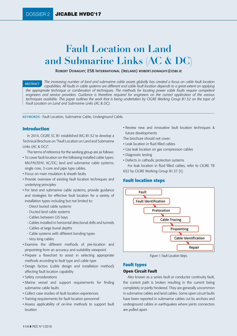
JICABLE HVDC'17
KEYWORDS : Fault Location, Submarine Cable, Underground Cable.
DOSSIER 2
114 ��REE N°1/2018
Fault Location on Land and Submarine Links (AC & DC)
Robert Donaghy; ESB International (Ireland) [email protected]
IntroductionIn 2014, CIGRE SC B1 established WG B1.52 to develop a
Technical Brochure on “Fault Location on Land and Submarine
Links (AC & DC)”.
The terms of reference for the working group are as follows:
- Cables installed in horizontal directional drills and tunnels
- Cables at large burial depths
submarine cable faults
location
future developments
The brochure should not cover:
Fault location steps
Fault typesOpen Circuit Fault
the current path is broken resulting in the current being
in submarine cables and land cables. Some open circuit faults
are pulled apart.
The increasing number of land and submarine cable assets globally has created a focus on cable fault location capabilities. All faults in cable systems are different and cable fault location depends to a great extent on applying
the appropriate technique or combination of techniques. The methods for locating power cable faults require competent engineers and service providers. Guidance is therefore required for engineers on the correct application of the various techniques available. This paper outlines the work that is being undertaken by CIGRE Working Group B1.52 on the topic of Fault Location on Land and Submarine Links (AC & DC).
ABSTRACT
Figure 1: Fault Location Steps.
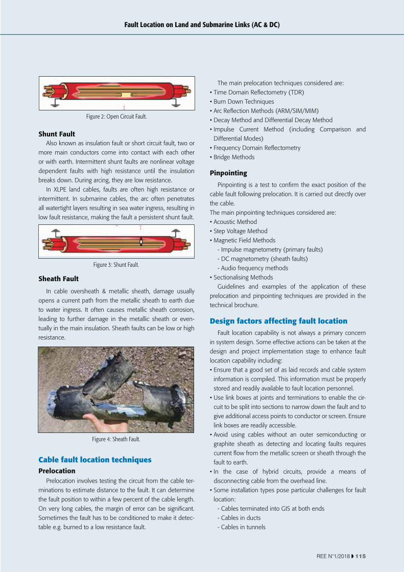
REE N°1/2018 � 115
Fault Location on Land and Submarine Links (AC & DC)
Shunt FaultAlso known as insulation fault or short circuit fault, two or
more main conductors come into contact with each other
or with earth. Intermittent shunt faults are nonlinear voltage
dependent faults with high resistance until the insulation
intermittent. In submarine cables, the arc often penetrates
low fault resistance, making the fault a persistent shunt fault.
Sheath Fault
opens a current path from the metallic sheath to earth due
to water ingress. It often causes metallic sheath corrosion,
leading to further damage in the metallic sheath or even-
resistance.
Cable fault location techniquesPrelocation
-
minations to estimate distance to the fault. It can determine
the fault position to within a few percent of the cable length.
Sometimes the fault has to be conditioned to make it detec-
table e.g. burned to a low resistance fault.
Differential Modes)
Pinpointing
the cable.
technical brochure.
Design factors affecting fault location
-
cuit to be split into sections to narrow down the fault and to
give additional access points to conductor or screen. Ensure
fault to earth.
disconnecting cable from the overhead line.
location:
- Cables terminated into GIS at both ends
- Cables in ducts
- Cables in tunnels
Figure 2: Open Circuit Fault.
Figure 3: Shunt Fault.
Figure 4: Sheath Fault.

JICABLE HVDC'17DOSSIER 2
116 ��REE N°1/2018
Emergency planning
prior to fault location
- Chronological overview of tests and measurements to be
performed in different scenarios
location which is adapted to the characteristics of the
cable connection
with fault location activities, but it is vital for successful fault
an evidence-based and forensic manner.
Innovation and future developmentsThe brochure describes some of the innovative methods
1. Fibre Optic Fault Location Methods- Distributed Temperature Sensing (DTS)
- Distributed Acoustic Sensing (DAS)
- Distributed Vibration Sensing (DVS)
- Brillouin Strain Measurements
2. Electrical/ Conventional Fault Location Methods
- Advances in conventional fault location Methods
- Online Fault Location Methods
3. Submarine Pinpointing Techniques Using ROVs
Fibre optic cables enable a wider range of fault pinpointing
methods to be applied including Distributed Temperature
Sensing, Distributed Vibration Sensing and Distributed Acoustic
Sensing through the application of Raman and Brillouin
Brillouin shift is temperature and strain sensitive.
attached to the cable, or contained in a separate duct. For best
optic cables have been reported, so particular attention should
Distributed Temperature Sensing (DTS)
insensitive to electromagnetic interference and can be used
from the shore.
Distributed Acoustic Sensing (DAS)Thumping high resistive faults with surge generator creates
vibration at the fault. Localised vibrations are captured on the
DAS interrogator (onshore) and compared with the initial
surge vibration detected at the fault location.
Distributed Vibration Sensing (DVS)
Figure 5: 3-core cable with integrated fibre optic.
Figure 6: Distributed Temperature Sensing.

REE N°1/2018 � 117
Fault Location on Land and Submarine Links (AC & DC)
causes a change in the phase relation.
If there is no integrated FO element, DVS can be
Safety considerations
that a risk assessment is carried out and method statements for
Training considerations
environment are registered in international standards national
- Working at height
- First aid training
- Fire awareness training
- Connection methods
- Understanding the various pre-location and pinpointing
methods
Accuracy and suitability of prelocation methods
Fault Type
Method Low Resistance High Resistance Open Circuit Intermittent Sheath Fault
TDR
Land & Submarine1-3 % accuracyFingerprint reference helpful Limitations for X bonded & screen interrupted systems
Fault Burning Required Land & Submarine1-3 % accuracyFingerprint reference helpful limitations for X bonded & screen interrup-ted systems
Fault Burning Required
Arc Reflection Methods
No need as TDR will work Land & Submarine1-3 % accuracyLength limited limitations for submarine cables (water ingress). Limitations for X bonded & screen interrupted systems
No need as TDR will work Land & Submarine1-3 % accuracyLength limited limitations for submarine cables (water ingress). Limitations for X bonded & screen interrupted systems
Decay
No need as TDR will work Cable cannot be charged to a DC voltage due to low resistance fault.
No need as TDR will work Land & Submarine1-10 % accuracyPropagation velocity unknown, no reference points available. Limitations for X bonded & screen interrupted systems
Differential
No need as TDR will work Land & Submarine1-3 % accuracyAccess to ref. conductor required
No need as TDR will work Land & Submarine1-3 % accuracyAccess to ref. conductor required

JICABLE HVDC'17DOSSIER 2
118 ��REE N°1/2018
Impulse Current
No need if TDR works Land & Submarine5-10 % accuracyLimited by breakdown voltage & distance to fault. Limitations for X bonded & screen interrupted systems
No need as TDR will work Land & Submarine5-10 % accuracyLimited by breakdown voltage & distance to fault. Limitations for X bonded & screen interrupted systems
Bridge Methods
Land & Submarine~ 1 % accuracyNeed 1 healthy return conductor
Land & Submarine~ 1 % accuracyUp to few MW fault resistance, Need 1 healthy return conductor
Land~ 1 % accuracyNeed 1 healthy return conductor
Voltage Drop
Land & Submarine~ 1 % accuracyNeed 1 healthy return conductor
Land & Submarine~ 1 % accuracyUp to few MW fault resistance, Need 1 healthy return conductor
Land~ 1 % accuracyNeed 1 healthy return conductor
Fibre Optic Methods
Land & Submarine1-3 % accuracyVibration from fault spot or magnetic force along route needed
Land & Submarine1-3 % accuracyDAS & DTS
Land & Submarine1-3 % accuracyAlready OTDR will work
Land & Submarine1-3 % accuracySound/heat needed at fault
Land & Submarine1-3 % accuracyVibration from fault spot needed
Table 1: Accuracy and Suitability of Prelocation Methods.
applicable not applicable
Fault Type
Method Low Resistance High Resistance Open Circuit Intermittent Sheath Fault
Acoustic
Land & SubmarineLimited application. A solid short circuit will not create noise. Can be used for submarine faults with water ingress
Land & Submarine1-3 m accuracyNot for cables in ducts
Land & Submarine1-3 % accuracyEarthing of disconnected sections neededCables in ducts
Land & Submarine1-3 m accuracyNot for cables in ducts
Step Voltage
Land1-3 m accuracyFault needs soil contactNot for cables in ducts
Land1-3 m accuracyFault needs soil contact Not for cables in ducts
Land1-3 m accuracyFault needs soil contact Not for cables in ducts
Land1-3 m accuracyFault needs soil contactNot for cables in ducts
Land0.1 m accuracyFault needs soil contact Not for cables in ductsGalvanic contact of neutral conductor to grounding systems
Audio Frequency
Land & SubmarineLand: 1-3 % accuracy Submarine: 10m - several hundred meters accuracy
Land & SubmarineLand: 1-3 % accuracy Submarine: 10m - several hundred meters accuracy
LandAudio frequency measurement with capacitive probes Step voltage usually preferred
Fibre Optic Methods
Land & Submarine1-3 % accuracyVibration from fault spot or magnetic force along cable route needed
Land & Submarine3-5m accuracyUp to few M ohms fault resistance, Need at least one healthy return conductor
3-5m accuracy 3-5m accuracySound or heat production in fault spot needed
Land1-3 % accuracyVibration from fault spot needed
Table 2 – Accuracy and Suitability of Pinpointing Methods
applicable not applicable

REE N°1/2018 � 119
Fault Location on Land and Submarine Links (AC & DC)
CONCLUSIONSThis paper has outlined the work that is being undertaken
being developed which increase the toolkit for fault location.
measures should be put in place for fault location activities
and fault location personnel must be competent and
The technical brochure for Working Group B1.52 will be
published in 2018.
AcknowledgmentsThe contribution of the members of CIGRE Working Group
References[1] CIGRE B1.37, Technical Brochure 652 “Guide for the
Operation of SCFF Cable Systems”
GlossaryDAS: Distributed Acoustic Sensing
DTS: Distributed Temperature Sensing
DVS: Distributed Vibrations Sensing
FO: Fibre Optic
GIS: Gas Insulated Switchgear
ROV: TDR: