study of side ditch liners for highway application
TRANSCRIPT

IJTRP
Joint
Transportation
Research
Program
FHWA/IN/JTRP-97/6Final Report
STUDY OF SIDE DITCH LINERS FORHIGHWAY APPLICATIONS - PHASE I
Anthony S. Calderon
Phillippe L. Bourdeau
December 1997
Indiana
Departmentof Transportation
PurdueUniversity


Final Report
FHWA/IN/JTRP-97/6
STUDY OF SIDE DITCH LINERS FOR HIGHWAY APPLICATIONS - PHASE I
by
Anthony S. Calderon and Philippe L. Bourdeau
Joint Transportation Research Program
Project No: C-36-15M
File No: 6-9-13
Prepared as Part of an Investigation
Conducted by the
Joint Transportation Research Program
Purdue University
In Cooperation with the
Indiana Department of Transportation
and the
U.S. Department of Transportation
Federal Highway Administration
The contents of this report reflect the views of the author who is responsible for the facts
and accuracy of the data presented herein. The contents do not necessarily reflect the
official views or policies of the Indiana Department of Transportation and Federal
Highway Administration. This report does not constitute a standard, specification, or
regulation.•e'
Purdue University
West Lafayette, IN 47907
December, 1997

Digitized by the Internet Archive
in 2011 with funding from
LYRASIS members and Sloan Foundation; Indiana Department of Transportation
http://www.archive.org/details/studyofsideditchOOcald

TECHNICAL REPORT STANDARD TITLE PAGE1. Report No.
FHWAyiN/JTRP-97/6
2. Government Accession No.3. Recipient's Catalog No.
4. Title and Subtitle
Study of Side Ditch Liners for Highway Applications - Phase I
5. Report Date
December 1997
6. Performing Organization Code
7. Authors)
Anthony S. Calderon and Philippe L- Bourdeau
8. Performing Organization Report No.
FHWA/IN/JTRP-97/6
9. Performing Organization Name and Address
Joint Transportation Research Program
Civil Engineering Building
Purdue University
West Lafayette, Indiana 47907-1284
10. Work Unit No.
11. Contract or Grant No.
SPR-2132
12. Sponsoring Agency Name and Address
Indiana Department ofTransportation
100 North Senate Avenue
Indianapolis, IN 46204
13. Type of Report and Period Covered
Final Report
14. Sponsoring Agency Code
15. Supplementary Notes
Prepared in cooperation with the Indiana Department of Transportation and Federal Highway Administration.
16. Abstract
Over the past few years, the INDOT new materials department has received numerous erosion control products
(mostly geosynthetics) to evaluate as alternatives to riprap and concrete in ditch liners. Potential benefits include lower
construction costs and better aesthetics over current products. Unfortunately, no specification, design methodology, or
classification system currently exists for these erosion control blankets.
In this project's phase I, existing information and knowledge on erosion control materials used to line highway side
drainage ditches were investigated. From the available technical literature (journal and conference publications, other
DOTs specifications, manufacturer documentation, independent test laboratory test data), design methodologies,
classification system, product approval procedures, and installation methods were reviewed for temporary and permanent
geosynthetic erosion control materials. Based on the synthesis of these reviews a design methodology was proposed
including design aids (tables, flow charts, and graphs) necessary to perform flexible liner computations. A classification
system based on product performance was also proposed. In addition, current design procedures for hard armor materials
(fabric formed revetments, concrete block systems, gabions, and riprap) were reviewed. A tentative specification for both
flexible and hard armor ditch liners was drafted.
17. Keywords
geosynthetic erosion control products, hard armor materials, rirpap, fabric
formed revetments, gabions, concrete block systems, straw blankets,
excelsior blankets, erosion control and revegetation mats, turfreinforcing
mats,
18. Distribution Statement
No restrictions. This document is available to the public through the National
Technical Information Service, Virginia, 22161
19. Security Classif. (of this report)
Unclassified
20. Security Classif. (of this page)
Unclassified
21. No. of Pages
284
22. Price
Form DOT F 1700.7 (8-69)

HI
Acknowledgments
Support for this project was provided by the Indiana Department of Transportation
(INDOT) and the Federal Highway Administration (FHWA). Many thanks go to the
Study Advisory Committee for their time, keen insight, and dedication to the erosion
control ditch liner study. Special thanks goes to Contech Construction Products, American
Excelsior Products, PPS Packaging Products, Synthetic Industries, and North American
Green for their phone interviews and company erosion control design software. Moreover
this project is indebted to the following companies that provided product information.
Contributing Companies
Akzo Nobel Geosynthetics BonTerra
Construction Techniques Drainage Products
Erosion Control Systems Nicolon Mirafi Group
North American Green PPS Packaging CompanySynthetic Industries Belton Industries
Greenfix America Webtec, Inc.
Aqua Shed Manufacturing Corp. Amoco Fabrics and Fibers
American Excelsior Company Siltco Industries
Contech Construction Products Midwest Construction
Hydrotex Synthetics Presto Products CompanyTenax Corporation EFS, Inc.
Verdyol Alabama Eljen Corporation
Nutec Supply Environmental Protection
Thanks also are extended to the Ohio, Illinois, Virginia, Wisconsin, Texas, and Maryland
DOTs for their respective erosion control specifications.

IV
Table of Contents
Acknowledgments ....List of Figures.....List of Tables.....Implementation Report
Chapter 1: Literature Review
1.1 Background
1.2 Temporary Erosion Control Products
1 .3 Permanent Erosion Control Products
1.4 TRMvs. ECRM
1.5 Available Design Procedures .
1 .6 Evaluating Erosion Control Products
1.7 Government Reports and Case Studies
1.8 Other Published Case Studies
.
Page
iii
viii
xi
xiii
1
5
6
8
10
11
15
24
Chapter 2: Design Methodologyfor Flexible Channel Liners
2. 1 Introduction to Design Procedures
2.2 Permissible Velocity Approach
2.3 Permissible Shear Approach .
2.4 Suggested Design Procedure .
2.4.
1
Note on safety factors .
2.4.2 Are channel liners necessary?
2.5 Computations .
2.6
2.5.1 Required Inputs
2.5.2 Required Calculations
.
Design Aids for Computations
28
28
32
36
37
38
39
39
43
48

Chapter 3: Design Methodologyfor HardArmor Channel Lining Systems
3.1 Introduction to Riprap Design
3.2 Descriptions of Riprap Design Procedures
3.2.1 HEC-11
3.2.2 HEC-15
3.2.3 California DOT "Bank & Shore Protection" Manual
3.2.4 U.S. Army Corps of Engineers
3.2.5 ASCE Sedimentation Manual #54 .
3.2.6 Sediment Transport Technology - Simons & Senturk
3.2.7 U.S. Bureau of Reclamation .
3.2.8 Escarameia and May "Turbulence" Approach
3.2.9 Blodgett Method ....3.2.10 Probabilistic Method by Froehlich and Benson
3.2.11 Summary of Riprap Design Procedures
3.3 Selecting Manning's n for Riprap
3.4 Gradation System for Riprap .
3.5 Gabion Design
3.5.1 Simons Design Procedure
3.5.2 Maynord Design Procedure
3.5.3 HEC- 1 5 Design Procedure
3.6 Fabric Formed Revetment Design Procedure
3.6.1 Design Principles
3.6.2 Design Equations
3.7 Concrete Block System Design
3.7.1 Design Principles
3.7.2 Design Equations - Simons Approach
3.7.3 Design Equations - Escarameia and May Approach
3.8 Summary of Hard Armor Design
3.9 Design for Composite Channel Linings
74
79
79
85
97
100
104
105
108
111
112
115
121
123
127
133
134
134
136
139
140
143
146
147
147
150
151
152
Chapter 4: Classification Systemfor Erosion Control Materials
4.
1
Why is a Classification System Needed?
4.2 Summary of Other DOT Erosion Control Specifications
156
158

VI
4.2.1 Virginia 158
4.2.2 Illinois 158
4.2.3 Ohio 159
4.2.4 Texas....... 160
4.2.5 Maryland . . . 160
4.2.6 Connecticut . . . . . 161
4.2.7 Synthetic Industries ..... 161
4.2.8 FHWA 161
4.3 Defining a Classification System for Erosion Control Products 163
4.4 Index Properties of Class A products . . . . 171
4.5 Index Properties of Class B products . . . 173
4.6 Summary of Erosion Control Product Classification . 174
Chapter 5: Erosion Control Product Approval Procedure
5.1 Introduction to Approval Procedures .
5.2 Texas DOT New Product Approval Procedure
5.3 Virginia DOT New Product Approval Procedure
5 .4 Proposed New Product Approval Procedures
.
5.4.1 Method 1 - Field Testing
5.4.2 Method 2 - Guarantee Specification .
5.5 Proposed Product Classification
Chapter 6: Installation Procedures
6.1 Introduction to Installation Procedures
6.2 Installation Procedures for Soft Armor Materials
6.3 Installation Requirements for Hard Armor Materials
.
Chapter 7: Proposed Draft Specification
7.
1
Flexible Ditch Lining Specification .
7.2 Hard Armor Ditch Lining Specification
176
177
179
181
181
183
190
193
193
199
203
210

Vll
Appendix
A Normal Depth Design Equations for Common Channel Geometries
B FHWA Design Procedure for Geotextile Underlays
C List of References
D FHWA Flexible Liner Design Procedure (1995)
E Typical Channel Drawings (courtesy of Synthetic Industries)
F Database of Erosion Control Products
G Summary of Acronyms

VU1
List of Figures
Figure Title page
1-la Elevation & Plan Views of Test Channels 14
1-lb Elevation & Plan Views of Test Channels 14
1-2 Cumulative RunoffVolume from Erosion Control Blanket Plots 19
1-3 Cumulative Soil Loss from Mulch Plots 19
1-4 Cumulative Soil Loss from Erosion Control Blanket Plots 20
1-5 Maximum Flow Depth vs Channel Slope Based on Bed Shear Stress 23
2-1 Limiting Velocity Versus Peak Flow 30
2-2 Typical Shear Stress Distribution in a Channel 32
2-3 Plan View Showing High Shear Stress Zones 33
2-4 Worksheet for Steep Channel Design 48
2-5 Flexible Liner Design Flow Chart 49
2-6 Manning's n vs. Relative Roughness for Selected Lining Types 56
2-7a Permissible Shear Stress for Non-cohesive Soils 57
2-7b Permissible Shear Stress for Cohesive Soils 58
2-8 Nomograph for Trapezoidal Design 59
2-9 Trapezoidal Design Chart 60
2-10 Geometric Design Chart for Triangular Channels 61
2-11 Geometric Design Chart for Parabolic Channels 62
2-12 Hydraulic Radius Design Chart for Parabolic Channels 63
2-13 Manning's "n" vs Hydraulic Radius for Class A Vegetation 64
2-14 Manning's "n" vs Hydraulic Radius for Class B Vegetation 65
2-15 Manning's "n" vs Hydraulic Radius for Class C Vegetation 66
2-16 Manning's "n" vs Hydraulic Radius for Class D Vegetation 67
2-17 Manning's "n" vs Hydraulic Radius for Class E Vegetation 68
2-18 Kb Correction Factor for Bend Shear Stress 69

IX
2-19 Length ofProtection, Lp, Downstream of Channel Bend 70
2-20 Angle ofRepose in Terms ofD50 (ft) 71
2-21 Channel Side Shear Stress Correction Factor 72
2-22 Tractive Force Ratio as a Function of Angle ofRepose and Side Slope 73
3-1 Classification of Principle Types ofFailures 76
3-2 Comparison ofProcedures for Estimating Stone Size 78
3-3 Flow Chart for Riprap Design Procedure for HEC- 11 81
3-4a Design Aids for HEC- 1
1
82
3-4b Flow Chart ofHEC-15 Design Procedure 87
3-5 HEC-15 Design Aids for B < 6 ft 90-91
3-6 Shields Diagram of Incipient Motion 94
3-7 Shields Diagram for Large Diameter Riprap 94
3-8 Comparison ofD50 Estimates from HEC-15 and Field Data 96
3-9 Flow Chart for Cal-B&SP Riprap Design Procedure 99
3-10 Design Aids for USACOE Riprap Design Procedure 101
3- 1
1
Location ofVM and Definition of "d" 103
3-12 Forces Acting on a Riprap Particle Resting on a Channel 106
3-13 Flow Chart and Equations for Simons & Senturk Design Procedure 107
3- 14a Curve to Determine Stone Size in a Mixture Based on Velocity 109
3 - 14b Transformed USBR Stone Size Curve 1 1
3-15 Blodgett's Riprap Design Method 1 1
4
3- 16a Displaced Ripap as a Function ofDimensionless Shear and Std. Dev 120
3- 16b Displaced Riprap as a Function ofDimensionless Shear and Bank Angle 120
3-17 Comparison ofManning's n Based on Theory and Lab Data 125
3-18 Illinois DOT Riprap Gradation Chart 128
3-19a Gabion Mattress Design Aids 137
3 - 1 9b Gabion Mattress Design Aids 137
3-20 Permissible Shear Stress vs Rock Fill Diameter for Gabions 138
3-21 Permissible Shear Stress vs Gabion Thickness 138

3-22 Typical Cylinder Test Results for FFR's 142
3-23 Schematic of Ground Anchors for FFRs 142
3-24 Bend Shear Stress Coefficient 142
3-25 Composite Channel Lining 152
3-26 Composite Channel Lining with Unequal Side Slopes 152
4-1 Limiting Velocity vs. Shear Strengths for Various Hydraulic Radii 165
4-2 Limiting Velocity vs. Shear Strengths (Modified Velocity Ranges) 167
4-3 Modified Shields Diagram 169
5-1 Sample Position Letter on Guarantee Specifications 188

XI
List of Tables
Table Title page
1-1 Temporary Erosion Control Categories 2
l-2a Permanent Erosion Control Categories - Biotechnical Composites 3
l-2b Permanent Erosion Control Categories - Hard Armor Systems 3
1-3 Definitions ofTRM & ECRM Material Properties 9
1-4 Physical Properties ofTRMs & ECRMs 9
1-5 Performance Limits of Several Classes ofErosion Control Products 13
1 -6 Summary of 1 993 Wisconsin DOT Study on Erosion Control Products 16-17
1-7 Summary ofUSGS / FHWA Erosion Control Study (1985) 22
2-1 Limiting Shear Stresses for Generic Erosion Control Materials 34
2-2 Suggested H:V ratios for Different Bed Materials 39
2-3 Permissible Shear and Velocity for Current Erosion Control Products 50-5
1
2-4 Permissible Shear Stress for Generic Lining Materials 52
2-5 Vegetation Classification (A-E) 53
2-6 Manning's Roughness Coefficients by Depth ofFlow 54
2-7 Manning's "n" for Current Linings 55
3-1 List ofRiprap Design Procedures Detailed in this Report
3-2 Values ofA3/Az for selected B and d/B Ratios
3-3 Bank Angle Correction Factor for USACOE Design
3-4 Riprap Example
3-5 Comparison ofMannings's n values
3-6 California Bank and Shore Protection Manual Gradation Table
3-7 Riprap Gradation Limits for a Design D5o from HEC-1
1
3-8 Riprap Gradation Classes Based on HEC- 1
1
3-9 USACOE Gradations given as Weights for Percent Finer
77
89
102
121
126
128
130
131

Xll
3-10 Bank Correction Factor 135
3-11 Typical FFR Thicknesses 145
4-1 Proposed Classification System for Erosion Control Products 163
4-2 Modified Velocity Ranges for Classification System 166
5-1 Texas DOT Approved Products List 178
5-2 Virginia DOT Approved Products List 1 80
5-3 Method 1 Proposed Approval Procedure 183
5-4 Method 2 Proposed Approval Procedure 185
5-5 Probable Warranty Periods for each Product Class 185
5-6 List ofPossible Damage Criteria for Drainage Channels 189
5-7 Classification ofErosion Control Products 191
6-1 Guidelines for Installing Erosion Control Materials 196
6-2 Mix Proportions for FFR Grout 200

Xlll
Implementation Report
Recently, the INDOT new materials department has received numerous erosion control
products to evaluate as alternatives to riprap and concrete in ditch liners. Potential benefits
include lower construction costs and better aesthetics over current products. Unfortunately,
no specification, design methodology, or classification system currently exists for these erosion
control blankets. The research proposes to draft a specification implementing erosion control
materials as ditch liners.
An extensive literature review of geosynthetic erosion control materials was performed
at the request of the Indiana Department of Transportation. These new technologies combine
natural vegetation with geosynthetic materials and have emerged as a cost-effective alternative
to the traditional materials (riprap and paved side ditch). "Flexible" geosynthetic linings
conform to a wide variety of contours, and geometries. Temporary products provide short
term erosion protection and degrade to leave the vegetation to resist the hydraulic forces.
Similar to temporary products, permanant products protection channels in the short term and
accelerate vegetative growth. However, these rugged, UV stabilized erosion control blankets
do not degrade. Ultimately, the liner becomes synergistically entangled with living plant tissue
to extend the performance limits of natural vegetation.
On the other hand, extremely high flow channels or streambanks require hard armor
protection. The solutions for this problem include traditional riprap and gabions (wire
enclosed riprap) and more recently, fabric formed revetments and articulating concrete block
systems. These products offer the highest level of erosion protection in demanding
environments.
Based on this research effort, specific recommendations suggested to INDOT for
implementation include:
1. Use a performance based design methodology for flexible ditch liners. The method
developed follows the recommendations outlined in the HEC-15 publication by Chen
and Cotton, 1988. However, modifications to the procedure have been made that
reflect recent research. Such changes include utilizing higher permissible shear stresses

XIV
for the erosion control materials, implementing a design safety factor against shear
failure, and designing against velocity failure.
2. Use ofthe design methodologies present herein for fabric formed revetments (FFRs)
and concrete block systems (CBSs). FFRs are designed using a traditional slope
stability analysis while CBSs are designed by one ofthree accepted methods.
3. A performance based erosion control product classification is proposed. Classifications
based upon limiting shear stress and velocity were created using current specifications
from seven state DOT's.
Classification Permissible Velocity Permissible Shear
m/s (ft/s) Pa (lb/ft2)
A (Degradable): Product degrade within 2 years (e.g. jute mesh, straw or coconut
blanket, excelsior, roving, straw bales, mulches.,)
A-l 0.0-1.2 (0-4) 0-45 (0-1)
Ar2 1.2-2.1 (4-7) 45-96 (1-2)
B (Non-degradable): Products stabilized with carbon black (e.g. nylon mesh, heat
bonded 3-D TRM, synthetic erosion control and revegetation mat)
B-l " " 1.2-2.1 (4-7)"
~'"~45-96 (1-2)
B-2 2.1-3.0 (7-10) 96-240 (2-5)
C (Hard Armor): Products made to resist extremely high Sows; made ofrock, concrete,
and often reinforced:with:galvanized steel cabfe;!
;
\fNote: limvett~de]m^^ in the
C-l Riprap
C-2 Gabions
C-3 Fabric Formed Revetments
C-4 Articulating Blocks

XV
4. This report reviews 10 available riprap design methodologies, Manning's n equations,
and standard gradations. Further research is necessary to select an appropriate riprap
design methodology for Indiana and test the viability of the standard riprap gradation
schemes presented in this report.
5. Use of either an approved list format or a guarantee specification format for erosion
control materials. The former puts the classification and field testing burden on
INDOT while the latter places the burden on the General or Landscape Contractor.

1. Literature Review
1.1 Background
Until recently, erosion of transportation infrastructure through channels such as
highway ditches has been controlled using rigid linings made of rocks, concrete, or asphalt
liners. Although rigid linings can withstand high discharges, flow velocities and shear
stresses, they fail entirely if a portion is damaged. Moreover they are difficult to construct
and provide no wildlife habitat.
Recently, new technologies that combine natural vegetation with geosynthetic
materials have emerged as a cost-effective alternative to the traditional materials. These
flexible linings conform to a wide variety of contours, and geometries. They provide
temporary erosion protection and accelerate vegetative growth. Ultimately, the liner
becomes synergistically entangled with living plant tissue to extend the performance limits
of natural vegetation.
The benefits of using geosynthetics abound. Flexible vegetated linings are easy to
install, feature a natural appearance, and provide a better habitat for local floral and fauna.
Geosynthetic materials permit infiltration, promote groundwater recharge, and capture
sediment. Following an extensive series of rainfall/erosion experiments, Austin (1996)
concludes "all products tested reduced sediment loss to below 60% of the sediment loss
from unprotected soil." Unlike rigid linings, flexible liners relieve water pressure.
Because of their flexibility, these materials resist differential settlement and frost heave
better than the concrete or asphalt lining. Furthermore, in pedestrian areas, geosynthetics
are safer; no sharp edges or surfaces to cause injury (Northcutt, 1995).
Most importantly, flexible linings are significantly less expensive than concrete or
riprap. Typical estimates are 1/3 to 1/2 the cost of hard armor (riprap and concrete).
Heavy duty turf reinforcing mats cost $8-$13/m2; whereas, concrete and rip rap cost
$25/m2
. Revetment systems cost between $21 and $42/m2depending on the area of the
country (Carroll, 1990). Indeed, this economic benefit provides the real impetus for this
research. One often cited example is the use of erosion mats in storm water runoff
channels at the exclusive Horse Ranch community near Aspen, Colorado. In this case,
Literature Review

Drexel Barrell installed Turf Reinforcing Mats designed to handle a 100-year storm at
approximately 41% of the cost of conventional rip rap. This resulted in a total saving of
over $250,000! (Theisen, Hageman, & Austin, 1995).
Erosion control products can be divided into two main categories: TERMs
(Temporary Erosion Control Materials) and PERMs (Permanent Erosion Control
Materials) (Austin, 1996; Theisen, 1991; Theisen, 1992). TERMs consist of degradable
natural or synthetic mats that provide temporary control, and rely on vegetation for long-
term resistance to low to medium flow. The blankets prevent erosion during vegetation
establishment, then degrade in 1-5 growing seasons.
PERMs on the other hand are permanent erosion control materials designed for
medium to high flows. These mats are constructed ofUV stabilized materials (i.e. carbon
black added to resist photodegradation). They are used on sites where mature vegetation
alone could not resist the design flow. These materials are subdivided into biotechnical
composites and hard armor systems. Biotechnical composites are non-degradable
materials that accelerate vegetative growth and become entangled with the roots. Hard
armor systems can resist more extreme conditions - tidal flows, harbors, and commercial
riverfront areas in addition to traditional highway ditches. Table 1-1 and 1-2 list the
general categories ofTERMs and PERMs (Modified from Theisen, 1992).
The following pages provide brief descriptions of each class of products
(Lancaster, 1994; Theisen, 1992; Agnew, 1991; Theisen, 1992; Northcutt, 1995; Theisen,
1991; Dikran, 1996). In addition, common applications are noted for each class.
TERM Categories
1). Hay, straw, and hyromulch
2). Fiber roving systems
3). Erosion control netting & mesh
4). Erosion control blankets
5). Tackifiers and soil stabilizers
Table 1-1 : Temporary erosion control materials
Literature Review
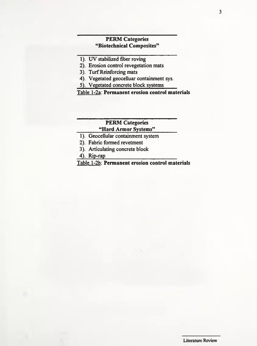
PERM Categories
"Biotechnical Composites'
1). UV stabilized fiber roving
2). Erosion control revegetation mats
3). TurfReinforcing mats
4). Vegetated geocelluar containment sys.
5). Vegetated concrete block systems
Table l-2a: Permanent erosion control materials
PERM Categories
'Hard Armor Systems"
1). Geocellular containment system
2). Fabric formed revetment
3). Articulating concrete block
4). Rip-rap
Table l-2b: Permanent erosion control materials
Literature Review

Pictures of Erosion Control Products
fSfr*!^ V„ v'-«/"A* -3 V tI/.v*;S»^«
s£^
ess
Temporary Erosion Control Products
Permanent Erosion Control Products
Literature Review

1.2 Temporary Erosion Control Material Characteristics
Mulches
(a). Assists in soil stabilization; capture sediment and blowing snow
(b). Works by decreasing soil temperature which in turn decreases
evaporation and heat stress on plants,
(c). Decomposes into valuable organic matter
(d). Loose straw /hay 10-20 cm long; -1.5-2.0 tons/acre
Tackifiers : viscous sprays to anchor mulch fiber; typically non-
toxic/degradable asphalt and petroleum are used
Hydraulic : one step application of seed, water, fertilizer, and mulch;
fibers only 1 cm long which degrade quickly
Erosion Control Netting or Biaxially OrientatedProcess nets (ECN& BOP, respectively)
(a). 2-D biaxial-orientated process nets from polypropylene or polyethylene
resin or woven natural fibers
(b). BOP / ECN's do not show significant shrink/swell behavior (unlike jute)
(c). Suited for moderate conditions
Open Weave Mesh
(a). Woven polyolefin yarns formed into 2-D matrix used with or without
mulch layer; mesh has a higher tensile strength than an ECN(b). Often used as a reinforcing underlay for sod; also used on slopes
Erosion Control Blanket (ECB)
(a). Degradable organic/synthetic fibers woven or glued to nettings or meshes
made from straw, wood excelsior, coconut, cotton, polyethylene or
polypropylene; A biaxially orientated process net sandwiches the fibers
in nearly every case.
(b). Used to retain soil moisture, promote quick seed germination, break up
raindrops, and prevent erosion until vegetation becomes established
(c). Applications include low to moderate flow channels (up to 3 m/s) and
gradual to steep slopes.
Literature Review

Fiber Roving Systems (FRS)
(a). Air compressor blown spaghetti-like strands of polypropylene ejected
through a nozzle over a slope or channel and anchored with asphalt
emulsions;
(b). Material can accommodate any geometry, width, or thickness;
(c). Roving may be a PERM ifUV stabilizing chemicals are added
(d). It is very easy to install along highways, surface mines, and landfills
(e). Though non-toxic, black asphalt tackifier may not be environmentally
acceptable.
1.3 Permanent Erosion Control Material Characteristics
Geocellular Containment System (GCS)
(a). Series of3-D soil-filled cells up to 20 cm deep that are interconnected by
manufactured joints; the spreadable sheet looks like a large honeycomb
stretched across a slope or channel. GCS are made ofHDPE 75-100 mils
thick.
(b). Wall pattern prevents development of deep plant roots; hence flow
velocities cannot exceed 2-3 m/s in drainage ditches.
(c). Each cell is hydraulically connected creating a cellular confinement system
that is free draining.
Fabric Formed Revetments (FFR)
(a). Double layer ofwoven geotextile that installed and then filled with
pumpable concrete; high strength cables may interconnect the blocks or
cells
(b). Used for high discharge / velocity flow or harsh conditions (e.g. coastal
zones)
(c). Common fabric types include: filter point, uniform section, and
articulating mats.
Concrete Block Systems (CBS)
(a). Prefabricated concrete panels joined by high strength cable
(b). Often allow vegetation to grow through slots in the panel
(c). Used for high flows, canals, riverbanks.
Literature Review

TurfReinforcingMats (TRM)
(a). Stiff, high strength, black, UV stabilized, 3-D polypropylene, polyethylene,
or PVC matrix that are installed on graded channel face, seeded and soil
filled. Mats are often more than 13 mm (0.5") thick and have in excess of
90% void space
(b). Vulnerable in the short term until vegetation becomes established;
however once vegetation mature, mats provide superior shear resistance as
roots become entangled with the material.
(c). Used in medium to high flow channels and steep 1 : 1 slopes.
(d). Mat is resistant to hydrolysis, bio-chemical degradation; It provides
permanent erosion control and turf reinforcement.
Erosion Control andRevegetation Mat (ECRM)
(a). Green, dense, 3-D mat ofUV stabilized PVC or polypropylene
monofilaments that is thinner (lower profile) and weaker than TRMs.(b). Channel bed is seeded prior to laying down the ECRM. That is,
vegetation must grow up through the mat.
(c). Provides superior erosion protection while vegetation gets established.
Literature Review

8
1.4 TRM Vs ECRMECRMs and TRMs have similarities, but also have distinct differences. First the
two materials are installed differently. TRMs are first installed, then seeded and soil filled;
while, in the case ofECRMs channel bed is seeded before the geosynthetics are rolled out.
This means that the roots entangle with the TRM, but not with the ECRM. Thus, the
vegetated TRM provides more shear resistance than the ECRM in the long term (Carroll,
1990, 1991, 1992; Theisen, 1992).
TRMs leave bare soil exposed until vegetation is established; whereas, ECRMs
provide dense cover during early stages of growth. Therefore, if short term erosion is
critical, an ECRM might be preferable. On the other hand, if long term erosion is critical,
then a TRM might be the best choice. In the event that both long and short term erosion
are critical, a TRM covered with a degradable mat (e.g. straw or excelsior) would be a
good solution.
Another difference is that TRMs are much stiffer than ECRMs. The high stretch
properties of the ECRM imply that it does not perform as well in the long term (Carroll,
1990). Carroll emphasizes that ECRMs only provide erosion protection for moderate
flow channels; they are not designed for turf reinforcement. Hence, while a TRM can
provide ECRM benefits, the reverse is not true. In order to grasp the differences between
these two products, table 1-3 defines the relevant material properties and table 1-4
provides the corresponding values of each parameter for TRMs and ECRMs. These
values are compiled from Carroll (1990) and the FHWA (1992).
A brief example furthers this point. Jason Consultants of Geneva Switzerland
published a report comparing various erosion control materials on 2:1 slopes. Materials
tested include jute mesh, excelsior, geocells, ECRM, and TRMs. In terms of vegation
density and height, the TRM had the best quality of growth. (Theisen, 1990). Similar
results were obtained from a 1988 Hartford, Connecticut landfill study. This research is
evaluating 20 erosion control products. Soil-filled TRM channel liners showed seed
germination within 6 days and had significantly denser vegetation after one month than any
of 28 other plots. The TRM also withstood a 5" rain event that devastated other plots.
(Theisen, 1990).
Literature Review

Definitions ofTRM and ECRM Material Properties
(Compliedfrom Carroll, 1990 andFHWA, 1992)
Material ASTM Test Definition
Property Number
1). Thickness ASTMD-1777 Minimum thickness of the blanket
2). Porosity Calculated Ratio ofvoids to total volume of blanket; based
on weight, thickness, and specific gravity.
3). Ground Cover Light Projection Ratio of light passing the specimen to a standard
4). Resiliency ASTMD-1777 Percent of original thickness retained after 3
cycles of a 100 psi (600 kPa) load for 60
seconds followed by 60 seconds without load.
Thickness measured 30 minutes after load
removed.
5). Tensile ASTMD-4632 Strength of both machine and cross direction
Strength using the 2" strip method
6). Elongation ASTMD-1682 Elongation of material at failure expressed as a
percent of total length
7). UV Stability ASTMD-4355 Tensile strength retained after 1000 hours in a
Xenon ARC weatherometer
Table 1-3 : Physical property definitions for TRM and ECRM
Physical Properties ofTRMs and ECRMs(Updatedfrom Carroll, 1990)
Material Property TRM ECRM
1). Thickness (mm) 13-18 6-8
2). Porosity > 90% > 90%3). Ground Cover 30 - 60 % 50 - 80%4). Resiliency 80% 80%5). Tensile Strength (kN/m; lb/ft) 1.9(130) 1.4(95)
6). Elongation 40% (max.) 70% (max).
?)• UV Stability 80% 80%Table 1-4 : Physical property requirements for TRM and ECRM
Literature Review
10
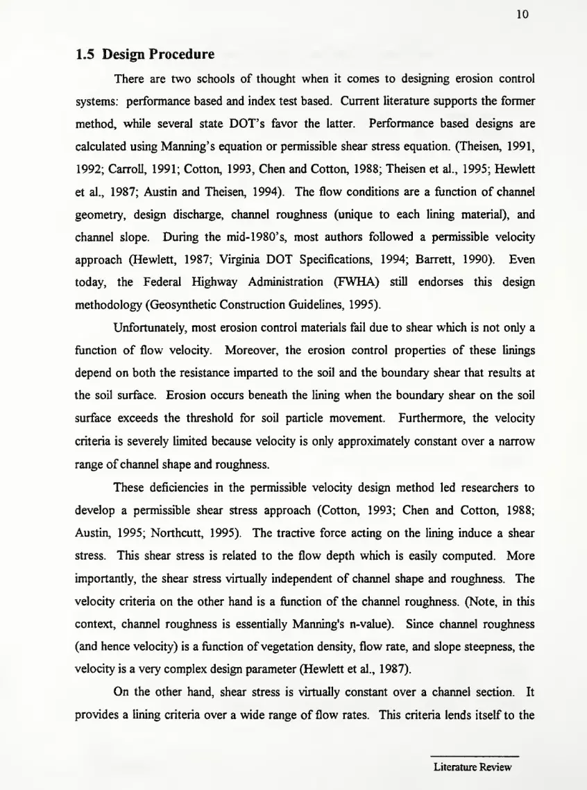
1.5 Design Procedure
There are two schools of thought when it comes to designing erosion control
systems: performance based and index test based. Current literature supports the former
method, while several state DOT's favor the latter. Performance based designs are
calculated using Manning's equation or permissible shear stress equation. (Theisen, 1991,
1992; Carroll, 1991; Cotton, 1993, Chen and Cotton, 1988; Theisen et al., 1995; Hewlett
et al., 1987; Austin and Theisen, 1994). The flow conditions are a function of channel
geometry, design discharge, channel roughness (unique to each lining material), and
channel slope. During the mid- 1 980' s, most authors followed a permissible velocity
approach (Hewlett, 1987; Virginia DOT Specifications, 1994; Barrett, 1990). Even
today, the Federal Highway Administration (FWHA) still endorses this design
methodology (Geosynthetic Construction Guidelines, 1995).
Unfortunately, most erosion control materials fail due to shear which is not only a
function of flow velocity. Moreover, the erosion control properties of these linings
depend on both the resistance imparted to the soil and the boundary shear that results at
the soil surface. Erosion occurs beneath the lining when the boundary shear on the soil
surface exceeds the threshold for soil particle movement. Furthermore, the velocity
criteria is severely limited because velocity is only approximately constant over a narrow
range of channel shape and roughness.
These deficiencies in the permissible velocity design method led researchers to
develop a permissible shear stress approach (Cotton, 1993; Chen and Cotton, 1988;
Austin, 1995; Northcutt, 1995). The tractive force acting on the lining induce a shear
stress. This shear stress is related to the flow depth which is easily computed. More
importantly, the shear stress virtually independent of channel shape and roughness. The
velocity criteria on the other hand is a function of the channel roughness. (Note, in this
context, channel roughness is essentially Manning's n-value). Since channel roughness
(and hence velocity) is a function of vegetation density, flow rate, and slope steepness, the
velocity is a very complex design parameter (Hewlett et al., 1987).
On the other hand, shear stress is virtually constant over a channel section. It
provides a lining criteria over a wide range of flow rates. This criteria lends itself to the
Literature Review

11
development of design safety factors (this idea is further developed in chapters 2 and 3).
In addition, the higher stresses developed in channel bends can be quantified by simple
shear stress calculations. This provides a higher level of design confidence than otherwise
possible (Dodson, 1990). The tractive force approach is used in both the HEC-15 Design
Circular (Chen and Cotton, 1988) and Texas DOT specifications (Northcutt, 1996).
Dodson (1990) suggests that critical shear stress should be used in tandem with velocity
calculations for erosion control lining designs. Hence, a combination of the permissible
velocity and shear design methodologies are reviewed in this report.
The other design methodology utilizes index properties of the material. For a
given site, one needs to determine the required tensile strength, elongation, UV stability,
Mullen burst strength (ASTM D-3786), and ground cover factor (see Table 1-4 for all
ASTM test references). Based on these results, one selects erosion control products that
meet or exceed these requirements. Illinois, Ohio, and the FWHA currently use index
property designs (ILDOT, ODOT, 1994; FWHA, 1992). One problem with using such a
system is that the majority of manufactures do not provide index test data for their
products. The reason for the lack of index data is that there no consensus on how to
perform erosion material index tests. According to the Erosion Control Technology
Council, a committee is currently attempting to standardize these index tests. Moreover,
ASTM has recently started a subcommittee (D-18.25) to investigate standard designs,
classifications, and testing procedures for erosion control products.
1.6 Evaluation of Geosynthetic Erosion Control Materials
In order to adopt a performance based specification, one needs to know how much
shear or velocity a given product can withstand. Several authors conducted flume tests
over the past decade to establish permissible velocity and more recently permissible shear
values for erosion control products. In 1987, the Construction Industry Research and
Information Association (CIRCA) from the United Kingdom published a report on field
testing ofvarious erosion control products (Hewlett et al., 1987). Nine reinforced grassed
channels were constructed on the upstream face of a 10 m high abandoned earth dam.
Materials tested included cellular concrete blocks, TRMs, roving, 2-D meshes, and woven
Literature Review

12
geotextile fabric. The CIRIA engineers established guidelines for the design of grassed
channels. Their velocity recommendations are noted below.
Erosion Control Measure
Mature unreinforced grass
Long Term VegetatedECMs1
Concrete blocks
xECMs = Erosion ControlMaterials
Max. Velocity Duration ofFlow
4.5 m/s Short event (0.5 hrs)
2.0 m/s Long event (50 hrs)
6.0 m/s Short event (0.5 hrs)
4.4 m/s Long event (50 hrs)
6.1 m/s Long event (50 hrs)
Notice that the allowable design flow velocities decrease with extended flow
duration. Increasing the duration of flow decreases the resistance of the material. The
CIRIA group chose a 2-day design duration because this period is longer than most high
velocity events. After two days, grass should recover and the subsoil should drain
(Theisen, 1990).
This initial work spurned numerous studies by universities (Colorado State and
Utah State) and private companies (Synthetic Industries and North American Green).
Vegetated and non-vegetated materials were installed in flumes 0.6-1.2 m (2-4 ft) wide
and 15.2 m (50 ft) long. Flows of 0.57, 0.91, 1.3, 1.7, and 2.1 m3/s (20, 32, 45, 60, and
75 ft3/s) gave rise to velocities of 0.91, 2.4, 3.4, 4.6, and 6.1 m/s (3, 8, 1 1, 15, and 20 ft/s)
(Schematic of channel in figure 1-1). Flow depth measurements were taken throughout
the channel to calculate maximum shear stress. Table 1-5 provides performance limits for
several classes of erosion control materials. Note that the information is combined from
several sources (Northcutt, 1995; Carroll, 1990, 1991; Theisen, 1991, 1992; Austin, 1995;
Cotton, 1993). Some researchers determined permissible velocity, while others
determined maximum shear. Consequently, there are several categories of incomplete
information.
Literature Review

13
Performance Limits of Several Classes of Erosion Control Products
Product Class Short Term Long Term Short Term Long Term
Velocity Velocity Shear Shear
m/s (ft/s) m/s (ft/s) N/m2(lb/ft
2) N/m2
(lb/ft2)
Bare Soil 5.4(0.11)
Grass - good cover 3.0(9.8) 1.5(4.9)
Grass - poor cover 2.0 (6.6) 1.0(3.0)
Fiber Roving 1.8 (6.0) 1.2(4.0) 29-68 (0.61-
1.4)
ECN - degradable 9 (0.2)
ECM - degradable 140 (3.0)
ECB - single net 95 (2.0)
ECB - double net 140(3.0)
ECB - excelsior 74(1.6)
ECB - straw w/ net 67(1.4)
Jute mesh 25 (0.53)
Hydromulch 0.76 (2.5)
ECRM - bare soU 4.0(13) 2.7 (9.0)
ECRM - vegetated 5.8(19) 4.6(15)
TRM - no soil 5.8 (19) 4.3 (14)
TRM - bare soil 4.0(13) 2.4 (8.0) 280 (5.8)
TRM - vegetated 6.0 (20) 4.6(15) 380 (7.9)
Concrete 8.0+ (26+) 6.0+ (20+)
Note: Short Term =>30 - 60 minutes; Long Term => 24 or 50 hours
Table 1-5 : Allowable shear and velocity for several classes of erosion control
products
Literature Review

14
PbaVieyl
Figure 1-1 a : Elevation and plan views of the test channels
(Reprintedfrom Theisen, 1992)
H—
5
1- -#-
nozzle
to load
cell
-8'- -*- -8'- * 5' H*-3H|c
2')|
test section 3"±_
flov.
test platform
rigid connection
fl
?3'
J,
Figure 1-lb : Elevation and plan views of the test channels
(Reprintedfrom Theisen, 1992)
Literature Review

15
1.7 Government Reports & Case Studies on Erosion Control Materials
This section presents several case studies found in the literature. The first four are
summaries of government field study reports. Missouri DOT, Wisconsin DOT, the
Ontario Ministry of Transportation and the FHWA installed and evaluated several erosion
control products. The next four are summaries of specific applications found in the
literature. For references, see Appendix C.
Missouri DOT - Investigation of Erosion Control Materials for Ditches, 1983
Summary: This field study compares a TRM (Enkamat), mulch blanket (Hold Gro),
Excelsior (Curlex), mulch blanket (Roll Lite) to traditional sod, rip rap, and
concrete. The Enkamat worked well at half the cost. The other materials
worked, but did not significantly improve shear resistance or offer any
savings over straw, sod, or netting.
Results Product
Enkamat
Mulch Blanket
Curlex
Roll Lite
Permissible Velocity
V<3.4m/s(llft/s)
V<1.8m/s(6ft/s)
V<1.8m/s(6ft/s)
V<1.8m/s(6ftVs)
Conclusions
1)-
2).
3).
4).
5).
Enkamat is easy to place, promotes faster seed germination than other
products
Mulch blanket ravels when subject to heavy flows and water undercut the
blanket
Curlex was successful, but blanket did have undercutting problems
Maintaining good contact between the ground and blanket was difficult
Two failures occurred after a 3. 1" storm 2 weeks after installation. It was
considered a rare event and not indicative ofthe products performance.
Literature Review

16
Wisconsin DOT - A Statewide Erosion Control Study - Evaluation Report, 1993
Thirty blankets, tackifiers, and mulches were installed at 10 sites throughout
Wisconsin. Twenty two ofthe thirty erosion blankets tested effectively controlled erosion,
and encouraged seed germination. Four of the eight failures were attributed to improper
installation. The other four failing blankets were installed on sites exceeding product
limitations. All of the products tested then appeared to play a beneficial role in highway
construction. In addition, the report cautions users to be aware of product limitations and
strictly adhere to the manufacturers installation guidelines. Table 1-6 lists each product
tested, its composition, and the field performance.
Manufacturer /
Product
Composition Field Performance
BonTerra Si 100% straw w/ top
net
Installed on backslope; held up well
and prevented erosion
BonTerra S2 100% straw w/ top &bottom net
Resisted 3" rain 2 weeks after installed;
good plant growth
BonTerra CS2 70% straw; 30%coconut w/ netting
Resisted 3" rain 2 weeks after
installation; good plant growth
BonTerra C2 100% coconut fiber
w/ top & bottom net
Resisted 1.5" rain first night after
installation; good plant growth
BonTerra SFB 100% PP staple fiber
w/ top & bottom net
Resisted 1.5" rain first night after
installation; good plant growth
North American.
Green - SC150
70% straw; 30%coconut w/ netting
Performed well; no erosion; good seed
germination
Synthetic Industries -
Polyjute 407 GTDegradable PP fibers Performed well despite late fall
installation
Synthetic Industries -
Landlok TRM 1060
Black polyolefin
fibers w/ netting
Severe erosion during heavy rain;
improper installation - no check slots
Synthetic Industries -
Landlok ECRM 450
Green polyolefin
fibers w/ netting
Severe erosion during heavy rain;
improper installation - no check slots
Phillips Fibers Corp.
SuperGro
Nonwoven PP fiber
blanket w/ netting
Performed well; no erosion
ProSeed (USA) Inc. -
PS100
79% hay, 21%polymer; no netting
Washed away on ditch bottom;
product should only be used on slopes
ProSeed (USA) Inc. -
PS200same as PS 100; seed
implanted in material
Washed away on ditch bottom;
product should only be used on slopes
Nicolon Mirafi -
Miramat 1000
Permanent mat of
PVC monofilaments
Performed well, but vegetation pushed
up mat in some places
Literature Review

17
Manufacturer /
Product
Composition Field Performance
Akzo Industrial Sys -
Enkamat 7020
Permanent nylon
monofilaments
Resisted spring 1993 mudslide;
excellent erosion control
Belton Industries -
Dekowe 700
100% coconut fiber Performed well; encouraged seed
germination and resisted erosion
Belton Industries -
Dekowe 900
100% coconut fiber Performed well; encouraged seed
germination and resisted erosion
Verdyol -
High Velocity Ero-mat
Wheat fiber w/ top &bottom netting
Resisted 1.5" rain first night after
installation; good plant growth
Verdyol -
Std Velocity Ero-mat
Wheat fiber w/ top
net only
Resisted initial erosion; Spring 1993
mudslide tore & washed away blanket
Verdyol -
High Velocity Excels.
Wood excelsior fiber
w/ top & bottom net
Resisted 1.5" rain first night after
installation; good plant growth
Verdyol -
Std Velocity Excelsior
Wood excelsior fiber
w/ top net only
Resisted initial erosion; Spring 1993
mudslide tore & washed away blanket
Erosion Control Sys. -
High Velocity Straw
Straw w/ top &bottom netting
Moderate erosion after 3" storm 2
weeks after installation
Erosion Control Sys -
Std Velocity Straw
Straw w/ top netting Performed well; Survived a 3" storm 2
weeks after installation
Erosion Control Sys -
High Impact Excelsior
Wood excelsior fiber
w/ top & bottom net
Moderate erosion after 3" storm 2
weeks after installation
Erosion Control Sys -
Std Excelsior
Wood excelsior fiber
w/ top net
Moderate erosion after 3" storm 2
weeks after installation
Contech Constr. Prod-
TRMC-60Web of polyolefin
fibers w/ netting
No erosion; Performed well
Contech Constr. Prod-
ECRMC-45Green polyolefin
fibers w/ netting
Performed well
Conwed Fibers
Futtera MatRecycled waste woodfibers w/ netting
Resisted initial erosion; Spring 1993
mudslide tore & washed away blanket
Conwed Fibers
Conwed 2000Reclaimed waste
wood fiber
Performed well
Research Products -
Earth Gard
Recycled paper Severe erosion after 3" storm; blanket
rolled over and balled up with flow
Table 1-6 : Summary of 1993 Wisconsin DOT erosion control study
Literature Review

18
Ontario Ministry of Transportation -
Effectiveness of Surficial Erosion Control Products, 1991
Summary: This study uses simulated rainfall to evaluate the effectiveness of 7 erosion
control products on highway construction sites. Three blankets (Curlex,
Ero-mat, and S75) and four mulches (Conwed, Ecofibre, Albion Hills
hydromulch, and Verdyol) were installed on 2:1 slopes. Simulated rainfall
was applied to each plot for 30 minutes. Runoffvolumes were recorded
and 100 ml samples were taken to determine the sediment content.
Conclusions:
1). All ofthe products reduced runoffvolumes relative to bare control plots.
Curlex and Conwed products were most effective, while Ero-mat and the
hydromulch were least effective (see Figure 1-2).
2). All products reduced sediment loss relative to the bare soil control plots.
Here, Ero-mat and the hydromulch were most effective, while the
Ecofibre, Fibramulch, and Verdyol products were least effective (see
Figure 1-3 and 1-4).
3). Analysis of the data indicated that all products remained stable throughout
the simulated rainfall events (abrupt changes in sediment concentration
with time would indicate a failure).
Literature Review

19
Cumulative Runoff Volume
i i
4 6 8 10 12 14 16 18 20 22 24 26 28 30Time (minutes)
Figure 1-2: Cumulative runoffvolume from erosion control blanket plots
Cumulative Soil Loss - Mulches
COCOo
oCO
CD>
3E3O
8000
7000
6000-
5000
4000
3000-
2000-
1000-
Albion Hills mulch
8 10 12 14 16 18 20 22 24 26 28 30
Time (minutes)
Figure 1-3: Cumulative soil loss from mulch plots
Literature Review

sCOo
o<n
<D
EO
8000
7000
6000-
5000-
4000-
3000-
2000
1000-
20
Cumulative Soil Loss - Blankets
Control
Conwed
Ecofibre
Verdyol
Time (minutes)
Figure 1-4 : Cumulative soil loss from erosion control blanket plots
Literature Review

21
Performance of Flexible Ditch Linings, U.S. Geological Survey / FHWA, Sept. 1985.
A series of tests to determine the performance of 10 flexible ditch liners were
conducted at the USGS Gulf Coast Hydroscience Center Hydraulic Laboratory. Each
liner was tested to failure in a 70 ft long trapezoidal channel. Data collected included flow
rate and normal depth at failure, channel elevation and slope, cross sectional area of flow,
and percentage grass cover. These values were reduced to channel velocity, induced shear
stress, and the Manning's roughness coefficient for the material. Table 1-7 and Figure 5
provide good summaries ofthe data.
Conclusion / Comments on Each Product
HoldGro
1). Paper came loose from liner even at low flow velocities
2). Water flowed under liner at all discharge rates
3). The liner tends to move in the direction of flow
Enkamat
1). Erosion damage was minimal in all tests; only erosion around wood stakes
2). Liner stretched at high slopes and high water flows
ExcelsiorMat
1). Wood fiber always moved down the ditch under the plastic net; it piled in
front ofthe staples creating small check dams
2). A large portion of the liner damage occurred along the side slope ofthe
ditch, especially as flow depth increased
3). Ifthe liner is secured tighter to the ditch surface, less wood fiber migrates
Gravel
1). Gravel moves down the ditch throughout the entire test
2). Erosion damage was minimal in all tests
Rolled Gravel
1). Gravel moves down the ditch throughout the entire test
2). After failure, only gravel embedded deep in the soil remained.
Literature Review

22
Jute Netting
1). Netting unraveled at high water flows between the staples
2). Longitudinal jute strands offer adequate protection in unraveled areas
Jute w/Asphalt
1). Liner had tendency to float
2). Most erosion damage occurred at the overlap ofthe jute netting
3). Straw moves down ditch during the test
Fiberglass Roving
1). Little or no erosion damage throughout the entire test
2). Failures occurred if liner bunched, allowing water to flow under it
3). Asphalt washed away in early tests
Summary of Flow Parameters from Erosion Control Experiments
Material Manning's Velocity @ Failure Shear @ Failure % Cover@"n" (ft/s) (lb/ft
2
) 6 wks / 6 mo.
Bare Soil 0.015 2.60 0.10 *
Hold Gro 0.023 3.93 0.71 50 / 70
Excelsior Mat 0.079 1.95 0.70 80 / 80
Enkamat 0.034 * 2.34* 50 / 60
Gravel 0.021 3.77 0.27 80 / 80
Gravel-Rolled 0.020 4.30 0.29 70 / 80
Jute Mesh 0.026 * 2.24* *
Jute/Straw/Asphalt 0.079 4.66 2.18 60 / 80
Straw/Asphalt 0.056 2.90 0.88 50 / 50
Fiberglass Roving 0.024 2.79 0.18 80 / 100
Table 1-7 : Summary ofUSGS / FHWA erosion control material flow parameters
(Note: "*"=> Uner did notfail or data was not collected during testing.)
Literature Review

Maximum Flow Depth Based on Bed Shear Stress
(Reprintedfrom Thibodeaux, 1985)
23
l.W
O
u.
o
auio
Flb«rgl«»«•rovlng-•ingi*
.01 I I I I
.005 .007.000 .015 .025 .04 .06 .08 .10
CHANNEL SLOPE (Ft/Ft)
Figure 1-5: Flow depth versus channel slope for all liners tested in USGS / FHWAstudy, 1985
Literature Review

24
1.8 Published Case Studies
"Fabric Controls Roadside Erosion"
Location: Rte 23 in Wise County & Rte 220 bypass, Maritinsville, Virginia
Application: 2:1 & 1.5:1 roadside slopes
Product: Armater by Akzo Industrial
A 3-D, semi-rigid, honeycomb mat (Geocellular Containment System)
Problem: Previously, VDOT crews tried dumping dirt on the area and hydroseeding
but the slope always eroded out. The alternatives included filling the area
to decrease the grade or installing gabions or retaining walls. All ofthese
options were too costly. Instead, the DOT installed an Armater over the
700 ft long slope.
Solution: After applying 2 tons/acre of lime on the existing shale/gravel slope, the 4"
deep honeycomb fabric was stretched across the slope. The cells were
filled using dump trucks and a grade-all. The Armater acted like a heavy
blanket and held the soil on the slope. Within 10 days, rye and fescue
sprouted on the slope. The same material was also successfully used on I-
81 north ofRoanoke. Plants grew in the separate pockets and prevent the
soil from being eroded out when it rains.
"Geomatrix Aids Soil Erosion Problem,
"
Location: Highway 14, Wyoming (Road leads to Devil's Tower national monument
in the northeast comer ofWyoming)
Application: 4:1 to 1:1 slopes along 6.5 mile section ofHighway 14
Product: Enkamat by BASF (TRM)
Problem: Heavy rains and the lack ofvegetation threatened to wash out a large
portion ofthe 1.2 million cu. yds of excavation. The option ofusing
concrete or rip rap was dismissed as being too costly. The 3-D resilient,
Literature Review

25
black, nylon matting was selected because it is not subject to biological
degradation and resists chemical attack.
Solution: Topsoil was first loosened in erosion prone areas. Next the area was
seeded, fertilized, and straw was spread. The Enkamat was then staked on
top of this layer. Despite immediate rainfall, the seed germinated in 7
days. Even after several heavy rains, the matting stayed firmly in place.
"BMWExtends Vegetation Performance Limits"
Location: Greenville-Spartanburg International Airport, Greer, SC.
Application: Diversion channel for two streams around construction ofBMW plant
Product: ECRM
Problem: The South Carolina Land Resources Conservation Commission required
the channel to resist a 10-year event. Lockewood Greene initially
considered several rigid materials (rip rap and concrete), but design
calculations using Manning's equation indicated a rigid lining was not
necessary. Unfortunately, unreinforced natural vegetation could not
accommodate the 1 .8 m/s (6 ft/s) design velocity. Even though straw,
coconut, and excelsior blanket manufacturers quoted values that exceeded
the required velocity, these products ultimately degrade. Hence, a
permanent, non-degradable, geosynthetic erosion-control mat seemed to be
the best solution.
Design: The design entailed calculating the 10 & 100-year storm runoff velocities
by Manning's equation. These results were compared to the maximum
permissible design velocity ofthe ECRM to establish a factor of safety.
Next, the hydraulic tractive force induced by the flowing water was
calculated. It cannot exceed the permissible shear stress ofthe lining
material. Using the Tractive Force Equation, the average shear stress in
the cross section was determined and again a safety factor against shear
Literature Review

26
failure was calculated. Since all safety factors were at least 1.3, the
ECRM was deemed appropriate for the channel.
Solution. Once the channel was graded, anchor slots were constructed. The bed was
next seeded and fertilized before securing the ECRM. Despite continuous
low flow conditions and persistent rain, the ECRM filled with sediment.
The vegetation quickly covered the mat with a dense stand. Even though
ECRMs are not intended for use in continuous flow channels, the material
performed excellently at this site.
"Geosynthetic Erosion Matsfor the Horse Ranch - A Case History"
Location: Horse Ranch housing community near Aspen, CO.
Application. Storm water runoff channels on steep slopes in a harsh climate
Product: Landlok 1060 by Synthetic Industries - TRM
Problem: Reducing runoff velocities and controlling sedimentation spurned Drexell
Barrell Engineers to consider both rigid and flexible lining materials to
line the channels. Water quality, freeze-thaw, aesthetic, and cost concerns
quickly ruled out concrete lined channels. Rip rap was overkill, but
unreinforced vegetation could not handle the predicted long term
velocities of 1.7-3.3 m/s (5.6-10.8 ft/s). Thus, TRMs were chosen for the
channels.
Design: The engineers designed a series of grass-lined, TRM-reinforced channels
designed to handle a 100-year storm. A 1.6 km main channel with 1
1
smaller laterals made up the system. The initial cross section was chosen
based upon a permissible velocity approach. Using Manning's Equation,
normal depth and channel velocity were calculated. The maximum
velocity was determined at several different points along the channel route.
From these values, the highest expected velocity was compared to the
permissible velocity ofthe TRM and a safety factor was calculated. This
Literature Review

27
procedure was repeated until the safety factor was greater than 1.2.
Similarly, the tractive force was calculated at several locations along the
channel. Again, a safety factor was computed. If the factor of safety was
less than 1 .2, the channel geometry was altered and the tractive force
recomputed.
Construction: During excavation ofthe main channel, natural springs from a perched
water table halted construction. Subsurface nonwoven geotextile-wrapped
trench drains were placed along the centerline ofthe channel to
accommodate this constant flow ofwater. The drains lowered the water
table 1.3 m (4.2 ft), enough to allow construction to continue 30 days later.
The TRM was installed, hydraulically seeded, fertilized and irrigated.
Solution: More than 19,228m2(23,000 yd
2) ofTRMs were installed at a cost of
$9.90/m2
. This cost was less than halfthe cost of rip rap ($24/m2). The
owner saved approximately $270,000 by using the TRM. The site has
since survived two snowy winters, one wet summer, and one dry summer
with no perceptible erosion. The channel is well vegetated and blends
naturally into the surrounding terrain.
Literature Review
28
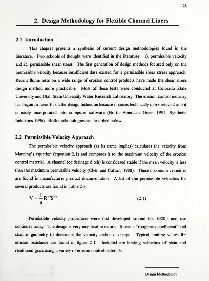
2. Design Methodology for Flexible Channel Liners
2.1 Introduction
This chapter presents a synthesis of current design methodologies found in the
literature. Two schools of thought were identified in the literature: 1). permissible velocity
and 2). permissible shear stress. The first generation of design methods focused only on the
permissible velocity because insufficient data existed for a permissible shear stress approach.
Recent flume tests on a wide range of erosion control products have made the shear stress
design method more practicable. Most of these tests were conducted at Colorado State
University and Utah State University Water Research Laboratory. The erosion control industry
has begun to favor this latter design technique because it seems technically more relevant and it
is easily incorporated into computer software (North American Green 1995, Synthetic
Industries 1996). Both methodologies are described below.
2.2 Permissible Velocity Approach
The permissible velocity approach (as its name implies) calculates the velocity from
Manning's equation (equation 2.1) and compares it to the maximum velocity of the erosion
control material. A channel (or drainage ditch) is considered stable if the mean velocity is less
than the maximum permissible velocity (Chen and Cotton, 1988). These maximum velocities
are found in manufacturer product documentation. A list of the permissible velocities for
several products are found in Table 2-3.
V = -R 2/3
S1/2
(2.1)n
Permissible velocity procedures were first developed around the 1920's and use
continues today. The design is very empirical in nature. It uses a "roughness coefficient" and
channel geometry to determine the velocity and/or discharge. Typical limiting values for
erosion resistance are found in figure 2-1. Included are limiting velocities of plain and
reinforced grass using a variety of erosion control materials.
Design Methodology

29
As illustrated in figure 2-1, increasing duration offlow reduces the erosion resistance of
a grassed surface. Notice that permissible velocities decrease as the duration of flow increases.
Fibers loosen from their stitching, netting stretches, and the entire blanket tends to slide
downstream. The erosion resistance is significantly reduced under extended flow durations.
Manufacturers of organic, natural, and synthetic erosion control products often use
maximum allowable velocity or shear stress to express the erosion resistance of these materials.
Manufacturer's information may be misleading when they quote maximum velocities. These
flow limits are typically for very short durations - usually a half hour flume test for temporary
erosion control materials. Such tests do not reflect the potential for severe erosion damage
that results from moderate to severe flow events during a period of several hours. Because
many storms are in excess of a half hour, a short term stable lining may fail under extended
flow conditions.
Hewlett and Boorman (1982) propose a 2 day flow duration to account for long,
erosive storms. Although no data are supplied, it is thought that two days is sufficient time for
storm waters to subside and for partially submerged vegetation to recover. In light of the fact
that erosion control blankets weaken as flow duration increases, 50 hour (~2 day) flume tests
produce the best design velocities for erosion control materials.
Maximum permissible velocities for several erosion control techniques are shown in
figure 2-1. It is a compilation ofvarious researchers data, and it attempts to categorize erosion
control materials into their cost-effective ranges. The graph shows permissible velocities of
vegetated and unvegetated linings. This provides a designer with performance guidelines from
the time a material is installed until it becomes fully vegetated (Thesien, 1992). Early stages of
growth may be designed with only a 1-2 year storm for unvegated conditions. At full
vegetative maturity, the designer can determine the erosion resistance for a 5-10 year storm
using the same product. In the first case, the material may only withstand a 2 m/s flow, but in
the second case, the strength of the vegetation enables the channel to withstand a 4 m/s flow
without significant damage.
Design Methodology

©
(0
<Eus
oat-zoo
oaui
CO
oS<>
o
(0u
oo-JUI
>za35ua
# *
/
r/#I] if j
1 1 i i
o m o mCM ^ *
XN
o *m a
z5UIUI
oo XCM UI
(0 ©
3^ o «
s0)
Q.
B u. o
^ ozo
c.©"5ath3
< < oe H 3
3 <Q Qa ©J
Ik UI
X"3>
(0 J3HB c^1 J
CM 3 1
a. CD
z3oz*o
(OBS/Xd) AJ.13013A NOIS3Q HU3± 9NO!

31
The long term performance guidelines show the limits of various temporary and
permanent erosion control products. Flow values for the blankets, mulches, meshes, and
rovings have question marks assigned to them because extended flow trials have not been
reported. However, since these products are only meant to survive until vegetation
becomes established, long term performance is not as important. It is the vegetation rather
than the reinforcement that provides the erosion resistance in the long term. Hence, when a
project calls for temporary erosion control, preliminary designs should use the "Limit of
Natural Vegetation" for a conservative estimate ofthe permissible velocity (Thesien, 1992).
As an example, notice that the short term performance of well-vegetated channel is
rather high - 4 m/s (13.1 ft/s) (refer to figure 2-1). However, at flows longer than 1.5
hours, the allowable velocity drops to 2 m/s (6. 1 ft/s) for good stands of vegetation and 1
m/s (3 ft/s) for poor vegetative cover. Using a non-vegetated TRM or ECRM rather than a
temporary erosion control product increases the long term velocity to 2.4 m/s (8 ft/s).
Using fully vegetated "Soft Armor" (TRM or ECRM) further increases the long term
permissible velocity to 4 m/s (13.1 ft/s) (Thesien, 1992).
The upper end of the graph shows the performance of hard armor materials (fabric
formed mats, articulating concrete blocks, concrete mattresses). This graph is not intended
to establish the upper boundary of these materials; rather, it defines the upper boundary of
soft armor materials (reinforced vegetation) (Caroll et al, 1990; Caroll et al, 1991;
Northcutt, 1995; Thesien, 1995; Thesien, 1992;). Such hard armor materials are necessary
for tidal zones, coastal areas, harbors, or streambanks. However, these materials are
overkill for drainage ditches. Costs for fabric form erosion control materials are
comparable to concrete ditches.
The permissible velocity design methodology is detailed in IFAI (1995). Known
parameters include the design storm and peak discharge, channel shape, width, maximum
depth, slope, and location of any bends. The methodology iterates on the normal depth to
determine the channel velocity. The computed velocity is then compared to the allowable
velocity of the specific channel liner. It is presented in detail in Appendix D.
Unfortunately, this design method ignores the actual soil erosion processes
occurring in open channel flow. Soil erosion is actually a function of the force required to
Design Methodology

32
move a soil particle. It is the shear force rather than the velocity of flow that most often
causes erosion. A permissible velocity design approach does not address this point. On the
other hand, the permissible shear force method takes account of the soil erosion process
(i.e. includes the hydraulic force causing erosion).
2.3 Permissible Shear Stress
A more realistic model of soil detachment is based on the permissible tractive force.
The hydrodynamic force of water flowing in a channel is known as the tractive force. Such
design methodologies are based on the concept that flow-induced tractive force should not
exceed the permissible or critical shear stress of the lining materials. The shear force is
equal to the component ofthe gravitational force acting on the body ofwater, parallel to the
channel bottom.
It is important to realize that shear is not uniformly distributed along the wetted
perimeter. Maximum shear occurs on the centerline of the channel bed and it gradually
decreases toward zero at the corners of the bed. Sideslope's peak shear occurs about one-
third of the way up the sides. Flow around bends also imposes higher currents near the
inside and outside of the bend. This stress increase in the bend increases as the ratio of the
radius of the curve to the channel width decreases. The point is that shear stress is not a
constant throughout the entire cross section. Moreover, as will be pointed out later, shear
is directly proportional to channel depth. Hence, the shear varies both normal and parallel
to the flow (see figure 2-2).
Figure 2-2 : Typical Distribution of Shear Stress in a Channel
(Modifiedfrom Chen and Cotton, 1988)
Design Methodology

33
Despite the obvious non-homogeneity of the problem, the tractive force method has
several advantages. First, it is a more compact approach than the permissible velocity
method. Stability is represented by a single shear stress value which is applicable to a wide
range of channel geometries (i.e. permissible shear stresses are not a function of lining
roughness and channel shape) (Chen and Cotton, 1988). Permissible velocities on the other
hand are a function of a highly variable roughness coefficient.
Moreover, the higher stresses developed in channel bends or other changes in stream
channel geometry can be quantified by simplified shear stress calculations (see figure 2-3).
This allows better designs than would normally be possible for the permissible velocity
design method. In addition, designs using permissible velocity require complex nomographs
or a series of long hand calculations. On the other hand, the permissible shear approach is
easier to perform by hand and it is readily programmable.
Flow HI High Shear Stress Zone
Figure 2-3 : Plan View of Plan Showing High Shear Stress Zones
(Modifiedfrom Chen and Cotton, 1988)
The approach requires that maximum shear strength of the erosion control material
is known. To this end, several western universities have conducted numerous independent
flume tests. Laboratory test flumes are typically 0.6-1.2 m (2-4 ft) wide and up to 15.2 m
(50 ft) long. They either have rectangular or trapezoidal shapes. Products are tested at
various flow velocities typically up to 50 hours (~2 days) or until material failure.
HEC-15 published by the FHWA in 1988 endorses the shear stress design
methodology. The document proposes permissible shear stress values for bare soil, riprap,
Design Methodology

34
vegetation, fiber roving, meshes, blankets, and both permanent synthetic erosion control
revegetation mats (ECRMs) as well as turf reinforcement mats (TRMs).
However, many of the above mentioned tests have indicated significantly higher
shear stress values. A comparison ofHEC-15 shear stress guidelines and the results of the
university tests are shown in Table 2-1. Notice that for the more persistent materials, HEC-
15 guidelines are extremely conservative.
The discrepancy is understandable; many advances in erosion control technology in
the past seven years have improved the performance of these materials. Since these results
are very well documented, the design methodology presented herein uses the industry shear
stress data (Carroll et al., 1991; Dodson, 1990; Hewlett et al., 1987; Lancaster and Austin,
1994; Theisen, 1991, 1992).
In the permissible shear stress method, flow duration also becomes an issue. Shear
resistance of the erosion control material decreases as flow duration increases. Again, a
two day design period is preferred. In fact, Table 2-1 gives permissible shear stresses for a
two day flow duration.
Comparison Permissible Shear Stress Values: HEC-15 vs. University Flume Tests
(Adaptedfrom Austin and Ward, 1996)
Erosion Control Product Type University Tests HEC-15Material Permissible Shear Permissible Shear
(lb/ft2) Ob/ft
2)
Low velocity Net 0.1-0.2 0.15
degradable Mat 0.4 - 3.0 0.60-1.45
Blanket - single net 1.4-2.0 1.45-1.55
High velocity Blanket - two nets 2.0-3.0 1.55
degradable
Long term TRM- unvegetated 3.0-6.0 2.00
nondegradable TRM- vegetated 5.0-8.0 3.70
Table 2-1: Limiting shear stresses for generic: erosion control materials
Design Methodology

35
One additional problem with the permissible shear approach is that the equation for
maximum shear depends only on depth of flow (equation 2.2). It is conceivable to have
shallow, turbulent flow. This situation also produces significant erosion, but it would not be
taken into consideration using a shear stress approach. Hence, it seems that the best overall
approach is to combine the two methods. Critical shear stress calculations are meant to be
used in conjunction with Manning's equation.
X = Y WDS (2.2)
t = hydraulic shear stress
y= unit weight ofwater
D = depth offlow
S = channel slope
Design Methodology

36
2.4 Design Procedure
This section outlines a possible design procedure based on the synthesis of existing
flexible channel lining information. Channels with steep gradients (slopes greater than 10%)
or very deep channels usually produce tractive forces in excess of the permissible shear
stress for most linings. For such steep channels, refer to chapter 3 - Hard Armor Design.
In addition, it is possible to design the channel using composite materials (e.g. use riprap in
the center ofthe channel and a TRM along the side slopes). This may be done for economy
or aesthetic reasons. Such designs are also detailed in chapter 3 under Designing
Composite Flexible Liners.
The basic design procedure requires first calculating the maximum flow depth
(normal depth) in the channel. Next, maximum shear stress is calculated at that depth. This
value is compared to the permissible shear stress and a factor of safety is computed.
Typical factors of safety against shear failure are 1.2-1.4. Using this shear stress, a
maximum velocity is calculated using a modified form ofManning's equation. This velocity
is also compared to the permissible velocity and a factor of safety against "velocity failure"
is computed. Here again, a typical factor of safety range is 1.2-1.4 (Austin and Thesien,
1994; Austin and Ward; 1996; North American Green, 1995; Synthetic Industries, 1995;
Thesien et al, 1995;). Worksheets, similar to those provided in HEC-15, are included at the
end of this section to aid calculations (figure 2-4).
Designers familiar with methods for determining normal depth may use any
convenient method and the Manning's roughness coefficients provided herein. Helpful
equations for selected channel geometries are provided in appendix A to ease calculations.
Nomographs are also provided to determine normal depth in trapezoidal channels. This
calculation often requires a few iterations. Typically one iterates until the estimate and the
calculated depth differ by no more than 0.03 m (0.1 ft or 1.2").
Once the normal depth is acceptable, the shear stress is easily computed using the
shear equation. The calculated shear stress is compared to the permissible shear stress for
that lining. Tables of permissible shear from HEC-15 are provided for generic classes of
materials. In addition, a list of current erosion control products (manufacturer and product
name) shear stresses are appended at the end ofthe chapter (tables 2-3 & 2-4).
Design Methodology

37
If the permissible shear stress is greater than the computed shear (and the safety
factor is greater than 1.2-1.4), then the lining is adequate. If a lining is inadequate, a lining
with a higher permissible shear stress may be selected from the tables. Since the roughness
coefficient of the new material is in general not equal to that of the initial lining, a new
normal depth needs to be calculated. If the new, stronger lining still fails to meet the safety
factor criteria, then the channel geometry may be changed (say, decreasing the side slopes
or increasing bottom width). Typically, there is a least cost alternative that could
conceivably include both geometry and product changes. Note, if the channel geometry
changes (slope, bottom width, H:V ratio of side slopes, etc.), then a new normal depth
must again be computed.
Once the shear stress requirement is satisfied, one enters the maximum shear into the
modified Manning's equation. Again, if the computed velocity exceeds the permissible
velocity, a new lining must be selected. All calculations must be redone and shear strength
must be checked again.
2.4.1 Note on Safety Factors
It is worth noting here that computing safety factors against shear and "velocity"
failure is not mentioned in the HEC-15 publication. The suggested safety factors of 1.2-1.4
for shear stress and velocity, respectively, come from current practice. HEC-15 does not
include such factors of safety because the permissible shear stresses already are very
conservative (i.e. the permissible shear stress include significant factors of safety). Merely,
satisfying the requirement that the actual shear be less than the permissible is sufficient. In
other words, HEC-15 considers a safety factor of 1.0 as satisfactory.
However, the design methodology presented in this report uses higher permissible
shear stresses from independent testing labs. Conservative designs should include a
minimum safety factor. Such a procedure is recommended despite the fact that most
manufacturers already include a safety factor in the permissible shear stress of their product.
Unfortunately, each manufacturer uses different safety factors or this information is
not provided. Therefore it is difficult to quantify the conservatism included in
Design Methodology

38
manufacturers' reported permissible shear stresses. The best approach is to require a
minimum factor of safety, FSr, for all designs.
According to current industry practice, this required safety factor would likely be in
the range of 1.2-1.5. Throughout the remainder of this report, the notation FS r is used as
the required safety factor for the design.
2.4.2 Is a flexible lining even needed for this design?
Before beginning lengthy design calculations for a particular project, it is prudent to
ask oneself, "are erosion control products needed?" To help answer this question,
allowable shear stress charts for bare non-cohesive and cohesive soil are included at the end
of this section. Figure 2-7a plots permissible shear stress versus particle diameter for non-
cohesive materials. Figure 2-7b similarly plots permissible shear stress versus plasticity
index. Unless the grains of a non-cohesive material are very large (>10 mm), the bare soil
can only withstand a maximum of 0. 1 lb/ft2of shear. Even compact, highly plastic (high
cohesion) soils can only withstand a maximum 0.5 lb/ft2of shear. Consequently, in almost
every case, erosion control will be needed.
Design Methodology

39
2.5 Computations
2.5.1 Required Input Data
(a). Channel Geometry
(i). Slope (S) - It is usually the slope ofthe road. The slope is used in
Manning's equation to the depth of flow.
(ii). Channel Shape - trapezoidal is most common; triangular, and parabolic
are also possible.
(iii). Top width (T) /Bottom width (B) - Typical trapezoidal bottom widths are
l-4m(3-12.2ft). Note that a bottom width ofzero gives a triangular
cross section. Top widths are used in parabolic designs.
(iv). Horizontal to Vertical Ratio (Z) for slide slopes - Typical values ofZ are
3 or 4. Slopes 2:1 and steeper are not recommended for loose sands or
normally consolidated clay because the soil becomes unstable. See table
2-2 for a list of appropriate Z values for several soil types (Adapted from
Chow, 1959). (Note: See appendix Afor typical cross sections)
Suitable Side Slopes for Channels as a Function of Bed Material
(From Chow, 1959)
Material Side Slope Ratio (Z)
Rock Nearly Vertical
Muck and Peat 1/4:1
Stiff clay with concrete lining 1/2:1 to 1:1
Earth with stone lining 1:1
Firm clay or earth for small ditches 1/2:1
Loose sandy earth 2:1
Sandy loam or normally consolidated clay 3:1
Table 2-2: Suggested H:V ratios for different bed materials
Design Methodology

40
(v). Channel Bends - Ifthe channel has a bend such that the radius divided
by the bottom width is in less than 10 (i.e. Rc/B < 10), the elevated
shear must be considered. As the ratio decreases, the severity ofthe
curve increases (i.e. elevated shear inside and outside ofthe bend. To
account for a channel bend, obtain a factor Kb offofFigure 2-18 and
multiply it by the straight channel shear stress. Note that the shear stress
corrections for bends are not applicable to triangular channels.
(v). Note also that the shear is elevated for a significant distance downstream
ofthe bend. To account for the elevated shear downstream ofthe bend,
enter figure 2-19 with the roughness coefficient and read offLp/Rc and
calculate Lp.
Also, flow around a bend in an open channel induces centrifugal forces
because ofthe change in direction. This results in a superelevation of
the water surface at the outside ofthe bend. Channels with bends must
include superelevation freeboard (Chen and Cotton, 1988). More detail
on calculating shear stresses in bends is discussed in the next section.
Ifthe channel changes significantly in slope, shape (bottom /top width /
side slopes) or roughness, the channel should be discretized into
representative reaches and the calculationsperformedfor each reach.
(b). Design Storm
(i). 1-2 year peak discharge for temporary blankets or for the early growth
stages of permanent reinforcing mats (TRMs and ECRMs)
(ii). 5-10 year peak discharge for long term, fully vegetated applications
(iii). 25-100 year peak discharge for critical applications or as specified by
local / regional regulating entity (State DOT, County, EPA, etc..)
Design Methodology
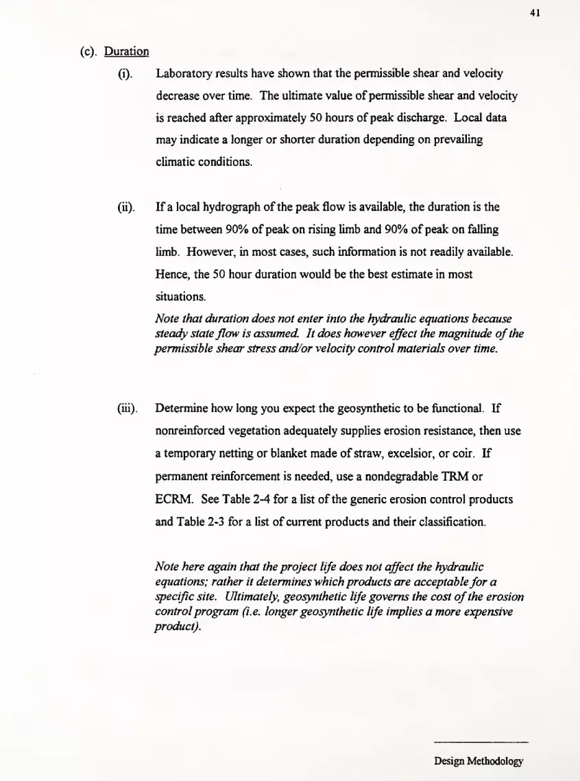
41
(c). Duration
(i). Laboratory results have shown that the permissible shear and velocity
decrease over time. The ultimate value of permissible shear and velocity
is reached after approximately 50 hours ofpeak discharge. Local data
may indicate a longer or shorter duration depending on prevailing
climatic conditions.
(ii). If a local hydrograph ofthe peak flow is available, the duration is the
time between 90% ofpeak on rising limb and 90% ofpeak on falling
limb. However, in most cases, such information is not readily available.
Hence, the 50 hour duration would be the best estimate in most
situations.
Note that duration does not enter into the hydraulic equations because
steady stateflow is assumed It does however effect the magnitude of the
permissible shear stress and/or velocity control materials over time.
(iii). Determine how long you expect the geosynthetic to be functional. If
nonreinforced vegetation adequately supplies erosion resistance, then use
a temporary netting or blanket made of straw, excelsior, or coir. If
permanent reinforcement is needed, use a nondegradable TRM or
ECRM. See Table 2-4 for a list ofthe generic erosion control products
and Table 2-3 for a list of current products and their classification.
Note here again that the project life does not affect the hydraulic
equations; rather it determines which products are acceptablefor aspecific site. Ultimately, geosynthetic life governs the cost ofthe erosion
controlprogram (i.e. longer geosynthetic life implies a more expensive
product).
Design Methodology

42
(d). Manning's Roughness Coefficient, "n"
(i). Values for Manning's "n" can be broken into 2 categories: 1).
Vegetated and 2). Unvegetated.
(ii). Vegetated - Calculating "n" is an iterative process based on Manning's
equation
(iii). Unvegetated - Read off"n" from table 2-4 or 2-5. These values are
compiled from manufacturer data and Chen and Cotton, 1988. Figure 2-6
also gives Manning's "n" as a function ofRelative Roughness (modified
fromHEC-15, 1988)
Design Methodology

43
2.5.2 Required Calculations
A flow chart of the required steps in the design process is shown in figure 2-5.
Details of the steps are shown below. A computation sheet (adapted from Chen and
Cotton, 1 988) is shown in figure 2-4.
1). First determine the required inputs outlined previously in section 2. 1
.
Discharge, channel slope, horizontal to vertical ratio, bottom width, and top
width are among the required inputs.
2). Select a flexible lining and determine the permissible shear stress (xp) either from table
2-3 or 2-4.
3). Estimate the flow depth range for vegetative or non-vegetative linings. This
brackets the roughness coefficients. Select one depth as an initial estimate. If
no information is available, a good first guess is 0.30 m (-1 ft).
4). Determine Manning's "n" for this estimated depth
(a). For non-vegetative linings, use Table 2-6 or 2-7. Ifthe table does not have
a particular erosion control product, an "n" of 0.02 is considered fairly
conservative (roughness coefficient for bare, soil filled liner)
(Synthetic Industries, 1995).
(b). For vegetative linings, use the following procedure:
(i). Calculate the hydraulic radius, R (Use figures 2-9 through 2-12 or
equations in Appendix A)
(ii). Determine vegetation class (Table 2-5)
(iii). Read off"n" from vegetation class figures (figures 2-13 through 2-17).
Design Methodology

44
(c). If the bottom or sides of the channel have different "n" values, a
composite value is determined for use in the Manning's equation. The
equation is presented by Chow, 1959.
%(p,n,
3/2
+ Pbn b
3^PA 3/2
)^
nc = ri5 — (2-3)
lie, ni, = Manning's "n" ofthe composite, left side slope, right
IV, nb side slope, and bottom, respectively
Pi, Pr= Wetted perimeter of left side slope, right side slope,
Pb,Pt bottom, and entire channel, respectively, in meters (feet)
5). Calculate flow depth (d) using above "n" and Manning's equation. Equations for
finding normal depth are in Appendix A. A nomograph for trapezoidal channels is
included to ease calculations (figure 2-8).
6). Compare computed depth to estimate. Ifthe two values differ by more than
0.03 m (0.1 ft), then redo steps 3-6.
7). Calculate shear stress using equation 2.4, Xd. If td > tp, the lining is not
adequate. Either change the channel geometry or select a stronger lining; repeat
steps 1-6.
T = Y WDS (2.4)
8). For Channel Bends:
(a). Determine the factor for maximum shear stress on channel bends (Kb) from
figure 2-18. Kb is a function ofthe ratio of channel curvature to bottom
width, Rc/B. Recall that a bend is considered significant ifRc/B < 10.
(b). Using Kb, calculate the shear stress in the bend from equation 2.5. If
Design Methodology

45
Tb > Xp, the lining is not acceptable. Either change the channel geometry
or select a stronger lining; repeat steps 1-7.
? b= K
bT d=KbYwDS (2.5)
Tb = shear stress in bend
Xa = maximum shear in straight channel
Kb = bend shear stress coefficient
(c). Calculate the length ofprotection (Lp) required downstream of a bend to
protect against the elevated shear. Enter figure 2-19 with Manning's "n"
and read ofFLp/Rc for the given radius, Re and calculate Lp.
(d). Calculate the shear stress on the side slope ifthe material on the side slopes
is different than the material on the bottom of the channel (typically it
would be a weaker material).
Enter figure 2-21 with Z and B/d (bottom width to normal flow depth ratio),
and determine Ki. If xs > xp, redo steps (1-8). The side slope stress is:
% = K,Td (2.6)
x, = shear stress on side slope
Xd = shear stress on bottom of channel
Ki = correction factor for side slope shear
(e). Calculate the superelevation ofthe water surface on the outside ofthe
bend. This is the amount offreeboard to accommodate the superelevation
ofthe water surface.
v2T
Ad = —
—
(2.7)
v = mean velocity = Discharge/Area (Q/A)T = surface width ofthe channel
g = gravitational acceleration
Re = mean radius ofthe bend
Design Methodology

46
9). Calculate the average velocity by substituting the shear stress into the a modified
form ofManning's equation. IfVive > Vaumv, redo steps 1-9.
For velocity on the channel bottom (accounting for any bends)
V„.=^R'"(K bT 4 )
B(2.8)
Vave = velocity on the channel bottom
R = hydraulic radius
n = Manning's "n" (composite "n" if required)
K8 = conversion factor that takes account ofthe unit weight of
water; 0.189 for English units, 0.03 1 6 for Metric units,
id = shear stress at maximum depth (lb/ft2
)
Note: unit weight ofwater = 62.4 lb/ft3or 9.81 kN/m3
.
Similarly, for velocity on the side slopes:
v-.«-.=Y
RW(K'K .
T«r <m>
Ki = correction factor for side slope shear
Velocity can also be calculated using the original form ofManning's equation
V„„ = ^"S,"2
(2.10)
' »ve = average velocity in the cross section
= unit conversion; 1.49 for English units, 1.0 for Metric
units
n = Manning's roughness coefficient (composite "n" if
required)
R = hydraulic radius; equal to the cross-sectional area, A,
divided by the wetted perimeter, P
Sf = friction slope of the channel approximated by the
average bed slope (uniform flow conditions)
Design Methodology

47
10). Calculated Safety Factors
(a). Safety factor against shear failure must be greater than FSr
(the required Safety Factor):
SFt= — >FS
r(2.11)
Note: One can calculate SF 's against shearfailure on side slopes and in
bends by substituting t, and nfor tj, respectively.
(b). Safety factor against velocity failure must be greater than FSr :
VSFV = -^ > FS
r(2.12)
Note: One can calculate SF's against velocityfailure on side slopes and
in bends by substituting V&iaiope and Vbaufor V„e, respectively.
As usual, one would like to be conservative in design calculations (i.e. design for the
worst case scenario). For stable channel slopes, this means designing for long-term,
unvegetated conditions. The reasons for long duration designs have already been noted. It
is readily apparent that a vegetated channel can resist erosion better than an unvegetated
channel. Denser vegetation implies a denser root mass which in turn holds the soil tighter.
In the event of drought or severe flooding, the vegetation may die. Hence, it is most
conservative to design the channel as ifthe vegetation is not there.
It is advised to perform the calculation twice - once for the early stages of growth
(bare soil, 1-2 year storm) and once for long term, fully vegetated conditions (5-10+year
storm). One should keep in mind that long term shear resistance for temporary products is
controlled by the strength ofthe vegetation. Based on recommendations from the SAC, the
design flow chart (figure 2-5) has been modified to design for both long term and short term
shear resistance. The long term case will have an increased design shear as compared to the
short term case (i.e. vegetation and root structure increases the permissible shear stress of
the channel). Provided the erosion control material is installed appropriately, the long term
permissible shear should also increase. For more conservative designs (especially in
continuous flow channels where TRMs or ECRMs are required), it is advisable to design
for an unvegetated condition. That is, you ignore increase in permissible shear afforded by
the vegetation and design only on the permissible shear ofthe geosynthetic.
Design Methodology

48
2.7 Design Charts & Tables for Flexible Liner Design
Figure 2-4: Worksheet for Steep Channel Design
Designer:
Project:
Station
Drainage Area:
Design Storm (yrs):
Design Flow - m3/s (ft
3/s):
Temporary Design Flow
Description
Slope
ShapeTriangular T =
Trapezoidal Z =
B =
Parabolic T =
Other
Bends Rc/B (not recommended)
Kb
Calculations Lining Q S d. dsoi z Aa/Az d dso
Safety Factors Shear FS
Velocity
FS
Design Methodology

49
InputsDesign Storm
Channel Geometry
Lining Type (tp)
FigureS: Flexible Liner
Design Flow Chart
Estimate normal
flow depth (d)
-s> ^
Short Term Long Term
Hn" from product
data (unvegetated)
Change Geometry
(S, B, Z) to decrease
velocity &/or
increase depth
x
'n" from equations
or design charts
(vegetated)
~ZLCalculate flow depth
Calculate shear
stress at max depth
Using R, n, & Scalculate V««
Use calculated depth
as new estimate
Change channel
geometry or choose
stronger product
(higher iP)
Change channel
geometry or choose
stronger product
(higher tp )
Figure 2.5

o
•**
u3tso:-
0-
"©•-**eoUss^o"s«oL.
*=*
&4>'-.
U3u
JO
>-as03
03CU
in
•4e/3
V3
•-
Oh
i
303
H
JB
i
c
a.>>HMS
o
503
3aoOh
sj
3S03
-"no©— —' © *'(S <N <N m
© o o m vofs -« "o >© r-<s ci ** ^' **
•I-l-l"U-i U-, t*w
4J 3 3 3 «5
Z S s o Zo o oo o o CJ 4>•a o o o -a
5 <-> u <
b b b b b(Q P3 (Q R (QU. !— U. k* !-,
u. Q. Q. CX O,
S E E S EO Q> O 4> QJ
H H H H H
oU©©
o<U
Q
o oU U© © 2© © .3•** * On« u a,S S 3^i ^ ?<U IU <u
Q Q O
i 1
1
s s| | g g |"O "O "O *o "OC C C £ J3
a a a c ao o o o o»-. —' w », »-
O O U 1> w03 03 CD CD 03
© © © ©© <n © (Nci es fN P-4
T3a
3>- s
l§3 ^.
§ =s s &g S S SU tfl 7) W
b b b bCQ CQ (Q <Qi_ i« U- !—
a. o. q. Oo
£ E E EV <u <u ui- b* t- t-
n in m is(J «J C/3 wt
eo
g
o03 03 O 03
S3SS•c -n -c -co o a> a>
to
t gto to
t tV u u u
o oeo
© © ©oo <r>"
©'— fN M
•c
>s
o
u —u
oa
oS o© faU O
•sl"S 03 -g
«- e 73.s '3 u,5 « -
g fi a£ < D
© © © © © © © © © ©vo 2 2 "> t~ t** u-. © ** t "*
© ©O O © © ©© © ©wS <r> u"i"
ato
2u o ua 33 '3
b l>4 Im u U O
s i 3 2 -s^ s
I 1 J JJ J I 33 41 i
"-> Dm Cl,
IS IS
1111.Ifl M > > ? fl f^l fl
e d 2 2 Sg.ag.g.g.1E E E E E Eo u o u u i> a>H H H H H a. a.
Tu
3 2-r oO w
©•n
y«i
U U X a. co u h
03 03 03 03
J5 J= Xio o oC) u
c e e eeeeeaesees000 00000000000•a-s-a OUUUCJOOOUUU111 Hiinnnn(A VI (A w — *— —' — •.* — «^ *^ »- n—eea eaecsescsae000 00000000000
© ©2 2 oo'
© <n inox « *—
i <s—
'
3S •-
§|_
•~» 3
CQ CQ CQK w w8.8.8.E E Eu u uH H H
Bi « rs
u u >
to to to
•c c su CJ
E< 1
E<
X X X
i t i
?u u« «^ «.>
iN u, h*
a a a
3o13

<r> n to o5 3 m m
o © o ©
(A (A (A (A CA
& | 5- 5- S-CO CD <T> CD C&
cr. c. r. c. r.o o o o osT 5* 5" 5" S"&b a a ac c c c sC/l (A C/) CA CA
5. 5. a. a. 5.
"0 -a-a *oGO GO13 TJ03 aso o££(TO (JO
5' 5"
oo do
n oo o
"t? 13 *"0
TJ "0 "TJ
CO 00 GO*t3 *o *oea Si 03o r> o£ 05 200^ 00^ (TQ_
5' 5' 5'00 00 00
o o no o o
CD CD CD CD CD CD
O O O O O DH 3 *3 5S 3 9rt rt ft rt rt rto n o o n n3 3 3 3 3 3
z8o"3
£»
o o © ©CO
Has
5"
i
t>>
/
rts
o3
3 £ 3 £CD CD CD CD
3 5 3 3"8
"S "S"2
-1 *n -i *n03
gj05 69
>5 -5 «5 -5
T3 *T3
«5 2.
I ^-3 c
033O.o
ST3£.O
n o
Ul O© Ono
3» 5» X X X§ § n o n3 3 O) CD CD
1 1 ^^sj — "* 3. sr
H H HO rt rt
3 3 3_ 1 1 1o cd 05 a: co
iiina> si an o n
on 00 go no o nO *-J " t-^> U3 t—Li m u; © t^i wtn O O © LnO
C C "0 **l
S. g. 5r S5? J*> rt rt
GO 00rt rt
!§o os s
O ©5' 5'
00 LA
GOO*0Jos.
U)
H H H %rt rt rt rt
3 3 3 3"8 "8 "S 1•H *H M gOS 65 CO 2
00 GO GO 00
T3 Hn> rt
1 3
3-3
Ul.1
aGO
5-
TD '"O T3 "0O O O rt
03 03 03 033 3 3 9rt rt rt rt3 3 3 3
o o o os o a ac c o o
Hrt
3
-5
nSi
O
»»a a
cr a- g: g:
o "' 3- 3-O O
33*era
H•o(0
©
3
GO.
rt"
rtSi
•*.
rt
00
Si
3a.
ors
* * » »o © ©©
a. w oo 9!
© © © '©
— — — - - » (J W M* Q\ C\ Lfl
Ul Ui O
00 -~)
© ©
Ul ^ Ul u —00 Ul « Ui K> M© Ui Ui © Ul Ul
© © © ©© © © © «0
00© ©
i
3<I
300
oSi
o
n3nrt3
©a3rt
Cfl"

52
Table 2-4: Permissible Shear Stress for Generic Lining Materials
(Modified from Chen and Cotton, 1988)
Lining Category Lining Type TD (lb/ft2)
Temporary Woven Paper Net 0.15
Jute Net 0.45
Fiberglass Roving 0.60-0.85
Straw w/ Net 1.45
Wood Fiber 1.55
Permanent Synthetic Mat 2.00
Vegetative1
Class A 3.70
Class B 2.10
Class C 1.00
Class
D
0.60
Class E 0.35
Gravel Riprap 1" 0.33
2" 0.67
6" 2.00
12" 4.00
Bare Soil Non-cohesive See chart 1
Cohesive See chart 2
'(Temporary lining
degraded)
Design Methodology

53
Vegetation Classification - Retardance Classes
(Modified from the Handbook ofChannel Designfor Soil and water Conservation, 1954)
Retardance Class Cover Vegetation Condition
A Weeping lovegrass Excellent stand, tall (average 30" (76 cm)
Yellow bluestem Ischaemum Excellent stand, tall (average 36") (91 cm)
B Kudzu Very dense growth, uncut
Bermuda grass Good stand, tall (average 12") (30 cm)
Native grass mixture Good stand, unmowed(little bluestem, bluestem,
bluegamma, and other long and
short midwest grasses)
Weeping lovegrass Good stand, tall (average 24") (61 cm)
Lespedeza sericea Good stand, not woody, tall (average 19")
Alfalfa Good stand, uncut (average 1 1") (28 cm)
Weeping lovegrass Good stand, uncut (average 13") (33 cm)
Kuszu Dense growth, uncut
%
Blue gamma Good stand, uncut (average 13") (28 cm)
c Crabgrass Fair stand, uncut (10-48" average)
Bermuda Grass Good stand, mowed (average 6") (15 cm)
Common lespedeza Good stand, uncut (average 11") (28 cm)
Grass-legume mixture - summer Good stand, uncut (6-8") (15-20 cm)
(orchard grass, redtop, Italian
ryegrass, and commonlespedeza) Very dense cover (average 6") (15 cm)
Centipedegrass Good stand, headed (6-12") (15-20 cm)
Kentucky bluegrass
D Bermuda grass Good stand, cut to 2.5" (6 cm)
Common lespedeza Excellent stand, uncut (ave. 4.5") (1 1 cm)
buffalo grass Good stand, uncut (3-6") (8-15 cm)
Grass-legume mixture - fall / Good stand, uncut (4-5") (10 to 13 cm)
spring
(orchard grass, redtop, Italian
ryegrass, and common Good stand, cut to 2" (5 cm)
lespedeza)
Lespedeza sericea
E Bermuda grass Good stand, cut to 1.5" (4 cm)
Bermuda grass Burned stubble
Table 2-5 : Vegetation Classification
Design Methodology

54
Table 2-6 : Manning's Roughness Coefficients by Depth of Flow(Reprinted from Chen and Cotton, 1988)
Lining Category Type n (0-0.5ft) n (0.5-2.0ft) n (2.0+
ft)
Rigid Concrete 0.015 0.013 0.013
Grouted riprap 0.040 0.030 0.028
Stone Masonry 0.042 0.032 0.030
Soil Cement 0.025 0.022 0.020
Asphalt 0.018 0.016 0.016
Unlined Bare soil 0.023 0.020 0.020
Rock cut 0.045 0.035 0.025
Temporary Paper net 0.016 0.015 0.015
Jute net 0.028 0.022 0.019
PP roving 0.028 0.021 0.019
Straw w/ net 0.065 0.033 0.025
Wood fiber 0.066 0.035 0.028
Synthetic mat 0.036 0.025 0.021
Gravel Riprap 1"D50 0.044 0.033 0.030
2"D50 0.066 0.041 0.034
Rock Riprap 6"D50 0.104 0.039 0.035
12"D50~~ 0.078 0.040
Design Methodology

55
Table 2-7 : Manning's "n" for Current Linings
(Compiled from manufacturer data)
Lining Type Manufacturer Product Manning's "n"
(0.5-2.0ft Flow)
Straw w/ Net Greenfix America WS052Greenfix America WS072Greenfix America WS072BNorth American Green S150
North American Green S75
Jute Belton Industries Anitwash Geojute
Belton Industries Geojute Plus
Contech C-Jute
Synthetic Industries Polyjute
Coconut fiber w/ Net Belton Industries Dekowe 400 Coir
Belton Industries Dekowe 700 Coir
Belton Industries Dekowe 900 Coir
Greenfix America CF072RRNorth American Green C125
Straw / Coconut Mix Greenfix America CF072RNorth American Green SC150
Grout Filled Fabric Construction Techniques Unimat
(FFR) Hydrotex Uniform Section - 3"
Hydrotex Uniform Section - 4"
Hydrotex Filter Point - 5"
Hydrotex Filter Point - 8"
Synthetic Mat Nicolon Mirafi TM8North American Green C350North American Green C300Synthetic Industries LandlokECRM450Synthetic Industries LandlokECRM1060Synthetic Industries Pryamat
0.021
0.019
0.019
0.028
0.028
0.025
0.025
0.025
0.021
0.025
0.029
0.033
0.014
0.014
0.018
0.025
0.025
0.018
0.018
0.027
0.027
0.029
0.025
0.024
0.025
0.028
0.027
Design Methodology

uo
i ;•*—w- -ne )
« 0)s"Z'Z"""
0~5~vT*j — -Q \
a+j P S (<
05 »-s 173 & Wh n n * m
1*; i
ii i
ooN
oooos
oco
o
oCD
Oin
O
CO
\
o
CO
- to
oCM
o OS 03 z^ CD Irt -* COfH o o o © o o o
£99T'0~s)i/u

57
.005 .01
lb/ft
3
2
1.0
0.5
2
o.io r
0.05
D(in)
.05 .10 .50 1.01 1 ,,,, —,..
1 ' "»| iI
i 1 1
1
1
"'I
—
—yS
2
—
1 III 1 i i Mil l l ll Ml
-
1 1 1
5 10
PARTICLE DIAMETER, D(mm)
50 100
Figure 2-7a : Permissible shear stress for non-cohesive soils
(Thibodeaux, 1985)
Design Methodology

58
1.0
0.5
lb/ft2
0.1
0.05
0.01
1
1
"i- —
i
-
{i
;1 1 i
i i 1
EXPLANATION
"H" Value
Loose 4-10Medium Compact 10 - 30Compact 30 - so
N - Nu«oer of blows required toeffect 1Z
- penetration of the 2*
split-spoon sampler seated to adeptn of 6* driven with a 140 lb.weight falling 30".
7 /,^7&
y^
•
5.0 10.0 60.0
PLASTICITY INDEX - P.I.
Figure 2-7b : Permissible shear stress for cohesive soils
(Smerdon and Beaseley, 1959)
Design Methodology

Chart 3 NOTE:59 d
Project horizontally from Z«0 tcolt - ^to obtain votes tor 2 = I to 6
s
r-0.1
0.08
-0.06
-0.05
-0.04
-0.03
-0.02
C0.01-N-0.608
-0.006
-0.00S
-0.004
0.003
-0.002
«-0.001
Qn
(FT3/S)
r20
—10
-6.0
-6.0
-5.0
-4.0
3.0
r-2.0
—1J0
-0.8
0.6
0.5
-0.4
-02. N
-0.1
-0.08
-0.06
0.05
-0.04
-0.03
-0.02
tXJ
GIVEN
Y S«0.0l
0=10 FT^S
n « 0.03
B«4 FT
Z = 4
find:
d
solution:
On* 0.3
d/B*O.I4
d«0.l4(4)*O56FT
Figure 2-8 : Nomograph for Trapezoidal Design - Finding Normal Depth
(Chen and Cotton, 1988)
Design Methodology

60
m
CLDL-
o
c
'en
Q
ONOJ
ao
01
(N
=1
\CL
CD
X)

61
CD lO to
a>cc(0
Ow3TOc(0
t:(0
OcTO"55
Q
Eo
O
ooo
M ill
oo
.- 00
- r-
a>
w0)
10 "—
«
cC c
(0.e
O O1—
£CO
3O)c_ u. CO* T1->*-
s. O*rf ca o>0) CO
Q <->
CO
- CM
[jj) (V) B9JV

62
a>cc(0
aoorek.re
a.
re
Oc
COa>
Q
CM
CD
Z5aLL.
oCO
in
oCM
.. W
WQ)CCco.cO
E S£ g*S CO
2 Q-
ocO)COa>
Qca
£<
{^i) B3JV

63
occ(0
ooo(01_(0
0.
(0
ocO)
"<7>
oQu>3
3(0
o>»Xcsi
c\i
<D1—
O
(y) smpey onncjpAH

64
0.50
0.10
.010
_ ...
- ••-
\n
V— V—-\
X V
XANI4EL SLO PE S
* X>
x.kftft--^
«^—-
—
—
--
__^S4
— —— ^
J„ .1
--- ... -
Ri/e
—— Iis.e+is.sziogCR^s -4)
.10 .20 .30 .40 .60 .70 1.00
R
2.0 3.0 4.0 6.0 7.0 10.0(
Figure 2-13 : Manning'sV vs. hydraulic radius for class A Vegetation
Design Methodology

o.so
0.10
.010
30.2 + 19.97log(R 1 -4 S04 )
"i"
.10 .20 .30 .40 .50 .70 1.00 2.0 3.0 4.0 5.0 7.0 10.00
Figure 2-14: Manning's "n" vs. hydraulic radius for class B Vegetation
Design Methodology

66
\
—\
~\ " — \r-
-
— —
10
O
Ii
:hannel SLCPE, s
>&} ^v— ^^ \ Is- \ 1——
_.. - - ^^^^». ^^^to^^T^ ' ^^ifc-
.... !
i
— — -
—
— • - ^,*»«
""^
Ri/e
23.0+1 9.97log(R 1 -4S04 )
.010
;
.10 -20 .30 .40 .60 .70 1.00
R
2.0 3.0 4.0 6.0 7.0 10.00
Figure 2-15 ; Manning's "n" vs. hydraulic radius for class C Vegetation
Design Methodology

67
0.60
0.10
.010
—
— —... -- -
CHANNEL J LOPE, J
\ \o\
k'
^8*I
! II
I
I"i •: i i
xSI _ . L L .i i- :
2--
—
^^ J
...
i
~-- g
-,
:
— "
—~-i
R1/6
37.7+19.97log(R 1.4 g0. 4)
.10 .20 .30 .40 .50 .70 1.00
R
2.0 3.0 4.0 6.0 7.0 10.00
Figure 2-16 : Manning's "n" vs. hydraulic radius for class D Vegetation
Design Methodology

68
0.50
0.10
.010
„_\
\
kx<
S
——
—
1
-
CHANNEL SLOPE.
\<
x<
>
^k ^^ v.1
N.0
.
-
i
....... ..... J. i
I
j i
-j
'
l-4-h
JJj:1 1 '
— — ^••
i
...J-.1Ri/e
'
1
]
I
].. .
!
T!
34.6+ 1J).97log(Ft1 -4 s -4
)
I
I
.10 .20 .40 .30 .60 .70 1.00
R
2.0 3.0 4.0 5.0 7.0 10.00
EiSireJMZ: Manning's «n» vs. hydraulic radius for class E Vegetation
Design Methodology

69
2.0
1.9
1.8
1.7
1.6
Kb1.5
1.4
1.3
1.2
1.1
1.0
\
TbsKbtd
\
1
-
1
I
I
•I
j
1
1
1
-
)
-
1 2 3 4 5
B
6 7 8 9 10
Figure 2-18 : Kb correction factor for bend shear stress
Design Methodology
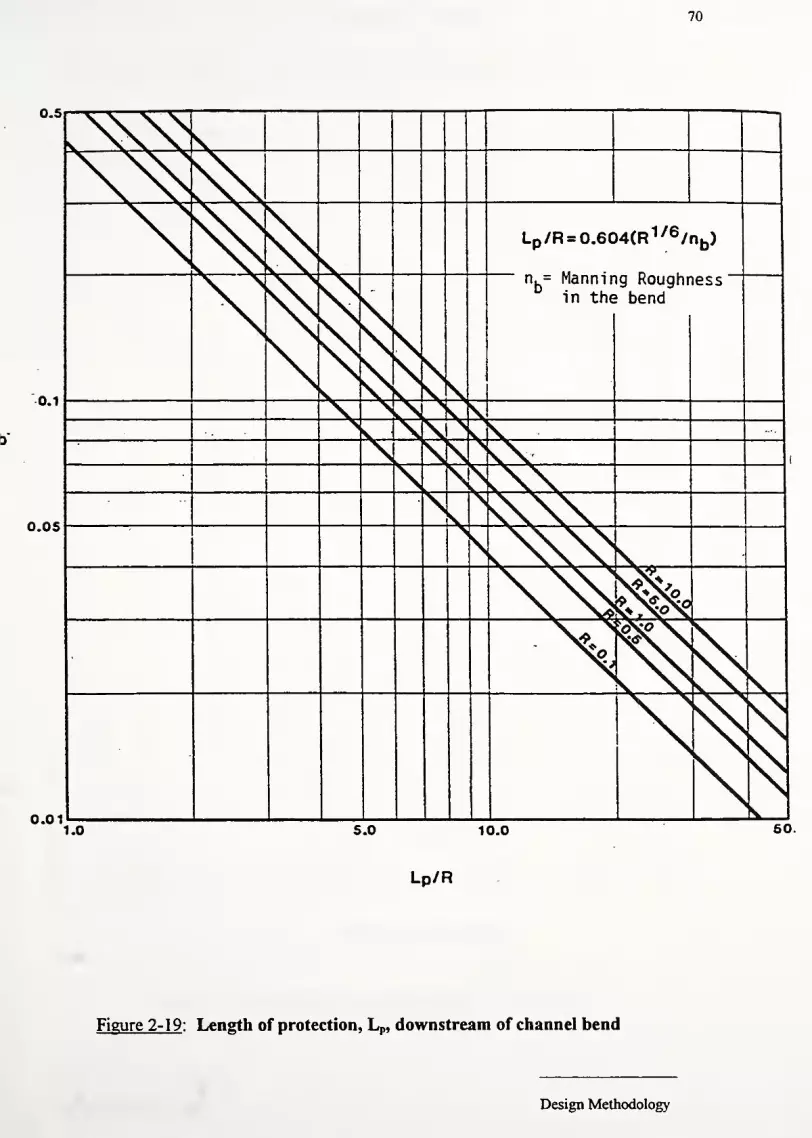
70
0.5
0.1
0.05
0.01
Lp /R = 0.604(R 1/6 /nb)
" n.- Manning Roughnessin the bend
y
v%
\\^»X*Xo
1.0 5.0 10.0 50.
Lp/R
Figure 2-19 : Length of protection, Lp, downstream of channel bend
Design Methodology

MEAN STONE SIZE, D50 , FT. 71
43
OHiQ
I
<!>
UiCO
ocUJ
u.o
-Io<
6 e 8 10 20 30 40 SO 80 100 200 300 400 600
MEAN STONE SIZE, D50,mm
Figure 2-20 : Angle of Repose in Terms of D50 - ft (mm)(Reprintedfrom Chen & Cotton, 1988)
Design Methodology

72
SIDELOPE N |
f
1
1.6
CO
1
•
/;' h ;
if^/, j.
i
\\ \ *
00
(O
m
&s
wto
2
CM
O)
600d d
(O
din
d
&>
sece
x:
U
i
5l-l »

73
a.o(A
Ua
eC8
9iv.
Oa.'-
O
"Soe«
e
e
s
4)>
3
D3Q P - 3d01S 3QIS 30 310NV

74
3. Hard Armor Design - Riprap, Gabion, FFR, ABS Design
The synthesis of design procedures presented in the previous sections is supplemented in
the present section for steep side slope channels, high velocity drainage ditches (typically in excess
of 10 ft/s), and continuous, turbulent flows. Erosion control products used in this category
include riprap, concrete blocks, gabions, articulating block systems, and fabric formed revetments.
Each class of products has its own characteristics and thus no one design methodology is
appropriate for all types. All classes will be addressed individually in this chapter.
Chen and Cotton (1988) recommend using a steep channel design procedure for side
slopes greater than 3:1. Recent research has targeted these "hard armor" materials for 2-2.5:1
side slopes (Escarameia et al, 1995; Maynord, 1991). Such designs are restricted to cohesive
soils because these soils have a large angle of repose. Non-cohesive soils on the other hand are
unstable at side slope ratios smaller than 3:1 because these soils have smaller angles of repose. In
other words, as the angle of the side slope approaches the angle of repose, the channel becomes
less stable (Chen and Cotton, 1988). Side slope stability must be checked for steep channels.
This computation is found in many geotechnical texts and will not be repeated here (Das, 1990;
Lambe and Whiteman, 1969).
3.1 Introduction to Riprap Design
Riprap is one of the most widely used forms of channel protection. For a given project,
the required mean riprap size increases rapidly as the slope and discharge increase. Riprap
gradation should follow a smooth size distribution curve. Ideally, small stones will fill the gaps
left by larger rocks. Such interlocking prevents open pockets which are very susceptible to
erosion. Moreover, rough, angular riprap are preferred to smooth, flat riprap. The latter types
are easily moved by high flows.
Nearly every state department of transportation has specifications for riprap. For
example, Illinois and Ohio utilize a class system for riprap. Moreover, each DOT has hydraulic
design guidelines for riprap. For example, Indiana DOT uses HEC-1 1 or HEC-15 methodologies
for all riprap designs.

75
Despite all of the specifications and design methodologies, failures still frequently occur.
Indiana DOT has problems with riprap "blowouts" downstream of drainage pipes and other
highway culverts. Figure 3-1 sketches three principal types of failures: transitional slide,
modified slump, and deep seated slump. Often the reasons for riprap failure are difficult to
quantify. It could be design flaws, installation problems, or simply poor stone from the quarry.
For the present discussion, we will limit ourselves to design flaws. Blodgett (1986) gives several
reasons for these failures:
*r Particle size is too small
*r Riprap material had improper gradation
>r Side slopes too steep
>r No filter blanket installed or filter blanket improperly installed
>r Differential settlement following excessive precipitation
>r No account made for impinging flow, toe scour, hydrostatic pressure
There are several other considerations that need to be addressed in steep slope design.
First, transition regions between steep and shallow slopes need riprap protection. Hydraulic jumps
often form in these areas and can lead to excessive erosion. Hence, it is good practice to protect
the channel in these turbulent regions. A good rule of thumb is to use riprap a distance equal to
five "normal" depths upstream of the transition from steep to mild slopes (Blodgett, 1986).
Second, bends should be avoided because the superelevation on the outside of the bend often
exceeds the available freeboard (note: superelevation is often estimated as two times the normal
depth).
There is need for design methodologies that address all of the above failure modes. Many
different riprap designs procedures have been proposed. As one might expect, each methodology
provides a different "answer" to the riprap problem. Figure 3-2 plots median stone size against
average velocity for several design procedures (Blodgett, 1986; HEC-11, 1989). Note the wide
range of Dso's for a given velocity. For an average velocity of 15 ft/s, median stone sizes range
from 0.75-3.5 ft! Such a range is undoubtedly going to influence the performance ofthe channel.

Lower part of riprap separates from upper part, and movesdownslope as homogeneous body. The toe may not showa bulge If channel bed is scoured. Translatlonal slideusuaHy occurs If side s.ope Is too steep or toe of riprap /srAJ°CKIs undermined. >^S~v SCA RP>.
LINE
76
BASEMATERIAL
TRAIMSLATIONAL SLIDE
Failure plane
Riprap moves downslope along a failure planethat lies at or above base materia). Failureplane is at a flatter slope than original ripraplayer. This type of failure is usually causedby excess hydrostatic pressure in ripraplayer or shear along filter blanket
isplaced
rock riprap.
Filter blanket at_ y surface of basev- / material (not shown)
MODIFIED SLUMP
Riprap moves downslope along a failure pianethat lies in base material. Failure zone Is
dish-shaped. This type of failure is usuallycaused by excess hydrostatic pressurein base material.
QHANNEL BED Failure zone in base material
MATERIALSLUMP
Figure 3-1: Classification of principle types of failures (from Blodgett, 1986)

77
This section provides an overview of 10 different design methodologies. This description
is followed by a few notes regarding the selection and/or calculation of an appropriate value for
Manning's coefficient, n. Finally, with regard to establishing a "class" system for riprap, three
different methods are given that create a gradation from Dso's.
Table 3-1 lists the agencies and/or authors of the 10 different design methodologies that
will be detailed. A review of each methodology follows the table.
Sources of Design Procedures
(Updatedfrom Blodgett, 1986)
Agency / Author Title/ Author / Date of Publication Abbreviation
Federal Highway Hydraulic Engineering Circulars for bank HEC-11Administration Protection (Searcy, 1967)
Federal Highway Hydraulic Engineering Circulars - design of HEC-15Administration stable channels for flexible linings
(Chen & Cotton, 1988)
California DOT Bank and shore protection in California Cal-B&SPhighway practice (1970)
U.S. Army Corps of Hydraulic design of flood control channels EM-1601Engineers (Maynord, 1970, 1991)
American Society of Sedimentation Engineering, Manual No. 54 Man-54
Civil Engineers (Vanoni, 1975)
Blodgett Riprap design protection of stream channels Blodgett
near highway structures (1986)
Escarameia & May Stability of riprap in highly turbulent flows E&M(1995)
Froehlich & Benson Sizing dumped rock riprap (1996) F&B
Simons & Senturk Sediment transport technology (1977) Simons
U.S. Bureau of Hydraulic design of stilling basins and energy USBRReclamation dissipaters (Peterka, 1958)
Table 3-1 : List of riprap design procedures described in this report

78
25
OOLUw(TLUQ-
HLULULL
too—ILU>LU
<ITLU><
20 -
15 -
10 -
0.5 1.0 1.5 2.0 2.5 3.0 3.5 4.0
MEDIAN STONE SIZE, D^ , IN FEET50
Figure 3-2: Comparison of procedures for estimating stone size based onpermissible velocities (from AppendixA ofHEC-U)

79
3.2 Riprap Design Procedures
3.2.1 HEC-ll
The size of riprap needed to protect the streambank is determined on a trial and error basis
using estimated stone size, design velocity, and depth. A flow chart illustrating the HEC-ll
procedure and relevant graphs are shown in figure 3-3 and 3-4. Depths exceeding 10 ft are
multiplied by 0.4. Velocity is multiplied by a factor of 1 to 2 for impinging flow.
Blodgett (1986) developed regression equations for each graph to simplify the
computations. These equations are developed with an assumed side slope of 2H:1V (Z=2) (most
designs require side slopes of 1.5-3:1). Note that the symbol Z is used interchangeably with the
H:V ratio in this report. Since D50 is the unknown variable, the regression equations are
combined to included mean velocity and maximum depth. The equations are listed below:
(a). Relationship ofD50 stone size on channel bottom to velocity against stone
fyY72
(3.1)Dso = 1-15(1,
V1
Dso = Median stone size (ft)
dm = Total depth (ft) ~ 1 ^d,,^
V, = Velocity against stone (ft/s)
V, = Average Velocity (ft/s)
(b). Velocity against stone
V.=10.63(DiorV. = 532(D„)"
V 0.522
(straight channels) (3.2a)
(curves - includes factor of 2.0) (3.2b)
(c). Overall regression equation
cv 3 -95
D50 = 1.06
(3.3a)
C = 0.000076 for Z=2: 1, dm <10 ft, and straight channel; (Z = H:V)
C = 0.000202 for Z=2: 1, dm >10 ft, and straight channel
C = 0.001 17 for Z=2:l, dm <10 ft, and curved channel
C = 0.00310 for Z=2:l, dm <10 ft, and curved channel

80
(d). Rewrite (3.3a) to include effect of the Froude Number, Fr=0.95 (borderline
subcritical flow & limit of applicability ofManning's equation). Note that total
depth (dm) is approximately 1.5 times average depth (da)
R = 0.95 = -J= => d = L5d = 0.0516(V )
2
Dso = C(V.)183
(3.3b)
C = 0.0018 for Z=2, dm <10', Fr -0.95, straight channel
C = 0.0046 for Z=2, dm >10', Fr -0.95, straight channel
C = 0.0273 for Z=2, dm <10', Fr -0.95, curved channel
C = 0.0718 for Z=2, dm >10', Fr -0.95, curved channel
Problems with HEC-11 (from Blodgett, 1986)
1). The graphs require an estimate ofvelocity against stone, yet no data are given in HEC-
1 1 to estimate it. Further, HEC-1 1 only shows V/Va < 1, yet it is conceivable in highly
turbulent flow to have near bed velocities in excess ofthe average velocity.
2). The resulting value ofD50 is too small for straight reaches and too large for curved
channels. This conclusion was reached after comparing HEC-1 1 predicted D5o to actual
failed riprap lined creeks (i.e. HEC-1 1 D50 was the same size or less than the D50 ofthe
failed riprap revetment).
3). An adjustment for specific gravity is unwarranted if it is 2.65± 10%. Errors in the ability
to asses hydraulic and frictional forces are ofthe same magnitude. Hence, the specific
gravity adjustment provides little, if any improvement in the design.
4). No guidelines for using the adjustment factor of 2 for curved channels. Moreover a range
of 1 to 2 for this adjustment factor is given with no justification.

Depth of flow > 10 feet, substitute
0.4d for d in ratio D$Q/d.
Impinging flow, apply factor
of 1 to 2 times V3 .
Select trial D5q. Determine d, Va ,
D50AI for design conditions.
vs/va
Fig. 1 - Velocity of stone on channel bottom.
Determine VSt Vs = (Va, D 50 /d).
>
2*4:1
z = 1:1
D50
Fig. 2 - Size of stone that will resist displacementfor various velocities and side slopes.
Determine D50 , D50 = (Vs , 2).
81
Continue until D5g selected in step 1 is in reasonable agreement
with size from Fig. 2 in step 3.
Design D50 .
End.
Figure 3-3 : Flow chart of riprap design procedure for HEC-11
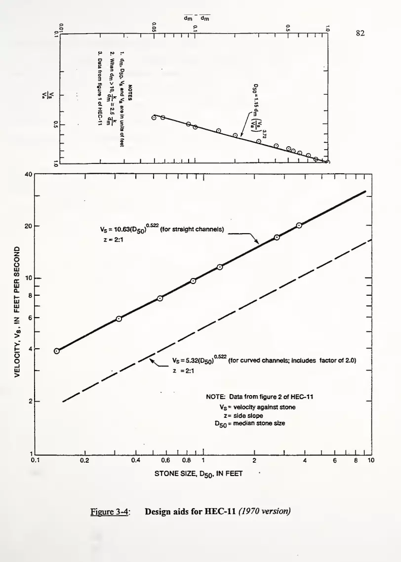
dm dm
40
o ow p ob
1
to to
i i1 1 1
i i T i i i1 1
1 1 1
oCD s a
3B a
—33
a3
oUlo
"
s V «< z o
_c3
p 3a.
oH o
II
_-* =u
Jl < CO -*
_«Ol
—
XmO
in 3
C3
a
/ r-
— O ™
— i —
_
-1 i 1 1 1 i i i 1 1 1 1 1 p9s*>
82
i—
r
i i r
20
azooUJ03
<rUJ0.
UJUJu.
00
>
oo-IUl>
10
8 -
6 -
4 -
VS = 10.63(D50)
z-=2:1
' (for straight channels)
Vs = 5.32(Dso) (for curved channels; includes factor of 2.0)
z =2:1
NOTE- Data from figure 2 of HEC-1
1
Vs = velocity against stone
z= side slope
D50 = median stone size
J I L J L0.1 0.2 0.4 0.6 0.8 1 2
STONE SIZE, D50 , IN FEET
8 10
Figure 3-4 : Design aids for HEC-11 (1970 version)

83
Recently (1989), HEC-1 1 has been updated. It incorporates new research results with the
suggestions recommended by Blodgett. The revised design procedure applies only to those open
channels with discharges in excess of 50 cubic feet per second (cfs). Design for most highway
channels now comes under HEC-1 5 (i.e. discharges less than 50 cfs). In addition to design
procedures, HEC-1 1 recommends gradations for the riprap based on D50. This new design
procedure uses the critical velocity rather than the critical shear approach. Even though tractive
force methods are better models, permissible velocity approaches are more accepted by the
engineering community (HEC-1 1, 1989).
The required equations for this revised version ofHEC-1 1 are shown below. Note that a
trial and error process is still required to find the normal depth, d. Once this depth is known, the
velocity is computed by Manning's equation and the equations below are used directly.
Equationsfor RevisedHEC-11 Procedure
(a). Compute Manning's n
n = 0.093d0167
for 1.5 < d/D50 < 185; S < 0.002 (3.4a)
n = 0.019d'167
for 185 < d/D50 < 30,000; S < 0.002 (3.4b)
n = 039Sf
8R (If information is available) (3.4c)
d = Mean flow depth
D50 = Median riprap size
Sf = friction slope
R = hydraulic radius
(b). Compute D50
0.001V3
d^K/D50 " C,
gCSF ;
,» (3.5)
sin29
sin2
<|)
212c.=(5^ir
(37)
CSF=y (3.8)

84
T = 2D50 (3.9)
V, = average velocity computed from Manning's equation
Ki = bank angle correction
<J>= riprap angle of repose (~ 36-42°)
6 = bank angle with the horizontal (degrees)
c^ = specific gravity correction factor ifGs *2.65
G, = specific gravity of riprap
csf = stability correction factor
SF = safety factor applied (see table below)
T = thickness of riprap layer
Guidelines for Selection of the Stability Factors
Uniform flow; straight or mild curves (R/W >30); Little uncertainty in parameters 1.0- 1.2
Gradually varying flow; Moderate bends (R/W < 30); Moderate wave impact 1.3-1.6
Rapidly varying flow; Sharp bends (RAV < 1 0); Large wave impact 1.6-2.0
As with all riprap designs, a filter layer must be placed underneath the riprap. See
Appendix B for the most recent FHWA geosynthetic filter layer design procedure.

85
3.2.2 HEC-15
Note: This review is based on the 1988 version ofHEC-15 by Chen and Cotton and not the 1975
version by Normann.
This design procedure is based on the concept ofmaximum permissible flow and hydraulic
resistance ofthe lining material. As with HEC-1 1, the size of riprap is determined from a trial and
error procedure. Two separate design procedures are used - one for slopes 3 : 1 and flatter and
one for 3:1 and steeper. A flow chart for each procedure follows on the next pages. Relevant
graphs for determining the angle of repose, Ki (ratio of side to bottom shear), and K2 (tractive
force ratio) follow the flow charts.
For steep channel design, HEC-15 provides simple charts and tables (also reproduced) to
facilitate the design. The first flow chart uses these graphs. Unfortunately, the charts are limited
to bottom widths of 6 ft. A rigorous design solution for the case ofB > 6 ft is presented in the
second steep channel flow chart.
The design is based on the Bathurst resistance equation to predict hydraulic conditions and
the Simons and Senturk factor of safety equation to assess riprap stability. Bathurst (1981) found
that the flow resistance significantly decreased as the Reynolds number increased and as relative
submergence increased. He also showed that form drag of the roughness elements and the
relative roughness area had to be included in the resistance equation. The above elements are
combined into a power law. The general resistance equation is very complex due to the
complexity of the processes it attempts to describe. Moreover, the equation is empirical. Thus,
its validity is limited to the ranges of data on which it is based. These limitations are listed in the
original paper. Readers interested in a more complete description of the resistance equation are
referred to the Bathurst (1981) paper.
The HEC-15 procedure next requires calculation of the Simons and Senturk (1977) factor
of safety equation to assess riprap stability. This equation analyzes the forces acting on an
individual particle and calculates a factor of safety against it movements. These forces include the
weight ofthe particle, drag in the direction of flow, and lift. Since the element tends to roll rather

86
than slide, its stability is calculated by taking moments about the contact point. A full explanation
ofthe Simons equation is given later in this chapter.
Listed below are the relevant equations for the HEC-15 riprap design procedure. For
convenience, the equations are grouped in order ofthere use for a particular method. Three main
methods are presented: Flat slope (Z^3), Steep Slope (b^6), and Steep Slope (b >6).
Flat slope (Z £ 3) Design Equations
(a). Manning's n
n = 0.0395(D50 )
,/6
(3.10)
(b). Equation to find depth offlow (see Appendix A for more detail)
(trapezoidal channels with side slope ratio Z and base width b)
(b + Zd-r Qn
(b + 2dVr7lf 1-486S-
(3U)
(c). Calculate design shear
T = ydS (3.12)
(d). Calculate permissible shear
Tp=4.0D
50 (3.13)
(e). Calculate velocity
y = l:486
R2/3SW
n
(f). Froude Number
VFr = -=<0.95 (3.15)
(g). Determine D50 side (median stone size on the side slopes)
D = ^-D^50 side v ^SO^2
(3.16)

B£6ft
Select Q, S, Z
87
Enter design aids to find flow
depth and mean riprap size D so
Determine K-JKz factor based on
geometry
Adjust Dso by k^jKz
Select Q, S, Z
B>6ft
*
'
Assume D50; Calculate n
1
>
Determine normal depth by
Manning's equation (iteration)
< f
Calculate V and Fr=V/(gD),/2
Modify channel geometry95? y• \i'PU.
J
/No
r
Calculate P/n r\', SF
<^FS>
\ No Assume new D$o and
1.57 3
Yes
End HEC-15 D50 Design
Figure 3-4 : Flow chart of riprap design procedure for HEC-15

88
Steep slope equations (Z > 3)for graph design ofriprap channels (b s6ft)
(a). Find the flow depth using the following equation (values of A3/AZ are found
on table 7):
d =—*-d. (3.17)Az
d = depth offlow in channel with side slope ratio Zi
di = depth offlow from design charts (3 : 1 side slopes)
A3/AZ = conversion factor from Z=3 to Z=Zi side slopes
(b). Find the riprap size using the equation
Dso^Dso. (3.18)
D50 i= mean riprap size from design charts
D5o = mean riprap size in channel
Steep channel design (b> 6)
(a). Bathurst Resistance Equation
_U_ _ W\_J = f(pr) x f(R£G) x f(CG) (3 J9)u. Vs n
U/U* = mean velocity divided by shear velocity
d = mean flow depth
U* = (gdS)1/2
Fr= Froude number
REG = Roughness Element Geometry
CG = Channel Geometry
, 0.7S5\ log-
f(Fr) = (^Fr)b
(3.20)
f(REG) = 13.434
c T ^
IDJ
0.492( T Y"'
.025 —b ^
D" ;
(3.21)
50'
-b
f(CG) =[ |j
(3.22)

A^IAz for selected d/B Ratios
89
d/B Z=2 Z=3 Z=4 Z=5 Z=6
0.1 1.083
0.2 0.142
0.3 1.187
0.4 1.222
0.5 1.250
0.6 1.272
0.7 1.291
0.8 1.307
0.9 1.321
1.0 1.333
1.1 1.343
1.2 1.352
1.3 1.361
1.4 1.368
1.5 1.378
1.6 1.381
1.7 1.386
1.8 1.391
1.9 1.395
2.0 1.400
Table 3-2: Values of
1.000
1.000
0.928 0.866 0.812
0.888 0.800 0.727
0.853 0.760 0.678
0.846 0.733 0.647
0.833 0.714 0.625
0.823 0.700 0.608
0.815 0.688 0.596
0.809 0.680 0.586
0.804 0.672 0.587
0.800 0.666 0.571
0.796 0.661 0.565
0.793 0.657 0.561
0.790 0.653 0.556
0.787 0.650 0.553
0.785 0.647 0.550
0.783 0.644 0.547
0.782 0.642 0.544
0.780 0.640 0.542
0.779 0.638 0.540
0.777 0.636 0.538
(Reprinted from Chen and Cotton, 1988)
1 + 3
Based on the equation :
mi+zK

RIPRAP MEAN DIAMETER, (ft)
0.50 1.00 1.50 2.00 2.50
50
45
40
35
OUJCO»*03I-
b 30
UJ
oa.<xow
25
20
16
10
6-?,?-3
RIPRAP MEAN DIAMETER, (ft)
0.25 0.50 0.75 1.00
DFPTH rifM)
1.25 1.50
.50 1.00 1.50 2.00
/
//
<v/
0/
/
f *<v©/o/<o/ o/
o/o/o/CHANNEL SLOPE. S
//
/
//
.25 .60 .75
DEPTH, d(ft)
Figure 3-5: HEC-15 Design Aids for b < 6' (Reprintedfrom HEC-15, 1988)
1.00 1.25
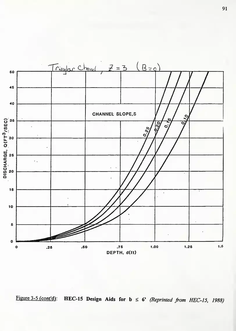
91
CdnJc^r ciw Z = 3) Lb-1
.76
DEPTH. d(ft)
Figure 3-5 (cont'd): HEC-15 Design Aids for b < 6' (Reprinted from HEC-15, 1988)

92
b = 1175f2a.
0.557/-10.648a-01"
D50'
(3.23)
<7" 0.182 (for most standard riprap gradations) (3.24)
T = channel top width
D50 = mean diameter ofthe stone
b = parameter describing roughness concentration
(b). Simons & Senturk Safety Factor equation
cos tan <{>
SF =r|'tan(|) + sin0cosp
(3.25)
b = tan_1 cos a
2 sin 6 A
VT(tan(J)y
+ sma
(3.26)
*!=-r(y.yp»
(3.27)
Tl =T|1 + sin(a + p)
(3.28)
x. = K,t = KjdS
a = angle ofthe channel bed slope
P= angles between the vectors weight and drag
(J)
= angle ofthe channel side slope
= angle ofrepose for the riprap
x, = side slope shear stress
To = shear stress at channel bottom
y= specific weight ofwater
(3.29)

93
y* = specific weight of rock
r\= stability number
T|'= side slope stability number
Ki = ratio of side to bottom shear stress
F* = 0.15 = dimensionless critical shear stress (see note below)
Note on F*
In the derivation given by Simons and Senturk, F* was 0.047 (this value comes straight
from the Shields diagram (see figure 3-6). The equation for F* is:
F* =,
Tcr- (3.30)
y, = specific weight of the stone
Yf = specific weight ofthe fluid (water)
However, recent studies have shown F* to take on much larger values for large diameter
riprap (Wang and Shen, 1983). For large particles, the drag coefficient drops abruptly for a
Reynolds number between 104and 10
5. Consequently, resistance to flow (the denominator of
equation 3.30) decreases and F* increases for Reynolds numbers between 104-10
5. This is shown
in the figure below (note that K* on the vertical axis is the same as F*).
Note that before and after this transition phase, F* is nearly constant. This result is similar
to the constant F* in the high Reynolds number region on the Shields diagram above. Wang and
Shen conclude for large diameter riprap that (figure 3-7):
For 100<Re<105
, F* = 0.0625
ForRe>106, F* = 0.25
Based on this work and the Reynolds numbers generally encountered in practice, HEC-15
sets F* arbitrarily at 0.15. It should be noted that no explanation is given for selecting an
intermediate F* value.
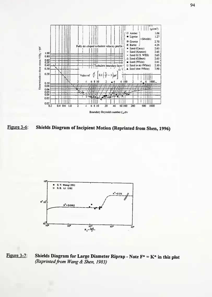
94
1.00
0.80
0.600.50
040
030
0.20 .
0.10
0.08
0.06
0.050.04
0.03
0.02
|!
j
Fullv dt\ eloped turbulent
"i II
1(g/cm'j
/ Amber "| 1.06
• Lignite 1 1.27
> (Shields)
Graniie 2.70
•eloci.y profilee Barite J 4 "25
|* Sand (Casey) 2.65
+ Sand (Kramer) 2.65
x Sand (U.S WES) 2.65 -
- [ A Sand (Gilbert) 2.65 -
f Sand (White) 2.61.J_. '
'
\
Value of "
4 6
i
s
1
\
8 10 2 A 4 (
!
L
.
"v_
V
"MIll ! 1 ill
> 100 2 4_6III
" V I ,
—ftfftW—t A f A t i4/A( / /i / f /i/y^\/\ ! V.'. V / / / I U / ', /,/, ! / / u u ' /,,'* t tif I / / / t V h
;
;ii ; / t 1 y // LvD /t '//' l\ J \
aA//iV\Ui l- ~~
i
'**/]///k±A . /^,W,L.*fTi«i 1
1 >£y *&* , >•»
i 1 !
1 1
1
0.2 0.4 0.6 1.0 4 6 8 10 20 40 60 100 200
Boundary' Reynolds number U,dlv
500 1000
Figure 3-6: Shields Diagram of Incipient Motion (Reprinted from Shen, 1996)
IO«
•<"id'-
• S. Y. Wang (3S)o G. 8. Li (19)
10* 10' IO«
K .025 o
Figure 3-7: Shields Diagram for Large Diameter Riprap - Note F* = K* in this plot(Reprintedfrom Wang & Shen, 1983)

95
Problems with HEC-15
1). The equation for Manning's n gives low estimates of channel roughness. For a given
discharge and slope, lower roughness coefficients give smaller flow depths which in
turn indicate a D50 that is smaller than needed for erosion protection. Other methods
for selecting a Manning's n are discussed later in this chapter.
2). Flat and steep channels both require a time consuming trial and error process to find
normal depth. Moreover, for steep channel design with b > 6, the resistance and factor
of safety equations are exceedingly complex. Although the equations account for many
processes involved with riprap failure, many assumptions are required to calculate the
median stone size (for example, assuming an F*). Hence, the benefits of such an inclusive
approach are severely lessened. A simpler approach may produce results that are just as
acceptable.
3). There is some evidence that the permissible shear stress equation (tp= 4Dso)
overestimates the allowable riprap shear stress. Blodgett (1986) superimposes this
equation on a performance data from 39 field sites. 12 ofthe 3 1 sites on or below the line
xp= 4D50 sustained some particle erosion (i.e. 39% ofthe investigated sites failed to
some degree - figure 3-8). The data is limited to D50 up to 24" so a general conclusion
can't be made; however, there is some question as to the validity ofthe HEC-15 equation.

96
15
10
TT T i r
0.1
0.01
Minimum size D50 normally furnishedas riprap. Smaller sizes available asroad- surfacing material
.
22©
NOTE• Sites with particle erosion
O Stable sites
0.05 0.1 0.5 1
MEDIAN DIAMETER OF STONE (D*n). IN FEET
Figure 3-8: Comparison of Dso estimates based on shear stress from HEC-15 and field
data (Reprintedfrom Blodgett, 1986)

97
3.2.3 California DOT "Bank and Shore Protection" Manual
The California Department of Transportation (Cal-B&SP, 1970) approach to riprap design
is based on the analysis ofwave action by wind or vessels. California DOT analyzed wave-theory
and force-energy relationships necessary to dislodge a particle. The result was an equation
relating velocity, specific gravity, and the angle of the side slopes to a minimum weight of the
rock. Based on this weight, riprap layer characteristics are then specified (gradation and riprap
layer thickness). A flow chart for this "Cal-B&SP" procedure is given in figure 3-9. Terms in the
equation are defined below.
Cal-B&SP Equationsfor Riprap Design
(a). Minimum weight of stone
0.00002
V
6G esc3
(p-\|/)W33= 7 ,3 (3-31)
(G. -1)
3
W33 = Minimum weight of stone (lbs), 2/3 of stone must be heavier
V = Stream velocity to which bank exposed (ft/s)
Flow near bank in tangential reaches (straight channel): V = 2/3 Vmean
Flow impinging on the bank (curved channels) V = 4/3 vmean
G, = specific gravity ofthe stones
p = 70° for randomly placed rubble (maximum angle of slope before stone is
dislodged from the channel bed - determined from experiments)
v|/ = side slope (degrees)
Note: The velocity here is not the mean stream velocity. Cal-B&SP requires an adjustment to
reflect the actual velocity acting on the riprap. An assumption is made that velocity of flow near
the bank is 2/3 ofthe mean velocity for straight channels and 4/3 of the mean velocity for bends in
the channel. No details are given to support the use ofthese adjustment factors.

98
(b). Thickness ofthe riprap layer
t = L5Ksinvj/\/W^ (3.32)
t = thickness of riprap layer
K = shape factor of stone = 0.4 (upper limit based on experiments)
\|/= angle of side slope
Wc= class weight ofthe stone determined from class/gradation table
Once the W33 is calculated, the gradation is determined from a table (see section 3.4). It is
very difficult to interpolate the size class for which 67% are larger from this table. Hence, it is
often easier to convert the W33 to D33 . Assuming an equivalent a spherical diameter, D33 is:
D„ =V 7ry
8 J(3.33)
(c). Combined equation (3.3 1 & 3.33) for rinding D33 based on Cal-B&SP
-|V3
(3.34)E>33 =0.00012V
6G,csc
3
(p-(p)
*Y.(G.-0
Equation (3.34) is similar to the equation (3.5) of the HEC-1 1 procedure in that it relates
stone size directly to velocity. If one considers ys, G„ and \\i constant (See Lambe and Whiteman,
1969), then we can rewrite equation (3.34). Assuming G,=2.65, y,=165 lb/ft3
, \i/=26.6° (2:1),
V=2/3V» (straight channel), we have:
D„ = 0.0016V2
(3.35)
Compare this equation to the HEC-1 1 equation with Fr=0.95 for the same conditions:
D50= 0.0018V,
183(3.36)
Notice that for a given average stream velocity, the Cal-B&SP predicts larger stone sizes (i.e. the
power to which Va is raised is larger for the Cal-B&SP model). In other words, for the same
velocity offlow, the Cal-B&SP is more conservative than HEC-1 1.
This conclusion has been verified by Weng and Shen (1983) and Blodgett (1986).

99
Assume/determine mean channel velocity, side slope,
and specific gravity of rock for design condition.
For impinging velocity use 4/3
V
a ;
tangent velocity use 2/3Va .
Calculate minimum weight of rock using:
_ O.OOOOSV^sCsc3 (p-vf)
(Gs-1)3
or use nomograph.
(Minimum rock size equalsW33 of size distribution.)
Determine class of stone to be used from Table 3.
Figure 3-9 : Flow Chart for CAL-B&SP Design Procedure

100
3.2.4 Army Corps of Engineers - EM-1601 (Maynord, 1992)
This method utilizes a trial and error approach based on the Chezy equation. Once the
depth of flow, velocity, and hydraulic radius are determined, one can either follow a permissible
shear or permissible velocity solution. For simplicity, this section only deals with the permissible
shear solution. Recently, USCOE has revised their design equations and these are presented here.
The design procedure requires an estimate of the proposed channel roughness (called k in
the literature). This roughness is a measure of the linear dimension of the roughness factor, but is
not necessarily equal to D5o. While EM-1601 states that designs are relatively insensitive to k,
Blodgett shows that there is a strong dependence on k (Blodgett, 1986). However, in absence of
other information, it is often assumed that k~Dso.
Using this estimate of the roughness, one calculates the velocity and hydraulic radius.
Next one calculates the tractive force for a straight reach and compares it to the permissible shear
stress for the selected D50 . For unspecified reasons, irregularly shaped channels include a safety
factor of 1.5 to account for flow turbulence, pressure variations, water surges. One iterates on
median riprap size until the design shear is less than the permissible shear. Notice that changing
D5o changes the roughness, k. Hence, the entire process must be repeated with the new D50 .
Since this design method is quite complex, the Corps of Engineers has issued an updated
design methodology (Maynord, 1988, 1991, 1992). This procedure no longer requires a trial and
error process to determine median riprap size. Instead, an equation is derived from the above
mentioned shear equations. The method relates the depth-averaged velocity plus a variety of
correction factors directly to D30. This design process is "limited to low turbulent flow" situations
(all situation except those downstream of hydraulic structures - weir, damns) as well as depth to
stone size ratios (d/D50) less than 50.
The equations and relevant constants for determining D30 and D50 are shown next. Notice
that the velocity used in this procedure is the depth averaged velocity. EM-1601 uses a depth-
averaged velocity at a point 20% upslope from the toe for riprap design. The equations for
selecting a depth averaged velocity are include below as are the original design charts (figure 3-
10) from Maynord's paper.

101
1.0
C T0.5
0.0
v^ j___ I
S^ " —
1
""s^
"nL1
• 9S /Dl5 = 2.1 » DaS /DlS =52Des /Dis = 2.5 ABT ET AL 0988)
D85 /D15 = 1.7 (INTERPOLATED)_ 1 __.. 1
1.0 1.5 2.0
„_ THICKNESS
2.5
WHERE C, - CORRECTION FOR THICKNESS
D 30 FCR THICKNESS OF NT«
D 30 FOR THICKNESS OF T.
T« = lD.nn OR l.SD sn . WHICHEVER IS GREATERMOO u 50
FIGURE 1 Correction for riprap blanketthickness.
1.6
1.4
CD>
>S
in
1.0
0.8
1.6
1.4
1.2
1.0
0.8
6 8 10 20
R/V
vss\ vavg
2 4 6 8 10 20 40 SO
R/v
Vss
= 1.74 - 0.52 LOG (R/V>Vv. avg
40 50
Figure 3-10: Design aids for USCOE riprap design procedures

102
U.S. Army Corps ofEngineers Riprap Design Equations
(a). D50 , D30 , V
D50- DsoCDss/Dj
v 0.32
D30= S
fC.CvCTd
0.5-i2.5
-Ys-Yw^ V^gd
(3.37)
(3.38)
-^ = 1.71- 0.78 log(R/W) (Trapezoidal channel) (3.39)
= 1.74- 052 log(R/W) (Natural channels) (3.40)
D30 = riprap size ofwhich 30% finer by weight
Sf = safety factor (minimum 1.1)
D85/D15 = gradation uniformity coefficient
R = radius of curvature ofbend
W = water surface width immediately upstream ofbend
d = local depth offlow =0.8 dave
yw = unit weight ofwater
ys = unit weight of stone
V = local depth averaged velocity
Ki = side slope correction factor (defined in table below)
coefficients are adjusted from equation defined in HEC-1 1 to be
more conservative
Bank Angle Correction Factor - Modified from HEC-1 1 Criteria
Side Slope (H:V) Ratio K,
1:1
1.5:1
2:1
3:1
4: 1 or flatter
0.46
0.71
0.88
0.98
1.00
Table 3-3 : Bank angle correction factor

103
C, = stability coefficient for incipient failure
= 0.30 for angular rock
= 0.375 for rounded rock
Cv = vertical velocity coefficient
= 1.0 for straight channels & inside ofbends= 1.283- 0.2 log(R/W)= 1.25 downstream of concrete channels or end of dikes
Ct = blanket thickness factor
= 1.0 for thickness = lDioo
Notes:
1). Since the velocity is often estimated conservatively and since one usually needs to select a
gradation larger than computed D30 (due to availability considerations), Sf is often set low.
Larger safety factors are used ifthere are significant consequences of failure.
2). Slopes steeper than 1.5:1 are not recommended for riprap design
3). Figure 3-11 below sketches the point for local depth of flow
20% upslope
0.8d,vc = d
Figure 3-11 : Location of V„ and definition of "d'

104
3.2.5 Sedimentation Engineering, ASCE Manual #54 (Man-54)
This riprap design is based on studies of the Missouri River. The median rock size is
based on flow velocity and the gradation is such that Dioo =1.5 D50 . Although Man-54 gives the
required stone as a function of W50, it is converted to D50 assuming spherical diameter riprap as
was done with Cal-B&SP. No flow chart is given because the design is straightforward. The
relevant equations are presented below.
Design EquationsforMan-54
(a). W50&D50
0.000041G V 6
W50 = 7 ^ -T~ (341 )50
(G.-l)cos 3e
0.000246G,V6 Y
7TY,(G,-l)3
cos3e,
(3.42)
For 2: 1 side slopes (9 = 26.6°) & G, = 2.65:
DM = 0.00732V 2(3.43)
Wso = Median weight of the stone (lbs)
V = mean velocity in the channel
Gs = specific gravity
D50 = median spherical stone size
= angle of the side slope
(b). Thickness ofthe riprap layer
T = 1.5D50 (3.44)
Problems with Man-54 Riprap Design Procedure
1). The flow velocity actually is the velocity 10 ft from the bank. No information is
provided to determine the velocity at this distance. Hence mean velocity is used.
2). The simplified equation for D50 above gives stone sizes that are 3.5 times larger than
similar riprap equations (i.e. HEC-1 1 and Cal-B&SP).
3). No equations to account for the effects of channel curvature, highly turbulent flow,
or side slope variations in velocity.

105
3.2.6 Sediment Transport Technology (Simons and Senturk, 1977)
The procedure involves a set of 4 equations that describe the stability of riprap particle for
a given set of hydraulic conditions. Equations describe the passive forces affecting particle
stability and active fluid forces tending to rotate the particle out of position. Recall that these
equations were also used in the HEC-15 procedure. A full explanation of all terms for the
Simons-Senturk factor of safety equation are found under the HEC-15 design section. A flow
chart illustrating the design procedure is given in figure 3-13. Applicable equations are shown for
each of 4 different design situations:
• Bed protection for a horizontal channel
• Bed protection for a sloping channel
• Side slope protection for horizontal side slopes
• Side slope protection for non-horizontal side slopes
Problems with Simons & Senturk Riprap Design Procedure
1). The development stems from a rigorous analysis ofthe forces acting on one particle
(see figure 3-12). Several assumptions made in the analysis have been questioned. For
example, the drag force is assumed to be twice the lift force on a particle; however, no
basis is given for this assumption. Blodgett explores these shortcomings.
2). No corrections are given for curves, bends, or impinging flows.
3). Safety factor equations are presented in a confusing fashion. Moreover, no range of
suitable safety factors are given in the model's development. Hence, an engineer does
not know what safety factor would lead to an adequate D50 for the given situation.

106
Particle PTOP OF BANK
HORIZONTAL
Ws sind
Direction ofparticle movement
NOTE:
1) Fd = dragforce on partricle P
2) For horizontal slope flow, A =
VIEW NORMAL TO SIDE SLOPE (FOR NONHORIZONTAL FLOW)
TOP OF BANK Particle P
V WATER SURFACE
Ws = weight of particle P
Ws cos0CHANNEL BED fct = slope angle)
CHANNEL CROSS-SECTION
I*4 A
Ws
sin 8 cos fi
Riprap Element
i VI Ws cos e
SECTION A -A
Figure 3-12 : Forces acting on a riprap particle resting on the slide slope of a channel

107
Determine hydraulic data for
given design condition.
Design for side slope protection. Design for bed protection.
Horizontal flow on|
side sippes.
r\
Nonhorizontal flow
on side slopes.
Flow on horizontal
channel bed.Flow on plane sloping
channel bed.
ASSUME D50 RIPRAP SIZE AND
Calculate safety factor
using following
regulations.
T) =21 rc
(Gs-1)vD
tand?SFm
=tanfl
£ = SF_ r\ sec 6m
SF =
SF,m (^W^
Assume new rock size
and reiterate until
SF = 1.5.
Calculate safety factor
using following
regulations.
v =21 7c
(Gs -1)yD
cos A
/3 = tan 2 sine
7]tan9-sinX
75=7,
SF=-7
1 + sin(A+/3)
2
cose tan<£
Vtand+sinecos0
Calculate safety factor
using following
regulations.
T) =21 r,
(Gs -1)yD
SF =—&h -7}
Suitable safety factor value = 1.5.
Calculate safety factor
using following
regulations.
1 =21
(Gs -1)yD
_ cosa tan<£
t) tand> + sina
Suitable rock size assumedcalculation terminated.
Figure 3-13 : Flow chart and design equations for Simons & Senturk protection procedure

108
3.2.7 U.S. Bureau of Reclamation Riprap Design Procedure (USER, 1958)
This design procedure uses published flume test data to develop a curve between stone
size and bottom velocity. Initially, the curve was developed to determine the maximum stone size
downstream of a stilling basin (Simons et al, 1977; Blodgett, 1986). From their tests, the USBR
concluded that a well-graded riprap layer with 40% stone smaller than the required size was the
most stable configuration.
The results are shown in figure 3-14a. These data points were taken downstream of an
end sill where the flow is highly turbulent. Since the erosive potential of this flow is considered
greater than that normally encountered in drainage channels, this data should be a good indication
ofthe stone size required to resist erosion in highway ditches (Blodgett, 1986). Notice that stone
size here is D40 and not D50. Given the bottom velocity (assumed here to be the mean velocity),
one merely enters figure 3-14a and reads off the corresponding D40.
In order to convert the curve to other methods presented in this section, Blodgett applies a
logarithmic transformation to the data. Then, this equation is adjusted to D50 according to the
HEC-11 gradations. The resulting graph is shown as figure 3-14b and the associated equations
are reprinted for clarity as well.
Equationsfor USBR Riprap Design Procedure
(a). Logarithmic transformation ofthe data
Dw = 0.0105V.206
(3.45)
(b). Adjusting the gradation to D50
D50= 060^ = 0.0122V,
206(3.46)
D50 = median stone size
V, = average velocity in the channel
Problems with the USBR Riprap Design Procedure
1). No method is given for finding Manning's n, normal depth (d), or velocity (V).
It is assumed that normal is computed from a trial and error process. Methods of
determining Manning's n will be discussed subsequently.
2). No adjustment for impinging flow or bends.

- 5000
- 4000
- 3000
coUJXo
UJI-UJ
<5LU
Ol—co
109
oou.
2000 ocoz>oocUJ0.
COQz3OQ.
1000 lO -2^co
900©
800CO
700 Qz
600 DOQ.
500 TF
- 400
- 200
— 100
UJ
- 300 CO
<ocUJ
IQ.CO
XgUJ
5
5 10 15 • ' 20
BOTTOM VELOCITY, IN FEET PER SECOND
Figure 3-14a : Curve to determine stone size in a mixture (D40) - Reprintedfrom Blodgett

110
20
15
10
1
0.1
D4o=0.0105V5a'
Wa = 9.1D4o°-4a5
(curve A)
.D50 = 0.0122Va(curve B)
I J_ I
0.2 0.4 0.6 0.8 1.0
•MEDIAN DIAMETER OF STONE (D50), IN-FEET
2.0 3.0
Figure 3-14b : Transformed USBR stone size curve (D50) - Reprintedfrom Blodgett

Ill
3.2.8 Escarameia & May Riprap Design Procedure (E&M, 1995)
Although existing riprap design methods often incorporate velocity and/or shear strength
into their governing equations, these methods do not consider the effect of turbulence directly.
These researchers state that turbulence ultimately causes failure of riprap. In their opinion, stones
are subject to random fluctuations in lift and drag forces.
Following an experimental study on small diameter riprap, Escarameia and May propose
an equation relating velocity to mean riprap diameter under high turbulence conditions. The
equation is based on an estimate of bottom velocity from Rouse's formula (shown below) (1988).
Hence, a trial and error process is required to size the riprap (note that the computing the mean
velocity itself was an iterative process). A turbulence coefficient, C, determines the level of the
velocity fluctuations. The design procedure is basically a plug-and-chug process using the
equations below; hence, no design flow chart is given.
Equationsfor Escarameia & May Riprap Design Procedure
(a). Median stone size, velocity, turbulence coefficient & intensity equations
V 2
D =C
—
j-* r (3.47)502g(G.-l)
C = 036 Ti<o.io
C = 123T - 020 o. 10 < Ti < 0.30
T =yyyh
(3-48)
V / Vb= 0.681og(d / D
so ) + 0.71 (3.49)
D50 - median stone size
C = turbulence coefficient
Vb = near-bed velocity (point is above bottom at a height of 10% depth)
Vnns = root mean square ofvelocity fluctuation about Vb
V = mean flow velocity
G, = specific gravity ofthe riprap
T; = turbulence intensity
d = depth of flow
Problems with the Escarameia andMay Procedure
1). Need estimate ofVb (function of D50). This requires a lengthy iterative analysis.
2). No consideration ofbends or impinging flow

112
3.2.9 Blodgett Riprap Design Procedure (Blodgett, 1986)
Using riprap field data from 26 sites throughout Washington, Oregon, California, Nevada,
and Arizona, Blodgett plotted median diameter against average channel velocity. Based upon the
relative positions of the sites that worked and failed, a tentative regression relationship was fit to
the data. The equation designs against particle erosion (see figure 3-15). The equation fit to the
data is given below.
The main advantage ofthe Blodgett method is its simplicity. There are no charts to enter,
safety factors to calculate, or difficult procedures to follow. Moreover, the relationship applies
for all channels, curved or straight, with side slopes 1.5:1 or less. Median stone size is a function
of V2"44which is considerably larger than other relationships. Hence, the Blodgett method
appears to be more conservative than Cal-B&SP, Man-54, and HEC-1 1. The main disadvantage
to this method is that extensive verification has not been done. Blodgett himself concedes this
point; however, it does not detract from the potential his method has to become an accepted
design procedure.
Notice that Blodgett based his design on velocity rather than shear. This is no accident.
First, the energy slope (Sf) must be well defined or else the shear stress equation (x=ydS) may be
greatly in error. Second, it is easier to estimate the design velocity rather than shear from a site
survey or an analysis of hydraulic data (i.e. channel geometry and discharge). Lastly, a velocity
approach is more intuitive for the designer. That is, most engineers have a better appreciation of
permissible velocities than permissible shear strengths (Blodgett, 1986).
Blodgett Equationfor Riprap Design
(a). Djo
DSO= 0.01V
244(3.50)
V = mean velocity in the channel - ft/s (from a trial and error solution to
Manning's equation)
D50 = mean riprap size (ft)

113
Problems with Blodgett Design Procedure
1). Limited data to support the equation. Only 39 sites went into developing the
equation. Further verification is still required before the method is widely accepted.
2). No procedure is given for finding mean velocity. It is assumed that a trial and error
process based on an estimate ofD50 is required to compute normal depth and velocity.
3). The method may be an oversimplification of a very complex process. There is no
dependence on flow depth, specific gravity, side slope angle, and turbulence.
Further, no mention of safety factor adjustments is made for severe flow situations.
4). No gradation guidelines or revetment thickness information is provided. It is
assumed that the revetment must be equal to 2DJ0 .

114
20
15
10QZooUJCO
crUJQ.
I-UlUJu.
- 5"5>
Tentative relationship
DS0=0.01Va2-**
1
0.1
HEC-11 procedure for
sinuous Channels; factor of 2.0
Minimum D50 normally
furnished as riprap
• Sites wtth panicle erosion
Sites wtth no particle erosion
Measurement numbers refer to sites
in table 7. Sites with no numbersare from USBR-EM-2S (1974)
3.5 4
MEDIAN DIAMETER OF STONE (D50) f IN FEET
Figure 3-15: Blodgett's riprap design method based on particle erosion data(Reprintedfrom Blodgett, 1986)

115
3.2.10 Probabilistic Approach to Riprap Design (Froehlich & Benson, 1996)
All of the previous riprap design procedures are based on the idea of a single critical
velocity and/or shear stress. However, lift and drag fluctuations (noted by Escaramia and May)
inevitably cause small degree of damage to a revetment after construction. Often such damage is
acceptable and expected. Thus, these researchers believe that an allowable degree of damage
provides a subjective criteria to size riprap revetments. The researchers quantify the damage from
the probability distribution of loose particle critical shear stress.
The cumulative Weibull distribution estimates the fraction of particles of mean diameter,
D, that are displaced by a given dimensionless shear stress, ta/c. This shear stress is itself a
function of a scale parameter (r|), a shape parameter (P), and the percentage of allowable
displaced particles (£%). In other words, Ta/C is a function of the cumulative number of particle
displacements.
The design procedure is fairly complex and requires some detailed description (see steps
listed below). To begin, one must have an estimate ofthe mean channel velocity from either a site
investigation or a Manning's equation analysis. Note that a Manning's analysis is an iterative
procedure requiring an estimate of the channel roughness (i.e. a D50 must be assumed in most
cases to enter a roughness equation). Using this mean velocity, the depth-averaged velocity (Vs)
is computed. Here, V, is defined using the Army Corps of Engineers criteria - the velocity
corresponding to a depth 20% up the bank from the toe of the slope (i.e. 0.8dave). This velocity is
then used to calculate the shear stress (t.) on the slope using the Manning-Strickler equation.
Once t, is calculated, the method includes the following steps:
Steps in the Froehlich and Benson Riprap Design Procedure
1). Divide the mixture into at least 10 size classes. Each class (/) must contain an equal
percentage of riprap by weight. The size classes are characterized by a diameter D;.
2). Calculate <biso, f\, P, and Ki using the equations below
3). Calculate t, / Ki = x and dimensionless shear t.c
4). Calculate F(x»c) using the cumulative Weibull distribution - i.e. the fraction of
particles displaced within each class of diameter D;. Note, the author assumes that

116
lower boundary of the shear stress (t»Ci) is zero. Obviously, below this boundary, no
displacement occurs.
5). Calculate Z F(t«c); multiply this sum by the constant fraction of riprap in each size
class. The result is the total fraction of dumped riprap particles by weight that is
displaced with shear x,. Ifthe predicted degree ofdamage is greater than allowable,
then redo the entire procedure with a larger Dso. Ifthe predicted degree of damage
is much less than allowable, then redo the entire procedure with a smaller Dso.
Equationsfor the Froehlich andBenson Riprap Design Procedure
(a). Calculate depth-averaged velocity, V,
R>V =v 1.74- 0.52 log[^
V, = depth averaged velocity at 20% up from toe ofthe slope (m/s)
Rb = channel bend radius (m)
W = water surface width (m)
(b). Calculate shear stress on side slope
' k 2lo.8dJ
1/3
i, = side slope shear stress (Pa)
y = unit weight of water
Dso = assumed median stone size (m)
kn = 21.1 for metric units
(c). Equations of (fcso, tj, P, and K
<|>i50= 35.0 + 465
^50
^d;;
1
f
(3.51)
V,2
(3.52)
a-°M (3.53)
Tj = 0.0561 + exp 1.73 - 2.68-^- - 0.177aE
I (3.54)
P = 159 + 0161-^i- - 0208a„ (3.55)
D50

117
„ ... L sin2G
K,(i)= 1-. 2 . (3.56)
V sm (|) i50
4>,5o = median angle of initial yield (basically, the angle of repose)
og= geometric standard deviation ofthe riprap sizes
= 1.5 for most well graded riprap mixtures (from Blodgett, 1986)~ (Dg5/Di5)
1/2for most gradations
D, = median diameter for class size /'
D50 = median riprap diameter for entire mixture
r)= scale parameter related to particle size
P= shape parameter related to particle size
Ki(/) = correction factor for channel side slopes for class i
6 = angle of side slopes
(d). Dimensionless shear, t»c
XS=T./K
1 (7) (3.58)
(e). Calculate F(t»c), fraction of particles within each size class /' that move
F(t.c )= 1 - exp hi. (3-59)
F(x»c) = fraction of particles displaced in each size class 1
T»c = dimensionless shear acting on each class size i
(f). Sum of all F(t«c) and total percent of displaced riprap
%_ displaced = p£ F(t.c ) (3 .60)
i
p = fraction of mixture in each class size
note: ifthe predicted "%_displaced" is larger than allowed, then increase
D5o and repeat the entire process

118
Selecting the an allowable "damage" level
The allowable degree of damage is based upon the consequences of failure for a given
project. Four classes of damage are defined that correspond reasonably well to the observations
of Blodgett (1986). The percentage displacement associated with each damage class is as
follows:
• Insignificant damage < 1%• Minor damage 1 - 3 %• Moderate damage 3 - 7 %• Severe damage > 7%
According to the authors, damage becomes noticeable when more than 3% of the particles
are displaced. These observations lead to the following design criteria for revetments:
• if minor damage is allowed, design the revetment for 2%displacement
• if only insignificant damage is allowed, design the revetment for 1%displacement
In order to facilitate design, the authors present two dimensionless shear versus
percentage displaced riprap graphs. These are shown on the following page. Figures 3-16 a & b
help refine the answer before finishing the iteration. For minor damage and typical og, x*c ranges
from 0.014 to 0.028. Hence, if calculated t»c is larger than 0.028, one can terminate the iteration
and revise Dso without further calculation (i.e. increase D50 to make x»c less than 0.028). Figure
3- 16b works in similar fashion using the bank angle, 6.
Problems with Froehlich andBenson Approach
1). There is some discrepancy between the predicted damage and the observed damage
using the Blodgett data. For example, only 6 ofthe 18 sites where minor damage was
predicted sustained any noticeable damage. This is not a deficiency in the method;
rather, it shows that for low damage areas, this approach tends to be conservative.
2). The method requires defining 10 or more class sizes. However, no method is given
for selecting these class sizes.

119
3). No mention is made ofhow to determine the mean flow velocity in the channel. A
trial and error approach using Manning's equation is assumed. Moreover, no method is
given for determining Manning's n.
4). The method is quite time consuming. A computer program may be necessary. Moreover,
a designer must be knowledgeable in basic probability in order to understand the
computation method.

16
14 -
UJ
Cd111
a.
Z 10
a.
cc
Q 6UJO
CO
Q
_
1 /77 / /
F
-
g= /A7
/
/
- 11V / / /
/ //yr
/
/SEVERE
A'/A/ z /
f
: I7i
/ /
/ /7 //7 / /
yj7/// /
?
/ /
V
/ MODERATE
iifl
MINOR
^ INSIGNIRCANTi : ] J
• i < • ,• j! •xu :'-ll"'-
120
Dmo30mmO-n
O>3>Om
opqqpp pqoi-;doddddddddDIMENSIONLESS SHEAR STRESS
Figure 3-16a: Displaced riprap as a function of median dimensionless shear stress and Q~
B*nkingto-40° J^jWa 0°
16
14
UJ
<rUi0.
2 10
2
cr
oUJo<G.CO
8 -
6 t-
4 U
-
/1i1
/
7
1
—
SEVERE
!_
1PF
MODERATE
yF MINOR
i i-lj '
INSIGNIHCANT
DmommOD>3>Om
ooooooooo*-dodo d dodo dDIMENSIONLESS SHEAR STRESS
Figure 3-16b : Displaced riprap as a function of median dimensionless shear stress and
bank slope angle (a = 1.5)

121
3.2.11 Summary of Riprap Design Procedures
In order to get a feel for the range of Dso's predicted by the various methods, a
hypothetical example is given. For simplicity, only straight channel flow is considered with
average flow velocities of 5, 10, 15 ft/s, respectively. Other reasonable assumptions made
include: Gs= 2.65, ys
=165 lb/ft3, 2H:1V side slopes, fully turbulent flow, n=0.040, d=3 ft. Table
3-4 below gives the equation, D50, and relevant comments for each procedure based on these
assumptions. Note: no results are reported for those methods that are not based on velocity.
Riprap D50 Design Equations and Results
Agency / Author Equation for D50 Dso(ft);V=(ft/s)
5 10 15
Comments
HEC-11 D5o = 0.0018V1.83 <1 0.1 0.25
HEC-15
California DOT
D5o=1.24D50 i
D50 = 0.0021V2
A3/Az=1.24
<1 0.2 0.47 D50 = 1.32 D33 (using HEC-1 1 gradation info)
U.S. Army Corps of D50 = 0.0035V25
0.20 1.1 3.05 D5o=1.30D3o, Ki=0.717
Engineers G= 1
,
d=3 ft,
Sr=l.l,Cv=l,C8=0.3
0.20 0.73 1.64American Society of Dso = 0.0073V2
Civil Engineers
Blodgett
Escarameia & May
Froehlich & Benson
Simons & Senturk
D50 = 0.010V2-44
D50 = 0.0041V2
<.51 2.8 7.41
0.1 0.41 0.92 Vb=l.lV;d/D5o~3-6
D50 can't be given
as 3(V")
Dso » 0.20 xjr) 0.6
U.S. Bureau of D50 =0.0122V2"06
0.34 1.40 3.23
Reclamation
xs=1.9psf;r|~0.65;
R~d=3 ft
Table 3-4: Example of riprap design

122
It is obvious that there is wide range of resulting Dso's for this simple example. The USBR
and USCOE methods seem to produce the most conservative results.
Some methods are relatively simple (Blodgett, Escarameia and May, Cal-B&SP), while
others are quite rigorous (Simons / Senturk, and Froehlich / Benson). The latter design
procedures require hydraulic factors that are difficult to estimate, (depth-averaged or near-bed
velocity, velocity 10 ft from the bank, impinging vs. straight flow, determining safety factors,
etc.). Given the limited data these values are derived from, further adjustments for bends,
specific gravity, side slope angle, and turbulence may be unwarranted. In this light, a simple
approach seems more appropriate.
The most appropriate design method will depend on the availability of hydrologic data and
the experience ofthe engineer. Blodgett (1986) covers this subject in further detail.

123
3.3 Selecting Manning's n
Nearly all of the previous designs requires an estimate of channel roughness. Often, D50 is
used to calculate Manning's n (HEC-11, Cal-B&SP, HEC-15, USBR, etc.). Unfortunately, most
procedures do not provide an equation for Manning's n. The following paragraphs provide some
insight in selecting an appropriate Manning's n.
One of the most common equations for determining Manning's n was proposed by
Strickler and modified by Anderson (1970).
n = 0.0395(DS0
)'/6
(3.61)
This equation is used in HEC-1 1, HEC-15, and the U.S. Corps of Engineers' design procedures.
Another common method of finding Manning's n is given by Limerinos (1970). It is based on a
study of 1 1 sites on California streams. The equation relates a relative roughness (n/R1/6
) to the
relative particle size and hydraulic radius of a channel:
R 1/6
a + blog(R/D)
0.0926(3.62)
R = hydraulic radius
D = selected percentile size of riprap
a, b = constants dependent on percentile of riprap size
This equation can be rearranged assuming R ~ d, (depth offlow) to give:
0.0926d° 167
n = *—r- (3.63)
035 + 2.01og(d1/D
50 )
Blodgett provides a similar equation from a regression analysis on 142 Manning's n
measurements. In this equation, the constants (a & b) change slightly.
0.0926d° 167
n = V— 7 1.5<d,/D5o<185 (3.64)0.79 + 1.851og(d
a/D
50 )

124
It is common practice to define a roughness factor (ng^/d,176
) to compare various Manning's n
equations. Blodgett presents such a graph (figure 3-17). For typical side ditch channels, the range
of interest is 1 < d/Dso < 200 (i.e. the left side of the graph). On this graph, the equation above is
curve C. Notice that the suggested Manning's n equation for HEC-15 falls below curve C. This
implies that the HEC-15 equation tends to underestimate n. This in turn gives flow depths less
than actually occurs.

125
10.0
i. oa
1.0
tr
oI-o<u-
COtoUJzIo3orr
0.10
0.01
Range in roughness
coefficient, n. lor gravel,
cobble, end boulder bedchannels
0.1ss
NOTES '
Data From fhwa Study.
Culbenson (1964). Barnes (1967).
Llmerlnos (1970). and Jarrett (1984)
CURVES A AND B ARE ENVELOPING LINES
Average curve for
gravel bed channels
Tis.
d 0«7an-fg
"~i9~
h 0.167'
CURVE
-or0.525
'fe)0.794 + 1.65 log .
j-^ <= 0.105; n =0.0185 da° «7
a
7.0.225^°- 167
n » 0.020
From laboratory Hume study data,
curve published In HEC - 15
(Normann. 1975) and NCHRPStudy 108 (Anderson. 1970)
,. Transition zone ',
Cy lor extension of/enveloping
• • • # • •*«»» •
LIMITS
1.5< ?-=- <35°50
35 < —- < 30.000°50
1.5 <-'50
185 < -i < 30.000D50
1.5 < -= <185J 50
Average curve lor
sand bed channels
daUpper limit ol ratios Tj~lor gravel bed channels
<Oso
>0.00328 leet)
—I n = 0.013
Flange In roughnesscoefficient, n. for
sand bed channels
°aLower limit ol ratios =— for sand bed channels (Dsn<0.00328 leet)
Lisa L_
10 100
RELATIVE ROUGHNESS,
1,000
daD50
10,000 100,000
Figure 3-17 : Comparison of Manning's n derived from laboratory and channel data
(Reprintedfrom Blodgett, 1986)

126
In some cases, a conservative estimate of Manning's n is required. Based on the data
shown in figure 3-17, Blodgett develops an enveloping curve for the worst case scenarios (low
depth / high velocity flow). This is given as curve A. The equation of this curve is:
0211D50
05
n = 333 1.5<d,/D50 <35 (3.65)d
.
The graph gives other equations in terms of the roughness factor (ng^/d,176
). In general, those
curves are only applicable to sand beds and hence do not have application to riprap design.
Jarrett (1984) presents still another approach to finding Manning's n. His equation relates
roughness to the hydraulic radius and the friction slope. It is valid for D50 larger than 0.2 ft and is
only recommended for d»/Dso < 35.
n = 0.395Sf
°-MR^16 ~ 0395Sw
038d/ 16
da/D50 < 35 (3.66)
Sf = friction slope
Sw = water-surface slope
As an example of the range produced by the various equations, consider two riprapped
channels each with a slope of 0.007 and depth of 2 ft. D5o is equal to 0.5 and 1.5 ft for channel 1
and 2 respectively. The table below was produced from the previous equations.
hannel D50 HEC-15 Limerinos Blodgett Envelope Jarret
(ft) Eqn- 3-6J Eqn. 3-63 Eqn. 3-64 Eqn 3-65 Eqn. 3-66
1 0.5 0.035 0.067 " 0.043 0.118 0.053
-2 L5 0.042 0.165 0097 0.205 0.053
Table 3-5 : Comparison of Manning's n based on various researchers equations
From the above example, it is apparent that the HEC-11 / HEC-15 method for finding
Manning's n consistently gives lower roughness coefficients than the others. On the other hand,
notice that the enveloping equation gives significantly higher n values. The method for selecting
Manning's n will undoubtedly be left up to the designer. However, a reasonable approach to
selecting a Manning's n would be to average the n values from 2 of the above methods.
Remember, the da/D5o is assumed in the previous equations. This necessitates an iterative
procedure until the assumed and calculated da/Dso agree with each other.

127
3.4 Class System for Riprap Gradation
There has been interest expressed in a class system for riprap. The desire for a class
system for riprap stems from requests from local quarries.
For example, consider a hypothetical project along highway 1-65. A one mile section of
channel of relatively flat terrain may require a D50 of 7.5", a second mile requires D50 of 9.5", and
a third requires a D50 of 11". A completely different project calls for D50's of 6, 8, and 12".
Rather than crush separate batches for each different project, the quarries desire a standard
gradation system. The 6", 7.5", and 8" riprap could hypothetically fall under gradation Class I,
while the 9.5", 11", and 12" may fall under gradation Class n. Such standardization would allow
quarries to stockpile only those gradations rather than attempt to meet the design D50 for every
DOT project. Illinois DOT currently uses such a system. The basic definition for riprap is as
follows:
"Riprap shall be stone quarried form undisturbed, consolidated deposits of rock
reasonably free of shale... seams, lamination, cracks, or other structural defects. Field
stone or boulders are not acceptable (sic)."
From this definition, seven separate gradations constitute the riprap classification system.
Each gradation is defined in terms of percent finer that the given sieve size. A maximum of5% by
weight of the riprap may be oversized. Moreover, each oversized piece shall not be more than
1.2Dioo. The gradations are reprinted on the next page for reference (figure 3-18). In addition,
each gradation is given a separate quality -designation - A B, or C. These categories are defined
as follows:
Quality Level Definition
A Stone shall not exceed 15% sodium sulfate soundness loss.
Elongated pieces shall not exceed 10% by weight.
Specific gravity be at least 2.45
B Stone shall not exceed 25% sodium sulfate soundness loss.
Elongated pieces shall not exceed 10% by weight.
C Stone only conforms to above definition and gradation requirements

BEDDING MATERIAL
Sieve Size
Percent Passing
GRAD.NO. 100 mm 75 mm 50 mm 37.5 mm 4.75 mm
1
2 100
100
53 ±23
53 ±23 8±e
s±e
BEDDING MATERIAL(ENGLISH)
128
Sieve Size
Percent Passing
GRAD.NO f 3' 2" 1 1/2" No. A
1
2 100
100
53 ±23
53 ±23 e±e
BIB
EROSION PROTECTION. SEDIMENT CONTROL AND ROCKFILL
Rock Sue (kg)
Porcem Patting
Grid.
NO 4S&V 2701' 1fl01/ 135 75 TO 1 ' 40 20 1 ' 18 5 4 3 1 0.5
S» 100 50 120 8TB4 100 50120 8x8
5 100 50120 ere
6 too 50120 eie
7 100 50-20 818
Grtd
NO «S»"
EROSION PROTECTION SEDIMENT CONTROL AND ROCKFILL(ENGLISH)
6001/ 400 1/ 300 170 1501/ 90 SO 1 ' 40 12 i0 6 3 i
32/ 100 50120 618
4 100 50 i 20 8:6
5 100 501 2C 8x6
6 100 50:20 8:6
7 100 50120 816
Figure 3-18 : Illinois DOT riprap gradation chart
(Reprintedfrom ILDOT Construction Specifications Guide, 1994)
TABLE 3. ROCK SLOPE PROTECTION—CLASS AND GRADING
Percentage Larger Than
Rock Size
Classes 18 Ton 8 Ton 4 Too 2 Ton 1 Ton MTon KTon 200 Lb. 75 Lb. 25 Lb. 5 Lb. I Lb.
Method A Placement0-S 50-100
0-505-10050-1000-5
05-10050-1000-5
05-10050-1000-5
95-10050-100 95-100
-IToti
2Ton1 TonMTon
Mclliixi It 1'laccinciit
1 Ton 0-5 50-1000-5 50-100
0-5
95-100
50-1000-5
95-100
50-1000-5
95-100
50-10095-10090-100
MTonKTonLight
0-5 50-1000-5
90-10025-750-5
90-10025-75
No. 2 HackingNo. 3 Backing 90-100
Note; When backing is required behind 2 Ton or larger stone No. I Backing should be used. If the bank consists of fine material with a low clay content No. 3 Backingshould be used behind the No. 1 Backing.
Table 3-6 : California Bank and Shore Protection Manual gradation table (1970)

129
The goal then is to establish a gradation system for riprap similar to that of Illinois. To
accomplish this task, a major hurdle must be overcome. The D50 calculated from any of the
previous design methods must be converted into a gradation. This gradation must be compared
to standard gradations to determine the proper class.
Of the available methods, only the probabilistic approach of Froehlich and Benson
provides a gradation as a result. Unfortunately, the gradation is given in terms of equal weight for
each class rather than a percent finer as is normally used. No method is given in the Froehlich and
Benson paper for making this conversion.
All of the remaining methods give Dso- Only three of these methods provide any insight
into selecting a gradation from this D50. Recall that Cal-B&SP method computes the minimum
stone weight (W33) (i.e. 67% of the stone must be larger). The California B&SP procedure gives a
gradation table based on weight class (See table 3-6). One picks the class at which 67% of the
stone in the gradation is larger than the computed value (W33). The process is not straight
forward. It depends on placement method - dumped (B) vs. not dumped (A). Moreover, the
required gradation is based upon one number (W33) rather than a range of riprap weights. Finally,
no mention is made on how the gradations were delineated (although some type of channel testing
is assumed).
HEC-11 provides a somewhat easier approach to selecting a channel gradation. This
procedure gives conversions to diameters other than D50 which helps to construct the required
gradation (see table 3-7). HEC-11 goes further to provide the AASHTO gradations based on
diameter, weight, and percent finer. HEC-11 gives the following table that defines the various
gradations. This gradation must in turn be superimposed on a graph of the standard gradations
(given in table 3-8) in order to select the gradation for the revetment.
Note that the following tables all assume that the specific gravity is 2.65. Unless the
specific gravity differs by more than 0.2 from this value, no corrections are recommended (i.e. so
many other assumptions go into calculating D50 that it does not make sense to correct for specific
gravity). Also, the standard gradation table comes directly from the AASHTO handbook.

130
Stone Size (ft) Stone Weight (lb) Percent Finer Gradation
1.5D5otol.7D50 3.0 W50 to 5.0 W50 100
1 .2 D50 to 1 .4D50 2.0 W50 to 2.75 WJ0 85
1.0 D50 to 1.15D50 1.0 Wjo to 1.5 W50 50
0.4 Dso to 0.6D50 0.1 Wi0 to 0.2 W50 15
Table 3-7: Rock riprap gradation limits for a design Dso from HEC-11
Riprap Class Rock Size (ft) Rock Size (lb) Percent Finer
Facing 1.30 200 100
0.95 75 50
0.40 5 10
Light 1.80 500 100
1.30 200 50
0.40 5 10
1/4 ton 2.25 1000 100
1.80 500 50
0.95 75 10
1/2 ton 2.85 2000 100
2.25 1000 50
1.80 500 5
1 ton 3.60 4000 100
2.85 2000 50
2.25 1000 5
2 4.50 8000 100
3.60 4000 50
2.85 2000 5
Table 3-8: Riprap gi'adation classes based on HEC-11 (Modifieaifrom HEC-11)
The U.S. Corps of Engineers provide another "standard" gradation scheme. The
gradations are given in terms of Dioo, D30, and D90. For each size, USCOE provides maximum
and minimum percent finer by weight by weight. The method is even easier than the HEC-11
gradation procedure. One simply enters with Dioo or D30 and reads the corresponding gradation
directly off of the table. Rather than interpolate in-between any two D3o's, merely select the next
largest size. The gradations are reprinted here from ETL 1 10-2-120 (Table 3-9).

131
Limits of Stone Weight by Percent Finer
100% 50% 15%D,oo (ft) D90(ft) D30 (ft) Max Min Max Min Max Min
1.00 0.70 0.48 86 35 26 17 13 5
1.33 0.88 0.61 169 67 50 34 25 11
1.50 1.06 0.73 292 117 86 58 43 18
1.66 1.23 0.85 463 185 137 993 69 29
2.00 1.40 0.97 691 276 205 138 102 43
2.33 1.59 1.10 984 394 292 197 146 62
2.50 1.77 1.22 1350 540 400 270 200 84
2.66 1.96 1.34 1797 719 532 359 266 112
3.00 2.11 1.46 2331 933 691 467 346 146
3.50 2.47 1.70 3704 1482 1098 741 549 232
4.00 2.82 1.95 5529 2122 1638 1106 819 346
4.50 3.17 2.19 7873 3149 2335 1575 1168 492
Table 3-9 : USCOE gradations given as weights for a percentage lighter (ETL-1 10-2-120)
The next question to ask is how comparable are the results of the three methods. For
simplicity, assume that the computed D50 is 0.5 ft. The required gradations predicted by each
method is shown below.
Example using the Cal-B&SP, HEC-11, and USCOE gradation procedures
Cal-B&SP :
D33= D5o/1.32 = 0.38
W33 = 4.70 lb (assuming spherical particles)
W100 = 14.2 lb
=> #3 backing is required (25-75% larger than 5 lbs; W100 ~ 25 lbs)
HEC-11:
D 100 = 0.5* 1.6 = 0.8 ft
D85 = 0.5* 1.3 = 0.65 ft
Djo - 0.5 ft
D 15 = 0.5* 0.5 = 0.25 ft
=> Facing required (W100 < 200, W50 < 75)
Note: This gradation category is too bigfor this design
w 100 = 44.2 lb (Assuming spherical
w85 = 23.7 lb particles)
w50 = 10.8 lb
w 15= 1.41b

132
USCOED3o = D5o/1.3= 0.5/1.3 =0.39
Wioo: 35-86 lb
WJ0 : 17-26 lb
Wis: 5-13 lb
Notice that the calculated Wn's ("n" is a percent lighter) from HEC-11 agree well with
those from both the USCOE and Cal-B&SP tables. However, the minimum gradation (facing) for
HEC-1 1 is much larger than that required by USCOE for this design. Without testing, there is no
way of knowing which method is more appropriate. That is, for the range of drainage ditch
designs, the HEC-11 method may be overly conservative for it does not provide sufficient design
gradations for small Dso. On the other hand, it is possible that the USCOE gradations are much
too small for the required flow. For this case, since the Cal-B&SP and USCOE methods produce
similar results, it is suggested that the HEC-1 1 gradation is too large.
Unlike with geosynthetics, there is not agreement amongst the various methods to classify
gradations. Although well detailed, the Illinois DOT method does not convert from D50 to one of
the seven gradations. The Cal-B&SP, HEC-1 1, and USCOE all provide gradation information as
function ofD50 or W33. The latter two methods are easy to use, but provide different results at
for small diameter riprap.
Although not recorded here, the same analysis was repeated for D50 of 2.5 ft with
satisfactory results (all three methods give similar gradations). However, in drainage ditch design,
most projects will only require D50 of about 1 ft. In this range, there appears to be some
discrepancy between the various methods. Hence, there is no way to devise a suitable gradation
classification system without further research.

133
Other Hard Armor Systems
In addition to riprap, several other hard armor techniques are available to line channels.
These include gabions, concrete blocks (including articulating blocks), and fabric formed
revetments (grout filled mats). Each technology has distinct advantages over traditional riprap.
These advantages as well as design procedures for each class of materials are explored in the next
several sections.
3.5 Gabions - Description and Design Principles
Increasingly, many riprap designs are being replaced by gabions (wire-enclosed riprap).
These structures are more rigid than dumped riprap. Rather than individual particle displacement,
gabions tend to deform as a unit. Since each unit weighs many times that of the largest riprap
particles, the entire gabion system is altogether more stable than the riprap system. Gabions also
provide a uniform channel appearance; an important consideration in aesthetically-sensitive areas.
This uniform appearance is more than just an aesthetic benefit; rather, the uniformity allows
gabions to be easily described by a single stability coefficient or equation. In design terms,
uniformity implies similarity of shape, roughness, unit weight, and attachment to other units
(Maynord, 1995).
A few schools of thought regarding the design of gabions are found in the literature. The
first (and most common) method of design utilizes Simons (1984) procedure. This method is
based on velocity only and ignores flow depth. The procedure also assumes that stability increases
as gabion thickness increases for the same median riprap.
HEC-15 presents a shear stress approach to gabion design. Although the method is not
well detailed, it seems to be based on the Simons and Senturk riprap design procedure. Similar to
HEC-15 riprap design, gabion designs for base widths less than 6 ft only require entering the
design charts to determine a D50 , correct for the side slope ratio, reading off permissible shear for
the D50 and gabion thickness, and finally comparing the permissible shear to the maximum shear
acting on the channel (xd=ydS). For base widths in excess of 6 ft, the complex Simons and
Senturk safety factor approach is required (detailed in the previous riprap section).

134
The third approach is based on the USCOE riprap design procedure. It uses a depth-
averaged velocity and channel depth to calculate the average diameter riprap in the mattress. This
allows variation ofgabion-mattress size with cross-section shape and channel alignment. Stability
in this latter approach is based on the gabion's median rock size instead of the thickness of the
gabion (i.e. the previous approach assumes one rock size is applicable to a wide range of gabion
thicknesses). By designing against rock movement within the mattress, rock deformation does
not occur. If such movement went unchecked, the resulting change in surficial roughness and
flow patterns may cause the gabion to fail (Maynord, 1995).
3.5.1 Equations for the Simons (1984) Approach to Gabion Design
(a). Calculate the median mattress stone size Dm
D_ = Old
n2.5
Y W V Vgd,(3.67)
Dm
d
Yw
Y.
V
= Median mattress stone size
= depth of flow
= specific weight ofwater
= specific weight of stone
= mean velocity in the channel
Note: This procedure is iterative. One must assume a Dm to calculate the flow depth (d) from a
Manning's analysis. This in turn is used to calculate Dm . The assumed and computed Dm are
compared and the process is repeated until good agreement is achieved. Also, no minimum
gabion thickness is given for this method. This equation was derived from 4 data points, yet it
seems to be the most widely accepted design procedure used today.
3.5.2 Equation for the Maynord Design Method
(a). Equation for Dm
D« = SfC,Cvd
( \
VY.-Yw^
0.5 H2.5
#5d (3.68)
Sf = Safety factor for gabion design
>1.1

135
C = Stability coefficient of rock in the gabion
= 0.1 (from data of several researchers)
Cv - Velocity distribution coefficient
= 1.0 Straight channels & R/W > 25
= 1.283 -0.3 log (R/W) R/W < 25
R = centerline bend radius
W = water surface width
Ki = side slope correction factor which is function of side slope ratio
correction factor is adjusted from HEC-1 1 / HEC-15 equation to
be more conservative
Modified Bank Correction Factor (Ki) from HEC-1
1
Side Slope (H:V) Ratio Kj_1:1
~
~
0.46
1.5:1 0.71
2:1 0.88
3:1 0.98
4:1 or flatter 1.00
Table 3-10 : Bank correction factor (from HEC-1 1)
V,s = Depth-averaged velocity at point 20% up from toe ofbank
VJV3 = 1.74 -0.52 log (R/W) VJV>> 1.0
Va = average velocity in channel
(b). Thickness of Gabion
T = 2Dm (3.69)
T = thickness of the gabion

136
3.5.3 HEC-15 Equations and Design Charts (B < 6 ft)
(a). For a given discharge and channel slope, enter figure 3-19a-b for correct shape
and determine flow depth. For channels where H:V * 3 : 1, use the
interpolation chart (given in the riprap design section); compute design flow depth.
d = ^-d. (3.70)A z
A3/AZ = Interpolation factor from table 3-2
d = Flow depth for side slope where H:V * 3 :
1
(b). Calculate design shear stress
xd= ydS (3.71)
(c). Select D50 and gabion thickness. Read off permissible shear strength for
each from figure 3-20 & 3-21 respectively. The larger ofthe two values is the
permissible shear stress. Modify the selection so that id < tp .
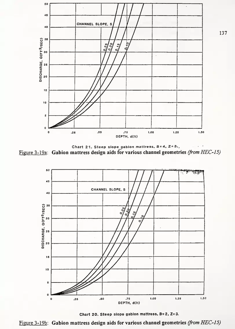
45
38
111
O 25
<IO£0 20
//|
-
CHANNEL SLOPE. S/ / //
0/0/ 0/ c
/
7
*^0^^
137
.26 .50 .75 1.00 1.25 1.60
DEPTH, d(ft)
Chart 21. Steep slope gabion mattress, B = 4, 2=3..
Figure 3- 19a : Gabion mattress design aids for various channel geometries (from HEC-15)
35
30
a 2sK<Xo03 20
///^^"wi
CHANNEL SLOPE. S ///// /4 1 /i *>/ /°7 v/ °y
.76
DEPTH, d(ft)
Chart 20. Steep slope gabion mattress. B=2, 2=3.
Figure 3-19b : Gabion mattress design aids for various channel geometries (from HEC-15)

138
lb/ft :
IS
10
5
-
-""
'
-
0.25 0.50 0.75 1-00 1.25
ROCK SIZE MEAN DIAMETER (ft)
Figure 3-20 : Permissible shear stress versus rock fill size for gabion mattresses (HEC-15)
Tp
lb/ft
-
-
10-
—
- -
f
2 - -
5
— "*
—
- "-
-
-
.
0.25 0.50 0.75 1.00
MATTRESS THICKNESS (ft)
1.2 5 1.5C
Figure 3-21 : Permissible shear stress versus mattress thickness for gabions (HEC-15)

139
3.6 Fabric Formed Revetments - Description
Fabric formed revetments (FFR's) consist of two synthetic fabric plies linked to form a
series of small cells. This "formwork" is filled with highly impermeable, high strength concrete.
Some FFR's are further reinforced with cables to form articulating mats. The intent ofFFR is to
combine the durability of conventional rigid linings (such as cast-in-place concrete, asphaltic
concrete, grouted riprap, and soil cement) with more flexible and/or water-permeable protective
rock systems (such as riprap and gabions) (Sprague et al, 1992).
The question arises of how FFR's differ from the paved side ditch already used in Indiana.
Conventional rigid linings are expensive and tend to progressively fail when a portion of the lining
is damaged. Slight cracks easily erode into spalls which in turn breaks up the concrete into large
sections. Structural damage to the lining develops as a result of poor subgrade conditions,
hydrostatic uplift pressure, swelling soils, embankment slumping, or frost heave (Sprague et al,
1992). Repair of such damage is often time consuming and expensive. FFR's limit these problems
through the use of articulating mats, pressure relief points, and a UV resistant fabric envelope
around the concrete. Moreover, FFR offer significantly increased strength over conventional
paved side ditch (see discussion below).
FFR's also have several advantages over conventional riprap and gabion solutions. In
some areas, riprap is quite expensive because it is not readily available. Well-graded mixtures
often contain a select percentage of stones that cannot resist the flow and are consequently
eroded. Loss of these small stones can lead to progressive liner failure. Gabions require a labor-
intensive installation procedure and hence may extend the construction schedule. In high
sediment channels, abrasive forces may weaken the gabion wire basket and ultimately cause the
basket to collapse.
The technology has its roots in the 1 960's when Dutch engineer H.F. Ffillen joined two
layers of nylon fabric together and filling it with fine fluid aggregate (Lamberton, 1989). Since this
crude experiment, three main types of FFR's have emerged: articulating block, uniform section,
and filter point fabrics.
The articulating block styles provides the flexibility necessary in most erosion control
applications. This fabric is produced by weaving two layers of fabric along regularly spaced grid
lines. These points serve as hinges between adjacent concrete blocks. Block thickness range

140
from 4-8". Cables are threaded through these hinge points after the concrete hardens in order to
interconnect the blocks. The connecting cables and fabric maintain the relative block positions as
the entire structure settles (Sprague et al, 1992). Types of reinforcement include galvanized steel
cable, synthetic rope, or polyester revetment cable.
Uniform section styles are produced by using equal length cords between the fabric layers.
The tie cords are located at 3-6" intervals. The integrity of these cords is crucial to the
performance of these products. These mats are nearly impermeable and most often used in
channel lining work where low coefficient of friction is required (Lamberton, 1989; Monnet,
1990). Typical thicknesses are 3-8" with 4" being the most common fabric used.
Filter point fabric provides a permeable, highly flexible mat of non-uniform cross section.
These mats look like concrete "pillows" (Monnet, 1990). The points not only serve to join the
two layers of fabric, but they also provide relief for hydrostatic uplift from upward water pressure.
Groundwater is allowed to pass through the "points," but soil is retained on the fabric (hence, the
name filter-point). The layers of fabric are woven on 5", 8", or 10" centers with thicknesses
varying from 3-6" (Lamberton, 1989).
Concrete is pumped through hoses into slits in the fabric. Because of the restricted flow
space, the coarsest aggregate can only be concrete sand. Mixes often have a high percentage of
cement content because of the lack of large aggregate (water/cement ratio of 0.65-0.75). Typical
concrete breaking strength is 2000-3000 psi in 28 days for conventional forms. If the mix is
placed in fabric forms ("concrete socks"), strength increases an average of 75% (see figure 3-22).
This implies that FFR's offer more durability than the concrete lined side ditch. For more detail,
consult Lamberton (1989); he gives a complete review of concrete mixes and fabric properties.
3.6.1 Design Principles of FFR Systems
The design ofFFR systems is similar to that proposed for soft armor geosynthetic erosion
control systems. Given the hydraulic characteristics of the channel, one sets up Manning's
equation and iterates to find the flow depth (y). Once the normal depth is determined, the
hydraulic radius is back calculated and the design shear stress (driving force) is computed
(T=RyS). The resisting shear stress comes from the friction between the mat / geotextile system
and the subgrade. The friction angle in this analysis is the least of the mat/soil, mat/geotextile or

141
soil/geotextile interface. A safety factor is computed from the resisting and driving stresses and
the thickness is readily calculated.
Modifications to this procedure are required for waves, curved sections, and anchors. In
curved sections, the tractive force is increased by a factor Kt; hence the driving force becomes
T=KtRyS. For sites subject to wave attack, the thickness of the mat (uniform section or filter
point) must be adjusted. This adjustment depends on the bank angle, wave height, and a non-
dimensional mat coefficient.
In most cases, anchors are used to further secure the FFR to the bank. To account for this
increased stability, a static analysis is carried out for the FFR system. Here, the necessary force
provided by the anchors is the difference between the required submerged weight and the
submerged weight of the mat itself. By resolving this force into components along and parallel to
the slope, respectively, the length and distance between anchors is calculated. Figure 3-23
sketches the anchor/bolt system for a FFR.

142
E2000
Ftbrlo formed
ConrvntloBAUy formed
A£« In <Ut«
Figure 3-22 : Typical cylinder test results for FFR's (Reprintedfrom Lamberton, 1989)
Alternate anchorage
concrete
Figure 3-23 : Schematic of ground anchor system for FFRs (Reprintedfrom Sprague, 1992)
9 10
RADIUS OF CURVATURECHANNEL WIDTH
Figure 3-24 : Bend shear stress coefficient (Reprinted from Sprague, 1992)

143
3.6.2 Equations for FFR Design Method
(a). Determine depth and velocity offlow (iterate to find normal depth)
Q =—AR 2/3S
1/2
(3.72)n
n = roughness coefficient
Q = discharge (m3/s)
A = cross sectional area (m2
)
R = hydraulic radius
5 = bottom slope
(b). Determine tractive shear stress
T = yRSKb (3.73)
x = tractive shear stress (kPa)
y = unit weight ofwater (lcN/m3
)
R - hydraulic radius
Kb = bend shear stress coefficient (see figure 3-24 below)
(c). Determine resisting shear stress
(T.-T.Xgn8-S)t
VTTsF
M = resisting shear stress (kPa)
yc= unit weight of concrete (kN/m
3
)
6 = minimum friction angle within the system
S = slope
t = thickness of the mat (given by manufacturer; typically 5, 8, 10")
(d). Calculate the Safety Factor
MFS =— >L5 (3.75)
Note: ifFS<1 .5, a thickness that would provide an adequate FS is given by:
100(FS)Tt = )-*- (3.76)Mt = thickness (cm)
FS = given by above equation

144
(e). For waves, the thickness is given by:
8328CHt = 7 xw (3.77)
(G,-l)3>/cote
t = thickness (cm)
Cw = mat coefficient
= 1 .3 for short term Uniform Section or Filter Point
= 3.7 for long term Uniform Section or Filter Point
= 2.0 for Articulating Block Mat
H = design wave height (m)
G, = specific gravity
6 = bank angle to be protected
(f). Added stability for using anchors
F = W'-Wm (3.78)
Fp= Fsin0;F
n= cos9 (3.79)
Fp=A
5<t>-^ (3.80)s
Fn = P
s ^-f (381)
W = required weight per unit area (kPa)
Wm' = weight provided by mat itself (kPa)
F = anchoring force (kPa)
F„ = normal component ofthe anchor force (kPa)
Fp
= parallel component ofthe anchor force (kPa)
= bank angle
A, = area of anchor bolt used
<t>=0.85; reduction factor for shear
f,= 13.78 kN/cm2
; allowable shear stress for steel
s = distance between anchors in a square grid (m)
Ps= perimeter ofthe anchor (m)
f,= adhesion between the steel/soil (kPa)
F, = 1.5; factor of safety
d, = necessary length of anchors (m)

145
Style
Filter Point
Uniform Section
Articulating Block
Typical Thicknesses ofFFR
Thickness (cm) Thickness (in.)
12.7 5
20.3 8
25.4 10
7.6 3
10.2 4
15.2 6
20.3 8
10.2 4
15.2 6
20.3 8
Table 3-11: Typical Thicknesses ofFFR
Notes:
1).
2).
3).
The equations for anchor stability can be used two ways: to calculate the
grid spacing (s) and the anchor depth (d) for a required mat weight Wm\ or to
calculate the additional resisting force for given anchor spacing and depth.
This design comes from that proposed by Bowser-Morner Associates and Simons, Li, and
Associates Inc. (Sprague, 1992).
It is assumed that the additional shear resistance Fp (i.e. acting along the slope) is
added to the resisting shear stress M. This increases the factor of safety.

146
3.7 Concrete Blocks (Articulating Block Systems - ABS) - Description
Concrete blocks interlock together in regular patterns to resist hydraulic forces. These
systems are designed to have freedom of movement between individual units. Hence, such
systems are usually referred to as articulating block systems (ABS). Concrete blocks often have
about 15-35% open area by design. This area allows vegetation to be established. The vegetation
conceals the revetment (improving aesthetics) and significantly increases hydraulic stability (up to
50% according to CIRCA 1987).
A major advantage of concrete blocks over riprap is in its ability to resist ice flow damage.
For example, one 8-year study at Rock State Park in Illinois compared riprap to Tri-Lock by
American Excelsior. After 8 years, the Tri-Lock section remained fully intact while most of the
riprap had eroded (Cabalka and Lutyens, 1996). This same lock and key block system was used
to control severe erosion along Spring Branch Creek in Harris County, Texas (Starrett, 1994). In
this case, the area was used for recreation. Obviously, the vegetation-covered revetment offered
a safer solution than large diameter jagged riprap.
Notice that ABS do not add structural strength to slopes and banks like lateral earth
retaining walls. They only protect the geotextile and underlying soil from erosion. As the bank
angle approaches the natural angle of repose for the saturated soil, it becomes unstable. Adding
concrete blocks to a bank near the angle of repose increases the likelihood of a rotational failure
(the blocks add a large component driving down the slope) (Fuller, 1992).
For simplicity, concrete blocks are divided up into two categories: cabled and non-cabled.
Cabled blocks have pre-cast holes which are threaded with high strength polyester or steel cable.
These cables turn the concrete blocks into articulating mats. The mats then are easily placed on
prepared slopes. Another benefit of using cabled systems is that mats are easily placed under
water. In addition, earth anchors installed along the top of the bank create "hanging" revetments.
Such installations can maintain shear resistance even if a toe failure occurs. Non-cabled blocks
rely only on the weight of the blocks. These blocks are hand placed on the channel bed.
Although these units are cheaper than cabled units, the installation is very labor intensive.
Consequently, non-cabled installation is not widely used anymore (Fuller, 1992).

147
3.7.1 Design of Concrete Block Systems
The design of ABS systems focuses on the lift and drag forces producing overturning
moments of a single block. Failure here is defined as the loss of intimate contact between a block
(or group of blocks) and the subgrade which they protect (Clopper, 1988, 1990). It is assumed
that the friction angle developed between the geotextile, blocks, and subgrade is sufficient to
prevent a sliding failure. This leads to the concept of incipient overturning - overturning moments
are equal to the resisting moments. In this analysis, the resistance added by the cables is
neglected. In order for tension to develop in the cables, some finite rotation of the block must
have occurred and by our definition, the system has already "failed" (i.e. overturning has begun)
(Clopper, 1990). This focus on overturning of one unit lends itself to the previously detailed
Simons and Senturk procedure.
The procedure requires knowledge of the moment arms for a given block. These
distances are not intuitive which complicates the design procedure. Moreover, the procedure
assumes a relationship between the lift and drag force (Simons assumes Fi/Fa = 2). However, it is
commonly used and the procedure is presented here.
Fuller (1992) points out that concrete block systems must be designed for both wave
attack and high velocity flows. He presents the Pilarcyzk approach to designing against wave
attack. As with r'r'K, the object is to make the blocks thick enough to resist wave erosion. These
equations are based on wave height, bank slope, wave period, and block strength coefficient.
Caution is needed when using this approach. This method does not account for the destructive
force of oblique waves (e.g. those produced by a boat running parallel to shore) (Fuller, 1992).
3.7.2 Design Equations for Concrete Block Design - Simons Approach (1977)
(a). Factor of safety equation and required parameters
(L/l.)coseSF = -jj
^—^ (3.82)
N+ sin(X + (3) ,
M +1"i
N
T|— + sin0cosp

148
p = tan-i cos A,
M/N-U,n 1,
A
sinG + sinA,
(3.83)
M J<FL
N 13FD
Tl = I±
*c
^0 == ydS
to = design shear stress
Tc = critical shear stress
X = longitudinal bed slope angle
e = bank slope angle
P,ri = computation parameters
y = specific weight ofwater
d = normal depth
S = bed slope
1;= moment arms (i= 1,2,3,4)
Fl, Fd = lift and drag force
(3.84)
(3.85)
(3.86)
(b). Equations for designing against wave attack
H
c=
= v-cos6
£tanG
mr = 125VH
tan6
(3.87)
(3.88)
H = wave height
T = wave period
e = bank angle
x = wavelength in deep water
M/= strength coefficient
= 3 to 5
c = wave breaking parameter
Pm = density of concrete block
D = thickness ofthe concrete block

149
Notes:
1). Several manufacturers have their own method for designing against
wave attack. Consult chosen manufacturer for variations from this procedure.
2). Although most ABS allow vegetation to grow between blocks, the added resistance
provided by plant roots is not included. Extended periods of drought, floods, or
environmental damage can weaken and/or destroy any vegetation in a short period of
time. Hence, it is not conservative to include vegetation resistance in ABS designs.
3). Even though not reflected in the design procedure, site grading and compaction often
determines the success or failure of an ABS project. Moreover, a geotextile filter must
be placed underneath the ABS. The selected geotextile must be strong enough to survive
installation and the design hydraulic forces. It also must retain the base soil and resist
clogging. The FHWA design procedure for geotextiles is found in Appendix B.
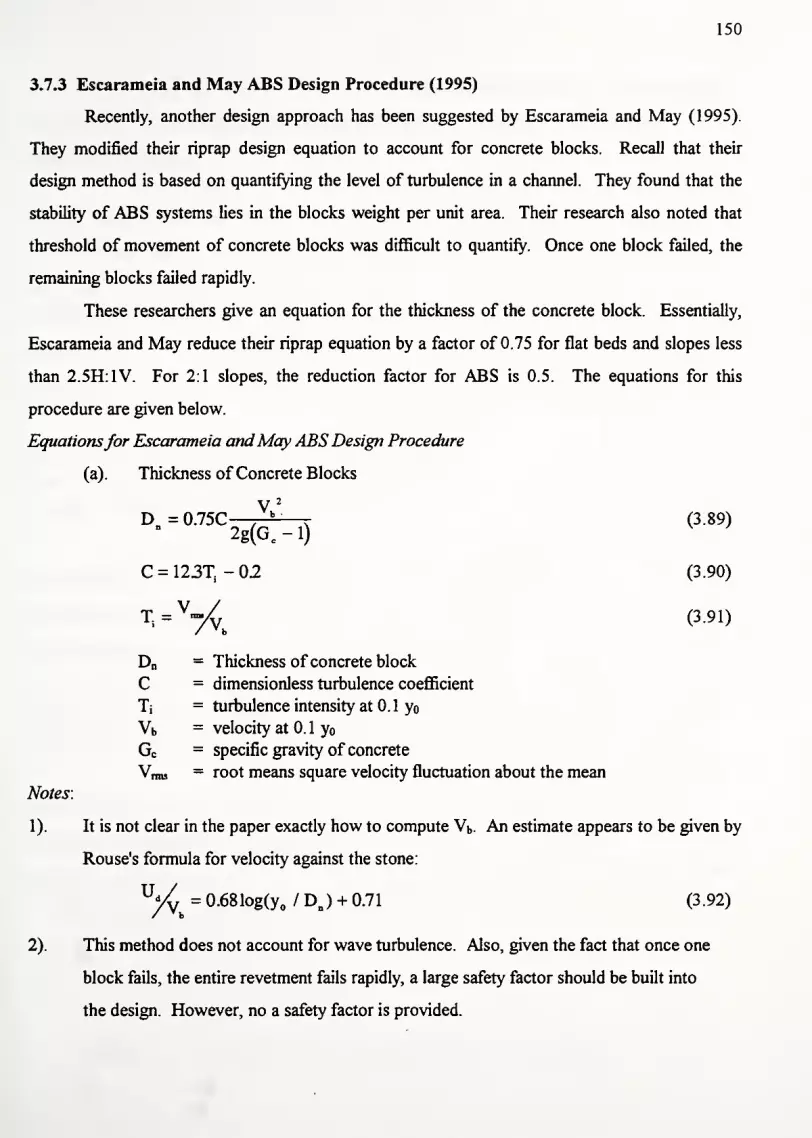
150
3.7.3 Escarameia and May ABS Design Procedure (1995)
Recently, another design approach has been suggested by Escarameia and May (1995).
They modified their riprap design equation to account for concrete blocks. Recall that their
design method is based on quantifying the level of turbulence in a channel. They found that the
stability of ABS systems lies in the blocks weight per unit area. Their research also noted that
threshold of movement of concrete blocks was difficult to quantify. Once one block failed, the
remaining blocks failed rapidly.
These researchers give an equation for the thickness of the concrete block. Essentially,
Escarameia and May reduce their riprap equation by a factor of 0.75 for flat beds and slopes less
than 2.5H:1V. For 2:1 slopes, the reduction factor for ABS is 0.5. The equations for this
procedure are given below.
Equationsfor Escarameia andMay ABS Design Procedure
(a). Thickness of Concrete Blocks
(3.89)
(3.90)
%= WyV
h
(3-91)
D„ = Thickness of concrete block
C = dimensionless turbulence coefficient
T; = turbulence intensity at 0.1 y
Vb = velocity at 0. 1 yGc
= specific gravity of concrete
Vnns - root means square velocity fluctuation about the mean
Notes:
1). It is not clear in the paper exactly how to compute Vb. An estimate appears to be given by
Rouse's formula for velocity against the stone:
U„
V 2
r» — n 7^p b
2g(Gc
--1)
C = 123T - 02
v = 0.681og(y / DB ) + 0.71 (3.92)d
2). This method does not account for wave turbulence. Also, given the fact that once one
block fails, the entire revetment fails rapidly, a large safety factor should be built into
the design. However, no a safety factor is provided.
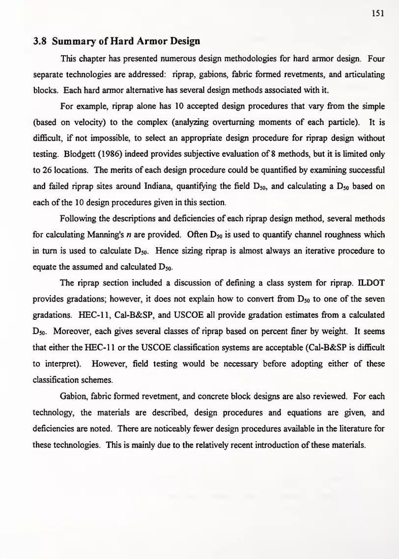
151
3.8 Summary of Hard Armor Design
This chapter has presented numerous design methodologies for hard armor design. Four
separate technologies are addressed: riprap, gabions, fabric formed revetments, and articulating
blocks. Each hard armor alternative has several design methods associated with it.
For example, riprap alone has 10 accepted design procedures that vary from the simple
(based on velocity) to the complex (analyzing overturning moments of each particle). It is
difficult, if not impossible, to select an appropriate design procedure for riprap design without
testing. Blodgett (1986) indeed provides subjective evaluation of 8 methods, but it is limited only
to 26 locations. The merits of each design procedure could be quantified by examining successful
and failed riprap sites around Indiana, quantifying the field D50 , and calculating a D50 based on
each ofthe 10 design procedures given in this section.
Following the descriptions and deficiencies of each riprap design method, several methods
for calculating Manning's n are provided. Often D50 is used to quantify channel roughness which
in turn is used to calculate D50 . Hence sizing riprap is almost always an iterative procedure to
equate the assumed and calculated D50.
The riprap section included a discussion of defining a class system for riprap. ILDOT
provides gradations; however, it does not explain how to convert from D50 to one of the seven
gradations. HEC-11, Cal-B&SP, and USCOE all provide gradation estimates from a calculated
D50. Moreover, each gives several classes of riprap based on percent finer by weight. It seems
that either the HEC-1 1 or the USCOE classification systems are acceptable (Cal-B&SP is difficult
to interpret). However, field testing would be necessary before adopting either of these
classification schemes.
Gabion, fabric formed revetment, and concrete block designs are also reviewed. For each
technology, the materials are described, design procedures and equations are given, and
deficiencies are noted. There are noticeably fewer design procedures available in the literature for
these technologies. This is mainly due to the relatively recent introduction ofthese materials.

152
3.9. Designing for Composite Channel Linings
As noted in the first design section, shear stress is typically less on the side slopes than on
the bottom of the channel. Consequently, the channel liner requirements may not be nearly as
great. The side slope lining can have a lower permissible shear stress than that used in the middle
ofthe channel. Figure 3-25 shows a schematic of a typical composite lining.
Class B Vegetation
Concrete channel
Figure 3-25 : Composite Channel Lining
Beyond economics, low flows are another reason for selecting a composite lining. Often,
sustained low flows kill the submerged vegetation and this decreases the erosion resistance of the
channel lining. Large discharges then loosen the blanket and ultimately cause it to fail. A solution
then is to use riprap or concrete in the center of the channel and reinforced vegetation on the side
slopes (Chen and Cotton, 1988). Another reason for using a composite lining is for the case of
side slopes with different Z values (H:V ratios). Obviously, the shear requirements of a 2:1 slope
are much greater than a 4:1 slope. This situation is shown in figure 3-26.
2.2
B
Figure 3-26 : Composite lining for unequal side slope ratios (Zt * Z?)
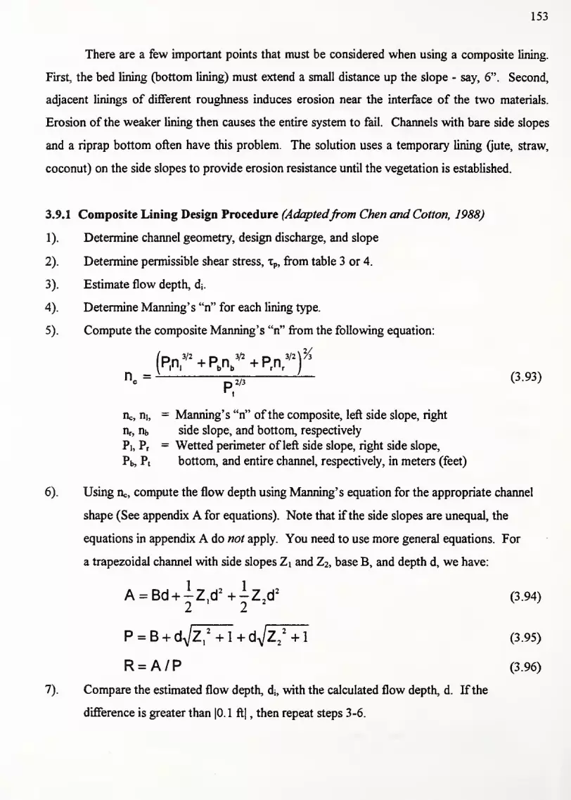
153
There are a few important points that must be considered when using a composite lining.
First, the bed lining (bottom lining) must extend a small distance up the slope - say, 6". Second,
adjacent linings of different roughness induces erosion near the interface of the two materials.
Erosion of the weaker lining then causes the entire system to fail. Channels with bare side slopes
and a riprap bottom often have this problem. The solution uses a temporary lining (jute, straw,
coconut) on the side slopes to provide erosion resistance until the vegetation is established.
3.9.1 Composite Lining Design Procedure (Adaptedfrom Chen and Cotton, 1988)
1). Determine channel geometry, design discharge, and slope
2). Determine permissible shear stress, xp, from table 3 or 4.
3). Estimate flow depth, d;.
4). Determine Manning's "n" for each lining type.
5). Compute the composite Manning's "n" from the following equation:
(PA* + PA* + PA*)
P
%
nc= Zl/i — (3-93)
1
iic, m, = Manning's "n" ofthe composite, left side slope, right
IV, nb side slope, and bottom, respectively
Pi, Pr= Wetted perimeter of left side slope, right side slope,
Pb, Pt bottom, and entire channel, respectively, in meters (feet)
6). Using ric, compute the flow depth using Manning's equation for the appropriate channel
shape (See appendix A for equations). Note that if the side slopes are unequal, the
equations in appendix A do not apply. You need to use more general equations. For
a trapezoidal channel with side slopes Z\ and Z2, base B, and depth d, we have:
A = Bd + -Z,d 2 +-Z2d
2(3.94)
2 ' 22
P = B + dA/Z,
2+ l+d-
N/Z
2
2
+l (3.95)
R = A/P (3.96)
7). Compare the estimated flow depth, di, with the calculated flow depth, d. Ifthe
difference is greater than |0.1 ft| , then repeat steps 3-6.

154
8). Determine shear stress at maximum depth, xd, and shear stress on the side slopes, x..
T = y wDS (3.97)
Ts= K,T
d(3.98)
where, Ki = side slope shear coefficient from Chart 13
D = calculated maximum depth
S = slope of channel
yw = unit weight ofwater - 9.807 kN/m3(62.4 lb/ft
2)
id = maximum shear stress
x, = side slope shear stress
9). Compute factor of safety for each lining. Each must be greater than 1.2. If either lining
fails, then select a new combination of linings and repeat steps 3-8.
FS^-i (3.99)
*d
FSEkte=^ (3.100)
Xp = permissible shear stress from tables 1 or 6
10). Using the calculated flow depth, compute the velocity using modified Manning's
equation for both the bottom and side slopes. Notice that the bend factor is
included here as a reminder that channel bends must be considered ifRc/B < 10. Refer
to section 2 to for complete details on how to design for channel bends.
V^ =^Rv,(KBtaf (3.101)
V^=^R"6(K BT,f (3 102)
c
lie = composite Manning's "n" computed from equation 3.4
Kb = bend coefficient, ifRc/B < 10
K, = conversion factor from shear stress to velocity
0.1 89 for English units
0.0316 for S.I. units

155
1 1). Compute factor of safety against velocity failure. Again, a minimum factor of safety
is 1 .2. If either lining fails to meet this criteria, then a new combination of linings must be
selected. In this case, repeat steps 2-10.
SF^ = £*- > L2 (3.103)
bottom
SFside=^>L2 (3.104)
''side
V.uow = permissible velocity found in table 6
Vbottom = calculated velocity on the channel bottom
V,ide = calculated velocity on the side slopes

156
4: Classification System for Erosion Control Products
4.1 Why is a classification system needed?
As mentioned previously, there are a myriad of erosion control products on the market
today. Some erosion control blankets are only meant to survive until the vegetation is fully
established - say 6-10 months. Examples in this category are straw mats with and without a
polypropylene netting, light excelsior blankets (under 0.5 lb./yd2), hydromulches, jute meshes,
polypropylene roving, and straw bales.
Other materials last several growing seasons before they ultimately biodegrade. Such
blankets are useful in harsher environments - steep sideslope channels, high water velocities,
and high shear stresses. Examples in this category include high grade excelsior blankets,
straw - coconut coir mixtures, coconut coir, and UV-stabilized polypropylene roving. All of
these products also biodegrade, albeit over 2-5 growing seasons depending upon the material,
thickness of netting, and installation protocol. Even though the early stages of growth rely
upon the blanket for strength, ultimate shear resistance is provided solely by the mature
vegetation. In other words, the vegetation shear resistance should be used in long term design
calculations rather than the shear resistance of the blanket. However, note that in the early
stages of growth, the design is controlled by the shear resistance of the erosion control blanket
(i.e. two sets of design calculations are required in this case; short and long term).
Still other erosion control materials are considered non-degradable. These materials
are made ofUV stabilized monofilaments of polypropylene or similar plastic. Some are low
profile and placed on top of the seedbed (ECRMs - Erosion Control and Revegetation Mats);
whereas, others are soil and seed filled (TRMs - Turf Reinforcing Mats). Both of these
products are used in extremely harsh environments - high velocity or deep flows. ECRMs and
TRMs are necessary for drainage channels in which vegetation alone cannot provide sufficient
shear resistance against the design discharge. For a full description of each class of products,
refer to the Literature Review section of this report.
It is apparent that each class of products has their own applications. Erosion control
products are selected based upon the requirements of the site. For a channel with a design
discharge of 16 ft3/s, base width of 4 ft, slope of 0.03 ft/ft, and sideslope ratio of 3, a wood
Classification of Erosion Control Products

157
excelsior would be an acceptable lining. However, if the base width is halved to 2 ft, an
ECRM is required due to increased shear.
This example illustrates the fact that erosion control products are selected based upon
their performance rather than traditional geosynthetic index tests - tensile strength, Mullen
burst, percent elongation, and resiliency. This statement should not be misconstrued to imply
that these tests are not important; rather, they may be useful for product classification
purposes. However, industry representatives (from American Excelsior, Synthetic Industries,
Nutec Supply, and the Erosion Control Technology Council - ECTC) interviewed in the
course of this study strongly favor the selection of an erosion control blanket based on its
shear resistance rather than index test data. These representatives support their position by
pointing out that index test conditions are rarely, if ever, realized in the field. Moreover, there
are no ASTM standards for testing erosion control materials. Currently, the ECTC is
attempting to standardize index tests for erosion control materials, but to date, no resolutions
have been released. Because of the industry's position, only 2 of the 25 companies
contributing product information provided index test data for their products. Since the
available data is so limited, no classifications in this report are based on index tests.
This doesn't imply that index tests are not used to classify products. Presently, the
U.S. Department of Transportation (Federal Highway Administration) provides minimum
index test values for various classes of erosion control products (5 713.07, 1992). The FHWA
requires only the non-degradable materials (ECRM's and TRM's) to undergo thorough index
testing. In addition, Ohio and Illinois Departments of Transportation also select erosion
control materials based upon index tests.
Although this report recommends classifying products on a performance basis, it is
worthwhile to summarize the specifications used in other states. These summaries become
the basis for the proposed classification system. Twenty states were asked to provide their
current specifications for erosion control products. Of the 1 1 responses, only 7 states
provided specifications on erosion control materials (the remainder did not have current
specifications). Also, one erosion control manufacturer (Synthetic Industries) provided a
framework for a specification. The next several pages summarize each specification,
including those obtained from the FHWA and Synthetic Industries.
Classification of Erosion Control Products

158
4.2 Summary of Erosion Control Product Classification Systems
4.2.1 Virginia
Type: Performance based (velocity) using an "approved list" format
(a). Products for ditch liners are broken into 2 categories - EC-2 & EC-3
(b). EC-2 includes all degradable materials (jute mesh, straw, excelsior,
coconut, or combinations).
Range of permissible velocity (Vp):
2.5 - 4.0 ft/s
Channels with Vp< 2.5 ft/s do not require an erosion control blanket
(c). EC-3 are the non-degradable ECRM's and TRM's which are sub-divided
into two groups - A & BA: Specified in ditches with a 2-yr storm discharge velocity of 4.0-7.0 ft/s
B: Specified in ditches with a 2-yr storm discharge velocity of 7.0-10.0ft/s
(d). New products are installed next to an "approved" material. The new
material is monitored through several storm events to ensure that the
installation does not fail and that vegetation grows. If it performs in an
equal manner to the previously approved material, it is considered
acceptable and added to the "Approved Products List" for that category.
4.2.2 Illinois
Type: Index test based
(a). Excelsior Blankets - 80% ofthe fibers must be 1 50 mm (6") or longer,
cured to obtain barbed fibers. The blanket must be covered and entwined
with a 90-day degradable netting having minimum opening of 16 x 16 mm(5/8" x 5/8"). The blanket must also resist a cigarette smolder test.
Minimum width 600 mm (24")
Minimum unit weight 0.5 kg/m2
(0.9 lb/yd2)
Minimum roll length 45 m (150ft)
(b). Knitted Straw Mat - weed free straw with a loose thickness of 1 3 mm(1/2") with the topside ofthe mat covered with a 90-day biodegradable
plastic mesh of 10 x 10 mm (3/8 x 3/8") square openings.
Minimum width 2 m (6.5 ft)
Minimum unit weight 0.38 kg/m2
(0.70 lb/yd2
)
Classification ofErosion Control Products

159
(c). FiberMat - entangled nylon monofilaments, melt-bonded at their
intersections, forming a stable mat (UV resistance)
Carbon black content 0.5%byweightFilament diameter 0.406 mm (0.016")
Mass 0.41 kg/m2(0.75 lb/yd
2)
Strength (length) 1.4N/mm (7.8 lb/in)
(width) 0.8N/mm (4.4 lb/in)
Elongation (length) 50% min.
(width) 50% min.
Resiliency 80% after 3 cycles of690 kPa (100
psi loading)
4.2.3 Ohio
Type: Performance (velocity) and Index based classification
(a). Straw blanket - 100 % straw mat with topside covered with polypropylene
degradable netting having an approximate 6x6 to 13x13 mm (1/4x1/4
to 1/2 x 1/2") square openings
Minimum weight 0.27 kg/m2(0.5 lb/yd
2)
(b). 70% straw, 30% coconut blanket - mat with topside degradable netting 16
x 16 mm (5/8 x 5/8") square openings
Minimum weight 0.27 kg/m2
(0.5 lb/yd2
)
(c). ECRM - vinyl monofilaments bonded together to form a stable 3-
dimensional web. It must be permeable, resistant to chemical,
environmental and UV degradation. Manufacture must also provide
certified test data proving the material meets the following specifications:
Porosity 90%Flexural rigidity 2000
Weight 0.61 kg/m2
(18 lb/yd2
)
Tensile Strength (length) 67 N (15 lbs)
(width) 22 N ( 5 lbs)
Elongation (length) 150% min.
(width) 100% min.
UV Resistance 95%
Classification ofErosion Control Products

160
(d). TRM - bulky structure of entangled nylon monofilaments having a
minimum content of0.5% carbon black.
Filament diameter 0.351 mm (0.0138")
Unit Weight 0.246 kg/m2
(0.454 lb/yd2
)
Tensile Strength (length) 19.6N/25mm (4.48 lb/in)
(width) 9.8 N/25mm (2.24 lb/in)
Elongation (length) 50% min.
(width) 50% min.
Resiliency 80% min.
(e). Permissible velocity 1 .22 - 1 .52 m/s (4-5 ft/s) for degradable blankets
For permissible velocity 1.52 < Vp< 3.05 m/s (5 < Vp
< 10 ft/s), use
synthetic, non-degradable blanket (ECRM or TRM) (from § 839 & 840).
4.2.4 Texas
Type: Performance based using shear resistance, sediment loss, and minimum
vegetation density
(a). A four class system that defines minimum performance standards for each
class - E, F, G, H
Type Shear Stress Maximum Minimum
Pa (lb/ft2
) Sediment Loss Vegetation
(kg/10 m2) Density
E 0-96 (0-2) 1.15 70%F - 192 (0 - 4) 1.00 70%G 0-287 (0-6) 1.00 70%H 0-383 (0-8) 0.80 70%
(b). Manning's "n" determined for all approved products by flume tests
(c). Contractors may use any ofthe products provided that the product is listed
by brand name on the current "Approved Products List" for the Class and
Type specified.
4.2.5 Maryland
Type: Performance based (velocity)
(a). Products classified into 2 categories - A & BA: Vp
< 1.52 m/s (< 5 ft/s)
B: 1.52 <VP< 2.44 m/s (5-8 ft/s)
Classification ofErosion Control Products

161
4.2.6 Connecticut
Type: Performance based (shear strength)
(a). Products classified into 4 categories: E, F, G, H
Type Shear Stress Range - Pa (lb/ft2
)
EFGH
0-45 (0 - 0.5)
45-96 (0.5-1.0)
96-192 (1.0-2.0)
192+ (2.0+
)
4.2.7 Synthetic Industries (Leading erosion control manufacturer)
Type: Performance based (velocity and shear strength)
(a). Products classified into 5 categories (C-l, C-2, C-3, C-4, C-5) that reflect
the realistic performance limits for these materials
Type Shear Resistance Permissible Velocity
Pa Ob/ft2) m/s (ft/s)
C-l < 20 (0.4) <0.5 (1.6)
C-2 20-45 (0.4-1.0) 0.5-1.5 (1.6-4.9)
C-3 45-95 (1.0-2.0) 1.5-2.0 (4.9-6.6)
C-4 45-95 (1.0-2.0) 1.5-2.5 (4.9-8.2)
C-5 95 - 140 (2.0 - 2.9) 2.5-3.0 (8.2-9.8)
4.2.8 FHWA - FP-92, 1992 {Standard Specifications}
Type: Index Based
(a). Synthetic Polypropylene MeshMinimum Weight
Tensile Strength
Elongation at break
Mullen burst strength
0.76 kg/m2
(0.14 lb/yd2
)
3.3 x 1.7 kN/m (225 x 120 lb/ft)
32% x 40%827 kPa (120 psi)
(b) . Erosion ControlMulch Blanket
Excelsior blanket
80% of fiber 8" or longer in length, top net of biodegradable plastic mesh
Dimensions (Width) 1.22 m (4 ft)
(Length) 55 m (180 ft)
Weight 0.42 kg/m2
(0.94 lb/yd2)
Classification ofErosion Control Products
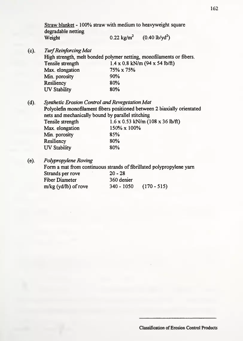
162
Straw blanket - 100% straw with medium to heavyweight square
degradable netting
Weight 0.22 kg/m2
(0.40 lb/yd2
)
(c). TurfReinforcingMatHigh strength, melt bonded polymer netting, monofilaments or fibers.
Tensile strength 1.4x0.8 kN/m (94 x 54 lb/ft)
Max. elongation 75% x 75%Min. porosity 90%Resiliency 80%UV Stability 80%
(d) . Synthetic Erosion Control and Revegetation MatPolyolefin monofilament fibers positioned between 2 biaxially orientated
nets and mechanically bound by parallel stitching
Tensile strength 1 .6 x 0.53 kN/m (108 x 36 lb/ft)
Max. elongation 150% x 100%
Min. porosity 85%Resiliency 80%UV Stability 80%
(e). Polypropylene Roving
Form a mat from continuous strands of fibrillated polypropylene yarn
Strands per rove 20 - 28
Fiber Diameter 360 denier
m/kg (yd/lb) ofrove 340-1050 (170-515)
Classification of Erosion Control Products

163
4.3 Defining a Classification System for Erosion Control ProductsThis report proposes to classify erosion control products by their performance rather
than index test data. Limiting velocity and shear resistance for each product define its
classification. Even though the industry is moving toward defining product strengths in terms
of shear resistance, many manufactures do not yet provide this data. Flume tests are extremely
expensive to perform properly. Hence, manufactures who have already performed velocity
tests on their products are reluctant to spend additional money on shear resistance flume tests.
More importantly, there are situations (already noted in the design methodology section of this
paper) where the liner fails even though the shear resistance safety factor is greater than one
(i.e. low depth, high velocity flow). In this case, failure is caused by the high velocity water
eroding the soil below the blanket.
Because this synthesis is based on existing data only, the proposed classification relies
on the classification schemes of other DOT's. Specifically, our classification system combines
elements from Virginia, Texas, Connecticut, and Ohio as well as the Synthetic Industries model
specification. Table 4-1 provides an overview ofthe proposed classification system.
Proposed Classification System for Flexible Channel Liners
Classification Permissible Velocity
m/s (ft/s)
Permissible Shear
Pa (lb/ft2
)
A (Degradable): Product degrade within 2 years (e.g. jute mesh, straw or coconut
blanket, excelsior, roving, straw bales, mulches.)
A-l
A-2
0.0-1.2 (0-4)
1.2-2.1 (4-7)
0-45 (0-1)
45-96 (1-2)
B (Non-degradable): Products stabilized with carbon black (e.g. nylon mesh, heat
bonded 3-D TRM, synthetic erosion control and revegetation mat) j
B-l
B-2
1.2-2.1 (4-7)
2.1-3.0 (7-10)
45-96 (1-2)
96-240 (2-5)
Table 4-1: Proposed classification system for erosion control products
Classification of Erosion Control Products

164
This classification system is entirely performance based. Indeed, the concept for this
classification system is derived from other state DOT's specifications (refer back to the
summaries ofthe DOT's specifications). By dividing the products into two general categories
(A & B), one can eliminate halfofthe products by answering the question, "Must the erosion
control material last for the entire design life?" Ifthe answer is "Yes," then the contractor is
limited to category B. Further subdividing the categories by performance characteristics
allows selection of cheaper products for less erosive situations.
Moreover, using both velocity and shear resistance limits falls in line with the proposed
design methodology. Recall that the design methodology was based on computing both the
shear and velocity induced during a given storm event. It follows then that the classification
system should use both quantities. In the event that shear resistance and permissible velocity
for a site fall under different classifications, one must choose the more resistant category
(either A-2 or B-2).
Defining product classification by both velocity and shear resistance is beneficial. It
encourages designers to calculate both shear strength and velocity (and their safety factors). It
also allows more products to be classified (Recall that some manufactures only provide
velocity or shear data alone). Unfortunately, herein lies a problem. What guarantee does the
contractor have that a product classified using permissible velocity performs equally as well as
one classified using shear resistance? We need some proof that the velocity range for a
particular class provides the same strength as the shear range for that class. In other words,
we need to determine ifthe two classifications are equivalent.
This requires finding a relationship between the velocity and shear resistance. Recall
that the proposed design methodology uses a modified form ofManning's equation:
0.189R,/6t
,/2
Vp= P— (4.1)
Using this equation and the ranges of shear strength provided in the proposed
classification, one generates limiting velocities. The Velocity-Shear graph (figure 4. 1) plots
this equation for several values ofR (hydraulic radius). Superimposed on the graph are shaded
regions corresponding to the categories ofthe proposed classification system. Notice that the
shaded regions by no means encompass all possible geometries. However, given the
Classification ofErosion Control Products

165
(0
OH
32o>»I</>
3O
5
CM
5CM CM
!5
CM o- m
T- CM CM CM
V V V V*«- * *-* *->
V V V Vo V *- «- o
K II 1- o
o o oV> V> V> V>Vo
Vto
Vm
Vm o
. mV CM ,- ^ co
< < CQ m
c (00)
G) CD
<"c3
» ^.> N-
oO0)
>o
oo
ooCO
o .Cm *•«
CM O)c0)v.+*V)i-
o IBo OCM S
(0
co oo
\ "~~"—
J
o- in
o co
o »- o>o O P5
ii iiV" —
'
c°* <ISu"---•-o^lJ o
*---^^ - o 0}Q.
o o O O o c> ° U)o o O o o c>
m o m o m c>CM CM T—
(s/W - PA) ^!00|3A

166
limitations ofusing a simple model, the proposed ranges of shear stress and velocity appear to
be equivalent. Ifthe classification system was grossly in error, most ofthe lines would not be
included in any ofthe shaded regions.
In order to improve the classification system to include more area ofthe graph, it is
necessary to change the ranges of either velocity or shear stress requirements. The suggested
shear stress ranges are pretty much standard, but the velocity ranges are somewhat variable
(see the previous specification summaries). As such, changes to the velocity ranges are made
as shown in table 4-2.
Classification System with Modified Velocity Ranges
Classification Permissible Velocity
m/s (ft/s)
Permissible Shear
Pa (lb/ft2)
& (Degradable): Product degrade within 2 years (e.g. jute mesh, straw or coconut
blanket, excelsior, roving, straw bales, mulches ..)
A-l
A-2
0.0-1.5 (0-5)
1.5-3.0 (5-10)
0-45 (0-1)
45-96 (1-2)
B (Non-degradable): Products stabilized with carbon black (e.g. nylon mesh, heat
bonded 3-D TRM, synthetic erosion control and revegetation mat) i
B-l
B-2
1.5-3.0 (5-10)
3.0-4.6 (10-15)
45-96 (1-2)
96-240 (2-5)i
Table 4-2: Classification system with modified velocity ranges that better fit
Manning's equation
Figure 4-2 uses these new velocity ranges. Notice that these ranges encompass nearly
all ofthe graph. From a theoretical standpoint then, these modified velocity ranges correspond
better to the proposed shear strength ranges. That is, these alternative velocity ranges are
more representative ofthe available strength.
The question then is which velocity range is more appropriate? Based on other DOT
specifications, the first velocity range is more accepted even though it does not fit the
theoretical data as well. More sophisticated shear stress - velocity models such as the Lane
method (1953) which utilizes drag and lift coefficients, soil diameter, and density may provide
a better correspondence between the theory and suggested shear / velocity ranges. One could
also use a modified Shields diagram from Vanoni (1975) to obtain a similiar velocity-shear
Classification of Erosion Control Products
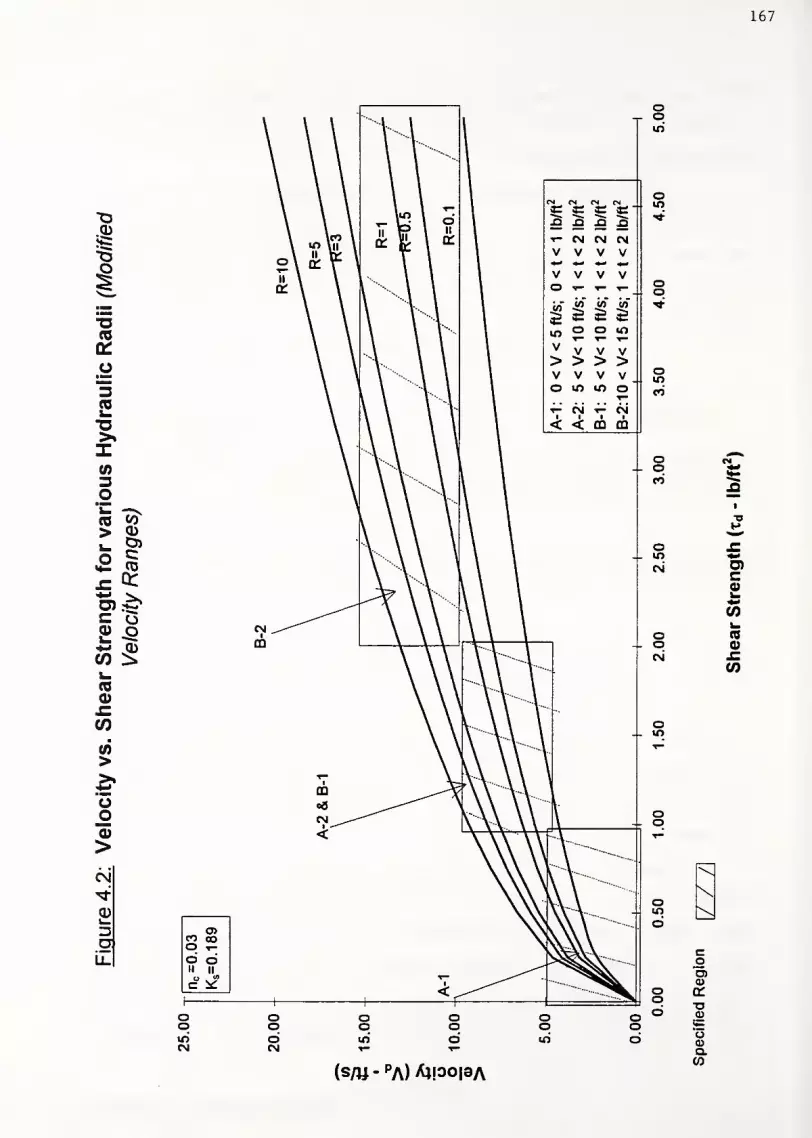
167
IaCO
a>»xto
CO CO> U)
u. o>
a CO
JZ u:4-1
c0) ou.+» CI)
CO ^s-CO0)
J^CO
CO>*•MBoOd)
>
oCN d mc c c c *"
XI .Q X3 n«- cm CM CM
V V V V** *-> *•* ^V V V Vo «- «- «-. oo
1to (0 (A *a a £
to o o IO^— T— ^—
V V V V> > > >V V V V o
ioo to IO o co
T- CM T- CM
< < m CO
CM
OOJ
CO oooo oII ii
ocCO
ooIO
oo OoIOCM
oCM
o CMo CCO Q
1
"O*»^^
o £IO *<
CM O)c0)>_*rf
COi_
o COo 0)
CM
OIO
CO
(s/W - PA) A!00|3A
o
CD
<r
aCD
'oCDQ.CO

168
relationship (see figure 4-3). Unfortunately, the diagram is only useful for bare soil; further
testing must be done to determine where erosion control materials lie on such a diagram.
However, such testing and analysis is beyond the scope of this report. The point of this
discussion is to at least loosely show that a theoretical basis exists for a combined shear -
velocity classification system.
The next question to ask is whether index tests have any place in the proposed
specification. It was already mentioned that some ofthe available tests do not simulate field
conditions closure. Recall that such tests (Mullen burst, tensile strength, and elongation, and
resiliency) are derived from the textile (clothing) industry tests.
On the other hand, other tests and/or material parameters may be useful. Among them
include UV stability, porosity or percent ground cover, thickness, unit weight, length, and
width. Ofthese tests, UV stability is ofutmost importance for ECRMs and TRMs. It may
either be specified by percent carbon black or the percent strength remaining after the Xenon
light test. Percent ground coverage would be useful for selecting a material of appropriate
density. Unfortunately, there is currently no accepted method of determining a product's
"ground cover factor" (note: light projection is used, but no ASTM standard exists). Index
test are also useful in quantifying the survivability during installation. For a complete review of
index tests and survivability criteria for geosynthetics, the interested reader should consult
Koener's text, Designing with Geosynthetics (1994).^
In terms ofthe products dimensions, no literature or research result is available that
compares the merits of using longer, wider materials over shorter, thinner ones. However,
several states including the FHWA do have minimum or approximate roll dimensions. If
specified, the roll dimensions should only be approximate; products rarely fail because they are
too short! The primary reason for specifying dimensions is to speed installation (no one wants
installation encumbered by thin or short products). Using longer, wider products means fewer
overlap areas or seams. i>&?
Classification ofErosion Control Products

Modified Shields Diagram
169
! O Amber• Lienite
,(Shields)
3 Granite
C Barite
» Sand (Casey)
- Sand (Kramer)
« Sand (U.S. WES)A Sand(Gilben)
Sand (While)
Sand in air (White)
i. Sieel shot (White)
Ti
(g/cm 3)
1.06
1.27
2.70
4.25
2.65
2.65
2.65
2.65
2.61
2.10
7.90
4 6 1000.
LUi
¥tmT7TJT.
WuE, £5SSPfT LLLLJ
MM).2 0.4 0.6 1.0 4 6 8 10 20 40 60 100 200 500 1000
Boundary Reynolds number U*dl\
Figure 4-3 : Shields diagram for incipient motion. Notice it includes the Vanoni
modification. (Reprintedfrom Chih Ted Yang, 1996)
Classification ofErosion Control Products

170
In terms of index tests then, this report recommends the following:
^ Approximate roll dimensions
*J Short product descriptions (name, material, & color)
^ Material parameters (mass per unit area, netting size, carbon black content)
On the other hand, the following index tests are not included in this specification
SS Mullen burst
% Tensile Strength
£3 Elongation
£S Resiliency
£2 Ground Cover Factor
It is the opinion ofthe authors that these material properties are useful for classification
and quantifying survivability. However, ultimate selection of an erosion control product still
rests with its performance characteristics (i.e. shear and velocity resistance). The following
pages outline the index tests relevant to each performance classification.
The information is compiled from HEC-15, 1988; Standard Specifications for
Construction for Roads and Bridges on Federal Highway Projects, FP-92, 1992, FWHA;
Synthetic Industries Proposed Index Based Specification, Nov. 1995; Illinois, Ohio, and Texas
DOT's Construction Specification Guides, 1993,1994, & 1995.
Classification ofErosion Control Products

171
4.4 Index Properties for Classification A (A-l, A-2)
Jute Mesh
Description: Uniform open weave, smolder resistant, fabricated from jute yarn that does
not vary in thickness by more than 1/2 its normal diameter.
Material Properties (Approximate)
:
Length 68.6 m (225 ft)
Width 1.22 m (4.0 ft)
Mass/Area: 0.59 kg/m2
UV Resistance: N/AColor: Brown
Polypropylene Roving
Description: Continuous fibers drawn from molten polypropylene that is ejected by
compressed air; the mat of fibers are coated with a degradable, liquid
asphalt. Neither the polypropylene nor the asphalt shall contain
chemicals toxic to plant or animal life.
ial Properties:
Variable length, width, and thickness
Strands per rove: 20-30
m/kg (yd/lb) of rove: 340-600 (170-300)
km/kg (yd/lb) strand: 26.2-28.2 (13000-14000)
Organic content
:
1.0% (max.)
Mass/Area: 0.19 kg/m2
Excelsior (Curled Wood) Mat
Description: Machine produced excelsior wood mat of 80%, 6" or longer fiber. The top
side should be covered with a biodegradable plastic mesh. The wood from
which the excelsior is cut shall be properly cured to achieve adequately
curled fibers
Material Properties (Approximate)
Length 45.7 m (150 ft)
Width (min.) 0.91m (4.0 ft)
Mass/Area (min.) 0.51 kg/m2
(0.94 lb/yd2)
Netting size 16 x 16 to (5/8 x 5/8" to
50 x 25 mm 2" x 1")
Classification of Erosion Control Products

172
Index Properties for Classification A (Continued)
Straw Blanket
Description: Machine produced 100% agricultural straw mat that ii
degradable polypropylene netting.
Dimensions (Approximate)
Length 45.7 m (150 ft)
Width 1.22 m (4.0 ft)
Thickness 13 mm (0.5 inch)
Mass/Area 0.27 kg/m2
(0.5 lb/yd2
)
Netting Weight 1.1/ 93 kg/m2(2.5 lb/1000 ft
2)
Netting Size 10 x 10 to (3/8 x 3/8" to
13 x 13 mm 1/2 x 1/2")
Combined Straw and Coconut Blanket
Description: Blanket consists of70% straw and 30% coconut coir with a top side
degradable netting. The blanket shall be of consistent thickness with the
straw and coconut fiber evenly distributed over the entire area ofthe mat.
Both sides ofthe mat should be covered with a degradable netting which is
sewn to the mat with degradable thread.
ial Properties:
Length 45.7 m (150 ft)
Width 1.22 m (4.0 ft)
Mass/Area 0.27 kg/m2
(0.5 lb/yd2
)
Netting Size 6x6 mm to (1/4 x 1/4" to
16x 16 mm 5/8 x 5/8")
Coconut Coir Blanket
Description: Blanket consists of 100% coconut fiber. The blanket shall be covered on
the top and the bottom with a polypropylene netting. The netting shall be
sewn together with polyester thread.
Material Properties:
Length 45.7 m (150 ft)
Width 1.22 m (4.0 ft)
Mass/Area 0.27 kg/m2
(0.5 lb/yd2)
Netting size (approx.) 16x16 mm (5/8 x 5/8")
Classification of Erosion Control Products

173
4.5 Index Properties for Classification B: (B-l, B-2)
Turf Reinforcing Mat (TRM):
Description: Synthetic mat consisting of3-D structure of entangled nylon
monofilaments, melt bonded, or mechanically bonded to form a
dimensionally stable mat. Bonding methods include polymer wielding,
thermal fusion, or the placement of fibers between 2 nets bound together
by polyolefin thread. Must include minimum 0.5% carbon black by
weight. Every component ofthe matrix shall be stabilized against UVdegradation and inert to chemicals normally found in the environment.
Material Properties (Approximate)
Color: Black
Thickness: 15.2 mmUV Resistance: 80%Mass/Area: 0.48 kg/m
2
Width: 0.97 mLength: 100 m
(0.6 inch)
2^(0.81 lb/yd0
(3.2 ft)
(327 ft)
Synthetic Erosion Control Revegetation Mats (ECRM)
Description: Dense web of green polyolefin fibers positioned between two biaxially-
orientated nets and mechanically bound by parallel stitching with
polyolefin thread. Every component ofthe matrix shall be stabilized
against UV degradation and inert to chemicals normally found in the
environment.
Material Properties (Approximate)
Color: Green
Width: 0.97 m (3.2 ft)
Length: 100 m (327 ft)
Thickness: 6.35 mm (0.25 inch)
Mass/Area 0.54 kg/m2
(1 lb/yd2)
UV Stability 85%
Classification of Erosion Control Products

174
4.6 Summary of Erosion Control Product Classification
This section outlined a proposed classification system for erosion control products.
Input received from industry representatives guided us toward a performance based system. In
mirroring other DOT's erosion control specifications, products are categorized according to
their shear and velocity resistance characteristics. First, two general classifications are created -
degradable and non-degradable. Next, each of these general classifications is subdivided into
two performance based categories. Each category has a suggested shear and velocity range.
The table below reiterates the proposed classification system.
Classification Permissible Velocity Permissible Shear
m/s (ft/s) Pa (lb/ft2)
A (Degradable): Product degrade within 2 years (e.g. jute mesh, straw or coconut
blanket^ excelsior, roving, straw bales, mulches. .)
A-l 0.0-1.2 (0-4) 0-45 (0-1)
A-2 1.2-2.1 (4-7) 45-96 (1-2)
B (Non-degradable): Products stabilized with carbon black (e.g. nylon mesh, heat
bonded 3-D TRM, synthetic erosion control and revegetation mat) I
B-l— ~~ "
12_21 (4?)— -
45_% ^B4 2.1-3.0 (7-10) 96-240 (2-5)
|
A theoretical basis for this combined shear and velocity classification is suggested. The
proposed ranges are superimposed on a plot of limiting velocity versus shear strength. A
modified form ofManning's equation provides a simple relationship between permissible
velocity and permissible shear strength. Since the ranges cover most ofthe feasible region of
the graph, we conclude that the ranges indeed have a theoretical basis.
Several states, including the FWHA use index based systems to classify erosion control
products. Unfortunately, rarely are the test conditions for these indices realized in the field
(recall that these tests came out ofthe textile industry). Consequently, this report only
recommends using the most basic material properties: descriptions, dimensions, color, unit
weight, and UV stability (or carbon black content). These parameters may be considered
"minimum performance standards." The first step in approving an erosion control material
may be how well the product meets these index properties.
Classification of Erosion Control Products

175
The index values suggested in this report are only approximate since the products come
in wide range of length, width, weight, etc. Furthermore, no literature was found that
correlates index properties to field performance. Hence, there appears to be no one length,
width, unit weight, elongation, or tensile strength that is most appropriate for any material.
While these material properties are useful for initial product classification and survivability,
their utility in final product selection is debatable.
Classification of Erosion Control Products

176
5: Classifying New Products / Product Approval Methods
5.1 Introduction to product classification
The erosion control industry is rapidly expanding. With each passing year, 20-30 new
products are placed on the market. Some are upgrades of previous products, while others are
new materials altogether. Verdyol's High Velocity Ero-Mat and BonTerra's CS-2 are
examples ofthe former while Synthetic Industries' Pyramat and North American Green's
C350 - 3 Phase are examples ofthe latter. Over the past 5 years, nearly 150-200 new erosion
control products have appeared on the market. At the same time, some products have been
upgraded or even dropped entirely from manufacturers lines.
Unfortunately, not all products are created equal. Some are degradable, while others
are UV stabilized. The degradable products include jute, straw, roving, excelsior, hydromulch,
netting, and even coconut fiber. Each manufacturer typically carries 2-5 products made ofthe
same material. For example, Belton Industries carries 3 types of coconut coir blankets
(Dekowe 400, 700, and 900). Similarly PPS Packaging Company supplies 3 excelsior blankets
(X-Cel Regular, Superior, and Super Duty). Many more companies could be added to this list
as well.
For instance, typical differences between the Dekowe products (as with other
manufactures product lines) include netting size and/or weight, overall unit weight ofthe
blanket, stitching differences, increased UV stability, rapid degradation (so called "environment
friendly" products) and the addition of seed mixtures.
For non-degradable materials, there are even more choices. Differences here include
stitching methods, unit weight, monofilament patterns, thickness, UV stability, porosity, tensile
strength, texture, flexibility, and most importantly, shear resistance. In short, classifying
erosion control products can rapidly become a Materials Departments worst nightmare.
This section presents two current DOT methods of classifying erosion control products
- Texas and Virginia. Each ofthese states use a performance based classification system,
similar to the one proposed for Indiana. As such, they provide a good basis for the suggested
new product approval process for Indiana. Following this review, two methods for approving
erosion control products are proposed. Method 1 is based on the Texas and Virginia approval
procedures. Using the data collected from manufacturers' product documentation, a tentative
New Product Classification

177
"Approved Products List" is proposed. Method 2 uses a "guarantee specification" format. It
is based on the recommendations ofthe Study Advisory Committee.
5.2 Texas DOT New Erosion Control Product Evaluation Procedure
Source: Northcutt, Paul, "Final Performance Analysis - 1995 Evaluation Cycle: Class 1 - Slope Protection,
Class 2 - Flexible Channel Liners," TxDOT / TTI Hydraulics and Erosion Control Laboratory. 1996.
Texas DOT uses an approved list format for erosion control products. Each product is
installed in a channel at their facility and tested at various channel flows (shear stresses) after
vegetation is established. Products are evaluated based on shear resistance, sediment loss, and
vegetation density.
Texas DOT in conjunction with the Texas Transportation Institute - TTI (an affiliate of
Texas A & M) has the premiere erosion control testing facility in the country. The facility is
located on a ridge above the Brazos River where it is exposed to harsh climatic conditions.
The flexible liner testing area consists of 10 channels (6 with a 7% grade and 4 with a 3%
grade). Each channel has a trapezoidal cross section, 1 foot bottom width, 1 : 1 channel
sideslopes, a 3 feet depth, and a 85 feet length.
Participants in the approval program may elect to install the blankets themselves or
commission TTI to do the work. In either case, the manufacturer may specify the shear stress
range most appropriate for their product. Generally, the 3% channels are used to evaluate
degradable products that withstand up to 96 Pa (2 psf); whereas, the 7% channels are used to
evaluate products that withstand higher shear stresses.
All soil retention blankets are installed in strict accordance with the manufacturer's
procedure. Each plot receives the same seed mixture and quantity of fertilizer. Products are
installed in mid-March and testing is completed by the end ofDecember. After determining
Manning's "n" in laboratory flume tests, plots are left to grow for 90 days. Before testing,
vegetation density is established. Two short term tests (20 minutes each) are performed
starting at 96 Pa (2 psf). Tests continue on a 48 Pa (1 psf) increment. Soil loss is monitored
and compared to the standard at each increment. Products are approved for a given shear
resistance as long as sediment loss and vegetation density are within established standards.
Passing products are placed in the appropriate category (E, F, G, H) depending on the shear
New Product Classification

178
resistance (see previous section for shear ranges for each category). Currently, sediment loss
is limited to 1.00 kg/m2while vegetation density must be at least 70%.
One important restriction is that TTI does not test cellulose fiber mulch (i.e.
hydromulch) using the above procedure. It is their opinion that the these materials cannot
perform as well as a soil retention blanket. Plots are instead monitored solely for vegetation
density. Ifthe final density is greater than the minimum, it is placed on the approved list for
slopes 3:1 and less (See table 5-1 for the current TXDOT approval list)
Approved Erosion Control Products for the Texas DOT - 1995 Evaluation Cycle
Type E: Shear Stress-Range 0-96 Pa (0-2 psf)
Contech C-45
Enkamat 7020
LandlokECRM450Miramat TM8
North American green C350 - 3 Phase
Pec-Mat
Tensar Erosion Mat TM3000Webmat 280
Type F: ShearStress Range 0-1920-4psf)
Contech C-45 North American green C350 - 3 Phase
Landlok ECRM 450 Pec-Mat
Miramat TM8 Tensar Erosion Mat TM3000Webmat 280
Type G: Shear Stress Range 0-287Pa (0-6 psf)
Contech C-45
Landlok ECRM 450
Webmat 280
North American green C350 - 3 Phase
Pec-Mat
Tensar Erosion Mat TM3000
TypeG: Shear StressRahgeO-287Pa (0-6 psf)
Contech C-45
Landlok ECRM 450
North American green C350 - 3 Phase
Tensar Erosion Mat TM3000
Table 5-1: Texas DOT Approved Products List
New Product Classification
179
5.3 Virginia DOT New Erosion Control Product Evaluation Procedure
Because of the wide variety of synthetics used and strength specifications listed for
each material, VDOT also uses an "Approved Products List." Similar to TxDOT, VDOT
requires a successful field installation before placing a product on the approved list. After new
products are submitted to VDOT for approval, they are installed on an active construction
project adjacent to a product on the "Approved Products List." The new material is monitored
through several storm events to ensure the installation does not fail. It is also monitored to
ensure the vegetation is established and grows. If the product performs in an equal manner to
the previously approved material, it is considered acceptable and added to the "Approved
Products List." However, ifthe product tears, shears, or exhibits characteristics that inhibit the
establishment ofvegetation, it is rejected. Extremely dense mats that prevent vegetation from
growing through them or materials that leach toxic chemicals are examples ofthese
characteristics.
After approval, products are periodically inspected. If a product had a successful test
but later fails (tear, washout, no vegetation growth), then the material is removed from the
"Approved Products List." It is recognized that failure may not have been caused by poor
materials. Rather, poor installation (improper check slots or staking patterns), underestimating
the storm discharge, and bad seed mixtures are often the real reason the material failed.
Consequently, the failure is documented and reviewed. Following this period, products may
reapply to the "Approved List" ifthe failure was caused by these other factors.
Table 5-2 is the current VDOT "Approved List" for erosion control materials. There
are two general categories - EC-2 (2.5-4.0 ft/s) and EC-3 (4-10 ft/s).
New Product Classification

180
VDOT "Approved Products List" for Erosion Control Materials
EC-2: Permissible Velocity 2.5- 4.0fi/s
Curlex Anti-wash Geojute
Dekowe 700, 900 X-Cel, X-Cel Superior, Permamat 100
Jute Mesh - Bemis Brothers Bag Co. Poplar Stitched Blanket - Winters Excelsior
Jute Mesh - Belting Bagging Co. Ridgegrow Excelsior ECBJute Mesh - JMD Std & High Velocity Excelsior
Jute Mesh - Ludlow Manufacturing BioD-Mat 70, 90
Jute Mesh - B&M Packaging Co. BonTerra S-l, S-2, CS-2, C-2
North American Green S-75, SC-150 North American Green C-125
Soil Saver Heavy Jute Mesh Earthlock - ECS Products
EC-3 Type A: Permissible Velocity 4.0- 7.0ft/s
Enkamat 7005, 7010 - Akzo Industrial Sys.
Landlok 1050 - Synthetic Industries
Miramat Regular (18 oz/yd ) - Nicolon
EC-3 Type B: Permissible Velocity 7.0 -J0.0 ft/s
Bon Terra America SFBTensar TBI 000 & TM3000Landlok 435, 450, 460, & 1060
PEC-MAT - Greenstreak
Enkamat 7012, 7020, 7210, & 7220
Miramat Heavyweight - Nicolon
North American Green P-300, P300P
Table 5-2 Virginia DOT Approved Products List
New Product Classification

181
5.4 Proposed Erosion Control Product Approval Procedure
Based on the reviews ofthe Texas and Virginia erosion control approval procedures, it
is apparent that a field test should be implemented. Method 1 then details a procedure (largely
drawn from the Virginia DOT) that incorporates a season long field test. However, given the
large number of products that are available today and the limited manpower ofthe INDOT
new products committee, it has been suggested that a less rigorous approval procedure be
investigated. Specifically, the SAC wanted to look at a "guarantee" approval process. This is
detailed under Method 2.
5.4.1 Method 1 - field test approval procedure
Because the suggested design procedure and classification system is entirely
performance based, it makes sense to include field testing in the approval process. The best
case scenario indeed is to create a separate testing facility as in Texas. However, this is not
economically feasible. On the other hand, Virginia's approval process may be more
appropriate for Indiana. Classification followed by a short field monitoring program is all that
is needed.
This report suggests a two-step approval process. The first step following the
submittal of a new material is its classification. The manufacturer must provide complete
product documentation, a 6" square sample, and installation guidelines. Using this
information, the erosion control material is classified (A-l, B-l, etc.). Notice that permissible
shear and/or permissible velocity data must be included in the application packet. Without this
information, the product could not be approved.
Also, the available index test data (dimensions, UV stability, unit weight, etc..) should
be compared to the suggested index test parameters. If the product is degradable, one must
determine its type (i.e. coconut, straw, excelsior, or a combination). If the product is non-
degradable, one needs to determine whether the product is an ECRM or a TRM. Based on the
performance and index data, the material is given a tentative classification.
After installation, the product is monitored for one growing season. Product
performance is quantified in terms of appearance, vegetation density, sediment loss, and shear
resistance. The following questions should be answered for each site.
New Product Classification

182
Appearance: Look at the vegetation. Is the growth thick, spotted, or non-existent? Is
the blanket still intact or is washed out. Look especially along the
centerline of the channel. Does the blanket have any tears? Is it pulled out
from its anchor slots? Did the blanket completely fail (wash downstream).
Is undermining a problem (water flowing beneath the blanket).
Vegetation Mark off five points at 20' intervals along the channel. Qualitatively Density:
determine the vegetation density at each location for both the sideslopes
and centerline. Average should be greater than 70%.
Sediment Are there any noticeable rills, gullies, bare spots, or other damaged areas? Loss:
Is soil able to move under the blanket? (i.e. poor blanket to ground contact
caused by poor stapling). Has soil caked over the blanket any choked off
all seedlings?
Shear Did the blanket withstand the design flow? If not, how intense was the
Resistance: storm? Was it above the design rate? Ifthere is water in the channel,
record depth, speed, and flow rate. Look especially around staples and
check slots for tears. (This is more important for the non-degradable
TRMs and ECRMs).
These assessments would be made at least three times during the growing season, say
at 2, 6, and 12 weeks after installation. It is important to have one site visit soon after
installation since the site is most vulnerable to erosion during this period. Extreme weather
(thunderstorms or drought) often devastates a site during vegetative establishment. Such
extenuating circumstances should be noted during a site visit. Table 5-3 summarizes method 1
.
New Product Classification

183
Method 1 - Erosion Control Material Approval Process
Step in Approval Process Description of Steps
Step r. Application Submit application, 6 x 6" product sample and
product documentation to Materials Dept.
Step 2: Classification Place product into tentative category based on
performance data (A-l, B-l, etc..)
Step 3: Field Installation Install product in place of"approved" product
Step 4: Field Monitoring Monitor appearance, vegetation density, sediment
loss, and shear resistance for one growing season
Step 5: Final Approval Product placed on list if field performance is
satisfactory
Table 5-3
:
Approval Procedure for Erosion Control Products
Remember, with an "Approved-List Format," INDOT must maintain the following:
1). an approved list of erosion control products (see section 5.5 for an example)
2). installation procedures for each class of erosion control products
3). regular inspections for all erosion control projects
4). large databases of product documentation (performance data, etc..)
5.4.2 Proposed New Product Approval Process - Method 2
While Method 1 is sound, it requires extensive work by the materials department. The
previous list highlights a some ofthis work. Among the tasks required under Method 1 are
organizing the application, finding test sites, supervising installation, and season-long
monitoring. Moreover, once such an approval process is adopted, the New Products
Committee would be flooded with hundreds of applications which further make the process
less attractive. Hence, on the recommendation ofthe Study Advisory Committee (SAC) an
alternative procedure is offered.
Method 2 is called "guarantee specifications." This procedure seeks to take the testing
burden off of the new products committee and hold the contractor and/or supplier accountable
New Product Classification

184
for product performance. Under this procedure, the manufacturer or contractor "guarantees"
the erosion control product will perform as expected for a finite period of time.
For example, say a channel has design velocity of 10 ft/s and the engineer opts for a
TRM. The TRM that is selected must withstand the design flow predetermined period, say 5
years. That is, ifthe TRM fails (rips, slides, or completely washes away), the manufacturer or
supplier must repair the channel at their own expense.
Thus, "guarantee specifications" eliminate the season long field test. Any product that
meets the design criteria for a particular channel may be used, but the manufacturer or
contractor must guarantee the product performs for a set period oftime in lieu of a field
testing. The specific steps for product approval under Method 2 are given in Table 5-4.
Under this method, several items in this report would not be used. For example,
INDOT would no longer need chapter 6 - "Installation Procedures" because the installation
burden falls completely to the General Contractor (GC). That is, the INDOT specification
guide would not contain installation procedures for each class of erosion control products (as
is the case under method 1). All INDOT would need to do is provide the General Contractor
with the classification scheme and design procedures detailed in this report. It is left to the GC
to design, select, install, and maintain the erosion control product for a fixed period of years.
Table 5-5 lists probable warranty periods for each class of erosion control products. Note that
these periods are only offered as suggestions and may be altered to suit the needs ofthe SAC
and INDOT.
New Product Classification

185
Method 2 - Erosion Control Material Approval Process
Description of Steps
Submit application, 6 x 6" product sample and
product documentation to Materials Dept.
Place product into tentative category based on
performance data (A-l, B-l, etc..)
Step in Approval Process
Step 1: Application
Step 2: Classification
Step 3: Yearly Inspections as per Contract Manufacturer / Contractor guarantees the
selected product will perform for a set period
Step 4: Final Approval
ofyears
Project approved if field performance is
satisfactory; Evaluation made at end of
warranty period
Table 5-4: Steps in Method 2 - "guarantee specification'
Probable Warranty Periods for Each Class of Erosion Control Products
Classification Design Storm Warranty Period Applicable Products
A-l 5 year 3-6 months Straw blankets, jute mesh
A-2 5 year 12-18 months Excelsior, and Coconut blankets
B-l 10 year 2 years ECRMs (e.g. P300, Landlok 450)
B-2 10 year 3 years TRM (e.g. C350, Pryamat, TM8)
C-l 25 year 5 years Riprap
C-2 25 year 5 years Gabions
C-3 25 year 5 years Fabric Formed Revetments
C-4 25 year 5 years Concrete / Articulating Blocks
Table 5-5: Probable warranty periods for each erosion control product class
New Product Classification

186
It appears that method 2 solves the problems associated with the "approved list"
method. INDOT is able to maintain high quality channels without performing extensive field
studies. Unfortunately, there are two problems that arise under Method 2. First, there is
essentially no information in the literature on guarantee specifications (in the field performance
sense implied here). Other DOT'S do use guarantee specifications. However, in every case,
the manufacturer / contractor must guarantee a product meets a certain "minimum average roll
value" (MARVs). These specifications say nothing about guarantees for field performance.
Secondly, manufacturers are strongly against the guarantee specifications (in the sense of
Method 2).
As a sample ofthe industries stance on guarantee specifications, several position letters
from erosion control manufacturers are referenced (one is included as an example - figure 5-1).
These letters represent three of the industries largest manufacturers / suppliers (i.e. Synthetic
Industries, American Excelsior, and Contech Construction Products). Note also that Don
Lutyens and Deron Austin regularly write for GFR and Erosion Control, two main publication
for the industry.
The position ofthese firms is quite clear; they have no qualms about "guarantees" for
their products as manufactured. However, they unanimously agree that they cannot control
the quality of the contractors installation. Who, then, should take responsibility for the proper
selection, installation, and long-term performance of the erosion control product? Don
Lutyens ofAmerican Excelsior provides the following answer:
"My recommendation is to have the General or Landscape Contractor (whoever
is making the final product selection and purchases the product) guarantee the
product performance and establishment of vegetation....They are the firm in
turnkey control and will be involved in the fine grading of the earthwork,
selection and installation of the erosion products, and broadcasting the grass
seed.
The position then is clear; make the general or landscape contractors guarantee the
selection, installation, and performance ofthe erosion control products. The advantages of this
"approval" procedure are as follows:
New Product Classification

187
> This procedure effectively eliminates the need for extensive DOT field testing of erosion
control products. Without any testing, an erosion control ditch lining specification can be
implemented immediately.
> The contractor selects the product. They take the risk in selecting a cheaper product.
>- The manufacturer / supplier is not liable for the installation procedures ofthe contractor.
** There is no approved list. Any available erosion control product can be used immediately.
There is no season long wait for approval.
Obviously, there are numerous administrative aspects to this procedure. Guarantee
contracts must be drawn up and kept on file for the duration ofthe project. Retainers and/or
bonds may be required in this contract. The length of the contract also must be fixed (example
warranty periods were given previously). Suggested warranty periods are given for each
proposed classification (see table 5-5).
Also, the definition of failure must be set. The degree of damage that requires repair
must be quantified. In general mild damage is acceptable (see the hard armor chapter for a
more quantitative "damage" description). For example, a critical damage state for
geosynthetic products might be 1/2" erosion ofthe subgrade (this criteria is often used in flume
tests). Other "damage assessment" parameters might include vegetation density, shear
resistance, and sedimentation. Texas DOT for example requires channels to have a minimum
70% vegetation density. Moreover, the next chapter on installation procedures may become
more of a checklist than a specification. That is, any trench not meeting the requisite depth, or
channel section lacking sufficient staples requires fixing. In addition, all slumping failures,
pullouts, major tears, ruts, gullies, or general washouts must be repaired. Table 5-6 list
potential criteria that quantify the damage to a channel. Obviously, a channel not meeting
these requirements needs repair if it is still under warranty.
Still another problem with warranty contracts is that the DOT needs to decide when the
warranty is applicable. Most channels are designed for a 10 year storm event. Ifa 50+ year
event occurs and washes out the channel, the GC is no longer liable. However, ifthe channel
fails from a 5 year storm event, then the GC must make the appropriate repairs. Hence, the
selection of a design storm for drainage channels is necessary. Suggested design storms for
each class of erosion control products is given in table 5-5.
New Product Classification

188
American Excelsior CompanyEarth Science Division
8256 B. Zionsville Road
Indianapolis, Indiana 46268
Page 2 of 2 pages / Warranty of Erosion Control Products
Also, the different manufacturers or distributors cannot guarantee which product will be selected by the
Landscape Contractor The contractor involved may choose to purchase the cheapest product available
and it may not be hydrzuiically suited for the particular application. In this case, the earthwork, erosion
product, and potentially established vegetation will be lost once the storm event exceeds the limitation of
the installed product and vegetation.
In a more realistic situation. I ha\c seen gencne blankets intact wthout established vegetation well beyond
the first 26 days of the critical germination and vegetation establishment period If the blanket is installed
and intact it is still control water run off. It is probably not the blanket that is lnlubiung die germination
or vegetation growth. It is more likely to be a case of matching the proper seed mix with the local soil
conditions for optimum germination results
Therefore, my recommendation is to have the General or Landscape Contractor who is making the final
product decision and purchase of the product guarantee the product performance and establishment of
vegetation The reason is they are the firm in turnkey control and will be involved in the fine grading of
the earthwork, the selection and installation of the erosion product, and broadcasting the grass seed
resulting ui establishment of vegetation. I have seen this guarantee work at other state DOT levels F
believe this recommendation is the most fair guarantee as it protects the DOT. Consultants, adjacent
Project or Property Owners. Suppliers, General Contractors, and the Sub-Contractor. This eliminates a
product purchased based on price only, without consideration for the application. If a firm does choose a
product based purely on pnee, and it does not perform or the grass seed does not germinate, the specifiers
do not loose. The firm making the choice to use an inferior product took the nsk and they make the
replacement good whether it be regrading the earthwork, replacement of the erosion control material, or
re-seeding. As the Sub-Contractor is the Landscape Contractor it allows them to control and remain
competitive in their bids by choosing a product within a approved products per the particular application
of classification ofA B. or C.
All products submitted to erosion product classifications should be supported with the basic hydraulic data
to support its claim to a product application within a classification A B. or C Case histories, test plots,
and case histories are recommended to compliment the Hydraulic Submittals
In the case of products already on the approved lists that may wished to be considered for. other
applications within the same or other classifications, test plots with similar conditions may be the most
appropriate method of determining the success of pending applicanons until the appropriate Hydraulic
Data can be generated.
Tony. I believe this covers the issues and recommendations discussed. If there are any additional
questions please feel free to contact me at the above telephone numbers.
Figure 5-1: Sample position letter on guarantee specifications
by Don Lutyens ofAmerican Excelsior
New Product Classification

189
To summarize, this section presents two ways in which erosion control products can be
implemented. The first is a standard field testing regimen. It requires an application,
preliminary classification, season long field test, periodic evaluations, and final approval.
Because of concerns ofbeing overwhelmed with applications, the New Products Committee
would like to implement a guarantee specifications procedure. This method places the liability
on the general contractor. Instead of an extensive testing protocol and maintaining an
approved list, any product is acceptable as long as the channel performs satisfactorily. In the
event that a channel shows severe erosion, the channel must be repaired while it is under the
warranty period.
List of Possible Damage Criteria for Drainage Channels
Criteria Damage Level
Vegetation Density Minimum 70% vegetative cover
Sedimentation No more than 1" sedimentation
Erosion No more than 1/2" erosion of channel grade
Appearance No rills greater than 2" wide and 2" deep
No ruts, dead spots greater than 2' diameter
Shear No tears, washouts, bunching;
No movement for permanent materials
Minimal straining
Table 5-6: Damage Criteria for Drainage Channels
New Product Classification

190
5.5 Current Product Classification
Now that the classification system has been approved, all that remains is to categorize
the existing products. In order to accomplish this task, a database of erosion control products
was created. Information gathered from 25 companies (representing nearly 60 products) aided
in setting up the database. The products listed in this section by no means include everything
the industry has to offer. New products are constantly being introduced and it is difficult to
keep track of every erosion control company. The list does however provide a representative
cross section of currently available products.
The information was entered into Paradox v. 4.5 for Windows 3.11. As new products
come available, the Materials Department can easily update the database. The database table
includes many parameters (some ofwhich are not applicable to all products). Some ofthe
properties include shear resistance, permissible velocity, product dimensions, descriptions,
recommended uses, color, and UV stability. Using the computerized database will save space
and time to keep manufacturer documentation. A complete listing of the information is
included in Appendix E of this report.
Table 5-7 is a tentative "approved list" solely based on the performance and index data
provided by the erosion control manufacturers. It is again emphasized that this list is only
tentative. The list is based only on existing literature, primarily manufacturer documentation.
No experimental evidence was produced by the Investigators on this project.
New Product Classification

191
Performance Based Approved List
(Note: Allperformance values are adjusted by safetyfactor of 1.3 before classifying the
erosion controlproduct.)
Classification Manufacturer Product
A: Degradable products. Includes jute mesh, coconut, straw, combination, polypropylene
roving, and wood excelsior blankets. -
:
•
'
A-l: < t < 1 psf American Excelsior Co. Curlex
Belton Industries Antiwash Geojute
BonTerra America BonTerra CS2BonTerra America BonTerra SI
BonTerra America BonTerra S2
Contech Const. ERO-MatContech Const Std. Excelsior
Greenfix America CF072RGreenfix America CF072RRGreenfix America WS052Greenfix America WS072
North Amer. Green S150
North Amer. Green S75
North Amer. Green SCI50
PPS Packaging Co. X-Cel Regular
PPS Packaging Co. X-Cel Superior
PPS Packaging Co. X-Cel Super Duty
Synthetic Industries Polyjute
Synthetic Industries Landstrand FRS
A-2: 1< x < 2 psf Belton Industries Dekowe 400 Cior
Belton Industries Dekowe 700 Cior
Belton Industries Dekowe 900 Cior
Belton Industries Geojute Plus
BonTerra America BonTerra C2
Contech Const. C-Jute
Contech Const. High Vel. ERO-MatContech Const. Plus Excelsior
Contech Const. Super Excelsior
North Amer. Green C125
New Product Classification

192
B: Non-degradable products. Includes turf reinforcing
and revegetation mats (ECRM's)
mats (TRM's) and erosion control
B-l: 1< x < 2 psf Akzo Industrial Systems Co. Enkamat 7005, 7010
North American Green C350
Nicolon Mirafi Miramat Regular
Synthetic Industries
Synthetic Industries
LandlokECRM1060
Landlok ECRM 1050
B-2: 2 < t < 5 psf Contech Const.
Contech Const.
Contech Const.
Contech Const.
Contech Const.
Contech Const.
ECRM C-45
ECRM C-50
TENSARTM-3000TRMC-60TRMC-61TensarTBlOOO
Akzo Industrial Systems
Akzo Industrial Systems
Co.
Co.
Enkamat 7210, 7220
Enkamat 7012,7020
Greenstreak PEC-MAT
Nicolon Mirafi
North American Green
North American Green
Miramat Heavyweight
C350
P300, P300P
PPS Packaging Co.
PPS Packaging Co.
Permamat 100
Permamat 200F
Synthetic Industries
Synthetic Industries
Landlok ECRM 435, 450, 460
Pryamat
Table 5-7: Classification of erosion control prodiicts
Note: The above classification is based strictly upon manufacturers data. Nofield
monitoring has been done. Before adopting this "Approved List, "field testing is
recommendedfor allproducts. Such testing is beyond the scope ofthis report.
New Product Classification

193
6: Installation Procedures
6.1 Introduction
Construction requirements depend on specific applications and site conditions. The
following general construction considerations apply for most flexible erosion control mat
systems. Special considerations related to specific site conditions need to be addressed by the
Project Engineer.
These recommendations are derived from Standard Specifications for Road
Construction in Illinois, Ohio, and Texas. In addition, the FHWA publication, "Construction
Guidelines for Geosynthetics, 1995, provides insight into installing erosion control materials.
Lastly, several manufactures installation procedures were consulted in compiling this section.
Some states do not list separate installation procedures for the various erosion control
products (Texas). Most sources prefer to delineate procedures for several classes of erosion
control products. This report also endorses listing unique procedures for the various classes of
products.
A complete installation procedure is listed for a "fiber mat" (straw, coconut,
straw/coconut combinations). Deviations from this basic procedure are noted for excelsior
mats, polypropylene roving, TRMs, and ECRMs. Also, separate guidelines are provided for
concrete blocks and fabric formed revetments. In Appendix F, several CAD drawings are
included as a basis for construction documents. These drawings are modified from those
provided in Synthetic Industries EC-Design Software manual.
6.2 Installation Requirements for Soft Armor Materials
6.2.1 Fiber Mat
All surfaces should be smoothed out to the lines, grades, and cross sections shown on
the plans. Finished surfaces should not vary from the plans by more than 50 mm (2"). The
area should be graded free of rocks, clods, and foreign material (sticks or garbage) 38 mm
(1.5") in diameter or larger. Such material will prevent the close contact of the blanket with
Installation Procedures

194
the seed bed. In addition, depressions or hole in the channel should be filled to avoid bridging
and possible tearing when the erosion control mat is installed.
After the channel is graded, the area must be immediately seeded and fertilized.
Prepare seedbed by loosening 50-75 mm of soil above final grade. Apply soil amendments
(lime), fertilizer, and seed to scarified surface prior to installation of the erosion control
material. A vegetative mulch may be placed over the area at approximately 0.12 kg/m2(25
lbs/1 000ft2). If it rains and the prepared seed bed becomes crusted or eroded (visible ruts or
depressions), the Contractor will be required to rework the soil until it is smooth. Once
regraded, the soil must be reseeded and fertilized.
The blanket must be placed within 24 hours after seeding operations have finished.
Care should be taken not to stretch the material. It should be laid loosely on the channel bed
to ensure good blanket to ground contact. Installation and anchorage of the erosion control
blanket must follow manufacturer recommendations and standard detail sheets.
For placement in ditches, the blanket shall be unrolled in the direction of flow.
Excavate a 300 mm (12") deep by 150 mm (6") wide trench across the downstream end of the
channel. This trench will inhibit undercutting by surface runoff. Place end in trench and secure
with anchoring devices (staples, pins, or wood stakes) at 300 mm (12") intervals. After
securing the mat in the trench, backfill the trench and compact. Roll mat across backfill and
continue upstream.
The staples shall be made from No. 1 1 gauge or heavier coated black steel wire of
sufficient thickness for soil penetration. They shall be of the "T" or "U" configuration with
pointed ends, 25-50 mm wide (1-2") at the top with a minimum length of 150 mm (6") from
top to bottom. Typical "staple densities" range from 1.2/m2(1/yd
2) for low velocity channels
to 3/m2(2.5/m
2) for high velocity channels. Loose, rocky, or highly compacted soils may
require longer and/or heavier gauge staples (or pins). An increase in staple density may also be
needed. Any changes will be directed by the Engineer.
The staples shall be spaced in a diamond pattern with the longer dimension in the
direction of flow and the shorter dimension across the channel. The longer dimension shall be
a maximum of 1.8 m (6') and the shorter dimension shall be a maximum of 0.9 m (3 ft). A
common row of staples on 1 ft centers shall be used along seams of adjoining blankets. Care
Installation Procedures

195
should be taken not to put irregular wrinkles in the erosion control material; significant erosion
channels can form beneath the mat in these locations.
For channels that require multiple strips, the sides shall overlap at least 100 mm (4").
Junction slots are not required, but ends must overlap a minimum of 300 mm (12"). Ends
must be anchored with two rows of staples 300 mm (12") apart on 300 mm (12") spacing.
Note that the blanket shall be unrolled parallel to the direction of flow so that there are no
seams within 600 mm (24") ofthe bottom centerline ofthe ditch.
Place check slots 200 mm (6") deep by 150 mm (6") wide across the channel at 10 m
(32.8 ft) intervals or less. These transverse slots are constructed by placing a tight fold at least
200 mm (8") vertically into the soil. Lay the material on the bottom of the slot and then fold
back against itself. Staple the material at 300 mm (12") intervals.
Place edges of outside mats in previously excavated longitudinal slots 150 mm (6")
wide by 150 mm (6") deep. These trenches should be 300-600 mm (12-24") inches above the
crest of channel side slopes if possible. These trenches are used to bury the edges of the
matting. Anchor at 300 mm (12") intervals, backfill, and compact the soil.
Upslope edges of the fiber mat must be anchored in a 300 mm (12") deep by 150 mm (6")
wide trench. Roll the mat through the trench being sure to allow sufficient amount of mat to
cover backfilled trench. After stapling the mat in the bottom of the trench, backfill and
compact firmly. Roll remaining mat downstream across the trench and staple in place.
Once installation is complete, the area should be overseeded, fertilized, and irrigated to
promote vigorous plant growth. Use only light weight equipment for channel work once the
blanket is placed. No tracked or heavy vehicles should be used in any phase of the installation
procedure. Table 6-1 summarizes these steps.
Installation Procedures

196
General Guidelines for Installing Erosion Control Materials
Installation Step Comments
1).
2).
3).
4).
5)-
6).
Grade channel area
Seed channel bed
Excavate all trenches (Check
slots, longitudinal, up &downstream anchors)
Secure mat in downstream
trench
Roll mat upstream
Staple all seams
Remove all foreign material 38 mm in diameter and larger
Fertilize and broadcast seed over scarified channel bed
Downstream - 300 mm deep by 150 mm wide trench
Upstream - 150 mm deep by 150 mm wide trench
Longitudinal - 150 mm deep by 150 mm wide trench
Check Slots - 200 mm x 150 mm @ 10 m intervals
Anchor mat @ 300 mm intervals, bury & compact soil
Anchor mat in a regular pattern (approx. 1 staple intervals)
Overlap adjacent rolls 100 mm & staple a common row on
300 mm centers along the seam;
Shingle-lap ends of roll & staple 2 rows across blanket on
300 mm centers
7). Fold & staple mat through Fold material into 200 mm deep slot and staple on 300 mmall check slots centers across the channel
8). Staple, bury, & compact
longitudinal trench
9). Secure mat in upstream
trench
10) Reseeding
Fold material into 150 mm deep trench, anchor at 300 mmintervals, bury the mat, and compact the soil
Roll mat through trench. Staple on 300 mm centers across
the channel. Bury and compact the soil. Roll remainder
downstream and staple in place.
Reseed, fertilize, and irrigate the channel
Table 6-1: Generic installation guidelines for a "Fiber Mat'
Installation Procedures

197
Excelsior MatWithin 24 hours after the specific area has been seeded, excelsior matting shall be laid
down, stapled, and overseeded as specified under the fiber mat procedure. The
following changes are made to the above procedure.
1). Only overlap edge and ends 50 mm (2").
2). No check slots nor upslope trenches are required; adjacent blankets should be
butted snugly and stapled in place. The upstream end shall be stapled in
place using 6 staples across the roll and placing staples on 1.2 m (4') centers
along each side. All seams shall over lap 50 mm (2"). Note. The Engineer
may require burying the upslope end the mat under certain site conditions.
3). No vegetative mulching material should be used with excelsior matting.
Polypropylene Roving
Within 24 hours after seeding, the roving shall be applied over the channel to
form a random mat of continuous fibers at a rate of 0. 14 kg/m2. Position 1-4
spools on the dispenser unit. Tie fibers from each spool together and extend
roving to air gun.
1). Construct 150 (6") mm by 150 mm (6") check slot every 10 m (32.8 ft)
2). Bury the upslope end in a 300 mm (12") deep by 150 mm (6") wide trench to
prevent undermining.
3). Without delay, apply emulsified asphalt overspray at the specified rate,
typically 0.28 to 0.40 1/m2
.
4). Do not apply roving in windy conditions or if significant rainfall is anticipated
shortly after installation (asphalt emulsion must cure).
ECRMWithin 24 hours after seeding, the ECRM shall be installed in the channel. Follow
all installation procedures specified under the Fiber Mat. The following changes
and/or additions apply:
1). Do not apply mulch prior to placing mat.
2). Both upstream, downstream, and longitudinal anchor trenches are required as
specified under the fiber mat. Also, check slots must be excavated every 10 m(32.8 ft).
Installation Procedures
198
TRM
3). Wire staples should be 8 gauge minimum; pins should be 4.8 mm (3/16") in
diameter, (18") long, and include a 1" steel washer at the head ofthe pin.
4). Overlap adjacent rolls by 100 mm (4"); Staple according to manufacture
guidelines.
5). Shingle-lap roll ends a minimum of 300 mm (12"). Anchor with 2 rows of
staples (pins) at 300 mm (12") centers.
Within 24 hours of seeding the mat, install the TRM in the channel. The area shall be
prepared as specified under Fiber Mat. That is, all transverse check slots,
longitudinal, upstream, and downstream anchor trenches must be excavated. The
following additions and/or changes to the procedure apply.
1). No mulch shall be applied prior to placement of the matting.
2). Triangular wooden stakes (approximately 300 x 75 x 25 mm or 12" x 3" x 1")
may be used in lieu ofwire staples. Staples must be 8 gauge and 8-18" long
(they must have sufficient ground penetration to resist pullout).
3). Overlap rolls a minimum of 4".
4). Shingle-lap roll ends a minimum of 300 mm (12"). Anchor with 2 rows of
staples (pins) at 300 mm (12") centers.
5). For maximum turf reinforcement, place soil filling in TRM. After seeding,
lightly rake 12-20 mm (1/2-3/4") of fine topsoil into the mat apertures to
completely fill mat thickness (the backside of a rake is often useful). If
equipment is used, limit it to lightweight loaders and backhoes. Avoid sharp
turns. Do not drive tracked or heavy equipment over the mat at any time.
6). Following installation (and soil filling), broadcast additional seed. Mulch is
then applied above the filled mat as directed by the Engineer.
Note: Manufacturers installation procedures may differ slightly from the above (i.e.
different overlap requirements, check slot intervals, anchor trench depths, staple
patterns, etc.). It is hard to generalize installation guides for all available products.
In the event that manufacturers installation guideline differs from the above, follow the
more stringent specification. Moreover, ifunique site conditions exist (i.e. natural
springs, poor/loose soil, harsh climate, etc.), consult both the Engineer and
manufacturer's technical representative for assistance.
Installation Procedures

199
6.3 Installation Requirements for Hard Armor Materials
Fabric Formed Revetments (FFR)
The fabric shall consists of a double layer, open-selvage material joined in a mat
configuration. Each layer shall have a minimum grab tensile strength of 900 N (200 lbs) in
accordance with ASTM D 4632. Hydrostatic uplift pressure relief shall be provided by
installing 40 mm (1.5 inch) diameter filter points on approximately 200 mm (8 inch) centers for
filter point style mats and 2.4 m (8 ft) centers for uniform section style mats.
Similar to the soft armor products, all slopes or channels to be protected shall be
graded such that they are normally stable in the absence of erosive forces. For FFRs, the mat
is placed over the graded area and filled with a pumpable sand/cement grout. Note that for
fine grained soils, a 6" sand blanket or suitable geotextile may be required to eliminate piping.
Excavation and preparation of anchor trenches, terminal anchor trenches, and toe
trenches follow the method in the previous section. Prior to grout injection, the lower fabric is
placed in the design location. Allowances should be made for contraction that occurs as a
result of grouting. Any reinforcing cables should then be installed in the fabric (note: these are
optional). Adjacent panels should be joined before injecting the concrete grout. The two
bottom layers and the two top layers of fabric must be sewn or zippered together. All seams
should be downward facing. Where it is impossible to sew or zipper the panels, they may be
overlapped a minimum of600 mm (2 ft) at the discretion ofthe engineer. No simple butt joints
are allowed.
Small cuts are next made in the fabric to allow the grout to be injected. Injection
pressure should not damaged the integrity of the fabric. Starting at the lowest point and
working up the slope or upstream, the grout shall be injected to the recommended thickness.
Also, the distance from the point of injection to the edge of the panel cannot be greater than
9 m (30 ft). Excessive grout that has inadvertently spilled on the mat surface mush be cleaned
up. Do not use a water hose to remove this spilled aggregate from freshly placed mats. Once
grouting is complete, all trenches should be backfilled.
Following grouting, the holes left by the removal of the injection pipe shall be closed by
inserting a piece of burlap or similar material. Once the concrete is no longer fluid, the burlap
is removed and the concrete smoothed by hand. Foot traffic on the FFR is restricted to an
Installation Procedures

200
absolute minimum for one hour after pumping in order to reduce indentations. Also, all filter
points shall be checked and cleaned after the mat has been pumped and the grout has been set.
To summarize, the stepsfor installing FFRs are:
1). Compact and grade soil to grade shown on the plans. Remove all foreign
debris.
2). Install an appropriate geotextile filter
3). Excavate longitudinal, upstream, and downstream trenches.
4). Place the fabric over the design location, allowing for post-grout contraction
5). Insert reinforcing cables; zipper or sew all seams of adjacent panels. Overlap
600 mm (2 ft) ifzippering or sewing is not practical.
6). Slit the fabric and insert grout hoses. Inject the grout until the FFR reaches
maximum thickness.
7). Remove hoses; Place burlap (or similar material) in hose hole.
8). Remove spilled grout (do not hose it off); no walking on the fabric for at least
one hour after grouting complete
Mixing Grout:
The grout shall consist of a mixture of Portland cement, fine aggregate, water,
Pozzolan (up to 20% of the cement), and grout fluidizer. The range of quantities as delivered
is given table 6-2 below. The grout shall have an air content between 6% and 9%. The mix
shall obtain a strength of 17 MPa (2500 psi) at 28 days. Mixing time must be greater than one
minute. If agitated continuously, the grout may be held for a maximum of 2.5 hours in the
mixer.
Range of Quantities as Delivered
Material Ib/cy kg/m3
Cement 800-900""""""
470-530
Sand 2030-2120 1200-1250
Water 540-550 320-325
Air As required As required
Table 6-2 : Mix proportions for FFR
Installation Procedures

201
Concrete Block Systems (CBS)
Before laying concrete blocks, the site must be graded free of clogs, roots, rubbish,
stones, or other foreign matter. Voids or soft areas should be filled and compacted to bring
the surface to its final grade.
After grading, the geotextile filter is laid out. It cannot contain any rips, wrinkles, or
punctures. The geotextile shall fit tightly against all abutting structures (culverts, piers,
boulders). Adjacent sheets shall be overlapped a minimum of 30 cm (1 ft) and the initial and
terminal ends must be secured in an anchor trench.
The blocks shall be cast solid; all aggregate must meet requirements for soundness,
gradation, and other physical properties listed under the concrete aggregate section. The
concrete shall have 24 MPa (3500 psi) at 14 days. Tests will be performed on cores or the
entire block itself depending on size and testing limitations. Blocks will have 4-7% entrained
air and a maximum slump of 40 mm (1.5 inches). All blocks shall have uniform dimensions;
minimum size is 200 mm x 200 mm x 400 mm (8" x 8" x 16").
Concrete blocks are laid with the joints perpendicular to the slope. Blocks of any row
should be arranged to lock with the blocks of preceding and succeeding rows (i.e. blocks must
be installed in straight lines). Around structures, concrete grout shall fill the entire depth in the
void between blocks and structures. For non-interlocking blocks, each 10th row shall be
embedded into the slope (long dimension perpendicular to the slope).
Once installation is complete, the blocks must be backfilled within 7 days to prevent
UV degradation of the filter. Topsoil is used for blocks that will be seeded and vegetated;
whereas, 1.25 cm nominal gravel is used for blocks left unvegetated. All debris, waste
materials, excess materials, etc., must be removed from the site.
Installation Procedures

202
The stepsfor installing CBS are asfollows:
1). Grade the area according to project documents. Make sure area is free of
debris and compacted to specifications.
2). Geotextile is laid out on the graded surface. It is entrenched as necessary.
Minimum overlap of30 cm (1 ft) for adjacent panels.*
3). Lay concrete blocks perpendicular to the slope. This applies for singlely-placed
blocks as well as machine placed articulating mats.
4). Grout areas full around structures where blocks cannot fit snugly
5). Backfill CBS within 7 days after installation. UsetopsoilifCBS is to be
vegetated or use crushed gravel ifCBS is left unvegetated.
6). Remove all waste materials from the site
Installation Procedures

203
7: Proposed Draft Specification
This section presents a tentatvie erosion material specification. The text's language is
combined from several DOT's - Texas, Ohio, Illinois, Virginia, and Wisconsin.
However, the details are all taken in part or whole from the proposed guidelines. It
essentially summarizes the previous sections into the form of Indiana's Standard
Specifications for Road and Bridge Construction.
Section 001: Flexible Ditch Lining
001.01: General
This work shall consist of furnishing and installing temporary as well as permanent
flexible linings in roadside ditches. These materials include (but are not limited to) wood
excelsior mats, straw or coconut fiber mats, paper mat, jute mesh, polypropylene roving,
and synthetic mats. The geosynthetic erosion control material will be secured in newly
constructed and rehabilitated stormwater channels intended to be seeded and vegetated.
This includes all labor, tools, and materials necessary to install and secure the
geosynthetic erosion control material on the prepared surface as shown on the Contract
Drawings.
001.02: Materials
All erosion control materials shall meet the requirements of this section. They must be
pre-qualified by the Director of the Materials Department prior to use. The flexible ditch
lining shall be one (1) of the following classes and types as shown on the plans:
Draft Specification

204
Classification Permissible Velocity
m/s (ft/s)
Permissible Shear
Pa (lb/ft)
A (Degradable): Product degrade within 2 years (e.g. jute mesh, straw or coconut
blanket, excelsior, roving, straw bales, mulches..)
A-l
A-2
0.0-1.2 (0-4)
1.2-2.1 (4-7)
0-45 (0-1)
45-96 (1-2)
B (Non-degradable): Products stabilized with carbon black (e.g. nylon mesh, heat
bonded 3-D TRM, synthetic erosion control and revegetation mat)
B-l
B-2
1.2-2.1 (4-7)
2.1-3.0 (7-10)
45-96 (1-2)
96-240 (2-5)
Properties of Erosion Control Materials
Uniform open weave, smolder resistant, fabricated from jute yarn
that does not vary in thickness by more than 1/2 its normal
diameter.
Continuous fibers drawn from molten polypropylene that is ejected
by compressed air; the mat of fibers are coated with a degradable,
liquid asphalt. Neither the polypropylene nor the asphalt shall
contain chemicals toxic to plant or animal life.
Machine produced excelsior wood mat of 80%, 6" or longer fiber.
The top side should be covered with a biodegradable plastic mesh.
The wood from which the excelsior is cut shall be properly cured
to adequately curl the fibers
Machine produced 100% agricultural straw mat that is sewn to a
degradable polypropylene netting.
Jute Mesh
Polypropylene
Roving
Excelsior
Mat
Straw
Blanket
Straw / Coconut
Blanket
Blanket consists of 70% straw and 30% coconut coir with a top
side degradable netting. The blanket shall be of consistent
thickness with the straw and coconut fiber evenly distributed over
the entire area of the mat. Both sides of the mat should be covered
with a degradable netting which is sewn to the mat with degradable
thread.
Draft Specification

205
Coconut Coir
Blanket
Turf Reinforcing
Mat (TRM)
Blanket consists of 1 00% coconut fiber. The blanket shall be
covered on the top and the bottom with a polypropylene netting.
The netting shall be sewn together with polyester thread.
Synthetic mat consisting of 3-D structure of entangled nylon
monofilaments, melt bonded, or mechanically bonded to form a
dimensionally stable mat. Bonding methods include polymer
wielding, thermal fusion, or the placement of fibers between 2 nets
bound together by polyolefin thread. Must include minimum 0.5%
carbon black by weight. Every component of the matrix shall be
stabilized against UV degradation and inert to chemicals normally
found in the environment.
Erosion Control
Revegetation Mats
(ECRM)
Dense web of green polyolefin fibers positioned between two
biaxially-orientated nets and mechanically bound by parallel
stitching with polyolefin thread. Every component of the matrix
shall be stabilized against UV degradation and inert to chemicals
normally found in the environment.
Properties of Erosion Control Materials
Material Width
m(ft)
Length
m(ft)
Unit Weight
kg/m2(lb/yd
2)
UVStability
Netting Size
mm (inch)
Color
Jute Mesh 1.2(4.0) 68.6 (225) 0.59(1.1 )* * Brown/
Beige1 PP Roving Varies Varies 0.19(0.35) 0-80% * white /
green
Excelsior
Mat1.2(4.0) 45.7(150) 0.51 (0.94) * 16x16 to 50x25
(5/8x5/8 to 2x1)
Beige /
Tan
Straw Mat 1.2(4.0) 45.7(150) 0.27 (0.50)* 10x10 to 13x13
(3/8x3/8 to 1/2x1/2)
Beige /
Yellow
Coconut
/
Straw Mat1.2(4.0) 45.7(150) 0.27 (0.50)
* 6x6 to 16x16
(1/4x1/4 to 5/8x5/8)
Brown/
Yellow
Coconut
Mat1.2(4.0) 45.7(150) 0.27 (0.50)
* 16x 16
(5/8 x 5/8)
Brown
TRM 0.97 (3.0) 100 (327) 0.48(0.81) 80% * Black
ECRM 0.97 (3.0) 100(327) 0.54(1.0) 85% * Green
1 Roving Material Properties:
Strands per rove: 20-30
m/kg (yd/lb) of rove: 340-600 (170-300)
km/kg (yd/lb) strand: 26.2-28.2 (13000-14000)
Organic content : 1 .0% (max.)
Draft Specification

206
Anchoring Devices
The ground anchoring devices for the geosynthetic erosion control material shall consist
of U-shaped wire staples, metal pins, or triangular wooden stakes. The temporary blanket
staples shall be made from No. 1 1 gauge or heavier coated black steel wire of sufficient
thickness for soil penetration (staples for permanent mats must be minimum 8 gauge).
They shall be of the "T" or "U" configuration with pointed ends, 25-50 mm wide (1-2")
at the top with a minimum length of 150 mm (6") from top to bottom.
Pins should be at least 5 mm diameter steel with a washer at the head of the pin.
Triangular wooden stakes (approximately 300 x 75 x 25 mm or 12" x 3" x 1") may be
used in lieu of wire staples for TRMs.
001.03: Construction Requirements
General
The geosynthetic erosion control blanket shall conform to the class and type shown on
the plans. The Contractor has the option of selecting an approved erosion control mat
conforming to the class and type shown on the plans and according to the current
approved products list. The flexible channel liner shall be placed within 24 hours after
seeding or mulching operations have been completed.
The mat shall be free of any treatment which might significantly alter its physical
properties. During shipment and storage, the mat shall be wrapped in a heavy-duty
protective covering to protect it from direct sunlight, dirt, dust, and other debris.
The manufacture shall submit certified test data to cover each shipment. Required data
includes permissible shear or permissible velocity. In addition, relevant index properties
(as specified in section 001.02) shall be included. Products will not be accepted without
this data.
Draft Specification

207
Preparation
A. All surfaces to be protected shall be graded and compacted in accordance with the
Contract Drawings or as directed by the Engineer.
B. The surface shall be cleared of large rocks, soil clods, vegetation, or other foreign
material larger than 38 mm that may inhibit intimate the erosion control material's
contact with the subgrade.
C. Prepare the seedbed by loosening 50 to 75 mm of soil above the final grade.
D. If directed, apply all soil amendments, fertilizer, and seed to the scarified surface
prior to the installation of the geosynthetic erosion control material.
E. Construct 1 50 x 300 mm (6 x 12") anchor trench at the downstream end of the
channel and a 1 50 x 1 50 mm (6 x 6") anchor trench at the upstream end of the
channel. Excavate 150 x 150 mm check slots at 10 m intervals along the length of
the channel. Finally, cut longitudinal anchor slots 150 x 150 mm along the edge
of the mat installation.
Draft Specification

208
Installation
Steps for Installing Erosion Control Materials
Installation Step Comments
1).
2).
3).
Grade channel area
Seed channel bed
Remove all foreign material 38 mm in diameter and larger
Fertilize and broadcast seed over scarified channel bed
4).
5).
Excavate all trenches (Check Downstream - 300 mm deep by 150 mm wide trench
slots, longitudinal, up & Upstream - 1 50 mm deep by 150 mm wide trench
downstream anchors) Longitudinal - 150 mm deep by 150 mm wide trench
Check Slots - 200 mm x 150 mm @ 10 m intervals
Secure mat - downstream Anchor mat @ 300 mm intervals, bury & compact soil
trench
Roll mat upstream Anchor mat in a regular pattern (approx. 1 foot intervals in
a diamond or square-shaped pattern)
6). Staple all seams Overlap adjacent rolls 100 mm & staple a common row on
300 mm centers along the seam;
Shingle-lap ends of roll & staple 2 rows across blanket on
300 mm centers
7). Fold & staple mat through Fold material into 200 mm deep slot and staple on 300
all check slots mm centers across the channel
8). Staple, bury, & compact
longitudinal trench
9). Secure mat in upstream
trench
1 0) Reseeding
Fold material into 150 mm deep trench, anchor at 300 mmintervals, bury the mat, and compact the soil
Roll mat through trench. Staple on 300 mm centers across
the channel. Bury and compact the soil. Roll remainder
downstream and staple in place.
Reseed, fertilize, and irrigate the channel
If as a result of rain, the prepared bed becomes crusted or eroded or if any eroded placed
ruts or depressions exist for any reason, the Contractor shall be required to reworked the
soil until it is smooth and to reseed or refertilize the area at the Contractor's expense.
Draft Specification

209
Installation of all geosynthetic erosion control mats shall be in accordance with the
Manufacturer recommendations and the Standard Detail Sheet, "Erosion Control Mat"
(See Appendix F for drawings).
001.04: Literature
The Contractor shall submit one (1) full set of manufacturer's literature and
manufacture's installation recommendations to the Engineer for the soil retention blanket
selected in accordance with the approved products list.
001.05: Maintenance
The matting areas shall be maintained until all work on the contract has been completed
and accepted. Maintenance shall consist of the repair of areas damaged by erosion, wind,
fire, or other causes. The soil in such areas shall be restored to the condition and grade
existing just prior to application of the matting. Restored or reclaimed areas shall be
relimed, refertilized, and reseeded. Where necessary, the geosynthetic erosion control
mat shall be completely replaced.
001.06: Method of Measurement
The area of seeding and erosion control mat shall be the number of square meters (square
yards) of ground surface area placed in accordance with these specifications, completed
and accepted.
001.07: Basis of Payment
Payment shall be full compensation for furnishing all materials, labor, tools, equipment,
and incidentals necessary to complete the work. Anchors, check slots, terminal or
junction slots, and wire staples, pins, or wood stakes will not be paid for directly, but will
be considered subsidiary to this Item. Payment for accepted quantities placed will be
made at contract prices for:
Item Unit Description
001 m2(yd
2
) Seeding and erosion control matting
Draft Specification

210
Section 002: Hard Armor Ditch Lining - FFR & CBS only
002.01: General
This work shall consist of furnishing and installing permanent hard armor channel
linings. These materials include fabric formed revetments and concrete block systems.
The hard armor erosion control material will be placed in newly constructed and
rehabilitated stormwater channels. In the case of concrete block systems, the blocks must
be backfilled and seeded to stimulated vegetation. This section includes all labor, tools,
and materials necessary to install and secure the hard armor erosion control material on
the prepared surface as shown on the Contract Drawings.
002.02: Materials
All erosion control materials shall meet the requirements of this section. They must be
pre-qualified by the Director of the Materials Department prior to use. The hard armor
shall be one of the following classes:
Class Material See Installation Section
C-l
C-2
C-3
C-4
Fabric Formed Revetments
Concrete Block Systems
Gabions
Riprap
002.03
002.03
INDOT Spec. Manual
INDOT Spec. Manual
Properties of Hard Armor Materials
Fabric Formed Fabric formed revetments (FFR's) consist of two synthetic fabric
Revetments (FFR) plies linked to form a series of small cells. This "formwork" is
filled with highly impermeable, high strength concrete. Some FFR's are
further reinforced with cables to form articulating mats.
Concrete Block
Systems (CBS)
Concrete blocks interlock together in regular patterns to resist
hydraulic forces. These systems are designed to have freedom of
movement between individual units. Concrete blocks often have
about 15-35% open area by design to allow for backfilling of
topsoil or crushed stone.
Draft Specification

211
Gabions Riprap placed in wire-enclosed baskets. These structures are more
rigid than dumped riprap. Rather than individual particle
displacement, gabions tend to deform as a unit.
Riprap Typically angular, well graded stone with a that is quantified by a
mean diameter and standard gradation, distribution curve.
002.03: Construction Requirements
General
The hard armor materials shall conform to the size, class, and/or type shown on the plans.
The Contractor has the option of selecting an approved erosion control mat conforming to
the class and type shown on the plans and according to the current approved products list.
The hard armor channel liner shall be placed within 24 hours the geotextile has been
installed. All materials shall be free of any treatment which might significantly alter its
physical properties. During shipment and storage, FFRs and CBS shall be wrapped in a
heavy-duty protective covering to protect it from direct sunlight, dirt, and other debris.
The manufacture shall submit certified test data to cover each shipment. Required data
includes permissible shear or permissible velocity for FFR, weight of each block for
CBS, median stone size and gradation for riprap and gabions. Products will not be
accepted without this data.
Preparation - All products
A. All surfaces to be protected shall be graded and compacted in accordance with the
Contract Drawings or as directed by the Engineer.
B. The surface shall be cleared of large rocks, soil clods, vegetation, or other foreign
material larger than 38 mm that may inhibit intimate the erosion control material's
contact with the subgrade.
C. Cut all longitudinal, terminal, and anchor trenches as required by the contract
plans.
Draft Specification

212
Installation
The grout shall consist of a mixture of Portland cement, fine aggregate, water, Pozzolan
(up to 20% of the cement), and grout fluidizer. The range of quantities as delivered is
given in the table below. The grout shave have an air content between 6% and 9%. The
mix shall obtain a strength of 17 MPa (2500 psi) at 28 days. Mixing time must be greater
than one minute. The grout may be held for a maximum of 2.5 hours in the mixer.
Range of Quantities as Delivered
Material Ib/cy kg/m
Cement
Sand
Water
Air
800-900
2030-2120
540-550
As required
470-530
1200-1250
320-325
As required
Steps for Installing FFRs
Step Comments
1). Compact and grade soil Make grade as shown on plans;
Remove all foreign debris;
2). Install geotextile filter Use 1 995 FHWA design guidelines
3). Excavate longitudinal, upstream, and
downstream trenches
These are required as per the plans
4). Lay fabric on geotextile Place the fabric over the design location,
allowing for post-grout contraction;
Insert reinforcing cable;
5). Zipper or sew all seams All seams must be facedown;
Overlap 600 mm (2 ft) if zippering or
sewing is not practical
6). Inject the grout Slit the fabric and insert grout hoses;
Fill until FFR reaches maximum thickness
7). Place burlap in hose hole Remove burlap once grout no longer fluid
and smooth the surface;
Remove any spilled grout from the surface
Limit walking on fabric for at least 1 hour
Draft Specification

213
Steps for Installing CBSs
Installation Step Comments
1). Compact and grade soil
2). Install geotextile filter
3). Place concrete blocks
4). Grout areas around structures
5). Backfill the CBS
Make grade as shown on plans;
Remove all foreign debris;
Use 1 995 FHWA design guidelines
Lay blocks perpendicular to the slope;
Blocks may be placed one at a time or in a
cabled mat configuration
Near culverts, piers, etc., grout the space
between the blocks and the structure full
Use topsoil if CBS is to be vegetated;
Use gravel ifCBS is to be left unvegetated;
CBS must be backfilled within 7 days after
installation
Installation procedures for rirpap and gabions is already found in the INDOT
Construction specification guide. They will not be repeated here.
002.04: Literature
The Contractor shall submit one (1) full set of manufacturer's literature and
manufacture's installation recommendations to the Engineer for the hard armor material
selected in accordance with the approved products list.
002.05: Maintenance
The hard armor areas shall be maintained until all work on the contract has been
completed and accepted. Maintenance shall consist of the repair of areas damaged by
erosion, wind, fire, or other causes. The soil in such areas shall be restored to the
condition and grade existing just prior to application of the matting. Restored or
reclaimed areas shall be relimed, refertilized, and reseeded. Where necessary, the hard
armor materials shall be completely replaced.
Draft Specification

214
002.06: Method of Measurement
Fabric formed mats will be measured in place and the area computed in square meters or
square yards. The measurement area includes the exposed surface of the mat. The mat in
the trenches shall be considered included in the cost of the mat and is not measured for
payment. No allowance is made for overlaps. Concrete blocks and riprap will be
measured for payment in place and the area computed in square meters or yards.
Measurement area includes exposed surface plus the horizontal surface of the toe anchor.
002.07: Basis of Payment
Payment shall be full compensation for furnishing all materials, labor, tools, equipment,
and incidentals necessary to complete the work. Anchors, check slots, terminal or
junction slots, and wire staples, pins, or wood stakes will not be paid for directly, but will
be considered subsidiary to this Item. Payment for accepted quantities placed will be
made at contract prices for:
Item Unit
002.1 nr (yd2
)
002.2 nr (yd2
)
Description
Placing and filling FFR mats
Placing riprap and CBS
Draft Specification

215
Appendix AEquations for Three Common Channel Geometries
Triangular
I
A = Zd2
P = 2dVZ 2 +
1
T = 2dZ
Tofind d, iterate on:Qn A 5/3 (Ztf)
5/3
0S'/2 p 2/3
(2dVZ 2 +1)
2/3
Parabolic
A = -Td3
1(
P = -Vl6d 2 +T 2 + — In
2 UdJ3A
"2d
4dWl6d 2 +T 2
Tofind d, iterate on:
5/3
Qn ,5/3Td
0S 1/ 2 Q2/3
2 UdJ I T
...2/3
yy

Appendix A (continued)
Trapezoidal
B
216
A = Bd + Zd2
P = B + 2dVz 2 +TT = B + 2dz
Tofind d, iterate on:Qn A 5/3 (Bd + Zd2f0S 1/ 2 d 2/3
(B + 2dVZ 2+l)
2/3

217
Appendix B
Designing Geotextile Underlay for Riprap Channel Lining
Reprintedfrom Geosynthetics Design and Construction Guidelines - FHWA-HI-95, 1995
Most riprap lined channels designed today include a geotextile underneath the stone layer.
Such layers often replace graded granular filters. Geotextiles hold the soil in place. Special
considerations are necessary for geotextiles beneath hard armor erosion control systems. They
are briefly described below.
Retention Criteria for Cyclic Flow
During cyclic or dynamic flow, soil particles move behind the geotextile if it is not properly
secured to the soil bed. Typically, the average opening size (AOS) of the geotextile is given
as:
^95(geotextile)=
"'"^(soS)
where, B = dimensionless coefficient, function ofthe uniformity coefficient
(COO95 = opening size in geotextile for which 95% are smaller
Dgs = soil particle size for which 85% are smaller
Often it is assumed B=l. However, if uplift forces are possible, then the B value should be
reduced. Optimally, the largest opening in the geotextile is small enough to retain the smallest
particles of soil.
Permeability of Geosynthetic
Since flow through the geosynthetic is restricted by the riprap, it is imperative that the available
area carry the required flow. In equation form:
A_Mroquired Mrequired "geotextile
A.
where, Ag = Reduced geotextile area available for flow
A = Total geotextile area

218
Clogging Resistance for Dynamic Flow
Soil-Geotextile filtration tests should always be conducted. One would like the geotextile to
allow water to pass and retains all but the finest particles. For sandy and silty soils (k>10-5
cm/s), the long term gradient ratio test is recommended (ASTM D 5101). For fine grained
soils, the hydraulic conductivity ratio test should be performed (ASTM D 5567). Better
results for this test are obtained if piezometers are included near the geotextile / soil interface.
Survivability Criteria
The geotextile must be able to withstand the weight and roughness of the riprap. Under high
flows, riprap moves and abrades the geotextile. Consequently, the required property values
are much higher than in other applications (see included design tables). These values are
minimum survivability criteria. They were derived from successful application of geotextile
underlays. Site specific and product specific tests are always encouraged.
The following pages present the FWHA design guidelines (1995) for geotextiles under hard
armor. After the D50 of the riprap is selected (based on one of the methods outlined in section
3.2) and normal depth of the channel is calculated, the geotextile underlay is designed using
these procedures. They are included in this report for completeness.

U.S. Department
of Transportation
Federal HighwayAdministration
219
Publication No. FHWA-HI-95-xxx
NHI Course No. 13213
GEOSYNTHETIC DESIGN &CONSTRUCTION GUIDELINES
PARTICIPANT NOTEBOOK
NHI National Highway Institute May 1995

220
TABLE 3-1
SUMMARY OF GEOTHXTILE DESIGN AND SELECTION CRITERIA FORHARD ARMOR EROSION CONTROL APPLICATIONS
L SOIL RETENTION (PIPING RESISTANCE CRITERIA)'
Soils Steady State Flow Dynamic, Pulsating and Cyclic
Flow (if geotextile can move)
<50% Passing2 0.075 mm AOS or M s B Du
C, s 2 or * 8: B= 1
2 s C„ i 4: B=0.5 C„ 0„ s J D
4s C, s 8: B=8/C,
250% Passing 0.075 mm Woven: W sDu 0„ s 0.5 Du
Nonwoven: W s 1.8 Dw
For cohesive soils (PI > 7) 0„ (geotextile) s 0.3 mm
13
IL PERMEABEJTY/PFJlMrnTvTrY CRITERIA5
A. Critical/Severe Applications
k^j. 2 lOk^,
B. Lass Critical/Less Severe Applications (with Clean Medium to Coarse Sands and Gravels)
kpniMiii * *m
C. Permittivity Requirement <|r 2 0.7 sec"1
for < 15% passing 0.075 mmt|r 2 0.2 sec'
1
for 15 to 50% passing 0.075 mm<|j 2 0.1 sec'
1
for > 50 % passing 0.075 mm
HI. CLOGGING CRITERIA
A. Critical/Severe Applications4
Select geotextile ""—™g It H, DIB, and perform soil/geotextile filtration tests before specification,
prequalifying the geotextile, or after selection before bid closing. Alternative: use approved list
specification for filtration applications. Suggested performance test method: Gradient Ratio, ASTM D5101 for cohesionless sous or Hydraulic Conductivity Ratio, ASTM D 5567 for cohesive soils.
B. Less Critical/Less Severe Applications
1. Perform soil-geotextile filtration tests.
2. Alternative: 0„ 2 3 Dl5
for C„ > 3 _^
3. For C, s 3, specify geotextile with maximum opening size possible from retention criteria
4. Apparent Open Area Qualifiers
For soils with % passing 0.075 mm > 5% < 5%
Woven monofilament geotextiles: Percent Open Area : £ 4% 10%Nonwoven geotextiles: Porosity
32 50% 70%
72"
May 1995

221
IV. SURVIVABILITY REQUIREMENTS
PHYSICAL REQUIREMENTS"-'FOR EROSION CONTROL GEOTEXTCLES(after AASHTO-AGC-ARTBA Task Force 25)
Property
Grab Strength (N)
Elongation (%) (min)
Seam Strength (N)"
Puncture Strength (N)
Burst Strength (kPa)
Trapezoid Tear
Ultraviolet Degradation
at500hru
High Moderate
Survivability'-M Survivabilitv 10
-" Test Method
890 400 ASTM D 4632
15 15 ASTM D 4632
800 356 ASTM D 4632
356 178 ASTM D 4833
2206 965 ASTM D 3787
222 133 ASTM D 4533
70% strength retained for
all classes ASTM D 4355
NOTES:1.
2.
3.
When the protected soil contains particles passing the 0.075 nun sieve, use only the gradation of soil passing
the 4.75 mm sieve in selecting the geotextile (Le. , scalp off the +4.75 mm material.)
Select geotextile on the basis of largest opening value required.
Permeability should be based on the actual geotextile open area available for flow. For example, if 50% of
geotextile area is to be covered by flat concrete blocks, the effective flow area is reduced by 50%.
Filtration tests are performance tests and, as they depend on specific soil and design conditions, they cannot
be performed by the manufacturer. Tests are to be performed by specifying agency or their representative. It
should also be recognized that experience is required to obtain reproducible results from performance tests.
Porosity requirements are based on graded granular filter porosity.
Acceptance of geotexnles should be based on ASTM D 4759.
Contracting agency may require a letter from the supplier certifying that its geotextile meets specification
requirements.
Minimum — use value in weaker principal direction. All numerical values represent minimum average roil
values (Le., test results from any sampled roll in a lot shall meet or exceed the minimum values in the table).
Stated values are for less critical/less severe conditions. Lot should be sampled according to ASTM D 4354.
High Survivability erosion control applications are used when geotextile installation stresses are more severe
than Moderate Survivability (Le., stone placement height should be less than 1 m and stone weights should not
exceed 100 kg).
Moderate Survivability erosion control applications are those in which geotexnles are used in structures or
under conditions where the geotextile is protected by a sand cushion or by "zero drop height" placement of
stone.
Values apply to both field and manufactured seams
12. If the armor stone can move after installation (e.g. , due to high wave action), then larger stone should be used
or abrasion resistance requirements for the geotextile should be considered, using the results of ASTM D4886.
13. 500 hours is the recommendation of the authors, Task Force 25 recommended 150 hours.
14. Numeric values are hard metric conversions of English units. —v.
10
11
Erosion Control Systems 73

222
3.4 GEOTEXTILE DESIGN GUIDELINES
STEP 1. Application evaluation.
A. Critical/less critical
1. If the erosion control system fails, will there be a risk of loss of life?
2. Does the erosion control system protect a significant structure,, and will failure lead
to significant structural damage?
3. If the geotextile clogs, will failure occur with no warning? Will failure be
catastrophic?
4. If the erosion control system fails, will the repair costs greatly exceed installation
costs?
B. Severe/less severe
1. Are soils to be protected gap-graded, pipable, or dispersive?
2. Are soils present which consist primarily of silts and uniform sands with 85%
passing the 0. 15 mm sieve?
3. Will the erosion control system be subjected to reversing or cyclic flow conditions
such as wave action or tidal variations?
4. Will high hydraulic gradients exist in the soils to be protected? Will rapid
drawdown conditions or seeps or weeps in the soil exist? Will blockage of seeps and
weeps produce high hydraulic pressures?
5. Will high-velocity conditions exist, such as in stream channels?
NOTE: If the answer is yes to any of the above questions, the design should proceed under the critical/severe
requirements; otherwise use the less critical/less severe design approach.
STEP 2. Obtain soil samples from the site.
A. Perform grain size analyses
1. Determine percent passing the 0.075 mm sieve.
2. Determine the plastic index (PI).
3. Calculate C, = Dso/Djq.
NOTE: When the protected soil contains particles passing the 0.07S mm sieve, use only the gradation of soil
passing the 4.75 mm sieve in selecting the geotextile (jue. , scalp off the +4.75 mm material).
4. Obtain DM for each soil and select the worst case soil (i.e. , soil with smallest B x
Djj) for retention.
74~
May 1995

2?3
B. Perform field or laboratory permeability tests
1. Select worse case soil (i.e. , soil with highest coefficient of permeability k).
NOTE: The permeability of clean sands (<5% passing 0.075 mm sieve) with 0.1 mm D10< 3 mm and C
< 5 can be estimated by Hazen's formula, k = (D10)
2(k in cm/s; D
10in mm). This formula should not be used
for finer-grained soils.
STEP 3. Evaluate armor material and placement.
Design reference: FHWA Hydraulic Engineering Circular No. 15 (FHWA, 1988).
A. Size armor stone or riprap
Where minimum size of stone exceeds 100 mm, or greater than a 100 mm gap exists
between blocks, an intermediate gravel layer 150 mm thick should be used between the
armor stone and geotextile. Gravel should be sized such that it will not wash through the
armor stone (i.e., Du gravel ;> D 15 riprap/5).
B. Determine armor stone placement technique (i.e. , maximum height of drop).
STEP 4. Calculate anticipated reverse flow through erosion control system.
Here we need to estimate the maximum flow from seeps and weeps, maximum flow from
wave runout, or maximum flow from rapid drawdown.
A. General case - use Darcy's law
q = kiA (Eq. 2 - 15)
where:
q = outflow rate (I?IT)
k = effective permeability of soil (from Step 2B above) (LIT)
i = average hydraulic gradient in soil (e.g., tangent of slope angle for wave
runoff)(dimensionless)
A = area of soil and drain material normal to the direction of flow (I2). Can be
evaluated using a unit area.
Use a conventional flow net analysis (Cedergren, 1977) for seepage through dikes and
dams or from a rapid drawdown analysis. -<-
B. Specific erosion control systems - Hydraulic characteristics depend on expected
precipitation, runoff volumes and flow rates, stream flow volumes and water level
fluctuations, normal and maximum wave heights anticipated, direction of waves and tidal
variations. Detailed information on determination of these parameters is available in the
FHWA (1989) Hydraulic Engineering Circular No. 11.
Erosion Control Systems 75

224
STEP 5. Determine geotextile requirements.
A. Retention Criteria
From Step 2A, obtain DM and C„; then determine largest pore size allowed.
AOSorOajfc*^ < BDg5(MiI) (Eq. 2 - 1)
where: B = 1 for a conservative design.
For a less-conservative design and for s 50% passing 0.075 mm sieve:
B = 1 for Cu <: 2 or a 8 (Eq. 2 - 2a)
B = 0.5 Q, for 2 * Cu <; 4 (Eq. 2 - 2b)
B = 8/C, for 4 < Q, < 8 (Eq. 2 - 2c)
For ^ 50% passing 0.075 mm sieve:
B = 1 for wovens
B = 1.8 for nonwovens
and AOS or O^ (geotextile) * 0.3 mm (Eq. 2 - 5)
For nondispersive cohesive soils (PI > 7) use:
AOS or O95 <; 0.3 mm
If geotextile and soil retained by it can move:
B = 0.5
B. Permeability/Pennittivity Criteria
1. Less Critical/Less Severe
* Ka (Eq- 2 -7a)
2. Critical/Severe
****** * 10 Ka (Eq. 2 - 8a)
3. Permittivity i|r Requirement
* 2 0.7 sec"1
for < 15% passing 0.075 mm [3 - la]
* 2 0.2 sec'1
for 15 to 50% passing 0.075 mm -^ [3 - lb]
* a 0.1 sec"1
for > 50% passing 0.075 mm [3 - lc]
4. Flow Capacity Requirement
q,^^ a (A/A,) q,,,,^ (from Eq. 2 - 9)
or
OWae/t) h \ * W*76
"~May 1995

225
where:
q^^ is obtained from Step 4 (Eq. 15) above.
kpaaft/t = y = permittivity
h = average head in field
Aj = area of fabric available for flow (e.g. , if 50% of geotextile covered by
flat rocks or riprap, A^ = 0.5 total area)
At = total area of geotextile
C. Clogging Criteria
1. Less critical/less severe
a. Perform soil-geotextile filtration tests.
b. Alternative: From Step 2A obtain D13 ; then determine minimum pore size
requirement, for soils with Cu > 3, from
9J s 3 D15 (Eq. 2 - 10)
c. Other qualifiers
For soils with % passing 0.075 mm > 5% <5%
Woven monofilament geotextiles: Percent Open Area :> 4% 10%
Nonwoven geotextiles: Porosity ;> 50% 70%
2. Critical/severe
Select geotextiles that meet retention, permeability, and survivability criteria; as well as
the criteria in Step 5C. 1 above; perform a filtration test.
Suggested filtration test for sandy and salty soils (i.e., k > 10"7 m/s) is the gradient ratio
test as described in Chapter 1. The hydraulic conductivity ratio test (see Chapter 1) is
recommended for fine-grained soils (i.e., k < 10'7 m/s), if appropriately modified.
D. Survivability
Select geotextile properties required for survivability from Table 3-1. Add durability
requirements if applicable. Don't forget to check for abrasion and check drop height.
Evaluate worst case scenario for drop height.
STEP 6. Estimate costs.
Calculate the volume of armor stone, the volume of aggregate and the area of the
geotextile. Apply appropriate unit cost values.
Erosion Control Systems T7

226
Appendix C
List of References
Agnew, William, (1991), "Erosion Control Products Selection", Geotechnical Fabrics
Report, Vol. 9, No. 3, April 1991 pp. 24-27.
Ahmed, A, F. (1989), "Model Study of Side Slope Riprap", Proceedings ofthe
International Symposium on Sediment Transport Modeling, New Orleans, LA 1989, pp.
233-241.
Allen, S. R. (1996), "Evaluation and Standardization ofRolled Erosion Control
Products", Geotextiles and Geomembranes, Vol. 14, pp. 207-221.
Anonymous, (1988), "Geomatrix Aids Soil Erosion Problem", Better Roads. Vol. 58, No.
3, pp. 38.
Anonymous, (1990), "Fabric Controls Roadside Erosion", Better Roads. Vol. 58, No. 11,
Nov. 1990, pp. 28-29.
Austin, Deron, and Carroll, R. G, (1993), "History Investigation ofthe Role of
Geosynthetics in Interrill Soil Erosion and Sediment Control", Geotechnical Fabrics
Report. Vol. 11., No. 3, April 1993, pp. 16-33.
Austin, Deron, and Theisen, Marc S., (1994) "BMW Extends Vegetation Performance
Limits", Geotechnical Fabrics Report . April/May 1994, pp. 8-16.
Austin, Deron N, and Ward, Lynn E., (1996), "ECTC Provides Guidelines for Rolled
Erosion Control Products", Geotechnical Fabrics Report . Jan/Feb. 1996, pp. 18-21.
Barrett, James, "How to Control Roadside Erosion", Better Roads. Feb. 1990, Vol. 60,
No. 2, pp. 24-25.
Bathurst, James, & Li, Ruh-Ming, & Simons, Daryl, B., "Resistance Equation for Large-
Scale Roughness", Journal ofthe Hydraulics Division, Vol. 107, No. HY12, Dec. 1981,
pp. 1593-1613.
Blodgett, J.C. (1986), "Rock Riprap Design for Protection of Stream Channels Near
Highway Structures - Volume 1, Hydraulics of Open Channels", USGS Water Resources
Investigations Report 86-4127, 65 pages.
Blodgett, J.C. (1986), "Rock Riprap Design for Protection of Stream Channels Near
Highway Structures - Volume 2, Evaluation ofRiprap Design Procedures", USGS Water
Resources Investigations Report 86-4128, 95 pages.
C-l Appendix C - References

227
Brown, Scott, & Clyde, Eric (1989), "Design ofRiprap Revetment (Revised HEC-1 1)",
FHWA Report No. FHWA-IP-89-016, 169 pages.
Cabalka, Dwight, & Lutyens, Don (1996), "Revetment Quenches Erosion at Starved Rock
State Park" Geotechnical Fabrics Report, Vol. 14, No. 5, June/July 1996, pp. 32-35.
Carroll, R.G. Jr., and Theisen, Marc S, (1990), "TurfReinforcement for Soft Armor
Erosion Protection", Proceedings ofthe IV International Conference on Geotextiles,
Geomembranes and Related Products, June 1990, The Hague, Netherlands.
Carroll, R.G. Jr., Rodencal, Jeff, and Theisen, Marc S., (1991), "Evaluation ofTurf
Reinforcement Mats and Erosion Control and Revegation Mats Under High Velocity
Flows", Proceedings ofthe XXU Annual Conference ofthe International Erosion Control
Association, Orlando, Florida, USA.
f? d> Carroll, R. G., Rodencal, J., and Collin, J, (1992), "Geosynthetics in Erosion Control -
The Principles", Geotextiles and Geomembranes, Vol. 11, pp. 523-534.
Chen, Y. H, and Cotton, G K., (1988), "Design ofRoadside Channels with Flexible
Linings", Federal Highway Administration, Report HEC 15 / FHWA-IP-87-7, McLean,
VA USA 1988.
Chih, Ted Yang, (1996), Sediment Transport: Theory and Practice. McGraw Hill Co.
Inc., New York, chapter 1-3.
Chow, Ven Te, (1964), Handbook of Applied Hydrology. McGraw Hill Book Co., NewYork.
Clopper, Paul, E (1990), "Minimizing Erosion damage to Embankments, Spillways, and
Channels with Articulated Concrete Block Revetment Systems", Proceedings ofthe 1990
Conference on Hydraulic Engineering, San Diego, CA Vol. 2, pp. 1 141-1 145.
Cotton, G. K., (1993), "Flow Resistance Properties ofFlexible Linings", Proceedings -
National conference on Hydraulic Engineering, Part 2, 1993, Published by ASCE, NY,NY, pp. 1344-1349.
Diyaljes, Vishnu, and Stoeck, James, (1990), "Highway Erosion Remediation Measures",
Proceedings: International Symposium on Sediment Transportation Modeling, Published
by ASCE, NY, NY, pp. 154-159.
Dodson, G. I., (1989), "Vegetated Waterway Linings Reinforced with Geomatrix Matting
- Design Methodology and Performance", Canadian Land Reclamation Association,
American Society for Surface Mining and Reclamation, Calgary, Canada, and Proceedings
ofthe XXI Annual Conference ofthe International Erosion Control Association,
Washington D.C., Feb. 1990, pp. 249-255.
C-2 Appendix C - References
228
"Erosion Control Product Data", Geotechnical fabrics Report - 1996 Specifiers Guide.
Vol. 13, No. 9, Dec. 1995, pp. 163-179.
Escarameia, Eng., M., & May, R. W. (1995), "Stability ofRiprap and Concrete Blocks in
Highly Turbulent Flows", Proceedings of the Institute of Civil Engineering Water,
Maritime, and Energy, Vol. 112, No. 3, Sept. 1995, pp. 227-237.
Froehlich, David, C, & Benson, Craig, A. (1996), "Sizing Dumped Rock Riprap", Journal
ofHydraulic engineering, Vol. 122, No. 7, July 1996, pp. 389-395.
Fuller, Chip (1992), "Concrete Blocks Gain Acceptance as Erosion Control Systems",
Geotechnical Fabrics Report, April 1992, pp. 24-34.
Godfrey, Sally, and Tatge, Joan, (1995), "Erosion Control Materials Tested at Texas Field
Facility", TR News. Nov/Dec 1995, pp. 11-13, 35.
Hall, J. M., & Moe, J. A, & Legarra, J. A. (1970), "Bank and Shore Protection in
California Highway Practice, State of California Business and Transportation Agency,
Department ofPublic Works, Division ofhighways, 1970, pp. 101-110.
Hamm, John L, and Busche, Nancy, (1993), "Erosion Control: A Statewide Study - NewProduct Evaluation Final Report", Wisconsin Department of Transportation, Division of
Highways, Research Report Number: WI-03-93. 15 pages.
Hewlett, H.W.M., Boorman, L.G., and Brambley, M.E., (1987), "Design ofReinforced
Grass Waterways", Construction Industry Research and Information Report 116, London,
England.
"High Velocity Shear Testing ofLandlok ECRM 450, Landlok TRM 1060, Polyjute, and
Pryamat Erosion Control Materials - A Laboratory Study", Synthetic Industries,
Chattanooga, TN, 1995.
Holtz, Robert D, Christopher, Barry, and Berg, Ryan, (1995), Geosynthetic Design and
Construction Guidelines - Participant Notebook. Federal Highway Administration, Report
No. FHWA-HI-95-xxx, May 1995, chapter 2-3, pp. 27-105.
Illinois Department of Transportation, Standard Specifications for Road and Bridge
Construction. 1994, SS 251, 283, 783.
Lamberton, Bruce, A. (1989), "Fabric Forms for Concrete", Concrete International:
Design & Construction, Vol. 1 1, No. 12, Dec. 1989, pp. 58-67.
C-3 Appendix C - References

229
Lancaster, Tim, and Austin, Deron, (1994), "Classifying Rolled Erosion Control Products:
A Current Perspective", Geotechnical Fabrics Report. Vol. 12, No. 8, Oct/Nov 1994, pp.
16-22.
Maynord, Stephen, T (1991), "Flow Resistance ofRiprap", Journal ofHydraulic
Engineering, Vol. 117, No. 6, June 1991, pp. 687-695.
Maynord, Stephen, T (1992), "U.S. Army Corps ofEngineers Riprap Design for Flood
Channels", Transportation Research Record # 1420, pp 14-22.
Maynord, Stephen, T (1995), "Gabion-Mattress Channel Protection Design", Journal of
Hydraulic Engineering, Vol. 121, No. 7, July 1995, pp. 519-522.
Missouri Highway and Transportation Department, (1983), "Investigation ofErosion
Control Materials for Ditches in Highway Corridors in Missouri", Published by Division of
Materials and Research, Report No. 81-3.
Monnet, Walter (1990), "Concrete Mats in Hydraulic Engineering and Experience",
Geotextiles, Geomembranes, and Related Products, 1990 Rotterdam.
Northcutt, Paul, (1993), "Field Performance Testing ofRoll Type Erosion Control
Blankets Through the Erosion Control Field Laboratory, Proceedings ofthe XXIV Annual
Conference of the International Erosion Control Association, Indianapolis, IN, Feb. 1993,
pp. 187-192.
Northcutt, Greg, (1995), "Geosynthetics Add Another Dimension to Erosion Control",
Erosion Control, Journal ofthe IECA May/June 1995, pp. 34-41.
Ohio Department of Transportation, Construction and Materials Specifications. 1995, SS
666-673, 839-840.
Ohio Department of Transportation, Location and Design Manual . 1992, pp. 11-2 - 11-5.
Simons, Daryl, B., & Senturk, Fuat (1977) Sediment Transport Technology, Water
Resources Publications, Fort Collins, CO, 1977, Ch. 7, pp. 418-457.
Starrett, Ken (1994), "Concrete Revetment System Controls Severe Erosion", Public
Works, Vol. 125, No. 13, pp. 46-47.
Software Manual: "EC-Design - Erosion Control Design Package", Synthetic Industries,
Chattanooga, TN, 1995.
Software Manual: "Erosion Control Materials Design Software", North American Green,
Evansville, IN, 1995.
C-4 Appendix C - References

230
Sprague, C, J., & Koutsourais, M., M. (1992), "Fabric Formed Concrete Revetment
Systems", Geotextiles and Geomebranes, Vol. 11, pp. 587-609.
Texas Department of Transportation, "Final Performance Analysis through the 1995 Test
Cycle - Class II, Channel Protection, Performance Testing of Selected Erosion Control
Products at the Texas Department of Transportation / Texas Transportation Institute
Hydraulics and Erosion Control Laboratory, prepared by Paul Northcutt, March 1996.
Theisen, Marc S, (1988), "Cost Effective Technique for Successful Erosion Control",
Proceedings from the High Altitude Revegetation Workshop, No 8, Fort Collins, CO,
USA, 1988.
Theisen, Marc S, and Carroll, R.G. Jr., (1990), "TurfReinforcement - the 'Soft Armor'
Alternative", Proceedings of the XXL Annual Conference ofthe International Erosion
Control Association, Washington D.C., USA.
Theisen, Marc S, (1991), "The Role of Geosynthethics on Erosion and Sediment Control:
An Overview", Proceedings of the 5th GRI Seminar, Geosynthetics in Filtration,
Drainage, and Erosion Control, Philadelphia, PA USA.
Theisen, Marc S, (1992), "Evaluation ofBiotechnical Composites Under High Velocity
and Shear Conditions", Conference Proceedings: International Erosion Control
Association, 1992, pp. 285-301.
Theisen, Marc S, (1992), "The Expanding Role of Geosynthetics in Erosion and Sediment
Control", Informational Paper published by Synthetic Industries, Chattanooga, TN, 20
pages.
Theisen, Marc S, (1992), "The Role of Geosynthetics in Erosion and Sediment Control:
An Overview", Geotextiles and Geomembranes, Vol. 11, pp. 535-550.
Theisen, Marc S, (1992), "Geosynthetics in Erosion and Sediment Control", Geotechnical
Fabrics Report . Vol. 10, No. 4, May/June 1992, pp. 26-35..
Theisen, Marc S, Hageman, M. and Austin, Deron, (1995), "Geosynthetic Erosion Mats
for the Horse Ranch - A Case History," Geosynthetics . Vol. 1, 1995, pp. 405-418, and
Proceedings ofthe XXVI Annual Conference ofthe International Erosion Control
Association, 1995.
Thibodeaux, Kirk, (1985), "Performance ofFlexible Ditch Linings", Federal Highway
Administration, Report Number: FWHA/RD/86/114, September 1985, 91 pages.
U.S. Department of Transportation, Standard Specifications for Construction ofRoads
and Bridges on Federal Highway Projects. FP-92, 1992, Federal Highway Administration,
SS 713, pp. 618-629.
C-5 Appendix C - References

231
Urroz, Gilberto, (1995), "High Velocity Shear Testing ofMriamat TM8 Erosion Control
Blanket", Report from Utah Water Research Lab, Utah State University, Logan, UT, 10
pages.
Virginia Department of Transportation, "Approved Erosion Control Products List", Road
and Bridge Construction Specifications. 1996.
Wall, G.J., (1991), "The Effectiveness of Surficial Erosion Control Products, Ontario
Ministry of Transportation, Research and Development Branch, Ontario, Canada, 23
pages.
Wang, Sayny-yi, & Shen, Hsieh, Wen (1985), "Incipient Sediment Motion and Riprap
Design", Journal ofHydraulic Engineering, Vol. Ill, No. 3, March 1985, pp. 520-536.
Wu, K., J., & Austin, D., N. (1992), "Three-Dimensional Polyethylene Geocells for
Erosion Control and Channel Linings", Geotextiles and Geomembranes, Vol. 11, 1992,
pp. 611-620.
Contributing Companies
Akzo Nobel Geosynthetics
Construction Techniques
Erosion Control Systems
North American Green
Synthetic Industries
Greenfix America
Aqua Shed Manufacturing Corp.
American Excelsior Company
Contech Construction Products
Hydrotex Synthetics
Tenax Corporation
Verdyol Alabama
Nutec Supply
BonTerra
Drainage Products
Nicolon Mirafi Group
PPS Packaging Company
Belton Industries
Webtec, Inc.
Amoco Fabrics and Fibers
Siltco Industries
Midwest Construction Products
Presto Products CompanyEFS, Inc.
Eljen Corporation
Environmental Protection Products
C-6 Appendix C - References

Appendix D - FWHA 1995 Flexible
Lining Design Prodedure
232
Repeat Calculations;
Terminate iterations
when channel
stabilized
z
Select riprap or
gabion matress for
hydraulic jumpregion
Need heavier armor;
May also need
stronger anchors
-Yes-
1Choose design storm
Select geometry,slope,
and freeboard
Select armor layer
and determine
Manning's "n"
Solve Manning's
eqn. by trial and
error using different
flow depths
Compare this
velocity to the
permissible velocity
Determine tailwater
conditions over a
range of discharges
Repeat calculations
-No-
Select a new lining
or change channel
geometry (e.g.
increase base width)

233
Appendix D - FHWA 1995 Flexible Lining Design Procedure - Continued
In addition to the design methodology outlined on the previous flow chart, there are several
other design considerations:
1). If a reservoir is included in the channel flow path, you need to carry out a flood
routing calculation for each option.
2). If a spillway or weir is involved, make sure that the freeboard is adequate. Include
allowances for floods, waves, and freeze / thaw cycles.
3). General planning : Need to consider the following:
(a), acceptability of failure
(b). dry usage (risk of vandalism)
(c). maintenance ability of owner
(d). inspection strategy
4). Geotechnical considerations
(a), nature of subsoil
(b). existing and extreme water table levels
(c). investigate dry and wet slope stability; this requires strength and
consolidation parameters
(d). consider if localized drainage needed beneath the waterway to relieve pore
pressures
(e). consider settlement of subsoil; settlement must be small enough (or the liner
must be flexible enough) so a failure doesn't occur.
5). Botanical considerations
(a). Obtain samples of soil and carry out physical and chemical tests to determine
its suitability
(b). Select a grass mixture
(c). Decide on method of planting / spreading seed
6). Detailing and Specification
(a). Anchorage: plans should show anchorage at edges of all liners
(b). Pins, stakes, staples - shape, thickness, and location throughout the blanket
(c). Cross section must show freeboard, and any transition region between
different slopes
(d). Joints, overlaps, check dams, temporary restraints must all be detailed
(e). Crest details: Upstream end must be designed to prevent erosion

234
Appendix £
Typical Channel Drawings
The following pages provide typical engineering drawings for geosynthetic-protected drainage
channels. Note that these drawings are modified from those found in the Synthetic Industries
software package EC-Design™. They are by no means complete for construction purposes.
Rather, these drawings are included as an example of how the designed channel should look.
Those interested in complete drawings should consult one ofthe firms listed in Appendix C.
Note thefollowing:
>• Details ofboth the channel and slope situations are given.
> Detail 1-B includes a French drain to accommodate continuous flows (i.e. these
drains handle perched water tables).
>• The dimensions of the anchor trenches will vary according to manufacturer.
Chapter 6 of this report provides some information about selecting an appropriate
depth and width anchor trench or check slot.
*• No staple patterns are included. These patterns are product specific and
generalizations are difficult to make. Consult the product's manufacturer for staple
pattern details.

235
B¥h i-
ui-u '
was
S
3"2
8*5
23'-"= =1 =
motiMM1=11=11=11=11
1=11=11=11
-^1=11=11^111
i3O
S 3
.5 2
O>«
PQI
opa.
i—
i
<:HwQ
ll"
LJ l-uj
Has
MMk'|= ||=||= |
E -hI
EdQ

236
mmmHWQ
BlE 3CO
I—
c
wQ

237
INSTALL ERDSIDN CDNTRDL MATTYPE DEPENDS DN DESIGN VELOCITY 8. SHEARNDTE> SDIL FILLING MAY BE REQUIRED FDR TRMs
SEE ANCHDR PATTERNDETAIL 2-E SHEET 2 DF 3
TYPICAL SLOPE LAYOUT
DETAIL 1-A i i=i 1
1—

238
Q_Ld(=1
>_l
I- L_<E21 Q
Ld
-"i .z&*-!*-*
nu lz°zUZD
^o <:•—
'
x
~l ,
a.>>h-
^OD
<r^touCK
>ru
CL>-1—
J.1—
! yS^1—
1
*t—
1
fo> 1 <
e0.
^55ar: <I
_li. 3c^oz
1
f <
CDcS-
aLO
a3O
CD
_1<: c_> 3L3Ld L
CTEDXISTS
CL
0i
_Q
ID LJC£1- >
Ld -p_l1—
' c
g _l
1—X 4->u
1, u d5
C/0
1—
NCH
DRAIN
CDNTINUDU
uLD
Ld
>>
75ai
uL.
Hi
CL
£>O><
3u -z. mf* i' oj _iL_ .—
1
Z. N^
<O
HOhO
PQ
Q

239
OfLd1—h-<EQ. CO
C£ Ld L_U1X OJu OJ
z. _l<L <-> 1—< Ld
Ld i- uU Ld XCO n co
COu1—
-i <rT Ld en( ) 4 n7T z 2:hi <L ST _L
IY J- n I—
1— o U LL
CJ Ld
IY <c M
Th-
od >( )
1—
T7 <T LD _l<r 2: z
i—
i
L_
LdQ_ SIDN RMIN U2_J Ld UCO C£ f=l CO
Z) Z)u
Ld
Ld C£ 00h- Z) i- 2:<I u z: —
>
> Ld Ld x<z CO > i—
i
u i_d XX (Y. <Lu H- Q_ X
1 11—|
I Izzl I Izzl I Izzl
HU>O<
w
a
<I—
I
Ph
H
I
<3HWQ

240
Appendix F
Erosion Control Product Database
One of the primary sources of information for this research was the erosion control
manufacturers. Letters were sent out to 31 erosion control manufacturers and suppliers
throughout the United States. Twenty-eight companies responded with product
documentation, samples, company design software, drawings, specifications, performance
data, and index test parameters. Documentation included the entire range of erosion control
products - temporary blankets, permanent ECRMs and TRMs, and hard armor fabric formed
revetments and concrete blocks.
In order to organize the information, the 62 products were entered into a computerized
database (Paradox 4.0 for Windows). Product descriptions, recommended uses, performance
properties (permissible shear and velocity data), index properties (tensile strength, UV stability,
etc.), and physical properties (thickness, color) are included in the database.
Note that manufacturers typically do not provide data for all categories in the database.
Hence, there are many blanks in the database. Moreover, the database is not an exhaustive
collection of all products on the market today; rather it is a representative cross section of the
erosion control market. It is merely a tool that demonstrates the range of product types,
strengths, and uses ofthe erosion control products available today.

241
^_
CDcd cCO
0_
>> CM-0
O >%co r^ CO
"ft m CD13O X X O
in CM 0^ CD
TT T— in"
co CO
CO COCD
'e £ „ „ HE £ ^_^ ^
CDQ 0)
^90^ ^50^
^9s
COCD I
< !
cd 2"
51 m-50^ •50^
•50^
COCD
<
c
OQ.
55c.0
fo
><
c ZCO
OCL
k_
55c
CO
>c s
CO
XCD
cocCD
CDCO
_CD
'33
CD
55
>COcoCO
XCDT3
COcCD
CDc
XCOCD
CO
>COCOCO
03
E_c H 111 cc Z5 2 en
c_C I- Lit cc D 2
-CCO T3
CO5 k.
CO CDCD
o5 oCD mc a)
111 **—
"CO ^ CD^"S3 enCD cCD CD CO> £2 CDL. CO >.
xen
COE
CD x: L_
3_o m
Z cCCO
XCMc c g H
XCD> n ^
CDCD
3
>•—co
O3 CD lo
CO COOO O)
CD> CO
tnCDQ.O
a)
'EO C
cE
.Q
T3Cco
a.
CO0CD
'E ..
CO
~xinCOX!
CO
E
T3
QOQ_
E~
E.COCD
E
m
CO
XJ
5 COc
x:
CO*
CDQ.
CD
QO1-
D.
EE JZ
COCD
CO
Xj
5 COc
<0
5*
COX)co
IT
1c3
CD
E^^
3_o
CO
"cO
OCO>JZQ_
COCOCDCJe!Oz
OOO
.cCOCD
Q.O1-
'co
C j
CD
Eb
(0
1 OO
OCO
a.CD
£co"
CDccCO-C
la
CO>Q.
COCOCDcOz1-
OOO
2E
CD
XCOCD
a.
COcCD
EQ
(0 Q) co CD (0 13
01
cS3CO
E
ccCO
x:
CO^_CDJO•*—
C1
a> 3 c £ 3 3O ^ .0 O C«5
C COO 3
_j
O OO inCM
OOOCQ
OOO
szCD
00 OO inCM
OOq
CQ ** 111 O CM O cb O i yl *1 rrCO oi d CN co d CO
CO COCD CD 1
'cCD
CM '-E
ICD
05©E
CDCO
a
Q. "co"
JQ
COCD
CM1
in CD E
CDCO
3QOQ. "co"
a.
131
COCD
cvj
in
"STX
co"CM "0
CO
-z. cg
T3CDCCD
CDOC
Q.
2?
szCOCD
0,
c
c
E.
k. co
c
T3CDCCD
OC
szCO
0,c
E,
O.<
CO-0
u_
cco
2
3T3Ok-
Q.
a.
COCD
Q
EE
CD
£E
co
E
t:CD
Q.
OOCD
>XCO
XI'coCO
EwCD
CO
"enc'ccCO
'>CD
c
co**—
CCO
2 Q.
OCOCD
Q
EE
CD
DC
co
E'0
CD
>XCO
XJ'coCO
E1—
CD
CO
"CDc'ccCO
">CDCDCO2 o_ 2 _J CL 2 Q. 2 _J

242
CM
;^ ~-
to n ^Q_
COCD
'E
CO
coX
co
CDCDX
W
05
ooCM
03CDQ.
CO
CDC3CD
Xo03
CMCDX
00CO
02
ocoCM
CD05cCD
5"^0
s8 05cOJ
>50^ ^0si
Q sS'*—'
coOJDm
<
O Q Sj.—
COCD
<Oa.
k-
COCo o
c ZiCO
03
Q.CO
OQ.
k>
55
_03
c.g CJ
c J5CO
XCD
X3
'55
CCD
05co
_0J
05CD
55
>0205CO
,
CD
t5
COCi
T3
"o5
cCD
a)co
_Q3
*05
OJ
55
>0202CO
C F LU cr Z3 2 C H LU cr 3 202
"" ^™C IDoOB oCJ
03"5. OJ
CO Q. "£Z
O CO 'oLU 3 _g
_gOJ
£. >02c c 3CO 03 _ol_
!c*—
05 T3
05"tok. E
03•a E
occCD
CD
k. c
oID
CDOLU
c03
XOJ c
omx
i
CD05C
CO
h-CM O
"co"
CO
h-CM
>o3D3
CD
T3"to
cOJ
OJ.a
"en
OO COOo
>o3
<•—
OJ COooc * CD o 03 o
<0
OO
cEoo.Q
ocCD
Q.OO
CD
3o03
acCOr:
c
oaj
u
ECD
QOl.
Q.
75o'co
>JZa.
E.
0505COcJt:
oZ1-
k.ooo
105CD
EooCD
~02
r:05OJ
Q.O1-
03co'03
cOJ
EQ
ti)
oO
D5_C
05co3c'CO
02CO
02k.OJ-Q
COJ
2.ooc-
CD
3oCO
acCO
'c
aok.
Q.
75oCO>a.
fE,
0303OJco
l-
I—
ooo
05OJ
EooCD
T—~05
05CO
Q.OH
toco'in
cCD
E
73.C
Og«
305
CD£2
oCL
Co'CO
«0
5
"5
couoCJ
c_o
o03
c ^ 3 o1— c ^ O
k.
o o C CD o o CD a.ooo
CDk-O
©CD
05CVJ
Ooo4»
7S CD
02cCD
CD
ooao o
COCOCO
ooq
CQ Q O 2COCD
CM
i
od CO
03 Q Q 2CO
'c
dCM
CM<
od co
CD
CD0505
EDCM
1—CD
o
CD
ECO
-z. co
CD05
DDCDCCD
QOk-
D.
CDOc
"o?
>>
CO0)-CCO
_03
CM1
C
"o?
co
k_
k.3O
CD
Eco
-z. co
CD03
aCDcCD
QOk-
Q.
oc
"oTQ.
COcoJCCO
co
CM1
in
c
oT
coE.
a.<>-CO
LL
CO
c03
73
T3Oa!
o05CD
Q
EEocj •
CD
cr
CO
Ei—
ot:CD
Q_
oCD
>s2
-Q0505
Ek_CD
0-
05
02C'ccCO
2
>»">
OJD5Co_1
3cCO
o
OQ.
g.'kTCJ02CD
a
EEooCD
cr
CO
Ek»
ot:©Q.
"oo03
>Xco
5
S3'CO05
Ek.CD
0-
05
"C32
C'ccCO
2
'>
OJC33Co_l

243
CO
CDa>CO
Q.
CO
£
CO
"Si
O j
0) !
CO
COCD
"t: £
CO
OCD
d
a cCD
0^s
0^
coCD
CD 5?Q. S
^50^0^
COk- c *—
^
.& ^_ c ~~-* >.1— 55
5k
c 5CO
k.
<k_
a.55
_cu
gC 5
CO
k.
<XCDa
COcCD
enc
_CD
'co
CD
55
>COCOCO
XCD
T3
'co
cCD
c COCD
55
>COcoCO
_c H LU CC 3 2 C 1- LU CC 3 2
CO
CD
cCDO3C\J CO
"COk_
(5
z
"</5
OCO CD CO
CD
•E
c
c
a._oCO
CD
s . .
O
CO
Q.
CO
E
CDQOt_
Q.
as
e"
E,
COtoCD
COCD
2
CO
COCD
COc
CO
gCD
CLCDk.CD>
CDQOk-
CL
"co
EECOCOCD
JCCOCD
E
CD
CO
COCD
COc
CO
<0
(0 V)
en
03
3•aCD
ECO
c
'co>-CCL
c
2OOO
E
m
2Q.OH
cCD
Ea
«0
.0
(L)
E 3^
k.CDjD«^-
c
CDCO
co"
CDccCO-C
O'co>jzQ_
cJitf
2 a.
H
cCD
Eb
3 3 £ c OC
55
CO
e O>>'0
a)>
co 3 i2 a4m"53 0)
ck-
.ca)
OCO
inCM
OOOc c
05
OOOQQ 55 if
COCD
'cCD
dco QQ CQ LU X
COCD
't:
CD
q
CM
COCO
coa>a>
CDCM
CD
3o
Eco
z c
CDCO
DT3CDCCU
QOi_
Q.
CDOC
a.
1
k.COCD.cCO
CD
CMt
in
d_
c
"35"
c
E,
CD
O
CD
£CO
zg
CDCO
aCDcCD
QOk-
CL
CDOC
1o"a>>
u.COCD-CCO
CD
CM1
in
o_
"co"
c
E,
<
CO
;g*k_
LL
cca
2aQ_
,9.*k.
COCD
a
EE
CD
or
CO
E
t:CD
CL
CD>co
2
'coCO
'E
CD
0.
CO
c'ccCO
2
>>">a>encO_i
co
cCO
2
=J
T5OIk.
Q.
.0.*k_
OCOCD
Q
EE
CD
CC
CO
E
CD
CL
CD
>XCO
2
COCO
ECD
0.
CO
"enc'ccCO
2
'>
CDD)CO-J

244
•*
05O)CO
Q.
COCD
'cCD
x:
cCO
o^ -O
CO
"ft
OIf)
d
COCD
rCD
5"
CO
o10 ;
C5 :
Q g. co !
CD 1
<
a ,r, sl caCD
<;
Ok_
Q.
k-
55
_co
coas
oc Z
CO
ok_
CL55
cJO o
c zca
XCDT3
'co
cCO
co
_co
'co
CD
co
>COCOCO
XCDa
"55
cCD
co
CD
'coCD
55
>CO i
COca
_C h- LU DC 3 2 c 1- LU CC 3 S
cok_0)
c _.,
CD co cao w
3 3CM "CO CO
c Z z.o—> ^_^ ^..^CO CO
0- CO
CO
Oo
k.CD^-C CO
CO
oOCL CD o co CD O50).Q
co
c T— CJ'c ^
COCOQ.oCO
QOLa
CL
"to
"e
E,
COCOCD
wCD
2
COXi
x:COCD
O-oH
COco'co
CM
coc»c2CD
COcoto
CDaok>
Cu
EE.
COCOCD
COCD
2
CO
x:COCD
COco'co
«5U
5 CO
CJoCJ
ocr>
3
CO
CD
cca
o"co
>
0.
cCJ
Z1-
ooO
Eoom
cCD
Ea v.
0)
s *—
c
Ice
oCvQ.co
OLU
o'co>Cu
cJ£oZ1-
ooO
E_o
om
2a.o1-
cCD
EQ
<* O CO x:o «s OJ
CDc gi
CQ fQ "55 >. f JO Q_C i* - O .^ s s Q.
~
c c 5s CJ V. v. CO
£ .2o o
CD £ £ ^ CDQ.O
coOQ
coOQ
erf
oLU
>3o
COCD
cCD
ooCO
ei
CJ
oooCM
COOQ
coOQ
5COk_
55
CO
c\i
COCD
trCD
oooCN
CM
oooCM
CD<J>
coCM
k_
CD
3O
CD
ECO
g
COCO
DaCOca
QOQ.
CDoC
"co"a2-
COCOXICO
CO
CM
d,
c
"co"
x:coE,
k.CDk.
CD
Eca
z: cg
CDCO
DCDCCO
QOk.
CL
CDOc
^0"
Q.
k.COCD-CCOCD
CM1
CO
c
"3Tx:coE,
<>-CO73
^2
cCD
2
T5
T3O
oCOCO
Q
EEoo
.
a>
DC
co
EoT:CD
ooCD
>3
-Q'coCO
EI—
CD
CO
"b>c"ccca
>%'>CDo>co
CO**—
Cca
2
T5
T5Ok.
CL
g.
oCOCO
a
EEooCD
DC
co
EotCD
OoCD
>CO
"coCO
ECD
CO
OJc"ccca
2
'>CDC33CO
LLa. 2 Q. 2 _J CL 2 0- _l

245
mCDCOCO
Q-
co
TmoITS
coCD
T? f .. ^^
QOJc03
-5^5" £
COO l_ c "*«£> Cl)
Q_CO g o XJ <<D CD CO
XCD-n
"co
cCOco
_CD
'55
CD
CO
>COCOCO
c 1- III GC 3 ^
CO
3CO
z.
O
S
e
Co
ae
co
CQ CQ
enj—
CD
cCDuCM
coc5CDCO
O)CV^03CQ.a.
COk_
co
moUJ
oUJ
CD>oo
T3C_C0
COCDQ.OCO
CM
COCD
rCDQ,O
COo'en>-CQ.
EE,
COCOCDco o a
If)
CD
oO
oCD
OOO
COCD
CLo
03cg'co
cCD
E
0)
coo
coIm
3o
COx:
CD
a>
coOJ
CL<COT3
CD
Oca
CCO
CD
£CO
oT3O
2 a.
CDCO
3T3CD
r co CD
Q. hE
o o03 oCD CDQ CL
o oo oCN
C\J
CM T"-
COCD
•c CVJ
CD
a X)" ^^o cC ^-^i_ ^. CM CO
0.
CDOc
COQ.
COCDszCO
CD
i
If)
6c
x:coE
co o X3 CO
E oCD
'co enc >
o >ECD
CL
c CD
tCD
0.
35
cCO
2co_l
o
0)3.?C
o3
u>
coO
Soa-
XJCO
CO
>3CD
JO
CVJ
COCDx:
CDcoCOc'CO
.!= "O
COT3coCL
3 1T3 CD
M o
CDoCOt3co
T3_CD
X3XIOO
XTCOCD
Eco>.ccCD>o3TDCDN= <D
>.O)i—CDCCD
COCOCDoXCD
CO3CCD
JSCO
CLLUQ.
CD"
CD CO1—
F _>
I—3 co
Z c:
CDc
OCO o _g
CD
F73 3 Cl
Ef- "D c_> oC0 O co
CDoCD
^ CL Q CL
aa
5?inr--
0J
oco >.
o CO
X o Pi
o ^5 o oin O o mcr> CVJ CD
COCD
'ECDQ.O
Xcd
"Oc
CO ^pf" o^UJl_ C'ft oCD CO
O)CO rC nCD1— LU
ocOJ
'co
CD
tx.
X3
co
>3
coCD
COco03
O <D
51
oCM
CD
COCD
cQ.O
COoCO>CL
COcoCDCXLOx:
CO
OOOT""
CO
5Xj
x:CO 5 COCD r:>
x:co
o
u-Eo
CD
2COCCD
JJ Cl Fo o OU CQ H u
oo r^o CM
oo oT" o
(0CD
c CM<
o>Q jD , fc
O CC —i— k. CM CO
CL
oc
03a.
COCDx:co
CD
in
c
x:coE
CO
EooCD
'03
CO
"coc
><">
o >1—CD0.
c CD
Q.
XCO
2cCO
2Co_1

246
CO
CD05CO
c c0-
in
XOID
oCO
X
o
oood
><CO
oin
in
C\J
Xoin
^9incoX
O b
CO
"a
t— i
CD CVJ CD CO CVJ c»
CO CO© • •
CD
r X: ^^ , , t:Xj
i^_CDQ 03
^9o"-
CO
<
CD g51 £ -5 0^
CO
<Ok_
a.55
.0
c_o
re
oc CO
oQ-
k_
55C
re
><oc
>sreX
CDTJ
"55
c co
"55 55
>COCOCO
—c
CD 1"CJ m
O)co
35 55
>COCOre
_C h- LU cc D 2 cou
_C h LU QC D Sco
k.
'CO
re0^
o CO
X!OCO
1
in
m c •*"
O o
ooCD
"5
o cc CD
> a> >
o CD(0 3 a
col_CD>._C0
o
oo
bOJ
Xco
a_cd
CO
oco o
bCVJ
CVJ
cCDCD
5
CO
COCDCL
oco
5CD
in "co
x:
1
o
x:
oCO 2
?• -
Xb
a) O to c "co
toQJ3.2"
cco o
o
XlcoCD
-QCOo5kX)
T3CD-X_C
CO
OoXI
CO
co"k.oXI
COx:
COCOCDk_CO
co'to
Ok*CD
CO
'cCDQOi_
a_
"co
o'co>jzQ-
"e
E,
COCO
c.*:
oZ1-
ooO
CO
Eoom
ooo"co
XI
x:CO
a.o1-
COcoCOc
Eb
o3
Co
JZCO
Eco>.cc>oga
o
iX
k.
CO
c"
COenc
COCD
'cCD
QOQ.
"cfl
CO
"co>JZa.
EECOCO
ciCozt-
OoO
JZ«
E_o
m
OOT—
ToXI
x:CO
Q.O1-
c
'co
c
EQ
c 32. CD c .o N 'c
c
o3
,c3CO
oco
>CO
gco"
o
u3
X]
55
>Ego
•» u s 4m
.5
1
D _l
coo
"5
ot:
CD
X)X
Li.
"53
ox:CO
oooiri
4a
coo
>._C0
CVJ
LUQ.
oo©d
inCVJ
CM CN -
co CO
CD CD
'c|
"t:<!
CD CD
CD03cx>
co"CM
Urn
CD
O
CD
ECO
Zo
CDCO
Z>
TJ
C
QO1—
Q_
CDoC
Q.
2r
Joi
co
x:C/3
£"
imb_
c
"co"
xj"EoE,
CD
CD
Eco
z
CO
DC
aok_
CL
CDOc
lo"Q.
><
x:C/)
£"CVJ
in
0,
c
"aTXj
c
E.
CL<CO
cCO
2oocl
.9.
oCOCD
a
EEoo
a:
co
£L.
oCD
oo
>XCO
X)'coCO
"E
CO
"OJc'ccCC
">
CnCo
CO
cco
2
o13-aoi-
a.
a.*£ZoCO
a
EEoo
cr
CO
£o1=CD
"oo
>Xre
XI"coCO
E1—
CO
enc'ccre
">
enc
11Q_
:> a. 2 _l Q. 2 a. H _]

247
CD0303
0.
CD>O3CD =CO
COcCO>sCDQ.
TJCCO
cCD
ECO
3E
XsoCDo>CD>COCD
cCDQ.OO"ECO03
o
co
CDCDC3
CDCM
CL<CO
OCO*^-13Cco
o
£CD
OTJO
co
w.g'x.CD
LL
CD
03
03CD
03
CDa>co
§"5enCD>
c3Cg03oCD
to
3"OcCO
T3C3E
9 or- .»-
03CDOCO
•c303
OCD
S CL
CD03
DTJCD
r (Z
o CD
a.bE
o o01 C3CD CD
Q CC
£o<*
XinCD
in-3-
0)
oincm
CM
> CO
3 CD
>— 'cx: ^^
CD
0303n
CD
c305CDTJCOi—03CDa
CDQOa.
XCDTJ
03c03
co
'35
cCD
C.g
c303Co
§>.ocG)
'55
CD
CO
CO
>
CO0)
<0)0)CO
c h- UJ DC _> z>
cCO
03
CMCO
X
CD
CM
COCD
cCDQO E
EUL
CO
COCOCDU c
CO Ox:Q.
x:
ooo
jzCO 503
2 .cO)
oEo
CD
Q.o o OO m 1-
03Cg03cCD
Eb
oooco
COCD
c CM
CDQ .O ^^O c ^.^
l_ CM 03
Q.
CDOC
CO
,0.
2?
COCD-CCOCD
i
in
b,
c
COE
CO CJoCD
X3 03 >>
b 03 COC ">
o >X E c
cCD03C
CD
Ql
ca
203
Q.ca
2 o_J
XJ
O
Xin o
en
ooobQ0
ooobcc
03
Rlo
COCD
r JC ^^CD
CO ^9
Q..
o1—
0.co
CD
co03
X C33
TJ
cocCD
cg
c H UJ
oc03
0)a)
IX
>.CDi—
JD <03
r/j 0)U)
> CO
D :>
uc
u3T3
ICo33o3i=wcoO W5
C Jto o
Eoo
ocCO
CLocoCDc>.
3a>COCD
T3CDi_CD>Oo©c
a.a.
oo
03
3o
oCD>JZ03
CDCccoj=CJ
Q.CD03
WCO03Q.
g03
DCLUCL
ol
-u m(^
CD
CM a
oCM
Xin
coCD
rCDa.o
COo'co>
ooo
EECO0)CDCj£o
03 <.CD
2 sz03
J—
oEo
CD
cao o OO m H
03
cg"03
cCO
E
CD
Oas
cco
Eco
oT3O
2 CL
CD03
3T3CD
c co CD
(r.Q. ECJ o03 C3CD CD
Q CL
oo oo oo o^ T
CO
c CM<
Q .Q ^_^O 4= .—
i_ C\J
CL
CJc
03aCOCD
CO
03
in
b,
c
coE
CO
EooCD
'co
03
"D3 ">
otCL
>XCO
2E03
a.
cCO
2
03D3Co_J

248
03
CDCJ)
03
Q.
oT~ oo o COX o o flin d
co
o oTT o o CMt- co CO
COCD
c jr ^^CD
aCJ)
c0)
0^
on
CO oCD CO
X .— enCD
"DcCD
co
C 1- LU
o
o
Ico'C«0
34:
coO
c ?:o oO UJ
Eoo-Q
T3CCD
Q.OCo"5
c>-"5
D>COCO
-aCDi—
CD>Oo
CJO.£>
Q.0-
OO
CDCD05
CDCM
Q.<>.COgLi-
CD
O
"BcCD
CD
ECO
zo"OO
S Q.
co
oCOCD
Q
COCD
COCJ)
c"c
"53
ccCO-CCJ
CO*
CDQ.OCO
CCLUQ.
CDCO
Z)
"OCDcCD
EEooCD
toCD
ra>Q.O
CO
gto>
Q.
toCD
'ECDQO
OtCD
Q.
>, COCD
<oc 35
COCD
CO COCO coCD > CO
CC O "2
ooC\J
cCDCD
£ O
LO
COCO
XLO
CD
EECOCOCDc
ooO
toCD
Eoom
CO
ooo
COCD
Q.o
COCD
'•e
CDQO
XCD
•DC
cCD
coco'co
cCD
E
oood
ooo
"to"
ncoCD,L^"'rn
>>cd
oo .a
CD
>toto
cd CO
I
C\l
to
o_
cCO
"b>c'ccco
coE
>CDCJ)co
o
O373
!co33U3
(0
CoO•co
coo
CD
oScco
5I
Os
CD
ECO
Zo"DO
tD
cm-Q
"o
CDgto
Q.
Co"55
ca.a,
co
oo
toCDoco
a>"53
cccc
COCDa.oto
toCD
"cCDQO
CO
g"to>i-C0.
*> Q_
»- CO
CDto-)
T3CDCCD
EEooCD
CC
COCD
trCDQO
co
otoCD
Q
CO .2
cocCD
h-
COCJ)
coIII
>, CO
2<o
cCD
35CO
CO toto COCD > CO
CC D ~>
coT-
o Xco 10LO
crid
to
ooo~to
? 5 ^E x:
to 5 to
toCO
CD
2co
CD CD toc
ofco
*> cCD
O Q. Fc (J o OH U CD h- u
oooin
0-
01
COQ.
COCO
(1**^
COc ^ CDCO o nE o
CD'toto
o >Et X
CD
Q.
CO
5CD
a.
?
# Ito
cto
"CJ)
c"ccrCO
o
>CDCJ)

249
a>
Jmm
CDCTCO
a.
COcu
'c x:o>cCD
s- ^O
COCD
'cCD
x:
cCD
5"^o 0^
a o?COCD
Q o^ "
COo k- C *~*.§• O k- C **^" >.
CD1m.
a.CO
_CD
gas
u XJCO
k.
< 0.CO_CD
gOB
CJc xi
_co
k>
<
0}aCOcCD
co
_CD
"53
CD
55
>COCOCO
XCOcCD
CDco
CD
'55
CD
55
>COCOCO
_c 1- 111 CC Z) 2
3o
_c H UJ CC 3 2
<D CMco
E3
Jx: T3CD
Inc *"
coJO O X E E
•r-
X) CO in o X
6OE
inCD
6oXJ c
CO
5 oto 5 "O
CCO
3k.
CD"co
(0X} CO
oo i5CL CO co
Oou3
1C.o
O
1CO
C
oDC
•DCCO
a.ooaCDx:g«a3ca.a.
CDXJCOk-O)
"55
ccCOx:o
CD
'•c
CDQOk_
a.
"co
O'co>jz
E,
COCOCOco
H
k>ooO
x:COCD
EooCD
oT—
X]
nCOCD
Q.
COco'co !
cCD
EQ
4mcj
3"O
1co45CJ
3isCO
cOO
o"Mi
oco"S3
c0.0.
3COL_CDXJ
aoo
a3
o£co"
CDT3CO
O)
"53
ccCOx:CJ
'cCD
QOk.
0.
"co
oco>
0.
E,
COCOCDcCJ
z1-
Imooo
x:COCD
EooCD
oloXI
%x:coCD
a.o
COco'co
cCD
EQ
oO o 3
CO
20)
3c
co
co"
o
coo
5COk>
03
oo
COCDa.oCO
cvi
COCD
'c
ooo
C\J
co
co
CO
3ct
CDa.COCO
55oo
CDQ.OCO
in
COCD
e
ooqi>^
CM<
•
CD CD
CDCD05
CO*CM
Q.<
COg"v_
11.
c51—
o
cco
CD
ECO
z:
oaok.
Q.
coQ.*k_cjCOCD
Q
CDCO
DCDCCD
EEouCD
CC
aol.
D_
CDOcCO
Ek_o*fc
CD
D.
Ina2>uoCD
>XCO
2
JO1
L.COCDJZCO
CD
XI"coCO
"E
CD
£"CVI
in
dcCO
OJc"ccCO
"co"
x:coE,
><">CDD)Co_1
1—
03k.
oCO**—
13
cco
CD
ECO
z"o13T5Ok_
a.
co_g.
uCO
Q
CDCO
13
T3CDCCD
EEooCD
CC
QOk.
CL
CDOcCO
EotCD
0.
"co"
J3.
>."5
oCD
>XCO
2
k(COCD-CCO
CD
XICOCO
ECD
CL
£?CM
in
cCO
"O)c:
'cczCO
"co"
x:
coE.
>.
>CDa>co_l

259
oT"
co
O)aQ.
COCD
toCD
'c £ J_^ J^. "•£ £ _^ _,- J
CDa c
CD
^5 -5" 5?
CCCD
< j
CD 2>
9 5O i:
CD
^9 -5"0^
CDCD
<55COto
Oc CC
cg >%
c
>.
COXCD"O
'55
cCD
CO
_CD
'55
CD
CO
>COCOCC
XCD
"D
coCm
C35
c '55
CD >COCOCD
_C h- LU CC 3 2 c Cl !- LU DC Z) 2|
_g
CDO)CD>
CO racd c"»—
<
'c'oo 'ECD> co"
CD
S Q.o _ O _
in CO
3=o
OOCD
E 5c O X CO x
5 co
3
k.CD
O
to
co
JD
•OCCD
g"CC
E "co
^f
£ Q.Do CO
OO «T a. CO
u3
Oc
Eo
CD
'cO
3 cCD CD
"r
oo"53
*—
2CDQOa.
la
'to>Q_
e" 1co "3
CD
CJD Q
OD.
"co
"55
>Q.
e" §CO
_g
c
fio33
k.
ca.a.
COl_COJD
T3
.2>
cd"0CC
05"5
ccCC
E,
COCOCDc
z1-
OOO
COCD
E
m
COCD
Q.OH
CO
'co
cCD
EQ
4:
c.0
O3&(0
v.
.O
cCLCL
COk.CD
a
co"
CDOCO
O)"5ccCO.c
0^CDA
£0)COCDc
s1-
OOO
szCOCD
E
m
^:COCD
Q.O1-
COc
'co
cCD
E i
oo
o OOgc
JZ
sS
c 5c
o * Q.CO
COCD
CDQ.CO
co"
CD
Qi Hi CC Q. OJ u CC Q.»S O «5 <D OC
o «0
^9
OOCO
c\i
c CO
6in Y™ *
CO COCD ©tc
i*-c CM
CD CD
CD
cx>
toCM
1_
QCD
ECO
g
CDCO
30CDCCD
QOD.
CDOc
"co"a
5CDCD
WCD
CM1
If)
c
'co'
c
E
(D
O
CD
Eco
g
CDCO
T3CDC01
QOQ_
Oc
"co"aCOCD.CCO
CD
OJ
CO
c
"co"
c
E.
Q.<
03T3
3.
cCO
o•aoi_
a.
a.
oCOa>Q
EE
.
CD
CL
co
E
tCD
CD>'coCO
E0)
CO
"enc'ccCD
>»'>CD
c
CO
Cco
TJOl.
CL
.g.*k_
COCD
O
EE
CD
CC
CO
E
tCD
'5
CD
>XCC
.Q'coCO
"E_CD
CO
o>c'ccCO
>»
>CDOCO
LLQ. 2 a. 5 _l D_ 2 CL 2 —I

251
CDU)CO
Q.
CO
'E
QO
XCDT3C
o
o3
ICo
2 OC o<0 piCOOcu
DC
o m
CO
go
"53
ccCO
a -c
g 0)
>OJco
CO
(D'£
CDQO
COo'co>,-CQ_
CD
EQ.Q.
QI
CO
CO05
CDCM
Cl<COo
" "
CD
CD Ei— CO
z<l
co o-i Dr uco o2 CL
co
oCOCD
Q
2IXLUCL
COCO
Z>
TJCOcCO
£EooCO
LT
coCD
'c
Q.O
OCD
Q_
oco
xoco o
LO
oood
oooCO
fao
oCO
CO
CD >5
CO'
k_ crn o09 co
O)CO cC oCD
LU
>.oc
COCD
CL
2?CO
jD <mro CO
(/)
> CO
13 :>
oo -*
t- CD
OoXLo
CO
oOo
EE.
COCOCDCJ£CJ
5 S
ooO
co(0
Eoom
x:COCD
CLo
cocg'coc
Eb
oo oo o<r 9T- IO
C\J<
COCL
ooCD>XCO
2
CNJ
o_
CCO
O)c'ccCO
COCD.CCO
_co
g'coco
CD
Q.
CO
coE
>CO
co
c.O
s ooX. o
o ^CM inCM CM
ooodCO
CO
o
"
CD E3 co
z<")
CO o"1 3r "Oco u
o
oCOCO
Q
CDCO
DaCDcCO
EEooCD
CL
co
ca.o
X
-ac
enr 0^
CI J
Crn ocd CO
rnCO cc nCD
LU
>.CJ
C
"co
CD
LX
.aco
CO
>
CO
CO
COCOCO
en
COCO
CO
ooCM
cCD
CD
XIn
CD LO O rpa.
o oc CO
a. CO
<D otf) CD CO oo3
CO
c "E ..
o
T3O
oo Q
oQ.
"co
E 5 ;Q
c
CO
oI—Q.
EtnCO
COCD
5 (0
co
o j*: CD
E_o
oCO
CD yj
cCO
COc
oto>sin
coZ1-
ooO
2Q.OH
(D
£s
U) cc o —o Ol CD
o o ^" cc
oaco
1
o
ft
CO
EQ.0.
Q
co
o
scrLU
ooo ooo h» CO 0. *ro
CO
"•c
QO
o
i- U)
CM<
O s~.
COQ.
ooCD
>XCO
COCD
CO
_g.g"coCO
CD
0.
CvJ
lO
d,
cCO
O)c'cczCO
coE
>CD
co

252
CVJT~
CDenCC
D_
OLO ooO
o><CO
coO)
^5Oco
CO
73X o ~R] X X oo d
CO
o o CVJ CVJ
LO o d r- co co ^JCO LO co co
CO COCD CD
'E £J jj. "c ^ ^ ,
.
t ^
CD
Q05cCD
«5 0^
COCD
<
CD ?Ql m
5" -50^
COCD
<O0.
55c
CO
CJc CO
O0.
k.
55
_CD
Co
CJc COX
CDtocCD
co
CD
'to
CD
55
>COCOco
XCDT3
'53
cCD
c»co
_cu
'toCD
55
>COco !
CO
_C H LU DC D 2
CO^-CDC
CO
CDccCO
_C H 111 DC Z> 2i
_CO T3 oCD CD
O _N O)to 5 CO"D «, CO ^:CD LO CJCg
dco
U5
>CO
LOO)
CDoo c
CDCDk.
(3
XID
EE3 o c
3om
o o COC
5
COCDQ.O
CM
dLO
doo
T3CD
Eco
dOcq
ood
Xco
CD CO ^^ T3 T3 _to3 Q. CO C
co
CCO "co
u3
1C
if0)
oTO
"co
_cd
X
CDCD^—05
cf.o
o
ok_Q.
COCD
'ECDaok*
Cl-
io
EECOCOCD
i-CCOCD
2
oooTo
szCOCD
COco"co
a.o
moLUk-ffl
ot
c3k_
>.>COCDszo
COCD
'tr
CD
QOi_
a.
"co
E"EtnCOCD
szCOCD
2
oOOIn
^:COCD
COco"co
o3
co
oCDO)toCC
b"
Cca£3
o>cc
"cd
oCO>0.
coz1-
ooO
Eoom
5Q.Oh-
cCD
Ea
s
3coooCJ
E
T3CD
E
o"co>JZQ_
coZ1-
k_
ooO
EooCD
2a.o1-
cCD
EQ
O »"»*k_ c
c ^ oCO
COCD
o
coo
to1
O"co
EQ.Q.
Q1
CC-CCJ
sDCLUa.
COCD
"tt
ooo oooto
cvj
c
CD o
9cok_
03
^?
O
Q.OCO
1
c\i
COCD
c
oood
oLOCO
T-
CVI<
00
od
ooocvj
CD CD
CD0)
5—
dOJ o
Eco
co
CDCO
ID
T3CD
CD
QOk-
a.
CDoc
a
5
k_C0CD
0)
_CD
CJi
LO
oc
1o"
coE,
CDk_
o
CD
ECC
zo
CDCO
aCDcCD
aok_
Q-
CDOc
a.
1\-COCD-CCOCD
CNI
LO
c
"co"
coE,
TZZ>2 o E co CJ .Q CO
">
CDCDCo
JO o '*= E CO 'ooCD
>XCO
J2 CO ^a.<
03
TJi—
IL
"5
cCO
13
ok_
Q_
otoCD
Q
EooCD
CC
EotCD
oCD
>XCO
COCO
ICD
"b>c"ccCC
"5
cco
2
zs
O0.
*k-OCOCD
Q
EooCD
CC
EotCD
'co0}
Ek-CD
"05
c"c
CO
'>CDUico
CL 5 0- 2 _1 Q_ 2 a. 2 —I

253
CO
CDenco
a.
.OC
c
<3
CDcEooX)TJCco
a.oTJCDNXICO
U,
>Dj=OJog> CD
CO o>CDx: co
eo
3 CO
TJ TJCD x:(II at> nOo ^m COo
0)cUJ
&- c03 mX) x:«•— o=3 tj
DC occo
oc oo to
cu
K Q.o
p CO
u.o
Oo
CDC303
CO
a.<COT3
IDi_3Oscco
CD
E03
O13-oO
CDCO_)
T3CD
f- Co CD
t-a.E
CJ oCO C)CD CDQ tr
CO
CDQ.O
CDOco>
cQ
r>°O oIN
X Xo s8CM <tCM CO
CO
oCM
COCD
r JZ^~ ^-^
<DQO
03CCDk_ c
"5caCD
a.CO O o 3 <CD CO c CO
XCDn
'35
cCD
O)co
_CD
COCD
CO
>0303CO
c 1- LU IT 13 k
oa)co
CO
gOm
LO
[«
o o CDo o Xo OCO co
co
CO
oOO
EE,
COCOCDcX.o
5 £CO <. 03
CD c2 sz.
03o
oEo
CD
Q.
0JcCD
Fo o ou m 1- ill
o oo o tj- oo m ^ of CM o CDT" CM o CO
COCD
tr 5NCD
a JQ ^^U c ,-u i— CM 03
CDoc
COa.
coCDx:CO
CD
in
c
coE
CD CJ XI 03
E oCD
'to >o >
E
a.
C CD
CD
a.
13
2cCO
2co
.oCo
cQ)
(3
cffl
XICOaCOk_O)0)
TJ
£oaX!
TJCCO
Q.O
5moUJ
gCOJ—
55
coCJCD
Oi—a.
co'co
Ok.CD
acCO
O)cx:o
Eg_o
g_o
TJcCO
Srock_
CD
CO
CDao£
03CDQ._o03
T3CD
CD03CD>c
oot- co
COCD
'•c
CDQO
CD
c
COCD
"t:
oQO
COOCO>
CL
3=
XI iS
CDCD
CDCM
03
O 0^ 75CM ^a- or- t CO
r 0^
0)^_ Crn o(1) CO
O)03 rc o
o —cCD
£ 03
03CD
az
XI
2CO
>
COCD
0303CO
LO
No CD o o CD
in O) o o XCO
CD
03
m ^ r-iCD
EE.
030)CD
Co
oO
03CD
£ooCD
ooo
03CD
a.o
03
cg'03
cCD
Eb
ooo
oO •>- OlO CM o<P P H
CO !— O t—CO©tr CM
<CDQ !ci tt m^
CD
CDCO
O1_ k_ c\S 'co*
I—o
O
ECD
co
oCDcCD
0.
CDOc
03a.
COCDx:CO
CD
i
in
c£^
x:
coE
CD o E CO o X3 03 >,
3CCO
3aok_
Q.
Q.*^_
oCOCD
a
EouCD
cr
EoCD
CD
>XCO
2
03CO
Ek_CD
CL
C'ccCO
2
">CDC33Co_l

254
CO
"c
j3
cocoXoCM
x:
CT-
coCM
X^50-
CO
TmoCM
COCD
'c
coco
XoCM
x:
••5
COCMX
CO
oi
CM
aQOQ.
cCO
55cO o
c sCO
COCD
<
CD £?
§ i
CLW
"" CD
5"c5^
Core
2oc
>.
xiCO
CD
XCD
'35
c0)
co
_CD
'35
a)
So
>COCOCO
XCD
COCCD
co
_CD
'35
CD
55
>COCOCO
_C h- LU CC 3 2 C 1- 111 CC D 2
coco'*-
T3Coo in lO
3 1^ r^
i2o o CO o o co o CD O o CO•^ O) O) o o X OT cn o o x
i
"55
cCO
T3CCD
oo
COCD
mCO CO
T— co Eo
00
00'CD
CQ -CO
co
2 gs J_l^ o c ^i.COT3CD
oc
CO
"co
oo
XI
oc
oc3 CO
ooCD
E
TDCO
E~3~
COCD
CD o CO ! CD oWT3
EooXI
c
'ECDQOi_
Q.
"co
"e
E,
inCOCD
x:enCO
2
"55
a
x:COCO
Q.o1-
COcoCO
a.ocoa5c
E
T3CD
E
10
rCDaoQ.
"co
E,
COCOCD
x:COCO
2
"35
XI
%x:COCD
COco"co
CO
O.O
3
Q.OCO
o'co>JZ
ciEo'EH
LbOoO
EooCD
cCD
Ea
CO
_2"co
1
CDa.oCO
a
oCO>a.
cOZ
k*ooo
Eoom
2Q.o1-
cCD
Ea
<u m CO q> m ^0
5 o CDCD S o
a3
R!
UJ
3CO
CO>c3 CD
CM
UJ
CO
CD>c3
c 55 *t c K 55
8? CO3?o
CM
o o CT>
oo(3
©O cvi
I o o enoo
(3 =£o
cooo CM O q
c\ik O
cooo o O p
en T- d a ^* 6 T"CO CO
CD CD
'cCD
CM 'cCD
CM
CD
CD
E
a?C/3
D
QOQ. "en"
COCD
C\J1
in
"co"
x:L.CD
CD
E
COCO
D
QO
a.
COCD
CM
in
"STx:
3O
co
z co
aCOc
CDOc
Q.
co
CD c
coE.
3o
CO
c
"OCDcCD
CDOc
x:CO
CD coE,
cav—3CCO
o3T3Oi_
Q_
'Co(0CD
Q
EEooco
QC
co
EEhOt=CD
Q_
OoCD>3
"to
"E
CD
CO
c'ccCD
">
CD0)co
CO**—
3CCO
2
o3•ao0.
g.
oCOCD
a
EEouCD
cr
co
EoCD
"5
oCD
>XCO
2
XI"coCO
ECD
CO
cccCO
2
>COa>co2 a. s _l a. Q. _l

255
lo1~
CDO) t: cCO
a.
CO
J)Ui
oomXoCMm
OX
oCD
CO
ocr>T—
CO
XI
oCM
Xo
oX
oCO
co
73oCD
JQX) "t:
x:_,_^ "t:
x:, s
CDocCO
OO
CD
a)QO
cCD1_
COCD
?a, §O i c
^9i8
coCD
CO01Q.Q.co
>oCO
5o <D
55
'55
cCD
o
COco
><OcjD
"coCD
CO
CO
>
<COCOCO
dXT3
CO
^)'55
cCD
oCOenco
oc
'55
CD
ZiCO
CO
>
<COCOCO !
"D>. _C 1- LU DC 3 2 o
.g
_C t- LU cr D 2X) o
oCD
XJOo
"5
O. . > c UUw x: CD
c'oQ.
0)
"o
c
ECDu
2
CCDCCO
E^ o ra CD*-
'ns 5 a.
reQ.
"^ 5CD
COCO B o
_ct:
ro ^^
'o ra cCO O CD
CD ^J O CDo l_ o j£J O) 3 o CO
x>CO
CD
cCD 5
C3)
CO
CD
XI
3oC\j
'CD
mis co a
,c<2 ^^
3OCO
c"5.
E CO
To
oox:
enCD'CD
C/3
"co
oo
73_CD
i_Q)
030)>>oQ.i.Oco>.
3a.COC'w3o<0COCD
»a.CD
"a.Q.
a)
'cCD
OOQ.
"co
oto>szQ.
e"
E,
COCOCDcox:1-
ooO
*->
x:COCD
Eoom
oToX)
x:COCD
Q.OH
COco'co
cCD
Eo
CO
co
cCD
«5
x:enx:
D
cCO
x:
CD>CO
x:CO
Ico"
CDx:o
CD
'•c
QOQ.
"coo"to>JZ0.
"E
E,
COCOCDcoz1-
ooo
x:COCD
EooCD
oloXI
x:COCD
a.o1-
COco'co
cCD
EQ
io CO a. CO
4a c COCD Q) 0. c
c a O CO D 'CO
I
1
CD_N
xiCO
CO
>
3
ecCOCOCD
QcoCD
ooo CMOd
1
1 5
CDNsCO
55
>
T3
5o
sz
XCO
ooooo
od
COCT>
O)
CDOJ
Q.<
CO
LL
1—CDu.
*—
•
O^cc
cco
2
ECO
ZoT3OQ.
coQ.'wOCOCD
Q
CDCO
DaCD
cCD
£EooCD
CE
'eCDaoi_
a.
occo
Ek.
otCD
Q_
"co-
ooCD
>
11
1_COCDx:COCD
X]"coco
'E1—CD
a.
CNJ
in
dcCO
"COc'ccCO
2
"STx:c:oE,
>.">CDcn£Zo_l
CD
13
O
cco
ECO
zoT3OV-
D.
coQ.*t_
OCOCD
Q
CDCO
oCDCZCD
EEooCD
DC
'c
QOi—
CL
OcCO
Eot=
>.
"ooCD
>XCO
2
11—COCDx:CO
CD
XI'toCO
EV—CD
0.
CVI
cd_
cCO
"co
"ccCO
2
"co"
x:c:oE,
>.'>CDCOco_l

256
CD~~
mCD c c03
CL
oC\J
C\i
X
oX
>>co
13
oomX
O-rX CO
"Rl
o o o oo CD CM O co
0J CO CO CO
O111
CO
£
COCD
n(f)
CD
£
d"o
1CD
0-
co"
c
c
CDQOk_
CL
XCDT3
03cCD
CO
_CD
COcCD1-
5"
Cg
CD
oLU
>.CJc_CD
COCD
CC
>.
25CO
CO
>3
COCD ;
la»<COCOCO
_»1
CDCJcCO
COCDQ.a.co
oCD
ook-o>oCO
o ndex
Prope
Tensile
Streng
5"
cz
_g
CDco111
~5"
>.oc_CD
COCD
CC
15CO
CO
>3
COCD
<COCOCO
2oCD
oCJ
cO}o
'5
ow o o CD
>c 'co -
CD o (0 s:
E CD c OS
010)
o !cCJ a. !«._
k_ E k_ oCD <D 2 cL_CC o5 CD >. CO
"^ - Ol "co
£re
OCD
c
o.COCO
T3cd c 'oCD CD o CD Q CD o CD
CD 3 o CD l» o •SZ
enco
CD
I—
3oC\j
'CD
m5-2
CDCCD
CO
c _co
2 to"5
o C •k-co
CDco
oo CD
'EL
E COOo
cO
cCD
03
!c
5T3._>
CCO
CD>CO
Ico"
CD-Co
CD
'E0)QO0.
75o'co>SIQ.
"e
E,
COCO
c._:
oz1-
ooO
szCOCD
_*
EooCD
oTo
j_COCD
o.o1-
COco'cocCD
EQ
a
Ik03
WCD>.
oo.Ik.
oco
3Q.Ol_C
3D(0COCDw03
•aa)
"5.
a.
CD
-ECD
QOw.
CL
"cOO"co>szCl
E*E,
COCOCDc-£CJ
' 21-
ooO
nCOCD
-E
Eoom
o"co
n
_:coCD
ClO
COco'co
cCD
Eb
*->
o 0-CDCO
COc
CO
CO
o DL c 4a CD
o
>
CO
1
c
TOCDN25CO
to
>
CO
o5_g
JZat
oo co
3hao
I
.s CDN
sCO
CO
>
o3TJCDk.
cCD'co
CD
oo CM
a: ;. D I q o u. 10 a q oin d in d
CO CO
0) CD
CM 'cCD |
CD0303
COCM
0)
3O
CD
£CO
z co
CDCO
3oCDcCD
QOCL
CDOc
1
1—
COCDszCO
CD
£"CM
i
in
d,
c
"co~
SZ
coE,
<D
O
CC
£CO
Z cg
CDCO
DCDCCD
Q2Cl
CDoc
"7n
a.
I
coCDJ_CO
CD
£"CM
1
in
d_
c
"co1
coE.
Q.<
TO
LL
^2*3
CCO
2
o
o
Q.*k_
OCOCD
D
EEooCD
CC
CO
EO"CCD
Cl
ooCD
>XCO
_>
COco
E1—
CD
0-
CO
"coc"ccCO
2
>CDCDCo
15cco
2
t33ooi—
Cl
g.
oCOCD
a
EEooCD
CC
co
£oCD
Cl
ooCD
>XCO
-3'coCO
E1—
CD
0-
CO
"CDc'ccCO
">
<DCDCo_j

257
.2
co
CD
>»toD
3OCO
CCC
cc
oT3O
2 Q.
CDN
X3CD C/}
CO CD
> Q.OO CO
o" Q.CD
X5CO
CD
c TJCD c> co
o CO
s CD
c x:o
IDQ. tjO
CDc TOCO CO
o cc CO
D
CO
QI
CD
a>
xa
'xCD
_C0
CDc
i= CC
CO
coCDC1qEoO
CDCO
DTJCD
r Co CD
(-Q. eCJ oCO OCD CDQ CC
CO
'cCDQ.O
xCD
C
CO
rCCO
CO
T
x:u3o
COCD£
CD $5
F x: Qm O) Oo
x:Q_
c 2 _oE
CCo
cco
o 111 CO>
CDi—
3acCO a.
xj
c_
)
CO CJ
X Xo s00 OCD CM
oooCO
ooodO)
CO
"ao
cm
cCD
CO .2
CD "CO= O)CO C§ -2
coCD
CC
CO
>
coCD
COcoCO
o
i- CD
OoXCM
CO
ooo
5 S.
COCOCDCCJ
COCD
O i!
oO
oCD
coCD
a.o
co
Cg'co
CCD
Eb
o o 05o o CMo o OGO m O
COCD
'n PCD
a JQ j— ,_
o 4S ^^u_ CM CO
Q.
CDOc
"35"
Q.
2?
CO<D
CO
CD c
x:coE
CO
EooCD
'to
CO
c ">
o >X E c
cCDenc
CD
a.
CO
2 0)
CL 2 o_J
c
£occau
Co
o2
CD
CJ
05
cCC
CD
ECO
oT3O
2 0_
CDcT3CDNs«"35
co
oCOCD
a
CDCO
DCDcCD
EEooCD
CC
CO
c jr_^^ . ,
© 2>
§ 1
CLW
"" CD
c_o"5
g>»oc s
CO
COCD
<XCD
-o
COc c
o COCD
CO
>COCOCO
C h- LU CC _> ^
un
mco
Xin
cb
> CO
Z> CD
cncCOx: CO
CD o CD
S>
CD
1_coCD
COx:
ao E
x: o Ec n
"a COoCDCO
x: COo
COCDc
COocCD
x:
CD
CO> oZH
l_ CO flCD CDX2
atu TJ3 cC COOo CO
o CD
o a.«> oCM o"- CO
f \oo -r.
co
OOo
5 ^
•^ CO
oO
oCD
Q.O
co
cg'co
cCD
Eb
oo "3" om ^ oCM O COCM o CO
CO
c pQ ^ ^^O 32 ^_^
^— CM CO
Q_
oc
coQ.
COCDx:COCD
1
c
x:coE
CO OOCD
XJ co >,b co ">
ot0-
>XCO
2ECD
a.
ccca
2
CD
Co

258
00
CDC3co
a.
c
"ScQ.OT3C(0
CD-
'STDCO
Eaj
c
Eo= 03O CD-Q =
"ooCL
Q.
g>'o>
S>.>0301
JC
T3CDN
TO
>D
C0J
s
c03o
OJ
E
o5
COCT>
03
COCM
<CO
<d
o
cCO
8
CD
ECD
o
O
o(D
CD
c
0)
Z3
Coooo
<D>3o
COo
cu
Q.=303
o5 5_U3
0)ccCO
oT3C03
COCD
D._gC/3
CUi—CD>q;03
LU0.
2 0.
CD03
DT3CD
c Co CD
kE
Q.
o o03 oCD CDQ CL
co<D
s
xCD
-DC
C/3 .2
_03
'03
cCD
I-
C0encoLU
><o nL mII) m0!CD >CL Z>
03CD
03O)CO
in
inen
Xin
CD
CO
<d"£
CDQ.O
COo'co
ooo
EE,
0303CDcO
i ^.c03 5CD
2 03
oEo
CD
2ii no o n
U CD h-
03
co'03
CCD
Eb
5o
DcCO
§
o inIT) OJCM oCM o
enCD
CD
OJ
Q _q ^_^O «
i_ OJQ_
CDoc
03 COCD
C/)
CD
1
in
c03 O 03
E OCD
"03
03
03C
o >E cV X c
CD
0-
CO
2 CD
0.CO
2
co
>CDOSCo
COJ
c03O'COJ
S
O
CD
O
cCO
CD
CD 03
F lO
CO
z cCDC
-^ o CD
o *— t-13 Q.
F~o CJ oo 03 ou. CD 03
CL Q DC
toCD
r £_^^
CD ?Q. £O h_ Cn
co .o
CD COX 03CD
ensco
c l- UJ
>. CO
uc CO
<CD
C/D 0303 03CD > CO
tx 3 2
CD03CD>?zCOcCDi—CD^5"OCD
03
03
032
c 03*
D_0.
03
c cCO
T3 ^:CD o03 CD WCO 03 CDo l_c CO cCD sz CDX
re
o03 Q
O ?E
E D3Q.
03
!c "co0303
J3 T3 o CSkS C 'co
>je
0. CO o0- 03
03Q.
SIQ_
1-
CD ONCO
15 CD
s"(0 >> CD
COD
oosDCLU0.
mCOCO
Xin
CD
ooo~03
§ ^
03 ^ 03CD C"
2 SI03
o
oEo
03
203CCD
CL Fo o oU m 1- u
o ^ro OJin oC4 o
CO
r: ?CD
Q ^a „ s
<J w CMCL
CDOC
03aCOCDJZCO
CD
in
c
coE
CO
Eoo J3
"to03
03
*D3C
o >X 'e
c 03
cCD
a.
CO
203
CLCO
2 o_l

259
<J>^"
03CDCO
Q.
WJ=
C/3
CD
'c JZ
c tCD
5"3" i2
COCD
CD ?51 m 3
o^ °SCOCDp k- c >< O %m c ^^ >.
Q.CO
CD
o oc z
CO< CL
CO
a)
g uc CO
<X03
-o1CD
o
_CD
coCD
55
>COCO !
CO
XCD
-a
COcCD
co
_CD
COCD
CO
>COCOCO
c K LU a: D 2 _c h- LU CL 3 2 i
to
Lb
COco
XIn
d
"co
LO
COco
XLO
d
w(0CD
ooooc
COooo
c rQo0.
75
"co
a3c
oo 'c
CDQOCL
15
.. "to
c
EooX3
DC£0
Q.O
3
e"
E,
COCOCD
.cCOCD
2 COCD
CLo1-
COCZ
OCO
c0)
a.oCD
.oCO
co"co
oCD
D
"e
ECOCOCD
COCD
2 COCD
CLoH
COcgCO
c(0
o'co>JZa.
coZ1-
ooO
EoSioCO
C ;
CD
Ea c
CO
OJCDT3~3*
co
cZCJ
O'co>SICL
coZ1-
ooO
Eoom
cCD
Eb
o QQO
mo E
0) LU co a> LU k.
s 3 Q. 5 3 ,p
^ CO o ^ CO COCD
oCO
to
oo
CO
CM1
CO
toa>
E
oinCO
coC\JOd
oood
oCO
"55
Oo
a.oCO
CO
COCD
oUiLO
1
COCMOd
oood
COen03
CD
as
£
CD00
Q2
to"
231
COCD
2"CVJ to"
CD
CD
E
CDCO
QOCL 17
Q.
"ooCD
>XCO
2
COCD
C\J "ST
COCM
'^Q.<
CD
LL
u
O
cCO
cc
T3OCL
cgQ.*k_oCOco
Q
a>cCD
EEooCD
DC
CDOcCO
Ek.otCD
0-
»*-
>.
'ooCD
>XCO
2
CO
CD
.o'co00
ECD
0_
cCO
O)c'ccCO
2
coE,
>>>CDO)co_l
O
cca
2
cc
-z.
oaoCL
coQ.*cocoCD
a
CDcCD
EEooCD
DC
Occc
Ei_ot:
CL
CO
CD
X3COCO
'E
CD
a.
d,
cCO
"b>c'ccCO
2
coE.
>.">
CDa>co

260
oCM
<sO)03Q.
CO
cd
t x:
CD
Q CO
>9
2n
55co
CD CO
X CDCDa
COcCD
co
c H LU
>> co
><CJc0)
5CO
CD
<co 0}
CO coCD
DC>3
CO
2
c
c(J
c
S
o5
CDCT3CON5co
to
>3*—
•*
x:CD
'co
S>.>COCOXCO
co
cpCO
COccCO
CO
COCOO CD
CD
QO Ec
co Eco CL
co x: (0
CO "coCOCO
.'•& c
3C E
"en>O 3 x:CL
!cooo
'-0
CO
1-
sE
O COCO CO
. a.g
p CO CO
If) to *;T— ^J
oCO
55
r-. CM
in
coco
xLb
CD
CO
"Si
oCD
COCD
'ECDao
XCDac
g 5?
S cTco .2
'co
c:CD
I-
COCDc_o
Hi
>. CO
>. w_
CO
X!CO
<CO CO
CO coco > co
DC 3 2
oooCO
5 £
ooo
COco
Eoom
x:COCO
ao
COcg'co
cCO
CD05
CDOJ
Q.<
COa
CI)
CD EZ3
CD
7"OCO
-I 3r u03
co
oCOCO
Q
coCO
Cj
ncocco
EEooCO
DC
COCD
'cCD
QOU- CO
CDOc
Q.
2?CO
E CO
>T XCD
CL
CO
2
oO IT) OO CM O» ° COT- O T-
? iCM
to
o^
cCO
"oc'ccCO
COc
COco
CO
mZ
cocox:CO
.CD
XIcoco
CO
CL
coE
>COenco
OO
ft .5
o
5
CLCL
a,CO a CO
n CO CDCOT3 5 cCO CD
CDCD E
QO E
En 3 k.
CO T3 LLc CD __
E co
I—
CDX)
'co>
cOx:1-
CO
5 XI
x:CO ? coCO c2 x;
CO
E CO
2COcCO
w Q. FOU m 1- u
oa:
COCJXCD
ccoa.CO
<
CD
O•S
cCO
CD
Eco
oT3O
o
CJCOCD
a
DCLUHcoCDQ.C)
CO
CM
coCO
z>
T3COcCD
EEoCD
DC
COCD
'cCDQO
OT=CD
Q.
inin
CM<
CO0.
CO
X^"*en
>.co
XI
coCOCO
XCO
b(D
CM
ocCO
"b>c'ccCO
oooCM
COXj
co
>CDCJ)
co

261
_CM
03enca
a.
COCD
"t:£
CO
oCD
CO
£Z
>>CO
"Rl
oCDCNJ
a2Q_
a>
1CO
_CD
-5"
co"5
~5"
CJ
CO
CO<D
<
g§ 1Ql
W"" CD
co
>5"
o
^9
CO
CO
fD
<
sac
CO
CD
co
_CD
"co
CD
CO
>COCOCO
Xa
COc
CDco
CD
'co
CD
CO
>co(0CO
H LU cr Z) 2 _c h- LU cr 3 2
c'coi~
CO k_— a;CD ^_
fflc o CO
"CO
a.a.
CD 3fc-
CO
CO 2 w 3 2S3
cQ.QL CO CO
"(0
oo
COoCOt_D5
co"
CDccCO
JCO3o
>."5oCD>sz
I5ccLUHco"
CD
a.
CO
to
oo
oCJ
J?
o
Q)
§"
CO
CD
-QCOTJCOh_05a)ao
|"I
CD
oCO
COoXCD
CDccca.cu3o
iT3CD
E
s"ex1X1
h-
co"
CDQ.
CD
'c
QOa.
"ca
oCO>szQ.
"e
E,
COCOCDcJtfoz
OoO
.cCOCD
Eoom
oTo
COCD
Q.OH
COco"cocCD 1
Ea
o.c
o
Q
§"
CO
CDo"5
a>.>COCDSZ
OJ
1CD
oco
CDOXCD
"£
Qou0.
"cao"co>JZa.
E"
ECOCOCD
coz1-
ooO
COCD
Eocom
olon
x:co0)
a.oH
COcoCOcCD
E"a
s aO
CCDQ.CO
OCO o ooo 8
"5CCD
a.CO
oCO o
tn
ooo
0. X < ^J CO ^r 0. < ^-' CO TTT- CVJ r- CM
CO CO
'c 2 1CD
03
CDC\J
'CQ-<
CO
1_
o
3CCO
2
Eco
z*-*
o3DOi_
Q_
CgQ.'uOCOCD
Q
CDCO
oCDcCD
EEooCD
EC
QOw_
D.
occo
Eot=
Q.
"co"
>»
'ooCD
>XCO
2
j3
i~
COCDx:CO
CD
_Q"coCO
ICD
0.
CM1
in
cCO
O)c'ccca
2
to"szcoE.
>>">CDOJCo_1
l_3o
cca
2
Eco
zo3T3Oi—
Q.
c_o
"5.
oCOCD
Q
CDCO
TJCDcCD
EEooCD
cr
DOa.
ocCO
EotQ.
1o"
>.
"ooCD
>XCO
2
i_COCD
CO
CD
-Q'coCO
ECD
Q.
in
CD,
cCO
c"ccCO
2
"ST
coE.
>.">CDD5Co

262
Si"<DCOCO
Q.
T3cd
mo.co
C
sooc Q
o
0.
a:
I
4
CD
cu
cT3CDN3«
>Z>
co
CO_x
eo
co
cCOID
CDnCD
o373c03CO
CD
JO
-aoo5cCO
a.COCO
Oo
CDO)
coCM
a.<
caT3
1—
F3 CO
C )
CO o-i 3r~ oifl O2 a_
o
oCOcu
Q
oCO
ucu
oin
COcca .<=
.C CO
CDCD
OCD•oCO
co
CO
_co
CO
ccCO-CCJ
cu
E_2o>
>coCU
oc
CDk_03>CDCO
COCDCLoCO
CELUa.
CDCO
Z>
aCDcCU
EEooCD
CC
§
nooco
ooociOS
EOS
CO
COCD
'E
Q.O
XCD
c
O)cCDI—
co
'co
cCO
I-
cq
aicoLU
oca)
COCD
CE
>.
ca
CO
>D
caCD
COcoca
oO CD
1- CD
cnCD
ECDQ.O
cao'co>
ooo
EECOCOCUcJ£o!cI-
f fi.cCO § coCD r2 CO
o
k.o
Eo
CD
2COcCU
a. Fo o oU CD 1- u
ooor»'
COCD
cCDDOi—
CL CO
CJc
a2?
cn oEo
oCD
>r- XCD
ca
2
ooodtCM
CM<
-Q £>
caCDszco
coco
CD
CL
CNJ
in
CD
cCO
"co
cCO
coE
>CDCOco
o wCD BJ= COo
^cto o
CDto szca oa. oJO in
^- cnca c^ 'co
03 3c
CU'«CO
cucT3 oCDN cu
-a3 COCO k.
COCO
5?> CO3co"
CO CUo
CO k.
_x oeo CO
co COcu
c l_
CD «5CD i—
g COcu
a!X3 CO
T3 —CD CD
.C c
c gcCOx:
CO •o o
1cCOCO
"3
oo
COk_CD
"k_
u5
O) u. ^ T3
c © T3 co"•3 © O cu0) CM O
5Q.
J?*» ocn c CO
oco £
CDa. T
tt CO
i
4
COCO
**"
s0.
ooaCCLUCL
• •CD
* "
CD CO
0) F Dw.
co
ZD
3•*-» c
CDCu
CO o g CD
F3 3 Q. Fr "O o oCO o CO o
1_ cu CD
2 CL Q CC
szoCO
CM<
S Fo u
X3 o min o or- o r>»co 03 co
COCD
E SI_ _-_v
CD S5
2 -LL
OT
c>
Co
3?
><o
>5
3COCO1—
<CD CO COV O) CDCOcCD
co
'55
cu
UJ
>l/J
COca
c H LU tr =3 2
oO CD
o cp
i- CD
in
CO
r" *
aok.
EE
LLCO
COCOCDU c
CO> CJ
> "p
oooCO
5 ;Q
CO ^ coCD r5 CO
o
gEo
CD
2CO
CCD
a. Fo o oU m 1- Q
o oo oo oeo *^ CM
w
c|Q S j^^U CJ— CM
Q.
ocCO
E
COa.
'o
CO03.cCOCD
.aCO
in
co^
cCO
"co
COE.
CD CO c >otCL
>Xca
5ECD
CL
cca
2
CDCOco

263
coCM
CD
£ ECO
Q-
COCD
'c
z
co"
XOJ•<*
Xj
^5
CM
ooqtri
CO
CM<E"o>
ooin
CO
'e
za
CM
XCO
CO
X
COtri
CO
CM<E"o>
inCD j
CO
QOQ_
03CZCD
coCD
co"5
5"
oc x
CO
COCD
<
CD
QO0.
C3)
cCD
co
jD
cuC
2
CO
COCDLb
<
cCO
XCD
COcCD1—
CDcoW
'55
CD
cr
co
>COCOCO
200
CDc
CD
c
cocCD
H
c
UJ
CD
COCD
CC
CO
>13
COCOCO
cCO
XI CD X0}
Cx: CL >.
o o 'u— CC-o .c CD0) >£ O)o c 5
CDk_
CO
COu5 Xjr D5"5
c EO)1c
!e Ea.
OmCM CM CM
oo ^ c\i o3 CD
OO cCD
CM
CM cm oCO
mX EX
CO
S CD X
X)in CM o
T3
CMc5
CM
CO CD
Xj "cOXj X
2 "co
cooo 35
toCD CO
OOc CO
Q.
CD
'•e
o CO
CD
CD
_>
O"co
XJo>.o
OCO
CDQ
E,
COCOCDcoz1-
%~55
XJXJ
_c
"co
>.
Q.0CDN!5
CD
CD
QO1—
0.
"co
"co>JZa.
E* §
(0
3
CO©
Q.T3CD.N
GO
>
Q.CDQ)
T5
co"
_o
"53
c
Oi—
Q_
"co
o'co>jzD_
i—
ooo
x:COCD
EooCO
XCOCD
Q.O1-
COco'co
cCD
EQ
«0
.a
3
CD>T3'a.co
CC
6"
UJ
£>CO
Q.£03
EU)COCD
c
X1-
OOO
XcoCD
E
m
5x:COCD
a.
h-
CO
c
COcCD
Eb
"O cCO
"O DC 2co
X-Co
oOUJ
CO
>3
*s ^ "o D) •a =5e
Q) 2 X Q) O s5 ^ cr
i-
95
1'o cr
1— a£ c
COtxtu
oo oo coCM
CCO Q CC
UJOO in
CM
«0 -J co 0.
COCD
'c
oCO
oCM
CM
od
CO -J co a.
COCD
qco
qcrJ
CM<
d *
CD CD
CD
05
CO(M
Q.<
CO
'l—
LL
1_cdL.
"o03"5
ccB
2
CD
E
oT3O
cog.
oCOd)
Q
CDCO
DCOcCD
EEoo0)
CC
QOi_
Q.
CDOcCD
E1—
otCD
Q.
"co"
Cl.
>.
'ooCD
>xCO
2
X1
L_COCDxCO
CD
XI'coCO
'E
CD
D.
CM1
in
o_
cCO
"rac'ccCO
5
Xj
oE.
><'>CDO)co_j
CD
13
OCO**—
CCO
2
CD
ECO
c5
O
c_g
g.*k_
COCD
Q
CDCO
T3CDCCD
EE
CD
cr
DO0.
CDOCCO
E
tCD
a.
"ST
CJ.
j>>
'0
CD
>XCO
2
XCOCDXCO
CD
XJCOCO
'e
CD
Q_
CM1mo_
CO
g'ccCO
2
"co"
Xjc
E
'>CDaic_l

264
-a-
CM
CDCO03
CL
CO
-CQ.COCC
cCO••^
5D(Uk.
a>>ooT3cCO CO_„ CD
o CLCO OCD
CO
£Z a•-
a)O CD
ECO
oT>
L.
OO Eo o
COo CI)o rLL (3CO
.CO
CDCO
ffl
CO
CO . .
OJas
0)
co 13
CM Oa.<>* 03CO
"a 2
a
o
3Eo
>o
T3 u. i
cCOWCDn
co
*« k. COCo *» C
8 oCOC
c c J2 >.
^ CQ a.COCO
CO -J CL LU
* ' CD
CI) CO
F _>
03
z cCD
c^_^ o CD
o3
bEO O oO CO o
L. CD
LL Q zz
^50^oo CO
in o CD
m o COY™ in >
coCD
c sz^_^ ^_^
CD CO5?
-—
-
iS
Q oxCOCDO
CL55
CD
coto
c_>
c COV CO CD
CDCOcCD
co CO
CD
CO
>U)COCO
c 1- 111 CC D :>
CO
CD
rCD
QO
CO
'co
-Ca.
COCD
'ECD
ao
o
CD
Q_
E2co
id
» oco co
E
W
CO
aa
CDNCO
>.cCO
ooo"35
§ o
COtoCDcCJ O
oO
x:COCD
EooCD
COCD
Q.O
cocococCD
Eb
oooW
|_Q ^—
s
3=^^
COCD
OJCOQ. in
o£•
CD cooCD
"c/5
CO
"coc>
'E
CD
cS to
2 CL 2
ooo
coE
>CDCOco
(0CO
0)
3tl.C
O"C toQ) *J
c -c*2s O05 0.
CO
EiSxi
2CO
_>.
"CO
co'co
cCD
E'a
CO
o
cCD>OgcCO>.
cCD
£M co
_co
CDctzCO
o
.o
_o
T3cCO
COCDQ.OCO
CLCDCD
ECD>COCD
cCDCLo
COCDT3COi—COCDa
LU
CDi—
Oco»*—
CCO
" "CD
0) CO
F J)
co
2 coCDc
^_^ o CD
o *«^ (-
3a *k_
OEo
o CO o^_ CD CD
CL a DC
CO
CD
c. x:.-
CD ^9 »o w cr
0.CO
CD
o15
X co0)D
COcCD
co
c 1- LU
>, CO
>. i—
CCI)
CO<
co coCO <nCD
CC> CO
CO
CD
cCDQ.O
COo'co
>
COcoCDco£
ENv=CO
COT—
i— X-1
enCO
2
"co
ooo"to
CO
§ £x:co ^ coCD c2 JC
COo
oEo
CD
2COc
a. Fu o oU CD h- u
o o «—o o CMo m O(0 *— O
CO
CD
cCD
<!
Q -Q ^.^O «:
CL
COn
"co"
CLCOCD
en
CVI
in
d
COXj
co
cCO
F"oo
CD
CO
"co><
CD CO c >ot
>X E c
cz
CDCO
®Q_
CO
2CD
CL
CO
2 o_l

265
inC\J
CO
£1
0-
co
CO
"e
ooCMCMXoooCO
x:
LO
ooodco
OOoOCO
CO
O|
CO
'c £
>>to
"S3
Oco
're
c
Q2Q.
cCO
CO
_CD
^5"
Core
^1"
oc
5"
15re
03COW<
?§ i c
_g
CO
-5
c
>,
15C0
reCD
<ooCD
XT3
'to
cCD
H
co 'co
CO
55
>co i
COre
XCOcCD
cnc
_cu
'to
CO
CO
>COCOto
^£ C ill CC D 2 c H UJ cr 3 2"O
•«
'e03 cc-
oa. re
03 to
_cCO
CO >C 1*—b_ o03Sn c*^ COcCO EE CO
o c bCM
_ro l_o o b o re
3^o c o JC G) o ^-
c CO h» o X l-~ sz LOoE
co
CM03
m co CMT—
ent^l
a.*—
a. coCO "co to
T3CD
a.oCO
COooo
COOOO
15re
05
a.co03
to
'E
Q EE.
COCOCDcieoIE
17/5
XJ
COCO
o QOa.
"cco"co>D.
"e ^
T—
"to
<0
.s>
>
"oCO"O(0
Ere
CCO
CO
5o
x:
IE
o1—
Q,
"cOo'co>0.
ooo
COCD
Eoom
COCO
2Q.o
COco'cocCD
E5 1
O)_c
"5
ca.a.CD
3
o
E
CO
E
£COCOCDciCoE1-
COCO
E
m
x:COCO
Q.
1-
COc
COcCO
Eb
XBoCO
>>CO
ECO
Oa
3reIh
to
ocCO
COCO
4> "5
5
cCO>o
Lll
| s
Q.oCO
*•CO 5 s oo
q
1s?
Q.
,| b a a:HI
oo CM
v.
2 soo
COCO
CO a. cb Q. ^f m O T™ 55 cJT- i*; d *—
CO CO
'cI
'c CM
COenCD
co"CM
Q.<m*wLi.
1—
-4—
*
o
cco
2
Eco
ZoZ5T3Oa.
oQ.*i_OCOCO
a
COCO
T3COcCO
EEooco
£E
QoQ_
ocCO
Eota.
t/TQ.
ooCO
>
2
/3
COCO
co
CO
-Q"coCO
"E1—
CD
a.
CM
in
o_
ECO
"oc'cc03
2
to".ccoE.
>.'>coo>co_1
o03"5
cCO
2
Eco
ZozzooQ_
g_g.
oCOCO
a
CO
aCOcCO
EEouCD
IT
QOa.
ocCO
Eot:©Q.
"05"
>.
CD
>XCO
2
}gi_reCOszco
CO
XI'coCO
Ea>
Q.
CM
in
O,
cCO
O)_c"ccCO
2
to"
c
E.
>.">CDC7)CO_l

COCM
CO
03
DL
Cl<
•a
CO
o05
CO
oco
CO COCO o'c
x:^ ^ r x: ^
CD
QO
cQ)
s8
c EIf
COCD
ro
Q S0[ ±: CZ
g COCDi—
CL55
_CD
o oc X)
CO< a.
COCD
o oc X)
CO<
XCD
'co
cCD
03co
_03
'co
CD
CO
>co !
COCO
© 1"O CD
CJ3
co
_CD
'55
cu
CO
>COCOCO
_C 1- ID CC 3 2 cl h- LU CC Z> s1
Ocoin
c03
03
"co
dC\J
XLb
CD
CCO
cd
oa03
o
OOr-
c\i
"co
dCD
x
1^'
COooo
03c/>
CD
ooot:CDQ e" i
7/5
X!
C
03C
COcux:o
ECDaoi—
CL
"coo'co>szCL
e" i"co
XI
COC
1cCLCL
03
OQ.
16o'cO
>x:CL
E,
enCOCDcos
ooCJ
szCOcd
Eooco
5COcu
a.oH
COczoco !
ccu
Eb
1c0)
CL0.
03
-Q
OT3
LTCU
.g
3o
E
'aCU
E
E.
COCOCDcSo
1 Z1-
ooo
x:CO03
5EooCO
5x:COCD
Q.OH
COco"co
cCD
Eb
Q "co co £ oo
T3CCO4m
CO33CO
u5
£o k.
o3 CO
CD^. «x :6 _ o g Q.o
1
3o
o]35
CDO
CCx:
OCO
OO 3o_J
oood 2
OOa.0303
55
ooosi
co CO
CD
HE1
'cCD I
1ft.CD
E
CDCO
Q2CL "eo"
i
COCD
CM1
lO
"ST
CD
CD
£
03CO
3
QOCL
I—
caCD
CM1
in
"co"
x:1_
CO
z co
COc0)
CDOC
Q_x:CO_cu
o,
c
coE. o
ca
Z co
03cCD
Oc
x:COCD
CD_
c
coE,
5 O E co 'o .Q CO
">CD03Co
3. o E CO ooCD
>XCO
2
X) CO >,"5
cca
2
3OuCL
ocoCD
Q
EouCD
EoCD
CL
oCD>XCO
COCO
Ia>
03c'ECco
"5
cca
2
13
o1—
CL
Q.*u-OCOCU
a
EouCD
CC
EoCD
'coCO
'E
03
03c"ccCO
2
">03D3Co2 Q. 2 _l CL CL _l

267
r».
C\J
CDO)to
Q.
COCD
'c ^
><(0 !
ftO !
CD
co
ao
cCD1_ c
0^COCD
CL55 o
X3CO
<XCDTJ
COCCD
03co
_CD
'co
CD
55
>COCOCO
C h- LU DC D 2
CD.*CCO c CD
CD Oco
H 03
X£ co s lb*— in 03O
03 -Jf~
T3CD *—*
x: to
to COoo
o>CD o
_c tr ^
c Q2CL
aso'co>.cCL
E" §COX3
a.Q.CD
03C"co
E.
10COCDc.a:
o o
(0CD
Eo
5COCD
Q.
COco'co
C !
CD
ELTCD
oO
oCD
O a"O X3.
«•CO
OO
COCD
>-. 3 o
t2
o
o
acos.
oo
3_o
3o
CO
c|
oooCNJ
CDCDCJ3
CDCNJ
CDi_3*-*
O
ECO
z co
CDCO
DDCDCCD
ao-
CL
oc
"co"
Q.COCDx:CO
CD
i
in
c
"5Tx:coE,
~ 5 o E co ooCD
>CO
2
X3 (0 >,Q.<CO
LL
"5
c03
2OQ_
*EoenCD
Q
EooCD
(X
Eot=
a.
'(OCO
EI—CD
Q.
c'ccco
2
>CD03co_1

268
Appendix G
Summary of Acronyms
ABS Articulated Block System
AOS Average Opening Size
ASCE American Society of Civil Engineers
BOP Biaxially Orientated Process net
Cal-B&SP California DOT Bank and Shore Protection manual
CBS Concrete Block system
CIRCA Construction Industry Research and Information Association
E&M Escarameia and May procedure
ECB Erosion Control Blanket
ECM Erosion Control Material
ECN Erosion Control Netting
ECRM ErosionControl and Revegetation Mat
ECTC Erosion Control Technology Council
EPA environmental Protection Agency
FFR Fabric Formed Revetment
FRS Fiber Roving System
GCS Geocellular Containment System
IFAI Industrial Fabric Association International
PERM Permanent erosion Control Materials
PVC Poly-Vinyl Chloride
TERM Temporary Erosion Control Materials
TRM Turf Reinforcing Mat
USBR United States Bureau of Reclamation
USCOE United States Army Cor of engineers
USGS United States Geological Survey
UV Ultraviolet
G-l Appendix G - Acronyms

