storage foundation and high availability 7.2 configuration
TRANSCRIPT

Storage Foundation andHigh Availability 7.2Configuration and UpgradeGuide - Solaris
October 2016

Storage Foundation and High AvailabilityConfiguration and Upgrade Guide
Last updated: 2016-10-25
Document version: 7.2 Rev 0
Legal NoticeCopyright © 2016 Veritas Technologies LLC. All rights reserved.
Veritas, the Veritas Logo, Veritas InfoScale, and NetBackup are trademarks or registeredtrademarks of Veritas Technologies LLC or its affiliates in the U.S. and other countries. Othernames may be trademarks of their respective owners.
This product may contain third party software for which Veritas is required to provide attributionto the third party (“Third Party Programs”). Some of the Third Party Programs are availableunder open source or free software licenses. The License Agreement accompanying theSoftware does not alter any rights or obligations you may have under those open source orfree software licenses. Refer to the third party legal notices document accompanying thisVeritas product or available at:
https://www.veritas.com/about/legal/license-agreements
The product described in this document is distributed under licenses restricting its use, copying,distribution, and decompilation/reverse engineering. No part of this document may bereproduced in any form by any means without prior written authorization of Veritas TechnologiesLLC and its licensors, if any.
THE DOCUMENTATION IS PROVIDED "AS IS" AND ALL EXPRESS OR IMPLIEDCONDITIONS, REPRESENTATIONS AND WARRANTIES, INCLUDING ANY IMPLIEDWARRANTY OF MERCHANTABILITY, FITNESS FOR A PARTICULAR PURPOSE ORNON-INFRINGEMENT, ARE DISCLAIMED, EXCEPT TO THE EXTENT THAT SUCHDISCLAIMERS ARE HELD TO BE LEGALLY INVALID. VERITAS TECHNOLOGIES LLCSHALL NOT BE LIABLE FOR INCIDENTAL OR CONSEQUENTIAL DAMAGES INCONNECTION WITH THE FURNISHING, PERFORMANCE, OR USE OF THISDOCUMENTATION. THE INFORMATION CONTAINED IN THIS DOCUMENTATION ISSUBJECT TO CHANGE WITHOUT NOTICE.
The Licensed Software and Documentation are deemed to be commercial computer softwareas defined in FAR 12.212 and subject to restricted rights as defined in FAR Section 52.227-19"Commercial Computer Software - Restricted Rights" and DFARS 227.7202, et seq."Commercial Computer Software and Commercial Computer Software Documentation," asapplicable, and any successor regulations, whether delivered by Veritas as on premises orhosted services. Any use, modification, reproduction release, performance, display or disclosureof the Licensed Software and Documentation by the U.S. Government shall be solely inaccordance with the terms of this Agreement.
Veritas Technologies LLC
500 E Middlefield RoadMountain View, CA 94043
http://www.veritas.com
Technical SupportTechnical Support maintains support centers globally. All support services will be deliveredin accordance with your support agreement and the then-current enterprise technical supportpolicies. For information about our support offerings and how to contact Technical Support,visit our website:
https://www.veritas.com/support
You can manage your Veritas account information at the following URL:
https://my.veritas.com
If you have questions regarding an existing support agreement, please email the supportagreement administration team for your region as follows:
[email protected] (except Japan)
DocumentationMake sure that you have the current version of the documentation. Each document displaysthe date of the last update on page 2. The document version appears on page 2 of eachguide. The latest documentation is available on the Veritas website:
https://sort.veritas.com/documents
Documentation feedbackYour feedback is important to us. Suggest improvements or report errors or omissions to thedocumentation. Include the document title, document version, chapter title, and section titleof the text on which you are reporting. Send feedback to:
You can also see documentation information or ask a question on the Veritas community site:
http://www.veritas.com/community/
Veritas Services and Operations Readiness Tools (SORT)Veritas Services and Operations Readiness Tools (SORT) is a website that provides informationand tools to automate and simplify certain time-consuming administrative tasks. Dependingon the product, SORT helps you prepare for installations and upgrades, identify risks in yourdatacenters, and improve operational efficiency. To see what services and tools SORT providesfor your product, see the data sheet:
https://sort.veritas.com/data/support/SORT_Data_Sheet.pdf
Section 1 Introduction to SFHA .............................................. 13
Chapter 1 Introducing Storage Foundation and HighAvailability ...................................................................... 14
About Storage Foundation High Availability ........................................ 14About Veritas Replicator Option ................................................. 15
About Veritas InfoScale Operations Manager ..................................... 15About Storage Foundation and High Availability features ...................... 16
About LLT and GAB ................................................................ 16About I/O fencing ................................................................... 16About global clusters ............................................................... 18
About Veritas Services and Operations Readiness Tools (SORT) ........... 18About configuring SFHA clusters for data integrity ............................... 19
About I/O fencing for SFHA in virtual machines that do not supportSCSI-3 PR ...................................................................... 19
About I/O fencing components .................................................. 20
Section 2 Configuration of SFHA ........................................... 23
Chapter 2 Preparing to configure ...................................................... 24
I/O fencing requirements ................................................................ 24Coordinator disk requirements for I/O fencing ............................... 24CP server requirements ........................................................... 25Non-SCSI-3 I/O fencing requirements ......................................... 27
Chapter 3 Preparing to configure SFHA clusters for dataintegrity ........................................................................... 28
About planning to configure I/O fencing ............................................. 28Typical SFHA cluster configuration with server-based I/O fencing
..................................................................................... 32Recommended CP server configurations ..................................... 33
Setting up the CP server ................................................................ 36Planning your CP server setup .................................................. 36
Contents
Installing the CP server using the installer ................................... 37Configuring the CP server cluster in secure mode ......................... 38Setting up shared storage for the CP server database .................... 38Configuring the CP server using the installer program .................... 39Configuring the CP server manually ........................................... 48Configuring CP server using response files .................................. 53Verifying the CP server configuration .......................................... 57
Chapter 4 Configuring SFHA ............................................................. 58
Configuring Storage Foundation High Availability using theinstaller ................................................................................ 58Overview of tasks to configure SFHA using the product
installer .......................................................................... 58Required information for configuring Storage Foundation and High
Availability Solutions ......................................................... 59Starting the software configuration ............................................. 60Specifying systems for configuration ........................................... 60Configuring the cluster name .................................................... 61Configuring private heartbeat links ............................................. 61Configuring the virtual IP of the cluster ........................................ 66Configuring SFHA in secure mode ............................................. 67Configuring a secure cluster node by node .................................. 67Adding VCS users .................................................................. 72Configuring SMTP email notification ........................................... 73Configuring SNMP trap notification ............................................. 74Configuring global clusters ....................................................... 76Completing the SFHA configuration ............................................ 76Verifying and updating licenses on the system .............................. 77
Configuring SFDB ........................................................................ 79
Chapter 5 Configuring SFHA clusters for data integrity ............. 81
Setting up disk-based I/O fencing using installer ................................. 81Initializing disks as VxVM disks ................................................. 81Checking shared disks for I/O fencing ......................................... 82Configuring disk-based I/O fencing using installer ......................... 86Refreshing keys or registrations on the existing coordination points
for disk-based fencing using the installer ............................... 88Setting up server-based I/O fencing using installer .............................. 90
Refreshing keys or registrations on the existing coordination pointsfor server-based fencing using the installer ............................ 98
Setting the order of existing coordination points for server-basedfencing using the installer ................................................. 100
5Contents
Setting up non-SCSI-3 I/O fencing in virtual environments usinginstaller ............................................................................... 103
Setting up majority-based I/O fencing using installer .......................... 105Enabling or disabling the preferred fencing policy .............................. 107
Chapter 6 Manually configuring SFHA clusters for dataintegrity ......................................................................... 110
Setting up disk-based I/O fencing manually ...................................... 110Removing permissions for communication ................................. 111Identifying disks to use as coordinator disks ............................... 111Setting up coordinator disk groups ........................................... 112Creating I/O fencing configuration files ...................................... 112Modifying VCS configuration to use I/O fencing ........................... 113Verifying I/O fencing configuration ............................................ 115
Setting up server-based I/O fencing manually ................................... 115Preparing the CP servers manually for use by the SFHA
cluster .......................................................................... 116Generating the client key and certificates manually on the client
nodes .......................................................................... 118Configuring server-based fencing on the SFHA cluster
manually ....................................................................... 120Configuring CoordPoint agent to monitor coordination points ......... 126Verifying server-based I/O fencing configuration .......................... 128
Setting up non-SCSI-3 fencing in virtual environments manually ........... 128Sample /etc/vxfenmode file for non-SCSI-3 fencing ...................... 130
Setting up majority-based I/O fencing manually ................................ 134Creating I/O fencing configuration files ...................................... 134Modifying VCS configuration to use I/O fencing ........................... 134Verifying I/O fencing configuration ............................................ 136
Chapter 7 Performing an automated SFHA configurationusing response files .................................................. 138
Configuring SFHA using response files ........................................... 138Response file variables to configure SFHA ....................................... 139Sample response file for SFHA configuration .................................... 148
Chapter 8 Performing an automated I/O fencingconfiguration using response files ........................ 150
Configuring I/O fencing using response files ..................................... 150Response file variables to configure disk-based I/O fencing ................. 151Sample response file for configuring disk-based I/O fencing ................ 154
6Contents
Response file variables to configure server-based I/O fencing .............. 155Sample response file for configuring server-based I/O
fencing ......................................................................... 157Sample response file for configuring non-SCSI-3 I/O fencing ............... 158Response file variables to configure non-SCSI-3 I/O fencing ................ 158Response file variables to configure majority-based I/O fencing ............ 160Sample response file for configuring majority-based I/O fencing ........... 161
Section 3 Upgrade of SFHA .................................................... 162
Chapter 9 Planning to upgrade SFHA ........................................... 163
About the upgrade ...................................................................... 163Supported upgrade paths ............................................................. 164Considerations for upgrading SFHA to 7.2 on systems configured with
an Oracle resource ............................................................... 165Preparing to upgrade SFHA .......................................................... 165
Getting ready for the upgrade .................................................. 165Creating backups ................................................................. 168Pre-upgrade planning for Volume Replicator .............................. 169Preparing to upgrade VVR when VCS agents are configured ......... 172Verifying that the file systems are clean ..................................... 175Upgrading the array support ................................................... 176
Using Install Bundles to simultaneously install or upgrade full releases(base, maintenance, rolling patch), and individual patches ............ 177
Chapter 10 Upgrading Storage Foundation and HighAvailability .................................................................... 180
Upgrading Storage Foundation and High Availability to 7.2 using theproduct installer .................................................................... 180Upgrading the operating system .............................................. 180Upgrading Storage Foundation and High Availability with the
product installer .............................................................. 181Upgrading Volume Replicator ........................................................ 183
Upgrading VVR without disrupting replication ............................. 183Upgrading language packages ...................................................... 185Upgrading SFDB ........................................................................ 185
Chapter 11 Performing a rolling upgrade of SFHA ...................... 186
About rolling upgrade .................................................................. 186About rolling upgrade with local zone on Solaris 11 ............................ 188Performing a rolling upgrade using the product installer ...................... 189
7Contents

Chapter 12 Performing a phased upgrade of SFHA .................... 194
About phased upgrade ................................................................ 194Prerequisites for a phased upgrade .......................................... 194Planning for a phased upgrade ................................................ 195Phased upgrade limitations ..................................................... 195Phased upgrade example ....................................................... 195Phased upgrade example overview .......................................... 196
Performing a phased upgrade using the product installer .................... 197Moving the service groups to the second subcluster ..................... 197Upgrading the operating system on the first subcluster ................. 200Upgrading the first subcluster .................................................. 201Preparing the second subcluster .............................................. 201Activating the first subcluster ................................................... 205Upgrading the operating system on the second subcluster ............ 206Upgrading the second subcluster ............................................. 206Finishing the phased upgrade ................................................. 207
Chapter 13 Performing an automated SFHA upgrade usingresponse files .............................................................. 211
Upgrading SFHA using response files ............................................. 211Response file variables to upgrade SFHA ........................................ 212Sample response file for SFHA upgrade .......................................... 215
Chapter 14 Upgrading SFHA using Boot Environmentupgrade ......................................................................... 216
About ZFS Boot Environment (BE) upgrade ..................................... 216Supported upgrade paths for Boot Environment upgrade .................... 217Performing Boot Environment upgrade on Solaris 11 systems .............. 218
Creating a new Solaris 11 BE on the primary boot disk ................. 219Upgrading SFHA using the installer for upgrading BE on Solaris
11 ................................................................................ 220Completing the SFHA upgrade on BE on Solaris 11 ..................... 221Verifying Solaris 11 BE upgrade .............................................. 222Administering BEs on Solaris 11 systems .................................. 222
About Live Upgrade in a Volume Replicator (VVR) environment ........... 224
Chapter 15 Performing post-upgrade tasks ................................... 225
Optional configuration steps .......................................................... 225Recovering VVR if automatic upgrade fails ....................................... 226Post-upgrade tasks when VCS agents for VVR are configured ............. 226
8Contents
Unfreezing the service groups ................................................. 226Restoring the original configuration when VCS agents are
configured ..................................................................... 227CVM master node needs to assume the logowner role for VCS
managed VVR resources ................................................. 229Resetting DAS disk names to include host name in FSS
environments ....................................................................... 230Upgrading disk layout versions ...................................................... 230Upgrading VxVM disk group versions .............................................. 231Updating variables ...................................................................... 232Setting the default disk group ........................................................ 232Upgrading the Array Support Library ............................................... 232
Adding JBOD support for storage arrays for which there is not anASL available ................................................................. 232
Unsuppressing DMP for EMC PowerPath disks .......................... 233Converting from QuickLog to Multi-Volume support ............................ 243About enabling LDAP authentication for clusters that run in secure
mode ................................................................................. 244Enabling LDAP authentication for clusters that run in secure
mode ........................................................................... 246Verifying the Storage Foundation and High Availability upgrade ............ 250
Section 4 Post-installation tasks ........................................... 251
Chapter 16 Performing post-installation tasks ............................... 252
Changing root user into root role .................................................... 252Installing language packages ........................................................ 253Switching on Quotas ................................................................... 253About configuring authentication for SFDB tools ................................ 253
Configuring vxdbd for SFDB tools authentication ......................... 254
Section 5 Adding and removing nodes ............................ 255
Chapter 17 Adding a node to SFHA clusters ................................. 256
About adding a node to a cluster .................................................... 256Before adding a node to a cluster ................................................... 257Adding a node to a cluster using the Veritas InfoScale installer ............. 259Adding the node to a cluster manually ............................................. 262
Starting Veritas Volume Manager (VxVM) on the new node ........... 263Configuring cluster processes on the new node .......................... 264Setting up the node to run in secure mode ................................. 265
9Contents
Starting fencing on the new node ............................................. 266Configuring the ClusterService group for the new node ................. 266
Adding a node using response files ................................................ 267Response file variables to add a node to a SFHA cluster .............. 267Sample response file for adding a node to a SFHA cluster ............ 268
Configuring server-based fencing on the new node ............................ 268Adding the new node to the vxfen service group .......................... 269
After adding the new node ............................................................ 269Adding nodes to a cluster that is using authentication for SFDB
tools ................................................................................... 270Updating the Storage Foundation for Databases (SFDB) repository
after adding a node ............................................................... 271
Chapter 18 Removing a node from SFHA clusters ...................... 272
Removing a node from a SFHA cluster ............................................ 272Verifying the status of nodes and service groups ......................... 273Deleting the departing node from SFHA configuration .................. 274Modifying configuration files on each remaining node ................... 277Removing the node configuration from the CP server ................... 278Removing security credentials from the leaving node .................. 279Unloading LLT and GAB and removing Veritas InfoScale
Availability or Enterprise on the departing node ..................... 279Updating the Storage Foundation for Databases (SFDB) repository
after removing a node ...................................................... 281
Section 6 Configuration and upgradereference .................................................................. 282
Appendix A Installation scripts ............................................................ 283
Installation script options .............................................................. 283About using the postcheck option ................................................... 289
Appendix B SFHA services and ports ............................................... 292
About InfoScale Enterprise services and ports .................................. 292
Appendix C Configuration files ............................................................ 294
About the LLT and GAB configuration files ....................................... 294About the AMF configuration files ................................................... 296About the VCS configuration files ................................................... 297
Sample main.cf file for VCS clusters ......................................... 298
10Contents
Sample main.cf file for global clusters ....................................... 300About I/O fencing configuration files ................................................ 301Sample configuration files for CP server .......................................... 304
Sample main.cf file for CP server hosted on a single node thatruns VCS ...................................................................... 305
Sample main.cf file for CP server hosted on a two-node SFHAcluster .......................................................................... 307
Sample CP server configuration (/etc/vxcps.conf) file output .......... 310Packaging related SMF services on Solaris 11 .................................. 310
Appendix D Configuring the secure shell or the remote shellfor communications ................................................... 311
About configuring secure shell or remote shell communication modesbefore installing products ........................................................ 311
Manually configuring passwordless ssh ........................................... 312Setting up ssh and rsh connection using the installer -comsetup
command ............................................................................ 316Setting up ssh and rsh connection using the pwdutil.pl utility ................ 317Restarting the ssh session ............................................................ 320Enabling and disabling rsh for Solaris ............................................. 321
Appendix E Sample SFHA cluster setup diagrams for CPserver-based I/O fencing ......................................... 323
Configuration diagrams for setting up server-based I/O fencing ............ 323Two unique client clusters served by 3 CP servers ....................... 323Client cluster served by highly available CPS and 2 SCSI-3
disks ............................................................................ 324Two node campus cluster served by remote CP server and 2
SCSI-3 disks .................................................................. 325Multiple client clusters served by highly available CP server and
2 SCSI-3 disks ............................................................... 327
Appendix F Reconciling major/minor numbers for NFS shareddisks ............................................................................... 328
Reconciling major/minor numbers for NFS shared disks ..................... 328Checking major and minor numbers for disk partitions .................. 329Checking the major and minor number for VxVM volumes ............. 332
11Contents

Appendix G Configuring LLT over UDP ............................................ 335
Using the UDP layer for LLT .......................................................... 335When to use LLT over UDP .................................................... 335
Manually configuring LLT over UDP using IPv4 ................................. 335Broadcast address in the /etc/llttab file ...................................... 336The link command in the /etc/llttab file ....................................... 337The set-addr command in the /etc/llttab file ................................ 337Selecting UDP ports .............................................................. 338Configuring the netmask for LLT .............................................. 339Configuring the broadcast address for LLT ................................. 339Sample configuration: direct-attached links ................................ 340Sample configuration: links crossing IP routers ........................... 342
Using the UDP layer of IPv6 for LLT ............................................... 344When to use LLT over UDP .................................................... 345
Manually configuring LLT over UDP using IPv6 ................................. 345Sample configuration: direct-attached links ................................ 345Sample configuration: links crossing IP routers ........................... 347
Index .................................................................................................................. 350
12Contents

Introduction to SFHA
■ Chapter 1. Introducing Storage Foundation and High Availability
1Section
Introducing StorageFoundation and HighAvailability
This chapter includes the following topics:
■ About Storage Foundation High Availability
■ About Veritas InfoScale Operations Manager
■ About Storage Foundation and High Availability features
■ About Veritas Services and Operations Readiness Tools (SORT)
■ About configuring SFHA clusters for data integrity
About Storage Foundation High AvailabilityStorage Foundation High Availability (SFHA) includes the following:
1Chapter
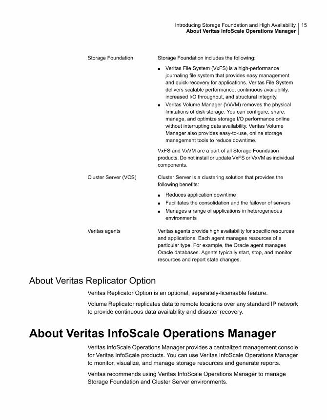
Storage Foundation includes the following:
■ Veritas File System (VxFS) is a high-performancejournaling file system that provides easy managementand quick-recovery for applications. Veritas File Systemdelivers scalable performance, continuous availability,increased I/O throughput, and structural integrity.
■ Veritas Volume Manager (VxVM) removes the physicallimitations of disk storage. You can configure, share,manage, and optimize storage I/O performance onlinewithout interrupting data availability. Veritas VolumeManager also provides easy-to-use, online storagemanagement tools to reduce downtime.
VxFS and VxVM are a part of all Storage Foundationproducts. Do not install or update VxFS or VxVM as individualcomponents.
Storage Foundation
Cluster Server is a clustering solution that provides thefollowing benefits:
■ Reduces application downtime■ Facilitates the consolidation and the failover of servers■ Manages a range of applications in heterogeneous
environments
Cluster Server (VCS)
Veritas agents provide high availability for specific resourcesand applications. Each agent manages resources of aparticular type. For example, the Oracle agent managesOracle databases. Agents typically start, stop, and monitorresources and report state changes.
Veritas agents
About Veritas Replicator OptionVeritas Replicator Option is an optional, separately-licensable feature.
Volume Replicator replicates data to remote locations over any standard IP networkto provide continuous data availability and disaster recovery.
About Veritas InfoScale Operations ManagerVeritas InfoScale Operations Manager provides a centralized management consolefor Veritas InfoScale products. You can use Veritas InfoScale Operations Managerto monitor, visualize, and manage storage resources and generate reports.
Veritas recommends using Veritas InfoScale Operations Manager to manageStorage Foundation and Cluster Server environments.
15Introducing Storage Foundation and High AvailabilityAbout Veritas InfoScale Operations Manager

You can download Veritas InfoScale Operations Manager fromhttps://sort.veritas.com/.
Refer to the Veritas InfoScale Operations Manager documentation for installation,upgrade, and configuration instructions.
The Veritas Enterprise Administrator (VEA) console is no longer packaged withVeritas InfoScale products. If you want to continue using VEA, a software versionis available for download fromhttps://www.veritas.com/product/storage-management/infoscale-operations-manager.Storage Foundation Management Server is deprecated.
If you want to manage a single cluster using Cluster Manager (Java Console), aversion is available for download fromhttps://www.veritas.com/product/storage-management/infoscale-operations-manager.You cannot manage the new features of this release using the Java Console. ClusterServer Management Console is deprecated.
About Storage Foundation and High Availabilityfeatures
The following section describes different features in the Storage Foundation andHigh Availability product.
About LLT and GABVCS uses two components, LLT and GAB, to share data over private networksamong systems. These components provide the performance and reliability thatVCS requires.
LLT (Low Latency Transport) provides fast kernel-to-kernel communications, andmonitors network connections.
GAB (Group Membership and Atomic Broadcast) provides globally ordered messagethat is required to maintain a synchronized state among the nodes.
About I/O fencingI/O fencing protects the data on shared disks when nodes in a cluster detect achange in the cluster membership that indicates a split-brain condition.
The fencing operation determines the following:
■ The nodes that must retain access to the shared storage
■ The nodes that must be ejected from the cluster
16Introducing Storage Foundation and High AvailabilityAbout Storage Foundation and High Availability features

This decision prevents possible data corruption. The installer installs the I/O fencingdriver, part of VRTSvxfen package, when you install Veritas InfoScale Enterprise.To protect data on shared disks, you must configure I/O fencing after you installVeritas InfoScale Enterprise and configure SFHA.
I/O fencing modes - disk-based and server-based I/O fencing - use coordinationpoints for arbitration in the event of a network partition. Whereas, majority-basedI/O fencing mode does not use coordination points for arbitration. Withmajority-based I/O fencing you may experience loss of high availability in somecases. You can configure disk-based, server-based, or majority-based I/O fencing:
I/O fencing that uses coordinator disks is referredto as disk-based I/O fencing.
Disk-based I/O fencing ensures data integrity in asingle cluster.
Disk-based I/O fencing
I/O fencing that uses at least one CP server systemis referred to as server-based I/O fencing.Server-based fencing can include only CP servers,or a mix of CP servers and coordinator disks.
Server-based I/O fencing ensures data integrity inclusters.
In virtualized environments that do not supportSCSI-3 PR, SFHA supports non-SCSI-3 I/Ofencing.
Server-based I/O fencing
Majority-based I/O fencing mode does not needcoordination points to provide protection againstdata corruption and data consistency in a clusteredenvironment.
Use majority-based I/O fencing when there are noadditional servers and or shared SCSI-3 disks tobe used as coordination points.
Majority-based I/O fencing
See “ About planning to configure I/O fencing” on page 28.
Note: Veritas recommends that you use I/O fencing to protect your cluster againstsplit-brain situations.
See the Cluster Server Administrator's Guide.
17Introducing Storage Foundation and High AvailabilityAbout Storage Foundation and High Availability features
About global clustersGlobal clusters provide the ability to fail over applications between geographicallydistributed clusters when disaster occurs. You must add this license during theinstallation. The installer asks about configuring global clusters.
See the Cluster Server Administrator's Guide.
About Veritas Services andOperations ReadinessTools (SORT)
Veritas Services and Operations Readiness Tools (SORT) is a Web site thatautomates and simplifies some of the most time-consuming administrative tasks.SORT helps you manage your datacenter more efficiently and get the most out ofyour Veritas products.
SORT can help you do the following:
■ List product installation and upgrade requirements, includingoperating system versions, memory, disk space, andarchitecture.
■ Analyze systems to determine if they are ready to install orupgrade Veritas products.
■ Download the latest patches, documentation, and highavailability agents from a central repository.
■ Access up-to-date compatibility lists for hardware, software,databases, and operating systems.
Prepare for your nextinstallation or upgrade
■ Get automatic email notifications about changes to patches,array-specific modules (ASLs/APMs/DDIs/DDLs), and highavailability agents from a central repository.
■ Identify and mitigate system and environmental risks.■ Display descriptions and solutions for hundreds of Veritas error
codes.
Manage risks
■ Find and download patches based on product version andplatform.
■ List installed Veritas products and license keys.■ Tune and optimize your environment.
Improve efficiency
Note: Certain features of SORT are not available for all products. Access to SORTis available at no extra cost.
To access SORT, go to:
18Introducing Storage Foundation and High AvailabilityAbout Veritas Services and Operations Readiness Tools (SORT)
https://sort.veritas.com
About configuring SFHA clusters for data integrityWhen a node fails, SFHA takes corrective action and configures its components toreflect the altered membership. If an actual node failure did not occur and if thesymptoms were identical to those of a failed node, then such corrective action wouldcause a split-brain situation.
Some example scenarios that can cause such split-brain situations are as follows:
■ Broken set of private networksIf a system in a two-node cluster fails, the system stops sending heartbeats overthe private interconnects. The remaining node then takes corrective action. Thefailure of the private interconnects, instead of the actual nodes, presents identicalsymptoms and causes each node to determine its peer has departed. Thissituation typically results in data corruption because both nodes try to take controlof data storage in an uncoordinated manner.
■ System that appears to have a system-hangIf a system is so busy that it appears to stop responding, the other nodes coulddeclare it as dead. This declaration may also occur for the nodes that use thehardware that supports a "break" and "resume" function. When a node dropsto PROM level with a break and subsequently resumes operations, the othernodes may declare the system dead. They can declare it dead even if the systemlater returns and begins write operations.
I/O fencing is a feature that prevents data corruption in the event of a communicationbreakdown in a cluster. SFHA uses I/O fencing to remove the risk that is associatedwith split-brain. I/O fencing allows write access for members of the active cluster.It blocks access to storage from non-members so that even a node that is alive isunable to cause damage.
After you install Veritas InfoScale Enterprise and configure SFHA, you must configureI/O fencing in SFHA to ensure data integrity.
See “ About planning to configure I/O fencing” on page 28.
About I/O fencing for SFHA in virtual machines that do not supportSCSI-3 PR
In a traditional I/O fencing implementation, where the coordination points arecoordination point servers (CP servers) or coordinator disks, Clustered VolumeManager (CVM) and Veritas I/O fencing modules provide SCSI-3 persistentreservation (SCSI-3 PR) based protection on the data disks. This SCSI-3 PR
19Introducing Storage Foundation and High AvailabilityAbout configuring SFHA clusters for data integrity

protection ensures that the I/O operations from the losing node cannot reach a diskthat the surviving sub-cluster has already taken over.
See the Cluster Server Administrator's Guide for more information on how I/Ofencing works.
In virtualized environments that do not support SCSI-3 PR, SFHA attempts toprovide reasonable safety for the data disks. SFHA requires you to configurenon-SCSI-3 I/O fencing in such environments. Non-SCSI-3 fencing either usesserver-based I/O fencing with only CP servers as coordination points ormajority-based I/O fencing, which does not use coordination points, along with someadditional configuration changes to support such environments.
See “Setting up non-SCSI-3 I/O fencing in virtual environments using installer”on page 103.
See “Setting up non-SCSI-3 fencing in virtual environments manually” on page 128.
About I/O fencing componentsThe shared storage for SFHA must support SCSI-3 persistent reservations to enableI/O fencing. SFHA involves two types of shared storage:
■ Data disks—Store shared dataSee “About data disks” on page 20.
■ Coordination points—Act as a global lock during membership changesSee “About coordination points” on page 20.
About data disksData disks are standard disk devices for data storage and are either physical disksor RAID Logical Units (LUNs).
These disks must support SCSI-3 PR and must be part of standard VxVM diskgroups. VxVM is responsible for fencing data disks on a disk group basis. Disksthat are added to a disk group and new paths that are discovered for a device areautomatically fenced.
About coordination pointsCoordination points provide a lock mechanism to determine which nodes get tofence off data drives from other nodes. A node must eject a peer from thecoordination points before it can fence the peer from the data drives. SFHA preventssplit-brain when vxfen races for control of the coordination points and the winnerpartition fences the ejected nodes from accessing the data disks.
20Introducing Storage Foundation and High AvailabilityAbout configuring SFHA clusters for data integrity
Note: Typically, a fencing configuration for a cluster must have three coordinationpoints. Veritas also supports server-based fencing with a single CP server as itsonly coordination point with a caveat that this CP server becomes a single point offailure.
The coordination points can either be disks or servers or both.
■ Coordinator disksDisks that act as coordination points are called coordinator disks. Coordinatordisks are three standard disks or LUNs set aside for I/O fencing during clusterreconfiguration. Coordinator disks do not serve any other storage purpose inthe SFHA configuration.You can configure coordinator disks to use Veritas Volume Manager's DynamicMulti-pathing (DMP) feature. Dynamic Multi-pathing (DMP) allows coordinatordisks to take advantage of the path failover and the dynamic adding and removalcapabilities of DMP. So, you can configure I/O fencing to use DMP devices. I/Ofencing uses SCSI-3 disk policy that is dmp-based on the disk device that youuse.
Note: The dmp disk policy for I/O fencing supports both single and multiplehardware paths from a node to the coordinator disks. If few coordinator diskshave multiple hardware paths and few have a single hardware path, then wesupport only the dmp disk policy. For new installations, Veritas only supportsdmp disk policy for IO fencing even for a single hardware path.
See the Storage Foundation Administrator’s Guide.
■ Coordination point servers
The coordination point server (CP server) is a software solution which runs ona remote system or cluster. CP server provides arbitration functionality byallowing the SFHA cluster nodes to perform the following tasks:
■ Self-register to become a member of an active SFHA cluster (registered withCP server) with access to the data drives
■ Check which other nodes are registered as members of this active SFHAcluster
■ Self-unregister from this active SFHA cluster
■ Forcefully unregister other nodes (preempt) as members of this active SFHAcluster
In short, the CP server functions as another arbitration mechanism that integrateswithin the existing I/O fencing module.
21Introducing Storage Foundation and High AvailabilityAbout configuring SFHA clusters for data integrity
Note: With the CP server, the fencing arbitration logic still remains on the SFHAcluster.
Multiple SFHA clusters running different operating systems can simultaneouslyaccess the CP server. TCP/IP based communication is used between the CPserver and the SFHA clusters.
About preferred fencingThe I/O fencing driver uses coordination points to prevent split-brain in a VCScluster. By default, the fencing driver favors the subcluster with maximum numberof nodes during the race for coordination points. With the preferred fencing feature,you can specify how the fencing driver must determine the surviving subcluster.
You can configure the preferred fencing policy using the cluster-level attributePreferredFencingPolicy for the following:
■ Enable system-based preferred fencing policy to give preference to high capacitysystems.
■ Enable group-based preferred fencing policy to give preference to service groupsfor high priority applications.
■ Enable site-based preferred fencing policy to give preference to sites with higherpriority.
■ Disable preferred fencing policy to use the default node count-based race policy.
See the Cluster Server Administrator's Guide for more details.
See “Enabling or disabling the preferred fencing policy” on page 107.
22Introducing Storage Foundation and High AvailabilityAbout configuring SFHA clusters for data integrity
Configuration of SFHA
■ Chapter 2. Preparing to configure
■ Chapter 3. Preparing to configure SFHA clusters for data integrity
■ Chapter 4. Configuring SFHA
■ Chapter 5. Configuring SFHA clusters for data integrity
■ Chapter 6. Manually configuring SFHA clusters for data integrity
■ Chapter 7. Performing an automated SFHA configuration using response files
■ Chapter 8. Performing an automated I/O fencing configuration using responsefiles
2Section
Preparing to configureThis chapter includes the following topics:
■ I/O fencing requirements
I/O fencing requirementsDepending on whether you plan to configure disk-based fencing or server-basedfencing, make sure that you meet the requirements for coordination points:
■ Coordinator disksSee “Coordinator disk requirements for I/O fencing” on page 24.
■ CP serversSee “CP server requirements” on page 25.
If you have installed Veritas InfoScale Enterprise in a virtual environment that isnot SCSI-3 PR compliant, review the requirements to configure non-SCSI-3 fencing.
See “Non-SCSI-3 I/O fencing requirements” on page 27.
Coordinator disk requirements for I/O fencingMake sure that the I/O fencing coordinator disks meet the following requirements:
■ For disk-based I/O fencing, you must have at least three coordinator disks orthere must be odd number of coordinator disks.
■ The coordinator disks must be DMP devices.
■ Each of the coordinator disks must use a physically separate disk or LUN.Veritas recommends using the smallest possible LUNs for coordinator disks.
■ Each of the coordinator disks should exist on a different disk array, if possible.
■ The coordinator disks must support SCSI-3 persistent reservations.
2Chapter
■ Coordinator devices can be attached over iSCSI protocol but they must be DMPdevices and must support SCSI-3 persistent reservations.
■ Veritas recommends using hardware-based mirroring for coordinator disks.
■ Coordinator disks must not be used to store data or must not be included in diskgroups that store user data.
■ Coordinator disks cannot be the special devices that array vendors use. Forexample, you cannot use EMC gatekeeper devices as coordinator disks.
■ The coordinator disk size must be at least 128 MB.
CP server requirementsSFHA 7.2 clusters (application clusters) support coordination point servers (CPservers) that are hosted on the following VCS and SFHA versions:
■ VCS 6.1 or later single-node cluster
■ SFHA 6.1 or later cluster
Upgrade considerations for CP servers
■ Upgrade VCS or SFHA on CP servers to version 7.2 if the current release versionis prior to version 6.1.
■ You do not need to upgrade CP servers to version 7.2 if the release version is6.1 or later.
■ CP servers on version 6.1 or later support HTTPS-based communication withapplication clusters on version 6.1 or later.
■ CP servers on version 6.1 to 7.0 support IPM-based communication withapplication clusters on versions before 6.1.
■ You need to configure VIPs for HTTPS-based communication if release versionof application clusters is 6.1 or later.
Make sure that you meet the basic hardware requirements for the VCS/SFHA clusterto host the CP server.
See the Veritas InfoScale™ Installation Guide.
Note: While Veritas recommends at least three coordination points for fencing, asingle CP server as coordination point is a supported server-based fencingconfiguration. Such single CP server fencing configuration requires that thecoordination point be a highly available CP server that is hosted on an SFHA cluster.
Make sure you meet the following additional CP server requirements which arecovered in this section before you install and configure CP server:
25Preparing to configureI/O fencing requirements
■ Hardware requirements
■ Operating system requirements
■ Networking requirements (and recommendations)
■ Security requirements
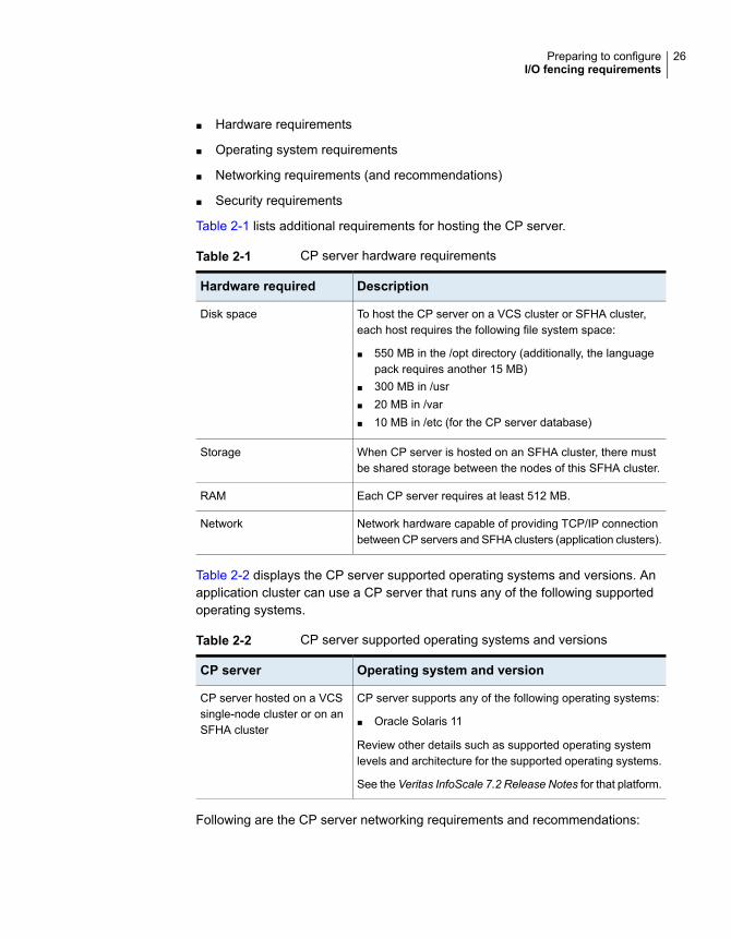
Table 2-1 lists additional requirements for hosting the CP server.
Table 2-1 CP server hardware requirements
DescriptionHardware required
To host the CP server on a VCS cluster or SFHA cluster,each host requires the following file system space:
■ 550 MB in the /opt directory (additionally, the languagepack requires another 15 MB)
■ 300 MB in /usr■ 20 MB in /var■ 10 MB in /etc (for the CP server database)
Disk space
When CP server is hosted on an SFHA cluster, there mustbe shared storage between the nodes of this SFHA cluster.
Storage
Each CP server requires at least 512 MB.RAM
Network hardware capable of providing TCP/IP connectionbetween CP servers and SFHA clusters (application clusters).
Network
Table 2-2 displays the CP server supported operating systems and versions. Anapplication cluster can use a CP server that runs any of the following supportedoperating systems.
Table 2-2 CP server supported operating systems and versions
Operating system and versionCP server
CP server supports any of the following operating systems:
■ Oracle Solaris 11
Review other details such as supported operating systemlevels and architecture for the supported operating systems.
See the Veritas InfoScale 7.2 Release Notes for that platform.
CP server hosted on a VCSsingle-node cluster or on anSFHA cluster
Following are the CP server networking requirements and recommendations:
26Preparing to configureI/O fencing requirements
■ Veritas recommends that network access from the application clusters to theCP servers should be made highly-available and redundant. The networkconnections require either a secure LAN or VPN.
■ The CP server uses the TCP/IP protocol to connect to and communicate withthe application clusters by these network paths. The CP server listens formessages from the application clusters using TCP port 443 if the communicationhappens over the HTTPS protocol. TCP port 443 is the default port that can bechanged while you configure the CP server.Veritas recommends that you configure multiple network paths to access a CPserver. If a network path fails, CP server does not require a restart and continuesto listen on all the other available virtual IP addresses.
■ The CP server only supports Internet Protocol version 4 (IPv4) whencommunicating with the application clusters over the HTTPS protocol.
■ When placing the CP servers within a specific network configuration, you musttake into consideration the number of hops from the different application clusternodes to the CP servers. As a best practice, Veritas recommends that thenumber of hops and network latency from the different application cluster nodesto the CP servers should be equal. This ensures that if an event occurs thatresults in an I/O fencing scenario, there is no bias in the race due to differencein number of hops or network latency between the CPS and various nodes.
For communication between the SFHA cluster (application cluster) and CP server,review the following support matrix:
For information about establishing secure communications between the applicationcluster and CP server, see the Cluster Server Administrator's Guide.
Non-SCSI-3 I/O fencing requirementsSupported virtual environment for non-SCSI-3 fencing:
■ Refer to Supported Solaris operating systems section in Veritas InfoScaleRelease Notes.
■ Refer to Supported Oracle VM Server for SPARC section in Veritas InfoScaleRelease Notes
Make sure that you also meet the following requirements to configure fencing inthe virtual environments that do not support SCSI-3 PR:
■ SFHA must be configured with Cluster attribute UseFence set to SCSI3
■ For server-based I/O fencing, all coordination points must be CP servers
27Preparing to configureI/O fencing requirements

Preparing to configureSFHA clusters for dataintegrity
This chapter includes the following topics:
■ About planning to configure I/O fencing
■ Setting up the CP server
About planning to configure I/O fencingAfter you configure SFHA with the installer, you must configure I/O fencing in thecluster for data integrity. Application clusters on release version 7.2 (HTTPS-basedcommunication) only support CP servers on release version 6.1 and later.
You can configure disk-based I/O fencing, server-based I/O fencing, ormajority-based I/O fencing. If your enterprise setup has multiple clusters that useVCS for clustering, Veritas recommends you to configure server-based I/O fencing.
The coordination points in server-based fencing can include only CP servers or amix of CP servers and coordinator disks.
Veritas also supports server-based fencing with a single coordination point whichis a single highly available CP server that is hosted on an SFHA cluster.
3Chapter
Warning: For server-based fencing configurations that use a single coordinationpoint (CP server), the coordination point becomes a single point of failure. In suchconfigurations, the arbitration facility is not available during a failover of the CPserver in the SFHA cluster. So, if a network partition occurs on any applicationcluster during the CP server failover, the application cluster is brought down. Veritasrecommends the use of single CP server-based fencing only in test environments.
You use majority fencing mechanism if you do not want to use coordination pointsto protect your cluster. Veritas recommends that you configure I/O fencing in majoritymode if you have a smaller cluster environment and you do not want to investadditional disks or servers for the purposes of configuring fencing.
Note: Majority-based I/O fencing is not as robust as server-based or disk-basedI/O fencing in terms of high availability. With majority-based fencing mode, in rarecases, the cluster might become unavailable.
If you have installed SFHA in a virtual environment that is not SCSI-3 PR compliant,you can configure non-SCSI-3 fencing.
See Figure 3-2 on page 31.
Figure 3-1 illustrates a high-level flowchart to configure I/O fencing for the SFHAcluster.
29Preparing to configure SFHA clusters for data integrityAbout planning to configure I/O fencing

Figure 3-1 Workflow to configure I/O fencing
Initialize disks as VxVM disks
Check disks for I/O fencingcompliance
Manually configure disk-based I/Ofencing
Preparatory tasksvxdiskadm or vxdisksetup utilities
vxfenadm and vxfentsthdw utilities
Configuredisk-basedfencing (scsi3mode)
Configureserver-based fencing(customized mode)
Configuration tasksUse one of the following methods
Edit the values in the response fileyou created and use them withinstaller -responsefile command
Install and configure VCS or SFHA on CP serversystems
Establish TCP/IP connection between CP server andSFHA cluster
Edit the values in the response file you created anduse them with installer -responsefile command
Manually configure server-based I/O fencing
Preparatory tasksIdentify an existing CP server
Configuration tasksUse one of the following methods
Run the installer -fencing, choose option 1, andfollow the prompts
If the CP server is clustered, set up shared storagefor the CP server
Run -configcps and follow the prompts (or) Manuallyconfigure CP server
Coordinationpoints for I/O
fencing?
Threedisks
At least one CPserver
Initialize disks as VxVM disks andCheck disks for I/O fencing compliance
For the disks that will serve as coordination points
Install and configure SFHA
Run the installer -fencing, chooseoption 2, and follow the prompts
(OR)Set up a CP server
Establish TCP/IP connection between CP server andSFHA cluster
or
or
or
orRun the installer -fencing, chooseoption 3, and follow the prompts
Configuration tasksNo coordination points
Figure 3-2 illustrates a high-level flowchart to configure non-SCSI-3 I/O fencing forthe SFHA cluster in virtual environments that do not support SCSI-3 PR.
30Preparing to configure SFHA clusters for data integrityAbout planning to configure I/O fencing
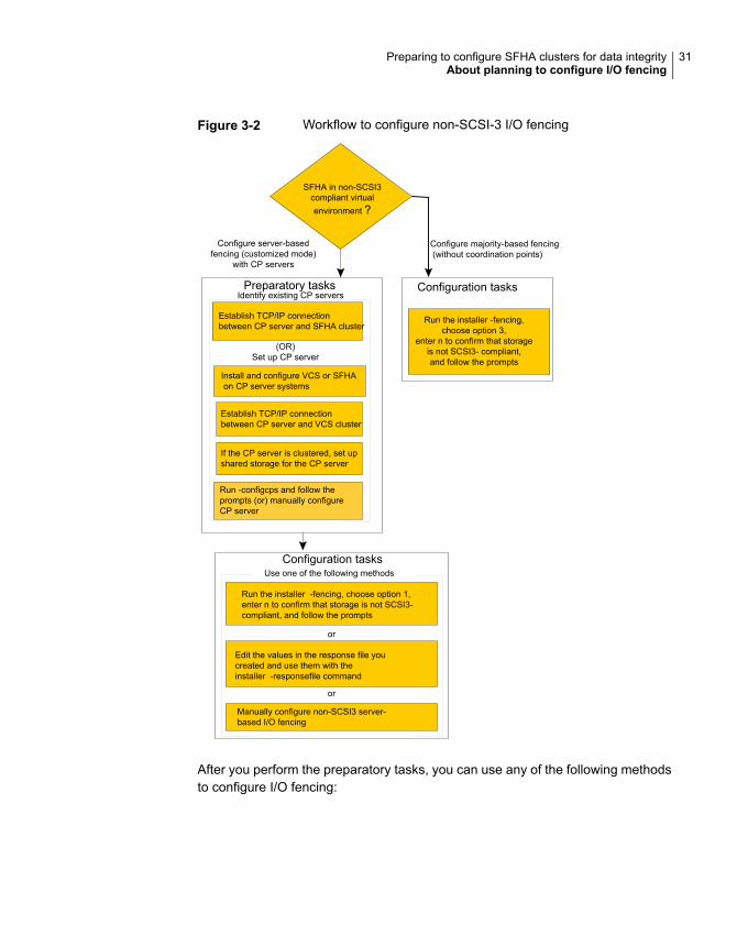
Figure 3-2 Workflow to configure non-SCSI-3 I/O fencing
Install and configure VCS or SFHAon CP server systems
Establish TCP/IP connectionbetween CP server and VCS cluster
Preparatory tasksIdentify existing CP servers
Configuration tasksUse one of the following methods
If the CP server is clustered, set upshared storage for the CP server
SFHA in non-SCSI3compliant virtualenvironment ?
(OR)Set up CP server
Establish TCP/IP connectionbetween CP server and SFHA cluster
or
or
Configuration tasks
Configure majority-based fencing(without coordination points)
Run the installer -fencing, choose option 1,enter n to confirm that storage is not SCSI3-compliant, and follow the prompts
Run the installer -fencing,choose option 3,
enter n to confirm that storageis not SCSI3- compliant,and follow the prompts
Edit the values in the response file youcreated and use them with theinstaller -responsefile command
Manually configure non-SCSI3 server-based I/O fencing
Configure server-basedfencing (customized mode)
with CP servers
Run -configcps and follow theprompts (or) manually configureCP server
After you perform the preparatory tasks, you can use any of the following methodsto configure I/O fencing:
31Preparing to configure SFHA clusters for data integrityAbout planning to configure I/O fencing
See “Setting up disk-based I/O fencing using installer” on page 81.
See “Setting up server-based I/O fencing using installer” on page 90.
See “Setting up non-SCSI-3 I/O fencing in virtual environments usinginstaller” on page 103.
See “Setting up majority-based I/O fencing using installer” on page 105.
Using the installer
See “Response file variables to configure disk-based I/O fencing”on page 151.
See “Response file variables to configure server-based I/O fencing”on page 155.
See “Response file variables to configure non-SCSI-3 I/O fencing”on page 158.
See “Response file variables to configure majority-based I/O fencing”on page 160.
See “Configuring I/O fencing using response files” on page 150.
Using response files
See “Setting up disk-based I/O fencing manually” on page 110.
See “Setting up server-based I/O fencing manually” on page 115.
See “Setting up non-SCSI-3 fencing in virtual environments manually”on page 128.
See “Setting up majority-based I/O fencing manually ” on page 134.
Manually editing configuration files
You can also migrate from one I/O fencing configuration to another.
See the Storage foundation High Availability Administrator's Guide for more details.
Typical SFHA cluster configuration with server-based I/O fencingFigure 3-3 displays a configuration using a SFHA cluster (with two nodes), a singleCP server, and two coordinator disks. The nodes within the SFHA cluster areconnected to and communicate with each other using LLT links.
32Preparing to configure SFHA clusters for data integrityAbout planning to configure I/O fencing
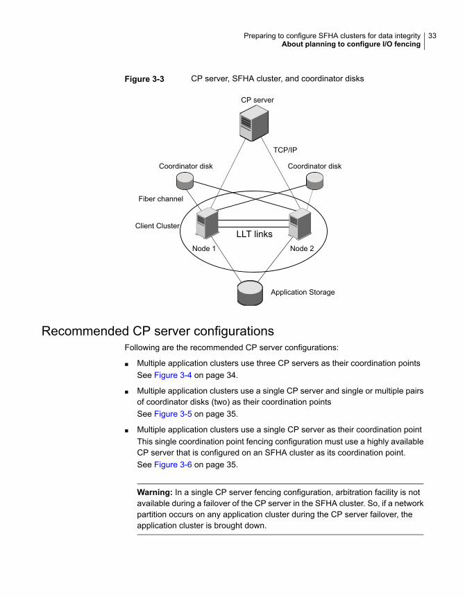
Figure 3-3 CP server, SFHA cluster, and coordinator disks
Coordinator disk Coordinator disk
CP server
Client Cluster
Node 1 Node 2
Application Storage
LLT links
TCP/IP
Fiber channel
Recommended CP server configurationsFollowing are the recommended CP server configurations:
■ Multiple application clusters use three CP servers as their coordination pointsSee Figure 3-4 on page 34.
■ Multiple application clusters use a single CP server and single or multiple pairsof coordinator disks (two) as their coordination pointsSee Figure 3-5 on page 35.
■ Multiple application clusters use a single CP server as their coordination pointThis single coordination point fencing configuration must use a highly availableCP server that is configured on an SFHA cluster as its coordination point.See Figure 3-6 on page 35.
Warning: In a single CP server fencing configuration, arbitration facility is notavailable during a failover of the CP server in the SFHA cluster. So, if a networkpartition occurs on any application cluster during the CP server failover, theapplication cluster is brought down.
33Preparing to configure SFHA clusters for data integrityAbout planning to configure I/O fencing
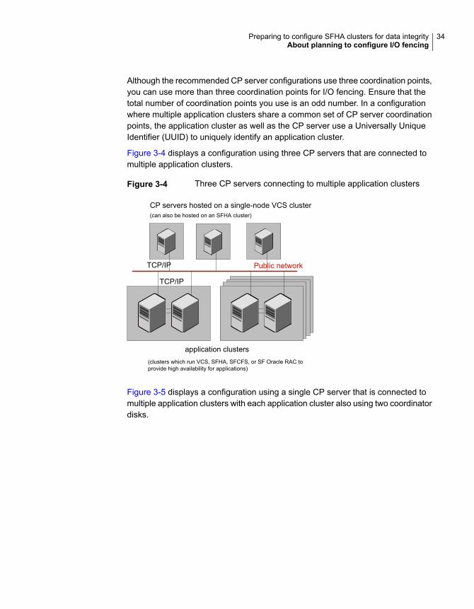
Although the recommended CP server configurations use three coordination points,you can use more than three coordination points for I/O fencing. Ensure that thetotal number of coordination points you use is an odd number. In a configurationwhere multiple application clusters share a common set of CP server coordinationpoints, the application cluster as well as the CP server use a Universally UniqueIdentifier (UUID) to uniquely identify an application cluster.
Figure 3-4 displays a configuration using three CP servers that are connected tomultiple application clusters.
Figure 3-4 Three CP servers connecting to multiple application clusters
Public networkTCP/IP
TCP/IP
CP servers hosted on a single-node VCS cluster(can also be hosted on an SFHA cluster)
application clusters(clusters which run VCS, SFHA, SFCFS, or SF Oracle RAC toprovide high availability for applications)
Figure 3-5 displays a configuration using a single CP server that is connected tomultiple application clusters with each application cluster also using two coordinatordisks.
34Preparing to configure SFHA clusters for data integrityAbout planning to configure I/O fencing
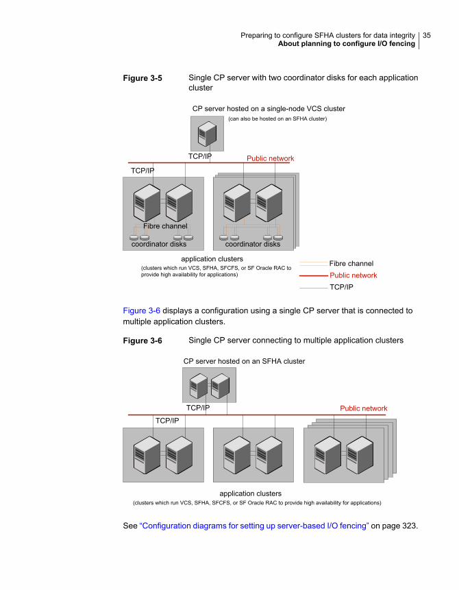
Figure 3-5 Single CP server with two coordinator disks for each applicationcluster
CP server hosted on a single-node VCS cluster
Public network
TCP/IP
TCP/IP
Fibre channelPublic networkTCP/IP
application clusters(clusters which run VCS, SFHA, SFCFS, or SF Oracle RAC toprovide high availability for applications)
Fibre channel
coordinator diskscoordinator disks
(can also be hosted on an SFHA cluster)
Figure 3-6 displays a configuration using a single CP server that is connected tomultiple application clusters.
Figure 3-6 Single CP server connecting to multiple application clusters
Public networkTCP/IP
TCP/IP
CP server hosted on an SFHA cluster
application clusters(clusters which run VCS, SFHA, SFCFS, or SF Oracle RAC to provide high availability for applications)
See “Configuration diagrams for setting up server-based I/O fencing” on page 323.
35Preparing to configure SFHA clusters for data integrityAbout planning to configure I/O fencing
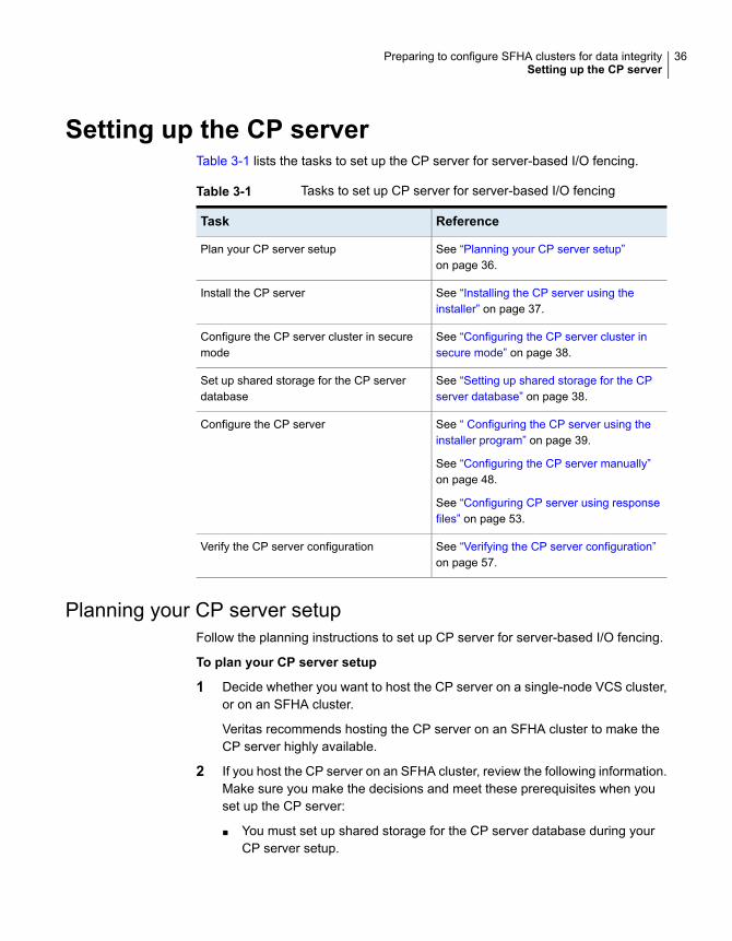
Setting up the CP serverTable 3-1 lists the tasks to set up the CP server for server-based I/O fencing.
Table 3-1 Tasks to set up CP server for server-based I/O fencing
ReferenceTask
See “Planning your CP server setup”on page 36.
Plan your CP server setup
See “Installing the CP server using theinstaller” on page 37.
Install the CP server
See “Configuring the CP server cluster insecure mode” on page 38.
Configure the CP server cluster in securemode
See “Setting up shared storage for the CPserver database” on page 38.
Set up shared storage for the CP serverdatabase
See “ Configuring the CP server using theinstaller program” on page 39.
See “Configuring the CP server manually”on page 48.
See “Configuring CP server using responsefiles” on page 53.
Configure the CP server
See “Verifying the CP server configuration”on page 57.
Verify the CP server configuration
Planning your CP server setupFollow the planning instructions to set up CP server for server-based I/O fencing.
To plan your CP server setup
1 Decide whether you want to host the CP server on a single-node VCS cluster,or on an SFHA cluster.
Veritas recommends hosting the CP server on an SFHA cluster to make theCP server highly available.
2 If you host the CP server on an SFHA cluster, review the following information.Make sure you make the decisions and meet these prerequisites when youset up the CP server:
■ You must set up shared storage for the CP server database during yourCP server setup.
36Preparing to configure SFHA clusters for data integritySetting up the CP server
■ Decide whether you want to configure server-based fencing for the SFHAcluster (application cluster) with a single CP server as coordination pointor with at least three coordination points.Veritas recommends using at least three coordination points.
3 Set up the hardware and network for your CP server.
See “CP server requirements” on page 25.
4 Have the following information handy for CP server configuration:
■ Name for the CP serverThe CP server name should not contain any special characters. CP servername can include alphanumeric characters, underscore, and hyphen.
■ Port number for the CP serverAllocate a TCP/IP port for use by the CP server.Valid port range is between 49152 and 65535. The default port number forHTTPS-based communication is 443.
■ Virtual IP address, network interface, netmask, and networkhosts for theCP serverYou can configure multiple virtual IP addresses for the CP server.
Installing the CP server using the installerPerform the following procedure to install Veritas InfoScale Enterprise and configureVCS or SFHA on CP server systems.
37Preparing to configure SFHA clusters for data integritySetting up the CP server
To install Veritas InfoScale Enterprise and configure VCS or SFHA on the CPserver systems
◆ Depending on whether your CP server uses a single system or multiple systems,perform the following tasks:
Install Veritas InfoScale Enterprise or Veritas InfoScale Availability and configure VCS tocreate a single-node VCS cluster.
See the Veritas InfoScale Installation Guide for instructions on CP server installation.
See the Cluster Server Configuration and Upgrade Guide for configuring VCS.
Proceed to configure the CP server.
See “ Configuring the CP server using the installer program” on page 39.
See “Configuring the CP server manually” on page 48.
CP server setup uses asingle system
Install Veritas InfoScale Enterprise and configure SFHA to create an SFHA cluster. Thismakes the CP server highly available.
Proceed to set up shared storage for the CP server database.
CP server setup usesmultiple systems
Configuring the CP server cluster in secure modeYou must configure security on the CP server only if you want IPM-based (VeritasProduct Authentication Service) secure communication between the CP server andthe SFHA cluster (CP server clients). However, IPM-based communication enablesthe CP server to support application clusters prior to release 6.1.
This step secures the HAD communication on the CP server cluster.
Note: If you already configured the CP server cluster in secure mode during theVCS configuration, then skip this section.
To configure the CP server cluster in secure mode
◆ Run the installer as follows to configure the CP server cluster in secure mode.
# /opt/VRTS/install/installer -security
Setting up shared storage for the CP server databaseIf you configured SFHA on the CP server cluster, perform the following procedureto set up shared storage for the CP server database.
38Preparing to configure SFHA clusters for data integritySetting up the CP server
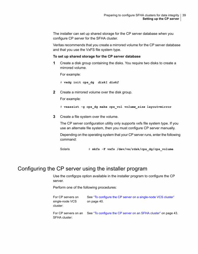
The installer can set up shared storage for the CP server database when youconfigure CP server for the SFHA cluster.
Veritas recommends that you create a mirrored volume for the CP server databaseand that you use the VxFS file system type.
To set up shared storage for the CP server database
1 Create a disk group containing the disks. You require two disks to create amirrored volume.
For example:
# vxdg init cps_dg disk1 disk2
2 Create a mirrored volume over the disk group.
For example:
# vxassist -g cps_dg make cps_vol volume_size layout=mirror
3 Create a file system over the volume.
The CP server configuration utility only supports vxfs file system type. If youuse an alternate file system, then you must configure CP server manually.
Depending on the operating system that your CP server runs, enter the followingcommand:
# mkfs -F vxfs /dev/vx/rdsk/cps_dg/cps_volumeSolaris
Configuring the CP server using the installer programUse the configcps option available in the installer program to configure the CPserver.
Perform one of the following procedures:
See “To configure the CP server on a single-node VCS cluster”on page 40.
For CP servers onsingle-node VCScluster:
See “To configure the CP server on an SFHA cluster” on page 43.For CP servers on anSFHA cluster:
39Preparing to configure SFHA clusters for data integritySetting up the CP server
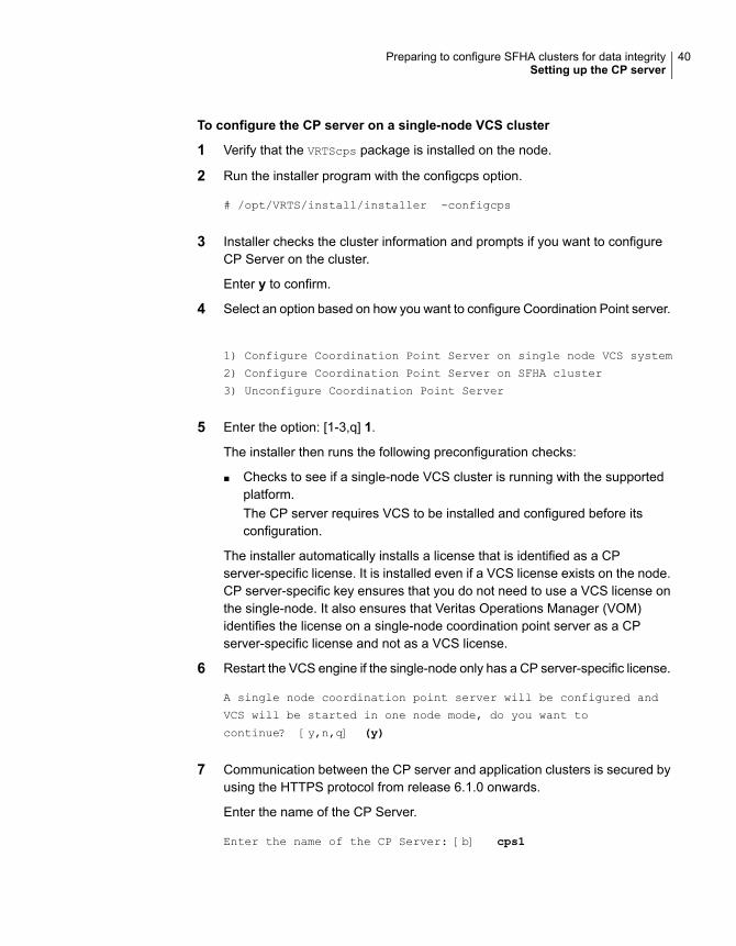
To configure the CP server on a single-node VCS cluster
1 Verify that the VRTScps package is installed on the node.
2 Run the installer program with the configcps option.
# /opt/VRTS/install/installer -configcps
3 Installer checks the cluster information and prompts if you want to configureCP Server on the cluster.
Enter y to confirm.
4 Select an option based on how you want to configure Coordination Point server.
1) Configure Coordination Point Server on single node VCS system
2) Configure Coordination Point Server on SFHA cluster
3) Unconfigure Coordination Point Server
5 Enter the option: [1-3,q] 1.
The installer then runs the following preconfiguration checks:
■ Checks to see if a single-node VCS cluster is running with the supportedplatform.The CP server requires VCS to be installed and configured before itsconfiguration.
The installer automatically installs a license that is identified as a CPserver-specific license. It is installed even if a VCS license exists on the node.CP server-specific key ensures that you do not need to use a VCS license onthe single-node. It also ensures that Veritas Operations Manager (VOM)identifies the license on a single-node coordination point server as a CPserver-specific license and not as a VCS license.
6 Restart the VCS engine if the single-node only has a CP server-specific license.
A single node coordination point server will be configured and
VCS will be started in one node mode, do you want to
continue? [y,n,q] (y)
7 Communication between the CP server and application clusters is secured byusing the HTTPS protocol from release 6.1.0 onwards.
Enter the name of the CP Server.
Enter the name of the CP Server: [b] cps1
40Preparing to configure SFHA clusters for data integritySetting up the CP server
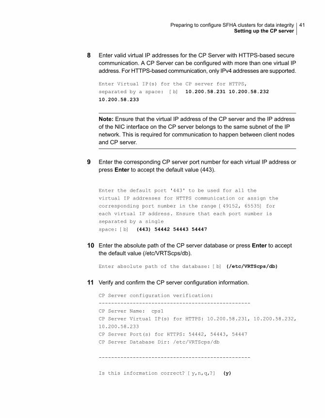
8 Enter valid virtual IP addresses for the CP Server with HTTPS-based securecommunication. A CP Server can be configured with more than one virtual IPaddress. For HTTPS-based communication, only IPv4 addresses are supported.
Enter Virtual IP(s) for the CP server for HTTPS,
separated by a space: [b] 10.200.58.231 10.200.58.232
10.200.58.233
Note: Ensure that the virtual IP address of the CP server and the IP addressof the NIC interface on the CP server belongs to the same subnet of the IPnetwork. This is required for communication to happen between client nodesand CP server.
9 Enter the corresponding CP server port number for each virtual IP address orpress Enter to accept the default value (443).
Enter the default port '443' to be used for all the
virtual IP addresses for HTTPS communication or assign the
corresponding port number in the range [49152, 65535] for
each virtual IP address. Ensure that each port number is
separated by a single
space: [b] (443) 54442 54443 54447
10 Enter the absolute path of the CP server database or press Enter to acceptthe default value (/etc/VRTScps/db).
Enter absolute path of the database: [b] (/etc/VRTScps/db)
11 Verify and confirm the CP server configuration information.
CP Server configuration verification:
-------------------------------------------------
CP Server Name: cps1
CP Server Virtual IP(s) for HTTPS: 10.200.58.231, 10.200.58.232,
10.200.58.233
CP Server Port(s) for HTTPS: 54442, 54443, 54447
CP Server Database Dir: /etc/VRTScps/db
-------------------------------------------------
Is this information correct? [y,n,q,?] (y)
41Preparing to configure SFHA clusters for data integritySetting up the CP server
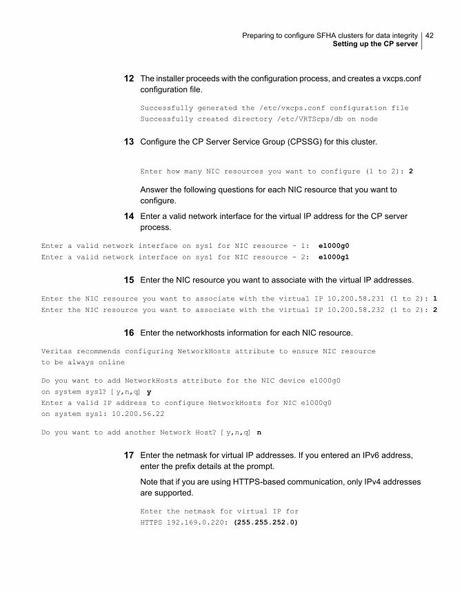
12 The installer proceeds with the configuration process, and creates a vxcps.confconfiguration file.
Successfully generated the /etc/vxcps.conf configuration file
Successfully created directory /etc/VRTScps/db on node
13 Configure the CP Server Service Group (CPSSG) for this cluster.
Enter how many NIC resources you want to configure (1 to 2): 2
Answer the following questions for each NIC resource that you want toconfigure.
14 Enter a valid network interface for the virtual IP address for the CP serverprocess.
Enter a valid network interface on sys1 for NIC resource - 1: e1000g0
Enter a valid network interface on sys1 for NIC resource - 2: e1000g1
15 Enter the NIC resource you want to associate with the virtual IP addresses.
Enter the NIC resource you want to associate with the virtual IP 10.200.58.231 (1 to 2): 1
Enter the NIC resource you want to associate with the virtual IP 10.200.58.232 (1 to 2): 2
16 Enter the networkhosts information for each NIC resource.
Veritas recommends configuring NetworkHosts attribute to ensure NIC resource
to be always online
Do you want to add NetworkHosts attribute for the NIC device e1000g0
on system sys1? [y,n,q] y
Enter a valid IP address to configure NetworkHosts for NIC e1000g0
on system sys1: 10.200.56.22
Do you want to add another Network Host? [y,n,q] n
17 Enter the netmask for virtual IP addresses. If you entered an IPv6 address,enter the prefix details at the prompt.
Note that if you are using HTTPS-based communication, only IPv4 addressesare supported.
Enter the netmask for virtual IP for
HTTPS 192.169.0.220: (255.255.252.0)
42Preparing to configure SFHA clusters for data integritySetting up the CP server

18 Installer displays the status of the Coordination Point Server configuration.After the configuration process has completed, a success message appears.
For example:
Updating main.cf with CPSSG service group.. Done
Successfully added the CPSSG service group to VCS configuration.
Trying to bring CPSSG service group
ONLINE and will wait for upto 120 seconds
The Veritas coordination point server is ONLINE
The Veritas coordination point server has
been configured on your system.
19 Run the hagrp -state command to ensure that the CPSSG service grouphas been added.
For example:
# hagrp -state CPSSG
#Group Attribute System Value
CPSSG State.... |ONLINE|
It also generates the configuration file for CP server (/etc/vxcps.conf). Thevxcpserv process and other resources are added to the VCS configuration inthe CP server service group (CPSSG).
For information about the CPSSG, refer to the Cluster Server Administrator's Guide.
To configure the CP server on an SFHA cluster
1 Verify that the VRTScps package is installed on each node.
2 Ensure that you have configured passwordless ssh or rsh on the CP servercluster nodes.
3 Run the installer program with the configcps option.
# ./installer -configcps
4 Specify the systems on which you need to configure the CP server.
5 Installer checks the cluster information and prompts if you want to configureCP Server on the cluster.
Enter y to confirm.
43Preparing to configure SFHA clusters for data integritySetting up the CP server

6 Select an option based on how you want to configure Coordination Point server.
1) Configure Coordination Point Server on single node VCS system
2) Configure Coordination Point Server on SFHA cluster
3) Unconfigure Coordination Point Server
7 Enter 2 at the prompt to configure CP server on an SFHA cluster.
The installer then runs the following preconfiguration checks:
■ Checks to see if an SFHA cluster is running with the supported platform.The CP server requires SFHA to be installed and configured before itsconfiguration.
8 Communication between the CP server and application clusters is secured byHTTPS from Release 6.1.0 onwards.
Enter the name of the CP server.
Enter the name of the CP Server: [b] cps1
9 Enter valid virtual IP addresses for the CP Server. A CP Server can beconfigured with more than one virtual IP address. For HTTPS-basedcommunication, only IPv4 addresses are supported.
Enter Virtual IP(s) for the CP server for HTTPS,
separated by a space: [b] 10.200.58.231 10.200.58.232 10.200.58.233
10 Enter the corresponding CP server port number for each virtual IP address orpress Enter to accept the default value (443).
Enter the default port '443' to be used for all the virtual IP addresses
for HTTPS communication or assign the corresponding port number in the range [49152,
65535] for each virtual IP address. Ensure that each port number is separated by
a single space: [b] (443) 65535 65534 65537
11 Enter absolute path of the database.
CP Server uses an internal database to store the client information.
As the CP Server is being configured on SFHA cluster, the database should reside
on shared storage with vxfs file system. Please refer to documentation for
information on setting up of shared storage for CP server database.
Enter absolute path of the database: [b] /cpsdb
44Preparing to configure SFHA clusters for data integritySetting up the CP server
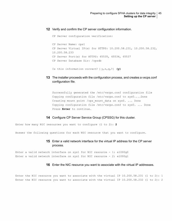
12 Verify and confirm the CP server configuration information.
CP Server configuration verification:
CP Server Name: cps1
CP Server Virtual IP(s) for HTTPS: 10.200.58.231, 10.200.58.232,
10.200.58.233
CP Server Port(s) for HTTPS: 65535, 65534, 65537
CP Server Database Dir: /cpsdb
Is this information correct? [y,n,q,?] (y)
13 The installer proceeds with the configuration process, and creates a vxcps.confconfiguration file.
Successfully generated the /etc/vxcps.conf configuration file
Copying configuration file /etc/vxcps.conf to sys0....Done
Creating mount point /cps_mount_data on sys0. ... Done
Copying configuration file /etc/vxcps.conf to sys0. ... Done
Press Enter to continue.
14 Configure CP Server Service Group (CPSSG) for this cluster.
Enter how many NIC resources you want to configure (1 to 2): 2
Answer the following questions for each NIC resource that you want to configure.
15 Enter a valid network interface for the virtual IP address for the CP serverprocess.
Enter a valid network interface on sys1 for NIC resource - 1: e1000g0
Enter a valid network interface on sys1 for NIC resource - 2: e1000g1
16 Enter the NIC resource you want to associate with the virtual IP addresses.
Enter the NIC resource you want to associate with the virtual IP 10.200.58.231 (1 to 2): 1
Enter the NIC resource you want to associate with the virtual IP 10.200.58.232 (1 to 2): 2
45Preparing to configure SFHA clusters for data integritySetting up the CP server
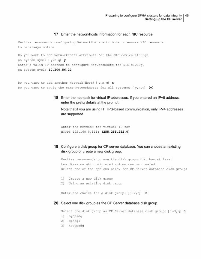
17 Enter the networkhosts information for each NIC resource.
Veritas recommends configuring NetworkHosts attribute to ensure NIC resource
to be always online
Do you want to add NetworkHosts attribute for the NIC device e1000g0
on system sys1? [y,n,q] y
Enter a valid IP address to configure NetworkHosts for NIC e1000g0
on system sys1: 10.200.56.22
Do you want to add another Network Host? [y,n,q] n
Do you want to apply the same NetworkHosts for all systems? [y,n,q] (y)
18 Enter the netmask for virtual IP addresses. If you entered an IPv6 address,enter the prefix details at the prompt.
Note that if you are using HTTPS-based communication, only IPv4 addressesare supported.
Enter the netmask for virtual IP for
HTTPS 192.168.0.111: (255.255.252.0)
19 Configure a disk group for CP server database. You can choose an existingdisk group or create a new disk group.
Veritas recommends to use the disk group that has at least
two disks on which mirrored volume can be created.
Select one of the options below for CP Server database disk group:
1) Create a new disk group
2) Using an existing disk group
Enter the choice for a disk group: [1-2,q] 2
20 Select one disk group as the CP Server database disk group.
Select one disk group as CP Server database disk group: [1-3,q] 3
1) mycpsdg
2) cpsdg1
3) newcpsdg
46Preparing to configure SFHA clusters for data integritySetting up the CP server
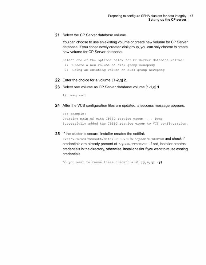
21 Select the CP Server database volume.
You can choose to use an existing volume or create new volume for CP Serverdatabase. If you chose newly created disk group, you can only choose to createnew volume for CP Server database.
Select one of the options below for CP Server database volume:
1) Create a new volume on disk group newcpsdg
2) Using an existing volume on disk group newcpsdg
22 Enter the choice for a volume: [1-2,q] 2.
23 Select one volume as CP Server database volume [1-1,q] 1
1) newcpsvol
24 After the VCS configuration files are updated, a success message appears.
For example:
Updating main.cf with CPSSG service group .... Done
Successfully added the CPSSG service group to VCS configuration.
25 If the cluster is secure, installer creates the softlink/var/VRTSvcs/vcsauth/data/CPSERVER to /cpsdb/CPSERVER and check ifcredentials are already present at /cpsdb/CPSERVER. If not, installer createscredentials in the directory, otherwise, installer asks if you want to reuse exstingcredentials.
Do you want to reuse these credentials? [y,n,q] (y)
47Preparing to configure SFHA clusters for data integritySetting up the CP server

26 After the configuration process has completed, a success message appears.
For example:
Trying to bring CPSSG service group ONLINE and will wait for upto 120 seconds
The Veritas Coordination Point Server is ONLINE
The Veritas Coordination Point Server has been configured on your system.
27 Run the hagrp -state command to ensure that the CPSSG service grouphas been added.
For example:
# hagrp -state CPSSG
#Group Attribute System Value
CPSSG State cps1 |ONLINE|
CPSSG State cps2 |OFFLINE|
It also generates the configuration file for CP server (/etc/vxcps.conf). Thevxcpserv process and other resources are added to the VCS configuration inthe CP server service group (CPSSG).
For information about the CPSSG, refer to the Cluster Server Administrator's Guide.
Configuring the CP server manuallyPerform the following steps to manually configure the CP server.
You need to manually generate certificates for the CP server and its client nodesto configure the CP server for HTTPS-based communication.
Table 3-2 Tasks to configure the CP server manually
ReferenceTask
See “Configuring the CP server manually for HTTPS-basedcommunication” on page 49.
See “Generating the key and certificates manually for the CPserver” on page 49.
See “Completing the CP server configuration” on page 53.
Configure CP servermanually forHTTPS-communication
48Preparing to configure SFHA clusters for data integritySetting up the CP server
Configuring the CP server manually for HTTPS-basedcommunicationPerform the following steps to manually configure the CP server in HTTPS-basedmode.
To manually configure the CP server
1 Stop VCS on each node in the CP server cluster using the following command:
# hastop -local
2 Edit the main.cf file to add the CPSSG service group on any node. Use theCPSSG service group in the sample main.cf as an example:
See “Sample configuration files for CP server” on page 304.
Customize the resources under the CPSSG service group as per yourconfiguration.
3 Verify the main.cf file using the following command:
# hacf -verify /etc/VRTSvcs/conf/config
If successfully verified, copy this main.cf to all other cluster nodes.
4 Create the /etc/vxcps.conf file using the sample configuration file providedat /etc/vxcps/vxcps.conf.sample.
Veritas recommends enabling security for communication between CP serverand the application clusters.
If you configured the CP server in HTTPS mode, do the following:
■ Edit the /etc/vxcps.conf file to set vip_https with the virtual IP addressesrequired for HTTPS communication.
■ Edit the /etc/vxcps.conf file to set port_https with the ports used forHTTPS communication.
5 Manually generate keys and certificates for the CP server.
See “Generating the key and certificates manually for the CP server”on page 49.
Generating the key and certificates manually for the CPserverCP server uses the HTTPS protocol to establish secure communication with clientnodes. HTTPS is a secure means of communication, which happens over a securecommunication channel that is established using the SSL/TLS protocol.
49Preparing to configure SFHA clusters for data integritySetting up the CP server
HTTPS uses x509 standard certificates and the constructs from a Public KeyInfrastructure (PKI) to establish secure communication between the CP server andclient. Similar to a PKI, the CP server, and its clients have their own set of certificatessigned by a Certification Authority (CA). The server and its clients trust the certificate.
Every CP server acts as a certification authority for itself and for all its client nodes.The CP server has its own CA key and CA certificate and a server certificategenerated, which is generated from a server private key. The server certificate isissued to the Universally Unique Identifier (UUID) of the CP server. All the IPaddresses or domain names that the CP server listens on are mentioned in theSubject Alternative Name section of the CP server’s server certificate
The OpenSSL library must be installed on the CP server to create the keys orcertificates.. If OpenSSL is not installed, then you cannot create keys or certificates.The vxcps.conf file points to the configuration file that determines which keys orcertificates are used by the CP server when SSL is initialized. The configurationvalue is stored in the ssl_conf_file and the default value is/etc/vxcps_ssl.properties.
To manually generate keys and certificates for the CP server:
1 Create directories for the security files on the CP server.
# mkdir -p /var/VRTScps/security/keys /var/VRTScps/security/certs
2 Generate an OpenSSL config file, which includes the VIPs.
The CP server listens to requests from client nodes on these VIPs. The servercertificate includes VIPs, FQDNs, and host name of the CP server. Clients canreach the CP server by using any of these values. However, Veritasrecommends that client nodes use the IP address to communicate to the CPserver.
The sample configuration uses the following values:
■ Config file name: https_ssl_cert.conf
■ VIP: 192.168.1.201
■ FQDN: cpsone.company.com
■ Host name: cpsone
Note the IP address, VIP, and FQDN values used in the [alt_names] sectionof the configuration file are sample values. Replace the sample values withyour configuration values. Do not change the rest of the values in theconfiguration file.
[req]
distinguished_name = req_distinguished_name
50Preparing to configure SFHA clusters for data integritySetting up the CP server

req_extensions = v3_req
[req_distinguished_name]
countryName = Country Name (2 letter code)
countryName_default = US
localityName = Locality Name (eg, city)
organizationalUnitName = Organizational Unit Name (eg, section)
commonName = Common Name (eg, YOUR name)
commonName_max = 64
emailAddress = Email Address
emailAddress_max = 40
[v3_req]
keyUsage = keyEncipherment, dataEncipherment
extendedKeyUsage = serverAuth
subjectAltName = @alt_names
[alt_names]
DNS.1 = cpsone.company.com
DNS.2 = cpsone
DNS.3 = 192.168.1.201
3 Generate a 4096-bit CA key that is used to create the CA certificate.
The key must be stored at /var/VRTScps/security/keys/ca.key. Ensurethat only root users can access the CA key, as the key can be misused tocreate fake certificates and compromise security.
# /usr/bin/openssl genrsa -out /var/VRTScps/security/keys/ca.key
4096
4 Generate a self-signed CA certificate.
# /usr/bin/openssl req -new -x509 -days days -sha256 -key
/var/VRTScps/security/keys/ca.key -subj \
'/C=countryname/L=localityname/OU=COMPANY/CN=CACERT' -out \
/var/VRTScps/security/certs/ca.crt
Where, days is the days you want the certificate to remain valid, countrynameis the name of the country, localityname is the city, CACERT is the certificatename.
51Preparing to configure SFHA clusters for data integritySetting up the CP server
5 Generate a 2048-bit private key for CP server.
The key must be stored at /var/VRTScps/security/keys/server_privatekey.
# /usr/bin/openssl genrsa -out \
/var/VRTScps/security/keys/server_private.key 2048
6 Generate a Certificate Signing Request (CSR) for the server certificate.
The Certified Name (CN) in the certificate is the UUID of the CP server.
# /usr/bin/openssl req -new -sha256 -key
/var/VRTScps/security/keys/server_private.key \
-config https_ssl_cert.conf -subj \
'/C=CountryName/L=LocalityName/OU=COMPANY/CN=UUID' \
-out /var/VRTScps/security/certs/server.csr
Where, countryname is the name of the country, localityname is the city, UUIDis the certificate name.
7 Generate the server certificate by using the key certificate of the CA.
# /usr/bin/openssl x509 -req -days days -sha256 -in
/var/VRTScps/security/certs/server.csr \
-CA /var/VRTScps/security/certs/ca.crt -CAkey \
/var/VRTScps/security/keys/ca.key \
-set_serial 01 -extensions v3_req -extfile https_ssl_cert.conf \
-out /var/VRTScps/security/certs/server.crt
Where, days is the days you want the certificate to remain valid,https_ssl_cert.conf is the configuration file name.
You successfully created the key and certificate required for the CP server.
8 Ensure that no other user except the root user can read the keys andcertificates.
9 Complete the CP server configuration.
See “Completing the CP server configuration” on page 53.
52Preparing to configure SFHA clusters for data integritySetting up the CP server
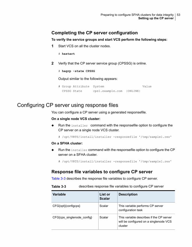
Completing the CP server configurationTo verify the service groups and start VCS perform the following steps:
1 Start VCS on all the cluster nodes.
# hastart
2 Verify that the CP server service group (CPSSG) is online.
# hagrp -state CPSSG
Output similar to the following appears:
# Group Attribute System Value
CPSSG State cps1.example.com |ONLINE|
Configuring CP server using response filesYou can configure a CP server using a generated responsefile.
On a single node VCS cluster:
◆ Run the installer command with the responsefile option to configure theCP server on a single node VCS cluster.
# /opt/VRTS/install/installer -responsefile '/tmp/sample1.res'
On a SFHA cluster:
◆ Run the installer command with the responsefile option to configure the CPserver on a SFHA cluster.
# /opt/VRTS/install/installer -responsefile '/tmp/sample1.res'
Response file variables to configure CP serverTable 3-3 describes the response file variables to configure CP server.
Table 3-3 describes response file variables to configure CP server
DescriptionList orScalar
Variable
This variable performs CP serverconfiguration task
ScalarCFG{opt}{configcps}
This variable describes if the CP serverwill be configured on a singlenode VCScluster
ScalarCFG{cps_singlenode_config}
53Preparing to configure SFHA clusters for data integritySetting up the CP server
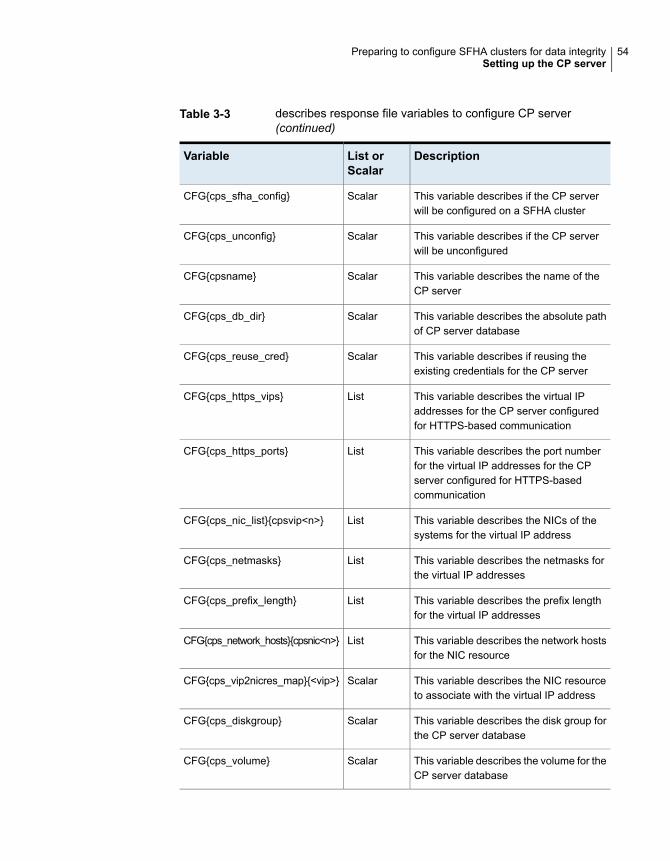
Table 3-3 describes response file variables to configure CP server(continued)
DescriptionList orScalar
Variable
This variable describes if the CP serverwill be configured on a SFHA cluster
ScalarCFG{cps_sfha_config}
This variable describes if the CP serverwill be unconfigured
ScalarCFG{cps_unconfig}
This variable describes the name of theCP server
ScalarCFG{cpsname}
This variable describes the absolute pathof CP server database
ScalarCFG{cps_db_dir}
This variable describes if reusing theexisting credentials for the CP server
ScalarCFG{cps_reuse_cred}
This variable describes the virtual IPaddresses for the CP server configuredfor HTTPS-based communication
ListCFG{cps_https_vips}
This variable describes the port numberfor the virtual IP addresses for the CPserver configured for HTTPS-basedcommunication
ListCFG{cps_https_ports}
This variable describes the NICs of thesystems for the virtual IP address
ListCFG{cps_nic_list}{cpsvip<n>}
This variable describes the netmasks forthe virtual IP addresses
ListCFG{cps_netmasks}
This variable describes the prefix lengthfor the virtual IP addresses
ListCFG{cps_prefix_length}
This variable describes the network hostsfor the NIC resource
ListCFG{cps_network_hosts}{cpsnic<n>}
This variable describes the NIC resourceto associate with the virtual IP address
ScalarCFG{cps_vip2nicres_map}{<vip>}
This variable describes the disk group forthe CP server database
ScalarCFG{cps_diskgroup}
This variable describes the volume for theCP server database
ScalarCFG{cps_volume}
54Preparing to configure SFHA clusters for data integritySetting up the CP server
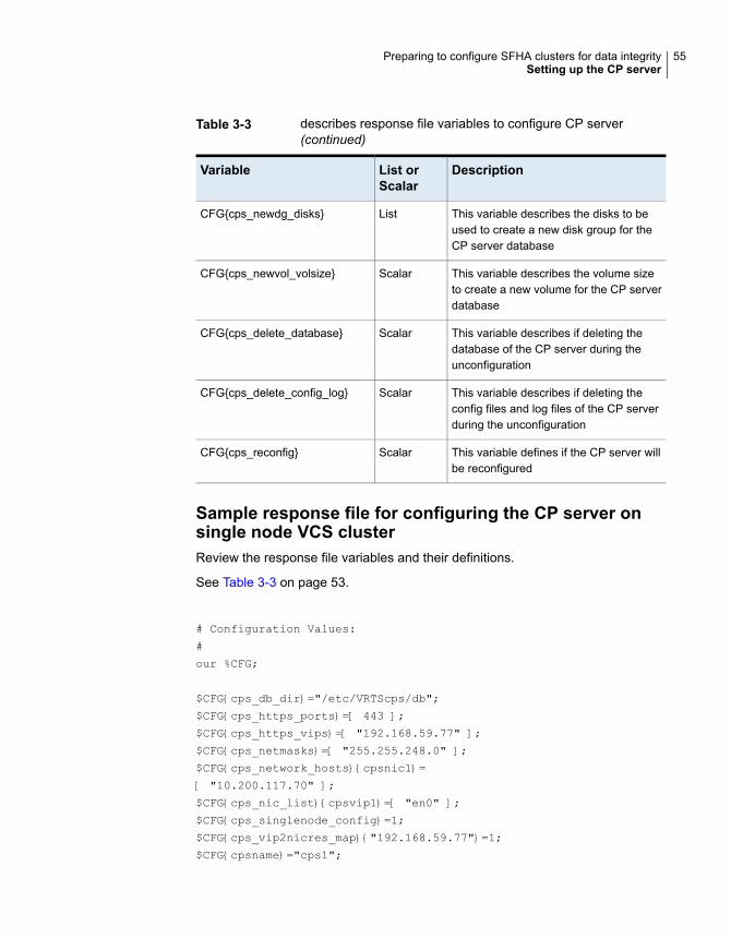
Table 3-3 describes response file variables to configure CP server(continued)
DescriptionList orScalar
Variable
This variable describes the disks to beused to create a new disk group for theCP server database
ListCFG{cps_newdg_disks}
This variable describes the volume sizeto create a new volume for the CP serverdatabase
ScalarCFG{cps_newvol_volsize}
This variable describes if deleting thedatabase of the CP server during theunconfiguration
ScalarCFG{cps_delete_database}
This variable describes if deleting theconfig files and log files of the CP serverduring the unconfiguration
ScalarCFG{cps_delete_config_log}
This variable defines if the CP server willbe reconfigured
ScalarCFG{cps_reconfig}
Sample response file for configuring the CP server onsingle node VCS clusterReview the response file variables and their definitions.
See Table 3-3 on page 53.
# Configuration Values:
#
our %CFG;
$CFG{cps_db_dir}="/etc/VRTScps/db";
$CFG{cps_https_ports}=[ 443 ];
$CFG{cps_https_vips}=[ "192.168.59.77" ];
$CFG{cps_netmasks}=[ "255.255.248.0" ];
$CFG{cps_network_hosts}{cpsnic1}=
[ "10.200.117.70" ];
$CFG{cps_nic_list}{cpsvip1}=[ "en0" ];
$CFG{cps_singlenode_config}=1;
$CFG{cps_vip2nicres_map}{"192.168.59.77"}=1;
$CFG{cpsname}="cps1";
55Preparing to configure SFHA clusters for data integritySetting up the CP server
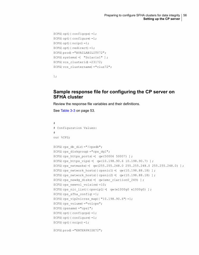
$CFG{opt}{configcps}=1;
$CFG{opt}{configure}=1;
$CFG{opt}{noipc}=1;
$CFG{opt}{redirect}=1;
$CFG{prod}="AVAILABILITY72";
$CFG{systems}=[ "Solaris1" ];
$CFG{vcs_clusterid}=23172;
$CFG{vcs_clustername}="clus72";
1;
Sample response file for configuring the CP server onSFHA clusterReview the response file variables and their definitions.
See Table 3-3 on page 53.
#
# Configuration Values:
#
our %CFG;
$CFG{cps_db_dir}="/cpsdb";
$CFG{cps_diskgroup}="cps_dg1";
$CFG{cps_https_ports}=[ qw(50006 50007) ];
$CFG{cps_https_vips}=[ qw(10.198.90.6 10.198.90.7) ];
$CFG{cps_netmasks}=[ qw(255.255.248.0 255.255.248.0 255.255.248.0) ];
$CFG{cps_network_hosts}{cpsnic1}=[ qw(10.198.88.18) ];
$CFG{cps_network_hosts}{cpsnic2}=[ qw(10.198.88.18) ];
$CFG{cps_newdg_disks}=[ qw(emc_clariion0_249) ];
$CFG{cps_newvol_volsize}=10;
$CFG{cps_nic_list}{cpsvip1}=[ qw(e1000g0 e1000g0) ];
$CFG{cps_sfha_config}=1;
$CFG{cps_vip2nicres_map}{"10.198.90.6"}=1;
$CFG{cps_volume}="volcps";
$CFG{cpsname}="cps1";
$CFG{opt}{configcps}=1;
$CFG{opt}{configure}=1;
$CFG{opt}{noipc}=1;
$CFG{prod}="ENTERPRISE72";
56Preparing to configure SFHA clusters for data integritySetting up the CP server

$CFG{activecomponent}=[qw(SFHA72)];
$CFG{systems}=[ qw(cps1 cps2) ];
$CFG{vcs_clusterid}=49604;
$CFG{vcs_clustername}="sfha2233";
1;
Verifying the CP server configurationPerform the following steps to verify the CP server configuration.
To verify the CP server configuration
1 Verify that the following configuration files are updated with the informationyou provided during the CP server configuration process:
■ /etc/vxcps.conf (CP server configuration file)
■ /etc/VRTSvcs/conf/config/main.cf (VCS configuration file)
■ /etc/VRTScps/db (default location for CP server database for a single-nodecluster)
■ /cps_db (default location for CP server database for a multi-node cluster)
2 Run the cpsadm command to check if the vxcpserv process is listening on theconfigured Virtual IP.
If the application cluster is configured for HTTPS-based communication, noneed to provide the port number assigned for HTTP communication.
# cpsadm -s cp_server -a ping_cps
where cp_server is the virtual IP address or the virtual hostname of the CPserver.
57Preparing to configure SFHA clusters for data integritySetting up the CP server
Configuring SFHAThis chapter includes the following topics:
■ Configuring Storage Foundation High Availability using the installer
■ Configuring SFDB
Configuring Storage Foundation High Availabilityusing the installer
Storage Foundation HA configuration requires configuring the HA (VCS) cluster.Perform the following tasks to configure the cluster.
Overview of tasks to configure SFHA using the product installerTable 4-1 lists the tasks that are involved in configuring SFHA using the script-basedinstaller.
Table 4-1 Tasks to configure SFHA using the script-based installer
ReferenceTask
See “Starting the software configuration”on page 60.
Start the software configuration
See “Specifying systems for configuration”on page 60.
Specify the systems where you want toconfigure SFHA
See “Configuring the cluster name”on page 61.
See “Configuring private heartbeat links”on page 61.
Configure the basic cluster
4Chapter

Table 4-1 Tasks to configure SFHA using the script-based installer(continued)
ReferenceTask
See “Configuring the virtual IP of the cluster”on page 66.
Configure virtual IP address of the cluster(optional)
See “Configuring SFHA in secure mode”on page 67.
Configure the cluster in secure mode(optional)
See “Adding VCS users” on page 72.Add VCS users (required if you did notconfigure the cluster in secure mode)
See “Configuring SMTP email notification”on page 73.
Configure SMTP email notification (optional)
See “Configuring SNMP trap notification”on page 74.
Configure SNMP email notification (optional)
See “Configuring global clusters” on page 76.Configure global clusters (optional)
See “Completing the SFHA configuration”on page 76.
Complete the software configuration
Required information for configuring Storage Foundation and HighAvailability Solutions
To configure Storage Foundation High Availability, the following information isrequired:
See also the Cluster Server Installation Guide.
■ A unique Cluster name
■ A unique Cluster ID number between 0-65535
■ Two or more NIC cards per system used for heartbeat linksOne or more heartbeat links are configured as private links and one heartbeatlink may be configured as a low priority link.
You can configure Storage Foundation High Availability in secure mode.
Running SFHA in Secure Mode guarantees that all inter-system communication isencrypted and that users are verified with security credentials. When running inSecure Mode, NIS and system usernames and passwords are used to verify identity.SFHA usernames and passwords are no longer used when a cluster is running inSecure Mode.
The following information is required to configure SMTP notification:
59Configuring SFHAConfiguring Storage Foundation High Availability using the installer
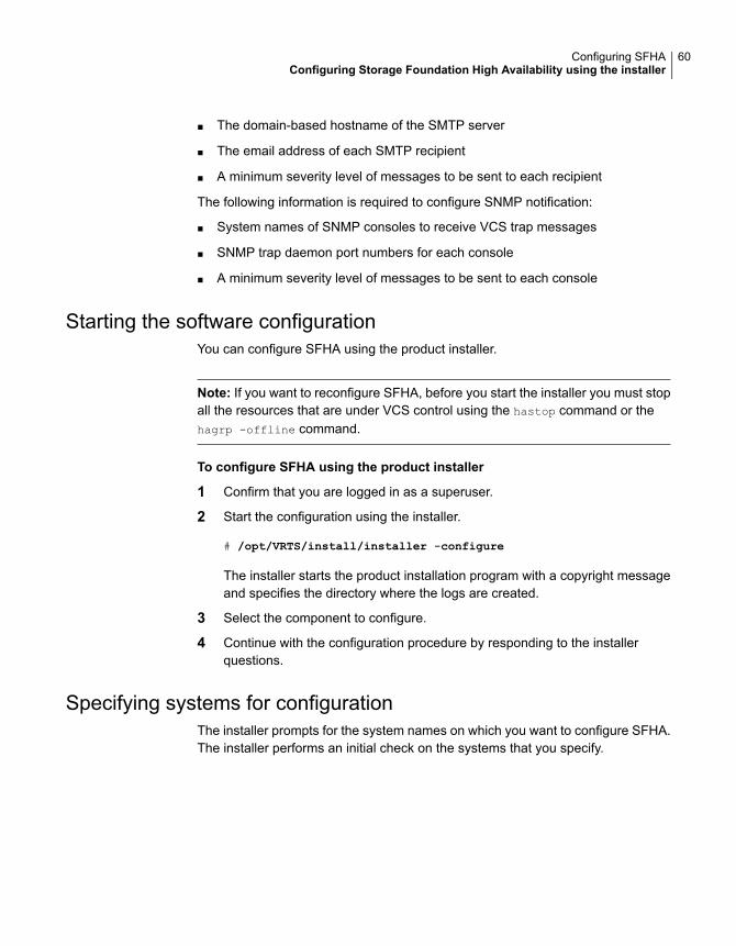
■ The domain-based hostname of the SMTP server
■ The email address of each SMTP recipient
■ A minimum severity level of messages to be sent to each recipient
The following information is required to configure SNMP notification:
■ System names of SNMP consoles to receive VCS trap messages
■ SNMP trap daemon port numbers for each console
■ A minimum severity level of messages to be sent to each console
Starting the software configurationYou can configure SFHA using the product installer.
Note: If you want to reconfigure SFHA, before you start the installer you must stopall the resources that are under VCS control using the hastop command or thehagrp -offline command.
To configure SFHA using the product installer
1 Confirm that you are logged in as a superuser.
2 Start the configuration using the installer.
# /opt/VRTS/install/installer -configure
The installer starts the product installation program with a copyright messageand specifies the directory where the logs are created.
3 Select the component to configure.
4 Continue with the configuration procedure by responding to the installerquestions.
Specifying systems for configurationThe installer prompts for the system names on which you want to configure SFHA.The installer performs an initial check on the systems that you specify.
60Configuring SFHAConfiguring Storage Foundation High Availability using the installer
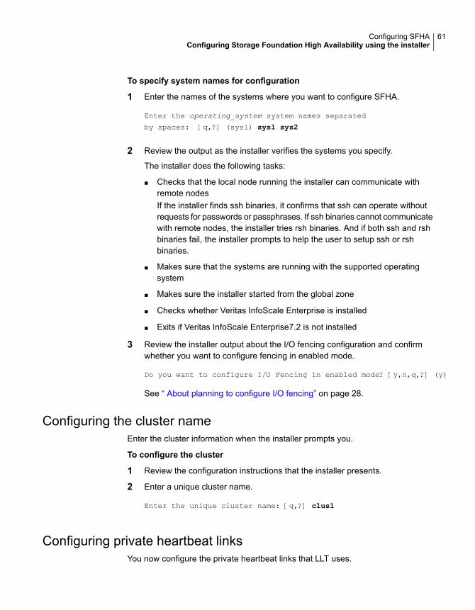
To specify system names for configuration
1 Enter the names of the systems where you want to configure SFHA.
Enter the operating_system system names separated
by spaces: [q,?] (sys1) sys1 sys2
2 Review the output as the installer verifies the systems you specify.
The installer does the following tasks:
■ Checks that the local node running the installer can communicate withremote nodesIf the installer finds ssh binaries, it confirms that ssh can operate withoutrequests for passwords or passphrases. If ssh binaries cannot communicatewith remote nodes, the installer tries rsh binaries. And if both ssh and rshbinaries fail, the installer prompts to help the user to setup ssh or rshbinaries.
■ Makes sure that the systems are running with the supported operatingsystem
■ Makes sure the installer started from the global zone
■ Checks whether Veritas InfoScale Enterprise is installed
■ Exits if Veritas InfoScale Enterprise7.2 is not installed
3 Review the installer output about the I/O fencing configuration and confirmwhether you want to configure fencing in enabled mode.
Do you want to configure I/O Fencing in enabled mode? [y,n,q,?] (y)
See “ About planning to configure I/O fencing” on page 28.
Configuring the cluster nameEnter the cluster information when the installer prompts you.
To configure the cluster
1 Review the configuration instructions that the installer presents.
2 Enter a unique cluster name.
Enter the unique cluster name: [q,?] clus1
Configuring private heartbeat linksYou now configure the private heartbeat links that LLT uses.
61Configuring SFHAConfiguring Storage Foundation High Availability using the installer
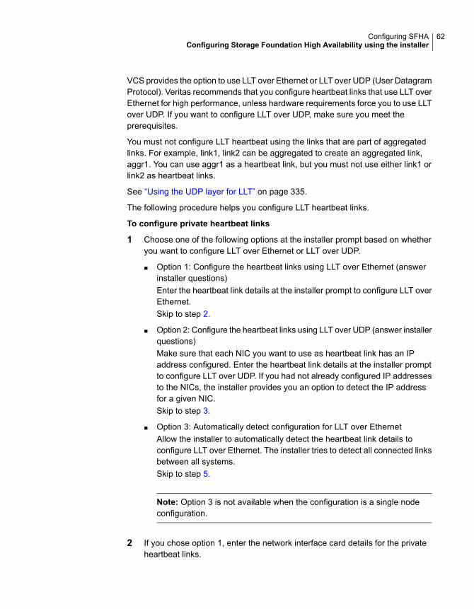
VCS provides the option to use LLT over Ethernet or LLT over UDP (User DatagramProtocol). Veritas recommends that you configure heartbeat links that use LLT overEthernet for high performance, unless hardware requirements force you to use LLTover UDP. If you want to configure LLT over UDP, make sure you meet theprerequisites.
You must not configure LLT heartbeat using the links that are part of aggregatedlinks. For example, link1, link2 can be aggregated to create an aggregated link,aggr1. You can use aggr1 as a heartbeat link, but you must not use either link1 orlink2 as heartbeat links.
See “Using the UDP layer for LLT” on page 335.
The following procedure helps you configure LLT heartbeat links.
To configure private heartbeat links
1 Choose one of the following options at the installer prompt based on whetheryou want to configure LLT over Ethernet or LLT over UDP.
■ Option 1: Configure the heartbeat links using LLT over Ethernet (answerinstaller questions)Enter the heartbeat link details at the installer prompt to configure LLT overEthernet.Skip to step 2.
■ Option 2: Configure the heartbeat links using LLT over UDP (answer installerquestions)Make sure that each NIC you want to use as heartbeat link has an IPaddress configured. Enter the heartbeat link details at the installer promptto configure LLT over UDP. If you had not already configured IP addressesto the NICs, the installer provides you an option to detect the IP addressfor a given NIC.Skip to step 3.
■ Option 3: Automatically detect configuration for LLT over EthernetAllow the installer to automatically detect the heartbeat link details toconfigure LLT over Ethernet. The installer tries to detect all connected linksbetween all systems.Skip to step 5.
Note: Option 3 is not available when the configuration is a single nodeconfiguration.
2 If you chose option 1, enter the network interface card details for the privateheartbeat links.
62Configuring SFHAConfiguring Storage Foundation High Availability using the installer
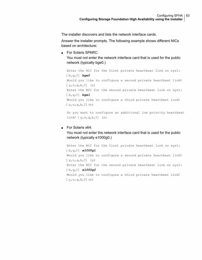
The installer discovers and lists the network interface cards.
Answer the installer prompts. The following example shows different NICsbased on architecture:
■ For Solaris SPARC:You must not enter the network interface card that is used for the publicnetwork (typically bge0.)
Enter the NIC for the first private heartbeat link on sys1:
[b,q,?] bge0
Would you like to configure a second private heartbeat link?
[y,n,q,b,?] (y)
Enter the NIC for the second private heartbeat link on sys1:
[b,q,?] bge1
Would you like to configure a third private heartbeat link?
[y,n,q,b,?](n)
Do you want to configure an additional low priority heartbeat
link? [y,n,q,b,?] (n)
■ For Solaris x64:You must not enter the network interface card that is used for the publicnetwork (typically e1000g0.)
Enter the NIC for the first private heartbeat link on sys1:
[b,q,?] e1000g1
Would you like to configure a second private heartbeat link?
[y,n,q,b,?] (y)
Enter the NIC for the second private heartbeat link on sys1:
[b,q,?] e1000g2
Would you like to configure a third private heartbeat link?
[y,n,q,b,?](n)
63Configuring SFHAConfiguring Storage Foundation High Availability using the installer

3 If you chose option 2, enter the NIC details for the private heartbeat links. Thisstep uses examples such as private_NIC1 or private_NIC2 to refer to theavailable names of the NICs.
Enter the NIC for the first private heartbeat link on sys1: [b,q,?]
private_NIC1
Some configured IP addresses have been found on
the NIC private_NIC1 in sys1,
Do you want to choose one for the first private heartbeat link? [y,n,q,?] (y)
Please select one IP address:
1) 192.168.0.1/24
2) 192.168.1.233/24
b) Back to previous menu
Please select one IP address: [1-2,b,q,?] (1)
Enter the UDP port for the first private heartbeat link on sys1:
[b,q,?] (50000)
Enter the NIC for the second private heartbeat link on sys1: [b,q,?]
private_NIC2
Some configured IP addresses have been found on the
NIC private_NIC2 in sys1,
Do you want to choose one for the second
private heartbeat link? [y,n,q,?] (y)
Please select one IP address:
1) 192.168.1.1/24
2) 192.168.2.233/24
b) Back to previous menu
Please select one IP address: [1-2,b,q,?] (1) 1
Enter the UDP port for the second private heartbeat link on sys1:
[b,q,?] (50001)
Would you like to configure a third private heartbeat
link? [y,n,q,b,?] (n)
Do you want to configure an additional low-priority heartbeat
link? [y,n,q,b,?] (n) y
Enter the NIC for the low-priority heartbeat link on sys1: [b,q,?]
private_NIC0
Some configured IP addresses have been found on
64Configuring SFHAConfiguring Storage Foundation High Availability using the installer
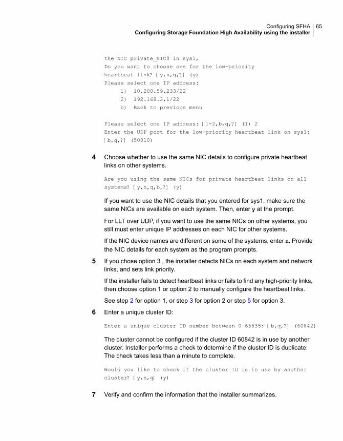
the NIC private_NIC0 in sys1,
Do you want to choose one for the low-priority
heartbeat link? [y,n,q,?] (y)
Please select one IP address:
1) 10.200.59.233/22
2) 192.168.3.1/22
b) Back to previous menu
Please select one IP address: [1-2,b,q,?] (1) 2
Enter the UDP port for the low-priority heartbeat link on sys1:
[b,q,?] (50010)
4 Choose whether to use the same NIC details to configure private heartbeatlinks on other systems.
Are you using the same NICs for private heartbeat links on all
systems? [y,n,q,b,?] (y)
If you want to use the NIC details that you entered for sys1, make sure thesame NICs are available on each system. Then, enter y at the prompt.
For LLT over UDP, if you want to use the same NICs on other systems, youstill must enter unique IP addresses on each NIC for other systems.
If the NIC device names are different on some of the systems, enter n. Providethe NIC details for each system as the program prompts.
5 If you chose option 3 , the installer detects NICs on each system and networklinks, and sets link priority.
If the installer fails to detect heartbeat links or fails to find any high-priority links,then choose option 1 or option 2 to manually configure the heartbeat links.
See step 2 for option 1, or step 3 for option 2 or step 5 for option 3.
6 Enter a unique cluster ID:
Enter a unique cluster ID number between 0-65535: [b,q,?] (60842)
The cluster cannot be configured if the cluster ID 60842 is in use by anothercluster. Installer performs a check to determine if the cluster ID is duplicate.The check takes less than a minute to complete.
Would you like to check if the cluster ID is in use by another
cluster? [y,n,q] (y)
7 Verify and confirm the information that the installer summarizes.
65Configuring SFHAConfiguring Storage Foundation High Availability using the installer
Configuring the virtual IP of the clusterYou can configure the virtual IP of the cluster to use to connect from the ClusterManager (Java Console), Veritas InfoScale Operations Manager, or to specify inthe RemoteGroup resource.
See theCluster Server Administrator's Guide for information on the Cluster Manager.
See the Cluster Server Bundled Agents Reference Guide for information on theRemoteGroup agent.
To configure the virtual IP of the cluster
1 Review the required information to configure the virtual IP of the cluster.
2 When the system prompts whether you want to configure the virtual IP, entery.
3 Confirm whether you want to use the discovered public NIC on the first system.
Do one of the following:
■ If the discovered NIC is the one to use, press Enter.
■ If you want to use a different NIC, type the name of a NIC to use and pressEnter.
Active NIC devices discovered on sys1: bge0
Enter the NIC for Virtual IP of the Cluster to use on sys1:
[b,q,?](bge0)
4 Confirm whether you want to use the same public NIC on all nodes.
Do one of the following:
■ If all nodes use the same public NIC, enter y.
■ If unique NICs are used, enter n and enter a NIC for each node.
Is bge0 to be the public NIC used by all systems
[y,n,q,b,?] (y)
If you want to set up trust relationships for your secure cluster, refer to the followingtopics:
See “Configuring a secure cluster node by node” on page 67.
66Configuring SFHAConfiguring Storage Foundation High Availability using the installer
Configuring SFHA in secure modeConfiguring SFHA in secure mode ensures that all the communication between thesystems is encrypted and users are verified against security credentials. SFHAuser names and passwords are not used when a cluster is running in secure mode.
To configure SFHA in secure mode
1 To install and configure SFHA in secure mode, run the command:
# ./installer -security
2 The installer displays the following question before the installer stops the productprocesses:
■ Do you want to grant read access to everyone? [y,n,q,?]
■ To grant read access to all authenticated users, type y.
■ To grant usergroup specific permissions, type n.
■ Do you want to provide any usergroups that you would like to grant readaccess?[y,n,q,?]
■ To specify usergroups and grant them read access, type y
■ To grant read access only to root users, type n. The installer grants readaccess read access to the root users.
■ Enter the usergroup names separated by spaces that you would like togrant read access. If you would like to grant read access to a usergroup ona specific node, enter like 'usrgrp1@node1', and if you would like to grantread access to usergroup on any cluster node, enter like 'usrgrp1'. If someusergroups are not created yet, create the usergroups after configurationif needed. [b]
3 To verify the cluster is in secure mode after configuration, run the command:
# haclus -value SecureClus
The command returns 1 if cluster is in secure mode, else returns 0.
Configuring a secure cluster node by nodeFor environments that do not support passwordless ssh or passwordless rsh, youcannot use the -security option to enable secure mode for your cluster. Instead,you can use the -securityonenode option to configure a secure cluster node bynode. Moreover, to enable security in fips mode, use the -fips option together with-securityonenode.
67Configuring SFHAConfiguring Storage Foundation High Availability using the installer
Table 4-2 lists the tasks that you must perform to configure a secure cluster.
Table 4-2 Configuring a secure cluster node by node
ReferenceTask
See “Configuring the first node” on page 68.Configure security on one node
See “Configuring the remaining nodes” on page 69.Configure security on theremaining nodes
See “Completing the secure cluster configuration”on page 69.
Complete the manualconfiguration steps
Configuring the first nodePerform the following steps on one node in your cluster.
To configure security on the first node
1 Ensure that you are logged in as superuser.
2 Enter the following command:
# /opt/VRTS/install/installer -securityonenode
The installer lists information about the cluster, nodes, and service groups. IfVCS is not configured or if VCS is not running on all nodes of the cluster, theinstaller prompts whether you want to continue configuring security. It thenprompts you for the node that you want to configure.
VCS is not running on all systems in this cluster. All VCS systems
must be in RUNNING state. Do you want to continue? [y,n,q] (n) y
1) Perform security configuration on first node and export
security configuration files.
2) Perform security configuration on remaining nodes with
security configuration files.
Select the option you would like to perform [1-2,q.?] 1
Warning: All VCS configurations about cluster users are deleted when youconfigure the first node. You can use the /opt/VRTSvcs/bin/hauser commandto create cluster users manually.
68Configuring SFHAConfiguring Storage Foundation High Availability using the installer

3 The installer completes the secure configuration on the node. It specifies thelocation of the security configuration files and prompts you to copy these filesto the other nodes in the cluster. The installer also specifies the location of logfiles, summary file, and response file.
4 Copy the security configuration files from the location specified by the installerto temporary directories on the other nodes in the cluster.
Configuring the remaining nodesOn each of the remaining nodes in the cluster, perform the following steps.
To configure security on each remaining node
1 Ensure that you are logged in as superuser.
2 Enter the following command:
# /opt/VRTS/install/installer -securityonenode
The installer lists information about the cluster, nodes, and service groups. IfVCS is not configured or if VCS is not running on all nodes of the cluster, theinstaller prompts whether you want to continue configuring security. It thenprompts you for the node that you want to configure. Enter 2.
VCS is not running on all systems in this cluster. All VCS systems
must be in RUNNING state. Do you want to continue? [y,n,q] (n) y
1) Perform security configuration on first node and export
security configuration files.
2) Perform security configuration on remaining nodes with
security configuration files.
Select the option you would like to perform [1-2,q.?] 2
Enter the security conf file directory: [b]
The installer completes the secure configuration on the node. It specifies thelocation of log files, summary file, and response file.
Completing the secure cluster configurationPerform the following manual steps to complete the configuration.
69Configuring SFHAConfiguring Storage Foundation High Availability using the installer
To complete the secure cluster configuration
1 On the first node, freeze all service groups except the ClusterService servicegroup.
# /opt/VRTSvcs/bin/haconf -makerw
# /opt/VRTSvcs/bin/hagrp -list Frozen=0
# /opt/VRTSvcs/bin/hagrp -freeze groupname -persistent
# /opt/VRTSvcs/bin/haconf -dump -makero
2 On the first node, stop the VCS engine.
# /opt/VRTSvcs/bin/hastop -all -force
3 On all nodes, stop the CmdServer.
# /opt/VRTSvcs/bin/CmdServer -stop
70Configuring SFHAConfiguring Storage Foundation High Availability using the installer

4 To grant access to all users, add or modify SecureClus=1 andDefaultGuestAccess=1 in the cluster definition.
For example:
To grant read access to everyone:
Cluster clus1 (
SecureClus=1
DefaultGuestAccess=1
)
Or
To grant access to only root:
Cluster clus1 (
SecureClus=1
)
Or
To grant read access to specific user groups, add or modify SecureClus=1 andGuestGroups={} to the cluster definition.
For example:
cluster clus1 (
SecureClus=1
GuestGroups={staff, guest}
5 Modify /etc/VRTSvcs/conf/config/main.cf file on the first node, and add-secure to the WAC application definition if GCO is configured.
For example:
Application wac (
StartProgram = "/opt/VRTSvcs/bin/wacstart -secure"
StopProgram = "/opt/VRTSvcs/bin/wacstop"
MonitorProcesses = {"/opt/VRTSvcs/bin/wac -secure"}
RestartLimit = 3
)
71Configuring SFHAConfiguring Storage Foundation High Availability using the installer
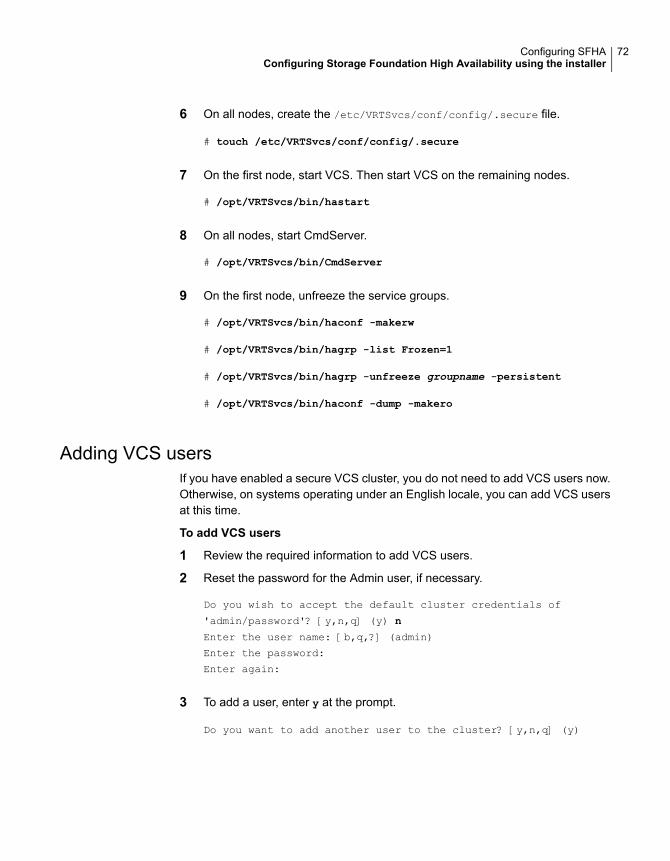
6 On all nodes, create the /etc/VRTSvcs/conf/config/.secure file.
# touch /etc/VRTSvcs/conf/config/.secure
7 On the first node, start VCS. Then start VCS on the remaining nodes.
# /opt/VRTSvcs/bin/hastart
8 On all nodes, start CmdServer.
# /opt/VRTSvcs/bin/CmdServer
9 On the first node, unfreeze the service groups.
# /opt/VRTSvcs/bin/haconf -makerw
# /opt/VRTSvcs/bin/hagrp -list Frozen=1
# /opt/VRTSvcs/bin/hagrp -unfreeze groupname -persistent
# /opt/VRTSvcs/bin/haconf -dump -makero
Adding VCS usersIf you have enabled a secure VCS cluster, you do not need to add VCS users now.Otherwise, on systems operating under an English locale, you can add VCS usersat this time.
To add VCS users
1 Review the required information to add VCS users.
2 Reset the password for the Admin user, if necessary.
Do you wish to accept the default cluster credentials of
'admin/password'? [y,n,q] (y) n
Enter the user name: [b,q,?] (admin)
Enter the password:
Enter again:
3 To add a user, enter y at the prompt.
Do you want to add another user to the cluster? [y,n,q] (y)
72Configuring SFHAConfiguring Storage Foundation High Availability using the installer
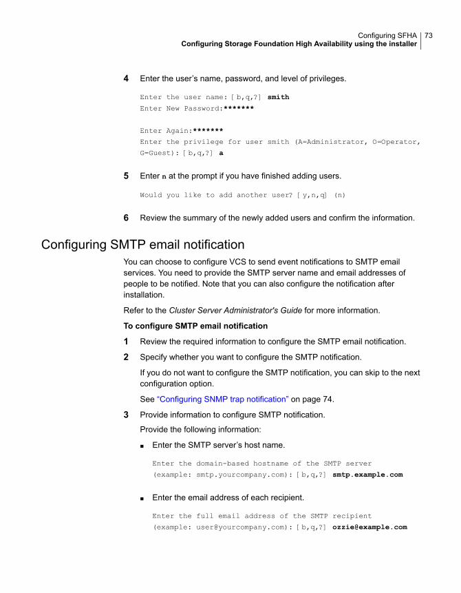
4 Enter the user’s name, password, and level of privileges.
Enter the user name: [b,q,?] smith
Enter New Password:*******
Enter Again:*******
Enter the privilege for user smith (A=Administrator, O=Operator,
G=Guest): [b,q,?] a
5 Enter n at the prompt if you have finished adding users.
Would you like to add another user? [y,n,q] (n)
6 Review the summary of the newly added users and confirm the information.
Configuring SMTP email notificationYou can choose to configure VCS to send event notifications to SMTP emailservices. You need to provide the SMTP server name and email addresses ofpeople to be notified. Note that you can also configure the notification afterinstallation.
Refer to the Cluster Server Administrator's Guide for more information.
To configure SMTP email notification
1 Review the required information to configure the SMTP email notification.
2 Specify whether you want to configure the SMTP notification.
If you do not want to configure the SMTP notification, you can skip to the nextconfiguration option.
See “Configuring SNMP trap notification” on page 74.
3 Provide information to configure SMTP notification.
Provide the following information:
■ Enter the SMTP server’s host name.
Enter the domain-based hostname of the SMTP server
(example: smtp.yourcompany.com): [b,q,?] smtp.example.com
■ Enter the email address of each recipient.
Enter the full email address of the SMTP recipient
(example: [email protected]): [b,q,?] [email protected]
73Configuring SFHAConfiguring Storage Foundation High Availability using the installer

■ Enter the minimum security level of messages to be sent to each recipient.
Enter the minimum severity of events for which mail should be
sent to [email protected] [I=Information, W=Warning,
E=Error, S=SevereError]: [b,q,?] w
4 Add more SMTP recipients, if necessary.
■ If you want to add another SMTP recipient, enter y and provide the requiredinformation at the prompt.
Would you like to add another SMTP recipient? [y,n,q,b] (n) y
Enter the full email address of the SMTP recipient
(example: [email protected]): [b,q,?] [email protected]
Enter the minimum severity of events for which mail should be
sent to [email protected] [I=Information, W=Warning,
E=Error, S=SevereError]: [b,q,?] E
■ If you do not want to add, answer n.
Would you like to add another SMTP recipient? [y,n,q,b] (n)
5 Verify and confirm the SMTP notification information.
SMTP Address: smtp.example.com
Recipient: [email protected] receives email for Warning or
higher events
Recipient: [email protected] receives email for Error or
higher events
Is this information correct? [y,n,q] (y)
Configuring SNMP trap notificationYou can choose to configure VCS to send event notifications to SNMP managementconsoles. You need to provide the SNMP management console name to be notifiedand message severity levels.
Note that you can also configure the notification after installation.
Refer to the Cluster Server Administrator's Guide for more information.
74Configuring SFHAConfiguring Storage Foundation High Availability using the installer
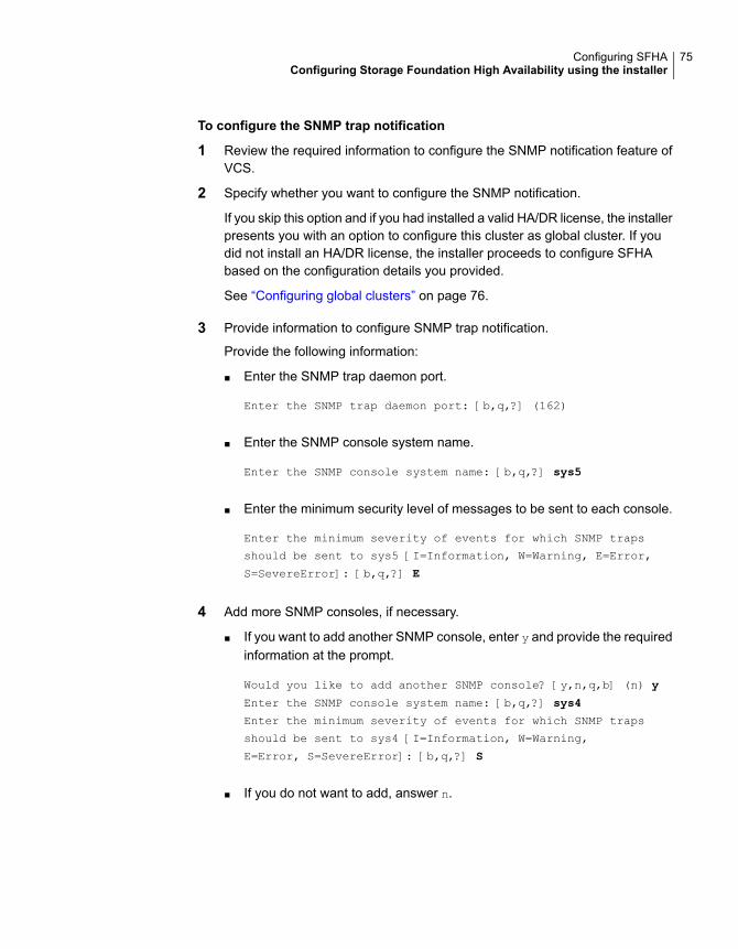
To configure the SNMP trap notification
1 Review the required information to configure the SNMP notification feature ofVCS.
2 Specify whether you want to configure the SNMP notification.
If you skip this option and if you had installed a valid HA/DR license, the installerpresents you with an option to configure this cluster as global cluster. If youdid not install an HA/DR license, the installer proceeds to configure SFHAbased on the configuration details you provided.
See “Configuring global clusters” on page 76.
3 Provide information to configure SNMP trap notification.
Provide the following information:
■ Enter the SNMP trap daemon port.
Enter the SNMP trap daemon port: [b,q,?] (162)
■ Enter the SNMP console system name.
Enter the SNMP console system name: [b,q,?] sys5
■ Enter the minimum security level of messages to be sent to each console.
Enter the minimum severity of events for which SNMP traps
should be sent to sys5 [I=Information, W=Warning, E=Error,
S=SevereError]: [b,q,?] E
4 Add more SNMP consoles, if necessary.
■ If you want to add another SNMP console, enter y and provide the requiredinformation at the prompt.
Would you like to add another SNMP console? [y,n,q,b] (n) y
Enter the SNMP console system name: [b,q,?] sys4
Enter the minimum severity of events for which SNMP traps
should be sent to sys4 [I=Information, W=Warning,
E=Error, S=SevereError]: [b,q,?] S
■ If you do not want to add, answer n.
75Configuring SFHAConfiguring Storage Foundation High Availability using the installer
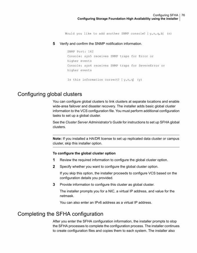
Would you like to add another SNMP console? [y,n,q,b] (n)
5 Verify and confirm the SNMP notification information.
SNMP Port: 162
Console: sys5 receives SNMP traps for Error or
higher events
Console: sys4 receives SNMP traps for SevereError or
higher events
Is this information correct? [y,n,q] (y)
Configuring global clustersYou can configure global clusters to link clusters at separate locations and enablewide-area failover and disaster recovery. The installer adds basic global clusterinformation to the VCS configuration file. You must perform additional configurationtasks to set up a global cluster.
See the Cluster Server Administrator's Guide for instructions to set up SFHA globalclusters.
Note: If you installed a HA/DR license to set up replicated data cluster or campuscluster, skip this installer option.
To configure the global cluster option
1 Review the required information to configure the global cluster option.
2 Specify whether you want to configure the global cluster option.
If you skip this option, the installer proceeds to configure VCS based on theconfiguration details you provided.
3 Provide information to configure this cluster as global cluster.
The installer prompts you for a NIC, a virtual IP address, and value for thenetmask.
You can also enter an IPv6 address as a virtual IP address.
Completing the SFHA configurationAfter you enter the SFHA configuration information, the installer prompts to stopthe SFHA processes to complete the configuration process. The installer continuesto create configuration files and copies them to each system. The installer also
76Configuring SFHAConfiguring Storage Foundation High Availability using the installer
configures a cluster UUID value for the cluster at the end of the configuration. Afterthe installer successfully configures SFHA, it restarts SFHA and its relatedprocesses.
To complete the SFHA configuration
1 If prompted, press Enter at the following prompt.
Do you want to stop InfoScale Enterprise processes now? [y,n,q,?] (y)
2 Review the output as the installer stops various processes and performs theconfiguration. The installer then restarts SFHA and its related processes.
3 Enter y at the prompt to send the installation information to Veritas.
Would you like to send the information about this installation
to us to help improve installation in the future?
[y,n,q,?] (y) y
4 After the installer configures SFHA successfully, note the location of summary,log, and response files that installer creates.
The files provide the useful information that can assist you with the configurationand can also assist future configurations.
Describes the cluster and its configured resources.summary file
Details the entire configuration.log file
Contains the configuration information that can be used to performsecure or unattended installations on other systems.
See “Configuring SFHA using response files” on page 138.
response file
Verifying and updating licenses on the systemAfter you install Veritas InfoScale Enterprise, you can verify the licensing informationusing the vxlicrep program. You can replace the demo licenses with a permanentlicense.
See “Checking licensing information on the system” on page 77.
See “Updating product licenses” on page 78.
Checking licensing information on the systemYou can use the vxlicrep program to display information about the licenses on asystem.
77Configuring SFHAConfiguring Storage Foundation High Availability using the installer
To check licensing information
1 Navigate to the /sbin folder containing the vxlicrep program and enter:
# vxlicrep
2 Review the following output to determine the following information:
■ The license key
■ The type of license
■ The product for which it applies
■ Its expiration date, if any. Demo keys have expiration dates. Permanentkeys and site keys do not have expiration dates.
License Key = xxx-xxx-xxx-xxx-xxx
Product Name = Veritas InfoScale Enterprise
Serial Number = xxxxx
License Type = PERMANENT
OEM ID = xxxxx
Features :=
Platform = Solaris
Version = 7.2
Tier = 0
Reserved = 0
Mode = VCS
Updating product licensesYou can use the ./installer -license command or the vxlicinstupgrade -k
to add the Veritas InfoScale Enterprise license key on each node. If you have VeritasInfoScale Enterprise already installed and SFHA configured and you use a demolicense, you can replace the demo license.
See “Replacing a Veritas InfoScale Enterprise demo license with a permanentlicense” on page 79.
To update product licenses using the installer command
1 On any one node, enter the license key using the command:
# ./installer -license
2 At the prompt, enter your license number.
78Configuring SFHAConfiguring Storage Foundation High Availability using the installer
To update product licenses using the vxlicinst command
◆ On each node, enter the license key using the command:
# vxlicinstupgrade -k license key
Replacing a Veritas InfoScale Enterprise demo license with apermanent licenseWhen a SFHA demo key license expires, you can replace it with a permanentlicense using the vxlicinstupgrade(1) program.
To replace a demo key
1 Make sure you have permissions to log in as root on each of the nodes in thecluster.
2 Shut down SFHA on all nodes in the cluster:
# hastop -all -force
This command does not shut down any running applications.
3 Enter the permanent license key using the following command on each node:
# vxlicinstupgrade -k license key
4 Make sure demo licenses are replaced on all cluster nodes before startingSFHA.
# vxlicrep
5 Start SFHA on each node:
# hastart
Configuring SFDBBy default, SFDB tools are disabled that is the vxdbd daemon is not configured.You can check whether SFDB tools are enabled or disabled usingthe/opt/VRTS/bin/sfae_config status command.
79Configuring SFHAConfiguring SFDB
To enable SFDB tools
1 Log in as root.
2 Run the following command to configure and start the vxdbd daemon. Afteryou perform this step, entries are made in the system startup so that thedaemon starts on a system restart.
#/opt/VRTS/bin/sfae_config enable
To disable SFDB tools
1 Log in as root.
2 Run the following command:
#/opt/VRTS/bin/sfae_config disable
80Configuring SFHAConfiguring SFDB

Configuring SFHA clustersfor data integrity
This chapter includes the following topics:
■ Setting up disk-based I/O fencing using installer
■ Setting up server-based I/O fencing using installer
■ Setting up non-SCSI-3 I/O fencing in virtual environments using installer
■ Setting up majority-based I/O fencing using installer
■ Enabling or disabling the preferred fencing policy
Setting up disk-based I/O fencing using installerYou can configure I/O fencing using the -fencing option of the installer.
Initializing disks as VxVM disksPerform the following procedure to initialize disks as VxVM disks.
To initialize disks as VxVM disks
1 List the new external disks or the LUNs as recognized by the operating system.On each node, enter:
# vxdisk list
2 To initialize the disks as VxVM disks, use one of the following methods:
■ Use the interactive vxdiskadm utility to initialize the disks as VxVM disks.For more information, see the Storage Foundation Administrator’s Guide.
5Chapter
■ Use the vxdisksetup command to initialize a disk as a VxVM disk.
# vxdisksetup -i device_name
The example specifies the CDS format:
# vxdisksetup -i c2t13d0
Repeat this command for each disk you intend to use as a coordinator disk.
Checking shared disks for I/O fencingMake sure that the shared storage you set up while preparing to configure SFHAmeets the I/O fencing requirements. You can test the shared disks using thevxfentsthdw utility. The two nodes must have ssh (default) or rsh communication.To confirm whether a disk (or LUN) supports SCSI-3 persistent reservations, twonodes must simultaneously have access to the same disks. Because a shared diskis likely to have a different name on each node, check the serial number to verifythe identity of the disk. Use the vxfenadm command with the -i option. Thiscommand option verifies that the same serial number for the LUN is returned onall paths to the LUN.
Make sure to test the disks that serve as coordinator disks.
The vxfentsthdw utility has additional options suitable for testing many disks. Reviewthe options for testing the disk groups (-g) and the disks that are listed in a file (-f).You can also test disks without destroying data using the -r option.
See the Cluster Server Administrator's Guide.
Checking that disks support SCSI-3 involves the following tasks:
■ Verifying the Array Support Library (ASL)See “Verifying Array Support Library (ASL)” on page 82.
■ Verifying that nodes have access to the same diskSee “Verifying that the nodes have access to the same disk” on page 83.
■ Testing the shared disks for SCSI-3See “Testing the disks using vxfentsthdw utility” on page 84.
Verifying Array Support Library (ASL)Make sure that the Array Support Library (ASL) for the array that you add is installed.
82Configuring SFHA clusters for data integritySetting up disk-based I/O fencing using installer

To verify Array Support Library (ASL)
1 If the Array Support Library (ASL) for the array that you add is not installed,obtain and install it on each node before proceeding.
The ASL for the supported storage device that you add is available from thedisk array vendor or Veritas technical support.
2 Verify that the ASL for the disk array is installed on each of the nodes. Run thefollowing command on each node and examine the output to verify theinstallation of ASL.
The following output is a sample:
# vxddladm listsupport all
LIBNAME VID PID
===========================================================
libvx3par.so 3PARdata VV
libvxCLARiiON.so DGC All
libvxFJTSYe6k.so FUJITSU E6000
libvxFJTSYe8k.so FUJITSU All
libvxap.so Oracle All
libvxatf.so VERITAS ATFNODES
libvxcompellent.so COMPELNT Compellent Vol
libvxcopan.so COPANSYS 8814, 8818
3 Scan all disk drives and their attributes, update the VxVM device list, andreconfigure DMP with the new devices. Type:
# vxdisk scandisks
See the Veritas Volume Manager documentation for details on how to add andconfigure disks.
Verifying that the nodes have access to the same diskBefore you test the disks that you plan to use as shared data storage or ascoordinator disks using the vxfentsthdw utility, you must verify that the systems seethe same disk.
To verify that the nodes have access to the same disk
1 Verify the connection of the shared storage for data to two of the nodes onwhich you installed Veritas InfoScale Enterprise.
2 Ensure that both nodes are connected to the same disk during the testing. Usethe vxfenadm command to verify the disk serial number.
83Configuring SFHA clusters for data integritySetting up disk-based I/O fencing using installer
# vxfenadm -i diskpath
Refer to the vxfenadm (1M) manual page.
For example, an EMC disk is accessible by the /dev/rdsk/c1t1d0s2 path onnode A and the /dev/rdsk/c2t1d0s2 path on node B.
From node A, enter:
# vxfenadm -i /dev/rdsk/c1t1d0s2
Vendor id : EMC
Product id : SYMMETRIX
Revision : 5567
Serial Number : 42031000a
The same serial number information should appear when you enter theequivalent command on node B using the /dev/rdsk/c2t1d0s2 path.
On a disk from another manufacturer, Hitachi Data Systems, the output isdifferent and may resemble:
Vendor id : HITACHI
Product id : OPEN-3
Revision : 0117
Serial Number : 0401EB6F0002
Testing the disks using vxfentsthdw utilityThis procedure uses the /dev/rdsk/c1t1d0s2 disk in the steps.
If the utility does not show a message that states a disk is ready, the verificationhas failed. Failure of verification can be the result of an improperly configured diskarray. The failure can also be due to a bad disk.
If the failure is due to a bad disk, remove and replace it. The vxfentsthdw utilityindicates a disk can be used for I/O fencing with a message resembling:
The disk /dev/rdsk/c1t1d0s2 is ready to be configured for I/O Fencing on
node sys1
For more information on how to replace coordinator disks, refer to theCluster ServerAdministrator's Guide.
84Configuring SFHA clusters for data integritySetting up disk-based I/O fencing using installer
To test the disks using vxfentsthdw utility
1 Make sure system-to-system communication functions properly.
See “About configuring secure shell or remote shell communication modesbefore installing products” on page 311.
2 From one node, start the utility.
3 The script warns that the tests overwrite data on the disks. After you reviewthe overview and the warning, confirm to continue the process and enter thenode names.
Warning: The tests overwrite and destroy data on the disks unless you usethe -r option.
******** WARNING!!!!!!!! ********
THIS UTILITY WILL DESTROY THE DATA ON THE DISK!!
Do you still want to continue : [y/n] (default: n) y
Enter the first node of the cluster: sys1
Enter the second node of the cluster: sys2
4 Review the output as the utility performs the checks and reports its activities.
5 If a disk is ready for I/O fencing on each node, the utility reports success foreach node. For example, the utility displays the following message for the nodesys1.
The disk is now ready to be configured for I/O Fencing on node
sys1
ALL tests on the disk /dev/rdsk/c1t1d0s2 have PASSED
The disk is now ready to be configured for I/O fencing on node
sys1
6 Run the vxfentsthdw utility for each disk you intend to verify.
Note: Only dmp disk devices can be used as coordinator disks.
85Configuring SFHA clusters for data integritySetting up disk-based I/O fencing using installer
Configuring disk-based I/O fencing using installer
Note: The installer stops and starts SFHA to complete I/O fencing configuration.Make sure to unfreeze any frozen VCS service groups in the cluster for the installerto successfully stop SFHA.
To set up disk-based I/O fencing using the installer
1 Start the installer with -fencing option.
# /opt/VRTS/install/installer -fencing
The installer starts with a copyright message and verifies the cluster information.
Note the location of log files which you can access in the event of any problemwith the configuration process.
2 Enter the host name of one of the systems in the cluster.
3 Confirm that you want to proceed with the I/O fencing configuration at theprompt.
The program checks that the local node running the script can communicatewith remote nodes and checks whether SFHA 7.2 is configured properly.
4 Review the I/O fencing configuration options that the program presents. Type2 to configure disk-based I/O fencing.
1. Configure Coordination Point client based fencing
2. Configure disk based fencing
3. Configure majority based fencing
4. Configure fencing in disabled mode
Select the fencing mechanism to be configured in this
Application Cluster [1-4,q.?] 2
5 Review the output as the configuration program checks whether VxVM isalready started and is running.
■ If the check fails, configure and enable VxVM before you repeat thisprocedure.
■ If the check passes, then the program prompts you for the coordinator diskgroup information.
6 Choose whether to use an existing disk group or create a new disk group toconfigure as the coordinator disk group.
86Configuring SFHA clusters for data integritySetting up disk-based I/O fencing using installer
The program lists the available disk group names and provides an option tocreate a new disk group. Perform one of the following:
■ To use an existing disk group, enter the number corresponding to the diskgroup at the prompt.The program verifies whether the disk group you chose has an odd numberof disks and that the disk group has a minimum of three disks.
■ To create a new disk group, perform the following steps:
■ Enter the number corresponding to theCreate a new disk group option.The program lists the available disks that are in the CDS disk format inthe cluster and asks you to choose an odd number of disks with at leastthree disks to be used as coordinator disks.Veritas recommends that you use three disks as coordination points fordisk-based I/O fencing.
■ If the available VxVM CDS disks are less than the required, installerasks whether you want to initialize more disks as VxVM disks. Choosethe disks you want to initialize as VxVM disks and then use them tocreate new disk group.
■ Enter the numbers corresponding to the disks that you want to use ascoordinator disks.
■ Enter the disk group name.
7 Verify that the coordinator disks you chose meet the I/O fencing requirements.
You must verify that the disks are SCSI-3 PR compatible using the vxfentsthdwutility and then return to this configuration program.
See “Checking shared disks for I/O fencing” on page 82.
8 After you confirm the requirements, the program creates the coordinator diskgroup with the information you provided.
9 Verify and confirm the I/O fencing configuration information that the installersummarizes.
10 Review the output as the configuration program does the following:
■ Stops VCS and I/O fencing on each node.
■ Configures disk-based I/O fencing and starts the I/O fencing process.
■ Updates the VCS configuration file main.cf if necessary.
■ Copies the /etc/vxfenmode file to a date and time suffixed file/etc/vxfenmode-date-time. This backup file is useful if any future fencingconfiguration fails.
87Configuring SFHA clusters for data integritySetting up disk-based I/O fencing using installer
■ Updates the I/O fencing configuration file /etc/vxfenmode.
■ Starts VCS on each node to make sure that the SFHA is cleanly configuredto use the I/O fencing feature.
11 Review the output as the configuration program displays the location of the logfiles, the summary files, and the response files.
12 Configure the Coordination Point Agent.
Do you want to configure Coordination Point Agent on
the client cluster? [y,n,q] (y)
13 Enter a name for the service group for the Coordination Point Agent.
Enter a non-existing name for the service group for
Coordination Point Agent: [b] (vxfen) vxfen
14 Set the level two monitor frequency.
Do you want to set LevelTwoMonitorFreq? [y,n,q] (y)
15 Decide the value of the level two monitor frequency.
Enter the value of the LevelTwoMonitorFreq attribute: [b,q,?] (5)
Installer adds Coordination Point Agent and updates the main configurationfile.
16 Enable auto refresh of coordination points.
Do you want to enable auto refresh of coordination points
if registration keys are missing
on any of them? [y,n,q,b,?] (n)
See “Configuring CoordPoint agent to monitor coordination points” on page 126.
Refreshing keys or registrations on the existing coordination pointsfor disk-based fencing using the installer
You must refresh registrations on the coordination points in the following scenarios:
■ When the CoordPoint agent notifies VCS about the loss of registration on anyof the existing coordination points.
■ A planned refresh of registrations on coordination points when the cluster isonline without having an application downtime on the cluster.
88Configuring SFHA clusters for data integritySetting up disk-based I/O fencing using installer
Registration loss may happen because of an accidental array restart, corruption ofkeys, or some other reason. If the coordination points lose the registrations of thecluster nodes, the cluster may panic when a network partition occurs.
Warning: Refreshing keys might cause the cluster to panic if a node leavesmembership before the coordination points refresh is complete.
To refresh registrations on existing coordination points for disk-based I/Ofencing using the installer
1 Start the installer with the -fencing option.
# /opt/VRTS/install/installer -fencing
The installer starts with a copyright message and verifies the cluster information.
Note down the location of log files that you can access if there is a problemwith the configuration process.
2 Confirm that you want to proceed with the I/O fencing configuration at theprompt.
The program checks that the local node running the script can communicatewith the remote nodes and checks whether SFHA 7.2 is configured properly.
3 Review the I/O fencing configuration options that the program presents. Typethe number corresponding to refresh registrations or keys on the existingcoordination points.
Select the fencing mechanism to be configured in this
Application Cluster [1-6,q]
4 Ensure that the disk group constitution that is used by the fencing modulecontains the same disks that are currently used as coordination disks.
89Configuring SFHA clusters for data integritySetting up disk-based I/O fencing using installer

5 Verify the coordination points.
For example,
Disk Group: fendg
Fencing disk policy: dmp
Fencing disks:
emc_clariion0_62
emc_clariion0_65
emc_clariion0_66
Is this information correct? [y,n,q] (y).
Successfully completed the vxfenswap operation
The keys on the coordination disks are refreshed.
6 Do you want to send the information about this installation to us to help improveinstallation in the future? [y,n,q,?] (y).
7 Do you want to view the summary file? [y,n,q] (n).
Setting up server-based I/O fencing using installerYou can configure server-based I/O fencing for the SFHA cluster using the installer.
With server-based fencing, you can have the coordination points in your configurationas follows:
■ Combination of CP servers and SCSI-3 compliant coordinator disks
■ CP servers onlyVeritas also supports server-based fencing with a single highly available CPserver that acts as a single coordination point.
See “ About planning to configure I/O fencing” on page 28.
See “Recommended CP server configurations” on page 33.
This section covers the following example procedures:
See “To configure server-based fencing for the SFHA cluster(one CP server and two coordinator disks)” on page 91.
Mix of CP servers andcoordinator disks
See “To configure server-based fencing for the SFHA cluster”on page 95.
Single CP server
90Configuring SFHA clusters for data integritySetting up server-based I/O fencing using installer
To configure server-based fencing for the SFHA cluster (one CP server andtwo coordinator disks)
1 Depending on the server-based configuration model in your setup, make sureof the following:
■ CP servers are configured and are reachable from the SFHA cluster. TheSFHA cluster is also referred to as the application cluster or the client cluster.See “Setting up the CP server” on page 36.
■ The coordination disks are verified for SCSI3-PR compliance.See “Checking shared disks for I/O fencing” on page 82.
2 Start the installer with the -fencing option.
# /opt/VRTS/install/installer -fencing
The installer starts with a copyright message and verifies the cluster information.
Note the location of log files which you can access in the event of any problemwith the configuration process.
3 Confirm that you want to proceed with the I/O fencing configuration at theprompt.
The program checks that the local node running the script can communicatewith remote nodes and checks whether SFHA 7.2 is configured properly.
4 Review the I/O fencing configuration options that the program presents. Type1 to configure server-based I/O fencing.
Select the fencing mechanism to be configured in this
Application Cluster [1-3,b,q] 1
5 Make sure that the storage supports SCSI3-PR, and answer y at the followingprompt.
Does your storage environment support SCSI3 PR? [y,n,q] (y)
6 Provide the following details about the coordination points at the installer prompt:
■ Enter the total number of coordination points including both servers anddisks. This number should be at least 3.
Enter the total number of co-ordination points including both
Coordination Point servers and disks: [b] (3)
■ Enter the total number of coordinator disks among the coordination points.
91Configuring SFHA clusters for data integritySetting up server-based I/O fencing using installer

Enter the total number of disks among these:
[b] (0) 2
7 Provide the following CP server details at the installer prompt:
■ Enter the total number of virtual IP addresses or the total number of fullyqualified host names for each of the CP servers.
How many IP addresses would you like to use to communicate
to Coordination Point Server #1?: [b,q,?] (1) 1
■ Enter the virtual IP addresses or the fully qualified host name for each ofthe CP servers. The installer assumes these values to be identical as viewedfrom all the application cluster nodes.
Enter the Virtual IP address or fully qualified host name #1
for the HTTPS Coordination Point Server #1:
[b] 10.209.80.197
The installer prompts for this information for the number of virtual IPaddresses you want to configure for each CP server.
■ Enter the port that the CP server would be listening on.
Enter the port that the coordination point server 10.209.80.197
would be listening on or accept the default port
suggested: [b] (443)
8 Provide the following coordinator disks-related details at the installer prompt:
■ Choose the coordinator disks from the list of available disks that the installerdisplays. Ensure that the disk you choose is available from all the SFHA(application cluster) nodes.The number of times that the installer asks you to choose the disks dependson the information that you provided in step 6. For example, if you hadchosen to configure two coordinator disks, the installer asks you to choosethe first disk and then the second disk:
Select disk number 1 for co-ordination point
1) c1t1d0s2
2) c2t1d0s2
3) c3t1d0s2
Please enter a valid disk which is available from all the
cluster nodes for co-ordination point [1-3,q] 1
92Configuring SFHA clusters for data integritySetting up server-based I/O fencing using installer
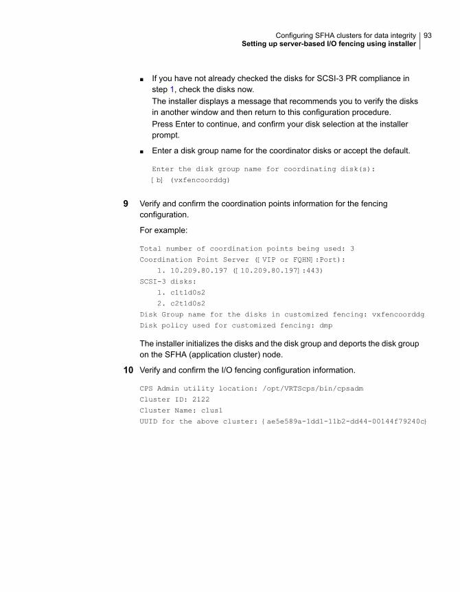
■ If you have not already checked the disks for SCSI-3 PR compliance instep 1, check the disks now.The installer displays a message that recommends you to verify the disksin another window and then return to this configuration procedure.Press Enter to continue, and confirm your disk selection at the installerprompt.
■ Enter a disk group name for the coordinator disks or accept the default.
Enter the disk group name for coordinating disk(s):
[b] (vxfencoorddg)
9 Verify and confirm the coordination points information for the fencingconfiguration.
For example:
Total number of coordination points being used: 3
Coordination Point Server ([VIP or FQHN]:Port):
1. 10.209.80.197 ([10.209.80.197]:443)
SCSI-3 disks:
1. c1t1d0s2
2. c2t1d0s2
Disk Group name for the disks in customized fencing: vxfencoorddg
Disk policy used for customized fencing: dmp
The installer initializes the disks and the disk group and deports the disk groupon the SFHA (application cluster) node.
10 Verify and confirm the I/O fencing configuration information.
CPS Admin utility location: /opt/VRTScps/bin/cpsadm
Cluster ID: 2122
Cluster Name: clus1
UUID for the above cluster: {ae5e589a-1dd1-11b2-dd44-00144f79240c}
93Configuring SFHA clusters for data integritySetting up server-based I/O fencing using installer
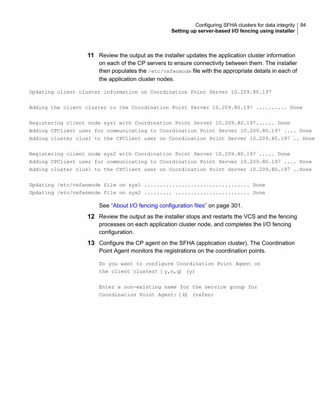
11 Review the output as the installer updates the application cluster informationon each of the CP servers to ensure connectivity between them. The installerthen populates the /etc/vxfenmode file with the appropriate details in each ofthe application cluster nodes.
Updating client cluster information on Coordination Point Server 10.209.80.197
Adding the client cluster to the Coordination Point Server 10.209.80.197 .......... Done
Registering client node sys1 with Coordination Point Server 10.209.80.197...... Done
Adding CPClient user for communicating to Coordination Point Server 10.209.80.197 .... Done
Adding cluster clus1 to the CPClient user on Coordination Point Server 10.209.80.197 .. Done
Registering client node sys2 with Coordination Point Server 10.209.80.197 ..... Done
Adding CPClient user for communicating to Coordination Point Server 10.209.80.197 .... Done
Adding cluster clus1 to the CPClient user on Coordination Point Server 10.209.80.197 ..Done
Updating /etc/vxfenmode file on sys1 .................................. Done
Updating /etc/vxfenmode file on sys2 ......... ........................ Done
See “About I/O fencing configuration files” on page 301.
12 Review the output as the installer stops and restarts the VCS and the fencingprocesses on each application cluster node, and completes the I/O fencingconfiguration.
13 Configure the CP agent on the SFHA (application cluster). The CoordinationPoint Agent monitors the registrations on the coordination points.
Do you want to configure Coordination Point Agent on
the client cluster? [y,n,q] (y)
Enter a non-existing name for the service group for
Coordination Point Agent: [b] (vxfen)
94Configuring SFHA clusters for data integritySetting up server-based I/O fencing using installer
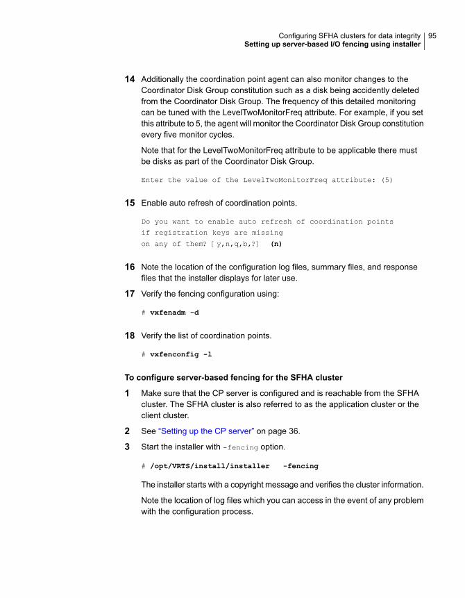
14 Additionally the coordination point agent can also monitor changes to theCoordinator Disk Group constitution such as a disk being accidently deletedfrom the Coordinator Disk Group. The frequency of this detailed monitoringcan be tuned with the LevelTwoMonitorFreq attribute. For example, if you setthis attribute to 5, the agent will monitor the Coordinator Disk Group constitutionevery five monitor cycles.
Note that for the LevelTwoMonitorFreq attribute to be applicable there mustbe disks as part of the Coordinator Disk Group.
Enter the value of the LevelTwoMonitorFreq attribute: (5)
15 Enable auto refresh of coordination points.
Do you want to enable auto refresh of coordination points
if registration keys are missing
on any of them? [y,n,q,b,?] (n)
16 Note the location of the configuration log files, summary files, and responsefiles that the installer displays for later use.
17 Verify the fencing configuration using:
# vxfenadm -d
18 Verify the list of coordination points.
# vxfenconfig -l
To configure server-based fencing for the SFHA cluster
1 Make sure that the CP server is configured and is reachable from the SFHAcluster. The SFHA cluster is also referred to as the application cluster or theclient cluster.
2 See “Setting up the CP server” on page 36.
3 Start the installer with -fencing option.
# /opt/VRTS/install/installer -fencing
The installer starts with a copyright message and verifies the cluster information.
Note the location of log files which you can access in the event of any problemwith the configuration process.
95Configuring SFHA clusters for data integritySetting up server-based I/O fencing using installer
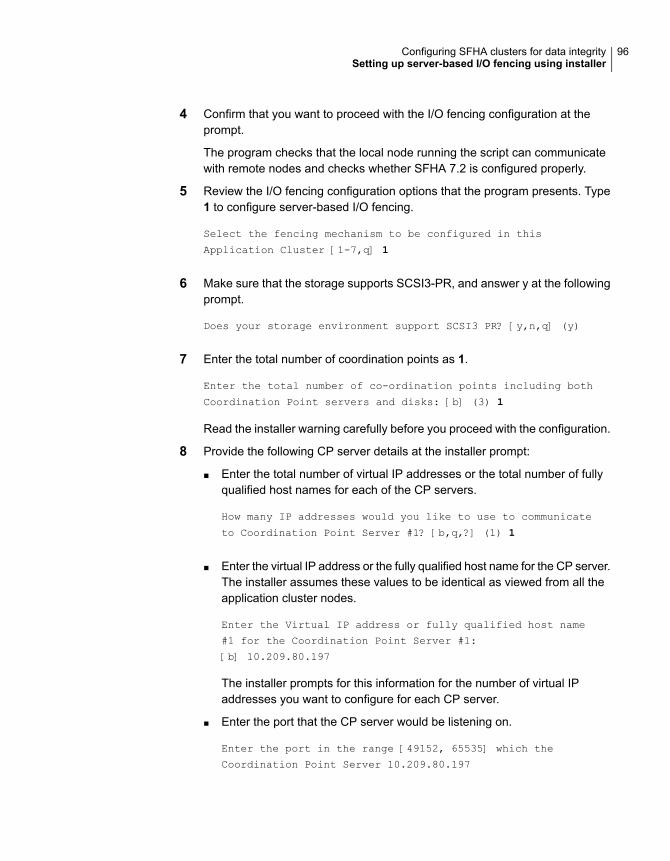
4 Confirm that you want to proceed with the I/O fencing configuration at theprompt.
The program checks that the local node running the script can communicatewith remote nodes and checks whether SFHA 7.2 is configured properly.
5 Review the I/O fencing configuration options that the program presents. Type1 to configure server-based I/O fencing.
Select the fencing mechanism to be configured in this
Application Cluster [1-7,q] 1
6 Make sure that the storage supports SCSI3-PR, and answer y at the followingprompt.
Does your storage environment support SCSI3 PR? [y,n,q] (y)
7 Enter the total number of coordination points as 1.
Enter the total number of co-ordination points including both
Coordination Point servers and disks: [b] (3) 1
Read the installer warning carefully before you proceed with the configuration.
8 Provide the following CP server details at the installer prompt:
■ Enter the total number of virtual IP addresses or the total number of fullyqualified host names for each of the CP servers.
How many IP addresses would you like to use to communicate
to Coordination Point Server #1? [b,q,?] (1) 1
■ Enter the virtual IP address or the fully qualified host name for the CP server.The installer assumes these values to be identical as viewed from all theapplication cluster nodes.
Enter the Virtual IP address or fully qualified host name
#1 for the Coordination Point Server #1:
[b] 10.209.80.197
The installer prompts for this information for the number of virtual IPaddresses you want to configure for each CP server.
■ Enter the port that the CP server would be listening on.
Enter the port in the range [49152, 65535] which the
Coordination Point Server 10.209.80.197
96Configuring SFHA clusters for data integritySetting up server-based I/O fencing using installer

would be listening on or simply accept the default
port suggested: [b] (443)
9 Verify and confirm the coordination points information for the fencingconfiguration.
For example:
Total number of coordination points being used: 1
Coordination Point Server ([VIP or FQHN]:Port):
1. 10.209.80.197 ([10.209.80.197]:443)
10 Verify and confirm the I/O fencing configuration information.
CPS Admin utility location: /opt/VRTScps/bin/cpsadm
Cluster ID: 2122
Cluster Name: clus1
UUID for the above cluster: {ae5e589a-1dd1-11b2-dd44-00144f79240c}
11 Review the output as the installer updates the application cluster informationon each of the CP servers to ensure connectivity between them. The installerthen populates the /etc/vxfenmode file with the appropriate details in each ofthe application cluster nodes.
The installer also populates the /etc/vxfenmode file with the entry single_cp=1for such single CP server fencing configuration.
Updating client cluster information on Coordination Point Server 10.209.80.197
Adding the client cluster to the Coordination Point Server 10.209.80.197 .......... Done
Registering client node sys1 with Coordination Point Server 10.209.80.197...... Done
Adding CPClient user for communicating to Coordination Point Server 10.209.80.197 .... Done
Adding cluster clus1 to the CPClient user on Coordination Point Server 10.209.80.197 .. Done
Registering client node sys2 with Coordination Point Server 10.209.80.197 ..... Done
Adding CPClient user for communicating to Coordination Point Server 10.209.80.197 .... Done
Adding cluster clus1 to the CPClient user on Coordination Point Server 10.209.80.197 .. Done
Updating /etc/vxfenmode file on sys1 .................................. Done
Updating /etc/vxfenmode file on sys2 ......... ........................ Done
See “About I/O fencing configuration files” on page 301.
97Configuring SFHA clusters for data integritySetting up server-based I/O fencing using installer
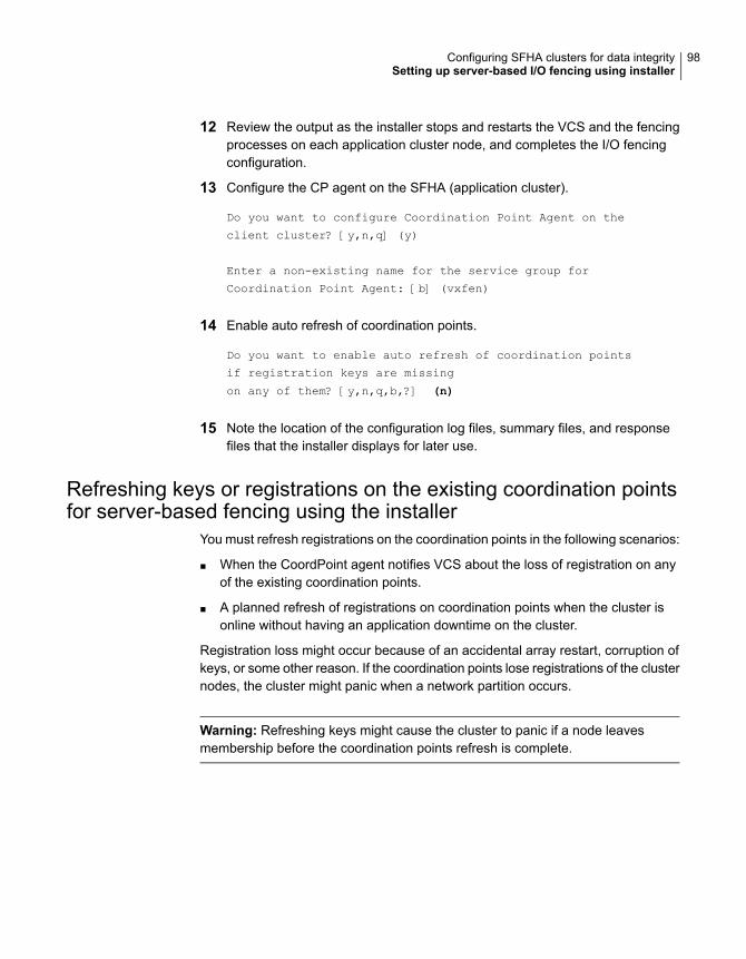
12 Review the output as the installer stops and restarts the VCS and the fencingprocesses on each application cluster node, and completes the I/O fencingconfiguration.
13 Configure the CP agent on the SFHA (application cluster).
Do you want to configure Coordination Point Agent on the
client cluster? [y,n,q] (y)
Enter a non-existing name for the service group for
Coordination Point Agent: [b] (vxfen)
14 Enable auto refresh of coordination points.
Do you want to enable auto refresh of coordination points
if registration keys are missing
on any of them? [y,n,q,b,?] (n)
15 Note the location of the configuration log files, summary files, and responsefiles that the installer displays for later use.
Refreshing keys or registrations on the existing coordination pointsfor server-based fencing using the installer
You must refresh registrations on the coordination points in the following scenarios:
■ When the CoordPoint agent notifies VCS about the loss of registration on anyof the existing coordination points.
■ A planned refresh of registrations on coordination points when the cluster isonline without having an application downtime on the cluster.
Registration loss might occur because of an accidental array restart, corruption ofkeys, or some other reason. If the coordination points lose registrations of the clusternodes, the cluster might panic when a network partition occurs.
Warning: Refreshing keys might cause the cluster to panic if a node leavesmembership before the coordination points refresh is complete.
98Configuring SFHA clusters for data integritySetting up server-based I/O fencing using installer

To refresh registrations on existing coordination points for server-based I/Ofencing using the installer
1 Start the installer with the -fencing option.
# /opt/VRTS/install/installer -fencing
The installer starts with a copyright message and verifies the cluster information.
Note the location of log files that you can access if there is a problem with theconfiguration process.
2 Confirm that you want to proceed with the I/O fencing configuration at theprompt.
The program checks that the local node running the script can communicatewith the remote nodes and checks whether SFHA 7.2 is configured properly.
3 Review the I/O fencing configuration options that the program presents. Typethe number corresponding to the option that suggests to refresh registrationsor keys on the existing coordination points.
Select the fencing mechanism to be configured in this
Application Cluster [1-7,q] 6
4 Ensure that the /etc/vxfentab file contains the same coordination pointservers that are currently used by the fencing module.
Also, ensure that the disk group mentioned in the /etc/vxfendg file containsthe same disks that are currently used by the fencing module as coordinationdisks.
5 Verify the coordination points.
For example,
Total number of coordination points being used: 3
Coordination Point Server ([VIP or FQHN]:Port):
1. 10.198.94.146 ([10.198.94.146]:443)
2. 10.198.94.144 ([10.198.94.144]:443)
SCSI-3 disks:
1. emc_clariion0_61
Disk Group name for the disks in customized fencing: vxfencoorddg
Disk policy used for customized fencing: dmp
99Configuring SFHA clusters for data integritySetting up server-based I/O fencing using installer

6 Is this information correct? [y,n,q] (y)
Updating client cluster information on Coordination Point Server
IPaddress
Successfully completed the vxfenswap operation
The keys on the coordination disks are refreshed.
7 Do you want to send the information about this installation to us to help improveinstallation in the future? [y,n,q,?] (y).
8 Do you want to view the summary file? [y,n,q] (n).
Setting the order of existing coordination points for server-basedfencing using the installer
This section describes the reasons, benefits, considerations, and the procedure toset the order of the existing coordination points for server-based fencing.
About deciding the order of existing coordination pointsYou can decide the order in which coordination points can participate in a raceduring a network partition. In a network partition scenario, I/O fencing attempts tocontact coordination points for membership arbitration based on the order that isset in the vxfentab file.
When I/O fencing is not able to connect to the first coordination point in the sequenceit goes to the second coordination point and so on. To avoid a cluster panic, thesurviving subcluster must win majority of the coordination points. So, the order mustbegin with the coordination point that has the best chance to win the race and mustend with the coordination point that has the least chance to win the race.
For fencing configurations that use a mix of coordination point servers andcoordination disks, you can specify either coordination point servers beforecoordination disks or disks before servers.
Note:Disk-based fencing does not support setting the order of existing coordinationpoints.
Considerations to decide the order of coordination points
■ Choose the coordination points based on their chances to gain membership onthe cluster during the race and hence gain control over a network partition. Ineffect, you have the ability to save a partition.
100Configuring SFHA clusters for data integritySetting up server-based I/O fencing using installer
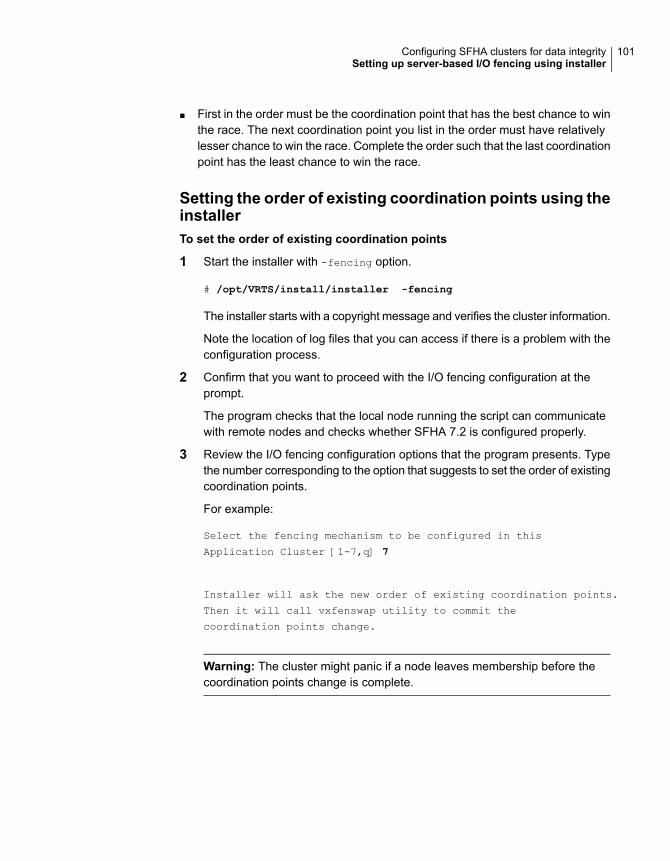
■ First in the order must be the coordination point that has the best chance to winthe race. The next coordination point you list in the order must have relativelylesser chance to win the race. Complete the order such that the last coordinationpoint has the least chance to win the race.
Setting the order of existing coordination points using theinstallerTo set the order of existing coordination points
1 Start the installer with -fencing option.
# /opt/VRTS/install/installer -fencing
The installer starts with a copyright message and verifies the cluster information.
Note the location of log files that you can access if there is a problem with theconfiguration process.
2 Confirm that you want to proceed with the I/O fencing configuration at theprompt.
The program checks that the local node running the script can communicatewith remote nodes and checks whether SFHA 7.2 is configured properly.
3 Review the I/O fencing configuration options that the program presents. Typethe number corresponding to the option that suggests to set the order of existingcoordination points.
For example:
Select the fencing mechanism to be configured in this
Application Cluster [1-7,q] 7
Installer will ask the new order of existing coordination points.
Then it will call vxfenswap utility to commit the
coordination points change.
Warning: The cluster might panic if a node leaves membership before thecoordination points change is complete.
101Configuring SFHA clusters for data integritySetting up server-based I/O fencing using installer
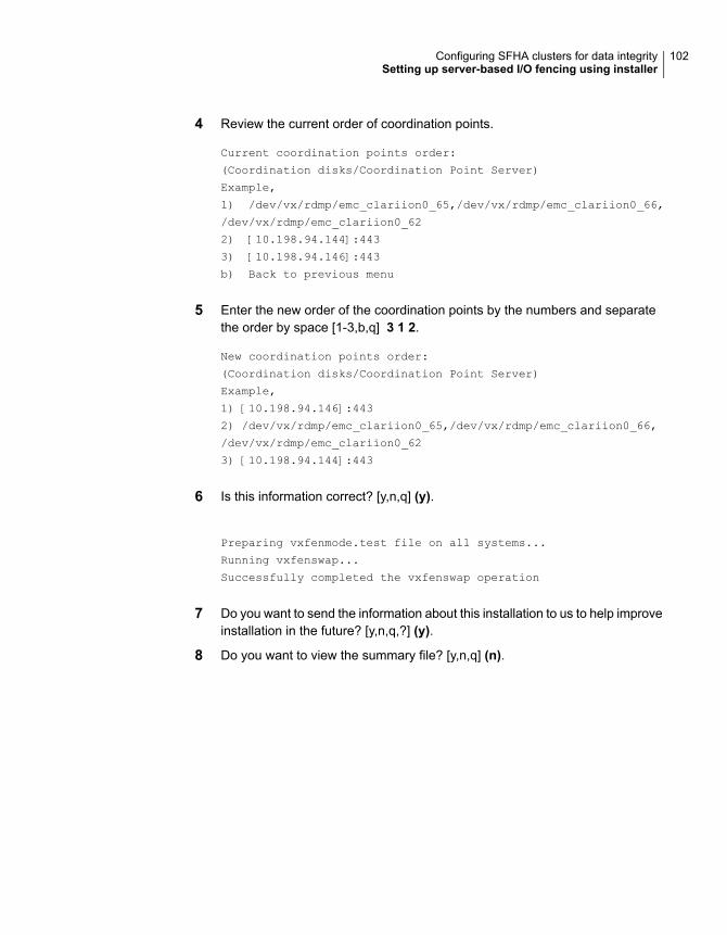
4 Review the current order of coordination points.
Current coordination points order:
(Coordination disks/Coordination Point Server)
Example,
1) /dev/vx/rdmp/emc_clariion0_65,/dev/vx/rdmp/emc_clariion0_66,
/dev/vx/rdmp/emc_clariion0_62
2) [10.198.94.144]:443
3) [10.198.94.146]:443
b) Back to previous menu
5 Enter the new order of the coordination points by the numbers and separatethe order by space [1-3,b,q] 3 1 2.
New coordination points order:
(Coordination disks/Coordination Point Server)
Example,
1) [10.198.94.146]:443
2) /dev/vx/rdmp/emc_clariion0_65,/dev/vx/rdmp/emc_clariion0_66,
/dev/vx/rdmp/emc_clariion0_62
3) [10.198.94.144]:443
6 Is this information correct? [y,n,q] (y).
Preparing vxfenmode.test file on all systems...
Running vxfenswap...
Successfully completed the vxfenswap operation
7 Do you want to send the information about this installation to us to help improveinstallation in the future? [y,n,q,?] (y).
8 Do you want to view the summary file? [y,n,q] (n).
102Configuring SFHA clusters for data integritySetting up server-based I/O fencing using installer
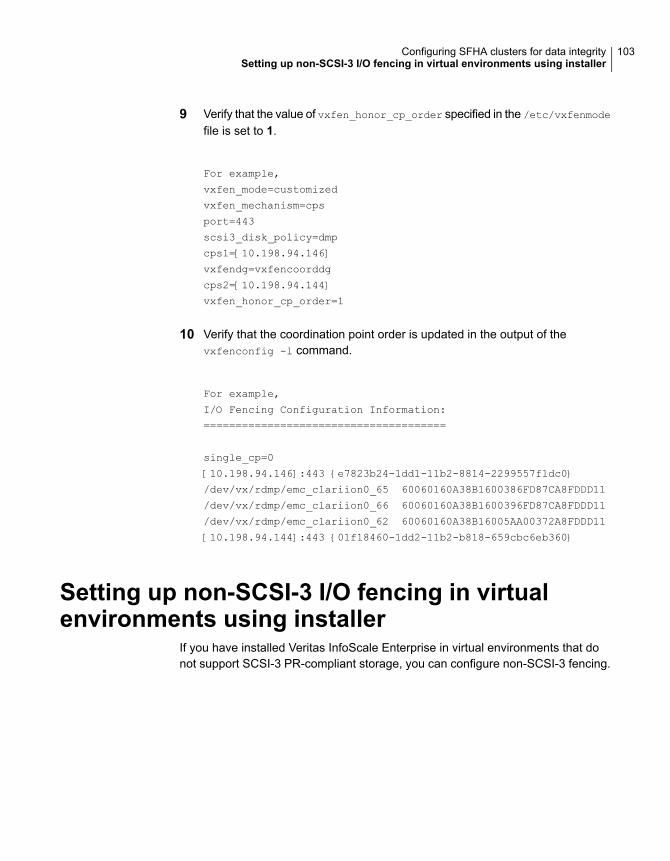
9 Verify that the value of vxfen_honor_cp_order specified in the /etc/vxfenmode
file is set to 1.
For example,
vxfen_mode=customized
vxfen_mechanism=cps
port=443
scsi3_disk_policy=dmp
cps1=[10.198.94.146]
vxfendg=vxfencoorddg
cps2=[10.198.94.144]
vxfen_honor_cp_order=1
10 Verify that the coordination point order is updated in the output of thevxfenconfig -l command.
For example,
I/O Fencing Configuration Information:
======================================
single_cp=0
[10.198.94.146]:443 {e7823b24-1dd1-11b2-8814-2299557f1dc0}
/dev/vx/rdmp/emc_clariion0_65 60060160A38B1600386FD87CA8FDDD11
/dev/vx/rdmp/emc_clariion0_66 60060160A38B1600396FD87CA8FDDD11
/dev/vx/rdmp/emc_clariion0_62 60060160A38B16005AA00372A8FDDD11
[10.198.94.144]:443 {01f18460-1dd2-11b2-b818-659cbc6eb360}
Setting up non-SCSI-3 I/O fencing in virtualenvironments using installer
If you have installed Veritas InfoScale Enterprise in virtual environments that donot support SCSI-3 PR-compliant storage, you can configure non-SCSI-3 fencing.
103Configuring SFHA clusters for data integritySetting up non-SCSI-3 I/O fencing in virtual environments using installer
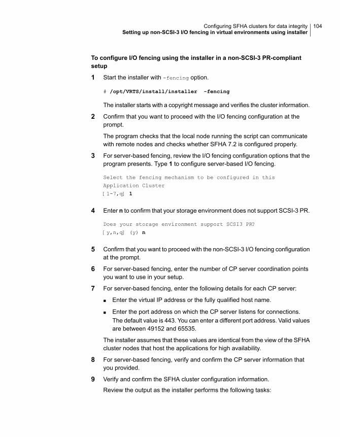
To configure I/O fencing using the installer in a non-SCSI-3 PR-compliantsetup
1 Start the installer with -fencing option.
# /opt/VRTS/install/installer -fencing
The installer starts with a copyright message and verifies the cluster information.
2 Confirm that you want to proceed with the I/O fencing configuration at theprompt.
The program checks that the local node running the script can communicatewith remote nodes and checks whether SFHA 7.2 is configured properly.
3 For server-based fencing, review the I/O fencing configuration options that theprogram presents. Type 1 to configure server-based I/O fencing.
Select the fencing mechanism to be configured in this
Application Cluster
[1-7,q] 1
4 Enter n to confirm that your storage environment does not support SCSI-3 PR.
Does your storage environment support SCSI3 PR?
[y,n,q] (y) n
5 Confirm that you want to proceed with the non-SCSI-3 I/O fencing configurationat the prompt.
6 For server-based fencing, enter the number of CP server coordination pointsyou want to use in your setup.
7 For server-based fencing, enter the following details for each CP server:
■ Enter the virtual IP address or the fully qualified host name.
■ Enter the port address on which the CP server listens for connections.The default value is 443. You can enter a different port address. Valid valuesare between 49152 and 65535.
The installer assumes that these values are identical from the view of the SFHAcluster nodes that host the applications for high availability.
8 For server-based fencing, verify and confirm the CP server information thatyou provided.
9 Verify and confirm the SFHA cluster configuration information.
Review the output as the installer performs the following tasks:
104Configuring SFHA clusters for data integritySetting up non-SCSI-3 I/O fencing in virtual environments using installer
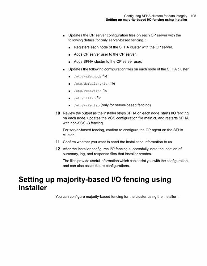
■ Updates the CP server configuration files on each CP server with thefollowing details for only server-based fencing, :
■ Registers each node of the SFHA cluster with the CP server.
■ Adds CP server user to the CP server.
■ Adds SFHA cluster to the CP server user.
■ Updates the following configuration files on each node of the SFHA cluster
■ /etc/vxfenmode file
■ /etc/default/vxfen file
■ /etc/vxenviron file
■ /etc/llttab file
■ /etc/vxfentab (only for server-based fencing)
10 Review the output as the installer stops SFHA on each node, starts I/O fencingon each node, updates the VCS configuration file main.cf, and restarts SFHAwith non-SCSI-3 fencing.
For server-based fencing, confirm to configure the CP agent on the SFHAcluster.
11 Confirm whether you want to send the installation information to us.
12 After the installer configures I/O fencing successfully, note the location ofsummary, log, and response files that installer creates.
The files provide useful information which can assist you with the configuration,and can also assist future configurations.
Setting up majority-based I/O fencing usinginstaller
You can configure majority-based fencing for the cluster using the installer .
105Configuring SFHA clusters for data integritySetting up majority-based I/O fencing using installer
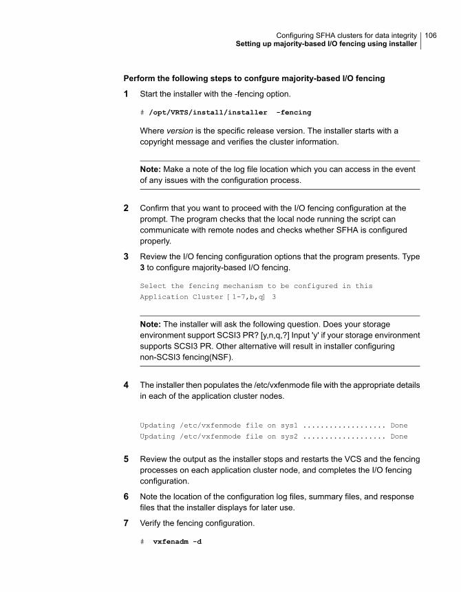
Perform the following steps to confgure majority-based I/O fencing
1 Start the installer with the -fencing option.
# /opt/VRTS/install/installer -fencing
Where version is the specific release version. The installer starts with acopyright message and verifies the cluster information.
Note: Make a note of the log file location which you can access in the eventof any issues with the configuration process.
2 Confirm that you want to proceed with the I/O fencing configuration at theprompt. The program checks that the local node running the script cancommunicate with remote nodes and checks whether SFHA is configuredproperly.
3 Review the I/O fencing configuration options that the program presents. Type3 to configure majority-based I/O fencing.
Select the fencing mechanism to be configured in this
Application Cluster [1-7,b,q] 3
Note: The installer will ask the following question. Does your storageenvironment support SCSI3 PR? [y,n,q,?] Input 'y' if your storage environmentsupports SCSI3 PR. Other alternative will result in installer configuringnon-SCSI3 fencing(NSF).
4 The installer then populates the /etc/vxfenmode file with the appropriate detailsin each of the application cluster nodes.
Updating /etc/vxfenmode file on sys1 ................... Done
Updating /etc/vxfenmode file on sys2 ................... Done
5 Review the output as the installer stops and restarts the VCS and the fencingprocesses on each application cluster node, and completes the I/O fencingconfiguration.
6 Note the location of the configuration log files, summary files, and responsefiles that the installer displays for later use.
7 Verify the fencing configuration.
# vxfenadm -d
106Configuring SFHA clusters for data integritySetting up majority-based I/O fencing using installer
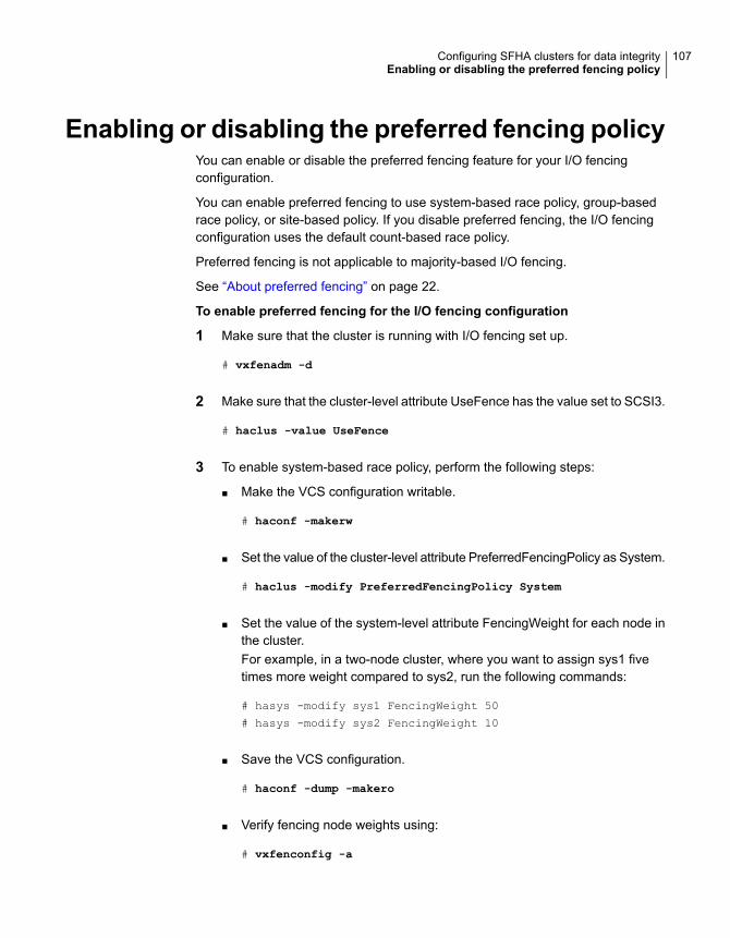
Enabling or disabling the preferred fencing policyYou can enable or disable the preferred fencing feature for your I/O fencingconfiguration.
You can enable preferred fencing to use system-based race policy, group-basedrace policy, or site-based policy. If you disable preferred fencing, the I/O fencingconfiguration uses the default count-based race policy.
Preferred fencing is not applicable to majority-based I/O fencing.
See “About preferred fencing” on page 22.
To enable preferred fencing for the I/O fencing configuration
1 Make sure that the cluster is running with I/O fencing set up.
# vxfenadm -d
2 Make sure that the cluster-level attribute UseFence has the value set to SCSI3.
# haclus -value UseFence
3 To enable system-based race policy, perform the following steps:
■ Make the VCS configuration writable.
# haconf -makerw
■ Set the value of the cluster-level attribute PreferredFencingPolicy as System.
# haclus -modify PreferredFencingPolicy System
■ Set the value of the system-level attribute FencingWeight for each node inthe cluster.For example, in a two-node cluster, where you want to assign sys1 fivetimes more weight compared to sys2, run the following commands:
# hasys -modify sys1 FencingWeight 50
# hasys -modify sys2 FencingWeight 10
■ Save the VCS configuration.
# haconf -dump -makero
■ Verify fencing node weights using:
# vxfenconfig -a
107Configuring SFHA clusters for data integrityEnabling or disabling the preferred fencing policy
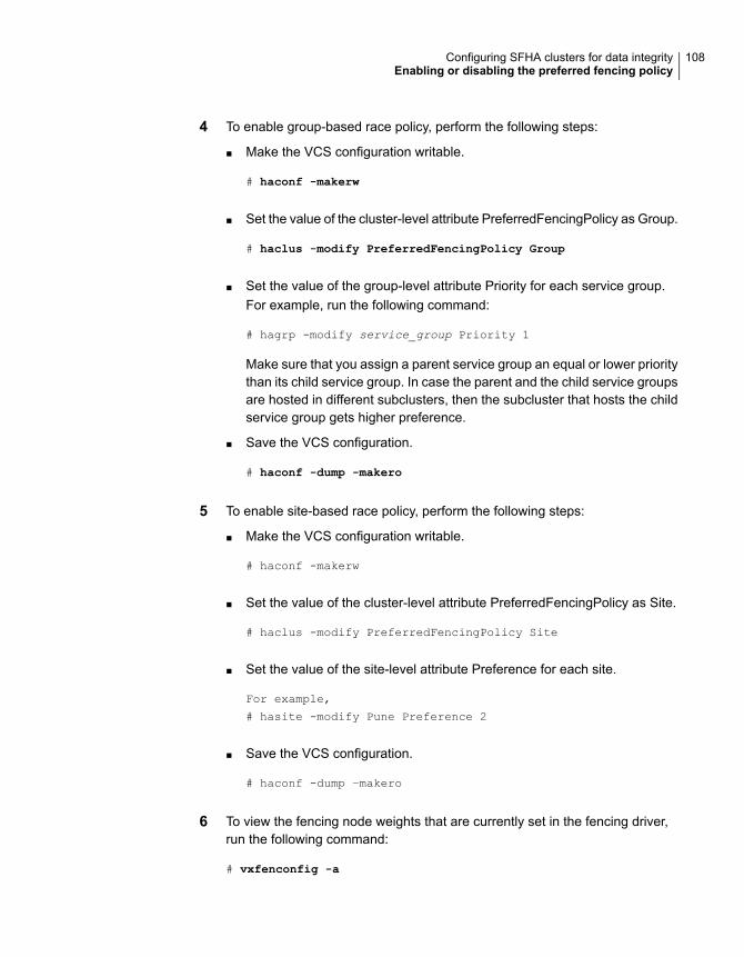
4 To enable group-based race policy, perform the following steps:
■ Make the VCS configuration writable.
# haconf -makerw
■ Set the value of the cluster-level attribute PreferredFencingPolicy as Group.
# haclus -modify PreferredFencingPolicy Group
■ Set the value of the group-level attribute Priority for each service group.For example, run the following command:
# hagrp -modify service_group Priority 1
Make sure that you assign a parent service group an equal or lower prioritythan its child service group. In case the parent and the child service groupsare hosted in different subclusters, then the subcluster that hosts the childservice group gets higher preference.
■ Save the VCS configuration.
# haconf -dump -makero
5 To enable site-based race policy, perform the following steps:
■ Make the VCS configuration writable.
# haconf -makerw
■ Set the value of the cluster-level attribute PreferredFencingPolicy as Site.
# haclus -modify PreferredFencingPolicy Site
■ Set the value of the site-level attribute Preference for each site.
For example,
# hasite -modify Pune Preference 2
■ Save the VCS configuration.
# haconf -dump –makero
6 To view the fencing node weights that are currently set in the fencing driver,run the following command:
# vxfenconfig -a
108Configuring SFHA clusters for data integrityEnabling or disabling the preferred fencing policy

To disable preferred fencing for the I/O fencing configuration
1 Make sure that the cluster is running with I/O fencing set up.
# vxfenadm -d
2 Make sure that the cluster-level attribute UseFence has the value set to SCSI3.
# haclus -value UseFence
3 To disable preferred fencing and use the default race policy, set the value ofthe cluster-level attribute PreferredFencingPolicy as Disabled.
# haconf -makerw
# haclus -modify PreferredFencingPolicy Disabled
# haconf -dump -makero
109Configuring SFHA clusters for data integrityEnabling or disabling the preferred fencing policy
Manually configuringSFHA clusters for dataintegrity
This chapter includes the following topics:
■ Setting up disk-based I/O fencing manually
■ Setting up server-based I/O fencing manually
■ Setting up non-SCSI-3 fencing in virtual environments manually
■ Setting up majority-based I/O fencing manually
Setting up disk-based I/O fencing manuallyTable 6-1 lists the tasks that are involved in setting up I/O fencing.
Table 6-1
ReferenceTask
See “Initializing disks as VxVM disks” on page 81.Initializing disks as VxVM disks
See “Identifying disks to use as coordinator disks”on page 111.
Identifying disks to use ascoordinator disks
See “Checking shared disks for I/O fencing” on page 82.Checking shared disks for I/Ofencing
See “Setting up coordinator disk groups” on page 112.Setting up coordinator diskgroups
6Chapter
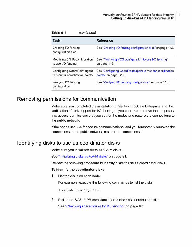
Table 6-1 (continued)
ReferenceTask
See “Creating I/O fencing configuration files” on page 112.Creating I/O fencingconfiguration files
See “Modifying VCS configuration to use I/O fencing”on page 113.
Modifying SFHA configurationto use I/O fencing
See “Configuring CoordPoint agent to monitor coordinationpoints” on page 126.
Configuring CoordPoint agentto monitor coordination points
See “Verifying I/O fencing configuration” on page 115.Verifying I/O fencingconfiguration
Removing permissions for communicationMake sure you completed the installation of Veritas InfoScale Enterprise and theverification of disk support for I/O fencing. If you used rsh, remove the temporaryrsh access permissions that you set for the nodes and restore the connections tothe public network.
If the nodes use ssh for secure communications, and you temporarily removed theconnections to the public network, restore the connections.
Identifying disks to use as coordinator disksMake sure you initialized disks as VxVM disks.
See “Initializing disks as VxVM disks” on page 81.
Review the following procedure to identify disks to use as coordinator disks.
To identify the coordinator disks
1 List the disks on each node.
For example, execute the following commands to list the disks:
# vxdisk -o alldgs list
2 Pick three SCSI-3 PR compliant shared disks as coordinator disks.
See “Checking shared disks for I/O fencing” on page 82.
111Manually configuring SFHA clusters for data integritySetting up disk-based I/O fencing manually
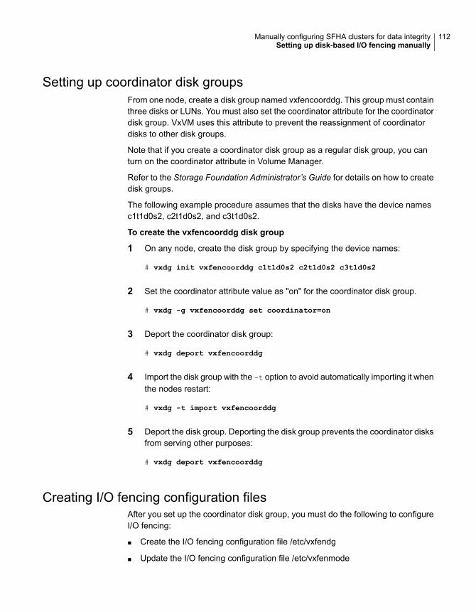
Setting up coordinator disk groupsFrom one node, create a disk group named vxfencoorddg. This group must containthree disks or LUNs. You must also set the coordinator attribute for the coordinatordisk group. VxVM uses this attribute to prevent the reassignment of coordinatordisks to other disk groups.
Note that if you create a coordinator disk group as a regular disk group, you canturn on the coordinator attribute in Volume Manager.
Refer to the Storage Foundation Administrator’s Guide for details on how to createdisk groups.
The following example procedure assumes that the disks have the device namesc1t1d0s2, c2t1d0s2, and c3t1d0s2.
To create the vxfencoorddg disk group
1 On any node, create the disk group by specifying the device names:
# vxdg init vxfencoorddg c1t1d0s2 c2t1d0s2 c3t1d0s2
2 Set the coordinator attribute value as "on" for the coordinator disk group.
# vxdg -g vxfencoorddg set coordinator=on
3 Deport the coordinator disk group:
# vxdg deport vxfencoorddg
4 Import the disk group with the -t option to avoid automatically importing it whenthe nodes restart:
# vxdg -t import vxfencoorddg
5 Deport the disk group. Deporting the disk group prevents the coordinator disksfrom serving other purposes:
# vxdg deport vxfencoorddg
Creating I/O fencing configuration filesAfter you set up the coordinator disk group, you must do the following to configureI/O fencing:
■ Create the I/O fencing configuration file /etc/vxfendg
■ Update the I/O fencing configuration file /etc/vxfenmode
112Manually configuring SFHA clusters for data integritySetting up disk-based I/O fencing manually
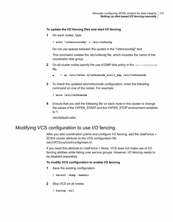
To update the I/O fencing files and start I/O fencing
1 On each nodes, type:
# echo "vxfencoorddg" > /etc/vxfendg
Do not use spaces between the quotes in the "vxfencoorddg" text.
This command creates the /etc/vxfendg file, which includes the name of thecoordinator disk group.
2 On all cluster nodes specify the use of DMP disk policy in the /etc/vxfenmode
file.
■ # cp /etc/vxfen.d/vxfenmode_scsi3_dmp /etc/vxfenmode
3 To check the updated /etc/vxfenmode configuration, enter the followingcommand on one of the nodes. For example:
# more /etc/vxfenmode
4 Ensure that you edit the following file on each node in the cluster to changethe values of the VXFEN_START and the VXFEN_STOP environment variablesto 1:
/etc/default/vxfen
Modifying VCS configuration to use I/O fencingAfter you add coordination points and configure I/O fencing, add the UseFence =SCSI3 cluster attribute to the VCS configuration file/etc/VRTSvcs/conf/config/main.cf.
If you reset this attribute to UseFence = None, VCS does not make use of I/Ofencing abilities while failing over service groups. However, I/O fencing needs tobe disabled separately.
To modify VCS configuration to enable I/O fencing
1 Save the existing configuration:
# haconf -dump -makero
2 Stop VCS on all nodes:
# hastop -all
113Manually configuring SFHA clusters for data integritySetting up disk-based I/O fencing manually

3 To ensure High Availability has stopped cleanly, run gabconfig -a.
In the output of the commans, check that Port h is not present.
4 If the I/O fencing driver vxfen is already running, stop the I/O fencing driver.
# svcadm disable -t vxfen
5 Make a backup of the main.cf file on all the nodes:
# cd /etc/VRTSvcs/conf/config
# cp main.cf main.orig
6 On one node, use vi or another text editor to edit the main.cf file. To modifythe list of cluster attributes, add the UseFence attribute and assign its valueas SCSI3.
cluster clus1(
UserNames = { admin = "cDRpdxPmHpzS." }
Administrators = { admin }
HacliUserLevel = COMMANDROOT
CounterInterval = 5
UseFence = SCSI3
)
Regardless of whether the fencing configuration is disk-based or server-based,the value of the cluster-level attribute UseFence is set to SCSI3.
7 Save and close the file.
8 Verify the syntax of the file /etc/VRTSvcs/conf/config/main.cf:
# hacf -verify /etc/VRTSvcs/conf/config
9 Start the I/O fencing driver and VCS. Perform the following steps on each node:
■ Start the I/O fencing driver.The vxfen startup script also invokes the vxfenconfig command, whichconfigures the vxfen driver to start and use the coordination points that arelisted in /etc/vxfentab.
# svcadm enable vxfen
■ Start VCS on the node where main.cf is modified.
# /opt/VRTS/bin/hastart
114Manually configuring SFHA clusters for data integritySetting up disk-based I/O fencing manually
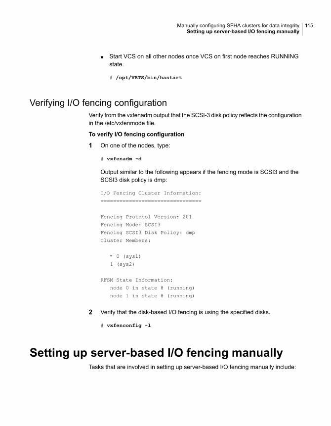
■ Start VCS on all other nodes once VCS on first node reaches RUNNINGstate.
# /opt/VRTS/bin/hastart
Verifying I/O fencing configurationVerify from the vxfenadm output that the SCSI-3 disk policy reflects the configurationin the /etc/vxfenmode file.
To verify I/O fencing configuration
1 On one of the nodes, type:
# vxfenadm -d
Output similar to the following appears if the fencing mode is SCSI3 and theSCSI3 disk policy is dmp:
I/O Fencing Cluster Information:
================================
Fencing Protocol Version: 201
Fencing Mode: SCSI3
Fencing SCSI3 Disk Policy: dmp
Cluster Members:
* 0 (sys1)
1 (sys2)
RFSM State Information:
node 0 in state 8 (running)
node 1 in state 8 (running)
2 Verify that the disk-based I/O fencing is using the specified disks.
# vxfenconfig -l
Setting up server-based I/O fencing manuallyTasks that are involved in setting up server-based I/O fencing manually include:
115Manually configuring SFHA clusters for data integritySetting up server-based I/O fencing manually
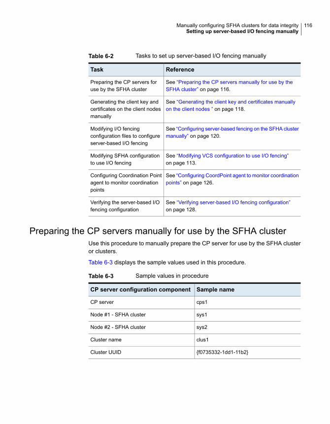
Table 6-2 Tasks to set up server-based I/O fencing manually
ReferenceTask
See “Preparing the CP servers manually for use by theSFHA cluster” on page 116.
Preparing the CP servers foruse by the SFHA cluster
See “Generating the client key and certificates manuallyon the client nodes ” on page 118.
Generating the client key andcertificates on the client nodesmanually
See “Configuring server-based fencing on the SFHA clustermanually” on page 120.
Modifying I/O fencingconfiguration files to configureserver-based I/O fencing
See “Modifying VCS configuration to use I/O fencing”on page 113.
Modifying SFHA configurationto use I/O fencing
See “Configuring CoordPoint agent to monitor coordinationpoints” on page 126.
Configuring Coordination Pointagent to monitor coordinationpoints
See “Verifying server-based I/O fencing configuration”on page 128.
Verifying the server-based I/Ofencing configuration
Preparing the CP servers manually for use by the SFHA clusterUse this procedure to manually prepare the CP server for use by the SFHA clusteror clusters.
Table 6-3 displays the sample values used in this procedure.
Table 6-3 Sample values in procedure
Sample nameCP server configuration component
cps1CP server
sys1Node #1 - SFHA cluster
sys2Node #2 - SFHA cluster
clus1Cluster name
{f0735332-1dd1-11b2}Cluster UUID
116Manually configuring SFHA clusters for data integritySetting up server-based I/O fencing manually

To manually configure CP servers for use by the SFHA cluster
1 Determine the cluster name and uuid on the SFHA cluster.
For example, issue the following commands on one of the SFHA cluster nodes(sys1):
# grep cluster /etc/VRTSvcs/conf/config/main.cf
cluster clus1
# cat /etc/vx/.uuids/clusuuid
{f0735332-1dd1-11b2-bb31-00306eea460a}
2 Use the cpsadm command to check whether the SFHA cluster and nodes arepresent in the CP server.
For example:
# cpsadm -s cps1.example.com -a list_nodes
ClusName UUID Hostname(Node ID) Registered
clus1 {f0735332-1dd1-11b2-bb31-00306eea460a} sys1(0) 0
clus1 {f0735332-1dd1-11b2-bb31-00306eea460a} sys2(1) 0
If the output does not show the cluster and nodes, then add them as describedin the next step.
For detailed information about the cpsadm command, see the Cluster ServerAdministrator's Guide.
117Manually configuring SFHA clusters for data integritySetting up server-based I/O fencing manually
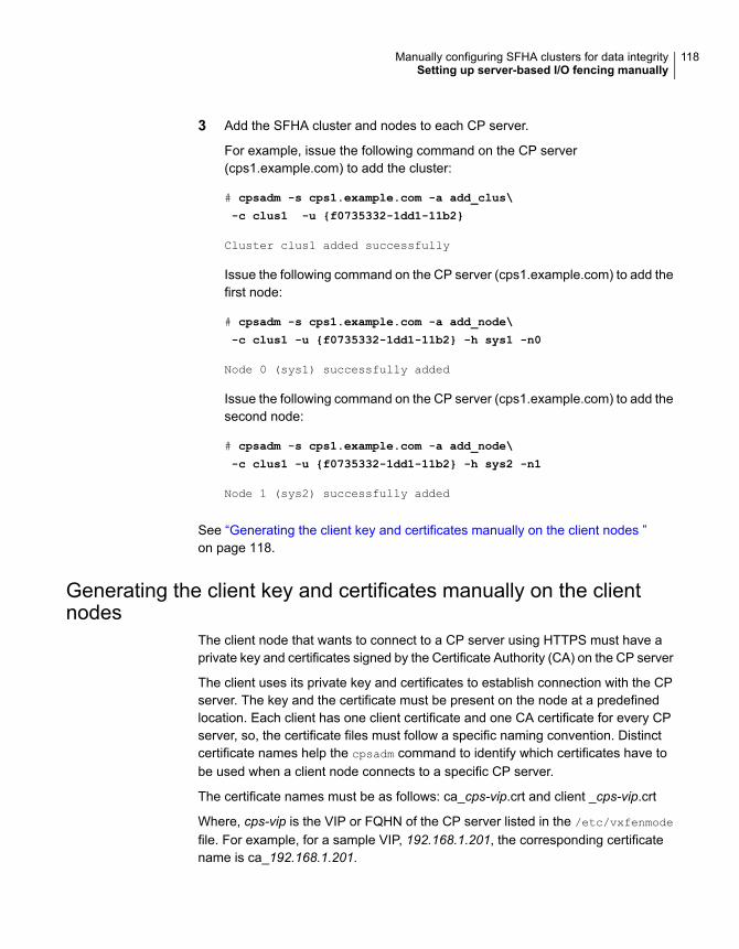
3 Add the SFHA cluster and nodes to each CP server.
For example, issue the following command on the CP server(cps1.example.com) to add the cluster:
# cpsadm -s cps1.example.com -a add_clus\
-c clus1 -u {f0735332-1dd1-11b2}
Cluster clus1 added successfully
Issue the following command on the CP server (cps1.example.com) to add thefirst node:
# cpsadm -s cps1.example.com -a add_node\
-c clus1 -u {f0735332-1dd1-11b2} -h sys1 -n0
Node 0 (sys1) successfully added
Issue the following command on the CP server (cps1.example.com) to add thesecond node:
# cpsadm -s cps1.example.com -a add_node\
-c clus1 -u {f0735332-1dd1-11b2} -h sys2 -n1
Node 1 (sys2) successfully added
See “Generating the client key and certificates manually on the client nodes ”on page 118.
Generating the client key and certificates manually on the clientnodes
The client node that wants to connect to a CP server using HTTPS must have aprivate key and certificates signed by the Certificate Authority (CA) on the CP server
The client uses its private key and certificates to establish connection with the CPserver. The key and the certificate must be present on the node at a predefinedlocation. Each client has one client certificate and one CA certificate for every CPserver, so, the certificate files must follow a specific naming convention. Distinctcertificate names help the cpsadm command to identify which certificates have tobe used when a client node connects to a specific CP server.
The certificate names must be as follows: ca_cps-vip.crt and client _cps-vip.crt
Where, cps-vip is the VIP or FQHN of the CP server listed in the /etc/vxfenmode
file. For example, for a sample VIP, 192.168.1.201, the corresponding certificatename is ca_192.168.1.201.
118Manually configuring SFHA clusters for data integritySetting up server-based I/O fencing manually
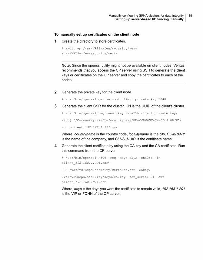
To manually set up certificates on the client node
1 Create the directory to store certificates.
# mkdir -p /var/VRTSvxfen/security/keys
/var/VRTSvxfen/security/certs
Note: Since the openssl utility might not be available on client nodes, Veritasrecommends that you access the CP server using SSH to generate the clientkeys or certificates on the CP server and copy the certificates to each of thenodes.
2 Generate the private key for the client node.
# /usr/bin/openssl genrsa -out client_private.key 2048
3 Generate the client CSR for the cluster. CN is the UUID of the client's cluster.
# /usr/bin/openssl req -new -key -sha256 client_private.key\
-subj '/C=countryname/L=localityname/OU=COMPANY/CN=CLUS_UUID'\
-out client_192.168.1.201.csr
Where, countryname is the country code, localityname is the city, COMPANYis the name of the company, and CLUS_UUID is the certificate name.
4 Generate the client certificate by using the CA key and the CA certificate. Runthis command from the CP server.
# /usr/bin/openssl x509 -req -days days -sha256 -in
client_192.168.1.201.csr\
-CA /var/VRTScps/security/certs/ca.crt -CAkey\
/var/VRTScps/security/keys/ca.key -set_serial 01 -out
client_192.168.10.1.crt
Where, days is the days you want the certificate to remain valid, 192.168.1.201is the VIP or FQHN of the CP server.
119Manually configuring SFHA clusters for data integritySetting up server-based I/O fencing manually

5 Copy the client key, client certificate, and CA certificate to each of the clientnodes at the following location.
Copy the client key at/var/VRTSvxfen/security/keys/client_private.key. The client is commonfor all the client nodes and hence you need to generate it only once.
Copy the client certificate at/var/VRTSvxfen/security/certs/client_192.168.1.201.crt.
Copy the CA certificate at/var/VRTSvxfen/security/certs/ca_192.168.1.201.crt
Note: Copy the certificates and the key to all the nodes at the locations thatare listed in this step.
6 If the client nodes need to access the CP server using the FQHN and or thehost name, make a copy of the certificates you generated and replace the VIPwith the FQHN or host name. Make sure that you copy these certificates to allthe nodes.
7 Repeat the procedure for every CP server.
8 After you copy the key and certificates to each client node, delete the clientkeys and client certificates on the CP server.
Configuring server-based fencing on the SFHA cluster manuallyThe configuration process for the client or SFHA cluster to use CP server as acoordination point requires editing the /etc/vxfenmode file.
You need to edit this file to specify the following information for your configuration:
■ Fencing mode
■ Fencing mechanism
■ Fencing disk policy (if applicable to your I/O fencing configuration)
■ CP server or CP servers
■ Coordinator disk group (if applicable to your I/O fencing configuration)
■ Set the order of coordination points
120Manually configuring SFHA clusters for data integritySetting up server-based I/O fencing manually
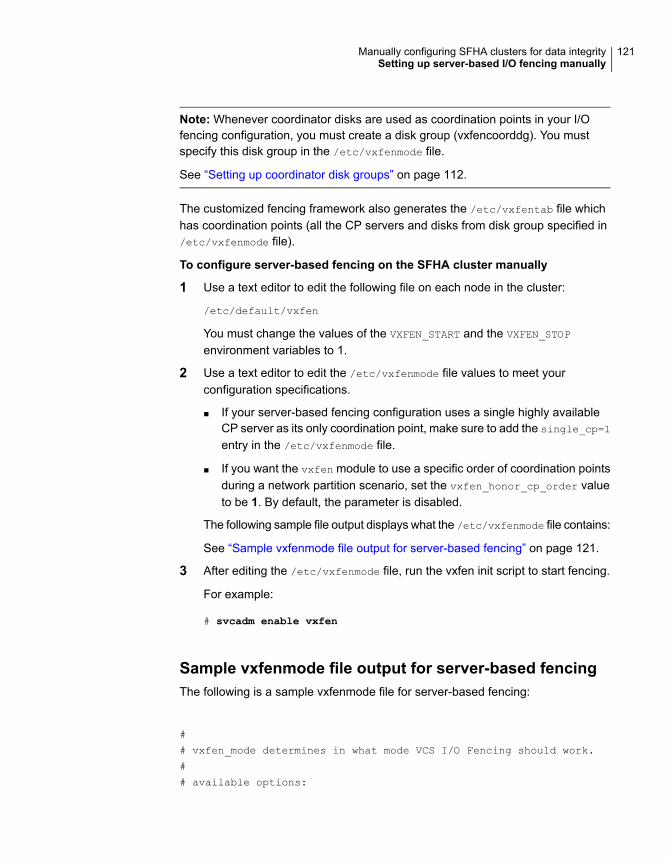
Note: Whenever coordinator disks are used as coordination points in your I/Ofencing configuration, you must create a disk group (vxfencoorddg). You mustspecify this disk group in the /etc/vxfenmode file.
See “Setting up coordinator disk groups” on page 112.
The customized fencing framework also generates the /etc/vxfentab file whichhas coordination points (all the CP servers and disks from disk group specified in/etc/vxfenmode file).
To configure server-based fencing on the SFHA cluster manually
1 Use a text editor to edit the following file on each node in the cluster:
/etc/default/vxfen
You must change the values of the VXFEN_START and the VXFEN_STOP
environment variables to 1.
2 Use a text editor to edit the /etc/vxfenmode file values to meet yourconfiguration specifications.
■ If your server-based fencing configuration uses a single highly availableCP server as its only coordination point, make sure to add the single_cp=1
entry in the /etc/vxfenmode file.
■ If you want the vxfen module to use a specific order of coordination pointsduring a network partition scenario, set the vxfen_honor_cp_order valueto be 1. By default, the parameter is disabled.
The following sample file output displays what the /etc/vxfenmode file contains:
See “Sample vxfenmode file output for server-based fencing” on page 121.
3 After editing the /etc/vxfenmode file, run the vxfen init script to start fencing.
For example:
# svcadm enable vxfen
Sample vxfenmode file output for server-based fencingThe following is a sample vxfenmode file for server-based fencing:
#
# vxfen_mode determines in what mode VCS I/O Fencing should work.
#
# available options:
121Manually configuring SFHA clusters for data integritySetting up server-based I/O fencing manually
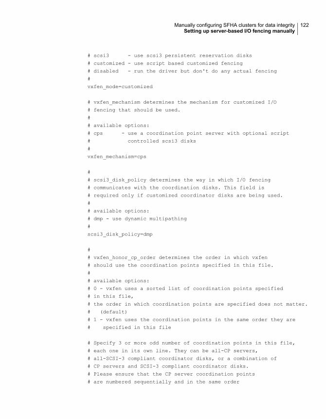
# scsi3 - use scsi3 persistent reservation disks
# customized - use script based customized fencing
# disabled - run the driver but don't do any actual fencing
#
vxfen_mode=customized
# vxfen_mechanism determines the mechanism for customized I/O
# fencing that should be used.
#
# available options:
# cps - use a coordination point server with optional script
# controlled scsi3 disks
#
vxfen_mechanism=cps
#
# scsi3_disk_policy determines the way in which I/O fencing
# communicates with the coordination disks. This field is
# required only if customized coordinator disks are being used.
#
# available options:
# dmp - use dynamic multipathing
#
scsi3_disk_policy=dmp
#
# vxfen_honor_cp_order determines the order in which vxfen
# should use the coordination points specified in this file.
#
# available options:
# 0 - vxfen uses a sorted list of coordination points specified
# in this file,
# the order in which coordination points are specified does not matter.
# (default)
# 1 - vxfen uses the coordination points in the same order they are
# specified in this file
# Specify 3 or more odd number of coordination points in this file,
# each one in its own line. They can be all-CP servers,
# all-SCSI-3 compliant coordinator disks, or a combination of
# CP servers and SCSI-3 compliant coordinator disks.
# Please ensure that the CP server coordination points
# are numbered sequentially and in the same order
122Manually configuring SFHA clusters for data integritySetting up server-based I/O fencing manually
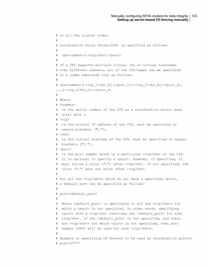
# on all the cluster nodes.
#
# Coordination Point Server(CPS) is specified as follows:
#
# cps<number>=[<vip/vhn>]:<port>
#
# If a CPS supports multiple virtual IPs or virtual hostnames
# over different subnets, all of the IPs/names can be specified
# in a comma separated list as follows:
#
# cps<number>=[<vip_1/vhn_1>]:<port_1>,[<vip_2/vhn_2>]:<port_2>,
...,[<vip_n/vhn_n>]:<port_n>
#
# Where,
# <number>
# is the serial number of the CPS as a coordination point; must
# start with 1.
# <vip>
# is the virtual IP address of the CPS, must be specified in
# square brackets ("[]").
# <vhn>
# is the virtual hostname of the CPS, must be specified in square
# brackets ("[]").
# <port>
# is the port number bound to a particular <vip/vhn> of the CPS.
# It is optional to specify a <port>. However, if specified, it
# must follow a colon (":") after <vip/vhn>. If not specified, the
# colon (":") must not exist after <vip/vhn>.
#
# For all the <vip/vhn>s which do not have a specified <port>,
# a default port can be specified as follows:
#
# port=<default_port>
#
# Where <default_port> is applicable to all the <vip/vhn>s for
# which a <port> is not specified. In other words, specifying
# <port> with a <vip/vhn> overrides the <default_port> for that
# <vip/vhn>. If the <default_port> is not specified, and there
# are <vip/vhn>s for which <port> is not specified, then port
# number 14250 will be used for such <vip/vhn>s.
#
# Example of specifying CP Servers to be used as coordination points:
# port=57777
123Manually configuring SFHA clusters for data integritySetting up server-based I/O fencing manually

# cps1=[192.168.0.23],[192.168.0.24]:58888,[cps1.company.com]
# cps2=[192.168.0.25]
# cps3=[cps2.company.com]:59999
#
# In the above example,
# - port 58888 will be used for vip [192.168.0.24]
# - port 59999 will be used for vhn [cps2.company.com], and
# - default port 57777 will be used for all remaining <vip/vhn>s:
# [192.168.0.23]
# [cps1.company.com]
# [192.168.0.25]
# - if default port 57777 were not specified, port 14250
# would be used for all remaining <vip/vhn>s:
# [192.168.0.23]
# [cps1.company.com]
# [192.168.0.25]
#
# SCSI-3 compliant coordinator disks are specified as:
#
# vxfendg=<coordinator disk group name>
# Example:
# vxfendg=vxfencoorddg
#
# Examples of different configurations:
# 1. All CP server coordination points
# cps1=
# cps2=
# cps3=
#
# 2. A combination of CP server and a disk group having two SCSI-3
# coordinator disks
# cps1=
# vxfendg=
# Note: The disk group specified in this case should have two disks
#
# 3. All SCSI-3 coordinator disks
# vxfendg=
# Note: The disk group specified in case should have three disks
# cps1=[cps1.company.com]
# cps2=[cps2.company.com]
# cps3=[cps3.company.com]
# port=443
124Manually configuring SFHA clusters for data integritySetting up server-based I/O fencing manually
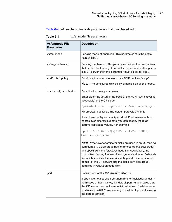
Table 6-4 defines the vxfenmode parameters that must be edited.
Table 6-4 vxfenmode file parameters
Descriptionvxfenmode FileParameter
Fencing mode of operation. This parameter must be set to“customized”.
vxfen_mode
Fencing mechanism. This parameter defines the mechanismthat is used for fencing. If one of the three coordination pointsis a CP server, then this parameter must be set to “cps”.
vxfen_mechanism
Configure the vxfen module to use DMP devices, "dmp".
Note: The configured disk policy is applied on all the nodes.
scsi3_disk_policy
Coordination point parameters.
Enter either the virtual IP address or the FQHN (whichever isaccessible) of the CP server.
cps<number>=[virtual_ip_address/virtual_host_name]:port
Where port is optional. The default port value is 443.
If you have configured multiple virtual IP addresses or hostnames over different subnets, you can specify these ascomma-separated values. For example:
cps1=[192.168.0.23],[192.168.0.24]:58888,[cps1.company.com]
Note: Whenever coordinator disks are used in an I/O fencingconfiguration, a disk group has to be created (vxfencoorddg)and specified in the /etc/vxfenmode file. Additionally, thecustomized fencing framework also generates the /etc/vxfentabfile which specifies the security setting and the coordinationpoints (all the CP servers and the disks from disk groupspecified in /etc/vxfenmode file).
cps1, cps2, or vxfendg
Default port for the CP server to listen on.
If you have not specified port numbers for individual virtual IPaddresses or host names, the default port number value thatthe CP server uses for those individual virtual IP addresses orhost names is 443. You can change this default port value usingthe port parameter.
port
125Manually configuring SFHA clusters for data integritySetting up server-based I/O fencing manually
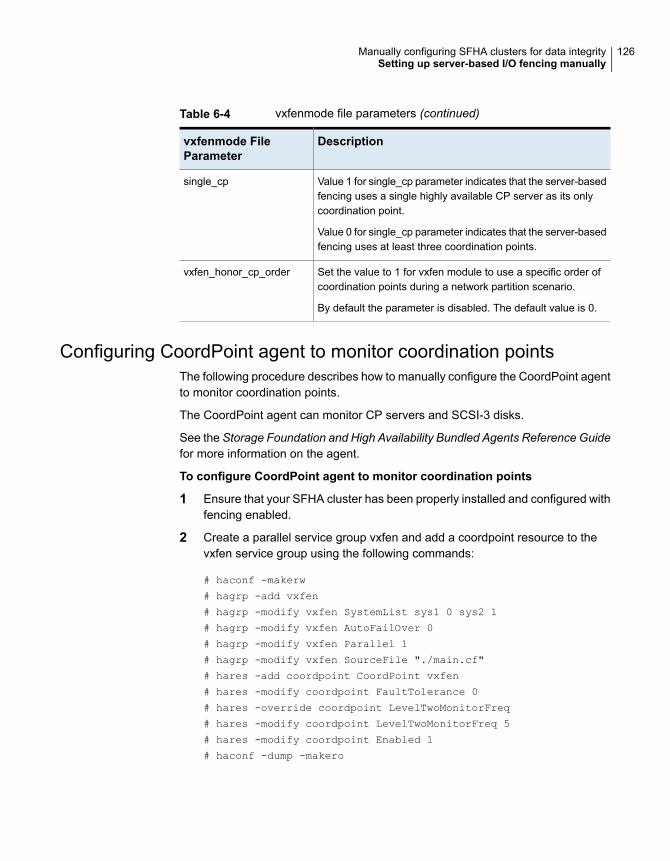
Table 6-4 vxfenmode file parameters (continued)
Descriptionvxfenmode FileParameter
Value 1 for single_cp parameter indicates that the server-basedfencing uses a single highly available CP server as its onlycoordination point.
Value 0 for single_cp parameter indicates that the server-basedfencing uses at least three coordination points.
single_cp
Set the value to 1 for vxfen module to use a specific order ofcoordination points during a network partition scenario.
By default the parameter is disabled. The default value is 0.
vxfen_honor_cp_order
Configuring CoordPoint agent to monitor coordination pointsThe following procedure describes how to manually configure the CoordPoint agentto monitor coordination points.
The CoordPoint agent can monitor CP servers and SCSI-3 disks.
See the Storage Foundation and High Availability Bundled Agents Reference Guidefor more information on the agent.
To configure CoordPoint agent to monitor coordination points
1 Ensure that your SFHA cluster has been properly installed and configured withfencing enabled.
2 Create a parallel service group vxfen and add a coordpoint resource to thevxfen service group using the following commands:
# haconf -makerw
# hagrp -add vxfen
# hagrp -modify vxfen SystemList sys1 0 sys2 1
# hagrp -modify vxfen AutoFailOver 0
# hagrp -modify vxfen Parallel 1
# hagrp -modify vxfen SourceFile "./main.cf"
# hares -add coordpoint CoordPoint vxfen
# hares -modify coordpoint FaultTolerance 0
# hares -override coordpoint LevelTwoMonitorFreq
# hares -modify coordpoint LevelTwoMonitorFreq 5
# hares -modify coordpoint Enabled 1
# haconf -dump -makero
126Manually configuring SFHA clusters for data integritySetting up server-based I/O fencing manually
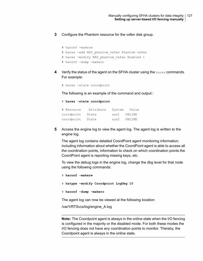
3 Configure the Phantom resource for the vxfen disk group.
# haconf -makerw
# hares -add RES_phantom_vxfen Phantom vxfen
# hares -modify RES_phantom_vxfen Enabled 1
# haconf -dump -makero
4 Verify the status of the agent on the SFHA cluster using the hares commands.For example:
# hares -state coordpoint
The following is an example of the command and output::
# hares -state coordpoint
# Resource Attribute System Value
coordpoint State sys1 ONLINE
coordpoint State sys2 ONLINE
5 Access the engine log to view the agent log. The agent log is written to theengine log.
The agent log contains detailed CoordPoint agent monitoring information;including information about whether the CoordPoint agent is able to access allthe coordination points, information to check on which coordination points theCoordPoint agent is reporting missing keys, etc.
To view the debug logs in the engine log, change the dbg level for that nodeusing the following commands:
# haconf -makerw
# hatype -modify Coordpoint LogDbg 10
# haconf -dump -makero
The agent log can now be viewed at the following location:
/var/VRTSvcs/log/engine_A.log
Note: The Coordpoint agent is always in the online state when the I/O fencingis configured in the majority or the disabled mode. For both these modes theI/O fencing does not have any coordination points to monitor. Thereby, theCoordpoint agent is always in the online state.
127Manually configuring SFHA clusters for data integritySetting up server-based I/O fencing manually
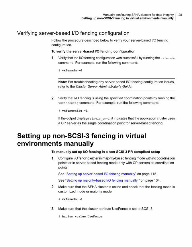
Verifying server-based I/O fencing configurationFollow the procedure described below to verify your server-based I/O fencingconfiguration.
To verify the server-based I/O fencing configuration
1 Verify that the I/O fencing configuration was successful by running the vxfenadm
command. For example, run the following command:
# vxfenadm -d
Note: For troubleshooting any server-based I/O fencing configuration issues,refer to the Cluster Server Administrator's Guide.
2 Verify that I/O fencing is using the specified coordination points by running thevxfenconfig command. For example, run the following command:
# vxfenconfig -l
If the output displays single_cp=1, it indicates that the application cluster usesa CP server as the single coordination point for server-based fencing.
Setting up non-SCSI-3 fencing in virtualenvironments manually
To manually set up I/O fencing in a non-SCSI-3 PR compliant setup
1 Configure I/O fencing either in majority-based fencing mode with no coordinationpoints or in server-based fencing mode only with CP servers as coordinationpoints.
See “Setting up server-based I/O fencing manually” on page 115.
See “Setting up majority-based I/O fencing manually ” on page 134.
2 Make sure that the SFHA cluster is online and check that the fencing mode iscustomized mode or majority mode.
# vxfenadm -d
3 Make sure that the cluster attribute UseFence is set to SCSI-3.
# haclus -value UseFence
128Manually configuring SFHA clusters for data integritySetting up non-SCSI-3 fencing in virtual environments manually
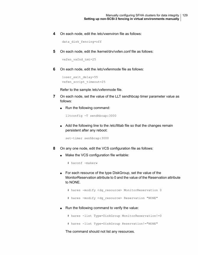
4 On each node, edit the /etc/vxenviron file as follows:
data_disk_fencing=off
5 On each node, edit the /kernel/drv/vxfen.conf file as follows:
vxfen_vxfnd_tmt=25
6 On each node, edit the /etc/vxfenmode file as follows:
loser_exit_delay=55
vxfen_script_timeout=25
Refer to the sample /etc/vxfenmode file.
7 On each node, set the value of the LLT sendhbcap timer parameter value asfollows:
■ Run the following command:
lltconfig -T sendhbcap:3000
■ Add the following line to the /etc/llttab file so that the changes remainpersistent after any reboot:
set-timer senhbcap:3000
8 On any one node, edit the VCS configuration file as follows:
■ Make the VCS configuration file writable:
# haconf -makerw
■ For each resource of the type DiskGroup, set the value of theMonitorReservation attribute to 0 and the value of the Reservation attributeto NONE.
# hares -modify <dg_resource> MonitorReservation 0
# hares -modify <dg_resource> Reservation "NONE"
■ Run the following command to verify the value:
# hares -list Type=DiskGroup MonitorReservation!=0
# hares -list Type=DiskGroup Reservation!="NONE"
The command should not list any resources.
129Manually configuring SFHA clusters for data integritySetting up non-SCSI-3 fencing in virtual environments manually
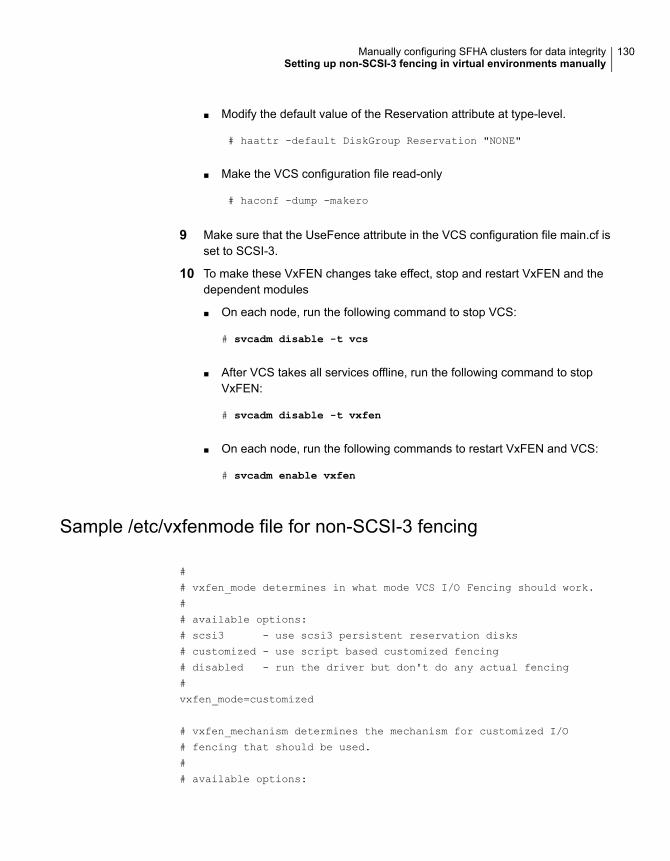
■ Modify the default value of the Reservation attribute at type-level.
# haattr -default DiskGroup Reservation "NONE"
■ Make the VCS configuration file read-only
# haconf -dump -makero
9 Make sure that the UseFence attribute in the VCS configuration file main.cf isset to SCSI-3.
10 To make these VxFEN changes take effect, stop and restart VxFEN and thedependent modules
■ On each node, run the following command to stop VCS:
# svcadm disable -t vcs
■ After VCS takes all services offline, run the following command to stopVxFEN:
# svcadm disable -t vxfen
■ On each node, run the following commands to restart VxFEN and VCS:
# svcadm enable vxfen
Sample /etc/vxfenmode file for non-SCSI-3 fencing
#
# vxfen_mode determines in what mode VCS I/O Fencing should work.
#
# available options:
# scsi3 - use scsi3 persistent reservation disks
# customized - use script based customized fencing
# disabled - run the driver but don't do any actual fencing
#
vxfen_mode=customized
# vxfen_mechanism determines the mechanism for customized I/O
# fencing that should be used.
#
# available options:
130Manually configuring SFHA clusters for data integritySetting up non-SCSI-3 fencing in virtual environments manually
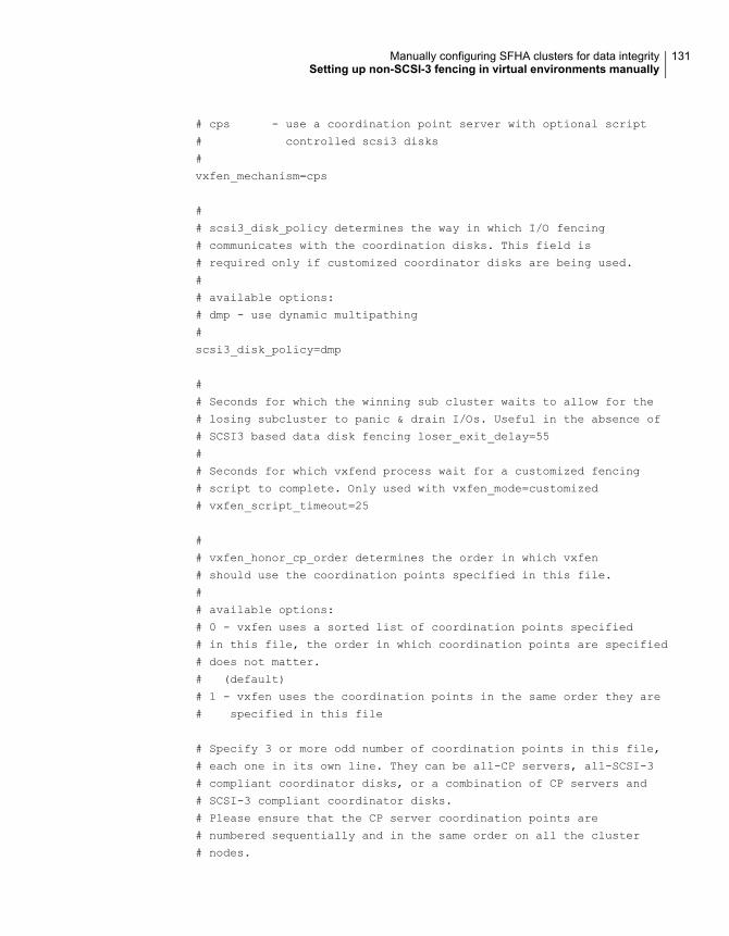
# cps - use a coordination point server with optional script
# controlled scsi3 disks
#
vxfen_mechanism=cps
#
# scsi3_disk_policy determines the way in which I/O fencing
# communicates with the coordination disks. This field is
# required only if customized coordinator disks are being used.
#
# available options:
# dmp - use dynamic multipathing
#
scsi3_disk_policy=dmp
#
# Seconds for which the winning sub cluster waits to allow for the
# losing subcluster to panic & drain I/Os. Useful in the absence of
# SCSI3 based data disk fencing loser_exit_delay=55
#
# Seconds for which vxfend process wait for a customized fencing
# script to complete. Only used with vxfen_mode=customized
# vxfen_script_timeout=25
#
# vxfen_honor_cp_order determines the order in which vxfen
# should use the coordination points specified in this file.
#
# available options:
# 0 - vxfen uses a sorted list of coordination points specified
# in this file, the order in which coordination points are specified
# does not matter.
# (default)
# 1 - vxfen uses the coordination points in the same order they are
# specified in this file
# Specify 3 or more odd number of coordination points in this file,
# each one in its own line. They can be all-CP servers, all-SCSI-3
# compliant coordinator disks, or a combination of CP servers and
# SCSI-3 compliant coordinator disks.
# Please ensure that the CP server coordination points are
# numbered sequentially and in the same order on all the cluster
# nodes.
131Manually configuring SFHA clusters for data integritySetting up non-SCSI-3 fencing in virtual environments manually

#
# Coordination Point Server(CPS) is specified as follows:
#
# cps<number>=[<vip/vhn>]:<port>
#
# If a CPS supports multiple virtual IPs or virtual hostnames
# over different subnets, all of the IPs/names can be specified
# in a comma separated list as follows:
#
# cps<number>=[<vip_1/vhn_1>]:<port_1>,[<vip_2/vhn_2>]:<port_2>,
# ...,[<vip_n/vhn_n>]:<port_n>
#
# Where,
# <number>
# is the serial number of the CPS as a coordination point; must
# start with 1.
# <vip>
# is the virtual IP address of the CPS, must be specified in
# square brackets ("[]").
# <vhn>
# is the virtual hostname of the CPS, must be specified in square
# brackets ("[]").
# <port>
# is the port number bound to a particular <vip/vhn> of the CPS.
# It is optional to specify a <port>. However, if specified, it
# must follow a colon (":") after <vip/vhn>. If not specified, the
# colon (":") must not exist after <vip/vhn>.
#
# For all the <vip/vhn>s which do not have a specified <port>,
# a default port can be specified as follows:
#
# port=<default_port>
#
# Where <default_port> is applicable to all the <vip/vhn>s for which a
# <port> is not specified. In other words, specifying <port> with a
# <vip/vhn> overrides the <default_port> for that <vip/vhn>.
# If the <default_port> is not specified, and there are <vip/vhn>s for
# which <port> is not specified, then port number 14250 will be used
# for such <vip/vhn>s.
#
# Example of specifying CP Servers to be used as coordination points:
# port=57777
# cps1=[192.168.0.23],[192.168.0.24]:58888,[cps1.company.com]
132Manually configuring SFHA clusters for data integritySetting up non-SCSI-3 fencing in virtual environments manually
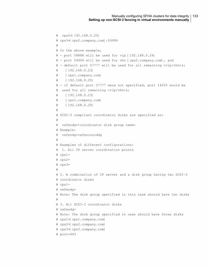
# cps2=[192.168.0.25]
# cps3=[cps2.company.com]:59999
#
# In the above example,
# - port 58888 will be used for vip [192.168.0.24]
# - port 59999 will be used for vhn [cps2.company.com], and
# - default port 57777 will be used for all remaining <vip/vhn>s:
# [192.168.0.23]
# [cps1.company.com]
# [192.168.0.25]
# - if default port 57777 were not specified, port 14250 would be
# used for all remaining <vip/vhn>s:
# [192.168.0.23]
# [cps1.company.com]
# [192.168.0.25]
#
# SCSI-3 compliant coordinator disks are specified as:
#
# vxfendg=<coordinator disk group name>
# Example:
# vxfendg=vxfencoorddg
#
# Examples of different configurations:
# 1. All CP server coordination points
# cps1=
# cps2=
# cps3=
#
# 2. A combination of CP server and a disk group having two SCSI-3
# coordinator disks
# cps1=
# vxfendg=
# Note: The disk group specified in this case should have two disks
#
# 3. All SCSI-3 coordinator disks
# vxfendg=
# Note: The disk group specified in case should have three disks
# cps1=[cps1.company.com]
# cps2=[cps2.company.com]
# cps3=[cps3.company.com]
# port=443
133Manually configuring SFHA clusters for data integritySetting up non-SCSI-3 fencing in virtual environments manually

Setting up majority-based I/O fencing manuallyTable 6-5 lists the tasks that are involved in setting up I/O fencing.
ReferenceTask
Creating I/O fencing configuration filesCreating I/O fencing configuration files
Modifying VCS configuration to use I/Ofencing
Modifying VCS configuration to use I/Ofencing
Verifying I/O fencing configurationVerifying I/O fencing configuration
Creating I/O fencing configuration filesTo update the I/O fencing files and start I/O fencing
1 On all cluster nodes, run the following command
# cp /etc/vxfen.d/vxfenmode_majority /etc/vxfenmode
2 To check the updated /etc/vxfenmode configuration, enter the followingcommand on one of the nodes.
# cat /etc/vxfenmode
3 Ensure that you edit the following file on each node in the cluster to changethe values of the VXFEN_START and the VXFEN_STOP environment variables to1.
/etc/sysconfig/vxfen
Modifying VCS configuration to use I/O fencingAfter you configure I/O fencing, add the UseFence = SCSI3 cluster attribute to theVCS configuration file /etc/VRTSvcs/conf/config/main.cf.
If you reset this attribute to UseFence = None, VCS does not make use of I/Ofencing abilities while failing over service groups. However, I/O fencing needs tobe disabled separately.
134Manually configuring SFHA clusters for data integritySetting up majority-based I/O fencing manually
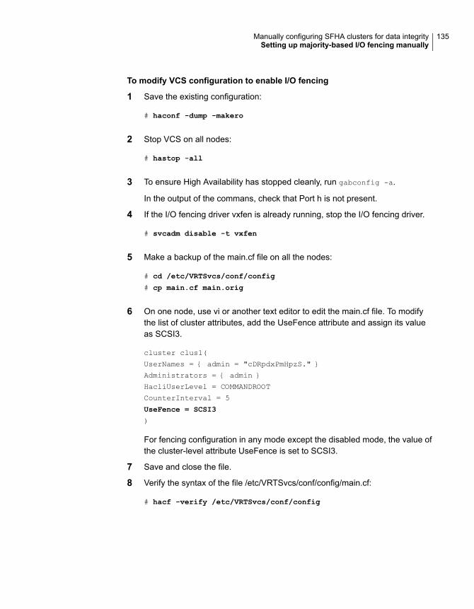
To modify VCS configuration to enable I/O fencing
1 Save the existing configuration:
# haconf -dump -makero
2 Stop VCS on all nodes:
# hastop -all
3 To ensure High Availability has stopped cleanly, run gabconfig -a.
In the output of the commans, check that Port h is not present.
4 If the I/O fencing driver vxfen is already running, stop the I/O fencing driver.
# svcadm disable -t vxfen
5 Make a backup of the main.cf file on all the nodes:
# cd /etc/VRTSvcs/conf/config
# cp main.cf main.orig
6 On one node, use vi or another text editor to edit the main.cf file. To modifythe list of cluster attributes, add the UseFence attribute and assign its valueas SCSI3.
cluster clus1(
UserNames = { admin = "cDRpdxPmHpzS." }
Administrators = { admin }
HacliUserLevel = COMMANDROOT
CounterInterval = 5
UseFence = SCSI3
)
For fencing configuration in any mode except the disabled mode, the value ofthe cluster-level attribute UseFence is set to SCSI3.
7 Save and close the file.
8 Verify the syntax of the file /etc/VRTSvcs/conf/config/main.cf:
# hacf -verify /etc/VRTSvcs/conf/config
135Manually configuring SFHA clusters for data integritySetting up majority-based I/O fencing manually
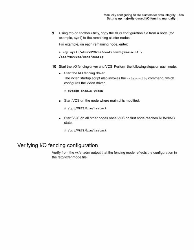
9 Using rcp or another utility, copy the VCS configuration file from a node (forexample, sys1) to the remaining cluster nodes.
For example, on each remaining node, enter:
# rcp sys1:/etc/VRTSvcs/conf/config/main.cf \
/etc/VRTSvcs/conf/config
10 Start the I/O fencing driver and VCS. Perform the following steps on each node:
■ Start the I/O fencing driver.The vxfen startup script also invokes the vxfenconfig command, whichconfigures the vxfen driver.
# svcadm enable vxfen
■ Start VCS on the node where main.cf is modified.
# /opt/VRTS/bin/hastart
■ Start VCS on all other nodes once VCS on first node reaches RUNNINGstate.
# /opt/VRTS/bin/hastart
Verifying I/O fencing configurationVerify from the vxfenadm output that the fencing mode reflects the configuration inthe /etc/vxfenmode file.
136Manually configuring SFHA clusters for data integritySetting up majority-based I/O fencing manually

To verify I/O fencing configuration
◆ On one of the nodes, type:
# vxfenadm -d
Output similar to the following appears if the fencing mode is majority:
I/O Fencing Cluster Information:
================================
Fencing Protocol Version: 201
Fencing Mode: MAJORITY
Cluster Members:
* 0 (sys1)
1 (sys2)
RFSM State Information:
node 0 in state 8 (running)
node 1 in state 8 (running)
137Manually configuring SFHA clusters for data integritySetting up majority-based I/O fencing manually
Performing an automatedSFHA configuration usingresponse files
This chapter includes the following topics:
■ Configuring SFHA using response files
■ Response file variables to configure SFHA
■ Sample response file for SFHA configuration
Configuring SFHA using response filesTypically, you can use the response file that the installer generates after you performSFHA configuration on one cluster to configure SFHA on other clusters.
To configure SFHA using response files
1 Make sure the Veritas InfoScale Availability or Enterprise packages are installedon the systems where you want to configure SFHA.
2 Copy the response file to one of the cluster systems where you want toconfigure SFHA.
7Chapter
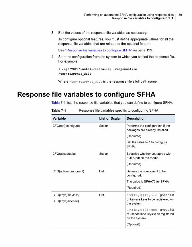
3 Edit the values of the response file variables as necessary.
To configure optional features, you must define appropriate values for all theresponse file variables that are related to the optional feature.
See “Response file variables to configure SFHA” on page 139.
4 Start the configuration from the system to which you copied the response file.For example:
# /opt/VRTS/install/installer -responsefile
/tmp/response_file
Where /tmp/response_file is the response file’s full path name.
Response file variables to configure SFHATable 7-1 lists the response file variables that you can define to configure SFHA.
Table 7-1 Response file variables specific to configuring SFHA
DescriptionList or ScalarVariable
Performs the configuration if thepackages are already installed.
(Required)
Set the value to 1 to configureSFHA.
ScalarCFG{opt}{configure}
Specifies whether you agree withEULA.pdf on the media.
(Required)
ScalarCFG{accepteula}
Defines the component to beconfigured.
The value is SFHA72 for SFHA
(Required)
ListCFG{activecomponent}
CFG{keys}{keyless} gives a listof keyless keys to be registered onthe system.
CFG{keys}{license} gives a listof user defined keys to be registeredon the system.
(Optional)
ListCFG{keys}{keyless}
CFG{keys}{license}
139Performing an automated SFHA configuration using response filesResponse file variables to configure SFHA
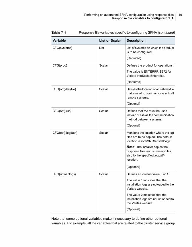
Table 7-1 Response file variables specific to configuring SFHA (continued)
DescriptionList or ScalarVariable
List of systems on which the productis to be configured.
(Required)
ListCFG{systems}
Defines the product for operations.
The value is ENTERPRISE72 forVeritas InfoScale Enterprise.
(Required)
ScalarCFG{prod}
Defines the location of an ssh keyfilethat is used to communicate with allremote systems.
(Optional)
ScalarCFG{opt}{keyfile}
Defines that rsh must be usedinstead of ssh as the communicationmethod between systems.
(Optional)
ScalarCFG{opt}{rsh}
Mentions the location where the logfiles are to be copied. The defaultlocation is /opt/VRTS/install/logs.
Note: The installer copies theresponse files and summary filesalso to the specified logpathlocation.
(Optional)
ScalarCFG{opt}{logpath}
Defines a Boolean value 0 or 1.
The value 1 indicates that theinstallation logs are uploaded to theVeritas website.
The value 0 indicates that theinstallation logs are not uploaded tothe Veritas website.
(Optional)
ScalarCFG{uploadlogs}
Note that some optional variables make it necessary to define other optionalvariables. For example, all the variables that are related to the cluster service group
140Performing an automated SFHA configuration using response filesResponse file variables to configure SFHA
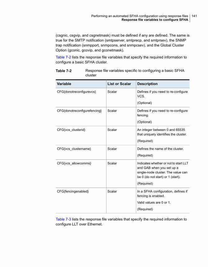
(csgnic, csgvip, and csgnetmask) must be defined if any are defined. The same istrue for the SMTP notification (smtpserver, smtprecp, and smtprsev), the SNMPtrap notification (snmpport, snmpcons, and snmpcsev), and the Global ClusterOption (gconic, gcovip, and gconetmask).
Table 7-2 lists the response file variables that specify the required information toconfigure a basic SFHA cluster.
Table 7-2 Response file variables specific to configuring a basic SFHAcluster
DescriptionList or ScalarVariable
Defines if you need to re-configureVCS.
(Optional)
ScalarCFG{donotreconfigurevcs}
Defines if you need to re-configurefencing.
(Optional)
ScalarCFG{donotreconfigurefencing}
An integer between 0 and 65535that uniquely identifies the cluster.
(Required)
ScalarCFG{vcs_clusterid}
Defines the name of the cluster.
(Required)
ScalarCFG{vcs_clustername}
Indicates whether or not to start LLTand GAB when you set up asingle-node cluster. The value canbe 0 (do not start) or 1 (start).
(Required)
ScalarCFG{vcs_allowcomms}
In a SFHA configuration, defines iffencing is enabled.
Valid values are 0 or 1.
(Required)
ScalarCFG{fencingenabled}
Table 7-3 lists the response file variables that specify the required information toconfigure LLT over Ethernet.
141Performing an automated SFHA configuration using response filesResponse file variables to configure SFHA
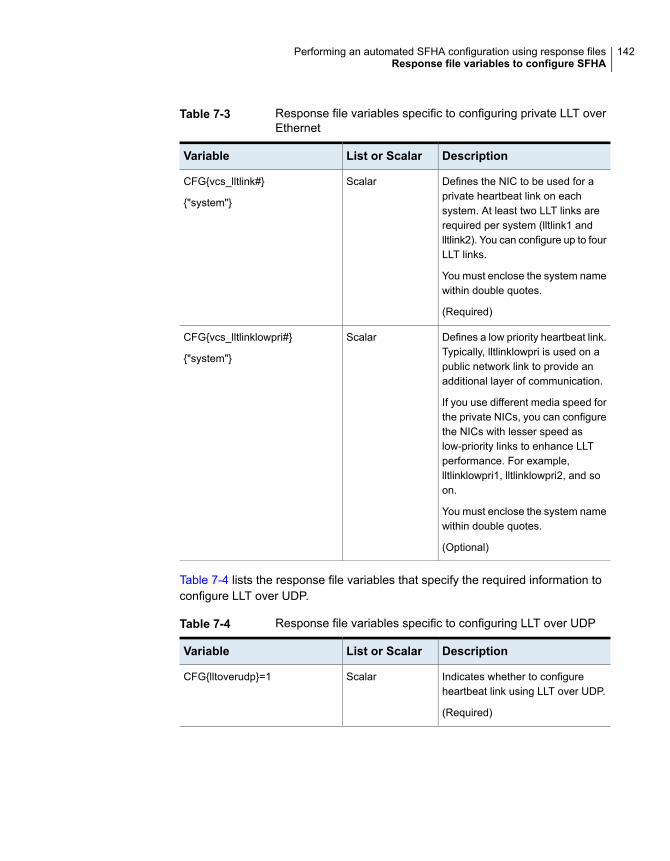
Table 7-3 Response file variables specific to configuring private LLT overEthernet
DescriptionList or ScalarVariable
Defines the NIC to be used for aprivate heartbeat link on eachsystem. At least two LLT links arerequired per system (lltlink1 andlltlink2). You can configure up to fourLLT links.
You must enclose the system namewithin double quotes.
(Required)
ScalarCFG{vcs_lltlink#}
{"system"}
Defines a low priority heartbeat link.Typically, lltlinklowpri is used on apublic network link to provide anadditional layer of communication.
If you use different media speed forthe private NICs, you can configurethe NICs with lesser speed aslow-priority links to enhance LLTperformance. For example,lltlinklowpri1, lltlinklowpri2, and soon.
You must enclose the system namewithin double quotes.
(Optional)
ScalarCFG{vcs_lltlinklowpri#}
{"system"}
Table 7-4 lists the response file variables that specify the required information toconfigure LLT over UDP.
Table 7-4 Response file variables specific to configuring LLT over UDP
DescriptionList or ScalarVariable
Indicates whether to configureheartbeat link using LLT over UDP.
(Required)
ScalarCFG{lltoverudp}=1
142Performing an automated SFHA configuration using response filesResponse file variables to configure SFHA
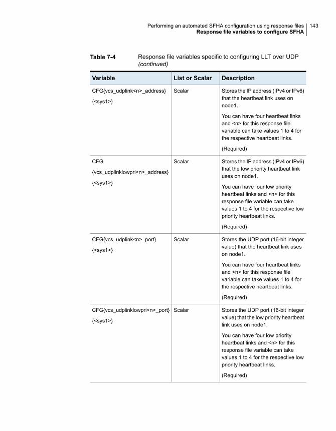
Table 7-4 Response file variables specific to configuring LLT over UDP(continued)
DescriptionList or ScalarVariable
Stores the IP address (IPv4 or IPv6)that the heartbeat link uses onnode1.
You can have four heartbeat linksand <n> for this response filevariable can take values 1 to 4 forthe respective heartbeat links.
(Required)
ScalarCFG{vcs_udplink<n>_address}
{<sys1>}
Stores the IP address (IPv4 or IPv6)that the low priority heartbeat linkuses on node1.
You can have four low priorityheartbeat links and <n> for thisresponse file variable can takevalues 1 to 4 for the respective lowpriority heartbeat links.
(Required)
ScalarCFG
{vcs_udplinklowpri<n>_address}
{<sys1>}
Stores the UDP port (16-bit integervalue) that the heartbeat link useson node1.
You can have four heartbeat linksand <n> for this response filevariable can take values 1 to 4 forthe respective heartbeat links.
(Required)
ScalarCFG{vcs_udplink<n>_port}
{<sys1>}
Stores the UDP port (16-bit integervalue) that the low priority heartbeatlink uses on node1.
You can have four low priorityheartbeat links and <n> for thisresponse file variable can takevalues 1 to 4 for the respective lowpriority heartbeat links.
(Required)
ScalarCFG{vcs_udplinklowpri<n>_port}
{<sys1>}
143Performing an automated SFHA configuration using response filesResponse file variables to configure SFHA

Table 7-4 Response file variables specific to configuring LLT over UDP(continued)
DescriptionList or ScalarVariable
Stores the netmask (prefix for IPv6)that the heartbeat link uses onnode1.
You can have four heartbeat linksand <n> for this response filevariable can take values 1 to 4 forthe respective heartbeat links.
(Required)
ScalarCFG{vcs_udplink<n>_netmask}
{<sys1>}
Stores the netmask (prefix for IPv6)that the low priority heartbeat linkuses on node1.
You can have four low priorityheartbeat links and <n> for thisresponse file variable can takevalues 1 to 4 for the respective lowpriority heartbeat links.
(Required)
ScalarCFG{vcs_udplinklowpri<n>_netmask}
{<sys1>}
Table 7-5 lists the response file variables that specify the required information toconfigure virtual IP for SFHA cluster.
Table 7-5 Response file variables specific to configuring virtual IP for SFHAcluster
DescriptionList or ScalarVariable
Defines the NIC device to use on asystem. You can enter ‘all’ as asystem value if the same NIC isused on all systems.
(Optional)
ScalarCFG{vcs_csgnic}
{system}
Defines the virtual IP address forthe cluster.
(Optional)
ScalarCFG{vcs_csgvip}
Defines the Netmask of the virtualIP address for the cluster.
(Optional)
ScalarCFG{vcs_csgnetmask}
144Performing an automated SFHA configuration using response filesResponse file variables to configure SFHA

Table 7-6 lists the response file variables that specify the required information toconfigure the SFHA cluster in secure mode.
Table 7-6 Response file variables specific to configuring SFHA cluster insecure mode
DescriptionList or ScalarVariable
Specifies if the cluster is in secureenabled mode or not.
ScalarCFG{vcs_eat_security}
Specifies that the securityonenodeoption is being used.
ScalarCFG{opt}{securityonenode}
Specifies the menu option to chooseto configure the secure cluster oneat a time.
■ 1—Configure the first node■ 2—Configure the other node
ScalarCFG{securityonenode_menu}
Defines the user groups which getread access to the cluster.
List or scalar: list
Optional or required: optional
ListCFG{secusrgrps}
Defines the read access to thecluster only for root and other usersor user groups which are grantedexplicit privileges in VCS objects.
(Optional)
ScalarCFG{rootsecusrgrps}
Specifies the directory where theconfiguration files are placed.
ScalarCFG{security_conf_dir}
Specifies that the security option isbeing used.
ScalarCFG{opt}{security}
Defines if the user chooses to grantread access to everyone.
Optional or required: optional
ScalarCFG{defaultaccess}
Specifies that the enabled securityis FIPS compliant.
ScalarCFG{vcs_eat_security_fips}
Table 7-7 lists the response file variables that specify the required information toconfigure VCS users.
145Performing an automated SFHA configuration using response filesResponse file variables to configure SFHA
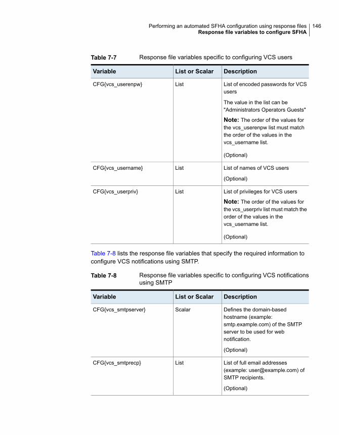
Table 7-7 Response file variables specific to configuring VCS users
DescriptionList or ScalarVariable
List of encoded passwords for VCSusers
The value in the list can be"Administrators Operators Guests"
Note: The order of the values forthe vcs_userenpw list must matchthe order of the values in thevcs_username list.
(Optional)
ListCFG{vcs_userenpw}
List of names of VCS users
(Optional)
ListCFG{vcs_username}
List of privileges for VCS users
Note: The order of the values forthe vcs_userpriv list must match theorder of the values in thevcs_username list.
(Optional)
ListCFG{vcs_userpriv}
Table 7-8 lists the response file variables that specify the required information toconfigure VCS notifications using SMTP.
Table 7-8 Response file variables specific to configuring VCS notificationsusing SMTP
DescriptionList or ScalarVariable
Defines the domain-basedhostname (example:smtp.example.com) of the SMTPserver to be used for webnotification.
(Optional)
ScalarCFG{vcs_smtpserver}
List of full email addresses(example: [email protected]) ofSMTP recipients.
(Optional)
ListCFG{vcs_smtprecp}
146Performing an automated SFHA configuration using response filesResponse file variables to configure SFHA

Table 7-8 Response file variables specific to configuring VCS notificationsusing SMTP (continued)
DescriptionList or ScalarVariable
Defines the minimum severity levelof messages (Information, Warning,Error, SevereError) that listed SMTPrecipients are to receive. Note thatthe ordering of severity levels mustmatch that of the addresses ofSMTP recipients.
(Optional)
ListCFG{vcs_smtprsev}
Table 7-9 lists the response file variables that specify the required information toconfigure VCS notifications using SNMP.
Table 7-9 Response file variables specific to configuring VCS notificationsusing SNMP
DescriptionList or ScalarVariable
Defines the SNMP trap daemon port(default=162).
(Optional)
ScalarCFG{vcs_snmpport}
List of SNMP console systemnames
(Optional)
ListCFG{vcs_snmpcons}
Defines the minimum severity levelof messages (Information, Warning,Error, SevereError) that listed SNMPconsoles are to receive. Note thatthe ordering of severity levels mustmatch that of the SNMP consolesystem names.
(Optional)
ListCFG{vcs_snmpcsev}
Table 7-10 lists the response file variables that specify the required information toconfigure SFHA global clusters.
147Performing an automated SFHA configuration using response filesResponse file variables to configure SFHA
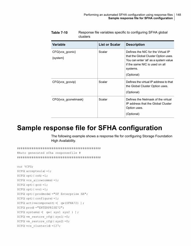
Table 7-10 Response file variables specific to configuring SFHA globalclusters
DescriptionList or ScalarVariable
Defines the NIC for the Virtual IPthat the Global Cluster Option uses.You can enter ‘all’ as a system valueif the same NIC is used on allsystems.
(Optional)
ScalarCFG{vcs_gconic}
{system}
Defines the virtual IP address to thatthe Global Cluster Option uses.
(Optional)
ScalarCFG{vcs_gcovip}
Defines the Netmask of the virtualIP address that the Global ClusterOption uses.
(Optional)
ScalarCFG{vcs_gconetmask}
Sample response file for SFHA configurationThe following example shows a response file for configuring Storage FoundationHigh Availability.
##############################################
#Auto generated sfha responsefile #
##############################################
our %CFG;
$CFG{accepteula}=1;
$CFG{opt}{rsh}=1;
$CFG{vcs_allowcomms}=1;
$CFG{opt}{gco}=1;
$CFG{opt}{vvr}=1;
$CFG{opt}{prodmode}="SF Enterprise HA";
$CFG{opt}{configure}=1;
$CFG{activecomponent}=[ qw(SFHA72) ];
$CFG{prod}="ENTERPRISE72";
$CFG{systems}=[ qw( sys1 sys2 ) ];
$CFG{vm_restore_cfg}{sys1}=0;
$CFG{vm_restore_cfg}{sys2}=0;
$CFG{vcs_clusterid}=127;
148Performing an automated SFHA configuration using response filesSample response file for SFHA configuration

$CFG{vcs_clustername}="clus1";
$CFG{vcs_username}=[ qw(admin operator) ];
$CFG{vcs_userenpw}=[ qw(JlmElgLimHmmKumGlj bQOsOUnVQoOUnTQsOSnUQuOUnPQtOS) ];
$CFG{vcs_userpriv}=[ qw(Administrators Operators) ];
$CFG{vcs_lltlink1}{"sys1"}="bge1";
$CFG{vcs_lltlink2}{"sys1"}="bge2";
$CFG{vcs_lltlink1}{"sys2"}="bge1";
$CFG{vcs_lltlink2}{"sys2"}="bge2";
$CFG{opt}{logpath}="/opt/VRTS/install/logs/installer-xxxxxx/installer-xxxxxx.response";
1;
149Performing an automated SFHA configuration using response filesSample response file for SFHA configuration

Performing an automatedI/O fencing configurationusing response files
This chapter includes the following topics:
■ Configuring I/O fencing using response files
■ Response file variables to configure disk-based I/O fencing
■ Sample response file for configuring disk-based I/O fencing
■ Response file variables to configure server-based I/O fencing
■ Sample response file for configuring non-SCSI-3 I/O fencing
■ Response file variables to configure non-SCSI-3 I/O fencing
■ Response file variables to configure majority-based I/O fencing
■ Sample response file for configuring majority-based I/O fencing
Configuring I/O fencing using response filesTypically, you can use the response file that the installer generates after you performI/O fencing configuration to configure I/O fencing for SFHA.
8Chapter
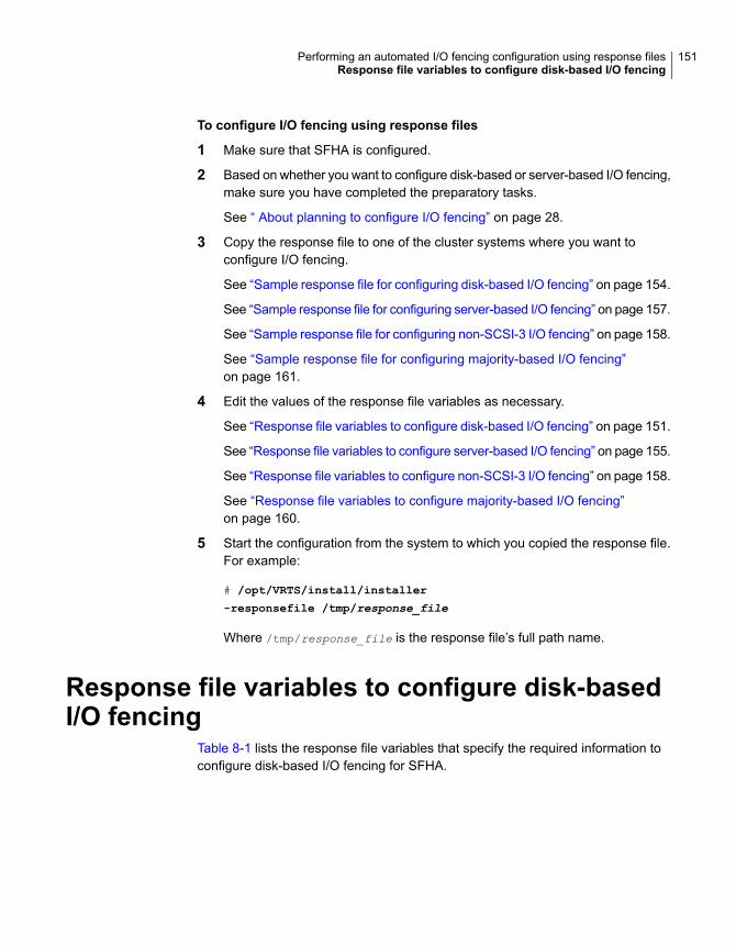
To configure I/O fencing using response files
1 Make sure that SFHA is configured.
2 Based on whether you want to configure disk-based or server-based I/O fencing,make sure you have completed the preparatory tasks.
See “ About planning to configure I/O fencing” on page 28.
3 Copy the response file to one of the cluster systems where you want toconfigure I/O fencing.
See “Sample response file for configuring disk-based I/O fencing” on page 154.
See “Sample response file for configuring server-based I/O fencing” on page 157.
See “Sample response file for configuring non-SCSI-3 I/O fencing” on page 158.
See “Sample response file for configuring majority-based I/O fencing”on page 161.
4 Edit the values of the response file variables as necessary.
See “Response file variables to configure disk-based I/O fencing” on page 151.
See “Response file variables to configure server-based I/O fencing” on page 155.
See “Response file variables to configure non-SCSI-3 I/O fencing” on page 158.
See “Response file variables to configure majority-based I/O fencing”on page 160.
5 Start the configuration from the system to which you copied the response file.For example:
# /opt/VRTS/install/installer
-responsefile /tmp/response_file
Where /tmp/response_file is the response file’s full path name.
Response file variables to configure disk-basedI/O fencing
Table 8-1 lists the response file variables that specify the required information toconfigure disk-based I/O fencing for SFHA.
151Performing an automated I/O fencing configuration using response filesResponse file variables to configure disk-based I/O fencing
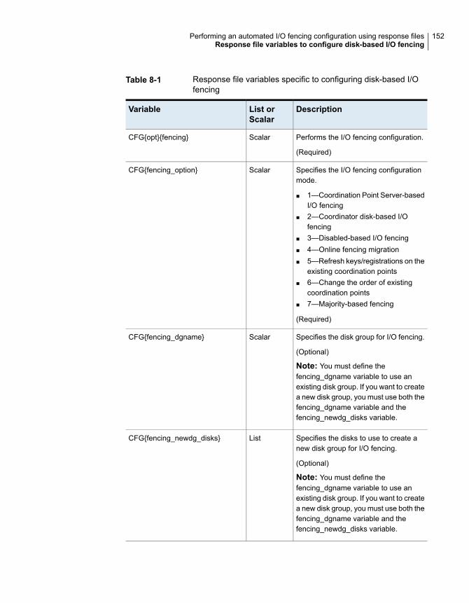
Table 8-1 Response file variables specific to configuring disk-based I/Ofencing
DescriptionList orScalar
Variable
Performs the I/O fencing configuration.
(Required)
ScalarCFG{opt}{fencing}
Specifies the I/O fencing configurationmode.
■ 1—Coordination Point Server-basedI/O fencing
■ 2—Coordinator disk-based I/Ofencing
■ 3—Disabled-based I/O fencing■ 4—Online fencing migration■ 5—Refresh keys/registrations on the
existing coordination points■ 6—Change the order of existing
coordination points■ 7—Majority-based fencing
(Required)
ScalarCFG{fencing_option}
Specifies the disk group for I/O fencing.
(Optional)
Note: You must define thefencing_dgname variable to use anexisting disk group. If you want to createa new disk group, you must use both thefencing_dgname variable and thefencing_newdg_disks variable.
ScalarCFG{fencing_dgname}
Specifies the disks to use to create anew disk group for I/O fencing.
(Optional)
Note: You must define thefencing_dgname variable to use anexisting disk group. If you want to createa new disk group, you must use both thefencing_dgname variable and thefencing_newdg_disks variable.
ListCFG{fencing_newdg_disks}
152Performing an automated I/O fencing configuration using response filesResponse file variables to configure disk-based I/O fencing

Table 8-1 Response file variables specific to configuring disk-based I/Ofencing (continued)
DescriptionList orScalar
Variable
Specifies the frequency at which theCoordination Point Agent monitors forany changes to the Coordinator DiskGroup constitution.
Note: Coordination Point Agent canalso monitor changes to the CoordinatorDisk Group constitution such as a diskbeing accidently deleted from theCoordinator Disk Group. The frequencyof this detailed monitoring can be tunedwith the LevelTwoMonitorFreq attribute.For example, if you set this attribute to5, the agent will monitor the CoordinatorDisk Group constitution every fivemonitor cycles. If LevelTwoMonitorFreqattribute is not set, the agent will notmonitor any changes to the CoordinatorDisk Group. 0 means not to monitor theCoordinator Disk Group constitution.
ScalarCFG{fencing_cpagent_monitor_freq}
Enter '1' or '0' depending upon whetheryou want to configure the CoordinationPoint agent using the installer or not.
Enter "0" if you do not want to configurethe Coordination Point agent using theinstaller.
Enter "1" if you want to use the installerto configure the Coordination Pointagent.
ScalarCFG {fencing_config_cpagent}
Name of the service group which willhave the Coordination Point agentresource as part of it.
Note: This field is obsolete if thefencing_config_cpagent field is givena value of '0'.
ScalarCFG {fencing_cpagentgrp}
153Performing an automated I/O fencing configuration using response filesResponse file variables to configure disk-based I/O fencing
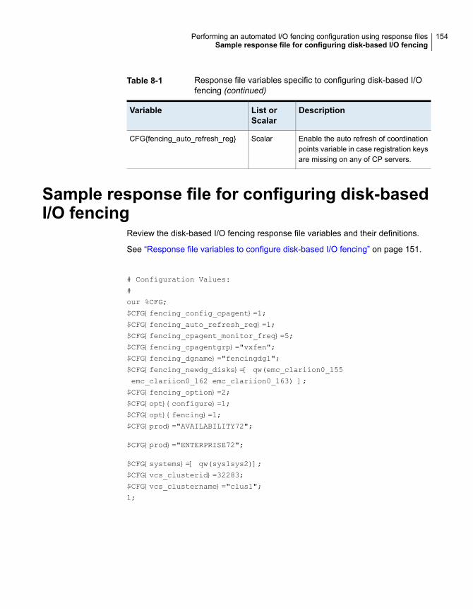
Table 8-1 Response file variables specific to configuring disk-based I/Ofencing (continued)
DescriptionList orScalar
Variable
Enable the auto refresh of coordinationpoints variable in case registration keysare missing on any of CP servers.
ScalarCFG{fencing_auto_refresh_reg}
Sample response file for configuring disk-basedI/O fencing
Review the disk-based I/O fencing response file variables and their definitions.
See “Response file variables to configure disk-based I/O fencing” on page 151.
# Configuration Values:
#
our %CFG;
$CFG{fencing_config_cpagent}=1;
$CFG{fencing_auto_refresh_reg}=1;
$CFG{fencing_cpagent_monitor_freq}=5;
$CFG{fencing_cpagentgrp}="vxfen";
$CFG{fencing_dgname}="fencingdg1";
$CFG{fencing_newdg_disks}=[ qw(emc_clariion0_155
emc_clariion0_162 emc_clariion0_163) ];
$CFG{fencing_option}=2;
$CFG{opt}{configure}=1;
$CFG{opt}{fencing}=1;
$CFG{prod}="AVAILABILITY72";
$CFG{prod}="ENTERPRISE72";
$CFG{systems}=[ qw(sys1sys2)];
$CFG{vcs_clusterid}=32283;
$CFG{vcs_clustername}="clus1";
1;
154Performing an automated I/O fencing configuration using response filesSample response file for configuring disk-based I/O fencing
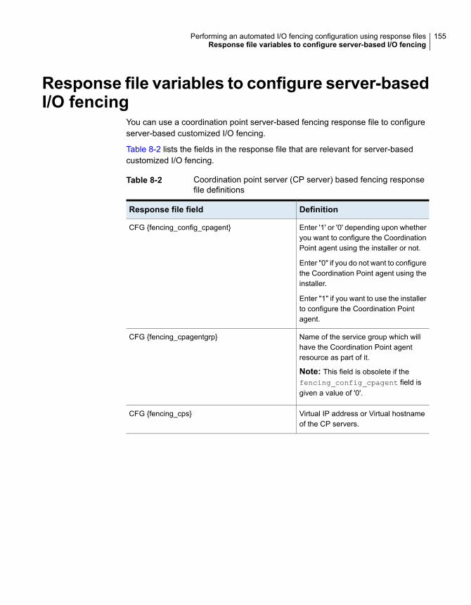
Response file variables to configure server-basedI/O fencing
You can use a coordination point server-based fencing response file to configureserver-based customized I/O fencing.
Table 8-2 lists the fields in the response file that are relevant for server-basedcustomized I/O fencing.
Table 8-2 Coordination point server (CP server) based fencing responsefile definitions
DefinitionResponse file field
Enter '1' or '0' depending upon whetheryou want to configure the CoordinationPoint agent using the installer or not.
Enter "0" if you do not want to configurethe Coordination Point agent using theinstaller.
Enter "1" if you want to use the installerto configure the Coordination Pointagent.
CFG {fencing_config_cpagent}
Name of the service group which willhave the Coordination Point agentresource as part of it.
Note: This field is obsolete if thefencing_config_cpagent field isgiven a value of '0'.
CFG {fencing_cpagentgrp}
Virtual IP address or Virtual hostnameof the CP servers.
CFG {fencing_cps}
155Performing an automated I/O fencing configuration using response filesResponse file variables to configure server-based I/O fencing

Table 8-2 Coordination point server (CP server) based fencing responsefile definitions (continued)
DefinitionResponse file field
This response file field indicateswhether to reuse an existing DG namefor the fencing configuration incustomized fencing (CP server andcoordinator disks).
Enter either a "1" or "0".
Entering a "1" indicates reuse, andentering a "0" indicates do not reuse.
When reusing an existing DG name forthe mixed mode fencing configuration.you need to manually add a line of text, such as "$CFG{fencing_reusedg}=0"or "$CFG{fencing_reusedg}=1" beforeproceeding with a silent installation.
CFG {fencing_reusedg}
The name of the disk group to be usedin the customized fencing, where atleast one disk is being used.
CFG {fencing_dgname}
The disks being used as coordinationpoints if any.
CFG {fencing_disks}
Total number of coordination pointsbeing used, including both CP serversand disks.
CFG {fencing_ncp}
The number of disks being used.CFG {fencing_ndisks}
The virtual IP addresses or the fullyqualified host names of the CP server.
CFG {fencing_cps_vips}
The port that the virtual IP address orthe fully qualified host name of the CPserver listens on.
CFG {fencing_cps_ports}
156Performing an automated I/O fencing configuration using response filesResponse file variables to configure server-based I/O fencing
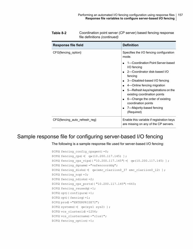
Table 8-2 Coordination point server (CP server) based fencing responsefile definitions (continued)
DefinitionResponse file field
Specifies the I/O fencing configurationmode.
■ 1—Coordination Point Server-basedI/O fencing
■ 2—Coordinator disk-based I/Ofencing
■ 3—Disabled-based I/O fencing■ 4—Online fencing migration■ 5—Refresh keys/registrations on the
existing coordination points■ 6—Change the order of existing
coordination points■ 7—Majority-based fencing
(Required)
CFG{fencing_option}
Enable this variable if registration keysare missing on any of the CP servers.
CFG{fencing_auto_refresh_reg}
Sample response file for configuring server-based I/O fencingThe following is a sample response file used for server-based I/O fencing:
$CFG{fencing_config_cpagent}=0;
$CFG{fencing_cps}=[ qw(10.200.117.145) ];
$CFG{fencing_cps_vips}{"10.200.117.145"}=[ qw(10.200.117.145) ];
$CFG{fencing_dgname}="vxfencoorddg";
$CFG{fencing_disks}=[ qw(emc_clariion0_37 emc_clariion0_12) ];
$CFG{fencing_ncp}=3;
$CFG{fencing_ndisks}=2;
$CFG{fencing_cps_ports}{"10.200.117.145"}=443;
$CFG{fencing_reusedg}=1;
$CFG{opt}{configure}=1;
$CFG{opt}{fencing}=1;
$CFG{prod}="ENTERPRISE72";
$CFG{systems}=[ qw(sys1 sys2) ];
$CFG{vcs_clusterid}=1256;
$CFG{vcs_clustername}="clus1";
$CFG{fencing_option}=1;
157Performing an automated I/O fencing configuration using response filesResponse file variables to configure server-based I/O fencing
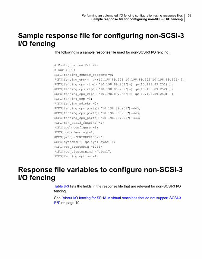
Sample response file for configuring non-SCSI-3I/O fencing
The following is a sample response file used for non-SCSI-3 I/O fencing :
# Configuration Values:
# our %CFG;
$CFG{fencing_config_cpagent}=0;
$CFG{fencing_cps}=[ qw(10.198.89.251 10.198.89.252 10.198.89.253) ];
$CFG{fencing_cps_vips}{"10.198.89.251"}=[ qw(10.198.89.251) ];
$CFG{fencing_cps_vips}{"10.198.89.252"}=[ qw(10.198.89.252) ];
$CFG{fencing_cps_vips}{"10.198.89.253"}=[ qw(10.198.89.253) ];
$CFG{fencing_ncp}=3;
$CFG{fencing_ndisks}=0;
$CFG{fencing_cps_ports}{"10.198.89.251"}=443;
$CFG{fencing_cps_ports}{"10.198.89.252"}=443;
$CFG{fencing_cps_ports}{"10.198.89.253"}=443;
$CFG{non_scsi3_fencing}=1;
$CFG{opt}{configure}=1;
$CFG{opt}{fencing}=1;
$CFG{prod}="ENTERPRISE72";
$CFG{systems}=[ qw(sys1 sys2) ];
$CFG{vcs_clusterid}=1256;
$CFG{vcs_clustername}="clus1";
$CFG{fencing_option}=1;
Response file variables to configure non-SCSI-3I/O fencing
Table 8-3 lists the fields in the response file that are relevant for non-SCSI-3 I/Ofencing.
See “About I/O fencing for SFHA in virtual machines that do not support SCSI-3PR” on page 19.
158Performing an automated I/O fencing configuration using response filesSample response file for configuring non-SCSI-3 I/O fencing
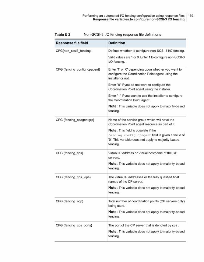
Table 8-3 Non-SCSI-3 I/O fencing response file definitions
DefinitionResponse file field
Defines whether to configure non-SCSI-3 I/O fencing.
Valid values are 1 or 0. Enter 1 to configure non-SCSI-3I/O fencing.
CFG{non_scsi3_fencing}
Enter '1' or '0' depending upon whether you want toconfigure the Coordination Point agent using theinstaller or not.
Enter "0" if you do not want to configure theCoordination Point agent using the installer.
Enter "1" if you want to use the installer to configurethe Coordination Point agent.
Note: This variable does not apply to majority-basedfencing.
CFG {fencing_config_cpagent}
Name of the service group which will have theCoordination Point agent resource as part of it.
Note: This field is obsolete if thefencing_config_cpagent field is given a value of'0'. This variable does not apply to majority-basedfencing.
CFG {fencing_cpagentgrp}
Virtual IP address or Virtual hostname of the CPservers.
Note: This variable does not apply to majority-basedfencing.
CFG {fencing_cps}
The virtual IP addresses or the fully qualified hostnames of the CP server.
Note: This variable does not apply to majority-basedfencing.
CFG {fencing_cps_vips}
Total number of coordination points (CP servers only)being used.
Note: This variable does not apply to majority-basedfencing.
CFG {fencing_ncp}
The port of the CP server that is denoted by cps .
Note: This variable does not apply to majority-basedfencing.
CFG {fencing_cps_ports}
159Performing an automated I/O fencing configuration using response filesResponse file variables to configure non-SCSI-3 I/O fencing
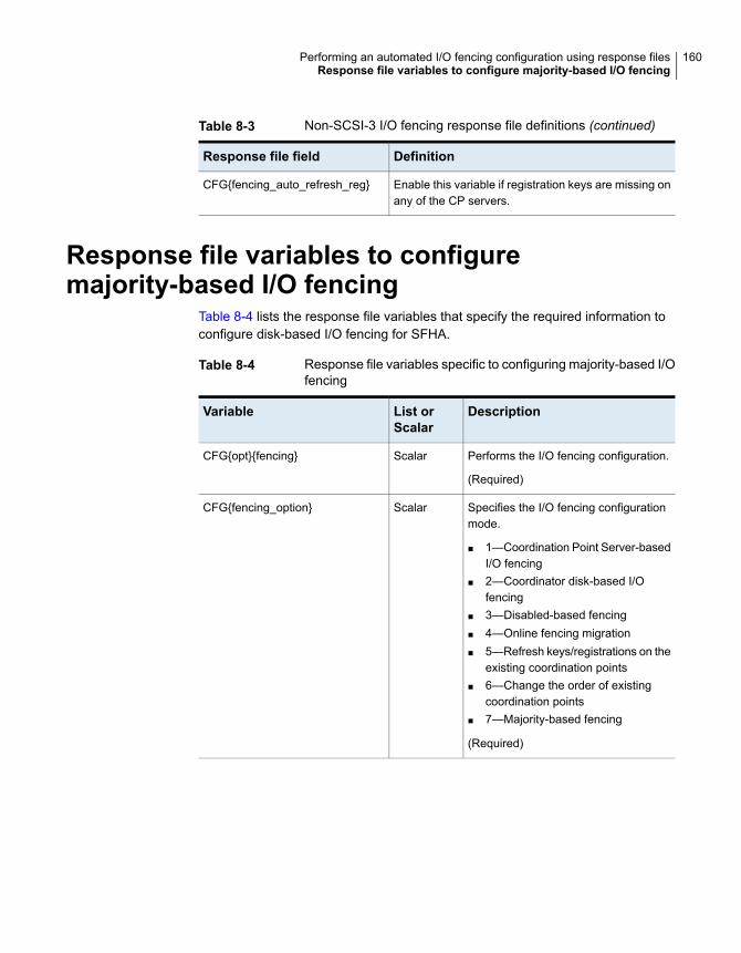
Table 8-3 Non-SCSI-3 I/O fencing response file definitions (continued)
DefinitionResponse file field
Enable this variable if registration keys are missing onany of the CP servers.
CFG{fencing_auto_refresh_reg}
Response file variables to configuremajority-based I/O fencing
Table 8-4 lists the response file variables that specify the required information toconfigure disk-based I/O fencing for SFHA.
Table 8-4 Response file variables specific to configuring majority-based I/Ofencing
DescriptionList orScalar
Variable
Performs the I/O fencing configuration.
(Required)
ScalarCFG{opt}{fencing}
Specifies the I/O fencing configurationmode.
■ 1—Coordination Point Server-basedI/O fencing
■ 2—Coordinator disk-based I/Ofencing
■ 3—Disabled-based fencing■ 4—Online fencing migration■ 5—Refresh keys/registrations on the
existing coordination points■ 6—Change the order of existing
coordination points■ 7—Majority-based fencing
(Required)
ScalarCFG{fencing_option}
160Performing an automated I/O fencing configuration using response filesResponse file variables to configure majority-based I/O fencing
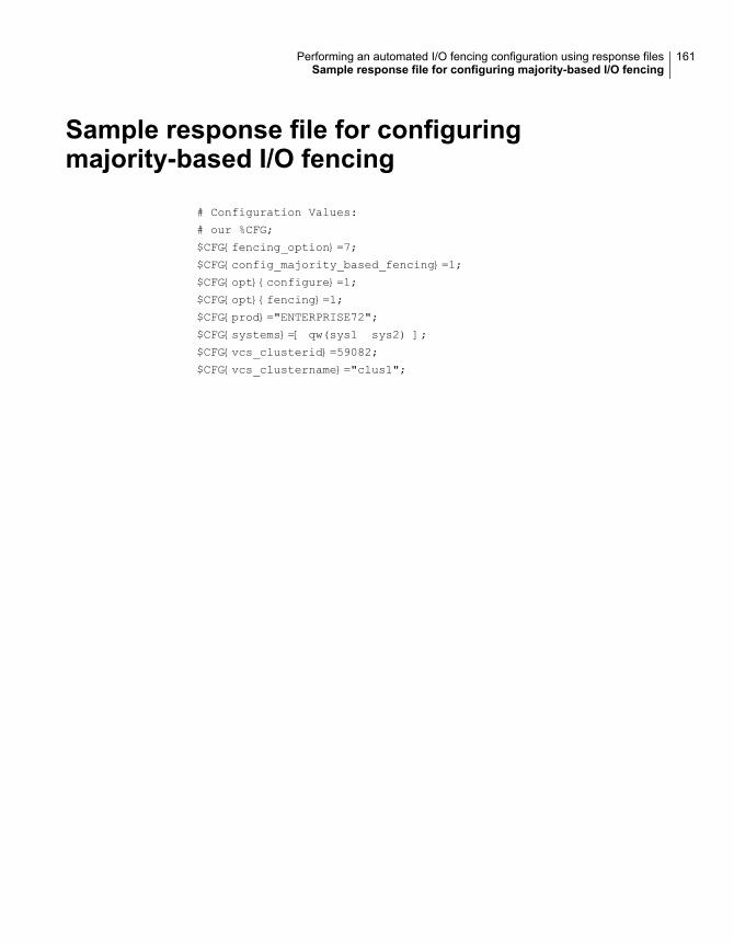
Sample response file for configuringmajority-based I/O fencing
# Configuration Values:
# our %CFG;
$CFG{fencing_option}=7;
$CFG{config_majority_based_fencing}=1;
$CFG{opt}{configure}=1;
$CFG{opt}{fencing}=1;
$CFG{prod}="ENTERPRISE72";
$CFG{systems}=[ qw(sys1 sys2) ];
$CFG{vcs_clusterid}=59082;
$CFG{vcs_clustername}="clus1";
161Performing an automated I/O fencing configuration using response filesSample response file for configuring majority-based I/O fencing

Upgrade of SFHA
■ Chapter 9. Planning to upgrade SFHA
■ Chapter 10. Upgrading Storage Foundation and High Availability
■ Chapter 11. Performing a rolling upgrade of SFHA
■ Chapter 12. Performing a phased upgrade of SFHA
■ Chapter 13. Performing an automated SFHA upgrade using response files
■ Chapter 14. Upgrading SFHA using Boot Environment upgrade
■ Chapter 15. Performing post-upgrade tasks
3Section
Planning to upgrade SFHAThis chapter includes the following topics:
■ About the upgrade
■ Supported upgrade paths
■ Considerations for upgrading SFHA to 7.2 on systems configured with an Oracleresource
■ Preparing to upgrade SFHA
■ Using Install Bundles to simultaneously install or upgrade full releases (base,maintenance, rolling patch), and individual patches
About the upgradeThis release supports upgrades from 6.0.1 and later versions. If your existinginstallation is from a pre-60 version, you must first upgrade to version 6.0.1, thenfollow the procedures mentioned in this document to upgrade the product.
The installer supports the following types of upgrade:
■ Full upgrade
■ Automated upgrade using response files
■ Phased Upgrade
■ Rolling Upgrade
Table 9-1 describes the product mapping after an upgrade.
9Chapter

Table 9-1 Veritas InfoScale product mapping after upgrade
Component (7.0 and later)Product (7.0 and later)Product (6.2.x andearlier)
SFHAVeritas InfoScale EnterpriseSFHA
Note: From 7.0 onwards, the existing Veritas InfoScale product upgrades to thehigher version of the same product. For example, Veritas InfoScale Enterprise 7.1gets upgraded to Veritas InfoScale Enterprise 7.2.
During the upgrade, the installation program performs the following tasks:
1. Stops the product before starting the upgrade
2. Upgrades the installed packages and installs additional packages
If your current installation uses a permanent license key, you will be promptedto update the license to 7.2. If you choose not to update, you can continue touse the old license, limiting the capability of your product to the correspondingcomponent. For example, if you choose not to update the permanent licenseof your existing SFHA installation, the installer after upgrade will enable SFHAcomponent. The capabilities of other components in the product VeritasInfoScale Enterprise will not be available to you. If your installation uses akeyless license, the installer registers the new keys for the new product withfull product capabilities.
3. Restores the existing configuration.
For example, if your setup contains an SFHA installation, the installer upgradesand restores the configuration to SFHA. If your setup included multiplecomponents, the installer upgrades and restores the configuration of thecomponents.
4. Starts the configured components.
Note: If the root disk is encapsulated, you need not unencapsulate the root disk.Reboot the system after the upgrade.
Supported upgrade pathsTable 9-2 lists the supported upgrade paths.
164Planning to upgrade SFHASupported upgrade paths
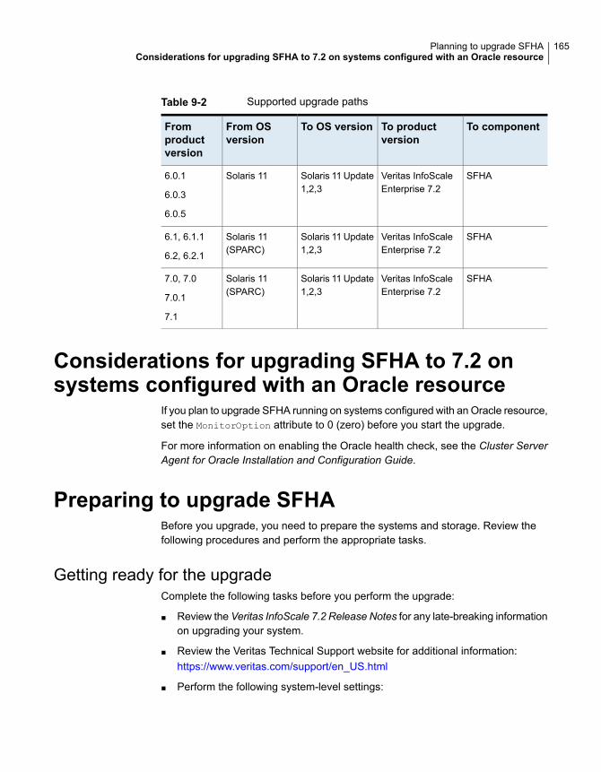
Table 9-2 Supported upgrade paths
To componentTo productversion
To OS versionFrom OSversion
Fromproductversion
SFHAVeritas InfoScaleEnterprise 7.2
Solaris 11 Update1,2,3
Solaris 116.0.1
6.0.3
6.0.5
SFHAVeritas InfoScaleEnterprise 7.2
Solaris 11 Update1,2,3
Solaris 11(SPARC)
6.1, 6.1.1
6.2, 6.2.1
SFHAVeritas InfoScaleEnterprise 7.2
Solaris 11 Update1,2,3
Solaris 11(SPARC)
7.0, 7.0
7.0.1
7.1
Considerations for upgrading SFHA to 7.2 onsystems configured with an Oracle resource
If you plan to upgrade SFHA running on systems configured with an Oracle resource,set the MonitorOption attribute to 0 (zero) before you start the upgrade.
For more information on enabling the Oracle health check, see the Cluster ServerAgent for Oracle Installation and Configuration Guide.
Preparing to upgrade SFHABefore you upgrade, you need to prepare the systems and storage. Review thefollowing procedures and perform the appropriate tasks.
Getting ready for the upgradeComplete the following tasks before you perform the upgrade:
■ Review the Veritas InfoScale 7.2 Release Notes for any late-breaking informationon upgrading your system.
■ Review the Veritas Technical Support website for additional information:https://www.veritas.com/support/en_US.html
■ Perform the following system-level settings:
165Planning to upgrade SFHAConsiderations for upgrading SFHA to 7.2 on systems configured with an Oracle resource
Set diag-level to min to perform the minimum number of diagnostics whenthe system boots. Depending on the configuration of your systems you maywant to turn it on after you perform the upgrade.
■
{1} ok setenv diag-level min
diag-level=min
■ Set auto-boot? to false. For tight control when systems restart, set thisvariable to false. Re-enable this variable after the upgrade.
{1} ok setenv auto-boot? false
auto-boot?=false
■ Deactivate cron to make sure that extraneous jobs are not performed whileyou upgrade the systems.Solaris 11:
# ps -ef | grep cron
# kill cron pid
# svcadm disable svc:/system/cron:default
■ If zones are present, make sure that all non-global zones are booted and arein the running state before you use the Veritas InfoScale product installer toupgrade the Storage Foundation products in the global zone so that anypackages present inside non-global zones also gets updated automatically.For Oracle Solaris 11.1, if the non-global zone has previous version of VCSpackages (VRTSperl, VRTSvlic, VRTSvcs, VRTSvcsag, VRTSvcsea) alreadyinstalled, then during upgrade of the VCS packages in global zone, packagesinside non-global zone are automatically upgraded if the zone is in running state.If non-global zones are not in running state, you must set the Veritas publisherinside the global zone. You also must attach the zone with –u option to upgradethe SFHA packages inside non-global zone. If previous version of VRTSvxfs,and VRTSodm packages are installed inside non- global zone, they must beuninstalled manually prior to the upgrade. Once the packages in global zoneare upgraded, VRTSvxfs and VRTSodm must be installed manaully insidenon-global zone.
■ Make sure that the administrator who performs the upgrade has root accessand a good knowledge of the operating system's administration.
■ Make sure that all users are logged off and that all major user applications areproperly shut down.
166Planning to upgrade SFHAPreparing to upgrade SFHA

■ Make sure that you have created a valid backup.See “Creating backups” on page 168.
■ Ensure that you have enough file system space to upgrade. Identify where youwant to copy the packages, for example /packages/Veritas when the root filesystem has enough space or /var/tmp/packages if the /var file system hasenough space.Do not put the files under /tmp, which is erased during a system restart.Do not put the files on a file system that is inaccessible before running theupgrade script.You can use a Veritas-supplied disc for the upgrade as long as modificationsto the upgrade script are not required.If /usr/local was originally created as a slice, modifications are required.
■ Unmount all the file systems not on the root disk. Comment out their entriesin /etc/vfstab. Stop the associated volumes and deport the associated diskgroups. Any file systems that the Solaris operating system or Storage Foundationassumes should be in rootdg but are not, must be unmounted, and theassociated entry in /etc/vfstab commented out.
■ For any startup scripts in /usr/sbin/svcadm disable, comment out anyapplication commands or processes that are known to hang if their file systemsare not present.
■ Make sure that the current operating system supports version 7.2 of the product.If the operating system does not support it, plan for a staged upgrade.
■ Schedule sufficient outage time and downtime for the upgrade and anyapplications that use the Veritas InfoScale products. Depending on theconfiguration, the outage can take several hours.
■ Any swap partitions not in rootdg must be commented out of /etc/vfstab. Ifpossible, swap partitions other than those on the root disk should be commentedout of /etc/vfstab and not mounted during the upgrade. The active swappartitions that are not in rootdg cause upgrade_start to fail.
■ Make sure that the file systems are clean before upgrading.See “Verifying that the file systems are clean” on page 175.
■ Veritas recommends that you upgrade VxFS disk layouts to a supported versionbefore installing VxFS 7.2. Unsupported disk layout versions 4, 5, and 6 can bemounted for the purpose of online upgrading in VxFS 7.2. You can upgradeunsupported layout versions online before installing VxFS 7.2.
■ Upgrade arrays (if required).See “Upgrading the array support” on page 176.
167Planning to upgrade SFHAPreparing to upgrade SFHA
■ To reliably save information on a mirrored disk, shut down the system andphysically remove the mirrored disk. Removing the disk in this manner offers afailback point.
■ Determine if the root disk is encapsulated.
■ Make sure that DMP support for native stack is disabled(dmp_native_support=off). If DMP support for native stack is enabled(dmp_native_support=on), the installer may detect it and ask you to restart thesystem.
■ If you want to upgrade the application clusters that use CP server based fencingto version 6.1 and later, make sure that you first upgrade VCS or SFHA on theCP server systems to version 6.1 and later. And then, from 7.0.1 onwards, CPserver supports only HTTPS based communication with its clients and IPM-basedcommunication is no longer supported. CP server needs to be reconfigured ifyou upgrade the CP server with IPM-based CP server configured.For instructions to upgrade VCS or SFHA on the CP server systems, refer tothe relevant Configuration and Upgrade Guides.
Creating backupsSave relevant system information before the upgrade.
To create backups
1 Log in as superuser.
2 Before the upgrade, ensure that you have made backups of all data that youwant to preserve.
Back up the /etc/system file.
3 Installer verifies that recent backups of configuration files in VxVM privateregion have been saved in /etc/vx/cbr/bk.
If not, a warning message is displayed.
Warning: Backup /etc/vx/cbr/bk directory.
4 Copy the vfstab file to vfstab.orig:
# cp /etc/vfstab /etc/vfstab.orig
5 Run the vxlicrep, vxdisk list, and vxprint -ht commands and recordthe output. Use this information to reconfigure your system after the upgrade.
168Planning to upgrade SFHAPreparing to upgrade SFHA
6 If you install Veritas InfoScale Enterprise 7.2 software, follow the guidelinesthat are given in the Cluster Server Configuration and Upgrade Guide forinformation on preserving your VCS configuration across the installationprocedure.
7 Back up the external quotas and quotas.grp files.
If you are upgrading from 6.0.3, you must also back up the quotas.grp.64
and quotas.64 files.
8 Verify that quotas are turned off on all the mounted file systems.
Pre-upgrade planning for Volume ReplicatorBefore installing or upgrading Volume Replicator (VVR):
■ Confirm that your system has enough free disk space to install VVR.
■ Make sure you have root permissions. You must have root permissions toperform the install and upgrade procedures.
■ If replication using VVR is configured, Veritas recommends that the disk groupversion is at least 110 prior to upgrading.You can check the Disk Group version using the following command:
# vxdg list diskgroup
■ If replication using VVR is configured, make sure the size of the SRL volume isgreater than 110 MB.Refer to the Veritas InfoScale™ Replication Administrator’s Guide.
■ If replication using VVR is configured, verify that all the Primary RLINKs areup-to-date on all the hosts.
# /usr/sbin/vxrlink -g diskgroup status rlink_name
Note: Do not continue until the primary RLINKs are up-to-date.
■ If VCS is used to manage VVR replication, follow the preparation steps toupgrade VVR and VCS agents.
■ Make sure that you have worked out all terminal emulation issues. Make surethat the terminal you use is fully functional for OpenBoot prompts and single-userand multi-user run levels.
See the Veritas InfoScale™Replication Administrator’s Guide for more information.
See the Getting Started Guide for more information on the documentation.
169Planning to upgrade SFHAPreparing to upgrade SFHA

Planning an upgrade from the previous VVR versionIf you plan to upgrade VVR from the previous VVR version, you can upgrade VVRwith reduced application downtime by upgrading the hosts at separate times. Whilethe Primary is being upgraded, the application can be migrated to the Secondary,thus reducing downtime. The replication between the (upgraded) Primary and theSecondary, which have different versions of VVR, will still continue. This featurefacilitates high availability even when the VVR upgrade is not complete on both thesites. Veritas recommends that the Secondary hosts be upgraded before the Primaryhost in the Replicated Data Set (RDS).
See the Veritas InfoScale™ Release Notes for information regarding VVR supportfor replicating across Storage Foundation versions.
Replicating between versions is intended to remove the restriction of upgrading thePrimary and Secondary at the same time. VVR can continue to replicate an existingRDS with Replicated Volume Groups (RVGs) on the systems that you want toupgrade. When the Primary and Secondary are at different versions, VVR does notsupport changing the configuration with the vradmin command or creating a newRDS.
Also, if you specify TCP as the network protocol, the VVR versions on the Primaryand Secondary determine whether the checksum is calculated. As shown inTable 9-3, if either the Primary or Secondary are running a version of VVR prior to7.2, and you use the TCP protocol, VVR calculates the checksum for every datapacket it replicates. If the Primary and Secondary are at VVR 7.2, VVR does notcalculate the checksum. Instead, it relies on the TCP checksum mechanism.
Table 9-3 VVR versions and checksum calculations
VVR calculateschecksum TCPconnections?
VVR 7.2
(DG version >= 150)
VVR prior to 7.2
(DG version <= 140)
YesSecondaryPrimary
YesPrimarySecondary
YesPrimary and Secondary
NoPrimary and Secondary
Note:When replicating between versions of VVR, avoid using commands associatedwith new features. The earlier version may not support new features and problemscould occur.
170Planning to upgrade SFHAPreparing to upgrade SFHA
If you do not need to upgrade all the hosts in the RDS simultaneously, you can usereplication between versions after you upgrade one host. You can then upgradethe other hosts in the RDS later at your convenience.
Note: If you have a cluster setup, you must upgrade all the nodes in the cluster atthe same time.
Planning and upgrading VVR to use IPv6 as connection protocolSFHA supports using IPv6 as the connection protocol.
This release supports the following configurations for VVR:
■ VVR continues to support replication between IPv4-only nodes with IPv4 as theinternet protocol
■ VVR supports replication between IPv4-only nodes and IPv4/IPv6 dual-stacknodes with IPv4 as the internet protocol
■ VVR supports replication between IPv6-only nodes and IPv4/IPv6 dual-stacknodes with IPv6 as the internet protocol
■ VVR supports replication between IPv6 only nodes
■ VVR supports replication to one or more IPv6 only nodes and one or more IPv4only nodes from a IPv4/IPv6 dual-stack node
■ VVR supports replication of a shared disk group only when all the nodes in thecluster that share the disk group are at IPv4 or IPv6
Additional settings for using VVR in a localizedenvironmentIf the language packages for VVR are installed, VVR displays localized messages,if the client locale is a supported non-English locale. The client locale is the localefrom which you are accessing the VVR command line or GUI. For example, if theJapanese version of VVR is installed, then the messages are displayed in theJapanese locale, if the client locale is Japanese.
Make sure that the appropriate locale has been installed on all the hosts that areintended to be a part of the VVR RDS setup. Otherwise, some VVR error messageswill be displayed in English, because it is the default locale. Make sure the followingsettings are done on all hosts that are intended to be part of the RDS:
■ Install the required client locale from the Operating System disc.
■ Install the required Volume Manager and VVR localized packages.
■ Set the client locale, before using any of the VVR interfaces:
171Planning to upgrade SFHAPreparing to upgrade SFHA
For the VVR command line, set the locale using the appropriate method foryour operating system.
■
■ For VRW, select the locale from the VRW login page.
Preparing to upgrade VVR when VCS agents are configuredTo prepare to upgrade VVR when VCS agents for VVR are configured, perform thefollowing tasks in the order presented:
■ Freezing the service groups and stopping all the applications
■ Preparing for the upgrade when VCS agents are configured
Freezing the service groups and stopping all theapplicationsThis section describes how to freeze the service groups and stop all applications.
To freeze the service groups and stop applications
Perform the following steps for the Primary and Secondary clusters:
1 Log in as the superuser.
2 Make sure that /opt/VRTS/bin is in your PATH so that you can execute allthe product commands.
3 Before the upgrade, cleanly shut down all applications.
■ OFFLINE all application service groups that do not contain RVG resources.Do not OFFLINE the service groups containing RVG resources.
■ If the application resources are part of the same service group as an RVGresource, then OFFLINE only the application resources. In other words,ensure that the RVG resource remains ONLINE so that the private diskgroups containing these RVG objects do not get deported.
Note: You must also stop any remaining applications not managed by VCS.
4 On any node in the cluster, make the VCS configuration writable:
# haconf -makerw
5 On any node in the cluster, list the groups in your configuration:
# hagrp -list
172Planning to upgrade SFHAPreparing to upgrade SFHA
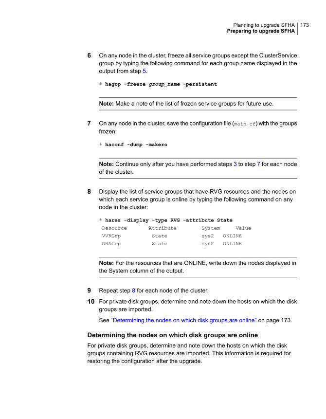
6 On any node in the cluster, freeze all service groups except the ClusterServicegroup by typing the following command for each group name displayed in theoutput from step 5.
# hagrp -freeze group_name -persistent
Note: Make a note of the list of frozen service groups for future use.
7 On any node in the cluster, save the configuration file (main.cf) with the groupsfrozen:
# haconf -dump -makero
Note: Continue only after you have performed steps 3 to step 7 for each nodeof the cluster.
8 Display the list of service groups that have RVG resources and the nodes onwhich each service group is online by typing the following command on anynode in the cluster:
# hares -display -type RVG -attribute State
Resource Attribute System Value
VVRGrp State sys2 ONLINE
ORAGrp State sys2 ONLINE
Note: For the resources that are ONLINE, write down the nodes displayed inthe System column of the output.
9 Repeat step 8 for each node of the cluster.
10 For private disk groups, determine and note down the hosts on which the diskgroups are imported.
See “Determining the nodes on which disk groups are online” on page 173.
Determining the nodes on which disk groups are onlineFor private disk groups, determine and note down the hosts on which the diskgroups containing RVG resources are imported. This information is required forrestoring the configuration after the upgrade.
173Planning to upgrade SFHAPreparing to upgrade SFHA

To determine the online disk groups
1 On any node in the cluster, list the disk groups in your configuration, and notedown the disk group names listed in the output for future use:
# hares -display -type RVG -attribute DiskGroup
Note: Write down the list of the disk groups that are under VCS control.
2 For each disk group listed in the output in step 1, list its corresponding diskgroup resource name:
# hares -list DiskGroup=diskgroup Type=DiskGroup
3 For each disk group resource name listed in the output in step 2, get and notedown the node on which the disk group is imported by typing the followingcommand:
# hares -display dg_resname -attribute State
The output displays the disk groups that are under VCS control and nodes onwhich the disk groups are imported.
Preparing for the upgradewhenVCS agents are configuredIf you have configured the VCS agents, it is recommended that you take backupsof the configuration files, such as main.cf and types.cf, which are present in the/etc/VRTSvcs/conf/config directory.
174Planning to upgrade SFHAPreparing to upgrade SFHA

To prepare a configuration with VCS agents for an upgrade
1 List the disk groups on each of the nodes by typing the following command oneach node:
# vxdisk -o alldgs list
The output displays a list of the disk groups that are under VCS control andthe disk groups that are not under VCS control.
Note: The disk groups that are not locally imported are displayed inparentheses.
2 If any of the disk groups have not been imported on any node, import them.For disk groups in your VCS configuration, you can import them on any node.For disk groups that are not under VCS control, choose an appropriate nodeon which to import the disk group. Enter the following command on theappropriate node:
# vxdg -t import diskgroup
3 If a disk group is already imported, then recover the disk group by typing thefollowing command on the node on which it is imported:
# vxrecover -bs
4 Verify that all the Primary RLINKs are up to date.
# vxrlink -g diskgroup status rlink_name
Note: Do not continue until the Primary RLINKs are up-to-date.
Verifying that the file systems are cleanVerify that all file systems have been cleanly unmounted.
175Planning to upgrade SFHAPreparing to upgrade SFHA
To make sure the file systems are clean
1 Verify that all file systems have been cleanly unmounted:
# echo "8192B.p S" | /opt/VRTS/bin/fsdb filesystem | \
grep clean
flags 0 mod 0 clean clean_value
A clean_value value of 0x5a indicates the file system is clean. A value of 0x3cindicates the file system is dirty. A value of 0x69 indicates the file system isdusty. A dusty file system has pending extended operations.
2 If a file system is not clean, enter the following commands for that file system:
# /opt/VRTS/bin/fsck -F vxfs filesystem
# /opt/VRTS/bin/mount -F vxfs Block_Device
mountpoint
# /opt/VRTS/bin/umount mountpoint
These commands should complete any extended operations on the file systemand unmount the file system cleanly.
A pending large package clone removal extended operation might be inprogress if the umount command fails with the following error:
file system device busy
An extended operation is in progress if the following message is generated onthe console:
Storage Checkpoint asynchronous operation on file_system
file system still in progress.
3 If an extended operation is in progress, you must leave the file system mountedfor a longer time to allow the operation to complete. Removing a very largepackage clone can take several hours.
4 Repeat step 1 to verify that the unclean file system is now clean.
Upgrading the array supportThe Veritas InfoScale 7.2 release includes all array support in a single package,VRTSaslapm. The array support package includes the array support previouslyincluded in the VRTSvxvm package. The array support package also includes supportpreviously packaged as external Array Support Libraries (ASLs) and array policymodules (APMs).
See the 7.2 Hardware Compatibility List for information about supported arrays.
176Planning to upgrade SFHAPreparing to upgrade SFHA
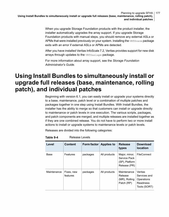
When you upgrade Storage Foundation products with the product installer, theinstaller automatically upgrades the array support. If you upgrade StorageFoundation products with manual steps, you should remove any external ASLs orAPMs that were installed previously on your system. Installing the VRTSvxvm packageexits with an error if external ASLs or APMs are detected.
After you have installed Veritas InfoScale 7.2, Veritas provides support for new diskarrays through updates to the VRTSaslapm package.
For more information about array support, see the Storage FoundationAdministrator's Guide.
Using Install Bundles to simultaneously install orupgrade full releases (base, maintenance, rollingpatch), and individual patches
Beginning with version 6.1, you can easily install or upgrade your systems directlyto a base, maintenance, patch level or a combination of multiple patches andpackages together in one step using Install Bundles. With Install Bundles, theinstaller has the ability to merge so that customers can install or upgrade directlyto maintenance or patch levels in one execution. The various scripts, packages,and patch components are merged, and multiple releases are installed together asif they are one combined release. You do not have to perform two or more installactions to install or upgrade systems to maintenance levels or patch levels.
Releases are divided into the following categories:
Table 9-4 Release Levels
Downloadlocation
Releasetypes
Applies toForm factorContentLevel
FileConnectMajor, minor,Service Pack(SP), PlatformRelease (PR)
All productspackagesFeaturesBase
VeritasServices andOperationsReadinessTools (SORT)
MaintenanceRelease(MR), RollingPatch (RP)
All productspackagesFixes, newfeatures
Maintenance
177Planning to upgrade SFHAUsing Install Bundles to simultaneously install or upgrade full releases (base, maintenance, rolling patch),
and individual patches
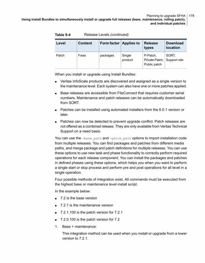
Table 9-4 Release Levels (continued)
Downloadlocation
Releasetypes
Applies toForm factorContentLevel
SORT,Support site
P-Patch,Private Patch,Public patch
Singleproduct
packagesFixesPatch
When you install or upgrade using Install Bundles:
■ Veritas InfoScale products are discovered and assigned as a single version tothe maintenance level. Each system can also have one or more patches applied.
■ Base releases are accessible from FileConnect that requires customer serialnumbers. Maintenance and patch releases can be automatically downloadedfrom SORT.
■ Patches can be installed using automated installers from the 6.0.1 version orlater.
■ Patches can now be detected to prevent upgrade conflict. Patch releases arenot offered as a combined release. They are only available from Veritas TechnicalSupport on a need basis.
You can use the -base_path and -patch_path options to import installation codefrom multiple releases. You can find packages and patches from different mediapaths, and merge package and patch definitions for multiple releases. You can usethese options to use new task and phase functionality to correctly perform requiredoperations for each release component. You can install the packages and patchesin defined phases using these options, which helps you when you want to performa single start or stop process and perform pre and post operations for all level in asingle operation.
Four possible methods of integration exist. All commands must be executed fromthe highest base or maintenance level install script.
In the example below:
■ 7.2 is the base version
■ 7.2.1 is the maintenance version
■ 7.2.1.100 is the patch version for 7.2.1
■ 7.2.0.100 is the patch version for 7.2
1. Base + maintenance:
This integration method can be used when you install or upgrade from a lowerversion to 7.2.1.
178Planning to upgrade SFHAUsing Install Bundles to simultaneously install or upgrade full releases (base, maintenance, rolling patch),
and individual patches
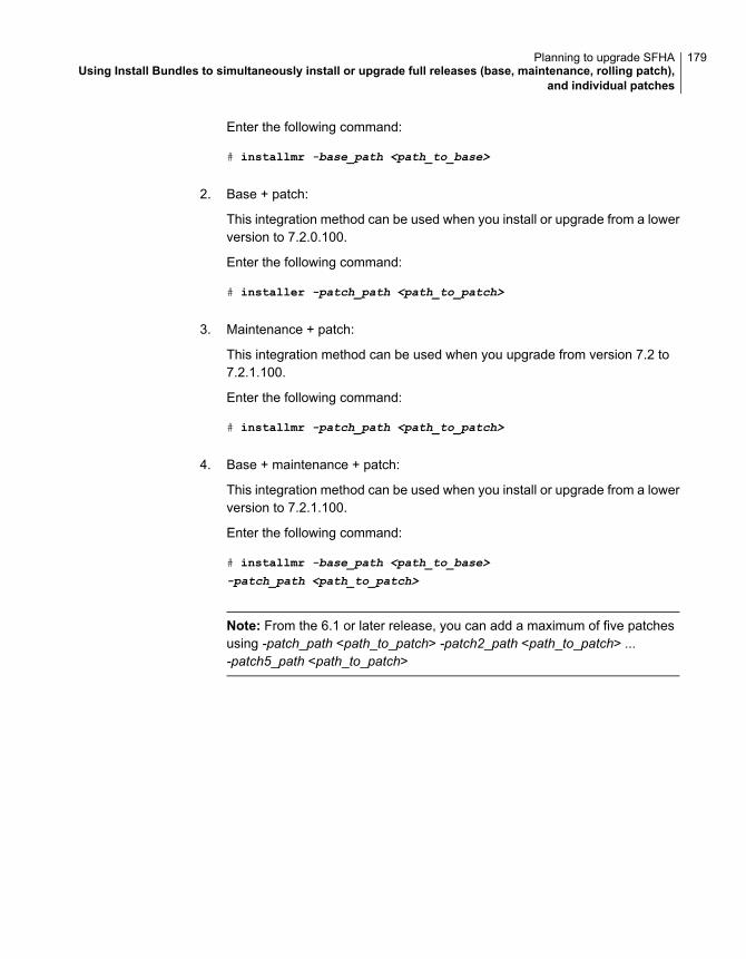
Enter the following command:
# installmr -base_path <path_to_base>
2. Base + patch:
This integration method can be used when you install or upgrade from a lowerversion to 7.2.0.100.
Enter the following command:
# installer -patch_path <path_to_patch>
3. Maintenance + patch:
This integration method can be used when you upgrade from version 7.2 to7.2.1.100.
Enter the following command:
# installmr -patch_path <path_to_patch>
4. Base + maintenance + patch:
This integration method can be used when you install or upgrade from a lowerversion to 7.2.1.100.
Enter the following command:
# installmr -base_path <path_to_base>
-patch_path <path_to_patch>
Note: From the 6.1 or later release, you can add a maximum of five patchesusing -patch_path <path_to_patch> -patch2_path <path_to_patch> ...-patch5_path <path_to_patch>
179Planning to upgrade SFHAUsing Install Bundles to simultaneously install or upgrade full releases (base, maintenance, rolling patch),
and individual patches

Upgrading StorageFoundation and HighAvailability
This chapter includes the following topics:
■ Upgrading Storage Foundation and High Availability to 7.2 using the productinstaller
■ Upgrading Volume Replicator
■ Upgrading language packages
■ Upgrading SFDB
Upgrading Storage Foundation and HighAvailability to 7.2 using the product installer
This section describes upgrading SFHA from a previous release to 7.2. Veritasrecommends that you perform this upgrade from single-user mode.
No VxFS file systems can be in use at the time of the upgrade.
If you plan to upgrade the operating system, or if the current InfoScale product isinstalled on an operating system which is no longer supported by 7.2, you mustperform additional steps to upgrade.
Upgrading the operating systemYou can upgrade the operating system, if required.
10Chapter
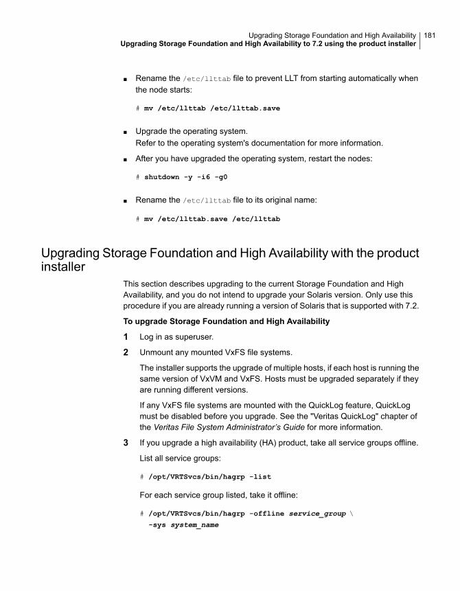
■ Rename the /etc/llttab file to prevent LLT from starting automatically whenthe node starts:
# mv /etc/llttab /etc/llttab.save
■ Upgrade the operating system.Refer to the operating system's documentation for more information.
■ After you have upgraded the operating system, restart the nodes:
# shutdown -y -i6 -g0
■ Rename the /etc/llttab file to its original name:
# mv /etc/llttab.save /etc/llttab
Upgrading Storage Foundation and High Availability with the productinstaller
This section describes upgrading to the current Storage Foundation and HighAvailability, and you do not intend to upgrade your Solaris version. Only use thisprocedure if you are already running a version of Solaris that is supported with 7.2.
To upgrade Storage Foundation and High Availability
1 Log in as superuser.
2 Unmount any mounted VxFS file systems.
The installer supports the upgrade of multiple hosts, if each host is running thesame version of VxVM and VxFS. Hosts must be upgraded separately if theyare running different versions.
If any VxFS file systems are mounted with the QuickLog feature, QuickLogmust be disabled before you upgrade. See the "Veritas QuickLog" chapter ofthe Veritas File System Administrator’s Guide for more information.
3 If you upgrade a high availability (HA) product, take all service groups offline.
List all service groups:
# /opt/VRTSvcs/bin/hagrp -list
For each service group listed, take it offline:
# /opt/VRTSvcs/bin/hagrp -offline service_group \
-sys system_name
181Upgrading Storage Foundation and High AvailabilityUpgrading Storage Foundation and High Availability to 7.2 using the product installer
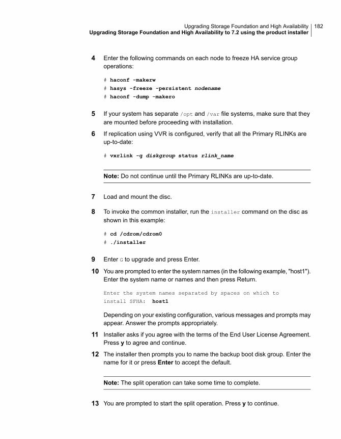
4 Enter the following commands on each node to freeze HA service groupoperations:
# haconf -makerw
# hasys -freeze -persistent nodename
# haconf -dump -makero
5 If your system has separate /opt and /var file systems, make sure that theyare mounted before proceeding with installation.
6 If replication using VVR is configured, verify that all the Primary RLINKs areup-to-date:
# vxrlink -g diskgroup status rlink_name
Note: Do not continue until the Primary RLINKs are up-to-date.
7 Load and mount the disc.
8 To invoke the common installer, run the installer command on the disc asshown in this example:
# cd /cdrom/cdrom0
# ./installer
9 Enter G to upgrade and press Enter.
10 You are prompted to enter the system names (in the following example, "host1").Enter the system name or names and then press Return.
Enter the system names separated by spaces on which to
install SFHA: host1
Depending on your existing configuration, various messages and prompts mayappear. Answer the prompts appropriately.
11 Installer asks if you agree with the terms of the End User License Agreement.Press y to agree and continue.
12 The installer then prompts you to name the backup boot disk group. Enter thename for it or press Enter to accept the default.
Note: The split operation can take some time to complete.
13 You are prompted to start the split operation. Press y to continue.
182Upgrading Storage Foundation and High AvailabilityUpgrading Storage Foundation and High Availability to 7.2 using the product installer
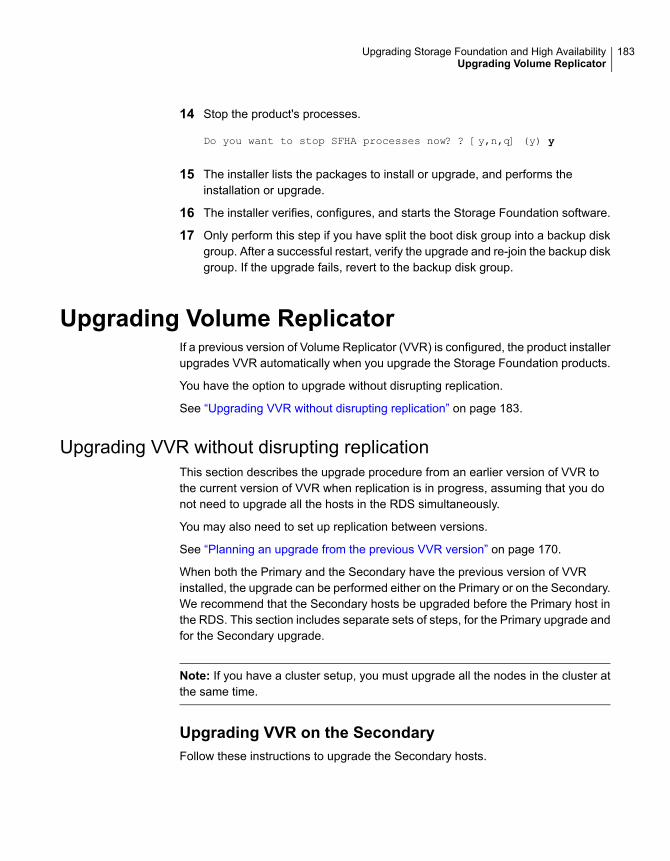
14 Stop the product's processes.
Do you want to stop SFHA processes now? ? [y,n,q] (y) y
15 The installer lists the packages to install or upgrade, and performs theinstallation or upgrade.
16 The installer verifies, configures, and starts the Storage Foundation software.
17 Only perform this step if you have split the boot disk group into a backup diskgroup. After a successful restart, verify the upgrade and re-join the backup diskgroup. If the upgrade fails, revert to the backup disk group.
Upgrading Volume ReplicatorIf a previous version of Volume Replicator (VVR) is configured, the product installerupgrades VVR automatically when you upgrade the Storage Foundation products.
You have the option to upgrade without disrupting replication.
See “Upgrading VVR without disrupting replication” on page 183.
Upgrading VVR without disrupting replicationThis section describes the upgrade procedure from an earlier version of VVR tothe current version of VVR when replication is in progress, assuming that you donot need to upgrade all the hosts in the RDS simultaneously.
You may also need to set up replication between versions.
See “Planning an upgrade from the previous VVR version” on page 170.
When both the Primary and the Secondary have the previous version of VVRinstalled, the upgrade can be performed either on the Primary or on the Secondary.We recommend that the Secondary hosts be upgraded before the Primary host inthe RDS. This section includes separate sets of steps, for the Primary upgrade andfor the Secondary upgrade.
Note: If you have a cluster setup, you must upgrade all the nodes in the cluster atthe same time.
Upgrading VVR on the SecondaryFollow these instructions to upgrade the Secondary hosts.
183Upgrading Storage Foundation and High AvailabilityUpgrading Volume Replicator
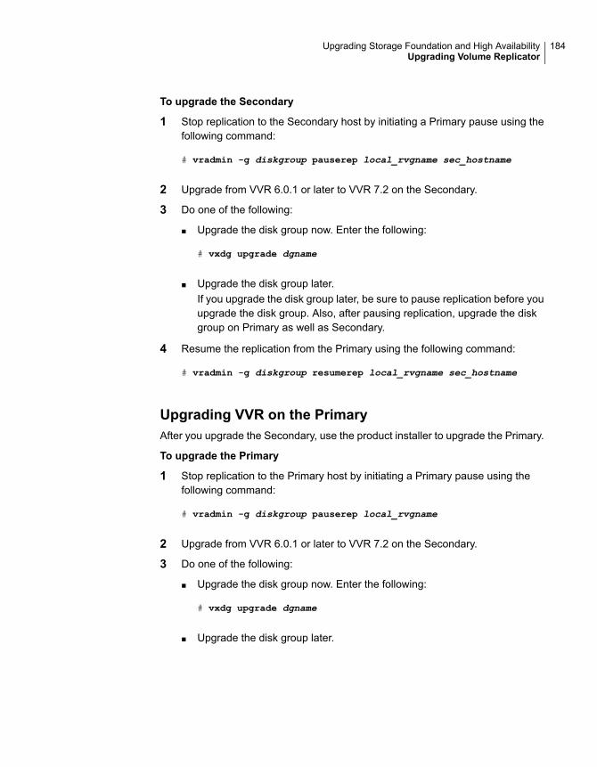
To upgrade the Secondary
1 Stop replication to the Secondary host by initiating a Primary pause using thefollowing command:
# vradmin -g diskgroup pauserep local_rvgname sec_hostname
2 Upgrade from VVR 6.0.1 or later to VVR 7.2 on the Secondary.
3 Do one of the following:
■ Upgrade the disk group now. Enter the following:
# vxdg upgrade dgname
■ Upgrade the disk group later.If you upgrade the disk group later, be sure to pause replication before youupgrade the disk group. Also, after pausing replication, upgrade the diskgroup on Primary as well as Secondary.
4 Resume the replication from the Primary using the following command:
# vradmin -g diskgroup resumerep local_rvgname sec_hostname
Upgrading VVR on the PrimaryAfter you upgrade the Secondary, use the product installer to upgrade the Primary.
To upgrade the Primary
1 Stop replication to the Primary host by initiating a Primary pause using thefollowing command:
# vradmin -g diskgroup pauserep local_rvgname
2 Upgrade from VVR 6.0.1 or later to VVR 7.2 on the Secondary.
3 Do one of the following:
■ Upgrade the disk group now. Enter the following:
# vxdg upgrade dgname
■ Upgrade the disk group later.
184Upgrading Storage Foundation and High AvailabilityUpgrading Volume Replicator
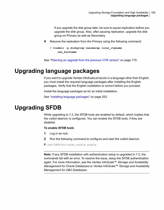
If you upgrade the disk group later, be sure to pause replication before youupgrade the disk group. Also, after pausing replication, upgrade the diskgroup on Primary as well as Secondary.
4 Resume the replication from the Primary using the following command:
# vradmin -g diskgroup resumerep local_rvgname
sec_hostname
See “Planning an upgrade from the previous VVR version” on page 170.
Upgrading language packagesIf you want to upgrade Veritas InfoScale products in a language other than English,you must install the required language packages after installing the Englishpackages. Verify that the English installation is correct before you proceed.
Install the language packages as for an initial installation.
See “Installing language packages” on page 253.
Upgrading SFDBWhile upgrading to 7.2, the SFDB tools are enabled by default, which implies thatthe vxdbd daemon is configured. You can enable the SFDB tools, if they aredisabled.
To enable SFDB tools
1 Log in as root.
2 Run the following command to configure and start the vxdbd daemon.
# /opt/VRTS/bin/sfae_config enable
Note: If any SFDB installation with authentication setup is upgraded to 7.2, thecommands fail with an error. To resolve the issue, setup the SFDB authenticationagain. For more information, see the Veritas InfoScale™ Storage and AvailabilityManagement for Oracle Databases or Veritas InfoScale™ Storage and AvailabilityManagement for DB2 Databases.
185Upgrading Storage Foundation and High AvailabilityUpgrading language packages

Performing a rollingupgrade of SFHA
This chapter includes the following topics:
■ About rolling upgrade
■ About rolling upgrade with local zone on Solaris 11
■ Performing a rolling upgrade using the product installer
About rolling upgradeRolling upgrade minimizes downtime for highly available clusters to the amount oftime that it takes to perform a service group failover. The rolling upgrade has twomain phases where the installer upgrades kernel packages in phase 1 and VCSagent related packages in phase 2.
Note: You need to perform a rolling upgrade on a completely configured cluster.
The following is an overview of the flow for a rolling upgrade:
The installer performs prechecks on the cluster.1.
Application downtime occurs during the first phase as the installer moves servicegroups to free nodes for the upgrade. The only downtime that is incurred is thenormal time required for the service group to failover. The downtime is limited tothe applications that are failed over and not the entire cluster.
2.
The installer performs the second phase of the upgrade on all of the nodes in thecluster. The second phase of the upgrade includes downtime of the Cluster Server(VCS) engine HAD, but does not include application downtime.
3.
11Chapter
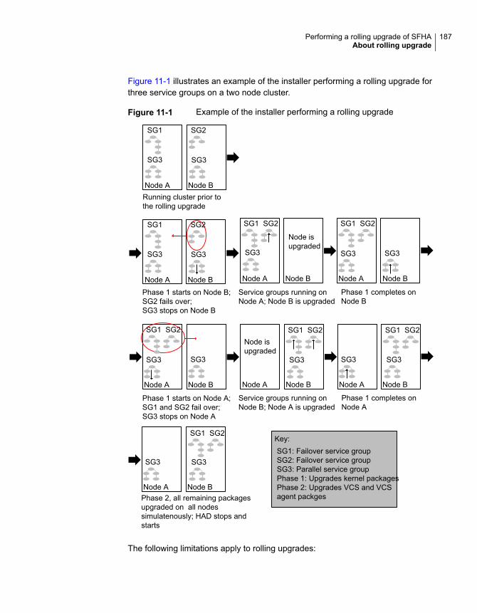
Figure 11-1 illustrates an example of the installer performing a rolling upgrade forthree service groups on a two node cluster.
Figure 11-1 Example of the installer performing a rolling upgrade
Phase 1 starts on Node B;SG2 fails over;SG3 stops on Node B
Phase 2, all remaining packagesupgraded on all nodessimulatenously; HAD stops andstarts
SG1: Failover service groupSG2: Failover service groupSG3: Parallel service groupPhase 1: Upgrades kernel packagesPhase 2: Upgrades VCS and VCSagent packges
Node A Node B
SG3 SG3
SG1 SG2
Phase 1 completes onNode B
Phase 1 starts on Node A;SG1 and SG2 fail over;SG3 stops on Node A
Service groups running onNode A; Node B is upgraded
Phase 1 completes onNode A
Running cluster prior tothe rolling upgrade
Node A Node B
SG3 SG3
SG1 SG2
Node A Node B
SG1 SG2
SG3SG3
Node A Node B
SG3 SG3
SG1 SG2
Node A Node B
SG1 SG2
SG3SG3
Service groups running onNode B; Node A is upgraded
Node A Node B
SG3 SG3
SG1 SG2
Node isupgraded
Node A Node B
SG3
SG1 SG2
Node A Node B
SG1 SG2
SG3
Node isupgraded
Key:
The following limitations apply to rolling upgrades:
187Performing a rolling upgrade of SFHAAbout rolling upgrade
■ Rolling upgrades are not compatible with phased upgrades. Do not mix rollingupgrades and phased upgrades.
■ You can perform a rolling upgrade from 6.0.1 and later versions.
■ The rolling upgrade procedures support only minor operating system upgrades.
■ The rolling upgrade procedure requires the product to be started before andafter upgrade. If the current release does not support your current operatingsystem version and the installed old release version does not support theoperating system version that the current release supports, then rolling upgradeis not supported.
About rolling upgrade with local zone on Solaris11
Before doing a rolling upgrade on Solaris 11, for all the local zones which are underVCS control, offline and freeze the service group first. After rolling upgrade iscomplete, unfreeze and bring the service groups online.
To offline local zone groups
1 Offline the local zone group on the cluster.
# hagrp -offline localzone_group -any
2 Freeze the local zone group.
# haconf -makerw
# hagrp -freeze localzone_group -persistent
# haconf -dump -makero
3 Verify that the group is offline and in the freeze state.
4 Perform the rolling upgrade.
5 After rolling upgrade is completed, do the following post upgrade tasks:
# haconf -makerw
# hagrp -unfreeze localzone_group -persistent
# haconf -dump -makero
188Performing a rolling upgrade of SFHAAbout rolling upgrade with local zone on Solaris 11
6 Sync the local zone with the global zone on nodes which have local zone.
# pkg set-publisher -p /release_media/pkgs/VRTSpkgs.p5p Veritas
Enable the repository service in the global zone
# svcadm enable svc:/application/pkg/system-repository
# zoneadm -z <zone-name> attach -U
7 Online the local zone service group on the cluster.
# hagrp -online localzone_group -any
Performing a rolling upgrade using the productinstaller
Before you start the rolling upgrade, make sure that Cluster Server (VCS) is runningon all the nodes of the cluster.
Stop all activity for all the VxVM volumes that are not under VCS control. Forexample, stop any applications such as databases that access the volumes, andunmount any file systems that have been created on the volumes. Then stop allthe volumes.
Unmount all VxFS file systems that are not under VCS control.
189Performing a rolling upgrade of SFHAPerforming a rolling upgrade using the product installer
To perform a rolling upgrade
1 Phase 1 of rolling upgrade begins on the first subcluster. Complete thepreparatory steps on the first subcluster.
Unmount all VxFS file systems not under VCS control:
# umount mount_point
2 Complete updates to the operating system, if required.
Make sure that the existing version of SFHA supports the operating systemupdate you apply. If the existing version of SFHA does not support the operatingsystem update, first upgrade SFHA to a version that supports the operatingsystem update.
For instructions, see the operating system documentation.
Switch applications to remaining subcluster and upgrade the operating systemof the fist subcluster.
The nodes are restarted after the operating system update.
3 Log in as superuser and mount the SFHA 7.2 installation media.
4 Complete the preparatory steps again for the first subcluster.
5 From root, start the installer.
# ./installer
6 From the menu, select Upgrade a Product and from the sub menu, selectRolling Upgrade.
7 The installer suggests system names for the upgrade. Press Enter to upgradethe suggested systems, or enter the name of any one system in the cluster onwhich you want to perform a rolling upgrade and then press Enter.
8 The installer checks system communications, release compatibility, versioninformation, and lists the cluster name, ID, and cluster nodes. Type y tocontinue.
9 The installer inventories the running service groups and determines the nodeor nodes to upgrade in phase 1 of the rolling upgrade. Type y to continue. Ifyou choose to specify the nodes, type n and enter the names of the nodes.
10 The installer performs further prechecks on the nodes in the cluster and maypresent warnings. You can type y to continue or quit the installer and addressthe precheck's warnings.
11 Review the end-user license agreement, and type y if you agree to its terms.
190Performing a rolling upgrade of SFHAPerforming a rolling upgrade using the product installer
12 If the boot disk is encapsulated and mirrored, you can create a backup bootdisk.
If you choose to create a backup boot disk, type y. Provide a backup name forthe boot disk group or accept the default name. The installer then creates abackup copy of the boot disk group.
13 After the installer detects the online service groups, the installer prompts theuser to do one of the following:
■ Manually switch service groups
■ Use the CPI to automatically switch service groups
The downtime is the time that it normally takes for the service group's failover.
Note: It is recommended that you manually switch the service groups.Automatic switching of service groups does not resolve dependency issues.
14 The installer prompts you to stop the applicable processes. Type y to continue.
The installer evacuates all service groups to the node or nodes that are notupgraded at this time. The installer stops parallel service groups on the nodesthat are to be upgraded.
15 The installer stops relevant processes, uninstalls old kernel packages, andinstalls the new packages. The installer asks if you want to update your licensesto the current version. Select Yes or No. Veritas recommends that you updateyour licenses to fully use the new features in the current release.
16 If the cluster has configured Coordination Point Server based fencing, thenduring upgrade, installer may ask the user to provide the new HTTPSCoordination Point Server.
The installer performs the upgrade configuration and starts the processes. Ifthe boot disk is encapsulated before the upgrade, installer prompts the userto reboot the node after performing the upgrade configuration.
17 Complete the preparatory steps on the nodes that you have not yet upgraded.
Unmount all VxFS file systems not under VCS control on all the nodes.
# umount mount_point
191Performing a rolling upgrade of SFHAPerforming a rolling upgrade using the product installer

18 If operating system updates are not required, skip this step.
Go to step 19.
Else, complete updates to the operating system on the nodes that you havenot yet upgraded. For instructions, see the operating system documentation.
Repeat steps 3 to 16 for each node.
Phase 1 of rolling upgrade is complete on the first subcluster. Phase 1 of rollingupgrade begins on the second subcluster.
19 The installer begins phase 1 of the upgrade on the remaining node or nodes.Type y to continue the rolling upgrade. If the installer was invoked on theupgraded (rebooted) nodes, you must invoke the installer again.
If the installer prompts to restart nodes, restart the nodes. Restart the installer.
The installer repeats step 9 through step 16.
For clusters with larger number of nodes, this process may repeat severaltimes. Service groups come down and are brought up to accommodate theupgrade.
20 When Phase 1 of the rolling upgrade completes, mount all the VxFS file systemsthat are not under VCS control manually. Begin Phase 2 of the upgrade. Phase2 of the upgrade includes downtime for the VCS engine (HAD), which doesnot include application downtime. Type y to continue. Phase 2 of the rollingupgrade begins here.
21 The installer determines the remaining packages to upgrade. Press Enter tocontinue.
22 The installer displays the following question before the installer stops the productprocesses. If the cluster was configured in secure mode and version is priorto 6.2 before the upgrade, these questions are displayed.
■ Do you want to grant read access to everyone? [y,n,q,?]
■ To grant read access to all authenticated users, type y.
■ To grant usergroup specific permissions, type n.
■ Do you want to provide any usergroups that you would like to grant readaccess?[y,n,q,?]
■ To specify usergroups and grant them read access, type y
■ To grant read access only to root users, type n. The installer grants readaccess read access to the root users.
■ Enter the usergroup names separated by spaces that you would like togrant read access. If you would like to grant read access to a usergroup on
192Performing a rolling upgrade of SFHAPerforming a rolling upgrade using the product installer
a specific node, enter like 'usrgrp1@node1', and if you would like to grantread access to usergroup on any cluster node, enter like 'usrgrp1'. If someusergroups are not created yet, create the usergroups after configurationif needed. [b]
23 The installer stops Cluster Server (VCS) processes but the applications continueto run. Type y to continue.
The installer performs prestop, uninstalls old packages, and installs the newpackages. It performs post-installation tasks, and the configuration for theupgrade.
24 If you have network connection to the Internet, the installer checks for updates.
If updates are discovered, you can apply them now.
25 A prompt message appears to ask if the user wants to read the summary file.You can choose y if you want to read the install summary file.
193Performing a rolling upgrade of SFHAPerforming a rolling upgrade using the product installer

Performing a phasedupgrade of SFHA
This chapter includes the following topics:
■ About phased upgrade
■ Performing a phased upgrade using the product installer
About phased upgradePerform a phased upgrade to minimize the downtime for the cluster.
Depending on the situation, you can calculate the approximate downtime as follows:
Table 12-1
DowntimeFail over condition
Downtime equals the time that is taken tooffline and online the service groups.
You can fail over all your service groups tothe nodes that are up.
Downtime for that service group equals thetime that is taken to perform an upgrade andrestart the node.
You have a service group that you cannot failover to a node that runs during upgrade.
Prerequisites for a phased upgradeBefore you start the upgrade, confirm that you have licenses for all the nodes thatyou plan to upgrade.
12Chapter

Planning for a phased upgradePlan out the movement of the service groups from node-to-node to minimize thedowntime for any particular service group.
Some rough guidelines follow:
■ Split the cluster into two subclusters of equal or near equal size.
■ Split the cluster so that your high priority service groups remain online duringthe upgrade of the first subcluster.
■ Before you start the upgrade, back up the VCS configuration files main.cf andtypes.cf which are in the /etc/VRTSvcs/conf/config/ directory.
■ Before you start the upgrade make sure that all the disk groups have the latestbackup of configuration files in the /etc/vx/cbr/bk directory. If not, then runthe following command to take the latest backup.
# /etc/vx/bin/vxconfigbackup -| [dir] [dgname|dgid]
Phased upgrade limitationsThe following limitations primarily describe not to tamper with configurations orservice groups during the phased upgrade:
■ While you perform the upgrades, do not start any modules.
■ When you start the installer, only select SFHA.
■ While you perform the upgrades, do not add or remove service groups to anyof the nodes.
■ After you upgrade the first half of your cluster (the first subcluster), you need toset up password-less ssh or rsh. Create the connection between an upgradednode in the first subcluster and a node from the other subcluster. The node fromthe other subcluster is where you plan to run the installer and also plan toupgrade.
■ Depending on your configuration, you may find that you cannot upgrade multiplenodes at the same time. You may only be able to upgrade one node at a time.
■ For very large clusters, you might have to repeat these steps multiple times toupgrade your cluster.
Phased upgrade exampleIn this example, you have a secure cluster that you have configured to run on fournodes: node01, node02, node03, and node04. You also have four service groups:
195Performing a phased upgrade of SFHAAbout phased upgrade
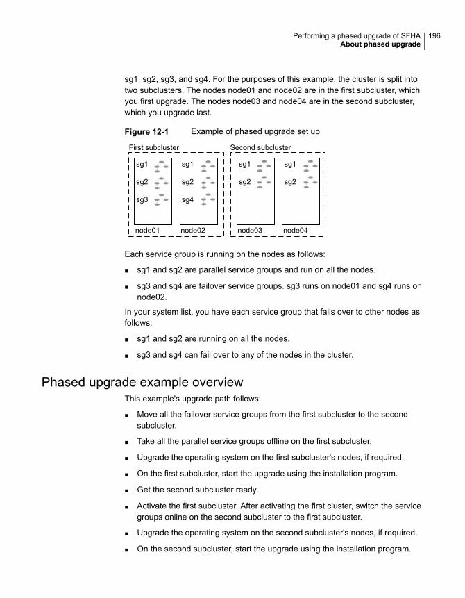
sg1, sg2, sg3, and sg4. For the purposes of this example, the cluster is split intotwo subclusters. The nodes node01 and node02 are in the first subcluster, whichyou first upgrade. The nodes node03 and node04 are in the second subcluster,which you upgrade last.
Figure 12-1 Example of phased upgrade set up
node01 node04node03node02
First subcluster Second subcluster
sg1
sg2
sg3
sg1
sg2
sg4
sg1
sg2
sg1
sg2
Each service group is running on the nodes as follows:
■ sg1 and sg2 are parallel service groups and run on all the nodes.
■ sg3 and sg4 are failover service groups. sg3 runs on node01 and sg4 runs onnode02.
In your system list, you have each service group that fails over to other nodes asfollows:
■ sg1 and sg2 are running on all the nodes.
■ sg3 and sg4 can fail over to any of the nodes in the cluster.
Phased upgrade example overviewThis example's upgrade path follows:
■ Move all the failover service groups from the first subcluster to the secondsubcluster.
■ Take all the parallel service groups offline on the first subcluster.
■ Upgrade the operating system on the first subcluster's nodes, if required.
■ On the first subcluster, start the upgrade using the installation program.
■ Get the second subcluster ready.
■ Activate the first subcluster. After activating the first cluster, switch the servicegroups online on the second subcluster to the first subcluster.
■ Upgrade the operating system on the second subcluster's nodes, if required.
■ On the second subcluster, start the upgrade using the installation program.
196Performing a phased upgrade of SFHAAbout phased upgrade

■ Activate the second subcluster.
See “Performing a phased upgrade using the product installer” on page 197.
Performing a phased upgrade using the productinstaller
This section explains how to perform a phased upgrade of SFHA on four nodeswith four service groups. Note that in this scenario, VCS and the service groupscannot stay online on the second subcluster during the upgrade of the secondsubcluster. Do not add, remove, or change resources or service groups on anynodes during the upgrade. These changes are likely to get lost after the upgrade.
An example of a phased upgrade follows. It illustrates the steps to perform a phasedupgrade. The example makes use of a secure SFHA cluster.
You can perform a phased upgrade from SFHA 6.0.1 to SFHA 7.2.
See “About phased upgrade” on page 194.
See “Phased upgrade example” on page 195.
Moving the service groups to the second subclusterPerform the following steps to establish the service group's status and to switchthe service groups.
197Performing a phased upgrade of SFHAPerforming a phased upgrade using the product installer
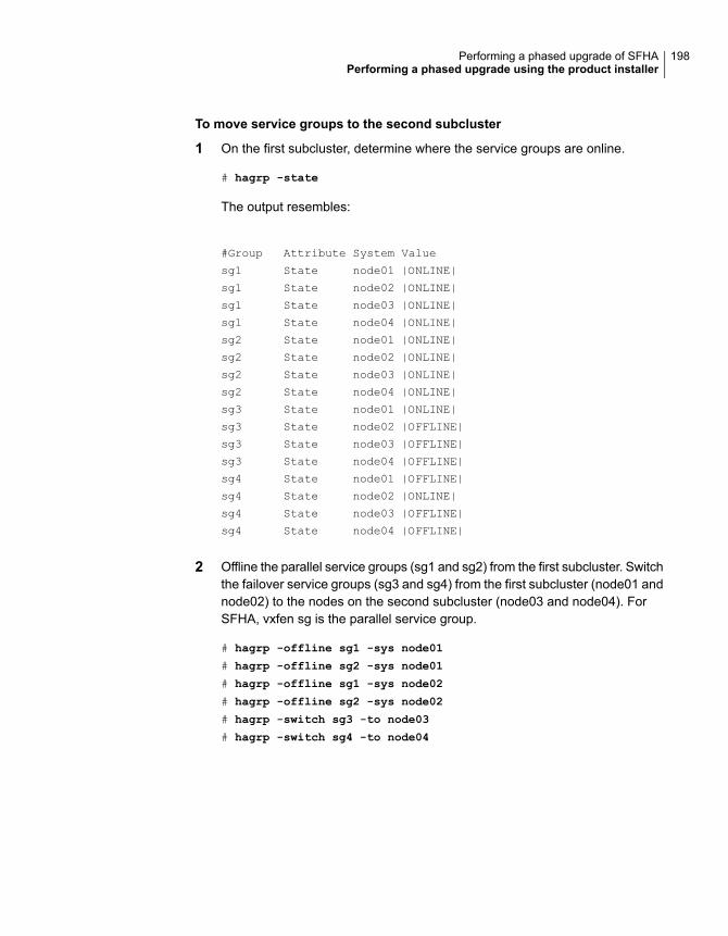
To move service groups to the second subcluster
1 On the first subcluster, determine where the service groups are online.
# hagrp -state
The output resembles:
#Group Attribute System Value
sg1 State node01 |ONLINE|
sg1 State node02 |ONLINE|
sg1 State node03 |ONLINE|
sg1 State node04 |ONLINE|
sg2 State node01 |ONLINE|
sg2 State node02 |ONLINE|
sg2 State node03 |ONLINE|
sg2 State node04 |ONLINE|
sg3 State node01 |ONLINE|
sg3 State node02 |OFFLINE|
sg3 State node03 |OFFLINE|
sg3 State node04 |OFFLINE|
sg4 State node01 |OFFLINE|
sg4 State node02 |ONLINE|
sg4 State node03 |OFFLINE|
sg4 State node04 |OFFLINE|
2 Offline the parallel service groups (sg1 and sg2) from the first subcluster. Switchthe failover service groups (sg3 and sg4) from the first subcluster (node01 andnode02) to the nodes on the second subcluster (node03 and node04). ForSFHA, vxfen sg is the parallel service group.
# hagrp -offline sg1 -sys node01
# hagrp -offline sg2 -sys node01
# hagrp -offline sg1 -sys node02
# hagrp -offline sg2 -sys node02
# hagrp -switch sg3 -to node03
# hagrp -switch sg4 -to node04
198Performing a phased upgrade of SFHAPerforming a phased upgrade using the product installer
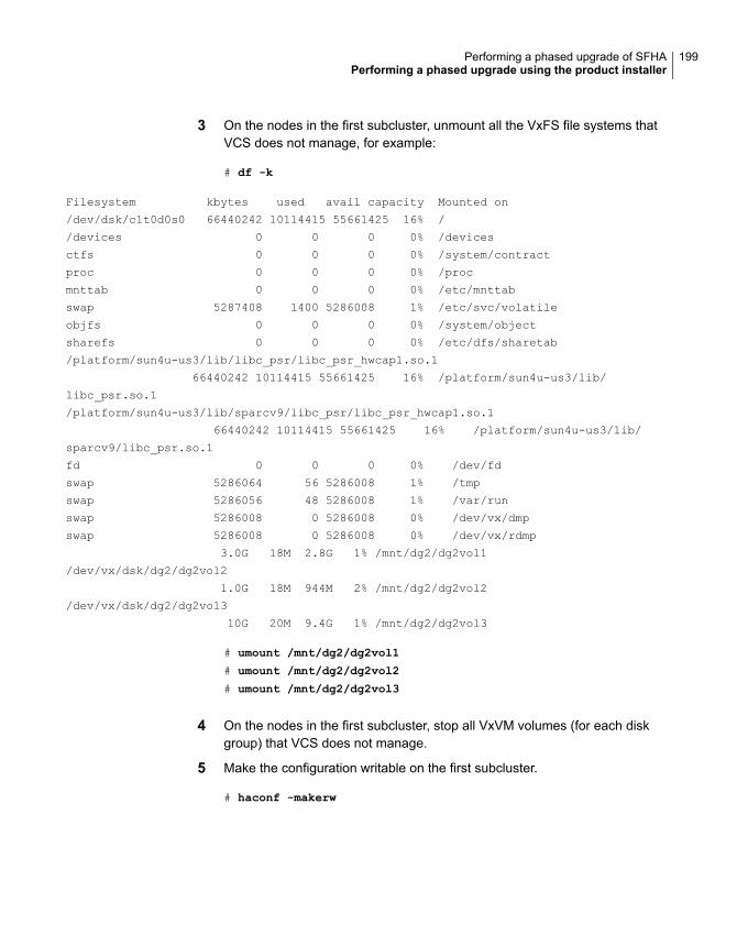
3 On the nodes in the first subcluster, unmount all the VxFS file systems thatVCS does not manage, for example:
# df -k
Filesystem kbytes used avail capacity Mounted on
/dev/dsk/c1t0d0s0 66440242 10114415 55661425 16% /
/devices 0 0 0 0% /devices
ctfs 0 0 0 0% /system/contract
proc 0 0 0 0% /proc
mnttab 0 0 0 0% /etc/mnttab
swap 5287408 1400 5286008 1% /etc/svc/volatile
objfs 0 0 0 0% /system/object
sharefs 0 0 0 0% /etc/dfs/sharetab
/platform/sun4u-us3/lib/libc_psr/libc_psr_hwcap1.so.1
66440242 10114415 55661425 16% /platform/sun4u-us3/lib/
libc_psr.so.1
/platform/sun4u-us3/lib/sparcv9/libc_psr/libc_psr_hwcap1.so.1
66440242 10114415 55661425 16% /platform/sun4u-us3/lib/
sparcv9/libc_psr.so.1
fd 0 0 0 0% /dev/fd
swap 5286064 56 5286008 1% /tmp
swap 5286056 48 5286008 1% /var/run
swap 5286008 0 5286008 0% /dev/vx/dmp
swap 5286008 0 5286008 0% /dev/vx/rdmp
3.0G 18M 2.8G 1% /mnt/dg2/dg2vol1
/dev/vx/dsk/dg2/dg2vol2
1.0G 18M 944M 2% /mnt/dg2/dg2vol2
/dev/vx/dsk/dg2/dg2vol3
10G 20M 9.4G 1% /mnt/dg2/dg2vol3
# umount /mnt/dg2/dg2vol1
# umount /mnt/dg2/dg2vol2
# umount /mnt/dg2/dg2vol3
4 On the nodes in the first subcluster, stop all VxVM volumes (for each diskgroup) that VCS does not manage.
5 Make the configuration writable on the first subcluster.
# haconf -makerw
199Performing a phased upgrade of SFHAPerforming a phased upgrade using the product installer
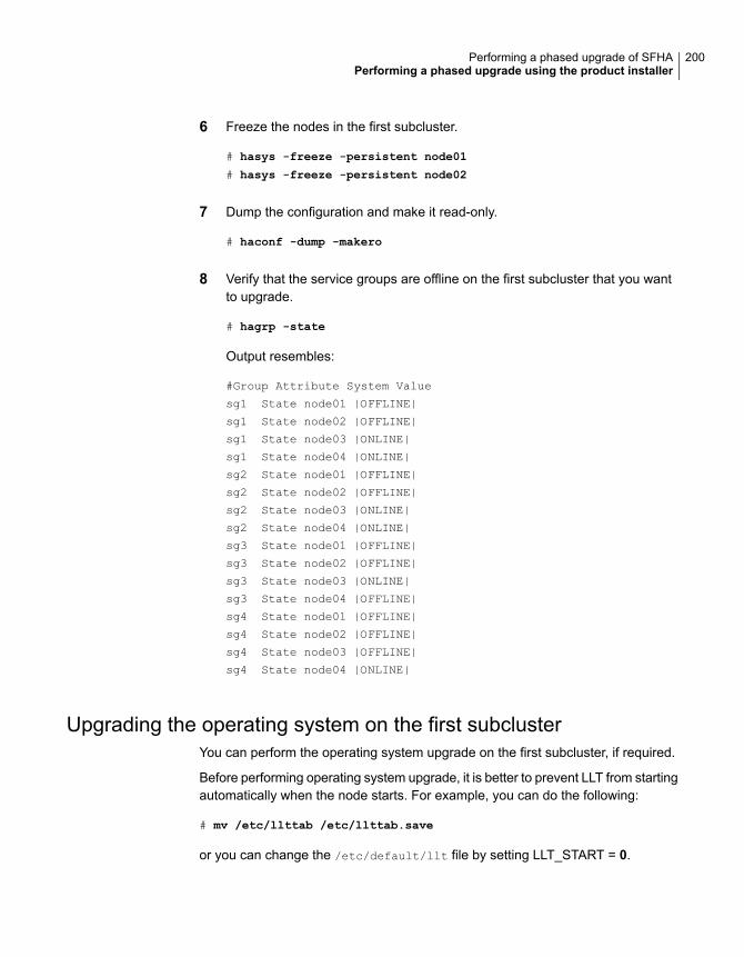
6 Freeze the nodes in the first subcluster.
# hasys -freeze -persistent node01
# hasys -freeze -persistent node02
7 Dump the configuration and make it read-only.
# haconf -dump -makero
8 Verify that the service groups are offline on the first subcluster that you wantto upgrade.
# hagrp -state
Output resembles:
#Group Attribute System Value
sg1 State node01 |OFFLINE|
sg1 State node02 |OFFLINE|
sg1 State node03 |ONLINE|
sg1 State node04 |ONLINE|
sg2 State node01 |OFFLINE|
sg2 State node02 |OFFLINE|
sg2 State node03 |ONLINE|
sg2 State node04 |ONLINE|
sg3 State node01 |OFFLINE|
sg3 State node02 |OFFLINE|
sg3 State node03 |ONLINE|
sg3 State node04 |OFFLINE|
sg4 State node01 |OFFLINE|
sg4 State node02 |OFFLINE|
sg4 State node03 |OFFLINE|
sg4 State node04 |ONLINE|
Upgrading the operating system on the first subclusterYou can perform the operating system upgrade on the first subcluster, if required.
Before performing operating system upgrade, it is better to prevent LLT from startingautomatically when the node starts. For example, you can do the following:
# mv /etc/llttab /etc/llttab.save
or you can change the /etc/default/llt file by setting LLT_START = 0.
200Performing a phased upgrade of SFHAPerforming a phased upgrade using the product installer
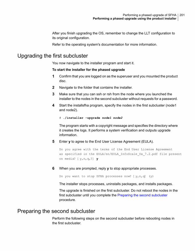
After you finish upgrading the OS, remember to change the LLT configuration toits original configuration.
Refer to the operating system's documentation for more information.
Upgrading the first subclusterYou now navigate to the installer program and start it.
To start the installer for the phased upgrade
1 Confirm that you are logged on as the superuser and you mounted the productdisc.
2 Navigate to the folder that contains the installer.
3 Make sure that you can ssh or rsh from the node where you launched theinstaller to the nodes in the second subcluster without requests for a password.
4 Start the installsfha program, specify the nodes in the first subcluster (node1and node2).
# ./installer -upgrade node1 node2
The program starts with a copyright message and specifies the directory whereit creates the logs. It performs a system verification and outputs upgradeinformation.
5 Enter y to agree to the End User License Agreement (EULA).
Do you agree with the terms of the End User License Agreement
as specified in the EULA/en/EULA_InfoScale_Ux_7.2.pdf file present
on media? [y,n,q,?] y
6 When you are prompted, reply y to stop appropriate processes.
Do you want to stop SFHA processes now? [y,n,q] (y)
The installer stops processes, uninstalls packages, and installs packages.
The upgrade is finished on the first subcluster. Do not reboot the nodes in thefirst subcluster until you complete the Preparing the second subclusterprocedure.
Preparing the second subclusterPerform the following steps on the second subcluster before rebooting nodes inthe first subcluster.
201Performing a phased upgrade of SFHAPerforming a phased upgrade using the product installer

To prepare to upgrade the second subcluster
1 Get the summary of the status of your resources.
# hastatus -summ
-- SYSTEM STATE
-- System State Frozen
A node01 EXITED 1
A node02 EXITED 1
A node03 RUNNING 0
A node04 RUNNING 0
-- GROUP STATE
-- Group System Probed AutoDisabled State
B SG1 node01 Y N OFFLINE
B SG1 node02 Y N OFFLINE
B SG1 node03 Y N ONLINE
B SG1 node04 Y N ONLINE
B SG2 node01 Y N OFFLINE
B SG2 node02 Y N OFFLINE
B SG2 node03 Y N ONLINE
B SG2 node04 Y N ONLINE
B SG3 node01 Y N OFFLINE
B SG3 node02 Y N OFFLINE
B SG3 node03 Y N ONLINE
B SG3 node04 Y N OFFLINE
B SG4 node01 Y N OFFLINE
B SG4 node02 Y N OFFLINE
B SG4 node03 Y N OFFLINE
B SG4 node04 Y N ONLINE
202Performing a phased upgrade of SFHAPerforming a phased upgrade using the product installer

2 Unmount all the VxFS file systems that VCS does not manage, for example:
# df -k
Filesystem kbytes used avail capacity Mounted on
/dev/dsk/c1t0d0s0 66440242 10114415 55661425 16% /
/devices 0 0 0 0% /devices
ctfs 0 0 0 0% /system/contract
proc 0 0 0 0% /proc
mnttab 0 0 0 0% /etc/mnttab
swap 5287408 1400 5286008 1% /etc/svc/volatile
objfs 0 0 0 0% /system/object
sharefs 0 0 0 0% /etc/dfs/sharetab
/platform/sun4u-us3/lib/libc_psr/libc_psr_hwcap1.so.1
66440242 10114415 55661425 16% /platform/sun4u-us3/
lib/libc_psr.so.1
/platform/sun4u-us3/lib/sparcv9/libc_psr/libc_psr_hwcap1.so.1
66440242 10114415 55661425 16% /platform/sun4u-us3/
lib/sparcv9/libc_psr.so.1
fd 0 0 0 0% /dev/fd
swap 5286064 56 5286008 1% /tmp
swap 5286056 48 5286008 1% /var/run
swap 5286008 0 5286008 0% /dev/vx/dmp
swap 5286008 0 5286008 0% /dev/vx/rdmp
3.0G 18M 2.8G 1% /mnt/dg2/dg2vol1
/dev/vx/dsk/dg2/dg2vol2
1.0G 18M 944M 2% /mnt/dg2/dg2vol2
/dev/vx/dsk/dg2/dg2vol3
10G 20M 9.4G 1% /mnt/dg2/dg2vol3
# umount /mnt/dg2/dg2vol1
# umount /mnt/dg2/dg2vol2
# umount /mnt/dg2/dg2vol3
3 Make the configuration writable on the second subcluster.
# haconf -makerw
4 Unfreeze the service groups.
# hagrp -unfreeze sg1 -persistent
# hagrp -unfreeze sg2 -persistent
# hagrp -unfreeze sg3 -persistent
# hagrp -unfreeze sg4 -persistent
203Performing a phased upgrade of SFHAPerforming a phased upgrade using the product installer
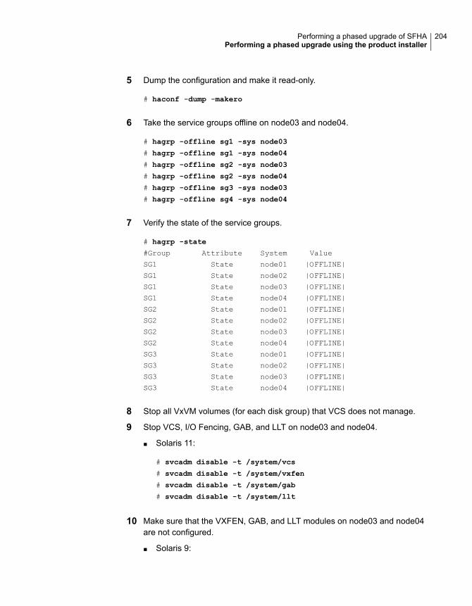
5 Dump the configuration and make it read-only.
# haconf -dump -makero
6 Take the service groups offline on node03 and node04.
# hagrp -offline sg1 -sys node03
# hagrp -offline sg1 -sys node04
# hagrp -offline sg2 -sys node03
# hagrp -offline sg2 -sys node04
# hagrp -offline sg3 -sys node03
# hagrp -offline sg4 -sys node04
7 Verify the state of the service groups.
# hagrp -state
#Group Attribute System Value
SG1 State node01 |OFFLINE|
SG1 State node02 |OFFLINE|
SG1 State node03 |OFFLINE|
SG1 State node04 |OFFLINE|
SG2 State node01 |OFFLINE|
SG2 State node02 |OFFLINE|
SG2 State node03 |OFFLINE|
SG2 State node04 |OFFLINE|
SG3 State node01 |OFFLINE|
SG3 State node02 |OFFLINE|
SG3 State node03 |OFFLINE|
SG3 State node04 |OFFLINE|
8 Stop all VxVM volumes (for each disk group) that VCS does not manage.
9 Stop VCS, I/O Fencing, GAB, and LLT on node03 and node04.
■ Solaris 11:
# svcadm disable -t /system/vcs
# svcadm disable -t /system/vxfen
# svcadm disable -t /system/gab
# svcadm disable -t /system/llt
10 Make sure that the VXFEN, GAB, and LLT modules on node03 and node04are not configured.
■ Solaris 9:
204Performing a phased upgrade of SFHAPerforming a phased upgrade using the product installer
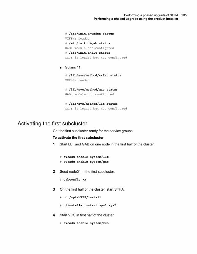
# /etc/init.d/vxfen status
VXFEN: loaded
# /etc/init.d/gab status
GAB: module not configured
# /etc/init.d/llt status
LLT: is loaded but not configured
■ Solaris 11:
# /lib/svc/method/vxfen status
VXFEN: loaded
# /lib/svc/method/gab status
GAB: module not configured
# /lib/svc/method/llt status
LLT: is loaded but not configured
Activating the first subclusterGet the first subcluster ready for the service groups.
To activate the first subcluster
1 Start LLT and GAB on one node in the first half of the cluster..
# svcadm enable system/llt
# svcadm enable system/gab
2 Seed node01 in the first subcluster.
# gabconfig -x
3 On the first half of the cluster, start SFHA:
# cd /opt/VRTS/install
# ./installer -start sys1 sys2
4 Start VCS in first half of the cluster:
# svcadm enable system/vcs
205Performing a phased upgrade of SFHAPerforming a phased upgrade using the product installer

5 Make the configuration writable on the first subcluster.
# haconf -makerw
6 Unfreeze the nodes in the first subcluster.
# hasys -unfreeze -persistent node01
# hasys -unfreeze -persistent node02
7 Dump the configuration and make it read-only.
# haconf -dump -makero
8 Bring the service groups online on node01 and node02.
# hagrp -online sg1 -sys node01
# hagrp -online sg1 -sys node02
# hagrp -online sg2 -sys node01
# hagrp -online sg2 -sys node02
# hagrp -online sg3 -sys node01
# hagrp -online sg4 -sys node02
Upgrading the operating system on the second subclusterYou can perform the operating system upgrade on the second subcluster, if required.
Before performing operating system upgrade, it is better to prevent LLT from startingautomatically when the node starts. For example, you can do the following:
# mv /etc/llttab /etc/llttab.save
or you can change the /etc/default/llt file by setting LLT_START = 0.
After you finish upgrading the OS, remember to change the LLT configuration toits original configuration.
Refer to the operating system's documentation for more information.
Upgrading the second subclusterPerform the following procedure to upgrade the second subcluster (node03 andnode04).
206Performing a phased upgrade of SFHAPerforming a phased upgrade using the product installer
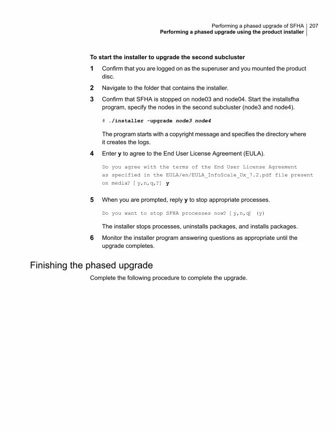
To start the installer to upgrade the second subcluster
1 Confirm that you are logged on as the superuser and you mounted the productdisc.
2 Navigate to the folder that contains the installer.
3 Confirm that SFHA is stopped on node03 and node04. Start the installsfhaprogram, specify the nodes in the second subcluster (node3 and node4).
# ./installer -upgrade node3 node4
The program starts with a copyright message and specifies the directory whereit creates the logs.
4 Enter y to agree to the End User License Agreement (EULA).
Do you agree with the terms of the End User License Agreement
as specified in the EULA/en/EULA_InfoScale_Ux_7.2.pdf file present
on media? [y,n,q,?] y
5 When you are prompted, reply y to stop appropriate processes.
Do you want to stop SFHA processes now? [y,n,q] (y)
The installer stops processes, uninstalls packages, and installs packages.
6 Monitor the installer program answering questions as appropriate until theupgrade completes.
Finishing the phased upgradeComplete the following procedure to complete the upgrade.
207Performing a phased upgrade of SFHAPerforming a phased upgrade using the product installer
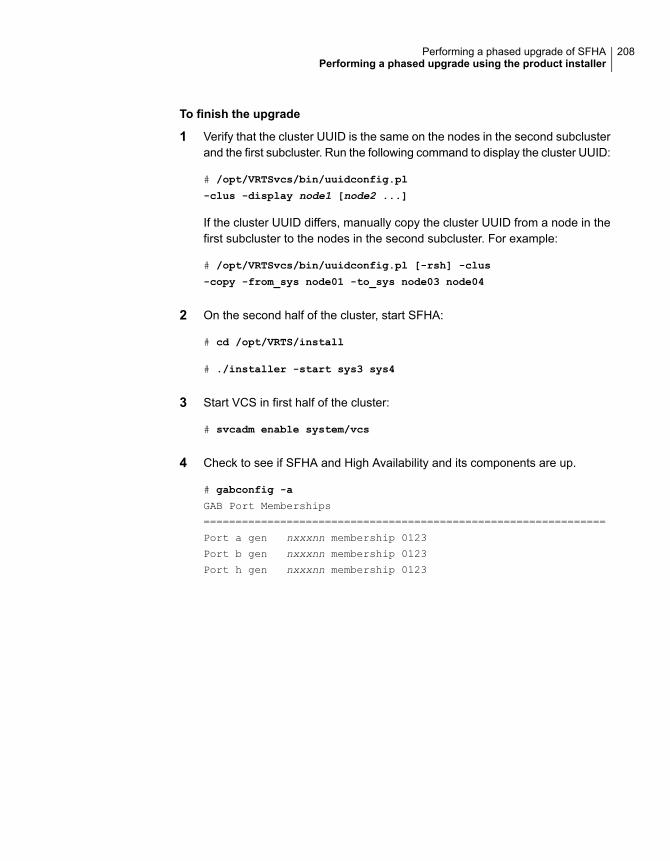
To finish the upgrade
1 Verify that the cluster UUID is the same on the nodes in the second subclusterand the first subcluster. Run the following command to display the cluster UUID:
# /opt/VRTSvcs/bin/uuidconfig.pl
-clus -display node1 [node2 ...]
If the cluster UUID differs, manually copy the cluster UUID from a node in thefirst subcluster to the nodes in the second subcluster. For example:
# /opt/VRTSvcs/bin/uuidconfig.pl [-rsh] -clus
-copy -from_sys node01 -to_sys node03 node04
2 On the second half of the cluster, start SFHA:
# cd /opt/VRTS/install
# ./installer -start sys3 sys4
3 Start VCS in first half of the cluster:
# svcadm enable system/vcs
4 Check to see if SFHA and High Availability and its components are up.
# gabconfig -a
GAB Port Memberships
===============================================================
Port a gen nxxxnn membership 0123
Port b gen nxxxnn membership 0123
Port h gen nxxxnn membership 0123
208Performing a phased upgrade of SFHAPerforming a phased upgrade using the product installer
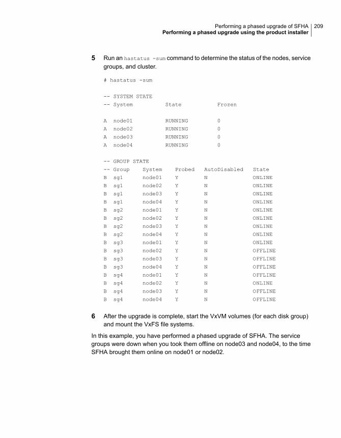
5 Run an hastatus -sum command to determine the status of the nodes, servicegroups, and cluster.
# hastatus -sum
-- SYSTEM STATE
-- System State Frozen
A node01 RUNNING 0
A node02 RUNNING 0
A node03 RUNNING 0
A node04 RUNNING 0
-- GROUP STATE
-- Group System Probed AutoDisabled State
B sg1 node01 Y N ONLINE
B sg1 node02 Y N ONLINE
B sg1 node03 Y N ONLINE
B sg1 node04 Y N ONLINE
B sg2 node01 Y N ONLINE
B sg2 node02 Y N ONLINE
B sg2 node03 Y N ONLINE
B sg2 node04 Y N ONLINE
B sg3 node01 Y N ONLINE
B sg3 node02 Y N OFFLINE
B sg3 node03 Y N OFFLINE
B sg3 node04 Y N OFFLINE
B sg4 node01 Y N OFFLINE
B sg4 node02 Y N ONLINE
B sg4 node03 Y N OFFLINE
B sg4 node04 Y N OFFLINE
6 After the upgrade is complete, start the VxVM volumes (for each disk group)and mount the VxFS file systems.
In this example, you have performed a phased upgrade of SFHA. The servicegroups were down when you took them offline on node03 and node04, to the timeSFHA brought them online on node01 or node02.
209Performing a phased upgrade of SFHAPerforming a phased upgrade using the product installer
Note: If you want to upgrade the application clusters that use CP server basedfencing to version 6.1 and later, make sure that you first upgrade VCS or SFHA onthe CP server systems to version 6.1 and later. And then, from 7.0.1 onwards, CPserver supports only HTTPS based communication with its clients and IPM-basedcommunication is no longer supported. CP server needs to be reconfigured if youupgrade the CP server with IPM-based CP server configured.
210Performing a phased upgrade of SFHAPerforming a phased upgrade using the product installer
Performing an automatedSFHA upgrade usingresponse files
This chapter includes the following topics:
■ Upgrading SFHA using response files
■ Response file variables to upgrade SFHA
■ Sample response file for SFHA upgrade
Upgrading SFHA using response filesTypically, you can use the response file that the installer generates after you performSFHA upgrade on one system to upgrade SFHA on other systems.
To perform automated SFHA upgrade
1 Make sure the systems where you want to upgrade SFHA meet the upgraderequirements.
2 Make sure the pre-upgrade tasks are completed.
3 Copy the response file to the system where you want to upgrade SFHA.
4 Edit the values of the response file variables as necessary.
13Chapter
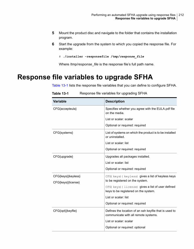
5 Mount the product disc and navigate to the folder that contains the installationprogram.
6 Start the upgrade from the system to which you copied the response file. Forexample:
# ./installer -responsefile /tmp/response_file
Where /tmp/response_file is the response file’s full path name.
Response file variables to upgrade SFHATable 13-1 lists the response file variables that you can define to configure SFHA.
Table 13-1 Response file variables for upgrading SFHA
DescriptionVariable
Specifies whether you agree with the EULA.pdf fileon the media.
List or scalar: scalar
Optional or required: required
CFG{accepteula}
List of systems on which the product is to be installedor uninstalled.
List or scalar: list
Optional or required: required
CFG{systems}
Upgrades all packages installed.
List or scalar: list
Optional or required: required
CFG{upgrade}
CFG{keys}{keyless} gives a list of keyless keysto be registered on the system.
CFG{keys}{license} gives a list of user definedkeys to be registered on the system.
List or scalar: list
Optional or required: required
CFG{keys}{keyless}
CFG{keys}{license}
Defines the location of an ssh keyfile that is used tocommunicate with all remote systems.
List or scalar: scalar
Optional or required: optional
CFG{opt}{keyfile}
212Performing an automated SFHA upgrade using response filesResponse file variables to upgrade SFHA
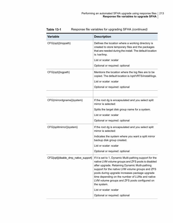
Table 13-1 Response file variables for upgrading SFHA (continued)
DescriptionVariable
Defines the location where a working directory iscreated to store temporary files and the packagesthat are needed during the install. The default locationis /var/tmp.
List or scalar: scalar
Optional or required: optional
CFG{opt}{tmppath}
Mentions the location where the log files are to becopied. The default location is /opt/VRTS/install/logs.
List or scalar: scalar
Optional or required: optional
CFG{opt}{logpath}
If the root dg is encapsulated and you select splitmirror is selected:
Splits the target disk group name for a system.
List or scalar: scalar
Optional or required: optional
CFG{mirrordgname}{system}
If the root dg is encapsulated and you select splitmirror is selected:
Indicates the system where you want a split mirrorbackup disk group created.
List or scalar: scalar
Optional or required: optional
CFG{splitmirror}{system}
If it is set to 1, Dynamic Multi-pathing support for thenative LVM volume groups and ZFS pools is disabledafter upgrade. Retaining Dynamic Multi-pathingsupport for the native LVM volume groups and ZFSpools during upgrade increases package upgradetime depending on the number of LUNs and nativeLVM volume groups and ZFS pools configured onthe system.
List or scalar: scalar
Optional or required: optional
CFG{opt}{disable_dmp_native_support}
213Performing an automated SFHA upgrade using response filesResponse file variables to upgrade SFHA
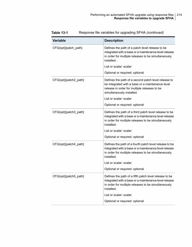
Table 13-1 Response file variables for upgrading SFHA (continued)
DescriptionVariable
Defines the path of a patch level release to beintegrated with a base or a maintenance level releasein order for multiple releases to be simultaneouslyinstalled .
List or scalar: scalar
Optional or required: optional
CFG{opt}{patch_path}
Defines the path of a second patch level release tobe integrated with a base or a maintenance levelrelease in order for multiple releases to besimultaneously installed.
List or scalar: scalar
Optional or required: optional
CFG{opt}{patch2_path}
Defines the path of a third patch level release to beintegrated with a base or a maintenance level releasein order for multiple releases to be simultaneouslyinstalled.
List or scalar: scalar
Optional or required: optional
CFG{opt}{patch3_path}
Defines the path of a fourth patch level release to beintegrated with a base or a maintenance level releasein order for multiple releases to be simultaneouslyinstalled.
List or scalar: scalar
Optional or required: optional
CFG{opt}{patch4_path}
Defines the path of a fifth patch level release to beintegrated with a base or a maintenance level releasein order for multiple releases to be simultaneouslyinstalled.
List or scalar: scalar
Optional or required: optional
CFG{opt}{patch5_path}
214Performing an automated SFHA upgrade using response filesResponse file variables to upgrade SFHA
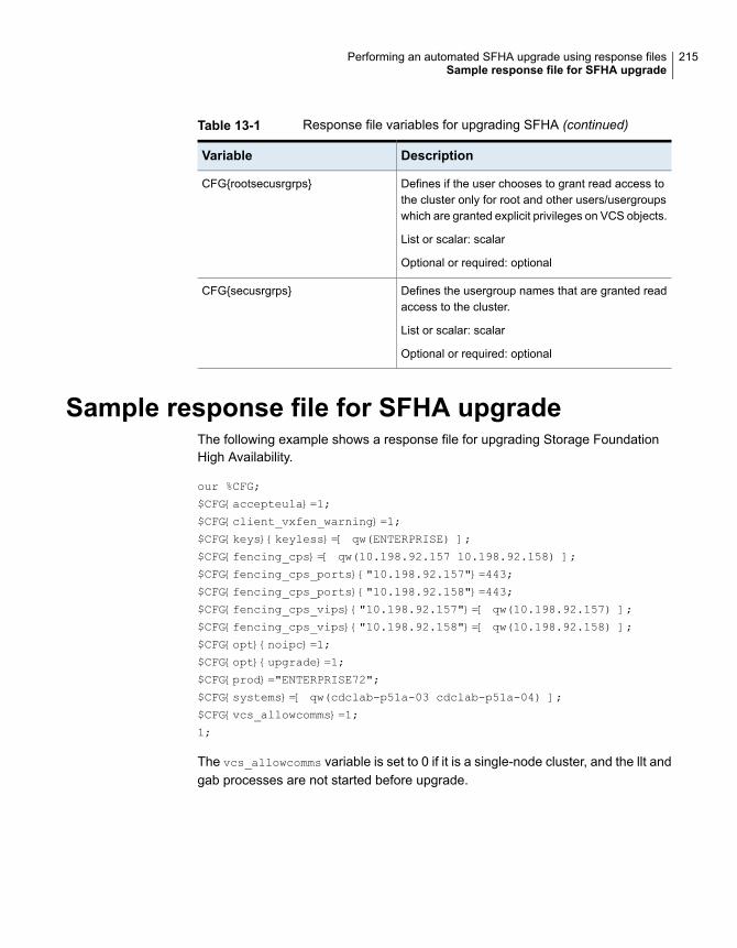
Table 13-1 Response file variables for upgrading SFHA (continued)
DescriptionVariable
Defines if the user chooses to grant read access tothe cluster only for root and other users/usergroupswhich are granted explicit privileges on VCS objects.
List or scalar: scalar
Optional or required: optional
CFG{rootsecusrgrps}
Defines the usergroup names that are granted readaccess to the cluster.
List or scalar: scalar
Optional or required: optional
CFG{secusrgrps}
Sample response file for SFHA upgradeThe following example shows a response file for upgrading Storage FoundationHigh Availability.
our %CFG;
$CFG{accepteula}=1;
$CFG{client_vxfen_warning}=1;
$CFG{keys}{keyless}=[ qw(ENTERPRISE) ];
$CFG{fencing_cps}=[ qw(10.198.92.157 10.198.92.158) ];
$CFG{fencing_cps_ports}{"10.198.92.157"}=443;
$CFG{fencing_cps_ports}{"10.198.92.158"}=443;
$CFG{fencing_cps_vips}{"10.198.92.157"}=[ qw(10.198.92.157) ];
$CFG{fencing_cps_vips}{"10.198.92.158"}=[ qw(10.198.92.158) ];
$CFG{opt}{noipc}=1;
$CFG{opt}{upgrade}=1;
$CFG{prod}="ENTERPRISE72";
$CFG{systems}=[ qw(cdclab-p51a-03 cdclab-p51a-04) ];
$CFG{vcs_allowcomms}=1;
1;
The vcs_allowcomms variable is set to 0 if it is a single-node cluster, and the llt andgab processes are not started before upgrade.
215Performing an automated SFHA upgrade using response filesSample response file for SFHA upgrade
Upgrading SFHA usingBoot Environment upgrade
This chapter includes the following topics:
■ About ZFS Boot Environment (BE) upgrade
■ Supported upgrade paths for Boot Environment upgrade
■ Performing Boot Environment upgrade on Solaris 11 systems
■ About Live Upgrade in a Volume Replicator (VVR) environment
About ZFS Boot Environment (BE) upgradeA Boot Environment (BE) is a bootable instance of the Oracle Solaris operatingsystem image along with any other application software packages installed into thatimage. System administrators can maintain multiple BEs on their systems, andeach BE can have different software versions installed. Upon the initial installationof the Oracle Solaris 11 release onto a system, a BE is created.
On Solaris 11, you can use the beadm utility to create and administer additional BEson your system.
14Chapter
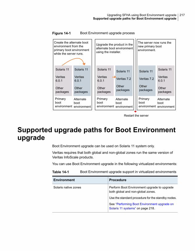
Figure 14-1 Boot Environment upgrade process
Create the alternate bootenvironment from theprimary boot environmentwhile the server runs.
Solaris 11
Veritas6.0.1
Otherpackages
Solaris 11
Veritas6.0.1
Otherpackages
Primarybootenvironment
Alternatebootenvironment
The server now runs thenew primary bootenvironment.
Solaris 11
Veritas 7.2
Otherpackages
Solaris 11
Veritas6.0.1
Otherpackages
Primarybootenvironment
Alternatebootenvironment
Upgrade the Veritasproduct in the alternateboot environment usingthe installer or manually.
Solaris 11
Veritas6.0.1
Otherpackages
Solaris 11
Veritas 7.2
Otherpackages
Primarybootenvironment
Alternatebootenvironment
Restart the server
Upgrade the product in thealternate boot environmentusing the installer.
Supported upgrade paths for Boot Environmentupgrade
Boot Environment upgrade can be used on Solaris 11 system only.
Veritas requires that both global and non-global zones run the same version ofVeritas InfoScale products.
You can use Boot Environment upgrade in the following virtualized environments:
Table 14-1 Boot Environment upgrade support in virtualized environments
ProcedureEnvironment
Perform Boot Environment upgrade to upgradeboth global and non-global zones.
Use the standard procedure for the standby nodes.
See “Performing Boot Environment upgrade onSolaris 11 systems” on page 218.
Solaris native zones
217Upgrading SFHA using Boot Environment upgradeSupported upgrade paths for Boot Environment upgrade

Table 14-1 Boot Environment upgrade support in virtualized environments(continued)
ProcedureEnvironment
Perform Boot Environment upgrade to upgrade theglobal zone.
See “Performing Boot Environment upgrade onSolaris 11 systems” on page 218.
Manually upgrade the branded zone separately.
Note that while you can perform a BootEnvironment upgrade in the presence of brandedzones, the branded zones are not upgraded.
Solaris branded zones (BrandZ)
Use Boot Environment upgrade procedure forControl domain as well as guest domains.
See “Performing Boot Environment upgrade onSolaris 11 systems” on page 218.
Oracle VM Server for SPARC
Performing Boot Environment upgrade on Solaris11 systems
For SFHA, the nodes do not form a cluster until all of the nodes are upgraded. Atthe end of the BE upgrade of the last node, all the nodes must boot from the alternateBE and join the cluster.
Table 14-2 Upgrading SFHA using BE upgrade
DescriptionStep
Create a new BE on the primary boot disk.
See “Creating a new Solaris 11 BE on the primary boot disk”on page 219.
Step 1
Upgrade SFHA using the installer on the new BE.
See “Upgrading SFHA using the installer for upgrading BE onSolaris 11” on page 220.
Step 2
To upgrade only Solaris
See the Oracle documentation on Oracle Solaris 11 operatingsystem.
218Upgrading SFHA using Boot Environment upgradePerforming Boot Environment upgrade on Solaris 11 systems

Table 14-2 Upgrading SFHA using BE upgrade (continued)
DescriptionStep
Switch the alternate BE to be the new primary.
See “Completing the SFHA upgrade on BE on Solaris 11”on page 221.
Step 3
Verify Upgrade of SFHA.
See “Verifying Solaris 11 BE upgrade ” on page 222.
Step 4
Creating a new Solaris 11 BE on the primary boot diskRun the beadm create command on each node in the cluster to create a new BEon the primary boot disk.
At the end of the process, a new BE is created on the primary boot disk by cloningthe primary BE.
To create a new BE on the primary boot disk
Perform the steps in this procedure on each node in the cluster.
1 View the list of BE in the primary disk.
# beadm list
2 If you have solaris brand zones in running state for which zone root is on sharedstorage, set AutoStart to 0 for the service group containing zone resource.
# hagrp -modify <group> AutoStart 0
# haconf -dump
3 Create a new BE in the primary boot disk.
# beadm create beName
# beadm mount beName mountpoint
4 Reset AutoStart to 1 for the service group containing zone resource in step2
# hagrp -modify <group> AutoStart 1
# haconf -dump
219Upgrading SFHA using Boot Environment upgradePerforming Boot Environment upgrade on Solaris 11 systems
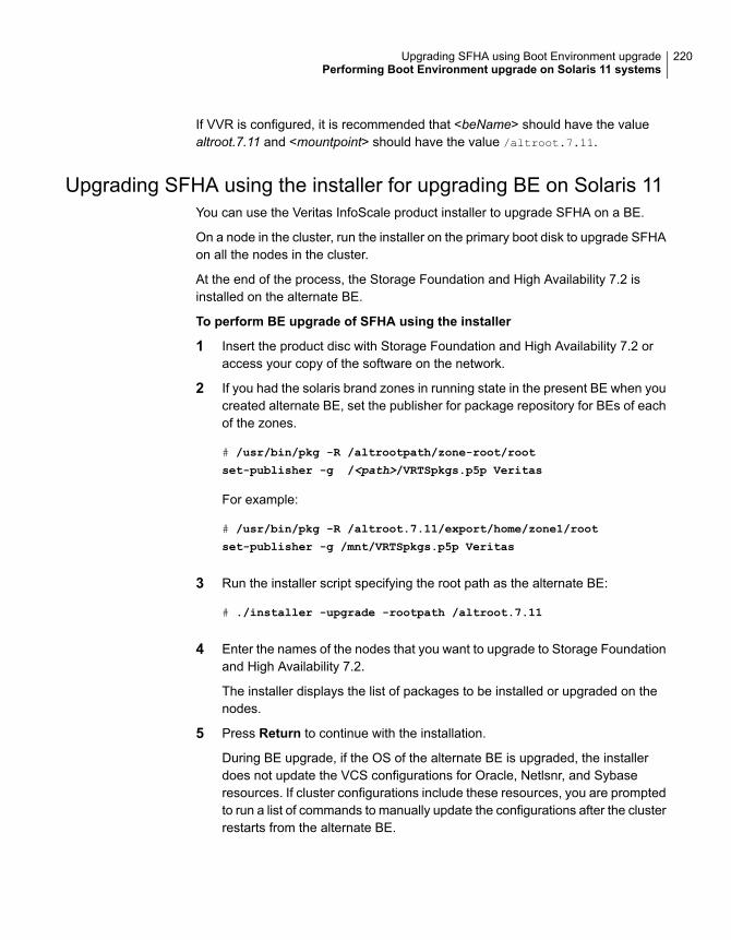
If VVR is configured, it is recommended that <beName> should have the valuealtroot.7.11 and <mountpoint> should have the value /altroot.7.11.
Upgrading SFHA using the installer for upgrading BE on Solaris 11You can use the Veritas InfoScale product installer to upgrade SFHA on a BE.
On a node in the cluster, run the installer on the primary boot disk to upgrade SFHAon all the nodes in the cluster.
At the end of the process, the Storage Foundation and High Availability 7.2 isinstalled on the alternate BE.
To perform BE upgrade of SFHA using the installer
1 Insert the product disc with Storage Foundation and High Availability 7.2 oraccess your copy of the software on the network.
2 If you had the solaris brand zones in running state in the present BE when youcreated alternate BE, set the publisher for package repository for BEs of eachof the zones.
# /usr/bin/pkg -R /altrootpath/zone-root/root
set-publisher -g /<path>/VRTSpkgs.p5p Veritas
For example:
# /usr/bin/pkg -R /altroot.7.11/export/home/zone1/root
set-publisher -g /mnt/VRTSpkgs.p5p Veritas
3 Run the installer script specifying the root path as the alternate BE:
# ./installer -upgrade -rootpath /altroot.7.11
4 Enter the names of the nodes that you want to upgrade to Storage Foundationand High Availability 7.2.
The installer displays the list of packages to be installed or upgraded on thenodes.
5 Press Return to continue with the installation.
During BE upgrade, if the OS of the alternate BE is upgraded, the installerdoes not update the VCS configurations for Oracle, Netlsnr, and Sybaseresources. If cluster configurations include these resources, you are promptedto run a list of commands to manually update the configurations after the clusterrestarts from the alternate BE.
220Upgrading SFHA using Boot Environment upgradePerforming Boot Environment upgrade on Solaris 11 systems
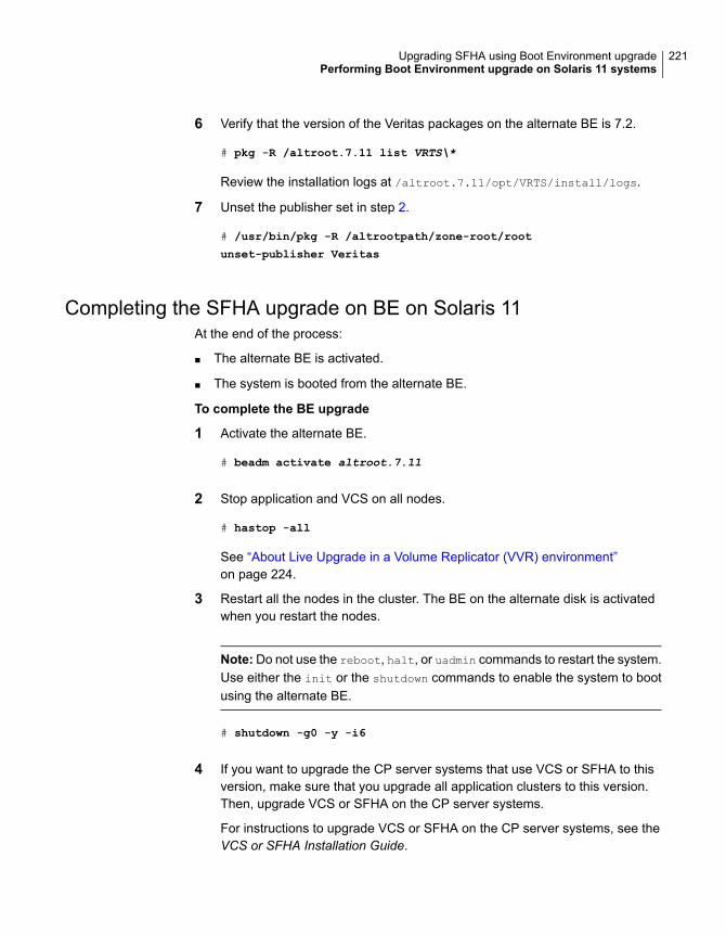
6 Verify that the version of the Veritas packages on the alternate BE is 7.2.
# pkg -R /altroot.7.11 list VRTS\*
Review the installation logs at /altroot.7.11/opt/VRTS/install/logs.
7 Unset the publisher set in step 2.
# /usr/bin/pkg -R /altrootpath/zone-root/root
unset-publisher Veritas
Completing the SFHA upgrade on BE on Solaris 11At the end of the process:
■ The alternate BE is activated.
■ The system is booted from the alternate BE.
To complete the BE upgrade
1 Activate the alternate BE.
# beadm activate altroot.7.11
2 Stop application and VCS on all nodes.
# hastop -all
See “About Live Upgrade in a Volume Replicator (VVR) environment”on page 224.
3 Restart all the nodes in the cluster. The BE on the alternate disk is activatedwhen you restart the nodes.
Note:Do not use the reboot, halt, or uadmin commands to restart the system.Use either the init or the shutdown commands to enable the system to bootusing the alternate BE.
# shutdown -g0 -y -i6
4 If you want to upgrade the CP server systems that use VCS or SFHA to thisversion, make sure that you upgrade all application clusters to this version.Then, upgrade VCS or SFHA on the CP server systems.
For instructions to upgrade VCS or SFHA on the CP server systems, see theVCS or SFHA Installation Guide.
221Upgrading SFHA using Boot Environment upgradePerforming Boot Environment upgrade on Solaris 11 systems
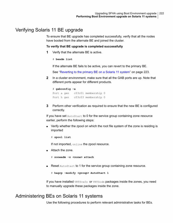
Verifying Solaris 11 BE upgradeTo ensure that BE upgrade has completed successfully, verify that all the nodeshave booted from the alternate BE and joined the cluster.
To verify that BE upgrade is completed successfully
1 Verify that the alternate BE is active.
# beadm list
If the alternate BE fails to be active, you can revert to the primary BE.
See “Reverting to the primary BE on a Solaris 11 system” on page 223.
2 In a cluster environment, make sure that all the GAB ports are up. Note thatdifferent ports appear for different products.
# gabconfig -a
Port a gen c03c01 membership 0
Port h gen c03c03 membership 0
3 Perform other verification as required to ensure that the new BE is configuredcorrectly.
If you have set AutoStart to 0 for the service group containing zone resourceearlier, perform the following steps:
■ Verify whether the zpool on which the root file system of the zone is residing isimported
# zpool list
If not imported, online the zpool resource.
■ Attach the zone.
# zoneadm -z <zone> attach
■ Reset AutoStart to 1 for the service group containing zone resource.
# hagrp -modify <group> AutoStart 1
If you have installed VRTSvxfs or VRTSodm packages inside the zones, you needto manually upgrade these packages inside the zone.
Administering BEs on Solaris 11 systemsUse the following procedures to perform relevant administrative tasks for BEs.
222Upgrading SFHA using Boot Environment upgradePerforming Boot Environment upgrade on Solaris 11 systems

Switching the BE for Solaris SPARC
1 Display the status of Live Upgrade boot environments.
# beadm list
BE Active Mountpoint Space Policy Created
-- ------ --------- ----- ------ -------
solaris NR / 13.08G static 2012-11-14 10:22
altroot.7.11 - - 3.68G static 2013-01-06 18:41
In this example, the primary boot disk is currently solaris. You want to activatethe alternate boot disk altroot.7.11.
2 Activate the Live Upgrade boot environment.
# beadm activate altroot.7.11
3 Restart the system to complete the BE activation.
# shutdown -g0 -i6 -y
The system automatically selects the BE entry that was activated.
4 You can destroy an existing BE.
# beadm destroy altroot.7.11
Reverting to the primary BE on a Solaris 11 systemBoot the system to ok prompt.
View the available BEs.
To view the BEs, enter the following:
ok> boot -L
Select the option of the original BE to which you need to boot.
To boot to the BE, enter the following:
# boot -Z <path to boot env>
For example:
{0} ok boot -L
Boot device: /virtual-devices@100/channel-devices@200/disk@0:a
File and args: -L
1 Oracle Solaris 11 11/11 SPARC
223Upgrading SFHA using Boot Environment upgradePerforming Boot Environment upgrade on Solaris 11 systems
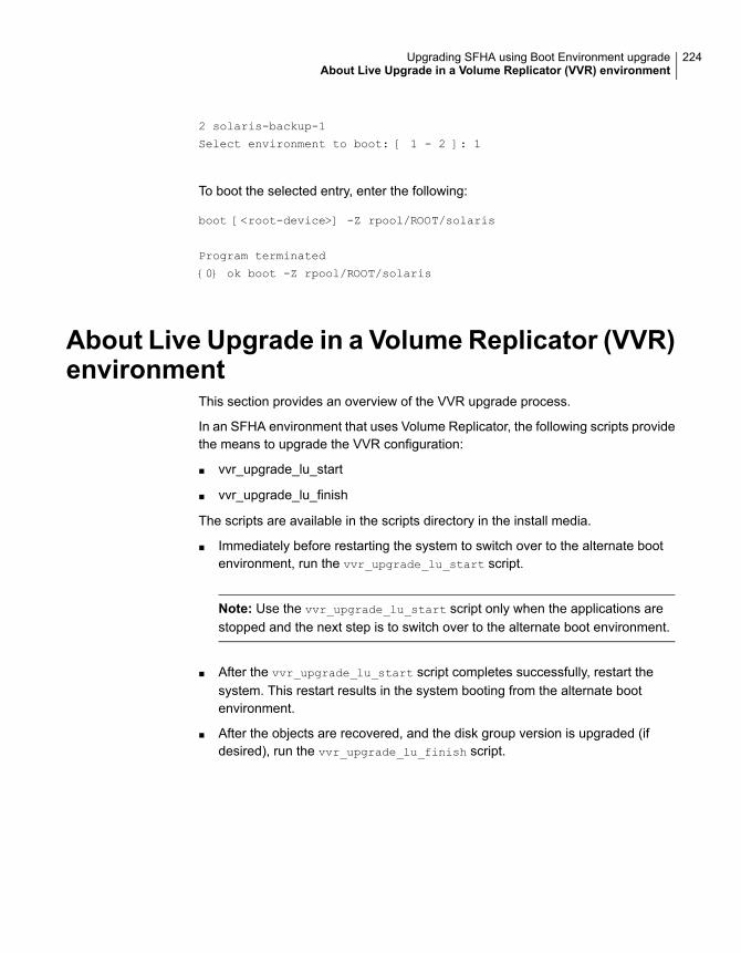
2 solaris-backup-1
Select environment to boot: [ 1 - 2 ]: 1
To boot the selected entry, enter the following:
boot [<root-device>] -Z rpool/ROOT/solaris
Program terminated
{0} ok boot -Z rpool/ROOT/solaris
About Live Upgrade in a Volume Replicator (VVR)environment
This section provides an overview of the VVR upgrade process.
In an SFHA environment that uses Volume Replicator, the following scripts providethe means to upgrade the VVR configuration:
■ vvr_upgrade_lu_start
■ vvr_upgrade_lu_finish
The scripts are available in the scripts directory in the install media.
■ Immediately before restarting the system to switch over to the alternate bootenvironment, run the vvr_upgrade_lu_start script.
Note: Use the vvr_upgrade_lu_start script only when the applications arestopped and the next step is to switch over to the alternate boot environment.
■ After the vvr_upgrade_lu_start script completes successfully, restart thesystem. This restart results in the system booting from the alternate bootenvironment.
■ After the objects are recovered, and the disk group version is upgraded (ifdesired), run the vvr_upgrade_lu_finish script.
224Upgrading SFHA using Boot Environment upgradeAbout Live Upgrade in a Volume Replicator (VVR) environment
Performing post-upgradetasks
This chapter includes the following topics:
■ Optional configuration steps
■ Recovering VVR if automatic upgrade fails
■ Post-upgrade tasks when VCS agents for VVR are configured
■ Resetting DAS disk names to include host name in FSS environments
■ Upgrading disk layout versions
■ Upgrading VxVM disk group versions
■ Updating variables
■ Setting the default disk group
■ Upgrading the Array Support Library
■ Converting from QuickLog to Multi-Volume support
■ About enabling LDAP authentication for clusters that run in secure mode
■ Verifying the Storage Foundation and High Availability upgrade
Optional configuration stepsAfter the upgrade is complete, additional tasks may need to be performed.
You can perform the following optional configuration steps:
15Chapter
■ If Volume Replicator (VVR) is configured, do the following steps in the ordershown:
■ Reattach the RLINKs.
■ Associate the SRL.
■ To encapsulate and mirror the boot disk, follow the procedures in the"Administering Disks" chapter of the Storage Foundation Administrator’s Guide.
■ To upgrade VxFS Disk Layout versions and VxVM Disk Group versions, followthe upgrade instructions.See “Upgrading VxVM disk group versions” on page 231.
Recovering VVR if automatic upgrade failsIf the upgrade fails during the configuration phase, after displaying the VVR upgradedirectory, the configuration needs to be restored before the next attempt. Run thescripts in the upgrade directory in the following order to restore the configuration:
# restoresrl
# adddcm
# srlprot
# attrlink
# start.rvg
After the configuration is restored, the current step can be retried.
Post-upgrade tasks when VCS agents for VVR areconfigured
The following lists post-upgrade tasks with VCS agents for VVR:
■ Unfreezing the service groups
■ Restoring the original configuration when VCS agents are configured
Unfreezing the service groupsThis section describes how to unfreeze services groups and bring them online.
226Performing post-upgrade tasksRecovering VVR if automatic upgrade fails
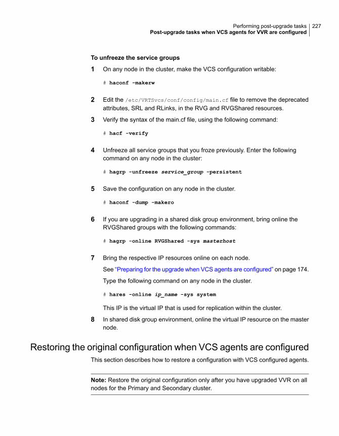
To unfreeze the service groups
1 On any node in the cluster, make the VCS configuration writable:
# haconf -makerw
2 Edit the /etc/VRTSvcs/conf/config/main.cf file to remove the deprecatedattributes, SRL and RLinks, in the RVG and RVGShared resources.
3 Verify the syntax of the main.cf file, using the following command:
# hacf -verify
4 Unfreeze all service groups that you froze previously. Enter the followingcommand on any node in the cluster:
# hagrp -unfreeze service_group -persistent
5 Save the configuration on any node in the cluster.
# haconf -dump -makero
6 If you are upgrading in a shared disk group environment, bring online theRVGShared groups with the following commands:
# hagrp -online RVGShared -sys masterhost
7 Bring the respective IP resources online on each node.
See “Preparing for the upgrade when VCS agents are configured” on page 174.
Type the following command on any node in the cluster.
# hares -online ip_name -sys system
This IP is the virtual IP that is used for replication within the cluster.
8 In shared disk group environment, online the virtual IP resource on the masternode.
Restoring the original configuration when VCS agents are configuredThis section describes how to restore a configuration with VCS configured agents.
Note: Restore the original configuration only after you have upgraded VVR on allnodes for the Primary and Secondary cluster.
227Performing post-upgrade tasksPost-upgrade tasks when VCS agents for VVR are configured

To restore the original configuration
1 Import all the disk groups in your VVR configuration.
# vxdg -t import diskgroup
Each disk group should be imported onto the same node on which it was onlinewhen the upgrade was performed. The reboot after the upgrade could resultin another node being online; for example, because of the order of the nodesin the AutoStartList. In this case, switch the VCS group containing the diskgroups to the node on which the disk group was online while preparing for theupgrade.
# hagrp -switch grpname -to system
2 Recover all the disk groups by typing the following command on the node onwhich the disk group was imported in step 1.
# vxrecover -bs
3 Upgrade all the disk groups on all the nodes on which VVR has been upgraded:
# vxdg upgrade diskgroup
4 On all nodes that are Secondary hosts of VVR, make sure the data volumeson the Secondary are the same length as the corresponding ones on thePrimary. To shrink volumes that are longer on the Secondary than the Primary,use the following command on each volume on the Secondary:
# vxassist -g diskgroup shrinkto volume_name volume_length
where volume_length is the length of the volume on the Primary.
Note: Do not continue until you complete this step on all the nodes in thePrimary and Secondary clusters on which VVR is upgraded.
5 Restore the configuration according to the method you used for upgrade:
If you upgraded with the VVR upgrade scripts
Complete the upgrade by running the vvr_upgrade_finish script on all thenodes on which VVR was upgraded. We recommend that you first run thevvr_upgrade_finish script on each node that is a Secondary host of VVR.
Perform the following tasks in the order indicated:
■ To run the vvr_upgrade_finish script, type the following command:
228Performing post-upgrade tasksPost-upgrade tasks when VCS agents for VVR are configured
# /disc_path/scripts/vvr_upgrade_finish
where disc_path is the location where the Veritas software disc is mounted.
■ Attach the RLINKs on the nodes on which the messages were displayed:
# vxrlink -g diskgroup -f att rlink_name
If you upgraded with the product installer
Use the Veritas InfoScale product installer and select start a Product. Or usethe installation script with the -start option.
6 Bring online the RVGLogowner group on the master:
# hagrp -online RVGLogownerGrp -sys masterhost
7 If you plan on using IPv6, you must bring up IPv6 addresses for virtualreplication IP on primary/secondary nodes and switch from using IPv4 to IPv6host names or addresses, enter:
# vradmin changeip newpri=v6 newsec=v6
where v6 is the IPv6 address.
8 Restart the applications that were stopped.
CVM master node needs to assume the logowner role for VCSmanaged VVR resources
If you use VCS to manage RVGLogowner resources in an SFCFSHA environmentor an SF Oracle RAC environment, Veritas recommends that you perform thefollowing procedures. These procedures ensure that the CVM master node alwaysassumes the logowner role. Not performing these procedures can result inunexpected issues that are due to a CVM slave node that assumes the logownerrole.
For a service group that contains an RVGLogowner resource, change the value ofits TriggersEnabled attribute to PREONLINE to enable it.
To enable the TriggersEnabled attribute from the command line on a servicegroup that has an RVGLogowner resource
◆ On any node in the cluster, perform the following command:
# hagrp -modify RVGLogowner_resource_sg TriggersEnabled PREONLINE
Where RVGLogowner_resource_sg is the service group that contains theRVGLogowner resource.
229Performing post-upgrade tasksPost-upgrade tasks when VCS agents for VVR are configured
To enable the preonline_vvr trigger, do one of the following:
■ If preonline trigger script is not already present, copy the preonline trigger scriptfrom the sample triggers directory into the triggers directory:# cp /opt/VRTSvcs/bin/sample_triggers/VRTSvcs/preonline_vvr
/opt/VRTSvcs/bin/triggers/preonline
Change the file permissions to make it executable.
■ If preonline trigger script is already present, create a directory such as/preonline and move the existing preonline trigger as T0preonline to thatdirectory. Copy the preonline_vvr trigger as T1preonline to the same directory.
■ If you already use multiple triggers, copy the preonline_vvr trigger asTNpreonline, where TN is the next higher TNumber.
Resetting DAS disk names to include host namein FSS environments
If you are on a version earlier than 7.1, the VxVM disk names in the case of DASdisks in FSS environments, must be regenerated to use the host name as a prefix.The host prefix helps to uniquely identify the origin of the disk. For example, thedevice name for the disk disk1 on the host sys1 is now displayed as sys1_disk1.
To regenerate the disk names, run the following command:
# vxddladm -c assign names
The command must be run on each node in the cluster.
Upgrading disk layout versionsIn this release, you can create and mount only file systems with disk layout Version7, 8, 9, and 10. You can only local mount disk layout Version 6 only to upgrade toa later disk layout version.
Note: If you plan to use 64-bit quotas, you must upgrade to the latest disk layoutVersion 10. The use of 64-bit quota on earlier disk layout versions is deprecated inthis release.
Disk layout Version 6 has been deprecated and you cannot cluster mount an existingfile system that has disk layout Version 6. To upgrade a cluster file system with disklayout Version 6, you must local mount the file system and then upgrade the filesystem using the vxupgrade utility to a later version.
230Performing post-upgrade tasksResetting DAS disk names to include host name in FSS environments
To upgrade the disk layout versions
◆ To get to disk layout Version 10 from Version 6. You must incrementally upgradethe disk layout of this file system. For example:
# vxupgrade -n 7 /mnt
# vxupgrade -n 8 /mnt
# vxupgrade -n 9 /mnt
# vxupgrade -n 10 /mnt
See the vxupgrade(1M) manual page.
You must upgrade any existing file systems with disk layout Version 4 or 5 to disklayout Version 7 or later using the vxfsconvert command.
See the vxfsconvert(1M) manual page.
Note: Veritas recommends that you upgrade existing file systems to the highestsupported disk layout version prior to upgrading to this release. Once a disk layoutversion has been upgraded, it is not possible to downgrade to the previous version.
You can check which disk layout version your file system has by using the followingcommand:
# fstyp -v /dev/vx/dsk/dg1/vol1 | grep -i version
For more information about disk layout versions, see the Storage FoundationAdministrator's Guide.
Upgrading VxVM disk group versionsAll Veritas Volume Manager disk groups have an associated version number. EachVxVM release supports a specific set of disk group versions. VxVM can import andperform tasks on disk groups with those versions. Some new features and taskswork only on disk groups with the current disk group version. Before you can performthe tasks or use the features, upgrade the existing disk groups.
For 7.2, the Veritas Volume Manager disk group version is different than in previousVxVM releases. Veritas recommends that you upgrade the disk group version ifyou upgraded from a previous VxVM release.
After upgrading to SFHA 7.2, you must upgrade any existing disk groups that areorganized by ISP. Without the version upgrade, configuration query operationscontinue to work fine. However, configuration change operations will not functioncorrectly.
231Performing post-upgrade tasksUpgrading VxVM disk group versions
For more information about ISP disk groups, refer to the Storage FoundationAdministrator's Guide.
Use the following command to find the version of a disk group:
# vxdg list diskgroup
To upgrade a disk group to the current disk group version, use the followingcommand:
# vxdg upgrade diskgroup
For more information about disk group versions, see the Storage FoundationAdministrator's Guide.
Updating variablesIn /etc/profile, update the PATH and MANPATH variables as needed.
MANPATH can include /opt/VRTS/man and PATH can include /opt/VRTS/bin.
Setting the default disk groupYou may find it convenient to create a system-wide default disk group. The mainbenefit of creating a default disk group is that VxVM commands default to the defaultdisk group. You do not need to use the -g option.
You can set the name of the default disk group after installation by running thefollowing command on a system:
# vxdctl defaultdg diskgroup
See the Storage Foundation Administrator’s Guide.
Upgrading the Array Support LibraryVxVM provides support for new disk arrays in the form of Array Support Library(ASL) software package.
Adding JBOD support for storage arrays for which there is not anASL available
If an array is of type A/A-A, A/P or ALUA and a suitable ASL is not available, thearray must be claimed as a JBOD of type A/P. This is to prevent path delays and
232Performing post-upgrade tasksUpdating variables
I/O failures arising. As JBODs are assumed to be type A/A by default, you mustcreate appropriate JBOD entries for such arrays.
To configure an A/A-A, A/P or ALUA array as a JBOD
1 Stop all applications, such as databases, from accessing the VxVM volumesthat are configured on the array, and unmount all VxFS file systems and StorageCheckpoints that are configured on the array.
2 Add the array as a JBOD of type A/P:
# vxddladm addjbod vid=SUN pid=T300 policy=ap
3 If you have not already done so, upgrade the Storage Foundation or VxVMsoftware to 7.2. Device discovery is performed during the upgrade, and thearray is claimed as a JBOD of appropriate type.
If you have already upgraded your system to 7.2, run the following commandto perform device discovery:
# vxdctl enable
4 Verify that the array has been added with the policy set to APdisk:
# vxddladm listjbod
VID PID Opcode Page Code Page Offset SNO length Policy
============================================================
SUN T300 18 -1 36 12 APdisk
5 Check that the correct devices are listed for the array:
# vxdisk list
DEVICE TYPE DISK GROUP STATUS
APdisk_0 auto:cdsdisk - - online invalid
APdisk_1 auto:cdsdisk - - online invalid
APdisk_2 auto:cdsdisk - - online invalid
...
Unsuppressing DMP for EMC PowerPath disksThis section is only applicable if you want to upgrade a system that includes EMCPowerPath disks.
In releases of VxVM before 4.1, a combination of DMP subpaths and the controllersof DMP subpaths were usually suppressed to prevent interference between DMPand the EMC PowerPath multi-pathing driver. Suppression has the effect of hiding
233Performing post-upgrade tasksUpgrading the Array Support Library

these subpaths and their controllers from DMP, and as a result VxVM cannot seethe disks on these subpaths and controllers.
VxVM 4.1 and later releases have the ability to discover EMCpower disks, andconfigure them as autodiscovered disks that DMP recognizes are under the controlof a separate multi-pathing driver. This has the benefit of allowing such disks toreconfigured in cluster-shareable disk groups. Before upgrading to VxVM 7.2, youmust remove the suppression of the subpaths and controllers so that DMP candetermine the association between EMCpower metadevices and c#t#d# diskdevices.
In the following scenarios, you may need to unsuppress DMP subpaths andcontrollers:
■ Converting a foreign diskSee “Converting a foreign disk to auto:simple” on page 234.
■ Converting a defined diskSee “Converting a defined disk to auto:simple” on page 237.
■ Converting a powervxvm diskSee “Converting a powervxvm disk to auto:simple” on page 240.
Because EMCpower disks are auto-discovered, the powervxvm script should bedisabled and removed from the startup script. To remove the powervxvm script, usethe command:
# powervxvm remove
Converting a foreign disk to auto:simpleRelease 4.0 of VxVM provides the vxddladm addforeign command to configureforeign disks with default disk offsets for the private regions and public regions, andto define them as simple disks. A foreign disk must be manually converted toauto:simple format before you upgrade to VxVM 7.2.
If the foreign disk is defined on a slice other than s2, you must copy the partitionentry for that slice to that for s0 and change the tag. If the tag of the original sliceis changed, the status of the disk is seen as online:aliased after the upgrade.
The following example is used to illustrate the procedure. The vxdisk list
command can be used to display the EMCpower disks that are known to VxVM:
# vxdisk list
DEVICE TYPE DISK GROUP STATUS
c6t0d12s2 auto:sliced - - online
emcpower10c simple fdisk fdg online
...
234Performing post-upgrade tasksUpgrading the Array Support Library

The vxprint command is used to display information about the disk group, fdg:
# vxprint
Disk group: fdg
TY NAME ASSOC KSTATE LENGTH PLOFFS STATE TUTIL0 PUTIL0
dg fdg fdg - - - - - -
dm fdisk emcpower10c - 17673456 - - - -
...
To convert a foreign disk to auto:simple format
1 Stop all the volumes in the disk group, and then deport it:
# vxvol -g fdg stopall
# vxdg deport fdg
2 Use the vxddladm command to remove definitions for the foreign devices:
# vxddladm rmforeign blockpath=/dev/dsk/emcpower10c \
charpath=/dev/rdsk/emcpower10c
If you now run the vxdisk list command, the EMCpower disk is no longerdisplayed:
# vxdisk list
DEVICE TYPE DISK GROUP STATUS
c6t0d12s2 auto:sliced - - online
...
3 Run the vxprtvtoc command to retrieve the partition table entry for the device:
# /etc/vx/bin/vxprtvtoc -f /tmp/vtoc /dev/rdsk/emcpower10c
235Performing post-upgrade tasksUpgrading the Array Support Library
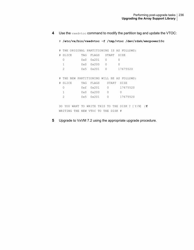
4 Use the vxedvtoc command to modify the partition tag and update the VTOC:
# /etc/vx/bin/vxedvtoc -f /tmp/vtoc /dev/rdsk/emcpower10c
# THE ORIGINAL PARTITIONING IS AS FOLLOWS:
# SLICE TAG FLAGS START SIZE
0 0x0 0x201 0 0
1 0x0 0x200 0 0
2 0x5 0x201 0 17675520
# THE NEW PARTITIONING WILL BE AS FOLLOWS:
# SLICE TAG FLAGS START SIZE
0 0xf 0x201 0 17675520
1 0x0 0x200 0 0
2 0x5 0x201 0 17675520
DO YOU WANT TO WRITE THIS TO THE DISK ? [Y/N] :Y
WRITING THE NEW VTOC TO THE DISK #
5 Upgrade to VxVM 7.2 using the appropriate upgrade procedure.
236Performing post-upgrade tasksUpgrading the Array Support Library

6 After upgrading VxVM, use the vxdisk list command to validate theconversion to auto:simple format:
# vxdisk list
DEVICE TYPE DISK GROUP STATUS
c6t0d12s2 auto:sliced - - online
emcpower10s2 auto:simple - - online
...
To display the physical device that is associated with the metadevice,emcpower10s2, enter the following command:
# vxdmpadm getsubpaths dmpnodename=emcpower10s2
7 Import the disk group and start the volumes:
# vxdg import fdg
# vxvol -g fdg startall
You can use the vxdisk list command to confirm that the disk status isdisplayed as online:simple:
# vxdisk list
DEVICE TYPE DISK GROUP STATUS
c6t0d12s2 auto:sliced - - online
emcpower10s2 auto:simple fdisk fdg online
Converting a defined disk to auto:simpleIn VxVM 4.0, and particularly in prior releases, EMCpower disks could be definedby a persistent disk access record (darec), and identified as simple disks. If anEMCpower disk is defined with a persistent darec, it must be manually convertedto auto:simple format before upgrading to VxVM 7.2.
If the defined disk is defined on a slice other than s2, you must copy the partitionentry for that slice to that for s0 and change the tag. If the tag of the original sliceis changed, the status of the disk is seen as online:aliased after the upgrade.
The following example is used to illustrate the procedure. The ls command showsthe mapping of the EMC disks to persistent disk access records:
# ls -l /dev/vx/dmp/emcdisk1
lrwxrwxrwx 1 root other 36 Sep 24 17:59 /dev/vx/dmp/emcdisk1->
/dev/dsk/c6t0d11s5
# ls -l /dev/vx/rdmp/emcdisk1
237Performing post-upgrade tasksUpgrading the Array Support Library
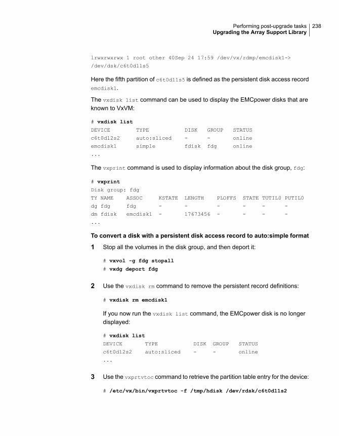
lrwxrwxrwx 1 root other 40Sep 24 17:59 /dev/vx/rdmp/emcdisk1->
/dev/dsk/c6t0d11s5
Here the fifth partition of c6t0d11s5 is defined as the persistent disk access recordemcdisk1.
The vxdisk list command can be used to display the EMCpower disks that areknown to VxVM:
# vxdisk list
DEVICE TYPE DISK GROUP STATUS
c6t0d12s2 auto:sliced - - online
emcdisk1 simple fdisk fdg online
...
The vxprint command is used to display information about the disk group, fdg:
# vxprint
Disk group: fdg
TY NAME ASSOC KSTATE LENGTH PLOFFS STATE TUTIL0 PUTIL0
dg fdg fdg - - - - - -
dm fdisk emcdisk1 - 17673456 - - - -
...
To convert a disk with a persistent disk access record to auto:simple format
1 Stop all the volumes in the disk group, and then deport it:
# vxvol -g fdg stopall
# vxdg deport fdg
2 Use the vxdisk rm command to remove the persistent record definitions:
# vxdisk rm emcdisk1
If you now run the vxdisk list command, the EMCpower disk is no longerdisplayed:
# vxdisk list
DEVICE TYPE DISK GROUP STATUS
c6t0d12s2 auto:sliced - - online
...
3 Use the vxprtvtoc command to retrieve the partition table entry for the device:
# /etc/vx/bin/vxprtvtoc -f /tmp/hdisk /dev/rdsk/c6t0d11s2
238Performing post-upgrade tasksUpgrading the Array Support Library

4 Use the vxedvtoc command to modify the partition tag and update the VTOC:
# /etc/vx/bin/vxedvtoc -f /tmp/hdisk /dev/rdsk/c6t0d11s2
# THE ORIGINAL PARTITIONING IS AS FOLLOWS:
# SLICE TAG FLAGS START SIZE
4 0x0 0x200 0 0
5 0x0 0x200 3591000 2100375
6 0x0 0x200 0 0
# THE NEW PARTITIONING WILL BE AS FOLLOWS:
# SLICE TAG FLAGS START SIZE
4 0x0 0x200 0 0
5 0xf 0x200 3591000 2100375
6 0x0 0x200 0 0
DO YOU WANT TO WRITE THIS TO THE DISK ? [Y/N] :Y
WRITING THE NEW VTOC TO THE DISK #
5 Upgrade to VxVM 7.2 using the appropriate upgrade procedure.
239Performing post-upgrade tasksUpgrading the Array Support Library
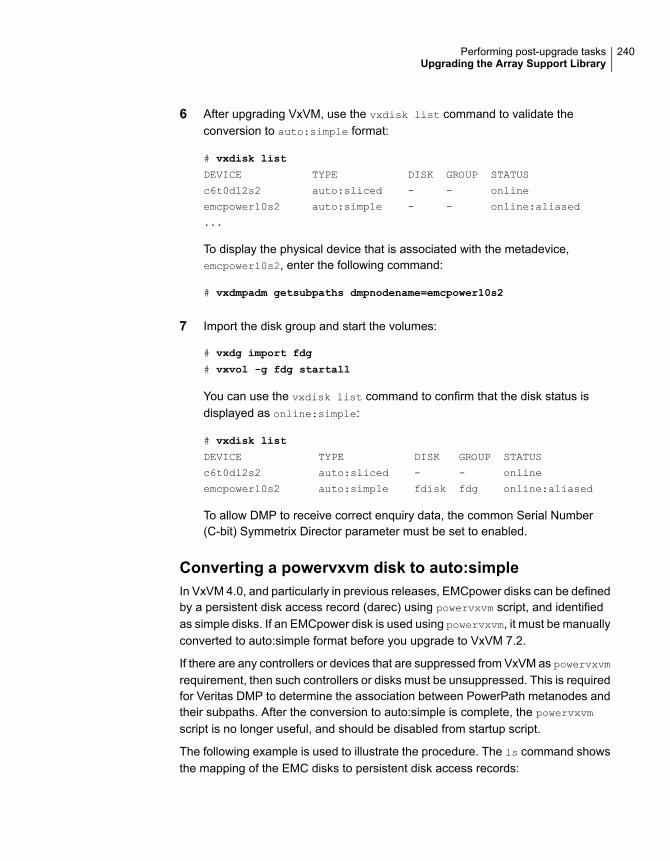
6 After upgrading VxVM, use the vxdisk list command to validate theconversion to auto:simple format:
# vxdisk list
DEVICE TYPE DISK GROUP STATUS
c6t0d12s2 auto:sliced - - online
emcpower10s2 auto:simple - - online:aliased
...
To display the physical device that is associated with the metadevice,emcpower10s2, enter the following command:
# vxdmpadm getsubpaths dmpnodename=emcpower10s2
7 Import the disk group and start the volumes:
# vxdg import fdg
# vxvol -g fdg startall
You can use the vxdisk list command to confirm that the disk status isdisplayed as online:simple:
# vxdisk list
DEVICE TYPE DISK GROUP STATUS
c6t0d12s2 auto:sliced - - online
emcpower10s2 auto:simple fdisk fdg online:aliased
To allow DMP to receive correct enquiry data, the common Serial Number(C-bit) Symmetrix Director parameter must be set to enabled.
Converting a powervxvm disk to auto:simpleIn VxVM 4.0, and particularly in previous releases, EMCpower disks can be definedby a persistent disk access record (darec) using powervxvm script, and identifiedas simple disks. If an EMCpower disk is used using powervxvm, it must be manuallyconverted to auto:simple format before you upgrade to VxVM 7.2.
If there are any controllers or devices that are suppressed from VxVM as powervxvmrequirement, then such controllers or disks must be unsuppressed. This is requiredfor Veritas DMP to determine the association between PowerPath metanodes andtheir subpaths. After the conversion to auto:simple is complete, the powervxvm
script is no longer useful, and should be disabled from startup script.
The following example is used to illustrate the procedure. The ls command showsthe mapping of the EMC disks to persistent disk access records:
240Performing post-upgrade tasksUpgrading the Array Support Library

# ls -l /dev/vx/rdmp/
crw------- 1 root root 260, 76 Feb 7 02:36 emcpower0c
# vxdisk list
DEVICE TYPE DISK GROUP STATUS
c6t0d12s2 auto:sliced - - online
emcpower0c simple ppdsk01 ppdg online
# vxprint
Disk group: fdg
TY NAME ASSOC KSTATE LENGTH PLOFFS STATE TUTIL0 PUTIL0
dg ppdg ppdg - - - - - -
dm ppdsk01 emcpower0c - 2094960 - - - -
To convert an EMCpower disk (defined using powervxvm) to auto:simple format
1 Stop all the volumes in the disk group, and then deport it:
# vxvol -g ppdg stopall
# vxdg deport ppdg
2 Use the vxdisk rm command to remove all emcpower disks from VxVM:
# vxdisk rm emcpower0c
If you now run the vxdisk list command, the EMCpower disk is no longerdisplayed:
# vxdisk list
DEVICE TYPE DISK GROUP STATUS
c6t0d12s2 auto:sliced - - online
3 Use the vxprtvtoc command to retrieve the partition table entry for this device:
# /etc/vx/bin/vxprtvtoc -f /tmp/vtoc /dev/vx/rdmp/emcpower0c
241Performing post-upgrade tasksUpgrading the Array Support Library

4 Use the vxedvtoc command to modify the partition tag and update the VTOC:
# /etc/vx/bin/vxedvtoc -f /tmp/vtoc /dev/vx/rdmp/emcpower0c
# THE ORIGINAL PARTITIONING IS AS FOLLOWS:
# SLICE TAG FLAGS START SIZE
0 0x0 0x201 0 0
1 0x0 0x200 0 0
2 0x5 0x201 0 17675520
# THE NEW PARTITIONING WILL BE AS FOLLOWS:
# SLICE TAG FLAGS START SIZE
0 0xf 0x201 0 17675520
1 0x0 0x200 0 0
2 0x5 0x201 0 17675520
DO YOU WANT TO WRITE THIS TO THE DISK ? [Y/N] :Y
WRITING THE NEW VTOC TO THE DISK #
5 Upgrade to VxVM 7.2 using the appropriate upgrade procedure.
6 After upgrading VxVM, use the vxdisk list command to validate theconversion to auto:simple format:
# vxdisk list
DEVICE TYPE DISK GROUP STATUS
c6t0d12s2 auto:sliced - - online
emcpower0s2 auto:simple - - online
7 Import the disk group and start the volumes.
# vxdg import ppdg
# vxvol -g ppdg startall
# vxdisk list
DEVICE TYPE DISK GROUP STATUS
c6t0d12s2 auto:sliced - - online
emcpower0s2 auto:simple ppdsk01 ppdg online
242Performing post-upgrade tasksUpgrading the Array Support Library
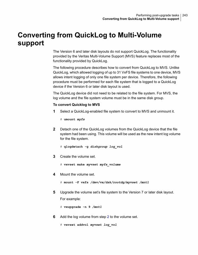
Converting from QuickLog to Multi-Volumesupport
The Version 6 and later disk layouts do not support QuickLog. The functionalityprovided by the Veritas Multi-Volume Support (MVS) feature replaces most of thefunctionality provided by QuickLog.
The following procedure describes how to convert from QuickLog to MVS. UnlikeQuickLog, which allowed logging of up to 31 VxFS file systems to one device, MVSallows intent logging of only one file system per device. Therefore, the followingprocedure must be performed for each file system that is logged to a QuickLogdevice if the Version 6 or later disk layout is used.
The QuickLog device did not need to be related to the file system. For MVS, thelog volume and the file system volume must be in the same disk group.
To convert Quicklog to MVS
1 Select a QuickLog-enabled file system to convert to MVS and unmount it.
# umount myfs
2 Detach one of the QuickLog volumes from the QuickLog device that the filesystem had been using. This volume will be used as the new intent log volumefor the file system.
# qlogdetach -g diskgroup log_vol
3 Create the volume set.
# vxvset make myvset myfs_volume
4 Mount the volume set.
# mount -F vxfs /dev/vx/dsk/rootdg/myvset /mnt1
5 Upgrade the volume set’s file system to the Version 7 or later disk layout.
For example:
# vxupgrade -n 9 /mnt1
6 Add the log volume from step 2 to the volume set.
# vxvset addvol myvset log_vol
243Performing post-upgrade tasksConverting from QuickLog to Multi-Volume support

7 Add the log volume to the file system. The size of the volume must be specified.
# fsvoladm add /mnt1 log_vol 50m
8 Move the log to the new volume.
# fsadm -o logdev=log_vol,logsize=16m /mnt1
About enabling LDAP authentication for clustersthat run in secure mode
Veritas Product Authentication Service (AT) supports LDAP (Lightweight DirectoryAccess Protocol) user authentication through a plug-in for the authentication broker.AT supports all common LDAP distributions such as OpenLDAP and WindowsActive Directory.
For a cluster that runs in secure mode, you must enable the LDAP authenticationplug-in if the VCS users belong to an LDAP domain.
If you have not already added VCS users during installation, you can add the userslater.
See the Cluster Server Administrator's Guide for instructions to add VCS users.
Figure 15-1 depicts the SFHA cluster communication with the LDAP servers whenclusters run in secure mode.
244Performing post-upgrade tasksAbout enabling LDAP authentication for clusters that run in secure mode
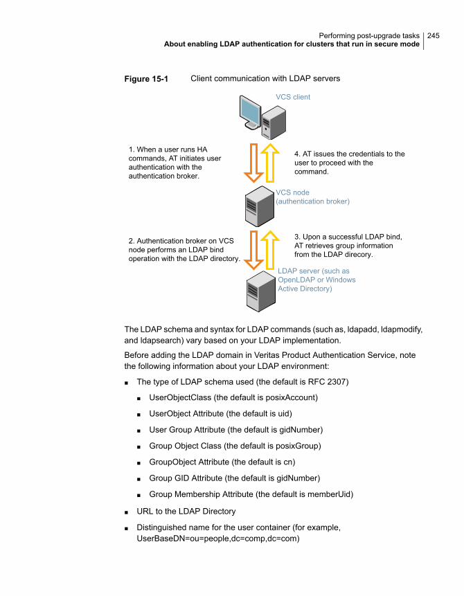
Figure 15-1 Client communication with LDAP servers
VCS node(authentication broker)
VCS client
1. When a user runs HAcommands, AT initiates userauthentication with theauthentication broker.
4. AT issues the credentials to theuser to proceed with thecommand.
2. Authentication broker on VCSnode performs an LDAP bindoperation with the LDAP directory.
3. Upon a successful LDAP bind,AT retrieves group informationfrom the LDAP direcory.
LDAP server (such asOpenLDAP or WindowsActive Directory)
The LDAP schema and syntax for LDAP commands (such as, ldapadd, ldapmodify,and ldapsearch) vary based on your LDAP implementation.
Before adding the LDAP domain in Veritas Product Authentication Service, notethe following information about your LDAP environment:
■ The type of LDAP schema used (the default is RFC 2307)
■ UserObjectClass (the default is posixAccount)
■ UserObject Attribute (the default is uid)
■ User Group Attribute (the default is gidNumber)
■ Group Object Class (the default is posixGroup)
■ GroupObject Attribute (the default is cn)
■ Group GID Attribute (the default is gidNumber)
■ Group Membership Attribute (the default is memberUid)
■ URL to the LDAP Directory
■ Distinguished name for the user container (for example,UserBaseDN=ou=people,dc=comp,dc=com)
245Performing post-upgrade tasksAbout enabling LDAP authentication for clusters that run in secure mode

■ Distinguished name for the group container (for example,GroupBaseDN=ou=group,dc=comp,dc=com)
Enabling LDAP authentication for clusters that run in secure modeThe following procedure shows how to enable the plug-in module for LDAPauthentication. This section provides examples for OpenLDAP and Windows ActiveDirectory LDAP distributions.
Before you enable the LDAP authentication, complete the following steps:
■ Make sure that the cluster runs in secure mode.
# haclus -value SecureClus
The output must return the value as 1.
■ Make sure that the AT version is 6.1.6.0 or later.
# /opt/VRTSvcs/bin/vcsauth/vcsauthserver/bin/vssat showversion
vssat version: 6.1.12.8
To enable OpenLDAP authentication for clusters that run in secure mode
1 Run the LDAP configuration tool atldapconf using the -d option. The -d optiondiscovers and retrieves an LDAP properties file which is a prioritized attributelist.
# /opt/VRTSvcs/bin/vcsauth/vcsauthserver/bin/atldapconf \
-d -s domain_controller_name_or_ipaddress -u domain_user
Attribute list file name not provided, using AttributeList.txt
Attribute file created.
You can use the catatldapconf command to view the entries in the attributesfile.
2 Run the LDAP configuration tool using the -c option. The -c option creates aCLI file to add the LDAP domain.
# /opt/VRTSvcs/bin/vcsauth/vcsauthserver/bin/atldapconf \
-c -d LDAP_domain_name
Attribute list file not provided, using default AttributeList.txt
CLI file name not provided, using default CLI.txt
CLI for addldapdomain generated.
246Performing post-upgrade tasksAbout enabling LDAP authentication for clusters that run in secure mode

3 Run the LDAP configuration tool atldapconf using the -x option. The -x optionreads the CLI file and executes the commands to add a domain to the AT.
# /opt/VRTSvcs/bin/vcsauth/vcsauthserver/bin/atldapconf -x
Using default broker port 14149
CLI file not provided, using default CLI.txt
Looking for AT installation...
AT found installed at ./vssat
Successfully added LDAP domain.
247Performing post-upgrade tasksAbout enabling LDAP authentication for clusters that run in secure mode
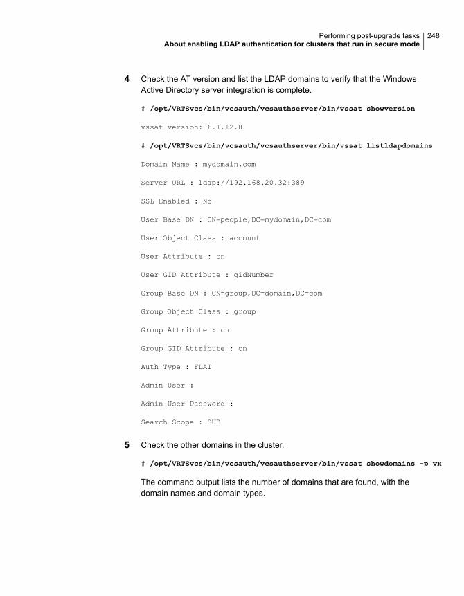
4 Check the AT version and list the LDAP domains to verify that the WindowsActive Directory server integration is complete.
# /opt/VRTSvcs/bin/vcsauth/vcsauthserver/bin/vssat showversion
vssat version: 6.1.12.8
# /opt/VRTSvcs/bin/vcsauth/vcsauthserver/bin/vssat listldapdomains
Domain Name : mydomain.com
Server URL : ldap://192.168.20.32:389
SSL Enabled : No
User Base DN : CN=people,DC=mydomain,DC=com
User Object Class : account
User Attribute : cn
User GID Attribute : gidNumber
Group Base DN : CN=group,DC=domain,DC=com
Group Object Class : group
Group Attribute : cn
Group GID Attribute : cn
Auth Type : FLAT
Admin User :
Admin User Password :
Search Scope : SUB
5 Check the other domains in the cluster.
# /opt/VRTSvcs/bin/vcsauth/vcsauthserver/bin/vssat showdomains -p vx
The command output lists the number of domains that are found, with thedomain names and domain types.
248Performing post-upgrade tasksAbout enabling LDAP authentication for clusters that run in secure mode
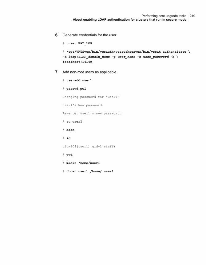
6 Generate credentials for the user.
# unset EAT_LOG
# /opt/VRTSvcs/bin/vcsauth/vcsauthserver/bin/vssat authenticate \
-d ldap:LDAP_domain_name -p user_name -s user_password -b \
localhost:14149
7 Add non-root users as applicable.
# useradd user1
# passwd pw1
Changing password for "user1"
user1's New password:
Re-enter user1's new password:
# su user1
# bash
# id
uid=204(user1) gid=1(staff)
# pwd
# mkdir /home/user1
# chown user1 /home/ user1
249Performing post-upgrade tasksAbout enabling LDAP authentication for clusters that run in secure mode

8 Add the non-root user to the VCS configuration.
# haconf -makerw
# hauser -add user1
# haconf -dump -makero
9 Log in as non-root user and run VCS commands as LDAP user.
# cd /home/user1
# ls
# cat .vcspwd
101 localhost mpise LDAP_SERVER ldap
# unset VCS_DOMAINTYPE
# unset VCS_DOMAIN
# /opt/VRTSvcs/bin/hasys -state
#System Attribute Value
cluster1:sysA SysState FAULTED
cluster1:sysB SysState FAULTED
cluster2:sysC SysState RUNNING
cluster2:sysD SysState RUNNING
Verifying the Storage Foundation and HighAvailability upgrade
Refer to the Verifying the Veritas InfoScale installation chapter in the VeritasInfoScale Installation Guide.
250Performing post-upgrade tasksVerifying the Storage Foundation and High Availability upgrade

Post-installation tasks
■ Chapter 16. Performing post-installation tasks
4Section
Performingpost-installation tasks
This chapter includes the following topics:
■ Changing root user into root role
■ Installing language packages
■ Switching on Quotas
■ About configuring authentication for SFDB tools
Changing root user into root roleOn Oracle Solaris 11, you need to create root user to perform installation. Thismeans that a local user cannot assume the root role. After installation, you maywant to turn root user into root role for a local user, who can log in as root.
1. Log in as root user.
2. Change the root account into role.
# rolemod -K type=role root
# getent user_attr root
root::::type=role;auths=solaris.*;profiles=All;audit_flags=lo\
:no;lock_after_retries=no;min_label=admin_low;clearance=admin_high
3. Assign the root role to a local user who was unassigned the role.
# usermod -R root admin
16Chapter
For more information, see the Oracle documentation on Oracle Solaris 11 operatingsystem.
Installing language packagesTo install SFHA in a language other than English, install the required languagepackages after installing the English packages.
To install the language packages on the server
1 Insert the "Language" disc into the DVD-ROM or CD-ROM drive. With Solarisvolume management software, the disc is automatically mounted as/cdrom/cdrom0.
2 Install the language packages using the install_lp command.
# cd /cdrom/cdrom0
# ./install_lp
Switching on QuotasThis turns on the group and user quotas once all the nodes are upgraded to 7.2, ifit was turned off earlier.
To turn on the group and user quotas
◆ Switch on quotas:
# vxquotaon -av
About configuring authentication for SFDB toolsTo configure authentication for Storage Foundation for Databases (SFDB) tools,perform the following tasks:
See “Configuring vxdbd for SFDB toolsauthentication” on page 254.
Configure the vxdbd daemon to requireauthentication
See “Adding nodes to a cluster that is usingauthentication for SFDB tools” on page 270.
Add a node to a cluster that is usingauthentication for SFDB tools
253Performing post-installation tasksInstalling language packages
Configuring vxdbd for SFDB tools authenticationTo configure vxdbd, perform the following steps as the root user
1 Run the sfae_auth_op command to set up the authentication services.
# /opt/VRTS/bin/sfae_auth_op -o setup
Setting up AT
Starting SFAE AT broker
Creating SFAE private domain
Backing up AT configuration
Creating principal for vxdbd
2 Stop the vxdbd daemon.
# /opt/VRTS/bin/sfae_config disable
vxdbd has been disabled and the daemon has been stopped.
3 Enable authentication by setting the AUTHENTICATION key to yes in the/etc/vx/vxdbed/admin.properties configuration file.
If /etc/vx/vxdbed/admin.properties does not exist, then usecp/opt/VRTSdbed/bin/admin.properties.example
/etc/vx/vxdbed/admin.properties.
4 Start the vxdbd daemon.
# /opt/VRTS/bin/sfae_config enable
vxdbd has been enabled and the daemon has been started.
It will start automatically on reboot.
The vxdbd daemon is now configured to require authentication.
254Performing post-installation tasksAbout configuring authentication for SFDB tools
Adding and removing nodes
■ Chapter 17. Adding a node to SFHA clusters
■ Chapter 18. Removing a node from SFHA clusters
5Section
Adding a node to SFHAclusters
This chapter includes the following topics:
■ About adding a node to a cluster
■ Before adding a node to a cluster
■ Adding a node to a cluster using the Veritas InfoScale installer
■ Adding the node to a cluster manually
■ Adding a node using response files
■ Configuring server-based fencing on the new node
■ After adding the new node
■ Adding nodes to a cluster that is using authentication for SFDB tools
■ Updating the Storage Foundation for Databases (SFDB) repository after addinga node
About adding a node to a clusterAfter you install Veritas InfoScale and create a cluster, you can add and removenodes from the cluster.You can create clusters of up to 64 nodes.
You can add a node:
■ Using the product installer
■ Manually
17Chapter
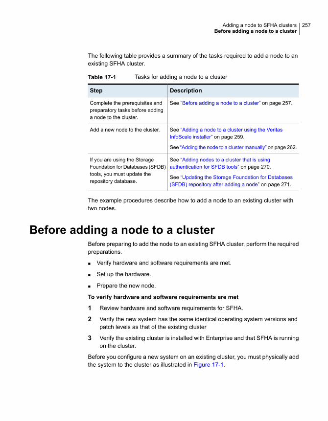
The following table provides a summary of the tasks required to add a node to anexisting SFHA cluster.
Table 17-1 Tasks for adding a node to a cluster
DescriptionStep
See “Before adding a node to a cluster” on page 257.Complete the prerequisites andpreparatory tasks before addinga node to the cluster.
See “Adding a node to a cluster using the VeritasInfoScale installer” on page 259.
See “Adding the node to a cluster manually” on page 262.
Add a new node to the cluster.
See “Adding nodes to a cluster that is usingauthentication for SFDB tools” on page 270.
See “Updating the Storage Foundation for Databases(SFDB) repository after adding a node” on page 271.
If you are using the StorageFoundation for Databases (SFDB)tools, you must update therepository database.
The example procedures describe how to add a node to an existing cluster withtwo nodes.
Before adding a node to a clusterBefore preparing to add the node to an existing SFHA cluster, perform the requiredpreparations.
■ Verify hardware and software requirements are met.
■ Set up the hardware.
■ Prepare the new node.
To verify hardware and software requirements are met
1 Review hardware and software requirements for SFHA.
2 Verify the new system has the same identical operating system versions andpatch levels as that of the existing cluster
3 Verify the existing cluster is installed with Enterprise and that SFHA is runningon the cluster.
Before you configure a new system on an existing cluster, you must physically addthe system to the cluster as illustrated in Figure 17-1.
257Adding a node to SFHA clustersBefore adding a node to a cluster
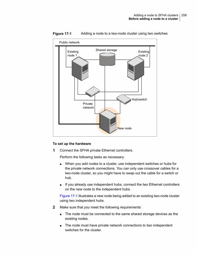
Figure 17-1 Adding a node to a two-node cluster using two switches
Public network
Privatenetwork
New node
Hub/switch
Existingnode 1
Shared storage Existingnode 2
To set up the hardware
1 Connect the SFHA private Ethernet controllers.
Perform the following tasks as necessary:
■ When you add nodes to a cluster, use independent switches or hubs forthe private network connections. You can only use crossover cables for atwo-node cluster, so you might have to swap out the cable for a switch orhub.
■ If you already use independent hubs, connect the two Ethernet controllerson the new node to the independent hubs.
Figure 17-1 illustrates a new node being added to an existing two-node clusterusing two independent hubs.
2 Make sure that you meet the following requirements:
■ The node must be connected to the same shared storage devices as theexisting nodes.
■ The node must have private network connections to two independentswitches for the cluster.
258Adding a node to SFHA clustersBefore adding a node to a cluster
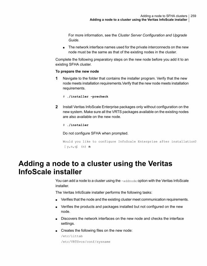
For more information, see the Cluster Server Configuration and UpgradeGuide.
■ The network interface names used for the private interconnects on the newnode must be the same as that of the existing nodes in the cluster.
Complete the following preparatory steps on the new node before you add it to anexisting SFHA cluster.
To prepare the new node
1 Navigate to the folder that contains the installer program. Verify that the newnode meets installation requirements.Verify that the new node meets installationrequirements.
# ./installer -precheck
2 Install Veritas InfoScale Enterprise packages only without configuration on thenew system. Make sure all the VRTS packages available on the existing nodesare also available on the new node.
# ./installer
Do not configure SFHA when prompted.
Would you like to configure InfoScale Enterprise after installation?
[y,n,q] (n) n
Adding a node to a cluster using the VeritasInfoScale installer
You can add a node to a cluster using the -addnode option with the Veritas InfoScaleinstaller.
The Veritas InfoScale installer performs the following tasks:
■ Verifies that the node and the existing cluster meet communication requirements.
■ Verifies the products and packages installed but not configured on the newnode.
■ Discovers the network interfaces on the new node and checks the interfacesettings.
■ Creates the following files on the new node:/etc/llttab
/etc/VRTSvcs/conf/sysname
259Adding a node to SFHA clustersAdding a node to a cluster using the Veritas InfoScale installer
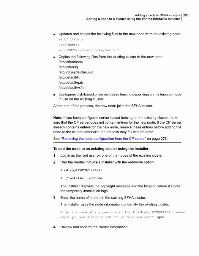
■ Updates and copies the following files to the new node from the existing node:/etc/llthosts
/etc/gabtab
/etc/VRTSvcs/conf/config/main.cf
■ Copies the following files from the existing cluster to the new node/etc/vxfenmode/etc/vxfendg/etc/vx/.uuids/clusuuid/etc/default/llt/etc/default/gab/etc/default/vxfen
■ Configures disk-based or server-based fencing depending on the fencing modein use on the existing cluster.
At the end of the process, the new node joins the SFHA cluster.
Note: If you have configured server-based fencing on the existing cluster, makesure that the CP server does not contain entries for the new node. If the CP serveralready contains entries for the new node, remove these entries before adding thenode to the cluster, otherwise the process may fail with an error.
See “Removing the node configuration from the CP server” on page 278.
To add the node to an existing cluster using the installer
1 Log in as the root user on one of the nodes of the existing cluster.
2 Run the Veritas InfoScale installer with the -addnode option.
# cd /opt/VRTS/install
# ./installer -addnode
The installer displays the copyright message and the location where it storesthe temporary installation logs.
3 Enter the name of a node in the existing SFHA cluster.
The installer uses the node information to identify the existing cluster.
Enter the name of any one node of the InfoScale ENTERPRISE cluster
where you would like to add one or more new nodes: sys1
4 Review and confirm the cluster information.
260Adding a node to SFHA clustersAdding a node to a cluster using the Veritas InfoScale installer

5 Enter the name of the systems that you want to add as new nodes to the cluster.
Enter the system names separated by spaces
to add to the cluster: sys5
Confirm if the installer prompts if you want to add the node to the cluster.
The installer checks the installed products and packages on the nodes anddiscovers the network interfaces.
6 Enter the name of the network interface that you want to configure as the firstprivate heartbeat link.
Enter the NIC for the first private heartbeat
link on sys5: [b,q,?] bge1
Enter the NIC for the second private heartbeat
link on sys5: [b,q,?] bge2
Note: At least two private heartbeat links must be configured for high availabilityof the cluster.
7 Depending on the number of LLT links configured in the existing cluster,configure additional private heartbeat links for the new node.
The installer verifies the network interface settings and displays the information.
8 Review and confirm the information.
9 If you have configured SMTP, SNMP, or the global cluster option in the existingcluster, you are prompted for the NIC information for the new node.
Enter the NIC for VCS to use on sys5: bge3
261Adding a node to SFHA clustersAdding a node to a cluster using the Veritas InfoScale installer
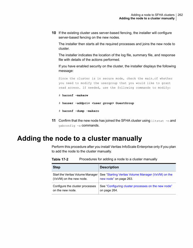
10 If the existing cluster uses server-based fencing, the installer will configureserver-based fencing on the new nodes.
The installer then starts all the required processes and joins the new node tocluster.
The installer indicates the location of the log file, summary file, and responsefile with details of the actions performed.
If you have enabled security on the cluster, the installer displays the followingmessage:
Since the cluster is in secure mode, check the main.cf whether
you need to modify the usergroup that you would like to grant
read access. If needed, use the following commands to modify:
# haconf -makerw
# hauser -addpriv <user group> GuestGroup
# haconf -dump -makero
11 Confirm that the new node has joined the SFHA cluster using lltstat -n andgabconfig -a commands.
Adding the node to a cluster manuallyPerform this procedure after you install Veritas InfoScale Enterprise only if you planto add the node to the cluster manually.
Table 17-2 Procedures for adding a node to a cluster manually
DescriptionStep
See “Starting Veritas Volume Manager (VxVM) on thenew node” on page 263.
Start the Veritas Volume Manager(VxVM) on the new node.
See “Configuring cluster processes on the new node”on page 264.
Configure the cluster processeson the new node.
262Adding a node to SFHA clustersAdding the node to a cluster manually
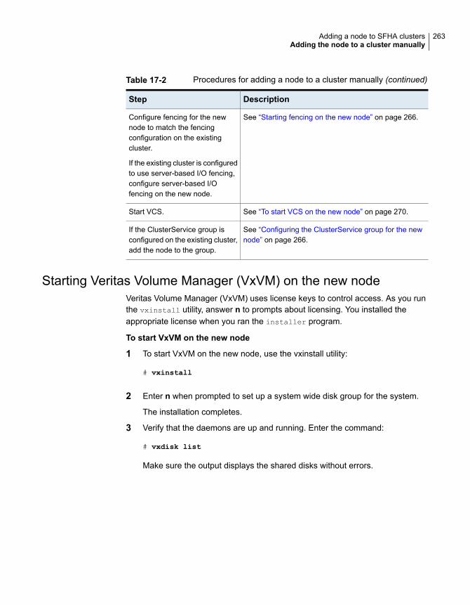
Table 17-2 Procedures for adding a node to a cluster manually (continued)
DescriptionStep
See “Starting fencing on the new node” on page 266.Configure fencing for the newnode to match the fencingconfiguration on the existingcluster.
If the existing cluster is configuredto use server-based I/O fencing,configure server-based I/Ofencing on the new node.
See “To start VCS on the new node” on page 270.Start VCS.
See “Configuring the ClusterService group for the newnode” on page 266.
If the ClusterService group isconfigured on the existing cluster,add the node to the group.
Starting Veritas Volume Manager (VxVM) on the new nodeVeritas Volume Manager (VxVM) uses license keys to control access. As you runthe vxinstall utility, answer n to prompts about licensing. You installed theappropriate license when you ran the installer program.
To start VxVM on the new node
1 To start VxVM on the new node, use the vxinstall utility:
# vxinstall
2 Enter n when prompted to set up a system wide disk group for the system.
The installation completes.
3 Verify that the daemons are up and running. Enter the command:
# vxdisk list
Make sure the output displays the shared disks without errors.
263Adding a node to SFHA clustersAdding the node to a cluster manually
Configuring cluster processes on the new nodePerform the steps in the following procedure to configure cluster processes on thenew node.
1 Edit the /etc/llthosts file on the existing nodes. Using vi or another text editor,add the line for the new node to the file. The file resembles:
0 sys1
1 sys2
2 sys5
2 Copy the /etc/llthosts file from one of the existing systems over to the newsystem. The /etc/llthosts file must be identical on all nodes in the cluster.
3 Create an /etc/llttab file on the new system. For example:
set-node sys5
set-cluster 101
link bge1 /dev/bge:1 - ether - -
link bge2 /dev/bge:2 - ether - -
Except for the first line that refers to the node, the file resembles the /etc/llttabfiles on the existing nodes. The second line, the cluster ID, must be the sameas in the existing nodes.
4 Use vi or another text editor to create the file /etc/gabtab on the new node.This file must contain a line that resembles the following example:
/sbin/gabconfig -c -nN
Where N represents the number of systems in the cluster including the newnode. For a three-system cluster, N would equal 3.
5 Edit the /etc/gabtab file on each of the existing systems, changing the contentto match the file on the new system.
6 Use vi or another text editor to create the file /etc/VRTSvcs/conf/sysname
on the new node. This file must contain the name of the new node added tothe cluster.
For example:
sys5
264Adding a node to SFHA clustersAdding the node to a cluster manually

7 Create the Unique Universal Identifier file /etc/vx/.uuids/clusuuid on thenew node:
# /opt/VRTSvcs/bin/uuidconfig.pl -rsh -clus -copy \
-from_sys sys1 -to_sys sys5
8 Start the LLT, GAB, and ODM drivers on the new node:
# svcadm enable llt
# svcadm enable gab
# svcadm restart vxodm
9 On the new node, verify that the GAB port memberships:
# gabconfig -a
GAB Port Memberships
===============================================================
Port a gen df204 membership 012
Setting up the node to run in secure modeYou must follow this procedure only if you are adding a node to a cluster that isrunning in secure mode. If you are adding a node to a cluster that is not running ina secure mode, proceed with configuring LLT and GAB.
Table 17-3 uses the following information for the following command examples.
Table 17-3 The command examples definitions
FunctionFully-qualified hostname (FQHN)
Name
The new node that you areadding to the cluster.
sys5.nodes.example.comsys5
Setting up SFHA related security configurationPerform the following steps to configure SFHA related security settings.
Setting up SFHA related security configuration
1 Start /opt/VRTSat/bin/vxatd process.
2 Create HA_SERVICES domain for SFHA.
# vssat createpd --pdrtype ab --domain HA_SERVICES
265Adding a node to SFHA clustersAdding the node to a cluster manually

3 Add SFHA and webserver principal to AB on node sys5.
# vssat addprpl --pdrtype ab --domain HA_SERVICES --prplname \
webserver_VCS_prplname --password new_password --prpltype \
service --can_proxy
4 Create /etc/VRTSvcs/conf/config/.secure file:
# touch /etc/VRTSvcs/conf/config/.secure
Starting fencing on the new nodePerform the following steps to start fencing on the new node.
To start fencing on the new node
1 For disk-based fencing on at least one node, copy the following files from oneof the nodes in the existing cluster to the new node:
/etc/default/vxfen
/etc/vxfendg
/etc/vxfenmode
See “Configuring server-based fencing on the new node” on page 268.
2 Start fencing on the new node:
# svcadm enable vxfen
Configuring the ClusterService group for the new nodeIf the ClusterService group is configured on the existing cluster, add the node tothe group by performing the steps in the following procedure on one of the nodesin the existing cluster.
To configure the ClusterService group for the new node
1 On an existing node, for example sys1, write-enable the configuration:
# haconf -makerw
2 Add the node sys5 to the existing ClusterService group.
# hagrp -modify ClusterService SystemList -add sys5 2
# hagrp -modify ClusterService AutoStartList -add sys5
266Adding a node to SFHA clustersAdding the node to a cluster manually
3 Modify the IP address and NIC resource in the existing group for the new node.
# hares -modify gcoip Device bge0 -sys sys5
# hares -modify gconic Device bge0 -sys sys5
4 Save the configuration by running the following command from any node.
# haconf -dump -makero
Adding a node using response filesTypically, you can use the response file that the installer generates on one systemto add nodes to an existing cluster.
To add nodes using response files
1 Make sure the systems where you want to add nodes meet the requirements.
2 Make sure all the tasks required for preparing to add a node to an existingSFHA cluster are completed.
3 Copy the response file to one of the systems where you want to add nodes.
See “Sample response file for adding a node to a SFHA cluster” on page 268.
4 Edit the values of the response file variables as necessary.
See “Response file variables to add a node to a SFHA cluster” on page 267.
5 Mount the product disc and navigate to the folder that contains the installationprogram.
6 Start adding nodes from the system to which you copied the response file. Forexample:
# ./installer -responsefile /tmp/response_file
Where /tmp/response_file is the response file’s full path name.
Depending on the fencing configuration in the existing cluster, the installerconfigures fencing on the new node. The installer then starts all the requiredprocesses and joins the new node to cluster. The installer indicates the locationof the log file and summary file with details of the actions performed.
Response file variables to add a node to a SFHA clusterTable 17-4 lists the response file variables that you can define to add a node to anSFHA cluster.
267Adding a node to SFHA clustersAdding a node using response files
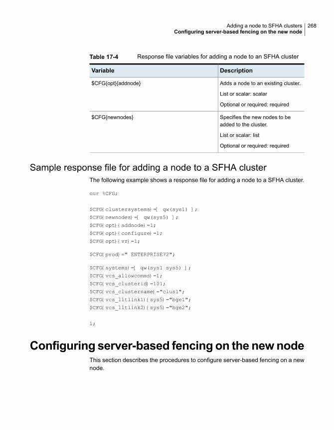
Table 17-4 Response file variables for adding a node to an SFHA cluster
DescriptionVariable
Adds a node to an existing cluster.
List or scalar: scalar
Optional or required: required
$CFG{opt}{addnode}
Specifies the new nodes to beadded to the cluster.
List or scalar: list
Optional or required: required
$CFG{newnodes}
Sample response file for adding a node to a SFHA clusterThe following example shows a response file for adding a node to a SFHA cluster.
our %CFG;
$CFG{clustersystems}=[ qw(sys1) ];
$CFG{newnodes}=[ qw(sys5) ];
$CFG{opt}{addnode}=1;
$CFG{opt}{configure}=1;
$CFG{opt}{vr}=1;
$CFG{prod}=" ENTERPRISE72";
$CFG{systems}=[ qw(sys1 sys5) ];
$CFG{vcs_allowcomms}=1;
$CFG{vcs_clusterid}=101;
$CFG{vcs_clustername}="clus1";
$CFG{vcs_lltlink1}{sys5}="bge1";
$CFG{vcs_lltlink2}{sys5}="bge2";
1;
Configuring server-based fencing on the newnodeThis section describes the procedures to configure server-based fencing on a newnode.
268Adding a node to SFHA clustersConfiguring server-based fencing on the new node
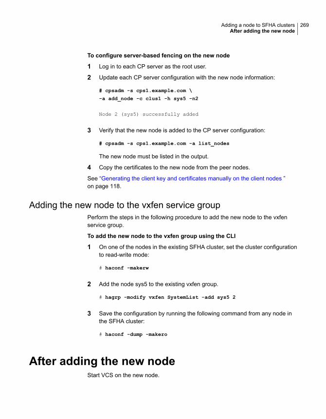
To configure server-based fencing on the new node
1 Log in to each CP server as the root user.
2 Update each CP server configuration with the new node information:
# cpsadm -s cps1.example.com \
-a add_node -c clus1 -h sys5 -n2
Node 2 (sys5) successfully added
3 Verify that the new node is added to the CP server configuration:
# cpsadm -s cps1.example.com -a list_nodes
The new node must be listed in the output.
4 Copy the certificates to the new node from the peer nodes.
See “Generating the client key and certificates manually on the client nodes ”on page 118.
Adding the new node to the vxfen service groupPerform the steps in the following procedure to add the new node to the vxfenservice group.
To add the new node to the vxfen group using the CLI
1 On one of the nodes in the existing SFHA cluster, set the cluster configurationto read-write mode:
# haconf -makerw
2 Add the node sys5 to the existing vxfen group.
# hagrp -modify vxfen SystemList -add sys5 2
3 Save the configuration by running the following command from any node inthe SFHA cluster:
# haconf -dump -makero
After adding the new nodeStart VCS on the new node.
269Adding a node to SFHA clustersAfter adding the new node
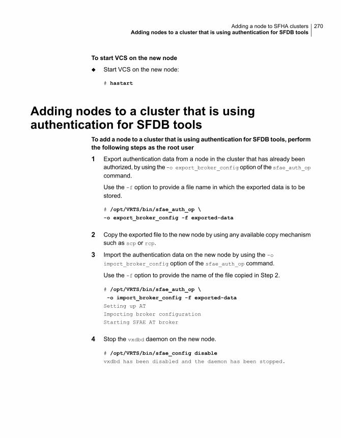
To start VCS on the new node
◆ Start VCS on the new node:
# hastart
Adding nodes to a cluster that is usingauthentication for SFDB tools
To add a node to a cluster that is using authentication for SFDB tools, performthe following steps as the root user
1 Export authentication data from a node in the cluster that has already beenauthorized, by using the -o export_broker_config option of the sfae_auth_op
command.
Use the -f option to provide a file name in which the exported data is to bestored.
# /opt/VRTS/bin/sfae_auth_op \
-o export_broker_config -f exported-data
2 Copy the exported file to the new node by using any available copy mechanismsuch as scp or rcp.
3 Import the authentication data on the new node by using the -o
import_broker_config option of the sfae_auth_op command.
Use the -f option to provide the name of the file copied in Step 2.
# /opt/VRTS/bin/sfae_auth_op \
-o import_broker_config -f exported-data
Setting up AT
Importing broker configuration
Starting SFAE AT broker
4 Stop the vxdbd daemon on the new node.
# /opt/VRTS/bin/sfae_config disable
vxdbd has been disabled and the daemon has been stopped.
270Adding a node to SFHA clustersAdding nodes to a cluster that is using authentication for SFDB tools

5 Enable authentication by setting the AUTHENTICATION key to yes in the/etc/vx/vxdbed/admin.properties configuration file.
If /etc/vx/vxdbed/admin.properties does not exist, then use cp
/opt/VRTSdbed/bin/admin.properties.example
/etc/vx/vxdbed/admin.properties
6 Start the vxdbd daemon.
# /opt/VRTS/bin/sfae_config enable
vxdbd has been enabled and the daemon has been started.
It will start automatically on reboot.
The new node is now authenticated to interact with the cluster to run SFDBcommands.
Updating the Storage Foundation for Databases(SFDB) repository after adding a node
If you are using Database Storage Checkpoints, Database FlashSnap, or SmartTierfor Oracle in your configuration, update the SFDB repository to enable access forthe new node after it is added to the cluster.
To update the SFDB repository after adding a node
1 Copy the /var/vx/vxdba/rep_loc file from one of the nodes in the cluster tothe new node.
2 If the /var/vx/vxdba/auth/user-authorizations file exists on the existingcluster nodes, copy it to the new node.
If the /var/vx/vxdba/auth/user-authorizations file does not exist on anyof the existing cluster nodes, no action is required.
This completes the addition of the new node to the SFDB repository.
271Adding a node to SFHA clustersUpdating the Storage Foundation for Databases (SFDB) repository after adding a node
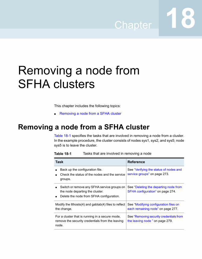
Removing a node fromSFHA clusters
This chapter includes the following topics:
■ Removing a node from a SFHA cluster
Removing a node from a SFHA clusterTable 18-1 specifies the tasks that are involved in removing a node from a cluster.In the example procedure, the cluster consists of nodes sys1, sys2, and sys5; nodesys5 is to leave the cluster.
Table 18-1 Tasks that are involved in removing a node
ReferenceTask
See “Verifying the status of nodes andservice groups” on page 273.
■ Back up the configuration file.■ Check the status of the nodes and the service
groups.
See “Deleting the departing node fromSFHA configuration” on page 274.
■ Switch or remove any SFHA service groups onthe node departing the cluster.
■ Delete the node from SFHA configuration.
See “Modifying configuration files oneach remaining node” on page 277.
Modify the llthosts(4) and gabtab(4) files to reflectthe change.
See “Removing security credentials fromthe leaving node ” on page 279.
For a cluster that is running in a secure mode,remove the security credentials from the leavingnode.
18Chapter
Table 18-1 Tasks that are involved in removing a node (continued)
ReferenceTask
See “Unloading LLT and GAB andremoving Veritas InfoScale Availabilityor Enterprise on the departing node”on page 279.
On the node departing the cluster:
■ Modify startup scripts for LLT, GAB, and SFHAto allow reboot of the node without affectingthe cluster.
■ Unconfigure and unload the LLT and GAButilities.
■ Remove the Veritas InfoScale packages.
Verifying the status of nodes and service groupsStart by issuing the following commands from one of the nodes to remain in thecluster node sys1 or node sys2 in our example.
273Removing a node from SFHA clustersRemoving a node from a SFHA cluster
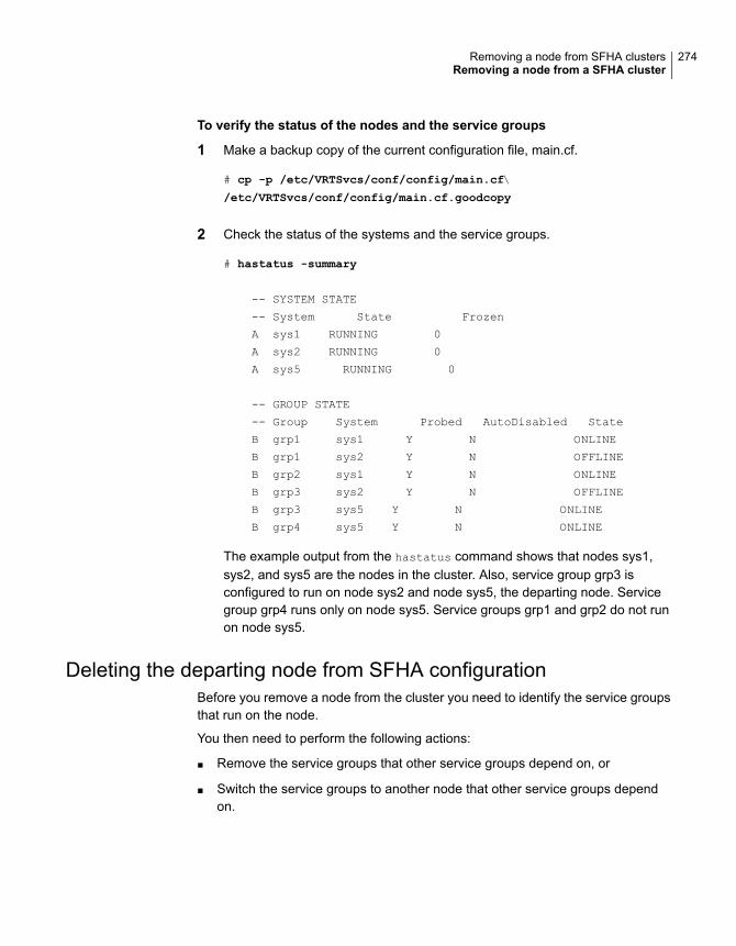
To verify the status of the nodes and the service groups
1 Make a backup copy of the current configuration file, main.cf.
# cp -p /etc/VRTSvcs/conf/config/main.cf\
/etc/VRTSvcs/conf/config/main.cf.goodcopy
2 Check the status of the systems and the service groups.
# hastatus -summary
-- SYSTEM STATE
-- System State Frozen
A sys1 RUNNING 0
A sys2 RUNNING 0
A sys5 RUNNING 0
-- GROUP STATE
-- Group System Probed AutoDisabled State
B grp1 sys1 Y N ONLINE
B grp1 sys2 Y N OFFLINE
B grp2 sys1 Y N ONLINE
B grp3 sys2 Y N OFFLINE
B grp3 sys5 Y N ONLINE
B grp4 sys5 Y N ONLINE
The example output from the hastatus command shows that nodes sys1,sys2, and sys5 are the nodes in the cluster. Also, service group grp3 isconfigured to run on node sys2 and node sys5, the departing node. Servicegroup grp4 runs only on node sys5. Service groups grp1 and grp2 do not runon node sys5.
Deleting the departing node from SFHA configurationBefore you remove a node from the cluster you need to identify the service groupsthat run on the node.
You then need to perform the following actions:
■ Remove the service groups that other service groups depend on, or
■ Switch the service groups to another node that other service groups dependon.
274Removing a node from SFHA clustersRemoving a node from a SFHA cluster
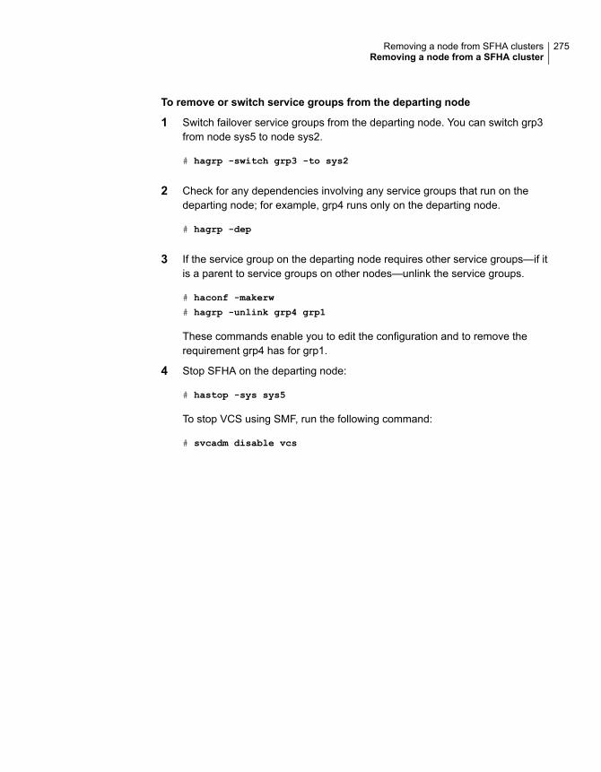
To remove or switch service groups from the departing node
1 Switch failover service groups from the departing node. You can switch grp3from node sys5 to node sys2.
# hagrp -switch grp3 -to sys2
2 Check for any dependencies involving any service groups that run on thedeparting node; for example, grp4 runs only on the departing node.
# hagrp -dep
3 If the service group on the departing node requires other service groups—if itis a parent to service groups on other nodes—unlink the service groups.
# haconf -makerw
# hagrp -unlink grp4 grp1
These commands enable you to edit the configuration and to remove therequirement grp4 has for grp1.
4 Stop SFHA on the departing node:
# hastop -sys sys5
To stop VCS using SMF, run the following command:
# svcadm disable vcs
275Removing a node from SFHA clustersRemoving a node from a SFHA cluster

5 Check the status again. The state of the departing node should be EXITED.Make sure that any service group that you want to fail over is online on othernodes.
# hastatus -summary
-- SYSTEM STATE
-- System State Frozen
A sys1 RUNNING 0
A sys2 RUNNING 0
A sys5 EXITED 0
-- GROUP STATE
-- Group System Probed AutoDisabled State
B grp1 sys1 Y N ONLINE
B grp1 sys2 Y N OFFLINE
B grp2 sys1 Y N ONLINE
B grp3 sys2 Y N ONLINE
B grp3 sys5 Y Y OFFLINE
B grp4 sys5 Y N OFFLINE
6 Delete the departing node from the SystemList of service groups grp3 andgrp4.
# haconf -makerw
# hagrp -modify grp3 SystemList -delete sys5
# hagrp -modify grp4 SystemList -delete sys5
Note: If sys5 was in the autostart list, then you need to manually add anothersystem in the autostart list so that after reboot, the group comes onlineautomatically.
7 For the service groups that run only on the departing node, delete the resourcesfrom the group before you delete the group.
# hagrp -resources grp4
processx_grp4
processy_grp4
# hares -delete processx_grp4
# hares -delete processy_grp4
276Removing a node from SFHA clustersRemoving a node from a SFHA cluster
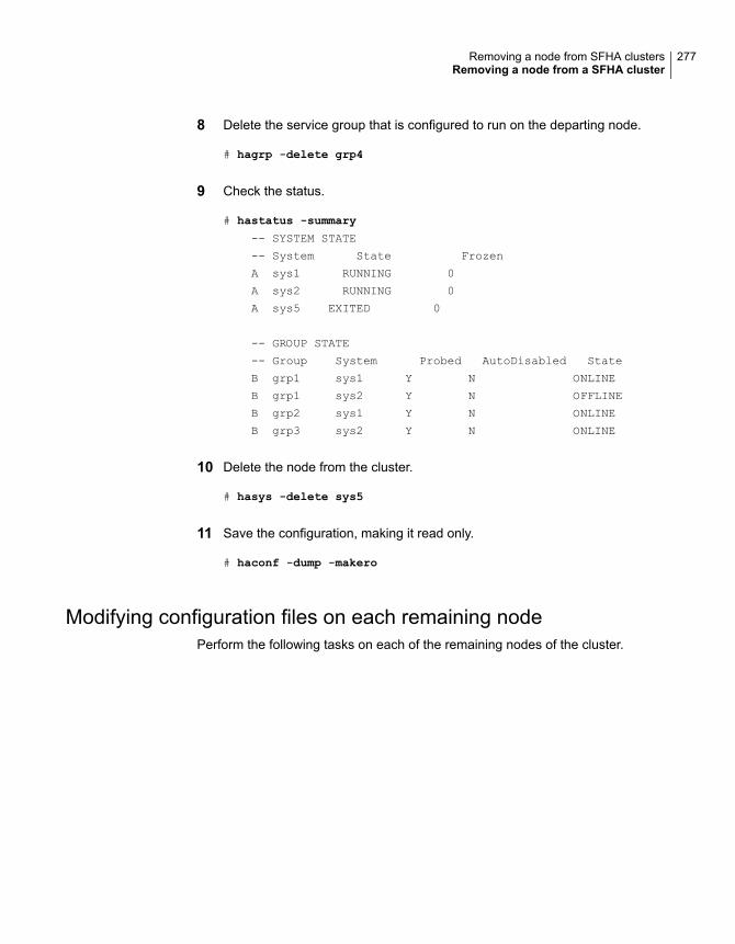
8 Delete the service group that is configured to run on the departing node.
# hagrp -delete grp4
9 Check the status.
# hastatus -summary
-- SYSTEM STATE
-- System State Frozen
A sys1 RUNNING 0
A sys2 RUNNING 0
A sys5 EXITED 0
-- GROUP STATE
-- Group System Probed AutoDisabled State
B grp1 sys1 Y N ONLINE
B grp1 sys2 Y N OFFLINE
B grp2 sys1 Y N ONLINE
B grp3 sys2 Y N ONLINE
10 Delete the node from the cluster.
# hasys -delete sys5
11 Save the configuration, making it read only.
# haconf -dump -makero
Modifying configuration files on each remaining nodePerform the following tasks on each of the remaining nodes of the cluster.
277Removing a node from SFHA clustersRemoving a node from a SFHA cluster

To modify the configuration files on a remaining node
1 If necessary, modify the /etc/gabtab file.
No change is required to this file if the /sbin/gabconfig command has onlythe argument -c. Veritas recommends using the -nN option, where N is thenumber of cluster systems.
If the command has the form /sbin/gabconfig -c -nN, whereN is the numberof cluster systems, make sure that N is not greater than the actual number ofnodes in the cluster. When N is greater than the number of nodes, GAB doesnot automatically seed.
Veritas does not recommend the use of the -c -x option for /sbin/gabconfig.
2 Modify /etc/llthosts file on each remaining nodes to remove the entry of thedeparting node.
For example, change:
0 sys1
1 sys2
2 sys5
To:
0 sys1
1 sys2
Removing the node configuration from the CP serverAfter removing a node from a SFHA cluster, perform the steps in the followingprocedure to remove that node's configuration from the CP server.
Note: The cpsadm command is used to perform the steps in this procedure. Fordetailed information about the cpsadm command, see the Cluster ServerAdministrator's Guide.
278Removing a node from SFHA clustersRemoving a node from a SFHA cluster
To remove the node configuration from the CP server
1 Log into the CP server as the root user.
2 View the list of VCS users on the CP server.
If the CP server is configured to use HTTPS-based communication, run thefollowing command:
# cpsadm -s cp_server -a list_users
Where cp_server is the virtual IP/ virtual hostname of the CP server.
3 Remove the node entry from the CP server:
# cpsadm -s cp_server -a rm_node -h sys5 -c clus1 -n 2
4 View the list of nodes on the CP server to ensure that the node entry wasremoved:
# cpsadm -s cp_server -a list_nodes
Removing security credentials from the leaving nodeIf the leaving node is part of a cluster that is running in a secure mode, you mustremove the security credentials from node sys5. Perform the following steps.
To remove the security credentials
1 Stop the AT process.
# /opt/VRTSvcs/bin/vcsauth/vcsauthserver/bin/vcsauthserver.sh \
stop
2 Remove the credentials.
# rm -rf /var/VRTSvcs/vcsauth/data/
Unloading LLT and GAB and removing Veritas InfoScale Availabilityor Enterprise on the departing node
Perform the tasks on the node that is departing the cluster.
You can use script-based installer to uninstall Veritas InfoScale Availability orEnterprise on the departing node or perform the following manual steps.
If you have configured Storage Foundation and High Availability as part of theInfoScale products, you may have to delete other dependent packages before youcan delete all of the following ones.
279Removing a node from SFHA clustersRemoving a node from a SFHA cluster
To unconfigure and unload LLT and GAB and remove InfoScale Availabilityor Enterprise
1 If you had configured I/O fencing in enabled mode, then stop I/O fencing.
# svcadm disable -s vxfen
2 Unconfigure GAB and LLT:
# /sbin/gabconfig -U
# /sbin/lltconfig -U
3 Unload the GAB and LLT modules from the kernel.
■ Determine the kernel module IDs:
# modinfo | grep gab
# modinfo | grep llt
The module IDs are in the left-hand column of the output.
■ Unload the module from the kernel:
# modunload -i gab_id
# modunload -i llt_id
4 Disable the startup files to prevent LLT, GAB, or InfoScale Availability orEnterprise from starting up:
# /usr/sbin/svcadm disable -s vcs
# /usr/sbin/svcadm disable -s gab
# /usr/sbin/svcadm disable -s llt
5 To determine the packages to remove, enter:
# pkginfo | grep VRTS
280Removing a node from SFHA clustersRemoving a node from a SFHA cluster
6 To permanently remove the InfoScale Availability or Enterprise packages fromthe system, use the pkg uninstall command. Start by removing the followingpackages, which may have been optionally installed, in the order shown below.
On Solaris 11:
# pkg uninstall VRTSvcsea
# pkg uninstall VRTSvcswiz
# pkg uninstall VRTSvbs
# pkg uninstall VRTSsfmh
# pkg uninstall VRTSvcsag
# pkg uninstall VRTScps
# pkg uninstall VRTSvcs
# pkg uninstall VRTSamf
# pkg uninstall VRTSvxfen
# pkg uninstall VRTSgab
# pkg uninstall VRTSllt
# pkg uninstall VRTSspt
# pkg uninstall VRTSsfcpi
# pkg uninstall VRTSperl
# pkg uninstall VRTSvlic
7 Remove the LLT and GAB configuration files.
# rm /etc/llttab
# rm /etc/gabtab
# rm /etc/llthosts
8 Remove the language packages and patches.
Updating the Storage Foundation for Databases (SFDB) repositoryafter removing a node
After removing a node from a cluster, you do not need to perform any steps toupdate the SFDB repository.
For information on removing the SFDB repository after removing the product:
281Removing a node from SFHA clustersRemoving a node from a SFHA cluster
Configuration and upgradereference
■ Appendix A. Installation scripts
■ Appendix B. SFHA services and ports
■ Appendix C. Configuration files
■ Appendix D. Configuring the secure shell or the remote shell for communications
■ Appendix E. Sample SFHA cluster setup diagrams for CP server-based I/Ofencing
■ Appendix F. Reconciling major/minor numbers for NFS shared disks
■ Appendix G. Configuring LLT over UDP
6Section
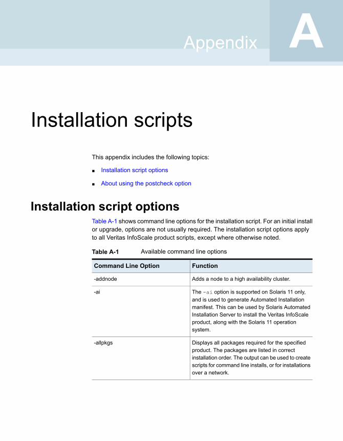
Installation scriptsThis appendix includes the following topics:
■ Installation script options
■ About using the postcheck option
Installation script optionsTable A-1 shows command line options for the installation script. For an initial installor upgrade, options are not usually required. The installation script options applyto all Veritas InfoScale product scripts, except where otherwise noted.
Table A-1 Available command line options
FunctionCommand Line Option
Adds a node to a high availability cluster.-addnode
The -ai option is supported on Solaris 11 only,and is used to generate Automated Installationmanifest. This can be used by Solaris AutomatedInstallation Server to install the Veritas InfoScaleproduct, along with the Solaris 11 operationsystem.
-ai
Displays all packages required for the specifiedproduct. The packages are listed in correctinstallation order. The output can be used to createscripts for command line installs, or for installationsover a network.
-allpkgs
AAppendix
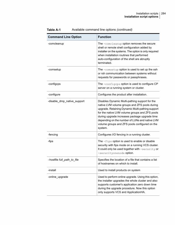
Table A-1 Available command line options (continued)
FunctionCommand Line Option
The -comcleanup option removes the secureshell or remote shell configuration added byinstaller on the systems. The option is only requiredwhen installation routines that performedauto-configuration of the shell are abruptlyterminated.
-comcleanup
The -comsetup option is used to set up the sshor rsh communication between systems withoutrequests for passwords or passphrases.
-comsetup
The -configcps option is used to configure CPserver on a running system or cluster.
-configcps
Configures the product after installation.-configure
Disables Dynamic Multi-pathing support for thenative LVM volume groups and ZFS pools duringupgrade. Retaining Dynamic Multi-pathing supportfor the native LVM volume groups and ZFS poolsduring upgrade increases package upgrade timedepending on the number of LUNs and native LVMvolume groups and ZFS pools configured on thesystem.
-disable_dmp_native_support
Configures I/O fencing in a running cluster.-fencing
The -fips option is used to enable or disablesecurity with fips mode on a running VCS cluster.It could only be used together with -security or-securityonenode option.
-fips
Specifies the location of a file that contains a listof hostnames on which to install.
–hostfile full_path_to_file
Used to install products on system-install
Used to perform online upgrade. Using this option,the installer upgrades the whole cluster and alsosupports customer's application zero down timeduring the upgrade procedure. Now this optiononly supports VCS and ApplicationHA.
-online_upgrade
284Installation scriptsInstallation script options
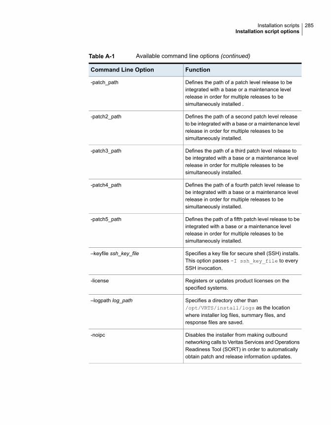
Table A-1 Available command line options (continued)
FunctionCommand Line Option
Defines the path of a patch level release to beintegrated with a base or a maintenance levelrelease in order for multiple releases to besimultaneously installed .
-patch_path
Defines the path of a second patch level releaseto be integrated with a base or a maintenance levelrelease in order for multiple releases to besimultaneously installed.
-patch2_path
Defines the path of a third patch level release tobe integrated with a base or a maintenance levelrelease in order for multiple releases to besimultaneously installed.
-patch3_path
Defines the path of a fourth patch level release tobe integrated with a base or a maintenance levelrelease in order for multiple releases to besimultaneously installed.
-patch4_path
Defines the path of a fifth patch level release to beintegrated with a base or a maintenance levelrelease in order for multiple releases to besimultaneously installed.
-patch5_path
Specifies a key file for secure shell (SSH) installs.This option passes -I ssh_key_file to everySSH invocation.
–keyfile ssh_key_file
Registers or updates product licenses on thespecified systems.
-license
Specifies a directory other than/opt/VRTS/install/logs as the locationwhere installer log files, summary files, andresponse files are saved.
–logpath log_path
Disables the installer from making outboundnetworking calls to Veritas Services and OperationsReadiness Tool (SORT) in order to automaticallyobtain patch and release information updates.
-noipc
285Installation scriptsInstallation script options
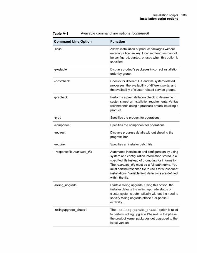
Table A-1 Available command line options (continued)
FunctionCommand Line Option
Allows installation of product packages withoutentering a license key. Licensed features cannotbe configured, started, or used when this option isspecified.
-nolic
Displays product's packages in correct installationorder by group.
-pkgtable
Checks for different HA and file system-relatedprocesses, the availability of different ports, andthe availability of cluster-related service groups.
–postcheck
Performs a preinstallation check to determine ifsystems meet all installation requirements. Veritasrecommends doing a precheck before installing aproduct.
-precheck
Specifies the product for operations.-prod
Specifies the component for operations.-component
Displays progress details without showing theprogress bar.
-redirect
Specifies an installer patch file.-require
Automates installation and configuration by usingsystem and configuration information stored in aspecified file instead of prompting for information.The response_file must be a full path name. Youmust edit the response file to use it for subsequentinstallations. Variable field definitions are definedwithin the file.
–responsefile response_file
Starts a rolling upgrade. Using this option, theinstaller detects the rolling upgrade status oncluster systems automatically without the need tospecify rolling upgrade phase 1 or phase 2explicitly.
-rolling_upgrade
The -rollingupgrade_phase1 option is usedto perform rolling upgrade Phase-I. In the phase,the product kernel packages get upgraded to thelatest version.
-rollingupgrade_phase1
286Installation scriptsInstallation script options

Table A-1 Available command line options (continued)
FunctionCommand Line Option
The -rollingupgrade_phase2 option is usedto perform rolling upgrade Phase-II. In the phase,VCS and other agent packages upgrade to thelatest version. Product kernel drivers arerolling-upgraded to the latest protocol version.
-rollingupgrade_phase2
Specifies an alternative root directory on which toinstall packages.
On Solaris operating systems, -rootpath passes-R path to pkgadd command.
–rootpath root_path
Specify this option when you want to use RSH andRCP for communication between systems insteadof the default SSH and SCP.
See “About configuring secure shell or remote shellcommunication modes before installing products”on page 311.
-rsh
The -security option is used to convert a runningVCS cluster between secure and non-securemodes of operation.
-security
The -securityonenode option is used toconfigure a secure cluster node by node.
-securityonenode
The -securitytrust option is used to setuptrust with another broker.
-securitytrust
Specifies that the installation script performs install,uninstall, start, and stop operations on each systemin a serial fashion. If this option is not specified,these operations are performed simultaneously onall systems.
–serial
Specify this option when you want to set tunableparameters after you install and configure aproduct. You may need to restart processes of theproduct for the tunable parameter values to takeeffect. You must use this option together with the-tunablesfile option.
-settunables
Starts the daemons and processes for the specifiedproduct.
-start
287Installation scriptsInstallation script options

Table A-1 Available command line options (continued)
FunctionCommand Line Option
Stops the daemons and processes for the specifiedproduct.
-stop
The -timeout option is used to specify thenumber of seconds that the script should wait foreach command to complete before timing out.Setting the -timeout option overrides the defaultvalue of 1200 seconds. Setting the -timeoutoption to 0 prevents the script from timing out. The-timeout option does not work with the -serialoption
-timeout
Specifies a directory other than /var/tmp as theworking directory for the installation scripts. Thisdestination is where initial logging is performedand where packages are copied on remotesystems before installation.
–tmppath tmp_path
Lists all supported tunables and create a tunablesfile template.
-tunables
Specify this option when you specify a tunablesfile. The tunables file should include tunableparameters.
-tunables_file tunables_file
This option is used to uninstall the products fromsystems
-uninstall
Specifies that an existing version of the productexists and you plan to upgrade it.
-upgrade
Checks and reports the installed products and theirversions. Identifies the installed and missingpackages and patches where applicable for theproduct. Provides a summary that includes thecount of the installed and any missing packagesand patches where applicable. Lists the installedpatches, patches, and available updates for theinstalled product if an Internet connection isavailable.
-version
288Installation scriptsInstallation script options
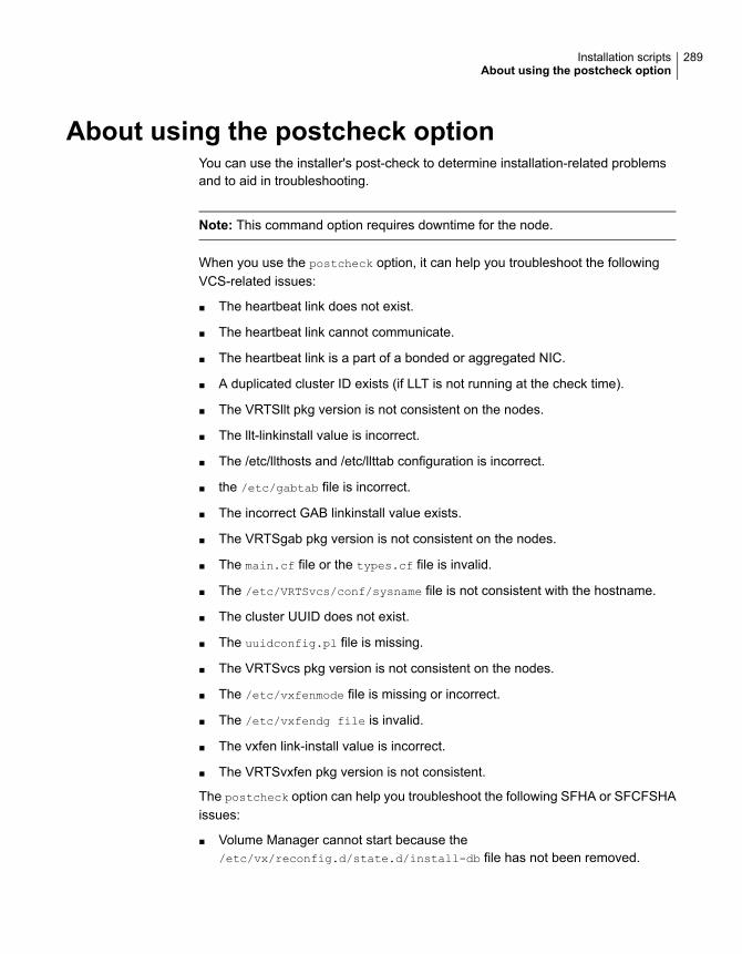
About using the postcheck optionYou can use the installer's post-check to determine installation-related problemsand to aid in troubleshooting.
Note: This command option requires downtime for the node.
When you use the postcheck option, it can help you troubleshoot the followingVCS-related issues:
■ The heartbeat link does not exist.
■ The heartbeat link cannot communicate.
■ The heartbeat link is a part of a bonded or aggregated NIC.
■ A duplicated cluster ID exists (if LLT is not running at the check time).
■ The VRTSllt pkg version is not consistent on the nodes.
■ The llt-linkinstall value is incorrect.
■ The /etc/llthosts and /etc/llttab configuration is incorrect.
■ the /etc/gabtab file is incorrect.
■ The incorrect GAB linkinstall value exists.
■ The VRTSgab pkg version is not consistent on the nodes.
■ The main.cf file or the types.cf file is invalid.
■ The /etc/VRTSvcs/conf/sysname file is not consistent with the hostname.
■ The cluster UUID does not exist.
■ The uuidconfig.pl file is missing.
■ The VRTSvcs pkg version is not consistent on the nodes.
■ The /etc/vxfenmode file is missing or incorrect.
■ The /etc/vxfendg file is invalid.
■ The vxfen link-install value is incorrect.
■ The VRTSvxfen pkg version is not consistent.
The postcheck option can help you troubleshoot the following SFHA or SFCFSHAissues:
■ Volume Manager cannot start because the/etc/vx/reconfig.d/state.d/install-db file has not been removed.
289Installation scriptsAbout using the postcheck option
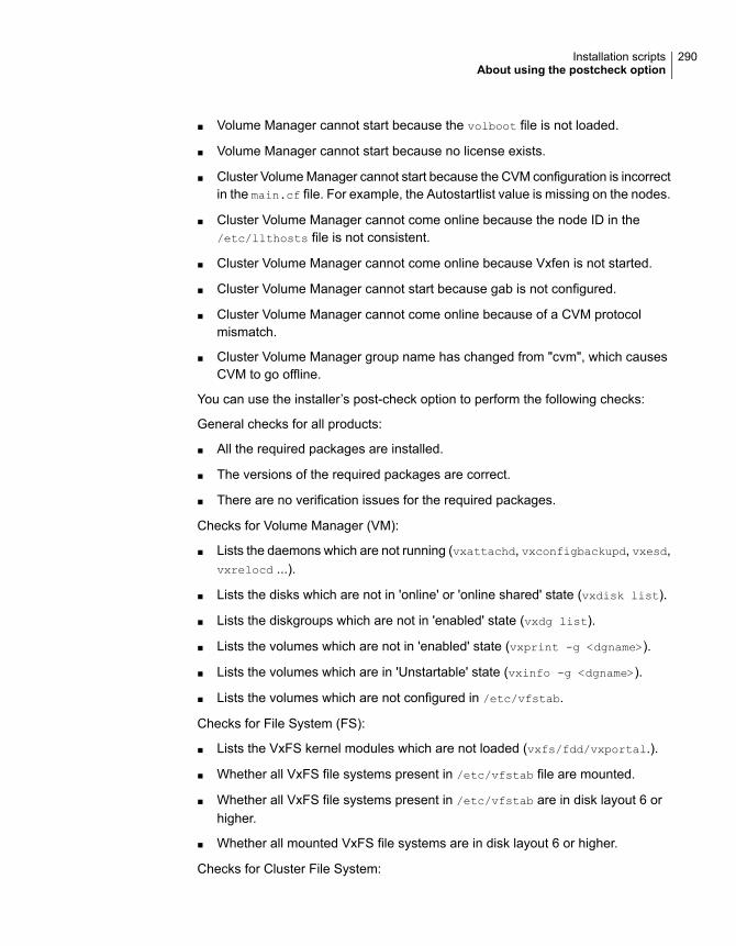
■ Volume Manager cannot start because the volboot file is not loaded.
■ Volume Manager cannot start because no license exists.
■ Cluster Volume Manager cannot start because the CVM configuration is incorrectin the main.cf file. For example, the Autostartlist value is missing on the nodes.
■ Cluster Volume Manager cannot come online because the node ID in the/etc/llthosts file is not consistent.
■ Cluster Volume Manager cannot come online because Vxfen is not started.
■ Cluster Volume Manager cannot start because gab is not configured.
■ Cluster Volume Manager cannot come online because of a CVM protocolmismatch.
■ Cluster Volume Manager group name has changed from "cvm", which causesCVM to go offline.
You can use the installer’s post-check option to perform the following checks:
General checks for all products:
■ All the required packages are installed.
■ The versions of the required packages are correct.
■ There are no verification issues for the required packages.
Checks for Volume Manager (VM):
■ Lists the daemons which are not running (vxattachd, vxconfigbackupd, vxesd,vxrelocd ...).
■ Lists the disks which are not in 'online' or 'online shared' state (vxdisk list).
■ Lists the diskgroups which are not in 'enabled' state (vxdg list).
■ Lists the volumes which are not in 'enabled' state (vxprint -g <dgname>).
■ Lists the volumes which are in 'Unstartable' state (vxinfo -g <dgname>).
■ Lists the volumes which are not configured in /etc/vfstab.
Checks for File System (FS):
■ Lists the VxFS kernel modules which are not loaded (vxfs/fdd/vxportal.).
■ Whether all VxFS file systems present in /etc/vfstab file are mounted.
■ Whether all VxFS file systems present in /etc/vfstab are in disk layout 6 orhigher.
■ Whether all mounted VxFS file systems are in disk layout 6 or higher.
Checks for Cluster File System:
290Installation scriptsAbout using the postcheck option

■ Whether FS and ODM are running at the latest protocol level.
■ Whether all mounted CFS file systems are managed by VCS.
■ Whether cvm service group is online.
291Installation scriptsAbout using the postcheck option
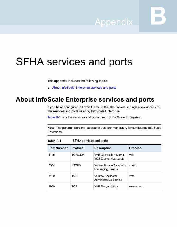
SFHA services and portsThis appendix includes the following topics:
■ About InfoScale Enterprise services and ports
About InfoScale Enterprise services and portsIf you have configured a firewall, ensure that the firewall settings allow access tothe services and ports used by InfoScale Enterprise.
Table B-1 lists the services and ports used by InfoScale Enterprise .
Note: The port numbers that appear in bold are mandatory for configuring InfoScaleEnterprise.
Table B-1 SFHA services and ports
ProcessDescriptionProtocolPort Number
vxioVVR Connection ServerVCS Cluster Heartbeats
TCP/UDP4145
xprtldVeritas Storage FoundationMessaging Service
HTTPS5634
vrasVolume ReplicatorAdministrative Service
TCP8199
vxreserverVVR Resync UtilityTCP8989
BAppendix
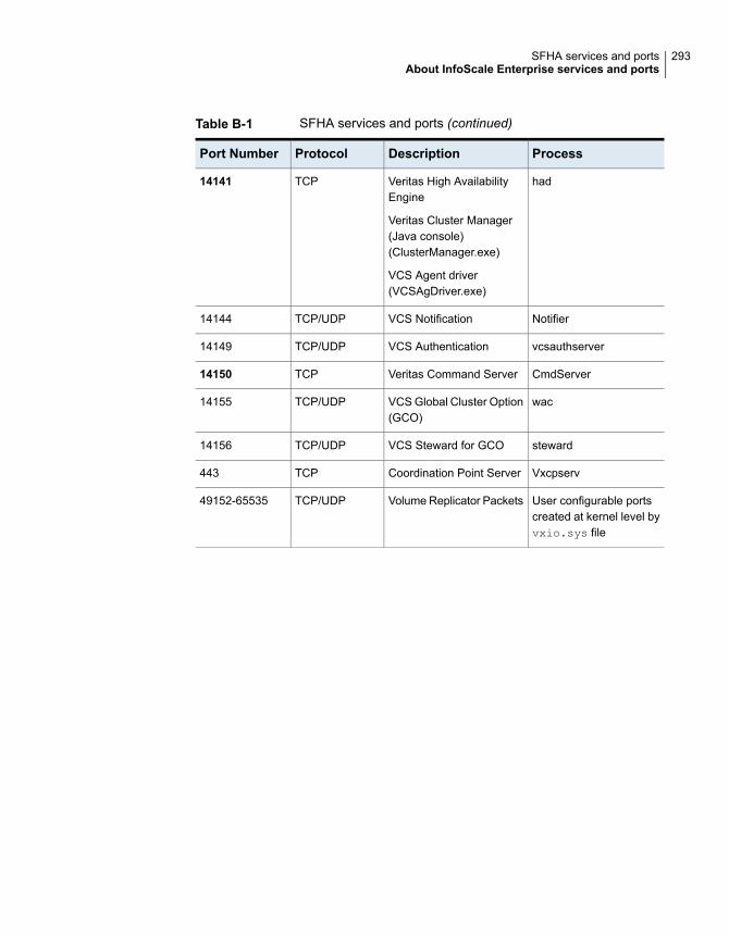
Table B-1 SFHA services and ports (continued)
ProcessDescriptionProtocolPort Number
hadVeritas High AvailabilityEngine
Veritas Cluster Manager(Java console)(ClusterManager.exe)
VCS Agent driver(VCSAgDriver.exe)
TCP14141
NotifierVCS NotificationTCP/UDP14144
vcsauthserverVCS AuthenticationTCP/UDP14149
CmdServerVeritas Command ServerTCP14150
wacVCS Global Cluster Option(GCO)
TCP/UDP14155
stewardVCS Steward for GCOTCP/UDP14156
VxcpservCoordination Point ServerTCP443
User configurable portscreated at kernel level byvxio.sys file
Volume Replicator PacketsTCP/UDP49152-65535
293SFHA services and portsAbout InfoScale Enterprise services and ports
Configuration filesThis appendix includes the following topics:
■ About the LLT and GAB configuration files
■ About the AMF configuration files
■ About the VCS configuration files
■ About I/O fencing configuration files
■ Sample configuration files for CP server
■ Packaging related SMF services on Solaris 11
About the LLT and GAB configuration filesLow Latency Transport (LLT) and Group Membership and Atomic Broadcast (GAB)are VCS communication services. LLT requires /etc/llthosts and /etc/llttab files.GAB requires /etc/gabtab file.
Table C-1 lists the LLT configuration files and the information that these files contain.
CAppendix
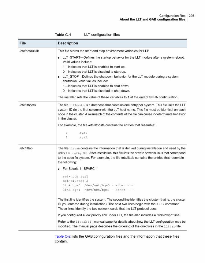
Table C-1 LLT configuration files
DescriptionFile
This file stores the start and stop environment variables for LLT:
■ LLT_START—Defines the startup behavior for the LLT module after a system reboot.Valid values include:1—Indicates that LLT is enabled to start up.0—Indicates that LLT is disabled to start up.
■ LLT_STOP—Defines the shutdown behavior for the LLT module during a systemshutdown. Valid values include:1—Indicates that LLT is enabled to shut down.0—Indicates that LLT is disabled to shut down.
The installer sets the value of these variables to 1 at the end of SFHA configuration.
/etc/default/llt
The file llthosts is a database that contains one entry per system. This file links the LLTsystem ID (in the first column) with the LLT host name. This file must be identical on eachnode in the cluster. A mismatch of the contents of the file can cause indeterminate behaviorin the cluster.
For example, the file /etc/llthosts contains the entries that resemble:
0 sys11 sys2
/etc/llthosts
The file llttab contains the information that is derived during installation and used by theutility lltconfig(1M). After installation, this file lists the private network links that correspondto the specific system. For example, the file /etc/llttab contains the entries that resemblethe following:
■ For Solaris 11 SPARC :
set-node sys1set-cluster 2link bge0 /dev/net/bge0 - ether - -link bge1 /dev/net/bge1 - ether - -
The first line identifies the system. The second line identifies the cluster (that is, the clusterID you entered during installation). The next two lines begin with the link command.These lines identify the two network cards that the LLT protocol uses.
If you configured a low priority link under LLT, the file also includes a "link-lowpri" line.
Refer to the llttab(4) manual page for details about how the LLT configuration may bemodified. The manual page describes the ordering of the directives in the llttab file.
/etc/llttab
Table C-2 lists the GAB configuration files and the information that these filescontain.
295Configuration filesAbout the LLT and GAB configuration files
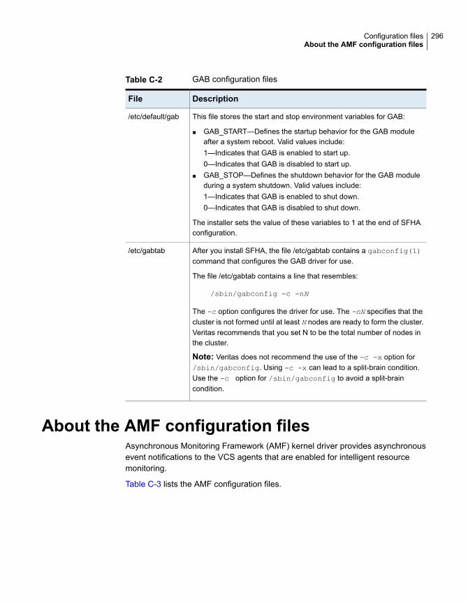
Table C-2 GAB configuration files
DescriptionFile
This file stores the start and stop environment variables for GAB:
■ GAB_START—Defines the startup behavior for the GAB moduleafter a system reboot. Valid values include:1—Indicates that GAB is enabled to start up.0—Indicates that GAB is disabled to start up.
■ GAB_STOP—Defines the shutdown behavior for the GAB moduleduring a system shutdown. Valid values include:1—Indicates that GAB is enabled to shut down.0—Indicates that GAB is disabled to shut down.
The installer sets the value of these variables to 1 at the end of SFHAconfiguration.
/etc/default/gab
After you install SFHA, the file /etc/gabtab contains a gabconfig(1)command that configures the GAB driver for use.
The file /etc/gabtab contains a line that resembles:
/sbin/gabconfig -c -nN
The -c option configures the driver for use. The -nN specifies that thecluster is not formed until at least N nodes are ready to form the cluster.Veritas recommends that you set N to be the total number of nodes inthe cluster.
Note: Veritas does not recommend the use of the -c -x option for/sbin/gabconfig. Using -c -x can lead to a split-brain condition.Use the -c option for /sbin/gabconfig to avoid a split-braincondition.
/etc/gabtab
About the AMF configuration filesAsynchronous Monitoring Framework (AMF) kernel driver provides asynchronousevent notifications to the VCS agents that are enabled for intelligent resourcemonitoring.
Table C-3 lists the AMF configuration files.
296Configuration filesAbout the AMF configuration files

Table C-3 AMF configuration files
DescriptionFile
This file stores the start and stop environment variables for AMF:
■ AMF_START—Defines the startup behavior for the AMF moduleafter a system reboot or when AMF is attempted to start usingthe init script. Valid values include:1—Indicates that AMF is enabled to start up. (default)0—Indicates that AMF is disabled to start up.
■ AMF_STOP—Defines the shutdown behavior for the AMFmodule during a system shutdown or when AMF is attemptedto stop using the init script. Valid values include:1—Indicates that AMF is enabled to shut down. (default)0—Indicates that AMF is disabled to shut down.
/etc/default/amf
After you install VCS, the file /etc/amftab contains aamfconfig(1) command that configures the AMF driver for use.
The AMF init script uses this /etc/amftab file to configure theAMF driver. The /etc/amftab file contains the following line bydefault:
/opt/VRTSamf/bin/amfconfig -c
/etc/amftab
About the VCS configuration filesVCS configuration files include the following:
■ main.cfThe installer creates the VCS configuration file in the /etc/VRTSvcs/conf/configfolder by default during the SFHA configuration. The main.cf file contains theminimum information that defines the cluster and its nodes.See “Sample main.cf file for VCS clusters” on page 298.See “Sample main.cf file for global clusters” on page 300.
■ types.cfThe file types.cf, which is listed in the include statement in the main.cf file, definesthe VCS bundled types for VCS resources. The file types.cf is also located inthe folder /etc/VRTSvcs/conf/config.Additional files similar to types.cf may be present if agents have been added,such as OracleTypes.cf.
Note the following information about the VCS configuration file after installing andconfiguring VCS:
297Configuration filesAbout the VCS configuration files
■ The cluster definition includes the cluster information that you provided duringthe configuration. This definition includes the cluster name, cluster address, andthe names of users and administrators of the cluster.Notice that the cluster has an attribute UserNames. The installer creates a user"admin" whose password is encrypted; the word "password" is the defaultpassword.
■ If you set up the optional I/O fencing feature for VCS, then the UseFence =SCSI3 attribute is present.
■ If you configured the cluster in secure mode, the main.cf includes "SecureClus= 1" cluster attribute.
■ The installer creates the ClusterService service group if you configured thevirtual IP, SMTP, SNMP, or global cluster options.
The service group also has the following characteristics:
■ The group includes the IP and NIC resources.
■ The service group also includes the notifier resource configuration, which isbased on your input to installer prompts about notification.
■ The installer also creates a resource dependency tree.
■ If you set up global clusters, the ClusterService service group contains anApplication resource, wac (wide-area connector). This resource’s attributescontain definitions for controlling the cluster in a global cluster environment.Refer to the Cluster Server Administrator's Guide for information aboutmanaging VCS global clusters.
Refer to the Cluster Server Administrator's Guide to review the configurationconcepts, and descriptions of main.cf and types.cf files for Solaris systems.
Sample main.cf file for VCS clustersThe following sample main.cf file is for a three-node cluster in secure mode.
include "types.cf"
include "OracleTypes.cf"
include "OracleASMTypes.cf"
include "Db2udbTypes.cf"
include "SybaseTypes.cf"
cluster vcs02 (
SecureClus = 1
)
298Configuration filesAbout the VCS configuration files

system sysA (
)
system sysB (
)
system sysC (
)
group ClusterService (
SystemList = { sysA = 0, sysB = 1, sysC = 2 }
AutoStartList = { sysA, sysB, sysC }
OnlineRetryLimit = 3
OnlineRetryInterval = 120
)
NIC csgnic (
Device = bge0
NetworkHosts = { "10.182.13.1" }
)
NotifierMngr ntfr (
SnmpConsoles = { sys4" = SevereError }
SmtpServer = "smtp.example.com"
SmtpRecipients = { "[email protected]" = SevereError }
)
ntfr requires csgnic
// resource dependency tree
//
// group ClusterService
// {
// NotifierMngr ntfr
// {
// NIC csgnic
// }
// }
299Configuration filesAbout the VCS configuration files
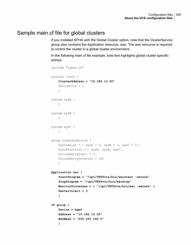
Sample main.cf file for global clustersIf you installed SFHA with the Global Cluster option, note that the ClusterServicegroup also contains the Application resource, wac. The wac resource is requiredto control the cluster in a global cluster environment.
In the following main.cf file example, bold text highlights global cluster specificentries.
include "types.cf"
cluster vcs03 (
ClusterAddress = "10.182.13.50"
SecureClus = 1
)
system sysA (
)
system sysB (
)
system sysC (
)
group ClusterService (
SystemList = { sysA = 0, sysB = 1, sysC = 2 }
AutoStartList = { sysA, sysB, sysC }
OnlineRetryLimit = 3
OnlineRetryInterval = 120
)
Application wac (
StartProgram = "/opt/VRTSvcs/bin/wacstart -secure"
StopProgram = "/opt/VRTSvcs/bin/wacstop"
MonitorProcesses = { "/opt/VRTSvcs/bin/wac -secure" }
RestartLimit = 3
)
IP gcoip (
Device = bge0
Address = "10.182.13.50"
NetMask = "255.255.240.0"
)
300Configuration filesAbout the VCS configuration files
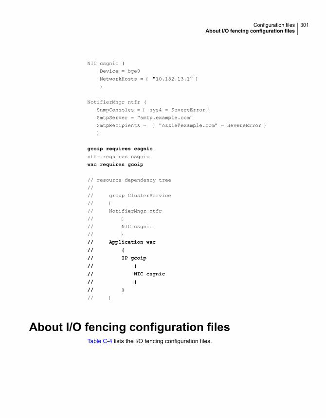
NIC csgnic (
Device = bge0
NetworkHosts = { "10.182.13.1" }
)
NotifierMngr ntfr (
SnmpConsoles = { sys4 = SevereError }
SmtpServer = "smtp.example.com"
SmtpRecipients = { "[email protected]" = SevereError }
)
gcoip requires csgnic
ntfr requires csgnic
wac requires gcoip
// resource dependency tree
//
// group ClusterService
// {
// NotifierMngr ntfr
// {
// NIC csgnic
// }
// Application wac
// {
// IP gcoip
// {
// NIC csgnic
// }
// }
// }
About I/O fencing configuration filesTable C-4 lists the I/O fencing configuration files.
301Configuration filesAbout I/O fencing configuration files
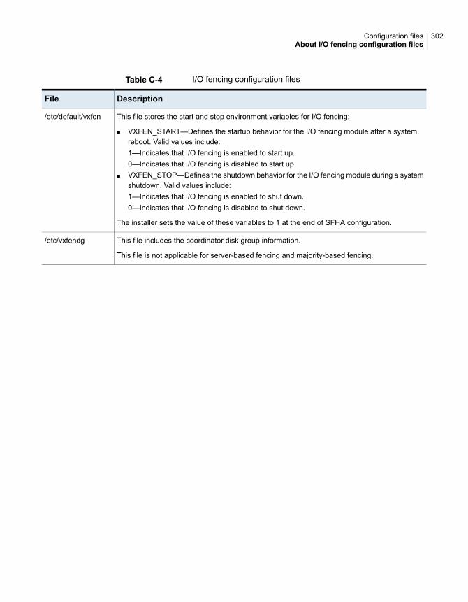
Table C-4 I/O fencing configuration files
DescriptionFile
This file stores the start and stop environment variables for I/O fencing:
■ VXFEN_START—Defines the startup behavior for the I/O fencing module after a systemreboot. Valid values include:1—Indicates that I/O fencing is enabled to start up.0—Indicates that I/O fencing is disabled to start up.
■ VXFEN_STOP—Defines the shutdown behavior for the I/O fencing module during a systemshutdown. Valid values include:1—Indicates that I/O fencing is enabled to shut down.0—Indicates that I/O fencing is disabled to shut down.
The installer sets the value of these variables to 1 at the end of SFHA configuration.
/etc/default/vxfen
This file includes the coordinator disk group information.
This file is not applicable for server-based fencing and majority-based fencing.
/etc/vxfendg
302Configuration filesAbout I/O fencing configuration files
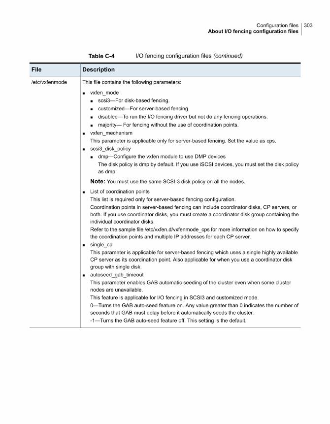
Table C-4 I/O fencing configuration files (continued)
DescriptionFile
This file contains the following parameters:
■ vxfen_mode■ scsi3—For disk-based fencing.■ customized—For server-based fencing.■ disabled—To run the I/O fencing driver but not do any fencing operations.■ majority— For fencing without the use of coordination points.
■ vxfen_mechanismThis parameter is applicable only for server-based fencing. Set the value as cps.
■ scsi3_disk_policy■ dmp—Configure the vxfen module to use DMP devices
The disk policy is dmp by default. If you use iSCSI devices, you must set the disk policyas dmp.
Note: You must use the same SCSI-3 disk policy on all the nodes.
■ List of coordination pointsThis list is required only for server-based fencing configuration.Coordination points in server-based fencing can include coordinator disks, CP servers, orboth. If you use coordinator disks, you must create a coordinator disk group containing theindividual coordinator disks.Refer to the sample file /etc/vxfen.d/vxfenmode_cps for more information on how to specifythe coordination points and multiple IP addresses for each CP server.
■ single_cpThis parameter is applicable for server-based fencing which uses a single highly availableCP server as its coordination point. Also applicable for when you use a coordinator diskgroup with single disk.
■ autoseed_gab_timeoutThis parameter enables GAB automatic seeding of the cluster even when some clusternodes are unavailable.This feature is applicable for I/O fencing in SCSI3 and customized mode.0—Turns the GAB auto-seed feature on. Any value greater than 0 indicates the number ofseconds that GAB must delay before it automatically seeds the cluster.-1—Turns the GAB auto-seed feature off. This setting is the default.
/etc/vxfenmode
303Configuration filesAbout I/O fencing configuration files
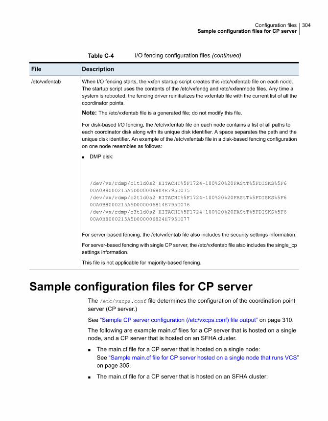
Table C-4 I/O fencing configuration files (continued)
DescriptionFile
When I/O fencing starts, the vxfen startup script creates this /etc/vxfentab file on each node.The startup script uses the contents of the /etc/vxfendg and /etc/vxfenmode files. Any time asystem is rebooted, the fencing driver reinitializes the vxfentab file with the current list of all thecoordinator points.
Note: The /etc/vxfentab file is a generated file; do not modify this file.
For disk-based I/O fencing, the /etc/vxfentab file on each node contains a list of all paths toeach coordinator disk along with its unique disk identifier. A space separates the path and theunique disk identifier. An example of the /etc/vxfentab file in a disk-based fencing configurationon one node resembles as follows:
■ DMP disk:
/dev/vx/rdmp/c1t1d0s2 HITACHI%5F1724-100%20%20FAStT%5FDISKS%5F600A0B8000215A5D000006804E795D075/dev/vx/rdmp/c2t1d0s2 HITACHI%5F1724-100%20%20FAStT%5FDISKS%5F600A0B8000215A5D000006814E795D076/dev/vx/rdmp/c3t1d0s2 HITACHI%5F1724-100%20%20FAStT%5FDISKS%5F600A0B8000215A5D000006824E795D077
For server-based fencing, the /etc/vxfentab file also includes the security settings information.
For server-based fencing with single CP server, the /etc/vxfentab file also includes the single_cpsettings information.
This file is not applicable for majority-based fencing.
/etc/vxfentab
Sample configuration files for CP serverThe /etc/vxcps.conf file determines the configuration of the coordination pointserver (CP server.)
See “Sample CP server configuration (/etc/vxcps.conf) file output” on page 310.
The following are example main.cf files for a CP server that is hosted on a singlenode, and a CP server that is hosted on an SFHA cluster.
■ The main.cf file for a CP server that is hosted on a single node:See “Sample main.cf file for CP server hosted on a single node that runs VCS”on page 305.
■ The main.cf file for a CP server that is hosted on an SFHA cluster:
304Configuration filesSample configuration files for CP server

See “Sample main.cf file for CP server hosted on a two-node SFHA cluster”on page 307.
The example main.cf files use IPv4 addresses.
Sample main.cf file for CP server hosted on a single node that runsVCS
The following is an example of a single CP server node main.cf.
For this CP server single node main.cf, note the following values:
■ Cluster name: cps1
■ Node name: cps1
include "types.cf"
include "/opt/VRTScps/bin/Quorum/QuorumTypes.cf"
// cluster name: cps1
// CP server: cps1
cluster cps1 (
UserNames = { admin = bMNfMHmJNiNNlVNhMK, haris = fopKojNvpHouNn,
"cps1.example.com@root@vx" = aj,
"[email protected]" = hq }
Administrators = { admin, haris,
"cps1.example.com@root@vx",
SecureClus = 1
HacliUserLevel = COMMANDROOT
)
system cps1 (
)
group CPSSG (
SystemList = { cps1 = 0 }
AutoStartList = { cps1 }
)
IP cpsvip1 (
Critical = 0
Device @cps1 = bge0
Address = "10.209.3.1"
305Configuration filesSample configuration files for CP server
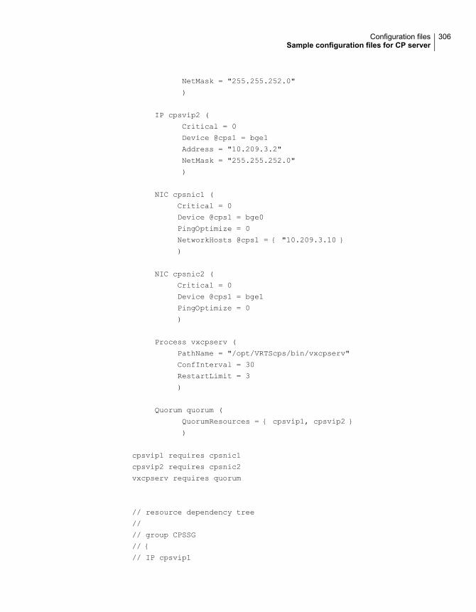
NetMask = "255.255.252.0"
)
IP cpsvip2 (
Critical = 0
Device @cps1 = bge1
Address = "10.209.3.2"
NetMask = "255.255.252.0"
)
NIC cpsnic1 (
Critical = 0
Device @cps1 = bge0
PingOptimize = 0
NetworkHosts @cps1 = { "10.209.3.10 }
)
NIC cpsnic2 (
Critical = 0
Device @cps1 = bge1
PingOptimize = 0
)
Process vxcpserv (
PathName = "/opt/VRTScps/bin/vxcpserv"
ConfInterval = 30
RestartLimit = 3
)
Quorum quorum (
QuorumResources = { cpsvip1, cpsvip2 }
)
cpsvip1 requires cpsnic1
cpsvip2 requires cpsnic2
vxcpserv requires quorum
// resource dependency tree
//
// group CPSSG
// {
// IP cpsvip1
306Configuration filesSample configuration files for CP server
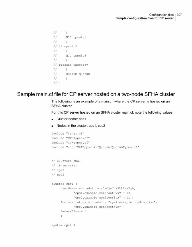
// {
// NIC cpsnic1
// }
// IP cpsvip2
// {
// NIC cpsnic2
// }
// Process vxcpserv
// {
// Quorum quorum
// }
// }
Sample main.cf file for CP server hosted on a two-node SFHA clusterThe following is an example of a main.cf, where the CP server is hosted on anSFHA cluster.
For this CP server hosted on an SFHA cluster main.cf, note the following values:
■ Cluster name: cps1
■ Nodes in the cluster: cps1, cps2
include "types.cf"
include "CFSTypes.cf"
include "CVMTypes.cf"
include "/opt/VRTScps/bin/Quorum/QuorumTypes.cf"
// cluster: cps1
// CP servers:
// cps1
// cps2
cluster cps1 (
UserNames = { admin = ajkCjeJgkFkkIskEjh,
"cps1.example.com@root@vx" = JK,
"cps2.example.com@root@vx" = dl }
Administrators = { admin, "cps1.example.com@root@vx",
"cps2.example.com@root@vx" }
SecureClus = 1
)
system cps1 (
307Configuration filesSample configuration files for CP server
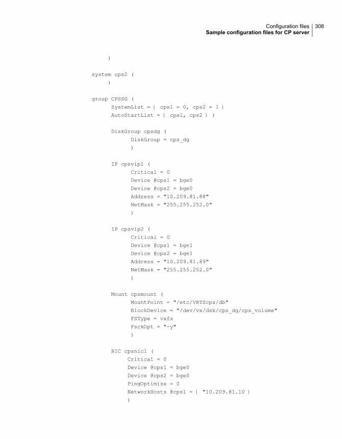
)
system cps2 (
)
group CPSSG (
SystemList = { cps1 = 0, cps2 = 1 }
AutoStartList = { cps1, cps2 } )
DiskGroup cpsdg (
DiskGroup = cps_dg
)
IP cpsvip1 (
Critical = 0
Device @cps1 = bge0
Device @cps2 = bge0
Address = "10.209.81.88"
NetMask = "255.255.252.0"
)
IP cpsvip2 (
Critical = 0
Device @cps1 = bge1
Device @cps2 = bge1
Address = "10.209.81.89"
NetMask = "255.255.252.0"
)
Mount cpsmount (
MountPoint = "/etc/VRTScps/db"
BlockDevice = "/dev/vx/dsk/cps_dg/cps_volume"
FSType = vxfs
FsckOpt = "-y"
)
NIC cpsnic1 (
Critical = 0
Device @cps1 = bge0
Device @cps2 = bge0
PingOptimize = 0
NetworkHosts @cps1 = { "10.209.81.10 }
)
308Configuration filesSample configuration files for CP server
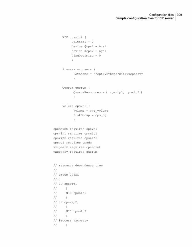
NIC cpsnic2 (
Critical = 0
Device @cps1 = bge1
Device @cps2 = bge1
PingOptimize = 0
)
Process vxcpserv (
PathName = "/opt/VRTScps/bin/vxcpserv"
)
Quorum quorum (
QuorumResources = { cpsvip1, cpsvip2 }
)
Volume cpsvol (
Volume = cps_volume
DiskGroup = cps_dg
)
cpsmount requires cpsvol
cpsvip1 requires cpsnic1
cpsvip2 requires cpsnic2
cpsvol requires cpsdg
vxcpserv requires cpsmount
vxcpserv requires quorum
// resource dependency tree
//
// group CPSSG
// {
// IP cpsvip1
// {
// NIC cpsnic1
// }
// IP cpsvip2
// {
// NIC cpsnic2
// }
// Process vxcpserv
// {
309Configuration filesSample configuration files for CP server
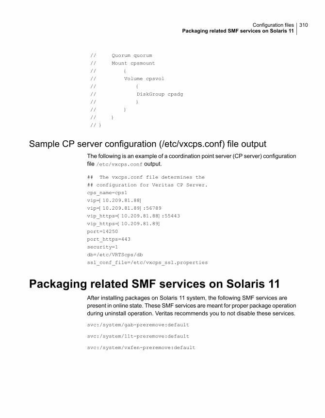
// Quorum quorum
// Mount cpsmount
// {
// Volume cpsvol
// {
// DiskGroup cpsdg
// }
// }
// }
// }
Sample CP server configuration (/etc/vxcps.conf) file outputThe following is an example of a coordination point server (CP server) configurationfile /etc/vxcps.conf output.
## The vxcps.conf file determines the
## configuration for Veritas CP Server.
cps_name=cps1
vip=[10.209.81.88]
vip=[10.209.81.89]:56789
vip_https=[10.209.81.88]:55443
vip_https=[10.209.81.89]
port=14250
port_https=443
security=1
db=/etc/VRTScps/db
ssl_conf_file=/etc/vxcps_ssl.properties
Packaging related SMF services on Solaris 11After installing packages on Solaris 11 system, the following SMF services arepresent in online state. These SMF services are meant for proper package operationduring uninstall operation. Veritas recommends you to not disable these services.
svc:/system/gab-preremove:default
svc:/system/llt-preremove:default
svc:/system/vxfen-preremove:default
310Configuration filesPackaging related SMF services on Solaris 11

Configuring the secureshell or the remote shellfor communications
This appendix includes the following topics:
■ About configuring secure shell or remote shell communication modes beforeinstalling products
■ Manually configuring passwordless ssh
■ Setting up ssh and rsh connection using the installer -comsetup command
■ Setting up ssh and rsh connection using the pwdutil.pl utility
■ Restarting the ssh session
■ Enabling and disabling rsh for Solaris
About configuring secure shell or remote shellcommunicationmodes before installing products
Establishing communication between nodes is required to install Veritas InfoScalesoftware from a remote system, or to install and configure a system. The systemfrom which the installer is run must have permissions to run rsh (remote shell) orssh (secure shell) utilities. You need to run the installer with superuser privilegeson the systems where you plan to install the Veritas InfoScale software.
You can install products to remote systems using either secure shell (ssh) or remoteshell (rsh). Veritas recommends that you use ssh as it is more secure than rsh.
DAppendix

You can set up ssh and rsh connections in many ways.
■ You can manually set up the ssh and rsh connection with UNIX shell commands.
■ You can run the installer -comsetup command to interactively set up sshand rsh connection.
■ You can run the password utility, pwdutil.pl.
This section contains an example of how to set up ssh password free communication.The example sets up ssh between a source system (sys1) that contains theinstallation directories, and a target system (sys2). This procedure also applies tomultiple target systems.
Note: The product installer supports establishing passwordless communication.
Manually configuring passwordless sshThe ssh program enables you to log into and execute commands on a remotesystem. ssh enables encrypted communications and an authentication processbetween two untrusted hosts over an insecure network.
In this procedure, you first create a DSA key pair. From the key pair, you appendthe public key from the source system to the authorized_keys file on the targetsystems.
Figure D-1 illustrates this procedure.
Figure D-1 Creating the DSA key pair and appending it to target systems
Source System: sys1 Target System: sys2
PrivateKey
PublicKey
authorized_keysfile
312Configuring the secure shell or the remote shell for communicationsManually configuring passwordless ssh
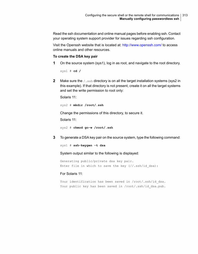
Read the ssh documentation and online manual pages before enabling ssh. Contactyour operating system support provider for issues regarding ssh configuration.
Visit the Openssh website that is located at: http://www.openssh.com/ to accessonline manuals and other resources.
To create the DSA key pair
1 On the source system (sys1), log in as root, and navigate to the root directory.
sys1 # cd /
2 Make sure the /.ssh directory is on all the target installation systems (sys2 inthis example). If that directory is not present, create it on all the target systemsand set the write permission to root only:
Solaris 11:
sys2 # mkdir /root/.ssh
Change the permissions of this directory, to secure it.
Solaris 11:
sys2 # chmod go-w /root/.ssh
3 To generate a DSA key pair on the source system, type the following command:
sys1 # ssh-keygen -t dsa
System output similar to the following is displayed:
Generating public/private dsa key pair.
Enter file in which to save the key (//.ssh/id_dsa):
For Solaris 11:
Your identification has been saved in /root/.ssh/id_dsa.
Your public key has been saved in /root/.ssh/id_dsa.pub.
313Configuring the secure shell or the remote shell for communicationsManually configuring passwordless ssh
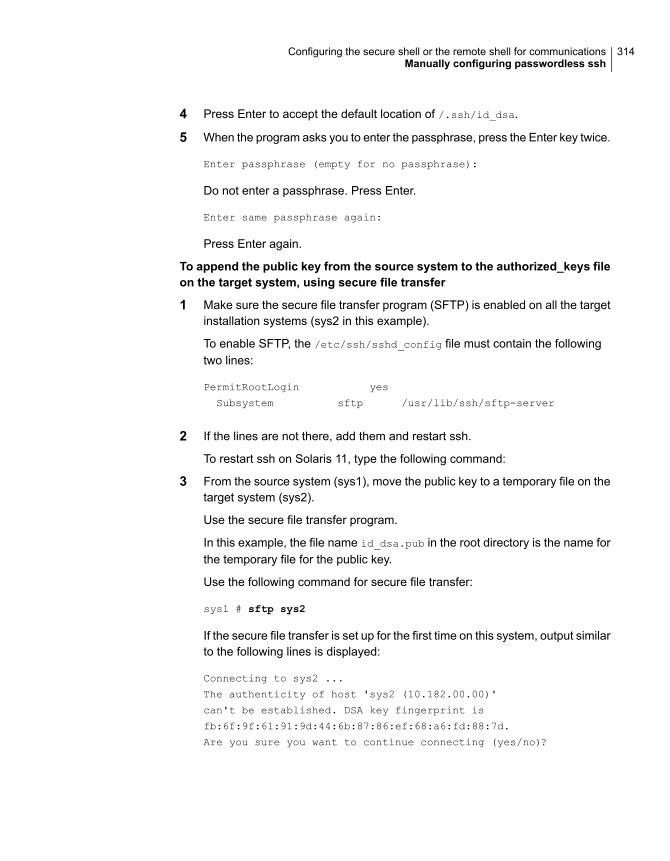
4 Press Enter to accept the default location of /.ssh/id_dsa.
5 When the program asks you to enter the passphrase, press the Enter key twice.
Enter passphrase (empty for no passphrase):
Do not enter a passphrase. Press Enter.
Enter same passphrase again:
Press Enter again.
To append the public key from the source system to the authorized_keys fileon the target system, using secure file transfer
1 Make sure the secure file transfer program (SFTP) is enabled on all the targetinstallation systems (sys2 in this example).
To enable SFTP, the /etc/ssh/sshd_config file must contain the followingtwo lines:
PermitRootLogin yes
Subsystem sftp /usr/lib/ssh/sftp-server
2 If the lines are not there, add them and restart ssh.
To restart ssh on Solaris 11, type the following command:
3 From the source system (sys1), move the public key to a temporary file on thetarget system (sys2).
Use the secure file transfer program.
In this example, the file name id_dsa.pub in the root directory is the name forthe temporary file for the public key.
Use the following command for secure file transfer:
sys1 # sftp sys2
If the secure file transfer is set up for the first time on this system, output similarto the following lines is displayed:
Connecting to sys2 ...
The authenticity of host 'sys2 (10.182.00.00)'
can't be established. DSA key fingerprint is
fb:6f:9f:61:91:9d:44:6b:87:86:ef:68:a6:fd:88:7d.
Are you sure you want to continue connecting (yes/no)?
314Configuring the secure shell or the remote shell for communicationsManually configuring passwordless ssh
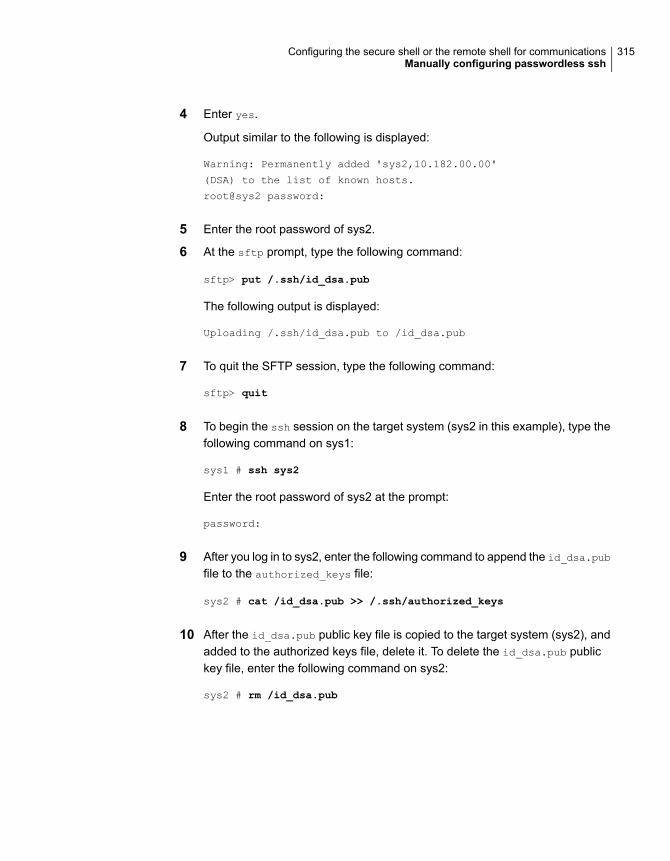
4 Enter yes.
Output similar to the following is displayed:
Warning: Permanently added 'sys2,10.182.00.00'
(DSA) to the list of known hosts.
root@sys2 password:
5 Enter the root password of sys2.
6 At the sftp prompt, type the following command:
sftp> put /.ssh/id_dsa.pub
The following output is displayed:
Uploading /.ssh/id_dsa.pub to /id_dsa.pub
7 To quit the SFTP session, type the following command:
sftp> quit
8 To begin the ssh session on the target system (sys2 in this example), type thefollowing command on sys1:
sys1 # ssh sys2
Enter the root password of sys2 at the prompt:
password:
9 After you log in to sys2, enter the following command to append the id_dsa.pub
file to the authorized_keys file:
sys2 # cat /id_dsa.pub >> /.ssh/authorized_keys
10 After the id_dsa.pub public key file is copied to the target system (sys2), andadded to the authorized keys file, delete it. To delete the id_dsa.pub publickey file, enter the following command on sys2:
sys2 # rm /id_dsa.pub
315Configuring the secure shell or the remote shell for communicationsManually configuring passwordless ssh
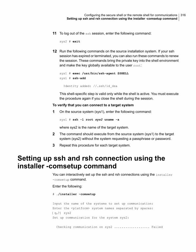
11 To log out of the ssh session, enter the following command:
sys2 # exit
12 Run the following commands on the source installation system. If your sshsession has expired or terminated, you can also run these commands to renewthe session. These commands bring the private key into the shell environmentand make the key globally available to the user root:
sys1 # exec /usr/bin/ssh-agent $SHELL
sys1 # ssh-add
Identity added: //.ssh/id_dsa
This shell-specific step is valid only while the shell is active. You must executethe procedure again if you close the shell during the session.
To verify that you can connect to a target system
1 On the source system (sys1), enter the following command:
sys1 # ssh -l root sys2 uname -a
where sys2 is the name of the target system.
2 The command should execute from the source system (sys1) to the targetsystem (sys2) without the system requesting a passphrase or password.
3 Repeat this procedure for each target system.
Setting up ssh and rsh connection using theinstaller -comsetup command
You can interactively set up the ssh and rsh connections using the installer
-comsetup command.
Enter the following:
# ./installer -comsetup
Input the name of the systems to set up communication:
Enter the <platform> system names separated by spaces:
[q,?] sys2
Set up communication for the system sys2:
Checking communication on sys2 ................... Failed
316Configuring the secure shell or the remote shell for communicationsSetting up ssh and rsh connection using the installer -comsetup command
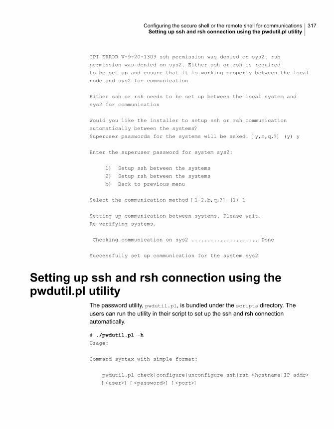
CPI ERROR V-9-20-1303 ssh permission was denied on sys2. rsh
permission was denied on sys2. Either ssh or rsh is required
to be set up and ensure that it is working properly between the local
node and sys2 for communication
Either ssh or rsh needs to be set up between the local system and
sys2 for communication
Would you like the installer to setup ssh or rsh communication
automatically between the systems?
Superuser passwords for the systems will be asked. [y,n,q,?] (y) y
Enter the superuser password for system sys2:
1) Setup ssh between the systems
2) Setup rsh between the systems
b) Back to previous menu
Select the communication method [1-2,b,q,?] (1) 1
Setting up communication between systems. Please wait.
Re-verifying systems.
Checking communication on sys2 ..................... Done
Successfully set up communication for the system sys2
Setting up ssh and rsh connection using thepwdutil.pl utility
The password utility, pwdutil.pl, is bundled under the scripts directory. Theusers can run the utility in their script to set up the ssh and rsh connectionautomatically.
# ./pwdutil.pl -h
Usage:
Command syntax with simple format:
pwdutil.pl check|configure|unconfigure ssh|rsh <hostname|IP addr>
[<user>] [<password>] [<port>]
317Configuring the secure shell or the remote shell for communicationsSetting up ssh and rsh connection using the pwdutil.pl utility
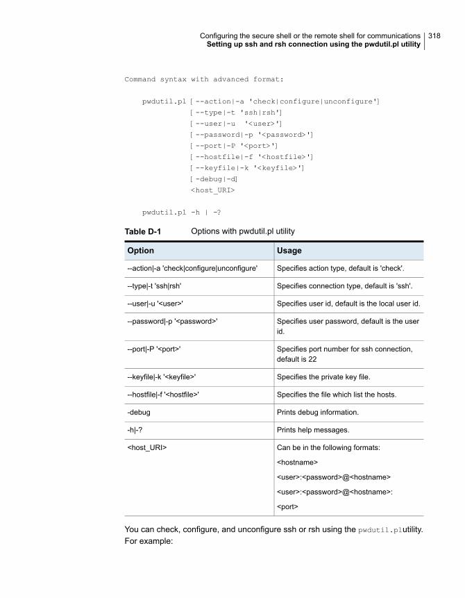
Command syntax with advanced format:
pwdutil.pl [--action|-a 'check|configure|unconfigure']
[--type|-t 'ssh|rsh']
[--user|-u '<user>']
[--password|-p '<password>']
[--port|-P '<port>']
[--hostfile|-f '<hostfile>']
[--keyfile|-k '<keyfile>']
[-debug|-d]
<host_URI>
pwdutil.pl -h | -?
Table D-1 Options with pwdutil.pl utility
UsageOption
Specifies action type, default is 'check'.--action|-a 'check|configure|unconfigure'
Specifies connection type, default is 'ssh'.--type|-t 'ssh|rsh'
Specifies user id, default is the local user id.--user|-u '<user>'
Specifies user password, default is the userid.
--password|-p '<password>'
Specifies port number for ssh connection,default is 22
--port|-P '<port>'
Specifies the private key file.--keyfile|-k '<keyfile>'
Specifies the file which list the hosts.--hostfile|-f '<hostfile>'
Prints debug information.-debug
Prints help messages.-h|-?
Can be in the following formats:
<hostname>
<user>:<password>@<hostname>
<user>:<password>@<hostname>:
<port>
<host_URI>
You can check, configure, and unconfigure ssh or rsh using the pwdutil.plutility.For example:
318Configuring the secure shell or the remote shell for communicationsSetting up ssh and rsh connection using the pwdutil.pl utility
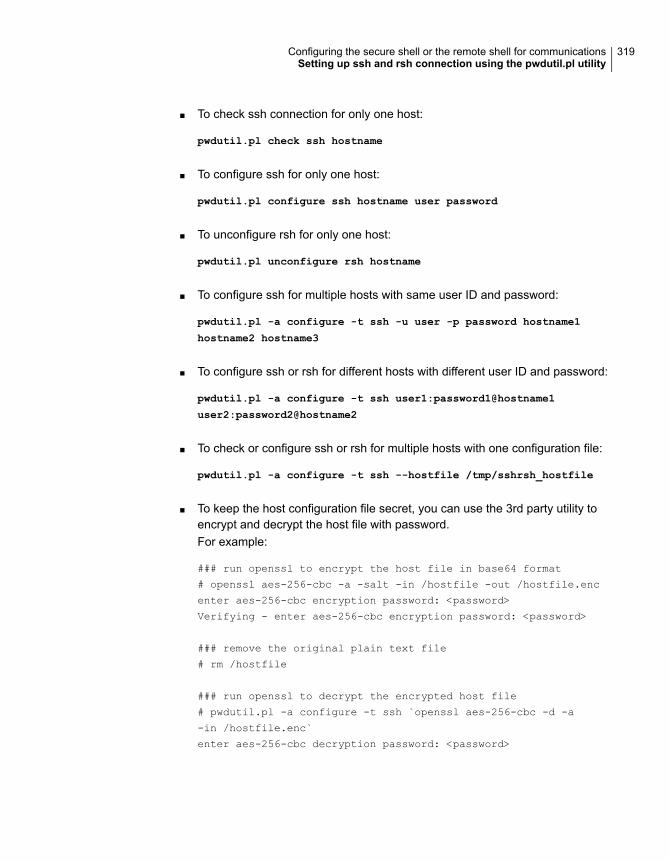
■ To check ssh connection for only one host:
pwdutil.pl check ssh hostname
■ To configure ssh for only one host:
pwdutil.pl configure ssh hostname user password
■ To unconfigure rsh for only one host:
pwdutil.pl unconfigure rsh hostname
■ To configure ssh for multiple hosts with same user ID and password:
pwdutil.pl -a configure -t ssh -u user -p password hostname1
hostname2 hostname3
■ To configure ssh or rsh for different hosts with different user ID and password:
pwdutil.pl -a configure -t ssh user1:password1@hostname1
user2:password2@hostname2
■ To check or configure ssh or rsh for multiple hosts with one configuration file:
pwdutil.pl -a configure -t ssh --hostfile /tmp/sshrsh_hostfile
■ To keep the host configuration file secret, you can use the 3rd party utility toencrypt and decrypt the host file with password.For example:
### run openssl to encrypt the host file in base64 format
# openssl aes-256-cbc -a -salt -in /hostfile -out /hostfile.enc
enter aes-256-cbc encryption password: <password>
Verifying - enter aes-256-cbc encryption password: <password>
### remove the original plain text file
# rm /hostfile
### run openssl to decrypt the encrypted host file
# pwdutil.pl -a configure -t ssh `openssl aes-256-cbc -d -a
-in /hostfile.enc`
enter aes-256-cbc decryption password: <password>
319Configuring the secure shell or the remote shell for communicationsSetting up ssh and rsh connection using the pwdutil.pl utility
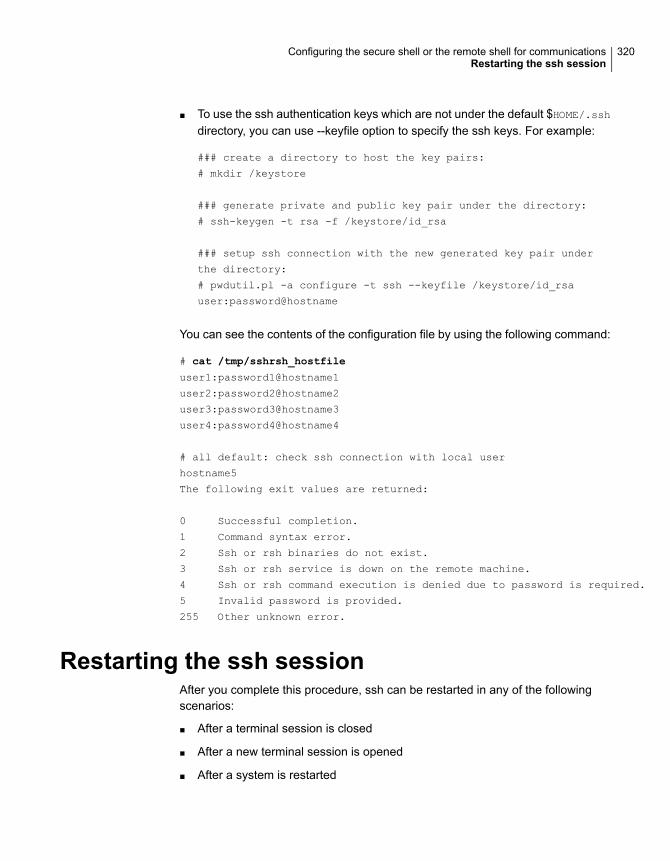
■ To use the ssh authentication keys which are not under the default $HOME/.sshdirectory, you can use --keyfile option to specify the ssh keys. For example:
### create a directory to host the key pairs:
# mkdir /keystore
### generate private and public key pair under the directory:
# ssh-keygen -t rsa -f /keystore/id_rsa
### setup ssh connection with the new generated key pair under
the directory:
# pwdutil.pl -a configure -t ssh --keyfile /keystore/id_rsa
user:password@hostname
You can see the contents of the configuration file by using the following command:
# cat /tmp/sshrsh_hostfile
user1:password1@hostname1
user2:password2@hostname2
user3:password3@hostname3
user4:password4@hostname4
# all default: check ssh connection with local user
hostname5
The following exit values are returned:
0 Successful completion.
1 Command syntax error.
2 Ssh or rsh binaries do not exist.
3 Ssh or rsh service is down on the remote machine.
4 Ssh or rsh command execution is denied due to password is required.
5 Invalid password is provided.
255 Other unknown error.
Restarting the ssh sessionAfter you complete this procedure, ssh can be restarted in any of the followingscenarios:
■ After a terminal session is closed
■ After a new terminal session is opened
■ After a system is restarted
320Configuring the secure shell or the remote shell for communicationsRestarting the ssh session
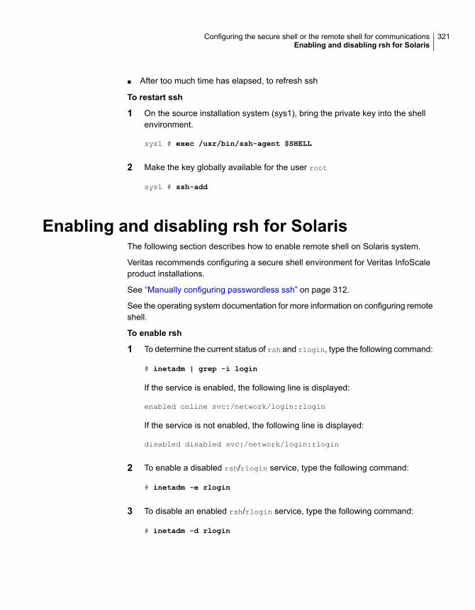
■ After too much time has elapsed, to refresh ssh
To restart ssh
1 On the source installation system (sys1), bring the private key into the shellenvironment.
sys1 # exec /usr/bin/ssh-agent $SHELL
2 Make the key globally available for the user root
sys1 # ssh-add
Enabling and disabling rsh for SolarisThe following section describes how to enable remote shell on Solaris system.
Veritas recommends configuring a secure shell environment for Veritas InfoScaleproduct installations.
See “Manually configuring passwordless ssh” on page 312.
See the operating system documentation for more information on configuring remoteshell.
To enable rsh
1 To determine the current status of rsh and rlogin, type the following command:
# inetadm | grep -i login
If the service is enabled, the following line is displayed:
enabled online svc:/network/login:rlogin
If the service is not enabled, the following line is displayed:
disabled disabled svc:/network/login:rlogin
2 To enable a disabled rsh/rlogin service, type the following command:
# inetadm -e rlogin
3 To disable an enabled rsh/rlogin service, type the following command:
# inetadm -d rlogin
321Configuring the secure shell or the remote shell for communicationsEnabling and disabling rsh for Solaris

4 Modify the .rhosts file. A separate .rhosts file is in the $HOME directory ofeach user. This file must be modified for each user who remotely accessesthe system using rsh. Each line of the .rhosts file contains a fully qualifieddomain name or IP address for each remote system having access to the localsystem. For example, if the root user must remotely access sys1 from sys2,you must add an entry for sys2.companyname.com in the .rhosts file on sys1.
# echo "sys2.companyname.com" >> $HOME/.rhosts
5 After you complete an installation procedure, delete the .rhosts file from eachuser’s $HOME directory to ensure security:
# rm -f $HOME/.rhosts
322Configuring the secure shell or the remote shell for communicationsEnabling and disabling rsh for Solaris
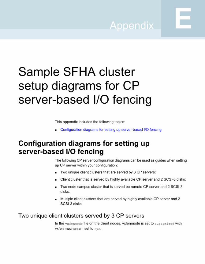
Sample SFHA clustersetup diagrams for CPserver-based I/O fencing
This appendix includes the following topics:
■ Configuration diagrams for setting up server-based I/O fencing
Configuration diagrams for setting upserver-based I/O fencing
The following CP server configuration diagrams can be used as guides when settingup CP server within your configuration:
■ Two unique client clusters that are served by 3 CP servers:
■ Client cluster that is served by highly available CP server and 2 SCSI-3 disks:
■ Two node campus cluster that is served be remote CP server and 2 SCSI-3disks:
■ Multiple client clusters that are served by highly available CP server and 2SCSI-3 disks:
Two unique client clusters served by 3 CP serversIn the vxfenmode file on the client nodes, vxfenmode is set to customized withvxfen mechanism set to cps.
EAppendix

Client cluster served by highly available CPS and 2 SCSI-3 disksFigure E-1 displays a configuration where a client cluster is served by one highlyavailable CP server and 2 local SCSI-3 LUNs (disks).
In the vxfenmode file on the client nodes, vxfenmode is set to customized with vxfenmechanism set to cps.
The two SCSI-3 disks are part of the disk group vxfencoorddg. The third coordinationpoint is a CP server hosted on an SFHA cluster, with its own shared database andcoordinator disks.
324Sample SFHA cluster setup diagrams for CP server-based I/O fencingConfiguration diagrams for setting up server-based I/O fencing
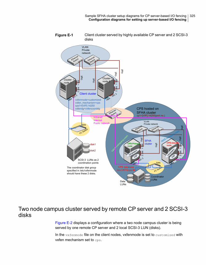
Figure E-1 Client cluster served by highly available CP server and 2 SCSI-3disks
SAN
FC Switch
CPS database/etc/VRTScps/db
NIC
1
Cluster -1node 1
NIC
2
NIC
1
Cluster-1node 2
NIC
2
Ethernet
SwitchEthernet
Switch
VLANPrivatenetwork
Ethernet
Switch
Intranet/InternetPublic network
NIC 3 NIC 3Client cluster
NIC
1
CPS-Primarynode
NIC
2
NIC
1
CPS-standbynode
NIC
2
Ethernet
Switch Ethernet
Switch
VLANPrivate network
NIC 3NIC 3
SFHAcluster
VIPvxcpserv
vxcp
serv
VIP
DataLUNs
CoordinatorLUNs
SAN
FC Switch
SCSI-3 LUNs as 2coordination points
disk1
disk2
CPS hosted onSFHA clustercp1=[VIP]:14250(port no.)
HBA HBA
HBAHBA
Gig
E
Gig
E
Gig
E Gig
E
Gig
E
Gig
E
Gig
EG
igE
cps1.company.com
cps2.company.com
vxfenmode=customizedvxfen_mechanism=cpscps1=[VIP]:14250vxfendg=vxfencoorddg
The coordinator disk groupspecified in /etc/vxfenmodeshould have these 2 disks.
Two node campus cluster served by remote CP server and 2 SCSI-3disks
Figure E-2 displays a configuration where a two node campus cluster is beingserved by one remote CP server and 2 local SCSI-3 LUN (disks).
In the vxfenmode file on the client nodes, vxfenmode is set to customized withvxfen mechanism set to cps.
325Sample SFHA cluster setup diagrams for CP server-based I/O fencingConfiguration diagrams for setting up server-based I/O fencing
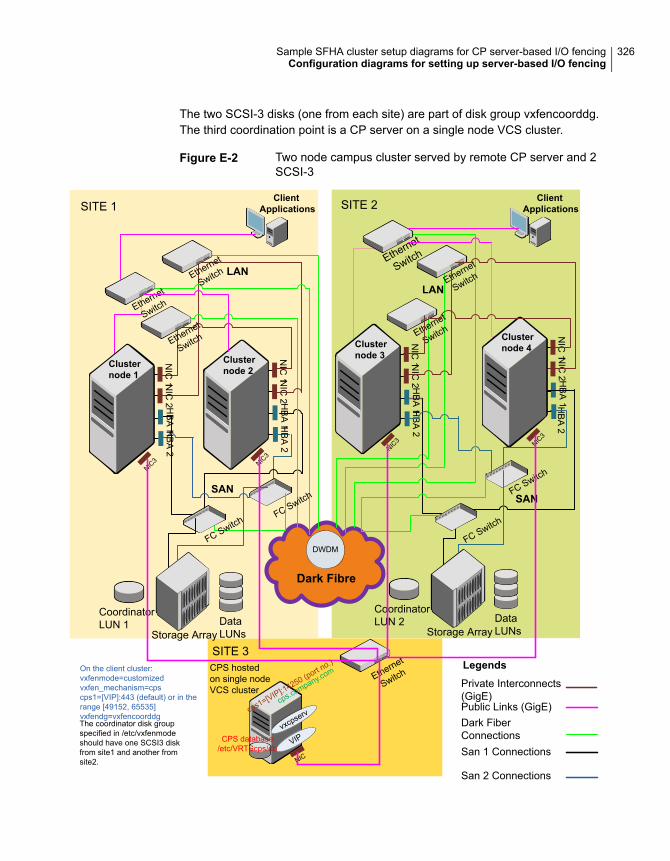
The two SCSI-3 disks (one from each site) are part of disk group vxfencoorddg.The third coordination point is a CP server on a single node VCS cluster.
Figure E-2 Two node campus cluster served by remote CP server and 2SCSI-3
LANLAN
Dark Fibre
SITE 1 SITE 2
SITE 3
NIC
1 NIC
2H
BA
2H
BA
1
Clusternode 1
NIC
1 NIC
2H
BA
2H
BA
1
Clusternode 2
NIC
1 NIC
2H
BA
2H
BA
1
Clusternode 3
NIC
1 NIC
2H
BA
2H
BA
1
Clusternode 4
ClientApplications
ClientApplications
Ethernet
Switch
Ethernet
Switch
Ethernet
Switch
Ethernet
Switch
Ethernet
Switch
Ethernet
Switch
FC SwitchFC Switch
FC Switch
FC Switch
CoordinatorLUN 1 Data
LUNsStorage Array
CoordinatorLUN 2 Data
LUNsStorage Array
DWDM
Private Interconnects(GigE)
San 2 Connections
Legends
Dark FiberConnectionsSan 1 Connections
Public Links (GigE)
SANSAN
CPS hostedon single nodeVCS cluster
NIC
VIPvxcpserv
CPS database/etc/VRTScps/db
cps.company.com Ethernet
Switch
NIC3 NIC
3
cps1=[VIP]:14250 (port no.)
NIC3 NIC
3
The coordinator disk groupspecified in /etc/vxfenmodeshould have one SCSI3 diskfrom site1 and another fromsite2.
On the client cluster:vxfenmode=customizedvxfen_mechanism=cpscps1=[VIP]:443 (default) or in therange [49152, 65535]vxfendg=vxfencoorddg
326Sample SFHA cluster setup diagrams for CP server-based I/O fencingConfiguration diagrams for setting up server-based I/O fencing

Multiple client clusters served by highly available CP server and 2SCSI-3 disks
In the vxfenmode file on the client nodes, vxfenmode is set to customized withvxfen mechanism set to cps.
The two SCSI-3 disks are are part of the disk group vxfencoorddg. The thirdcoordination point is a CP server, hosted on an SFHA cluster, with its own shareddatabase and coordinator disks.
327Sample SFHA cluster setup diagrams for CP server-based I/O fencingConfiguration diagrams for setting up server-based I/O fencing
Reconciling major/minornumbers for NFS shareddisks
This appendix includes the following topics:
■ Reconciling major/minor numbers for NFS shared disks
Reconcilingmajor/minor numbers for NFS shareddisks
Your configuration may include disks on the shared bus that support NFS. You canconfigure the NFS file systems that you export on disk partitions or on VeritasVolume Manager volumes.
An example disk partition name is /dev/dsk/c1t1d0s2.
An example volume name is /dev/vx/dsk/shareddg/vol3. Each name representsthe block device on which the file system is to be mounted.
In a VCS cluster, block devices providing NFS service must have the same majorand minor numbers on each cluster node. Major numbers identify required devicedrivers (such as a Solaris partition or a VxVM volume). Minor numbers identify thespecific devices themselves. NFS also uses major and minor numbers to identifythe exported file system.
Major and minor numbers must be verified to ensure that the NFS identity for thefile system is the same when exported from each node.
FAppendix
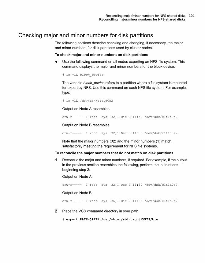
Checking major and minor numbers for disk partitionsThe following sections describe checking and changing, if necessary, the majorand minor numbers for disk partitions used by cluster nodes.
To check major and minor numbers on disk partitions
◆ Use the following command on all nodes exporting an NFS file system. Thiscommand displays the major and minor numbers for the block device.
# ls -lL block_device
The variable block_device refers to a partition where a file system is mountedfor export by NFS. Use this command on each NFS file system. For example,type:
# ls -lL /dev/dsk/c1t1d0s2
Output on Node A resembles:
crw-r----- 1 root sys 32,1 Dec 3 11:50 /dev/dsk/c1t1d0s2
Output on Node B resembles:
crw-r----- 1 root sys 32,1 Dec 3 11:55 /dev/dsk/c1t1d0s2
Note that the major numbers (32) and the minor numbers (1) match,satisfactorily meeting the requirement for NFS file systems.
To reconcile the major numbers that do not match on disk partitions
1 Reconcile the major and minor numbers, if required. For example, if the outputin the previous section resembles the following, perform the instructionsbeginning step 2:
Output on Node A:
crw-r----- 1 root sys 32,1 Dec 3 11:50 /dev/dsk/c1t1d0s2
Output on Node B:
crw-r----- 1 root sys 36,1 Dec 3 11:55 /dev/dsk/c1t1d0s2
2 Place the VCS command directory in your path.
# export PATH=$PATH:/usr/sbin:/sbin:/opt/VRTS/bin
329Reconciling major/minor numbers for NFS shared disksReconciling major/minor numbers for NFS shared disks
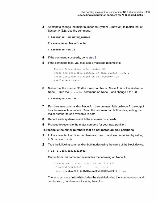
3 Attempt to change the major number on System B (now 36) to match that ofSystem A (32). Use the command:
# haremajor -sd major_number
For example, on Node B, enter:
# haremajor -sd 32
4 If the command succeeds, go to step 8.
5 If the command fails, you may see a message resembling:
Error: Preexisting major number 32
These are available numbers on this system: 128...
Check /etc/name_to_major on all systems for
available numbers.
6 Notice that the number 36 (the major number on Node A) is not available onNode B. Run the haremajor command on Node B and change it to 128,
# haremajor -sd 128
7 Run the same command on Node A. If the command fails on Node A, the outputlists the available numbers. Rerun the command on both nodes, setting themajor number to one available to both.
8 Reboot each system on which the command succeeds.
9 Proceed to reconcile the major numbers for your next partition.
To reconcile the minor numbers that do not match on disk partitions
1 In the example, the minor numbers are 1 and 3 and are reconciled by settingto 30 on each node.
2 Type the following command on both nodes using the name of the block device:
# ls -1 /dev/dsk/c1t1d0s2
Output from this command resembles the following on Node A:
lrwxrwxrwx 1 root root 83 Dec 3 11:50
/dev/dsk/c1t1d0s2 -> ../../
devices/sbus@1f,0/QLGC,isp@0,10000/sd@1,0:d,raw
The device name (in bold) includes the slash following the word devices, andcontinues to, but does not include, the colon.
330Reconciling major/minor numbers for NFS shared disksReconciling major/minor numbers for NFS shared disks
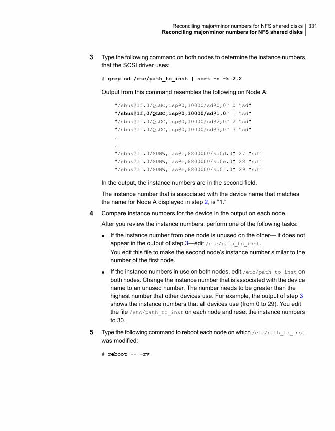
3 Type the following command on both nodes to determine the instance numbersthat the SCSI driver uses:
# grep sd /etc/path_to_inst | sort -n -k 2,2
Output from this command resembles the following on Node A:
"/sbus@1f,0/QLGC,isp@0,10000/sd@0,0" 0 "sd"
"/sbus@1f,0/QLGC,isp@0,10000/sd@1,0" 1 "sd"
"/sbus@1f,0/QLGC,isp@0,10000/sd@2,0" 2 "sd"
"/sbus@1f,0/QLGC,isp@0,10000/sd@3,0" 3 "sd"
.
.
"/sbus@1f,0/SUNW,fas@e,8800000/sd@d,0" 27 "sd"
"/sbus@1f,0/SUNW,fas@e,8800000/sd@e,0" 28 "sd"
"/sbus@1f,0/SUNW,fas@e,8800000/sd@f,0" 29 "sd"
In the output, the instance numbers are in the second field.
The instance number that is associated with the device name that matchesthe name for Node A displayed in step 2, is "1."
4 Compare instance numbers for the device in the output on each node.
After you review the instance numbers, perform one of the following tasks:
■ If the instance number from one node is unused on the other— it does notappear in the output of step 3—edit /etc/path_to_inst.You edit this file to make the second node’s instance number similar to thenumber of the first node.
■ If the instance numbers in use on both nodes, edit /etc/path_to_inst onboth nodes. Change the instance number that is associated with the devicename to an unused number. The number needs to be greater than thehighest number that other devices use. For example, the output of step 3shows the instance numbers that all devices use (from 0 to 29). You editthe file /etc/path_to_inst on each node and reset the instance numbersto 30.
5 Type the following command to reboot each node on which /etc/path_to_inst
was modified:
# reboot -- -rv
331Reconciling major/minor numbers for NFS shared disksReconciling major/minor numbers for NFS shared disks
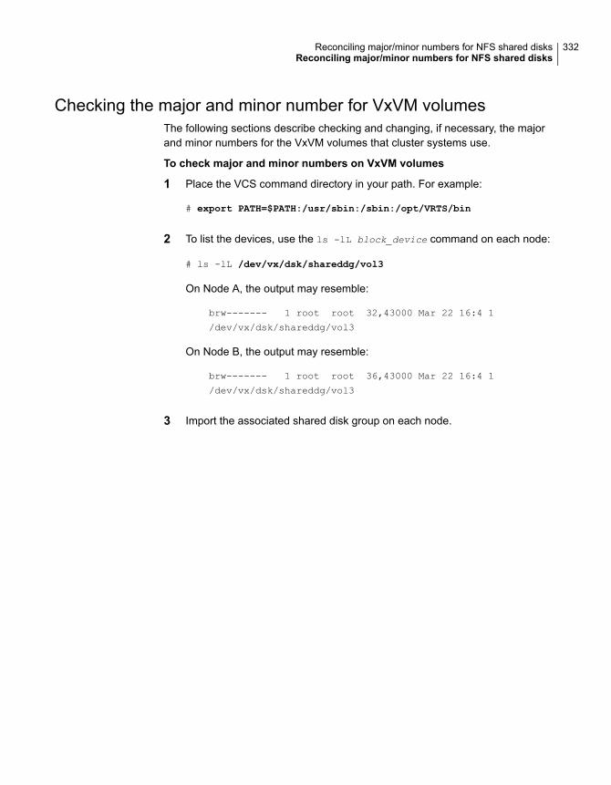
Checking the major and minor number for VxVM volumesThe following sections describe checking and changing, if necessary, the majorand minor numbers for the VxVM volumes that cluster systems use.
To check major and minor numbers on VxVM volumes
1 Place the VCS command directory in your path. For example:
# export PATH=$PATH:/usr/sbin:/sbin:/opt/VRTS/bin
2 To list the devices, use the ls -lL block_device command on each node:
# ls -lL /dev/vx/dsk/shareddg/vol3
On Node A, the output may resemble:
brw------- 1 root root 32,43000 Mar 22 16:4 1
/dev/vx/dsk/shareddg/vol3
On Node B, the output may resemble:
brw------- 1 root root 36,43000 Mar 22 16:4 1
/dev/vx/dsk/shareddg/vol3
3 Import the associated shared disk group on each node.
332Reconciling major/minor numbers for NFS shared disksReconciling major/minor numbers for NFS shared disks
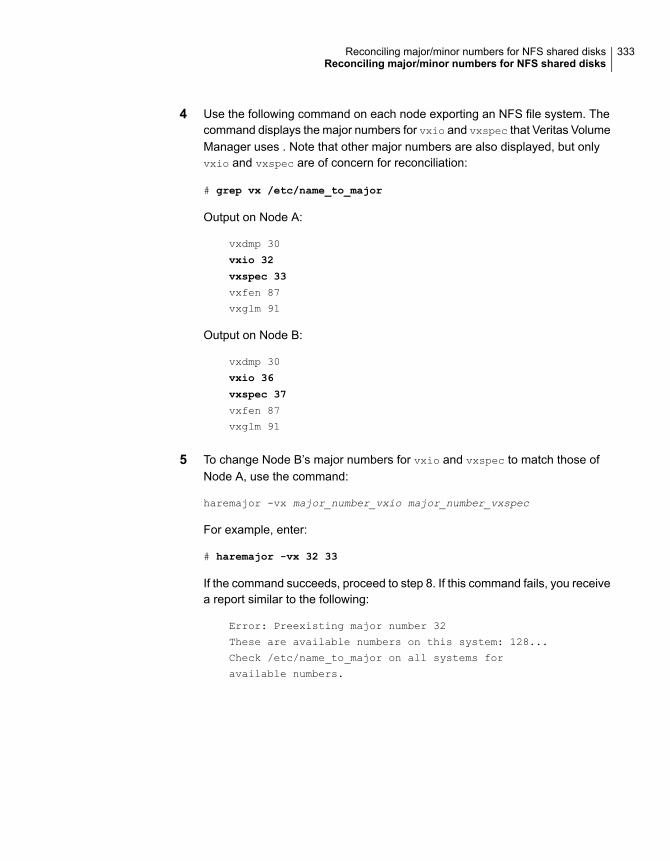
4 Use the following command on each node exporting an NFS file system. Thecommand displays the major numbers for vxio and vxspec that Veritas VolumeManager uses . Note that other major numbers are also displayed, but onlyvxio and vxspec are of concern for reconciliation:
# grep vx /etc/name_to_major
Output on Node A:
vxdmp 30
vxio 32
vxspec 33
vxfen 87
vxglm 91
Output on Node B:
vxdmp 30
vxio 36
vxspec 37
vxfen 87
vxglm 91
5 To change Node B’s major numbers for vxio and vxspec to match those ofNode A, use the command:
haremajor -vx major_number_vxio major_number_vxspec
For example, enter:
# haremajor -vx 32 33
If the command succeeds, proceed to step 8. If this command fails, you receivea report similar to the following:
Error: Preexisting major number 32
These are available numbers on this system: 128...
Check /etc/name_to_major on all systems for
available numbers.
333Reconciling major/minor numbers for NFS shared disksReconciling major/minor numbers for NFS shared disks

6 If you receive this report, use the haremajor command on Node A to changethe major number (32/33) to match that of Node B (36/37). For example, enter:
# haremajor -vx 36 37
If the command fails again, you receive a report similar to the following:
Error: Preexisting major number 36
These are available numbers on this node: 126...
Check /etc/name_to_major on all systems for
available numbers.
7 If you receive the second report, choose the larger of the two available numbers(in this example, 128). Use this number in the haremajor command to reconcilethe major numbers. Type the following command on both nodes:
# haremajor -vx 128 129
8 Reboot each node on which haremajor was successful.
9 If the minor numbers match, proceed to reconcile the major and minor numbersof your next NFS block device.
10 If the block device on which the minor number does not match is a volume,consult the vxdg(1M) manual page. The manual page provides instructions onreconciling the Veritas Volume Manager minor numbers, and gives specificreference to the reminor option.
Node where the vxio driver number have been changed require rebooting.
334Reconciling major/minor numbers for NFS shared disksReconciling major/minor numbers for NFS shared disks
Configuring LLT over UDPThis appendix includes the following topics:
■ Using the UDP layer for LLT
■ Manually configuring LLT over UDP using IPv4
■ Using the UDP layer of IPv6 for LLT
■ Manually configuring LLT over UDP using IPv6
Using the UDP layer for LLTSFHA provides the option of using LLT over the UDP (User Datagram Protocol)layer for clusters using wide-area networks and routers. UDP makes LLT packetsroutable and thus able to span longer distances more economically.
When to use LLT over UDPUse LLT over UDP in the following situations:
■ LLT must be used over WANs
■ When hardware, such as blade servers, do not support LLT over Ethernet
LLT over UDP is slower than LLT over Ethernet. Use LLT over UDP only when thehardware configuration makes it necessary.
Manually configuring LLT over UDP using IPv4The following checklist is to configure LLT over UDP:
■ Make sure that the LLT private links are on separate subnets. Set the broadcastaddress in /etc/llttab explicitly depending on the subnet for each link.
GAppendix
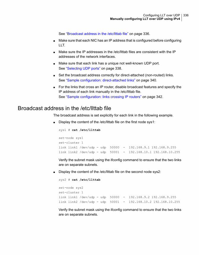
See “Broadcast address in the /etc/llttab file” on page 336.
■ Make sure that each NIC has an IP address that is configured before configuringLLT.
■ Make sure the IP addresses in the /etc/llttab files are consistent with the IPaddresses of the network interfaces.
■ Make sure that each link has a unique not well-known UDP port.See “Selecting UDP ports” on page 338.
■ Set the broadcast address correctly for direct-attached (non-routed) links.See “Sample configuration: direct-attached links” on page 340.
■ For the links that cross an IP router, disable broadcast features and specify theIP address of each link manually in the /etc/llttab file.See “Sample configuration: links crossing IP routers” on page 342.
Broadcast address in the /etc/llttab fileThe broadcast address is set explicitly for each link in the following example.
■ Display the content of the /etc/llttab file on the first node sys1:
sys1 # cat /etc/llttab
set-node sys1
set-cluster 1
link link1 /dev/udp - udp 50000 - 192.168.9.1 192.168.9.255
link link2 /dev/udp - udp 50001 - 192.168.10.1 192.168.10.255
Verify the subnet mask using the ifconfig command to ensure that the two linksare on separate subnets.
■ Display the content of the /etc/llttab file on the second node sys2:
sys2 # cat /etc/llttab
set-node sys2
set-cluster 1
link link1 /dev/udp - udp 50000 - 192.168.9.2 192.168.9.255
link link2 /dev/udp - udp 50001 - 192.168.10.2 192.168.10.255
Verify the subnet mask using the ifconfig command to ensure that the two linksare on separate subnets.
336Configuring LLT over UDPManually configuring LLT over UDP using IPv4
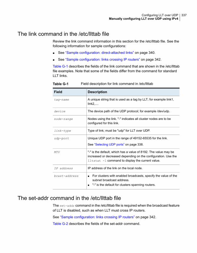
The link command in the /etc/llttab fileReview the link command information in this section for the /etc/llttab file. See thefollowing information for sample configurations:
■ See “Sample configuration: direct-attached links” on page 340.
■ See “Sample configuration: links crossing IP routers” on page 342.
Table G-1 describes the fields of the link command that are shown in the /etc/llttabfile examples. Note that some of the fields differ from the command for standardLLT links.
Table G-1 Field description for link command in /etc/llttab
DescriptionField
A unique string that is used as a tag by LLT; for example link1,link2,....
tag-name
The device path of the UDP protocol; for example /dev/udp.device
Nodes using the link. "-" indicates all cluster nodes are to beconfigured for this link.
node-range
Type of link; must be "udp" for LLT over UDP.link-type
Unique UDP port in the range of 49152-65535 for the link.
See “Selecting UDP ports” on page 338.
udp-port
"-" is the default, which has a value of 8192. The value may beincreased or decreased depending on the configuration. Use thelltstat -l command to display the current value.
MTU
IP address of the link on the local node.IP address
■ For clusters with enabled broadcasts, specify the value of thesubnet broadcast address.
■ "-" is the default for clusters spanning routers.
bcast-address
The set-addr command in the /etc/llttab fileThe set-addr command in the /etc/llttab file is required when the broadcast featureof LLT is disabled, such as when LLT must cross IP routers.
See “Sample configuration: links crossing IP routers” on page 342.
Table G-2 describes the fields of the set-addr command.
337Configuring LLT over UDPManually configuring LLT over UDP using IPv4
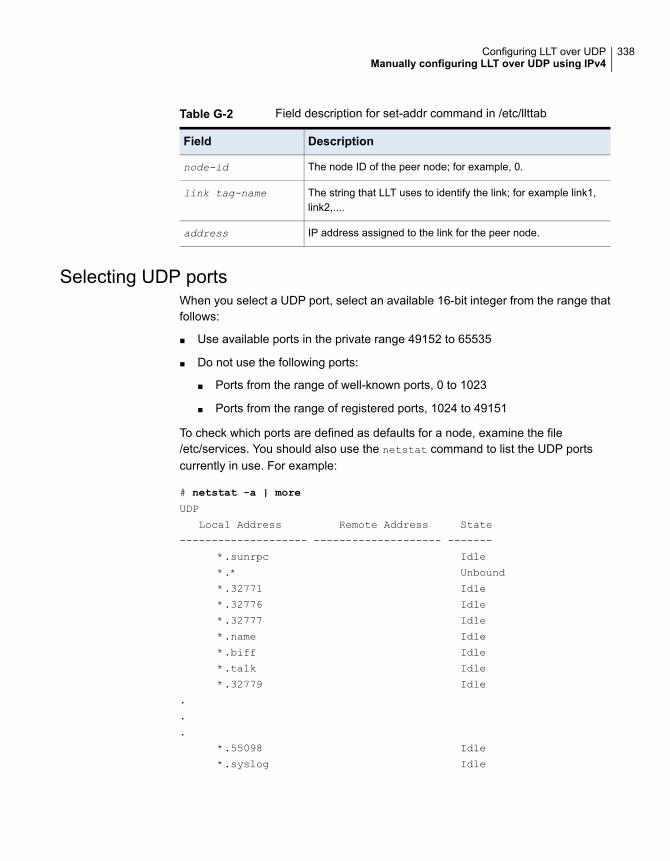
Table G-2 Field description for set-addr command in /etc/llttab
DescriptionField
The node ID of the peer node; for example, 0.node-id
The string that LLT uses to identify the link; for example link1,link2,....
link tag-name
IP address assigned to the link for the peer node.address
Selecting UDP portsWhen you select a UDP port, select an available 16-bit integer from the range thatfollows:
■ Use available ports in the private range 49152 to 65535
■ Do not use the following ports:
■ Ports from the range of well-known ports, 0 to 1023
■ Ports from the range of registered ports, 1024 to 49151
To check which ports are defined as defaults for a node, examine the file/etc/services. You should also use the netstat command to list the UDP portscurrently in use. For example:
# netstat -a | more
UDP
Local Address Remote Address State
-------------------- -------------------- -------
*.sunrpc Idle
*.* Unbound
*.32771 Idle
*.32776 Idle
*.32777 Idle
*.name Idle
*.biff Idle
*.talk Idle
*.32779 Idle
.
.
.
*.55098 Idle
*.syslog Idle
338Configuring LLT over UDPManually configuring LLT over UDP using IPv4
*.58702 Idle
*.* Unbound
Look in the UDP section of the output; the UDP ports that are listed under LocalAddress are already in use. If a port is listed in the /etc/services file, its associatedname is displayed rather than the port number in the output.
Configuring the netmask for LLTFor nodes on different subnets, set the netmask so that the nodes can access thesubnets in use. Run the following command and answer the prompt to set thenetmask:
# ifconfig interface_name netmask netmask
For example:
■ For the first network interface on the node sys1:
IP address=192.168.9.1, Broadcast address=192.168.9.255,
Netmask=255.255.255.0
For the first network interface on the node sys2:
IP address=192.168.9.2, Broadcast address=192.168.9.255,
Netmask=255.255.255.0
■ For the second network interface on the node sys1:
IP address=192.168.10.1, Broadcast address=192.168.10.255,
Netmask=255.255.255.0
For the second network interface on the node sys2:
IP address=192.168.10.2, Broadcast address=192.168.10.255,
Netmask=255.255.255.0
Configuring the broadcast address for LLTFor nodes on different subnets, set the broadcast address in /etc/llttab dependingon the subnet that the links are on.
An example of a typical /etc/llttab file when nodes are on different subnets. Notethe explicitly set broadcast address for each link.
339Configuring LLT over UDPManually configuring LLT over UDP using IPv4
# cat /etc/llttab
set-node nodexyz
set-cluster 100
link link1 /dev/udp - udp 50000 - 192.168.30.1 192.168.30.255
link link2 /dev/udp - udp 50001 - 192.168.31.1 192.168.31.255
Sample configuration: direct-attached linksFigure G-1 depicts a typical configuration of direct-attached links employing LLTover UDP.
340Configuring LLT over UDPManually configuring LLT over UDP using IPv4
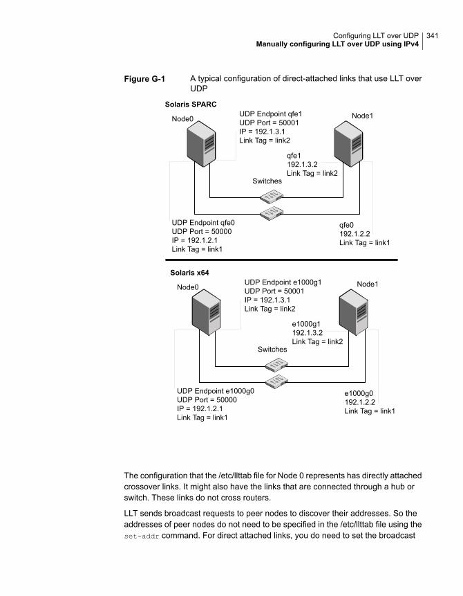
Figure G-1 A typical configuration of direct-attached links that use LLT overUDP
UDP Endpoint qfe1UDP Port = 50001IP = 192.1.3.1Link Tag = link2
UDP Endpoint qfe0UDP Port = 50000IP = 192.1.2.1Link Tag = link1
qfe1192.1.3.2Link Tag = link2
qfe0192.1.2.2Link Tag = link1
Switches
Node0 Node1Solaris SPARC
Solaris x64UDP Endpoint e1000g1UDP Port = 50001IP = 192.1.3.1Link Tag = link2
UDP Endpoint e1000g0UDP Port = 50000IP = 192.1.2.1Link Tag = link1
e1000g1192.1.3.2Link Tag = link2
e1000g0192.1.2.2Link Tag = link1
Switches
Node0 Node1
The configuration that the /etc/llttab file for Node 0 represents has directly attachedcrossover links. It might also have the links that are connected through a hub orswitch. These links do not cross routers.
LLT sends broadcast requests to peer nodes to discover their addresses. So theaddresses of peer nodes do not need to be specified in the /etc/llttab file using theset-addr command. For direct attached links, you do need to set the broadcast
341Configuring LLT over UDPManually configuring LLT over UDP using IPv4
address of the links in the /etc/llttab file. Verify that the IP addresses and broadcastaddresses are set correctly by using the ifconfig -a command.
set-node Node0
set-cluster 1
#configure Links
#link tag-name device node-range link-type udp port MTU \
IP-address bcast-address
link link1 /dev/udp - udp 50000 - 192.1.2.1 192.1.2.255
link link2 /dev/udp - udp 50001 - 192.1.3.1 192.1.3.255
The file for Node 1 resembles:
set-node Node1
set-cluster 1
#configure Links
#link tag-name device node-range link-type udp port MTU \
IP-address bcast-address
link link1 /dev/udp - udp 50000 - 192.1.2.2 192.1.2.255
link link2 /dev/udp - udp 50001 - 192.1.3.2 192.1.3.255
Sample configuration: links crossing IP routersFigure G-2 depicts a typical configuration of links crossing an IP router employingLLT over UDP. The illustration shows two nodes of a four-node cluster.
342Configuring LLT over UDPManually configuring LLT over UDP using IPv4
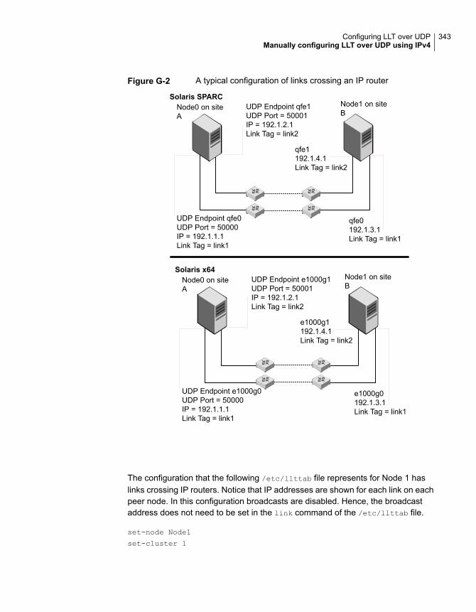
Figure G-2 A typical configuration of links crossing an IP router
UDP Endpoint qfe1UDP Port = 50001IP = 192.1.2.1Link Tag = link2
UDP Endpoint qfe0UDP Port = 50000IP = 192.1.1.1Link Tag = link1
qfe1192.1.4.1Link Tag = link2
qfe0192.1.3.1Link Tag = link1
Node0 on siteA
Node1 on siteB
Solaris SPARC
Solaris x64UDP Endpoint e1000g1UDP Port = 50001IP = 192.1.2.1Link Tag = link2
UDP Endpoint e1000g0UDP Port = 50000IP = 192.1.1.1Link Tag = link1
e1000g1192.1.4.1Link Tag = link2
e1000g0192.1.3.1Link Tag = link1
Node0 on siteA
Node1 on siteB
The configuration that the following /etc/llttab file represents for Node 1 haslinks crossing IP routers. Notice that IP addresses are shown for each link on eachpeer node. In this configuration broadcasts are disabled. Hence, the broadcastaddress does not need to be set in the link command of the /etc/llttab file.
set-node Node1
set-cluster 1
343Configuring LLT over UDPManually configuring LLT over UDP using IPv4
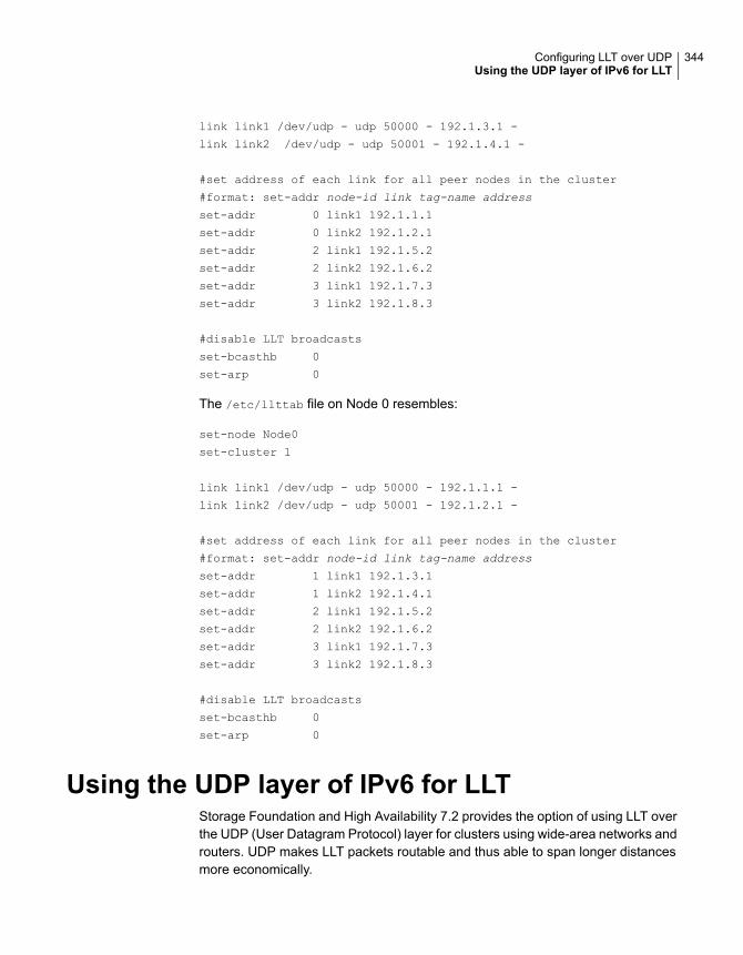
link link1 /dev/udp - udp 50000 - 192.1.3.1 -
link link2 /dev/udp - udp 50001 - 192.1.4.1 -
#set address of each link for all peer nodes in the cluster
#format: set-addr node-id link tag-name address
set-addr 0 link1 192.1.1.1
set-addr 0 link2 192.1.2.1
set-addr 2 link1 192.1.5.2
set-addr 2 link2 192.1.6.2
set-addr 3 link1 192.1.7.3
set-addr 3 link2 192.1.8.3
#disable LLT broadcasts
set-bcasthb 0
set-arp 0
The /etc/llttab file on Node 0 resembles:
set-node Node0
set-cluster 1
link link1 /dev/udp - udp 50000 - 192.1.1.1 -
link link2 /dev/udp - udp 50001 - 192.1.2.1 -
#set address of each link for all peer nodes in the cluster
#format: set-addr node-id link tag-name address
set-addr 1 link1 192.1.3.1
set-addr 1 link2 192.1.4.1
set-addr 2 link1 192.1.5.2
set-addr 2 link2 192.1.6.2
set-addr 3 link1 192.1.7.3
set-addr 3 link2 192.1.8.3
#disable LLT broadcasts
set-bcasthb 0
set-arp 0
Using the UDP layer of IPv6 for LLTStorage Foundation and High Availability 7.2 provides the option of using LLT overthe UDP (User Datagram Protocol) layer for clusters using wide-area networks androuters. UDP makes LLT packets routable and thus able to span longer distancesmore economically.
344Configuring LLT over UDPUsing the UDP layer of IPv6 for LLT

When to use LLT over UDPUse LLT over UDP in the following situations:
■ LLT must be used over WANs
■ When hardware, such as blade servers, do not support LLT over Ethernet
Manually configuring LLT over UDP using IPv6The following checklist is to configure LLT over UDP:
■ For UDP6, the multicast address is set to "-".
■ Make sure that each NIC has an IPv6 address that is configured beforeconfiguring LLT.
■ Make sure the IPv6 addresses in the /etc/llttab files are consistent with the IPv6addresses of the network interfaces.
■ Make sure that each link has a unique not well-known UDP port.
■ For the links that cross an IP router, disable multicast features and specify theIPv6 address of each link manually in the /etc/llttab file.See “Sample configuration: links crossing IP routers” on page 347.
Sample configuration: direct-attached linksFigure G-3 depicts a typical configuration of direct-attached links employing LLTover UDP.
345Configuring LLT over UDPManually configuring LLT over UDP using IPv6

Figure G-3 A typical configuration of direct-attached links that use LLT overUDP
UDP Port = 50001IP = fe80::21a:64ff:fe92:1b47Link Tag = link2
UDP Port = 50000IP = fe80::21a:64ff:fe92:1b46Link Tag = link1
fe80::21a:64ff:fe92:1a93Link Tag = link2
fe80::21a:64ff:fe92:1a92Link Tag = link1
Switches
Node0 Node1Solaris SPARC
Solaris x64
UDP Port = 50001IP = fe80::21a:64ff:fe92:1b47Link Tag = link2
UDP Port = 50000IP = fe80::21a:64ff:fe92:1b46Link Tag = link1
fe80::21a:64ff:fe92:1a93Link Tag = link2
fe80::21a:64ff:fe92:1a92Link Tag = link1
Switches
Node0 Node1
The configuration that the /etc/llttab file for Node 0 represents has directly attachedcrossover links. It might also have the links that are connected through a hub orswitch. These links do not cross routers.
LLT uses IPv6 multicast requests for peer node address discovery. So the addressesof peer nodes do not need to be specified in the /etc/llttab file using the set-addr
command. Use the ifconfig -a command to verify that the IPv6 address is setcorrectly.
set-node Node0
set-cluster 1
346Configuring LLT over UDPManually configuring LLT over UDP using IPv6
#configure Links
#link tag-name device node-range link-type udp port MTU \
IP-address mcast-address
link link1 /dev/udp6 - udp6 50000 - fe80::21a:64ff:fe92:1b46 -
link link1 /dev/udp6 - udp6 50001 - fe80::21a:64ff:fe92:1b47 -
The file for Node 1 resembles:
set-node Node1
set-cluster 1
#configure Links
#link tag-name device node-range link-type udp port MTU \
IP-address mcast-address
link link1 /dev/udp6 - udp6 50000 - fe80::21a:64ff:fe92:1a92 -
link link1 /dev/udp6 - udp6 50001 - fe80::21a:64ff:fe92:1a93 -
Sample configuration: links crossing IP routersFigure G-4 depicts a typical configuration of links crossing an IP router employingLLT over UDP. The illustration shows two nodes of a four-node cluster.
347Configuring LLT over UDPManually configuring LLT over UDP using IPv6
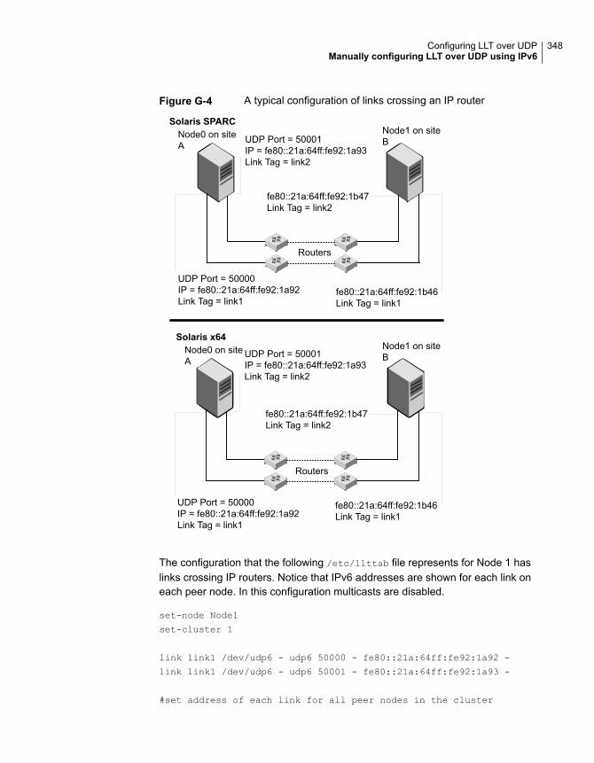
Figure G-4 A typical configuration of links crossing an IP router
UDP Port = 50001IP = fe80::21a:64ff:fe92:1a93Link Tag = link2
UDP Port = 50000IP = fe80::21a:64ff:fe92:1a92Link Tag = link1
fe80::21a:64ff:fe92:1b47Link Tag = link2
fe80::21a:64ff:fe92:1b46Link Tag = link1
Node0 on siteA
Node1 on siteB
Solaris SPARC
Solaris x64
UDP Port = 50001IP = fe80::21a:64ff:fe92:1a93Link Tag = link2
UDP Port = 50000IP = fe80::21a:64ff:fe92:1a92Link Tag = link1
fe80::21a:64ff:fe92:1b47Link Tag = link2
fe80::21a:64ff:fe92:1b46Link Tag = link1
Node0 on siteA
Node1 on siteB
Routers
Routers
The configuration that the following /etc/llttab file represents for Node 1 haslinks crossing IP routers. Notice that IPv6 addresses are shown for each link oneach peer node. In this configuration multicasts are disabled.
set-node Node1
set-cluster 1
link link1 /dev/udp6 - udp6 50000 - fe80::21a:64ff:fe92:1a92 -
link link1 /dev/udp6 - udp6 50001 - fe80::21a:64ff:fe92:1a93 -
#set address of each link for all peer nodes in the cluster
348Configuring LLT over UDPManually configuring LLT over UDP using IPv6
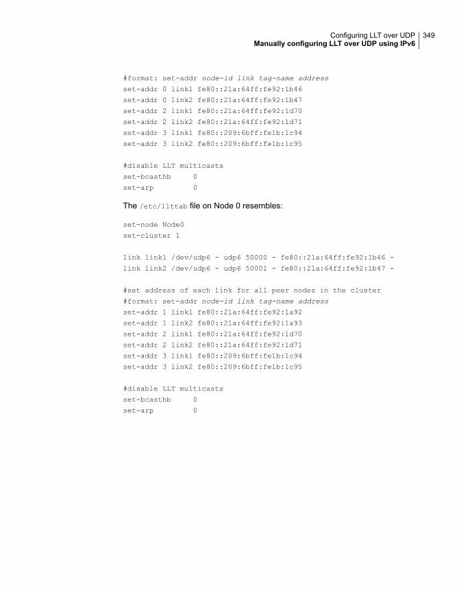
#format: set-addr node-id link tag-name address
set-addr 0 link1 fe80::21a:64ff:fe92:1b46
set-addr 0 link2 fe80::21a:64ff:fe92:1b47
set-addr 2 link1 fe80::21a:64ff:fe92:1d70
set-addr 2 link2 fe80::21a:64ff:fe92:1d71
set-addr 3 link1 fe80::209:6bff:fe1b:1c94
set-addr 3 link2 fe80::209:6bff:fe1b:1c95
#disable LLT multicasts
set-bcasthb 0
set-arp 0
The /etc/llttab file on Node 0 resembles:
set-node Node0
set-cluster 1
link link1 /dev/udp6 - udp6 50000 - fe80::21a:64ff:fe92:1b46 -
link link2 /dev/udp6 - udp6 50001 - fe80::21a:64ff:fe92:1b47 -
#set address of each link for all peer nodes in the cluster
#format: set-addr node-id link tag-name address
set-addr 1 link1 fe80::21a:64ff:fe92:1a92
set-addr 1 link2 fe80::21a:64ff:fe92:1a93
set-addr 2 link1 fe80::21a:64ff:fe92:1d70
set-addr 2 link2 fe80::21a:64ff:fe92:1d71
set-addr 3 link1 fe80::209:6bff:fe1b:1c94
set-addr 3 link2 fe80::209:6bff:fe1b:1c95
#disable LLT multicasts
set-bcasthb 0
set-arp 0
349Configuring LLT over UDPManually configuring LLT over UDP using IPv6
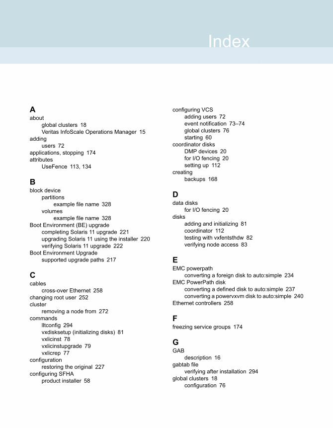
Aabout
global clusters 18Veritas InfoScale Operations Manager 15
addingusers 72
applications, stopping 174attributes
UseFence 113, 134
Bblock device
partitionsexample file name 328
volumesexample file name 328
Boot Environment (BE) upgradecompleting Solaris 11 upgrade 221upgrading Solaris 11 using the installer 220verifying Solaris 11 upgrade 222
Boot Environment Upgradesupported upgrade paths 217
Ccables
cross-over Ethernet 258changing root user 252cluster
removing a node from 272commands
lltconfig 294vxdisksetup (initializing disks) 81vxlicinst 78vxlicinstupgrade 79vxlicrep 77
configurationrestoring the original 227
configuring SFHAproduct installer 58
configuring VCSadding users 72event notification 73–74global clusters 76starting 60
coordinator disksDMP devices 20for I/O fencing 20setting up 112
creatingbackups 168
Ddata disks
for I/O fencing 20disks
adding and initializing 81coordinator 112testing with vxfentsthdw 82verifying node access 83
EEMC powerpath
converting a foreign disk to auto:simple 234EMC PowerPath disk
converting a defined disk to auto:simple 237converting a powervxvm disk to auto:simple 240
Ethernet controllers 258
Ffreezing service groups 174
GGAB
description 16gabtab file
verifying after installation 294global clusters 18
configuration 76
Index

Hhubs
independent 258
II/O fencing
checking disks 82setting up 110shared storage 82
I/O fencing requirementsnon-SCSI-3 27
Install Bundlesintegration options 177
installation script options 283installing
language packages 253post 76
Llicense keys
adding with vxlicinstupgrade 78replacing demo key 79
licensesinformation about 77
linksprivate network 294
Live Upgradeadministering boot environment in Solaris 11 222creating new Solaris 11 boot environment
(BE) 219VVR environment 224
LLTdescription 16
lltconfig command 294llthosts file
verifying after installation 294llttab file
verifying after installation 294localized environment settings for using VVR
settings for uisng VVR in a localizedenvironment 171
Mmain.cf file
contents after installation 298main.cf files 304major and minor numbers
checking 329, 332
major and minor numbers (continued)shared devices 328
NNFS services
shared storage 328nodes
adding application nodesconfiguring GAB 264configuring LLT 264configuring VXFEN 264starting Volume Manager 263
non-SCSI-3 fencingmanual configuration 128setting up 128
non-SCSI-3 I/O fencingrequirements 27
non-SCSI3 fencingsetting up 103using installer 103
Ooriginal configuration
restoring the 227
Pphased 194phased upgrade 194, 196
example 195planning to upgrade VVR 169post-upgrade
adding JBOD support 232unsuppressing DMP for EMC PowerPath
disks 233updating variables 232upgrading the array support library 232verifying 250
preinstallation 169preparing to upgrade 165preparing to upgrade VVR 174product installer
SFHA configuration overview 58
Rremoving a system from a cluster 272response files
upgrading 211restoring the original configuration 227
351Index
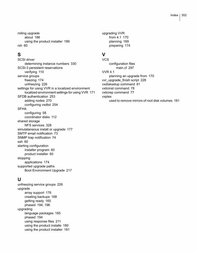
rolling upgradeabout 186using the product installer 189
rsh 60
SSCSI driver
determining instance numbers 330SCSI-3 persistent reservations
verifying 110service groups
freezing 174unfreezing 226
settings for uisng VVR in a localized environmentlocalized environment settings for using VVR 171
SFDB authentication 253adding nodes 270configuring vxdbd 254
SFHAconfiguring 58coordinator disks 112
shared storageNFS services 328
simulataneous install or upgrade 177SMTP email notification 73SNMP trap notification 74ssh 60starting configuration
installer program 60product installer 60
stoppingapplications 174
supported upgrade pathsBoot Environment Upgrade 217
Uunfreezing service groups 226upgrade
array support 176creating backups 168getting ready 165phased 194, 196
upgradinglanguage packages 185phased 194using response files 211using the product installe 180using the product installer 181
upgrading VVRfrom 4.1 170planning 169preparing 174
VVCS
configuration filesmain.cf 297
VVR 4.1planning an upgrade from 170
vvr_upgrade_finish script 228vxdisksetup command 81vxlicinst command 78vxlicrep command 77vxplex
used to remove mirrors of root disk volumes 181
352Index