communication configuration tool
TRANSCRIPT
© Copyright 2014 - 2016 Softing Industrial Automation GmbH
User Guide
Version: VCM-YY-097701-EN-072016-2.20
Communication ConfigurationTool

The information contained in these instructions corresponds to the technical status at the time of printing of it and is passed on with thebest of our knowledge. The information in these instructions is in no event a basis for warranty claims or contractual agreementsconcerning the described products, and may especially not be deemed as warranty concerning the quality and durability pursuant to Sec.443 German Civil Code. We reserve the right to make any alterations or improvements to these instructions without prior notice. Theactual design of products may deviate from the information contained in the instructions if technical alterations and productimprovements so require.
It may not, in part or in its entirety, be reproduced, copied, or transferred into electronic media.
Disclaimer of liability
Softing Industrial Automation GmbH
Richard-Reitzner-Allee 685540 Haar / Germanyhttp://industrial.softing.com
The latest version of this manual is available in the Softing download area at: http://industrial.softing.com/en/downloads.html
+ 49 89 4 56 56-0+ 49 89 4 56 [email protected]@softing.com
Copyright 2016 Softing Industrial Automation GmbH 3
Table of Contents
Table of Contents
Chapter 1 ...................................................................................... 7Introduction
............................................................................................................... 71.1 About the Communication Configuration Tool
............................................................................................................... 71.2 Scope of delivery
............................................................................................................... 81.3 Additionally required components for FOUNDATION fieldbus H1 devices
............................................................................................................... 91.4 Product history
............................................................................................................... 91.5 Licensing
............................................................................................................... 91.6 Supported operating systems
............................................................................................................... 101.7 Reference to trademarks
............................................................................................................... 101.8 Document history
............................................................................................................... 101.9 About this document
............................................................................................................... 101.10 Conventions used
Chapter 2 ...................................................................................... 12Introduction to PROFINET
............................................................................................................... 122.1 Organization and specifications
............................................................................................................... 122.2 System model
............................................................................................................... 132.3 Device model
............................................................................................................... 142.4 I/O data exchange
............................................................................................................... 142.5 Acyclic data exchange
............................................................................................................... 142.6 Device description
............................................................................................................... 162.7 PROFINET mapping in the Communication Configuration Tool
Chapter 3 ...................................................................................... 17Introduction to FOUNDATION fieldbus
Chapter 4 ...................................................................................... 20Graphical user interface
............................................................................................................... 204.1 General functionality
.......................................................................................................... 20Main window functionality 4.1.1
.......................................................................................................... 21Main window buttons 4.1.2
.......................................................................................................... 22Filtering (precedence filter) 4.1.3
.......................................................................................................... 25Configuring a project 4.1.4
............................................................................................................... 264.2 Live list view
.......................................................................................................... 27Live list view (FOUNDATION fieldbus) 4.2.1
.......................................................................................................... 29Live list view (PROFINET) 4.2.2
.......................................................................................................... 31Live list view buttons 4.2.3
..................................................................................................... 31Live list scanning4.2.3.1
..................................................................................................... 31Filter and matching4.2.3.2
..................................................................................................... 34Assignment4.2.3.3
.......................................................................................................... 35Online Maintenance view 4.2.4
Copyright 2016 Softing Industrial Automation GmbH
Table of Contents
4
..................................................................................................... 35Online Maintenance view (FOUNDATION fieldbus)4.2.4.1
..................................................................................................... 41Online Maintenance view (PROFINET)4.2.4.2
............................................................................................................... 434.3 Topology view
.......................................................................................................... 46Topology view (FOUNDATION Fieldbus) 4.3.1
.......................................................................................................... 46Topology view (PROFINET) 4.3.2
.......................................................................................................... 46Topology status icons (PROFINET only) 4.3.3
............................................................................................................... 474.4 Project Explorer view
............................................................................................................... 474.5 Function block application view (FOUNDATION fieldbus only)
.......................................................................................................... 48Function block application view buttons and status icons 4.5.1
.......................................................................................................... 49Function block application view shortcut keys 4.5.2
.......................................................................................................... 49Function block properties in property view 4.5.3
.......................................................................................................... 50Use function blocks 4.5.4
..................................................................................................... 50Add function blocks to the function block application4.5.4.1
..................................................................................................... 52Function block association4.5.4.2
................................................................................................................................. 53Remove association4.5.4.2.1
................................................................................................................................. 53Establish association4.5.4.2.2
..................................................................................................... 54Operations with a used function block in the function block application4.5.4.3
..................................................................................................... 54Locate a used function block in the function block application4.5.4.4
..................................................................................................... 54Remove a used function block from the function block application4.5.4.5
..................................................................................................... 56Multiple selection in the diagram editor4.5.4.6
.......................................................................................................... 56Connections 4.5.5
..................................................................................................... 56Establish a connection4.5.5.1
..................................................................................................... 58Remove a connection4.5.5.2
..................................................................................................... 59Connection properties4.5.5.3
............................................................................................................... 594.6 Instances view
.......................................................................................................... 60Instances view (FOUNDATION Fieldbus) 4.6.1
.......................................................................................................... 64Instances view (PROFINET) 4.6.2
............................................................................................................... 644.7 Device types view
.......................................................................................................... 65Device types view functionality 4.7.1
.......................................................................................................... 65Device types view buttons 4.7.2
.......................................................................................................... 66Device types filtering 4.7.3
............................................................................................................... 674.8 Type Catalog Maintenance view
.......................................................................................................... 68Type Catalog Maintenance view functionality 4.8.1
.......................................................................................................... 69Type Catalog Maintenance buttons 4.8.2
............................................................................................................... 694.9 Templates view (FOUNDATION fieldbus only)
.......................................................................................................... 70Templates view functionality 4.9.1
.......................................................................................................... 74Templates view buttons and elements 4.9.2
.......................................................................................................... 76Templates properties in templates view 4.9.3
Copyright 2016 Softing Industrial Automation GmbH 5
Table of Contents
............................................................................................................... 764.10 Message log view
.......................................................................................................... 76Message log view functionality 4.10.1
.......................................................................................................... 77Message log view buttons 4.10.2
............................................................................................................... 784.11 Properties view
.......................................................................................................... 78Segment properties view 4.11.1
..................................................................................................... 79Segment properties view (FOUNDATION fieldbus - FF H1)4.11.1.1
..................................................................................................... 84Segment properties view (FOUNDATION fieldbus - FF HSE)4.11.1.2
..................................................................................................... 85Segment properties view (PROFINET)4.11.1.3
.......................................................................................................... 85Device properties view 4.11.2
..................................................................................................... 85Device properties view (FOUNDATION fieldbus - FF H1)4.11.2.1
..................................................................................................... 87Device properties view (FOUNDATION fieldbus - FF HSE)4.11.2.2
..................................................................................................... 92Controller and device properties view (PROFINET)4.11.2.3
.......................................................................................................... 95Properties view buttons 4.11.3
............................................................................................................... 954.12 Segment Management
.......................................................................................................... 96Segment Management functionality 4.12.1
.......................................................................................................... 97Segment Management buttons 4.12.2
............................................................................................................... 974.13 Network Access Profiles
.......................................................................................................... 97Network Access Profiles (FOUNDATION Fieldbus - FF H1) 4.13.1
.......................................................................................................... 100Network Access Profiles (FOUNDATION Fieldbus - FF HSE) 4.13.2
.......................................................................................................... 100Network Access Profiles (PROFINET) 4.13.3
............................................................................................................... 1014.14 Module Management (PROFINET only)
.......................................................................................................... 102Module Management view functionality (PROFINET only) 4.14.1
.......................................................................................................... 102Module Management buttons (PROFINET only) 4.14.2
............................................................................................................... 1034.15 Edit parameters
.......................................................................................................... 103Edit device parameters (FOUNDATION fieldbus) 4.15.1
.......................................................................................................... 104Edit configuration parameters (FOUNDATION fieldbus) 4.15.2
.......................................................................................................... 106Edit configuration parameters (PROFINET) 4.15.3
............................................................................................................... 1074.16 New Project window
............................................................................................................... 1084.17 Open Project window
............................................................................................................... 1094.18 Save Project As window
............................................................................................................... 1094.19 Delete Project window
............................................................................................................... 1104.20 Settings window
.......................................................................................................... 110Common settings 4.20.1
.......................................................................................................... 111FF Settings 4.20.2
............................................................................................................... 1124.21 Project Properties window
............................................................................................................... 1124.22 Views window
Chapter 5 ...................................................................................... 113Menu items
............................................................................................................... 1135.1 File menu
Copyright 2016 Softing Industrial Automation GmbH
Table of Contents
6
............................................................................................................... 1135.2 Edit menu
............................................................................................................... 1135.3 View menu
............................................................................................................... 1145.4 Project menu
............................................................................................................... 1155.5 Options menu
............................................................................................................... 1155.6 Window menu
............................................................................................................... 1155.7 Help menu
Chapter 6 ...................................................................................... 117Tutorials
............................................................................................................... 1176.1 How to define the configurator's interface to the network
............................................................................................................... 1176.2 How to define the network topology (PROFINET only)
............................................................................................................... 1186.3 How to assign a device name or PD tag
.......................................................................................................... 118How to assign a PD tag (FOUNDATION fieldbus) 6.3.1
.......................................................................................................... 119How to assign a device name (PROFINET) 6.3.2
............................................................................................................... 1206.4 How to define IP addresses (PROFINET only)
............................................................................................................... 1206.5 How to define modules and parameters (PROFINET only)
............................................................................................................... 1226.6 How to represent a switch without PROFINET functionality in the
topology view (PROFINET only)
............................................................................................................... 1226.7 How to transmit the device name to a PROFINET device (PROFINET only)
............................................................................................................... 1236.8 How to match live list devices to instances in the topology view?
.......................................................................................................... 123Automatic assignment (FOUNDATION fieldbus) 6.8.1
.......................................................................................................... 124Automatic assignment (PROFINET) 6.8.2
............................................................................................................... 1256.9 How to check, compile and download the configuration to the target
device
............................................................................................................... 1266.10 Softing controller on Windows PC communicating with Softing device on
another Windows PC (PROFINET only)
............................................................................................................... 1276.11 Softing controller running on RTEM (PROFINET only)
............................................................................................................... 1286.12 How to configure parameters for Modbus access
Chapter 7 ...................................................................................... 131Frequently asked questions
............................................................................................................... 1317.1 There are more connections targeted at slot 0 than ports available on
the plugged module (PROFINET only)
............................................................................................................... 1317.2 A symbol for an incorrect entry appears
............................................................................................................... 1327.3 A device cannot be assigned to any instance (PROFINET only)
............................................................................................................... 1327.4 An FF device is connected but not displayed in the Live List
(FOUNDATION fieldbus only)
............................................................................................................... 1337.5 An FF device is connected but the live list displays this device with device
type zero (FOUNDATION fieldbus only)
Chapter 8 ...................................................................................... 134Glossary of terms
Index ................................................................................................................ 141
Chapter 1 - Introduction
Copyright 2016 Softing Industrial Automation GmbH 7
1 Introduction
1.1 About the Communication Configuration Tool
The Communication Configuration Tool is a universal Configuration Software for Industrial Ethernet andFieldbus Networks. It allows for easy configuration and commissioning of PROFINET and FOUNDATIONfieldbus networks and is designed for working with Softing products such as Softing Industrial Automation’sPROFINET Controller stack or Softing FOUNDATION fieldbus stacks.
Several functionalities are implemented bus-specifically. You can or read that in the heading indicating therespective bus system or you find bus-specific links in the related content marked with the correspondingbus system logo:
for FOUNDATION fieldbus and for PROFINET.
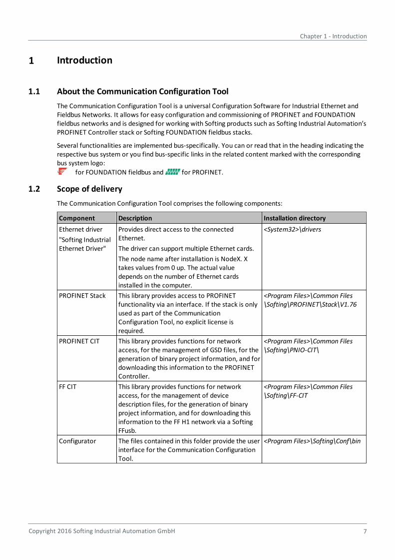
1.2 Scope of delivery
The Communication Configuration Tool comprises the following components:
Component Description Installation directory
Ethernet driver
"Softing IndustrialEthernet Driver"
Provides direct access to the connectedEthernet.
The driver can support multiple Ethernet cards.
The node name after installation is NodeX. Xtakes values from 0 up. The actual valuedepends on the number of Ethernet cardsinstalled in the computer.
<System32>\drivers
PROFINET Stack This library provides access to PROFINETfunctionality via an interface. If the stack is onlyused as part of the CommunicationConfiguration Tool, no explicit license isrequired.
<Program Files>\Common Files\Softing\PROFINET\Stack\V1.76
PROFINET CIT This library provides functions for networkaccess, for the management of GSD files, for thegeneration of binary project information, and fordownloading this information to the PROFINETController.
<Program Files>\Common Files\Softing\PNIO-CIT\
FF CIT This library provides functions for networkaccess, for the management of devicedescription files, for the generation of binaryproject information, and for downloading thisinformation to the FF H1 network via a SoftingFFusb.
<Program Files>\Common Files\Softing\FF-CIT
Configurator The files contained in this folder provide the userinterface for the Communication ConfigurationTool.
<Program Files>\Softing\Conf\bin

Communication Configuration Tool - User Guide
8 Copyright 2016 Softing Industrial Automation GmbH
1.3 Additionally required components for FOUNDATION fieldbus H1 devices
In order to connect to FOUNDATION fieldbus H1 devices you need
a Softing FFusb Interface, order number DUL-KK-020302. This device contains the interface, the driversrequired and the USB cable to connect to a PC.
a power hub. We recommend ordering the Softing Fieldbus Lab kit, order number APL-KL-020601. Itincludes a Relcom F11 labkit, cables, connectors and a power supply:
Note
Make sure the corresponding USB driver for the FFusb has been installed correctly from theSetup CD-ROM.

Chapter 1 - Introduction
Copyright 2016 Softing Industrial Automation GmbH 9
1.4 Product history
Product version Modifications compared to previous version
Initial version none
1.11 Support of DAPs in slots other than 0
Support of device-specific realtime classes
Support of Assembly ID conformance"
2.00 Supports the configuration of FOUNDATION™ fieldbus H1 viaSofting FFusb
2.10 New templates functionality for FOUNDATION Fieldbus Templates view (FOUNDATION fieldbus only)
New tab Software Download in Online Maintenance view(FOUNDATION fieldbus) for firmware update ofFOUNDATION fieldbus devices.
Enhanced Trace settings for FOUNDATION Fieldbus in CommonSettings .
New FF Settings tab in Common settings to load and updateFOUNDATION Fieldbus dictionaries.
2.20 FF-HSE functionality implemented
Supporting operating system Windows 10
1.5 Licensing
Apart from the license agreement accepted on installation no separate licensing is required for theCommunication Configuration Tool. The required functionality of the PROFINET Controller Stack islicensed through the Communication Configuration Tool.
For open source licensing refer to http://opensource.softing.com/IA/ComConf/V1.
1.6 Supported operating systems
This version of the Communication Configuration Tool supports the following operating systems:
Operating System Product version Bit system
Windows 7 Professional
Enterprise
Ultimate
32 and 64
32 and 64
32 and 64
Windows 8 Pro
Enterprise
32 and 64
32 and 64
Windows 10 Pro
Enterprise
32 and 64
Note
When working with operating system Windows 10, Communication Configuration Tool doesnot provide the online maintenance functionality for PROFINET (Online Maintenance view(PROFINET) or Live list view (PROFINET) ).
If you try to perform one of the online actions mentioned above, a corresponding errormessage will appear in the Message log view .
69
35
110
111
41 29
76
Communication Configuration Tool - User Guide
10 Copyright 2016 Softing Industrial Automation GmbH
1.7 Reference to trademarks
FOUNDATION Fieldbus is a registered trademark of the Fieldbus Foundation (see http://www.fieldbus.org/index.html)
PROFINET is a trademark of PROFIBUS Nutzerorganisation e.V. (http://www.profibus.com/)
1.8 Document history
Document version Modifications compared to previous version
Initial version none
1.11 New product release 1.11
2.00 New product release 2.00 allowing configuration of FOUNDATIONfieldbus H1 devices, see also Product history .
2.10 New product release 2.10 allowing to use templates forFOUNDATION fieldbus, see also Product history .
2.20 New product release 2.20 supporting FF-HSE functionality andWindows 10 support, see also Product history
1.9 About this document
Read this document before starting
For damages due to improper connection, implementation or operation Softing refuses anyliability according to our existing guarantee obligations.
This document describes in detail how to use the Communication Configuration Tool.
It starts with an Introduction to PROFINET . This chapter also explains how the different PROFINETconcepts are represented in the Communication Configuration Tool. This chapter is followed by an Introduction to FOUNDATION fieldbus .
The next two chapters provide a description of the Graphical user interface and an overview of theMenu items . The Tutorials chapter explains how to perform various tasks using the availablefunctions and features. We recommend reading this chapter before using the CommunicationConfiguration Tool.
At the end of the document, a list of Frequently asked questions is provided.
1.10 Conventions used
The following conventions are used throughout Softing customer documentation:
Keys, buttons, menu items, commands and otherelements involving user interaction are set inbold font and menu sequences are separated byan arrow
Open Start Control Panel Programs
Buttons from the user interface are enclosed inbrackets and set to bold typeface
Press [Start] to start the application
Coding samples, file extracts and screen output isset in Courier font type
MaxDlsapAddressSupported=23
File names and directories are written in italic Device description files are located in C:\<product name>\delivery\software\Device Description files
9
9
9
12
17
20
113 117
131
Chapter 1 - Introduction
Copyright 2016 Softing Industrial Automation GmbH 11
CAUTION
CAUTION indicates a potentially hazardous situation which, if not avoided, may result in minoror moderate injury.
Note
This symbol is used to call attention to notable information that should be followed duringinstallation, use, or servicing of this device.
Hint
This symbol is used when providing you with helpful user hints.
Communication Configuration Tool - User Guide
12 Copyright 2016 Softing Industrial Automation GmbH
2 Introduction to PROFINET
2.1 Organization and specifications
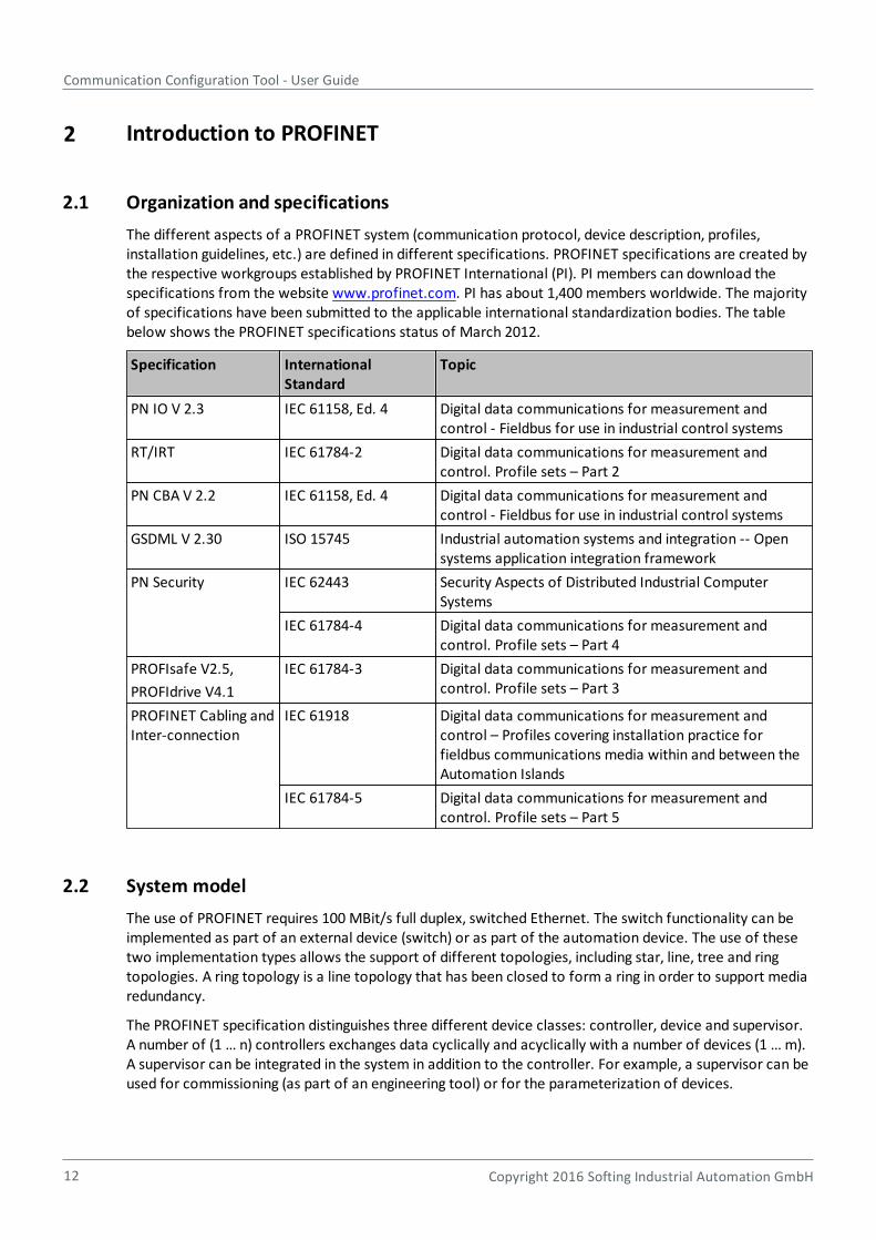
The different aspects of a PROFINET system (communication protocol, device description, profiles,installation guidelines, etc.) are defined in different specifications. PROFINET specifications are created bythe respective workgroups established by PROFINET International (PI). PI members can download thespecifications from the website www.profinet.com. PI has about 1,400 members worldwide. The majorityof specifications have been submitted to the applicable international standardization bodies. The tablebelow shows the PROFINET specifications status of March 2012.
Specification International Standard
Topic
PN IO V 2.3 IEC 61158, Ed. 4 Digital data communications for measurement andcontrol - Fieldbus for use in industrial control systems
RT/IRT IEC 61784-2 Digital data communications for measurement andcontrol. Profile sets – Part 2
PN CBA V 2.2 IEC 61158, Ed. 4 Digital data communications for measurement andcontrol - Fieldbus for use in industrial control systems
GSDML V 2.30 ISO 15745 Industrial automation systems and integration -- Opensystems application integration framework
PN Security IEC 62443 Security Aspects of Distributed Industrial ComputerSystems
IEC 61784-4 Digital data communications for measurement andcontrol. Profile sets – Part 4
PROFIsafe V2.5,
PROFIdrive V4.1
IEC 61784-3 Digital data communications for measurement andcontrol. Profile sets – Part 3
PROFINET Cabling andInter-connection
IEC 61918 Digital data communications for measurement andcontrol – Profiles covering installation practice forfieldbus communications media within and between theAutomation Islands
IEC 61784-5 Digital data communications for measurement andcontrol. Profile sets – Part 5
2.2 System model
The use of PROFINET requires 100 MBit/s full duplex, switched Ethernet. The switch functionality can beimplemented as part of an external device (switch) or as part of the automation device. The use of thesetwo implementation types allows the support of different topologies, including star, line, tree and ringtopologies. A ring topology is a line topology that has been closed to form a ring in order to support mediaredundancy.
The PROFINET specification distinguishes three different device classes: controller, device and supervisor.A number of (1 … n) controllers exchanges data cyclically and acyclically with a number of devices (1 … m).A supervisor can be integrated in the system in addition to the controller. For example, a supervisor can beused for commissioning (as part of an engineering tool) or for the parameterization of devices.
Chapter 2 - Introduction to PROFINET
Copyright 2016 Softing Industrial Automation GmbH 13
2.3 Device model
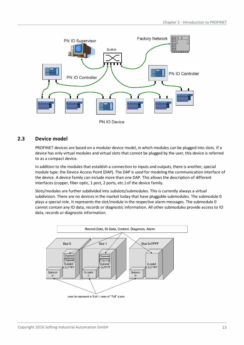
PROFINET devices are based on a modular device model, in which modules can be plugged into slots. If adevice has only virtual modules and virtual slots that cannot be plugged by the user, this device is referredto as a compact device.
In addition to the modules that establish a connection to inputs and outputs, there is another, specialmodule type: the Device Access Point (DAP). The DAP is used for modeling the communication interface ofthe device. A device family can include more than one DAP. This allows the description of differentinterfaces (copper, fiber optic, 1 port, 2 ports, etc.) of the device family.
Slots/modules are further subdivided into subslots/submodules. This is currently always a virtualsubdivision. There are no devices in the market today that have pluggable submodules. The submodule 0plays a special role. It represents the slot/module in the respective alarm messages. The submodule 0cannot contain any IO data, records or diagnostic information. All other submodules provide access to IOdata, records or diagnostic information.
Communication Configuration Tool - User Guide
14 Copyright 2016 Softing Industrial Automation GmbH
2.4 I/O data exchange
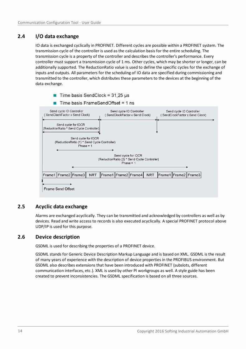
IO data is exchanged cyclically in PROFINET. Different cycles are possible within a PROFINET system. Thetransmission cycle of the controller is used as the calculation basis for the entire scheduling. Thetransmission cycle is a property of the controller and describes the controller's performance. Everycontroller must support a transmission cycle of 1 ms. Other cycles, which may be shorter or longer, can beadditionally supported. The ReductionRatio value is used to define the specific cycles for the exchange ofinputs and outputs. All parameters for the scheduling of IO data are specified during commissioning andtransmitted to the controller, which distributes these parameters to the devices at the beginning of thedata exchange.
2.5 Acyclic data exchange
Alarms are exchanged acyclically. They can be transmitted and acknowledged by controllers as well as bydevices. Read and write access to records is also executed acyclically. A special PROFINET protocol aboveUDP/IP is used for this purpose.
2.6 Device description
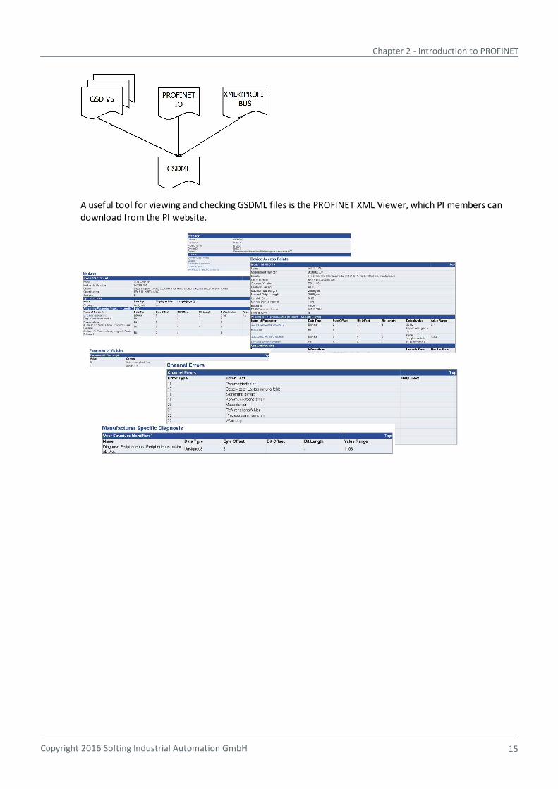
GSDML is used for describing the properties of a PROFINET device.
GSDML stands for Generic Device Description Markup Language and is based on XML. GSDML is the resultof many years of experience with the description of device properties in the PROFIBUS environment. ButGSDML also describes extensions that have been introduced with PROFINET (subslots, differentcommunication interfaces, etc.). XML is used by other PI workgroups as well. A style guide has beencreated to prevent inconsistencies. The GSDML specification is based on all three sources.
Chapter 2 - Introduction to PROFINET
Copyright 2016 Softing Industrial Automation GmbH 15
A useful tool for viewing and checking GSDML files is the PROFINET XML Viewer, which PI members candownload from the PI website.
Communication Configuration Tool - User Guide
16 Copyright 2016 Softing Industrial Automation GmbH
2.7 PROFINET mapping in the Communication Configuration Tool
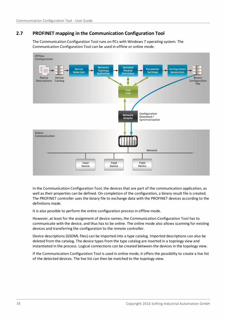
The Communication Configuration Tool runs on PCs with Windows 7 operating system. TheCommunication Configuration Tool can be used in offline or online mode.
In the Communication Configuration Tool, the devices that are part of the communication application, aswell as their properties can be defined. On completion of the configuration, a binary result file is created.The PROFINET controller uses the binary file to exchange data with the PROFINET devices according to thedefinitions made.
It is also possible to perform the entire configuration process in offline mode.
However, at least for the assignment of device names, the Communication Configuration Tool has tocommunicate with the device, and thus has to be online. The online mode also allows scanning for existingdevices and transferring the configuration to the remote controller.
Device descriptions (GSDML files) can be imported into a type catalog. Imported descriptions can also bedeleted from the catalog. The device types from the type catalog are inserted in a topology view andinstantiated in the process. Logical connections can be created between the devices in the topology view.
If the Communication Configuration Tool is used in online mode, it offers the possibility to create a live listof the detected devices. The live list can then be matched to the topology view.
Chapter 3 - Introduction to FOUNDATION fieldbus
Copyright 2016 Softing Industrial Automation GmbH 17
3 Introduction to FOUNDATION fieldbus
Once the first fieldbus standards had become available, it soon turned out that these specifications did notcover the specific requirements to be met by a fieldbus used in process automation. Thus in 1992, thissituation led to the start of two independent initiatives for defining a fieldbus standard for use inhazardous environments, one being the Interoperable System Project (ISP) while the other, the WorldFIPproject, was the result of a merger of the French and North American Flux Information Processus (FIP,earlier also known as Factory Instrumentation Protocol) organizations. When major end-users like Chevronor Exxon demanded not two but just one solution, the two initiatives merged in 1994 to form the FieldbusFoundation. Using the results of both organizations, the Fieldbus Foundation developed the FOUNDATIONfieldbus standard. In 1995 an initial implementation of this standard was started.
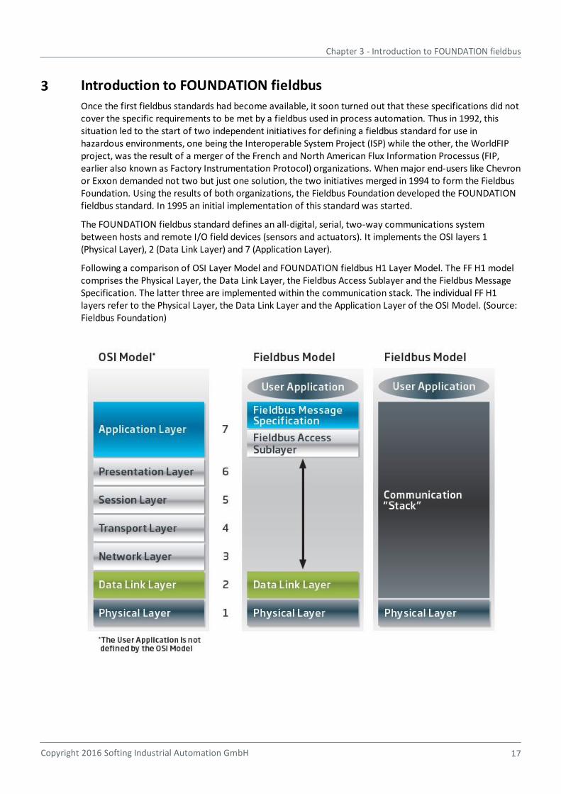
The FOUNDATION fieldbus standard defines an all-digital, serial, two-way communications systembetween hosts and remote I/O field devices (sensors and actuators). It implements the OSI layers 1(Physical Layer), 2 (Data Link Layer) and 7 (Application Layer).
Following a comparison of OSI Layer Model and FOUNDATION fieldbus H1 Layer Model. The FF H1 modelcomprises the Physical Layer, the Data Link Layer, the Fieldbus Access Sublayer and the Fieldbus MessageSpecification. The latter three are implemented within the communication stack. The individual FF H1layers refer to the Physical Layer, the Data Link Layer and the Application Layer of the OSI Model. (Source:Fieldbus Foundation)
Communication Configuration Tool - User Guide
18 Copyright 2016 Softing Industrial Automation GmbH
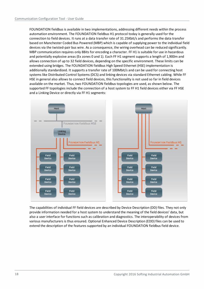
FOUNDATION fieldbus is available in two implementations, addressing different needs within the processautomation environment. The FOUNDATION fieldbus H1 protocol today is generally used for theconnection to field devices. It runs at a data transfer rate of 31.25Kbit/s and performs the data transferbased on Manchester Coded Bus Powered (MBP) which is capable of supplying power to the individual fielddevices via the twisted-pair bus wire. As a consequence, the wiring overhead can be reduced significantly.MBP communication requires only 8Bits for encoding a character. FF H1 is suitable for use in hazardousand potentially explosive areas (Ex zones 0 and 1). Each FF H1 segment supports a length of 1,900m andallows connection of up to 32 field devices, depending on the specific environment. These limits can beextended using bridges. The FOUNDATION fieldbus High Speed Ethernet (HSE) implementation isadditionally standardized. It supports a transfer rate of 100Mbit/s and can be used for connecting hostsystems like Distributed Control Systems (DCS) and linking devices via standard Ethernet cabling. While FFHSE in general also allows to connect field devices, this functionality is not used so far in field devicesavailable on the market. Thus, two FOUNDATION fieldbus topologies are used, as shown below. Thesupported FF topologies include the connection of a host system to FF H1 field devices either via FF HSEand a Linking Device or directly via FF H1 segments:
The capabilities of individual FF field devices are described by Device Description (DD) files. They not onlyprovide information needed for a host system to understand the meaning of the field devices’ data, butalso a user interface for functions such as calibration and diagnostics. The interoperability of devices fromvarious manufacturers is thus ensured. Optional Enhanced Device Description (EDD) files can be used toextend the description of the features supported by an individual FOUNDATION fieldbus field device.
Chapter 3 - Introduction to FOUNDATION fieldbus
Copyright 2016 Softing Industrial Automation GmbH 19
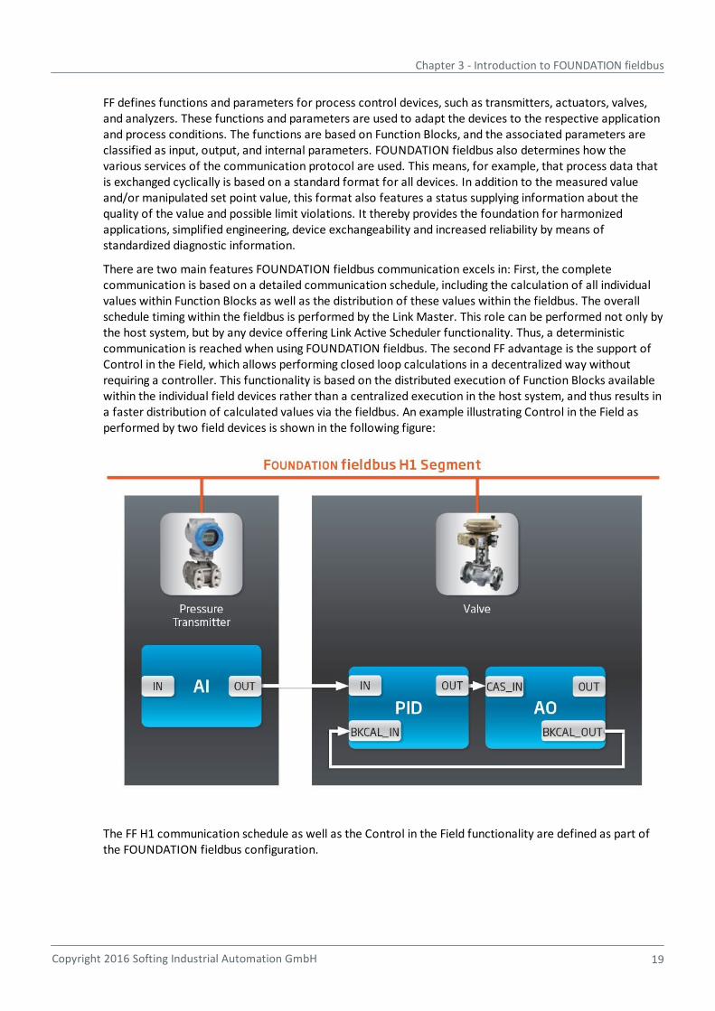
FF defines functions and parameters for process control devices, such as transmitters, actuators, valves,and analyzers. These functions and parameters are used to adapt the devices to the respective applicationand process conditions. The functions are based on Function Blocks, and the associated parameters areclassified as input, output, and internal parameters. FOUNDATION fieldbus also determines how thevarious services of the communication protocol are used. This means, for example, that process data thatis exchanged cyclically is based on a standard format for all devices. In addition to the measured valueand/or manipulated set point value, this format also features a status supplying information about thequality of the value and possible limit violations. It thereby provides the foundation for harmonizedapplications, simplified engineering, device exchangeability and increased reliability by means ofstandardized diagnostic information.
There are two main features FOUNDATION fieldbus communication excels in: First, the completecommunication is based on a detailed communication schedule, including the calculation of all individualvalues within Function Blocks as well as the distribution of these values within the fieldbus. The overallschedule timing within the fieldbus is performed by the Link Master. This role can be performed not only bythe host system, but by any device offering Link Active Scheduler functionality. Thus, a deterministiccommunication is reached when using FOUNDATION fieldbus. The second FF advantage is the support ofControl in the Field, which allows performing closed loop calculations in a decentralized way withoutrequiring a controller. This functionality is based on the distributed execution of Function Blocks availablewithin the individual field devices rather than a centralized execution in the host system, and thus results ina faster distribution of calculated values via the fieldbus. An example illustrating Control in the Field asperformed by two field devices is shown in the following figure:
The FF H1 communication schedule as well as the Control in the Field functionality are defined as part ofthe FOUNDATION fieldbus configuration.
Communication Configuration Tool - User Guide
20 Copyright 2016 Softing Industrial Automation GmbH
4 Graphical user interface
4.1 General functionality
4.1.1 Main window functionality
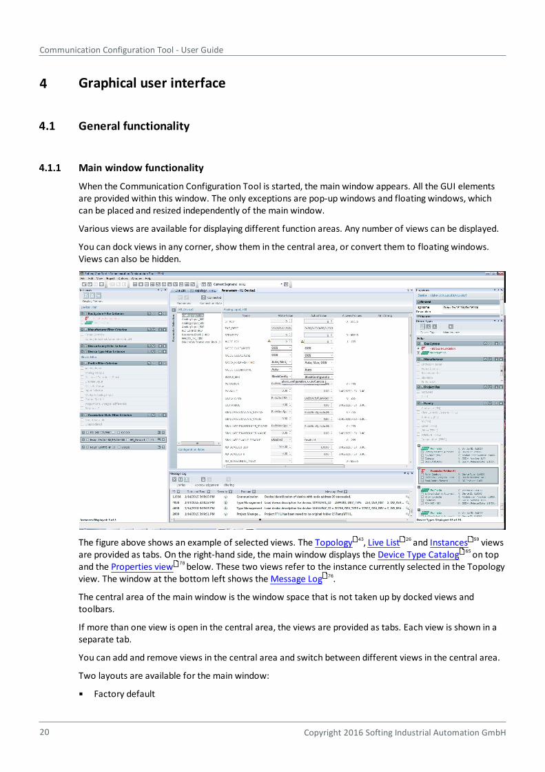
When the Communication Configuration Tool is started, the main window appears. All the GUI elementsare provided within this window. The only exceptions are pop-up windows and floating windows, whichcan be placed and resized independently of the main window.
Various views are available for displaying different function areas. Any number of views can be displayed.
You can dock views in any corner, show them in the central area, or convert them to floating windows.Views can also be hidden.
The figure above shows an example of selected views. The Topology , Live List and Instances viewsare provided as tabs. On the right-hand side, the main window displays the Device Type Catalog on topand the Properties view below. These two views refer to the instance currently selected in the Topologyview. The window at the bottom left shows the Message Log .
The central area of the main window is the window space that is not taken up by docked views andtoolbars.
If more than one view is open in the central area, the views are provided as tabs. Each view is shown in aseparate tab.
You can add and remove views in the central area and switch between different views in the central area.
Two layouts are available for the main window:
Factory default
43 26 59
65
78
76
Chapter 4 - Graphical user interface
Copyright 2016 Softing Industrial Automation GmbH 21
Custom layout
You can reset the window layout to the factory default at any time. To do so, select Menu Window Reset Layout. The current layout will then be overwritten, regardless of whether a project has beenloaded.
There are two versions of the factory default:
1. A project is open:
The factory default comprises the list of open views and indicates the position and status of each view.The position of the docking area is also stored
2. No project is open:
The factory default basically has the same layout as for an open project, with the followingdifferences:
o The Properties views and the Topology views are not open.
o The Device Type view on the right-hand side of the main window covers the full height.
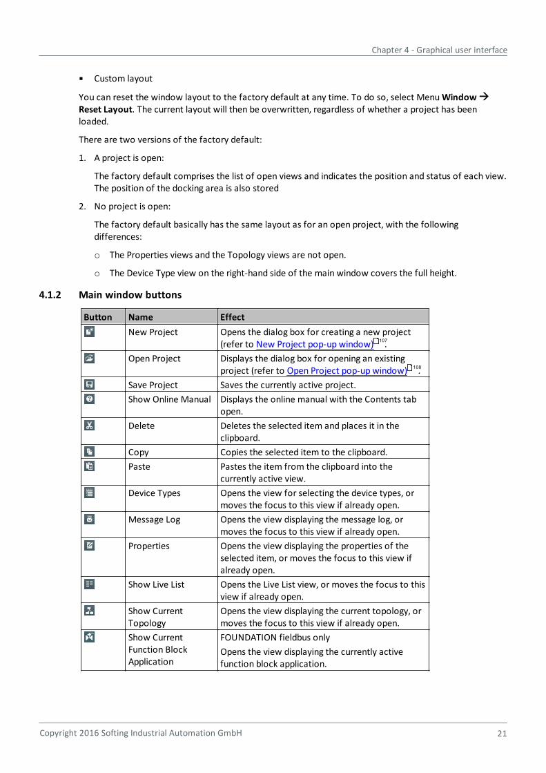
4.1.2 Main window buttons
Button Name Effect
New Project Opens the dialog box for creating a new project(refer to New Project pop-up window) .
Open Project Displays the dialog box for opening an existingproject (refer to Open Project pop-up window) .
Save Project Saves the currently active project.
Show Online Manual Displays the online manual with the Contents tabopen.
Delete Deletes the selected item and places it in theclipboard.
Copy Copies the selected item to the clipboard.
Paste Pastes the item from the clipboard into thecurrently active view.
Device Types Opens the view for selecting the device types, ormoves the focus to this view if already open.
Message Log Opens the view displaying the message log, ormoves the focus to this view if already open.
Properties Opens the view displaying the properties of theselected item, or moves the focus to this view ifalready open.
Show Live List Opens the Live List view, or moves the focus to thisview if already open.
Show CurrentTopology
Opens the view displaying the current topology, ormoves the focus to this view if already open.
Show CurrentFunction BlockApplication
FOUNDATION fieldbus only
Opens the view displaying the currently activefunction block application.
107
108
Communication Configuration Tool - User Guide
22 Copyright 2016 Softing Industrial Automation GmbH
Show Instances Opens the view displaying information about theinstances, or moves the focus to this view ifalready open. An instance is a device that is shownin the Topology view and has been derived from adevice type.
Type CatalogMaintenance
Opens the pop-up window for editing the devicetype catalog.
Segments Opens the pop-up window for segmentmanagement.
Network AccessProfiles
Opens the pop-up window for editing thenetwork access profiles.
Settings Opens the pop-up window for editing programsettings.
Check CurrentSegment
Performs a check of the current segment. Theresults are displayed in the Message Log.
Download CurrentSegment
Downloads the configuration information of theselected segment to the target platform.
Check All Segments Performs a check of all segments. The results aredisplayed in the Message Log.
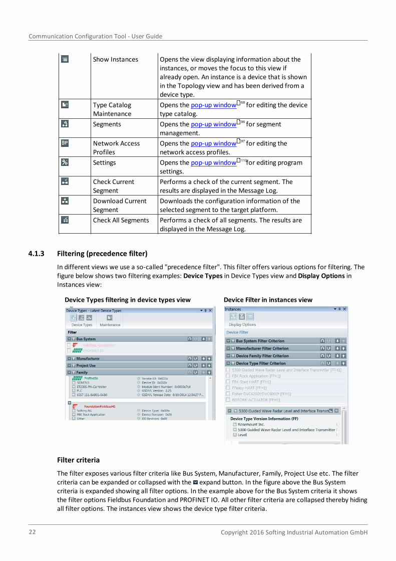
4.1.3 Filtering (precedence filter)
In different views we use a so-called "precedence filter". This filter offers various options for filtering. Thefigure below shows two filtering examples: Device Types in Device Types view and Display Options inInstances view:
Device Types filtering in device types view Device Filter in instances view
Filter criteria
The filter exposes various filter criteria like Bus System, Manufacturer, Family, Project Use etc. The filtercriteria can be expanded or collapsed with the expand button. In the figure above the Bus Systemcriteria is expanded showing all filter options. In the example above for the Bus System criteria it showsthe filter options Fieldbus Foundation and PROFINET IO. All other filter criteria are collapsed thereby hidingall filter options. The instances view shows the device type filter criteria.
68
96
97
110
Chapter 4 - Graphical user interface
Copyright 2016 Softing Industrial Automation GmbH 23
The order of the filter criteria can be changed thereby defining a precedence of criteria. The precedence isthe order in which the filters are applied. The precedence is defined by the position of the filter criteria inthe filter. Thus in the figure above the Bus System criteria has a higher precedence than the Manufacturercriteria, and the Manufacturer criteria has a higher precedence than the Family criteria. Hence the filter isapplied with Bus System first, then Manufacturer, then Family. The position and thereby the precedence ofthe criteria can be changed with the button to move the position of the selected criteria down or tomove it up with the button .
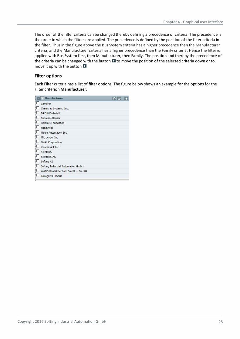
Filter options
Each Filter criteria has a list of filter options. The figure below shows an example for the options for theFilter criterion Manufacturer:

Communication Configuration Tool - User Guide
24 Copyright 2016 Softing Industrial Automation GmbH
Activate/deactivate filter options
The filter options can be activated by checking the check boxes near to the corresponding filter option.This is only possible if the filter criterion itself is activated via the button . If deactivated , the filteroptions are disabled and cannot be selected. The set of filter options presented for each filter criteriondepends on the device descriptions being imported AND the active filters having a higher precedence. Forinstance you give the filter criterion "Family" a higher precedence by moving it up and activate the filterand set for instance the Family criterion filter option "Pressure". Then the list of filter options for theManufacturer filter criterion will be reduced to the list of manufacturers that have pressure device types.This is shown in the figure below:
The filter result will be the logical AND combination of all active ( ) filter criteria in the order defined bythe precedence. In the example above the filter result will show all pressure device types of themanufacturers Endress+Hauser and Yokogawa Electric.
Chapter 4 - Graphical user interface
Copyright 2016 Softing Industrial Automation GmbH 25
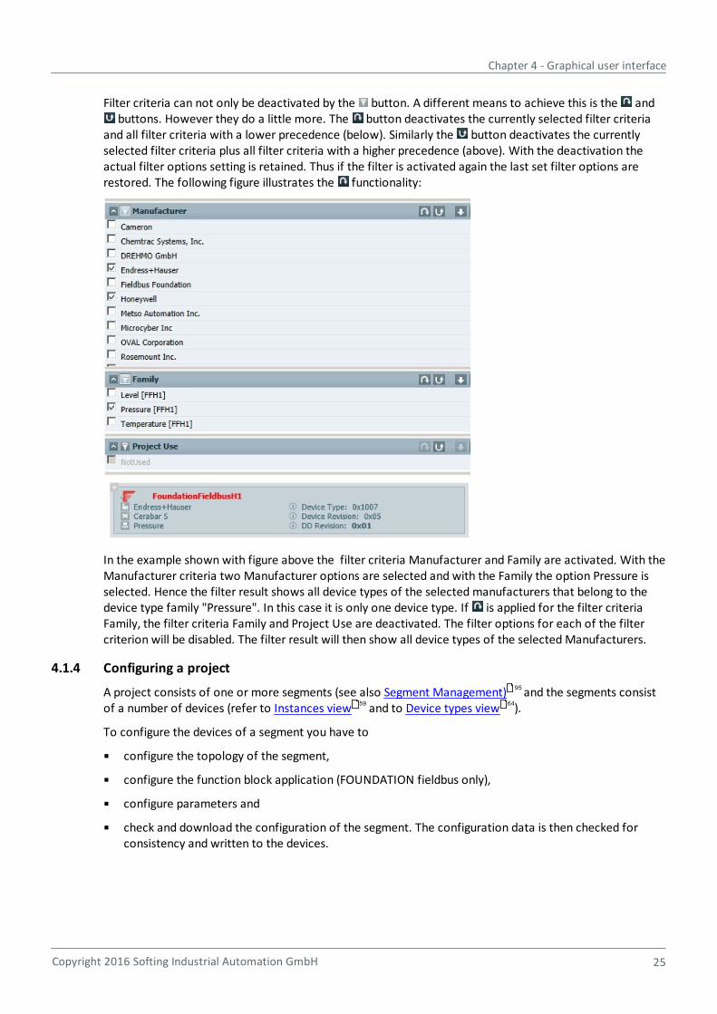
Filter criteria can not only be deactivated by the button. A different means to achieve this is the and buttons. However they do a little more. The button deactivates the currently selected filter criteria
and all filter criteria with a lower precedence (below). Similarly the button deactivates the currentlyselected filter criteria plus all filter criteria with a higher precedence (above). With the deactivation theactual filter options setting is retained. Thus if the filter is activated again the last set filter options arerestored. The following figure illustrates the functionality:
In the example shown with figure above the filter criteria Manufacturer and Family are activated. With theManufacturer criteria two Manufacturer options are selected and with the Family the option Pressure isselected. Hence the filter result shows all device types of the selected manufacturers that belong to thedevice type family "Pressure". In this case it is only one device type. If is applied for the filter criteriaFamily, the filter criteria Family and Project Use are deactivated. The filter options for each of the filtercriterion will be disabled. The filter result will then show all device types of the selected Manufacturers.
4.1.4 Configuring a project
A project consists of one or more segments (see also Segment Management) and the segments consistof a number of devices (refer to Instances view and to Device types view ).
To configure the devices of a segment you have to
configure the topology of the segment,
configure the function block application (FOUNDATION fieldbus only),
configure parameters and
check and download the configuration of the segment. The configuration data is then checked forconsistency and written to the devices.
95
59 64
Communication Configuration Tool - User Guide
26 Copyright 2016 Softing Industrial Automation GmbH
FOUNDATION fieldbus PROFINET
Topology Topology view (FOUNDATION Fieldbus) Topology view (PROFINET)
Function BlockApplication
Function block application view(FOUNDATION fieldbus only)
n/a
Parameters Edit configuration parameters(FOUNDATION fieldbus)
Edit configuration parameters (PROFINET)
Download Project menu - Download (current)segment
Project menu - Download (current)segment
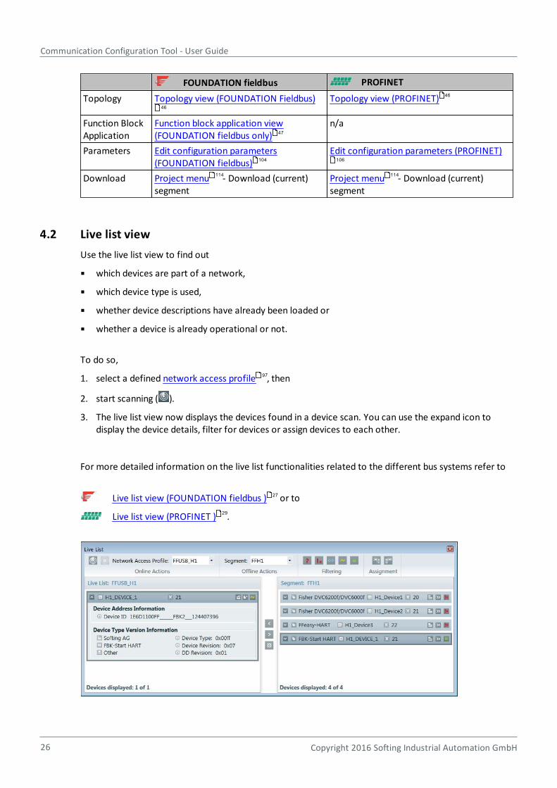
4.2 Live list view
Use the live list view to find out
which devices are part of a network,
which device type is used,
whether device descriptions have already been loaded or
whether a device is already operational or not.
To do so,
1. select a defined network access profile , then
2. start scanning ( ).
3. The live list view now displays the devices found in a device scan. You can use the expand icon todisplay the device details, filter for devices or assign devices to each other.
For more detailed information on the live list functionalities related to the different bus systems refer to
Live list view (FOUNDATION fieldbus ) or to
Live list view (PROFINET ) .
46
46
47
104 106
114 114
97
27
29
Chapter 4 - Graphical user interface
Copyright 2016 Softing Industrial Automation GmbH 27
Devices from the live list and the topology can be matched, which means that live list devices can beassigned to instances from the Topology view (configured devices), and instances from the Topologyview can be assigned to live list devices. The Live list view buttons section contains an overview. Amore detailed assignment description is also provided in the Tutorials section.
The live list devices and the configured devices (Segment) can be filtered. This is particularly useful ifthere are many devices. You can find a detailed description on filtering in Device types filtering .
The scan feature is also available if no project is open.
When a project is active, the instances shown in the Topology view can be displayed. As a project mayinclude multiple segments, the desired segment has to be selected.
The set of segments that can be selected depends on the bus type of the network access profile (NAP).Thus segments which do not have the same bus type as the NAP are not presented for selection.
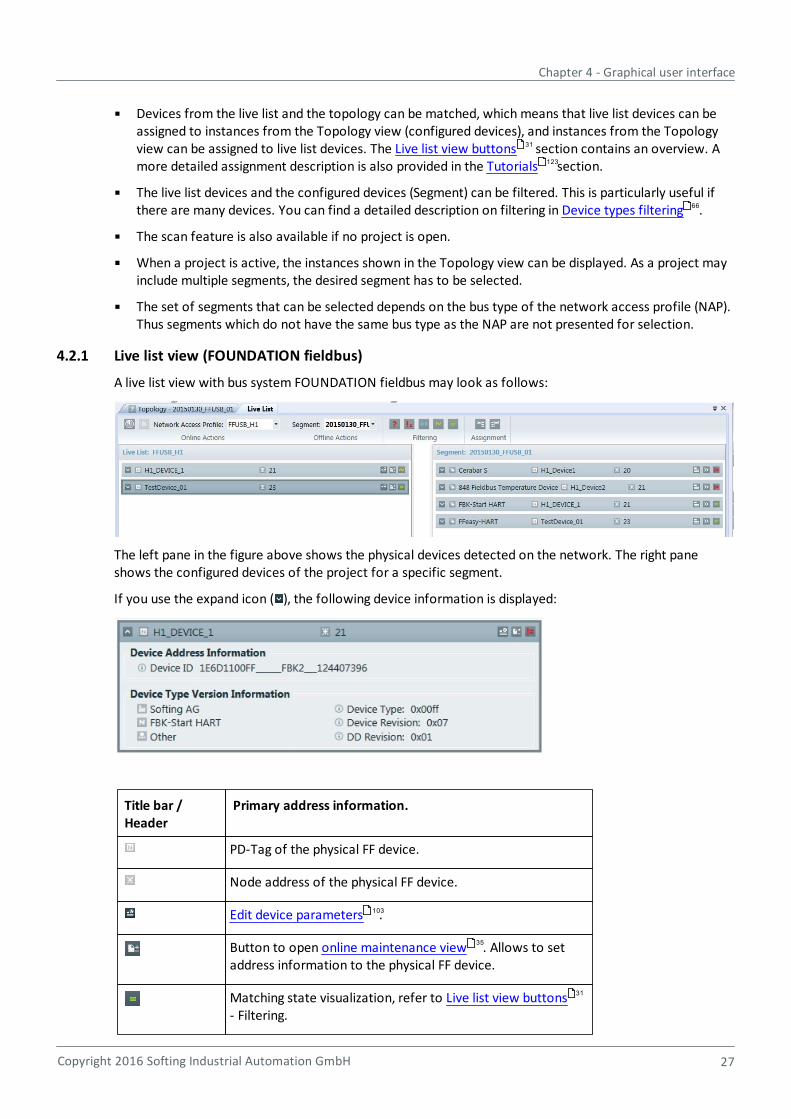
4.2.1 Live list view (FOUNDATION fieldbus)
A live list view with bus system FOUNDATION fieldbus may look as follows:
The left pane in the figure above shows the physical devices detected on the network. The right paneshows the configured devices of the project for a specific segment.
If you use the expand icon ( ), the following device information is displayed:
Title bar /Header
Primary address information.
PD-Tag of the physical FF device.
Node address of the physical FF device.
Edit device parameters .
Button to open online maintenance view . Allows to setaddress information to the physical FF device.
Matching state visualization, refer to Live list view buttons- Filtering.
31
123
66
103
35
31
Communication Configuration Tool - User Guide
28 Copyright 2016 Softing Industrial Automation GmbH
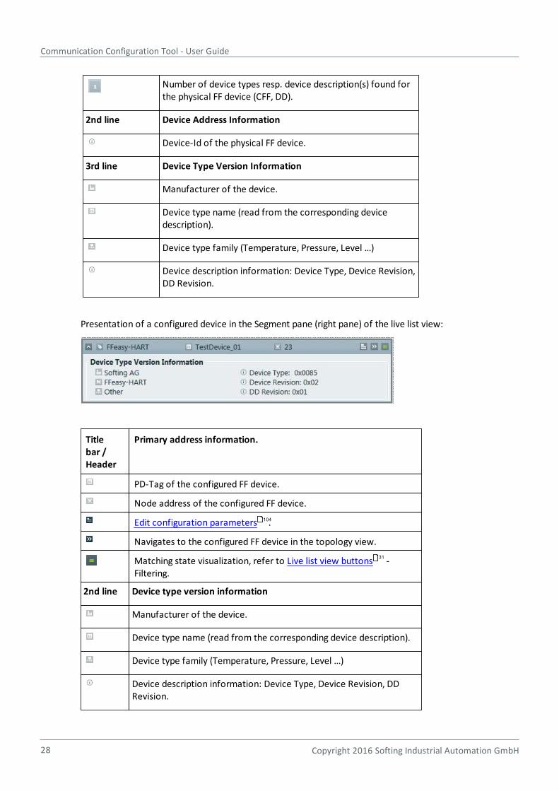
Number of device types resp. device description(s) found forthe physical FF device (CFF, DD).
2nd line Device Address Information
Device-Id of the physical FF device.
3rd line Device Type Version Information
Manufacturer of the device.
Device type name (read from the corresponding devicedescription).
Device type family (Temperature, Pressure, Level …)
Device description information: Device Type, Device Revision,DD Revision.
Presentation of a configured device in the Segment pane (right pane) of the live list view:
Titlebar /Header
Primary address information.
PD-Tag of the configured FF device.
Node address of the configured FF device.
Edit configuration parameters .
Navigates to the configured FF device in the topology view.
Matching state visualization, refer to Live list view buttons -Filtering.
2nd line Device type version information
Manufacturer of the device.
Device type name (read from the corresponding device description).
Device type family (Temperature, Pressure, Level …)
Device description information: Device Type, Device Revision, DDRevision.
104
31
Chapter 4 - Graphical user interface
Copyright 2016 Softing Industrial Automation GmbH 29
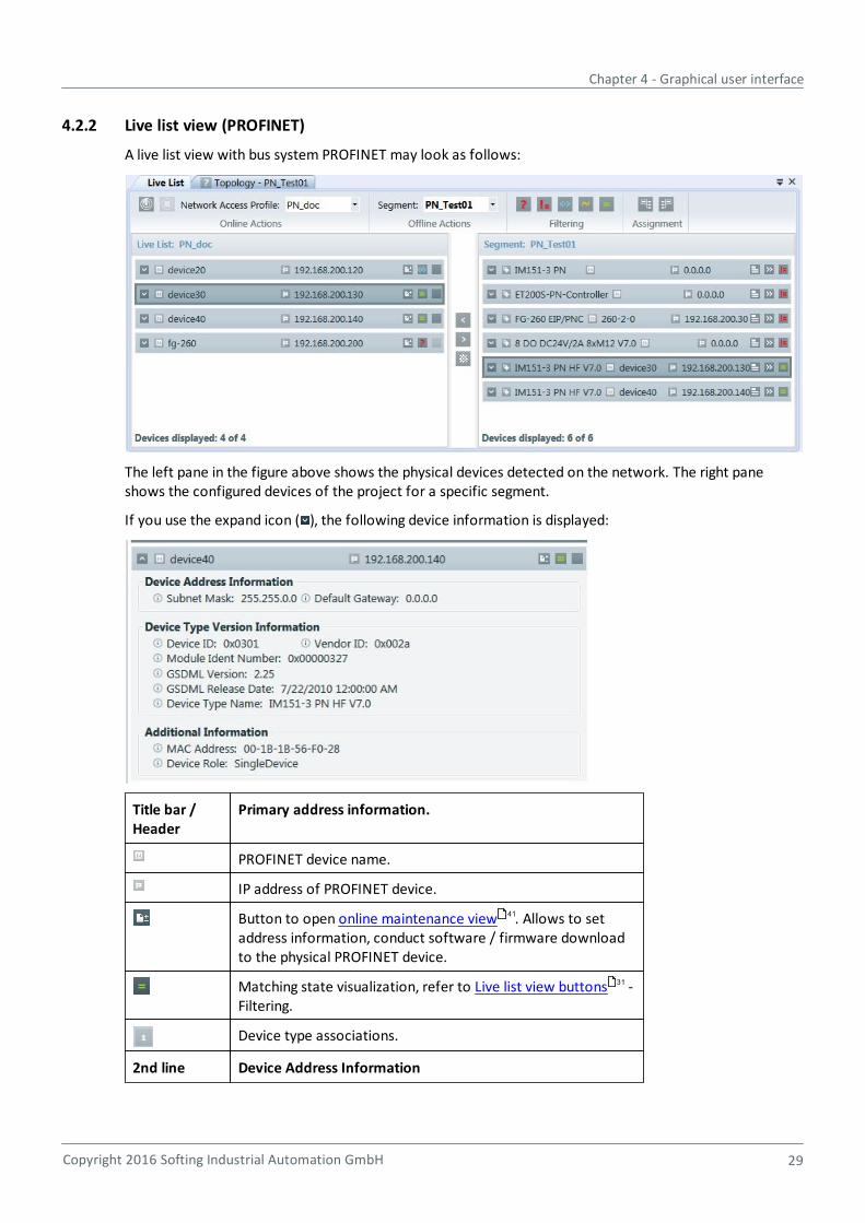
4.2.2 Live list view (PROFINET)
A live list view with bus system PROFINET may look as follows:
The left pane in the figure above shows the physical devices detected on the network. The right paneshows the configured devices of the project for a specific segment.
If you use the expand icon ( ), the following device information is displayed:
Title bar /Header
Primary address information.
PROFINET device name.
IP address of PROFINET device.
Button to open online maintenance view . Allows to setaddress information, conduct software / firmware downloadto the physical PROFINET device.
Matching state visualization, refer to Live list view buttons -Filtering.
Device type associations.
2nd line Device Address Information
41
31

Communication Configuration Tool - User Guide
30 Copyright 2016 Softing Industrial Automation GmbH
Device-Id of the physical PROFINET device such as SubnetMask and Default Gateway.
3rd line Device Type Version Information
Device ID, Vendor ID, Module Ident Number, GSDML Version,GSDML Release Date, Device Type Name
4th line Additional Information
MAC Address and Device Role
Presentation of a configured device in the Segment pane (right pane) of the live list view:
Title bar /Header
Primary address information
Tag name of the PROFINET device.
PROFINET device name.
IP address of PROFINET device.
Button to edit configuration parameters, refer to Editconfiguration parameters (PROFINET) .
Navigate to the configured PROFINET device in the topologyview.
Matching state visualization, refer to Live list view buttons -Filtering.
2nd line Device Address Information
Device-Id of the physical PROFINET device such as SubnetMask and Default Gateway.
3rd line Device Type Version Information
Device ID, Vendor ID, Module Ident Number, GSDML Version,GSDML Release Date, Device Type Name
106
31

Chapter 4 - Graphical user interface
Copyright 2016 Softing Industrial Automation GmbH 31
4.2.3 Live list view buttons
4.2.3.1 Live list scanning
Button Name Effect
Start scanning Precondition: a network access profile hasbeen selected.
Performs a scan for devices over the selectednetwork connection. The devices found aredisplayed. The button is disabled if a networkscan is pending or no network access profile(NAP) is selected.
Stop scanning Allows to stop a network scan. This button isonly enabled if a network scan is running.
4.2.3.2 Filter and matching
Filter and matching state; the criteria can be combined.
Type unknown Displays only the devices found of typeunknown. This means that there is no type forthis device in the type catalog. The appropriatedevice description file has either not beenimported or the properties of the found devicediffer from the corresponding entry in the typecatalog. For example, the instance created inthe Topology view and the found device maydiffer in the Module ID of the DAP.
Not assignable Displays those instances that cannot beassigned to any device found.
Uniquely assigned Displays only the devices uniquely assigned. Inthis case, all the properties of the found devicematch those of an instance created in theTopology view.
Ambiguously assigned Displays all instances that cannot be uniquelyassigned to a found device.
Assignable Displays all assignable devices.
Live list view buttons – Live list view matching
The buttons displayed rely on the matching between a configured device and a physical device. Matchingcriteria differ between the segment types.
Matching states are recalculated if
configured device is added to topology of selected segment.
configured device is removed from topology of selected segment.
identifying device address information (for bus type PN: Station name) of a configured station ismodified.
a live list scan has been initiated.
Communication Configuration Tool - User Guide
32 Copyright 2016 Softing Industrial Automation GmbH
device type association of a live list device is modified.
identifying device address information (for bus type PN: Station name) of a live list device is modified.
The following matching states exist:
Unique Match
The device matches exactly one device on the other side and there is no interfering device (see yellow~ symbol).
A device is said to match a station on the other side if station type and address information areidentical. If the device address information in a specific bus system consists of more than one piece ofinformation, all pieces of information have to be identical to make the devices match.
The address information in bus system PROFINET is the station name.
The address information in bus system FF/HSE consists of PD-Tag and IP address.
The address information in bus system FF-H1 consists of PD-Tag and node address.
Ambiguous and/or Disturbed Match
Ambiguous match
The device matches more than one device on the other side (see green = symbol for a definition of whatmatching means).
Disturbed match
The device matches at least one device on the other side (see green = symbol for a definition of whatmatching means). However, there is at least one additional device interfering with matching. A device issaid to interfere with matching if one of the following applies:
The device is on the same side and one or more (possibly all) pieces of addressing information areidentical with the matching device pair. The device type of the interfering device doesn't matter in thisscenario.
The device is on the other side, has the same device type as the matching device pair and some but notall pieces of addressing information are identical with the matching device pair. Note that if all piecesof addressing information were identical, the device would be a matching device and give reason foran ambiguous match rather than a disturbed match.
The device is on the other side, has a different device type and one or more (possibly all) pieces ofaddressing information are identical with the matching device pair.
Note
Note that both ambiguous and disturbed match may be in effect at the same time.
Assignable
The device does not match any device on the other side (see green = symbol for a definition of whatmatching means). However, it is assignable to one or more devices on the other side.
Chapter 4 - Graphical user interface
Copyright 2016 Softing Industrial Automation GmbH 33
A device is said to be assignable to a device on the other side if device types are identical but at least onepiece of addressing information is not.
Note
Note the intentional exclusion of devices whose addressing information is completelyidentical. This way, the set of matching devices and the set of assignable devices does notintersect..
Not Assignable
The device does not match any device on the other side nor is it assignable.
Effectively, this means, none of the devices on the other side has the identical device type.
For an FF-HSE segment with a FG-110 or FG-200, the H1 devices can only match if the gateway above alsomatches. The matching state of the link between is not relevant.
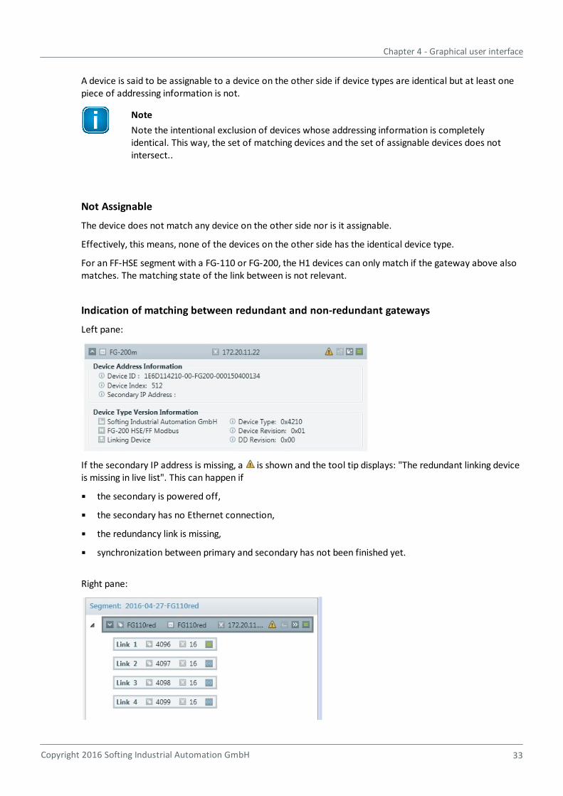
Indication of matching between redundant and non-redundant gateways
Left pane:
If the secondary IP address is missing, a is shown and the tool tip displays: "The redundant linking deviceis missing in live list". This can happen if
the secondary is powered off,
the secondary has no Ethernet connection,
the redundancy link is missing,
synchronization between primary and secondary has not been finished yet.
Right pane:
Communication Configuration Tool - User Guide
34 Copyright 2016 Softing Industrial Automation GmbH
There is a non-redundant linking device configured, but the physical device is redundant.
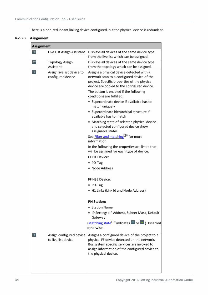
4.2.3.3 Assignment
Assignment
Live List Assign Assistant Displays all devices of the same device typefrom the live list which can be assigned.
Topology AssignAssistant
Displays all devices of the same device typefrom the topology which can be assigned.
Assign live list device toconfigured device
Assigns a physical device detected with anetwork scan to a configured device of theproject. Specific properties of the physicaldevice are copied to the configured device.
The button is enabled if the followingconditions are fulfilled:
Superordinate device if available has tomatch uniquely
Superordinate hierarchical structure ifavailable has to match
Matching state of selected physical deviceand selected configured device showassignable states
See Filter and matching for moreinformation.
In the following the properties are listed thatwill be assigned for each type of device:
FF H1 Device:
PD-Tag
Node Address
FF HSE Device:
PD-Tag
H1 Links (Link Id and Node Address)
PN Station:
Station Name
IP Settings (IP Address, Subnet Mask, DefaultGateway)
(Matching state indicates or ). Disabledotherwise.
Assign configured deviceto live list device
Assigns a configured device of the project to aphysical FF device detected on the network.Bus system specific services are invoked toassign information of the configured device tothe physical device.
31
31

Chapter 4 - Graphical user interface
Copyright 2016 Softing Industrial Automation GmbH 35
Assignment
The button is enabled if the physical device andthe configured device are of the same device
type (Matching state indicates or ).Disabled otherwise.
For FF devices the following properties areassigned:
- PD-Tag
- Node address
Create configured devicefrom selected live listdevice
Creates configured device(s) within thetopology of the selected segment of theproject.
The button is enabled if the followingconditions are fulfilled:
Physical device is selected
Type information of selected device isavailable
Device type corresponding to typeinformation is available in type catalog
In case of device(s) that have subordinatedevices the complete hierarchical structure willbe created. If the type information of asubordinate device is not available or thecorresponding device type is not available inthe type catalog this device will not be created.
The button is disabled if either no physicaldevice is selected or the selected device has no
type .
4.2.4 Online Maintenance view
The online maintenance view allows to perform maintenance operations with devices detected on thenetwork with a network scan.
1. Select a device in the live list.
2. Click to open the Online Maintenance view.
The view is specific with regards to the underlying bus system (PROFINET or FOUNDATION fieldbus):
Online Maintenance view (FOUNDATION fieldbus)
Online Maintenance view (PROFINET)
4.2.4.1 Online Maintenance view (FOUNDATION fieldbus)
The view is split in two parts:
The upper part representing the header of the view contains information identifying the device thatcannot be changed. For maintenance operations that take much time a rotating circle is shown in theright part to indicate that the operation is ongoing.
35
41
Communication Configuration Tool - User Guide
36 Copyright 2016 Softing Industrial Automation GmbH
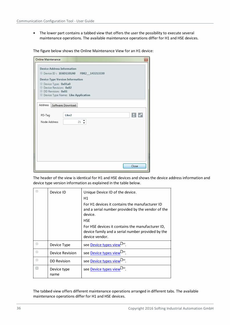
The lower part contains a tabbed view that offers the user the possibility to execute severalmaintenance operations. The available maintenance operations differ for H1 and HSE devices.
The figure below shows the Online Maintenance View for an H1 device:
The header of the view is identical for H1 and HSE devices and shows the device address information anddevice type version information as explained in the table below.
Device ID Unique Device ID of the device.
H1
For H1 devices it contains the manufacturer IDand a serial number provided by the vendor of thedevice.
HSE
For HSE devices it contains the manufacturer ID,device family and a serial number provided by thedevice vendor.
Device Type see Device types view .
Device Revision see Device types view .
DD Revision see Device types view .
Device typename
see Device types view .
The tabbed view offers different maintenance operations arranged in different tabs. The availablemaintenance operations differ for H1 and HSE devices.
64
64
64
64
Chapter 4 - Graphical user interface
Copyright 2016 Softing Industrial Automation GmbH 37
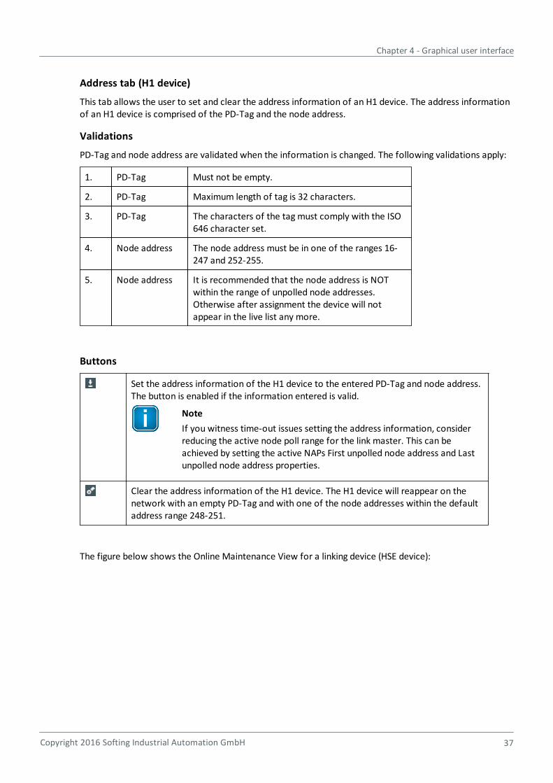
Address tab (H1 device)
This tab allows the user to set and clear the address information of an H1 device. The address informationof an H1 device is comprised of the PD-Tag and the node address.
Validations
PD-Tag and node address are validated when the information is changed. The following validations apply:
1. PD-Tag Must not be empty.
2. PD-Tag Maximum length of tag is 32 characters.
3. PD-Tag The characters of the tag must comply with the ISO646 character set.
4. Node address The node address must be in one of the ranges 16-247 and 252-255.
5. Node address It is recommended that the node address is NOTwithin the range of unpolled node addresses.Otherwise after assignment the device will notappear in the live list any more.
Buttons
Set the address information of the H1 device to the entered PD-Tag and node address.The button is enabled if the information entered is valid.
Note
If you witness time-out issues setting the address information, considerreducing the active node poll range for the link master. This can beachieved by setting the active NAPs First unpolled node address and Lastunpolled node address properties.
Clear the address information of the H1 device. The H1 device will reappear on thenetwork with an empty PD-Tag and with one of the node addresses within the defaultaddress range 248-251.
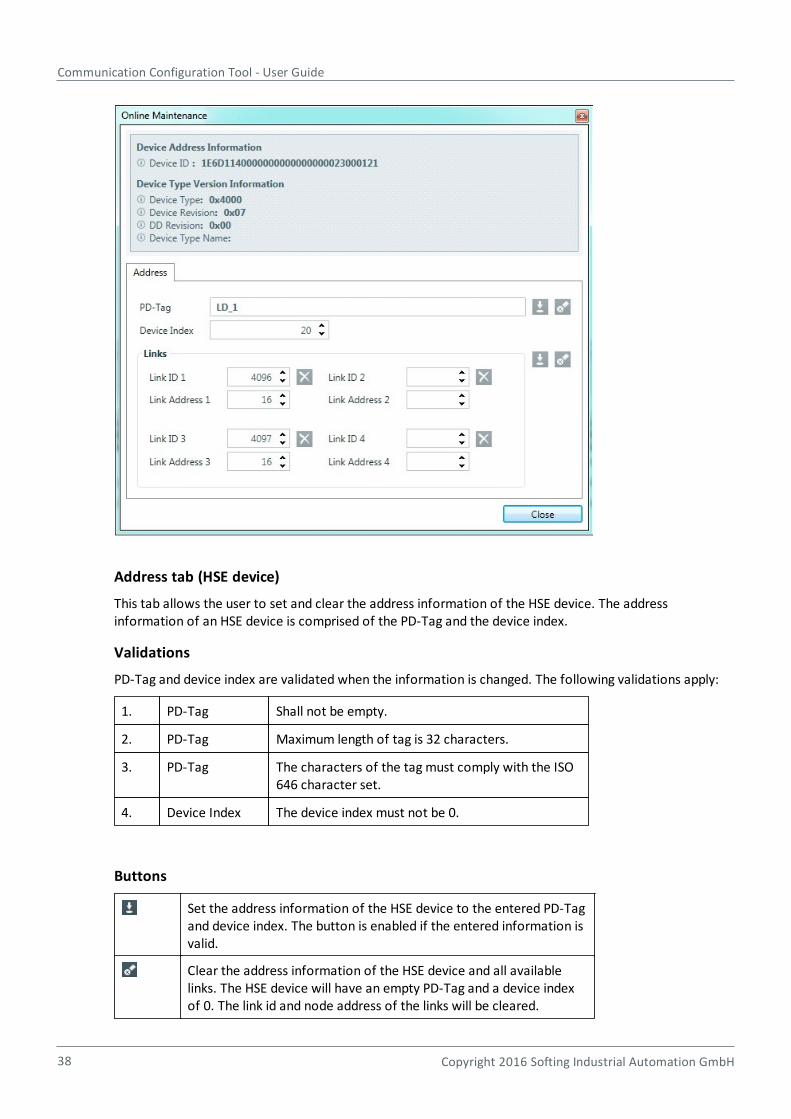
The figure below shows the Online Maintenance View for a linking device (HSE device):
Communication Configuration Tool - User Guide
38 Copyright 2016 Softing Industrial Automation GmbH
Address tab (HSE device)
This tab allows the user to set and clear the address information of the HSE device. The addressinformation of an HSE device is comprised of the PD-Tag and the device index.
Validations
PD-Tag and device index are validated when the information is changed. The following validations apply:
1. PD-Tag Shall not be empty.
2. PD-Tag Maximum length of tag is 32 characters.
3. PD-Tag The characters of the tag must comply with the ISO646 character set.
4. Device Index The device index must not be 0.
Buttons
Set the address information of the HSE device to the entered PD-Tagand device index. The button is enabled if the entered information isvalid.
Clear the address information of the HSE device and all availablelinks. The HSE device will have an empty PD-Tag and a device indexof 0. The link id and node address of the links will be cleared.
Chapter 4 - Graphical user interface
Copyright 2016 Softing Industrial Automation GmbH 39
For linking devices the address tab additionally shows the available links and allows the user to set andclear their address information. The address information of a link is comprised of the link id and the nodeaddress. There must not be a conflict between the node address of the link and the node address of anyH1 device connected to that link.
To clear a single link, the link id and node address have to be cleared. This can be done by manuallyclearing the fields or by using the corresponding button next to the link. Setting the address information ofall available links will clear links that have no values defined.
Validations
Link id and node address of all available links are validated when the information is changed. The followingvalidations apply:
1. Link id Must be greater than 4096.
2. Link id The link id must be unique over all links of the linkingdevice.
3. Link id Must be in the range from 16 to 19.
Buttons
Adapts the address information of the linking device links to theentered values. This button is enabled if the entered information isvalid.
Clears the address information of the linking device links. The linkswill have an empty link id and node address.
Clears the link id and node address of the corresponding link.
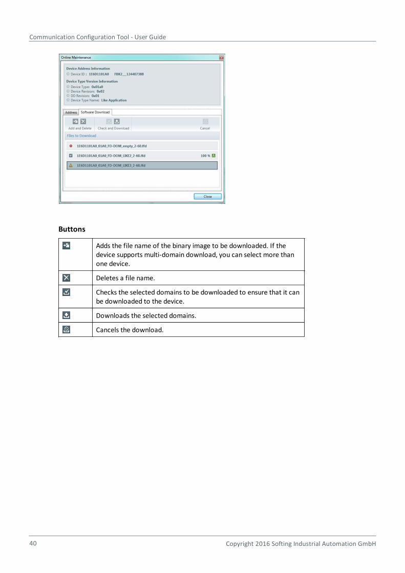
Software Download tab
Here you can update the software (firmware) of a device. This tab does not appear if your device does notsupport this feature:
Communication Configuration Tool - User Guide
40 Copyright 2016 Softing Industrial Automation GmbH
Buttons
Adds the file name of the binary image to be downloaded. If thedevice supports multi-domain download, you can select more thanone device.
Deletes a file name.
Checks the selected domains to be downloaded to ensure that it canbe downloaded to the device.
Downloads the selected domains.
Cancels the download.
Chapter 4 - Graphical user interface
Copyright 2016 Softing Industrial Automation GmbH 41
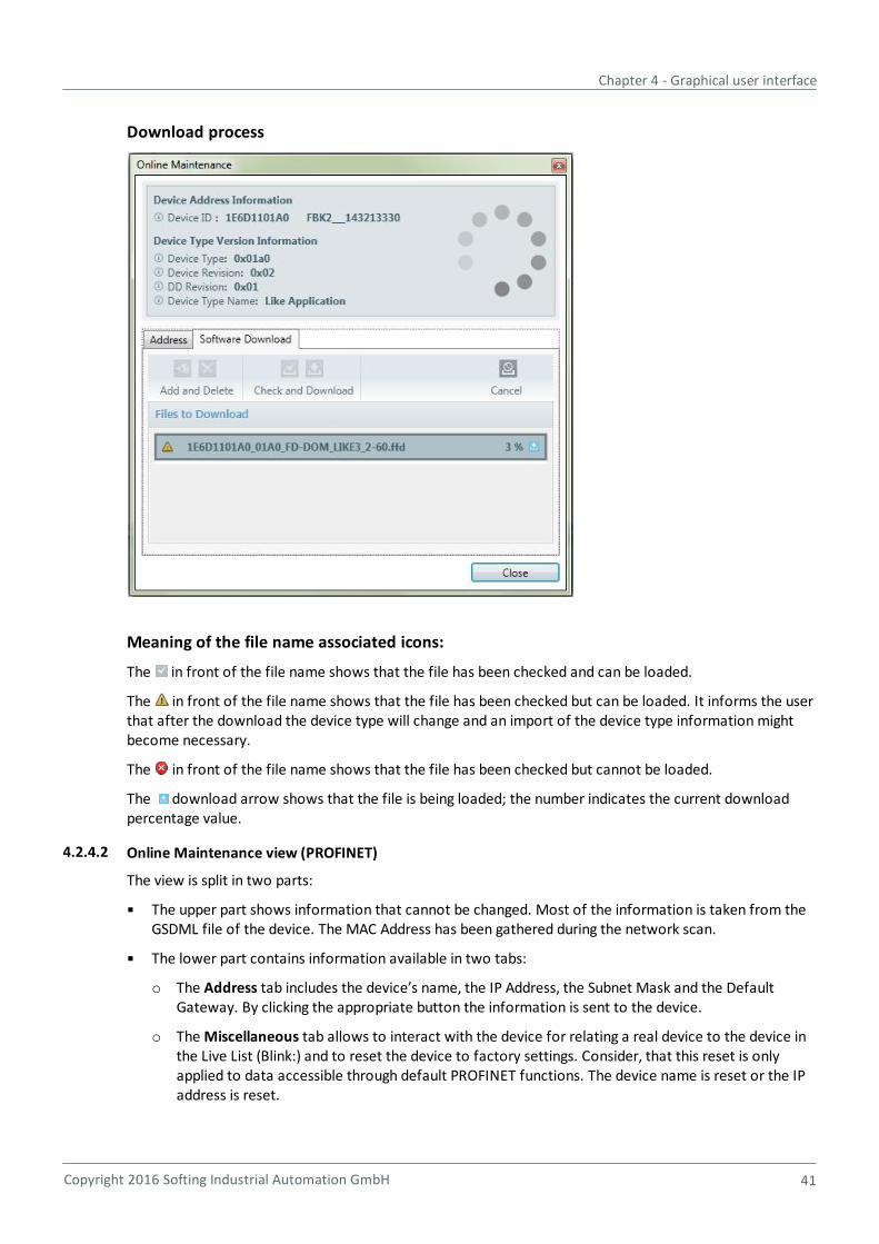
Download process
Meaning of the file name associated icons:
The in front of the file name shows that the file has been checked and can be loaded.
The in front of the file name shows that the file has been checked but can be loaded. It informs the userthat after the download the device type will change and an import of the device type information mightbecome necessary.
The in front of the file name shows that the file has been checked but cannot be loaded.
The download arrow shows that the file is being loaded; the number indicates the current downloadpercentage value.
4.2.4.2 Online Maintenance view (PROFINET)
The view is split in two parts:
The upper part shows information that cannot be changed. Most of the information is taken from theGSDML file of the device. The MAC Address has been gathered during the network scan.
The lower part contains information available in two tabs:
o The Address tab includes the device’s name, the IP Address, the Subnet Mask and the DefaultGateway. By clicking the appropriate button the information is sent to the device.
o The Miscellaneous tab allows to interact with the device for relating a real device to the device inthe Live List (Blink:) and to reset the device to factory settings. Consider, that this reset is onlyapplied to data accessible through default PROFINET functions. The device name is reset or the IPaddress is reset.
Communication Configuration Tool - User Guide
42 Copyright 2016 Softing Industrial Automation GmbH
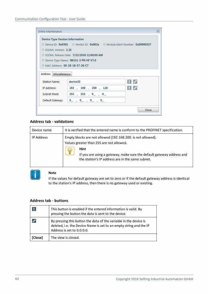
Address tab - validations
Device name It is verified that the entered name is conform to the PROFINET specification.
IP Address Empty blocks are not allowed (192.168.200. is not allowed).
Values greater than 255 are not allowed.
Hint
If you are using a gateway, make sure the default gateway address andthe station's IP address are in the same subnet.
Note
If the values for default gateway are set to zero or if the default gateway address is identicalto the station's IP address, then there is no gateway used or existing.
Address tab - buttons
This button is enabled if the entered information is valid. Bypressing the button the data is sent to the device.
By pressing this button the data of the variable in the device isdeleted, i.e. the Device Name is set to an empty string and the IPAddress is set to 0.0.0.0.
[Close] The view is closed.
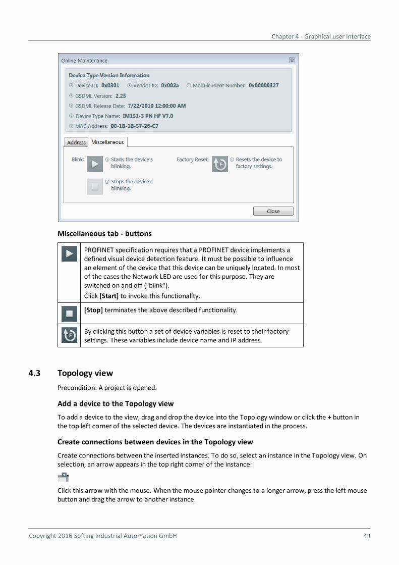
Chapter 4 - Graphical user interface
Copyright 2016 Softing Industrial Automation GmbH 43
Miscellaneous tab - buttons
PROFINET specification requires that a PROFINET device implements adefined visual device detection feature. It must be possible to influencean element of the device that this device can be uniquely located. In mostof the cases the Network LED are used for this purpose. They areswitched on and off ("blink").
Click [Start] to invoke this functionality.
[Stop] terminates the above described functionality.
By clicking this button a set of device variables is reset to their factorysettings. These variables include device name and IP address.
4.3 Topology view
Precondition: A project is opened.
Add a device to the Topology view
To add a device to the view, drag and drop the device into the Topology window or click the + button inthe top left corner of the selected device. The devices are instantiated in the process.
Create connections between devices in the Topology view
Create connections between the inserted instances. To do so, select an instance in the Topology view. Onselection, an arrow appears in the top right corner of the instance:
Click this arrow with the mouse. When the mouse pointer changes to a longer arrow, press the left mousebutton and drag the arrow to another instance.

Communication Configuration Tool - User Guide
44 Copyright 2016 Softing Industrial Automation GmbH
Display context menu
For bus-specific topology view functionality refer to
Topology view (FOUNDATION Fieldbus)
Topology view (PROFINET)
Select an instance and click the right mouse button to display the context menu. The following actions areavailable:
Menu Item Keyboardshortcut
Action
Cut Ctrl + X Cuts the selected device.
Copy Ctrl + C Copies the selected device.
Delete Ctrl + D, Del Deletes the selected device.
ConfigureModules
PROFINET only
Displays the window for specifying the modules for the selecteddevice.
Edit ConfigurationParameters
Displays the window for editing the configuration parameter valuesfor the selected device.
Edit DeviceParameters
FOUNDATION fieldbus only
Displays the window for editing the device parameter values for theselected device.
Show PortDescriptors
PROFINET only
In PROFINET, the model of the entire communication interface isdefined using Device Access Points (DAP). A communication interfacemay have one or more Ethernet ports. A port can be assigned adescriptor. This property is used for topology scans. To enter adescriptor for the port, the Show Port Descriptor option must beenabled. The entry of the descriptor is optional in the current versionof the Communication Configuration Tool.
Hide PortDescriptors
PROFINET only
The port descriptor is hidden again.
Note
A project can contain multiple Topology views.
View device properties
1. Select the device instance.
2. Then select View Properties from the menu or press Alt+Enter.
3. Property values are shown in the respective fields. They have been read from the device descriptionfile or have been entered by the user.
46
46
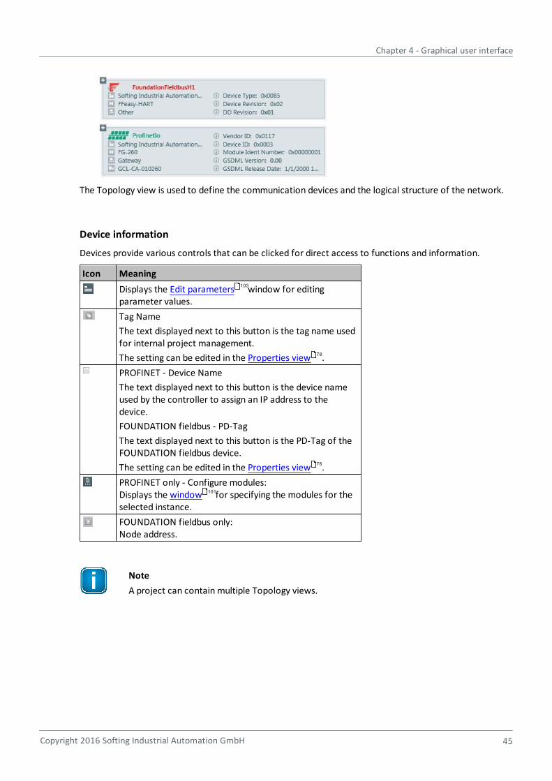
Chapter 4 - Graphical user interface
Copyright 2016 Softing Industrial Automation GmbH 45
The Topology view is used to define the communication devices and the logical structure of the network.
Device information
Devices provide various controls that can be clicked for direct access to functions and information.
Icon Meaning
Displays the Edit parameters window for editingparameter values.
Tag Name
The text displayed next to this button is the tag name usedfor internal project management.
The setting can be edited in the Properties view .
PROFINET - Device Name
The text displayed next to this button is the device nameused by the controller to assign an IP address to thedevice.
FOUNDATION fieldbus - PD-Tag
The text displayed next to this button is the PD-Tag of theFOUNDATION fieldbus device.
The setting can be edited in the Properties view .
PROFINET only - Configure modules:Displays the window for specifying the modules for theselected instance.
FOUNDATION fieldbus only:Node address.
Note
A project can contain multiple Topology views.
103
78
78
101

Communication Configuration Tool - User Guide
46 Copyright 2016 Softing Industrial Automation GmbH
4.3.1 Topology view (FOUNDATION Fieldbus)
With bus system Foundation fieldbus the appearance of devices within the Topology view is as shownbelow:
For common functionality refer to Topology view .
4.3.2 Topology view (PROFINET)
With bus system PROFINET the appearance of devices within the Topology view is as shown below:
Note
For every segment consisting of controller and devices, a separate Topology view is used.
4.3.3 Topology status icons (PROFINET only)
Status icons are displayed in the topology view directly to the left of the topology view name and indicate,whether a topology is valid and/or has been checked:
43

Chapter 4 - Graphical user interface
Copyright 2016 Softing Industrial Automation GmbH 47
The status icons indicate the following:
Icon Meaning
The configuration is valid and code has beengenerated.
The configuration is valid but no code has beengenerated.
The configuration has not been checked sincethe last change.
The configuration is not valid.
4.4 Project Explorer view
Use the project explorer
to show the topology as a tree and
to create and delete configured devices.
To do so,
1. drag and drop a device type from Device Types View and add an instance of this type to topology.
2. Drag and drop within the project explorer. Copy with Ctrl + drag/drop.
3. Copy/paste with Ctrl+C/Ctrl+V.
4. Copy/Paste/Delete via context menu.
5. Drag/Drop between project explorer view and topology view is not possible.
Note
Within the project explorer, you can only move and create devices belonging to the selectedbus type. Creating a H1 device under a link will implicitly connect the device to that link intopology.
4.5 Function block application view (FOUNDATION fieldbus only)
Precondition: current segment or selected segment is of bus system FOUNDATION fieldbus.
The function block application view allows to create function block applications representing controlloops. A control loop is thereby realized by a set of function blocks connected via FF publisher/subscriberconnections. A typical control loop consists of
an Analog Input (AI) block getting a process value like a level or a temperature,
a Proportional Integral Derivative (PID) block for the actual control task and
an Analog Output block (AO) controlling for instance the position of a valve.
For more specific details about this topic we recommend referring to the specific literature.
From the menu select View Current Function Block Application or View Function BlockApplication.
The function block application view will appear as shown below:
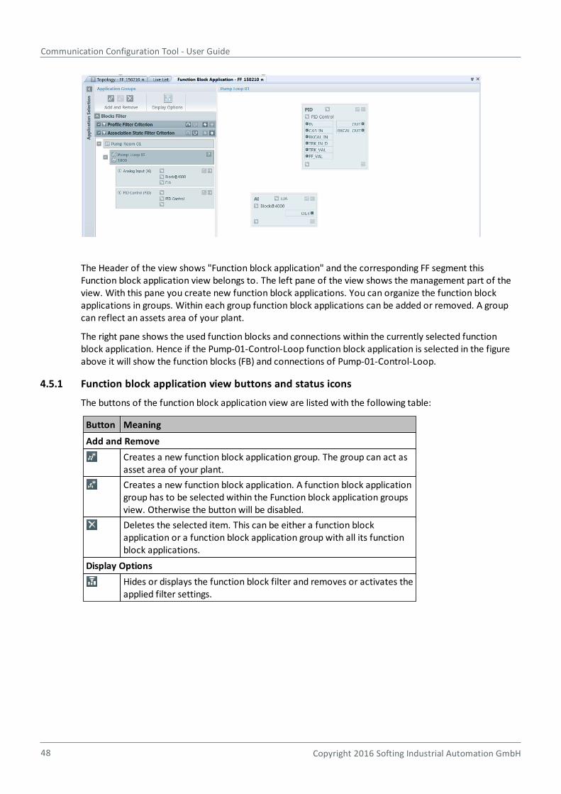
Communication Configuration Tool - User Guide
48 Copyright 2016 Softing Industrial Automation GmbH
The Header of the view shows "Function block application" and the corresponding FF segment thisFunction block application view belongs to. The left pane of the view shows the management part of theview. With this pane you create new function block applications. You can organize the function blockapplications in groups. Within each group function block applications can be added or removed. A groupcan reflect an assets area of your plant.
The right pane shows the used function blocks and connections within the currently selected functionblock application. Hence if the Pump-01-Control-Loop function block application is selected in the figureabove it will show the function blocks (FB) and connections of Pump-01-Control-Loop.
4.5.1 Function block application view buttons and status icons
The buttons of the function block application view are listed with the following table:
Button Meaning
Add and Remove
Creates a new function block application group. The group can act asasset area of your plant.
Creates a new function block application. A function block applicationgroup has to be selected within the Function block application groupsview. Otherwise the button will be disabled.
Deletes the selected item. This can be either a function blockapplication or a function block application group with all its functionblock applications.
Display Options
Hides or displays the function block filter and removes or activates theapplied filter settings.

Chapter 4 - Graphical user interface
Copyright 2016 Softing Industrial Automation GmbH 49
4.5.2 Function block application view shortcut keys
The following table shows the keyboard shortcut keys used within function block application view:
CTRL+C Copies the currently selected function block application group withall its function block applications or a selected function blockapplication into the clipboard.
CTRL+V Pastes a copied function block application group or function blockapplication. To paste a copied function block application select afunction block application group first.
Del Deletes the selected function block application group or functionblock application.
4.5.3 Function block properties in property view
With the function block application and the function block application group there are specific propertiesthat can be edited using property view:
Application group
General
Tag Name Name of the function block application group. Norestrictions apply.
Description Description of the function block application group. Norestrictions apply.
Function Block Application
General
Tag Name Name of the function block application group. No restrictions apply.
Description Description of the function block application group. No restrictions apply.
Schedule
Cycle Time (ms) Cycle time of the function block application. Unit is millisecond (ms).
Restrictions
The value has to be an integer factor of the macro cycle time defined in the segment !
Block
General
Tag Name Name of the function block application group. Norestrictions apply.
Description Description of the function block application group. Norestrictions apply.
Identity
Block Tag Unique identification of the block within the segment.
Restrictions: It has to comply with ISO 646. Its maximumlength is 32 characters.
Type
Label Type name of the block.
83 78
Communication Configuration Tool - User Guide
50 Copyright 2016 Softing Industrial Automation GmbH
General
Profile Name Profile name of the block.
Profile Revision Profile revision of this block
Address
Device Tag Name Tag name of the device hosting this function block.
Index Block start index used to address the block in the device
4.5.4 Use function blocks
4.5.4.1 Add function blocks to the function block application
With the Function block application view opened and a specific function block application selectedfunction blocks can be added to the application. Use the Instance view to add function blocks to afunction block application.
1. From the menu select View Instances or click .
2. Select the device you want to use. See figure below.
3. Make sure that the blocks of the device that you are using are displayed. If this is not the case, toggle
the button (Show / hide blocks from devices).
4. If you want to display only blocks of a certain profile (e.g. AI blocks or PID blocks), apply a block filter (
) within the instance view.
5. Each block is displayed as child of the corresponding device.
6. Use the button to add the corresponding block to the Function block application.
7. Alternatively select the block item within the instance view and drag&drop it to the Function blockapplication diagram.
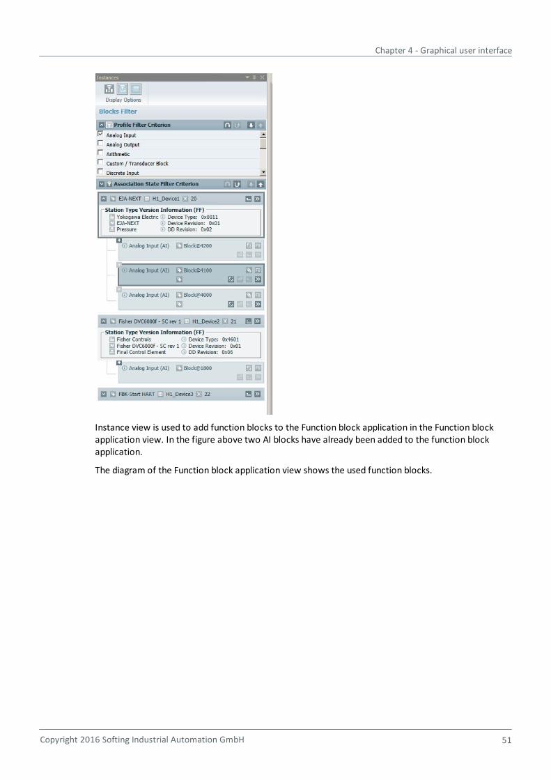
Chapter 4 - Graphical user interface
Copyright 2016 Softing Industrial Automation GmbH 51
Instance view is used to add function blocks to the Function block application in the Function blockapplication view. In the figure above two AI blocks have already been added to the function blockapplication.
The diagram of the Function block application view shows the used function blocks.

Communication Configuration Tool - User Guide
52 Copyright 2016 Softing Industrial Automation GmbH
The function blocks added to the function block application "Pump-01-Control-Loop" appear on thediagram with the following information:
The input and output parameters of the block (e.g. OUT).
The profile information of the block (e.g. AI).
The Tag name of the device the block belongs to (in the figure above EJA-PT-01).
Block tag of the block (AI-0101 in the figure above).
Tag name of the block (Block@4200 in the figure above).
4.5.4.2 Function block association
If a function block (FB) is added to a function block application, a so-called used function block is createdand an association (link) to the function block of the device is also created. This means that this functionblock of the device shall be used for the application.
Within instance view the association state of an FB of a device is also shown with the following icons:
FB is associated: It is used within a function block application.
FB is not associated: It can be used within a function block application.
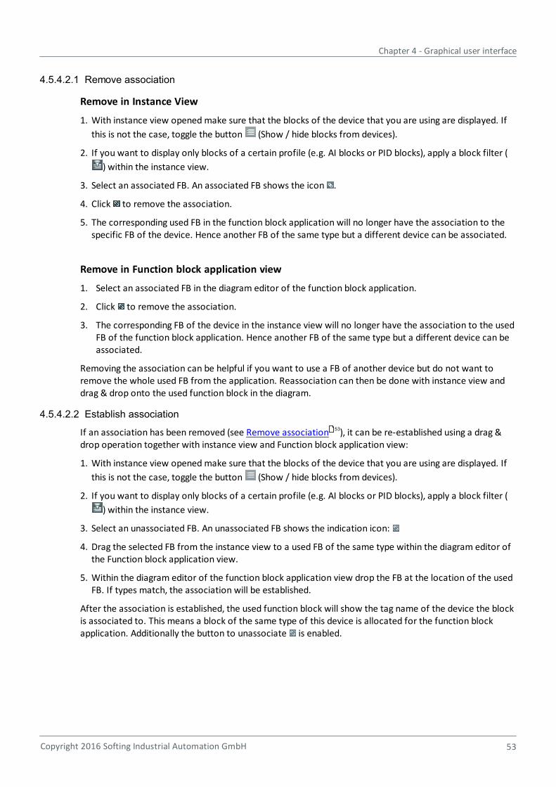
Chapter 4 - Graphical user interface
Copyright 2016 Softing Industrial Automation GmbH 53
4.5.4.2.1 Remove association
Remove in Instance View
1. With instance view opened make sure that the blocks of the device that you are using are displayed. If
this is not the case, toggle the button (Show / hide blocks from devices).
2. If you want to display only blocks of a certain profile (e.g. AI blocks or PID blocks), apply a block filter (
) within the instance view.
3. Select an associated FB. An associated FB shows the icon .
4. Click to remove the association.
5. The corresponding used FB in the function block application will no longer have the association to thespecific FB of the device. Hence another FB of the same type but a different device can be associated.
Remove in Function block application view
1. Select an associated FB in the diagram editor of the function block application.
2. Click to remove the association.
3. The corresponding FB of the device in the instance view will no longer have the association to the usedFB of the function block application. Hence another FB of the same type but a different device can beassociated.
Removing the association can be helpful if you want to use a FB of another device but do not want toremove the whole used FB from the application. Reassociation can then be done with instance view anddrag & drop onto the used function block in the diagram.
4.5.4.2.2 Establish association
If an association has been removed (see Remove association ), it can be re-established using a drag &drop operation together with instance view and Function block application view:
1. With instance view opened make sure that the blocks of the device that you are using are displayed. If
this is not the case, toggle the button (Show / hide blocks from devices).
2. If you want to display only blocks of a certain profile (e.g. AI blocks or PID blocks), apply a block filter (
) within the instance view.
3. Select an unassociated FB. An unassociated FB shows the indication icon:
4. Drag the selected FB from the instance view to a used FB of the same type within the diagram editor ofthe Function block application view.
5. Within the diagram editor of the function block application view drop the FB at the location of the usedFB. If types match, the association will be established.
After the association is established, the used function block will show the tag name of the device the blockis associated to. This means a block of the same type of this device is allocated for the function blockapplication. Additionally the button to unassociate is enabled.
53

Communication Configuration Tool - User Guide
54 Copyright 2016 Softing Industrial Automation GmbH
4.5.4.3 Operations with a used function block in the function block application
Used function block shown with the diagram editor of the function block application have a set of buttonsfor specific operations:
Opens a window allowing you to edit the configuration parameter setof the block. It is used for configuration purposes and is persisted anddownloaded to the device with the download operation.
Opens a window allowing you to edit the device parameters . You canread block parameters from the device and write block parameters tothe device. The button is disabled if the used FB is not associated.
Unassociates a used FB from its "linked" block of a device. See section Function block association . The button is disabled if the used FB is notassociated.
4.5.4.4 Locate a used function block in the function block application
If a function flock (FB) is used in the function block application, the instance view further provides a meansto show the FB in the function block application. Via the button you can navigate from the instance viewto the used FB in the function block application view.
4.5.4.5 Remove a used function block from the function block application
Within the diagram editor of the function block application select the used function block(s) you want toremove. The function blocks will be highlighted. Multi selection is possible:
1. Press the Ctrl button and select the used function block to remove.
2. Drag a bounding box (sometimes called a "rubber band") around the used FBs in the diagram area andrelease the left mouse button. This will multi-select the used FBs "in" the bounding box. To start drag abounding box press the left mouse-button and move the mouse to create the bounding box (see figurebelow):
104
103
52

Chapter 4 - Graphical user interface
Copyright 2016 Softing Industrial Automation GmbH 55
3. Right-click to open the context menu:
4. The figure shows the bounding box prior to release of the left mouse-button. All objects in thebounding box are selected if the left mouse-button is released.
5. Select the context menu item Delete or press the Del key. All selected used FBs and connectionsbetween them are deleted.
6. A query will appear asking you whether to delete the selected items or not:
7. Click [Yes] to delete the selected items.

Communication Configuration Tool - User Guide
56 Copyright 2016 Softing Industrial Automation GmbH
Hint
To suppress confirmation messages refer to Settings window .
4.5.4.6 Multiple selection in the diagram editor
Within the diagram editor of the function block application multiple used FBs and connections can beselected. This is useful for rearranging the function block application by moving the selected items orremoving multiple selected items (see Remove a used Function Block from the function block application
).
Multiple selection can be achieved by creating a bounding box (sometimes called a "rubber band") aroundthe items to select. To start dragging a bounding box press the left mouse-button and move the mouse tocreate the bounding box (see figure below). Multiple selection will then be applied if the left mouse-buttonis released.
The figure above shows the bounding box prior to release of the left mouse-button. All objects in thebounding box are selected if the left mouse-button is released.
4.5.5 Connections
Connections can be established between parameters of used function blocks on the Function blockapplication diagram. The connections correspond to Publisher / Subscriber communication relationshipsbetween function blocks in the application.
4.5.5.1 Establish a connection
1. Select View Function Block Application <Function Block Application Name> from the menu.
2. Within Function block application view select the Function block application you want to edit.Selection is done on the left pane in the tree view of application groups and function blockapplications. The left pane will show the diagram editor of the function block application view.
110
54
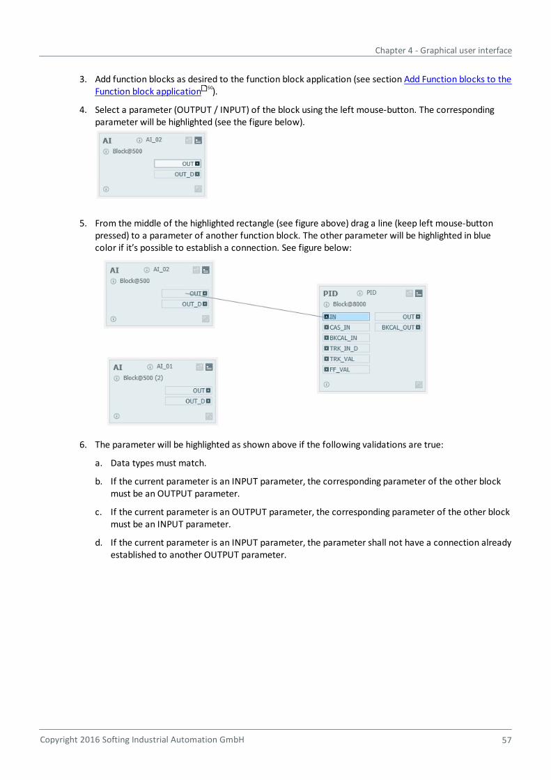
Chapter 4 - Graphical user interface
Copyright 2016 Softing Industrial Automation GmbH 57
3. Add function blocks as desired to the function block application (see section Add Function blocks to theFunction block application ).
4. Select a parameter (OUTPUT / INPUT) of the block using the left mouse-button. The correspondingparameter will be highlighted (see the figure below).
5. From the middle of the highlighted rectangle (see figure above) drag a line (keep left mouse-buttonpressed) to a parameter of another function block. The other parameter will be highlighted in bluecolor if it’s possible to establish a connection. See figure below:
6. The parameter will be highlighted as shown above if the following validations are true:
a. Data types must match.
b. If the current parameter is an INPUT parameter, the corresponding parameter of the other blockmust be an OUTPUT parameter.
c. If the current parameter is an OUTPUT parameter, the corresponding parameter of the other blockmust be an INPUT parameter.
d. If the current parameter is an INPUT parameter, the parameter shall not have a connection alreadyestablished to another OUTPUT parameter.
50
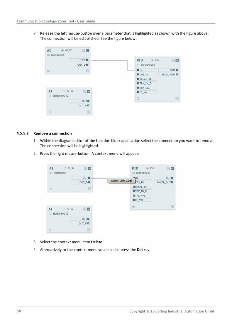
Communication Configuration Tool - User Guide
58 Copyright 2016 Softing Industrial Automation GmbH
7. Release the left mouse-button over a parameter that is highlighted as shown with the figure above.The connection will be established. See the figure below:
4.5.5.2 Remove a connection
1. Within the diagram editor of the function block application select the connection you want to remove.The connection will be highlighted.
2. Press the right mouse-button. A context menu will appear:
3. Select the context menu item Delete.
4. Alternatively to the context menu you can also press the Del key.
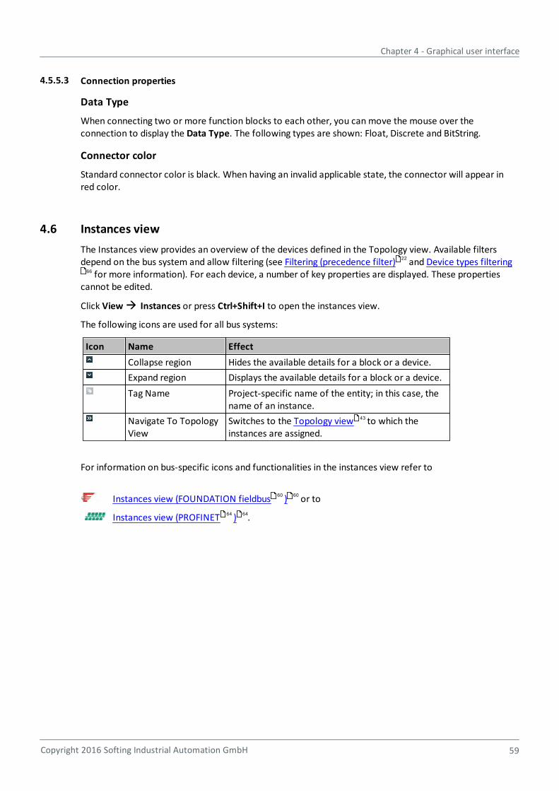
Chapter 4 - Graphical user interface
Copyright 2016 Softing Industrial Automation GmbH 59
4.5.5.3 Connection properties
Data Type
When connecting two or more function blocks to each other, you can move the mouse over theconnection to display the Data Type. The following types are shown: Float, Discrete and BitString.
Connector color
Standard connector color is black. When having an invalid applicable state, the connector will appear inred color.
4.6 Instances view
The Instances view provides an overview of the devices defined in the Topology view. Available filtersdepend on the bus system and allow filtering (see Filtering (precedence filter) and Device types filtering
for more information). For each device, a number of key properties are displayed. These propertiescannot be edited.
Click View Instances or press Ctrl+Shift+I to open the instances view.
The following icons are used for all bus systems:
Icon Name Effect
Collapse region Hides the available details for a block or a device.
Expand region Displays the available details for a block or a device.
Tag Name Project-specific name of the entity; in this case, thename of an instance.
Navigate To TopologyView
Switches to the Topology view to which theinstances are assigned.
For information on bus-specific icons and functionalities in the instances view refer to
Instances view (FOUNDATION fieldbus ) or to
Instances view (PROFINET ) .
22
66
43
60 60
64 64

Communication Configuration Tool - User Guide
60 Copyright 2016 Softing Industrial Automation GmbH
4.6.1 Instances view (FOUNDATION Fieldbus)
With a FOUNDATION fieldbus device the following data including resource, transducer and function blocksis shown:
Tag name of the device.
PD – Tag of the FF device.
Node address of the FF device.
Edit configuration parameters .
Show in Topology view – opens the Topology view and displays theselected device.
Manufacturer name - see Device types view .
Device name - see Device types view .
Device family name - Device types view .
Device Type – see Device types view .
Device Revision – see Device types view .
DD Revision – see Device types view .
104
43
64
64
64
64
64
64
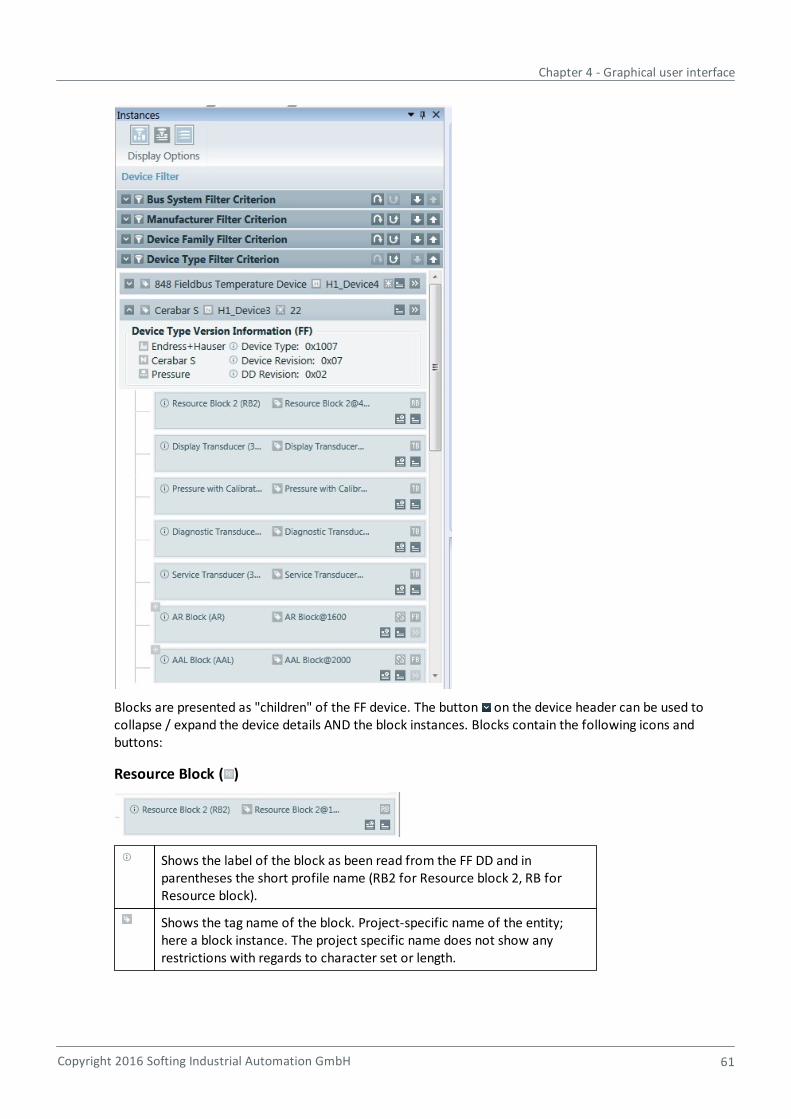
Chapter 4 - Graphical user interface
Copyright 2016 Softing Industrial Automation GmbH 61
Blocks are presented as "children" of the FF device. The button on the device header can be used tocollapse / expand the device details AND the block instances. Blocks contain the following icons andbuttons:
Resource Block ( )
Shows the label of the block as been read from the FF DD and inparentheses the short profile name (RB2 for Resource block 2, RB forResource block).
Shows the tag name of the block. Project-specific name of the entity;here a block instance. The project specific name does not show anyrestrictions with regards to character set or length.
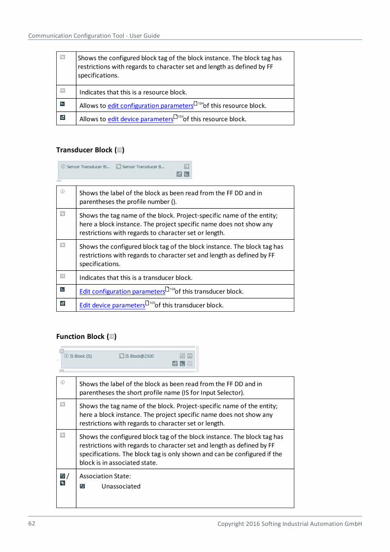
Communication Configuration Tool - User Guide
62 Copyright 2016 Softing Industrial Automation GmbH
Shows the configured block tag of the block instance. The block tag hasrestrictions with regards to character set and length as defined by FFspecifications.
Indicates that this is a resource block.
Allows to edit configuration parameters of this resource block.
Allows to edit device parameters of this resource block.
Transducer Block ( )
Shows the label of the block as been read from the FF DD and inparentheses the profile number ().
Shows the tag name of the block. Project-specific name of the entity;here a block instance. The project specific name does not show anyrestrictions with regards to character set or length.
Shows the configured block tag of the block instance. The block tag hasrestrictions with regards to character set and length as defined by FFspecifications.
Indicates that this is a transducer block.
Edit configuration parameters of this transducer block.
Edit device parameters of this transducer block.
Function Block ( )
Shows the label of the block as been read from the FF DD and inparentheses the short profile name (IS for Input Selector).
Shows the tag name of the block. Project-specific name of the entity;here a block instance. The project specific name does not show anyrestrictions with regards to character set or length.
Shows the configured block tag of the block instance. The block tag hasrestrictions with regards to character set and length as defined by FFspecifications. The block tag is only shown and can be configured if theblock is in associated state.
/ Association State:
Unassociated
104
103
104
103
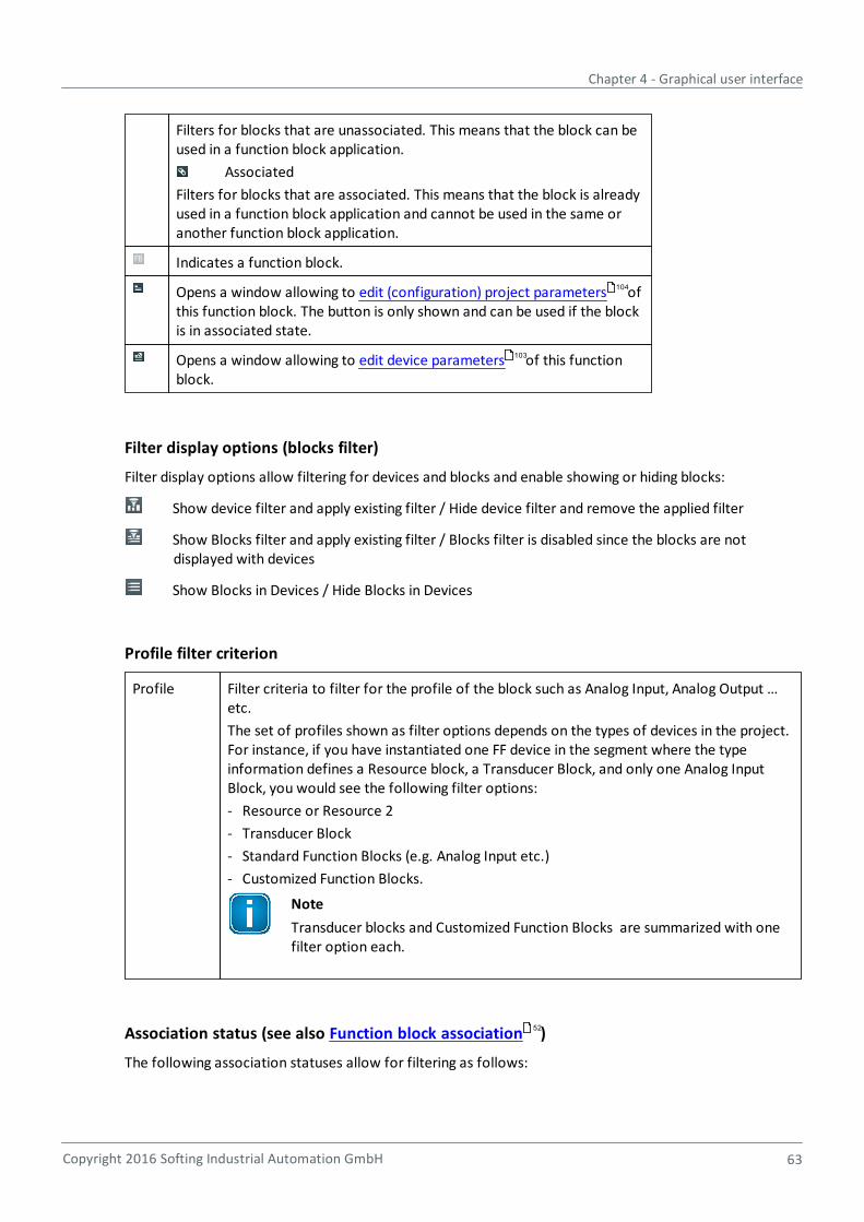
Chapter 4 - Graphical user interface
Copyright 2016 Softing Industrial Automation GmbH 63
Filters for blocks that are unassociated. This means that the block can beused in a function block application.
Associated
Filters for blocks that are associated. This means that the block is alreadyused in a function block application and cannot be used in the same oranother function block application.
Indicates a function block.
Opens a window allowing to edit (configuration) project parameters ofthis function block. The button is only shown and can be used if the blockis in associated state.
Opens a window allowing to edit device parameters of this functionblock.
Filter display options (blocks filter)
Filter display options allow filtering for devices and blocks and enable showing or hiding blocks:
Show device filter and apply existing filter / Hide device filter and remove the applied filter
Show Blocks filter and apply existing filter / Blocks filter is disabled since the blocks are notdisplayed with devices
Show Blocks in Devices / Hide Blocks in Devices
Profile filter criterion
Profile Filter criteria to filter for the profile of the block such as Analog Input, Analog Output …etc.
The set of profiles shown as filter options depends on the types of devices in the project.For instance, if you have instantiated one FF device in the segment where the typeinformation defines a Resource block, a Transducer Block, and only one Analog InputBlock, you would see the following filter options:
- Resource or Resource 2
- Transducer Block
- Standard Function Blocks (e.g. Analog Input etc.)
- Customized Function Blocks.
Note
Transducer blocks and Customized Function Blocks are summarized with onefilter option each.
Association status (see also Function block association )
The following association statuses allow for filtering as follows:
104
103
52

Communication Configuration Tool - User Guide
64 Copyright 2016 Softing Industrial Automation GmbH
Status Filtering for
Non Associable Filters for blocks that cannot be associated. This means that the block cannot beused in a function block application. This is true for resource blocks and fortransducer blocks.
Unassociated Filters for blocks that are not associated. This means that the block can be used ina function block application.
Associated Filters for blocks that are associated. This means that the block is already used in afunction block application and cannot be used in the same or another functionblock application.
For detailed information on filtering refer to Filtering (precedence filter) .
The Blocks filter works the same as the filtering in device types view (refer to Filtering (precedence filter)).
4.6.2 Instances view (PROFINET)
With a PROFINET device the following data is presented in instances view:
Display Options
Display options allows filtering for devices:
Show device filter and apply existing filter / Hide device filter and remove the applied filter
4.7 Device types view
22
22

Chapter 4 - Graphical user interface
Copyright 2016 Softing Industrial Automation GmbH 65
4.7.1 Device types view functionality
This view shows all the devices that are available in the Configurator 's type catalog. The relevant devicedescriptions have to be imported first. This is done using the Type Catalog Maintenance view .
The devices are grouped into the following categories:
Bus System: Currently, PROFINET and FOUNDATION fieldbus systems (HSE and H1) are supported.
Manufacturer: The manufacturers listed here depend on the imported device description files.
Device Type Family: The entries given here depend on the used bus system and on the imported devicedescription files (Gateway, ...).
Note
Device types will only be displayed if either the relevant manufacturer or all manufacturers areselected and the filter criteria is not deactivated. See also Filtering (precedence filter) .
The categories can be used for filtering. They are weighted in the order they appear. The order can bechanged. When a new project is created, the following order is used for filtering: Bus System -Manufacturer - Device Type Family.
4.7.2 Device types view buttons
Button Name Effect
All Device Types Displays all device types contained in the catalog. This means thatinformation from all the device description files in the catalog isavailable. The list can be narrowed down by using the filters describedbelow.
Most Recently UsedDevice Types
Displays only the device types of which instances have been created inthe Topology view.
Latest Device Types Depending on the supported fieldbus it is possible to have multiplerevisions of the same device type being imported. Then the LatestDevice types set shows only the latest revision of the device type beingimported.
67
22
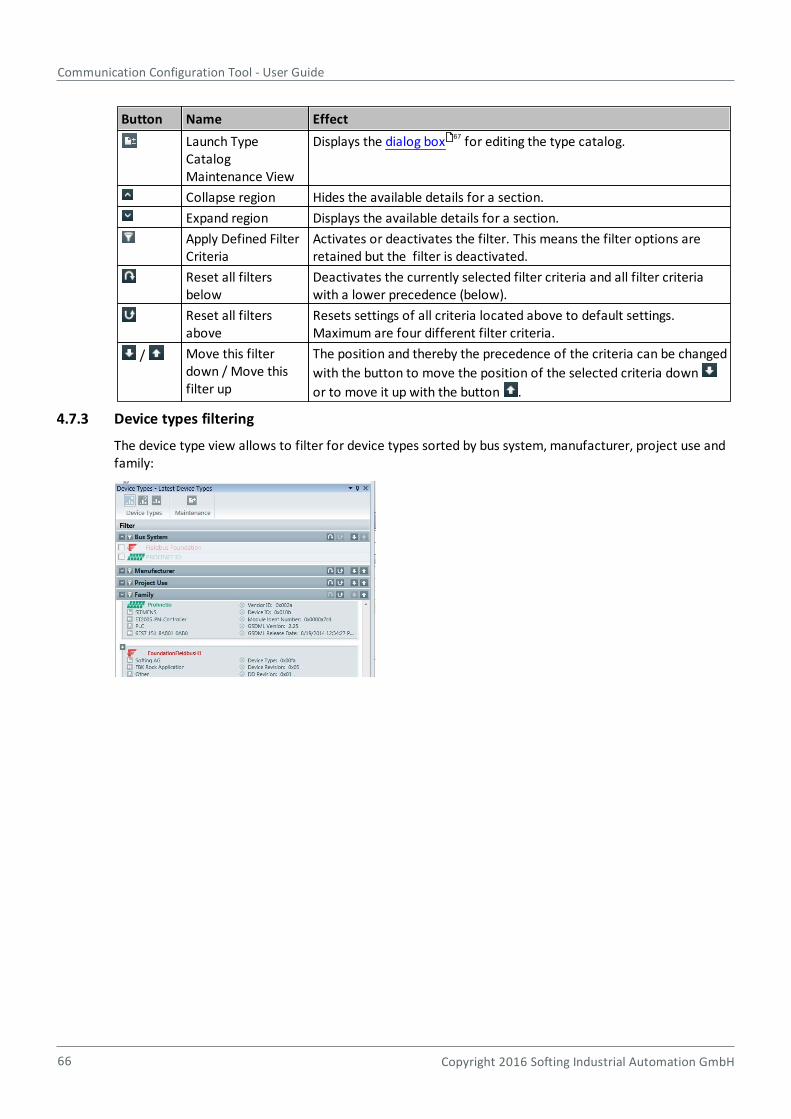
Communication Configuration Tool - User Guide
66 Copyright 2016 Softing Industrial Automation GmbH
Button Name Effect
Launch TypeCatalogMaintenance View
Displays the dialog box for editing the type catalog.
Collapse region Hides the available details for a section.
Expand region Displays the available details for a section.
Apply Defined FilterCriteria
Activates or deactivates the filter. This means the filter options areretained but the filter is deactivated.
Reset all filtersbelow
Deactivates the currently selected filter criteria and all filter criteriawith a lower precedence (below).
Reset all filtersabove
Resets settings of all criteria located above to default settings.Maximum are four different filter criteria.
/ Move this filterdown / Move thisfilter up
The position and thereby the precedence of the criteria can be changed
with the button to move the position of the selected criteria down
or to move it up with the button .
4.7.3 Device types filtering
The device type view allows to filter for device types sorted by bus system, manufacturer, project use andfamily:
67

Chapter 4 - Graphical user interface
Copyright 2016 Softing Industrial Automation GmbH 67
The currently selected filter criteria and filter options are retained for each individual device type used:
Latest device types
Depending on the supported fieldbus it is possible to have multiple revisions of the same devicetype being imported. Then the Latest device types set shows only the latest revision of the devicetype being imported.
Most recently used device types
Shows all device types that have been used most recently with a project.
All device types
Shows all device types used with a project.
/ Expand / Collapse
Expands or collapses the selected filter criteria entries
/ Move criterion up or down
Moves the position of the selected criterion down or up.
Deactivates the currently selected filter criteria and all filter criteria with a lower precedence(below).
Deactivates the currently selected filter criteria plus all filter criteria with a higher precedence(above).
Opens the Type Catalog Maintenance view .
For more information on filtering refer to Filtering (precedence filter) .
4.8 Type Catalog Maintenance view
67
22
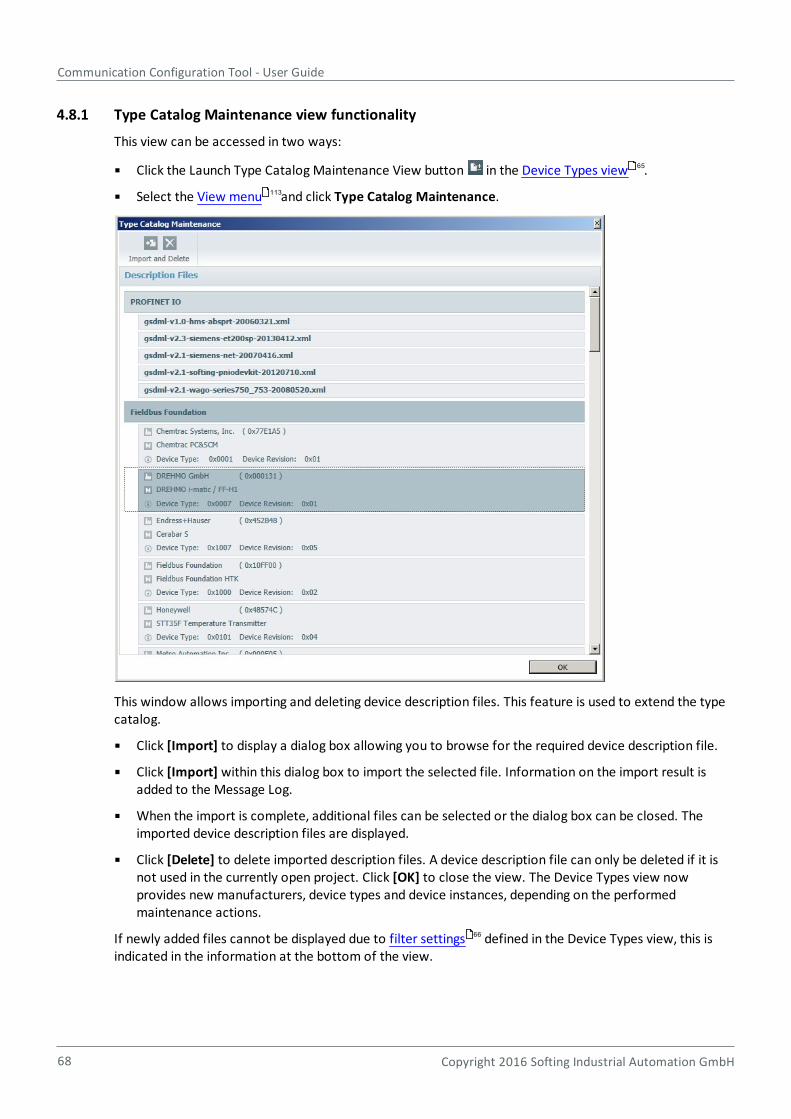
Communication Configuration Tool - User Guide
68 Copyright 2016 Softing Industrial Automation GmbH
4.8.1 Type Catalog Maintenance view functionality
This view can be accessed in two ways:
Click the Launch Type Catalog Maintenance View button in the Device Types view .
Select the View menu and click Type Catalog Maintenance.
This window allows importing and deleting device description files. This feature is used to extend the typecatalog.
Click [Import] to display a dialog box allowing you to browse for the required device description file.
Click [Import] within this dialog box to import the selected file. Information on the import result isadded to the Message Log.
When the import is complete, additional files can be selected or the dialog box can be closed. Theimported device description files are displayed.
Click [Delete] to delete imported description files. A device description file can only be deleted if it isnot used in the currently open project. Click [OK] to close the view. The Device Types view nowprovides new manufacturers, device types and device instances, depending on the performedmaintenance actions.
If newly added files cannot be displayed due to filter settings defined in the Device Types view, this isindicated in the information at the bottom of the view.
65
113
66
Chapter 4 - Graphical user interface
Copyright 2016 Softing Industrial Automation GmbH 69
4.8.2 Type Catalog Maintenance buttons
Button Name Effect
Import Imports the device description file specified in the dialog box into the catalog.Device description files up to version 2.3 can be imported.
Remove Removes the selected device description files from the catalog. A confirmationmessage appears before final deletion. To suppress confirmation messagesrefer to Settings window .
4.9 Templates view (FOUNDATION fieldbus only)
Templates are used to store and reuse a set of parameters assigned to a device type.
The templates view allows to add new templates and to edit existing templates. A template wizard
supports this functionality. Select View Template to open the view. The first time an empty window isopened.
110
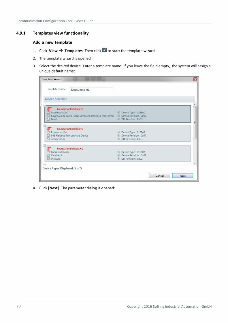
Communication Configuration Tool - User Guide
70 Copyright 2016 Softing Industrial Automation GmbH
4.9.1 Templates view functionality
Add a new template
1. Click View Templates. Then click to start the template wizard.
2. The template wizard is opened.
3. Select the desired device. Enter a template name. If you leave the field empty, the system will assign aunique default name:
4. Click [Next]. The parameter dialog is opened:

Chapter 4 - Graphical user interface
Copyright 2016 Softing Industrial Automation GmbH 71
5. Select the block. Then switch to the parameters list to include the required parameters in the template:
a. Select all parameters by clicking left beside Name or
b. select single parameters by activating the respective check box.
6. To remove or exclude a parameter leave the check box empty (deactivated).
7. Repeat this action for any block you want to add.
8. Click [Finish] to complete the template wizard.
Edit a template
1. Select a template, then click to start the template wizard. The parameter dialog is opened.
2. Modify the information as described above in Add a new template.
3. Click [Finish] to complete your modifications.
Configure the values of a template
Select the block for which you want to configure the values. The values can be entered the same way as inthe parameter view.
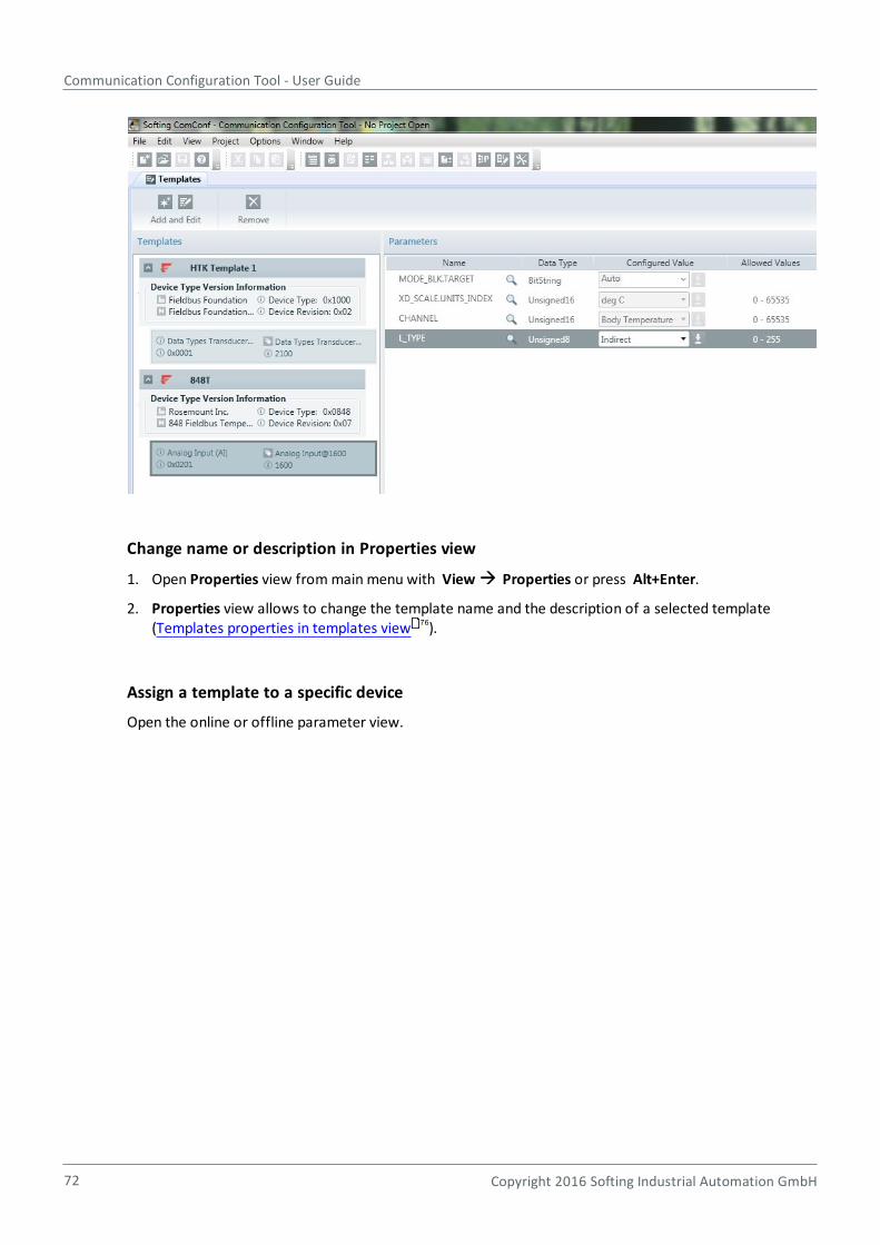
Communication Configuration Tool - User Guide
72 Copyright 2016 Softing Industrial Automation GmbH
Change name or description in Properties view
1. Open Properties view from main menu with View Properties or press Alt+Enter.
2. Properties view allows to change the template name and the description of a selected template(Templates properties in templates view ).
Assign a template to a specific device
Open the online or offline parameter view.
76
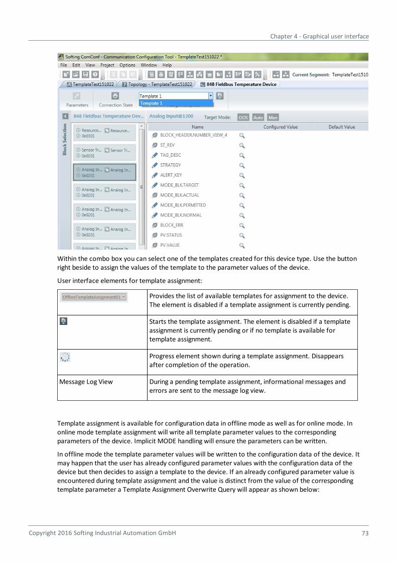
Chapter 4 - Graphical user interface
Copyright 2016 Softing Industrial Automation GmbH 73
Within the combo box you can select one of the templates created for this device type. Use the buttonright beside to assign the values of the template to the parameter values of the device.
User interface elements for template assignment:
Provides the list of available templates for assignment to the device.The element is disabled if a template assignment is currently pending.
Starts the template assignment. The element is disabled if a templateassignment is currently pending or if no template is available fortemplate assignment.
Progress element shown during a template assignment. Disappearsafter completion of the operation.
Message Log View During a pending template assignment, informational messages anderrors are sent to the message log view.
Template assignment is available for configuration data in offline mode as well as for online mode. Inonline mode template assignment will write all template parameter values to the correspondingparameters of the device. Implicit MODE handling will ensure the parameters can be written.
In offline mode the template parameter values will be written to the configuration data of the device. Itmay happen that the user has already configured parameter values with the configuration data of thedevice but then decides to assign a template to the device. If an already configured parameter value isencountered during template assignment and the value is distinct from the value of the correspondingtemplate parameter a Template Assignment Overwrite Query will appear as shown below:

Communication Configuration Tool - User Guide
74 Copyright 2016 Softing Industrial Automation GmbH
With this query you have four options:
Overwrite the currently configured parameter value with the value of the template.
Skip the currently processed parameter and thereby leave the already configured value.
Overwrite all parameters having a configured value with the corresponding values of the template.
Skip all remaining parameters having a configured value that is distinct from the correspondingtemplate parameter value and thereby leaving the already configured values.
4.9.2 Templates view buttons and elements
Button Name Effect
Add template Opens the corresponding dialog.
Edit template Edits a selected template.
Copy template Creates a copy of an already existing template.
Remove Removes the selected template.
Displayed in the left window pane:
Template name,
device type, the template is linked to with device type information,
blocks used for the template with block type information:
User interface elements for template definition
Allows to modify the name of the template.
Allows to modify the description of the template.
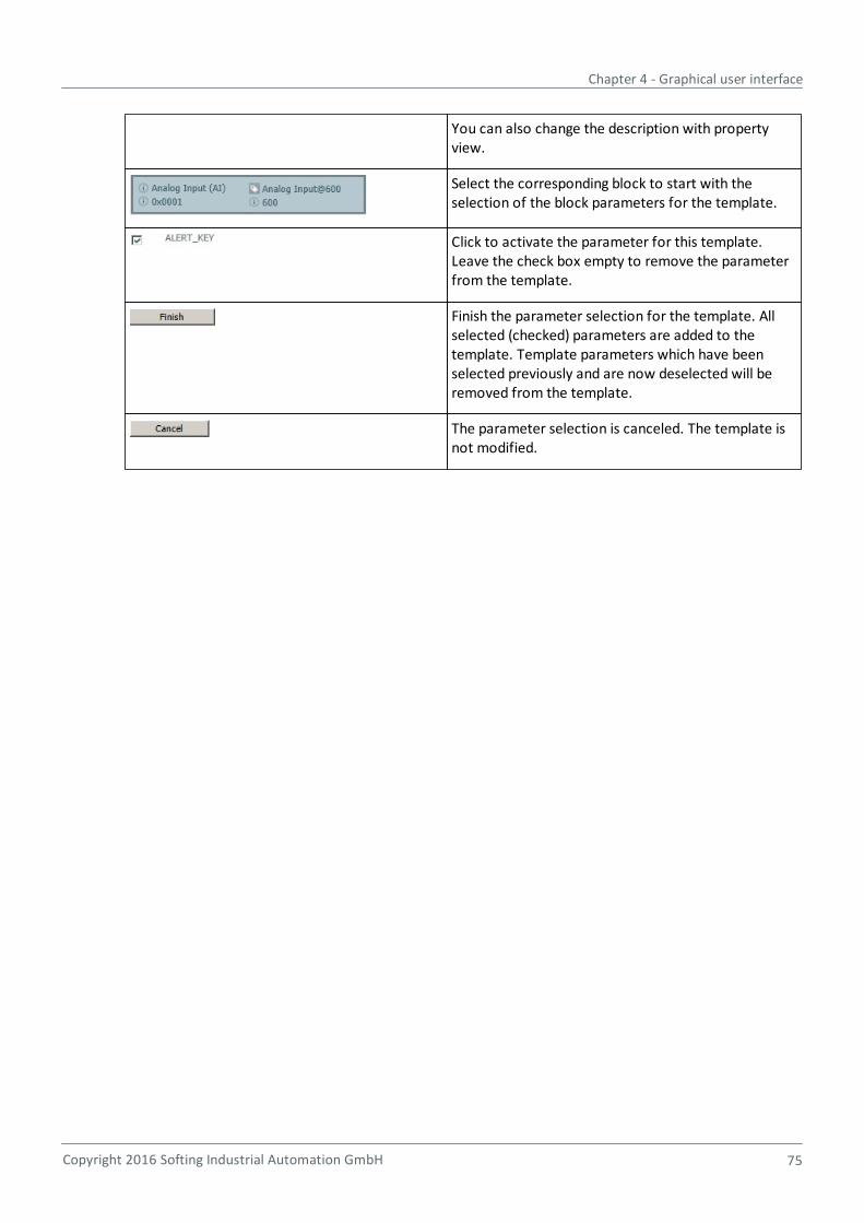
Chapter 4 - Graphical user interface
Copyright 2016 Softing Industrial Automation GmbH 75
You can also change the description with propertyview.
Select the corresponding block to start with theselection of the block parameters for the template.
Click to activate the parameter for this template.Leave the check box empty to remove the parameterfrom the template.
Finish the parameter selection for the template. Allselected (checked) parameters are added to thetemplate. Template parameters which have beenselected previously and are now deselected will beremoved from the template.
The parameter selection is canceled. The template isnot modified.
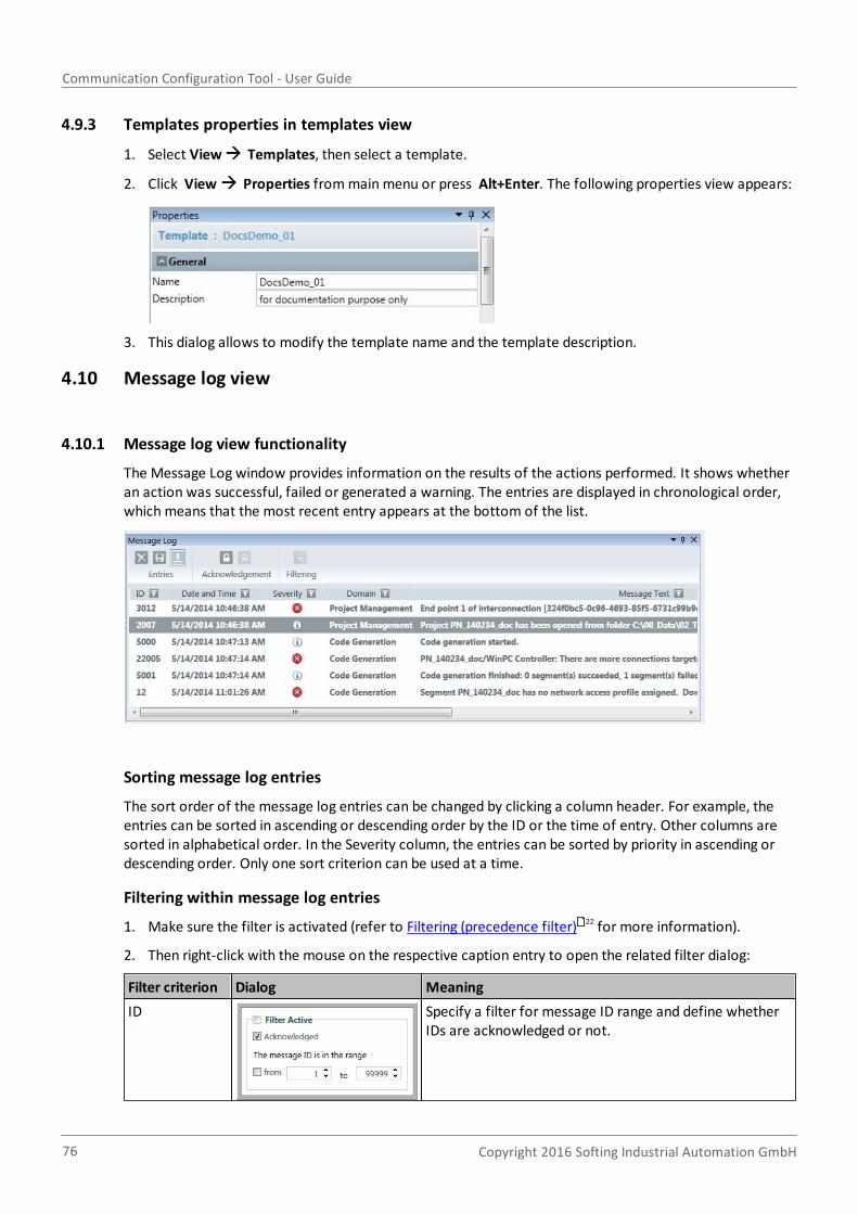
Communication Configuration Tool - User Guide
76 Copyright 2016 Softing Industrial Automation GmbH
4.9.3 Templates properties in templates view
1. Select View Templates, then select a template.
2. Click View Properties from main menu or press Alt+Enter. The following properties view appears:
3. This dialog allows to modify the template name and the template description.
4.10 Message log view
4.10.1 Message log view functionality
The Message Log window provides information on the results of the actions performed. It shows whetheran action was successful, failed or generated a warning. The entries are displayed in chronological order,which means that the most recent entry appears at the bottom of the list.
Sorting message log entries
The sort order of the message log entries can be changed by clicking a column header. For example, theentries can be sorted in ascending or descending order by the ID or the time of entry. Other columns aresorted in alphabetical order. In the Severity column, the entries can be sorted by priority in ascending ordescending order. Only one sort criterion can be used at a time.
Filtering within message log entries
1. Make sure the filter is activated (refer to Filtering (precedence filter) for more information).
2. Then right-click with the mouse on the respective caption entry to open the related filter dialog:
Filter criterion Dialog Meaning
ID Specify a filter for message ID range and define whetherIDs are acknowledged or not.
22

Chapter 4 - Graphical user interface
Copyright 2016 Softing Industrial Automation GmbH 77
Filter criterion Dialog Meaning
Date and Time Specify a filter for date and time range to display onlythose messages that have been generated in the specifiedrange.
Severity Specify one or more severity types such as
Error
Information
Warning
to display only those messages which contain thespecified message.
Domain Specify one or more domain types.
Message Text Specify a part of a message text, e.g. "connection" tofilter for messages that contain the term "connection".
Project Name Specify a project name or a part of it, e.g. "FF" to filter forproject names that contain the characters "FF".
Project Path Specify a project path or a part of it, e.g. "\custom" tofilter for project paths that contain the characters"\custom".
Host Machine Specify a host machine name or a part of it, e.g. "1234" tofilter for host machine names that contain the numbers"1234".
4.10.2 Message log view buttons
Button Name Effect
Delete all message entries Deletes all messages
Delete all selected messageentries
Deletes one or more selected messages.
Save messages to file Saves all messages to a file. You can specify thename and location for the file. The file is saved inCSV format. This format cannot be changed.
Communication Configuration Tool - User Guide
78 Copyright 2016 Softing Industrial Automation GmbH
Button Name Effect
Force the Message Log listto scroll to the newly addedelement at the end of thelist
Lists all messages in reverse chronological order.Use this button to scroll to the most recent entryat the bottom of the list.
Acknowledge all selectedunacknowledged entries
Displays all unacknowledged messages in bold.Acknowledged messages are displayed in normaltype. It is possible to acknowledge multiplemessages in a single step.
Unacknowledge selectedacknowledged entries
Undoes the change from bold to normal type.
Remove filters Clears all filters defined in the columns.
For sorting message log entries refer to Sorting Message log entries .
For filtering refer to Filtering (precedence filter) .
4.11 Properties view
Properties are focus-related, i.e. if you select a device in the topology view and then select View Properties from the menu, you will display the properties of that selected device. If you do not select anydevice, the segment properties will be displayed.
You can find detailed information in:
Segment properties view (FOUNDATION fieldbus)
Device properties view (FOUNDATION Fieldbus)
Function block properties in property view
Templates properties in templates view
Segment properties view (PROFINET)
Controller and device properties view (PROFINET)
Note
Project properties are displayed with Project Project Properties from the menu. Thisdialog allows changing Project Name and Project Description.
4.11.1 Segment properties view
76
22
79
85
49
76
85
92
112
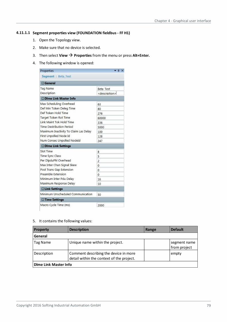
Chapter 4 - Graphical user interface
Copyright 2016 Softing Industrial Automation GmbH 79
4.11.1.1 Segment properties view (FOUNDATION fieldbus - FF H1)
1. Open the Topology view.
2. Make sure that no device is selected.
3. Then select View Properties from the menu or press Alt+Enter.
4. The following window is opened:
5. It contains the following values:
Property Description Range Default
General
Tag Name Unique name within the project. segment namefrom project
Description Comment describing the device in moredetail within the context of the project.
empty
Dlme Link Master Info
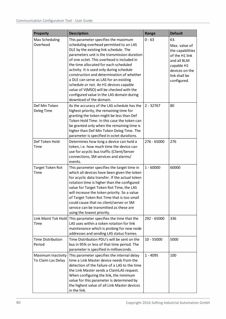
Communication Configuration Tool - User Guide
80 Copyright 2016 Softing Industrial Automation GmbH
Property Description Range Default
Max SchedulingOverhead
This parameter specifies the maximumscheduling overhead permitted to an LASDLE by the existing link schedule. Theparameters unit is the transmission durationof one octet. This overhead is included inthe time allocated for each scheduledactivity. It is used only during scheduleconstruction and determination of whethera DLE can serve as LAS for an existingschedule or not. An H1 devices capablevalue of V(MSO) will be checked with theconfigured value in the LAS domain duringdownload of the domain.
0 - 63 63.
Max. value ofthe capabilitiesof the H1 linkand all BLMcapable H1devices on thelink shall beconfigured.
Def Min TokenDeleg Time
As the accuracy of the LAS schedule has thehighest priority, the remaining time forgranting the token might be less than DefToken Hold Time. In this case the token canbe granted only when the remaining time ishigher than Def Min Token Deleg Time. Theparameter is specified in octet durations.
2 - 32767 80
Def Token HoldTime
Determines how long a device can hold atoken, i.e. how much time the device canuse for acyclic bus traffic (Client/Serverconnections, SM services and alarms/events.
276 - 65000 276
Target Token RotTime
This parameter specifies the target time inwhich all devices have been given the tokenfor acyclic data transfer. If the actual tokenrotation time is higher than the configuredvalue for Target Token Rot Time, the LASwill increase the token priority. So a valueof Target Token Rot Time that is too smallcould cause that no client/server or SMservice can be transmitted as these areusing the lowest priority.
1 - 60000 60000
Link Maint Tok HoldTime
This parameter specifies the time that theLAS uses within a token rotation for linkmaintenance which is probing for new nodeaddresses and sending LAS status frames.
292 - 65000 336
Time DistributionPeriod
Time Distribution PDU's will be sent on thebus in 95% or less of that time period. Theparameter is specified in milliseconds.
10 - 55000 5000
Maximum InactivityTo Claim Las Delay
This parameter specifies the internal delaytime a Link Master device needs from thedetection of the failure of a LAS to the timethe Link Master sends a ClaimLAS request.When configuring the link, the minimumvalue for this parameter is determined bythe highest value of all Link Master devicesin the link.
1 - 4095 100
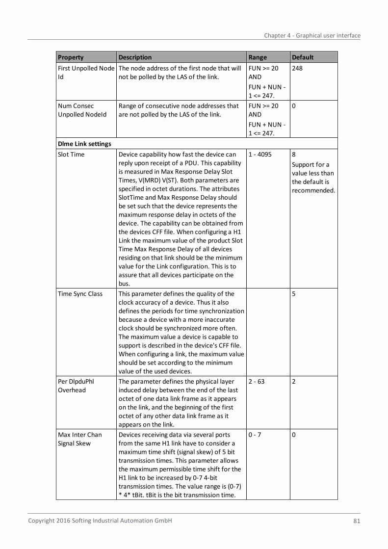
Chapter 4 - Graphical user interface
Copyright 2016 Softing Industrial Automation GmbH 81
Property Description Range Default
First Unpolled NodeId
The node address of the first node that willnot be polled by the LAS of the link.
FUN >= 20AND
FUN + NUN -1 <= 247.
248
Num ConsecUnpolled NodeId
Range of consecutive node addresses thatare not polled by the LAS of the link.
FUN >= 20AND
FUN + NUN -1 <= 247.
0
Dlme Link settings
Slot Time Device capability how fast the device canreply upon receipt of a PDU. This capabilityis measured in Max Response Delay SlotTimes, V(MRD) V(ST). Both parameters arespecified in octet durations. The attributesSlotTime and Max Response Delay shouldbe set such that the device represents themaximum response delay in octets of thedevice. The capability can be obtained fromthe devices CFF file. When configuring a H1Link the maximum value of the product SlotTime Max Response Delay of all devicesresiding on that link should be the minimumvalue for the Link configuration. This is toassure that all devices participate on thebus.
1 - 4095 8
Support for avalue less thanthe default isrecommended.
Time Sync Class This parameter defines the quality of theclock accuracy of a device. Thus it alsodefines the periods for time synchronizationbecause a device with a more inaccurateclock should be synchronized more often.The maximum value a device is capable tosupport is described in the device's CFF file.When configuring a link, the maximum valueshould be set according to the minimumvalue of the used devices.
5
Per DlpduPhlOverhead
The parameter defines the physical layerinduced delay between the end of the lastoctet of one data link frame as it appearson the link, and the beginning of the firstoctet of any other data link frame as itappears on the link.
2 - 63 2
Max Inter ChanSignal Skew
Devices receiving data via several portsfrom the same H1 link have to consider amaximum time shift (signal skew) of 5 bittransmission times. This parameter allowsthe maximum permissible time shift for theH1 link to be increased by 0-7 4-bittransmission times. The value range is (0-7)* 4* tBit. tBit is the bit transmission time.
0 - 7 0

Communication Configuration Tool - User Guide
82 Copyright 2016 Softing Industrial Automation GmbH
Property Description Range Default
Post Trans GapExtension
After every transmission, a gap of 4 bittransmission times is inserted. Thisparameter allows the gap to be increased bya further 0-7 4-bit transmission times. Thevalue range is (0-7) * 4* tBit. tBit is the bittransmission time. Increasing this valueleads to an increase in Per DlpduPhlOverhead.
0 - 7 0
Preamble Extension Each frame on the H1 link starts with apreamble octet which is used by thereceiving nodes (Devices) to synchronize tothe signal clock. The number of preamble(s)can be extended when setting thisparameter. The default value is 0. Networksincluding digital repeaters may require largervalues.
0 - 7 0
Minimum Inter PduDelay
This parameter specifies the minimuminterval between two frames on the H1 link.The minimum value of Minimum Inter PduDelay which a device is able to support isdescribed in the CFF file of a device. Whenconfiguring the H1 link, the minimum valuethat can be used for Minimum Inter PduDelay is the maximum of the values fromthe CFF files of the used devices.
Max. value ofthecapabilities ofthe H1 linkand all H1devices onthe link shallbeconfigured.
MaximumResponse Delay
Device capability how fast the device canreply upon receipt of a PDU. This capabilityis measured in Maximum Response DelaySlot Times, V(MRD) V(ST). Both parametersare specified in octet durations. Theattributes Maximum Response Delay andSlot Time should be set such that the devicerepresents the maximum response delay inoctets of the device. The capability can beobtained from the devices CFF file. Whenconfiguring a H1 Link the maximum value ofthe product Slot Time u Maximum ResponseDelay of all devices residing on that linkshould be the minimum value for the Linkconfiguration. This is to assure that alldevices participate on the bus.
1 - 11 10
Link settings
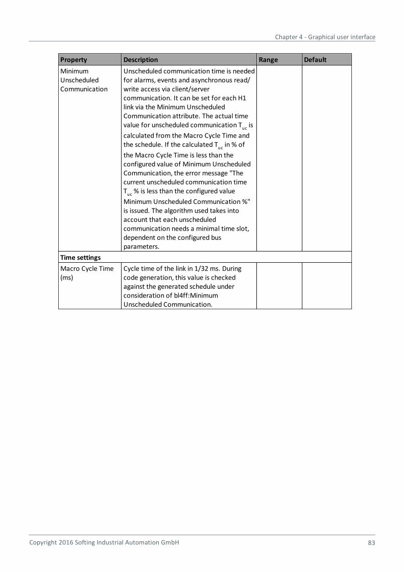
Chapter 4 - Graphical user interface
Copyright 2016 Softing Industrial Automation GmbH 83
Property Description Range Default
MinimumUnscheduledCommunication
Unscheduled communication time is neededfor alarms, events and asynchronous read/write access via client/servercommunication. It can be set for each H1link via the Minimum UnscheduledCommunication attribute. The actual timevalue for unscheduled communication Tuc is
calculated from the Macro Cycle Time andthe schedule. If the calculated Tuc in % of
the Macro Cycle Time is less than theconfigured value of Minimum UnscheduledCommunication, the error message "Thecurrent unscheduled communication timeT
uc % is less than the configured value
Minimum Unscheduled Communication %"is issued. The algorithm used takes intoaccount that each unscheduledcommunication needs a minimal time slot,dependent on the configured busparameters.
Time settings
Macro Cycle Time(ms)
Cycle time of the link in 1/32 ms. Duringcode generation, this value is checkedagainst the generated schedule underconsideration of bl4ff:MinimumUnscheduled Communication.
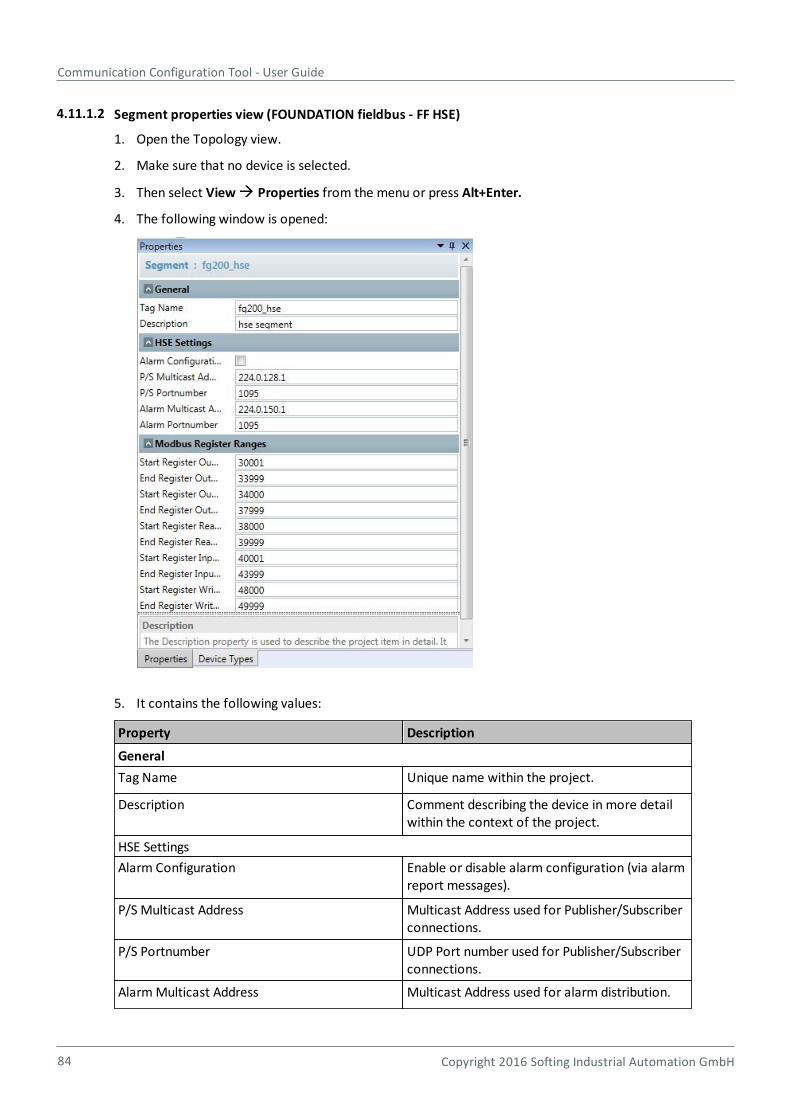
Communication Configuration Tool - User Guide
84 Copyright 2016 Softing Industrial Automation GmbH
4.11.1.2 Segment properties view (FOUNDATION fieldbus - FF HSE)
1. Open the Topology view.
2. Make sure that no device is selected.
3. Then select View Properties from the menu or press Alt+Enter.
4. The following window is opened:
5. It contains the following values:
Property Description
General
Tag Name Unique name within the project.
Description Comment describing the device in more detailwithin the context of the project.
HSE Settings
Alarm Configuration Enable or disable alarm configuration (via alarmreport messages).
P/S Multicast Address Multicast Address used for Publisher/Subscriberconnections.
P/S Portnumber UDP Port number used for Publisher/Subscriberconnections.
Alarm Multicast Address Multicast Address used for alarm distribution.
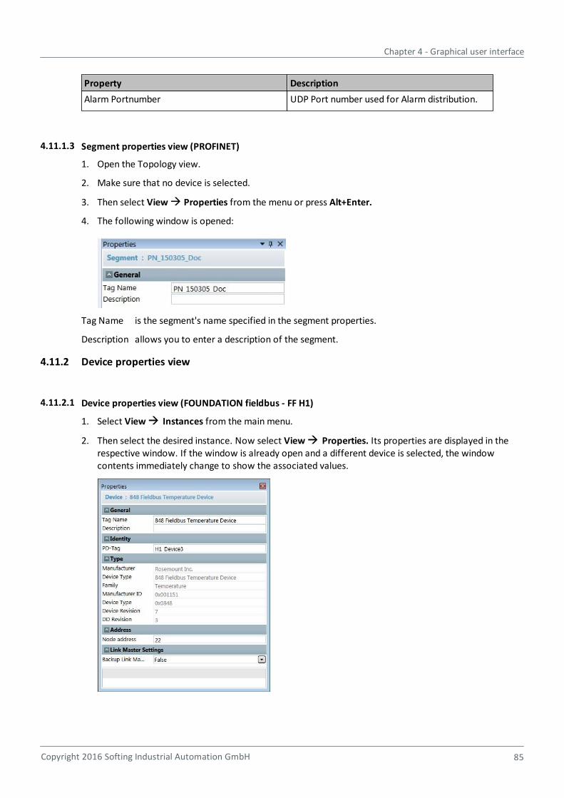
Chapter 4 - Graphical user interface
Copyright 2016 Softing Industrial Automation GmbH 85
Property Description
Alarm Portnumber UDP Port number used for Alarm distribution.
4.11.1.3 Segment properties view (PROFINET)
1. Open the Topology view.
2. Make sure that no device is selected.
3. Then select View Properties from the menu or press Alt+Enter.
4. The following window is opened:
Tag Name is the segment's name specified in the segment properties.
Description allows you to enter a description of the segment.
4.11.2 Device properties view
4.11.2.1 Device properties view (FOUNDATION fieldbus - FF H1)
1. Select View Instances from the main menu.
2. Then select the desired instance. Now select View Properties. Its properties are displayed in therespective window. If the window is already open and a different device is selected, the windowcontents immediately change to show the associated values.
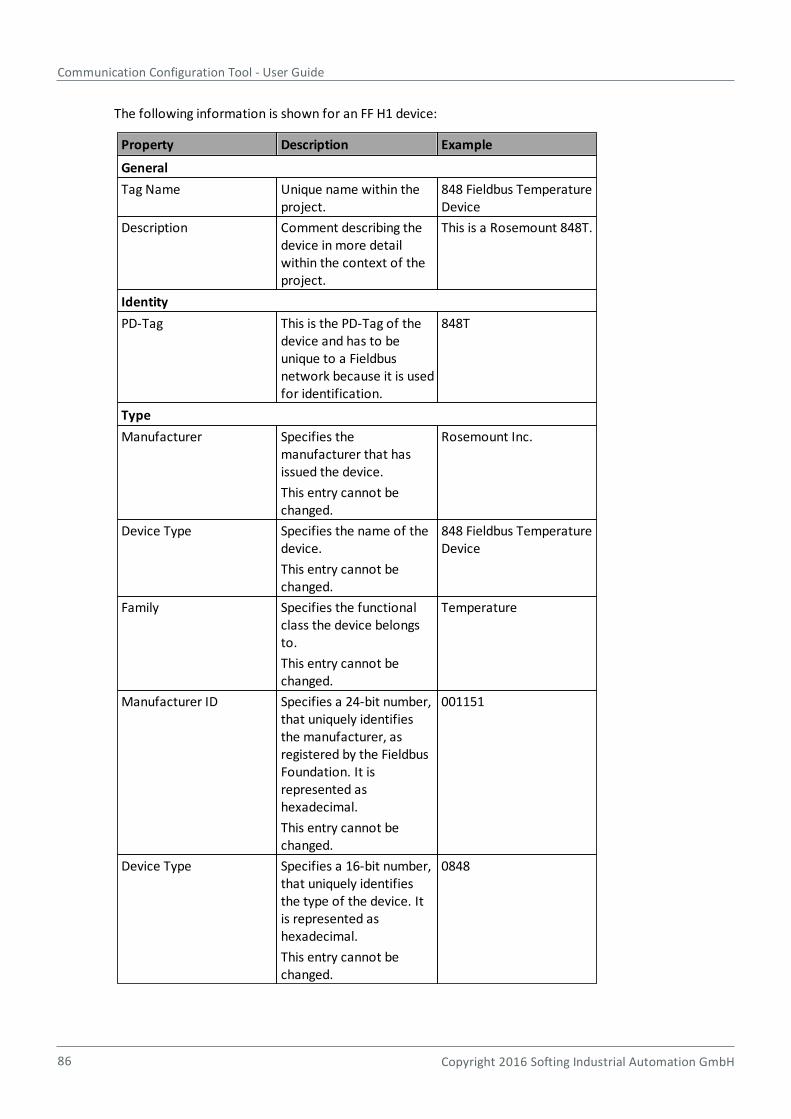
Communication Configuration Tool - User Guide
86 Copyright 2016 Softing Industrial Automation GmbH
The following information is shown for an FF H1 device:
Property Description Example
General
Tag Name Unique name within theproject.
848 Fieldbus TemperatureDevice
Description Comment describing thedevice in more detailwithin the context of theproject.
This is a Rosemount 848T.
Identity
PD-Tag This is the PD-Tag of thedevice and has to beunique to a Fieldbusnetwork because it is usedfor identification.
848T
Type
Manufacturer Specifies themanufacturer that hasissued the device.
This entry cannot bechanged.
Rosemount Inc.
Device Type Specifies the name of thedevice.
This entry cannot bechanged.
848 Fieldbus TemperatureDevice
Family Specifies the functionalclass the device belongsto.
This entry cannot bechanged.
Temperature
Manufacturer ID Specifies a 24-bit number,that uniquely identifiesthe manufacturer, asregistered by the FieldbusFoundation. It isrepresented ashexadecimal.
This entry cannot bechanged.
001151
Device Type Specifies a 16-bit number,that uniquely identifiesthe type of the device. Itis represented ashexadecimal.
This entry cannot bechanged.
0848
Chapter 4 - Graphical user interface
Copyright 2016 Softing Industrial Automation GmbH 87
Property Description Example
Device Revision Specifies an 8-bit number,that uniquely identifiesthe revision level of thedevice type. It isrepresented ashexadecimal.
This entry cannot bechanged.
07
DD Revision Specifies an 8-bit number,that uniquely identifiesthe revision level of thedevice descriptionscorresponding to thedevice type. It isrepresented ashexadecimal.
This entry cannot bechanged.
03
Address
Node Address The node address of thedevice.
20
Link Master Settings
Backup Link Master Specifies if the deviceshall act as backup linkmaster.
False
4.11.2.2 Device properties view (FOUNDATION fieldbus - FF HSE)
1. Select View Instances from the main menu.
2. Then select the desired instance. Now select View Properties. Its properties are displayed in therespective window. If the window is already open and a different device is selected, the windowcontents immediately change to show the associated values.
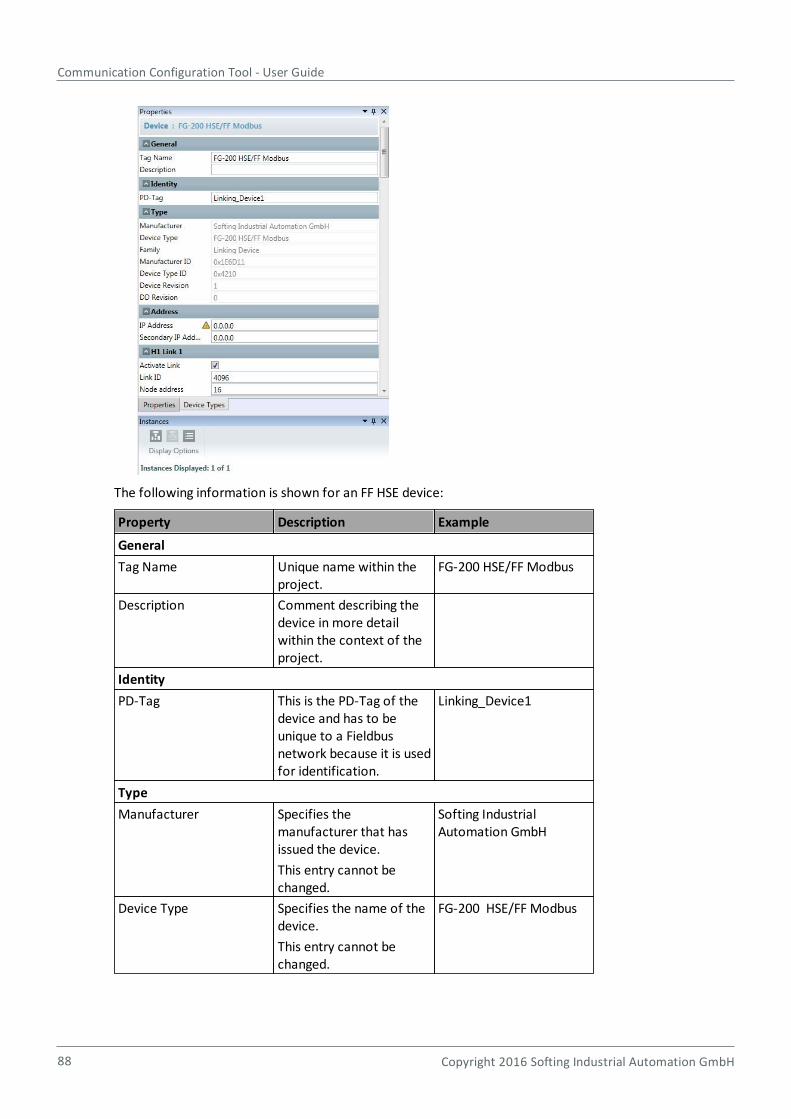
Communication Configuration Tool - User Guide
88 Copyright 2016 Softing Industrial Automation GmbH
The following information is shown for an FF HSE device:
Property Description Example
General
Tag Name Unique name within theproject.
FG-200 HSE/FF Modbus
Description Comment describing thedevice in more detailwithin the context of theproject.
Identity
PD-Tag This is the PD-Tag of thedevice and has to beunique to a Fieldbusnetwork because it is usedfor identification.
Linking_Device1
Type
Manufacturer Specifies themanufacturer that hasissued the device.
This entry cannot bechanged.
Softing IndustrialAutomation GmbH
Device Type Specifies the name of thedevice.
This entry cannot bechanged.
FG-200 HSE/FF Modbus
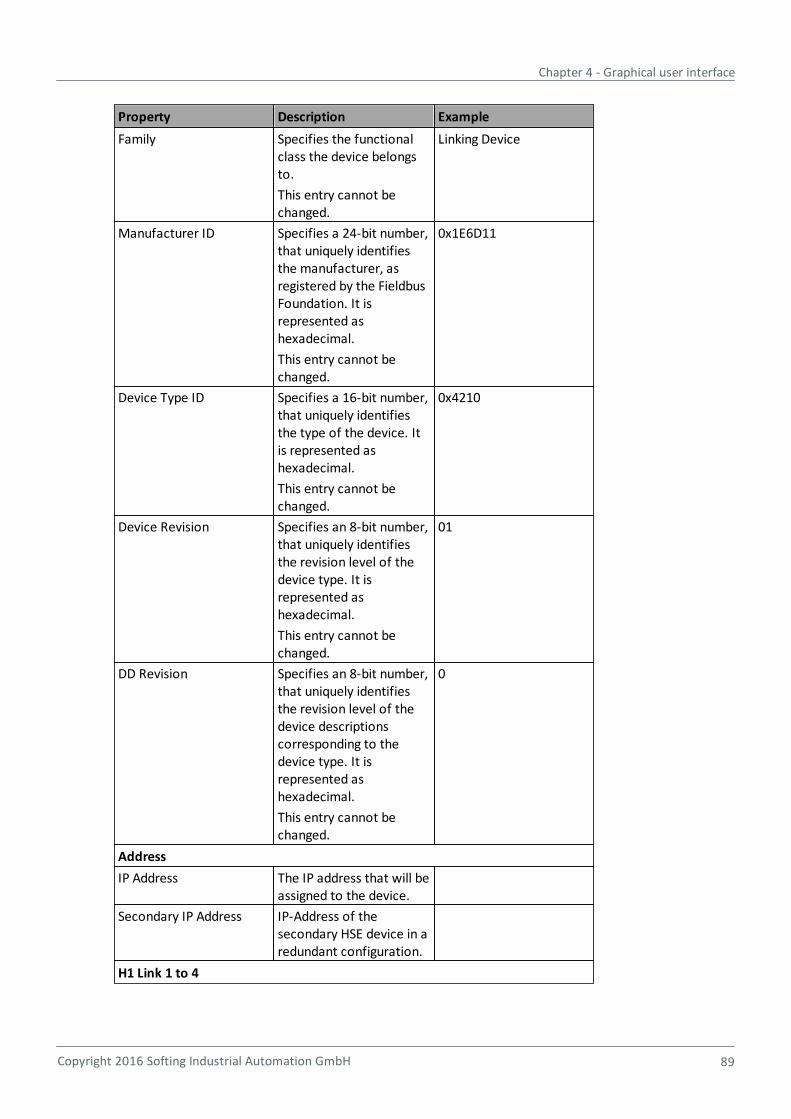
Chapter 4 - Graphical user interface
Copyright 2016 Softing Industrial Automation GmbH 89
Property Description Example
Family Specifies the functionalclass the device belongsto.
This entry cannot bechanged.
Linking Device
Manufacturer ID Specifies a 24-bit number,that uniquely identifiesthe manufacturer, asregistered by the FieldbusFoundation. It isrepresented ashexadecimal.
This entry cannot bechanged.
0x1E6D11
Device Type ID Specifies a 16-bit number,that uniquely identifiesthe type of the device. Itis represented ashexadecimal.
This entry cannot bechanged.
0x4210
Device Revision Specifies an 8-bit number,that uniquely identifiesthe revision level of thedevice type. It isrepresented ashexadecimal.
This entry cannot bechanged.
01
DD Revision Specifies an 8-bit number,that uniquely identifiesthe revision level of thedevice descriptionscorresponding to thedevice type. It isrepresented ashexadecimal.
This entry cannot bechanged.
0
Address
IP Address The IP address that will beassigned to the device.
Secondary IP Address IP-Address of thesecondary HSE device in aredundant configuration.
H1 Link 1 to 4
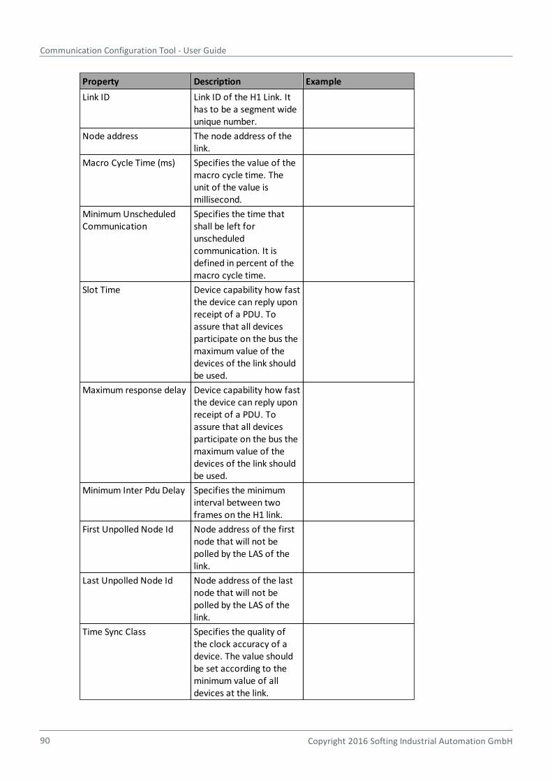
Communication Configuration Tool - User Guide
90 Copyright 2016 Softing Industrial Automation GmbH
Property Description Example
Link ID Link ID of the H1 Link. Ithas to be a segment wideunique number.
Node address The node address of thelink.
Macro Cycle Time (ms) Specifies the value of themacro cycle time. Theunit of the value ismillisecond.
Minimum UnscheduledCommunication
Specifies the time thatshall be left forunscheduledcommunication. It isdefined in percent of themacro cycle time.
Slot Time Device capability how fastthe device can reply uponreceipt of a PDU. Toassure that all devicesparticipate on the bus themaximum value of thedevices of the link shouldbe used.
Maximum response delay Device capability how fastthe device can reply uponreceipt of a PDU. Toassure that all devicesparticipate on the bus themaximum value of thedevices of the link shouldbe used.
Minimum Inter Pdu Delay Specifies the minimuminterval between twoframes on the H1 link.
First Unpolled Node Id Node address of the firstnode that will not bepolled by the LAS of thelink.
Last Unpolled Node Id Node address of the lastnode that will not bepolled by the LAS of thelink.
Time Sync Class Specifies the quality ofthe clock accuracy of adevice. The value shouldbe set according to theminimum value of alldevices at the link.
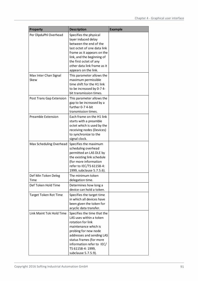
Chapter 4 - Graphical user interface
Copyright 2016 Softing Industrial Automation GmbH 91
Property Description Example
Per DlpduPhl Overhead Specifies the physicallayer induced delaybetween the end of thelast octet of one data linkframe as it appears on thelink, and the beginning ofthe first octet of anyother data link frame as itappears on the link.
Max Inter Chan SignalSkew
This parameter allows themaximum permissibletime shift for the H1 linkto be increased by 0-7 4-bit transmission times.
Post Trans Gap Extension This parameter allows thegap to be increased by afurther 0-7 4-bittransmission times.
Preamble Extension Each frame on the H1 linkstarts with a preambleoctet which is used by thereceiving nodes (Devices)to synchronize to thesignal clock.
Max Scheduling Overhead Specifies the maximumscheduling overheadpermitted an LAS DLE bythe existing link schedule(for more informationrefer to IEC/TS 61158-4:1999, subclause 5.7.5.6).
Def Min Token DelegTime
The minimum tokendelegation time.
Def Token Hold Time Determines how long adevice can hold a token.
Target Token Rot Time Specifies the target timein which all devices havebeen given the token foracyclic data transfer.
Link Maint Tok Hold Time Specifies the time that theLAS uses within a tokenrotation for linkmaintenance which isprobing for new nodeaddresses and sending LASstatus frames (for moreinformation refer to IEC/TS 61158-4: 1999,subclause 5.7.5.9).
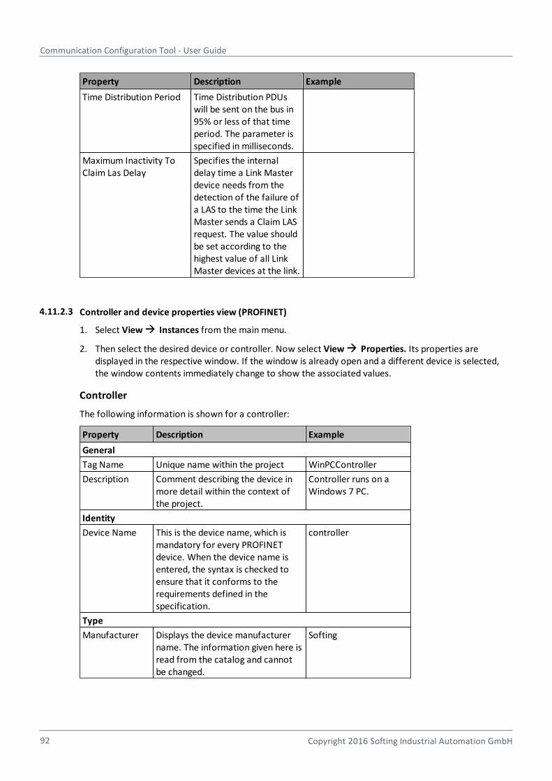
Communication Configuration Tool - User Guide
92 Copyright 2016 Softing Industrial Automation GmbH
Property Description Example
Time Distribution Period Time Distribution PDUswill be sent on the bus in95% or less of that timeperiod. The parameter isspecified in milliseconds.
Maximum Inactivity ToClaim Las Delay
Specifies the internaldelay time a Link Masterdevice needs from thedetection of the failure ofa LAS to the time the LinkMaster sends a Claim LASrequest. The value shouldbe set according to thehighest value of all LinkMaster devices at the link.
4.11.2.3 Controller and device properties view (PROFINET)
1. Select View Instances from the main menu.
2. Then select the desired device or controller. Now select View Properties. Its properties aredisplayed in the respective window. If the window is already open and a different device is selected,the window contents immediately change to show the associated values.
Controller
The following information is shown for a controller:
Property Description Example
General
Tag Name Unique name within the project WinPCController
Description Comment describing the device inmore detail within the context ofthe project.
Controller runs on aWindows 7 PC.
Identity
Device Name This is the device name, which ismandatory for every PROFINETdevice. When the device name isentered, the syntax is checked toensure that it conforms to therequirements defined in thespecification.
controller
Type
Manufacturer Displays the device manufacturername. The information given here isread from the catalog and cannotbe changed.
Softing
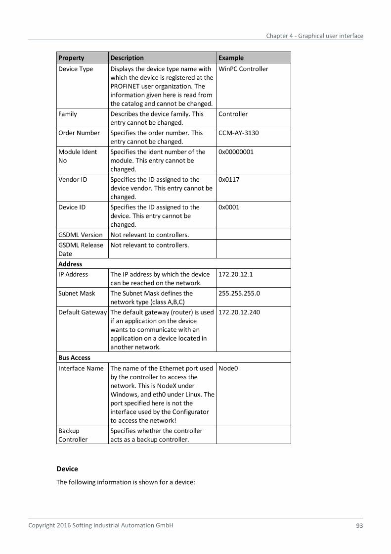
Chapter 4 - Graphical user interface
Copyright 2016 Softing Industrial Automation GmbH 93
Property Description Example
Device Type Displays the device type name withwhich the device is registered at thePROFINET user organization. Theinformation given here is read fromthe catalog and cannot be changed.
WinPC Controller
Family Describes the device family. Thisentry cannot be changed.
Controller
Order Number Specifies the order number. Thisentry cannot be changed.
CCM-AY-3130
Module IdentNo
Specifies the ident number of themodule. This entry cannot bechanged.
0x00000001
Vendor ID Specifies the ID assigned to thedevice vendor. This entry cannot bechanged.
0x0117
Device ID Specifies the ID assigned to thedevice. This entry cannot bechanged.
0x0001
GSDML Version Not relevant to controllers.
GSDML ReleaseDate
Not relevant to controllers.
Address
IP Address The IP address by which the devicecan be reached on the network.
172.20.12.1
Subnet Mask The Subnet Mask defines thenetwork type (class A,B,C)
255.255.255.0
Default Gateway The default gateway (router) is usedif an application on the devicewants to communicate with anapplication on a device located inanother network.
172.20.12.240
Bus Access
Interface Name The name of the Ethernet port usedby the controller to access thenetwork. This is NodeX underWindows, and eth0 under Linux. Theport specified here is not theinterface used by the Configuratorto access the network!
Node0
BackupController
Specifies whether the controlleracts as a backup controller.
Device
The following information is shown for a device:
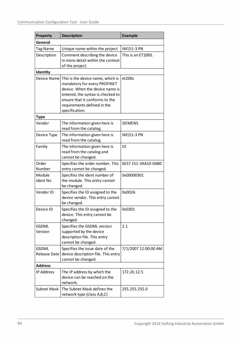
Communication Configuration Tool - User Guide
94 Copyright 2016 Softing Industrial Automation GmbH
Property Description Example
General
Tag Name Unique name within the project IM151-3 PN
Description Comment describing the devicein more detail within the contextof the project.
This is an ET200S.
Identity
Device Name This is the device name, which ismandatory for every PROFINETdevice. When the device name isentered, the syntax is checked toensure that it conforms to therequirements defined in thespecification.
et200s
Type
Vendor The information given here isread from the catalog.
SIEMENS
Device Type The information given here isread from the catalog.
IM151-3 PN
Family The information given here isread from the catalog andcannot be changed.
IO
OrderNumber
Specifies the order number. Thisentry cannot be changed.
6ES7 151-3AA10-0AB0
ModuleIdent No
Specifies the ident number ofthe module. This entry cannotbe changed.
0x00000301
Vendor ID Specifies the ID assigned to thedevice vendor. This entry cannotbe changed.
0x002A
Device ID Specifies the ID assigned to thedevice. This entry cannot bechanged.
0x0301
GSDMLVersion
Specifies the GSDML versionsupported by the devicedescription file. This entrycannot be changed.
2.1
GSDMLRelease Date
Specifies the issue date of thedevice description file. This entrycannot be changed.
7/1/2007 12:00:00 AM
Address
IP Address The IP address by which thedevice can be reached on thenetwork.
172.20.12.5
Subnet Mask The Subnet Mask defines thenetwork type (class A,B,C)
255.255.255.0
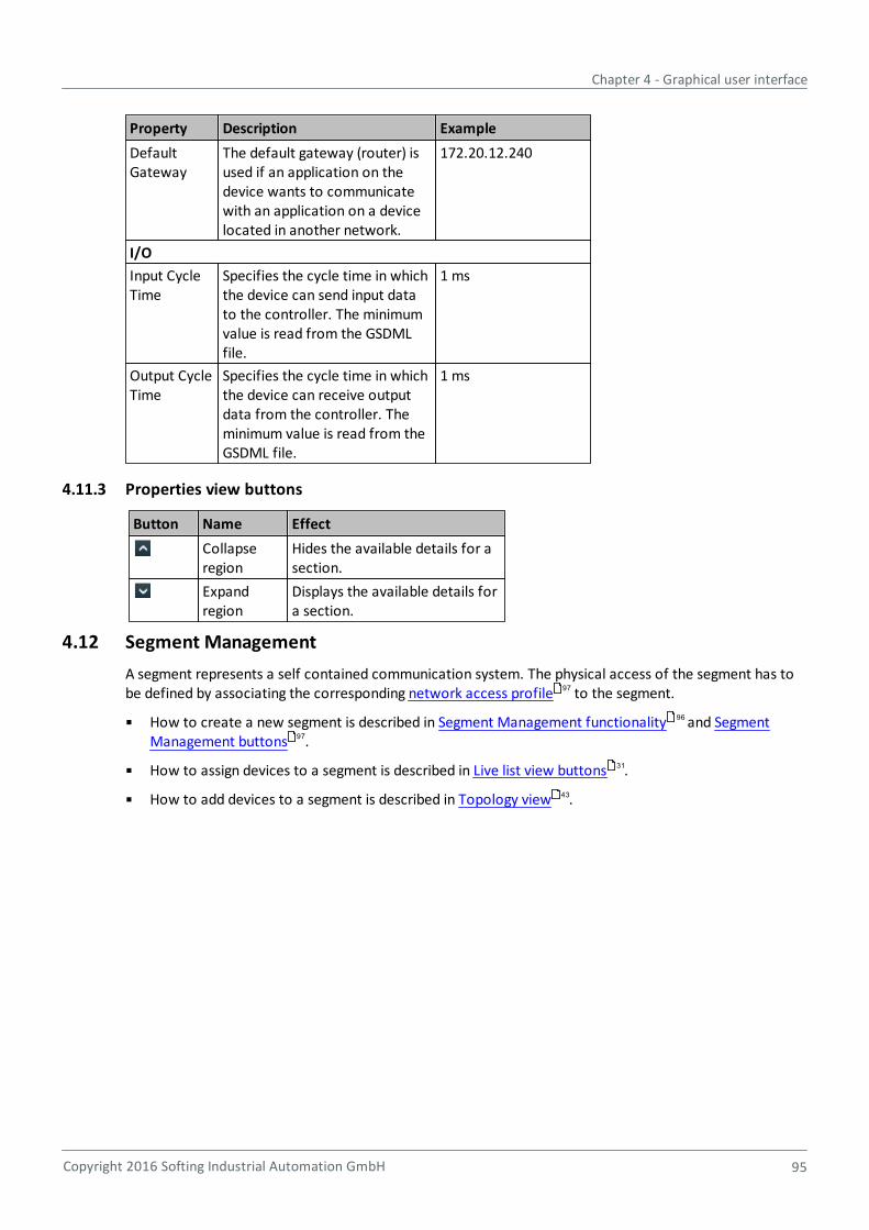
Chapter 4 - Graphical user interface
Copyright 2016 Softing Industrial Automation GmbH 95
Property Description Example
DefaultGateway
The default gateway (router) isused if an application on thedevice wants to communicatewith an application on a devicelocated in another network.
172.20.12.240
I/O
Input CycleTime
Specifies the cycle time in whichthe device can send input datato the controller. The minimumvalue is read from the GSDMLfile.
1 ms
Output CycleTime
Specifies the cycle time in whichthe device can receive outputdata from the controller. Theminimum value is read from theGSDML file.
1 ms
4.11.3 Properties view buttons
Button Name Effect
Collapseregion
Hides the available details for asection.
Expandregion
Displays the available details fora section.
4.12 Segment Management
A segment represents a self contained communication system. The physical access of the segment has tobe defined by associating the corresponding network access profile to the segment.
How to create a new segment is described in Segment Management functionality and SegmentManagement buttons .
How to assign devices to a segment is described in Live list view buttons .
How to add devices to a segment is described in Topology view .
97
96
97
31
43
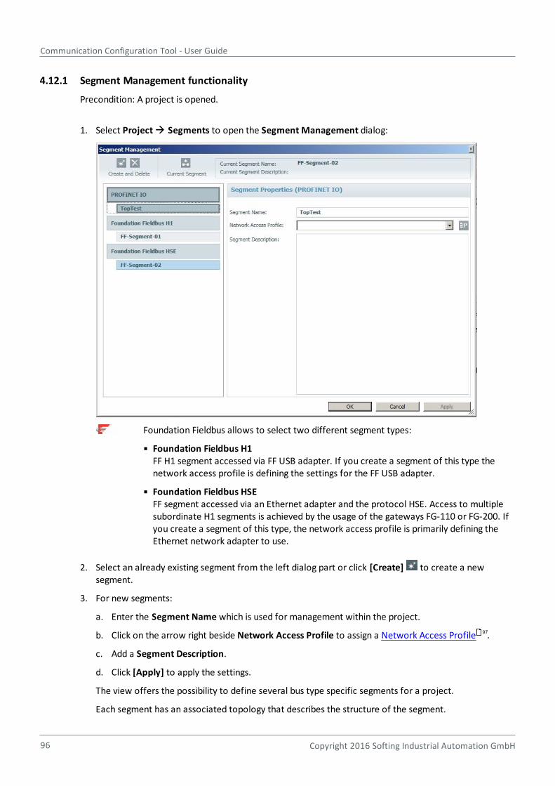
Communication Configuration Tool - User Guide
96 Copyright 2016 Softing Industrial Automation GmbH
4.12.1 Segment Management functionality
Precondition: A project is opened.
1. Select Project Segments to open the Segment Management dialog:
Foundation Fieldbus allows to select two different segment types:
Foundation Fieldbus H1FF H1 segment accessed via FF USB adapter. If you create a segment of this type thenetwork access profile is defining the settings for the FF USB adapter.
Foundation Fieldbus HSEFF segment accessed via an Ethernet adapter and the protocol HSE. Access to multiplesubordinate H1 segments is achieved by the usage of the gateways FG-110 or FG-200. Ifyou create a segment of this type, the network access profile is primarily defining theEthernet network adapter to use.
2. Select an already existing segment from the left dialog part or click [Create] to create a newsegment.
3. For new segments:
a. Enter the Segment Name which is used for management within the project.
b. Click on the arrow right beside Network Access Profile to assign a Network Access Profile .
c. Add a Segment Description.
d. Click [Apply] to apply the settings.
The view offers the possibility to define several bus type specific segments for a project.
Each segment has an associated topology that describes the structure of the segment.
97
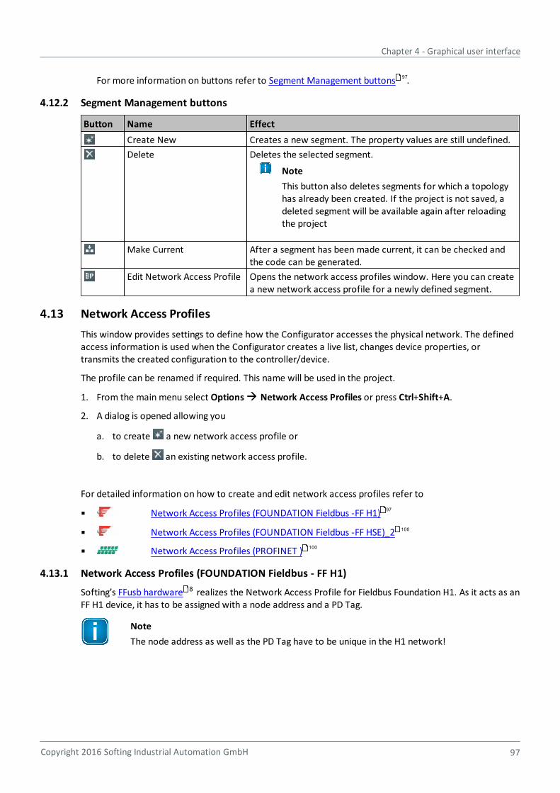
Chapter 4 - Graphical user interface
Copyright 2016 Softing Industrial Automation GmbH 97
For more information on buttons refer to Segment Management buttons .
4.12.2 Segment Management buttons
Button Name Effect
Create New Creates a new segment. The property values are still undefined.
Delete Deletes the selected segment.
Note
This button also deletes segments for which a topologyhas already been created. If the project is not saved, adeleted segment will be available again after reloadingthe project
Make Current After a segment has been made current, it can be checked andthe code can be generated.
Edit Network Access Profile Opens the network access profiles window. Here you can createa new network access profile for a newly defined segment.
4.13 Network Access Profiles
This window provides settings to define how the Configurator accesses the physical network. The definedaccess information is used when the Configurator creates a live list, changes device properties, ortransmits the created configuration to the controller/device.
The profile can be renamed if required. This name will be used in the project.
1. From the main menu select Options Network Access Profiles or press Ctrl+Shift+A.
2. A dialog is opened allowing you
a. to create a new network access profile or
b. to delete an existing network access profile.
For detailed information on how to create and edit network access profiles refer to
Network Access Profiles (FOUNDATION Fieldbus -FF H1)
Network Access Profiles (FOUNDATION Fieldbus -FF HSE)_2
Network Access Profiles (PROFINET )
4.13.1 Network Access Profiles (FOUNDATION Fieldbus - FF H1)
Softing’s FFusb hardware realizes the Network Access Profile for Fieldbus Foundation H1. As it acts as anFF H1 device, it has to be assigned with a node address and a PD Tag.
Note
The node address as well as the PD Tag have to be unique in the H1 network!
97
97
100
100
8
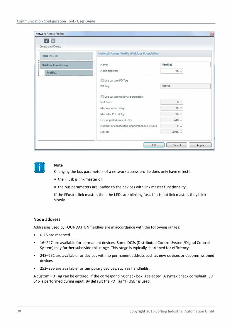
Communication Configuration Tool - User Guide
98 Copyright 2016 Softing Industrial Automation GmbH
Note
Changing the bus parameters of a network access profile does only have effect if
the FFusb is link master or
the bus parameters are loaded to the devices with link master functionality.
If the FFusb is link master, then the LEDs are blinking fast. If it is not link master, they blinkslowly.
Node address
Addresses used by FOUNDATION fieldbus are in accordance with the following ranges:
0-15 are reserved.
16–247 are available for permanent devices. Some DCSs (Distributed Control System/Digital ControlSystem) may further subdivide this range. This range is typically shortened for efficiency.
248–251 are available for devices with no permanent address such as new devices or decommissioneddevices.
252–255 are available for temporary devices, such as handhelds.
A custom PD Tag can be entered, if the corresponding check box is selected. A syntax check compliant ISO646 is performed during input. By default the PD Tag "FFUSB" is used.
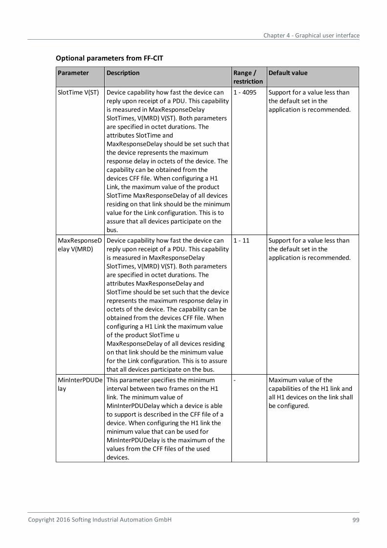
Chapter 4 - Graphical user interface
Copyright 2016 Softing Industrial Automation GmbH 99
Optional parameters from FF-CIT
Parameter Description Range /restriction
Default value
SlotTime V(ST) Device capability how fast the device canreply upon receipt of a PDU. This capabilityis measured in MaxResponseDelaySlotTimes, V(MRD) V(ST). Both parametersare specified in octet durations. Theattributes SlotTime andMaxResponseDelay should be set such thatthe device represents the maximumresponse delay in octets of the device. Thecapability can be obtained from thedevices CFF file. When configuring a H1Link, the maximum value of the productSlotTime MaxResponseDelay of all devicesresiding on that link should be the minimumvalue for the Link configuration. This is toassure that all devices participate on thebus.
1 - 4095 Support for a value less thanthe default set in theapplication is recommended.
MaxResponseDelay V(MRD)
Device capability how fast the device canreply upon receipt of a PDU. This capabilityis measured in MaxResponseDelaySlotTimes, V(MRD) V(ST). Both parametersare specified in octet durations. Theattributes MaxResponseDelay andSlotTime should be set such that the devicerepresents the maximum response delay inoctets of the device. The capability can beobtained from the devices CFF file. Whenconfiguring a H1 Link the maximum valueof the product SlotTime uMaxResponseDelay of all devices residingon that link should be the minimum valuefor the Link configuration. This is to assurethat all devices participate on the bus.
1 - 11 Support for a value less thanthe default set in theapplication is recommended.
MinInterPDUDelay
This parameter specifies the minimuminterval between two frames on the H1link. The minimum value ofMinInterPDUDelay which a device is ableto support is described in the CFF file of adevice. When configuring the H1 link theminimum value that can be used forMinInterPDUDelay is the maximum of thevalues from the CFF files of the useddevices.
- Maximum value of thecapabilities of the H1 link andall H1 devices on the link shallbe configured.
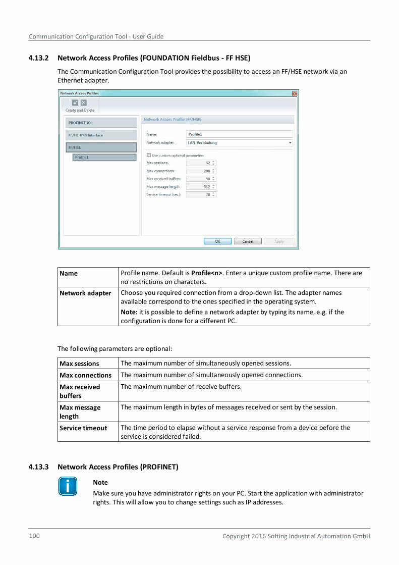
Communication Configuration Tool - User Guide
100 Copyright 2016 Softing Industrial Automation GmbH
4.13.2 Network Access Profiles (FOUNDATION Fieldbus - FF HSE)
The Communication Configuration Tool provides the possibility to access an FF/HSE network via anEthernet adapter.
Name Profile name. Default is Profile<n>. Enter a unique custom profile name. There areno restrictions on characters.
Network adapter Choose you required connection from a drop-down list. The adapter namesavailable correspond to the ones specified in the operating system.
Note: it is possible to define a network adapter by typing its name, e.g. if theconfiguration is done for a different PC.
The following parameters are optional:
Max sessions The maximum number of simultaneously opened sessions.
Max connections The maximum number of simultaneously opened connections.
Max receivedbuffers
The maximum number of receive buffers.
Max messagelength
The maximum length in bytes of messages received or sent by the session.
Service timeout The time period to elapse without a service response from a device before theservice is considered failed.
4.13.3 Network Access Profiles (PROFINET)
Note
Make sure you have administrator rights on your PC. Start the application with administratorrights. This will allow you to change settings such as IP addresses.
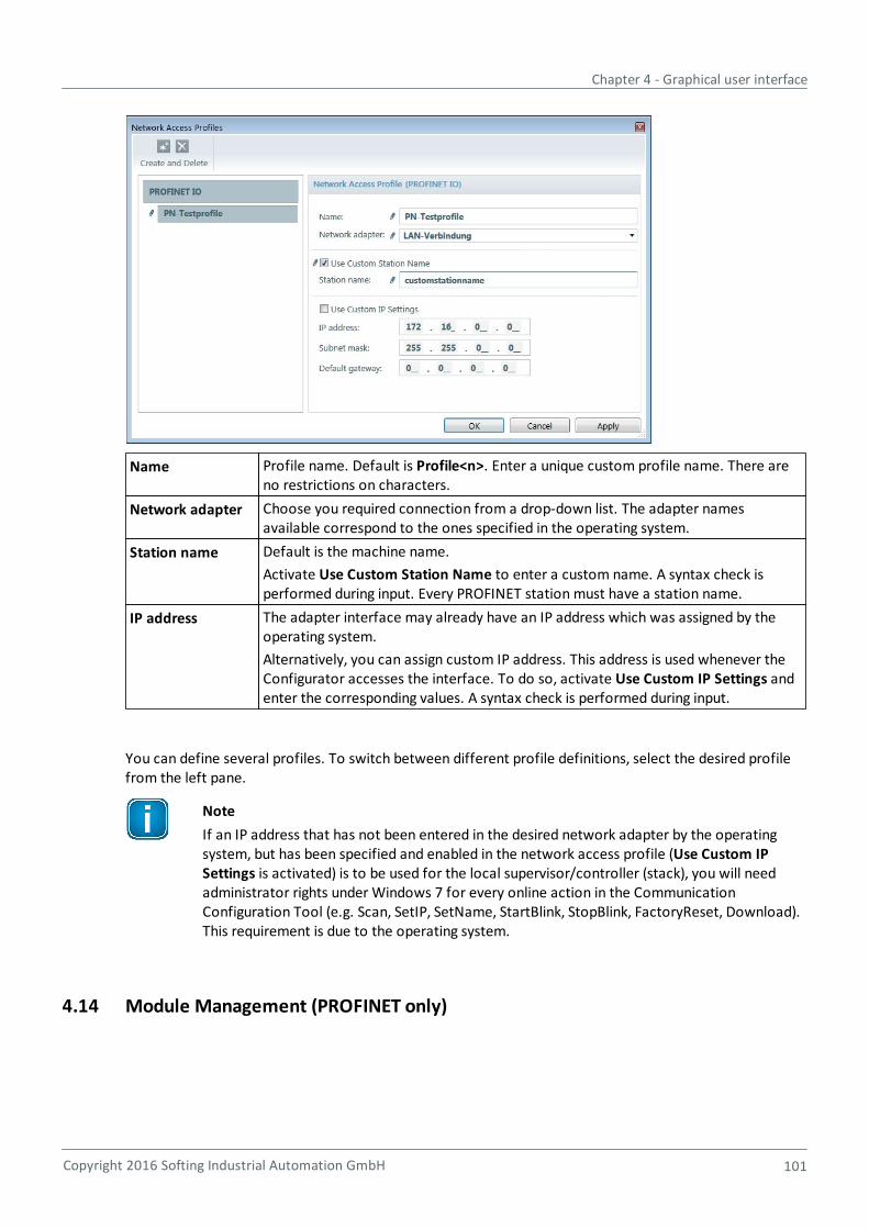
Chapter 4 - Graphical user interface
Copyright 2016 Softing Industrial Automation GmbH 101
Name Profile name. Default is Profile<n>. Enter a unique custom profile name. There areno restrictions on characters.
Network adapter Choose you required connection from a drop-down list. The adapter namesavailable correspond to the ones specified in the operating system.
Station name Default is the machine name.
Activate Use Custom Station Name to enter a custom name. A syntax check isperformed during input. Every PROFINET station must have a station name.
IP address The adapter interface may already have an IP address which was assigned by theoperating system.
Alternatively, you can assign custom IP address. This address is used whenever theConfigurator accesses the interface. To do so, activate Use Custom IP Settings andenter the corresponding values. A syntax check is performed during input.
You can define several profiles. To switch between different profile definitions, select the desired profilefrom the left pane.
Note
If an IP address that has not been entered in the desired network adapter by the operatingsystem, but has been specified and enabled in the network access profile (Use Custom IPSettings is activated) is to be used for the local supervisor/controller (stack), you will needadministrator rights under Windows 7 for every online action in the CommunicationConfiguration Tool (e.g. Scan, SetIP, SetName, StartBlink, StopBlink, FactoryReset, Download).This requirement is due to the operating system.
4.14 Module Management (PROFINET only)
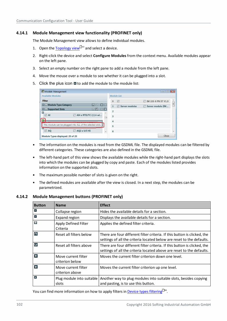
Communication Configuration Tool - User Guide
102 Copyright 2016 Softing Industrial Automation GmbH
4.14.1 Module Management view functionality (PROFINET only)
The Module Management view allows to define individual modules.
1. Open the Topology view and select a device.
2. Right-click the device and select Configure Modules from the context menu. Available modules appearon the left pane.
3. Select an empty number on the right pane to add a module from the left pane.
4. Move the mouse over a module to see whether it can be plugged into a slot.
5. Click the plus icon to add the module to the module list:
The information on the modules is read from the GSDML file. The displayed modules can be filtered bydifferent categories. These categories are also defined in the GSDML file.
The left-hand part of this view shows the available modules while the right-hand part displays the slotsinto which the modules can be plugged by copy and paste. Each of the modules listed providesinformation on the supported slots.
The maximum possible number of slots is given on the right.
The defined modules are available after the view is closed. In a next step, the modules can beparametrized.
4.14.2 Module Management buttons (PROFINET only)
Button Name Effect
Collapse region Hides the available details for a section.
Expand region Displays the available details for a section.
Apply Defined FilterCriteria
Applies the defined filter criteria.
Reset all filters below There are four different filter criteria. If this button is clicked, thesettings of all the criteria located below are reset to the defaults.
Reset all filters above There are four different filter criteria. If this button is clicked, thesettings of all the criteria located above are reset to the defaults.
Move current filtercriterion below
Moves the current filter criterion down one level.
Move current filtercriterion above
Moves the current filter criterion up one level.
Plug module into suitableslots
Another way to plug modules into suitable slots, besides copyingand pasting, is to use this button.
You can find more information on how to apply filters in Device types filtering .
43
66
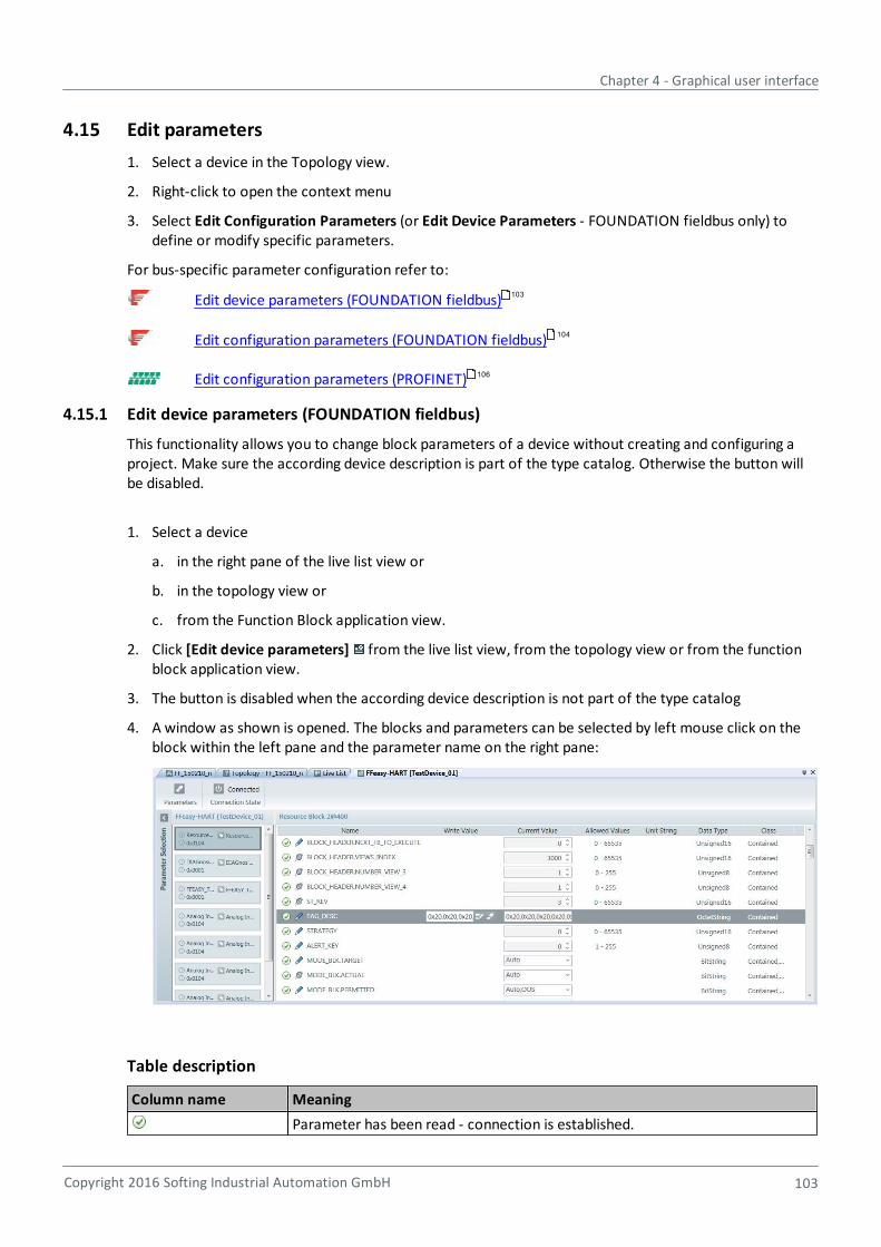
Chapter 4 - Graphical user interface
Copyright 2016 Softing Industrial Automation GmbH 103
4.15 Edit parameters
1. Select a device in the Topology view.
2. Right-click to open the context menu
3. Select Edit Configuration Parameters (or Edit Device Parameters - FOUNDATION fieldbus only) todefine or modify specific parameters.
For bus-specific parameter configuration refer to:
Edit device parameters (FOUNDATION fieldbus)
Edit configuration parameters (FOUNDATION fieldbus)
Edit configuration parameters (PROFINET)
4.15.1 Edit device parameters (FOUNDATION fieldbus)
This functionality allows you to change block parameters of a device without creating and configuring aproject. Make sure the according device description is part of the type catalog. Otherwise the button willbe disabled.
1. Select a device
a. in the right pane of the live list view or
b. in the topology view or
c. from the Function Block application view.
2. Click [Edit device parameters] from the live list view, from the topology view or from the functionblock application view.
3. The button is disabled when the according device description is not part of the type catalog
4. A window as shown is opened. The blocks and parameters can be selected by left mouse click on theblock within the left pane and the parameter name on the right pane:
Table description
Column name Meaning
Parameter has been read - connection is established.
103
104
106
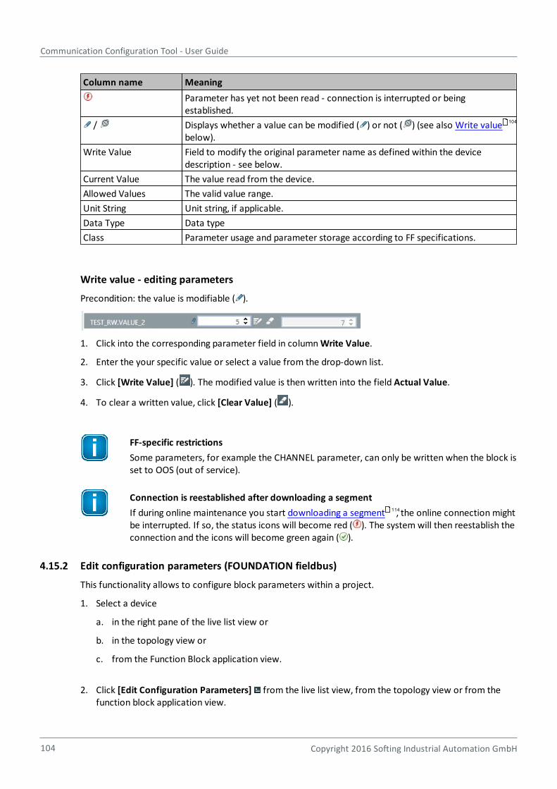
Communication Configuration Tool - User Guide
104 Copyright 2016 Softing Industrial Automation GmbH
Column name Meaning
Parameter has yet not been read - connection is interrupted or beingestablished.
/ Displays whether a value can be modified ( ) or not ( ) (see also Write valuebelow).
Write Value Field to modify the original parameter name as defined within the devicedescription - see below.
Current Value The value read from the device.
Allowed Values The valid value range.
Unit String Unit string, if applicable.
Data Type Data type
Class Parameter usage and parameter storage according to FF specifications.
Write value - editing parameters
Precondition: the value is modifiable ( ).
1. Click into the corresponding parameter field in column Write Value.
2. Enter the your specific value or select a value from the drop-down list.
3. Click [Write Value] ( ). The modified value is then written into the field Actual Value.
4. To clear a written value, click [Clear Value] ( ).
FF-specific restrictions
Some parameters, for example the CHANNEL parameter, can only be written when the block isset to OOS (out of service).
Connection is reestablished after downloading a segment
If during online maintenance you start downloading a segment , the online connection mightbe interrupted. If so, the status icons will become red ( ). The system will then reestablish theconnection and the icons will become green again ( ).
4.15.2 Edit configuration parameters (FOUNDATION fieldbus)
This functionality allows to configure block parameters within a project.
1. Select a device
a. in the right pane of the live list view or
b. in the topology view or
c. from the Function Block application view.
2. Click [Edit Configuration Parameters] from the live list view, from the topology view or from thefunction block application view.
104
114
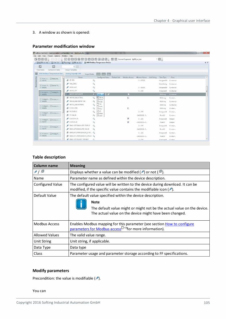
Chapter 4 - Graphical user interface
Copyright 2016 Softing Industrial Automation GmbH 105
3. A window as shown is opened:
Parameter modification window
Table description
Column name Meaning
/ Displays whether a value can be modified ( ) or not ( ).
Name Parameter name as defined within the device description.
Configured Value The configured value will be written to the device during download. It can bemodified, if the specific value contains the modifiable icon ( ).
Default Value The default value specified within the device description.
Note
The default value might or might not be the actual value on the device.The actual value on the device might have been changed.
Modbus Access Enables Modbus mapping for this parameter (see section How to configureparameters for Modbus access for more information).
Allowed Values The valid value range.
Unit String Unit string, if applicable.
Data Type Data type
Class Parameter usage and parameter storage according to FF specifications.
Modify parameters
Precondition: the value is modifiable ( ).
You can
128
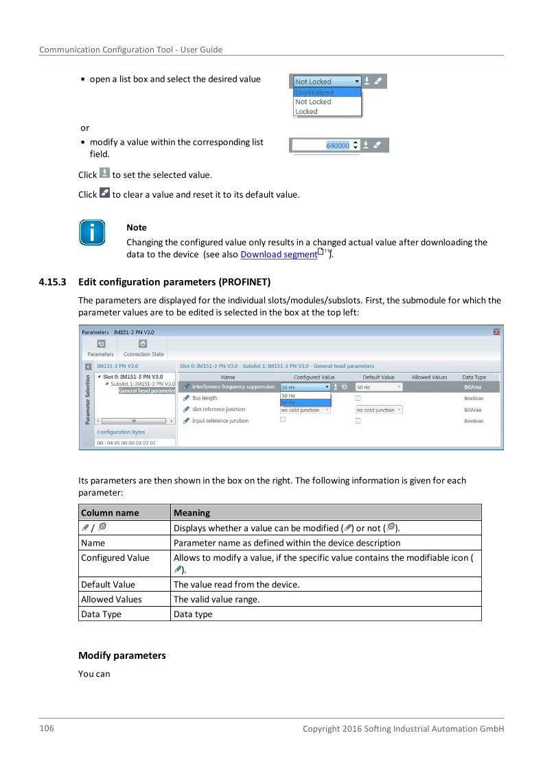
Communication Configuration Tool - User Guide
106 Copyright 2016 Softing Industrial Automation GmbH
open a list box and select the desired value
or
modify a value within the corresponding listfield.
Click to set the selected value.
Click to clear a value and reset it to its default value.
Note
Changing the configured value only results in a changed actual value after downloading thedata to the device (see also Download segment ).
4.15.3 Edit configuration parameters (PROFINET)
The parameters are displayed for the individual slots/modules/subslots. First, the submodule for which theparameter values are to be edited is selected in the box at the top left:
Its parameters are then shown in the box on the right. The following information is given for eachparameter:
Column name Meaning
/ Displays whether a value can be modified ( ) or not ( ).
Name Parameter name as defined within the device description
Configured Value Allows to modify a value, if the specific value contains the modifiable icon ().
Default Value The value read from the device.
Allowed Values The valid value range.
Data Type Data type
Modify parameters
You can
114
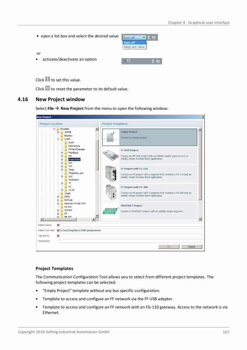
Chapter 4 - Graphical user interface
Copyright 2016 Softing Industrial Automation GmbH 107
open a list box and select the desired value
or
activate/deactivate an option
Click to set this value.
Click to reset the parameter to its default value.
4.16 New Project window
Select File New Project from the menu to open the following window:
Project Templates
The Communication Configuration Tool allows you to select from different project templates. Thefollowing project templates can be selected:
"Empty Project" template without any bus specific configuration.
Template to access and configure an FF network via the FF USB adapter.
Template to access and configure an FF network with an FG-110 gateway. Access to the network is viaEthernet.
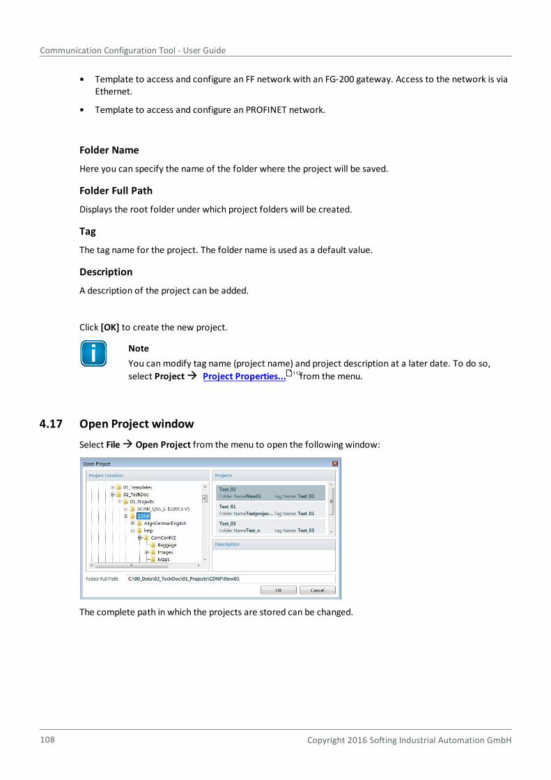
Communication Configuration Tool - User Guide
108 Copyright 2016 Softing Industrial Automation GmbH
Template to access and configure an FF network with an FG-200 gateway. Access to the network is viaEthernet.
Template to access and configure an PROFINET network.
Folder Name
Here you can specify the name of the folder where the project will be saved.
Folder Full Path
Displays the root folder under which project folders will be created.
Tag
The tag name for the project. The folder name is used as a default value.
Description
A description of the project can be added.
Click [OK] to create the new project.
Note
You can modify tag name (project name) and project description at a later date. To do so,
select Project Project Properties... from the menu.
4.17 Open Project window
Select File Open Project from the menu to open the following window:
The complete path in which the projects are stored can be changed.
112
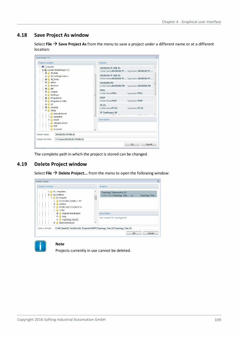
Chapter 4 - Graphical user interface
Copyright 2016 Softing Industrial Automation GmbH 109
4.18 Save Project As window
Select File Save Project As from the menu to save a project under a different name or at a differentlocation:
The complete path in which the project is stored can be changed.
4.19 Delete Project window
Select File Delete Project... from the menu to open the following window:
Note
Projects currently in use cannot be deleted.
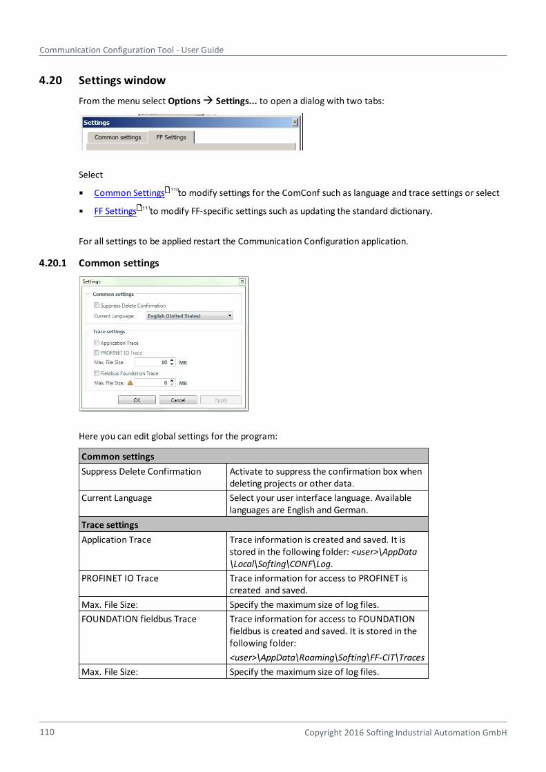
Communication Configuration Tool - User Guide
110 Copyright 2016 Softing Industrial Automation GmbH
4.20 Settings window
From the menu select Options Settings... to open a dialog with two tabs:
Select
Common Settings to modify settings for the ComConf such as language and trace settings or select
FF Settings to modify FF-specific settings such as updating the standard dictionary.
For all settings to be applied restart the Communication Configuration application.
4.20.1 Common settings
Here you can edit global settings for the program:
Common settings
Suppress Delete Confirmation Activate to suppress the confirmation box whendeleting projects or other data.
Current Language Select your user interface language. Availablelanguages are English and German.
Trace settings
Application Trace Trace information is created and saved. It isstored in the following folder: <user>\AppData\Local\Softing\CONF\Log.
PROFINET IO Trace Trace information for access to PROFINET iscreated and saved.
Max. File Size: Specify the maximum size of log files.
FOUNDATION fieldbus Trace Trace information for access to FOUNDATIONfieldbus is created and saved. It is stored in thefollowing folder:
<user>\AppData\Roaming\Softing\FF-CIT\Traces
Max. File Size: Specify the maximum size of log files.
110
111
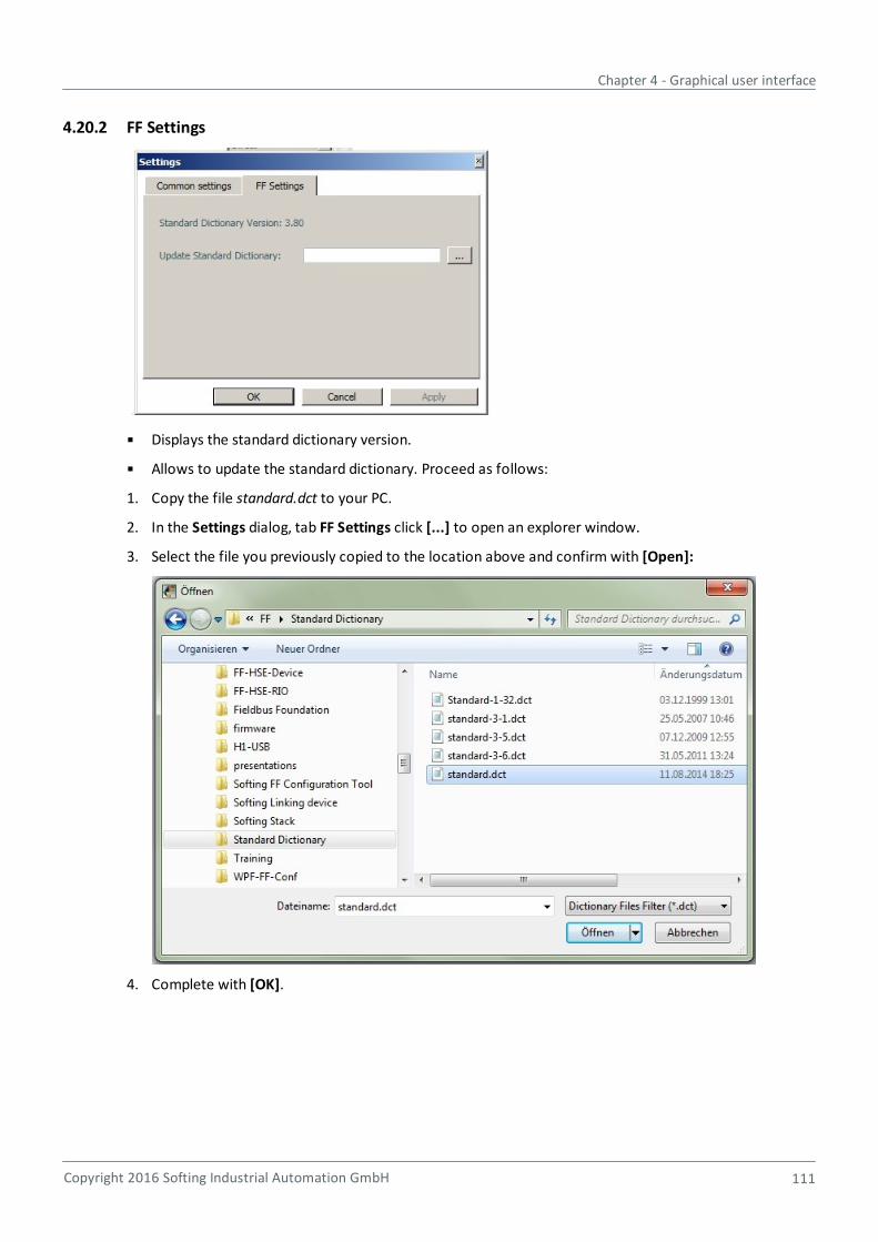
Chapter 4 - Graphical user interface
Copyright 2016 Softing Industrial Automation GmbH 111
4.20.2 FF Settings
Displays the standard dictionary version.
Allows to update the standard dictionary. Proceed as follows:
1. Copy the file standard.dct to your PC.
2. In the Settings dialog, tab FF Settings click [...] to open an explorer window.
3. Select the file you previously copied to the location above and confirm with [Open]:
4. Complete with [OK].

Communication Configuration Tool - User Guide
112 Copyright 2016 Softing Industrial Automation GmbH
4.21 Project Properties window
Select Project Project Properties... from the menu to open the following window:
The project can be renamed, but the location cannot be changed.
Text given in the Description box can also be added or edited.
4.22 Views window
Select Window Views from the menu to open the following window:
Here you can activate or close selected windows.
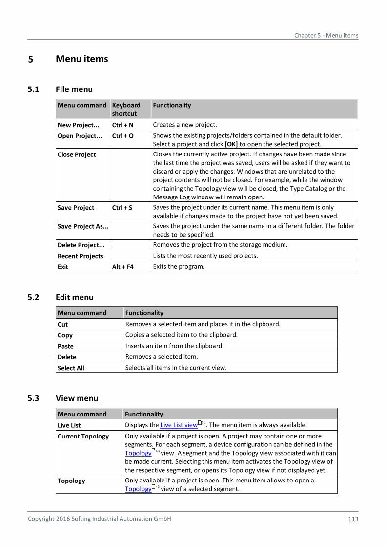
Chapter 5 - Menu items
Copyright 2016 Softing Industrial Automation GmbH 113
5 Menu items
5.1 File menu
Menu command Keyboardshortcut
Functionality
New Project... Ctrl + N Creates a new project.
Open Project... Ctrl + O Shows the existing projects/folders contained in the default folder.Select a project and click [OK] to open the selected project.
Close Project Closes the currently active project. If changes have been made sincethe last time the project was saved, users will be asked if they want todiscard or apply the changes. Windows that are unrelated to theproject contents will not be closed. For example, while the windowcontaining the Topology view will be closed, the Type Catalog or theMessage Log window will remain open.
Save Project Ctrl + S Saves the project under its current name. This menu item is onlyavailable if changes made to the project have not yet been saved.
Save Project As... Saves the project under the same name in a different folder. The folderneeds to be specified.
Delete Project... Removes the project from the storage medium.
Recent Projects Lists the most recently used projects.
Exit Alt + F4 Exits the program.
5.2 Edit menu
Menu command Functionality
Cut Removes a selected item and places it in the clipboard.
Copy Copies a selected item to the clipboard.
Paste Inserts an item from the clipboard.
Delete Removes a selected item.
Select All Selects all items in the current view.
5.3 View menu
Menu command Functionality
Live List Displays the Live List view . The menu item is always available.
Current Topology Only available if a project is open. A project may contain one or moresegments. For each segment, a device configuration can be defined in the Topology view. A segment and the Topology view associated with it canbe made current. Selecting this menu item activates the Topology view ofthe respective segment, or opens its Topology view if not displayed yet.
Topology Only available if a project is open. This menu item allows to open a Topology view of a selected segment.
26
43
43
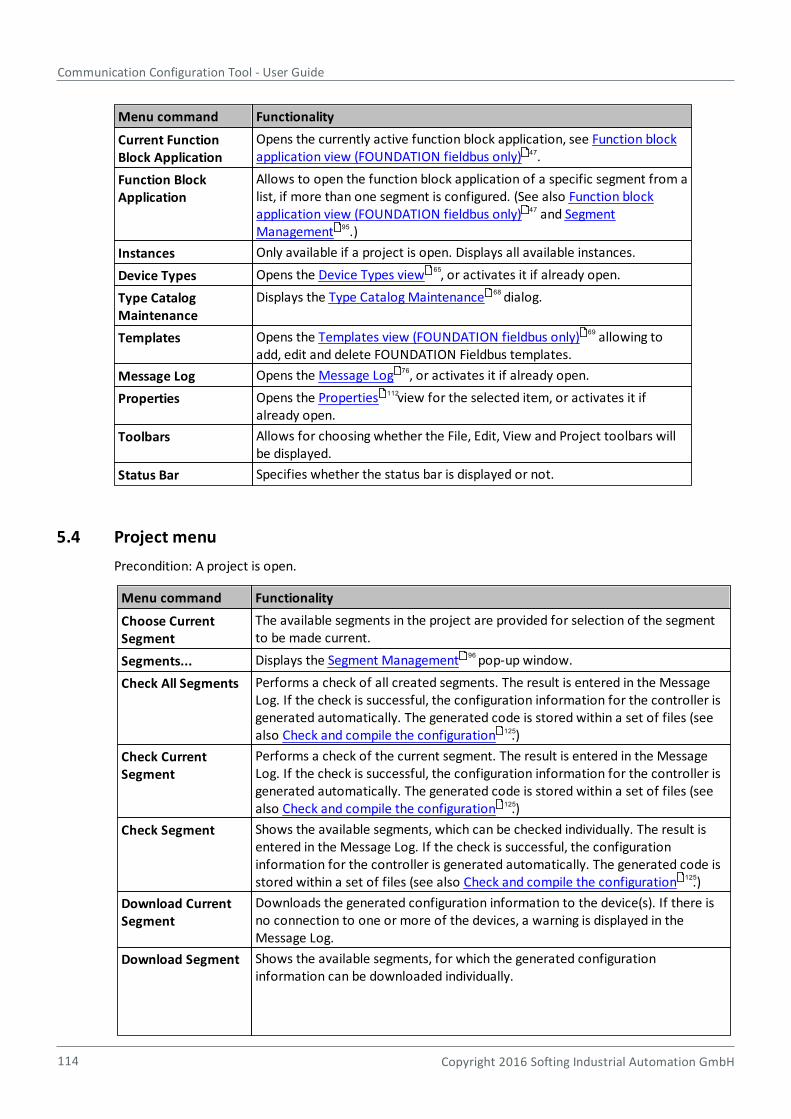
Communication Configuration Tool - User Guide
114 Copyright 2016 Softing Industrial Automation GmbH
Menu command Functionality
Current FunctionBlock Application
Opens the currently active function block application, see Function blockapplication view (FOUNDATION fieldbus only) .
Function BlockApplication
Allows to open the function block application of a specific segment from alist, if more than one segment is configured. (See also Function blockapplication view (FOUNDATION fieldbus only) and SegmentManagement .)
Instances Only available if a project is open. Displays all available instances.
Device Types Opens the Device Types view , or activates it if already open.
Type CatalogMaintenance
Displays the Type Catalog Maintenance dialog.
Templates Opens the Templates view (FOUNDATION fieldbus only) allowing toadd, edit and delete FOUNDATION Fieldbus templates.
Message Log Opens the Message Log , or activates it if already open.
Properties Opens the Properties view for the selected item, or activates it ifalready open.
Toolbars Allows for choosing whether the File, Edit, View and Project toolbars willbe displayed.
Status Bar Specifies whether the status bar is displayed or not.
5.4 Project menu
Precondition: A project is open.
Menu command Functionality
Choose CurrentSegment
The available segments in the project are provided for selection of the segmentto be made current.
Segments... Displays the Segment Management pop-up window.
Check All Segments Performs a check of all created segments. The result is entered in the MessageLog. If the check is successful, the configuration information for the controller isgenerated automatically. The generated code is stored within a set of files (seealso Check and compile the configuration .)
Check CurrentSegment
Performs a check of the current segment. The result is entered in the MessageLog. If the check is successful, the configuration information for the controller isgenerated automatically. The generated code is stored within a set of files (seealso Check and compile the configuration .)
Check Segment Shows the available segments, which can be checked individually. The result isentered in the Message Log. If the check is successful, the configurationinformation for the controller is generated automatically. The generated code isstored within a set of files (see also Check and compile the configuration .)
Download CurrentSegment
Downloads the generated configuration information to the device(s). If there isno connection to one or more of the devices, a warning is displayed in theMessage Log.
Download Segment Shows the available segments, for which the generated configurationinformation can be downloaded individually.
47
47
95
65
68
69
76
112
96
125
125
125
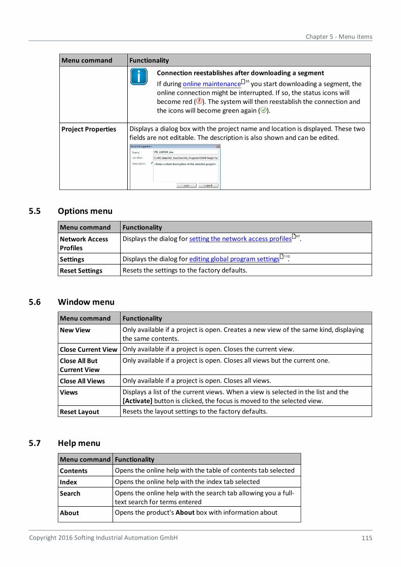
Chapter 5 - Menu items
Copyright 2016 Softing Industrial Automation GmbH 115
Menu command Functionality
Connection reestablishes after downloading a segment
If during online maintenance you start downloading a segment, theonline connection might be interrupted. If so, the status icons willbecome red ( ). The system will then reestablish the connection andthe icons will become green again ( ).
Project Properties Displays a dialog box with the project name and location is displayed. These twofields are not editable. The description is also shown and can be edited.
5.5 Options menu
Menu command Functionality
Network AccessProfiles
Displays the dialog for setting the network access profiles .
Settings Displays the dialog for editing global program settings .
Reset Settings Resets the settings to the factory defaults.
5.6 Window menu
Menu command Functionality
New View Only available if a project is open. Creates a new view of the same kind, displayingthe same contents.
Close Current View Only available if a project is open. Closes the current view.
Close All ButCurrent View
Only available if a project is open. Closes all views but the current one.
Close All Views Only available if a project is open. Closes all views.
Views Displays a list of the current views. When a view is selected in the list and the [Activate] button is clicked, the focus is moved to the selected view.
Reset Layout Resets the layout settings to the factory defaults.
5.7 Help menu
Menu command Functionality
Contents Opens the online help with the table of contents tab selected
Index Opens the online help with the index tab selected
Search Opens the online help with the search tab allowing you a full-text search for terms entered
About Opens the product's About box with information about
35
97
110

Communication Configuration Tool - User Guide
116 Copyright 2016 Softing Industrial Automation GmbH
the supported protocols,
the software version,
and the copyright and address information.
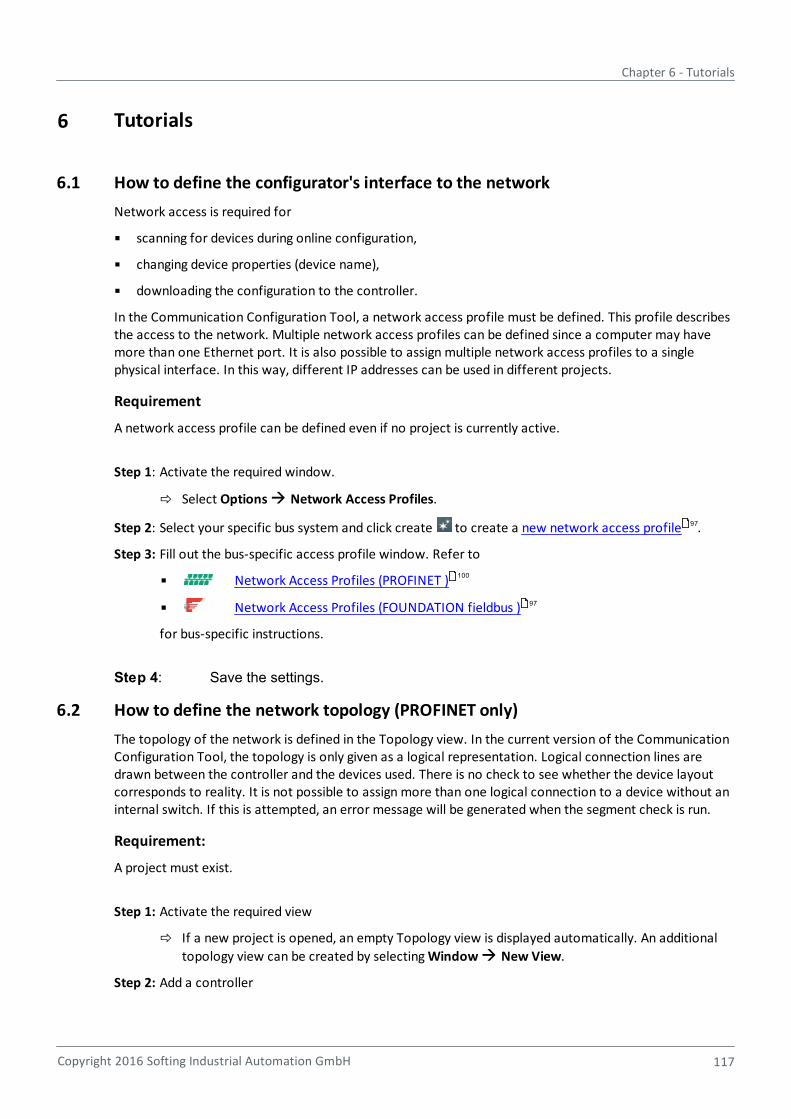
Chapter 6 - Tutorials
Copyright 2016 Softing Industrial Automation GmbH 117
6 Tutorials
6.1 How to define the configurator's interface to the network
Network access is required for
scanning for devices during online configuration,
changing device properties (device name),
downloading the configuration to the controller.
In the Communication Configuration Tool, a network access profile must be defined. This profile describesthe access to the network. Multiple network access profiles can be defined since a computer may havemore than one Ethernet port. It is also possible to assign multiple network access profiles to a singlephysical interface. In this way, different IP addresses can be used in different projects.
Requirement
A network access profile can be defined even if no project is currently active.
Step 1: Activate the required window.
Select Options Network Access Profiles.
Step 2: Select your specific bus system and click create to create a new network access profile .
Step 3: Fill out the bus-specific access profile window. Refer to
Network Access Profiles (PROFINET )
Network Access Profiles (FOUNDATION fieldbus )
for bus-specific instructions.
Step 4: Save the settings.
6.2 How to define the network topology (PROFINET only)
The topology of the network is defined in the Topology view. In the current version of the CommunicationConfiguration Tool, the topology is only given as a logical representation. Logical connection lines aredrawn between the controller and the devices used. There is no check to see whether the device layoutcorresponds to reality. It is not possible to assign more than one logical connection to a device without aninternal switch. If this is attempted, an error message will be generated when the segment check is run.
Requirement:
A project must exist.
Step 1: Activate the required view
If a new project is opened, an empty Topology view is displayed automatically. An additional
topology view can be created by selecting Window New View.
Step 2: Add a controller
97
100
97
Communication Configuration Tool - User Guide
118 Copyright 2016 Softing Industrial Automation GmbH
As controllers are device types, they are included in the type catalog. The following twocontrollers are currently available:
Softing WinPC Controller. This is a PROFINET controller stack that can be executed onWindows 7.
Softing RTEM Controller. This is a PROFINET controller stack that can be executed onSofting's FPGA Module.
Softing FG-260 gateway. This is gateway between EtherNet/IP and PROFINET networkswith integrated PROFINET controller functionality.
After the required device type has been selected in the type catalog, drag and drop thecontroller into the topology view where it is instantiated. Set name, IP address and nodecorrectly according to the specifications defined in the project (name and IP addresses) andaccording to the controller hardware (node).
Step 3: Add devices
A device is only available in the type catalog if its GSDML file has been imported. The devicetype is represented by the Device Access Point (DAP) in the type catalog view. GSDML filesdescribe device families. The members of a family differ at least in the DAP. Therefore, thecatalog may include multiple entries. The DAPs of different devices differ at least in theModuleIdentNumber and, in most cases, also in the order number.
After the required device type has been selected in the type catalog, drag and drop the deviceinto the topology view where it is instantiated. Filter the catalog entries to improve readabilityof the type catalog view.
Step 4: Create logical connections between instances in the topology view
Before a connection can be created, an instance has to be selected in the Topology view. Onselection, an arrow appears in the top right corner of the instance. Click this arrow with themouse. When the mouse pointer changes to an arrow, press the left mouse button and dragthe arrow to another instance.
6.3 How to assign a device name or PD tag
6.3.1 How to assign a PD tag (FOUNDATION fieldbus)
Every device in the network must have a unique name. FOUNDATION fieldbus uses PD tags.
This tag name is defined in the project and assigned in the live list. This process involves the followingsteps.
Requirement:
A topology has been created.
Step 1: Select the relevant instance
Select the instance to which a name is to be assigned.
Step 2: Activate the Properties view
This can be done in two ways:
select the instance and then press the key combination Alt+Enter, or
Chapter 6 - Tutorials
Copyright 2016 Softing Industrial Automation GmbH 119
selecting View Properties.
If the view is already open, the properties of the instance will be displayed immediately after theinstance is selected.
Step 3: Enter the PD tag
The PD tag is given in the Identity section. If no tag has been entered yet, an exclamation markis shown next to the input field. This symbol disappears as soon as characters are typed intothe field. If the entered characters are not permitted, a white cross on a red background will bedisplayed next to the input field.
After entering the PD tag, it is immediately shown in the selected instance of the topologyview.
Step 4: Assign a configured device to physical device in live list.
Refer to Live list view buttons for a description on how to perform this task.
Alternatively you can configure the PD tag directly on the physical device via the Online Maintenanceview and assign the physical device to the configured device .
6.3.2 How to assign a device name (PROFINET)
Every device in the network must have a unique name. PROFINET uses device names.
This name is assigned in the project and downloaded to the device. This process involves the followingsteps.
Requirement:
A topology has been created.
Step 1: Select the relevant instance
Select the instance to which a device name is to be assigned.
Step 2: Activate the Properties view
This can be done in two ways:
select the instance and then press the key combination Alt+Enter, or
selecting View Properties.
If the view is already open, the properties of the instance will be displayed immediately after theinstance is selected.
Step 3: Enter the device name
The device name is given in the Identity section. If no name has been entered yet, anexclamation mark is shown next to the input field. This symbol disappears as soon ascharacters are typed into the field. If the entered characters are not permitted, a white crosson a red background will be displayed next to the input field.
After entering the device name, it is immediately shown in the selected instance of thetopology view.
31
35
31
Communication Configuration Tool - User Guide
120 Copyright 2016 Softing Industrial Automation GmbH
In a next step, device names can be assigned to all remaining instances, or the IP address informationcan be specified for the selected instance.
6.4 How to define IP addresses (PROFINET only)
Every PROFINET device needs an IP address. While the defined device name is assigned to the deviceduring the configuration, the IP address is assigned by the controller at runtime. The IP addresses are partof the configuration information that is provided to the controller as soon as the configuration has beencompleted.
Requirement:
A topology has been created.
Step 1: Select the relevant instance
The instance to which the IP addresses are to be assigned is selected.
Step 2: Activate the Properties view
This can be done in two ways:
select the instance and then press the key combination Alt+Enter, or
selecting View Properties.
If the view is already open, the properties of the instance will be displayed immediately after theinstance is selected.
Step 3: Enter the IP addresses
The IP addresses are given in the Address section. Three addresses are assigned here:
IP address of the device, for example 172.20.12.1
Subnet mask, for example 255.255.0.0
Default gateway, for example 172.20.12.1
If no IP address has been entered yet, an exclamation mark is shown next to the input field. Thissymbol disappears as soon as numbers are typed into the field. If the entered numbers are notpermitted, a white cross on a red background will be displayed next to the input field.
6.5 How to define modules and parameters (PROFINET only)
PROFINET differentiates between compact and modular devices. A compact device has a fixedfunctionality, whereas the functionality of a modular device can be adapted to suit specific requirements.For this purpose, modules are selected from the set of available modules and assigned to the respectiveslots. The procedure described here is also very useful to check the modules implemented in compactdevices.
Define modules
Prerequisite: A topology has been created.
Step 1: Select the relevant instance
The instance for which the implemented modules are to be specified or checked is selected.
34
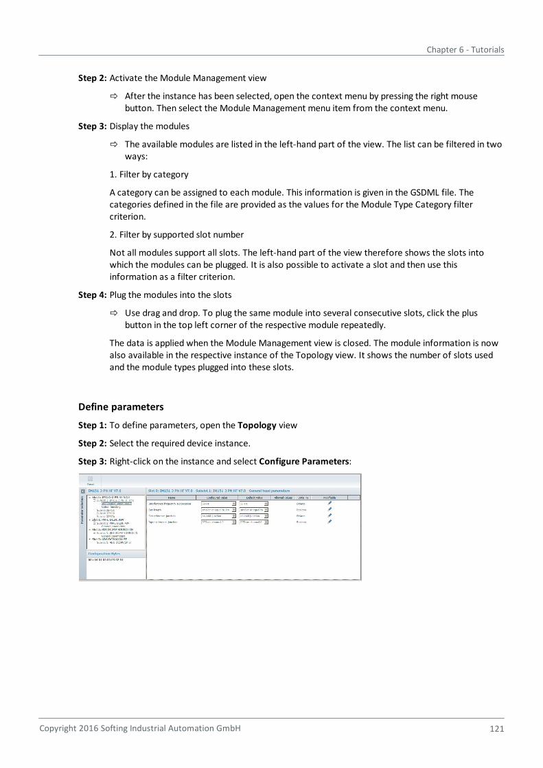
Chapter 6 - Tutorials
Copyright 2016 Softing Industrial Automation GmbH 121
Step 2: Activate the Module Management view
After the instance has been selected, open the context menu by pressing the right mousebutton. Then select the Module Management menu item from the context menu.
Step 3: Display the modules
The available modules are listed in the left-hand part of the view. The list can be filtered in twoways:
1. Filter by category
A category can be assigned to each module. This information is given in the GSDML file. Thecategories defined in the file are provided as the values for the Module Type Category filtercriterion.
2. Filter by supported slot number
Not all modules support all slots. The left-hand part of the view therefore shows the slots intowhich the modules can be plugged. It is also possible to activate a slot and then use thisinformation as a filter criterion.
Step 4: Plug the modules into the slots
Use drag and drop. To plug the same module into several consecutive slots, click the plusbutton in the top left corner of the respective module repeatedly.
The data is applied when the Module Management view is closed. The module information is nowalso available in the respective instance of the Topology view. It shows the number of slots usedand the module types plugged into these slots.
Define parameters
Step 1: To define parameters, open the Topology view
Step 2: Select the required device instance.
Step 3: Right-click on the instance and select Configure Parameters:
Communication Configuration Tool - User Guide
122 Copyright 2016 Softing Industrial Automation GmbH
6.6 How to represent a switch without PROFINET functionality in the topologyview (PROFINET only)
Switches are used for communication in PROFINET networks. They are available in different versions:
External switch with PROFINET functionality
Switch functionality integrated in PROFINET device
External switch without PROFINET functionality
As the first two versions listed are PROFINET devices, GSDML files are available for these products. Thisway external switches, in particular, can be treated just like other devices during configuration.
How can switches be integrated into the configuration if they are not described by an GSDML file?
Requirement:
A topology has been created.
Step 1: Insert a connector
A logical connection has already been created to connect two devices. The connection isselected. Press the right mouse button to enable the Add Connector action. A gray circle isdisplayed, which represents the external switch.
Step 2: Create additional connections between devices and the external switch
Select an instance in the topology view. On selection, an arrow appears in the top right cornerof the instance. Click this arrow with the mouse. When the mouse pointer changes to anarrow, press the left mouse button and drag the arrow to the connector.
Information about external switches that are not PROFINET devices is not stored in the binary result file.
6.7 How to transmit the device name to a PROFINET device (PROFINET only)
During the configuration, a device name and an IP address are defined for each device. The controller usesthe device name at runtime to detect the configured devices and assign the IP addresses to them. Thefactory default name of the device will usually not correspond to the name used in the project. Therefore,the device name can be modified in the Communication Configuration Tool.
Requirement:
The live list has been created and the device name to be assigned is known. The topology of the networkthus may have been defined already.
Step 1: Select the device
After a successful network scan, the list of found devices is displayed in the left-hand part ofthe Live List view. The device can now be selected in the list and the Online Maintenancebutton can be clicked. A pop-up window is displayed.
Step 2: Set the device name
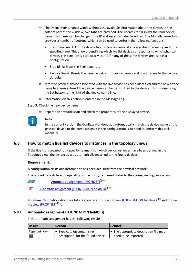
Chapter 6 - Tutorials
Copyright 2016 Softing Industrial Automation GmbH 123
The Online Maintenance window shows the available information about the device. In thebottom part of the window, two tabs are provided. The Address tab displays the read devicename. This name can be changed. The IP addresses can also be edited. The Miscellaneous tabprovides a number of buttons, which can be used to perform the following functions:
Start Blink: An LED of the device has to blink on demand at a specified frequency and for aspecified time. This allows identifying which live list device corresponds to which physicaldevice. This function is particularly useful if many of the same devices are used in aconfiguration.
Stop Blink: Stops the Blink function.
Factory Reset: Resets the variable values for device names and IP addresses to the factorydefaults.
After the physical device associated with the live device has been identified and the new devicename has been entered, the device name can be transmitted to the device. This is done usingthe Set button to the right of the device name line.
Information on this action is entered in the Message Log.
Step 3: Check the new device name
Repeat the network scan and check the properties of the displayed device.
Note
In the current version, the Configurator does not automatically match the device name of thephysical device to the name assigned in the configuration. You need to perform this taskmanually.
6.8 How to match live list devices to instances in the topology view?
If the live list is created for a specific segment for which device instances have been defined in theTopology view, the instances are automatically matched to the found devices.
Requirement:
A configuration exists and information has been acquired from the physical network.
The procedure is different depending on the bus system used. Refer to the corresponding bus system:
Automatic assignment (PROFINET)
Automatic assignment (FOUNDATION fieldbus)
For more information about live list creation refer to Live list view (FOUNDATION fieldbus ) and to Livelist view (PROFINET ) .
6.8.1 Automatic assignment (FOUNDATION fieldbus)
The automatic assignment has the following results:
Result Reason Remark
Type unknown Type catalog contains nodescription for the found device
The appropriate description file mayneed to be imported.
124
123
27
29
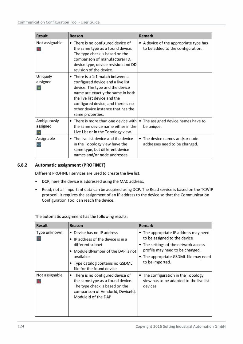
Communication Configuration Tool - User Guide
124 Copyright 2016 Softing Industrial Automation GmbH
Result Reason Remark
Not assignable There is no configured device ofthe same type as a found device.The type check is based on thecomparison of manufacturer ID,device type, device revision and DDrevision of the device.
A device of the appropriate type hasto be added to the configuration..
Uniquelyassigned
There is a 1:1 match between aconfigured device and a live listdevice. The type and the devicename are exactly the same in boththe live list device and theconfigured device, and there is noother device instance that has thesame properties.
Ambiguouslyassigned
There is more than one device withthe same device name either in theLive List or in the Topology view.
The assigned device names have tobe unique.
Assignable The live list device and the devicein the Topology view have thesame type, but different devicenames and/or node addresses.
The device names and/or nodeaddresses need to be changed.
6.8.2 Automatic assignment (PROFINET)
Different PROFINET services are used to create the live list.
DCP; here the device is addressed using the MAC address.
Read; not all important data can be acquired using DCP. The Read service is based on the TCP/IPprotocol. It requires the assignment of an IP address to the device so that the CommunicationConfiguration Tool can reach the device.
The automatic assignment has the following results:
Result Reason Remark
Type unknown Device has no IP address
IP address of the device is in adifferent subnet
ModuleIdNumber of the DAP is notavailable
Type catalog contains no GSDMLfile for the found device
The appropriate IP address may needto be assigned to the device
The settings of the network accessprofile may need to be changed.
The appropriate GSDML file may needto be imported.
Not assignable There is no configured device ofthe same type as a found device.The type check is based on thecomparison of VendorId, DeviceId,ModuleId of the DAP
The configuration in the Topologyview has to be adapted to the live listdevices.
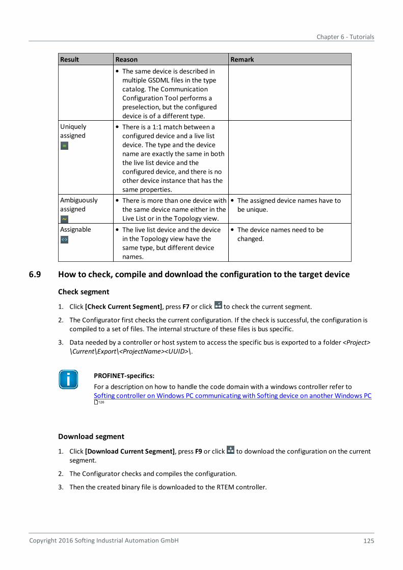
Chapter 6 - Tutorials
Copyright 2016 Softing Industrial Automation GmbH 125
Result Reason Remark
The same device is described inmultiple GSDML files in the typecatalog. The CommunicationConfiguration Tool performs apreselection, but the configureddevice is of a different type.
Uniquelyassigned
There is a 1:1 match between aconfigured device and a live listdevice. The type and the devicename are exactly the same in boththe live list device and theconfigured device, and there is noother device instance that has thesame properties.
Ambiguouslyassigned
There is more than one device withthe same device name either in theLive List or in the Topology view.
The assigned device names have tobe unique.
Assignable The live list device and the devicein the Topology view have thesame type, but different devicenames.
The device names need to bechanged.
6.9 How to check, compile and download the configuration to the target device
Check segment
1. Click [Check Current Segment], press F7 or click to check the current segment.
2. The Configurator first checks the current configuration. If the check is successful, the configuration iscompiled to a set of files. The internal structure of these files is bus specific.
3. Data needed by a controller or host system to access the specific bus is exported to a folder <Project>\Current\Export\<ProjectName><UUID>\.
PROFINET-specifics:
For a description on how to handle the code domain with a windows controller refer to Softing controller on Windows PC communicating with Softing device on another Windows PC
Download segment
1. Click [Download Current Segment], press F9 or click to download the configuration on the currentsegment.
2. The Configurator checks and compiles the configuration.
3. Then the created binary file is downloaded to the RTEM controller.
126
Communication Configuration Tool - User Guide
126 Copyright 2016 Softing Industrial Automation GmbH
The download progress is shown in the status bar ( ). If you need to cancel this
operation, click .
Note
The FG-260 must meet the following two requirements:
It must be located in the same network as the PC running the CommunicationConfiguration Tool, and it must be accessible.
The device name of the controller must correspond to the device name of the instance.
6.10 Softing controller on Windows PC communicating with Softing device onanother Windows PC (PROFINET only)
Requirements:
Softing's Communication Configuration Tool, PROFINET IO Controller and PROFINET IO Device productshave been installed. The controller and the device should be installed in different PCs. As an alternative,they can be installed in a single PC that has two different Ethernet ports. In this case, the controller and thedevice must be assigned to different Ethernet ports.
The Communication Configuration Tool and the controller can be installed on the same PC.
A project, a segment, and a topology exist. The network access profile has also been defined and assignedto the segment.
Step 1: Import the GSDML file for the device
Import the GSDML files by using the Type Catalog Maintenance view . The view can beaccessed in different ways, e.g. by clicking the [Maintenance] button in the Device Types view.
The file to be imported is located in the following folder: ..\Program Files (x86)\Softing\Profinet\Stack\V1.76\SDK\Stack\GSD\
Step 2: Create the topology
The system consists of two instances:
the Softing WinPC Controller. This device type has been preinstalled.
the Softing PROFINET IO Device Developers Kit for PC. This device type needs to beinstalled.
A connection is created between the controller and the device.
Step 3: Assign device names, IP addresses and interface name
In the sample application, the name of the device is "devkitpc-1.pnio-sys". We recommendusing this name in the project. The IP address can be set to suit the specific setup.
For the controller, the interface name has to be adapted in the "Bus Access" section of theProperties view. The same name that was assigned by the system to the Softing IndustrialEthernet Driver must be entered in the Interface Name field. Examples are Node0 or Node1.The field is case sensitive!
Step 4: Define modules, cycle time and parameter settings
67
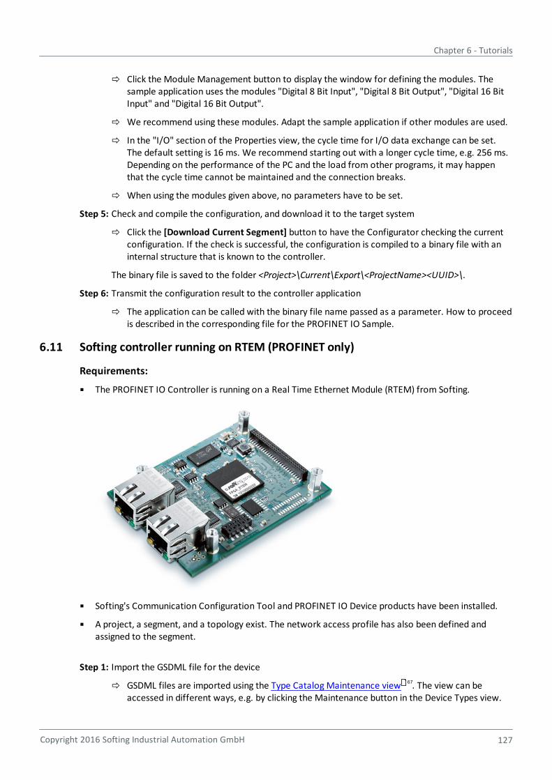
Chapter 6 - Tutorials
Copyright 2016 Softing Industrial Automation GmbH 127
Click the Module Management button to display the window for defining the modules. Thesample application uses the modules "Digital 8 Bit Input", "Digital 8 Bit Output", "Digital 16 BitInput" and "Digital 16 Bit Output".
We recommend using these modules. Adapt the sample application if other modules are used.
In the "I/O" section of the Properties view, the cycle time for I/O data exchange can be set.The default setting is 16 ms. We recommend starting out with a longer cycle time, e.g. 256 ms.Depending on the performance of the PC and the load from other programs, it may happenthat the cycle time cannot be maintained and the connection breaks.
When using the modules given above, no parameters have to be set.
Step 5: Check and compile the configuration, and download it to the target system
Click the [Download Current Segment] button to have the Configurator checking the currentconfiguration. If the check is successful, the configuration is compiled to a binary file with aninternal structure that is known to the controller.
The binary file is saved to the folder <Project>\Current\Export\<ProjectName><UUID>\.
Step 6: Transmit the configuration result to the controller application
The application can be called with the binary file name passed as a parameter. How to proceedis described in the corresponding file for the PROFINET IO Sample.
6.11 Softing controller running on RTEM (PROFINET only)
Requirements:
The PROFINET IO Controller is running on a Real Time Ethernet Module (RTEM) from Softing.
Softing's Communication Configuration Tool and PROFINET IO Device products have been installed.
A project, a segment, and a topology exist. The network access profile has also been defined andassigned to the segment.
Step 1: Import the GSDML file for the device
GSDML files are imported using the Type Catalog Maintenance view . The view can beaccessed in different ways, e.g. by clicking the Maintenance button in the Device Types view.
67
Communication Configuration Tool - User Guide
128 Copyright 2016 Softing Industrial Automation GmbH
Step 2: Create the topology
The system consists of two instances:
the Softing RTEM Controller. This device type has been preinstalled.
the Softing PROFINET IO Device Developers Kit for PC. This device type may need to beinstalled.
A connection is created between the controller and the device.
Step 3: Assign device names, IP addresses and interface name
In the sample application, the name of the device is devkitpc-1.pnio-sys. We recommendusing this name in the project. The IP address can be set to suit the specific setup.
For the controller, eth0 is entered for the interface name in the "Bus Access" section of theProperties view. This entry can be used if no changes have been made to the implementationon the RTEM.
Step 4: Define modules and parameter settings
Click the Module Management button to display the window for defining the modules. Thesample application uses the modules "Digital 8 Bit Input", "Digital 8 Bit Output", "Digital 16 BitInput" and "Digital 16 Bit Output".
We recommend using these modules. The sample application needs to be adapted if othermodules are used.
In the "I/O" section of the Properties view, the cycle time for I/O data exchange can be set.The default setting is 16 ms. We recommended starting with a longer cycle time. Depending onthe performance of the PC and the load from other programs, it may happen that the cycletime cannot be maintained and the connection breaks.
When using the modules given above, no parameters have to be set.
Step 5: Check and compile the configuration
When the [Check Current Segment] button is clicked, the Configurator first checks the currentconfiguration. If the check is successful, the configuration is compiled to a binary file with aninternal structure that is known to the controller.
The binary file is saved to the folder <Project>\Current\Export\<ProjectName><UUID>\ .
Step 6: Transmit the configuration result to the target system
If the Download Current Segment button is clicked, the Configurator not only checks andcompiles the configuration, but also downloads the created binary file to the RTEM controller.
The RTEM controller must meet the following two requirements:
It must be located in the same network as the PC running the CommunicationConfiguration Tool, and it must be accessible.
The device name of the controller must correspond to the device name of the instance.
How to proceed is described in the corresponding file for the PROFINET IO Sample.
6.12 How to configure parameters for Modbus access
Modbus access is only possible within a FF-HSE segment via a Softing FG110 or FG200. FG110 and FG200differ that the FG200 supports more parameters that can be written via Modbus.
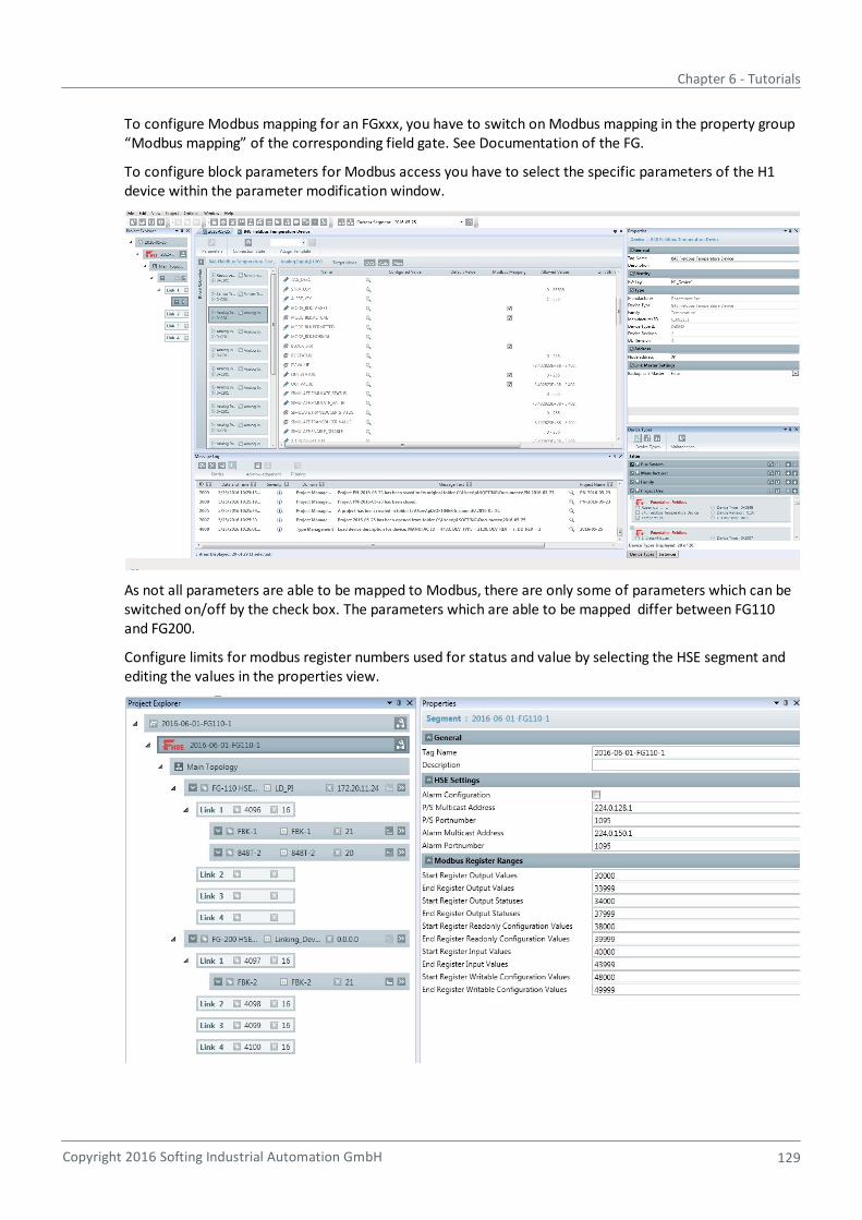
Chapter 6 - Tutorials
Copyright 2016 Softing Industrial Automation GmbH 129
To configure Modbus mapping for an FGxxx, you have to switch on Modbus mapping in the property group“Modbus mapping” of the corresponding field gate. See Documentation of the FG.
To configure block parameters for Modbus access you have to select the specific parameters of the H1device within the parameter modification window.
As not all parameters are able to be mapped to Modbus, there are only some of parameters which can beswitched on/off by the check box. The parameters which are able to be mapped differ between FG110and FG200.
Configure limits for modbus register numbers used for status and value by selecting the HSE segment andediting the values in the properties view.

Communication Configuration Tool - User Guide
130 Copyright 2016 Softing Industrial Automation GmbH
The Modbus configuration is not loaded automatically to the field gate. Thus, you need to load theconfiguration files by using the web interface of the corresponding Gateway. The files are located in <ProjectFolder>\Export\<ProjectName><GUID>\modbus_<PDTag>.csv and ModbusMapping.html
They are created during code generation of the project (see Check current segment/Check all segmentsin Main window functionality ). Refer to the FG 200 FF HSE Modbus User Manual for a more detaileddescription.
20
Chapter 7 - Frequently asked questions
Copyright 2016 Softing Industrial Automation GmbH 131
7 Frequently asked questions
There are more connections targeted at slot 0 than ports available on the plugged module
A symbol for an incorrect entry appears
A device cannot be assigned to any instance
An FF device is connected but not displayed in the Live List
An FF device is connected but the live list displays this device with device type zero
7.1 There are more connections targeted at slot 0 than ports available on theplugged module (PROFINET only)
Question:
During the segment check or the code generation for a segment, the error "There are moreconnections targeted at slot 0 than ports available on the plugged module" is displayed in the MessageLog.
What is the cause of this error and how can it be corrected?
Answer:
PROFINET devices can have 1, 2 or more Ethernet ports. Consequently, a device can be directlyconnected to one, two or even more other devices. During the creation of the topology, there is nocheck to see whether the specified connections are feasible. This check is only performed whenthe code is generated.
The error can be corrected in the following ways:
The design must match the physical topology; connections that do not correspond to realitymust be removed.
In the physical system, a switch is used that is not a PROFINET device. Refer to How torepresent a switch without PROFINET functionality in the topology view to find a descriptionon how this error can be corrected.
7.2 A symbol for an incorrect entry appears
Question:
When entering the device name, the symbol for an incorrect entry appears. But actually there is noerror.
Why does this happen and what can be done?
Answer:
The "-" (dash) character must not be given at the end of a device name, but it is allowed anywhereelse within the name. While the name is being typed, its syntax is immediately checked. If the "-"character is entered, the check at first assumes that this character is at the end of the name, andthus indicates the error. The error symbol will disappear immediately as soon as more charactersare entered.
131
131
132
132
133
122
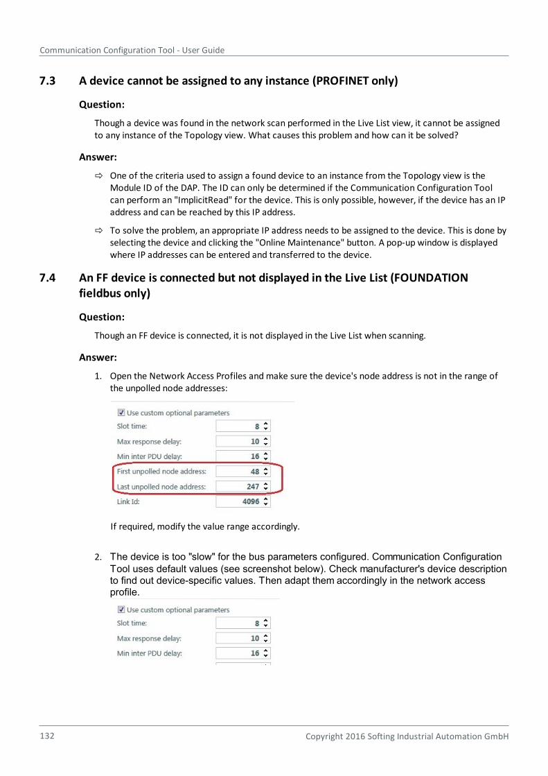
Communication Configuration Tool - User Guide
132 Copyright 2016 Softing Industrial Automation GmbH
7.3 A device cannot be assigned to any instance (PROFINET only)
Question:
Though a device was found in the network scan performed in the Live List view, it cannot be assignedto any instance of the Topology view. What causes this problem and how can it be solved?
Answer:
One of the criteria used to assign a found device to an instance from the Topology view is theModule ID of the DAP. The ID can only be determined if the Communication Configuration Toolcan perform an "ImplicitRead" for the device. This is only possible, however, if the device has an IPaddress and can be reached by this IP address.
To solve the problem, an appropriate IP address needs to be assigned to the device. This is done byselecting the device and clicking the "Online Maintenance" button. A pop-up window is displayedwhere IP addresses can be entered and transferred to the device.
7.4 An FF device is connected but not displayed in the Live List (FOUNDATIONfieldbus only)
Question:
Though an FF device is connected, it is not displayed in the Live List when scanning.
Answer:
1. Open the Network Access Profiles and make sure the device's node address is not in the range ofthe unpolled node addresses:
If required, modify the value range accordingly.
2. The device is too "slow" for the bus parameters configured. Communication ConfigurationTool uses default values (see screenshot below). Check manufacturer's device descriptionto find out device-specific values. Then adapt them accordingly in the network accessprofile.
Chapter 7 - Frequently asked questions
Copyright 2016 Softing Industrial Automation GmbH 133
7.5 An FF device is connected but the live list displays this device with device typezero (FOUNDATION fieldbus only)
Question:
Though an FF device is connected, the live list displays this device with device type zero. Usually thedevice is shown with a default address in the range from 248 to 252.
Answer:
Assign the device a node address in the range of the polled node addresses. To do so, select the device,then open Online Maintenance and then set the node value to a value in the range allowed. Then click [Assign]. Now update the live list.
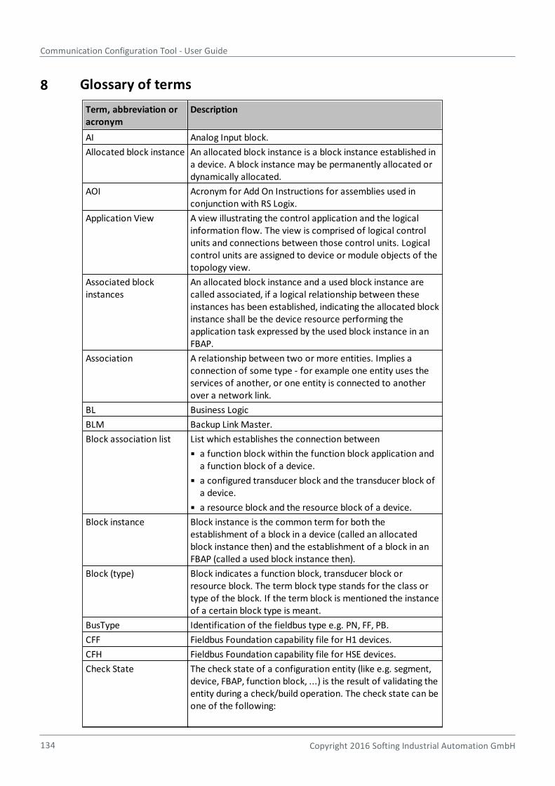
Communication Configuration Tool - User Guide
134 Copyright 2016 Softing Industrial Automation GmbH
8 Glossary of terms
Term, abbreviation oracronym
Description
AI Analog Input block.
Allocated block instance An allocated block instance is a block instance established ina device. A block instance may be permanently allocated ordynamically allocated.
AOI Acronym for Add On Instructions for assemblies used inconjunction with RS Logix.
Application View A view illustrating the control application and the logicalinformation flow. The view is comprised of logical controlunits and connections between those control units. Logicalcontrol units are assigned to device or module objects of thetopology view.
Associated blockinstances
An allocated block instance and a used block instance arecalled associated, if a logical relationship between theseinstances has been established, indicating the allocated blockinstance shall be the device resource performing theapplication task expressed by the used block instance in anFBAP.
Association A relationship between two or more entities. Implies aconnection of some type - for example one entity uses theservices of another, or one entity is connected to anotherover a network link.
BL Business Logic
BLM Backup Link Master.
Block association list List which establishes the connection between
a function block within the function block application anda function block of a device.
a configured transducer block and the transducer block ofa device.
a resource block and the resource block of a device.
Block instance Block instance is the common term for both theestablishment of a block in a device (called an allocatedblock instance then) and the establishment of a block in anFBAP (called a used block instance then).
Block (type) Block indicates a function block, transducer block orresource block. The term block type stands for the class ortype of the block. If the term block is mentioned the instanceof a certain block type is meant.
BusType Identification of the fieldbus type e.g. PN, FF, PB.
CFF Fieldbus Foundation capability file for H1 devices.
CFH Fieldbus Foundation capability file for HSE devices.
Check State The check state of a configuration entity (like e.g. segment,device, FBAP, function block, ...) is the result of validating theentity during a check/build operation. The check state can beone of the following:
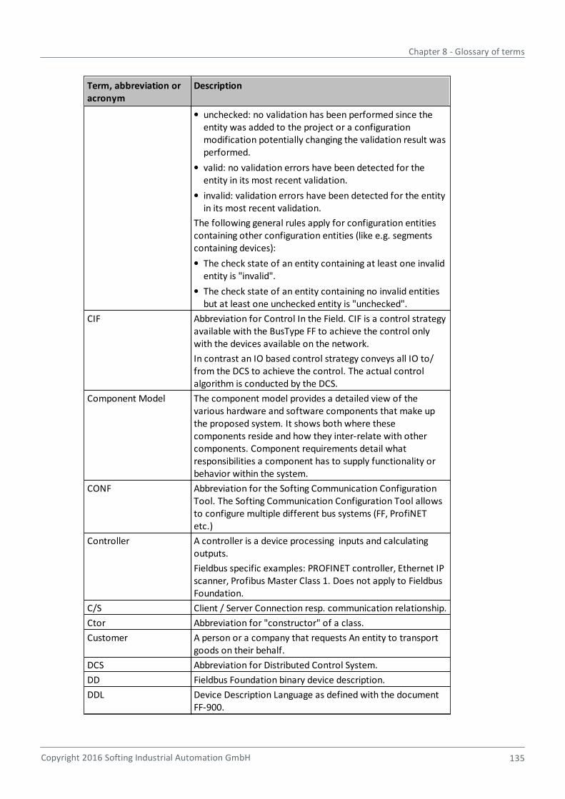
Chapter 8 - Glossary of terms
Copyright 2016 Softing Industrial Automation GmbH 135
Term, abbreviation oracronym
Description
unchecked: no validation has been performed since theentity was added to the project or a configurationmodification potentially changing the validation result wasperformed.
valid: no validation errors have been detected for theentity in its most recent validation.
invalid: validation errors have been detected for the entityin its most recent validation.
The following general rules apply for configuration entitiescontaining other configuration entities (like e.g. segmentscontaining devices):
The check state of an entity containing at least one invalidentity is "invalid".
The check state of an entity containing no invalid entitiesbut at least one unchecked entity is "unchecked".
CIF Abbreviation for Control In the Field. CIF is a control strategyavailable with the BusType FF to achieve the control onlywith the devices available on the network.
In contrast an IO based control strategy conveys all IO to/from the DCS to achieve the control. The actual controlalgorithm is conducted by the DCS.
Component Model The component model provides a detailed view of thevarious hardware and software components that make upthe proposed system. It shows both where thesecomponents reside and how they inter-relate with othercomponents. Component requirements detail whatresponsibilities a component has to supply functionality orbehavior within the system.
CONF Abbreviation for the Softing Communication ConfigurationTool. The Softing Communication Configuration Tool allowsto configure multiple different bus systems (FF, ProfiNETetc.)
Controller A controller is a device processing inputs and calculatingoutputs.
Fieldbus specific examples: PROFINET controller, Ethernet IPscanner, Profibus Master Class 1. Does not apply to FieldbusFoundation.
C/S Client / Server Connection resp. communication relationship.
Ctor Abbreviation for "constructor" of a class.
Customer A person or a company that requests An entity to transportgoods on their behalf.
DCS Abbreviation for Distributed Control System.
DD Fieldbus Foundation binary device description.
DDL Device Description Language as defined with the documentFF-900.
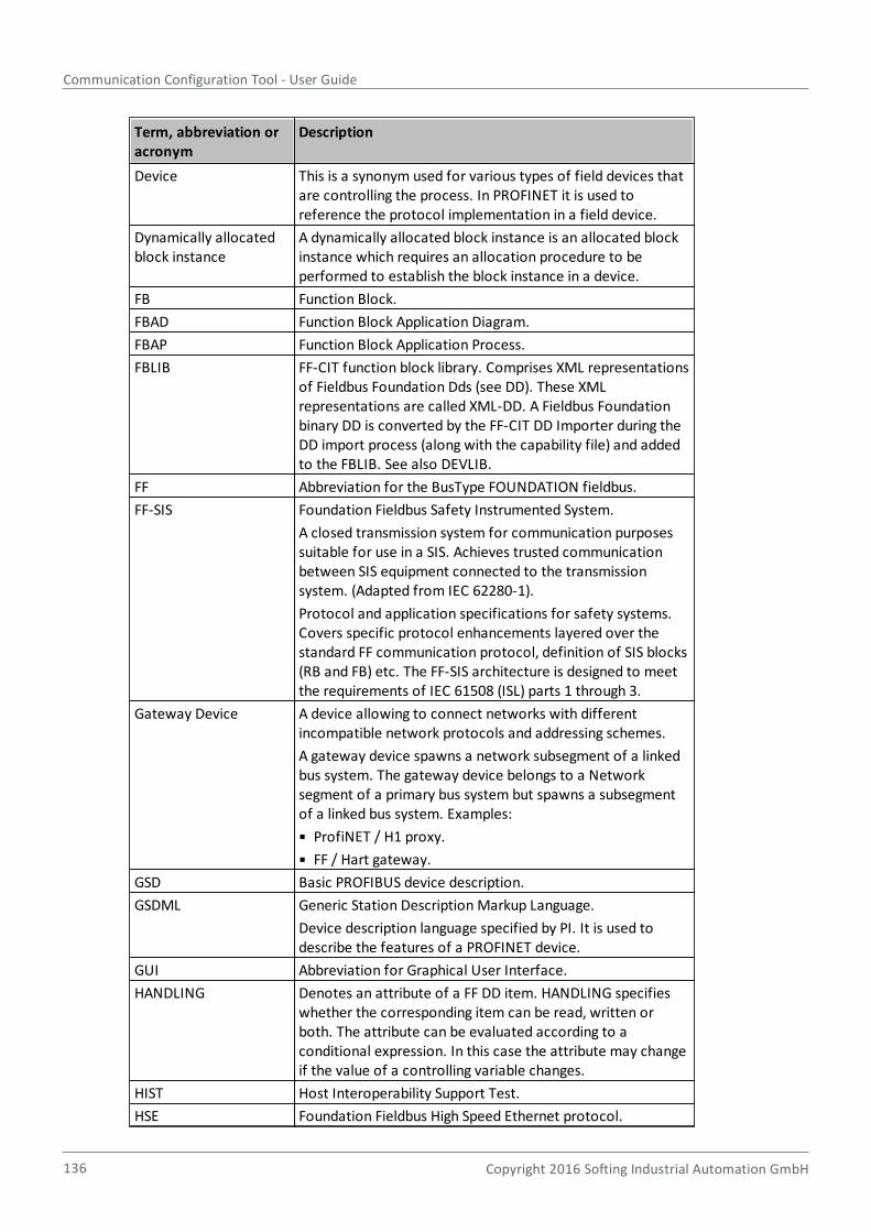
Communication Configuration Tool - User Guide
136 Copyright 2016 Softing Industrial Automation GmbH
Term, abbreviation oracronym
Description
Device This is a synonym used for various types of field devices thatare controlling the process. In PROFINET it is used toreference the protocol implementation in a field device.
Dynamically allocatedblock instance
A dynamically allocated block instance is an allocated blockinstance which requires an allocation procedure to beperformed to establish the block instance in a device.
FB Function Block.
FBAD Function Block Application Diagram.
FBAP Function Block Application Process.
FBLIB FF-CIT function block library. Comprises XML representationsof Fieldbus Foundation Dds (see DD). These XMLrepresentations are called XML-DD. A Fieldbus Foundationbinary DD is converted by the FF-CIT DD Importer during theDD import process (along with the capability file) and addedto the FBLIB. See also DEVLIB.
FF Abbreviation for the BusType FOUNDATION fieldbus.
FF-SIS Foundation Fieldbus Safety Instrumented System.
A closed transmission system for communication purposessuitable for use in a SIS. Achieves trusted communicationbetween SIS equipment connected to the transmissionsystem. (Adapted from IEC 62280-1).
Protocol and application specifications for safety systems.Covers specific protocol enhancements layered over thestandard FF communication protocol, definition of SIS blocks(RB and FB) etc. The FF-SIS architecture is designed to meetthe requirements of IEC 61508 (ISL) parts 1 through 3.
Gateway Device A device allowing to connect networks with differentincompatible network protocols and addressing schemes.
A gateway device spawns a network subsegment of a linkedbus system. The gateway device belongs to a Networksegment of a primary bus system but spawns a subsegmentof a linked bus system. Examples:
ProfiNET / H1 proxy.
FF / Hart gateway.
GSD Basic PROFIBUS device description.
GSDML Generic Station Description Markup Language.
Device description language specified by PI. It is used todescribe the features of a PROFINET device.
GUI Abbreviation for Graphical User Interface.
HANDLING Denotes an attribute of a FF DD item. HANDLING specifieswhether the corresponding item can be read, written orboth. The attribute can be evaluated according to aconditional expression. In this case the attribute may changeif the value of a controlling variable changes.
HIST Host Interoperability Support Test.
HSE Foundation Fieldbus High Speed Ethernet protocol.
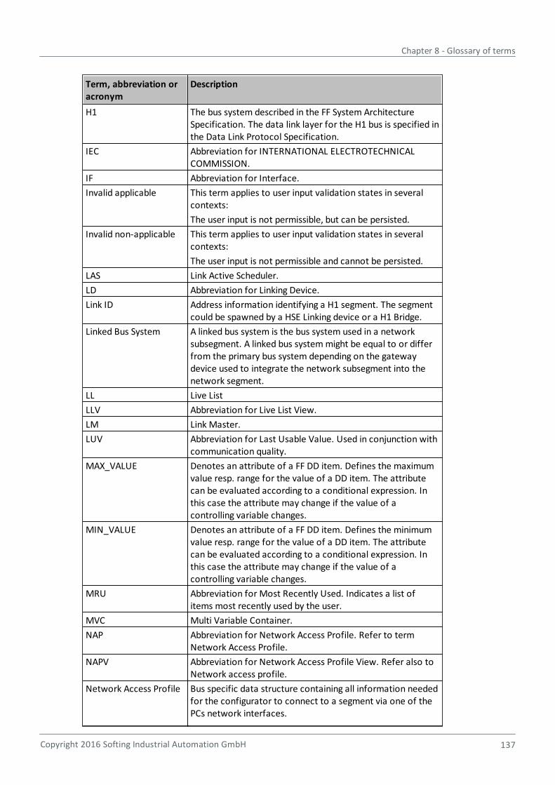
Chapter 8 - Glossary of terms
Copyright 2016 Softing Industrial Automation GmbH 137
Term, abbreviation oracronym
Description
H1 The bus system described in the FF System ArchitectureSpecification. The data link layer for the H1 bus is specified inthe Data Link Protocol Specification.
IEC Abbreviation for INTERNATIONAL ELECTROTECHNICALCOMMISSION.
IF Abbreviation for Interface.
Invalid applicable This term applies to user input validation states in severalcontexts:
The user input is not permissible, but can be persisted.
Invalid non-applicable This term applies to user input validation states in severalcontexts:
The user input is not permissible and cannot be persisted.
LAS Link Active Scheduler.
LD Abbreviation for Linking Device.
Link ID Address information identifying a H1 segment. The segmentcould be spawned by a HSE Linking device or a H1 Bridge.
Linked Bus System A linked bus system is the bus system used in a networksubsegment. A linked bus system might be equal to or differfrom the primary bus system depending on the gatewaydevice used to integrate the network subsegment into thenetwork segment.
LL Live List
LLV Abbreviation for Live List View.
LM Link Master.
LUV Abbreviation for Last Usable Value. Used in conjunction withcommunication quality.
MAX_VALUE Denotes an attribute of a FF DD item. Defines the maximumvalue resp. range for the value of a DD item. The attributecan be evaluated according to a conditional expression. Inthis case the attribute may change if the value of acontrolling variable changes.
MIN_VALUE Denotes an attribute of a FF DD item. Defines the minimumvalue resp. range for the value of a DD item. The attributecan be evaluated according to a conditional expression. Inthis case the attribute may change if the value of acontrolling variable changes.
MRU Abbreviation for Most Recently Used. Indicates a list ofitems most recently used by the user.
MVC Multi Variable Container.
NAP Abbreviation for Network Access Profile. Refer to termNetwork Access Profile.
NAPV Abbreviation for Network Access Profile View. Refer also toNetwork access profile.
Network Access Profile Bus specific data structure containing all information neededfor the configurator to connect to a segment via one of thePCs network interfaces.
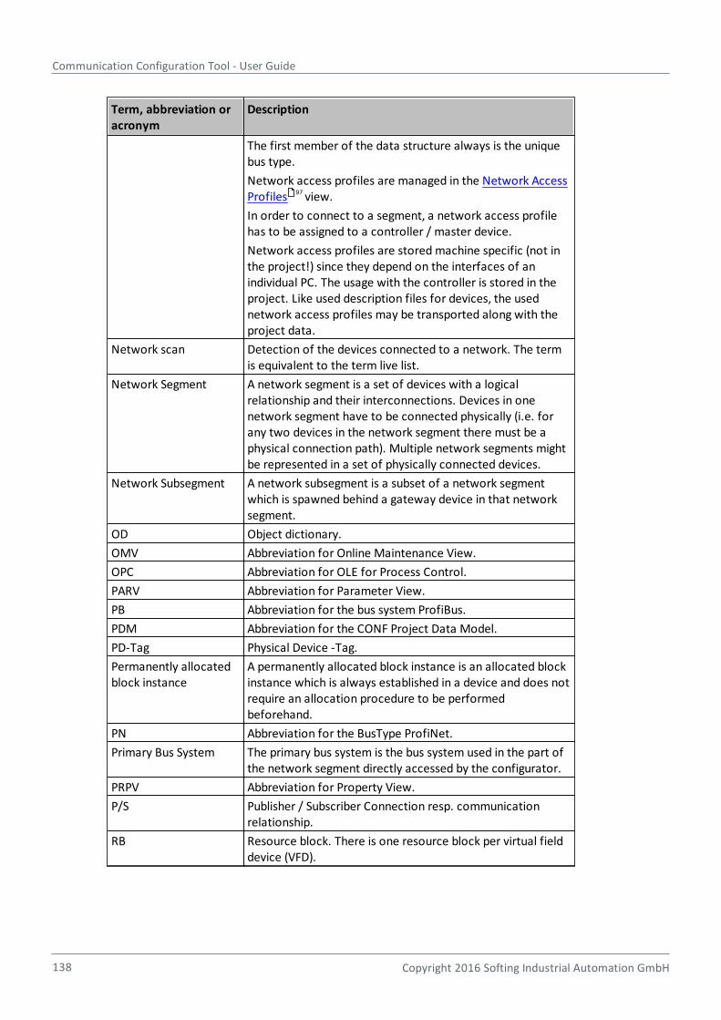
Communication Configuration Tool - User Guide
138 Copyright 2016 Softing Industrial Automation GmbH
Term, abbreviation oracronym
Description
The first member of the data structure always is the uniquebus type.
Network access profiles are managed in the Network AccessProfiles view.
In order to connect to a segment, a network access profilehas to be assigned to a controller / master device.
Network access profiles are stored machine specific (not inthe project!) since they depend on the interfaces of anindividual PC. The usage with the controller is stored in theproject. Like used description files for devices, the usednetwork access profiles may be transported along with theproject data.
Network scan Detection of the devices connected to a network. The termis equivalent to the term live list.
Network Segment A network segment is a set of devices with a logicalrelationship and their interconnections. Devices in onenetwork segment have to be connected physically (i.e. forany two devices in the network segment there must be aphysical connection path). Multiple network segments mightbe represented in a set of physically connected devices.
Network Subsegment A network subsegment is a subset of a network segmentwhich is spawned behind a gateway device in that networksegment.
OD Object dictionary.
OMV Abbreviation for Online Maintenance View.
OPC Abbreviation for OLE for Process Control.
PARV Abbreviation for Parameter View.
PB Abbreviation for the bus system ProfiBus.
PDM Abbreviation for the CONF Project Data Model.
PD-Tag Physical Device -Tag.
Permanently allocatedblock instance
A permanently allocated block instance is an allocated blockinstance which is always established in a device and does notrequire an allocation procedure to be performedbeforehand.
PN Abbreviation for the BusType ProfiNet.
Primary Bus System The primary bus system is the bus system used in the part ofthe network segment directly accessed by the configurator.
PRPV Abbreviation for Property View.
P/S Publisher / Subscriber Connection resp. communicationrelationship.
RB Resource block. There is one resource block per virtual fielddevice (VFD).
97
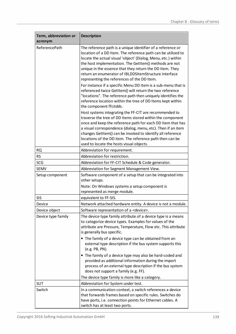
Chapter 8 - Glossary of terms
Copyright 2016 Softing Industrial Automation GmbH 139
Term, abbreviation oracronym
Description
ReferencePath The reference path is a unique identifier of a reference orlocation of a DD Item. The reference path can be utilized tolocate the actual visual 'object' (Dialog, Menu, etc.) withinthe host implementation. The GetItem() methods are notunique in the essence that they return the DD Item. Theyreturn an enumerator of IBLDDSItemStructure interfacerepresenting the references of the DD Item.
For instance if a specific Menu DD Item is a sub-menu that isreferenced twice GetItem() will return the two reference"locations". The reference path then uniquely identifies thereference location within the tree of DD Items kept withinthe component ffcitdds.
Host systems integrating the FF-CIT are recommended totraverse the tree of DD Items stored within the componentonce and keep the reference path for each DD Item that hasa visual correspondence (dialog, menu, etc). Then if an itemchanges GetItem() can be invoked to identify all referencelocations of the DD item. The reference path then can beused to locate the hosts visual objects.
RQ Abbreviation for requirement.
RS Abbreviation for restriction.
SCG Abbreviation for FF-CIT Schedule & Code generator.
SEMV Abbreviation for Segment Management View.
Setup component Software component of a setup that can be integrated intoother setups.
Note: On Windows systems a setup component isrepresented as merge module.
SIS equivalent to FF-SIS.
Device Network attached hardware entity. A device is not a module.
Device object Software representation of a <device>.
Device type family The device type family attribute of a device type is a meansto categorize device types. Examples for values of theattribute are Pressure, Temperature, Flow etc. This attributeis generally bus specific.
The family of a device type can be obtained from anexternal type description if the bus system supports this(e.g. PB, PN).
The family of a device type may also be hard-coded andprovided as additional information during the importprocess of an external type description if the bus systemdoes not support a family (e.g. FF).
The device type family is more like a category.
SUT Abbreviation for System under test.
Switch In a communication context, a switch references a devicethat forwards frames based on specific rules. Switches dohave ports, i.e. connection points for Ethernet cables. Aswitch has at least two ports.
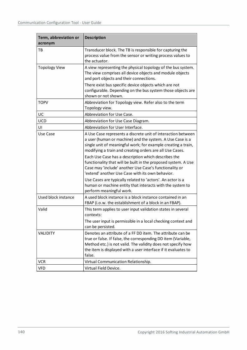
Communication Configuration Tool - User Guide
140 Copyright 2016 Softing Industrial Automation GmbH
Term, abbreviation oracronym
Description
TB Transducer block. The TB is responsible for capturing theprocess value from the sensor or writing process values tothe actuator.
Topology View A view representing the physical topology of the bus system.The view comprises all device objects and module objectsand port objects and their connections.
There exist bus specific device objects which are notconfigurable. Depending on the bus system those objects areshown or not shown.
TOPV Abbreviation for Topology view. Refer also to the termTopology view.
UC Abbreviation for Use Case.
UCD Abbreviation for Use Case Diagram.
UI Abbreviation for User Interface.
Use Case A Use Case represents a discrete unit of interaction betweena user (human or machine) and the system. A Use Case is asingle unit of meaningful work; for example creating a train,modifying a train and creating orders are all Use Cases.
Each Use Case has a description which describes thefunctionality that will be built in the proposed system. A UseCase may 'include' another Use Case's functionality or'extend' another Use Case with its own behavior.
Use Cases are typically related to 'actors'. An actor is ahuman or machine entity that interacts with the system toperform meaningful work.
Used block instance A used block instance is a block instance contained in anFBAP (i.o.w. the establishment of a block in an FBAP).
Valid This term applies to user input validation states in severalcontexts:
The user input is permissible in a local checking context andcan be persisted.
VALIDITY Denotes an attribute of a FF DD item. The attribute can betrue or false. If false, the corresponding DD item (Variable,Method etc.) is not valid. The validity does not specify howthe item is displayed with a user interface if it evaluates tofalse.
VCR Virtual Communication Relationship.
VFD Virtual Field Device.
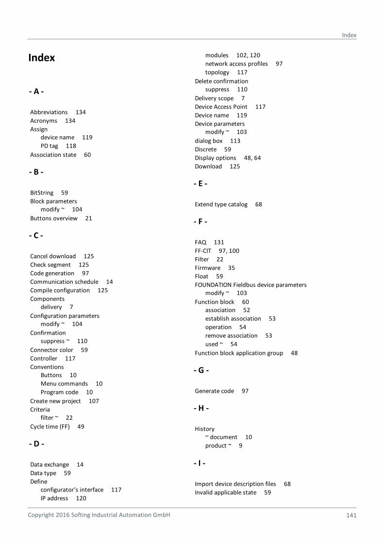
Copyright 2016 Softing Industrial Automation GmbH
Index
141
Index
- A -
Abbreviations 134
Acronyms 134
Assign device name 119
PD tag 118
Association state 60
- B -
BitString 59
Block parameters modify ~ 104
Buttons overview 21
- C -
Cancel download 125
Check segment 125
Code generation 97
Communication schedule 14
Compile configuration 125
Components delivery 7
Configuration parameters modify ~ 104
Confirmation suppress ~ 110
Connector color 59
Controller 117
Conventions Buttons 10
Menu commands 10
Program code 10
Create new project 107
Criteria filter ~ 22
Cycle time (FF) 49
- D -
Data exchange 14
Data type 59
Define configurator's interface 117
IP address 120
modules 102, 120
network access profiles 97
topology 117
Delete confirmation suppress 110
Delivery scope 7
Device Access Point 117
Device name 119
Device parameters modify ~ 103
dialog box 113
Discrete 59
Display options 48, 64
Download 125
- E -
Extend type catalog 68
- F -
FAQ 131
FF-CIT 97, 100
Filter 22
Firmware 35
Float 59
FOUNDATION Fieldbus device parameters modify ~ 103
Function block 60association 52
establish association 53
operation 54
remove association 53
used ~ 54
Function block application group 48
- G -
Generate code 97
- H -
History ~ document 10
product ~ 9
- I -
Import device description files 68
Invalid applicable state 59
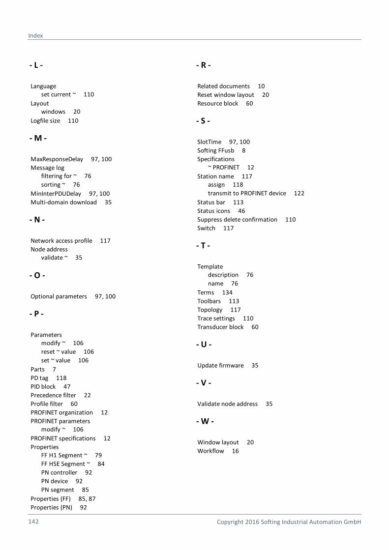
Index
Copyright 2016 Softing Industrial Automation GmbH142
- L -
Language set current ~ 110
Layout windows 20
Logfile size 110
- M -
MaxResponseDelay 97, 100
Message log filtering for ~ 76
sorting ~ 76
MinInterPDUDelay 97, 100
Multi-domain download 35
- N -
Network access profile 117
Node address validate ~ 35
- O -
Optional parameters 97, 100
- P -
Parameters modify ~ 106
reset ~ value 106
set ~ value 106
Parts 7
PD tag 118
PID block 47
Precedence filter 22
Profile filter 60
PROFINET organization 12
PROFINET parameters modify ~ 106
PROFINET specifications 12
Properties FF H1 Segment ~ 79
FF HSE Segment ~ 84
PN controller 92
PN device 92
PN segment 85
Properties (FF) 85, 87
Properties (PN) 92
- R -
Related documents 10
Reset window layout 20
Resource block 60
- S -
SlotTime 97, 100
Softing FFusb 8
Specifications ~ PROFINET 12
Station name 117assign 118
transmit to PROFINET device 122
Status bar 113
Status icons 46
Suppress delete confirmation 110
Switch 117
- T -
Template description 76
name 76
Terms 134
Toolbars 113
Topology 117
Trace settings 110
Transducer block 60
- U -
Update firmware 35
- V -
Validate node address 35
- W -
Window layout 20
Workflow 16

This page is intentionally left blank.
Copyright 2016 Softing Industrial Automation GmbH 143

Tel: + 49 89 45 656-0Fax: + 49 89 45 [email protected]
Richard-Reitzner-Allee 685540 Haar / Germanyhttp://industrial.softing.com
Softing Industrial Automation GmbH