spacecraft design project
TRANSCRIPT

Spacecraft Design Project
© University of Surrey, Guildford, Surrey, UK
SPACECRAFT DESIGN PROJECT
Dr. Craig Underwood & Dr. Martin Unwin
1. INTRODUCTION AND AIMS
You are required to design a small spacecraft for a tactical reconnaissance mission. This spacecraft will form part of a constellation of satellites which will be launched in pairs from a PEGASUS launch vehicle -possibly in rapid response to a developing situation. Thus, the design aim is to minimise the size, mass and complexity of each satellite so that they may fit within the limited performance envelope of the PEGASUS vehicle.
Initially, the satellites are to be placed in a circular, near-polar, Sun-synchronous orbit, in order to provide global coverage at medium resolution. Additionally, the satellites are to be equipped with a kick-motor, to allow the satellite to be brought down to low altitude over an area of specific interest for higher resolution imaging.
Images are to be recorded electronically in a solid-state memory, and downloaded to a Mission Operation Centre (MOC) based in the UK.
This project is to specify an outline design for the satellite, concentrating on the following areas:
Orbital Dynamics;
Optical Systems;
On-Board Data Handling;
RF Link;
Power Systems;
Mass Budget / Volume Constraints;
At the end of the project, you will be required to give a small presentation on your design, noting the various trade-offs, assumptions and decisions which you have made.
2. PERFORMANCE SPECIFICATION
The satellite must provide all the 'housekeeping' systems and support for the imaging payload. This includes: RF Systems (transmitters and receivers), Telemetry and Telecommand Systems, Power System, Thermal Control, Attitude Determination and Control System and Propulsion System.
The spacecraft should have the minimum of moving parts.
The spacecraft is to be powered by solar-panels and batteries.
The mission lifetime is to be at least 3 years in the nominal orbit, but may be reduced to a few months when brought down to low altitude.
The imaging payload will be based around a state-of-the-art CCD imaging-array, with a 31mm square image-plane
consisting of 4096 x 4096 pixels (i.e. each light-sensitive cell is 7.5 m (i.e. 10-6
m) square. The maximum clock-rate for the CCD is 10 MHz, giving a minimum read-out time of 1.678 seconds. Each pixel value is to be digitized to 256 levels of grey, and stored in a solid-state memory. There is to be real-time data-compression between the picture read-out and the memory, which gives a 3:1 reduction in data storage without loss of picture information. Data decompression is to be carried out on the ground. The power consumed by the CCD imaging system is 10W during picture acquisition and 5W in stand-by mode.
Spacecraft Design Project
© University of Surrey, Guildford, Surrey, UK
It is required to store up to 6 images on-board the satellite, and the entire memory contents must be able to be downloaded to the MOC within a single pass.
The optical system is to be based on a Cassegrainian folded-optics telescope, such that the resolution of the entire camera is to be better than 0.5 m at the sub-satellite point when the satellite is at 180 km altitude.
The mass of a pair of satellites and their deployment structure should be such that the PEGASUS vehicle can attain an altitude of at least 500 km at the appropriate inclination to achieve a Sun-synchronous orbit.
3. DESIGN PROCEDURE
The design of a satellite is usually an iterative procedure, and can be approached from many different starting points. It is suggested that for this exercise, the orbit geometry of the satellite be considered first, as this has a direct impact on the physical design of the spacecraft in terms of mass and volume. It will also have a major influence on the design of the imaging payload (size of mirrors required, focal length, etc.). Next, the propulsion system is considered, as this will also be a major factor in planning the size and mass of the satellite. Finally, the electronic and RF systems are considered, with their impact on the power system design.
3.1 Orbit Geometry and Propulsion
The initial orbit is to be a circular, near-polar, Sun-synchronous orbit, at least 500 km in altitude. Sun-synchronous orbits are often chosen for imaging satellites as the near constant angle between the orbit-plane and the line joining the Sun to the centre of the Earth, means that objects on the Earth's surface are illuminated in a uniform way every time the satellite passes over them. Thus, for example, changes in shadow length can be attributed to changes in the height of objects, rather than to changes in illumination due to different Sun angles.
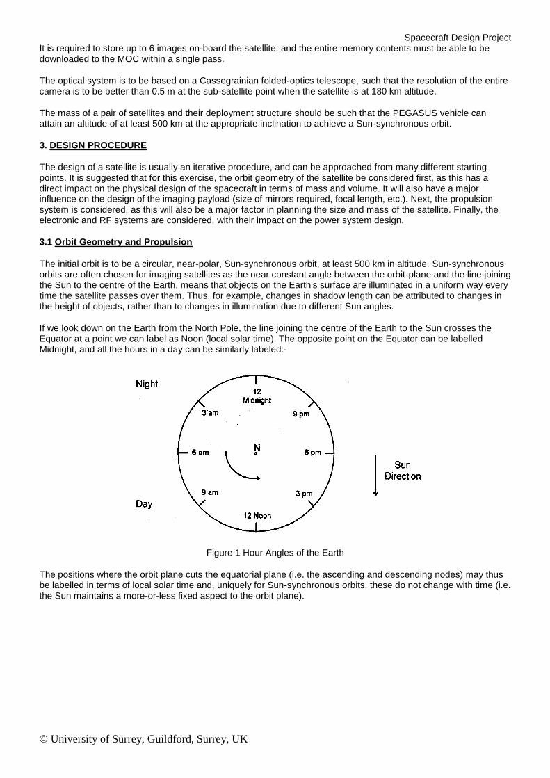
If we look down on the Earth from the North Pole, the line joining the centre of the Earth to the Sun crosses the Equator at a point we can label as Noon (local solar time). The opposite point on the Equator can be labelled Midnight, and all the hours in a day can be similarly labeled:-
Figure 1 Hour Angles of the Earth
The positions where the orbit plane cuts the equatorial plane (i.e. the ascending and descending nodes) may thus be labelled in terms of local solar time and, uniquely for Sun-synchronous orbits, these do not change with time (i.e. the Sun maintains a more-or-less fixed aspect to the orbit plane).
Spacecraft Design Project
© University of Surrey, Guildford, Surrey, UK
Thus, a 12am/12pm orbit means that the Sun-line lies in the orbit plane, whereas a 6am/6pm orbit means that the orbit plane is orthogonal to the Sun-line.
With reference to eclipse period and illumination conditions on the ground, investigate the effect of choosing different Sun-synchronous orbits (as described by the local solar time of the ascending node), and thus choose a suitable orbit plane for this imaging mission.
Sun-synchronicity is achieved by choosing exactly the right value of inclination for a given altitude to ensure that the nodal precession of the satellite's orbit precisely matches the rate at which the Earth orbits around the Sun (i.e. once per year).
Calculate the inclination required to give Sun-synchronicity for a circular orbit at 500 km altitude, and thus give the Keplerian Elements:
a Semi-Major Axis [km] e Eccentricity i Inclination [degs] T Orbit Period [mins] n Mean Motion [revs/day]
d/dt Rate of Change of Argument of Perigee (Apsidal Rotation)
d/dt Rate of Change of Right-Ascension of the Ascending Node (Nodal Precession)
Satellites in low-Earth orbit (LEO) are subject to perturbing forces including some degree of drag from the residual atmosphere. This drag factor (dn/dt) depends very much on the effective cross-sectional area and mass of the satellite. A typical drag factor might be of the order of 10
-4 revolutions per day per day. Interestingly, this drag factor
causes an acceleration of the satellite contrary to what might be expected. This is because the effect of the atmospheric friction is to cause the satellite orbit to decay in altitude (i.e. to lose potential energy), but as the satellite 'falls' it must speed up to maintain a stable orbit, thus as the altitude decreases, the kinetic energy increases. However, the total energy (kinetic + potential) of the satellite is reduced.
If the satellite is allowed to lose altitude, it will depart from Sun-synchronicity, thus some form of propulsion will be needed to maintain the proper altitude over the required three year lifetime.
Assuming the decay rate (dn/dt) does not change significantly during this time, estimate the increase in speed (and hence the loss in altitude) over the planned lifetime and assess whether or not the departure from Sun-synchronicity is significant (i.e. does the orbit-plane swing round dramatically?). If so, select a propulsion system to overcome this drag effect.
In order to observe a particular region of the Earth more closely, it is possible to fire a kick-motor to change the orbit into an ellipse, with the apogee at the original height (500 km) and the perigee at 180 km. By firing the motor at the appropriate time, the perigee can be made to occur over the region of interest. Another approach would be to circularise the orbit at 180 km.
To do this requires a propulsion system and the ability to carry out the appropriate orbital manoeuvres. One of the most common procedures used for in-plane orbit changes is the Hohmann transfer orbit, which provides a minimum energy solution.
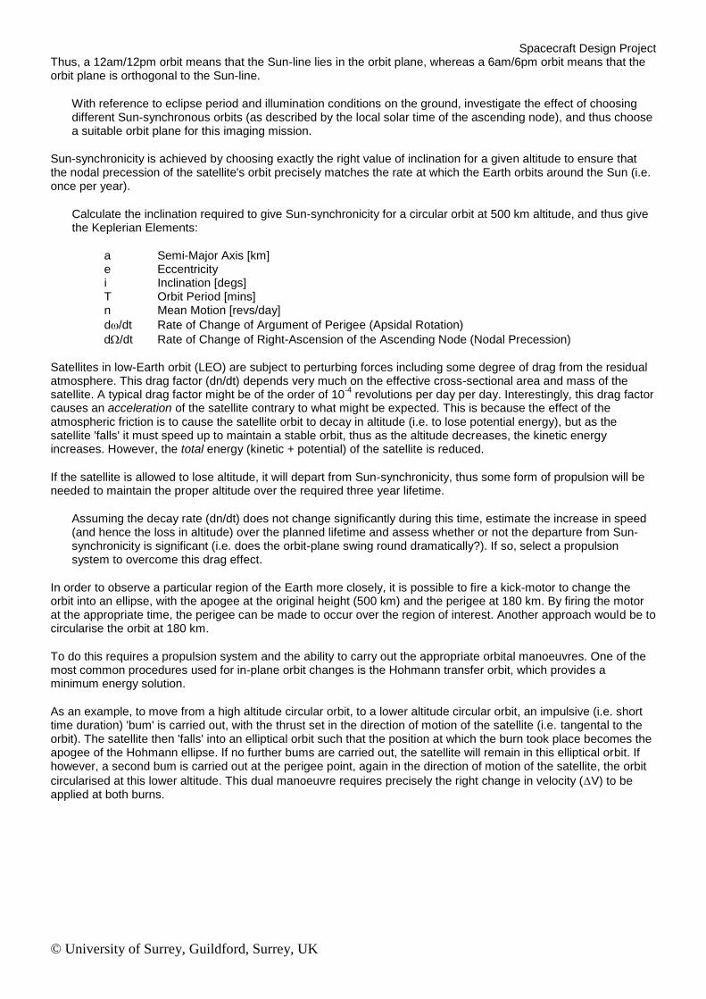
As an example, to move from a high altitude circular orbit, to a lower altitude circular orbit, an impulsive (i.e. short time duration) 'bum' is carried out, with the thrust set in the direction of motion of the satellite (i.e. tangental to the orbit). The satellite then 'falls' into an elliptical orbit such that the position at which the burn took place becomes the apogee of the Hohmann ellipse. If no further bums are carried out, the satellite will remain in this elliptical orbit. If however, a second bum is carried out at the perigee point, again in the direction of motion of the satellite, the orbit
circularised at this lower altitude. This dual manoeuvre requires precisely the right change in velocity (V) to be applied at both burns.
Spacecraft Design Project
© University of Surrey, Guildford, Surrey, UK
Hohmann Transfer. Step 1: The first burn or V of a Hohmann Transfer takes you out of your first circular orbit and puts you on an elliptical transfer orbit. Step 2: The second burn of a Hohmann Transfer takes you from the transfer orbit and places you in the desired final, circular orbit.
Figure 2 Hohmann Transfer Orbit Manoeuvre (Sellers)
Carry out a trade off analysis of these two options considering the following factors:
minimum V required to achieve the orbit changes;
propulsion system required (mass of fuel, etc.) Assume the mass of the motor is 10% the mass of the fuel;
consider the trade-offs between solid propellant (one-shot only) and liquid propellants (more controllable);
movement of the perigee point due to apsidal rotation;
departure from Sun-synchronicity;
feasibility of lowering the perigee below 180 km;
orbital lifetime;
(Assume the region of interest to be imaged is geographically compact and the minimum useful imaging time is 2 weeks)
3.2 Optical Design
Having specified the orbit and propulsion system, the optical system can now be defined.
The main requirement is to have an imaging system with better than 0.5 m resolution at 180 km altitude. With this sort of resolution, it would be possible to distinguish roads, buildings, runways etc., and should even be possible to identify aircraft and, to some extent, vehicle types.
Another way of specifying the resolution is to calculate the angle subtended by a line 0.5 m long at 180 km distance
(angle ‘').
The Rayleigh limit describes the ultimate resolving power of an optical instrument in terms of the wavelength of light ('L ') and the aperture of the system ('D') as:
= 1.22 L / D [radians]
[the wavelength of visible light is between 0.4 -0.7 um]
The resolving power (magnification) of the CCD can be calculated as follows:
Spacecraft Design Project
© University of Surrey, Guildford, Surrey, UK
f/b = x/r where f= the focal length of the imaging system h = altitude of the satellite x = pixel cell-size r = minimum distance to be resolved
The F-number of the optical system is given by the ratio: f/D. Normal camera lenses have F-numbers between F/l.8 and F/22. The smaller the F-number, the more light is gathered (an F/8 system is 4 times as bright as an F/16 system).
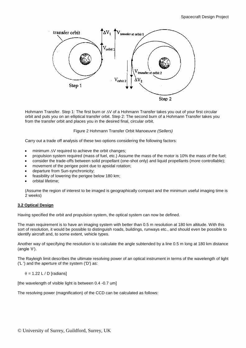
The optical system is to be a Cassegrainian telescope, which has an effective focal-length as follows:
fe = fl2 / I1 (approx.)
where f is the focal length of the primary mirror
11 is the distance between the secondary mirror and the focal point of the primary mirror 12 is the distance between the primary and secondary mirrors (I1 + 12 = f)
Using this information, design a suitable optical system bearing in mind the following:
the effective focal length should give sufficient magnification for one pixel to be equivalent to 0.5 m on the ground;
the diameter of the primary must be sufficiently large to meet the Rayleigh criterion for resolving angle , i.e. the angle subtended by 0.5 m at 180 km. (Note: the diameter of the primary defines the aperture of the system -however, remember the occluding effect of the secondary mirror which will mask off some of the area);
the F-number of the system should be sufficiently small to give a bright image;
a suitable secondary mirror position needs to be selected to give a compact system with the correct effective focal length;
field of view (4096 x 4096 pixels);
Design a suitable mounting for this structure on the satellite body, possibly with deployable parts. Discuss the reasons for the choice of mechanics and materials, and note the effect of thermal cycling on the structure. Estimate the mass of the system. How might mass be kept to a minimum?
Describe the optical performance of the system in the nominal, 500 km orbit.
One problem with high-resolution imaging is coping with image-blur due to the motion of the satellite.
Considering the effective ground-speed of the satellite, and estimating any motions around the pitch, roll and yaw axes, calculate the maximum exposure time which can be tolerated so as not to limit the resolution. Comment on your findings.
Spacecraft Design Project
© University of Surrey, Guildford, Surrey, UK
Considering the field of view of the instrument, define the pointing accuracy requirements for the satellite in order to be sure of imaging a specific object. Comment on the attitude determination and control (ADCS) requirements for the satellite and suggest a suitable system for achieving the desired accuracy.
When the image is being read-out into memory, the CCD cannot be used for further imaging, thus there will be a certain 'dead-time' after each image is taken.
Calculate the ground-distance travelled in this 'dead-time'. If several contiguous images are required along-track, how could this dead-time effect be circumvented? Discuss any possible benefits to exposure time of such techniques.
3.3 On-Board Data Handling (OBDH)
The output of the CCD is an analogue voltage representing the light-level falling on a particular pixel. Pixel values are read-out serially at a maximum clock-rate of 10 MHz (i.e. 4096 x 4096 = 16777216 pixels would take 1.678 seconds to read out). These analogue values need to be digitized to 8-bit resolution before storing in the solid-state memory. Because CCDs represent a large capacitative load, the power consumption of the CCD drivers can be quite high. A good estimate of the power consumption on the imager might be of the order of 10 W during its active phase.
Solid-state memory devices are subject to single-event upset (SEU) due to the action of space radiation. For these orbits, a typical rate would be 10
-6 SEU per bit per day. One solution to the problem of memory corruption is to
store a Hamming code-word for every byte of data. To detect and correct any single bit-error in an 8-bit byte, a 4-bit code- word is required. Thus, each data-byte will require 12-bits of storage. Data are written-to and read-from the memory via an EDAC circuit which automatically calculates the Hamming code and corrects any single bit errors.
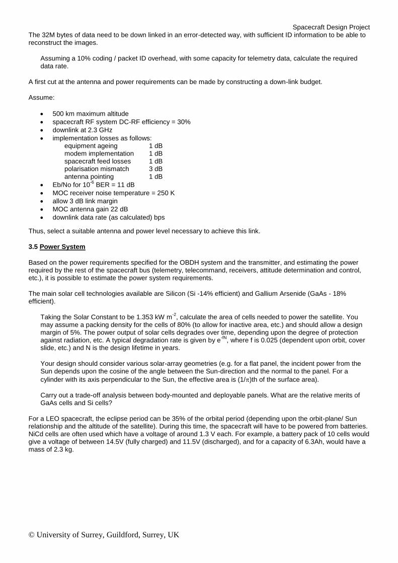
Typical Memory Device Data:
Device Physical Size (mm)
Standby Power (uW)
Operating Power (mW)
Acc. Time (ns)
128K x 8 SRAM (monolithic)
40.64 x 10.7 x 2.54 (32 pin VIL)
50 150 55
1M x 1 DRAM (monolithic)
30.48 x 10.7 x 2.54 (24 pin VIL)
5000 (refresh = 300 mW,
300 8ms 512 cycles)
100
1Mx 8 SRAM (hybrid module)
92.3 x 20.83 x 7.5 (35 pin SIP)
100 110 70
1M x 1 SRAM (monolithic)
35.56 x 10.7 x 2.54 (28 pin VIL)
100 350 55
Assuming the 3:1 data-compression system referred to, design a memory system that would be capable of storing the required 6 images. In particular, note the size, mass and power consumption.
3.4 RF Link
At 500 km altitude, a typical pass over the MOC will last for perhaps 10 minutes, in this time it is required to downlink the entire memory contents.
Spacecraft Design Project
© University of Surrey, Guildford, Surrey, UK
The 32M bytes of data need to be down linked in an error-detected way, with sufficient ID information to be able to reconstruct the images.
Assuming a 10% coding / packet ID overhead, with some capacity for telemetry data, calculate the required data rate.
A first cut at the antenna and power requirements can be made by constructing a down-link budget.
Assume:
500 km maximum altitude
spacecraft RF system DC-RF efficiency = 30%
downlink at 2.3 GHz
implementation losses as follows: equipment ageing 1 dB modem implementation 1 dB spacecraft feed losses 1 dB polarisation mismatch 3 dB antenna pointing 1 dB
Eb/No for 10-6
BER = 11 dB
MOC receiver noise temperature = 250 K
allow 3 dB link margin
MOC antenna gain 22 dB
downlink data rate (as calculated) bps
Thus, select a suitable antenna and power level necessary to achieve this link.
3.5 Power System
Based on the power requirements specified for the OBDH system and the transmitter, and estimating the power required by the rest of the spacecraft bus (telemetry, telecommand, receivers, attitude determination and control, etc.), it is possible to estimate the power system requirements.
The main solar cell technologies available are Silicon (Si -14% efficient) and Gallium Arsenide (GaAs - 18% efficient).
Taking the Solar Constant to be 1.353 kW m-2
, calculate the area of cells needed to power the satellite. You may assume a packing density for the cells of 80% (to allow for inactive area, etc.) and should allow a design margin of 5%. The power output of solar cells degrades over time, depending upon the degree of protection against radiation, etc. A typical degradation rate is given by e
-fN, where f is 0.025 (dependent upon orbit, cover
slide, etc.) and N is the design lifetime in years.
Your design should consider various solar-array geometries (e.g. for a flat panel, the incident power from the Sun depends upon the cosine of the angle between the Sun-direction and the normal to the panel. For a
cylinder with its axis perpendicular to the Sun, the effective area is (1/)th of the surface area).
Carry out a trade-off analysis between body-mounted and deployable panels. What are the relative merits of GaAs cells and Si cells?
For a LEO spacecraft, the eclipse period can be 35% of the orbital period (depending upon the orbit-plane/ Sun relationship and the altitude of the satellite). During this time, the spacecraft will have to be powered from batteries. NiCd cells are often used which have a voltage of around 1.3 V each. For example, a battery pack of 10 cells would give a voltage of between 14.5V (fully charged) and 11.5V (discharged), and for a capacity of 6.3Ah, would have a mass of 2.3 kg.
Spacecraft Design Project
© University of Surrey, Guildford, Surrey, UK
Calculate the capacity (in Ampere-hours) of 10 cell NiCd battery required to fully operate the spacecraft in eclipse. Assuming the mass scales with capacity, estimate the mass of the battery pack.
3.6 Mass / Volume Constraints
By this stage, all the major sub-systems have been examined and an idea of the mass and size of each has been reached.
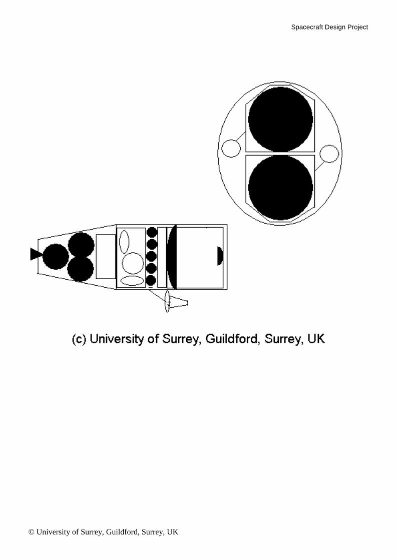
Noting the limited capacity of the PEGASUS vehicle in terms of volume and mass lifting-capacity, draw a dimensioned sketch of your spacecraft showing the antenna, optical system, solar cells, propulsion unit and internal positioning of the on-board systems. Remember that there needs to be an interface to the launch vehicle, and that there may be a need for thermal control surfaces.
3.7 Final Comments
Due to the limited time available, this design can only be a simplified case study. There are many other factors to take into account, such as the design of the 'housekeeping' systems, ADCS, thermal control, etc. However, this exercise has hopefully given some insight into some of the factors that need to be considered when designing a spacecraft for a particular mission.
In your presentation, you should show the trade-offs and assumptions you have made in putting together your spacecraft design and outline any additional areas where the spacecraft design will be impacted by the mission requirements.
4. USEFUL INFORMATION
The following information and equations may be of use in the project. It is believed that all necessary information is included in this hand-out, however, if there are any parameters etc. which have been omitted which you believe you require then just make some ‘educated assumptions/guesses' as best you can clearly indicating those estimates in your presentation.
G = Gravitational Constant = 6.673 x 10⁻¹¹
N m2 kg
-2
M = Mass of Earth= 5.977 x 1024 kg u = GM = 3.986 x 10
5 km
3 s
-2
k = Boltzmann Constant = 1.3807 x 10⁻²³
W K-1
Hz-1
Req = Radius of Earth = 6378 km (Equatorial) R = Radius of Earth = 6371 km (mean) a = Semi-Major Axis b = Semi-Minor Axis ra = Apogee Distance rp = Perigee Distance g = Acceleration due to gravity at Earth's surface = 9.807 ms
-2
Conversion Factors:
1 nautical mile = 1852 m 1 pound (lb) = 0.45359 kg 1 ft = 0.3048 m 1 year = 365.25 days (approx.) 1 day = 1440 minutes = 86400 seconds
360° = 27 radians
Specific Impulse, Isp (s) for different propellants: (typical thrust levels in brackets)
Cold Gas ( < few N) 70 s
Monopropellant Hydrazine (0.5 N to a few N) 220 s
Liquid Bi-PropeIlant (few N to 500 N) 320 s
Solid Propellant (400N to 50 kN) 290 s
Electric (< 0.1 N) 1000-10000 s
Spacecraft Design Project
© University of Surrey, Guildford, Surrey, UK
Formulae:
Circumference of a circle = 2r
Area of a circle = r2
Area of a sphere = 4r2
Volume of a sphere = (4/3)r3
Volume of a cylinder (height h) = hr2
Gravitational force between two masses = G m1 m2/r2
Centripetal force = m v2 / r
Satellite velocity at distance r: V2= GM ((2/r) - (I/a))
Circular Velocity: v2 = GM / r
Eccentricity: e = ( 1 -(b/a) 2 )
0.5
= 1/2a (ra -rp)
Orbital Period: T2= 4
2 a
3/GM
Polar Equation of an Orbit [position (r, )]: r = a (1 -e2 )/(1 + e cos )
Time from Perigee (Elliptic Orbit): t = T (E- e sin E) /2.
Eccentric Anomaly E = cos-1
[(e + cos ) / (1 + e cos )]
Nodal Precession [deg/day]: d./dt = -9.95 x(Req / a)3.5
cos i /(1 - e2)2
Apsidal Rotation [deg/day]: d//dt = -4.97 x (Req / a)3.5
(1 -5 cos2 i) / (1 -e
2) 2
Atmospheric Drag: F drag = 0.5 v2 A CD
where is atmospheric density. CD = coefficient of drag (= 2.2 for most satellites) A = projected area v = velocity relative to atmosphere
Ballistic Coefficient = m / (CD x A) [kg/m2]
where m = mass (kg) A = projected area (m
2)
CD = coefficient of drag (unitless) = 2.2 approx.
Mass of propellant required for a velocity increment V:
V = lsp g In ((Me + Mp)/Me)
where lsp = specific impulse of propellant Me = empty mass of satellite Mp = propellant mass g = 9.807 ms
-2
Free Space Path Loss = 10 log (4R / wavelength)2
Speed of Light = 3 x 10⁸ m/s
Received Noise Power = k.Bandwidth. Temperature (kBT)
Spacecraft Design Project
© University of Surrey, Guildford, Surrey, UK
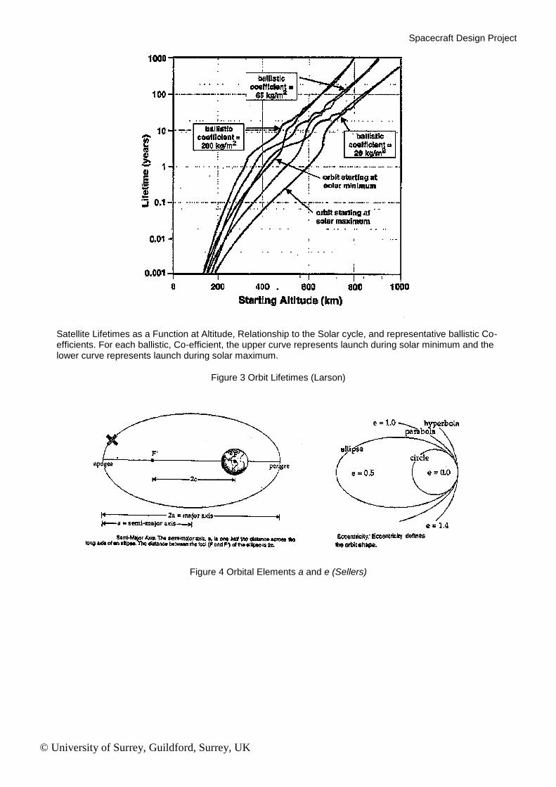
Satellite Lifetimes as a Function at Altitude, Relationship to the Solar cycle, and representative ballistic Co-efficients. For each ballistic, Co-efficient, the upper curve represents launch during solar minimum and the lower curve represents launch during solar maximum.
Figure 3 Orbit Lifetimes (Larson)
Figure 4 Orbital Elements a and e (Sellers)
Spacecraft Design Project
© University of Surrey, Guildford, Surrey, UK
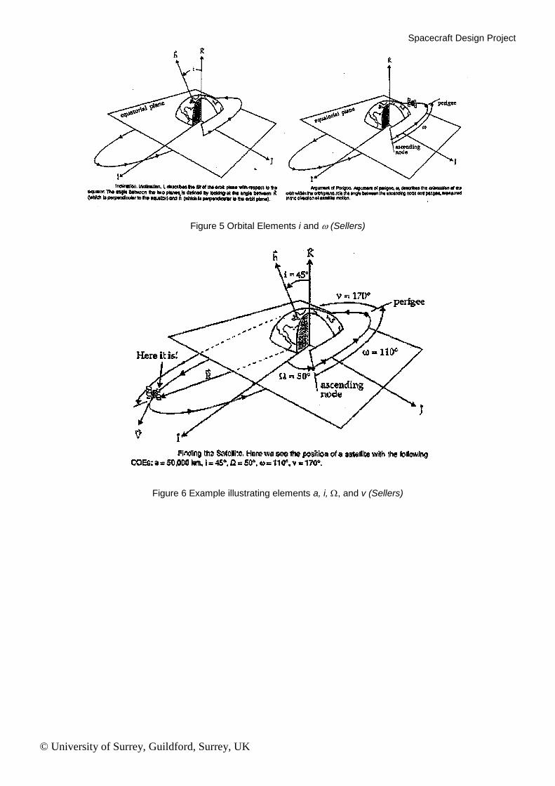
Figure 5 Orbital Elements i and (Sellers)
Figure 6 Example illustrating elements a, i, , and v (Sellers)
Spacecraft Design Project
© University of Surrey, Guildford, Surrey, UK
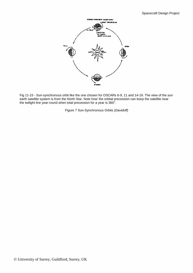
Fig 11-15 - Sun-synchronous orbit like the one chosen for OSCARs 6-9, 11 and 14-19. The view of the sun earth satellite system is from the North Star. Note how' the orbital precession can keep the satellite near the twilight line year-round when total precession for a year is 360°.
Figure 7 Sun-Synchronous Orbits (Davidoff)
Spacecraft Design Project
© University of Surrey, Guildford, Surrey, UK
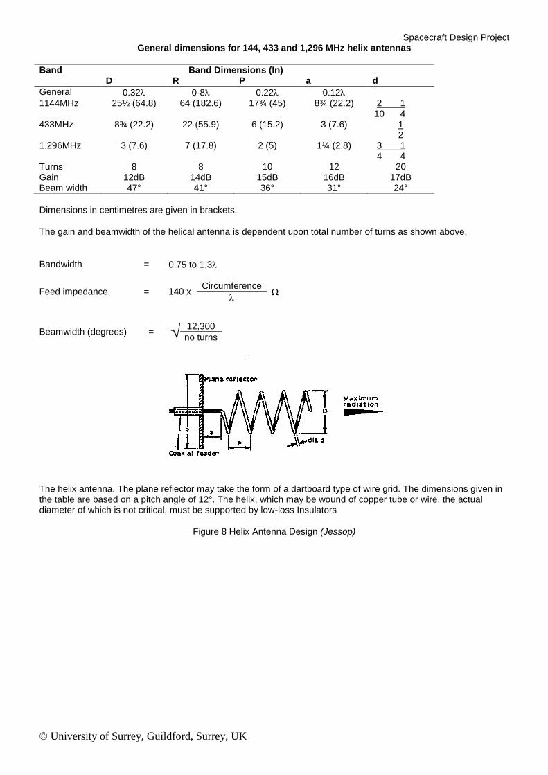
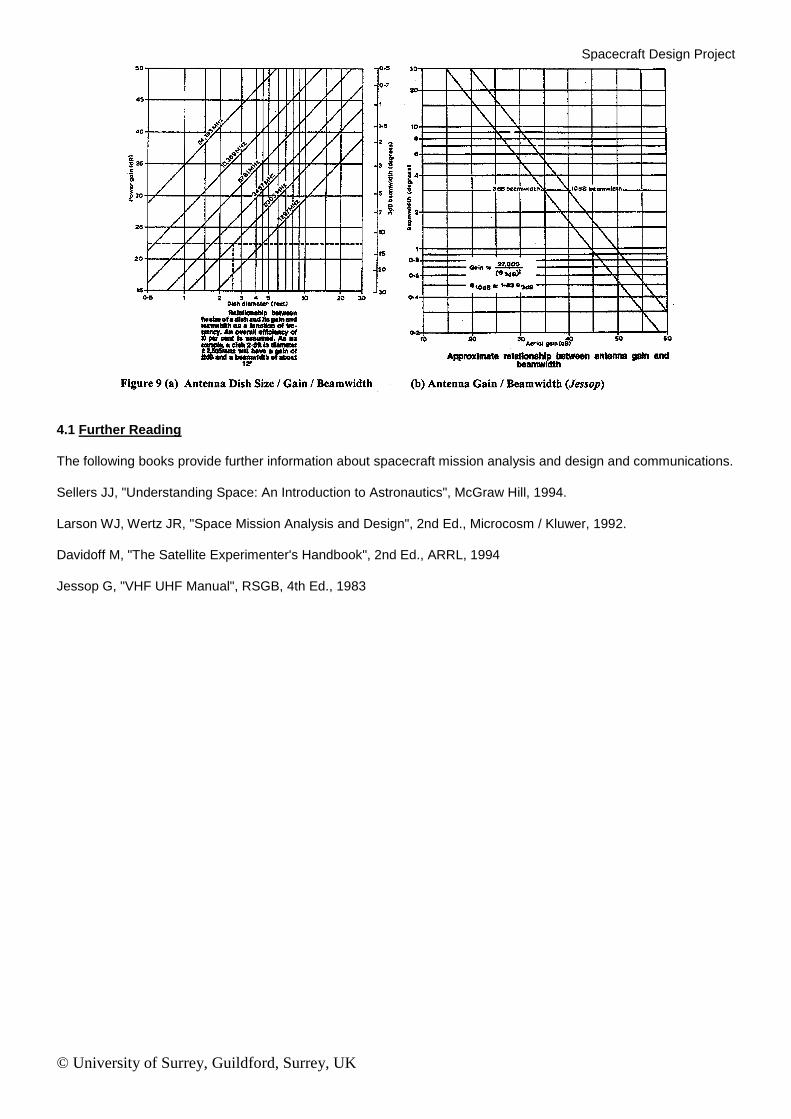
General dimensions for 144, 433 and 1,296 MHz helix antennas
Band Band Dimensions (In) D R P a d
General 0.32 0-8 0.22 0.12
1144MHz 25½ (64.8) 64 (182.6) 17¾ (45) 8¾ (22.2) 2 1 10 4
433MHz 8¾ (22.2) 22 (55.9) 6 (15.2) 3 (7.6) 1 2
1.296MHz 3 (7.6) 7 (17.8) 2 (5) 1¼ (2.8) 3 1 4 4
Turns 8 8 10 12 20 Gain 12dB 14dB 15dB 16dB 17dB Beam width 47° 41° 36° 31° 24°
Dimensions in centimetres are given in brackets.
The gain and beamwidth of the helical antenna is dependent upon total number of turns as shown above.
Bandwidth = 0.75 to 1.3
Feed impedance = 140 x Circumference
Beamwidth (degrees)
=
12,300
no turns
The helix antenna. The plane reflector may take the form of a dartboard type of wire grid. The dimensions given in the table are based on a pitch angle of 12°. The helix, which may be wound of copper tube or wire, the actual diameter of which is not critical, must be supported by low-loss Insulators
Figure 8 Helix Antenna Design (Jessop)
Spacecraft Design Project
© University of Surrey, Guildford, Surrey, UK
4.1 Further Reading
The following books provide further information about spacecraft mission analysis and design and communications.
Sellers JJ, "Understanding Space: An Introduction to Astronautics", McGraw Hill, 1994.
Larson WJ, Wertz JR, "Space Mission Analysis and Design", 2nd Ed., Microcosm / Kluwer, 1992.
Davidoff M, "The Satellite Experimenter's Handbook", 2nd Ed., ARRL, 1994
Jessop G, "VHF UHF Manual", RSGB, 4th Ed., 1983
Spacecraft Design Project
© University of Surrey, Guildford, Surrey, UK
SPACECRAFT DESIGN PROJECT
SAMPLE ANSWER
3.1 Orbit Geometry and Propulsion
With reference to eclipse period and illumination conditions on the ground, investigate the effect of choosing different Sun-synchronous orbits (as described by the local solar time of the ascending node), and thus choose a suitable orbit plane for this imaging mission.
A 12am/12pm Sun-synchronous orbit would suffer a maximum eclipse time, and the illumination conditions on the ground would be poor, as the Sun would always be close to its maximum elevation and therefore the shadows would be very fore-shortened giving poor relief detail. At the other extreme, a 6am/6pm orbit would be continuously in sunlight, giving a good power profile for the satellite. However, the Earth underneath the satellite would always be in twilight, either at dawn or dusk, and therefore this would also be unsuitable.
The best orbits to choose would be around 9am/9pm or 3am/3pm to maximise the level of illumination and the shadow detail. This would also give some leeway for the orbit-plane to drift, whilst still giving reasonable viewing conditions on the ground.
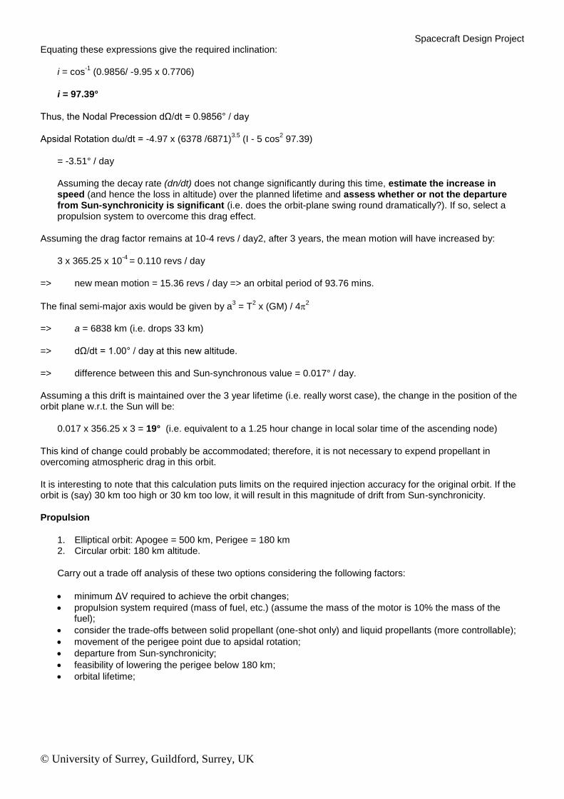
Calculate the inclination required to give Sun-synchronicity for a circular orbit at 500 km altitude, and thus give the Keplerian Elements:
a Semi-Major Axis [km] e Eccentricity i Inclination [degs] T Orbit Period [mins] n Mean Motion [revs/day] dω/dt Rate of Change of Argument of Perigee (Apsidal Rotation) dΩ/dt Rate of Change of Right-Ascension of the Ascending Node (Nodal Precession)
At 500 km altitude,
a = 500 + 6371 (mean Earth radius) = 6871 km e = zero (circular orbit!)
Orbital period is given by: T2 = 4π
2a
3 / (GM)
T = 5666 s (94.4 mins)
Mean motion is given by: n = (1440 / T (mins))
= 15.249 revolutions per day.
Motion of Earth around the Sun = 360 degrees / 365.25 days = 0.9856 deg / day
Nodal Precession = -9.95 x (6378 / 6871)3.5
x cos i [deg / day]
Spacecraft Design Project
© University of Surrey, Guildford, Surrey, UK
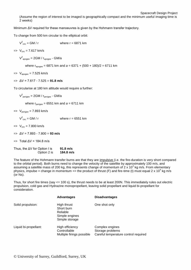
Equating these expressions give the required inclination:
i = cos-1
(0.9856/ -9.95 x 0.7706)
i = 97.39°
Thus, the Nodal Precession dΩ/dt = 0.9856° / day
Apsidal Rotation dω/dt = -4.97 x (6378 /6871)3.5
(I - 5 cos2 97.39)
= -3.51° / day
Assuming the decay rate (dn/dt) does not change significantly during this time, estimate the increase in speed (and hence the loss in altitude) over the planned lifetime and assess whether or not the departure from Sun-synchronicity is significant (i.e. does the orbit-plane swing round dramatically?). If so, select a propulsion system to overcome this drag effect.
Assuming the drag factor remains at 10-4 revs / day2, after 3 years, the mean motion will have increased by:
3 x 365.25 x 10-4
= 0.110 revs / day
=> new mean motion = 15.36 revs / day => an orbital period of 93.76 mins.
The final semi-major axis would be given by a3 = T
2 x (GM) / 4
2
=> a = 6838 km (i.e. drops 33 km)
=> dΩ/dt = 1.00° / day at this new altitude.
=> difference between this and Sun-synchronous value = 0.017° / day.
Assuming a this drift is maintained over the 3 year lifetime (i.e. really worst case), the change in the position of the orbit plane w.r.t. the Sun will be:
0.017 x 356.25 x 3 = 19° (i.e. equivalent to a 1.25 hour change in local solar time of the ascending node)
This kind of change could probably be accommodated; therefore, it is not necessary to expend propellant in overcoming atmospheric drag in this orbit.
It is interesting to note that this calculation puts limits on the required injection accuracy for the original orbit. If the orbit is (say) 30 km too high or 30 km too low, it will result in this magnitude of drift from Sun-synchronicity.
Propulsion
1. Elliptical orbit: Apogee = 500 km, Perigee = 180 km 2. Circular orbit: 180 km altitude.
Carry out a trade off analysis of these two options considering the following factors:
minimum ΔV required to achieve the orbit changes;
propulsion system required (mass of fuel, etc.) (assume the mass of the motor is 10% the mass of the fuel);
consider the trade-offs between solid propellant (one-shot only) and liquid propellants (more controllable);
movement of the perigee point due to apsidal rotation;
departure from Sun-synchronicity;
feasibility of lowering the perigee below 180 km;
orbital lifetime;
Spacecraft Design Project
© University of Surrey, Guildford, Surrey, UK
(Assume the region of interest to be imaged is geographically compact and the minimum useful imaging time is 2 weeks)
Minimum ΔV required for these manoeuvres is given by the Hohmann transfer trajectory.
To change from 500 km circular to the elliptical orbit:
V2circ = GM / r where r = 6871 km
=> Vcirc = 7.617 km/s
V2apogee = 2GM / rapogee - GM/a
where rapogee = 6871 km and a = 6371 + (500 + 180)/2 = 6711 km
=> Vapogee = 7.525 km/s
=> ΔV = 7.617 - 7.525 = 91.8 m/s
To circularise at 180 km altitude would require a further:
V2perigee = 2GM / rperigee - GM/a
where rperigee = 6551 km and a = 6711 km
=> Vperigee = 7.893 km/s
V2circ = GM / r where r = 6551 km
=> Vcirc = 7.800 km/s
=> ΔV = 7.893 - 7.800 = 93 m/s
=> Total ΔV = 184.8 m/s
Thus, the ΔV for Option I is 91.8 m/s Option 2 is 184.8 m/s
The feature of the Hohmann transfer burns are that they are impulsive (i.e. the fire-duration is very short compared to the orbital period). Both burns need to change the velocity of the satellite by approximately 100 m/s, and assuming a satellite mass of 200 kg, this represents change of momentum of 2 x 10
4 kg m/s. From elementary
physics, impulse = change in momentum => the product of thrust (F) and fire-time (t) must equal 2 x 10⁴ kg m/s
(or Ns).
Thus, for short fire times (say <= 100 s), the thrust needs to be at least 200N. This immediately rules out electric propulsion, cold gas and Hydrazine monopropellant, leaving solid propellant and liquid bi-propellant for consideration.
Advantages Disadvantages
Solid propulsion: High thrust One shot only Short burn Reliable Simple engines Simple storage
Liquid bi-propellant: High efficiency Complex engines Controllable Storage problems Multiple firings possible Careful temperature control required
Spacecraft Design Project
© University of Surrey, Guildford, Surrey, UK
Comparing these, the flexibility of a liquid propellant probably outweighs that of a solid motor, particularly as it may be possible to integrate it into the attitude control system.
The rocket equation gives the mass of propellant required for a particular change in velocity:
ΔV = Isp g In ((Me+Mp) / Me)
Where g = 9.81 m/s/s, Isp is the specific impulse, Me is the empty mass of the satellite and Mp is the mass of propellant used.
For a total ΔV of approximately 200 m/s (Option 2), setting the specific impulse Isp to be 320s, g = 9.81 m/s/s
=> (Me + Mp) / Me = exp (200 / (9.81 x 320)) = 1.066
Setting the satellite mass to be (say) 200 kg, the mass of propellant required would be 13 kg. Allowing a 10% margin for the tanks and motor, the total mass of the (fully fuelled) propulsion system would be approximately 15 kg.
This mass would be roughly halved for Option I.
Option 2 requires more propellant, but the above calculation shows that it is not prohibitively high.
However, note that some factors have not been taken into account, including: volume of propellant tanks, pressurant tanks, pipe and valves, thermal control problems, etc.
A circular orbit at 180 km would be subject to substantial atmospheric drag, and the lifetime of the orbit would be perhaps only one day. This would therefore not be very suitable.
Similarly, no orbit can come below 180 km as the atmospheric drag will cause it to re-enter very rapidly (unless propellant is expended!)
Option 2, would give a lifetime perhaps in excess of two weeks, so this would be more useful, however, the perigee point would drift considerably.
The drift of the perigee point is given as follows: e = 1 - (rperigee / a) = 1 - (6551 / 6711) = 0.024
dω/dt = -4.97 x (6378 / 6711)3.5
(1 - 5 cos2 97.39) / (1 - e
2)2
= -3.82° / day
In a two week period, the drift would be approximately 56°. The problem of calculating the corresponding change in altitude over the target is equivalent to solving the polar-equation of the orbit for an angle of 56 degrees from perigee.
r = a (1 - e2) / (1 + e cos θ)
r = 6711 (1 - 0.023842) / (1 + 0.02384 cos 56)
r = 6707 / 1.0133 = 6619 km (i.e. 248 km altitude)
Thus, there will be some degradation in resolution. In practice, the orbit will tend to circularise, with the apogee declining rapidly over the last days of the mission. These calculations will not be valid in such conditions.
The satellite will no longer be Sun-synchronous, with the Nodal precession being:
dΩ/dt = -9.95 (6378 / 6711)3.5
cos 97.39 / (1 - e2)2
Spacecraft Design Project
© University of Surrey, Guildford, Surrey, UK
= 1.07° / day
However, the departure of this from the required 0.9856 is very small, so is not of any consequence over the limited lifetime remaining to the satellite.
So in conclusion, the elliptical orbit is to be chosen, with all its advantages in terms of propulsion requirements, etc. There is an unavoidable problem with apsidal drift which will cause the satellite altitude over the target to increase with time. However, for the relatively short life of the satellite, this is not too bad.
Note: the lifetime of the satellite could be considerably extended by using the propulsion system to re-boost the satellite. This would have to be done at perigee either just before or just after the images of the target were taken.
3.2. Optical Design
Design a suitable optical system bearing in mind the following:
the effective focal length should give sufficient magnification for one pixel to be equivalent to 0.5 m on the ground;
the diameter of the primary must be sufficiently large to meet the Rayleigh criterion for resolving angle 'θ', i.e. the angle subtended by 0.5 m at 180 km. (Note: the diameter of the primary defines the aperture of the system -however, remember the occluding effect of the secondary mirror which will mask off some of the area);
the F-number of the system should be sufficiently small to give a bright image;
a suitable secondary mirror position needs to be selected to give a compact system with the correct effective focal length;
field of view (4096 x 4096 pixels);
The required focal length is given by:
f/h = x/r where h = altitude of satellite = 180 km x = pixel cell size = 7.5 μm r = distance to be resolved = 0.5 m
f = 7.5 x 10-6
x 180000 / 0.5
= 2.7 m (say 3 m)
The Rayleigh criterion determines the aperture size of the system (effectively the diameter of the primary mirror) as:
θ = 0.5 / 180000 = 2.78 x 10⁻⁶
radians
Taking the worst case (i.e. imaging red light at 0.7 μm wavelength)
D = 1.22 x 0.7 / 2.78 = 0.307 m
Thus, the primary mirror needs to be at least 31 cm in diameter.
The F-number of this system is given by f/D = 3/.31 = 9.76. This is between F/8 and F/11, and so meets the requirement for a reasonably 'bright' optical system.
The Cassegrainian telescope needs an effective focal length of 3 m, Thus:
f l2 / l1 = 3 and l1 + l2 = f
Let f = 0.6 m, and set l2 = 0.5 m and l1 = 0.1 m
Spacecraft Design Project
© University of Surrey, Guildford, Surrey, UK
There are many other solutions but f should be >= 0.35 m to adequately illuminate the CCD.
The field of view of the telescope is given by the effective focal length and the size of the CCD.
The diagonal of the CCD is 1.4142 x 31mm = 43.8 mm. The angle of view is therefore:
θ = 2 tan-1
(0.5 x 43.84 / 3000)
= 0.837°
This corresponds to an on-ground distance of2.63 km at 180 km altitude (i.e. a square 1.86 km on each side).
Design a suitable mounting for this structure on the satellite body, possibly with deployable parts. Discuss the reasons for the choice of mechanics and materials, and note the effect of thermal cycling on the structure. Estimate the mass of the system. How might mass be kept to a minimum.
The points to note here are that the mirrors should be rigid, but light-weight, perhaps using silvered composites? The struts holding the secondary mirror should have a very low coefficient of expansion or be compensated so that the optical path does not alter with temperature. Any movable joints need careful lubrication (possibly using PTFE), and care must be taken to avoid contact between similar materials which may cold-weld in the high vacuum of space. Carbon-fibre reinforced plastics offer a high degree of rigidity, low coefficient of expansion and low-mass per unit strength.
Describe the optical performance of the system in the nominal, 500 km orbit.
At 500 km, the resolution is 1.25 m, and the area visible is a square 5.16 km on each side.
Considering the effective ground-speed of the satellite, and estimating any motions around the pitch, roll and yaw axes, calculate the maximum exposure time which can be tolerated so as not to limit the resolution. Comment on your findings.
The orbital speed of the satellite at perigee (180 km) is 7.893 km/s. The effective ground speed is therefore:
7.893 x 6371 / 6551 = 7.676 km/s
Therefore, the satellite will cover 0.5 m on the ground in 65 microseconds.
This is a very short time compared to a conventional camera, and puts severe constraints on the imaging system design.
The angular resolution of the imager is 2.78 x 10⁻⁶
radians, and so the angular motions (pitch, roll and yaw) of the satellite must be much less than 0.04 rad/s (2.4 deg/s). This latter requirement should be relatively simple to meet, however the upper limit of 65 microseconds on the exposure time would require a very sensitive CCD.
Possible solutions to increasing the exposure would be to:
1) increase the mirror diameter (2 x diameter = 4 x the light); 2) 'panning' the camera by deliberately introducing a pitch motion; 3) panning the mirror itself; 4) cooling the CCD to increase its sensitivity and reduce its 'noise'.
Considering the requirement for a large light gathering ability, the primary mirror size should be increased from the minimum 31 cm. A practical maximum would be (say) 1m. This would give an F-number of F/3.
Considering the field of view of the instrument, define the pointing accuracy requirements for the satellite in order to be sure of imaging a specific object. Comment of the attitude determination and control (ADCS) requirements for the satellite and suggest a suitable system for achieving the desired accuracy.
The angle of view of the imager at 180 km is 0.837 degrees. Therefore, the satellite needs to point within a cone of 0.42 degree half-angle in order to image a specific object. This requires a very good knowledge of the attitude of the satellite. The ground-area captured in anyone image is only 1.86 km by 1.86 km, and so position within the orbit needs to be known to a high degree of accuracy.
Spacecraft Design Project
© University of Surrey, Guildford, Surrey, UK
The satellite will overfly the target area in a quarter of a second. This suggests a fairly sophisticated ADCS unit is required, with at least Sun and horizon sensors to obtain an attitude fix, and probably with cold-gas or hydrazine monopropellant thrusters to achieve fine-pointing control. Primary stabilisation may be obtained by momentum wheels. Star-sensors may be used to get very precise attitude determination.
The satellite would need to be 3-axis controlled to give the most stable platform for the camera, however, this will lead to problems with thermal control. Another possible solution is a slowly yawing satellite, with a yaw-rate of (say) 1 revolution every 10 minutes so that the image remains unaffected.
Calculate the ground-distance travelled in the 'dead-time'. If several contiguous images are required along- track, how could this dead-time effect be circumvented. Discuss any possible benefits to exposure time of such techniques.
The 1.678 s dead-time means that the satellite will travel a ground-distance of 12.88 km between images. This could be circumvented by being able to pan the mirrors slightly between images. A rotation of 4.1 x 10
-3 degrees
would counteract the ground distance covered in the dead-time, and all movement could be carried out during the read-out. Any vibrations set-up in the system would have to have settled down during this time.
If a very smooth motion could be achieved, the panning could be carried out during the exposure, thus enabling the shutter to be kept open longer. This would require the mirror to pan exactly along the track of the satellite's motion, and would only be possible on a 3-axis controlled platform.
3.3. On-Board Data Handling (OBDH)
Assuming the 3:1 data-compression system referred to, design a memory system that would be capable of storing the required 6 images. In particular, note the size, mass and power consumption.
The dynamic RAM consumes too much power to be considered, and so we are left with the static RAMs.
The memory size required is 4096 x 4096 x (8 + 4) bits per raw image.
Each image is compressed by a factor of 3, but 6 images are required to be stored thus, the total number of bytes is:
2 x 4096 x 4096 x 12 i.e. 32M x 12 bits.
This could be accommodated as:
384 off 1M x 1 SRAMs with 38.4 mW standby power, 134.4 W full power. 384 off 128K x 8 SRAMs with 19.2 mW standby power, 57.6 W full power. 48 off 1M x 8 SRAMs with 4.8 mW standby power, 5.28 W full power.
From the above, the best solution would be to use the 1M x 8 hybrid SRAMs. For convenience, it would be possible to accommodate the images in 64 chips, allowing a 16-bit wide data bus (i.e. wasting 4 bits per byte). The area occupied by these chips would be:
(two rows of 32 hybrids): 190mm x 280mm x 21mm high
The total standby power (normal mode) = 6.4 mW The maximum power (during access) = 7.04 W
3.4. RF Link
At 500 km altitude, a typical pass over the MOC will last for perhaps 10 minutes, in this time it is required to downlink the entire memory contents.
Spacecraft Design Project
© University of Surrey, Guildford, Surrey, UK
The 32M bytes of data need to be downlinked in an error-detected way, with sufficient ID information to be able to reconstruct the images. Assuming a 10% coding / packet ID overhead, with some capacity for telemetry data:
Calculate a reasonable data-rate:
Data rate = 32 x 1024 x 1024 x 8 x 1.1 / 600 = 492 (say) 500 kbps
Thus, select a suitable antenna and power level necessary to achieve this link. PowerTx = Combined losses x PowerRx / (GainTx x GainRx)
Combined losses: Free space loss at 2.3 GHz = 20 log (4 pi d/L) (500 km) = 153.66 dB Implementation losses = 7 dB Link margin = 3 dB Total = 163.66 dB
PowerRx = Eb/No + kBT = 11 - 228.6 + 57 + 24 = -136.6 dB
GainRx = 22 dB
GainTx = 3 dB (beamwidth 95 degrees) say a 1.5 turn helical, 10cm reflector, 6cm long.
PowerTx = 163.66 - 136.6 - 3 - 22 = 2.06 dB = 1.6 W RF
At 30% efficiency, the DC power consumed would be 5.4 W
Thus, the 500 kbps data link can be easily supported.
3.5. Power System
Taking the Solar Constant to be 1.353 kW m-2
, calculate the area of cells needed to power the satellite. You may assume a packing density for the cells of 80% (to allow for inactive area, etc.) and should allow a design margin of 5%. The power output of solar cells degrades over time, depending upon the degree of protection against radiation, etc. A typical degradation rate is given by e
-fN, where f is 0.025 (dependent upon orbit, cover
slide, etc.) and N is the design lifetime in years.
So far the power requirements are:
5.4 W for the transmitters 6.4 m W for the memory (7.04 W when being accessed)
Estimates for the other systems:
TLM/TCMD = 5 W ADCS = 5 W Rx = 2 W Power = 2 W OBC = 5 W Camera Payload = 10 W when on, otherwise 5 W
So nominal power requirement is 30 W with peaks up to 42 W for short periods of time.
Spacecraft Design Project
© University of Surrey, Guildford, Surrey, UK
Setting an upper limit to the orbit average power of 35 W, and taking the overall power system efficiency to be around 75% the power required from the solar panels is 45 W.
The factors to consider for the solar panels are:
80% for the packing factor 7.2% loss for degradation over 3 years 5% design margin
Minimum Area = (45 W x 1.05 x e0.075
) / (1353 x u x 0.8)
For Si cells (u = 14%) = 0.336 m2
GaAs cells (u = 18%) = 0.261 m2.
The most efficient use of cells would be to use a steerable array, always pointing at the Sun. However, this would be undesirable in terms of system complexity, mass and reliability. Another solution is to place panels on the body of the satellite.
For example, imagine the Sun lying in the plane of the orbit. As seen from the Sun, a panel on the top of the spacecraft would trace out a cylindrical path, thus would need to be 3.142 times the size of the minimum area to receive the required power. For a 9am/9pm orbit, with the Sun making an angle of 45 degrees (at best) with the top of the satellite, a further cos 45 factor would need to be added in.
Thus, the area for a single, top-mounted body panel would be:
Si: 0.336 x 3.142 / 0.707 = 1.493 m2
GaAs: 0.261 x 3.142 1 0.707 = 1.160 m2 (this would also take into account the eclipse period)
Carry out a trade-off analysis between body-mounted and deployable panels. What are the costs/benefits of GaAs cells over Si cells?
For a 1m diameter spacecraft, the maximum area of a top body-mounted panel would be /4 m2. This is not
enough to power the spacecraft, and so further body panels would have to be added -for example on the sides of the spacecraft. Even so, it would seem that a body-mounted solution would be close to the minimum acceptable. Perhaps a better solution would be to have simple unfolding panels which lock into fixed positions upon deployment.
GaAs cells are more efficient than Si, but they are also much more expensive. In terms of cost per unit power, Si would be the better solution. Si cells are lighter than GaAs for a given area and so there is a potential mass saving. Thus, the cheapness of Si may make a deployable panel solution more attractive than a body-mounted GaAs cell solution. The extra radiation hardness of GaAs over Si would not be a significant factor in this low orbit for a 3 year lifetime.
For a LEO spacecraft, the eclipse period can be 35% of the orbital period (depending upon the orbit-plane/ Sun relationship and the altitude of the satellite). During this time, the spacecraft will have to be powered from batteries. NiCd cells are often used which have a voltage of around 1.3V each. For example, a battery pack of 10 cells would give a voltage of between 14.5V (fully charged) and 11.5V (discharged), and for a capacity of 6.3Ah, would have a mass of 2.3 kg.
Calculate the capacity (in Ampere-hours) of 10 cell NiCd battery required to fully operate the spacecraft in eclipse. Assuming the mass scales with capacity, estimate the mass of the battery pack.
The orbit average raw power is 45 W. The batteries would need to supply this for 35% of the orbit period (i.e. 35% of 94.4 = 33 mins).
45 W for 33 mins at 13 V = 1.9 Ah.
If the battery is only allowed to discharge by 40%, the capacity of the battery must be:
1.9 / 0.4 = 4.76 Ah.
Spacecraft Design Project
© University of Surrey, Guildford, Surrey, UK
Thus, the battery pack mass would be of the order of:
4.76 x 2.3 / 6.3 = 1.74 kg.
In order to re-charge the battery on coming out of eclipse, the solar-panels will have to supply an extra:
45 x 33 / 61 = 24.4 W
Thus the area of the solar-panels will have to increase by a factor of:
1 + 24.4 / 45 = 1.54
Therefore, minimum Area for:
Si cells = 0.517 m2
GaAs cells = 0.402 m2.
3.6. Mass / Volume Constraints
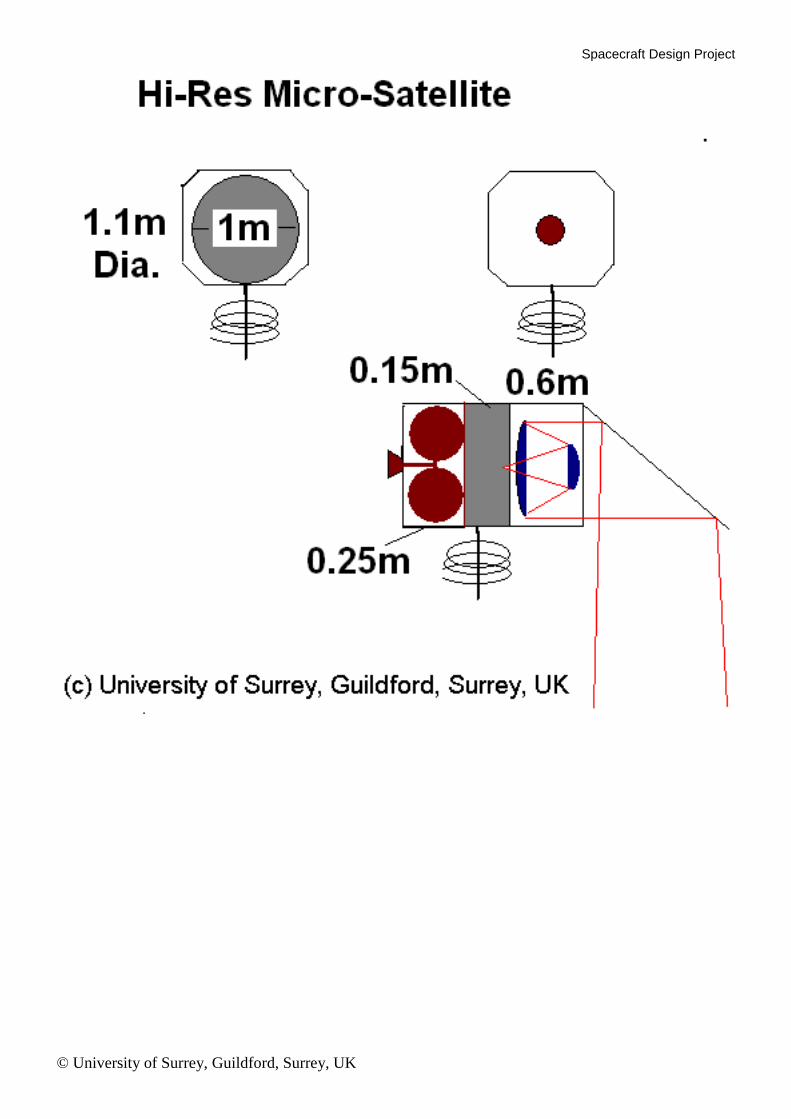
Noting the limited capacity of the PEGASUS vehicle in terms of volume and mass lifting-capacity, draw a dimensioned sketch of your spacecraft showing the antenna, optical system, solar cells, propulsion unit and internal positioning of the on-board systems. Remember that there needs to be an interface to the launch vehicle, and that there may be a need for thermal control surfaces.
The structure should show the optical system and antenna on the Earth-facing facet. The kick-motor should be shown, together with the attach-fitting. Solar panels should be shown, and care must be taken not to over-shadow them. The spacecraft body should be protected by thermal surfaces such as aluminised Kapton. The total mass should be less than or equal to 250 kg.
Spacecraft Design Project
© University of Surrey, Guildford, Surrey, UK
Spacecraft Design Project
© University of Surrey, Guildford, Surrey, UK