final request for proposals design-build project
TRANSCRIPT
-- STATE OF NORTH CAROLINA-- DEPARTMENT OF TRANSPORTATION
RALEIGH, N.C.
FINAL REQUEST FOR PROPOSALS
DESIGN-BUILD PROJECT
Dredge Project 43546.3
October 30, 2013
Includes Addendum No. 1 Dated October 21, 2013 Includes Addendum No. 2 Dated October 30, 2013
VOID FOR BIDDING
DATE AND TIME OF TECHNICAL AND PRICE PROPOSAL SUBMISSION: December 4, 2013 BY 4:00 PM DATE AND TIME OF PRICE PROPOSAL OPENING: December 17, 2013 AT 2:00 PM CONTRACT ID: C 203381 WBS ELEMENT NO. 43546.3 COUNTY: Dare TYPE OF WORK: DESIGN-BUILD OF 12” CUTTER HEAD SUCTION/DISCHARGE DREDGE NOTICE: ALL PROPOSERS SHALL COMPLY WITH ALL APPLICABLE LAWS REGULATING THE PRACTICE OF GENERAL CONTRACTING AS CONTAINED IN CHAPTER 87 OF THE GENERAL STATUTES OF NORTH CAROLINA WHICH REQUIRES THE PROPOSER TO BE LICENSED BY THE N.C. LICENSING BOARD FOR CONTRACTORS WHEN BIDDING ON ANY NON-FEDERAL AID PROJECT WHERE THE BID IS $30,000 OR MORE, EXCEPT FOR CERTAIN SPECIALTY WORK AS DETERMINED BY THE LICENSING BOARD. PROPOSERS SHALL ALSO COMPLY WITH ALL OTHER APPLICABLE LAWS REGULATING THE PRACTICES OF ELECTRICAL, PLUMBING, HEATING AND AIR CONDITIONING AND REFRIGERATION CONTRACTING AS CONTAINED IN CHAPTER 87 OF THE GENERAL STATUTES OF NORTH CAROLINA. NOT WITHSTANDING THESE LIMITATIONS ON BIDDING, THE PROPOSER WHO IS AWARDED ANY PROJECT SHALL COMPLY WITH CHAPTER 87 OF THE GENERAL STATUTES OF NORTH CAROLINA FOR LICENSING REQUIREMENTS WITHIN 60 CALENDAR DAYS OF BID OPENING, REGARDLESS OF FUNDING SOURCES. ___________ 5% BID BOND OR BID DEPOSIT REQUIRED ___________

PROPOSAL FORM FOR THE CONSTRUCTION OF CONTRACT NO. C203381
IN DARE COUNTY, NORTH CAROLINA
Date_________________________ 20_________
DEPARTMENT OF TRANSPORTATION,
RALEIGH, NORTH CAROLINA
The Design-Build Team herein acknowledges that it has carefully examined the location of the proposed work to be known as Contract No. C203381; has carefully examined the Final Request for Proposals (RFP) and all addendums thereto, specifications, special provisions, the form of contract, and the forms of contract payment bond and contract performance bonds, which are acknowledged to be part of the Contract; and thoroughly understands the stipulations, requirements and provisions. The undersigned Design-Build Team agrees to be bound upon their execution of the Contract and including any subsequent award to them by the Secretary of Transportation in accordance with this Contract to provide the necessary contract payment bond and contract performance bond within fourteen calendar days after the written notice of award is received by them.
The undersigned Design-Build Team further agrees to provide all necessary materials, machinery, implements, appliances, tools, labor, and other means of construction, except as otherwise noted, to perform all the work and required labor to design, construct and complete all the work necessary for State Highway Contract No. C203381 in Dare County by no later than the dates(s) specified in the Final RFP or Technical Proposal, whichever is earlier, and in accordance with the requirements of the Engineer, the Final RFP and Addenda thereto, specifications prepared by the Department, the Technical Proposal prepared by the Design-Build Team, at the lump sum price(s) bid by the Design-Build Team in their Price Proposal.
The Design-Build Team shall provide signed and sealed documents prepared by the Design-Build Team, which specifications and plans show the details covering this project and adhere to the items noted above.
The Design-Build Team acknowledges that project documents furnished by the Department are preliminary and provided solely to assist the Design-Build Team in the development of the project design. Unless otherwise noted herein, the Department does not warrant or guarantee the sufficiency or accuracy of any information furnished by the Department.
Although the Department has furnished preliminary designs for this project, unless otherwise noted herein, the Design-Build Team shall assume full responsibility, including liability, for the project design, including the use of portions of the Department design, modification of such design, or other designs as may be submitted by the Design-Build Team.
The Design-Build Team shall be fully and totally responsible for the accuracy and completeness of all work performed under this contract, and shall indemnify and hold the Department harmless for any additional costs and all claims against the Department or the State which may arise due to errors or omissions of the Department in furnishing the preliminary project designs and information, and of the Design-Build Team in performing the work.
Publications and guidelines referenced in the Request For Proposals, with all amendments and supplements thereto, are by reference, incorporated and made part of this contract; that, except as
herein modified, all the design, construction and testing included in this contract is to be done in accordance with the documents noted above and under the direction of the Engineer.
If the Design-Build Proposal is accepted and the award is made, the Technical Proposal submitted by the Design-Build Team is by reference, incorporated and made part of this contract. The contract is valid only when signed either by the Contract Officer or such other person as may be designated by the Secretary to sign for the Department of Transportation. The conditions and provisions herein cannot be changed except by written approval as allowed by the Request for Proposals.
Accompanying the Design-Build Proposal shall be a bid bond secured by a corporate surety, or certified check payable to the order of the Department of Transportation, for five percent of the total bid price, which deposit is to be forfeited as liquidated damages in case this bid is accepted and the Design-Build Team shall fail to provide the required payment and performance bonds with the Department of Transportation, under the condition of this proposal, within 14 calendar days after the written notice of award is received by them, as provided in the Standard Specifications; otherwise said deposit will be returned to the Design-Build Team.
Addendum No. 2 October 30, 2013 C203381 Dredge Project Table of Contents Dare County
Table of Contents COVER SHEET PROPOSAL SHEETS DEFINITIONS ...................................................................................................1 INSTRUCTION TO PROPOSERS..................................................................5 Overview ..............................................................................................................5 Scope of Work .....................................................................................................5 Invitation to Bid ...................................................................................................5 Prequalification Requirements .............................................................................5 Request for Proposals Contents ...........................................................................6 Examination of Plans, Specifications, Contract and Site of Work ......................7 Preparation and Submission of Bids ....................................................................7 Execution of Bid, Non-Collusion Affidavit, Debarment Certification and Gift Ban Certification ....................................................................................8 Bid Bond or Bid Deposit ......................................................................................9 Non-Collusion Affidavit, Debarment Certification and Gift Ban Certification ..10 Withdrawal or Revision of Bids ..........................................................................11 Receipt and Opening of Bids ...............................................................................11 Rejection of Bids ..................................................................................................11 Disqualification of Contractors ............................................................................11 Consideration of Price Proposals .........................................................................12 Award of Contract ................................................................................................12 Cancellation of Award .........................................................................................12 Return of Bid Bond or Bid Deposit .....................................................................12 Contract Bonds .....................................................................................................13 Execution of Contract ..........................................................................................13 Failure to Furnish Contract Bonds .......................................................................13 Stipend .................................................................................................................13 Submittal of Technical and Price Proposals ........................................................14 Oral Explanations and Instructions ......................................................................15 No Contact Clause ...............................................................................................15 Submission of Design-Build Proposal .................................................................16 Alternative Technical Concepts and Confidential Questions ..............................16 Individual Meetings with Proposers ....................................................................21
Addendum No. 2 October 30, 2013 C203381 Dredge Project Table of Contents Dare County TECHNICAL PROPOSAL EVALUATION AND DETERMINATION OF BEST VALUE PROPOSAL .......................................................................22 PROJECT SPECIAL PROVISIONS ...............................................................30 Intent of Contract .................................................................................................30 Contract Time and Liquidated Damages..............................................................31 Progress of Work .................................................................................................31 Progress Schedule ................................................................................................32 Pre-Design Conference .......................................................................................33 Preconstruction Conference .................................................................................33 Construction Conferences ....................................................................................33 On-Site Project Supervision .................................................................................33 Mobilization .........................................................................................................34 Schedule of Estimated Completion Progress .......................................................34 Partial Payments ...................................................................................................34 Prompt Payments .................................................................................................35 Quality Control ....................................................................................................35 Care During Construction ....................................................................................35 Material Furnished by Owner and to be Retained by Owner ...............................36 Protection and Custody of Vessel ........................................................................36 Hauling and Lay-Time .........................................................................................36 Railway Certification ...........................................................................................37 Owner’s Right to Temporarily Suspend Work ....................................................37 Inspection .............................................................................................................37 Certificates, Documents, Etc. ...............................................................................38 Delivery ................................................................................................................39 Acceptance ...........................................................................................................39 Minority Business Enterprise and Women Business Enterprise ..........................39 Domestic Steel and Iron Products ........................................................................40 Twelve Month Guarantee.....................................................................................41 Outsourcing Outside the USA .............................................................................42 SCOPES OF WORK .........................................................................................43 Group 000 - General ............................................................................................43 Group 100 - Structural .........................................................................................51 Group 200 - Dredge Pump, Engine, Cutter Head, and Spuds ..............................58 Group 300 - Electrical ..........................................................................................64 Group 400 - Navigation, Communications and Electronics ................................75 Group 500 - Mechanical Systems and Spares ......................................................82 Group 600 - Outfitting .........................................................................................96 Group 800 – Testing, Inspection and Delivery ....................................................117
C203381 Dredge Project Table of Contents Dare County STANDARD SPECIAL PROVISIONS ...........................................................123 Gifts from Vendors and Contractors ....................................................................123 State Highway Administrator Title Change .........................................................123 Ethics Policy ........................................................................................................123 Approval of Personnel .........................................................................................123 Laws, Permits, and Regulations ...........................................................................124 Insurance ..............................................................................................................125 Subcontracts .........................................................................................................125 Failure to Recognize ............................................................................................126 Patent Rights ........................................................................................................127 Default of Contract ..............................................................................................127 Termination of Contract .......................................................................................127 Design-Build Team’s Title to Materials ..............................................................127 Assignments .........................................................................................................127 Availability of Funds – Termination of Contracts ...............................................128 Minimum Wages ..................................................................................................129 PROPOSAL FORMS – ITEMIZED SHEET, ETC. Itemized Proposal Sheet Execution of Bid, Non-Collusion Affidavit, Debarment Certification and Gift Ban Certification Signature Sheet
C 203381 (43546.3) Definitions Dare County
DEFINITIONS The following definitions apply to this Request for Proposal. Wherever the words defined in this section occur in these specifications, they shall have the meanings provided herein.
ABS American Bureau of Shipping
ACT OF GOD Events in nature so extraordinary that the history of climate variations and other conditions in the particular locality affords no reasonable warning of them.
ADDITIONAL WORK Additional work is that which results from a change or alteration to the contract and for which there are contract unit prices in the original contract or an executed supplemental agreement.
ADVERTISEMENT The public advertisement inviting Statements of Qualifications for the design and construction of specific projects.
APPROVAL OF THE OWNERS (OR APPROVED) An approval in writing signed by the Owner.
AWARD The decision of the Department of Transportation to accept the proposal of the selected Design-Build Team for work which is subject to the furnishing of payment and performance bonds, and such other conditions as may be otherwise provided by law, the Request for Proposals, and the Standard Specifications.
CHIEF ENGINEER Chief Engineer of the Division of Highways, North Carolina Department of Transportation.
COAST GUARD INSPECTOR Officer in Charge of Marine Inspection having cognizance over the certification of the vessel, where applicable, and includes Inspection Officers under his command.
CONTRACT The executed agreement between the Department and the successful proposer, covering the performance of, and compensation for, the work. The term contract is all inclusive with reference to all written agreements affecting a contractual relationship and all documents referred to therein. The contract shall include, but not be limited to, the Request for Proposals, the Technical Proposal, the Price Proposal, the printed contract form and attachments, contract bonds, plans and associated special provisions prepared by the Design-Build Team, standard specifications and supplemental specifications, standard special provisions and project special provisions contained in the Request for Proposals or as developed by the Design-Build Team and accepted by the Department, and all executed supplemental agreements. The contract shall constitute one instrument.
1
C 203381 (43546.3) Definitions Dare County
DATE OF AVAILABILITY
That date set forth in the Request for Proposals, by which it is anticipated that the Contract will be executed and sufficient design efforts or work sites within the project limits will be available for the Design-Build Team to begin his controlling operations or design.
DESIGN-BUILD A form of contracting in which the successful proposer undertakes responsibility for both the design and construction of a project.
DESIGN-BUILD TEAM An individual, partnership, joint venture, corporation or other legal entity that furnishes the necessary design and construction services, whether by itself or through subcontracts.
DESIGN-BUILD PROPOSAL A proposal to contract consisting of a separately sealed Technical Proposal and a separately sealed Price Proposal submitted in response to a Request for Proposals on a Design-Build project. Throughout this request for Proposals, the term “Contractor” is synonymous with Design-Build Team.
DEPARTMENT A principal department of the Executive Branch which performs the function of planning, construction, and maintenance of an integrated statewide transportation system.
DIVISION OF HIGHWAYS The division of the Department of Transportation which, under the direction of the Secretary of Transportation, carries out state highway planning, construction, and maintenance functions assigned to the Department of Transportation.
FURNISH / PROVIDE / INSTALL The Design-Build Team shall provide and install the specified material or equipment with necessary fittings, foundations, piping, electrical wiring and fixtures, etc., and make necessary hook-up and connections even if only one of the aforementioned words is used, unless it is specifically stated otherwise.
GOOD MARINE PRACTICE The level of quality that would be done by a capable marine mechanic experienced in construction and outfitting of passenger vessels, using proper tools in good condition and in accordance with normally accepted good shipbuilding practice.
GOOD MARINE QUALITY (OR FIRST-CLASS MATERIAL) Top grade product of an approved marine manufacturer.
INSPECTOR The authorized representative(s) of the Owner assigned to make a detailed inspection of any or all portions of the work and materials.
2
C 203381 (43546.3) Definitions Dare County
NOTICE Includes all written notices, demands, instructions, claims, approvals, and disapprovals, required to obtain compliance with Contract requirements. Any written notice by either party to the Contract shall be considered sufficiently given if delivered to the other party, agent, representative or officer in person. The person to whom the notice is delivered shall sign the duplicate copy and return the same to the other party immediately after receipt.
OR EQUAL Of equal quality, size capacity, general configuration and suitability for the use intended, as the item or items set out. Where reference is made to "trade names" or "catalogs", the reference is descriptive and restrictive unless stated otherwise by adding "or equal".
OWNER The North Carolina Department of Transportation to include its authorized representatives and Inspectors.
OWNER’S REPRESENTATIVE Marine Design Engineer, Ferry Division, NCDOT.
PLANS The project plans, working drawings, supplemental drawings, and as-built plans or reproductions thereof, submitted by the Design-Build Team and approved by the Owner which show the character, dimensions and details of the work to be performed.
PRICE PROPOSAL The offer of a Proposer, submitted on the prescribed forms, to perform the work and furnish the labor and materials at the price quoted.
PROPOSER An individual, partnership, firm, corporation, LLC, or joint venture formally submitting a Technical Proposal and Price Proposal in response to a Request for Proposals.
REINSTALL Reuse existing material and completely install in either its original location or a new location.
RENEW (OR REPLACE) Removing and disposing of an existing material or item as directed, and other material or items installed in place of the same.
REQUEST FOR PROPOSALS The paper document provided by the Department that the proposer uses to develop his paper offer to perform the work at designated bid prices.
SCHEDULE OF VALUES A schedule of work items necessary to complete work, along with the progress of each work item, primarily for the purpose of partial payments.
3
C 203381 (43546.3) Definitions Dare County
STANDARD SPECIFICATIONS The January 2012 NCDOT Standard Specifications for Roads and Structures for which the portions referenced throughout this Request for Proposals are hereby incorporated into the Contract.
SUBCONTRACTOR An individual, partnership, irm, joint venture, or corporation to whom the Design-Build Team, with written consent of the Engineer, sublets any part of the contract.
TECHNICAL PROPOSAL A submittal from a proposer, in accordance with requirements of the Request for Proposals, for the purpose of final selection. The Technical Proposal is defined to also include any supplemental information requested by the Department from a proposer prior to opening bids.
TONS Long Tons 2,240 pounds each.
USCG United States Coast Guard.
VENDOR Suppliers and/or manufacturers of materials and equipment purchased by the Design-Build Team for use in the work covered by the Contract.
VESSEL 12” Cutter Head Suction/Discharge Dredge.
4
C 203381 (43546.3) Instructions to Proposers Dare County
INSTRUCTIONS TO PROPOSERS OVERVIEW The proposed dredge will be designed for dredging service up to 25’-0” depth. Dredging operations and discharge of spoil will use flexible 12” pipeline to spoil areas up to three (3) miles with assistance of two (2) booster pumps provided by the Department and dredge pipe furnished by the Department. Normal operations will be to maintain ferry turning basins and short state channels to connect to Federal Channels during the late fall, winter, and early spring seasons of the year per environmental restrictions. SCOPE OF WORK The design and construction shall comply with the following References, ABS “Rules for Building and Classing Steel Vessels for Service on Rivers and Intracoastal Waterways”, IEEE & NEC “National Electrical Codes”, and ANSI “Steel Construction Manual”. Scopes of Work required for this project will include, but are not limited to, the following items:
1. General 2. Structural 3. Dredge Pump, Engine, Cutter Head, and Spuds 4. Electrical 5. Navigation, Communications, and Electronics 6. Mechanical Systems and Spares 7. Outfitting 8. Testing, Inspection, and Delivery
INVITATION TO BID
After the advertisement has been made, an Invitation to Bid will be made available to known prequalified contractors and any other contracting firms, material suppliers and other interested parties who have requested they be placed on the Invitation to Bid mailing list, informing them that Statements of Qualifications and Proposals will be received for the construction of specific projects. Such invitation will indicate the contract identification number, length, locations and descriptions; a general summary of the scope of work to be performed; and information on how to receive a Request for Qualifications.
All projects will be advertised in daily newspapers throughout the state before the bid opening.
PREQUALIFICATION REQUIREMENTS All team members shall be prequalified by the Department for the work they are identified to perform as outlined below. Failure to become prequalified as stipulated below may result in the Technical Proposal being deemed non-responsive. The prime contracting entity shall be approved as a prequalified bidder with the Department no later than September 27, 2013, unless otherwise approved by the Department. In the event a shortlisted prime contracting entity is not approved as a prequalified bidder prior to September
5
C 203381 (43546.3) Instructions to Proposers Dare County
27, 2013, the Department reserves the right to remove the prime contracting entity from the list of shortlisted teams. Prime contracting entities are encouraged to submit prequalification packages to the Department at least four weeks prior to this deadline. All Joint Ventures, LLCs, or any legal structure that is different than the existing prequalification status must be prequalified prior to the submittal deadline for the Technical and Price Proposals. Subcontractors need only be prequalified prior to performing the work. The prequalification process and requirements for the prime contracting entity and subcontractors will be in accordance with Article 102-2 of the Standard Specifications. Design firms shall be pre-qualified specifically for this project prior to the due date for Technical Proposals and Sealed Price Proposals. The Statement of Qualifications will form the basis for this pre-qualification except that inclusion of a design firm on the shortlist of Design-Build Teams does not necessarily satisfy this prequalification requirement. This pre-qualification is specific to this advertisement and may not be used as pre-qualification for other NCDOT contracts. Instead, the Department reserves the right to request, either before or after shortlisting, further details from design firms of the proposing Design-Build Team to ensure that they are pre-qualified for the work that these entities are intending to perform on the Project. REQUEST FOR PROPOSALS CONTENTS
A Request for Proposals will be furnished by the Department to the selected proposers from among the respondents to the Request for Qualifications. Each Request for Proposals will be marked on the front cover by the Department with an identifier of the Proposer to whom it is being furnished. This Request for Proposals will state the location of the project and will show a schedule of contract items for which Technical and Price Proposals are invited. It will set forth the date and time Technical and Price Proposals are to be submitted and when the Price Proposals will be opened.
The Request for Proposals will also include the printed contract forms and signature sheets for execution by both parties to the contract. In the event the Proposer is awarded the contract, execution of the Request for Proposals by the Proposer is considered the same as execution of the contract.
Specifications or other documents designated in the Request for Proposals shall be considered a part of the Request for Proposals whether or not they are attached thereto. All papers bound with the proposal are necessary parts thereof and shall not be detached, taken apart, or altered.
The names and identity of each prospective Proposer that receives a copy of the Request for Qualifications for the purposes of submitting a Statement of Qualifications shall be made public, except that a potential Proposer who obtains a Request for Qualifications may, at the time of ordering, request that his name remain confidential.
One copy of the Final Request for Proposals will be furnished to each prospective Proposer. Additional copies may be purchased for the sum of $25 each. The copy of the Final Request for Proposals marked with the Proposer’s name and prequalification number shall be returned to the Department as the Proposer’s Price Proposal.
6
C 203381 (43546.3) Instructions to Proposers Dare County
EXAMINATION OF PLANS, SPECIFICATIONS, CONTRACT AND SITE OF WORK
The proposer shall examine carefully the character and site of the work contemplated, the specifications, and the proposals and contracts therefor. The submission of a bid shall be conclusive evidence that the bidder has investigated and is satisfied as to the conditions to be encountered; the character, quality and scope of work to be performed; the quantities of materials to be furnished; and the conditions and requirements of the proposal, plans and contract under which his bid is offered.
A proposer is cautioned to make such independent investigation and examination as he deems necessary to satisfy himself as to conditions to be encountered in the performance of the work and with respect to possible local material sources, the quality and quantity of material available from such property, and the type and extent of processing that may be required to produce material conforming to the contract.
PREPARATION AND SUBMISSION OF BIDS All Price Proposals shall be prepared and submitted in accordance with the following requirements:
1. The Request for Proposals provided by the Department shall be used and shall not be taken apart or altered. The Price Proposal shall be submitted on the same form, which has been furnished to the Proposer by the Department as identified by the Proposer’s name marked on the front cover by the Department.
2. All entries including signatures shall be written in ink.
3. The Proposer shall submit a lump sum or unit price for every item in the Price Proposal. The lump sum or unit prices bid for the various contract items shall be written in figures.
4. An amount bid shall be entered in the Request for Proposals for every item and the price shall be written in figures in the "Amount Bid" column in the Request for Proposals.
5. An amount bid shall be entered in the proposal for every item on which a unit price has been submitted. The amount bid for each item other than lump sum items shall be determined by multiplying each unit bid price by the quantity for that item and shall be written in figures in the Amount Bid column in the proposal.
6. The total amount bid shall be written in figures in the proper place in the Request for Proposals. The total amount bid shall be determined by adding the amounts bid for each lump sum item.
7. Changes in any entry shall be made by marking through the entry in ink and making the correct entry adjacent thereto in ink. A representative of the Proposer shall initial the change in ink.
8. The Price Proposal shall be properly executed. To constitute proper execution, the Price Proposal shall be executed in strict compliance with the following:
a. If a Price Proposal is by an individual, it shall show the name of the individual and shall be signed by the individual with the word "Individually" appearing under the signature. If the individual operates under a firm name, the bid shall be signed in the name of the individual doing business under the firm name.
7
C 203381 (43546.3) Instructions to Proposers Dare County
b. If the Price Proposal is by a corporation, it shall be executed in the name of the corporation by the President, Vice President, or Assistant Vice President. It shall be attested by the Secretary or Assistant Secretary. The seal of the corporation shall be affixed. If the Price Proposal is executed on behalf of a corporation in any other manner than as above, a certified copy of the minutes of the Board of Directors of said corporation authorizing the manner and style of execution and the authority of the person executing shall be attached to the Price Proposal or shall be on file with the Department.
c. If the Price Proposal is made by a partnership, it shall be executed in the name of the partnership by one of the general partners.
d. If the Price Proposal is made by a limited liability company, it shall be signed by the manager, member, or authorized agent and notarized.
e. If the Price Proposal is made by a joint venture, it shall be executed by each of the joint venturers in the appropriate manner set out above. In addition, the execution by the joint venturers shall appear below their names.
f. The Price Proposal execution shall be notarized by a notary public whose commission is in effect on the date of execution. Such notarization shall be applicable both to the Price Proposal and to the Non-Collusion Affidavit, Debarment Certification and Gift Ban Certification that is part of the signature sheets.
9. The Price Proposal shall not contain any unauthorized additions, deletions, or conditional bids.
10. The Proposer shall not add any provision reserving the right to accept or reject an award or to enter into a contract pursuant to an award.
11. The Price Proposal shall be accompanied by a bid bond on the form furnished by the Department or by a bid deposit. The bid bond shall be completely and properly executed in accordance with the requirements of the section entitled “Bid Bond or Bid Deposit” contained herein.
12. The Price Proposal shall be placed in a sealed envelope and shall have been delivered to and received by the Department prior to the time specified in the Request for Proposals.
EXECUTION OF BID, NON-COLLUSION AFFIDAVIT, DEBARMENT CERTIFICATION AND GIFT BAN CERTIFICATION (1/24/13) DB1 G52 The Proposer's attention is directed to the various sheets in the Request for Proposals which are to be signed by the Proposer. A list of these sheets is shown below. The signature sheets are located behind the Itemized Proposal Sheet in this Request for Proposal. The NCDOT bid bond form is available on-line at:
https://connect.ncdot.gov/letting/Pages/Design-Build-Resources.aspx
or by contacting the Records and Documents office at 919-707-6900.
1. Applicable Signature Sheets: 1, 2, 3, 4, 5, or 6 (Bid)
2. Bid Bond dated the day of Technical and Price Proposal submission
8
C 203381 (43546.3) Instructions to Proposers Dare County
The Proposer shall certify to the best of his knowledge all subcontractors, material suppliers and vendors utilized herein current status concerning suspension, debarment, voluntary exclusion, or determination of ineligibility by any federal agency, in accordance with the "Debarment Certification" located behind the Execution of Bid Non-Collusion Affidavit, Debarment Certification and Gift Ban Certification signature sheets in this RFP. Execution of the bid signature sheets in conjunction with any applicable statements concerning exceptions, when such statements have been made on the "Debarment Certification", constitutes the Proposer’s certification of "status" under penalty of perjury under the laws of the United States. BID BOND OR BID DEPOSIT Each bid shall be accompanied by a corporate bid bond or a bid deposit of a certified or cashier’s check in the amount of at least 5% of the total amount bid for the contract. When a bid is secured by a bid deposit, the execution of a bid bond will not be required. If the bidder has failed to meet all conditions of the bid bond and the Department has not received the amount due under the bid bond, the bidder may be disqualified from further bidding on Department projects. No bid will be considered or accepted unless accompanied by one of the foregoing securities. The bid bond shall be executed by a corporate surety licensed to do business in North Carolina. The certified check or cashier’s check shall be drawn on a bank or trust company insured by the Federal Deposit Insurance Corporation. Both shall be made payable to the Department of Transportation in an amount of at least 5% of the total amount bid for the contract. The condition of the bid bond or bid deposit is: the Principal shall not withdraw its bid within 75 days after the submittal of same and, if the Department shall award a contract to the Principal, the Principal shall, within 14 calendar days after the notice of award is received by him, give payment and performance bonds with good and sufficient surety as required for the faithful performance of the contract and for the protection of all persons supplying labor and materials in the prosecution of the work. In the event of the failure of the Principal to give such payment and performance bonds as required, then the amount of the bid bond shall be immediately paid to the Department as liquidated damages, or, in the case of a bid deposit, the deposit shall be forfeited to the Department. Withdrawal of a bid due to a mistake made in the preparation of the bid, where permitted by Article 103-3, shall not constitute withdrawal of a bid as cause for payment of the bid bond or forfeiture of the bid deposit. When a bid is secured by a bid bond, the bid bond shall be on the form furnished by the Department. The bid bond shall be executed by both the bidder and a corporate surety licensed under the laws of North Carolina to write such bonds. The execution by the bidder shall be in the same manner as required by Bullet #8 under the section entitled “Preparation and Submission of Bids” contained herein for the proper execution of the bid. The execution by the corporate surety shall be the same as is provided for by Bullet #8(b) under the section entitled “Preparation and Submission of Bids” contained herein, for the execution of the bid by a corporation. The seal of the corporate surety shall be affixed to the bid bond. The bid bond form furnished is for execution of the corporate surety by a General Agent or Attorney in Fact. A certified copy of the Power of Attorney shall be attached if the bid bond is executed by a General Agent or Attorney
9
C 203381 (43546.3) Instructions to Proposers Dare County
in Fact. The Power of Attorney shall contain a certification that the Power of Attorney is still in full force and effect as of the date of the execution of the bid bond by the General Agent or Attorney in Fact. If the bid bond is executed by the corporate surety, the President, Vice President or Assistant Vice President, and attested to by the Secretary or Assistant Secretary, then the bid bond form furnished shall be modified for such execution, instead of execution by the Attorney in Fact or the General Agent. NON-COLLUSION AFFIDAVIT, DEBARMENT CERTIFICATION AND GIFT BAN CERTIFICATION Prime Contractors and lower tier participants in each transaction involving public funds shall execute a Non-Collusion Affidavit, Debarment Certification and Gift Ban Certification. Transactions that require certifications from lower tier participants are:
(1) Transactions between a Prime Contractor and a person, other than for a procurement contract, for goods or services, regardless of type.
(2) Procurement contracts for goods and services, between a prime contractor and a person, regardless of type, expected to equal or exceed the Federal small purchase threshold fixed at 10 U.S.C. 2304(g) as revised [currently $100,000] under a prime contract.
(3) Procurement contracts for goods or services between a prime contractor and a person, regardless of the amount, under which that person will have a critical influence on or substantive control over the transaction. Such persons include, but are not limited to, bid estimators and contract managers.
The certifications for both the Prime Contractor and the lower tier participants shall be on a form furnished by the Department. The Prime Contractor is responsible for obtaining the certifications from the lower tier participants and is responsible for keeping them as part of the contract records. Non-Collusion Affidavit In compliance with applicable Federal and State laws and regulations, each and every bidder shall furnish the Department with an affidavit certifying that the bidder has not entered into any agreement, participated in any collusion, or otherwise taken any action in restraint of free competitive bidding in connection with his bid on the project. The affidavit shall conclusively indicate that the bidder intends to do the work with its own bona fide employees or subcontractors and is not bidding for the benefit of another contractor. Debarment Certification In compliance with applicable Federal and State laws and regulations, each and every bidder shall furnish the Department with a debarment certification, stating that he is not debarred, or if he is debarred, an explanation shall be included. The explanation will not necessarily result in denial of participation in a contract. Failure to furnish a certification or an explanation will be grounds for rejection of a bid. If the prequalified bidder’s status changes, he shall immediately submit a new fully executed debarment certification with an explanation of the change.
10
C 203381 (43546.3) Instructions to Proposers Dare County
Failure to have a fully executed Non-Collusion Affidavit, Debarment Certification and Gift Ban Certification on file in the Contractual Services Office before submitting bids will cause those bids to be non-responsive. Execution of Bid, Non-Collusion Affidavit, Debarment Certification and Gift Ban Certification forms will be included in the proposal as part of the signature sheets contained in the Request for Proposals. Execution of the signature sheets will constitute Execution of the Bid, Non-Collusion Affidavit, Debarment Certification and Gift Ban Certification. The signature sheets shall be notarized. WITHDRAWAL OR REVISION OF BIDS
A Design-Build Team will not be permitted to withdraw its Technical and Price Proposals after they have been submitted to the Department, unless allowed under, and in accordance with, Article 103-3 of the Standard Specifications or unless otherwise approved by the Chief Engineer.
RECEIPT AND OPENING OF BIDS
Price Proposals from shortlisted Proposers will be opened and read publicly on the date and time indicated in the Request for Proposals. The scores of the previously conducted evaluation of the Technical Proposals will also be read publicly in accordance with the procedures outlined in the Request for Proposals. Proposers, their authorized agents, and other interested parties are invited to be present.
REJECTION OF BIDS
Any Price Proposal submitted which fails to comply with any of the requirements of this Request for Proposals, or with the requirements of the project scope and specifications shall be considered irregular and may be rejected. A Price Proposal that does not contain costs for all proposal items shall be considered irregular and may be rejected.
DISQUALIFICATION OF CONTRACTORS
The Department may disqualify Contractors or responsible members of a Design-Build Team from further bidding on Department projects for any of the reasons outlined in Article 102-15 of the Standard Specifications, or if in violation of the requirement set forth below:
The Contractor shall not recruit Department employees for employment. Additionally, Department employees who elect to become employed by a Contractor may not perform any function on a project with which they have been involved during employment with the Department without written consent of the State. Any person employed by the Contractor and assigned to a project who has previously been involved in the project as a Department employee shall be, at the written direction of the Engineer, removed from the project. An exception to these terms may be granted when recommended by the Secretary and approved by the Board.
11
C 203381 (43546.3) Instructions to Proposers Dare County
CONSIDERATION OF PRICE PROPOSALS
After the Price Proposals are opened and read, they will be tabulated. The Price Proposal and score of the Technical Proposal will be made available in accordance with procedures outlined in the Request for Proposals. In the event of errors, omissions, or discrepancies in the bid prices, corrections to the Price Proposal will be made in accordance with the provisions of Article 103-2 of the Standard Specifications. Such corrected bid prices will be used to determine the lowest adjusted price.
After the reading of the Price Proposals and technical scores, the Department will calculate the lowest adjusted price as described in the Request for Proposals.
The right is reserved to reject any or all Price Proposals, to waive technicalities, to request the Proposer with the lowest adjusted price to submit an up-to-date financial and operating statement, to advertise for new proposals, or to proceed to do the work otherwise, if in the judgment of the Department, the best interests of the State will be promoted thereby.
AWARD OF CONTRACT
The North Carolina Department of Transportation, in accordance with the provisions of Title VI of the Civil Rights Act of 1964 (78 Stat. 252) and the Regulations of the Department of Transportation (49 CFR, Part 21), issued pursuant to such act, hereby notifies all proposers that it will affirmatively insure that contracts entered in pursuant to advertisements, if awarded, will be made by the Department to the proposer with the lowest adjusted price without discrimination on the grounds of race, color or national origin. The proposer with the lowest adjusted price will be notified by letter that his bid has been accepted and that he has been awarded the contract. This letter shall constitute the notice of award. Where award is to be made, the notice of award will be issued within 75 days after the submittal of Price Proposals; except with the consent of the proposer with the lowest adjusted price, the decision to award the contract to such proposer may be delayed for as long a time as may be agreed upon by the Department and such proposer. In the absence of such agreement, the proposer with the lowest adjusted price may withdraw his Price Proposal at the expiration of the 75 days without penalty if no notice of award has been issued.
CANCELLATION OF AWARD
The Department reserves the right to rescind the award of any contract at any time before the receipt of the properly executed contract bonds from the successful bidder.
RETURN OF BID BOND OR BID DEPOSIT
Checks that have been furnished as a bid deposit will be retained until after the contract bonds have been furnished by the successful proposer, at which time the checks that were furnished as a bid deposit will be returned.
Paper bid bonds will be retained by the Department until the contract bonds are furnished by the successful bidder after which all such bid bonds will be destroyed unless the individual bid bond form contains a note requesting that it be returned to the bidder or the Surety.
12
C 203381 (43546.3) Instructions to Proposers Dare County
CONTRACT BONDS
The successful proposer, within 14 calendar days after the notice of award is received by him, shall provide the Department with a contract payment bond and a contract performance bond each in an amount equal to 100% of the amount of the contract. All bonds shall be in conformance with NCGS § 44A-33. The corporate surety furnishing the bonds shall be authorized to do business in the State.
EXECUTION OF CONTRACT
As soon as possible following receipt of the properly executed contract bonds, the Department will complete the execution of the contract, retain the original contract and return one certified copy of the contract to the Design-Build Team.
FAILURE TO FURNISH CONTRACT BONDS
The successful proposer's failure to file acceptable bonds within 14 calendar days after the notice of award is received by him shall be just cause for the forfeiture of the bid bond or bid deposit and rescinding the award of the contract. Award may then be made to the proposer with the next lowest adjusted price or the work may be readvertised and constructed under contract or otherwise, as the Department may decide.
STIPEND
A stipulated fee of $10,000 will be awarded to each short-listed Design-Build Team that provides a responsive, but unsuccessful, Design-Build Proposal in response to the final RFP and all associated addenda. If a contract award is not made, all short-listed Design- Build Teams that provide a responsive Design-Build Proposal shall receive the stipulated fee. Once award is made, or a decision is made not to award, unsuccessful Design-Build Teams can apply for the stipulated fee by notifying the State Contract Officer in writing and providing an original invoice. If the Design-Build Team accepts the stipulated fee, the Department reserves the right to use any ideas or information contained in the Design-Build Proposal and / or Alternative Technical Concepts, whether incorporated into the Design-Build Proposal or not, in connection with any contract awarded for the project, or in connection with any subsequent procurement, with no obligation to pay additional compensation to the unsuccessful Design-Build Team. The stipulated fee shall be paid to eligible Design-Build Teams within ninety days after the award of the contract of the decision not to award. Unsuccessful Design-Build Teams may elect to refuse payment of the stipulated fee and retain any rights to its Design-Build Proposal and the ideas and information contained therein. In the event that the Department suspends or discontinues the procurement process prior to the Design-Build Proposal submittal date current at the time of the suspension, no stipulated fee will be paid.
13

Addendum No. 2 October 30, 2013 C 203381 (43546.3) Instructions to Proposers Dare County
SUBMITTAL OF TECHNICAL AND PRICE PROPOSALS Technical and / or Price Proposals that do not adhere to all the requirements noted below may be considered non-responsive and may result in the Department not considering the Design-Build Team for award of the contract or reading their Price Proposal publicly. Technical and Price Proposals will be accepted until 4:00 p.m. Local Time on Wednesday, December 4, 2013 at the office of the State Contract Officer:
Mr. Randy A. Garris, PE Contract Standards and Development
1020 Birch Ridge Drive Century Center Complex - Building B
Raleigh, NC 27610
No Proposals will be accepted after the time specified. Proposals shall be submitted in 2 separate, sealed parcels containing the Technical Proposal in one and the Price Proposal in the other parcel. Price Proposals and Technical Proposals shall be submitted concurrently. Technical Proposal Submittal Twelve (12) copies of both volumes of the Technical Proposals shall be submitted in a sealed package. The outer wrapping shall clearly indicate the following information:
Technical Proposal Submitted By: (Design-Build Team's Name)
Design-Build Team Address Contract Number C 203381
WBS 43546.3 Dare County
Design-Build of 12” Cutter Head Suction/Discharge Dredge If delivered by mail, the sealed envelope shall be placed in another sealed envelope and the outer envelope addressed to the Contract Officer as stated in the Request for Proposals. The outer envelope shall also bear the statement "Technical Proposal for the Design/Build of State Highway Contract No.C203381".
Technical Proposal Format Requirements The Technical Proposal shall consist of two volumes, the first being a narrative, no more than 25 pages in length (excluding an introductory letter to Mr. Randy Garris, PE, and double-spaced. 12 point font is recommended, but no less than 10 point font may be used, 10 point font is also permitted in embedded tables, charts, and graphics. The first volume shall consist of 8 ½ inch by 11 inch pages, printed on one side of paper only.
14
C 203381 (43546.3) Instructions to Proposers Dare County
The second volume shall consist of 11” x 17” supporting plan sheets and details. The second volume does not have a page limit. Project team members, identified in the Statement of Qualifications, shall not be modified in the Technical Proposal without written approval of the Department. Any such request should be sent to the attention of Mr. Randy Garris, PE, at the address below:
NCDOT- Contract Standards and Development Century Center Complex - Building B
1020 Birch Ridge Drive Raleigh, NC 27610
Price Proposal Submittal Price Proposals shall be submitted in a sealed package. The outer wrapping will clearly indicate the following information:
Price Proposal
Submitted By: (Design-Build Team's Name) Design-Build Team Address Contract Number C 203381
WBS 43546.3 Dare County
Design-Build of 12” Cutter Head Suction/Discharge Dredge The Price Proposal shall be submitted by returning the Request for Proposals with the item sheets completed, and all required signatures and bonds. Failure to execute the required documents may render the proposal non-responsive. If delivered by mail, the sealed envelope shall be placed in another sealed envelope and the outer envelope addressed to the Contract Officer as stated in the Request for Proposals. The outer envelope shall also bear the statement "Price Proposal for the Design/Build of State Highway Contract No. C 203381". ORAL EXPLANATIONS AND INSTRUCTIONS The State will not be bound by oral explanations or instructions given at any time during the bidding process or after award. Only information that is received in response to this RFP will be evaluated; reference to information previously submitted will not suffice as a response to this solicitation. NO CONTACT CLAUSE To ensure that information is distributed equitably to all short-listed Design-Build Teams, all questions and requests for information shall be directed to the State Contract Officer through the Design-Build e-mail address. This precludes any Design-Build Team Member, or representative,
15
C 203381 (43546.3) Instructions to Proposers Dare County
from contacting representatives of the Department, other State Agencies or Federal Agencies either by phone, e-mail or in person concerning the Design-Build Project. SUBMISSION OF DESIGN-BUILD PROPOSAL (9-1-11) DB1 G55A The Proposer's attention is directed that each Proposer's Design-Build Proposal shall comply with the following requirements in order for that Design-Build Proposal to be responsive and considered for award. 1. The Proposer shall be prequalified with the Department by the deadline specified herein,
unless otherwise approved by the Department. 2. The Proposer shall deliver the Design-Build Proposal to the place indicated, and prior to
the time indicated in this Request for Proposals. 3. The Design-Build Proposal documents shall be signed by an authorized employee of the
Proposer. 4. The Design-Build Proposal shall be accompanied by Bid surety in the form of a Bid
Bond or Bid Deposit, dated the day of Technical and Price Proposal submission. 5. The Design-Build Proposal shall address all the requirements as specified in this Request
for Proposals.
6. The Bidder shall submit a unit or lump sum price for every item in the proposal form.
7. Changes in any entry shall be made by marking through the entry in ink and making the correct entry adjacent thereto in ink. A representative of the bidder shall initial the change in ink.
ALTERNATIVE TECHNICAL CONCEPTS AND CONFIDENTIAL QUESTIONS (06-08-11) DB1 G56A To accommodate innovation that may or may not be specifically allowed by the RFP, or other documents incorporated into the contract by reference, the Design-Build Team has the option of submitting Confidential Questions and Alternative Technical Concepts. Definitions A Confidential Question is defined as a private query to the Department containing information whose disclosure could alert others to certain details of doing business in a particular manner. An Alternative Technical Concept is a private query to the Department that requests a variance to the requirements of the RFP, or other documents incorporated into the contract by reference, that is equal or better in quality or effect as determined by the Department in its sole discretion and that have been used elsewhere under comparable circumstances.
16
C 203381 (43546.3) Instructions to Proposers Dare County
Confidential Questions The Design-Build Team will be permitted to ask Confidential Questions of the Department, and neither the question nor the answer will be shared with other Design-Build Teams. The Department, in its sole discretion, will determine if a question is considered confidential. Confidential Questions arising prior to issuance of the Final RFP will be allowed during the industry review of the draft RFP with the individual Design-Build Teams. the Department will answer the Confidential Question verbally at the industry review meeting, if possible, and/or through subtle changes in the Final RFP, which will clarify the scope by either allowing or disallowing the request. To the greatest extent possible, the revision will be made in such a manner as to not disclose the Confidential Question. After the issuance of the Final RFP, Confidential Questions may be asked by requesting a meeting with the State Contract Officer. The request shall be in writing and provide sufficient detail to evaluate the magnitude of the request. Questions shall be of such magnitude as to warrant a special meeting. Minor questions will not be acknowledged or answered. After evaluation, the State Contract Officer will respond to the question in writing to the Design-Build Team and/or through subtle changes in the Final RFP as reflected in an addendum, which will clarify the scope by either allowing or disallowing the request. To the greatest extent possible, the revision will be made in such a manner as to not disclose the Confidential Question. If the Design-Build Team includes work based on the Confidential Questions and answers, the work shall be discussed in the Technical Proposal. Alternative Technical Concepts The Design-Build Team may include an ATC in the Technical and Price Proposal only if the ATC has been received by the Department by no later than the date specified on the Dredge Timeline noted as the Deadline for Submittal of Alternative Technical Concepts and it has been approved by the Department (including conditionally approved ATCs, if all conditions are met). The submittal deadline above applies only to initial ATC submittals. Resubmittal of an ATC that (1) has been revised in response to the Department’s requests for further information concerning a prior submittal or (2) is a Formal ATC for a Preliminary ATC that received a favorable response from the Department shall be received by the Department no later than one week prior to the deadline for submitting Technical and Price Proposals. Should the Department revise the RFP after a Formal ATC has been approved, the Design-Build Team shall be solely responsible for reviewing the RFP and determining if the ATC deviates from the revised requirements. If necessary, the Design-Build Team must submit a request for approval of all additional required variance(s) within five business days of the revised RFP distribution. An ATC shall in no way take advantage of an error or omission in the RFP, or other documents incorporated into the contract by reference. If, at the sole discretion of the Department, an ATC is deemed to take an advantage of an error or omission in the RFP, or other documents incorporated into the contract by reference, the RFP will be revised without regard to
17
C 203381 (43546.3) Instructions to Proposers Dare County
confidentiality. If at any time, the Department receives a question on the project similar to a concept submitted in the form of a Preliminary ATC or Formal ATC, the Department reserves the right to revise the RFP without further regard for confidentiality. By approving an ATC, the Department acknowledges that the ATC may be included in the design and RFC plans; however, approval of any ATC in no way relieves the Design-Build Team of its obligation to satisfy (1) other contract requirements not specifically identified in the ATC submittal; (2) any obligation that may arise under applicable laws and regulations; and (3) any obligation mandated by the regulatory agencies as a permit condition. ATC Submittals Each ATC submittal shall include three individually bound hard copies and an electronic pdf file of the entire submittal and shall be submitted to the State Contract Officer at the address provided elsewhere in this RFP. Formal ATCs Each Formal ATC submittal shall include the following information:
1) Description. A detailed description and schematic drawings of the configuration of the ATC or other appropriate descriptive information (including, if appropriate, product details [i.e., specifications, construction tolerances, special provisions]);
2) Usage. Where and how the ATC would be used on the project; 3) Deviations. References to all requirements of the RFP, or other documents incorporated
into the contract by reference, that are inconsistent with the proposed ATC, an explanation of the nature of the deviations from said requirements, and a request for approval of such variance(s);
4) Analysis. An analysis justifying use of the ATC and why the variance to the requirements of the RFP, or other documents incorporated into the contract by reference, should be allowed;
5) History. A description of other projects where the ATC has been used, if any, the success of such usage, and names and telephone numbers of project owners that can confirm such statements;
6) Risks. A description of added risks to the Department and other entities associated with implementing the ATC; and
7) Costs. An estimate of the ATC implementation costs to the Department, the Design-Build Team, and other entities.
The Formal ATC, if approved, shall be included in the Price Proposal if the Design-Build Team elects to include it in their Technical Proposal. Review of ATCs A panel will be selected to review each ATC, which may or may not include members of the Technical Review Committee. The Design-Build Team shall make no direct contact with any member of the review panel, except as may be permitted by the State Contract Officer.
18
C 203381 (43546.3) Instructions to Proposers Dare County
Unapproved contact with any member of the review panel will result in a disqualification of that ATC. The Department may request additional information regarding a proposed ATC at any time. To the greatest extent possible, the Department will return responses to, or request additional information from, the Design-Build Team within 15 business days of the original submittal of a Formal ATC. If additional information is requested, the Department will provide a response within 5 business days of receipt of all requested information. The Department may conduct confidential one-on-one meeting(s) to discuss the Design-Build Team’s ATC. Under no circumstances will the Department be responsible or liable to the Design-Build Team or any other party as a result of disclosing any ATC materials, whether the disclosure is deemed required by law, by an order of court, or occurs through inadvertence, mistake or negligence on the part of the Department or their respective officers, employees, contractors, or consultants. In the event that the Department receives ATCs from more than one Design-Build Team that are deemed by the Department to be similar in nature, the Department reserves the right to modify the RFP without further regard for confidentiality. The Department Response to Formal ATCs The Department will review each Formal ATC and will respond to the Design-Build Team with one of the following determinations:
1) The ATC is approved;
2) The ATC is not approved;
3) The ATC is not approved in its present form, but may be approved upon satisfaction, in the Department’s sole discretion, of certain identified conditions that shall be met or certain clarifications or modifications that shall be made (conditionally approved);
4) The submittal does not qualify as an ATC but may be included in the Proposal without an
ATC (i.e., the concept complies with the baseline requirements of the RFP);
5) The submittal does not qualify as an ATC and may not be included in the Proposal;
6) The ATC is deemed to take advantage of an error or omission in the RFP, or other documents incorporated into the contract by reference, in which case the ATC will not be considered, and the RFP will be revised to correct the error or omission.
7) A question has been received outside of the ATC process on the same topic and the RFP
will be revised to address that question; or
8) More than one ATC has been received on the same topic and the Department has elected to exercise its right to revise the RFP. This response could also follow and supersede one of the other previously supplied responses above.
19
C 203381 (43546.3) Instructions to Proposers Dare County
Formal ATC Inclusion in Technical Proposal The Design-Build Team may incorporate one or more approved Formal ATCs as part of its Technical and Price Proposals. If the Department responded to an Formal ATC by stating that it would be approved if certain conditions were met, those conditions shall be stipulated and met in the Technical Proposal. In addition to outlining each implemented Formal ATC, and providing assurances to meet all attached conditions, The Design-Build Team shall also include a copy of the Formal ATC approval letter from the State Contract Officer in each of the twelve Technical Proposals submitted. This letter will be included in the distribution of the Technical Proposals to the Technical Review Committee. Approval of an Formal ATC in no way implies that the Formal ATC will receive a favorable review from the Technical Review Committee. The Technical Proposals will be evaluated in regards to the evaluation criteria found in this RFP, regardless of whether or not Formal ATCs are included. The Price Proposal shall reflect all incorporated Formal ATCs. Except for incorporating approved Formal ATCs, the Technical Proposal may not otherwise contain exceptions to, or deviations from, the requirements of the RFP, or other documents incorporated into the contract by reference. Preliminary ATCs At the Design-Build Team’s option, a Preliminary ATC submittal may be made that presents a concept and a brief narrative of the benefits of said concept. The purpose of allowing such a Preliminary ATC is to limit the Design-Build Team’s expense in the pursuit of a Formal ATC that may be quickly denied by the Department. To the greatest extent possible, the Department will review Preliminary ATCs within 10 business days of submittal and provide written comments and one of the responses noted below. The Department’s response to a Preliminary ATC submittal will be either (1) that the Preliminary ATC is denied; (2) that the Preliminary ATC would be considered as a Formal ATC if the Team so elects to pursue a Formal ATC submission; (3) that an ATC is not required; (4) a question has been received outside of the ATC process on the same topic and the RFP will be revised to address that question; or (5) that the ATC takes advantage of an error or omission in the RFP or other documents incorporated into the contract by reference, in which case the ATC will not be considered and the RFP will be revised to correct the error or omission. The Department in no way warrants that a favorable response to a Preliminary ATC submittal will translate into a favorable response to a Formal ATC submittal. Likewise, a favorable response to a Preliminary ATC submittal is not sufficient to include the ATC in a Technical Proposal.
20
C 203381 (43546.3) Instructions to Proposers Dare County
INDIVIDUAL MEETINGS WITH PROPOSERS (9-1-11) DB1 G048 The Department will provide at least one Question and Answer Session to meet with each proposer individually to specifically address questions regarding the draft Requests for Proposals. The Department will afford each proposer one additional meeting with the Department to discuss project specifics and address the proposers' concerns and questions. This meeting may occur at any time after the first Question and Answer Session with the proposers and before two weeks prior to the date of Technical and Price Proposals submission. The proposer shall request this meeting in writing to the State Contract Officer, providing the Department a minimum of one week advance notice of the requested date. The Department makes no assurance that the request may be honored on that specific date. Additional individual meetings may be permitted in accordance with the Alternative Technical Concepts and Confidential Questions Project Special Provision found elsewhere in this RFP.
21
C 203381 (43546.3) Technical Proposal Evaluation and Determination of Best Value Proposal Dare County
TECHNICAL PROPOSAL EVALUATION AND DETERMINATION OF BEST VALUE PROPOSAL
Decisions based on cost alone will not establish the design standards for the project. Technical Proposals shall address the technical elements of the design and construction of the project. The Technical Review Committee will consider the understanding of the project, the anticipated problems and the solutions to those problems, in addition to other evaluation criteria identified herein. The Design-Build Team’s Technical Proposal shall be developed using narratives, tables, charts, plots, drawings and sketches as appropriate. The purpose of the Technical Proposal is to document the firm's understanding of the project, demonstrate the Team’s capabilities to complete the project, document their selection of appropriate design criteria, and state their approach and schedule for completing all design and construction activities. The review of design plans by the Department is not intended to reflect a reviewer’s personal preferences, but rather to ensure that all contract requirements are met, sound engineering judgment is exercised by the Design-Build Team, and that the Design-Build Team adheres to all referenced documents, including but not limited to, design standards, codes, memos and manuals. As such, the award of the Design-Build contract does not in any way imply that the NCDOT accepts the details of the Technical Proposal submitted by the Design-Build Team. The Technical Proposal will be evaluated in each of the following major categories:
EVALUATION FACTORS POINTS 1. Management and Staffing 15 2. Vessel Design and Construction Features 35 3. Long Term Maintenance 10 4. Schedule and Milestones 15 5. Innovation and Value Added Features 15 6. 7.
Additional Warranty and/or Guarantee Oral Interview
5 5
TECHNICAL PROPOSAL EVALUATION CRITERIA 1. Management and Staffing – 15 points
Design-Build Team Management
• Describe the Design-Build Team’s concept of design management. The proposal shall identify key positions and subordinate organizational units.
• Provide a narrative description of the proposed location of the design office(s) and their respective responsibilities.
• Identify the location of the Vessel construction. • Describe how the designs developed by different firms and offices will be integrated. • Describe how design personnel will interface with the construction personnel.
22
C 203381 (43546.3) Technical Proposal Evaluation and Determination of Best Value Proposal Dare County
• Describe the overall strengths of the Design Team and their ability to fulfill the design requirements of this project.
Quality Management
• Describe how the Design-Build Team will comply with the quality control
requirements for both design and construction. Specifically, include a narrative describing the Design-Build Team’s understanding of the Department’s construction quality control philosophy for this project and how the Design-Build Team will implement it.
• Describe any significant quality control issues experienced on similar projects in the last ten years and how those issues will be addressed for this project.
• The narrative shall include both design and construction activities. Construction Management
• Describe the Design-Build Team’s concept of the project construction management
organization and how it interrelates with the other elements of the Design-Build Team’s organization for the project.
• Provide a brief narrative description of the Design-Build Team’s proposed plan for performing construction on the project. This description shall include at least the following:
• A construction organization chart for the project, showing the relationships
between functions shown on the chart and the functional relationships with subcontractors.
• The chart shall indicate how the Design-Build Team intends to divide the project into work segments to enable optimum construction performance.
• Descriptions of those categories of work that the Design-Build Team anticipates will be performed by the Design-Build Team’s own direct labor force and those categories that will be performed by subcontractors.
• Describe the overall strengths of the construction team and their ability to fulfill the construction and construction management requirements of this project.
Staffing
• Provide an itemization of staff intended to support the timely design,
construction, and delivery of the Vessel. • Describe how the dedicated staffing has been developed to ensure the quality
of the Vessel design, Vessel construction, and timeliness of the Vessel delivery.
23
C 203381 (43546.3) Technical Proposal Evaluation and Determination of Best Value Proposal Dare County
2. Vessel Design and Construction Features – 35 points
• At a minimum, provide the following plans in the Technical Proposal: 1. Outboard Profile 2. General Arrangement 3. Machinery Layout 4. Dredging Equipment Layout 5. Joiner Layout
• Describe the safety features included in the Vessel. • Show proposed deviations to the preliminary design provided by the Department. • Describe the Vessel features that maximize the efficiency and effectiveness of the
Vessel. • Describe the Vessel features that enhance its ease of operation.
3. Long Term Maintenance – 10 points
• Describe any design or construction features, materials, etc. beyond those required in the Contract that are proposed to be incorporated into the Vessel that would result in long term reduction in maintenance costs.
4. Schedule and Milestones –15 points
• Provide a detailed schedule for the project including both design and construction activities. The schedule shall show the sequence and continuity of operations, as well as the month of delivery the Vessel.
• The schedule shall also include the Design-Build Team’s final completion date.
• This evaluation criterion also include the credibility of the schedule proposed.
5. Innovation and Value Added Features – 15 points • Identify any aspects of the design or construction elements that the Design-Build
Team considers innovative. • Identify Value Added Features included in the Price Proposal such as additional spare
parts. Suggested additional spare parts are listed below: • Spare Air Starter, One (1) for Dredge Pump Engine
• Spare Cutter Head Carbide Teeth, One (1) Set
• Spare Cutter Head Hydraulic Drive Motor, One (1)
• Spare Hydraulic Pumps of Each Type for Hydraulic Power Unit
• Spare Air Starter, One (1) for Hydraulic Power Unit
• Spare Spuds Complete with Sheaves, One (1) for Walker Spuds
• Spare Air Starter, One (1) for Vessel’s generators
24
C 203381 (43546.3) Technical Proposal Evaluation and Determination of Best Value Proposal Dare County
• Spare Generator Exiter Control Board, One (1) for Vessel generators
• Potable Water Pump, One (1)
• Sanitary Water Pump, One (1)
• Bilge Pump Overhaul Kit, One (1)
• Ballast Pump Overhaul Kit, One (1)
• Fire Pump Overhaul Kit, One (1)
• Priming Pump Overhaul Kit, One (1)
• Fire Hose, One (1)
• Switchboard Main Generator Breaker, One (1)
• Spare Anchor Cable Winch, One (1)
• Spare Spool of Anchor Cable
• Navigational Light Spare Bulbs, One (1) Set
• Spare Video Cameras, Two (2)
• Electric Motor for ER Ventilation Fan, One (1)
• Electric Motor for Priming Pump, One (1)
• Electric Motor for Bilge Pump, One (1)
• Electric Motor for Potable Water Pump, One (1)
• Electric Motor for Sanitary Water Pump, One (1)
• Electric Motor for Fire Pump, One (1)
6. Additional Warranty and/or Guarantee – 5 points
• A twelve-month guarantee as outlined in the Twelve-Month Guarantee Project Special Provision is required for this project. However, the Design-Build Team may provide additional warranties and / or guarantees at their discretion. This criteria applies to any additional warranties and / or guarantees that are included in the Price Proposal as offered by the Proposer.
• If additional warranties and / or guarantees are offered, the Design-Build Team shall indicate in the Technical Proposal the general terms of the warranties and / or guarantees, a list of the items covered, performance parameters, notification and response parameters for corrective action, and evaluation periods. Prior to the first partial payment, the Design-Build Team shall submit a document that provides additional warranty / guarantee specifics in sufficient detail that allows the document to be made a part of the contract through supplemental agreement.
• The Design-Build Team shall not provide additional warranty and / or guarantee for any material supplied by the Department.
25
C 203381 (43546.3) Technical Proposal Evaluation and Determination of Best Value Proposal Dare County
7. Oral Interview – 5 points
• The Design-Build Team’s Project Management Team shall present a brief introduction of the project team and design / construction approach.
• Introductory comments shall be held to no more than 30 minutes. • The Department will use this interview to ask specific questions about the Team’s
Technical Proposal, background, philosophies, and approach to the project. • Presentation, questions, and answers shall not exceed 75 minutes. No more than 10
people from the Design-Build Team may attend. The Department will use the information presented in the oral interview to assist in the evaluation of all areas of the Technical Proposal.
SELECTION PROCEDURE
There will be a Technical Review Committee (TRC) composed of five or more senior personnel from involved engineering groups that will evaluate the Technical Proposal on the basis of the criteria provided in the Request for Proposals. The selection of a Design-Build Team will involve both technical quality and price. The Technical Proposals will be presented to the TRC for evaluation. The TRC shall first determine whether the proposals are responsive to the requirements of the Request for Proposals. The Department reserves the right to ask for clarification on any item in the Technical Proposal. A written response to this request for clarification shall be provided to the Department prior to the opening of the Price Proposals. The contents of the written response may affect the Technical Review Committee’s determination of the Technical Proposal’s responsiveness and/or the overall evaluation of the Technical Proposal. If any commitments or clarifications provided in the written response conflict with the contents of the Technical Proposal, the contents of the written response will govern and be incorporated into the contract. Each responsive Technical Proposal shall be evaluated based on the rating criteria provided in the Request for Proposals. The TRC will submit an overall consensus Technical Proposal score for each Design-Build Team to the State Contract Officer. The State Contract Officer will use a table based on the maximum quality credit percentage to assign a Quality Credit Percentage to each proposal based on the proposal’s overall Technical Score. The maximum quality credit percentage for this project is 15%. The Technical Review Committee may elect to assign point values to the nearest one-half of a point (e.g. 90.5). In this event, the Quality Credit Percentage will be determined by linearly interpolating within the table entitled “Quality Credit Percentage for Technical Proposals”.
26
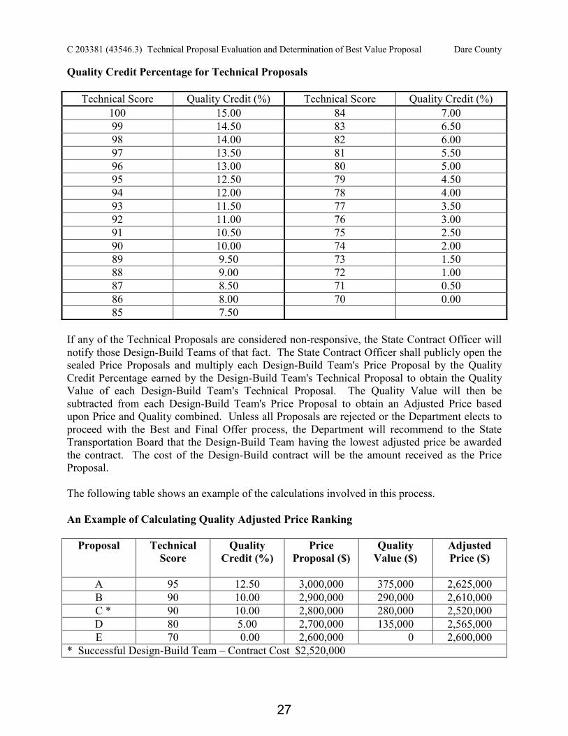
C 203381 (43546.3) Technical Proposal Evaluation and Determination of Best Value Proposal Dare County
Quality Credit Percentage for Technical Proposals
Technical Score Quality Credit (%) Technical Score Quality Credit (%) 100 15.00 84 7.00 99 14.50 83 6.50 98 14.00 82 6.00 97 13.50 81 5.50 96 13.00 80 5.00 95 12.50 79 4.50 94 12.00 78 4.00 93 11.50 77 3.50 92 11.00 76 3.00 91 10.50 75 2.50 90 10.00 74 2.00 89 9.50 73 1.50 88 9.00 72 1.00 87 8.50 71 0.50 86 8.00 70 0.00 85 7.50
If any of the Technical Proposals are considered non-responsive, the State Contract Officer will notify those Design-Build Teams of that fact. The State Contract Officer shall publicly open the sealed Price Proposals and multiply each Design-Build Team's Price Proposal by the Quality Credit Percentage earned by the Design-Build Team's Technical Proposal to obtain the Quality Value of each Design-Build Team's Technical Proposal. The Quality Value will then be subtracted from each Design-Build Team's Price Proposal to obtain an Adjusted Price based upon Price and Quality combined. Unless all Proposals are rejected or the Department elects to proceed with the Best and Final Offer process, the Department will recommend to the State Transportation Board that the Design-Build Team having the lowest adjusted price be awarded the contract. The cost of the Design-Build contract will be the amount received as the Price Proposal. The following table shows an example of the calculations involved in this process. An Example of Calculating Quality Adjusted Price Ranking
Proposal Technical Score
Quality Credit (%)
Price Proposal ($)
Quality Value ($)
Adjusted Price ($)
A 95 12.50 3,000,000 375,000 2,625,000 B 90 10.00 2,900,000 290,000 2,610,000
C * 90 10.00 2,800,000 280,000 2,520,000 D 80 5.00 2,700,000 135,000 2,565,000 E 70 0.00 2,600,000 0 2,600,000
* Successful Design-Build Team – Contract Cost $2,520,000
27

C 203381 (43546.3) Technical Proposal Evaluation and Determination of Best Value Proposal Dare County
Opening of Price Proposals Prior to opening the Price Proposals, the State Contract Officer will provide to each Design-Build Team their Technical Score in a sealed envelope. The sealed envelope will contain that Team’s score only. At the time and date specified, the State Contract Officer will open the Price Proposals and calculate the percentage difference between the Price Proposals submitted and the Engineer’s Estimate. Should all of the Price Proposals be within an acceptable range or below the Engineer’s Estimate the State Contract Officer will proceed to calculate the quality credit and publicly read the Price Proposal, Technical Score, and Adjusted Price as outlined in the selection procedure above. Should any one or more of the Price Proposals be within an acceptable range or below the Engineer’s Estimate and the remaining Price Proposals exceed an acceptable range of the Engineer’s Estimate the State Contract Officer will go to a separate location to calculate the quality credit and determine if the Design-Build Team with the lowest Adjusted Price is within an acceptable range of the Engineer’s Estimate. Should the Price Proposal of the Design-Build Team with the lowest Adjusted Price be within an acceptable range of the Engineer’s Estimate or below the Engineer’s Estimate the State Contract Officer will proceed to publicly read the Price Proposals, Technical Scores, and Adjusted Prices. Should the Price Proposal of the Design-Build Team with the lowest Adjusted Price exceed an acceptable range of the Engineer’s Estimate the State Contract Officer will publicly read the Price Proposals only and the Department will then determine whether to proceed to request a Best and Final Offer (BAFO) as outlined below. Should all Price Proposals submitted exceed an acceptable range of the Engineer’s Estimate the State Contract Officer will publicly read the Price Proposals only. The Department will then determine whether to proceed to request a Best and Final Offer (BAFO) as outlined below. In the event that the Department elects to not proceed with a Best and Final Offer (BAFO), then the State Contract Officer will schedule a date and time to publicly reiterate all Price Proposals, and read all Technical Scores and Adjusted Prices. Provided the Department elects to proceed to request a Best and Final Offer (BAFO), at the date and time specified, the State Contract Officer will open the Best and Final Offer Price Proposals and proceed to publicly read all Price Proposals, Technical Scores and Adjusted Prices. Best and Final Offer In the event initial Price Proposals exceed an acceptable range of the Engineer’s Estimate or if the Department feels it is necessary for any reason the Department may choose to make amendments to the details of the RFP and request a Best and Final Offer from all of the previously short-listed teams. Alternately, the Department may choose to redistribute to the short-listed Design-Build Teams another RFP for the project with no amendments to the RFP scope. After receipt of the redistributed RFP, the Design-Build Team has the option of changing their Technical Proposal details. If the Design-Build Team changes any component of the Technical
28
C 203381 (43546.3) Technical Proposal Evaluation and Determination of Best Value Proposal Dare County
Proposal, the TRC will review those amended components of the Technical Proposal and reevaluate the scores accordingly. The Design-Build Team shall highlight the changes to bring them to the Department’s attention. A revised total score will be calculated, if appropriate, based on these amendments to the Technical Proposal. Additional oral interviews will not be held. The Design-Build Teams shall submit both a revised Price Proposal and a revised Technical Proposal (if applicable) at the time, place, and date specified in the redistributed RFP. A revised Quality Credit Percentage (if required) and Adjusted Price will be determined. This will constitute the Design-Build Team’s Best and Final Offer. Award of the project may be made to the Design-Build Team with the lowest Adjusted Price on this Best and Final Offer for the project.
29

C 203381 (43546.3) Project Special Provisions Dare County
*** PROJECT SPECIAL PROVISIONS *** INTENT OF CONTRACT The intent of the contract is to prescribe the work or improvements that the Design-Build Team undertakes to perform, in full compliance with the contract documents. In case the method of construction or character of any part of the work is not covered by the contract, this section shall apply. The Design-Build Team shall perform all work in accordance with the contract or as may be modified by written orders, and shall do such special, additional, extra, and incidental work as may be considered necessary to complete the work to the full intent of the contract. Unless otherwise provided elsewhere in the contract, the Design-Build Team shall furnish all implements, machinery, equipment, tools, materials, supplies, transportation, and labor necessary for the design, prosecution and completion of the work. It is the intent that the Design Build Team shall Design, Build, Equip, Launch, Test and Deliver to the Owner one (1) Vessel, as described, complete and ready for service in every respect as concerns the work covered herein. All specifications written for singular description shall be applicable for the construction of one (1) Vessel. The Design-Build Team shall provide the necessary plant, launch/railway and lay days to construct the Vessels, all tools, materials, machinery, equipment, fittings and labor, including upkeep of the Vessel until final acceptance by the Owner. The Design-Build Team shall make removals and replacements as necessary to affect the work covered by these specifications as a part of the contract if required. The Design-Build Team shall coat all new work and restore and recoat all areas disturbed due to the work required by these specifications as a part of the Contract. Any work, equipment, machinery, or other part or parts of the Vessels injured or damaged while the Vessel is in the custody of the Design-Build Team during the progress of the work covered by these specifications shall be repaired by the Design-Build Team to the satisfaction of the Inspector, at no cost to the Owner Any work or detail omitted from this Request for Proposals, but necessary to complete the specified construction covered herein in accordance with good shipbuilding practice shall be furnished by the Design-Build Team as a part of the Contract at no additional cost to the Owner, and nothing herein or on the plans shall be construed as meaning otherwise. Whereas the true intent and meaning is manifest, the Design-Build Team shall not be relieved from fulfilling the full requirements of the contract plans, contract guidance plans and specifications, or of the responsibility for producing satisfactory results, or of properly performing any work by any of the following: • Absence of the details where the essential features, functions and arrangements are defined. • Mistakes in description of hull or machinery details which, if not corrected, would interfere
with the proper performance of the items involved.
30
Addendum No. 2 October 30, 2013 C 203381 (43546.3) Project Special Provisions Dare County The Design-Build Team is responsible for proper performance of the Contract in accordance with the full manifested intent of this Request for Proposals despite any error, omission, discrepancy or lack of clarity in the plans or specifications which should reasonably have been apparent to an experienced Contractor upon a careful and critical review. CONTRACT TIME AND LIQUIDATED DAMAGES 07/12/07 DB1 G04A The date of availability for this contract is January 27, 2014. The completion date for this contract is defined as the date proposed in the Technical Proposal by the proposer who is awarded the project. The completion date thus proposed shall not be later than September 22, 2015. The completion date is defined as the date upon which acceptance is achieved in accordance with the Acceptance Project Special Provision. The Design-Build Team will be required to pay liquidated damages for each and every day that delivery is delayed beyond the completion date for this contract. The timely completion of the performance of this contract has a substantial financial value to the Owners, which value is difficult or impossible to forecast or evaluate exactly. It is, therefore, stipulated and agreed that the value to the Owners for each calendar day of delay in delivery of the Vessel by the Design-Build Team to the Owners beyond the contract completion date of the work to be performed by the Design-Build Team under this contract shall be a fixed sum and shall be set in advance. Upon the foregoing consideration and for the purpose of this contract, the sum of One Thousand Dollars ($1,000.00) per calendar day is hereby mutually agreed upon as the sum which the Design-Build Team shall give to the Owners as liquidated damages for each calendar day delayed beyond the contract completion date that the work remains unfinished and said Vessel remains undelivered. PROGRESS OF WORK It is the intent of this Request for Proposals that the Design-Build Team shall commence work on the date of availability as noted elsewhere herein. The Design-Build Team shall not begin work prior to the date of availability without written approval of the Inspector. If such approval is given and the Design-Build Team begins work prior to the date of availability, the Department will assume no responsibility for any delays caused prior to the date of availability by any reason whatsoever, and such delays, if any, will not constitute a valid reason for extending the completion date. In no case shall the Design-Build Team perform any work on the project until the Department has received the properly executed contract payment and performance bonds. It is further the intent of this Request for Proposals that the Design-Build Team shall pursue the work diligently with workmen in sufficient numbers, abilities, and supervision and with
31
C 203381 (43546.3) Project Special Provisions Dare County
equipment, material, and method of construction as may be required to complete the work described in the contract, or as may be amended by the completion date. Should progress of the work lag or fall behind schedule, the Design-Build Team shall direct sufficient additional labor to work, including overtime if required, to maintain the contract delivery date, at no additional cost to the Owner. For the purpose of these specifications in determining the days for which liquidated damages will be charged, the Design-Build Team shall be entitled to an extension of the contract time or to an apportionment and remittance of liquidated damages when a contract is not completed within the contract time to the extent that delays to the current controlling operations, or operations, were caused by an Act of God. The Design-Build Team, however, shall be entitled to an extension of contract time, or an apportionment and remittance of liquidated damages, only to the extent and in the proportion that such delays were caused by an Act of God or the Department, and it is understood that Department does not hereby waive or release any claim against the Design-Build Team for liquidated damages when the contract is not completed within the contract time for any reason whatsoever other than the said an Act of God or Department caused delay. A request by the Design-Build Team for an extension of time shall be made to the Inspector within five (5) days after such delay has occurred and he shall make a determination as to the cause of the delay and the amount of time that the contract should be extended by reason of such delay. It is understood and agreed that if a claim is filed for an extension of contract time, or an apportionment and remittance of liquidated damages, the burden of proof shall be upon the Design-Build Team to establish the Act of God or the acts of the Department causing the alleged delay; and if the Design-Build Team fails to sustain the burden of proof, he shall not be entitled to an extension of contract time, or to an apportionment and remittance of liquidated damages. The burden of proof herein referred to shall be the same that in other cases of like nature exists. Proof by the Design-Build Team of delays due to an Act of God or act of the Department to enforce or collect liquidated damages due to any other reason whatsoever. The Design-Build Team is hereby notified that no consideration will be given to requests for remissions of liquidated damages for any reason whatsoever, except as stated herein. The Contract date for completion will be changed on a negotiated basis for any work authorized or deleted by supplemental agreements to the original contract. PROGRESS SCHEDULE The Design-Build Team shall prepare and submit for approval by the Inspector a schedule of his proposed working progress on the project. The proposed progress schedule shall be submitted no later than the date of the project preconstruction conference and before any work is begun on the project. When conditions beyond the Design-Build Team's control have adversely affected his progress, the Design-Build Team may submit a revised progress schedule to the Inspector for approval. Such revised progress schedules will not be approved unless accompanied by a detailed written statement giving the Design-Build Team's reasons for the proposed revision.
32
C 203381 (43546.3) Project Special Provisions Dare County
When, at any time during construction or repair of the project, the Design-Build Team's progress deviates substantially from the latest approved progress schedule, the Inspector may request the Design-Build Team to submit a revised progress schedule. Revised progress schedules requested by the Inspector shall be submitted within seven (7) days after the date of such request. PRE-DESIGN CONFERENCE The Design-Build Team shall meet with the Owner for a pre-design conference concerning the design phase of the work. This conference shall be held prior to the commencement of design work and will be scheduled by the Owner. At the predesign conference, the Design-Build Team shall furnish authorized signature forms and a list of any proposed subcontractors associated with the design of the project. PRECONSTRUCTION CONFERENCE Immediately after receipt of notice of award, the Owner and the Design-Build Team will establish a mutually agreeable date on which the preconstruction conference will be held. The Design-Build Team's project superintendent and other individuals representing the Design-Build Team who are knowledgeable of the Design-Build Team's proposed progress schedule or who will be in charge of major items of the work shall attend the preconstruction conference. Design-Build Team shall provide necessary personnel to take, transcribe, correct, reproduce and distribute minutes of the pre-construction meeting.
CONSTRUCTION CONFERENCES After work on the project has begun, initially construction conferences shall be held monthly and adjusted to suit construction. The construction conferences are to be scheduled at times which are mutually agreeable to both the Design-Build Team's project superintendent and the Inspector. It shall be the superintendent's responsibility to attend the conference. Design-Build Team may elect to have other members of his staff attend construction conferences. Design-Build Team shall provide necessary personnel to take, transcribe, reproduce and distribute minutes of each meeting. ON-SITE PROJECT SUPERVISION At all times that work is actually being performed, the Design-Build Team shall have present on the project one competent individual who has been authorized to act in a supervisory capacity over all work on the project including work subcontracted. This individual who has been so authorized shall be experienced in the type of work being performed and is to be fully capable of managing, directing and coordinating the work; of reading and thoroughly understanding the contract; and of receiving and carrying out directions from the Inspector. He shall be an employee of the Design-Build Team. The project Supervisor shall be authorized to accept and sign for notices and instructions, if and when found necessary, from the Inspector.
33
Addendum No. 2 October 30, 2013 C 203381 (43546.3) Project Special Provisions Dare County The Project Supervisor shall be identified at the time of the Pre-construction Conference and shall meet with the Inspector's approval. Should it become necessary to assign another individual in this position, the Design-Build Team shall provide the Inspector written notification within five (5) working days of the proposed change. The individual assigned shall be approved by the Inspector and shall be capable of assuming the duties as outlined herein. MOBILIZATION (9-1-11)
DB1 G15B
Ten (10) percent of the “Total Amount of Bid for Entire Project” shall be considered the lump sum amount for Mobilization. Partial payment for Mobilization will be made with the first partial pay estimate paid on the contract. SCHEDULE OF ESTIMATED COMPLETION PROGRESS (9-1-11) DB1 G58 The Design-Build Team's attention is directed to the Standard Special Provision entitled "Availability of Funds - Termination of Contracts" included elsewhere in this RFP. The Department of Transportation's schedule of estimated completion progress for this project as required by that Standard Special Provision is as follows: Fiscal Year Progress (Dollar Value) 2014 (07/01/13 – 06/30/14) 35% of Total Amount Bid 2015 (07/01/14 – 06/30/15) 57% of Total Amount Bid 2016 (07/01/15 – 06/30/16) 8% of Total Amount Bid The Design-Build Team shall also furnish its own progress schedule in accordance with the Progress Schedule Project Special Provision. Any acceleration of the progress as shown by the Design-Build Team's progress schedule over the progress as shown above shall be subject to the approval of the Engineer. PARTIAL PAYMENTS Partial payments will be based upon progress estimates prepared by the Owner’s Representative at least once each month on the date established by the Owner’s Representative. Partial payments may be made twice each month if in the judgment of the Owner’s representative the amount of work performed is sufficient to warrant such payment. No partial payment will be made when the total value of work performed since the last partial payment amounts to less than $10,000.00. Partial payments will be approximate only and will be subject to correction in the final estimate and payment. Partial payments shall be based on a certified Schedule of Values submitted by the successful Design-Build Team and approved by the Owner’s Representative. The certification shall indicate the Design-Build Team has reviewed the information submitted and the information accurately represents the work performed for which payment is requested. The certified Schedule of Values shall be submitted no later than 30 calendar days after the date of award.
34
C 203381 (43546.3) Project Special Provisions Dare County
Each item on the certified Schedule of Values shall be assigned a cost and quantity, if applicable, consistent with the line items contained in the Itemized Proposal Sheet and shall be identified as an activity on the progress schedule. A revised certified Schedule of Values shall be submitted with each update of the progress schedule as described in Article 108-2, and as modified herein, or when requested by the Owner’s Representative. All material and work covered by partial payments made shall thereupon become the sole property of the Owner, but this provision shall not be construed as relieving the Design-Build Team from the sole responsibility for all materials and work upon which payments have been made or the restoration of any damaged work or any responsibility of the Design-Build Team as herein set forth or as a waiver of the right of the Owner to require the fulfillment of all of the terms of the Contract. The Owner’s Representative may withhold an amount sufficient to cover anticipated liquidated damages as determined by the Owner’s Representative. PROMPT PAYMENTS Payments due to subcontractors, material suppliers, and other service or product suppliers shall be made promptly and in accordance with Article 109-4(B) of the Standard Specifications. Neither the final payment nor any part of the retained percentage shall become due until the Design-Build Team shall deliver to the Owner through the Inspector, Consent of Surety for final payment and an Affidavit of Payments of Claims that all subcontractors and suppliers of either labor or materials have been paid all sums due them for work performed or materials furnished in connection with this Contract or that satisfactory arrangements have been made by the Design-Build Team with such subcontractors and suppliers with respect to the payment of such sums as may be due them by the Design-Build Team. QUALITY CONTROL A competent employee of the Design-Build Team, satisfactory to the Owner, shall from the start of work until the completion of the Vessel, maintain quality control over the job. This employee shall make such inspections and investigations as are necessary to insure that the quality of workmanship, materials and testing is in accordance with that specified. The quality control employee shall prepare and maintain records of his actions and provide copies to the Inspector and cooperate with the Inspector. The Inspector shall have access to the quality control employee and records at all reasonable times during working hours. CARE DURING CONSTRUCTION All parts of the Vessel, including, but not limited to, structure, deck coverings, fittings, equipage, outfit, furniture, insulation, paint work, machinery, auxiliaries, appliances and apparatus, shall be
35
C 203381 (43546.3) Project Special Provisions Dare County
maintained in satisfactory condition during the entire period of construction and fitting out. All dirt, chips, and scrap material shall be cleaned out at frequent intervals during construction, and no water shall be allowed to remain in the Vessel. The Vessel must be thoroughly cleaned throughout at the time of delivery to the Owner. Special measures shall be taken to minimize damage incident to storage, installation and construction and to prevent corrosion or other deterioration, especially to all unpainted, polished, and moving parts. All defects, damage, and deterioration of the Vessel, its parts, fittings, and outfit that occur before acceptance of the Vessel shall be corrected and repaired by the Design-Build Team at their expense. Equipment, prefabricated parts, furniture, and items such as life floats, lines, and canvas, which are stored in the warehouse during the construction period of the Vessel, shall be thoroughly examined for and rid of rats and vermin before being placed on board. MATERIAL FURNISHED BY OWNER AND TO BE RETAINED BY OWNER The Design-Build Team shall receive, handle, and install all Owner furnished material and equipment, if any, and shall provide the required foundation, piping, wiring, etc., to make a complete and satisfactory installation at no additional cost to the Owner as a part of this contract. The Department will provide two booster pumps and the dredge pipe, which will be utilized on an NCDOT barge. PROTECTION AND CUSTODY OF VESSEL The Design-Build Team shall take suitable means of protecting the Vessel, the engines, and all other machinery, outfit, equipment, piping, wiring, etc. from the start of construction and until the Vessel is accepted by the Owner, and the Design-Build Team will be held responsible for any damage that may be sustained during this period. The Vessel is agreed to be in the custody of the Design-Build Team from the start of work at his plant until the completion of the Vessels, including the tests and trials as required herein, and until delivery to the Owner. The Design-Build Team shall keep all litter and debris removed from the Vessels, and shall conform to normal standard safety practices in the prosecution of the work and condition of the shipyard area. HAULING AND LAY-TIME (See Surface Preparation and Paint Application Sections of Outfitting Scope of Work) The Design-Build Team shall provide a suitable marine railway for hauling the Vessel and sufficient lay days to complete all work as required, or that may become necessary. A railway lift will be provided by the NCDOT Ferry Division at the Shipyard for final inspection of hull. The Vessel shall enter the drydock or railway without list and without excessive trim. If any strain or possible damage to the Vessel be suspected or observed, the docking operation shall be suspended and necessary corrective measures taken. Blocking and shores shall be arranged in
36
C 203381 (43546.3) Project Special Provisions Dare County
accordance with standard practice, leaving room in way of rudders, propellers, and other obstructions. The Vessel shall remain on the drydock or railway until the underwater work has been satisfactorily completed, then it shall be carefully undocked. RAILWAY CERTIFICATION The Design-Build Team shall submit a certificate of condition and capacity of Railway or Dry-dock intended for use during docking if required. Certificate shall indicate capacity, maximum width, and condition of facility which has been inspected within 30 days of bidding by a Certified Marine Inspector or Registered Professional Engineer. OWNER’S RIGHT TO TEMPORARILY SUSPEND WORK The Owner maintains the right to temporarily suspend work in accordance with Article 108-7 of the Standard Specifications. In addition, when so ordered by the Inspector, the Design-Build Team shall suspend any work that may be subject to damage by climatic conditions existing or predicted for the area within 24 hours. INSPECTION All work and materials entering into the construction of the Vessels and their machinery, fittings and equipment shall be subject at all times to the inspection and approval of the Inspector. It is the duty of the Inspector to insist that the Design-Build Team perform all work and supply all materials as called for in this Request for Proposals. The Design-Build Team shall perform all work in a satisfactory manner. In the event that any work or materials fail to comply with these specifications the Inspector will notify the Design-Build Team in writing of the deficiency or unsatisfactory work as soon as it comes to his attention. Any work not satisfactory, whether from defective material, departure from specifications, or poor workmanship, or any work performed in the absence of the Inspector and later found to be unsatisfactory, shall be removed and replaced promptly to the satisfaction of the Inspector, at the Design-Build Team's expense. The Owners, the Inspector, and any person employed by the same shall be allowed access to the work at any time during the regular working hours of the Design-Build Team, or at such other times as will not entail additional expense to the Design-Build Team, and the Design-Build Team shall furnish all reasonable facilities and give ample time for such inspection. A desk, desk chair, 4-drawer legal file cabinet with lock and keys, three (3) chairs, a 3' x 6' x 36" drawing board and copy machine shall be provided in a private office, and apart from facilities occupied by Design-Build Team's production personnel. Office shall be for the Inspector's and Owner's sole use during the contract period. Office shall be provided with telephone service and telefax connection. Necessary long distance calls made to discuss questions arising concerning the work shall be at the Design-Build Team's expense. Telephone service shall be two private lines not subject to connection to Design-Build Team's telephone network listed in the Owner’s
37
C 203381 (43546.3) Project Special Provisions Dare County
name. Design-Build Team shall provide internet service access as a part of this contract. Additional telephone service on Design-Build Team's system may be installed. The Inspector shall determine the amount, quality, acceptability, and witness all parts of the work. He shall interpret the specifications, Contract Documents and supplemental agreements, if any, and he shall decide all other questions in connection with the work. The Inspector shall have no authority to approve or order changes in the work which alter the terms or conditions of the Contract. The Inspector shall confirm in writing within five (5) days any oral order, direction, requirement, or determination. The decision of the Inspector shall be final and binding on both Design-Build Team and Owner. Nothing herein shall be taken to relieve the Design-Build Team of complete responsibility for unsatisfactory workmanship, faulty materials or other deficiencies of any kind whatsoever that are the result of his work, his sub-Design-Build Teams work, or material purchased or provided and installed by him. The Inspector shall have general surveillance of the work. All orders and communications from the Design-Build Team shall be transmitted through him. He shall have authority to stop the work whenever such stoppage may be necessary to ensure the proper execution of contract, said stoppage is to be a Design-Build Team caused delay in computing liquidated damages, if any, for late delivery. As the Inspector is, in the first instance, the interpreter of the conditions of the contract and the judge of its performance, he shall use his powers under the contract to enforce its faithful performance. The Design-Build Team shall notify the Inspector prior to any and all Design-Build Team scheduled meetings or inspections relevant to this contract which involve any representative of the U.S. Coast Guard. The Inspector shall be given the opportunity, at his option, to be present on such occasions. At no time shall the Design-Build Team allow access to any portion of this contract by personnel other than those employed by the Design-Build Team without first receiving the Inspectors approval. CERTIFICATES, DOCUMENTS, ETC. Upon completion of Vessel and prior to acceptance the Design-Build Team shall turn over to the Owner "Consent of Surety," "Affidavit of Payment of Labor and Materials" which shall include a list of material and equipment that is unpaid, waivers from suppliers and a statement that the Vessel is free and clear of all liens and any other documents called for in other paragraphs herein. Upon completion of the Vessel and after it is delivered, the Owner shall turn over to the Design-Build Team a certified statement that all work required by this request for Proposals, including any extra work is complete and satisfactory on the date of delivery. This statement in no way affects or reflects on the guarantee covered herein.
38
Addendum No. 1 October 21, 2013 C 203381 (43546.3) Project Special Provisions Dare County Upon completion of Vessel construction, the Design-Build Team shall provide the Owner with a "Builder's Certificate" properly executed and acceptable by the U. S. Coast Guard Documentation Office. Upon the issue of an Official Number, the Design-Build Team shall perform necessary work to permanently install, by welding, Vessel's Official Number, to a Main Beam in accordance with the Label Plates and Hull Markings Section of the Outfitting Scope of Work. Upon completion of the Vessel & prior to acceptance, the Design-Build Team shall turn over to the Owner all copies of documents, reports, certificates, radiographic film, quality control & deficiency reports, etc. pertaining to this contract. DELIVERY The Vessel shall be delivered by the Design-Build Team to the Owner at the North Carolina State Shipyard at Manns Harbor, NC. The Design-Build Team shall upon delivery turn over to the Owner all documents required by this Request for Proposals, ACCEPTANCE When the trials, training and all tests have been completed, and all work finished to the satisfaction of the Owner, the Vessel will be formally accepted by the Owner after delivery of all necessary documents as described herein. Upon acceptance, the NCDOT will take ownership of the vessel. No certificate for payment issued by the Inspector and no payment, final or otherwise, nor partial or entire use or occupancy of the work by the Owner, shall be an acceptance of any work or materials not in accordance with the contract, nor shall the same relieve the Design-Build Team of responsibility for faulty materials on workmanship or operate to release the Design-Build Team or his surety from any obligations under the contract or the Performance Bond. North Carolina General Statute 136-29 (2) applies. MINORITY BUSINESS ENTERPRISE AND WOMEN BUSINESS ENTERPRISE: (03/26/13) DB1 G066 Description The purpose of this Special Provision is to carry out the North Carolina Department of Transportation’s policy of ensuring nondiscrimination in the award and administration of contracts financed in whole or in part with State funds. The Design-Build Team and subcontractors shall ensure that Minority Business Enterprises and Women Business Enterprises have maximum opportunity to perform work required by this Contract.
39
C 203381 (43546.3) Project Special Provisions Dare County MBE and WBE Goal Due to the nature of work in this contract, specific goals for participation by minority and women businesses are not established. Reporting Minority and Women Business Enterprise Participation The Design-Build Team shall provide the Engineer with an accounting of payments made to all MBE and WBE firms, including material suppliers and contractors at all levels (prime, subcontractor, or second tier subcontractor). This accounting shall be furnished to the Engineer for any given month by the end of the following month. Failure to submit this information accordingly may result in the following action: (A) Withholding of money due in the next partial pay estimate; or (B) Removal of an approved Prime Contractor or other affiliated companies within the
Design-Build Team from the prequalified bidders’ list or the removal of other entities from the approved subcontractors list.
While each contractor (prime, subcontractor, 2nd tier subcontractor) is responsible for accurate accounting of payments to MBEs/WBEs, it shall be the prime contractor’s responsibility to report all monthly and final payment information in the correct reporting manner. At any time, the Engineer can request written verification of subcontractor payments. The Design-Build Team shall report the accounting of payments through the Department’s Payment Tracking System available at:
https://apps.dot.state.nc.us/Vendor/PaymentTracking/. DOMESTIC STEEL AND IRON PRODUCTS (3-6-13) All steel and iron products that are permanently incorporated into this project shall be produced in the United States except minimal amounts of foreign steel and iron products may be used provided the combined material cost of the items involved does not exceed 0.1% of the total amount bid for the entire project or $2,500, whichever is greater, and that the contractor can provide invoices documenting the cost of the items. This minimal amount of foreign produced steel and iron products permitted for use is not applicable to high strength fasteners. Domestically produced high strength fasteners are required. All steel and iron products furnished as domestic products shall be melted, cast, formed, shaped, drawn, extruded, forged, fabricated, produced, or otherwise processed and manufactured in the United States. Raw materials including pig iron and processed pelletized and reduced iron ore used in manufacturing domestic steel products may be imported; however, all manufacturing processes to produce the products, including coatings, shall occur in the United States.
40
C 203381 (43546.3) Project Special Provisions Dare County Before each steel or iron product is incorporated into any project or included for partial payment on a monthly estimate, the Design-Build Team shall furnish the Owner either a notarized certification certifying that the product conforms to the above or material Mill Certifications, including origin and test information, for all steel used in the construction of the vessel. The Owner will forward a copy of each certification to the Materials and Tests Unit. Each purchase order issued by the Design-Build Team or a subcontractor for steel and iron products to be permanently incorporated into any project shall contain in bold print a statement advising the supplier that all manufacturing processes to produce the steel or iron shall have occurred in the United States. The Design-Build Team and all affected subcontractors shall maintain a separate file for steel products permanently incorporated into any project so that verification of the Design-Build Team's efforts to purchase domestic steel and iron products can readily be verified by an authorized Owner’s representative. Exclusions The requirements of this provision do NOT apply to certain equipment and machinery items. These items include marine diesel engines, propulsion units, electrical switchboards and switchgear, electrical motors, pumps, ventilation fans, boilers, electrical controls and electronic equipment. The use of these specific equipment and machinery items, which have been manufactured outside the United States, is permitted for construction. TWELVE MONTH GUARANTEE
The Design-Build Team shall guarantee all materials furnished and all workmanship performed by him under these specifications for a period of twelve months following final acceptance by the Owner. This guarantee shall be limited to replacement (including labor) of any parts giving out under normal service because of defect in material or workmanship, and not because of carelessness or neglect on the part of the Owner, his officers or agents; provided further, that any work necessary under this warranty shall be performed without delay by the Design-Build Team at a shipyard or such other place as may be approved by the Owner, and said Design-Build Team shall not be liable for any expense or damages other than as herein called for above. The regular manufacturer's warranty shall be furnished with all equipment, machinery, fitting, etc., provided by the Design-Build Team. Manufacturer's warranties shall be filed by the Design-Build Team for all equipment provided and installed and said warranties shall be transferred and/or filed in the Owner's name for all equipment, machinery, fittings, etc.; regular warranty periods will apply for all component items not hereinafter listed.
The Design-Build Team shall make good all damage to the Vessel or its equipment or contents thereof, which is the result of the use of materials, equipment or workmanship which are inferior, defective, or not in accordance with the terms of the contract and shall restore all disturbed work resulting from the same. If the Design-Build Team, after notice, fails to proceed promptly to comply with the terms of the
41
C 203381 (43546.3) Project Special Provisions Dare County guarantee, the Owner may have the defects corrected and the Design-Build Team and his surety shall be liable for all expenses incurred. All special guarantees applicable to definite parts of the work that may be stipulated in the specifications or other papers forming a part of the contract shall be subject to the terms of this paragraph during the life of such special guarantees. Appropriate provisions of the payment and/or performance bonds shall cover this guarantee for the project. In addition, failure on the part of the responsible entity(ies) of the Design-Build Team to perform guarantee work within the terms of this provision shall be just cause to remove the responsible entity(ies) from the Department’s corresponding prequalified list. The Design-Build Team will be removed for a minimum of 6 months and will be reinstated only after all work has been corrected and the Design-Build Team requests reinstatement in writing. This provision does not apply to the booster pumps and dredge pipe that will be supplied by the Department. OUTSOURCING OUTSIDE THE USA (5-16-06) DB1 G150 All work on consultant contracts, services contracts, and construction contracts shall be performed in the United States of America. No work shall be outsourced outside of the United States of America. Outsourcing for the purpose of this provision is defined as the practice of subcontracting labor, work, services, staffing, or personnel to entities located outside of the United States. The North Carolina Secretary of Transportation shall approve exceptions to this provision in writing.
42
C 203381 (43546.3) General Scope of Work Dare County
GROUP 000 - GENERAL SCOPE OF WORK
This dredge is a steel barge type hull with rake on after end and two levels of superstructure. All spaces below main deck are voids and ballast tanks with the exception of machinery space. The main deck area shall have a machinery space, living quarters for sixteen (16) persons, galley and mess area. The wheelhouse is located above the 01 level for control of the Vessel and dredging operations. Dredging control shall be from the wheelhouse area using electric over hydraulic semi-automated control system to direct dredging operations. The Vessel is to be equipped with two walking spuds for movement of the dredge during dredging operations. The two anchors are to be used to move the cutter head from side to side during dredging operations.
The dredge is designed for dredging service up to 25’-0” depth. Dredging operations and discharge of spoil will be using flexible 12” pipeline to spoil areas up to three (3) miles with assistance of booster pumps. Normal operations will be to maintain ferry turning basins and short state channels to connect to Federal Channels during the late fall, winter and early spring seasons of the year per environmental restrictions.
References 0.1 ABS “Rules for Building and Classing Steel Barges on Rivers and Intracoastal
Waterways”. 0.2 IEEE & NEC “National Electrical codes” 0.3 ANSI “Steel Construction Manual” 010 Vessel Performance/Capabilities The Vessel is a 12” Cutter Head/Suction Dredge intended for service on the lakes, bays, rivers and sounds of North Carolina from Wilmington to Knots Island. The hull of the Vessel shall be all welded steel construction using a transverse system of framing with longitudinal plate stiffeners. The hull shall be subdivided compartments as shown on General Arrangement drawing provided by the Department. The main deck house superstructure shall be arranged with doors and windows to allow access throughout. The house shall be designed to prevent for racking and high enough to allow for 8’-0” clearance below all overhead structure, ventilation ducting, piping, and electrical cable trays. The front of the house shall be designed to withstand anticipated loading of the dredge lattice attached. The structure shall be a minimum of ¼” steel plate with 4” x 3” x 5/16” angle stiffeners. Additional heavy beams and columns shall be installed as needed. The wheelhouse shall be designed to house the control console and chart table. The forward window between the consoles shall be full height to allow for full view of the cutting operation.The aft window shall be large enough such that the console and chart table can pass through without disassembly so as to allow for the console to be built as needed and installed after the wheelhouse has been welded in place.
43
C 203381 (43546.3) General Scope of Work Dare County
The wheelhouse shall be a minimum of ¼” plate with 3” x 2” x ¼” angle stiffeners. Additional heavy beams shall be installed as needed overhead. No columns shall be used to support overhead structure. Dredging be provided by one (1) 1000 hp marine diesel engine at 1800 rpm. Drive will be through a reduction gear with a ratio to match the dredge pump. See Dredge Pump, Engine, Cutter Head and Spuds Scope of Work for details. Electric power requirements shall be by two (2) 105 kW 208 volt 3 phase diesel generators with only one genset running at a time. No emergency genset will be required. See Electrical Scope of Work for details. The Vessel shall be designed for cutting and suction dredging in inland waters of coastal North Carolina. Dredge operating depth would be a maximum of 25’-0” at 45 degrees. 042 Regulatory Body/Classification Requirements The Vessel shall be designed and constructed to the requirements of Reference 0.1, except where exempted in writing by the Owner. 060 Principal Characteristics Dimensions:
Length overall (molded) hull only 100'-0" Length on design load waterline 100'-0" Breadth (molded) not including bumpers or tires 36'-0" Depth (molded) amidships at side 9'-0" Maximum Vessel Draft (molded) 4'-0" Gross Tonnage Under 500
Capacities
Fuel oil (96%) 5,000 Gallons Fresh water (96%) 5,000 Gallons Lube oil (96%) 250 Gallons Gear oil (96%) 110 Gallons
Power (approximate):
Dredge pump 1000 hp@ 1800 rpm Ship's service generators (2) 105 kW @ 1800 rpm Hydraulic power unit 500 hp@ 1800 rpm
44
C 203381 (43546.3) General Scope of Work Dare County
070 General Requirements for Design and Construction The Vessel shall comply with all the rules and regulations of the regulatory bodies as stated in section 042. The Vessel shall be designed to meet the rules and regulations that are in effect at the time of the contract signing. In the event any changes occur in these applicable rules and regulations, all design and construction changes necessary to conform to the applicable rules and regulations shall be as directed by the Owner. 078 Materials All materials, machinery, equipment, and components shall be of good commercial marine quality, in full compliance with these Specifications, suitable for the service intended. An "or equal" product is one which exhibits the same features of size, weight, characteristics, performance, reliability, and maintainability as the product identified in this Request for Proposals. The total performance of the "or equal" product shall be such that its use will not adversely affect the intended performance of other systems or the Vessel and with no increase in required maintenance or replacement periodicity. Demonstration of an "or equal" status is the responsibility of the Design-Build Team and must be approved by Owner prior to purchase. Disapproval of vendor shall not constitute a change order to cover difference in cost. All items purchased shall be of good marine quality approved by Owner. Unless otherwise specified in the RFP, fasteners shall be in accordance with all sizes required or shown on the approved plans and listed elsewhere in this Request for Proposals and adhere to the following: • Exterior fastenings shall be 316 stainless steel. • Interior fastenings shall be steel • All fasteners exposed to view shall be chrome finish with chrome finish washers. • Hidden fasteners may be plain steel All hardware shall be made of best quality marine grade brass, bronze or 316 stainless steel, unless otherwise specified. Bolts shall be fitted with lock washers, flat washers and nuts. Nuts shall be drawn up tight. Screws shall be of highest quality stainless steel, with clean cut threads. All threads shall be coated with sealant (non-seizing) prior to installation or Teflon impregnated as part of the manufacturing process. 085 PLANS AND SPECIFICATIONS Major design milestones and required design submittals shall be identified as activities on a CPM, bar chart, or other scheduling tool. This schedule shall be submitted to the Transportation Program Management Director and the Assistant Ferry Director of Maintenance and Materials concurrently with the first design submittal, or within 30 days of the contract award, whichever is earlier. The schedule shall be revised and resubmitted as design milestones change or as directed by the Transportation Program Management Director and the Assistant Ferry Director of Maintenance and Materials. Submittals will be reviewed within 15 working days from the date of receipt by NCDOT
45
C 203381 (43546.3) General Scope of Work Dare County
unless otherwise stipulated in the scope of work. All submittals shall be made simultaneously to the Transportation Program Management Director and the designated Owner’s representative. The Design-Build Team shall inform the Transportation Program Management Director in writing of any proposed changes to the Technical Proposal and / or previously reviewed submittals and obtain approval prior to incorporation. The Design-Build Team shall prioritize submittals in the event that multiple submittals are made based on the current schedule. The following plans shall be furnished by the Design-Build Team:
• Outboard & Inboard Profile • General Arrangement • Hold Plan • Joiner Layout, Elevations and Details • Fire and Safety Plan and Equipment Listing • Door, Window & Manhole Arrangement Material List • Navigation Light Mast Arrangement, Details and Material List • Insulation Plan, Details and Material List • Dredging Control System Layout, Details and Material List • Main Deck, Hold Machinery Arrangement and Equipment List • EOS Arrangement, Elevations and Equipment List • Galley Cabinet Arrangement, Elevations and Equipment List • Wheelhouse Arrangement, Elevations, Console and Equipment List • Structural Scantling and Inboard Profile • Main Deck Structure • Shell Expansion and Plating • Transverse Bulkheads • Transverse Frames • Longitudinal Frames and Bulkheads • Main Engine, Generator, and Pump Foundations • Main Deck House Structure • Wheelhouse Structure • Stack Structure and Louver Details • Fender, Tire Elevation Arrangement and Details • Handrail Arrangement and Details • Inclined Stairways and Ladder Details • Fuel Oil System, Schematic, System Arrangement & Material List • Bilge System, Schematic, System Arrangement & Material List • Ballast System, Schematic, System Arrangement & Material List • Fire Piping System, Schematic, System Arrangement & Material
List • Engine Exhaust System, System Arrangement & Material List • Vents, Fills and Sounds Layout, Details & Material List • Engine Cooling System Schematic, Arrangement, Details &
Material List • Compressed Air System Schematic, Arrangement & Material List • Hydraulic System Schematic, Arrangement and Material List
46
C 203381 (43546.3) General Scope of Work Dare County
• Fresh Water System, Schematic, Arrangement & Material List • Sewage and Gray Water Schematic, Arrangement & Material List • HVAC Plan, Calculations & Material List • Anchor, Winch Layout, Details and Material List • Walking Spud Arrangement, Details and Material List • Machinery Ventilation Plan Layout, Details and Material List • CO2 Flooding System Schematic, Layout Arrangement & Material
List • Cutter Head Arrangement, Details and Material List • Monorail, Jib Crane Arrangements, Details and Material List • Mast Details, Arrangement, Details and Material List • Main Deck Outfitting Arrangement, Details and Material List • Hull Marking and Signage Plan • AC Electrical One-Line Diagram • AC Electrical 208 Volt Power Layout Plan and Material List • AC Electrical 120 Volt Lighting Layout Plan and Material List • DC Electrical 24 Volt One-Line Diagram • Electronic Wiring Diagram and Material List (Radios, depth finder,
etc) • General Alarm & Misc. Wiring Diagrams and Material List • DC Electrical 24 Wiring Layout Plan and Material List • AC Electrical Load Analysis • DC Electrical Load Analysis
All plans, drawings, specifications and calculations shall be submitted to the Department for approval. It is expressly understood that the Design-Build Team shall verify all quantities and figures, will be held responsible for the proper coordination of all dimensions and the work, and that the furnishing of the drawings herewith will not relieve the Design-Build Team from responsibility for errors, or omissions in dimensions and quantities. No addition to the cost will be entertained for errors, omissions or for discrepancies found between actual details and the plans and specifications after the Proposal has been received. Piping drawings shall include bill of material schedule stating size, quantity, mfg. model number, etc. All drawings shall be as-built by the Design-Build Team prior to Vessel delivery. Any calculations that pertain to a respective drawing shall be included on that drawing such as bilge pipe required size calculations or in a booklet with same drawing number with suffix. The engineering firm shall furnish a design calculation booklet with the structural drawings. The Owner reserves the right to alter the drawings to correct or avoid impossible conditions created by prosecution of the work. The alterations necessary in the work, if any, are to be made by the Design-Build Team without additional cost to the Owner.
47
C 203381 (43546.3) General Scope of Work Dare County
085.1 DETAIL WORKING DRAWINGS Detail working drawings shall be prepared as listed in this Scope of Work. Four (4) copies of each prepared drawing shall be submitted to the Owner for review and approval. Owner comments, if any, shall be incorporated in drawings and four (4) copies re-submitted to the Owner for final approval. Owner's drawing review action can be expected in one of the following manners:
(1) "APPROVED" - Drawing is acceptable and ready for construction.
(2) "APPROVED SUBJECT TO COMMENTS" - Owner's comments shall be included on drawing at next normal issue or issue for construction.
(3) "RETURNED FOR REVISION" - Drawing is not in accordance with contract specifications . Drawing shall be revised and resubmitted to Owner for approval prior to issue .
(4) "REJECTED" - Drawing is not in compliance with the contract requirements and shall be redeveloped and resubmitted to Owner for review.
(5) "EXAMINED" - Plans, calculations, sketches, etc., are found to be in accordance with contract specifications and do not require specific Owner approval. General data of this nature is supporting documentation.
The Design-Build Team shall provide all engineering services necessary for the development and construction of the Vessel, including technical calculations, and prepare and submit to the Owner four (4) copies each for approval all calculations, shop and working drawings as required. Working and shop drawings will be reviewed, and approved, or returned for correction, within fifteen (15) working days. No deviations from approved working drawings shall be made without the written approval of the Inspector. Plans/Drawings shall be prepared by the Design-Build Team’s Engineering Design personnel or by subcontract with an approved engineering firm. All drawings shall be approved and PE stamped by a Naval Architect, Marine Engineer, or Mechanical Engineer with experience in dredge component design. All plans shall be prepared using AUTODESK, AutoCAD LT 2012 and using D size drawings for all engineering plans. All plans shall be revised providing details, assemblies, arrangements and material list to indicate "as built" condition. Drawings shall reflect all changes to "as built" conditions. AutoCAD drawings shall be furnished on CD. All revised, Owner furnished and Design-Build Team prepared CD shall be provided to Owner. Drawings shall be revised to reflect final "as built conditions". All drawings shall be stamped to indicate final OWNER approval date and letter file number. Two (2) copies of all Design-Build Team correspondence relating to plan approval shall be submitted to the Inspector and a carbon copy sent to the Transportation Program Management Unit. In developing the working plans and detailed design, the Design-Build Team shall adhere to all salient features and characteristics embodied in the specifications and plans, and the intent thereof. Modifications to the drawings which become necessary during development, or which may be sired by the Design-Build Team to suit their standard practice, shall be brought to the attention of the
48
C 203381 (43546.3) General Scope of Work Dare County
Inspector at the time of submittal of working drawings for approval. Failure to notify the Inspector of such modifications will not constitute approval even though the working drawing was approved. Within 30 days of execution of the contract, the Design-Build Team shall prepare and submit a design and construction schedule for all drawings and production work included in this specification and contract. The schedule shall be updated monthly and submitted to the Owner’s and his Inspector. Upon completion of drawing preparation and revision, the updates only need to be made when new drawings are added or drawings revised. The format of the schedule may use the Design-Build Team’s standards and incorporate Drawing number, Title, and distribution list with applicable dates. The Inspector will cooperate with the Design-Build Team in developing a plan approval procedure in order to expedite plan approval with minimum delay. Approval will be given subject to correction by the Design-Build Team of any errors, omissions, and/or interferences contained thereon and compliance with the plans and this Request for Proposals as previously noted. All revisions made to approved working plans shall be concisely described in a suitable revision column and copies forwarded to the Inspector for comments. Such revisions shall not negate the intent of the original approval without written consent of the Owner. Upon completion of the contract and at time of Vessel delivery, all original drawings and CD’s shall become the property of the North Carolina Department of Transportation and it is understood that the Department of Transportation shall reproduce and issue above noted drawings in any manner for future use. Five (5) sets of the final approved copies and one (1) set of the originals shall be delivered with the Vessel. Each set of drawings shall be individually packaged or boxed and shall be labeled as to contents. A list of drawings shall be included in each set. Shop sketches and templates shall be prepared by the Design-Build Team as required for their shop use. Five (5) copies of shop sketches shall be provided to the Owner. The Design-Build Team shall keep, on the work site, a copy of the drawings (latest revision) and specifications including all authorized supplemental agreements and shall at all times give the Owner and their authorized representatives access thereto. All drawings and specifications, except the signed contract, shall be returned to the Owner at the completion of work. 085.2 ALTERATIONS (CHANGES) The Owner reserves the right to make any deletions or additions to the work to be performed without invalidating the contract, or giving notices to the sureties. Any change in cost due to alterations or deletions shall be negotiated prior to accomplishment, or performed on a time and material basis as hereinafter provided in this section, at the Owner's option, and approval of any such changes shall be authorized by the Owner and accepted by the Design-Build Team in writing on the Standard form provided prior to start of the work. Optional items, if any, may be approved by issue of a supplemental agreement by the Owner at the cost quoted therefore. In making any alteration on a time and material basis, the charge or credit for the change shall be determined by the labor rates submitted with the bid proposal and purchase orders for materials to
49
C 203381 (43546.3) General Scope of Work Dare County
be used. Material shall be at invoiced cost to the Design-Build Team plus 15%. Deletion of equipment and/or material is to be negotiated on a cost of material and labor estimated basis. The Design-Build Team shall, within five (5) working days, when required by the Owner, furnish to the Owner an itemized breakdown of the man-hours, quantities, and prices used in computing the value of any change that might be ordered. The completion date will be changed to cover additions to, or deletions from the contract, on a negotiated basis. (See Contract Time and Liquidated Damages Project Special Provision) The Design-Build Team shall not substitute other material for that specified. Plans provided to the Design-Build Team by the Owner at time of bidding are to be used for guidance only. The Design-Build Team shall verify quantities and provide finalized sets of these drawings and additional working drawings, and sketches, if required at the expense of the Design-Build Team. All drawings shall be as-built by the Design-Build Team prior to Vessel delivery. All design, engineering drawings, and calculations shall be completed and approved by the Owner prior to commencement of Vessel material purchasing and construction. 090 CONSTRUCTION LOCATION All Proposers shall specify, in their Technical Proposal, the physical location of the construction facility, which will be used for the construction of the Vessel. The Design-Build Team will not be permitted to utilize the Mann’s Harbor Shipyard for any construction activities prior to delivery of the completed Vessel. Adjustments to the Vessel as a result of the at sea dredge trial will be permitted at the Mann’s Harbor Shipyard. Any substitution of construction site after award of contract shall be approved by the Department. The Design-Build Team shall submit any request for substitution of construction location through the Owner’s Representative, and the request must provide a valid basis or reason for the proposed substitution.
50
C 203381 (43546.3) Structural Scope of Work Dare County
GROUP 100 - STRUCTURAL SCOPE OF WORK
100 Structure – General Requirements All steel shall be new, ASTM-A36 with mill certificates. All steel to be U.S. manufacture and origin. 101 Material and Scantlings The Vessel shall be constructed on a Transverse system of framing. Limber and vent holes, 1-1/2" radius minimum, shall be cut smooth to ensure proper venting and drainage of tanks, compartments, pockets, and voids. Tanks shall have limber holes and vent holes of adequate size for full capacity flow to suction and vent lines. All scantlings shall meet or exceed the American Bureau of Shipping requirements. Where scantlings on the plans exceed ABS requirements, the increased scantlings shall be used. Temporary access openings may be provided through shell, bulkheads, decks, etc., for convenience of workers and shall be reclosed in place by welding. All such openings shall have large radius corners for this purpose, openings shall be positioned to utilize existing design butt welds and seams wherever possible. Local reinforcements, for special loads and vulnerable areas subject to high wear, also compensation for penetration, doors, stairway openings, etc., shall be provided generally in accordance with ABS rules. Doublers may be used at bitts and deck fittings except at the main deck, wherever there is a difference in adjacent plate thickness, the stiffener side shall be kept flush. Particular care shall be taken on all visible surfaces (i.e., outside shell, deckhouse, etc.) to maintain a good appearance. No rough edges shall remain where steelwork is cut. Penetrations shall be pre-cut by machine or neatly burned and ground smooth such that no jagged edges remain. All steel material shall be blasted to coating manufacturer's recommendations but at least to SSPC Sp 10 standard, and immediately thereafter coated with a suitable primer. The primer shall be of weldable type and fully compatible with ultimate coating system. Design of steel structures shall allow clear heights as specified after allowing for passage of ducts, pipes, etc. Minimum of 7’-6” ceilings and 6’-8” doors clearance is required throughout vessel. Unfairness of plating between frames, stiffeners, or deck beams shall not exceed 1/8" in 24”. Where plate is unfair additional flatbar of similar stiffener shall be installed to straighten plate. In no case shall excess heat be applied to remove excess plate buckle.
51
C 203381 (43546.3) Structural Scope of Work Dare County
102 Welding Electric arc welding shall be used for assembly of all construction elements in hull, superstructures, stern, stem, meeting ABS requirements. Weld joints shall be prepared and welded in compliance with ABS requirements. Mill scale, rust, moisture, dirt, slag, and other alien substances shall be removed before welding is executed. After the welding, remnants of slag are to be removed. Special care shall be taken in regard to welding sequence in narrow places or places having difficult access (i.e., fore peak, etc.). All welding shall be done after carefully scheduled sequences. The welding sequence shall ensure a minimum of strains of finished hull. Particular care is to be taken in the welding sequence to relieve stresses which might cause inherent weakness in the structure or excessive buckling of plates. Deck beams shall be welded with a minimum of 3" in 12" intermittent 5/16" fillet weld wrapped at the ends. All other welds shall meet or exceed ABS requirements. All welding exposed to the weather shall be double-continuous. Electrodes shall be of the quality approved by ABS and USCG for intended materials. Electrodes shall be per approved USCG welding procedures. Electrodes shall be kept in warm dry storage to protect against humidity damage. No welding wire or electrodes shall be left on the vessel overnight except in proper storage cabinet designed to protect welding material from humidity. Internal scallops may only be used for air escape, drainage and in way of cross welds. Crossings shall be made with notch, or the first weld to be ground flush before the crossing element is installed. Single side welding may be performed only on down-hand runs, generally to ABS requirements. The welding shall be controlled by means of X-ray, ultrasound, and magna-flux methods. Random radiographs shall be made to regulatory body requirements. Magna-flux method shall be used for examination for cracks when appropriate. In the event that defects are found, rechecking shall be carried out after repair. Back gouging, where necessary, shall be carried out by air gouging or grinding wheel. Temporary welding shall be carefully removed by chipping and/or grinding and steelwork in way made good to the satisfaction of Owner's Representative. Direct attachment of fittings to oil-tight structures shall be by welding only. Such welds shall be tested for tightness.
52
C 203381 (43546.3) Structural Scope of Work Dare County
103 Lofting Hand lofting is permitted under proper supervision from the Design-Build Team and Owner. The Owner must approve all hand lofting for fairness and accuracy. 110 Shell and Supporting Structure Frames and girders shall be bracketed on both sides of oil-tight and watertight bulkheads, or slotted through watertight bulkheads and collared. Special attention shall be paid to the alignment of girders under the engines and reduction gears. 111 Shell Plating Attention shall be paid to finish of exposed steel on outside shell and superstructure; welding shall be ground smooth where unsightly. It is not the intention to grind smooth all hand-made welding on the side shell plating. Shell plating shall be a minimum of 3/8” throughout. Deck plating shall be 3/8” throughout. The bilge knuckle shall be minimum 6” radius. Each overboard discharge through the shell plating shall be rigidly stiffened vertically and horizontally to the nearest structural members to remove stress from the weld providing watertight integrity. All penetrations shall be reinforced with a proper size plate doubler of same thickness as plate being penetrated. Shell doublers shall be installed on the outside of the hull. 115 Stanchions Stanchions and girders shall be used in spaces as needed to minimize girder size. They are to be part of the structural trusses used for transverse framing. Care is to be taken in the design of accommodation areas that no stanchions will be required in the open galley/mess area. Any stanchions required in this area shall be located in walls are near stairways. 117 Framing Framing shall be in accordance with ABS rules per this Scope of Work. All transverse framing shall be truss type construction using channel members with vertical and diagonal angle members. Longitudinal stiffeners shall be used on the main deck, sides and bottom plating. 120 Hull Structural Bulkheads Structural bulkheads shall be arranged as shown on the approved plans. Hull bulkhead plating shall be no less than 5/16" thick. Bulkhead stiffeners shall be arranged to line up with deck and bottom longitudinal stiffeners. Bulkhead stiffeners shall be sized using deep tank rules for all bulkheads with a minimum member thickness of 5/16”.
53
C 203381 (43546.3) Structural Scope of Work Dare County
121 Center Vertical Keel (CVK) The center vertical keel shall be a longitudinal bulkhead except in the dredge pump compartment. In the dredge pump area the CVK shall be fabricated using a 1/2” thick web plate minimum with a ¾” x 6” flatbar rider plate. Transverse frames in this area shall be the same size as the CVK from longitudinal bulkhead to longitudinal bulkhead. The Design-Build Team has the option to design the vessel without the use of a center vertical keel. 130 Decks Insert plates ½” thick with radius corners shall be installed under bitts, cleats, pad eyes, and similar fittings. Main Deck insert plates shall be installed flush on the underside with surrounding plates. Decks shall be reinforced in way of openings, breaks, etc., with flatbar all around openings. Flatbar shall be size according to ABS rules as specified elsewhere. 136 Upper Decks All upper decks shall be ¼” plate minimum with 4” x 3” x ¼” angle and WF beams or Channel as required to support the deck to a minimum of 300 pounds per square foot loading. 150 Superstructure Structural Bulkheads Structural bulkheads shall be arranged as shown on the reference drawings provided by the Department. Superstructure shall be minimum ¼” thick steel plate with 3”x2”x1/4” angle stiffeners. An adequate number of transverse and longitudinal bulkheads shall be installed to prevent structural racking of the superstructure. A minimum of two transverse bulkheads shall be provided. 161 Deck Fittings 8” double cast steel bitts, 8” cast steel chocks and 30” cast steel kevels shall be provided on the main deck as shown. All corners and weld bead shall be ground smooth to prevent chafing of mooring lines. Chafing protection shall consist of 3” half-round bar on the main deck where lines may lead from kevels or chocks. All deck fittings shall be mounted on ½” insert plates with adequate under deck stiffening to withstand a minimum of 10 tons of bollard pull in all directions. 163 Sea Chests Each vertical sea chest shall be 1/2" minimum thickness pipe (approximately 20” in diameter) with a stainless steel gate valve sized by the Design-Build Team. Sea chests shall be vented outside the machinery space. Provide a ¾” air blow down line to clear sea chest. Seachest shall be of the same design as used on new Sound Class Ferries. See reference drawing as provided by the Department. Sea chest strainer plates shall have a minimum cross section area of 3 times the total cross section of the piping attached to it. Strainers shall be 5/16” plate steel. Sea chest valve shall be located as low as possible above the strainer plate.
54
C 203381 (43546.3) Structural Scope of Work Dare County
167 Watertight Doors, Hatches, and Manholes Steel hatches and doors shall be shot blasted and coated with one coat of inorganic zinc to all surfaces prior to assembly. Bolted manholes (15" x 23") shall be provided for each built-in tank and void. Manholes located in the maindeck shall be a minimum of 24” diameter single bolt with a vertical bolt in ladder for easy maintenance. NCDOT Ferry Division currently uses Freeman 2400 Series Cast Flush Single Bolted Round Manholes. Ladders shall be fabricated of 3/8” x 3” flatbar with ¾” square bar rungs on 12” spacing. Mounting bolts shall be ¾” ASTM 316 stainless steel with stainless steel nylock nut. 168 Tanks The interiors of all tanks and voids shall be thoroughly cleaned and coated to the satisfaction of the Owner per paint specifications (see Outfitting Scope of Work, Section 631). The potable water tanks shall have all bottom and vertical stiffeners located on the outside of the tank. Overhead stiffeners shall be flatbar and welded continuous on both sides and ends. A 2” drain with ball valve and plug shall be located in the forward transverse bulkhead for draining. After coating, the potable fresh water tanks shall be filled and flushed at least three times, the first time having sufficient chlorine dosage to ensure decontamination. Tanks shall be certified safe by competent authority and laboratory certificate shall be provided to Owner at delivery. The fuel and lubrication oil tanks shall be thoroughly cleaned of all debris, weld splatter, flux and other foreign matter and approved by the Owner prior to initial filling, and shall be kept closed thereafter until ready for use. Both fuel tanks shall be fitted with three gallon sump and ¾” drain with ball valve and brass plug at the machinery space bulkhead. Fuel and potable water tanks shall be fitted with a stainless steel sight glass similar to “Gems”. No clear tube type sight glass tubes shall be used. 171 Masts Navigation light masts shall be provided. The navigation light masts shall be of aluminum construction, hinged with a winch to raise and lower the mast. The main mast shall be fitted with anchor light, flag staff and yard arm with six eyes for connecting NC state flag and additional signal flags as needed. The secondary mast shall be for the two red and one white all-round lights and shall also have a single yard arm facing aft to hold the two round and one diamond day shapes for dredging operations. Two additional masts shall be provided with two red and two green lights on either side of the upper house to provide warning when dredging at night. These lights shall provide notice of obstruction at either side of vessel. Electrical cables plugs on the navigation light masts shall be provided with watertight receptacles at each light fixture and adjacent to the mast base. Flagstaffs shall be fitted with sheaves and brass cleats for halyards. Provide pulleys for each arm and gaff, six (6) complete with flag halyard of 1/4" white braded line with brass snap hooks for
55
C 203381 (43546.3) Structural Scope of Work Dare County
minimum of six signal flags on two of the lines. Halyards shall be endless loop type, suitable for service intended. 180 Pump Foundations The Design-Build Team shall fabricate and install all necessary foundations and supporting structure. All foundations shall be fabricated using angle and plate to suit equipment to be mounted. All pump foundations shall have drip type foundations with 2” flange up to catch any liquid with one (1) ¾” npt drain collar with brass ball valve and brass plug with 6” stainless steel lanyard. All equipment mounting holes shall be drilled. Foundations shall have primer and one intermediate coat of paint applied before installation on vessel. 182 Dredge Pump and Engine Foundation Foundations for the dredge pump and engine shall be fitted as an integral part of the vessel's primary structure. Abrupt discontinuities shall be avoided by gradual tapers at the extremities of foundation structure. Pump bed plates shall be tee type construction. Engine/Pump skid shall not be considered as substitution for primary foundation. Primary foundation shall have drain openings. Foundations and brackets shall be continuous welded all-around. The dredge pump engine and pump skid shall be on a common rail fabricated from either channel or I-beam members. 183 Generator Engine Foundations The generator sets will be furnished skid mounted. The engine rails shall be secured to the foundations using vibration isolation devices approved by the generator set manufacturer. Hull structure shall be locally reinforced to support the generator sets. 184 Navigation/Communications/Electronics Foundations Foundations shall be provided as required for all navigation, communications, and electronics equipment and consoles. Electronic racks are acceptable for mounting large electronic components below the wheelhouse in the void space. 185 Auxiliary Equipment Foundations Appropriate foundations and support structure (brackets, etc.) shall be provided for all equipment, such as electrical panels and instrumentation, regardless of weight. Foundations shall incorporate suitable supports so as to prevent excessive or unusual vibration under the normal range of vessel operating conditions. Motor starters shall be mounted on 3”x2”x1/4” angle welded to the vertical bulkheads nearest equipment. Starter foundations shall be painted prior to mounting starters
56
Addendum No. 2 October 30, 2013 C 203381 (43546.3) Structural Scope of Work Dare County
186 Crane Foundations – Jib Crane and Overhead Trolley These foundations shall be designed to withstand anticipated loads with a factor of 1.5. Testing of equipment of and foundations shall be 2 times maximum capacity load of equipment. Structure shall be designed to 6 times capacity of maximum load capacity. A die penetrate test shall be performed after the 2X load test on all crane foundation welds. A test certificate shall be provided by the Design-Build Team to the Owner within 2 working days of any test. 187 Overhead Trolley Rail System The Design-Build Team shall install an overhead trolley rail system rated at 3 ton working capacity. This rail shall be as shown on the upper machinery space arrangement. The rail system shall be a minimum of an 8” I-Beam with a three (3) ton trolley and chain hoist to provide means of moving equipment to the sliding doors on either side of the deck house. 188 Overhead Jib Cranes The Design-Build Team shall install four (4) overhead Jib Cranes rated at 3 ton working capacity and 12’-0” reach. These cranes shall be installed as noted on. Each crane shall be outfitted with a trolley head and a three (3) ton chain fall with 15’-0” working length. Jib Cranes shall be capable stowing back against the house when not in use. Cranes and equipment shall be painted international orange color and a rating sticker installed on beam.
57
C 203381 (43546.3) Dredge Pump, Engine, Cutter Head, and Spuds Scope of Work Dare County
GROUP 200 - Dredge Pump, Engine, Cutter Head, and Spuds SCOPE OF WORK
200 General The dredge pump and engine shall be adequate to pump silt, sand and mud from the bottom at a level depth of 25’-0”. The Design-Build Team shall obtain the Cutter Head Lattice with Cutter Head and Hydraulic motor, Walking Spuds, Anchor Winches and Hydraulic Power Unit from a dredge equipment manufacturer to guarantee that the system is totally compatible and properly suited for service required of this design. The wheelhouse shall be furnished complete with all dredging controls, air conditioning, doors, windows, window wipers, console with adequate space to allow for other required equipment to manage the Vessel equipment, captain’s chair, chart table, lighting, four (4) 120 VAC receptacles, insulation, flooring and interior finish to match the living quarters portion of the dredge from the dredge equipment vendor. Layout of the wheelhouse shall be approved by the Owner and engineering and design firm prior to purchase of the dredging equipment and wheelhouse. The control system, wheelhouse, spuds and spud wells and hydraulic power unit shall all be furnished by a single vendor to insure that system works smoothly and prevent different vendors from shifting blame to other vendors if system fails to work properly. The dredge pump and drive engine skid may be furnished by separate vendor. Marine diesel engines shall be built to ABS rules but will not require an ABS Certificate. The Department shall provide dredge pipe and two booster pumps with the following specifications: Engine: CAT Model: C15, 440 hp, 328 kw Serial: JRE6540
Gear: Twin Disc Model: MG-S114HD Ratio: 3.00:1
Pump: Pearce Model: 12x12x36 PF/LS AS BR HB DNF WV Shaft: 6.125 Serial: 581 Build Date: 1/29/08 233 Dredge Pump Engine The dredge pump engine shall be minimum 1000 HP continuous duty @ 1800 RPM, arranged for keel cooling. Engine shall burn No. 2 diesel fuel and be Tier III EPA rated. The pump engine shall have an air-start system. Adequate space shall be allowed in the arrangement of the exhaust system
58
C 203381 (43546.3) Dredge Pump, Engine, Cutter Head, and Spuds Scope of Work Dare County
to install Tier IV equipment at a later date to meet future EPA requirements. The engine shall have a minimum shutdown alarms including: low oil pressure, low oil level, high water temperature, low water level, and overspeed trip. All alarms shall sound prior to shutdown to allow operator to make control decisions prior to engine shutdown. The engine control throttle shall be electronic furnished by the engine or gear manufacturer or custom-designed and installed by the Design-Build Team and have the capability of controlling the gear from neutral to ahead only. No third party controls will be acceptable. The throttle control shall have the option of locking the reduction gear out to allow for the engine to warm up and throttle up for testing and maintenance. The controls and instrument panels shall be 24 volt and powered from the starting battery bank. The Design-Build Team shall provide all required fasteners, engine controls, and electronic monitor panels at the engine and EOS booth, wiring, fuel oil flex hoses, exhaust system flex connections, all piping, insulation, guards, gaskets, fittings, etc. for a complete and operational installation package. The local engine monitor panel shall be mounted near but not on the engine to reduce vibration. Engine silencer shall be located the exhaust stack. See section 237 for details of reduction gear to be mounted to the aft end of the engine. The skid unit shall be run and tested at the point of manufacture prior to shipment. The state equipment inspector shall be present at the test event to witness and sign off for the State of North Carolina. The unit shall not be shipped without this prior inspection. 234 Hydraulic Cutter Head The hydraulic powered cutter head shall be mounted on the dredge cutting frame as indicated on the general arrangement. The Cutter Head shall be designed to cut in packed sand and mud as found in eastern North Carolina sounds. The cutting teeth shall be carbide tipped and shall be easily removable for maintenance. The cutter head bearing shall have double seals to prevent contamination. The cutter head shall be so designed such that the hydraulic drive motor can be close coupled so that an intermediate is not required. An adapter type coupling shaft may be used to connect the two together but without using a pillow block support bearing. 235 Cutter Head Hydraulic Drive Motor The hydraulic powered cutter head hydraulic drive motor shall be mounted on the dredge cutting frame as located on the general arrangement. The Cutter Head shall be powered by the hydraulic piston type motor with a minimum of 250 hp. The operating pressure shall not exceed 3,000 psi to develop full power to the cutter head. Controls for the motor shall be located in the wheelhouse console. Controls shall be electric over hydraulic with control valve located near the hydraulic power unit as possible.
59
Addendum No. 1 October 21, 2013 C 203381 (43546.3) Dredge Pump, Engine, Cutter Head, and Spuds Scope of Work Dare County
236 Cutter Head Lattice The Cutter Head Lattice shall be purchased from a reputable vendor as approved by the Owner’s Representative. The dredge equipment vendor shall be familiar with this type dredge, its operational capabilities and dredging equipment used on these type dredges. The lattice shall be made of two separate sections as shown on the plans. The upper section shall be fixed while the lower section shall hinge to raise and lower the cutter head. Both units shall be fabricated using steel wide flange sections. All welds shall be full penetration type continuous. The upper section shall be fixed at the main deck while the lower section shall have a steel hinge at the notch forward bulkhead. The aft end of the lower lattice shall be hinged at the hull using a minimum of 3” diameter stainless steel pins through a minimum of 2 x 2” steel plate padeyes. Support padeyes shall be double plate on the lattice and the dredge hull. The hinge pins shall have keeper plates to prevent pins from moving. There shall be bronze bushings at the pins with a minimum of ½” thick material. The bushings shall have stainless steel grooves to allow the grease to be spread across the entire bushing. Stainless steel grease fittings shall be located on each end of the hinge pins with a short section of 1” pipe to protect the grease fitting from mechanical damage. The lattice shall be raised and lowered by a hydraulic powered winch located inside of the upper engine room as shown on the approved plans. A minimum of a ¾” x 16” sheave shall be located on the front of the house to direct the cable to the sheave on the lattice. The lattice shall have a minimum of two ¾”x 16” sheaves at the cutter head end to control the movement of the dredge during cutting operations. These sheaves shall be snatch block type configuration with shackle type connection. The padeyes on the lattice shall be designed to withstand a minimum of 15 tons working load. The upper lattice shall have a minimum of two 1” diameter stay cables to hold the lattice at the correct angle. The ends of the cable shall be fitted with open spelter socket connections. The front of the house shall be reinforced to support the stay padeyes. The padeyes shall be designed to withstand the weight and mechanical loading introduced by the cutter head. All padeye holes shall be drilled to fit cable stay pins. Cable stays shall be manufactured to matching lengths to avoid undue loads on the lattice. The cutter head hydraulic drive motor shall be mounted adjacent to the cutter head at the end of the cutter head lattice. The foundation for the cutter head and hydraulic drive motor shall be part of the lattice structure. The cutter head and hydraulic drive motor shall be mounted using stainless steel fasteners with nuts to be wired together to prevent loosening during operation. The lower hinged lattice shall have a simple mechanical angle indicator located such that it can be seen by the operator in the wheelhouse at all times. 237 Pump Engine Reduction Gear There shall be a reduction gear mounted to the pump engine to allow for clutching of the pump engine to the pump to perform maintenance and warming up of the pump engine prior to pumping. The gear shall be a unit designed for minimum of 1000 hp at 1800 rpm continuous duty. The ratio
60
C 203381 (43546.3) Dredge Pump, Engine, Cutter Head, and Spuds Scope of Work Dare County
shall be 3:1 with such that the pump shall turn at 600 rpm with the engine turning at 1800 rpm. See section 233 for other details. The gear operation shall have electric controls as part of the engine throttle. The pump engine may be close mounted to the engine to reduce skid overall length. A torsional vibration study shall be performed by the engine manufacturer to insure that the dredge pump package will not have undue vibration problems. A special gear coupling shall be used to prevent vibration without cost to the Owner. This study shall be made prior to the purchase and construction of the unit for Owner approval of purchase. 238 Pump Engine Controls Control of diesel engine shall be achieved through the use of an electronic engine throttle system. See section 233 for more details. 239 Hydraulic Power Unit The Design-Build Team shall provide a diesel driven hydraulic unit skid mounted with a hydraulic storage tank mounted on the skid. The diesel engine shall be arranged for keel cooling. The engine skid shall be mounted on spring isolation mounts. Exhaust from the engine shall be routed to the exhaust stack with the silence located in the exhaust stack. The diesel engine shall have an air-start system with local and remote gage panels. The remote gauge panel shall be located in the wheelhouse and EOS booth. The engine shall have a minimum shutdown alarms including: low oil pressure, low oil level, high water temperature, low expansion tank water level and overspeed trip. All alarms shall sound prior to shutdown to allow operator to make control decisions prior to engine shutdown. The engine manufacturer shall provide wiring harness from the engine to the wheelhouse with plug type terminations. At minimum, three separate pumps shall be installed for the cutter head hydraulic motor, winches and spud winches, and spud hydraulic moving cylinders. Each pump will have its own suction, return and filter system from the hydraulic reservoir. The pump skid shall be mounted on a common base to include diesel engine, PTO, hydraulic pumps and separate hydraulic reservoir. The hydraulic reservoir shall be fitted with an electric fan cooled radiator to keep oil cool. The skid unit shall be run and tested at the point of manufacture prior to shipment. The state equipment inspector shall be present at the test event to witness and sign off for the State of North Carolina. The unit cannot be shipped without this prior inspection. 240 Walking Spuds The Design-Build Team shall provide and install two 24” minimum x 50’-0” long walking spuds and spud well unit as shown on the General Arrangement Drawing provided by the Department. The walking spuds shall be designed and built by the same manufacturer as other parts of the dredging system so that all components work seamlessly together. The spuds shall travel a minimum of 10’-0” and shall be capable of independent operation. The spuds shall be raised and lowered by use of a hydraulic powered winch. The forward and aft motion of the spud shall be
61
C 203381 (43546.3) Dredge Pump, Engine, Cutter Head, and Spuds Scope of Work Dare County
controlled by a single hydraulic cylinder sized to suit intended service. The entire spud and spud well shall be housed in a single structural rectangular unit that can be installed in such a way the unit becomes part of the Vessel hull. The Design-Build Team shall work with the dredge equipment vendor and Owner to insure that the design is compact and structurally sound. The spuds shall be tapered on the lower end and have an emergency lifting padeye at the top end. The spuds shall be capable of being removed from the spud well in the field if it has to be returned to the shipyard for repairs. There shall be an emergency pin to hold the spuds in the stowed position during travel and repairs to cable or spud. The Design-Build Team shall prove to the Owner that the spud can be easily removed if bent for repairs or replacement. The spuds shall be capable of being removed by the Ferry Division crane barge if required. The spuds shall have flush brass pipe plugs in stainless steel collars to air test of leaks. The Design-Build Team shall provide one or two spare spuds as necessary to fit either side of the Vessel to minimize operating down time. Controls for the spuds shall be located in the wheelhouse along with controls for other portions of the dredging operation. 241 Anchor Handling and Stowage The Design-Build Team shall provide and install two (2) 750 pound “Danforth” light weight style anchors with swivel fitting forward per General Arrangement Drawing as provided by the Department. Anchors shall be fitted with 5 feet of ¾” stud link anchor chain and swivel. Winches shall provide maneuvering of the dredge using sheaves located on the forward end of the cutter head while connected to the anchors. Winches shall be connected to the Vessel maneuvering system located in the wheelhouse console. Controls for the winches shall be part of the Vessel maneuvering automation system. Winches shall have a minimum capacity of 20,000 pounds of line pull at 50 ft./minute line speed using a minimum of 750 feet of ¾” EIP galvanized wire cable. Cable from the winches shall be routed to the far end of the cutter head frame by use of snatch block sheaves as shown on the General Arrangement Drawing as provided by the Department. Sheaves shall be a minimum of 16” diameter. 242 Spare Dredging Equipment Spares 242.1 Dredge Pump Engine The Design-Build Team shall furnish spare parts for the dredge pump engine as follows:
1. Lube Oil Filter, two (2) sets of spin-on type or cartridge filters 2. Fuel Filter, two (2) sets of spin-on or cartridge filters 3. Air Filter at turbocharger, two (2) sets of dry type filters
62
C 203381 (43546.3) Dredge Pump, Engine, Cutter Head, and Spuds Scope of Work Dare County
242.2 Dredge Pump Engine Gear The Design-Build Team shall furnish spare parts for the dredge pump engine as follows:
1. Lube Oil Filter, two (2) sets of spin-on type or cartridge filters
242.3 Hydraulic Power Unit The Design-Build Team shall furnish spare parts for the hydraulic power unit as follows:
1. Drive Engine Lube Oil Filter, two (2) sets of spin-on type or cartridge 2. Drive Engine Fuel Filter, two (2) sets of spin-on type or cartridge 3. Drive Engine Air Filter at turbocharger, two (2) sets of dry type filters
242.4 Walking Spuds The Design-Build Team shall furnish spare parts for the hydraulic power unit as follows:
1. Spud Well Hydraulic Cylinder, two (2) complete cylinder
242.5 Hydraulic Controls
The Design-Build Team shall furnish spare parts for the hydraulic power unit as follows:
1. Control Valve, one (1) set 2. Electric Solenoid for Control Valve, One (1) set 3. Control Panel to Control Solenoid Valves
63
C 203381 (43546.3) Electrical Scope of Work Dare County
GROUP 300 - ELECTRICAL SCOPE OF WORK
300 Electrical System – General The Design-Build Team shall provide a complete electrical system, including wiring and equipment, as described herein. All equipment, materials and workmanship shall fully comply with the following electrical standards:
46CFR Subchapter J, Electrical Engineering IEEE NEC UL listings
301 Electrical Equipment Arrangement Each connection box in a damp or wet location shall be watertight, with terminal or stuffing tubes for cable entrance and external mounting feet. Each watertight connection box shall be mounted by using external mounting pads. Drilling holes in bulkheads to mount equipment is not allowed. All electrical components installed in locations exposed to the weather shall be 316 stainless steel or bronze, as approved by the Owner. 302 Electrical Motors & Associated Equipment 302.1 General Motors and controllers shall be supplied to suit the requirements of each application. Particular care shall be exercised in the selection of AC motors to ensure that each motor is not too large for the service intended, thereby avoiding the low power factor inherent in under loaded induction motors. Any remote mounted equipment such as AC compressors shall have stainless steel Nema 4 watertight controllers or disconnects with lock out hardware. 302.2 Motors Unless otherwise specified, motors rated 2 HP or larger shall be AC squirrel cage, induction type, designed for 208 VAC, 3-phase, 60 Hz, continuous duty, with class B or F insulation. Motors of less than 2 HP rating shall be designed for operation on 115VAC single phase. Motors located in the both the lower and upper engine rooms shall be rated and stamped for 50 degree service per 46 CFR Subchapter J, Electrical Engineering. Electric motors installed in the engine room, open decks, or otherwise exposed to weather shall be marine waterproof type; all other motors shall be TEFC and in accordance with all requirements of IEEE STD 45. Fan motors installed in ventilating trunks shall be TEAO type construction. Except as otherwise specified, all integral horsepower motors shall have horsepower, speed, and torque characteristics that will best suit the intended application. All ratings shall be continuous duty.
64
C 203381 (43546.3) Electrical Scope of Work Dare County
Bearings shall be of the readily renewable anti-friction (ball or roller) type. Bearing housings shall be equipped with pressure and relief fittings for grease lubrication, and all such fittings shall be of a uniform type. Pressure fittings shall be located to facilitate lubrication. If necessary, they shall be extended to an accessible location with suitable piping to the Owner's satisfaction. In lieu of provided fittings, anti-friction bearings may be of pre-lubricated "sealed-for-life" type, provided that the lubricant is of a type guaranteed not to deteriorate during the guaranteed full life of the bearings, and that the seals and housings are of such design as will prevent entry of contaminants and/or loss of lubricant. 302.3 Motor Controllers Each motor controller and protective device shall be suitable for a marine application and constructed in accordance with IEEE STD 45, and shall meet Article 430 of the National Electrical Code and UL 508, including the Marine Supplement. All motor controllers shall be Nema 12 enclosure except where exposed to whether they shall be Nema 4 stainless steel. Motor overload protection shall be provided by thermal overloads (melting alloy unless otherwise specified) in the motor controller. Motor overloads shall be sized in accordance with motor nameplate data and controller manufacturer's guidelines. All starter control voltages shall not exceed 120 volt AC. A 208/120 transformer shall be used for this purpose. Integral horsepower motor controllers for motors requiring remote operators and/or pressure switches shall be of the combination type with local pushbutton operators and an external reset button mounted in the controller door. Controllers shall have LVP and a green run indication light mounted in the door unless otherwise specified except for the fire pump, bilge pump and priming pump which shall have LVR auto restart controllers. Integral horsepower motor controllers for motors less than 20 HP which do not require remote operated start/stop, shall be manual, across the line type with pushbutton operators mounted in the controller face except for the fire pump which will have remote pushbutton control at each fire hose. Reduced voltage starters shall be provided for motors of 20 hp and larger. Manual starting switches may be used for all fractional horsepower motors, single phase. These switches shall have a "quick-make-break" mechanism and shall provide thermal overload protection to the motors, except where such protection is built into the motors. These switches shall be installed in waterproof corrosion resistant housings. Each motor controller hinged door shall have door positioners and stops. Equipment mounted on a hinged door shall be constructed or shielded so that no electrically live part of the door mounted equipment is exposed to accidental contact by a person when the controller is open and the circuit energized. Each starter shall have lockout capability. Starters shall be located within 4 feet of pump, blower or equipment. The name of machinery controlled shall be listed on each starter cover. A complete wiring diagram, specific to the application, of each controller shall be attached to the inside surface of the control cabinet door. All starter detailed drawings shall be furnished in AutoCAD format to the Owner as part of the electrical drawing package.
65
C 203381 (43546.3) Electrical Scope of Work Dare County
Each controller shall be provided with the necessary circuits and auxiliary contacts for energizing indicating lights, alarms, and illuminated push buttons as required. All field wiring shall terminate at terminal blocks. Automatic controls shall have provisions for manual over-ride control through the use of 3-position switches, which can be set to "HAND", "OFF", or "AUTO" (HOA). The 3-position switch shall have spring return to "OFF" from "HAND". A blue automatic mode light and a green run indicating light shall be provided on any HOA motor controller. All compressor, potable water pump, priming pump, etc., drive motors shall be interlocked as required for safety in the affected auxiliary system. 302.4 Pushbutton Stations Starters shall be installed as conveniently near their respective motors as possible. If a starter must be installed at a point from which the motor served is not visible, separately mounted start-stop push-buttons and disconnect shall be installed near the motor, in addition to those at the starter. Each fire station located on the maindeck shall have a remote start/stop controller located 12 inches above each station. An emergency stop station with run indication shall be located on the open Main Deck outside of the Engine Room access. The station shall have a means to stop all main ventilation fans, fuel oil service and transfer pumps. A separate ventilation stop station shall be located in the wheelhouse. 304 Cabling – General Cables shall be selected and sized per ABS and USCG rules and shall meet the recommendations of IEEE STD 45 except as noted elsewhere in this section. 208/120 VAC cables shall be rated for 600 VAC. The minimum size of conductors for power and lighting cables shall be #14 AWG. Cables shall be TNIU with PVC exterior jacket throughout. Three phase 208 volt cables shall be FTNIU, single phase 208 volt cables shall be TTNIU, 120 volt cables shall be TTNIU and 24 or 12 volt power cables shall be DTNIU. Engine starting cables shall be single conductor sized for engine starting amps. All electrical power, lighting and low voltage control cables in interior areas and protected exterior areas shall be low smoke cable. Plenum-rated cabling may be used for specialty data and communications cabling. Cabling shall be separated from each other with no cable bundles allowed. Cables exiting bulkhead penetrations shall not form a rat nest effect when entering cable trays. Care shall be taken to route cables in a neat and orderly fashion. Proper planning and layout shall be maintained or installation will be rejected by Owner. There shall be a minimum of six (6) spare penetrations at each bulkhead and main deck penetrations to allow for future runs. These shall consist of two (2) ¾” diameter, two (2) 1” diameter and two (2) 1 ½” diameter penetrations. Penetration transits shall be square or rectangular with adjustable fire proof type blocks for each cable. A layout of cables penetrations at each watertight junction shall be shown on electrical cable wire way layout plan. This plan shall show cable tray size, penetration detail and list of cables in each cable tray including AC power, DC power and communication. DC power cables shall not run in the same tray or transit penetration as communication cables.
66
C 203381 (43546.3) Electrical Scope of Work Dare County
All electrical communications and data cable in interior areas and protected exterior areas shall comply with UL 1581. Control cable shall be separated from power cables using separate cable trays with note showing power cables or control cables on wire ways in 1” red block letters not less than 6 foot apart. Voltage drop for motor and lighting circuits shall not exceed 5% from the switchboard to the last load in a branch. The Design-Build Team shall also take and provide the actual voltages (under full load) at the load end for the longest run of each cable size to verify that voltage drops are not exceeded. Particular care shall be exercised for lighting circuits with multiple branches. All electrical cable to deck mounted equipment and controls exposed on deck shall be adequately guarded for the full run from deck to terminal box with pipe or other substantial protection. Kick-pipes shall be arranged to permit movement of the deck relative to the terminal box. No horizontal cable runs on deck are allowed. Cables shall be routed vertical from deck machinery. Cable in crew's spaces shall be concealed wherever practical. Where bulkhead construction makes concealment impractical, the wiring shall be neatly formed and installed on the surface, giving particular attention to appearance. Cables are to be installed in the interior of the hull or superstructure insofar as possible. Where fixtures and equipment are fitted on exterior surfaces of the Vessel, cable shall be run in 316 stainless steel pipe screwed directly into the light fixture, junction box, receptacle, shore power box, fan housing, sound powered telephone, etc. Stainless steel unions, type 316, shall be provided as close as practical to each fixture to facilitate easy removal. Each fire station shall have a remote start/stop pushbutton to start the fire pump. There shall be an additional fire pump start/stop pushbutton with pressure gauge located in the wheelhouse console. Where cables are run to fixtures which are designed to be adjustable (such as spot lights; flood lights, and public address system speakers), stainless steel pipe shall terminate as close as possible to the fixture and a watertight simplex receptacle shall be provided. Short lengths of heavy duty "SO" Cord shall be provided with watertight plugs from each fixture to the receptacle. All fasteners used to attach fixtures or equipment to the Vessel shall be stainless steel. 305 Equipment Label Plates Labeling requirements for specific equipment/components are included in the following sections. Any equipment with multiple power sources shall be labeled with a warning placard (white letters on a red background); "WARNING – MULTIPLE POWER SOURCES" and include the circuit designations of all power sources. Cable tags:
All electrical cables shall be tagged with embossed aluminum tags on each side of a penetration, into and out of junction/connection boxes and/or equipment. The unique circuit designation, keyed to the various electrical plans, shall be embossed on the tag.
67
C 203381 (43546.3) Electrical Scope of Work Dare County
All control wiring within control panels and consoles shall be identified with floaters. 311 Vessel's Service Generators The two (2) 105 kw minimum ship service generators shall be diesel marine type generators built to USCG requirements and sized to meet Electrical Load Analysis with only one genset operating at a time. Generator engines will be USCG-approved marine type arranged for keel cooling. One generator engine shall have a 24 volt electric starter and one shall have an air-start system. Generators shall be provided with a separate manual remote voltage controller to be mounted in the ship’s switchboard. Certification shall be provided for generators showing manufacturer Certificate of Approval or letter stating that the gensets meet USCG requirements for marine gensets. Generators shall be arranged for one operating at a time only. Controls and control power for each generator shall be independent such that the loss of any control device, signal or power source will not affect more than one generator set. Installation shall be approved by the Owner. Generators shall be mounted above the flooring level on spring isolation mounts to allow for maintenance and ease of changing oil. All external moving or hot parts of engines and generators shall be provided with suitable guards to prevent personal injury. Turbocharger housing shall be insulated with removable thermal blanket with a temperature rating of at least 1500 degrees F. All connecting piping shall be flexible type suitable for engine on spring mounts. Fuel hoses shall be USCG approved with maximum length of 30”. The Design-Build Team shall provide and install all necessary ancillary materials and equipment, including but not limited to all foundations, fasteners, wiring, piping, hoses, fittings, hardware, etc., for a complete and operational system. Shore power shall be provided at each end of the Vessel with 200 amp (3) phase capacity. Each shore power shall have its own breaker with a switch type disconnect to prevent power to both shore receptacles at the same time. Shore power receptacles shall match that used by the NCDOT Ferry Division at all of its operating terminals. Shore power receptacles shall be mounted in such a fashion that the connection point shall be at least 36” above the main deck to prevent damage to cable caused by excessive bend in cable. Receptacles shall be located at each end of superstructure. 311.1 Generator Spare Parts The Design-Build Team shall furnish spare parts for the generator as follows:
1. Lube Oil Filter, Two (2) Sets 2. Fuel Oil Filter, Two (2) Sets 3. Air Filter at Turbocharger, Two (2) Sets 4. 24-Volt Electric Starter
68
C 203381 (43546.3) Electrical Scope of Work Dare County
312 Emergency Generator An emergency generator is not required. 313 Batteries and Battery Chargers Battery and charger installations shall comply with 46CFR 115 and ABS Sections 4-6-3/3.7, 4-6-4/5, and 4-6-4/7.19. Battery connections shall be pressure type lugs. Battery cables shall be end sealed to prevent electrolyte entrance, which may be accomplished by color coded heat shrink material. Each battery bank shall be contained in a fiberglass battery box located adjacent to the served unit and securely mounted in a foundation to the Owner's satisfaction. Battery chargers shall not be installed directly over the batteries to allow easy removal of batteries. Battery chargers shall be mounted approximately 48” above the deck to the bottom of the charger. 313.1 Temporary Emergency Power (TEP) System One 24 VDC battery bank (for Pilothouse) consisting of two (2) 8D batteries for electronics shall be located in the wheelhouse. One 45 Amp 24 volt inverter/charger shall be provided to charge the batteries. The battery box shall be vented outside of the space. There shall be a 24 volt power panel located in the wheelhouse to service all 24 volt DC equipment. A panelboard shall be located in the wheelhouse to include ten (10) 24 volt breakers, (4)-20 amp, (4)-10 amp, (4)-5 amp and (2)-3 amp. There shall be a 12 VDC battery bank for the wheelhouse, consisting of one 8D battery for other electronics that require 12 volt power. One 45 Amp 12 volt inverter/charger shall be provided to charge the batteries. The battery box shall be vented outside of the space. There shall be a 12 volt power panel located in the wheelhouse to service all 12 volt DC equipment. A panelboard shall be located in the wheelhouse to include ten (10) 24 volt breakers, (4)-20 amp, (4)-10 amp, (4)-5 amp and (2)-3 amp. 313.2 Vessel's Service Generator Engine Starting There shall be two (2) 12 volt 8D 1000 amp battery banks for 24 volt starting generator engines. Battery banks shall be provided with approved 600 amp minimum capacity rotary type switch and shall be cross connected in such a manner as to be capable of starting either generator engine from either battery bank. The battery switch unit shall be arranged with A, B and center off positions. Batteries shall be housed in fiberglass battery boxes on angle foundations a minimum of 4” above the deck. Two (2) 24 volt 45 amp battery chargers shall be provided, one (1) to charge each battery bank.
69
C 203381 (43546.3) Electrical Scope of Work Dare County
321 Vessel Electrical Service System The ship’s service electrical system shall be provided by two (2) gensets at 208 volt three (3) phase power. Power from the switchboard shall be directed to panelboards throughout the Vessel to distribute loads as required. Panel boards shall have a main disconnect breaker to isolate the panel. No panel shall provide power to another panel. All cabling shall be run in metal wire way racks with cables individually strapped. No bundling of cables will be allowed. All cables shall be fastened to the wire way on a 24” center maximum span. All DC current and communication wiring shall be separated from other cables to avoid electrical interference. Control cables shall be separated from all other power cables by a minimum of 6”. An electrical load analysis shall be done at the beginning of the engineering phase to verify generator size prior to purchase of generators. The load analysis shall be done such that the switchboard and each panelboard is on a separate sheet to verify loading of panelboards does not exceed the size of the disconnect breaker. 324 Switchboard The ship's service switchboard shall provide for the control and protection of the ship's service generators, ground detection, and shore power with distribution of 3-phase, 4-wire, 208/120 VAC electrical power to ship's service loads. Switchboard shall be arranged for operation of one generator at a time or one 200 amp shore power receptacle. A sliding gate type bar shall be installed to allow only one source of power at any time. The switchboard shall be constructed to meet ABS standard construction but not ABS approved or inspected. All circuit numbers shall match the Electrical One-Line Diagram. The color of the switchboard shall be light gray. The switchboard shall have a 4” channel frame all around the base for mounting. The channel shall look outward to make installation of bolts accessible. Access to the switchboard shall be from the front. Interior layout shall be such that control circuit boards shall be capable of hinging out to gain access to the main power connection to the buss bars and breakers. Cable entry shall be from the top of the switchboard through terminal tube type penetrations. The switchboard shall include but not limited to the following, cabinet, volt meter, amp meter, cycle meter, ground lights for each phase, ground indicator meter with switch to select A, B or C phases, generator 1 controller, generator 2 controller, generator breakers, shore power breakers, major equipment breakers, panelboard breakers, fire pump, electronic circuitry, foundation, lifting eyes, hinged front access panels, rear lugs at breakers and any other items necessary for proper operation of the Vessels generators and shore power. There shall be a wooden grab rail located on the front of the switchboard and a 600 volt rubber mate located on the deck at the front and rear of the switchboard. All other equipment breakers shall be located in panelboards in various locations about the Vessel. No piping valves, flanges, or threaded connections such as couplings shall be located over or within 12” of the switchboard. Switchboard vendor drawings shall be furnished in AutoCAD format as part of the drawing package. 326 Panels/Panelboards Panelboards shall be dead front, circuit breaker type. Lighting and power panelboards shall be provided with at least one spare switching unit, complete and installed but not used, for every ten active units or fraction thereof installed or 10% spares. Spare breakers shall be 15 AT in a 30 amp
70
C 203381 (43546.3) Electrical Scope of Work Dare County
frame. Electrical panel boards shall not be rated at more than 200 amps. Each panelboard shall have a main disconnect breaker. All panelboards shall have a drip shield at the top to prevent water entry. No item greater than 60 amps shall be powered from a panelboard. These items shall be powered directly from the switchboard. All electric motors of 20 hp or greater shall be powered directly from the main switchboard. Each panelboard door shall be provided with a catch and lock closing devise. Catch and lock shall be flush on the panels. No piping valves, flanges, units or threaded connections such as couplings shall be located over any panelboard, starter or other electrical controller devise. All panel boards shall be of the same manufacturer. 208/120 VAC Power Panels:
Panels shall be 3-phase, 4-wire, with bolt-on style circuit breakers. Panels shall be main lug only (MLO), fully rated, with all copper current carrying parts and 20" wide standard cabinets. Circuit breakers for 120 VAC shall be double pole with switched neutral. Circuit breakers for 208 VAC circuits shall be double pole (single phase) or three poles (three phase).
327 DC Systems/Loads All 24 VDC systems shall be provided as necessary to provide power for starting, DC power and pilothouse electronics. Systems shall include batteries, cabling, heavy duty disconnects panels, breakers, inverters, chargers, transfer switches, power supplies, and monitoring devices. Where loads are supplied from a 120 VAC panel and require 24 VDC or 12 VDC, a 120VAC/24-12 DC volt 45 amp minimum power supply will be utilized and located as close as possible to the load. All 120 VAC/24-12 VDC battery chargers shall have volt and amp meters. No charger shall charge more than one set of batteries. 328 Wire ways Wire ways shall be routed such that no structure will be cut or modified to allow for the wire way. The electrical wiring plan shall show all wire ways and their size along with what cables will be contained. All wiring shall be strapped at 24” centers on vertical runs and no more than 48” on horizontal runs. Straps may be 5/8” stainless steel type banding. No plastic tie straps shall be used to secure power cables. Plastic cable ties shall only be used for communication or electronic cables. Cables shall not be stacked in wire ways to prevent heat buildup which affects cable capacity. 328.1 General Wire Way Specifications All wire ways and cable installations shall be in accordance with IEEE STD 45 recommendations unless noted elsewhere in these specifications. Cable wire ways shall be segregated into two individual systems: power/lighting and low voltage (including data and communications). Electrical control systems shall maintain a minimum of 6" separation in wireways and MCT's and shall cross at right angles to each other. No DC and AC
71
C 203381 (43546.3) Electrical Scope of Work Dare County
power or control cables shall be run adjacent to each other. Minimum separation of 6” shall be maintained to avoid interference. All cable hanger material shall be steel with galvanized finish. Bolts, nuts, and washers for use with hanger material shall be stainless steel. Wiring shall not be painted. Exterior hanger material and studs shall be stainless steel with stainless steel, brass or bronze nuts, bolts, and washers. Each weld at hangers and/or studs shall be wire brushed and coated immediately after welding and before the installation or any cables. 328.2 Wire Way Penetrations Openings in decks or platforms for the purpose of cable penetrations which do not require stuffing tubes or kick pipe protection shall have a collar continuously welded around the edge of the opening. This requirement particularly applies to cable openings in switchboard platforms and other deck structures where watertight integrity is not otherwise required. Any exterior penetrations shall be 316 stainless steel. All exterior conduit shall be stainless steel. Cable penetrations through bulkheads and decks, both watertight and non-watertight, shall comply with ABS rules. Multi-cable, transit type penetrations may be substituted for stuffing tubes for all penetrations. Built-in watertight boxes may be used in lieu of kick pipes. Transits shall be of a box type construction with individual fire retardant penetrations. The use of poured sealers or putty type packing shall not be used. Cabling shall not be routed in tanks or voids below the main deck. All penetrations shall extend 2” beyond the locate insulation depth unless required otherwise as noted below. All pipe or transit installations shall extend a minimum of 2” beyond the bulkhead or deck unless required otherwise by electrical standards noted elsewhere in this Scope of Work. Multi-cable, transit type penetrations shall maintain segregation of power/lighting circuits and low voltage/data/communication circuits. The two different types of circuits shall not share the same multi-cable penetration. The Design-Build Team shall provide four (4) spare penetrations at each main bulkhead and deck penetration for future wires. There shall be four (4) additional wire penetrations at the main mast and four (4) additional penetrations at the wheelhouse roof. Locations shall be by approved by the Owner. All transits shall use fire stop caulking per USCG requirements. All penetrations through A60 boundaries shall be per USCG regulation for length of stand pipe. 329 Receptacles, Junction Boxes, & Misc. Distribution Devices 329.1 House/General Receptacles All duplex receptacles shall be commercial grade with screw type wire clamps, 15 amp, 2 pole, 3 wire (U-ground) shall be furnished and installed throughout the Vessel for maintenance and house services. All duplex receptacles shall be white in color. All receptacle and switch plates shall be polished stainless steel for interior applications. All external and machinery space receptacles shall have a brass enclosure with screw on type covers to keep water from entering the receptacle when
72
C 203381 (43546.3) Electrical Scope of Work Dare County
not in use. All switches and receptacles shall have a phenolic name plate (black letters on white background) indicating the circuit number and voltage. Receptacles at galley cabinets and restrooms shall be GFI type per latest IEEE rules. 329.2 Shore Power Receptacles Two (2) 200 amp 3 phase shore power receptacle shall be provided, one aft and one forward at the ends of the main deck house per Reference 3.1. The shore power circuit breaker and generator circuit breakers shall be interlocked such that the shore power breaker cannot be closed at the same time. The shore connection box/locker shall have a white power available indicator lamp which shall be energized via an auxiliary switch on the shore power circuit breaker deriving power from the load side of the breaker. An engraved phenolic placard with complete operating instructions shall be provided describing the operation of connection to shore power. The Design-Build Team shall provide the male mating half of the shore power receptacle for use by the NC Ferry Division. The shore power plug and receptacle shall match existing units used by the NC Ferry Division. There shall be a shore power switch near the switchboard to separate the two shore power cables to prevent both from being connected to the switchboard at the same time. 329.3 Junction/Connection Boxes Each junction/connection box in a damp or wet location shall be watertight, terminal or stuffing tubes for cable entrance and have external mounting feet. Each watertight connection box shall be mounted on external stainless steel mounting feet such as a weld stand-off. The mounting foot shall be approved by the Owner. Watertight junction boxes shall be stainless steel with gaskets, etc., as needed. All junction boxes shall be identified with phenolic tags, black with white lettering, which correspond with the unique circuit designation keyed to the various electrical plans. All wiring shall be installed per approved drawings. No changes can be made without prior approval of the Owner. Approved plans must be followed without question unless approved prior to installation by the Owner. 330 Lighting Systems Interior lighting shall be fluorescent and exterior lighting shall be incandescent fixtures Owner-approved. Interior overhead lighting shall be recessed flush type fluorescent 2-bulb 48” or 24” to suit location. Lighting in heads shall be 24” size only. Bunk lights shall be fluorescent fixtures with a single type receptacle. Bunk lights shall have local control for each light. Exterior watertight fixtures shall be black phenolic with stainless steel trim. The Design-Build Team shall prepare and submit a list of all lighting fixtures and control devices with manufacturer cut sheets for approval by the Owner prior to purchasing any items.
73
C 203381 (43546.3) Electrical Scope of Work Dare County
Emergency lighting shall be installed using a 12 volt battery bank and 45 amp charger as there is no emergency generator set installed. Each room shall have an emergency incandescent light along with one at each generator, switchboard, wheelhouse, four (4) in machinery space at main deck and four (4) in the lower machinery space. There shall be adequate number of lights to provide lighted escape routes doors throughout the Vessel. Exterior lights shall be watertight type with 12 volt incandescent bulbs. The Owner shall approve final locations of emergency lighting throughout the Vessel. Each emergency light shall have a 1” vinyl red (E) attached to indicate that it is an emergency light. There shall be three (3) red three (3) cell “D” size flashlights to be located by the Owner with mounting brackets. The Design-Build Teams shall provide a 120 volt 300 watt floodlight. Location to be determined by Owner.
74
C 203381 (43546.3) Navigation, Communications, and Electronics Scope of Work Dare County
GROUP 400 - NAVIGATION, COMMUNICATIONS, and ELECTRONICS SCOPE OF WORK
400 Navigation and Communications Electronic systems shall be in accordance with the applicable regulations of the FCC Rules. Installation and testing of equipment shall be supervised by the equipment manufacturer's representative. All antennae shall be installed to avoid interference with each other and provide maximum clear reception. All antennas shall be mounted on the house top with lay-down type mounts. The Design-Build Team shall provide for six (6) antenna penetrations and mounts, three (3) port and three (3) starboard. 400.1 Television antenna: The Design-Build Team shall furnish and install mount and television antenna. Location shall be by Owner. The mount shall consist of a six (6) inch schedule 40 pipe stand 60” high with a 1/4” x 18” diameter plate. The Galley shall be pre-wired for television service. The Design-Build Team shall run coax cable from antenna mount to the area of the galley mess table in a wall plate. The Design-Build Team shall provide the antenna and receiver designed for local reception. The Design-Build Team shall provide a separate antenna mount similar to the other mount to receiver future Satellite type antenna. There shall be a 120 volt duplex watertight receptacle located near the antenna mount for power. The Design-Build Team shall provide coax cable from mount to mess table area with termination in stainless steel wall plate. Both coax cables can be located in the same wall plate. There shall be a 120 volt duplex outlet within 12” of the cable outlet to power the television and VCR equipment. 421 Non-Electrical Navigation Equipment Magnetic Compass Magnetic Compass is not required. Ship’s Bell Pilothouse shall be fitted with an 8” brass bell. Bell shall have the ship's name, official number, year built engraved, and including mounting bracket. The bell will be located on the forward side of the wheelhouse on centerline at a location approved by the Owner. Inclinometers Pilothouse shall be fitted with two inclinometers with dual glass tube scales: 5-0-5 and 15-0-15. Location shall be on centerline forward above the center window and on the starboard side over the window.
75
C 203381 (43546.3) Navigation, Communications, and Electronics Scope of Work Dare County
Air Horn Pilothouse shall be fitted with one air-horn. System shall include bronze whistle pulls, operating valves, air strainer, moisture separator and white indicator light located on main mast. A whistle pull and solenoid/manual valves shall be installed on the overhead forward of the helm chair. The Design-Build Team shall provide and install all necessary ancillary materials and equipment, including but not limited to all foundations, metal grounds for whistle pull, air supply piping from the machinery space to pilothouse, cables, pulleys, wiring, fasteners, tubing, fittings, etc. for a complete and operational system. A 0-150 psi pressure gage flush mounting type shall be located in the console top as directed by the Owner. 422 Navigation/Flood Lights 422.1 Navigation Lights The Design-Build Team shall provide and install navigation lights to comply with latest COLREG requirements. Masthead, stern, and sidelight fixtures shall be dual-lens. Navigation light fixtures shall be plastic with stainless steel hardware complete with lamps. All fixtures shall utilize the same lamp. The Design-Build Team shall provide yard arms for day markers per COLREG as required and signal flags, three (3) halyards on each side. The side lights (red/green) shall be installed on both ends of the upper house for normal operation needs and dredge being towed stern end. There shall be two (2) stern lights, one located forward and one aft for this purpose. There shall be two (2) bow lights, one on each end for dredging and one for towing. The green and red dredging lights shall also be provided with their own mast as required by COLREG requirements on each side of the Vessel. Mast higher than 5’-0” shall be hinged using counterweight and stainless steel cable stays with adjustable turnbuckles. Stays shall be a minimum of ¼” cable. The Design-Build Team shall provide and install navigation lighting panel with label plates so that all the lights can be controlled from the pilothouse. The navigation panel shall be divided into two groups of lights, one for dredging operation and one for towing. Each circuit shall be supervised. 422.2 Flood Lights The design-Build Team shall provide and install four (4) 500 watt, halogen flood lights two (2) aft and two (2) forward with switches located in the main wheelhouse overhead console. The lights shall be stainless steel construction with stainless steel mounting brackets and bolts. The forward lights shall be mounted on pipe stands at a minimum height above the house top of 6’-0”. The aft lights shall be mounted on the 01-level on pipe stands a minimum of 6’-0” high with locations to be determined by the Owner.
76
C 203381 (43546.3) Navigation, Communications, and Electronics Scope of Work Dare County
423 Electronic Navigation Equipment Required electronic equipment shall be furnished and installed consisting of the following:
• Two (2) VHF radios with antenna mounted on top of pilothouse as directed by Owner. • Two (2) Digital depth sounders with two (2) transducers in separate sea chests as directed by
the Owner. • One (1) GPS with GPS antenna located on the wheelhouse mast opposite the weather station
direction indicator. The above equipment shall be located by the Owner on the wheelhouse top plan.
429 Environmental Monitoring Systems Marine Barometer with matching clock Both shall be located in the pilothouse and located near the chart table. The units shall be minimum 4” diameter. The clock shall be electric battery powered. Wind Instruments Pilothouse shall be fitted with one wind speed/direction readout and shall be located on the overhead wheelhouse console. Wind speed indicator shall be located on the wheelhouse mast. 433 Interior Communications An integrated system shall be furnished and installed by the Design-Build Team with six (6) stations; one in the wheelhouse with hand mike, one in galley/mess area with wall mounted mike and speaker, one in manager’s stateroom with wall mounted mike and speaker, one talkback speaker on rear deck near aft near each spud well and one in the EOS booth with speaker and mike. 434 General Alarm System The general alarm system shall consist of a 12 VDC general alarm panel per USCG requirements, contact makers, general alarm bells and rotating red light beacon. The general alarm panel shall have fused circuits for each bell and contact make. The system shall have a 12 volt 8D 1000 amp battery in a fiberglass battery box and 12 VDC 45 amp battery charge located in the upper machinery space. Equipment locations are as follows:
1. Wheelhouse Contact Maker 3” Alarm Bell 2. EOS Booth Contact Maker 3” Alarm Bell 3. Upper Machinery Space 8” Alarm Bell Rotating red light 4. Lower Machinery Space 8” Alarm Bell Rotating red light 5. Galley/Mess Area Contact Maker 8” Alarm Bell
77
C 203381 (43546.3) Navigation, Communications, and Electronics Scope of Work Dare County
436 Alarm Systems 436.1 Fire Detection System The fire detection/monitoring system shall provide the following functions (automatic and Pilothouse manual control):
• Fire Detection Panel to be located in wheelhouse • Heat detection, (4) upper and (4) lower machinery spaces • Smoke detection (4) upper and (4) lower machinery spaces, (1) galley and (1) in each
stateroom • Yellow revolving 24 volt DC light with siren alarm in upper machinery space • 24 volt DC bell alarm in wheelhouse • 24 volt DC bell alarm in galley
436.2 Machinery Monitoring & Alarm System (MMAS) The Design-Build Team shall provide and install an integrated machinery monitoring and alarm system. The system shall include sensors, control display units, and interface with the machinery as needed. Local and remote indication and alarm functions shall be provided for all bilge level alarms, engines, generators, and dredge pump. Installation shall consist of the following minimum components: Wheelhouse Control Console Main alarm and monitoring panels complete with "POWER ON" light, test/silence push buttons and internal and external audible horns. System shall be designed with oil pressure contacts to prevent system from alarming when engines start and give alarm. Two (2) alarm panels shall be furnished with one in the wheelhouse and the other in the EOS booth. This system shall be powered by 24 volt power from a pair of 12 volt 8D batteries with a 24 volt DC charger rated at 45 amps. Charger shall have amp meter and volt meter to monitor power. Battery charger shall be located in EOS booth with battery box located outside of EOS booth. The monitoring panels shall be touch screen with alarms separated into four (4) groups as follows:
• Engines • Tank levels (Fuel and Water) • DC power • Misc.
By touching on a group, all alarms in that group shall be displayed to show which alarm is tripped. System shall be configured to monitor the following active alarm points:
• Dredge pump engine low oil pressure
78
C 203381 (43546.3) Navigation, Communications, and Electronics Scope of Work Dare County
• Dredge pump engine high water temperature (1) • Dredge pump engine cooling low jacket water level (1) • Dredge pump engine cooling low after cooler water level (1) if required • Dredge pump engine overspeed alarm (1) • Dredge pump engine gear low oil pressure (1) • Dredge pump engine gear high water temperature (1) • Dredge pump engine gear low cooling water level (1) • Port Generator engine low oil pressure (1) • Port Generator engine high water temperature (1) • Port Generator engine cooling water low level (1) • Stbd Generator engine low oil pressure (1) • Stbd Generator engine high water temperature (1) • Stbd Generator engine cooling water low level (1) • Hydraulic power unit engine low oil pressure (1) • Hydraulic power unit engine high water temperature (1) • Hydraulic power unit engine low cooling water level (1) • Hydraulic power unit reservoir low oil level (1) • Bilge high level (10) • Fuel low level (2) • Fuel high level (2) • Potable Water low level (2) • Sewage Effluent High Level (2) • 24 VDC Generator No. 1 Power Failure • 24 VDC Generator No. 2 Power Failure • 24 VDC Dredge Pump Engine Power Failure • 24 VDC Hydraulic Power Unit Engine Power Failure • 24 VDC Vessel Alarm System Power Failure • 12 VDC Electronic System Power Failure • 12 VDC Emergency Lighting System Low Voltage • 12 VDC General Alarm System Low Voltage • Ship’s Compressed air low pressure (below 120 psi)
EOS & Console General Requirements The console shall be constructed from 10 gage sheet metal approximately 24 inches deep and full width of the room. The EOS booth shall be installed on rubber machinery mounts with sound proof insulation to reduce noise to a maximum of (75 dB for 12 hour period). A fume tight door with window shall be installed on one side with four sided frame. There shall be three (3) double pane windows provided at the console side and one window provided opposite the door. The alarm panel shall be installed in the console top (see section 436.2 for details of alarm system).
79
C 203381 (43546.3) Navigation, Communications, and Electronics Scope of Work Dare County
437 Tank Level Indication 437.1 Fuel Tank Indicators The two (2) fuel tanks shall be fitted with high/low level alarms to be monitored in the wheelhouse console alarm panel and EOS console alarm panel. A manual readout shall be installed in the lower machinery space aft bulkhead on each side of centerline. A low and high level alarm shall be installed and monitored by the Alarm Panel (see section 436.2). Low level shall be at 25% and high level shall be at 90% full. Electrical voltage for tank indicators shall be 120 volt. 437.2 Potable Water Tank Indicators The two (2) potable water tanks shall be fitted with low level alarms to be monitored in the alarm panel (see section 436.2). Low and high level alarms shall be set the same as for fuel tanks. Electrical voltage for tank indicators shall be 120 volt. 441 Radio Systems 441.1 VHF Radio The Design-Build Team shall provide and install two (2) 12 VDC VHF radios with antenna in the wheelhouse. Radios shall be mounted on the overhead above the control console per Owner. Location of radios and antenna shall be by the Owner. Radios shall be of the latest design to meet marine safety requirements. 442 Loudhailer System There shall be a talk-back loudhailer system installed to communicate with the following areas:
• Wheelhouse • EOS Booth • Upper Engine Room at switchboard • Upper Engine Room at winches • Dredge pump engine • Galley Area • Main deck forward port • Main deck forward starboard • Main deck aft near discharge valve
The control cabinet for this system shall be located in the wheelhouse overhead above the chart table. 443 Closed circuit camera system There shall be a closed circuit camera system installed to view Vessel working systems from the wheelhouse and EOS booth. The system shall consist of eight (8) black & white cameras, two
80
C 203381 (43546.3) Navigation, Communications, and Electronics Scope of Work Dare County
monitors and one system control/recorder unit. There is to be a keypad with zoom in and out control to operate the eight (8) different cameras. The monitor shall be capable of showing all eight (8) camera views at one time. The monitor shall be a flat screen 19” unit with overhead mount included. The overhead of the wheelhouse shall be reinforced locally to handle the monitor weight. The overhead monitor mounting shall capable of being bolted to reinforced frame with 1 ½” minimum pipe and clamping connection to adjust height of monitor. The final location of the cameras shall be determined by Owner. The following is a list of locations for the cameras:
• Hydraulic power unit • Suction pump and drive engine • Cutter head winch • Port swing winch • Starboard swing winch • Port walking spud • Starboard walking spud • Discharge valve at stern
444 Dredging Recording System including Plotter Unit 444.1 Plot Recording System The Design-Build Team shall provide a third party recording system to record and plot dredging operation with GPS coordinates. The Design-Build Team shall provide two (2) day minimum training period for two (2) dredge crew operators. System shall be capable of down loading to portable laptop computer for transfer of data off Vessel or data storage. All software shall be included and updated for a period of (2) years without cost to Owner. 444.2 GPS Unit with Antenna The Design-Build Team shall provide a GPS unit with antenna for use with the recording system described above. 445 Mapping Software The Design-Build Team shall provide HYPACK DREDGEPACK software for use in monitoring dredging channels.
81
C 203381 (43546.3) Mechanical Systems and Spares Scope of Work Dare County
GROUP 500 - MECHANICAL SYSTEMS and SPARES SCOPE OF WORK 500 Piping and Auxiliary Systems - General Interiors of all piping systems shall be cleaned by high velocity flushing or other Owner-approved method to a degree suitable to their service. Particular care shall be exercised for fuel, lubricating oil, compressed air, hydraulic, and potable water piping, which shall be cleaned to a degree that when the flushing medium is passed through a temporary filter, no contamination is detected by unaided human senses. Vibrators shall be used while flushing systems requiring a high degree of cleanliness and shall be occasionally repositioned to include all accessible portions of such systems. Templates, gauges and jigs required for the proper machining and assembly of components and furnished by the Design-Build Team shall become the property of the Owner at the conclusion of the work. Templates shall be made of 1/4" steel plate fitted with not less than two removable hardened steel drilling guide bushings for drilling flange holes and other drilling in the components. All such items shall be accurately and substantially made in a manner to retain their accuracy under repeated use and with proper care and handling. At the completion of the work, all patterns, templates, jigs, and gages shall be cleaned and all metal parts given a suitable coating of anti-corrosive grease. The equipment shall then be delivered in first class condition to the Owner. A tag containing the name of the equipment and the purpose of the template, etc., shall be attached securely to the item. 500.1 Piping General All piping shall be as set forth below and elsewhere in these specifications and shall be arranged to obtain optimum operating conditions and shall be compatible with the machinery or equipment served. All piping shall be schedule 80 A-53 or A-106 seamless steel for all fuel, oil, lube oil, compressed air, sewage, bilge, ballast, sewage and gray water systems. All exhaust piping shall be schedule 20 A-106 seamless steel. Unless otherwise specified in the RFP, all potable and sanitary water supply systems shall be copper tubing. All piping that penetrates the main deck shall be stainless steel ASTM 316 pipe. Hydraulic piping shall be ASTM 316 tubing with wall thickness to be rated at (4) times system maximum working pressure. No PVC or CPVC pipe shall be used on any systems except to make connections at the sewage MSD Type II unit. Piping shall be led as directly as practicable. Piping shall include valves, unions and fittings necessary to isolate any piece of equipment for repairs without disrupting the entire system. Unions and flanges shall be used to facilitate installation and subsequent replacement with minimum labor and materials. Flexible connections to machinery components, where vibration may be encountered, shall be used. Piping shall be kept clear of switchboard, panelboards, and motor starters.
82
C 203381 (43546.3) Mechanical Systems and Spares Scope of Work Dare County
All pumps shall have a flanged cast bronze duplex strainer installed at pump suction. Each pump shall have a vacuum gauge and a pressure gauge installed with closing ball valve to permit repairs to the gauge while pump is in service. Piping shall be secured by supports and hangers so as to avoid excessive strains, avoid the weight of the piping being transmitted to valves and fittings; minimize the effects of vibrations, shock, pitching and rolling of the Vessel consistent with the kind of service in which the Vessel will be normally exposed; and permit proper thermal expansion and contraction by changes in direction of pipe runs or by use of expansion bends, joints, loops or offsets. Hangers for copper pipe to be lined with molded rubber or plastic. To minimize galvanic corrosion, valves and fittings in salt water lines shall be of the same composition as adjacent piping, unless otherwise specified. Galvanized pipe shall not be used for welded connections, as welding destroys the finish which is near impossible to repair. Joints for galvanized steel piping shall be screwed for size 1-1/2". Vent and sounding pipes shall be welded for all sizes. Hydraulic piping at each hydraulic component shall use 4 bolt O-ring type flange connections, straight thread O-ring with jic swivel at the other end. All piping joints shall stainless steel swage type fitting. All burrs shall be removed from the ends of all piping and be dressed with a reamer before installation. Black steel piping shall be screwed, socket weld or flanged as required. All piping above 2” diameter shall be butt weld connections with flanged take-down joints to make installation, removal or maintenance easier. Socket weld fittings shall be 3000 pound minimum, and butt weld fittings shall be schedule 40 or 80 per system requirements and flange connections shall be 150 # RFSO type flanges. Where not otherwise specified, valves shall be of the flanged, union nut bonnet gate or full port ball valve. Gate valves shall be used only on shell or sea chest connections. All other system closing valves shall be full port ball. Materials shall be corrosion resisting for the service conditions to which they may be subjected. Valves shall be readily accessible. Where installation conditions do not permit ready access to valves, reach rods shall be provided for operation with the remote end located at the main deck in a deck box fitting with tee wrench. These shall be located outside of the deck house labeled with a stainless steel name plate using ¼” lettering. Where pipes are carried through watertight bulkheads, decks or tank tops, the watertight integrity of the structure shall be maintained. Heat sensitive materials shall not be used in piping systems which penetrate watertight sub-divisions where deterioration of such materials would, in the event of fire, impair the watertight integrity of such sub-divisions. Hydraulic tubing and all copper tubing shall penetrate watertight bulkheads and decks using suitable bulkhead stuffing boxes. Where overboard discharge lines are attached to the inside of the hull, the hull shall be reinforced by a doubler or heavy insert plate, to maintain the original strength and integrity. No overboard penetration and valves shall be less than 2” nominal cast steel gate with rising stem. Valve connection shall be 150 pound raised flange. No hull penetrations shall be threaded. Piping systems shall be designed in accordance with 46CFR 56.50. All piping, piping appurtenances and applicable equipment shall be thoroughly cleaned after fabrication and prior to shipboard installation. After complete shipboard installation each system
83
C 203381 (43546.3) Mechanical Systems and Spares Scope of Work Dare County
shall be thoroughly cleaned and flushed of all foreign matter with the applicable system's medium or an approved substitute. System flushing shall be conducted at the applicable system's maximum operating pressure and where practicable, above the normal line velocity. However, prior to flushing operations, items having in-line mechanisms capable of trapping or being affected by the carrying of foreign matter shall be either removed or blanked off and bypassed. Flushing of the piping systems shall be witnessed and approved by the Owner. Piping sizes shall be such that no system shall have more than 15 feet per second flow rate unless approved by the Owner. Generally, all systems shall be one size larger than the pump discharge size except for fire piping, which shall be sized to allow for maximum water flow to prevent loss of pressure at the final nozzle. Threaded joints in pipes shall be reamed after cutting and threading. Fittings shall be free from fins and burrs. Joints shall be made with approved pipe joint compound applied to male threads only and all exposed threads on pipes shall be protected to prevent rust. All threading machinery shall be new dies to provide for clean threads without breakage due to worn dies. Flanged joints shall be fitted and made up with suitable gaskets and bolts on the interior and stainless steel bolts on the Vessel exterior. Stainless steel nuts shall have Teflon coating to prevent damage to threads. Stainless steel nuts and studs with Teflon coating (blue) shall be used in-place of bolts on piping systems only. 500.2 Overboard Discharges Hull discharge connections shall be installed using a positive closing gate valve and a swing check valve located in the lower machinery space. The positive closing gate valve shall be nearest to the hull plate. All overboard lines shall be a minimum of 2” flanged connections with doublers on the outside of the hull plating. All discharge lines outboard of the shell valves shall be a minimum of .30” wall thickness or sch. 80 whichever is greater. 500.3 Guarding of Machinery Provide and install guards to prevent injury to operating personnel. Installation of guards shall be fitted on but not limited to such items as, belts, motor pump connections, pulleys, etc. All guards shall be bolted in place for easy removal. Bolts shall be stainless steel with nylon insert nuts. Guards shall be fabricated using #7 flattened expanded-metal with flatbar reinforcing at edges. All metal used to guard machinery shall be steel painted (safety orange). 500.4 Drip Pans Provide and install drip pans under all engines, constructed of 16 gauge galvanized sheet metal, with minimum 2" flanged sides properly sealed to prevent leakage of engine oil into the bilges or on deck. Drip pans shall be provided with necessary supports to restrain movement and shall be easily removable for cleaning and maintenance. All perimeters shall be folded to prevent sharp edges. Provide and install galvanized steel plate drip pans under all pump installations with drain valves and space to install a 5 gallon bucket for drainage. Provide galvanized drip pans at all pump
84
C 203381 (43546.3) Mechanical Systems and Spares Scope of Work Dare County
strainers and fuel filters. Drip pans shall be easily removable but secured in place with clips to prevent movement. 502 Auxiliary Equipment Provide and store on board as directed by Owner the following: Two (2) self-retracting air hose reel with 3/8” x 50 foot capacity complete with 3/8” heavy duty hose, male and female quick disconnect fittings. Quick disconnect fittings shall be installed to allow for attachment of tools or blowgun. One reel shall be located near the work bench in upper machinery space and second located in lower machinery space by Owner. Hose reel shall be located overhead to avoid any head contact. 506 Fills, Vents, Sounding Tubes, and Overflows Fills, vents and sounding tubes shall be provided for all tanks and sea chest. Vents shall be provided for tanks and inaccessible spaces below the Main Deck. Vents to the weather shall penetrate the main deck. Vent terminals shall be located next to the superstructure with the goosenecks located a minimum of 30" above the deck. Fuel fills and discharges shall have a 21 gallon drip pan installed with a stainless steel ball valve at drain. Drip pans shall be installed a minimum of 12” above the main deck to allow for drain valve and maintenance. 507 Label Plates and Markings Valves:
Provide label plates for all valves. Where practicable, fasten tags to the hand wheel or operating lever of the valve. In locations where such labels would not be visible during normal operation, or the valve is a type where such attachment is not practical, attach the label plate to another part of the valve or nearby the valve. Valve label plates shall be engraved and filled with black paint, except fire main and C02 fire extinguishing system valves which shall be filled with red paint.
Valve label plates shall be brass or stainless steel connected to the valve hand wheel. Piping:
Exposed piping shall be stenciled to indicate the medium contained in the system and the normal direction of flow. Each pipe shall be marked at least once between take down joints, on each side of bulkhead penetrations, and in no case less than once in each compartment through which the pipe passes or is contained.
The stencil letters, numerals, and direction arrows shall be proportional to the diameter of the pipe. The color of the lettering and arrows shall be per Ferry Division standards for each system.
Each stencil shall be applied so as to be readily visible from adjacent decks, floor plates, or walkways.
85
C 203381 (43546.3) Mechanical Systems and Spares Scope of Work Dare County
Fill, vent and sounding pipes shall be provided with engraved 316 stainless steel plates identifying the function. Letters shall be ¼” high and filled with black enamel.
508 Pipe Insulation General:
Insulate piping as required for safety, energy conservation, freezing where exposed to weather, to prevent condensation where damage or discomfort may occur due to condensation on pipe exterior, and where required to meet structural fire protection requirements. All exterior water lines shall have a drain and shutoff valve below deck to prevent freezing. Valves shall be located to allow for easy access without the use of a step ladder.
All materials and installations shall be Owner approved. Materials, insulation thickness, and installation methods shall be in accordance with
ASTM Standard F683, Standard Practice for Selection and Application. No paint shall be applied to insulation or lagging on engine exhaust pipes or hot water
pipe insulation. Exhaust pipe insulation shall be blanket type rated at 1500 degrees with removable sections at flanges, flexible fittings and silencers.
Provide insulation including, but not limited to, the following:
Insulate the exhaust piping, including silencers. Insulate hot potable water piping for energy conservation with foam type insulation. Insulate main and generator engine jacket water piping with blanket type insulation
above the floor plates and where necessary to prevent injury to personnel and equipment. Insulate various systems where necessary to prevent freezing. Systems such as dry fire
main and sewage discharge piping shall not require insulation if installed with proper drainage to prevent freezing.
Insulate piping penetrating decks and bulkheads where necessary for structural fire protection as required by NVIC 6-80.
512 Ventilation System Provide mechanical exhaust from all toilet spaces to the outside of the superstructure with a down turned elbow and stainless steel bug screen. Fan control shall be separate from the light switch for the toilet space. Fan capacity shall be a minimum of 300 CFM. Louvers for machinery spaces shall be removable and 316 stainless steel construction, including 1/8" square mesh insect screens. Insect screen shall be supported by ½” square mesh screen. Louver shall be sized for a maximum air velocity of 1500 feet per minute and assuming a 50% open area. Louvers shall be manual closing at all locations. 513 Machinery Space Heating, Ventilation, and Air Conditioning Definitions: For the purposes of ventilation and heating, the following are defined as machinery spaces:
Lower Machinery Space
86
C 203381 (43546.3) Mechanical Systems and Spares Scope of Work Dare County
Upper Machinery Space 513.1 Ventilation – Machinery Space Engine room ducts shall be constructed of 16 gauge galvanized sheet metal, with necessary transitions, laterals, adjustable terminals, screens, etc. Joints shall be connected using flanged sections of no more than eight (8) feet long. Intake fan requirements and sizing shall be for complete air change every two (2) minutes in the machinery space. There shall be two (2) intake fans, one in each forward corner of the upper engine room sized to deliver ½ of the required air change in the machinery space. Air changes shall be a minimum of one (1) change every two (2) minutes. Each fan shall not furnish less than 5000 CFM at 3/4” static pressure. Fans shall be marine duty direct drive vane axial minimum 24” diameter @ 1160 RPM maximum speed. Fan starters shall be connected to the emergency ventilation shutdown buss located in a vent shutdown panelboard. Ducting from the fans shall be installed to direct air to all four (4) corners of the engine room to prevent hot spots per machinery arrangement. Duct shall be arranged along the outside walls of the machinery space to avoid head room problems in the engine room. Ducts shall be rectangular in shape to maintain head clearance of 6’-8” below ducting to floor plate level. Exhaust air in the engine room shall be though two (2) louvers with goose neck type cowl the O1 deck. Exhaust fans requirements shall each be ½ of the capacity of each intake fan at 1160 rpm in order to remove hot air from the upper machinery space. All ventilation fans shall be connected to a ventilation panel board with a main electric closing breaker controlled from the wheelhouse and EOS both. Louvers shall be installed on the upper deck at each side of the deck house upper engine room as high as possible. Louvers shall be stainless steel type. Manual operators shall be provided on all louvers and located at no higher than 6’-0” above the main deck. 513.2 Emergency Generator Room Ventilation Not applicable 513.3 Machinery Space Heating The Design-Build Team shall furnish and install one (1) 5000 watt wall mounted industrial heater with adjustable thermostat in the lower machinery space and one in the upper machinery space. The location of both heaters will be determined by the Owner.
87
Addendum No. 1 October 21, 2013 C 203381 (43546.3) Mechanical Systems and Spares Scope of Work Dare County
514 Heating, Ventilation, and Air Conditioning 514.1 Crew Space HVAC System The main system shall consist of the following:
One (1) 5-Ton air over coil heat pump type unit to provide air for the following areas: Crew staterooms Galley and Mess area Passage ways and Heads EOS booth
The Design-Build Team shall provide engineering, duct layout drawings, installation, startup and 12 month warranty for the entire system. Compressor unit coils shall be copper to maximize life of compressor unit. The evaporator coil unit shall have a drip pan with 2” high sides with oversized drain to prevent water from spilling out of the unit in rough seas. The coil drains shall be lead overboard in a common 2” drain line. All blower units shall have strip heaters sized for volume of air. Air filters shall be metal reusable type. 514.2 Wheelhouse HVAC System The wheelhouse shall have one (1) 1 ½ ton heat pump type unit with heater coil for winter conditions. Power shall be 208 volt AC single phase. The Design-Build Team shall provide engineering, duct layout drawings, installation, startup and 12 month warranty for the entire system. Compressor unit coils shall be copper to maximize life of compressor unit. The evaporator coil unit shall have a drip pan with 2” high sides with oversized drain to prevent water from spilling out of the unit in rough seas. 521 Dredge Piping System Provide a dredge pump similar or equal to “Pierce Group, Inc.” 600 rpm 12” x 12” x 36” high performance centrifugal dredge pump mounted on a common skid with the 1000 hp pump engine at 1800 rpm. The pump specifications shall be as follows: Threaded impellers Solid back shell Tapered liners Suction/cleanout adapter Grease lubricated bearings Pump shall be connected to the transmission via flex coupling connecting the gear to the engine flywheel. Proper bolted OSHA safety guards fabricated of #9 flattened expanded- metal, or OSHA approved, commercially manufactured, solid split fiberglass shall be installed at couplings and shafts to provide protection.
88
C 203381 (43546.3) Mechanical Systems and Spares Scope of Work Dare County
Piping for the dredge pump shall be 12” schedule 80 with flanged take down joints no more than 10’-0” long, flexible hose sections to isolate pump from piping at the suction point where piping enters the hull from the cutter head lattice and at the discharge side to isolate the pump from discharge line in machinery space. An inline 12” IBBM 125# flanged swing check valve shall be mounted aft at the main deck with a lug type butterfly valve at the stern discharge hose. A 4” x 3” x 12” driven centrifugal priming pump with 20 hp 1750 rpm electric motor capable of producing a minimum of 300 gpm at 150 ft. head shall be provided in the lower machinery space to prim and flush the dredge pump. This pump shall be mounted on a fabricated steel frame with suitable coupling and OSHA safety guard. The pump unit shall be painted light gray including motor and pump. A 4” bronze flanged duplex strainer shall be installed at the pump suction. There shall be a 12” x 30’-0” long flexible discharge hose aft to connect the main deck discharge pipe to the floating dredge pipe. 522 Fire Main System Provide a fire main system as described below. Furnish and install a 3” x 2 1/2” x 8” centrifugal pump with 20 hp 3500 rpm electric motor capable of producing 200 gpm at 150 ft. head located in the lower machinery space to provide water to the four (4) fire stations. The pump shall be mounted on a fabricated steel frame with suitable coupling and OSHA safety guard. The skid unit shall be painted light gray including motor and pump. A 2” relief valve set at 120 psi shall be installed if needed to prevent system overpressure with all valves closed. Fire main system shall consist of four (4) stations with fire hose fitted with combination nozzles and brass couplings. Fire hose shall be stowed on a stainless steel rack adjacent to each fire plug, so that it may remain connected at all times. Suitable clips shall be provided to secure the nozzle and spanner wrench at each station. The fire pump suction line shall have a flanged bronze duplex strainer with stainless steel strainer basket near the fire pump to allow easy control of the strainer. Install a vacuum gage at the strainer to indicate strainer blockage. A check valve shall be located at the pump discharge to prevent back flow from the priming pump. A remote start/stop push button control shall be located in the wheelhouse and the EOS booth to start the fire pump along with local start/stop control at the pump starter. The fire pump starter shall be LVR type with auto restart capabilities. The fire pump shall be located to provide flooded suction at all times. To accomplish this, the fire pump should be a vertical type arrangement so that the electric motor is always above the floor plate level. The dredge pump priming pump shall be cross-connected to the fire pump to provide back-up capabilities. The dredge pump priming pump shall have local start/stop button along with a remote start/stop button in the EOS booth.
89
C 203381 (43546.3) Mechanical Systems and Spares Scope of Work Dare County
526 Scuppers and Weather Deck Drains Provide weather deck drains as necessary to remove water from upper decks. Deck drains shall be 4” x 2” stainless steel weld-in with removable grating at deck. All connecting piping shall be 2” stainless steel from the deck drain fitting to 4” above the main deck. All drains shall be routed on the exterior of the houses for easy maintenance. Main deck drains are not required. A check and gate valve shall be installed on each overboard drain line. All horizontal lines shall have ¼” per foot slope. All 90 degree turns shall be 12” bend radius using pipe. Overboard discharges shall be in accordance with 46CFR 56.50-95. 528 Plumbing Drains and Sewage System Shipyard shall provide sanitary drains and a sewage treatment system. The sewage unit shall be a MSD Type II USCG approved unit designed for minimum of 16 persons/day black water usage only. There are to be two plastic holding tanks of 1000 gallon capacity each with a transfer pump to discharge from the holding tank off of Vessel with a capacity of 200 gpm at 100 ft. head. This installation shall meet the requirements for Type II / Type III sewage system, (zero discharge). The effluent system shall have one (1) 5 hp x 2” centrifugal self-priming pump with 2” schedule 40 galvanized piping. Two (2) deck discharges shall be located on main deck by the Owner. Tanks shall be located in between frames 15 and 19 in the lower machinery space opposite the MSD unit. Sanitary flushing water to all water closets shall be supplied by a pressure set drawing from the fresh water tank. Piping, valves and fittings shall be of 316 stainless steel material. The Design-Build Team shall provide and install two (2) 1 ½ hp sanitary pressure pumps. Pump delivery capacity shall be minimum 50 GPM. Provide and install two (2) bladder type, 40 gallon captive air stowage tank, or equal, fitted with pressure-operated switch set to start pump motor at 30 psig and stop at 50 psig. The Design-Build Team shall provide and install all necessary ancillary materials and equipment including but not limited to all valves, unions, fittings, wax seals, nuts, bolts, hangers, foundations, etc. All mounting hardware shall be stainless steel. 529 Bilge System The bilge system shall have a 2” x 2” electric self- priming bilge pump with a minimum of 5 hp 3500 rpm electric motor with a capacity of 200 gpm at 70 ft. head minimum. There shall be a 0-100 psi scale pressure gauge with ½” NPT isolation ball valve. The pump shall have a LVR type motor controller with local start/stop push button control on the starter front cover. The bilge pump shall be located below the Vessel waterline to provide a flooded suction. The bilge manifold shall have a minimum of 10 modified globe valves capable of pumping out all void compartments and machinery space below the main deck. The bilge pump shall take suction from the seachest and bilge manifold and discharge overboard. All valves on the manifold shall be
90
C 203381 (43546.3) Mechanical Systems and Spares Scope of Work Dare County
2” flanged modified globe valves with check valves at the suction end of each line. A flanged joint shall be installed to remove suction strainer and check valve as a unit. Each suction line shall have a 2” bronze navy type strainer at the suction end. There shall be an independent 2” suction line from the pump to take direct suction in the lower machinery space near the pump. The bilge manifold shall be fabricated using 6” x 3/8” wall steel square tubing. All suction lines shall be run on top of transverse frames with ½” square stock straps at each frame. Bilge suction lines shall not penetrate hull structural shapes. The bilge pump shall have a bronze 3” flanged duplex strainer at the suction side of the pump with a 3” IBBM rising stem gate valve. The pump shall be connected to the manifold and sea chest with 3” schedule 80 lines. The overboard line from the pump shall be 2” with a rising stem cast steel swing check and cast steel flanged gate valve at the Vessel side shell located approximately 24” below the main deck or below the upper split pipe bumper. The dredge pump priming pump shall act as the independent bilge suction pump in the lower machinery space with its own 4” suction and separate 3” overboard discharge. The discharge shall have a cast steel rising stem gate valve and a cast steel swing check valve at the shell connection. The gate valve shall be nearest the shell at a maximum distance of 6” from the shell plate. The discharge shall be below the upper half pipe bumper. 530 Ballast System The ballast system shall have a 3” x 3” electric self- priming bilge pump with a minimum of 7 1/2 hp 3500 rpm electric motor with a minimum capacity of 200 gpm at 70 ft. head. The pump shall have a 100 psi scale pressure gauge with ½” isolation ball valve. The ballast manifold shall have four (4) butterfly valves capable of pumping to 4 compartments. There shall be a 3” deck connection for filling the system and a 3” overboard discharge for draining the system. The ballast pump shall take suction from any ballast tank and pump to any other ballast tank. All valves on the manifold shall be 3” lug type butterfly valve. The ballast manifold shall be fabricated using 6” x 3/8” wall steel square tubing similar to the bilge manifold. It shall be located as low as possible to help in pumping operations. The ballast system shall use only fresh water with each tank being ½ full minimum at all times. Two trim gauges located near the manifold shall be installed to indicate transverse and longitudinal trim. All piping shall be schedule 80 steel pipe with flanged connections at pump, manifold and valves. Flanged strainers shall be located at the open end of each suction line. 532 Keel Coolers and Cooling Piping System Provide and install keel coolers for the pump engine and ship’s service generator engines sized for 0 knots. The coolers shall be inserted into the hull using a tapered steel box of the same thickness as
91
C 203381 (43546.3) Mechanical Systems and Spares Scope of Work Dare County
the shell plate. Installation shall be complete, including but not limited to, all valves, hull fittings and guards, piping, hardware and anodes. Coolers shall be recess-mounted on the bottom shell plating located as near the engine serviced as possible to minimize piping. Keel cooler connections shall be flanged at the coolers outside of the hull with butterfly (bolted lug type) of cast steel or ductile iron construction on the inside. Valves shall be located outside of engine foundation to provide ease of accessibility. Cooling system piping shall be schedule 40 welded steel pipe with flanged connection joints. The cooling system shall be built to ABS and USCG rules. All engine connections shall by flex hose with two stainless steel screw type clamps at each end. Hose shall be rated for 250 degree F water. The gap between pipe ends shall be a 6” with hose lap of 3” on pipe ends. Flex hose shall be located in the vertical position with a stop at the lower end to prevent hose from sliding down. This stop can be fabricated from ½” key stock material welded to the vertical pipe. All cooling valves are to flanged lug type butterfly valves. Valve shall be located in such a way as to provide easy access for closing. No valves shall be located beneath engines. Engine coolant expansion tanks shall have a 5/8” or ¾” sight glass with closing ball valves at each end along with a high level alarm switch. Tanks shall be built from 10 gage steel plate in a rectangular shape located near each engine but not directly above and as high as possible in the upper machinery space. Expansion tanks shall be a minimum of 20 gallon capacity at 100% full for all engines. There shall be a 2” air gap between end of supply line and opening in the expansion tank per public health rules. The opening in the expansion tank shall be 2” x 4” using weld type pipe reducer. 532.1 Keel Cooler Spare Parts The Design-Build Team shall furnish spare parts for the keel coolers as follows:
1. Dredge Pump Engine Coolers, One (1) Set 533 Potable Water System The potable water system shall be provided in accordance with the requirements of the USCG, U.S. Public Health Service. Potable water shall be stored in two steel tanks located as shown on hold plan. The Design-Build Team shall provide and install two (2) 1 ½ hp pressure pumps. Pump delivery capacity shall be minimum 50 GPM. Provide and install two (2) bladder-type, 40 gallon captive air stowage tanks, fitted with pressure-operated switch set to start pump motor at 35 psig and stop at 50 psig. Pumps and tanks shall be cross connected with one primary and the other as secondary. Piping in spaces within lining shall be concealed behind ceiling panels. Shut off valves shall have easily removable access panels with signage indicating instructions. Piping shall be run as directly
92
C 203381 (43546.3) Mechanical Systems and Spares Scope of Work Dare County
as possible using a minimum of fittings. Install a ½” NPT stainless steel screwed ball valve below each lavatory and drinking fountain and water closet for supply piping to allow repairs without securing the system. Provide and install four (4) hose reels and high quality reinforced red rubber hose in 50 foot lengths, 3/4" diameter commercial grade, with permanently attached brass couplings and brass nozzles at both hose bibs. All exterior water hose outlets shall be designed to prevent freezing. One hose is to be located in the upper machinery space, one on the main deck port and one starboard outside of the main deck house and one on the upper level near the wheelhouse at the starboard handrailing. The cartridge type water filters for the galley sink, drinking fountain, and refrigerator ice makers and bathroom lavatories shall be capable of removing harmful contaminates from the system. Install ½” stainless steel ball valves at each filter for maintenance. All filters shall be same size rated for the largest flow. Except for drinking fountain, all filters shall be located inside of cabinets and provide easy maintenance. The Design-Build Team shall change all potable water filters prior to delivery with date indicated on each filter. 551 Ship's Service Air System The Design-Build Team shall provide and install a ship's service air including two (2) 120 gallon horizontal air receivers, two (2) multi-stage air compressors with 5 hp electric motors, four (4) reducing stations with reducing regulators, 50 foot of 3/8” air hose with spring rewind hose reels, air filters and oil eliminators and a 2 ½”face stainless steel pressure gage. Each reducing station shall have a 1/2” stainless steel ball valve to isolate the station for repairs. Owner will locate the four work stations at the preconstruction conference with the Design-Build Team. Hose reels shall be bulkhead mounted at a height of 7’-0”. Air tools and such shall be furnished by NCDOT Ferry Division. Air receivers shall have ½” ball valves for draining condensate. Air receivers shall be ASME stamped for 200 psi working pressure. Air receivers and air compressors shall have relief valves. Relief valves on receivers shall be set at 220 psi. System operating pressure shall be 150 psi before reducing stations. Air supply to the air horn shall be regulated to 90 psi. The supply line to the air horn shall be ½” copper tubing. All other compressed air piping shall be screwed steel. Valves shall be bronze full port screwed ball. Relief valves shall be factory tagged and test certificates shall be provided for each valve. Compressors shall be isolated using factory type stainless steel flex hoses. Installation shall be complete with all necessary foundation, brackets, flexible connectors, control cable (wiring), pressure switches, relief valves, etc. Compressor motor controllers shall be arranged for "on/off", "auto" and "manual" operation with LVR starters. On/off pushbuttons shall be mounted in starter covers with green run indicating light. 552 Engine Exhaust Piping System The Design-Build Team shall provide and install an exhaust piping system use schedule 20 steel pipe with flanged connections sized to suit all engines to include flex connections, marine type silencers, flanged take down sections, vibration type hanger mounts and insulation type blankets.
93
C 203381 (43546.3) Mechanical Systems and Spares Scope of Work Dare County
All engine exhaust shall terminate on the upper deck as shown on the plans in a common removable stack. All piping shall be seamless schedule 20 to reduce weight. Flex units shall be installed at each engine exhaust outlet, in each horizontal run and each vertical run to minimize pipe expansion and vibration. Silencers shall be residential type flanged units located in the exhaust stack on top of the upper machinery space. All hot air from the machinery space shall be exhausted up the stack using marine type vane axial blowers with a minimum of ¾” static pressure used for sizing fans. See ventilation requirements in section 513. All exhaust piping, silencers, flanges, and flex units shall be insulated using 1500 degree F blanket insulation. 555 Fixed Fire Extinguishing Systems The machinery space shall have a fixed fire extinguishing system to protect the lower and upper machinery spaces. The system shall include all necessary parts and hardware. Bottles shall not be larger than 100 pounds each. CO2 bottles shall be located at transverse bulkhead 32 in the storage and equipment space between frames 19 and 32. The pressure switches on the CO2 system shall be arranged in such a manner that when the system is engaged, all ventilation fans shall shutdown. Louvers will be closed manually. All heat sensors shall be located as high as possible in each compartment and shall be tested using hot water bath. 556 Hydraulic Piping System The Design-Build Team shall provide a hydraulic piping system to connect the diesel driven hydraulic power unit to all of the dredging system components including the following:
• Hydraulic power unit • Cutter head hydraulic motor • Cutter head hydraulic lifting winches • Spud lifting winches • Spud hydraulic cylinders • Anchor tension winches • Electric/hydraulic controls
The hydraulic system shall be designed to operate at a minimum of 1500 psi and a maximum of 3000 psi. The piping and fittings shall be steel inside the dredge, and stainless steel outside the dredge, tubing with compression fittings. No welding will be allowed to the system. Tubing shall be run on the overhead of the machinery space and thru the lower machinery space overhead and thru bulkhead penetration in tanks to each component. Turns shall be by 5 diameter bends in tubing with no fitting elbows. High pressure hoses with straight thread O-Ring fittings on one end and JIC swivel on the other end shall be used at all equipment. Hose components shall be 24” long minimum to allow for bends and easy alignment to connections. Hydraulic tubing shall be mounted
94
C 203381 (43546.3) Mechanical Systems and Spares Scope of Work Dare County
using split-type tubing mounts made of plastic designed for such application. O-ring flange connectors will be permitted at equipment. The hydraulic system shall be flushed with a high volume pump and filter to clean the system prior to start-up. The system shall be run for a minimum of 24 hours, then drained and refilled with new filters prior to delivery. The hydraulic power unit shall be equipped with keel cooling. The hydraulic oil radiator shall be designed for 150% of the system cooling demand at an ambient temperature of 110 degrees. The cooling unit shall me mounted separate from the power unit in order for the unit to me mounted on the exterior wall of the upper machinery space and take outside air across the radiator and discharge hot air to the outside to not add additional heat during summer months. The arrangement shall be approved by the Owner prior to manufacturer and installation. 559 Environmental Pollution Control The system shall be installed in accordance with CFR 33, Part 159 Subpart A and 59.3(s). See section 528 for details of sewage and gray water systems. 582 Mooring Lines Provide four (4) 1 1/2” diameter x 50’-0” long Sampson braid type mooring lines. One end of the mooring line shall have a 36” eye spliced with protective cover to prevent chaffing. Material shall be synthetic to provide protection against UV breakdown. Mooring lines shall not be used to moor Vessel during construction.
95
C 203381 (43546.3) Outfitting Scope of Work Dare County
GROUP 600 - OUTFITTING SCOPE OF WORK 600 General Outfitting shall be provided and installed by the Design-Build Team as described herein. All materials supplied under this item shall be constructed, applied or stowed in accordance with the authorized regulatory bodies listed General Scope of Work. 602 Label Plates and Hull Markings 602.1 Hull Markings The name of the Vessel shall be approximately 10" high, cut from 1/4" plate, and welded to the bow of the hull port and starboard as shown on Outboard Profile Plan. The Vessel's name and hailing port, center punched to the aft side of the main deck house approximately 10" and 6" high respectively and painted using roman block style lettering. Name boards shall be provided by the Owner and installed by the builder on the upper deck handrailing. The Owner shall provide two (2) DOT signs and two (2) Ferry Division logo signs to be mounted on the upper handrailing by the Design-Build Team and located by the Owner. The Vessel's official number, which can be a vessel contract number unique to the Design-Build Team, shall be center punched and painted black on the aft lower machinery space bulkhead. Letters and numbers shall be 3" high in roman block style lettering. The Builder's name plaque shall be approximately 24" square and shall be engraved on polished bronze plate and with raised letters. The nameplate shall be mounted on 3/4" thick varnished (oak) and shall be located as directed by Owner. Builder's nameplate shall include the following information:
VESSEL NAME Official Number 00000000
Date of build (e.g. 18 May, 2013) North Carolina Department of Transportation
Ferry Division Pat McCrory – Governor
Anthony Tata – Secretary of Transportation Engineered by XXXXXXXXXXXX
Builder XXXXXXXXX Hull 000
602.2 Labeling Life rings, life preservers, fire axes, fire hoses, fire extinguishers shall have the Vessel name and/or station number attached using vinyl or painted lettering at the direction of the Owner.
96
C 203381 (43546.3) Outfitting Scope of Work Dare County
All valves and operating gear shall be labeled to indicate the service used. Labels shall be brass material, machine engraved, with 1/8" letters to suit condition and easy legibility. Labels shall be secured to handwheels using stainless steel wire tie. All wiring cables shall be labeled with embossed metal tags secured to cable at sufficient intervals to allow ready identification of cable and circuit if it should become necessary to trace circuits after shipboard installation is complete). Label plates marking the centerline and six foot mark above baseline shall be fitted on the after side of the engine room forward bulkhead. Paint lines to indicate walkways and safety zones on decks, colors and markings as specified by the Owner. Provide fire station labels as required by 46CFR78.47- 20 (minimum 2" letters). Provide 1” high red "E" on all emergency and exit lights. Center punch and paint the frame number on forward and aft side of each watertight bulkhead, 3" high, in black roman style numerals. Provide and install 3/16" stainless steel, deeply engraved labels adjacent to each sounding plug, remote valve operator, fuel fill and vents, fresh water fill and vent, lube oil fill, bilge discharge line, quick acting hatches, watertight doors and joiner doors. Labels shall identify service and/or space served and be continuously welded in place. All signs, notices, and labels required to be placed on Vessel shall be vinyl. All signs, notices, and labels, required to be painted shall be produced by a qualified sign painter or shipyard sign shop personnel approved by the Owner. Hand painting by painting department personnel is not an approved alternative to a qualified sign painter. Any stencils used for signage shall become part of the Vessel and provided to the Owner at delivery. 602.3 Labeling And Identification of Hand Wheels and Piping All valve hand wheels and actuator handles shall be coated with glossy enamel using the following color codes.
SYSTEM COLOR FED.STD.NUMBER
Fire main Red 11105 Fresh water Blue (light) 15200 Fuel oil Yellow 13538 Compressed air Orange 12246 Bilge Black 16081 Hydraulic Purple 17141 Sea water Green 14062 Sewage Light Gray w/Black Strip 16376 Gray Water Light Gray w/White Strip 16376
97
C 203381 (43546.3) Outfitting Scope of Work Dare County
All piping in the engine room shall be color coded, using the same scheme as above, by painting an arrow pointing in the direction of flow at sufficient intervals to allow ready identification. All fuel oil, hydraulic oil, and fire main piping shall be marked in the same manner throughout the Vessel. Provide and mount in frame in EOS, one 8 ½" × 11" color code key plan. System name shall be located between two (2) color bands in 1” black or contrasting color a minimum of twice in each compartment. On lines less than 1 ½”, system name is not required. All valve handles shall be color coded including ball valves and butterfly valves. System labeling shall be a minimum of 1” high lettering. 603 Draft Marks Draft marks shall be cut from 1/4" plate and installed fore and aft, port and starboard. Numerals shall be expanded so that the vertical projected height of each numeral is 6" and shall be painted in a contrasting color (black or white). Draft marks shall be located from the underside of the bottom plate on 12” centers. 604 Locks, Keys and Tags Spaces to be fitted with lockable doors are the Pilothouse. Lockable doors shall be capable of being unlocked from inside the space without a key. Door hardware shall be provided for all doors including the following:
Lock sets provided for crew spaces are standard marine hardware. Lock sets shall be keyed alike.
Latch sets provided for crew spaces are stainless steel marine hardware (handles in-lieu of knobs)
Hardware shall be heavy duty marine-type stainless steel.
604.1 Spare Keys The Design-Build Team shall furnish the following spares as part of this contract:
1. An additional key for each locking door or cabinet 605 Rodent and Vermin Proofing The galley shall be constructed in accordance with U.S. Public Health Service - "Standards for Rat-proof Construction" 611 Docking Plugs Bronze 2" socket head plugs with steel docking couplings shall be provided for voids and lower machinery space to permit proper drainage during drydocking of the Vessel. The docking plugs shall be 2” located per Owner. Docking plug locations shall be noted on the docking plan to avoid
98
C 203381 (43546.3) Outfitting Scope of Work Dare County
being located under blocking timbers. Docking plugs shall be labeled with weld bead on the hull identifying the space it drains. 612 Rails and Stanchions Rails and guards shall be provided and installed. All rails shall be 1 1/4" Schedule 40 steel pipe, smooth and free of abrasions, sharp corners, and defects which could injure persons sliding a hand on or along the same. Pipe bending is preferred over welded fittings. Handrails shall be air tested to prevent leaks and interior rusting issues, unless otherwise approved by the Owner. Handrails shall be provided around the perimeter of all decks fabricated of steel schedule 40 pipe, be three coarse and minimum 42" high. Handrail stanchions shall not exceed 6’-0” center to center spacing throughout Vessel. Handrail stanchions shall have a 3/8” x 3” diameter doubler at the deck connection. Handrails shall also be provided at the main deck opening in-way of the dredge pump skid. These handrails shall be removable for maintenance of the pump skid. Handrails around the house top shall be three-course, 42" high. Storm rails of l-1/4" Schedule 40 steel pipe shall be fitted around the perimeter of the Pilothouse and Deckhouse. Storm rails shall be set 4" out from sides of the superstructure. Removable chain railing shall be located to allow for unobstructed access to the doors, bitts and other outfitting on the main deck. Chain railing shall be 3/16” stainless steel with brass snap hook at one end. Chain railing shall be installed at the top of inclined ladders in the upper machinery space of one coarse only with brass snap clip connecting to ½ of ¼” chain link. All handrails shall be painted white with the bottom 2 inches painted deck gray to match the surrounding deck. 621 Joiner Bulkheads, Linings, and Ceilings The entire joiner system of the living quarters shall be rated for fire proof materials and installation. All penetrations for wiring shall be by USCG approved method such as approved transit system using fire proof caulk or fixed inserts to insure that all penetrations meet USCG A60 requirements. The joiner system is to be metal with vinyl cover on metal framing. The finish system shall be manufactured by a reputable company and installed by a metal finish contractor with experience in installation of these type systems. Panel seams shall be fitted with matching divider. Ceilings shall be metal panels colored white of a type that is attached by a designed system that prevents ceiling from being damaged by strong air currents when doors are opened. Panels shall be interlocking and attached with sheet metal screws. Color will be selected by the Owner at the preconstruction conference. Living quarters shall have tile flooring with vinyl cove base. Flooring shall be installed over 1 ½” poured underlayment to prevent sweating of floors over tanks and voids below. This underlayment
99
C 203381 (43546.3) Outfitting Scope of Work Dare County
shall be USCG approved for fire protection type installations. Concrete is not acceptable for this application. Staterooms, mess areas and galley floors shall be tile flooring with deck drains located in the center of the space for cleaning purposes. Showers shall have epoxy painted floors of a color to match the tile flooring elsewhere. Wood grating of 1” minimum thickness with shall be installed on the floor of the showers to provide dry footing. Wood grating shall be exterior pressure treated lumber, 1” high with ½”x 3” slots. Finish by sanding and coating with two coats of urethane sealant. 622 Floor Plates and Gratings The Design-Build Team shall develop necessary drawings for the installation of aluminum deck plates in the Lower Machinery Space frames 3 thru 19 from side shell to side shell. Aluminum deck plates are to be installed from frame 19 to 32 between the longitudinal bulkhead in the Storage and Misc. Equipment Space. Aluminum deck plates shall also be installed in the outboard void areas between frames 25 and 27. Flooring shall be 1/4" aluminum diamond plate supported by 3" × 2" × 1/4" angles with vertical 2”x 2”x1/4” support angles on 48” centers. Flooring shall be bolted down with 3/8" diameter socket flat head countersunk stainless steel machine screws with nuts welded under the framing angle. Holes in aluminum flooring shall be 7/16” to allow for misalignment of screws. Hinged plates shall be provided for quick access to valves and bilge suction foot valves located below floor plate. Hinges shall be stainless steel. 1” x 5” finger slots shall be cut into each hinged plate. Aluminum plate shall be isolated from the steel framing using 1/8” rubber to prevent dissimilar metal corrosion and excess noise created due to vibration of running equipment. Flooring shall be installed in panels not to exceed 36” x 48” to allow for easy removal. Each panel shall be numbered with a layout map showing location of each numbered plate mounted in a frame on the wall in each compartment. Two course pipe handrails shall be provided around the perimeter of floor plates where a drop off of more than 12" exists. 623 Ladders and Stairways All ladders and stairways shall be constructed in accordance with 46CFR 72.05-20. Install vertical ladders for access to all voids on bulkheads at each manhole.
Vertical ladders shall be provided for access to the bottom of voids, tanks, house tops, and elsewhere, as required. Vertical ladders shall be portable, secured with stainless steel fasteners, and constructed with 3" × 3/8" flat bar stringers and 3/4" square bar rungs spaced 12" apart. The minimum ladder width shall be 16" between stringers. Where independent ladder rungs are required, they shall be fabricated with a 3" drop (sturrip type step) center to prevent a person’s foot from slipping off an open side. Rungs shall be aligned vertically.
Ladders and independent rungs shall provide a foothold of 7" minimum depth from bulkhead. Ladders shall not be recessed under the deck more than is reasonably
100
C 203381 (43546.3) Outfitting Scope of Work Dare County
necessary to keep the ladder clear of the access opening. Details of ladders shall be approved by Owner.
Vertical ladders shall be installed at all escapes and elsewhere as required for access to compartments. Escape ladders shall be painted red.
Inclined ladders shall be portable and secured with stainless steel fasteners. Inclined steel ladders shall have MC 10" × 8.4 # channel side stringers. Steps shall be MC 10" × 6.5 # channel with 10" wide aluminum safety treads, with grit insert to provide non-slip surface. Safety treads shall be attached by stainless steel, flat head countersunk machine screws and nylock nuts on the underside. There shall be a flatbar coaming at the maindeck machinery opening except in-way of the stairway landing. There shall be a section of bar grating 6” wide by the width of the stair landing with a catch pan and drain routing overboard using a 2” schedule 80 pipe. This water trough is to prevent water from entering the lower machinery space when washing the upper machinery space flooring. 624 Doors Interior doors shall be at least 30” wide x 80" tall above the finished deck. Interior doors shall be operable from both sides and shall be furnished complete with latches, locks, key hooks, holdbacks, bumpers, and closers as required for each particular door. Reinforcing plates shall be provided in way of door closers. All interior doors shall be steel. All exterior doors shall be stainless steel except for watertight dogged doors. Doors to bathrooms shall have a four sided frame to prevent water from escaping the bathroom. A 2” high steel flatbar sill shall be installed and seal welded to prevent water escape. Hull bulkhead watertight doors shall be steel quick-acting multi-dog per ABS rules. All doors shall be operable from both sides including dogs. Exterior weather doors shall be weather-tight stainless steel construction 36” x 80” with four (4) sided jam. They shall have watersheds over them where not otherwise protected. All doors shall have solid C-cap at the top to prevent water entry into the door interior. Exterior doors shall have a 4” high sill. All fire rated doors shall be A-60 rated filled with rock wool type thermal insulation. Fire-rated doors shall be filled with USCG-approved structural insulation necessary to comply with the structural fire protection requirements. There shall be three fire rated doors in the living space. One door is to separate the galley/mess area from the stateroom area and the other two at the forward end of the living quarters to separate it from the upper machinery space at the vestibule. The aft of the two doors at the vestibule shall also be rated fume tight with a two (2) inch threshold. Machinery Room access doors at the Main Deck shall be steel 36” x 80” with latch type handles. These doors shall be fire rated and fume tight to protect living-quarters from machinery space fire, smoke and carbon monoxide fumes. Door frame shall be four (4) sided. Door threshold shall be 4” above the main deck. Sliding doors at the main deck machinery space shall be stainless steel weather tight construction with four (4) sided frame. Bottom of frame shall be 4” above the main deck. Head clearance shall be the same as for all other doors. These doors shall have a inboard trough to prevent water from
101
C 203381 (43546.3) Outfitting Scope of Work Dare County
entering the upper machinery space. All doors from the maindeck accessing the machinery space or living quarters shall have a 4” coaming at the deck. 625 Windows and Window Wipers The front windows at the Pilothouse shall be fitted with pantograph style wipers similar to Wynn model 1801. At a minimum, wipers shall be marine type with stainless steel fasteners not commercial 304 stainless. Window motors shall be 110 volt with individual controls mounted in the console. The layout shall be per Owner approval. All windows including the pilothouse shall be of size and at locations as shown on plans and shall be clamp-in style with black powder coated aluminum frames. Wheelhouse windows shall not be tented but supplied with tented curtains made to roll up when not used. The curtains shall use manual roll up chain in-lieu of spring return type mechanism. All windows shall have a 3” radius at corners. All other windows shall be of size and at locations as shown on plans and shall be 1/4" thick (minimum) dark tint laminated safety plate glass. Watershed bars of 1//4" × 3" flat bar shall be installed in an arch above all windows which are not protected by overhangs. The arch must be a minimum of 3 inches high at the center and 6 inches beyond the door at each end. This flatbar shall be welded continuous on both sides to prevent rust. Exterior windows in EOS shall be set in rubber bead gasket and interior windows shall be clamp-in style to make removal easy. Windows shall have an air gap of 3” to match wall thickness. Glass shall be ¼” safety glass clear without tint. 631 Coating Systems The hull shall be black with the main deck light gray. The superstructure shall be white with upper decks light gray as the main deck. Spuds and dredging structure shall be black. Deck fittings and manholes shall be painted safety yellow. 631.1 Surface Preparation Surface preparations and coating as specified herein shall be accomplished in strict accordance with and as recommended by the Steel Structure Paint Council, Jotun Marine Coatings Company, and the Owner. The Owner reserves the right to select the standards used. Where structure, machinery, or equipment will cover other structure in a manner that prevents access for maintenance, both structures shall be cleaned prior to installation of the covering structure and both coated with one (1) coat of inorganic zinc followed by the applicable paint schedule as applied to the surrounding area as specified elsewhere herein. All grease, dirt, and other contaminating properties shall be removed from surfaces before painting. All loose, blistered, cracked paint, all rust and mil scale shall be removed from surfaces to be
102
C 203381 (43546.3) Outfitting Scope of Work Dare County
painted by appropriate methods as specified elsewhere herein, and spot primed with appropriate primers prior to subsequent coatings. Zinc primers shall be fully cured and all oxidation removed prior to subsequent coatings. All coats of paint applied must be compatible with primers and other paints. Sufficient time for proper drying or tacking shall be allowed between coats. The Vessel shall be shifted on blocks so that complete painting of the bottom area may be accomplished. Areas in way of block spots shall be shotblasted and coating system brought up as specified herein. 631.2 Coating Type All paints used, unless otherwise specified, shall be “Jotun” for marine application and applied in strict accordance with Jotun recommendations as directed by Jotun and/or the Owner. Any equipment not fabricated as part of the Vessel shall be painted using “Jotun” furnished by the Design-Build Team and be part of the purchase approval by the Owner. All equipment shall be painted to match the Vessel in the area in which it shall be located. Provide the Owner’s representative with one (1) copy of painting report prior to application of paint. The Owner reserves the right to approve the manufacturer of the coating system used and all paint for work not described or called for in this section but which is required and shall be accomplished using a paint schedule designed for the purpose intended and within the applicable standards. 631.3 Weather Conditions – Minimum Standards No paint shall be applied when weather conditions are below the minimum recommended standards as prescribed by Jotun product data sheets. The Design-Build Team shall provide a factory authorized applications technician to accept or reject surface preparation and environmental conditions prior to paint applications. In the event of uncertain or unfavorable weather conditions, the Design-Build Team shall advise and discuss conditions and paint applications with the Owner prior to applying paint. Conditions of the hull such as condensation will prohibit paint application. The Owner shall stop or delay all painting operation until more favorable weather conditions exist. Daily reports shall be kept using Owner furnished form at any time blasting or painting is done. This includes equipment painted by vendors outside of the shipyard. Painting performed by vendors on their product shall be subject to inspection by the Owner.
103
C 203381 (43546.3) Outfitting Scope of Work Dare County
631.4 Paint Application Paint may be sprayed on the hull and rolled on the decks. Handrails and deck fitting final paint may be applied by brush. Paint may not be thinned, except as approved by the Owner. Any coat applied without measurement or inspection of previous coats by Owner will not be recognized as applied. The Design-Build Team shall repair, as specified elsewhere herein, any areas damaged due to the use of destructive testing techniques, if used. This applies to equipment and Vessel. Equipment shall be touch up or recoated to manufacturer type coating and color scheme. Protect all hull anodes, keel coolers, stainless steel and transducer surfaces from paint coatings. The final coat of finish paint above the water line shall not be applied until all other work has been completed and the Vessel is otherwise ready for delivery. The final coat shall be applied by spraying only. The Owner shall be present for all painting Should the Vessel remain undelivered, excluding delivery time, three (3) months after launching, it shall be dry-docked, surface prepared and one (1) additional coat of anti-fouling paint applied. The 3'-6" waterline shall be defined by 1” long intermittent weld bead on 4'-0" centers. 631.5 Surface Preparation All steel surfaces on the exterior of the hull, the entire interior of the hull, including all void spaces, the machinery space, and entire superstructure, maindeck, overhang, bulwarks, etc. shall be blasted to near white metal, SSPC-SP-l0. Alternate methods of protecting surface blast such as preconstruction primer may be used as approved by the Owner. Shop primer must be compatible with paint system and shall be a minimum of ¾ to 1 mill in thickness. As shop primers have a maximum life of approximately six (6) months, steel shall not remain primed and unused for longer than 3 months prior to construction. Once steel is fabricated and erected, it should have first coat of primer applied to prevent surface rust. Disturbed areas from welding are to be touched up to prevent rust within 12 hours if fabrication is not conducted inside of fabrication shops. Immediately after blasting all blast material shall be completely removed from surfaces by sweeping and blowing with dry compressed air or other suitable means and one coat of primer applied to prevent rusting. All blast media shall be completely removed from surfaces prior to any coating being applied. The following general directions shall be accomplished for the preparation of surfaces to receive the first coat of primer: Round off all rough welds and sharp steel edges, remove weld spatter. Dry-abrasive blast all pits and depressions, remove all mill scale, rust, rust scale. Apply primer coating as soon as possible to prevent blasted surfaces from flower rust. Keep surfaces moisture-free until coated.
104
C 203381 (43546.3) Outfitting Scope of Work Dare County
No blasting operations shall take place after machinery has been installed in the hull or house. Only power wire brush may be used at this point in construction.
All foundations, inclined ladders, handrailing and other fabricated items shall be blasted and primed before installation in the Vessel to insure proper surface coating.
631.6 Disturbed Surface Repairs Any painted surface that is disturbed during construction or outfitting shall be restored to suit the adjacent area as follows: Remove any damaged coating system to a sound anchor profile. Clean surrounding paint to present an even contour with edges feathered and at least two of
the three underlying coats separately visible and distinct from each other. Each layer or coat shall be a minimum of 2" wide.
Where the disturbed area has penetrated through to the substrate, any scarred or damaged metal shall be repaired and a proper anchor profile.
Restore damaged epoxy coatings systems to a finished surface profile equal to adjacent and surrounding areas.
Apply top coats as required. 631.7 Clean-Up After all construction and outfitting has been completed and just prior to Vessels departure/delivery, the Design-Build Team shall remove all paint from all windows. The Design-Build Team shall remove paint from all glass and bright work. All bright work shall be polished after all other work has been completed and Vessel is otherwise ready for delivery. Remove all paint and paint over-spray from machinery components, machinery label plates, signs, threads of wing nuts and bolts used for securing vent and storm covers etc., hinge pins, shafting, door knobs, latching mechanisms, actuator rods, valve stems, etc. Vessel shall be thoroughly cleaned throughout including but not limited to the removal of all dust, grit, grease, solvents, and lint from all spaces, machinery, components, structure, void vents, drains, bilges, paneling, furnishings, deck coverings. Wash down with fresh water and dry all decks, superstructure and bilges prior to final delivery of Vessel. 631.8 Paint Schedule Steel surfaces shall be finished as described below. Special care shall be taken to apply full thickness of coatings behind flanges. Failure to apply full coating thickness at any locations shall be remedied prior to application of successive coats.
105
C 203381 (43546.3) Outfitting Scope of Work Dare County
Exterior hull to waterline No. Product Mils DFT 1 Safeguard Universal gray 4 2 Hydroclean antifouling, red 4 3 Hydroclean antifouling, red 6
Exterior hull above 3’-6” waterline No. Product Mils DFT 1 Jotamastic light gray 6 2 J-Kryl black 4
Exterior decks
No. Product Mils DFT 1 Jotamastic light gray 6
2 J-Kryl medium gray 4 Add heavy nonskid to final coat on all exterior decks.
Superstructure and house exterior
No. Product Mils DFT 1 Jotamastic light gray 6
2 J-Kryl white 4
Interior exposed bulkheads and overheads No. Product Mils DFT 1 Jotamastic light gray 6
2 J-Kryl white 4
Interior decks (maindeck machinery space) No. Product Mils DFT 1 Jotamastic light gray 6
2 J-Kryl medium gray 4
Bilges to floor plate level No. Product Mils DFT 1 Jotamastic light gray 6
2 J-Kryl red 4
Potable water tanks No. Product Mils DFT 1 Epoxy Tank Lining 550, Buff 6
2 Epoxy Tank Lining 550, White 6
Fuel and lube oil tanks No. Product Mils DFT
1 Mineral oil 2 Aluminum deck plates and stainless steel surfaces shall not be coated.
106
C 203381 (43546.3) Outfitting Scope of Work Dare County
Safety Areas or Vertical Transition No. Product Mils DFT 1 J-Kryl Safety Yellow 4 18” x width of opening 633 Cathodic Protection Provide one 22 pound zinc anode for every 200 square foot of bottom surface of the hull using flat bar raised racks. Owner shall provide details at preconstruction conference. Provide 5 pound tear drop type zinc anodes at each seachest. Two (2) 22 lb. anodes shall be installed in each ballast tank within 6” of the bottom plate. These anodes shall be bolted in place. Install one 5 lb. teardrop anode near each sea chest. Install two (2) 5 lb. anodes at spud wells and cutter head support structure. Anodes shall be located on docking plan. 634 Deck Coverings Deck covering shall not be installed under built-in furniture or under equipment at enclosed foundations. All deck coverings shall be applied in accordance with manufacturer's recommendations. Deck covering in Pilothouse, Crew Staterooms, Crew Day Room, and crew galley shall be 12" × 12" vinyl tile of high quality. The color of the tile flooring and cove base shall be selected at the time of the preconstruction conference from samples furnished by the Design-Build Team or interior subcontractor. Restroom floors and shall be painted with epoxy paint with light non-skid material of a color and pattern to be chosen by NCDOT representative at the preconstruction conference. Prior to delivery, the Design-Build Team shall apply a sealer coat on all vinyl flooring. The entire EOS floor shall be painted medium gray to match the upper machinery space floor. Finish walls in the EOS shall be similar to crew quarters except that the finish paneling shall stop 4” above floor with stainless steel metal cap to prevent water from entering the insulation. Paint used on floor shall be applied up the vertical walls to the stainless steel cap. 635 Hull Insulation The Design-Build Team shall furnish and install thermal insulation and 46 CFR Subchapter H. Installation of all types of insulation shall be per manufacturer's recommendations. Exterior weather boundaries and boundaries separating air conditioned spaces from non-air conditioned spaces to be insulated with a minimum 3” rock wool with vapor barrier USCG-approved insulating material. EOS booth shall have 3” rock wool insulation with vapor barrier all around and in ceiling overhead to reduce noise levels. Acoustic faced insulation shall be installed at the machinery space aft bulkhead to reduce noise into the living quarter area. Insulation shall be sheathed with factory-finished perforated, 18 gage aluminum metal sheathing. Fasteners shall have button type finish caps installed throughout.
107
Addendum No. 2 October 30, 2013 C 203381 (43546.3) Outfitting Scope of Work Dare County
Where structural fire protection insulation is not required, thermal insulation (2” rock wool) shall be provided on all weather boundaries in ventilated passenger and crew spaces, with the exception of the machinery space. The machinery space shall have 3” rock wool insulation with a waterproof vinyl barrier on the vertical bulkhead and overhead to reduce heat transfer in the summer season. The insulation shall be covered with perforated 18 gage aluminum metal sheathing held in place by steel pins and round push on caps. The corners of metal sheathing shall be bent such that no sharp edges are exposed. The lower 6” of the vertical structure shall not be sheathed or insulated to prevent water from wicking in the insulation. A horizontal flatbar (1/4” x 4” shall be installed between the vertical stiffeners to prevent the insulation from sagging and water from being splashed up into the insulation. Additional spray type foam insulation shall be installed below the main deck house to avoid sweating of the floors during winter conditions from frame 19 to 41 and outboard 24” beyond house boundary. Transverse bulkheads 19 and 32 shall be insulated to meet A-60 requirements of USCG along with sound proof material to keep noise levels at a reasonable level. 636 Hull Dampening and Vibration Control The following measures will be taken by the Design-Build Team to control vibration:
Generator sets shall be mounted on marine spring isolators. Spring mounts shall be used by the Design-Build Team with design by generator manufacturer.
Fans and compressors shall be mounted on machinery isolation mounts to prevent excess vibration being transmitted into hull and houses.
Piping connections to diesel engines shall be flanged rubber bellow type connections except for flanged stainless steel flexible bellows at all engines.
640 Furniture and Furnishings Furniture and furnishings shall be provided as shown and shall be of good marine/commercial quality metal, installed so as to present a complete and pleasing package satisfactory to the Owner. Chairs shall be square tubing type construction with padded seats and backs. Color to be brown. Metal bunks shall be fitted with custom built inter-spring mattresses with hypoallergenic covers. Pillows and linens shall be furnished by crew. All bunks shall be double bunk navy type construction with drawers, and shall match room color, which will be selected at the preconstruction conference. Galley cabinets shall be commercial grade stainless steel with adjustable shelves with seal rails and appliances such as stove, stove hood/microwave and refrigerator of good domestic quality with stainless steel finish fronts minimum. Stove hood shall be vented outside of galley to 01 deck with goose neck type return. Stove hood vent shall be constructed of 8” round stainless steel duct with removable insect screen and gravity
108
Addendum No. 2 October 30, 2013 C 203381 (43546.3) Outfitting Scope of Work Dare County
type closure flap to keep wind and cold air from entering duct. End of duct shall be a minimum of 30” above the 01 deck. Storage cabinets in the galley area shall be commercial grade stainless steel with adjustable shelves per arrangement drawing. Each section of the storage cabinet shall have a lockable door to allow secure storage for each crew shift. 644 Sanitary Spaces and Furnishings Two full baths shall be provided on the living quarters level. Unless otherwise approved by the Owner, one-half bath shall be required on any other level except below main deck. Bulkhead mounted stainless steel countertops and lavatories shall be provided in the toilet spaces. There shall be no sharp edges or corners on the countertops or its supporting structure that may cause injury to passengers. Install a self-closing solid brass chrome plated faucet at the lavatory. Toilets shall be vitreous china, deck mounted, white with Sloan 110-3 flush valve (brass, chrome plated). Toilet seats shall be commercial high impact polystyrene open front with stainless steel hinge as manufactured by American Standard catalog number 2221.018. or equal. Owner shall furnish one commercial grade toilet paper (roll) holder and one commercial grade paper towel holder for each restroom. The Design-Build Team shall provide a 16” x 24” mirror with stainless steel trim frame and 5” x 16” stainless steel shelf at each lavatory. Provide two (2) stainless steel soap dishes between shelf and lavatory. 655 Crew Galley The crew galley shall be arranged as shown on the General Arrangements Drawing provided by the Department. Counters shall have drawers under along with upper and lower cabinets (with shelves as directed by the Owner) as well as full backsplashes at counter tops. All cabinets shall be stainless steel. Cabinet doors and drawers shall be equipped with latches to prevent opening in rough seas. Overhead cabinets shall have adjustable shelves and sea rails. There shall be one cabinet section with rack for cookie pans and such. There shall be four (4) duplex receptacles in-way of cabinets for cooking equipment such as blender, toaster, waffle iron and coffee pot. Additional equipment (to be Owner-approved prior to purchase) shall include:
• Stainless steel 18” x 18”x 14” deep compartment double sink with high quality commercial faucet and sprayer for pots and large baking trays. Sink shall be built as part of the stainless steel counter top and cabinets as shown on plans.
• Heavy duty microwave oven, 2.4 cu. ft. capacity minimum mounted on the cabinets near the coffee pot.
• Four burner electric range/oven with stainless steel finish. Stove shall have large capacity oven so suit roasting pots for such items as turkeys
109
Addendum No. 2 October 30, 2013 C 203381 (43546.3) Outfitting Scope of Work Dare County
• Two (2) Refrigerators with lower freezer section, double upper doors having a total of 26 cu. ft. minimum with internal ice maker and stainless steel finish. Each refrigerator shall have its own cartridge type water filter to remove particles and odor other than the internal filter.
• Four slice pop-up toaster with clean-out tray and stainless steel finish. • Automatic coffee maker, “Bunn” 12-cup capacity or equal with two (2) stainless steel
decanters and secondary warming station on top. Coffee maker is to be mounted in place, water piped to unit with shutoff valve below inside cabinet and with water filter similar to that used for the ice maker in refrigerator.
• A large commercial stove hood 42” width x minimum 25” depth with light and fan shall be installed at 6’-6” above the floor. The stove hood shall cover the entire stove and be constructed using stainless steel. The hood shall be fitted with washable stainless steel filter. The vent capacity of the hood shall be approximately 300/600 CFM to remove smoke from the cooking area with 2-speed motor.
• Galley tables shall be wood with “Formica” finish. Tables shall have (2) legs to support the table top. Legs shall be restaurant type legs with bell adapter at the floor to hid mounting bolts. Tables shall be as shown on General Arrangement plan.
• General Alarm bell 8” • Galley chairs and settees shall be metal with brown vinyl cushions as shown on plans.
Settees shall be constructed to allow for storage below seat. • Loud Hailer Speaker with hand held microphone to be located by Owner.
657 Staterooms Each crew stateroom shall be arranged as shown in the General Arrangements Drawing provided by the Department. All furniture shall be light tan in color.
• Two (2) double navy type berths shall be enameled steel double case bunks with curtains and double drawers.
• Two (2) tan colored, enamel coated steel clothing lockers with louvered door for ventilation. • One (1) wall mounted steel enamel coated desk with hinged top and storage inside. • One (1) fluorescent berth light over the desk with 110 volt receptacle • One (1) fluorescent type berth light at each bunk with 110 volt receptacle • One (1) duplex receptacle at each berth and at the wall mounted desk.
658 Toilet Spaces
• Toilets shall be vitreous china, deck mounted, white with Sloan 110-3 flush valve (brass, chrome plated). Toilet seats shall be commercial high impact polystyrene open front with stainless steel hinge as manufactured by American Standard catalog number 2221.018.
• Provide and install one toilet paper holder in each toilet stall. The Department will supply these holders and dispensers.
• Shower stalls shall be high quality stainless steel with soap and shampoo holders. Stall shall be complete with curtain rods, clear vinyl curtain.
• Lavatory shall be stainless steel bowl installed in stainless steel 24” x 30”cabinet with double doors to storage below. Cabinet shall be standard height.
110
C 203381 (43546.3) Outfitting Scope of Work Dare County
• Large stainless steel soap dish shall be installed above the lavatory on the right side. • One 24” x 36” mirror in stainless steel frame shall be mounted on the wall above the cabinet. • There shall be a 5” wide x 24” long stainless steel shelf installed below the mirror. • Faucet set shall be heavy duty stainless steel with hot and cold control knobs with red and
blue inserts. • One 24” fluorescent light above the mirror. • One duplex receptacle shall be located on one side of the wall mounted shelve. • One 30” long stainless steel round towel bar located near shower (bulkhead mounted) • One 18” long stainless steel round towel bar located near lavatory. • One stainless steel storage cabinet located as shown with louvered door and three (3) shelves • One 300 CFM vent fan located above the toilet and ducted up to top deck with a 180 return
vent 30” above the deck, bug screen and on/off switch located near the light switch. • One combination light/fan switch
662 Wheelhouse Construction and Console and Outfitting 662.1 Wheelhouse Construction The wheelhouse shall meet the requirements of Section 100 of the Structural Scope of Work. 662.2 Wheelhouse Console The Pilothouse shall be fitted with a console that shall be totally enclosed and manufactured with steel hinged doors. Console shall have “black” baked on enamel finish and be power ventilated with a minimum of two (2) 4” diameter 110 volt AC blowers (one on each end). Blowers shall be of type used to ventilate electrical or electronic equipment cabinets. Blowers shall be quite and low speed as to not create excess noise in the wheelhouse. Equipment and instruments listed elsewhere herein shall be installed in consoles to provide complete operational control centers. The console shall be provided as part of the wheelhouse from the dredge equipment vendor. Purchase order concerning dredging equipment, wheelhouse, console and controls shall be subject to approval by the Owner. This shall be discussed during the pre-bid conference meeting at the Owner’s shipyard in Manns Harbor, NC. There shall be an opening in the floor inside the console to provide raceway for power and control cables from the wheelhouse to other parts of the dredge. The opening shall be through a fire proof transit box with 50 % additional open area for future wiring and controls. The additional open area shall be separate from the installed wiring so that modification will not require rework of the packing of existing wires. 662.3 Wheelhouse Outfit The Pilothouse shall be furnished with the following commercial grade furniture and items by the Design-Build Team:
• One marine clock, non-striking with 4" dial electric operation, color black
111
Addendum No. 2 October 30, 2013 C 203381 (43546.3) Outfitting Scope of Work Dare County
• One marine barometer, 4" dial, color black. • One (1) Chart table of black colored enameled steel construction with a single 5" deep chart
drawer and cabinets below with doors. Provide two duplex electrical outlets at the chart table.
• One (1) metal book case colored black with three adjustable shelves. • One (1) metal tan colored life preserver storage rack suitable for two preservers located
overhead. • Dredging controls on lower console • Spud controls on lower console • Dredge pump engine throttle on lower console • Dredge pump engine monitor screen on lower console • Alarm System touch screen monitor on lower console • Fire alarm panel on aft wall below windows to be located by Owner • Depth sounder readout on console • VHF radios on overhead above lower console to be located by Owner • Loud hailer system with emergency communications on lower console • Navigation light panel on aft wall near fire alarm panel • General alarm panel, contact maker and 3” GA bell on front of lower console to be located
by Owner • Window wiper controls on overhead console to be located by Owner • Window washer control switch on/off near window wiper controls to be located by Owner • Two (2) Pilot Chairs bolted to floor, color tan, adjustable height, with arm rests and foot
rests. Chair stands shall be metal. One (1) chair shall be located at the control station and the other to be located on the port side in the control house.
• HVAC unit with two duct outlets and an electronic thermostat 662.4 Window Shades The Design-Build Team shall provide and install window shades on all windows in the staterooms to block out light. The window tinted blinds in the wheelhouse shall be roll-up type used on marine Vessels with manual roll-up sprocket and chain sized to suit window. Tinting shall be per Owner approval. 662.5 Window Defrosters Fabricate and install an integral defroster system. A discharge duct system to distribute hot air to the bottom the Pilothouse forward three middle windows. Duct work shall be fitted with a minimum of five (3) aluminum directional flow grills. Defroster control shall be located by Owner. Controls shall include heater temperature control and fan speed (low, medium and high). 662.6 Window Washers Install a window washer system to service the forward windows of the wheelhouse with an electric controller mounted in the overhead console adjacent to the wiper controls. The controller shall be a 24 volt electric switch to control an electric solenoid valve for water flow to windows. Water shall
112
C 203381 (43546.3) Outfitting Scope of Work Dare County
be delivered to each window by a 1/4” copper tube located below each window. Water spray shall be delivered to the three center windows. The solenoid shall be located under the lower console to prevent freezing in winter months. There shall be a water filter located in the supply line before the solenoid with a shutoff stainless steel ball valve. 663 Engineers Operating Station (EOS) The EOS shall have a console made of baked enamel coated steel with access doors.
• One (1) console similar to that in the control/wheelhouse. It shall be ventilated as the wheelhouse console.
• One (1) Pilots chair, color black similar to wheelhouse chair. • Loud Hailer hand held mike and speaker • Dredge Pump Engine gage panel • Forward Generator gage panel • Aft Generator gage panel • Hydraulic skid pump engine gage panel • Alarm System touch screen monitor • General Alarm contact maker and 3” GA bell
664 Upper Machinery Spaces Outfit The upper machinery space shall be outfitted with equipment shown on arrangement plan and as listed below:
• EOS booth • Generators • Switchboard • Winches • Hydraulic power unit • Air compress and air receivers • Water heater, 50 gallon • Overhead trolley system rated for 2 ton capacity with two (2) trolley cars • 60” x 30” Workbench with five (5) drawers and 6” multi-purpose vise • Storage lockers as shown on plans with four (4) adjustable shelves in each • General Alarm Bell 8” with red rotating strobe light • Loud hailer yellow rotating strobe light
665 Lower Machinery Spaces Outfit The lower machinery space shall be outfitted with equipment shown on arrangement plan and as noted below:
• Dredge pump skid with engine, engine coupling, gear, pump coupling and pump • Dredge pump priming pump
113
C 203381 (43546.3) Outfitting Scope of Work Dare County
• Ballast pump and manifold • Bilge pump and manifold • Fire pump • Two (2) Sea chest • Two (2) Water pressure pumps and pressure tanks • MSD Type II USCG approved sewage unit • Two (2) 1000 gallon polyethylene zero discharge holding tanks • Zero Discharge pump (5) horsepower x 2” self-priming discharge pump • General Alarm Bell 8” with red rotating strobe light • Loud hailer yellow rotating strobe light • CO2 Bottles
671 Lockers Each stateroom shall have a metal locker with hanging clothes bar and lower shelve for shoes. Lockers shall be louvered for ventilation. Handle shall be fitted with key lock. 672 Store Rooms There shall be several metal storage lockers located as shown on the Main Deck Plan of the General Arrangement Drawing A-2 for storing a variety of items such as tools, filters, parts, and lifesaving and fire-fighting equipment. These lockers shall be of substantial quality to store parts and tools with a minimum of four (4) adjustable shelves. The handle shall have a keyed lock. Lockers shall be at least 36” wide x 18” deep x 72” tall. Construction shall be 16 gage steel with shelve capacity of 700 lbs. each. 680 Life Safety/Emergency Equipment Life preservers and other equipment shall be marked with paint by stenciling with ¾” high roman style letters in accordance with the U.S. Coast Guard regulations. Life jackets shall be stenciled with Vessel name. Life jackets shall be stowed in staterooms above the clothes lockers. There shall be four (2) life jackets above each locker for a total of sixteen (16) life jackets. There are to be eight (8) work vests with Vessel name stenciled per life jackets stowed in fiberglass deck box on the main deck forward. 681 Life Rafts/Buoyant Apparatus Life Raft/Buoyant Apparatus is not required. 682 Personal Life Saving Equipment Provide, install, and stow as required the following equipment: Sixteen (16) adult life preservers in a single white fiberglass deck box located by Owner. Eight (8) adult work vest to be located in separate fiberglass deck box located by Owner.
114
C 203381 (43546.3) Outfitting Scope of Work Dare County
Four (4) 30” life rings with stainless steel life ring brackets and 100 foot of orange line. The Design-Build Team shall stow life rings and man overboard lights as shown on general arrangement drawing. Final stowage locations shall be approved by the Owner. The Design-Build Team shall provide and install on each main deck life ring, 100 feet of 5/16", braided, orange, polyethylene rope. The Design-Build Team shall provide and install all necessary ancillary materials and equipment, including but not limited to all stainless steel fasteners, lashing twine, rope, etc., for a complete and operational system. All equipment shall be mounted using stainless steel weld pads with ¼” stainless screws. Not drilling of holes in houses shall be permitted. 683 Emergency Equipment Emergency equipment shall be provided and installed generally as shown on plans. The emergency equipment shall be as listed below: 683.1 Rescue Equipment The Design-Build Team shall provide and stow on board Vessel as directed by the Owner the following rescue equipment:
Personnel Litter w/flotation kit installed and with litter hoisting sling
683.2 Defibrillator The Design-Build Team shall install one (1) Owner furnished portable deliberator in the galley/mess area in a location directed by Owner. 683.3 Fire Axes The Design-Build Team shall provide and install two (2) fire axes with stainless steel mounting brackets in locations directed by Owner. 683.4 Fire Extinguishers Hand Portable As a minimum, the Design-Build Team shall provide and install hand portable fire extinguishers, USCG-approved type in following locations per the Owner approved fire/safety plan:
Lower Machinery Space 2 15 # C02 Upper Machinery Space 4 15 # CO2 Main Deck exterior 2 15 # CO2 Wheelhouse 1 5 # ABC Type II Dry Chemical Galley/Mess area 2 10# ABC Type II Dry Chemical Stateroom Passageway 1 10# ABC Type II Dry Chemical
115
C 203381 (43546.3) Outfitting Scope of Work Dare County
Spares located per Owner 4 15 # CO2 Spares located per Owner 2 10 # ABC Type II Spare located per Owner 1 5 # ABC Type II Dry Chemical
CO2 and ABC type extinguishers shall be contained in truck type clamp holder/bracket, color black. Spares shall be mounted in like manner and stowed in a location as directed by the Owner. 683.5 Fire Hose Stations As a minimum, the Design-Build Team shall provide and install four (4) 1 ½ “ x 50’ fire hoses with adjustable brass nozzle, 1 ½” fire house shutoff valve, spanner wrench and hose rack. All four (4) stations shall be on the main deck, as shown on the arrangement plans.
116
C 203381 (43546.3) Testing, Inspection, and Delivery Scope of Work Dare County
GROUP 800 - TESTING, INSPECTION, and DELIVERY SCOPE OF WORK 800 Tests and Inspections 841 Tests Tests of structure, piping, machinery, and electrical systems shall be accomplished n accordance with applicable classification societies and regulatory agency test requirements. Three copies of all test records signed and dated by the Design-Build Team, Owner. These records shall be bound in 3" D-style ring binders and properly labeled. Binders shall be black in color with clear cover to hold a label of 8-1/2" × 11" with the vessel's name, the Design-Build Team’s name, and hull number and items included. Three copies of the documents, test reports, manuals and drawings shall also be provided on CD. Tests and trials shall be conducted by the Design-Build Team at the Design-Build Team’s expense. Any deficiency recorded during the trials shall be corrected and given another trial similar to the original. 841.1 Structure Steel and Welding Inspection Structural steel shall be purchased from domestic US firms only. Mill reports for all structure including plate, shapes and pipe shall be furnished along with a copy of the purchase order and receiving ticket showing matching heat numbers to verify material used is purchased domestic. Welding shall be subject to inspection at any point in the process from fit-up to finish. Non-destructive inspection (i.e. Dye Penetrant or X-Ray) of all welds shall be performed at any point in the welding process at the discretion of the Owner. Final welds on any major joints or superstructure components, which includes dredging equipment, shall be subjected to radiographic inspection in accordance with ABS Rules for Non-Destructive Inspection of Hull Welds, latest edition. Additional radiographs shall be taken for each failed radiograph, if any, in random locations designated by the Owner on a one-for-one basis. All welds shall be subjected to visual inspection by the Owner to assure that they are free from surface discontinuities which might prove detrimental to the weld, such as undercut, porosity, cracks, melt through, burn through, etc. 841.2 Structural Fabrication Inspection Voids and compartments below the Main Deck shall be proven watertight by testing at 1.5 PSI. While compartments and voids are under pressure, all boundaries shall be soaped to identify any leaks. Leaks shall be repaired by completely removing non-tight welds by grinding or other suitable means and re-welded to the satisfaction of the Owner. No repair welding shall be accomplished while the compartment is being tested. Welds shall be repaired by removing the weld 3” in either direction of the damaged weld.
117
C 203381 (43546.3) Testing, Inspection, and Delivery Scope of Work Dare County
Watertight boundaries above Main Deck shall be proven by hose testing using a stream of water of at least 50 PSI directed at the boundary being tested to prove the boundary tight. 841.3 Piping System Tests All tests of piping systems required by the USCG shall be performed as a part of contract. All piping systems shall be tested using the medium normally carried in the system to a pressure of 1 1/2 times the system DWP (Design Working Pressure). After testing, all systems shall be flushed clean for final approval. Test results shall be included on test reports within 24 hours of testing. Hydraulic system piping shall be flushed using high volume pump with filter to insure all hydraulic piping is clean. A report stating pressure, flow rate and equipment used shall be furnished to the owner’s representative stating test method, results, signed and dated by the Design-Build Team QA department head. Fuel system piping shall be flushed using diesel oil with a high velocity pump and filter to insure all trash is removed from lines. Hoses at engines shall be disconnected and jointed together to be sure all parts of the fuel system are flushed. A report stating pressure, flow rate and equipment used shall be furnished to the owner’s representative stating test method, results, signed and dated by the Design-Build Team QA department head. Test pressures shall be held for a minimum of thirty minutes to allow inspection of the entire piping system. After inspection of the system under pressure, the test pressure shall be monitored by a calibrated gauge, with a mid point range within 10% of the test pressure, for a minimum of one hour without any drop in pressure. The test gauge shall be at the opposite end of the piping system from the source of the test medium. 841.4 Electrical System Tests Electrical systems shall be tested as prescribed in IEEE Standard #45 Section 46, ABS Rules for Building and Classing Steel Vessels Sections 35.161.2 and 35.161.3; and 46CFR 110.30. The generators and switchboard shall be tested for the full anticipated load during an emergency condition. This shall include pumps, steering, lighting, and any other expected loads as required. The list of items to be loaded on the switchboard shall be pre-approved by the Owner before test can begin. The switchboard shall be tested for the full anticipated load using an approved load condition. This shall include pumps, lighting, and any other expected loads as required the list of items to be loaded on the switchboard shall be pre-approved by the Owner before test proceeds. A test procedure shall be submitted to the owner for approval two weeks prior testing. Test shall include full load daytime operating condition, night time operating condition and shore power condition. All conditions shall be tested for summer and winter conditions. Test results shall be included on the test reports within 24 hours of testing. The Design-Build Team shall develop a PSTP (Periodic Safety Test Report)
118
C 203381 (43546.3) Testing, Inspection, and Delivery Scope of Work Dare County
document prior to testing with approval by the owner. This report shall show expected and actual results for all items. The Design-Build Team shall furnish “meg” readings on all motors for a baseline. This report shall be included with all other reports in ring binders. The Design-Build Team shall have the switchgear manufacturer demonstrate the switchboard to the owner’s crew with training for one day prior to acceptance by the owner. 841.5 Machinery Tests Each piece of machinery shall be operated for a period of two hours minimum to demonstrate satisfactory performance and operational acceptability. Each piece of machinery shall have its own test page or pages as required to record data with place for date, time, results, pressures and witnesses of test. Test shall be conducted only after approved schedule by owner. Anticipated test results shall be pre-approved by the Owner. All test records shall have the signature of the owner or his approved representative, the Design-Build Team, and test conductor without exception. All test results shall be recorded on test reports within 24 hours of testing. The Design-Build Team shall develop a PSTP (Periodic Safety Test Report) document prior to testing with approval by the owner. This report shall show expected and actual results for all items. All engines shall have a PAR test performed to show equipment under several load ranges to verify proper settings and performance. This test shall be performed by the engine manufacturer, dated, signed and copies included in each manual for an operating baseline. 841.6 Electronic Equipment Tests All other machinery and equipment shall be tested to prove its satisfactory operation and performance to the satisfaction of the Owner. All test results shall be recorded on test reports within 24 hours of testing. 841.7 Alarm System Tests A pretest of all alarm points shall be conducted to verify alarm point settings and dependability of system. The test shall be conducted by the manufacturer so any adjustments can be made by the manufacturer and noted in the warranty paper work. The Design-Build Team shall provide testing of the alarm system by the vendor to the owner’s crew with two (2) two additional days of training prior to acceptance by the owner. The Design-Build Team shall develop a PSTP (Periodic Safety Test Report) document prior to testing with approval by the owner. This report shall show expected and actual results for all items. 841.8 Dredging Test The Design-Build Team shall demonstrate satisfactory operation of all dredging equipment including the cutter head, spuds and anchor winches. These systems shall be demonstrated by the
119
C 203381 (43546.3) Testing, Inspection, and Delivery Scope of Work Dare County
dredge equipment builder with two additional days of training at the Design-Build Team’s sight prior to acceptance by the owner. Testing of the recording equipment shall be demonstrated by the equipment manufacturer to the owner’s crew at the expense of the Design-Build Team. The equipment manufacturer shall provide two (2) days of additional trainer prior to acceptance by the owner. 842 Dock and Sea Trials Dock trials shall include but not be limited to Sections 841.5 through 841.8, and Section 842. A pre-approved agenda shall be used to conduct all dock trials. This document shall be signed by Design-Build Team and by the Owner at the conclusion of each test. All equipment must be tested at the dock trial and shown to pass before final test can be conducted. Any equipment failure shall be corrected and retested at another scheduled dock trial before final acceptance trials can be conducted. Sea trials shall be conducted to check operation of the following equipment:
• Generators, Switchboard and Panel Boards (208/120 Volt AC and 24 Volt DC) • All lights including Navigation System • Hydraulic Power Unit and Hydraulic System • Hydraulic Walking Spuds • Hydraulic Anchor Winches with Anchors • Hydraulic Cutter Head • Ballast System • Bilge System • Fire Hose System • Sewage Unit and Zero Discharge System • Compressed Air System including work stations • Potable Water System, complete such as: pumps, showers, lavatories, sink. • Galley Equipment • HVAC Systems including quarters and wheelhouse systems • Engine Room Ventilation System • CO2 System • Equipment Alarm System • General Alarm System • Electronics such as radios, depth sounder, General Alarm system and Loud Hailer System
The Owner, or his representative and Dredge Department Representatives shall be present to witness the trials. A minimum of two weeks notice shall be given by the Design-Build Team to all parties involved as to the date(s) and time of the sea trials. To allow for the Owner and their representatives to witness and sign all test, only one test shall be demonstrated at any one time. For this reason, Dock Trials, the Design-Build Team shall allow a minimum of five (5) working days to conduct these tests.
120
C 203381 (43546.3) Testing, Inspection, and Delivery Scope of Work Dare County
842.1 Dredge Pump Engine and Pump, Generators and Hydraulic Power Unit Each engine and generator shall receive a sea trial audit in accordance with manufacturer requirements. Dredge Pump Engine and Generator Engines shall be tested using manufacture provided testing equipment as required to provide an accurate PAR test, providing a baseline for future testing of equipment by the Owner. The Design-Build Team shall provide demonstration of the equipment by the vendor or manufacturer to the owner’s crew with (2) two additional days of training prior to acceptance by the owner. 842.2 Vibration Analysis The Design-Build Team shall provide a licensed vendor to conduct a vibration study of the vessel and its equipment with a minimum of 50 reading points. The study shall include reading and graphs to indicate vessel readings. Any excessive vibration readings shall be corrected by the Design-Build Team at their expense. Excessive readings are those that produce high noise levels or potential vibration damage to the equipment of vessel. Any corrections shall be approved by the owner prior to work commencement. 842.3 Stability/Inclining Test A simple stability study shall be performed to verify vessel adequacy to support dredge cutter head and spuds. Two conditions shall be used to verify vessel stability characteristics in the light ship condition and loaded with all fluids including fuel, water and ballast. Ballast tanks are to be assumed half full of fresh water used to correct vessel trim in both the transverse and longitudinal directions. Tank capacity tables shall be included in the Stability Package submitted to the owner. Tank tables shall be in inches and gallons for the potable water and fuel tanks. 856 Instruction Manuals, Drawings, Delivery and Certificates 856.1 Manuals Three (3) sets each of the manufacturer's operating and maintenance manuals shall be furnished for all machinery and equipment furnished by the Design-Build Team. Manuals shall contain operating, maintenance instructions, and a list of parts. These manuals, along with the test records, shall be delivered to the Owner bound in ring binders in alphabetical order prior to the vessel leaving the Design-Build Team’s facility. The Owner shall approve all departure documents which shall include all deliverable items at the time of departure. The Vibrations analysis and the Stability study shall be included in these documents. All manuals shall be gathered into 4” D-Ring Binders.
121
C 203381 (43546.3) Testing, Inspection, and Delivery Scope of Work Dare County
856.2 Drawings The Design-Build Team shall provide as-built drawings signed by the owner. Drawings shall be on CD and one set of original on standard bond paper to the Owner prior to sea trials. The drawings shall include contract plans and all other plans noted herein required to construct the vessel including vendor detail drawings, schematics, and bill of materials. All drawings shall be in AutoCAD Format using 24” x 36” size sheets. Bill of materials shall be included on drawings. 856.3 Vessel Delivery The Design-Build Team shall deliver the dredge complete without any outstanding items to the NC State Shipyard at Manns Harbor, NC in complete working order ready to begin dredging. Spare parts shall be delivered to NC State Shipyard warehouse for storage. All loose items such as spare parts, manuals and drawings shall be listed and received in proper order and signed by the owner on a typed acceptance form. Both parties shall sign and date the acceptance form. The Vessel cannot be delivered to the Owner without proper training prior to delivery by the Design-Build Team and /or vendors for all equipment. 856.4 Training and Dredge Trial After Delivery Immediately upon delivery of the dredge to the NC State Shipyard at Mann’s Harbor, NC, the Design-Build Team shall provide an additional seven days of training of all systems and operations of the Vessel. Representatives from the Design-Build Team, as identified by the Owner’s Representative shall attend an at sea dredge trial run. The Owner’s Representative will designate the time for this trial run to occur no later than four months after delivery of the Vessel; however the timing of the at sea dredge trial may be delayed if dredging is precluded a seasonal dredging moratorium. The trial run will be used to identify any deficiency in the Vessel in regards to meeting the contract requirements and specified performance standards. The resolution of such deficiencies will be the responsibility of the Design-Build Team at no additional cost to the Department. 856.5 List of Certificates and Documents to Be Provided:
1. Builder's Certificate (Design-Build Team) 2. Documentation Certificate (Owner) 3. Admeasurement/Tonnage Certificates, Regulatory and International (Design-Build Team) 4. Stability data and other stability documents (furnished by Design-Build Team) 5. Radio License (Owner) 6. Compass Deviation Card (Design-Build Team) 7. Local testing lab certificate for potable water tanks (Design-Build Team) 8. Certificate of Financial Responsibility (Owner) if required 9. Consent of Surety to Final Payment (Design-Build Team) 10. Bonding certificates from bonding agent
122
C 203381 (43546.3) Standard Special Provisions Dare County
*** STANDARD SPECIAL PROVISIONS ***
GIFTS FROM VENDORS AND CONTRACTORS (12-15-09) DB1 G152
By Executive Order 24, issued by Governor Perdue, and N.C. G.S.§ 133-32, it is unlawful for any vendor or contractor (i.e. architect, bidder, contractor, construction manager, design professional, engineer, landlord, offeror, seller, subcontractor, supplier, or vendor), to make gifts or to give favors to any State employee of the Governor’s Cabinet Agencies (i.e. Administration, Commerce, Correction, Crime Control and Public Safety, Cultural Resources, Environment and Natural Resources, Health and Human Services, Juvenile Justice and Delinquency Prevention, Revenue, Transportation, and the Office of the Governor). This prohibition covers those vendors and contractors who: (1) have a contract with a governmental agency; or (2) have performed under such a contract within the past year; or (3) anticipate bidding on such a contract in the future. For additional information regarding the specific requirements and exemptions, vendors and contractors are encouraged to review Executive Order 24 and G.S. § 133-32. Executive Order 24 also encouraged and invited other State Agencies to implement the requirements and prohibitions of the Executive Order to their agencies. Vendors and contractors should contact other State Agencies to determine if those agencies have adopted Executive Order 24. STATE HIGHWAY ADMINISTRATOR TITLE CHANGE: 07-31-12) DB1 G185 Revise the 2012 Standard Specifications as follows: Replace all references to “State Highway Administrator” with “Chief Engineer”. ETHICS POLICY Employees employed by the Design-Build Team or employees employed by any subconsultant for the Design-Build Team to provide services for this project shall comply with the Department’s ethics policy. Failure to comply with the ethics policy will result in the employee's removal from the project and may result in removal of the Company from the Department’s appropriate prequalified list. APPROVAL OF PERSONNEL The Department will have the right to approve or reject any personnel, assigned to a project by the Design-Build Team. In the event of engagement of a former employee of the Department, the Design-Build Team or their subcontractors shall restrict such person or persons from working on any of the Design-
123
C 203381 (43546.3) Standard Special Provisions Dare County Build Team's contracted projects in which the person or persons were “formerly involved” while employed by the State. The restriction period shall be for the duration of the contracted project with which the person was involved. Former Involvement shall be defined as active participation in any of the following activities:
Drafting the contract Defining the contract scope of the contract Design-Build Team selection Negotiation of the contract cost (including calculating manhours or fees); and Contract administration
An exception to these terms may be granted when recommended by the Secretary and approved by the Board of Transportation. Failure to comply with the terms stated above in this section shall be grounds for termination of this contract and / or not being considered for selection of work on future contracts for a period of one year. The Design-Build Team shall not change team members, subconsultants or subcontractors identified in the Statement of Qualifications (SOQ) or Technical Proposal without written consent of the Owner’s Representative or the State Contract Officer. In addition, subconsultants and subcontractors not identified in the SOQ or Technical Proposal shall not perform any work without written consent by the Owner’s Representative. The Design-Build Team shall not recruit Department employees for employment. Additionally, Department employees who elect to become employed by a Design-Build Team may not perform any function on a project with which they have been involved during employment with the Department without written consent of the State. Any person employed by the Design-Build Team and assigned to a project who has previously been involved in the project as a Department employee shall be, at the written direction of the Owner’s Representative, removed from the project. An exception to these terms may be granted when recommended by the Secretary and approved by the Board. Any person employed by the Design-Build Team or by any subcontractor who, in the opinion of the Owner’s Representative, does not perform his work in a proper and skillful manner or is disrespectful, intemperate, or disorderly or who has been determined by the Owner’s Representative to have engaged in fraudulent activities in connection with any work for the Department shall, at the written request of the Owner’s Representative, be removed forthwith by the Design-Build Team or subcontractor employing such person and shall not be employed again in any portion of the work without the written consent of the Owner. LAWS, PERMITS, AND REGULATIONS The Design-Build Team shall be bound by the provisions contained in Section 107 of the Standard Specifications.
124

C 203381 (43546.3) Standard Special Provisions Dare County The Design-Build Team shall furnish the Inspector copies of affidavits upon request giving the original dates, renewal dates and expiration dates of all labor contracts, if any, related to any phase of the work to be performed in the shipyard under this contract. INSURANCE
The Design-Build Team shall not commence work under this contract until he has obtained all the insurance required here under and such insurance has been approved by the Owner; nor shall the Design-Build Team allow any subcontractor to commence work on his subcontract until all similar insurance has been so obtained and approved. Approval of the insurance by the Owner shall not relieve or decrease the liability of the Design-Build Team hereunder. In addition to the insurance requirements contained in Article 107-15 of the Standard Specifications, the Design-Build Team shall, at their expense, from the time construction starts at his facility to the time of final acceptance at N.C. State Shipyard in Manns Harbor, N.C. after completion of all work and testing, furnish all risk insurance as provided in American Institute Builder's Risk Form dated February 8, 1979, amended by striking out line 217 covering the value of the vessel in the full amount and shall save the Owner harmless from any damage whatsoever while the vessel is in custody of the Design-Build Team. The insurance shall be in a responsible company or companies authorized to transact such business in the State in which the construction is being accomplished, and in the State of North Carolina. A statement agreeing to accept service of legal action in North Carolina must accompany the policy. The policy shall be made payable to the Owner. Where the Design-Build Team carries a blank plant policy a rider must be obtained designating the Owner as first beneficiary under the policy in the amount stated. For the purpose of this Contract the value of the vessel shall be placed at the Total Amount Bid. SUBCONTRACTS The Contractor shall not sublet, sell, transfer, assign, or otherwise dispose of the contract or any portion thereof; or of his right, title, or interest therein; without written consent of the Owner’s Representative. In case such consent is given, the sublet work shall be performed by the Subcontractor unless otherwise approved in writing by the Inspector. A firm which has been disqualified because of its failure to maintain satisfactory progress will not be approved as a subcontractor until the firm demonstrates the ability to perform the work in a satisfactory manner. Contractor shall submit a certified copy of the actual subcontract agreement executed between the Contractor and Subcontractor prior to written consent being issued by the Inspector. In case such consent is given, the Contractor will be permitted to sublet a portion thereof, but shall perform with his own organization, work amounting to not less the 50 percent of the total original contract amount. Extra work performed in accordance with the Alterations (Changes) section of the General Scope of Work will not be considered in the computation of work required to be performed by the Contractor.
125

C 203381 Standard Special Provision Dare County
An assignment by operations of law or assignment for the benefit of creditors, or the bankruptcy of the Contractor, shall not vest any right in this contract in the Trustee in bankruptcy, the Contractor's creditors, or the agent of the creditors. A Subcontractor shall not sublet, sell, transfer, assign, or otherwise dispose of his contract with a Contractor or any portion thereof; or of his right, title, or interest therein; without written consent of the Inspector. When directed by the Inspector, the Contractor shall submit a certified copy of the actual subcontract agreement executed between the Subcontractor and the Second Tier Subcontractor. In the event of an assignment by operations of law or the bankruptcy of the Subcontractor, the Contractor shall have the right, power, and authority, in its discretion, without violating the contract or releasing the surety, to terminate the subcontract. An assignment by operations of law or assignment for the benefit of creditors or the bankruptcy of the Subcontractor shall not vest any right in this contract in the Trustee in bankruptcy, nor the Subcontractor's creditors or agents of the creditors. Neither the Contractor, nor any Subcontractor, shall enter into any written or oral equipment lease or rental agreement, materials purchase agreement, and/or labor agreement which circumvents the provisions of this article. If the Contractor or a Subcontractor enters into a lease or rental agreement for equipment based upon payment for a unit of work, such agreement will be considered subletting of the contract unless the lease or rental agreement is with a commercial equipment company, manufacturer, and/or commercial leasing agency and such firm has been approved by the Inspector. An equipment lease or rental agreement which is based upon unit price per unit of time will not be considered subletting of the contract. The approval of any subcontract will not release the Contractor of his liability under the contract and bonds, nor will the Subcontractor or the second tier Subcontractor have any claim against the Department of Transportation by reason of the approval of the subcontract. The Contractor shall as soon as practicable after the signing of the Contract, notify the Owner in writing of the names of the Subcontractors proposed for parts of the work and shall not employ any that the Inspector may within a reasonable time object to as incompetent or unfit. The Contractor agrees that he is as fully responsible to the Owner for the acts and omissions of his Subcontractors and of persons either directly or indirectly employed by them, as he is for the acts and omissions of persons directly employed by him. Failure of the Contractor to comply with any of the provisions of this article may be justification for disqualifying the Contractor from further bidding in accordance with Article 102-15 of the Standard Specifications. FAILURE TO RECOGNIZE Failure of the Design-Build Team to recognize the need for performance of work or furnishing of materials required to complete the vessel in accordance with the true intent of this Request for
126
C 203381 Standard Special Provision Dare County
Proposals or the approved plans shall not be grounds for additional payments or charges under this contract or these specifications. PATENT RIGHTS The Contractor shall pay all royalties and assume defense and indemnity and save harmless the Owner and his officers, from any patent infringements. DEFAULT OF CONTRACT The provisions of Article 108-9 of the Standard Specifications apply in their entirety to this contract. TERMINATION OF CONTRACT Excluding Subarticle 108-13(E)(2), the provisions of Article 108-13 of the Standard Specifications shall govern the termination rights of the Owner and the Design-Build Team. DESIGN-BUILD TEAM'S TITLE TO MATERIALS No materials or supplies for the work shall be purchased by the Design-Build Team or by any subcontractor subject to any chattel mortgage or under a conditional sale or other agreement by which an interest is retained by the seller. The Design-Build Team warrants that he has good title to all materials and supplies for which he accepts partial payment. ASSIGNMENTS The Design-Build Team shall not assign any part of the contract nor shall the Design-Build Team assign any claim due under the contract or monies due or to become due under the contract. In accordance with NCGS § 143B-426.40A, the Department will not recognize any assignment of claims by any contractor against the Department.
127
C 203381 (43546.3) Availability of Funds – Termination of Contracts Dare County
STANDARD SPECIAL PROVISION
AVAILABILITY OF FUNDS – TERMINATION OF CONTRACTS (9-1-11) Z-2 General Statute 143C-6-11. (h) Highway Appropriation is hereby incorporated verbatim in this contract as follows: “(h) Amounts Encumbered – Transportation project appropriations may be encumbered in the amount of allotments made to the Department of Transportation by the Director for the estimated payments for transportation project contract work to be performed in the appropriation fiscal year. The allotments shall be multiyear allotments and shall be based on estimated revenues and shall be subject to the maximum contract authority contained in General Statute 143C-6-11(c). Payment for transportation project work performed pursuant to contract in any fiscal year other than the current fiscal year is subject to appropriations by the General Assembly. Transportation project contracts shall contain a schedule of estimated completion progress, and any acceleration of this progress shall be subject to the approval of the Department of Transportation provided funds are available. The State reserves the right to terminate or suspend any transportation project contract, and any transportation project contract shall be so terminated or suspended if funds will not be available for payment of the work to be performed during that fiscal year pursuant to the contract. In the event of termination of any contract, the contractor shall be given a written notice of termination at least 60 days before completion of scheduled work for which funds are available. In the event of termination, the contractor shall be paid for the work already performed in accordance with the contract specifications.” Payment will be made on any contract terminated pursuant to the special provision in accordance with Article 108-13(E), of the North Carolina Department of Transportation Standard Specifications for Roads and Structures, dated January 2012 and as amended by the Standard Special Provision, Division One found elsewhere in this RFP.
128
C 203381 (43546.3) Minimum Wages Dare County
MINIMUM WAGES (07-21-09) Z-5 FEDERAL: The Fair Labor Standards Act provides that with certain exceptions every
employer must pay wages at the rate of not less than SEVEN DOLLARS AND TWENTY FIVE CENTS ($7.25) per hour.
STATE: The North Carolina Minimum Wage Act provides that every employer shall pay
to each of his employees wages at a rate of not less than SEVEN DOLLARS AND TWENTY FIVE CENTS ($7.25) per hour.
The minimum wage paid to all skilled labor employed on this contract shall be
SEVEN DOLLARS AND TWENTY FIVE CENTS ($7.25) per hour.
The minimum wage paid to all intermediate labor employed on this contract shall be SEVEN DOLLARS AND TWENTY FIVE CENTS ($7.25) per hour.
The minimum wage paid to all unskilled labor on this contract shall be SEVEN DOLLARS AND TWENTY FIVE CENTS ($7.25) per hour.
The determination of the intent of the application of these Acts to the project's contract shall be the Design-Build Team's responsibility. The Design-Build Team shall have no claim against the Department of Transportation for any changes in the minimum wage laws, State or Federal. It is the responsibility of the Design-Build Team to be fully informed of all Federal and State Laws affecting the project's contract.
129
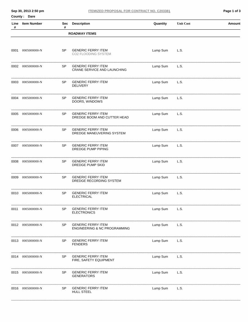
Line#
AmountQuantity Unit CostDescriptionSec#
Item Number
Page 1 of 3 ITEMIZED PROPOSAL FOR CONTRACT NO. C203381Sep 30, 2013 2:50 pm
County : Dare
ROADWAY ITEMS
--------------------------------------------------------------------------------------------------------------------------------------------------------------------------------------------------------------------------------------------------------------------
Lump Sum L.S.SP 0005000000-N GENERIC FERRY ITEMCO2 FLOODING SYSTEM
0001
--------------------------------------------------------------------------------------------------------------------------------------------------------------------------------------------------------------------------------------------------------------------
Lump Sum L.S.SP 0005000000-N GENERIC FERRY ITEMCRANE SERVICE AND LAUNCHING
0002
--------------------------------------------------------------------------------------------------------------------------------------------------------------------------------------------------------------------------------------------------------------------
Lump Sum L.S.SP 0005000000-N GENERIC FERRY ITEMDELIVERY
0003
--------------------------------------------------------------------------------------------------------------------------------------------------------------------------------------------------------------------------------------------------------------------
Lump Sum L.S.SP 0005000000-N GENERIC FERRY ITEMDOORS, WINDOWS
0004
--------------------------------------------------------------------------------------------------------------------------------------------------------------------------------------------------------------------------------------------------------------------
Lump Sum L.S.SP 0005000000-N GENERIC FERRY ITEMDREDGE BOOM AND CUTTER HEAD
0005
--------------------------------------------------------------------------------------------------------------------------------------------------------------------------------------------------------------------------------------------------------------------
Lump Sum L.S.SP 0005000000-N GENERIC FERRY ITEMDREDGE MANEUVERING SYSTEM
0006
--------------------------------------------------------------------------------------------------------------------------------------------------------------------------------------------------------------------------------------------------------------------
Lump Sum L.S.SP 0005000000-N GENERIC FERRY ITEMDREDGE PUMP PIPING
0007
--------------------------------------------------------------------------------------------------------------------------------------------------------------------------------------------------------------------------------------------------------------------
Lump Sum L.S.SP 0005000000-N GENERIC FERRY ITEMDREDGE PUMP SKID
0008
--------------------------------------------------------------------------------------------------------------------------------------------------------------------------------------------------------------------------------------------------------------------
Lump Sum L.S.SP 0005000000-N GENERIC FERRY ITEMDREDGE RECORDING SYSTEM
0009
--------------------------------------------------------------------------------------------------------------------------------------------------------------------------------------------------------------------------------------------------------------------
Lump Sum L.S.SP 0005000000-N GENERIC FERRY ITEMELECTRICAL
0010
--------------------------------------------------------------------------------------------------------------------------------------------------------------------------------------------------------------------------------------------------------------------
Lump Sum L.S.SP 0005000000-N GENERIC FERRY ITEMELECTRONICS
0011
--------------------------------------------------------------------------------------------------------------------------------------------------------------------------------------------------------------------------------------------------------------------
Lump Sum L.S.SP 0005000000-N GENERIC FERRY ITEMENGINEERING & NC PROGRAMMING
0012
--------------------------------------------------------------------------------------------------------------------------------------------------------------------------------------------------------------------------------------------------------------------
Lump Sum L.S.SP 0005000000-N GENERIC FERRY ITEMFENDERS
0013
--------------------------------------------------------------------------------------------------------------------------------------------------------------------------------------------------------------------------------------------------------------------
Lump Sum L.S.SP 0005000000-N GENERIC FERRY ITEMFIRE, SAFETY EQUIPMENT
0014
--------------------------------------------------------------------------------------------------------------------------------------------------------------------------------------------------------------------------------------------------------------------
Lump Sum L.S.SP 0005000000-N GENERIC FERRY ITEMGENERATORS
0015
--------------------------------------------------------------------------------------------------------------------------------------------------------------------------------------------------------------------------------------------------------------------
Lump Sum L.S.SP 0005000000-N GENERIC FERRY ITEMHULL STEEL
0016
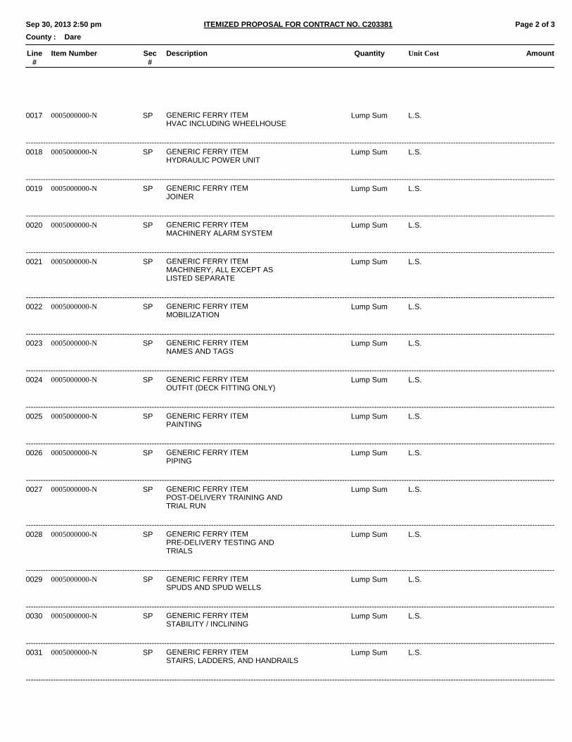
Line#
AmountQuantity Unit CostDescriptionSec#
Item Number
Page 2 of 3 ITEMIZED PROPOSAL FOR CONTRACT NO. C203381Sep 30, 2013 2:50 pm
County : Dare
--------------------------------------------------------------------------------------------------------------------------------------------------------------------------------------------------------------------------------------------------------------------
Lump Sum L.S.SP 0005000000-N GENERIC FERRY ITEMHVAC INCLUDING WHEELHOUSE
0017
--------------------------------------------------------------------------------------------------------------------------------------------------------------------------------------------------------------------------------------------------------------------
Lump Sum L.S.SP 0005000000-N GENERIC FERRY ITEMHYDRAULIC POWER UNIT
0018
--------------------------------------------------------------------------------------------------------------------------------------------------------------------------------------------------------------------------------------------------------------------
Lump Sum L.S.SP 0005000000-N GENERIC FERRY ITEMJOINER
0019
--------------------------------------------------------------------------------------------------------------------------------------------------------------------------------------------------------------------------------------------------------------------
Lump Sum L.S.SP 0005000000-N GENERIC FERRY ITEMMACHINERY ALARM SYSTEM
0020
--------------------------------------------------------------------------------------------------------------------------------------------------------------------------------------------------------------------------------------------------------------------
Lump Sum L.S.SP 0005000000-N GENERIC FERRY ITEMMACHINERY, ALL EXCEPT ASLISTED SEPARATE
0021
--------------------------------------------------------------------------------------------------------------------------------------------------------------------------------------------------------------------------------------------------------------------
Lump Sum L.S.SP 0005000000-N GENERIC FERRY ITEMMOBILIZATION
0022
--------------------------------------------------------------------------------------------------------------------------------------------------------------------------------------------------------------------------------------------------------------------
Lump Sum L.S.SP 0005000000-N GENERIC FERRY ITEMNAMES AND TAGS
0023
--------------------------------------------------------------------------------------------------------------------------------------------------------------------------------------------------------------------------------------------------------------------
Lump Sum L.S.SP 0005000000-N GENERIC FERRY ITEMOUTFIT (DECK FITTING ONLY)
0024
--------------------------------------------------------------------------------------------------------------------------------------------------------------------------------------------------------------------------------------------------------------------
Lump Sum L.S.SP 0005000000-N GENERIC FERRY ITEMPAINTING
0025
--------------------------------------------------------------------------------------------------------------------------------------------------------------------------------------------------------------------------------------------------------------------
Lump Sum L.S.SP 0005000000-N GENERIC FERRY ITEMPIPING
0026
--------------------------------------------------------------------------------------------------------------------------------------------------------------------------------------------------------------------------------------------------------------------
Lump Sum L.S.SP 0005000000-N GENERIC FERRY ITEMPOST-DELIVERY TRAINING ANDTRIAL RUN
0027
--------------------------------------------------------------------------------------------------------------------------------------------------------------------------------------------------------------------------------------------------------------------
Lump Sum L.S.SP 0005000000-N GENERIC FERRY ITEMPRE-DELIVERY TESTING ANDTRIALS
0028
--------------------------------------------------------------------------------------------------------------------------------------------------------------------------------------------------------------------------------------------------------------------
Lump Sum L.S.SP 0005000000-N GENERIC FERRY ITEMSPUDS AND SPUD WELLS
0029
--------------------------------------------------------------------------------------------------------------------------------------------------------------------------------------------------------------------------------------------------------------------
Lump Sum L.S.SP 0005000000-N GENERIC FERRY ITEMSTABILITY / INCLINING
0030
--------------------------------------------------------------------------------------------------------------------------------------------------------------------------------------------------------------------------------------------------------------------
Lump Sum L.S.SP 0005000000-N GENERIC FERRY ITEMSTAIRS, LADDERS, AND HANDRAILS
0031
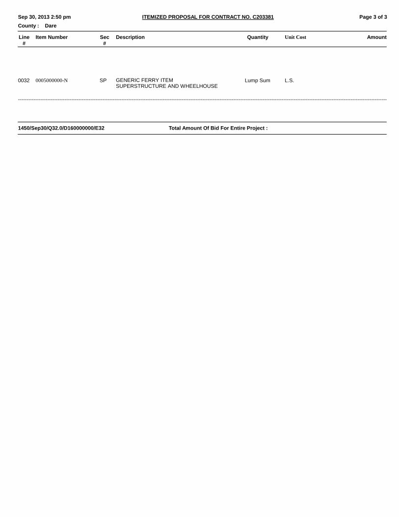
Line#
AmountQuantity Unit CostDescriptionSec#
Item Number
Page 3 of 3 ITEMIZED PROPOSAL FOR CONTRACT NO. C203381Sep 30, 2013 2:50 pm
County : Dare
--------------------------------------------------------------------------------------------------------------------------------------------------------------------------------------------------------------------------------------------------------------------
Lump Sum L.S.SP 0005000000-N GENERIC FERRY ITEMSUPERSTRUCTURE AND WHEELHOUSE
0032
Total Amount Of Bid For Entire Project :1450/Sep30/Q32.0/D160000000/E32
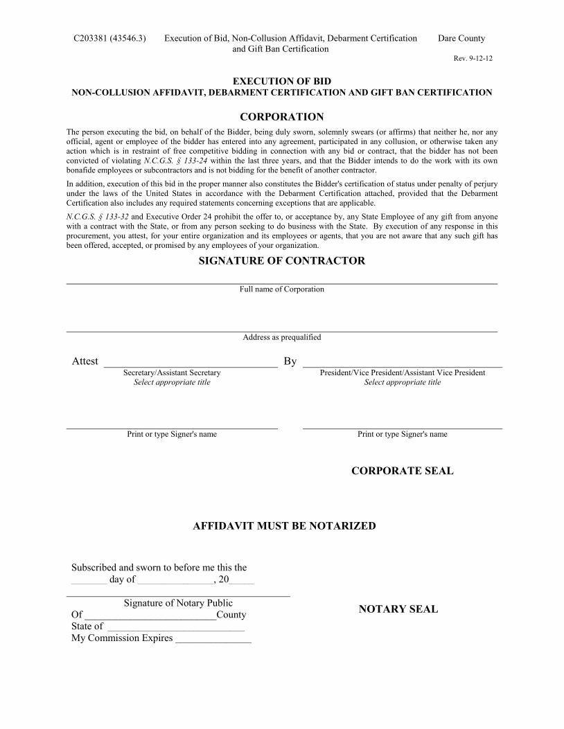
C203381 (43546.3) Execution of Bid, Non-Collusion Affidavit, Debarment Certification Dare County and Gift Ban Certification
Rev. 9-12-12
EXECUTION OF BID
NON-COLLUSION AFFIDAVIT, DEBARMENT CERTIFICATION AND GIFT BAN CERTIFICATION
CORPORATION
The person executing the bid, on behalf of the Bidder, being duly sworn, solemnly swears (or affirms) that neither he, nor any official, agent or employee of the bidder has entered into any agreement, participated in any collusion, or otherwise taken any action which is in restraint of free competitive bidding in connection with any bid or contract, that the bidder has not been convicted of violating N.C.G.S. § 133-24 within the last three years, and that the Bidder intends to do the work with its own bonafide employees or subcontractors and is not bidding for the benefit of another contractor.
In addition, execution of this bid in the proper manner also constitutes the Bidder's certification of status under penalty of perjury under the laws of the United States in accordance with the Debarment Certification attached, provided that the Debarment Certification also includes any required statements concerning exceptions that are applicable.
N.C.G.S. § 133-32 and Executive Order 24 prohibit the offer to, or acceptance by, any State Employee of any gift from anyone with a contract with the State, or from any person seeking to do business with the State. By execution of any response in this procurement, you attest, for your entire organization and its employees or agents, that you are not aware that any such gift has been offered, accepted, or promised by any employees of your organization.
SIGNATURE OF CONTRACTOR
Full name of Corporation
Address as prequalified
Attest By Secretary/Assistant Secretary President/Vice President/Assistant Vice President
Select appropriate title Select appropriate title
Print or type Signer's name Print or type Signer's name
CORPORATE SEAL
AFFIDAVIT MUST BE NOTARIZED
Subscribed and sworn to before me this the
_______ day of _______________, 20_____
Signature of Notary Public Of __________________________County State of ___________________________ My Commission Expires _______________
NOTARY SEAL
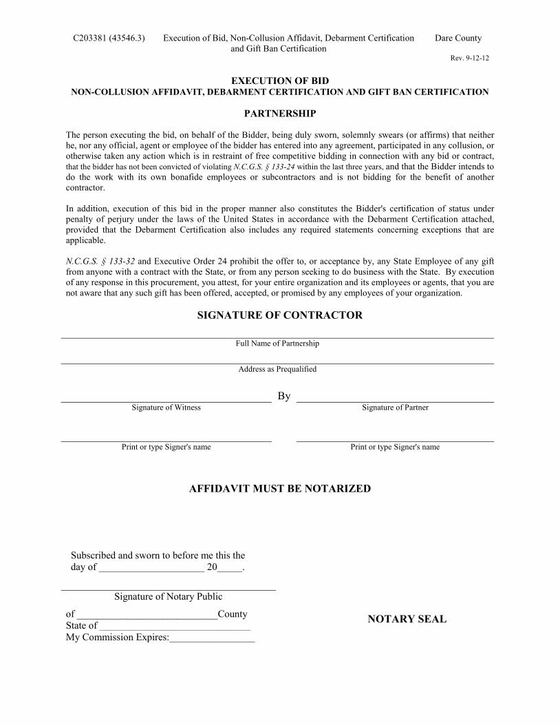
C203381 (43546.3) Execution of Bid, Non-Collusion Affidavit, Debarment Certification Dare County and Gift Ban Certification
Rev. 9-12-12
EXECUTION OF BID
NON-COLLUSION AFFIDAVIT, DEBARMENT CERTIFICATION AND GIFT BAN CERTIFICATION
PARTNERSHIP
The person executing the bid, on behalf of the Bidder, being duly sworn, solemnly swears (or affirms) that neither he, nor any official, agent or employee of the bidder has entered into any agreement, participated in any collusion, or otherwise taken any action which is in restraint of free competitive bidding in connection with any bid or contract, that the bidder has not been convicted of violating N.C.G.S. § 133-24 within the last three years, and that the Bidder intends to do the work with its own bonafide employees or subcontractors and is not bidding for the benefit of another contractor. In addition, execution of this bid in the proper manner also constitutes the Bidder's certification of status under penalty of perjury under the laws of the United States in accordance with the Debarment Certification attached, provided that the Debarment Certification also includes any required statements concerning exceptions that are applicable.
N.C.G.S. § 133-32 and Executive Order 24 prohibit the offer to, or acceptance by, any State Employee of any gift from anyone with a contract with the State, or from any person seeking to do business with the State. By execution of any response in this procurement, you attest, for your entire organization and its employees or agents, that you are not aware that any such gift has been offered, accepted, or promised by any employees of your organization.
SIGNATURE OF CONTRACTOR
Full Name of Partnership
Address as Prequalified
By
Signature of Witness Signature of Partner
Print or type Signer's name Print or type Signer's name
AFFIDAVIT MUST BE NOTARIZED
Subscribed and sworn to before me this the day of _____________________ 20_____.
Signature of Notary Public
of ____________________________County State of ______________________________ My Commission Expires:_________________
NOTARY SEAL
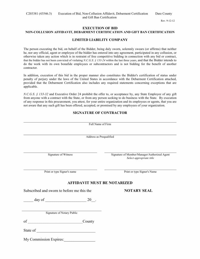
C203381 (43546.3) Execution of Bid, Non-Collusion Affidavit, Debarment Certification Dare County and Gift Ban Certification
Rev. 9-12-12
EXECUTION OF BID
NON-COLLUSION AFFIDAVIT, DEBARMENT CERTIFICATION AND GIFT BAN CERTIFICATION
LIMITED LIABILITY COMPANY
The person executing the bid, on behalf of the Bidder, being duly sworn, solemnly swears (or affirms) that neither he, nor any official, agent or employee of the bidder has entered into any agreement, participated in any collusion, or otherwise taken any action which is in restraint of free competitive bidding in connection with any bid or contract, that the bidder has not been convicted of violating N.C.G.S. § 133-24 within the last three years, and that the Bidder intends to do the work with its own bonafide employees or subcontractors and is not bidding for the benefit of another contractor. In addition, execution of this bid in the proper manner also constitutes the Bidder's certification of status under penalty of perjury under the laws of the United States in accordance with the Debarment Certification attached, provided that the Debarment Certification also includes any required statements concerning exceptions that are applicable.
N.C.G.S. § 133-32 and Executive Order 24 prohibit the offer to, or acceptance by, any State Employee of any gift from anyone with a contract with the State, or from any person seeking to do business with the State. By execution of any response in this procurement, you attest, for your entire organization and its employees or agents, that you are not aware that any such gift has been offered, accepted, or promised by any employees of your organization.
SIGNATURE OF CONTRACTOR
Full Name of Firm
Address as Prequalified
Signature of Witness Signature of Member/Manager/Authorized Agent
Select appropriate title
Print or type Signer's name Print or type Signer's Name
AFFIDAVIT MUST BE NOTARIZED Subscribed and sworn to before me this the _____ day of _____________________ 20__.
Signature of Notary Public of ____________________________County State of ______________________________ My Commission Expires:________________
NOTARY SEAL
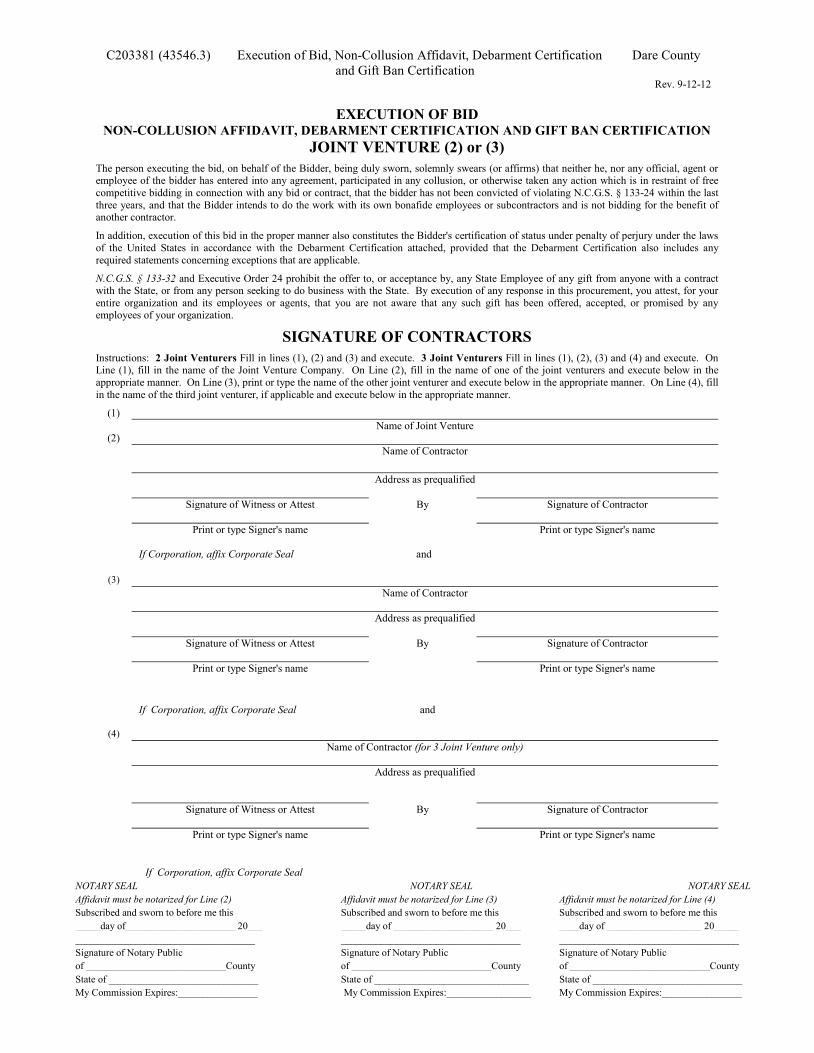
C203381 (43546.3) Execution of Bid, Non-Collusion Affidavit, Debarment Certification Dare County and Gift Ban Certification
Rev. 9-12-12
EXECUTION OF BID
NON-COLLUSION AFFIDAVIT, DEBARMENT CERTIFICATION AND GIFT BAN CERTIFICATION JOINT VENTURE (2) or (3)
The person executing the bid, on behalf of the Bidder, being duly sworn, solemnly swears (or affirms) that neither he, nor any official, agent or employee of the bidder has entered into any agreement, participated in any collusion, or otherwise taken any action which is in restraint of free competitive bidding in connection with any bid or contract, that the bidder has not been convicted of violating N.C.G.S. § 133-24 within the last three years, and that the Bidder intends to do the work with its own bonafide employees or subcontractors and is not bidding for the benefit of another contractor.
In addition, execution of this bid in the proper manner also constitutes the Bidder's certification of status under penalty of perjury under the laws of the United States in accordance with the Debarment Certification attached, provided that the Debarment Certification also includes any required statements concerning exceptions that are applicable.
N.C.G.S. § 133-32 and Executive Order 24 prohibit the offer to, or acceptance by, any State Employee of any gift from anyone with a contract with the State, or from any person seeking to do business with the State. By execution of any response in this procurement, you attest, for your entire organization and its employees or agents, that you are not aware that any such gift has been offered, accepted, or promised by any employees of your organization.
SIGNATURE OF CONTRACTORS
Instructions: 2 Joint Venturers Fill in lines (1), (2) and (3) and execute. 3 Joint Venturers Fill in lines (1), (2), (3) and (4) and execute. On Line (1), fill in the name of the Joint Venture Company. On Line (2), fill in the name of one of the joint venturers and execute below in the appropriate manner. On Line (3), print or type the name of the other joint venturer and execute below in the appropriate manner. On Line (4), fill in the name of the third joint venturer, if applicable and execute below in the appropriate manner.
(1) Name of Joint Venture
(2) Name of Contractor Address as prequalified Signature of Witness or Attest By Signature of Contractor Print or type Signer's name Print or type Signer's name If Corporation, affix Corporate Seal and
(3) Name of Contractor Address as prequalified Signature of Witness or Attest By Signature of Contractor Print or type Signer's name Print or type Signer's name If Corporation, affix Corporate Seal and
(4) Name of Contractor (for 3 Joint Venture only) Address as prequalified Signature of Witness or Attest By Signature of Contractor Print or type Signer's name Print or type Signer's name
If Corporation, affix Corporate Seal NOTARY SEAL NOTARY SEAL NOTARY SEAL Affidavit must be notarized for Line (2) Affidavit must be notarized for Line (3) Affidavit must be notarized for Line (4) Subscribed and sworn to before me this Subscribed and sworn to before me this Subscribed and sworn to before me this _____day of______________________ 20___ _____day of ____________________ 20___ ____day of ___________________ 20_____ ____________________________________ ____________________________________ ____________________________________ Signature of Notary Public Signature of Notary Public Signature of Notary Public of ____________________________County of ____________________________County of ____________________________County State of ______________________________ State of _______________________________ State of ______________________________ My Commission Expires:________________ My Commission Expires:_________________ My Commission Expires:________________
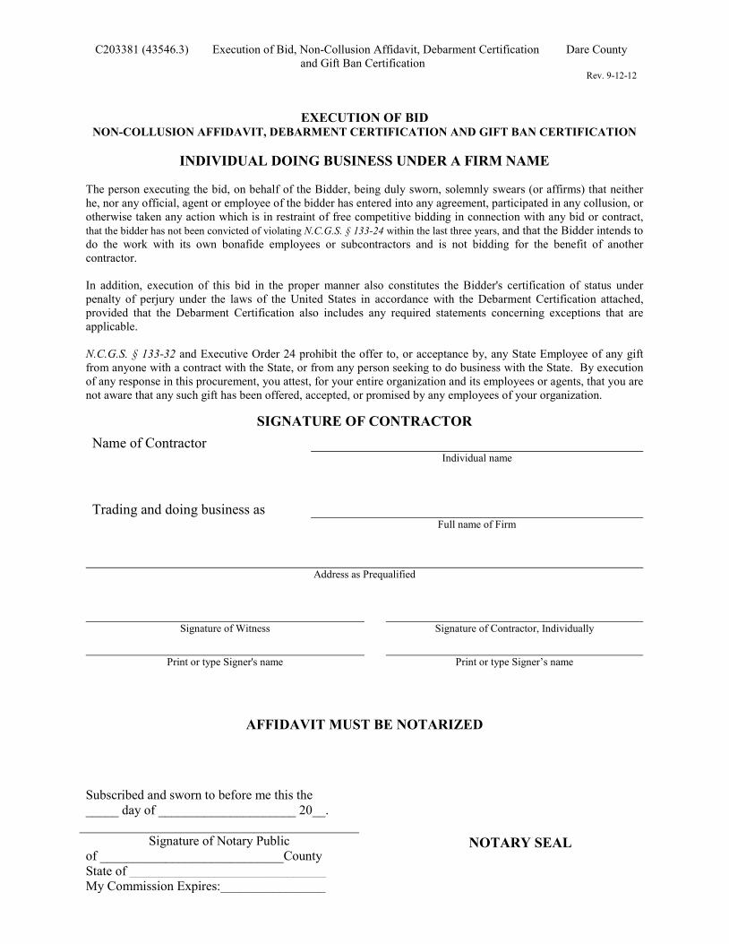
C203381 (43546.3) Execution of Bid, Non-Collusion Affidavit, Debarment Certification Dare County and Gift Ban Certification
Rev. 9-12-12
EXECUTION OF BID NON-COLLUSION AFFIDAVIT, DEBARMENT CERTIFICATION AND GIFT BAN CERTIFICATION
INDIVIDUAL DOING BUSINESS UNDER A FIRM NAME
The person executing the bid, on behalf of the Bidder, being duly sworn, solemnly swears (or affirms) that neither he, nor any official, agent or employee of the bidder has entered into any agreement, participated in any collusion, or otherwise taken any action which is in restraint of free competitive bidding in connection with any bid or contract, that the bidder has not been convicted of violating N.C.G.S. § 133-24 within the last three years, and that the Bidder intends to do the work with its own bonafide employees or subcontractors and is not bidding for the benefit of another contractor. In addition, execution of this bid in the proper manner also constitutes the Bidder's certification of status under penalty of perjury under the laws of the United States in accordance with the Debarment Certification attached, provided that the Debarment Certification also includes any required statements concerning exceptions that are applicable.
N.C.G.S. § 133-32 and Executive Order 24 prohibit the offer to, or acceptance by, any State Employee of any gift from anyone with a contract with the State, or from any person seeking to do business with the State. By execution of any response in this procurement, you attest, for your entire organization and its employees or agents, that you are not aware that any such gift has been offered, accepted, or promised by any employees of your organization.
SIGNATURE OF CONTRACTOR
Name of Contractor Individual name
Trading and doing business as
Full name of Firm
Address as Prequalified
Signature of Witness Signature of Contractor, Individually
Print or type Signer's name Print or type Signer’s name
AFFIDAVIT MUST BE NOTARIZED
Subscribed and sworn to before me this the _____ day of _____________________ 20__.
Signature of Notary Public of ____________________________County State of ______________________________ My Commission Expires:________________
NOTARY SEAL
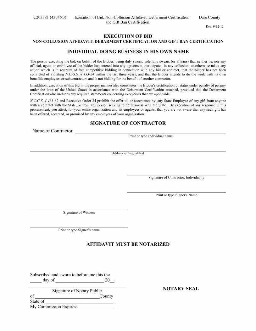
C203381 (43546.3) Execution of Bid, Non-Collusion Affidavit, Debarment Certification Dare County and Gift Ban Certification
Rev. 9-12-12
EXECUTION OF BID
NON-COLLUSION AFFIDAVIT, DEBARMENT CERTIFICATION AND GIFT BAN CERTIFICATION
INDIVIDUAL DOING BUSINESS IN HIS OWN NAME
The person executing the bid, on behalf of the Bidder, being duly sworn, solemnly swears (or affirms) that neither he, nor any official, agent or employee of the bidder has entered into any agreement, participated in any collusion, or otherwise taken any action which is in restraint of free competitive bidding in connection with any bid or contract, that the bidder has not been convicted of violating N.C.G.S. § 133-24 within the last three years, and that the Bidder intends to do the work with its own bonafide employees or subcontractors and is not bidding for the benefit of another contractor.
In addition, execution of this bid in the proper manner also constitutes the Bidder's certification of status under penalty of perjury under the laws of the United States in accordance with the Debarment Certification attached, provided that the Debarment Certification also includes any required statements concerning exceptions that are applicable.
N.C.G.S. § 133-32 and Executive Order 24 prohibit the offer to, or acceptance by, any State Employee of any gift from anyone with a contract with the State, or from any person seeking to do business with the State. By execution of any response in this procurement, you attest, for your entire organization and its employees or agents, that you are not aware that any such gift has been offered, accepted, or promised by any employees of your organization.
SIGNATURE OF CONTRACTOR
Name of Contractor Print or type Individual name
Address as Prequalified
Signature of Contractor, Individually
Print or type Signer's Name
Signature of Witness
Print or type Signer’s name
AFFIDAVIT MUST BE NOTARIZED
Subscribed and sworn to before me this the _____ day of _____________________ 20__.
Signature of Notary Public of ____________________________County State of ______________________________ My Commission Expires:________________
NOTARY SEAL
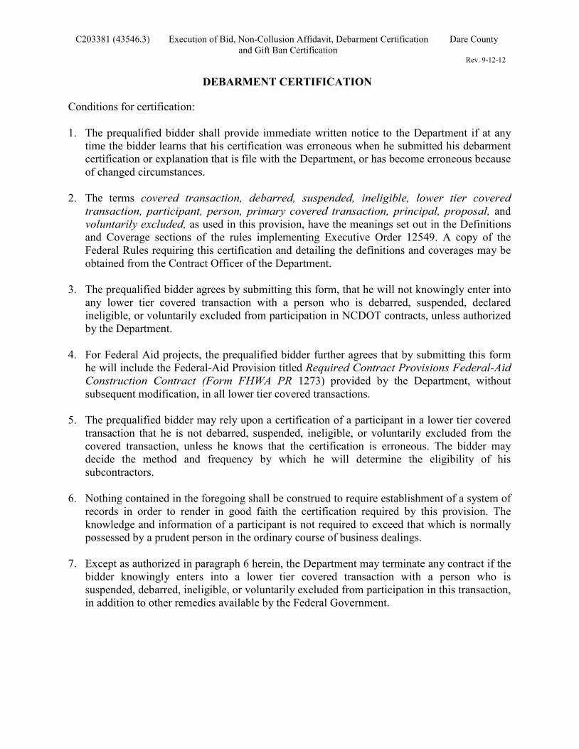
C203381 (43546.3) Execution of Bid, Non-Collusion Affidavit, Debarment Certification Dare County and Gift Ban Certification
Rev. 9-12-12
DEBARMENT CERTIFICATION
Conditions for certification: 1. The prequalified bidder shall provide immediate written notice to the Department if at any
time the bidder learns that his certification was erroneous when he submitted his debarment certification or explanation that is file with the Department, or has become erroneous because of changed circumstances.
2. The terms covered transaction, debarred, suspended, ineligible, lower tier covered
transaction, participant, person, primary covered transaction, principal, proposal, and voluntarily excluded, as used in this provision, have the meanings set out in the Definitions and Coverage sections of the rules implementing Executive Order 12549. A copy of the Federal Rules requiring this certification and detailing the definitions and coverages may be obtained from the Contract Officer of the Department.
3. The prequalified bidder agrees by submitting this form, that he will not knowingly enter into
any lower tier covered transaction with a person who is debarred, suspended, declared ineligible, or voluntarily excluded from participation in NCDOT contracts, unless authorized by the Department.
4. For Federal Aid projects, the prequalified bidder further agrees that by submitting this form
he will include the Federal-Aid Provision titled Required Contract Provisions Federal-Aid Construction Contract (Form FHWA PR 1273) provided by the Department, without subsequent modification, in all lower tier covered transactions.
5. The prequalified bidder may rely upon a certification of a participant in a lower tier covered
transaction that he is not debarred, suspended, ineligible, or voluntarily excluded from the covered transaction, unless he knows that the certification is erroneous. The bidder may decide the method and frequency by which he will determine the eligibility of his subcontractors.
6. Nothing contained in the foregoing shall be construed to require establishment of a system of
records in order to render in good faith the certification required by this provision. The knowledge and information of a participant is not required to exceed that which is normally possessed by a prudent person in the ordinary course of business dealings.
7. Except as authorized in paragraph 6 herein, the Department may terminate any contract if the
bidder knowingly enters into a lower tier covered transaction with a person who is suspended, debarred, ineligible, or voluntarily excluded from participation in this transaction, in addition to other remedies available by the Federal Government.
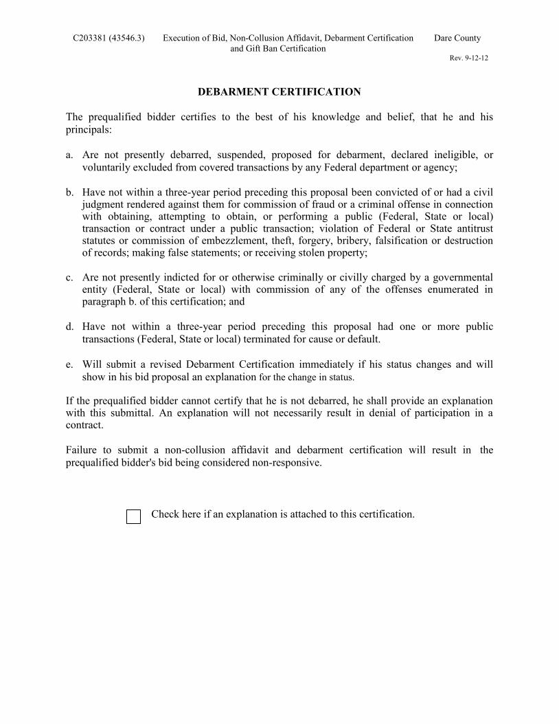
C203381 (43546.3) Execution of Bid, Non-Collusion Affidavit, Debarment Certification Dare County and Gift Ban Certification
Rev. 9-12-12
DEBARMENT CERTIFICATION The prequalified bidder certifies to the best of his knowledge and belief, that he and his principals: a. Are not presently debarred, suspended, proposed for debarment, declared ineligible, or
voluntarily excluded from covered transactions by any Federal department or agency; b. Have not within a three-year period preceding this proposal been convicted of or had a civil
judgment rendered against them for commission of fraud or a criminal offense in connection with obtaining, attempting to obtain, or performing a public (Federal, State or local) transaction or contract under a public transaction; violation of Federal or State antitrust statutes or commission of embezzlement, theft, forgery, bribery, falsification or destruction of records; making false statements; or receiving stolen property;
c. Are not presently indicted for or otherwise criminally or civilly charged by a governmental
entity (Federal, State or local) with commission of any of the offenses enumerated in paragraph b. of this certification; and
d. Have not within a three-year period preceding this proposal had one or more public
transactions (Federal, State or local) terminated for cause or default. e. Will submit a revised Debarment Certification immediately if his status changes and will
show in his bid proposal an explanation for the change in status. If the prequalified bidder cannot certify that he is not debarred, he shall provide an explanation with this submittal. An explanation will not necessarily result in denial of participation in a contract. Failure to submit a non-collusion affidavit and debarment certification will result in the prequalified bidder's bid being considered non-responsive.
Check here if an explanation is attached to this certification.
1-18-08 Z-13
Contract No C203381
County (ies): Dare County
ACCEPTED BY THE DEPARTMENT OF TRANSPORTATION
Contract Officer
Date Execution of Contract and Bonds Approved as to Form:
Attorney General Signature Sheet (Bid - Acceptance by Department)