bored pile foundation design at project of
TRANSCRIPT

i
BORED PILE FOUNDATION DESIGN AT PROJECT OF
APARTEMEN TAMAN MELATI YOGYAKARTA
Final Project
to complete the requirements of
achieve Bachelor Degree of Civil Engineering
Submitted by:
Sholichatun Nisa
D 100 164 008
CIVIL ENGINEERING DEPARTMENT
ENGINEERING FACULTY
UNIVERSITAS MUHAMMADIYAH SURAKARTA
2020
ii
VALIDATION SHEET
BORED PILE FOUNDATION DESIGN AT PROJECT OF
APARTEMEN TAMAN MELATI YOGYAKARTA
Final Project
Submitted and defended on the Awareness Test
Final Project before the Board of Examiners
At the date of :...........................
Submitted by:
Sholichatun Nisa
ID: D 100 164 008
Composition of the Board of Examiners:
Supervisor Lecturer:
Anto Budi Listyawan, S.T., M.Sc.
NIDN. 0622036101
1st Examiner
Agus Susanto, S.T., M.T.
NIDN. 0611087101
2nd Examiner
Ir. Renaningsih, M.T.
NIDN. 0624096301
This Final Project is accepted as one of the requirements
To achieve Bachelor's degree in Civil Engineering
Surakarta,.........................
Dean of Engineering Faculty
Ir. Sri Sunarjono,M.T., Ph.D., IPM.
NIDN. 0630126302
Head of Civil Engineering Dept.
Mochamad Solikin, Ph.D.
NIDN. 0617127201
iii
STATEMENT OF FINAL PROJECT AUTHENTICITY
Bismillahirrahmanirrohim,
The Undersigned below:
Name : Sholichatun Nisa
Student ID : D 100 164 008
Faculty / Department : Engineering / Engineering Faculty
Type : Final Project
Tittle : Bored Pile Foundation Design at Project of Apartemen
Taman Melati Yogyakarta
Stating exactly that the final project I made and submitted is my own
work, except for the equotation and summaries, that I have explained the
source of. If in the future and / or can be proven that this thesis is the result
of plagiarism, then I am willing to accept any sanctions from the Civil
Engineering Department, Faculty of Engineering and/or the degrees and
diplomas granted by Universitas Muhammadiyah Surakarta, I will cancel my
receipt.
Thus I make this statement properly and hopefully can be used as it
should.
Surakarta, October 2020
Who make a statement,
Sholichatun Nisa
D 100 164 008
iv
MOTTO AND OFFERING PAGE
“Indeed with every difficulty there is a relief”
(Al-Insyirah 5)
"Take care of five things before (come) the five (other) things. Your youth
before your old age, your health before your illness, your wealth before your
poverty, your free time before your busyness and your life before your death. "
(HR. Nasai and Baihaqi)
Live to competition. Offer the best. Meaningful to the world. And meaningful
for the afterlife. That’s thanksgiving.
(Author)
Dedicated to:
My priceless treasure, dearest Mom and Dad who always supporting me in every
condition, giving all the prayers, sacrifices, and struggles for my success
Dearest big sisters, who always encouraged me to complete my studies, giving
the moral and material support
My supervisor lecturer, someone who is never tired giving criticism and
suggestion, so I can accomplish this project well
A place for me to gain knowledge, my beloved Civil Engineering Department of
Universitas Muhammadiyah Surakarta
And,
An offerings to my beloved nation and country, Indonesia
v
PREFACE
هتاگربوهللاةمحرومکيلعمالسلا
Alhamdulillah, all praise and gratitude to Allah SWT, with His blessing
final project entitled "Bored Pile Foundation Design at Project of Apartemen
Taman Melati Yogyakarta" can be resolved properly. So that the author can fulfil
the requirement to achieve Bachelor Degree of civil Engineering. In its
completion,of course the author does not do it by herself. Grateful
acknowledgment given to those who have supported the writer in completing her
task. With the completion of this final project, the author would like to thank:
1. Allah SWT who has given the greatest gift of health and time, direction and
guidance, and an opportunity to realize one of the author's big dreams
2. Mr. Sri Sunarjono., Ph.D. as Dean of the Engineering Faculty and Mr.
Mochamad Solikin, as Chair of the Civil Engineering Department of
Universitas Muhammadiyah Surakarta and his staff, which has provided
facilities for author to be able to complete the research.
3. Mr. Anto Budi Listyawan., S.T., M.Sc. as supervisor lecturer who was
willing to share knowledge and provide guidance to the author patiently,
assist and provide feedback to the author in preparing the final report
4. Mrs. Ir. Renaningsih M.T. as an academic supervisor who always provides
valuable guidance and advice to the author during the study period in Civil
Engineering Department Universitas Muhammadiyah Surakarta
5. Mr. Agus Susanto S.T., M.T., and Mrs. Ir. Renaningsih M.T. as examiners
who contributed many constructive criticisms and suggestions
6. Mr/Mrs. Lecturer of Civil Engineering Study Program Universitas
Muhammadiyah Surakarta who has provided useful knowledge to the author
7. All employees of the Civil Engineering Study Program, University of
Muhammadiyah Surakarta who have served and assisted the authors during
the study and until the completion of this Final Project

vi
8. Author’s bestfriend, who are always willing to hear the author's cries and
complaints and provide support in completing this final project
9. Co-author in the research process, thank you for your contribution
10. My big family who has give the support for me to complete the final project
11. All parties that cannot be mentioned one by one, who have provided a lot of
help and support to me. And all the people who have come and go in my life.
Thank you very much.
There is no vory that is not cracked, same with the completion of this final
project, the author believe that this report is far from perfection. Therefore, the
author expect criticism and constructive suggestions to enhance this report. Lastly,
the author hopes that this Final Project can be useful for author herself and for all
readers.
هتاکربوهللاةمحرومكياعمالسلاو
Surakarta, 16th October 2020
Author
Sholichatun Nisa
vii
TABLE OF CONTENT
COVER ........................................................................................................ i
VALIDATION SHEET .............................................................................. ii
STATEMENT OF FINAL PROJECT AUTHENTICITY ...................... iii
MOTTO AND OFFERING PAGE ........................................................... iv
PREFACE .................................................................................................... v
TABLE OF CONTENT ............................................................................... vii
LIST OF FIGURE ...................................................................................... x
LIST OF TABLE ......................................................................................... xii
LIST OF ATTACHMENT .......................................................................... xiii
LIST OF NOTATION ................................................................................ xiv
ABSTRACT .................................................................................................. xvi
ABSTRAK .................................................................................................... xvii
I. INTRODUCTION
A. Background ................................................................................ 1
B. Problem Formulation ................................................................. 2
C. Research Objective ................................................................... 2
D. Research Benefit......................................................................... 3
E. Limitation Problem .................................................................... 3
F. Research Authenticity................................................................ 4
II. LITERATURE REVIEW
A. Similar Research Review........................................................... 6
III. BASIC THEORY
A. Soil ........................................................................................... 14
B. Soil Investigation ...................................................................... 14
C. Foundation ............................................................................... 16
1. Definition of Foundation ..................................................... 16
viii
2. Types of Foundation ............................................................ 16
3. Bored Pile Foundation ......................................................... 19
D. Load .......................................................................................... 21
1. Dead Load ........................................................................... 21
2. Live Load ............................................................................ 21
3. Earthquake Load................................................................... 22
4. Factor Combination Load .................................................... 22
E. Bearing Capacity of Bored Pile on Granular Soil ................... 22
F. Bearing Capacity of Pile Groups .............................................. 26
G. Number of Piles Needed........................................................... 27
H. Pile Group Efficiency .............................................................. 27
I. Distance Between Piles in Groups ........................................... 28
J. Maximum Load on Pile Group ................................................. 29
K. Pile Cap Planning .................................................................... 30
1. Reinforcement of Pile Cap ................................................... 30
2. Review of the Shear ............................................................. 33
L. Reinforcement of Bored Pile Foundation ................................. 35
M. Stirrup Reinforcement Design .................................................. 35
IV. RESEARCH METHOD
A. General Review ........................................................................ 37
B. Research Data ........................................................................... 37
C. Research Location .................................................................... 37
D. Research Equipment ................................................................. 38
E. Research Method ...................................................................... 39
V. ANALYSIS AND DISCUSSION
A. Load Analysis ........................................................................... 42
1. General Data ........................................................................ 42
2. Dead Load Analysis ............................................................. 45
3. Live Load Analysis .............................................................. 46
ix
4. Earthquake Load Analysis ................................................... 46
5. Combination Load ............................................................... 50
6. Input and Output Program SAP 2000 .................................. 50
B. Bearing Capacity Analysis ...................................................... 52
1. Calculation of Bearing Capacity based N-SPT Data ........... 52
2. Number of Piles Needed ...................................................... 60
3. Pile Group Efficiency .......................................................... 60
4. Bearing Capacity of Piles Group ......................................... 62
5. Maximum Load on Piles Group .......................................... 63
C. Pile Cap Design ........................................................................ 66
1. Review of Shear................................................................... 66
2. Reinforcement of Pile Cap .................................................. 72
D. Bored Pile Design ..................................................................... 88
1. Calculation of Main Reinforcement .................................... 88
2. Calculation of Stirrup Reinforcement .................................. 94
VI. CONCLUSION AND RECOMMENDATION
A. Conclusion ................................................................................ 100
B. Recommendation ...................................................................... 101
REFERENCE
ATTACHMENT
x
LIST OF FIGURE
Figure III.1 Penetration with SPT ............................................................. 15
Figure III.2 Schematic Standard Penetration Test Sequence .................... 16
Figure III.3 Foot Foundation ..................................................................... 17
Figure III.4 Elongated Foundation ............................................................ 17
Figure III.5 Raft Foundation ...................................................................... 18
Figure III.6 Pier Foundation ...................................................................... 18
Figure III.7 Pile Foundation ...................................................................... 19
Figure III.8 Types of Bored Pile Foundation ............................................ 19
Figure III.9 Piles Group ............................................................................. 27
Figure III.10 Distance From Center to Pile Center ..................................... 28
Figure III.11 Load Acting on the Pile Cap .................................................. 30
Figure III.12 One-Way Shear Stress............................................................ 33
Figure III.13 Two-way Shear Stress ............................................................ 34
Figure IV.1 Location Project of Taman Melati Yogyakarta Apartment .... 38
Figure IV.2 Flow Chart of Research .......................................................... 41
Figure V.1 Response Spectrum Diagram Result from Application ......... 48
Figure V.2 Modeling 3D Structure use SAP 2000 Program .................... 51
Figure V.3 Column Frame 161 ................................................................. 51
Figure V.4 Location of the Maximum Axial Load on the 1st Floor ......... 52
Figure V.5 Pile Cap used Diameter 0,4 m ................................................ 62
Figure V.6 Pile Cap used Diameter 0,7 m ................................................ 63
Figure V.7 Load that Work used Diameter 0,4 m .................................... 64
Figure V.8 Load that Work used Diameter 0,7 m .................................... 65
Figure V.9 One-way Shear Stress for Diameter 0,4 m ............................ 67
Figure V.10 Two-way Shear Stress for Diameter 0,4 m ............................ 68
Figure V.11 One-way Shear Stress for Diameter 0,7 m ............................. 70
Figure V.12 Two-way Shear Stress for Diameter 0,7 m ............................ 71
Figure V.13 Detail Reinforcement for Pile Cap 2,20 x 2,20 m ................. 80
Figure V.14 Cross Section I-I for Pile Cap 2,20 x 2,20 m ......................... 80
xi
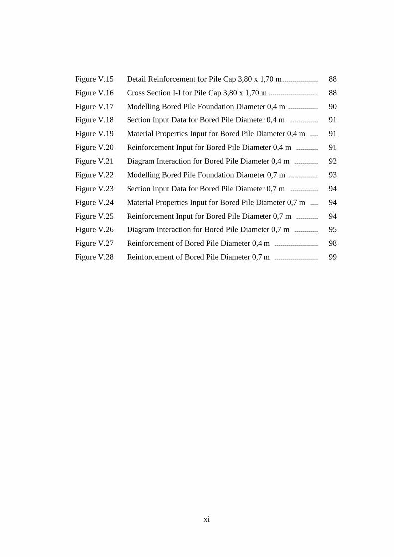
Figure V.15 Detail Reinforcement for Pile Cap 3,80 x 1,70 m .................. 88
Figure V.16 Cross Section I-I for Pile Cap 3,80 x 1,70 m ......................... 88
Figure V.17 Modelling Bored Pile Foundation Diameter 0,4 m ............... 90
Figure V.18 Section Input Data for Bored Pile Diameter 0,4 m .............. 91
Figure V.19 Material Properties Input for Bored Pile Diameter 0,4 m .... 91
Figure V.20 Reinforcement Input for Bored Pile Diameter 0,4 m ........... 91
Figure V.21 Diagram Interaction for Bored Pile Diameter 0,4 m ............ 92
Figure V.22 Modelling Bored Pile Foundation Diameter 0,7 m ............... 93
Figure V.23 Section Input Data for Bored Pile Diameter 0,7 m .............. 94
Figure V.24 Material Properties Input for Bored Pile Diameter 0,7 m .... 94
Figure V.25 Reinforcement Input for Bored Pile Diameter 0,7 m ........... 94
Figure V.26 Diagram Interaction for Bored Pile Diameter 0,7 m ............ 95
Figure V.27 Reinforcement of Bored Pile Diameter 0,4 m ...................... 98
Figure V.28 Reinforcement of Bored Pile Diameter 0,7 m ...................... 99
xii
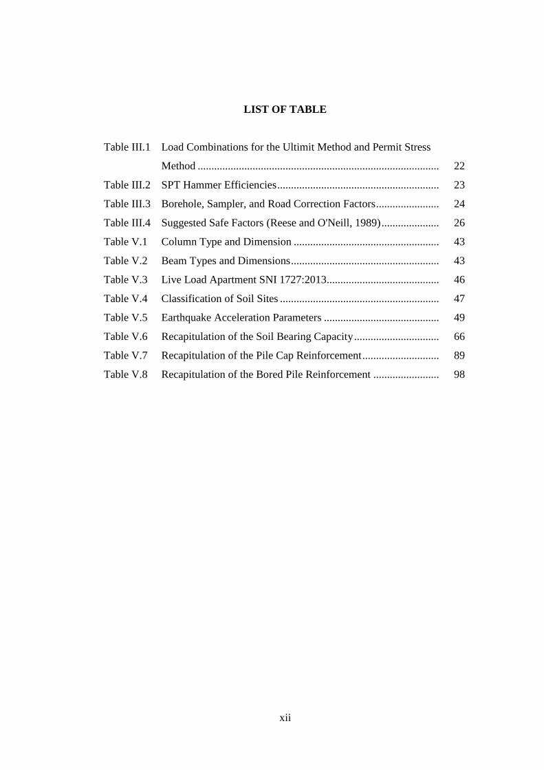
LIST OF TABLE
Table III.1 Load Combinations for the Ultimit Method and Permit Stress
Method ........................................................................................ 22
Table III.2 SPT Hammer Efficiencies ........................................................... 23
Table III.3 Borehole, Sampler, and Road Correction Factors ....................... 24
Table III.4 Suggested Safe Factors (Reese and O'Neill, 1989) ..................... 26
Table V.1 Column Type and Dimension ..................................................... 43
Table V.2 Beam Types and Dimensions ...................................................... 43
Table V.3 Live Load Apartment SNI 1727:2013......................................... 46
Table V.4 Classification of Soil Sites .......................................................... 47
Table V.5 Earthquake Acceleration Parameters .......................................... 49
Table V.6 Recapitulation of the Soil Bearing Capacity ............................... 66
Table V.7 Recapitulation of the Pile Cap Reinforcement ............................ 89
Table V.8 Recapitulation of the Bored Pile Reinforcement ........................ 98
xiii
LIST OF ATTACHMENT
Attachment A. Structure Data ......................................................................... L-1
Attachment B. Soil Investigation Data ........................................................... L-7
xiv
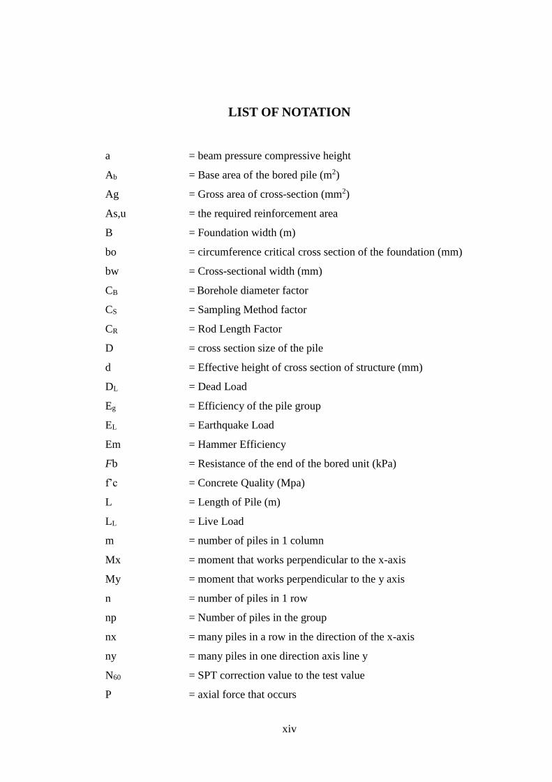
LIST OF NOTATION
a = beam pressure compressive height
Ab = Base area of the bored pile (m2)
Ag = Gross area of cross-section (mm2)
As,u = the required reinforcement area
B = Foundation width (m)
bo = circumference critical cross section of the foundation (mm)
bw = Cross-sectional width (mm)
CB = Borehole diameter factor
CS = Sampling Method factor
CR = Rod Length Factor
D = cross section size of the pile
d = Effective height of cross section of structure (mm)
DL = Dead Load
Eg = Efficiency of the pile group
EL = Earthquake Load
Em = Hammer Efficiency
Fb = Resistance of the end of the bored unit (kPa)
f’c = Concrete Quality (Mpa)
L = Length of Pile (m)
LL = Live Load
m = number of piles in 1 column
Mx = moment that works perpendicular to the x-axis
My = moment that works perpendicular to the y axis
n = number of piles in 1 row
np = Number of piles in the group
nx = many piles in a row in the direction of the x-axis
ny = many piles in one direction axis line y
N60 = SPT correction value to the test value
P = axial force that occurs
xv
Pmax = maximum pile load
Pmin = minimum pile load
Qa = Permit bearing capacity of pile (kN)
Qb = Ultimate end resistance (kN)
Qg = Bearing capacity of the pile group (kN)
Qs = Ultimate friction resistance (kN)
Qu = Ultimate bearing capacity of pile (kN)
s = distance between piles (axles to axles)
s = Spacing of reinforcement
SF = Safety Factor
U = Upward lift force (kN)
Vc = Nominal Shear Force held by concrete
Vs = Nominal Shear Force held by Stirrup (N)
Vu = Nominal Shear Force
WL = Wind Load
Wp = Weight of Pile (kN)
X Max = the distance of the pile toward the farthest x axis
Y Max = the distance from the pile to the furthest y axis
∑X2 = number of squares X
∑Y2 = number of squares Y
Ө = arc tg (D/s) (degree)
β = L / B, Ratio from the long side to the short side (m)
λ = 0,75 for lightweight concrete or 1 for normal concrete
αs = 40 for deep column foundations
= 30 for the edge column foundation
= 20 for corner column foundations
Ø = 0,75
xvi
BORED PILE FOUNDATION DESIGN AT PROJECT OF
APARTEMEN TAMAN MELATI YOGYAKARTA
ABSTRACT
Taman Melati Yogyakarta Apartment Project located on Prof. Dr. Sardjito
No. 66 road, Terban Gondokusuman, Yogyakarta City. Taman Melati Yogyakarta
Apartment Project is a new structure consisting of a 5-story building. Foundation
work is one of the most important jobs in a construction, because the foundation
has the function of bearing and holding all the loads that work on it. The soil layer
in Taman Melati Yogyakarta Apartment Project is sand soil with a depth of ± 0 to
40 meters. Groundwater level at that location is 14,50 meters. The foundation
used in this final project is the bored pile foundation with a diameter of 0,4 m and
0,7 m at a depth of 12 m. The objective of the project are analyze the load of the
upper structure that works, calculating the amount of bearing capacity of the bored
pile foundation, and analyze the dimensions and reinforcement design of pile cap
and bored pile foundation. Data collection method used is study literature. Based
on the results of the upper structure analysis used SAP2000 program get value of
largest axial load (P) 3779,897 kN. The bearing capacity of a single bored pile
used Reese and Wright method (1977) with diameter of 0,4 m obtained value of
2108,134 kN and diameter of 0,7 m obtained value of 4338,414 kN. The pile for
diameter 0,4 m needed are 4 piles where the bearing capacity of group piles is
3871,555 kN and for diameter 0,7 m needed are 2 piles where the bearing capacity
of group piles is 4289,926 kN. The pile cap based on SNI 2847-2013 used
dimension 2,20 x 2,20 x 1,30 m and 3,80 x 1,70 x 1,30 m. The x-direction and y-
direction obtained D25-110 for the main reinforcement and D19-110 for the
stirrup reinforcement. The bored pile analysis used SP column program, for
diameter 0,4 m need main reinforcement 6-D20 with the reinforcement area is
1884 mm2 and for diameter 0,7 m need main reinforcement 16-D20 with the
reinforcement area is 5024 mm2. The stirrup reinforcement analysis based on SNI
2847-2013 for diameter 0,4 m obtained Ø10-150 and for diameter 0,7 m obtained
Ø10-300.
Keywords: Bearing Capacity, Bored Pile, Foundation, Pile Cap,
Reinforcement
xvii
PERENCANAAN PONDASI TIANG BOR PADA PROYEK
APARTEMEN TAMAN MELATI YOGYAKARTA
ABSTRAK
Apartemen Taman Melati Yogyakarta berlokasi di Jalan Prof. Dr. Sardjito
No. 66, Terban Gondokusuman, Kota Yogyakarta. Proyek Apartemen Taman
Melati Yogyakarta adalah sebuah bangunan baru yang terdiri dari 5 lantai.
Pekerjaan fondasi adalah salah satu pekerjaan penting dalam konstruksi, karena
fondasi memiliki fungsi mendukung dan menahan semua beban yang bekerja dari
struktur atas. Lapisan tanah di Proyek Apartemen Taman Melati Yogyakarta
adalah pasir dengan kedalaman dari ± 0 sampai 40 meter. Muka air tanah berada
di kedalaman 14,50 meter. Fondasi yang digunakan dalam tugas akhir ini adalah
pondasi tiang bor dengan diameter 0,4 m dan 0,7 m dengan kedalaman 12 m.
Penelitian ini bertujuan untuk menganalisis beban yang bekerja dari struktur atas,
menghitung jumlah kapasitas daya dukung dari pondasi tiang bor, dan
menganalisis dimensi serta merencanakan tulangan dari pile cap dan pondasi tiang
bor. Metode penelitian yang digunakan adalah pengumpulan data dan studi
pustaka. Berdasarkan hasil analisis struktur atas menggunakan program SAP2000
memiliki beban aksial terbesar (P) sebesar 3779,897 kN. Kapasitas daya dukung
pondasi tiang bor menggunakan metode Reese and Wright (1977) dengan
diameter 0,4 m mendapatkan nilai 2108,134 kN dan diameter 0,7 m mendapatkan
nilai 4338,414 kN. Pondasi tiang bor untuk diameter 0,4 m membutuhkan 4 tiang
dimana kapasitas daya dukung kelompok adalah 3871,555 kN dan untuk diameter
0,7 m membutuhkan 2 tiang dimana kapasitas daya dukung kelompok adalah
4289,926 kN. Pile cap berdasarkan SNI 2847-2013 memiliki dimensi 2,20 x 2,20
x 1,30 m dan 3,80 x 1,70 x 1,30 m. Tulangan pile cap arah x dan arah y
didapatkan D25-110 untuk tulangan utama dan D19-110 untuk tulangan
sengkang. Analisis pondasi tiang bor menggunakan program SP column untuk
diameter 0,4 m membutuhkan tulangan utama 6-D20 dengan area tulangan adalah
1884 mm2 dan untuk diameter 0,7 m membutuhkan tulangan utama 16-D20
dengan area tulangan adalah 5024 mm2. Analisis tulangan sengkang berdasarkan
SNI 2847-2013 untuk diameter 0,4 m menggunakan Ø10-150 dan untuk diameter
0,7 m menggunakan Ø10-300.
Kata Kunci : Fondasi, Kapasitas Dukung, Pile Cap, Tiang Bor, Tulangan