chapter 5 pile driving - dot.sd.gov
TRANSCRIPT
CHAPTER 5 PILE DRIVING
SDDOT Standard Specifications Section 510
10/16/2013
PILE DRIVING CHECKLIST
U:\op\inspection list
Structures Manual, Chapter 5
Pages 5-54 to 5-96
USE IT, LEARN IT, KNOW IT!!!!!
10/16/2013

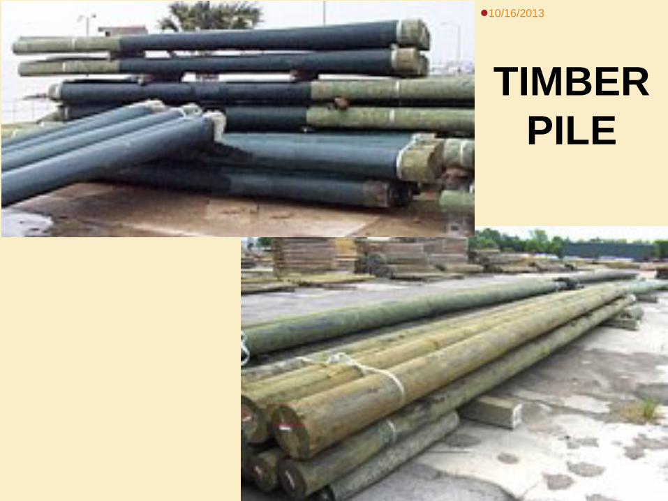
PILE TYPES:
Timber
Steel
Concrete
10/16/2013
10/16/2013
TIMBER PILE
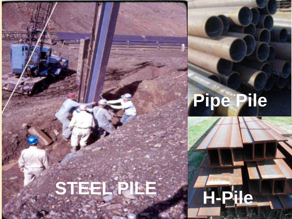
H-Pile
Pipe Pile
STEEL PILE
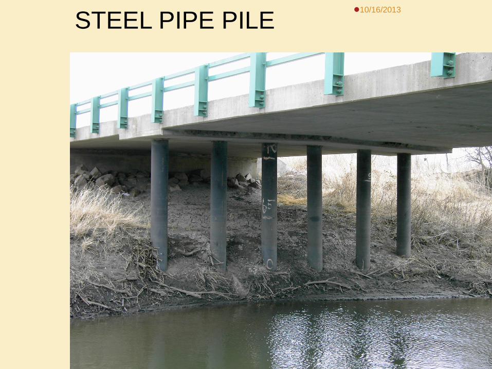
10/16/2013 STEEL PIPE PILE
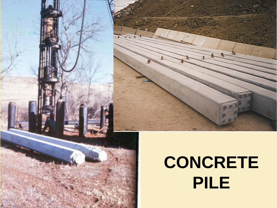
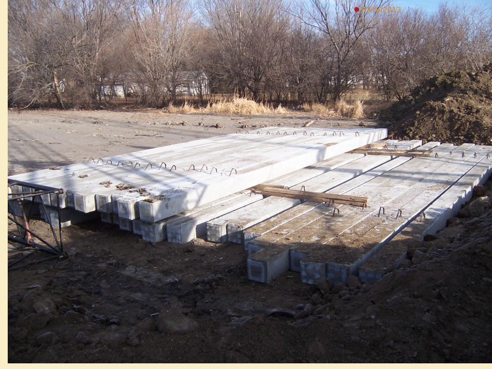
CONCRETE PILE
10/16/2013

INSPECTION OF STEEL PILES
Certificate of Compliance/Mill Test Report Chemical and Physical Tests Heat Numbers Made in the USA (Example on pg 5-62, Fig 5.10)
Visual Inspection
Size, Heat #, Defects, etc.
Document
10/16/2013
10/16/2013
CONCRETE PILE INSPECTION
Should Be Shop Inspected Region Materials inspect @ plant
Gage Brothers or SD Concrete
Visual Inspection Conformance to Plans Cracks 100% Chips > 10%
Proper lift procedure
10/16/2013
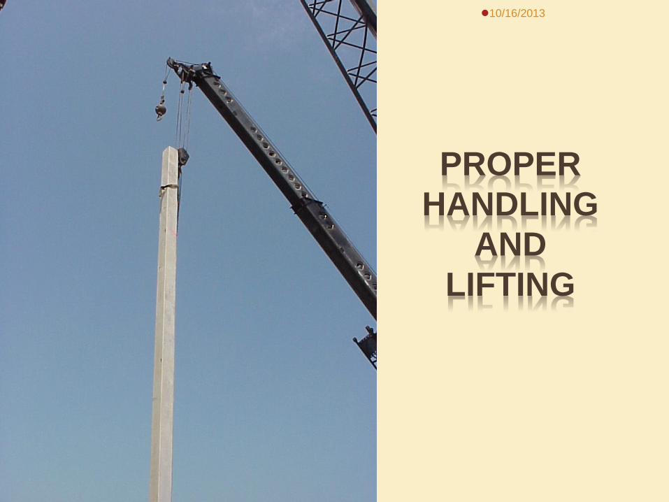
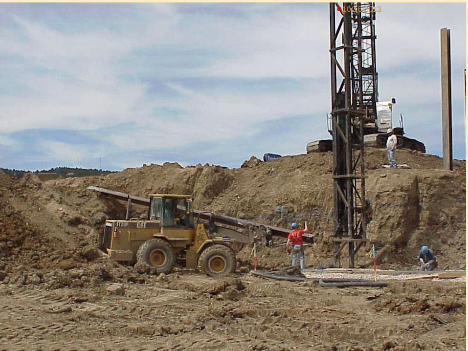
PROPER HANDLING
AND LIFTING
10/16/2013
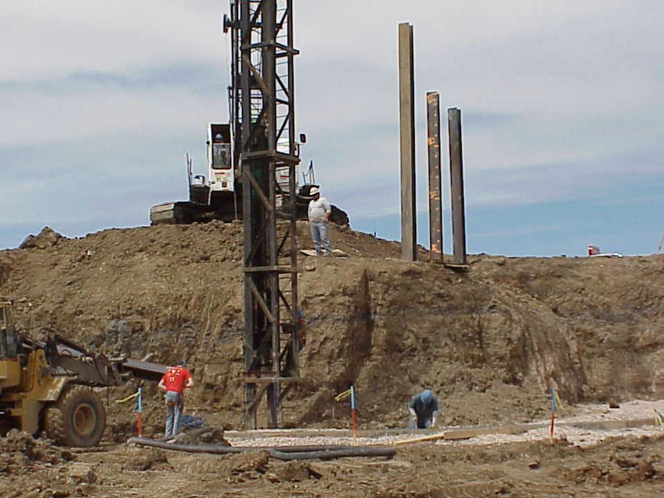
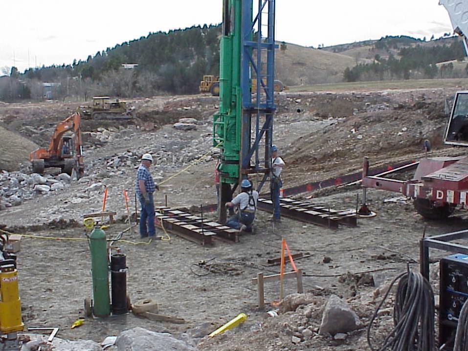
PILE DRIVER
Hammer
Cap
Leads
10/16/2013
Page 5-64, Figure 5.12
TYPES OF PILE DRIVERS
Single Acting Hammer
Double Acting Hammer
Vibratory Hammer (Not Allowed)
10/16/2013
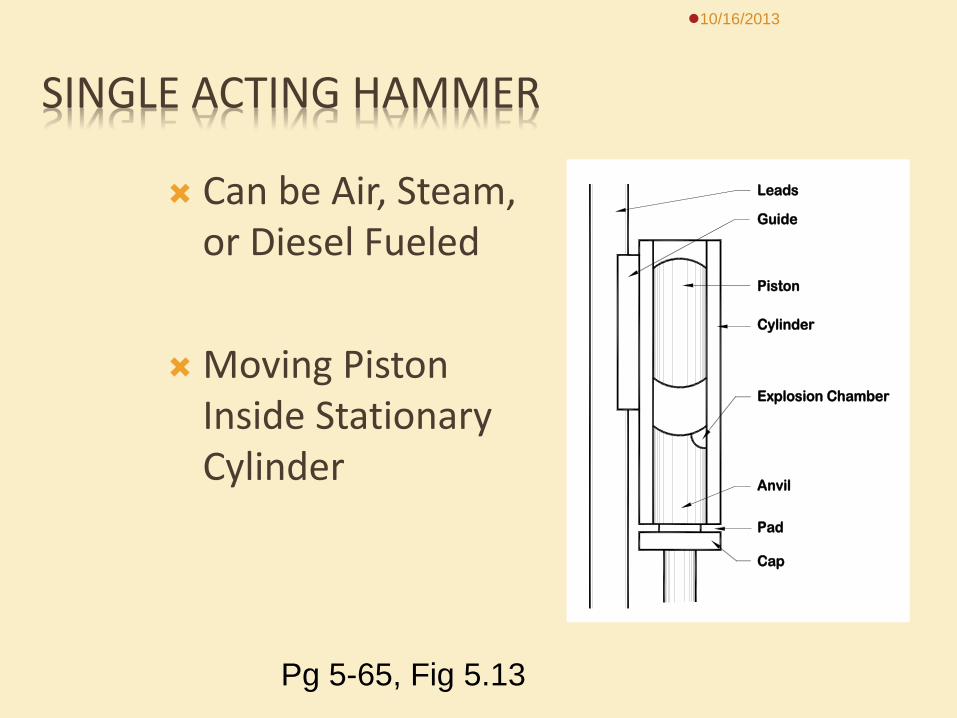
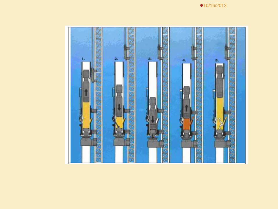
SINGLE ACTING HAMMER
Can be Air, Steam, or Diesel Fueled
Moving Piston Inside Stationary Cylinder
10/16/2013
Leads
Guide
Piston
Cylinder
Explosion Chamber
Anvil
Pad
Cap
Pg 5-65, Fig 5.13
10/16/2013
10/16/2013
10/16/2013
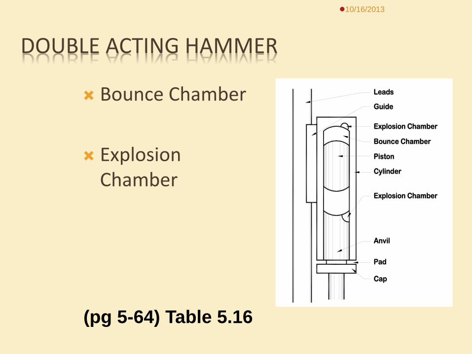
DOUBLE ACTING HAMMER
Bounce Chamber
Explosion Chamber
10/16/2013
Leads
Guide
Piston
Cylinder
Explosion Chamber
Anvil
Pad
Cap
Bounce Chamber
Explosion Chamber
(pg 5-64) Table 5.16
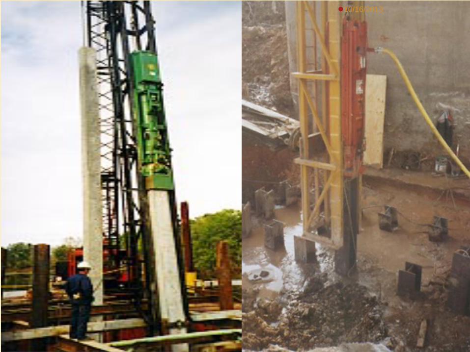
DOUBLE ACTING HAMMERS
10/16/2013
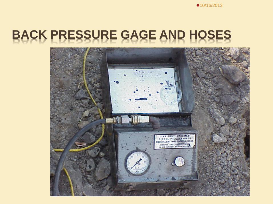
BACK PRESSURE GAGE AND HOSES
10/16/2013

ENERGY CHART 10/16/2013
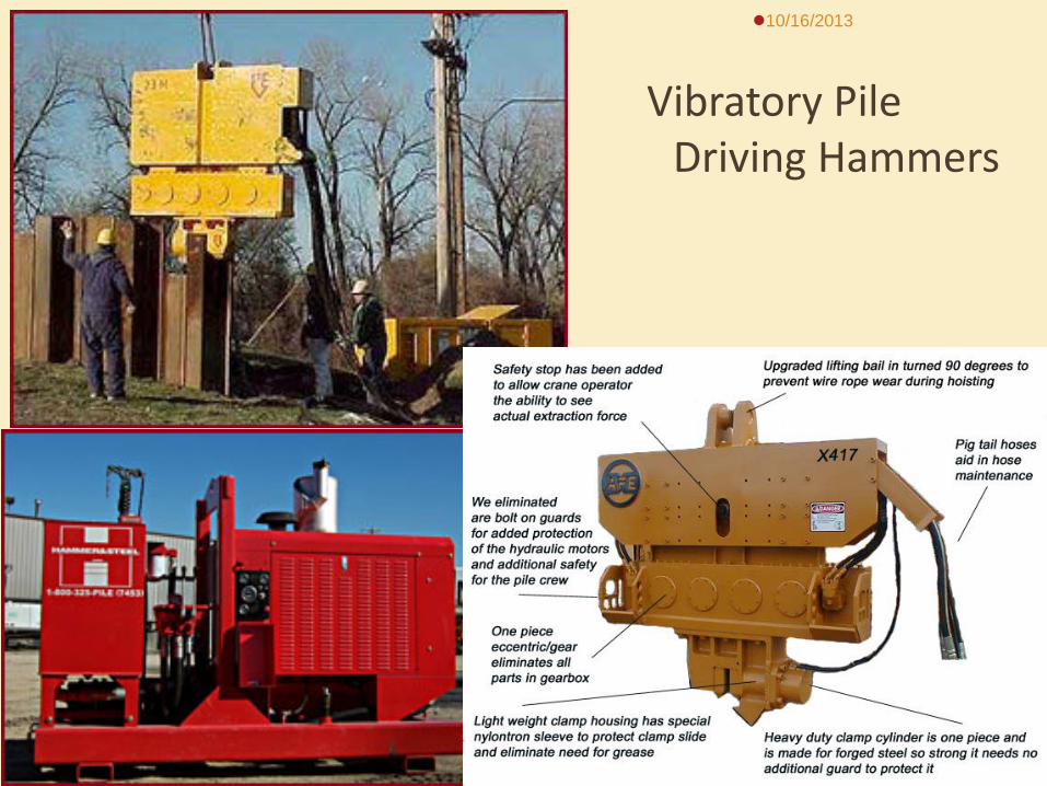
Vibratory Pile
Driving Hammers
10/16/2013
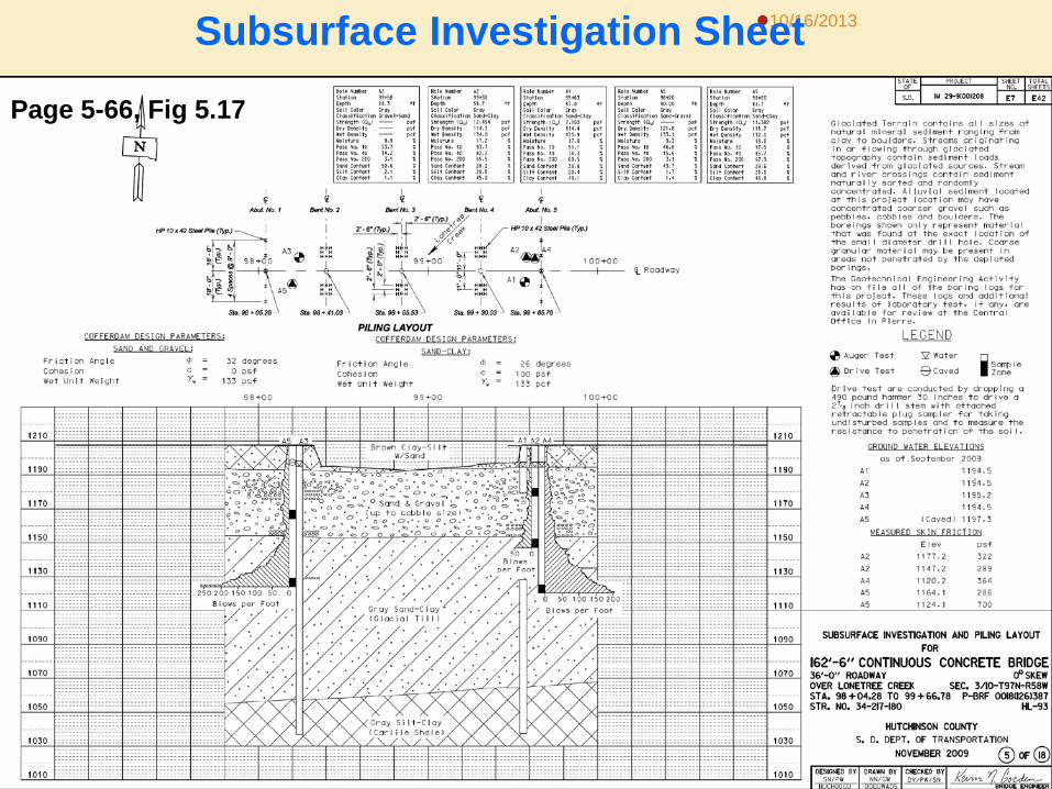
SUBSURFACE INVESTIGATION SHEET
Upper Half
Structure Location Project Centerline Piling Layout Test Hole Locations
Lower Half
Geographic profile Boring Logs Soil Formations Blow per foot graph
10/16/2013
Page 5-70 Fig 5.17
10/16/2013
Page 5-66, Fig 5.17
Subsurface Investigation Sheet
PRIMARY TYPES OF BEARING “PICKUP”
Uniform Buildup
Quick Buildup
Double Buildup
10/16/2013
Page 5-71
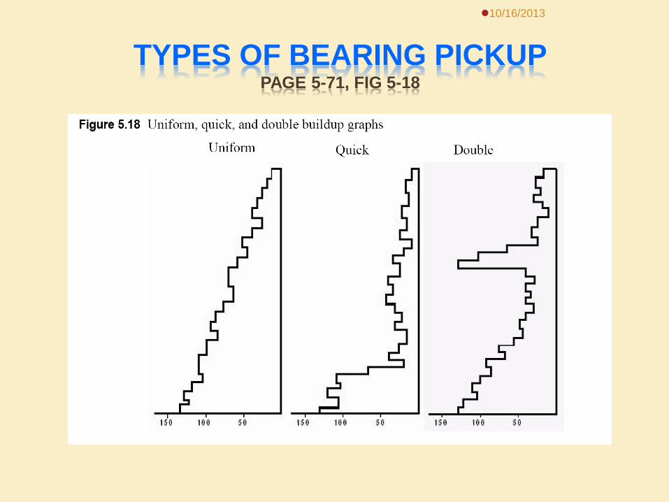
TYPES OF BEARING PICKUP PAGE 5-71, FIG 5-18
10/16/2013
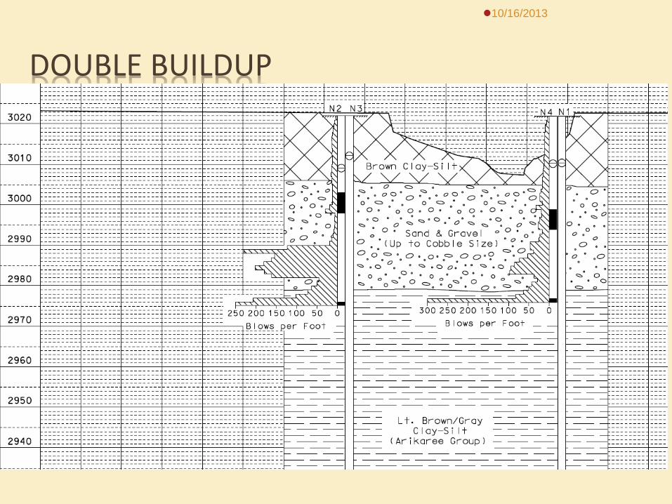
DOUBLE BUILDUP
10/16/2013
DOUBLE BUILDUP ON TEST PILES
Was the bearing 5-10 Tons more than the required bearing before it dropped off?
Did the pile have more than the required bearing for at least 3 feet?
10/16/2013
PILE REPORTS
Test Pile Report DOT-203 (Pg 5-73)
Pile Inspector’s Report DOT-204 (Pg 5-74)
10/16/2013
GENERAL INFO ON PILE REPORTS
Project Number County Date Contractor Foundation Unit Structure Number
Inspector’s Name Structure Type Location Type of Pile Bearing Required Pile ID No.
10/16/2013
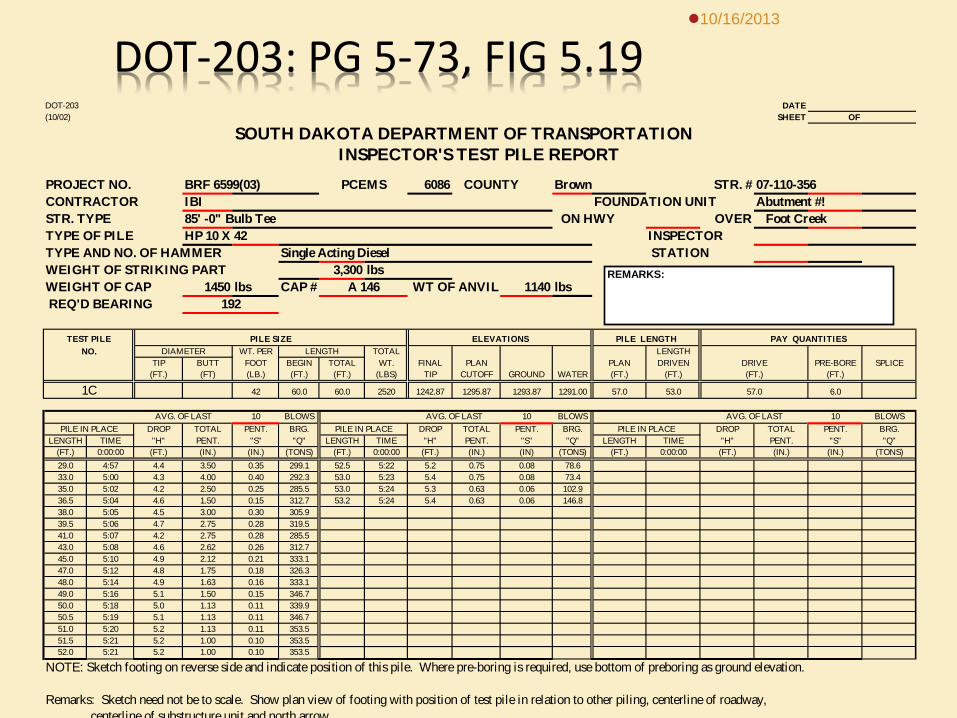
DOT-203: PG 5-73, FIG 5.19 10/16/2013
DOT-203 DATE(10/02) SHEET OF
SOUTH DAKOTA DEPARTMENT OF TRANSPORTATION INSPECTOR'S TEST PILE REPORT
PROJECT NO. BRF 6599(03) 6086 COUNTY Brown STR. # 07-110-356CONTRACTOR IBI FOUNDATION UNIT Abutment #!STR. TYPE 85' -0" Bulb Tee ON HWY OVER Foot CreekTYPE OF PILE HP 10 X 42 INSPECTORTYPE AND NO. OF HAMMER Single Acting Diesel STATIONWEIGHT OF STRIKING PART 3,300 lbsWEIGHT OF CAP 1450 lbs CAP # WT OF ANVIL 1140 lbs REQ'D BEARING
TEST PILENO. DIAMETER WT. PER LENGTH TOTAL LENGTH
TIP BUTT FOOT BEGIN TOTAL WT. FINAL PLAN PLAN DRIVEN PRE-BORE SPLICE(FT.) (FT) (LB.) (FT.) (FT.) (LBS) TIP CUTOFF GROUND WATER (FT.) (FT.) (FT.)
42 60.0 60.0 2520 1242.87 1295.87 1293.87 1291.00 57.0 53.0 6.0
AVG. OF LAST 10 BLOWS AVG. OF LAST 10 BLOWS AVG. OF LAST 10 BLOWSDROP TOTAL PENT. BRG. DROP TOTAL PENT. BRG. DROP TOTAL PENT. BRG.
LENGTH TIME "H" PENT. "S" "Q" LENGTH TIME "H" PENT. "S" "Q" LENGTH TIME "H" PENT. "S" "Q"(FT.) 0:00:00 (FT.) (IN.) (IN.) (TONS) (FT.) 0:00:00 (FT.) (IN.) (IN) (TONS) (FT.) 0:00:00 (FT.) (IN.) (IN.) (TONS)29.0 4:57 4.4 3.50 0.35 299.1 52.5 5:22 5.2 0.75 0.08 78.633.0 5:00 4.3 4.00 0.40 292.3 53.0 5:23 5.4 0.75 0.08 73.435.0 5:02 4.2 2.50 0.25 285.5 53.0 5:24 5.3 0.63 0.06 102.936.5 5:04 4.6 1.50 0.15 312.7 53.2 5:24 5.4 0.63 0.06 146.838.0 5:05 4.5 3.00 0.30 305.939.5 5:06 4.7 2.75 0.28 319.541.0 5:07 4.2 2.75 0.28 285.543.0 5:08 4.6 2.62 0.26 312.745.0 5:10 4.9 2.12 0.21 333.147.0 5:12 4.8 1.75 0.18 326.348.0 5:14 4.9 1.63 0.16 333.149.0 5:16 5.1 1.50 0.15 346.750.0 5:18 5.0 1.13 0.11 339.950.5 5:19 5.1 1.13 0.11 346.751.0 5:20 5.2 1.13 0.11 353.551.5 5:21 5.2 1.00 0.10 353.552.0 5:21 5.2 1.00 0.10 353.5
NOTE: Sketch footing on reverse side and indicate position of this pile. Where pre-boring is required, use bottom of preboring as ground elevation.
Remarks: Sketch need not be to scale. Show plan view of footing with position of test pile in relation to other piling, centerline of roadway, centerline of substructure unit and north arrow
PCEMS
A 146192
PILE SIZE ELEVATIONS PILE LENGTH PAY QUANTITIES
DRIVE(FT.)
1C 57.0
PILE IN PLACE PILE IN PLACE PILE IN PLACE
REMARKS:
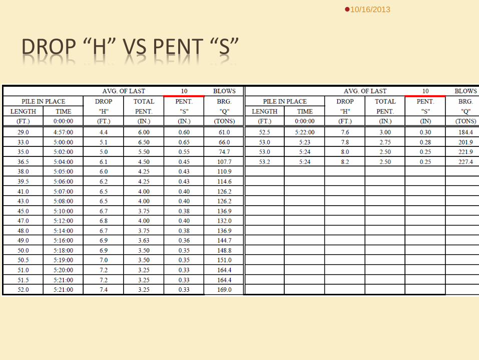
DROP “H” VS PENT “S”
10/16/2013
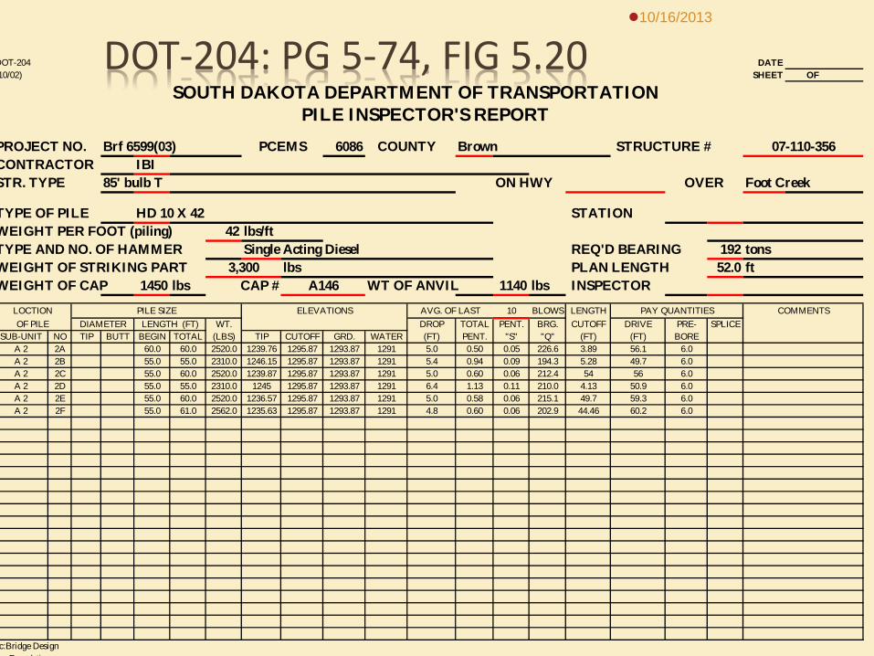
DOT-204: PG 5-74, FIG 5.20 DOT-204 DATE10/02) SHEET OF
SOUTH DAKOTA DEPARTMENT OF TRANSPORTATION PILE INSPECTOR'S REPORT
PROJECT NO. Brf 6599(03) 6086 COUNTY Brown STRUCTURE #CONTRACTOR IBISTR. TYPE 85' bulb T ON HWY OVER Foot Creek
TYPE OF PILE HD 10 X 42 STATION WEIGHT PER FOOT (piling) 42 lbs/ftTYPE AND NO. OF HAMMER Single Acting Diesel REQ'D BEARING 192 tonsWEIGHT OF STRIKING PART lbs PLAN LENGTH 52.0 ftWEIGHT OF CAP 1450 lbs CAP # WT OF ANVIL 1140 lbs INSPECTOR
LOCTION PILE SIZE ELEVATIONS AVG. OF LAST 10 BLOWS LENGTHOF PILE DIAMETER LENGTH (FT) WT. DROP TOTAL PENT. BRG. CUTOFF DRIVE PRE- SPLICE
SUB-UNIT NO TIP BUTT BEGIN TOTAL (LBS) TIP CUTOFF GRD. WATER (FT) PENT. "S" "Q" (FT) (FT) BOREA 2 2A 60.0 60.0 2520.0 1239.76 1295.87 1293.87 1291 5.0 0.50 0.05 226.6 3.89 56.1 6.0A 2 2B 55.0 55.0 2310.0 1246.15 1295.87 1293.87 1291 5.4 0.94 0.09 194.3 5.28 49.7 6.0A 2 2C 55.0 60.0 2520.0 1239.87 1295.87 1293.87 1291 5.0 0.60 0.06 212.4 54 56 6.0A 2 2D 55.0 55.0 2310.0 1245 1295.87 1293.87 1291 6.4 1.13 0.11 210.0 4.13 50.9 6.0A 2 2E 55.0 60.0 2520.0 1236.57 1295.87 1293.87 1291 5.0 0.58 0.06 215.1 49.7 59.3 6.0A 2 2F 55.0 61.0 2562.0 1235.63 1295.87 1293.87 1291 4.8 0.60 0.06 202.9 44.46 60.2 6.0
c:Bridge Design F d ti
COMMENTS
07-110-356
3,300A146
PCEMS
PAY QUANTITIES
10/16/2013
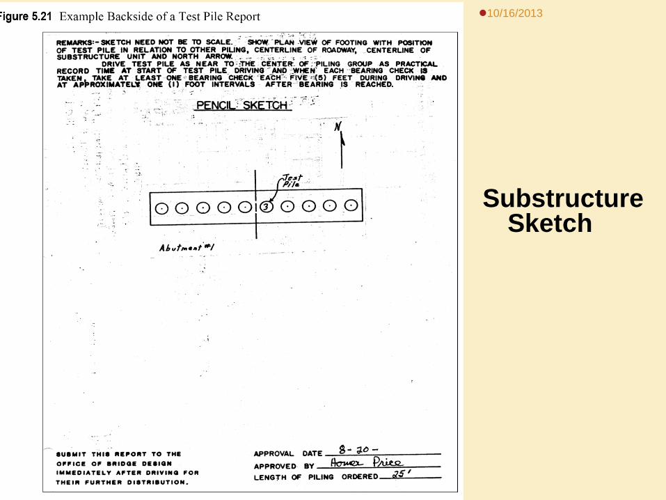
10/16/2013
Substructure Sketch
PRELIMINARY DATA NEEDED
Determine Type and Model No. of Hammer Determine Weight of Striking Part Determine Weight and No. of Cap Determine the Bearing Required Determine the Weights of the Piles
10/16/2013
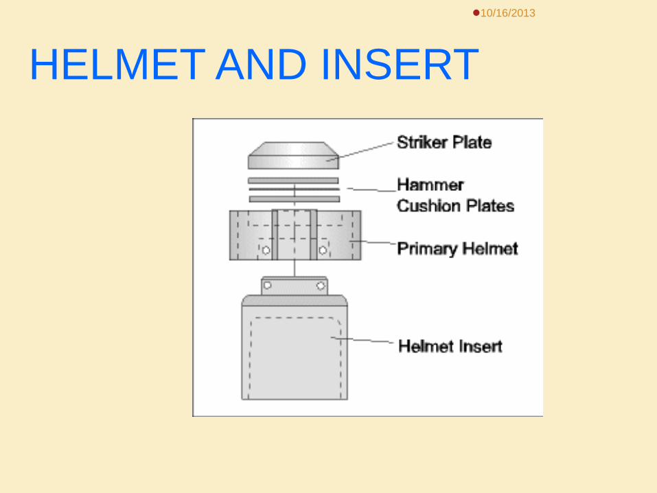
HELMET AND INSERT 10/16/2013
10/16/2013
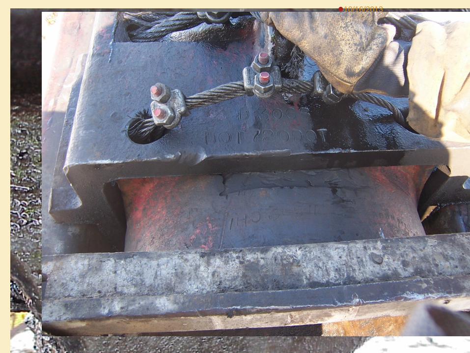
STAMPED PILE CAP
10/16/2013
HAMMER/LEADS/CAP
10/16/2013
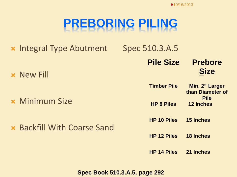
PREBORING PILING
Integral Type Abutment
New Fill
Minimum Size
Backfill With Coarse Sand
Spec 510.3.A.5
10/16/2013
Pile Size Prebore Size
Timber Pile Min. 2” Largerthan Diameter of
PileHP 8 Piles 12 Inches
HP 10 Piles 15 Inches
HP 12 Piles 18 Inches
HP 14 Piles 21 Inches
Spec Book 510.3.A.5, page 292
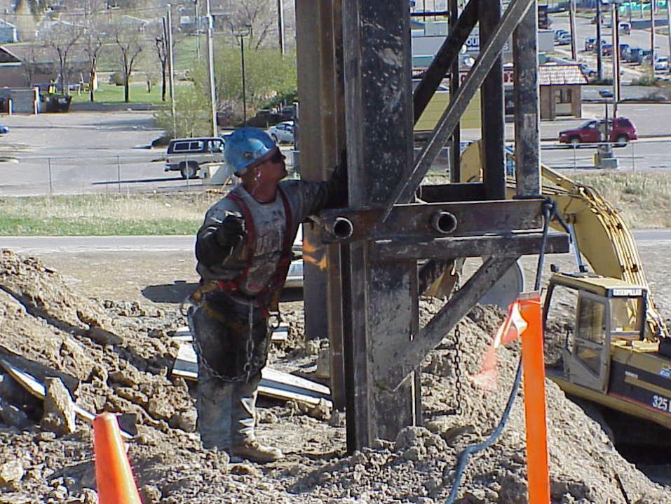
PILE DRIVING
Remove Excavation
Contractor Determines Correct Location (Inspector Verified)
Check and Recheck Position and Batter After First Few Feet
10/16/2013
LOCATION AND POSITION SPECIFICATIONS
Piling are acceptable if they are within 6”
of plans position.
Battered pile must be within 1/4” in 12” of the plans specified batter. (Same for vertical pile)
10/16/2013
10/16/2013
10/16/2013
10/16/2013
10/16/2013
10/16/2013
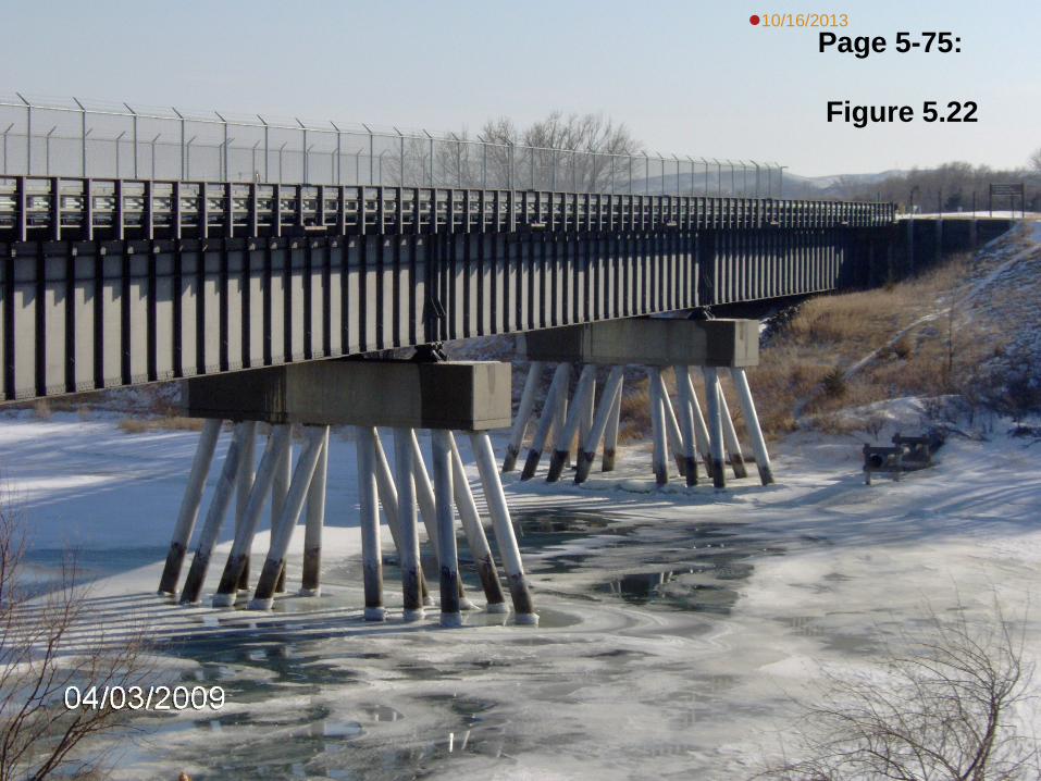
10/16/2013 Page 5-75: Figure 5.22
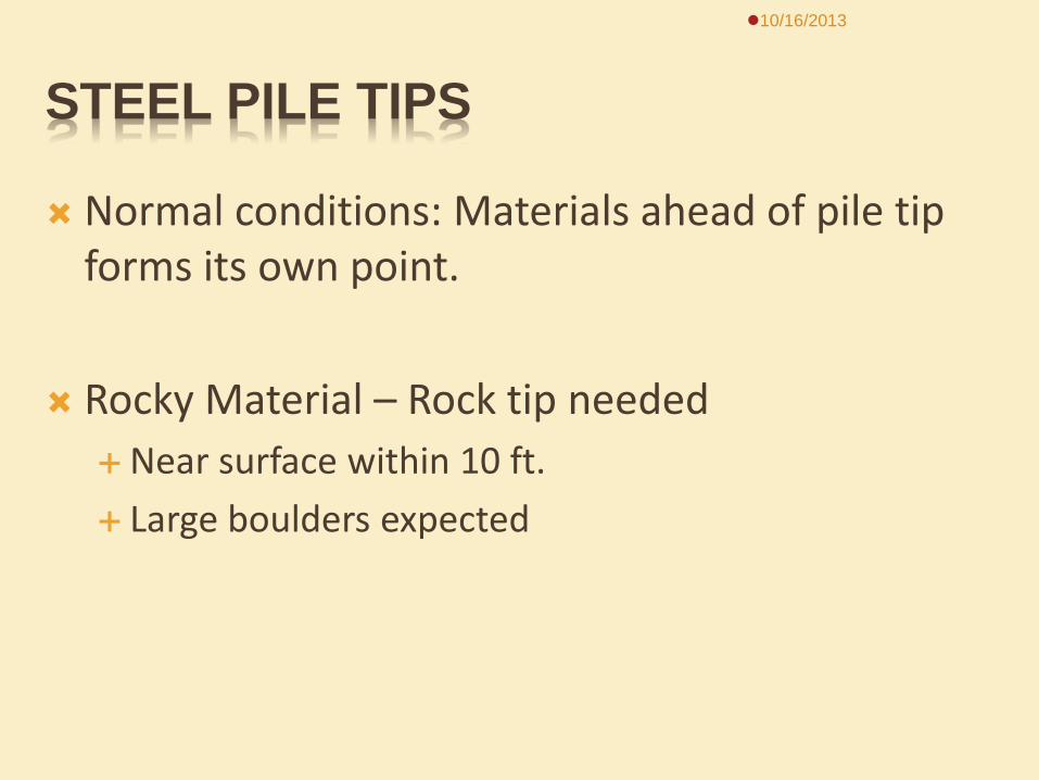
STEEL PILE TIPS
Normal conditions: Materials ahead of pile tip forms its own point.
Rocky Material – Rock tip needed
Near surface within 10 ft. Large boulders expected
10/16/2013
10/16/2013
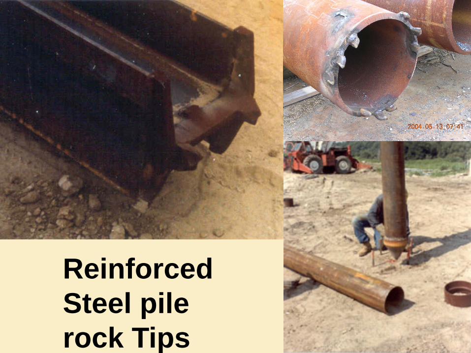
Reinforced Steel pile rock Tips

DRIVING PILE & COMPUTING BEARING
Only drive pile 10 to 20% , more than plans required bearing.
Pile need to be plumb or per spec batter Set pile, check alignment after a couple of feet. Start driving pile into ground Take readings every 5 ft & 1 ft after bearing achieved up
to 10 – 20% over bearing.
10/16/2013
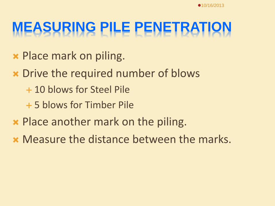
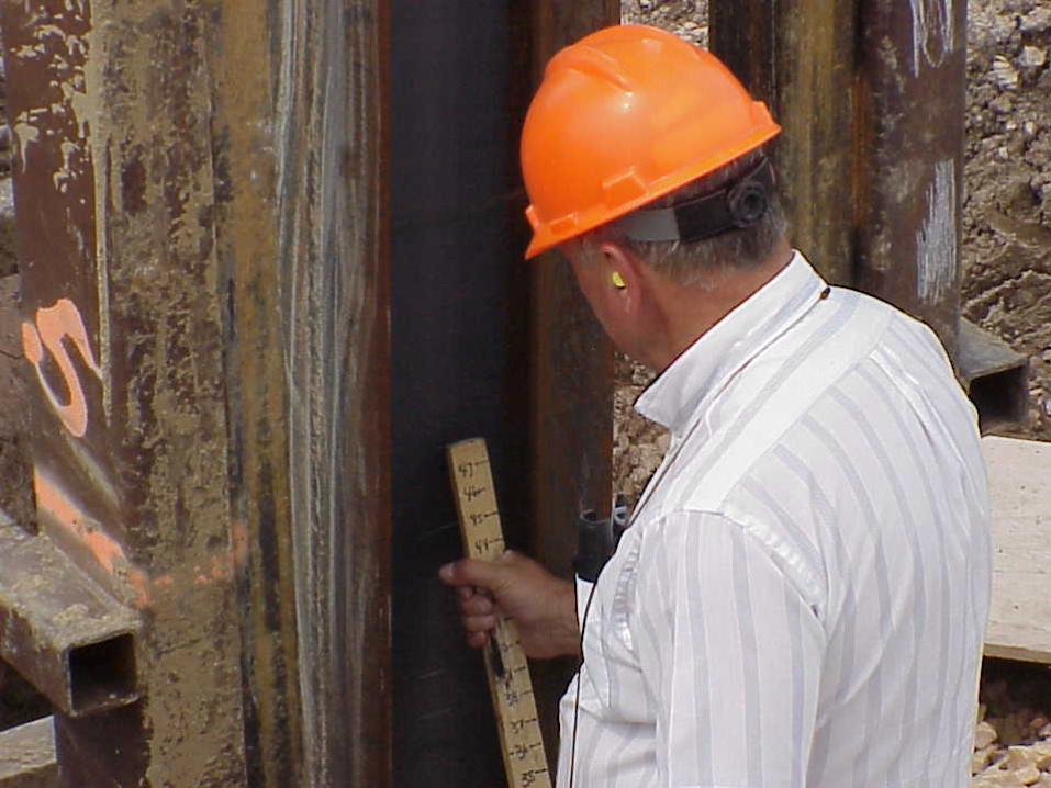
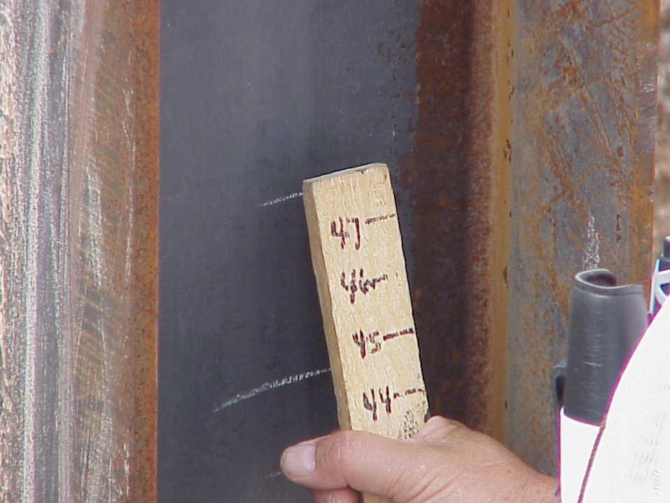
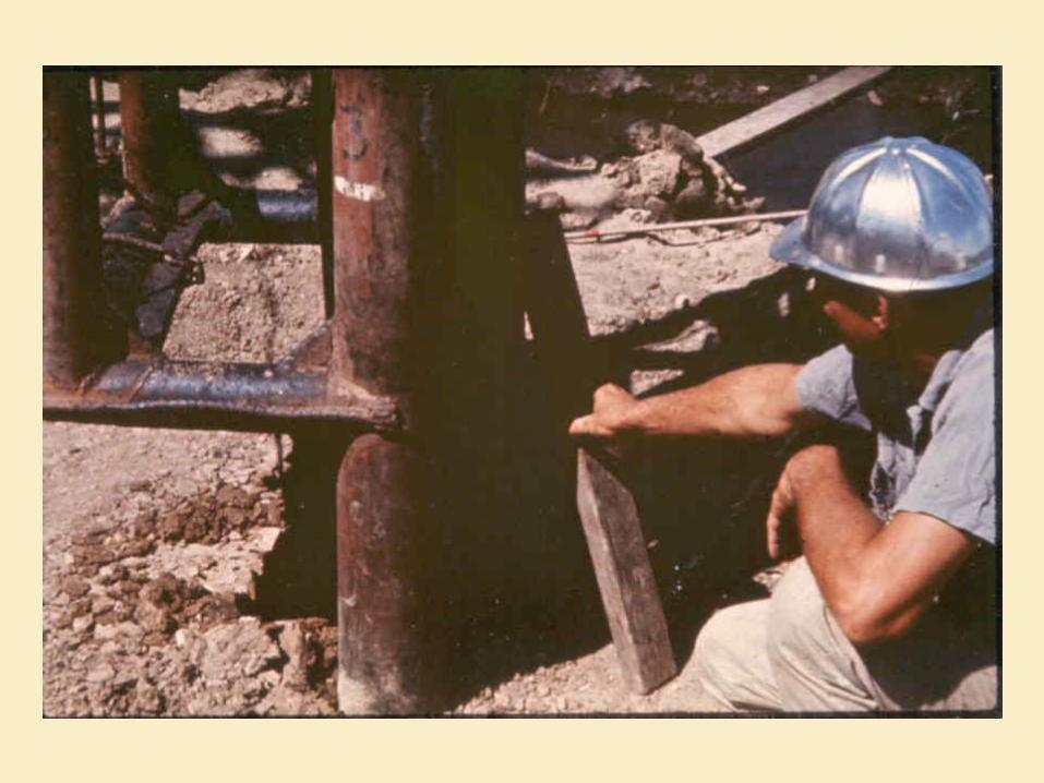
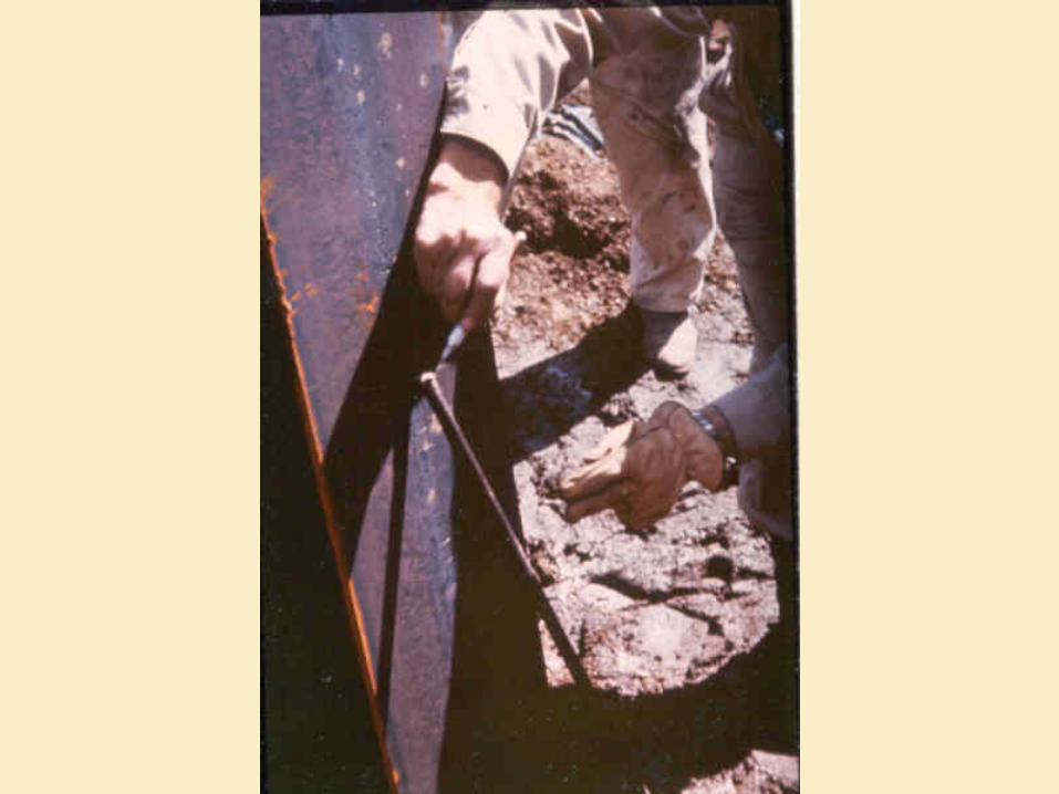
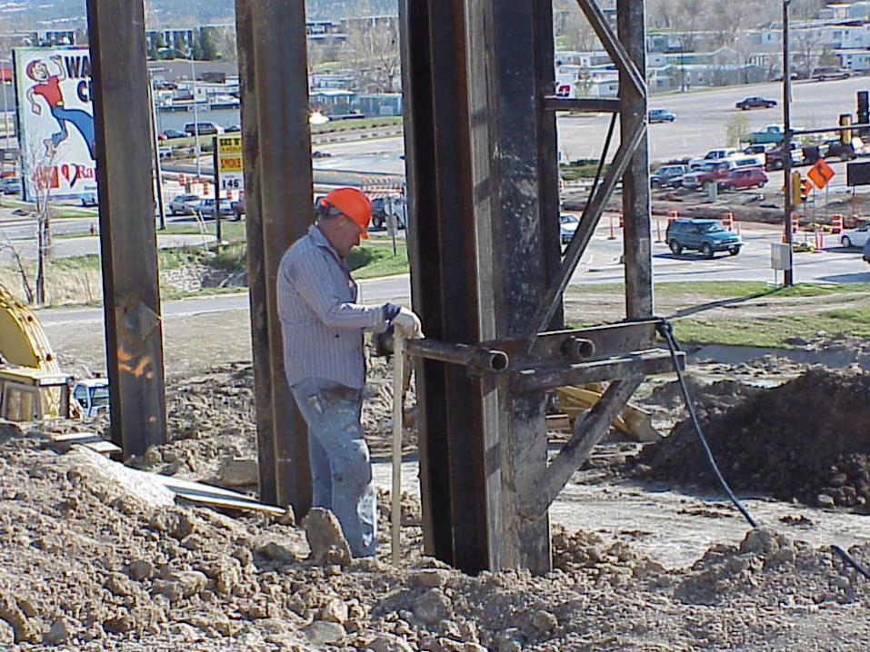
MEASURING PILE PENETRATION
Place mark on piling. Drive the required number of blows
10 blows for Steel Pile 5 blows for Timber Pile
Place another mark on the piling. Measure the distance between the marks.
10/16/2013

Pile drive measurement sax.MPG
10/16/2013
Pile Driving Video
HAMMER FALL
Single & Double Acting Hammers Meets the minimum energy per plans Hammer operating efficiently Uniform driving rates
Hammers must have the capability to drive 1 inch in 10 blows
10/16/2013
NEW PILE DRIVING FORMULA
LRFD Platform: To determine the ultimate bearing capacity of
driven piles The SDDOT uses the following formulas for
timber, concrete, steel H-piling and shell type piles.
10/16/2013
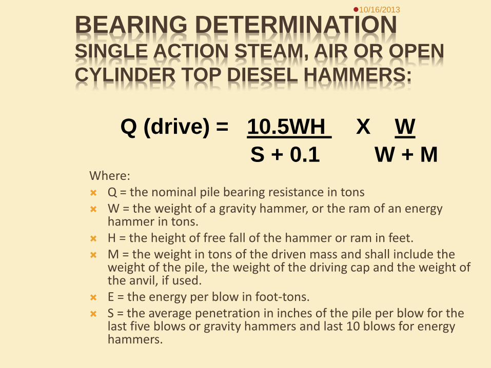
BEARING DETERMINATION SINGLE ACTION STEAM, AIR OR OPEN CYLINDER TOP DIESEL HAMMERS:
Where: Q = the nominal pile bearing resistance in tons W = the weight of a gravity hammer, or the ram of an energy
hammer in tons. H = the height of free fall of the hammer or ram in feet. M = the weight in tons of the driven mass and shall include the
weight of the pile, the weight of the driving cap and the weight of the anvil, if used.
E = the energy per blow in foot-tons. S = the average penetration in inches of the pile per blow for the
last five blows or gravity hammers and last 10 blows for energy hammers.
10/16/2013
Q (drive) = 10.5WH X W S + 0.1 W + M
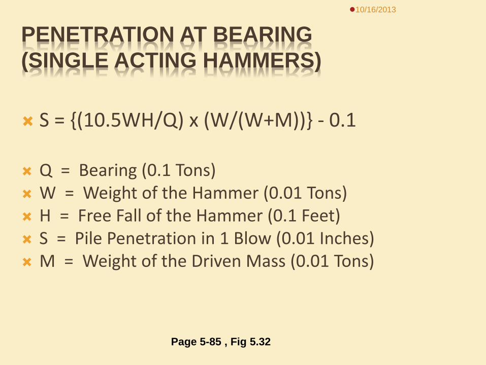
PENETRATION AT BEARING (SINGLE ACTING HAMMERS)
S = {(10.5WH/Q) x (W/(W+M))} - 0.1
Q = Bearing (0.1 Tons) W = Weight of the Hammer (0.01 Tons) H = Free Fall of the Hammer (0.1 Feet) S = Pile Penetration in 1 Blow (0.01 Inches) M = Weight of the Driven Mass (0.01 Tons)
10/16/2013
Page 5-85 , Fig 5.32
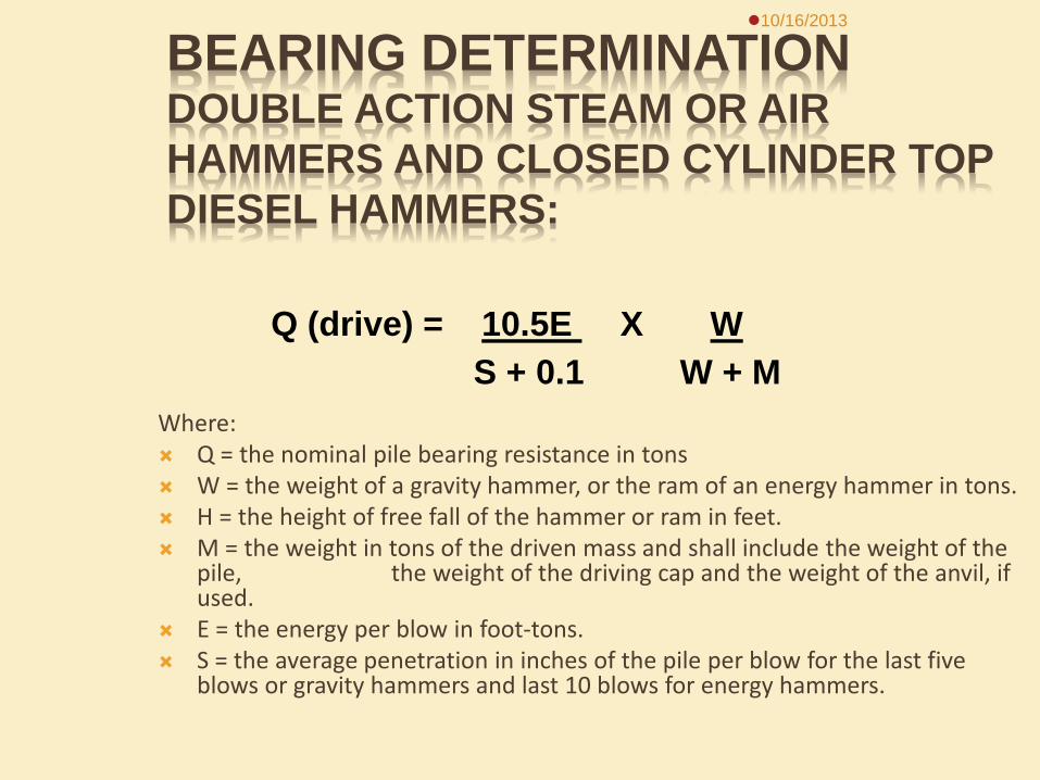
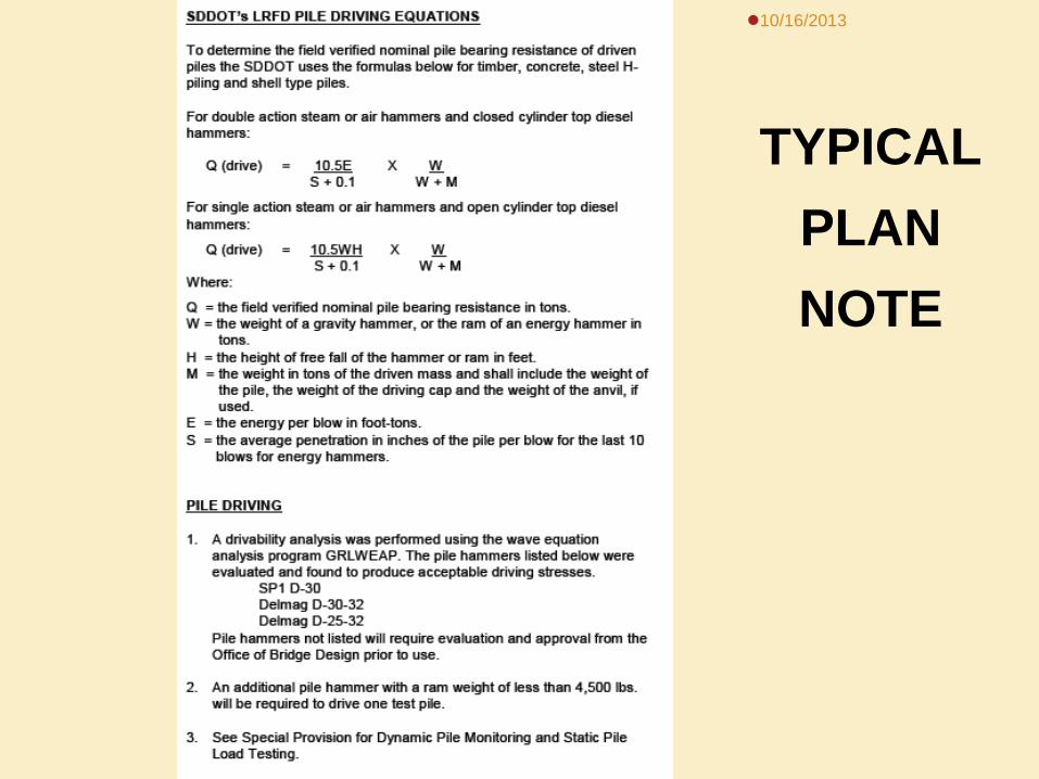
BEARING DETERMINATION DOUBLE ACTION STEAM OR AIR HAMMERS AND CLOSED CYLINDER TOP DIESEL HAMMERS:
Where: Q = the nominal pile bearing resistance in tons W = the weight of a gravity hammer, or the ram of an energy hammer in tons. H = the height of free fall of the hammer or ram in feet. M = the weight in tons of the driven mass and shall include the weight of the
pile, the weight of the driving cap and the weight of the anvil, if used.
E = the energy per blow in foot-tons. S = the average penetration in inches of the pile per blow for the last five
blows or gravity hammers and last 10 blows for energy hammers.
10/16/2013
Q (drive) = 10.5E X W S + 0.1 W + M
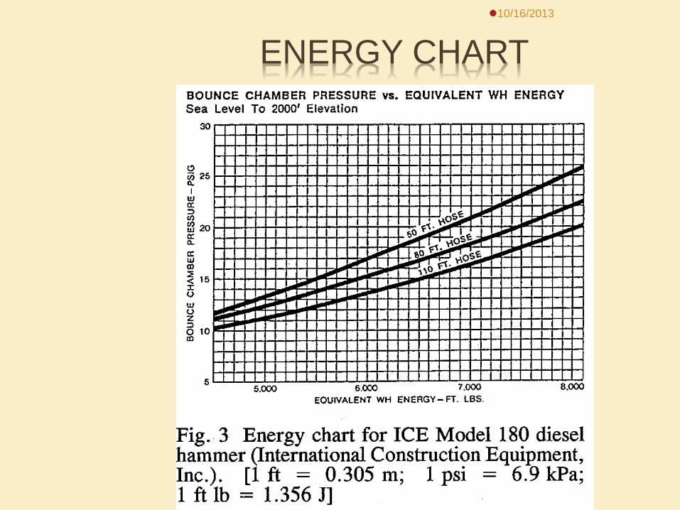
ENERGY CHART 10/16/2013
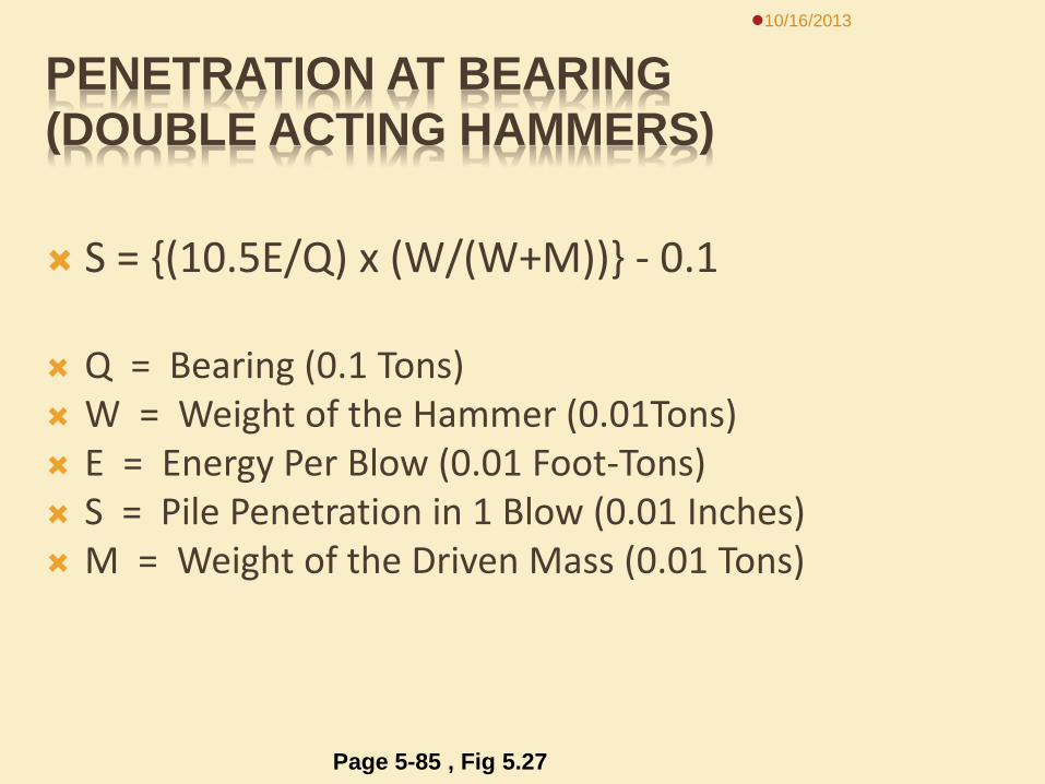
PENETRATION AT BEARING (DOUBLE ACTING HAMMERS)
S = {(10.5E/Q) x (W/(W+M))} - 0.1
Q = Bearing (0.1 Tons) W = Weight of the Hammer (0.01Tons) E = Energy Per Blow (0.01 Foot-Tons) S = Pile Penetration in 1 Blow (0.01 Inches) M = Weight of the Driven Mass (0.01 Tons)
10/16/2013
Page 5-85 , Fig 5.27
10/16/2013
TYPICAL PLAN NOTE
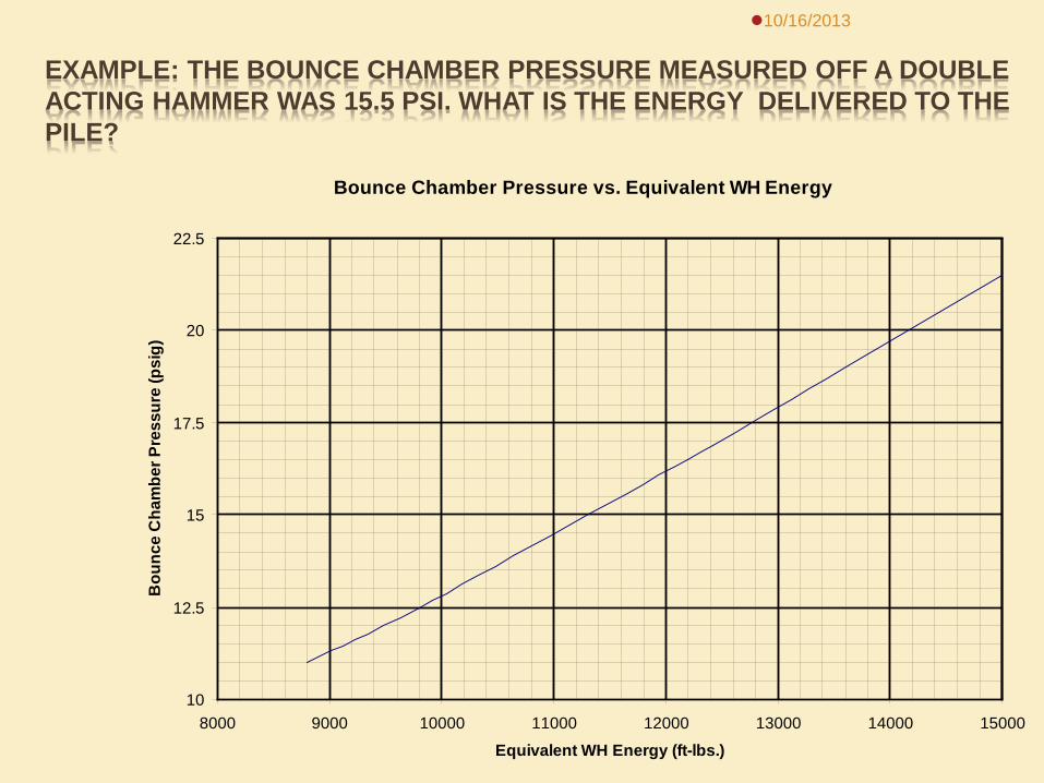
EXAMPLE: THE BOUNCE CHAMBER PRESSURE MEASURED OFF A DOUBLE ACTING HAMMER WAS 15.5 PSI. WHAT IS THE ENERGY DELIVERED TO THE PILE?
10/16/2013
Bounce Chamber Pressure vs. Equivalent WH Energy
10
12.5
15
17.5
20
22.5
8000 9000 10000 11000 12000 13000 14000 15000
Equivalent WH Energy (ft-lbs.)
Bou
nce
Cha
mbe
r Pre
ssur
e (p
sig)
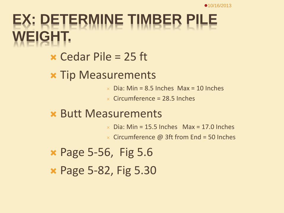
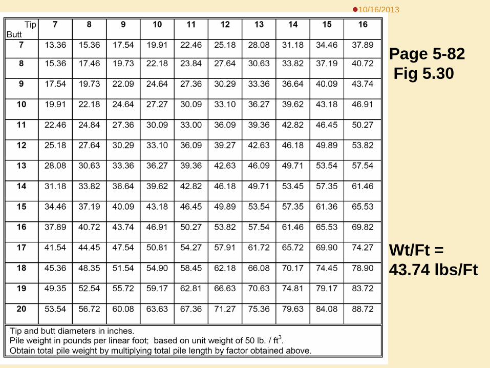
EX: DETERMINE TIMBER PILE WEIGHT.
Cedar Pile = 25 ft Tip Measurements
Dia: Min = 8.5 Inches Max = 10 Inches Circumference = 28.5 Inches
Butt Measurements Dia: Min = 15.5 Inches Max = 17.0 Inches Circumference @ 3ft from End = 50 Inches
Page 5-56, Fig 5.6 Page 5-82, Fig 5.30
10/16/2013

FIRST COMPUTE DIAMETERS
Tip Dia: 28.5”/3.14 = 9 Inches Butt Dia: 50”/3.14 = 16 Inches Wt/Ft = Use Fig 5.30 ???????
10/16/2013
10/16/2013
Wt/Ft = 43.74 lbs/Ft
Page 5-82 Fig 5.30
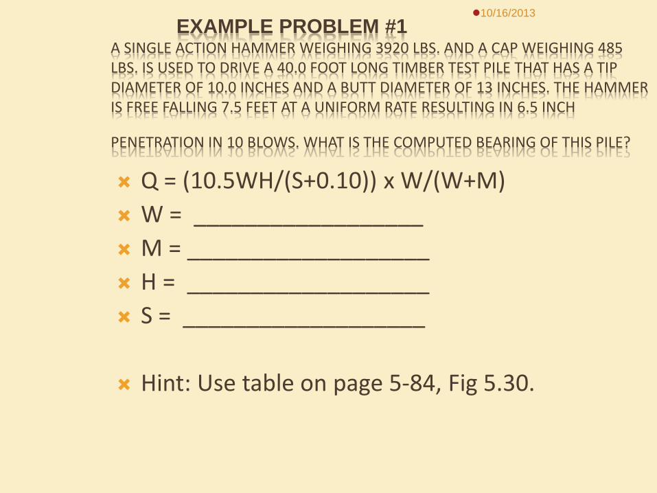
EXAMPLE PROBLEM #1 A SINGLE ACTION HAMMER WEIGHING 3920 LBS. AND A CAP WEIGHING 485 LBS. IS USED TO DRIVE A 40.0 FOOT LONG TIMBER TEST PILE THAT HAS A TIP DIAMETER OF 10.0 INCHES AND A BUTT DIAMETER OF 13 INCHES. THE HAMMER IS FREE FALLING 7.5 FEET AT A UNIFORM RATE RESULTING IN 6.5 INCH
PENETRATION IN 10 BLOWS. WHAT IS THE COMPUTED BEARING OF THIS PILE? Q = (10.5WH/(S+0.10)) x W/(W+M) W = __________________ M = ___________________ H = ___________________ S = ___________________ Hint: Use table on page 5-84, Fig 5.30.
10/16/2013
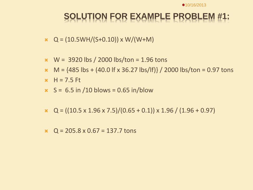
SOLUTION FOR EXAMPLE PROBLEM #1:
Q = (10.5WH/(S+0.10)) x W/(W+M) W = 3920 lbs / 2000 lbs/ton = 1.96 tons M = {485 lbs + (40.0 lf x 36.27 lbs/lf)} / 2000 lbs/ton = 0.97 tons H = 7.5 Ft S = 6.5 in /10 blows = 0.65 in/blow Q = ((10.5 x 1.96 x 7.5)/(0.65 + 0.1)) x 1.96 / (1.96 + 0.97) Q = 205.8 x 0.67 = 137.7 tons
10/16/2013
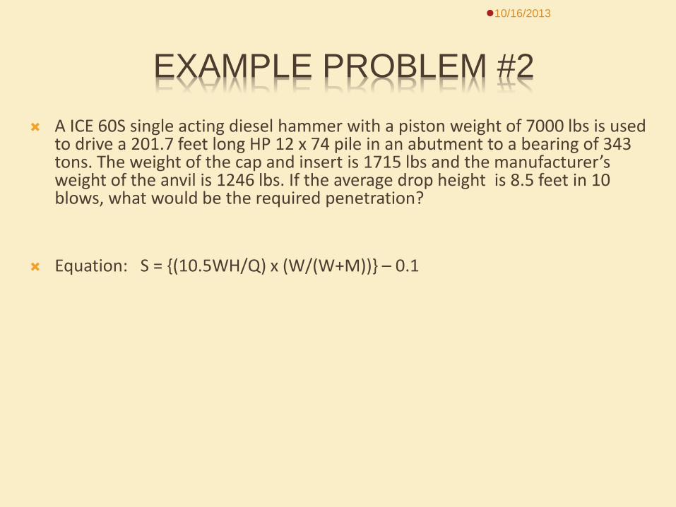
EXAMPLE PROBLEM #2 A ICE 60S single acting diesel hammer with a piston weight of 7000 lbs is used
to drive a 201.7 feet long HP 12 x 74 pile in an abutment to a bearing of 343 tons. The weight of the cap and insert is 1715 lbs and the manufacturer’s weight of the anvil is 1246 lbs. If the average drop height is 8.5 feet in 10 blows, what would be the required penetration?
Equation: S = {(10.5WH/Q) x (W/(W+M))} – 0.1
10/16/2013
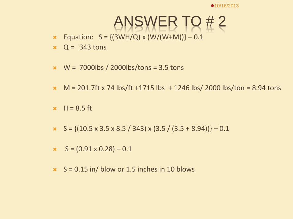
ANSWER TO # 2 Equation: S = {(3WH/Q) x (W/(W+M))} – 0.1 Q = 343 tons W = 7000lbs / 2000lbs/tons = 3.5 tons M = 201.7ft x 74 lbs/ft +1715 lbs + 1246 lbs/ 2000 lbs/ton = 8.94 tons H = 8.5 ft S = {(10.5 x 3.5 x 8.5 / 343) x (3.5 / (3.5 + 8.94))} – 0.1 S = (0.91 x 0.28) – 0.1 S = 0.15 in/ blow or 1.5 inches in 10 blows
10/16/2013
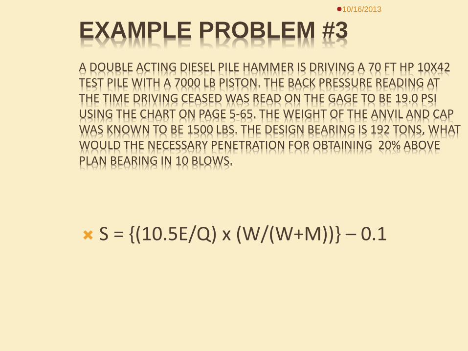
EXAMPLE PROBLEM #3 A DOUBLE ACTING DIESEL PILE HAMMER IS DRIVING A 70 FT HP 10X42 TEST PILE WITH A 7000 LB PISTON. THE BACK PRESSURE READING AT THE TIME DRIVING CEASED WAS READ ON THE GAGE TO BE 19.0 PSI USING THE CHART ON PAGE 5-65. THE WEIGHT OF THE ANVIL AND CAP WAS KNOWN TO BE 1500 LBS. THE DESIGN BEARING IS 192 TONS, WHAT WOULD THE NECESSARY PENETRATION FOR OBTAINING 20% ABOVE PLAN BEARING IN 10 BLOWS.
S = {(10.5E/Q) x (W/(W+M))} – 0.1
10/16/2013
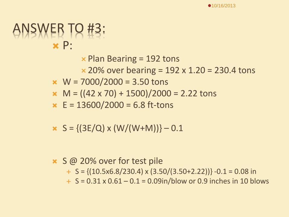
ANSWER TO #3: P:
Plan Bearing = 192 tons 20% over bearing = 192 x 1.20 = 230.4 tons
W = 7000/2000 = 3.50 tons M = ((42 x 70) + 1500)/2000 = 2.22 tons E = 13600/2000 = 6.8 ft-tons
S = {(3E/Q) x (W/(W+M))} – 0.1
S @ 20% over for test pile
S = {(10.5x6.8/230.4) x (3.50/(3.50+2.22))} -0.1 = 0.08 in S = 0.31 x 0.61 – 0.1 = 0.09in/blow or 0.9 inches in 10 blows
10/16/2013
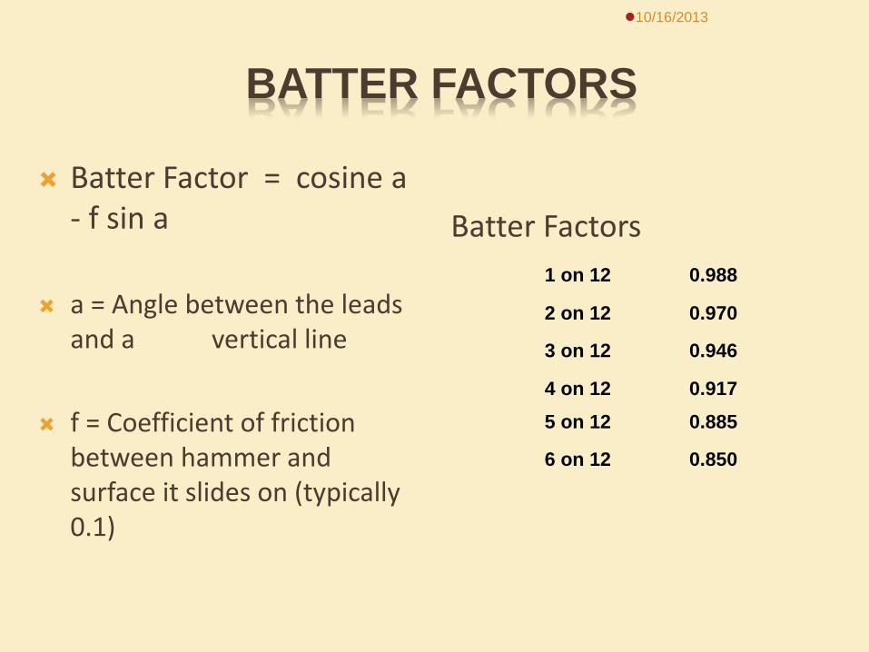
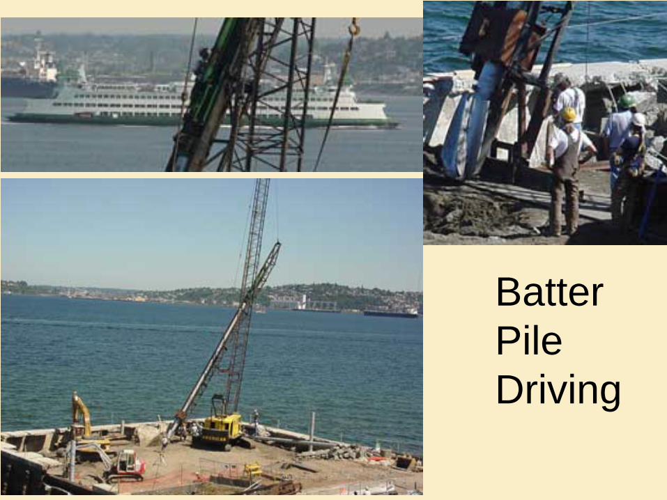
BATTER FACTORS
Batter Factor = cosine a - f sin a
a = Angle between the leads and a vertical line
f = Coefficient of friction between hammer and surface it slides on (typically 0.1)
Batter Factors
10/16/2013
1 on 12 0.988
2 on 12 0.970
3 on 12 0.946
4 on 12 0.9175 on 12 0.885
6 on 12 0.850
10/16/2013
Batter Pile Driving
WHEN TO STOP DRIVING
Test Pile - 10-20% Over Plans Bearing Location near center of substructure unit Verify Bearing Build-up type & check subsurface
investigation sheet
Bearing Pile - Stop When Bearing is Achieved Prevent overdriving
10/16/2013
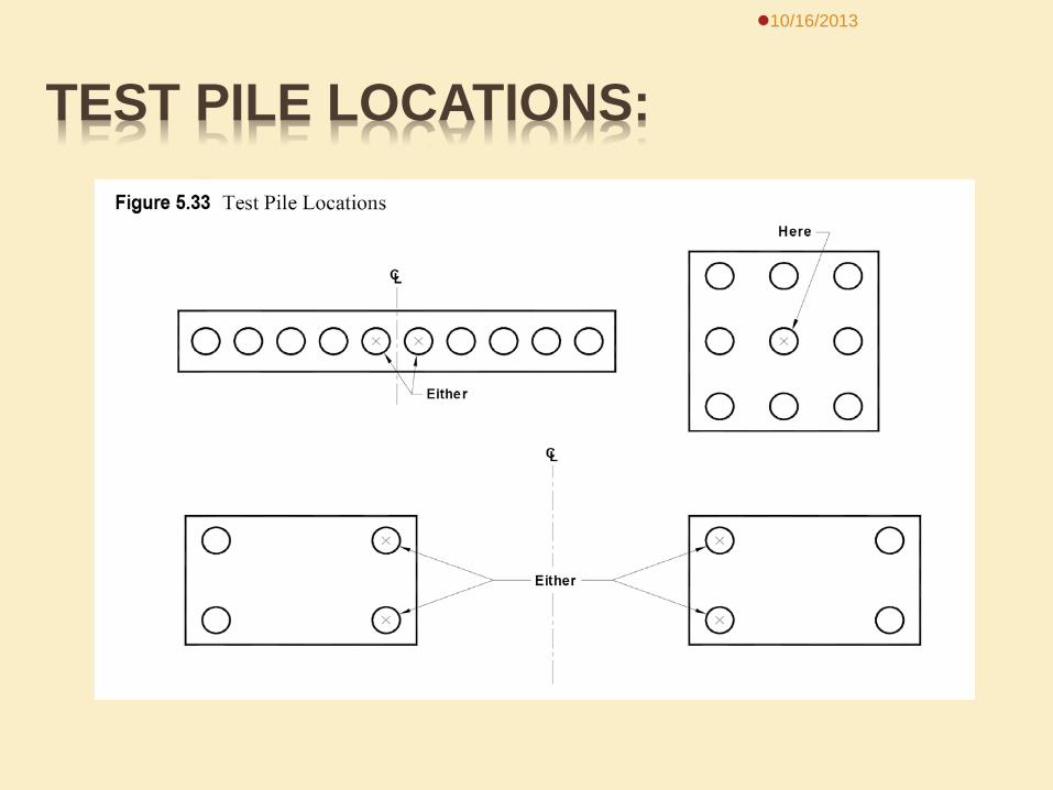
TEST PILE LOCATIONS:
10/16/2013
SET-UP EFFECT
Stop Driving When Pile is Two Feet Above Cutoff Elevation
Let Set For 24 Hours Warm up the Hammer on Another Pile Reset the Cap (2-3 Blows) Take Measurement on Next 10 Blows
10/16/2013

Setup Video: 101_3336a.wmv 10/16/2013
DRIVING PILING NEAR FRESH CONCRETE
Vibrations Adversely Affect Fresh Concrete
24 Hour Waiting Period
“Glass of Water Method”
10/16/2013
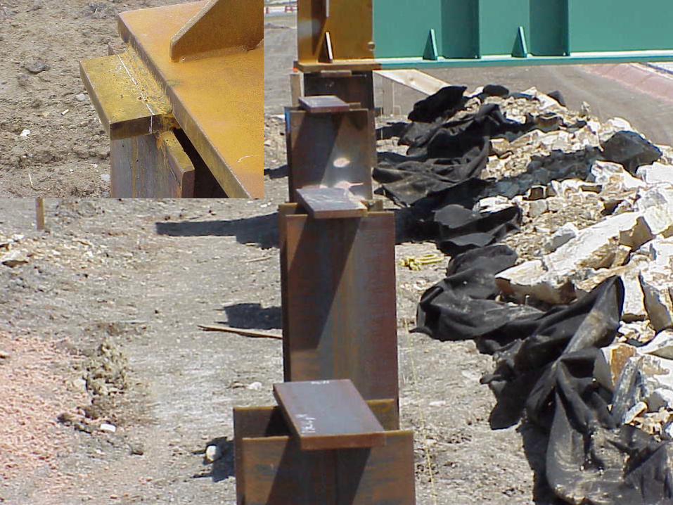
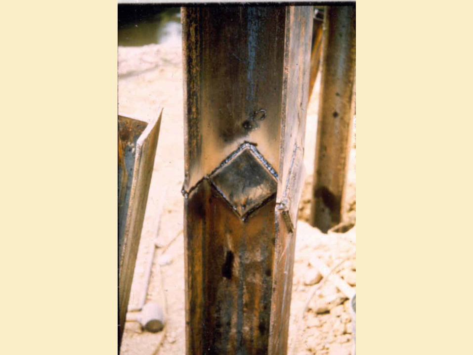
PILE SPLICES Timber
Snug Fit? Properly Treated?
Steel
Certified Welder Needed? Sec 410 of Standard Specifications
Prevent splice in upper 10 ft in an integral abutment or pile frame bent.
Concrete?
10/16/2013
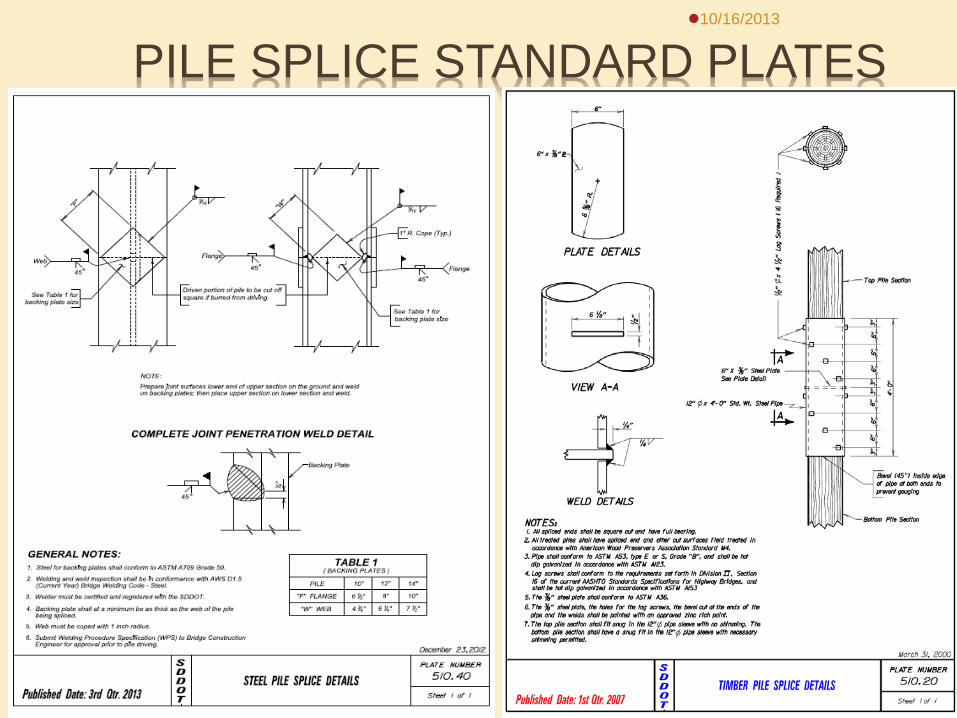
PILE SPLICE STANDARD PLATES 10/16/2013
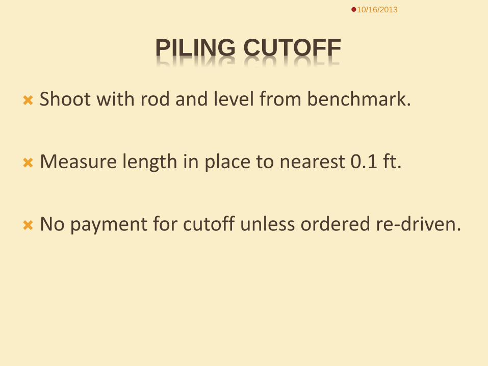
PILING CUTOFF
Shoot with rod and level from benchmark.
Measure length in place to nearest 0.1 ft.
No payment for cutoff unless ordered re-driven.
10/16/2013
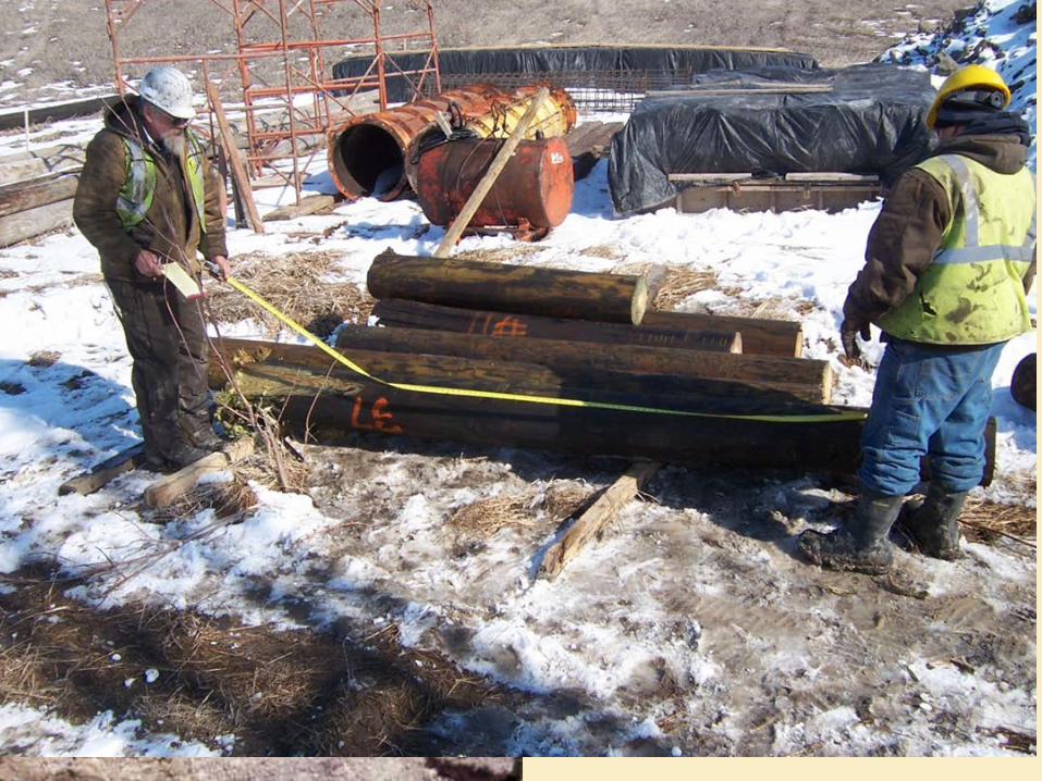
10/16/2013
Measuring Pile
Cutoff
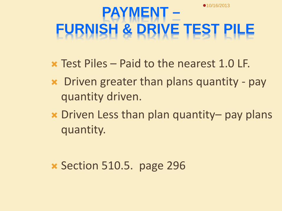
PAYMENT – FURNISH & DRIVE TEST PILE
Test Piles – Paid to the nearest 1.0 LF. Driven greater than plans quantity - pay
quantity driven. Driven Less than plan quantity– pay plans
quantity.
Section 510.5. page 296
10/16/2013
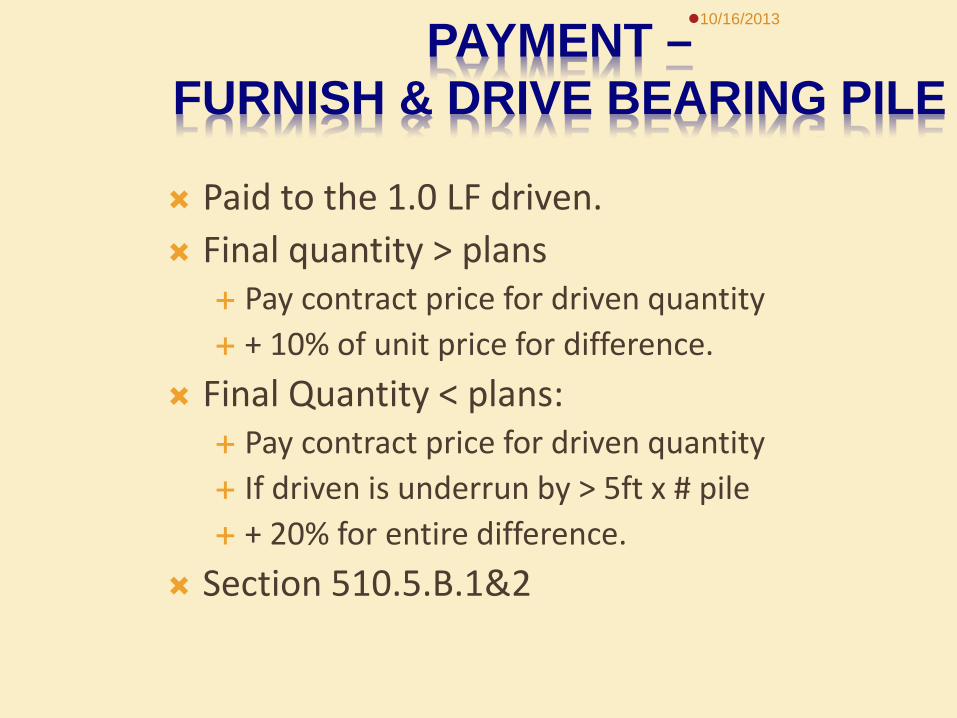
PAYMENT – FURNISH & DRIVE BEARING PILE Paid to the 1.0 LF driven. Final quantity > plans
Pay contract price for driven quantity + 10% of unit price for difference.
Final Quantity < plans: Pay contract price for driven quantity If driven is underrun by > 5ft x # pile + 20% for entire difference.
Section 510.5.B.1&2
10/16/2013
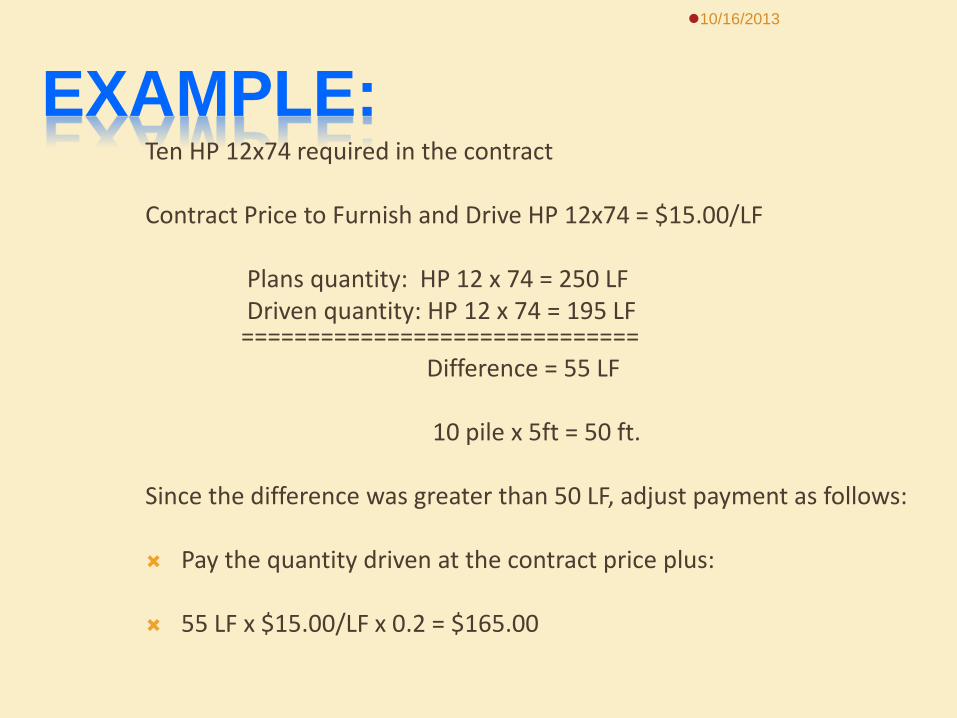
EXAMPLE: Ten HP 12x74 required in the contract Contract Price to Furnish and Drive HP 12x74 = $15.00/LF Plans quantity: HP 12 x 74 = 250 LF Driven quantity: HP 12 x 74 = 195 LF
============================== Difference = 55 LF 10 pile x 5ft = 50 ft.
Since the difference was greater than 50 LF, adjust payment as follows:
Pay the quantity driven at the contract price plus: 55 LF x $15.00/LF x 0.2 = $165.00
10/16/2013
PILE SPLICE PAYMENT:
Within the specified pile length No payment
Located at or beyond specified length: Measure per each for payment
10/16/2013
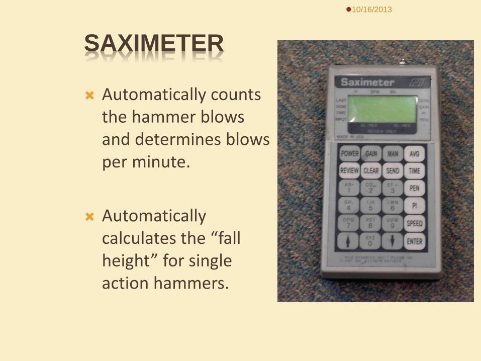
SAXIMETER
Automatically counts the hammer blows and determines blows per minute.
Automatically calculates the “fall height” for single action hammers.
10/16/2013
PILE RESEARCH
Static Load Test and Dynamic Testing Inspection Requirements

PILE RESEARCH
Review all contract documents Plans Special Provision Spec Book Shop-plans
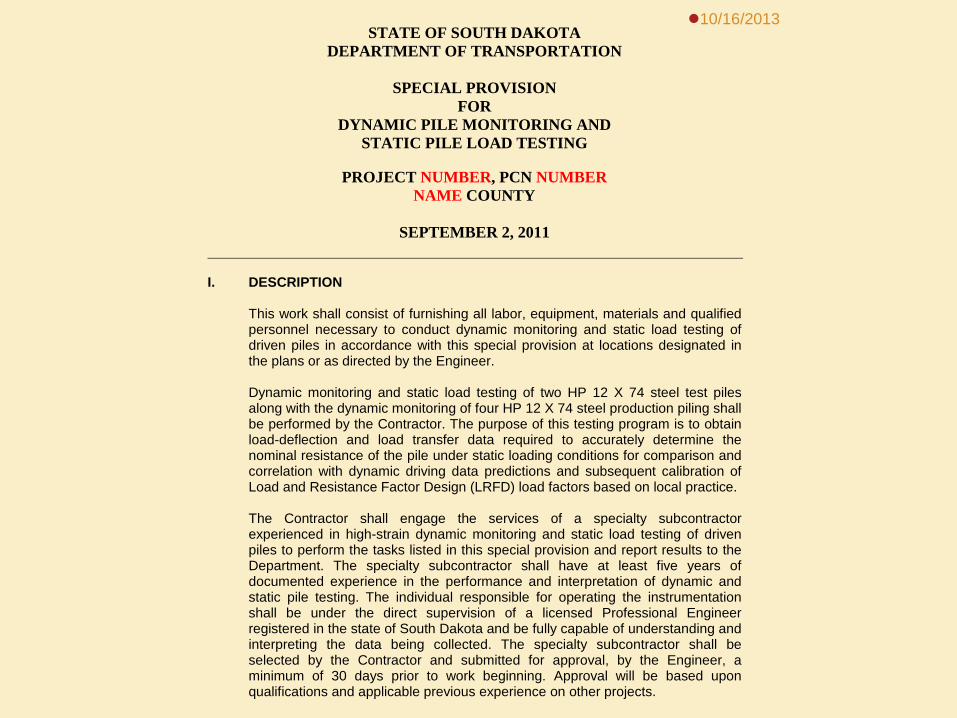
10/16/2013 STATE OF SOUTH DAKOTA
DEPARTMENT OF TRANSPORTATION
SPECIAL PROVISION FOR
DYNAMIC PILE MONITORING AND STATIC PILE LOAD TESTING
PROJECT NUMBER, PCN NUMBER
NAME COUNTY
SEPTEMBER 2, 2011
I. DESCRIPTION
This work shall consist of furnishing all labor, equipment, materials and qualified personnel necessary to conduct dynamic monitoring and static load testing of driven piles in accordance with this special provision at locations designated in the plans or as directed by the Engineer. Dynamic monitoring and static load testing of two HP 12 X 74 steel test piles along with the dynamic monitoring of four HP 12 X 74 steel production piling shall be performed by the Contractor. The purpose of this testing program is to obtain load-deflection and load transfer data required to accurately determine the nominal resistance of the pile under static loading conditions for comparison and correlation with dynamic driving data predictions and subsequent calibration of Load and Resistance Factor Design (LRFD) load factors based on local practice. The Contractor shall engage the services of a specialty subcontractor experienced in high-strain dynamic monitoring and static load testing of driven piles to perform the tasks listed in this special provision and report results to the Department. The specialty subcontractor shall have at least five years of documented experience in the performance and interpretation of dynamic and static pile testing. The individual responsible for operating the instrumentation shall be under the direct supervision of a licensed Professional Engineer registered in the state of South Dakota and be fully capable of understanding and interpreting the data being collected. The specialty subcontractor shall be selected by the Contractor and submitted for approval, by the Engineer, a minimum of 30 days prior to work beginning. Approval will be based upon qualifications and applicable previous experience on other projects.
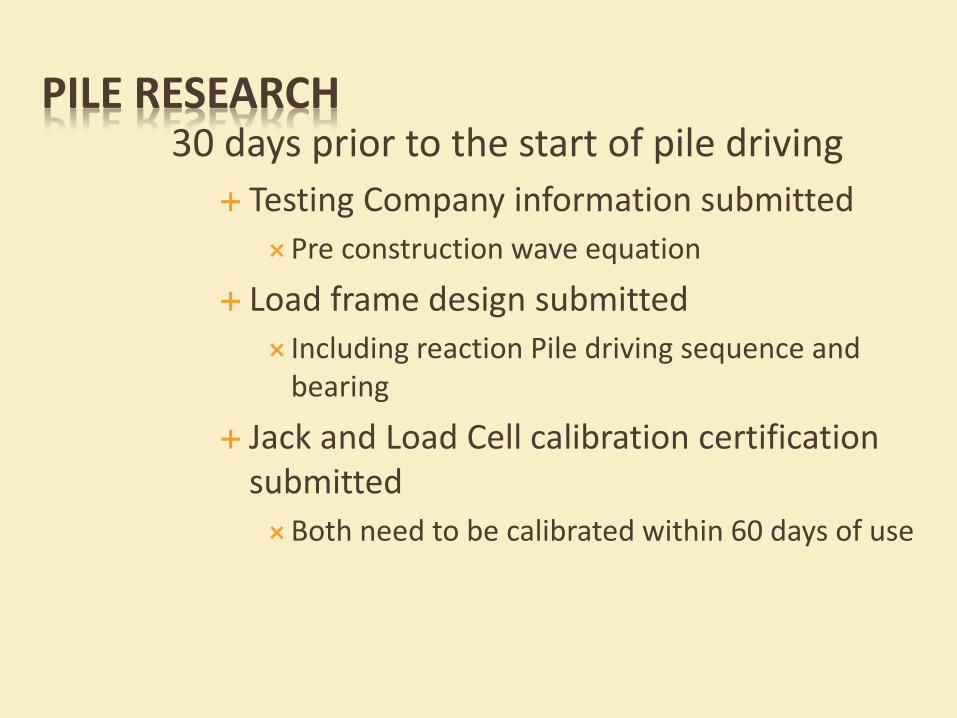
PILE RESEARCH 30 days prior to the start of pile driving
Testing Company information submitted Pre construction wave equation
Load frame design submitted Including reaction Pile driving sequence and
bearing
Jack and Load Cell calibration certification submitted Both need to be calibrated within 60 days of use
STATIC LOAD TEST
Test pile must be driven in order as per special provision
Each test will have different number of days to restrike as per special provision
SDDOT inspectors will need to locate area for test pile to be driven
SDDOT inspectors need to witness reaction pile driving to insure proper bearing and placement as per load test frame design
Inspector will need to provide saximeter and monitor static test piles being driven
Provide data for each foot of pile being driven or as requested by testing company
Provide inspector pile report Static load test will be ran by testing
company Inform Foundations when test will be
performed
Dynamic testing will be performed on piles in substructure
Inspectors will monitor pile driving the same as normal projects
Testing company will place monitoring equipment on pile when hammer is in place
Measurement will be done according to test pile section in SDDOT spec. book
10/16/2013

DYNAMIC TESTING OF PILE
10/16/2013
Pile Dynamic Analysis
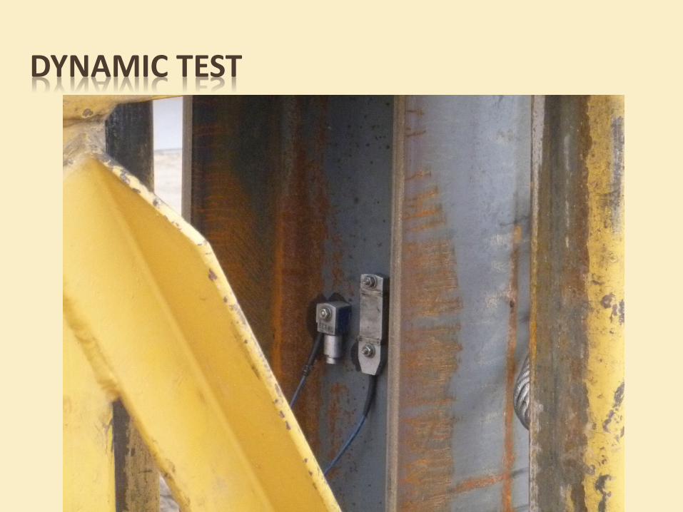
DYNAMIC TEST
10/16/2013
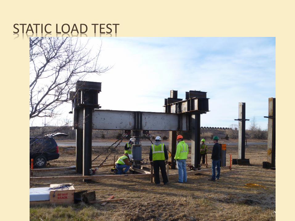
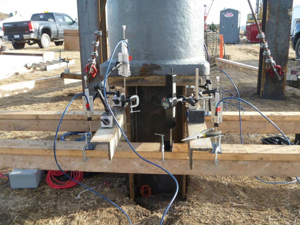
STATIC LOAD TEST
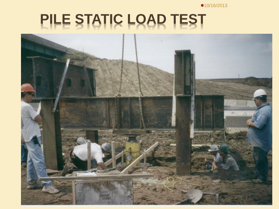
PILE STATIC LOAD TEST 10/16/2013
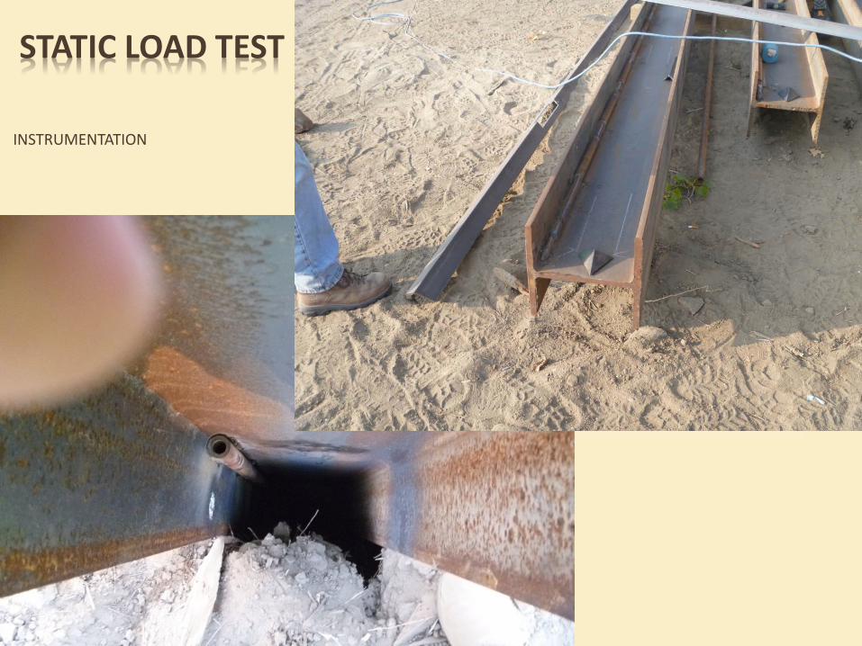
STATIC LOAD TEST
INSTRUMENTATION
10/16/2013
10/16/2013

STATNAMIC LOAD TEST
http://www.youtube.com/watch?v=2LlHdpZIwH8
10/16/2013

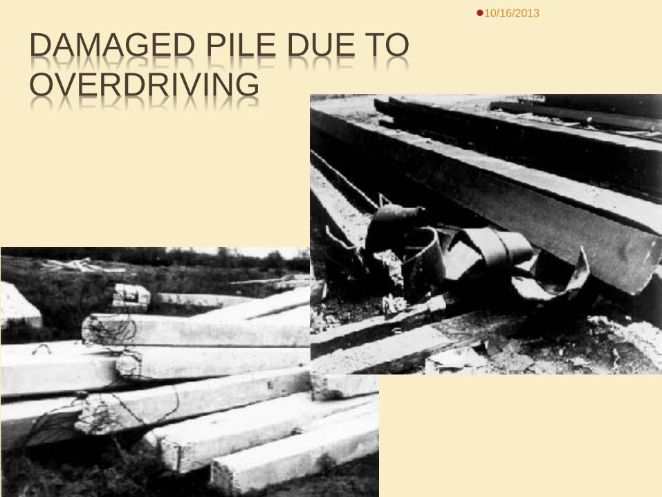
DAMAGED PILE DUE TO OVERDRIVING
10/16/2013
PRECAUTIONS IN PILE DRIVING
Drive Pile Axially Prevent Overdriving Significant Hammer Energy Keep Piston Cable Slack Preventing the Hammer from Bouncing Hammer operating properly
10/16/2013
10/16/2013

QUESTIONS 10/16/2013
Office of Bridge Design: 605-773-3285
Bridge Construction Engineer: Hadley Eisenbeisz
Office # = 605-773-4452 Cell: 605-280-4645