service manual beverage center genio 2
TRANSCRIPT
SERVICE MANUALBEVERAGE CENTERGENIO 2
Version 1.1 en
Genio 2 service manual2
C O N T E N T S
Main components.................................................................................................. 5
Overview of external parts............................................................................................ 5
Overview of internal parts............................................................................................. 6
Overview of rating plates.............................................................................................. 7Krups rating plate ..................................................................................................... 7De´Longhi rating plate .............................................................................................. 8Breville rating plate (example).................................................................................. 9
Water circuit................................................................................................................ 10
Technical data ............................................................................................................. 11
Operating ................................................................................................................ 14
Machine status ........................................................................................................... 14
Bargraph display ........................................................................................................ 15
Preparation, first use .................................................................................................. 16
Preparing a beverage................................................................................................. 18
Economy mode .......................................................................................................... 20
Empty fluid system for shipping.................................................................................. 20
Troubleshooting................................................................................................... 22
Checklist..................................................................................................................... 22
Repair ....................................................................................................................... 26
General....................................................................................................................... 26
Safety information ...................................................................................................... 26
Tools and repair accessories...................................................................................... 27
Repair work without disassembling the machine ....................................................... 27Removing / replacing needle plate, deblocking of needle ...................................... 27
General disassembly.................................................................................................. 30
Replacing water tank connector ................................................................................. 34Assembly tip ........................................................................................................... 34
Replacing flowmeter................................................................................................... 35
Replacing pump ......................................................................................................... 36Assembly tips ......................................................................................................... 39
Replacing NTC temperature sensor........................................................................... 41Assembly tips ......................................................................................................... 42
Replacing power cord with thermo fuses ................................................................... 43Assembly tips ......................................................................................................... 45
Replacing thermoblock............................................................................................... 46Assembly tips ......................................................................................................... 47
Replacing electronic mainboard ................................................................................. 49Assembly tips ......................................................................................................... 50
Replacing locking handle and control unit.................................................................. 51
Replacing electromagnet............................................................................................ 52Assembly tip ........................................................................................................... 53
Replacing extraction head.......................................................................................... 54Assembly tips ......................................................................................................... 55
Genio 2 service manual 3
Wiring diagram......................................................................................................56
Final testing............................................................................................................57
Test equipment............................................................................................................ 57
Heating up time........................................................................................................... 58
Flow rate (at 8 bar) / water temperature...................................................................... 58
Maximal pressure / leakage check.............................................................................. 60
Final inspections ..................................................................................................61
General ....................................................................................................................... 61
Safety instructions....................................................................................................... 62
Protective earthing (PE) resistance test...................................................................... 62
Insulation resistance test............................................................................................. 63
Earth leakage current test ........................................................................................... 64
Leakage current test ................................................................................................... 65
Maintenance ...........................................................................................................66
Descaling .................................................................................................................... 66
Daily care and final cleaning ....................................................................................... 70
Packing instructions .................................................................................................... 72
Krups spare parts ................................................................................................74
De´Longhi spare parts .......................................................................................78
NOTES ......................................................................................................................83
Genio 2 service manual4
P R E F A C E
The purpose of this Service Manual is to provide the service personnel with all neces-sary information with regards to correct handling, maintenance and repair of the Genio 2 beverage center W.I.K. model 9771. This beverage center is a further development of the Genio beverage center W.I.K. 9747.12.
This Service Manual should be used by the technicians as a valuable aid to guarantee the permanent readiness for use of the machine. In order to take full advantage of all the functions, it is absolutely necessary to follow the instructions in this manual.
If you have any questions, please contact your country’s Nestlé hot line, listed in the user manual.
For a quick information access, this service manual is also available in the internet as a PDF file.
The required utility software to read PDF files (Adobe Reader®) for PCs and MAC computers can be downloaded (under http://www.adobe.com) for free - please click the logo:
Please keep this manual together
with the corresponding service documentation. This way you are assured to have the necessary information.
If you display the service manual on a
computer you can click on the contents or on page references to jump to the required informa-tion immediately.
Genio 2 service manual 5
M A I N C O M P O N E N T S
M A I N C O M P O N E N T S
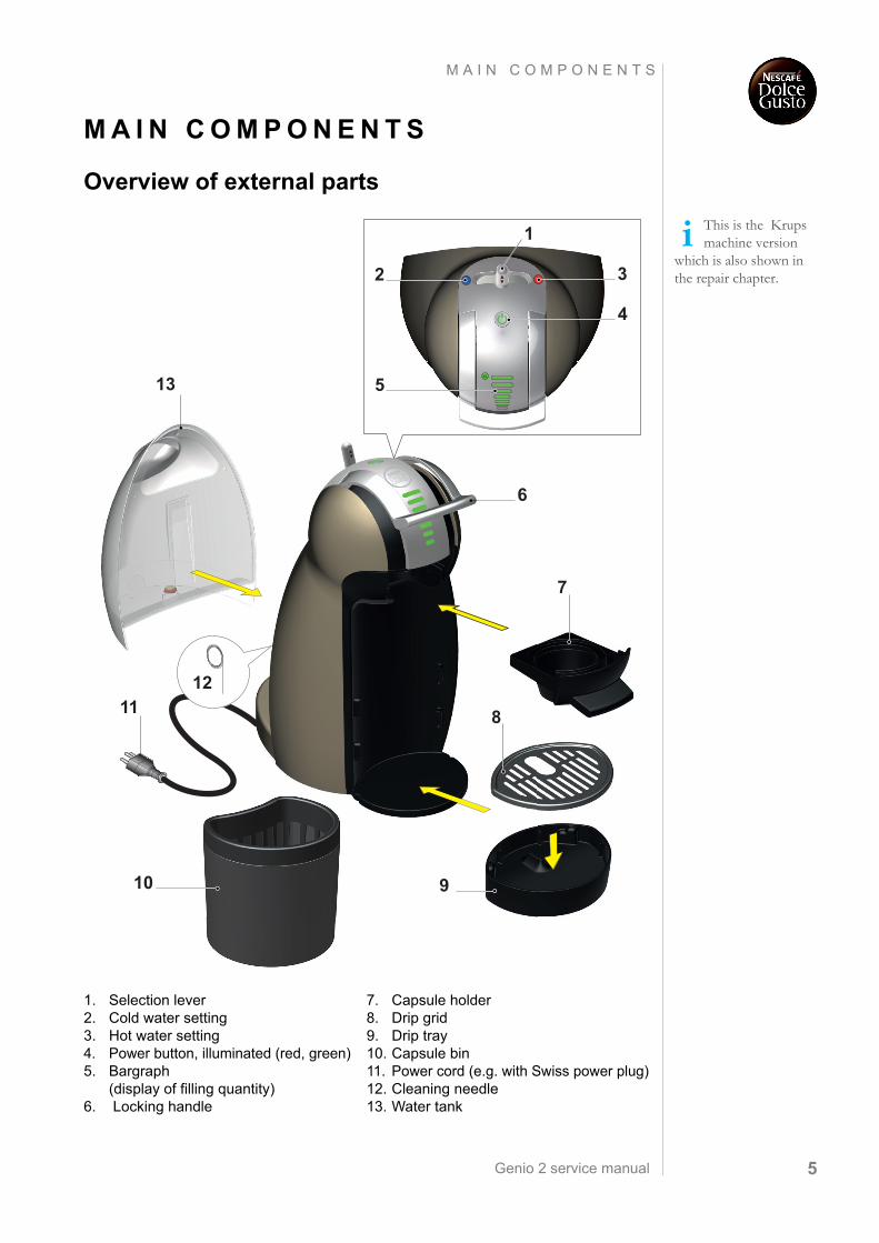
Overview of external parts
This is the Krups machine version
which is also shown in the repair chapter.
1. Selection lever2. Cold water setting3. Hot water setting4. Power button, illuminated (red, green)5. Bargraph
(display of filling quantity)6. Locking handle
7. Capsule holder8. Drip grid9. Drip tray10. Capsule bin11. Power cord (e.g. with Swiss power plug)12. Cleaning needle13. Water tank
7
1112
13
6
8
910
2 3
4
5
1
Genio 2 service manual6
M A I N C O M P O N E N T S
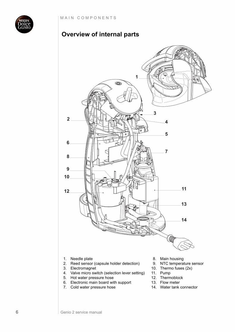
Overview of internal parts
1. Needle plate2. Reed sensor (capsule holder detection)3. Electromagnet 4. Valve micro switch (selection lever setting)5. Hot water pressure hose6. Electronic main board with support7. Cold water pressure hose
8. Main housing9. NTC temperature sensor
10. Thermo fuses (2x)11. Pump12. Thermoblock13. Flow meter14. Water tank connector
1
23
4
6
7
5
9
8
1112
13
14
10
Genio 2 service manual 7
M A I N C O M P O N E N T S
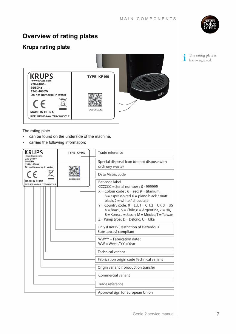
Overview of rating plates
Krups rating plate
The rating plate
• can be found on the underside of the machine,
• carries the following information:
The rating plate is laser-engraved.
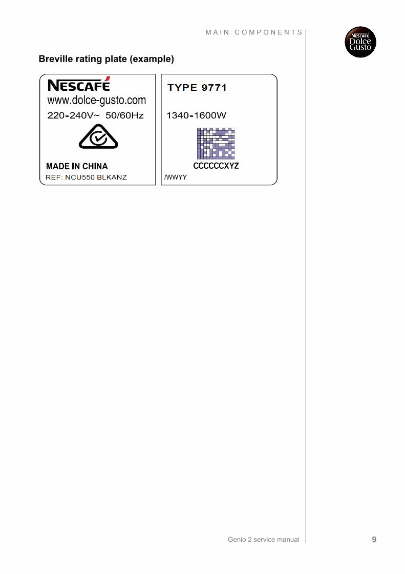
www.krups.com
REF: KP160AAA /7Z0- WWYY R
TYPE KP160
220-240V~50/60Hz1340-1600WDo not immerse in water
MADE IN CHINACCCCCCXYZ
Trade reference
WWYY = Fabrication date :WW = Week / YY = Year
Commercial variant
Trade reference
Only if RoHS (Restriction of Hazardous Substances) compliant
Fabrication origin code Technical variant
Origin variant if production transfer
Approval sign for European Union
Bar code labelCCCCCC = Serial number : 0 - 999999 X = Colour code : 6 = red, 9 = titanium, 8 = espresso red, 0 = piano black / matt black, 2 = white / chocolate Y = Country code: 0 = EU, 1 = CH, 2 = UK, 3 = US 4 = Brazil, 5 = Chile, 6 = Argentina, 7 = HK, 8 = Korea, J = Japan, M = Mexico, T = TaiwanZ = Pump type : D = Defond, U = Ulka
Data Matrix code
Special disposal icon (do not dispose with ordinary waste)
Technical variant
www.krups.com
REF: KP160AAA /7Z0- WWYY R
TYPE KP160
220-240V~50/60Hz1340-1600WDo not immerse in water
MADE IN CHINACCCCCCXYZ
Genio 2 service manual8
M A I N C O M P O N E N T S
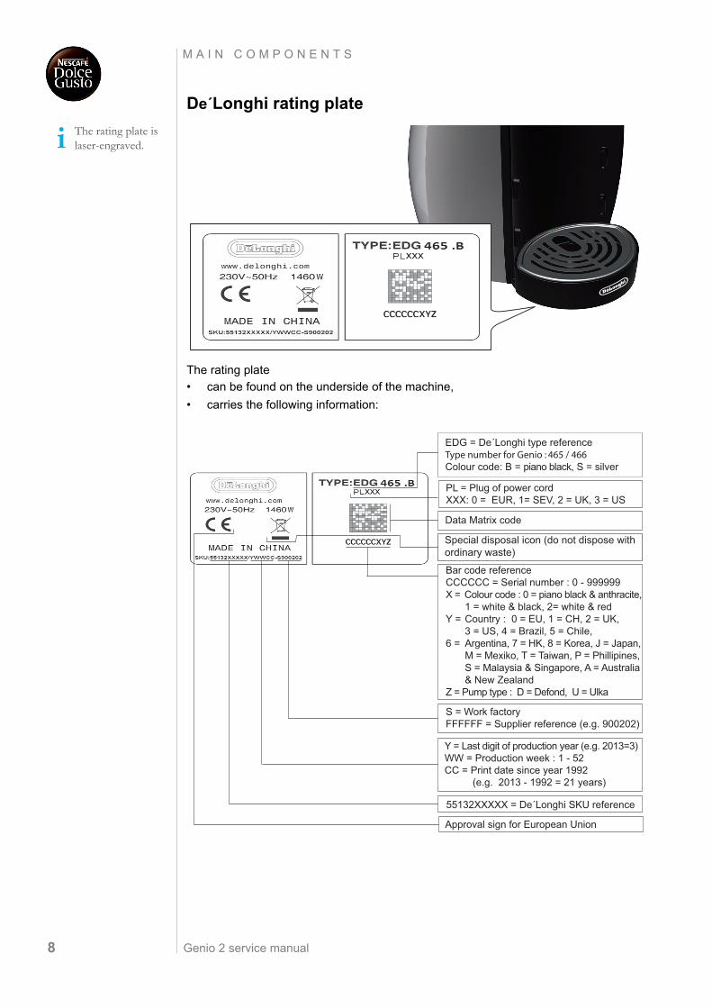
De´Longhi rating plate
The rating plate
• can be found on the underside of the machine,
• carries the following information:
The rating plate is laser-engraved.
EDG = De´Longhi type referenceType number for Genio : 465 / 466Colour code: B = piano black, S = silver
S = Work factoryFFFFFF = Supplier reference (e.g. 900202)
55132XXXXX = De´Longhi SKU reference
Y = Last digit of production year (e.g. 2013=3) WW = Production week : 1 - 52CC = Print date since year 1992 (e.g. 2013 - 1992 = 21 years)
Approval sign for European Union
Special disposal icon (do not dispose with ordinary waste)
PL = Plug of power cordXXX: 0 = EUR, 1= SEV, 2 = UK, 3 = US
Bar code referenceCCCCCC = Serial number : 0 - 999999 X = Colour code : 0 = piano black & anthracite, 1 = white & black, 2= white & redY = Country : 0 = EU, 1 = CH, 2 = UK, 3 = US, 4 = Brazil, 5 = Chile, 6 = Argentina, 7 = HK, 8 = Korea, J = Japan, M = Mexiko, T = Taiwan, P = Phillipines, S = Malaysia & Singapore, A = Australia & New ZealandZ = Pump type : D = Defond, U = Ulka
Data Matrix code
Genio 2 service manual 9
M A I N C O M P O N E N T S
Breville rating plate (example)
Genio 2 service manual10
M A I N C O M P O N E N T S
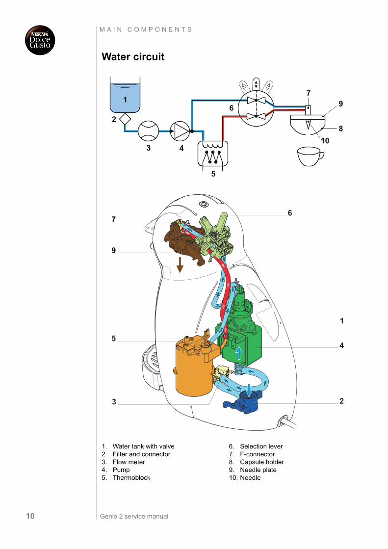
Water circuit
1. Water tank with valve2. Filter and connector3. Flow meter4. Pump5. Thermoblock
6. Selection lever7. F-connector8. Capsule holder9. Needle plate10. Needle
1
2
4
5
6
8
9
10
7
3
7
9
1
2
45
3
6
Genio 2 service manual 11
M A I N C O M P O N E N T S
Technical data
Mains voltage
Europe (UK, CH, DE, AT, FR, ES, PT, IT, NL, LU, BE, NO, SE, FI, DK, GR, CZ, SK, PL, HU, RU, UA, LT, LV, EE, BG, RO, SI, BiH, SRB, HR)... 230 V / 50 Hz
USA / Canada ...........................................................................................120 V / 60 Hz
Japan ...................................................................................................100 V / 50/60 Hz
Mexico, Brazil............................................................................................127 V / 60 Hz
Approvals (country dependent) e.g.
Europe .......................................................................................................................CE
USA, Canada ......................................................................................... UL, C-UL, CSA
Japan ....................................................................................................................... JET
Russia ..................................................................................................................... PCT
Power consumption................................................................................max. 1’500 W
Thermoblock ..................................................................................................... 1’400 W
Pump...................................................................................................................... 41 W
Energy consumption (CECED / FEA 2009 method)
Energy efficiency class level ........................................................................................ A
Daily energy consumption.................................................................................... 90 Wh
Annual energy consumption............................................................................... 33 kWh
Preset water quantities (without capsule)
Bar graph segment 1 (bottom) ...............................................................................53 ml
Bar graph segment 2..............................................................................................68 ml
Bar graph segment 3..............................................................................................94 ml
Bar graph segment 4............................................................................................130 ml
Bar graph segment 5............................................................................................146 ml
Bar graph segment 6............................................................................................173 ml
Bar graph segment 7 (top) ...................................................................................230 ml
Bar graph segment 7 + XL ...................................................................................300 ml
Capacities
Water tank.......................................................................................................... max. 1 l
Drip tray.....................................................................................................approx. 70 ml
Environmental conditions
Operating temperature ................................5 °C up to + 45 °C (+ 41 °F up to + 113 °F)
Genio 2 service manual12
M A I N C O M P O N E N T S
Various data
Pre-heating time .....................................................................................approx. 30 sec.
Automatic shut off time (eco mode)........................................................................5 min
Hot beverage outlet temperature......................................85 °C ± 5 °C (185 °F ± 41 °F)
Descaling temperature ...............................................65 °C to 70 °C (149 °F to 158 °F)
Safety temperature for thermo block (thermal cut-off)........................... 133 °C (271 °F)
Safety temperature for pump (thermal cut-off) .......................................113 °C (235 °F)
Pump pressure ................................................................................ max. 13.5 ± 1.5 bar
Noise ....................................................................................................... max. 65 dB(A)
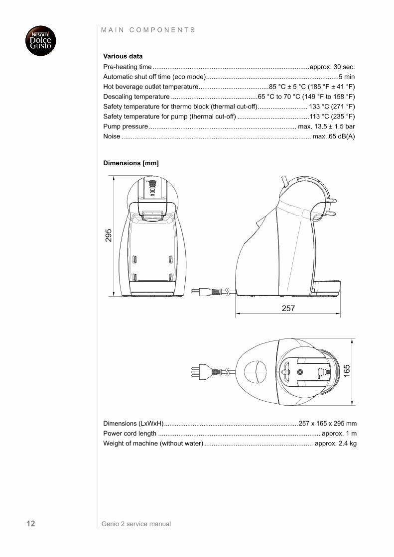
Dimensions [mm]
Dimensions (LxWxH)...........................................................................257 x 165 x 295 mm
Power cord length ........................................................................................ approx. 1 m
Weight of machine (without water) ........................................................... approx. 2.4 kg
295
257
165
Genio 2 service manual 13
M A I N C O M P O N E N T S
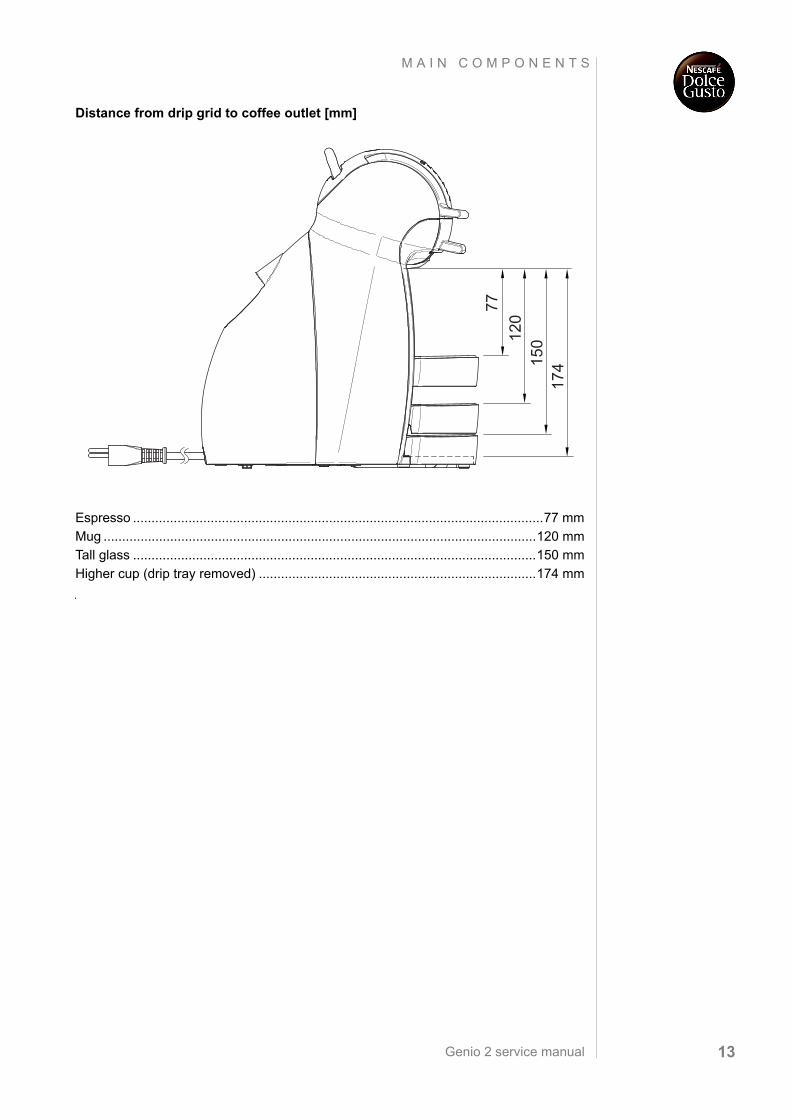
Distance from drip grid to coffee outlet [mm]
Espresso ...............................................................................................................77 mm
Mug .....................................................................................................................120 mm
Tall glass .............................................................................................................150 mm
Higher cup (drip tray removed) ...........................................................................174 mm
120
77
150
174
Genio 2 service manual14
O P E R A T I N G
O P E R AT I N G
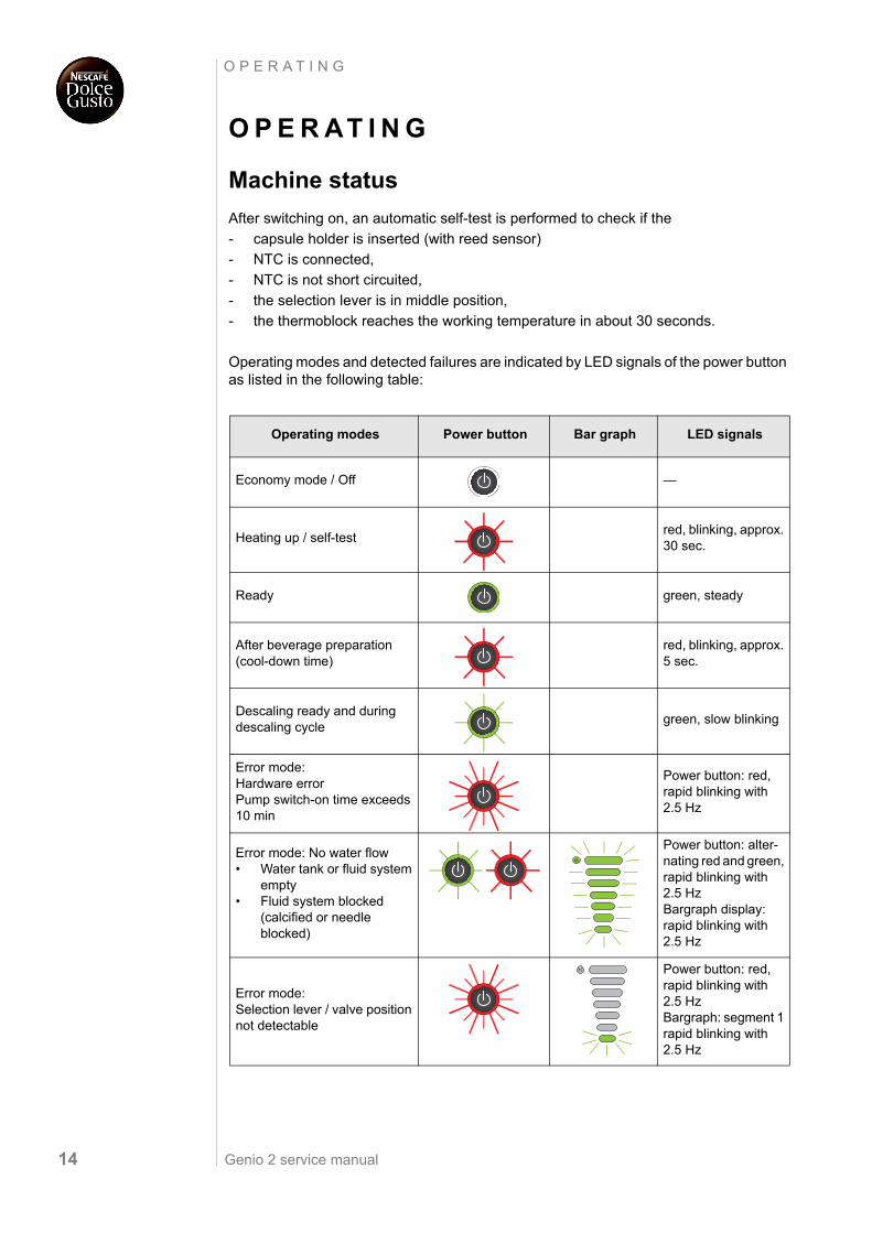
Machine status
After switching on, an automatic self-test is performed to check if the
- capsule holder is inserted (with reed sensor)
- NTC is connected,
- NTC is not short circuited,
- the selection lever is in middle position,
- the thermoblock reaches the working temperature in about 30 seconds.
Operating modes and detected failures are indicated by LED signals of the power button as listed in the following table:
Operating modes Power button Bar graph LED signals
Economy mode / Off —
Heating up / self-testred, blinking, approx. 30 sec.
Ready green, steady
After beverage preparation (cool-down time)
red, blinking, approx. 5 sec.
Descaling ready and during descaling cycle
green, slow blinking
Error mode: Hardware errorPump switch-on time exceeds 10 min
Power button: red, rapid blinking with 2.5 Hz
Error mode: No water flow• Water tank or fluid system
empty• Fluid system blocked
(calcified or needle blocked)
Power button: alter-nating red and green, rapid blinking with 2.5 Hz Bargraph display: rapid blinking with 2.5 Hz
Error mode: Selection lever / valve position not detectable
Power button: red, rapid blinking with 2.5 HzBargraph: segment 1 rapid blinking with 2.5 Hz
XL
XL
Genio 2 service manual 15
O P E R A T I N G
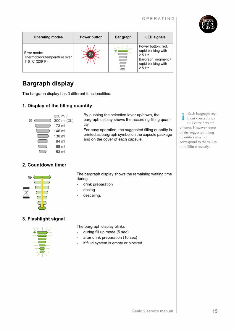
Bargraph display
The bargraph display has 3 different functionalities:
1. Display of the filling quantity
2. Countdown timer
3. Flashlight signal
Error mode:Thermoblock temperature over 115 °C (239°F)
Power button: red, rapid blinking with 2.5 HzBargraph: segment 7 rapid blinking with 2.5 Hz
Operating modes Power button Bar graph LED signals
XL
Each bargraph seg-ment corresponds to a certain water
volume. However some of the suggested filling quantities may not correspond to the values in millilitres exactly.
By pushing the selection lever up/down, the bargraph display shows the according filling quan-tity.
For easy operation, the suggested filling quantity is printed as bargraph symbol on the capsule package and on the cover of each capsule.
The bargraph display shows the remaining waiting time during
- drink preparation
- rinsing
- descaling.
The bargraph display blinks
- during fill up mode (5 sec)
- after drink preparation (10 sec)
- if fluid system is empty or blocked.
173 ml146 ml130 ml94 ml68 ml53 ml
230 ml /300 ml (XL)XL
XL
XL
Genio 2 service manual16
O P E R A T I N G
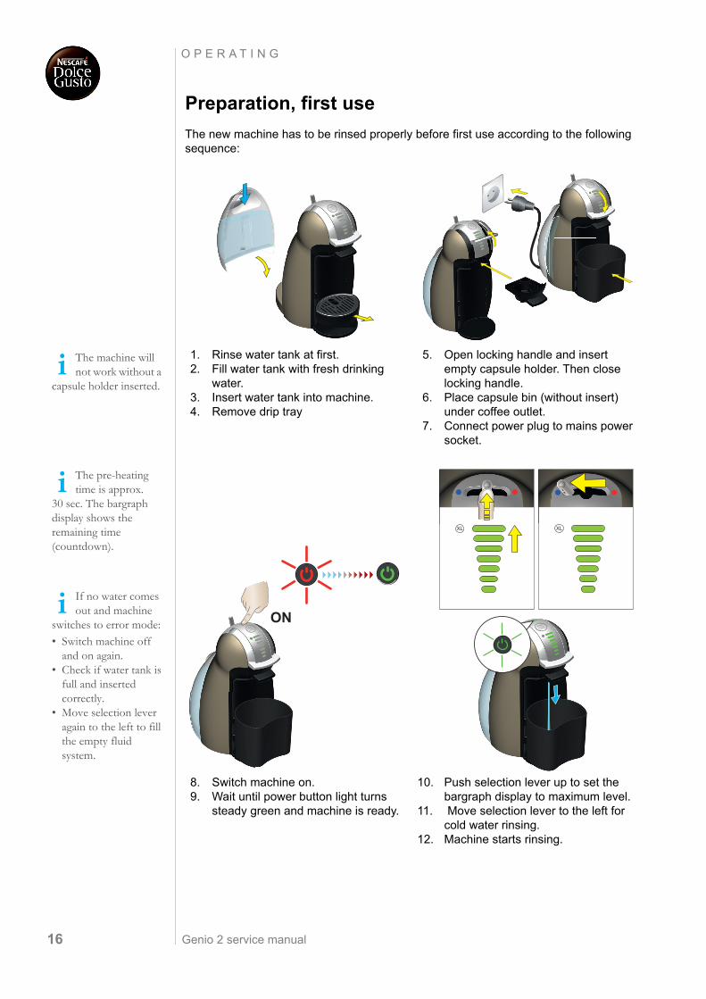
Preparation, first use
The new machine has to be rinsed properly before first use according to the following sequence:
The machine will not work without a
capsule holder inserted.
The pre-heating time is approx.
30 sec. The bargraph display shows the remaining time (countdown).
If no water comes out and machine
switches to error mode: • Switch machine off
and on again.• Check if water tank is
full and inserted correctly.
• Move selection lever again to the left to fill the empty fluid system.
1. Rinse water tank at first.2. Fill water tank with fresh drinking
water.3. Insert water tank into machine.4. Remove drip tray
5. Open locking handle and insert empty capsule holder. Then close locking handle.
6. Place capsule bin (without insert) under coffee outlet.
7. Connect power plug to mains power socket.
8. Switch machine on.9. Wait until power button light turns
steady green and machine is ready.
10. Push selection lever up to set the bargraph display to maximum level.
11. Move selection lever to the left for cold water rinsing.
12. Machine starts rinsing.
XL
XL
XL
ONXL
Genio 2 service manual 17
O P E R A T I N G
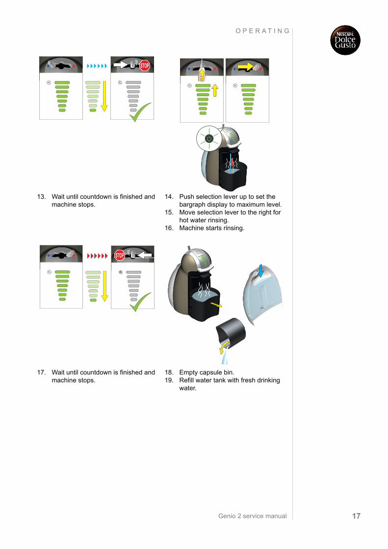
13. Wait until countdown is finished and machine stops.
14. Push selection lever up to set the bargraph display to maximum level.
15. Move selection lever to the right for hot water rinsing.
16. Machine starts rinsing.
17. Wait until countdown is finished and machine stops.
18. Empty capsule bin. 19. Refill water tank with fresh drinking
water.
STOP
STOP XL
Genio 2 service manual18
O P E R A T I N G
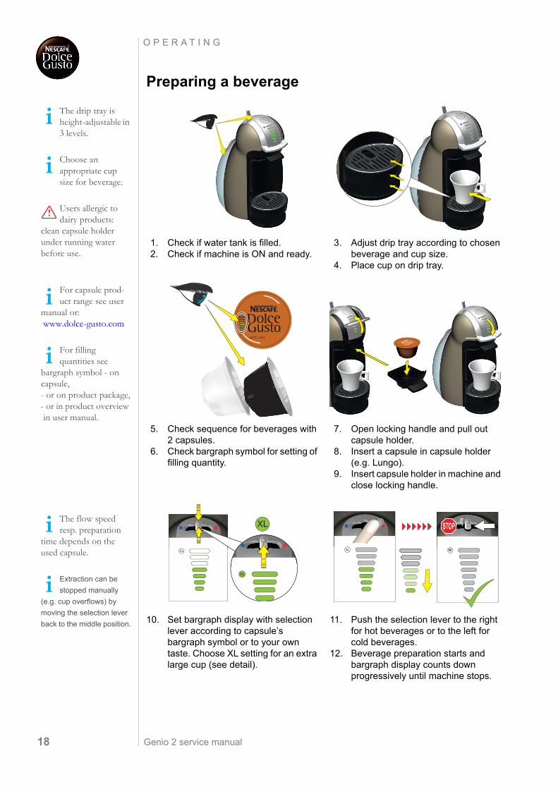
Preparing a beverage
The drip tray is height-adjustable in 3 levels.
Choose an appropriate cup size for beverage.
Users allergic to dairy products:
clean capsule holder under running water before use.
For capsule prod-uct range see user
manual or: www.dolce-gusto.com
For filling quantities see
bargraph symbol - on capsule,- or on product package,- or in product overview in user manual.
The flow speed resp. preparation
time depends on the used capsule.
Extraction can be
stopped manually
(e.g. cup overflows) by
moving the selection lever
back to the middle position.
1. Check if water tank is filled.2. Check if machine is ON and ready.
3. Adjust drip tray according to chosen beverage and cup size.
4. Place cup on drip tray.
5. Check sequence for beverages with 2 capsules.
6. Check bargraph symbol for setting of filling quantity.
7. Open locking handle and pull out capsule holder.
8. Insert a capsule in capsule holder (e.g. Lungo).
9. Insert capsule holder in machine and close locking handle.
10. Set bargraph display with selection lever according to capsule’s bargraph symbol or to your own taste. Choose XL setting for an extra large cup (see detail).
11. Push the selection lever to the right for hot beverages or to the left for cold beverages.
12. Beverage preparation starts and bargraph display counts down progressively until machine stops.
XLXL
CAFFÉ LUNGO
XL
STOP
Genio 2 service manual 19
O P E R A T I N G
Danger of damage and hot water /
product splashes.Do not open locking handle prematurely.
Risk of burning from hot capsule.
Do not touch capsule immediately after use.
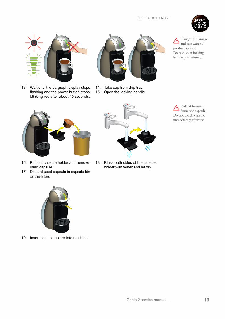
13. Wait until the bargraph display stops flashing and the power button stops blinking red after about 10 seconds.
14. Take cup from drip tray. 15. Open the locking handle.
16. Pull out capsule holder and remove used capsule.
17. Discard used capsule in capsule bin or trash bin.
18. Rinse both sides of the capsule holder with water and let dry.
19. Insert capsule holder into machine.
XLXL XL
XL
Genio 2 service manual20
O P E R A T I N G
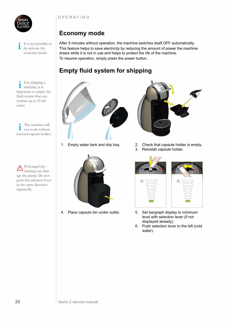
Economy mode
After 5 minutes without operation, the machine switches itself OFF automatically.
This feature helps to save electricity by reducing the amount of power the machine draws while it is not in use and helps to protect the life of the machine.
To resume operation, simply press the power button.
Empty fluid system for shipping
It is not possible to de-activate the economy mode.
For shipping a machine, it is
important to empty the fluid system that can contain up to 25 ml water.
The machine will not work without
inserted capsule holder.
Prolonged dry-running can dam-
age the pump. Do not push the selection lever in the same direction repeatedly.
1. Empty water tank and drip tray. 2. Check that capsule holder is empty.3. Reinstall capsule holder.
4. Place capsule bin under outlet. 5. Set bargraph display to minimum level with selection lever (if not displayed already).
6. Push selection lever to the left (cold water).
Genio 2 service manual 21
O P E R A T I N G
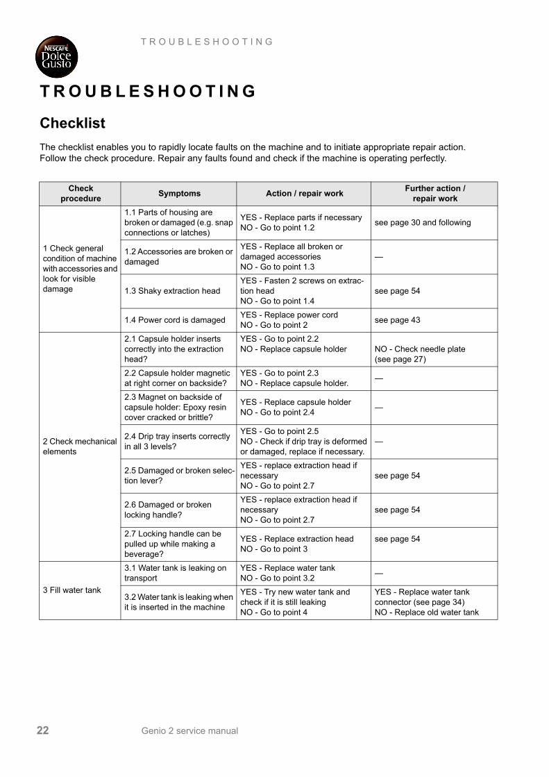
In error mode, the power button
blinks red and green alternately and the bar-graph segment blinks green.
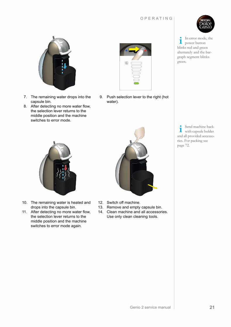
7. The remaining water drops into the capsule bin.
8. After detecting no more water flow, the selection lever returns to the middle position and the machine switches to error mode.
9. Push selection lever to the right (hot water).
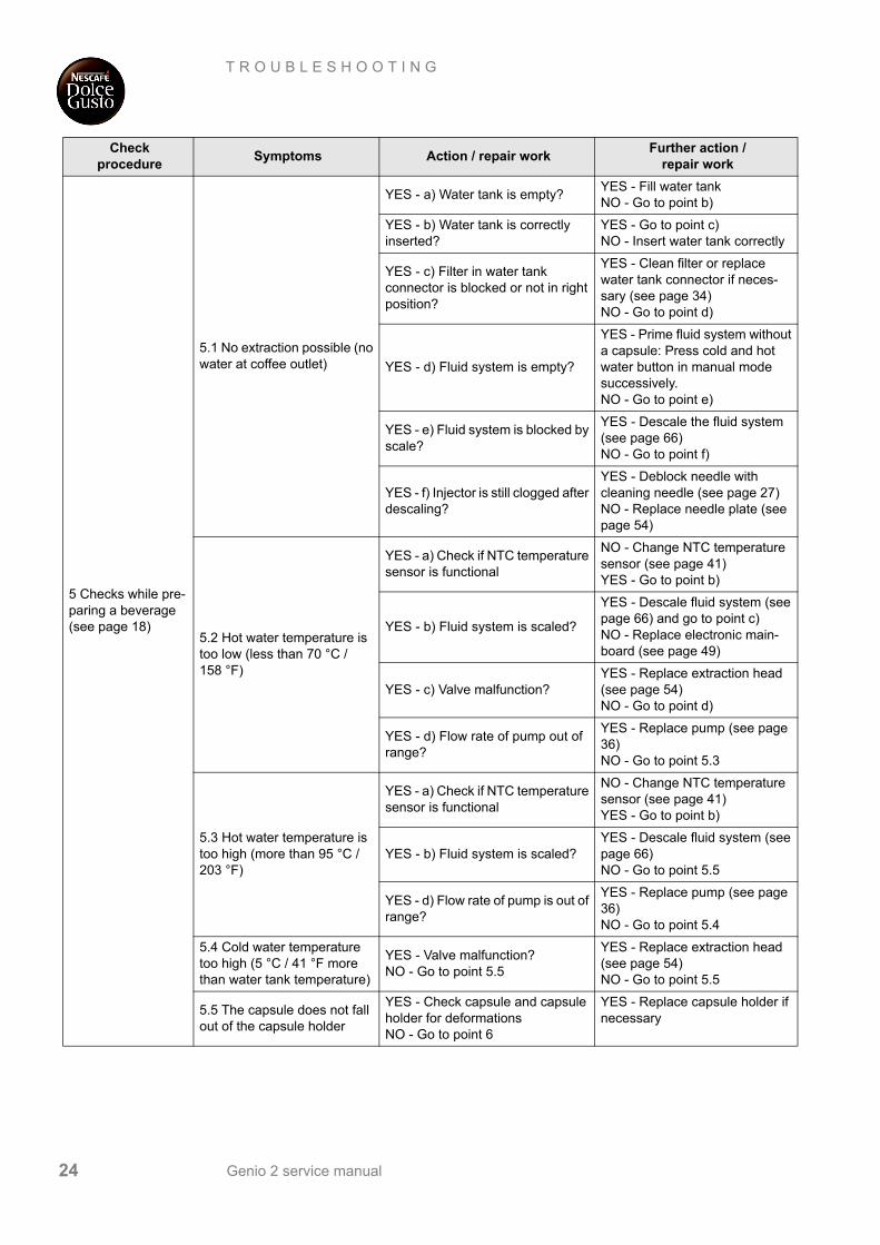
Send machine back with capsule holder
and all provided accesso-ries. For packing see page 72.
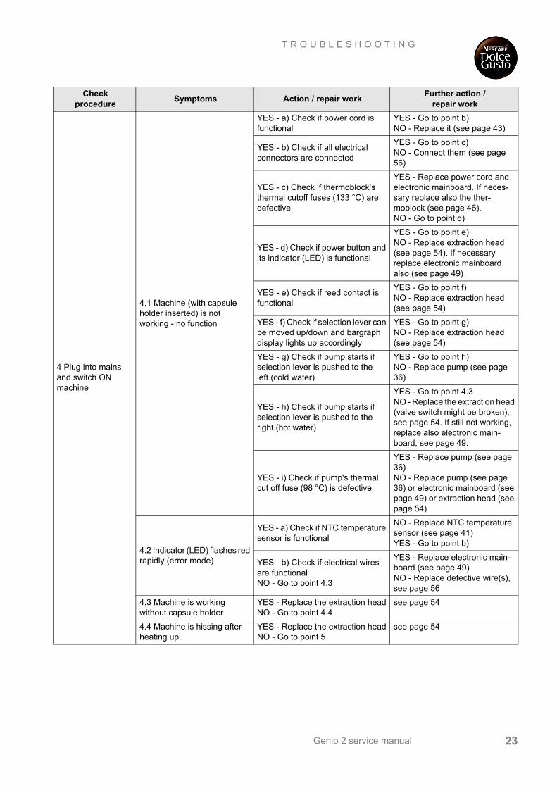
10. The remaining water is heated and drops into the capsule bin.
11. After detecting no more water flow, the selection lever returns to the middle position and the machine switches to error mode again.
12. Switch off machine.13. Remove and empty capsule bin.14. Clean machine and all accessories.
Use only clean cleaning tools.
XL
Genio 2 service manual22
T R O U B L E S H O O T I N G
T R O U B L E S H O O T I N G
Checklist
The checklist enables you to rapidly locate faults on the machine and to initiate appropriate repair action.Follow the check procedure. Repair any faults found and check if the machine is operating perfectly.
Check procedure
Symptoms Action / repair workFurther action /
repair work
1 Check general condition of machine with accessories and look for visible damage
1.1 Parts of housing are broken or damaged (e.g. snap connections or latches)
YES - Replace parts if necessaryNO - Go to point 1.2
see page 30 and following
1.2 Accessories are broken or damaged
YES - Replace all broken or damaged accessoriesNO - Go to point 1.3
—
1.3 Shaky extraction headYES - Fasten 2 screws on extrac-tion headNO - Go to point 1.4
see page 54
1.4 Power cord is damaged YES - Replace power cordNO - Go to point 2
see page 43
2 Check mechanical elements
2.1 Capsule holder inserts correctly into the extraction head?
YES - Go to point 2.2NO - Replace capsule holder NO - Check needle plate
(see page 27)
2.2 Capsule holder magnetic at right corner on backside?
YES - Go to point 2.3NO - Replace capsule holder.
—
2.3 Magnet on backside of capsule holder: Epoxy resin cover cracked or brittle?
YES - Replace capsule holder NO - Go to point 2.4
—
2.4 Drip tray inserts correctly in all 3 levels?
YES - Go to point 2.5NO - Check if drip tray is deformed or damaged, replace if necessary.
—
2.5 Damaged or broken selec-tion lever?
YES - replace extraction head if necessaryNO - Go to point 2.7
see page 54
2.6 Damaged or broken locking handle?
YES - replace extraction head if necessaryNO - Go to point 2.7
see page 54
2.7 Locking handle can be pulled up while making a beverage?
YES - Replace extraction head NO - Go to point 3
see page 54
3 Fill water tank
3.1 Water tank is leaking on transport
YES - Replace water tankNO - Go to point 3.2
—
3.2 Water tank is leaking when it is inserted in the machine
YES - Try new water tank and check if it is still leakingNO - Go to point 4
YES - Replace water tank connector (see page 34)NO - Replace old water tank
Genio 2 service manual 23
T R O U B L E S H O O T I N G
4 Plug into mains and switch ON machine
4.1 Machine (with capsule holder inserted) is not working - no function
YES - a) Check if power cord is functional
YES - Go to point b)NO - Replace it (see page 43)
YES - b) Check if all electrical connectors are connected
YES - Go to point c)NO - Connect them (see page 56)
YES - c) Check if thermoblock’s thermal cutoff fuses (133 °C) are defective
YES - Replace power cord and electronic mainboard. If neces-sary replace also the ther-moblock (see page 46). NO - Go to point d)
YES - d) Check if power button and its indicator (LED) is functional
YES - Go to point e)NO - Replace extraction head (see page 54). If necessary replace electronic mainboard also (see page 49)
YES - e) Check if reed contact is functional
YES - Go to point f)NO - Replace extraction head (see page 54)
YES - f) Check if selection lever can be moved up/down and bargraph display lights up accordingly
YES - Go to point g)NO - Replace extraction head (see page 54)
YES - g) Check if pump starts if selection lever is pushed to the left.(cold water)
YES - Go to point h)NO - Replace pump (see page 36)
YES - h) Check if pump starts if selection lever is pushed to the right (hot water)
YES - Go to point 4.3NO - Replace the extraction head (valve switch might be broken), see page 54. If still not working, replace also electronic main-board, see page 49.
YES - i) Check if pump's thermal cut off fuse (98 °C) is defective
YES - Replace pump (see page 36)NO - Replace pump (see page 36) or electronic mainboard (see page 49) or extraction head (see page 54)
4.2 Indicator (LED) flashes red rapidly (error mode)
YES - a) Check if NTC temperature sensor is functional
NO - Replace NTC temperature sensor (see page 41)YES - Go to point b)
YES - b) Check if electrical wires are functionalNO - Go to point 4.3
YES - Replace electronic main-board (see page 49)NO - Replace defective wire(s), see page 56
4.3 Machine is working without capsule holder
YES - Replace the extraction headNO - Go to point 4.4
see page 54
4.4 Machine is hissing after heating up.
YES - Replace the extraction headNO - Go to point 5
see page 54
Check procedure
Symptoms Action / repair workFurther action /
repair work
Genio 2 service manual24
T R O U B L E S H O O T I N G
5 Checks while pre-paring a beverage (see page 18)
5.1 No extraction possible (no water at coffee outlet)
YES - a) Water tank is empty?YES - Fill water tankNO - Go to point b)
YES - b) Water tank is correctly inserted?
YES - Go to point c)NO - Insert water tank correctly
YES - c) Filter in water tank connector is blocked or not in right position?
YES - Clean filter or replace water tank connector if neces-sary (see page 34)NO - Go to point d)
YES - d) Fluid system is empty?
YES - Prime fluid system without a capsule: Press cold and hot water button in manual mode successively.NO - Go to point e)
YES - e) Fluid system is blocked by scale?
YES - Descale the fluid system (see page 66)NO - Go to point f)
YES - f) Injector is still clogged after descaling?
YES - Deblock needle with cleaning needle (see page 27)NO - Replace needle plate (see page 54)
5.2 Hot water temperature is too low (less than 70 °C / 158 °F)
YES - a) Check if NTC temperature sensor is functional
NO - Change NTC temperature sensor (see page 41)YES - Go to point b)
YES - b) Fluid system is scaled?
YES - Descale fluid system (see page 66) and go to point c)NO - Replace electronic main-board (see page 49)
YES - c) Valve malfunction?YES - Replace extraction head (see page 54)NO - Go to point d)
YES - d) Flow rate of pump out of range?
YES - Replace pump (see page 36)NO - Go to point 5.3
5.3 Hot water temperature is too high (more than 95 °C / 203 °F)
YES - a) Check if NTC temperature sensor is functional
NO - Change NTC temperature sensor (see page 41)YES - Go to point b)
YES - b) Fluid system is scaled?YES - Descale fluid system (see page 66)NO - Go to point 5.5
YES - d) Flow rate of pump is out of range?
YES - Replace pump (see page 36)NO - Go to point 5.4
5.4 Cold water temperature too high (5 °C / 41 °F more than water tank temperature)
YES - Valve malfunction?NO - Go to point 5.5
YES - Replace extraction head (see page 54)NO - Go to point 5.5
5.5 The capsule does not fall out of the capsule holder
YES - Check capsule and capsule holder for deformationsNO - Go to point 6
YES - Replace capsule holder if necessary
Check procedure
Symptoms Action / repair workFurther action /
repair work
Genio 2 service manual 25
T R O U B L E S H O O T I N G
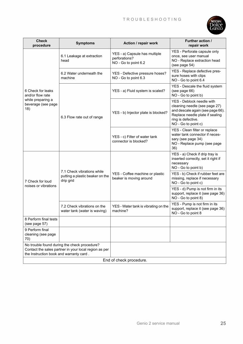
6 Check for leaks and/or flow rate while preparing a beverage (see page 18)
6.1 Leakage at extraction head
YES - a) Capsule has multiple perforations?NO - Go to point 6.2
YES - Perforate capsule only once, see user manualNO - Replace extraction head (see page 54)
6.2 Water underneath the machine
YES - Defective pressure hoses?NO - Go to point 6.3
YES - Replace defective pres-sure hoses with clipsNO - Go to point 6.4
6.3 Flow rate out of range
YES - a) Fluid system is scaled?YES - Descale the fluid system (see page 66) NO - Go to point b)
YES - b) Injector plate is blocked?
YES - Deblock needle with cleaning needle (see page 27) and descale again (see page 66). Replace needle plate if sealing ring is defective.NO - Go to point c)
YES - c) Filter of water tank connector is blocked?
YES - Clean filter or replace water tank connector if neces-sary (see page 34)NO - Replace pump (see page 36)
7 Check for loud noises or vibrations
7.1 Check vibrations while putting a plastic beaker on the drip grid
YES - Coffee machine or plastic beaker is moving around
YES - a) Check if drip tray is inserted correctly, set it right if necessaryNO - Go to point b)
YES - b) Check if rubber feet are missing, replace if necessaryNO - Go to point c)
YES - d) Pump is not firm in its support, replace it (see page 36)NO - Go to point 8)
7.2 Check vibrations on the water tank (water is waving)
YES - Water tank is vibrating on the machine?
YES - Pump is not firm in its support, replace it (see page 36)NO - Go to point 8
8 Perform final tests (see page 57)
9 Perform final cleaning (see page 70)
No trouble found during the check procedure?Contact the sales partner in your local region as per the Instruction book and warranty card .
End of check procedure.
Check procedure
Symptoms Action / repair workFurther action /
repair work
Genio 2 service manual26
R E P A I R
R E PA I R
General
This chapter contains special safety and assembly notes.
The disassembly and repair procedures are presented as step by step instructions.
The position numbers of the parts correspond to the Krups spare parts list. Parts not included in the spare parts list are marked with capital letters.
Safety information
• Empty the fluid system before disassembly (if possible) and shipment (see page 20).
• The machine is screwed together with special safety screws. Please insert the same screws when reassembling the machine - for safety reasons for the user.
• With each disassembly and repair
- always accomplish internal cleaning
- renew all pressure hoses and clips when disassembled.
• Handle snap connections and latches with care to avoid any damage.
• If it is necessary to cut or pull off hoses, hold a towel ready to wipe away leaking water.
Non-observance of these notes can lead to injuries and damages!
De´Longhi spare parts have different
position and part num-bers, see page 78 and fol-lowing.
WARNINGDanger of electric shock - live parts inside coffee machine.
Unplug from the mains before disassembling the machine - appliance must be isolated!
Every time a pressure hose or a clip is disconnected, it must be replaced by a new one.
Genio 2 service manual 27
R E P A I R
Tools and repair accessories
With the following tools, all described disassembly and repair work can be done:
Repair work without disassembling the machine
Without disassembling the machine, the following parts can be removed resp. replaced:
• Water tank (17)
• Capsule holder (8)
• Needle plate (5)
• Drip tray (15) and drip grid (16)
Removing / replacing needle plate, deblocking of needleSolid residues in the water circuit can block the needle completely. An example is the development of calcium particles if the machine is not descaled periodically. Therefore this error appears during descaling frequently.
A pin-torx screw head looks like this:Tools Applications
Torx screwdriver for security screws, Pin-TX 10
Fastening screws for extraction head, side panels and water tank connector
Phillips screwdriver no. 1
Fastening screw for fuse holder on thermoblock.Fastening screw for NTC holding plate on ther-moblock.Fastening screws (2x) for magnet bracket.
Screwdriver with blade width 4 mm To open latches and snap connections.To remove connectors from electronic mainboard.
Flat nose pliersFlat receptacles, hose clips, filter element of water tank connector
Fork wrench no. 12 Adjustable pump connector
Cutter (stanley knife) Cut new pressure hoses to length.
Cutting pliersTo cut cable tie for cable routing. To cut H-connector for pressure hoses.
Heat conducting paste NTC temperature sensor
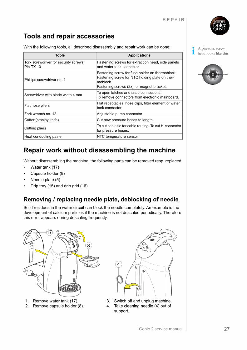
1. Remove water tank (17).2. Remove capsule holder (8).
3. Switch off and unplug machine.4. Take cleaning needle (4) out of
support.
17
8
4
Genio 2 service manual28
R E P A I R
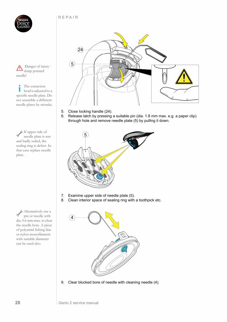
5. Close locking handle (24).6. Release latch by pressing a suitable pin (dia. 1.8 mm max. e.g. a paper clip)
through hole and remove needle plate (5) by pulling it down.
7. Examine upper side of needle plate (5).8. Clean interior space of sealing ring with a toothpick etc.
9. Clear blocked bore of needle with cleaning needle (4).
Danger of injury - sharp pointed
needle!
The extraction head is adjusted to a
specific needle plate. Do not assemble a different needle plates by mistake.
24
5
If upper side of needle plate is wet
and badly soiled, the sealing ring is defect. In that case replace needle plate.
5
Alternatively use a pin or needle with
dia. 0.6 mm max. to clear the needle bore. A piece of polyamid fishing line or nylon monofilament with suitable diameter can be used also.
4
Genio 2 service manual 29
R E P A I R
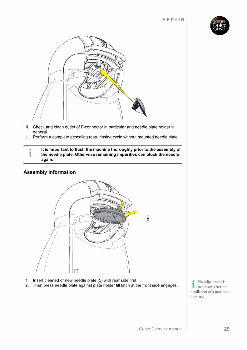
10. Check and clean outlet of F-connector in particular and needle plate holder in general.
11. Perform a complete descaling resp. rinsing cycle without mounted needle plate.
Assembly information
1. Insert cleaned or new needle plate (5) with rear side first.2. Then press needle plate against plate holder till latch at the front side engages.
It is important to flush the machine thoroughly prior to the assembly of the needle plate. Otherwise remaining impurities can block the needle again.
5
No adjustment is necessary after the
installation of a new nee-dle plate.
Genio 2 service manual30
R E P A I R
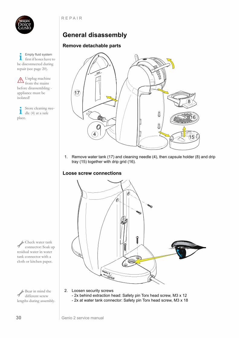
General disassembly
Remove detachable parts
1. Remove water tank (17) and cleaning needle (4), then capsule holder (8) and drip tray (15) together with drip grid (16).
Loose screw connections
2. Loosen security screws - 2x behind extraction head: Safety pin Torx head screw, M3 x 12- 2x at water tank connector: Safety pin Torx head screw, M3 x 18
Empty fluid system
first if hoses have to be disconnected during repair (see page 20).
Unplug machine from the mains
before disassembling - appliance must be isolated!
Store cleaning nee-dle (4) at a safe
place.
17
4 15
8
16
Check water tank connector: Soak up
residual water in water tank connector with a cloth or kitchen paper.
Bear in mind the different screw
lengths during assembly.
Genio 2 service manual 31
R E P A I R
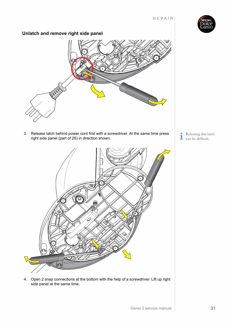
Unlatch and remove right side panel
3. Release latch behind power cord first with a screwdriver. At the same time press right side panel (part of 26) in direction shown.
4. Open 2 snap connections at the bottom with the help of a screwdriver. Lift up right side panel at the same time.
Releasing this latch can be difficult.
Genio 2 service manual32
R E P A I R
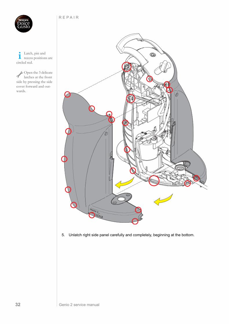
5. Unlatch right side panel carefully and completely, beginning at the bottom.
Latch, pin and recess positions are
circled red.
Open the 3 delicate latches at the front
side by pressing the side cover forward and out-wards.
Genio 2 service manual 33
R E P A I R
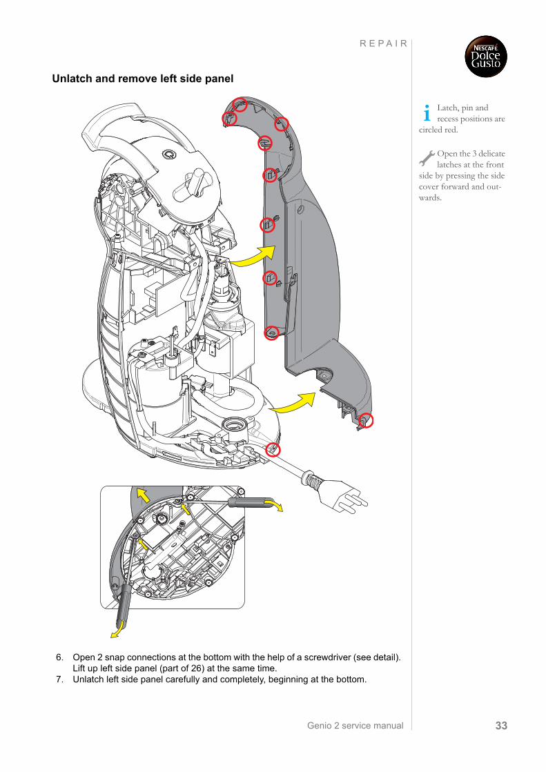
Unlatch and remove left side panel
6. Open 2 snap connections at the bottom with the help of a screwdriver (see detail). Lift up left side panel (part of 26) at the same time.
7. Unlatch left side panel carefully and completely, beginning at the bottom.
Latch, pin and recess positions are
circled red.
Open the 3 delicate latches at the front
side by pressing the side cover forward and out-wards.
Genio 2 service manual34
R E P A I R
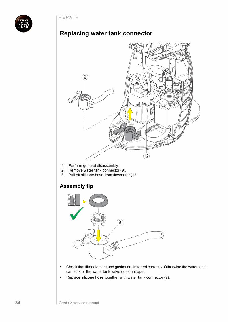
Replacing water tank connector
1. Perform general disassembly.2. Remove water tank connector (9).3. Pull off silicone hose from flowmeter (12).
Assembly tip
• Check that filter element and gasket are inserted correctly. Otherwise the water tank can leak or the water tank valve does not open.
• Replace silicone hose together with water tank connector (9).
9
12
9
Genio 2 service manual 35
R E P A I R
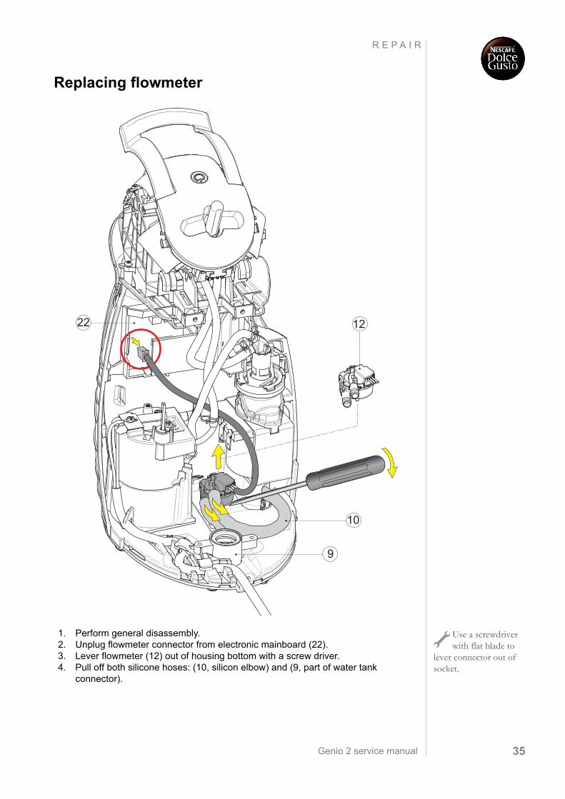
Replacing flowmeter
1. Perform general disassembly.2. Unplug flowmeter connector from electronic mainboard (22).3. Lever flowmeter (12) out of housing bottom with a screw driver.4. Pull off both silicone hoses: (10, silicon elbow) and (9, part of water tank
connector).
12
10
9
22
Use a screwdriver with flat blade to
lever connector out of socket.
Genio 2 service manual36
R E P A I R
Replacing pump
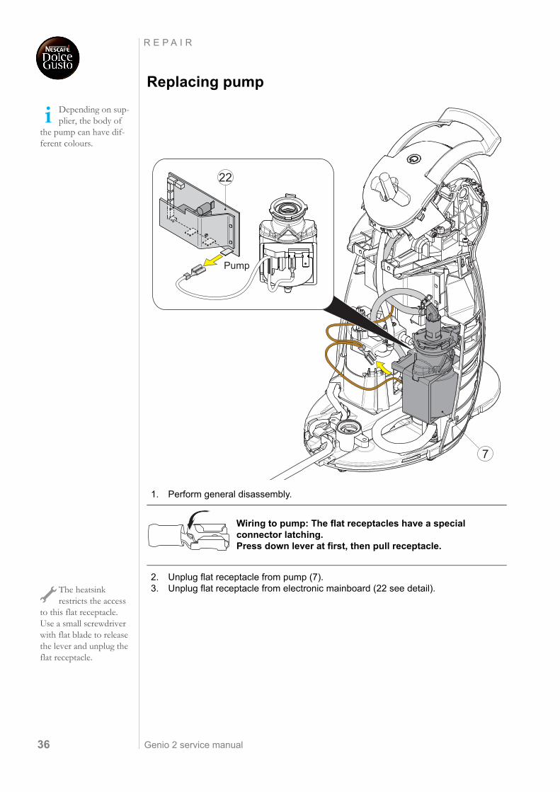
1. Perform general disassembly.
2. Unplug flat receptacle from pump (7).3. Unplug flat receptacle from electronic mainboard (22 see detail).
Depending on sup-plier, the body of
the pump can have dif-ferent colours.
Wiring to pump: The flat receptacles have a special connector latching. Press down lever at first, then pull receptacle.
Pump
7
22
The heatsink restricts the access
to this flat receptacle. Use a small screwdriver with flat blade to release the lever and unplug the flat receptacle.

Genio 2 service manual 37
R E P A I R
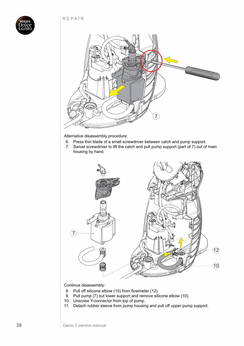
4. Remove both pressure hoses with clips from pump (7).
First disassembly procedure:
5. Press blade of a small screwdriver into opening to lift catch. At the same time pull pump support (part of 7) out of main housing by hand.
The pressure hose to the thermoblock
and the clips have to be discarded together with the defect pump.
7
The pump support is difficult to
remove - please be patient. Try alternative disassembly procedure if you encounter difficul-ties.
7
Genio 2 service manual38
R E P A I R
Alternative disassembly procedure:
6. Press thin blade of a small screwdriver between catch and pump support.7. Swivel screwdriver to lift the catch and pull pump support (part of 7) out of main
housing by hand.
Continue disassembly:
8. Pull off silicone elbow (10) from flowmeter (12).9. Pull pump (7) out lower support and remove silicone elbow (10).
10. Unscrew Y-connector from top of pump.11. Detach rubber sleeve from pump housing and pull off upper pump support.
7
12
10
7
Genio 2 service manual 39
R E P A I R
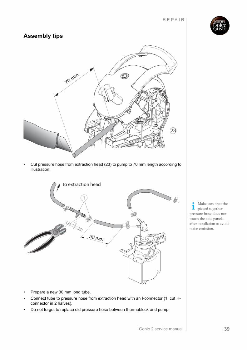
Assembly tips
• Cut pressure hose from extraction head (23) to pump to 70 mm length according to illustration.
• Prepare a new 30 mm long tube.
• Connect tube to pressure hose from extraction head with an I-connector (1, cut H-connector in 2 halves).
• Do not forget to replace old pressure hose between thermoblock and pump.
70 mm
23
Make sure that the pieced together
pressure hose does not touch the side panels after installation to avoid noise emission.
30 mm
to extraction head
1
Genio 2 service manual40
R E P A I R
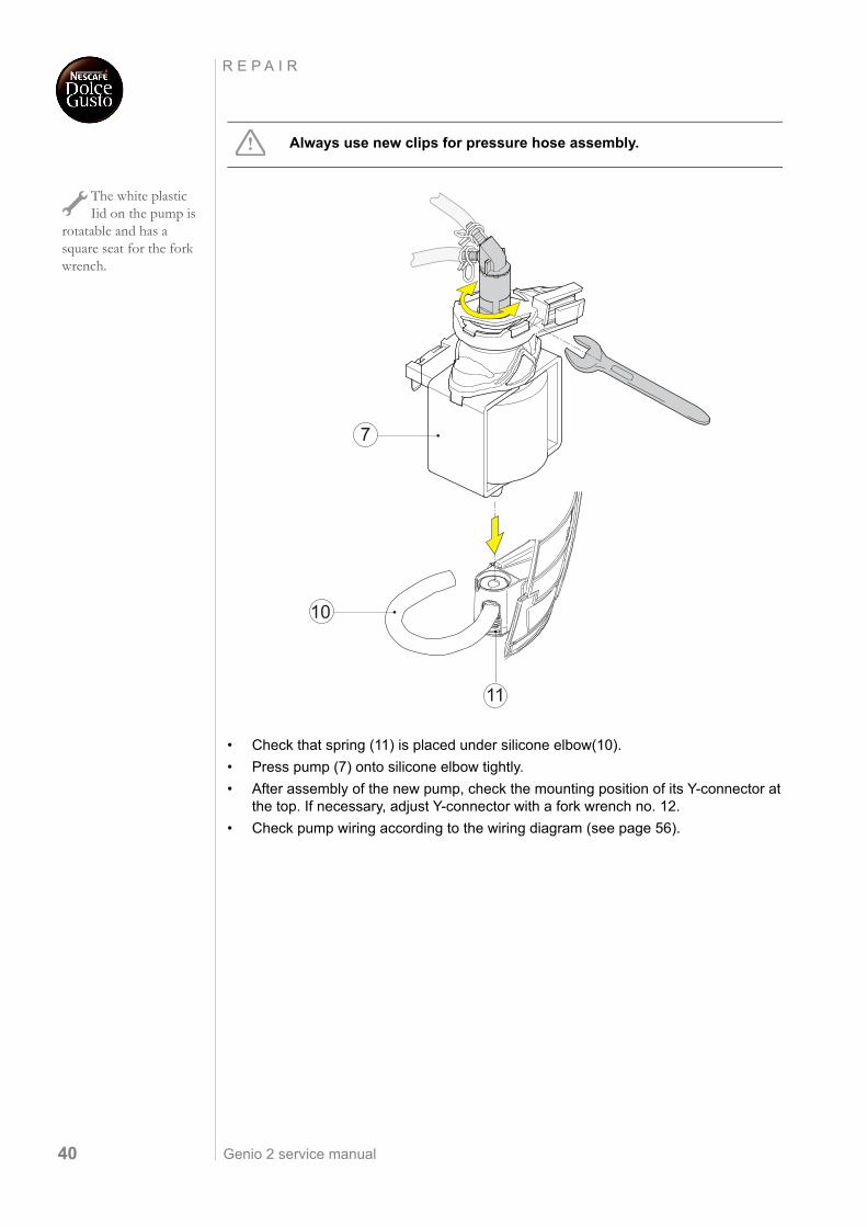
• Check that spring (11) is placed under silicone elbow(10).
• Press pump (7) onto silicone elbow tightly.
• After assembly of the new pump, check the mounting position of its Y-connector at the top. If necessary, adjust Y-connector with a fork wrench no. 12.
• Check pump wiring according to the wiring diagram (see page 56).
Always use new clips for pressure hose assembly.
The white plastic Iid on the pump is
rotatable and has a square seat for the fork wrench.
10
7
11
Genio 2 service manual 41
R E P A I R
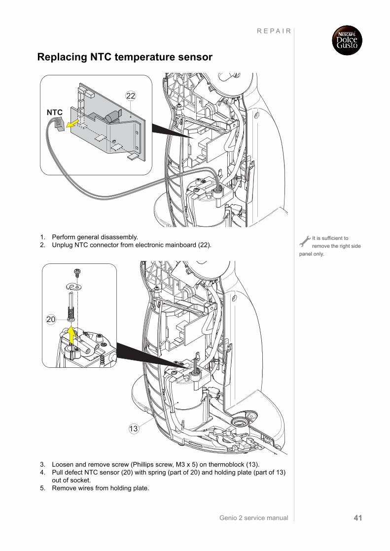
Replacing NTC temperature sensor
1. Perform general disassembly.2. Unplug NTC connector from electronic mainboard (22).
3. Loosen and remove screw (Phillips screw, M3 x 5) on thermoblock (13). 4. Pull defect NTC sensor (20) with spring (part of 20) and holding plate (part of 13)
out of socket.5. Remove wires from holding plate.
22
NTC
It is sufficient to
remove the right side
panel only.
20
13
Genio 2 service manual42
R E P A I R
Assembly tips
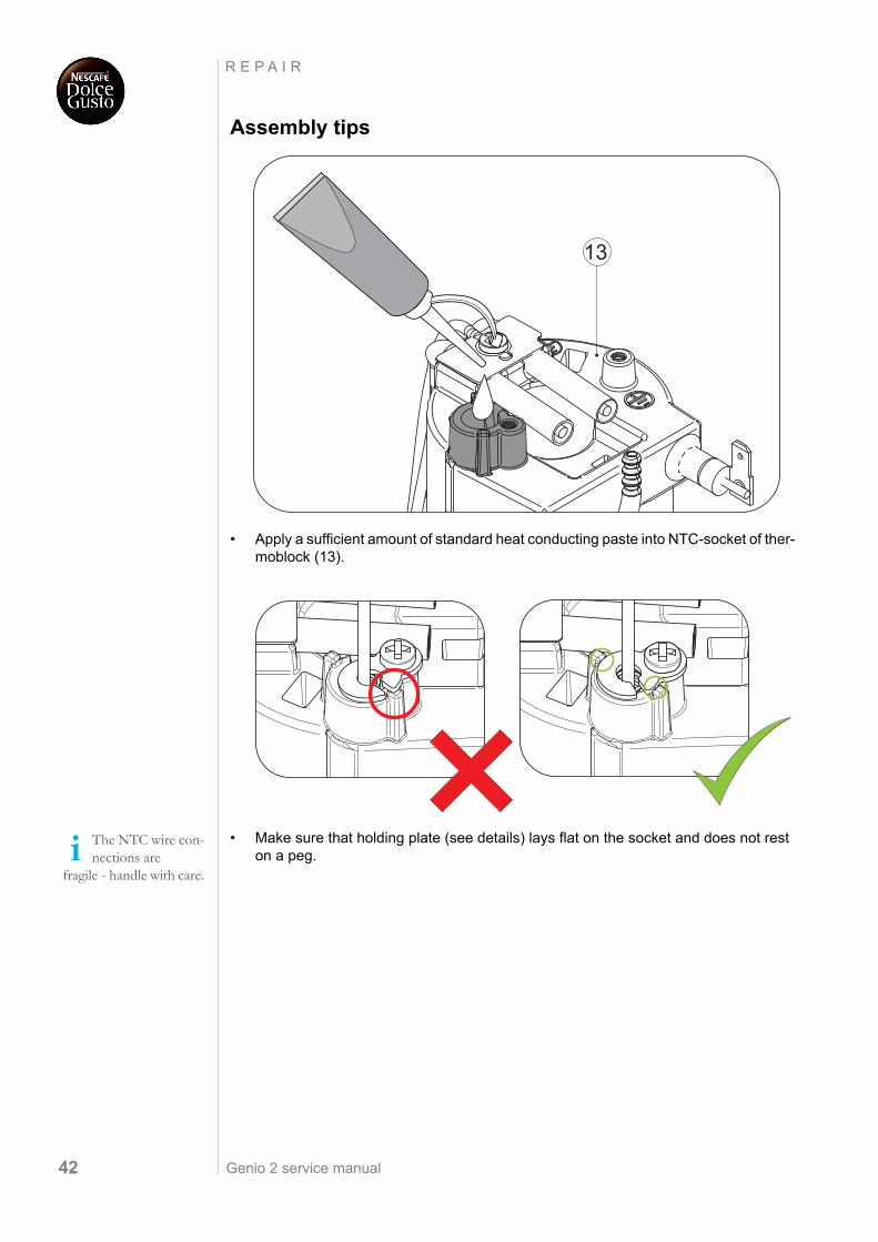
• Apply a sufficient amount of standard heat conducting paste into NTC-socket of ther-moblock (13).
• Make sure that holding plate (see details) lays flat on the socket and does not rest on a peg.
13
The NTC wire con-nections are
fragile - handle with care.
Genio 2 service manual 43
R E P A I R
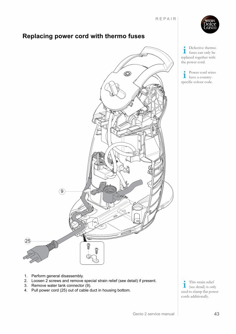
Replacing power cord with thermo fuses
1. Perform general disassembly.2. Loosen 2 screws and remove special strain relief (see detail) if present.3. Remove water tank connector (9).4. Pull power cord (25) out of cable duct in housing bottom.
Defective thermo fuses can only be
replaced together with the power cord.
Power cord wires have a country-
specific colour code.
9
25
This strain relief (see detail) is only
used to clamp flat power cords additionally.
Genio 2 service manual44
R E P A I R
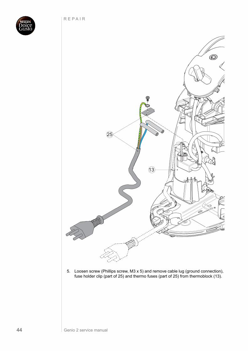
5. Loosen screw (Phillips screw, M3 x 5) and remove cable lug (ground connection), fuse holder clip (part of 25) and thermo fuses (part of 25) from thermoblock (13).
25
13
Genio 2 service manual 45
R E P A I R
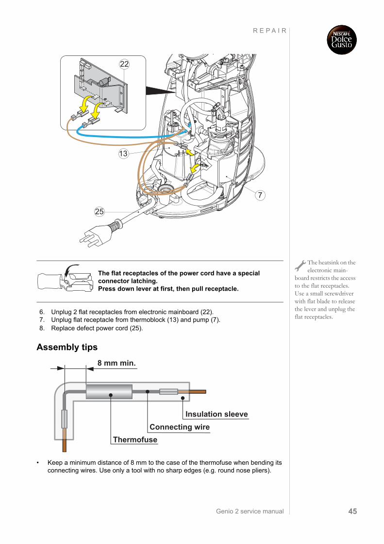
6. Unplug 2 flat receptacles from electronic mainboard (22). 7. Unplug flat receptacle from thermoblock (13) and pump (7).8. Replace defect power cord (25).
Assembly tips
• Keep a minimum distance of 8 mm to the case of the thermofuse when bending its connecting wires. Use only a tool with no sharp edges (e.g. round nose pliers).
22
13
25
7
The heatsink on the electronic main-
board restricts the access to the flat receptacles. Use a small screwdriver with flat blade to release the lever and unplug the flat receptacles.
The flat receptacles of the power cord have a special connector latching. Press down lever at first, then pull receptacle.
8 mm min.
Insulation sleeveConnecting wire
Thermofuse
Genio 2 service manual46
R E P A I R
• Check power cord wiring according to the wiring diagram (see page 56).
• Check wire and cable routing:
• Cable duct in housing bottom
• Additional strain relief for a flat power cord
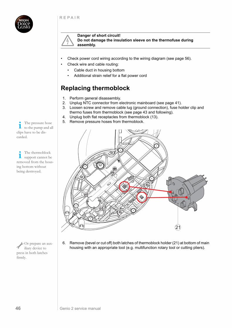
Replacing thermoblock
1. Perform general disassembly.2. Unplug NTC connector from electronic mainboard (see page 41).3. Loosen screw and remove cable lug (ground connection), fuse holder clip and
thermo fuses from thermoblock (see page 43 and following).4. Unplug both flat receptacles from thermoblock (13).5. Remove pressure hoses from thermoblock.
6. Remove (bevel or cut off) both latches of thermoblock holder (21) at bottom of main housing with an appropriate tool (e.g. multifunction rotary tool or cutting pliers).
Danger of short circuit!Do not damage the insulation sleeve on the thermofuse during assembly.
The pressure hose to the pump and all
clips have to be dis-carded.
The thermoblock support cannot be
removed from the hous-ing bottom without being destroyed.
21
Or prepare an aux-iliary device to
press in both latches firmly.
Genio 2 service manual 47
R E P A I R
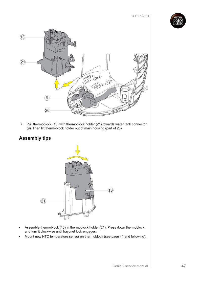
7. Pull thermoblock (13) with thermoblock holder (21) towards water tank connector (9). Then lift thermoblock holder out of main housing (part of 26).
Assembly tips
• Assemble thermoblock (13) in thermoblock holder (21): Press down thermoblock and turn it clockwise until bayonet lock engages.
• Mount new NTC temperature sensor on thermoblock (see page 41 and following).
9
21
13
26
21
13
Genio 2 service manual48
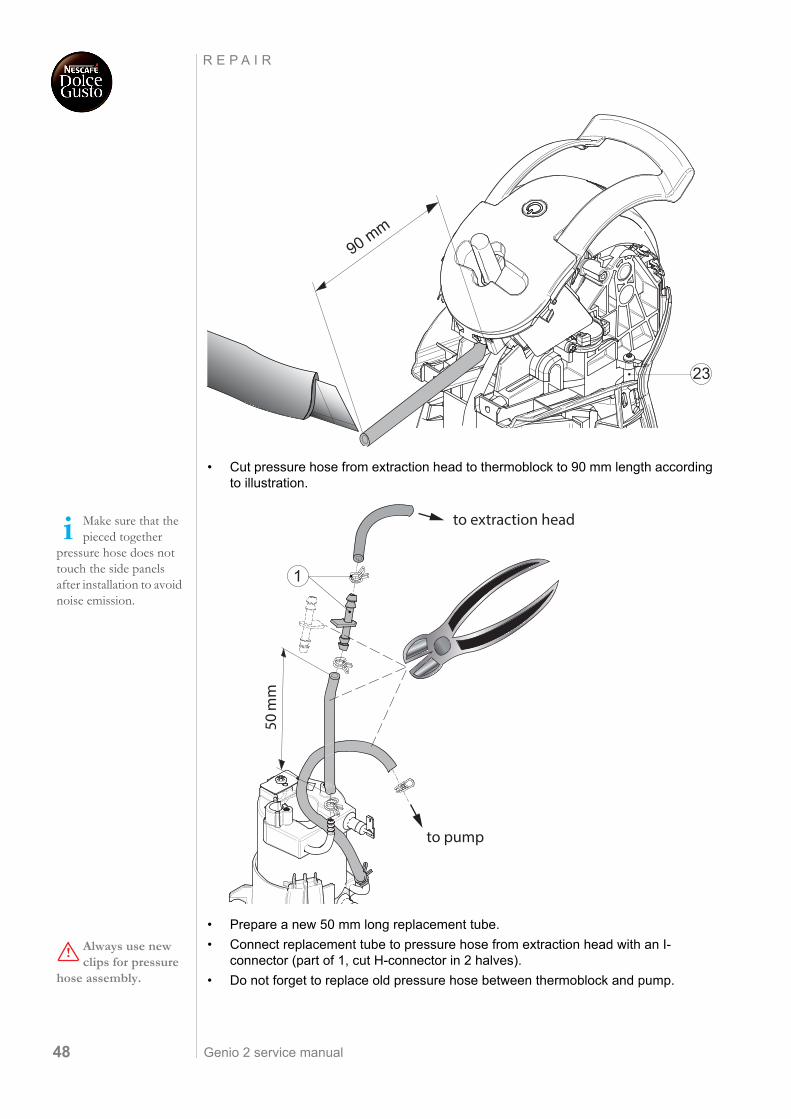
R E P A I R
• Cut pressure hose from extraction head to thermoblock to 90 mm length according to illustration.
• Prepare a new 50 mm long replacement tube.
• Connect replacement tube to pressure hose from extraction head with an I-connector (part of 1, cut H-connector in 2 halves).
• Do not forget to replace old pressure hose between thermoblock and pump.
90 mm
23
Make sure that the pieced together
pressure hose does not touch the side panels after installation to avoid noise emission.
to extraction head
1
to pump
Always use new clips for pressure
hose assembly.
Genio 2 service manual 49
R E P A I R
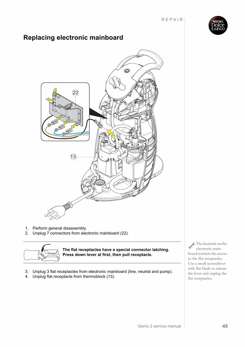
Replacing electronic mainboard
1. Perform general disassembly.2. Unplug 7 connectors from electronic mainboard (22).
3. Unplug 3 flat receptacles from electronic mainboard (line, neutral and pump).4. Unplug flat receptacle from thermoblock (13).
22
13
The heatsink on the electronic main-
board restricts the access to the flat receptacles. Use a small screwdriver with flat blade to release the lever and unplug the flat receptacles.
The flat receptacles have a special connector latching. Press down lever at first, then pull receptacle.
Genio 2 service manual50
R E P A I R
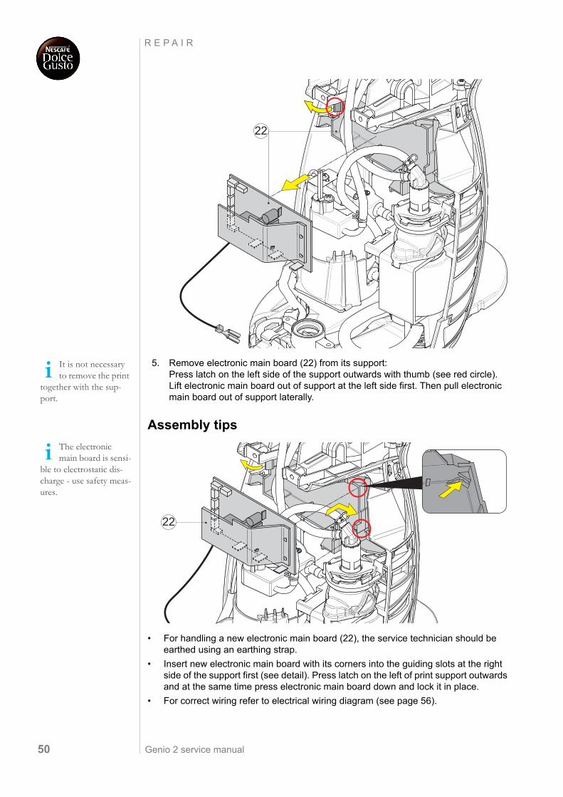
5. Remove electronic main board (22) from its support: Press latch on the left side of the support outwards with thumb (see red circle). Lift electronic main board out of support at the left side first. Then pull electronic main board out of support laterally.
Assembly tips
• For handling a new electronic main board (22), the service technician should be earthed using an earthing strap.
• Insert new electronic main board with its corners into the guiding slots at the right side of the support first (see detail). Press latch on the left of print support outwards and at the same time press electronic main board down and lock it in place.
• For correct wiring refer to electrical wiring diagram (see page 56).
22
It is not necessary to remove the print
together with the sup-port.
The electronic main board is sensi-
ble to electrostatic dis-charge - use safety meas-ures.
22
Genio 2 service manual 51
R E P A I R
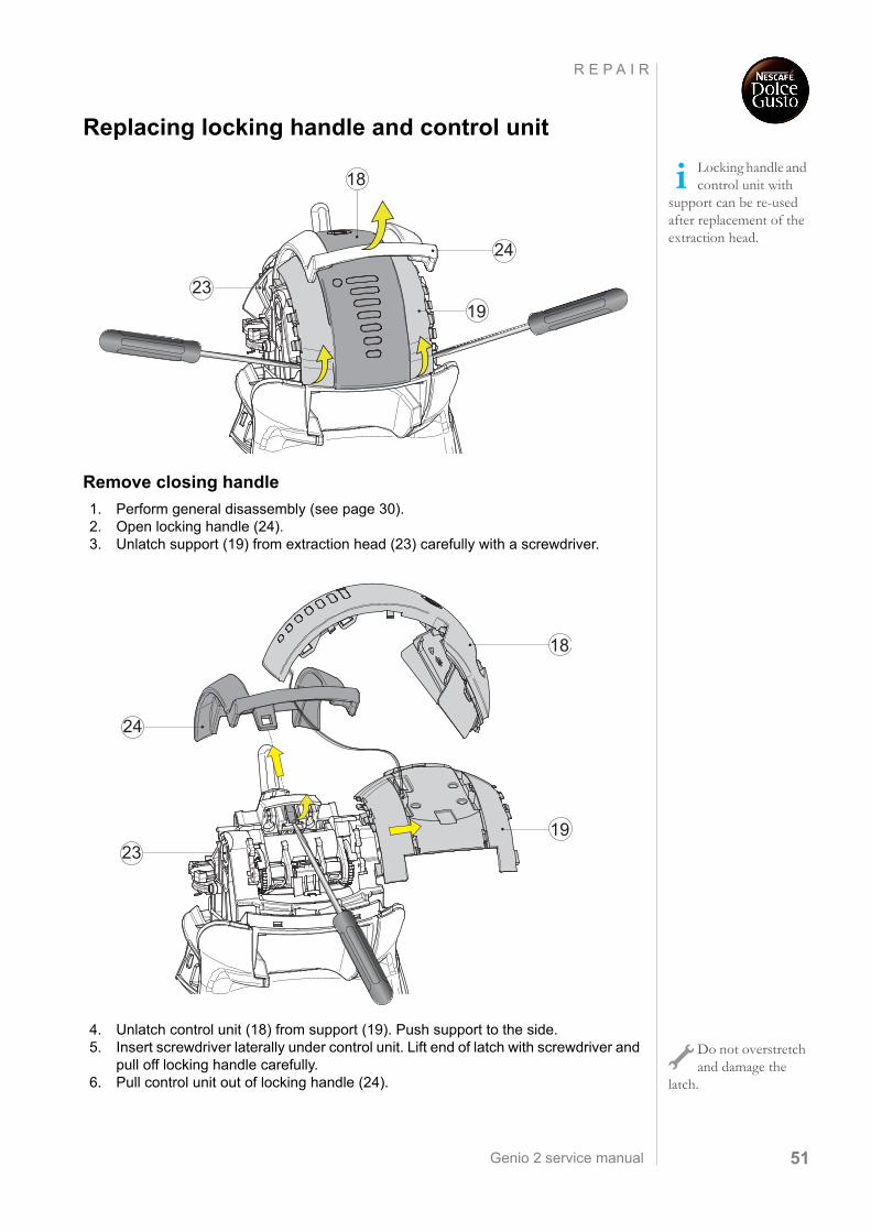
Replacing locking handle and control unit
Remove closing handle
1. Perform general disassembly (see page 30).2. Open locking handle (24).3. Unlatch support (19) from extraction head (23) carefully with a screwdriver.
4. Unlatch control unit (18) from support (19). Push support to the side.5. Insert screwdriver laterally under control unit. Lift end of latch with screwdriver and
pull off locking handle carefully.6. Pull control unit out of locking handle (24).
Locking handle and control unit with
support can be re-used after replacement of the extraction head.
18
24
1923
19
24
18
23
Do not overstretch and damage the
latch.
Genio 2 service manual52
R E P A I R
Remove control unit
7. Cut cable tie near electronic mainboard (22).8. Unplug HMI-connector from electronic mainboard.
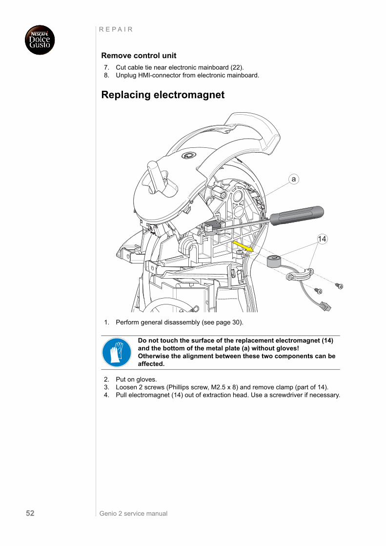
Replacing electromagnet
1. Perform general disassembly (see page 30).
2. Put on gloves. 3. Loosen 2 screws (Phillips screw, M2.5 x 8) and remove clamp (part of 14). 4. Pull electromagnet (14) out of extraction head. Use a screwdriver if necessary.
Do not touch the surface of the replacement electromagnet (14) and the bottom of the metal plate (a) without gloves! Otherwise the alignment between these two components can be affected.
14
a
Genio 2 service manual 53
R E P A I R
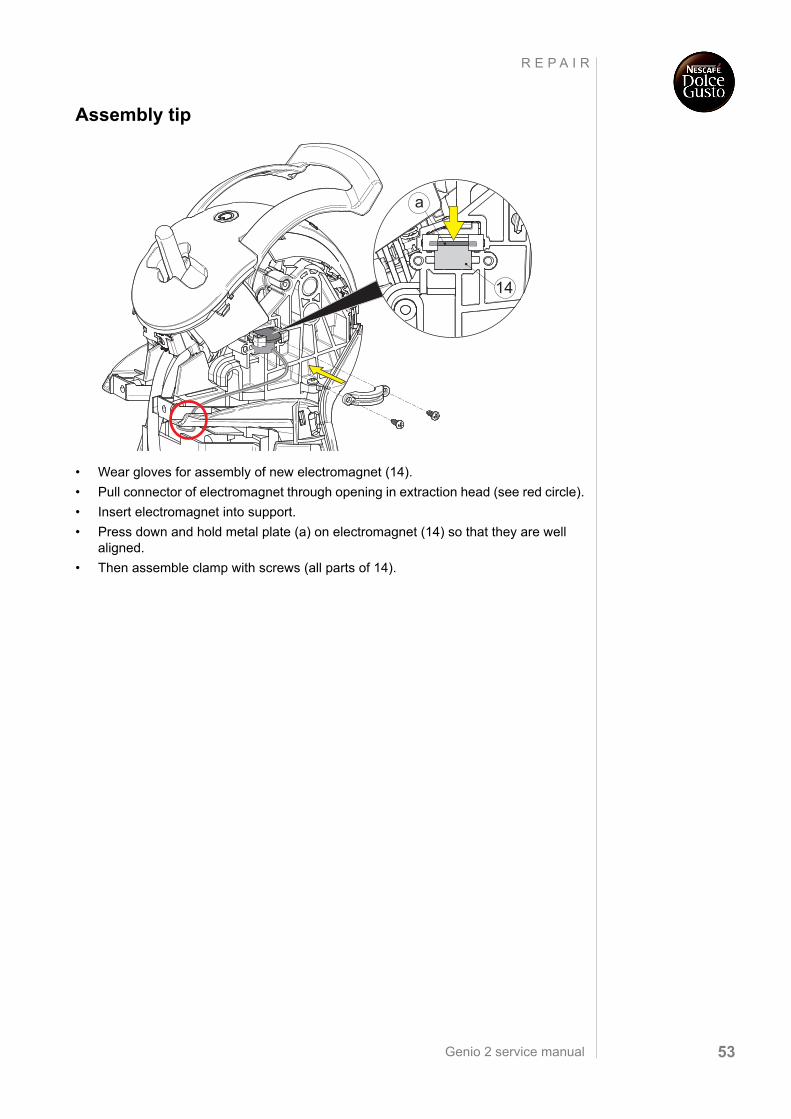
Assembly tip
• Wear gloves for assembly of new electromagnet (14).
• Pull connector of electromagnet through opening in extraction head (see red circle).
• Insert electromagnet into support.
• Press down and hold metal plate (a) on electromagnet (14) so that they are well aligned.
• Then assemble clamp with screws (all parts of 14).
14
a
Genio 2 service manual54
R E P A I R
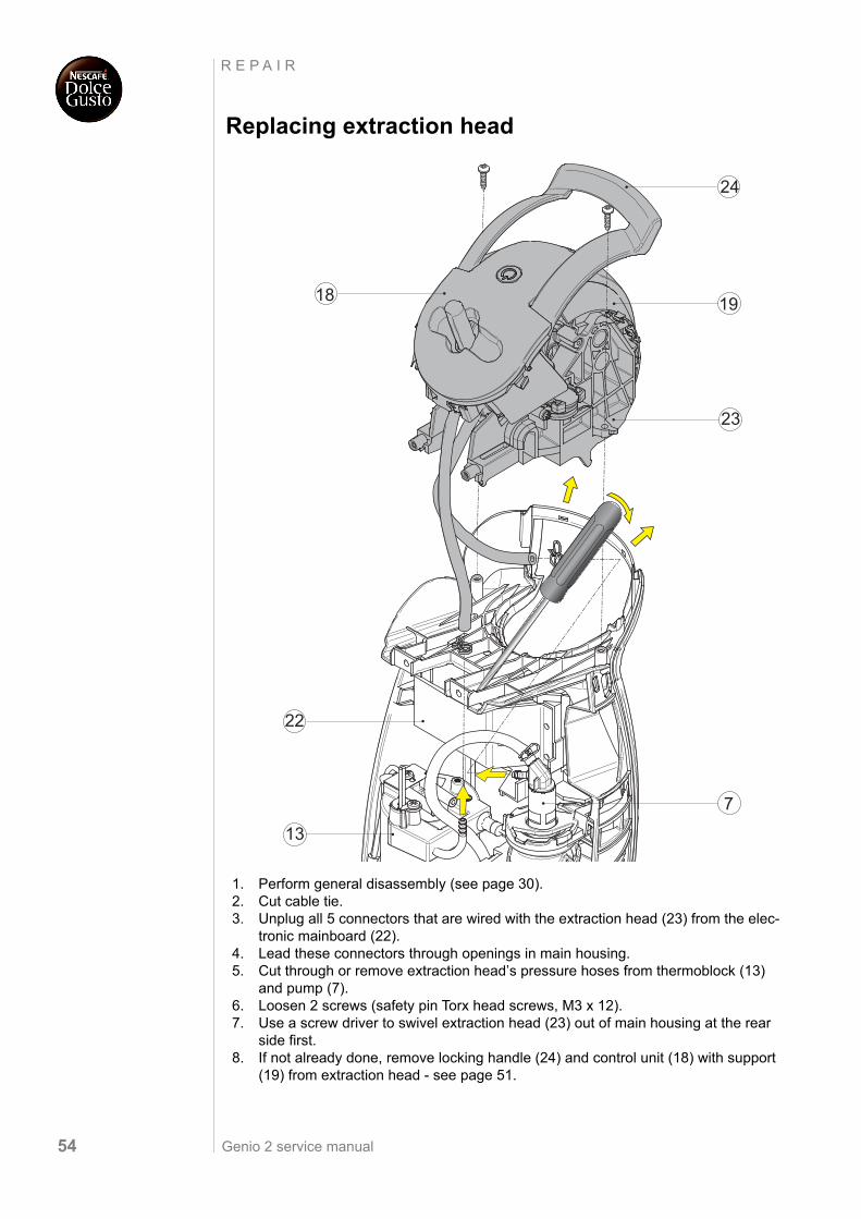
Replacing extraction head
1. Perform general disassembly (see page 30).2. Cut cable tie.3. Unplug all 5 connectors that are wired with the extraction head (23) from the elec-
tronic mainboard (22). 4. Lead these connectors through openings in main housing.5. Cut through or remove extraction head’s pressure hoses from thermoblock (13)
and pump (7). 6. Loosen 2 screws (safety pin Torx head screws, M3 x 12).7. Use a screw driver to swivel extraction head (23) out of main housing at the rear
side first.8. If not already done, remove locking handle (24) and control unit (18) with support
(19) from extraction head - see page 51.
1918
23
7
22
13
24
Genio 2 service manual 55
R E P A I R
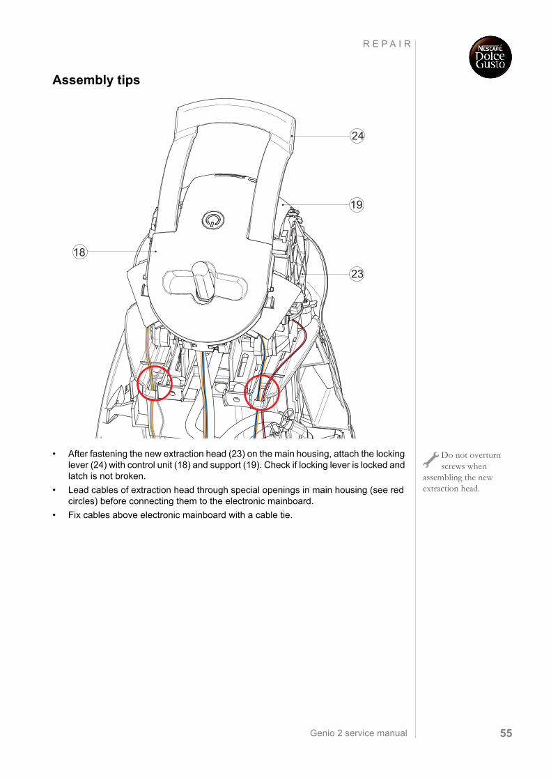
Assembly tips
• After fastening the new extraction head (23) on the main housing, attach the locking lever (24) with control unit (18) and support (19). Check if locking lever is locked and latch is not broken.
• Lead cables of extraction head through special openings in main housing (see red circles) before connecting them to the electronic mainboard.
• Fix cables above electronic mainboard with a cable tie.
18
24
19
23
Do not overturn screws when
assembling the new extraction head.
Genio 2 service manual56
W I R I N G D I A G R A M
W I R I N G D I A G R A M
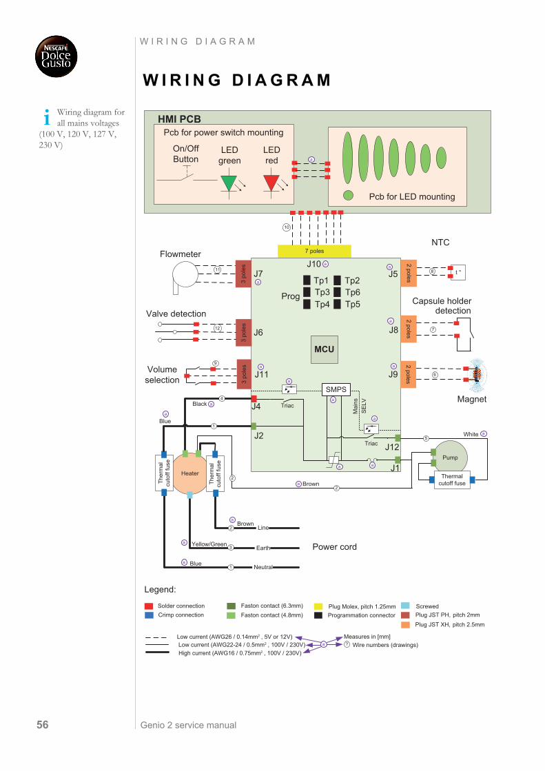
Wiring diagram for all mains voltages
(100 V, 120 V, 127 V, 230 V)
Solder connectionCrimp connection Faston contact (4.8mm)
Faston contact (6.3mm)
Plug JST XH, pitch 2.5mmPlug JST PH, pitch 2mm
Plug Molex, pitch 1.25mm
On/OffButton
LEDgreen
LEDred
HMI PCB
MCU
3po
les
J6
3po
les
J7
7 poles
J10
3po
les
J11
11
12
NTC
2polesJ5
2polesJ8
Capsule holderdetection
2polesJ9
t °
10
9
8
7
6
Pump
Heater
Ther
mal
cuto
fffu
se
Ther
mal
cuto
fffu
se
Thermalcutoff fuse
Neutral
Earth
Line
Power cord
1
3
2
2
5
2
J12
J1
J44
J21
Tp3Tp4
Tp6Tp5
Prog
Tp2Tp1
ScrewedProgrammation connector
Flowmeter
Valve detection
Volumeselection
Magnet
Pcb for LED mounting
Low current (AWG26 / 0.14mm2 , 5V or 12V)Low current (AWG22-24 / 0.5mm2 , 100V / 230V)High current (AWG16 / 0.75mm2 , 100V / 230V)
Pcb for power switch mounting
Measures in [mm]? Wire numbers (drawings)
SE
LVM
ainsTriac
Triac
Blue
Yellow/Green
Brown
Black
Blue
Brown
White
SMPS
a
a
a
a
a
a
a
a
a
a
a
a
a
a a
a
a
a
a
a
Legend:
Genio 2 service manual 57
F I N A L T E S T I N G
F I N A L T E S T I N G
The following tests guarantee the correct function of the machine:
1. Heating up time2. Flow rate (at 8 bar) / water temperature3. Maximal pressure / leakage check
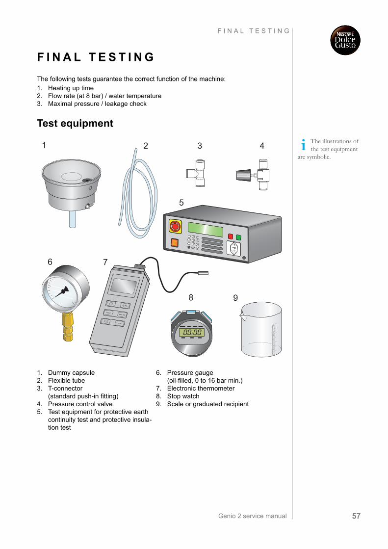
Test equipment
The illustrations of the test equipment
are symbolic.
1. Dummy capsule2. Flexible tube3. T-connector
(standard push-in fitting)4. Pressure control valve5. Test equipment for protective earth
continuity test and protective insula-tion test
6. Pressure gauge (oil-filled, 0 to 16 bar min.)
7. Electronic thermometer8. Stop watch9. Scale or graduated recipient
1 432
6
8
7
9
5
REL
HOLD
T1 T2T1←T2
°C/°F
MAX MIN
1
Genio 2 service manual58
F I N A L T E S T I N G
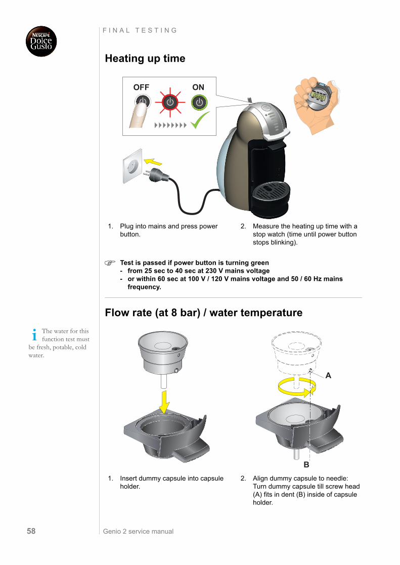
Heating up time
Test is passed if power button is turning green - from 25 sec to 40 sec at 230 V mains voltage- or within 60 sec at 100 V / 120 V mains voltage and 50 / 60 Hz mains
frequency.
Flow rate (at 8 bar) / water temperature
1. Plug into mains and press power button.
2. Measure the heating up time with a stop watch (time until power button stops blinking).
XL
ONOFF
The water for this function test must
be fresh, potable, cold water.
1. Insert dummy capsule into capsule holder.
2. Align dummy capsule to needle:Turn dummy capsule till screw head (A) fits in dent (B) inside of capsule holder.
A
B
Genio 2 service manual 59
F I N A L T E S T I N G
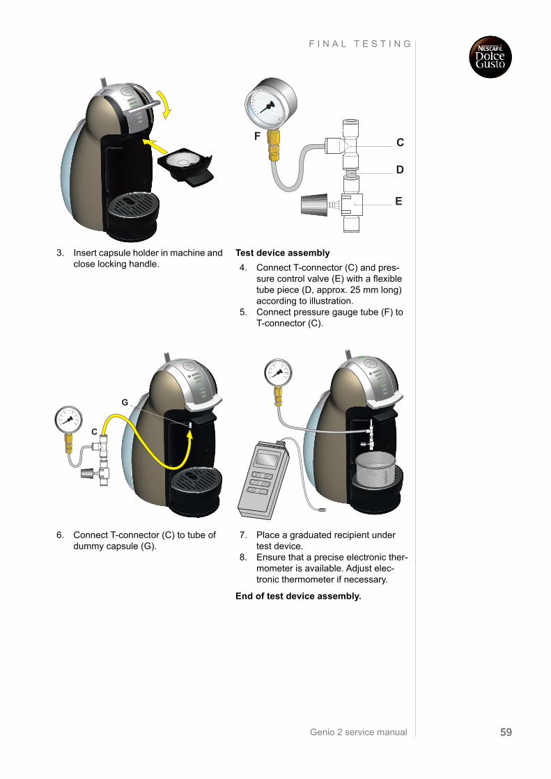
3. Insert capsule holder in machine and close locking handle.
Test device assembly
4. Connect T-connector (C) and pres-sure control valve (E) with a flexible tube piece (D, approx. 25 mm long) according to illustration.
5. Connect pressure gauge tube (F) to T-connector (C).
6. Connect T-connector (C) to tube of dummy capsule (G).
7. Place a graduated recipient under test device.
8. Ensure that a precise electronic ther-mometer is available. Adjust elec-tronic thermometer if necessary.
End of test device assembly.
E
D
CF
XL
G
C
XL
REL
HOLD
T1 T2T1←T2
°C/°F
MAX MIN
1
Genio 2 service manual60
F I N A L T E S T I N G
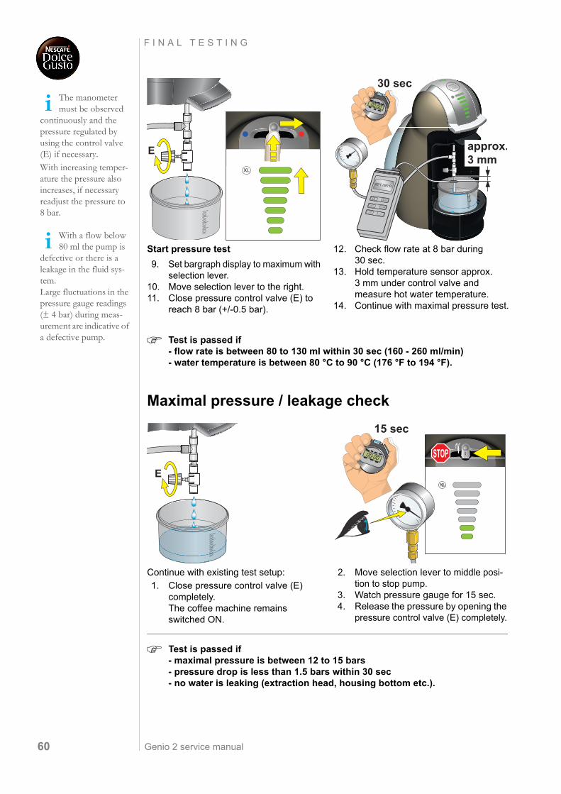
Test is passed if - flow rate is between 80 to 130 ml within 30 sec (160 - 260 ml/min) - water temperature is between 80 °C to 90 °C (176 °F to 194 °F).
Maximal pressure / leakage check
Test is passed if - maximal pressure is between 12 to 15 bars- pressure drop is less than 1.5 bars within 30 sec - no water is leaking (extraction head, housing bottom etc.).
The manometer must be observed
continuously and the pressure regulated by using the control valve (E) if necessary.With increasing temper-ature the pressure also increases, if necessary readjust the pressure to 8 bar.
With a flow below 80 ml the pump is
defective or there is a leakage in the fluid sys-tem. Large fluctuations in the pressure gauge readings (± 4 bar) during meas-urement are indicative of a defective pump.
Start pressure test
9. Set bargraph display to maximum with selection lever.
10. Move selection lever to the right.11. Close pressure control valve (E) to
reach 8 bar (+/-0.5 bar).
12. Check flow rate at 8 bar during 30 sec.
13. Hold temperature sensor approx. 3 mm under control valve and measure hot water temperature.
14. Continue with maximal pressure test.
Continue with existing test setup:
1. Close pressure control valve (E) completely. The coffee machine remains switched ON.
2. Move selection lever to middle posi-tion to stop pump.
3. Watch pressure gauge for 15 sec.4. Release the pressure by opening the
pressure control valve (E) completely.
E
XL
30 sec
approx.3 mm
REL
HOLD
T1 T2T1←T2
°C/°F
MAX MIN
1
E
STOP
15 sec
Genio 2 service manual 61
F I N A L I N S P E C T I O N S
F I N A L I N S P E C T I O N S
General
Legal situation
Repair centres can be legally obligated to ensure the safety and physical integrity of the user/consumer by national regulations and standards.
The basic demands of these regulations are:
• The regular condition of the coffee machine has to be restored after a repair.
• If the housing bottom of the coffee machine was removed during a repair, certain tests like shown in this chapter have to be performed after final assembly.
Test equipment
The necessary test equipment
- has to be obtained by the repair centre,
- must comply with EN/IEC 60335-1 and national standard(s) for after-repair testing (e.g. DIN VDE 0701),
- has to be calibrated by a qualified test centre periodically.
Ideally the test equipment has a national power socket for testing, so that the coffee machine can plugged in directly. Otherwise a special shunt is necessary to connect the phase and neutral pin of the coffee machine’s power plug.
Test procedures
The after-repair tests shown in this chapter
- are based on the German standard DIN VDE 0701 - 0702,
- are valid therefore for German repair centres only,
- are explained only generally and serve as an example for other nationalities.
For detailed information refer to the operating manual of your test equipment and your national standard(s) for after-repair test.
Job-related requirements for after-repair testing
After-repair tests should only be performed by a certitfied electrician
- with experience in electrical metrology,
- who is familiar with the test equipment and the applicable national standard(s).
Test report
The repair centre should prepare a test report for each repaired coffee machine and keep it safely.
Check the legal sit-uation in your
country to avoid prose-cution.
Contact the sales partner in your
local region as per the Instruction book and warranty card .
Only symbolic illustrations of test equipment are shown in this manual.
Genio 2 service manual62
F I N A L I N S P E C T I O N S
Safety instructions
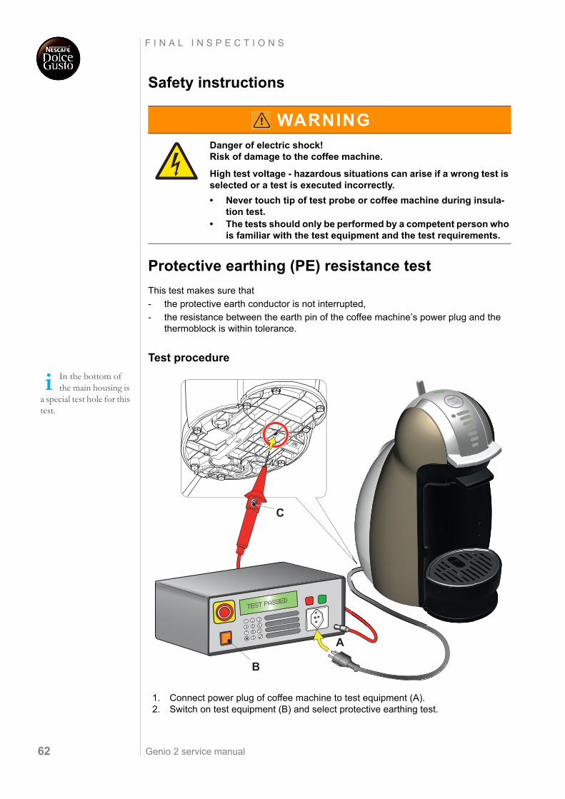
Protective earthing (PE) resistance test
This test makes sure that
- the protective earth conductor is not interrupted,
- the resistance between the earth pin of the coffee machine’s power plug and the thermoblock is within tolerance.
Test procedure
1. Connect power plug of coffee machine to test equipment (A).2. Switch on test equipment (B) and select protective earthing test.
WARNINGDanger of electric shock!Risk of damage to the coffee machine.
High test voltage - hazardous situations can arise if a wrong test is selected or a test is executed incorrectly.
• Never touch tip of test probe or coffee machine during insula-tion test.
• The tests should only be performed by a competent person who is familiar with the test equipment and the test requirements.
In the bottom of the main housing is
a special test hole for this test.
A
B
C
TEST PASSED
XL
Genio 2 service manual 63
F I N A L I N S P E C T I O N S
3. Touch thermoblock with test probe (through opening in housing bottom (see detail).4. Press start button (C) and read off displayed resistance.
If test fails,
- check/tighten ground connection on thermoblock (see page 44),
- replace power cord if necessary,
- repeat protective earthing test once more.
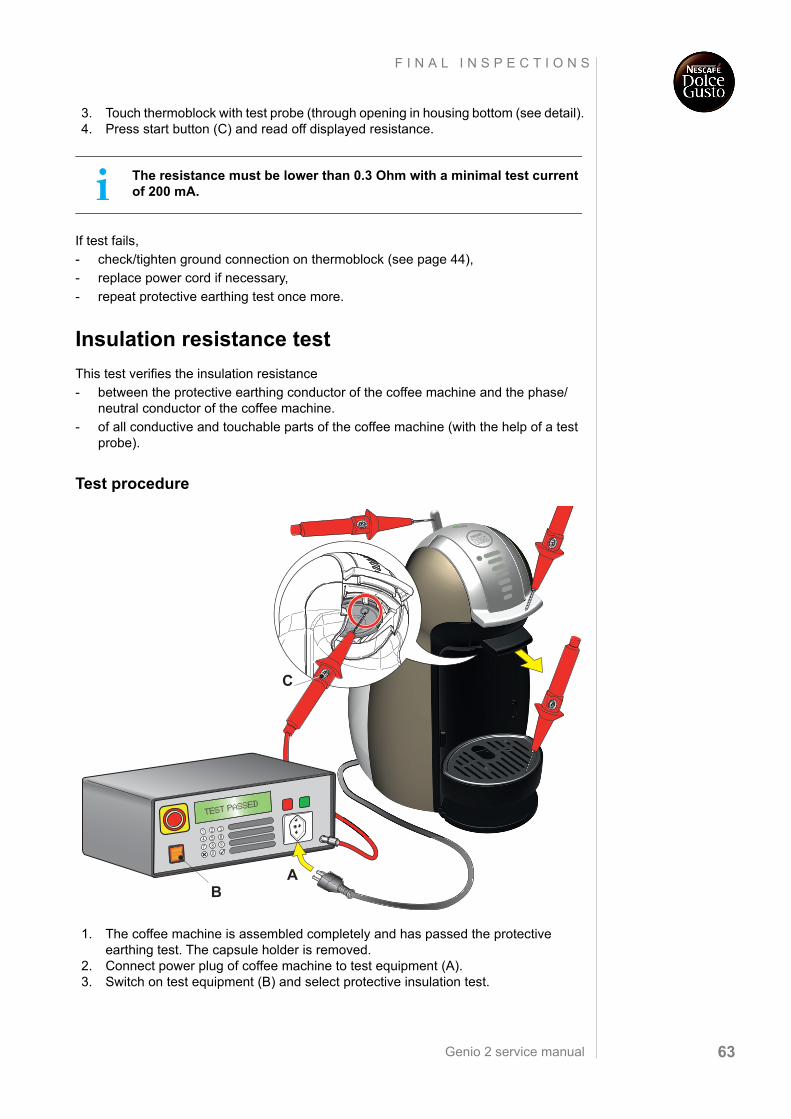
Insulation resistance test
This test verifies the insulation resistance
- between the protective earthing conductor of the coffee machine and the phase/neutral conductor of the coffee machine.
- of all conductive and touchable parts of the coffee machine (with the help of a test probe).
Test procedure
1. The coffee machine is assembled completely and has passed the protective earthing test. The capsule holder is removed.
2. Connect power plug of coffee machine to test equipment (A).3. Switch on test equipment (B) and select protective insulation test.
The resistance must be lower than 0.3 Ohm with a minimal test current of 200 mA.
AB
C
TEST PASSED
XL
Genio 2 service manual64
F I N A L I N S P E C T I O N S
4. Read off displayed insulation resistance between earthing conductor and phase/neutral conductors.
5. Switch test voltage to test probe (if necessary).6. Touch with test probe the following test points:
- selection lever- locking handle- needle at underside of extraction head (see detail)- drip grid
7. For each test point press start button (C) and read off displayed resistance.
If insulation test fails, a sparkover has damaged the coffee machine probably.
In that case check wiring, locate fault(s) and proceed with troubleshooting check list.
Repeat protective insulation test.
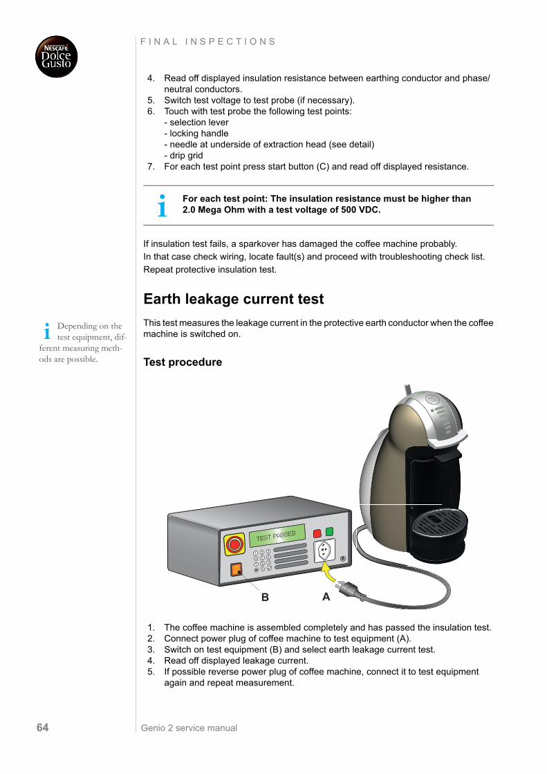
Earth leakage current test
This test measures the leakage current in the protective earth conductor when the coffee machine is switched on.
Test procedure
1. The coffee machine is assembled completely and has passed the insulation test.2. Connect power plug of coffee machine to test equipment (A).3. Switch on test equipment (B) and select earth leakage current test.4. Read off displayed leakage current.5. If possible reverse power plug of coffee machine, connect it to test equipment
again and repeat measurement.
For each test point: The insulation resistance must be higher than 2.0 Mega Ohm with a test voltage of 500 VDC.
Depending on the test equipment, dif-
ferent measuring meth-ods are possible.
AB
TEST PASSED
XL
Genio 2 service manual 65
F I N A L I N S P E C T I O N S
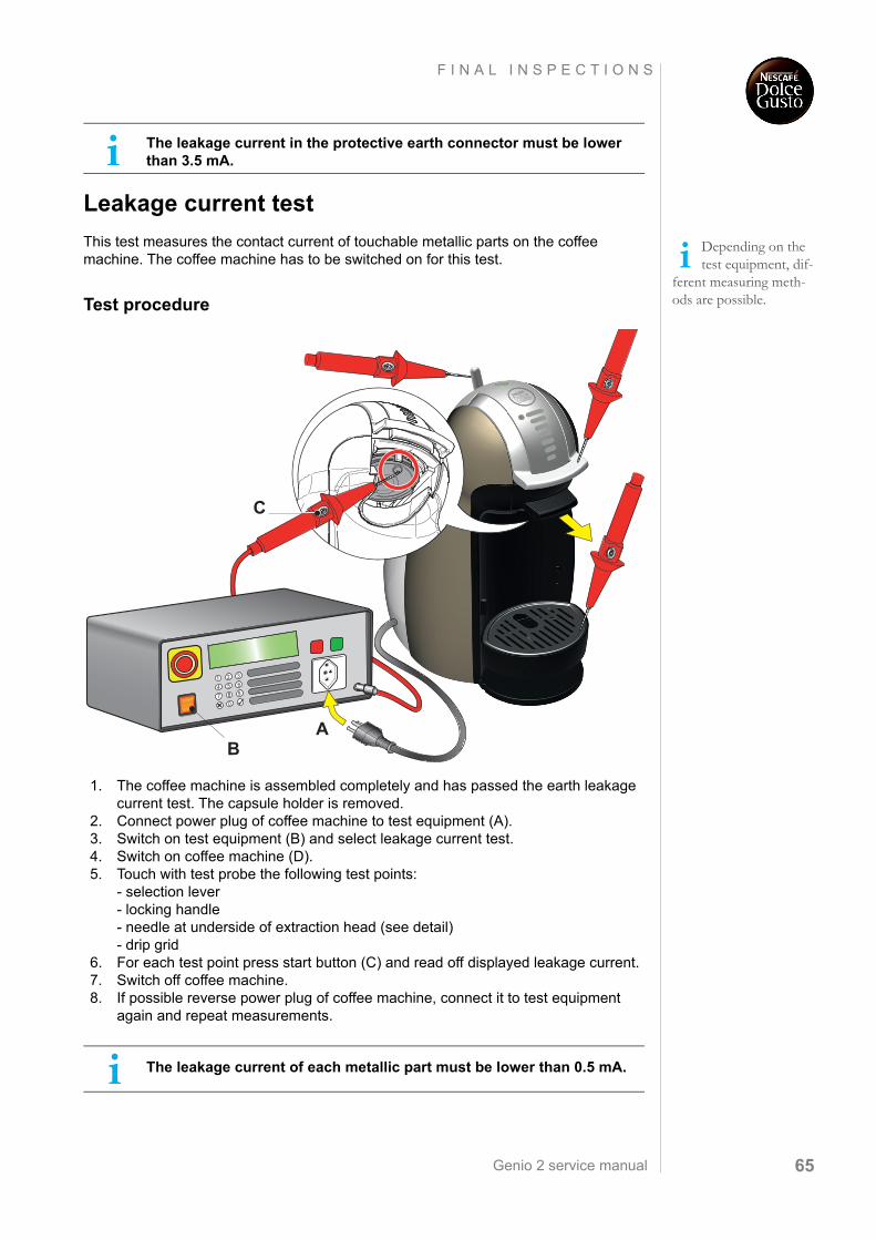
Leakage current test
This test measures the contact current of touchable metallic parts on the coffee machine. The coffee machine has to be switched on for this test.
Test procedure
1. The coffee machine is assembled completely and has passed the earth leakage current test. The capsule holder is removed.
2. Connect power plug of coffee machine to test equipment (A).3. Switch on test equipment (B) and select leakage current test.4. Switch on coffee machine (D).5. Touch with test probe the following test points:
- selection lever- locking handle- needle at underside of extraction head (see detail)- drip grid
6. For each test point press start button (C) and read off displayed leakage current.7. Switch off coffee machine.8. If possible reverse power plug of coffee machine, connect it to test equipment
again and repeat measurements.
The leakage current in the protective earth connector must be lower than 3.5 mA.
Depending on the test equipment, dif-
ferent measuring meth-ods are possible.
The leakage current of each metallic part must be lower than 0.5 mA.
C
TEST PASSED
XL
AB
Genio 2 service manual66
M A I N T E N A N C E
M A I N T E N A N C E
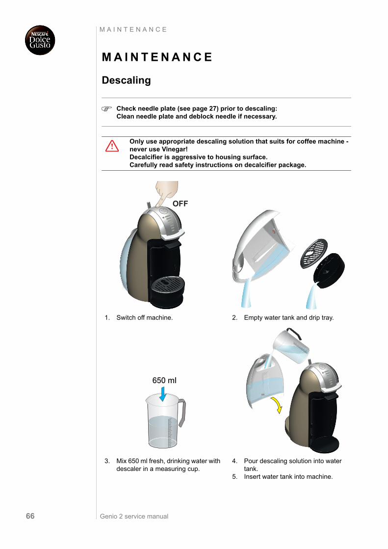
Descaling
Check needle plate (see page 27) prior to descaling: Clean needle plate and deblock needle if necessary.
Only use appropriate descaling solution that suits for coffee machine - never use Vinegar! Decalcifier is aggressive to housing surface. Carefully read safety instructions on decalcifier package.
1. Switch off machine. 2. Empty water tank and drip tray.
3. Mix 650 ml fresh, drinking water with descaler in a measuring cup.
4. Pour descaling solution into water tank.
5. Insert water tank into machine.
XL
OFF
650 mlXL
Genio 2 service manual 67
M A I N T E N A N C E
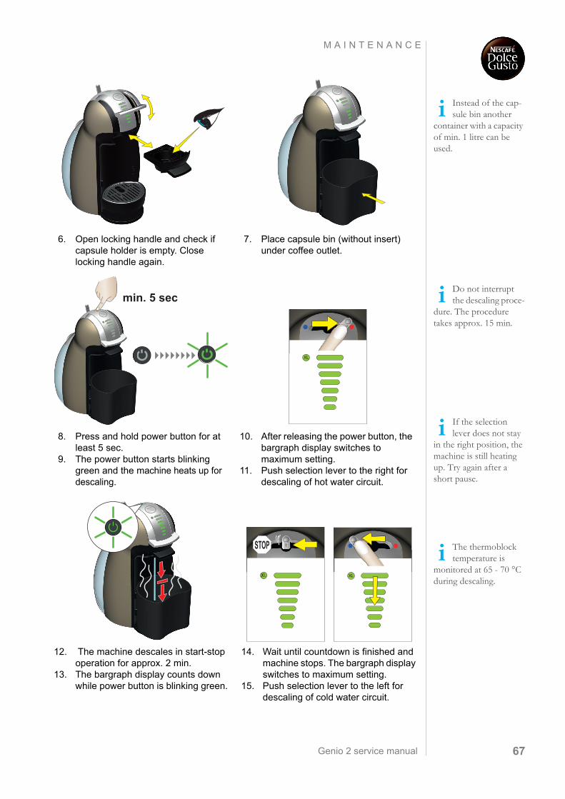
Instead of the cap-sule bin another
container with a capacity of min. 1 litre can be used.
6. Open locking handle and check if capsule holder is empty. Close locking handle again.
7. Place capsule bin (without insert) under coffee outlet.
Do not interrupt the descaling proce-
dure. The procedure takes approx. 15 min.
If the selection lever does not stay
in the right position, the machine is still heating up. Try again after a short pause.
8. Press and hold power button for at least 5 sec.
9. The power button starts blinking green and the machine heats up for descaling.
10. After releasing the power button, the bargraph display switches to maximum setting.
11. Push selection lever to the right for descaling of hot water circuit.
XL
min. 5 sec
The thermoblock temperature is
monitored at 65 - 70 °C during descaling.
12. The machine descales in start-stop operation for approx. 2 min.
13. The bargraph display counts down while power button is blinking green.
14. Wait until countdown is finished and machine stops. The bargraph display switches to maximum setting.
15. Push selection lever to the left for descaling of cold water circuit.
XL
STOP
Genio 2 service manual68
M A I N T E N A N C E
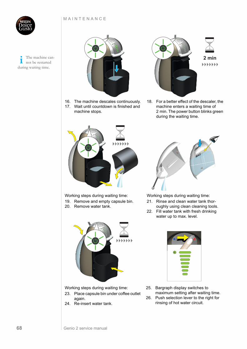
The machine can-not be restarted
during waiting time.
16. The machine descales continuously.17. Wait until countdown is finished and
machine stops.
18. For a better effect of the descaler, the machine enters a waiting time of 2 min. The power button blinks green during the waiting time.
Working steps during waiting time:
19. Remove and empty capsule bin.20. Remove water tank.
Working steps during waiting time:
21. Rinse and clean water tank thor-oughly using clean cleaning tools.
22. Fill water tank with fresh drinking water up to max. level.
Working steps during waiting time:
23. Place capsule bin under coffee outlet again.
24. Re-insert water tank.
25. Bargraph display switches to maximum setting after waiting time.
26. Push selection lever to the right for rinsing of hot water circuit.
XL XL
2 min
XL
MAX
XL
Genio 2 service manual 69
M A I N T E N A N C E
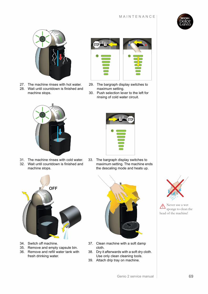
27. The machine rinses with hot water.28. Wait until countdown is finished and
machine stops.
29. The bargraph display switches to maximum setting.
30. Push selection lever to the left for rinsing of cold water circuit.
31. The machine rinses with cold water.32. Wait until countdown is finished and
machine stops.
33. The bargraph display switches to maximum setting. The machine ends the descaling mode and heats up.
XL
STOP
XL
STOP
Never use a wet sponge to clean the
head of the machine!
34. Switch off machine.35. Remove and empty capsule bin.36. Remove and refill water tank with
fresh drinking water.
37. Clean machine with a soft damp cloth.
38. Dry it afterwards with a soft dry cloth. Use only clean cleaning tools.
39. Attach drip tray on machine.
XL
OFFXLXXLLXL
Genio 2 service manual70
M A I N T E N A N C E
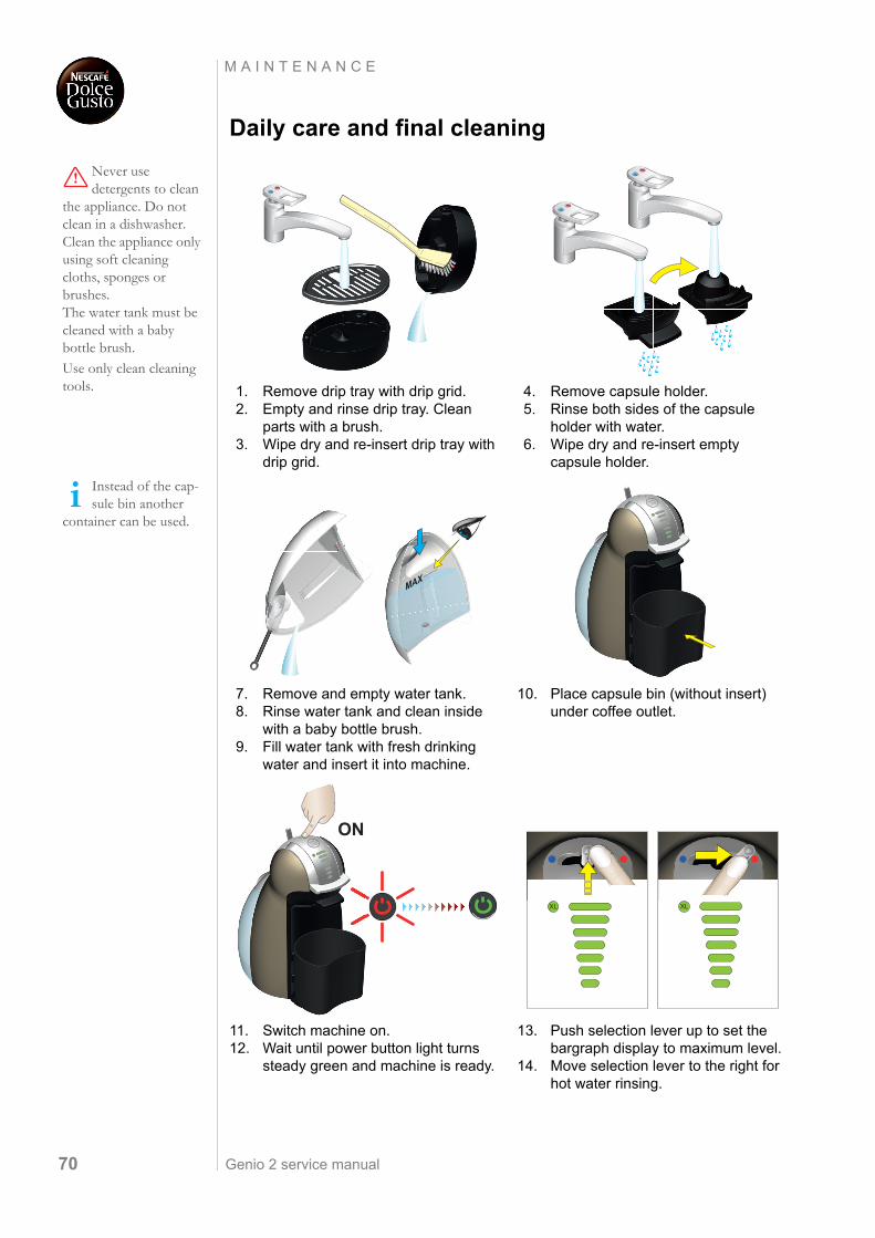
Daily care and final cleaning
Never use detergents to clean
the appliance. Do not clean in a dishwasher. Clean the appliance only using soft cleaning cloths, sponges or brushes. The water tank must be cleaned with a baby bottle brush.
Use only clean cleaning tools. 1. Remove drip tray with drip grid.
2. Empty and rinse drip tray. Clean parts with a brush.
3. Wipe dry and re-insert drip tray with drip grid.
4. Remove capsule holder.5. Rinse both sides of the capsule
holder with water.6. Wipe dry and re-insert empty
capsule holder.
Instead of the cap-sule bin another
container can be used.
7. Remove and empty water tank.8. Rinse water tank and clean inside
with a baby bottle brush.9. Fill water tank with fresh drinking
water and insert it into machine.
10. Place capsule bin (without insert) under coffee outlet.
11. Switch machine on.12. Wait until power button light turns
steady green and machine is ready.
13. Push selection lever up to set the bargraph display to maximum level.
14. Move selection lever to the right for hot water rinsing.
MAX
XL
ON
Genio 2 service manual 71
M A I N T E N A N C E
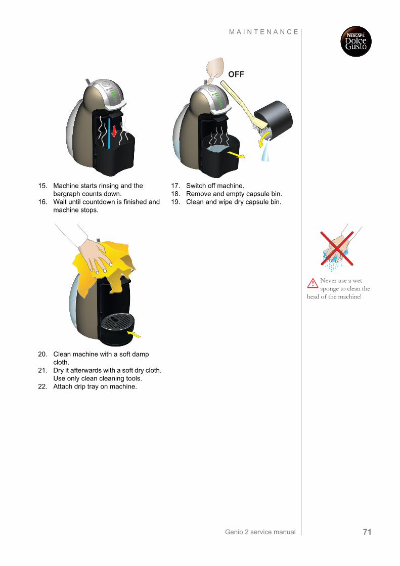
15. Machine starts rinsing and the bargraph counts down.
16. Wait until countdown is finished and machine stops.
17. Switch off machine.18. Remove and empty capsule bin.19. Clean and wipe dry capsule bin.
XL
XL
OFF
Never use a wet sponge to clean the
head of the machine!
20. Clean machine with a soft damp cloth.
21. Dry it afterwards with a soft dry cloth. Use only clean cleaning tools.
22. Attach drip tray on machine.
XLXXLLXL
Genio 2 service manual72
M A I N T E N A N C E
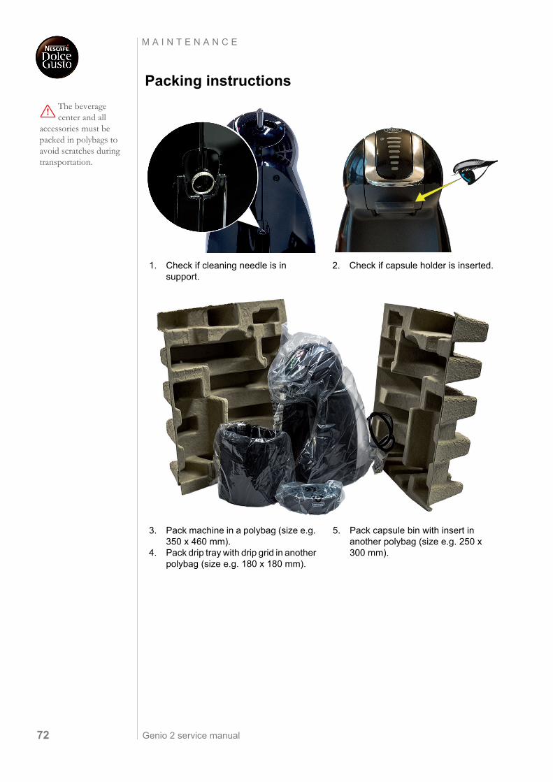
Packing instructions
The beverage center and all
accessories must be packed in polybags to avoid scratches during transportation.
1. Check if cleaning needle is in support.
2. Check if capsule holder is inserted.
3. Pack machine in a polybag (size e.g. 350 x 460 mm).
4. Pack drip tray with drip grid in another polybag (size e.g. 180 x 180 mm).
5. Pack capsule bin with insert in another polybag (size e.g. 250 x 300 mm).
Genio 2 service manual 73
M A I N T E N A N C E
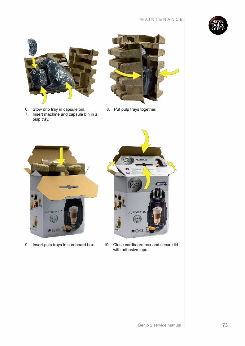
6. Stow drip tray in capsule bin.7. Insert machine and capsule bin in a
pulp tray.
8. Put pulp trays together.
9. Insert pulp trays in cardboard box. 10. Close cardboard box and secure lid with adhesive tape.

Genio 2 service manual74
K R U P S S P A R E P A R T S
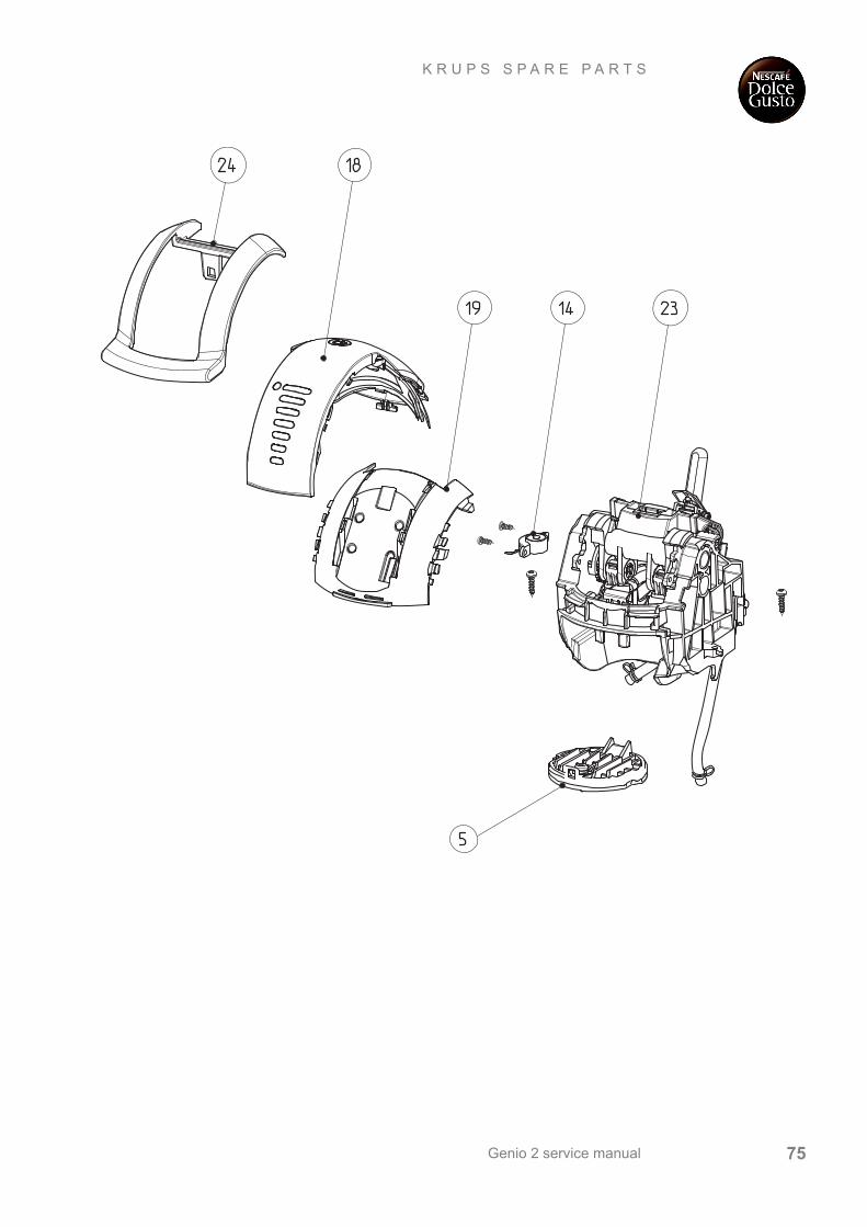
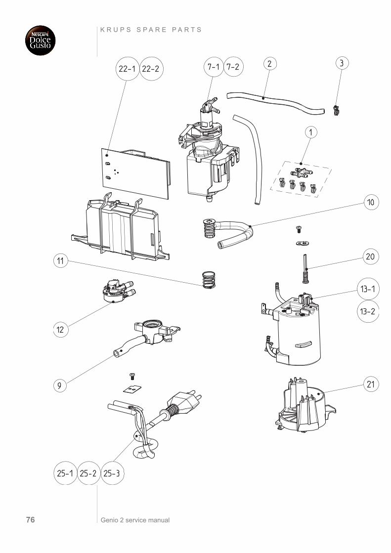
K R U P S S PA R E PA R T S
Genio 2 service manual 75
K R U P S S P A R E P A R T S
Genio 2 service manual76
K R U P S S P A R E P A R T S
Genio 2 service manual 77
K R U P S S P A R E P A R T S
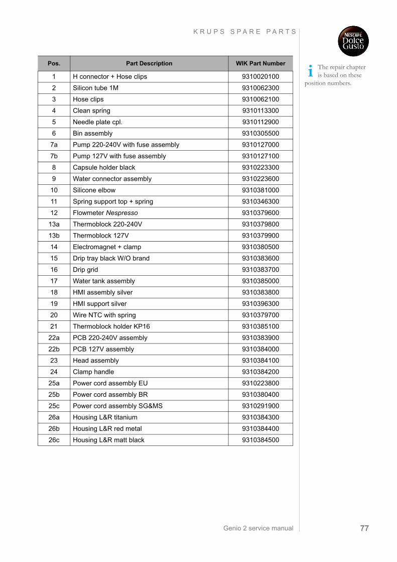
The repair chapter is based on these
position numbers.
Pos. Part Description WIK Part Number
1 H connector + Hose clips 9310020100
2 Silicon tube 1M 9310062300
3 Hose clips 9310062100
4 Clean spring 9310113300
5 Needle plate cpl. 9310112900
6 Bin assembly 9310305500
7a Pump 220-240V with fuse assembly 9310127000
7b Pump 127V with fuse assembly 9310127100
8 Capsule holder black 9310223300
9 Water connector assembly 9310223600
10 Silicone elbow 9310381000
11 Spring support top + spring 9310346300
12 Flowmeter Nespresso 9310379600
13a Thermoblock 220-240V 9310379800
13b Thermoblock 127V 9310379900
14 Electromagnet + clamp 9310380500
15 Drip tray black W/O brand 9310383600
16 Drip grid 9310383700
17 Water tank assembly 9310385000
18 HMI assembly silver 9310383800
19 HMI support silver 9310396300
20 Wire NTC with spring 9310379700
21 Thermoblock holder KP16 9310385100
22a PCB 220-240V assembly 9310383900
22b PCB 127V assembly 9310384000
23 Head assembly 9310384100
24 Clamp handle 9310384200
25a Power cord assembly EU 9310223800
25b Power cord assembly BR 9310380400
25c Power cord assembly SG&MS 9310291900
26a Housing L&R titanium 9310384300
26b Housing L&R red metal 9310384400
26c Housing L&R matt black 9310384500
Genio 2 service manual78
D E ´ L O N G H I S P A R E P A R T S
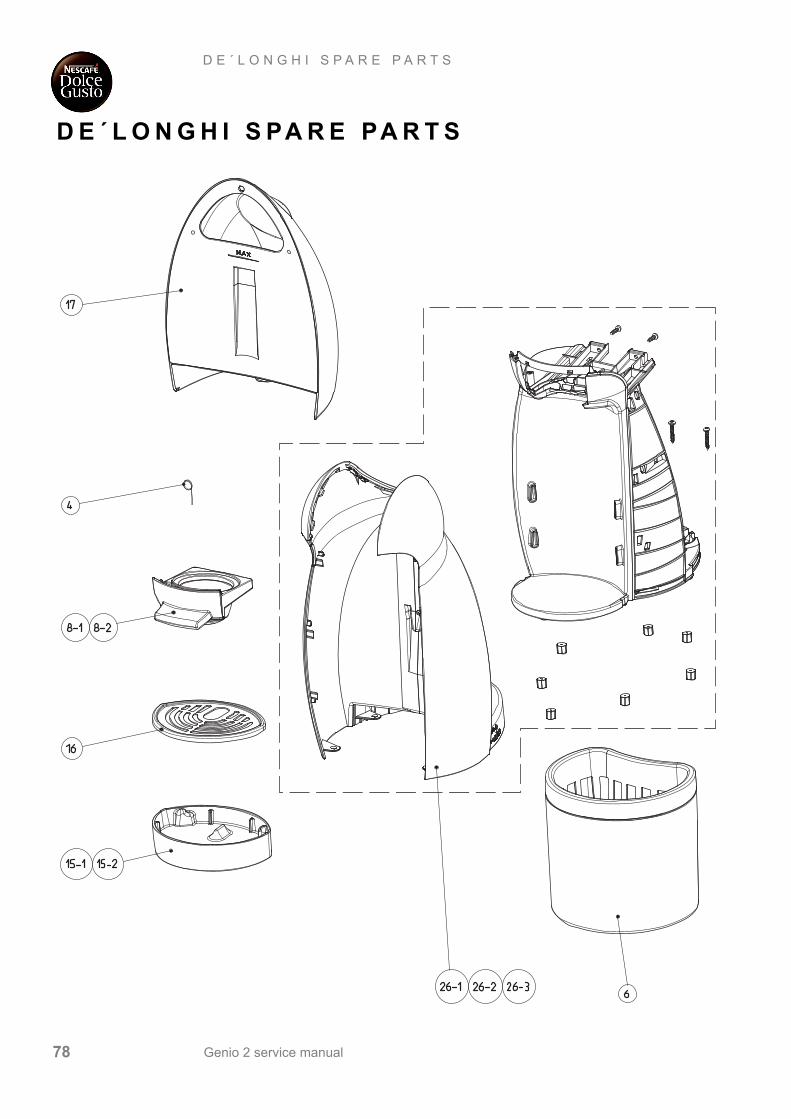
D E ´ L O N G H I S PA R E PA R T S
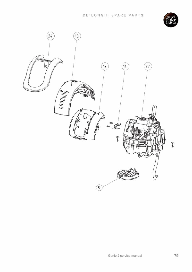
Genio 2 service manual 79
D E ´ L O N G H I S P A R E P A R T S
Genio 2 service manual80
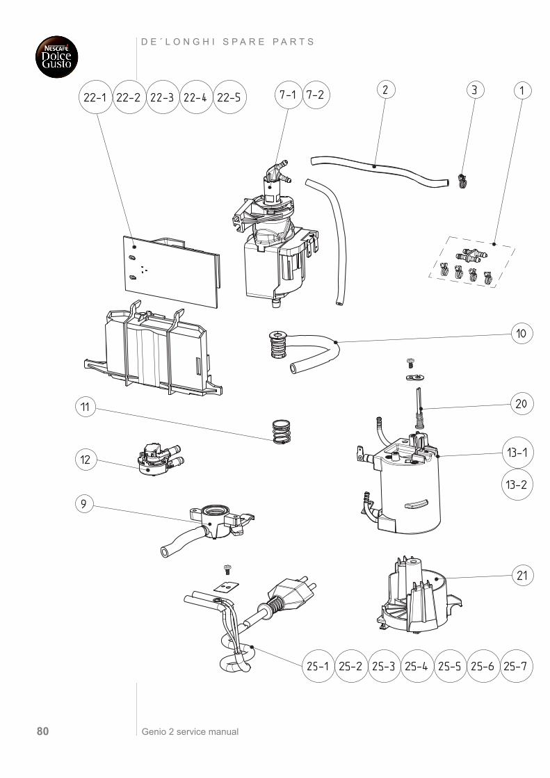
D E ´ L O N G H I S P A R E P A R T S
Genio 2 service manual 81
D E ´ L O N G H I S P A R E P A R T S
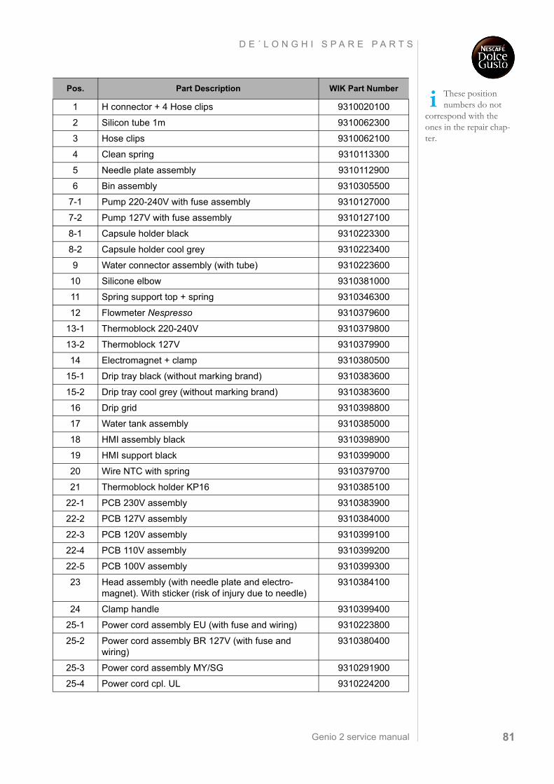
These position numbers do not
correspond with the ones in the repair chap-ter.
Pos. Part Description WIK Part Number
1 H connector + 4 Hose clips 9310020100
2 Silicon tube 1m 9310062300
3 Hose clips 9310062100
4 Clean spring 9310113300
5 Needle plate assembly 9310112900
6 Bin assembly 9310305500
7-1 Pump 220-240V with fuse assembly 9310127000
7-2 Pump 127V with fuse assembly 9310127100
8-1 Capsule holder black 9310223300
8-2 Capsule holder cool grey 9310223400
9 Water connector assembly (with tube) 9310223600
10 Silicone elbow 9310381000
11 Spring support top + spring 9310346300
12 Flowmeter Nespresso 9310379600
13-1 Thermoblock 220-240V 9310379800
13-2 Thermoblock 127V 9310379900
14 Electromagnet + clamp 9310380500
15-1 Drip tray black (without marking brand) 9310383600
15-2 Drip tray cool grey (without marking brand) 9310383600
16 Drip grid 9310398800
17 Water tank assembly 9310385000
18 HMI assembly black 9310398900
19 HMI support black 9310399000
20 Wire NTC with spring 9310379700
21 Thermoblock holder KP16 9310385100
22-1 PCB 230V assembly 9310383900
22-2 PCB 127V assembly 9310384000
22-3 PCB 120V assembly 9310399100
22-4 PCB 110V assembly 9310399200
22-5 PCB 100V assembly 9310399300
23 Head assembly (with needle plate and electro-magnet). With sticker (risk of injury due to needle)
9310384100
24 Clamp handle 9310399400
25-1 Power cord assembly EU (with fuse and wiring) 9310223800
25-2 Power cord assembly BR 127V (with fuse and wiring)
9310380400
25-3 Power cord assembly MY/SG 9310291900
25-4 Power cord cpl. UL 9310224200
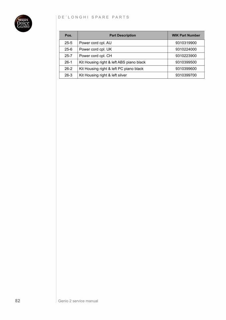
Genio 2 service manual82
D E ´ L O N G H I S P A R E P A R T S
25-5 Power cord cpl. AU 9310319900
25-6 Power cord cpl. UK 9310224000
25-7 Power cord cpl. CH 9310223900
26-1 Kit Housing right & left ABS piano black 9310399500
26-2 Kit Housing right & left PC piano black 9310399600
26-3 Kit Housing right & left silver 9310399700
Pos. Part Description WIK Part Number
Genio 2 service manual 83
N O T E S
N O T E S