section 10 - structural steel
TRANSCRIPT
BRIDGE DESIGN SPECIFICATIONS • FEBRUARY 2004
SECTION 10 - STRUCTURAL STEEL
(1996 Sixteenth Edition with 1997 - 2001 Interim Revisions)
Part A General Requirements and Materials
10.1 APPLICATION
+ 10.1.1 General
+ The specifications of this section are intended
+ for design of steel components, splices and connections
+ for straight beam and girder structures, frames, trusses,
+ arches and metal structures, as applicable. For horizon-
+ tally curved bridges, see the current AASHTO Guide
+ Specifications for Horizontally Curved Bridges.
+ 10.1.2 Notations
+ A = area of cross section (in.2) (Articles 10.37.1.1,
+ 10.34.4.7, 10.48.1.1, 10.48.4.2, 10.48.5.3
and 10.55.1)
A = bending moment coefficient (Article
10.50.1.1.2)
+ Ae = effective area of a flange or splice plate with
holes (in.2) (Articles 10.18.2.2.1, 10.18.2.2.3 )+AF = amplification factor (Articles 10.37.1.1 and
10.55.1)
+ Af = sum of the area of the fillers on the top and + bottom of the connected plate (in.2) (Article + 10.18.1.2)
+ (AFy)bf = product of area and yield strength for bottom
+ flange of steel section (lb) (Article 10.50.1.1.1)
+ (AFy)c = product of area and yield strength of that
part of reinforcing which lies in the com-
+ pression zone of the slab (lb.) (Article
10.50.1.1.1)
+ (AFy)tf = product of area and yield strength for top
+ flange of steel section (lb.) (Article
+ 10.50.1.1.1)
+ (AFy)w = product of area and yield strength for web of
+ steel section (lb.) (Article 10.50.1.1.1)
+ Af = area of flange (in.2) (Articles 10.39.4.4.2,
10.48.2.1, 10.53.1.2, and 10.56.3)+
Afc = area of compression flange (in.2) (Article +10.48.4.1)
Ag = gross area of whole connected material (in.2)
(Article 10.19.4.2)
Ag = gross area of a flange or splice plate (in.2) +
(Article 10.18.2.2.1 and 10.18.2.2) +
An = net area of the fastener (in.2) (Article +
10.32.3.2.1 and 10.57.3.1) +
Ap = smaller of either the connected plate area or +
the sum of the splice plate areas on the top +
and bottom of the connected plate (in.2) +
(Article 10.18.1.2) +s
rA = total area of longitudinal slab reinforcement
steel for each beam over interior support
(in.2) (Article 10.38.5.1.3) +
As = area of steel section (in.2) (Articles +
10.38.5.1.2, 10.54.1.1, and 10.54.2.1) +r
sA = total area of longitudinal reinforcing steel at
the interior support within the effective flange +
width (in.2) (Article 10.38.5.1.2) +
Atg = gross area along the plane resisting tension +
(in.2) (Article 10.19.4) +
Atn = net area along the plane resisting tension +
(in.2) (Article 10.19.4) +
Avg = gross area along the plane resisting shear +
(in.2) (Article 10.19.4) +
Avn = net area along the plane resisting shear (in.2) +
(Article 10.19.4)
Aw = area of web of beam (in.2) (Article 10.53.1.2) +
a = distance from center of bolt under consider-
ation to edge of plate (in.) (Articles +
10.32.3.3.2 and 10.56.2)
a = spacing of transverse stiffeners (in.) (Article +
10.39.4.4.2)
a = depth of stress block (in.) (Figure 10.50A) +
B = constant based on the number of stress cycles
(Article 10.38.5.1.1)
SECTION 10 STRUCTURAL STEEL 10-1
BRIDGE DESIGN SPECIFICATIONS • FEBRUARY 2004
B = constant for stiffeners (Articles 10.34.4.7
and 10.48.5.3)
+ b = compression flange width (in.) (Tables
10.32.1A and 10.34.2A, Article 10.34.2.1.3)
b = distance from center of bolt under consider-
+ ation to toe of fillet of connected part (in.)
(Articles 10.32.3.3.2 and 10.56.2)
+
+b = effective flange width (in.) (Articles 10.38.3,
10.38.5.1.2 and 10.50.1.1.1)
+ b = widest flange width (in.) (Article 10.15.2.1)
b = distance from edge of plate or edge of perfo-
+ ration to the point of support (in.) (Article
10.35.2.3)
b = unsupported distance between points of sup-
+ port (in.) (Table 10.35.2A and Article 10.35.2.3)
+ b = flange width between webs (in.) (Articles
10.37.3.1, 10.39.4.2, and 10.51.5.1)
+ b' = width of stiffeners (in.) (Articles 10.34.5.2,
10.34.6, 10.37.2.4, 10.39.4.5.1, and 10.55.2)
b' = width of a projecting flange element, angle,
+ or stiffener (in.) Articles 10.34.2.2, 10.37.3.2,
10.39.4.5.1, 10.48.1, 10.48.2, 10.48.5.3,
10.50, 10.51.5.5, and 10.55.3)
+ beb = width of the body of the eyebar (in.) (Article + 10.25.3)
C = web buckling coefficient (Articles 10.34.4,
10.48.5.3, and 10.48.8.)
+ C = compressive force in the slab (lb.) (Article
10.50.1.1.1)
C' = compressive force in top portion of steel + section (lb.) (Article 10.50.1.1.1)
Cb = bending coefficient (Table 10.32.1A, Ar-
ticle 10.48.4.1)
Cc = column slenderness ratio dividing elastic
and inelastic buckling (Table 10.32.1A)
+ Cmx = coefficient applied to bending term in inter-
+ action formula for prismatic members; de-
+ pendent upon member curvature caused by
+ applied moments about the X axis (Articles
+ 10.36 and 10.54.2 )
+ Cmy = coefficient applied to bending term in inter-
+ action formula for prismatic members; de-
+
+
pendent upon member curvature caused by
applied moments about the Y axis (Articles
10.36 and 10.54.2)
+ c = buckling stress coefficient (Article 10.51.5.2)
D = clear distance between flanges (in.) (Article
10.15.2)
D = clear unsupported distance between flange +
components (in.) (Table 10.34.3A,10.37.2A, +
10.48.5A, 10.55.2A, Articles 10.18.2.3.4,
10.18.2.3.5, 10.18.2.3.7, 10.18.2.3.8, 10.18.2.3.9,
10.34.3, 10.34.4, 10.34.5, 10.37.2, 10.48.1, +
10.48.2, 10.48.4, 10.48.5, 10.48.6, 10.48.8,
10.49.2, 10.49.3.2, 10.50.2.1, and 10.55.2)
D' = distance from the top of concrete slab to the
neutral axis at which a composite section in
positive bending theoretically reaches its +plastic moment capacity when the maxi-
mum compressive strain in concrete slab is +
at 0.003 (Article 10.50.1.1.2)
Dc = clear distance between the neutral axis and
the compression flange (in.) (Table +
10.34.3A, Articles 10.48.2.1(b), 10.48.4.1, +10.49.2, 10.49.3.2.2 and 10.50)
Dcp = depth of web in compression at the plastic
moment (in.) (Articles 10.50.1.1.2 and +
10.50.2.1)
Dp = distance from top of the slab to the plastic
neutral axis at the plastic moment (in.) +
(Article 10.50.1.1.2)
d = bolt diameter (in.) (Table 10.32.3B) +
d = diameter of stud (in.) (Article 10.38.5.1) +
d = depth of beam or girder (in.) (Article 10.13, +
Table 10.32.1A, Articles 10.48.2, 10.48.4.1,
and 10.50.1.1.2)
d = diameter of rocker or roller (in.) (Article +
10.32.4.2)
db = beam depth (in.) (Article 10.56.3) +
dc = column depth (in.) (Article 10.56.3) +
do = spacing of intermediate stiffener (in.) (Ar- +
ticles 10.34.4, 10.34.5, 10.48.5.3, 10.48.6.3,
and 10.48.8)
ds = distance from the centerline of a plate longi- +
tudinal stiffener or the gage line of an angle +
longitudinal stiffener to the inner surface or +
the leg of the compression flange compo- +
nent (in.) (Table 10.34.3A, 10.34.5A, Ar- +
ticles 10.34.5 and 10.49.3.2) +
E = modulus of elasticity of steel (psi) (Table
10.32.1A and Articles 10.15.3, 10.36, 10.37,
10.39.4.4.2, 10.54.1, 10.54.2 and 10.55.1) +
Ec = modulus of elasticity of concrete (psi) (Ar-
ticle 10.38.5.1.2)
10-2 SECTION 10 STRUCTURAL STEEL
BRIDGE DESIGN SPECIFICATIONS • FEBRUARY 2004
+ e = distance from the centerline of the splice to the centroid of the connection on the side of the joint under consideration (in.) (Articles 10.18.2.3.3, 10.18.2.3.5 and 10.18.2.3.7) + Fa = allowable axial stress (psi) (Table 10.32.1A and Articles 10.36, 10.37.1.2, and 10.55.1) + Fb = allowable bending stress (psi) (Table 10.32.1A and Articles 10.37.1.2 and 10.55.1) + Fbc = allowable compression flange stress specified + in Table 10.32.1A (psi) (Article 10.18.2.3.8) + Fbs = allowable block shear rupture stress (psi) + (Article 10.19.14) + Fbt = allowable tension flange stress specified in + Table 10.32.1A (psi) (Article 10.18.2.3.8) + Fbx = allowable compressive bending stress about + the X axis (psi) (Article 10.36) + Fby = allowable compressive bending stress about + the Y axis (psi) (Article 10.36)
Fcr = critical stress of the compression flange plate + or member (psi) (Articles 10.51.1, 10.51.5, + 10.54.1.1, and 10.54.2.1)
Fcu = design stress for the flange at a point of splice (psi) (Article10.18.2.2.2) + FD = maximum horizontal force (lb.) (Article 10.20.2.2)+ Fe = Euler buckling stress (psi) (Articles 10.37.1, 10.54.2, and 10.55.1) + e
F ′ = Euler stress divided by a factor of safety (psi) (Article 10.36) + Fp = allowable bearing stress on high-strength + bolts or connected material (psi) (Table 10.32.3B)+ Fs = limiting bending stress (psi) (Article 10.34.4) + Fsr = allowable range of fatigue stress (psi) (Table 10.3.1A)
F.S. = factor of safety (Table 10.32.1A and Ar-+ ticles 10.36 and 10.37.1.3) tF′ = reduced allowable tensile stress on rivet or
+ bolt due to the applied shear stress (psi) (Articles 10.32.3.3.4 and 10.56.1.3.3) Fu = specified minimum tensile strength (psi) + (Tables 10.2C, 10.32.1A and 10.32.3B, Ar-+ ticles 10.18.4 and 10.19.4) Fu = tensile strength of electrode classification + (psi) (Table 10.56A and Article 10.32.2)
Fu m = maximum bending strength of either the top +or bottom flange, whichever flange has the +larger ratio of (fs/Fum ) (Article 10.48.8.2) +Fv = allowable shear stress (psi) (Tables 10.32.1A, +10.32.3Band 10.34.3A, and Articles 10.18.2.3.6, +10.32.2, 10.32.3, 10.34.4, 10.40.2.2) +Fv = shear strength of a fastener (psi) (Article +10.56.1.3) +Fw = design shear stress in the web at the point of +splice defined in Article 10.18.2.3.6 (psi) (Ar- +ticles 10.18.2.3.6, 10.18.2.3.7 and 10.18.2.3.9) +
Fy = specified minimum yield strength of steel +
(psi) (Table 10.34.2A, 10.34.3A, 10.34.5A, ++10.35.2A, 10.48.5A, and Articles 10.15.2.1, +10.15.3,10.16.11, 10.19.4, 10.32.1, 10.32.4, 10.34, 10.35, 10.37.1.3, 10.38.5, 10.39.4, 10.40.2.2, 10.41.4.6, 10.46, 10.48, 10.49, 10.50, 10.51.5, and 10.54) Fy
r = specified minimum yield strength of the +reinforcing steel (psi) (Article 10.38.5.1.2) Fyf = specified minimum yield strength of the flange (psi) (Articles 10.18.2.2.2, +10.18.2.3.4, 10.48.1.1, and 10.53.1) + Fyw = specified minimum yield strength of the + web (psi) (Articles 10.18.2.3.4 and 10.53.1) +
f = maximum induced stress in the bottom flange +(psi) (Article 10.21.2) +
f = maximum compressive stress (psi) (Article +
10.41.4.6) +
+fDL = non-composite dead-load stress in the com- +pression flange (psi) (Articles 10.34.5.1 and +10.49.3.2) +fDL+LL = total non-composite and composite dead +load plus the composite live-load stress in +compression flange at the most highly +stressed section of the web (psi) (Articles +10.34.5.1 and 10.49.3.2) +fa = calculated axial compression stress (psi) +(Table 10.35.2A, 10.37.2A, 10.55.2A, and +Articles 10.36 and 10.37) fb = calculated compressive bending stress (psi) +(Table 10.34.2A, 10.34.3A, 10.37.2A, +10.55.2A, and Articles 10.37 and 10.39) +
fbx = calculated compressive bending stress about +
the x axis (psi) (Article 10.36) +
fby = calculated compressive bending stress about +the y axis (psi) (Article 10.36) +
SECTION 10 STRUCTURAL STEEL 10-3
BRIDGE DESIGN SPECIFICATIONS • FEBRUARY 2004
+cf ! = specified compressive strength of concrete
as determined by cylinder tests at age of 28
+days (psi) (Articles 10.38.1, 10.38.5.1.2,
10.45.3, and 10.50.1.1.1)
fdl1 = top flange compressive stress due to
+ noncomposite dead load (psi) (Table
10.34.2A)
+ fo = maximum flexural stress due to Group I
loading divided by 1.3 at the mid-thickness
of the flange under consideration for the
smaller section at the point of splice (psi)
(Articles 10.18.2.2.2 and 10.18.2.3.5)
+ fof = flexural stress due to Group I loading di-
vided by 1.3 at the mid-thickness of the
other flange at the point of splice concurrent
with fo in the flange under consideration
(psi) (Article 10.18.2.3.5)
fr = range of stress due to live load plus impact,
in the slab reinforcement over the support
+ (psi) (Article 10.38.5.1.3)
fs = maximum longitudinal bending stress in the
flange of the panels on either side of the
+ transverse stiffener (psi) (Article 10.39.4.4)
+ ft = calculated tensile stress (psi) (Articles
10.32.3.3.3 and 10.56.1.3.3)
+ fv = calculated shear stress (psi) (Table 10.34.3A,
Articles 10.32.3.2.3 and 10.34.4.4)
+ g = gage between fasteners (in.) (Articles
10.16.14 and 10.24.5)
+ H = height of stud (in.) (Article 10.38.5.1.1)
+ Hw = horizontal design force resultant in the web
at a point of splice (lb.) (Articles 10.18.2.3.8
and 10.18.2.3.9)
+ Hwo = overload horizontal design force resultant in
+ the web at a point of splice (lb.) (Article
10.18.2.3.5)
+ Hwu =horizontal design force resultant in the web
at a point of splice (lb.) (Articles 10.18.2.3.4
and 10.18.2.3.5)
+ h = average flange thickness of the channel
flange (in.)(Article 10.38.5.1.2)
+ I = moment of inertia (in.4) (Articles 10.34.4, 10.34.5,
10.38.5.1.1, 10.48.5.3, and 10.48.6.3)
Is = moment of inertia of stiffener (in.4) (Articles + 10.37.2, 10.39.4.4.1, and 10.51.5.4)
+It = moment of inertia of transverse stiffeners
(in.4) (Article 10.39.4.4.2)
10-4 SECTION 10 STRUCTURAL STEEL
Iy = moment of inertia of member about the
vertical axis in the plane of the web (in.4) +
(Article 10.48.4.1)
Iyc = moment of inertia of compression flange
about the vertical axis in the plane of the web
(in.4) (Table 10.32.1A, Article 10.48.4.1)
J = required ratio of rigidity of one transverse +
stiffener to that of the web plate (Articles
10.34.4.7 and 10.48.5.3)
J = St. Venant torsional constant (in.4) (Table
10.32.1A, Article 10.48.4.1)
K = effective length factor in plane of buckling
(Table 10.32.1A and Articles 10.37, 10.54.1,
10.54.2 and Appendix C) +
Kb = effective length factor in plane of buckling +(Article 10.36)
Kh = hole size factor (Articles 10.32.3.2 and
10.57.3.1)
k = constant: 0.75 for rivets; 0.6 for high-strength
bolts with thread excluded from shear plane
(Article 10.32.3.3.4)
k = buckling coefficient (Table 10.34.3A, Articles +
10.34.4, 10.39.4.3, 10.48.8, and 10.51.5.4)
k = distance from outer face of flange to toe of
web fillet of member to be stiffened (in.)
(Article 10.56.3) +
k1 = buckling coefficient (Article 10.39.4.4)
L = actual unbraced length (in.) (Table 10.32.1A
and Articles 10.7.4, 10.15.3, and 10.55.1) +
L = 1/2 of the length of the arch rib (in.) (Article +10.37.1)
L = distance between transverse beams (in.) (Ar- +ticle 10.41.4.6)
Lb = unbraced length (in.) (Table 10.48.2.1A and +Articles 10.36, 10.48.1.1, 10.48.2.1,
10.48.4.1, and 10.53.1.3)
Lc = length of member between points of support
(in.)(Article 10.54.1.1) +
Lc = clear distance between the holes or between
the hole and the edge of the material in the
direction of the applied bearing force (in.) +
(Table 10.32.3B and Article 10.56.1.3.2)
Lp = limiting unbraced length for the yield mo- +
ment capacity (in.) (Article 10.48.4.1) +
Lr = limiting unbraced length for elastic lateral +
torsional buckling moment capacity (in.) +
(Article 10.48.4.1)
BRIDGE DESIGN SPECIFICATIONS • FEBRUARY 2004
+ l = member length (in.) (Table 10.32.1A and
+ Article 10.35.1)
+ M = maximum bending moment (lb-in.) (Articles
+ 10.48.2, 10.48.8 and 10.54.2)
+ M1 = smaller end moment at the end of a member
+ (lb-in.) (Table 10.36A)
+ M1 & M2 = moments at two adjacent braced points (lb-
+ in.) ( Table 10.36A)
+ MA = absolute value of moment at quarter point of
+ the unbraced beam segment (lb-in.) (Table
+ 32.1.A and Article 10.48.4.1)
+ MB = absolute value of moment at midpoint of the
+ unbraced beam segment (lb-in.) (Table
+ 32.1.A and Article 10.48.4.1)
+ MC = absolute value of moment at three-quarter
+ point of the unbraced beam segment (lb-in.)
+ (Table 32.1.A and Article 10.48.4.1)
+ Mc = column moment (lb-in.) (Article 10.56.3.2)
+ McD = moments caused by dead load acting on
+ composite girder (lb-in.) (Article 10.50.1.2.2)
+ Mmax = absolute value of maximum moment in the
+ unbraced beam segment (lb-in.) (Table
+ 32.1.A and Article 10.48.4.1)
+ Mp = full plastic moment of the section (lb-in.)
(Articles 10.50.1.1.2 and 10.54.2.1)
+ Mr = lateral torsional buckling moment capacity
+ (lb-in.) (Articles 10.48.4.1 and 10.53.1.3)
Ms = elastic pier moment for loading producing
maximum positive moment in adjacent span
+ (lb-in.) (Article 10.50.1.1.2)
+ MsD = moments caused by dead load acting on
+ steel girder (lb-in.) (Article 10.50.1.2.2)
+ Mu = design bending strength (lb-in.) (Articles
+ 10.18.2.2.2, 10.48, 10.51.1, 10.53.1, and
10.54.2.1)
+ Mv = design moment due to the eccentricity of the
+ design shear at a point of splice (lb-in.)
+ (Articles 10.18.2.3.7 and 10.18.2.3.9)
+ Mvo = overload design moment due to the eccen-
+ tricity of the design shear at a point of splice
+ (lb-in.) (Article 10.18.2.3.5)
+ Mvu = design moment due to the eccentricity of the
+ design shear at a point of splice (lb-in.)
+ (Articles 10.18.2.3.3 and 10.18.2.3.5)
+ Mw = overload design moment at the point of splice
+ representing the portion of the flexural mo-
+ ment assumed to be resisted by the web (lb-in.)
+ (Articles 10.18.2.3.8 and 10.18.2.3.9)
Mwo = overload design moment at the point of +
splice representing the portion of the flex- +
ural moment assumed to be resisted by the +web (lb-in.) (Article 10.18.2.3.5) +
Mwu = design moment at a point of splice repre- +
senting the portion of the flexural moment +assumed to be resisted by the web (lb-in.) +(Articles 10.18.2.3.4 and 10.18.2.3.5) +
My = moment capacity at first yield (lb-in.) (Ar- +
ticles 10.18.2.2.2 and 10.50.1.1.2)
N1 & N2 = number of shear connectors (Article
10.38.5.1.2)
Nb = number of bolts in the joint (Articles +
10.32.3.2.1 and 10.57.3.1) +
Nc = number of additional connectors for each
beam at point of contraflexure (Article
10.38.5.1.3)
Ns = number of slip planes in a slip critical con-
nection (Articles 10.32.3.2.1 and 10.57.3.1)
Nw = number of roadway design lanes (Article
10.39.2)
n = ratio of modulus of elasticity of steel to that
of concrete (Article 10.38.1)
n = number of longitudinal stiffeners (Articles
10.39.4.3, 10.39.4.4, and 10.51.5.4)
P = allowable compressive axial load on mem-
bers (lb.) (Article 10.35.1) +
P = axial compression on the member (lb.) (Ar- +ticles 10.48.1.1, 10.48.2.1, and 10.54.2.1)
P, P1,P2
& P3 = force in the slab or in the steel girder (lb.)
(Article 10.38.5.1.2) +
Pcf = design force for the flange at a point of splice +(lb.) (Article10.18.2.2.3) +
Pcu = design force for the flange at a point of splice +(lb.) (Article10.18.2.2.2) +
Pfo = overload design force for the flange at a +point of splice (lb.) (Article10.18.2.2.2) +
Ps = allowable slip resistance (lb.) (Article 10.32 +
2.2.1) +
Pu = design axial compression strength (lb.) (Ar- +
ticle 10.54.1.1) +
p = allowable bearing (lb/in.) (Article 10.32.4.2) +
Q = prying tension per bolt (lb.) (Articles +
10.32.3.3.2 and 10.56.2) +
SECTION 10 STRUCTURAL STEEL 10-5
BRIDGE DESIGN SPECIFICATIONS • FEBRUARY 2004
+ Q = statical moment about the neutral axis (in.3)
(Article 10.38.5.1.1)
R = radius (ft.) (Article 10.15.2.1)
R = number of design lanes per box girder (Ar-
ticle 10.39.2.1)
R = reduction factor for hybrid girders (Articles
10.18.2.2.2, 10.18.2.2.4, 10.18.2.2.8,
10.40.2.1.1, 10.53.1.2, and 10.53.1.3)
Rb = bending capacity reduction factor (Articles
10.48.4.1, and 10.53.1.3)
Rev = a range of stress involving both tension and
+ compression during a stress cycle (psi) (Table
10.3.1B)
+ Rs = design slip strength of a fastener (lb.) (Ar-
+ ticle 10.57.3.1)
Rs = vertical force at connections of vertical stiff-
+ eners to longitudinal stiffeners (lb.) (Article
10.39.4.4.8)
+ Rt = design tension strength of a fastener (lb.)
+ (Article 10.56.1.3.3)
+ Rv = design shear strength of a fastener (lb.) (Ar-
+ ticle 10.56.1.3.2)
+ Rw = vertical web force (lb.) (Article 10.39.4.4.7)
+ r = radius of gyration (in.) (Articles 10.35.1,
10.37.1, 10.41.4.6, 10.48.6.3, 10.54.1.1,
10.54.2.1, and 10.55.1)
+ rb = radius of gyration in plane of bending (in.)
(Article 10.36)
+ ry = radius of gyration with respect to the Y–Y
+ axis (in.) (Article 10.48.1.1)
r' = radius of gyration of the compression flange + about the axis in the plane of the web (in.)
(Table 10.32.1A, and Article 10.48.4.1)
+ S = section modulus (in.3) (Articles 10.48.2, + 10.51.1, and 10.53.1.3) + Sr = range of horizontal shear (lb.) (Article
10.38.5.1.1)
+ Ss = section modulus of transverse stiffener (in.3)
(Articles 10.39.4.4 and 10.48.6.3)
St = section modulus of longitudinal or trans-+ verse stiffener (in.3) (Article 10.48.6.3)
+ Su = design shear strength of the shear connector + (lb.) (Article 10.38.5.1.2)
+Sxc = section modulus with respect to the com-
pression flange (in.3) (Table 10.32.1A, and
Article 10.48.4.1)
10-6 SECTION 10 STRUCTURAL STEEL
Sxt = section modulus with respect to the tension +
flange (in.3) (Article 10.53.1.2) +
s = pitch of any two successive holes in the +
chain (in.) (Article 10.16.14.2) +
T = range in tensile stress (psi) (Table 10.3.1B) +
T = calculated direct tension per bolt (lb.) (Ar- +
ticles 10.32.3 and 10.56.2)
T = arch rib thrust at the quarter point from dead
+ live + impact loading (lb.) (Articles 10.37.1 +
and 10.55.1)
Tb = required minimum bolt tension stress (psi) +
(Articles 10.32.3.2 and 10.57.3.1) +
Tbs = design block shear rupture strength (lb.) +
(Article 10.19.4) +
t = thickness of the thinner outside plate or
shape (in.) (Article 10.24.6) +
t = thickness of members in compression (in.) +
(Table 10.35.2A and Article 10.35.2) +
t = thickness of thinnest part connected (in.) +
(Articles 10.32.3.3.2 and 10.56.2) +
t = thickness of the wearing surface (in.) (Ar- +
ticle 10.41.2) +
t = flange thickness (in.) (Articles 10.18.2.2.1, +
10.34.2.1, 10.39.4.2, 10.48.1.1, 10.48.2.1, +
10.50, and 10.51.5.1) +
t = thickness of a flange angle (in.) (Article +
10.34.2.2) +
t = thickness of stiffener (in.) (Article 10.48.5.3) +
tb = thickness of flange delivering concentrated
force (in.) (Article 10.56.3.2) +
tc = thickness of flange of member to be stiff-
ened (in.) (Article 10.56.3.2) +
tf = thickness of the flange (in.) (Table 10.37.2A, +10.55.2A, and Articles 10.37.3, 10.55.3 and
10.39.4.3)+
th = thickness of the concrete haunch above the
beam or girder top flange (in.) (Article +
10.50.1.1.2)
ts = thickness of stiffener (in.) (Table 10.34.5A, +10.37.2A, 10.48.5A, 10.55.2A, and Article +10.34.5, 10.37.2, 10.48.5.3 and 10.55.2) +
ts = slab thickness (in.) (Articles 10.38.5.1.2, +
10.50.1.1.1, and 10.50.1.1.2)
BRIDGE DESIGN SPECIFICATIONS • FEBRUARY 2004
+ ttf = thickness of top flange (in.) (Article 10.50.1.1.1)+ tw = web thickness (in.) (Table 10.34.3A, 10.48.5A, + 10.55.2A, Articles 10.15.2.1, 10.18.2.3.4, 10.18.2.3.5, 10.18.2.3.7, 10.18.2.3.8, 10.18.2.3.9, 10.34.3, 10.34.4, 10.34.5, 10.37.2, 10.48, 10.49.2, 10.49.3, 10.55.2, and 10.56.3) + t' = thickness of outstanding stiffener element (in.) (Articles 10.39.4.5.1 and 10.51.5.5) + V = shearing force (lb.) (Articles 10.35.1, 10.48.5.3, 10.48.8, and 10.51.3) + Vo = maximum shear in the web due to Group I + loading divided by 1.3 at the point of splice + (lb.) (Article 10.18.2.3.5) + Vp = shear yielding strength of the web (lb.) (Ar-ticles 10.48.8 and 10.53.1.4)
Vr = range of shear due to live loads and impact + (lb.) (Article 10.38.5.1.1) + Vu = design shear strength (lb.) (Articles 10.18.2.3.2, 10.48.5.3, 10.48.8, and 10.53.1.4)
Vv = calculated vertical shear (lb.) (Article 10.39.3.1) + Vw = design shear for a web (lb.) (Articles 10.39.3.1 and 10.51.3) + Vwu = design shear in the web at the point of splice + (lb.) (Articles 10.18.2.3.2, 10.18.2.3.3 and + 10.18.2.3.5)+ W = length of a channel shear connector, (in.) (Article 10.38.5.1.2)
WL = fraction of a wheel load (Article 10.39.2) + Wc = roadway width between curbs or barriers if curbs are not used (ft.) (Article 10.39.2.1) + Wn = least net width of the flange or splice plate + (in.) (Article10.18.2.2.1)
w = length of a channel shear connector mea-sured in a transverse direction on the flange + of a girder (in.) (Article 10.38.5.1.1) + w = unit weight of concrete (pcf) (Article 10.38.5.1.2)
w = width of flange between longitudinal stiff-+ eners (in.) (Articles 10.39.4.3, 10.39.4.4, and 10.51.5.4) + x = subscript, represents the x-x axis (Article + 10.54.2)+ y = subscript, represents the y-y axis (Article + 10.54.2)
Yo = distance from the neutral axis to the extreme outer fiber (in.) (Article 10.15.3) +
y = location of steel sections from neutral axis (in.) (Article 10.50.1.1.1) +
Z = plastic section modulus (in.3) (Articles +
10.48.1, 10.53.1.1, and 10.54.2.1) Zr = allowable range of horizontal shear on an individual connector (lb.) (Article 10.38.5.1) +
α = constant based on the number of stress cycles (Article 10.38.5.1.1) α = specified minimum yield strength of the +web divided by the specified minimum yield +strength of the tension flange (Articles 10.40.2, 10.40.4 and 10.53.1.2 ) +
α =factor for flange splice design equal to 1.0 except that a lower value equal to (Mu/My)may be used for flanges in compression at sections where Mu is less than My (Article 10.18.2.2.2)β = area of the web divided by the area of the tension flange (Articles 10.40.2 and 10.53.1.2) β = factor applied to gross area of flange and splice plate in computing the effective area (Article 10.18.2.2.1) θ = angle of inclination of the web plate to the vertical (Articles 10.39.3.1 and 10.51.3) ψ = ratio of total cross sectional area to the cross sectional area of both flanges (Article 10.15.2) ψ = distance from the outer edge of the tension flange to the neutral axis divided by the depth of the steel section (Articles 10.40.2 and 10.53.1.2) ∆ = amount of camber (in.) (Article 10.15.3) +∆DL = dead load camber at any point (in.) (Article +10.15.3)∆m = maximum value of∆DL (in.) (Article 10.15.3) +
φ = reduction factor (Articles 10.38.5.1.2, and Table 10.56A ) +
φ = longitudinal stiffener coefficient (Articles 10.39.4.3 and 10.51.5.4) φbs = 0.8, reduction factor for block shear rupture +strength (Article 10.19.4) +
γ = ratio of Af to Ap (Article 10.18.1.2) µ = slip coefficient in a slip-critical joint (Ar-ticles 10.32.3.2 and 10.57.3) +
SECTION 10 STRUCTURAL STEEL 10-7
BRIDGE DESIGN SPECIFICATIONS • FEBRUARY 2004
+ 10.1.3 Definition +
+ The following terms are defined for general use in + Section 10. Specialized definitions appear in individual + Articles.+
+ Allowable Design Strength – The capacity based on + allowable stress in the case of SERVICE LOAD DE-+ SIGN METHOD, or the capacity based on design strength + in the case of STRENGTH DESIGN METHOD. + Allowable Fatigue Stress Range – The maximum + stress range that can be sustained without failure of the + detail for a specified number of cycles. + Allowable Stress – The maximum stress permitted + under full service load. + Anchor Rod - A fastener that is typically used to + connect superstructure element to substructure and made + from threaded rod or stud material. + Arch – A curved vertical structure in which the hori-+ zontal component of the force in the rib is resisted by a + horizontal tie or its foundation. + Beam – A straight or curved horizontal structural + member, primarily supporting transverse loads through + flexure, shear and torsion actions. Generally, this term is + used when the member is made of rolled shapes. + Beam-Column – A member subjected to a combina-+ tion of axial force and bending moment. + Block Shear Rupture – Failure of a bolted web connec-+ tion of coped beams or any tension connection when a + portion of a plate tears out along the perimeter of the + connecting bolts. + Bolt - A threaded fastener with a head, generally + available in stock lengths up to about eight inches. + Bolt Assembly – The bolt, nut(s) and washer (s). + Bracing Member – A member intended to brace a + main member, or part thereof, against lateral movement. + Charpy V-Notch Impact Requirement – The minimum + energy required to be absorbed in a Charpy V-notch test + conducted at a specified temperature. + Charpy V-notch Test – An impact test complying with + the AASHTO T243M (ASTM A673M). + Clear Distance of Fasteners – The distance between + edges of adjacent fastener holes. + Column – A vertical framed structural member pri-+ mary supporting axial compression loads. + Collapse Load – That load which can be carried by a + structural member or structure when failure is imminent. + Compact Section – A section which is capable of + developing the fully plastic stress distribution in flexure. + The rotational capacity required to comply with analysis
assumptions used in various articles of this section is
10-8 SECTION 10 STRUCTURAL STEEL
provided by satisfying various flange and web slender- +ness and bracing requirements. +
Component – A constituent part of a structure or +structural system. +
Composite Beam/Girder – A beam/girder in which a +steel beam/girder and concrete deck are interconnected +by shear connectors and respond to force effects as a unit. +
Cross Frame – Transverse truss framework connect- +ing adjacent longitudinal flexural components. +
Deck Truss – A truss system in which the roadway is +at or above the elevation of the top chord of the truss. +
Detail Category – A grouping of components and +details having essentially the same fatigue resistance. +
Diaphragm – A transverse flexural component con- +necting adjacent longitudinal flexural components. +
Edge Distance of Fasteners – The distance perpen- +dicular to the line of force between the center of a fastener +hole and the edge of the component. +
End Panel – The end section of a truss or girder. +Eyebar – A tension member with a rectangular section +
and enlarged ends for a pin connection. +Fastener – A rivet, bolt, threaded rod, or threaded stud +
that is used to fasten individual elements together. +Fatigue – The initiation and/or propagation of a crack +
due to repeated variation of normal stress with a tensile +component. +
Fatigue Design Life – The number of years that a +detail is expected to resist the assumed traffic loads +without fatigue cracking. In the development of these +Specifications it has been taken as 75 years. +
Fatigue Life – The number of repeated stress cycles +that results in fatigue failure of a detail. +
Finite Fatigue Life – The number of cycles to failure +of a detail when the maximum probable stress range +exceeds the constant amplitude fatigue threshold. +
FCM – Fracture Critical Member – A tension member +or a tension component of a flexural member (including +those subject to reversal of stress) whose failure is ex- +pected to result in the collapse of the bridge +
Fracture Toughness – A measure of a structural ma- +terial or element to absorb energy without fracture, gen- +erally determined by the Charpy V-notch test. +
Gage of Bolts – The distance between adjacent lines of +bolts or the distance from the back of an angle or other +shape to the first line of bolts. +
Girder – A straight or curved structural horizontal +member, primarily supporting transverse loads through +flexure, shear and torsional actions. Generally, this term +is used when the member is made of fabricated sections. +
Grip – Distance between the nut and the bolt head. +Gusset Plate – Plate used to interconnect vertical, +
BRIDGE DESIGN SPECIFICATIONS • FEBRUARY 2004
+ diagonal and horizontal truss members at a panel point.
+ Half-Through Truss Spans – A truss system with the
+ roadway located somewhere between the top and bottom
+ chords and which precludes the use of a top lateral system.
+ Horizontally Curved Beam/Girder – A beam/girder
+ which is curved in plan.
+ Hybrid Girder – Fabricated steel girder with a web
+ that has a specified minimum yield strength which is
+ lower than one or both flanges.
+ Inelastic Action – A condition in which deformation is
+ not fully recovered upon removal of the load that pro-
+ duces it.
+ Inelastic Redistribution – The redistribution of inter-
+ nal force effects in a component or structure caused by
+ inelastic deformation at one or more sections.
+ Interior Panel – The interior section of a truss or girder
+ component.
+ Lacing – Plates or bars to connect main components of
+ a member.
+ Lateral Bracing Component – A component utilized
+ individually or as part of a lateral bracing system to
+ prevent lateral buckling of components and/or to resist
+ lateral loads.
+ Load Path – A succession of components and joints
+ through which a load is transmitted from its origin to its
+ destination.
+ Longitudinally Loaded Weld – Weld with applied load
+ parallel to the longitudinal axis of the weld.
+ Main Member – Any member on a critical path that
+ carries bridge gravity load. The loss of capacity of these
+ members would have serious consequences on the struc-
+ tural integrity.
+ Net Tensile Stress – The algebraic sum of two or more
+ stresses in which the net effect is tension.
+ Non-Compact Section – A section that can develop the
+ yield strength in compression elements before onset of local
+ buckling, but cannot resist inelastic local buckling at strain
+ levels required for a fully plastic stress distribution.
+ Orthotropic Deck – A deck made of steel plates
+ stiffened with open or closed steel ribs welded to the
+ underside.
+ Permanent Deflection – A type of inelastic deflection
+ which remains in a component or system after the load is
+ removed.
+ Pitch of Bolts – The distance along the line of force
+ between the centers of adjacent holes.
+ Plate – A flat steel plate product whose thickness
+ exceeds 0.25 in.
+ Portal Frames – End transverse truss bracing or
+ Vierendeel bracing that provides for stability and resists
+ wind or seismic loads.
Redistribution Moment – An internal moment caused +
by yielding in a continuous span bending component and +
held in equilibrium by external actions. +
Redistribution of Moments – A process which results +
from formulation of inelastic deformation in continuous +
structures. +
Redistribution Stress – The bending stress resulting +
from the redistribution moment. +
Redundancy – The multiple load paths of a bridge +
which enables it to perform its design function in a +
damaged state. +
Redundant Member – A member whose failure does +
not cause failure of the bridge. +
Secondary Member - All members other than main +
member not designed to carry primary load. +
Sheet – A flat rolled steel product whose thickness is +
between 0.006 in. and 0.25 in. +
St. Venant Torsion – A torsional moment producing +
pure shear stresses on a cross-section in which plane +
sections remain plane. +
Stress Range – The algebraic difference between +
extreme stresses resulting from the passage of a defined +
load. +
Subpanel – A stiffened web panel divided by one or +
more longitudinal stiffeners. +
Sway Bracing – Transverse vertical bracing between +
truss members. +
Threaded Rod - An unheaded rod that is threaded its +
entire length, typically an “off-the-shelf” item. +
Threaded Stud – An unheaded rod which is not threaded +
its entire length and typically threaded each end or one +
end. +
Through Truss Spans – A truss system where the +
roadway is located near the bottom chord and which +
contains a top chord lateral system. +
Tie Plates – Plates used to connect components of a +
member. +
Transversely Loaded Weld – Weld with applied force +
perpendicular to the longitudinal axis of the weld. +
Unbraced Length – Distance between brace points +
resisting the mode of buckling or distortion under consid- +
eration; generally, the distance between panel points or +
brace locations. +
Warping Torsion – A twisting moment producing +
shear stress and normal stresses, and under which the +
cross-section does not remain plane. +
Yield Strength – The stress at which a material exhibits +
a specified limiting deviation from the proportionality of +
stress to strain. +
SECTION 10 STRUCTURAL STEEL 10-9
BRIDGE DESIGN SPECIFICATIONS • FEBRUARY 2004
10.2 MATERIALS
10.2.1 General
These specifications recognize steels listed in the
following subparagraphs. Other steels may be used;
however, their properties, strengths, allowable stresses,
and workability must be established and specified.
10.2.2 Structural Steels
Structural steels shall conform to the material desig-
nated in Table 10.2A. The modulus of elasticity of all
grades of structural steel shall be assumed to be
29,000,000 psi and the coefficient of linear expansion
0.0000065 per degree Fahrenheit. The shear modulus of
elasticity shall be assumed to be 11,200,000 psi.
10.2.3 Steels for Pins, Rollers, and
Expansion Rockers
Steels for pins, rollers, and expansion rockers shall
conform to one of the designations listed in Table 10.2A
and 10.2B, or shall be stainless steel conforming to
ASTM A 240 or ASTM A 276 HNS 21800.
10.2.4 Fasteners
Fasteners may be carbon steel bolts (ASTM A 307);
power-driven rivets, AASHTO M 228 Grades 1 or 2
(ASTM A 502 Grades 1 or 2); or high-strength bolts,
AASHTO M 164 (ASTM A 325), AASHTO M 253
(ASTM A 490) or fasteners conforming to ASTM A354
and ASTM A449. Structural fasteners shall conform the
material designated in Table 10.2C.
In the Standard Specifications of California Depart-
ment of Transportation, the following fastener descrip-
tions are defined: “Bolt” is ASTM A307; “HS Bolt” is
ASTM A325; “Threaded Rod” is ASTM A307 Grade C.
“HS Threaded Rod” is ASTM A449. “Thread Stud” is
ASTM A307 Grade C. “HS Threaded Stud” is ASTM
A449; tensioning requirements only apply to A325 and
A490 bolts; and “Bolt” is a generic term that applies to
threaded rods, threaded studs, and anchor rods. The
provisions and specifications in ASTM A325, A490, and
A307 Grades A and B, are for headed bolts only and do not
apply to threaded rods and studs. While ASTM A449 or
A354 bolts seem to be the equal of ASTM A325 or A490 for
certain diameters and grades, there are differences in the
requirements for inspection and quality assurance, and
heavy-hex head and nut dimensions. The tensioning
requirements in the Standard Specifications only apply to
ASTM A325 and A490 bolts.
10.2.5 Weld Metal
Weld metal shall conform to the current requirements
of the ANSI/AASHTO/AWS D1.5 Bridge Welding Code.
10-10 SECTION 10 STRUCTURAL STEEL
BRIDGE DESIGN SPECIFICATIONS • FEBRUARY 2004
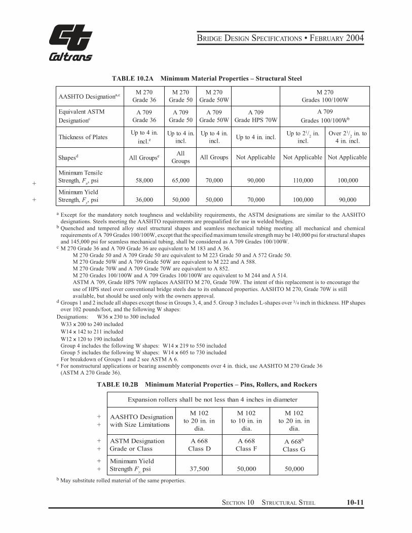
TABLE 10.2A Minimum Material Properties – Structural Steel
AASHTO Designationa,c M 270
Grade 36
M 270
Grade 50
M 270
Grade 50W
M 270
Grades 100/100W
Equivalent ASTM
Designationc
A 709
Grade 36
A 709
Grade 50
A 709
Grade 50W
A 709
Grade HPS 70W
A 709
Grades 100/100Wb
Thickness of Plates Up to 4 in.
incl. eUp to 4 in.
incl.
Up to 4 in.
incl. Up to 4 in. incl.
Up to 21/2
in.
incl.
Over 21/2
in. to
4 in. incl.
Shapesd All Groupse All
Groups All Groups Not Applicable Not Applicable Not Applicable
Minimum Tensile
Strength, Fu, psi 58,000 65,000 70,000 90,000 110,000 100,000
Minimum Yield
Strength, Fy, psi 36,000 50,000 50,000 70,000 100,000 90,000
+
+
a Except for the mandatory notch toughness and weldability requirements, the ASTM designations are similar to the AASHTO
designations. Steels meeting the AASHTO requirements are prequalified for use in welded bridges. b Quenched and tempered alloy steel structural shapes and seamless mechanical tubing meeting all mechanical and chemical
requirements of A 709 Grades 100/100W, except that the specified maximum tensile strength may be 140,000 psi for structural shapes
and 145,000 psi for seamless mechanical tubing, shall be considered as A 709 Grades 100/100W. c M 270 Grade 36 and A 709 Grade 36 are equivalent to M 183 and A 36.
M 270 Grade 50 and A 709 Grade 50 are equivalent to M 223 Grade 50 and A 572 Grade 50.
M 270 Grade 50W and A 709 Grade 50W are equivalent to M 222 and A 588.
M 270 Grade 70W and A 709 Grade 70W are equivalent to A 852.
M 270 Grades 100/100W and A 709 Grades 100/100W are equivalent to M 244 and A 514.
ASTM A 709, Grade HPS 70W replaces AASHTO M 270, Grade 70W. The intent of this replacement is to encourage the
use of HPS steel over conventional bridge steels due to its enhanced properties. AASHTO M 270, Grade 70W is still
available, but should be used only with the owners approval. d Groups 1 and 2 include all shapes except those in Groups 3, 4, and 5. Group 3 includes L-shapes over 3/4 inch in thickness. HP shapes
over 102 pounds/foot, and the following W shapes:
Designations: W36 x 230 to 300 included
W33 x 200 to 240 included
W14 x 142 to 211 included
W12 x 120 to 190 included
Group 4 includes the following W shapes: W14 x 219 to 550 included
Group 5 includes the following W shapes: W14 x 605 to 730 included
For breakdown of Groups 1 and 2 see ASTM A 6. e For nonstructural applications or bearing assembly components over 4 in. thick, use AASHTO M 270 Grade 36
(ASTM A 270 Grade 36).
TABLE 10.2B Minimum Material Properties – Pins, Rollers, and Rockers
+
+
+
+
+
+
Expansion rollers shall be not less than 4 inches in diameter
AASHTO Designation
with Size Limitations
M 102
to 20 in. in
dia.
M 102
to 10 in. in
dia.
M 102
to 20 in. in
dia.
ASTM Designation
Grade or Class
A 668
Class D
A 668
Class F A 668b
Class G
Minimum Yield
Strength Fy,
psi 37,500 50,000 50,000
b May substitute rolled material of the same properties.
SECTION 10 STRUCTURAL STEEL 10-11
BRIDGE DESIGN SPECIFICATIONS • FEBRUARY 2004
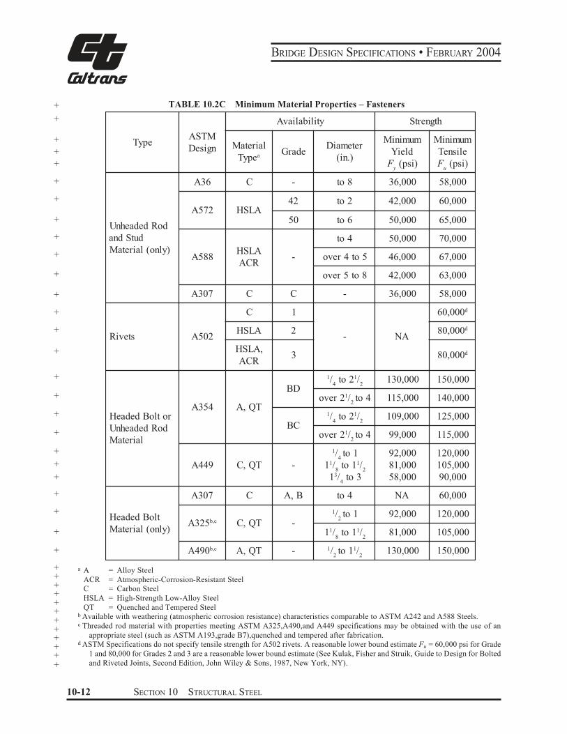
+ TABLE 10.2C Minimum Material Properties – Fasteners
+
+
+
+
+
+
+
+
+
+
+
+
+
+
+
+
+
+
+
+
+
+
+
+
+
Type ASTM
Design
Availability Strength
Material
TypeaGrade
Diameter
(in.)
Minimum
Yield
Fy
(psi)
Minimum
Tensile
Fu
(psi)
Unheaded Rod
and Stud
Material (only)
A36 C - to 8 36,000 58,000
A572 HSLA 42 to 2 42,000 60,000
50 to 6 50,000 65,000
A588 HSLA
ACR -
to 4 50,000 70,000
over 4 to 5 46,000 67,000
over 5 to 8 42,000 63,000
A307 C C - 36,000 58,000
Rivets A502
C 1
- NA
60,000d
HSLA 2 80,000d
HSLA,
ACR 3 80,000d
Headed Bolt or
Unheaded Rod
Material
A354 A, QT
BD
1/4
to 21/2
130,000 150,000
over 21/2to 4 115,000 140,000
BC
1/4
to 21/2
109,000 125,000
over 21/2to 4 99,000 115,000
A449 C, QT -
1/4to 1
11/8
to 11/2
13/4
to 3
92,000
81,000
58,000
120,000
105,000
90,000
Headed Bolt
Material (only)
A307 C A, B to 4 NA 60,000
A325b,c C, QT -
1/2to 1 92,000 120,000
11/8
to 11/2
81,000 105,000
A490b,c A, QT - 1/2to 11/
2130,000 150,000
+ a A = Alloy Steel+ ACR = Atmospheric-Corrosion-Resistant Steel+ C = Carbon Steel+
HSLA = High-Strength Low-Alloy Steel +
QT = Quenched and Tempered Steel+
b Available with weathering (atmospheric corrosion resistance) characteristics comparable to ASTM A242 and A588 Steels.+
c Threaded rod material with properties meeting ASTM A325,A490,and A449 specifications may be obtained with the use of an+appropriate steel (such as ASTM A193,grade B7),quenched and tempered after fabrication.+
d ASTM Specifications do not specify tensile strength for A502 rivets. A reasonable lower bound estimate Fu = 60,000 psi for Grade+1 and 80,000 for Grades 2 and 3 are a reasonable lower bound estimate (See Kulak, Fisher and Struik, Guide to Design for Bolted+and Riveted Joints, Second Edition, John Wiley & Sons, 1987, New York, NY).+
10-12 SECTION 10 STRUCTURAL STEEL
BRIDGE DESIGN SPECIFICATIONS • FEBRUARY 2004
10.2.6 Cast Steel, Ductile Iron Castings, Malleable Castings and Cast Iron
10.2.6.1 Cast Steel and Ductile Iron
Cast steel shall conform to specifications for Steel
Castings for Highway Bridges, AASHTO M 192 (ASTM
A 486); Mild-to-Medium-Strength Carbon-Steel Cast-
ings for General Application, AASHTO M 103 (ASTM
A 27); and Corrosion-Resistant Iron-Chromium, Iron-
Chromium-Nickel and Nickel-Based Alloy Castings for
General Application, AASHTO M 163 (ASTM A 743).
Ductile iron castings shall conform to ASTM A 536.
10.2.6.2 Malleable Castings
Malleable castings shall conform to specifications for
+ Malleable Iron Castings, ASTM A 47, Grade 35018
+ (specified minimum yield strength 35,000 psi).
10.2.6.3 Cast Iron
Cast iron castings shall conform to specifications for
Gray Iron Castings, AASHTO M 105, Class 30.
SECTION 10 STRUCTURAL STEEL 10-13
BRIDGE DESIGN SPECIFICATIONS • FEBRUARY 2004
Part B Design Details
10.3 REPETITIVE LOADING AND TOUGHNESS CONSIDERATIONS
+ 10.3.1 Allowable Fatigue Stress Ranges
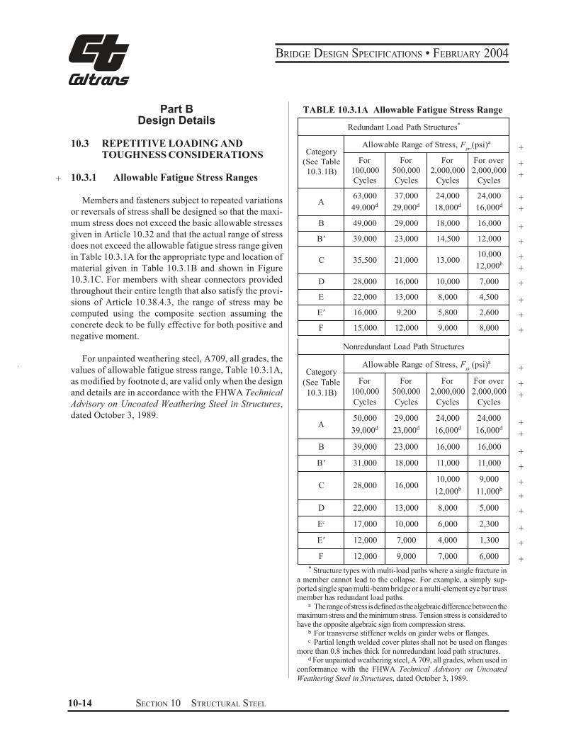
Members and fasteners subject to repeated variations
or reversals of stress shall be designed so that the maxi-
mum stress does not exceed the basic allowable stresses
given in Article 10.32 and that the actual range of stress
does not exceed the allowable fatigue stress range given
in Table 10.3.1A for the appropriate type and location of
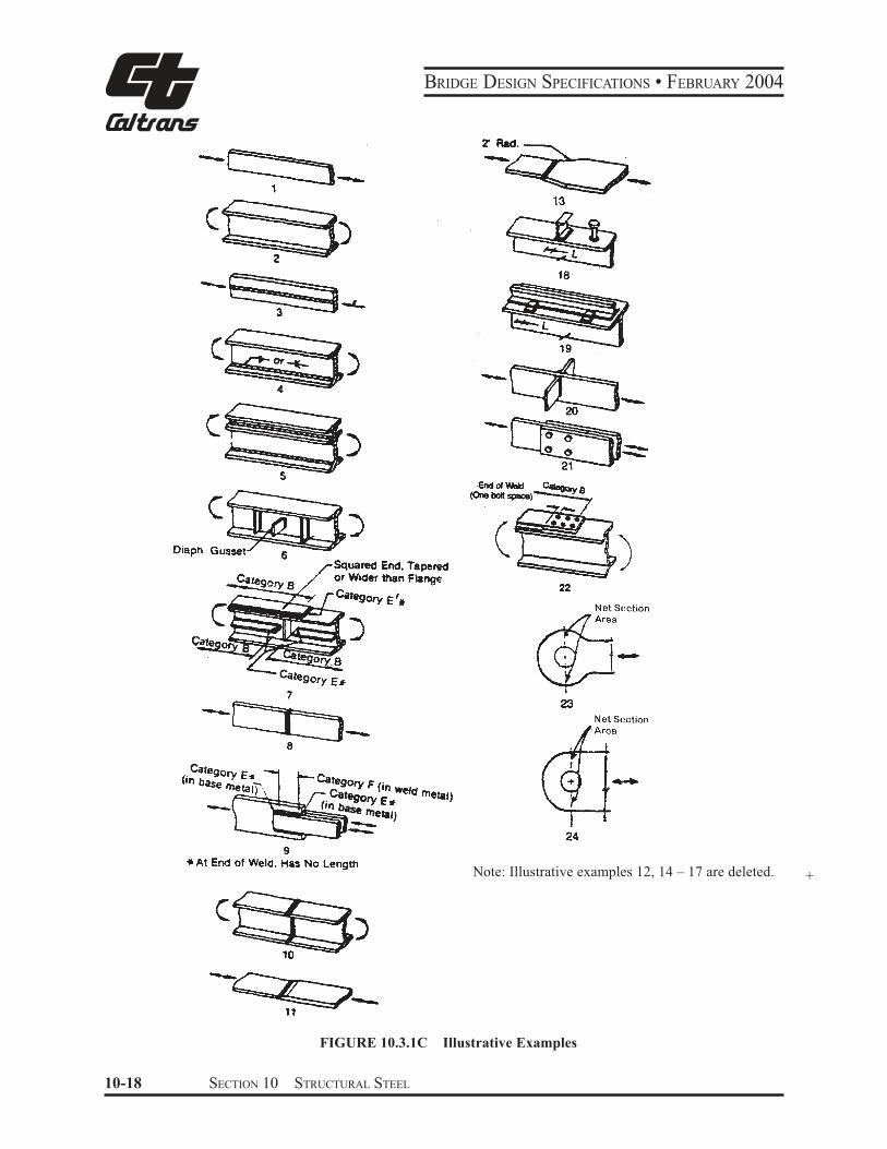
material given in Table 10.3.1B and shown in Figure
10.3.1C. For members with shear connectors provided
throughout their entire length that also satisfy the provi-
sions of Article 10.38.4.3, the range of stress may be
computed using the composite section assuming the
concrete deck to be fully effective for both positive and
negative moment.
For unpainted weathering steel, A709, all grades, the
values of allowable fatigue stress range, Table 10.3.1A,
as modified by footnote d, are valid only when the design
and details are in accordance with the FHWA Technical
Advisory on Uncoated Weathering Steel in Structures,
dated October 3, 1989.
TABLE 10.3.1A Allowable Fatigue Stress Range
Redundant Load Path Structures *
Category
(See Table
10.3.1B)
Allowable Range of Stress, Fsr
(psi)a
For
100,000
Cycles
For
500,000
Cycles
For
2,000,000
Cycles
For over
2,000,000
Cycles
A63,000
49,000d
37,000
29,000d
24,000
18,000d
24,000
16,000d
B 49,000 29,000 18,000 16,000
B' 39,000 23,000 14,500 12,000
C 35,500 21,000 13,00010,000
12,000b
D 28,000 16,000 10,000 7,000
E 22,000 13,000 8,000 4,500
E' 16,000 9,200 5,800 2,600
F 15,000 12,000 9,000 8,000
Nonredundant Load Path Structures
Category
(See Table
10.3.1B)
Allowable Range of Stress, Fsr
(psi)a
For
100,000
Cycles
For
500,000
Cycles
For
2,000,000
Cycles
For over
2,000,000
Cycles
A50,000
39,000d
29,000
23,000d
24,000
16,000d
24,000
16,000d
B 39,000 23,000 16,000 16,000
B' 31,000 18,000 11,000 11,000
C 28,000 16,00010,000
12,000b
9,000
11,000b
D 22,000 13,000 8,000 5,000
Ec 17,000 10,000 6,000 2,300
E' 12,000 7,000 4,000 1,300
F 12,000 9,000 7,000 6,000
+
+
+
+
+
+
+
+
+
+
+
+
+
+
+
+
+
+
+
+
+
+
+
+
+
+* Structure types with multi-load paths where a single fracture in
a member cannot lead to the collapse. For example, a simply sup-ported single span multi-beam bridge or a multi-element eye bar truss member has redundant load paths.
a The range of stress is defined as the algebraic difference between the maximum stress and the minimum stress. Tension stress is considered to have the opposite algebraic sign from compression stress.
b For transverse stiffener welds on girder webs or flanges. c Partial length welded cover plates shall not be used on flanges
more than 0.8 inches thick for nonredundant load path structures. d For unpainted weathering steel, A 709, all grades, when used in
conformance with the FHWA Technical Advisory on Uncoated
Weathering Steel in Structures, dated October 3, 1989.
10-14 SECTION 10 STRUCTURAL STEEL
BRIDGE DESIGN SPECIFICATIONS • FEBRUARY 2004
TABLE 10.3.1B
General
Condition
Situation
Stress
Kind of
Stress
Illustrative
Category E x a m p l e
(See Table (See Figure
10.3.1A) 10.3.1C)
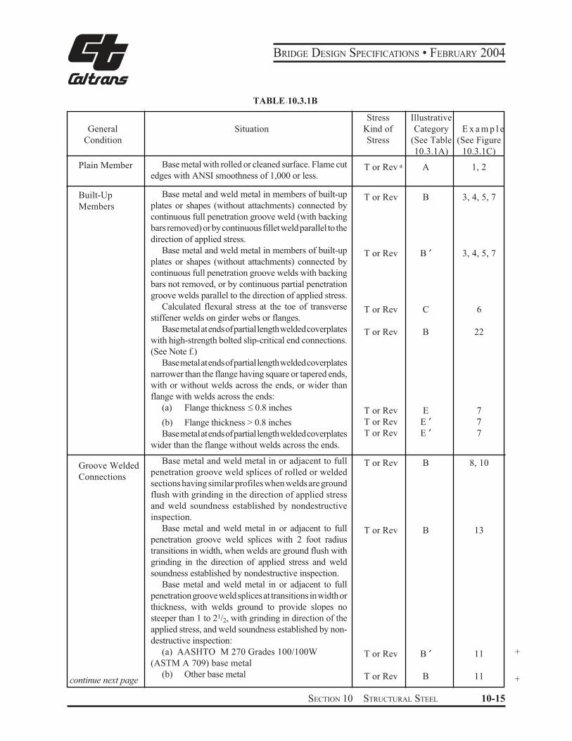
Plain Member Base metal with rolled or cleaned surface. Flame cut
edges with ANSI smoothness of 1,000 or less. T or Rev a A 1, 2
Built-Up
Members
Groove Welded
Connections
continue next page
Base metal and weld metal in members of built-up
plates or shapes (without attachments) connected by
continuous full penetration groove weld (with backing
bars removed) or by continuous fillet weld parallel to the
direction of applied stress.
Base metal and weld metal in members of built-up
plates or shapes (without attachments) connected by
continuous full penetration groove welds with backing
bars not removed, or by continuous partial penetration
groove welds parallel to the direction of applied stress.
Calculated flexural stress at the toe of transverse
stiffener welds on girder webs or flanges.
Base metal at ends of partial length welded coverplates
with high-strength bolted slip-critical end connections.
(See Note f.)
Base metal at ends of partial length welded coverplates
narrower than the flange having square or tapered ends,
with or without welds across the ends, or wider than
flange with welds across the ends:
(a) Flange thickness " 0.8 inches
(b) Flange thickness > 0.8 inches
Base metal at ends of partial length welded coverplates
wider than the flange without welds across the ends.
Base metal and weld metal in or adjacent to full
penetration groove weld splices of rolled or welded
sections having similar profiles when welds are ground
flush with grinding in the direction of applied stress
and weld soundness established by nondestructive
inspection.
Base metal and weld metal in or adjacent to full
penetration groove weld splices with 2 foot radius
transitions in width, when welds are ground flush with
grinding in the direction of applied stress and weld
soundness established by nondestructive inspection.
Base metal and weld metal in or adjacent to full
penetration groove weld splices at transitions in width or
thickness, with welds ground to provide slopes no
steeper than 1 to 21/2, with grinding in direction of the
applied stress, and weld soundness established by non-
destructive inspection:
(a) AASHTO M 270 Grades 100/100W
(ASTM A 709) base metal
(b) Other base metal
T or Rev B 3, 4, 5, 7
T or Rev B ′ 3, 4, 5, 7
T or Rev C 6
T or Rev B 22
T or Rev E 7
T or Rev E ′ 7 T or Rev E ′ 7
T or Rev B 8, 10
T or Rev B 13
+T or Rev B ′ 11
T or Rev B 11 +
SECTION 10 STRUCTURAL STEEL 10-15
BRIDGE DESIGN SPECIFICATIONS • FEBRUARY 2004
TABLE 10.3.1B (continued)
General
Condition
Situation Kind of
Stress
Stress
Category
(See Table
10.3.1A)
Illustrative
Example
(See Figure
10.3.1C)
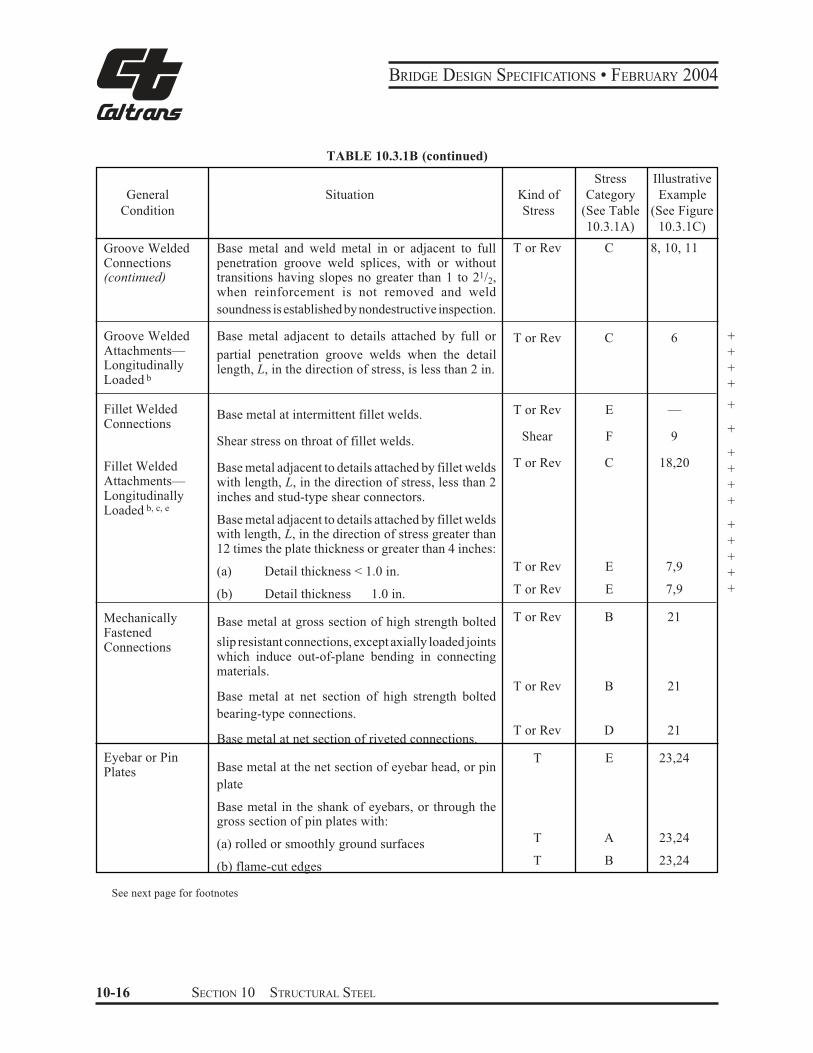
Groove Welded Connections(continued)
Base metal and weld metal in or adjacent to full penetration groove weld splices, with or without transitions having slopes no greater than 1 to 21/2,when reinforcement is not removed and weld
soundness is established by nondestructive inspection.
T or Rev C 8, 10, 11
Groove Welded Base metal adjacent to details attached by full or T or Rev C 6Attachments— partial penetration groove welds when the detail Longitudinally length, L, in the direction of stress, is less than 2 in.Loaded b
Fillet Welded Connections
Base metal at intermittent fillet welds.
Shear stress on throat of fillet welds.
T or Rev
Shear
E
F
—
9
Fillet Welded Base metal adjacent to details attached by fillet welds T or Rev C 18,20
Attachments— with length, L, in the direction of stress, less than 2 Longitudinally inches and stud-type shear connectors. Loaded b, c, e
Base metal adjacent to details attached by fillet welds with length, L, in the direction of stress greater than 12 times the plate thickness or greater than 4 inches:
(a) Detail thickness < 1.0 in.
(b) Detail thickness 1.0 in.
T or Rev
T or Rev
E
E
7,9
7,9
Mechanically Base metal at gross section of high strength bolted T or Rev B 21
FastenedConnections slip resistant connections, except axially loaded joints
which induce out-of-plane bending in connecting materials.
Base metal at net section of high strength bolted
bearing-type connections.
T or Rev B 21
Base metal at net section of riveted connections. T or Rev D 21
Eyebar or Pin Plates Base metal at the net section of eyebar head, or pin
plate
Base metal in the shank of eyebars, or through the gross section of pin plates with:
T E 23,24
(a) rolled or smoothly ground surfaces T A 23,24
(b) flame-cut edges T B 23,24
+
+
+
+
+
+
+
+
+
+
+
+
+
+
+
See next page for footnotes
10-16 SECTION 10 STRUCTURAL STEEL
BRIDGE DESIGN SPECIFICATIONS • FEBRUARY 2004
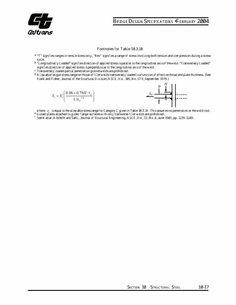
Footnotes for Table 10.3.1B a “T” signifies ranges in tensile stress only, “Rev” signifies a range of stress involving both tension and compression during a stress cycle.b “Longitudinally Loaded” signifies direction of applied stress is parallel to the longitudinal axis of the weld. “Transversely Loaded” signifies direction of applied stress is perpendicular to the longitudinal axis of the weld. c Transversely loaded partial penetration groove welds are prohibited. d Allowable fatigue stress range on throat of fillet welds transversely loaded is a function of effective throat and plate thickness. (See Frank and Fisher, Journal of the Structural Division, ASCE, Vol. 105, No. ST9, September 1979.)
H
0.06 + 0.79H / t c p SrS = S
r r 1 /6 1.1tp
tp
cwhere S is equal to the allowable stress range for Category C given in Table 10.3.1A. This assumes no penetration at the weld root. re Gusset plates attached to girder flange surfaces with only transverse fillet welds are prohibited. f See Wattar, Albrecht and Sahli, Journal of Structural Engineering, ASCE, Vol. III, No. 6, June 1985, pp. 1235-1249.
SECTION 10 STRUCTURAL STEEL 10-17
BRIDGE DESIGN SPECIFICATIONS • FEBRUARY 2004
Note: Illustrative examples 12, 14 – 17 are deleted.
FIGURE 10.3.1C Illustrative Examples
+
10-18 SECTION 10 STRUCTURAL STEEL
BRIDGE DESIGN SPECIFICATIONS • FEBRUARY 2004
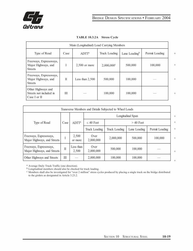
a Average Daily Truck Traffic (one direction). b Longitudinal members should also be checked for truck loading. c Members shall also be investigated for “over 2 million” stress cycles produced by placing a single truck on the bridge distributed
to the girders as designated in Article 3.23.2.
srebmeMgniyrraCdaoL)lanidutignoL(niaM
daoRfoepyT esaC TTDA a gnidaoLkcurT gnidaoLenaL b gnidaoLtimreP
,syawsserpxE,syaweerF
dna,syawhgiHrojaM
steertS
I eromro005,2 000,000,2 c 000,005 000,001
,syawsserpxE,syaweerF
dna,syawhgiHrojaM
steertS
II 005,2nahtsseL 000,005 000,001 —
dnasyawhgiHrehtO
nidedulcnitonsteertS
IIroIesaC
III — 000,001 000,001 —
TABLE 10.3.2A Stress Cycle
sdaoLleehWotdetcejbuSsliateDdnasrebmeMesrevsnarT
daoRfoepyT esaC TTDA a
napSlanidutignoL
teeF04 teeF04>
gnidaoLkcurT gnidaoLkcurT gnidaoLenaL gnidaoLtimreP
,syawsserpxE,syaweerF
steertSdna,syawhgiHrojaMI
005,2
eromro
revO
000,000,2000,000,2 000,005 000,001
,syawsserpxE,syaweerF
steertSdna,syawhgiHrojaMII
nahtsseL
005,2
revO
000,000,2000,005 000,001 —
steertSdnasyawhgiHrehtO III — 000,000,2 000,001 000,001 —
"
+
+
+
+
+
+
+
+
+
+
SECTION 10 STRUCTURAL STEEL 10-19
BRIDGE DESIGN SPECIFICATIONS • FEBRUARY 2004
+
+
Main load carrying components subjected to tensile
force that may be considered nonredundant load path
members—that is, where failure of a single element could
cause collapse—shall be designed for the allowable stress
ranges indicated in Table 10.3.1A for Nonredundant Load
Path Structures. Examples of nonredundant load path mem-
bers are flange and web plates in one or two girder bridges,
main one-element truss members, hanger plates, and caps at
single or two-column bents.
See AASHTO “Guide Specifications for Fracture
Critical Non-Redundant Steel Bridge Members.”
10.3.2 Load Cycles
10.3.2.1 The number of cycles of maximum stress
range to be considered in the design shall be selected
from Table 10.3.2A unless traffic and loadometer sur-
+
+
veys or other considerations indicate otherwise.
For new structures and widenings, the number of
stress cycles shall be based on Case I.
+ 10.3.2.2 Allowable fatigue stress ranges shall ap-
ply to those Group Loadings that include live load or
wind load.
10.3.2.3 The number of cycles of stress range to
be considered for wind loads in combination with dead
loads, except for structures where other considerations
indicate a substantially different number of cycles, shall
be 100,000 cycles.
10.3.3 Charpy V-Notch Impact Requirements
+10.3.3.1 Main load carrying member components
subjected to tensile force require supplemental impact
properties.
+
+
+
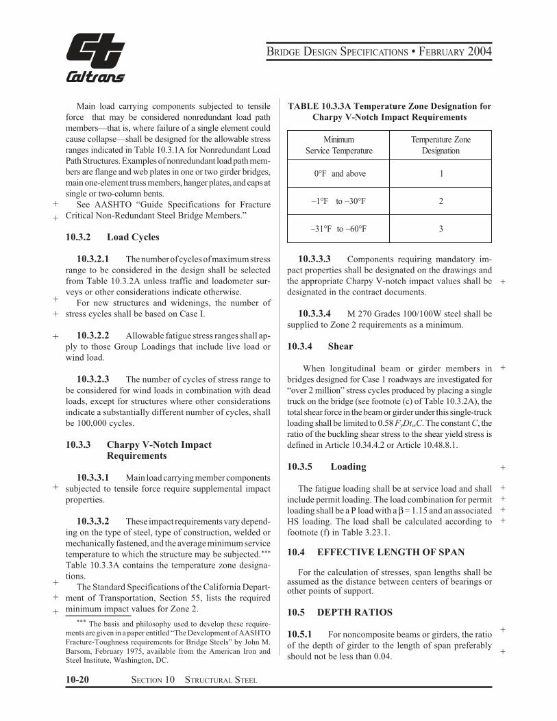
10.3.3.2 These impact requirements vary depend-
ing on the type of steel, type of construction, welded or
mechanically fastened, and the average minimum service
temperature to which the structure may be subjected.***
Table 10.3.3A contains the temperature zone designa-
tions.
The Standard Specifications of the California Depart-
ment of Transportation, Section 55, lists the required
minimum impact values for Zone 2.
*** The basis and philosophy used to develop these require-
ments are given in a paper entitled “The Development of AASHTO
Fracture-Toughness requirements for Bridge Steels” by John M.
Barsom, February 1975, available from the American Iron and
Steel Institute, Washington, DC.
TABLE 10.3.3A Temperature Zone Designation for
Charpy V-Notch Impact Requirements
Minimum Temperature Zone
Service Temperature Designation
and above0°F 1
to –30°F–1°F 2
–31°F to –60°F 3
10.3.3.3 Components requiring mandatory im-
pact properties shall be designated on the drawings and
the appropriate Charpy V-notch impact values shall be +designated in the contract documents.
10.3.3.4 M 270 Grades 100/100W steel shall be
supplied to Zone 2 requirements as a minimum.
10.3.4 Shear
When longitudinal beam or girder members in +
bridges designed for Case 1 roadways are investigated for
“over 2 million” stress cycles produced by placing a single
truck on the bridge (see footnote (c) of Table 10.3.2A), the
total shear force in the beam or girder under this single-truck
loading shall be limited to 0.58 FyDtwC. The constant C, the
ratio of the buckling shear stress to the shear yield stress is
defined in Article 10.34.4.2 or Article 10.48.8.1.
10.3.5 Loading +
The fatigue loading shall be at service load and shall +
include permit loading. The load combination for permit +
loading shall be a P load with a β = 1.15 and an associated +
HS loading. The load shall be calculated according to +
footnote (f) in Table 3.23.1.
10.4 EFFECTIVE LENGTH OF SPAN
For the calculation of stresses, span lengths shall be assumed as the distance between centers of bearings or other points of support.
10.5 DEPTH RATIOS
10.5.1 For noncomposite beams or girders, the ratio +
of the depth of girder to the length of span preferably +
should not be less than 0.04.
10-20 SECTION 10 STRUCTURAL STEEL
BRIDGE DESIGN SPECIFICATIONS • FEBRUARY 2004
+
+
+
10.5.2 For composite girders, the ratio of the overall
depth of girder (concrete slab plus steel girder) to the
length of span preferably should not be less than 0.045 for
simple spans and 0.04 for continuous spans.
10.5.3 For trusses the ratio of depth to length of span
preferably should not be less than 0.1.
+ 10.5.4 Deleted
10.5.5 The foregoing requirements as they relate to
beam or girder bridges may be exceeded at the discretion
of the designer.*
10.6 DEFLECTION
10.6.1 The term “deflection” as used herein shall be the
deflection computed in accordance with the assumption
made for loading when computing the stress in the member.
+
+
+
10.6.2 Members having simple or continuous spans
preferably should be designed so that the ratio of the
deflection to the length of the span due to service live load
plus impact shall not exceed 1/800 , except on bridges in
urban areas used in part by pedestrians whereon the ratio
preferably shall not exceed 1/1000.
+
+
+
10.6.3 The ratio of the deflection to the cantilever
arm length due to service live load plus impact preferably
should be limited to 1/300 except for the case including
pedestrian use, where the ratio preferably should be 1/375.
+
10.6.4 When spans have cross-bracing or diaphragms
sufficient in depth or strength to ensure lateral distribution
of loads, the deflection may be computed for the standard
H or HS loading considering all beams or stringers as
acting together and having equal deflection.
10.6.5 The moment of inertia of the gross cross-
sectional area shall be used for computing the deflections
of beams and girders. When the beam or girder is a part
of a composite member, the service live load may be
considered as acting upon the composite section.
10.6.6 The gross area of each truss member shall be
used in computing deflections of trusses. If perforated
plates are used, the effective area shall be the net volume
divided by the length from center to center of perforations.
* For consideration to be taken into account when exceeding
these limitations, reference is made to “Bulletin No.19, Criteria for
the Deflection of Steel Bridges,” available from the American Iron
and Steel Institute, Washington, D.C.
10.6.7 The foregoing requirements as they relate to
beam or girder bridges may be exceeded at the discretion
of the designer.*
10.7 LIMITING LENGTHS OF MEMBERS
10.7.1 For compression members, the slenderness
ratio, KL/r, shall not exceed 120 for main members, or those
in which the major stresses result from dead or live load, or
both; and shall not exceed 140 for secondary members, or
those whose primary purpose is to brace the structure against
lateral or longitudinal force, or to brace or reduce the
unbraced length of other members, main or secondary.
10.7.2 In determining the radius of gyration, r, for the
purpose of applying the limitations of the KL/r ratio, the area
of any portion of a member may be neglected provided that
the strength of the member as calculated without using the
area thus neglected and the strength of the member as
computed for the entire section with the KL/rratio applicable
thereto, both equal or exceed the computed total force that +the member must sustain.
10.7.3 The radius of gyration and the effective area
of a member containing perforated cover plates shall be
computed for a transverse section through the maximum
width of perforation. When perforations are staggered in
opposite cover plates the cross-sectional area of the +member shall be considered the same as for a section
having perforations in the same transverse plane.
+10.7.4 The unbraced length, L, shall be assumed as
follows: +
For the compression chords of trusses, the length +
between panel points laterally supported as indicated
under Article 10.16.12; for other members, the length
between panel point intersections or centers of braced
points or centers of end connections.
10.7.5 For tension members, except rods, eyebars,
cables, and plates, the ratio of unbraced length to
radius of gyration shall not exceed 200 for main
members, shall not exceed 240 for bracing members,
and shall not exceed 140 for main members subject to
a reversal of stress.
SECTION 10 STRUCTURAL STEEL 10-21
BRIDGE DESIGN SPECIFICATIONS • FEBRUARY 2004
10.8 MINIMUM THICKNESS OF METAL
+ 10.8.1 The plate thickness of structural steel including
+ bracing, cross frames, and all types of gusset plates, shall
+ be not less than 5/16 inch. The web thickness of rolled
beams or channels shall be not less than 0.23 inches. The
+ thickness of closed ribs in orthotropic decks, fillers, and
+ in railings, shall be not less than 3/16 inch.
10.8.2 Where the metal will be exposed to marked
corrosive influences, it shall be increased in thickness or
specially protected against corrosion.
10.8.3 It should be noted that there are other
provisions in this section pertaining to thickness for
fillers, segments of compression members, gusset plates,
etc. As stated above, fillers need not be 5/16 inch minimum.
10.8.4 For compression members, refer to “Trusses”
(Article 10.16).
+ 10.8.5 For flexural members, refer to “Plate Girders”
(Article 10.34).
10.8.6 For stiffeners and outstanding legs of angles,
+ etc., refer to relevant Articles 10.10, 10.34, 10.37, 10.48,
+ 10.51 and 10.55.
+ 10.9 EFFECTIVE NET AREA FOR + TENSION MEMBERS
+ 10.9.1 When a tension load is transmitted directly to
+ each of the cross-sectional elements by fasteners or
+ welds, the effective net area Ae is equal to the net area An.
+ 10.9.2 When a tension load is transmitted by bolts or
+ rivets through some but not all of the cross-sectional
+ elements of the member, the effective net area Ae shall be
+ calculated as:
+ Ae = UA (10-1a)
+ where:
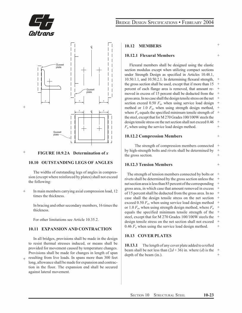
+ A = area as defined below (in.2)
+ U = reduction coefficient
+ = 1 - (x/L) 0.9 or as defined in (c) and (d)
+ x = connection eccentricity (in.); for rolled or built-
+ up shapes, it is referred to the center of gravity
+ of the material lying on either side of the
centerline of symmetry of the cross-section, as +
shown in Fig. 10.9.2A +
L = length of connection in the directions of loading +
(in.)
Larger values of U are permitted to be used when +
justified by tests or other rational criteria. +
(a) When the tension load is transmitted only by +
bolts or rivets: +
A = An = net area of member (in.2) +
(b) When the tension load is transmitted only by +
longitudinal welds to other than a plate member or by +
longitudinal welds in combination with transverse welds: +
A = Ag = gross area of member (in.2) +
(c) When the tension load is transmitted only by +
transverse welds: +
A = area of directly connected elements (in.2) +
U = 1.0 +
(d) When the tension load is transmitted to a plate +
by longitudinal welds along both edges at the end of the +
plate for Lw > W +
A = area of plate (in.2) +
for Lw 2W U = 1.0 +
for 2W > Lw 1.5 W U = 0.87 +
+for 1.5W > Lw W U = 0.75 +
where: +
Lw = length of weld (in.) +W = plate width (distance between welds) (in.) +
10.9.3 Deleted +
10.9.4 Deleted +
10-22 SECTION 10 STRUCTURAL STEEL
BRIDGE DESIGN SPECIFICATIONS • FEBRUARY 2004
Gussetplate
x
+
Gussetplate
+ FIGURE 10.9.2A
Gussetplate
LC
LC
x x
xx
Determination of x
10.10 OUTSTANDING LEGS OF ANGLES
The widths of outstanding legs of angles in compres-
sion (except where reinforced by plates) shall not exceed
the following:
+ In main members carrying axial compression load, 12
times the thickness.
In bracing and other secondary members, 16 times the
thickness.
For other limitations see Article 10.35.2.
10.11 EXPANSION AND CONTRACTION
In all bridges, provisions shall be made in the design
to resist thermal stresses induced, or means shall be
provided for movement caused by temperature changes.
Provisions shall be made for changes in length of span
resulting from live loads. In spans more than 300 feet+long, allowance shall be made for expansion and contrac-
tion in the floor. The expansion end shall be secured
against lateral movement.
10.12 MEMBERS +
10.12.1 Flexural Members +
Flexural members shall be designed using the elastic
section modulus except when utilizing compact sections
under Strength Design as specified in Articles 10.48.1,
10.50.1.1, and 10.50.2.1. In determining flexural strength, +
the gross section shall be used, except that if more than 15 +
percent of each flange area is removed, that amount re- +
moved in excess of 15 percent shall be deducted from the +
gross area. In no case shall the design tensile stress on the net +
section exceed 0.50 Fu, when using service load design +
method or 1.0 Fu, when using strength design method, +
where Fu equals the specified minimum tensile strength of +
the steel, except that for M 270 Grades 100/100W steels the
design tensile stress on the net section shall not exceed 0.46 +
Fu when using the service load design method. +
10.12.2 Compression Members +
The strength of compression members connected +
by high-strength bolts and rivets shall be determined by +
the gross section. +
10.12.3 Tension Members +
The strength of tension members connected by bolts or +
rivets shall be determined by the gross section unless the +
net section area is less than 85 percent of the corresponding +
gross area, in which case that amount removed in excess +
of 15 percent shall be deducted from the gross area. In no +
case shall the design tensile stress on the net section +
exceed 0.50 Fu, when using service load design method +
or 1.0 Fu, when using strength design method, where Fu +
equals the specified minimum tensile strength of the +
steel, except that for M 270 Grades 100/100W steels the +
design tensile stress on the net section shall not exceed +
0.46 Fu when using the service load design method. +
10.13 COVER PLATES
10.13.1 The length of any cover plate added to a rolled
beam shall be not less than (2d + 36) in. where (d) is the +
depth of the beam (in.). +
SECTION 10 STRUCTURAL STEEL 10-23
BRIDGE DESIGN SPECIFICATIONS • FEBRUARY 2004
10.13.2 Partial length welded cover plates shall not be used on flanges more than 0.8 inches thick for nonredundant load path structures subjected to repetitive loadings that produce tension or reversal of stress in the member.10.13.3 The maximum thickness of a single cover plate on a flange shall not be greater than 2 times the thickness of the flange to which the cover plate is attached. The total thickness of all cover plates should not be greater than 21/2 times the flange thickness. 10.13.4 Any partial length welded cover plate shall extend beyond the theoretical end by the terminal distance, and it shall extend to a section where the stress range in the beam flange is equal to the allowable fatigue stress range for base metal adjacent to or connected by fillet welds. The theoretical end of the cover plate, when using service load design methods, is the section at which the stress in the flange without that cover plate equals the allowable service load stress, exclusive of fatigue considerations. When using strength design methods, the theoretical end of the cover plate is the section at which the flange strength without that cover plate equals the required strength for the design loads, exclusive of fatigue requirements. The terminal distance is two times the nominal cover plate width for cover plates not welded across their ends, and 11/2 times for cover plates welded across their ends. The width at ends of tapered cover plates shall be not less that 3 inches. The weld connecting+ the cover plate to the flange in its terminal distance shall be continuous and of sufficient size to develop a total force of not less than the computed force in the cover plate at its theoretical end. All welds connecting cover plates to beam flanges shall be continuous and shall not be smaller than the minimum size permitted by Article 10.23.2.2.10.13.5 Any partial length end-bolted cover plate shall extend beyond the theoretical end by the terminal distance equal to the length of the end-bolted portion, and the cover plate shall extend to a section where the stress range in the beam flange is equal to the allowable fatigue stress range for base metal at ends of partial length welded cover plates with high-strength bolted, slip-critical end connections (Table 10.3.1B). Beams with end-bolted cover plates shall be fabricated in the following sequence: drill holes; clean faying surfaces; install bolts; weld. The theoretical end of the end-bolted cover plate is determined in the same manner as that of a welded cover plate, as specified in Article 10.3.4. The bolts in the slip-critical
connections of the cover plate ends to the flange, shall be of sufficient numbers to develop a total force of not less than the computed force in the cover plate at the theoretical end. The slip resistance of the end-bolted connection shall be determined in accordance with Article 10.32.3.2 for service load design, and 10.56.1.4 for load factor design. The longitudinal welds connecting the cover plate to the beam flange shall be continuous and stop a distance equal to one bolt spacing before the first row of bolts in the end-bolted portion. 10.14 CAMBER
Girder should be cambered to compensate for dead load deflections and vertical curvature required by pro-file grade. 10.15 HEAT-CURVED ROLLED BEAMS AND WELDED PLATE GIRDERS 10.15.1 Scope
This section pertains to rolled beans and welded I-section plate girders heat-curved to obtain a horizontal curvature. Steels that are manufactured to a specified minimum yield strength greater than 50,000 psi, except +for Grade HPS 70W Steel, shall not be heat-curved. 10.15.2 Minimum Radius of Curvature
10.15.2.1 For heat-curved beams and girders, the horizontal radius of curvature measured to the centerline of the girder web shall not be less than 150 feet and shall not be less than the larger of the values calculated (at any and all cross sections throughout the length of the girder) from the following two equations: 440 b D
R = (10-1) +Fyψ t
w
7,500,000 bR = (10-2)F
yψ +
where:Fy = specified minimum yield strength of the web (psi) +
10-24 SECTION 10 STRUCTURAL STEEL
BRIDGE DESIGN SPECIFICATIONS • FEBRUARY 2004
+ y = ratio of the total cross-sectional area to the
+ cross-sectional area of both flanges
+ b = widest flange width (in.)
+ D = clear distance between flanges (in.)
+ tw = web thickness (in.)
+ R = horizontal radius of curvature (in.)
10.15.2.2 In addition to the above requirements,
the radius shall not be less than 1,000 feet when the flange
thickness exceeds 3 inches or the flange width exceeds 30
inches.
10.15.3 Camber
To compensate for possible loss of camber of heat-
curved girders in service as residual stresses dissipate, the
+ amount of camber, ∆ (in.) at any section along the length
L of the girder shall be equal to:
DL# $# %#
M& #
R' (10-3)#M
+ 0.02L2Fy (1,000 )R *#R $ + , - 0E Yo . 850 /
where:
+ ∆DL = camber at any point along the length L calcu-+ lated by usual procedures to compensate for + deflection due to dead loads or any other + specified loads (in.) + ∆M = maximum value of ∆DL within the length L (in.)+ E = modulus of elasticity of steel (psi) + Fy = specified minimum yield strength of girder + flange (psi) + Yo = distance from the neutral axis to the extreme + outer fiber (in.) (maximum distance for non-+ symmetrical sections) + R = radius of curvature (ft.) + L = span length for simple spans or for continuous + spans, the distance between a simple end sup-+ port and the dead load contraflexure point, or + the distance between points of dead load + contraflexure (in.)
Camber loss between dead load contraflexure points
adjacent to piers is small and may be neglected.
Note: Part of the camber loss is attributable to construc-
tion loads and will occur during construction of
the bridge; total camber loss will be complete after
several months of in-service loads. Therefore, a
portion of the camber increase (approximately 50
percent) should be included in the bridge profile.
Camber losses of this nature (but generally smaller
in magnitude) are also known to occur in straight
beams and girders.
10.16 TRUSSES
10.16.1 General
10.16.1.1 Component parts of individual truss
members may be connected by welds, rivets, or high-
strength bolts.
10.16.1.2 Preference should be given to trusses
with single intersection web systems. Members shall be
symmetrical about the central plane of the truss.
10.16.1.3 Trusses preferably shall have inclined
end posts. Laterally unsupported hip joints shall be
avoided.
10.16.1.4 Main trusses shall be spaced a sufficient
distance apart, center to center, to be secure against
overturning by the design lateral forces. +
10.16.1.5 For the calculation of forces, effective +depths shall be assumed as follows:
Riveted and bolted trusses, distance between centers
of gravity of the chords.
Pin-connected trusses, distance between centers of
chord pins
10.16.2 Truss Members
10.16.2.1 Chord and web truss members shall usu-
ally be made in the following shapes:
“H” sections, made with two side segments (com-
posed of angles or plates) with solid web, perforated
web, or web of stay plates and lacing.
SECTION 10 STRUCTURAL STEEL 10-25
BRIDGE DESIGN SPECIFICATIONS • FEBRUARY 2004
Channel sections, made with two angle segments,
with solid web, perforated web, or web of stay plates
and lacing.
Single Box sections, made with side channels, beams,
angles, and plates or side segments of plates only,
connected top and bottom with perforated plates or
stay plates and lacing.
Single Box sections, made with side channels, beams,
angles and plates only, connected at top with solid
cover plates and at the bottom with perforated plates
or stay plates and lacing.
Double Box sections, made with side channels, beams,
angles and plates or side segments of plates only,
connected with a conventional solid web, together
with top and bottom perforated cover plates or stay
plates and lacing.
10.16.2.2 If the shape of the truss permits, com-
pression chords shall be continuous.
10.16.2.3 In chords composed of angles in channel
shaped members, the vertical legs of the angles prefer-
ably shall extend downward.
10.16.2.4 If web members are subject to reversal
of stress, their end connections shall not be pinned.
Counters preferably shall be rigid. Adjustable counters,
if used, shall have open turnbuckles, and in the design of
+ these members an allowance of 10,000 psi shall be
made for initial stress. Only one set of diagonals in any
panel shall be adjustable. Sleeve nuts and loop bars
shall not be used.
10.16.3 Secondary Stresses
The design and details shall be such that secondary
stresses will be as small as practicable. Secondary
stresses due to truss distortion or floor beam deflection
usually need not be considered in any member, the width
of which, measured parallel to the plane of distortion, is
less than one-tenth of its length. If the secondary stress
+ exceeds 4,000 psi for tension members and 3,000 psi for
+ compression members, the excess shall be treated as a
primary stress. Stresses due to the flexural dead load
moment of the member shall be considered as additional
secondary stress.
10.16.4 Diaphragms
10.16.4.1 There shall be diaphragms in the trusses
at the end connections of floor beams.
10.16.4.2 The gusset plates engaging the pedestal
pin at the end of the truss shall be connected by a
diaphragm. Similarly, the webs of the pedestal shall, if
practicable, be connected by a diaphragm.
10.16.4.3 There shall be a diaphragm between
gusset plates engaging main members if the end tie plate
is 4 feet or more from the point of intersection of the
members.
10.16.5 Camber
The length of the truss members shall be such that the
camber will be equal to or greater than the deflection
produced by the dead load.
10.16.6 Working Lines and Gravity Axes
10.16.6.1 Main members shall be proportioned so
that their gravity axes will be as nearly as practicable in
the center of the section.
10.16.6.2 In compression members of unsymmetri-
cal section, such as chord sections formed of side seg-
ments and a cover plate, the gravity axis of the section
shall coincide as nearly as practicable with the working
line, except that eccentricity may be introduced to coun-
teract dead load bending. In two-angle bottom chord or
diagonal members, the working line may be taken as the
gage line nearest the back of the angle or at the center of
gravity for welded trusses.
10.16.7 Portal and Sway Bracing
10.16.7.1 Through truss spans shall have portal
bracing, preferably, of the two-plane or box type, rigidly
connected to the end post and the top chord flanges, and
as deep as the clearance will allow. If a single plane portal
is used, it shall be located, preferably, in the central
transverse plane of the end posts, with diaphragms be-
tween the webs of the posts to provide for a distribution
of the portal stresses. The portal bracing shall be designed
to take the full end reaction of the top chord lateral
system, and the end posts shall be designed to transfer this
reaction to the truss bearings.
10-26 SECTION 10 STRUCTURAL STEEL
BRIDGE DESIGN SPECIFICATIONS • FEBRUARY 2004
10.16.7.2 Through truss spans shall have sway
bracing 5 feet or more deep at each intermediate panel
point. Top lateral struts shall be at least as deep as the top
chord.
10.16.7.3 Deck truss spans shall have sway brac-
ing in the plane of the end posts and at all intermediate
panel points. This bracing shall extend the full depth of
the trusses below the floor system. The end sway bracing
+ shall be proportioned to carry the entire upper lateral load
to the supports through the end posts of the truss.
10.16.8 Perforated Cover Plates
When perforated cover plates are used, the following
provisions shall govern their design.
10.16.8.1 The ratio of length, in direction of stress,
to width of perforation, shall not exceed two.
10.16.8.2 The clear distance between perforations
in the direction of stress shall not be less than the distance
between points of support.
10.16.8.3 The clear distance between the end per-
foration and the end of the cover plate shall not be less
than 1.25 times the distance between points of support.
10.16.8.4 The point of support shall be the inner
line of fasteners or fillet welds connecting the perforated
plate to the flanges. For plates butt welded to the flange
edge of rolled segments, the point of support may be
taken as the weld whenever the ratio of the outstanding
flange width to flange thickness of the rolled segment is
less than seven. Otherwise, the point of support shall be
the root of the flange of the rolled segment.
10.16.8.5 The periphery of the perforation at all
points shall have a minimum radius of 11/2 inches.
10.16.8.6 For thickness of metal, see Article
10.35.2.
10.16.9 Stay Plates
10.16.9.1 Where the open sides of compression
members are not connected by perforated plates, such
members shall be provided with lacing bars and shall
have stay plates as near each end as practicable. Stay
plates shall be provided at intermediate points where the
lacing is interrupted. In main members, the length of the
end stay plates between end fasteners shall be not less
than 11/4 times the distance between points of support and
the length of intermediate stay plates not less than 3/4 of
that distance. In lateral struts and other secondary mem-+
bers, the overall length of end and intermediate stay
plates shall be not less than 3/4 of the distance between +
points of support. +
10.16.9.2 The point of support shall be the inner +
+
line of fasteners or fillet welds connecting the stay plates +
to the flanges. For stay plates butt welded to the flange edge
of rolled segment, the point of support may be taken as the
weld whenever the ratio of outstanding flange width to
flange thickness or the rolled segment is less than seven.
Otherwise, the point of support shall be the root of flange of
rolled segment. When stay plates are butt welded to rolled
segments of a member, the allowable stress in the member
shall be determined in accordance with Article 10.3. Termi-
nations of butt welds shall be ground smooth.
10.16.9.3 The separate segments of tension mem-+
+
bers composed of shapes may be connected by perforated +
plates or by stay plates or end stay plates and lacing. End
stay plates shall have the same minimum length as +specified for end stay plates on main compression mem-
bers, and intermediate stay plates shall have a mini-
mum length of 3/4 of that specified for intermediate stay
plates on main compression members. The clear distance
between stay plates on tension members shall not exceed
3 feet.
10.16.9.4 The thickness of stay plates shall be not
less than 1/50 of the distance between points of support for
main members, and 1/60 of that distance for bracing
members. Stay plates shall be connected by not less than
three fasteners on each side, and in members having
lacing bars the last fastener in the stay plates preferably
shall also pass through the end of the adjacent bar.
10.16.10 Lacing Bars
When lacing bars are used, the following provisions
shall govern their design.
10.16.10.1 Lacing bars of compression members
shall be so spaced that the slenderness ratio of the portion
of the flange included between the lacing bar connections
will be not more than 40 or more than 2/3 of the slender-
ness ratio of the member.
SECTION 10 STRUCTURAL STEEL 10-27
BRIDGE DESIGN SPECIFICATIONS • FEBRUARY 2004
10.16.10.2 The section of the lacing bars shall be
determined by the formula for axial compression in
which L is taken as the distance along the bar between its
connections to the main segments for single lacing, and
as 70 percent of that distance for double lacing.
10.16.10.3 If the distance across the member be-
tween fastener lines in the flanges is more than 15 inches
and a bar with a single fastener in the connection is used,
the lacing shall be double and fastened at the intersec-
tions.
10.16.10.4 The angle between the lacing bars and
the axis of the member shall be approximately 45 degrees
for double lacing and 60 degrees for single lacing.
10.16.10.5 Lacing bars may be shapes or flat bars.
For main members, the minimum thickness of flat bars
shall be 1/40 of the distance along the bar between its
connections for single lacing and 1/60 for double lacing.
For bracing members, the limits shall be 1/50 for single
lacing and 1/75 for double lacing.
10.16.10.6 The diameter of fasteners in lacing bars
shall not exceed one-third the width of the bar. There
shall be at least two fasteners in each end of lacing bars
connected to flanges more than 5 inches in width.
10.16.11 Gusset Plates
10.16.11.1 Gusset or connection plates preferably
shall be used for connecting main members, except when
the members are pin-connected. The fasteners connect-
ing each member shall be symmetrical with the axis of the
member, so far as practicable, and the full development
of the elements of the member shall be given consider-
ation. The gusset plates shall be designed to resist shear,
axial force, and bending moments acting on the weakest
or critical section.
10.16.11.2 Re-entrant cuts, except curves made for
appearance, shall be avoided as far as practicable.
10.16.11.3 If the length of unsupported edge of a
gusset plate exceeds the value of the expression 11,000/ Fy times its thickness, the edge shall be stiff-ened.
10.16.11.4 Listed below are the values of the expres-
sion 11,000 / Fy for the following grades of steel:
Fy (psi) 11,000/ Fy+
+36,000 58 +50,000 49 +70,000 42 +90,000 37 +
100,000 35 +
10.16.12 Half-Through Truss Spans
10.16.12.1 The vertical truss members and the floor
beams and their connections in half-through truss spans
shall be proportioned to resist a lateral force of not less
than 300 pounds per linear foot applied at the top chord
panel points of each truss.
10.16.12.2 The compression chord shall be de-
signed as a compression member with elastic lateral +supports at the panel points. The strength of the compres- +sion chord, so determined, shall exceed the maximum +force from dead load, live load, and impact in any panel
of the compression chord by not less than 50 percent.* +
10.16.13 Fastener Pitch in Ends of Compression Members
In the ends of compression members, the pitch of
fasteners connecting the component parts of the member
shall not exceed four times the diameter of the fastener for
a length equal to 11/2 times the maximum width of the
member. Beyond this point, the pitch shall be increased
gradually for a length equal to 11/2 times the maximum
width of the member until the maximum pitch is reached.
10.16.14 Net Section of Riveted or High-Strength Bolted Tension Members
10.16.14.1 The net section of a riveted or high-
strength bolted tension member is the sum of the net
sections of its component parts. The net section of a part
is the product of the thickness of the part multiplied by its
least net width.
* For a discussion of columns with elastic lateral supports, refer
to Timoshenko & Gere, “Theory of Elastic Stability,” McGraw-
Hill Book Co., Second Edition, P.70.
10-28 SECTION 10 STRUCTURAL STEEL
BRIDGE DESIGN SPECIFICATIONS • FEBRUARY 2004
10.16.14.2 The net width for any chain of holes
extending progressively across the part shall be obtained
by deducting from the gross width the sum of the diam-
eters of all the holes in the chain and adding, for each gage
space in the chain, the quantity:
2s+ (10-4)
4g
where:
+ s = pitch of any two successive holes in the chain
+ (in.)
+ g = gage of the same holes (in.)
The net section of the part is obtained from the chain
that gives the least net width.
10.16.14.3 For angles, the gross width shall be the
sum of the widths of the legs less the thickness. The gage
for holes in opposite legs shall be the sum of gages from
back of angle less the thickness.
+ 10.16.14.4 At a splice, the total force in the member
+ being spliced is transferred by fasteners to the splice
material.
+ 10.16.14.5 When determining the stress on any least
net width of either splice material or member being
+ spliced, the amount of the force previously transferred by
fasteners adjacent to the section being investigated shall
+ be considered in determining the stress on the net section.
10.16.14.6 The diameter of the hole shall be taken
as 1/8 inch greater than the nominal diameter of the rivet
or high-strength bolt, unless larger holes are permitted in
accordance with Article 10.24.
10.17 BENTS AND TOWERS
10.17.1 General
Bents preferably shall be composed of two supporting
columns, and the bents usually shall be united in pairs to
form towers. The design of members for bents and towers
is governed by applicable articles.
10.17.2 Single Bents
Single bents shall have hinged ends or else shall be
designed to resist bending.
10.17.3 Batter
Bents preferably shall have a sufficient spread at the base
to prevent uplift under the design lateral loadings. In +general, the width of a bent at its base shall be not less than
one-third of its height.
10.17.4 Bracing
10.17.4.1 Towers shall be braced, both transversely
and longitudinally, with stiff members having either
welded, high-strength bolted or riveted connections. The
sections of members of longitudinal bracing in each
panel shall not be less than those of the members in
corresponding panels of the transverse bracing.
10.17.4.2 The bracing of long columns shall be
designed to fix the column about both axes at or near the
same point.
10.17.4.3 Horizontal diagonal bracing shall be
placed in all towers having more than two vertical panels,
at alternate intermediate panel points.
10.17.5 Bottom Struts
The bottom struts of towers shall be strong enough to
slide the movable shoes with the structure unloaded, the
coefficient of friction being assumed at 0.25. Provision
for expansion of the tower bracing shall be made in the
column bearings.
10.18 SPLICES
10.18.1 General
10.18.1.1 Design Strength
Splices may be made by rivets, by high-strength bolts, +or by the use of welding. In general, splices whether in +tension, compression, bending, or shear, shall be de- +signed in the cases of the service load design or the +strength design methods for a capacity based on not less +than 100 percent of the allowable design strength in the +
SECTION 10 STRUCTURAL STEEL 10-29
BRIDGE DESIGN SPECIFICATIONS • FEBRUARY 2004
+ member taking into account the bolt holes. Bolted and
+ riveted splices in flexural members shall satisfy the
+ requirements of Article 10.18.2. Bolted and riveted splices
+ in compression members shall satisfy the requirements of
+ Article 10.18.3. Bolted and riveted splices in tension
+ members shall satisfy the requirements of Article 10.18.4.
+ Bolted and riveted splices in tension members shall also
+ satisfy the requirements of Article 10.19.4. Welded splices
+ shall satisfy the requirements of Article 10.18.5. Where
+ a section changes at a splice, the small section is to be
+ used to satisfy the above splice requirements.
10.18.1.2 Fillers
10.18.1.2.1 For fillers 1/4 inch and thicker in bolted or
riveted axially loaded connections, including girder flange
splices, additional fasteners shall be required to distribute
the total stress in the member uniformly over the combined
section of the member and the filler. The filler shall either be
+ extended beyond the splice material and secured by addi-
+ tional fasteners, or as an alternate to extending the filler, an
+ equivalent number of fasteners may be included in the
+ connection. Fillers 1/4 inch and thicker need not be extended
+ and developed provided that the design shear strength of the
+ fasteners, specified in Article 10.56.1.3.2 in the case of the
strength design method and in the Tables 10.32.3A and
10.32.3B in the case of the service load design method, is
reduced by the following factor R:
R=[(1+!)/(1+2!)] (10-4a)
where γ=Af /Ap
+ Af= sum of the area of the fillers on the top and
+ bottom of the connected plate (in.2)
+ Ap
= smaller of either the connected plate area or
+ the sum of the splice plate areas on the top and
+ bottom of the connected plate (in.2)
+ The design slip force, specified in Article 10.56.1.3.2
+ in the case of the strength design method and in Article
10.32.3.2.1 in the case of the service load design method,
for slip-critical connections shall not be adjusted for the
effect of the fillers. Fillers 1/4 inch or more in thickness
shall consist of not more than two plates, unless special
permission is given by the Engineer.
10.18.1.2.2 For bolted web splices with thickness
differences of 1/16 inch or less, no filler plates are
required.
10.18.1.2.3 Fillers for welded splices shall conform to the
requirements of the AISI/AASHTO/AWS D1.5 Bridge
Welding Code.
10.18.1.3 Design Force for Flange Splice Plates
For a flange splice with inner and outer splice plates,
the flange design force may be assumed to be divided
equally to the inner and outer plates and their connections
when the areas of the inner and outer plates do not differ
by more than 10 percent. When the areas of the inner and
outer plates differ by more than 10 percent, the design
force in each splice plate and its connection shall be
determined by multiplying the flange design force by the
ratio of the area of the splice plate under consideration to
the total area of the inner and outer splice plates. For this
case, the shear strength of the connection shall be checked
for the maximum calculated splice plate force acting on
a single shear plane. The slip resistance of high-strength
bolted connections for a flange splice with inner and
outer splice plates shall always be checked for the flange
design force divided equally to the two slip planes.
10.18.1.4 Truss Chords and Columns
Splices in truss chords and columns shall be located as
near to the panel points as practicable and usually on the
side where smaller stress occurs. The arrangement of
plates, angles, or other splice elements shall be such as to
make proper provision for the stresses, both axial and
bending, in the component parts of the member spliced.
10.18.2 Flexural Member
10.18.2.1 General
10.18.2.1.1 Splices shall preferably be made at or near
points of dead load contraflexure in continuous spans and
at points of the section change.
+
+
+
10.18.2.1.2 In both flange and web splices, there shall
be not less than two rows of bolts on each side of the joint.
10.18.2.1.3 Oversize or slotted holes shall not be used
in either the member or the splice plates at the bolted
splices.
10.18.2.1.4 In both flange and web splices, high-
strength bolted connections shall be proportioned to
prevent slip during erection of the steel and during the
casting or placing of the deck.
10-30 SECTION 10 STRUCTURAL STEEL
BRIDGE DESIGN SPECIFICATIONS • FEBRUARY 2004
+ 10.18.2.1.5 Deleted
10.18.2.1.6 Flange and web splices in areas of stress reversal
shall be checked for both positive and negative flexure.
10.18.2.1.7 Riveted and bolted flange angle splices
shall include two angles, one on each side of the flexural
member.
10.18.2.2 Flange Splices
+ 10.18.2.2.1 For checking the strength of flange splices,
+ an effective area, Ae, shall be used for the flanges and for
+ the individual splice plates as follows:
+ For flanges and their splice plates subject to
+ tension:
+ Ae= wnt + β Ag ≤ Ag (10-4b)
+ where:
+ Wn = least net width of the flange or splice plate
+ computed as specified in Article10.16.14 (in.)
+ t = flange or splice plate thickness (in.)
+ Ag = gross area of the flange or splice plate (in.2)
+ β = 0.0 for M 270 Grade 100/100W steels, or when
+ holes exceed 1 1/4 inch in diameter + = 0.15 for all other steels and when holes are less + than or equal to 1 1/4 inch in diameter
++
The diameter of the holes shall be taken as specified
in Article 10.16.14.6.
+ For the flanges and their splice plates subject to + compression:
+ Ae = Ag (10-4c)
+ 10.18.2.2.2 In the case of the strength design method,
+ the splice plates shall be proportioned for a design force,
+ Pcu
equal to a design stress, Fcu
, times the smaller effec-
+ tive area, Ae, on either side of the splice. F
cu is defined as
+ follows:
+ Fcu =α Fyf (10-4d)
where:
" = 1.0 except that a lower value equal to (Mu/My)
may be used for flanges in compression at sec-
tions where Mu is less than My
Mu =design bending strength of the section in posi-
tive or negative flexure at the point of splice,
whichever causes the maximum compressive
stress due to the factored loads at the mid-thick-
ness of the flange under consideration (lb-in.)
My = moment capacity at first yield for the section at
the point of splice used to compute Mu (lb-in.). +For composite sections, My shall be calculated +in accordance with Article10.50(c). For hybrid
sections, My shall be computed in accordance
with Article 10.53.
Fyf = specified minimum yield strength of the flange
(psi)
In calculating Mu and My, holes in the flange subject
to tension shall be accounted for as specified in Article
10.12. For a flange splice with inner and outer splice
plates, the flange design forces shall be proportioned to
the inner and outer plates and their connections as
specified in Article 10.18.1.3. The effective area, Ae, of
each splice plate shall be sufficient to prevent yielding
of the splice plate under its calculated portion of the
design force. As a minimum, the connections for both
the top and bottom flange splices shall be proportioned
to develop the design force in the flange through shear
in the bolts and bearing at the bolt holes, as specified
in Article 10.56.1.3.2. Where filler plates are required,
the requirements of Article 10.18.1.2.1 shall also be
satisfied.
As a minimum, high-strength bolted connection for
both top and bottom flange splices shall be proportioned
to prevent slip at an overload design force, Pfo
, defined as
follows:
Pfo=fo /RAg (10-4e) +
where:
fo = maximum flexural stress due to Group I loading +divided by 1.3 at the mid-thickness of the flange +under consideration for the smaller section at +the point of splice (psi) +
R = reduction factor for hybrid girders specified in
Article 10.53.1.2. R shall be taken equal to 1.0
when fo is less than or equal to the specified
minimum yield strength of the web, Fyw. For
homogeneous girders, R shall always be taken
equal to 1.0
SECTION 10 STRUCTURAL STEEL 10-31
BRIDGE DESIGN SPECIFICATIONS • FEBRUARY 2004
+
+
Ag = smaller gross flange area on either side of the
splice (in.2)
fo
and R shall be computed using the gross section of the
member. The slip resistance of the connection shall be
computed from Equation (10-172).
+
+
+
+
10.18.2.2.3 In the case of the service load design
method, the splice plates shall be proportioned for a
design force, Pcf
equal to the allowable flexural stress for
the flange under consideration at the point of splice, Fb,
times the smaller effective area, Ae, on either side of the
splice.
+ For a flange splice with inner and outer splice plates,
the flange design forces shall be proportioned to the inner
and outer plates and their connections as specified in
Article 10.18.1.3. The effective area, Ae, of each splice
plate shall be sufficient to ensure that the stress in the
splice plate does not exceed the allowable flexural stress
under its calculated portion of the design force. As a
minimum, the connections for both the top and bottom
flange splices shall be proportioned to develop the design
force in the flange through shear in the bolts and bearing
at the bolt holes, as specified in Table 10.3.23B. Where
filler plates are required, the requirements of Article
10.18.1.2.1 shall also be satisfied.
+
+
As a minimum, high-strength bolted connection for
both top and bottom flange splices shall be proportioned
to prevent slip at a force equal to the flange design stress
times the smaller value of the gross flange area on either
side of the splice. The slip resistance of the connection
shall be determined as specified in Article 10.32.3.2.1.
+ 10.18.2.2.4 (Deleted)
10.18.2.3 Web Splices
10.18.2.3.1 In general, web splice plates and their
connections shall be proportioned for shear, a moment
due to eccentricity of the shear at the point of splice, and
a portion of the flexural moment that is assumed to be
resisted by the web at the point of splice. Webs shall be
spliced symmetrically by plates on each side. The web
splice plates shall extend as near as practical for the full
depth between flanges.
10.18.2.3.2 In the case of the strength design method,
web splice plates and their connections shall be propor-
tioned for a design shear, Vwu
equal to the shear capacity
of the smaller web at the point of splice, Vu.
+
+
+
+
10.18.2.3.3 In the case of the strength design method,
web splice plates and their connections shall be propor-
tioned for a design moment, Mvu due to the eccentricity of
the design shear at the point of splice defined as follows:
+
Mvu=Vwue (10-4f) +
where:
Vwu= design shear in the web at the point of splice
defined in Article 10.18.2.3.2 (lb.)
e = distance from the centerline of the splice to the
centroid of the connection on the side of the joint
under consideration (in.)
+
+
+
+
10.18.2.3.4 In the case of the strength design method,
web splice plates and their connections shall be propor-
tioned for a design moment, Mwu
, representing the por-
tion of the flexural moment that is assumed to be resisted
by the web. Mwu
shall be applied at the mid-depth of the
web. For sections where the neutral axis is not located at
mid-depth of the web, a horizontal design force resultant
in the web at the point of splice, Hwu
, shall also be applied
at the mid-depth of the web. Mwu
and Hwu
may be
computed as follows:
+
+
For non-compact sections: +
% '2
12
wwu cr yf
t DM RF F$ & (10-4g)
+
% '2
wwu yf cr
t DH F RF$ ) (10-4h)
+
For compact sections:
% '2 244
w yw
wu c
t FM D y$ ) (10-4i)
+
+
2wu w o ywtH y F$ (10-4j) +
10-32 SECTION 10 STRUCTURAL STEEL
BRIDGE DESIGN SPECIFICATIONS • FEBRUARY 2004
+ where:+ Fcr = design flexural strength specified in Articles + 10.50.1.2 and 10.50.2.2 for composite sections, + or determined byMu/SxcRb, where Mu is defined + as in Articles 10.48.2, 10.48.3, 10.48.4 for + noncomposite sections (psi) + Fyf = specified minimum yield strength of the flange + (psi)+ Fyw = specified minimum yield strength of the web (psi) + yo = distance form the mid-depth of the web to the + plastic neutral axis (in.) + D = clear unsupported distance between flange com-+ ponents (in.) + tw = web thickness (in.) + 10.18.2.3.5 In the case of the strength design method, + web splice plates and their connections shall be propor-+ tioned for the most critical combination of V , M , M ,wu vu wu+ and H . The connections shall be proportioned as eccentri-wucally loaded connections to resist the resultant design force through shear in the bolts and bearing at the bolt holes, as specified in Article 10.56.1.3.2. In addition, as a minimum, high-strength bolted connections for web splices shall be proportioned as eccentrically loaded connections to prevent slip under the most critical combination of: 1) an overload design shear, V , 2) an overload design moment, M , duewo voto the eccentricity of the overload design shear, 3) an overload design moment, M , applied at mid-depth of thewoweb representing the portion of the flexural moment that is assumed to be resisted by the web, and 4) for sections where the neutral axis is not located at mid-depth of the web, an overload horizontal design forceH , applied at mid-depthwoof the web, as follows: + Vwo = Vo (10-4k) + Mvo = Vwoe (10-4l)
where:+ Vo = maximum shear in the web due to Group I loading divided by 1.3 at the point of splice (lb.)
Mwo and Hwo may be determined as follows: t D
2
w+ Mwo
= (10-4m)fo
− fof
12
t D+ wHwo
= 2
( fo+ f
of ) (10-4n)
where:fo = maximum flexural stress due to Group I loading divided by 1.3 at the mid-thickness of the flange under consideration for smaller section at the point of splice (positive for tension; negative for compression) (psi) fof = flexural stress due to Group I loading divided by 1.3 at the mid-thickness of the other flange at the point of splice concurrent with fo in the flange under consideration (positive for ten- +sion; negative for compression) (psi) +
fo and fof shall be computed using the gross section of the member. The maximum resultant force on the eccentri-cally loaded connection shall not exceed the slip resis-tance computed from Equation (10-172) with Nb takenequal to 1.0. 10.18.2.3.6 In the case of the service load design +method, web splice plates and their connections shall be +proportioned for a design shear stress in the web at the +point of splice, Fw equal to the allowable shear stress in +the web at the point of splice, Fv.10.18.2.3.7 In the case of the service load design method, web splice plates and their connections shall be proportioned for a design moment, Mv due to the eccentricity of the design shear at the point of splice defined as follows:
Mv = FwDtwe (10-4o) +where:Fw = design shear stress in the web at the point of +splice defined in Article 10.18.2.3.6 (psi) +D = web depth (in.) +tw =web thickness (in.) +10.18.2.3.8 In the case of the service design method, +web splice plates and their connections shall be propor-tioned for a design moment,Mw, representing the portion of the flexural moment that is assumed to be resisted by the web. Mw shall be applied at the mid-depth of the web. For sections where the neutral axis is not located at mid-depth of the web, a horizontal design force resultant in the web at the point of splice,Hw, shall also be applied at the mid-depth of the web. Mw and Hw may be computed as follows:
t D2
wM = ( RF + F ) (10-4p)w bc bt +12
SECTION 10 STRUCTURAL STEEL 10-33
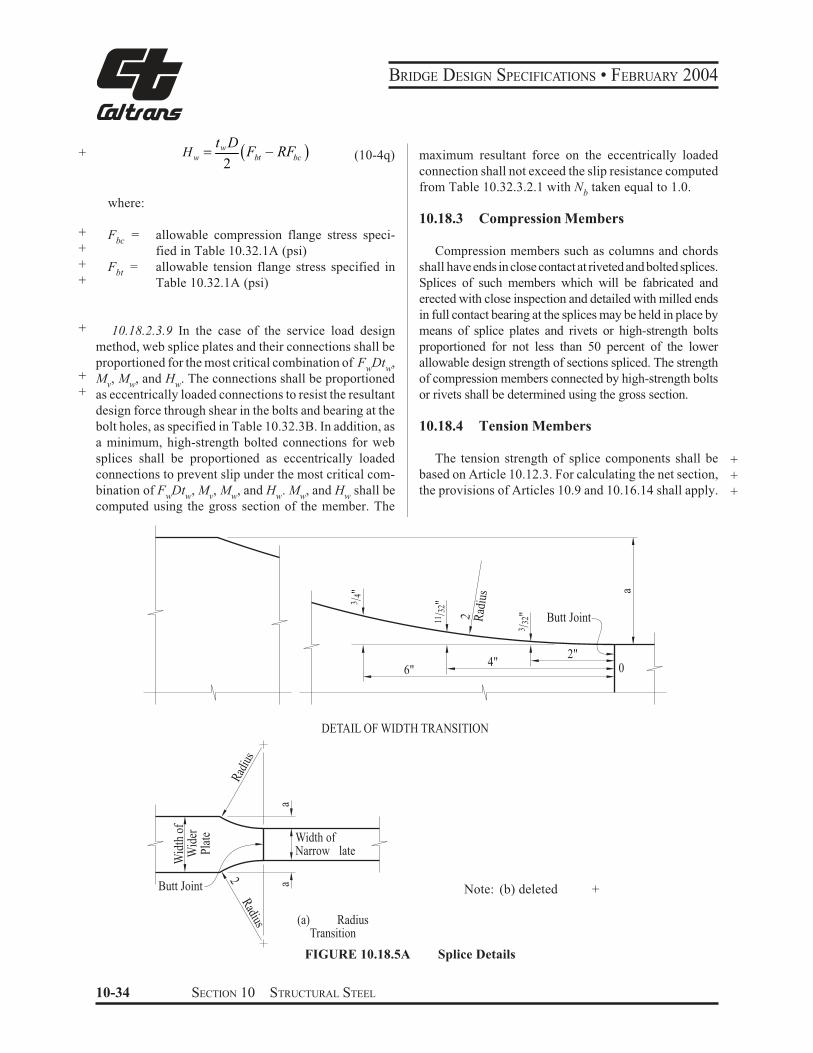
BRIDGE DESIGN SPECIFICATIONS • FEBRUARY 2004
w+ H =
t D (F − RF ) (10-4q)w bt bc2
where:
+ = allowable compression flange stress speci-Fbc
+ fied in Table 10.32.1A (psi) + = allowable tension flange stress specified inF
bt+ Table 10.32.1A (psi)
+ 10.18.2.3.9 In the case of the service load design
method, web splice plates and their connections shall be
proportioned for the most critical combination of F Dt ,w w
+ M , M , and H . The connections shall be proportionedv w w
+ as eccentrically loaded connections to resist the resultant
design force through shear in the bolts and bearing at the
bolt holes, as specified in Table 10.32.3B. In addition, as
a minimum, high-strength bolted connections for web
splices shall be proportioned as eccentrically loaded
connections to prevent slip under the most critical com-
bination of F Dt , M , M , and H . M , and H shall be w w v w w w w
computed using the gross section of the member. The
maximum resultant force on the eccentrically loaded
connection shall not exceed the slip resistance computed
from Table 10.32.3.2.1 with Nb
taken equal to 1.0.
10.18.3 Compression Members
Compression members such as columns and chords
shall have ends in close contact at riveted and bolted splices.
Splices of such members which will be fabricated and
erected with close inspection and detailed with milled ends
in full contact bearing at the splices may be held in place by
means of splice plates and rivets or high-strength bolts
proportioned for not less than 50 percent of the lower
allowable design strength of sections spliced. The strength
of compression members connected by high-strength bolts
or rivets shall be determined using the gross section.
10.18.4 Tension Members
The tension strength of splice components shall be
based on Article 10.12.3. For calculating the net section,
the provisions of Articles 10.9 and 10.16.14 shall apply.
+
+
+
02"
4"6"
3 /4"
11/3
2"
3 /32
"
aButt Joint2 R
adiu
s
DETAIL OF WIDTH TRANSITION
aa
Width ofNarrow lateW
ider
Pla
te
Wid
th o
f
Rad
ius
2R
adius
Butt Joint Note: (b) deleted +
(a) RadiusTransition
FIGURE 10.18.5A Splice Details
10-34 SECTION 10 STRUCTURAL STEEL
BRIDGE DESIGN SPECIFICATIONS • FEBRUARY 2004
As a minimum, in the case of the strength design
method, high-strength bolted connections for splices in
tension members shall be proportioned to prevent slip at
an overload design force, Po, equal to the maximum
tensile stress in the member due to Group I loading
divided by 1.3 times the gross section of member. The
slip resistance shall be computed from Equation (10-
172). In the case of the service load design method, high-
strength bolted connections shall be proportioned to
prevent slip at a force equal to the allowable design
strength specified in Article 10.18.1.1 times the gross
area of the member. The slip resistance of the connection
shall be determined as specified in Article 10.32.3.2.1.
10.18.5 Welding Splices
10.18.5.1 Tension and compression members may
be spliced by means of full penetration butt welds,
preferably without the use of splice plates.
10.18.5.2 Splices shall not be welded in field.
10.18.5.3 Material of different widths spliced by
butt welds shall have transitions conforming to Figure
10.18.5A. At butt weld splices joining material of differ-
ent thicknesses there shall be a uniform slope between the
offset surfaces of not more than 1 in 2 1/2 with respect to
the surface of either part.
10.19 CONNECTIONS
+ 10.19.1 General
10.19.1.1 Except as otherwise provided herein, con-
+ nections for main members shall be designed in the cases
+ of the service load design and the strength design meth-
+ ods for a capacity based on not less than 100 percent of
+ the allowable design strength in the member.
10.19.1.2 Connections shall be made symmetrical
about the axis of the members insofar as practicable.
Connections, except for lacing bars and handrails, shall
contain not less than two fasteners or equivalent weld.
10.19.1.3 Members, including bracing, preferably shall
be so connected that their gravity axes will intersect in a
point. Eccentric connections shall be avoided, if practi-
cable, but if unavoidable the members shall be so propor-
+ tioned that the combined forces will not exceed the
+ allowable design strength.
10.19.1.4 In the case of connections which transfer
total member shear at the end of the member, the gross
section shall be taken as the gross section of the con-
nected elements.
10.19.2 End Connections of Floor Beams and Stringers
10.19.2.1 The end connection shall be designed for
calculated member loads. The end connection angles of
floor beams and stringers shall be not less than 3/8 inch in
finished thickness. Except in cases of special end floor
beam details, each end connection for floor beams and
stringers shall be made with two angles. The length of
these angles shall be as great as the flanges will permit.
Bracket or shelf angles which may be used to furnish
support during erection shall not be considered in deter-
mining the number of fasteners required to transmit end
shear.
10.19.2.2 End connection details shall be designed
with special care to provide clearance for making the
field connection.
10.19.2.3 End connections of stringers and floor
beams preferably shall be bolted with high-strength bolts;
however, they may be riveted or welded. In the case of
welded end connections, they shall be designed for the
vertical loads and the end bending moment resulting
from the deflection of the members.
10.19.2.4 Where timber stringers frame into steel
floor beams, shelf angles with stiffeners shall be pro-
vided to carry the total reaction. Shelf angles shall be not
less than 7/16 inch thick.
10.19.3 End Connections of Diaphragms and Cross Frames
10.19.3.1 The end connections for diaphragms or
cross frames in straight rolled-beam and plate girder
bridges shall be designed for the calculated member
loads.
10.19.3.2 Vertical connection plates such as trans-
verse stiffeners which connect diaphragms or cross frames
to the beam or girder shall be rigidly connected to both
top and bottom flanges.
SECTION 10 STRUCTURAL STEEL 10-35
BRIDGE DESIGN SPECIFICATIONS • FEBRUARY 2004
+ 10.19.4 Block Shear Rupture Strength
+ 10.19.4.1 General
+ Block shear rupture is one of several possible failure
+ modes for splices, connections, gusset plates and tension
+ members. Block shear rupture failure is developed when
+ the net section of one segment ruptures and the gross
+ section of a perpendicular segment yields. The web
+ connections of coped beams, all tension connections
+ including connection plates, splice plates and gusset
+ plates, and tension members shall be investigated to
+ ensure that the adequate block shear rupture strength is
+ provided.
+ 10.19.4.2 Allowable Block Shear Rupture + Stress
+ In the Service Load Design Method, calculated ten-
+ sion stress based on the gross section shall not exceed the
+ allowable block shear rupture stress obtained from the
+ following equations:
+ for A - 0.6 Atn vn
Fbs $ %0.33 Fy Avg &0.55Fu Atn '/ Ag (10-4r)+
+ for A 0 0.6Atn vn
Fbs $ %0.33 Fu Avn &0.55 Fy Atg '/ Ag (10-4s)+
+ where:
+ Ag = gross area of whole connected material (in.2)
+ Avg = gross area along the plane resisting shear (in.2)
+ Avn = net area along the plane resisting shear (in.2)
+ Atg = gross area along the plane resisting tension (in.2)
+ Atn = net area along the plane resisting tension (in.2)
+ Fy = specified minimum yield strength of the con-
+ nected materials (psi)
+ Fu = specified minimum tensile strength of the con-
+ nected materials (psi)
+ Fbs = allowable block shear rupture stress (psi)
10.19.4.3 Design Block Shear Rupture +Strength +
In the Strength Design Method, calculated tension +force shall not exceed the design block shear rupture +strength obtained from the following equations: +
+
for Atn - 0.58 Avn +
+Tbs $ 1bs %0.58 Fy Avg & Fu Atn ' (10-4t)
+
for A 0 0.58 Atn vn
Tbs $ 1bs %0.58 Fu Avn & Fy Atg ' (10-4u) +
+
where: +
Tbs = design block shear rupture strength (lb.) +
φ bs= 0.8, reduction factor for block shear rupture +
strength +
10.20 DIAPHRAGMS AND CROSS FRAMES
10.20.1 General
Rolled beam and plate girder spans shall be provided
with cross frames or diaphragms at each support and with
cross frames or diaphragms placed in all bays and spaced +at intervals not to exceed 25 feet. Diaphragms for rolled
beams shall be at least 1/3 and preferably 1/2 the beam
depth and for plate girders shall be at least 1/2 and
preferably 3/4 the girder depth. Cross frames shall be as
deep as practicable. Cross frames shall preferably be of +the cross type or vee type. End cross frames or dia-
phragms shall be proportioned to adequately transmit all
the lateral forces to the bearings. Intermediate cross
frames shall be normal to the main beams and girders +when the supports are skewed more than twenty degrees
(20°). Cross frames on horizontally curved steel girder
bridges shall be designed as main members with ad-
equate provisions for transfer of lateral forces from the
girder flanges. Cross frames and diaphragms shall be
designed for horizontal wind loads as described in Article +10.21.2, seismic loads and other applicable loads. +
10-36 SECTION 10 STRUCTURAL STEEL
BRIDGE DESIGN SPECIFICATIONS • FEBRUARY 2004
+ 10.20.2 Horizontal Force
+ The maximum horizontal force, FD (lb.), in the trans-
verse diaphragms and cross frames is obtained from the
following:
+ FD = 1.14WSd (10-5)
+ where:
+ W = wind load along the exterior flange (lb/ft)
+ Sd = diaphragm spacing (ft)
+ 10.20.2.1 Deleted
+ 10.20.2.2 Deleted
+ 10.20.3 Deleted
+ 10.21 LATERAL BRACING
10.21.1 The need for lateral bracing shall be
+ investigated for wind loads, seismic loads and other
+ applicable lateral loads. Flanges attached to concrete
decks or other decks of comparable rigidity will not
require lateral bracing.
10.21.2 A horizontal wind force of 50 pounds per
square foot shall be applied to the area of the superstructure
+ exposed in elevation. Half this force shall be applied in
+ the plane of each flange. The maximum induced stresses,
+ f (psi), in the bottom flange of each girder in the system
+ when top flanges are continuously supported can be
computed from the following:
+
f $ R fcb (10-6)
+
2 3)$ )110.2272 2/ 3SdLR ,,/
*++.
(bracing is provided
when no bottom lateral
(10-7)
+
2 3)$ )0.640.059 1/ 2SdLR ,,/
*++.
(bracing is provided
when bottom lateral
(10-8)
+cbf
2
72
ff
cb
t b
M$ (10-9)
+cbM
20.08 dW S$ (10-10)
L
tf
bf
= span length (ft.)
= thickness of flange (in.)
= width of flange (in.)
+
+
The stresses in flanges of each girder in the system
when top flanges are not continuously supported shall be
computed using the structural system in the plane of the
flanges under consideration. The allowable stress shall
be factored in accordance with Article 3.22.
+
+
+
+
10.21.3 When required, lateral bracing shall be placed
in the exterior bays between diaphragms or cross frames.
All required lateral bracing shall be placed in or near the
plane of the flange being braced.
10.21.4 Where beams or girders comprise the main
members of through spans, such members shall be
stiffened against lateral deformation by means of gusset
plates or knee braces with solid webs which shall be
connected to the stiffeners on the main members and the
floor beams. If the unsupported length of the edge of the
gusset plate (or solid web) exceeds 60 times its thickness,
the plate or web shall have a stiffening plate or angles
connected along its unsupported edge.
10.21.5 Through truss spans, deck truss spans, and
spandrel braced arches shall have top and bottom lateral
bracing.
10.21.6 Bracing shall be composed of angles, other
shapes, or welded sections. The smallest angle used in
bracing shall be 3 by 21/2 inches. There shall be not less
than 2 fasteners or equivalent weld in each end connection
of the angles.
10.21.7 If a double system of bracing is used, both
systems may be considered effective simultaneously if
the members meet the requirements both as tension and
compression members. The members shall be connected
at their intersections.
10.21.8 The lateral bracing of compression chords
preferably shall be as deep as the chords and effectively
connected to both flanges.
10.22 CLOSED SECTIONS AND POCKETS
10.22.1 Closed sections, and pockets or depressions
that will retain water, shall be avoided where practicable.
SECTION 10 STRUCTURAL STEEL 10-37
BRIDGE DESIGN SPECIFICATIONS • FEBRUARY 2004
Pockets shall be provided with effective drain holes or be
filled with waterproofing material.
10.22.2 Details shall be so arranged that the destructive
effects of bird life and the retention of dirt, leaves, and
other foreign matter will be reduced to a minimum.
Where angles are used, either singly or in pairs, they
preferably shall be placed with the vertical legs extending
downward. Structural tees preferably shall have the web
extending downward.
10.23 WELDING
10.23.1 General
+
+
10.23.1.1 Steel base metal to be welded, weld
metal, and welding design details shall conform to the
requirements of the ANSI/AASHTO/AWS D1.5 Bridge
Welding Code and the current Standard Specifications of
the California Department of Transportation.
10.23.1.2 Welding symbols shall conform with
the latest edition of the American Welding Society Pub-
lication AWS A2.4.
+
+
+
+
+
10.23.1.3 Fabrication shall conform to the Stan-
dard Specifications of the California Department of Trans-
portation. For fracture critical members see the AASHTO
“Guide Specifications for Fracture Critical Non-Redun-
dant Steel Bridge Members.”
10.23.2 Effective Size of Fillet Welds
10.23.2.1 Maximum Size of Fillet Welds
The maximum size of a fillet weld that may be as-
sumed in the design of a connection shall be such that the
stresses in the adjacent base material do not exceed the
values allowed in Article 10.32. The maximum size that
may be used along edges of connected parts shall be:
(1) Along edges of material less than 1/4 inch thick,
the maximum size may be equal to the thickness
of the material.
(2) Along edges of material 1/4 inch or more in
thickness, the maximum size shall be 1/16 inch less
than the thickness of the material, unless the weld
is especially designated on the drawings to be
built out to obtain full throat thickness.
10.23.2.2 Minimum Size of Fillet Welds
The minimum fillet weld size shall be as shown in
the following table**.
Base Metal
Thickness of Minimum Size
Thicker Part of Fillet Weld*
Jointed (T)
in. mm in. mm
T" 3/4 T 19.0 1/4 6 Single-pass Welds}T > 3/4 T> 19.0 5/16 8 must be used
* Except that the weld size need not exceed the
thickness of the thinner part jointed. For this excep-
tion, particular care should be taken to provide
sufficient preheat to ensure weld soundness.
** Smaller fillet welds may be approved by the
Engineer based upon applied stress and the use of
appropriate preheat.
10.23.3 Minimum Effective Length of Fillet Welds
The minimum effective length of a fillet weld shall be
four times its size and in no case less than 11/2 inches.
10.23.4 Fillet Weld End Returns
Fillet welds which support a tensile force that is not
parallel to the axis of the weld, or which are proportioned
to withstand repeated stress, shall not terminate at corners
of parts or members but shall be returned continuously,
full size, around the corner for a length equal to twice the
weld size where such return can be made in the same
plane. End returns shall be indicated on design and detail
drawings.
10.23.5 Seal Welds
Seal welding shall preferably be accomplished by a
continuous weld combining the functions of sealing and
strength, changing section only as the required strength
or the requirements of minimum size fillet weld, based on
material thickness, may necessitate.
10-38 SECTION 10 STRUCTURAL STEEL
BRIDGE DESIGN SPECIFICATIONS • FEBRUARY 2004
+ 10.24 FASTENERS
10.24.1 General
+
10.24.1.1 In proportioning fasteners, for shear and
tension the cross-sectional area based upon the nominal
diameter shall be used. Galvanization of AASHTO M253 +
+
+
+
+
+
(ASTM A490) and A354 Grade BD high strength bolts is
not permitted due to hydrogen embrittlement problems.
These fasteners must be carefully evaluated before being
utilized. Requirements for bolts in these specifications
shall be used for threaded rods, threaded studs and anchor
rods, where applicable.
+
10.24.1.2 High-strength bolts may be substituted for
Grade 1 rivets (ASTM A 502) or ASTM A307 bolts. When
AASHTO M 164 (ASTM A325) high-strength bolts are
substituted for ASTM A307 bolts they shall be tightened to
the full effort of a man using an ordinary spud wrench.
+
+
+
+
+
+
+
+
+
+
10.24.1.3 All bolts, except high-strength bolts
tensioned to the requirements of the Standard Specifications
of the California Department of Transportation, shall have
single self-locking nut, double nuts, or a nut with a thread
locking system (anaerobic adhesive) to prevent nut loosen-
ing. The thread locking system is the preferred method for
bolt diameters of one inch or less. The thread locking system
shall not be used on bolt diameters greater than one inch.
When using the double nut method a torque value for the jam
nut, relative to the main nut, shall be shown on the plans to
assure that a reasonable effort will be made to lock the two
+ nuts together.
+
+
10.24.1.4 Joints required to resist shear between
their connected parts are designated as either slip-critical
or bearing-type connections. Slip-critical joints are re-
quired for joints subject to stress reversal, heavy impact
loads, severe vibration or where stress and strain due to
joint slippage would be detrimental to the serviceability
of the structure. They include:
(1) Joints subject to fatigue loading.
(2) Joints with bolts installed in oversized holes.
(3) Except where the Engineer intends otherwise and
so indicates in the contract documents, joints with
bolts installed in slotted holes where the force on
the joint is in a direction other than normal (be-
tween approximately 80 and 100 degrees) to the
axis of the slot.
(4) Joints subject to significant load reversal.
(5) Joints in which welds and bolts share in transmit-
ting load at a common faying surface.
(6) Joints in which, in the judgment of the Engineer,
any slip would be critical to the performance of
the joint or the structure and so designated on the
contract plans and specifications.
10.24.1.5 High-strength bolted connections sub-
ject to tension, or combined shear and tension shall be
designed as slip-critical connections.
+
+
10.24.1.6 Bolted bearing-type connections using
high-strength bolts shall be limited to members in com-
pression and secondary members.
10.24.1.7 The effective bearing area of a fastener
shall be its diameter multiplied by the thickness of the
metal on which it bears. In metal less than 3/8 inch thick,
countersunk fasteners shall not be assumed to carry
stress. In metal 3/8 inch thick and over, one-half the depth
of countersink shall be omitted in calculating the bearing
area.
10.24.1.8 In determining whether the bolt threads
are excluded from the shear planes of the contact sur-
faces, thread length of bolts shall be calculated as two
thread pitches greater than the specified thread length as
an allowance for thread run out.
10.24.1.9 In bearing-type connections, pull-out
shear in a plate should be investigated between the end of
the plate and the end row of fasteners. (See Table 10.32.3B,
footnote h or Article 10.56.1.3.).
SECTION 10 STRUCTURAL STEEL 10-39
BRIDGE DESIGN SPECIFICATIONS • FEBRUARY 2004
Bolt
Diameter (in.)
5/8
3/4
7/8
1
11/8
10.24.2 Hole Types
TABLE 10.24.2 Nominal Hole Dimension
Hole Dimension (in.)
Standard Oversize Short Slot Long Slot
(Diameter) (Diameter) (Width x Length) (Width x Length)
1 3 11 / 1 / 1 / x 7/ 11/ x 19/16 16 16 8 16 16
3 5 3 3 71 / 1 / 1 / 1 /16x 1 /
816 16 16x 1
5 5 1 5 31 /16
11/16
1 /16x 1 /
8
1 /16x 2 /
16
11/4
11/16x 15/
1611/
16x 21/
211/
16
d + 1/ d + 5/ (d + 1/ ) x (d + 3/ ) (d + 1/ ) x (2.5 x d)16 16
Hole types for high-strength bolted connections are
standard holes, oversize holes, short slotted holes and long
slotted holes. The nominal dimensions for each type hole
+ shall be not greater than those shown in Table 10.24.2.
10.24.2.1 In the absence of approval by the Engi-
neer for use of other hole types, standard holes shall be
used in high-strength bolted connections.
10.24.2.2 When approved by the Engineer, over-
size, short slotted hole or long slotted holes may be used
subject to the following joint detail requirements.
10.24.2.2.1 Oversize holes may be used in all plies
of connections which satisfy the requirements of Article
10.32.3.2.1 or Article 10.57.3, as applicable. Oversize
holes shall not be used in bearing-type connections.
10.24.2.2.2 Short slotted holes may be used in any
or all plies of high-strength bolted connections designed
on the basis of Table 10.32.3B or Table 10.56A, as
applicable, provided the load is applied approximately
normal (between 80 and 100 degrees) to the axis of the
slot. Short slotted holes may be used without regard for
the direction of applied load in any or all plies of connec-
tions which satisfy the requirements of Article 10.32.3.2.1
or Article 10.57.3.1, as applicable.
10.24.2.2.3 Long slotted holes may be used in one
of the connected parts at any individual faying surface in
high-strength bolted connections designed on the basis of
Table 10.32.3B or Table 10.56A, as applicable, provided
the load is applied approximately normal (between 80
16 8 16
and 100 degrees) to the axis of the slot. Long slotted holes
may be used in one of the connected parts at any individual
faying surface without regard for the direction of applied
load on connections which satisfy the requirements of
Article 10.32.3.2.1 or Article 10.57.3.1, as applicable.
10.24.3 Washer Requirements
Design details shall provide for washers in high-
strength bolted connections as follows:
10.24.3.1 Where the outer face of the bolted parts
has slope greater than 1:20 with respect to a plane normal
to the bolt axis, a hardened beveled washer shall be used
to compensate for the lack of parallelism. Beveled wash-
ers other than the standard 1:6 slope shall be detailed in
the plans.
10.24.3.2 Hardened washers are not required for
connections using AASHTO M164 (ASTM A325) and
AASHTO M253 (ASTM A490) bolts except as required
in Articles 10.24.3.3 through 10.24.3.7.
10.24.3.3 Hardened washers shall be used under
the element turned in tightening and to cover oversize or
short slotted holes in the outer ply.
10.24.3.4 Irrespective of the tightening method,
hardened washers shall be used under both the head and
the nut when AASHTO M253 (ASTM A490) bolts are to
be installed in material having a specified yield strength
less than 40,000 psi.
+
+
+
+
+
+
+
+
+
+
10-40 SECTION 10 STRUCTURAL STEEL
BRIDGE DESIGN SPECIFICATIONS • FEBRUARY 2004
10.24.3.5 Where AASHTO M 164 (ASTM A 325)
bolts of any diameter or AASHTO M 253 (ASTM A 490)
bolts equal to or less than 1 inch in diameter are to be
installed in an oversize or short slotted hole in an outer
ply, a hardened washer conforming to ASTM F 436 shall
be used.
10.24.3.6 When AASHTO M 253 (ASTM A 490)
bolts over 1 inch in diameter are to be installed in an oversize
or short slotted hole in an outer ply, hardened washers
conforming to ASTM F 436 except with 5/16 inch minimum
thickness shall be used under both the head and the nut in lieu
of standard thickness hardened washers. Multiple hardened
washers with combined thickness equal to or greater than 5/
16 inch do not satisfy this requirement.
10.24.3.7 Where AASHTO M 164 (ASTM A 325)
bolts of any diameter or AASHTO M 253 (ASTM A 490)
bolts equal to or less than 1 inch in diameter are to be installed
in a long slotted hole in an outer ply, a plate washer or
continuous bar of at least 5/16 inch thickness with standard
holes shall be provided. These washers or bars shall have a
size sufficient to completely cover the slot after installation
and shall be of structural grade material but need not be
hardened except as follows. When AASHTO M 253 (ASTM
A 490) bolts over 1 inch in diameter are to be used in long
slotted holes in external plies, a single hardened washer
conforming to ASTM F436 but with 5/16 inch minimum
thickness shall be used in lieu of washers or bars of structural
grade material. Multiple hardened washers with combined
thickness equal to or greater than 5/16 inch do not satisfy this
requirement.
10.24.4 Size of Fasteners (Rivets or High-Strength Bolts)
10.24.4.1 Fasteners shall be of the size shown on
the drawings, but generally shall be 3/4 inch or 7/8 inch in
diameter. Fasteners 5/8 inch in diameter shall not be used
+ in members carrying design loads except in 21/2-inch
legs of angles and in flanges of sections.
10.24.4.2 The diameter of fasteners in angles car-
+ rying design loads shall not exceed one-fourth the width
of the leg in which they are placed.
10.24.4.3 In angles whose size is not determined
+ by design loads, 5/8-inch fasteners may be used in 2-inch
legs, 3/4-inch fasteners in 21/2-inch legs, 7/8-inch fasteners
in 3-inch legs, and 1-inch fasteners in 31/2-inch legs.
10.24.4.4 Structural shapes which do not admit the
use of 5/8-inch diameter fasteners shall not be used except
in handrails.
10.24.5 Spacing of Fasteners
10.24.5.1 Pitch and Gage of Fasteners
The pitch of fasteners is the distance along the line of
principal stress, between centers of adjacent fasteners,
measured along one or more fastener lines. The gage of
fasteners is the distance between adjacent lines of fasten-
ers or the distance from the back of angle or other shape
to the first line of fasteners.
+
+
10.24.5.2 Minimum Spacing of Fasteners
The minimum distance between centers of fasteners in
standard holes shall be three times the diameter of the
fastener but, preferably, shall not be less than the following:
Fastener Diameter Minimum Spacing
(in.) (in.)
1 31/2
7/8
3
3/4
21/2
5/8
21/4
+
+
+
+
+
10.24.5.3 Minimum Clear Distance between Holes
When oversize or slotted holes are used, the minimum
clear distance between the edges of adjacent holes in the
direction of the force and transverse to the direction of the
force shall not be less than twice the diameter of the bolt.
10.24.5.4 Maximum Spacing of Fasteners
The maximum spacing of fasteners shall be in accor-
dance with the provisions of Articles 10.24.6, as appli-
cable.
SECTION 10 STRUCTURAL STEEL 10-41
BRIDGE DESIGN SPECIFICATIONS • FEBRUARY 2004
10.24.6 Maximum Spacing of Sealing and Stitch Fasteners
10.24.6.1 Sealing Fasteners
+
+
+
For sealing against the penetration of moisture in
joints, the fastener spacing along a single line of fasteners
adjacent to a free edge of an outside plate or shape shall
not exceed 4 inches + 4t or 7 inches. If there is a second
line of fasteners uniformly staggered with those in the
line adjacent to the free edge, at a gage “g” less than 11/
2 inches + 4t therefrom, the staggered pitch in two such
lines, considered together, shall not exceed 4 inches + 4t –
3g/4 or 7 inches, but need not be less than one-half the
requirement for a single line, where t is the thickness of
the thinner outside plate or shape (in.), and g is the gage
between fasteners (in.).
10.24.6.2 Stitch Fasteners
In built-up members where two or more plates or
shapes are in contact, stitch fasteners shall be used to
ensure that the parts act as a unit and, in compression
members, to prevent buckling. In compression members
the pitch of stitch fasteners on any single line in the
direction of stress shall not exceed 12t, except that, if the
fasteners on adjacent lines are staggered and the gage, g,
between the line under consideration and the farther
adjacent line (if there are more than two lines) is less than
24t, the staggered pitch in the two lines, considered
together, shall not exceed 12t or 15t – 3g/8. The gage
between adjacent lines of fasteners shall not exceed 24t.
In tension members the pitch shall not exceed twice that
specified for compression members and the gage shall
not exceed that specified for compression members.
The maximum pitch of fasteners in built-up members
shall be governed by the requirements for sealing or stitch
fasteners, which is minimum.
For pitch of fasteners in the ends of compression
members, see Article 10.16.13.
10.24.7 Edge Distance of Fasteners
10.24.7.1 General
+
+
+
The distance from the center of any fastener in a
standard hole to an edge of a connected part shall not be
less than the applicable value specified in Table
10.24.7.1.A.
The maximum distance from the center of any fastener
to any edge shall be eight times the thickness of the
thinnest outside plate, but shall not exceed 5 inches.
10.24.7.2 When there is only a single transverse
fastener in the direction of the line of force in a standard
or short slotted hole, the distance from the center of the
hole to the edge of the connected part shall not be less than
11/2 times the diameter of the fastener, unless accounted
for by the bearing provisions of Table 10.32.3B or Article
10.56.1.3.2.
10.24.7.3 When oversize or slotted holes are used,
the distance between edges of holes and edges of mem-
bers shall not be less than the diameter of the bolt.
TABLE 10.24.7.1A Minimum Edge Distance from +Center of Standard Hole to Edge of Connected Part +
At Flange
At Sheared At Rolled Edges of
Fasteners or Thermally or Planed Beams and
Diameter Cut Edges Edges Channels
(in.) (in.) (in.) (in.)
1 13/4
11/2
11/4
7/8
11/2
11/4
11/8
3/4
11/4
11/8
15/
811/
81 7/
8
+
+
+
+
+
+
+
+
+
10.24.8 Long Rivets
Rivets subjected to design forces and having a grip in +excess of 41/2 diameters shall be increased in number at
least 1 percent for each additional 1/16 inch of grip. If the
grip exceeds six times the diameter of the rivet, specially
designed rivets shall be used.
10.25 LINKS AND HANGERS
10.25.1 Net Section
In pin-connected tension members other than eyebars,
the net section across the pin hole shall be not less than
140 percent, and the net section back of the pin hole not
less than 100 percent of the required net section of the
body of the member. The ratio of the net width (through
the pin hole transverse to the axis of the member) to the
thickness of the segment shall not be more than 8. Flanges
not bearing on the pin shall not be considered in the net
section across the pin.
10-42 SECTION 10 STRUCTURAL STEEL
BRIDGE DESIGN SPECIFICATIONS • FEBRUARY 2004
+
+
+
Pin plates are not recommended in new construction. The thickness required shall be full length. Hanger plates shall be designed to provide free movement of the parts. 10.25.2 Location of Pins
Pins shall be so located with respect to the gravity axis of the members as to reduce to a minimum the stresses due to bending. 10.25.3 Size of Pins
++Pins shall be proportioned for the maximum shears and bending moments produced by the members con-nected. If there are eyebars among the parts connected, the diameter of the pin shall be not less than
3 F
10.25.5.2 Members shall be restrained against lat-eral movement on the pins and against lateral distortion due to the skew of the bridge. 10.26 UPSET ENDS
Bars and rods with screw ends, where specified, shall be upset to provide a section at the root of the thread, which will exceed the net section of the body of the member by at least 15 percent. 10.27 EYEBARS10.27.1 Thickness and Net Section
Eyebars shall be of a uniform thickness without rein-forcement at the pin holes. The thickness of eyebars shall be not less that1/8 of the width, nor less than1/2 inch, andy
400,000+ 4
+ beb (10-11)
not greater than 2 inches. The section of the head through the center of the pin hole shall exceed the required section of the body of the bar by at least 35 percent. The net section back of the pin hole shall not be less than 75 percent of the required net section of the body of the member. The radius of transition between the head and body of the eyebar shall be equal to or greater than the width of the head through the centerline of the pin hole. 10.27.2 Packing of Eyebars
10.27.2.1 The eyebars of a set shall be symmetrical about the central plane of the truss and as nearly parallel as practicable. Bars shall be as close together as practi-cable and held against lateral movement, but they shall be so arranged that adjacent bars in the same panel will be separated by at least 1/2 inch. 10.27.2.2 Intersecting diagonal bars not far enough apart to clear each other at all times shall be clamped together at the intersection. 10.27.2.3 Steel filling rings shall be provided, if needed, to prevent lateral movement of eyebars or other members connected on the pin.
10.28 FORKED ENDS Forked ends will be permitted only where unavoid-able. There shall be enough pin plates on forked ends to
where:++ Fy = specified minimum yield strength of steel (psi) beb = width of the body of the eyebar (in.)
10.25.4 Pin Plates
+
When necessary for the required section or bearing area, the section at the pin holes shall be increased on each segment by plates so arranged as to reduce to a minimum the eccentricity of the segment. One plate on each side shall be as wide as the outstanding flanges will allow. At least one full-width plate on each segment shall extend to the far edge of the stay plate and the others not less than 6 inches beyond the near edge. These plates shall be connected by enough rivets, bolts, or fillet welds to transmit the bearing pressure, and so arranged as to distribute it uniformly over the full section. 10.25.5 Pins and Pin Nuts
+++
10.25.5.1 Pins shall be of sufficient length to secure a full bearing of all parts connected upon the turned body of the pin. They shall be secured in position by hexagonal recessed nuts or by hexagonal solid nuts with washers. If the pins are bored, through rods with cap washers may be used. Pin nuts shall be malleable castings or steel. They shall be secured by cotter pins or other suitable locking devices which will not affect the removal of the nut.
SECTION 10 STRUCTURAL STEEL 10-43
BRIDGE DESIGN SPECIFICATIONS • FEBRUARY 2004
make the section of each jaw equal to that of the member.
The pin plates shall be long enough to develop the pin
plate beyond the near edge of the stay plate, but not less
than the length required by Article 10.25.4.
10.29 FIXED AND EXPANSION BEARINGS
10.29.1 General
+
+
10.29.1.1 Fixed ends shall be firmly anchored.
Bearings for spans less than 50 feet need have no provi-
sion for rotation. Spans of 50 feet or greater shall be
provided with a type of bearing to accommodate rotation.
+
+
10.29.1.2
type of bearing
Expansion ends shall be provided with a
to accommodate rotation and expansion.
+ 10.29.1.3 Deleted
+ 10.29.2 Deleted
+ 10.29.3 Deleted
+ 10.29.4 Sole Plates and Masonry Plates
10.29.4.1 Sole plates and masonry plates shall
have a minimum thickness of 3/4 inch.
10.29.4.2 For spans on inclined grades greater
than 1 percent without hinged bearings, the sole plates
shall be beveled so that the bottom of the sole plate is
level, unless the bottom of the sole plate is radially
curved.
10.29.5 Masonry Bearings
Beams, girders, or trusses on masonry shall be so
supported that the bottom chords or flanges will be above
the bridge seat, preferably not less than 6 inches.
+ 10.29.6 Anchor Rods
+
+
+
+
+
+
10.29.6.1 Trusses, girders, and rolled beam spans
preferably shall be securely anchored to the substructure.
Anchor rods shall be headed, hooked, or threaded with
a nut to secure a satisfactory grip upon the material used
to embed them in the holes. All anchor rods shall conform
to specifications shown in Table 10.2C. High strength
steels (quenched and tempered) are not recommended for
use in hooked anchor rods since bending with heat may
affect their strength. The embedded end of a threaded rod
with a nut shall have a positive locking device or system to
prevent rod rotation when a nut is installed on other end.
+
+
+
10.29.6.2 The following are the minimum require-
ments for each bearing:
For rolled beam spans the outer beams shall be an-
chored at each end with 2 rods, 1 inch in diameter, set
10 inches in the masonry.
+
For trusses and girders:
Spans 50 feet in length or less; 2 rods, 1 inch in
diameter set 10 inches in the masonry.
+
Spans 51 to 100 feet; 2 rods, 11/4 inches in
diameter, set 12 inches in the masonry.
+
Spans 101 to 150 feet; 2 rods, 11/2 inches in diam-
eter, set 15 inches in the masonry.
+
Spans greater than 150 feet; 4 rods, 11/2 inches in
diameter, set 15 inches in the masonry.
+
10.29.6.3 Anchor rods shall be designed to resist
uplift as specified in Article 3.17 and seismic forces
specified in Article 3.21. Other restraining devices may
be used in conjunction with anchor rods.
+
+
+
+
10.29.7 Pedestals and Shoes
10.29.7.1 Pedestals and shoes preferably shall be
made of cast steel or structural steel. The difference in
width between the top and bottom bearing surfaces shall
not exceed twice the distance between them. For hinged
bearings, this distance shall be measured from the center
of the pin. In built-up pedestals and shoes, the web plates
and angles connecting them to the base plate shall be not
less than 5/8 inch thick. If the size of the pedestal permits,
the webs shall be rigidly connected transversely. The
minimum thickness of the metal in cast steel pedestals
shall be 1 inch. Pedestals and shoes shall be so designed
that the load will be distributed uniformly over the entire
bearing.
10.29.7.2 Webs and pin holes in the webs shall be
arranged to keep any eccentricity to a minimum. The net
10-44 SECTION 10 STRUCTURAL STEEL
BRIDGE DESIGN SPECIFICATIONS • FEBRUARY 2004
section through the hole shall provide 140 percent of the
net section required for the design load transmitted through
the pedestal or shoe. Pins shall be of sufficient length to
secure a full bearing. Pins shall be secured in position by
appropriate nuts with washers. All portions of pedestals
and shoes shall be held against lateral movement of the
pins.
10.30 FLOOR SYSTEM
10.30.1 Stringers
Stringers preferably shall be framed into floor beams.
Stringers supported on the top flanges of floor beams
+ preferably shall be continuous.
10.30.2 Floor Beams
Floor beams preferably shall be at right angles to the
trusses or main girders and shall be rigidly connected
thereto. Floor beam connections preferably shall be lo-
cated so the lateral bracing system will engage both the
floor beam and the main supporting member. In pin-
connected trusses, if the floor beams are located below
the bottom chord pins, the vertical posts shall be extended
sufficiently below the pins to make a rigid connection to
the floor beam.
10.30.3 Cross Frames
In bridges with wooden floors and steel stringers,
intermediate cross frames (or diaphragms) shall be
placed between stringers more than 20 feet long.
10.30.4 Expansion Joints
10.30.4.1 To provide for expansion and contrac-
tion movement, floor expansion joints shall be provided
at all expansion ends of spans and at other points where
they may be necessary.
10.30.4.2 Apron plates, when used, shall be de-
signed to bridge the joint and to prevent, so far as
practicable, the accumulation of roadway debris upon
the bridge seats. Preferably, they shall be connected
rigidly to the end floor beam.
10.30.5 End Floor Beams
There shall be end floor beams in all square-ended
trusses and girder spans and preferably in skew spans.
End floor beams for truss spans preferably shall be
designed to permit the use of jacks for lifting the super-
structure. For this case the allowable stresses may be
increased 50 percent.
10.30.6 End Panel of Skewed Bridges
In skew bridges without end floor beams, the end
panel stringers shall be secured in correct position by end
struts connected to the stringers and to the main truss or
girder. The end panel lateral bracing shall be attached to
the main trusses or girders and also to the end struts.
Adequate provisions shall be made for the expansion
movement of stringers.
10.30.7 Sidewalk Brackets
Sidewalk brackets shall be connected in such a way
that the bending stresses will be transferred directly to the
floor beams.
10.30.8 Stay-in-Place Deck Forms
10.30.8.1 Concrete Deck Panels
When precast prestressed deck panels are used as
permanent forms spanning between beams, stringers, or
girders, the requirements of Article 9.12, Deck Panels,
and Article 9.23, Deck Panels, shall be met.
10.30.8.2 Metal Stay-in-Place Forms
When metal stay-in-place forms are used as perma-
nent forms spanning between beams, stringers, or girders,
the forms shall be designed a minimum of, to support the
weight of the concrete (including that in the corrugations, if
applicable), a construction load of 50 psf, and the weight of
the form. The forms shall be designed to be elastic under
construction loads. The elastic deformation caused by the
dead load of the forms, plastic concrete and reinforcement,
shall not exceed a deflection greater than L/80 or one half
inch, for form work spans (L) of 10 feet or less, or a
deflection of L/240 or three-quarter inch, for form work for
spans L over 10 feet. Dead load due to metal stay-in-place
forms shall be taken into account in design of girders.
+
+
+
+
+
SECTION 10 STRUCTURAL STEEL 10-45
BRIDGE DESIGN SPECIFICATIONS • FEBRUARY 2004
Part C Service Load Design Method
Allowable Stress Design
10.31 SCOPE
+
Allowable stress design is a method for proportioning
structural members using design loads and forces, allow-
able stresses, and design limitations for the appropriate
material under service conditions. See Part D – Strength
Design Method – Load Factor Design for a preferred
design procedure.
10.32 ALLOWABLE STRESSES
10.32.1 Steel
Allowable stresses for steel shall be as specified in
Table 10.32.1A.
10.32.2 Weld Metal
+
+
Unless otherwise specified, the ultimate strength of
weld metal shall be equal to or greater than specified
minimum value of the base metal. Allowable stresses on
the effective areas of weld metal shall be as follows:
Butt Welds
The same as the base metal joined, except in the case
of joining metals of different yields when the lower
yield material shall govern.
Fillet Welds
Fv = 0.27 Fu (10-12)
where:
+ Fv = allowable basic shear stress (psi)
Fu = tensile strength of the electrode classification
(psi).
When detailing fillet welds for quenched and tem-
pered steels the designer may use electrode classifica-
tions with strengths less than the base metal provided
that this requirement is clearly specified on the plans.
10.32.3 Fasteners +
Allowable stresses for fasteners shall be as listed in
Tables 10.32.3A and 10.32.3B, and the allowable force
on a slip-critical connection shall be as provided by
Article 10.32.3.2.1.
10.32.3.1 General
10.32.3.1.1 In proportioning fasteners for shear or
tension, the cross sectional area based upon the nominal
diameter shall be used except as otherwise noted.
10.32.3.1.2 The effective bearing area of a fastener
shall be its diameter multiplied by the thickness of the
metal on which it bears. In metal less than 3/8 inch thick,
countersunk fasteners shall not be assumed to carry load.
In metal 3/8 inch thick and over, one-half of the depth of
countersink shall be omitted in calculating the bearing
area.
+
10.32.3.1.3 In determining whether the bolt threads
are excluded from the shear planes of the contact sur-
faces, thread length of bolts shall be calculated as at least
two thread pitches greater than the specified thread length
as an allowance for thread run out.
+
10.32.3.1.4 In bearing-type connections, pull-out
shear in a plate should be investigated between the end of
the plate and the end row of fasteners. (See Table 10.32.3B,
footnote g.).
10.32.3.1.5 Deleted +
10.32.3.1.6 Joints, utilizing high-strength bolts,
required to resist shear between their connected parts are
designated as either slip-critical (see Article 10.24.1.4) or
bearing-type connections. Shear connections subjected
to stress reversal, or where slippage would be undesir-
able, shall be slip-critical connections. Potential slip of
joints should be investigated at intermediate load stages
especially those joints located in composite regions.
10.32.3.1.7 The percentage of stress increase shown
in Article 3.22, Combination of Loads, shall apply to
allowable stresses in bolted slip-critical connections us-
ing high-strength bolts, except that in no case shall the
percentage of allowable stress exceed 133 percent, and
the requirements of Article 10.32.3.3 shall not be ex-
ceeded.
10-46 SECTION 10 STRUCTURAL STEEL
BRIDGE DESIGN SPECIFICATIONS • FEBRUARY 2004
10.32.3.1.8 Bolted bearing-type connections shall
be limited to members in compression and secondary
members.
10.32.3.2 The allowable stress in shear, bearing
and tension for AASHTO M164 (ASTM A325) and
AASHTO M253 (ASTM A490) bolts shall be as listed in
Table 10.32.3B.
+ High strength bolts installed according to the Standard
+ Specifications of the California Department of Transpor-
+ tation, Section 55, will be fully tensioned and the contact
+ surface condition of the assembly will be Class B.
SECTION 10 STRUCTURAL STEEL 10-47
BRIDGE DESIGN SPECIFICATIONS • FEBRUARY 2004
+ TABLE 10.32.1A Allowable Stresses—Structural Steel (psi)
+ AASHTO Designation M 270 Grade 36
M 270Grade 50
M 270 Grade 50W
M 270 Grades 100/100W
Equivalent ASTM Designation A 709 Grade 36
A 709 Grade 50
A 709 Grade 50W G
A 709 rade HPS 70W
A 709 Grades 100/100W
Thickness of Plates Up to 4" included
Up to 4" included
Up to 4" included
Up to 4" included
Up to Over 21/2" to 21/2" included 4" included
+ Shapes All Groups All Groups All Groups N/A N/A
+ Axial tension in members with no holes for high-strength bolts or rivets.
0.55 Fy 20,000 27,000 27,000 38,000 N/A
Use net section when member has any open holes larger than 11/4 inch diameter such as perforations.
0.46 Fu N/A 51,000 46,000
+ Axial tension in members with holes for high-strength bolts or rivets and tension in extreme fiber of rolled
Gross Sectioni
0.55 Fy
20,000 27,000 27,000 38,000 N/A
+ shapes girders, and built-up sections subject to bending. Satisfy both Gross and Net Section criterion.
Net Section 0.50 Fu
29,000 32,500 35,000 45,000 N/A
Net Section 0.46 Fu
N/A 51,000 46,000
Axial compression, gross section: stiffeners of plate girders. Compression in splice material, gross section
20,000 27,000 27,000 38,000 55,000 49,000
+ Compression in extreme fibers of 0.625 Fy 22,000 31,000 31,000 43,000 62,000 62,000
+ doubly symmetrical I- and H-shape
+ members with compact flanges
+ continuously connected to the web
+ and bent about their weak axes (except
+ members with the yield strength
+ greater than 65,000 psi); solid round
+ and square bars; and solid rectangular
+ sections bent about their weak axes
Compression in extreme fibers of rolled shapes, girders, and built-up sections subject to bending. Gross section, when compression flange is:
(A) Supported laterally its full length by embedment in concrete
0.55 Fy 20,000 27,000 27,000 38,000 55,000 49,000
(B) Partially supported or is unsupported a, b
4 ( * J ( *2
50 106CbIyc d
Fb $ + , 0 772 &9 87 . + , . Fy. "0 55 S l I lxc . / yc . /
10-48 SECTION 10 STRUCTURAL STEEL
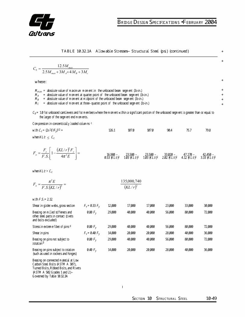
BRIDGE DESIGN SPECIFICATIONS • FEBRUARY 2004
TABLE 10.32.1A Allowable Stresses—Structural Steel (psi) (continued) ++
12.5Mmax=Cb
2.5M max + 3M A+ 4M B + 3Mc
+where:Mmax = absolute value of maximum moment in the unbraced beam segment (lb-in.) +MA = absolute value of moment at quarter point of the unbraced beam segment (lb-in.) +MB = absolute value of moment at midpoint of the unbraced beam segment (lb-in.) +MC = absolute value of moment at three- quarter point of the unbraced segment (lb-in.) +
Cb = 1.0 for unbraced cantilevers and for members where the moment within a significant portion of the unbraced segment is greater than or equal to the larger of the segment end moments. cCompression in concentrically loaded columns
with Cc = (2π2E/Fy)1/2 = 126.1 107.0 107.0 90.4 75.7 79.8 when KL/r ≤ Cc
Fy
(KL / r )2 Fy
F = 1− = a 2 16,980 – 23,580 – 23,580 – 33,020 – 47,170 – 42,450 –F.S. 4π E 0.53 (KL/r)2 1.03 (KL/r)2 1.03 (KL/r)2 2.02 (KL/r)2 4.12 (KL/r)2 3.33 (KL/r)2
when KL/r > Ccπ 2E 135,000,740
Fa = 2
= (KL / r)2F.S.(KL / r)
with F.S. = 2.12 Shear in girder webs, gross section Fv = 0.33 Fy 12,000 17,000 17,000 23,000 33,000 30,000 Bearing on milled stiffeners and 0.80 Fy 29,000 40,000 40,000 56,000 80,000 72,000 other steel parts in contact (rivets and bolts excluded) Stress in extreme fiber of pins d 0.80 Fy 29,000 40,000 40,000 56,000 80,000 72,000 Shear in pins Fv = 0.40 Fy 14,000 20,000 20,000 28,000 40,000 36,000 Bearing on pins not subject to 0.80 Fy 29,000 40,000 40,000 56,000 80,000 72,000 rotation gBearing on pins subject to rotation 0.40 Fy 14,000 20,000 20,000 28,000 40,000 36,000 (such as used in rockers and hinges) Bearing on connected material at Low Carbon Steel Bolts (ASTM A 307), Turned Bolts, Ribbed Bolts, and Rivets (ASTM A 502 Grades 1 and 2)—Governed by Table 10.32.3A
SECTION 10 STRUCTURAL STEEL 10-49
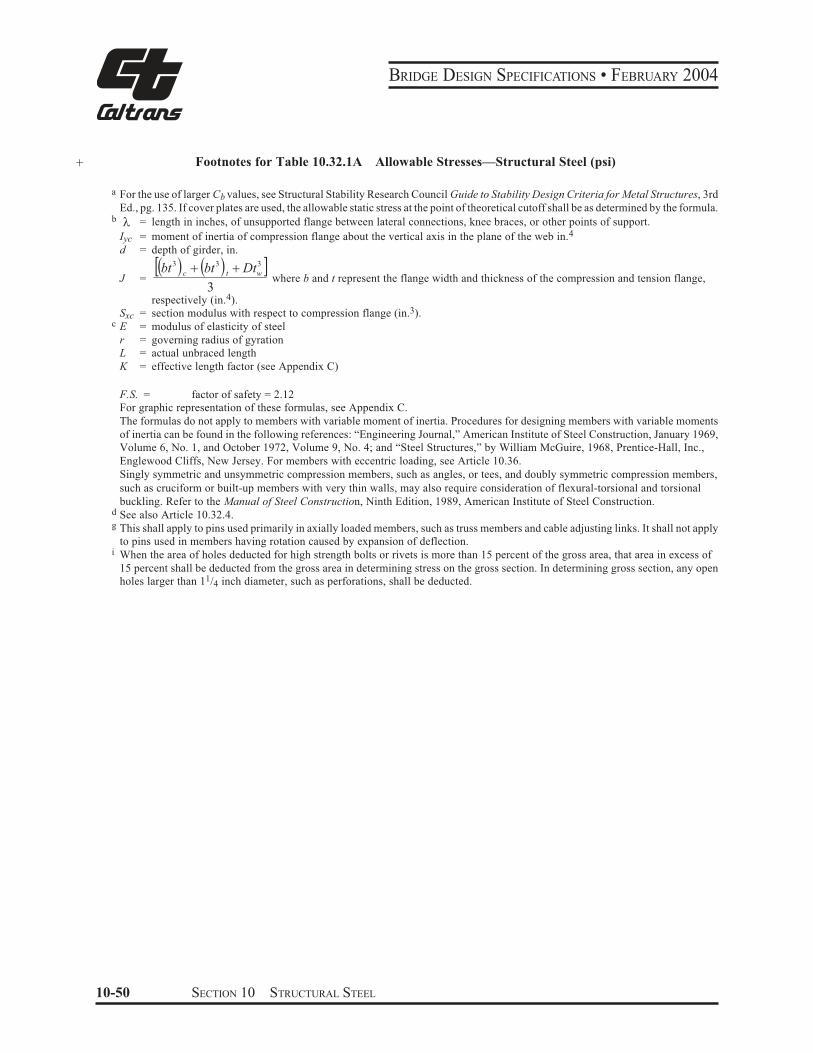
BRIDGE DESIGN SPECIFICATIONS • FEBRUARY 2004
+ Footnotes for Table 10.32.1A Allowable Stresses—Structural Steel (psi)
a For the use of larger Cb values, see Structural Stability Research Council Guide to Stability Design Criteria for Metal Structures, 3rd
Ed., pg. 135. If cover plates are used, the allowable static stress at the point of theoretical cutoff shall be as determined by the formula. b 5 = length in inches, of unsupported flange between lateral connections, knee braces, or other points of support.
Iyc = moment of inertia of compression flange about the vertical axis in the plane of the web in.4
d = depth of girder, in. 3 3 32% ' % '& bt & Dtbt 3
c t wJ = where b and t represent the flange width and thickness of the compression and tension flange,
3respectively (in.4).
Sxc = section modulus with respect to compression flange (in.3). c E = modulus of elasticity of steel
r = governing radius of gyration
L = actual unbraced length
K = effective length factor (see Appendix C)
F.S. = factor of safety = 2.12
For graphic representation of these formulas, see Appendix C.
The formulas do not apply to members with variable moment of inertia. Procedures for designing members with variable moments
of inertia can be found in the following references: “Engineering Journal,” American Institute of Steel Construction, January 1969,
Volume 6, No. 1, and October 1972, Volume 9, No. 4; and “Steel Structures,” by William McGuire, 1968, Prentice-Hall, Inc.,
Englewood Cliffs, New Jersey. For members with eccentric loading, see Article 10.36.
Singly symmetric and unsymmetric compression members, such as angles, or tees, and doubly symmetric compression members,
such as cruciform or built-up members with very thin walls, may also require consideration of flexural-torsional and torsional
buckling. Refer to the Manual of Steel Construction, Ninth Edition, 1989, American Institute of Steel Construction. d See also Article 10.32.4. g This shall apply to pins used primarily in axially loaded members, such as truss members and cable adjusting links. It shall not apply
to pins used in members having rotation caused by expansion of deflection. i When the area of holes deducted for high strength bolts or rivets is more than 15 percent of the gross area, that area in excess of
15 percent shall be deducted from the gross area in determining stress on the gross section. In determining gross section, any open
holes larger than 11/4 inch diameter, such as perforations, shall be deducted.
10-50 SECTION 10 STRUCTURAL STEEL
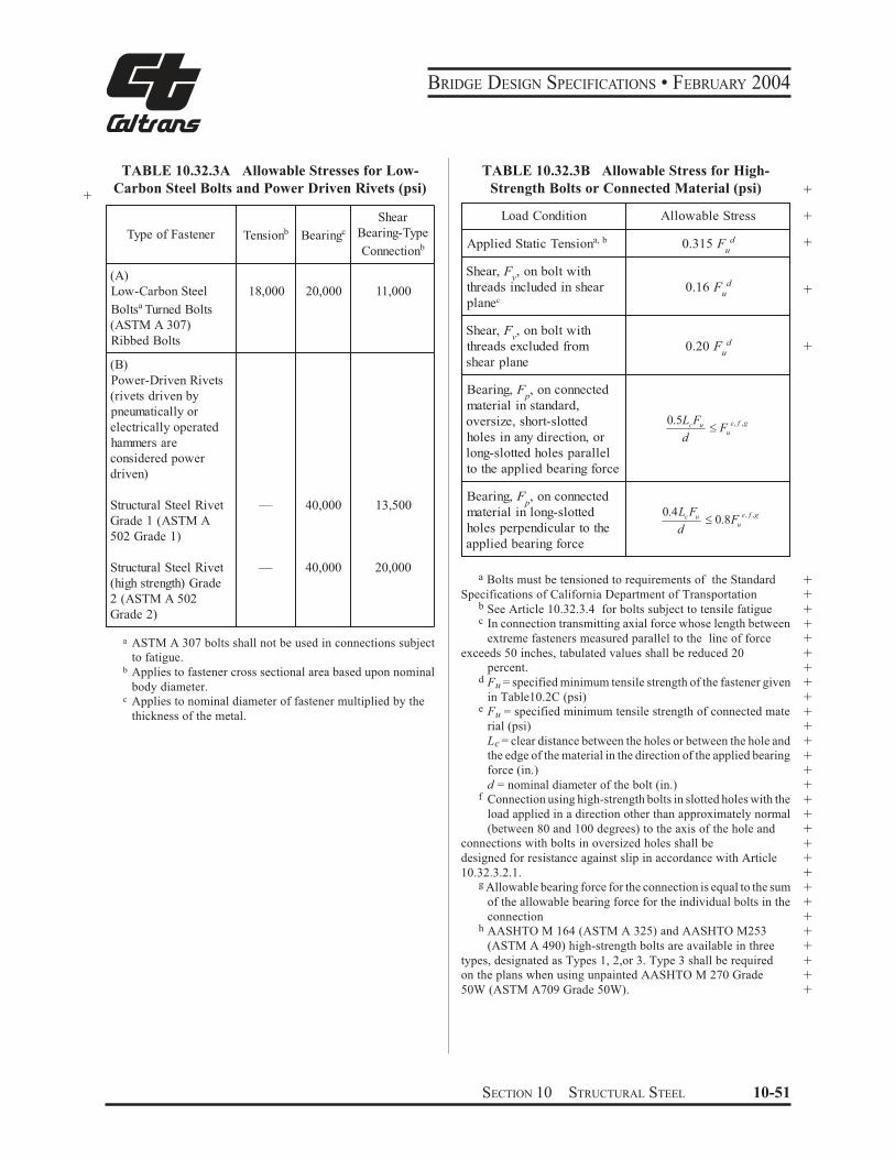
c
BRIDGE DESIGN SPECIFICATIONS • FEBRUARY 2004
+
TABLE 10.32.3A Allowable Stresses for Low-
Carbon Steel Bolts and Power Driven Rivets (psi)
Type of Fastener Tensionb Bearingc
Shear
Bearing-Type
Connectionb
(A)
Low-Carbon Steel
Boltsa Turned Bolts
(ASTM A 307)
Ribbed Bolts
18,000 20,000 11,000
(B)
Power-Driven Rivets
(rivets driven by
pneumatically or
electrically operated
hammers are
considered power
driven)
Structural Steel Rivet
Grade 1 (ASTM A
502 Grade 1)
— 40,000 13,500
Structural Steel Rivet
(high strength) Grade
2 (ASTM A 502
Grade 2)
— 40,000 20,000
a ASTM A 307 bolts shall not be used in connections subject
to fatigue. b Applies to fastener cross sectional area based upon nominal
body diameter.
Applies to nominal diameter of fastener multiplied by the
thickness of the metal.
TABLE 10.32.3B Allowable Stress for High-
Strength Bolts or Connected Material (psi) +
Load Condition Allowable Stress
Applied Static Tensiona, b 0.315 Fud
Shear, Fv, on bolt with
threads included in shear
planec
0.16 Fud
Shear, Fv, on bolt with
threads excluded from
shear plane
0.20 Fud
Bearing, F , on connected p
material in standard,
oversize, short-slotted
holes in any direction, or
f ge
uuc F
d
L F ,,0.5 "
long-slotted holes parallel
to the applied bearing force
Bearing, F , on connected p
material in long-slotted
holes perpendicular to the f ge
uuc F
d
L F ,,0.8
0.4 "
applied bearing force
+
+
+
+
a Bolts must be tensioned to requirements of the Standard +Specifications of California Department of Transportation +
b See Article 10.32.3.4 for bolts subject to tensile fatigue +c In connection transmitting axial force whose length between +
extreme fasteners measured parallel to the line of force +exceeds 50 inches, tabulated values shall be reduced 20 +
percent. +d Fu = specified minimum tensile strength of the fastener given +
in Table10.2C (psi) +e Fu = specified minimum tensile strength of connected mate +
rial (psi) +Lc = clear distance between the holes or between the hole and +the edge of the material in the direction of the applied bearing +force (in.) +d = nominal diameter of the bolt (in.) +
f Connection using high-strength bolts in slotted holes with the +load applied in a direction other than approximately normal +(between 80 and 100 degrees) to the axis of the hole and +
connections with bolts in oversized holes shall be +designed for resistance against slip in accordance with Article +10.32.3.2.1. +
g Allowable bearing force for the connection is equal to the sum +of the allowable bearing force for the individual bolts in the +connection +
h AASHTO M 164 (ASTM A 325) and AASHTO M253 +(ASTM A 490) high-strength bolts are available in three +
types, designated as Types 1, 2,or 3. Type 3 shall be required +on the plans when using unpainted AASHTO M 270 Grade +50W (ASTM A709 Grade 50W). +
SECTION 10 STRUCTURAL STEEL 10-51
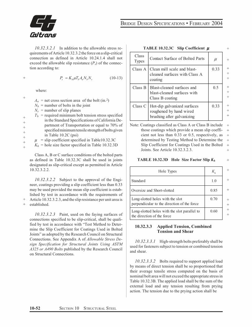
BRIDGE DESIGN SPECIFICATIONS • FEBRUARY 2004
10.32.3.2.1 In addition to the allowable stress re-
quirements of Article 10.32.3.2 the force on a slip-critical
connection as defined in Article 10.24.1.4 shall not
exceed the allowable slip resistance (Ps) of the connec-
tion according to:
Ps $ Kh b n b s (10-13)+ 6T A N N
where:
+ An = net cross section area of the bolt (in.2)
Nb = number of bolts in the joint
Ns = number of slip planes
Tb = required minimum bolt tension stress specified+
in the Standard Specifications of California De-+
partment of Transportation or equal to 70% of+
specified minimum tensile strength of bolts given+
in Table 10.2C (psi)+
µ = slip coefficient specified in Table10.32.3C+
Kh = hole size factor specified in Table 10.32.3D+
Class A, B or C surface conditions of the bolted parts
as defined in Table 10.32.3C shall be used in joints
designated as slip-critical except as permitted in Article
10.32.3.2.2.
10.32.3.2.2 Subject to the approval of the Engi-
neer, coatings providing a slip coefficient less than 0.33
may be used provided the mean slip coefficient is estab-
lished by test in accordance with the requirements of
+ Article 10.32.3.2.3, and the slip resistance per unit area is
+ established.
10.32.3.2.3 Paint, used on the faying surfaces of
connections specified to be slip-critical, shall be quali-
fied by test in accordance with “Test Method to Deter-
mine the Slip Coefficient for Coatings Used in Bolted
Joints” as adopted by the Research Council on Structural
Connections. See Appendix A of Allowable Stress De-
sign Specification for Structural Joints Using ASTM
A325 or A490 Bolts published by the Research Council
on Structural Connections.
TABLE 10.32.3C Slip Coefficient µµµµµ +
Class
Types Contact Surface of Bolted Parts µ
Class A Clean mill scale and blast-
cleaned surfaces with Class A
coating
0.33
Class B Blast-cleaned surfaces and
blast-cleaned surfaces with
Class B coating
0.5
Class C Hot-dip galvanized surfaces
roughened by hand wired
brushing after galvanizing
0.33
+
+
+
+
+
+
+
+
+
+
Note: Coatings classified as Class A or Class B include +those coatings which provide a mean slip coeffi- +cient not less than 0.33 or 0.5, respectively, as +determined by Testing Method to Determine the +Slip Coefficient for Coatings Used in the Bolted +Joints. See Article 10.32.3.2.3. +
TABLE 10.32.3D Hole Size Factor Slip Kh +
Hole Types Kh
Standard 1.0
Oversize and Short-slotted 0.85
Long-slotted holes with the slot
perpendicular to the direction of the force
0.70
Long-slotted holes with the slot parallel to
the direction of the force
0.60
+
+
+
+
+
+
+
10.32.3.3 Applied Tension, Combined Tension and Shear
10.32.3.3.1 High-strength bolts preferably shall be
used for fasteners subject to tension or combined tension
and shear.
10.32.3.3.2 Bolts required to support applied load
by means of direct tension shall be so proportioned that
their average tensile stress computed on the basis of
nominal bolt area will not exceed the appropriate stress in
Table 10.32.3B. The applied load shall be the sum of the
external load and any tension resulting from prying
action. The tension due to the prying action shall be
10-52 SECTION 10 STRUCTURAL STEEL
BRIDGE DESIGN SPECIFICATIONS • FEBRUARY 2004
a
bQ
=
8
3− T
t
20
3 (10-14)
where:
++++++
QTabt
= the prying tension per bolt (taken as zero when negative) (lb.) = the direct tension per bolt due to external load (lb.)= distance from center of bolt under consideration to edge of plate (in.) = distance from center of bolt under consideration to toe of fillet of connected part (in.) = thickness of thinnest part connected (in.)
+++
10.32.3.3.3 For combined shear and tension in slip-critical joints using high-strength bolts where applied forces reduce the total clamping force on the friction plane, the shear stress, fv (psi), shall meet the following requirement:( )
utsv FfFf /1.881 −≤ (10-15)
where:++++++
ftFsFu
= calculated tensile stress in the bolt including any stress due to prying action (psi) = allowable slip stress (psi) =bh
TK µ = specified minimum tensile strength of the bolt from Table 10.2C (psi)
++++
10.32.3.3.4 Where rivets or high-strength bolts in bearing type connections are subject to both shear and tension, the tensile stress shall not exceed the reduced allowable tensile stress obtained from the following equations. The combined stresses shall meet the require-ment of Equation (10-18). for 0.33/ ≤
vv Ff
tt FF ′= (10-16)
for 0.33/ >vv
Ff
F ′ = F 1 − ( f / F )2 (10-17)t t v v
2 2 2 +f + (k f ) ≤ F (10-18)v t v
where:ft = calculated tensile stress in rivet or bolt includ- +ing any stress due to prying action (psi) +fv = calculated shear stress in rivet or bolt (psi) +Ft = allowable tensile stress on rivet or bolt from Table 10.32.3A or Table 10.32.3B (psi) +Ft′ = reduced allowable tensile stress on rivet or bolt due to the applied shear stress (psi) +Fv = allowable shear stress on rivet or bolt from Table 10.32.3A or Table 10.32.3B (psi) +k = a constant: 0.75 for rivets; 0.6 for high-strength bolts with threads excluded from shear plane 10.32.3.4 FatigueWhen subject to tensile fatigue loading, the tensile stress in the bolt due to the service load plus the prying force resulting from application of service load shall not exceed the following allowable stresses (psi). The nomi- +nal diameter of the bolt shall be used in calculating the bolt stress. The prying force shall not exceed 80 percent of the externally applied load.
Number of Cycles AASHTO M 164
(ASTM A 325)
AASHTO M 235
(ASTM A 490)
Not more
than 20,000 38,000 47,000
From 20,000
to 500,000 35,500 44,000
More than
500,00027,500 34,000
++++
10.32.4 Pins, Rollers, and Expansion Rockers 10.32.4.1 The effective bearing area of a pin shall be its diameter multiplied by the thickness of the material on which it bears. When parts in contact have different yield strength, Fy shall be the smaller value. +10.32.4.2 Design stresses for Steel Bars, Carbon Cold Finished Standard Quality, AASHTO M 169 (ASTM A 108), and Steel Forgings, Carbon and Alloy, for Gen-eral Industrial Use, AASHTO M 102 (ASTM A 668), are given in Table 10.32.4.2A. +
SECTION 10 STRUCTURAL STEEL 10-53
BRIDGE DESIGN SPECIFICATIONS • FEBRUARY 2004
TABLE 10.32.4.2A Allowable Stresses—Steel Bars and Steel Forgings +
M 102 To
20" in dia.
A 668b
Class G
+
+
+
+
50,000 +
40,000 +
20,000 +
40,000 +
20,000 +
AASHTO Designation with Size
Limitations —
M 102 To
20" in dia.
M 102 To 10"
in dia.
ASTM Designation Grade or Class —A 668
Class D
A 668
Class F
Minimum Yield Strength, psi Fy
37,500 50,000
Stress in Extreme Fiber, psi 0.80Fy
30,000 40,000
Shear, psi 0.40Fy
15,000 20,000
Bearing on Pins not Subject to
Rotation, psic0.80F
y30,000 40,000
Bearing on Pins Subject to Rotation,
psi (such as used in rockers and
hinges)
0.40Fy
15,000 20,000
b May substitute rolled material of the same properties. c This shall apply to pins used primarily in axially loaded members, such as truss members and cable adjusting links. It shall not apply
to pins used in members having rotation caused by expansion or deflection.
10.32.5 Cast Steel, Ductile Iron Castings, Malleable Castings, and Cast Iron
10.32.5.1 Cast Steel and Ductile Iron
10.32.5.1.1 For cast steel conforming to specifica-
tions for Steel Castings for Highway Bridges, AASHTO M
192 (ASTM A 486), Mild-to-Medium-Strength Carbon-
Steel Castings for General Application, AASHTO M103
(ASTM A27), and Corrosion-Resistant Iron-Chromium,
Iron-Chromium-Nickel and Nickel-Based Alloy Castings
for General Application, AASHTO M 163 (ASTM A 743),
and for Ductile Iron Castings (ASTM A 536), the allowable
+ stresses shall be in accordance with Table 10.32.5.1A.
10.32.5.1.2 When in contact with castings or steel
of a different yield strength, the allowable bearing stress
+ of the material with the lower yield strength shall govern.
+ For riveted or bolted connections, Article 10.32.3 shall
govern.
10.32.5.2 Malleable Castings
Malleable castings shall conform to specifications for
Malleable Iron Castings, ASTM A 47 Grade 35018.
The following allowable stresses (psi) and modulus of
elasticity (psi) shall be used:
+
+
Tension ……………………………… 18,000
Bending in Extreme Fiber ……………18,000
Modulus of Elasticity ……………25,000,000
10.32.5.3 Cast Iron
Cast iron castings shall conform to specifications
for Gray Iron Castings, AASHTO M 105 (ASTM A
48), Class 30B. The following allowable stresses (psi)
shall be used:
+
Bending in Extreme Fiber ……………..3,000
Shear …………………………………...3,000
Direct Compression, short columns ….12,000
10.32.5.4 Deleted +
10-54 SECTION 10 STRUCTURAL STEEL
BRIDGE DESIGN SPECIFICATIONS • FEBRUARY 2004
+
+
+
+
+
TABLE 10.32.5.1A Allowable Stresses—Cast Steel and Ductile Iron (psi)
AASHTO Designation M 103 M 192 M 192 M 163 None
ASTM Designation A 27 A 486 A 486 A 743 A 536
Class or Grade 70-36 70 90 120 CA-15 60-40-18
Minimum Yield Strength, Fy 36,000 60,000 95,000 65,000 40,000
Axial Tension 14,500 22,500 34,000 24,000 16,000
Tension in Extreme Fiber 14,500 22,500 34,000 24,000 16,000
Axial Compression, Short Columns 20,000 30,000 45,000 32,000 22,000
Compression in Extreme Fibers 20,000 30,000 45,000 32,000 22,000
Shear 09,000 13,500 21,000 14,000 10,000
Bearing, Steel Parts in Contact 30,000 45,000 68,000 48,000 33,000
Bearings on Pins not subject to Rotation 26,000 40,000 60,000 43,000 28,000
Bearings on Pins subject to Rotation
(such as used in rockers and hinges) 13,000 20,000 30,000 21,500 14,000
10.32.6 Bearing on Masonry
10.32.6.1 The allowable bearing stress (psi) on the
following types of masonry shall be:
Granite ………………………………….800
Sandstone and Limestone ……………400
10.32.6.2 The above bridge seat stress will apply
only where the edge of the bridge seat projects at least 3
inches (average) beyond the edge of shoe or plate. Oth-
erwise, the stresses permitted will be 75 percent of the
above amounts.
10.32.6.3 For allowable bearing stress on concrete
masonry, refer to Article 8.15.2.1.3.
10.33 ROLLED BEAMS
10.33.1 General
10.33.1.1 Rolled beams, including those with welded cover plates, shall be designed by the mo-ment of inertia method. Rolled beams with riveted cover plates shall be designed on the same basis as riveted plate girders.
10.33.1.2 The compression flanges of rolled beams supporting timber floors shall not be consid-ered to be laterally supported by the flooring unless the floor and fastenings are specially designed to provide adequate support.
10.33.2 Bearing Stiffeners
Suitable stiffeners shall be provided to stiffen the webs of rolled beams at bearings when the calculated shear stress in the web adjacent to the bearing ex-ceeds 75 percent of the allowable shear stress for girder webs. See the related provisions of Article 10.34.6.
10.34 PLATE GIRDERS
10.34.1 General
10.34.1.1 Girders shall be proportioned by the mo-
ment of inertia method. For members primarily in bending,
the entire gross section shall be used when calculating
tensile and compressive stresses. Holes for high-strength
bolts or rivets and/or open holes not exceeding 11/4 inches,
may be neglected provided the area removed from each
flange does not exceed 15 percent of that flange. That area
in excess of 15 percent shall be deducted from the gross area.
+
+
SECTION 10 STRUCTURAL STEEL 10-55
BRIDGE DESIGN SPECIFICATIONS • FEBRUARY 2004
10.34.1.2 The compression flanges of plate gird-
ers supporting timber floors shall not be considered to be
laterally supported by the flooring unless the floor and
fastenings are specially designed to provide support.
10.34.2 Flanges
10.34.2.1 Welded Girders
+
+
10.34.2.1.1 Each flange may comprise a series of
plates joined end to end by full penetration butt welds.
Changes in flange areas may be accomplished by varying
the thickness and/or width of the flange plate, or by
adding cover plate. Varying the thickness and/or width of
the flange plate is preferred. Where plates of varying
thicknesses or widths are connected, the splice shall be
made in accordance with Article 10.18 and welds ground
smooth before attaching to the web. The compression-
flange width, b, on fabricated I-shaped girders preferably
shall not be less than 0.2 times the web depth, but in no
case shall it be less than 0.15 times the web depth. If the
area of the compression flange is less than the area of the
tension flange, the minimum flange width may be based
on 2 times the depth of the web in compression rather than
the web depth. The compression-flange thickness, t,
preferably shall not be less than 1.5 times the web
thickness. The width-to-thickness ratio, b/t, of flanges
subject to tension shall not exceed 24.
10.34.2.1.2 When cover plates are used, they shall
be designed in accordance with Article 10.13.
+
+
+
10.34.2.1.3 The width-thickness ratio (b/t) of com-
pression flange plate shall not exceed the limiting values
specified in Table 10.34.2A.
+ 10.34.2.1.4 Deleted
10-56 SECTION 10 STRUCTURAL STEEL
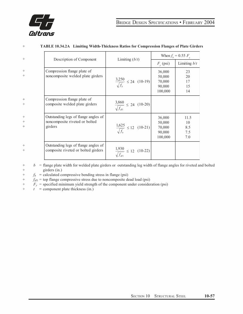
BRIDGE DESIGN SPECIFICATIONS • FEBRUARY 2004
+ TABLE 10.34.2A Limiting Width-Thickness Ratios for Compression Flanges of Plate Girders
+
+
+
+
+
+
+
+
+
+
Description of Component Limiting (b/t)When f
b= 0.55 F
y
Fy
(psi) Limiting b/t
Compression flange plate of
noncomposite welded plate girders
(10-19)243,250
"fb
36,000
50,000
70,000
90,000
100,000
23
20
17
15
14
Compression flange plate of
composite welded plate girders (10-20)243,860
1
"fdl
Outstanding legs of flange angles of
noncomposite riveted or bolted
girders (10-21)121,625
"bf
36,000
50,000
70,000
90,000
100,000
11.5
10
8.5
7.5
7.0
Outstanding legs of flange angles of
composite riveted or bolted girders (10-22)121,930
1
"fdl
+ b = flange plate width for welded plate girders or outstanding leg width of flange angles for riveted and bolted
+ girders (in.)
+ fb = calculated compressive bending stress in flange (psi)
+ fdl1 = top flange compressive stress due to noncomposite dead load (psi)
+ Fy = specified minimum yield strength of the component under consideration (psi)
+ t = component plate thickness (in.)
SECTION 10 STRUCTURAL STEEL 10-57
BRIDGE DESIGN SPECIFICATIONS • FEBRUARY 2004
+
+
+
10.34.2.1.5 In the case of a composite girder the
width-thickness ratio (b/t) ratio of the top compression
flange plate shall not exceed the limiting values specified
in Table 10.34.2A.
10.34.2.2 Riveted or Bolted Girders
10.34.2.2.1 Flange angles shall form as large a part
of the area of the flange as practicable. Side plates shall
not be used except where flange angles exceeding 7/8 inch
in thickness otherwise would be required.
+
+
+
10.34.2.2.2 The width-thickness ratio (b'/t) of out-
standing legs of flange angles in compression, except
those reinforced by plates, shall not exceed the limiting
values specified in Table 10.34.2A
+ 10.34.2.2.3 Deleted
+
+
+
10.34.2.2.4 In the case of a composite girder the
width-thickness ratio (b'/t) of outstanding legs of top
flange angles in compression, except those reinforced by
plates, shall not exceed the limiting values specified in
Table 10.34.2A.
10.34.2.2.5 The gross area of the compression
flange, except for composite design, shall be not less than
the gross area of the tension flange.
10.34.2.2.6 Flange plates shall be of equal thick-
ness, or shall decrease in thickness from the flange angles
outward. No plate shall have a thickness greater than that
of the flange angles.
10.34.2.2.7 At least one cover plate of the top
flange shall extend the full length of the girder except when
the flange is covered with concrete. Any cover plate that is
not full length shall extend beyond the theoretical cutoff
point far enough to develop the capacity of the plate or shall
extend to a section where the stress in the remainder of the
girder flange is equal to the allowable fatigue stress, which-
ever is greater. The theoretical cutoff point of the cover plate
is the section at which the stress in the flange without that
cover plate equals the allowable stress, exclusive of fatigue
considerations.
10.34.2.2.8 The number of fasteners connecting
the flange angles to the web plate shall be sufficient to
develop the increment of flange stress transmitted to the
flange angles, combined with any load that is applied
directly to the flange.
10-58 SECTION 10 STRUCTURAL STEEL
10.34.2.2.9 Legs of angles 6 inches or greater in
width, connected to web plates, shall have two lines of
fasteners. Cover plates over 14 inches wide shall have
four lines of fasteners.
+10.34.3 Web Plates
10.34.3.1 Girders Not Stiffened Longitudinally
+The girder without longitudinal stiffeners is usually +preferred. The width-thickness ratio (D/tw) of the web +plate of plate girders without longitudinal stiffeners shall +not exceed the limiting values specified in Table +10.34.3A.
+10.34.3.1.1 Deleted
+10.34.3.1.2 Deleted
10.34.3.2 Girders Stiffened Longitudinally
+The width-thickness ratio (D/tw) of the web plate of plate +girders equipped with longitudinal stiffeners shall not ex-+ceed the limiting values specified in Table 10.34.3A.
+10.34.3.2.1 Deleted
+10.34.3.2.2 Deleted
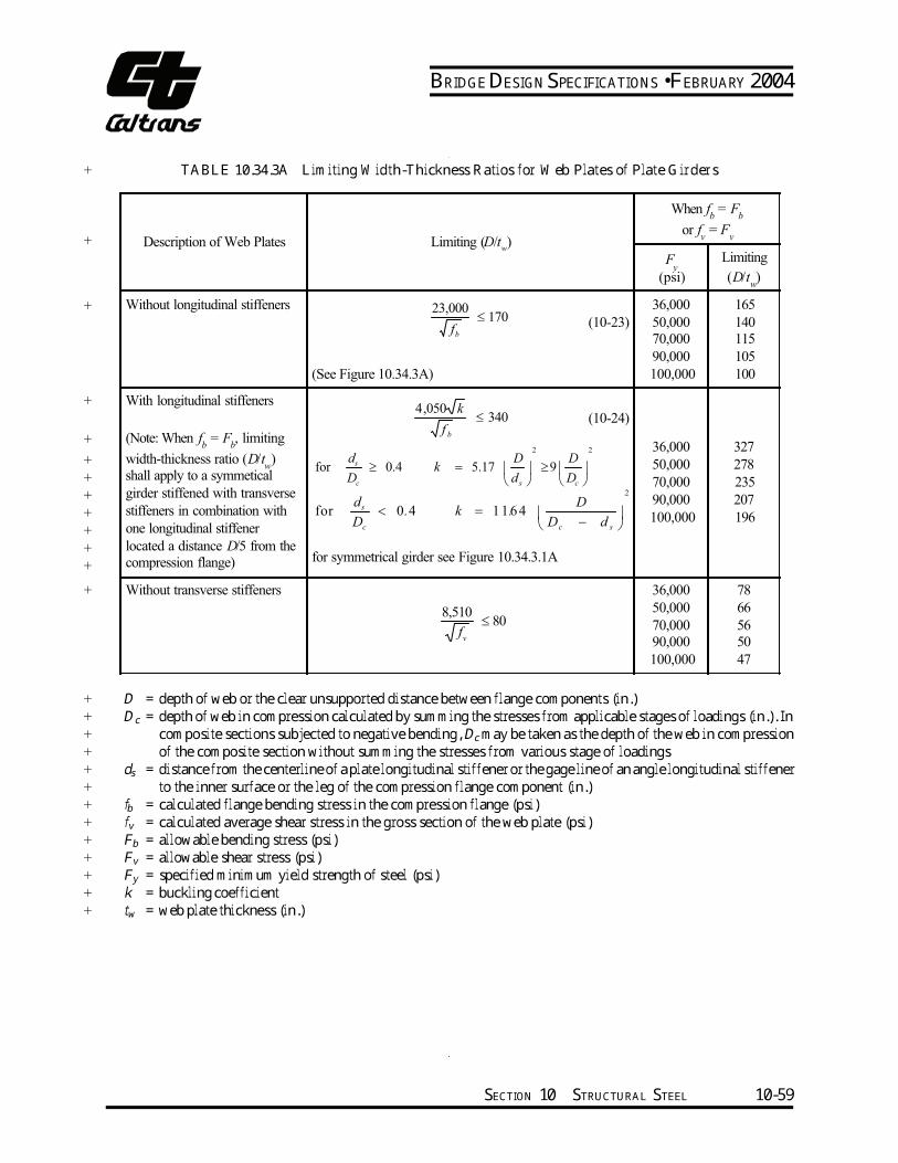
BRIDGE DESIGN SPECIFICATIONS • FEBRUARY 2004
+
+
+
+
+
+
+
+
+
+
+
+
+
+
+
+
+
+
+
+
+
+
+
+
+
+
TABLE 10.34.3A Limiting Width-Thickness Ratios for Web Plates of Plate Girders
D = depth of web or the clear unsupported distance between flange components (in.) Dc = depth of web in compression calculated by summing the stresses from applicable stages of loadings (in.). In composite sections subjected to negative bending, Dc may be taken as the depth of the web in compression of the composite section without summing the stresses from various stage of loadings ds = distance from the centerline of a plate longitudinal stiffener or the gage line of an angle longitudinal stiffener to the inner surface or the leg of the compression flange component (in.) fb = calculated flange bending stress in the compression flange (psi) fv = calculated average shear stress in the gross section of the web plate (psi) Fb = allowable bending stress (psi) Fv = allowable shear stress (psi) Fy = specified minimum yield strength of steel (psi) k = buckling coefficient tw = web plate thickness (in.)
Description of Web Plates Limiting (D/tw)
When fb = F
b
or fv = F
v
Fy
(psi)
Limiting
(D/tw)
Without longitudinal stiffeners
(10-23)
(See Figure 10.34.3A)
36,000
50,000
70,000
90,000
100,000
165
140
115
105
100
With longitudinal stiffeners
(Note: When fb = F
b, limiting
width-thickness ratio (D/tw)
shall apply to a symmetical
girder stiffened with transverse
stiffeners in combination with
one longitudinal stiffener
located a distance D/5 from the
compression flange)
(10-24)
for symmetrical girder see Figure 10.34.3.1A
36,000
50,000
70,000
90,000
100,000
327
278
235
207
196
Without transverse stiffeners 36,000
50,000
70,000
90,000
100,000
78
66
56
50
47
170000,23
≤ bf
340050,4
≤ bf
k
2 2
for 0.4 5.17 9s
c s c
d D Dk
D d D ≥ = ≥
2
for 0 4 1164s
c c s
d D. k .
D D d < = −
80510,8
≤ v
f
SECTION 10 STRUCTURAL STEEL 10-59
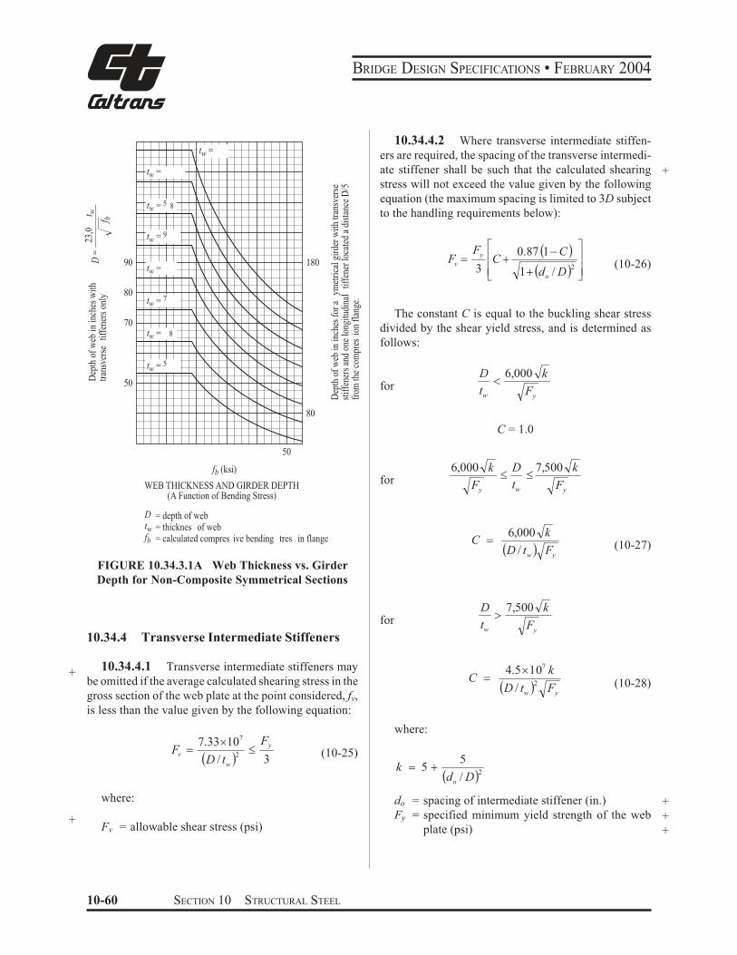
180
BRIDGE DESIGN SPECIFICATIONS • FEBRUARY 2004
10.34.4.2 Where transverse intermediate stiffen-
ers are required, the spacing of the transverse intermedi-
ate stiffener shall be such that the calculated shearing +stress will not exceed the value given by the following
equation (the maximum spacing is limited to 3D subject
to the handling requirements below):
Fy7 0.87 %1)C ' 8
Fv $ 9C & :
tw =
tw = 5 8
tw =
tw = 9
tw =
tw = 7
tw = 8
tw = 5
Dep
th o
f w
eb in
inch
esfo
r a
ymet
rica
l gir
der
wit
h tr
ansv
erse
stif
fene
rs a
nd o
ne lo
ngit
udin
al
tiff
ener
loca
ted
a di
stan
ce D
/5fr
om th
e co
mpr
esio
n fl
ange
.
23,0
tD
epth
of
web
in in
ches
wit
hw
D =
tran
sver
se
tiff
ener
s on
lybf
90
80
70
50
3;9 1& %do / D'2 :<
(10-26)
The constant C is equal to the buckling shear stress
divided by the shear yield stress, and is determined as
follows:
D 6,000 k0for tw Fy
80
50
fb (ksi)
WEB THICKNESS AND GIRDER DEPTH(A Function of Bending Stress)
D = depth of webtw = thicknes of webfb = calculated compres ive bending tres in flange
FIGURE 10.34.3.1A Web Thickness vs. Girder
Depth for Non-Composite Symmetrical Sections
10.34.4 Transverse Intermediate Stiffeners
+ 10.34.4.1 Transverse intermediate stiffeners may
be omitted if the average calculated shearing stress in the
gross section of the web plate at the point considered, fv,
is less than the value given by the following equation:
7.334107 FyFv $ 2
" (10-25)%D / tw ' 3
where:
+Fv = allowable shear stress (psi)
C = 1.0
6,000 k D 7,500 k" "for Fy w Fy
t
6,000 k(10-27)C $
%D / tw ' Fy
D 7,500 k=for tw Fy
4.54107 k2 (10-28)C $
%D / tw ' Fy
where:
5k $ 5 &
%do / D'2
do = spacing of intermediate stiffener (in.) +Fy = specified minimum yield strength of the web +
plate (psi) +
10-60 SECTION 10 STRUCTURAL STEEL

BRIDGE DESIGN SPECIFICATIONS • FEBRUARY 2004
(Fy/3) in Equation (10-26) can be replaced by the allowable shearing stress given in Table 10.32.1A.Transverse stiffeners shall be required if D/tw is greater than 150. The spacing of these stiffeners shall not exceed 2
260 the handling requirement D .D / tw
10.34.4.3 The spacing of the first intermediate stiffener at the simple support end of a girder shall be such that the shearing stress in the end panel shall not exceed the value given by the following equation (the maximum spacing is limited to 1.5D):C Fy Fy
Fv = ≤ (10-29)3 3
10.34.4.4 If a girder panel is subjected to simul-taneous action of shear and bending moment with the + magnitude of the shear stress higher than 0.6Fv, the + calculated bending stress shall not exceed the reduced + allowable bending stress,Fs determined by the following + equation:
0.34 fF = 0.754− v F
s y (10-30)F v
where:fv = average calculated shearing stress at the section; live load shall be the load to produce maxi-
+ mum moment at the section under consider-+ ation (psi)+ Fv = allowable shear stress obtained from Equation + (10-26) (psi) + Fs = reduced allowable bending stress (psi)
10.34.4.5 Where the calculated shear stress equals the allowable shear stress, transverse intermediate stiff-eners may be omitted if the width-thickness ratio (D/tw)of the web plate does not exceed the limiting values specified in Table 10.34.3A.
10.34.4.6 Intermediate stiffeners preferably shall be made of plates for welded plate girders and shall be made of angles for riveted plate girders. They may be in pairs, one stiffener fastened on each side of the web plate, with a tight fit at the compression flange. They may, however, be made of a single stiffener fastened to one side of the web plate. Stiffeners provided on only one side of the web must be welded to the compression flange and +fitted tightly to the tension flange. +
10.34.4.7 The width-thickness ratio (b'/ts) of the +transverse stiffener shall not exceed the limiting values +specified in Table 10.34.5A. The moment of inertia of +any type of transverse stiffener with reference to the plane defined in Article 10.34.4.8 shall meet the follow- +ing requirement: +
I ≥ do
tw
3 J (10-31) +
where:2
DJ = 2.5 − 2 ≥ 0.5 (10-32) +
d o
I = minimum required moment of inertia of any type of transverse intermediate stiffener (in4) +J = ratio of rigidity of one transverse stiffener to that of the web plate do = spacing of transverse stiffeners (in.) +D = unsupported depth of web plate between flange components (in.) +tw = thickness of the web plate (in.) +
SECTION 10 STRUCTURAL STEEL 10-61
BRIDGE DESIGN SPECIFICATIONS • FEBRUARY 2004
The gross cross-sectional area of intermediate trans-+ verse stiffeners, A (in.2) shall meet the following require-+ ment: D f F
v yweb 2A≥ ( ) −18 tw (10-32a)0.15B 1− C
where:
+ b′ =+ ts =+ Fyweb =++ Fystiffener =++ B =++
tw Fv Fcr
9,025,000F = ≤ Fcr 2 ystiffener
b′ (10-32b) ts
projecting width of the stiffener (in.) thickness of the stiffener (in.) specified minimum yield strength of the web (psi) specified minimum yield strength of the stiffener (psi) 1.0 for stiffener pairs 1.8 for single angles and 2.4 for single plates + C = constant computed by Article 10.34.4.2.
When values computed by Equation (10-32a) approach zero or are negative, then transverse stiffeners need only meet the requirements of Equation (10-31), and the requirements of Article 10.34.4.10. 10.34.4.8 When stiffeners are in pairs, the moment of inertia shall be taken about the centerline of the web plate. When single stiffeners are used, the moment of inertia shall be taken about the face in contact with the web plate.
++++++++
10.34.4.9 Transverse intermediate stiffeners shall be preferably fitted tightly to the tension flange. If the intermediate stiffener is used for attaching a cross frame or diaphragm, a positive connection using either bolts or welds must be made to the tension flange. The distance between the end of the vertical weld on the stiffener to the web-to-flange weld shall be 4tw but not less than 11/2inches. Stiffeners at points of concentrated loading shall be placed in pairs and should be designed in accordance with Article 10.34.6.
10.34.4.10 The width of a plate or the outstanding leg of an angle intermediate stiffener shall not be less than 2 inches plus 1/30 the depth of the girder, and it shall preferably not be less than1/4 the full width of the girder flange. The thickness of a plate or the outstanding leg of an angle intermediate stiffener shall not be less than1/16its width. +
10.34.5 Longitudinal Stiffeners 10.34.5.1 The optimum distance, ds, of a plate longitudinal stiffener or the gage line of an angle longi-tudinal stiffener from the inner surface or the leg of the compression flange component is D/5 for a symmetrical girder. The optimum distance, ds, for an unsymmetrical composite girder in positive-moment regions may be determined from the equation given below: +
cs
s
D
d
DL
DL LL
f
f ++ =
1 1.5
1
(10-32c)
where: +
Dc s = depth of the web in compression of the non-composite steel beam or girder (in.) fDL = non-composite dead-load stress in the com-pression flange (psi) fDL+LL = total non-composite and composite dead load plus the composite live-load stress in compression flange at the most highly stressed section of the web (psi)
+
+
+
+
++++The optimum distance, ds, of the stiffener in negative-moment regions of composite sections is 2 Dc/5, whereDcis the depth of the web in compression of the composite section at the most highly stressed section of the web. The longitudinal stiffener shall be proportioned so that:
I
= 2.4 2
23
D
dD t o
w
− 0.13 (10-33)
where:I = required moment of inertia of the longitudinal stiffener about its edge in contact with the web plate (in.4)
++
10-62 SECTION 10 STRUCTURAL STEEL
BRIDGE DESIGN SPECIFICATIONS • FEBRUARY 2004
+
+
+
D
tw
do
= unsupported distance between flange compo-
nents (in.)
= thickness of the web plate (in.)
= spacing of transverse stiffeners (in.)
+
+
+
10.34.5.2 The width-thickness ratio (b'/ts) of the
longitudinal stiffener shall not exceed the limiting values
specified in Table 10.34.5A.
10.34.5.3 The stress in the stiffener shall not be
greater than the basic allowable bending stress for the
material used in the stiffener.
+
+
TABLE 10.34.5A Limiting Width-Thickness
Ratios for Stiffeners
+
+
+
+
+
+
Description of Component Limiting (b'/ts)
Longitudinal and Transverse
stiffeners yF
2,600 (10-34)
Bearing stiffeners
yF
2,180 (10-35)
& (10-36)
Compression flange
stiffeners yF
2,600 (10-88)
+ b' = width of stiffener plate or outstanding legs of
+ angle stiffener (in.)
+ Fy = specified minimum yield strength of stiffener
+ (psi)
+ ts = thickness of stiffener plate or outstanding legs
+ of angle stiffener (in.)
+ 10.34.5.4 Longitudinal stiffeners are usually placed + on one side only of the web plate. They shall preferably + be continuous where required. The termination and inter-+ section of the longitudinal stiffener with transverse at-+ tachments shall consider the effects of fatigue. The inter-+ rupted element shall maintain the same strength charac-+ teristics as an uninterrupted element.
10.34.5.5 For longitudinally stiffened girders,
transverse stiffeners shall be spaced a distance, do, ac-
cording to shear capacity as specified in Article 10.34.4.2,
but not more than 1.5 times the web depth. The handling
requirement given in Article 10.34.4.2 shall not apply to
longitudinally stiffened girders. The spacing of the first
transverse stiffener at the simple support end of a longi-
tudinally stiffened girder shall be such that the shearing
stress in the end panel does not exceed the value given in
Article 10.34.4.3. The total web depth D shall be used in
determining the shear capacity of longitudinally stiff-
ened girders in Articles 10.34.4.2 and 10.34.4.3.
10.34.5.6 Transverse stiffeners for girder panels
with longitudinal stiffeners shall be designed according
to Article 10.34.4.7.
10.34.6 Bearing Stiffeners
10.34.6.1 Welded Girders
Over the end bearings of welded plate girders and over
the intermediate bearings of continuous welded plate
girders there shall be stiffeners. They shall extend as
nearly as practicable to the outer edges of the flange
plates. They shall be made of plates placed on both sides +
of the web plate. Bearing stiffeners shall be designed as
columns, and their connection to the web shall be de-
signed to transmit the entire end reaction to the bearings.
For stiffeners consisting of two plates, the column section
shall be assumed to comprise the two plates and a centrally
located strip of the web plate whose width is equal to not
more than 18 times its thickness. For stiffeners consisting of
four or more plates, the column section shall be assumed to
comprise the four or more plates and a centrally located strip
of the web plate whose width is equal to that enclosed by the
four or more plates plus a width of not more than 18 times
the web plate thickness. (See Article 10.40 for Hybrid
Girders.) The radius of gyration shall be computed about the
axis through the centerline of the web plate. The stiffeners
shall be ground to fit against the flange through which they
receive their reaction, or attached to the flange by full
penetration groove welds. Only the portions of the stiffeners
outside the flange-to-web plate welds shall be considered
effective in bearing. The width-thickness ratio (b'/ts) of the +
bearing stiffener plates shall not exceed the limiting values +
specified in Table 10.34.5A. +
The allowable compressive stress and the bearing
pressure on the stiffeners shall not exceed the values
specified in Article 10.32.
SECTION 10 STRUCTURAL STEEL 10-63
BRIDGE DESIGN SPECIFICATIONS • FEBRUARY 2004
10.34.6.2 Riveted or Bolted Girders
Over the end bearings of riveted or bolted plate girders
there shall be stiffener angles, the outstanding legs of
which shall extend as nearly as practicable to the outer
edge on the flange angle. Bearing stiffener angles shall be
proportioned for bearing on the outstanding legs of
flange angles, no allowance being made for the portions
of the legs being fitted to the fillets of the flange angles.
Bearing stiffeners shall be arranged, and their connec-
tions to the web shall be designed to transmit the entire
end reaction to the bearings. They shall not be crimped.
The width-thickness ratio (b'/ts) of the bearing stiff-
ener angles shall not exceed the limiting values specified
in Table 10.34.5A.
The allowable compressive stress and the bearing
pressure on the stiffeners shall not exceed the values
specified in Article 10.32.
10.35 TRUSSES
10.35.1 Perforated Cover Plates and Lacing Bars
+
The shearing force normal to the member in the planes
of lacing or continuous perforated plates shall be as-
sumed divided equally between all such parallel planes.
The shearing force shall include that due to the weight of
the member plus any other external force. For compres-
sion members, an additional shear force shall be added as
obtained by the following formula:
V% '
:<
89;
7&
&$
3,300,000
/
10/
100
100
yr Fl
rl
P(10-37)
+ where:
+
+
+
+
+
+
V
P
l
r
Fy
= normal shearing force (lb.)
= allowable compressive axial load on members
(lb.)
= length of member (in.)
= radius of gyration of section about the axis
perpendicular to plane of lacing or perforated
plate (in.)
= specified minimum yield strength of type of
steel being used (psi)
10.35.2 Compression Members +
10.35.2.1 Compression members shall be so de-
signed that the main elements of the section will be
connected directly to the gusset plates, pins, or other
members.
10.35.2.2 The center of gravity of a built-up sec-
tion shall coincide as nearly as practicable with the center
of the section. Preferably, segments shall be connected
by solid webs or perforated cover plates.
10.35.2.3 The with-thickness ratio (b/t) of ele-
ments of compression members shall not exceed the
limiting values specified in Table 10.35.2A.
+
+
+
10.35.2.4 Deleted +
10.35.2.5 Deleted +
10.35.2.6 Deleted +
10.35.2.7 Deleted +
10.35.2.8 Deleted +
10.35.2.9 Deleted +
10.35.2.10 Deleted +
10.35.2.11 Deleted +
10-64 SECTION 10 STRUCTURAL STEEL
BRIDGE DESIGN SPECIFICATIONS • FEBRUARY 2004
+
+
+
+
+
+
+
+
+
+
+
+
+
+
+
+
+
+
+
+
+
+
+
+
+
+
+
+
+
+
+
+
+
+
+
+
TABLE 10.35.2A Limiting Width-Thickness Ratios for Compression Member Elements
Description of Component Limiting (b/t)
When fa
= 0.44 Fy
Fy
(psi)
Limiting
b/t
Plates supported on one side,
outstanding legs of angles and
perforated plates–for outstanding
plates, outstanding legs of angles, and
perforated plates at the perforations (10-38)
>?@
"for secondary member16
12 for main members1,625
af
36,000
50,000
70,000
90,000
100,000
12
11
9
8
7.5
Plates supported on two edges or
webs of main component segments
–for members of box shape consisting
of main plates, rolled sections, or
made up component segments with
cover plates
(10-39)454,000
"af
36,000
50,000
70,000
90,000
100,000
32
27
23
20
19
Solid cover plates supported on two
edges or webs connecting main
members or segments–for members of
H or box shapes consisting of solid
cover plates or solid webs connecting
main plates or segments
(10-40)505,000
"af
36,000
50,000
70,000
90,000
100,000
40
34
28
25
24
Perforated cover plates supported on
two edges–for members of box shapes
consisting of perforated cover plates
connecting main plates or segments,
perforated cover plates supported on
one side
(10-41)556,000
"af
36,000
50,000
70,000
90,000
100,000
48
41
34
30
29
b = distance between points of support (in.).
fa = calculated compressive stress in the component under consideration (psi)
Fy = specified minimum yield strength of the component under consideration (psi)
t = component plate thickness (in.)
Note: The point of support shall be the inner line of fasteners or fillet welds connecting the plate to the main segment.
For plates butt welded to the flange edge of rolled segments the point of support may be taken as the weld
whenever the ratio of outstanding flange width to flange thickness of the rolled segment is less than seven.
Otherwise, point of support shall be the root of flange of rolled segment. Terminations of the butt welds are to
be ground smooth.
SECTION 10 STRUCTURAL STEEL 10-65
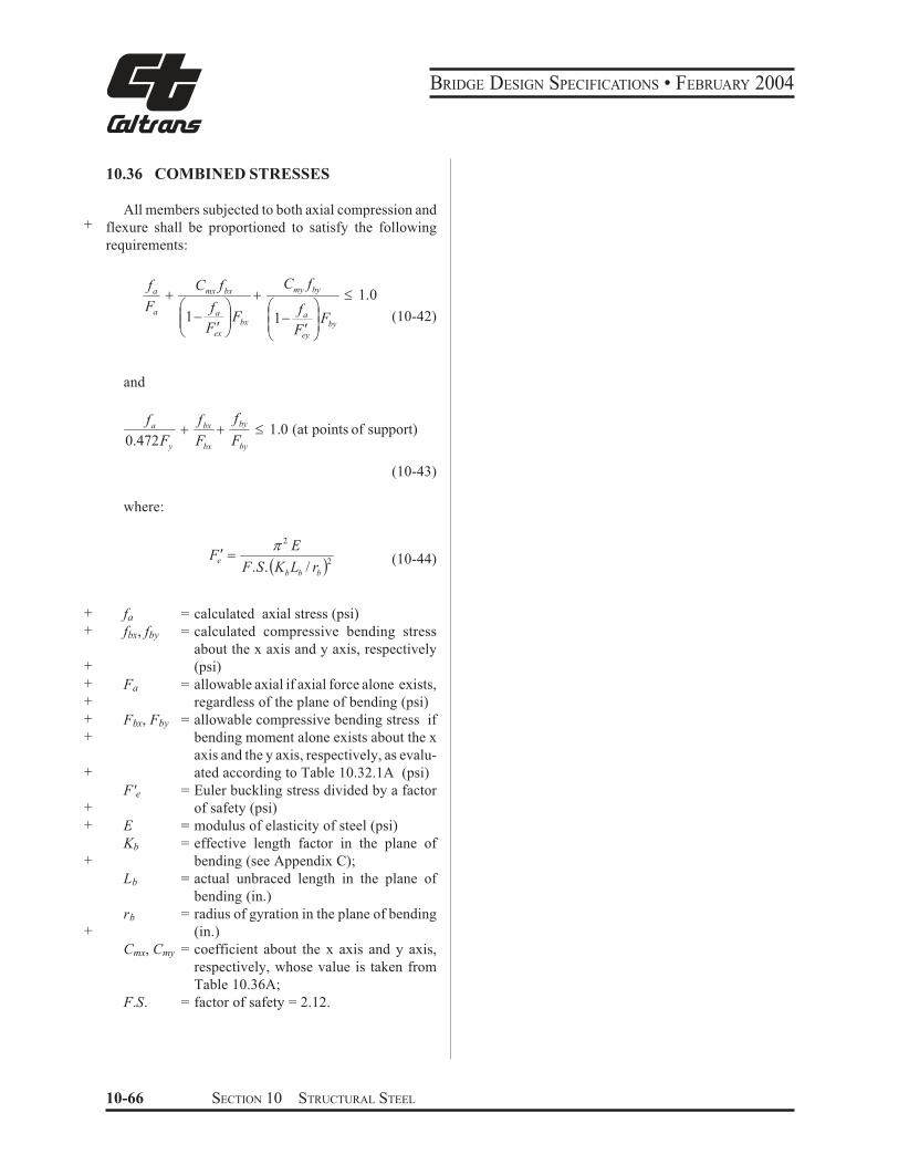
BRIDGE DESIGN SPECIFICATIONS • FEBRUARY 2004
10.36 COMBINED STRESSES
All members subjected to both axial compression and + flexure shall be proportioned to satisfy the following
requirements:
fa &Fa
and
fa
0.472 yF
where:
+ fa
+ fbx, fby
+
+ Fa
+
+ Fbx, Fby
+
+
F'e+
+ E
Kb
+
Lb
rb
+
Cmx, Cmy
F.S.
Cmx fbxCmy fby& " 1.0
( * ( f *fa a++1) ,,Fbx +1) ,Fby
(10-42)F ! + ,!. ex / . Fey /
f fbx by& & " 1.0 (at points of support)
F Fbx by
(10-43)
A 2 EFe! $
'2 (10-44)F.S.%K L / rb b b
= calculated axial stress (psi)
= calculated compressive bending stress
about the x axis and y axis, respectively
(psi)
= allowable axial if axial force alone exists,
regardless of the plane of bending (psi)
= allowable compressive bending stress if
bending moment alone exists about the x
axis and the y axis, respectively, as evalu-
ated according to Table 10.32.1A (psi)
= Euler buckling stress divided by a factor
of safety (psi)
= modulus of elasticity of steel (psi)
= effective length factor in the plane of
bending (see Appendix C);
= actual unbraced length in the plane of
bending (in.)
= radius of gyration in the plane of bending
(in.)
= coefficient about the x axis and y axis,
respectively, whose value is taken from
Table 10.36A;
= factor of safety = 2.12.
10-66 SECTION 10 STRUCTURAL STEEL
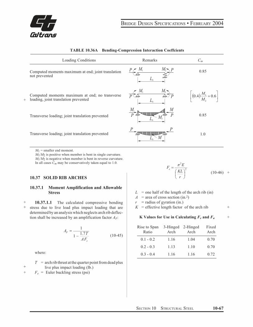
BRIDGE DESIGN SPECIFICATIONS • FEBRUARY 2004
+
+
+
+
+
TABLE 10.36A Bending-Compression Interaction Coeffcients
Loading Conditions Remarks Cm
Computed moments maximum at end; joint translation 0.85P M1 M2 P
not prevented Lb
Computed moments maximum at end; no transverseloading, joint translation prevented
% ' :<
89;
7& 0.60.4
2
1
M
M
Lb
P
M1 M2
P
Transverse loading; joint translation prevented 0.85Lb
M1
P
M
PM3
P P
Transverse loading; joint translation prevented 1.0Lb
M
M1 = smaller end moment.
M1/M2 is positive when member is bent in single curvature.
M1/M2 is negative when member is bent in reverse curvature.
In all cases Cm may be conservatively taken equal to 1.0.
10.37 SOLID RIB ARCHES
2
2
,/*
+.(
$
r
KL
EFe
A
(10-46)
10.37.1 Moment Amplification and Allowable Stress
10.37.1.1 The calculated compressive bending
stress due to live load plus impact loading that are
determined by an analysis which neglects arch rib deflec-
tion shall be increased by an amplification factor AF:
e
F
AF
TA
1.71
1
)$
(10-45)
L = one half of the length of the arch rib (in)
A = area of cross section (in.2)
r = radius of gyration (in.)
K = effective length factor of the arch rib
K Values for Use in Calculating Fe and Fa
Rise to Span 3-Hinged 2-Hinged Fixed
Ratio Arch Arch Arch
0.1 - 0.2 1.16 1.04 0.70
where:
T = arch rib thrust at the quarter point from dead plus
live plus impact loading (lb.)
Fe = Euler buckling stress (psi)
0.2 - 0.3 1.13 1.10 0.70
0.3 - 0.4 1.16 1.16 0.72
+
+
+
SECTION 10 STRUCTURAL STEEL 10-67
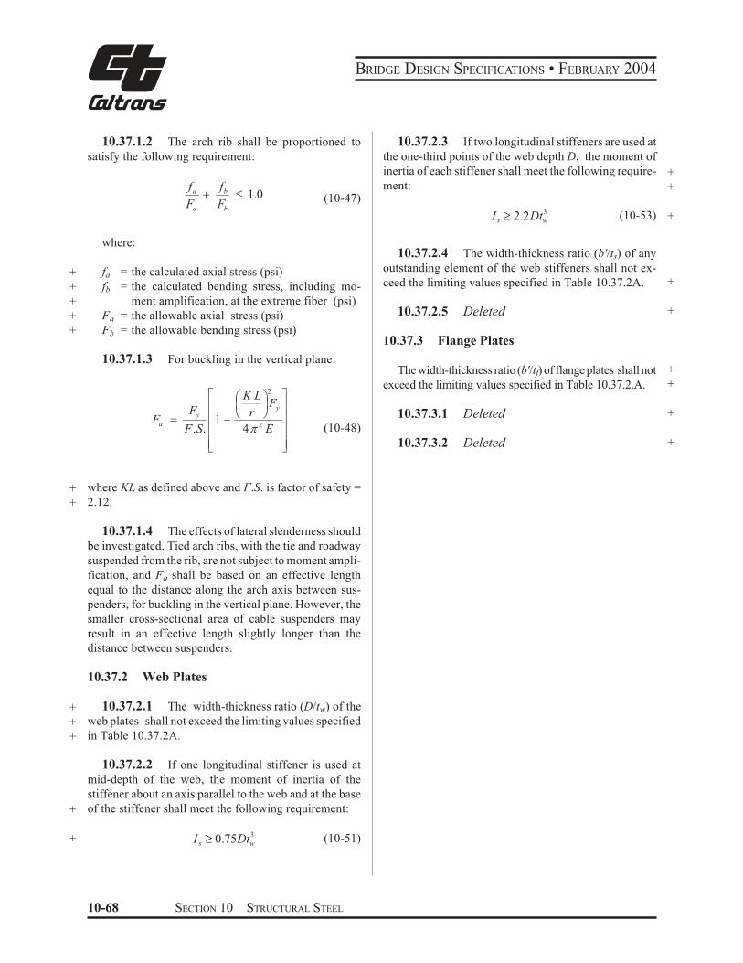
BRIDGE DESIGN SPECIFICATIONS • FEBRUARY 2004
10.37.1.2 The arch rib shall be proportioned to 10.37.2.3 If two longitudinal stiffeners are used at
satisfy the following requirement: the one-third points of the web depth D, the moment of
inertia of each stiffener shall meet the following require- +
fa
Fa
& ment: +fb " 1.0 (10-47)
Fb
I s - 2.2Dtw
3 (10-53) +
where:
+ fa = the calculated axial stress (psi)
+ fb = the calculated bending stress, including mo-
+ ment amplification, at the extreme fiber (psi)
+ Fa = the allowable axial stress (psi)
+ Fb = the allowable bending stress (psi)
10.37.1.3 For buckling in the vertical plane:
10.37.2.4 The width-thickness ratio (b'/ts) of any
outstanding element of the web stiffeners shall not ex-
ceed the limiting values specified in Table 10.37.2A. +
10.37.2.5 Deleted +
10.37.3 Flange Plates
The width-thickness ratio (b'/tf) of flange plates shall not +
+exceed the limiting values specified in Table 10.37.2.A.2
Fy
7 K L
2A
8 (+.
*,/ 9
999;
::::<
Fa $ Fy
F.S.
10.37.3.1 Deleted +
10.37.3.2 Deleted +
r1 )
4 E (10-48)
+ where KL as defined above and F.S. is factor of safety =
+ 2.12.
10.37.1.4 The effects of lateral slenderness should
be investigated. Tied arch ribs, with the tie and roadway
suspended from the rib, are not subject to moment ampli-
fication, and Fa shall be based on an effective length
equal to the distance along the arch axis between sus-
penders, for buckling in the vertical plane. However, the
smaller cross-sectional area of cable suspenders may
result in an effective length slightly longer than the
distance between suspenders.
10.37.2 Web Plates
+ 10.37.2.1 The width-thickness ratio (D/tw) of the
+ web plates shall not exceed the limiting values specified
+ in Table 10.37.2A.
10.37.2.2 If one longitudinal stiffener is used at
mid-depth of the web, the moment of inertia of the
stiffener about an axis parallel to the web and at the base
+ of the stiffener shall meet the following requirement:
+ I s - 0.75Dtw
3 (10-51)
10-68 SECTION 10 STRUCTURAL STEEL
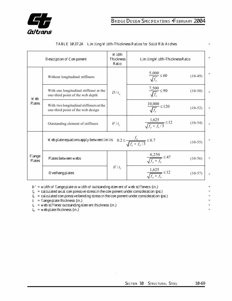
BRIDGE DESIGN SPECIFICATIONS • FEBRUARY 2004
TABLE 10.37.2A Limiting Width-Thickness Ratios for Solid Rib Arches +
WebPlates
Flange Plates
b' =fa =fb =tf =ts =tw =
Description of Component
Without longitudinal stiffiners
With one longitudinal stiffener at the
one-third point of the web depth
With two longitudinal stiffeners at the
one-third point of the web design
Outstanding element of stiffiners
Web plate equations apply between limits
Plates between webs
Overhang plates
Width+Thickness Limiting Width-Thickness Ratio Ratio
5,000 +≤ 60 (10-49)f
a
7,500≤ 90 (10-50) +D t/
w fa
10,000≤ 120 (10-52) +
fa
1,625≤ 12 (10-54)b t/′ +s f
a+ f
b/ 3
fb0.2 ≤ ≤ 0.7 +
(10-55)fa
+ fb
/ 3
4,250≤ 47 (10-56) +
fa
+ fb
′b t/ f 1,625(10-57)
fa
+ fb
≤ 12+
width of flange plate or width of outstanding element of web stiffeners (in.) +calculated axial compressive stress in the component under consideration (psi) +calculated compressive bending stress in the component under consideration (psi) +flange plate thickness (in.) +web stiffener outstanding element thickness (in.) +web plate thickness (in.) +
SECTION 10 STRUCTURAL STEEL 10-69
BRIDGE DESIGN SPECIFICATIONS • FEBRUARY 2004
+ 10.38 COMPOSITE BEAMS AND GIRDERS +
10.38.1 General
+
10.38.1.1 This section pertains to structures com-
posed of steel beams or girders with concrete slabs
connected by shear connectors.
10.38.1.2 General specifications pertaining to the
design of concrete and steel structures shall apply to struc-
tures utilizing composite girders where such specifications
are applicable. Composite girders and slabs shall be de-
signed and the stresses computed by the composite moment
of inertia method and shall be consistent with the predeter-
mined properties of the various materials used.
+ 10.38.1.3 The ratio of the modulus of elasticity of
steel (29,000,000 psi) to those of normal weight concrete
(W = 145 pcf) of various design strengths shall be as
follows:
+
+
+
f 'c
n
f 'c
= specified compressive strength of concrete as
determined by cylinder tests at the age of 28
days (psi)
= ratio of modulus of elasticity of steel to that of
concrete. The value of n, as a function of the
specified compressive strength of concrete, shall
be assumed as follows:
= 2,000 - 2,300 n = 11
2,400 - 2,800 n = 10
2,900 - 3,500 n = 9
3,600 - 4,500 n = 8
4,600 - 5,900 n = 7
6,000 or more n = 6
+
+
+
10.38.1.4 The effect of creep shall be considered
in the design of composite girders which have dead loads
acting on the composite section. In such structures, bend-
ing stresses and horizontal shears produced by dead loads
acting on the composite section shall be computed for n
as given above or for this value multiplied by 3, which-
ever gives the higher bending stresses and shears.
10.38.1.5 If concrete with expansive characteris-
tics is used, composite design should be used with cau-
tion and provision must be made in the design to accom-
modate the expansion.
10.38.1.6 Composite sections in simple spans and
the positive moment regions of continuous spans should
preferably be proportioned so that the neutral axis lies
below the top surface of the steel beam. Concrete on the
tension side of the neutral axis shall not be considered in
calculating resisting moments. In the negative moment
regions of continuous spans, only the slab reinforcement
can be considered to act compositely with the steel beams
in calculating resisting moments. Mechanical anchor-
ages shall be provided in the composite regions to de-
velop stresses on the plane joining the concrete and the
steel. Concrete on the tension side of the neutral axis may
be considered in computing moments of inertia for de-
flection calculations, for determining stiffness used in +
calculating moments and shears, and for computing fa-
tigue stress ranges and fatigue shear ranges as permitted
under the provisions of Article10.3.1and 10.38.5.1.
10.38.1.7 The steel beams or girders, especially if
not supported by intermediate falsework, shall be inves-
tigated for stability and strength for the loading applied
during the time the concrete is in place and before it has
hardened. The casting or placing sequence specified in
the plans for the composite concrete deck shall be consid-
ered when calculating the moments and shears on the
steel section. The maximum flange compression stress
shall not exceed the value specified in Table 10.32.1A for
partially supported or unsupported compression flanges
multiplied by a factor of 1.4, but not exceed 0.55Fy. The
sum of the non-composite and composite dead-load shear
stresses in the web shall not exceed the shear-buckling
capacity of the web multiplied by a factor of 1.35, nor the
allowable shear stress, as follows:
Fv $ 0.45CFy " 0.33Fy (10-57a)
where:
+C = constant specified in Article 10.34.4.2.
10.38.2 Shear Connectors
10.38.2.1 The mechanical means used at the junc-
tion of the girder and slab for the purpose of developing
the shear resistance necessary to produce composite
action shall conform to the specifications of the respec-
tive materials. The shear connectors shall be of types that +
permit a thorough compaction of the concrete in order to
ensure that their entire surfaces are in contact with the
concrete. They shall be capable of resisting both horizon-
tal and vertical movement between the concrete and the
steel.
10-70 SECTION 10 STRUCTURAL STEEL
BRIDGE DESIGN SPECIFICATIONS • FEBRUARY 2004
10.38.2.2 The capacity of stud and channel shear
connectors welded to the girders is given in Article
10.38.5. Channel shear connectors shall have at least
3/16-inch fillet welds placed along the heel and toe of the
channel.
10.38.2.3 The clear depth of concrete cover over
the tops of the shear connectors shall be not less than 2
inches. Shear connectors shall penetrate at least 2 inches
above bottom of slab.
10.38.2.4 The clear distance between the edge of a
girder flange and the edge of the shear connectors shall be
not less than 1 inch. Adjacent stud shear connectors shall
not be closer than 4 diameters center to center.
10.38.3 Effective Flange Width
10.38.3.1 In composite girder construction the as-
sumed effective width of the slab as a T-beam flange shall
not exceed the following:
(1) One-fourth of the span length of the girder.
(2) The distance center to center of girders.
(3) Twelve times the least thickness of the slab.
10.38.3.2 For girders having a flange on one side
only, the effective flange width shall not exceed one-
twelfth of the span length of the girder, or six times the
thickness of the slab, or one-half the distance center to
center of the next girder.
10.38.4 Stresses
10.38.4.1 Maximum compressive and tensile stresses
in girders that are not provided with temporary supports
during the placing of the permanent dead load shall be the
sum of the stresses produced by the dead loads acting on the
steel girders alone and the stresses produced by the superim-
posed loads acting on the composite girder. When girders
are provided with effective intermediate supports that are
kept in place until the concrete has attained 75 percent of its
required 28-day strength, the dead and live load stresses
shall be computed on the basis of the composite section.
10.38.4.2 A continuous composite bridge may be
built with shear connectors either in the positive moment
regions or throughout the length of the bridge. The
positive moment regions may be designed with compos-
ite sections as in simple spans. Shear connectors shall be
provided in the negative moment portion in which the
reinforcement steel embedded in the concrete is consid-
ered a part of the composite section. In case the reinforce-
ment steel embedded in the concrete is not used in
computing section properties for negative moments, shear
connectors need not be provided in these portions of the
spans, but additional anchorage connectors shall be placed
in the region of the point of dead load contra-flexure in
accordance with Article 10.38.5.1.3. Shear connectors
shall be provided in accordance with Article 10.38.5.
10.38.4.3 The minimum longitudinal reinforce-
ment including the longitudinal distribution reinforce-
ment must equal or exceed one percent of the cross-
sectional area of the concrete slab whenever the longitu-
dinal tensile stress in the concrete slab due to either the
construction loads or the design loads exceeds f specifiedt
in Article 8.15.2.1.1. The area of the concrete slab shall
be equal to the structural thickness times the entire width
of the bridge deck. The required reinforcement shall be
No. 6 bars or smaller spaced at not more than 12 inches.
Two-thirds of this required reinforcement is to be placed
in the top layer of slab. Placement of distribution steel as
specified in Article 3.24.10 is waived.
10.38.4.4 When shear connectors are omitted from
the negative moment region, the longitudinal reinforce-
ment shall be extended into the positive moment region
beyond the anchorage connectors at least 40 times the
reinforcement diameter. For epoxy-coated bars, the length
to be extended into the positive moment region beyond
the anchorage connectors should be modified to comply
with Article 8.25.2.3.
10.38.5 Shear
10.38.5.1 Horizontal Shear
The maximum pitch of shear connectors shall not
exceed 24 inches except over the interior supports of
continuous beams where wider spacing may be used to
avoid placing connectors at locations of high stresses in
the tension flange.
Resistance to horizontal shear shall be provided by me-
chanical shear connectors at the junction of the concrete
slab and the steel girder. The shear connectors shall be
mechanical devices placed transversely across the flange
SECTION 10 STRUCTURAL STEEL 10-71
BRIDGE DESIGN SPECIFICATIONS • FEBRUARY 2004
of the girder spaced at regular or variable intervals. The
shear connectors shall be designed for fatigue* and
+ checked for design strength.
10.38.5.1.1 Fatigue
The range of horizontal shear shall be computed by
the formula:
VrQSr $ (10-58)I
where:
+ Sr = range of horizontal shear (lb/in.), at the junction
of the slab and girder at the point in the span
under consideration
+ Vr = range of shear due to live loads and impact (lb.);
at any section, the range of shear shall be taken
as the difference in the minimum and maximum
shear envelopes (excluding dead loads)
Q = statical moment about the neutral axis of the
composite section of the transformed concrete
+ area (in3). Between points of dead-load
contraflexure, the static moment about the neu-
tral axis of the composite section of the area of
reinforcement embedded in the concrete may be
used unless the transformed concrete area is
considered to be fully effective for the negative
moment in computing the longitudinal ranges of
stress.
+ I = moment of inertia of the transformed short-term
+ composite section (in4). Between points of dead-
load contraflexure, the moment of inertia of the
steel girder including the area of reinforcement
embedded in the concrete may be used unless
the transformed concrete area is considered to
be fully effective for the negative moment in
+ computing the longitudinal ranges of stress.
+ (In the formula, the concrete area is transformed into
an equivalent area of steel by dividing the effective
concrete flange width by the modular ratio, n.)
* Reference is made to the paper titled “Fatigue Strength of
Shear Connectors,” by Roger G. Slutter and John W. Fisher, in
Highway Research Record, No. 147, published by the Highway
Research Board, Washington, D.C., 1966.
The allowable range of horizontal shear, Zr (lb.) on an +individual connector is as follows:
Channels:
Zr = Bw (10-59)
Welded studs (for H/d - 4):
Zr = α d2 (10-60)
where:
w = length of a channel shear connector (in.), mea- +sured in a transverse direction on the flange of a
girder
d = diameter of stud (in.) +α = 13,000 for 100,000 cycles +
10,600 for 500,000 cycles
7,850 for 2,000,000 cycles
5,500 for over 2,000,000 cycles;
B = 4,000 for 100,000 cycles
3,000 for 500,000 cycles
2,400 for 2,000,000 cycles
2,100 for over 2,000,000 cycles;
H = height of stud (in.). +
The required pitch of shear connectors is determined
by dividing the allowable range of horizontal shear of all
connectors at one transverse girder cross-section (ΣZr)
by the horizontal range of shear Sr, but not to exceed the
maximum pitch specified in Article 10.38.5.1. Over the
interior supports of continuous beams the pitch may be
modified to avoid placing the connectors at locations of
high stresses in the tension flange provided that the total
number of connectors remains unchanged.
10.38.5.1.2 Design Strength +
The number of connectors so provided for fatigue
shall be checked to ensure that adequate connectors are
provided for design strength. +
10-72 SECTION 10 STRUCTURAL STEEL
BRIDGE DESIGN SPECIFICATIONS • FEBRUARY 2004
+ The number of shear connectors required shall meet + the following requirement: P
N1 ≥ (10-61)φ Su
where:N1 = number of connectors between points of maxi-mum positive moment and adjacent end supports + Su = design strength of the shear connector as given + below (lb.) φ = reduction factor = 0.85;
+ P = horizontal shear force transferred by shear con-+ nectors as defined hereafter as P1 or P2.
At points of maximum positive moment, the force in the slab is taken as the smaller value of the formulas: P1 = AsFy (10-62)
orP = 0.85 f ′bt (10-63)
2 c s
where:As = total area of the steel section including cover -+ plates (in.2)+ Fy = specified minimum yield strength of the steel + being used (psi) + f
c′ = specified compressive strength of concrete at + age of 28 days (psi) + b = effective flange width given in Article 10.38.3 (in.) + ts = thickness of the concrete slab (in.)
The number of connectors, N2, required between the points of maximum positive moment and points of adja-+ cent maximum negative moment shall meet the follow-+ ing requirement: P + P
N ≥ 32 (10-64)φ Su
At points of maximum negative moment the force in the slab is taken as: r r∗P
3= A
sF
y (10-65)where:A
s
r = total area of longitudinal reinforcing steel at the interior support within the effective flange width (in.2) +
F r∗ y = specified minimum yield strength of the rein- +forcing steel (psi) +
The design strength of the shear connector is given +as follows: Channels:Su = 550h +
tW f c
′ (10-66) 2
Welded studs (for H/d > 4): S = 0.4d 2 f '
cE ≤ 60,000A (10-67)
u c sc
where:Ec = modulus of elasticity of the concrete (psi) +
Ec = w3/ 233 f c′ (10-68)
Su = design strength of individual shear connector +(lb.) +h = average flange thickness of the channel flange (in.) +t = thickness of the web of a channel (in.) +W = length of a channel shear connector (in.) +
fc′ = specified compressive strength of the concrete at 28 days (psi) +d = diameter of stud (in.) +w = unit weight of concrete (pcf) +Asc = area of welded stud cross section (in.2) +
SECTION 10 STRUCTURAL STEEL 10-73
BRIDGE DESIGN SPECIFICATIONS • FEBRUARY 2004
10.38.5.1.3 Additional Connectors to Develop Slab Stresses The number of additional connectors required at points of contraflexure when reinforcing steel embedded in the concrete is not used in computing section proper-ties for negative moments shall be computed by the formula:
cN = r
r
s
r
Z
A f (10-69)
where:Nc = number of additional connectors for each beam at point of contraflexure
+ srA = total area of longitudinal slab reinforcing steel for each beam over interior support (in.2)
+ fr = range of stress due to live load plus impact in the slab reinforcement over the support (psi) (in lieu of more accurate computations, fr maybe taken as equal to 10,000 psi); + Zr = allowable range of horizontal shear on an individual shear connector (lb.) The additional connectors,Nc, shall be placed adjacent to the point of dead load contraflexure within a distance equal to one-third the effective slab width, i.e., placed either side of this point or centered about it. It is prefer-able to locate field splices so that they clear the connec-tors.
+ 10.38.5.2 Vertical Shear The intensity of shearing stress in a composite girder may be determined on the basis that the web of the steel girder carries the total external shear, neglecting the effects of the steel flanges and of the concrete slab. The shear may be assumed to be uniformly distributed throughout the gross area of the web.
10.38.6 Deflection10.38.6.1 The provisions of Article 10.6 in regard to deflections from live load plus impact also shall be applicable to composite girders. 10.38.6.2 When the girders are not provided with falsework or other effective intermediate support during
the placing of the concrete slab, the deflection due to the weight of the slab and other permanent dead loads added before the concrete has attained 75 percent of its required 28-day strength shall be computed on the basis of noncomposite action. 10.39 COMPOSITE BOX GIRDERS 10.39.1 General
10.39.1.1 This section pertains to the design of simple and continuous bridges of moderate length sup-ported by two or more single cell composite box girders. The distance center-to-center of flanges of each box should be the same and the average distance center-to-center of flanges of adjacent boxes shall be not greater than 1.2 times and not less than 0.8 times the distance center-to-center of flanges of each box. In addition to the above, when nonparallel girders are used, the distance center-to-center of adjacent flanges at supports shall be no greater than 1.35 times and not less than 0.65 times the distance center-to-center of flanges of each box. The cantilever overhang of the deck slab, including curbs and parapets, shall be limited to 60 percent of the average distance center-to-center of flanges of adjacent boxes, but shall in no case exceed 6 feet. +
10.39.1.2 The provisions of these Specifications shall govern where applicable, except as specifically modified by Articles 10.39.1 through 10.39.8. 10.39.2 Lateral Distribution of Loads for Bending Moment
10.39.2.1 The live load bending moment for each box girder shall be determined by applying to the girder, the fraction WL of a wheel load (both front and rear), determined by the following equation: 0.85
WL = 0.1 + 1.7 R + (10-70)Nw
where:N
wR = (10-71)Numberof Box Girders
10-74 SECTION 10 STRUCTURAL STEEL

BRIDGE DESIGN SPECIFICATIONS • FEBRUARY 2004
Nw = Wc/12 reduced to the nearest whole number
+ Wc = roadway width between curbs (ft.), or barriers
if curbs are not used.
+ R shall not be less than 0.5 or greater than 1.5.
10.39.2.2 The provision of Article 3.12, Reduc-
tion of Load Intensity, shall not apply in the design of box
girders when using the design load WL given by the above
equation.
+ 10.39.3 Web Plates
10.39.3.1 Vertical Shear
The design shear Vw for a web shall be calculated using
the following equation:
VvVw $
10.39.4 Bottom Flange Plates +
10.39.4.1 General +
The tension flange and the compression flange shall +
be considered completely effective in resisting bending if +
its width does not exceed one-fifth the span length. If the +
flange plate width exceeds one-fifth of the span, an +
amount equal to one-fifth of the span only shall be +
considered effective. Effective flange plate width shall +
be used to calculate the flange bending stress. Full flange +
plate width shall be used to calculate the allowable +
compressive bending stress.
10.39.4.1.2 Deleted +
10.39.4.2 Compression Flanges Unstiffened
10.39.4.2.1 For unstiffened compression flanges, +(10-72) the calculated bending stress shall not exceed the allow- +cosB
able bending stress, Fb (psi), determined by either of the +
following equations: +where:
b
t F
6,140 + " + Vv = vertical shear (lb.) for
θ = angle of inclination of the web plate to the
vertical.
y
Fb $ 0.55 Fy (10-73) +10.39.3.2 Secondary Bending Stresses
+
yy Ft
b
F
6,140 13,300 " 0 10.39.3.2.1 Web plates may be plumb (90° to bot- for
tom of flange) or inclined. If the inclination of the web
plates to a plane normal to bottom flange is no greater
than 1 to 4, and the width of the bottom flange is no
greater than 20 percent of the span, the transverse bend- 7 8 b Fy
t
(++++
*,,,,
::::<
)13,300
2 7,160
ing stresses resulting from distortion of the span, and the
transverse bending stresses resulting from distortion of A
Fb 0.55 Fy 0.224 Fy) ) sin$ +
the girder cross section and from vibrations of the bottom
plate need not be considered. For structures in this cat-
egory transverse bending stresses due to supplementary
/.
9999;
1
(10-74) loadings, such as utilities, shall not exceed 5,000 psi.
b 13,300 +-
t Ffor10.39.3.2.2 For structures exceeding these limits, a y
detailed evaluation of the transverse bending stresses due
to all causes shall be made. These stresses shall be limited 2
to a maximum stress or range of stress of 20,000 psi. (+.
*,/
t4 106
(10-75) + Fb $ 57.6 b
SECTION 10 STRUCTURAL STEEL 10-75
BRIDGE DESIGN SPECIFICATIONS • FEBRUARY 2004
where:+
+ b = flange width between webs (in.)
+ t = flange thickness (in.)
10.39.4.2.2 Deleted+
10.39.4.2.3 Deleted+
10.39.4.2.4 The b/t ratio preferably should not ex-
ceed 60 except in areas of low stress near points of dead
load contraflexure.
+ 10.39.4.2.5 If the b/t ratio exceeds 45, longitudinal
+ stiffeners may be considered.
+ 10.39.4.2.6 Deleted
10.39.4.3 Compression Flanges Stiffened Longitudinally*
10.39.4.3.1 Longitudinal stiffeners shall be at equal
spacings across the flange width and shall be propor-
tioned so that the moment of inertia of each stiffener
about an axis parallel to the flange and at the base of the
+ stiffener, Is (in.4) shall meet the following requirement:
+ I s - 1 t3
f w (10-76)
where:
φ = 0.07 k3n4 for values of n greater than 1;
+ φ = 0.125 k3 for a value of n = 1;
tf = thickness of the flange (in.)
w = width of flange between longitudinal stiffeners
+ or distance from a web to the nearest longitudi-
nal stiffener (in.)
n = number of longitudinal stiffeners;
k = buckling coefficient which shall not exceed 4.
+ 10.39.4.3.2 For the longitudinally stiffened flange,
+ including stiffeners, the calculated bending stress shall
+ not exceed the allowable bending stress, Fb (psi), deter-
+ mined by either of the following equations:
w 3,070 k"+ for t Fy
* In solving these equations a value of k between 2 and 4
generally should be assumed.
F $ 0.55 Fb y
3,070 k wfor
Fy
0 " smaller of C D60 or t
7 (
. w /
Fb $ 0.55Fy
99
)0.224 Fy91)sin +9
; .++
+ 6,650 k )
2 3,580
Ak
t
y
::::
/<,,,,
+
(10-78)
for6,650
Fy
k"
t
w" 60
+
Fb
( t *2
6$ 14.4 k + , 410 (10-79) +
+10.39.4.3.3 Deleted
+10.39.4.3.4 Deleted
10.39.4.3.5 When longitudinal stiffeners are used,
it is preferable to have at least one transverse stiffener
placed near the point of dead load contraflexure. The
stiffener should have a size equal to that of a longitudinal
stiffener.
10.39.4.3.6 If the longitudinal stiffeners are placed
at their maximum w/t ratio to be designed for the basic
allowable design stresses of 0.55Fy and the number of
longitudinal stiffeners exceeds 2, then transverse stiffen-
ers should be considered.
10.39.4.3.7 Deleted +
(10-77) +
> EF 6,650 k F? G +F F y FH@
w F *8
10-76 SECTION 10 STRUCTURAL STEEL

BRIDGE DESIGN SPECIFICATIONS • FEBRUARY 2004
100
90
80
70
60
50
Isbt3
40
30
20
10
0
k = 4 k = 4 k = 4
n=
4
Fcr = Fy ,
Fcr = 0.96 Fy ,
NO ST
bt
fb = 0.55 Fy ,
bfb = 0.53 Fy ,
IFFENERS REQUIRED
Fy = 6,140
Fy = 08,200
n=
4
=4
Fcr = 0.85 Fy ,
t
bt
fb = 0.47 Fy , Fy = 10,060
n
Note:
Fcr refe
fb refers
Fy is in
rs to Load Factor
to Working Stres
lb/in2
Design
s Design
n=
3
k = 2.56
n=
3
k = 2.56 k
n=
3
= 2.56
f b =
0.5
5 F
y
Fcr
= F
y
f b =
0.5
3 F
ycr
= 0
.96 F
y
Fy
y
WITHOUT TRANSVERSE STIFFENERS
F
f b =
0.4
7
Fcr
= 0
.85 F
k = 4 k = 4 k = 4
k = 2.25
n=
2 k = 2.25
n=
2
n=
k = 2.2 25 WIT
S
H TRANSVERSE
TIFFENERS
k
n = 1
k = 4= 1.78
n
k = 4
= 1n = 1
k = 1.78
k = 4
k = 1.78
n =
n =
n =
n =
2, Is = 2.67bt3
3, Is = 2.00bt3
4, Is = 1.60bt3
5, Is = 1.33bt3
5,000 10,000 15,000 20,000 25,000 30,000 35,000 40,000
bFyt
FIGURE 10.39.4.3A Longitudinal StiffenersñBox Girder Compression Flange
SECTION 10 STRUCTURAL STEEL 10-77
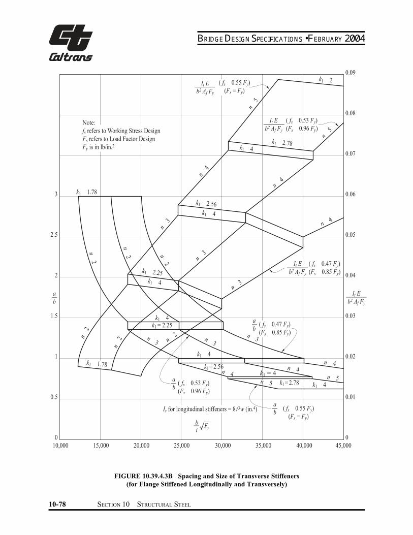
BRIDGE DESIGN SPECIFICATIONS • FEBRUARY 2004
3
2.5
2
a
b
1.5
1
0.5
0
( fs 0.47 Fy)
(Fs 0.85 Fy)
bt
Fy
Is for longitudinal stiffeners = 8 t3w (in.4)
k1 4k1 = 2.25
k1 2.25
k1 4
k1 2.56
k1 4
k1 1.78
k1 1.78
k1 2.78k1 4
n 2
n5
n5
n4
n4
n4
n3
n3
n3
n2
n 2n
2
n3
n3
n 4
n 3
n 4n 4
n 5n 5 k1 4k1= 2.78
k1= 2.56
k1 4
k1 2
n 2 n
2
Note:
fs refers to Working Stress Design
Fs refers to Load Factor Design
Fy is in lb/in.2
a
b( fs 0.47 Fy)
(Fs 0.85 Fy)
a
b( fs 0.55 Fy)
(Fs = Fy)
a
b( fs 0.53 Fy)
(Fs 0.96 Fy)
It E
b2 Af Fy
It E
b2 Af Fy
( fs 0.53 Fy)
(Fs 0.96 Fy)
It E
b2 Af Fy
( fs 0.55 Fy)
(Fs = Fy)
k1 = 4
0.09
0.08
0.07
0.06
0.05
0.04
It E
b2 Af Fy
0.03
0.02
0.01
10,000 15,000 20,000 25,000 30,000 35,000 40,000 45,000
FIGURE 10.39.4.3B Spacing and Size of Transverse Stiffeners
(for Flange Stiffened Longitudinally and Transversely)
10-78 SECTION 10 STRUCTURAL STEEL
0
BRIDGE DESIGN SPECIFICATIONS • FEBRUARY 2004
10.39.4.4 Compression Flanges Stiffened Longitudinally and Transversely
10.39.4.4.1 The longitudinal stiffeners shall be at
equal spacings across the flange width and shall be
proportioned so that the moment of inertia of each stiff-
eners about an axis parallel to the flange and at the base
+ of the stiffeners meet the following requirement:
I s - 8t3
f w (10-80)
10.39.4.4.2 The transverse stiffeners shall be pro-
portioned so that the moment of inertia of each stiffener
about an axis through the centroid of the section and parallel
+ to its bottom edge meets the following requirement:
3 3 fs
Af+ It - 0.10 %n & 1' w (10-81)
E do
where:
Af = area of bottom flange including longitudinal + stiffeners (in.2)+ do = spacing of transverse stiffeners (in.)
fs = maximum longitudinal bending stress in the
flange of the panels on either side of the trans-+ verse stiffeners (psi) + E = modulus of elasticity of steel (psi)
+ 10.39.4.4.3 For the flange, including stiffeners, the + calculated bending stress shall not exceed the allowable + bending stress, Fb (psi), determined by either of the + following equations:
w 3,070 k1+ "for t Fy
+ Fb $ 0.55 Fy (10-82)
3,070 k1 w F> 6,650 k1EF" C Dor ?+ 0 smaller of 60for
Fyt F@ F y FH
G
7 ( w F *89 + 6,650 k1 )
y ,:+ A t ,:F $ 0.55F )0.224 F 91)sinb y y + , +9 2 3,580 k1
:+ ,9 :
; . /<
(10-83)
6,650 k1 w" " 60 +for Fy
t
( t *2
6Fb $ 14.4 k1 + , 410 (10-84) +. w /
where:
% '2% ' % '/1
/1 22
2
1 &
&$
a bn
a bk
3% '2 1 30.11
87.32
&&
&
n(10-85) +
10.39.4.4.4 Deleted +
10.39.4.4.5 Deleted +
10.39.4.4.6 The maximum value of the buckling
coefficient, k1, shall be 4. When k1 has its maximum
value, the transverse stiffeners shall have a spacing, a,
equal to or less than 4w. If the ratio a/b exceeds 3,
transverse stiffeners are not necessary.
10.39.4.4.7 The transverse stiffeners need not be
connected to the flange plate but shall be connected to the
webs of the box and to each longitudinal stiffener. The
connection to the web shall be designed to resist the
vertical force determined by the formula:
R $FySs
w (10-86)2b
where:
Ss = section modulus of the transverse stiffener (in.3) +
SECTION 10 STRUCTURAL STEEL 10-79
BRIDGE DESIGN SPECIFICATIONS • FEBRUARY 2004
10.39.4.4.8 The connection to each longitudinal
stiffener shall be designed to resist the vertical force
determined by the formula:
F S$Rs
n
y
b
s
(10-87)
10.39.4.5 Compression Flange Stiffeners, General
+ 10.39.4.5.1 The width-thickness ratio (b'/ts) of any
outstanding element of the flange stiffeners shall not
+ exceed the limiting values specified in Table 10.34.5A.
10.39.4.5.2 Longitudinal stiffeners shall be ex-
tended to locations where the maximum stress in the
flange does not exceed that allowed for base metal
adjacent to or connected by fillet welds.
+ 10.39.5 Flange to Web Welds
The total effective thickness of the web-flange welds
+ shall be not less than the thickness of the web. Regardless
of the type weld used, welds shall be deposited on both
sides of the connecting flange or web plate.
10.39.6 Diaphragms
10.39.6.1 Diaphragms, cross-frames, or other
means shall be provided within the box girders at each
support to resist transverse rotation, displacement, and
distortion.
10.39.6.2 Intermediate diaphragms or cross-frames
are not required for steel box girder bridges designed in
accordance with this specification.
10.39.7 Lateral Bracing
Generally, no lateral bracing system is required be-
tween box girders. A horizontal wind load of 50 pounds
per square foot shall be applied to the area of the super-
structure exposed in elevation. Half of the resulting force
shall be applied in the plane of the bottom flange. The
section assumed to resist the horizontal load shall consist
of the bottom flange acting as a web and 12 times the
thickness of the webs acting as flanges. A lateral bracing
system shall be provided if the combined stresses due to
the specified horizontal force and dead load of steel and
deck exceed 150 percent of the allowable design stress.
10.39.8 Access and Drainage
Consistent with climate, location, and materials, consid-
eration shall be given to the providing of manholes, or other
openings, either in the deck slab or in the steel box for form
removal, inspection, maintenance, drainage, etc.
10.40 HYBRID GIRDERS
10.40.1 General
10.40.1.1 This section pertains to the design of
girders that utilize a lower strength steel in the web than in
one or both of the flanges. It applies to composite and
noncomposite plate girders, and composite box girders. At
any cross section where the bending stress in either flange
exceeds 55 percent of minimum specified yield strength of
the web steel, the compression-flange area shall not be less
than the tension-flange area. The top-flange area shall
include the transformed area of any portion of the slab or
reinforcing steel that is considered to act compositely with
the steel girder.
10.40.1.2 The provisions of these Specifications,
shall govern where applicable, except as specifically
modified by Articles 10.40.1 through 10.40.4. +
10.40.2 Allowable Stresses
10.40.2.1 Bending
10.40.2.1.1 The bending stress in the web may
exceed the allowable stress for the web steel provided
that the stress in each flange does not exceed the allow-
able stress from Articles 10.3 or 10.32 for the steel in that
flange multiplied by the reduction factor, R.
% ' % '% I 'JI
IKIKJI)&
&)))$
36
311
2
R (10-89)
(See Figures 10.40.2.1A and 10.40.2.1B)
where:
α = specified minimum yield strength of the web
divided by the specified minimum yield strength
of the tension flange;*
β = area of the web divided by the area of the tension
flange;*
* Bottom flange of orthotropic deck bridge
+
10-80 SECTION 10 STRUCTURAL STEEL
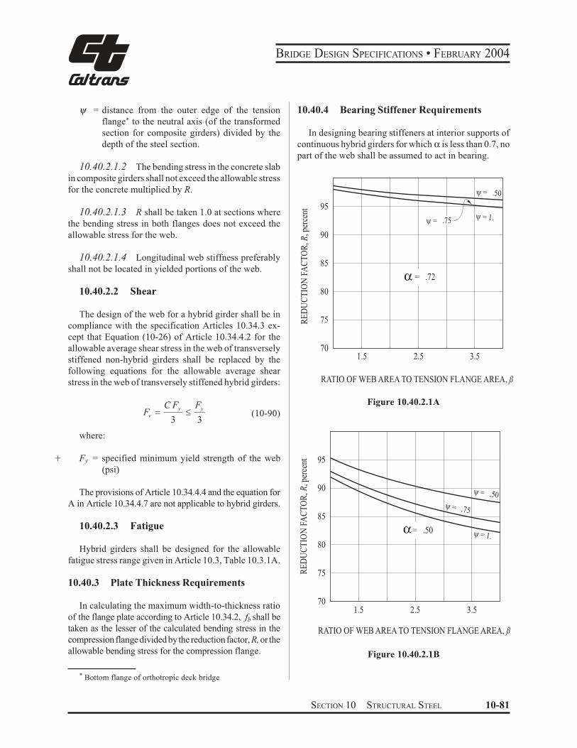
BRIDGE DESIGN SPECIFICATIONS • FEBRUARY 2004
ψ = distance from the outer edge of the tension
flange* to the neutral axis (of the transformed
section for composite girders) divided by the
depth of the steel section.
10.40.2.1.2 The bending stress in the concrete slab
in composite girders shall not exceed the allowable stress
for the concrete multiplied by R.
10.40.2.1.3 R shall be taken 1.0 at sections where
the bending stress in both flanges does not exceed the
allowable stress for the web.
10.40.2.1.4 Longitudinal web stiffness preferably
shall not be located in yielded portions of the web.
10.40.2.2 Shear
The design of the web for a hybrid girder shall be in
compliance with the specification Articles 10.34.3 ex-
cept that Equation (10-26) of Article 10.34.4.2 for the
allowable average shear stress in the web of transversely
stiffened non-hybrid girders shall be replaced by the
following equations for the allowable average shear
stress in the web of transversely stiffened hybrid girders:
C Fy FyFv $ " (10-90)
3 3
where:
+ Fy = specified minimum yield strength of the web
(psi)
The provisions of Article 10.34.4.4 and the equation for
A in Article 10.34.4.7 are not applicable to hybrid girders.
10.40.2.3 Fatigue
Hybrid girders shall be designed for the allowable
fatigue stress range given in Article 10.3, Table 10.3.1A.
10.40.3 Plate Thickness Requirements
In calculating the maximum width-to-thickness ratio
of the flange plate according to Article 10.34.2, fb shall be
taken as the lesser of the calculated bending stress in the
compression flange divided by the reduction factor, R, or the
allowable bending stress for the compression flange.
* Bottom flange of orthotropic deck bridge
10.40.4 Bearing Stiffener Requirements
In designing bearing stiffeners at interior supports of
continuous hybrid girders for which α is less than 0.7, no
part of the web shall be assumed to act in bearing.
95
90
85
80
75
70
y = .50
y = .75y = 1.
α = .72
1.5 2.5 3.5
RATIO OF WEB AREA TO TENSION FLANGE AREA, ß
Figure 10.40.2.1A
95
90
85
80
75
70 1.5 2.5
y = .75
y = .50
α= .50 y = 1.
3.5
RATIO OF WEB AREA TO TENSION FLANGE AREA, ß
Figure 10.40.2.1B
RE
DU
CT
ION
FA
CT
OR
, R, p
erce
nt
RE
DU
CT
ION
FA
CT
OR
, R, p
erce
nt
SECTION 10 STRUCTURAL STEEL 10-81
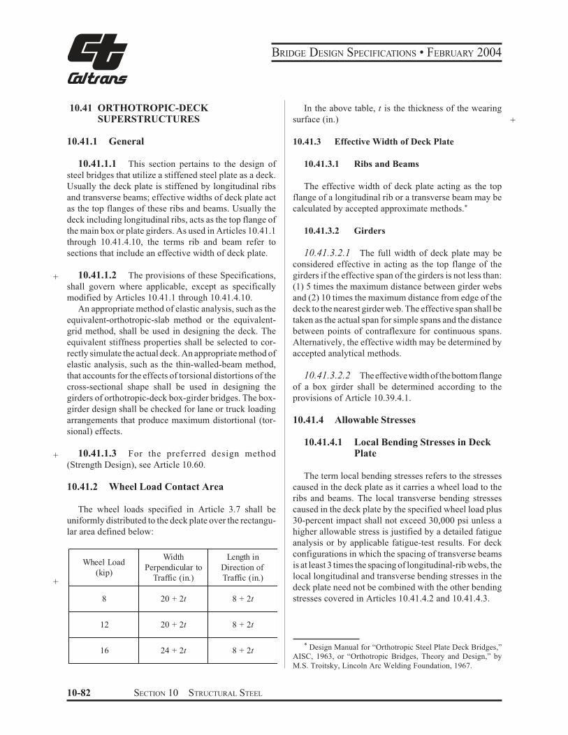
BRIDGE DESIGN SPECIFICATIONS • FEBRUARY 2004
10.41 ORTHOTROPIC-DECK SUPERSTRUCTURES
10.41.1 General
10.41.1.1 This section pertains to the design of
steel bridges that utilize a stiffened steel plate as a deck.
Usually the deck plate is stiffened by longitudinal ribs
and transverse beams; effective widths of deck plate act
as the top flanges of these ribs and beams. Usually the
deck including longitudinal ribs, acts as the top flange of
the main box or plate girders. As used in Articles 10.41.1
through 10.41.4.10, the terms rib and beam refer to
sections that include an effective width of deck plate.
+ 10.41.1.2 The provisions of these Specifications,
shall govern where applicable, except as specifically
modified by Articles 10.41.1 through 10.41.4.10.
An appropriate method of elastic analysis, such as the
equivalent-orthotropic-slab method or the equivalent-
grid method, shall be used in designing the deck. The
equivalent stiffness properties shall be selected to cor-
rectly simulate the actual deck. An appropriate method of
elastic analysis, such as the thin-walled-beam method,
that accounts for the effects of torsional distortions of the
cross-sectional shape shall be used in designing the
girders of orthotropic-deck box-girder bridges. The box-
girder design shall be checked for lane or truck loading
arrangements that produce maximum distortional (tor-
sional) effects.
+ 10.41.1.3 For the preferred design method
(Strength Design), see Article 10.60.
10.41.2 Wheel Load Contact Area
The wheel loads specified in Article 3.7 shall be
uniformly distributed to the deck plate over the rectangu-
lar area defined below:
+
Wheel Load
(kip)
Width
Perpendicular to
Traffic (in.)
Length in
Direction of
Traffic (in.)
8 20 + 2t 8 + 2t
12 20 + 2t 8 + 2t
16 24 + 2t 8 + 2t
In the above table, t is the thickness of the wearing
surface (in.) +
10.41.3 Effective Width of Deck Plate
10.41.3.1 Ribs and Beams
The effective width of deck plate acting as the top
flange of a longitudinal rib or a transverse beam may be
calculated by accepted approximate methods.*
10.41.3.2 Girders
10.41.3.2.1 The full width of deck plate may be
considered effective in acting as the top flange of the
girders if the effective span of the girders is not less than:
(1) 5 times the maximum distance between girder webs
and (2) 10 times the maximum distance from edge of the
deck to the nearest girder web. The effective span shall be
taken as the actual span for simple spans and the distance
between points of contraflexure for continuous spans.
Alternatively, the effective width may be determined by
accepted analytical methods.
10.41.3.2.2 The effective width of the bottom flange
of a box girder shall be determined according to the
provisions of Article 10.39.4.1.
10.41.4 Allowable Stresses
10.41.4.1 Local Bending Stresses in Deck Plate
The term local bending stresses refers to the stresses
caused in the deck plate as it carries a wheel load to the
ribs and beams. The local transverse bending stresses
caused in the deck plate by the specified wheel load plus
30-percent impact shall not exceed 30,000 psi unless a
higher allowable stress is justified by a detailed fatigue
analysis or by applicable fatigue-test results. For deck
configurations in which the spacing of transverse beams
is at least 3 times the spacing of longitudinal-rib webs, the
local longitudinal and transverse bending stresses in the
deck plate need not be combined with the other bending
stresses covered in Articles 10.41.4.2 and 10.41.4.3.
* Design Manual for “Orthotropic Steel Plate Deck Bridges,”
AISC, 1963, or “Orthotropic Bridges, Theory and Design,” by
M.S. Troitsky, Lincoln Arc Welding Foundation, 1967.
10-82 SECTION 10 STRUCTURAL STEEL
BRIDGE DESIGN SPECIFICATIONS • FEBRUARY 2004
10.41.4.2 Bending Stresses in Longitudinal Ribs
The total bending stresses in longitudinal ribs due to a
combination of (1) bending of the rib and (2) bending of
the girders may exceed the allowable bending stresses in
Article 10.32 by 25 percent. The bending stress due to
each of the two individual modes shall not exceed the
allowable bending stresses in Article 10.32.
10.41.4.6 Maximum Slenderness of Longitudinal Ribs
The slenderness, L/r, of a longitudinal rib shall not
exceed the value given by the following formula unless
it can be shown by a detailed analysis that overall buck-
ling of the deck will not occur as a result of compressive
stress induced by bending of the girders:
L 1,500 2,700 f(+.
*,/
$ 1,000 ) 10.41.4.3 Bending Stresses in Transverse Beams
(10-91) + F Fyr max y
The bending stresses in transverse beams shall not
exceed the allowable bending stresses in Article 10.32.
10.41.4.4 Intersections of Ribs, Beams, and Girders
Connections between ribs and the webs of beams,
holes in the webs of beams to permit passage of ribs,
connections of beams to the webs of girders, and rib
splices may affect the fatigue life of the bridge when they
occur in regions of tensile stress. Where applicable, the
number of cycles of maximum stress and the allowable
fatigue stresses given in Article 10.3 shall be applied in
designing these details; elsewhere, a rational fatigue
analysis shall be made in designing the details. Connec-
tions between webs of longitudinal ribs and the deck plate
shall be designed to sustain the transverse bending fa-
tigue stresses caused in the webs by wheel loads.
10.41.4.5 Thickness of Plate Elements
10.41.4.5.1 Longitudinal Ribs and Deck Plate
Plate elements comprising longitudinal ribs, and
deck-plate elements between webs of these ribs, shall
meet the minimum thickness requirements of Article
10.35.2. The quantity fa may be taken as 75 percent of the
sum of the compressive stresses due to (1) bending of the
rib and (2) bending of the girder, but not less than the
compressive stress due to either of these two individual
bending modes.
10.41.4.5.2 Girders and Transverse Beams
Plate elements of box girders, plate girders, and trans-
verse beams shall meet the requirements of Articles
10.34.2 to 10.34.6 and 10.39.4.
where:
L
r
f
Fy
= distance between transverse beams (in.)
= radius of gyration about the horizontal centroidal
axis of the rib including an effective width of
deck plate (in.)
= maximum compressive stress in the deck plate
as a result of the deck acting as the top flange
of the girders; this stress shall be taken as
positive (psi)
= specified minimum yield strength of rib mate-
rial (psi)
+
+
+
+
+
+
10.41.4.7 Diaphragms
Diaphragms, cross frames, or other means shall be
provided at each support to transmit lateral forces to the
bearings and to resist transverse rotation, displacement,
and distortion. Intermediate diaphragms or cross frames
shall be provided at locations consistent with the analysis
of the girders. The stiffness and strength of the interme-
diate and support diaphragms or cross frames shall be
consistent with the analysis of the girders.
10.41.4.8 Stiffness Requirements
10.41.4.8.1 Deflections
The deflections of ribs, beams, and girders due to live
load plus impact may exceed the limitations in Article
10.6 but preferably shall not exceed 1/500 of their span.
The calculation of the deflections shall be consistent with
the analysis used to calculate the stresses.
To prevent excessive deterioration of the wearing
surface, the deflection of the deck plate due to the
specified wheel load plus 30-percent impact preferably
SECTION 10 STRUCTURAL STEEL 10-83
BRIDGE DESIGN SPECIFICATIONS • FEBRUARY 2004
shall be less than 1/300 of the distance between webs of
ribs. The stiffening effect of the wearing surface shall not
be included in calculating the deflection of the deck plate.
10.41.4.8.2 Vibrations
The vibrational characteristics of the bridge shall be
considered in arriving at a proper design.
10.41.4.9 Wearing Surface
A suitable wearing surface shall be adequately bonded
to the top of the deck plate to provide a smooth, nonskid
riding surface and to protect the top of the plate against
corrosion and abrasion. The wearing surface material
shall provide (1) sufficient ductility to accommodate,
without cracking or debonding, expansion and contrac-
tion imposed by the deck plate, (2) sufficient fatigue
strength to withstand flexural cracking due to deck-plate
deflections, (3) sufficient durability to resist rutting,
shoving, and wearing, (4) imperviousness to water and
motor-vehicle fuels and oils, and (5) resistance to dete-
rioration from deicing salts, oils, gasolines, diesel fuels,
and kerosenes.
10.41.4.10 Closed Ribs
Closed ribs without access holes for inspection, clean-
ing, and painting are permitted. Such ribs shall be sealed
against the entrance of moisture by continuously welding
(1) the rib webs to the deck plate, (2) splices in the ribs,
and (3) diaphragms, or transverse beam webs, to the ends
of the ribs.
10-84 SECTION 10 STRUCTURAL STEEL
BRIDGE DESIGN SPECIFICATIONS • FEBRUARY 2004
Part D Strength Design Method
Load Factor Design
10.42 SCOPE
+ Load factor design is the preferred method of propor-
tioning structural members for multiples of the design
loads. To ensure serviceability and durability, consider-
ation is given to the control of permanent deformations
under overloads, to the fatigue characteristics under
service loadings, and to the control of live load deflec-
+ tions under service loadings.
10.43 LOADS
10.43.1 Service live loads are vehicles which may
operate on a highway legally without special load permit.
10.43.2 For design purposes, the service loads are
taken as the dead, live, and impact loadings described in
+ Section 3 – Loads.
10.43.3 Overloads are the live loads that can be allowed
on a structure on infrequent occasions without causing
permanent damage. For design purposes, the maximum
overload is taken as 5(L + I)/3.
10.43.4 The maximum loads are the loadings specified
in Article 10.47.
10.44 DESIGN THEORY
10.44.1 The moments, shears and other forces shall be
determined by assuming elastic behavior of the structure
except as modified in Article 10.48.1.3.
10.44.2 The members shall be proportioned by the
methods specified in Articles 10.48 through 10.56 so that
their computed maximum strengths shall be at least equal
to the total effects of design loads multiplied by their
respective load factors specified in Article 3.2.
10.44.3 Service behavior shall be investigated as
specified in Articles 10.57 through 10.59.
10.45 ASSUMPTIONS
10.45.1 Strain in flexural members shall be assumed
directly proportional to the distance from the neutral axis.
10.45.2 Stress in steel below the yield strength, Fy, of
the grade of steel used shall be taken as 29,000,000 psi
times the steel strain. For strain greater than that
corresponding to the yield strength, Fy, the stress shall be
considered independent of strain and equal to the yield
strength, Fy. This assumption shall apply also to the
longitudinal reinforcement in the concrete floor slab in
the region of negative moment when shear connectors are
provided to ensure composite action in this region.
10.45.3 At maximum strength the compressive stress
in the concrete slab of a composite beam shall be assumed independent of strain and equal to 0.85 fc! .
10.45.4 Tensile strength of concrete shall be neglected
in flexural calculations, except as permitted under the
provisions of Articles 10.57.2, 10.58.1 and 10.58.2.
10.46 DESIGN STRESS FOR STRUCTURAL STEEL
The design stress for structural steel shall be the
specified minimum yield strength, Fy, of the steel used as
set forth in Article 10.2. +
10.47 MAXIMUM DESIGN LOADS
The maximum moments, shears or forces to be sus-
tained by a load-carrying member shall be computed
from the formulas shown in Article 3.2. Each part of the
structure shall be proportioned for the group loads that
are applicable and the maximum design required by the
group loading combinations shall be used.
+
10.48 FLEXURAL MEMBERS
Flexural members are subject to the following re-
quirements in this article in addition to any applicable
requirements from Articles 10.49 through 10.61 that may
supersede these requirements. The compression-flange
width, b, on fabricated I-shaped girders preferably shall
not be less than 0.2 times the web depth, but in no case
shall it be less than 0.15 times the web depth. If the area
of the compression flange is less than the area of the
tension flange, the minimum flange width may be based
on 2 times the depth of the web in compression rather than
SECTION 10 STRUCTURAL STEEL 10-85
BRIDGE DESIGN SPECIFICATIONS • FEBRUARY 2004
the web depth. The compression-flange thickness, t,
preferably shall not be less than 1.5 times the web
thickness. The width-to-thickness ratio, b/t, of flanges
subject to tension shall not exceed 24.
10.48.1 Compact Sections
+
Sections of properly braced constant-depth flexural
members without longitudinal web stiffeners, without
holes in the tension flange and with high resistance to
local buckling qualify as compact sections.
Sections of rolled or fabricated flexural members
meeting the requirements of Article 10.48.1.1 below
shall be considered compact sections and the design
bending strength shall be computed as:
F ZM yu $ (10-92)
+ where:
+
+
+
Fy
Z
= specified minimum yield strength of the steel
being used (psi)
= plastic section modulus* (in.3)
10.48.1.1 Compact sections shall meet the follow-
ing requirements: (for certain frequently used steels these
requirements are listed in Table 10.48.1.2A).
(a) Compression flange:
yFt
b 4,110"
(10-93)
+ where:
+
+
b
t
= compression flange width (in.)
= flange thickness (in.)
(b) Web thickness:
* Values for rolled sections are listed in the Manual of Steel
Construction, Ninth Edition, 1989, American Institute of Steel
Construction, Appendix D shows the methods of computing Z as
presented in the Commentary of AISI Bulletin 15.
10-86 SECTION 10 STRUCTURAL STEEL
D 19,230"
(10-94)t Fw y
where: +
D = clear distance between the flanges (in.) +tw = web thickness (in.) +
When both b/t and D/tw exceed 75% of the above
limits, the following interaction equation shall apply
D ( b * 33,650& 4.68+ , " (10-95)tw . t / Fyf
where: +
Fyf = specified minimum yield strength +of compression flange (psi) +
(c) Lateral bracing for compression flange:
6Lb "23.6 ) 2.2 %M1 / Mu '3410
(10-96)ry Fy
where:
Lb = distance between points of bracing of the com- +
pression flange(in.) +
ry = radius of gyration of the steel section with +
respect to the Y-Y axis (in.) +
M1 = smaller moment at the end of the unbraced +
length of the member (lb-in.) +
Mu = design strength from Equation (10-92) at the +
other end of the unbraced length: (M1/Mu) is +
positive when moments cause single curvature +
between brace points (lb-in.). (M1/Mu) is nega- +
tive when moments cause reverse curvature +
between brace points. +
The required lateral bracing shall be provided by
braces capable of preventing lateral displacement and
twisting of the main members or by embedment of the top
and sides of the compression flange in concrete.
(d) Maximum axial compression:
BRIDGE DESIGN SPECIFICATIONS • FEBRUARY 2004
P ≤ 0.15Fy A (10-97)where:
+ A = area of the cross section (in.2)Members with axial loads in excess of 0.15Fy Ashouldbe designed as beam-columns as specified in Article 10.54.2.10.48.1.2 Article 10.48.1 is applicable to steels with a demonstrated ability to reach Mp. Steels such as AASHTO M 270 Grades 36, 50 and 50W (ASTM A 709 Grades 36, 50 and 50W) and ASTM A 709, Grade HPS 70W meet these requirements. The limitations set forth in Article 10.48.1 are given in Table 10.48.1.2A.TABLE 10.48.1.2A Limitations for Compact Sections
Fy (psi) 36,000 50,000 70,000
b /t 21.6 18.4 15.0
D/tw
101 86 70
Lb/r
y(M
1/M
u = 0*) 100 72 51
Lb/r
y(M
1/M
u = 1*) 39 28 20
For values ofM1/Muother than 0 and 1, use Equation (10-96). 10.48.1.3 In the design of a continuous beam with compact negative-moment support sections of AASHTO M 270 Grade 36, 50 and 50W (ASTM A 709 Grade 36, 50 and 50W) steel complying with the provision of Article 10.48.1.1, negative moments over such supports at Overload and Maximum Load determined by elastic analysis may be reduced by a maximum of 10 percent. Such reduction shall be accompanied by an increase in moments throughout adjacent spans statically equivalent and opposite in sign to the decrease of the negative moments at the adjacent supports. For example, the increase in moment at the center of the span shall equal the average decrease of the moments at the two adjacent supports. The reduction shall not apply to the negative moment of a cantilever. This 10-percent redistribution of moment shall not apply to compact sections of ASTM A 709 Grade HPS 70W or AASHTO M 270, Grade 70W steel.
10.48.2 Braced Non-Compact Sections For sections of rolled or fabricated flexural mem-bers not meeting the requirements of Article 10.48.1.1 but meeting the requirement of Article 10.48.2.1 below, the design strength shall be computed as the lesser of +
Mu=FySxt (10-98)or
Mu=FcrSxcRb (10-99)subject to the requirement of Article 10.48.2.1 (c) where
2Fcr = 4,400t
≤ Fy
b
b = compression flange width (in.) +t = compression flange thickness (in.) +Sxt = elastic section modulus with respect to tension +flange (in.3) +Sxc = elastic section modulus with respect to com- +pression flange (in.3) +Rb = flange-stress reduction factor determined from +the provisions of Article 10.48.4.1, with fb sub-stituted for the term Mr/Sxc when Equation (10-103b) applies fb = factored bending stress in the compression flange +(psi), but not to exceed Fy10.48.2.1 The above equations are applicable to sections meeting the following requirements: (a) Compression flange:
b≤ 24 (10-100)
t
(b) Web thickness: The web thickness shall not exceed the requirement given by Equation (10-104) or Equation (10-109), as applicable, subject to the corresponding requirements as shown in Table 10.48.5A of Article 10.49.2 or 10.49.3. For unstiffened web, the web thickness shall not be less than D/150.
SECTION 10 STRUCTURAL STEEL 10-87
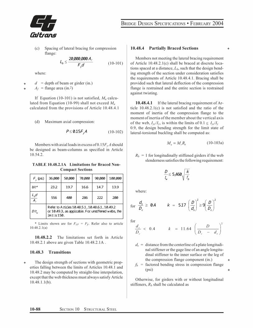
BRIDGE DESIGN SPECIFICATIONS • FEBRUARY 2004
(c) Spacing of lateral bracing for compression
flange: 20,000,000 AfLb ! (10-101)Fydwhere:
+ d = depth of beam or girder (in.) + Af = flange area (in.2)
If Equation (10-101) is not satisfied, Mu calcu-
lated from Equation (10-99) shall not exceed Mu
calculated from the provisions of Article 10.48.4.1
(d) Maximum axial compression:
P ! 0.15FyA (10-102)
Members with axial loads in excess of 0.15Fy A should
be designed as beam-columns as specified in Article
10.54.2.
TABLE 10.48.2.1A Limitations for Braced Non-
Compact Sections
Fy (psi) 36,000 50,000 70,000 90,000 100,000 b/t* 23.2 19.7 16.6 14.7 13.9 LbdAf 556 400 286 222 200 D/tw Refer to Articles 10.48.5.1, 10.48.6.1, 10.49.2 or 10.49.3, as applicable. For unstiffened webs, the limit is 150.
* Limits shown are for Fcr = Fy. Refer also to article
10.48.2.1(a)
10.48.2.2 The limitations set forth in Article
10.48.2.1 above are given Table 10.48.2.1A .
10.48.3 Transitions
+ The design strength of sections with geometric prop-
erties falling between the limits of Articles 10.48.1 and
10.48.2 may be computed by straight-line interpolation,
except that the web thickness must always satisfy Article
10.48.1.1(b).
10.48.4 Partially Braced Sections +Members not meeting the lateral bracing requirement
of Article 10.48.2.1(c) shall be braced at discrete loca-
tions spaced at a distance, Lb, such that the design bend-
ing strength of the section under consideration satisfies
the requirements of Article 10.48.4.1. Bracing shall be
provided such that lateral deflection of the compression
flange is restrained and the entire section is restrained
against twisting.
10.48.4.1 If the lateral bracing requirement of Ar-
ticle 10.48.2.1(c) is not satisfied and the ratio of the
moment of inertia of the compression flange to the
moment of inertia of the member about the vertical axis
of the web, Iyc/Iy, is within the limits of 0.1 ! Iyc/Iy
0.9, the design bending strength for the limit state of
lateral-torsional buckling shall be computed as:
Mu = M rRb(10-103a)
Rb = 1 for longitudinally stiffened girders if the web
slenderness satisfies the following requirement:
D k! 5,460 tw fb
where:
d " D #2
" D #2s $ 0.4 k % 5.17 $ 9for & ' & 'Dc ( ds ) ( Dc )
for
d ! D "2
s # 0.4 k $ 11.64 % &D D ' dc ( c s )
ds = distance from the centerline of a plate longitudi-
nal stiffener or the gage line of an angle longitu-
dinal stiffener to the inner surface or the leg of
the compression flange component (in.) +fb = factored bending stress in compression flange
(psi) +Otherwise, for girders with or without longitudinal
stiffeners, Rb shall be calculated as
10-88 SECTION 10 STRUCTURAL STEEL
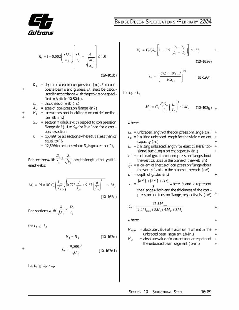
BRIDGE DESIGN SPECIFICATIONS • FEBRUARY 2004
bR
+
Dc =
+
+
twAfcMrSxc
====
λ ==
For sections with or with longitudinally stiff-tw Fyened webs:
6I
yc J d 2
M r = 91×10 Cb 0.772 + 9.87 ≤ M yL I L b yc b
(10-103c)λ Dc<For sections with Fy
tw
for Lb ≤ Lp
Mr = My (10-103d)9,500r′
+ Lp = F (10-103d1)
y
for Lr ≥ Lb > Lp
Dctw Dc λ =1 −0.002 − ≤ 1.0
A fc tw M r
S xc
(10-103b)depth of web in compression (in.). For com-posite beams and girders, Dc shall be calcu-lated in accordance with the provisions speci-fied in Article 10.50(b). thickness of web (in.) area of compression flange (in.2)lateral torsional buckling moment defined be-low (lb.-in.) section modulus with respect to compression flange (in.3). Use Sxc for live load for a com-posite section 15,400 for all sections where Dc is less than or equal to D/212,500 forsections where Dc isgreater than D/2
Dc λ≤
Lb − Lp
M = C F S 1 − 0.5 ≤ Mr b y x c y + Lr − Lp
(10-103e)1/2
572 ×106I dL = yc
r (10-103f) y x c F S
for Lb > Lr
F S L2
y xc rM r = Cb ≤ M y (10-103g) +2 Lb
where:Lb = unbraced length of the compression flange (in.) +Lp = limiting unbraced length for the yield moment +capacity (in.) +Lr = limiting unbraced length for elastic lateral tor- +sional buckling moment capacity (in.) +r' = radius of gyration of compression flange about the vertical axis in the plane of the web (in) Iyc = moment of inertia of compression flange about the vertical axis in the plane of the web (in.4)d = depth of girder (in.) +
3 3 3(b t ) + (bt ) + D tc t wJ = where b and t represent
3the flange width and the thickness of the com-pression and tension flange, respectively (in.4) +12.5M
maxC = b +2.5M +3M + 4M + 3Mmax A B c
where: +Mmax = absolute value of maximum moment in the +unbraced beam segment (lb-in.) +MA = absolute value of moment at quarter point of +the unbraced beam segment (lb-in.) +
SECTION 10 STRUCTURAL STEEL 10-89
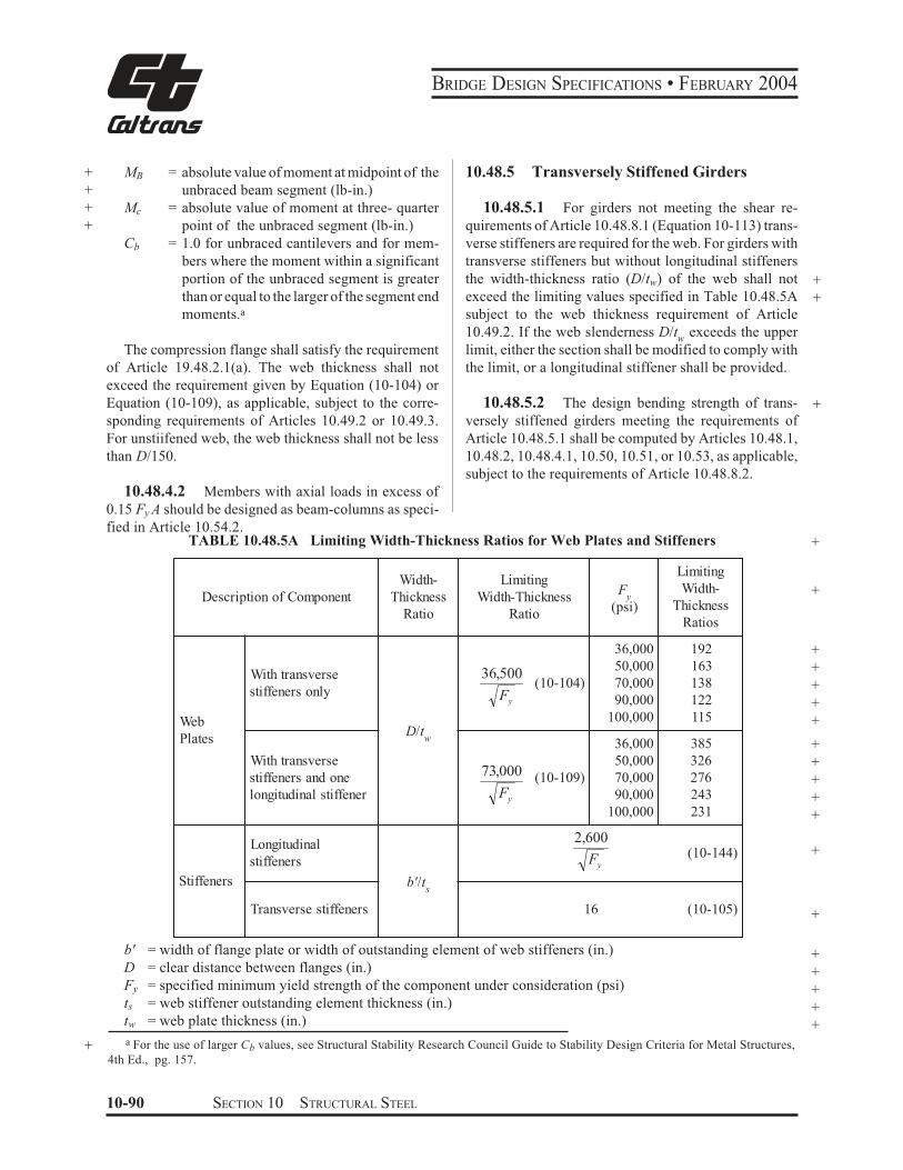
BRIDGE DESIGN SPECIFICATIONS • FEBRUARY 2004
+ MB = absolute value of moment at midpoint of the
+ unbraced beam segment (lb-in.)
+ Mc = absolute value of moment at three- quarter
+ point of the unbraced segment (lb-in.)
Cb = 1.0 for unbraced cantilevers and for mem-
bers where the moment within a significant
portion of the unbraced segment is greater
than or equal to the larger of the segment end
moments.a
The compression flange shall satisfy the requirement
of Article 19.48.2.1(a). The web thickness shall not
exceed the requirement given by Equation (10-104) or
Equation (10-109), as applicable, subject to the corre-
sponding requirements of Articles 10.49.2 or 10.49.3.
For unstiifened web, the web thickness shall not be less
than D/150.
10.48.4.2 Members with axial loads in excess of
0.15 Fy A should be designed as beam-columns as speci-
fied in Article 10.54.2.
10.48.5 Transversely Stiffened Girders
10.48.5.1 For girders not meeting the shear re-
quirements of Article 10.48.8.1 (Equation 10-113) trans-
verse stiffeners are required for the web. For girders with
transverse stiffeners but without longitudinal stiffeners
the width-thickness ratio (D/tw) of the web shall not +exceed the limiting values specified in Table 10.48.5A +subject to the web thickness requirement of Article
10.49.2. If the web slenderness D/t exceeds the upperw
limit, either the section shall be modified to comply with
the limit, or a longitudinal stiffener shall be provided.
10.48.5.2 The design bending strength of trans- +versely stiffened girders meeting the requirements of
Article 10.48.5.1 shall be computed by Articles 10.48.1,
10.48.2, 10.48.4.1, 10.50, 10.51, or 10.53, as applicable,
subject to the requirements of Article 10.48.8.2.
TABLE 10.48.5A Limiting Width-Thickness Ratios for Web Plates and Stiffeners +
Description of Component
Web
Plates
With transverse
stiffeners only
With transverse
stiffeners and one
longitudinal stiffener
Longitudinal
stiffeners
Stiffeners
Transverse stiffeners
Width- Limiting
Thickness Width-Thickness
Ratio Ratio
D/tw
b'/ts
36,500
Fy
(psi)
36,000
50,000
(10-104) 70,000Fy 90,000
100,000
36,000
50,00073,000 (10-109) 70,000
Fy 90,000
100,000
2,600
Fy
16
b' = width of flange plate or width of outstanding element of web stiffeners (in.)
D = clear distance between flanges (in.)
Fy = specified minimum yield strength of the component under consideration (psi)
ts = web stiffener outstanding element thickness (in.)
tw = web plate thickness (in.)
Limiting
Width- +Thickness
Ratios
192 +163 +138 +122 +115 +
385 +326 +276 +243 +231 +
+(10-144)
(10-105) +
+
+
+
+
+
+ a For the use of larger Cb values, see Structural Stability Research Council Guide to Stability Design Criteria for Metal Structures,
4th Ed., pg. 157.
10-90 SECTION 10 STRUCTURAL STEEL
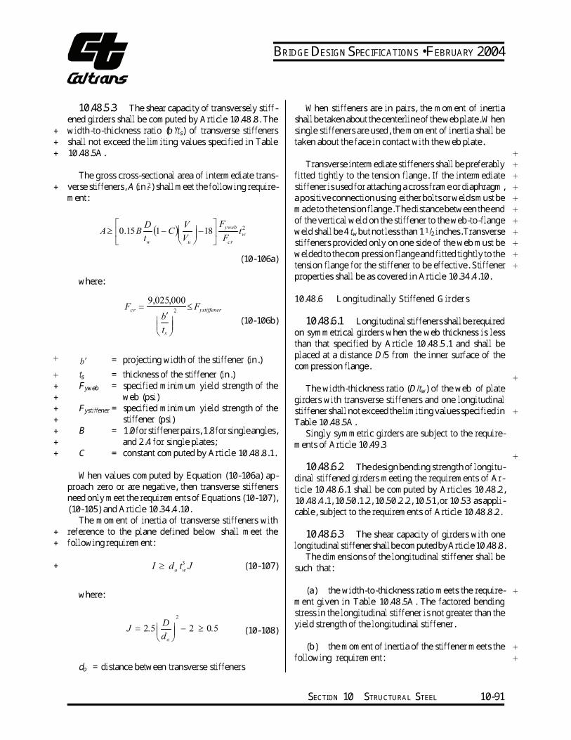
BRIDGE DESIGN SPECIFICATIONS • FEBRUARY 2004
+++
10.48.5.3 The shear capacity of transversely stiff-ened girders shall be computed by Article 10.48.8. The width-to-thickness ratio (b'/ts) of transverse stiffeners shall not exceed the limiting values specified in Table 10.48.5A.
+ The gross cross-sectional area of intermediate trans-verse stiffeners, A (in.2) shall meet the following require-ment:
When stiffeners are in pairs, the moment of inertia shall be taken about the centerline of the web plate. When single stiffeners are used, the moment of inertia shall be taken about the face in contact with the web plate. +Transverse intermediate stiffeners shall be preferably +fitted tightly to the tension flange. If the intermediate +stiffener is used for attaching a cross frame or diaphragm, +a positive connection using either bolts or welds must be +made to the tension flange. The distance between the end +of the vertical weld on the stiffener to the web-to-flange +Fyweb D V
1u cr welded to the compression flange and fitted tightly to the +(10-106a) tension flange for the stiffener to be effective. Stiffener +properties shall be as covered in Article 10.34.4.10.where:
10.48.6 Longitudinally Stiffened Girders9,025,000
(
) 2≥
A 0.15B C 18 weld shall be 4 tw but not less than 1 1/2 inches. Transverset
− − +
wV F t stiffeners provided only on one side of the web must be +w
Fcr ≤ Fystiffener= 2
b
ts
′
(10-106b) 10.48.6.1 Longitudinal stiffeners shall be required on symmetrical girders when the web thickness is less
+ b′ = projecting width of the stiffener (in.) + ts = thickness of the stiffener (in.) + Fyweb = specified minimum yield strength of the + web (psi) + Fystiffener = specified minimum yield strength of the + stiffener (psi) + B = 1.0 for stiffener pairs, 1.8 for single angles, + and 2.4 for single plates; + C = constant computed by Article 10.48.8.1.
When values computed by Equation (10-106a) ap-proach zero or are negative, then transverse stiffeners need only meet the requirements of Equations (10-107), (10-105) and Article 10.34.4.10. The moment of inertia of transverse stiffeners with + reference to the plane defined below shall meet the + following requirement:
than that specified by Article 10.48.5.1 and shall be placed at a distance D/5 from the inner surface of the compression flange. The width-thickness ratio (D/tw) of the web of plate girders with transverse stiffeners and one longitudinal stiffener shall not exceed the limiting values specified in Table 10.48.5A. Singly symmetric girders are subject to the require-ments of Article 10.49.3
+
+
10.48.6.2 The design bending strength of longitu-dinal stiffened girders meeting the requirements of Ar-ticle 10.48.6.1 shall be computed by Articles 10.48.2, 10.48.4.1, 10.50.1.2, 10.50.2.2, 10.51, or 10.53 as appli-cable, subject to the requirements of Article 10.48.8.2.
+
10.48.6.3 The shear capacity of girders with one longitudinal stiffener shall be computed by Article 10.48.8. The dimensions of the longitudinal stiffener shall bed t3 JI ≥ (10-107)+ such that:o w
(a) the width-to-thickness ratio meets the require- +where: ment given in Table 10.48.5A. The factored bending stress in the longitudinal stiffener is not greater than the2
D yield strength of the longitudinal stiffener.
− 2 ≥ J = 2.5 0.5 (10-108)d o
do = distance between transverse stiffeners (b) the moment of inertia of the stiffener meets the following requirement: +
+
SECTION 10 STRUCTURAL STEEL 10-91
BRIDGE DESIGN SPECIFICATIONS • FEBRUARY 2004
For stiffened web panels complying with the provi-27 8 d(+.
*,/
3I - Dt 2.4 )0.13 o sions of Article 10.48.8.3, the shear capacity shall be(10-110)determined by including post-buckling resistance due to
tension-field action as follows:
99;
::<
wD
+ (c) the radius of gyration of the stiffener meets the
+ following requirement: 8799999;
C &
:::::<
% ')
1
187.0
d
C
o
Vu $ V yFd p 2 (10-114) o
r - (+.
*,/
(10-111) & 23,000 D
In computing I and r values above, a centrally located
web strip not more than 18tw in width shall be considered
as a part of the longitudinal stiffener. Transverse stiffen-
ers for girder panels with longitudinal stiffeners shall be
designed according to Article 10.48.5.3. In addition, the
+ section modulus of the transverse stiffener shall meet the
+ following requirement:
Vp is equal to the plastic shear strength and is deter- +
mined as follows:
Vp = 0.58 FyDtw (10-115)
The constant C is equal to the buckling shear stress
divided by the shear yield stress, and is determined as
follows:
+(+.
,*,/
D 1 S S (10-112) D-
0 yF
k000,6+ tsd3 o for tw
where:C = 1.0
+ D = total panel depth (clear distance between flange
+ components) (in.)
y F
k
t
D
F
k 500,7000,6+ St = section modulus of the longitudinal stiffener. " " for(in3.)+ w y
10.48.7 Bearing Stiffeners k6,000 C $
,+(+.
*,/
D (10-116)FyBearing stiffeners shall be designed for beams and tgirders as specified in Articles 10.33.2 and 10.34.6. w
yF
k500,7D
tw
+ Axial compression strength shall be computed as speci-for+ fied in Article 10.54.1. Bearing strength shall be taken at
=
+ 1.35 Fy times the bearing area of bearing stiffners.
107 k4.5 4 C
10.48.8 Shear (+.
$
+
2
*,/,
D (10-117)Fyt10.48.8.1 The shear capacity of webs of rolled or w
fabricated flexural members shall be computed as follows:
+ For unstiffened webs, the design shear strength shall
+ be limited to the plastic or buckling shear strength as
+ follows:
Vu = CVp (10-113)
10-92 SECTION 10 STRUCTURAL STEEL
BRIDGE DESIGN SPECIFICATIONS • FEBRUARY 2004
where the buckling coefficient, k = 5 + 5 / (do/D)2, except k shall be taken as 5 for unstiffened beams and girders. + D = clear, unsupported distance between flange com-+ ponents (in.) + do = distance between transverse stiffeners (in.) + Fy = specified minimum yield strength of the web + plate (psi)
10.48.8.2 If a girder panel is controlled by Equa-tion (10-114) and is subjected to the simultaneous action of shear and bending moment with the magnitude of the + moment greater than 0.75 Mu, the shear shall meet the + following requirement:
V 1.6 M≤ 2.2 − + (10-118)V M
u u
If a girder panel adjacent to a composite noncompact section is controlled by Equation (10-114) and is sub-jected to the simultaneous action of shear and bending moment with the magnitude of factored bending stress fsgreater than 0.75Fum, the shear shall meet the following requirement:V 1.6fs≤ 2.2 − (10-118a)V F
u um
where:fs = factored bending stress in either the top or bot-tom flange, whichever flange has the larger ratio of (fs/Fum)Fum =maximum bending strength of either the top or bottom flange, whichever flange has the larger ratio of (fs/Fum)10.48.8.3 Where transverse intermediate stiffen-ers are required, transverse stiffeners shall be spaced at a distance, do, according to shear capacity as specified in Article 10.48.8.1, but not more than 3D. Transverse stiffeners may be omitted in those portions of the girders where the maximum shear force is less than the value given by Article 10.48.8.1 Equation (10-113), subject to the handling requirements below.
+ Transverse stiffeners shall be required ifD/tw is greater than 150. The spacing of these stiffeners shall not exceed
the handling requirement 2
/
260
D twD .
For longitudinally stiffened girders, transverse stiff-eners shall be spaced a distance, do, according to shear capacity as specified in Article 10.48.8.1, but not more than 1.5 times the web depth. The handling requirement given above shall not apply to longitudinally stiffened girders. The total web depthD shall be used in determin-ing the shear capacity of longitudinally stiffened girders in Article 10.48.8.1 and in Equation (10-119). The first stiffener space at the simple support end of a transversely or longitudinally stiffened girder shall be such that the shear force in the end panel will not exceed the plastic or buckling shear strength given by the following equation: +Vu = CVp (10-119)
For transversely stiffened girders, the maximum spac-ing of the first transverse stiffener is limited to 1.5D.10.49 FLEXURAL MEMBERS WITH SINGLY SYMMETRIC SECTIONS +
+
10.49.1 GeneralFor sections symmetric about the vertical axis but unsymmetric with respect to the horizontal centroidal axis, the provisions of Articles 10.48.1 through 10.48.4 shall be applicable.
10.49.2 Transversely Stiffened Sections +
Girders with transverse stiffeners shall be designed and evaluated by the provisions of Article 10.48.5 except that when Dc, the clear distance between the neutral axis and the compression flange, exceeds D/2 the web thick-ness, tw, shall meet the requirement:
w
c
t
D≤
yF
18,250 (10-120)
If the web slenderness Dc/tw exceeds the upper limit, either the section shall be modified to comply with the limit, or a longitudinal stiffener shall be provided.
SECTION 10 STRUCTURAL STEEL 10-93
BRIDGE DESIGN SPECIFICATIONS • FEBRUARY 2004
10.49.3 Longitudinally Stiffened Sections
+
+
+
10.49.3.1 Longitudinal stiffeners shall be required
on singly symmetric sections when the web thickness
does not meet the requirement specified by Articles
10.48.5.1 or 10.49.2.
10.49.3.2 For girders with one longitudinal stiff-
ener and transverse stiffeners, the provisions of Article
10.48.6 for symmetrical sections shall be applicable in
addition to the following:
(a) The optimum distance, ds, of a plate longitudinal
stiffener or the gage line of an angle longitudinal
stiffener from the inner surface or the leg of the
compression flange component is D/5 for a sym-
metrical girder. The optimum distance, ds, for a
singly symmetric composite girder in positive-
moment regions may be determined from the
equation given below:
sd$
1(10-121)
DL
LLDLcs
f
fD &&1 1.5
+ where:
+ Dcs = depth of the web in compression of the non-
+ composite steel beam or girder (in.)
+ fDL = non-composite dead-load stress in the com-
+ pression flange (psi)
+ fDL+LL = total non-composite and composite dead
+ load plus the composite live-load stress in
+ compression flange at the most highly
+ stressed section of the web (psi)
The optimum distance ds, of the stiffener in negative-
moment regions of composite sections is 2Dc/5, where Dc
is the depth of the web in compression of the composite
section at the most highly stressed section of the web.
(b) When Dc exceeds D/2, the web thickness, tw, shall
meet the requirement:
Dc 36,500"
(10-122)t Fw y
10.49.4 Braced Non-Compact Sections +
Singly symmetric braced non-compact sections of
rolled or fabricated flexural members shall be designed
and evaluated by the provisions of Article 10.48.2.
10.49.5 Partially Braced Sections +
The design strength of singly symmetric sections +
meeting all requirements of Article 10.48.2.1, except for the
lateral bracing requirement given by Equation (10-101),
shall be computed as the lesser of Mu calculated from
Equation (10-98) or Mu calculated from Equation (10-99),
with Mu calculated from Equation (10-99) not to exceed Mu
calculated from the provisions of Article 10.48.4.1.
10.50 COMPOSITE SECTIONS
Composite sections shall be so proportioned that the
following criteria are satisfied:
(a) The design strength of any section shall not be
less than the sum of the computed moments at that +
section multiplied by the appropriate load factors.
(b) The web of the steel section shall be designed to
carry the total external shear and must satisfy the
applicable provisions of Articles 10.48 and 10.49.
The value of Dc shall be taken as the clear distance
between the neutral axis and the compression
flange. In positive-moment regions, the value of
Dc shall be calculated by summing the stresses
due to the appropriate loadings acting on the
respective cross sections supporting the loading.
The depth of web in compression, Dc, in compos-
ite section subjected to negative bending may be
taken as the depth of the web in compression of the
composite section without summing the stresses
from the various stages of loading. The web depth in
compression, Dcp, of sections meeting the web
compactness and ductility requirements of Article
10.50.1.1.2 under the maximum design loads shall
be calculated from the full plastic section ignoring
the sequence of load application. Girders with a web
slenderness exceeding the limits of Article 10.48.5.1
or 10.49.2 shall either be modified to comply with
these limits or else shall be stiffened by one longitu-
dinal stiffener.
10-94 SECTION 10 STRUCTURAL STEEL
BRIDGE DESIGN SPECIFICATIONS • FEBRUARY 2004
(c) The moment capacity at first yield shall be com-puted considering the application of the dead and live loads to the steel and composite sections. + (d) steel beam or girder shall satisfy the + constructibility requirements of Article 10.61. + (e) The stress in the top flange of a composite girder + shall be limited to 0.6Fy under dead load if no + calculations are made for the construction load-ing stage of the concrete deck. The concrete deck is assumed to be placed instantaneously.
10.50.1 Positive Moment Sections 10.50.1.1 Compact Sections
+ The design strength, Mu, of compact composite sec-tions in positive-moment regions shall be computed in accordance with Article 10.50.1.1.2. The steel shall have the demonstrated ability to reach Mp. Steel such as AASHTO M 270 Grades 26, 50 and 50W (ASTM A 709 Grades 36, 50 and 50W), and ASTM A 709 Grade HPS 70W meet these requirements. 10.50.1.1.1 The resultant moment of the fully plas-tic stress distribution (Figure 10.50A) may be computed as follows: (a) The compressive force in the slab, C, is equal to the smallest of the values given by the following Equations:(1) C = 0.85 f
c′bt
s+ (AF
y) (10-123)
c
(2) C = (AFy)bf + (AFy)tf + (AFy)w (10-124)+ where:+ b =+
+ ts =+ (AFy)c =+
+
+ (AFy)b f =+
+
+ (AFy)t f =+
+ (AFy)w =+
effective width of slab specified in Article 38.3 (in.) the slab thickness (in.) product of the area and yield strength of that part of reinforcement which lies in the compression zone of the slab (lb.) product of area and yield strength for bot-tom flange of steel section (including cover plate if any) (lb.) product of area and yield strength for top flange of steel section (lb.) product of area and yield strength for web of steel section (lb.)
(b) The depth of the stress block is computed from the compressive force in the slab. C − (AFy )ca = (10-125)
0.85 f c′b
(c) When the compressive force in the slab is less than the value given by Equation (10-124), the top portion of the steel section will be subjected to the following compressive force: +∑(AF )−C
C′= y (10-126)2
where: +(AFy) = product of the area and yield strength of steel +girder section (lb.) +
(d) The location of the neutral axis within the steel section measured from the top of the steel section may be determined as follows: for C' < (AFy)tf
C′ y = t(AF
y)
tf
tf (10-127)
for C' ≥ (AFy)tf
C′ − (AFy ) y = t + tf
Dtf (10-128)(AFy)w
(e) The plastic moment capacity,Mp of the section in bending is the first moment of all forces about the neutral axis, taking all forces and moment arms as positive quantities.
SECTION 10 STRUCTURAL STEEL 10-95
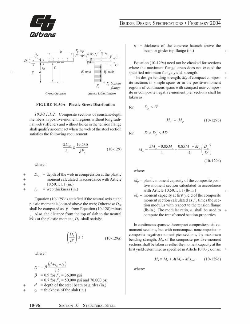
BRIDGE DESIGN SPECIFICATIONS • FEBRUARY 2004
F top tb y s ts0.85 f ' 2ts flange
Dp
Dttf
+ y d
c y C
C'
F web F webyy
F bottomyFy flange
Cross-Section Stress Distribution
FIGURE 10.50A Plastic Stress Distribution
10.50.1.1.2 Composite sections of constant-depth
members in positive-moment regions without longitudi-
nal web stiffeners and without holes in the tension flange
shall qualify as compact when the web of the steel section
satisfies the following requirement:
2Dcp "19,230
(10-129)t Fw y
where:
+ Dcp = depth of the web in compression at the plastic
+ moment calculated in accordance with Article
+ 10.50.1.1.1 (in.)
+ tw = web thickness (in.)
Equation (10-129) is satisfied if the neutral axis at the
plastic moment is located above the web; Otherwise Dcp
shall be computed as y from Equation (10-128) minus
Also, the distance from the top of slab to the neutralttf.axis at the plastic moment, Dp, shall satisfy:
( Dp *,,++ " 5 (10-129a)
D!. /
where:
%d & t & t 's hD' = J
7.5
β = 0.9 for Fy = 36,000 psi
= 0.7 for Fy = 50,000 psi and 70,000 psi
+ d = depth of the steel beam or girder (in.)
+ ts = thickness of the slab (in.)
th = thickness of the concrete haunch above the
beam or girder top flange (in.) +
Equation (10-129a) need not be checked for sections
where the maximum flange stress does not exceed the
specified minimum flange yield strength.
The design bending strength, Mu of compact compos-
ite sections in simple spans or in the positive-moment
regions of continuous spans with compact non-compos-
ite or composite negative-moment pier sections shall be
taken as:
for DDp!"
+
+
uM $ pM (10-129b)
for DDD p!"!0 5
,,/
*++.
(!
)&
)$
D
DMMMMM
ppyyp
u4
0.85
4
0.855
(10-129c)
where:
Mp = plastic moment capacity of the composite posi-
tive moment section calculated in accordance
with Article 10.50.1.1.1 (lb-in.)
My = moment capacity at first yield of the composite
moment section calculated as Fy times the sec-
tion modulus with respect to the tension flange
(lb-in.). The modular ratio, n, shall be used to
compute the transformed section properties.
In continuous spans with compact composite positive-
moment sections, but with noncompact noncomposite or
composite negative-moment pier sections, the maximum
bending strength, Mu, of the composite positive-moment
sections shall be taken as either the moment capacity at the
first yield determined as specified in Article 10.50(c), or as:
Mu = My + A(Mu - Ms)pier (10-129d)
where:
+
+
+
10-96 SECTION 10 STRUCTURAL STEEL
BRIDGE DESIGN SPECIFICATIONS • FEBRUARY 2004
My = the moment at first yield of the com-
pact positive moment section calcu-
lated in accordance with Article
10.50(c) (lb-in.)+
(Mu - Ms)pier = moment capacity of noncompact sec-
tion at the pier, Mu, given by Article
10.48.2 or Article 10.48.4, minus the
elastic moment at the pier, Ms, for the
loading producing maximum positive
bending in the span. Use the smaller
value of the difference for the two pier
+ sections for interior spans (lb-in.)
A = 1 for interior spans
= distance from end support to the loca-
tion of maximum positive moment
divided by the span length for end
spans.
Mu computed from Equation (10-129d) shall not ex-
ceed the applicable value of Mu computed from either
Equation (10-129b) or Equation (10-129c).
For continuous spans where the maximum bending
strength of the positive-moment sections is determined
from Equation (10-129d), the maximum positive mo-
ment in the span shall not exceed My, for the loading
which produces the maximum negative moment at the
adjacent pier(s).
For composite sections in positive-moment regions
not satisfying the requirements of Equation (10-129) or
Equation (10-129a), or of variable-depth members or
with longitudinal web stiffeners, or with holes in the
tension flange, the design bending strength shall be
determined as specified in Article 10.50.1.2.
10.50.1.2 Non-Compact Sections
10.50.1.2.1 When the steel section does not satisfy
the compactness requirements of Article 10.50.1.1.2, the
sum of bending stresses due to the appropriate loadings
acting on the respective cross sections supporting the load-
ings shall not exceed Fy for the tension flange, and FyRb for
compression flange, where Rb is the flange-stress reduction
factor determined from the provisions of Article 10.48.4.1.
When Rb is determined from Equation (10-103b), fb shall be
substituted for the term Mr/Sxc and Afc shall be taken as the
effective combined transformed area of the top flange and
concrete deck that yields Dc calculated in accordance with
Article 10.50(b). fb is equal to the factored bending stress in
the compression flange (psi), but not to exceed Fy. The
resultingRb factorshall be distributed to the top flange and
concrete deck in proportion to their relative stiffness. The
provisions of Article 10.48.2.1(b) shall apply.
10.50.1.2.2 When the girders are not provided with
temporary supports during the placing of dead loads, the
sum of the stresses produced by 1.30MsD acting on the +steel girder alone with 1.30McD and the appropriate +factored live loading according to Table 3.22.1A acting +on the composite girder shall not exceed yield strength at +any point, where MsD and McD are the moments caused by +the dead load acting on the steel girder and composite
girder, respectively.
10.50.1.2.3 When the girders are provided with
effective intermediate supports that are kept in place until
the concrete has attained 75 percent of its required 28-day
strength, stresses produced by the factored dead load plus +live loading, acting on the composite girder, shall not +exceed yield strength at any point. +
10.50.2 Negative Moment Sections
The design strength of composite sections in negative +moment regions shall be computed in accordance with
Articles 10.50.2.1 or 10.50.2.2, as applicable. It shall be
assumed that the concrete slab does not carry tensile
forces. In cases where the slab reinforcement is continu- +ous over interior supports, the reinforcement may be
considered to act compositely with the steel section.
10.50.2.1 Compact Sections
Composite sections of constant-depth members with-
out longitudinal web stiffeners and without holes in the
tension flange in negative bending qualify as compact
when their steel section meets the requirements of Article
10.48.1.1, and has the demonstrated ability to reach Mp.
Steels such as AASHTO M 270 Grade 26, 50 and 50W
(ASTM A 709, Grade 36, 50 and 50W), and ASTM A 709
Grade HPS 70W meet these requirements. Mu shall be
computed as the resultant moment of the fully plastic
stress distribution acting on the section including any
composite slab reinforcement. +
If the distance from the neutral axis to the compression
flange exceeds D/2, the compact section requirements
given by Equation (10-94) and (10-95) must be modified
by replacing D with the quantity 2Dcp, where Dcp is the
depth of the web in compression at the plastic moment. +
SECTION 10 STRUCTURAL STEEL 10-97
BRIDGE DESIGN SPECIFICATIONS • FEBRUARY 2004
10.50.2.2 Non-Compact Sections
When the steel section does not satisfy the compact-
ness requirements of Article 10.50.2.1, but does satisfy
the requirement of Article 10.48.2.1, the sum of bending
stresses due to the appropriate loadings acting on the
respective cross sections supporting the loadings shall
not exceed Fy for the tension flange, and FcrRb for
compression flange, where Fcr is the critical compression
flange stress specified in Article 10.48.2 and Rb is the
flange-stress reduction factor determined from the provi-
sions of Article 10.48.4.1. When Rb is determined from
Equation (10-103b), fb shall be substituted for the term
Mr /Sxc. fb is equal to the factored bending stress in the
compression flange (psi), but not to exceed Fy. When all
requirements of Article 10.48.2.1 are satisfied, except for
lateral bracing requirement given by Equation (10-101),
the design strength of the compression flange shall be
taken to be FcrRb but not to exceed Mu /Sxc, where Mu and
Sxc are determined according to the provisions of Article
10.48.4.1.
10.50.2.3 The minimum longitudinal reinforce-
ment including the longitudinal distribution reinforce-
ment must equal or exceed 1 percent of the cross-sec-
tional area of the concrete slab whenever the longitudinal
tensile stress in the concrete slab due to either the factored
construction loads or the overload specified in Article
10.57 exceeds 0.9f , where f is the modulus of rupturer r
specified in Article 8.15.2.1.1. The area of concrete slab
shall be taken equal to the structural thickness times the
entire width of the bridge deck. The required reinforce-
ment shall be No. 6 bars or smaller spaced at not more
than 12 inches. Two-thirds of this required reinforcement
is to be placed in the top layer of the slab. Placement of
distribution steel as specified in Article 3.24.10 is waived.
10.50.2.4 When shear connectors are omitted from
the negative moment region, the longitudinal reinforce-
ment shall be extended into the positive moment region
beyond the anchorage connectors at least 40 times the
reinforcement diameter.
10.51 COMPOSITE BOX GIRDERS*
This section pertains to the design of simple and
continuous bridges of moderate length supported by two
or more single-cell composite box girders. The distance
* For information regarding the design of long-span steel box
girder bridge, Report No. FHWA-TS-80-205, “Proposed Design
Specifications for Steel Box Girder Bridges” is available from the
Federal Highway Administration.
center-to-center of the flanges of adjacent boxes shall be
not greater than 1.2 times and not less than 0.8 times the
distance center-to-center of the flanges of each box. In
addition to the above, when nonparallel girders are used
the distance center-to-center of adjacent flanges at sup-
ports shall be not greater than 1.35 times and not less than
0.65 times the distance center-to-center of the flanges of
each box. The cantilever overhang of the deck slab,
including curbs and parapet, shall be limited to 60 percent
of the distance between the centers of adjacent top steel
flanges of adjacent box girders, but in no case greater than
6 feet.
+
10.51.1 Design Bending Strength +
The design bending strength of box girders shall be
determined according to the applicable provisions of
Articles 10.48, 10.49, and 10.50. In addition, the design
strength of the negative moment sections shall be limited
by:
+
+
+
Mu = FcrS (10-130)
where:
Fcr = critical stress of the bottom flange plate as given
in Article 10.51.5 (psi) +
+
10.51.2 Live Load Moment Distribution +
The live load bending moment for each box girder
shall be determined in accordance with Article 10.39.2.
10.51.3 Web Plates
The design shear Vw for a web shall be calculated using
the following equation:
cosBV
Vw $ (10-131)
where:
V = one-half of the total vertical shear force on one
box girder (lb.)
θ = angle of inclination of the web plate to the
vertical
+
+
The inclination of the web plates to the vertical shall
not exceed 1 to 4.
10-98 SECTION 10 STRUCTURAL STEEL
BRIDGE DESIGN SPECIFICATIONS • FEBRUARY 2004
10.51.4 Tension Flanges
In the case of simply supported spans, the bottom
flange shall be considered fully effective in resisting
bending if its width does not exceed one-fifth the span
length. If the flange plate width exceeds one-fifth of the
span, only an amount equal to one-fifth of the span shall
be considered effective.
For continuous spans, the requirements above shall be
applied to the distance between points of contraflexure.
10.51.5 Compression Flanges
+ 10.51.5.1 For unstiffened compression flanges, the
+ critical stress, Fcr , shall be computed as:
b 6,140"
+ for (10-132)t Fy
+ Fcr $ Fy (10-132a)
6,140 b 13,3000 "
+ for (10-133)Fyt F y
( cA *+ F $ 0.592 Fy +1 &0.687sin , (10-134)cr. 2 /
13,300 )b
Fy+ t (10-135)c $
7,160
b 13,300=
+ for (10-136)t F y
( t *2
6+ Fcr $ 105+ , 410 (10-137)
. b /
+ where:
b = flange width between webs (in.) +
t = flange thickness (in.) +
10.51.5.2 Deleted +
10.51.5.3 Deleted +
10.51.5.4 If longitudinal stiffeners are used, they
shall be equally spaced across the flange width and shall
be proportioned so that the moment of inertia of each
stiffener about an axis parallel to the flange and at the
base of the stiffener meet the following requirement: +
Is -1 t3w (10-138)
where:
φ = 0.07 k3n4 when n equals 2, 3, 4, or 5;
φ = 0.125 k3 when n equals 1;
w = width of flange between longitudinal stiffeners
or distance from a web to the nearest longitudi-
nal stiffener (in.) +
n = number of longitudinal stiffeners;
k = buckling coefficient which shall not exceed 4.
10.51.5.4.1 For longitudinally stiffened flanges, +
the critical stress, Fcr , shall be computed as: +
w 3,070 k"for t Fy
(10-139) +
Fcr $ Fy (10-139a) +
3,070 k w 6,650 k0 "for (10-140) +Fy
t F y
( cA *F $ 0.592 F +1 &0.687sin ,cr y (10-141) +
. 2 /
w6,650 k ) Fy
t (10-141a) +c $3,580
SECTION 10 STRUCTURAL STEEL 10-99

BRIDGE DESIGN SPECIFICATIONS • FEBRUARY 2004
b 6,650 k=
+ for (10-142)t F y
( t *2
+ Fcr $ 26.2k + , 4106(10-143)
.w /
+ 10.51.5.4.2 Deleted
+ 10.51.5.4.3 Deleted
10.51.5.4.4 When longitudinal stiffeners are used,
it is preferable to have at least one transverse stiffener
placed near the point of dead load contraflexure. The
stiffener should have a size equal to that of a longitudinal
stiffener. The number of longitudinal stiffeners prefer-
ably shall not exceed 2. If the number of longitudinal
stiffeners exceeds 2, then the use of additional transverse
stiffeners shall be considered.
10.51.5.5 The width-to-thickness ratio of any out-
standing element of the flange stiffeners shall not exceed
+ the limiting values specified in Table 10.48.5A.
10.51.5.6 Compression flanges shall also satisfy
the provisions of Article 10.51.4. The effective flange
plate width shall be used to calculate the factored flange
bending stress. The full flange plate width shall be used
to calculate the buckling stress of the flange.
10.51.6 Diaphragms
Diaphragms, cross-frames, or other means shall be
provided within the box girders at each support to resist
transverse rotation, displacement, and distortion.
Intermediate diaphragms or cross-frames are not re-
quired for box girder bridges designed in accordance
with this specification.
+ 10.51.7 Flange to Web Welds
The total effective thickness of the web-flange welds
shall not be less than the thickness of the web, except,
when two or more interior intermediate diaphragms per
span are provided, the minimum size fillet welds speci-
fied in Article 10.23.2.2 may be used. Regardless of the
type weld used, welds shall be deposited on both sides of
the connecting flange or web plate.
10.52 SHEAR CONNECTORS
10.52.1 General
The horizontal shear at the interface between the
concrete slab and the steel girder shall be provided for by
mechanical shear connectors throughout the simple
spans and the positive moment regions of continuous
spans. In the negative moment regions, shear connectors
shall be provided when the reinforcing steel embedded in
the concrete is considered a part of the composite section.
In case the reinforcing steel embedded in the concrete is
not considered in computing section properties of nega-
tive moment sections, shear connectors need not be
provided in these portions of the span, but additional
connectors shall be placed in the region of the points of
dead load contraflexure as specified in Article
10.38.5.1.3.
+
10.52.2 Number of Connectors
The number of shear connectors shall be determined
in accordance with Article 10.38.5.1.2 and checked for
fatigue in accordance with Articles 10.38.5.1.1 and
10.38.5.1.3.
10.52.3 Maximum Spacing
The maximum pitch shall not exceed 24 inches except
over the interior supports of continuous beams where
wider spacing may be used to avoid placing connectors at
locations of high stresses in the tension flange.
10.53 HYBRID GIRDERS
This section pertains to the design of girders that
utilize a lower strength steel in the web than in one or both
of the flanges. It applies to composite and non-composite
plate girders and to composite box girders. At any cross
section where the bending stress in either flange caused
by the maximum design load exceeds the minimum
specified yield strength of the web steel, the compres-
sion-flange area shall not be less than the tension-flange
area. The top-flange area shall include the transformed
area of any portion of the slab or reinforcing steel that is
considered to act compositely with the steel girder.
The provisions of Article 10.48 through 10.52 shall
apply to hybrid beams and girders except as modified below.
In all equations of these articles, Fy shall be taken as the
minimum specified yield strength of the steel of the element
under consideration with the following exceptions:
10-100 SECTION 10 STRUCTURAL STEEL
BRIDGE DESIGN SPECIFICATIONS • FEBRUARY 2004
(1) In Articles 10.48.1.1(b), 10.48.4.1, 10.48.5.1,
10.48.6.1, 10.49.2, 10.49.3.2(b), and 10.50.1.1.2,
use Fy of the compression flange.
(2) Articles 10.57.1 and 10.57.2 shall apply to the
flanges, but not to the web of hybrid girders.
The provisions specified in Article 10.40.4 shall also
apply. Longitudinal web stiffeners preferably shall not be
located in yielded portion of the web.
+ 10.53.1 Non-Composite Sections
10.53.1.1 Compact Sections
The equation of Article 10.48.1 for the maximum
strength of compact sections shall be replaced by the
expression:
Mu = FyfZ (10-145)
where:
+
+
+
Fyf = specified minimum yield strength of the flange
(psi)
Z = plastic section modulus (in.3)
+
+
In computing Z, the web thickness shall be multiplied
by the ratio of the specified minimum yield strength of the
web, Fyw, to the specified minimum yield strength of the
flange Fyf.
10.53.1.2 Braced Non-Compact Sections
+ The equations of Article 10.48.2 for the design bend-
ing strength of braced non-compact sections shall be
replaced by the expressions
Mu = FyfSxtR (10-146)
Mu = FcrSxcRbR (10-146a)
+ where:
Sxt = section modulus with respect to the tension +flange (in.3) +
For symmetrical sections,
3
R $12& J %3K ) K '
(10-147) +12& 2J
where:
FK $ yw
+Fyf
AwJ $A f
for unsymmetrical sections,
JI %1)K '2 %3)I &KI 'R$1) (10-148) +
6& JI %3)I '
where:
ψ = distance from the outer fiber of the tension +
flange to the neutral axis divided by depth of the +
steel section +
R shall be taken 1.0 at sections where the bending
stress in both flanges caused by factored loads does not +
exceed the specified minimum yield strength of the web.
10.53.1.3 Partially Braced Sections +
The design bending strength of non-compact hybrid +
sections of partially braced members not satisfying the
lateral bracing requirement given by Equation (10-101)
shall be calculated as the lesser of the M calculated from u
Equation (10-146) or M calculated from Equation (10-u
146a). M calculated from Equation (10-146a) is not tou
exceed M calculated from the provisions of Article u
10.48.4.1 with Equation (10-103a) replaced by the ex-
pression
Mu = Mr Rb R (10-148a)
and the yield moment calculated as
SECTION 10 STRUCTURAL STEEL 10-101
BRIDGE DESIGN SPECIFICATIONS • FEBRUARY 2004
My = Fyf S R (10-148b)
where:
+
+
+
+
R = Reduction factor for hybrid girders determined
from Article 10.53.1.2
Rb = bending reduction factor determined by Equa-
tion (10-103)
10.53.1.4 Transversely Stiffened Girders
Equation (10-114) of Article 10.48.8.1 for the shear
capacity of transversely stiffened girders shall be re-
placed by the expression
Pu = 0.85 As Fcr (10-150)
where:
As = gross effective area of the column cross section +(in.2) +
Fcr = critical stress determined by one of the follow- +ing two formulas* (psi) +
KL 2A 2E" for
c
(10-151) + Fyr
27 8 Fy
24
KLc
A
yF
E22A
(+.
*,/
Fcr $ F 1 ) Vu = VpC (10-149) 99;
::<
(10-152) + yE r
The provisions of Article 10.48.8.2 and equation for A
in Article 10.48.5.3 are not applicable to hybrid girders.
KLfor
c = (10-153) + + 10.53.2 Composite Sections r
+ The design strength of a compact composite section
shall be computed as specified in Article 10.50.1.1.2 or 2A
KLc
r
E Article10.50.2.1, as applicable, using the specified mini- Fcr
mum yield strength of the element under consideration to (+.
$2
*,/
(10-154) +
compute the plastic moment capacity. The yield moment
in Article 10.50.1.1.2 shall be multiplied by R (for singly
symmetrical sections) from Article 10.53.1.2, where ψ is where:
calculated as specified below for non-compact compos-
ite sections. K = effective length factor in the plane of buckling;
Lc = length of the member between points of support + The design bending strength of a non-compact com-
posite section shall be taken as the design strength com-
puted from Article10.50.1.2 or Article 10.50.2.2, as ap-
plicable times R (for unsymmetrical sections) from Ar-
ticle 10.53.1.2, in which ψ is the distance from the outer
fiber of the tension flange to the neutral axis of the
transformed section divided by the depth of the steel
section.
10.54 COMPRESSION MEMBERS
10.54.1 Axial Loading
+ 10.54.1.1 Design Axial Strength
(in.)
r = radius of gyration in the plane of buckling (in.) +
Fy = yield stress of the steel (psi) +
E = 29,000,000 (psi) +
*Singly symmetric and unsymmetric compression members,
such as angles, or tees, and doubly symmetric compression mem-+ The design axial compression strength of concentri-bers, such as cruciform or built-up members with very thin walls,
cally loaded columns shall be computed as: may also require consideration of flexural-torsional and torsional
buckling. Refer to the Manual of Steel Construction, Ninth Edition,
1989, American Institute of Steel Construction.
10-102 SECTION 10 STRUCTURAL STEEL
BRIDGE DESIGN SPECIFICATIONS • FEBRUARY 2004
10.54.1.2 Effective Length
The effective length factor K shall be determined as
follows:
(a) For members having lateral support in both direc-
tions at its end:
K
K
=
=
0.75 for riveted, bolted, or welded end connec-
tions;
0.875 for pinned ends.
(b) For members having ends not fully supported
laterally by diagonal bracing or an attachment to
an adjacent structure, the effective length factor
shall be determined by a rational procedure.*
10.54.2 Combined Axial Load and Bending
The combined maximum axial force P and the maxi-
mum bending moment M acting on a beam-column shall
satisfy the following equations:
mx M yCP M xC my " 1.0 & &
Cmx, Cmy = coefficients applied to bending terms in +
interaction formula for prismatic mem- +
bers; dependent upon member curvature +
caused by applied moments about the x- +
axis and y- axis, respectively, as deter- +
mined from Table 10.36A
Mp = FyZ, the full plastic moment of the sec-
tion (lb-in.) +
Z = plastic section modulus (in.3) +
KLc= effective slenderness ratio in the plane of
r bending;
x = subscript; represents the x axis +y = subscript; represents the y axis +
10.54.2.1 Deleted +
10.54.2.2 Deleted +
10.55 SOLID RIB ARCHES
10.55.1 Moment Amplification and Allowable Stresses
+ 0.85AsFcr M ux+
(+.1
*,/,
(++
*,,
P P 1 ) M 1 ) AF $ AsFexuy
AsFey 1.18T . / (10-159) 1 ) AFe
(10-155)
M P
0.85 AsFy
& M
M
27 8
A
KL
4
y1.0 " (
+.
*,/2
x
px
& + (10-156) F ::::<
M Fa $
Fy
1.18
ypy rFb $ F ) and y
E
where:
+ Fcr = critical stress as determined by the equations of
9999;
1
(10-160) + Article 10.54.1.1(psi) + Mu = design bending strength as determined by Ar- 10.55.2 Web Plates
ticles 10.48.1, 10.48.2, or 10.48.4;
10.55.2.1 The width-thickness ratio (D/tw) of the +
*,/
A 2E+2 web plates shall not exceed the limiting values specified
KLcFe = (+.
the Euler buckling stress in the plane of +in Table 10.55.2A.r
bending;
(10-157)
* B.G. Johnson, Guide to Stability Design Criteria for Metal
Structures, John Wiley and Sons, Inc., New York, 1976.
SECTION 10 STRUCTURAL STEEL 10-103
BRIDGE DESIGN SPECIFICATIONS • FEBRUARY 2004
+TABLE 10.55.2A Limiting Width-Thickness Ratios for Solid Rib Arches
Description of Component
Width-
Thickness
ratio
Limiting Width-Thickness Ratio
Without longitudinal
stiffeners (10-161)
af
6,750
Web
Plates
With two longitudinal
stiffeners at the one-third
points of the web depth
D/tw (10-162)
af
10,150
(10-163) af
13,500
Outstanding element of
stiffeners b'/t
s(10-164)12
/ 3
2,200 "
& ba ff
Flange
Plates between webs (10-165) ba ff &
5,700
Plates
Overhang plates
b'/tf
(10-166)122,200
"& ba ff
+
+
+
+
+
+
+
b' = width of flange plate or width of outstanding element of web stiffeners (in.) +
D = clear distance between flanges (in.) +
fa = calculated axial compressive stress in the component under consideration (psi) +
fb = calculated compressive bending stress in the component under consideration (psi) +
tf = flange plate thickness (in.) +
ts = web stiffener outstanding element thickness (in.) +
tw = web plate thickness (in.) +
10-104 SECTION 10 STRUCTURAL STEEL
BRIDGE DESIGN SPECIFICATIONS • FEBRUARY 2004
+
+
+
10.55.2.2 The width-thickness ratio (b'/ts) of any
outstanding element of the web stiffeners shall not ex-
ceed the limiting values specified in Table 10.55.2A.
10.55.3 Flange Plates
+
+The width-thickness ratio (b'/tf) of flange plates shall not
exceed the limiting values specified in Table 10.55.2.A.
10.56 SPLICES, CONNECTIONS, AND DETAILS
10.56.1 Connectors
10.56.1.1 General
+
Connectors and connections shall be proportioned so
that their design strength as given in this Article, as
applicable, shall be at least equal to the effects of service
loads multiplied by their respective load factors as speci-
fied in Article 3.22.
10.56.1.2 Welds
+
+
+
+
+
+
+
The design strength of the weld metal in groove and fillet
welds shall be equal to or greater than that of the base metal,
except that the designer may use electrode classifications
with strengths less than the base metal when detailing fillet
welds for quenched and tempered steels. However, the
welding procedure and weld metal shall be selected to
ensure sound welds. The effective weld area shall be taken
as defined in ANSI/AASHTO/AWS D1.5 Bridge Welding
Code, Article 2.3 and the Standard Specifications of the
California Department of Transportation.
The design strength of the weld metal, F (psi), shall be
taken as:
Groove Welds:
+ F = 1.00 Fy (10-166a)
+ Fillet Welds:
+ F = 0.45 Fu (10-166b)
+ where:
Fy = specified minimum yield strength of +
connected material (psi) +
Fu = specified minimum tensile strength of the weld- +
ing rod but not greater than the tensile stress of +
the connected parts (psi) +
10.56.1.3 Fasteners +
10.56.1.3.1 In proportioning fasteners (rivets, bolts, +
threaded studs and threaded rods), the cross sectional +
area based upon nominal diameter shall be used.
10.56.1.3.2 Design Shear Strength +
The design shear strength of a fastener, Rv (lb.), shall +
be taken as: +
For fasteners in joints whose length between extreme +
fasteners measured parallel to the line of action of the +
force is less than 50 inches:
svbv A F NR $ (10-166c) +
where: +
Ab = area of the fastener corresponding to the nomi- +
nal diameter (in.2) +
Fv = design shear strength of fastener material speci- +
fied in Table 10.56A (psi) +
Ns = number of shear planes of the fastener +
The design shear strength of a fastener in connections +
greater than 50 inches shall be taken as 0.8 times the value +
given by Equation (10-166c). +
10.56.1.3.3 Design Tension Strength +
The design tension strength of a fastener, Rt (lb.), shall +
be taken as: +
tbt A FR $ (10-166d) +
where: +
Ft = design tension strength of fastener material speci- +fied in Table 10.56A (psi) +
SECTION 10 STRUCTURAL STEEL 10-105
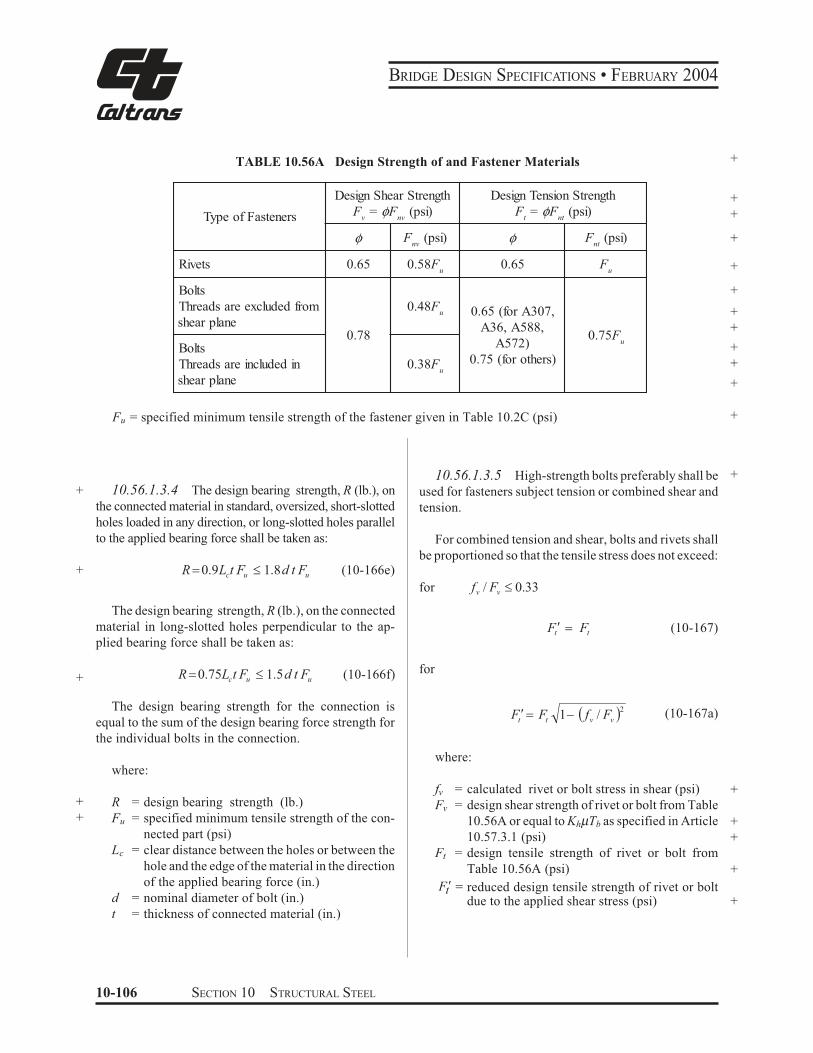
BRIDGE DESIGN SPECIFICATIONS • FEBRUARY 2004
TABLE 10.56A
Type of Fasteners
Rivets
Bolts
Threads are excluded from
shear plane
Bolts
Threads are included in
shear plane
+Design Strength of and Fastener Materials
Design Shear Strength
F = φF (psi)v nv
F (psi)φ nv
0.65 0.58Fu
0.48Fu
0.78
0.38Fu
Design Tension Strength +F = φF (psi) +t nt
φ
0.65
0.65 (for A307,
A36, A588,
A572)
0.75 (for others)
Fu = specified minimum tensile strength of the fastener given in Table 10.2C (psi)
Fnt
(psi) +
F +
+
+
+
u
0.75Fu
+
+
+
+
+ 10.56.1.3.4 The design bearing strength, R (lb.), on
the connected material in standard, oversized, short-slotted
holes loaded in any direction, or long-slotted holes parallel
to the applied bearing force shall be taken as:
+ R$0.9L t F " 1.8d t F (10-166e)c u u
The design bearing strength, R (lb.), on the connected
material in long-slotted holes perpendicular to the ap-
plied bearing force shall be taken as:
+ R$0.75Lct Fu " 1.5d t Fu (10-166f)
The design bearing strength for the connection is
equal to the sum of the design bearing force strength for
the individual bolts in the connection.
where:
+ R = design bearing strength (lb.)
+ Fu = specified minimum tensile strength of the con-
nected part (psi)
Lc = clear distance between the holes or between the
hole and the edge of the material in the direction
of the applied bearing force (in.)
d = nominal diameter of bolt (in.)
t = thickness of connected material (in.)
10.56.1.3.5 High-strength bolts preferably shall be +
used for fasteners subject tension or combined shear and
tension.
For combined tension and shear, bolts and rivets shall
be proportioned so that the tensile stress does not exceed:
for fv / Fv " 0.33
Ft! $ Ft (10-167)
for
F ! $ F 1) % f / F '2 (10-167a)t t v v
where:
fv = calculated rivet or bolt stress in shear (psi) +
Fv = design shear strength of rivet or bolt from Table
10.56A or equal to KhµTb as specified in Article +
10.57.3.1 (psi) +
Ft = design tensile strength of rivet or bolt from
Table 10.56A (psi) +
Ft! = reduced design tensile strength of rivet or bolt due to the applied shear stress (psi) +
10-106 SECTION 10 STRUCTURAL STEEL
BRIDGE DESIGN SPECIFICATIONS • FEBRUARY 2004
10.56.1.4 Slip-Critical Joints
Slip-critical joints shall be designed to prevent slip at
the overload in accordance with Article 10.57.3, but as a
minimum the bolts shall be capable of developing the
minimum strength requirements in bearing of Articles
10.18 and 10.19.
Potential slip of joints should be investigated at inter-
mediate load stages especially those joints located in
composite regions.
10.56.2 Bolts Subjected to Prying Action by Connected Parts
+ Bolts required to carry applied load by means of direct
tension shall be proportioned for the sum of the external
load and tension resulting from prying action produced
by deformation of the connected parts. The total tension
should not exceed the values given in Table 10.56A.
The tension due to prying actions shall be computed
as:
73b t3 8Q $ ) T9 : (10-168)
8a 20; <
where:
Q = prying tension per bolt (taken as zero when
+ negative) (lb.)
+ T = direct tension per bolt due to external load (lb.)
+ a = distance from center of bolt under consider-
+ ation to edge of plate (in.)
+ b = distance from center of bolt under consideration
+ to toe of fillet of connected part (in.)
+ t = thickness of thinnest part connected (in.)
10.56.3 Rigid Connections
10.56.3.1 All rigid frame connections, the rigidity
of which is essential to the continuity assumed as the
basis of design, shall be capable of resisting the moments,
shears, and axial loads to which they are subjected by
maximum loads.
+
+
10.56.3.2 The thickness of beam web shall meet
the following requirement:
-wt ,,/
*++.
(
cby
c
F d d
M3 (10-169)
where:
Mc = column moment (lb-in.)
db = beam depth (in.)
dc = column depth (in.)
+
+
+
When the thickness of the connection web does not
satisfy the above requirement, the web shall be strength-
ened by diagonal stiffeners or by a reinforcing plate in
contact with the web over the connection area.
At joints where the flanges of one member are rigidly
framed into one flange of another member, the thickness
of the web, tw, supporting the latter flange and the
thickness of the latter flange, tc, shall be checked by the
formulas below. Stiffeners are required on the web of the
second member opposite the compression flange of the
first member when
+
+
kt
At
b
f
w & 50 (10-170)
and opposite the tension flange of the first member when
ct 0 0.4 fA (10-171)
where:
tw
k
tb
tc
Af
= thickness of web to be stiffened (in.)
= distance from outer face of flange to toe of web
fillet of member to be stiffened (in.)
= thickness of flange delivering concentrated force
(in.)
= thickness of flange of member to be stiffened (in.)
= area of flange delivering concentrated load (in.2)
+
+
+
+
+
10.57 OVERLOAD
The overload is defined as Group 1 loading divided by
1.3. If moment distribution is permitted under the provi-
sions of Article 10.48.1.3, the limitations specified in
Articles 10.57.1 and 10.57.2 shall apply to the modified
+
+
SECTION 10 STRUCTURAL STEEL 10-107
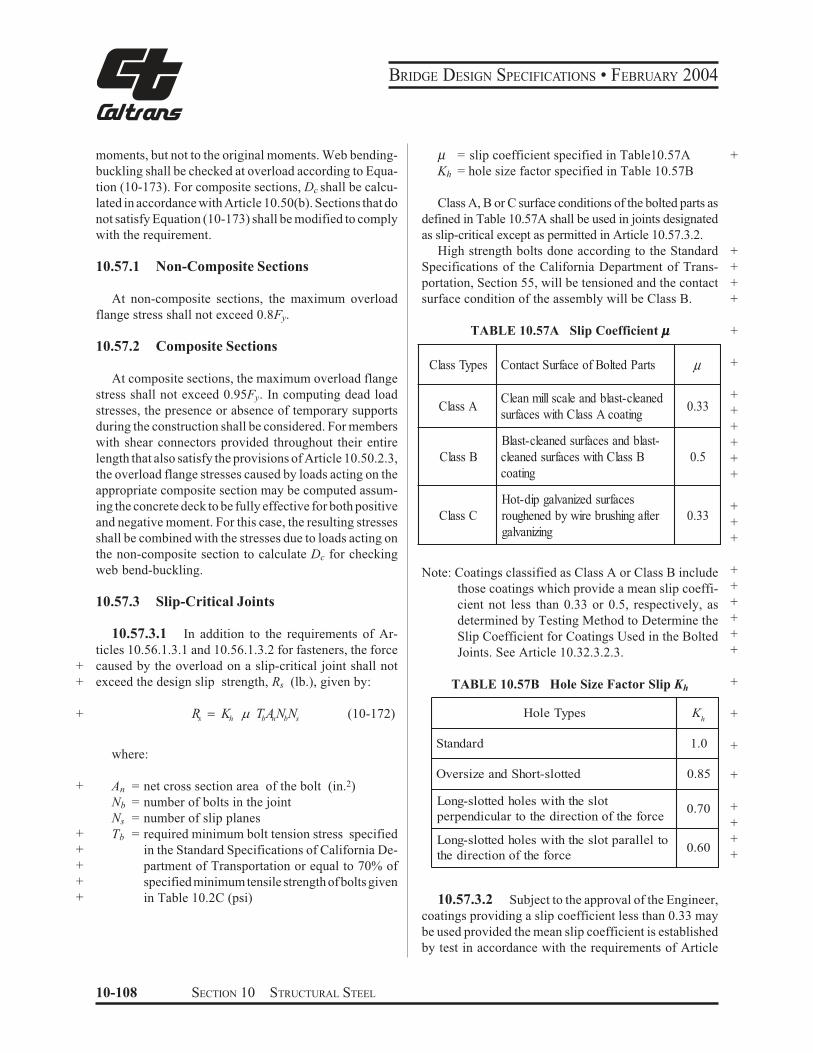
BRIDGE DESIGN SPECIFICATIONS • FEBRUARY 2004
moments, but not to the original moments. Web bending-
buckling shall be checked at overload according to Equa-
tion (10-173). For composite sections, Dc shall be calcu-
lated in accordance with Article 10.50(b). Sections that do
not satisfy Equation (10-173) shall be modified to comply
with the requirement.
10.57.1 Non-Composite Sections
At non-composite sections, the maximum overload
flange stress shall not exceed 0.8Fy.
10.57.2 Composite Sections
At composite sections, the maximum overload flange
stress shall not exceed 0.95Fy. In computing dead load
stresses, the presence or absence of temporary supports
during the construction shall be considered. For members
with shear connectors provided throughout their entire
length that also satisfy the provisions of Article 10.50.2.3,
the overload flange stresses caused by loads acting on the
appropriate composite section may be computed assum-
ing the concrete deck to be fully effective for both positive
and negative moment. For this case, the resulting stresses
shall be combined with the stresses due to loads acting on
the non-composite section to calculate Dc for checking
web bend-buckling.
10.57.3 Slip-Critical Joints
+
+
10.57.3.1 In addition to the requirements of Ar-
ticles 10.56.1.3.1 and 10.56.1.3.2 for fasteners, the force
caused by the overload on a slip-critical joint shall not
exceed the design slip strength, Rs (lb.), given by:
+ s hR K$ b n b sT A N N6 (10-172)
where:
+
+
+
+
+
+
An
Nb
Ns
Tb
= net cross section area of the bolt (in.2)
= number of bolts in the joint
= number of slip planes
= required minimum bolt tension stress specified
in the Standard Specifications of California De-
partment of Transportation or equal to 70% of
specified minimum tensile strength of bolts given
in Table 10.2C (psi)
µ = slip coefficient specified in Table10.57A
Kh = hole size factor specified in Table 10.57B
Class A, B or C surface conditions of the bolted parts as
defined in Table 10.57A shall be used in joints designated
as slip-critical except as permitted in Article 10.57.3.2.
High strength bolts done according to the Standard
Specifications of the California Department of Trans-
portation, Section 55, will be tensioned and the contact
surface condition of the assembly will be Class B.
TABLE 10.57A Slip Coefficient µµµµµ
Class Types Contact Surface of Bolted Parts µ
Class A Clean mill scale and blast-cleaned
surfaces with Class A coating 0.33
Class B
Blast-cleaned surfaces and blast-
cleaned surfaces with Class B
coating
0.5
Class C
Hot-dip galvanized surfaces
roughened by wire brushing after
galvanizing
0.33
Note: Coatings classified as Class A or Class B include
those coatings which provide a mean slip coeffi-
cient not less than 0.33 or 0.5, respectively, as
determined by Testing Method to Determine the
Slip Coefficient for Coatings Used in the Bolted
Joints. See Article 10.32.3.2.3.
TABLE 10.57B Hole Size Factor Slip Kh
Hole Types Kh
Standard 1.0
Oversize and Short-slotted 0.85
Long-slotted holes with the slot
perpendicular to the direction of the force 0.70
Long-slotted holes with the slot parallel to
the direction of the force 0.60
10.57.3.2 Subject to the approval of the Engineer,
coatings providing a slip coefficient less than 0.33 may
be used provided the mean slip coefficient is established
by test in accordance with the requirements of Article
+
+
+
+
+
+
+
+
+
+
+
+
+
+
+
+
+
+
+
+
+
+
+
+
+
+
+
+
+
+
10-108 SECTION 10 STRUCTURAL STEEL
BRIDGE DESIGN SPECIFICATIONS • FEBRUARY 2004
10.57.3.3, and the slip resistance per unit area estab-
lished. The slip resistance per unit area shall be taken as
equal to the slip resistance per unit area from Table
10.57A for Class A coatings as appropriate for the hole
type and bolt type times the slip coefficient determined
by test divided by 0.33.
10.57.3.3 Paint, used on the faying surfaces of
connections specified to be slip critical, shall be qualified
by test in accordance with ”Test Method to Determine the
Slip Coefficient for Coatings Used in Bolted Joints” as
adopted by the Research Council on Structural Connec-
tions. See Appendix A of Allowable Stress Design Speci-
fication for Structural Joints Using ASTM A 325 or A 490
Bolts, published by the Research Council on Structural
Connections.
10.57.3.4 For combined shear and tension in slip
critical joints where applied forces reduce the total clamp-
ing force on the friction plane, the slip force shall not
+ exceed the design slip strength given by:
+ Rs! $ Rs %1)1.88 f t / Fu ' (10-172b)
where:
+
+
+
+
+
+
ft
Rs
Fu
=
=
=
calculated tensile stress in the bolt due to ap-
plied loads including any stress due to prying
actions (psi)
design slip strength specified in Equation (10-
172) (lb.)
specified minimum tensile strength of the bolt
from Table 10.2C (psi)
10.58 FATIGUE
10.58.1 General
The analysis of the probability of fatigue of steel
members or connection under service loads and the
allowable range of stress for fatigue shall conform to
Article 10.3, except that the limitation imposed by the
basic criteria given in Article 10.3.1 shall not apply. For
members with shear connectors provided throughout
their entire length that also satisfy the provisions of
Article 10.50.2.3, the range of stress may be computed
using composite section assuming the concrete deck to be
fully effective for both positive and negative moment.
10.58.2 Composite Construction
10.58.2.1 Slab Reinforcement
When composite action is provided in the negative
moment region, the range of stress in slab reinforcement
shall be limited to 20,000 psi.
10.58.2.2 Shear Connectors
The shear connectors shall be designed for fatigue in
accordance with Article 10.38.5.1.
10.58.3 Hybrid Beams and Girders
Hybrid girders shall be designed for fatigue in accor-
dance with Article 10.3.
10.59 DEFLECTION
The control of deflection of steel or of composite steel
and concrete structures shall conform to the provision of
Article 10.6.
10.60 ORTHOTROPICSUPERSTRUCTURES
A rational analysis based on the Strength Design
Method, in accordance with the specifications, will be
considered as compliance with the specifications.
10.61 CONSTRUCTIBILITY
The Moment and shear capacity of a steel beam or
girder shall meet the requirements specified below to
control local buckling of the web and compression
flange, and to prevent lateral torsional buckling of the
cross section under the non-composite dead load prior to
hardening of the deck slab. The casting or placing se-
quence of the concrete deck specified in plans shall be
considered in determining the applied moments and
shears. A load factor γ = 1.3 shall be used in calculating
the applied moments and shears.
10.61.1 Web +
The maximum factored non-composite dead load
compressive bending stress in the web shall not exceed
the allowable design bending stress given below: +
SECTION 10 STRUCTURAL STEEL 10-109
BRIDGE DESIGN SPECIFICATIONS • FEBRUARY 2004
26,200,000α kFb = ≤ Fyw
D2 +
(10-173) tw where:
+ Fyw= specified minimum yield strength of the web (psi)+ Dc = depth of the web of the steel beam or girder in + compression (in.) + D = web depth (in.) tw = thickness of web (in.) k = 9(D/Dc)2 for members without a longitudinal stiffenerα = 1.3 for members without a longitudinal stiffener α = 1.0 for members with a longitudinal stiffener Sections without longitudinal stiffeners that do not satisfy Equation (10-173) shall either be modified to comply with the requirement or a longitudinal stiffener shall be added to the web at a location on the web that satisfies both Equation (10-173) and all strength require-ments, which may or may not correspond to the optimum location of the longitudinal stiffeners specified in Article 10.49.3.2(a). For longitudinally stiffened girders, the buckling coefficient, k is calculated as
for2 2
ds D D
≥ 0.4 k = 5.17 ≥ 9 Dc ds Dc
for2
ds D
< 0.4 k = 11.64 D c Dc − d s
where:ds = distance from the centerline of a plate longitudi-nal stiffener or the gage line of an angle longitu-+ dinal stiffener to the inner surface or the leg of+ the compression flange component (in.) The web thickness requirements specified in Articles 10.48.5.1, 10.48.6.1, 10.49.2 and 10.49.3.2(b) shall not be applied to the constructibility load case.
The sum of the factored non-composite and composite dead load shears shall not exceed design shear strength of the +web specified in Article 10.48.8.1 (Equation 10-113). 10.61.2 Deleted +10.61.3 Cross Section +
The maximum factored non-composite dead-load moment shall not exceed the value of Mu calculated for the steel beams or girder using the equations specified in Article 10.48.4.1. +10.61.4 Compression Flange
The ratio of the compression flange width to thickness in positive-moment regions shall meet the following requirement:b 4,400
≤ ≤ 24 (10-174) +t fdl
where:fdl = top-flange compressive stress due to the fac- +tored non-composite dead load divided by the +factor Rb specified in Article 10.48.4.1, but not to exceed Fy. (psi)
10-110 SECTION 10 STRUCTURAL STEEL