section viii
TRANSCRIPT
SECTION VII IRules for Construct ion of Pressure Vessels
ASME BPVC.VI I I .1-2019
Div is ion 1
2019 ASME Boiler andPressure Vessel CodeAn International Code
Copyright ASME International (BPVC) Provided by IHS under license with ASME Licensee=Khalda Petroleum/5986215001, User=Amer, Mohamed
Not for Resale, 07/02/2019 13:29:04 MDTNo reproduction or networking permitted without license from IHS
--`,``,``,,`,`,,````,`,``,,,`-`-`,,`,,`,`,,`---
Markings such as “ASME,” “ASME Standard,” or any other marking including “ASME,” ASME
logos, or the ASME Single Certification Mark shall not be used on any item that is not constructed
in accordance with all of the applicable requirements of the Code or Standard. Use of ASME’s
name or logos or of the ASME Single Certification Mark requires formal ASME certification; if no
certification program is available, such ASME markings may not be used. (For Certification and
Accreditation Programs, see https://www.asme.org/shop/certification‐accreditation.)
Items produced by parties not formally possessing an ASME Certificate may not be described,
either explicitly or implicitly, as ASME certified or approved in any code forms or other document.
Copyright ASME International (BPVC) Provided by IHS under license with ASME Licensee=Khalda Petroleum/5986215001, User=Amer, Mohamed
Not for Resale, 07/02/2019 13:29:04 MDTNo reproduction or networking permitted without license from IHS
--`,``,``,,`,`,,````,`,``,,,`-`-`,,`,,`,`,,`---

VIIIRULES FOR CONSTRUCTIONOF PRESSURE VESSELS
Division 1ASME Boiler and Pressure Vessel Committeeon Pressure Vessels
AN INTERNATIONAL CODE
2019 ASME Boiler &Pressure Vessel Code2019 Edition July 1, 2019
Two Park Avenue • New York, NY • 10016 USA
Copyright ASME International (BPVC) Provided by IHS under license with ASME Licensee=Khalda Petroleum/5986215001, User=Amer, Mohamed
Not for Resale, 07/02/2019 13:29:04 MDTNo reproduction or networking permitted without license from IHS
--`,``,``,,`,`,,````,`,``,,,`-`-`,,`,,`,`,,`---
Date of Issuance: July 1, 2019
This international code or standard was developed under procedures accredited as meeting the criteria forAmerican National Standards and it is an American National Standard. The Standards Committee that approvedthe code or standard was balanced to assure that individuals from competent and concerned interests havehad an opportunity to participate. The proposed code or standard was made available for public review and com-ment that provides an opportunity for additional public input from industry, academia, regulatory agencies, andthe public-at-large.ASME does not “approve," "certify," “rate,” or “endorse” any item, construction, proprietary device, or activity.ASME does not take any position with respect to the validity of any patent rights asserted in connection with any
items mentioned in this document, and does not undertake to insure anyone utilizing a standard against liabilityfor infringement of any applicable letters patent, nor assume any such liability. Users of a code or standard areexpressly advised that determination of the validity of any such patent rights, and the risk of infringement of suchrights, is entirely their own responsibility.Participation by federal agency representative(s) or person(s) affiliated with industry is not to be interpreted as
government or industry endorsement of this code or standard.ASME accepts responsibility for only those interpretations of this document issued in accordance with the es-
tablished ASME procedures and policies, which precludes the issuance of interpretations by individuals.The endnotes and preamble in this document (if any) are part of this American National Standard.
ASME Collective Membership Mark
ASME Single Certification Mark
"ASME" and the above ASME symbols are registered trademarks of The American Society of Mechanical Engineers.
No part of this document may be reproduced in any form, in an electronicretrieval system or otherwise, without the prior written permission of the
publisher.
Library of Congress Catalog Card Number: 56-3934Printed in the United States of America
Adopted by the Council of The American Society of Mechanical Engineers, 1914; latest edition 2019.
The American Society of Mechanical EngineersTwo Park Avenue, New York, NY 10016-5990
Copyright © 2019 byTHE AMERICAN SOCIETY OF MECHANICAL ENGINEERS
All rights reserved
Copyright ASME International (BPVC) Provided by IHS under license with ASME Licensee=Khalda Petroleum/5986215001, User=Amer, Mohamed
Not for Resale, 07/02/2019 13:29:04 MDTNo reproduction or networking permitted without license from IHS
--`,``,``,,`,`,,````,`,``,,,`-`-`,,`,,`,`,,`---

TABLE OF CONTENTS
List of Sections . . . . . . . . . . . . . . . . . . . . . . . . . . . . . . . . . . . . . . . . . . . . . . . . . . . . . . . . . . . . . . . . . . . . . . . . . . . . . . xxxiiiForeword . . . . . . . . . . . . . . . . . . . . . . . . . . . . . . . . . . . . . . . . . . . . . . . . . . . . . . . . . . . . . . . . . . . . . . . . . . . . . . . . . . . xxxvStatement of Policy on the Use of the ASME Single Certification Mark and Code Authorization in Advertising xxxviiStatement of Policy on the Use of ASME Marking to Identify Manufactured Items . . . . . . . . . . . . . . . . . . . . . . xxxviiSubmittal of Technical Inquiries to the Boiler and Pressure Vessel Standards Committees . . . . . . . . . . . . . . . xxxviiiPersonnel . . . . . . . . . . . . . . . . . . . . . . . . . . . . . . . . . . . . . . . . . . . . . . . . . . . . . . . . . . . . . . . . . . . . . . . . . . . . . . . . . . . xliSummary of Changes . . . . . . . . . . . . . . . . . . . . . . . . . . . . . . . . . . . . . . . . . . . . . . . . . . . . . . . . . . . . . . . . . . . . . . . . . lxiiiList of Changes in Record Number Order . . . . . . . . . . . . . . . . . . . . . . . . . . . . . . . . . . . . . . . . . . . . . . . . . . . . . . . . lxxiCross-Referencing and Stylistic Changes in the Boiler and Pressure Vessel Code . . . . . . . . . . . . . . . . . . . . . . . lxxvIntroduction . . . . . . . . . . . . . . . . . . . . . . . . . . . . . . . . . . . . . . . . . . . . . . . . . . . . . . . . . . . . . . . . . . . . . . . . . . . . . . . . . 1U-1 Scope . . . . . . . . . . . . . . . . . . . . . . . . . . . . . . . . . . . . . . . . . . . . . . . . . . . 1U-2 General . . . . . . . . . . . . . . . . . . . . . . . . . . . . . . . . . . . . . . . . . . . . . . . . . 3U-3 Standards Referenced by This Division . . . . . . . . . . . . . . . . . . . . . . 4U-4 Units of Measurement . . . . . . . . . . . . . . . . . . . . . . . . . . . . . . . . . . . . . 4U-5 Tolerances . . . . . . . . . . . . . . . . . . . . . . . . . . . . . . . . . . . . . . . . . . . . . . 5
Subsection A General Requirements . . . . . . . . . . . . . . . . . . . . . . . . . . . . . . . . . . . 7
Part UG General Requirements for All Methods of Construction and AllMaterials . . . . . . . . . . . . . . . . . . . . . . . . . . . . . . . . . . . . . . . . . . . . . 7
UG-1 Scope . . . . . . . . . . . . . . . . . . . . . . . . . . . . . . . . . . . . . . . . . . . . . . . . . . . 7Materials . . . . . . . . . . . . . . . . . . . . . . . . . . . . . . . . . . . . . . . . . . . . . . . . 7
UG-4 General . . . . . . . . . . . . . . . . . . . . . . . . . . . . . . . . . . . . . . . . . . . . . . . . . 7UG-5 Plate . . . . . . . . . . . . . . . . . . . . . . . . . . . . . . . . . . . . . . . . . . . . . . . . . . . 8UG-6 Forgings . . . . . . . . . . . . . . . . . . . . . . . . . . . . . . . . . . . . . . . . . . . . . . . . 8UG-7 Castings . . . . . . . . . . . . . . . . . . . . . . . . . . . . . . . . . . . . . . . . . . . . . . . . 8UG-8 Pipe and Tubes . . . . . . . . . . . . . . . . . . . . . . . . . . . . . . . . . . . . . . . . . . 8UG-9 Welding Materials . . . . . . . . . . . . . . . . . . . . . . . . . . . . . . . . . . . . . . . . 9UG-10 Material Identified With or Produced to a Specification Not Per-
mitted by This Division, and Material Not Fully Identified . . . . 9UG-11 Prefabricated or Preformed Pressure Parts Furnished Without a
Certification Mark . . . . . . . . . . . . . . . . . . . . . . . . . . . . . . . . . . . . . . 10UG-12 Bolts and Studs . . . . . . . . . . . . . . . . . . . . . . . . . . . . . . . . . . . . . . . . . . 12UG-13 Nuts and Washers . . . . . . . . . . . . . . . . . . . . . . . . . . . . . . . . . . . . . . . . 12UG-14 Rods and Bars . . . . . . . . . . . . . . . . . . . . . . . . . . . . . . . . . . . . . . . . . . . 12UG-15 Product Specification . . . . . . . . . . . . . . . . . . . . . . . . . . . . . . . . . . . . . 13
Design . . . . . . . . . . . . . . . . . . . . . . . . . . . . . . . . . . . . . . . . . . . . . . . . . . 13UG-16 General . . . . . . . . . . . . . . . . . . . . . . . . . . . . . . . . . . . . . . . . . . . . . . . . . 13UG-17 Methods of Fabrication in Combination . . . . . . . . . . . . . . . . . . . . . . 14UG-18 Materials in Combination . . . . . . . . . . . . . . . . . . . . . . . . . . . . . . . . . . 14UG-19 Special Constructions . . . . . . . . . . . . . . . . . . . . . . . . . . . . . . . . . . . . . 14UG-20 Design Temperature . . . . . . . . . . . . . . . . . . . . . . . . . . . . . . . . . . . . . . 15UG-21 Design Pressure . . . . . . . . . . . . . . . . . . . . . . . . . . . . . . . . . . . . . . . . . . 16UG-22 Loadings . . . . . . . . . . . . . . . . . . . . . . . . . . . . . . . . . . . . . . . . . . . . . . . . 16UG-23 Maximum Allowable Stress Values . . . . . . . . . . . . . . . . . . . . . . . . . . 16UG-24 Castings . . . . . . . . . . . . . . . . . . . . . . . . . . . . . . . . . . . . . . . . . . . . . . . . 17UG-25 Corrosion . . . . . . . . . . . . . . . . . . . . . . . . . . . . . . . . . . . . . . . . . . . . . . . 18UG-26 Linings . . . . . . . . . . . . . . . . . . . . . . . . . . . . . . . . . . . . . . . . . . . . . . . . . 19UG-27 Thickness of Shells Under Internal Pressure . . . . . . . . . . . . . . . . . . 19UG-28 Thickness of Shells and Tubes Under External Pressure . . . . . . . . 19
iii
Copyright ASME International (BPVC) Provided by IHS under license with ASME Licensee=Khalda Petroleum/5986215001, User=Amer, Mohamed
Not for Resale, 07/02/2019 13:29:04 MDTNo reproduction or networking permitted without license from IHS
--`,``,``,,`,`,,````,`,``,,,`-`-`,,`,,`,`,,`---
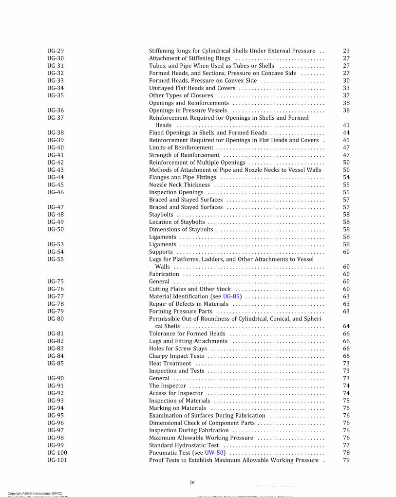
UG-29 Stiffening Rings for Cylindrical Shells Under External Pressure . . 23UG-30 Attachment of Stiffening Rings . . . . . . . . . . . . . . . . . . . . . . . . . . . . . 27UG-31 Tubes, and Pipe When Used as Tubes or Shells . . . . . . . . . . . . . . . 27UG-32 Formed Heads, and Sections, Pressure on Concave Side . . . . . . . . 27UG-33 Formed Heads, Pressure on Convex Side . . . . . . . . . . . . . . . . . . . . . 30UG-34 Unstayed Flat Heads and Covers . . . . . . . . . . . . . . . . . . . . . . . . . . . . 33UG-35 Other Types of Closures . . . . . . . . . . . . . . . . . . . . . . . . . . . . . . . . . . . 37
Openings and Reinforcements . . . . . . . . . . . . . . . . . . . . . . . . . . . . . . 38UG-36 Openings in Pressure Vessels . . . . . . . . . . . . . . . . . . . . . . . . . . . . . . 38UG-37 Reinforcement Required for Openings in Shells and Formed
Heads . . . . . . . . . . . . . . . . . . . . . . . . . . . . . . . . . . . . . . . . . . . . . . . . 41UG-38 Flued Openings in Shells and Formed Heads . . . . . . . . . . . . . . . . . . 44UG-39 Reinforcement Required for Openings in Flat Heads and Covers . 45UG-40 Limits of Reinforcement . . . . . . . . . . . . . . . . . . . . . . . . . . . . . . . . . . . 47UG-41 Strength of Reinforcement . . . . . . . . . . . . . . . . . . . . . . . . . . . . . . . . . 47UG-42 Reinforcement of Multiple Openings . . . . . . . . . . . . . . . . . . . . . . . . . 50UG-43 Methods of Attachment of Pipe and Nozzle Necks to Vessel Walls 50UG-44 Flanges and Pipe Fittings . . . . . . . . . . . . . . . . . . . . . . . . . . . . . . . . . . 54UG-45 Nozzle Neck Thickness . . . . . . . . . . . . . . . . . . . . . . . . . . . . . . . . . . . . 55UG-46 Inspection Openings . . . . . . . . . . . . . . . . . . . . . . . . . . . . . . . . . . . . . . 55
Braced and Stayed Surfaces . . . . . . . . . . . . . . . . . . . . . . . . . . . . . . . . 57UG-47 Braced and Stayed Surfaces . . . . . . . . . . . . . . . . . . . . . . . . . . . . . . . . 57UG-48 Staybolts . . . . . . . . . . . . . . . . . . . . . . . . . . . . . . . . . . . . . . . . . . . . . . . . 58UG-49 Location of Staybolts . . . . . . . . . . . . . . . . . . . . . . . . . . . . . . . . . . . . . . 58UG-50 Dimensions of Staybolts . . . . . . . . . . . . . . . . . . . . . . . . . . . . . . . . . . . 58
Ligaments . . . . . . . . . . . . . . . . . . . . . . . . . . . . . . . . . . . . . . . . . . . . . . . 58UG-53 Ligaments . . . . . . . . . . . . . . . . . . . . . . . . . . . . . . . . . . . . . . . . . . . . . . . 58UG-54 Supports . . . . . . . . . . . . . . . . . . . . . . . . . . . . . . . . . . . . . . . . . . . . . . . . 60UG-55 Lugs for Platforms, Ladders, and Other Attachments to Vessel
Walls . . . . . . . . . . . . . . . . . . . . . . . . . . . . . . . . . . . . . . . . . . . . . . . . . 60Fabrication . . . . . . . . . . . . . . . . . . . . . . . . . . . . . . . . . . . . . . . . . . . . . . 60
UG-75 General . . . . . . . . . . . . . . . . . . . . . . . . . . . . . . . . . . . . . . . . . . . . . . . . . 60UG-76 Cutting Plates and Other Stock . . . . . . . . . . . . . . . . . . . . . . . . . . . . . 60UG-77 Material Identification (see UG-85) . . . . . . . . . . . . . . . . . . . . . . . . . . 63UG-78 Repair of Defects in Materials . . . . . . . . . . . . . . . . . . . . . . . . . . . . . . 63UG-79 Forming Pressure Parts . . . . . . . . . . . . . . . . . . . . . . . . . . . . . . . . . . . 63UG-80 Permissible Out‐of‐Roundness of Cylindrical, Conical, and Spheri-
cal Shells . . . . . . . . . . . . . . . . . . . . . . . . . . . . . . . . . . . . . . . . . . . . . . 64UG-81 Tolerance for Formed Heads . . . . . . . . . . . . . . . . . . . . . . . . . . . . . . . 66UG-82 Lugs and Fitting Attachments . . . . . . . . . . . . . . . . . . . . . . . . . . . . . . 66UG-83 Holes for Screw Stays . . . . . . . . . . . . . . . . . . . . . . . . . . . . . . . . . . . . . 66UG-84 Charpy Impact Tests . . . . . . . . . . . . . . . . . . . . . . . . . . . . . . . . . . . . . . 66UG-85 Heat Treatment . . . . . . . . . . . . . . . . . . . . . . . . . . . . . . . . . . . . . . . . . . 73
Inspection and Tests . . . . . . . . . . . . . . . . . . . . . . . . . . . . . . . . . . . . . . 73UG-90 General . . . . . . . . . . . . . . . . . . . . . . . . . . . . . . . . . . . . . . . . . . . . . . . . . 73UG-91 The Inspector . . . . . . . . . . . . . . . . . . . . . . . . . . . . . . . . . . . . . . . . . . . . 74UG-92 Access for Inspector . . . . . . . . . . . . . . . . . . . . . . . . . . . . . . . . . . . . . . 74UG-93 Inspection of Materials . . . . . . . . . . . . . . . . . . . . . . . . . . . . . . . . . . . . 75UG-94 Marking on Materials . . . . . . . . . . . . . . . . . . . . . . . . . . . . . . . . . . . . . 76UG-95 Examination of Surfaces During Fabrication . . . . . . . . . . . . . . . . . . 76UG-96 Dimensional Check of Component Parts . . . . . . . . . . . . . . . . . . . . . . 76UG-97 Inspection During Fabrication . . . . . . . . . . . . . . . . . . . . . . . . . . . . . . 76UG-98 Maximum Allowable Working Pressure . . . . . . . . . . . . . . . . . . . . . . 76UG-99 Standard Hydrostatic Test . . . . . . . . . . . . . . . . . . . . . . . . . . . . . . . . . 77UG-100 Pneumatic Test (see UW-50) . . . . . . . . . . . . . . . . . . . . . . . . . . . . . . . 78UG-101 Proof Tests to Establish Maximum Allowable Working Pressure . 79
iv
Copyright ASME International (BPVC) Provided by IHS under license with ASME Licensee=Khalda Petroleum/5986215001, User=Amer, Mohamed
Not for Resale, 07/02/2019 13:29:04 MDTNo reproduction or networking permitted without license from IHS
--`,``,``,,`,`,,````,`,``,,,`-`-`,,`,,`,`,,`---

UG-102 Test Gages . . . . . . . . . . . . . . . . . . . . . . . . . . . . . . . . . . . . . . . . . . . . . . 84UG-103 Nondestructive Testing . . . . . . . . . . . . . . . . . . . . . . . . . . . . . . . . . . . . 84
Marking and Reports . . . . . . . . . . . . . . . . . . . . . . . . . . . . . . . . . . . . . 84UG-115 General . . . . . . . . . . . . . . . . . . . . . . . . . . . . . . . . . . . . . . . . . . . . . . . . . 84UG-116 Required Marking . . . . . . . . . . . . . . . . . . . . . . . . . . . . . . . . . . . . . . . . 84UG-117 Certificates of Authorization and Certification Marks . . . . . . . . . . . 86UG-118 Methods of Marking . . . . . . . . . . . . . . . . . . . . . . . . . . . . . . . . . . . . . . 87UG-119 Nameplates . . . . . . . . . . . . . . . . . . . . . . . . . . . . . . . . . . . . . . . . . . . . . 88UG-120 Data Reports . . . . . . . . . . . . . . . . . . . . . . . . . . . . . . . . . . . . . . . . . . . . 89
Overpressure Protection . . . . . . . . . . . . . . . . . . . . . . . . . . . . . . . . . . 91UG-125 General . . . . . . . . . . . . . . . . . . . . . . . . . . . . . . . . . . . . . . . . . . . . . . . . . 91UG-126 Pressure Relief Valves . . . . . . . . . . . . . . . . . . . . . . . . . . . . . . . . . . . . 92UG-127 Nonreclosing Pressure Relief Devices . . . . . . . . . . . . . . . . . . . . . . . . 92UG-128 Liquid Pressure Relief Valves . . . . . . . . . . . . . . . . . . . . . . . . . . . . . . 94UG-129 Marking . . . . . . . . . . . . . . . . . . . . . . . . . . . . . . . . . . . . . . . . . . . . . . . . 94UG-130 Certification Mark . . . . . . . . . . . . . . . . . . . . . . . . . . . . . . . . . . . . . . . . 97UG-131 Certification of Capacity of Pressure Relief Devices . . . . . . . . . . . . 97UG-132 Certification of Capacity of Pressure Relief Valves in Combination
With Nonreclosing Pressure Relief Devices . . . . . . . . . . . . . . . . . 101UG-133 Determination of Pressure-Relieving Requirements . . . . . . . . . . . . 102UG-134 Pressure Settings and Performance Requirements . . . . . . . . . . . . . 102UG-135 Installation . . . . . . . . . . . . . . . . . . . . . . . . . . . . . . . . . . . . . . . . . . . . . . 103UG-136 Minimum Requirements for Pressure Relief Valves . . . . . . . . . . . . 103UG-137 Minimum Requirements for Rupture Disk Devices . . . . . . . . . . . . . 108UG-138 Minimum Requirements for Pin Devices . . . . . . . . . . . . . . . . . . . . . 109UG-140 Overpressure Protection by System Design . . . . . . . . . . . . . . . . . . . 112
Subsection B Requirements Pertaining to Methods of Fabrication of Pres-sure Vessels . . . . . . . . . . . . . . . . . . . . . . . . . . . . . . . . . . . . . . . . . . 114
Part UW Requirements for Pressure Vessels Fabricated by Welding . . 114General . . . . . . . . . . . . . . . . . . . . . . . . . . . . . . . . . . . . . . . . . . . . . . . . . 114
UW-1 Scope . . . . . . . . . . . . . . . . . . . . . . . . . . . . . . . . . . . . . . . . . . . . . . . . . . . 114UW-2 Service Restrictions . . . . . . . . . . . . . . . . . . . . . . . . . . . . . . . . . . . . . . . 114UW-3 Welded Joint Category . . . . . . . . . . . . . . . . . . . . . . . . . . . . . . . . . . . . 115
Materials . . . . . . . . . . . . . . . . . . . . . . . . . . . . . . . . . . . . . . . . . . . . . . . . 116UW-5 General . . . . . . . . . . . . . . . . . . . . . . . . . . . . . . . . . . . . . . . . . . . . . . . . . 116UW-6 Nonmandatory Guidelines for Welding Material Selections . . . . . . 117
Design . . . . . . . . . . . . . . . . . . . . . . . . . . . . . . . . . . . . . . . . . . . . . . . . . . 117UW-8 General . . . . . . . . . . . . . . . . . . . . . . . . . . . . . . . . . . . . . . . . . . . . . . . . . 117UW-9 Design of Welded Joints . . . . . . . . . . . . . . . . . . . . . . . . . . . . . . . . . . . 117UW-10 Postweld Heat Treatment . . . . . . . . . . . . . . . . . . . . . . . . . . . . . . . . . . 119UW-11 Radiographic and Ultrasonic Examination . . . . . . . . . . . . . . . . . . . . 119UW-12 Joint Efficiencies . . . . . . . . . . . . . . . . . . . . . . . . . . . . . . . . . . . . . . . . . 120UW-13 Attachment Details . . . . . . . . . . . . . . . . . . . . . . . . . . . . . . . . . . . . . . . 120UW-14 Openings in or Adjacent to Welds . . . . . . . . . . . . . . . . . . . . . . . . . . . 129UW-15 Welded Connections . . . . . . . . . . . . . . . . . . . . . . . . . . . . . . . . . . . . . . 131UW-16 Minimum Requirements for Attachment Welds at Openings . . . . . 131UW-17 Plug Welds . . . . . . . . . . . . . . . . . . . . . . . . . . . . . . . . . . . . . . . . . . . . . . 141UW-18 Fillet Welds . . . . . . . . . . . . . . . . . . . . . . . . . . . . . . . . . . . . . . . . . . . . . 141UW-19 Welded Stayed Construction . . . . . . . . . . . . . . . . . . . . . . . . . . . . . . . 141UW-20 Tube‐to‐Tubesheet Welds . . . . . . . . . . . . . . . . . . . . . . . . . . . . . . . . . 143UW-21 ASME B16.5 Socket and Slip-on Flange Welds . . . . . . . . . . . . . . . . 145
Fabrication . . . . . . . . . . . . . . . . . . . . . . . . . . . . . . . . . . . . . . . . . . . . . . 145UW-26 General . . . . . . . . . . . . . . . . . . . . . . . . . . . . . . . . . . . . . . . . . . . . . . . . . 145UW-27 Welding Processes . . . . . . . . . . . . . . . . . . . . . . . . . . . . . . . . . . . . . . . . 146UW-28 Qualification of Welding Procedure . . . . . . . . . . . . . . . . . . . . . . . . . 146
v
Copyright ASME International (BPVC) Provided by IHS under license with ASME Licensee=Khalda Petroleum/5986215001, User=Amer, Mohamed
Not for Resale, 07/02/2019 13:29:04 MDTNo reproduction or networking permitted without license from IHS
--`,``,``,,`,`,,````,`,``,,,`-`-`,,`,,`,`,,`---
UW-29 Tests of Welders and Welding Operators . . . . . . . . . . . . . . . . . . . . . 147UW-30 Lowest Permissible Temperatures for Welding . . . . . . . . . . . . . . . 147UW-31 Cutting, Fitting, and Alignment . . . . . . . . . . . . . . . . . . . . . . . . . . . . . 147UW-32 Cleaning of Surfaces to Be Welded . . . . . . . . . . . . . . . . . . . . . . . . . . 148UW-33 Alignment Tolerance . . . . . . . . . . . . . . . . . . . . . . . . . . . . . . . . . . . . . . 148UW-34 Spin‐Holes . . . . . . . . . . . . . . . . . . . . . . . . . . . . . . . . . . . . . . . . . . . . . . 148UW-35 Finished Longitudinal and Circumferential Joints . . . . . . . . . . . . . . 148UW-36 Fillet Welds . . . . . . . . . . . . . . . . . . . . . . . . . . . . . . . . . . . . . . . . . . . . . 149UW-37 Miscellaneous Welding Requirements . . . . . . . . . . . . . . . . . . . . . . . 149UW-38 Repair of Weld Defects . . . . . . . . . . . . . . . . . . . . . . . . . . . . . . . . . . . . 150UW-39 Peening . . . . . . . . . . . . . . . . . . . . . . . . . . . . . . . . . . . . . . . . . . . . . . . . . 150UW-40 Procedures for Postweld Heat Treatment . . . . . . . . . . . . . . . . . . . . 150UW-41 Sectioning of Welded Joints . . . . . . . . . . . . . . . . . . . . . . . . . . . . . . . . 152UW-42 Surface Weld Metal Buildup . . . . . . . . . . . . . . . . . . . . . . . . . . . . . . . . 152
Inspection and Tests . . . . . . . . . . . . . . . . . . . . . . . . . . . . . . . . . . . . . . 152UW-46 General . . . . . . . . . . . . . . . . . . . . . . . . . . . . . . . . . . . . . . . . . . . . . . . . . 152UW-47 Check of Welding Procedure . . . . . . . . . . . . . . . . . . . . . . . . . . . . . . . 152UW-48 Check of Welder and Welding Operator Qualifications . . . . . . . . . 152UW-49 Check of Postweld Heat Treatment Practice . . . . . . . . . . . . . . . . . . 152UW-50 Nondestructive Examination of Welds on Pneumatically Tested
Vessels . . . . . . . . . . . . . . . . . . . . . . . . . . . . . . . . . . . . . . . . . . . . . . . 152UW-51 Radiographic Examination of Welded Joints . . . . . . . . . . . . . . . . . . 153UW-52 Spot Examination of Welded Joints . . . . . . . . . . . . . . . . . . . . . . . . . . 153UW-53 Ultrasonic Examination of Welded Joints . . . . . . . . . . . . . . . . . . . . . 154UW-54 Qualification of Nondestructive Examination Personnel . . . . . . . . 154
Marking and Reports . . . . . . . . . . . . . . . . . . . . . . . . . . . . . . . . . . . . . 154UW-60 General . . . . . . . . . . . . . . . . . . . . . . . . . . . . . . . . . . . . . . . . . . . . . . . . . 154
Part UF Requirements for Pressure Vessels Fabricated by Forging . . 155General . . . . . . . . . . . . . . . . . . . . . . . . . . . . . . . . . . . . . . . . . . . . . . . . . 155
UF-1 Scope . . . . . . . . . . . . . . . . . . . . . . . . . . . . . . . . . . . . . . . . . . . . . . . . . . . 155Materials . . . . . . . . . . . . . . . . . . . . . . . . . . . . . . . . . . . . . . . . . . . . . . . . 155
UF-5 General . . . . . . . . . . . . . . . . . . . . . . . . . . . . . . . . . . . . . . . . . . . . . . . . . 155UF-6 Forgings . . . . . . . . . . . . . . . . . . . . . . . . . . . . . . . . . . . . . . . . . . . . . . . . 155UF-7 Forged Steel Rolls Used for Corrugating Paper Machinery . . . . . . 155
Design . . . . . . . . . . . . . . . . . . . . . . . . . . . . . . . . . . . . . . . . . . . . . . . . . . 155UF-12 General . . . . . . . . . . . . . . . . . . . . . . . . . . . . . . . . . . . . . . . . . . . . . . . . . 155UF-13 Head Design . . . . . . . . . . . . . . . . . . . . . . . . . . . . . . . . . . . . . . . . . . . . . 155UF-25 Corrosion Allowance . . . . . . . . . . . . . . . . . . . . . . . . . . . . . . . . . . . . . . 156
Fabrication . . . . . . . . . . . . . . . . . . . . . . . . . . . . . . . . . . . . . . . . . . . . . . 156UF-26 General . . . . . . . . . . . . . . . . . . . . . . . . . . . . . . . . . . . . . . . . . . . . . . . . . 156UF-27 Tolerances on Body Forgings . . . . . . . . . . . . . . . . . . . . . . . . . . . . . . . 156UF-28 Methods of Forming Forged Heads . . . . . . . . . . . . . . . . . . . . . . . . . . 156UF-29 Tolerance on Forged Heads . . . . . . . . . . . . . . . . . . . . . . . . . . . . . . . . 156UF-30 Localized Thin Areas . . . . . . . . . . . . . . . . . . . . . . . . . . . . . . . . . . . . . . 156UF-31 Heat Treatment . . . . . . . . . . . . . . . . . . . . . . . . . . . . . . . . . . . . . . . . . . 156UF-32 Welding for Fabrication . . . . . . . . . . . . . . . . . . . . . . . . . . . . . . . . . . . 157UF-37 Repair of Defects in Material . . . . . . . . . . . . . . . . . . . . . . . . . . . . . . . 158UF-38 Repair of Weld Defects . . . . . . . . . . . . . . . . . . . . . . . . . . . . . . . . . . . . 158UF-43 Attachment of Threaded Nozzles to Integrally Forged Necks and
Thickened Heads on Vessels . . . . . . . . . . . . . . . . . . . . . . . . . . . . . 158Inspection and Tests . . . . . . . . . . . . . . . . . . . . . . . . . . . . . . . . . . . . . . 159
UF-45 General . . . . . . . . . . . . . . . . . . . . . . . . . . . . . . . . . . . . . . . . . . . . . . . . . 159UF-46 Acceptance by Inspector . . . . . . . . . . . . . . . . . . . . . . . . . . . . . . . . . . . 159UF-47 Parts Forging . . . . . . . . . . . . . . . . . . . . . . . . . . . . . . . . . . . . . . . . . . . . 159UF-52 Check of Heat Treatment and Postweld Heat Treatment . . . . . . . . 159UF-53 Test Specimens . . . . . . . . . . . . . . . . . . . . . . . . . . . . . . . . . . . . . . . . . . 159
vi
Copyright ASME International (BPVC) Provided by IHS under license with ASME Licensee=Khalda Petroleum/5986215001, User=Amer, Mohamed
Not for Resale, 07/02/2019 13:29:04 MDTNo reproduction or networking permitted without license from IHS
--`,``,``,,`,`,,````,`,``,,,`-`-`,,`,,`,`,,`---
UF-54 Tests and Retests . . . . . . . . . . . . . . . . . . . . . . . . . . . . . . . . . . . . . . . . 159UF-55 Ultrasonic Examination . . . . . . . . . . . . . . . . . . . . . . . . . . . . . . . . . . . . 159
Marking and Reports . . . . . . . . . . . . . . . . . . . . . . . . . . . . . . . . . . . . . 159UF-115 General . . . . . . . . . . . . . . . . . . . . . . . . . . . . . . . . . . . . . . . . . . . . . . . . . 159
Part UB Requirements for Pressure Vessels Fabricated by Brazing . . 160General . . . . . . . . . . . . . . . . . . . . . . . . . . . . . . . . . . . . . . . . . . . . . . . . . 160
UB-1 Scope . . . . . . . . . . . . . . . . . . . . . . . . . . . . . . . . . . . . . . . . . . . . . . . . . . . 160UB-2 Elevated Temperature . . . . . . . . . . . . . . . . . . . . . . . . . . . . . . . . . . . . 160UB-3 Service Restrictions . . . . . . . . . . . . . . . . . . . . . . . . . . . . . . . . . . . . . . . 160
Materials . . . . . . . . . . . . . . . . . . . . . . . . . . . . . . . . . . . . . . . . . . . . . . . . 160UB-5 General . . . . . . . . . . . . . . . . . . . . . . . . . . . . . . . . . . . . . . . . . . . . . . . . . 160UB-6 Brazing Filler Metals . . . . . . . . . . . . . . . . . . . . . . . . . . . . . . . . . . . . . . 161UB-7 Fluxes and Atmospheres . . . . . . . . . . . . . . . . . . . . . . . . . . . . . . . . . . 161
Design . . . . . . . . . . . . . . . . . . . . . . . . . . . . . . . . . . . . . . . . . . . . . . . . . . 161UB-9 General . . . . . . . . . . . . . . . . . . . . . . . . . . . . . . . . . . . . . . . . . . . . . . . . . 161UB-10 Strength of Brazed Joints . . . . . . . . . . . . . . . . . . . . . . . . . . . . . . . . . . 161UB-11 Qualification of Brazed Joints for Design Temperatures Up to the
Maximum Shown in Column 1 of Table UB-2 . . . . . . . . . . . . . . . 161UB-12 Qualification of Brazed Joints for Design Temperatures in the
Range Shown in Column 2 of Table UB-2 . . . . . . . . . . . . . . . . . . 161UB-13 Corrosion . . . . . . . . . . . . . . . . . . . . . . . . . . . . . . . . . . . . . . . . . . . . . . . 161UB-14 Joint Efficiency Factors . . . . . . . . . . . . . . . . . . . . . . . . . . . . . . . . . . . . 161UB-15 Application of Brazing Filler Metal . . . . . . . . . . . . . . . . . . . . . . . . . . 161UB-16 Permissible Types of Joints . . . . . . . . . . . . . . . . . . . . . . . . . . . . . . . . 162UB-17 Joint Clearance . . . . . . . . . . . . . . . . . . . . . . . . . . . . . . . . . . . . . . . . . . . 162UB-18 Joint Brazing Procedure . . . . . . . . . . . . . . . . . . . . . . . . . . . . . . . . . . . 163UB-19 Openings . . . . . . . . . . . . . . . . . . . . . . . . . . . . . . . . . . . . . . . . . . . . . . . . 163UB-20 Nozzles . . . . . . . . . . . . . . . . . . . . . . . . . . . . . . . . . . . . . . . . . . . . . . . . . 163UB-21 Brazed Connections . . . . . . . . . . . . . . . . . . . . . . . . . . . . . . . . . . . . . . . 163UB-22 Low Temperature Operation . . . . . . . . . . . . . . . . . . . . . . . . . . . . . . . 164
Fabrication . . . . . . . . . . . . . . . . . . . . . . . . . . . . . . . . . . . . . . . . . . . . . . 164UB-30 General . . . . . . . . . . . . . . . . . . . . . . . . . . . . . . . . . . . . . . . . . . . . . . . . . 164UB-31 Qualification of Brazing Procedure . . . . . . . . . . . . . . . . . . . . . . . . . . 164UB-32 Qualification of Brazers and Brazing Operators . . . . . . . . . . . . . . . 164UB-33 Buttstraps . . . . . . . . . . . . . . . . . . . . . . . . . . . . . . . . . . . . . . . . . . . . . . . 165UB-34 Cleaning of Surfaces to Be Brazed . . . . . . . . . . . . . . . . . . . . . . . . . . . 165UB-35 Clearance Between Surfaces to Be Brazed . . . . . . . . . . . . . . . . . . . . 165UB-36 Postbrazing Operations . . . . . . . . . . . . . . . . . . . . . . . . . . . . . . . . . . . 165UB-37 Repair of Defective Brazing . . . . . . . . . . . . . . . . . . . . . . . . . . . . . . . . 165
Inspection and Tests . . . . . . . . . . . . . . . . . . . . . . . . . . . . . . . . . . . . . . 165UB-40 General . . . . . . . . . . . . . . . . . . . . . . . . . . . . . . . . . . . . . . . . . . . . . . . . . 165UB-41 Inspection During Fabrication . . . . . . . . . . . . . . . . . . . . . . . . . . . . . . 165UB-42 Procedure . . . . . . . . . . . . . . . . . . . . . . . . . . . . . . . . . . . . . . . . . . . . . . . 165UB-43 Brazer and Brazing Operator . . . . . . . . . . . . . . . . . . . . . . . . . . . . . . . 165UB-44 Visual Examination . . . . . . . . . . . . . . . . . . . . . . . . . . . . . . . . . . . . . . . 166UB-50 Exemptions . . . . . . . . . . . . . . . . . . . . . . . . . . . . . . . . . . . . . . . . . . . . . 166
Marking and Reports . . . . . . . . . . . . . . . . . . . . . . . . . . . . . . . . . . . . . 166UB-55 General . . . . . . . . . . . . . . . . . . . . . . . . . . . . . . . . . . . . . . . . . . . . . . . . . 166
Subsection C Requirements Pertaining to Classes of Materials . . . . . . . . . . . 167
Part UCS Requirements for Pressure Vessels Constructed of Carbon andLow Alloy Steels . . . . . . . . . . . . . . . . . . . . . . . . . . . . . . . . . . . . . . 167
General . . . . . . . . . . . . . . . . . . . . . . . . . . . . . . . . . . . . . . . . . . . . . . . . . 167UCS-1 Scope . . . . . . . . . . . . . . . . . . . . . . . . . . . . . . . . . . . . . . . . . . . . . . . . . . . 167
Materials . . . . . . . . . . . . . . . . . . . . . . . . . . . . . . . . . . . . . . . . . . . . . . . . 167UCS-5 General . . . . . . . . . . . . . . . . . . . . . . . . . . . . . . . . . . . . . . . . . . . . . . . . . 167
vii
Copyright ASME International (BPVC) Provided by IHS under license with ASME Licensee=Khalda Petroleum/5986215001, User=Amer, Mohamed
Not for Resale, 07/02/2019 13:29:04 MDTNo reproduction or networking permitted without license from IHS
--`,``,``,,`,`,,````,`,``,,,`-`-`,,`,,`,`,,`---

UCS-6 Steel Plates . . . . . . . . . . . . . . . . . . . . . . . . . . . . . . . . . . . . . . . . . . . . . . 167UCS-7 Steel Forgings . . . . . . . . . . . . . . . . . . . . . . . . . . . . . . . . . . . . . . . . . . . 168UCS-8 Steel Castings . . . . . . . . . . . . . . . . . . . . . . . . . . . . . . . . . . . . . . . . . . . . 168UCS-9 Steel Pipe and Tubes . . . . . . . . . . . . . . . . . . . . . . . . . . . . . . . . . . . . . . 168UCS-10 Bolt Materials . . . . . . . . . . . . . . . . . . . . . . . . . . . . . . . . . . . . . . . . . . . . 168UCS-11 Nuts and Washers . . . . . . . . . . . . . . . . . . . . . . . . . . . . . . . . . . . . . . . . 168UCS-12 Bars and Shapes . . . . . . . . . . . . . . . . . . . . . . . . . . . . . . . . . . . . . . . . . 168
Design . . . . . . . . . . . . . . . . . . . . . . . . . . . . . . . . . . . . . . . . . . . . . . . . . . 168UCS-16 General . . . . . . . . . . . . . . . . . . . . . . . . . . . . . . . . . . . . . . . . . . . . . . . . . 168UCS-19 Welded Joints . . . . . . . . . . . . . . . . . . . . . . . . . . . . . . . . . . . . . . . . . . . . 169UCS-23 Maximum Allowable Stress Values . . . . . . . . . . . . . . . . . . . . . . . . . . 169UCS-27 Shells Made From Pipe . . . . . . . . . . . . . . . . . . . . . . . . . . . . . . . . . . . . 169UCS-28 Thickness of Shells Under External Pressure . . . . . . . . . . . . . . . . . . 170UCS-29 Stiffening Rings for Shells Under External Pressure . . . . . . . . . . . . 170UCS-30 Attachment of Stiffening Rings to Shell . . . . . . . . . . . . . . . . . . . . . . 170UCS-33 Formed Heads, Pressure on Convex Side . . . . . . . . . . . . . . . . . . . . . 170UCS-56 Requirements for Postweld Heat Treatment . . . . . . . . . . . . . . . . . . 170UCS-57 Radiographic Examination . . . . . . . . . . . . . . . . . . . . . . . . . . . . . . . . . 181
Low Temperature Operation . . . . . . . . . . . . . . . . . . . . . . . . . . . . . . . 181UCS-65 Scope . . . . . . . . . . . . . . . . . . . . . . . . . . . . . . . . . . . . . . . . . . . . . . . . . . . 181UCS-66 Materials . . . . . . . . . . . . . . . . . . . . . . . . . . . . . . . . . . . . . . . . . . . . . . . . 181UCS-67 Impact Tests of Welding Procedures . . . . . . . . . . . . . . . . . . . . . . . . 197UCS-68 Design . . . . . . . . . . . . . . . . . . . . . . . . . . . . . . . . . . . . . . . . . . . . . . . . . . 197
Fabrication . . . . . . . . . . . . . . . . . . . . . . . . . . . . . . . . . . . . . . . . . . . . . . 198UCS-75 General . . . . . . . . . . . . . . . . . . . . . . . . . . . . . . . . . . . . . . . . . . . . . . . . . 198UCS-79 Forming Pressure Parts . . . . . . . . . . . . . . . . . . . . . . . . . . . . . . . . . . . 198UCS-85 Heat Treatment of Test Specimens . . . . . . . . . . . . . . . . . . . . . . . . . . 198
Inspection and Tests . . . . . . . . . . . . . . . . . . . . . . . . . . . . . . . . . . . . . . 200UCS-90 General . . . . . . . . . . . . . . . . . . . . . . . . . . . . . . . . . . . . . . . . . . . . . . . . . 200
Marking and Reports . . . . . . . . . . . . . . . . . . . . . . . . . . . . . . . . . . . . . 200UCS-115 General . . . . . . . . . . . . . . . . . . . . . . . . . . . . . . . . . . . . . . . . . . . . . . . . . 200
Nonmandatory Appendix UCS-A . . . . . . . . . . . . . . . . . . . . . . . . . . . . . . . . . . . . . . . . . . . . . . . . . . . . . . . . 201UCS-A-1 General . . . . . . . . . . . . . . . . . . . . . . . . . . . . . . . . . . . . . . . . . . . . . . . . . 201UCS-A-2 Creep–Rupture Properties of Carbon Steels . . . . . . . . . . . . . . . . . . . 201UCS-A-3 Vessels Operating at Temperatures Colder Than the MDMT
Stamped on the Nameplate . . . . . . . . . . . . . . . . . . . . . . . . . . . . . . 201
Part UNF Requirements for Pressure Vessels Constructed of NonferrousMaterials . . . . . . . . . . . . . . . . . . . . . . . . . . . . . . . . . . . . . . . . . . . . . 202
General . . . . . . . . . . . . . . . . . . . . . . . . . . . . . . . . . . . . . . . . . . . . . . . . . 202UNF-1 Scope . . . . . . . . . . . . . . . . . . . . . . . . . . . . . . . . . . . . . . . . . . . . . . . . . . . 202UNF-3 Uses . . . . . . . . . . . . . . . . . . . . . . . . . . . . . . . . . . . . . . . . . . . . . . . . . . . . 202UNF-4 Conditions of Service . . . . . . . . . . . . . . . . . . . . . . . . . . . . . . . . . . . . . 202
Materials . . . . . . . . . . . . . . . . . . . . . . . . . . . . . . . . . . . . . . . . . . . . . . . . 202UNF-5 General . . . . . . . . . . . . . . . . . . . . . . . . . . . . . . . . . . . . . . . . . . . . . . . . . 202UNF-6 Nonferrous Plate . . . . . . . . . . . . . . . . . . . . . . . . . . . . . . . . . . . . . . . . . 202UNF-7 Forgings . . . . . . . . . . . . . . . . . . . . . . . . . . . . . . . . . . . . . . . . . . . . . . . . 202UNF-8 Castings . . . . . . . . . . . . . . . . . . . . . . . . . . . . . . . . . . . . . . . . . . . . . . . . 202UNF-12 Bolt Materials . . . . . . . . . . . . . . . . . . . . . . . . . . . . . . . . . . . . . . . . . . . . 202UNF-13 Nuts and Washers . . . . . . . . . . . . . . . . . . . . . . . . . . . . . . . . . . . . . . . . 203UNF-14 Rods, Bars, and Shapes . . . . . . . . . . . . . . . . . . . . . . . . . . . . . . . . . . . . 203UNF-15 Other Materials . . . . . . . . . . . . . . . . . . . . . . . . . . . . . . . . . . . . . . . . . . 203
Design . . . . . . . . . . . . . . . . . . . . . . . . . . . . . . . . . . . . . . . . . . . . . . . . . . 203UNF-16 General . . . . . . . . . . . . . . . . . . . . . . . . . . . . . . . . . . . . . . . . . . . . . . . . . 203UNF-19 Welded Joints . . . . . . . . . . . . . . . . . . . . . . . . . . . . . . . . . . . . . . . . . . . . 203UNF-23 Maximum Allowable Stress Values . . . . . . . . . . . . . . . . . . . . . . . . . . 203
viii
Copyright ASME International (BPVC) Provided by IHS under license with ASME Licensee=Khalda Petroleum/5986215001, User=Amer, Mohamed
Not for Resale, 07/02/2019 13:29:04 MDTNo reproduction or networking permitted without license from IHS
--`,``,``,,`,`,,````,`,``,,,`-`-`,,`,,`,`,,`---
UNF-28 Thickness of Shells Under External Pressure . . . . . . . . . . . . . . . . . . 206UNF-30 Stiffening Rings . . . . . . . . . . . . . . . . . . . . . . . . . . . . . . . . . . . . . . . . . . 206UNF-33 Formed Heads, Pressure on Convex Side . . . . . . . . . . . . . . . . . . . . . 206UNF-56 Postweld Heat Treatment . . . . . . . . . . . . . . . . . . . . . . . . . . . . . . . . . . 206UNF-57 Radiographic Examination . . . . . . . . . . . . . . . . . . . . . . . . . . . . . . . . . 207UNF-58 Liquid Penetrant Examination . . . . . . . . . . . . . . . . . . . . . . . . . . . . . . 207UNF-65 Low Temperature Operation . . . . . . . . . . . . . . . . . . . . . . . . . . . . . . . 207
Fabrication . . . . . . . . . . . . . . . . . . . . . . . . . . . . . . . . . . . . . . . . . . . . . . 207UNF-75 General . . . . . . . . . . . . . . . . . . . . . . . . . . . . . . . . . . . . . . . . . . . . . . . . . 207UNF-77 Forming Shell Sections and Heads . . . . . . . . . . . . . . . . . . . . . . . . . . 208UNF-78 Welding . . . . . . . . . . . . . . . . . . . . . . . . . . . . . . . . . . . . . . . . . . . . . . . . 208UNF-79 Requirements for Postfabrication Heat Treatment Due to
Straining . . . . . . . . . . . . . . . . . . . . . . . . . . . . . . . . . . . . . . . . . . . . . . 208Inspection and Tests . . . . . . . . . . . . . . . . . . . . . . . . . . . . . . . . . . . . . . 208
UNF-90 General . . . . . . . . . . . . . . . . . . . . . . . . . . . . . . . . . . . . . . . . . . . . . . . . . 208UNF-91 Requirements for the Image Quality Indicator . . . . . . . . . . . . . . . . 208UNF-95 Welding Test Plates . . . . . . . . . . . . . . . . . . . . . . . . . . . . . . . . . . . . . . 208
Marking and Reports . . . . . . . . . . . . . . . . . . . . . . . . . . . . . . . . . . . . . 208UNF-115 General . . . . . . . . . . . . . . . . . . . . . . . . . . . . . . . . . . . . . . . . . . . . . . . . . 208
Nonmandatory Appendix UNF-A Characteristics of the Nonferrous Materials . . . . . . . . . . . . . . . . 210UNF-A-1 Purpose . . . . . . . . . . . . . . . . . . . . . . . . . . . . . . . . . . . . . . . . . . . . . . . . . 210UNF-A-2 General . . . . . . . . . . . . . . . . . . . . . . . . . . . . . . . . . . . . . . . . . . . . . . . . . 210UNF-A-3 Properties . . . . . . . . . . . . . . . . . . . . . . . . . . . . . . . . . . . . . . . . . . . . . . . 210UNF-A-4 Magnetic Properties . . . . . . . . . . . . . . . . . . . . . . . . . . . . . . . . . . . . . . 210UNF-A-5 Elevated Temperature Effects . . . . . . . . . . . . . . . . . . . . . . . . . . . . . . 210UNF-A-6 Low Temperature Behavior . . . . . . . . . . . . . . . . . . . . . . . . . . . . . . . . 210UNF-A-7 Thermal Cutting . . . . . . . . . . . . . . . . . . . . . . . . . . . . . . . . . . . . . . . . . . 210UNF-A-8 Machining . . . . . . . . . . . . . . . . . . . . . . . . . . . . . . . . . . . . . . . . . . . . . . . 210UNF-A-9 Gas Welding . . . . . . . . . . . . . . . . . . . . . . . . . . . . . . . . . . . . . . . . . . . . . 210UNF-A-10 Metal Arc Welding . . . . . . . . . . . . . . . . . . . . . . . . . . . . . . . . . . . . . . . . 211UNF-A-11 Inert Gas Metal Arc Welding . . . . . . . . . . . . . . . . . . . . . . . . . . . . . . . 211UNF-A-12 Resistance Welding . . . . . . . . . . . . . . . . . . . . . . . . . . . . . . . . . . . . . . . 211UNF-A-13 Corrosion . . . . . . . . . . . . . . . . . . . . . . . . . . . . . . . . . . . . . . . . . . . . . . . 211UNF-A-14 Special Comments . . . . . . . . . . . . . . . . . . . . . . . . . . . . . . . . . . . . . . . . 211
Part UHA Requirements for Pressure Vessels Constructed of High AlloySteel . . . . . . . . . . . . . . . . . . . . . . . . . . . . . . . . . . . . . . . . . . . . . . . . . 212
General . . . . . . . . . . . . . . . . . . . . . . . . . . . . . . . . . . . . . . . . . . . . . . . . . 212UHA-1 Scope . . . . . . . . . . . . . . . . . . . . . . . . . . . . . . . . . . . . . . . . . . . . . . . . . . . 212UHA-5 Uses . . . . . . . . . . . . . . . . . . . . . . . . . . . . . . . . . . . . . . . . . . . . . . . . . . . . 212UHA-6 Conditions of Service . . . . . . . . . . . . . . . . . . . . . . . . . . . . . . . . . . . . . 212UHA-8 Material . . . . . . . . . . . . . . . . . . . . . . . . . . . . . . . . . . . . . . . . . . . . . . . . 212
Materials . . . . . . . . . . . . . . . . . . . . . . . . . . . . . . . . . . . . . . . . . . . . . . . . 212UHA-11 General . . . . . . . . . . . . . . . . . . . . . . . . . . . . . . . . . . . . . . . . . . . . . . . . . 212UHA-12 Bolt Materials . . . . . . . . . . . . . . . . . . . . . . . . . . . . . . . . . . . . . . . . . . . . 212UHA-13 Nuts and Washers . . . . . . . . . . . . . . . . . . . . . . . . . . . . . . . . . . . . . . . . 212
Design . . . . . . . . . . . . . . . . . . . . . . . . . . . . . . . . . . . . . . . . . . . . . . . . . . 213UHA-20 General . . . . . . . . . . . . . . . . . . . . . . . . . . . . . . . . . . . . . . . . . . . . . . . . . 213UHA-21 Welded Joints . . . . . . . . . . . . . . . . . . . . . . . . . . . . . . . . . . . . . . . . . . . . 213UHA-23 Maximum Allowable Stress Values . . . . . . . . . . . . . . . . . . . . . . . . . . 213UHA-28 Thickness of Shells Under External Pressure . . . . . . . . . . . . . . . . . . 213UHA-29 Stiffening Rings for Shells Under External Pressure . . . . . . . . . . . . 213UHA-30 Attachment of Stiffening Rings to Shell . . . . . . . . . . . . . . . . . . . . . . 213UHA-31 Formed Heads, Pressure on Convex Side . . . . . . . . . . . . . . . . . . . . . 213UHA-32 Requirements for Postweld Heat Treatment . . . . . . . . . . . . . . . . . . 213UHA-33 Radiographic Examination . . . . . . . . . . . . . . . . . . . . . . . . . . . . . . . . . 219
ix
Copyright ASME International (BPVC) Provided by IHS under license with ASME Licensee=Khalda Petroleum/5986215001, User=Amer, Mohamed
Not for Resale, 07/02/2019 13:29:04 MDTNo reproduction or networking permitted without license from IHS
--`,``,``,,`,`,,````,`,``,,,`-`-`,,`,,`,`,,`---

UHA-34 Liquid Penetrant Examination . . . . . . . . . . . . . . . . . . . . . . . . . . . . . . 219Fabrication . . . . . . . . . . . . . . . . . . . . . . . . . . . . . . . . . . . . . . . . . . . . . . 219
UHA-40 General . . . . . . . . . . . . . . . . . . . . . . . . . . . . . . . . . . . . . . . . . . . . . . . . . 219UHA-42 Weld Metal Composition . . . . . . . . . . . . . . . . . . . . . . . . . . . . . . . . . . 219UHA-44 Requirements for Postfabrication Heat Treatment Due to
Straining . . . . . . . . . . . . . . . . . . . . . . . . . . . . . . . . . . . . . . . . . . . . . . 220Inspection and Tests . . . . . . . . . . . . . . . . . . . . . . . . . . . . . . . . . . . . . . 220
UHA-50 General . . . . . . . . . . . . . . . . . . . . . . . . . . . . . . . . . . . . . . . . . . . . . . . . . 220UHA-51 Impact Tests . . . . . . . . . . . . . . . . . . . . . . . . . . . . . . . . . . . . . . . . . . . . . 220UHA-52 Welded Test Plates . . . . . . . . . . . . . . . . . . . . . . . . . . . . . . . . . . . . . . . 224
Marking and Reports . . . . . . . . . . . . . . . . . . . . . . . . . . . . . . . . . . . . . 224UHA-60 General . . . . . . . . . . . . . . . . . . . . . . . . . . . . . . . . . . . . . . . . . . . . . . . . . 224
Nonmandatory Appendix UHA-A Suggestions on the Selection and Treatment of AusteniticChromium–Nickel and Ferritic and Martensitic High Chro-mium Steels . . . . . . . . . . . . . . . . . . . . . . . . . . . . . . . . . . . . . . . . . . 225
UHA-A-1 General . . . . . . . . . . . . . . . . . . . . . . . . . . . . . . . . . . . . . . . . . . . . . . . . . 225UHA-A-2 Dissimilar Weld Metal . . . . . . . . . . . . . . . . . . . . . . . . . . . . . . . . . . . . . 225UHA-A-3 Fabrication . . . . . . . . . . . . . . . . . . . . . . . . . . . . . . . . . . . . . . . . . . . . . . 225UHA-A-4 Relaxation Cracking . . . . . . . . . . . . . . . . . . . . . . . . . . . . . . . . . . . . . . 225
Part UCI Requirements for Pressure Vessels Constructed of Cast Iron 227General . . . . . . . . . . . . . . . . . . . . . . . . . . . . . . . . . . . . . . . . . . . . . . . . . 227
UCI-1 Scope . . . . . . . . . . . . . . . . . . . . . . . . . . . . . . . . . . . . . . . . . . . . . . . . . . . 227UCI-2 Service Restrictions . . . . . . . . . . . . . . . . . . . . . . . . . . . . . . . . . . . . . . . 227UCI-3 Pressure–Temperature Limitations . . . . . . . . . . . . . . . . . . . . . . . . . . 227
Materials . . . . . . . . . . . . . . . . . . . . . . . . . . . . . . . . . . . . . . . . . . . . . . . . 227UCI-5 General . . . . . . . . . . . . . . . . . . . . . . . . . . . . . . . . . . . . . . . . . . . . . . . . . 227UCI-12 Bolt Materials . . . . . . . . . . . . . . . . . . . . . . . . . . . . . . . . . . . . . . . . . . . . 227
Design . . . . . . . . . . . . . . . . . . . . . . . . . . . . . . . . . . . . . . . . . . . . . . . . . . 227UCI-16 General . . . . . . . . . . . . . . . . . . . . . . . . . . . . . . . . . . . . . . . . . . . . . . . . . 227UCI-23 Maximum Allowable Stress Values . . . . . . . . . . . . . . . . . . . . . . . . . . 227UCI-28 Thickness of Shells Under External Pressure . . . . . . . . . . . . . . . . . . 228UCI-29 Dual Metal Cylinders . . . . . . . . . . . . . . . . . . . . . . . . . . . . . . . . . . . . . . 228UCI-32 Heads With Pressure on Concave Side . . . . . . . . . . . . . . . . . . . . . . . 228UCI-33 Heads With Pressure on Convex Side . . . . . . . . . . . . . . . . . . . . . . . . 228UCI-35 Spherically Shaped Covers (Heads) . . . . . . . . . . . . . . . . . . . . . . . . . . 228UCI-36 Openings and Reinforcements . . . . . . . . . . . . . . . . . . . . . . . . . . . . . . 228UCI-37 Corners and Fillets . . . . . . . . . . . . . . . . . . . . . . . . . . . . . . . . . . . . . . . 229
Fabrication . . . . . . . . . . . . . . . . . . . . . . . . . . . . . . . . . . . . . . . . . . . . . . 229UCI-75 General . . . . . . . . . . . . . . . . . . . . . . . . . . . . . . . . . . . . . . . . . . . . . . . . . 229UCI-78 Repairs in Cast Iron Materials . . . . . . . . . . . . . . . . . . . . . . . . . . . . . . 229
Inspection and Tests . . . . . . . . . . . . . . . . . . . . . . . . . . . . . . . . . . . . . . 230UCI-90 General . . . . . . . . . . . . . . . . . . . . . . . . . . . . . . . . . . . . . . . . . . . . . . . . . 230UCI-99 Standard Hydrostatic Test . . . . . . . . . . . . . . . . . . . . . . . . . . . . . . . . . 230UCI-101 Hydrostatic Test to Destruction . . . . . . . . . . . . . . . . . . . . . . . . . . . . 230
Marking and Reports . . . . . . . . . . . . . . . . . . . . . . . . . . . . . . . . . . . . . 230UCI-115 General . . . . . . . . . . . . . . . . . . . . . . . . . . . . . . . . . . . . . . . . . . . . . . . . . 230
Part UCL Requirements for Welded Pressure Vessels Constructed ofMaterial With Corrosion Resistant Integral Cladding, WeldMetal Overlay Cladding, or Applied Linings . . . . . . . . . . . . . . 231
General . . . . . . . . . . . . . . . . . . . . . . . . . . . . . . . . . . . . . . . . . . . . . . . . . 231UCL-1 Scope . . . . . . . . . . . . . . . . . . . . . . . . . . . . . . . . . . . . . . . . . . . . . . . . . . . 231UCL-2 Methods of Fabrication . . . . . . . . . . . . . . . . . . . . . . . . . . . . . . . . . . . . 231UCL-3 Conditions of Service . . . . . . . . . . . . . . . . . . . . . . . . . . . . . . . . . . . . . 231
Materials . . . . . . . . . . . . . . . . . . . . . . . . . . . . . . . . . . . . . . . . . . . . . . . . 231UCL-10 General . . . . . . . . . . . . . . . . . . . . . . . . . . . . . . . . . . . . . . . . . . . . . . . . . 231
x
Copyright ASME International (BPVC) Provided by IHS under license with ASME Licensee=Khalda Petroleum/5986215001, User=Amer, Mohamed
Not for Resale, 07/02/2019 13:29:04 MDTNo reproduction or networking permitted without license from IHS
--`,``,``,,`,`,,````,`,``,,,`-`-`,,`,,`,`,,`---
UCL-11 Integral and Weld Metal Overlay Clad Material . . . . . . . . . . . . . . . . 231UCL-12 Lining . . . . . . . . . . . . . . . . . . . . . . . . . . . . . . . . . . . . . . . . . . . . . . . . . . 232
Design . . . . . . . . . . . . . . . . . . . . . . . . . . . . . . . . . . . . . . . . . . . . . . . . . . 232UCL-20 General . . . . . . . . . . . . . . . . . . . . . . . . . . . . . . . . . . . . . . . . . . . . . . . . . 232UCL-23 Maximum Allowable Stress Values . . . . . . . . . . . . . . . . . . . . . . . . . . 232UCL-24 Maximum Allowable Working Temperature . . . . . . . . . . . . . . . . . . 233UCL-25 Corrosion of Cladding or Lining Material . . . . . . . . . . . . . . . . . . . . . 233UCL-26 Thickness of Shells and Heads Under External Pressure . . . . . . . . 233UCL-27 Low Temperature Operations . . . . . . . . . . . . . . . . . . . . . . . . . . . . . . 233
Fabrication . . . . . . . . . . . . . . . . . . . . . . . . . . . . . . . . . . . . . . . . . . . . . . 233UCL-30 General . . . . . . . . . . . . . . . . . . . . . . . . . . . . . . . . . . . . . . . . . . . . . . . . . 233UCL-31 Joints in Integral or Weld Metal Overlay Cladding and Applied
Linings . . . . . . . . . . . . . . . . . . . . . . . . . . . . . . . . . . . . . . . . . . . . . . . 233UCL-32 Weld Metal Composition . . . . . . . . . . . . . . . . . . . . . . . . . . . . . . . . . . 233UCL-33 Inserted Strips in Clad Material . . . . . . . . . . . . . . . . . . . . . . . . . . . . . 233UCL-34 Postweld Heat Treatment . . . . . . . . . . . . . . . . . . . . . . . . . . . . . . . . . . 234UCL-35 Radiographic Examination . . . . . . . . . . . . . . . . . . . . . . . . . . . . . . . . . 234UCL-36 Examination of Chromium Stainless Steel Cladding or Lining . . . . 234UCL-40 Welding Procedures . . . . . . . . . . . . . . . . . . . . . . . . . . . . . . . . . . . . . . 234UCL-42 Alloy Welds in Base Metal . . . . . . . . . . . . . . . . . . . . . . . . . . . . . . . . . 234UCL-46 Fillet Welds . . . . . . . . . . . . . . . . . . . . . . . . . . . . . . . . . . . . . . . . . . . . . 234
Inspection and Tests . . . . . . . . . . . . . . . . . . . . . . . . . . . . . . . . . . . . . . 235UCL-50 General . . . . . . . . . . . . . . . . . . . . . . . . . . . . . . . . . . . . . . . . . . . . . . . . . 235UCL-51 Tightness of Applied Lining . . . . . . . . . . . . . . . . . . . . . . . . . . . . . . . . 235UCL-52 Hydrostatic Test . . . . . . . . . . . . . . . . . . . . . . . . . . . . . . . . . . . . . . . . . 235
Marking and Reports . . . . . . . . . . . . . . . . . . . . . . . . . . . . . . . . . . . . . 235UCL-55 General . . . . . . . . . . . . . . . . . . . . . . . . . . . . . . . . . . . . . . . . . . . . . . . . . 235
Part UCD Requirements for Pressure Vessels Constructed of Cast DuctileIron . . . . . . . . . . . . . . . . . . . . . . . . . . . . . . . . . . . . . . . . . . . . . . . . . . 236
General . . . . . . . . . . . . . . . . . . . . . . . . . . . . . . . . . . . . . . . . . . . . . . . . . 236UCD-1 Scope . . . . . . . . . . . . . . . . . . . . . . . . . . . . . . . . . . . . . . . . . . . . . . . . . . . 236UCD-2 Service Restrictions . . . . . . . . . . . . . . . . . . . . . . . . . . . . . . . . . . . . . . . 236UCD-3 Pressure–Temperature Limitations . . . . . . . . . . . . . . . . . . . . . . . . . . 236
Materials . . . . . . . . . . . . . . . . . . . . . . . . . . . . . . . . . . . . . . . . . . . . . . . . 236UCD-5 General . . . . . . . . . . . . . . . . . . . . . . . . . . . . . . . . . . . . . . . . . . . . . . . . . 236UCD-12 Bolt Materials . . . . . . . . . . . . . . . . . . . . . . . . . . . . . . . . . . . . . . . . . . . . 236
Design . . . . . . . . . . . . . . . . . . . . . . . . . . . . . . . . . . . . . . . . . . . . . . . . . . 236UCD-16 General . . . . . . . . . . . . . . . . . . . . . . . . . . . . . . . . . . . . . . . . . . . . . . . . . 236UCD-23 Maximum Allowable Stress Values . . . . . . . . . . . . . . . . . . . . . . . . . . 236UCD-28 Thickness of Shells Under External Pressure . . . . . . . . . . . . . . . . . . 236UCD-32 Heads With Pressure on Concave Side . . . . . . . . . . . . . . . . . . . . . . . 237UCD-33 Heads With Pressure on Convex Side . . . . . . . . . . . . . . . . . . . . . . . . 237UCD-35 Spherically Shaped Covers (Heads) . . . . . . . . . . . . . . . . . . . . . . . . . . 237UCD-36 Openings and Reinforcements . . . . . . . . . . . . . . . . . . . . . . . . . . . . . . 237UCD-37 Corners and Fillets . . . . . . . . . . . . . . . . . . . . . . . . . . . . . . . . . . . . . . . 237
Fabrication . . . . . . . . . . . . . . . . . . . . . . . . . . . . . . . . . . . . . . . . . . . . . . 237UCD-75 General . . . . . . . . . . . . . . . . . . . . . . . . . . . . . . . . . . . . . . . . . . . . . . . . . 237UCD-78 Repairs in Cast Ductile Iron Material . . . . . . . . . . . . . . . . . . . . . . . . 237
Inspection and Tests . . . . . . . . . . . . . . . . . . . . . . . . . . . . . . . . . . . . . . 238UCD-90 General . . . . . . . . . . . . . . . . . . . . . . . . . . . . . . . . . . . . . . . . . . . . . . . . . 238UCD-99 Standard Hydrostatic Test . . . . . . . . . . . . . . . . . . . . . . . . . . . . . . . . . 238UCD-101 Hydrostatic Test to Destruction . . . . . . . . . . . . . . . . . . . . . . . . . . . . 239
Marking and Reports . . . . . . . . . . . . . . . . . . . . . . . . . . . . . . . . . . . . . 239UCD-115 General . . . . . . . . . . . . . . . . . . . . . . . . . . . . . . . . . . . . . . . . . . . . . . . . . 239
xi
Copyright ASME International (BPVC) Provided by IHS under license with ASME Licensee=Khalda Petroleum/5986215001, User=Amer, Mohamed
Not for Resale, 07/02/2019 13:29:04 MDTNo reproduction or networking permitted without license from IHS
--`,``,``,,`,`,,````,`,``,,,`-`-`,,`,,`,`,,`---
Part UHT Requirements for Pressure Vessels Constructed of FerriticSteels With Tensile Properties Enhanced by HeatTreatment . . . . . . . . . . . . . . . . . . . . . . . . . . . . . . . . . . . . . . . . . . . . 240
General . . . . . . . . . . . . . . . . . . . . . . . . . . . . . . . . . . . . . . . . . . . . . . . . . 240UHT-1 Scope . . . . . . . . . . . . . . . . . . . . . . . . . . . . . . . . . . . . . . . . . . . . . . . . . . . 240
Materials . . . . . . . . . . . . . . . . . . . . . . . . . . . . . . . . . . . . . . . . . . . . . . . . 240UHT-5 General . . . . . . . . . . . . . . . . . . . . . . . . . . . . . . . . . . . . . . . . . . . . . . . . . 240UHT-6 Test Requirements . . . . . . . . . . . . . . . . . . . . . . . . . . . . . . . . . . . . . . . 240
Design . . . . . . . . . . . . . . . . . . . . . . . . . . . . . . . . . . . . . . . . . . . . . . . . . . 241UHT-16 General . . . . . . . . . . . . . . . . . . . . . . . . . . . . . . . . . . . . . . . . . . . . . . . . . 241UHT-17 Welded Joints . . . . . . . . . . . . . . . . . . . . . . . . . . . . . . . . . . . . . . . . . . . . 241UHT-18 Nozzles . . . . . . . . . . . . . . . . . . . . . . . . . . . . . . . . . . . . . . . . . . . . . . . . . 242UHT-19 Conical Sections . . . . . . . . . . . . . . . . . . . . . . . . . . . . . . . . . . . . . . . . . . 242UHT-20 Joint Alignment . . . . . . . . . . . . . . . . . . . . . . . . . . . . . . . . . . . . . . . . . . 242UHT-23 Maximum Allowable Stress Values . . . . . . . . . . . . . . . . . . . . . . . . . . 242UHT-25 Corrosion Allowance . . . . . . . . . . . . . . . . . . . . . . . . . . . . . . . . . . . . . . 242UHT-27 Thickness of Shells Under External Pressure . . . . . . . . . . . . . . . . . . 245UHT-28 Structural Attachments and Stiffening Rings . . . . . . . . . . . . . . . . . . 245UHT-29 Stiffening Rings for Shells Under External Pressure . . . . . . . . . . . . 245UHT-30 Attachment of Stiffening Rings to Shells . . . . . . . . . . . . . . . . . . . . . 245UHT-32 Formed Heads, Pressure on Concave Side . . . . . . . . . . . . . . . . . . . . 245UHT-33 Formed Heads, Pressure on Convex Side . . . . . . . . . . . . . . . . . . . . . 246UHT-34 Hemispherical Heads . . . . . . . . . . . . . . . . . . . . . . . . . . . . . . . . . . . . . 246UHT-40 Materials Having Different Coefficients of Expansion . . . . . . . . . . . 246UHT-56 Postweld Heat Treatment . . . . . . . . . . . . . . . . . . . . . . . . . . . . . . . . . . 246UHT-57 Examination . . . . . . . . . . . . . . . . . . . . . . . . . . . . . . . . . . . . . . . . . . . . . 246
Fabrication . . . . . . . . . . . . . . . . . . . . . . . . . . . . . . . . . . . . . . . . . . . . . . 248UHT-75 General . . . . . . . . . . . . . . . . . . . . . . . . . . . . . . . . . . . . . . . . . . . . . . . . . 248UHT-79 Forming Pressure Parts . . . . . . . . . . . . . . . . . . . . . . . . . . . . . . . . . . . 248UHT-80 Heat Treatment . . . . . . . . . . . . . . . . . . . . . . . . . . . . . . . . . . . . . . . . . . 248UHT-81 Heat Treatment Verification Tests . . . . . . . . . . . . . . . . . . . . . . . . . . 248UHT-82 Welding . . . . . . . . . . . . . . . . . . . . . . . . . . . . . . . . . . . . . . . . . . . . . . . . 249UHT-83 Methods of Metal Removal . . . . . . . . . . . . . . . . . . . . . . . . . . . . . . . . . 250UHT-84 Weld Finish . . . . . . . . . . . . . . . . . . . . . . . . . . . . . . . . . . . . . . . . . . . . . 250UHT-85 Structural and Temporary Welds . . . . . . . . . . . . . . . . . . . . . . . . . . . 250UHT-86 Marking on Plates and Other Materials . . . . . . . . . . . . . . . . . . . . . . 250
Inspection and Tests . . . . . . . . . . . . . . . . . . . . . . . . . . . . . . . . . . . . . . 250UHT-90 General . . . . . . . . . . . . . . . . . . . . . . . . . . . . . . . . . . . . . . . . . . . . . . . . . 250
Marking and Reports . . . . . . . . . . . . . . . . . . . . . . . . . . . . . . . . . . . . . 250UHT-115 General . . . . . . . . . . . . . . . . . . . . . . . . . . . . . . . . . . . . . . . . . . . . . . . . . 250
Part ULW Requirements for Pressure Vessels Fabricated by LayeredConstruction . . . . . . . . . . . . . . . . . . . . . . . . . . . . . . . . . . . . . . . . . . 251
Introduction . . . . . . . . . . . . . . . . . . . . . . . . . . . . . . . . . . . . . . . . . . . . . 251ULW-1 Scope . . . . . . . . . . . . . . . . . . . . . . . . . . . . . . . . . . . . . . . . . . . . . . . . . . . 251ULW-2 Nomenclature . . . . . . . . . . . . . . . . . . . . . . . . . . . . . . . . . . . . . . . . . . . 251
Material . . . . . . . . . . . . . . . . . . . . . . . . . . . . . . . . . . . . . . . . . . . . . . . . 251ULW-5 General . . . . . . . . . . . . . . . . . . . . . . . . . . . . . . . . . . . . . . . . . . . . . . . . . 251
Design . . . . . . . . . . . . . . . . . . . . . . . . . . . . . . . . . . . . . . . . . . . . . . . . . . 251ULW-16 General . . . . . . . . . . . . . . . . . . . . . . . . . . . . . . . . . . . . . . . . . . . . . . . . . 251ULW-17 Design of Welded Joints . . . . . . . . . . . . . . . . . . . . . . . . . . . . . . . . . . . 254ULW-18 Nozzle Attachments and Opening Reinforcement . . . . . . . . . . . . . . 254ULW-20 Welded Joint Efficiency . . . . . . . . . . . . . . . . . . . . . . . . . . . . . . . . . . . . 262ULW-22 Attachments . . . . . . . . . . . . . . . . . . . . . . . . . . . . . . . . . . . . . . . . . . . . . 262ULW-26 Postweld Heat Treatment . . . . . . . . . . . . . . . . . . . . . . . . . . . . . . . . . . 262
Welding . . . . . . . . . . . . . . . . . . . . . . . . . . . . . . . . . . . . . . . . . . . . . . . . 262ULW-31 Welded Joints . . . . . . . . . . . . . . . . . . . . . . . . . . . . . . . . . . . . . . . . . . . . 262
xii
Copyright ASME International (BPVC) Provided by IHS under license with ASME Licensee=Khalda Petroleum/5986215001, User=Amer, Mohamed
Not for Resale, 07/02/2019 13:29:04 MDTNo reproduction or networking permitted without license from IHS
--`,``,``,,`,`,,````,`,``,,,`-`-`,,`,,`,`,,`---
ULW-32 Welding Procedure Qualification . . . . . . . . . . . . . . . . . . . . . . . . . . . . 266ULW-33 Performance Qualification . . . . . . . . . . . . . . . . . . . . . . . . . . . . . . . . . 266
Nondestructive Examination of Welded Joints . . . . . . . . . . . . . . . . 266ULW-50 General . . . . . . . . . . . . . . . . . . . . . . . . . . . . . . . . . . . . . . . . . . . . . . . . . 266ULW-51 Inner Shells and Inner Heads . . . . . . . . . . . . . . . . . . . . . . . . . . . . . . 266ULW-52 Layers — Welded Joints . . . . . . . . . . . . . . . . . . . . . . . . . . . . . . . . . . . 266ULW-53 Layers — Step Welded Girth Joints . . . . . . . . . . . . . . . . . . . . . . . . . . 268ULW-54 Butt Joints . . . . . . . . . . . . . . . . . . . . . . . . . . . . . . . . . . . . . . . . . . . . . . 268ULW-55 Flat Head and Tubesheet Weld Joints . . . . . . . . . . . . . . . . . . . . . . . . 269ULW-56 Nozzle and Communicating Chambers Weld Joints . . . . . . . . . . . . . 269ULW-57 Random Spot Examination and Repairs of Weld . . . . . . . . . . . . . . . 269
Fabrication . . . . . . . . . . . . . . . . . . . . . . . . . . . . . . . . . . . . . . . . . . . . . . 272ULW-75 General . . . . . . . . . . . . . . . . . . . . . . . . . . . . . . . . . . . . . . . . . . . . . . . . . 272ULW-76 Vent Holes . . . . . . . . . . . . . . . . . . . . . . . . . . . . . . . . . . . . . . . . . . . . . . 272ULW-77 Contact Between Layers . . . . . . . . . . . . . . . . . . . . . . . . . . . . . . . . . . . 272ULW-78 Alternative to Measuring Contact Between Layers During Con-
struction . . . . . . . . . . . . . . . . . . . . . . . . . . . . . . . . . . . . . . . . . . . . . . 272Inspection and Testing . . . . . . . . . . . . . . . . . . . . . . . . . . . . . . . . . . . . 273
ULW-90 General . . . . . . . . . . . . . . . . . . . . . . . . . . . . . . . . . . . . . . . . . . . . . . . . . 273Marking and Reports . . . . . . . . . . . . . . . . . . . . . . . . . . . . . . . . . . . . . 273
ULW-115 General . . . . . . . . . . . . . . . . . . . . . . . . . . . . . . . . . . . . . . . . . . . . . . . . . 273
Part ULT Alternative Rules for Pressure Vessels Constructed of Mate-rials Having Higher Allowable Stresses at Low Tempera-ture . . . . . . . . . . . . . . . . . . . . . . . . . . . . . . . . . . . . . . . . . . . . . . . . . . 274
General . . . . . . . . . . . . . . . . . . . . . . . . . . . . . . . . . . . . . . . . . . . . . . . . . 274ULT-1 Scope . . . . . . . . . . . . . . . . . . . . . . . . . . . . . . . . . . . . . . . . . . . . . . . . . . . 274ULT-2 Conditions of Service . . . . . . . . . . . . . . . . . . . . . . . . . . . . . . . . . . . . . 274ULT-5 General . . . . . . . . . . . . . . . . . . . . . . . . . . . . . . . . . . . . . . . . . . . . . . . . . 274
Design . . . . . . . . . . . . . . . . . . . . . . . . . . . . . . . . . . . . . . . . . . . . . . . . . . 275ULT-16 General . . . . . . . . . . . . . . . . . . . . . . . . . . . . . . . . . . . . . . . . . . . . . . . . . 275ULT-17 Welded Joints . . . . . . . . . . . . . . . . . . . . . . . . . . . . . . . . . . . . . . . . . . . . 275ULT-18 Nozzles and Other Connections . . . . . . . . . . . . . . . . . . . . . . . . . . . . . 275ULT-23 Maximum Allowable Stress Values . . . . . . . . . . . . . . . . . . . . . . . . . . 275ULT-27 Thickness of Shells . . . . . . . . . . . . . . . . . . . . . . . . . . . . . . . . . . . . . . . 275ULT-28 Thickness of Shells Under External Pressure . . . . . . . . . . . . . . . . . . 275ULT-29 Stiffening Rings for Shells Under External Pressure . . . . . . . . . . . . 275ULT-30 Structural Attachments . . . . . . . . . . . . . . . . . . . . . . . . . . . . . . . . . . . . 275ULT-56 Postweld Heat Treatment . . . . . . . . . . . . . . . . . . . . . . . . . . . . . . . . . . 279ULT-57 Examination . . . . . . . . . . . . . . . . . . . . . . . . . . . . . . . . . . . . . . . . . . . . . 279
Fabrication . . . . . . . . . . . . . . . . . . . . . . . . . . . . . . . . . . . . . . . . . . . . . . 279ULT-75 General . . . . . . . . . . . . . . . . . . . . . . . . . . . . . . . . . . . . . . . . . . . . . . . . . 279ULT-79 Forming Shell Sections and Heads . . . . . . . . . . . . . . . . . . . . . . . . . . 279ULT-82 Welding . . . . . . . . . . . . . . . . . . . . . . . . . . . . . . . . . . . . . . . . . . . . . . . . 279ULT-86 Marking on Plate and Other Materials . . . . . . . . . . . . . . . . . . . . . . . 280
Inspection and Tests . . . . . . . . . . . . . . . . . . . . . . . . . . . . . . . . . . . . . . 281ULT-90 General . . . . . . . . . . . . . . . . . . . . . . . . . . . . . . . . . . . . . . . . . . . . . . . . . 281ULT-99 Hydrostatic Test . . . . . . . . . . . . . . . . . . . . . . . . . . . . . . . . . . . . . . . . . 281ULT-100 Pneumatic Test . . . . . . . . . . . . . . . . . . . . . . . . . . . . . . . . . . . . . . . . . . 282
Marking and Reports . . . . . . . . . . . . . . . . . . . . . . . . . . . . . . . . . . . . . 282ULT-115 General . . . . . . . . . . . . . . . . . . . . . . . . . . . . . . . . . . . . . . . . . . . . . . . . . 282
Overpressure Protection . . . . . . . . . . . . . . . . . . . . . . . . . . . . . . . . . . 282ULT-125 General . . . . . . . . . . . . . . . . . . . . . . . . . . . . . . . . . . . . . . . . . . . . . . . . . 282
Part UHX Rules for Shell-and-Tube Heat Exchangers . . . . . . . . . . . . . . . . . 283UHX-1 Scope . . . . . . . . . . . . . . . . . . . . . . . . . . . . . . . . . . . . . . . . . . . . . . . . . . . 283UHX-2 Materials and Methods of Fabrication . . . . . . . . . . . . . . . . . . . . . . . 283
xiii
Copyright ASME International (BPVC) Provided by IHS under license with ASME Licensee=Khalda Petroleum/5986215001, User=Amer, Mohamed
Not for Resale, 07/02/2019 13:29:04 MDTNo reproduction or networking permitted without license from IHS
--`,``,``,,`,`,,````,`,``,,,`-`-`,,`,,`,`,,`---

UHX-3 Terminology . . . . . . . . . . . . . . . . . . . . . . . . . . . . . . . . . . . . . . . . . . . . . 283UHX-4 Design . . . . . . . . . . . . . . . . . . . . . . . . . . . . . . . . . . . . . . . . . . . . . . . . . . 283UHX-8 Tubesheet Effective Bolt Load, W* . . . . . . . . . . . . . . . . . . . . . . . . . . 286UHX-9 Tubesheet Extension . . . . . . . . . . . . . . . . . . . . . . . . . . . . . . . . . . . . . . 286UHX-10 General Conditions of Applicability for Tubesheets . . . . . . . . . . . . 287UHX-11 Tubesheet Characteristics . . . . . . . . . . . . . . . . . . . . . . . . . . . . . . . . . 288UHX-12 Rules for the Design of U‐Tube Tubesheets . . . . . . . . . . . . . . . . . . . 290UHX-13 Rules for the Design of Fixed Tubesheets . . . . . . . . . . . . . . . . . . . . 301UHX-14 Rules for the Design of Floating Tubesheets . . . . . . . . . . . . . . . . . . 319UHX-16 Bellows Expansion Joints . . . . . . . . . . . . . . . . . . . . . . . . . . . . . . . . . . 330UHX-17 Flexible Shell Element Expansion Joints . . . . . . . . . . . . . . . . . . . . . . 331UHX-18 Pressure Test Requirements . . . . . . . . . . . . . . . . . . . . . . . . . . . . . . . 332UHX-19 Heat Exchanger Marking and Reports . . . . . . . . . . . . . . . . . . . . . . . 332UHX-20 Examples . . . . . . . . . . . . . . . . . . . . . . . . . . . . . . . . . . . . . . . . . . . . . . . 333
Part UIG Requirements for Pressure Vessels Constructed of Impreg-nated Graphite . . . . . . . . . . . . . . . . . . . . . . . . . . . . . . . . . . . . . . . . 334
Nonmandatory Introduction . . . . . . . . . . . . . . . . . . . . . . . . . . . . . . . 334General . . . . . . . . . . . . . . . . . . . . . . . . . . . . . . . . . . . . . . . . . . . . . . . . . 334
UIG-1 Scope . . . . . . . . . . . . . . . . . . . . . . . . . . . . . . . . . . . . . . . . . . . . . . . . . . . 334UIG-2 Equipment and Service Limitations . . . . . . . . . . . . . . . . . . . . . . . . . 334UIG-3 Terminology . . . . . . . . . . . . . . . . . . . . . . . . . . . . . . . . . . . . . . . . . . . . . 335
Materials . . . . . . . . . . . . . . . . . . . . . . . . . . . . . . . . . . . . . . . . . . . . . . . . 335UIG-5 Raw Material Control . . . . . . . . . . . . . . . . . . . . . . . . . . . . . . . . . . . . . 335UIG-6 Certified Material Control . . . . . . . . . . . . . . . . . . . . . . . . . . . . . . . . . . 335UIG-7 Additional Properties . . . . . . . . . . . . . . . . . . . . . . . . . . . . . . . . . . . . . 336UIG-8 Tolerances for Impregnated Graphite Tubes . . . . . . . . . . . . . . . . . . 336
Design . . . . . . . . . . . . . . . . . . . . . . . . . . . . . . . . . . . . . . . . . . . . . . . . . . 336UIG-22 Loadings . . . . . . . . . . . . . . . . . . . . . . . . . . . . . . . . . . . . . . . . . . . . . . . . 336UIG-23 Maximum Allowable Stress Values for Certified Material . . . . . . . 336UIG-27 Thickness of Cylindrical Shells Made of Certified Materials Under
Internal Pressure . . . . . . . . . . . . . . . . . . . . . . . . . . . . . . . . . . . . . . . 336UIG-28 External Pressure . . . . . . . . . . . . . . . . . . . . . . . . . . . . . . . . . . . . . . . . 337UIG-29 Euler Buckling of Extruded Graphite Tubes . . . . . . . . . . . . . . . . . . . 337UIG-34 Calculating Flat Heads, Covers, and Tubesheets . . . . . . . . . . . . . . . 337UIG-36 Openings and Reinforcements . . . . . . . . . . . . . . . . . . . . . . . . . . . . . . 344UIG-45 Nozzle Neck Thickness . . . . . . . . . . . . . . . . . . . . . . . . . . . . . . . . . . . . 344UIG-60 Lethal Service . . . . . . . . . . . . . . . . . . . . . . . . . . . . . . . . . . . . . . . . . . . 344
Fabrication . . . . . . . . . . . . . . . . . . . . . . . . . . . . . . . . . . . . . . . . . . . . . . 354UIG-75 General Requirements . . . . . . . . . . . . . . . . . . . . . . . . . . . . . . . . . . . . 354UIG-76 Procedure and Personnel Qualification . . . . . . . . . . . . . . . . . . . . . . 354UIG-77 Certified Material Specification . . . . . . . . . . . . . . . . . . . . . . . . . . . . . 354UIG-78 Certified Cement Specification . . . . . . . . . . . . . . . . . . . . . . . . . . . . . . 360UIG-79 Certified Cementing Procedure Specification . . . . . . . . . . . . . . . . . . 360UIG-80 Cementing Technician Qualification . . . . . . . . . . . . . . . . . . . . . . . . . 360UIG-81 Repair of Materials . . . . . . . . . . . . . . . . . . . . . . . . . . . . . . . . . . . . . . . 360UIG-84 Required Tests . . . . . . . . . . . . . . . . . . . . . . . . . . . . . . . . . . . . . . . . . . . 360
Inspection and Tests . . . . . . . . . . . . . . . . . . . . . . . . . . . . . . . . . . . . . . 361UIG-90 General . . . . . . . . . . . . . . . . . . . . . . . . . . . . . . . . . . . . . . . . . . . . . . . . . 361UIG-95 Visual Examination . . . . . . . . . . . . . . . . . . . . . . . . . . . . . . . . . . . . . . . 362UIG-96 Qualification of Visual Examination Personnel . . . . . . . . . . . . . . . . 362UIG-97 Acceptance Standards and Documentation . . . . . . . . . . . . . . . . . . . 362UIG-99 Pressure Tests . . . . . . . . . . . . . . . . . . . . . . . . . . . . . . . . . . . . . . . . . . . 362UIG-112 Quality Control Requirements . . . . . . . . . . . . . . . . . . . . . . . . . . . . . . 362UIG-115 Markings and Reports . . . . . . . . . . . . . . . . . . . . . . . . . . . . . . . . . . . . . 362UIG-116 Required Markings . . . . . . . . . . . . . . . . . . . . . . . . . . . . . . . . . . . . . . . 362UIG-120 Data Reports . . . . . . . . . . . . . . . . . . . . . . . . . . . . . . . . . . . . . . . . . . . . 363
xiv
Copyright ASME International (BPVC) Provided by IHS under license with ASME Licensee=Khalda Petroleum/5986215001, User=Amer, Mohamed
Not for Resale, 07/02/2019 13:29:04 MDTNo reproduction or networking permitted without license from IHS
--`,``,``,,`,`,,````,`,``,,,`-`-`,,`,,`,`,,`---
UIG-121 Records . . . . . . . . . . . . . . . . . . . . . . . . . . . . . . . . . . . . . . . . . . . . . . . . . 363
Mandatory Appendix 1 Supplementary Design Formulas . . . . . . . . . . . . . . . . . . . . . . . . . 3761-1 Thickness of Cylindrical and Spherical Shells . . . . . . . . . . . . . . . . . 3761-2 Cylindrical Shells . . . . . . . . . . . . . . . . . . . . . . . . . . . . . . . . . . . . . . . . . 3761-3 Spherical Shells . . . . . . . . . . . . . . . . . . . . . . . . . . . . . . . . . . . . . . . . . . 3761-4 Formulas for the Design of Formed Heads Under Internal
Pressure . . . . . . . . . . . . . . . . . . . . . . . . . . . . . . . . . . . . . . . . . . . . . . 3761-5 Rules for Conical Reducer Sections and Conical Heads Under In-
ternal Pressure . . . . . . . . . . . . . . . . . . . . . . . . . . . . . . . . . . . . . . . . 3791-6 Dished Covers (Bolted Heads) . . . . . . . . . . . . . . . . . . . . . . . . . . . . . . 3821-7 Large Openings in Cylindrical and Conical Shells . . . . . . . . . . . . . . 3841-8 Rules for Reinforcement of Cones and Conical Reducers Under
External Pressure . . . . . . . . . . . . . . . . . . . . . . . . . . . . . . . . . . . . . . 387
Mandatory Appendix 2 Rules for Bolted Flange Connections With Ring Type Gaskets 3912-1 Scope . . . . . . . . . . . . . . . . . . . . . . . . . . . . . . . . . . . . . . . . . . . . . . . . . . . 3912-2 Materials . . . . . . . . . . . . . . . . . . . . . . . . . . . . . . . . . . . . . . . . . . . . . . . . 3912-3 Notation . . . . . . . . . . . . . . . . . . . . . . . . . . . . . . . . . . . . . . . . . . . . . . . . 3922-4 Circular Flange Types . . . . . . . . . . . . . . . . . . . . . . . . . . . . . . . . . . . . . 3932-5 Bolt Loads . . . . . . . . . . . . . . . . . . . . . . . . . . . . . . . . . . . . . . . . . . . . . . 3942-6 Flange Moments . . . . . . . . . . . . . . . . . . . . . . . . . . . . . . . . . . . . . . . . . 4002-7 Calculation of Flange Stresses . . . . . . . . . . . . . . . . . . . . . . . . . . . . . . 4032-8 Allowable Flange Design Stresses . . . . . . . . . . . . . . . . . . . . . . . . . . . 4032-9 Split Loose Flanges . . . . . . . . . . . . . . . . . . . . . . . . . . . . . . . . . . . . . . . 4032-10 Noncircular Shaped Flanges With Circular Bore . . . . . . . . . . . . . . . 4102-11 Flanges Subject to External Pressures . . . . . . . . . . . . . . . . . . . . . . . 4102-12 Flanges With Nut‐Stops . . . . . . . . . . . . . . . . . . . . . . . . . . . . . . . . . . . 4102-13 Reverse Flanges . . . . . . . . . . . . . . . . . . . . . . . . . . . . . . . . . . . . . . . . . . 4102-14 Flange Rigidity . . . . . . . . . . . . . . . . . . . . . . . . . . . . . . . . . . . . . . . . . . . 4132-15 Qualification of Assembly Procedures and Assemblers . . . . . . . . . 413
Mandatory Appendix 3 Definitions . . . . . . . . . . . . . . . . . . . . . . . . . . . . . . . . . . . . . . . . . . . . . 4143-1 Introduction . . . . . . . . . . . . . . . . . . . . . . . . . . . . . . . . . . . . . . . . . . . . . 4143-2 Definitions of Terms . . . . . . . . . . . . . . . . . . . . . . . . . . . . . . . . . . . . . . 414
Mandatory Appendix 4 Rounded Indications Charts Acceptance Standard for Radio-graphically Determined Rounded Indications in Welds . . . 417
4-1 Applicability of These Standards . . . . . . . . . . . . . . . . . . . . . . . . . . . . 4174-2 Terminology . . . . . . . . . . . . . . . . . . . . . . . . . . . . . . . . . . . . . . . . . . . . . 4174-3 Acceptance Criteria . . . . . . . . . . . . . . . . . . . . . . . . . . . . . . . . . . . . . . . 417
Mandatory Appendix 5 Flexible Shell Element Expansion Joints . . . . . . . . . . . . . . . . . . . 4255-1 General . . . . . . . . . . . . . . . . . . . . . . . . . . . . . . . . . . . . . . . . . . . . . . . . . 4255-2 Materials . . . . . . . . . . . . . . . . . . . . . . . . . . . . . . . . . . . . . . . . . . . . . . . . 4255-3 Design . . . . . . . . . . . . . . . . . . . . . . . . . . . . . . . . . . . . . . . . . . . . . . . . . . 4255-4 Fabrication . . . . . . . . . . . . . . . . . . . . . . . . . . . . . . . . . . . . . . . . . . . . . . 4265-5 Inspection and Tests . . . . . . . . . . . . . . . . . . . . . . . . . . . . . . . . . . . . . . 4285-6 Marking and Reports . . . . . . . . . . . . . . . . . . . . . . . . . . . . . . . . . . . . . 428
Mandatory Appendix 6 Methods for Magnetic Particle Examination (MT) . . . . . . . . . . 4296-1 Scope . . . . . . . . . . . . . . . . . . . . . . . . . . . . . . . . . . . . . . . . . . . . . . . . . . . 4296-2 Certification of Competency for Nondestructive Examination
Personnel . . . . . . . . . . . . . . . . . . . . . . . . . . . . . . . . . . . . . . . . . . . . . 4296-3 Evaluation of Indications . . . . . . . . . . . . . . . . . . . . . . . . . . . . . . . . . . 4296-4 Acceptance Standards . . . . . . . . . . . . . . . . . . . . . . . . . . . . . . . . . . . . . 4296-5 Repair Requirements . . . . . . . . . . . . . . . . . . . . . . . . . . . . . . . . . . . . . 429
Mandatory Appendix 7 Examination of Steel Castings . . . . . . . . . . . . . . . . . . . . . . . . . . . . 4317-1 Scope . . . . . . . . . . . . . . . . . . . . . . . . . . . . . . . . . . . . . . . . . . . . . . . . . . . 431
xv
Copyright ASME International (BPVC) Provided by IHS under license with ASME Licensee=Khalda Petroleum/5986215001, User=Amer, Mohamed
Not for Resale, 07/02/2019 13:29:04 MDTNo reproduction or networking permitted without license from IHS
--`,``,``,,`,`,,````,`,``,,,`-`-`,,`,,`,`,,`---

7-2 Examination Techniques . . . . . . . . . . . . . . . . . . . . . . . . . . . . . . . . . . 4317-3 Examination Requirements . . . . . . . . . . . . . . . . . . . . . . . . . . . . . . . . 4317-4 Repairs . . . . . . . . . . . . . . . . . . . . . . . . . . . . . . . . . . . . . . . . . . . . . . . . . 4327-5 Identification and Marking . . . . . . . . . . . . . . . . . . . . . . . . . . . . . . . . . 433
Mandatory Appendix 8 Methods for Liquid Penetrant Examination (PT) . . . . . . . . . . . 4348-1 Scope . . . . . . . . . . . . . . . . . . . . . . . . . . . . . . . . . . . . . . . . . . . . . . . . . . . 4348-2 Certification of Competency of Nondestructive Examination
Personnel . . . . . . . . . . . . . . . . . . . . . . . . . . . . . . . . . . . . . . . . . . . . . 4348-3 Evaluation of Indications . . . . . . . . . . . . . . . . . . . . . . . . . . . . . . . . . . 4348-4 Acceptance Standards . . . . . . . . . . . . . . . . . . . . . . . . . . . . . . . . . . . . . 4348-5 Repair Requirements . . . . . . . . . . . . . . . . . . . . . . . . . . . . . . . . . . . . . 434
Mandatory Appendix 9 Jacketed Vessels . . . . . . . . . . . . . . . . . . . . . . . . . . . . . . . . . . . . . . . . 4369-1 Scope . . . . . . . . . . . . . . . . . . . . . . . . . . . . . . . . . . . . . . . . . . . . . . . . . . . 4369-2 Types of Jacketed Vessels . . . . . . . . . . . . . . . . . . . . . . . . . . . . . . . . . . 4369-3 Materials . . . . . . . . . . . . . . . . . . . . . . . . . . . . . . . . . . . . . . . . . . . . . . . . 4369-4 Design of Jacket Shells and Jacket Heads . . . . . . . . . . . . . . . . . . . . . 4369-5 Design of Closure Member of Jacket to Vessel . . . . . . . . . . . . . . . . . 4369-6 Design of Penetrations Through Jackets . . . . . . . . . . . . . . . . . . . . . . 4429-7 Design of Partial Jackets . . . . . . . . . . . . . . . . . . . . . . . . . . . . . . . . . . . 4429-8 Fabrication . . . . . . . . . . . . . . . . . . . . . . . . . . . . . . . . . . . . . . . . . . . . . . 4449-10 Inspection . . . . . . . . . . . . . . . . . . . . . . . . . . . . . . . . . . . . . . . . . . . . . . . 444
Mandatory Appendix 10 Quality Control System . . . . . . . . . . . . . . . . . . . . . . . . . . . . . . . . . . 44510-1 General . . . . . . . . . . . . . . . . . . . . . . . . . . . . . . . . . . . . . . . . . . . . . . . . . 44510-2 Outline of Features to Be Included in the Written Description of the
Quality Control System . . . . . . . . . . . . . . . . . . . . . . . . . . . . . . . . . . 44510-3 Authority and Responsibility . . . . . . . . . . . . . . . . . . . . . . . . . . . . . . . 44510-4 Organization . . . . . . . . . . . . . . . . . . . . . . . . . . . . . . . . . . . . . . . . . . . . . 44510-5 Drawings, Design Calculations, and Specification Control . . . . . . . 44510-6 Material Control . . . . . . . . . . . . . . . . . . . . . . . . . . . . . . . . . . . . . . . . . 44610-7 Examination and Inspection Program . . . . . . . . . . . . . . . . . . . . . . . . 44610-8 Correction of Nonconformities . . . . . . . . . . . . . . . . . . . . . . . . . . . . . 44610-9 Welding . . . . . . . . . . . . . . . . . . . . . . . . . . . . . . . . . . . . . . . . . . . . . . . . 44610-10 Nondestructive Examination . . . . . . . . . . . . . . . . . . . . . . . . . . . . . . . 44610-11 Heat Treatment . . . . . . . . . . . . . . . . . . . . . . . . . . . . . . . . . . . . . . . . . . 44610-12 Calibration of Measurement and Test Equipment . . . . . . . . . . . . . . 44610-13 Records Retention . . . . . . . . . . . . . . . . . . . . . . . . . . . . . . . . . . . . . . . . 44610-14 Sample Forms . . . . . . . . . . . . . . . . . . . . . . . . . . . . . . . . . . . . . . . . . . . 44710-15 Inspection of Vessels and Vessel Parts . . . . . . . . . . . . . . . . . . . . . . . 44710-16 Inspection of Pressure Relief Valves . . . . . . . . . . . . . . . . . . . . . . . . . 44710-17 Certifications . . . . . . . . . . . . . . . . . . . . . . . . . . . . . . . . . . . . . . . . . . . . 447
Mandatory Appendix 11 Capacity Conversions for Safety Valves . . . . . . . . . . . . . . . . . . . . 44811-1 . . . . . . . . . . . . . . . . . . . . . . . . . . . . . . . . . . . . . . . . . . . . . . . . . . . . . . . . 44811-2 . . . . . . . . . . . . . . . . . . . . . . . . . . . . . . . . . . . . . . . . . . . . . . . . . . . . . . . . 451
Mandatory Appendix 12 Ultrasonic Examination of Welds (UT) . . . . . . . . . . . . . . . . . . . . . 45212-1 Scope . . . . . . . . . . . . . . . . . . . . . . . . . . . . . . . . . . . . . . . . . . . . . . . . . . . 45212-2 Certification of Competence of Nondestructive Examiner . . . . . . . 45212-3 Acceptance–Rejection Standards . . . . . . . . . . . . . . . . . . . . . . . . . . . . 45212-4 Report of Examination . . . . . . . . . . . . . . . . . . . . . . . . . . . . . . . . . . . . 452
Mandatory Appendix 13 Vessels of Noncircular Cross Section . . . . . . . . . . . . . . . . . . . . . . 45313-1 Scope . . . . . . . . . . . . . . . . . . . . . . . . . . . . . . . . . . . . . . . . . . . . . . . . . . . 45313-2 Types of Vessels . . . . . . . . . . . . . . . . . . . . . . . . . . . . . . . . . . . . . . . . . 45313-3 Materials . . . . . . . . . . . . . . . . . . . . . . . . . . . . . . . . . . . . . . . . . . . . . . . . 45313-4 Design of Vessels of Noncircular Cross Section . . . . . . . . . . . . . . . . 457
xvi
Copyright ASME International (BPVC) Provided by IHS under license with ASME Licensee=Khalda Petroleum/5986215001, User=Amer, Mohamed
Not for Resale, 07/02/2019 13:29:04 MDTNo reproduction or networking permitted without license from IHS
--`,``,``,,`,`,,````,`,``,,,`-`-`,,`,,`,`,,`---
13-5 Nomenclature . . . . . . . . . . . . . . . . . . . . . . . . . . . . . . . . . . . . . . . . . . . 46013-6 Ligament Efficiency of Multidiameter Holes in Plates . . . . . . . . . . 46213-7 Unreinforced Vessels of Rectangular Cross Section . . . . . . . . . . . . 46313-8 Reinforced Vessels of Rectangular Cross Section . . . . . . . . . . . . . . 46513-9 Stayed Vessels of Rectangular Cross Section [Figure 13-2(a),
Sketches (7) and (8)] . . . . . . . . . . . . . . . . . . . . . . . . . . . . . . . . . . . 47013-10 Unreinforced Vessels Having an Obround Cross Section
[Figure 13-2(b), Sketch (1)] . . . . . . . . . . . . . . . . . . . . . . . . . . . . . . 47313-11 Reinforced Vessels of Obround Cross Section [Figure 13-2(b),
Sketch (2)] . . . . . . . . . . . . . . . . . . . . . . . . . . . . . . . . . . . . . . . . . . . . 47313-12 Stayed Vessels of Obround Cross Section [Figure 13-2(b), Sketch
(3)] . . . . . . . . . . . . . . . . . . . . . . . . . . . . . . . . . . . . . . . . . . . . . . . . . . 47413-13 Vessels of Circular Cross Section Having a Single Diametral Staying
Member [Figure 13-2(c)] . . . . . . . . . . . . . . . . . . . . . . . . . . . . . . . . 47513-14 Vessels of Noncircular Cross Section Subject to External Pressure 47613-15 Fabrication . . . . . . . . . . . . . . . . . . . . . . . . . . . . . . . . . . . . . . . . . . . . . . 47813-16 Inspection . . . . . . . . . . . . . . . . . . . . . . . . . . . . . . . . . . . . . . . . . . . . . . . 47813-17 Examples . . . . . . . . . . . . . . . . . . . . . . . . . . . . . . . . . . . . . . . . . . . . . . . 47813-18 Special Calculations . . . . . . . . . . . . . . . . . . . . . . . . . . . . . . . . . . . . . . . 478
Mandatory Appendix 14 Integral Flat Heads With a Large, Single, Circular, CentrallyLocated Opening . . . . . . . . . . . . . . . . . . . . . . . . . . . . . . . . . . . . . . 482
14-1 Scope . . . . . . . . . . . . . . . . . . . . . . . . . . . . . . . . . . . . . . . . . . . . . . . . . . . 48214-2 Nomenclature . . . . . . . . . . . . . . . . . . . . . . . . . . . . . . . . . . . . . . . . . . . 48214-3 Design Procedure . . . . . . . . . . . . . . . . . . . . . . . . . . . . . . . . . . . . . . . . 48214-4 Data Reports . . . . . . . . . . . . . . . . . . . . . . . . . . . . . . . . . . . . . . . . . . . . 484
Mandatory Appendix 17 Dimpled or Embossed Assemblies . . . . . . . . . . . . . . . . . . . . . . . . 48517-1 Scope . . . . . . . . . . . . . . . . . . . . . . . . . . . . . . . . . . . . . . . . . . . . . . . . . . . 48517-2 Service Restrictions . . . . . . . . . . . . . . . . . . . . . . . . . . . . . . . . . . . . . . . 48517-3 Materials . . . . . . . . . . . . . . . . . . . . . . . . . . . . . . . . . . . . . . . . . . . . . . . . 48517-4 Thickness Limitations . . . . . . . . . . . . . . . . . . . . . . . . . . . . . . . . . . . . . 48617-5 Maximum Allowable Working Pressure (MAWP) . . . . . . . . . . . . . . 48617-6 Design Limitations . . . . . . . . . . . . . . . . . . . . . . . . . . . . . . . . . . . . . . . 48617-7 Welding Control . . . . . . . . . . . . . . . . . . . . . . . . . . . . . . . . . . . . . . . . . . 48617-8 Quality Control . . . . . . . . . . . . . . . . . . . . . . . . . . . . . . . . . . . . . . . . . . 48817-9 Records . . . . . . . . . . . . . . . . . . . . . . . . . . . . . . . . . . . . . . . . . . . . . . . . . 48817-10 Data Reports . . . . . . . . . . . . . . . . . . . . . . . . . . . . . . . . . . . . . . . . . . . . 489
Mandatory Appendix 18 Adhesive Attachment of Nameplates . . . . . . . . . . . . . . . . . . . . . . 49718-1 Scope . . . . . . . . . . . . . . . . . . . . . . . . . . . . . . . . . . . . . . . . . . . . . . . . . . . 49718-2 Nameplate Application Procedure Qualification . . . . . . . . . . . . . . . 497
Mandatory Appendix 19 Electrically Heated or Gas-Fired Jacketed Steam Kettles . . . . . 49819-1 Scope . . . . . . . . . . . . . . . . . . . . . . . . . . . . . . . . . . . . . . . . . . . . . . . . . . . 49819-2 Service Restrictions . . . . . . . . . . . . . . . . . . . . . . . . . . . . . . . . . . . . . . . 49819-3 Materials . . . . . . . . . . . . . . . . . . . . . . . . . . . . . . . . . . . . . . . . . . . . . . . . 49819-4 Design . . . . . . . . . . . . . . . . . . . . . . . . . . . . . . . . . . . . . . . . . . . . . . . . . . 49819-5 Inspection and Stamping . . . . . . . . . . . . . . . . . . . . . . . . . . . . . . . . . . 49819-6 Pressure Relief . . . . . . . . . . . . . . . . . . . . . . . . . . . . . . . . . . . . . . . . . . . 49819-7 Appurtenances and Controls . . . . . . . . . . . . . . . . . . . . . . . . . . . . . . . 49819-8 Data Reports . . . . . . . . . . . . . . . . . . . . . . . . . . . . . . . . . . . . . . . . . . . . 498
Mandatory Appendix 20 Hubs Machined From Plate . . . . . . . . . . . . . . . . . . . . . . . . . . . . . . . 49920-1 Scope . . . . . . . . . . . . . . . . . . . . . . . . . . . . . . . . . . . . . . . . . . . . . . . . . . . 49920-2 Material . . . . . . . . . . . . . . . . . . . . . . . . . . . . . . . . . . . . . . . . . . . . . . . . 49920-3 Examination Requirements . . . . . . . . . . . . . . . . . . . . . . . . . . . . . . . . 49920-4 Data Reports . . . . . . . . . . . . . . . . . . . . . . . . . . . . . . . . . . . . . . . . . . . . 499
xvii
Copyright ASME International (BPVC) Provided by IHS under license with ASME Licensee=Khalda Petroleum/5986215001, User=Amer, Mohamed
Not for Resale, 07/02/2019 13:29:04 MDTNo reproduction or networking permitted without license from IHS
--`,``,``,,`,`,,````,`,``,,,`-`-`,,`,,`,`,,`---
Mandatory Appendix 21 Jacketed Vessels Constructed of Work‐Hardened Nickel . . . . . 50021-1 Scope . . . . . . . . . . . . . . . . . . . . . . . . . . . . . . . . . . . . . . . . . . . . . . . . . . . 50021-2 Design Requirements . . . . . . . . . . . . . . . . . . . . . . . . . . . . . . . . . . . . . 50021-3 Fabrication . . . . . . . . . . . . . . . . . . . . . . . . . . . . . . . . . . . . . . . . . . . . . . 50021-4 Data Reports . . . . . . . . . . . . . . . . . . . . . . . . . . . . . . . . . . . . . . . . . . . . 500
Mandatory Appendix 22 Integrally Forged Vessels . . . . . . . . . . . . . . . . . . . . . . . . . . . . . . . . 50122-1 Scope . . . . . . . . . . . . . . . . . . . . . . . . . . . . . . . . . . . . . . . . . . . . . . . . . . . 50122-2 Material . . . . . . . . . . . . . . . . . . . . . . . . . . . . . . . . . . . . . . . . . . . . . . . . 50122-3 Design . . . . . . . . . . . . . . . . . . . . . . . . . . . . . . . . . . . . . . . . . . . . . . . . . . 50122-4 Heat Treatment . . . . . . . . . . . . . . . . . . . . . . . . . . . . . . . . . . . . . . . . . . 50222-5 Marking . . . . . . . . . . . . . . . . . . . . . . . . . . . . . . . . . . . . . . . . . . . . . . . . 50222-6 Data Reports . . . . . . . . . . . . . . . . . . . . . . . . . . . . . . . . . . . . . . . . . . . . 502
Mandatory Appendix 23 External Pressure Design of Copper, Copper Alloy, and Tita-nium Alloy Condenser and Heat Exchanger Tubes With In-tegral Fins . . . . . . . . . . . . . . . . . . . . . . . . . . . . . . . . . . . . . . . . . . . . 503
23-1 Scope . . . . . . . . . . . . . . . . . . . . . . . . . . . . . . . . . . . . . . . . . . . . . . . . . . . 50323-2 Materials . . . . . . . . . . . . . . . . . . . . . . . . . . . . . . . . . . . . . . . . . . . . . . . . 50323-3 Test Procedure . . . . . . . . . . . . . . . . . . . . . . . . . . . . . . . . . . . . . . . . . . 50323-4 Criteria . . . . . . . . . . . . . . . . . . . . . . . . . . . . . . . . . . . . . . . . . . . . . . . . . 50323-5 Data Reports . . . . . . . . . . . . . . . . . . . . . . . . . . . . . . . . . . . . . . . . . . . . 504
Mandatory Appendix 24 Design Rules for Clamp Connections . . . . . . . . . . . . . . . . . . . . . . 50524-1 Scope . . . . . . . . . . . . . . . . . . . . . . . . . . . . . . . . . . . . . . . . . . . . . . . . . . . 50524-2 Materials . . . . . . . . . . . . . . . . . . . . . . . . . . . . . . . . . . . . . . . . . . . . . . . . 50524-3 Notation . . . . . . . . . . . . . . . . . . . . . . . . . . . . . . . . . . . . . . . . . . . . . . . . 50524-4 Bolt Loads . . . . . . . . . . . . . . . . . . . . . . . . . . . . . . . . . . . . . . . . . . . . . . 50924-5 Hub Moments . . . . . . . . . . . . . . . . . . . . . . . . . . . . . . . . . . . . . . . . . . . 51024-6 Calculation of Hub Stresses . . . . . . . . . . . . . . . . . . . . . . . . . . . . . . . . 51024-7 Calculation of Clamp Stresses . . . . . . . . . . . . . . . . . . . . . . . . . . . . . . 51024-8 Allowable Design Stresses for Clamp Connections . . . . . . . . . . . . . 510
Mandatory Appendix 26 Bellows Expansion Joints . . . . . . . . . . . . . . . . . . . . . . . . . . . . . . . . 51126-1 Scope . . . . . . . . . . . . . . . . . . . . . . . . . . . . . . . . . . . . . . . . . . . . . . . . . . . 51126-2 Conditions of Applicability . . . . . . . . . . . . . . . . . . . . . . . . . . . . . . . . . 51126-3 Nomenclature . . . . . . . . . . . . . . . . . . . . . . . . . . . . . . . . . . . . . . . . . . . 51126-4 Design Considerations . . . . . . . . . . . . . . . . . . . . . . . . . . . . . . . . . . . . 51526-5 Materials . . . . . . . . . . . . . . . . . . . . . . . . . . . . . . . . . . . . . . . . . . . . . . . . 51826-6 Design of U‐Shaped Unreinforced Bellows . . . . . . . . . . . . . . . . . . . . 51826-7 Design of U‐Shaped Reinforced Bellows . . . . . . . . . . . . . . . . . . . . . . 52326-8 Design of Toroidal Bellows . . . . . . . . . . . . . . . . . . . . . . . . . . . . . . . . 52626-9 Bellows Subjected to Axial, Lateral, or Angular Displacements . . . 52826-10 Fabrication . . . . . . . . . . . . . . . . . . . . . . . . . . . . . . . . . . . . . . . . . . . . . . 53126-11 Examination . . . . . . . . . . . . . . . . . . . . . . . . . . . . . . . . . . . . . . . . . . . . . 53126-12 Pressure Test Requirements . . . . . . . . . . . . . . . . . . . . . . . . . . . . . . . 53226-13 Marking and Reports . . . . . . . . . . . . . . . . . . . . . . . . . . . . . . . . . . . . . 53326-14 Examples . . . . . . . . . . . . . . . . . . . . . . . . . . . . . . . . . . . . . . . . . . . . . . . 53326-15 Polynomial Approximation for Coefficients Cp , Cf , Cd . . . . . . . . . . 533
Mandatory Appendix 27 Alternative Requirements for Glass‐Lined Vessels . . . . . . . . . . 54127-1 Scope . . . . . . . . . . . . . . . . . . . . . . . . . . . . . . . . . . . . . . . . . . . . . . . . . . . 54127-2 Permissible Out‐of‐Roundness of Cylindrical Shells Under Internal
Pressure . . . . . . . . . . . . . . . . . . . . . . . . . . . . . . . . . . . . . . . . . . . . . . 54127-3 Permissible Tolerance for Hemispherical or 2:1 Ellipsoidal Heads 54127-4 Hydrostatic Test . . . . . . . . . . . . . . . . . . . . . . . . . . . . . . . . . . . . . . . . . 54127-5 Heat Treatment of Test Specimens . . . . . . . . . . . . . . . . . . . . . . . . . . 54227-6 Low Temperature Operation . . . . . . . . . . . . . . . . . . . . . . . . . . . . . . . 54227-7 Postweld Heat Treatment . . . . . . . . . . . . . . . . . . . . . . . . . . . . . . . . . . 542
xviii
Copyright ASME International (BPVC) Provided by IHS under license with ASME Licensee=Khalda Petroleum/5986215001, User=Amer, Mohamed
Not for Resale, 07/02/2019 13:29:04 MDTNo reproduction or networking permitted without license from IHS
--`,``,``,,`,`,,````,`,``,,,`-`-`,,`,,`,`,,`---

27-8 Data Reports . . . . . . . . . . . . . . . . . . . . . . . . . . . . . . . . . . . . . . . . . . . . 542
Mandatory Appendix 30 Rules for Drilled Holes Not Penetrating Through Vessel Wall 54330-1 Scope . . . . . . . . . . . . . . . . . . . . . . . . . . . . . . . . . . . . . . . . . . . . . . . . . . . 54330-2 Supplementary Requirements . . . . . . . . . . . . . . . . . . . . . . . . . . . . . . 54330-3 Nomenclature . . . . . . . . . . . . . . . . . . . . . . . . . . . . . . . . . . . . . . . . . . . 543
Mandatory Appendix 31 Rules for Cr–Mo Steels With Additional Requirements forWelding and Heat Treatment . . . . . . . . . . . . . . . . . . . . . . . . . . . 545
31-1 Scope . . . . . . . . . . . . . . . . . . . . . . . . . . . . . . . . . . . . . . . . . . . . . . . . . . . 54531-2 Postweld Heat Treatment . . . . . . . . . . . . . . . . . . . . . . . . . . . . . . . . . . 54531-3 Test Specimen Heat Treatment . . . . . . . . . . . . . . . . . . . . . . . . . . . . . 54731-4 Welding Procedure Qualification and Welding Consumables
Testing . . . . . . . . . . . . . . . . . . . . . . . . . . . . . . . . . . . . . . . . . . . . . . . 54731-5 Toughness Requirements . . . . . . . . . . . . . . . . . . . . . . . . . . . . . . . . . . 547
Mandatory Appendix 32 Local Thin Areas in Cylindrical Shells and in Spherical Seg-ments of Shells . . . . . . . . . . . . . . . . . . . . . . . . . . . . . . . . . . . . . . . . 548
32-1 Scope . . . . . . . . . . . . . . . . . . . . . . . . . . . . . . . . . . . . . . . . . . . . . . . . . . . 54832-2 General Requirements . . . . . . . . . . . . . . . . . . . . . . . . . . . . . . . . . . . . 54832-3 Nomenclature . . . . . . . . . . . . . . . . . . . . . . . . . . . . . . . . . . . . . . . . . . . 54832-4 Allowable Locations for Local Thin Areas . . . . . . . . . . . . . . . . . . . . 54932-5 Blend Grinding Requirements for Local Thin Areas . . . . . . . . . . . . 55032-6 Single Local Thin Areas in Cylindrical Shells . . . . . . . . . . . . . . . . . . 55032-7 Multiple Local Thin Areas in Cylindrical Shells . . . . . . . . . . . . . . . . 55132-8 Single Local Thin Areas in Spherical Segments of Shells . . . . . . . . 55132-9 Multiple Local Thin Areas in Spherical Segments of Shells . . . . . . 55132-10 Data Reports . . . . . . . . . . . . . . . . . . . . . . . . . . . . . . . . . . . . . . . . . . . . 551
Mandatory Appendix 33 Standard Units for Use in Equations . . . . . . . . . . . . . . . . . . . . . . 552
Mandatory Appendix 34 Requirements for Use of High Silicon Stainless Steels forPressure Vessels . . . . . . . . . . . . . . . . . . . . . . . . . . . . . . . . . . . . . . 553
34-1 Scope . . . . . . . . . . . . . . . . . . . . . . . . . . . . . . . . . . . . . . . . . . . . . . . . . . . 55334-2 Heat Treatment . . . . . . . . . . . . . . . . . . . . . . . . . . . . . . . . . . . . . . . . . . 55334-3 Weld Procedure Qualification . . . . . . . . . . . . . . . . . . . . . . . . . . . . . . 55334-4 Toughness Requirements . . . . . . . . . . . . . . . . . . . . . . . . . . . . . . . . . . 55434-5 Additional Requirements . . . . . . . . . . . . . . . . . . . . . . . . . . . . . . . . . . 554
Mandatory Appendix 35 Rules for Mass Production of Pressure Vessels . . . . . . . . . . . . . 55535-1 Introduction . . . . . . . . . . . . . . . . . . . . . . . . . . . . . . . . . . . . . . . . . . . . . 55535-2 Scope . . . . . . . . . . . . . . . . . . . . . . . . . . . . . . . . . . . . . . . . . . . . . . . . . . . 55535-3 General . . . . . . . . . . . . . . . . . . . . . . . . . . . . . . . . . . . . . . . . . . . . . . . . . 55535-4 Quality Control Procedures . . . . . . . . . . . . . . . . . . . . . . . . . . . . . . . . 55535-5 Data Reports . . . . . . . . . . . . . . . . . . . . . . . . . . . . . . . . . . . . . . . . . . . . 55635-6 Pneumatic Testing . . . . . . . . . . . . . . . . . . . . . . . . . . . . . . . . . . . . . . . . 55635-7 Hydrostatic Testing . . . . . . . . . . . . . . . . . . . . . . . . . . . . . . . . . . . . . . . 557
Mandatory Appendix 36 Standard Test Method for Determining the Flexural Strengthof Certified Materials Using Three‐Point Loading . . . . . . . . . 558
36-1 Scope . . . . . . . . . . . . . . . . . . . . . . . . . . . . . . . . . . . . . . . . . . . . . . . . . . . 55836-2 Terminology . . . . . . . . . . . . . . . . . . . . . . . . . . . . . . . . . . . . . . . . . . . . . 55836-3 Apparatus . . . . . . . . . . . . . . . . . . . . . . . . . . . . . . . . . . . . . . . . . . . . . . . 55836-4 Test Specimen . . . . . . . . . . . . . . . . . . . . . . . . . . . . . . . . . . . . . . . . . . . 55836-5 Procedure . . . . . . . . . . . . . . . . . . . . . . . . . . . . . . . . . . . . . . . . . . . . . . . 55836-6 Test Data Record . . . . . . . . . . . . . . . . . . . . . . . . . . . . . . . . . . . . . . . . . 55836-7 Calculation . . . . . . . . . . . . . . . . . . . . . . . . . . . . . . . . . . . . . . . . . . . . . . 55836-8 Report . . . . . . . . . . . . . . . . . . . . . . . . . . . . . . . . . . . . . . . . . . . . . . . . . . 559
xix
Copyright ASME International (BPVC) Provided by IHS under license with ASME Licensee=Khalda Petroleum/5986215001, User=Amer, Mohamed
Not for Resale, 07/02/2019 13:29:04 MDTNo reproduction or networking permitted without license from IHS
--`,``,``,,`,`,,````,`,``,,,`-`-`,,`,,`,`,,`---
Mandatory Appendix 37 Standard Test Method for Determining the Tensile Strength ofCertified Impregnated Graphite Materials . . . . . . . . . . . . . . . 560
37-1 Scope . . . . . . . . . . . . . . . . . . . . . . . . . . . . . . . . . . . . . . . . . . . . . . . . . . . 56037-2 Terminology . . . . . . . . . . . . . . . . . . . . . . . . . . . . . . . . . . . . . . . . . . . . . 56037-3 Apparatus . . . . . . . . . . . . . . . . . . . . . . . . . . . . . . . . . . . . . . . . . . . . . . . 56037-4 Test Specimens . . . . . . . . . . . . . . . . . . . . . . . . . . . . . . . . . . . . . . . . . . 56037-5 Procedure . . . . . . . . . . . . . . . . . . . . . . . . . . . . . . . . . . . . . . . . . . . . . . . 56037-6 Test Data Record . . . . . . . . . . . . . . . . . . . . . . . . . . . . . . . . . . . . . . . . . 56037-7 Calculations . . . . . . . . . . . . . . . . . . . . . . . . . . . . . . . . . . . . . . . . . . . . . 56037-8 Reports . . . . . . . . . . . . . . . . . . . . . . . . . . . . . . . . . . . . . . . . . . . . . . . . . 561
Mandatory Appendix 38 Standard Test Method for Compressive Strength of Impreg-nated Graphite . . . . . . . . . . . . . . . . . . . . . . . . . . . . . . . . . . . . . . . . 562
38-1 Scope . . . . . . . . . . . . . . . . . . . . . . . . . . . . . . . . . . . . . . . . . . . . . . . . . . . 56238-2 Referenced Documents . . . . . . . . . . . . . . . . . . . . . . . . . . . . . . . . . . . . 56238-3 Terminology . . . . . . . . . . . . . . . . . . . . . . . . . . . . . . . . . . . . . . . . . . . . . 56238-4 Significance and Use . . . . . . . . . . . . . . . . . . . . . . . . . . . . . . . . . . . . . . 56238-5 Apparatus . . . . . . . . . . . . . . . . . . . . . . . . . . . . . . . . . . . . . . . . . . . . . . . 56238-6 Sampling . . . . . . . . . . . . . . . . . . . . . . . . . . . . . . . . . . . . . . . . . . . . . . . . 56238-7 Test Specimen . . . . . . . . . . . . . . . . . . . . . . . . . . . . . . . . . . . . . . . . . . . 56238-8 Procedure . . . . . . . . . . . . . . . . . . . . . . . . . . . . . . . . . . . . . . . . . . . . . . . 56238-9 Calculation . . . . . . . . . . . . . . . . . . . . . . . . . . . . . . . . . . . . . . . . . . . . . . 56338-10 Report . . . . . . . . . . . . . . . . . . . . . . . . . . . . . . . . . . . . . . . . . . . . . . . . . . 56338-11 Precision and Bias . . . . . . . . . . . . . . . . . . . . . . . . . . . . . . . . . . . . . . . . 563
Mandatory Appendix 39 Testing the Coefficient of Permeability of Impregnated Gra-phite . . . . . . . . . . . . . . . . . . . . . . . . . . . . . . . . . . . . . . . . . . . . . . . . . 564
39-1 Scope and Field of Application . . . . . . . . . . . . . . . . . . . . . . . . . . . . . 56439-2 Concept . . . . . . . . . . . . . . . . . . . . . . . . . . . . . . . . . . . . . . . . . . . . . . . . . 56439-3 Principle . . . . . . . . . . . . . . . . . . . . . . . . . . . . . . . . . . . . . . . . . . . . . . . . 56439-4 Apparatus . . . . . . . . . . . . . . . . . . . . . . . . . . . . . . . . . . . . . . . . . . . . . . . 56439-5 Specimens . . . . . . . . . . . . . . . . . . . . . . . . . . . . . . . . . . . . . . . . . . . . . . 56539-6 Procedure . . . . . . . . . . . . . . . . . . . . . . . . . . . . . . . . . . . . . . . . . . . . . . . 56539-7 Test Report . . . . . . . . . . . . . . . . . . . . . . . . . . . . . . . . . . . . . . . . . . . . . 56539-8 Precision . . . . . . . . . . . . . . . . . . . . . . . . . . . . . . . . . . . . . . . . . . . . . . . . 565
Mandatory Appendix 40 Thermal Expansion Test Method for Graphite and Impreg-nated Graphite . . . . . . . . . . . . . . . . . . . . . . . . . . . . . . . . . . . . . . . . 566
40-1 Scope . . . . . . . . . . . . . . . . . . . . . . . . . . . . . . . . . . . . . . . . . . . . . . . . . . . 56640-2 Test Method . . . . . . . . . . . . . . . . . . . . . . . . . . . . . . . . . . . . . . . . . . . . . 56640-3 Equipment . . . . . . . . . . . . . . . . . . . . . . . . . . . . . . . . . . . . . . . . . . . . . . 56640-4 Test Specimen . . . . . . . . . . . . . . . . . . . . . . . . . . . . . . . . . . . . . . . . . . . 56640-5 Testing Process . . . . . . . . . . . . . . . . . . . . . . . . . . . . . . . . . . . . . . . . . . 56740-6 Thermal Expansion Factor . . . . . . . . . . . . . . . . . . . . . . . . . . . . . . . . . 567
Mandatory Appendix 41 Electric Immersion Heater Element Support Plates . . . . . . . . . 56941-1 Scope . . . . . . . . . . . . . . . . . . . . . . . . . . . . . . . . . . . . . . . . . . . . . . . . . . . 56941-2 Materials and Methods of Fabrication . . . . . . . . . . . . . . . . . . . . . . . 56941-3 Terminology . . . . . . . . . . . . . . . . . . . . . . . . . . . . . . . . . . . . . . . . . . . . . 56941-4 Conditions of Applicability for EIH Support Plates . . . . . . . . . . . . . 56941-5 Nomenclature . . . . . . . . . . . . . . . . . . . . . . . . . . . . . . . . . . . . . . . . . . . 56941-6 Design Considerations . . . . . . . . . . . . . . . . . . . . . . . . . . . . . . . . . . . . 57141-7 Calculation Procedure . . . . . . . . . . . . . . . . . . . . . . . . . . . . . . . . . . . . . 57141-8 Pressure Test Requirement . . . . . . . . . . . . . . . . . . . . . . . . . . . . . . . . 57241-9 Data Reports . . . . . . . . . . . . . . . . . . . . . . . . . . . . . . . . . . . . . . . . . . . . 57241-10 Example . . . . . . . . . . . . . . . . . . . . . . . . . . . . . . . . . . . . . . . . . . . . . . . . 572
Mandatory Appendix 42 Diffusion Bonding . . . . . . . . . . . . . . . . . . . . . . . . . . . . . . . . . . . . . . . 57442-1 General . . . . . . . . . . . . . . . . . . . . . . . . . . . . . . . . . . . . . . . . . . . . . . . . . 574
xx
Copyright ASME International (BPVC) Provided by IHS under license with ASME Licensee=Khalda Petroleum/5986215001, User=Amer, Mohamed
Not for Resale, 07/02/2019 13:29:04 MDTNo reproduction or networking permitted without license from IHS
--`,``,``,,`,`,,````,`,``,,,`-`-`,,`,,`,`,,`---

42-2 Diffusion Bonding Procedure Specification (DBPS) . . . . . . . . . . . . . 57442-3 Diffusion Bonding Procedure Qualification Record (PQR) . . . . . . . 57442-4 Diffusion Bonding Performance Qualification (DBPQ) . . . . . . . . . . 57442-5 Diffusion Bonding Variables . . . . . . . . . . . . . . . . . . . . . . . . . . . . . . . . 57442-6 Mechanical Testing of DBPQ and DBPS Diffusion Bonded Blocks . 57442-7 Production Diffusion Bond Examination . . . . . . . . . . . . . . . . . . . . . 57542-8 Design . . . . . . . . . . . . . . . . . . . . . . . . . . . . . . . . . . . . . . . . . . . . . . . . . . 575
Mandatory Appendix 43 Establishing Governing Code Editions and Cases for PressureVessels and Parts . . . . . . . . . . . . . . . . . . . . . . . . . . . . . . . . . . . . . 576
43-1 General . . . . . . . . . . . . . . . . . . . . . . . . . . . . . . . . . . . . . . . . . . . . . . . . . 57643-2 Construction . . . . . . . . . . . . . . . . . . . . . . . . . . . . . . . . . . . . . . . . . . . . . 57643-3 Materials . . . . . . . . . . . . . . . . . . . . . . . . . . . . . . . . . . . . . . . . . . . . . . . . 576
Mandatory Appendix 44 Cold Stretching of Austenitic Stainless Steel Pressure Vessels 57744-1 Scope . . . . . . . . . . . . . . . . . . . . . . . . . . . . . . . . . . . . . . . . . . . . . . . . . . . 57744-2 General Requirements . . . . . . . . . . . . . . . . . . . . . . . . . . . . . . . . . . . . 57744-3 Nomenclature . . . . . . . . . . . . . . . . . . . . . . . . . . . . . . . . . . . . . . . . . . . 57744-4 Materials and Allowable Design Stress . . . . . . . . . . . . . . . . . . . . . . . 57744-5 Design . . . . . . . . . . . . . . . . . . . . . . . . . . . . . . . . . . . . . . . . . . . . . . . . . . 57744-6 Fabrication Process . . . . . . . . . . . . . . . . . . . . . . . . . . . . . . . . . . . . . . . 57844-7 Stamping and Certification . . . . . . . . . . . . . . . . . . . . . . . . . . . . . . . . . 579
Mandatory Appendix 45 Plate Heat Exchangers . . . . . . . . . . . . . . . . . . . . . . . . . . . . . . . . . . . 58045-1 Scope . . . . . . . . . . . . . . . . . . . . . . . . . . . . . . . . . . . . . . . . . . . . . . . . . . . 58045-2 Materials of Construction . . . . . . . . . . . . . . . . . . . . . . . . . . . . . . . . . . 58045-3 Terminology . . . . . . . . . . . . . . . . . . . . . . . . . . . . . . . . . . . . . . . . . . . . . 58045-4 Conditions of Applicability . . . . . . . . . . . . . . . . . . . . . . . . . . . . . . . . . 58145-5 Design Considerations . . . . . . . . . . . . . . . . . . . . . . . . . . . . . . . . . . . . 58145-6 Calculation Procedure . . . . . . . . . . . . . . . . . . . . . . . . . . . . . . . . . . . . . 58245-7 Pressure Test Requirements . . . . . . . . . . . . . . . . . . . . . . . . . . . . . . . 58245-8 Manufacturer’s Data Reports . . . . . . . . . . . . . . . . . . . . . . . . . . . . . . . 582
Mandatory Appendix 46 Rules for Use of Section VIII, Division 2 . . . . . . . . . . . . . . . . . . . 58346-1 Scope . . . . . . . . . . . . . . . . . . . . . . . . . . . . . . . . . . . . . . . . . . . . . . . . . . . 58346-2 Allowable Design Stress and Other Material Rules . . . . . . . . . . . . . 58346-3 Design by Rule . . . . . . . . . . . . . . . . . . . . . . . . . . . . . . . . . . . . . . . . . . . 58346-4 Design by Analysis . . . . . . . . . . . . . . . . . . . . . . . . . . . . . . . . . . . . . . . 583
Nonmandatory Appendix A Basis for Establishing Allowable Loads for Tube‐to‐TubesheetJoints . . . . . . . . . . . . . . . . . . . . . . . . . . . . . . . . . . . . . . . . . . . . . . . . 585
A-1 General . . . . . . . . . . . . . . . . . . . . . . . . . . . . . . . . . . . . . . . . . . . . . . . . . 585A-2 Maximum Axial Loadings . . . . . . . . . . . . . . . . . . . . . . . . . . . . . . . . . . 586A-3 Shear Load Test . . . . . . . . . . . . . . . . . . . . . . . . . . . . . . . . . . . . . . . . . . 587A-4 Acceptance Standards for f r Determined by Test . . . . . . . . . . . . . . 591A-5 Acceptance Standards for Proposed Operating Temperatures De-
termined by Test . . . . . . . . . . . . . . . . . . . . . . . . . . . . . . . . . . . . . . . 591
Nonmandatory Appendix C Suggested Methods for Obtaining the Operating Temperatureof Vessel Walls in Service . . . . . . . . . . . . . . . . . . . . . . . . . . . . . . 592
C-1 Thermocouple Installation . . . . . . . . . . . . . . . . . . . . . . . . . . . . . . . . . 592C-2 Alternative Thermocouple Installation . . . . . . . . . . . . . . . . . . . . . . . 592
Nonmandatory Appendix D Suggested Good Practice Regarding Internal Structures . . . . . 593D-1 Introduction . . . . . . . . . . . . . . . . . . . . . . . . . . . . . . . . . . . . . . . . . . . . . 593D-2 Internal Structures Support . . . . . . . . . . . . . . . . . . . . . . . . . . . . . . . . 593D-3 Internal Structures Support Guidelines . . . . . . . . . . . . . . . . . . . . . . 593
Nonmandatory Appendix E Suggested Good Practice Regarding Corrosion Allowance . . . 594E-1 General . . . . . . . . . . . . . . . . . . . . . . . . . . . . . . . . . . . . . . . . . . . . . . . . . 594
xxi
Copyright ASME International (BPVC) Provided by IHS under license with ASME Licensee=Khalda Petroleum/5986215001, User=Amer, Mohamed
Not for Resale, 07/02/2019 13:29:04 MDTNo reproduction or networking permitted without license from IHS
--`,``,``,,`,`,,````,`,``,,,`-`-`,,`,,`,`,,`---

E-2 Predictable Corrosion Rate . . . . . . . . . . . . . . . . . . . . . . . . . . . . . . . . 594E-3 Indeterminate Corrosion Rate . . . . . . . . . . . . . . . . . . . . . . . . . . . . . . 594E-4 Negligible Corrosion Rate . . . . . . . . . . . . . . . . . . . . . . . . . . . . . . . . . . 594E-5 Corrosive Service . . . . . . . . . . . . . . . . . . . . . . . . . . . . . . . . . . . . . . . . . 594E-6 External Attachment Corrosion Rate . . . . . . . . . . . . . . . . . . . . . . . . 594
Nonmandatory Appendix F Suggested Good Practice Regarding Linings . . . . . . . . . . . . . . . . 595F-1 General . . . . . . . . . . . . . . . . . . . . . . . . . . . . . . . . . . . . . . . . . . . . . . . . . 595F-2 Metal Linings . . . . . . . . . . . . . . . . . . . . . . . . . . . . . . . . . . . . . . . . . . . . 595F-3 Paint . . . . . . . . . . . . . . . . . . . . . . . . . . . . . . . . . . . . . . . . . . . . . . . . . . . 595F-4 Hydrotest Considerations for Metal Linings . . . . . . . . . . . . . . . . . . 595
Nonmandatory Appendix G Suggested Good Practice Regarding Piping Reactions and De-sign of Supports and Attachments . . . . . . . . . . . . . . . . . . . . . . 596
G-1 General . . . . . . . . . . . . . . . . . . . . . . . . . . . . . . . . . . . . . . . . . . . . . . . . . 596G-2 Supports Considerations . . . . . . . . . . . . . . . . . . . . . . . . . . . . . . . . . . . 596G-3 Vertical Vessels, Post Supported . . . . . . . . . . . . . . . . . . . . . . . . . . . . 596G-4 Vertical Vessels Supported at Shell . . . . . . . . . . . . . . . . . . . . . . . . . . 596G-5 Vertical Vessels, Skirt Supported . . . . . . . . . . . . . . . . . . . . . . . . . . . . 596G-6 Horizontal Vessel Supports . . . . . . . . . . . . . . . . . . . . . . . . . . . . . . . . 597G-7 Horizontal Gas Storage Tank Supports . . . . . . . . . . . . . . . . . . . . . . . 597G-8 Attachments Subject to Cyclic Loading . . . . . . . . . . . . . . . . . . . . . . . 597G-9 Additional References . . . . . . . . . . . . . . . . . . . . . . . . . . . . . . . . . . . . . 597
Nonmandatory Appendix H Guidance to Accommodate Loadings Produced byDeflagration . . . . . . . . . . . . . . . . . . . . . . . . . . . . . . . . . . . . . . . . . . 598
H-1 Scope . . . . . . . . . . . . . . . . . . . . . . . . . . . . . . . . . . . . . . . . . . . . . . . . . . . 598H-2 General . . . . . . . . . . . . . . . . . . . . . . . . . . . . . . . . . . . . . . . . . . . . . . . . . 598H-3 Design Limitations . . . . . . . . . . . . . . . . . . . . . . . . . . . . . . . . . . . . . . . 598H-4 Design Criteria . . . . . . . . . . . . . . . . . . . . . . . . . . . . . . . . . . . . . . . . . . . 598H-5 References . . . . . . . . . . . . . . . . . . . . . . . . . . . . . . . . . . . . . . . . . . . . . . 599
Nonmandatory Appendix K Sectioning of Welded Joints . . . . . . . . . . . . . . . . . . . . . . . . . . . . . . 600K-1 Etch Tests . . . . . . . . . . . . . . . . . . . . . . . . . . . . . . . . . . . . . . . . . . . . . . . 600K-2 Closure of Openings Resulting From Sectioning . . . . . . . . . . . . . . . 600K-3 Preheating . . . . . . . . . . . . . . . . . . . . . . . . . . . . . . . . . . . . . . . . . . . . . . 601
Nonmandatory Appendix L Application of Rules for Joint Efficiency in Shells and Heads ofVessels With Welded Joints . . . . . . . . . . . . . . . . . . . . . . . . . . . . 602
L-1 Vessels Under Internal Pressure . . . . . . . . . . . . . . . . . . . . . . . . . . . . 602
Nonmandatory Appendix M Installation and Operation . . . . . . . . . . . . . . . . . . . . . . . . . . . . . . . 607M-1 Introduction . . . . . . . . . . . . . . . . . . . . . . . . . . . . . . . . . . . . . . . . . . . . . 607M-2 Corrosion . . . . . . . . . . . . . . . . . . . . . . . . . . . . . . . . . . . . . . . . . . . . . . . 607M-3 Marking on the Vessel . . . . . . . . . . . . . . . . . . . . . . . . . . . . . . . . . . . . 607M-4 Pressure-Relieving Devices . . . . . . . . . . . . . . . . . . . . . . . . . . . . . . . . 607M-5 Stop Valves Located in the Relief Path . . . . . . . . . . . . . . . . . . . . . . . 607M-6 Inlet Pressure Drop for High Lift, Top-Guided Safety, Safety Relief,
and Pilot-Operated Pressure Relief Valves in Compressible FluidService . . . . . . . . . . . . . . . . . . . . . . . . . . . . . . . . . . . . . . . . . . . . . . . 609
M-7 Discharge Lines From Pressure Relief Devices . . . . . . . . . . . . . . . . 610M-8 Pressure Drop, Nonreclosing Pressure Relief Devices . . . . . . . . . . 610M-9 General Advisory Information on the Characteristics of Pressure
Relief Devices Discharging Into a Common Header . . . . . . . . . . 610M-10 Pressure Differentials for Pressure Relief Valves . . . . . . . . . . . . . . 610M-11 Installation of Safety and Safety Relief Valves . . . . . . . . . . . . . . . . . 611M-12 Reaction Forces and Externally Applied Loads . . . . . . . . . . . . . . . . 611M-13 Sizing of Pressure Relief Devices for Fire Conditions . . . . . . . . . . . 612M-14 Pressure-Indicating Device . . . . . . . . . . . . . . . . . . . . . . . . . . . . . . . . . 612
xxii
Copyright ASME International (BPVC) Provided by IHS under license with ASME Licensee=Khalda Petroleum/5986215001, User=Amer, Mohamed
Not for Resale, 07/02/2019 13:29:04 MDTNo reproduction or networking permitted without license from IHS
--`,``,``,,`,`,,````,`,``,,,`-`-`,,`,,`,`,,`---
Nonmandatory Appendix P Basis for Establishing Allowable Stress Values for UCI, UCD,and ULT Materials . . . . . . . . . . . . . . . . . . . . . . . . . . . . . . . . . . . . . 613
P-1 . . . . . . . . . . . . . . . . . . . . . . . . . . . . . . . . . . . . . . . . . . . . . . . . . . . . . . . . 613
Nonmandatory Appendix R Preheating . . . . . . . . . . . . . . . . . . . . . . . . . . . . . . . . . . . . . . . . . . . . . 614Introduction . . . . . . . . . . . . . . . . . . . . . . . . . . . . . . . . . . . . . . . . . . . . . 614
R-1 P‐No. 1 Group Nos. 1, 2, and 3 . . . . . . . . . . . . . . . . . . . . . . . . . . . . . 614R-2 P‐No. 3 Group Nos. 1, 2, and 3 . . . . . . . . . . . . . . . . . . . . . . . . . . . . . 614R-3 P‐No. 4 Group Nos. 1 and 2 . . . . . . . . . . . . . . . . . . . . . . . . . . . . . . . . 614R-4 P‐Nos. 5A and 5B Group No. 1 . . . . . . . . . . . . . . . . . . . . . . . . . . . . . . 614R-5 P‐No. 6 Group Nos. 1, 2, and 3 . . . . . . . . . . . . . . . . . . . . . . . . . . . . . 614R-6 P‐No. 7 Group Nos. 1 and 2 . . . . . . . . . . . . . . . . . . . . . . . . . . . . . . . . 614R-7 P‐No. 8 Group Nos. 1 and 2 . . . . . . . . . . . . . . . . . . . . . . . . . . . . . . . . 614R-8 P‐No. 9 Groups . . . . . . . . . . . . . . . . . . . . . . . . . . . . . . . . . . . . . . . . . . . 614R-9 P‐No. 10 Groups . . . . . . . . . . . . . . . . . . . . . . . . . . . . . . . . . . . . . . . . . 614R-10 P‐No. 11 Groups . . . . . . . . . . . . . . . . . . . . . . . . . . . . . . . . . . . . . . . . . 614R-11 P‐No. 15E Group No. 1 . . . . . . . . . . . . . . . . . . . . . . . . . . . . . . . . . . . . 615
Nonmandatory Appendix S Design Considerations for Bolted Flange Connections . . . . . . . 616S-1 Bolting . . . . . . . . . . . . . . . . . . . . . . . . . . . . . . . . . . . . . . . . . . . . . . . . . 616
Nonmandatory Appendix T Temperature Protection . . . . . . . . . . . . . . . . . . . . . . . . . . . . . . . . . 618
Nonmandatory Appendix W Guide for Preparing Manufacturer’s Data Reports . . . . . . . . . . 619W-1 Guide for Preparing Manufacturer’s Data Reports . . . . . . . . . . . . . 619W-2 Guide for Preparing Supplemental Data Reports for Parts Con-
structed of Graphite . . . . . . . . . . . . . . . . . . . . . . . . . . . . . . . . . . . . 619
Nonmandatory Appendix Y Flat Face FlangesWith Metal‐to‐Metal Contact Outside the BoltCircle . . . . . . . . . . . . . . . . . . . . . . . . . . . . . . . . . . . . . . . . . . . . . . . . 651
Y-1 General . . . . . . . . . . . . . . . . . . . . . . . . . . . . . . . . . . . . . . . . . . . . . . . . . 651Y-2 Materials . . . . . . . . . . . . . . . . . . . . . . . . . . . . . . . . . . . . . . . . . . . . . . . . 652Y-3 Notation . . . . . . . . . . . . . . . . . . . . . . . . . . . . . . . . . . . . . . . . . . . . . . . . 652Y-4 Bolt Loads . . . . . . . . . . . . . . . . . . . . . . . . . . . . . . . . . . . . . . . . . . . . . . 656Y-5 Classification of Assemblies and Categorization of Individual
Flanges . . . . . . . . . . . . . . . . . . . . . . . . . . . . . . . . . . . . . . . . . . . . . . . 656Y-6 Flange Analysis . . . . . . . . . . . . . . . . . . . . . . . . . . . . . . . . . . . . . . . . . . 658Y-7 Allowable Flange Design Stresses . . . . . . . . . . . . . . . . . . . . . . . . . . . 662Y-8 Prestressing the Bolts . . . . . . . . . . . . . . . . . . . . . . . . . . . . . . . . . . . . . 662Y-9 Estimating Flange Thicknesses and Bolting . . . . . . . . . . . . . . . . . . . 662Y-10 . . . . . . . . . . . . . . . . . . . . . . . . . . . . . . . . . . . . . . . . . . . . . . . . . . . . . . . . 664
Nonmandatory Appendix DD Guide to Information Appearing on Certificate ofAuthorization . . . . . . . . . . . . . . . . . . . . . . . . . . . . . . . . . . . . . . . . . 665
Nonmandatory Appendix EE Half‐Pipe Jackets . . . . . . . . . . . . . . . . . . . . . . . . . . . . . . . . . . . . . . . . 666EE-1 General . . . . . . . . . . . . . . . . . . . . . . . . . . . . . . . . . . . . . . . . . . . . . . . . . 666EE-2 Half‐Pipe Jackets . . . . . . . . . . . . . . . . . . . . . . . . . . . . . . . . . . . . . . . . . 666EE-3 Jackets With Other Geometries . . . . . . . . . . . . . . . . . . . . . . . . . . . . . 666
Nonmandatory Appendix FF Guide for the Design and Operation of Quick‐Actuating andQuick‐Opening Closures . . . . . . . . . . . . . . . . . . . . . . . . . . . . . . . 671
FF-1 Introduction . . . . . . . . . . . . . . . . . . . . . . . . . . . . . . . . . . . . . . . . . . . . . 671FF-2 Responsibilities . . . . . . . . . . . . . . . . . . . . . . . . . . . . . . . . . . . . . . . . . . 671FF-3 Design . . . . . . . . . . . . . . . . . . . . . . . . . . . . . . . . . . . . . . . . . . . . . . . . . . 671FF-4 Installation . . . . . . . . . . . . . . . . . . . . . . . . . . . . . . . . . . . . . . . . . . . . . . 672FF-5 Maintenance . . . . . . . . . . . . . . . . . . . . . . . . . . . . . . . . . . . . . . . . . . . . . 672FF-6 Inspection . . . . . . . . . . . . . . . . . . . . . . . . . . . . . . . . . . . . . . . . . . . . . . . 672FF-7 Training . . . . . . . . . . . . . . . . . . . . . . . . . . . . . . . . . . . . . . . . . . . . . . . . 672FF-8 Administrative Controls . . . . . . . . . . . . . . . . . . . . . . . . . . . . . . . . . . . 673
xxiii
Copyright ASME International (BPVC) Provided by IHS under license with ASME Licensee=Khalda Petroleum/5986215001, User=Amer, Mohamed
Not for Resale, 07/02/2019 13:29:04 MDTNo reproduction or networking permitted without license from IHS
--`,``,``,,`,`,,````,`,``,,,`-`-`,,`,,`,`,,`---
Nonmandatory Appendix GG Guidance for the Use of U.S. Customary and SI Units in theASME Boiler and Pressure Vessel Code . . . . . . . . . . . . . . . . . . 674
GG-1 Use of Units in Equations . . . . . . . . . . . . . . . . . . . . . . . . . . . . . . . . . . 674GG-2 Guidelines Used to Develop SI Equivalents . . . . . . . . . . . . . . . . . . . 674GG-3 Soft Conversion Factors . . . . . . . . . . . . . . . . . . . . . . . . . . . . . . . . . . . 676
Nonmandatory Appendix HH Tube Expanding Procedures and Qualification . . . . . . . . . . . . . 677HH-1 General . . . . . . . . . . . . . . . . . . . . . . . . . . . . . . . . . . . . . . . . . . . . . . . . . 677HH-2 Scope . . . . . . . . . . . . . . . . . . . . . . . . . . . . . . . . . . . . . . . . . . . . . . . . . . . 677HH-3 Terms and Definitions . . . . . . . . . . . . . . . . . . . . . . . . . . . . . . . . . . . . 677HH-4 Tube Expanding Procedure Specification (TEPS) . . . . . . . . . . . . . . 678HH-5 Tube Expanding Procedure Qualification . . . . . . . . . . . . . . . . . . . . . 678HH-6 Tube Expanding Performance Qualification (TEPQ) . . . . . . . . . . . . 678HH-7 Tube Expanding Variables . . . . . . . . . . . . . . . . . . . . . . . . . . . . . . . . . 678
Nonmandatory Appendix JJ Flowcharts Illustrating Toughness Testing Requirements andExemptions From Toughness Testing by the Rules ofUHA-51 . . . . . . . . . . . . . . . . . . . . . . . . . . . . . . . . . . . . . . . . . . . . . . 686
JJ-1 UHA-51 Toughness Test Requirements for High Alloy Vessels . . . 686
Nonmandatory Appendix KK Guide for Preparing User’s Design Requirements . . . . . . . . . . . 692KK-1 Introduction . . . . . . . . . . . . . . . . . . . . . . . . . . . . . . . . . . . . . . . . . . . . . 692
Nonmandatory Appendix LL Graphical Representations of Ft ,min and Ft ,max . . . . . . . . . . . . . 698
Nonmandatory Appendix MM Alternative Marking and Stamping of Graphite PressureVessels . . . . . . . . . . . . . . . . . . . . . . . . . . . . . . . . . . . . . . . . . . . . . . . 701
MM-1 General Requirements . . . . . . . . . . . . . . . . . . . . . . . . . . . . . . . . . . . . 701MM-2 Application of the Certification Mark . . . . . . . . . . . . . . . . . . . . . . . . 701MM-3 Application of Characters Directly to Graphite . . . . . . . . . . . . . . . . 701MM-4 Acceptance Criterion . . . . . . . . . . . . . . . . . . . . . . . . . . . . . . . . . . . . . . 701
Nonmandatory Appendix NN Guidance to the Responsibilities of the User and DesignatedAgent . . . . . . . . . . . . . . . . . . . . . . . . . . . . . . . . . . . . . . . . . . . . . . . . 702
NN-1 Introduction . . . . . . . . . . . . . . . . . . . . . . . . . . . . . . . . . . . . . . . . . . . . . 702NN-2 Information Regarding the “User” Designation . . . . . . . . . . . . . . . . 702NN-3 Information Regarding the User’s “Designated Agent” . . . . . . . . . . 702NN-4 Common Scenarios Involving the “User” or “Designated Agent”
Responsibilities . . . . . . . . . . . . . . . . . . . . . . . . . . . . . . . . . . . . . . . . 703NN-5 Examples Illustrating the NN-4 Common Scenarios Involving the
“User or His Designated Agent” . . . . . . . . . . . . . . . . . . . . . . . . . . . 703NN-6 Specific Code-Assigned Responsibilities . . . . . . . . . . . . . . . . . . . . . . 703
FIGURESUG-28 Diagrammatic Representation of Variables for Design of Cylindrical Vessels Subjected to
External Pressure . . . . . . . . . . . . . . . . . . . . . . . . . . . . . . . . . . . . . . . . . . . . . . . . . . . . . . . . . . . 20UG-28.1 Diagrammatic Representation of Lines of Support for Design of Cylindrical Vessels Subjected
to External Pressure . . . . . . . . . . . . . . . . . . . . . . . . . . . . . . . . . . . . . . . . . . . . . . . . . . . . . . . . . 21UG-29.1 Various Arrangements of Stiffening Rings for Cylindrical Vessels Subjected to External
Pressure . . . . . . . . . . . . . . . . . . . . . . . . . . . . . . . . . . . . . . . . . . . . . . . . . . . . . . . . . . . . . . . . . . . 25UG-29.2 Maximum Arc of Shell Left Unsupported Because of Gap in Stiffening Ring of Cylindrical Shell
Under External Pressure . . . . . . . . . . . . . . . . . . . . . . . . . . . . . . . . . . . . . . . . . . . . . . . . . . . . . 26UG-30 Some Acceptable Methods of Attaching Stiffening Rings . . . . . . . . . . . . . . . . . . . . . . . . . . . . . 28UG-33.1 Length Lc of Some Typical Conical Sections for External Pressure . . . . . . . . . . . . . . . . . . . . 31UG-34 Some Acceptable Types of Unstayed Flat Heads and Covers . . . . . . . . . . . . . . . . . . . . . . . . . . 34UG-36 Large Head Openings — Reverse-Curve and Conical Shell-Reducer Sections . . . . . . . . . . . . 39UG-37 Chart for Determining Value of F , as Required in UG-37 . . . . . . . . . . . . . . . . . . . . . . . . . . . . . 42UG-37.1 Nomenclature and Formulas for Reinforced Openings . . . . . . . . . . . . . . . . . . . . . . . . . . . . . . . 43UG-38 Minimum Depth for Flange of Flued‐In Openings . . . . . . . . . . . . . . . . . . . . . . . . . . . . . . . . . . . 44
xxiv
Copyright ASME International (BPVC) Provided by IHS under license with ASME Licensee=Khalda Petroleum/5986215001, User=Amer, Mohamed
Not for Resale, 07/02/2019 13:29:04 MDTNo reproduction or networking permitted without license from IHS
--`,``,``,,`,`,,````,`,``,,,`-`-`,,`,,`,`,,`---

UG-39 Openings in Flat Heads and Covers . . . . . . . . . . . . . . . . . . . . . . . . . . . . . . . . . . . . . . . . . . . . . . 46UG-40 Some Representative Configurations Describing the Reinforcement Dimension te and the
Opening Dimension d . . . . . . . . . . . . . . . . . . . . . . . . . . . . . . . . . . . . . . . . . . . . . . . . . . . . . . . . 48UG-41.1 Nozzle Attachment Weld Loads and Weld Strength Paths to Be Considered . . . . . . . . . . . . 51UG-42 Examples of Multiple Openings . . . . . . . . . . . . . . . . . . . . . . . . . . . . . . . . . . . . . . . . . . . . . . . . . . 53UG-47 Acceptable Proportions for Ends of Stays . . . . . . . . . . . . . . . . . . . . . . . . . . . . . . . . . . . . . . . . . 57UG-53.1 Example of Tube Spacing With Pitch of Holes Equal in Every Row . . . . . . . . . . . . . . . . . . . . 59UG-53.2 Example of Tube Spacing With Pitch of Holes Unequal in Every Second Row . . . . . . . . . . . 59UG-53.3 Example of Tube Spacing With Pitch of Holes Varying in Every Second and Third Row . . . 60UG-53.4 Example of Tube Spacing With Tube Holes on Diagonal Lines . . . . . . . . . . . . . . . . . . . . . . . . 60UG-53.5 Diagram for Determining the Efficiency of Longitudinal and Diagonal Ligaments Between
Openings in Cylindrical Shells . . . . . . . . . . . . . . . . . . . . . . . . . . . . . . . . . . . . . . . . . . . . . . . . . 61UG-53.6 Diagram for Determining Equivalent Longitudinal Efficiency of Diagonal Ligaments Between
Openings in Cylindrical Shells . . . . . . . . . . . . . . . . . . . . . . . . . . . . . . . . . . . . . . . . . . . . . . . . . 62UG-80.1 Maximum Permissible Deviation From a Circular Form e for Vessels Under External
Pressure . . . . . . . . . . . . . . . . . . . . . . . . . . . . . . . . . . . . . . . . . . . . . . . . . . . . . . . . . . . . . . . . . . . 65UG-80.2 Example of Differences Between Maximum and Minimum Inside Diameters in Cylindrical,
Conical, and Spherical Shells . . . . . . . . . . . . . . . . . . . . . . . . . . . . . . . . . . . . . . . . . . . . . . . . . . 65UG-84 Simple Beam Impact Test Specimens (Charpy Type Test) . . . . . . . . . . . . . . . . . . . . . . . . . . . . 66UG-84.1 Charpy V‐Notch Impact Test Requirements for Full-Size Specimens for Carbon and Low
Alloy Steels, Having a Specified Minimum Tensile Strength of Less Than 95 ksi, Listed inTable UCS-23 . . . . . . . . . . . . . . . . . . . . . . . . . . . . . . . . . . . . . . . . . . . . . . . . . . . . . . . . . . . . . . . 68
UG-84.1M Charpy V‐Notch Impact Test Requirements for Full-Size Specimens for Carbon and LowAlloy Steels, Having a Specified Minimum Tensile Strength of Less Than 655 MPa, Listedin Table UCS-23 . . . . . . . . . . . . . . . . . . . . . . . . . . . . . . . . . . . . . . . . . . . . . . . . . . . . . . . . . . . . . 69
UG-84.5 HAZ Impact Specimen Removal . . . . . . . . . . . . . . . . . . . . . . . . . . . . . . . . . . . . . . . . . . . . . . . . . . 71UG-116 Official Certification Mark to Denote the American Society of Mechanical Engineers’
Standard . . . . . . . . . . . . . . . . . . . . . . . . . . . . . . . . . . . . . . . . . . . . . . . . . . . . . . . . . . . . . . . . . . . 85UG-118 Form of Stamping . . . . . . . . . . . . . . . . . . . . . . . . . . . . . . . . . . . . . . . . . . . . . . . . . . . . . . . . . . . . . 88UG-129.1 Official Certification Mark to Denote the American Society of Mechanical Engineers’ Stan-
dard for Pressure Relief Valves . . . . . . . . . . . . . . . . . . . . . . . . . . . . . . . . . . . . . . . . . . . . . . . . 95UG-129.2 Official Certification Mark to Denote the American Society of Mechanical Engineers’ Stan-
dard for Nonreclosing Pressure Relief Devices . . . . . . . . . . . . . . . . . . . . . . . . . . . . . . . . . . . 95UW-3 Illustration of Welded Joint Locations Typical of Categories A, B, C, and D . . . . . . . . . . . . . . 116UW-9-1 Butt Welding of Plates of Unequal Thickness . . . . . . . . . . . . . . . . . . . . . . . . . . . . . . . . . . . . . . 118UW-9-2 Butt Welding of Components to Thickened Neck Nozzles . . . . . . . . . . . . . . . . . . . . . . . . . . . . 118UW-13.1 Heads Attached to Shells . . . . . . . . . . . . . . . . . . . . . . . . . . . . . . . . . . . . . . . . . . . . . . . . . . . . . . . 122UW-13.2 Attachment of Pressure Parts to Flat Plates to Form a Corner Joint . . . . . . . . . . . . . . . . . . . 125UW-13.3 Typical Pressure Parts With Butt-Welded Hubs . . . . . . . . . . . . . . . . . . . . . . . . . . . . . . . . . . . . 130UW-13.4 Nozzle Necks Attached to Piping of Lesser Wall Thickness . . . . . . . . . . . . . . . . . . . . . . . . . . . 130UW-13.5 Fabricated Lap Joint Stub Ends for Lethal Service . . . . . . . . . . . . . . . . . . . . . . . . . . . . . . . . . . 131UW-16.1 Some Acceptable Types of Welded Nozzles and Other Connections to Shells, Heads, etc. . . 132UW-16.2 Some Acceptable Types of Small Standard Fittings . . . . . . . . . . . . . . . . . . . . . . . . . . . . . . . . . 139UW-16.3 Some Acceptable Types of Small Bolting Pads . . . . . . . . . . . . . . . . . . . . . . . . . . . . . . . . . . . . . 140UW-19.1 Typical Forms of Welded Staybolts . . . . . . . . . . . . . . . . . . . . . . . . . . . . . . . . . . . . . . . . . . . . . . . 142UW-19.2 Use of Plug and Slot Welds for Staying Plates . . . . . . . . . . . . . . . . . . . . . . . . . . . . . . . . . . . . . . 142UW-20.1 Some Acceptable Types of Tube‐to‐Tubesheet Strength Welds . . . . . . . . . . . . . . . . . . . . . . . . 144UW-21 Welds of Socket Weld Flanges to Nozzle Necks . . . . . . . . . . . . . . . . . . . . . . . . . . . . . . . . . . . . 146UB-14 Examples of Filler Metal Application . . . . . . . . . . . . . . . . . . . . . . . . . . . . . . . . . . . . . . . . . . . . . 162UB-16 Some Acceptable Types of Brazed Joints . . . . . . . . . . . . . . . . . . . . . . . . . . . . . . . . . . . . . . . . . . 163UCS-66 Impact Test Exemption Curves . . . . . . . . . . . . . . . . . . . . . . . . . . . . . . . . . . . . . . . . . . . . . . . . . . 182UCS-66M Impact Test Exemption Curves . . . . . . . . . . . . . . . . . . . . . . . . . . . . . . . . . . . . . . . . . . . . . . . . . . 185UCS-66.1 Reduction in Minimum Design Metal Temperature Without Impact Testing . . . . . . . . . . . . 190UCS-66.1M Reduction in Minimum Design Metal Temperature Without Impact Testing . . . . . . . . . . . . 191UCS-66.2 Diagram of UCS-66 Rules for Determining Lowest Minimum Design Metal Temperature
(MDMT) Without Impact Testing . . . . . . . . . . . . . . . . . . . . . . . . . . . . . . . . . . . . . . . . . . . . . . 192
xxv
Copyright ASME International (BPVC) Provided by IHS under license with ASME Licensee=Khalda Petroleum/5986215001, User=Amer, Mohamed
Not for Resale, 07/02/2019 13:29:04 MDTNo reproduction or networking permitted without license from IHS
--`,``,``,,`,`,,````,`,``,,,`-`-`,,`,,`,`,,`---
UCS-66.3 Some Typical Vessel Details Showing the Governing Thicknesses as Defined in UCS-66 . . . 194UHA-51-1 Weld Metal Delta Ferrite Content . . . . . . . . . . . . . . . . . . . . . . . . . . . . . . . . . . . . . . . . . . . . . . . . 222UHT-6.1 Charpy V‐Notch Impact Test Requirements . . . . . . . . . . . . . . . . . . . . . . . . . . . . . . . . . . . . . . . . 241UHT-6.1M Charpy V‐Notch Impact Test Requirements . . . . . . . . . . . . . . . . . . . . . . . . . . . . . . . . . . . . . . . . 241UHT-18.1 Acceptable Welded Nozzle Attachment Readily Radiographed to Code Standards . . . . . . . . 243UHT-18.2 Acceptable Full PenetrationWelded Nozzle Attachments Radiographable With Difficulty and
Generally Requiring Special Techniques Including Multiple Exposures to Take Care ofThickness Variations . . . . . . . . . . . . . . . . . . . . . . . . . . . . . . . . . . . . . . . . . . . . . . . . . . . . . . . . . 244
ULW-2.1 Some Acceptable Layered Shell Types . . . . . . . . . . . . . . . . . . . . . . . . . . . . . . . . . . . . . . . . . . . . 252ULW-2.2 Some Acceptable Layered Head Types . . . . . . . . . . . . . . . . . . . . . . . . . . . . . . . . . . . . . . . . . . . . 253ULW-17.1 Transitions of Layered Shell Sections . . . . . . . . . . . . . . . . . . . . . . . . . . . . . . . . . . . . . . . . . . . . . 255ULW-17.2 Some Acceptable Solid Head Attachments to Layered Shell Sections . . . . . . . . . . . . . . . . . . . 256ULW-17.3 Some Acceptable Flat Heads and Tubesheets With Hubs Joining Layered Shell Sections . . 258ULW-17.4 Some Acceptable Flanges for Layered Shells . . . . . . . . . . . . . . . . . . . . . . . . . . . . . . . . . . . . . . . 259ULW-17.5 Some Acceptable Layered Head Attachments to Layered Shells . . . . . . . . . . . . . . . . . . . . . . . 260ULW-17.6 Some Acceptable Welded Joints of Layered‐to‐Layered and Layered‐to‐Solid Sections . . . . 261ULW-18.1 Some Acceptable Nozzle Attachments in Layered Shell Sections . . . . . . . . . . . . . . . . . . . . . . 263ULW-22 Some Acceptable Supports for Layered Vessels . . . . . . . . . . . . . . . . . . . . . . . . . . . . . . . . . . . . 265ULW-32.1 Solid‐to‐Layered and Layered‐to‐Layered Test Plates . . . . . . . . . . . . . . . . . . . . . . . . . . . . . . . 267ULW-32.2 . . . . . . . . . . . . . . . . . . . . . . . . . . . . . . . . . . . . . . . . . . . . . . . . . . . . . . . . . . . . . . . . . . . . . . . . . . . . . 268ULW-32.3 . . . . . . . . . . . . . . . . . . . . . . . . . . . . . . . . . . . . . . . . . . . . . . . . . . . . . . . . . . . . . . . . . . . . . . . . . . . . . 268ULW-32.4 . . . . . . . . . . . . . . . . . . . . . . . . . . . . . . . . . . . . . . . . . . . . . . . . . . . . . . . . . . . . . . . . . . . . . . . . . . . . . 269ULW-54.1 . . . . . . . . . . . . . . . . . . . . . . . . . . . . . . . . . . . . . . . . . . . . . . . . . . . . . . . . . . . . . . . . . . . . . . . . . . . . . 270ULW-54.2 . . . . . . . . . . . . . . . . . . . . . . . . . . . . . . . . . . . . . . . . . . . . . . . . . . . . . . . . . . . . . . . . . . . . . . . . . . . . . 271ULW-77 . . . . . . . . . . . . . . . . . . . . . . . . . . . . . . . . . . . . . . . . . . . . . . . . . . . . . . . . . . . . . . . . . . . . . . . . . . . . . 273UHX-3 Terminology of Heat Exchanger Components . . . . . . . . . . . . . . . . . . . . . . . . . . . . . . . . . . . . . . 284UHX-4-1 Nozzles Adjacent to Tubesheets . . . . . . . . . . . . . . . . . . . . . . . . . . . . . . . . . . . . . . . . . . . . . . . . . 285UHX-9 Some Representative Configurations Describing the Minimum Required Thickness of the
Tubesheet Flanged Extension, hr . . . . . . . . . . . . . . . . . . . . . . . . . . . . . . . . . . . . . . . . . . . . . . . 288UHX-10 Integral Channels . . . . . . . . . . . . . . . . . . . . . . . . . . . . . . . . . . . . . . . . . . . . . . . . . . . . . . . . . . . . . 289UHX-11.3-1 Tubesheet Geometry . . . . . . . . . . . . . . . . . . . . . . . . . . . . . . . . . . . . . . . . . . . . . . . . . . . . . . . . . . . 291UHX-11.3-2 Typical Untubed Lane Configurations . . . . . . . . . . . . . . . . . . . . . . . . . . . . . . . . . . . . . . . . . . . . . 292UHX-11.3-3 Location of Tubesheet Metal Temperature, T' , at Rim . . . . . . . . . . . . . . . . . . . . . . . . . . . . . . . 293UHX-11.5.2-1 Curves for the Determination of E*/E and ν* (Equilateral Triangular Pattern) . . . . . . . . . . 294UHX-11.5.2-2 Curves for the Determination of E*/E and ν* (Square Pattern) . . . . . . . . . . . . . . . . . . . . . . . 295UHX-12.1 U‐Tube Tubesheet Configurations . . . . . . . . . . . . . . . . . . . . . . . . . . . . . . . . . . . . . . . . . . . . . . . . 296UHX-12.2 Tube Layout Perimeter . . . . . . . . . . . . . . . . . . . . . . . . . . . . . . . . . . . . . . . . . . . . . . . . . . . . . . . . . 297UHX-13.1 Fixed Tubesheet Configurations . . . . . . . . . . . . . . . . . . . . . . . . . . . . . . . . . . . . . . . . . . . . . . . . . 304UHX-13.2 Zd, Zv, Zw, and Zm Versus Xa . . . . . . . . . . . . . . . . . . . . . . . . . . . . . . . . . . . . . . . . . . . . . . . . . . . . . 307UHX-13.4 Different Shell Thicknesses and/or Material Adjacent to the Tubesheets . . . . . . . . . . . . . . . 308UHX-13.5.7-1 Fm Versus Xa (0.0 ≤ Q3 ≤ 0.8) . . . . . . . . . . . . . . . . . . . . . . . . . . . . . . . . . . . . . . . . . . . . . . . . . . . 310UHX-13.5.7-2 Fm Versus Xa (−0.8 ≤ Q3 ≤ 0.0) . . . . . . . . . . . . . . . . . . . . . . . . . . . . . . . . . . . . . . . . . . . . . . . . . . 311UHX-13.10.3-1 Kettle Shell . . . . . . . . . . . . . . . . . . . . . . . . . . . . . . . . . . . . . . . . . . . . . . . . . . . . . . . . . . . . . . . . . . . 318UHX-14.1 Floating Tubesheet Heat Exchangers . . . . . . . . . . . . . . . . . . . . . . . . . . . . . . . . . . . . . . . . . . . . . 320UHX-14.2 Stationary Tubesheet Configurations . . . . . . . . . . . . . . . . . . . . . . . . . . . . . . . . . . . . . . . . . . . . . 321UHX-14.3 Floating Tubesheet Configurations . . . . . . . . . . . . . . . . . . . . . . . . . . . . . . . . . . . . . . . . . . . . . . . 323UIG-34-1 Typical Graphite Shell and Tube Heat Exchanger . . . . . . . . . . . . . . . . . . . . . . . . . . . . . . . . . . . 338UIG-34-2 Fixed Tubesheet Configurations . . . . . . . . . . . . . . . . . . . . . . . . . . . . . . . . . . . . . . . . . . . . . . . . . 338UIG-34-3 Floating Tubesheet Configurations . . . . . . . . . . . . . . . . . . . . . . . . . . . . . . . . . . . . . . . . . . . . . . . 339UIG-34-4 Tubesheet Geometry . . . . . . . . . . . . . . . . . . . . . . . . . . . . . . . . . . . . . . . . . . . . . . . . . . . . . . . . . . . 346UIG-36-1 Unacceptable Nozzle Attachment Details . . . . . . . . . . . . . . . . . . . . . . . . . . . . . . . . . . . . . . . . . . 349UIG-36-2 Some Acceptable Nozzle Attachment Details in Impregnated Graphite Pressure Vessels . . 350UIG-76-1 Tension Test Specimen . . . . . . . . . . . . . . . . . . . . . . . . . . . . . . . . . . . . . . . . . . . . . . . . . . . . . . . . . 355UIG-76-2 Cement Material Tension Test Specimen . . . . . . . . . . . . . . . . . . . . . . . . . . . . . . . . . . . . . . . . . . 356UIG-76-3 Tube-to-Tubesheet Tension Test Specimen . . . . . . . . . . . . . . . . . . . . . . . . . . . . . . . . . . . . . . . . 357UIG-76-4 Tube Cement Joint Tension Test Specimen . . . . . . . . . . . . . . . . . . . . . . . . . . . . . . . . . . . . . . . . 358
xxvi
Copyright ASME International (BPVC) Provided by IHS under license with ASME Licensee=Khalda Petroleum/5986215001, User=Amer, Mohamed
Not for Resale, 07/02/2019 13:29:04 MDTNo reproduction or networking permitted without license from IHS
--`,``,``,,`,`,,````,`,``,,,`-`-`,,`,,`,`,,`---

UIG-76-5 Tube Tension Test Specimen . . . . . . . . . . . . . . . . . . . . . . . . . . . . . . . . . . . . . . . . . . . . . . . . . . . . 3591-4 Principal Dimensions of Typical Heads . . . . . . . . . . . . . . . . . . . . . . . . . . . . . . . . . . . . . . . . . . . 3781-6 Dished Covers With Bolting Flanges . . . . . . . . . . . . . . . . . . . . . . . . . . . . . . . . . . . . . . . . . . . . . . 3831-7-1 . . . . . . . . . . . . . . . . . . . . . . . . . . . . . . . . . . . . . . . . . . . . . . . . . . . . . . . . . . . . . . . . . . . . . . . . . . . . . 3861-7-2 . . . . . . . . . . . . . . . . . . . . . . . . . . . . . . . . . . . . . . . . . . . . . . . . . . . . . . . . . . . . . . . . . . . . . . . . . . . . . 3862-4 Types of Flanges . . . . . . . . . . . . . . . . . . . . . . . . . . . . . . . . . . . . . . . . . . . . . . . . . . . . . . . . . . . . . . 3952-7.1 Values of T , U , Y , and Z (Terms Involving K) . . . . . . . . . . . . . . . . . . . . . . . . . . . . . . . . . . . . . . 4042-7.2 Values of F (Integral Flange Factors) . . . . . . . . . . . . . . . . . . . . . . . . . . . . . . . . . . . . . . . . . . . . . 4052-7.3 Values of V (Integral Flange Factors) . . . . . . . . . . . . . . . . . . . . . . . . . . . . . . . . . . . . . . . . . . . . . 4062-7.4 Values of FL (Loose Hub Flange Factors) . . . . . . . . . . . . . . . . . . . . . . . . . . . . . . . . . . . . . . . . . . 4072-7.5 Values of VL (Loose Hub Flange Factors) . . . . . . . . . . . . . . . . . . . . . . . . . . . . . . . . . . . . . . . . . . 4072-7.6 Values of f (Hub Stress Correction Factor) . . . . . . . . . . . . . . . . . . . . . . . . . . . . . . . . . . . . . . . . 4082-13.1 Reverse Flange . . . . . . . . . . . . . . . . . . . . . . . . . . . . . . . . . . . . . . . . . . . . . . . . . . . . . . . . . . . . . . . . 4112-13.2 Loose Ring Type Reverse Flange . . . . . . . . . . . . . . . . . . . . . . . . . . . . . . . . . . . . . . . . . . . . . . . . . 4124-1 Aligned Rounded Indications . . . . . . . . . . . . . . . . . . . . . . . . . . . . . . . . . . . . . . . . . . . . . . . . . . . . 4184-2 Groups of Aligned Rounded Indications . . . . . . . . . . . . . . . . . . . . . . . . . . . . . . . . . . . . . . . . . . . 4194-3 Charts for t Equal to 1/8 in. to
1/4 in. (3 mm to 6 mm), Inclusive . . . . . . . . . . . . . . . . . . . . . . . 4204-4 Charts for t Over 1/4 in. to
3/8 in. (6 mm to 10 mm), Inclusive . . . . . . . . . . . . . . . . . . . . . . . . . 4214-5 Charts for t Over 3/8 in. to
3/4 in. (10 mm to 19 mm), Inclusive . . . . . . . . . . . . . . . . . . . . . . . 4214-6 Charts for t Over 3/4 in. to 2 in. (19 mm to 50 mm), Inclusive . . . . . . . . . . . . . . . . . . . . . . . . 4224-7 Charts for t Over 2 in. to 4 in. (50 mm to 100 mm), Inclusive . . . . . . . . . . . . . . . . . . . . . . . . 4234-8 Charts for t Over 4 in. (100 mm) . . . . . . . . . . . . . . . . . . . . . . . . . . . . . . . . . . . . . . . . . . . . . . . . 4245-1 Typical Flexible Shell Element Expansion Joints . . . . . . . . . . . . . . . . . . . . . . . . . . . . . . . . . . . . 4265-2 Typical Nozzle Attachment Details Showing Minimum Length of Straight Flange or Outer
Shell Element . . . . . . . . . . . . . . . . . . . . . . . . . . . . . . . . . . . . . . . . . . . . . . . . . . . . . . . . . . . . . . . 4279-2 Some Acceptable Types of Jacketed Vessels . . . . . . . . . . . . . . . . . . . . . . . . . . . . . . . . . . . . . . . 4379-5 Some Acceptable Types of Jacket Closures . . . . . . . . . . . . . . . . . . . . . . . . . . . . . . . . . . . . . . . . 4399-6 Some Acceptable Types of Penetration Details . . . . . . . . . . . . . . . . . . . . . . . . . . . . . . . . . . . . . 4439-7 . . . . . . . . . . . . . . . . . . . . . . . . . . . . . . . . . . . . . . . . . . . . . . . . . . . . . . . . . . . . . . . . . . . . . . . . . . . . . 44411-1 Constant, C , for Gas or Vapor Related to Ratio of Specific Heats (k = cp/cv) . . . . . . . . . . . . . 44911-1M Constant, C , for Gas or Vapor Related to Ratio of Specific Heats (k = cp/cv) . . . . . . . . . . . . . 44911-2 Flow Capacity Curve for Rating Nozzle-Type Safety Valves on Saturated Water (Based on
10% Overpressure) . . . . . . . . . . . . . . . . . . . . . . . . . . . . . . . . . . . . . . . . . . . . . . . . . . . . . . . . . . 45111-2M Flow Capacity Curve for Rating Nozzle-Type Safety Valves on Saturated Water (Based on
10% Overpressure) . . . . . . . . . . . . . . . . . . . . . . . . . . . . . . . . . . . . . . . . . . . . . . . . . . . . . . . . . . 45113-2(a) Vessels of Rectangular Cross Section . . . . . . . . . . . . . . . . . . . . . . . . . . . . . . . . . . . . . . . . . . . . . 45413-2(b) Vessels of Obround Cross Section . . . . . . . . . . . . . . . . . . . . . . . . . . . . . . . . . . . . . . . . . . . . . . . . 45813-2(c) Vessel of Circular Cross Section With Central Dividing Plate . . . . . . . . . . . . . . . . . . . . . . . . . 45913-6 Plate With Multidiameter Hole Pattern . . . . . . . . . . . . . . . . . . . . . . . . . . . . . . . . . . . . . . . . . . . 46313-14(a) . . . . . . . . . . . . . . . . . . . . . . . . . . . . . . . . . . . . . . . . . . . . . . . . . . . . . . . . . . . . . . . . . . . . . . . . . . . . . 47713-14(b) Orientation of Panel Dimensions and Stresses . . . . . . . . . . . . . . . . . . . . . . . . . . . . . . . . . . . . . 47714-1 Integral Flat Head With Large Central Opening . . . . . . . . . . . . . . . . . . . . . . . . . . . . . . . . . . . . 48317-1 Two Embossed Plates . . . . . . . . . . . . . . . . . . . . . . . . . . . . . . . . . . . . . . . . . . . . . . . . . . . . . . . . . . 48917-2 Two Dimpled Plates . . . . . . . . . . . . . . . . . . . . . . . . . . . . . . . . . . . . . . . . . . . . . . . . . . . . . . . . . . . 48917-3 Embossed Plate to Plain Plate . . . . . . . . . . . . . . . . . . . . . . . . . . . . . . . . . . . . . . . . . . . . . . . . . . . 48917-4 Arc‐Spot‐Welded Two‐Layer Assembly . . . . . . . . . . . . . . . . . . . . . . . . . . . . . . . . . . . . . . . . . . . 49017-5 Dimpled Plate Welded to Plain Plate . . . . . . . . . . . . . . . . . . . . . . . . . . . . . . . . . . . . . . . . . . . . . 49017-6 Three‐Ply Assemblies . . . . . . . . . . . . . . . . . . . . . . . . . . . . . . . . . . . . . . . . . . . . . . . . . . . . . . . . . . 49017-7 Single‐Spot‐Weld Tension Specimen, Two‐Ply Joint . . . . . . . . . . . . . . . . . . . . . . . . . . . . . . . . . 49017-8 Seam‐Weld Specimen for Tension and Macrosection, Two‐Ply Joint . . . . . . . . . . . . . . . . . . . 49117-9 Single Spot‐Weld Tension Specimen for Three‐Ply Joint . . . . . . . . . . . . . . . . . . . . . . . . . . . . . 49117-10 Seam‐Weld Specimen for Tension and Macrosection for Three‐Ply Joint . . . . . . . . . . . . . . . 49117-11 Gas Metal Arc‐Spot‐Weld Block for Macrosections and Strength Tests . . . . . . . . . . . . . . . . . 49217-12 Gas Metal Arc‐Spot‐Weld Block for Bend Tests . . . . . . . . . . . . . . . . . . . . . . . . . . . . . . . . . . . . . 49317-13 Gas Tungsten‐Arc Seam Weld, Plasma‐Arc Seam Weld, Submerged‐Arc Seam Weld, and
Laser Beam Seam Weld Test Specimen for Bend Tests . . . . . . . . . . . . . . . . . . . . . . . . . . . . 494
xxvii
Copyright ASME International (BPVC) Provided by IHS under license with ASME Licensee=Khalda Petroleum/5986215001, User=Amer, Mohamed
Not for Resale, 07/02/2019 13:29:04 MDTNo reproduction or networking permitted without license from IHS
--`,``,``,,`,`,,````,`,``,,,`-`-`,,`,,`,`,,`---

17-14 . . . . . . . . . . . . . . . . . . . . . . . . . . . . . . . . . . . . . . . . . . . . . . . . . . . . . . . . . . . . . . . . . . . . . . . . . . . . . 49517-15 . . . . . . . . . . . . . . . . . . . . . . . . . . . . . . . . . . . . . . . . . . . . . . . . . . . . . . . . . . . . . . . . . . . . . . . . . . . . . 49517-16 Peel Test . . . . . . . . . . . . . . . . . . . . . . . . . . . . . . . . . . . . . . . . . . . . . . . . . . . . . . . . . . . . . . . . . . . . . 49517-17 Complete Penetration Welding Per 17-1(c) . . . . . . . . . . . . . . . . . . . . . . . . . . . . . . . . . . . . . . . . 49622-1 Typical Sections of Special Seamless Vessels . . . . . . . . . . . . . . . . . . . . . . . . . . . . . . . . . . . . . . . 50124-1 Typical Hub and Clamp . . . . . . . . . . . . . . . . . . . . . . . . . . . . . . . . . . . . . . . . . . . . . . . . . . . . . . . . 50624-2 Typical Clamp Lug Configurations . . . . . . . . . . . . . . . . . . . . . . . . . . . . . . . . . . . . . . . . . . . . . . . . 50726-1-1 Typical Bellows Expansion Joints . . . . . . . . . . . . . . . . . . . . . . . . . . . . . . . . . . . . . . . . . . . . . . . . 51226-1-2 Starting Points for the Measurement of the Length of Shell on Each Side of the Bellows . . 51326-2 Dimensions to Determine Ixx . . . . . . . . . . . . . . . . . . . . . . . . . . . . . . . . . . . . . . . . . . . . . . . . . . . 51526-3 Possible Convolution Profile in the Neutral Position . . . . . . . . . . . . . . . . . . . . . . . . . . . . . . . . 51826-4 Coefficient Cp . . . . . . . . . . . . . . . . . . . . . . . . . . . . . . . . . . . . . . . . . . . . . . . . . . . . . . . . . . . . . . . . 51926-5 Coefficient Cf . . . . . . . . . . . . . . . . . . . . . . . . . . . . . . . . . . . . . . . . . . . . . . . . . . . . . . . . . . . . . . . . . 52026-6 Coefficient Cd . . . . . . . . . . . . . . . . . . . . . . . . . . . . . . . . . . . . . . . . . . . . . . . . . . . . . . . . . . . . . . . . 52426-7 Bellows Subjected to an Axial Displacement x . . . . . . . . . . . . . . . . . . . . . . . . . . . . . . . . . . . . . 52726-8 Bellows Subjected to a Lateral Deflection y . . . . . . . . . . . . . . . . . . . . . . . . . . . . . . . . . . . . . . . . 53026-9 Bellows Subjected to an Angular Rotation θ . . . . . . . . . . . . . . . . . . . . . . . . . . . . . . . . . . . . . . . 53026-10 Cyclic Displacements . . . . . . . . . . . . . . . . . . . . . . . . . . . . . . . . . . . . . . . . . . . . . . . . . . . . . . . . . . . 53226-11 Cyclic Displacements . . . . . . . . . . . . . . . . . . . . . . . . . . . . . . . . . . . . . . . . . . . . . . . . . . . . . . . . . . . 53326-12 Cyclic Displacements . . . . . . . . . . . . . . . . . . . . . . . . . . . . . . . . . . . . . . . . . . . . . . . . . . . . . . . . . . . 53326-13 Some Typical Expansion Bellows to Weld End Details . . . . . . . . . . . . . . . . . . . . . . . . . . . . . . . 53426-14 Toroidal Bellows Manufacturing Tolerances . . . . . . . . . . . . . . . . . . . . . . . . . . . . . . . . . . . . . . . 53530-1 Thickness Ratio Versus Diameter Ratio . . . . . . . . . . . . . . . . . . . . . . . . . . . . . . . . . . . . . . . . . . . 54331-1 . . . . . . . . . . . . . . . . . . . . . . . . . . . . . . . . . . . . . . . . . . . . . . . . . . . . . . . . . . . . . . . . . . . . . . . . . . . . . 54632-3 Nomenclature . . . . . . . . . . . . . . . . . . . . . . . . . . . . . . . . . . . . . . . . . . . . . . . . . . . . . . . . . . . . . . . . 54832-4-1 Limits for Torispherical Head . . . . . . . . . . . . . . . . . . . . . . . . . . . . . . . . . . . . . . . . . . . . . . . . . . . 54932-4-2 Limits for Ellipsoidal Head . . . . . . . . . . . . . . . . . . . . . . . . . . . . . . . . . . . . . . . . . . . . . . . . . . . . . . 55032-4-3 Limits for Hemispherical Head . . . . . . . . . . . . . . . . . . . . . . . . . . . . . . . . . . . . . . . . . . . . . . . . . . 55032-5-1 LTA Blend Grinding . . . . . . . . . . . . . . . . . . . . . . . . . . . . . . . . . . . . . . . . . . . . . . . . . . . . . . . . . . . . 55136-4-1 Test Specimen Arrangement . . . . . . . . . . . . . . . . . . . . . . . . . . . . . . . . . . . . . . . . . . . . . . . . . . . . 55939-4-1 Schematic Diagram of Vacuum Apparatus . . . . . . . . . . . . . . . . . . . . . . . . . . . . . . . . . . . . . . . . . 56540-3-1 Typical Equipment (Dilometer) for Thermal Expansion Test . . . . . . . . . . . . . . . . . . . . . . . . . 56640-6-1 Typical Recording Curve in Thermal Expansion Test, ΔLt = f(θ) . . . . . . . . . . . . . . . . . . . . . . 56741-1-1 EIH Support Plate Gasketed With Mating Flange . . . . . . . . . . . . . . . . . . . . . . . . . . . . . . . . . . . 56941-4-1 Typical EIH Support Plate and Element Geometry . . . . . . . . . . . . . . . . . . . . . . . . . . . . . . . . . . 57041-5-1 Some Representative Configurations Describing the Minimum Required Thickness of the
EIH Support Plate Flanged Extension, hr . . . . . . . . . . . . . . . . . . . . . . . . . . . . . . . . . . . . . . . . 57145-3.1-1 Typical Plate Heat Exchanger . . . . . . . . . . . . . . . . . . . . . . . . . . . . . . . . . . . . . . . . . . . . . . . . . . . 581A-2 Some Acceptable Types of Tube‐to‐Tubesheet Welds . . . . . . . . . . . . . . . . . . . . . . . . . . . . . . . 589A-3 Typical Test Fixtures for Expanded or Welded Tube‐to‐Tubesheet Joints . . . . . . . . . . . . . . . 590K-2 Some Acceptable Types of Filler Plugs . . . . . . . . . . . . . . . . . . . . . . . . . . . . . . . . . . . . . . . . . . . . 601L-1.4-1 Joint Efficiency and Weld Joint Type — Cylinders and Cones . . . . . . . . . . . . . . . . . . . . . . . . . 603L-1.4-2 Joint Efficiency and Weld Joint Type — Heads . . . . . . . . . . . . . . . . . . . . . . . . . . . . . . . . . . . . . 604L-1.4-3 Joint Efficiencies for Category A and D Welded Joints in Shells, Heads, or Cones . . . . . . . . 605L-1.4-4 Joint Efficiencies for Category B and C Welded Joints in Shells or Cones . . . . . . . . . . . . . . . 606W-3.1 Example of the Use of Form U-4 . . . . . . . . . . . . . . . . . . . . . . . . . . . . . . . . . . . . . . . . . . . . . . . . . 646Y-3.1 . . . . . . . . . . . . . . . . . . . . . . . . . . . . . . . . . . . . . . . . . . . . . . . . . . . . . . . . . . . . . . . . . . . . . . . . . . . . . 654Y-3.2 Flange Dimensions and Forces . . . . . . . . . . . . . . . . . . . . . . . . . . . . . . . . . . . . . . . . . . . . . . . . . . 655Y-5.1.1 Class 1 Flange Assembly (Identical Flange Pairs) . . . . . . . . . . . . . . . . . . . . . . . . . . . . . . . . . . . 657Y-5.1.2 Class 2 Flange Assembly . . . . . . . . . . . . . . . . . . . . . . . . . . . . . . . . . . . . . . . . . . . . . . . . . . . . . . . . 657Y-5.1.3 Class 3 Flange Assembly . . . . . . . . . . . . . . . . . . . . . . . . . . . . . . . . . . . . . . . . . . . . . . . . . . . . . . . . 658EE-1 NPS 2 Pipe Jacket . . . . . . . . . . . . . . . . . . . . . . . . . . . . . . . . . . . . . . . . . . . . . . . . . . . . . . . . . . . . . 667EE-2 NPS 3 Pipe Jacket . . . . . . . . . . . . . . . . . . . . . . . . . . . . . . . . . . . . . . . . . . . . . . . . . . . . . . . . . . . . . 668EE-3 NPS 4 Pipe Jacket . . . . . . . . . . . . . . . . . . . . . . . . . . . . . . . . . . . . . . . . . . . . . . . . . . . . . . . . . . . . . 669EE-4 . . . . . . . . . . . . . . . . . . . . . . . . . . . . . . . . . . . . . . . . . . . . . . . . . . . . . . . . . . . . . . . . . . . . . . . . . . . . . 670EE-5 . . . . . . . . . . . . . . . . . . . . . . . . . . . . . . . . . . . . . . . . . . . . . . . . . . . . . . . . . . . . . . . . . . . . . . . . . . . . . 670
xxviii
Copyright ASME International (BPVC) Provided by IHS under license with ASME Licensee=Khalda Petroleum/5986215001, User=Amer, Mohamed
Not for Resale, 07/02/2019 13:29:04 MDTNo reproduction or networking permitted without license from IHS
--`,``,``,,`,`,,````,`,``,,,`-`-`,,`,,`,`,,`---

JJ-1.2-1 Austenitic Stainless Steel Base Metal and HAZ Toughness Testing Requirements . . . . . . . . 687JJ-1.2-2 Welding Procedure Qualification With Toughness Testing Requirements for Austenitic
Stainless Steel . . . . . . . . . . . . . . . . . . . . . . . . . . . . . . . . . . . . . . . . . . . . . . . . . . . . . . . . . . . . . . 688JJ-1.2-3 Welding Consumable Pre‐Use Testing Requirements for Austenitic Stainless Steel . . . . . . . 689JJ-1.2-4 Production Toughness Testing Requirements for Austenitic Stainless Steel . . . . . . . . . . . . . 690JJ-1.2-5 Austenitic-Ferritic Duplex, Ferritic Chromium, and Martensitic Stainless Steel Toughness
Testing Requirements . . . . . . . . . . . . . . . . . . . . . . . . . . . . . . . . . . . . . . . . . . . . . . . . . . . . . . . . 691LL-1 Graphical Representation of Ft ,min . . . . . . . . . . . . . . . . . . . . . . . . . . . . . . . . . . . . . . . . . . . . . . . 699LL-2 Graphical Representation of Ft ,max . . . . . . . . . . . . . . . . . . . . . . . . . . . . . . . . . . . . . . . . . . . . . . . 700
TABLESU-3 Year of Acceptable Edition of Referenced Standards in This Division . . . . . . . . . . . . . . . . . . . 5U-4-1 Standard Units for Use in Equations . . . . . . . . . . . . . . . . . . . . . . . . . . . . . . . . . . . . . . . . . . . . . . . 6UG-33.1 Values of Spherical Radius Factor Ko for Ellipsoidal Head With Pressure on Convex Side . . 31UG-37 Values of Spherical Radius Factor K1 . . . . . . . . . . . . . . . . . . . . . . . . . . . . . . . . . . . . . . . . . . . . . . 44UG-43 Minimum Number of Pipe Threads for Connections . . . . . . . . . . . . . . . . . . . . . . . . . . . . . . . . . . 53UG-44-1 Moment Factor, FM . . . . . . . . . . . . . . . . . . . . . . . . . . . . . . . . . . . . . . . . . . . . . . . . . . . . . . . . . . . . . 55UG-45 Nozzle Minimum Thickness Requirements . . . . . . . . . . . . . . . . . . . . . . . . . . . . . . . . . . . . . . . . . 56UG-79-1 Equations for Calculating Forming Strains . . . . . . . . . . . . . . . . . . . . . . . . . . . . . . . . . . . . . . . . . . 63UG-84.2 Charpy Impact Test Temperature Reduction Below Minimum Design Metal Temperature . 70UG-84.3 Specifications for Impact Tested Materials in Various Product Forms . . . . . . . . . . . . . . . . . . . 70UG-84.4 Impact Test Temperature Differential . . . . . . . . . . . . . . . . . . . . . . . . . . . . . . . . . . . . . . . . . . . . . 70UG-84.6 Required HAZ Impact Test Specimen Set Removal . . . . . . . . . . . . . . . . . . . . . . . . . . . . . . . . . . . 71UW-12 Maximum Allowable Joint Efficiencies for Welded Joints . . . . . . . . . . . . . . . . . . . . . . . . . . . . . . 121UW-16.1 Minimum Thickness Requirements for Fittings . . . . . . . . . . . . . . . . . . . . . . . . . . . . . . . . . . . . . . 138UW-33 . . . . . . . . . . . . . . . . . . . . . . . . . . . . . . . . . . . . . . . . . . . . . . . . . . . . . . . . . . . . . . . . . . . . . . . . . . . . . . 148UB-2 Maximum Design Temperatures for Brazing Filler Metal . . . . . . . . . . . . . . . . . . . . . . . . . . . . . 160UB-17 Recommended Joint Clearances at Brazing Temperature . . . . . . . . . . . . . . . . . . . . . . . . . . . . . 163UCS-23 Carbon and Low Alloy Steel . . . . . . . . . . . . . . . . . . . . . . . . . . . . . . . . . . . . . . . . . . . . . . . . . . . . . . 169UCS-56-1 Postweld Heat Treatment Requirements for Carbon and Low Alloy Steels — P-No. 1 . . . . . 172UCS-56-2 Postweld Heat Treatment Requirements for Carbon and Low Alloy Steels — P-No. 3 . . . . . 173UCS-56-3 Postweld Heat Treatment Requirements for Carbon and Low Alloy Steels — P-No. 4 . . . . . 174UCS-56-4 Postweld Heat Treatment Requirements for Carbon and Low Alloy Steels — P-Nos. 5A, 5B,
and 5C . . . . . . . . . . . . . . . . . . . . . . . . . . . . . . . . . . . . . . . . . . . . . . . . . . . . . . . . . . . . . . . . . . . . . . 175UCS-56-5 Postweld Heat Treatment Requirements for Carbon and Low Alloy Steels — P-No. 9A . . . . 176UCS-56-6 Postweld Heat Treatment Requirements for Carbon and Low Alloy Steels — P-No. 9B . . . . 177UCS-56-7 Postweld Heat Treatment Requirements for Carbon and Low Alloy Steels — P-No. 10A . . . 178UCS-56-8 Postweld Heat Treatment Requirements for Carbon and Low Alloy Steels — P-No. 10B . . . 178UCS-56-9 Postweld Heat Treatment Requirements for Carbon and Low Alloy Steels — P-No. 10C . . . 179UCS-56-11 Postweld Heat Treatment Requirements for Carbon and Low Alloy Steels — P-No. 15E . . . 180UCS-56.1 Alternative Postweld Heat Treatment Requirements for Carbon and Low Alloy Steels . . . . . 181UCS-57 Thickness Above Which Full Radiographic Examination of Butt-Welded Joints Is Mandatory 181UCS-66 Tabular Values for Figure UCS-66 and Figure UCS-66M . . . . . . . . . . . . . . . . . . . . . . . . . . . . . . 188UCS-79-1 Post-Cold-Forming Strain Limits and Heat Treatment Requirements for P-No. 15E Materials 199UNF-23.1 Nonferrous Metals — Aluminum and Aluminum Alloy Products . . . . . . . . . . . . . . . . . . . . . . . 204UNF-23.2 Nonferrous Metals — Copper and Copper Alloys . . . . . . . . . . . . . . . . . . . . . . . . . . . . . . . . . . . . 204UNF-23.3 Nonferrous Metals — Nickel, Cobalt, and High Nickel Alloys . . . . . . . . . . . . . . . . . . . . . . . . . . 205UNF-23.4 Nonferrous Metals — Titanium and Titanium Alloys . . . . . . . . . . . . . . . . . . . . . . . . . . . . . . . . . 206UNF-23.5 Nonferrous Metals — Zirconium . . . . . . . . . . . . . . . . . . . . . . . . . . . . . . . . . . . . . . . . . . . . . . . . . . 206UNF-79 Postfabrication Strain Limits and Required Heat Treatment . . . . . . . . . . . . . . . . . . . . . . . . . . . 209UHA-23 High Alloy Steel . . . . . . . . . . . . . . . . . . . . . . . . . . . . . . . . . . . . . . . . . . . . . . . . . . . . . . . . . . . . . . . . 214UHA-32-1 Postweld Heat Treatment Requirements for High Alloy Steels — P-No. 6 . . . . . . . . . . . . . . . 216UHA-32-2 Postweld Heat Treatment Requirements for High Alloy Steels — P-No. 7 . . . . . . . . . . . . . . . 217UHA-32-3 Postweld Heat Treatment Requirements for High Alloy Steels — P-No. 8 . . . . . . . . . . . . . . . 217UHA-32-4 Postweld Heat Treatment Requirements for High Alloy Steels — P-No. 10H . . . . . . . . . . . . . 218UHA-32-5 Postweld Heat Treatment Requirements for High Alloy Steels — P-No. 10I . . . . . . . . . . . . . . 218
xxix
Copyright ASME International (BPVC) Provided by IHS under license with ASME Licensee=Khalda Petroleum/5986215001, User=Amer, Mohamed
Not for Resale, 07/02/2019 13:29:04 MDTNo reproduction or networking permitted without license from IHS
--`,``,``,,`,`,,````,`,``,,,`-`-`,,`,,`,`,,`---

UHA-32-6 Postweld Heat Treatment Requirements for High Alloy Steels — P-No. 10K . . . . . . . . . . . . . 219UHA-32-7 Postweld Heat Treatment Requirements for High Alloy Steels — P-No. 45 . . . . . . . . . . . . . . 219UHA-44 Postfabrication Strain Limits and Required Heat Treatment . . . . . . . . . . . . . . . . . . . . . . . . . . . 221UCI-23 Maximum Allowable Stress Values in Tension for Cast Iron . . . . . . . . . . . . . . . . . . . . . . . . . . . 228UCI-78.1 . . . . . . . . . . . . . . . . . . . . . . . . . . . . . . . . . . . . . . . . . . . . . . . . . . . . . . . . . . . . . . . . . . . . . . . . . . . . . . 229UCI-78.2 . . . . . . . . . . . . . . . . . . . . . . . . . . . . . . . . . . . . . . . . . . . . . . . . . . . . . . . . . . . . . . . . . . . . . . . . . . . . . . 229UCD-23 Maximum Allowable Stress Values in Tension for Cast Ductile Iron, ksi (MPa) . . . . . . . . . . . 237UCD-78.1 . . . . . . . . . . . . . . . . . . . . . . . . . . . . . . . . . . . . . . . . . . . . . . . . . . . . . . . . . . . . . . . . . . . . . . . . . . . . . . 238UCD-78.2 . . . . . . . . . . . . . . . . . . . . . . . . . . . . . . . . . . . . . . . . . . . . . . . . . . . . . . . . . . . . . . . . . . . . . . . . . . . . . . 238UHT-23 Ferritic Steels With Properties Enhanced by Heat Treatment . . . . . . . . . . . . . . . . . . . . . . . . . . 245UHT-56 Postweld Heat Treatment Requirements for Materials in Table UHT-23 . . . . . . . . . . . . . . . . . 247ULT-23 V001 Maximum Allowable Stress Values in Tension for 5%, 7%, 8%, and 9% Nickel Steels;
Types 304 and 316 Stainless Steels; and 5083‐0 Aluminum Alloy at Cryogenic Tempera-tures for Welded and Nonwelded Construction . . . . . . . . . . . . . . . . . . . . . . . . . . . . . . . . . . . 276
ULT-82 Minimum Tensile Strength Requirements for Welding Procedure Qualification Tests onTension Specimens Conforming to Section IX, Figures QW-462.1(a) Through QW-462.1(e) 280
ULT-82M Minimum Tensile Strength Requirements for Welding Procedure Qualification Tests onTension Specimens Conforming to Section IX, Figures QW-462.1(a) Through QW-462.1(e) 281
UHX-8.1 Tubesheet Effective Bolt Load, W* . . . . . . . . . . . . . . . . . . . . . . . . . . . . . . . . . . . . . . . . . . . . . . . . 286UHX-12.4-1 . . . . . . . . . . . . . . . . . . . . . . . . . . . . . . . . . . . . . . . . . . . . . . . . . . . . . . . . . . . . . . . . . . . . . . . . . . . . . . 298UHX-13.1 Formulas for Determination of Zd, Zv, Zm, Zw, and Fm . . . . . . . . . . . . . . . . . . . . . . . . . . . . . . . . . 305UHX-13.2 Formulas for Determination of Ft ,min and Ft ,max . . . . . . . . . . . . . . . . . . . . . . . . . . . . . . . . . . . 306UHX-13.4-1 . . . . . . . . . . . . . . . . . . . . . . . . . . . . . . . . . . . . . . . . . . . . . . . . . . . . . . . . . . . . . . . . . . . . . . . . . . . . . . 307UHX-13.4-2 . . . . . . . . . . . . . . . . . . . . . . . . . . . . . . . . . . . . . . . . . . . . . . . . . . . . . . . . . . . . . . . . . . . . . . . . . . . . . . 308UHX-13.8.4-1 . . . . . . . . . . . . . . . . . . . . . . . . . . . . . . . . . . . . . . . . . . . . . . . . . . . . . . . . . . . . . . . . . . . . . . . . . . . . . . 315UHX-14.4-1 . . . . . . . . . . . . . . . . . . . . . . . . . . . . . . . . . . . . . . . . . . . . . . . . . . . . . . . . . . . . . . . . . . . . . . . . . . . . . . 324UHX-14.6.4-1 . . . . . . . . . . . . . . . . . . . . . . . . . . . . . . . . . . . . . . . . . . . . . . . . . . . . . . . . . . . . . . . . . . . . . . . . . . . . . . 329UHX-17 Flexible Shell Element Expansion Joint Load Cases and Stress Limits . . . . . . . . . . . . . . . . . . . 331UIG-6-1 Properties of Certified Material . . . . . . . . . . . . . . . . . . . . . . . . . . . . . . . . . . . . . . . . . . . . . . . . . . . 336UIG-34-1 . . . . . . . . . . . . . . . . . . . . . . . . . . . . . . . . . . . . . . . . . . . . . . . . . . . . . . . . . . . . . . . . . . . . . . . . . . . . . . 342UIG-34-2 Values for Determining E*/E and v* Equilateral Triangular Pattern . . . . . . . . . . . . . . . . . . . 345UIG-34-3 Values for Determining E*/E and v* Equilateral Square Pattern . . . . . . . . . . . . . . . . . . . . . . . 345UIG-34-4 Formulas for Determination of Zd, Zv, Zm, Zw, and Fm . . . . . . . . . . . . . . . . . . . . . . . . . . . . . . . . . 347UIG-34-5 Formulas for Determination of Ft ,min and Ft ,max . . . . . . . . . . . . . . . . . . . . . . . . . . . . . . . . . . . 348UIG-84-1 Test Frequency for Certified Materials . . . . . . . . . . . . . . . . . . . . . . . . . . . . . . . . . . . . . . . . . . . . . 3611-4.1 Values of Factor K . . . . . . . . . . . . . . . . . . . . . . . . . . . . . . . . . . . . . . . . . . . . . . . . . . . . . . . . . . . . . . 3781-4.2 Values of Factor M . . . . . . . . . . . . . . . . . . . . . . . . . . . . . . . . . . . . . . . . . . . . . . . . . . . . . . . . . . . . . 3791-4.3 Maximum Metal Temperature . . . . . . . . . . . . . . . . . . . . . . . . . . . . . . . . . . . . . . . . . . . . . . . . . . . . 3791-4.4 Values of Knuckle Radius, r . . . . . . . . . . . . . . . . . . . . . . . . . . . . . . . . . . . . . . . . . . . . . . . . . . . . . . 3801-5.1 Values of Δ for Junctions at the Large Cylinder for α ≤ 30 deg . . . . . . . . . . . . . . . . . . . . . . . . . 3801-5.2 Values of Δ for Junctions at the Small Cylinder for α ≤ 30 deg . . . . . . . . . . . . . . . . . . . . . . . . . 3811-8.1 Values of Δ for Junctions at the Large Cylinder for α ≤ 60 deg . . . . . . . . . . . . . . . . . . . . . . . . . 3882-4 Recommended Minimum Gasket Contact Widths for Sheet and Composite Gaskets . . . . . . . 3982-5.1 Gasket Materials and Contact Facings . . . . . . . . . . . . . . . . . . . . . . . . . . . . . . . . . . . . . . . . . . . . . 3992-5.2 Effective Gasket Width . . . . . . . . . . . . . . . . . . . . . . . . . . . . . . . . . . . . . . . . . . . . . . . . . . . . . . . . . . 4012-6 Moment Arms for Flange Loads Under Operating Conditions . . . . . . . . . . . . . . . . . . . . . . . . . . 4022-7.1 Flange Factors in Formula Form . . . . . . . . . . . . . . . . . . . . . . . . . . . . . . . . . . . . . . . . . . . . . . . . . . 4092-14 Flange Rigidity Factors . . . . . . . . . . . . . . . . . . . . . . . . . . . . . . . . . . . . . . . . . . . . . . . . . . . . . . . . . . 4134-1 . . . . . . . . . . . . . . . . . . . . . . . . . . . . . . . . . . . . . . . . . . . . . . . . . . . . . . . . . . . . . . . . . . . . . . . . . . . . . . 41711-1 Molecular Weights of Gases and Vapors . . . . . . . . . . . . . . . . . . . . . . . . . . . . . . . . . . . . . . . . . . . . 45013-8(d) . . . . . . . . . . . . . . . . . . . . . . . . . . . . . . . . . . . . . . . . . . . . . . . . . . . . . . . . . . . . . . . . . . . . . . . . . . . . . . 46513-8(e) . . . . . . . . . . . . . . . . . . . . . . . . . . . . . . . . . . . . . . . . . . . . . . . . . . . . . . . . . . . . . . . . . . . . . . . . . . . . . . 47013-13(c) . . . . . . . . . . . . . . . . . . . . . . . . . . . . . . . . . . . . . . . . . . . . . . . . . . . . . . . . . . . . . . . . . . . . . . . . . . . . . . 47613-18.1 . . . . . . . . . . . . . . . . . . . . . . . . . . . . . . . . . . . . . . . . . . . . . . . . . . . . . . . . . . . . . . . . . . . . . . . . . . . . . . 48013-18(b) . . . . . . . . . . . . . . . . . . . . . . . . . . . . . . . . . . . . . . . . . . . . . . . . . . . . . . . . . . . . . . . . . . . . . . . . . . . . . . 48124-8 Allowable Design Stress for Clamp Connections . . . . . . . . . . . . . . . . . . . . . . . . . . . . . . . . . . . . . 510
xxx
Copyright ASME International (BPVC) Provided by IHS under license with ASME Licensee=Khalda Petroleum/5986215001, User=Amer, Mohamed
Not for Resale, 07/02/2019 13:29:04 MDTNo reproduction or networking permitted without license from IHS
--`,``,``,,`,`,,````,`,``,,,`-`-`,,`,,`,`,,`---
26-2-1 Maximum Design Temperatures for Application of the Rules of Mandatory Appendix 26 . . 51326-8 Tabular Values for Coefficients B1 , B2 , B3 . . . . . . . . . . . . . . . . . . . . . . . . . . . . . . . . . . . . . . . . . 52926-10-1 U-Shaped Unreinforced and Reinforced Bellows Manufacturing Tolerances . . . . . . . . . . . . . . 53226-15.1a Polynomial Coefficients α i for the Determination of Cp When C1 ≤ 0.3 . . . . . . . . . . . . . . . . . 53526-15.1b Polynomial Coefficients α i for the Determination of Cp When C1 > 0.3 . . . . . . . . . . . . . . . . . 53526-15.2 Polynomial Coefficients β i for the Determination of Cf . . . . . . . . . . . . . . . . . . . . . . . . . . . . . . 53626-15.3 Polynomial Coefficients γ i for the Determination of Cd . . . . . . . . . . . . . . . . . . . . . . . . . . . . . . 53631-1 Material Specifications . . . . . . . . . . . . . . . . . . . . . . . . . . . . . . . . . . . . . . . . . . . . . . . . . . . . . . . . . . 54531-2 Composition Requirements for 21/4Cr–1Mo–1/4V Weld Metal . . . . . . . . . . . . . . . . . . . . . . . . . . 54634-1 Material Specifications . . . . . . . . . . . . . . . . . . . . . . . . . . . . . . . . . . . . . . . . . . . . . . . . . . . . . . . . . . 55334-2 Additional Requirements . . . . . . . . . . . . . . . . . . . . . . . . . . . . . . . . . . . . . . . . . . . . . . . . . . . . . . . . 55442-5.1-1 . . . . . . . . . . . . . . . . . . . . . . . . . . . . . . . . . . . . . . . . . . . . . . . . . . . . . . . . . . . . . . . . . . . . . . . . . . . . . . 57544-4-1 Allowable Materials and Design Stress . . . . . . . . . . . . . . . . . . . . . . . . . . . . . . . . . . . . . . . . . . . . . 577A-2 Efficiencies fr . . . . . . . . . . . . . . . . . . . . . . . . . . . . . . . . . . . . . . . . . . . . . . . . . . . . . . . . . . . . . . . . . . 588P-1 Criteria for Establishing Allowable Stress Values . . . . . . . . . . . . . . . . . . . . . . . . . . . . . . . . . . . . 613W-3 Instructions for the Preparation of Manufacturer’s Data Reports . . . . . . . . . . . . . . . . . . . . . . . 641W-3.1 Supplementary Instructions for the Preparation of Manufacturer’s Data Reports for Layered
Vessels . . . . . . . . . . . . . . . . . . . . . . . . . . . . . . . . . . . . . . . . . . . . . . . . . . . . . . . . . . . . . . . . . . . . . 647W-3.2 Supplementary Instructions for the Preparation of Manufacturer’s or Assembler’s Certificate
of Conformance Forms UV-1 and UD-1 . . . . . . . . . . . . . . . . . . . . . . . . . . . . . . . . . . . . . . . . . . 650Y-6.1 Summary of Applicable Equations for Different Classes of Assemblies and Different Cate-
gories of Flanges . . . . . . . . . . . . . . . . . . . . . . . . . . . . . . . . . . . . . . . . . . . . . . . . . . . . . . . . . . . . . 658Y-9.1 Trial Flange Thickness and Area of Bolting for Various Classes of Assemblies and Flange
Categories . . . . . . . . . . . . . . . . . . . . . . . . . . . . . . . . . . . . . . . . . . . . . . . . . . . . . . . . . . . . . . . . . . . 663QEXP-1 Instructions for Filling Out TEPS Form . . . . . . . . . . . . . . . . . . . . . . . . . . . . . . . . . . . . . . . . . . . . 682KK-1 Instructions for the Preparation of User’s Design Requirements . . . . . . . . . . . . . . . . . . . . . . . 697NN-6-1 Responsibilities of the User . . . . . . . . . . . . . . . . . . . . . . . . . . . . . . . . . . . . . . . . . . . . . . . . . . . . . . 705NN-6-2 Matters of Agreement Between the User and the Manufacturer . . . . . . . . . . . . . . . . . . . . . . . . 706NN-6-3 The Manufacturer’s Responsibility to the User . . . . . . . . . . . . . . . . . . . . . . . . . . . . . . . . . . . . . . 706NN-6-4 Recommendations to the User . . . . . . . . . . . . . . . . . . . . . . . . . . . . . . . . . . . . . . . . . . . . . . . . . . . . 706NN-6-5 Responsibilities of the User or His Designated Agent . . . . . . . . . . . . . . . . . . . . . . . . . . . . . . . . . 707NN-6-6 Matters of Agreement Between the User or His Designated Agent and the Manufacturer . . 707NN-6-7 The Manufacturer’s Responsibility to the User or His Designated Agent . . . . . . . . . . . . . . . . . 708NN-6-8 Recommendations to the User or His Designated Agent . . . . . . . . . . . . . . . . . . . . . . . . . . . . . . 708NN-6-9 Cautionary Advice Provided to the User . . . . . . . . . . . . . . . . . . . . . . . . . . . . . . . . . . . . . . . . . . . 708NN-6-10 Guidance Code to Users and Their Designated Agents . . . . . . . . . . . . . . . . . . . . . . . . . . . . . . . . 709NN-6-11 User–Manufacturer Rules . . . . . . . . . . . . . . . . . . . . . . . . . . . . . . . . . . . . . . . . . . . . . . . . . . . . . . . . 709
FORMSCMQ Certified Material Qualification Form . . . . . . . . . . . . . . . . . . . . . . . . . . . . . . . . . . . . . . . . . . . . . . . . . . . 364CCQ Certified Cement Qualification Form . . . . . . . . . . . . . . . . . . . . . . . . . . . . . . . . . . . . . . . . . . . . . . . . . . . . 371CPQ Cementing Procedure Qualification Form . . . . . . . . . . . . . . . . . . . . . . . . . . . . . . . . . . . . . . . . . . . . . . . 373CTQ Cementing Technician Qualification Form . . . . . . . . . . . . . . . . . . . . . . . . . . . . . . . . . . . . . . . . . . . . . . . 37526-1 Specification Sheet for ASME Section VIII, Division 1 Mandatory Appendix 26 Bellows Expansion
Joints . . . . . . . . . . . . . . . . . . . . . . . . . . . . . . . . . . . . . . . . . . . . . . . . . . . . . . . . . . . . . . . . . . . . . . . . . . . . 53726-1M Specification Sheet for ASME Section VIII, Division 1 Mandatory Appendix 26 Bellows Expansion
Joints . . . . . . . . . . . . . . . . . . . . . . . . . . . . . . . . . . . . . . . . . . . . . . . . . . . . . . . . . . . . . . . . . . . . . . . . . . . . 539U-1 Manufacturer’s Data Report for Pressure Vessels . . . . . . . . . . . . . . . . . . . . . . . . . . . . . . . . . . . . . . . . . 620U-1A Manufacturer’s Data Report for Pressure Vessels . . . . . . . . . . . . . . . . . . . . . . . . . . . . . . . . . . . . . . . . . 623U-1B Manufacturer’s Supplementary Data Report for Graphite Pressure Vessels . . . . . . . . . . . . . . . . . . . 625U-1P Manufacturer’s Data Report for Plate Heat Exchangers . . . . . . . . . . . . . . . . . . . . . . . . . . . . . . . . . . . . 626U-2 Manufacturer’s Partial Data Report . . . . . . . . . . . . . . . . . . . . . . . . . . . . . . . . . . . . . . . . . . . . . . . . . . . . 628U-2A Manufacturer’s Partial Data Report (Alternative Form) . . . . . . . . . . . . . . . . . . . . . . . . . . . . . . . . . . . . 631U-3 Manufacturer’s Certificate of Compliance Covering Pressure Vessels to Be Stamped With the UM
Designator [See U-1(j)] . . . . . . . . . . . . . . . . . . . . . . . . . . . . . . . . . . . . . . . . . . . . . . . . . . . . . . . . . . . . . 633
xxxi
Copyright ASME International (BPVC) Provided by IHS under license with ASME Licensee=Khalda Petroleum/5986215001, User=Amer, Mohamed
Not for Resale, 07/02/2019 13:29:04 MDTNo reproduction or networking permitted without license from IHS
--`,``,``,,`,`,,````,`,``,,,`-`-`,,`,,`,`,,`---

U-3A Manufacturer’s Certificate of Compliance (Alternative Form) Covering Pressure Vessels to BeStamped With the UM Designator [See U-1(j)] . . . . . . . . . . . . . . . . . . . . . . . . . . . . . . . . . . . . . . . . . 635
U-3P Manufacturer’s Certificate of Compliance for Plate Heat Exchangers Covering Pressure Vessels to BeStamped With the UM Designator [See U-1(j)] . . . . . . . . . . . . . . . . . . . . . . . . . . . . . . . . . . . . . . . . . 637
U-4 Manufacturer’s Data Report Supplementary Sheet . . . . . . . . . . . . . . . . . . . . . . . . . . . . . . . . . . . . . . . . 639U-5 Manufacturer’s Data Report Supplementary Sheet Shell-and-Tube Heat Exchangers . . . . . . . . . . . . 640UV-1 Manufacturer’s or Assembler’s Certificate of Conformance for Pressure Relief Valves . . . . . . . . . . 648UD-1 Manufacturer’s Certificate of Conformance for Nonreclosing Pressure Relief Devices . . . . . . . . . . . 649QEXP-1 Tube Expanding Procedure Specification (TEPS) . . . . . . . . . . . . . . . . . . . . . . . . . . . . . . . . . . . . . . . . . 680QEXP-2 Suggested Format for Tube-to-Tubesheet Expanding Procedure Qualification Record for Test
Qualification (TEPQR) . . . . . . . . . . . . . . . . . . . . . . . . . . . . . . . . . . . . . . . . . . . . . . . . . . . . . . . . . . . . . . 684U-DR-1 User’s Design Requirements for Single-Chamber Pressure Vessels . . . . . . . . . . . . . . . . . . . . . . . . . . 693U-DR-2 User’s Design Requirements for Multichamber Pressure Vessels . . . . . . . . . . . . . . . . . . . . . . . . . . . . 695
ENDNOTES . . . . . . . . . . . . . . . . . . . . . . . . . . . . . . . . . . . . . . . . . . . . . . . . . . . . . . . . . . . . . . . . . . . . . . . . . . . . . . . . . 711
xxxii
Copyright ASME International (BPVC) Provided by IHS under license with ASME Licensee=Khalda Petroleum/5986215001, User=Amer, Mohamed
Not for Resale, 07/02/2019 13:29:04 MDTNo reproduction or networking permitted without license from IHS
--`,``,``,,`,`,,````,`,``,,,`-`-`,,`,,`,`,,`---

ð19ÞLIST OF SECTIONSSECTIONSI Rules for Construction of Power Boilers
II Materials• Part A — Ferrous Material Specifications• Part B — Nonferrous Material Specifications• Part C — Specifications for Welding Rods, Electrodes, and Filler Metals• Part D — Properties (Customary)• Part D — Properties (Metric)
III Rules for Construction of Nuclear Facility Components• Subsection NCA — General Requirements for Division 1 and Division 2• Appendices• Division 1– Subsection NB — Class 1 Components– Subsection NC — Class 2 Components– Subsection ND — Class 3 Components– Subsection NE — Class MC Components– Subsection NF — Supports– Subsection NG — Core Support Structures
• Division 2 — Code for Concrete Containments• Division 3 — Containment Systems for Transportation and Storage of Spent Nuclear Fuel and High-LevelRadioactive Material
• Division 5 — High Temperature Reactors
IV Rules for Construction of Heating Boilers
V Nondestructive Examination
VI Recommended Rules for the Care and Operation of Heating Boilers
VII Recommended Guidelines for the Care of Power Boilers
VIII Rules for Construction of Pressure Vessels• Division 1• Division 2 — Alternative Rules• Division 3 — Alternative Rules for Construction of High Pressure Vessels
IX Welding, Brazing, and Fusing Qualifications
X Fiber-Reinforced Plastic Pressure Vessels
XI Rules for Inservice Inspection of Nuclear Power Plant Components• Division 1 — Rules for Inspection and Testing of Components of Light-Water-Cooled Plants• Division 2 — Requirements for Reliability and Integrity Management (RIM) Programs for Nuclear PowerPlants
XII Rules for Construction and Continued Service of Transport Tanks
xxxiii
Copyright ASME International (BPVC) Provided by IHS under license with ASME Licensee=Khalda Petroleum/5986215001, User=Amer, Mohamed
Not for Resale, 07/02/2019 13:29:04 MDTNo reproduction or networking permitted without license from IHS
--`,``,``,,`,`,,````,`,``,,,`-`-`,,`,,`,`,,`---
INTERPRETATIONS
Interpretations are issued in real time in ASME’s Interpretations Database at http://go.asme.org/Interpretations. His-torical BPVC interpretations may also be found in the Database.
CODE CASES
The Boiler and Pressure Vessel Code committees meet regularly to consider proposed additions and revisions to theCode and to formulate Cases to clarify the intent of existing requirements or provide, when the need is urgent, rules formaterials or constructions not covered by existing Code rules. Those Cases that have been adopted will appear in theappropriate 2019 Code Cases book: “Boilers and Pressure Vessels” or “Nuclear Components.” Each Code Cases bookis updated with seven Supplements. Supplements will be sent or made available automatically to the purchasers ofthe Code Cases books up to the publication of the 2021 Code. Code Case users can check the current status of any CodeCase at http://go.asme.org/BPVCCDatabase. Code Case users can also view an index of the complete list of Boiler andPressure Vessel Code Cases and Nuclear Code Cases at http://go.asme.org/BPVCC.
xxxiv
Copyright ASME International (BPVC) Provided by IHS under license with ASME Licensee=Khalda Petroleum/5986215001, User=Amer, Mohamed
Not for Resale, 07/02/2019 13:29:04 MDTNo reproduction or networking permitted without license from IHS
--`,``,``,,`,`,,````,`,``,,,`-`-`,,`,,`,`,,`---

ð19ÞFOREWORD*
In 1911, The American Society of Mechanical Engineers established the Boiler and Pressure Vessel Committee to for-mulate standard rules for the construction of steam boilers and other pressure vessels. In 2009, the Boiler and PressureVessel Committee was superseded by the following committees:
(a) Committee on Power Boilers (I)(b) Committee on Materials (II)(c) Committee on Construction of Nuclear Facility Components (III)(d) Committee on Heating Boilers (IV)(e) Committee on Nondestructive Examination (V)(f) Committee on Pressure Vessels (VIII)(g) Committee on Welding, Brazing, and Fusing (IX)(h) Committee on Fiber-Reinforced Plastic Pressure Vessels (X)(i) Committee on Nuclear Inservice Inspection (XI)(j) Committee on Transport Tanks (XII)(k) Technical Oversight Management Committee (TOMC)Where reference is made to “the Committee” in this Foreword, each of these committees is included individually and
collectively.The Committee’s function is to establish rules of safety relating only to pressure integrity, which govern the
construction** of boilers, pressure vessels, transport tanks, and nuclear components, and the inservice inspection of nu-clear components and transport tanks. The Committee also interprets these rules when questions arise regarding theirintent. The technical consistency of the Sections of the Code and coordination of standards development activities of theCommittees is supported and guided by the Technical Oversight Management Committee. This Code does not addressother safety issues relating to the construction of boilers, pressure vessels, transport tanks, or nuclear components, orthe inservice inspection of nuclear components or transport tanks. Users of the Code should refer to the pertinent codes,standards, laws, regulations, or other relevant documents for safety issues other than those relating to pressure integ-rity. Except for Sections XI and XII, and with a few other exceptions, the rules do not, of practical necessity, reflect thelikelihood and consequences of deterioration in service related to specific service fluids or external operating environ-ments. In formulating the rules, the Committee considers the needs of users, manufacturers, and inspectors of pressurevessels. The objective of the rules is to afford reasonably certain protection of life and property, and to provide a marginfor deterioration in service to give a reasonably long, safe period of usefulness. Advancements in design and materialsand evidence of experience have been recognized.
This Code contains mandatory requirements, specific prohibitions, and nonmandatory guidance for construction ac-tivities and inservice inspection and testing activities. The Code does not address all aspects of these activities and thoseaspects that are not specifically addressed should not be considered prohibited. The Code is not a handbook and cannotreplace education, experience, and the use of engineering judgment. The phrase engineering judgment refers to technicaljudgments made by knowledgeable engineers experienced in the application of the Code. Engineering judgments mustbe consistent with Code philosophy, and such judgments must never be used to overrule mandatory requirements orspecific prohibitions of the Code.
The Committee recognizes that tools and techniques used for design and analysis change as technology progressesand expects engineers to use good judgment in the application of these tools. The designer is responsible for complyingwith Code rules and demonstrating compliance with Code equations when such equations are mandatory. The Codeneither requires nor prohibits the use of computers for the design or analysis of components constructed to the
* The information contained in this Foreword is not part of this American National Standard (ANS) and has not been processed in accordancewith ANSI's requirements for an ANS. Therefore, this Foreword may contain material that has not been subjected to public review or a con-sensus process. In addition, it does not contain requirements necessary for conformance to the Code.
** Construction, as used in this Foreword, is an all-inclusive term comprising materials, design, fabrication, examination, inspection, testing,certification, and pressure relief.
xxxv
Copyright ASME International (BPVC) Provided by IHS under license with ASME Licensee=Khalda Petroleum/5986215001, User=Amer, Mohamed
Not for Resale, 07/02/2019 13:29:04 MDTNo reproduction or networking permitted without license from IHS
--`,``,``,,`,`,,````,`,``,,,`-`-`,,`,,`,`,,`---
requirements of the Code. However, designers and engineers using computer programs for design or analysis are cau-tioned that they are responsible for all technical assumptions inherent in the programs they use and the application ofthese programs to their design.The rules established by the Committee are not to be interpreted as approving, recommending, or endorsing any pro-
prietary or specific design, or as limiting in any way the manufacturer’s freedom to choose any method of design or anyform of construction that conforms to the Code rules.The Committee meets regularly to consider revisions of the rules, new rules as dictated by technological development,
Code Cases, and requests for interpretations. Only the Committee has the authority to provide official interpretations ofthis Code. Requests for revisions, new rules, Code Cases, or interpretations shall be addressed to the Secretary in writingand shall give full particulars in order to receive consideration and action (see Submittal of Technical Inquiries to theBoiler and Pressure Vessel Standards Committees). Proposed revisions to the Code resulting from inquiries will be pre-sented to the Committee for appropriate action. The action of the Committee becomes effective only after confirmationby ballot of the Committee and approval by ASME. Proposed revisions to the Code approved by the Committee are sub-mitted to the American National Standards Institute (ANSI) and published at http://go.asme.org/BPVCPublicReview toinvite comments from all interested persons. After public review and final approval by ASME, revisions are published atregular intervals in Editions of the Code.The Committee does not rule on whether a component shall or shall not be constructed to the provisions of the Code.
The scope of each Section has been established to identify the components and parameters considered by the Committeein formulating the Code rules.Questions or issues regarding compliance of a specific component with the Code rules are to be directed to the ASME
Certificate Holder (Manufacturer). Inquiries concerning the interpretation of the Code are to be directed to the Commit-tee. ASME is to be notified should questions arise concerning improper use of the ASME Single Certification Mark.When required by context in this Section, the singular shall be interpreted as the plural, and vice versa, and the fem-
inine, masculine, or neuter gender shall be treated as such other gender as appropriate.
xxxvi
Copyright ASME International (BPVC) Provided by IHS under license with ASME Licensee=Khalda Petroleum/5986215001, User=Amer, Mohamed
Not for Resale, 07/02/2019 13:29:04 MDTNo reproduction or networking permitted without license from IHS
--`,``,``,,`,`,,````,`,``,,,`-`-`,,`,,`,`,,`---
ð19Þ
ð19Þ
STATEMENT OF POLICY ON THE USE OF THE ASME SINGLECERTIFICATION MARK AND CODE AUTHORIZATION IN
ADVERTISING
ASME has established procedures to authorize qualified organizations to perform various activities in accordancewith the requirements of the ASME Boiler and Pressure Vessel Code. It is the aim of the Society to provide recognitionof organizations so authorized. An organization holding authorization to perform various activities in accordance withthe requirements of the Code may state this capability in its advertising literature.
Organizations that are authorized to use the ASME Single Certification Mark for marking items or constructions thathave been constructed and inspected in compliance with the ASME Boiler and Pressure Vessel Code are issued Certifi-cates of Authorization. It is the aim of the Society to maintain the standing of the ASME Single Certification Mark for thebenefit of the users, the enforcement jurisdictions, and the holders of the ASME Single Certification Mark who complywith all requirements.
Based on these objectives, the following policy has been established on the usage in advertising of facsimiles of theASME Single Certification Mark, Certificates of Authorization, and reference to Code construction. The American Societyof Mechanical Engineers does not “approve,” “certify,” “rate,” or “endorse” any item, construction, or activity and thereshall be no statements or implications that might so indicate. An organization holding the ASME Single Certification Markand/or a Certificate of Authorization may state in advertising literature that items, constructions, or activities “are built(produced or performed) or activities conducted in accordance with the requirements of the ASME Boiler and PressureVessel Code,” or “meet the requirements of the ASME Boiler and Pressure Vessel Code.”An ASME corporate logo shall notbe used by any organization other than ASME.
The ASME Single Certification Mark shall be used only for stamping and nameplates as specifically provided in theCode. However, facsimiles may be used for the purpose of fostering the use of such construction. Such usage may beby an association or a society, or by a holder of the ASME Single Certification Mark who may also use the facsimilein advertising to show that clearly specified items will carry the ASME Single Certification Mark.
STATEMENT OF POLICY ON THE USE OF ASME MARKING TOIDENTIFY MANUFACTURED ITEMS
The ASME Boiler and Pressure Vessel Code provides rules for the construction of boilers, pressure vessels, and nuclearcomponents. This includes requirements for materials, design, fabrication, examination, inspection, and stamping. Itemsconstructed in accordance with all of the applicable rules of the Code are identified with the ASME Single CertificationMark described in the governing Section of the Code.
Markings such as “ASME,” “ASME Standard,” or any other marking including “ASME” or the ASME Single CertificationMark shall not be used on any item that is not constructed in accordance with all of the applicable requirements of theCode.
Items shall not be described on ASME Data Report Forms nor on similar forms referring to ASME that tend to implythat all Code requirements have been met when, in fact, they have not been. Data Report Forms covering items not fullycomplying with ASME requirements should not refer to ASME or they should clearly identify all exceptions to the ASMErequirements.
xxxvii
Copyright ASME International (BPVC) Provided by IHS under license with ASME Licensee=Khalda Petroleum/5986215001, User=Amer, Mohamed
Not for Resale, 07/02/2019 13:29:04 MDTNo reproduction or networking permitted without license from IHS
--`,``,``,,`,`,,````,`,``,,,`-`-`,,`,,`,`,,`---

ð19Þ SUBMITTAL OF TECHNICAL INQUIRIES TO THE BOILER ANDPRESSURE VESSEL STANDARDS COMMITTEES
1 INTRODUCTION
(a) The following information provides guidance to Code users for submitting technical inquiries to the applicableBoiler and Pressure Vessel (BPV) Standards Committee (hereinafter referred to as the Committee). See the guidelineson approval of new materials under the ASME Boiler and Pressure Vessel Code in Section II, Part D for requirements forrequests that involve adding new materials to the Code. See the guidelines on approval of new welding and brazing ma-terials in Section II, Part C for requirements for requests that involve adding new welding and brazing materials (“con-sumables”) to the Code.Technical inquiries can include requests for revisions or additions to the Code requirements, requests for Code Cases,
or requests for Code Interpretations, as described below:(1) Code Revisions. Code revisions are considered to accommodate technological developments, to address admin-
istrative requirements, to incorporate Code Cases, or to clarify Code intent.(2) Code Cases. Code Cases represent alternatives or additions to existing Code requirements. Code Cases are writ-
ten as a Question and Reply, and are usually intended to be incorporated into the Code at a later date. When used, CodeCases prescribe mandatory requirements in the same sense as the text of the Code. However, users are cautioned thatnot all regulators, jurisdictions, or Owners automatically accept Code Cases. The most common applications for CodeCases are as follows:
(-a) to permit early implementation of an approved Code revision based on an urgent need(-b) to permit use of a new material for Code construction(-c) to gain experience with new materials or alternative requirements prior to incorporation directly into the
Code(3) Code Interpretations(-a) Code Interpretations provide clarification of the meaning of existing requirements in the Code and are pre-
sented in Inquiry and Reply format. Interpretations do not introduce new requirements.(-b) If existing Code text does not fully convey the meaning that was intended, or conveys conflicting require-
ments, and revision of the requirements is required to support the Interpretation, an Intent Interpretation will be issuedin parallel with a revision to the Code.(b) Code requirements, Code Cases, and Code Interpretations established by the Committee are not to be considered
as approving, recommending, certifying, or endorsing any proprietary or specific design, or as limiting in any way thefreedom of manufacturers, constructors, or Owners to choose any method of design or any form of construction thatconforms to the Code requirements.(c) Inquiries that do not comply with the following guidance or that do not provide sufficient information for the Com-
mittee’s full understanding may result in the request being returned to the Inquirer with no action.
2 INQUIRY FORMAT
Submittals to the Committee should include the following information:(a) Purpose. Specify one of the following:
(1) request for revision of present Code requirements(2) request for new or additional Code requirements(3) request for Code Case(4) request for Code Interpretation
(b) Background. The Inquirer should provide the information needed for the Committee’s understanding of the In-quiry, being sure to include reference to the applicable Code Section, Division, Edition, Addenda (if applicable), para-graphs, figures, and tables. Preferably, the Inquirer should provide a copy of, or relevant extracts from, the specificreferenced portions of the Code.
xxxviii
Copyright ASME International (BPVC) Provided by IHS under license with ASME Licensee=Khalda Petroleum/5986215001, User=Amer, Mohamed
Not for Resale, 07/02/2019 13:29:04 MDTNo reproduction or networking permitted without license from IHS
--`,``,``,,`,`,,````,`,``,,,`-`-`,,`,,`,`,,`---

(c) Presentations. The Inquirer may desire to attend or be asked to attend a meeting of the Committee to make a for-mal presentation or to answer questions from the Committee members with regard to the Inquiry. Attendance at a BPVStandards Committee meeting shall be at the expense of the Inquirer. The Inquirer’s attendance or lack of attendance ata meeting will not be used by the Committee as a basis for acceptance or rejection of the Inquiry by the Committee. How-ever, if the Inquirer’s request is unclear, attendance by the Inquirer or a representative may be necessary for the Com-mittee to understand the request sufficiently to be able to provide an Interpretation. If the Inquirer desires to make apresentation at a Committee meeting, the Inquirer should provide advance notice to the Committee Secretary, to ensuretime will be allotted for the presentation in the meeting agenda. The Inquirer should consider the need for additionalaudiovisual equipment that might not otherwise be provided by the Committee. With sufficient advance notice to theCommittee Secretary, such equipment may be made available.
3 CODE REVISIONS OR ADDITIONS
Requests for Code revisions or additions should include the following information:(a) Requested Revisions or Additions. For requested revisions, the Inquirer should identify those requirements of the
Code that they believe should be revised, and should submit a copy of, or relevant extracts from, the appropriate require-ments as they appear in the Code, marked up with the requested revision. For requested additions to the Code, the In-quirer should provide the recommended wording and should clearly indicate where they believe the additions should belocated in the Code requirements.
(b) Statement of Need. The Inquirer should provide a brief explanation of the need for the revision or addition.(c) Background Information. The Inquirer should provide background information to support the revision or addition,
including any data or changes in technology that form the basis for the request, that will allow the Committee to ade-quately evaluate the requested revision or addition. Sketches, tables, figures, and graphs should be submitted, as appro-priate. The Inquirer should identify any pertinent portions of the Code that would be affected by the revision or additionand any portions of the Code that reference the requested revised or added paragraphs.
4 CODE CASES
Requests for Code Cases should be accompanied by a statement of need and background information similar to thatdescribed in 3(b) and 3(c), respectively, for Code revisions or additions. The urgency of the Code Case (e.g., project un-derway or imminent, new procedure) should be described. In addition, it is important that the request is in connectionwith equipment that will bear the ASME Single Certification Mark, with the exception of Section XI applications. The pro-posed Code Case should identify the Code Section and Division, and should be written as a Question and a Reply, in thesame format as existing Code Cases. Requests for Code Cases should also indicate the applicable Code Editions and Ad-denda (if applicable) to which the requested Code Case applies.
5 CODE INTERPRETATIONS
(a) Requests for Code Interpretations should be accompanied by the following information:(1) Inquiry. The Inquirer should propose a condensed and precise Inquiry, omitting superfluous background infor-
mation and, when possible, composing the Inquiry in such a way that a “yes” or a “no” Reply, with brief limitations orconditions, if needed, can be provided by the Committee. The proposed question should be technically and editoriallycorrect.
(2) Reply. The Inquirer should propose a Reply that clearly and concisely answers the proposed Inquiry question.Preferably, the Reply should be “yes” or “no,” with brief limitations or conditions, if needed.
(3) Background Information. The Inquirer should provide any need or background information, such as described in3(b) and 3(c), respectively, for Code revisions or additions, that will assist the Committee in understanding the proposedInquiry and Reply.
If the Inquirer believes a revision of the Code requirements would be helpful to support the Interpretation, the In-quirer may propose such a revision for consideration by the Committee. In most cases, such a proposal is not necessary.
(b) Requests for Code Interpretations should be limited to an Interpretation of a particular requirement in the Code orin a Code Case. Except with regard to interpreting a specific Code requirement, the Committee is not permitted to con-sider consulting-type requests such as the following:
(1) a review of calculations, design drawings, welding qualifications, or descriptions of equipment or parts to de-termine compliance with Code requirements
xxxix
Copyright ASME International (BPVC) Provided by IHS under license with ASME Licensee=Khalda Petroleum/5986215001, User=Amer, Mohamed
Not for Resale, 07/02/2019 13:29:04 MDTNo reproduction or networking permitted without license from IHS
--`,``,``,,`,`,,````,`,``,,,`-`-`,,`,,`,`,,`---
(2) a request for assistance in performing any Code-prescribed functions relating to, but not limited to, materialselection, designs, calculations, fabrication, inspection, pressure testing, or installation
(3) a request seeking the rationale for Code requirements
6 SUBMITTALS
(a) Submittal. Requests for Code Interpretation should preferably be submitted through the online Interpretation Sub-mittal Form. The form is accessible at http://go.asme.org/InterpretationRequest. Upon submittal of the form, the In-quirer will receive an automatic e-mail confirming receipt. If the Inquirer is unable to use the online form, theInquirer may mail the request to the following address:
SecretaryASME Boiler and Pressure Vessel CommitteeTwo Park AvenueNew York, NY 10016-5990
All other Inquiries should be mailed to the Secretary of the BPV Committee at the address above. Inquiries are unlikelyto receive a response if they are not written in clear, legible English. They must also include the name of the Inquirer andthe company they represent or are employed by, if applicable, and the Inquirer’s address, telephone number, fax num-ber, and e-mail address, if available.(b) Response. The Secretary of the appropriate Committee will provide a written response, via letter or e-mail, as ap-
propriate, to the Inquirer, upon completion of the requested action by the Committee. Inquirers may track the status oftheir Interpretation Request at http://go.asme.org/Interpretations.
xl
Copyright ASME International (BPVC) Provided by IHS under license with ASME Licensee=Khalda Petroleum/5986215001, User=Amer, Mohamed
Not for Resale, 07/02/2019 13:29:04 MDTNo reproduction or networking permitted without license from IHS
--`,``,``,,`,`,,````,`,``,,,`-`-`,,`,,`,`,,`---
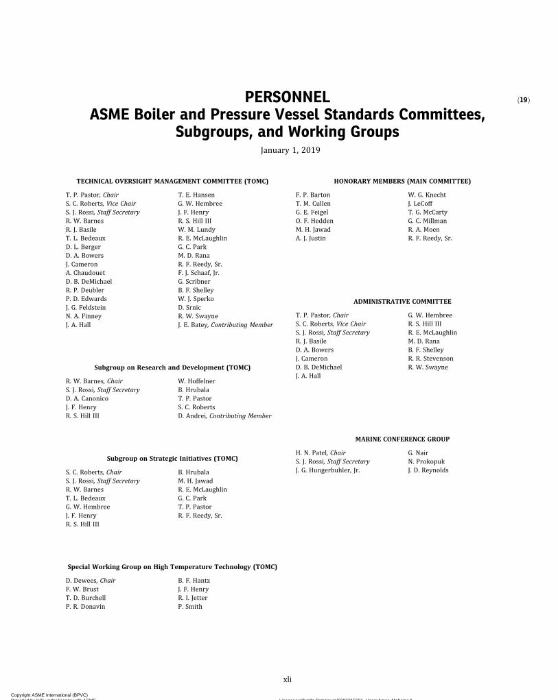
ð19ÞPERSONNELASME Boiler and Pressure Vessel Standards Committees,
Subgroups, and Working GroupsJanuary 1, 2019
TECHNICAL OVERSIGHT MANAGEMENT COMMITTEE (TOMC)
T. P. Pastor, ChairS. C. Roberts, Vice ChairS. J. Rossi, Staff SecretaryR. W. BarnesR. J. BasileT. L. BedeauxD. L. BergerD. A. BowersJ. CameronA. ChaudouetD. B. DeMichaelR. P. DeublerP. D. EdwardsJ. G. FeldsteinN. A. FinneyJ. A. Hall
T. E. HansenG. W. HembreeJ. F. HenryR. S. Hill IIIW. M. LundyR. E. McLaughlinG. C. ParkM. D. RanaR. F. Reedy, Sr.F. J. Schaaf, Jr.G. ScribnerB. F. ShelleyW. J. SperkoD. SrnicR. W. SwayneJ. E. Batey, Contributing Member
Subgroup on Research and Development (TOMC)
R. W. Barnes, ChairS. J. Rossi, Staff SecretaryD. A. CanonicoJ. F. HenryR. S. Hill III
W. HoffelnerB. HrubalaT. P. PastorS. C. RobertsD. Andrei, Contributing Member
Subgroup on Strategic Initiatives (TOMC)
S. C. Roberts, ChairS. J. Rossi, Staff SecretaryR. W. BarnesT. L. BedeauxG. W. HembreeJ. F. HenryR. S. Hill III
B. HrubalaM. H. JawadR. E. McLaughlinG. C. ParkT. P. PastorR. F. Reedy, Sr.
Special Working Group on High Temperature Technology (TOMC)
D. Dewees, ChairF. W. BrustT. D. BurchellP. R. Donavin
B. F. HantzJ. F. HenryR. I. JetterP. Smith
HONORARY MEMBERS (MAIN COMMITTEE)
F. P. BartonT. M. CullenG. E. FeigelO. F. HeddenM. H. JawadA. J. Justin
W. G. KnechtJ. LeCoffT. G. McCartyG. C. MillmanR. A. MoenR. F. Reedy, Sr.
ADMINISTRATIVE COMMITTEE
T. P. Pastor, ChairS. C. Roberts, Vice ChairS. J. Rossi, Staff SecretaryR. J. BasileD. A. BowersJ. CameronD. B. DeMichaelJ. A. Hall
G. W. HembreeR. S. Hill IIIR. E. McLaughlinM. D. RanaB. F. ShelleyR. R. StevensonR. W. Swayne
MARINE CONFERENCE GROUP
H. N. Patel, ChairS. J. Rossi, Staff SecretaryJ. G. Hungerbuhler, Jr.
G. NairN. ProkopukJ. D. Reynolds
xli
Copyright ASME International (BPVC) Provided by IHS under license with ASME Licensee=Khalda Petroleum/5986215001, User=Amer, Mohamed
Not for Resale, 07/02/2019 13:29:04 MDTNo reproduction or networking permitted without license from IHS
--`,``,``,,`,`,,````,`,``,,,`-`-`,,`,,`,`,,`---

CONFERENCE COMMITTEE
C. B. Cantrell — Nebraska, ChairJ. T. Amato — Minnesota, ViceChair
D. A. Douin — Ohio, SecretaryM. J. Adams — Ontario, CanadaW. Anderson — MississippiR. Becker — ColoradoR. J. Brockman — MissouriR. J. Bunte — IowaJ. H. Burpee — MaineM. J. Byrum — AlabamaS. Chapman — TennesseeD. C. Cook — CaliforniaB. J. Crawford — GeorgiaE. L. Creaser — New Brunswick,Canada
J. J. Dacanay — HawaiiC. Dautrich — North CarolinaR. DeLury — Manitoba, CanadaD. Eastman — Newfoundland andLabrador, Canada
D. A. Ehler — Nova Scotia, CanadaJ. J. Esch — DelawareT. J. Granneman II — OklahomaE. G. Hilton — VirginiaC. Jackson — City of Detroit,Michigan
M. L. Jordan — KentuckyE. Kawa, Jr. — MassachusettsA. Khssassi — Quebec, CanadaJ. Klug — City of Milwaukee,Wisconsin
K. J. Kraft — MarylandK. S. Lane — AlaskaL. C. Leet — City of Seattle,Washington
J. LeSage, Jr. — LouisianaA. M. Lorimor — South DakotaM. Mailman — NorthwestTerritories, Canada
D. E. Mallory — New HampshireW. McGivney — City of New York,New York
A. K. Oda — WashingtonL. E. Parkey — IndianaM. Poehlmann — Alberta, CanadaJ. F. Porcella — West VirginiaC. F. Reyes — CaliforniaM. J. Ryan — City of Chicago,Illinois
D. A. Sandfoss — NevadaM. H. Sansone — New YorkA. S. Scholl — British Columbia,Canada
T. S. Seime — North DakotaC. S. Selinger — Saskatchewan,Canada
J. E. Sharier — OhioN. Smith — PennsylvaniaR. Spiker — North CarolinaD. J. Stenrose — MichiganR. J. Stimson II — KansasR. K. Sturm — UtahD. K. Sullivan — ArkansasR. Tomka — OregonS. R. Townsend — Prince EdwardIsland, Canada
R. D. Troutt — TexasM. C. Vogel — IllinoisT. J. Waldbillig — WisconsinD. M. Warburton — FloridaM. Washington — New Jersey
INTERNATIONAL INTEREST REVIEW GROUP
V. FelixY.-G. KimS. H. LeongW. LinO. F. Manafa
C. MinuY.-W. ParkA. R. R. NogalesP. Williamson
COMMITTEE ON POWER BOILERS (BPV I)
R. E. McLaughlin, ChairE. M. Ortman, Vice ChairU. D’Urso, Staff SecretaryD. I. AndersonJ. L. ArnoldD. L. BergerK. K. ColemanP. D. EdwardsJ. G. FeldsteinG. W. GalanesT. E. HansenJ. F. HenryJ. S. HunterG. B. KomoraF. MassiL. MoedingerP. A. MolvieY. OishiJ. T. PillowM. Slater
J. M. TanzoshD. E. TompkinsD. E. TuttleJ. VattappillyM. WadkinsonR. V. WielgoszinskiF. ZellerH. Michael, DelegateD. A. Canonico, Honorary MemberD. N. French, Honorary MemberJ. Hainsworth, Honorary MemberC. Jeerings, Honorary MemberW. L. Lowry, Honorary MemberJ. R. MacKay, Honorary MemberT. C. McGough, Honorary MemberB. W. Roberts, Honorary MemberR. D. Schueler, Jr., HonoraryMember
R. L. Williams, Honorary MemberL. W. Yoder, Honorary Member
Subgroup on Design (BPV I)
J. Vattappilly, ChairG. B. Komora, Vice ChairD. I. Anderson, SecretaryD. DeweesH. A. Fonzi, Jr.J. P. Glaspie
L. KruppP. A. MolvieL. S. TsaiM. WadkinsonC. F. Jeerings, Contributing Member
Subgroup on Fabrication and Examination (BPV I)
J. L. Arnold, ChairP. F. Gilston, Vice ChairP. Becker, SecretaryD. L. BergerS. FincherG. W. GalanesJ. HainsworthT. E. Hansen
P. JenningsC. T. McDarisR. E. McLaughlinR. J. NewellY. OishiJ. T. PillowR. V. Wielgoszinski
Subgroup on General Requirements and Piping (BPV I)
E. M. Ortman, ChairD. E. Tompkins, Vice ChairF. Massi, SecretaryP. BeckerD. L. BergerP. D. EdwardsT. E. HansenM. IshikawaM. Lemmons
R. E. McLaughlinB. J. MollitorJ. T. PillowD. E. TuttleM. WadkinsonR. V. WielgoszinskiC. F. Jeerings, Contributing MemberW. L. Lowry, Contributing Member
Subgroup on Locomotive Boilers (BPV I)
P. Boschan, ChairJ. R. Braun, Vice ChairS. M. Butler, SecretaryA. BieseckerC. CrossR. C. Franzen, Jr.G. W. GalanesD. W. Griner
S. D. JacksonM. A. JanssenS. A. LeeL. MoedingerG. M. RayR. B. StoneM. W. Westland
xlii
Copyright ASME International (BPVC) Provided by IHS under license with ASME Licensee=Khalda Petroleum/5986215001, User=Amer, Mohamed
Not for Resale, 07/02/2019 13:29:04 MDTNo reproduction or networking permitted without license from IHS
--`,``,``,,`,`,,````,`,``,,,`-`-`,,`,,`,`,,`---
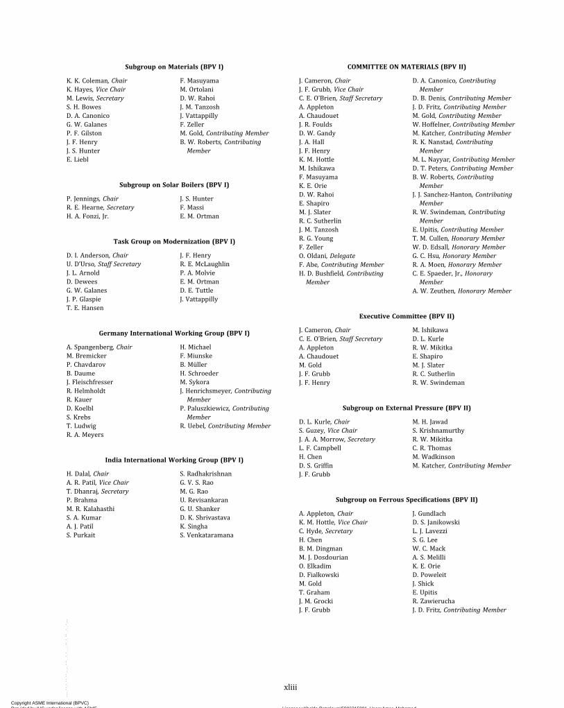
Subgroup on Materials (BPV I)
K. K. Coleman, ChairK. Hayes, Vice ChairM. Lewis, SecretaryS. H. BowesD. A. CanonicoG. W. GalanesP. F. GilstonJ. F. HenryJ. S. HunterE. Liebl
F. MasuyamaM. OrtolaniD. W. RahoiJ. M. TanzoshJ. VattappillyF. ZellerM. Gold, Contributing MemberB. W. Roberts, ContributingMember
Subgroup on Solar Boilers (BPV I)
P. Jennings, ChairR. E. Hearne, SecretaryH. A. Fonzi, Jr.
J. S. HunterF. MassiE. M. Ortman
Task Group on Modernization (BPV I)
D. I. Anderson, ChairU. D’Urso, Staff SecretaryJ. L. ArnoldD. DeweesG. W. GalanesJ. P. GlaspieT. E. Hansen
J. F. HenryR. E. McLaughlinP. A. MolvieE. M. OrtmanD. E. TuttleJ. Vattappilly
Germany International Working Group (BPV I)
A. Spangenberg, ChairM. BremickerP. ChavdarovB. DaumeJ. FleischfresserR. HelmholdtR. KauerD. KoelblS. KrebsT. LudwigR. A. Meyers
H. MichaelF. MiunskeB. MüllerH. SchroederM. SykoraJ. Henrichsmeyer, ContributingMember
P. Paluszkiewicz, ContributingMember
R. Uebel, Contributing Member
India International Working Group (BPV I)
H. Dalal, ChairA. R. Patil, Vice ChairT. Dhanraj, SecretaryP. BrahmaM. R. KalahasthiS. A. KumarA. J. PatilS. Purkait
S. RadhakrishnanG. V. S. RaoM. G. RaoU. RevisankaranG. U. ShankerD. K. ShrivastavaK. SinghaS. Venkataramana
COMMITTEE ON MATERIALS (BPV II)
J. Cameron, ChairJ. F. Grubb, Vice ChairC. E. O’Brien, Staff SecretaryA. AppletonA. ChaudouetJ. R. FouldsD. W. GandyJ. A. HallJ. F. HenryK. M. HottleM. IshikawaF. MasuyamaK. E. OrieD. W. RahoiE. ShapiroM. J. SlaterR. C. SutherlinJ. M. TanzoshR. G. YoungF. ZellerO. Oldani, DelegateF. Abe, Contributing MemberH. D. Bushfield, ContributingMember
D. A. Canonico, ContributingMember
D. B. Denis, Contributing MemberJ. D. Fritz, Contributing MemberM. Gold, Contributing MemberW. Hoffelner, Contributing MemberM. Katcher, Contributing MemberR. K. Nanstad, ContributingMember
M. L. Nayyar, Contributing MemberD. T. Peters, Contributing MemberB. W. Roberts, ContributingMember
J. J. Sanchez-Hanton, ContributingMember
R. W. Swindeman, ContributingMember
E. Upitis, Contributing MemberT. M. Cullen, Honorary MemberW. D. Edsall, Honorary MemberG. C. Hsu, Honorary MemberR. A. Moen, Honorary MemberC. E. Spaeder, Jr., HonoraryMember
A. W. Zeuthen, Honorary Member
Executive Committee (BPV II)
J. Cameron, ChairC. E. O’Brien, Staff SecretaryA. AppletonA. ChaudouetM. GoldJ. F. GrubbJ. F. Henry
M. IshikawaD. L. KurleR. W. MikitkaE. ShapiroM. J. SlaterR. C. SutherlinR. W. Swindeman
Subgroup on External Pressure (BPV II)
D. L. Kurle, ChairS. Guzey, Vice ChairJ. A. A. Morrow, SecretaryL. F. CampbellH. ChenD. S. GriffinJ. F. Grubb
M. H. JawadS. KrishnamurthyR. W. MikitkaC. R. ThomasM. WadkinsonM. Katcher, Contributing Member
Subgroup on Ferrous Specifications (BPV II)
A. Appleton, ChairK. M. Hottle, Vice ChairC. Hyde, SecretaryH. ChenB. M. DingmanM. J. DosdourianO. ElkadimD. FialkowskiM. GoldT. GrahamJ. M. GrockiJ. F. Grubb
J. GundlachD. S. JanikowskiL. J. LavezziS. G. LeeW. C. MackA. S. MelilliK. E. OrieD. PoweleitJ. ShickE. UpitisR. ZawieruchaJ. D. Fritz, Contributing Member
xliii
Copyright ASME International (BPVC) Provided by IHS under license with ASME Licensee=Khalda Petroleum/5986215001, User=Amer, Mohamed
Not for Resale, 07/02/2019 13:29:04 MDTNo reproduction or networking permitted without license from IHS
--`,``,``,,`,`,,````,`,``,,,`-`-`,,`,,`,`,,`---

Subgroup on International Material Specifications (BPV II)
M. Ishikawa, ChairA. R. Nywening, Vice ChairB. Mruk, SecretaryA. ChaudouetP. ChavdarovH. ChenA. F. GarbolevskyD. O. Henry
W. M. LundyE. UpitisF. ZellerO. Oldani, DelegateD. A. Canonico, ContributingMember
H. Lorenz, Contributing MemberT. F. Miskell, Contributing Member
Subgroup on Nonferrous Alloys (BPV II)
E. Shapiro, ChairS. Yem, Vice ChairJ. Robertson, SecretaryR. BeldykJ. CallandJ. M. DownsJ. F. GrubbD. MaitraJ. A. McMaster
D. W. RahoiW. RenR. C. SutherlinJ. WeritzR. WrightD. B. Denis, Contributing MemberM. Katcher, Contributing MemberD. T. Peters, Contributing Member
Subgroup on Physical Properties (BPV II)
J. F. Grubb, ChairG. Aurioles, Sr.D. ChandiramaniP. ChavdarovH. EshraghiB. F. HantzR. D. JonesP. K. LamS. Neilsen
D. W. RahoiP. K. RaiE. ShapiroM. S. SheltonD. K. VermaS. YemH. D. Bushfield, ContributingMember
D. B. Denis, Contributing Member
Subgroup on Strength, Ferrous Alloys (BPV II)
M. J. Slater, ChairS. W. Knowles, Vice ChairD. A. CanonicoA. Di RienzoJ. R. FouldsJ. A. HallJ. F. HenryF. MasuyamaT. OnoM. Ortolani
D. W. RahoiM. S. SheltonJ. M. TanzoshR. G. YoungF. ZellerF. Abe, Contributing MemberM. Gold, Contributing MemberM. Nair, Contributing MemberB. W. Roberts, ContributingMember
Subgroup on Strength of Weldments (BPV II & BPV IX)
G. W. Galanes, ChairK. L. Hayes, Vice ChairS. H. BowesK. K. ColemanM. DenaultP. D. FlennerJ. R. FouldsD. W. GandyM. GhahremaniJ. F. HenryE. Liebl
W. F. Newell, Jr.J. PensoD. W. RahoiB. W. RobertsW. J. SperkoJ. P. Swezy, Jr.J. M. TanzoshM. Gold, Contributing MemberJ. J. Sanchez-Hanton, ContributingMember
Working Group on Materials Database (BPV II)
J. F. Henry, ChairC. E. O’Brien, Staff SecretaryF. AbeJ. R. FouldsM. J. SlaterR. C. SutherlinD. Andrei, Contributing MemberJ. L. Arnold, Contributing Member
J. Grimes, Contributing MemberW. Hoffelner, Contributing MemberD. T. Peters, Contributing MemberW. Ren, Contributing MemberB. W. Roberts, ContributingMember
R. W. Swindeman, ContributingMember
Working Group on Creep Strength Enhanced Ferritic Steels (BPV II)
J. F. Henry, ChairM. Ortolani, Vice ChairJ. A. Siefert, SecretaryS. H. BowesD. A. CanonicoK. K. ColemanP. D. FlennerJ. R. FouldsG. W. GalanesM. LangF. MasuyamaT. MelfiW. F. Newell, Jr.
J. ParkerJ. J. Sanchez-HantonW. J. SperkoJ. M. TanzoshR. H. WorthingtonR. G. YoungF. ZellerF. Abe, Contributing MemberG. Cumino, Contributing MemberB. W. Roberts, ContributingMember
R. W. Swindeman, ContributingMember
Working Group on Data Analysis (BPV II)
J. F. Grubb, ChairJ. R. FouldsJ. F. HenryF. MasuyamaM. OrtolaniW. RenM. SubanovicM. J. SwindemanF. Abe, Contributing Member
M. Gold, Contributing MemberW. Hoffelner, Contributing MemberM. Katcher, Contributing MemberD. T. Peters, Contributing MemberB. W. Roberts, ContributingMember
R. W. Swindeman, ContributingMember
China International Working Group (BPV II)
A. T. Xu, SecretaryW. FangQ. C. FengS. HuoF. KongH. LiJ. LiS. LiZ. RongcanS. TanC. WangJ. WangQ.-J. WangX. Wang
F. YangG. YangH.-C. YangJ. YangR. YeL. YinD. ZhangH. ZhangX.-H. ZhangYingkai ZhangYong ZhangQ. ZhaoS. Zhao
xliv
Copyright ASME International (BPVC) Provided by IHS under license with ASME Licensee=Khalda Petroleum/5986215001, User=Amer, Mohamed
Not for Resale, 07/02/2019 13:29:04 MDTNo reproduction or networking permitted without license from IHS
--`,``,``,,`,`,,````,`,``,,,`-`-`,,`,,`,`,,`---

COMMITTEE ON CONSTRUCTION OF NUCLEAR FACILITYCOMPONENTS (BPV III)
R. S. Hill III, ChairR. B. Keating, Vice ChairJ. C. Minichiello, Vice ChairA. Byk, Staff SecretaryT. M. AdamsA. AppletonR. W. BarnesW. H. BorterC. W. BrunyT. D. BurchellR. P. DeublerP. R. DonavinA. C. EberhardtJ. V. GardinerJ. GrimmS. HunterR. M. JesseeR. I. JetterC. C. KimG. H. KooV. KostarevM. A. LockwoodK. A. ManolyD. E. Matthews
M. N. MitchellM. MorishitaD. K. MortonT. NagataJ. E. NestellE. L. PleinsR. F. Reedy, Sr.I. SaitoS. ShamG. J. SoloveyW. K. Sowder, Jr.W. J. SperkoJ. P. TuckerC. S. WithersH.-T. Wang, DelegateC. T. Smith, Contributing MemberM. Zhou, Contributing MemberE. B. Branch, Honorary MemberG. D. Cooper, Honorary MemberD. F. Landers, Honorary MemberR. A. Moen, Honorary MemberC. J. Pieper, Honorary MemberK. R. Wichman, Honorary Member
Executive Committee (BPV III)
R. S. Hill III, ChairA. Byk, Staff SecretaryT. M. AdamsC. W. BrunyP. R. DonavinJ. V. GardinerJ. Grimm
R. B. KeatingJ. C. MinichielloJ. A. MunshiJ. E. NestellS. ShamG. J. SoloveyW. K. Sowder, Jr.
Subcommittee on Design (BPV III)
P. R. Donavin, ChairT. M. Adams, Vice ChairR. L. BrattonC. W. BrunyR. P. DeublerM. A. GrayS. HorowitzR. I. JetterR. B. KeatingK. A. ManolyR. J. MastersonD. E. MatthewsS. McKillop
M. N. MitchellW. J. O’Donnell, Sr.S. ShamJ. P. TuckerW. F. WeitzeT. YamazakiJ. YangR. S. Hill III, Contributing MemberG. L. Hollinger, ContributingMember
M. H. Jawad, Contributing MemberK. Wright, Contributing Member
Subgroup on Component Design (SC-D) (BPV III)
T. M. Adams, ChairR. B. Keating, Vice ChairS. Pellet, SecretaryD. J. AmmermanG. A. AntakiS. AsadaJ. F. BallC. BasavarajuD. ChowdhuryR. P. DeublerP. HirschbergM. KassarO.-S. KimH. KobayashiK. A. ManolyR. J. MastersonD. E. Matthews
J. C. MinichielloD. K. MortonT. M. MustoT. NagataI. SaitoG. C. SlagisJ. R. StinsonG. Z. TokarskiJ. P. TuckerP. VockC. WilsonJ. YangC. W. Bruny, Contributing MemberA. A. Dermenjian, ContributingMember
K. R. Wichman, Honorary Member
Working Group on Core Support Structures (SG-CD) (BPV III)
J. Yang, ChairD. Keck, SecretaryL. C. HartlessJ. F. KielbT. LiszkaiH. S. Mehta
M. NakajimaM. D. SnyderR. VollmerT. M. WigerY. WongR. Z. Ziegler
Working Group on Design of Division 3 Containment Systems(SG-CD) (BPV III)
D. J. Ammerman, ChairG. BjorkmanV. BrozS. HorowitzS. KleinD. W. LewisJ. C. Minichiello
D. K. MortonX. ZhaiX. ZhangD. Dunn, AlternateI. D. McInnes, Contributing MemberH. P. Shrivastava, ContributingMember
Working Group on HDPE Design of Components (SG-CD) (BPV III)
T. M. Musto, ChairJ. Ossmann, SecretaryT. M. AdamsT. A. BaconM. BrandesS. ChoiJ. R. HebeisenP. KrishnaswamyK. A. Manoly
M. MartinJ. C. MinichielloD. P. MunsonF. J. Schaaf, Jr.R. StakenborghsJ. WrightM. T. Audrain, AlternateD. Burwell, Contributing Member
xlv
Copyright ASME International (BPVC) Provided by IHS under license with ASME Licensee=Khalda Petroleum/5986215001, User=Amer, Mohamed
Not for Resale, 07/02/2019 13:29:04 MDTNo reproduction or networking permitted without license from IHS
--`,``,``,,`,`,,````,`,``,,,`-`-`,,`,,`,`,,`---

Working Group on Piping (SG-CD) (BPV III)
G. A. Antaki, ChairG. Z. Tokarski, SecretaryT. M. AdamsT. A. BaconC. BasavarajuJ. CatalanoF. ClaeysC. M. FaidyR. G. GiladaN. M. GrahamM. A. GrayR. J. GurdalR. W. HauptA. HiranoP. HirschbergM. Kassar
J. KawahataR. B. KeatingV. KostarevD. LiebT. B. LittletonJ. F. McCabeJ. C. MinichielloI.-K. NamG. C. SlagisN. C. SutherlandC.-I. WuY. Liu, Contributing MemberA. N. Nguyen, Contributing MemberM. S. Sills, Contributing MemberE. A. Wais, Contributing Member
Working Group on Pressure Relief (SG-CD) (BPV III)
J. F. Ball, ChairJ. W. DicksonS. JonesR. KrithivasanR. LackK. R. MayD. MillerT. Patel
K. ShoresI. H. TsengJ. YuN. J. Hansing, AlternateB. J. Yonsky, AlternateS. T. French, Contributing MemberD. B. Ross, Contributing Member
Working Group on Pumps (SG-CD) (BPV III)
D. Chowdhury, ChairJ. V. Gregg, Jr., SecretaryX. DiM. D. EftychiouC. GabhartJ. KikushimaR. Klein
R. LadefianW. LienauK. J. NoelR. A. PatrickJ. SulleyA. G. WashburnY. Wong
Working Group on Supports (SG-CD) (BPV III)
J. R. Stinson, ChairU. S. Bandyopadhyay, SecretaryK. AvrithiT. H. BakerF. J. BirchR. P. DeublerN. M. GrahamR. J. Masterson
S. PelletI. SaitoC. StirzelG. Z. TokarskiA. TsirigotisL. VandershipP. WisemanJ. Huang, Alternate
Working Group on Valves (SG-CD) (BPV III)
P. Vock, ChairS. Jones, SecretaryM. C. BuckleyR. FarrellG. A. JollyJ. LambinT. LippucciC. A. Mizer
H. O’BrienJ. O’CallaghanK. E. Reid IIJ. SulleyI. H. TsengJ. P. TuckerN. J. Hansing, Alternate
Working Group on Vessels (SG-CD) (BPV III)
D. E. Matthews, ChairS. Willoughby, SecretaryJ. ArthurC. BasavarajuM. KassarR. B. KeatingD. KeckJ. I. KimO.-S. KimT. MitsuhashiD. MurphyT. J. Schriefer
M. C. ScottP. K. ShahJ. ShupertC. TuryloD. VlaicuC. WilsonT. YamazakiR. Z. ZieglerB. Basu, Contributing MemberA. Kalnins, Contributing MemberW. F. Weitze, Contributing Member
Subgroup on Design Methods (SC-D) (BPV III)
C. W. Bruny, ChairP. R. Donavin, Vice ChairS. McKillop, SecretaryK. AvrithiL. DaviesS. R. GosselinM. A. GrayJ. V. Gregg, Jr.H. T. Harrison IIIK. HsuD. Keck
J. I. KimM. N. MitchellW. J. O’Donnell, Sr.W. D. ReinhardtP. SmithS. D. SnowR. VollmerW. F. WeitzeK. WrightT. M. Adams, Contributing Member
Working Group on Design Methodology (SG-DM) (BPV III)
S. McKillop, ChairR. Vollmer, SecretaryK. AvrithiC. BasavarajuD. L. CaldwellC. M. FaidyR. FarrellH. T. Harrison IIIC. F. Heberling IIP. HirschbergM. KassarR. B. KeatingJ. I. KimH. Kobayashi
T. LiszkaiJ. F. McCabeS. RanganathW. D. ReinhardtP. K. ShahS. D. SnowS. WangW. F. WeitzeJ. WenT. M. WigerK. WrightJ. YangR. D. Blevins, Contributing MemberM. R. Breach, Contributing Member
Working Group on Environmental Effects (SG-DM) (BPV III)
L. Davies, ChairB. D. Frew, SecretaryP. J. DobsonJ. I. Kim
J. E. NestellM. OsterfossT. J. SchrieferI. H. Tseng
Working Group on Environmental Fatigue Evaluation Methods(SG-DM) (BPV III)
M. A. Gray, ChairW. F. Weitze, SecretaryT. M. AdamsS. AsadaK. AvrithiR. C. CipollaT. M. DamianiC. M. FaidyT. D. GilmanS. R. GosselinY. He
P. HirschbergH. S. MehtaT. MetaisJ.-S. ParkB. PellereauI. SaitoD. VlaicuK. WangK. WrightR. Z. Ziegler
xlvi
Copyright ASME International (BPVC) Provided by IHS under license with ASME Licensee=Khalda Petroleum/5986215001, User=Amer, Mohamed
Not for Resale, 07/02/2019 13:29:04 MDTNo reproduction or networking permitted without license from IHS
--`,``,``,,`,`,,````,`,``,,,`-`-`,,`,,`,`,,`---
Working Group on Fatigue Strength (SG-DM) (BPV III)
P. R. Donavin, ChairM. S. Shelton, SecretaryT. M. DamianiC. M. FaidyP. GillS. R. GosselinR. J. GurdalC. F. Heberling IIC. E. HinnantP. HirschbergK. Hsu
S. H. KleinsmithS. MajumdarS. N. MalikH. S. MehtaS. MohantyS. RanganathA. TsirigotisD. Dewees, Contributing MemberW. J. O'Donnell, Sr., ContributingMember
K. Wright, Contributing Member
Working Group on Graphite and Composite Design(SG-DM) (BPV III)
M. N. Mitchell, ChairT. D. Burchell, SecretaryA. AppletonS.-H. ChiW. J. GeringerS. T. GonczyM. G. Jenkins
Y. KatohJ. OssmannW. WindesA. YeshnikS. YuG. L. ZengN. McMurray, Alternate
Working Group on Probabilistic Methods in Design(SG-DM) (BPV III)
M. Golliet, ChairT. AsayamaK. AvrithiG. BrouetteJ. Hakii
D. O. HenryR. S. Hill IIIM. MorishitaP. J. O'ReganI. Saito
Special Working Group on Computational Modeling for ExplicitDynamics (SG-DM) (BPV III)
G. Bjorkman, ChairD. J. Ammerman, Vice ChairV. Broz, SecretaryM. R. BreachJ. M. JordanS. KuehnerD. Molitoris
W. D. ReinhardtP. Y.-K. ShihS. D. SnowC.-F. TsoM. C. YakshU. ZenckerA. Rigato, Alternate
Subgroup on Elevated Temperature Design (SC-D) (BPV III)
S. Sham, ChairT. AsayamaC. Becht IVF. W. BrustP. CarterM. E. CohenB. F. HantzM. H. JawadR. I. JetterK. KimuraG. H. KooT. Le
J. E. NestellR. WrightA. B. Hull, AlternateD. S. Griffin, Contributing MemberS. Majumdar, Contributing MemberD. L. Marriott, ContributingMember
W. J. O'Donnell, Sr., ContributingMember
R. W. Swindeman, ContributingMember
Working Group on Allowable Stress Criteria (SG-ETD) (BPV III)
R. Wright, ChairM. J. Swindeman, SecretaryC. J. JohnsK. KimuraT. LeD. MaitraM. McMurtreyJ. E. Nestell
W. RenS. ShamX. WeiS. N. Malik, AlternateJ. R. Foulds, Contributing MemberR. W. Swindeman, ContributingMember
Working Group on Analysis Methods (SG-ETD) (BPV III)
P. Carter, ChairM. J. Swindeman, SecretaryM. E. CohenR. I. JetterT. LeM. C. Messner
S. ShamX. WeiA. Tsirigotis, AlternateS. Krishnamurthy, ContributingMember
Working Group on Creep-Fatigue and Negligible Creep (SG-ETD)(BPV III)
T. Asayama, ChairF. W. BrustP. CarterM. E. CohenR. I. JetterG. H. KooT. LeB.-L. Lyow
M. McMurtreyM. C. MessnerH. QianS. ShamY. WangX. WeiN. McMurray, Alternate
Working Group on Elevated Temperature Construction (SG-ETD)(BPV III)
A. Mann, ChairC. Nadarajah, SecretaryD. I. AndersonD. DeweesB. F. HantzM. H. JawadR. I. JetterS. KrishnamurthyT. Le
M. N. MitchellP. PrueterM. J. SwindemanN. McMurray, AlternateJ. P. Glaspie, Contributing MemberD. L. Marriott, ContributingMember
B. J. Mollitor, Contributing Member
Working Group on High Temperature Flaw Evaluation (SG-ETD)(BPV III)
F. W. Brust, ChairP. CarterS. KalyanamT. LeM. C. MessnerH. Qian
P. J. RushD.-J. ShimX. WeiS. X. XuN. McMurray, Alternate
Special Working Group on Inelastic Analysis Methods (SG-ETD)(BPV III)
M. C. Messner, ChairS. X. Xu, SecretaryR. W. BarnesJ. A. BlancoT. HassanG. H. Koo
B.-L. LyowS. ShamM. J. SwindemanX. WeiG. L. Zeng
xlvii
Copyright ASME International (BPVC) Provided by IHS under license with ASME Licensee=Khalda Petroleum/5986215001, User=Amer, Mohamed
Not for Resale, 07/02/2019 13:29:04 MDTNo reproduction or networking permitted without license from IHS
--`,``,``,,`,`,,````,`,``,,,`-`-`,,`,,`,`,,`---
Subgroup on General Requirements (BPV III)
J. V. Gardiner, ChairJ. Rogers, SecretaryV. ApostolescuA. AppletonS. BellJ. R. BerryG. BrouetteJ. W. HighlandsE. V. ImbroK. A. KavanaghY.-S. KimB. McGlone
E. C. RenaudT. N. RezkD. J. RoszmanW. K. Sowder, Jr.R. SpuhlG. E. SzabaturaD. M. VickeryC. S. WithersJ. DeKleine, Contributing MemberH. Michael, Contributing MemberC. T. Smith, Contributing Member
Working Group on Duties and Responsibilities (SG-GR) (BPV III)
S. Bell, ChairN. DeSantis, SecretaryJ. R. BerryP. J. CocoY. Diaz-CastilloJ. V. Gardiner
E. V. ImbroK. A. KavanaghD. J. RoszmanB. S. SandhuJ. L. WilliamsJ. DeKleine, Contributing Member
Working Group on Quality Assurance, Certification, and Stamping(SG-GR) (BPV III)
B. McGlone, ChairJ. Grimm, SecretaryV. ApostolescuA. AppletonG. BrouetteO. ElkadimS. M. GoodwinJ. HarrisJ. W. HighlandsK. A. KavanaghY.-S. KimD. T. Meisch
R. B. PatelE. C. RenaudT. N. RezkJ. RogersW. K. Sowder, Jr.R. SpuhlJ. F. StrunkG. E. SzabaturaD. M. VickeryC. S. WithersC. A. Spletter, Contributing Member
Special Working Group on General Requirements Consolidation(SG-GR) (BPV III)
J. V. Gardiner, ChairC. T. Smith, Vice ChairS. BellM. B. CusickY. Diaz-CastilloJ. GrimmJ. M. LyonsB. McGloneR. B. PatelE. C. RenaudT. N. Rezk
J. RogersD. J. RoszmanB. S. SandhuG. J. SoloveyR. SpuhlG. E. SzabaturaJ. L. WilliamsC. S. WithersS. F. Harrison, Jr., ContributingMember
Working Group on General Requirements for Graphite and CeramicComposite Core Components and Assemblies (SG-GR) (BPV III)
A. Appleton, ChairW. J. Geringer, SecretaryJ. R. BerryT. D. BurchellM. N. Mitchell
E. C. RenaudW. WindesA. YeshnikN. McMurray, Alternate
Subgroup on Materials, Fabrication, and Examination (BPV III)
J. Grimm, ChairB. D. Frew, Vice ChairS. Hunter, SecretaryW. H. BorterT. D. BurchellS. ChoP. J. CocoR. H. DavisG. B. GeorgievS. E. GingrichM. GollietL. S. HarbisonR. M. JesseeJ. Johnston, Jr.C. C. KimM. Lashley
T. MelfiI.-K. NamJ. OssmannJ. E. O’SullivanM. C. ScottW. J. SperkoJ. R. StinsonJ. F. StrunkW. WindesR. WrightS. YeeH. Michael, DelegateR. W. Barnes, Contributing MemberG. R. Cannell, Contributing MemberD. B. Denis, Contributing Member
Working Group on Graphite and Composite Materials (SG-MFE)(BPV III)
T. D. Burchell, ChairM. N. Mitchell, SecretaryA. AppletonR. L. BrattonS. R. CadellS.-H. ChiA. CovacS. W. DomsS. F. DuffyW. J. GeringerS. T. Gonzcy
M. G. JenkinsY. KatohJ. OssmannM. RoemmlerN. SalstromT. ShibataW. WindesA. YeshnikS. YuG. L. ZengN. McMurray, Alternate
Working Group on HDPE Materials (SG-MFE) (BPV III)
G. Brouette, ChairM. A. Martin, SecretaryW. H. BorterM. C. BuckleyM. GollietJ. HakiiJ. Johnston, Jr.P. Krishnaswamy
D. P. MunsonT. M. MustoS. PattersonS. SchuesslerR. StakenborghsM. TroughtonJ. WrightB. Hauger, Contributing Member
Joint ACI-ASME Committee on Concrete Components for NuclearService (BPV III)
J. A. Munshi, ChairJ. McLean, Vice ChairJ. Cassamassino, Staff SecretaryC. J. BangL. J. ColarussoA. C. EberhardtF. FarzamP. S. GhosalB. D. HovisT. C. InmanC. JonesO. JovallT. KangN.-H. LeeT. Muraki
N. OrbovicJ. F. StrunkG. ThomasT. TonyanS. WangJ. F. Artuso, Contributing MemberS. Bae, Contributing MemberJ.-B. Domage, Contributing MemberB. B. Scott, Contributing MemberM. R. Senecal, ContributingMember
Z. Shang, Contributing MemberM. Sircar, Contributing MemberC. T. Smith, Contributing Member
xlviii
Copyright ASME International (BPVC) Provided by IHS under license with ASME Licensee=Khalda Petroleum/5986215001, User=Amer, Mohamed
Not for Resale, 07/02/2019 13:29:04 MDTNo reproduction or networking permitted without license from IHS
--`,``,``,,`,`,,````,`,``,,,`-`-`,,`,,`,`,,`---

Working Group on Design (BPV III-2)
N.-H. Lee, ChairS. Wang, Vice ChairM. AllamS. BaeL. J. ColarussoA. C. EberhardtF. FarzamP. S. GhosalB. D. HovisT. C. InmanC. JonesO. JovallJ. A. Munshi
T. MurakiG. ThomasM. Diaz, Contributing MemberA. Istar, Contributing MemberS.-Y. Kim, Contributing MemberJ. Kwon, Contributing MemberB. R. Laskewitz, ContributingMember
B. B. Scott, Contributing MemberZ. Shang, Contributing MemberM. Shin, Contributing MemberM. Sircar, Contributing Member
Working Group on Materials, Fabrication, and Examination(BPV III-2)
T. Tonyan, ChairA. Eberhardt, Vice ChairM. AllamC. J. BangB. BirchJ.-B. DomageP. S. GhosalC. Jones
T. KangN.-H. LeeZ. ShangJ. F. StrunkI. ZivanovicJ. F. Artuso, Contributing MemberB. B. Scott, Contributing Member
Special Working Group on Modernization (BPV III-2)
N. Orbovic, ChairJ. McLean, Vice ChairA. AdediranO. JovallN. Stoeva
S. WangI. ZivanovicJ.-B. Domage, Contributing MemberF. Lin, Contributing MemberM. A. Ugalde, Contributing Member
Subgroup on Containment Systems for Spent Nuclear Fuel andHigh-Level Radioactive Material (BPV III)
G. J. Solovey, ChairD. J. Ammerman, Vice ChairG. BjorkmanV. BrozS. HorowitzS. KleinD. W. LewisD. K. MortonE. L. Pleins
J. WellwoodX. J. ZhaiD. Dunn, AlternateW. H. Borter, Contributing MemberP. E. McConnell, ContributingMember
N. M. Simpson, ContributingMember
R. H. Smith, Contributing Member
Subgroup on Fusion Energy Devices (BPV III)
W. K. Sowder, Jr., ChairD. Andrei, Staff SecretaryD. J. Roszman, SecretaryM. BashirL. C. CadwalladerB. R. DoshiG. HoltmeierK. A. KavanaghK. KimI. KimihiroS. LeeG. Li
X. LiP. MokariaT. R. MuldoonM. PortonF. J. Schaaf, Jr.P. SmithY. SongM. TrosenC. WaldonI. J. ZatzR. W. Barnes, Contributing Member
Working Group on General Requirements (BPV III-4)
D. J. Roszman, Chair W. K. Sowder, Jr.
Working Group on In-Vessel Components (BPV III-4)
M. Bashir, ChairY. Carin
M. Kalsey
Working Group on Magnets (BPV III-4)
S. Lee, Chair K. Kim, Vice Chair
Working Group on Materials (BPV III-4)
M. Porton, Chair P. Mummery
Working Group on Vacuum Vessels (BPV III-4)
I. Kimihiro, ChairL. C. CadwalladerB. R. Doshi
Q. ShijunY. Song
Subgroup on High Temperature Reactors (BPV III)
J. E. Nestell, ChairN. BroomT. D. BurchellM. E. CohenR. I. JetterG. H. KooD. K. MortonS. Sham
W. WindesA. YeshnikG. L. ZengN. McMurray, AlternateX. Li, Contributing MemberM. Morishita, Contributing MemberL. Shi, Contributing Member
Working Group on High Temperature Gas-Cooled Reactors(BPV III-5)
J. E. Nestell, ChairN. BroomT. D. BurchellR. I. JetterY. W. KimT. Le
D. K. MortonS. ShamG. L. ZengS. N. Malik, AlternateX. Li, Contributing MemberL. Shi, Contributing Member
Working Group on High Temperature Liquid-Cooled Reactors(BPV III-5)
S. Sham, ChairM. ArcaroT. AsayamaR. W. BarnesP. CarterM. E. CohenA. B. HullR. I. Jetter
G. H. KooT. LeJ. E. NestellX. WeiC. Moyer, AlternateS. Majumdar, Contributing MemberM. Morishita, Contributing MemberG. Wu, Contributing Member
xlix
Copyright ASME International (BPVC) Provided by IHS under license with ASME Licensee=Khalda Petroleum/5986215001, User=Amer, Mohamed
Not for Resale, 07/02/2019 13:29:04 MDTNo reproduction or networking permitted without license from IHS
--`,``,``,,`,`,,````,`,``,,,`-`-`,,`,,`,`,,`---

Argentina International Working Group (BPV III)
J. Fernández, ChairA. Politi, Vice ChairO. Martinez, Staff SecretaryA. Gomez, SecretaryA. AcroglianoW. AgreloG. O. AnteriM. AnticoliC. A. ArayaJ. P. BalbianiA. A. BetervideD. O. BordatoG. BourguigneM. L. CappellaA. ClausR. G. CoccoA. ColeffA. J. Dall’OstoL. M. De BarberisD. P. DelfinoD. N. Dell’ErbaF. G. DiezA. Dominguez
S. A. EcheverriaE. P. FresquetM. M. GamizoI. M. GuerreiroR. S. Hill IIII. A. KnorrM. F. LiendoL. R. MiñoJ. MonteR. L. MorardA. E. PastorE. PizzichiniJ. L. RacamatoH. C. SanziG. J. ScianG. G. SebastianM. E. SzarkoP. N. ToranoA. TurrinO. A. VerasteguiM. D. ViglianoP. YamamotoM. Zunino
China International Working Group (BPV III)
J. Yan, ChairW. Tang, Vice ChairY. He, SecretaryL. GuoY. JingD. KangY. LiB. LiangH. LinS. LiuW. LiuJ. MaK. MaoD. E. MatthewsW. Pei
G. SunZ. SunG. TangL. TingY. TuY. WangH. WuX. WuS. XueZ. YinG. ZhangW. ZhangW. ZhaoY. ZhongZ. Zhong
German International Working Group (BPV III)
J. Wendt, ChairD. Koelbl, Vice ChairR. Gersinska, SecretaryH.-R. BathP. R. DonavinR. DöringA. HuberR. E. HueggenbergC. HuttnerE. IacopettaM. H. KoeppenC. Kuschke
H.-W. LangeT. LudwigX. PitoisetM. ReichertG. RoosJ. RudolphH. SchauL. SybertR. TrieglaffF. WilleS. Zickler
India International Working Group (BPV III)
R. N. Sen, ChairS. B. Parkash, Vice ChairA. D. Bagdare, SecretaryS. AithalH. DalalS. Kovalai
D. KulkarniR. KumarE. I. PleinsM. PonnusamyK. R. ShahB. K. Sreedhar
Korea International Working Group (BPV III)
G. H. Koo, ChairS. S. Hwang, Vice ChairO.-S. Kim, SecretaryH. S. ByunS. ChoG.-S. ChoiS. ChoiJ. Y. HongN.-S. HuhJ.-K. HwangC. JangI. I. JeongH. J. KimJ.-I. KimJ.-S. KimK. KimM.-W. KimS.-S. KimY.-B. KimY.-S. Kim
D. KwonB. LeeD. LeeSanghoon LeeSangil LeeS.-G. LeeH. LimI.-K. NamB. NohC.-K. OhC. ParkH. ParkJ.-S. ParkY. S. PyunT. ShinS. SongW. J. SperkoJ. S. YangO. Yoo
Special Working Group on Editing and Review (BPV III)
D. E. Matthews, ChairR. L. BrattonR. P. DeublerA. C. Eberhardt
S. HorowitzJ. C. MinichielloR. F. Reedy, Sr.C. Wilson
Special Working Group on HDPE Stakeholders (BPV III)
M. Brandes, ChairS. Patterson, SecretaryT. M. AdamsS. ChoiC. M. FaidyM. GollietR. M. JesseeJ. Johnston, Jr.M. LashleyK. A. Manoly
D. P. MunsonT. M. MustoJ. E. O’SullivanV. RohatgiF. J. Schaaf, Jr.R. StakenborghsM. TroughtonJ. WrightD. Burwell, Contributing Member
Special Working Group on Honors and Awards (BPV III)
R. M. Jessee, ChairA. AppletonR. W. Barnes
D. E. MatthewsJ. C. Minichiello
Special Working Group on Industry Experience for New Plants(BPV III & BPV XI)
J. T. Lindberg, ChairJ. Ossmann, ChairM. C. Buckley, SecretaryA. CardilloT. L. ChanP. J. HennesseyD. O. HenryJ. HoncharikC. G. Kim
O.-S. KimK. MatsunagaD. E. MatthewsR. E. McLaughlinD. W. SanduskyT. TsurutaR. M. WilsonS. M. YeeA. Tsirigotis, Alternate
l
Copyright ASME International (BPVC) Provided by IHS under license with ASME Licensee=Khalda Petroleum/5986215001, User=Amer, Mohamed
Not for Resale, 07/02/2019 13:29:04 MDTNo reproduction or networking permitted without license from IHS
--`,``,``,,`,`,,````,`,``,,,`-`-`,,`,,`,`,,`---

Special Working Group on International Meetings (BPV III)
D. E. Matthews, ChairA. Byk, Staff SecretaryR. W. BarnesT. D. BurchellR. L. CraneP. R. Donavin
R. S. Hill IIIM. N. MitchellE. L. PleinsR. F. Reedy, Sr.C. A. SannaW. J. Sperko
Special Working Group on New Plant Construction Issues (BPV III)
E. L. Pleins, ChairM. C. Scott, SecretaryA. CardilloP. J. CocoJ. HoncharikE. V. ImbroO.-S. KimM. Kris
J. C. MinichielloD. W. SanduskyR. R. StevensonM. L. WilsonH. XuJ. YanN. J. Hansing, AlternateA. Byk, Contributing Member
Special Working Group on Regulatory Interface (BPV III)
E. V. Imbro, ChairP. Malouines, SecretaryS. BellA. CardilloP. J. CocoJ. GrimmJ. Honcharik
K. MatsunagaD. E. MatthewsB. McGloneA. T. Roberts IIIR. R. StevensonM. L. WilsonN. J. Hansing, Alternate
COMMITTEE ON HEATING BOILERS (BPV IV)
J. A. Hall, ChairT. L. Bedeaux, Vice ChairC. R. Ramcharran, Staff SecretaryB. CalderonJ. CallandJ. P. ChicoineJ. M. DownsJ. L. KleissJ. KlugP. A. Molvie
R. D. TrouttM. WadkinsonR. V. WielgoszinskiH. Michael, DelegateD. Picart, DelegateB. J. Iske, AlternateA. Heino, Contributing MemberS. V. Voorhees, ContributingMember
Subgroup on Care and Operation of Heating Boilers (BPV IV)
R. D. Troutt, ChairC. R. Ramcharran, Staff SecretaryB. AheeT. L. BedeauxJ. CallandJ. M. Downs
J. A. HallJ. L. KleissP. A. MolvieM. WadkinsonC. Lasarte, Contributing Member
Subgroup on Cast Boilers (BPV IV)
J. P. Chicoine, ChairC. R. Ramcharran, Staff SecretaryT. L. BedeauxJ. M. Downs
J. A. HallJ. L. KleissM. Mengon
Subgroup on Materials (BPV IV)
M. Wadkinson, ChairC. R. Ramcharran, Staff SecretaryL. BadziagowskiT. L. Bedeaux
J. CallandJ. M. DownsJ. A. HallB. J. Iske
Subgroup on Water Heaters (BPV IV)
J. Calland, ChairC. R. Ramcharran, Staff SecretaryB. AheeL. BadziagowskiJ. P. ChicoineC. Dinic
B. J. IskeJ. L. KleissP. A. MolvieM. A. TaylorT. E. TrantR. D. Troutt
Subgroup on Welded Boilers (BPV IV)
P. A. Molvie, ChairC. R. Ramcharran, Staff SecretaryB. AheeL. BadziagowskiT. L. BedeauxB. CalderonJ. Calland
C. DinicJ. L. KleissM. MengonR. D. TrouttM. WadkinsonR. V. Wielgoszinski
COMMITTEE ON NONDESTRUCTIVE EXAMINATION (BPV V)
G. W. Hembree, ChairN. A. Finney, Vice ChairC. R. Ramcharran, Staff SecretaryJ. BennettP. L. BrownM. A. BurnsN. CarterC. EmslanderA. F. GarbolevskyJ. F. HalleyP. T. HayesS. A. JohnsonF. B. KovacsB. D. LaiteC. MayL. E. MullinsA. B. Nagel
T. L. PlasekF. J. SattlerP. B. ShawC. VorwaldG. M. Gatti, DelegateX. Guiping, DelegateS. J. Akrin, Contributing MemberJ. E. Batey, Contributing MemberA. S. Birks, Contributing MemberN. Y. Faransso, ContributingMember
R. W. Kruzic, Contributing MemberH. C. Graber, Honorary MemberO. F. Hedden, Honorary MemberJ. R. MacKay, Honorary MemberT. G. McCarty, Honorary Member
Executive Committee (BPV V)
N. A. Finney, ChairG. W. Hembree, Vice ChairC. R. Ramcharran, Staff SecretaryC. Emslander
S. A. JohnsonF. B. KovacsA. B. NagelC. Vorwald
Subgroup on General Requirements/Personnel Qualifications andInquiries (BPV V)
C. Emslander, ChairN. Carter, Vice ChairJ. BennettT. ClausingN. A. FinneyG. W. HembreeS. A. JohnsonF. B. KovacsK. KruegerC. May
D. I. MorrisA. B. NagelS. J. Akrin, Contributing MemberJ. E. Batey, Contributing MemberA. S. Birks, Contributing MemberN. Y. Faransso, ContributingMember
J. P. Swezy, Jr., ContributingMember
li
Copyright ASME International (BPVC) Provided by IHS under license with ASME Licensee=Khalda Petroleum/5986215001, User=Amer, Mohamed
Not for Resale, 07/02/2019 13:29:04 MDTNo reproduction or networking permitted without license from IHS
--`,``,``,,`,`,,````,`,``,,,`-`-`,,`,,`,`,,`---

Subgroup on Surface Examination Methods (BPV V)
S. A. Johnson, ChairC. May, Vice ChairP. L. BrownN. CarterT. ClausingN. FarenbaughN. A. FinneyJ. F. HalleyK. HayesG. W. HembreeB. D. LaiteL. E. Mullins
A. B. NagelF. J. SattlerP. B. ShawM. WolfD. WoodwardG. M. Gatti, DelegateS. J. Akrin, Contributing MemberJ. E. Batey, Contributing MemberA. S. Birks, Contributing MemberN. Y. Faransso, ContributingMember
R. W. Kruzic, Contributing Member
Subgroup on Volumetric Methods (BPV V)
A. B. Nagel, ChairC. May, Vice ChairP. L. BrownJ. M. DavisN. A. FinneyA. F. GarbolevskyJ. F. HalleyR. W. HardyP. T. HayesG. W. HembreeS. A. JohnsonF. B. Kovacs
C. MagruderL. E. MullinsT. L. PlasekF. J. SattlerC. VorwaldG. M. Gatti, DelegateS. J. Akrin, Contributing MemberJ. E. Batey, Contributing MemberN. Y. Faransso, ContributingMember
R. W. Kruzic, Contributing Member
Special Working Group on Advanced Ultrasonic Testing Technique(BPV V)
L. E. Mullins, ChairK. Krueger, Vice ChairD. AdkinsD. BajulaN. A. FinneyJ. L. Garner
J. F. HaleyP. T. HayesM. LozevC. MagruderM. Sens
Special Working Group on Full Matrix Capture (FMC) UltrasonicTesting (BPV V)
P. T. Hayes, ChairK. Hayes, Vice ChairD. AdkinsD. BajulaD. BraconnierJ. CattyB. ErneS. FalterN. A. FinneyJ. L. GarnerR. T. GrotenhuisJ. F. HalleyG. W. HembreeB. D. Laite
F. LapriseM. LozevC. MagruderF. MorrowL. E. MullinsA. B. NagelE. PeloquinD. RichardM. SensD. TompkinsJ. VinyardO. VolfC. Wassink
Special Working Group on the Use of Unmanned Aerial Vehicles/Systems for Inspection (BPV V)
G. W. Hembree, ChairP. J. Coco, Vice ChairL. Pulgarin, Staff SecretaryA. BloyeT. CinsonJ. DiPalmaM. EllisS. FlashR. T. GrotenhuisK. HayesP. T. HayesR. JanowiakC. MayL. E. MullinsM. OrihuelaL. Petrosky
P. C. PrahlJ. SchroeterK. SchuppM. SensA. T. TaggartR. VaydaK. H. Kim, DelegateR. J. Winn, DelegateL. Zhang, DelegateQ. Chen, Contributing MemberA. Cook, Contributing MemberA. E. Krauser, Contributing MemberX. Wen, Contributing MemberF. Wu, Contributing MemberY. Yang, Contributing Member
Working Group on Acoustic Emissions (SG-VM) (BPV V)
N. Y. Faransso, ChairS. R. Doctor, Vice ChairJ. CattyV. F. Godinez-Azcuaga
R. K. MillerM. A. Gonzalez, AlternateJ. E. Batey, Contributing Member
Working Group on Radiography (SG-VM) (BPV V)
C. Vorwald, ChairF. B. Kovacs, Vice ChairJ. AndersonP. L. BrownC. EmslanderA. F. GarbolevskyR. W. HardyG. W. HembreeC. JohnsonS. A. JohnsonB. D. LaiteC. May
R. J. MillsA. B. NagelT. L. PlasekT. VidimosB. WhiteD. WoodwardS. J. Akrin, Contributing MemberJ. E. Batey, Contributing MemberN. Y. Faransso, ContributingMember
R. W. Kruzic, Contributing Member
Working Group on Ultrasonics (SG-VM) (BPV V)
N. A. Finney, ChairJ. F. Halley, Vice ChairD. AdkinsC. BrownJ. M. DavisC. EmslanderP. T. HayesS. A. JohnsonK. KruegerB. D. LaiteC. MagruderC. May
L. E. MullinsA. B. NagelK. PageF. J. SattlerD. TompkinsD. Van AllenJ. VinyardC. VorwaldN. Y. Faransso, ContributingMember
R. W. Kruzic, Contributing Member
Working Group on GuidedWave Ultrasonic Testing (SG-VM) (BPV V)
N. Y. Faransso, ChairS. A. Johnson, Vice ChairD. AlleyneJ. F. HalleyG. M. Light
P. MudgeM. J. QuarryJ. VanvelsorJ. E. Batey, Contributing Member
lii
Copyright ASME International (BPVC) Provided by IHS under license with ASME Licensee=Khalda Petroleum/5986215001, User=Amer, Mohamed
Not for Resale, 07/02/2019 13:29:04 MDTNo reproduction or networking permitted without license from IHS
--`,``,``,,`,`,,````,`,``,,,`-`-`,,`,,`,`,,`---
Italy International Working Group (BPV V)
P. L. Dinelli, ChairA. Veroni, SecretaryT. AldoR. BertolottiF. BrescianiG. CamposN. CaputoM. ColomboF. Ferrarese
E. FerrariM. A. GrimoldiG. LuoniO. OldaniU. PapponettiP. PedersoliM. ZambonG. Gobbi, Contributing MemberG. Pontiggia, Contributing Member
COMMITTEE ON PRESSURE VESSELS (BPV VIII)
R. J. Basile, ChairS. C. Roberts, Vice ChairE. Lawson, Staff SecretaryS. J. Rossi, Staff SecretaryG. Aurioles, Sr.J. CameronA. ChaudouetD. B. DeMichaelJ. P. GlaspieJ. F. GrubbB. F. HantzL. E. Hayden, Jr.M. KowalczykD. L. KurleM. D. LowerR. MahadeenS. A. MarksR. W. MikitkaG. M. MitalB. R. MorelockT. P. PastorD. T. PetersM. J. PischkeM. D. RanaG. B. Rawls, Jr.
F. L. RichterC. D. RoderyJ. C. SowinskiD. SrnicD. B. StewartP. L. SturgillD. A. SwansonJ. P. Swezy, Jr.S. TeradaE. UpitisA. VietK. XuP. A. McGowan, DelegateH. Michael, DelegateK. Oyamada, DelegateM. E. Papponetti, DelegateX. Tang, DelegateW. S. Jacobs, Contributing MemberG. G. Karcher, ContributingMember
K. T. Lau, Contributing MemberU. R. Miller, Contributing MemberK. Mokhtarian, ContributingMember
K. K. Tam, Honorary Member
Executive Committee (BPV VIII)
S. C. Roberts, ChairS. J. Rossi, Staff SecretaryG. Aurioles, Sr.R. J. BasileM. KowalczykD. L. Kurle
M. D. LowerR. MahadeenS. A. MarksG. M. MitalD. A. SwansonA. Viet
Subgroup on Design (BPV VIII)
D. A. Swanson, ChairJ. C. Sowinski, Vice ChairM. Faulkner, SecretaryG. Aurioles, Sr.S. R. BabkaO. A. BarskyR. J. BasileM. R. BreachF. L. BrownD. ChandiramaniB. F. HantzC. E. HinnantC. S. HinsonM. H. JawadS. KrishnamurthyD. L. KurleM. D. LowerR. W. MikitkaB. MilletT. P. Pastor
M. D. RanaG. B. Rawls, Jr.S. C. RobertsC. D. RoderyT. G. SeippD. SrnicS. TeradaJ. VattappillyR. A. WhippleK. XuK. Oyamada, DelegateM. E. Papponetti, DelegateW. S. Jacobs, Contributing MemberP. K. Lam, Contributing MemberK. Mokhtarian, ContributingMember
S. C. Shah, Contributing MemberK. K. Tam, Contributing MemberE. Upitis, Contributing MemberZ. Wang, Contributing Member
Working Group on Design-By-Analysis (BPV VIII)
B. F. Hantz, ChairT. W. Norton, SecretaryD. A. ArnettR. G. BrownD. DeweesC. F. Heberling IIC. E. HinnantM. H. JawadS. KataokaS. KilambiK. D. Kirkpatrick
S. KrishnamurthyA. MannN. McKieG. A. MillerC. NadarajahP. PrueterM. D. RanaT. G. SeippM. A. ShahS. TeradaK. Saboda, Contributing Member
Subgroup on Fabrication and Examination (BPV VIII)
S. A. Marks, ChairE. A. Whittle, Vice ChairT. Halligan, SecretaryB. R. Morelock, SecretaryN. CarterD. I. MorrisO. MuletM. J. PischkeM. J. RiceC. D. RoderyB. F. ShelleyP. L. Sturgill
J. P. Swezy, Jr.E. UpitisK. Oyamada, DelegateW. J. Bees, Contributing MemberL. F. Campbell, ContributingMember
W. S. Jacobs, Contributing MemberJ. Lee, Contributing MemberJ. Si, Contributing MemberR. Uebel, Contributing MemberX. Xue, Contributing MemberB. Yang, Contributing Member
Subgroup on General Requirements (BPV VIII)
M. D. Lower, ChairJ. P. Glaspie, Vice ChairF. L. Richter, SecretaryR. J. BasileT. P. BeirneD. T. DavisD. B. DeMichaelM. FaulknerF. HamtakL. E. Hayden, Jr.J. HoskinsonT. P. Pastor
D. K. PeetzG. B. Rawls, Jr.S. C. RobertsJ. C. SowinskiP. SperanzaD. SrnicD. B. StewartD. A. SwansonR. UebelZ. Wang, Contributing MemberY. Yang, Contributing Member
liii
Copyright ASME International (BPVC) Provided by IHS under license with ASME Licensee=Khalda Petroleum/5986215001, User=Amer, Mohamed
Not for Resale, 07/02/2019 13:29:04 MDTNo reproduction or networking permitted without license from IHS
--`,``,``,,`,`,,````,`,``,,,`-`-`,,`,,`,`,,`---
Task Group on Fired Heater Pressure Vessels (BPV VIII)
F. Hamtak, ChairJ. HoskinsonW. KimS. KirkT. P. Pastor
J. RustE. SmithD. SrnicJ. P. Swezy, Jr.
Task Group on Subsea Applications (BPV VIII)
K. Karpanan, ChairM. Sarzynski, Vice ChairL. P. AntalffyR. C. BielP. BunchJ. EllensA. J. GrohmannS. HarbertX. Kaculi
F. KirkemoC. LanN. McKieS. K. ParimiJ. R. SimsY. WadaR. Cordes, Contributing MemberD. T. Peters, Contributing Member
Task Group on UG-20(f) (BPV VIII)
S. Krishnamurthy, ChairT. L. AndersonK. E. BagnoliR. P. DeublerB. F. Hantz
B. R. MacejkoJ. PensoM. PragerM. D. Rana
Task Group on U-2(g) (BPV VIII)
D. A. Swanson, ChairG. Aurioles, Sr.S. R. BabkaR. J. BasileD. K. ChandiramaniR. MahadeenT. W. Norton
T. P. PastorR. F. Reedy, Sr.S. C. RobertsD. SrnicJ. P. Swezy, Jr.R. UebelK. K. Tam, Contributing Member
Subgroup on Heat Transfer Equipment (BPV VIII)
G. Aurioles, Sr., ChairP. Matkovics, Vice ChairM. D. Clark, SecretaryD. AngstadtS. R. BabkaJ. H. BarbeeO. A. BarskyL. BowerT. BunyarattaphantuA. ChaudouetD. L. KurleR. MahadeenS. Mayeux
S. NeilsenE. SmithA. M. VoytkoR. P. WibergI. G. Campbell, ContributingMember
G. G. Karcher, ContributingMember
T. W. Norton, Contributing MemberJ. Pasek, Contributing MemberD. Srnic, Contributing MemberZ. Tong, Contributing Member
Working Group on Plate Heat Exchangers (BPV VIII)
P. Matkovics, ChairS. R. BabkaK. DevlinJ. F. GrubbV. GudgeF. Hamtak
R. MahadeenS. A. MarksD. I. MorrisM. J. PischkeD. SrnicS. Sullivan
Subgroup on High Pressure Vessels (BPV VIII)
G. M. Mital, ChairK. Subramanian, Vice ChairA. P. Maslowski, Staff SecretaryL. P. AntalffyR. C. BielP. N. ChakuL. FridlundR. T. HallmanJ. A. KappK. KarpananA. K. KhareS. C. MordreG. T. NelsonD. T. PetersE. A. RodriguezE. D. RollK. C. Simpson, Jr.J. R. SimsE. Smith
F. W. TatarS. TeradaC. TippleJ. L. TraudR. WinkY. XuR. Cordes, Contributing MemberR. D. Dixon, Contributing MemberR. M. Hoshman, ContributingMember
Y. Huang, Contributing MemberJ. Keltjens, Contributing MemberF. Kirkemo, Contributing MemberK.-J. Young, Contributing MemberD. J. Burns, Honorary MemberD. M. Fryer, Honorary MemberG. J. Mraz, Honorary MemberE. H. Perez, Honorary Member
Subgroup on Materials (BPV VIII)
M. Kowalczyk, ChairJ. Cameron, Vice ChairK. Xu, SecretaryP. ChavdarovA. Di RienzoJ. F. GrubbS. KilambiD. MaitraJ. PensoD. W. RahoiJ. RobertsonR. C. Sutherlin
E. UpitisJ. D. Fritz, Contributing MemberM. Katcher, Contributing MemberW. M. Lundy, Contributing MemberJ. A. McMaster, ContributingMember
B. Pletcher, Contributing MemberR. Schiavi, Jr., Contributing MemberP. G. Wittenbach, ContributingMember
X. Wu, Contributing Member
Subgroup on Toughness (BPV VIII)
D. L. Kurle, ChairK. Xu, Vice ChairN. CarterT. HalliganW. S. JacobsS. KrishnamurthyK. E. OrieM. D. RanaF. L. Richter
K. SubramanianD. A. SwansonJ. P. Swezy, Jr.S. TeradaE. UpitisJ. VattappillyK. Oyamada, DelegateK. Mokhtarian, ContributingMember
Subgroup on Graphite Pressure Equipment (BPV VIII)
A. Viet, ChairC. W. Cary, Vice ChairG. C. BechererF. L. Brown
J. D. ClementsR. W. DickersonE. SoltowA. A. Stupica
liv
Copyright ASME International (BPVC) Provided by IHS under license with ASME Licensee=Khalda Petroleum/5986215001, User=Amer, Mohamed
Not for Resale, 07/02/2019 13:29:04 MDTNo reproduction or networking permitted without license from IHS
--`,``,``,,`,`,,````,`,``,,,`-`-`,,`,,`,`,,`---
China International Working Group (BPV VIII)
X. Chen, ChairB. Shou, Vice ChairZ. Fan, SecretaryY. ChenZ. ChenJ. CuiR. DuanW. GuoB. HanJ. HuQ. HuH. HuiD. LuoY. Luo
C. MiaoX. QianL. SunB. WangC. WuF. XuF. XuanY. YangK. ZhangYanfeng ZhangYijun ZhangS. ZhaoJ. ZhengG. Zhu
Germany International Working Group (BPV VIII)
P. Chavdarov, ChairA. Spangenberg, Vice ChairH. P. Schmitz, SecretaryB. DaumeA. EmrichJ. FleischfresserR. HelmholdtR. KauerD. KoelblS. Krebs
T. LudwigR. A. MeyersH. MichaelG. NaumannS. ReichM. SykoraP. Paluszkiewicz, ContributingMember
R. Uebel, Contributing Member
India International Working Group (BPV VIII)
D. Chandiramani, ChairD. Kulkarni, Vice ChairA. D. Dalal, SecretaryP. ArulkumarB. BasuP. U. GandhiV. Jayabalan
P. C. PathakS. B. PatilV. V. P. KumarM. P. ShahP. G. ShahV. T. ValavanM. Sharma, Contributing Member
Italy International Working Group (BPV VIII)
A. Teli, ChairA. Veroni, SecretaryB. G. AlboraliP. AliprandiA. AvogadriR. BoattiA. CamanniM. ColomboP. ContiP. L. DinelliF. Finco
M. GuglielmettiA. F. MagriP. MantovaniM. MassobrioM. MillefantiL. MoracchioliP. PacorG. PontiggiaC. SangalettiS. SartiG. Gobbi, Contributing Member
Special Working Group on Bolted Flanged Joints (BPV VIII)
R. W. Mikitka, ChairG. Aurioles, Sr.D. Bankston, Jr.W. BrownH. ChenA. Mann
W. McDanielM. OsterfossJ. R. PayneG. B. Rawls, Jr.R. Wacker
Task Group on Impulsively Loaded Vessels (BPV VIII)
A. M. Clayton, ChairG. A. AntakiD. D. BarkerJ. E. Didlake, Jr.T. A. DuffeyK. HayashiK. W. KingR. KitamuraR. A. LeishearP. O. LeslieF. Ohlson
E. A. RodriguezC. RomeroN. RushtonJ. H. StoflethQ. Dong, Contributing MemberH.-P. Schildberg, ContributingMember
J. E. Shepherd, ContributingMember
M. Yip, Contributing Member
Subgroup on Interpretations (BPV VIII)
R. Mahadeen, ChairE. Lawson, Staff SecretaryG. Aurioles, Sr.S. R. BabkaR. J. BasileJ. CameronN. CarterC. W. CaryD. B. DeMichaelR. D. DixonM. KowalczykD. L. KurleM. D. LowerA. MannP. Matkovics
G. M. MitalD. I. MorrisD. T. PetersS. C. RobertsC. D. RoderyT. G. SeippD. B. StewartP. L. SturgillD. A. SwansonJ. P. Swezy, Jr.J. VattappillyA. VietP. G. WittenbachK. XuT. P. Pastor, Contributing Member
COMMITTEE ON WELDING, BRAZING, AND FUSING (BPV IX)
D. A. Bowers, ChairM. J. Pischke, Vice ChairE. Lawson, Staff SecretaryM. BernasekM. A. BoringJ. G. FeldsteinP. D. FlennerS. E. GingrichK. L. HayesR. M. JesseeJ. S. LeeW. M. LundyT. MelfiW. F. Newell, Jr.D. K. PeetzJ. PillowE. G. ReicheltM. J. RiceM. B. Sims
W. J. SperkoP. L. SturgillJ. P. Swezy, Jr.E. W. WoelfelA. Roza, DelegateM. Consonni, Contributing MemberS. A. Jones, Contributing MemberA. S. Olivares, ContributingMember
S. Raghunathan, ContributingMember
M. J. Stanko, Contributing MemberP. L. Van Fosson, ContributingMember
R. K. Brown, Jr., Honorary MemberM. L. Carpenter, Honorary MemberB. R. Newmark, Honorary MemberS. D. Reynolds, Jr., HonoraryMember
Subgroup on Brazing (BPV IX)
M. J. Pischke, ChairE. W. BeckmanA. F. GarbolevskyS. A. Marks
N. MohrA. R. NyweningJ. P. Swezy, Jr.
lv
Copyright ASME International (BPVC) Provided by IHS under license with ASME Licensee=Khalda Petroleum/5986215001, User=Amer, Mohamed
Not for Resale, 07/02/2019 13:29:04 MDTNo reproduction or networking permitted without license from IHS
--`,``,``,,`,`,,````,`,``,,,`-`-`,,`,,`,`,,`---

Subgroup on General Requirements (BPV IX)
P. L. Sturgill, ChairS. A. Marks, SecretaryE. W. BeckmanJ. P. BellD. A. BowersP. GilstonF. HamtakA. Howard
R. M. JesseeD. K. PeetzJ. PillowH. B. PorterJ. P. Swezy, Jr.E. W. WoelfelE. Molina, DelegateB. R. Newmark, Honorary Member
Subgroup on Materials (BPV IX)
M. Bernasek, ChairT. AndersonJ. L. ArnoldE. CutlipS. E. GingrichL. S. HarbisonR. M. JesseeT. MelfiS. D. NelsonM. J. Pischke
A. RozaC. E. SainzW. J. SperkoP. L. SturgillJ. WarrenC. ZanfirV. G. V. Giunto, DelegateB. Krueger, Contributing MemberM. J. Stanko, Contributing Member
Subgroup on Plastic Fusing (BPV IX)
E. W. Woelfel, ChairD. BurwellK. L. HayesR. M. JesseeJ. Johnston, Jr.J. E. O’Sullivan
E. G. ReicheltM. J. RiceS. SchuesslerM. TroughtonJ. Wright
Subgroup on Welding Qualifications (BPV IX)
M. J. Rice, ChairJ. S. Lee, Vice ChairK. L. Hayes, SecretaryM. BernasekM. A. BoringD. A. BowersR. B. CorbitP. D. FlennerL. S. HarbisonM. HeinrichsW. M. LundyT. MelfiW. F. Newell, Jr.B. R. Newton
S. RaghunathanE. G. ReicheltM. B. SimsW. J. SperkoS. A. SpragueP. L. SturgillJ. P. Swezy, Jr.T. C. WiesnerA. D. WilsonD. Chandiramani, ContributingMember
M. Consonni, Contributing MemberM. Dehghan, Contributing Member
Germany International Working Group (BPV IX)
P. Chavdarov, ChairA. Spangenberg, Vice ChairE. Lawson, Staff SecretaryP. Thiebo, SecretaryJ. DaldrupB. DaumeE. Floer
R. HelmholdtS. KrebsT. LudwigG. NaumannA. RozaK.-G. ToelleF. Wodke
Italy International Working Group (BPV IX)
A. Camanni, ChairA. Veroni, SecretaryP. AngeliniM. BernasekR. BoattiP. L. DinelliF. FerrareseE. LazzariM. Mandina
M. MassobrioA. S. MonastraL. MoracchioliP. PacorG. PontiggiaS. VerderameA. VolpiG. Gobbi, Contributing Member
COMMITTEE ON FIBER-REINFORCED PLASTIC PRESSURE VESSELS(BPV X)
B. Linnemann, ChairB. F. Shelley, Vice ChairP. D. Stumpf, Staff SecretaryA. L. BeckwithF. L. BrownJ. L. BustillosB. R. ColleyT. W. CowleyI. L. DinovoD. EisbergM. R. Gorman
B. HebbL. E. HuntD. L. KeelerD. H. McCauleyN. L. NewhouseG. RamirezJ. R. RichterD. O. Yancey, Jr.P. H. ZiehlD. H. Hodgkinson, ContributingMember
COMMITTEE ON NUCLEAR INSERVICE INSPECTION (BPV XI)
R. W. Swayne, ChairS. D. Kulat, Vice ChairD. W. Lamond, Vice ChairK. Verderber, Staff SecretaryV. L. ArmentroutJ. F. BallW. H. BamfordM. L. BensonJ. M. BoughmanS. B. BrownT. L. ChanR. C. CipollaD. R. CordesD. D. DavisH. DoR. L. DyleE. V. Farrell, Jr.M. J. FerlisiP. D. FisherE. B. GerlachT. J. GriesbachJ. HakiiM. L. HallD. O. HenryD. R. LeeJ. T. LindbergG. A. LofthusH. Malikowski
G. NavratilS. A. NormanJ. E. O’SullivanN. A. PalmG. C. ParkA. T. Roberts IIID. A. ScarthF. J. Schaaf, Jr.J. C. Spanner, Jr.D. J. TillyD. E. WaskeyJ. G. WeicksH. D. Chung, DelegateC. Ye, DelegateW. C. Holston, AlternateR. O. McGill, AlternateT. Nuoffer, AlternateB. R. Newton, Contributing MemberC. D. Cowfer, Honorary MemberR. E. Gimple, Honorary MemberF. E. Gregor, Honorary MemberO. F. Hedden, Honorary MemberR. D. Kerr, Honorary MemberP. C. Riccardella, Honorary MemberR. A. West, Honorary MemberC. J. Wirtz, Honorary MemberR. A. Yonekawa, Honorary Member
Executive Committee (BPV XI)
S. D. Kulat, ChairR. W. Swayne, Vice ChairK. Verderber, Staff SecretaryW. H. BamfordM. L. BensonR. L. DyleM. J. FerlisiE. B. Gerlach
D. W. LamondJ. T. LindbergG. NavratilT. NuofferG. C. ParkJ. C. Spanner, Jr.W. C. Holston, Alternate
lvi
Copyright ASME International (BPVC) Provided by IHS under license with ASME Licensee=Khalda Petroleum/5986215001, User=Amer, Mohamed
Not for Resale, 07/02/2019 13:29:04 MDTNo reproduction or networking permitted without license from IHS
--`,``,``,,`,`,,````,`,``,,,`-`-`,,`,,`,`,,`---

Argentina International Working Group (BPV XI)
F. M. Schroeter, ChairM. F. Liendo, Vice ChairO. Martinez, Staff SecretaryD. A. CipollaA. ClausD. CostaD. P. DelfinoD. N. Dell’ErbaA. DominguezS. A. EcheverriaE. P. FresquetM. M. GamizoI. M. Guerreiro
F. LlorenteR. J. LopezM. MagliocchiL. R. MiñoJ. MonteM. D. PeredaA. PolitiC. G. RealG. J. ScianM. J. SolariP. N. ToranoP. Yamamoto
China International Working Group (BPV XI)
J. H. Liu, ChairY. Nie, Vice ChairC. Ye, Vice ChairM. W. Zhou, SecretaryJ. F. CaiH. ChenH. D. ChenY. ChengY. B. GuoY. HongqiD. R. HornY. HouD. M. KangS. X. LinY. Liu
W. N. PeiL. ShiweiY. X. SunG. X. TangQ. WangQ. W. WangZ. S. WangL. XingF. XuQ. YinK. ZhangY. ZhangY. ZheZ. M. Zhong
German International Working Group (BPV XI)
R. Döring, ChairR. Trieglaff, Vice ChairR. Piel, SecretaryH.-R. BathA. CasseS. DuganM. HagenbruchE. IacopettaH.-W. Lange
N. LeglT. LudwigX. PitoisetM. ReichertH. SchauL. SybertzJ. WendtS. Zickler
Special Working Group on Editing and Review (BPV XI)
R. W. Swayne, ChairM. Orihuela
K. R. RaoD. J. Tilly
Task Group on Inspectability (BPV XI)
J. T. Lindberg, ChairM. J. Ferlisi, SecretaryW. H. BamfordA. CardilloD. R. CordesP. GiontaD. O. HenryE. HenryJ. HoncharikJ. HowardR. Klein
C. LatiolaisD. LiebG. A. LofthusD. E. MatthewsP. J. O’ReganJ. OssmannS. A. SaboP. SullivanC. ThomasJ. Tucker
Task Group on ISI of Spent Nuclear Fuel Storage and TransportationContainment Systems (BPV XI)
K. Hunter, ChairM. Orihuela, SecretaryD. J. AmmermanW. H. BorterJ. BroussardS. BrownC. R. BryanT. CarraherD. DunnN. FalesR. C. FolleyG. GrantB. GuthermanS. HorowitzM. W. JosephM. KeeneM. Liu
K. MauskarR. M. MeyerB. L. MontgomeryT. NuofferR. M. PaceE. L. PleinsM. A. RichterB. SarnoR. SindelarJ. C. Spanner, Jr.M. StaleyJ. WellwoodX. J. ZhaiP.-S. Lam, AlternateG. White, AlternateJ. Wise, AlternateH. Smith, Contributing Member
Subgroup on Evaluation Standards (SG-ES) (BPV XI)
W. H. Bamford, ChairN. A. Palm, SecretaryM. BrumovskyH. D. ChungR. C. CipollaC. M. FaidyB. R. GantaT. J. GriesbachK. HasegawaK. HojoD. N. HopkinsD. R. LeeY. S. LiR. O. McGill
H. S. MehtaK. MiyazakiR. M. PaceJ. C. PoehlerS. RanganathD. A. ScarthD.-J. ShimG. L. StevensA. UdyawarT. V. VoG. M. WilkowskiS. X. XuM. L. Benson, Alternate
Task Group on Evaluation of Beyond Design Basis Events (SG-ES)(BPV XI)
R. M. Pace, ChairS. X. Xu, SecretaryG. A. AntakiP. R. DonavinR. G. GiladaT. J. GriesbachM. HayashiK. Hojo
S. A. KleinsmithH. S. MehtaD. V. SommervilleT. V. VoK. R. WichmanG. M. WilkowskiT. Weaver, Contributing Member
lvii
Copyright ASME International (BPVC) Provided by IHS under license with ASME Licensee=Khalda Petroleum/5986215001, User=Amer, Mohamed
Not for Resale, 07/02/2019 13:29:04 MDTNo reproduction or networking permitted without license from IHS
--`,``,``,,`,`,,````,`,``,,,`-`-`,,`,,`,`,,`---

Working Group on Flaw Evaluation (SG-ES) (BPV XI)
R. C. Cipolla, ChairS. X. Xu, SecretaryW. H. BamfordM. L. BensonB. BezensekM. BrumovskyH. D. ChungT. E. DemersM. A. EricksonC. M. FaidyM. M. FarooqB. R. GantaR. G. GiladaF. D. HayesP. H. HoangK. HojoD. N. HopkinsY. KimV. LacroixD. R. Lee
Y. S. LiM. LiuH. S. MehtaG. A. A. MiessiK. MiyazakiS. NoronhaR. K. QashuS. RanganathP. J. RushD. A. ScarthW. L. ServerD.-J. ShimS. SmithM. UddinA. UdyawarT. V. VoB. WasilukK. R. WichmanG. M. Wilkowski
Working Group on Flaw Evaluation Reference Curves (BPV XI)
G. L. Stevens, ChairA. Udyawar, SecretaryW. H. BamfordM. L. BensonF. W. BrustR. C. CipollaM. M. FarooqA. E. FreedK. HasegawaD. N. HopkinsR. JanowiakK. Kashima
K. KoyamaD. R. LeeH. S. MehtaK. MiyazakiB. PellereauS. RanganathD. A. ScarthD.-J. ShimS. SmithT. V. VoS. X. Xu
Working Group on Operating Plant Criteria (SG-ES) (BPV XI)
N. A. Palm, ChairA. E. Freed, SecretaryK. R. BakerW. H. BamfordM. BrumovskyT. L. DicksonR. L. DyleM. A. EricksonT. J. GriesbachM. HayashiR. JanowiakS. A. KleinsmithH. Kobayashi
H. S. MehtaA. D. OdellR. M. PaceJ. C. PoehlerS. RanganathW. L. ServerC. A. TomesA. UdyawarT. V. VoD. P. WeaklandH. Q. XuT. Hardin, Alternate
Working Group on Pipe Flaw Evaluation (SG-ES) (BPV XI)
D. A. Scarth, ChairG. M. Wilkowski, SecretaryK. AzumaM. L. BensonM. BrumovskyF. W. BrustH. D. ChungR. C. CipollaN. G. CofieT. E. DemersC. M. FaidyM. M. FarooqB. R. GantaS. R. GosselinC. E. Guzman-LeongK. HasegawaP. H. HoangK. HojoD. N. HopkinsE. J. Houston
R. JanowiakS. KalyanamK. KashimaV. LacroixY. S. LiR. O. McGillH. S. MehtaG. A. A. MiessiK. MiyazakiS. H. PelletP. J. RushW. L. ServerD.-J. ShimS. SmithA. UdyawarT. V. VoB. WasilukS. X. XuA. Alleshwaram, Alternate
Task Group on Evaluation Procedures for Degraded Buried Pipe(WG-PFE) (BPV XI)
R. O. McGill, ChairS. X. Xu, SecretaryF. G. AbattG. A. AntakiR. C. CipollaR. G. GiladaK. HasegawaK. M. Hoffman
R. JanowiakM. KassarM. MoenssensD. P. MunsonR. M. PaceP. J. RushD. A. Scarth
Subgroup on Nondestructive Examination (SG-NDE) (BPV XI)
J. C. Spanner, Jr., ChairD. R. Cordes, SecretaryM. BrileyC. BrownT. L. ChanS. E. CumblidgeK. J. HackerJ. Harrison
D. O. HenryJ. T. LindbergG. A. LofthusS. A. SaboF. J. Schaaf, Jr.R. V. SwainC. A. Nove, Alternate
Working Group on Personnel Qualification and Surface Visual andEddy Current Examination (SG-NDE) (BPV XI)
J. T. Lindberg, ChairC. Brown, SecretaryJ. E. AycockJ. BennettS. E. CumblidgeA. Diaz
N. FarenbaughD. O. HenryC. ShinskyJ. C. Spanner, Jr.T. ThulienJ. T. Timm
Working Group on Procedure Qualification and VolumetricExamination (SG-NDE) (BPV XI)
G. A. Lofthus, ChairJ. Harrison, SecretaryM. BrileyA. BushmireD. R. CordesS. R. DoctorK. J. HackerW. A. Jensen
D. A. KullC. A. NoveS. A. SaboR. V. SwainS. J. ToddD. K. ZimmermanB. Lin, Alternate
lviii
Copyright ASME International (BPVC) Provided by IHS under license with ASME Licensee=Khalda Petroleum/5986215001, User=Amer, Mohamed
Not for Resale, 07/02/2019 13:29:04 MDTNo reproduction or networking permitted without license from IHS
--`,``,``,,`,`,,````,`,``,,,`-`-`,,`,,`,`,,`---
Subgroup on Repair/Replacement Activities (SG-RRA) (BPV XI)
E. B. Gerlach, ChairE. V. Farrell, Jr., SecretaryJ. F. BallM. BrandesS. B. BrownR. ClowP. D. FisherM. L. HallS. L. McCrackenA. B. Meichler
B. R. NewtonJ. E. O’SullivanG. C. ParkP. RaynaudR. R. StevensonR. W. SwayneD. J. TillyD. E. WaskeyJ. G. WeicksW. C. Holston, Alternate
Working Group on Welding and Special Repair Processes (SG-RRA)(BPV XI)
D. E. Waskey, ChairD. J. Tilly, SecretaryD. BarborakS. J. FindlanP. D. FisherR. C. FolleyM. L. HallW. C. HolstonC. C. Kim
M. KrisS. E. MarletteS. L. McCrackenD. B. MeredithB. R. NewtonJ. E. O’SullivanD. SegletesJ. G. Weicks
Task Group on Temper Bead Welding (BPV XI)
S. J. Findlan, ChairD. BarborakM. L. HallS. L. McCrackenD. B. MeredithN. MohrB. R. Newton
J. E. O’SullivanD. SegletesJ. TatmanD. J. TillyD. E. WaskeyJ. G. Weicks
Task Group on Weld Overlay (BPV XI)
S. L. McCracken, ChairS. J. FindlanM. L. HallS. HunterS. E. Marlette
D. B. MeredithP. RaynaudD. SegletesD. E. WaskeyJ. G. Weicks
Working Group on Non-Metals Repair/Replacement Activities(SG-RRA) (BPV XI)
J. E. O'Sullivan, ChairS. Schuessler, SecretaryM. BrandesJ. Johnston, Jr.M. LashleyM. P. Marohl
T. M. MustoS. PattersonA. PridmoreP. RaynaudF. J. Schaaf, Jr.R. Stakenborghs
Task Group on Repair by Carbon Fiber Composites(WGN-MRR) (BPV XI)
J. E. O'Sullivan, ChairS. F. ArnoldS. W. ChoiD. R. DecheneM. GollietL. S. GordonM. KuntzM. P. MarohlC. A. NoveR. P. Ojdrovic
A. PridmoreP. RaynaudS. RiosV. RoyJ. SealeyN. StoevaM. F. UddinJ. WenB. Davenport, AlternateC. W. Rowley, Alternate
Working Group on Design and Programs (SG-RRA) (BPV XI)
S. B. Brown, ChairA. B. Meichler, SecretaryO. BhattyR. ClowR. R. CroftE. V. Farrell, Jr.E. B. Gerlach
H. MalikowskiG. C. ParkM. A. PyneP. RaynaudR. R. StevensonR. W. Swayne
Task Group on Risk-Informed Categorization and Treatment(BPV XI)
S. L. McCracken, ChairT. AnselmiH. DoM. J. FerlisiE. B. GerlachK. W. HallA. E. KeyserS. D. KulatD. W. Lamond
A. B. MeichlerG. NavratilS. A. NormanP. J. O’ReganJ. E. O’SullivanM. RalstinT. V. VoJ. G. Weicks
Subgroup on Water-Cooled Systems (SG-WCS) (BPV XI)
G. Navratil, ChairJ. Nygaard, SecretaryJ. M. AgoldV. L. ArmentroutJ. M. BoughmanS. B. BrownS. T. ChesworthD. D. DavisH. Q. DoR. L. DyleM. J. Ferlisi
K. W. HallP. J. HennesseyK. M. HoffmanS. D. KulatD. W. LamondT. NomuraT. NuofferH. M. Stephens, Jr.M. WeisM. J. Homiack, Alternate
Task Group on High Strength Nickel Alloys Issues (SG-WCS) (BPV XI)
H. Malikowski, ChairW. H. BamfordK. DietrichP. R. DonavinR. L. DyleK. M. HoffmanC. Lohse
S. E. MarletteB. L. MontgomeryG. C. ParkW. SimsJ. C. Spanner, Jr.D. E. Waskey
Working Group on Containment (SG-WCS) (BPV XI)
H. M. Stephens, Jr., ChairS. G. Brown, SecretaryP. S. GhosalH. T. HillB. LehmanJ. A. Munshi
M. SircarP. C. SmithF. SyedR. ThamesS. Walden
lix
Copyright ASME International (BPVC) Provided by IHS under license with ASME Licensee=Khalda Petroleum/5986215001, User=Amer, Mohamed
Not for Resale, 07/02/2019 13:29:04 MDTNo reproduction or networking permitted without license from IHS
--`,``,``,,`,`,,````,`,``,,,`-`-`,,`,,`,`,,`---
Working Group on Inspection of Systems and Components(SG-WCS) (BPV XI)
M. J. Ferlisi, ChairM. Weis, SecretaryJ. M. AgoldR. W. BlydeK. CaverC. Cueto-FelguerosoH. Q. DoK. W. HallM. L. G. Heras
K. M. HoffmanJ. HowardS. D. KulatE. LantzG. J. NavratilT. NomuraJ. C. NygaardJ. C. Younger
Working Group on Pressure Testing (SG-WCS) (BPV XI)
J. M. Boughman, ChairS. A. Norman, SecretaryT. AnselmiB. CaseyY.-K. ChungM. J. Homiack
A. E. KeyserD. W. LamondJ. K. McClanahanT. P. McClureB. L. MontgomeryC. Thomas
Task Group on Buried Components Inspection and Testing(WG-PT) (BPV XI)
D. W. Lamond, ChairJ. M. Boughman, SecretaryM. Moenssens, SecretaryT. AnselmiV. L. Armentrout
B. DavenportA. HiserJ. OssmannS. Rios
Working Group on Risk-Informed Activities (SG-WCS) (BPV XI)
M. A. Pyne, ChairS. T. Chesworth, SecretaryJ. M. AgoldC. Cueto-FelguerosoA. E. FreedJ. HakiiK. W. HallM. J. Homiack
S. D. KulatD. W. LamondE. LantzG. J. NavratilP. J. O’ReganN. A. PalmD. VetterJ. C. Younger
Working Group on General Requirements (BPV XI)
T. Nuoffer, ChairJ. Mayo, SecretaryJ. F. Ball
T. L. ChanP. J. HennesseyA. T. Roberts III
Subgroup on Reliability and Integrity Management Program(SG-RIM) (BPV XI)
F. J. Schaaf, Jr., ChairA. T. Roberts III, SecretaryT. AnselmiN. BroomS. R. DoctorJ. D. FletcherJ. T. FongT. GrahamJ. Grimm
B. HealdD. M. JonesD. R. LeeB. LinR. K. MillerR. W. SwayneS. TakayaR. Vayda
Working Group on MANDE (BPV XI)
H. M. Stephens, Jr., ChairS. R. DoctorN. A. FinneyJ. T. Fong
D. O. HenryL. E. MullinsM. Turnbow
JSME/ASME Joint Task Group for System-Based Code (SWG-RIM)(BPV XI)
T. Asayama, ChairS. R. DoctorK. DozakiM. HayashiD. M. JonesY. Kamishima
D. R. LeeH. MachidaA. T. Roberts IIIF. J. Schaaf, Jr.S. TakayaD. Watanabe
COMMITTEE ON TRANSPORT TANKS (BPV XII)
N. J. Paulick, ChairM. D. Rana, Vice ChairJ. Oh, Staff SecretaryA. N. AntoniouP. ChilukuriW. L. GarfieldM. Pitts
T. A. RogersS. StaniszewskiA. P. VargheseY. Doron, Contributing MemberR. Meyers, Contributing MemberM. R. Ward, Contributing Member
Executive Committee (BPV XII)
M. D. Rana, ChairN. J. Paulick, Vice ChairJ. Oh, Staff Secretary
M. PittsS. StaniszewskiA. P. Varghese
Subgroup on Design and Materials (BPV XII)
A. P. Varghese, ChairR. C. Sallash, SecretaryD. K. ChandiramaniP. ChilukuriY. DoronR. D. HayworthS. L. McWilliamsN. J. PaulickM. D. RanaT. A. Rogers
M. ShahS. StaniszewskiK. XuA. T. Duggleby, ContributingMember
G. G. Karcher, ContributingMember
M. R. Ward, Contributing MemberJ. Zheng, Contributing Member
Subgroup on Fabrication, Inspection, and Continued Service(BPV XII)
M. Pitts, ChairP. ChilukuriY. DoronW. GarfieldR. D. HayworthO. MuletJ. RobertsT. A. Rogers
M. RudekR. C. SallashL. SelenskyS. StaniszewskiS. E. Benet, Contributing MemberG. McRae, Contributing MemberA. S. Olivares, ContributingMember
lx
Copyright ASME International (BPVC) Provided by IHS under license with ASME Licensee=Khalda Petroleum/5986215001, User=Amer, Mohamed
Not for Resale, 07/02/2019 13:29:04 MDTNo reproduction or networking permitted without license from IHS
--`,``,``,,`,`,,````,`,``,,,`-`-`,,`,,`,`,,`---
Subgroup on General Requirements (BPV XII)
S. Staniszewski, ChairA. N. AntoniouY. DoronJ. L. FreilerW. L. GarfieldO. MuletB. F. PittelM. PittsT. RummelR. C. Sallash
L. SelenskyP. Chilukuri, Contributing MemberT. J. Hitchcock, ContributingMember
G. McRae, Contributing MemberS. L. McWilliams, ContributingMember
T. A. Rogers, Contributing MemberD. G. Shelton, Contributing MemberM. R. Ward, Contributing Member
Subgroup on Nonmandatory Appendices (BPV XII)
N. J. Paulick, ChairS. Staniszewski, SecretaryP. ChilukuriM. PittsT. A. RogersD. G. Shelton
S. E. Benet, Contributing MemberD. D. Brusewitz, ContributingMember
Y. Doron, Contributing MemberT. J. Hitchcock, ContributingMember
COMMITTEE ON OVERPRESSURE PROTECTION (BPV XIII)
D. B. DeMichael, ChairJ. P. Glaspie, Vice ChairC. E. O’Brien, Staff SecretaryJ. F. BallJ. BurgessJ. W. DicksonA. DonaldsonS. F. Harrison, Jr.D. MillerB. K. NutterT. PatelM. PoehlmannD. E. TompkinsZ. WangJ. A. WestA. WilsonB. Calderon, AlternateH. Aguilar, Contributing Member
R. W. Barnes, Contributing MemberR. D. Danzy, Contributing MemberM. Elias, Contributing MemberD. Felix, Contributing MemberA. Frigerio, Contributing MemberA. Hassan, Contributing MemberP. K. Lam, Contributing MemberJ. M. Levy, Contributing MemberM. Mengon, Contributing MemberJ. Mize, Contributing MemberM. Mullavey, Contributing MemberS. K. Parimi, Contributing MemberJ. Phillips, Contributing MemberR. Raman, Contributing MemberM. Reddy, Contributing MemberK. Shores, Contributing MemberD. E. Tezzo, Contributing Member
Executive Committee (BPV XIII)
J. P. Glaspie, ChairC. E. O’Brien, Staff SecretaryJ. F. BallD. B. DeMichael
A. DonaldsonD. MillerB. K. NutterJ. A. West
Subgroup on Design and Materials (BPV XIII)
D. Miller, ChairC. E. BeairA. BieseckerW. E. ChapinJ. L. FreilerB. JoergensenV. KalyanasundaramB. J. MollitorB. MrukT. PatelA. C. Ramirez
G. RamirezJ. A. WestA. WilliamsD. J. Azukas, Contributing MemberR. D. Danzy, Contributing MemberA. Hassan, Contributing MemberR. Miyata, Contributing MemberM. Mullavey, Contributing MemberS. K. Parimi, Contributing MemberK. Shores, Contributing Member
Subgroup on General Requirements (BPV XIII)
A. Donaldson, ChairD. J. AzukasJ. F. BallM. Z. BrownJ. BurgessD. B. DeMichaelM. EliasT. M. FabianiS. T. FrenchJ. GillhamJ. P. GlaspieR. Klimas, Jr.Z. E. KumanaP. K. LamJ. M. LevyK. R. MayJ. MizeL. MoedingerM. MullaveyJ. PhillipsB. F. Pittel
M. PoehlmannK. ShoresD. E. TezzoD. E. TompkinsJ. F. WhiteB. Calderon, Contributing MemberP. Chavdarov, ContributingMember
J. L. Freiler, Contributing MemberG. D. Goodson, ContributingMember
C. Haldiman, Contributing MemberB. Joergensen, ContributingMember
C. Lasarte, Contributing MemberM. Mengon, Contributing MemberD. E. Miller, Contributing MemberR. Miyata, Contributing MemberB. Mruk, Contributing MemberR. Raman, Contributing MemberM. Reddy, Contributing Member
Subgroup on Nuclear (BPV XIII)
J. F. Ball, ChairJ. W. DicksonS. JonesR. KrithivasanK. R. MayD. MillerT. Patel
K. ShoresI. H. TsengJ. YuN. J. Hansing, AlternateB. J. Yonsky, AlternateS. T. French, Contributing MemberD. B. Ross, Contributing Member
Subgroup on Testing (BPV XIII)
B. K. Nutter, ChairT. P. BeirneB. CalderonV. ChicolaJ. W. DicksonB. EngmanR. J. GarnettR. HoukD. T. KelleyR. LackM. MengonC. SharpeJ. R. ThomasZ. WangA. Wilson
S. Alessandro, ContributingMember
J. Britt, Contributing MemberW. E. Chapin, Contributing MemberJ. Cockerham, ContributingMember
R. Miyata, Contributing MemberJ. Mize, Contributing MemberM. Mullavey, Contributing MemberR. Raman, Contributing MemberA. C. Ramirez, ContributingMember
G. Ramirez, Contributing MemberK. Shores, Contributing Member
lxi
Copyright ASME International (BPVC) Provided by IHS under license with ASME Licensee=Khalda Petroleum/5986215001, User=Amer, Mohamed
Not for Resale, 07/02/2019 13:29:04 MDTNo reproduction or networking permitted without license from IHS
--`,``,``,,`,`,,````,`,``,,,`-`-`,,`,,`,`,,`---

COMMITTEE ON BOILER AND PRESSURE VESSEL CONFORMITYASSESSMENT (CBPVCA)
R. V. Wielgoszinski, ChairG. Scribner, Vice ChairG. Moino, Staff SecretaryP. Murray, Staff SecretaryJ. P. ChicoineD. C. CookP. D. EdwardsT. E. HansenB. L. KrasiunP. F. MartinL. E. McDonaldD. MillerI. PowellD. E. TuttleR. UebelE. A. WhittleP. Williams
T. P. Beirne, AlternateM. Blankinship, AlternateJ. W. Dickson, AlternateJ. M. Downs, AlternateB. J. Hackett, AlternateW. Hibdon, AlternateY.-S. Kim, AlternateB. Morelock, AlternateM. Poehlmann, AlternateR. Rockwood, AlternateL. Skarin, AlternateR. D. Troutt, AlternateB. C. Turczynski, AlternateS. V. Voorhees, AlternateD. Cheetham, Contributing MemberA. J. Spencer, Honorary Member
COMMITTEE ON NUCLEAR CERTIFICATION (CNC)
R. R. Stevenson, ChairJ. DeKleine, Vice ChairL. Powers, Staff SecretaryS. AndrewsG. GobbiS. M. GoodwinJ. W. HighlandsK. A. HuberK. A. KavanaghJ. C. KraneM. A. LockwoodL. M. PlanteT. E. QuakaG. SzabaturaC. TuryloD. M. VickeryE. A. WhittleC. S. WithersJ. Ball, Alternate
P. J. Coco, AlternateN. DeSantis, AlternateC. Dinic, AlternateP. D. Edwards, AlternateD. P. Gobbi, AlternateK. M. Hottle, AlternateP. Krane, AlternateM. Martin, AlternateD. Nenstiel, AlternateM. Paris, AlternateE. L. Pleins, AlternateP. F. Prescott, AlternateA. Torosyan, AlternateS. V. Voorhees, AlternateM. Wilson, AlternateS. Yang, AlternateS. F. Harrison, Jr., ContributingMember
lxii
Copyright ASME International (BPVC) Provided by IHS under license with ASME Licensee=Khalda Petroleum/5986215001, User=Amer, Mohamed
Not for Resale, 07/02/2019 13:29:04 MDTNo reproduction or networking permitted without license from IHS
--`,``,``,,`,`,,````,`,``,,,`-`-`,,`,,`,`,,`---

SUMMARY OF CHANGES
Errata to the BPV Code may be posted on the ASME website to provide corrections to incorrectly published items, or tocorrect typographical or grammatical errors in the BPV Code. Such Errata shall be used on the date posted.
Information regarding Special Notices and Errata is published by ASME at http://go.asme.org/BPVCerrata.
Changes given below are identified on the pages by a margin note, (19), placed next to the affected area.
The Record Numbers listed below are explained in more detail in “List of Changes in Record Number Order” followingthis Summary of Changes.
Page Location Change (Record Number)
xxxiii List of Sections Updated
xxxv Foreword Penultimate paragraph revised
xxxvii Statement of Policy on theUse of the ASME SingleCertification Mark andCode Authorization inAdvertising
Revised
xxxvii Statement of Policy on theUse of ASME Marking toIdentify ManufacturedItems
Revised
xxxviii Submittal of TechnicalInquiries to the Boilerand Pressure VesselStandards Committees
In para. 4, third sentence revised
xli Personnel Updated
3 U-2 Subparagraph (g) revised (12-307)
5 Table U-3 References updated (14-598, 18-71, 18-1976)
4 U-4 (1) Revised in its entirety (13-2204)(2) Table 33-1 redesignated as Table U-4-1 (13-2204)
10 UG-11 In subpara. (c)(1), cross-references revised (18-1306)
12 UG-14 Revised in its entirety (17-1800)
13 UG-16 In subpara. (a), last sentence added (12-307)
14 UG-18 Second paragraph revised (15-2814)
16 UG-23 Subparagraphs (f) and (g) added (17-2204)
33 UG-34 (1) In subpara. (b), definition of C revised (13-1075)(2) In subpara. (c)(1), cross-reference to UG-44 revised to UG-44(a)
(18-1306)
38 UG-35.3 In subpara. (a)(1), cross-reference to UG-44 revised to UG-44(a)(18-1306)
40 UG-36(g)(2) Revised (16-2413)
45 UG-39 Title and subparas. (b)(3) and (c)(2) revised (17-2671)
lxiii
Copyright ASME International (BPVC) Provided by IHS under license with ASME Licensee=Khalda Petroleum/5986215001, User=Amer, Mohamed
Not for Resale, 07/02/2019 13:29:04 MDTNo reproduction or networking permitted without license from IHS
--`,``,``,,`,`,,````,`,``,,,`-`-`,,`,,`,`,,`---
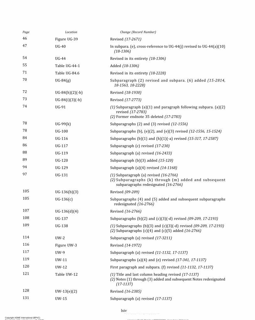
Page Location Change (Record Number)
46 Figure UG-39 Revised (17-2671)
47 UG-40 In subpara. (e), cross-reference to UG-44(j) revised to UG-44(a)(10)(18-1306)
54 UG-44 Revised in its entirety (18-1306)
55 Table UG-44-1 Added (18-1306)
71 Table UG-84.6 Revised in its entirety (18-2228)
70 UG-84(g) Subparagraph (2) revised and subpara. (6) added (15-2814,18-1563, 18-2228)
72 UG-84(h)(2)(-b) Revised (18-1930)
73 UG-84(i)(3)(-b) Revised (17-2773)
74 UG-91 (1) Subparagraph (a)(1) and paragraph following subpara. (a)(2)revised (17-2783)
(2) Former endnote 35 deleted (17-2783)
78 UG-99(k) Subparagraphs (2) and (3) revised (12-1556)
78 UG-100 Subparagraphs (b), (e)(2), and (e)(3) revised (12-1556, 15-1524)
84 UG-116 Subparagraphs (b)(1) and (h)(1)(-a) revised (15-317, 17-2587)
86 UG-117 Subparagraph (c) revised (17-230)
88 UG-119 Subparagraph (a) revised (16-2433)
89 UG-120 Subparagraph (b)(3) added (15-120)
94 UG-129 Subparagraph (a)(4) revised (14-1168)
97 UG-131 (1) Subparagraph (a) revised (16-2766)(2) Subparagraphs (k) through (m) added and subsequent
subparagraphs redesignated (16-2766)
105 UG-136(b)(3) Revised (09-209)
105 UG-136(c) Subparagraphs (4) and (5) added and subsequent subparagraphsredesignated (16-2766)
107 UG-136(d)(4) Revised (16-2766)
108 UG-137 Subparagraphs (b)(2) and (c)(3)(-d) revised (09-209, 17-2193)
109 UG-138 (1) Subparagraphs (b)(3) and (c)(3)(-d) revised (09-209, 17-2193)(2) Subparagraphs (c)(4) and (c)(5) added (16-2766)
114 UW-2 Subparagraph (a) revised (17-3211)
116 Figure UW-3 Revised (14-1972)
117 UW-9 Subparagraph (a) revised (11-1132, 17-1137)
119 UW-11 Subparagraphs (a)(4) and (e) revised (17-341, 17-1137)
120 UW-12 First paragraph and subpara. (f) revised (11-1132, 17-1137)
121 Table UW-12 (1) Title and last column heading revised (17-1137)(2) Notes (1) through (3) added and subsequent Notes redesignated
(17-1137)
128 UW-13(e)(2) Revised (16-2385)
131 UW-15 Subparagraph (a) revised (17-1137)
lxiv
Copyright ASME International (BPVC) Provided by IHS under license with ASME Licensee=Khalda Petroleum/5986215001, User=Amer, Mohamed
Not for Resale, 07/02/2019 13:29:04 MDTNo reproduction or networking permitted without license from IHS
--`,``,``,,`,`,,````,`,``,,,`-`-`,,`,,`,`,,`---
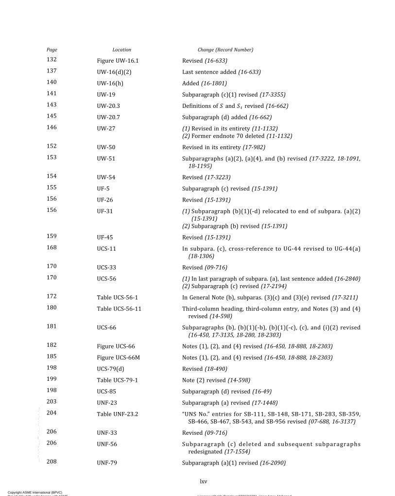
Page Location Change (Record Number)
132 Figure UW-16.1 Revised (16-633)
137 UW-16(d)(2) Last sentence added (16-633)
140 UW-16(h) Added (16-1801)
141 UW-19 Subparagraph (c)(1) revised (17-3355)
143 UW-20.3 Definitions of S and St revised (16-662)
145 UW-20.7 Subparagraph (d) added (16-662)
146 UW-27 (1) Revised in its entirety (11-1132)(2) Former endnote 70 deleted (11-1132)
152 UW-50 Revised in its entirety (17-982)
153 UW-51 Subparagraphs (a)(2), (a)(4), and (b) revised (17-3222, 18-1091,18-1195)
154 UW-54 Revised (17-3223)
155 UF-5 Subparagraph (c) revised (15-1391)
156 UF-26 Revised (15-1391)
156 UF-31 (1) Subparagraph (b)(1)(-d) relocated to end of subpara. (a)(2)(15-1391)
(2) Subparagraph (b) revised (15-1391)
159 UF-45 Revised (15-1391)
168 UCS-11 In subpara. (c), cross-reference to UG-44 revised to UG-44(a)(18-1306)
170 UCS-33 Revised (09-716)
170 UCS-56 (1) In last paragraph of subpara. (a), last sentence added (16-2840)(2) Subparagraph (c) revised (17-2194)
172 Table UCS-56-1 In General Note (b), subparas. (3)(c) and (3)(e) revised (17-3211)
180 Table UCS-56-11 Third-column heading, third-column entry, and Notes (3) and (4)revised (14-598)
181 UCS-66 Subparagraphs (b), (b)(1)(-b), (b)(1)(-c), (c), and (i)(2) revised(16-450, 17-3135, 18-280, 18-2303)
182 Figure UCS-66 Notes (1), (2), and (4) revised (16-450, 18-888, 18-2303)
185 Figure UCS-66M Notes (1), (2), and (4) revised (16-450, 18-888, 18-2303)
198 UCS-79(d) Revised (18-490)
199 Table UCS-79-1 Note (2) revised (14-598)
198 UCS-85 Subparagraph (d) revised (16-49)
203 UNF-23 Subparagraph (a) revised (17-1448)
204 Table UNF-23.2 “UNS No.” entries for SB-111, SB-148, SB-171, SB-283, SB-359,SB-466, SB-467, SB-543, and SB-956 revised (07-688, 16-3137)
206 UNF-33 Revised (09-716)
206 UNF-56 Subparagraph (c) deleted and subsequent subparagraphsredesignated (17-1554)
208 UNF-79 Subparagraph (a)(1) revised (16-2090)
lxv
Copyright ASME International (BPVC) Provided by IHS under license with ASME Licensee=Khalda Petroleum/5986215001, User=Amer, Mohamed
Not for Resale, 07/02/2019 13:29:04 MDTNo reproduction or networking permitted without license from IHS
--`,``,``,,`,`,,````,`,``,,,`-`-`,,`,,`,`,,`---

Page Location Change (Record Number)
209 Table UNF-79 Revised (15-2426)
208 UNF-91 Revised (18-1195)
213 UHA-23 In subpara. (a), cross-reference revised (17-1448)
214 Table UHA-23 Revised (07-799, 09-1776, 17-2082)
213 UHA-31 Revised (09-716)
213 UHA-32 Subparagraphs (a), (b), and (c) revised (15-698, 16-2462, 17-2194)
217 Table UHA-32-2 General Note (d) added (17-1200)
217 Table UHA-32-3 General Note (b) added (18-1198)
219 Table UHA-32-7 General Note (b) added (18-1198)
219 UHA-34 Revised (17-1344)
220 UHA-44 Subparagraph (a)(1) revised (16-2090)
223 UHA-51(d)(3) Paragraph after subpara. (-c) added (15-2391)
225 NonmandatoryAppendix UHA-A
Revised in its entirety (15-698)
228 UCI-35 In subpara. (b)(3), cross-reference to UG-44 revised to UG-44(a)(1)(18-1306)
235 UCL-52 Revised (12-1556)
242 UHT-18 Subparagraphs (b)(4) and (c) revised (17-2272, 18-1306)
245 Table UHT-23 Type/Grade for SA-553 revised (17-2272)
247 Table UHT-56 Type/Grade for SA-553 revised (17-2272)
246 UHT-57 Subparagraph (e) revised (17-2272)
249 UHT-82 In subpara. (e), row for SA-553 Type III added to table (17-2272)
266 ULW-52 Subparagraphs (a) and (b) revised (18-1090)
268 ULW-53 Subparagraphs (a), (b), and (c) revised (18-1090)
274 ULT-5 Subparagraphs (c) and (e) revised (17-2272)
275 ULT-16 Subparagraph (b) revised (17-2272)
275 ULT-17 Subparagraph (c) revised (17-2272)
276 Table ULT-23 Revised (17-2272)
275 ULT-30 Subparagraphs (a) and (c) revised (17-2272)
279 ULT-56 Subparagraph (a) revised (17-2272)
279 ULT-79 Revised (17-2272)
279 ULT-82 Subparagraph (b) revised (17-2272)
280 Table ULT-82 SA-553 Type III added (17-2272)
281 Table ULT-82M SA-553 Type III added (17-2272)
280 ULT-86 Revised (17-2272)
283 UHX-4 (1) In subpara. (b), cross-reference to UG-44 revised to UG-44(a)(18-1306)
(2) Subparagraph (h) added (07-1495)
lxvi
Copyright ASME International (BPVC) Provided by IHS under license with ASME Licensee=Khalda Petroleum/5986215001, User=Amer, Mohamed
Not for Resale, 07/02/2019 13:29:04 MDTNo reproduction or networking permitted without license from IHS
--`,``,``,,`,`,,````,`,``,,,`-`-`,,`,,`,`,,`---
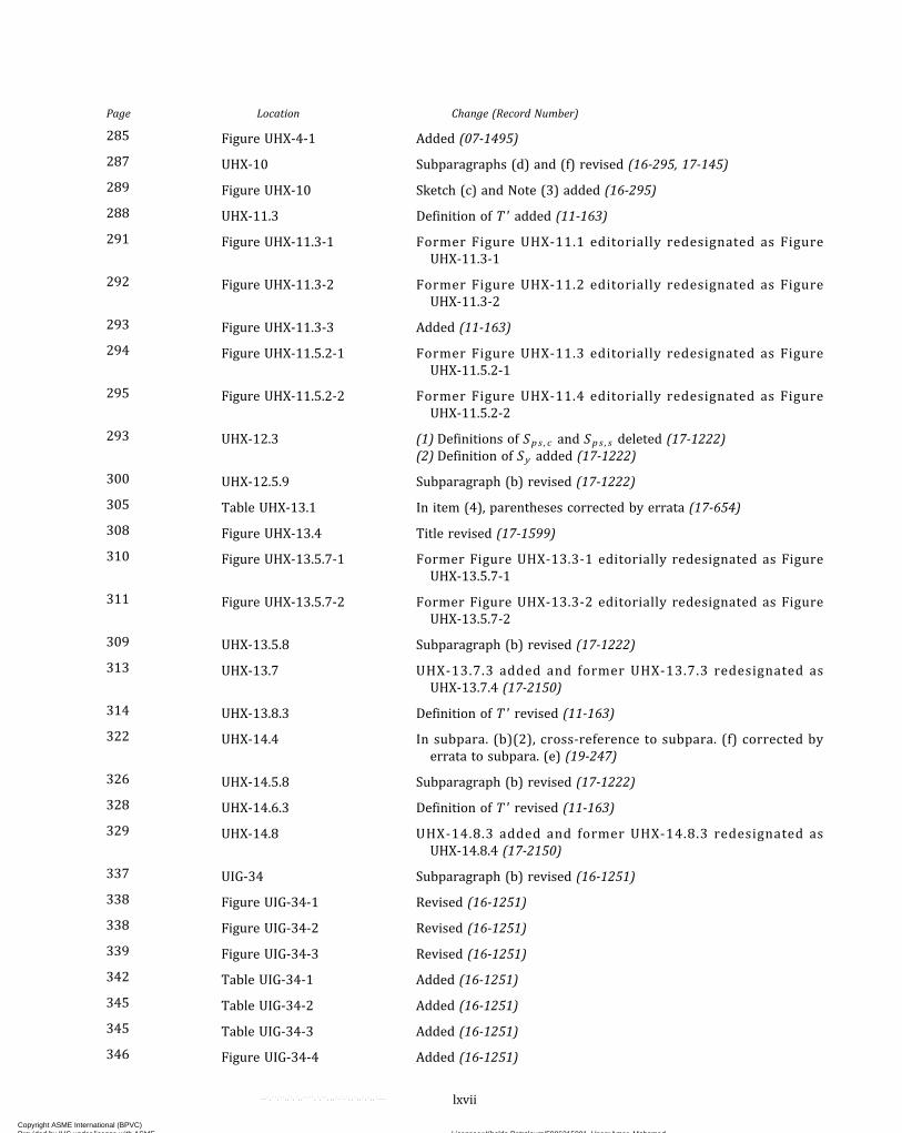
Page Location Change (Record Number)
285 Figure UHX-4-1 Added (07-1495)
287 UHX-10 Subparagraphs (d) and (f) revised (16-295, 17-145)
289 Figure UHX-10 Sketch (c) and Note (3) added (16-295)
288 UHX-11.3 Definition of T' added (11-163)
291 Figure UHX-11.3-1 Former Figure UHX-11.1 editorially redesignated as FigureUHX-11.3-1
292 Figure UHX-11.3-2 Former Figure UHX-11.2 editorially redesignated as FigureUHX-11.3-2
293 Figure UHX-11.3-3 Added (11-163)
294 Figure UHX-11.5.2-1 Former Figure UHX-11.3 editorially redesignated as FigureUHX-11.5.2-1
295 Figure UHX-11.5.2-2 Former Figure UHX-11.4 editorially redesignated as FigureUHX-11.5.2-2
293 UHX-12.3 (1) Definitions of Sps , c and Sps , s deleted (17-1222)(2) Definition of Sy added (17-1222)
300 UHX-12.5.9 Subparagraph (b) revised (17-1222)
305 Table UHX-13.1 In item (4), parentheses corrected by errata (17-654)
308 Figure UHX-13.4 Title revised (17-1599)
310 Figure UHX-13.5.7-1 Former Figure UHX-13.3-1 editorially redesignated as FigureUHX-13.5.7-1
311 Figure UHX-13.5.7-2 Former Figure UHX-13.3-2 editorially redesignated as FigureUHX-13.5.7-2
309 UHX-13.5.8 Subparagraph (b) revised (17-1222)
313 UHX-13.7 UHX-13.7.3 added and former UHX-13.7.3 redesignated asUHX-13.7.4 (17-2150)
314 UHX-13.8.3 Definition of T' revised (11-163)
322 UHX-14.4 In subpara. (b)(2), cross-reference to subpara. (f) corrected byerrata to subpara. (e) (19-247)
326 UHX-14.5.8 Subparagraph (b) revised (17-1222)
328 UHX-14.6.3 Definition of T' revised (11-163)
329 UHX-14.8 UHX-14.8.3 added and former UHX-14.8.3 redesignated asUHX-14.8.4 (17-2150)
337 UIG-34 Subparagraph (b) revised (16-1251)
338 Figure UIG-34-1 Revised (16-1251)
338 Figure UIG-34-2 Revised (16-1251)
339 Figure UIG-34-3 Revised (16-1251)
342 Table UIG-34-1 Added (16-1251)
345 Table UIG-34-2 Added (16-1251)
345 Table UIG-34-3 Added (16-1251)
346 Figure UIG-34-4 Added (16-1251)
lxvii
Copyright ASME International (BPVC) Provided by IHS under license with ASME Licensee=Khalda Petroleum/5986215001, User=Amer, Mohamed
Not for Resale, 07/02/2019 13:29:04 MDTNo reproduction or networking permitted without license from IHS
--`,``,``,,`,`,,````,`,``,,,`-`-`,,`,,`,`,,`---
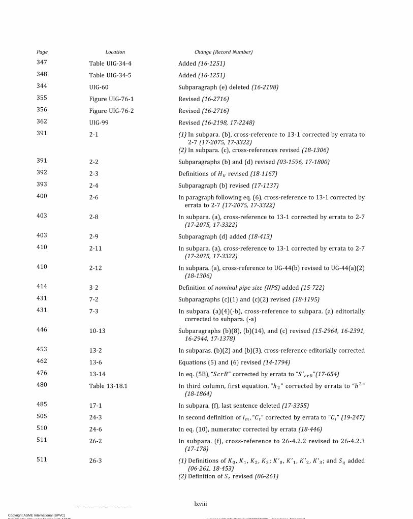
Page Location Change (Record Number)
347 Table UIG-34-4 Added (16-1251)
348 Table UIG-34-5 Added (16-1251)
344 UIG-60 Subparagraph (e) deleted (16-2198)
355 Figure UIG-76-1 Revised (16-2716)
356 Figure UIG-76-2 Revised (16-2716)
362 UIG-99 Revised (16-2198, 17-2248)
391 2-1 (1) In subpara. (b), cross-reference to 13-1 corrected by errata to2-7 (17-2075, 17-3322)
(2) In subpara. (c), cross-references revised (18-1306)
391 2-2 Subparagraphs (b) and (d) revised (03-1596, 17-1800)
392 2-3 Definitions of HG revised (18-1167)
393 2-4 Subparagraph (b) revised (17-1137)
400 2-6 In paragraph following eq. (6), cross-reference to 13-1 corrected byerrata to 2-7 (17-2075, 17-3322)
403 2-8 In subpara. (a), cross-reference to 13-1 corrected by errata to 2-7(17-2075, 17-3322)
403 2-9 Subparagraph (d) added (18-413)
410 2-11 In subpara. (a), cross-reference to 13-1 corrected by errata to 2-7(17-2075, 17-3322)
410 2-12 In subpara. (a), cross-reference to UG-44(b) revised to UG-44(a)(2)(18-1306)
414 3-2 Definition of nominal pipe size (NPS) added (15-722)
431 7-2 Subparagraphs (c)(1) and (c)(2) revised (18-1195)
431 7-3 In subpara. (a)(4)(-b), cross-reference to subpara. (a) editoriallycorrected to subpara. (-a)
446 10-13 Subparagraphs (b)(8), (b)(14), and (c) revised (15-2964, 16-2391,16-2944, 17-1378)
453 13-2 In subparas. (b)(2) and (b)(3), cross-reference editorially corrected
462 13-6 Equations (5) and (6) revised (14-1794)
476 13-14 In eq. (5B), “ScrB” corrected by errata to “S ʹc rB”(17-654)
480 Table 13-18.1 In third column, first equation, “h2 ” corrected by errata to “h 2 ”(18-1864)
485 17-1 In subpara. (f), last sentence deleted (17-3355)
505 24-3 In second definition of lm , “Ct” corrected by errata to “Ci” (19-247)
510 24-6 In eq. (10), numerator corrected by errata (18-446)
511 26-2 In subpara. (f), cross-reference to 26-4.2.2 revised to 26-4.2.3(17-178)
511 26-3 (1) Definitions of K0 , K1 , K2 , K3 ; K ’0 , K ’1 , K ’2 , K ’3 ; and Sq added(06-261, 18-453)
(2) Definition of St revised (06-261)
lxviii
Copyright ASME International (BPVC) Provided by IHS under license with ASME Licensee=Khalda Petroleum/5986215001, User=Amer, Mohamed
Not for Resale, 07/02/2019 13:29:04 MDTNo reproduction or networking permitted without license from IHS
--`,``,``,,`,`,,````,`,``,,,`-`-`,,`,,`,`,,`---
Page Location Change (Record Number)
516 26-4.2 Revised in its entirety (06-261, 17-178)
522 26-6.6.3.1 (1) Subparagraph (a) revised (17-178)(2) Subparagraph (c) deleted (17-178)
522 26-6.6.3.2 (1) Subparagraph (a) revised (17-178)(2) Subparagraph (c) added (17-178)
525 26-7.6.3.1 (1) Subparagraph (a) revised (17-178)(2) Subparagraph (c) deleted (17-178)
525 26-7.6.3.2 (1) Subparagraphs (a) and (b) revised (17-178)(2) Subparagraph (c) added (17-178)
527 26-8.6.3.1 (1) Subparagraph (a) revised (17-178)(2) Subparagraph (c) deleted (17-178)
528 26-8.6.3.2 (1) Subparagraph (a) revised (17-178)(2) Subparagraph (c) added (17-178)
530 Figure 26-8 Revised (18-1820)
529 26-9.5 Revised in its entirety (06-261, 18-1820)
530 Figure 26-9 Revised (18-1820)
529 26-9.6 (1) Designator and title added (06-261)(2) Former 26-9.5.2 through 26-9.5.4 revised and redesignated as
26-9.6.1 through 26-9.6.3, respectively (06-261, 18-1820)
532 Figure 26-10 Revised (18-1820)
537 Form 26-1 Revised (06-261)
539 Form 26-1M Revised (06-261)
552 Mandatory Appendix 33 Deleted (13-2204)
556 35-6 Endnote 101 (formerly endnote 103) revised (18-1976)
564 39-2 Subparagraph (b) revised (16-1805)
565 39-6 Revised (16-1805)
569 Figure 41-1-1 Former Figure 41-1.1-1 editorially redesignated as Figure 41-1-1
569 41-5 Definition of P revised (15-2046)
571 41-7 Step 12 revised (15-2046)
575 42-7 Subparagraph (b) revised (17-2410)
577 Table 44-4-1 SA-240, Type 304LN added (09-1776)
577 44-5 Subparagraph (a) revised (17-2997)
578 44-6.1 Subparagraph (g)(2) revised (18-887)
581 45-5 Subparagraph (b) revised (18-1094)
582 45-7 Revised (18-1308)
583 Mandatory Appendix 46 Added (12-307)
585 A-1 Subparagraphs (e)(1) through (e)(3), (e)(3)(-b), and (f) revised(08-829, 14-2469)
lxix
Copyright ASME International (BPVC) Provided by IHS under license with ASME Licensee=Khalda Petroleum/5986215001, User=Amer, Mohamed
Not for Resale, 07/02/2019 13:29:04 MDTNo reproduction or networking permitted without license from IHS
--`,``,``,,`,`,,````,`,``,,,`-`-`,,`,,`,`,,`---
Page Location Change (Record Number)
586 A-2 (1) Equations (2) and (3), second definition of fT , and definitions ofPo and PT revised (08-829, 17-1897)
(2) Definitions of d i , E , Et , f r e , Pe , Ta , α , and αT added (08-829,17-1897)
588 Table A-2 Note (10) added (08-829)
607 M-3 Cross-reference revised (16-2433)
637 Form U-3P Editorially revised
639 Form U-4 Revised (16-1084)
640 Form U-5 Revised (16-1084)
641 Table W-3 Instruction for Reference Number (61) revised (17-231)
665 NonmandatoryAppendix DD
Deleted (17-230)
674 GG-1 Revised (13-2204)
689 Figure JJ-1.2-3 Revised (18-1623)
706 Table NN-6-4 Code Reference for “Fabrication” revised (15-698)
708 Table NN-6-7 Code Reference for “Prior notification of weld repair” editoriallyrevised
lxx
Copyright ASME International (BPVC) Provided by IHS under license with ASME Licensee=Khalda Petroleum/5986215001, User=Amer, Mohamed
Not for Resale, 07/02/2019 13:29:04 MDTNo reproduction or networking permitted without license from IHS
--`,``,``,,`,`,,````,`,``,,,`-`-`,,`,,`,`,,`---
LIST OF CHANGES IN RECORD NUMBER ORDER
Record Number Change
03-1596 Revised 2-2(b).06-261 Revised the procedure for cycle counting and stress ranges in 26-4.2.1, Cumulative Fatigue
Damage.Split 26-9.5 into two paragraphs, one dealing with displacement and the other dealing with dis-placement range.Added a note for a more precise description of the displacements on the specification forms.
07-688 Added UNS C95820 to Table UNF-23.2.07-799 Added UNS S32003 to Table UHA-23 under SA-240, SA-789, and SA-790.07-1495 AddedUHX-4(h) stating new rules for openings near tubesheets.08-829 Added joint types f, g, and h (expanded and welded) and i, j, and k (expanded only) in A-1.
Added new note for explosive and hydraulic expansion joints.Added cautionary note to Table A-2 for when fT is negative.
09-209 Revised UG-136(b)(3), UG-137(b)(3), and UG-138(b)(3).09-716 Revised the external pressure references to Section II, Part D, Subpart 3 in UCS-33, UNF-33, and
UHA-31.09-1776 Added materials in Table UHA-23 with footnote giving the correspondence between grades and
types of materials.Added Type 304LN in Table 44-4-1.
11-163 Added Figure UHX-11.3-3 showing the location of T' .11-1132 Revised UW-27 to delete the list of welding processes and replace it with a single reference to
Section IX, Article 2 for acceptable welding processes. Replaced “pressure welding processes”in UW-9(a) and UW-12(f) with “permitted welding processes in UW-27(a) that include the ap-plication of pressure.” Revised UW-9 and UW-12 to correct the paragraph references to the re-vised UW-27 paragraphs.
12-307 Revised U-2(g) with rules to allow usage of Section VIII, Division 2 for design methods not pro-vided in Section VIII, Division 1 as well as other recognized standards or codes.Added Mandatory Appendix 46 to incorporate Code Case 2695 and provide a means for the de-signer to use the rules given in Section VIII, Division 2.
12-1556 Revised UG-99(k)(2) and UG-100(e)(2) to clarify that leak test requirements are applicable forvessels with nonmetallic linings.Revised UG-99(k)(3) and UG-100(e)(3) to clarify the requirement for pressure testing prior toinstallation of linings in vessels for lethal service.Revised UCL-52 to clarify that the requirements of UG-99(k) are not required for vessels fromintegral or weld metal overlay cladding.
13-1075 Revised the definition of C in UG-34(b).13-2204 Revised U-4 to limit any material data published in Section VIII, Division 1 or from Section II,
Part D in Code calculations to the units listed in Table 33-1. Renumbered subparagraphs in U-4and added subpara. (f) addressing dimensions shown as decimals or fractions. Corrected refer-ence in Nonmandatory Appendix GG to clarify that the term “equations” as used in GG-1 is re-ferring to equations used throughout the Division and not to any equations listed inNonmandatory Appendix GG. Redesignated Table 33-1 as Table U-4-1, relocated it to U-4,and deleted Mandatory Appendix 33.
14-598 Revised Tables U-3, UCS-56-11, and UCS-79-1 to address Mn + Ni limits for weld consumablesand PWHT limits for P-No. 15E Group 1 pressure vessels.
14-1168 Revised UG-129(a)(4) and UG-136(d)(4) to specify test media for pressure relief valves markedfor gas or vapor service, rules for performing set pressure testing using alternate test fluids,and treatment of steam to air or gas correction factors with respect to CDT. Revised “popping”pressure to “set” pressure.
14-1794 Inserted “+…” and “...+” in eqs. (5) and (6) in Mandatory Appendix 13, 13-6(b) after the termsstarting with bnTn .
14-1972 Revised Figure UW-3 by adding a sketch of weld neck flange with its weld category as C.
lxxi
Copyright ASME International (BPVC) Provided by IHS under license with ASME Licensee=Khalda Petroleum/5986215001, User=Amer, Mohamed
Not for Resale, 07/02/2019 13:29:04 MDTNo reproduction or networking permitted without license from IHS
--`,``,``,,`,`,,````,`,``,,,`-`-`,,`,,`,`,,`---
Record Number Change
14-2469 Added references to Nonmandatory Appendix HH and to 4-E.15-120 Added UG-120(b)(3).15-317 Removed W, P, B, and RES from the table in G-116(b)(1).
Added the UHT marking and reference to UHT-115; the WL marking and reference toULW-115; the ULT marking and reference to ULT-115; a reference to UIG-116 with the Gra-phite G marking; and the CS marking and reference to Mandatory Appendix 44, 44-7 to thetable in UG-116(b)(1).
15-698 Deleted references to Section II, Part D, Nonmandatory Appendix A, A-310 to A-360 inUHA-100. Deleted UHA-101 through UHA-105 and UHA-109. Redesignated UHA-107 asUHA-101 and UHA-108 as UHA-102. Corrected cross-references to deleted paragraphs inUHA-32, Table UHA-32-3, and Table NN-6-4.
15-722 Added definition of “NPS” in Mandatory Appendix 3.15-1391 Deleted reference to austenitic steel in UF-5(c) as this paragraph is specific to SA-372.
Revised UF-26 to remove specific reference to forged vessels, main sections of vessels, andother vessel parts.Moved UF-31(b)(1)(-d) referencing austenitic steels to UF-31(a)(1)(-d), revised the title ofUF-31(b) from “material” to “SA-372,” and deleted reference to austenitic steel inUF-31(b)(1)(-b) [redesignated as UF-31(b)(2)].Revised UF-45 to refer to inspections and tests given throughout Part UF as well as UG-90through UG-102.
15-1524 Revised UG-100(b) to correct the language for pneumatic testing of enameled (glass-lined) ves-sels.
15-2046 Revised definition of P in 41-5. Revised Step 12 in 41-7.15-2391 Revised UHA-51(d)(3).15-2426 Revised Table UNF-79 to include other nickel alloys from Table UNF-23.3 after cross-checking
the maximum-use temperature from Section II, Division D and Code Cases.Revised the minimum heat treatment temperature for UNS N08811 to 2,100°F from 2,050°F tobe consistent with the SB specifications.
15-2814 Revised UG-18 and added new UG-84(g)(6), addressing requirements for toughness testing andacceptance criteria for weld metal and HAZ test specimens when qualifying a WPS for joiningdissimilar metals where WPS qualification with toughness testing is required.
15-2964 Revised “hydrostatic” to “pressure” in 10-13(b)(14).16-49 Added “torch brazing” in UCS-85(d).16-295 Revised UHX-10(d), the maximum tubesheet butt length when directly attached to a hemisphe-
rical head (i.e., no intervening cylinder).16-450 Revised UCS-66(c). Added new subpara. (c) to Note (1) and revised the text for Note (2)(a) in
Figures UCS-66 and UCS-66M.16-633 Added new sketch (p-2) and relabeled the existing sketch (p) as (p-1) in Figure UW-16.1. Added
“Studding-outlet-type flanges may also be attached by full-penetration welds as shown inFigure UW-16.1, sketch (p-2)” in UW-16(d)(2).
16-662 Added UW-20.7(d) to clarify what the tubesheet allowable stress to be used is when the tube-sheet is clad.
16-1084 Replaced “Name” with “Signed” on Forms U-4 and U-5 for the Authorized Inspector.16-1251 Revised UIG-34(b), “Calculation Procedure for Tubesheets,” to incorporate all the necessary in-
formation into Part UIG, as well as to make necessary improvements to the procedure itself.16-1801 Added subpara. (h) to UW-16.16-1805 Revised Mandatory Appendix 39 variables for clarity.16-2090 Revised UHA-44 and UNF-79 to reduce the minimum annealing time from 10 min to 20 min/in.16-2198 Revised the hydrostatic pressure test requirements for graphite pressure vessels in UIG-60 and
UIG-99 to make them consistent with the pressure test requirements in UG-99.16-2385 Revised UW-13(e)(2) to clarify referenced Figure UW-13.2 sketches.16-2391 Revised Mandatory Appendix 10, 10-13(c).16-2413 Added “except as provided for in 1-5(g)” to UG-36(g)(2).16-2433 Revised UG-119(a) by deleting “[See UG-116(j)]” and revised M-3 by deleting “(j)” from the
cross-reference.
lxxii
Copyright ASME International (BPVC) Provided by IHS under license with ASME Licensee=Khalda Petroleum/5986215001, User=Amer, Mohamed
Not for Resale, 07/02/2019 13:29:04 MDTNo reproduction or networking permitted without license from IHS
--`,``,``,,`,`,,````,`,``,,,`-`-`,,`,,`,`,,`---
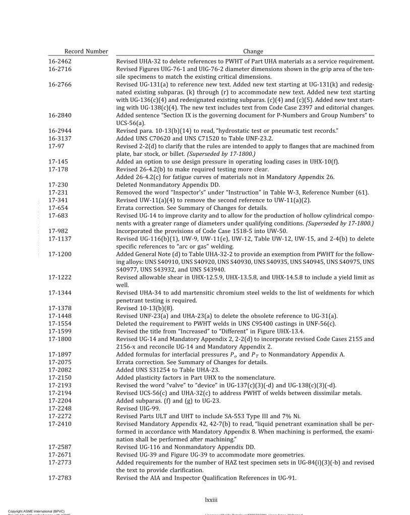
Record Number Change
16-246216-2716
16-2766
16-2840
16-294416-313717-97
17-14517-178
17-23017-23117-34117-65417-683
17-98217-1137
17-1200
17-1222
17-1344
17-137817-144817-155417-159917-1800
17-189717-207517-208217-215017-219317-219417-220417-224817-227217-2410
17-258717-267117-2773
17-2783
Revised UHA-32 to delete references to PWHT of Part UHA materials as a service requirement. Revised Figures UIG-76-1 and UIG-76-2 diameter dimensions shown in the grip area of the ten-sile specimens to match the existing critical dimensions.Revised UG-131(a) to reference new text. Added new text starting at UG-131(k) and redesig-nated existing subparas. (k) through (r) to accommodate new text. Added new text starting with UG-136(c)(4) and redesignated existing subparas. (c)(4) and (c)(5). Added new text start-ing with UG-138(c)(4). The new text includes text from Code Case 2397 and editorial changes. Added sentence “Section IX is the governing document for P-Numbers and Group Numbers” to UCS-56(a).Revised para. 10-13(b)(14) to read, “hydrostatic test or pneumatic test records.”Added UNS C70620 and UNS C71520 to Table UNF-23.2.Revised 2-2(d) to clarify that the rules are intended to apply to flanges that are machined from plate, bar stock, or billet. (Superseded by 17-1800.)Added an option to use design pressure in operating loading cases in UHX-10(f).Revised 26-4.2(b) to make required testing more clear.Added 26-4.2(c) for fatigue curves of materials not in Mandatory Appendix 26.Deleted Nonmandatory Appendix DD.Removed the word “Inspector's” under “Instruction” in Table W-3, Reference Number (61). Revised UW-11(a)(4) to remove the second reference to UW-11(a)(2).Errata correction. See Summary of Changes for details.Revised UG-14 to improve clarity and to allow for the production of hollow cylindrical compo-nents with a greater range of diameters under qualifying conditions. (Superseded by 17-1800.) Incorporated the provisions of Code Case 1518-5 into UW-50.Revised UG-116(b)(1), UW-9, UW-11(e), UW-12, Table UW-12, UW-15, and 2-4(b) to delete specific references to “arc or gas” welding.Added General Note (d) to Table UHA-32-2 to provide an exemption from PWHT for the follow-ing alloys: UNS S40910, UNS S40920, UNS S40930, UNS S40935, UNS S40945, UNS S40975, UNS S40977, UNS S43932, and UNS S43940.Revised allowable shear in UHX-12.5.9, UHX-13.5.8, and UHX-14.5.8 to include a yield limit as well.Revised UHA-34 to add martensitic chromium steel welds to the list of weldments for which penetrant testing is required.Revised 10-13(b)(8).Revised UNF-23(a) and UHA-23(a) to delete the obsolete reference to UG-31(a).Deleted the requirement to PWHT welds in UNS C95400 castings in UNF-56(c).Revised the title from “Increased” to “Different” in Figure UHX-13.4.Revised UG-14 and Mandatory Appendix 2, 2-2(d) to incorporate revised Code Cases 2155 and 2156-x and reconcile UG-14 and Mandatory Appendix 2.Added formulas for interfacial pressures Po and PT to Nonmandatory Appendix A.Errata correction. See Summary of Changes for details.Added UNS S31254 to Table UHA-23.Added plasticity factors in Part UHX to the nomenclature.Revised the word “valve” to “device” in UG-137(c)(3)(-d) and UG-138(c)(3)(-d).Revised UCS-56(c) and UHA-32(c) to address PWHT of welds between dissimilar metals. Added subparas. (f) and (g) to UG-23.Revised UIG-99.Revised Parts ULT and UHT to include SA-553 Type III and 7% Ni.Revised Mandatory Appendix 42, 42-7(b) to read, “liquid penetrant examination shall be per-formed in accordance with Mandatory Appendix 8. When machining is performed, the exami-nation shall be performed after machining.”Revised UG-116 and Nonmandatory Appendix DD.Revised UG-39 and Figure UG-39 to accommodate more geometries.Added requirements for the number of HAZ test specimen sets in UG-84(i)(3)(-b) and revised the text to provide clarification.Revised the AIA and Inspector Qualification References in UG-91.
lxxiii
Copyright ASME International (BPVC) Provided by IHS under license with ASME Licensee=Khalda Petroleum/5986215001, User=Amer, Mohamed
Not for Resale, 07/02/2019 13:29:04 MDTNo reproduction or networking permitted without license from IHS
--`,``,``,,`,`,,````,`,``,,,`-`-`,,`,,`,`,,`---

Record Number Change
17-2997 Revised 44-5(a).17-3135 Deleted “or (c)” in UCS-66(b)(1)(-c).17-3211 Revised UW-2(a) and Table UCS-56-1.17-3222 Revised UW-51(a)(2) by deleting the exception to written procedure requirements, replacing
the term “penetrameter” with “image quality indicator,” and deleting the phrase “shall be thebasis for final acceptance.”Revised UW-51(b) to simplify the wording and delete the requirement for Inspector confirma-tion of the defect indication by ultrasonic examination.
17-3223 Deleted reference to Section V, Article 1, T-120(h), and added references to Section V, Article 1,T-120(j) and T-120(k) in UW-54.
17-3322 Errata correction. See Summary of Changes for details.17-3355 Revised UW-19(c)(1) to increase the applicable thickness limit from 3/16 in. (5 mm) to ½ in.
(12 mm) when completely filling the hole with weld metal, and deleted the second sentenceof 17-1(f).
18-71 In Table U-3, updated year of acceptable edition for ASME B16.24, ASME B16.42, ASME B16.47,ASTM E4, and ASTM E691. Updated title of ASME B16.24. Added ASCE/SEI 7-16.
18-280 Revised UCS-66(b) to clarify that Figure UCS-66.1 is not permitted for bolts and nuts.Deleted “(including bolts and nuts)” from UCS-66(b)(1)(-b) and UCS-66(i)(2).
18-413 Revised Mandatory Appendix 2 to state that flange rigidity rules are not required for split looseflanges.
18-446 Errata correction. See Summary of Changes for details.18-453 Revised coefficient names in correlation testing fatigue equations and added names in the no-
menclature in Mandatory Appendix 26.18-490 Revised UCS-79 to include provisions for relaxing post-forming heat treatment requirements
for thin-walled tubing and pipe.18-887 Revised 44-6.1(g)(2).18-888 Revised Notes (2) and (4) in Figures UCS-66 and UCS-66M.18-1090 Revised ULW-52(a), ULW-52(b), and ULW-53(a) through ULW-53(c).18-1091 Revised UW-51(a)(4) to clarify that the permission to use UT in lieu of RT applies to welds in
which the thinner of the members joined is ¼ in. thick or greater.18-1094 Added requirements from Code Case 2766 to 45-5(b).18-1167 Replaced W with Wm1 in the definition of gasket load HG .18-1195 Replaced “penetrameter” with “image quality indicator” or “IQI” in UW-51, UNF-91, and 7-2.18-1198 Added the cautionary note in Tables UHA-32-3 and UHA-32-7.18-1306 Renumbered the existing UG-44 to be UG-44(a) and added UG-44(b) to add the provisions from
Code Case 2901. Added Table UG-44-1. Updated references to UG-44.18-1308 Deleted the first three words in the first sentence of the first paragraph and deleted the second
paragraph in Mandatory Appendix 45, 45-7.18-1563 Added new last sentence to UG-84(g)(2), “Where the material thickness permits, the axis of the
notch may be inclined to allow the root of the notch to align parallel to the fusion line.”18-1623 Added two decision diamonds in the flowchart of Figure JJ-1.2-3.18-1820 Added difference between “extension” and “compression” in 26-9.5.
Added alternative formulas for the calculation of the total equivalent axial displacement rangein 26-9.6.
18-1864 Errata correction. See Summary of Changes for details.18-1930 Replaced UG-84(h)(2)(-b) with the following: “be in the same heat-treated condition, and this
heat-treated condition shall be noted on the PQR and WPS used for construction; and.”18-1976 Revised Table U-3 to update year of acceptable edition of ASME PCC-2 to 2018.
Revised endnote 103 to align with Article-numbering format of ASME PCC-2.18-2228 Revised the second sentence in UG-84(g)(2) to clarify the intent of the Code.
Revised Table UG-84.6 to clarify the intent of the Code related to approximate location of thenotch in the test specimens.
18-2303 Revised UCS-66(c) and Figure UCS-66 to address low toughness concerns with SA-105.19-247 Errata correction. See Summary of Changes for details.
lxxiv
Copyright ASME International (BPVC) Provided by IHS under license with ASME Licensee=Khalda Petroleum/5986215001, User=Amer, Mohamed
Not for Resale, 07/02/2019 13:29:04 MDTNo reproduction or networking permitted without license from IHS
--`,``,``,,`,`,,````,`,``,,,`-`-`,,`,,`,`,,`---
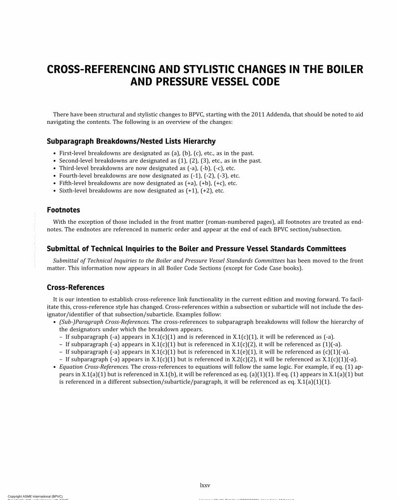
CROSS-REFERENCING AND STYLISTIC CHANGES IN THE BOILERAND PRESSURE VESSEL CODE
There have been structural and stylistic changes to BPVC, starting with the 2011 Addenda, that should be noted to aidnavigating the contents. The following is an overview of the changes:
Subparagraph Breakdowns/Nested Lists Hierarchy
• First-level breakdowns are designated as (a), (b), (c), etc., as in the past.• Second-level breakdowns are designated as (1), (2), (3), etc., as in the past.• Third-level breakdowns are now designated as (-a), (-b), (-c), etc.• Fourth-level breakdowns are now designated as (-1), (-2), (-3), etc.• Fifth-level breakdowns are now designated as (+a), (+b), (+c), etc.• Sixth-level breakdowns are now designated as (+1), (+2), etc.
Footnotes
With the exception of those included in the front matter (roman-numbered pages), all footnotes are treated as end-notes. The endnotes are referenced in numeric order and appear at the end of each BPVC section/subsection.
Submittal of Technical Inquiries to the Boiler and Pressure Vessel Standards Committees
Submittal of Technical Inquiries to the Boiler and Pressure Vessel Standards Committees has been moved to the frontmatter. This information now appears in all Boiler Code Sections (except for Code Case books).
Cross-References
It is our intention to establish cross-reference link functionality in the current edition and moving forward. To facil-itate this, cross-reference style has changed. Cross-references within a subsection or subarticle will not include the des-ignator/identifier of that subsection/subarticle. Examples follow:
• (Sub-)Paragraph Cross-References. The cross-references to subparagraph breakdowns will follow the hierarchy ofthe designators under which the breakdown appears.– If subparagraph (-a) appears in X.1(c)(1) and is referenced in X.1(c)(1), it will be referenced as (-a).– If subparagraph (-a) appears in X.1(c)(1) but is referenced in X.1(c)(2), it will be referenced as (1)(-a).– If subparagraph (-a) appears in X.1(c)(1) but is referenced in X.1(e)(1), it will be referenced as (c)(1)(-a).– If subparagraph (-a) appears in X.1(c)(1) but is referenced in X.2(c)(2), it will be referenced as X.1(c)(1)(-a).
• Equation Cross-References. The cross-references to equations will follow the same logic. For example, if eq. (1) ap-pears in X.1(a)(1) but is referenced in X.1(b), it will be referenced as eq. (a)(1)(1). If eq. (1) appears in X.1(a)(1) butis referenced in a different subsection/subarticle/paragraph, it will be referenced as eq. X.1(a)(1)(1).
lxxv
Copyright ASME International (BPVC) Provided by IHS under license with ASME Licensee=Khalda Petroleum/5986215001, User=Amer, Mohamed
Not for Resale, 07/02/2019 13:29:04 MDTNo reproduction or networking permitted without license from IHS
--`,``,``,,`,`,,````,`,``,,,`-`-`,,`,,`,`,,`---

INTENTIONALLY LEFT BLANK
Copyright ASME International (BPVC) Provided by IHS under license with ASME Licensee=Khalda Petroleum/5986215001, User=Amer, Mohamed
Not for Resale, 07/02/2019 13:29:04 MDTNo reproduction or networking permitted without license from IHS
--`,``,``,,`,`,,````,`,``,,,`-`-`,,`,,`,`,,`---

INTRODUCTION
U-1 SCOPE
(a) See below.(1) The Foreword provides the basis for the rules de-
scribed in this Division.(2) For the scope of this Division, pressure vessels
are containers for the containment of pressure, either in-ternal or external. This pressure may be obtained from anexternal source, or by the application of heat from a director indirect source, or any combination thereof.
(3) This Division contains mandatory requirements,specific prohibitions, and nonmandatory guidance forpressure vessel materials, design, fabrication, examina-tion, inspection, testing, certification, and pressure relief.The Code does not address all aspects of these activities,and those aspects which are not specifically addressedshould not be considered prohibited. Engineering judg-ment must be consistent with the philosophy of this Divi-sion, and such judgments must never be used to overrulemandatory requirements or specific prohibitions of thisDivision. See also informative and nonmandatory guid-ance regarding metallurgical phenomena in Section II,Part D, Nonmandatory Appendix A.
(b) This Division is divided into three Subsections,Mandatory Appendices, and Nonmandatory Appendices.Subsection A consists of Part UG, covering the general re-quirements applicable to all pressure vessels. SubsectionB covers specific requirements that are applicable to thevarious methods used in the fabrication of pressure ves-sels. It consists of Parts UW, UF, and UB dealing withwelded, forged, and brazed methods, respectively. Sub-section C covers specific requirements applicable to theseveral classes of materials used in pressure vessel con-struction. It consists of Parts UCS, UNF, UHA, UCI, UCL,UCD, UHT, ULW, ULT, and Part UIG dealing with carbonand low alloy steels, nonferrous metals, high alloy steels,cast iron, clad and lined material, cast ductile iron, ferriticsteels with properties enhanced by heat treatment,layered construction, low temperature materials, and im-pregnated graphite, respectively. Section II, Part D alsocontains tables of maximum allowable stress values forthese classes of materials, except for impregnatedgraphite.
The Mandatory Appendices address specific subjectsnot covered elsewhere in this Division, and their require-ments are mandatory when the subject covered is in-cluded in construction under this Division. TheNonmandatory Appendices provide information and sug-gested good practices.
(c) See below.
(1) The scope of this Division has been established toidentify the components and parameters considered informulating the rules given in this Division. Laws or reg-ulations issued by municipality, state, provincial, federal,or other enforcement or regulatory bodies having juris-diction at the location of an installation establish the man-datory applicability of the Code rules, in whole or in part,within their jurisdiction. Those laws or regulations mayrequire the use of this Division of the Code for vesselsor components not considered to be within its scope.These laws or regulations should be reviewed to deter-mine size or service limitations of the coverage whichmay be different or more restrictive than those givenhere.
(2) Based on the Committee’s consideration, the fol-lowing classes of vessels are not included in the scopeof this Division; however, any pressure vessel whichmeets all the applicable requirements of this Divisionmay be stamped with the Certification Mark with the UDesignator:
(-a) those within the scope of other Sections;(-b) fired process tubular heaters;(-c) pressure containers which are integral parts
or components of rotating or reciprocating mechanicaldevices, such as pumps, compressors, turbines, genera-tors, engines, and hydraulic or pneumatic cylinders wherethe primary design considerations and/or stresses are de-rived from the functional requirements of the device;
(-d) structures whose primary function is thetransport of fluids from one location to another within asystem of which it is an integral part, that is, pipingsystems;
(-e) piping components, such as pipe, flanges, bolt-ing, gaskets, valves, expansion joints, and fittings, and thepressure-containing parts of other components, such asstrainers and devices which serve such purposes as mix-ing, separating, snubbing, distributing, and metering orcontrolling flow, provided that pressure-containing partsof such components are generally recognized as pipingcomponents or accessories;
(-f)a vessel for containing water1 under pressure,including those containing air the compression of whichserves only as a cushion, when none of the following lim-itations are exceeded:
(-1) a design pressure of 300 psi (2 MPa);(-2) a design temperature of 210°F (99°C);
(-g) a hot water supply storage tank heated bysteam or any other indirect means when none of the fol-lowing limitations is exceeded:
(-1) a heat input of 200,000 Btu/hr (58.6 kW);
1
ASME BPVC.VIII.1-2019 U-1
Copyright ASME International (BPVC) Provided by IHS under license with ASME Licensee=Khalda Petroleum/5986215001, User=Amer, Mohamed
Not for Resale, 07/02/2019 13:29:04 MDTNo reproduction or networking permitted without license from IHS
--`,``,``,,`,`,,````,`,``,,,`-`-`,,`,,`,`,,`---

(-2) a water temperature of 210°F (99°C);(-3) a nominal water containing capacity of
120 gal (450 L);(-h) vessels not exceeding the design pressure
(see 3-2), at the top of the vessel, limitations below, withno limitation on size [see UG-28(f), 9-1(c)]:
(-1) vessels having an internal or external pres-sure not exceeding 15 psi (100 kPa);
(-2) combination units having an internal or ex-ternal pressure in each chamber not exceeding 15 psi(100 kPa) and differential pressure on the common ele-ments not exceeding 15 psi (100 kPa) [see UG-19(a)];
(-i) vessels having an inside diameter, width,height, or cross section diagonal not exceeding 6 in.(152 mm), with no limitation on length of vessel orpressure;
(-j) pressure vessels for human occupancy.2
(d) The rules of this Division have been formulated onthe basis of design principles and construction practicesapplicable to vessels designed for pressures not exceed-ing 3,000 psi (20 MPa). For pressures above 3,000 psi(20 MPa), deviations from and additions to these rulesusually are necessary to meet the requirements of designprinciples and construction practices for these higherpressures. Only in the event that after having appliedthese additional design principles and construction prac-tices the vessel still complies with all of the requirementsof this Division may it be stamped with the applicable Cer-tification Mark with the Designator.(e) In relation to the geometry of pressure-containing
parts, the scope of this Division shall include thefollowing:
(1)where external piping; other pressure vessels in-cluding heat exchangers; or mechanical devices, such aspumps, mixers, or compressors, are to be connected tothe vessel:
(-a) the welding end connection for the first cir-cumferential joint for welded connections [seeUW-13(i)];
(-b) the f i rs t threaded jo in t for screwedconnections;
(-c) the face of the first flange for bolted, flangedconnections;
(-d) the first sealing surface for proprietary con-nections or fittings;
(2)where nonpressure parts are welded directly toeither the internal or external pressure-retaining surfaceof a pressure vessel, this scope shall include the design,fabrication, testing, and material requirements estab-lished for non-pressure-part attachments by the applic-able paragraphs of this Division;3
(3) pressure-retaining covers for vessel openings,such as manhole or handhole covers, and bolted coverswith their attaching bolting and nuts;
(4) the first sealing surface for proprietary fittings orcomponents for which rules are not provided by this Divi-sion, such as gages, instruments, and nonmetalliccomponents.(f) The scope of the Division includes requirements for
overpressure protection in UG-125 through UG-140 andMandatory Appendix 11.(g) Vessels That Generate Steam
(1) Unfired steam boilers shall be constructed in ac-cordance with the rules of Section I or this Division [seeUG-120(f), UG-125(b), and UW-2(c)].
(2) The following pressure vessels in which steam isgenerated shall not be considered as unfired steam boil-ers, and shall be constructed in accordance with the rulesof this Division:
(-a) vessels known as evaporators or heatexchangers;
(-b) vessels in which steam is generated by the useof heat resulting from operation of a processing systemcontaining a number of pressure vessels such as used inthe manufacture of chemical and petroleum products;
(-c) vessels in which steam is generated but notwithdrawn for external use.(h) Pressure vessels or parts subject to direct firing
from the combustion of fuel (solid, liquid, or gaseous),which are not within the scope of Sections I, III, or IVmay be constructed in accordance with the rules of thisDivision [see UW-2(d)].(i) Gas fired jacketed steam kettles with jacket operat-
ing pressures not exceeding 50 psi (345 kPa) may be con-structed in accordance with the rules of this Division (seeMandatory Appendix 19).(j) Pressure vessels exclusive of those covered in (c),
(g), (h), and (i) that are not required by the rules of thisDivision to be fully radiographed, that are not providedwith quick-actuating or quick-opening closures (seeUG-35.2 and UG-35.3, respectively), and that do not ex-ceed the following volume and pressure limits may be ex-empted from inspection by Inspectors, as defined inUG-91, provided that they comply in all other respectswith the requirements of this Division:
(1) 5 ft3 (0.14 m3) in volume and 250 psi (1.7 MPa)design pressure; or
(2) 3 ft3 (0.08 m3) in volume and 350 psi (2.4 MPa)design pressure;
(3) 11/2 ft3 (0.04 m3) in volume and 600 psi(4.1 MPa) design pressure.In an assembly of vessels, the limitations in (1) through
(3) above apply to each vessel and not the assembly as awhole. Straight line interpolation for intermediate vol-umes and design pressures is permitted. Vessels fabri-cated in accordance with this rule shall be marked withthe “UM” Symbol in Figure UG-116, sketch (b) and withthe data required in UG-116. Certificates of Complianceshall satisfy the requirements of UG-120(a).
2
ASME BPVC.VIII.1-2019U-1
Copyright ASME International (BPVC) Provided by IHS under license with ASME Licensee=Khalda Petroleum/5986215001, User=Amer, Mohamed
Not for Resale, 07/02/2019 13:29:04 MDTNo reproduction or networking permitted without license from IHS
--`,``,``,,`,`,,````,`,``,,,`-`-`,,`,,`,`,,`---

ð19Þ U-2 GENERAL
(a) The user or his designated agent (see Nonmanda-tory Appendix NN) shall establish the design require-ments for pressure vessels, taking into considerationfactors associated with normal operation, such other con-ditions as startup and shutdown, and abnormal condi-t i ons wh i ch may become a govern ing des i gnconsideration (see UG-22).
Such consideration shall include but shall not be lim-ited to the following:
(1) the need for corrosion allowances;(2) the definition of lethal services. For example, see
UW-2(a).(3) the need for postweld heat treatment beyond the
requirements of this Division and dependent on serviceconditions;
(4) for pressure vessels in which steam is generated,or water is heated [see U-1(g) and U-1(h)], the need forpiping, valves, instruments, and fittings to perform thefunctions covered by Section I, PG‐59 through PG‐61.
(5) the degree of nondestructive examination(s) andthe selection of applicable acceptance standards whensuch examinations are beyond the requirements of thisDivision.
Sample User Design Requirements forms and guid-ance on their preparation are found in NonmandatoryAppendix KK. This sample form might not be applicableto all pressure vessels that may be constructed in accor-dance with this Division. The user is cautioned that inputfrom the Manufacturer may be necessary for completionof this form.
(b) Responsibilities4
(1) The Manufacturer of any vessel or part to bemarked with the Certification Mark has the responsibilityof complying with all of the applicable requirements ofthis Division and, through proper certification, of assuringthat all work done by others also complies. The vesselManufacturer or, when applicable, the part Manufactureris responsible for the preparation and accuracy of designcalculations to show compliance with the rules of this Di-vision, and his signature on the Manufacturer’s Data Re-port Form shall be considered as certification that thishas been done. The vessel or part Manufacturer shall haveavailable for the Inspector’s review the applicable designcalculations. See 10-5 and 10-15(d).
(2) Some types of work, such as forming, nondestruc-tive examination, and heat treating, may be performed byothers (for welding, see UW-26 and UW-31). It is the ves-sel or part Manufacturer’s responsibility to ensure that allwork so performed complies with all the applicable re-quirements of this Division. After ensuring Code compli-ance, the vessel or part may be stamped with theCertification Mark and Designator by the appropriate Cer-tificate holder after acceptance by the Inspector.
(c) A vessel may be designed and constructed using anycombination of the methods of fabrication and the classesof materials covered by this Division, provided the rulesapplying to each method and material are complied withand the vessel is marked as required by UG-116.
(d)When the strength of any part cannot be computedwith a satisfactory assurance of safety, the rules provideprocedures for establishing its maximum allowable work-ing pressure.
(e) It is the duty of the Inspector to make all of the in-spections specified by the rules of this Division, and tomonitor the quality control and the examinations madeby the Manufacturer. The Inspector shall make such otherinspections as in his judgment are necessary to permitcertification that the vessel has been designed and con-structed in accordance with the minimum requirementsof this Division. The Inspector has the duty of verifyingthat the applicable design calculations have been madeand are on file at Manufacturer’s plant at the time theData Report is signed. Any questions concerning the cal-culations raised by the Inspector must be resolved. SeeUG-90(c)(1).
NOTE: The term “applicable design calculations” means that allpressure-retaining components covered by the Certification Markstamping are supported by calculations and/or proof tests that com-ply with the requirements of this Division. The method of verifyingthat applicable design calculations have been made will vary withthe individual Inspector and depend largely on the Manufacturer’sprocedures for producing the design calculations and any subse-quent quality checks performed by the Manufacturer.
(f) The rules of this Division shall serve as the basis forthe Inspector to:
(1) perform the required duties;(2) authorize the application of the Certification
Mark;(3) sign the Certificate of Shop (or Field Assembly)
Inspection.(g) This Division of Section VIII does not contain rules
to cover all details of construction. Where complete de-tails of construction are not given, the Manufacturer, sub-ject to the acceptance of the Authorized Inspector, shallprovide the appropriate details to be used.
(1)Where design rules do not exist in this Division,one of the following three methods shall be used:
(-a) Mandatory Appendix 46.(-b) proof test in accordance with UG-101.(-c) other recognized and generally accepted
methods, such as those found in other ASME, EN, ISO, na-tional, and industry standards or codes. This option shallprovide details of design consistent with the allowablestress criteria provided in UG-23.
(2) The provisions of this paragraph shall not be usedto justify the use of materials, joining processes (fabrica-tion), examination, inspection, testing, certification, andoverpressure protection methods other than those al-lowed by this Division.
3
ASME BPVC.VIII.1-2019 U-2
Copyright ASME International (BPVC) Provided by IHS under license with ASME Licensee=Khalda Petroleum/5986215001, User=Amer, Mohamed
Not for Resale, 07/02/2019 13:29:04 MDTNo reproduction or networking permitted without license from IHS
--`,``,``,,`,`,,````,`,``,,,`-`-`,,`,,`,`,,`---

ð19Þ(h) Field assembly of vessels constructed to this Divi-sion may be performed as follows.
(1) The Manufacturer of the vessel completes thevessel in the field; completes the Form U-1, U-1A, orU-1P Manufacturer’s Data Report; and stamps the vessel.
(2) The Manufacturer of parts of a vessel to be com-pleted in the field by some other party stamps these partsin accordance with Code rules and supplies the Form U-2or U-2A Manufacturer’s Partial Data Report to the otherparty. The other party, who must hold a valid U Certificateof Authorization, makes the final assembly, required NDE,and final pressure test; completes the Form U-1, U-1A, orU-1P Manufacturer’s Data Report; and stamps the vessel.
(3) The field portion of the work is completed by aholder of a valid U Certificate of Authorization other thanthe vessel Manufacturer. The Certificate Holder perform-ing the field work is required to supply a Form U-2 orU-2A Manufacturer’s Partial Data Report covering theportion of the work completed by his organization (in-cluding data on the pressure test if conducted by the Cer-tificate Holder performing the field work) to theManufacturer responsible for the Code vessel. The vesselManufacturer applies his Certification Mark with the UDesignator in the presence of a representative from hisInspection Agency and completes the Form U-1, U-1A,or U-1P Manufacturer’s Data Report with his Inspector.In all three alternatives, the party completing and sign-
ing the Form U-1, U-1A, or U-1P Manufacturer’s Data Re-port assumes full Code responsibility for the vessel. In allthree cases, each Manufacturer’s Quality Control Systemshall describe the controls to assure compliance for eachCertificate Holder.(i) For some design analyses, both a chart or curve and
a equation or tabular data are given. Use of the equationor tabular data may result in answers which are slightlydifferent from the values obtained from the chart orcurve. However, the difference, if any, is within practicalaccuracy and either method is acceptable.
U-3 STANDARDS REFERENCED BY THISDIVISION
(a) Throughout this Division references are made tovarious standards, such as ASME standards, which coverpressure–temperature rating, dimensional, or proceduralstandards for pressure vessel parts. These standards,with the year of the acceptable edition, are listed in TableU-3.(b) Rules for the use of these standards are stated else-
where in this Division.
U-4 UNITS OF MEASUREMENT5
(a) U.S. Customary, SI, or any local customary units maybe used to demonstrate compliance with requirements ofthis edition related to materials, fabrication, examination,inspection, testing, certification, and overpressureprotection.(b) A single system of units shall be used for all aspects
of design except where otherwise permitted by this Divi-sion. When components are manufactured at different lo-cations where local customary units are different thanthose used for the general design, the local units may beused for the design and documentation of that compo-nent, subject to the limitations given in (c). Similarly, forproprietary components or those uniquely associatedwith a system of units different than that used for the gen-eral design, the alternate units may be used for the designand documentation of that component, subject to the lim-itations given in (c).(c) For any single equation, all variables shall be ex-
pressed in a single system of units. Calculations usingany material data published in this Division or SectionII, Part D (e.g., allowable stresses, physical properties, ex-ternal pressure design factor B ) shall be carried out inone of the standard units given in Table U-4-1. When se-parate equations are provided for U.S. Customary and SIunits, those equations must be executed using variablesin the units associated with the specific equation. Data ex-pressed in other units shall be converted to U.S. Custom-ary or SI units for use in these equations. The resultobtained from execution of these equations or any othercalculations carried out in either U.S. Customary or SIunits may be converted to other units.(d) Production, measurement and test equipment,
drawings, welding procedure specifications, welding pro-cedure and performance qualifications, and other fabrica-tion documents may be in U.S. Customary, SI, or localcustomary units in accordance with the fabricator’s prac-tice. When values shown in calculations and analysis, fab-rication documents, or measurement and test equipmentare in different units, any conversions necessary for ver-ification of Code compliance and to ensure that dimen-sional consistency is maintained, shall be in accordancewith the following:
(1) Conversion factors shall be accurate to at leastfour significant figures.
(2) The results of conversions of units shall be ex-pressed to a minimum of three significant figures.(e) Conversion of units, using the precision specified
above, shall be performed to assure that dimensional con-sistency is maintained. Conversion factors between U.S.Customary and SI units may be found in NonmandatoryAppendix GG, Guidance for the Use of U.S. Customaryand SI Units in the ASME Boiler and Pressure Vessel Code.Whenever local customary units are used , the
4
ASME BPVC.VIII.1-2019U-2 – U-4
Copyright ASME International (BPVC) Provided by IHS under license with ASME Licensee=Khalda Petroleum/5986215001, User=Amer, Mohamed
Not for Resale, 07/02/2019 13:29:04 MDTNo reproduction or networking permitted without license from IHS
--`,``,``,,`,`,,````,`,``,,,`-`-`,,`,,`,`,,`---
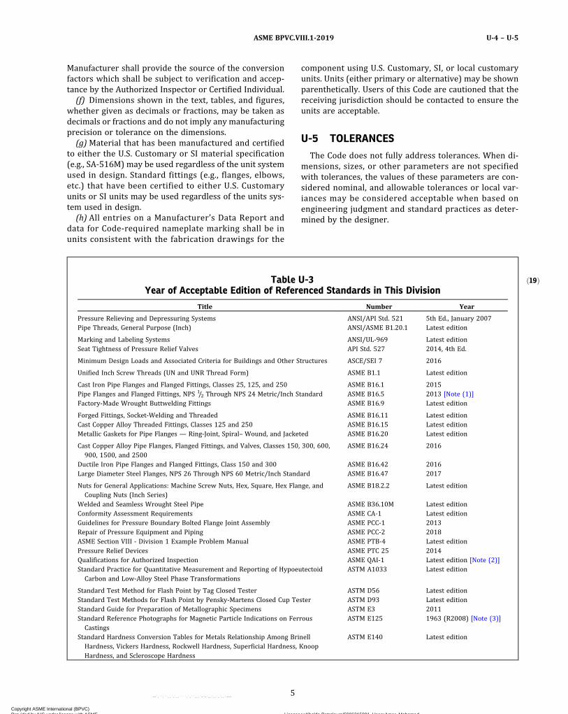
ð19Þ
Manufacturer shall provide the source of the conversionfactors which shall be subject to verification and accep-tance by the Authorized Inspector or Certified Individual.
(f) Dimensions shown in the text, tables, and figures,whether given as decimals or fractions, may be taken asdecimals or fractions and do not imply any manufacturingprecision or tolerance on the dimensions.
(g)Material that has been manufactured and certifiedto either the U.S. Customary or SI material specification(e.g., SA-516M) may be used regardless of the unit systemused in design. Standard fittings (e.g., flanges, elbows,etc.) that have been certified to either U.S. Customaryunits or SI units may be used regardless of the units sys-tem used in design.
(h) All entries on a Manufacturer’s Data Report anddata for Code‐required nameplate marking shall be inunits consistent with the fabrication drawings for the
component using U.S. Customary, SI, or local customaryunits. Units (either primary or alternative) may be shownparenthetically. Users of this Code are cautioned that thereceiving jurisdiction should be contacted to ensure theunits are acceptable.
U-5 TOLERANCES
The Code does not fully address tolerances. When di-mensions, sizes, or other parameters are not specifiedwith tolerances, the values of these parameters are con-sidered nominal, and allowable tolerances or local var-iances may be considered acceptable when based onengineering judgment and standard practices as deter-mined by the designer.
Table U-3Year of Acceptable Edition of Referenced Standards in This Division
Title Number Year
Pressure Relieving and Depressuring Systems ANSI/API Std. 521 5th Ed., January 2007Pipe Threads, General Purpose (Inch) ANSI/ASME B1.20.1 Latest edition
Marking and Labeling Systems ANSI/UL‐969 Latest editionSeat Tightness of Pressure Relief Valves API Std. 527 2014, 4th Ed.
Minimum Design Loads and Associated Criteria for Buildings and Other Structures ASCE/SEI 7 2016
Unified Inch Screw Threads (UN and UNR Thread Form) ASME B1.1 Latest edition
Cast Iron Pipe Flanges and Flanged Fittings, Classes 25, 125, and 250 ASME B16.1 2015Pipe Flanges and Flanged Fittings, NPS 1/2 Through NPS 24 Metric/Inch Standard ASME B16.5 2013 [Note (1)]Factory‐Made Wrought Buttwelding Fittings ASME B16.9 Latest edition
Forged Fittings, Socket‐Welding and Threaded ASME B16.11 Latest editionCast Copper Alloy Threaded Fittings, Classes 125 and 250 ASME B16.15 Latest editionMetallic Gaskets for Pipe Flanges — Ring‐Joint, Spiral– Wound, and Jacketed ASME B16.20 Latest edition
Cast Copper Alloy Pipe Flanges, Flanged Fittings, and Valves, Classes 150, 300, 600,900, 1500, and 2500
ASME B16.24 2016
Ductile Iron Pipe Flanges and Flanged Fittings, Class 150 and 300 ASME B16.42 2016Large Diameter Steel Flanges, NPS 26 Through NPS 60 Metric/Inch Standard ASME B16.47 2017
Nuts for General Applications: Machine Screw Nuts, Hex, Square, Hex Flange, andCoupling Nuts (Inch Series)
ASME B18.2.2 Latest edition
Welded and Seamless Wrought Steel Pipe ASME B36.10M Latest editionConformity Assessment Requirements ASME CA-1 Latest editionGuidelines for Pressure Boundary Bolted Flange Joint Assembly ASME PCC‐1 2013Repair of Pressure Equipment and Piping ASME PCC‐2 2018ASME Section VIII - Division 1 Example Problem Manual ASME PTB-4 Latest editionPressure Relief Devices ASME PTC 25 2014Qualifications for Authorized Inspection ASME QAI‐1 Latest edition [Note (2)]Standard Practice for Quantitative Measurement and Reporting of HypoeutectoidCarbon and Low-Alloy Steel Phase Transformations
ASTM A1033 Latest edition
Standard Test Method for Flash Point by Tag Closed Tester ASTM D56 Latest editionStandard Test Methods for Flash Point by Pensky‐Martens Closed Cup Tester ASTM D93 Latest editionStandard Guide for Preparation of Metallographic Specimens ASTM E3 2011Standard Reference Photographs for Magnetic Particle Indications on FerrousCastings
ASTM E125 1963 (R2008) [Note (3)]
Standard Hardness Conversion Tables for Metals Relationship Among BrinellHardness, Vickers Hardness, Rockwell Hardness, Superficial Hardness, KnoopHardness, and Scleroscope Hardness
ASTM E140 Latest edition
5
ASME BPVC.VIII.1-2019 U-4 – U-5
Copyright ASME International (BPVC) Provided by IHS under license with ASME Licensee=Khalda Petroleum/5986215001, User=Amer, Mohamed
Not for Resale, 07/02/2019 13:29:04 MDTNo reproduction or networking permitted without license from IHS
--`,``,``,,`,`,,````,`,``,,,`-`-`,,`,,`,`,,`---

Table U-3Year of Acceptable Edition of Referenced Standards in This Division (Cont'd)
Title Number Year
Standard Reference Radiographs for Heavy‐Walled [2 to 41/2 in. (50.8 to 114 mm)]Steel Castings
ASTM E186 2015
Standard Test Method for Conducting Drop‐Weight Test to Determine Nil– DuctilityTransition Temperature of Ferritic Steels
ASTM E208 2006 (R2012) [Note (3)]
Standard Reference Radiographs for Heavy‐Walled [41/2 to 12 in. (114 to 305 mm)]Steel Castings
ASTM E280 2015
Standard Reference Radiographs for Steel Castings up to 2 in. (51 mm) in Thickness ASTM E446 2015Metallic Materials — Charpy Pendulum Impact Test Part 1: Test Method ISO 148‐1 2009Metallic Materials — Charpy Pendulum Impact Test Part 2: Verification of Testing
MachinesISO 148‐2 2008
Metallic Materials — Charpy Pendulum Impact Test Part 3: Preparation andCharacterization of Charpy V-Notch Test Pieces for Indirect Verification ofPendulum Impact Machines
ISO 148‐3 2008
Metric StandardsStandard Procedures for Calibrating Magnetic Instruments to Measure the Delta
Ferrite Content of Austenitic and Duplex Ferritic-Austenitic Stainless Steel WeldMetal
ANSI/AWS A4.2M 2006
Metric Screw Thread — M Profile ASME B1.13M Latest editionMetric Screw Thread — MJ Profile ASME B1.21M Latest editionMetric Heavy Hex Screws ASME B18.2.3.3M Latest editionMetric Hex Bolts ASME B18.2.3.5M Latest edition
Metric Heavy Hex Bolts ASME B18.2.3.6M Latest editionMetric Fasteners for Use in Structural Applications ASME B18.2.6M Latest editionStandard Test Method for Compressive Strength of Carbon and Graphite ASTM C695 2015Standard Terminology Relating to Manufactured Carbon and Graphite ASTM C709 2009Standard Practices for Force Verification of Testing Machines ASTM E4 2016Standard Practice for Use of the Terms Precision and Bias in ASTM Test Methods ASTM E177 2014Standard Practice for Conducting an Interlaboratory Study to Determine the Precision
of a Test MethodASTM E691 2016
NOTES:(1) See UG-11(a)(2).(2) See UG-91 and UG-117(a).(3) R — Reaffirmed.
Table U-4-1Standard Units for Use in Equations
Quantity U.S. Customary Units SI Units
Linear dimensions (e.g., length, height, thickness, radius, diameter) inches (in.) millimeters (mm)Area square inches (in.2) square millimeters (mm2)Volume cubic inches (in.3) cubic millimeters (mm3)Section modulus cubic inches (in.3) cubic millimeters (mm3)Moment of inertia of section inches4 (in.4) millimeters4 (mm4)Mass (weight) pounds mass (lbm) kilograms (kg)Force (load) pounds force (lbf) newtons (N)Bending moment inch‐pounds (in.‐lb) newton‐millimeters (N·mm)Pressure, stress, stress intensity, and modulus of elasticity pounds per square inch (psi) megapascals (MPa)Energy (e.g., Charpy impact values) foot‐pounds (ft‐lb) joules (J)Temperature degrees Fahrenheit (°F) degrees Celsius (°C)Absolute temperature Rankine (°R) kelvin (K)Fracture toughness ksi square root inches (ksi ) MPa square root meters (MPa )
Angle degrees or radians degrees or radiansBoiler capacity Btu/hr watts (W)
6
ASME BPVC.VIII.1-2019U-5
Copyright ASME International (BPVC) Provided by IHS under license with ASME Licensee=Khalda Petroleum/5986215001, User=Amer, Mohamed
Not for Resale, 07/02/2019 13:29:04 MDTNo reproduction or networking permitted without license from IHS
--`,``,``,,`,`,,````,`,``,,,`-`-`,,`,,`,`,,`---
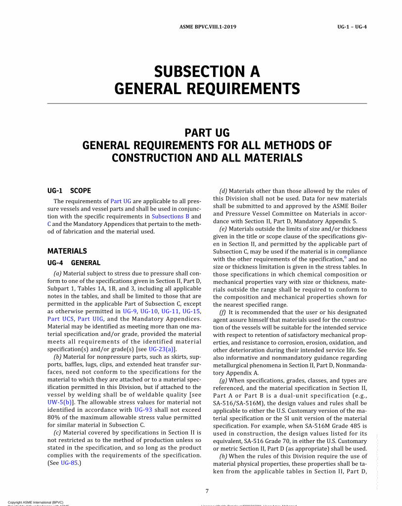
SUBSECTION AGENERAL REQUIREMENTS
PART UGGENERAL REQUIREMENTS FOR ALL METHODS OF
CONSTRUCTION AND ALL MATERIALS
UG-1 SCOPEThe requirements of Part UG are applicable to all pres-
sure vessels and vessel parts and shall be used in conjunc-tion with the specific requirements in Subsections B andC and the Mandatory Appendices that pertain to the meth-od of fabrication and the material used.
MATERIALS
UG-4 GENERAL(a)Material subject to stress due to pressure shall con-
form to one of the specifications given in Section II, Part D,Subpart 1, Tables 1A, 1B, and 3, including all applicablenotes in the tables, and shall be limited to those that arepermitted in the applicable Part of Subsection C, exceptas otherwise permitted in UG-9, UG-10, UG-11, UG-15,Part UCS, Part UIG, and the Mandatory Appendices.Material may be identified as meeting more than one ma-terial specification and/or grade, provided the materialmeets all requirements of the identified materialspecification(s) and/or grade(s) [see UG-23(a)].
(b)Material for nonpressure parts, such as skirts, sup-ports, baffles, lugs, clips, and extended heat transfer sur-faces, need not conform to the specifications for thematerial to which they are attached or to a material spec-ification permitted in this Division, but if attached to thevessel by welding shall be of weldable quality [seeUW-5(b)]. The allowable stress values for material notidentified in accordance with UG-93 shall not exceed80% of the maximum allowable stress value permittedfor similar material in Subsection C.
(c) Material covered by specifications in Section II isnot restricted as to the method of production unless sostated in the specification, and so long as the productcomplies with the requirements of the specification.(See UG-85.)
(d)Materials other than those allowed by the rules ofthis Division shall not be used. Data for new materialsshall be submitted to and approved by the ASME Boilerand Pressure Vessel Committee on Materials in accor-dance with Section II, Part D, Mandatory Appendix 5.
(e) Materials outside the limits of size and/or thicknessgiven in the title or scope clause of the specifications giv-en in Section II, and permitted by the applicable part ofSubsection C, may be used if the material is in compliancewith the other requirements of the specification,6 and nosize or thickness limitation is given in the stress tables. Inthose specifications in which chemical composition ormechanical properties vary with size or thickness, mate-rials outside the range shall be required to conform tothe composition and mechanical properties shown forthe nearest specified range.
(f) It is recommended that the user or his designatedagent assure himself that materials used for the construc-tion of the vessels will be suitable for the intended servicewith respect to retention of satisfactory mechanical prop-erties, and resistance to corrosion, erosion, oxidation, andother deterioration during their intended service life. Seealso informative and nonmandatory guidance regardingmetallurgical phenomena in Section II, Part D, Nonmanda-tory Appendix A.
(g)When specifications, grades, classes, and types arereferenced, and the material specification in Section II,Part A or Part B is a dual‐unit specification (e.g.,SA-516/SA-516M), the design values and rules shall beapplicable to either the U.S. Customary version of the ma-terial specification or the SI unit version of the materialspecification. For example, when SA-516M Grade 485 isused in construction, the design values listed for itsequivalent, SA-516 Grade 70, in either the U.S. Customaryor metric Section II, Part D (as appropriate) shall be used.
(h)When the rules of this Division require the use ofmaterial physical properties, these properties shall be ta-ken from the applicable tables in Section II, Part D,
7
ASME BPVC.VIII.1-2019 UG-1 – UG-4
Copyright ASME International (BPVC) Provided by IHS under license with ASME Licensee=Khalda Petroleum/5986215001, User=Amer, Mohamed
Not for Resale, 07/02/2019 13:29:04 MDTNo reproduction or networking permitted without license from IHS
--`,``,``,,`,`,,````,`,``,,,`-`-`,,`,,`,`,,`---
Subpart 2. If the applicable tables in Section II, Part D,Subpart 2 do not contain these properties for a permittedmaterial or do not list them within the required tempera-ture range, the Manufacturer may use other authoritativesources for the needed information. The Manufacturer’sData Report shall note under “Remarks” the property val-ues obtained and their source.
NOTE: If material physical properties are not listed, the Manufac-turer is encouraged to bring the information to the attention of theASME Committee on Materials (BPV Section II) so that the datacan be added in Section II, Part D, Subpart 2.
UG-5 PLATE7
Plate used in the construction of pressure parts of pres-sure vessels shall conform to one of the specifications inSection II for which allowable stress values are given inthe tables referenced in UG-23, except as otherwise pro-vided in UG-4, UG-10, UG-11, and UG-15.
UG-6 FORGINGS(a) Forged material may be used in pressure vessel
construction, provided the material has been worked suf-ficiently to remove the coarse ingot structure. Specifica-tions and maximum allowable stress values foracceptable forging materials are given in the tables refer-enced in UG-23. (See Part UF for forged vessels.)(b) Forged rod or bar may only be used within the lim-
itations of UG-14.(c) Forgings certified to SA-105, SA-181, SA-182,
SA-350, SA-403, and SA-420 may be used as tubesheetsand hollow cylindrical forgings for pressure vessel shellsthat otherwise meet all the rules of this Division, providedthat the following additional requirements are met:
(1) Forgings certified to SA-105 or SA-181 shall besubject to one of the austenitizing heat treatments per-mitted by these specifications.
(2) One tension test specimen shall be taken fromeach forging weighing more than 5,000 lb (2 250 kg).The largest obtainable tension test specimen as specifiedby the test methods referenced in the applicable specifica-tion shall be used. Except for upset-disk forgings, the lon-gitudinal axis of the test specimen shall be taken parallelto the direction of major working of the forging. Forupset-disk forgings, the longitudinal axis of the test speci-men shall be taken in the tangential direction. Whenagreed to by the Manufacturer, and when not prohibitedby the material specification, test specimens may be ma-chined from specially forged test blocks meeting the pro-visions provided in SA-266 or other similar specificationsfor large forgings.
(3) For quenched and tempered forgings weighingmore than 10,000 lb (4 500 kg) at the time of heat treat-ment, two tension test specimens shall be taken fromeach forging. These shall be offset 180 deg from each
other, except that if the length of the forging, excludingtest prolongations, exceeds 12 ft (3.7 m), then one speci-men shall be taken from each end of the forging.
UG-7 CASTINGSCast material may be used in the construction of pres-
sure vessels and vessel parts. Specifications and maxi-mum allowable stress values for acceptable castingmaterials are given in the tables referenced in UG-23.These allowable stress values shall be multiplied by theapplicable casting quality factor given in UG-24 for all ma-terials except cast iron.
UG-8 PIPE AND TUBES(a) Pipe and tubes of seamless or welded8 construction
conforming to one of the specifications given in Section IImay be used for shells and other parts of pressure vessels.Allowable stress values for the materials used in pipe andtubes are given in the tables referenced in UG-23.(b) Integrally finned tubes may be made from tubes
that conform in every respect with one of the specifica-tions given in Section II. These tubes may be used underthe following conditions:
(1) The tubes, after finning, shall have a temper orcondition that conforms to one of those provided in thegoverning specifications, or, when specified, they maybe furnished in the “as‐fabricated condition” where thefinned portions of the tube are in the cold worked temper(as‐finned) resulting from the finning operation, and theunfinned portions in the temper of the tube prior tofinning.
(2) The maximum allowable stress value for thefinned tube shall be that given in the tables referencedin UG-23 for the tube before finning except as permittedin (3) below.
(3) The maximum allowable stress value for a tem-per or condition that has a higher stress value than thatof the tube before finning may be used, provided that qua-lifying mechanical property tests demonstrate that such atemper or condition is obtained and conforms to one ofthose provided in the governing specifications in SectionII, and provided that allowable stress values have been es-tablished in the tables referenced in UG-23 for the tubematerial used. The qualifying mechanical property testsshall be made on specimens of finned tube from whichthe fins have been removed by machining. The frequencyof tests shall be as required in the unfinned tubespecification.
(4) The maximum allowable internal or externalworking pressure of the tube shall be based on the rootdiameter and the minimum wall of the finned section,or the outside diameter and wall of the unfinned sectiontogether with appropriate stress values, whichever re-sults in the lower maximum allowable working pressure.Alternatively, the maximum allowable external pressurefor tubes with integral fins may be established underthe rules of Mandatory Appendix 23.
8
ASME BPVC.VIII.1-2019UG-4 – UG-8
Copyright ASME International (BPVC) Provided by IHS under license with ASME Licensee=Khalda Petroleum/5986215001, User=Amer, Mohamed
Not for Resale, 07/02/2019 13:29:04 MDTNo reproduction or networking permitted without license from IHS
--`,``,``,,`,`,,````,`,``,,,`-`-`,,`,,`,`,,`---
(5) In addition to the tests required by the governingspecifications, each tube after finning shall be subjected toa pneumatic test or a hydrostatic test as indicated below.UG-90(c)(1)(-i) requirement for a visual inspection by theInspector does not apply to either of these tests.
(-a) an internal pneumatic test of not less than250 psi (1.7 MPa) for 5 sec without evidence of leakage.The test method shall permit easy visual detection ofany leakage such as immersion of the tube under wateror a pressure differential method.9
(-b) an individual tube hydrostatic test in accor-dance with UG-99 that permits complete examination ofthe tube for leakage.
UG-9 WELDING MATERIALSWelding materials used for production shall comply
with the requirements of this Division, those of SectionIX, and the applicable qualified welding procedure speci-fication. When the welding materials comply with one ofthe specifications in Section II, Part C, the marking or tag-ging of the material, containers, or packages as requiredby the applicable Section II specification may be acceptedfor identification in lieu of a Test Report or a Certificate ofCompliance. When the welding materials do not complywith one of the specifications of Section II, the markingor tagging shall be identifiable with the welding materialsset forth in the welding procedure specification, and maybe accepted in lieu of a Test Report or a Certificate ofCompliance.
UG-10 MATERIAL IDENTIFIED WITH ORPRODUCED TO A SPECIFICATION NOTPERMITTED BY THIS DIVISION, ANDMATERIAL NOT FULLY IDENTIFIED
(a) Identified Material With Complete CertificationFrom the Material Manufacturer. Material identified witha specification not permitted by this Division and identi-fied to a single production lot as required by a permittedspecification may be accepted as satisfying the require-ments of a specification permitted by this Division, pro-vided the following conditions are satisfied:
(1) Recertification by an Organization Other Than theVessel or Part Manufacturer. Not permitted.
(2) Recertification by the Vessel or Part Manufacturer(-a) Documentation is provided to the Certificate
Holder demonstrating that all applicable requirements(including, but not limited to, melting method, meltingpractice, deoxidation, chemical analysis, mechanical prop-erties, quality, and heat treatment) of the specificationpermitted by this Division, to which the material is tobe recertified, have been met.
(-b) The material has marking, acceptable to theInspector, for identification to the documentation.
(-c) When the conformance of the material withthe permitted specification has been established, the ma-terial shall be marked as required by the permittedspecification.
(b) Material Identified With a Specification Not Per-mitted by This Division and Identified to a Particular Pro-duction Lot as Required by a Specification Permitted byThis Division but Which Cannot Be Qualified Under (a).Any material for which the documentation required in(a) is not available may be accepted as satisfying the re-quirements of the specification permitted by this Division,provided that the conditions set forth below are satisfied.
(1) Recertification by an Organization Other Than theVessel or Part Manufacturer. Not permitted.
(2) Recertification by the Vessel or Part Manufacturer(-a) When documentation demonstrating com-
plete conformance to the chemical requirements is notavailable, chemical analyses are made on different piecesfrom the lot to establish a mean analysis that is to be ac-cepted as representative of the lot. The pieces chosen foranalysis shall be selected at random from the lot. Thenumber of pieces selected shall be at least 10% of thenumber of pieces in the lot, but not less than three. Forlots of three pieces or less, each piece shall be analyzed.Each individual analysis for an element shall conform tothe limits for product analysis in the permitted specifica-tion, and the mean for each element shall conform to theheat analysis limits of that specification. Analyses needonly be made for those elements required by the per-mitted specification (including its general specification);only those elements for which documentation is not avail-able must be tested.
(-b) When documentation demonstrating com-plete conformance to the mechanical property require-ments is not available, mechanical property tests aremade in accordance with the requirements of the per-mitted specification, and the results of the tests conformto the specified requirements; only those properties forwhich documentation is not available must be tested.
(-c) When documentation demonstrating com-plete conformance to the heat treatment requirementsis not available, the material is heat treated in accordancewith those specification heat treatment requirements,either prior to or during fabrication. (See also UG-85.)
(-d) All other applicable requirements (including,but not limited to, melting method, melting practice,deoxidation, chemical analysis, mechanical properties,grain size, and quality) of the specification permitted bythis Division, to which the material is to be recertified,have been demonstrated to have been met.
(-e) The material has marking, acceptable to theInspector, for identification to the documentation.
(-f)When the conformance of the material with thepermitted specification has been established, the materialsha l l be marked as required by the permittedspecification.
(c) Material Not Fully Identified. Material that cannotbe qualified under the provisions of either (a) or (b), suchas material not fully identified as required by the per-mitted specification or unidentified material, may be
9
ASME BPVC.VIII.1-2019 UG-8 – UG-10
Copyright ASME International (BPVC) Provided by IHS under license with ASME Licensee=Khalda Petroleum/5986215001, User=Amer, Mohamed
Not for Resale, 07/02/2019 13:29:04 MDTNo reproduction or networking permitted without license from IHS
--`,``,``,,`,`,,````,`,``,,,`-`-`,,`,,`,`,,`---
ð19Þ
accepted as satisfying the requirements of a specificationpermitted by this Division, provided that the conditionsset forth below are satisfied.
(1) Qualification by an Organization Other Than theVessel or Part Manufacturer. Not permitted.
(2) Qualification by the Vessel or Part Manufacturer(-a) Each piece is tested to show that it meets the
chemical composition for heat analysis and the mechani-cal properties requirements of the permitted specifica-tion. Chemical analyses need only be made for thoseelements required by the permitted specification (includ-ing its general specification). When the direction of finalrolling or major work (as required by the material speci-fication) is not known, tension test specimens shall be ta-ken in each appropriate direction from each samplinglocation designated in the permitted specification. The re-sults of all tests shall conform to the minimum require-ments of the specification, but the tensile strength ofonly one of the specimens need conform to the maximumrequirement.
(-b) The provision of (b)(2)(-c) above shall bemet.
(-c) All other applicable requirements (including,but not limited to, melting method, melting practice,deoxidation, chemical analysis, mechanical properties,grain size, and quality) of the specification permitted bythis Division, to which the material is to be recertified,have been demonstrated to have been met. If such verifi-able evidence cannot be provided, recertification is notpermitted.
(-d) When the identity of the material with thepermitted specification has been established in accor-dance with (-a), (-b), and (-c) above, each piece (or bun-dle, etc., if permitted in the specification) shall bemarked with a marking giving the permitted specificationnumber and grade, type, or class, as applicable, and a se-rial number identifying the particular lot of material. Asuitable report, clearly marked as being a “Report onTests of Nonidentified Material,” shall be completed andcertified by the vessel or Part Manufacturer. This report,when accepted by the Inspector, shall constitute authorityto use the material in lieu of material procured to the re-quirements of the permitted specification.
UG-11 PREFABRICATED OR PREFORMEDPRESSURE PARTS FURNISHED WITHOUTA CERTIFICATION MARK
(a) Prefabricated or preformed pressure parts for pres-sure vessels that are subject to stresses due to pressureand that are furnished by others or by the Manufacturerof the completed vessel shall conform to all applicable re-quirements of this Division except as permitted in (b),(c), (d), and (e) below. When the prefabricated or pre-formed parts are furnished with a nameplate that con-tains product identifying marks and the nameplateinterferes with further fabrication or service, and where
stamping on the material is prohibited, the Manufacturerof the completed vessel, with the concurrence of theAuthorized Inspector, may remove the nameplate. The re-moval of the nameplate shall be noted in the “Remarks”section of the vessel Manufacturer’s Data Report. Thenameplate shall be destroyed. The rules of (b), (c), (d),and (e) below shall not be applied to welded shells orheads or to quick-actuating or quick-opening closures(see UG-35.2 and UG-35.3, respectively).Parts furnished under the provisions of (b), (c), and (d)
need not be manufactured by a Certificate Holder. How-ever, the Manufacturer of the completed vessel or Certifi-cation Mark–stamped part shall ensure that partsfurnished under the provisions of (b), (c), (d), and (e)meet all of the applicable Code requirements such asUCS-79(d), UNF-79(a), UHA-44(a), and UHT-79(a). Pre-fabricated or preformed pressure parts may be suppliedas follows:
(1) cast, forged, rolled, or die formed non-standardpressure parts
(2) cast, forged, rolled, or die formed standard pres-sure parts that comply with an ASME product standard,either welded or nonwelded
(3) cast, forged, rolled, or die formed standard pres-sure parts that comply with a standard other than anASME product standard, either welded or nonwelded(b) Cast, Forged, Rolled, or Die Formed Non-standard
Pressure Parts. Pressure parts such as shells, heads, remo-vable doors, and pipe coils that are wholly formed by cast-ing, forging, rolling, or die forming may be suppliedbasically as materials. All such parts shall be made ofmaterials permitted under this Division, and the manufac-turer of the part shall furnish identification in accordancewith UG-93. Such parts shall be marked with the name ortrademark of the parts manufacturer and with such othermarkings as will serve to identify the particular parts withaccompanying material identification. The Manufacturerof the completed vessel shall be satisfied that the part issuitable for the design conditions specified for the com-pleted vessel in accordance with the rules of this Division.(c) Cast, Forged, Rolled, or Die Formed Standard Pres-
sure Parts That Comply With an ASME Product Standard,Either Welded or Nonwelded
(1) These are pressure parts that comply with anASME product standard accepted by reference inUG-44(a). The ASME product standard establishes the ba-sis for the pressure–temperature rating and marking un-less modified in UG-44(a).
(2) Flanges and flanged fittings may be used at thepressure–temperature ratings specified in the appropri-ate standard listed in this Division.
(3)Materials for standard pressure parts shall be asfollows:
(-a) as permitted by this Division or(-b) as specifically listed in the ASME product
standard
10
ASME BPVC.VIII.1-2019UG-10 – UG-11
Copyright ASME International (BPVC) Provided by IHS under license with ASME Licensee=Khalda Petroleum/5986215001, User=Amer, Mohamed
Not for Resale, 07/02/2019 13:29:04 MDTNo reproduction or networking permitted without license from IHS
--`,``,``,,`,`,,````,`,``,,,`-`-`,,`,,`,`,,`---
(4)When welding is performed it shall meet thefollowing:
(-a) the requirements of UW-26(a), UW-26(b),and UW-26(c) and UW-27 through UW-40, or;
(-b) the welding requirements of ASME specifica-tion SA-234.
(5) Standard pressure parts as identified in UG-11(c)do not require inspection, identification in accordancewith UG-93(a) or UG-93(b), or Partial Data Reports, pro-vided the requirements of UG-11(c) are met.
(6) If postweld heat treatment is required by therules of this Division, it may be performed either in the lo-cation of the parts manufacturer or in the location of theManufacturer of the vessel to be marked with the Certifi-cation Mark.
(7) If radiography or other volumetric examination isrequired by the rules of this Division, it may be performedat one of the following locations:
(-a) the location of the Manufacturer of the com-pleted vessel
(-b) t h e l o c a t i o n o f t h e p r e s s u r e p a r t smanufacturer
(8) Parts made to an ASME product standard shall bemarked as required by the ASME product standard.
(9) The Manufacturer of the completed vessels shallhave the following responsibilities when using standardpressure parts that comply with an ASME productstandard:
(-a) Ensure that all standard pressure parts com-ply with applicable rules of this Division.
(-b) Ensure that all standard pressure parts aresuitable for the design conditions of the completed vessel.
(-c) When volumetric examination is required bythe rules of this Division, obtain the completed radio-graphs, properly identified, with a radiographic inspec-tion report, and any other applicable volumetricexamination report.
(10) The Manufacturer shall fulfill these responsibil-ities by obtaining, when necessary, documentation as pro-vided below, provide for retention of this documentation,and have such documentation available for examinationby the Inspector when requested. The documentationshall contain at a minimum:
(-a) material used(-b) the pressure–temperature rating of the part(-c) the basis for establishing the pressure–
temperature rating(d) Cast, Forged, Rolled, or Die Formed Standard Pres-
sure Parts That Comply With a Standard Other Than anASME Product Standard, Either Welded or Nonwelded
(1) Standard pressure parts that are either welded ornonwelded and comply with a manufacturer’s proprie-tary standard or a standard other than an ASME productstandard may be supplied by
(-a) a Certificate Holder(-b) a pressure parts manufacturer
(2) Parts of small size falling within this category forwhich it is impossible to obtain identified material or thatmay be stocked and for which identification in accordancewith UG-93 cannot be obtained and are not customarilyfurnished, may be used for parts as described in UG-4(b).
(3)Materials for these parts shall be as permitted bythis Division only.
(4) Requirements for welding and brazing are asfollows:
(-a) When welding is performed, it shall meet therequirements of UW-26(a), UW-26(b), UW-26(c), andUW-27 through UW-40.
(-b) When brazing is performed, it shall meet therequirements of Part UB.
(5) Standard pressure parts as identified in (d) donot require inspection, identification in accordance withUG-93(a) or UG-93(b), or Partial Data Reports, providedthe requirements of (d) are met.
(6) If postweld heat treatment is required by therules of this Division, it may be performed either in the lo-cation of the parts manufacturer or in the location of theManufacturer of the completed vessel.
(7) If radiography or other volumetric examination isrequired by the rules of this Division, it may be performedat one of the following locations:
(-a) the location of the Manufacturer of the com-pleted vessel
(-b) the location of the parts Manufacturer(-c) t h e l o c a t i o n o f t h e p r e s s u r e p a r t s
manufacturer(8)Marking for these parts shall be as follows:
(-a) with the name or trademark of the CertificateHolder or the pressure part manufacturer and any othermarkings as required by the proprietary standard orother standard used for the pressure part
(-b) with a permanent or temporary marking thatwill serve to identify the part with the Certificate Holderor the pressure parts manufacturer’s written documenta-tion of the particular items, and that defines the pressure–temperature rating of the part
(9) The Manufacturer of the completed vessels shallhave the following responsibilities when using standardpressure parts:
(-a) Ensure that all standard pressure parts com-ply with applicable rules of this Division.
(-b) Ensure that all standard pressure parts aresuitable for the design conditions of the completed vessel.
(-c) When volumetric examination is required bythe rules of this Division, obtain the completed radio-graphs, properly identified, with a radiographic inspec-tion report, and any other applicable volumetricexamination report.
11
ASME BPVC.VIII.1-2019 UG-11
Copyright ASME International (BPVC) Provided by IHS under license with ASME Licensee=Khalda Petroleum/5986215001, User=Amer, Mohamed
Not for Resale, 07/02/2019 13:29:04 MDTNo reproduction or networking permitted without license from IHS
--`,``,``,,`,`,,````,`,``,,,`-`-`,,`,,`,`,,`---

ð19Þ
(10) The Manufacturer of the completed vessel shallfulfill these responsibilities by one of the followingmethods:
(-a) Obtain, when necessary, documentation asprovided below, provide for retention of this documenta-tion, and have such documentation available for examina-tion by the Inspector when requested, or;
(-b) Perform an analysis of the pressure part in ac-cordance with the rules of this Division. [See also U-2(g).]This analysis shall be included in the documentation andshall be made available for examination by the Inspectorwhen requested.
(11) The documentation shall contain at a minimum:(-a) material used(-b) the pressure–temperature rating of the part(-c) the basis for establishing the pressure–
temperature rating(-d) a written certification by the pressure parts
manufacturer that all welding and brazing complies withCode requirements(e) The Code recognizes that a Certificate Holder may
fabricate parts in accordance with UG-11(d), and thatare marked in accordance with UG-11(d)(8). In lieu ofthe requirement in UG-11(d)(4)(-a), the CertificateHolder may subcontract to an individual or organizationnot holding an ASME Certificate standard pressure partsthat are fabricated to a standard other than an ASME pro-duct standard provided all the following conditions aremet:
(1) The activities to be performed by the subcontrac-tor are included within the Certificate Holder’s QualityControl System.
(2) The Certificate Holder’s Quality Control Systemprovides for the following activities associated with sub-contracting of welding operations, and these provisionsshall be acceptable to the Manufacturer’s Authorized In-spection Agency:
(-a) the welding processes permitted by this Divi-sion that are permitted to be subcontracted
(-b) welding operations(-c) Authorized Inspection activities(-d) placement of the Certificate Holder’s marking
in accordance with UG-11(d)(8)(3) The Certificate Holder’s Quality Control System
provides for the requirements of UG-92 to be met at thesubcontractor’s facility.
(4) The Certificate Holder shall be responsible for re-viewing and accepting the Quality Control Programs ofthe subcontractor.
(5) The Certificate Holder shall ensure that the sub-contractor uses written procedures and welding opera-tions that have been qualified as required by this Division.
(6) The Certificate Holder shall ensure that the sub-contractor uses personnel that have been qualified as re-quired by this Division.
(7) The Certificate Holder and the subcontractorshall describe in their Quality Control Systems the opera-tional control of procedure and personnel qualificationsof the subcontracted welding operations.
(8) The Certificate Holder shall be responsible forcontrolling the quality and ensuring that all materialsand parts that are welded by subcontractors and sub-mitted to the Inspector for acceptance, conform to all ap-plicable requirements of this Division.
(9) The Certificate Holder shall describe in theirQuality Control Systems the operational control for main-taining traceability of materials received from thesubcontractor.
(10) The Certificate Holder shall receive approval forsubcontracting from the Authorized Inspection Agencyprior to commencing of activities.
UG-12 BOLTS AND STUDS(a) Bolts and studs may be used for the attachment of
removable parts. Specifications, supplementary rules,and maximum allowable stress values for acceptable bolt-ing materials are given in the tables referenced in UG-23.(b) Studs shall be threaded full length or shall be ma-
chined down to the root diameter of the thread in the un-threaded portion, provided that the threaded portions areat least 11/2 diameters in length.Studs greater than eight diameters in length may have
an unthreaded portion that has the nominal diameter ofthe thread, provided the following requirements are met:
(1) the threaded portions shall be at least 11/2 dia-meters in length;
(2) the stud shall be machined down to the root dia-meter of the thread for a minimum distance of 0.5 dia-meters adjacent to the threaded portion;
(3) a suitable transition shall be provided betweenthe root diameter and the unthreaded portion; and
(4) particular consideration shall be given to any dy-namic loadings.
UG-13 NUTS AND WASHERS(a) Nuts shall conform to the requirements in the ap-
plicable Part of Subsection C (see UCS-11 and UNF-13).They shall engage the threads for the full depth of the nut.(b) The use of washers is optional. When used, they
shall be of wrought materials.
UG-14 RODS AND BARS(a) Rods and Bars Used for Pressure Parts. Rod and bar
may be used in pressure vessel construction for pressureparts such as flange rings [see 2-2(d)], stiffening rings,frames for reinforced openings, stays and stay‐bolts,and similar parts. Rod and bar materials shall conformto the requirements for bars or bolting in the applicablepart of Subsection C.
12
ASME BPVC.VIII.1-2019UG-11 – UG-14
Copyright ASME International (BPVC) Provided by IHS under license with ASME Licensee=Khalda Petroleum/5986215001, User=Amer, Mohamed
Not for Resale, 07/02/2019 13:29:04 MDTNo reproduction or networking permitted without license from IHS
--`,``,``,,`,`,,````,`,``,,,`-`-`,,`,,`,`,,`---
ð19Þ
(b) Parts Machined From Rod and Bar. Pressure partssuch as hollow cylindrically shaped parts, heads, caps,flanges, elbows, return bends, tees, and header tees maybe machined directly from rod or bar as provided in (1)through (4) below.
(1) Examination by the magnetic particle or liquidpenetrant method in accordance with the requirementsof Mandatory Appendix 6 or Mandatory Appendix 8 re-spectively, shall be as follows:
(-a) for flanges: the back of the flange and the out-er surface of the hub
(-b) for heads, caps, elbows, return bends, tees,and header tees: all surfaces
(-c) for hollow, cylindrically shaped parts: no sur-face examination needed
(2) Parts may be machined from rod or bar having ahot-worked diameter not greater than 5.50 in. (140 mm),provided that the axial length of the part is approximatelyparallel to the metal flow lines of the stock.
(3) Parts may be machined from rod or bar having ahot-worked diameter greater than 5.50 in. (140 mm), butnot greater than 8.00 in. (205 mm), provided the axiallength of the part is approximately parallel to the metalflow lines of the stock, and the minimum required thick-ness of the component is calculated following the rulesof this Division using 50% of the specified allowablestress.
(4) As an alternative to (3) above and for rod or barhaving a hot-worked diameter greater than 8.00 in.(205 mm), parts may be machined from such rod orbar, if the following requirements are met:
(-a) The longitudinal axis of the part shall be par-allel to the longitudinal axis of the rod or bar.
(-b) At least two transverse tension test speci-mens that have the same diameter shall be taken fromeach lot (as defined in the material specification) of rodor bar material.
(-1) The second specimen shall be taken at90 deg around the perimeter from the first specimen.
(-2) The axis of the tension test specimen shallbe located, as nearly as practicable, midway betweenthe center thickness and the surface of the rod or bar.
(-3) Both specimens shall meet the mechanicalproperty requirements of the material specification.
(-4) For Table UCS-23 materials, the reductionof area shall be not less than 30%.
(-c) Each rod or bar, before machining, shall be100% ultrasonically examined perpendicular to the longi-tudinal axis by the straight beam technique in accordancewith SA-388. The rod or bar shall be unacceptable if eitherof the following occurs:
(-1) The examination results show one or moreindications accompanied by loss of back reflection largerthan 60% of the reference back reflection.
(-2) The examination results show indicationslarger than 40% of the reference back reflection when ac-companied by a 40% loss of back reflection.
(-d) For heads and the flat portion of caps, the ex-aminations of (-c) shall also be performed in the axialdirection.
(-e) Before welding, the cut surfaces of the partadjacent to the weld shall be examined by magnetic par-ticle or liquid penetrant methods in accordance with Man-datory Appendix 6 or Mandatory Appendix 8 ,respectively.
UG-15 PRODUCT SPECIFICATIONWhen there is no material specification listed in Sub-
section C covering a particular wrought product of agrade, but there is an approved specification listed in Sub-section C covering some other wrought product of thatgrade, the product for which there is no specificationmay be used provided:
(a) the chemical and physical properties, heat treatingrequirements, and requirements for deoxidation, or grainsize requirements conform to the approved specificationlisted in Subsection C. The stress values for that specifica-tion given in the tables referenced in UG-23 shall be used.
(b) the manufacturing procedures, tolerances, tests,and marking are in accordance with a Section II specifica-tion covering the same product form of a similar material;
(c) for the case of welded tubing made of plate, sheet,or strip, without the addition of filler metal, the appropri-ate stress values are multiplied by a factor of 0.85;
(d) the product is not pipe or tubing fabricated by fu-sion welding with the addition of filler metal unless it isfabricated in accordance with the rules of this Divisionas a pressure part;
(e) mill test reports reference the specifications used inproducing the material and in addition make reference tothis paragraph.
DESIGN
UG-16 GENERAL(a) The design of pressure vessels and vessel parts shall
conform to the general design requirements in the follow-ing paragraphs and in addition to the specific require-ments for Design given in the applicable Parts ofSubsections B and C As an alternative, the design rulesof Mandatory Appendix 46 may be used.
(b) Minimum Thickness of Pressure-Retaining Compo-nents. Except for the special provisions listed below, theminimum thickness permitted for shells and heads, afterforming and regardless of product form and material,shall be 1/16 in. (1.5 mm) exclusive of any corrosion allow-ance. Exceptions are:
(1) the minimum thickness does not apply to heattransfer plates of plate‐type heat exchangers;
(2) this minimum thickness does not apply to the in-ner pipe of double pipe heat exchangers nor to pipes andtubes that are enclosed and protected from mechanicaldamage by a shell, casing, or ducting, where such pipes
13
ASME BPVC.VIII.1-2019 UG-14 – UG-16
Copyright ASME International (BPVC) Provided by IHS under license with ASME Licensee=Khalda Petroleum/5986215001, User=Amer, Mohamed
Not for Resale, 07/02/2019 13:29:04 MDTNo reproduction or networking permitted without license from IHS
--`,``,``,,`,`,,````,`,``,,,`-`-`,,`,,`,`,,`---
ð19Þ
or tubes are NPS 6 (DN 150) and less. This exemption ap-plies whether or not the outer pipe, shell, or protectiveelement is constructed to Code rules. When the outer pro-tective element is not provided by the Manufacturer aspart of the vessel, the Manufacturer shall note this onthe Manufacturer’s Data Report, and the owner or his de-signated agent shall be responsible to assure that the re-quired enclosures are installed prior to operation. Wherepipes and tubes are fully enclosed, consideration shall begiven to avoiding buildup of pressure within the protec-tive chamber due to a tube/pipe leak. All other pressureparts of these heat exchangers that are constructed toCode rules must meet the 1/16 in. (1.5 mm) minimumthickness requirements.
(3) the minimum thickness of shells and heads of un-fired steam boilers shall be 1/4 in. (6 mm) exclusive of anycorrosion allowance;
(4) the minimum thickness of shells and heads usedin compressed air service, steam service, and water ser-vice, made from materials listed in Table UCS-23, shallbe 3/32 in. (2.5 mm) exclusive of any corrosion allowance.
(5) this minimum thickness does not apply to thetubes in air cooled and cooling tower heat exchangers ifall the following provisions are met:
(-a) the tubes shall not be used for lethal UW-2(a)service applications;
(-b) the tubes shall be protected by fins or othermechanical means;
(-c) the tube outside diameter shall be a minimumof 3/8 in. (10 mm) and a maximum of 11/2 in. (38 mm);
(-d) the minimum thickness used shall not be lessthan that calculated by the formulas given in UG-27 or1-1 and in no case less than 0.022 in. (0.5 mm).(c) Plate Undertolerance
(1) Plate material shall not be ordered with a nom-inal thickness thinner than the design thickness.
(2) Plate material with an actual thickness less thanthe design thickness shall not be used unless thedifference in thicknesses is less than the smaller of 0.01in. (0.3 mm) or 6% of the design thickness [seeUG-90(b)(6)].
(3) If plate material is ordered to a specification thatallows an undertolerance greater than the smaller of 0.01in. (0.3 mm) or 6% of the nominal thickness, the thicknessof the plate ordered shall be increased, if required, so thatthe plate material will meet the requirement of (2) whenused.(d) Pipe Undertolerance. If pipe or tube is ordered by its
nominal wall thickness, the manufacturing undertoler-ance on wall thickness shall be taken into account exceptfor nozzle wall reinforcement area requirements in accor-dance with UG-37 and UG-40. The manufacturing under-tolerances are given in the several pipe and tubespecifications listed in the applicable Tables inSubsection C.
(e) Corrosion Allowance in Design Formulas. The di-mensional symbols used in all design formulas through-out this Division represent dimensions in the corrodedcondition.(f) Examples showing the application of the design
rules of this Division are contained in ASME PTB-4, ASMESection VIII, Division 1, Example Problem Manual.
UG-17 METHODS OF FABRICATION INCOMBINATION
A vessel may be designed and constructed by a combi-nation of the methods of fabrication given in this Division,provided the rules applying to the respective methods offabrication are followed and the vessel is limited to theservice permitted by the method of fabrication havingthe most restrictive requirements (see UG-116).
UG-18 MATERIALS IN COMBINATIONExcept as specifically prohibited by other rules of this
Division, a vessel may be designed and constructed ofany combination of materials permitted in Subsection C,provided the applicable rules are followed and the re-quirements in Section IX for welding dissimilar metalsare met.The requirements for the base metals, HAZs, and weld
metal(s) of a weldment between metals having differentimpact testing requirements and acceptance criteria shalleach be applied in accordance with the rules of thisDivision.
NOTE: Because of the different thermal coefficients of expansion ofdissimilar materials, caution should be exercised in design and con-struction under the provisions of this paragraph in order to avoiddifficulties in service under extreme temperature conditions, or withunusual restraint of parts such as may occur at points of stress con-centration and also because of metallurgical changes occurring atelevated temperatures. [See also Galvanic Corrosion in Section II,Part D, Nonmandatory Appendix A, A-440(c).]
UG-19 SPECIAL CONSTRUCTIONS(a) Combination Units. A combination unit is a pressure
vessel that consists of more than one independent or de-pendent pressure chamber, operating at the same or dif-ferent pressures and temperatures. The parts separatingeach pressure chamber are the common elements. Eachelement, including the common elements, shall be de-signed for at least the most severe condition of coincidentpressure and temperature expected in normal operation(see 3-2). Only the chambers that come within the scopeof this Division, U-1, need be constructed in compliancewith its provisions. Also, see 9-1(c) for jacketed vessels.
(1) Common Element Design. It is permitted to designeach common element for a differential pressure less thanthe maximum of the design pressures of its adjacentchambers (differential pressure design) or a mean metaltemperature less than the maximum of the design tem-peratures of its adjacent chambers (mean metal
14
ASME BPVC.VIII.1-2019UG-16 – UG-19
Copyright ASME International (BPVC) Provided by IHS under license with ASME Licensee=Khalda Petroleum/5986215001, User=Amer, Mohamed
Not for Resale, 07/02/2019 13:29:04 MDTNo reproduction or networking permitted without license from IHS
--`,``,``,,`,`,,````,`,``,,,`-`-`,,`,,`,`,,`---
temperature design), or both, only when the vessel is tobe installed in a system that controls the common ele-ment design conditions.
(2) Differential Pressure Design (Dependent PressureChamber). When differential pressure design is permitted,the common element design pressure shall be the maxi-mum differential design pressure expected between theadjacent chambers. The common element and its corre-sponding differential pressure shall be indicated in the“Remarks” section of the Manufacturer’s Data Report[see UG-120(b)(1) and UHX-19.3] and marked on the ves-sel [see UG-116(j)(1)(-a) and UHX-19.2.1(a)]. The differ-ential pressure shall be controlled to ensure thecommon element design pressure is not exceeded.
(3) Mean Metal Temperature Design (DependentPressure Chamber). When mean metal temperature de-sign is used, the maximum common element design tem-perature determined in accordance with UG-20(a) maybe less than the greater of the maximum design tempera-tures of its adjacent chambers; however, it shall not beless than the lower of the maximum design temperaturesof its adjacent chambers. The common element and itscorresponding design temperature shall be indicated inthe “Remarks” section of the Manufacturer’s Data Report[see UG-120(b)(2) and UHX-19.3] and marked on the ves-sel [see UG-116(j)(1)(-b) and UHX-19.2.1(b)]. The fluidtemperature, flow, and pressure, as required, shall be con-trolled to ensure the common element design tempera-ture is not exceeded.
(b) Special Shapes. Vessels other than cylindrical andspherical and those for which no design rules are pro-vided in this Division may be designed under the condi-tions set forth in U-2.
(c) When no design rules are given and the strength ofa pressure vessel or vessel part cannot be calculated witha satisfactory assurance of accuracy, the maximum allow-able working pressure of the completed vessel shall be es-tablished in accordance with the provisions of UG-101.
UG-20 DESIGN TEMPERATURE(a) Maximum. Except as required in UW-2(d)(3), the
maximum temperature used in design shall be not lessthan the mean metal temperature (through the thickness)expected under operating conditions for the part consid-ered (see 3-2). If necessary, the metal temperature shallbe determined by computation or by measurement fromequipment in service under equivalent operating condi-tions. See also U-2(a).
NOTE: The user and Manufacturer are cautioned that certain fabrica-tion details allowed by this Division may result in cracking at weldsand associated heat-affected zones (HAZ) for vessels designed foruse at elevated temperature. WRC Bulletin 470, “Recommendationsfor Design of Vessels for Elevated Temperature Service” has informa-tion that may prove helpful to the vessel designer. WRC Bulletin 470contains recommended design details for use at elevated tempera-ture service, which is for the purposes of this Division, when the al-lowable stresses in Section II, Part D are based on time-dependentproperties. The use of these details does not relieve the Manufac-turer of design responsibility with regard to consideration of stress-es associated with both steady state conditions and transient events,such as startup, shutdown, intermittent operation, thermal cycling,etc., as defined by the user.
(b) Minimum. The minimummetal temperature used indesign shall be the lowest expected in service exceptwhen lower temperatures are permitted by the rules ofthis Division10 (see UG-116, UCS-66, and UCS-A-3). Theminimum mean metal temperature shall be determinedby the principles described in (a) above. Considerationshall include the lowest operating temperature, opera-tional upsets, autorefrigeration, atmospheric tempera-ture, and any other sources of cooling [except aspermitted in (f)(3) below for vessels meeting the require-ments of (f) below]. The MDMT marked on the nameplateshall correspond to a coincident pressure equal to theMAWP. When there are multiple MAWP’s, the largest val-ue shall be used to establish the MDMT marked on thenameplate. Additional MDMT’s corresponding with otherMAWP’s may also be marked on the nameplate.10
(c) Design temperatures that exceed the temperaturelimit in the applicability column shown in Section II, PartD, Subpart 1, Tables 1A, 1B, and 3 are not permitted. Inaddition, design temperatures for vessels under externalpressure shall not exceed the maximum temperaturesgiven on the external pressure charts.
(d) The design of zones with different metal tempera-tures may be based on their determined temperatures.
(e) Suggested methods for obtaining the operating tem-perature of vessel walls in service are given in Nonman-datory Appendix C.
(f) Impact testing per UG-84 is not mandatory for pres-sure vessel materials that satisfy all of the following:
(1) The material shall be limited to P‐No. 1, Gr. No. 1or 2, and the thickness, as defined in UCS-66(a) [see alsoNote (1) in Figure UCS-66.2], shall not exceed that givenin (-a) or (-b) below:
(-a) 1/2 in. (13 mm) for materials listed in Curve Aof Figure UCS-66;
(-b) 1 in. (25 mm) for materials listed in Curve B,C, or D of Figure UCS-66.
(2) The completed vessel shall be hydrostaticallytested per UG-99(b) or UG-99(c) or 27-4. Alternatively,the completed vessel may be pneumatically tested in ac-cordance with 35-6.
15
ASME BPVC.VIII.1-2019 UG-19 – UG-20
Copyright ASME International (BPVC) Provided by IHS under license with ASME Licensee=Khalda Petroleum/5986215001, User=Amer, Mohamed
Not for Resale, 07/02/2019 13:29:04 MDTNo reproduction or networking permitted without license from IHS
--`,``,``,,`,`,,````,`,``,,,`-`-`,,`,,`,`,,`---
ð19Þ
(3) Design temperature is no warmer than 650°F(345°C) nor colder than −20°F (−29°C). Occasional oper-ating temperatures colder than −20°F (−29°C) are accept-able when due to lower seasonal atmospherictemperature.
(4) The thermal or mechanical shock loadings are nota controlling design requirement. (See UG-22.)
(5) Cyclical loading is not a controlling design re-quirement. (See UG-22.)
UG-21 DESIGN PRESSURE11
Each element of a pressure vessel shall be designed forat least the most severe condition of coincident pressure(including coincident static head in the operating posi-tion) and temperature expected in normal operation.For this condition, the maximum difference in pressurebetween the inside and outside of a vessel, or betweenany two chambers of a combination unit, shall be consid-ered [see UG-98 and 3-2]. See also U-2(a).
UG-22 LOADINGSThe loadings to be considered in designing a vessel
shall include those from:(a) internal or external design pressure (as defined in
UG-21);(b) weight of the vessel and normal contents under op-
erating or test conditions;(c) superimposed static reactions from weight of at-
tached equipment, such as motors, machinery, other ves-sels, piping, linings, and insulation;(d) the attachment of:
(1) internals (see Nonmandatory Appendix D);(2) vessel supports, such as lugs, rings, skirts, sad-
dles, and legs (see Nonmandatory Appendix G);(e) cyclic and dynamic reactions due to pressure or
thermal variations, or from equipment mounted on a ves-sel, and mechanical loadings;(f) wind, snow, and seismic reactions, where required;(g) impact reactions such as those due to fluid shock;(h) temperature gradients and differential thermal
expansion;(i) abnormal pressures, such as those caused by
deflagration;(j) test pressure and coincident static head acting dur-
ing the test (see UG-99).
UG-23 MAXIMUM ALLOWABLE STRESSVALUES12
(a) The maximum allowable stress value is the maxi-mum unit stress permitted in a given material used in avessel constructed under these rules. The maximum al-lowable tensile stress values permitted for different mate-rials are given in Section II, Part D, Subpart 1. Section II,Part D is published as two separate publications. One pub-lication contains values only in the U.S. Customary unitsand the other contains values only in SI units. The
selection of the version to use is dependent on the setof units selected for construction. A listing of these mate-rials is given in the following tables, which are included inSubsection C. For material identified as meeting morethan one material specification and/or grade, the maxi-mum allowable tensile stress value for either materialspecification and/or grade may be used provided all re-quirements and limitations for the material specificationand grade are met for the maximum allowable tensilestress value chosen.
Table Title
UCS-23 Carbon and Low Alloy Steel (stress values in SectionII, Part D, Subpart 1, Table 3 for bolting and Table1A for other carbon steels)
UNF-23.1throughUNF-23.5
Nonferrous Metals (stress values in Section II, Part D,Subpart 1, Table 3 for bolting and Table 1B forother nonferrous metals)
UHA-23 High Alloy Steel (stress values in Section II, Part D,Subpart 1, Table 3 for bolting and Table 1A orTable 1B for other high alloy steels)
UCI-23 Maximum Allowable Stress Values in Tension forCast Iron
UCD-23 Maximum Allowable Stress Values in Tension forCast Ductile Iron
UHT-23 Ferritic Steels with Properties Enhanced by HeatTreatment (stress values in Section II, Part D,Subpart 1, Table 1A)
ULT-23 Maximum Allowable Stress Values in Tension for5%, 8%, and 9% Nickel Steels and 5083‐0Aluminum Alloy at Cryogenic Temperatures forWelded and Nonwelded Construction
(b) The maximum allowable longitudinal compressivestress to be used in the design of cylindrical shells ortubes, either seamless or butt welded, subjected to load-ings that produce longitudinal compression in the shellor tube shall be the smaller of the following values:
(1) the maximum allowable tensile stress value per-mitted in (a) above;
(2) the value of the factor B determined by the fol-lowing procedure where
E = modulus of elasticity of material at design tempera-ture. The modulus of elasticity to be used shall betaken from the applicable materials chart in SectionII, Part D, Subpart 3. (Interpolation may be madebetween lines for intermediate temperatures.)
Ro = outside radius of cylindrical shell or tubet = the minimum required thickness of the cylindrical
shell or tube
The joint efficiency for butt-welded joints shall be ta-ken as unity.
The value of B shall be determined as follows.
16
ASME BPVC.VIII.1-2019UG-20 – UG-23
Copyright ASME International (BPVC) Provided by IHS under license with ASME Licensee=Khalda Petroleum/5986215001, User=Amer, Mohamed
Not for Resale, 07/02/2019 13:29:04 MDTNo reproduction or networking permitted without license from IHS
--`,``,``,,`,`,,````,`,``,,,`-`-`,,`,,`,`,,`---

Step 1. Using the selected values of t and R , calculatethe value of factor A using the following equation:
Step 2. Using the value of A calculated in Step 1, enterthe applicable material chart in Section II, Part D, Subpart3 for the material under consideration. Move vertically toan intersection with the material/temperature line for thedesign temperature (see UG-20). Interpolation may bemade between lines for intermediate temperatures. If tab-ular values in Section II, Part D, Subpart 3 are used, linearinterpolation or any other rational interpolation methodmay be used to determine a B value that lies betweentwo adjacent tabular values for a specific temperature.Such interpolation may also be used to determine a B val-ue at an intermediate temperature that lies between twosets of tabular values, after first determining B values foreach set of tabular values.
In cases where the value at A falls to the right of the endof the material/temperature line, assume an intersectionwith the horizontal projection of the upper end of the ma-terial/temperature line. If tabular values are used, the last(maximum) tabulated value shall be used. For values of Afalling to the left of the material/temperature line, seeStep 4.
Step 3. From the intersection obtained in Step 2, movehorizontally to the right and read the value of factor B .This is the maximum allowable compressive stress forthe values of t and Ro used in Step 1.
Step 4. For values of A falling to the left of the applic-able material/temperature line, the value of B shall becalculated using the following equation:
If tabulated values are used, determine B as in Step 2and apply it to the equation in Step 4.
Step 5. Compare the value of B determined in Step 3 orStep 4 with the computed longitudinal compressive stressin the cylindrical shell or tube, using the selected values oft and Ro. If the value of B is smaller than the computedcompressive stress, a greater value of t must be selectedand the design procedure repeated until a value of B isobtained that is greater than the compressive stress com-puted for the loading on the cylindrical shell or tube.
(c) The wall thickness of a vessel computed by theserules shall be determined such that, for any combinationof loadings listed in UG-22 that induce primary stress andare expected to occur simultaneously during normaloperation13 of the vessel, the induced maximum generalprimary membrane stress does not exceed the maximumallowable stress value in tension (see UG-23), except asprovided in (d) below. Except where limited by special
rules, such as those for cast iron in flanged joints, theabove loads shall not induce a combined maximum pri-mary membrane stress plus primary bending stressacross the thickness that exceeds 11/2 times14 the maxi-mum allowable stress value in tension (see UG-23). It isrecognized that high localized discontinuity stressesmay exist in vessels designed and fabricated in accor-dance with these rules. Insofar as practical, design rulesfor details have been written to limit such stresses to asafe level consistent with experience.
The maximum allowable stress values that are to beused in the thickness calculations are to be taken fromthe tables at the temperature that is expected to be main-tained in the metal under the conditions of loading beingconsidered. Maximum stress values may be interpolatedfor intermediate temperatures.
(d) For the combination of earthquake loading, or windloading with other loadings in UG-22, the wall thicknessof a vessel computed by these rules shall be determinedsuch that the general primary membrane stress shallnot exceed 1.2 times the maximum allowable stress per-mitted in (a), (b), or (c) above. This rule is applicable tostresses caused by internal pressure, external pressure,and axial compressive load on a cylinder.15
Earthquake loading and wind loading need not be con-sidered to act simultaneously.
(e) Localized discontinuity stresses [see (c) above] arecalculated in Mandatory Appendix 1, 1-5(g) and 1-8(e),Part UHX, and Mandatory Appendix 5. The primary plussecondary stresses14 at these discontinuities shall be lim-ited to SPS, where SPS = 3S , and S is the maximum allow-able stress of the material at temperature [see (a) above].
In lieu of using SPS = 3S , a value of SPS = 2SY may beused, where SY is the yield strength at temperature, pro-vided the following are met:
(1) the allowable stress of material S is not governedby time‐dependent properties as provided in Section II,Part D, Subpart 1, Table 1A or Table 1B;
(2) the room temperature ratio of the specified mini-mum yield strength to specified minimum tensilestrength for the material does not exceed 0.7;
(3) the value for SY at temperature can be obtainedfrom Section II, Part D, Subpart 1, Table Y‐1.
(f) Maximum shear stress in restricted shear, such asdowel bolts or similar construction in which the shearingmember is so restricted that the section under considera-tion would fail without a reduction of area, shall be lim-ited to 0.80 times the values in Section II, Part D,Subpart 1, Table 1A, Table 1B, or Table 3.
(g)Maximum bearing stress shall be limited to 1.60times the values in Section II, Part D, Subpart 1, Table1A, Table 1B, or Table 3.
UG-24 CASTINGS(a) Quality Factors. A casting quality factor as specified
below shall be applied to the allowable stress values forcast materials given in Subsection C except for castings
17
ASME BPVC.VIII.1-2019 UG-23 – UG-24
Copyright ASME International (BPVC) Provided by IHS under license with ASME Licensee=Khalda Petroleum/5986215001, User=Amer, Mohamed
Not for Resale, 07/02/2019 13:29:04 MDTNo reproduction or networking permitted without license from IHS
--`,``,``,,`,`,,````,`,``,,,`-`-`,,`,,`,`,,`---

permitted by Part UCI. At a welded joint in a casting, onlythe lesser of the casting quality factor or the weld joint ef-ficiency specified in UW-12 applies, but not both. NDEmethods and acceptance standards are given in Manda-tory Appendix 7.
(1) A factor not to exceed 80% shall be applied to sta-tic castings that are examined in accordance with theminimum requirements of the material specification. Inaddition to the minimum requirements of the materialspecification, all surfaces of centrifugal castings shall bemachined after heat treatment to a finish not coarser than250 μin. (6.3 μm) arithmetical average deviation, and afactor not to exceed 85% shall be applied.
(2) For nonferrous and ductile cast iron materials, afactor not to exceed 90% shall be applied if in additionto the minimum requirements of (1):
(-a) each casting is subjected to a thorough exam-ination of all surfaces, particularly such as are exposed bymachining or drilling, without revealing any defects;
(-b) at least three pilot castings16 representing thefirst lot of five castings made from a new or altered designare sectioned or radiographed at all critical sections17
without revealing any defects;(-c) one additional casting taken at random from
every subsequent lot of five is sectioned or radiographedat all critical sections without revealing any defects; and
(-d) all castings other than those that have beenradiographed are examined at all critical sections by themagnetic particle or liquid penetrant methods in accor-dance with the requirements of Mandatory Appendix 7.
(3) For nonferrous and ductile cast iron materials, afactor not to exceed 90% may be used for a single castingthat has been radiographed at all critical sections andfound free of defects.
(4) For nonferrous and ductile cast iron materials, afactor not to exceed 90% may be used for a casting thathas been machined to the extent that all critical sectionsare exposed for examination for the full wall thickness;as in tubesheets drilled with holes spaced no farther apartthan the wall thickness of the casting. The examination af-forded may be taken in lieu of destructive or radiographictesting required in (2)(-b) above.
(5) For carbon, low alloy, or high alloy steels, higherquality factors may be applied if in addition to the mini-mum requirements of (1) above, additional examinationsare made as follows.
(-a) For centrifugal castings, a factor not to exceed90% may be applied if the castings are examined by themagnetic particle or liquid penetrant methods in accor-dance with the requirements of Mandatory Appendix 7.
(-b) For static and centrifugal castings a factor notto exceed 100% may be applied if the castings are exam-ined in accordance with all of the requirements of Manda-tory Appendix 7.
(6) The following additional requirements applywhen castings (including those permitted in UG-11) areto be used in vessels to contain lethal substances (UW-2).
(-a) Castings of cast iron (UCI-2) and cast ductileiron (UCD-2) are prohibited.
(-b) Each casting of nonferrous material permittedby this Division shall be radiographed at all criticalsections17 without revealing any defects. The quality fac-tor for nonferrous castings for lethal service shall not ex-ceed 90%.
(-c) Each casting of steel material permitted bythis Division shall be examined per Mandatory Appendix7 for severe service applications [7-3(b)]. The quality fac-tor for lethal service shall not exceed 100%.(b) Defects. Imperfections defined as unacceptable by
either the material specification or by Mandatory Appen-dix 7, 7-3, whichever is more restrictive, are consideredto be defects and shall be the basis for rejection of thecasting. Where defects have been repaired by welding,the completed repair shall be subject to reexaminationand, when required by either the rules of this Divisionor the requirements of the castings specification, the re-paired casting shall be postweld heat treated and, to ob-tain a 90% or 100% quality factor, the repaired castingshall be stress relieved.(c) Identification and Marking. Each casting to which a
quality factor greater than 80% is applied shall be markedwith the name, trademark, or other traceable identifica-tion of the manufacturer and the casting identification, in-cluding the casting quality factor and the materialdesignation.
UG-25 CORROSION(a) The user or his designated agent (see U-2) shall spe-
cify corrosion allowances other than those required bythe rules of this Division. Where corrosion allowancesare not provided, this fact shall be indicated on the DataReport.(b) Vessels or parts of vessels subject to thinning by
corrosion, erosion, or mechanical abrasion shall have pro-vision made for the desired life of the vessel by a suitableincrease in the thickness of the material over that deter-mined by the design formulas, or by using some othersuitable method of protection. (See NonmandatoryAppendix E.)
NOTE: When using high alloys and nonferrous materials either forsolid wall or clad or lined vessels, refer to UHA-6, UCL-3, andUNF-4, as appropriate.
(c) Material added for these purposes need not be ofthe same thickness for all parts of the vessel if differentrates of attack are expected for the various parts.(d) No additional thickness need be provided when
previous experience in like service has shown that corro-sion does not occur or is of only a superficial nature.(e) Telltale Holes. Telltale holes may be used to provide
some positive indication when the thickness has been re-duced to a dangerous degree. Telltale holes shall not beused in vessels that are to contain lethal substances[see UW-2(a)], except as permitted by ULW-76 for vent
18
ASME BPVC.VIII.1-2019UG-24 – UG-25
Copyright ASME International (BPVC) Provided by IHS under license with ASME Licensee=Khalda Petroleum/5986215001, User=Amer, Mohamed
Not for Resale, 07/02/2019 13:29:04 MDTNo reproduction or networking permitted without license from IHS
--`,``,``,,`,`,,````,`,``,,,`-`-`,,`,,`,`,,`---

holes in layered construction. When telltale holes are pro-vided, they shall have a diameter of 1/16 in. to 3/16 in.(1.5 mm to 5 mm)and have a depth not less than 80%of the thickness required for a seamless shell of like di-mensions. These holes shall be provided in the oppositesurface to that where deterioration is expected. [For tell-tale holes in clad or lined vessels, see UCL-25(b).]
(f) Openings for Drain. Vessels subject to corrosionshall be supplied with a suitable drain opening at the low-est point practicable in the vessel; or a pipe may be usedextending inward from any other location to within 1/4 in.(6 mm) of the lowest point.
UG-26 LININGSCorrosion resistant or abrasion resistant linings,
whether or not attached to the wall of a vessel, shall notbe considered as contributing to the strength of the wallexcept as permitted in Part UCL (see NonmandatoryAppendix F).
UG-27 THICKNESS OF SHELLS UNDER INTERNALPRESSURE
(a) The minimum required thickness of shells under in-ternal pressure shall not be less than that computed bythe following formulas,18 except as permitted by Manda-tory Appendix 1 or Mandatory Appendix 32. In addition,provision shall be made for any of the loadings listed inUG-22, when such loadings are expected. The providedthickness of the shells shall also meet the requirementsof UG-16, except as permitted in Mandatory Appendix 32.
(b) The symbols defined below are used in the formulasof this paragraph.
E = joint efficiency for, or the efficiency of, appropriatejoint in cylindrical or spherical shells, or the effi-ciency of ligaments between openings, whicheveris less.For welded vessels, use the efficiency specified inUW-12.For ligaments between openings, use the efficiencycalculated by the rules given in UG-53.
P = internal design pressure (see UG-21)R = i n s i d e r ad i u s o f t h e s h e l l c o u r s e unde r
consideration,19
S = maximum allowable stress value (see UG-23 and thestress limitations specified in UG-24)
t = minimum required thickness of shell
(c) Cylindrical Shells. The minimum thickness or max-imum allowable working pressure of cylindrical shellsshall be the greater thickness or lesser pressure as givenby (1) or (2) below.
(1) Circumferential Stress (Longitudinal Joints).When the thickness does not exceed one‐half of the insideradius, or P does not exceed 0.385SE , the following for-mulas shall apply:
ð1Þ
(2) Longitudinal Stress (Circumferential Joints).20
When the thickness does not exceed one‐half of the insideradius, or P does not exceed 1.25SE , the following formu-las shall apply:
ð2Þ
(d) Spherical Shells. When the thickness of the shell of awholly spherical vessel does not exceed 0.356R , or P doesnot exceed 0.665SE , the following formulas shall apply:
ð3Þ
(e) When necessary, vessels shall be provided with stif-feners or other additional means of support to preventoverstress or large distortions under the external load-ings listed in UG-22 other than pressure and temperature.
(f) A stayed jacket shell that extends completelyaround a cylindrical or spherical vessel shall also meetthe requirements of UG-47(c).
(g) Any reduction in thickness within a shell course orspherical shell shall be in accordance with UW-9.
UG-28 THICKNESS OF SHELLS AND TUBESUNDER EXTERNAL PRESSURE
(a) Rules for the design of shells and tubes under exter-nal pressure given in this Division are limited to cylindri-cal shells, with or without stiffening rings, tubes, andspherical shells. Three typical forms of cylindrical shellsare shown in Figure UG-28. Charts used in determiningminimum required thicknesses of these components aregiven in Section II, Part D, Subpart 3.
(b) The symbols defined below are used in the proce-dures of this paragraph:
A = factor determined from Section II, Part D, Subpart3, Figure G and used to enter the applicable materi-al chart in Section II, Part D, Subpart 3. For the caseof cylinders having Do/t values less than 10, see(c)(2).
B = factor determined from the applicable materialchart or table in Section II, Part D, Subpart 3 formaximum design meta l temperature [seeUG-20(c)]
Do = outside diameter of cylindrical shell course or tube
19
ASME BPVC.VIII.1-2019 UG-25 – UG-28
Copyright ASME International (BPVC) Provided by IHS under license with ASME Licensee=Khalda Petroleum/5986215001, User=Amer, Mohamed
Not for Resale, 07/02/2019 13:29:04 MDTNo reproduction or networking permitted without license from IHS
--`,``,``,,`,`,,````,`,``,,,`-`-`,,`,,`,`,,`---
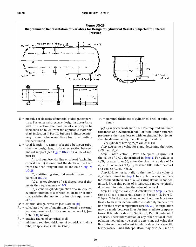
E = modulus of elasticity of material at design tempera-ture. For external pressure design in accordancewith this Section, the modulus of elasticity to beused shall be taken from the applicable materialschart in Section II, Part D, Subpart 3. (Interpolationmay be made between lines for intermediatetemperatures.)
L = total length, in. (mm), of a tube between tube-sheets, or design length of a vessel section betweenlines of support (see Figure UG-28.1). A line of sup-port is:
(a) a circumferential line on a head (excludingconical heads) at one‐third the depth of the headfrom the head tangent line as shown on FigureUG-28;
(b) a stiffening ring that meets the require-ments of UG-29;
(c) a jacket closure of a jacketed vessel thatmeets the requirements of 9-5;
(d) a cone‐to‐cylinder junction or a knuckle‐to‐cylinder junction of a toriconical head or sectionthat satisfies the moment of inertia requirementof 1-8.
P = external design pressure [see Note in (f)]Pa = calculated value of maximum allowable external
working pressure for the assumed value of t , [seeNote in (f) below]
Ro = outside radius of spherical shellt = minimum required thickness of cylindrical shell or
tube, or spherical shell, in. (mm)
t s = nominal thickness of cylindrical shell or tube, in.(mm)
(c) Cylindrical Shells and Tubes. The required minimumthickness of a cylindrical shell or tube under externalpressure, either seamless or with longitudinal butt joints,shall be determined by the following procedure:
(1) Cylinders having Do/t values ≥ 10:Step 1. Assume a value for t and determine the ratios
L/Do and Do/t.Step 2. Enter Section II, Part D, Subpart 3, Figure G at
the value of L/Do determined in Step 1. For values ofL/Do greater than 50, enter the chart at a value of L/Do = 50. For values of L/Do less than 0.05, enter the chartat a value of L/Do = 0.05.Step 3. Move horizontally to the line for the value of
Do/t determined in Step 1. Interpolation may be madefor intermediate values of Do/t; extrapolation is not per-mitted. From this point of intersection move verticallydownward to determine the value of factor A .Step 4. Using the value of A calculated in Step 3, enter
the applicable material chart in Section II, Part D,Subpart 3 for the material under consideration. Move ver-tically to an intersection with the material/temperatureline for the design temperature (see UG-20). Interpolationmay be made between lines for intermediate tempera-tures. If tabular values in Section II, Part D, Subpart 3are used, linear interpolation or any other rational inter-polation method may be used to determine a B value thatlies between two adjacent tabular values for a specifictemperature. Such interpolation may also be used to
Figure UG-28Diagrammatic Representation of Variables for Design of Cylindrical Vessels Subjected to External
Pressure
20
ASME BPVC.VIII.1-2019UG-28
Copyright ASME International (BPVC) Provided by IHS under license with ASME Licensee=Khalda Petroleum/5986215001, User=Amer, Mohamed
Not for Resale, 07/02/2019 13:29:04 MDTNo reproduction or networking permitted without license from IHS
--`,``,``,,`,`,,````,`,``,,,`-`-`,,`,,`,`,,`---

Figure UG-28.1Diagrammatic Representation of Lines of Support for Design of Cylindrical Vessels Subjected to External
Pressure
NOTES:(1) When the cone‐to‐cylinder or the knuckle‐to‐cylinder junction is not a line of support, the required thickness of the cone, knuckle, or tor-
iconical section shall not be less than the required thickness of the adjacent cylindrical shell. Also, the reinforcement requirement of 1-8shall be satisfied when a knuckle is not provided at the cone-to-cylinder junction.
(2) Calculations shall be made using the diameter and corresponding thickness of each cylindrical section with dimension L as shown. Thick-nesses of the transition sections are based on Note (1).
(3) When the cone‐to‐cylinder or the knuckle‐to‐cylinder junction is a line of support, the moment of inertia shall be provided in accordancewith 1-8 [see UG-33(f)].
21
ASME BPVC.VIII.1-2019 UG-28
Copyright ASME International (BPVC) Provided by IHS under license with ASME Licensee=Khalda Petroleum/5986215001, User=Amer, Mohamed
Not for Resale, 07/02/2019 13:29:04 MDTNo reproduction or networking permitted without license from IHS
--`,``,``,,`,`,,````,`,``,,,`-`-`,,`,,`,`,,`---

determine a B value at an intermediate temperature thatlies between two sets of tabular values, after first deter-mining B values for each set of tabular values.In cases where the value of A falls to the right of the end
of the material/temperature line, assume an intersectionwith the horizontal projection of the upper end of the ma-terial/temperature line. If tabular values are used, the last(maximum) tabulated value shall be used. For values of Afalling to the left of the material/temperature line, seeStep 7.Step 5. From the intersection obtained in Step 4, move
horizontally to the right and read the value of factor B .Step 6. Using this value of B , calculate the value of the
maximum allowable external working pressure Pa usingthe following equation:
Step 7. For values of A falling to the left of the applic-able material/temperature line, the value of Pa can be cal-culated using the following equation:
If tabular values are used, determine B as in Step 4 andapply it to the equation in Step 6.Step 8. Compare the calculated value of Pa obtained in
Step 6 or Step 7 with P . If Pa is smaller than P , select alarger value for t and repeat the design procedure untila value of Pa is obtained that is equal to or greater than P .
(2) Cylinders having Do/t values <10:Step 1. Using the same procedure as given in (1), obtain
the value of B . For values of Do/t less than 4, the value offactor A can be calculated using the following equation:
For values of A greater than 0.10, use a value of 0.10.Step 2. Using the value of B obtained in Step 1, calculate
a value Pa1 using the following equation:
Step 3. Calculate a value P a 2 using the followingequation:
where S is the lesser of two times the maximum allowablestress value in tension at design metal temperature, fromthe applicable table referenced in UG-23, or 0.9 times theyield strength of the material at design temperature. Val-ues of yield strength are obtained from the applicable ex-ternal pressure chart as follows:(a) For a given temperature curve, determine the B val-
ue that corresponds to the right hand side terminationpoint of the curve.(b) The yield strength is twice the B value obtained in
(a) above.Step 4. The smaller of the values of Pa1 calculated in
Step 2, or Pa2 calculated in Step 3 shall be used for themaximum allowable external working pressure Pa. Com-pare Pa with P . If Pa is smaller than P , select a larger valuefor t and repeat the design procedure until a value for Pais obtained that is equal to or greater than P .(d) Spherical Shells. The minimum required thickness
of a spherical shell under external pressure, either seam-less or of built‐up construction with butt joints, shall bedetermined by the following procedure:Step 1. Assume a value for t and calculate the value of
factor A using the following equation:
Step 2. Using the value of A calculated in Step 1, enterthe applicable material chart in Section II, Part D,Subpart 3 for the material under consideration. Move ver-tically to an intersection with the material/temperatureline for the design temperature (see UG-20). Interpolationmay be made between lines for intermediate tempera-tures. If tabular values in Section II, Part D, Subpart 3are used, linear interpolation or any other rational inter-polation method may be used to determine a B value thatlies between two adjacent tabular values for a specifictemperature. Such interpolation may also be used to de-termine a B value at an intermediate temperature thatlies between two sets of tabular values, after first deter-mining B values for each set of tabular values.In cases where the value at A falls to the right of the end
of the material/temperature line, assume an intersectionwith the horizontal projection of the upper end of the ma-terial/temperature line. If tabular values are used, the last(maximum) tabulated value shall be used. For values at Afalling to the left of the material/temperature line, seeStep 5.Step 3. From the intersection obtained in Step 2, move
horizontally to the right and read the value of factor B .
22
ASME BPVC.VIII.1-2019UG-28
Copyright ASME International (BPVC) Provided by IHS under license with ASME Licensee=Khalda Petroleum/5986215001, User=Amer, Mohamed
Not for Resale, 07/02/2019 13:29:04 MDTNo reproduction or networking permitted without license from IHS
--`,``,``,,`,`,,````,`,``,,,`-`-`,,`,,`,`,,`---

Step 4. Using the value of B obtained in Step 3, calculatethe value of the maximum allowable external workingpressure Pa using the following equation:
Step 5. For values of A falling to the left of the applic-able material/temperature line, the value of Pa can be cal-culated using the following equation:
If tabulated values are used, determine B as in Step 2and apply it to the equation in Step 4.
Step 6. Compare Pa obtained in Step 4 or Step 5 with P .If Pa is smaller than P , select a larger value for t and re-peat the design procedure until a value for Pa is obtainedthat is equal to or greater than P .
(e) The external design pressure or maximum allow-able external working pressure shall not be less thanthe maximum expected difference in operating pressurethat may exist between the outside and the inside of thevessel at any time.
(f) Vessels intended for service under externaldesign pressures of 15 psi (103 kPa) and less [seeU-1(c)(2)(-h)] may be stamped with the CertificationMark and Designator denoting compliance with the rulesfor external pressure, provided all the applicable rules ofthis Division are satisfied. When the Certification Mark isto be applied, the user or his designated agent shall spe-cify the required maximum allowable external workingpressure.21 The vessel shall be designed and stampedwith the maximum allowable external working pressure.
(g)When there is a longitudinal lap joint in a cylindricalshell or any lap joint in a spherical shell under externalpressure, the thickness of the shell shall be determinedby the rules in this paragraph, except that 2P shall beused instead of P in the calculations for the requiredthickness.
(h) Circumferential joints in cylindrical shells may be ofany type permitted by the Code and shall be designed forthe imposed loads.
(i) Those portions of pressure chambers of vessels thatare subject to a collapsing pressure and that have a shapeother than that of a complete circular cylinder or formedhead, and also jackets of cylindrical vessels that extendover only a portion of the circumference, shall be fullystaybolted in accordance with the requirements ofUG-47 through UG-50 or shall be proof tested in compli-ance with UG-101(p).
(j) When necessary, vessels shall be provided with stif-feners or other additional means of support to preventoverstress or large distortions under the external load-ings listed in UG-22 other than pressure and temperature.
UG-29 STIFFENING RINGS FOR CYLINDRICALSHELLS UNDER EXTERNAL PRESSURE
(a) External stiffening rings shall be attached to theshell by welding or brazing [see UG-30]. Internal stiffen-ing rings need not be attached to the shell when the ringsare designed to carry the loads and adequate means ofsupport is provided to hold the ring in place when sub-jected to external pressure loads. Segments of rings neednot be attached when the requirements of (c) are met.
Except as exempted in (f) below, the available momentof inertia of a circumferential stiffening ring shall be notless than that determined by one of the following twoformulas:
where
I = available moment of inertia of the stiffening ringcross section about its neutral axis parallel to theaxis of the shell
I s = required moment of inertia of the stiffening ringcross section about its neutral axis parallel to theaxis of the shell
I ′ = available moment of inertia of combined ring‐shellcross section about its neutral axis parallel to theaxis of the shell. The nominal shell thickness ts shallbe used and the width of shell that is taken as con-tributing to the moment of inertia of the combined
section shall not be greater than and
shall be taken as lying one‐half on each side ofthe centroid of the ring. Portions of the shell plateshall not be considered as contributing area tomore than one stiffening ring.
= required moment of inertia of the combined ring‐shell cross section about its neutral axis parallelto the axis of the shell
CAUTION: Stiffening rings may be subject to lateral buckling.This should be considered in addition to the requirements forIs and I′s [see U-2(g)].
If the stiffeners should be so located that the maximumpermissible effective shell sections overlap on either orboth sides of a stiffener, the effective shell section for thatstiffener shall be shortened by one‐half of each overlap.
A = factor determined from the applicable chart in Sec-tion II, Part D, Subpart 3 for the material used in thestiffening ring, corresponding to the factor B , below,and the design temperature for the shell underconsideration
As = cross‐sectional area of the stiffening ring
23
ASME BPVC.VIII.1-2019 UG-28 – UG-29
Copyright ASME International (BPVC) Provided by IHS under license with ASME Licensee=Khalda Petroleum/5986215001, User=Amer, Mohamed
Not for Resale, 07/02/2019 13:29:04 MDTNo reproduction or networking permitted without license from IHS
--`,``,``,,`,`,,````,`,``,,,`-`-`,,`,,`,`,,`---

B = factor determined from the applicable chart or tablein Section II, Part D, Subpart 3 for the material usedfor the stiffening ring [see UG-20(c)]
Ls = one‐half of the distance from the centerline of thestiffening ring to the next line of support on oneside, plus one‐half of the centerline distance to thenext line of support on the other side of the stiffen-ing ring, both measured parallel to the axis of thecylinder. A line of support is:
(a) a stiffening ring that meets the require-ments of this paragraph;
(b) a circumferential connection to a jacket fora jacketed section of a cylindrical shell;
(c) a circumferential line on a head at one‐thirdthe depth of the head from the head tangent line asshown on Figure UG-28;
(d) a cone‐to‐cylinder junction.
Do , E , P , t , and t s are as defined in UG-28(b).The adequacy of the moment of inertia for a stiffening
ring shall be determined by the following procedure.Step 1. Assuming that the shell has been designed and
Do , Ls , and t are known, select a member to be used forthe stiffening ring and determine its cross‐sectional areaAs . Then calculate factor B using the following equation:
Step 2. See below.(a) If tabular values in Section II, Part D, Subpart 3 are
used, linear interpolation or any other rational interpola-tion methodmay be used to determine an A value that liesbetween two adjacent tabular values for a specific tem-perature. Linear interpolation may also be used to deter-mine an A value at an intermediate temperature that liesbetween two sets of tabular values, after first determiningA values for each set of tabular values. The value of A sodetermined is then applied in the equation for I s or inStep 6(a) or Step 6(b).(b) If material charts in Section II, Part D, Subpart 3 are
used, enter the right‐hand side of the applicable materialchart for the material under consideration at the value ofB determined by Step 1. If different materials are used forthe shell and stiffening ring, use the material chart result-ing in the larger value of A in Step 4, below.Step 3. Move horizontally to the left to the material/
temperature line for the design metal temperature. Forvalues of B falling below the left end of the material/tem-perature line, see Step 5.Step 4. Move vertically to the bottom of the chart and
read the value of A .Step 5. For values of B falling below the left end of the
material/temperature line for the design temperature,the value of A can be calculated using the formulaA = 2B/E .Step 6. See below.
(a) In those cases where only the stiffening ring is con-sidered, compute the required moment of inertia from theformula for Is given above.(b) In those cases where the combined ring‐shell is con-
sidered, compute the required moment of inertia from theformula for given above.Step 7. See below.(a) In those cases where only the stiffening ring is con-
sidered, determine the available moment of inertia I asgiven in the definitions.(b) In those cases where the combined ring‐shell is con-
sidered, determine the available moment of inertia I ′ asgiven in the definitions.
NOTE: In those cases where the stiffening ring is not attached to theshell or where the stiffening ring is attached but the designerchooses to consider only the ring, Step 6(a) and Step 7(a) are consid-ered. In those cases where the stiffening ring is attached to the shelland the combined moment of inertia is considered, 6(b) and (b) areconsidered.
Step 8. If the required moment of inertia is greater thanthe available moment of inertia for the section selected,for those cases where the stiffening ring is not attachedor where the combined ring‐shell stiffness was not con-sidered, a new section with a larger moment of inertiamust be selected; the ring must be attached to the shelland the combination shall be considered; or the ring‐shellcombination that was previously not considered togethershall be considered together. If the required moment ofinertia is greater than the available moment of inertiafor those cases where the combined ring‐shell was con-sidered, a new ring section with a larger moment of iner-tia must be selected. In any case, when a new section isused, all of the calculations shall be repeated using thenew section properties of the ring or ring‐shellcombination.If the required moment of inertia is smaller than the ac-
tual moment of inertia of the ring or ring‐shell combina-tion, whichever is used, that ring section or combinedsection is satisfactory.(b) Stiffening rings shall extend completely around the
circumference of the cylinder except as permitted in (c)below. Any joints between the ends or sections of suchrings, such as shown in Figure UG-29.1 (A) and (B), andany connection between adjacent portions of a stiffeningring lying inside or outside the shell as shown in FigureUG-29.1 (C) shall be made so that the required momentof inertia of the combined ring‐shell section ismaintained.(c) Stiffening rings placed on the inside of a vessel may
be arranged as shown in Figure UG-29.1 (E) and (F), pro-vided that the required moment of inertia of the ring in(E) or of the combined ring‐shell section in (F) is main-tained within the sections indicated. Where the gap at(A) or (E) does not exceed eight times the thickness ofthe shell plate, the combined moment of inertia of theshell and stiffener may be used.
24
ASME BPVC.VIII.1-2019UG-29
Copyright ASME International (BPVC) Provided by IHS under license with ASME Licensee=Khalda Petroleum/5986215001, User=Amer, Mohamed
Not for Resale, 07/02/2019 13:29:04 MDTNo reproduction or networking permitted without license from IHS
--`,``,``,,`,`,,````,`,``,,,`-`-`,,`,,`,`,,`---
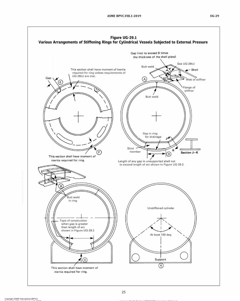
Figure UG-29.1Various Arrangements of Stiffening Rings for Cylindrical Vessels Subjected to External Pressure
25
ASME BPVC.VIII.1-2019 UG-29
Copyright ASME International (BPVC) Provided by IHS under license with ASME Licensee=Khalda Petroleum/5986215001, User=Amer, Mohamed
Not for Resale, 07/02/2019 13:29:04 MDTNo reproduction or networking permitted without license from IHS
--`,``,``,,`,`,,````,`,``,,,`-`-`,,`,,`,`,,`---
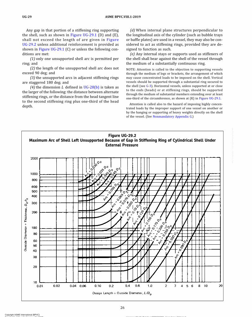
Any gap in that portion of a stiffening ring supportingthe shell, such as shown in Figure UG-29.1 (D) and (E),shall not exceed the length of are given in FigureUG-29.2 unless additional reinforcement is provided asshown in Figure UG-29.1 (C) or unless the following con-ditions are met:
(1) only one unsupported shell arc is permitted perring; and
(2) the length of the unsupported shell arc does notexceed 90 deg; and
(3) the unsupported arcs in adjacent stiffening ringsare staggered 180 deg; and
(4) the dimension L defined in UG-28(b) is taken asthe larger of the following: the distance between alternatestiffening rings, or the distance from the head tangent lineto the second stiffening ring plus one‐third of the headdepth.
(d)When internal plane structures perpendicular tothe longitudinal axis of the cylinder (such as bubble traysor baffle plates) are used in a vessel, they may also be con-sidered to act as stiffening rings, provided they are de-signed to function as such.(e) Any internal stays or supports used as stiffeners of
the shell shall bear against the shell of the vessel throughthe medium of a substantially continuous ring.
NOTE: Attention is called to the objection to supporting vesselsthrough the medium of legs or brackets, the arrangement of whichmay cause concentrated loads to be imposed on the shell. Verticalvessels should be supported through a substantial ring secured tothe shell (see G-3). Horizontal vessels, unless supported at or closeto the ends (heads) or at stiffening rings, should be supportedthrough the medium of substantial members extending over at leastone‐third of the circumference, as shown at (K) in Figure UG-29.1.
Attention is called also to the hazard of imposing highly concen-trated loads by the improper support of one vessel on another orby the hanging or supporting of heavy weights directly on the shellof the vessel. (See Nonmandatory Appendix G.)
Figure UG-29.2Maximum Arc of Shell Left Unsupported Because of Gap in Stiffening Ring of Cylindrical Shell Under
External Pressure
26
ASME BPVC.VIII.1-2019UG-29
Copyright ASME International (BPVC) Provided by IHS under license with ASME Licensee=Khalda Petroleum/5986215001, User=Amer, Mohamed
Not for Resale, 07/02/2019 13:29:04 MDTNo reproduction or networking permitted without license from IHS
--`,``,``,,`,`,,````,`,``,,,`-`-`,,`,,`,`,,`---
(f) When closure bars or other rings are attached toboth the inner shell and outer jacket of a vessel, with pres-sure in the space between the jacket and inner shell, thisconstruction has adequate inherent stiffness, and there-fore the rules of this paragraph do not apply.
UG-30 ATTACHMENT OF STIFFENING RINGS(a) Stiffening rings may be placed on the inside or out-
side of a vessel, and except for the configurations per-mitted by UG-29, shall be attached to the shell bywelding or brazing. Brazing may be used if the vessel isnot to be later stress relieved. The ring shall be essentiallyin contact with the shell and meet the rules in UG-29(b)and UG-29(c). Welding of stiffening rings shall complywith the requirements of this Division for the type of ves-sel under construction.
(b) Stiffening rings may be attached to the shell by con-tinuous, intermittent, or a combination of continuous andintermittent welds or brazes. Some acceptable methods ofattaching stiffening rings are illustrated in Figure UG-30.
(c) Intermittent welding shall be placed on both sidesof the stiffener and may be either staggered or in‐line.Length of individual fillet weld segments shall not be lessthan 2 in. (50 mm) and shall have a maximum clear spa-cing between toes of adjacent weld segments of 8t for ex-ternal rings and 12t for internal rings where t is the shellthickness at the attachment. The total length of weld oneach side of the stiffening ring shall be:
(1) not less than one‐half the outside circumferenceof the vessel for rings on the outside; and
(2) not less than one‐third the circumference of thevessel for rings on the inside.
(d) A continuous full penetration weld is permitted asshown in sketch (e) of Figure UG-30. Continuous filletwelding or brazing on one side of the stiffener with inter-mittent welding or brazing on the other side is permittedfor sketches (a), (b), (c), and (d) of Figure UG-30 when thethickness tw of the outstanding stiffening element[sketches (a) and (c)] or width w of the stiffening elementmating to the shell [sketches (b) and (d)] is not more than1 in. (25 mm). The weld segments shall be not less than2 in. (50 mm) long and shall have a maximum clear spa-cing between toes of adjacent weld segments of 24t .
(e) Strength of Attachment Welds. Stiffening ring at-tachment welds shall be sized to resist the full radial pres-sure load from the shell between stiffeners, and shearloads acting radially across the stiffener caused by exter-nal design loads carried by the stiffener (if any) and acomputed radial shear equal to 2% of the stiffening ring’scompressive load.
(1) The radial pressure load from shell, lb/in., isequal to PLs.
(2) The radial shear load is equal to 0.01PLsDO .(3) P , Ls , and DO are defined in UG-29.
(f) Minimum Size of Attachment Welds. The fillet weldleg size shall be not less than the smallest of the following:
(1) 1/4 in. (6 mm);
(2) vessel thickness at the weld location;(3) stiffener thickness at weld location.
UG-31 TUBES, AND PIPE WHEN USED AS TUBESOR SHELLS
(a) Internal Pressure. The required wall thickness fortubes and pipe under internal pressure shall be deter-mined in accordance with the rules for shells in UG-27.
(b) External Pressure. The required wall thickness fortubes and pipe under external pressure shall be deter-mined in accordance with the rules in UG-28.
(c) The thickness as determined under (a) or (b) aboveshall be increased when necessary to meet the followingrequirements:
(1) Additional wall thickness should be providedwhen corrosion, erosion, or wear due to cleaning opera-tions is expected.
(2)Where ends are threaded, additional wall thick-ness is to be provided in the amount of 0.8/n in.(20/n mm) [where n equals the number of threads perinch (25.4 mm)].
NOTE: The requirements for rolling, expanding, or otherwise seatingtubes in tube plates may require additional wall thickness and care-ful choice of materials because of possible relaxation due to differen-tial expansion stresses.
UG-32 FORMED HEADS, AND SECTIONS,PRESSURE ON CONCAVE SIDE
(a) The minimum required thickness at the thinnestpoint after forming22 of ellipsoidal, torispherical, hemi-spherical, conical, and toriconical heads under pressureon the concave side (plus heads) shall be computed bythe appropriate formulas in this paragraph,23 except aspermitted by Mandatory Appendix 32. Heads with boltingflanges shall meet the requirements of UG-35.1. In addi-tion, provision shall be made for any of the loadings listedin UG-22. The provided thickness of the heads shall alsomeet the requirements of UG-16, except as permitted inMandatory Appendix 32.
(b) The symbols defined below are used in the formulasof this paragraph:
D = inside diameter of the head skirt; or inside length ofthe major axis of an ellipsoidal head; or inside dia-meter of a conical head at the point underconsideration, measured perpendicular to the longi-tudinal axis
Di = inside diameter of the conical portion of a toriconi-cal head at its point of tangency to the knuckle, mea-sured perpendicular to the axis of the cone
= D – 2r(1 – cos α)E = lowest efficiency of any joint in the head; for hemi-
spherical heads this includes head‐to‐shell joint; forwelded vessels, use the efficiency specified inUW-12
27
ASME BPVC.VIII.1-2019 UG-29 – UG-32
Copyright ASME International (BPVC) Provided by IHS under license with ASME Licensee=Khalda Petroleum/5986215001, User=Amer, Mohamed
Not for Resale, 07/02/2019 13:29:04 MDTNo reproduction or networking permitted without license from IHS
--`,``,``,,`,`,,````,`,``,,,`-`-`,,`,,`,`,,`---

Figure UG-30Some Acceptable Methods of Attaching Stiffening Rings
Shell
Stiffener
Continuous full penetration weld
(a) (b)
S [Notes (1) and (2)]
2 in. (50 mm) min.
tw
w
2 in. (50 mm) min.
2 in. (50 mm) min.
24t max.
tw
twt
w
(c)
Continuous Fillet Weld
One Side, Intermittent
Other Side
Staggered
Intermittent
Weld
In-line
Intermittent
Weld
tw
(d) (e)
w
tw
t
S [Notes (1) and (2)]
NOTES:(1) For external stiffeners, S ≤ 8t .(2) For internal stiffeners, S ≤ 12t .
28
ASME BPVC.VIII.1-2019UG-32
Copyright ASME International (BPVC) Provided by IHS under license with ASME Licensee=Khalda Petroleum/5986215001, User=Amer, Mohamed
Not for Resale, 07/02/2019 13:29:04 MDTNo reproduction or networking permitted without license from IHS
--`,``,``,,`,`,,````,`,``,,,`-`-`,,`,,`,`,,`---

L = inside spherical or crown radius. The value of L forellipsoidal heads shall be obtained from TableUG-37.
P = internal design pressure (see UG-21)r = inside knuckle radiusS = maximum allowable stress value in tension as given
in the tables referenced in UG-23, except as limitedin UG-24 and (d) below.
t = minimum required thickness of head after formingt s = minimum specified thickness of head after forming,
in. (mm). ts shall be ≥ tα = one‐half of the included (apex) angle of the cone at
the centerline of the head (see Figure 1-4)
(c) Ellipsoidal Heads With ts/L ≥ 0.002. The requiredthickness of a dished head of semiellipsoidal form, inwhich half the minor axis (inside depth of the head minusthe skirt) equals one‐fourth of the inside diameter of thehead skirt, shall be determined by
ð1Þ
NOTE: For ellipsoidal heads with t s/L < 0.002, the rules of 1-4(f)shall also be met.
An acceptable approximation of a 2:1 ellipsoidal head isone with a knuckle radius of 0.17D and a spherical radiusof 0.90D .
(d) Torispherical Heads With t s/L ≥ 0.002. The re-quired thickness of a torispherical head for the case inwhich the knuckle radius is 6% of the inside crown radiusand the inside crown radius equals the outside diameterof the skirt [see (i)] shall be determined by
ð2Þ
NOTE: For torispherical heads with t s/L < 0.002, the rules of 1-4(f)shall also be met.
Torispherical heads made of materials having a speci-fied minimum tensile strength exceeding 70,000 psi(485 MPa) shall be designed using a value of S equal to20,000 psi (138 MPa) at room temperature and reducedin proportion to the reduction in maximum allowablestress values at temperature for the material (see UG-23).
(e) Hemispherical Heads. When the thickness of a hemi-spherical head does not exceed 0.356L , or P does not ex-ceed 0.665SE , the following formulas shall apply:
ð3Þ
(f) Conical Heads and Sections (Without TransitionKnuckle). The required thickness of conical heads or con-ical shell sections that have a half apex‐angle α not great-er than 30 deg shall be determined by
ð4Þ
A reinforcing ring shall be provided when required bythe rule in 1-5(d) and 1-5(e).
Conical heads or sections having a half apex‐angle αgreater than 30 deg without a transition knuckle shallcomply with eq. (4) and 1-5(g).
(g) Toriconical Heads and Sections. The required thick-ness of the conical portion of a toriconical head or section,in which the knuckle radius is neither less than 6% of theoutside diameter of the head skirt nor less than threetimes the knuckle thickness, shall be determined by eq.(f)(4) in (f) above, using Di in place of D .
The required thickness of the knuckle shall be deter-mined by eq. 1-4(d)(3) in which
Toriconical heads or sections may be used when the an-gle α ≤ 30 deg and are mandatory for conical head designswhen the angle α exceeds 30 deg, unless the design com-plies with 1-5(g).
(h)When an ellipsoidal, torispherical, hemispherical,conical, or toriconical head is of a lesser thickness than re-quired by the rules of this paragraph, it shall be stayed asa flat surface according to the rules of UG-47 for bracedand stayed flat plates.
(i) The inside crown radius to which an unstayed headis dished shall be not greater than the outside diameter ofthe skirt of the head. The inside knuckle radius of a tori-spherical head shall be not less than 6% of the outsidediameter of the skirt of the head but in no case less than3 times the head thickness.
(j) A dished head with a reversed skirt may be used ina pressure vessel, provided the maximum allowableworking pressure for the head is established in accor-dance with the requirements of UG-101.
(k) All formed heads, thicker than the shell and concaveto pressure, intended for butt-welded attachment, shallhave a skirt length sufficient to meet the requirementsof Figure UW-13.1, when a tapered transition is required.All formed heads concave to pressure and intended forbutt-welded attachment need not have an integral skirtwhen the thickness of the head is equal to or less thanthe thickness of the shell. When a skirt is provided, itsthickness shall be at least that required for a seamlessshell of the same inside diameter.
29
ASME BPVC.VIII.1-2019 UG-32
Copyright ASME International (BPVC) Provided by IHS under license with ASME Licensee=Khalda Petroleum/5986215001, User=Amer, Mohamed
Not for Resale, 07/02/2019 13:29:04 MDTNo reproduction or networking permitted without license from IHS
--`,``,``,,`,`,,````,`,``,,,`-`-`,,`,,`,`,,`---
(l) Heads concave to pressure, intended for attachmentby brazing, shall have a skirt length sufficient to meet therequirements for circumferential joints in Part UB.(m) Any taper at a welded joint within a formed head
shall be in accordance with UW-9. The taper at a circum-ferential welded joint connecting a formed head to a mainshell shall meet the requirements of UW-13 for the re-spective type of joint shown therein.(n) If a torispherical, ellipsoidal, or hemispherical head
is formed with a flattened spot or surface, the diameter ofthe flat spot shall not exceed that permitted for flat headsas given by eq. UG-34(c)(2)(1), using C = 0.25.(o) Openings in formed heads under internal pressure
shall comply with the requirements of UG-36 throughUG-46.(p) A stayed jacket that completely covers a formed in-
ner head or any of the types included in this paragraphshall also meet the requirements of UG-47(c).
UG-33 FORMED HEADS, PRESSURE ON CONVEXSIDE
(a) General. The required thickness at the thinnestpoint after forming22 of ellipsoidal, torispherical, hemi-spherical, toriconical, and conical heads and conical seg-ments under pressure on the convex side (minus heads)shall be computed by the appropriate formulas given inthis paragraph (see UG-16). Heads with bolting flangesshall meet the requirements of UG-35.1. In addition, pro-visions shall be made for any other loading given inUG-22. The required thickness for heads due to pressureon the convex side shall be determined as follows.
(1) For ellipsoidal and torispherical heads, the re-quired thickness shall be the greater of the following:
(-a) the thickness computed by the procedure giv-en in UG-32 for heads with pressure on the concave side(plus heads) using a design pressure 1.67 times the de-sign pressure on the convex side, assuming a joint effi-ciency E = 1.00 for all cases; or
(-b) the thickness as computed by the appropriateprocedure given in (d) or (e) below.
In determining the maximum allowable workingpressure on the convex side of ellipsoidal or torisphericalheads, reverse the procedures in (-a) and (-b) above, anduse the smaller of the pressures obtained.
(2) For hemispherical heads, the required thicknessshall be determined by the rules given in (c) below.
(3) For conical and toriconical heads and conical sec-tions, the required thickness shall be determined by therules given in (f) below.(b) Nomenclature. The nomenclature defined below is
used in this paragraph. Figure 1-4 shows principal dimen-sions of typical heads.
A , B , E , and P are as defined in UG-28(b)
Do = outside diameter of the head skirtDo/2ho = ratio of the major to the minor axis of ellipsoi-
dal heads, which equals the outside diameterof the head skirt divided by twice the outsideheight of the head (see Table UG-33.1)
DL = outside diameter at large end of conical sec-tion under consideration
Ds = outside diameter at small end of conical sec-tion under consideration
Dss = outside diameter at small end of conical sec-tion under consideration
ho = one‐half of the length of the outside minor axisof the ellipsoidal head, or the outside height ofthe ellipsoidal head measured from the tan-gent line (head‐bend line)
Ko = factor depending on the ellipsoidal head pro-portions Do/2ho (see Table UG-33.1)
Lc = axial length of cone or conical section (seeFigure UG-33.1).
Le = equivalent length of conical head or Sectionbetween lines of support [see (g)]
Ro = for hemispherical heads, the outside radius= for ellipsoidal heads, the equivalent outside
spherical radius taken as KoDo
= for torispherical heads, the outside radius ofthe crown portion of the head
t = minimum required thickness of head afterforming, in. (mm)
te = effective thickness of conical section= t cos α
α = one‐half the apex angle in conical heads andsections, deg
(c) Hemispherical Heads. The required thickness of ahemispherical head having pressure on the convex sideshall be determined in the same manner as outlined inUG-28(d) for determining the thickness for a sphericalshell.(d) Ellipsoidal Heads. The required thickness of an el-
lipsoidal head having pressure on the convex side, eitherseamless or of built‐up construction with butt joints, shallnot be less than that determined by the followingprocedure.Step 1. Assume a value for t and calculate the value of
factor A using the following formula:
30
ASME BPVC.VIII.1-2019UG-32 – UG-33
Copyright ASME International (BPVC) Provided by IHS under license with ASME Licensee=Khalda Petroleum/5986215001, User=Amer, Mohamed
Not for Resale, 07/02/2019 13:29:04 MDTNo reproduction or networking permitted without license from IHS
--`,``,``,,`,`,,````,`,``,,,`-`-`,,`,,`,`,,`---
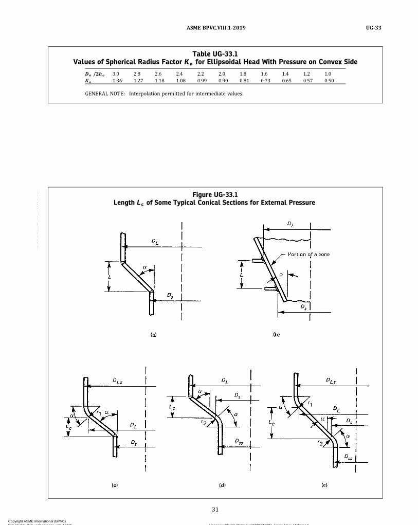
Table UG-33.1Values of Spherical Radius Factor Ko for Ellipsoidal Head With Pressure on Convex Side
Do /2ho 3.0 2.8 2.6 2.4 2.2 2.0 1.8 1.6 1.4 1.2 1.0Ko 1.36 1.27 1.18 1.08 0.99 0.90 0.81 0.73 0.65 0.57 0.50
GENERAL NOTE: Interpolation permitted for intermediate values.
Figure UG-33.1Length Lc of Some Typical Conical Sections for External Pressure
31
ASME BPVC.VIII.1-2019 UG-33
Copyright ASME International (BPVC) Provided by IHS under license with ASME Licensee=Khalda Petroleum/5986215001, User=Amer, Mohamed
Not for Resale, 07/02/2019 13:29:04 MDTNo reproduction or networking permitted without license from IHS
--`,``,``,,`,`,,````,`,``,,,`-`-`,,`,,`,`,,`---
Step 2. Using the value of A calculated in Step 1, followthe same procedure as that given for spherical shells inUG-28(d), Steps 2 through 6.(e) Torispherical Heads. The required thickness of a
torispherical head having pressure on the convex side,either seamless or of built‐up construction with buttjoints, shall not be less than that determined by the samedesign procedure as is used for ellipsoidal heads given in(d) above, using the appropriate value for Ro.(f) Conical Heads and Sections. When the cone-to-
cylinder junction is not a line-of-support, the requiredthickness of a conical head or section under pressure onthe convex side, either seamless or of built‐up construc-tion with butt joints shall not be less than the requiredthickness of the adjacent cylindrical shell and, when aknuckle is not provided, the reinforcement requirementof 1-8 shall be satisfied (see Figure UG-28.1). When thecone-to-cylinder junction is a line-of-support, the re-quired thickness shall be determined in accordance withthe following subparagraphs.
(1)When α is equal to or less than 60 deg:(-a) cones having DL/te values ≥10:
Step 1. Assume a value for te and determine the ratiosLe/DL and DL/te .Step 2. Enter Section II, Part D, Subpart 3, Figure G at a
value of L/Do equivalent to the value of Le/DL deter-mined in Step 1. For values of Le/DL greater than 50, en-ter the chart at a value of Le/DL = 50.Step 3. Move horizontally to the line for the value of
Do/t equivalent to the value of DL/te determined in Step1. Interpolation may be made for intermediate values ofDL/t e ; extrapolation is not permitted. From this pointof intersection move vertically downwards to determinethe value of factor A .Step 4. Using the value of A calculated in Step 3, enter
the applicable material chart in Section II, Part D, Subpart3 for the material under consideration. Move vertically toan intersection with the material/temperature line for thedesign temperature (see UG-20). Interpolation may bemade between lines for intermediate temperatures.In cases where the value of A falls to the right of the end
of the material/temperature line, assume an intersectionwith the horizontal projection of the upper end of the ma-terial/temperature line. For values of A falling to the leftof the material/temperature line, see Step 7.Step 5. From the intersection obtained in Step 4, move
horizontally to the right and read the value of factor B .Step 6. Using this value of B , calculate the value of the
maximum allowable external working pressure Pa usingthe following formula:
Step 7. For values of A falling to the left of the applic-able material/temperature line, the value of Pa can be cal-culated using the following formula:
Step 8. Compare the calculated value of Pa obtained inStep 6 or Step 7 with P . If Pa is smaller than P , select alarger value for t and repeat the design procedure untila value of Pa is obtained that is equal to or greater than P .Step 9. Provide adequate moment of inertia and rein-
forcement at the cone-to-cylinder junction in accordancewith 1-8. For a junction with a knuckle, the reinforcementcalculation is not required, and the moment of inertia cal-culation may be performed either by considering thepresence of the knuckle or by assuming the knuckle isnot present whereby the cone is assumed to intersectthe adjacent cylinder.
(-b) cones having DL/te values <10:Step 1. Using the same procedure as given in (-a) above,
obtain the value of B . For values of DL/te less than 4, thevalue of factor A can be calculated using the followingformula:
For values of A greater than 0.10, use a value of 0.10.Step 2. Using the value of B obtained in Step 1, calculate
a value Pa1 using the following formula:
Step 3. Calculate a value P a 2 using the followingformula:
where
S = the lesser of two times the maximum allowablestress value in tension at design metal temperature,from the applicable table referenced by UG-23, or0.9 times the yield strength of the material at de-sign temperature
Values of yield strength are obtained from the applic-able external pressure chart as follows.(a) For a given temperature curve, determine the B val-
ue that corresponds to the right hand side terminationpoint of the curve.(b) The yield strength is twice the B value obtained in
(a) above.
32
ASME BPVC.VIII.1-2019UG-33
Copyright ASME International (BPVC) Provided by IHS under license with ASME Licensee=Khalda Petroleum/5986215001, User=Amer, Mohamed
Not for Resale, 07/02/2019 13:29:04 MDTNo reproduction or networking permitted without license from IHS
--`,``,``,,`,`,,````,`,``,,,`-`-`,,`,,`,`,,`---

ð19Þ
Step 4. The smaller of the values of Pa1 calculated inStep 2, or Pa2 calculated in Step 3 shall be used for themaximum allowable external working pressure Pa. Com-pare Pa with P . If Pa is smaller than P , select a larger val-ue for t and repeat the design procedure until a value forPa is obtained that is equal to or greater than P .
Step 5. Provide adequate moment of inertia and rein-forcement at the cone-to-cylinder junction in accordancewith 1-8. For a junction with a knuckle, the reinforcementcalculation is not required, and the moment of inertia cal-culation may be performed either by considering thepresence of the knuckle or by assuming the knuckle isnot present whereby the cone is assumed to intersectthe adjacent cylinder.
(2)When α of the cone is greater than 60 deg, thethickness of the cone shall be the same as the requiredthickness for a flat head under external pressure, the dia-meter of which equals the largest diameter of the cone(see UG-34).
(3) The thickness of an eccentric cone shall be takenas the greater of the two thicknesses obtained using boththe smallest and largest α in the calculations.
(g) The required thickness of a conical part of a torico-nical head or conical section having pressure on the con-vex side, either seamless or of built‐up construction withbutt joints within the conical part of a toriconical head orconical section, shall not be less than that determinedfrom (f) above with the exception that Le shall be deter-mined as follows:
(1) For sketches (a) and (b) in Figure UG-33.1,
(2) For sketch (c) in Figure UG-33.1,
(3) For sketch (d) in Figure UG-33.1,
(4) For sketch (e) in Figure UG-33.1,
(h)When lap joints are used in formed head construc-tion or for longitudinal joints in a conical head under ex-ternal pressure, the thickness shall be determined by therules in this paragraph, except that 2P shall be used in-stead of P in the calculations for the required thickness.
(i) The required length of skirt on heads convex topressure shall comply with the provisions of UG-32(k)and UG-32(l) for heads concave to pressure.
(j) Openings in heads convex to pressure shall complywith the requirements of UG-36 through UG-46.
UG-34 UNSTAYED FLAT HEADS AND COVERS(a) The minimum thickness of unstayed flat heads, cov-
er plates and blind flanges shall conform to the require-ments given in this paragraph. These requirementsapply to both circular and noncircular24 heads and covers.Some acceptable types of flat heads and covers are shownin Figure UG-34. In this figure, the dimensions of the com-ponent parts and the dimensions of the welds are exclu-sive of extra metal required for corrosion allowance.
(b) The symbols used in this paragraph and in FigureUG-34 are defined as follows:
C = a factor depending upon the method of attachmentof head, shell dimensions, and other items as listedin (d) below, dimensionless
D = long span of noncircular heads or covers measuredperpendicular to short span
d = diameter, or short span, measured as indicated inFigure UG-34
E = joint efficiency, from Table UW-12, of any CategoryA weld as defined in UW-3(a)
hG = gasket moment arm, equal to the radial distancefrom the centerline of the bolts to the line of thegasket reaction, as shown in Table 2-5.2
L = perimeter of noncircular bolted head measuredalong the centers of the bolt holes
m = the ratio t r/t s , dimensionlessP = internal design pressure (see UG-21)r = inside corner radius on a head formed by flanging
or forgingS = maximum allowable stress value in tension from
applicable table of stress values referenced byUG-23
t = minimum required thickness of flat head or covert1 = throat dimension of the closure weld, as indicated
in Figure UG-34, sketch (r)t f = nominal thickness of the flange on a forged head, at
the large end, as indicated in Figure UG-34, sketch(b)
th = nominal thickness of flat head or covert r = required thickness of seamless shell, for pressuret s = nominal thickness of shelltw = thickness through the weld joining the edge of a
head to the inside of a vessel, as indicated in FigureUG-34, sketch (g)
W = total bolt load given for circular heads for eqs.2-5(e)(4) and 2-5(e)(5)
Y = length of flange of flanged heads, measured fromthe tangent line of knuckle, as indicated in FigureUG-34, sketches (a) and (c), in. (mm)
Z = a factor of noncircular heads and covers that de-pends on the ratio of short span to long span, as giv-en in (c) below, dimensionless
33
ASME BPVC.VIII.1-2019 UG-33 – UG-34
Copyright ASME International (BPVC) Provided by IHS under license with ASME Licensee=Khalda Petroleum/5986215001, User=Amer, Mohamed
Not for Resale, 07/02/2019 13:29:04 MDTNo reproduction or networking permitted without license from IHS
--`,``,``,,`,`,,````,`,``,,,`-`-`,,`,,`,`,,`---
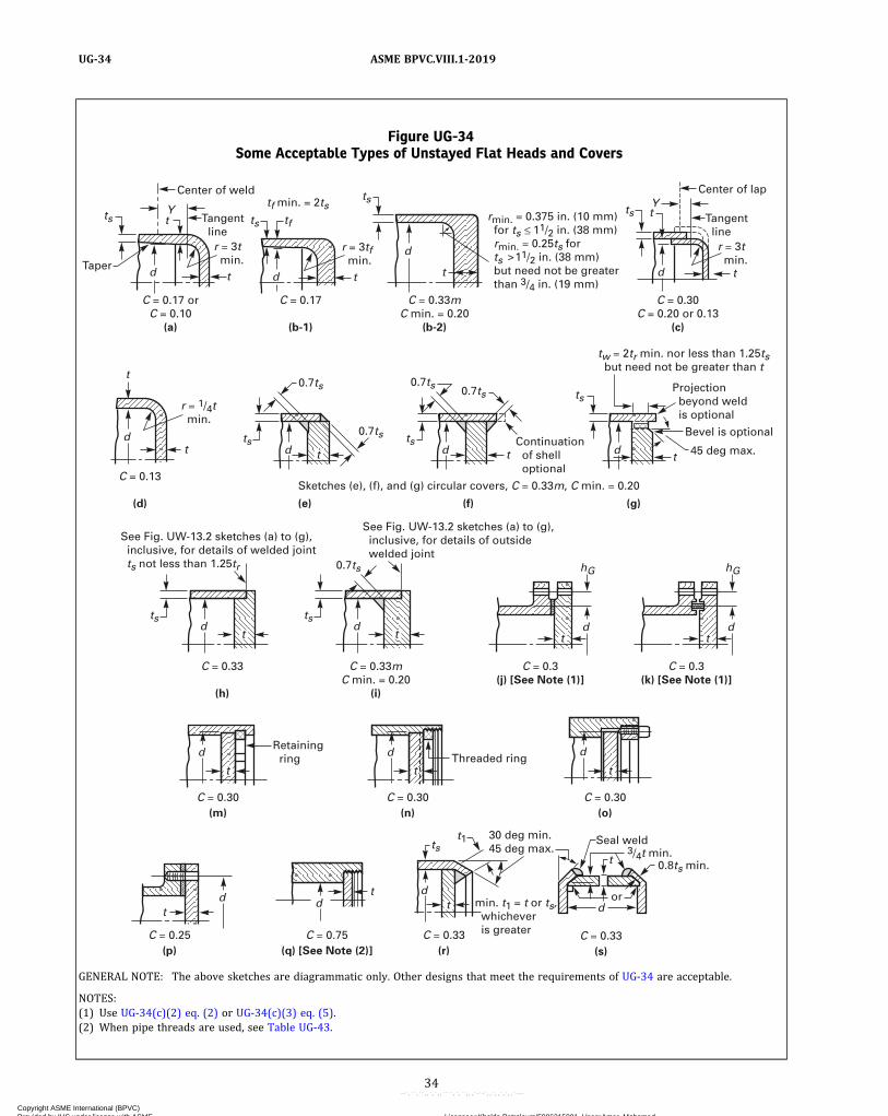
Figure UG-34Some Acceptable Types of Unstayed Flat Heads and Covers
ts ts
ts ts t
ts
tf
d d
d
Y t
t t t
C = 0.17 or C = 0.10
(a)
C = 0.13
(d)
C = 0.33m C min. = 0.20
(i)
C = 0.3(j) [See Note (1)]
C = 0.3(k) [See Note (1)]
C = 0.33
(h)
C = 0.30
C = 0.25 C = 0.75 C = 0.33 C = 0.33
C = 0.30 C = 0.30 (m)
(p) (q) [See Note (2)] (r) (s)
(n) (o)
(e)
(f)
(g)
C = 0.33mC min. = 0.20
(b-2)
Continuation of shell optional
Sketches (e), (f), and (g) circular covers, C = 0.33m, C min. = 0.20
See Fig. UW-13.2 sketches (a) to (g), inclusive, for details of welded joint ts not less than 1.25tr
See Fig. UW-13.2 sketches (a) to (g), inclusive, for details of outside welded joint
Threaded ring
30 deg min. 45 deg max.
Seal weld
0.8ts min. 3/4t min.
or min. t1 = t or ts, whichever is greater
Retaining ring
rmin. = 0.375 in. (10 mm) for ts 11/2 in. (38 mm) rmin. = 0.25ts for ts 11/2 in. (38 mm) but need not be greater than 3/4 in. (19 mm)
C = 0.17
(b-1)
Center of weld
Taper
Tangent line
r = 3t min.
d
Y
ts ts
t
ts ts
ts t1
d
t
hG
t t d d d d
d d d
hG
d
Projection beyond weld is optional
Bevel is optional
45 deg max.
tw = 2tr min. nor less than 1.25ts but need not be greater than t
tf min. = 2ts
0.7ts 0.7ts 0.7ts
0.7ts
0.7ts
t
C = 0.30 C = 0.20 or 0.13
(c)
Center of lap
Tangent line
r = 3t min.
r = 3tf min.
r = 1/4t min.
t
t t t
d d d
d d
d
t t t
t
tt
t
t
GENERAL NOTE: The above sketches are diagrammatic only. Other designs that meet the requirements of UG-34 are acceptable.
NOTES:(1) Use UG-34(c)(2) eq. (2) or UG-34(c)(3) eq. (5).(2) When pipe threads are used, see Table UG-43.
34
ASME BPVC.VIII.1-2019UG-34
Copyright ASME International (BPVC) Provided by IHS under license with ASME Licensee=Khalda Petroleum/5986215001, User=Amer, Mohamed
Not for Resale, 07/02/2019 13:29:04 MDTNo reproduction or networking permitted without license from IHS
--`,``,``,,`,`,,````,`,``,,,`-`-`,,`,,`,`,,`---

(c) The thickness of flat unstayed heads, covers, andblind flanges shall conform to one of the following threerequirements.25
(1) Circular blind flanges conforming to any of theflange standards listed in Table U-3 and further limitedin UG-44(a) shall be acceptable for the diameters andpressure–temperature ratings in the respective standardwhen the blind flange is of the types shown in FigureUG-34, sketches (j) and (k).
(2) The minimum required thickness of flat unstayedcircular heads, covers and blind flanges shall be calcu-lated by the following formula:
ð1Þ
except when the head, cover, or blind flange is attached bybolts causing an edge moment [sketches (j) and (k)] inwhich case the thickness shall be calculated by
ð2Þ
When using eq. (2), the thickness t shall be calcu-lated for both operating conditions and gasket seating,and the greater of the two values shall be used. For oper-ating conditions, the value of P shall be the design pres-sure, and the values of S at the design temperature andW from eq. 2-5(e)(4) shall be used. For gasket seating,P equals zero, and the values of S at atmospheric tem-perature and W from eq. 2-5(e)(5) shall be used.
(3) Flat unstayed heads, covers, or blind flanges maybe square, rectangular, elliptical, obround, segmental, orotherwise noncircular. Their required thickness shall becalculated by the following formula:
ð3Þ
where
ð4Þ
with the limitation that Z need not be greater than twoand one‐half (2.5).
Equation (3) does not apply to noncircular heads,covers, or blind flanges attached by bolts causing a boltedge moment [Figure UG-34, sketches (j) and (k)]. Fornoncircular heads of this type, the required thicknessshall be calculated by the following formula:
ð5Þ
When using eq. (5), the thickness t shall be calcu-lated in the same way as specified above for eq. (2)(2).
(d) For the types of construction shown in FigureUG-34, the minimum values of C to be used in eqs.(c)(2)(1), (c)(2)(2), (c)(3)(3), and (c)(3)(5) are:
(1) Sketch (a). C = 0.17 for flanged circular and non-circular heads forged integral with or butt welded to thevessel with an inside corner radius not less than threetimes the required head thickness, with no special re-quirement with regard to length of flange, and wherethe welding meets all the requirements for circumferen-tial joints given in Part UW.
C = 0.10 for circular heads, when the flange length forheads of the above design is not less than
ð6Þ
C = 0.10 for circular heads, when the flange length Yis less than the requirements in eq. (6) but the shell thick-ness is not less than
ð7Þ
for a length of at least .
When C = 0.10 is used, the taper shall be at least 1:3.(2) Sketch (b‐1). C = 0.17 for forged circular and non-
circular heads integral with or butt welded to the vessel,where the flange thickness is not less than two times theshell thickness, the corner radius on the inside is not lessthan three times the flange thickness, and the weldingmeets all the requirements for circumferential joints giv-en in Part UW.
(3) Sketch (b‐2). C = 0.33m but not less than 0.20 forforged circular and noncircular heads integral with orbutt welded to the vessel, where the flange thickness isnot less than the shell thickness, the corner radius onthe inside is not less than the following:
The welding shall meet all the requirements for cir-cumferential joints given in Part UW.
(4) Sketch (c). C = 0.13 for circular heads lap weldedor brazed to the shell with corner radius not less than 3tand Y not less than required by eq. (1)(6) and the require-ments of UW-13 are met.
C = 0.20 for circular and noncircular lap welded orbrazed construction as above, but with no special require-ment with regard to Y .
C = 0.30 for circular flanged plates screwed over theend of the vessel, with inside corner radius not less than3t , in which the design of the threaded joint against
35
ASME BPVC.VIII.1-2019 UG-34
Copyright ASME International (BPVC) Provided by IHS under license with ASME Licensee=Khalda Petroleum/5986215001, User=Amer, Mohamed
Not for Resale, 07/02/2019 13:29:04 MDTNo reproduction or networking permitted without license from IHS
--`,``,``,,`,`,,````,`,``,,,`-`-`,,`,,`,`,,`---
failure by shear, tension, or compression, resulting fromthe end force due to pressure, is based on a factor ofsafety of at least four, and the threaded parts are at leastas strong as the threads for standard piping of the samediameter. Seal welding may be used, if desired.
(5) Sketch (d). C = 0.13 for integral flat circular headswhen the dimension d does not exceed 24 in. (600 mm),the ratio of thickness of the head to the dimension d is notless than 0.05 or greater than 0.25, the head thickness this not less than the shell thickness ts, the inside corner ra-dius is not less than 0.25t , and the construction is ob-tained by special techniques of upsetting and spinningthe end of the shell, such as employed in closing headerends.
(6) Sketches (e), (f), and (g). C = 0.33m but not lessthan 0.20 for circular plates, welded to the inside of a ves-sel, and otherwise meeting the requirements for the re-spective types of welded vessels. If a value of m lessthan 1 is used in calculating t , the shell thickness ts shallbe maintained along a distance inwardly from the inside
face of the head equal to at least . The throat thick-
ness of the fillet welds in sketches (e) and (f) shall be atleast 0.7ts. The size of the weld tw in sketch (g) shall benot less than 2 times the required thickness of a seamlessshell nor less than 1.25 times the nominal shell thicknessbut need not be greater than the head thickness; the weldshall be deposited in a welding groove with the root of theweld at the inner face of the head as shown in the sketch.
C = 0.33 for noncircular plates, welded to the insideof a vessel and otherwise meeting the requirements forthe respective types of welded vessels. The throat thick-ness of the fillet welds in sketches (e) and (f) shall be atleast 0.7ts. The size of the weld tw in sketch (g) shall benot less than 2 times the required thickness of a seamlessshell nor less than 1.25 times the nominal shell thicknessbut need not be greater than the head thickness; the weldshall be deposited in a welding groove with the root of theweld at the inner face of the head as shown in the sketch.
(7) Sketch (h). C = 0.33 for circular plates welded tothe end of the shell when ts is at least 1.25tr and the welddetails conform to the requirements of UW-13(e) andFigure UW-13.2, sketches (a) to (g) inclusive. See alsoUG-93(d)(3).
(8) Sketch (i). C = 0.33m but not less than 0.20 for cir-cular plates if an inside fillet weld with minimum throatthickness of 0.7ts is used and the details of the outsideweld conform to the requirements of UW-13(e) andFigure UW-13.2, sketches (a) to (g) inclusive, in whichthe inside weld can be considered to contribute anamount equal to ts to the sum of the dimensions a andb . See also UG-93(d)(3).
(9) Sketches (j) and (k). C = 0.3 for circular and non-circular heads and covers bolted to the vessel as indicatedin the figures. Note that eq. (c)(2)(2) or (c)(3)(5) shall beused because of the extra moment applied to the cover bythe bolting.
When the cover plate is grooved for a peripheral gas-ket, as shown in sketch (k), the net cover plate thicknessunder the groove or between the groove and the outeredge of the cover plate shall be not less than
for circular heads and covers, nor less than
for noncircular heads and covers.(10) Sketches (m), (n), and (o). C = 0.3 for a circular
plate inserted into the end of a vessel and held in placeby a positive mechanical locking arrangement, and whenall possible means of failure (either by shear, tension,compression, or radial deformation, including flaring, re-sulting from pressure and differential thermal expansion)are resisted with a factor of safety of at least four. Sealwelding may be used, if desired.
(11) Sketch (p). C = 0.25 for circular and noncircularcovers bolted with a full‐face gasket, to shells, flanges orside plates.
(12) Sketch (q). C = 0.75 for circular plates screwedinto the end of a vessel having an inside diameter d notexceeding 12 in. (300 mm); or for heads having an inte-gral flange screwed over the end of a vessel having an in-side diameter d not exceeding 12 in. (300 mm); and whenthe design of the threaded joint, against failure by shear,tension, compression, or radial deformation, includingflaring, resulting from pressure and differential thermalexpansion, is based on a factor of safety of at least four.If a tapered pipe thread is used, the requirements of TableUG-43 shall also be met. Seal welding may be used, ifdesired.
(13) Sketch (r). C = 0.33 for circular plates having adimension d not exceeding 18 in. (450 mm) inserted intothe vessel as shown and otherwise meeting the require-ments for the respective types of welded vessels. Theend of the vessel shall be crimped over at least 30 deg,but not more than 45 deg. The crimping may be done coldonly when this operation will not injure the metal. Thethroat of the weld shall be not less than the thickness ofthe flat head or shell, whichever is greater.
(14) Sketch (s). C = 0.33 for circular beveled plateshaving a diameter d not exceeding 18 in. (450 mm), in-serted into a vessel, the end of which is crimped over atleast 30 deg, but not more than 45 deg, and when the un-dercutting for seating leaves at least 80% of the shellthickness. The beveling shall be not less than 75% ofthe head thickness. The crimping shall be done whenthe entire circumference of the cylinder is uniformlyheated to the proper forging temperature for the materialused. For this construction, the ratio t s/d shall be not lessthan the ratio P/S nor less than 0.05. The maximum al-lowable pressure for this construction shall not exceedP = S/5d for Customary units (P = 127S/d for SI units).
36
ASME BPVC.VIII.1-2019UG-34
Copyright ASME International (BPVC) Provided by IHS under license with ASME Licensee=Khalda Petroleum/5986215001, User=Amer, Mohamed
Not for Resale, 07/02/2019 13:29:04 MDTNo reproduction or networking permitted without license from IHS
--`,``,``,,`,`,,````,`,``,,,`-`-`,,`,,`,`,,`---
This construction is not permissible if machinedfrom rolled plate.
UG-35 OTHER TYPES OF CLOSURESUG-35.1 Dished Covers
Requirements for design of dished heads with boltingflanges are given in 1-6.
UG-35.2 Quick-Actuating Closures(a) Definitions(1) Quick-actuating closures are closures that are op-
erated by an action that releases all holding elements.(2) Holding elements are parts of the closure used to
hold the cover to the vessel, and/or to provide the loadrequired to seal the closure. Hinge pins or bolts may beused as holding elements.
(3) Locking elements are parts of the closure thatprevent a reduction in the load on a holding element orprevent the release of a holding element. Locking ele-ments may also be used as holding elements.
(4) The locking mechanism or locking device mayconsist of a combination of locking elements.
(b) General(1) Quick‐actuating closures shall be designed such
that the locking elements are engaged prior to or upon ap-plication of pressure and remain engaged until the pres-sure is released.
(2) Quick‐actuating closures shall be designed suchthat the failure of a single holding element while the ves-sel is pressurized (or contains a static head of liquid act-ing at the closure) will not
(-a) cause or allow the closure to be opened orleak; or
(-b) result in the failure of any locking element orother holding element; or
(-c) increase the stress in any other holding ele-ment by more than 50% above the allowable stress ofthe element
(3) Quick‐actuating closures shall be designed andinstalled such that it may be determined by visual exter-nal observation that the holding elements are in satisfac-tory condition.
(4) Quick‐actuating closures shall also be designed sothat all locking elements can be verified to be fully en-gaged by visual observation or other means prior to theapplication of pressure to the vessel.
(5)When installed, all vessels having quick‐actuatingclosures shall be provided with a pressure-indicating de-vice visible from the operating area and suitable for de-tecting pressure at the closure.
(6) The use of a multilink component, such as a chain,is not permitted.
(7)When a quick-actuating closure is provided as apart, it shall be provided with a Partial Data Report asmeeting the applicable requirements of this Division.
(8) Nonmandatory Appendix FF provides supple-mentary information for the Manufacturer of the pressurevessel and provides guidance on installation, operation,and maintenance for the owner and user.
(c) Specific Design Requirements(1) Quick‐actuating closures that are held in position
by positive locking devices and that are fully released bypartial rotation or limited movement of the closure itselfor the locking mechanism, and any closure that is otherthan manually operated, shall be so designed that whenthe vessel is installed the following conditions are met(see also Nonmandatory Appendix FF):
(-a) The closure and its holding elements are fullyengaged in their intended operating position before pres-sure can be applied in the vessel.
(-b) Pressure tending to force the closure open ordischarge the vessel contents clear of the vessel shall bereleased before the closure can be fully opened for access.
(-c) In the event that compliance with (-a) and(-b) above is not inherent in the design of the closureand its holding elements, provisions shall be made so thatdevices to accomplish this can be added when the vesselis installed.
(2) The design rules of Mandatory Appendix 2 of thisDivision may not be applicable to the design of quick‐actuating closures; see 2-1(e).
(3) The design shall consider the effects of cyclic andother loadings (see UG-22) and mechanical wear on theholding and locking elements and sealing surfaces.
(4) It is recognized that it is impractical to write re-quirements to cover the multiplicity of quick-actuatingclosures, or to prevent negligent operation or the circum-venting of safety devices. Any device or devices that willprovide the safeguards described in (1)(-a), (1)(-b), and(1)(-c) above will meet the intent of these rules.
(5) If clamps used in the design of quick-actuatingclosures meet the scope of Mandatory Appendix 24, thenthe requirements of Mandatory Appendix 24 shall also bemet.
(6) The Manufacturer of a pressure vessel with aquick-actuating closure shall supply the user with an in-stallation, operation, and maintenance manual that shalladdress the maintenance and operation of the closure.The manual should address the topics discussed in Non-mandatory Appendix FF. The intent is for this manual tostay with the owner or operator of the pressure vessel.
(d) Alternative Designs for Manually Operated Closures(1) Quick‐actuating closures that are held in position
by a locking mechanism designed for manual operationshall be designed such that if an attempt is made to openthe closure when the vessel is under pressure, the closurewill leak prior to full disengagement of the locking ele-ments and release of the closure. The design of the closureand vessel shall be such that any leakage shall be directedaway from the normal position of the operator.
37
ASME BPVC.VIII.1-2019 UG-34 – UG-35.2
Copyright ASME International (BPVC) Provided by IHS under license with ASME Licensee=Khalda Petroleum/5986215001, User=Amer, Mohamed
Not for Resale, 07/02/2019 13:29:04 MDTNo reproduction or networking permitted without license from IHS
--`,``,``,,`,`,,````,`,``,,,`-`-`,,`,,`,`,,`---

ð19Þ
(2)Manually operated closures need not satisfy(c)(1)(-a), (c)(1)(-b), or (c)(1)(-c) above, but pressurevessels equipped with such closures shall be equippedwith an audible or visible warning device that will warnthe operator if pressure is applied to the vessel beforethe holding elements and locking elements are fully en-gaged in their intended position or if an attempt is madeto disengage the locking mechanism before the pressurewithin the vessel is released.
UG-35.3 Quick-Opening Closures(a) Definitions
(1) Quick-opening closures are closures other thanbolted flange joints as described in UG-44(a), 1-6, andMandatory Appendix 2, and quick-actuating closures asdescribed in UG-35.2. Closures utilizing a clamp designthat meets the requirements of Mandatory Appendix 24are exempt from the rules for quick-opening closures. Clo-sures with multiple swing bolts are not consideredquick-opening closures.
(2) Holding elements are parts of the closure used tohold the closure to the vessel, and/or to provide the loadrequired to seal the closure. Hinge pins or bolts may beused as holding elements.(b) General
(1) Quick-opening closures shall be designed suchthat the failure of a single holding element while the ves-sel is pressurized (or contains a static head of liquid act-ing at the closure) will not
(-a) cause or allow the closure to be opened orleak; or
(-b) increase the stress in any other holding ele-ment by more than 50% above the allowable stress ofthe element
(2) Quick-opening closures shall be designed and in-stalled such that it can be determined by visual externalobservation that the holding elements are in satisfactorycondition.
(3) All vessels having quick-opening closures shallhave a pressure release device (e.g., vent valve, threadedplug) installed on the vessel that will relieve the pressureinside the vessel prior to opening the closure. Alterna-tively, if release of the product in the vessel could be dan-gerous to personnel or the environment, or could causeother safety issues, the provisions for pressure releaseneed not be furnished when operating procedures aresuch that they can ensure there is no pressure in the ves-sel prior to opening the closure.
(4)When a quick-opening closure is provided as apart, it shall be provided with a Partial Data Report andshall meet the applicable requirements of this Division.
(5) Nonmandatory Appendix FF provides supple-mentary design information for the Manufacturer andprovides guidance on installation, operation, and mainte-nance for the owner and user.
(c) Specific Design Requirements(1) The design rules of Mandatory Appendix 2 of this
Division may not be applicable to the design ofquick‐opening closures; see 2-1(e).
(2) The design shall consider the effects of cyclic andother loadings (see UG-22) and mechanical wear on theholding elements and the sealing surfaces.
(3) The Manufacturer of a pressure vessel with aquick-opening closure shall supply the user with an in-stallation, operation, and maintenance manual that shalladdress the maintenance and operation of the closure.The manual should address the topics discussed in Non-mandatory Appendix FF. The intent is for this manual tostay with the owner or operator of the pressure vessel.
OPENINGS AND REINFORCEMENTS26
UG-36 OPENINGS IN PRESSURE VESSELS(a) Shape of Opening 27
(1) Openings in cylindrical or conical portions of ves-sels, or in formed heads, shall preferably be circular, ellip-tical, or obround.28 When the long dimension of anelliptical or obround opening exceeds twice the short di-mensions, the reinforcement across the short dimensionsshall be increased as necessary to provide against exces-sive distortion due to twisting moment.
(2) Openings may be of other shapes than those giv-en in (1) above, and all corners shall be provided with asuitable radius. When the openings are of such propor-tions that their strength cannot be computed with assur-ance of accuracy, or when doubt exists as to the safety of avessel with such openings, the part of the vessel affectedshall be subjected to a proof hydrostatic test as pre-scribed in UG-101.(b) Size of Openings
(1) Properly reinforced openings in cylindrical andconical shells are not limited as to size except with the fol-lowing provisions for design. The rules in UG-36 throughUG-43 apply to openings not exceeding the following: forvessels 60 in. (1 520 mm) inside diameter and less, one‐half the vessel diameter, but not to exceed 20 in.(510 mm); for vessels over 60 in. (1 520 mm) inside dia-meter, one‐third the vessel diameter, but not to exceed40 in. (1 020 mm). (For conical shells, the inside shell dia-meter as used above is the cone diameter at the center ofthe opening.) For openings exceeding these limits, supple-mental rules of 1-7 shall be satisfied in addition to therules of this paragraph.
(2) Properly reinforced openings in formed headsand spherical shells are not limited in size. For an openingin an end closure, which is larger than one‐half the insidediameter of the shell, one of the following alternatives toreinforcement may also be used:
(-a) a conical section as shown in Figure UG-36,sketch (a);
38
ASME BPVC.VIII.1-2019UG-35.2 – UG-36
Copyright ASME International (BPVC) Provided by IHS under license with ASME Licensee=Khalda Petroleum/5986215001, User=Amer, Mohamed
Not for Resale, 07/02/2019 13:29:04 MDTNo reproduction or networking permitted without license from IHS
--`,``,``,,`,`,,````,`,``,,,`-`-`,,`,,`,`,,`---
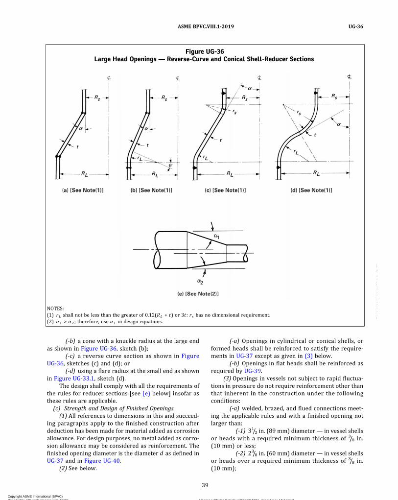
(-b) a cone with a knuckle radius at the large endas shown in Figure UG-36, sketch (b);
(-c) a reverse curve section as shown in FigureUG-36, sketches (c) and (d); or
(-d) using a flare radius at the small end as shownin Figure UG-33.1, sketch (d).
The design shall comply with all the requirements ofthe rules for reducer sections [see (e) below] insofar asthese rules are applicable.
(c) Strength and Design of Finished Openings(1) All references to dimensions in this and succeed-
ing paragraphs apply to the finished construction afterdeduction has been made for material added as corrosionallowance. For design purposes, no metal added as corro-sion allowance may be considered as reinforcement. Thefinished opening diameter is the diameter d as defined inUG-37 and in Figure UG-40.
(2) See below.
(-a) Openings in cylindrical or conical shells, orformed heads shall be reinforced to satisfy the require-ments in UG-37 except as given in (3) below.
(-b) Openings in flat heads shall be reinforced asrequired by UG-39.
(3) Openings in vessels not subject to rapid fluctua-tions in pressure do not require reinforcement other thanthat inherent in the construction under the followingconditions:
(-a) welded, brazed, and flued connections meet-ing the applicable rules and with a finished opening notlarger than:
(-1) 31/2 in. (89 mm) diameter— in vessel shellsor heads with a required minimum thickness of 3/8 in.(10 mm) or less;
(-2) 23/8 in. (60 mm) diameter— in vessel shellsor heads over a required minimum thickness of 3/8 in.(10 mm);
Figure UG-36Large Head Openings — Reverse-Curve and Conical Shell-Reducer Sections
NOTES:(1) rL shall not be less than the greater of 0.12(RL + t) or 3t : r s has no dimensional requirement.(2) α1 > α2; therefore, use α1 in design equations.
39
ASME BPVC.VIII.1-2019 UG-36
Copyright ASME International (BPVC) Provided by IHS under license with ASME Licensee=Khalda Petroleum/5986215001, User=Amer, Mohamed
Not for Resale, 07/02/2019 13:29:04 MDTNo reproduction or networking permitted without license from IHS
--`,``,``,,`,`,,````,`,``,,,`-`-`,,`,,`,`,,`---

ð19Þ
(-b) threaded, studded, or expanded connectionsin which the hole cut in the shell or head is not greaterthan 23/8 in. (60 mm) diameter;
(-c) no two isolated unreinforced openings, in ac-cordance with (-a) or (-b) above, shall have their centerscloser to each other than the sum of their diameters;
(-d) no two unreinforced openings, in a cluster ofthree or more unreinforced openings in accordance with(-a) or (-b) above, shall have their centers closer to eachother than the following:
for cylindrical or conical shells,
for doubly curved shells and formed or flat heads,
where
d1 , d2 = the finished diameter of the two adjacentopenings
θ = the angle between the line connecting the cen-ter of the openings and the longitudinal axisof the shell
The centerline of an unreinforced opening as de-fined in (-a) and (-b) above shall not be closer than its fin-ished diameter to any material used for reinforcement ofan adjacent reinforced opening.(d) Openings Through Welded Joints. Additional provi-
sions governing openings through welded joints are givenin UW-14.(e) Reducer Sections Under Internal Pressure
(1) The equations and rules of this paragraph applyto concentric reducer sections wherein all the longitudi-nal loads are transmitted wholly through the shell ofthe reducer. Where loads are transmitted in part or as awhole by other elements, e.g., inner shells, stays, or tubes,the rules of this paragraph do not apply.
(2) The thickness of each element of a reducer, as de-fined in (4) below, under internal pressure shall not beless than that computed by the applicable formula. In ad-dition, provisions shall be made for any of the other load-ings listed in UG-22, where such loadings are expected.
(3) The symbols defined in either UG-32(b) or beloware used in this paragraph (see Figure UG-36).
t = minimum required thickness of the considered ele-ment of a reducer after forming
RL = inside radius of larger cylinderRs = inside radius of smaller cylinderrL = inside radius of knuckle at larger cylinderrs = radius to the inside surface of flare at the small endα = one‐half of the included (apex) angle of a conical
element
(4) Elements of a Reducer. A transition section redu-cer consisting of one or more elements may be used tojoin two cylindrical shell sections of different diametersbut with a common axis, provided the requirements ofthis paragraph are met.
(-a) Conical Shell Section. The required thicknessof a conical shell section, or the allowable working pres-sure for such a section of given thickness, shall be deter-mined by the equations given in UG-32(f).
(-b) Knuckle Tangent to the Larger Cylinder.Where a knuckle is used at the large end of a reducer sec-tion, its shape shall be that of a portion of an ellipsoidal,hemispherical, or torispherical head. The thickness andother dimensions shall satisfy the requirements of the ap-propriate equations and provisions of UG-32.
(5) Combination of Elements to Form a Reducer.When elements of (4) above, having different thicknessesare combined to form a reducer, the joints including theplate taper required by UW-9(c) shall lie entirely withinthe limits of the thinner element being joined.
(-a) A reducer may be a simple conical shell sec-tion, Figure UG-36, sketch (a), without knuckle, providedthe half‐apex angle α is not greater than 30 deg, except asprovided for in 1-5(g). A reinforcement ring shall be pro-vided at either or both ends of the reducer when requiredby the rules of 1-5.
(-b) A toriconical reducer, Figure UG-36, sketch(b), may be shaped as a portion of a toriconical head,UG-32(g), a portion of a hemispherical head plus a conicalsection, or a portion of an ellipsoidal head plus a conicalsection, provided the half‐apex angle α is not greater than30 deg, except as provided for in 1-5(g). A reinforcementring shall be provided at the small end of the conical re-ducer element when required by the rules in 1-5.
(-c) Reverse curve reducers, Figure UG-36,sketches (c) and (d), may be shaped of elements otherthan those of (4) above. See U-2(g).(f) Reducers Under External Pressure. The rules of
UG-33(f) shall be followed, where applicable, in the de-sign of reducers under external pressure.(g) Oblique Conical Shell Sections Under Internal Pres-
sure. A transition section reducer consisting of an obliqueconical shell section may be used to join two cylindricalshell sections of different diameters and axes, providedthe following requirements are used:
(1) The required thickness shall be determined bythe equations given in UG-32(f).
(2) The angle α to be used shall be the largest in-cluded angle between the oblique cone and the attachedcylindrical section [see Figure UG-36, sketch (e)] and shallnot be greater than 30 deg, except as provided for in1-5(g)
(3) Diametrical dimensions to be used in the designequations shall be measured perpendicular to the axisof the cylinder to which the cone is attached.
40
ASME BPVC.VIII.1-2019UG-36
Copyright ASME International (BPVC) Provided by IHS under license with ASME Licensee=Khalda Petroleum/5986215001, User=Amer, Mohamed
Not for Resale, 07/02/2019 13:29:04 MDTNo reproduction or networking permitted without license from IHS
--`,``,``,,`,`,,````,`,``,,,`-`-`,,`,,`,`,,`---

(4) A reinforcement ring shall be provided at eitheror both ends of the reducer when required by the rulesof 1-5.
UG-37 REINFORCEMENT REQUIRED FOROPENINGS IN SHELLS AND FORMEDHEADS
(a) Nomenclature. The symbols used in this paragraphare defined as follows:
A = total cross‐sectional area of reinforcementrequired in the plane under consideration(see Figure UG-37.1) (includes considerationof nozzle area through shell if Sn/Sv < 1.0)
A1 = area in excess thickness in the vessel wallavailable for reinforcement (see FigureUG-37.1) (includes consideration of nozzlearea through shell if Sn/Sv < 1.0)
A2 = area in excess thickness in the nozzle wallavailable for reinforcement (see FigureUG-37.1)
A3 = area available for reinforcement when thenozzle extends inside the vessel wall (seeFigure UG-37.1)
A5 = cross‐sectional area of material added as re-inforcement (see Figure UG-37.1)
A41 , A42 ,A43 = cross‐sectional area of various welds avail-
able for reinforcement (see Figure UG-37.1)c = corrosion allowanceD = inside shell diameterDp = outside diameter of reinforcing element (ac-
tual size of reinforcing element may exceedthe limits of reinforcement established byUG-40; however, credit cannot be taken forany material outside these limits)
d = finished diameter of circular openingor finished dimension (chord length at mid-surface of thickness excluding excess thick-ness avai lable for reinforcement) ofnonradial opening in the plane underconsideration, in. (mm) [see FiguresUG-37.1 and UG-40]
E = 1 (see definitions for tr and trn)E1 = 1 when an opening is in the solid plate or in a
Category B butt joint; or= 0.85 when an opening is located in an ERW
or autogenously welded pipe or tube. If theERW or autogenously welded joint is clearlyidentifiable and it can be shown that theopening does not pass through this weldjoint, then E1 may be determined using theother rules of this paragraph; or
= joint efficiency obtained from Table UW-12when any part of the opening passesthrough any other welded joint
F = correction factor that compensates for thevariation in internal pressure stresses ondifferent planes with respect to the axis ofa vessel. A value of 1.00 shall be used forall configurations except that Figure UG-37may be used for integrally reinforced open-ings in cylindrical shells and cones. [SeeUW-16(c)(1).]
f r = strength reduction factor, not greater than1.0 [see UG-41(a)]
f r1 = Sn/Sv for nozzle wall inserted through thevessel wall
= 1.0 for nozzle wall abutting the vessel walland for nozzles shown in Figure UG-40,sketch (j), (k), (n), and (o).
f r2 = Sn/Svf r3 = (lesser of Sn or Sp)/Svf r4 = Sp/Svh = distance nozzle projects beyond the inner
surface of the vessel wall. (Extension of thenozzle beyond the inside surface of the ves-sel wall is not limited; however, for rein-forcement calculations, credit shall not betaken for material outside the limits of rein-forcement established by UG-40.)
K1 = spherical radius factor (see definition of trand Table UG-37)
L = length of projection defining the thickenedportion of integral reinforcement of a nozzleneck beyond the outside surface of the ves-sel wall [see Figure UG-40, sketch (e)]
P = internal design pressure (see UG-21), psi(MPa)
R = inside radius of the shell course underconsideration
Rn = i n s i d e r ad i u s o f t h e no z z l e unde rconsideration
S = allowable stress value in tension (seeUG-23), psi (MPa). For welded pipe or tub-ing, the allowable stress of the correspond-ing seamless product form. If there is nocorresponding seamless product form, usethe allowable stress for the welded productform divided by 0.85.
Sn = allowable stress in nozzle, psi (MPa) (see Sabove)
Sp = allowable stress in reinforcing element(plate), psi (MPa) (see S above)
Sv = allowable stress in vessel, psi (MPa) (see Sabove)
t = specified vessel wall thickness,29 (not in-cluding forming allowances). For pipe it isthe nominal thickness less manufacturingunderto lerance a l lowed in the pipespecification.
te = thickness or height of reinforcing element(see Figure UG-40)
41
ASME BPVC.VIII.1-2019 UG-36 – UG-37
Copyright ASME International (BPVC) Provided by IHS under license with ASME Licensee=Khalda Petroleum/5986215001, User=Amer, Mohamed
Not for Resale, 07/02/2019 13:29:04 MDTNo reproduction or networking permitted without license from IHS
--`,``,``,,`,`,,````,`,``,,,`-`-`,,`,,`,`,,`---
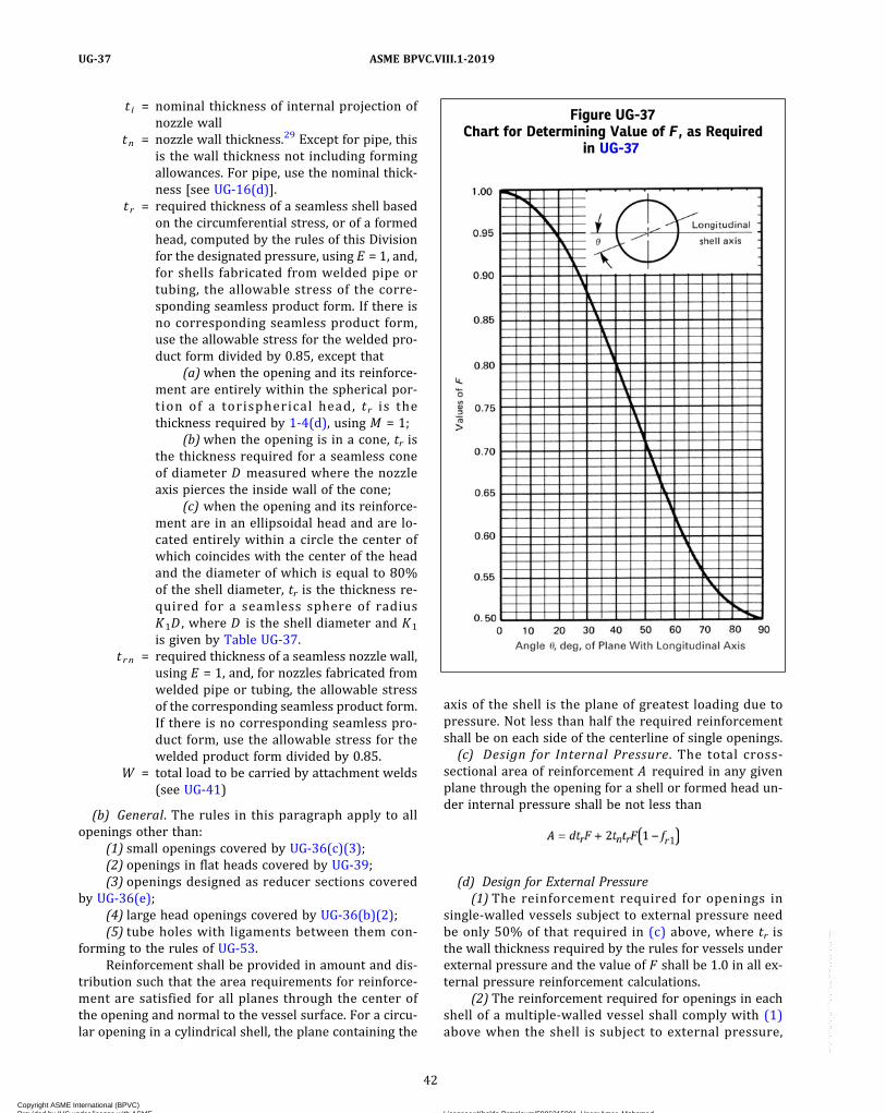
t i = nominal thickness of internal projection ofnozzle wall
tn = nozzle wall thickness.29 Except for pipe, thisis the wall thickness not including formingallowances. For pipe, use the nominal thick-ness [see UG-16(d)].
t r = required thickness of a seamless shell basedon the circumferential stress, or of a formedhead, computed by the rules of this Divisionfor the designated pressure, using E = 1, and,for shells fabricated from welded pipe ortubing, the allowable stress of the corre-sponding seamless product form. If there isno corresponding seamless product form,use the allowable stress for the welded pro-duct form divided by 0.85, except that
(a)when the opening and its reinforce-ment are entirely within the spherical por-tion of a torispherical head, tr is thethickness required by 1-4(d), using M = 1;
(b) when the opening is in a cone, tr isthe thickness required for a seamless coneof diameter D measured where the nozzleaxis pierces the inside wall of the cone;
(c) when the opening and its reinforce-ment are in an ellipsoidal head and are lo-cated entirely within a circle the center ofwhich coincides with the center of the headand the diameter of which is equal to 80%of the shell diameter, tr is the thickness re-quired for a seamless sphere of radiusK1D , where D is the shell diameter and K1
is given by Table UG-37.t rn = required thickness of a seamless nozzle wall,
using E = 1, and, for nozzles fabricated fromwelded pipe or tubing, the allowable stressof the corresponding seamless product form.If there is no corresponding seamless pro-duct form, use the allowable stress for thewelded product form divided by 0.85.
W = total load to be carried by attachment welds(see UG-41)
(b) General. The rules in this paragraph apply to allopenings other than:
(1) small openings covered by UG-36(c)(3);(2) openings in flat heads covered by UG-39;(3) openings designed as reducer sections covered
by UG-36(e);(4) large head openings covered by UG-36(b)(2);(5) tube holes with ligaments between them con-
forming to the rules of UG-53.Reinforcement shall be provided in amount and dis-
tribution such that the area requirements for reinforce-ment are satisfied for all planes through the center ofthe opening and normal to the vessel surface. For a circu-lar opening in a cylindrical shell, the plane containing the
axis of the shell is the plane of greatest loading due topressure. Not less than half the required reinforcementshall be on each side of the centerline of single openings.(c) Design for Internal Pressure. The total cross‐
sectional area of reinforcement A required in any givenplane through the opening for a shell or formed head un-der internal pressure shall be not less than
(d) Design for External Pressure(1) The reinforcement required for openings in
single‐walled vessels subject to external pressure needbe only 50% of that required in (c) above, where tr isthe wall thickness required by the rules for vessels underexternal pressure and the value of F shall be 1.0 in all ex-ternal pressure reinforcement calculations.
(2) The reinforcement required for openings in eachshell of a multiple‐walled vessel shall comply with (1)above when the shell is subject to external pressure,
Figure UG-37Chart for Determining Value of F , as Required
in UG-37
42
ASME BPVC.VIII.1-2019UG-37
Copyright ASME International (BPVC) Provided by IHS under license with ASME Licensee=Khalda Petroleum/5986215001, User=Amer, Mohamed
Not for Resale, 07/02/2019 13:29:04 MDTNo reproduction or networking permitted without license from IHS
--`,``,``,,`,`,,````,`,``,,,`-`-`,,`,,`,`,,`---

Figure UG-37.1Nomenclature and Formulas for Reinforced Openings
GENERAL NOTE: This figure illustrates a common nozzle configuration and is not intended to prohibit other configurations permitted by theCode.
NOTES:(1) Includes consideration of these areas if Sn/Sv < 1.0 (both sides of centerline).(2) This formula is applicable for a rectangular cross‐sectional element that falls within the limits of reinforcement.
43
ASME BPVC.VIII.1-2019 UG-37
Copyright ASME International (BPVC) Provided by IHS under license with ASME Licensee=Khalda Petroleum/5986215001, User=Amer, Mohamed
Not for Resale, 07/02/2019 13:29:04 MDTNo reproduction or networking permitted without license from IHS
--`,``,``,,`,`,,````,`,``,,,`-`-`,,`,,`,`,,`---
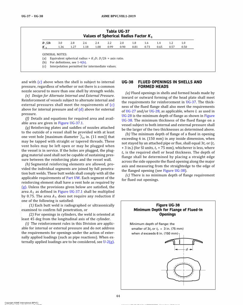
and with (c) above when the shell is subject to internalpressure, regardless of whether or not there is a commonnozzle secured to more than one shell by strength welds.(e) Design for Alternate Internal and External Pressure.
Reinforcement of vessels subject to alternate internal andexternal pressures shall meet the requirements of (c)above for internal pressure and of (d) above for externalpressure.(f) Details and equations for required area and avail-
able area are given in Figure UG-37.1.(g) Reinforcing plates and saddles of nozzles attached
to the outside of a vessel shall be provided with at leastone vent hole [maximum diameter 7/16 in. (11 mm)] thatmay be tapped with straight or tapered threads. Thesevent holes may be left open or may be plugged whenthe vessel is in service. If the holes are plugged, the plug-ging material used shall not be capable of sustaining pres-sure between the reinforcing plate and the vessel wall.(h) Segmental reinforcing elements are allowed, pro-
vided the individual segments are joined by full penetra-tion butt welds. These butt welds shall comply with all theapplicable requirements of Part UW. Each segment of thereinforcing element shall have a vent hole as required by(g). Unless the provisions given below are satisfied, thearea A5 as defined in Figure UG-37.1 shall be multipliedby 0.75. The area A5 does not require any reduction ifone of the following is satisfied:
(1) Each butt weld is radiographed or ultrasonicallyexamined to confirm full penetration, or
(2) For openings in cylinders, the weld is oriented atleast 45 deg from the longitudinal axis of the cylinder.(i) The reinforcement rules in this Division are applic-
able for internal or external pressure and do not addressthe requirements for openings under the action of exter-nally applied loadings (such as pipe reactions). When ex-ternally applied loadings are to be considered, see U-2(g).
UG-38 FLUED OPENINGS IN SHELLS ANDFORMED HEADS
(a) Flued openings in shells and formed heads made byinward or outward forming of the head plate shall meetthe requirements for reinforcement in UG-37. The thick-ness of the flued flange shall also meet the requirementsof UG-27 and/or UG-28, as applicable, where L as used inUG-28 is the minimum depth of flange as shown in FigureUG-38. The minimum thickness of the flued flange on avessel subject to both internal and external pressure shallbe the larger of the two thicknesses as determined above.(b) The minimum depth of flange of a flued in opening
exceeding 6 in. (150 mm) in any inside dimension, whennot stayed by an attached pipe or flue, shall equal 3tr or (tr+ 3 in.) (for SI units, tr + 75 mm), whichever is less, wheretr is the required shell or head thickness. The depth offlange shall be determined by placing a straight edgeacross the side opposite the flued opening along the majoraxis and measuring from the straightedge to the edge ofthe flanged opening (see Figure UG-38).(c) There is no minimum depth of flange requirement
for flued out openings.
Table UG-37Values of Spherical Radius Factor K1
D /2h 3.0 2.8 2.6 2.4 2.2 2.0 1.8 1.6 1.4 1.2 1.0K 1 1.36 1.27 1.18 1.08 0.99 0.90 0.81 0.73 0.65 0.57 0.50
GENERAL NOTES:(a) Equivalent spherical radius = K1D ; D/2h = axis ratio.(b) For definitions, see 1-4(b).(c) Interpolation permitted for intermediate values.
Figure UG-38Minimum Depth for Flange of Flued-In
Openings
Minimum depth of flange: the
smaller of 3tr or tr + 3 in. (75 mm)
when d exceeds 6 in. (150 mm)
d
44
ASME BPVC.VIII.1-2019UG-37 – UG-38
Copyright ASME International (BPVC) Provided by IHS under license with ASME Licensee=Khalda Petroleum/5986215001, User=Amer, Mohamed
Not for Resale, 07/02/2019 13:29:04 MDTNo reproduction or networking permitted without license from IHS
--`,``,``,,`,`,,````,`,``,,,`-`-`,,`,,`,`,,`---

ð19Þ
(d) The minimum width of bearing surface for a gasketon a self‐sealing flued opening shall be in accordance withUG-46(j).
UG-39 REINFORCEMENT REQUIRED FOROPENINGS IN FLAT HEADS AND COVERS
(a) General. The rules in this paragraph apply to allopenings in flat heads except opening(s) that do not ex-ceed the size and spacing limits in UG-36(c)(3) and donot exceed one‐fourth the head diameter or shortest span.Electric immersion heater support plates (see 41-3) maybe designed in accordance with the rules of this para-graph or Mandatory Appendix 41.
(b) Single and multiple openings in flat heads that havediameters equal to or less than one‐half the head dia-meter may be reinforced as follows:
(1) Flat heads that have a single opening with a dia-meter that does not exceed one‐half the head diameter orshortest span, as defined in UG-34, shall have a totalcross‐sectional area of reinforcement for all planesthrough the center of the opening not less than that givenby the formula
where d, tn, and f r1 are defined in UG-37 and t in UG-34.(2)Multiple openings none of which have diameters
exceeding one‐half the head diameter and no pair havingan average diameter greater than one‐quarter the headdiameter may be reinforced individually as required by(1) above when the spacing between any pair of adjacentopenings is equal to or greater than twice the average dia-meter of the pair.
When spacing between adjacent openings is less thantwice but equal to or more than 11/4 the average diameterof the pair, the required reinforcement for each openingin the pair, as determined by (1) above, shall be summedtogether and then distributed such that 50% of the sum islocated between the two openings. Spacings of less than11/4 the average diameter of adjacent openings shall betreated by rules of U-2(g).
(3) Referencing Figure UG-39, sketch (a), the liga-ment between two adjacent openings (U 1 , U 2 , or U 3 )shall not be less than one-quarter of the diameter of thesmaller of the two openings in the pair. The radial dis-tance between the inner edge of the opening (U4 , U5 , orU6) and the dimension d as shown in Figure UG-34 andFigure UG-39, sketch (a) shall not be less than one-quarter of the diameter of that one opening.
(c) Flat heads that have an opening with a diameterthat exceeds one‐half the head diameter or shortest span,as defined in UG-34, shall be designed as follows:
(1)When the opening is a single, circular centrally lo-cated opening in a circular flat head, the head shall be de-signed according to Mandatory Appendix 14 and relatedfactors in Mandatory Appendix 2. The head‐to‐shell junc-tion may be integral, as shown in Figure UG-34, sketches(a), (b‐1), (b‐2), (d), and (g). The head may also be at-tached by a butt weld or a full‐penetration corner weldsimilar to the joints shown in Figure UW-13.2, sketches(a), (b), (c), (d), (e), or (f). The large centrally locatedopening may have a nozzle that is integrally formed or in-tegrally attached by a full penetration weld or may beplain without an attached nozzle or hub. The head thick-ness does not have to be calculated by UG-34 rules. Thethickness that satisfies all the requirements of MandatoryAppendix 14 meets the requirements of the Code.
(2) Opening(s) may be located in the rim space sur-rounding the central opening. See Figure UG-39, sketch(b). Such openings may be reinforced by area replace-ment in accordance with the formula in (b)(1) aboveusing as a required head thickness the thickness that sa-tisfies rules of Mandatory Appendix 14. Multiple rimopenings shall meet spacing rules of (b)(2) and (b)(3)above. Alternatively, the head thickness that meets therules of Mandatory Appendix 14 may be increased bymultiplying it by the square root of two (1.414) if only asingle opening is placed in the rim space or if spacing pbetween two such openings is twice or more than theiraverage diameter. For spacing less than twice their aver-age diameter, the thickness that satisfies MandatoryAppendix 14 shall be divided by the square root of effi-ciency factor e , where e is defined in (e)(2) below.
The rim opening(s) shall not be larger in diameterthan one‐quarter the differences in head diameter lesscentral opening diameter. The minimum ligament widthU shall not be less than one‐quarter the diameter of thesmaller of the two openings in the pair. A minimum liga-ment width of one‐quarter the diameter of the rim open-ing applies to ligaments designated as U2 , U4 , U3 , and U5
in Figure UG-39, sketch (b).(3)When the large opening is any other type than
that described in (1) above, there are no specific rules giv-en. Consequently, the requirements of U-2(g) shall bemet.
(d) As an alternative to (b)(1) above, the thickness offlat heads and covers with a single opening with a dia-meter that does not exceed one‐half the head diametermay be increased to provide the necessary reinforcementas follows:
(1) In eq. UG-34(c)(2)(1) or eq. UG-34(c)(3)(3), use2C or 0.75 in place of C , whichever is the lesser; exceptthat, for sketches (b‐1), (b‐2), (e), (f), (g), and (i) of FigureUG-34, use 2C or 0.50, whichever is the lesser.
(2) In eq. UG-34(c)(2)(2) or eq. UG-34(c)(3)(5), dou-ble the quantity under the square root sign.
45
ASME BPVC.VIII.1-2019 UG-38 – UG-39
Copyright ASME International (BPVC) Provided by IHS under license with ASME Licensee=Khalda Petroleum/5986215001, User=Amer, Mohamed
Not for Resale, 07/02/2019 13:29:04 MDTNo reproduction or networking permitted without license from IHS
--`,``,``,,`,`,,````,`,``,,,`-`-`,,`,,`,`,,`---
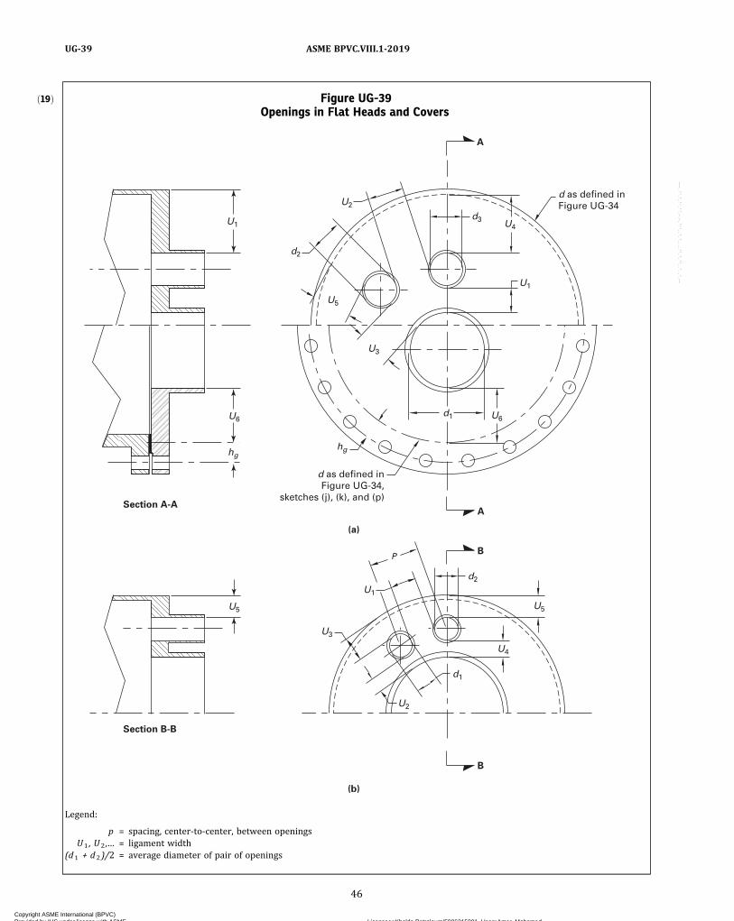
ð19Þ Figure UG-39Openings in Flat Heads and Covers
Section A-A
U5
U6
hg
U1
U5
U3
hg
U6
U2
d2
d3
d1
U1
U4
A
d as defined inFigure UG-34
d as defined inFigure UG-34,
sketches (j), (k), and (p)A
B
d2
U5
U4
d1
U1
U3
U2
Section B-B
B
(a)
P
(b)
Legend:
p = spacing, center-to-center, between openingsU1 , U2 ,… = ligament width
(d1 + d2)/2 = average diameter of pair of openings
46
ASME BPVC.VIII.1-2019UG-39
Copyright ASME International (BPVC) Provided by IHS under license with ASME Licensee=Khalda Petroleum/5986215001, User=Amer, Mohamed
Not for Resale, 07/02/2019 13:29:04 MDTNo reproduction or networking permitted without license from IHS
--`,``,``,,`,`,,````,`,``,,,`-`-`,,`,,`,`,,`---

ð19Þ
(e) Multiple openings none of which have diameters ex-ceeding one‐half the head diameter and no pair having anaverage diameter greater than one‐quarter the head dia-meter may be reinforced as follows:
(1)When the spacing between a pair of adjacentopenings is equal to or greater than twice the average dia-meter of the pair, and this is so for all opening pairs, thehead thickness may be determined by rules in (d) above.
(2)When the spacing between adjacent openings in apair is less than twice but equal to or greater than 11/4 theaverage diameter of the pair, the required head thicknessshall be that determined by (d) above multiplied by a fac-tor h , where
where
dave = average diameter of the same two adjacentopenings
e = smallest ligament efficiency of adjacent openingpairs in the head
p = center‐to‐center spacing of two adjacentopenings
(3) Spacings of less than 11/4 the average diameter ofadjacent openings shall be treated by rules of U-2(g).
(4) In no case shall the width of ligament betweentwo adjacent openings be less than one‐quarter the dia-meter of the smaller of the two openings in the pair.
(5) The width of ligament between the edge of anyone opening and the edge of the flat head (such as U 3
or U5 in Figure UG-39) shall not be less than one‐quarterthe diameter of that one opening.
UG-40 LIMITS OF REINFORCEMENT(a) The boundaries of the cross sectional area in any
plane normal to the vessel wall and passing through thecenter of the opening within which metal must be locatedin order to have value as reinforcement are designated asthe limits of reinforcement for that plane (see FigureUG-37.1). Figure UG-40 depicts thicknesses t, te, and tn,or ti and diameter d used in establishing the limits of re-inforcement. All dimensions are in the corroded condi-tion; for nomenclature, see UG-37(a).
(b) The limits of reinforcement, measured parallel tothe vessel wall, shall be at a distance, on each side ofthe axis of the opening, equal to the greater of thefollowing:
(1) the diameter d of the finished opening;(2) the inside radius, Rn, of the nozzle plus the vessel
wall thickness t , plus the nozzle wall thickness tn.
(c) The limits of reinforcement, measured normal tothe vessel wall, shall conform to the contour of the surfaceat a distance from each surface equal to the smaller of thefollowing:
(1) 21/2 times the vessel wall thickness t ;(2) 21/2 times the nozzle wall thickness tn plus the
thickness te as defined in Figure UG-40.(d)Metal within the limits of reinforcement that may be
considered to have reinforcing value shall include thefollowing:
(1)metal in the vessel wall over and above the thick-ness required to resist pressure and the thickness speci-fied as corrosion allowance. the area in the vessel wallavailable as reinforcement is the larger of the values ofA1 given by the equations in Figure UG-37.1.
(2)metal over and above the thickness required toresist pressure and the thickness specified as corrosionallowance in that part of a nozzle wall extending outsidethe vessel wall. The maximum area in the nozzle wallavailable as reinforcement is the smaller of the values ofA2 given by the equations in Figure UG-37.1.
All metal in the nozzle wall extending inside the ves-sel wall A3 may be included after proper deduction forcorrosion allowance on all the exposed surface is made.No allowance shall be taken for the fact that a differentialpressure on an inwardly extending nozzle may cause op-posing stress to that of the stress in the shell around theopening:
(3)metal in attachment welds A4 and metal added asreinforcement A5.
(e) With the exception of studding outlet type flangesand the straight hubs of forged nozzle flanges [seeUG-44(a)(10)], bolted flange material within the limitsof reinforcement shall not be considered to have reinfor-cing value. With the exception of material within an inte-gral hub, no material in a tubesheet or flat head shall becredited as reinforcement for an opening in an adjacentshell or head.
UG-41 STRENGTH OF REINFORCEMENT(a)Material used for reinforcement shall have an al-
lowable stress value equal to or greater than that of thematerial in the vessel wall, except that when such materi-al is not available, lower strength material may be used,provided the area of reinforcement is increased in inverseproportion to the ratio of the allowable stress values ofthe two materials to compensate for the lower allowablestress value of the reinforcement. No credit may be takenfor the additional strength of any reinforcement having ahigher allowable stress value than that of the vessel wall.Deposited weld metal outside of either the vessel wall orany reinforcing pad used as reinforcement shall be cred-ited with an allowable stress value equivalent to theweaker of the materials connected by the weld. Vessel‐to‐nozzle or pad‐to‐nozzle attachment weld metal within the
47
ASME BPVC.VIII.1-2019 UG-39 – UG-41
Copyright ASME International (BPVC) Provided by IHS under license with ASME Licensee=Khalda Petroleum/5986215001, User=Amer, Mohamed
Not for Resale, 07/02/2019 13:29:04 MDTNo reproduction or networking permitted without license from IHS
--`,``,``,,`,`,,````,`,``,,,`-`-`,,`,,`,`,,`---
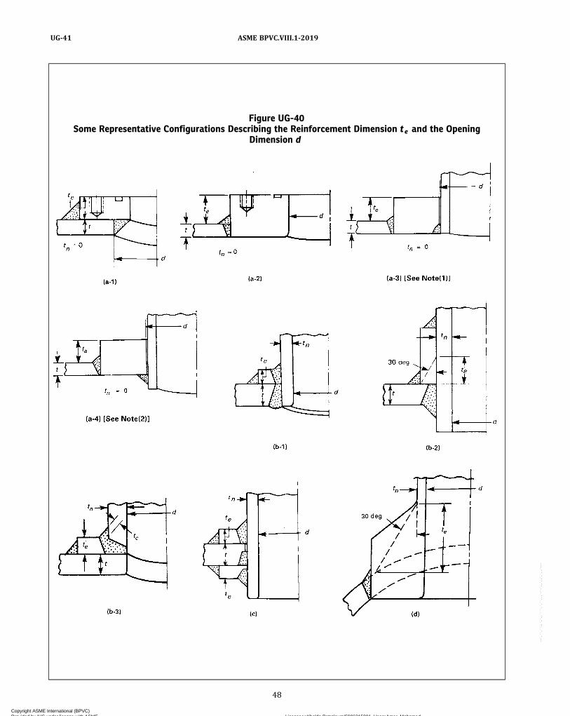
Figure UG-40Some Representative Configurations Describing the Reinforcement Dimension te and the Opening
Dimension d
48
ASME BPVC.VIII.1-2019UG-41
Copyright ASME International (BPVC) Provided by IHS under license with ASME Licensee=Khalda Petroleum/5986215001, User=Amer, Mohamed
Not for Resale, 07/02/2019 13:29:04 MDTNo reproduction or networking permitted without license from IHS
--`,``,``,,`,`,,````,`,``,,,`-`-`,,`,,`,`,,`---

Figure UG-40Some Representative Configurations Describing the Reinforcement Dimension te and the Opening
Dimension d (Cont'd)
t
L
d
30 deg
30 deg
30 deg
(k) (l) (m)
(n) (o)
(i)(h)
(g)
(f)
(e-2) [See Note (3)](e-1) [See Note (3)](e) [See Note (3)]
(j)
3/4 in (19 mm) R min.
te = 0.73R
30 deg
30 deg45 deg max.
30 deg max.
13
te = 0
d
d
d
d d
d
d
d
d
d d
d
tx
te
te
te
te
te
te
te
tn
tn tn
tntn
tn
tn tn
tn
tn
tn
tn
t
t
t
t t
t
t
t
t
tt
t
NOTES:(1) See Figure UW-16.1, sketch (v-2) for limitations.(2) See Figure UW-16.1, sketch (w-2) for limitations.(3) If L < 2.5t x , use sketch (e-1); if L ≥ 2.5t x , use sketch (e-2).
49
ASME BPVC.VIII.1-2019 UG-41
Copyright ASME International (BPVC) Provided by IHS under license with ASME Licensee=Khalda Petroleum/5986215001, User=Amer, Mohamed
Not for Resale, 07/02/2019 13:29:04 MDTNo reproduction or networking permitted without license from IHS
--`,``,``,,`,`,,````,`,``,,,`-`-`,,`,,`,`,,`---
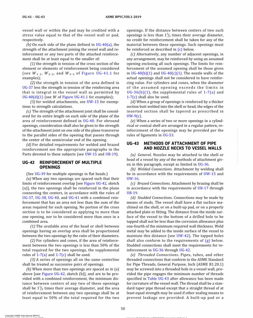
vessel wall or within the pad may be credited with astress value equal to that of the vessel wall or pad,respectively.(b) On each side of the plane defined in UG-40(a), the
strength of the attachment joining the vessel wall and re-inforcement or any two parts of the attached reinforce-ment shall be at least equal to the smaller of:
(1) the strength in tension of the cross section of theelement or elements of reinforcement being considered(see W 1 ‐1, W 2 ‐2, and W 3 ‐3 of Figure UG-41.1 forexamples);
(2) the strength in tension of the area defined inUG-37 less the strength in tension of the reinforcing areathat is integral in the vessel wall as permitted byUG-40(d)(1) (see W of Figure UG-41.1 for examples);
(3) for welded attachments, see UW-15 for exemp-tions to strength calculations.(c) The strength of the attachment joint shall be consid-
ered for its entire length on each side of the plane of thearea of reinforcement defined in UG-40. For obroundopenings, consideration shall also be given to the strengthof the attachment joint on one side of the plane transverseto the parallel sides of the opening that passes throughthe center of the semicircular end of the opening.(d) For detailed requirements for welded and brazed
reinforcement see the appropriate paragraphs in theParts devoted to these subjects (see UW-15 and UB-19).
UG-42 REINFORCEMENT OF MULTIPLEOPENINGS
(See UG-39 for multiple openings in flat heads.)(a)When any two openings are spaced such that their
limits of reinforcement overlap [see Figure UG-42, sketch(a)], the two openings shall be reinforced in the planeconnecting the centers, in accordance with the rules ofUG-37, UG-38, UG-40, and UG-41 with a combined rein-forcement that has an area not less than the sum of theareas required for each opening. No portion of the crosssection is to be considered as applying to more thanone opening, nor to be considered more than once in acombined area.
(1) The available area of the head or shell betweenopenings having an overlap area shall be proportionedbetween the two openings by the ratio of their diameters.
(2) For cylinders and cones, if the area of reinforce-ment between the two openings is less than 50% of thetotal required for the two openings, the supplementalrules of 1-7(a) and 1-7(c) shall be used.
(3) A series of openings all on the same centerlineshall be treated as successive pairs of openings.(b)When more than two openings are spaced as in (a)
above [see Figure UG-42, sketch (b)], and are to be pro-vided with a combined reinforcement, the minimum dis-tance between centers of any two of these openingsshall be 11/3 times their average diameter, and the areaof reinforcement between any two openings shall be atleast equal to 50% of the total required for the two
openings. If the distance between centers of two suchopenings is less than 11/3 times their average diameter,no credit for reinforcement shall be taken for any of thematerial between these openings. Such openings mustbe reinforced as described in (c) below.(c) Alternatively, any number of adjacent openings, in
any arrangement, may be reinforced by using an assumedopening enclosing all such openings. The limits for rein-forcement of the assumed opening shall be those givenin UG-40(b)(1) and UG-40(c)(1). The nozzle walls of theactual openings shall not be considered to have reinfor-cing value. For cylinders and cones, when the diameterof the assumed opening exceeds the l imi ts inUG-36(b)(1), the supplemental rules of 1-7(a) and1-7(c) shall also be used.(d)When a group of openings is reinforced by a thicker
section butt welded into the shell or head, the edges of theinserted section shall be tapered as prescribed inUW-9(c).(e) When a series of two or more openings in a cylind-
rical or conical shell are arranged in a regular pattern, re-inforcement of the openings may be provided per therules of ligaments in UG-53.
UG-43 METHODS OF ATTACHMENT OF PIPEAND NOZZLE NECKS TO VESSEL WALLS
(a) General. Nozzles may be attached to the shell orhead of a vessel by any of the methods of attachment giv-en in this paragraph, except as limited in UG-36.(b) Welded Connections. Attachment by welding shall
be in accordance with the requirements of UW-15 andUW-16.(c) Brazed Connections. Attachment by brazing shall be
in accordance with the requirements of UB-17 throughUB-19.(d) Studded Connections. Connections may be made by
means of studs. The vessel shall have a flat surface ma-chined on the shell, or on a built‐up pad, or on a properlyattached plate or fitting. The distance from the inside sur-face of the vessel to the bottom of a drilled hole to betapped shall not be less than the corrosion allowance plusone‐fourth of the minimum required wall thickness. Weldmetal may be added to the inside surface of the vessel tomaintain this distance (see UW-42). The tapped holesshall also conform to the requirements of (g) below.Studded connections shall meet the requirements for re-inforcement in UG-36 through UG-42.(e) Threaded Connections. Pipes, tubes, and other
threaded connections that conform to the ASME Standardfor Pipe Threads, General Purpose, Inch (ASME B1.20.1)may be screwed into a threaded hole in a vessel wall, pro-vided the pipe engages the minimum number of threadsspecified in Table UG-43 after allowance has been madefor curvature of the vessel wall. The thread shall be a stan-dard taper pipe thread except that a straight thread of atleast equal strength may be used if other sealing means toprevent leakage are provided. A built‐up pad or a
50
ASME BPVC.VIII.1-2019UG-41 – UG-43
Copyright ASME International (BPVC) Provided by IHS under license with ASME Licensee=Khalda Petroleum/5986215001, User=Amer, Mohamed
Not for Resale, 07/02/2019 13:29:04 MDTNo reproduction or networking permitted without license from IHS
--`,``,``,,`,`,,````,`,``,,,`-`-`,,`,,`,`,,`---
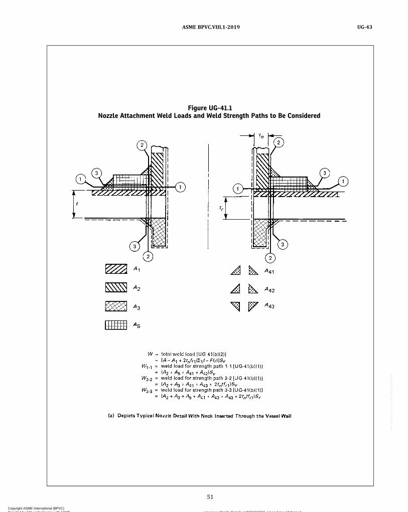
Figure UG-41.1Nozzle Attachment Weld Loads and Weld Strength Paths to Be Considered
51
ASME BPVC.VIII.1-2019 UG-43
Copyright ASME International (BPVC) Provided by IHS under license with ASME Licensee=Khalda Petroleum/5986215001, User=Amer, Mohamed
Not for Resale, 07/02/2019 13:29:04 MDTNo reproduction or networking permitted without license from IHS
--`,``,``,,`,`,,````,`,``,,,`-`-`,,`,,`,`,,`---

properly attached plate or fitting may be used to providethe metal thickness and number of threads required inTable UG-43, or to furnish reinforcement when required.Threaded connections larger than 4 in. pipe size
(DN 100) shall not be used in vessels that contain liquidshaving a flash point below 110°F (43°C), or flammable va-pors, or flammable liquids at temperatures above that atwhich they boil under atmospheric pressure.Threaded connections larger than 3 in. pipe size
(DN 80) shall not be used when the maximum allowableworking pressure exceeds 125 psi (0.8 MPa), except thatthis 3 in. pipe size (DN 80) restriction does not apply toplug closures used for inspection openings, end closures,or similar purposes, or to integrally forged openings invessel heads meeting the requirement of UF-43.
(f) Expanded Connections. A pipe, tube, or forging maybe attached to the wall of a vessel by inserting through anunreinforced opening and expanding into the shell, pro-vided the diameter is not greater than 2 in. pipe size(DN 50). A pipe, tube, or forging not exceeding 6 in.(150mm) in outside diameter may be attached to the wallof a vessel by inserting through a reinforced opening andexpanding into the shell.Such connections shall be:
(1) firmly rolled in and beaded; or(2) rolled in, beaded, and seal‐welded around the
edge of the bead; or(3) expanded and flared not less than 1/8 in. (3 mm)
over the diameter of the hole; or(4) rolled, flared, and welded; or
Figure UG-41.1Nozzle Attachment Weld Loads and Weld Strength Paths to Be Considered (Cont'd)
GENERAL NOTES:(a) Areas A1 , A2 , A3 , A5 , and A4 i are modified by f r x factors.(b) Nomenclature is the same as in UG-37 and Figure UG-37.1.
52
ASME BPVC.VIII.1-2019UG-43
Copyright ASME International (BPVC) Provided by IHS under license with ASME Licensee=Khalda Petroleum/5986215001, User=Amer, Mohamed
Not for Resale, 07/02/2019 13:29:04 MDTNo reproduction or networking permitted without license from IHS
--`,``,``,,`,`,,````,`,``,,,`-`-`,,`,,`,`,,`---

Figure UG-42Examples of Multiple Openings
Table UG-43Minimum Number of Pipe Threads for Connections
Size of Pipe Connection,NPS (DN)
ThreadsEngaged
Min. Plate Thickness Required,in. (mm)
1/2 and3/4 (DN 15 and 20) 6 0.43 (11.0)
1, 11/4, and 11/2 (DN 25, 32, and 40) 7 0.61 (15)2 (DN 50) 8 0.70 (18)21/2 and 3 (DN 65 and 80) 8 1.0 (25)4–6 (DN 100–150) 10 1.25 (32)8 (DN 200) 12 1.5 (38)10 (DN 250) 13 1.62 (41)12 (DN 300) 14 1.75 (45)
53
ASME BPVC.VIII.1-2019 UG-43
Copyright ASME International (BPVC) Provided by IHS under license with ASME Licensee=Khalda Petroleum/5986215001, User=Amer, Mohamed
Not for Resale, 07/02/2019 13:29:04 MDTNo reproduction or networking permitted without license from IHS
--`,``,``,,`,`,,````,`,``,,,`-`-`,,`,,`,`,,`---
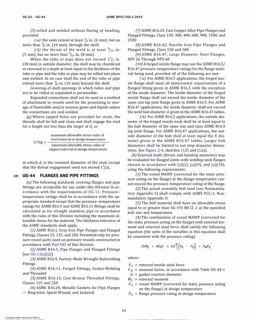
ð19Þ
(5) rolled and welded without flaring or beading,provided:
(-a) the ends extend at least 1/4 in. (6 mm), but nomore than 3/8 in. (10 mm), through the shell;
(-b) the throat of the weld is at least 3/16 in.(5 mm), but no more than 5/16 in. (8 mm).
When the tube or pipe does not exceed 11/2 in.(38 mm) in outside diameter, the shell may be chamferedor recessed to a depth at least equal to the thickness of thetube or pipe and the tube or pipe may be rolled into placeand welded. In no case shall the end of the tube or pipeextend more than 3/8 in. (10 mm) beyond the shell.
Grooving of shell openings in which tubes and pipeare to be rolled or expanded is permissible.
Expanded connections shall not be used as a methodof attachment to vessels used for the processing or stor-age of flammable and/or noxious gases and liquids unlessthe connections are seal‐welded.(g)Where tapped holes are provided for studs, the
threads shall be full and clean and shall engage the studfor a length not less than the larger of ds or
in which ds is the nominal diameter of the stud, exceptthat the thread engagement need not exceed 11/2ds.
UG-44 FLANGES AND PIPE FITTINGS(a) The following standards covering flanges and pipe
fittings are acceptable for use under this Division in ac-cordance with the requirements of UG-11. Pressure–temperature ratings shall be in accordance with the ap-propriate standard except that the pressure–temperatureratings for ASME B16.9 and ASME B16.11 fittings shall becalculated as for straight seamless pipe in accordancewith the rules of this Division including the maximum al-lowable stress for the material. The thickness tolerance ofthe ASME standards shall apply.
(1) ASME B16.1, Gray Iron Pipe Flanges and FlangedFittings, Classes 25, 125, and 250. Permitted only for pres-sure vessel parts used on pressure vessels constructed inaccordance with Part UCI of this Division.
(2) ASME B16.5, Pipe Flanges and Flanged Fittings[see UG-11(a)(2)]
(3) ASME B16.9, Factory‐Made Wrought ButtweldingFittings
(4) ASME B16.11, Forged Fittings, Socket‐Weldingand Threaded
(5) ASME B16.15, Cast Bronze Threaded Fittings,Classes 125 and 250
(6) ASME B16.20, Metallic Gaskets for Pipe Flanges— Ring‐Joint, Spiral‐Wound, and Jacketed
(7) ASME B16.24, Cast Copper Alloy Pipe Flanges andFlanged Fittings, Class 150, 300, 400, 600, 900, 1500, and2500
(8) ASME B16.42, Ductile Iron Pipe Flanges andFlanged Fittings, Class 150 and 300
(9) ASME B16.47, Large Diameter Steel Flanges,NPS 26 Through NPS 60
(10) A forged nozzle flange may use the ASME B16.5/B16.47 pressure–temperature ratings for the flange mate-rial being used, provided all of the following are met:
(-a) For ASME B16.5 applications, the forged noz-zle flange shall meet all dimensional requirements of aflanged fitting given in ASME B16.5 with the exceptionof the inside diameter. The inside diameter of the forgednozzle flange shall not exceed the inside diameter of thesame size lap joint flange given in ASME B16.5. For ASMEB16.47 applications, the inside diameter shall not exceedthe weld hub diameter A given in the ASME B16.47 tables.
(-b) For ASME B16.5 applications, the outside dia-meter of the forged nozzle neck shall be at least equal tothe hub diameter of the same size and class ASME B16.5lap joint flange. For ASME B16.47 applications, the out-side diameter of the hub shall at least equal the X dia-meter given in the ASME B16.47 tables. Larger hubdiameters shall be limited to nut stop diameter dimen-sions. See Figure 2-4, sketches (12) and (12a).(b) External loads (forces and bending moments) may
be evaluated for flanged joints with welding neck flangeschosen in accordance with (a)(2), (a)(9), and (a)(10),using the following requirements:
(1) The vessel MAWP (corrected for the static pres-sure acting on the flange) at the design temperature can-not exceed the pressure–temperature rating of the flange.
(2) The actual assembly bolt load (see Nonmanda-tory Appendix S) shall comply with ASME PCC-1, Non-mandatory Appendix O.
(3) The bolt material shall have an allowable stressequal to or greater than SA-193 B8 Cl. 2 at the specifiedbolt size and temperature.
(4) The combination of vessel MAWP (corrected forthe static pressure acting on the flange) with external mo-ment and external axial force shall satisfy the followingequation (the units of the variables in this equation shallbe consistent with the pressure rating):
where
FE = external tensile axial forceFM = moment factor, in accordance with Table UG-44-1G = gasket reaction diameter
ME = external momentPD = vessel MAWP (corrected for static pressure acting
on the flange) at design temperaturePR = flange pressure rating at design temperature
54
ASME BPVC.VIII.1-2019UG-43 – UG-44
Copyright ASME International (BPVC) Provided by IHS under license with ASME Licensee=Khalda Petroleum/5986215001, User=Amer, Mohamed
Not for Resale, 07/02/2019 13:29:04 MDTNo reproduction or networking permitted without license from IHS
--`,``,``,,`,`,,````,`,``,,,`-`-`,,`,,`,`,,`---

UG-45 NOZZLE NECK THICKNESSThe minimum wall thickness of nozzle necks shall be
determined as given below.For access openings and openings used only for
inspection:
For other nozzles:
Determine tb .
where
ta = minimum neck thickness required for internaland external pressure using UG-27 and UG-28(plus corrosion and threading allowance), asapplicable. The effects of external forces andmoments from supplemental loads (seeUG-22) shall be considered. Shear stressescaused by UG-22 loadings shall not exceed70% of the allowable tensile stress for the noz-zle material.
tb1 = for vessels under internal pressure, the thick-ness (plus corrosion allowance) required forpressure (assuming E = 1.0) for the shell orhead at the location where the nozzle neck orother connection attaches to the vessel but inno case less than the minimum thickness speci-fied for the material in UG-16(b).
tb2 = for vessels under external pressure, the thick-ness (plus corrosion allowance) obtained byusing the external design pressure as anequivalent internal design pressure (assumingE = 1.0) in the formula for the shell or headat the location where the nozzle neck or otherconnection attaches to the vessel but in no caseless than the minimum thickness specified forthe material in UG-16(b).
tb3 = the thickness given in Table UG-45 plus thethickness added for corrosion allowance.
tUG-45 = minimum wall thickness of nozzle necks
UG-46 INSPECTION OPENINGS30
(a) All pressure vessels for use with compressed airand those subject to internal corrosion or having partssubject to erosion or mechanical abrasion (see UG-25),except as permitted otherwise in this paragraph, shallbe provided with suitable manhole, handhole, or other in-spection openings for examination and cleaning.
Compressed air as used in this paragraph is not in-tended to include air that has had moisture removed toprovide an atmospheric dew point of −50°F (‐46°C) orless.
Inspection openings may be omitted in vessels coveredin (b), and in heat exchangers where the constructiondoes not permit access to the shell side, such as fixedtubesheet heat exchangers or U-tube and floating tube-sheet heat exchangers with Configuration a, b, or c asshown in Figure UHX-12.1 or Figure UHX-14.2. When in-spection openings are not provided, the Manufacturer’sData Report shall include one of the following notationsunder “Remarks”:
(1) “UG-46(b)” when telltale holes are used in lieu ofinspection openings;
ð19ÞTable UG-44-1Moment Factor, FM
Standard Size Range
Flange Pressure Rating Class
150 300 600 900 1500 2500
ASME B16.5 ≤NPS 12 1.2 0.5 0.5 0.5 0.5 0.5>NPS 12 and
≤NPS 241.2 0.5 0.5 0.3 0.3 …
ASME B16.47Series A All 0.6 0.1 0.1 0.1 … …Series B <NPS 48 [Note (1)] [Note (1)] 0.13 0.13 … …
≥NPS 48 0.1 [Note (2)] … … … …
GENERAL NOTES:(a) The combinations of size ranges and flange pressure classes for which this Table gives no moment factor value are outside the scope of this
Table.(b) The designer should consider reducing the moment factor if the loading is primarily sustained in nature and the bolted flange joint oper-
ates at a temperature where gasket creep/relaxation will be significant.
NOTES:(1) FM = [0.1 + (48 − NPS)]⁄56.(2) FM = 0.1, except for NPS 60, Class 300, in which case FM = 0.03.
55
ASME BPVC.VIII.1-2019 UG-45 – UG-46
Copyright ASME International (BPVC) Provided by IHS under license with ASME Licensee=Khalda Petroleum/5986215001, User=Amer, Mohamed
Not for Resale, 07/02/2019 13:29:04 MDTNo reproduction or networking permitted without license from IHS
--`,``,``,,`,`,,````,`,``,,,`-`-`,,`,,`,`,,`---

(2) “UG-46(a)” when inspection openings areomitted in fixed tubesheet heat exchangers or U-tubeand floating tubesheet heat exchangers with Configura-tion a, b, or c as shown in Figure UHX-12.1 or FigureUHX-14.2;
(3) “UG-46(c)”, “UG-46(d)”, or “UG-46(e)” when pro-vision for inspection is made in accordance with one ofthese paragraphs;
(4) the statement “for noncorrosive service.”(b)When provided with telltale holes complying with
the provisions of UG-25, inspection openings as requiredin (a) above may be omitted in vessels not over 36 in.(900 mm) I.D. that are subject only to corrosion, providedthat the holes are spaced one hole per 10 ft2 (0.9 m2 ) (orfraction thereof) of internal vessel surface area wherecorrosion is expected with a minimum of four uniformlyspaced holes per vessel. This provision does not applyto vessels for compressed air.(c) Vessels over 12 in. (300 mm) I.D. under air pressure
that also contain, as an inherent requirement of their op-eration, other substances that will prevent corrosion neednot have openings for inspection only, provided the vesselcontains suitable openings through which inspection canbe made conveniently, and provided such openings areequivalent in size and number to the requirements for in-spection openings in (f) below.
(d) For vessels 12 in. (300 mm) or less in inside dia-meter, openings for inspection only may be omitted ifthere are at least two removable pipe connections not lessthan NPS 3/4 (DN 20).(e) Vessels less than 16 in. (400 mm) and over 12 in.
(300 mm) I.D. shall have at least two handholes or twothreaded pipe plug inspection openings of not less thanNPS 11/2 (DN 40) except as permitted by the following:when vessels less than 16 in. (400 mm) and over 12 in.(300 mm) I.D. are to be installed so that inspection cannotbe made without removing the vessel from the assembly,openings for inspection only may be omitted, providedthere are at least two removable pipe connections ofnot less than NPS 11/2 (DN 40).(f) Vessels that require access or inspection openings
shall be equipped as follows.31
(1) All vessels less than 18 in. (450 mm) and over12 in. (300 mm) I.D. shall have at least two handholesor two plugged, threaded inspection openings of not lessthan NPS 11/2 (DN 40).
(2) All vessels 18 in. (450 mm) to 36 in. (900 mm),inclusive, I.D. shall have a manhole or at least two hand-holes or two plugged, threaded inspection openings ofnot less than NPS 2 (DN 50).
(3) All vessels over 36 in. (900 mm) I.D. shall have amanhole, except that those whose shape or use makes oneimpracticable shall have at least two handholes 4 in.× 6 in. (100 mm × 150 mm) or two equal openings ofequivalent area.
(4)When handholes or pipe plug openings are per-mitted for inspection openings in place of a manhole,one handhole or one pipe plug opening shall be in eachhead or in the shell near each head.
(5) Openings with removable heads or cover platesintended for other purposes may be used in place of therequired inspection openings, provided they are equalat least to the size of the required inspection openings.
(6) A single opening with removable head or coverplate may be used in place of all the smaller inspectionopenings, provided it is of such size and location as to af-ford at least an equal view of the interior.
(7) Flanged and/or threaded connections fromwhichpiping, instruments, or similar attachments can be re-moved may be used in place of the required inspectionopenings, provided that:
(-a) the connections are at least equal to the sizeof the required openings; and
(-b) the connections are sized and located to af-ford at least an equal view of the interior as the requiredinspection openings.(g)When inspection or access openings are required,
they sha l l comply a t leas t wi th the fo l lowingrequirements:
(1) An elliptical or obround manhole shall be not lessthan 12 in. × 16 in. (300 mm × 400 mm). A circular man-hole shall be not less than 16 in. (400 mm) I.D.
Table UG-45Nozzle Minimum Thickness Requirements
Nominal Size
Minimum Wall Thickness[See UG-16(d)]
in. mm
0.060 1.510.077 1.96
NPS 1/8 (DN 6) NPS 1/4 (DN 8) NPS 3/8 (DN 10) 0.080 2.02
0.095 2.420.099 2.51
NPS 1/2 (DN 15) NPS 3/4 (DN 20) NPS 1 (DN 25) 0.116 2.96
0.123 3.120.127 3.220.135 3.420.178 4.52
NPS 11/4 (DN 32) NPS 11/2 (DN 40) NPS 2 (DN 50) NPS 21/2 (DN 65) NPS 3 (DN 80) 0.189 4.80
0.198 5.020.207 5.270.226 5.730.245 6.22
NPS 31/2 (DN 90) NPS 4 (DN 100) NPS 5 (DN 125) NPS 6 (DN 150) NPS 8 (DN 200) 0.282 7.16NPS 10 (DN 250) 0.319 8.11≥ NPS 12 (DN 300) 0.328 8.34
GENERAL NOTE: For nozzles having a specified outside diameternot equal to the outside diameter of an equivalent standard NPS(DN) size, the NPS (DN) size chosen from the table shall be onehaving an equivalent outside diameter larger than the nozzle out-side diameter.
56
ASME BPVC.VIII.1-2019UG-46
Copyright ASME International (BPVC) Provided by IHS under license with ASME Licensee=Khalda Petroleum/5986215001, User=Amer, Mohamed
Not for Resale, 07/02/2019 13:29:04 MDTNo reproduction or networking permitted without license from IHS
--`,``,``,,`,`,,````,`,``,,,`-`-`,,`,,`,`,,`---

(2) A handhole opening shall be not less than 2 in.× 3 in. (50 mm × 75 mm), but should be as large as is con-sistent with the size of the vessel and the location of theopening.
(h) All access and inspection openings in a shell or un-stayed head shall be designed in accordance with therules of this Division for openings.
(i) When a threaded opening is to be used for inspec-tion or cleaning purposes, the closing plug or cap shallbe of a material suitable for the pressure and no materialshall be used at a temperature exceeding the maximumtemperature allowed in this Division for that material.The thread shall be a standard taper pipe thread exceptthat a straight thread of at least equal strength may beused if other sealing means to prevent leakage areprovided.
(j) Manholes of the type in which the internal pressureforces the cover plate against a flat gasket shall have aminimum gasket bearing width of 11/16 in. (17 mm).
BRACED AND STAYED SURFACES
UG-47 BRACED AND STAYED SURFACES(a) The minimum thickness and maximum allowable
working pressure for braced and stayed flat plates andthose parts that, by these rules, require staying as flatplates with braces or staybolts of uniform diameter sym-metrically spaced, shall be calculated by the followingequations:
ð1Þ
ð2Þ
where
C = 2.1 for welded stays or stays screwed throughplates not over 7/16 in. (11 mm) in thickness withends riveted over
= 2.2 for welded stays or stays screwed throughplates over 7/16 in. (11 mm) in thickness with endsriveted over
= 2.5 for stays screwed through plates and fitted withsingle nuts outside of plate, or with inside and out-side nuts, omitting washers; and for stays screwedinto plates as shown in Figure UG-47, sketch (b)
= 2.8 for stays with heads not less than 1.3 times thediameter of the stays screwed through plates ormade a taper fit and having the heads formed onthe stays before installing them, and not rivetedover, said heads being made to have a true bearingon the plate
= 3.2 for stays fitted with inside and outside nuts andoutside washers where the diameter of washers isnot less than 0.4p and thickness not less than t
P = internal design pressure (see UG-21)p = maximum pitch. The maximum pitch is the greatest
distance between any set of parallel straight linespassing through the centers of staybolts in adjacentrows. Each of the three parallel sets running in thehorizontal, the vertical, and the inclined planesshall be considered.
S = maximum allowable stress value in tension (seeUG-23)
t = minimum thickness of plate
(b) The minimum thickness of plates to which staysmay be applied, in other than cylindrical or spherical out-er shell plates, shall be 5/16 in. (8 mm) except for weldedconstruction covered by UW-19 or Mandatory Appendix17.
(c) If a stayed jacket extends completely around a cy-lindrical or spherical vessel, or completely covers aformed head, it shall meet the requirements given in (a)above, and shall also meet the applicable requirements
Figure UG-47Acceptable Proportions for Ends of Stays
NOTE:(1) See UG-83.
57
ASME BPVC.VIII.1-2019 UG-46 – UG-47
Copyright ASME International (BPVC) Provided by IHS under license with ASME Licensee=Khalda Petroleum/5986215001, User=Amer, Mohamed
Not for Resale, 07/02/2019 13:29:04 MDTNo reproduction or networking permitted without license from IHS
--`,``,``,,`,`,,````,`,``,,,`-`-`,,`,,`,`,,`---
for shells or heads in UG-27(c) and UG-27(d) and UG-32.In addition, where any nozzle or other opening penetratesthe cylindrical or spherical vessel, or completely coveredhead, and the jacket, the vessel or formed head shall bedesigned in accordance with UG-37(d)(2).(d)When two plates are connected by stays and but
one of these plates requires staying, the value of C shallbe governed by the thickness of the plate requiringstaying.(e) Acceptable proportions for the ends of through
stays with washers are indicated in Figure UG-47, sketch(a). See UG-83.(f) The maximum pitch shall be 81/2 in. (220 mm), ex-
cept that for welded‐in staybolts the pitch may be greater,provided it does not exceed 15 times the diameter of thestaybolt. See UW-19(a) for plate thicknesses greater than3/4 in. (19 mm).(g)When the staybolting of shells is unsymmetrical by
reason of interference with butt straps or other construc-tion, it is permissible to consider the load carried by eachstaybolt as the area calculated by taking the distance fromthe center of the spacing on one side of the bolt to the cen-ter of the spacing on the other side.
UG-48 STAYBOLTS(a) The ends of staybolts or stays screwed through the
plate shall extend beyond the plate not less than twothreads when installed, after which they shall be rivetedover or upset by an equivalent process without excessivescoring of the plates, or they shall be fitted with threadednuts through which the bolt or stay shall extend.(b) The ends of steel stays upset for threading shall be
fully annealed.(c) Requirements for welded‐in staybolts are given in
UW-19.
UG-49 LOCATION OF STAYBOLTS(a)When the edge of a flat stayed plate is flanged, the
distance from the center of the outermost stays to the in-side of the supporting flange shall not be greater than thepitch of the stays plus the inside radius of the flange.
UG-50 DIMENSIONS OF STAYBOLTS(a) The required area of a staybolt at its minimum cross
section32 and exclusive of any allowance for corrosionshall be obtained by dividing the load on the stayboltcomputed in accordance with (b) below by the allowablestress value for the material used, as given inSubsectionC, and multiplying the result by 1.10.(b) Load Carried by Stays. The area supported by a stay
shall be computed on the basis of the full pitch dimen-sions, with a deduction for the area occupied by the stay.The load carried by a stay is the product of the area sup-ported by the stay and the maximum allowable workingpressure.
(c) Stays made of parts joined by welding shall bechecked for strength using a joint efficiency of 60% forthe weld.
LIGAMENTS
UG-53 LIGAMENTS(a) The symbols used in the equations and charts of this
paragraph are defined as follows:
d = diameter of tube holesn = number of tube holes in length p1
p = longitudinal pitch of tube holesp1 = unit length of ligamentp ′ = diagonal pitch of tube holess = longitudinal dimension of diagonal pitch= p ′ cos θ
θ = angle of diagonal with longitudinal line, deg
(b)When a cylindrical shell is drilled for tubes in a lineparallel to the axis of the shell for substantially the fulllength of the shell as shown in Figures UG-53.1 throughUG-53.3, the efficiency of the ligaments between the tubeholes shall be determined as follows:
(1)When the pitch of the tube holes on every row isequal (see Figure UG-53.1), the formula is
(2)When the pitch of tube holes on any one row isunequal (as in Figures UG-53.2 and UG-53.3), the formulais
(c) When the adjacent longitudinal rows are drilled asdescribed in (b) above, diagonal and circumferential liga-ments shall also be examined. The least equivalent longi-tudinal efficiency shall be used to determine theminimum required thickness and the maximum allowableworking pressure.(d)When a cylindrical shell is drilled for holes so as to
form diagonal ligaments, as shown in Figure UG-53.4, theefficiency of these ligaments shall be determined byFigures UG-53.5 and UG-53.6. Figure UG-53.5 is used todetermine the efficiency of longitudinal and diagonal liga-ments with limiting boundaries where the condition ofequal efficiency of diagonal and longitudinal ligamentsform one boundary and the condition of equal efficiencyof diagonal and circumferential ligaments form the otherboundary. Figure UG-53.6 is used for determining theequivalent longitudinal efficiency of diagonal ligaments.This efficiency is used in the equations for setting theminimum required thickness and the maximum allowableworking pressure.
58
ASME BPVC.VIII.1-2019UG-47 – UG-53
Copyright ASME International (BPVC) Provided by IHS under license with ASME Licensee=Khalda Petroleum/5986215001, User=Amer, Mohamed
Not for Resale, 07/02/2019 13:29:04 MDTNo reproduction or networking permitted without license from IHS
--`,``,``,,`,`,,````,`,``,,,`-`-`,,`,,`,`,,`---

(e) Figure UG-53.5 is used when either or both longitu-dinal and circumferential ligaments exist with diagonal li-gaments. To use Figure UG-53.5, compute the value ofp ′/p1 and also the efficiency of the longitudinal ligament.Next find the vertical line in the diagram corresponding tothe longitudinal efficiency of the ligament and follow thisline vertically to the point where it intersects the diagonalline representing the ratio of p ′/p 1. Then project thispoint horizontally to the left, and read the diagonal effi-ciency of the ligament on the scale at the edge of the dia-gram. The minimum shell thickness and the maximumallowable working pressure shall be based on the liga-ment that has the lower efficiency.
(f) Figure UG-53.6 is used for holes which are not inline, placed longitudinally along a cylindrical shell. Thediagram may be used for pairs of holes for all planes be-tween the longitudinal plane and the circumferentialplane. To use Figure UG-53.6, determine the angle θ be-tween the longitudinal shell axis and the line betweenthe centers of the openings, θ , and compute the value ofp ′/d . Find the vertical line in the diagram correspondingto the value of θ and follow this line vertically to the linerepresenting the value of p ′/d . Then project this pointhorizontally to the left, and read the equivalent longitudi-nal efficiency of the diagonal ligament. This equivalent
longitudinal efficiency is used to determine the minimumrequired thickness and the maximum allowable workingpressure.
(g)When tube holes in a cylindrical shell are arrangedin symmetrical groups which extend a distance greaterthan the inside diameter of the shell along lines parallelto the axis and the same spacing is used for each group,the efficiency for one of the groups shall be not less thanthe efficiency on which the maximum allowable workingpressure is based.
(h) The average ligament efficiency in a cylindricalshell, in which the tube holes are arranged along linesparallel to the axis with either uniform or nonuniformspacing, shall be computed by the following rules andshall satisfy the requirements of both:33
(1) For a length equal to the inside diameter of theshell for the position which gives the minimum efficiency,the efficiency shall be not less than that on which the max-imum allowable working pressure is based. When the in-side diameter of the shell exceeds 60 in. (1 520 mm), thelength shall be taken as 60 in. (1 520 mm) in applying thisrule.
(2) For a length equal to the inside radius of the shellfor the position which gives the minimum efficiency, theefficiency shall be not less than 80% of that on whichthe maximum allowable working pressure is based. When
Figure UG-53.1Example of Tube Spacing With Pitch of Holes Equal in Every Row
Longitudinal line
51/4
in.
51/4
in.
51/4
in.
51/4
in.
51/4
in.
51/4
in.
51/4
in.
GENERAL NOTE: 51/4 in. = 133 mm.
Figure UG-53.2Example of Tube Spacing With Pitch of Holes Unequal in Every Second Row
51/4
in.
51/4
in.
51/4
in.
51/4
in.
63/4
in.
63/4
in.
63/4
in.
Longitudinal line
p1 = 12 in. (305 mm)
GENERAL NOTE: 51/4 in. = 135 mm; 63/4 in. = 170 mm.
59
ASME BPVC.VIII.1-2019 UG-53
Copyright ASME International (BPVC) Provided by IHS under license with ASME Licensee=Khalda Petroleum/5986215001, User=Amer, Mohamed
Not for Resale, 07/02/2019 13:29:04 MDTNo reproduction or networking permitted without license from IHS
--`,``,``,,`,`,,````,`,``,,,`-`-`,,`,,`,`,,`---
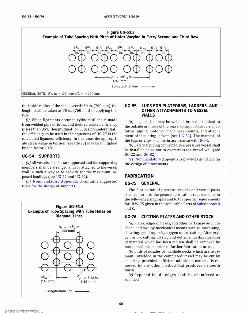
the inside radius of the shell exceeds 30 in. (760 mm), thelength shall be taken as 30 in. (760 mm) in applying thisrule.(i) When ligaments occur in cylindrical shells made
from welded pipe or tubes, and their calculated efficiencyis less than 85% (longitudinal) or 50% (circumferential),the efficiency to be used in the equations of UG-27 is thecalculated ligament efficiency. In this case, the appropri-ate stress value in tension (see UG-23) may be multipliedby the factor 1.18.
UG-54 SUPPORTS(a) All vessels shall be so supported and the supporting
members shall be arranged and/or attached to the vesselwall in such a way as to provide for the maximum im-posed loadings (see UG-22 and UG-82).(b) Nonmandatory Appendix G contains suggested
rules for the design of supports.
UG-55 LUGS FOR PLATFORMS, LADDERS, ANDOTHER ATTACHMENTS TO VESSELWALLS
(a) Lugs or clips may be welded, brazed, or bolted tothe outside or inside of the vessel to support ladders, plat-forms, piping, motor or machinery mounts, and attach-ment of insulating jackets (see UG-22). The material ofthe lugs or clips shall be in accordance with UG-4.(b) External piping connected to a pressure vessel shall
be installed so as not to overstress the vessel wall (seeUG-22 and UG-82).(c) Nonmandatory Appendix G provides guidance on
the design of attachments.
FABRICATION
UG-75 GENERALThe fabrication of pressure vessels and vessel parts
shall conform to the general fabrication requirements inthe following paragraphs and to the specific requirementsfor ULW-75 given in the applicable Parts of Subsections Band C.
UG-76 CUTTING PLATES AND OTHER STOCK(a) Plates, edges of heads, and other parts may be cut to
shape and size by mechanical means such as machining,shearing, grinding, or by oxygen or arc cutting. After oxy-gen or arc cutting, all slag and detrimental discolorationof material which has been molten shall be removed bymechanical means prior to further fabrication or use.(b) Ends of nozzles or manhole necks which are to re-
main unwelded in the completed vessel may be cut byshearing, provided sufficient additional material is re-moved by any other method that produces a smoothfinish.(c) Exposed inside edges shall be chamfered or
rounded.
Figure UG-53.3Example of Tube Spacing With Pitch of Holes Varying in Every Second and Third Row
51/4
in.
51/4
in.
51/4
in.
51/4
in.
51/4
in.
51/4
in.
63/4
in.
63/4
in.
63/4
in.
Longitudinal line
p1 = 291/4 in. (745 mm)
GENERAL NOTE: 51/4 in. = 135 mm; 63/4 in. = 170 mm.
Figure UG-53.4Example of Tube Spacing With Tube Holes on
Diagonal Lines
53/4 in. (145 mm)
Longitudinal line
p1 = 111/2 in. (290 mm)
p' = 6.42 in. (165 mm)
60
ASME BPVC.VIII.1-2019UG-53 – UG-76
Copyright ASME International (BPVC) Provided by IHS under license with ASME Licensee=Khalda Petroleum/5986215001, User=Amer, Mohamed
Not for Resale, 07/02/2019 13:29:04 MDTNo reproduction or networking permitted without license from IHS
--`,``,``,,`,`,,````,`,``,,,`-`-`,,`,,`,`,,`---
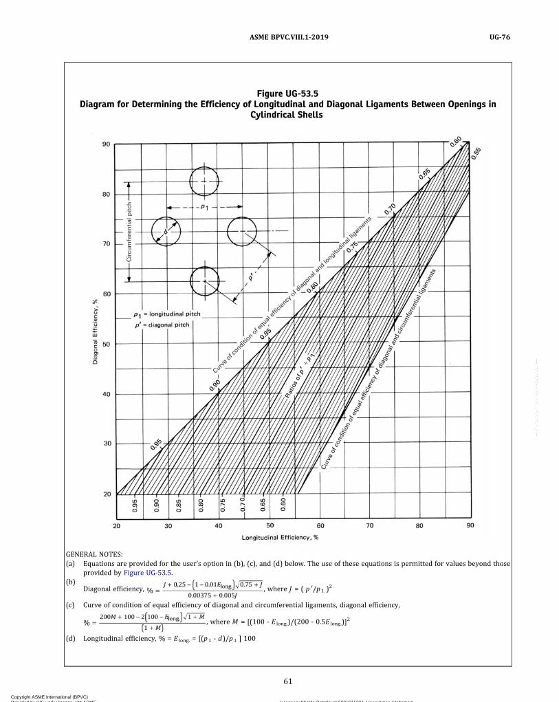
Figure UG-53.5Diagram for Determining the Efficiency of Longitudinal and Diagonal Ligaments Between Openings in
Cylindrical Shells
GENERAL NOTES:(a) Equations are provided for the user’s option in (b), (c), and (d) below. The use of these equations is permitted for values beyond those
provided by Figure UG-53.5.(b)
Diagonal efficiency, , where J = ( p ′/p1 )2
(c) Curve of condition of equal efficiency of diagonal and circumferential ligaments, diagonal efficiency,
, where M = [(100 - E long.)/(200 - 0.5E long.)]2
(d) Longitudinal efficiency, % = E long. = [(p1 - d)/p1 ] 100
61
ASME BPVC.VIII.1-2019 UG-76
Copyright ASME International (BPVC) Provided by IHS under license with ASME Licensee=Khalda Petroleum/5986215001, User=Amer, Mohamed
Not for Resale, 07/02/2019 13:29:04 MDTNo reproduction or networking permitted without license from IHS
--`,``,``,,`,`,,````,`,``,,,`-`-`,,`,,`,`,,`---

Figure UG-53.6Diagram for Determining Equivalent Longitudinal Efficiency of Diagonal Ligaments Between Openings in
Cylindrical Shells
GENERAL NOTE: The equation below is provided for the user’s option. The use of the equation is prohibited beyond the range of the abscissaand ordinate shown.
62
ASME BPVC.VIII.1-2019UG-76
Copyright ASME International (BPVC) Provided by IHS under license with ASME Licensee=Khalda Petroleum/5986215001, User=Amer, Mohamed
Not for Resale, 07/02/2019 13:29:04 MDTNo reproduction or networking permitted without license from IHS
--`,``,``,,`,`,,````,`,``,,,`-`-`,,`,,`,`,,`---
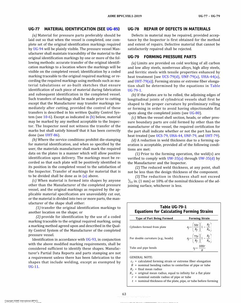
UG-77 MATERIAL IDENTIFICATION (SEE UG-85)(a)Material for pressure parts preferably should be
laid out so that when the vessel is completed, one com-plete set of the original identification markings requiredby UG-94 will be plainly visible. The pressure vessel Man-ufacturer shall maintain traceability of the material to theoriginal identification markings by one or more of the fol-lowing methods: accurate transfer of the original identifi-cation markings to a location where the markings will bevisible on the completed vessel; identification by a codedmarking traceable to the original required marking; or re-cording the required markings using methods such as ma-terial tabulations or as-built sketches that ensureidentification of each piece of material during fabricationand subsequent identification in the completed vessel.Such transfers of markings shall be made prior to cuttingexcept that the Manufacturer may transfer markings im-mediately after cutting, provided the control of thesetransfers is described in his written Quality Control Sys-tem (see 10-6). Except as indicated in (b) below, materialmay be marked by any method acceptable to the Inspec-tor. The Inspector need not witness the transfer of themarks but shall satisfy himself that it has been correctlydone (see UHT-86).
(b)Where the service conditions prohibit die‐stampingfor material identification, and when so specified by theuser, the materials manufacturer shall mark the requireddata on the plates in a manner which will allow positiveidentification upon delivery. The markings must be re-corded so that each plate will be positively identified inits position in the completed vessel to the satisfaction ofthe Inspector. Transfer of markings for material that isto be divided shall be done as in (a) above.
(c) When material is formed into shapes by anyoneother than the Manufacturer of the completed pressurevessel, and the original markings as required by the ap-plicable material specification are unavoidably cut out,or the material is divided into two or more parts, the man-ufacturer of the shape shall either:
(1) transfer the original identification markings toanother location on the shape; or
(2) provide for identification by the use of a codedmarking traceable to the original required marking, usinga marking method agreed upon and described in the Qual-ity Control System of the Manufacturer of the completedpressure vessel.
Identification in accordance with UG-93, in conjunctionwith the above modified marking requirements, shall beconsidered sufficient to identify these shapes. Manufac-turer’s Partial Data Reports and parts stamping are nota requirement unless there has been fabrication to theshapes that include welding, except as exempted byUG-11.
UG-78 REPAIR OF DEFECTS IN MATERIALSDefects in material may be repaired, provided accep-
tance by the Inspector is first obtained for the methodand extent of repairs. Defective material that cannot besatisfactorily repaired shall be rejected.
UG-79 FORMING PRESSURE PARTS(a) Limits are provided on cold working of all carbon
and low alloy steels, nonferrous alloys, high alloy steels,and ferritic steels with tensile properties enhanced byheat treatment [see UCS-79(d), UNF-79(a), UHA-44(a),and UHT-79(a)]. Forming strains or extreme fiber elonga-tion shall be determined by the equations in TableUG-79-1.
(b) If the plates are to be rolled, the adjoining edges oflongitudinal joints of cylindrical vessels shall first beshaped to the proper curvature by preliminary rollingor forming in order to avoid having objectionable flatspots along the completed joints (see UG-80).
(c) When the vessel shell section, heads, or other pres-sure boundary parts are cold formed by other than themanufacturer of the vessel, the required certification forthe part shall indicate whether or not the part has beenheat treated (see UCS-79, UHA-44, UNF-79, and UHT-79).
(d) A reduction in weld thickness due to a forming op-eration is acceptable, provided all of the following condi-tions are met:
(1) Prior to the forming operation, the weld(s) areverified to comply with UW-35(a) through UW-35(d) bythe Manufacturer and the Inspector.
(2) The reduced weld thickness, at any point, shallnot be less than the design thickness of the component.
(3) The reduction in thickness shall not exceed1/32 in. (1 mm) or 10% of the nominal thickness of the ad-joining surface, whichever is less.
Table UG-79-1Equations for Calculating Forming Strains
Type of Part Being Formed Forming Strain
Cylinders formed from plate
For double curvature (e.g., heads)
Tube and pipe bends
GENERAL NOTE:ε f = calculated forming strain or extreme fiber elongationR = nominal bending radius to centerline of pipe or tubeRf = final mean radiusRo = original mean radius, equal to infinity for a flat plater = nominal outside radius of pipe or tubet = nominal thickness of the plate, pipe, or tube before forming
63
ASME BPVC.VIII.1-2019 UG-77 – UG-79
Copyright ASME International (BPVC) Provided by IHS under license with ASME Licensee=Khalda Petroleum/5986215001, User=Amer, Mohamed
Not for Resale, 07/02/2019 13:29:04 MDTNo reproduction or networking permitted without license from IHS
--`,``,``,,`,`,,````,`,``,,,`-`-`,,`,,`,`,,`---
UG-80 PERMISSIBLE OUT-OF-ROUNDNESS OFCYLINDRICAL, CONICAL, ANDSPHERICAL SHELLS
(a) Internal Pressure. The shell of a completed vesselshall be substantially round and shall meet the followingrequirements:
(1) The difference between the maximum and mini-mum inside diameters at any cross section shall not ex-ceed 1% of the nominal diameter at the cross sectionunder consideration. The diameters may be measuredon the inside or outside of the vessel. If measured onthe outside, the diameters shall be corrected for the platethickness at the cross section under consideration (seeFigure UG-80.2).
(2)When the cross section passes through an open-ing or within 1 I.D. of the opening measured from the cen-ter of the opening, the permissible difference in insidediameters given above may be increased by 2% of the in-side diameter of the opening. When the cross sectionpasses through any other location normal to the axis ofthe vessel, including head‐to‐shell junctions, the differ-ence in diameters shall not exceed 1%.For vessels with longitudinal lap joints, the permissible
difference in inside diameters may be increased by thenominal plate thickness.(b) External Pressure. The shell of a completed vessel to
operate under external pressure shall meet the followingrequirements at any cross section:
(1) The out‐of‐roundness limitations prescribed in(a)(1) and (a)(2) above.
(2) The maximum plus‐or‐minus deviation from thetrue circular form, measured radially on the outside or in-side of the vessel, shall not exceed the maximum permis-sible deviation e obtained from Figure UG-80.1. Usee = 1.0t or e = 0.2t , respectively, for points falling aboveor below these curves. Measurements shall be made froma segmental circular template having the design inside oroutside radius (depending upon where the measurementsare taken) and a chord length equal to twice the arc lengthobtained from Figure UG-29.2. The values of L and Do inFigures UG-29.2 and UG-80.1 shall be determined asfollows:
(-a) for cyl inders , L and D o as def ined inUG-28(b);
(-b) for cones and conical sections, L and Do val-ues to be used in the figures are given below in termsof the definitions given in UG-33(b). In all cases below,
(-1) at the large diameter end,
(-2) at the small diameter end,
(-3) at the midlength diameter,
(-4) at any cross section having an outside dia-meter of Dx ,
(-c) for spheres, L is one‐half of the outside dia-meter Do .
(3) For cylinders and spheres, the value of t shall bedetermined as follows:
(-a) For vessels with butt joints, t is the nominalplate thickness less corrosion allowance.
(-b) For vessels with longitudinal lap joints, t isthe nominal plate thickness and the permissible deviationis
(-c) Where the shell at any cross section is madeof plates having different thicknesses, t is the nominalthickness of the thinnest plate less corrosion allowance.
(4) For cones and conical sections, the value of t shallbe determined as in (3) above, except that t in (3)(-a),(3)(-b), and (3)(-c) shall be replaced by te as defined inUG-33(b).
(5) The requirements of (2) above shall be met inany plane normal to the axis of revolution for cylindersand cones and in the plane of any great circle for spheres.For cones and conical sections, a check shall be made atlocations (2)(-b)(-1), (2)(-b)(-2), and (2)(-b)(-3) aboveand such other locations as may be necessary to satisfymanufacturers and inspectors that requirements are met.
(6)Measurements shall be taken on the surface ofthe base metal and not on welds or other raised partsof the material.
64
ASME BPVC.VIII.1-2019UG-80
Copyright ASME International (BPVC) Provided by IHS under license with ASME Licensee=Khalda Petroleum/5986215001, User=Amer, Mohamed
Not for Resale, 07/02/2019 13:29:04 MDTNo reproduction or networking permitted without license from IHS
--`,``,``,,`,`,,````,`,``,,,`-`-`,,`,,`,`,,`---

(7) The dimensions of a completed vessel may bebrought within the requirements of this paragraph byany process which will not impair the strength of thematerial.
(8) Sharp bends and flat spots shall not be permittedunless provision is made for them in the design.
(9) If the nominal thickness of plate used for a cylind-rical vessel exceeds the minimum thickness required byUG-28 for the external design pressure, and if such excessthickness is not required for corrosion allowance or load-ings causing compressive forces, the maximum permissi-ble deviation e determined for the nominal platethickness used may be increased by the ratio of factor Bfor the nominal plate thickness used divided by factor Bfor the minimum required plate thickness; and the chordlength for measuring emax shall be determined by Do/tfor the nominal plate thickness used.
Figure UG-80.1Maximum Permissible Deviation From a Circular Form e for Vessels Under External Pressure
Figure UG-80.2Example of Differences Between Maximum and
Minimum Inside Diameters in Cylindrical,Conical, and Spherical Shells
65
ASME BPVC.VIII.1-2019 UG-80
Copyright ASME International (BPVC) Provided by IHS under license with ASME Licensee=Khalda Petroleum/5986215001, User=Amer, Mohamed
Not for Resale, 07/02/2019 13:29:04 MDTNo reproduction or networking permitted without license from IHS
--`,``,``,,`,`,,````,`,``,,,`-`-`,,`,,`,`,,`---

(c) Vessels and components fabricated of pipe or tubeunder internal or external pressure may have permissiblevariations in diameter (measured outside) in accordancewith those permitted under the specification covering itsmanufacture.
UG-81 TOLERANCE FOR FORMED HEADS(a) The inner surface of a torispherical, toriconical,
hemispherical, or ellipsoidal head shall not deviate out-side of the specified shape by more than 11/4% of D norinside the specified shape by more than 5/8% of D , whereD is the nominal inside diameter of the vessel shell atpoint of attachment. Such deviations shall be measuredperpendicular to the specified shape and shall not beabrupt. The knuckle radius shall not be less than thatspecified.(b) Hemispherical heads or any spherical portion of a
torispherical or ellipsoidal head designed for externalpressure shall, in addition to satisfying (a) above, meetthe tolerances specified for spheres in UG-80(b) using avalue of 0.5 for L/Do .(c) Measurements for determining the deviations spe-
cified in (a) above shall be taken from the surface of thebase metal and not from welds.(d) The skirts of heads shall be sufficiently true to
round so that the difference between the maximum andminimum inside diameters shall not exceed 1% of thenominal diameter.(e) When the skirt of any unstayed formed head is ma-
chined to make a driving fit into or over a shell, the thick-ness shall not be reduced to less than 90% of thatrequired for a blank head (see UW-13) or the thicknessof the shell at the point of attachment. When so machined,the transition from the machined thickness to the originalthickness of the head shall not be abrupt but shall be ta-pered for a distance of at least three times the differencebetween the thicknesses.
UG-82 LUGS AND FITTING ATTACHMENTSAll lugs, brackets, saddle type nozzles, manhole frames,
reinforcement around openings, and other appurtenancesshall be formed and fitted to conform reasonably to thecurvature of the shell or surface to which they areattached.(a)When pressure parts, such as saddle type nozzles,
manhole frames, and reinforcement around openings, ex-tend over pressure-retaining welds, such welds shall beground flush for the portion of the weld to be covered.(b)When nonpressure parts, such as lugs, brackets, and
support legs and saddles, extend over pressure-retainingwelds, such welds shall be ground flush as described in(a) above, or such parts shall be notched or coped to clearthose welds.
UG-83 HOLES FOR SCREW STAYSHoles for screw stays shall be drilled full size or
punched not to exceed 1/4 in. (6 mm) less than full dia-meter of the hole for plates over 5/16 in. (8 mm) in thick-ness and 1/8 in. (3 mm) less than the full diameter of thehole for plates not exceeding 5/16 in. (8 mm) in thickness,and then drilled or reamed to the full diameter. The holesshall be tapped fair and true with a full thread.
UG-84 CHARPY IMPACT TESTS(a) General. Charpy V‐notch impact tests in accordance
with the provisions of this paragraph shall be made onweldments and all materials for shells, heads, nozzles,and other vessel parts subject to stress due to pressurefor which impact tests are required by the rules in Sub-section C.(b) Test Procedures
(1) Impact test procedures and apparatus shall con-form to the applicable paragraphs of SA-370 or ISO 148(Parts 1, 2, and 3).
(2) Unless permitted by Table UG-84.4, impact testtemperature shall not be warmer than the minimum de-sign metal temperature [see UG-20(b)]. The test tempera-ture may be colder than the minimum specified in thematerial specification of Section II.(c) Test Specimens
(1) Each set of impact test specimens shall consist ofthree specimens.
(2) The impact test specimens shall be of the CharpyV‐notch type and shall conform in all respects to FigureUG-84. The standard (10 mm × 10 mm) specimens, whenobtainable, shall be used for nominal thicknesses of7/16 in. (11 mm) or greater, except as otherwise permittedin (-a) below.
Figure UG-84Simple Beam Impact Test Specimens (Charpy
Type Test)
0.394 in. (10 mm) [Note (1)]
0.315 in. (8 mm)
0.010 in. (0.25 mm) R
45 deg
2.165 in. (55 mm)
0.394 in. (10 mm)
NOTE:(1) See UG-84(c) for thickness of reduced-size specimen.
66
ASME BPVC.VIII.1-2019UG-80 – UG-84
Copyright ASME International (BPVC) Provided by IHS under license with ASME Licensee=Khalda Petroleum/5986215001, User=Amer, Mohamed
Not for Resale, 07/02/2019 13:29:04 MDTNo reproduction or networking permitted without license from IHS
--`,``,``,,`,`,,````,`,``,,,`-`-`,,`,,`,`,,`---

(-a) For materials that normally have absorbedenergy in excess of 180 ft‐lbf (240 J) when tested usingfull size (10 mm × 10 mm) specimens at the specified test-ing temperature, subsize (10 mm × 6.7 mm) specimensmay be used in lieu of full size specimens. However, whenthis option is used, the acceptance value shall be 75 ft‐lbf(100 J) minimum for each specimen and the lateral expan-sion in mils (mm) shall be reported.
(3) For material from which full size (10 mm ×10 mm) specimens cannot be obtained, either due tothe material shape or thickness, the specimens shall beeither the largest possible standard subsize specimensobtainable or specimens of full material nominal thick-ness which may be machined to remove surface irregula-rities. [The test temperature criteria of (5)(-b) belowshall apply for Table UCS-23 materials having a specifiedminimum tensile strength less than 95,000 psi (655 MPa)when the width along the notch is less than 80% of thematerial nominal thickness.] Alternatively, such materialmay be reduced in thickness to produce the largest possi-ble Charpy subsize specimen. Toughness tests are not re-quired where the maximum obtainable Charpy specimenhas a width along the notch less than 0.099 in. (2.5 mm).
(4) See below.(-a) Except for materials produced and impact
tested in accordance with the requirements in the speci-fications listed in General Note (c) of Figure UG-84.1,the applicable minimum energy requirement for all speci-men sizes for Table UCS-23 materials having a specifiedminimum tensi le strength less than 95,000 psi(655 MPa) shall be that shown in Figure UG-84.1, multi-plied by the ratio of the actual specimen width alongthe notch to the width of a full‐size (10 mm × 10 mm)specimen, except as otherwise provided in (2)(-a) above.
(-b) The applicable minimum lateral expansionopposite the notch for all specimen sizes for TableUCS-23 materials, having a specified minimum tensilestrength of 95,000 psi (655 MPa) or more, shall be as re-quired in UHT-6(a)(3) and UHT-6(a)(4). For UHT materi-als, all requirements of UHT-6(a)(3) and UHT-6(a)(4)shall apply. For Table UHA-23 materials, all requirementsof UHA-51 shall apply.
(5) For all Charpy impact tests the following test tem-perature criteria shall be observed:
(-a) For Materials of Nominal Thickness Equal toor Greater Than 0.394 in. (10 mm). Where the largest ob-tainable Charpy V‐notch specimen has a width along thenotch of at least 0.315 in. (8 mm), the Charpy test usingsuch a specimen shall be conducted at a temperatureno t warmer than the min imum des i gn meta ltemperature.34 Where the largest possible test specimenhas a width along the notch less than 0.315 in. (8 mm),the test shall be conducted at a temperature lower thanthe minimum design metal temperature34 by the amountshown in Table UG-84.2 for that specimen width. [Thislatter requirement does not apply when the option of(2)(-a) above is used.]
(-b) For Materials of Nominal Thickness Less Than0.394 in. (10 mm). Where the largest obtainable CharpyV‐notch specimen has a width along the notch of at least80% of the material nominal thickness, the Charpy test ofsuch a specimen shall be conducted at a temperature notwarmer than the minimum design metal temperature.34
Where the largest possible test specimen has awidth along the notch of less than 80% of the materialnominal thickness, the test, for Table UCS-23 materialshaving specified minimum tensile strength of less than95,000 psi (655 MPa), shall be conducted at a tempera-t u r e l owe r t h an t h e m in imum de s i g n me t a ltemperature34 by an amount equal to the difference (re-ferring to Table UG-84.2) between the temperature re-duction corresponding to the actual material thicknessand the temperature reduction corresponding to theCharpy specimen width actually tested. [This latter re-quirement does not apply when the option of (2)(-a)above is used.] For Table UCS-23 materials having a spe-cified minimum tensile strength of 95,000 psi (655 MPa)and over, for Table UHT-23 materials, and for TableUHA-23 materials, the test shall be conducted at a tem-perature not warmer than the minimum designtemperature.
(6)When the average value of the three specimensequals or exceeds the minimum value permitted for a sin-gle specimen and the value for more than one specimen isbelow the required average value, or when the value forone specimen is below the minimum value permittedfor a single specimen, a retest of three additional speci-mens shall be made. The value for each of these retestspecimens shall equal or exceed the required averagevalue.
When an erratic result is caused by a defective speci-men or there is uncertainty in test procedure, a retest willbe allowed. When the option of (2)(-a) above is used forthe initial test and the acceptance value of 75 ft‐lbf(100 J) minimum is not attained, retest using full size(10 mm × 10 mm) specimens will be allowed.
(d) Impact Tests of Material(1) Reports or certificates of impact tests by the ma-
terial manufacturer will be acceptable evidence that thematerial meets the requirements of this paragraph, pro-vided the specimens comply with UCS-85, UHT-5, orUHT-81, as applicable.
(2) The Manufacturer of the vessel may have impacttests made to prove the suitability of a material which thematerial manufacturer has not impact tested provided thenumber of tests and the method of taking the test speci-mens shall be as specified for the material manufacturer(see UG-85).
(e) Procedural Requirements(1) Product Form Procedural Requirements. When no
procedural requirements are listed in the material speci-fications, impact testing of each form of material shallcomply with the applicable product form procedural re-quirements of the specifications listed in Table UG-84.3.
67
ASME BPVC.VIII.1-2019 UG-84
Copyright ASME International (BPVC) Provided by IHS under license with ASME Licensee=Khalda Petroleum/5986215001, User=Amer, Mohamed
Not for Resale, 07/02/2019 13:29:04 MDTNo reproduction or networking permitted without license from IHS
--`,``,``,,`,`,,````,`,``,,,`-`-`,,`,,`,`,,`---
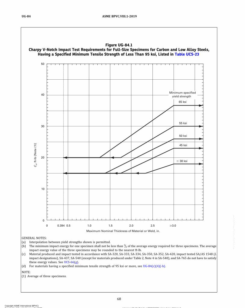
Figure UG-84.1Charpy V-Notch Impact Test Requirements for Full-Size Specimens for Carbon and Low Alloy Steels,
Having a Specified Minimum Tensile Strength of Less Than 95 ksi, Listed in Table UCS-23
Cv,
ft-
lb [
No
te (
1)]
0
0
Maximum Nominal Thickness of Material or Weld, in.
45 ksi
50 ksi
55 ksi
65 ksi
� 38 ksi
10
20
30
40
50
Minimum specified yield strength
0.394 0.5 1.0 1.5 2.0 2.5 �3.0
GENERAL NOTES:(a) Interpolation between yield strengths shown is permitted.(b) The minimum impact energy for one specimen shall not be less than 2/3 of the average energy required for three specimens. The average
impact energy value of the three specimens may be rounded to the nearest ft‐lb.(c) Material produced and impact tested in accordance with SA-320, SA-333, SA-334, SA-350, SA-352, SA-420, impact tested SA/AS 1548 (L
impact designations), SA-437, SA-540 (except for materials produced under Table 2, Note 4 in SA-540), and SA-765 do not have to satisfythese energy values. See UCS-66(g).
(d) For materials having a specified minimum tensile strength of 95 ksi or more, see UG-84(c)(4)(-b).
NOTE:(1) Average of three specimens.
68
ASME BPVC.VIII.1-2019UG-84
Copyright ASME International (BPVC) Provided by IHS under license with ASME Licensee=Khalda Petroleum/5986215001, User=Amer, Mohamed
Not for Resale, 07/02/2019 13:29:04 MDTNo reproduction or networking permitted without license from IHS
--`,``,``,,`,`,,````,`,``,,,`-`-`,,`,,`,`,,`---

Figure UG-84.1MCharpy V-Notch Impact Test Requirements for Full-Size Specimens for Carbon and Low Alloy Steels,
Having a Specified Minimum Tensile Strength of Less Than 655 MPa, Listed in Table UCS-23
Cv,
J [
No
te (
1)]
00 10 20 30 40 50 60 70
Maximum Nominal Thickness, mm
310 MPa
350 MPa
380 MPa
� 450, <660 MPa
� 260 MPa
10
20
30
40
50
60
Minimum specified yield strength
� 75
GENERAL NOTES:(a) Interpolation between yield strengths shown is permitted.(b) The minimum impact energy for one specimen shall not be less than 2/3 of the average energy required for three specimens. The average
impact energy value of the three specimens may be rounded to the nearest J.(c) Material produced and impact tested in accordance with SA-320, SA-333, SA-334, SA-350, SA-352, SA-420, impact tested SA/AS 1548 (L
impact designations), SA-437, SA-540 (except for materials produced under Table 2, Note 4 in SA-540), and SA-765 do not have to satisfythese energy values. See UCS-66(g).
(d) For materials having a specified minimum tensile strength of 655 MPa or more, see UG-84(c)(4)(-b).
NOTE:(1) Average of three specimens.
69
ASME BPVC.VIII.1-2019 UG-84
Copyright ASME International (BPVC) Provided by IHS under license with ASME Licensee=Khalda Petroleum/5986215001, User=Amer, Mohamed
Not for Resale, 07/02/2019 13:29:04 MDTNo reproduction or networking permitted without license from IHS
--`,``,``,,`,`,,````,`,``,,,`-`-`,,`,,`,`,,`---
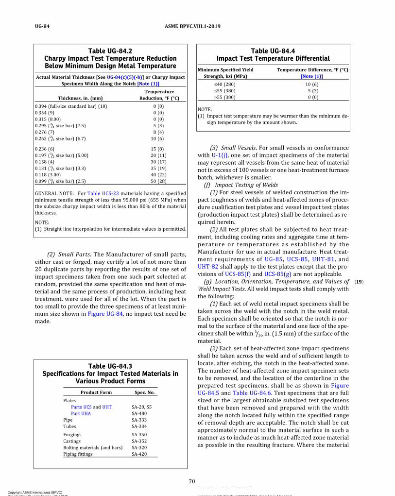
ð19Þ
(2) Small Parts. The Manufacturer of small parts,either cast or forged, may certify a lot of not more than20 duplicate parts by reporting the results of one set ofimpact specimens taken from one such part selected atrandom, provided the same specification and heat of ma-terial and the same process of production, including heattreatment, were used for all of the lot. When the part istoo small to provide the three specimens of at least mini-mum size shown in Figure UG-84, no impact test need bemade.
(3) Small Vessels. For small vessels in conformancewith U-1(j), one set of impact specimens of the materialmay represent all vessels from the same heat of materialnot in excess of 100 vessels or one heat‐treatment furnacebatch, whichever is smaller.(f) Impact Testing of Welds
(1) For steel vessels of welded construction the im-pact toughness of welds and heat-affected zones of proce-dure qualification test plates and vessel impact test plates(production impact test plates) shall be determined as re-quired herein.
(2) All test plates shall be subjected to heat treat-ment, including cooling rates and aggregate time at tem-perature or temperatures as established by theManufacturer for use in actual manufacture. Heat treat-ment requirements of UG-85, UCS-85, UHT-81, andUHT-82 shall apply to the test plates except that the pro-visions of UCS-85(f) and UCS-85(g) are not applicable.(g) Location, Orientation, Temperature, and Values of
Weld Impact Tests. All weld impact tests shall comply withthe following:
(1) Each set of weld metal impact specimens shall betaken across the weld with the notch in the weld metal.Each specimen shall be oriented so that the notch is nor-mal to the surface of the material and one face of the spe-cimen shall be within 1/16 in. (1.5 mm) of the surface of thematerial.
(2) Each set of heat-affected zone impact specimensshall be taken across the weld and of sufficient length tolocate, after etching, the notch in the heat-affected zone.The number of heat-affected zone impact specimen setsto be removed, and the location of the centerline in theprepared test specimens, shall be as shown in FigureUG-84.5 and Table UG-84.6. Test specimens that are fullsized or the largest obtainable subsized test specimensthat have been removed and prepared with the widthalong the notch located fully within the specified rangeof removal depth are acceptable. The notch shall be cutapproximately normal to the material surface in such amanner as to include as much heat-affected zone materialas possible in the resulting fracture. Where the material
Table UG-84.2Charpy Impact Test Temperature ReductionBelow Minimum Design Metal Temperature
Actual Material Thickness [See UG-84(c)(5)(-b)] or Charpy ImpactSpecimen Width Along the Notch [Note (1)]
Thickness, in. (mm)Temperature
Reduction, °F (°C)
0.394 (full‐size standard bar) (10) 0 (0)0.354 (9) 0 (0)0.315 (8.00) 0 (0)0.295 (3/4 size bar) (7.5) 5 (3)0.276 (7) 8 (4)0.262 (2/3 size bar) (6.7) 10 (6)
0.236 (6) 15 (8)0.197 (1/2 size bar) (5.00) 20 (11)0.158 (4) 30 (17)0.131 (1/3 size bar) (3.3) 35 (19)0.118 (3.00) 40 (22)0.099 (1/4 size bar) (2.5) 50 (28)
GENERAL NOTE: For Table UCS-23 materials having a specifiedminimum tensile strength of less than 95,000 psi (655 MPa) whenthe subsize charpy impact width is less than 80% of the materialthickness.
NOTE:(1) Straight line interpolation for intermediate values is permitted.
Table UG-84.3Specifications for Impact Tested Materials in
Various Product Forms
Product Form Spec. No.
PlatesParts UCS and UHT SA-20, S5Part UHA SA-480
Pipe SA-333Tubes SA-334
Forgings SA-350Castings SA-352Bolting materials (and bars) SA-320Piping fittings SA-420
Table UG-84.4Impact Test Temperature Differential
Minimum Specified YieldStrength, ksi (MPa)
Temperature Difference, °F (°C)[Note (1)]
≤40 (280) 10 (6)≤55 (380) 5 (3)>55 (380) 0 (0)
NOTE:(1) Impact test temperature may be warmer than the minimum de-
sign temperature by the amount shown.
70
ASME BPVC.VIII.1-2019UG-84
Copyright ASME International (BPVC) Provided by IHS under license with ASME Licensee=Khalda Petroleum/5986215001, User=Amer, Mohamed
Not for Resale, 07/02/2019 13:29:04 MDTNo reproduction or networking permitted without license from IHS
--`,``,``,,`,`,,````,`,``,,,`-`-`,,`,,`,`,,`---

thickness permits, the axis of the notch may be inclined toallow the root of the notch to align parallel to the fusionline.
(3) For welds made by a solid‐state welding process,such as for electric resistance-welded (ERW) pipe, theweld impact tests shall consist only of one set of threespecimens taken across the weld with the notch at theweld centerline. Each specimen shall be oriented so thatthe notch is normal to the surface of the material andone face of the specimen shall be within 1/16 in.(1.5 mm) of the surface of the material. The weld impacttests are not required if the weld and the base metal havebeen: annealed, normalized, normalized and tempered,double normalized and tempered, or quenched andtempered.
(4) The test temperature for welds and heat-affectedzones shall not be higher than required for the basematerials.
(5) Impact values shall be at least as high as those re-quired for the base materials.
(6)When qualifying a Welding Procedure Specifica-tion (WPS) for welding base metals having different im-pact testing requirements and acceptance criteria, thefollowing shall apply:
(-a) The weld metal impact test specimens shallmeet the acceptance criteria for either base metal.
(-b) When HAZ tests are required, separate impacttest specimens shall be removed from the HAZ of eachbase metal that requires impact testing, and those speci-mens shall meet the acceptance criteria applicable tothe base metal from which they were removed.
Figure UG-84.5HAZ Impact Specimen Removal
½t
Middle ½tt
Weld metal
Base metal
HAZ
Weld surface
Root surface
¼t
¼t
ð19ÞTable UG-84.6Required HAZ Impact Test Specimen Set Removal
Base Metal Thickness, t
Number of Specimen Sets and the Locationsof Their Approximate Centerline
Single-Sided Weld Two-Sided Weld
t ≤ 3/4 in. (19 mm) One set, 1/4t to1/2t One set, middle 1/2t [Note (1)]
t > 3/4 in. (19 mm) One set, 1/4t to1/2t Two sets, 1/4t to
1/2t [Note (2)]
GENERAL NOTE: Testing shall be performed on sets of three impact test specimens as required by UG-84(c)(1).Each specimen shall be full size, or the largest subsize specimen that may be removed from the available materialthickness. The specimen sets shall be removed at the indicated depth from the weld surface, as described in Notes(1) and (2).
NOTES:(1) For two-sided welds in base metal thicknesses of 3/4 in. (19 mm) or less, a single specimen set prepared with
the centerline of the width of the notch falling within the middle 1/2t shall represent the HAZ of the welds ap-plied to both surfaces.
(2) For two-sided welds in base metal thicknesses greater than 3/4 in. (19 mm), the specimen sets shall be preparedwith the centerline of the width along the notch falling between 1/4t and
1/2t from each weld surface.
71
ASME BPVC.VIII.1-2019 UG-84
Copyright ASME International (BPVC) Provided by IHS under license with ASME Licensee=Khalda Petroleum/5986215001, User=Amer, Mohamed
Not for Resale, 07/02/2019 13:29:04 MDTNo reproduction or networking permitted without license from IHS
--`,``,``,,`,`,,````,`,``,,,`-`-`,,`,,`,`,,`---

ð19Þ
(h) Impact Tests of Welding Procedure Qualifications(1) General. For steel vessels of welded construction,
the impact toughness of the welds and heat-affectedzones of the procedure qualification test plates shall bedetermined in accordance with (g) above and the follow-ing subparagraphs:
(2) When Required. Welding procedure impact testsshall be made when required by UCS-67, UHT-82, orUHA-51. For vessels constructed to the rules of PartUCS, the test plate material shall satisfy all of the follow-ing requirements relative to the material to be used inproduction:
(-a) be of the same P‐Number and Group Number;(-b) be in the same heat-treated condition, and
this heat-treated condition shall be noted on the PQRand WPS used for construction; and
(-c) meet the minimum notch toughness require-ments of (c)(4) for the thickest material of the range ofbase material qualified by the procedure (see FigureUG-84.1).
If impact tests are required for the deposited weldmetal, but the base material is exempted from impacttests (as in UHA-51), welding procedure test plates shallbe made. The test plate material shall be material of thesame P‐Number and Group Number used in the vessel.One set of impact specimens shall be taken with the notchapproximately centered in the weld metal and perpendi-cular to the surface; the heat-affected zone need not beimpact tested.
When the welding procedure employed for produc-tion welding is used for fillet welds only, it shall be qual-ified by a groove weld qualification test. The qualificationtest plate or pipe material shall meet the requirements of(-a), (-b), and (-c) above when impact testing is a require-ment. This welding procedure test qualification is in addi-tion to the requirements of Section IX, QW‐202.2 for P‐No.11 materials.
(3) Material Over 11/2 in. (38 mm) Thick. When proce-dure tests are made on material over 11/2 in. (38 mm) inthickness, the following heat-affected zone and weld me-tal impact specimens are required:
(-a) Heat-affected zone specimens shall be as de-scribed in (g)(2) above.
(-b) Two sets of impact specimens shall be re-moved from the weld with one set located near [within1/16 in. (1.5 mm)] the surface of one side of the materialand one set taken as near as practical midway betweenthe surface and the center of thickness of the oppositeside and oriented as described in (g)(1) above.
(4) Essential Variables. The supplementary essentialvariables specified in Section IX, QW‐250, for impact test-ing are required.
(5) Multiple Process Welding Procedures.When quali-fying a welding procedure with impact testing that em-ploys multiple welding processes, or multiple sets of
essential and supplementary essential variables for awelding process, the welding procedure shall be qualifiedby testing separate sets of impact test specimens removedfrom the weld metal and heat-affected zone, as follows:
(-a) The requirements of (f) shall be met.(-b) The requirements of (g) and (3) specifying
the location, number, and orientation of test specimensets to be removed for each welding process or set of vari-ables shall be modified as follows:
(-1) The weld thickness shall be considered thebase metal thickness.
(-2) The surface of the last deposited layer ofweld metal shall be considered the weld surface.
(-3) The root side of the first deposited layer ofweld metal shall be considered the root surface.
(-c) If the weld thickness for a welding process orset of variables is small enough that the maximum obtain-able Charpy specimen has a width along the notch lessthan 0.099 in. (2.5 mm), toughness testing of the weld me-tal and heat-affected zone is not required for that weldingprocess or set of variables.(i) Vessel (Production) Impact Test Plates
(1) General. In addition to the requirements of (h)above, impact tests of welds and heat-affected zones shallbe made in accordance with (g) above for each qualifiedwelding procedure used on each vessel or group of ves-sels as defined in (3) below. The vessel impact test plateshall be from one of the heats of steel used for the vesselor group of vessels. For Category A joints, the test plateshall, where practicable, be welded as an extension tothe end of a production joint so that the test plate weld-ment will represent as nearly as practicable the qualityand type of welding in the vessel joint. For Category Bjoints that are welded using a different welding procedurethan used on Category A joints, a test plate shall bewelded under the production welding conditions usedfor the vessel, using the same type of equipment and atthe same location and using the same procedures as usedfor the joint, and it shall be welded concurrently with theproduction welds or as close to the start of productionwelding as practicable.
(2) When Required. Vessel (production) impact testplates shall be made for all joints for which impact testsare required for the welding procedure by UCS-67,UHT-82, or UHA-51 (except where production test platesare specifically exempt by these paragraphs). Test shallbe made of the weld metal and/or heat-affected zone tothe extent required by the procedure test (see UCS-67and UHA-51).
(3) Number of Vessel Impact Test Plates Required(-a) For each vessel, one test plate shall be made
for each welding procedure used for Category A and Bjoints, unless the vessel is one of several as defined in(-b) or (-c) below.
72
ASME BPVC.VIII.1-2019UG-84
Copyright ASME International (BPVC) Provided by IHS under license with ASME Licensee=Khalda Petroleum/5986215001, User=Amer, Mohamed
Not for Resale, 07/02/2019 13:29:04 MDTNo reproduction or networking permitted without license from IHS
--`,``,``,,`,`,,````,`,``,,,`-`-`,,`,,`,`,,`---

ð19Þ
In addition, for Category A and B joints the follow-ing requirements shall apply:
(-1) If automatic, machine, or semiautomaticwelding is performed, a test plate shall be made in eachposition employed in the vessel welding.
(-2) If manual welding is also employed, a testplate shall be made in the flat position only, except ifwelding is to be performed in other positions a test plateneed be made in the vertical position only (where the ma-jor portions of the layers of welds are deposited in thevertical upward direction). The vertically welded testplate will qualify the manual welding in all positions.
(-b) For several vessels or parts of vessels, a mini-mum of one test plate shall be made for each welding pro-cedure used for Category A and B joints, provided that allof the following requirements are met:
(-1) Welding is completed within any 3-monthperiod at one location.
(-2) The cumulative length of all joints weldedby each welding procedure does not exceed 400 ft(120 m).
(-3) Materials are of the same specification andgrade.
(-4) The plate thicknesses of the vessels or partsof vessels do not vary by more than 1/4 in. (6 mm) or 25%,whichever is greater.
(-5) The number of heat-affected-zone impactspecimen sets to be removed and the locations of their re-moval shall be as shown in Figure UG-84.5 and TableUG-84.6 for the largest plate thickness in the range speci-fied in (-4).
(-6) The additional requirements specified in(-a) shall be met.
(-c) For small vessels not exceeding the volumelimitations defined in U-1(j) made from one heat of mate-rial requiring impact tests, one welded test joint madefrom the same heat of material and welded with the sameelectrode and the same welding procedure may representone lot of 100 vessels or less, or each heat treatment fur-nace batch, whichever is smaller.
(j) Rejection. If the vessel test plate fails to meet theimpact requirements, the welds represented by the plateshall be unacceptable. Reheat treatment and retesting orretesting only are permitted.
UG-85 HEAT TREATMENTWhen plate specification heat treatments are not per-
formed by the material manufacturer, they shall be per-formed by, or be under the control of, the Manufacturerwho shall then place the letter “T” following the letter“G” in the Mill plate marking (see SA-20) to indicate thatthe heat treatments required by the material specificationhave been performed. The Manufacturer shall also docu-ment in accordance with UG-93(b) that the specified heattreatment has been performed.
UCS-85, UHT-5(e), and UHT-81 provide requirementsfor heat treatment of test specimens.
INSPECTION AND TESTS
UG-90 GENERAL(a) The inspection and testing of pressure vessels to be
marked with the Certification Mark with the U Designatorand the testing of vessels to be marked with the Certifica-tion Mark with the UM Designator shall conform to thegeneral requirements for inspection and testing in the fol-lowing paragraphs and, in addition, to the specific re-quirements for Inspection and Tests given in theapplicable Parts of Subsections B and C.
(b) The Manufacturer has the responsibility of assuringthat the quality control, the detailed examinations, andthe tests required by this Division are performed. TheManufacturer shall perform his specified duties. SeeUG-92 and 10-15. Some, but not all, of these responsibil-ities, which are defined in the applicable rules, are sum-marized as follows:
(1) the Certificate of Authorization from the ASMEBoiler and Pressure Vessel Committee authorizing theManufacturer to fabricate the class of vessel being con-structed [UG-117(a)];
(2) the drawings and design calculations for the ves-sel or part [10-5 and 10-15(d)];
(3) identification for all material used in the fabrica-tion of the vessel or part (UG-93);
(4) securing Partial Data Reports [UG-120(c)];(5) access for the Inspector in accordance with
UG-92 and 10-15;(6) examination of all materials before fabrication to
make certain the materials meet the design thickness re-quirements, to detect defects [UG-93(d)], and to makecertain the materials are permitted by this Division(UG-4) and that traceability (UG-77) to the material iden-tification (UG-93) has been maintained;
(7) documentation of impact tests when such testsare required (UF-5, UCS-66, UHA-51, UHT-6, and ULT-5);
(8) concurrence of the Inspector prior to any basemetal repairs (UG-78 and UF-37);
(9) examination of the shell and head sections to con-firm they have been properly formed to the specifiedshapes within the permissible tolerances (UG-79, UG-80,UG-81, UF-27, and UF-29);
(10) qualification of the welding and/or brazing pro-cedures before they are used in fabrication [UG-84(h),UW-28(b), and UB-31];
(11) qualification of welders and welding operatorsand brazers before using the welders or brazers in pro-duction work (UW-29, UW-48, UB-32, and UB-43);
(12) examination of all parts prior to joining to makecertain they have been properly fitted for welding orbrazing and that the surfaces to be joined have beencleaned and the alignment tolerances are maintained(UW-31, UW-32, UW-33, and UB-17);
73
ASME BPVC.VIII.1-2019 UG-84 – UG-90
Copyright ASME International (BPVC) Provided by IHS under license with ASME Licensee=Khalda Petroleum/5986215001, User=Amer, Mohamed
Not for Resale, 07/02/2019 13:29:04 MDTNo reproduction or networking permitted without license from IHS
--`,``,``,,`,`,,````,`,``,,,`-`-`,,`,,`,`,,`---
ð19Þ
(13) examination of parts as fabrication progresses,for material marking (UG-94), that defects are not evident(UG-95), and that dimensional geometries are maintained(UG-96 and UF-30);
(14) provision of controls to assure that all requiredheat treatments are performed (UW-2, UW-10, UG-85,UF-31, and 10-11);
(15) provision of records of nondestructive testingexaminations performed on the vessel or vessel parts.This shall include retaining the radiographic film if radio-graphic examinations are performed (UW-51, UW-52,and 10-10);
(16)making the required hydrostatic or pneumatictest and having the required inspection performed duringsuch test (UG-99, UG-100, UG-101, and UW-50);
(17) applying the required stamping and/or name-plate to the vessel and making certain it is applied toproper vessel (UG-116, UG-118, and UG-119);
(18) preparing required Manufacturer’s Data Reportand having it certified by the Inspector (UG-120);
(19) providing for retention of radiographs (UW-51),ultrasonic test reports (12-4), Manufacturer’s Data Re-ports (UG-120), and other documents as required by thisDivision (10-13).(c) See below.
(1) The Inspector shall make all inspections specifi-cally required of him plus such other inspections as he be-lieves are necessary to enable him to certify that allvessels which he authorizes to be stamped with the Cer-tification Mark have been designed and constructed in ac-cordance with the requirements of this Division. Some,but not all, of the required inspections and verifications,which are defined in the applicable rules, are summarizedas follows:
(-a) verifying that the Manufacturer has a validCertificate of Authorization [UG-117(a)] and is workingto a Quality Control System [UG-117(e)];
(-b) verifying that the applicable design calcula-tions are available [U-2(b), U-2(c), 10-5, and 10-15(d)];
(-c) verifying that materials used in the construc-tion of the vessel comply with the requirements of UG-4through UG-14 (UG-93);
(-d) verifying that all welding and brazing proce-dures have been qualified (UW-28, UW-47, and UB-42);
(-e) verifying that all welders, welding operators,brazers, and brazing operators have been qualified(UW-29, UW-48, and UB-43);
(-f) verifying that the heat treatments, includingPWHT, have been performed (UG-85, UW-10, UW-40,UW-49, and UF-52);
(-g) verifying that material imperfections repairedby weld ing were acceptab ly repaired [ UG-78 ,UW-52(d)(2)(-c), UF-37, and UF-47(c)];
(-h) verifying that weld defects were acceptablyrepaired [UW-51(a) and UW-52(c)];
(-i) verifying that required nondestructive exami-nations, impact tests, and other tests have been per-formed and that the results are acceptable (UG-84,UG-93, UW-50, UW-51, UW-52, and UB-44);
(-j)making a visual inspection of vessel to confirmthat the material identification numbers have been prop-erly transferred (UG-77 and UG-94);
(-k) making a visual inspection of the vessel toconfirm that there are no material or dimensional defects(UG-95, UG-96, and UG-97);
(-l) performing internal and external inspectionsand witnessing the hydrostatic or pneumatic tests(UG-96, UG-97, UG-99, UG-100, and UG-101);
(-m)verifying that the required marking is pro-vided (UG-115) and that any nameplate has been attachedto the proper vessel;
(-n) signing the Certificate of Inspection on theManufacturer’s Data Report when the vessel, to the bestof his knowledge and belief, is in compliance with allthe provisions of this Division. When the Inspector hascertified by signing the Manufacturer’s Data Report, thisindicates acceptance by the Inspector. This acceptancedoes not imply assumption by the Inspector of any ofthe responsibilities of the Manufacturer.
(2)When mass production of pressure vessels makesit impracticable for the Inspector to personally performeach of his required duties,4 the Manufacturer, in colla-boration with the Inspector, shall prepare an inspectionand quality control procedure setting forth, in completedetail, the method by which the requirements4 of this Di-vision will be maintained. This procedure shall be devel-oped, accepted, and implemented in accordance withMandatory Appendix 35.
UG-91 THE INSPECTOR(a) All references to Inspectors throughout this Division
mean the Authorized Inspector as defined in this para-graph. All inspections required by this Division of SectionVIII shall be:
(1) by an Inspector regularly employed by an ASMEaccredited Authorized Inspection Agency, as defined inASME QAI-1, except that
(2) inspections may be by the regularly employeduser’s Inspector in the case of a User‐Manufacturer thatmanufactures pressure vessels exclusively for its ownuse and not for resale [see UG-116(a)(1)].
Except as permitted in (2) above, the Inspector shallnot be in the employ of the Manufacturer. All Inspectorsshall have been qualified in accordance with ASME QAI-1.(b) In addition to the duties specified, the Inspector has
the duty to monitor the Manufacturer’s Quality ControlSystem as required in Mandatory Appendix 10.
UG-92 ACCESS FOR INSPECTORThe Manufacturer of the vessel shall arrange for the In-
spector to have free access to such parts of all plants asare concerned with the supply or manufacture of
74
ASME BPVC.VIII.1-2019UG-90 – UG-92
Copyright ASME International (BPVC) Provided by IHS under license with ASME Licensee=Khalda Petroleum/5986215001, User=Amer, Mohamed
Not for Resale, 07/02/2019 13:29:04 MDTNo reproduction or networking permitted without license from IHS
--`,``,``,,`,`,,````,`,``,,,`-`-`,,`,,`,`,,`---
materials for the vessel, when so requested. The Inspectorshall be permitted free access, at all times while work onthe vessel is being performed, to all parts of the Manufac-turer’s shop that concern the construction of the vesseland to the site of field erected vessels during the periodof assembly and testing of the vessel. The Manufacturershall keep the Inspector informed of the progress of thework and shall notify him reasonably in advance whenvessels will be ready for any required tests or inspections.
UG-93 INSPECTION OF MATERIALS(a) Except as otherwise provided in UG-4(b), UG-10,
UG-11, or UG-15, requirements for acceptance of materi-als furnished by the material manufacturer or materialsupplier in complete compliance with a material specifi-cation of Section II shall be as follows.
(1) For plates,7 the vessel Manufacturer shall ensureall requirements of the material specification, and all spe-cial requirements of this Division, that are to be fulfilledby the materials manufacturer have been complied with.The Manufacturer shall accomplish this by obtaining cer-tificates of compliance or Material Test Reports. The In-spector shall determine if these documents representthe material and meet the requirements of the materialspecification.
(-a) These documents shall include results of allrequired tests and examinations, evidence of compliancewith the material specifications, and additional require-ments, as applicable. When the specification permits cer-tain specific requirements to be completed later, thoseincomplete items shall be noted on the material documen-tation. When these specific requirements have been com-pleted by someone other than the material manufacturer,this completion shall be documented and attached to thematerial documentation.
(-b) The vessel Manufacturer shall receive a copyof the test report or reports as prepared by the materialmanufacturer, or by the material manufacturer and anysubsequent processors responsible for the data, and shallmaintain the reports as part of the construction records.
(2) For all other product forms(-a) the material shall be accepted by the Manufac-
turer as complying with the material specification if thematerial specification provides for the marking of eachpiece with the specification designation, including thegrade, type, and class, if applicable, and each piece is somarked, or
(-b) if a Material Test Report is supplied by a ma-terials manufacturer, the materials manufacturer maytranscribe data produced by other organizations, pro-vided he accepts responsibility for the accuracy andauthenticity of the data
(3) If the material specification does not provide forthe marking of each piece as indicated in (2) above, thematerial shall be accepted as complying with the materialspecification, provided the following requirements aremet:
(-a) Each bundle, lift, or shipping container ismarked with the specification designation, including thegrade, type, and class if applicable by the material manu-facturer or supplier.
(-b) The handling and storage of the material bythe vessel Manufacturer shall be documented in his Qual-ity Control System such that the Inspector can determinethat it is the material identified in (-a) above. Traceabilityto specific lot, order, or heat is not required. Traceabilityis required only to material specification and grade andtype and class, if applicable.
(4) For pipe or tube where the length is not adequatefor the complete marking in accordance with the materialspecification or not provided in accordance with (3)above, the material shall be acceptable as complying withthe material specification, provided the following are met:
(-a) a coded marking is applied to each piece ofpipe or tube by the material manufacturer or materialsupplier; and
(-b) the coded marking applied by the materialmanufacturer or material supplier is traceable to thespecification designation, including the grade, type, andclass if applicable.
(b) Except as otherwise provided in UG-4(b), UG-10,UG-11, or UG-15, when some requirements of a materialspecification of Section II have been completed by otherthan the material manufacturer [see UG-84(d) andUG-85], then the vessel Manufacturer shall obtain supple-mentary material test reports or certificates of compli-ance and the Inspector shall examine these documentsand shall determine that they represent the materialand meet the requirements of the material specification.
(c) When requirements or provisions of this Divisionapplicable to materials exceed or supplement the require-ments of the material specification of Section II (seeUG-24, UG-84, and UG-85), then the vessel Manufacturershall obtain supplementary material test reports or certi-ficates of compliance and the Inspector shall examinethese documents and shall determine that they representthe material and meet the requirements or provisions ofthis Division.
(d) All materials to be used in constructing a pressurevessel shall be examined before fabrication for the pur-pose of detecting, as far as possible, imperfections whichwould affect the safety of the vessel.
(1) Particular attention should be given to cut edgesand other parts of rolled plate which would disclose theexistence of serious laminations, shearing cracks, andother imperfections.
(2) All materials that are to be tested in accordancewith the requirements of UG-84 shall be inspected forsurface cracks.
75
ASME BPVC.VIII.1-2019 UG-92 – UG-93
Copyright ASME International (BPVC) Provided by IHS under license with ASME Licensee=Khalda Petroleum/5986215001, User=Amer, Mohamed
Not for Resale, 07/02/2019 13:29:04 MDTNo reproduction or networking permitted without license from IHS
--`,``,``,,`,`,,````,`,``,,,`-`-`,,`,,`,`,,`---

(3)When a pressure part is to be welded to a flatplate thicker than 1/2 in. (13 mm) to form a corner jointunder the provision of UW-13(e), the weld joint prepara-tion in the flat plate shall be examined before welding asspecified in (4) below by either the magnetic particle orliquid penetrant methods. After welding, both the periph-eral edge of the flat plate and any remaining exposed sur-face of the weld joint preparation shall be reexamined bythe magnetic particle or liquid penetrant methods as spe-cified in (4) below. When the plate is nonferromagnetic,only the liquid penetrant method shall be used.
(4) For Figure UW-13.2 the weld joint preparationand the peripheral edges of flat plate forming a cornerjoint shall be examined as follows:
(-a) the weld edge preparation of typical weldjoint preparations in the flat plate as shown in sketches(b), (c), (d), (e-2), (f), and (n);
(-b) the outside peripheral edge of the flat plateafter welding as shown in sketches (a), (b), (c), and (d);
(-c) the outside peripheral edge of the flat plateafter welding, as shown in sketches (e-1), (e-2), (f), and(g) if the distance from the edge of the completed weldto the peripheral edge of the flat plate is less than thethickness of the flat plate such as defined in UG-34(b);
(-d) the inside peripheral surface of the flat plateafter welding as shown in sketches (m) and (n);
(-e) no examination is required on the flat plate asshown in sketches (h), (i), (j), (k), and (l).(e) The Inspector shall assure himself that the thick-
ness and other dimensions of material comply with therequirements of this Division.(f) The Inspector shall satisfy himself that the inspec-
tion and marking requirements of UG-24 have been com-plied with for those castings assigned a casting qualityfactor exceeding 80%.
UG-94 MARKING ON MATERIALSThe Inspector shall inspect materials used in the con-
struction to see that they bear the identification requiredby the applicable material specification, except as other-wise provided in UG-4(b), UG-10, UG-11, UG-15, orUG-93. Should the identifying marks be obliterated orthe material be divided into two or more parts, the marksshall be properly transferred by the Manufacturer as pro-vided in UG-77(a). See UG-85.
UG-95 EXAMINATION OF SURFACES DURINGFABRICATION
As fabrication progresses, all materials used in the con-struction shall be examined for imperfections that havebeen uncovered during fabrication as well as to deter-mine that the work has been done properly.
UG-96 DIMENSIONAL CHECK OF COMPONENTPARTS
(a) The Manufacturer shall examine the pressure-retaining parts to make certain they conform to the pre-scribed shape and meet the design thickness after form-ing. The Manufacturer of the vessel shall furnishaccurately formed templates as required by the Inspectorfor verification. See UG-80.(b) Before attaching nozzles, manhole frames, nozzle
reinforcement and other appurtenances to the inside oroutside of the vessel they shall be examined to make cer-tain they properly fit the vessel curvature. See UG-82.(c) The Inspector shall satisfy himself that the above di-
mensional requirements have been met. This shall in-clude making such dimensional measurements as heconsiders necessary.
UG-97 INSPECTION DURING FABRICATION(a)When conditions permit entry into the vessel, as
complete an examination as possible shall be made beforefinal closure.(b) The Inspector shall make an external inspection of
the completed vessel at the time of the final hydrostatictest or pneumatic test.(c) All welds, including the nozzle welds, of homoge-
neously lead‐lined vessels shall be visually inspected onthe inside prior to application of lining. A visual examina-tion of the lining shall be made after completion to ensurethat there are no imperfections which might impair theintegrity of the lining and subject the vessel to corrosioneffects.
UG-98 MAXIMUM ALLOWABLE WORKINGPRESSURE
(a) The maximum allowable working pressure for avessel is the maximum pressure permissible at the topof the vessel in its normal operating position at the desig-nated coincident temperature specified for that pressure.It is the least of the values found for maximum allowableworking pressure for any of the essential parts of the ves-sel by the principles given in (b) below, and adjusted forany difference in static head that may exist between thepart considered and the top of the vessel. (See 3-2.)(b) The maximum allowable working pressure for a
vessel part is the maximum internal or external pressure,including the static head thereon, as determined by therules and equations in this Division, together with the ef-fect of any combination of loadings listed in UG-22 that islikely to occur, for the designated coincident temperature,excluding any metal thickness specified as corrosion al-lowance. See UG-25.(c) Maximum allowable working pressure may be de-
termined for more than one designated operating tem-perature, using for each temperature the applicableallowable stress value.
76
ASME BPVC.VIII.1-2019UG-93 – UG-98
Copyright ASME International (BPVC) Provided by IHS under license with ASME Licensee=Khalda Petroleum/5986215001, User=Amer, Mohamed
Not for Resale, 07/02/2019 13:29:04 MDTNo reproduction or networking permitted without license from IHS
--`,``,``,,`,`,,````,`,``,,,`-`-`,,`,,`,`,,`---
UG-99 STANDARD HYDROSTATIC TEST(a) A hydrostatic test shall be conducted on all vessels
after(1) all fabrication has been completed, except for op-
erations that could not be performed prior to the test,such as weld end preparation [see U-1(e)(1)(-a)], and cos-metic grinding on the base material that does not reducethe actual thickness below the design thickness; and
(2) all examinations have been performed, exceptthose required after the test.
The completed vessels, except those tested in accor-dance with the requirements of UG-100 and UG-101, shallhave satisfactorily passed the hydrostatic test prescribedin this paragraph.
(b) Except as otherwise permitted in (a) above and27-4, vessels designed for internal pressure shall be sub-jected to a hydrostatic test pressure that at every point inthe vessel is at least equal to 1.3 times the maximum al-lowable working pressure35 multiplied by the loweststress ratio (LSR) for the pressure-boundary materialsof which the vessel is constructed. The stress ratio foreach pressure-boundary material is the ratio of the stressvalue S at its test temperature to the stress value S at itsdesign temperature (see UG-21). Bolting shall not be in-cluded in the determination of the LSR, except when 1.3times the LSR multiplied by the allowable stress of thebolt at its design temperature exceeds 90% of the boltmaterial specified minimum yield strength at the testtemperature. All loadings that may exist during this testshall be given consideration. The hydrostatic test pres-sure reading shall be adjusted to account for any statichead conditions depending on the difference in elevationbetween the chamber being tested and the pressuregauge.
(c) A hydrostatic test based on a calculated pressuremay be used by agreement between the user and theManufacturer. The hydrostatic test pressure at the topof the vessel shall be the minimum of the test pressurescalculated by multiplying the basis for calculated testpressure as defined in 3-2 for each pressure element by1.3 and reducing this value by the hydrostatic head onthat element. When this pressure is used, the Inspectorshall reserve the right to require the Manufacturer orthe designer to furnish the calculations used for deter-mining the hydrostatic test pressure for any part of thevessel.
(d) The requirements of (b) above represent the mini-mum standard hydrostatic test pressure required by thisDivision. The requirements of (c) above represent a spe-cial test based on calculations. Any intermediate value ofpressure may be used. This Division does not specify anupper limit for hydrostatic test pressure. However, ifthe hydrostatic test pressure is allowed to exceed, eitherintentionally or accidentally, the value determined as
prescribed in (c) above to the degree that the vessel issubjected to visible permanent distortion, the Inspectorshall reserve the right to reject the vessel.
(e) Combination units [see UG-19(a) and UG-21] shallbe tested by one of the following methods.
(1) Independent Pressure Chambers. Pressure cham-bers of combination units that have been designed to op-erate independently shall be hydrostatically tested asseparate vessels, that is, each chamber shall be testedwithout pressure in the adjacent chamber. If the commonelements of a combination unit are designed for a largerdifferential pressure than the higher maximum allowableworking pressure to be marked on the adjacent cham-bers, the hydrostatic test shall subject the common ele-ments to at least their design differential pressure,corrected for temperature as in (b) above, as well as meetthe requirements of (b) or (c) above for each independentchamber.
(2) Dependent Pressure Chambers. When pressurechambers of combination units have their common ele-ments designed for the maximum differential pressurethat can possibly occur during startup, operation, andshutdown, and the differential pressure is less than thehigher pressure in the adjacent chambers, the commonelements shall be subjected to a hydrostatic test pressureof at least 1.3 times the differential pressure to be markedon the unit, corrected for temperature as in (b).
Following the test of the common elements and theirinspection as required by (g) below, the adjacent cham-bers shall be hydrostatically tested simultaneously [see(b) or (c) above]. Care must be taken to limit the differen-tial pressure between the chambers to the pressure usedwhen testing the common elements.
The vessel stamping and the vessel Data Report mustdescribe the common elements and their limiting differ-ential pressure. See UG-116(j) and UG-120(b).
(f) Single‐wall vessels and individual pressure cham-bers of combination units designed for vacuum only(MAWP less than or equal to zero) shall be subjected toeither
(1) an internal hydrostatic pressure test in accor-dance with UG-99, or a pneumatic pressure test in accor-dance with UG-100. The applied test pressure shall be notless than 1.3 times the specified external design pressure;or
(2) a vacuum test conducted at the lowest value ofspecified absolute internal design pressure. In conjunc-tion with the vacuum test, a leak test shall be performedfollowing a written procedure complying with the applic-able technical requirements of Section V, Article 10 forthe leak test method and technique specified by the user.Leak testing personnel shall be qualified and certified asrequired by Section V, Article 1, T-120(e).
(g) Following the application of the hydrostatic testpressure, an inspection shall be made of all joints and con-nections. This inspection shall be made at a pressure notless than the test pressure divided by 1.3. Except for
77
ASME BPVC.VIII.1-2019 UG-99
Copyright ASME International (BPVC) Provided by IHS under license with ASME Licensee=Khalda Petroleum/5986215001, User=Amer, Mohamed
Not for Resale, 07/02/2019 13:29:04 MDTNo reproduction or networking permitted without license from IHS
--`,``,``,,`,`,,````,`,``,,,`-`-`,,`,,`,`,,`---
ð19Þ
ð19Þ
leakage that might occur at temporary test closures forthose openings intended for welded connections, leakageis not allowed at the time of the required visual inspec-tion. Leakage from temporary seals shall be directed awayso as to avoid masking leaks from other joints.The visual inspection of joints and connections for
leaks at the test pressure divided by 1.3 may be waived,provided:
(1) a suitable gas leak test is applied;(2) substitution of the gas leak test is by agreement
reached between Manufacturer and Inspector;(3) all welded seams that will be hidden by assembly
are given a visual examination for workmanship prior toassembly;
(4) the vessel will not contain a “lethal” substance.(h) Any nonhazardous liquid at any temperature may
be used for the hydrostatic test if below its boiling point.Combustible liquids having a flash point less than 110°F(43°C), such as petroleum distillates, may be used onlyfor near atmospheric temperature tests. It is recommend-ed that the metal temperature during hydrostatic test bemaintained at least 30°F (17°C) above the minimum de-sign metal temperature, but need not exceed 120°F(48°C), to minimize the risk of brittle fracture. [SeeUG-20 and Figure UCS-66.2, Note (6).] The test pressureshall not be applied until the vessel and its contents areat about the same temperature. If the test temperature ex-ceeds 120°F (48°C), it is recommended that inspection ofthe vessel required by (g) above be delayed until the tem-perature is reduced to 120°F (48°C) or less.
CAUTION: A small liquid relief valve set to 11/3 times the testpressure is recommended for the pressure test system, in casea vessel, while under test, is likely to be warmed up materiallywith personnel absent.
(i) Vents shall be provided at all high points of the ves-sel in the position in which it is to be tested to purge pos-sible air pockets while the vessel is filling.(j) Before applying pressure, the test equipment shall
be examined to see that it is tight and that all low‐pressure filling lines and other appurtenances that shouldnot be subjected to the test pressure have beendisconnected.(k) Painting and Coating
(1) Unless permitted by the user or his designatedagent, pressure-retaining welds of vessels shall not bepainted or otherwise coated either internally or exter-nally prior to the pressure test. [See UCI-99(b) andUCD-99(b).]
(2)When painting or coating prior to the hydrostatictest is permitted, or when internal nonmetallic linings areto be applied, the pressure-retaining welds shall first beleak tested in accordance with Section V, Article 10. Sucha test may be waived with the approval of the user or hisdesignated agent.
(3) Vessels for lethal service [see UW-2(a)]
(-a) shall not be painted or coated either intern-ally or externally prior to the hydrostatic pressure test
(-b) shall not be internally lined by mechanical orwelded attachments prior to the hydrostatic pressure testunless the requirements of UCL-51 are followed
(4) The requirements given in (1) and (2) do not ap-ply to glass-lined vessels; see 27-4.
UG-100 PNEUMATIC TEST36 (SEE UW-50)(a) Subject to the provisions of UG-99(a)(1) and
UG-99(a)(2), a pneumatic test prescribed in this para-graph may be used in lieu of the standard hydrostatic testprescribed in UG-99 for vessels:
(1) that are so designed and/or supported that theycannot safely be filled with water;
(2) not readily dried, that are to be used in serviceswhere traces of the testing liquid cannot be toleratedand the parts of which have, where possible, been pre-viously tested by hydrostatic pressure to the pressure re-quired in UG-99.(b) Except for enameled vessels, for which the pneu-
matic test shall be at least equal to, but need not exceed,the maximum allowable working pressure to be markedon the vessel, the pneumatic test pressure at every pointin the vessel shall be at least equal to 1.1 times the max-imum allowable working pressure35 multiplied by thelowest stress ratio (LSR) for the pressure-boundary mate-rials of which the vessel is constructed. The stress ratiofor each pressure-boundary material is the ratio of thestress value S at its test temperature to the stress valueS at its design temperature (see UG-21). Bolting shallnot be included in the determination of the LSR, exceptwhen 1.1 times the LSR multiplied by the allowable stressof the bolt at its design temperature exceeds 90% of thebolt material specified minimum yield strength at the testtemperature. All loadings that may exist during this testshall be given consideration. In no case shall the pneu-matic test pressure exceed 1.1 times the basis for the cal-culated test pressure as defined in 3-2.(c) The metal temperature during pneumatic test shall
be maintained at least 30°F (17°C) above the minimumdesign metal temperature to minimize the risk of brittlefracture. [See UG-20 and Figure UCS-66.2, Note (6).](d) The pressure in the vessel shall be gradually in-
creased to not more than one‐half of the test pressure.Thereafter, the test pressure shall be increased in stepsof approximately one‐tenth of the test pressure until therequired test pressure has been reached. Then the pres-sure shall be reduced to a value equal to the test pressuredivided by 1.1 and held for a sufficient time to permit in-spection of the vessel. Any leaks that are present, exceptfor leakage that might occur at temporary test closuresfor those openings intended for welded connections, shallbe corrected, and the vessel shall be retested.The visual inspection of the vessel at the required test
pressure divided by 1.1 may be waived, provided:(1) a suitable gas leak test is applied;
78
ASME BPVC.VIII.1-2019UG-99 – UG-100
Copyright ASME International (BPVC) Provided by IHS under license with ASME Licensee=Khalda Petroleum/5986215001, User=Amer, Mohamed
Not for Resale, 07/02/2019 13:29:04 MDTNo reproduction or networking permitted without license from IHS
--`,``,``,,`,`,,````,`,``,,,`-`-`,,`,,`,`,,`---

(2) substitution of the gas leak test is by agreementreached between Manufacturer and Inspector;
(3) all welded seams that will be hidden by assemblyare given a visual examination for workmanship prior toassembly;
(4) the vessel will not contain a “lethal” substance.(e) Painting and Coating(1) Unless permitted by the user or his designated
agent, pressure-retaining welds of vessels shall not bepainted or otherwise coated either internally or exter-nally prior to the pneumatic pressure test.
(2)When painting or coating prior to the pneumatictest is permitted, or when internal nonmetallic linings areto be applied, the pressure-retaining welds shall first beleak tested in accordance with Section V, Article 10. Sucha test may be waived with the approval of the user or hisdesignated agent.
(3) Vessels for lethal service [see UW-2(a)](-a) shall not be painted or coated either intern-
ally or externally prior to the pneumatic pressure test(-b) shall not be internally lined by mechanical or
welded attachments prior to the pneumatic pressure testunless the requirements of UCL-51 are followed
UG-101 PROOF TESTS TO ESTABLISH MAXIMUMALLOWABLE WORKING PRESSURE
(a) General(1) The maximum allowable working pressure for
vessels or vessel parts for which the strength cannot becomputed with a satisfactory assurance of accuracy (seeU-2) shall be established in accordance with the require-ments of this paragraph, using one of the test proceduresapplicable to the type of loading and to the material usedin construction. Production vessels or vessel parts thatutilize the results of a proof test shall comply with all ap-plicable construction rules of the current edition and ap-plicable addenda of this Division.
(-a) Consideration of the use of proof‐tested con-struction specifications based on past editions of this Di-vision and documented in the original Proof Test Reportrequires that the Manufacturer determine whether ornot there have been subsequent revisions to this Divisionthat apply and must be evaluated. This evaluation mayvoid the Division acceptability of establishing the vesselMAWP by proof testing (e.g., UCS-66, Part UHX, Manda-tory Appendix 13, etc.). However, if applicable revisionsare found, and it is judged that a new proof test is not re-quired, the Manufacturer, using Duplicate and SimilarParts rules in (d) as guidelines, shall prepare a Supple-ment to the original Proof Test Report documenting anychanges to the construction requirements and to the Man-ufacturer’s Data Report. The following should be noted:
(-1) The production vessel material need not beidentical with that used for the original proof tested ves-sel, but material equivalence must be confirmed anddocumented.
(-2) The MDMT established by current Divisionrules may be different from that originally assigned butmust be suitable for the nameplate MDMT marking coin-cident with the established MAWP.
(-3) The Supplement to the original Proof TestReport shall be made available to the Inspector prior tothe start of construction.
(2) Provision is made in these rules for two types oftests to determine the internal maximum allowable work-ing pressure:
(-a) tests based on yielding of the part to be tested.These tests are limited to materials with a ratio of mini-mum specified yield to minimum specified ultimatestrength of 0.625 or less.
(-b) tests based on bursting of the part.(3) Safety of testing personnel should be given ser-
ious consideration when conducting proof tests, and par-ticular care should be taken during bursting tests in (m)below.
(4) The Code recognizes that Manufacturers maymaintain control of proof test reports under differentownerships than existed during the original applicationof the proof test. When a Manufacturer is acquired by anew owner(s), the proof test reports may be used bythe new owner(s) without retesting, provided all of thefollowing are met:
(-a) the new owner(s) takes responsibility for theproof tests;
(-b) the Proof Test Reports reflect the name of thenew owner(s);
(-c) the Proof Test Reports indicate the actual testwas performed by the former Manufacturer;
(-d) the Proof Test Report(s) is acceptable to theInspector of the new owner(s) as indicated by his/her sig-nature on the Manufacturer’s report of the test.
(b) The tests in these paragraphs may be used only forthe purpose of establishing the maximum allowableworking pressure of those elements or component partsfor which the thickness cannot be determined by meansof the design rules given in this Division. The maximumallowable working pressure of all other elements or com-ponent parts shall not be greater than that determined bymeans of the applicable design rules.
Tests to establish the maximum allowable workingpressure of vessels, or vessel parts, shall be witnessedby and be acceptable to the Inspector, as indicated byhis signature on the Manufacturer’s Proof Test Report.The report shall include sufficient detail to describe thetest, the instrumentation and the methods of calibrationused, and the results obtained. The report shall be madeavailable to the Inspector for each application [seeU-2(b) and UG-90(b)(2)].
(c) The vessel or vessel part for which the maximum al-lowable working pressure is to be established shall notpreviously have been subjected to a pressure greater than
79
ASME BPVC.VIII.1-2019 UG-100 – UG-101
Copyright ASME International (BPVC) Provided by IHS under license with ASME Licensee=Khalda Petroleum/5986215001, User=Amer, Mohamed
Not for Resale, 07/02/2019 13:29:04 MDTNo reproduction or networking permitted without license from IHS
--`,``,``,,`,`,,````,`,``,,,`-`-`,,`,,`,`,,`---

1.3 times the desired or anticipated maximum allowableworking pressure, adjusted for operating temperatureas provided in (k) below.(d) Duplicate and Similar Parts. When the maximum al-
lowable working pressure of a vessel or vessel part hasbeen established by a proof test, duplicate parts, or geo-metrically similar parts, that meet all of the requirementsin (1) or (2) below, need not be proof tested but shall begiven a hydrostatic pressure test in accordance withUG-99, or a pneumatic pressure test in accordance withUG-100, except as otherwise provided in UCI-101, andUCD-101.
(1) Duplicate Parts. All of the following requirementsshall be met in order to qualify a part as a duplicate of thepart that had been proof tested:
(-a) same basic design configuration and type ofconstruction;
(-b) the material of the duplicate part is either:(-1) the same material specifications:(+a) alloy;(+b) grade, class;(+c) type, form;(+d) heat treatment; or
(-2) the same or closely similar material whenonly the material specification, the alloy, grade, or formis different, provided the material meets the following ad-ditional requirements:
(+a) has allowable stress in tension equal toor greater than the material used in the proof tested partat the test temperature [see (k) below];
(+b) has the same P‐Number (Section IX);(+c) for carbon or low alloy steels (Part UCS),
has the same or tougher material grouping in UCS-66,Figure UCS-66, and Notes;
(-c) the nominal dimensions, diameter, or widthand height, of the duplicate parts shall be the same, andthe corresponding nominal thicknesses shall be the sameas those used in the proof test. The length shall not belonger than that proof tested.
(-d) heat treatment shall be the same as per-formed on the original part that was tested;
(-e) the MAWP shall be calculated according to (e)below;
(-f)when there are permissible deviations fromthe original part that was proof tested, a supplement tothe original Proof Test Report shall be prepared thatstates and evaluates each deviation.
(2) Geometrically Similar Parts. The maximum allow-able working pressure for geometrically similar partsmay be established by a series of proof tests that uni-formly cover the complete range of sizes, pressure, orother variables by interpolation from smooth curvesplotted from the results of the tests.37
(-a) Sufficient tests shall be performed to provideat least five data points that are at increments that arewithin 20% to 30% of the range covered.
(-b) The curves shall be based on the lower boundof the test data.
(-c) Extrapolation is not permitted.(e) Proof test methods (l), (m), (n), and (o) below es-
tablish a pressure at which the test is terminated. The re-sults of the test are recorded in a Proof Test Reportaccording to (b).
(1) The MAWP for the first duplicate part, as definedin (d), to be put into service, shall be calculated accordingto the equations given in the proof test method applied.
The requirements for NDE are given in UG-24 andUW-12. Other requirements are based on thickness ormaterial. These apply to parts which are to be put intoservice. It is not necessary to examine the part actuallytested.
(2) For subsequent duplicate parts, the MAWP maybe recalculated for a different extent of NDE in a supple-ment to the original Proof Test Report.
(3) The effect of the location of a weld joint may beevaluated and included in the Proof Test Report.(f) A retest shall be allowed on a duplicate vessel or
vessel part if errors or irregularities are obvious in thetest results.(g) In tests for determination of governing stresses, suf-
ficient locations on the vessel shall be investigated to en-sure that measurements are taken at the most criticalareas. As a check that the measurements are being takenon the most critical areas, the Inspector may require abrittle coating to be applied on all areas of probable highstress concentrations in the test procedures given in (n)and (o) below. The surfaces shall be suitably cleaned be-fore the coating is applied in order to obtain satisfactoryadhesion. The technique shall be suited to the coatingmaterial.
NOTE: Strains should be measured as they apply to membranestresses and to bending stresses within the range covered byUG-23(c).
(h) Application of Pressure. In the procedures given in(l), (n), and (o) below, the Displacement MeasurementTest, the hydrostatic pressure in the vessel or vessel partshall be increased gradually until approximately one‐halfthe anticipated working pressure is reached. Thereafter,the test pressure shall be increased in steps of approxi-mately one‐tenth or less of the anticipated maximum al-lowable working pressure until the pressure requiredby the test procedure is reached. The pressure shall beheld stationary at the end of each increment for a suffi-cient time to allow the observations required by the testprocedure to be made, and shall be released to zero topermit determination of any permanent strain after anypressure increment that indicates an increase in strainor displacement over the previous equal pressureincrement.(i) Corrosion Allowance. The test procedures in this
paragraph give the maximum allowable working pressurefor the thickness of material tested. The thickness of thepressure vessel that is to be proof tested should be the
80
ASME BPVC.VIII.1-2019UG-101
Copyright ASME International (BPVC) Provided by IHS under license with ASME Licensee=Khalda Petroleum/5986215001, User=Amer, Mohamed
Not for Resale, 07/02/2019 13:29:04 MDTNo reproduction or networking permitted without license from IHS
--`,``,``,,`,`,,````,`,``,,,`-`-`,,`,,`,`,,`---
corroded thickness. When this is not practical and whenthe thickness as tested includes extra thickness as pro-vided in UG-25, the maximum allowable working pres-sure at which the vessel shall be permitted to operateshall be determined by multiplying the maximum allow-able working pressure obtained from the test by the ratio
where
c = allowance added for corrosion, erosion, andabrasion
n = 1 for curved surfaces such as parts of cylinders,spheres, cones with angle α ≤ 60 deg; for stayedsurfaces similar to those described in UW-19(b)and UW-19(c); and parts whose stress due to bend-ing is ≤ 67% of the total stress
= 2 for flat or nearly flat surfaces, such as flat sides,flanges, or cones with angle α > 60 deg (exceptfor stayed surfaces noted above) unless it can beshown that the stress due to bending at the limitinglocation is <67% of the total stress
t = nominal thickness of the material at the weakestpoint
(j) Determination of Yield Strength and TensileStrength
(1) For proof tests based on yielding, (l), (n), or (o)below, the yield strength (or yield point for those materi-als which exhibit that type of yield behavior indicated by a“sharp‐kneed” portion of the stress–strain diagram) of thematerial in the part tested shall be determined in accor-dance with the method prescribed in the applicable mate-rial specification. For proof tests based on bursting [see(m) below], the tensile strength instead of the yieldstrength of the material in the part tested shall be simi-larly determined.
(2) Yield or tensile strength so determined shall bethe average from three or four specimens cut from thepart tested after the test is completed. The specimensshall be cut from a location where the stress during thetest has not exceeded the yield strength. The specimensshall not be flame cut because this might affect thestrength of the material. If yield or tensile strength isnot determined by test specimens from the pressure parttested, alternative methods are given in (l), (m), (n), and(o) below for evaluation of proof test results to establishthe maximum allowable working pressure.
(3)When excess stock from the same piece ofwrought material is available and has been given thesame stress relieving heat treatment as the pressure part,the test specimens may be cut from this excess stock. Thespecimen shall not be removed by flame cutting or anyother method involving sufficient heat to affect the prop-erties of the specimen. When the sheet material is used,
test specimens obtained from another piece cut fromthe same coil of sheet used in the proof tested componentmeet the requirements of this paragraph.
(k) Maximum Allowable Working Pressure at HigherTemperatures. The maximum allowable working pressurefor vessels and vessel parts that are to operate at tem-peratures at which the allowable stress value of the mate-rial is less than at the test temperature shall bedetermined by the following formula:
where
P0 = maximum allowable working pressure at the de-sign temperature
Pt = maximum allowable working pressure at testtemperature
S = maximum allowable stress value at the design tem-perature, as given in the tables referenced in UG-23but not to exceed S2
S2 = maximum allowable stress value for the materialused in the test at test temperature as given inthe tables referenced in UG-23
(l) Brittle‐Coating Test Procedure(1) Subject to the limitations of (a)(2)(-a) above, this
procedure may be used only for vessels and vessel partsunder internal pressure, constructed of materials havinga definitely determinable yield point (see SA-370, 13.1).The component parts that require proof testing shall becoated with a brittle coating in accordance with (g) above.Pressure shall be applied in accordance with (h) above.The parts being proof tested shall be examined betweenpressure increments for signs of yielding as evidencedby flaking of the brittle coating, or by the appearance ofstrain lines. The application of pressure shall be stoppedat the first sign of yielding, or if desired, at some lowerpressure.
(2) The maximum allowable working pressure P inpounds per square inch (MPa) at test temperature forparts tested under this paragraph shall be computed byone of the following equations.
(-a) If the average yield strength is determined inaccordance with (j) above,
(-b) To eliminate the necessity of cutting tensilespecimens and determining the actual yield strength ofthe material under test, one of the following equationsmay be used to determine the maximum allowable work-ing pressure:
81
ASME BPVC.VIII.1-2019 UG-101
Copyright ASME International (BPVC) Provided by IHS under license with ASME Licensee=Khalda Petroleum/5986215001, User=Amer, Mohamed
Not for Resale, 07/02/2019 13:29:04 MDTNo reproduction or networking permitted without license from IHS
--`,``,``,,`,`,,````,`,``,,,`-`-`,,`,,`,`,,`---
(-1) For carbon steel meeting an acceptableCode specification, with a specified minimum tensilestrength of not over 70,000 psi (480 MPa),
(U.S. Customary Units)
(SI Units)
(-2) For any acceptable material listed in thisDivision,
where
H = hydrostatic test pressure at which the test wasstopped, psi (kPa)
Sy = specified minimum yield strength at room tem-perature, psi ( kPa)
Sy avg = actual average yield strength from test speci-mens at room temperature, psi (kPa)
Sμ = specified minimum tensile strength at roomtemperature, psi (kPa)
When the formula in (-1) or (-2) above is used,the material in the pressure part shall have had no appre-ciable cold working or other treatment that would tend toraise the yield strength above the normal.
The maximum allowable working pressure at othertemperatures shall be determined as provided in (k)above.(m) Bursting Test Procedure
(1) This procedure may be used for vessels or vesselparts under internal pressure when constructed of anymaterial permitted to be used under the rules of this Divi-sion. The maximum allowable working pressure of anycomponent part proof tested by this method shall be es-tablished by a hydrostatic test to failure by rupture of afull‐size sample of such pressure part. The hydrostaticpressure at which rupture occurs shall be determined. Al-ternatively, the test may be stopped at any pressure be-fore rupture that will satisfy the requirements for thedesired maximum allowable working pressure.
(2) The maximum allowable working pressure P inpounds per square inch (kilopascals) at test temperaturefor parts tested under this paragraph shall be computedby one of the following equations:
(-a) parts constructed of materials other than castmaterials:
(-b) parts constructed of cast iron — see UCI-101;parts constructed of cast ductile iron — see UCD-101;
(-c) parts constructed of cast materials, exceptcast iron and ductile iron:
where
B = bursting test pressure, or hydrostatic test pres-sure at which the test was stopped
E = efficiency of welded joint, if used (see TableUW-12)
f = casting quality factor as specified in UG-24Sμ = specified minimum tensile strength at room
temperatureSμ avg = average actual tensile strength of test speci-
mens at room temperatureSμ r = maximum tensile strength of range of specifica-
tion at room temperature
The maximum allowable working pressure at othertemperatures shall be determined as provided in (k)above.(n) Strain Measurement Test Procedure
(1) Subject to limitations of (a)(2)(-a) above, thisprocedure may be used for vessels or vessel parts underinternal pressure, constructed of any material permittedto be used under the rules of this Division. Strains shallbe measured in the direction of the maximum stress atthe most highly stressed parts [see (g) above] by meansof strain gages of any type capable of indicating incremen-tal strains to 0.00005 in./in. (0.005%). It is recommendedthat the gage length be such that the expected maximumstrain within the gage length does not exceed the ex-pected average strain within the gage length by more than10%. The strain gages and the method of attachment shallbe shown by test to be reliable and the results documen-ted for a range of strain values that is at least 50% higherthan expected, when used with the material surface finishand configuration being considered. [See (e) above.]
(2) Pressure shall be applied as provided in (h)above. After each increment of pressure has been applied,readings of the strain gages and the hydrostatic pressureshall be taken and recorded. The pressure shall be re-leased and any permanent strain at each gage shall be de-termined after any pressure increment that indicates anincrease in strain for this increment over the previousequal pressure increment. Only one application of eachincrement of pressure is required.
82
ASME BPVC.VIII.1-2019UG-101
Copyright ASME International (BPVC) Provided by IHS under license with ASME Licensee=Khalda Petroleum/5986215001, User=Amer, Mohamed
Not for Resale, 07/02/2019 13:29:04 MDTNo reproduction or networking permitted without license from IHS
--`,``,``,,`,`,,````,`,``,,,`-`-`,,`,,`,`,,`---

(3) Two curves of strain against test pressure shallbe plotted for each gage line as the test progresses, oneshowing the strain under pressure and one showing thepermanent strain when the pressure is removed. The testmay be discontinued when the test pressure reaches thevalue H which will, by the formula, justify the desiredworking pressure, but shall not exceed the pressure atwhich the plotted points for the most highly strained gageline reaches the value given below for the material used:
(-a) 0.2% permanent strain for aluminum‐baseand nickel‐base alloys;
(-b) 0.2% permanent strain for carbon low alloyand high alloy steels;
(-c) 0.5% strain under pressure for copper‐basealloys.
(4) The maximum allowable working pressure P inpounds per square inch (kilopascals) at test temperaturefor parts tested under this paragraph shall be computedby one of the following equations:
(-a) If the average yield strength is determined inaccordance with (j) above,
(-b) If the actual average yield strength is not de-termined by test specimens,
where
H = hydrostatic test pressure at which the test wasstopped in accordance with (3) above
Sy = specified minimum yield strength at roomtemperature
Sy avg = actual average yield strength from test speci-mens at room temperature
The maximum allowable working pressure at othertemperatures shall be determined as provided in (k)above.
(o) Displacement Measurement Test Procedure(1) Subject to the limitations of (a)(2)(-a) above, this
procedure may be used only for vessels and vessel partsunder internal pressure, constructed of materials havinga definitely determinable yield point (see SA-370, 13.1).Displacement shall be measured at the most highlystressed parts [see (g) above] by means of measuring de-vices of any type capable of measuring to 0.001 in.(0.02 mm). The displacement may be measured betweentwo diametrically opposed reference points in a symme-trical structure, or between a reference point and a fixedbase point. Pressure shall be applied as provided in (h)above.
(2) After each increment of pressure has been ap-plied, readings of the displacement and hydrostatic testpressure shall be taken and recorded. The pressure shallbe released and any permanent displacement shall be de-termined after any pressure increment that indicates anincrease in measured displacement for this incrementover the previous equal pressure increment. Only one ap-plication of each increment is required. Care mustbe taken to assure that the readings represent only dis-placements of the parts on which measurements arebeing made and do not include any slip of the measuringdevices or any movement of the fixed base points or of thepressure part as a whole.
(3) Two curves of displacement against test pressureshall be plotted for each reference point as the test pro-gresses, one showing the displacement under pressureand one showing the permanent displacement when thepressure is removed. The application of pressure shallbe stopped when it is evident that the curve throughthe points representing displacement under pressurehas deviated from a straight line.
(4) The pressure coincident with the proportionallimit of the material shall be determined by noting thepressure at which the curve representing displacementunder pressure deviates from a straight line. The pressureat the proportional limit may be checked from the curveof permanent displacement by locating the point wherethe permanent displacement begins to increase regularlywith further increases in pressure. Permanent deforma-tion at the beginning of the curve that results from theequalization of stresses and irregularities in the materialmay be disregarded.
(5) The maximum allowable working pressure P inpounds per square inch (kilopascals) at test temperaturefor parts tested under this paragraph shall be computedby one of the following equations.
(-a) If the average yield strength is determined inaccordance with (j) above,
(-b) To eliminate the necessity of cutting tensilespecimens and determining the actual yield strength ofthe material under test, one of the following equationsmay be used to determine the maximum allowable work-ing pressure.
(-1) For carbon steel, meeting an acceptableCode specification, with a specified minimum tensilestrength of not over 70,000 psi (480 MPa),
(U.S. Customary Units)
83
ASME BPVC.VIII.1-2019 UG-101
Copyright ASME International (BPVC) Provided by IHS under license with ASME Licensee=Khalda Petroleum/5986215001, User=Amer, Mohamed
Not for Resale, 07/02/2019 13:29:04 MDTNo reproduction or networking permitted without license from IHS
--`,``,``,,`,`,,````,`,``,,,`-`-`,,`,,`,`,,`---

ð19Þ
(SI Units)
(-2) For any acceptable material listed in thisDivision,
where
H = hydrostatic test pressure coincident with theproportional limit of the weakest element ofthe component part tested
Sy = specified minimum yield strength at roomtemperature
Sy avg = actual average yield strength from test speci-mens at room temperature
Sμ = specified minimum tensile strength at roomtemperature
When the formula in (-1) or (-2) above is used,the material in the pressure part shall have had no appre-ciable cold working or other treatment that would tend toraise the yield strength above the normal. The maximumallowable working pressure at other temperatures shallbe determined as provided in (k) above.(p) Procedure for Vessels Having Chambers of Special
Shape Subject to Collapse(1) Pressure chambers of vessels, portions of which
have a shape other than that of a complete circular cylin-der or formed head, and also jackets of cylindrical vesselswhich extend over only a portion of the circumference,which are not fully staybolted as required by UG-28(i),shall withstand without excessive deformation a hydro-static test of not less than three times the desired maxi-mum allowable working pressure.
(2) The maximum allowable working pressure atother temperatures shall be determined as provided in(k) above.
UG-102 TEST GAGES(a) An indicating gage shall be connected directly to the
vessel or with a pressure line that does not include inter-mediate valves. If the indicating gage is not readily visibleto the operator controlling the pressure applied, an addi-tional indicating gage shall be provided where it will bevisible to the operator throughout the duration of the test.For large vessels, it is recommended that a recording gagebe used in addition to indicating gages.(b) Dial indicating pressure gages used in testing shall
be graduated over a range of about double the intendedmaximum test pressure, but in no case shall the rangebe less than 11/2 nor more than 4 times that pressure. Di-gital reading pressure gages having a wider range of
pressure may be used, provided the readings give thesame or greater degree of accuracy as obtained with dialpressure gages.(c) All gages shall be calibrated against a standard
dead‐weight tester or a calibrated master gage. Gagesshall be recalibrated at any time that there is reason to be-lieve that they are in error.
UG-103 NONDESTRUCTIVE TESTINGWhere magnetic particle examination is prescribed in
this Division it shall be done in accordance with Manda-tory Appendix 6. Where liquid penetrant examination isprescribed it shall be done in accordance with MandatoryAppendix 8.
MARKING AND REPORTS
UG-115 GENERAL(a) The marking and certification of all pressure vessels
built under this Division shall comply with the require-ments of the following paragraphs and in addition withthe requirements forMarking and Reports given in the ap-plicable Parts of Subsections B and C.(b) The units of measurement used in Manufacturer’s
Data Reports, Manufacturer’s Certificates of Compliance(UG-120), and capacity certification of pressure relief de-vices, and in marking or stamping pressure vessels, pres-sure vessel parts, and pressure relief devices, required bythis Division, shall be either U.S. Customary units, SI, orany local customary units. See U-4.
UG-116 REQUIRED MARKING(a) Each pressure vessel shall be marked with the
following:(1) See below.(-a) the official Certification Mark with the U Des-
ignator shown in Figure UG-116, sketch (a) on vessels in-spected in accordance with the requirements in UG-90through UG-97 (when inspected by a user’s Inspector asprovided in UG-91, the word USER shall be marked abovethe Certification Mark); or
(-b) the official Certification Mark with the UMDesignator shown in Figure UG-116, sketch (b) on vesselsconstructed in accordance with the provisions in U-1(j);or
(-c) the official Certification Mark with the PRTDesignator shown in Figure UG-116, sketch (c) on parts[see (h)]
(2) name of the Manufacturer of the pressure vesselpreceded by the words “certified by”
(3)maximum allowable working pressure10,35 (in-ternal or external38) at temperature
(4)minimum design metal temperature atmaximum allowable working pressure10
(5)Manufacturer’s serial number(6) year built
84
ASME BPVC.VIII.1-2019UG-101 – UG-116
Copyright ASME International (BPVC) Provided by IHS under license with ASME Licensee=Khalda Petroleum/5986215001, User=Amer, Mohamed
Not for Resale, 07/02/2019 13:29:04 MDTNo reproduction or networking permitted without license from IHS
--`,``,``,,`,`,,````,`,``,,,`-`-`,,`,,`,`,,`---

(7) the maximum designed steaming capacity forvessels in accordance with U-1(g)(1)
(b) See below.(1) The type of construction used for the vessel shall
be indicated directly under the Certification Mark by ap-plying the appropriate designators and letter(s) asfollows:
Type of Construction Letter(s)
Tensile enhanced by heat treat (see UHT-115) UHTLayered (see ULW-115) WLLow temperature (see ULT-115) ULTGraphite (see UIG-116) GCold stretched (see Mandatory Appendix 44,
44-7)CS
(2) Vessels embodying a combination of types of con-struction shall be marked to indicate all of the types ofconstruction used.
(c) When a vessel is intended for special service andthe special requirements have been complied with [seeUG-120(d)], the appropriate lettering shall be applied aslisted below:
Special Service Letter(s)
Lethal service LUnfired steam boiler UBDirect firing DF
This lettering shall be separated by a hyphen and ap-plied after the lettering of (b) above.
(d) The maximum allowable working pressure andtemperature to be indicated on vessels embodying a com-bination of types of construction and material shall bebased on the most restrictive detail of construction andmaterial used.
(e) When radiographic or ultrasonic examination hasbeen performed on a vessel in accordance with UW-11,marking shall be applied under the Certification Mark asfollows:
(1) “RT 1” when all pressure‐retaining butt welds,other than Category B and C butt welds associated withnozzles and communicating chambers that neither exceedNPS 10 (DN 250) nor 11/8 in. (29 mm) wall thickness [ex-cept as required by UHT-57(a)], satisfy the full radiogra-phy requirements of UW-11(a) for their full length; fullradiography of the above exempted Category B and C buttwelds, if performed, may be recorded on the Manufac-turer’s Data Report; or
(2) “RT 2” when the complete vessel satisfies the re-quirements of UW-11(a)(5) and when the spot radiogra-phy requirements of UW-11(a)(5)(-b) have been applied;or
(3) “RT 3”when the complete vessel satisfies the spotradiography requirements of UW-11(b); or
(4) “RT 4” when only part of the complete vessel hassatisfied the radiographic requirements of UW-11(a) orwhere none of the markings “RT 1,” “RT 2,” or “RT 3”are applicable.
The extent of radiography and the applicable joint effi-ciencies shall be noted on the Manufacturer’s Data Report.
(f) See below.(1) The letters HT shall be applied under the Desig-
nators when the complete vessel has been postweld heattreated as provided in UW-10.
(2) The letters PHT shall be applied under the Desig-nators when only part of the complete vessel has beenpostweld heat treated as provided in UW-10.
The extent of the postweld heat treatment shall benoted on the Manufacturer’s Data Report.
(g) The Manufacturer shall have a valid Certificate ofAuthorization, and, with the acceptance of the Inspector,shall apply the Certification Mark to the vessel, which, to-gether with the final certification [see U-1(j) andUG-120], shall indicate that all requirements of this Divi-sion have been met.
(1) Except as provided in (2) below, the CertificationMark shall be applied after the hydrostatic test or pneu-matic test.
(2) The Certification Mark may be preapplied to anameplate. The nameplate may be attached to the vesselafter the final fabrication and examination sequence butbefore the hydrostatic tests or pneumatic test, providedthe procedure for sequence of stamping is described inthe Manufacturer’s accepted Quality Control System.
(h) See below.(1) Parts of vessels for which Partial Data Reports
are required in UG-120(c) shall be marked by the partsManufacturer, with a nameplate or stamping, with thefollowing:
(-a) the official Certification Mark with, as applic-able, either
(-1) the U Designator shown in Figure UG-116,sketch (a) above the word “PART”
(-2) the PRT Designator shown in FigureUG-116, sketch (c)
Figure UG-116Official Certification Mark to Denote the
American Society of Mechanical Engineers’Standard
U
(a)
UM
(b)
PRT
(c)
85
ASME BPVC.VIII.1-2019 UG-116
Copyright ASME International (BPVC) Provided by IHS under license with ASME Licensee=Khalda Petroleum/5986215001, User=Amer, Mohamed
Not for Resale, 07/02/2019 13:29:04 MDTNo reproduction or networking permitted without license from IHS
--`,``,``,,`,`,,````,`,``,,,`-`-`,,`,,`,`,,`---

ð19Þ
(-b) name of the Manufacturer of the part of thepressure vessel preceded by the words “certified by”;
(-c) the Manufacturer’s serial number.Parts may be stamped with the Certification Mark
without being pressure tested prior to shipment. If testingwas not performed, this shall be indicated in the Remarkssection of the U-2 and U-2A Manufacturer’s Partial DataReports (see Nonmandatory Appendix W, Forms U-2and U-2A).
This requirement does not apply to such items ashandhole covers, manhole covers and their accessories.[See (k) below.]
(2) As an alternative to nameplates or stamping,parts 5 in O.D. and under may be marked with an identi-fication acceptable to the Inspector and traceable to theForm U-2 or Form U-2A Manufacturer’s Partial Data Re-port. Such marking shall be of a type that will remain visi-ble until the parts are installed. The Certification Mark isnot required.
(3) No accessory or part of a pressure vessel may bemarked “ASME” or “ASME Std.” unless so specified in thisDivision.
(4) A nameplate furnished with the CertificationMark on prefabricated or preformed parts may be re-moved from the completed pressure vessel if all of the fol-lowing conditions are satisfied:
(-a) The nameplate interferes with further fabri-cation or service.
(-b) The Manufacturer of the completed vessel hasagreement from the Authorized Inspector to remove thenameplate.
(-c) The removal of the nameplate shall be notedin the “Remarks” section of the vessel Manufacturer'sData Report.
(-d) The removed nameplate shall be destroyed.(i) All required markings shall be located in a conspic-
uous place on the vessel, preferably near a manhole orhandhole (see M-3).(j) Combination Units
(1) Those chambers included within the scope of thisDivision shall be marked. The marking shall include thename of each chamber (e.g., process chamber, jacket,tubes, channel) and its corresponding data. The markingsshall be grouped in one location on the combination unitor applied to each individual chamber. Each detachablechamber shall be marked to identify it with the combina-tion unit. When required, the marking shall include thefollowing:
(-a) for differential pressure design, the maximumdifferential design pressure for each common elementand the name of the higher pressure chamber [seeUG-19(a)(2)]
(-b) for mean metal temperature design, the max-imum mean metal design temperature for each commonelement [see UG-19(a)(3)].
(-c) for a common element adjacent to a chambernot included within the scope of this Division, the com-mon element design conditions from that chamber
(2) It is recommended that the design conditions forthose chambers not included within the scope of this Di-vision be marked on the combination unit. The markingsmay be on the applicable chamber or grouped as de-scribed in (1), provided they are not included in the mark-ings covered by the Certification Mark.(k) Removable pressure parts shall be permanently
marked in a manner to identify them with the vessel orchamber of which they form a part. This does not applyto manhole covers, handhole covers, and their accessoryparts, provided the marking requirements of UG-11 aremet.
UG-117 CERTIFICATES OF AUTHORIZATION ANDCERTIFICATION MARKS
(a) A Certificate of Authorization to use the Certifica-tion Mark with the U, UM, PRT, UV, or UD Designatorshown in Figures UG-116, UG-129.1, and UG-129.2 willbe granted by the Society pursuant to the provisions ofthe following paragraphs. Stamps for applying the Certifi-cation Mark shall be obtained from the Society. For thoseitems to be marked with the UM, UV, or UD Designator, aCertified Individual meeting the current requirements ofASME QAI-1 shall provide oversight to ensure that eachuse of the UM, UV, or UD Designator is in accordance withthe requirements of this Division. In addition, each use ofthe UM, UV, or UD Designators is to be documented on theCertificate of Compliance (Form U-3, U-3A, or U-3P) forvessels bearing the UM Designator, or a Certificate of Con-formance (Form UV-1 or Form UD-1) as appropriate.
(1) Requirements for the Certified Individual (CI). TheCI shall
(-a) be qualified in accordance with ASME CA-1and the requirements of this Division
(-b) have the fol lowing quali f ications as aminimum:
(-1) knowledge of the requirements of this Divi-sion for the application of the Certification Mark with theappropriate designator;
(-2) knowledge of the Manufacturer’s or Assem-bler’s quality program;
(-3) training commensurate with the scope,complexity, or special nature of the activities to whichoversight is to be provided.
(-c) have a record, maintained and certified by theManufacturer or Assembler, containing objective evi-dence of the qualifications of the CI and the training pro-gram provided.
(2) Duties of the Certified Individual (CI). The CI shall(-a) verify that each item to which the Certifica-
tion Mark is applied meets all applicable requirementsof this Division and has a current capacity certificationfor the UV or UD Designator;
86
ASME BPVC.VIII.1-2019UG-116 – UG-117
Copyright ASME International (BPVC) Provided by IHS under license with ASME Licensee=Khalda Petroleum/5986215001, User=Amer, Mohamed
Not for Resale, 07/02/2019 13:29:04 MDTNo reproduction or networking permitted without license from IHS
--`,``,``,,`,`,,````,`,``,,,`-`-`,,`,,`,`,,`---
(-b) for the UV or UD Designator, review docu-mentation for each lot of items to be stamped to verify,for the lot, that requirements of this Division have beencompleted;
(-c) sign the appropriate Certificate of Compli-ance/Conformance (Form U-3, U-3A, U-3P, UV-1, orUD-1) as appropriate prior to release of control of theitem.
(3) Certificate of Compliance/Conformance (FormU-3, U-3A, U-3P, UV-1, or UD-1)
(-a) The appropriate Certificate of Conformanceshall be filled out by the Manufacturer or Assemblerand signed by the Certified Individual. Mass-producedpressure relief devices may be recorded on a single entry,provided the devices are identical and produced in thesame lot.
(-b) The Manufacturer’s or Assembler’s writtenquality control program shall include requirements forcompletion of Certificates of Conformance forms and re-tention by the Manufacturer or Assembler for a minimumof 5 yr.
(b) Application for Certificate of Authorization. Any or-ganization desiring a Certificate of Authorization shall ap-ply to ASME in accordance with the certification processof ASME CA-1. Authorization to use Certification Marksmaybe granted, renewed, suspended, or withdrawn asspecified in ASME CA-1. Applicants for a UM Certificateof Authorization must already hold an S or U Certificate.
(c) Issuance of Authorization. Certificate of Authoriza-tion shall be issued in accordance with ASME CA-1 (seewww.asme.org/shop/certification-accreditation).
(d) Designated Oversight.. The Manufacturer shall com-ply with the requirements of ASME CA-1 for designatedoversight by use of an Authorized Inspection Agency orCertified Individual, as applicable.
(e) Quality Control System. Any Manufacturer holdingor applying for a Certificate of Authorization shall demon-strate a quality control program that meets the require-ments of ASME CA-1 and establishes that all Coderequirements, including material, design, fabrication, ex-amination (by the Manufacturer), inspection of vesseland vessel parts (by the Authorized Inspector or CertifiedIndividual, as applicable), pressure testing, and certifica-tion, will be met. The Quality Control System shall be inaccordance with the requirements of Mandatory Appen-dix 10.
(f) Evaluation of the Quality Control System. The issu-ance or renewal of a Certificate of Authorization is basedupon ASME's evaluation and approval of the Quality Con-trol System, and shall be in accordance with ASME CA-1.Before issuance or renewal of a Certificate of Authoriza-tion for use of the U, UM, or PRT Designator, the Manufac-turer’s facilities and organization are subject to a jointreview by a representative of the Authorized InspectionAgency and an individual certified as an ASME designeewho is selected by the concerned legal jurisdiction.
Before issuance or renewal of a Certificate of Authori-zation for use of the UV or UD Designator, the valve orrupture disk device Manufacturer’s or Assembler’s facil-ities and organization are subject to a review by a repre-sentative from an ASME Designated Organization.
Certificates of Authorization are valid for the periodgiven in ASME CA-1. UM Certificates are valid for 1 yr,but reviews after the first and second years of each 3-yrperiod are performed by the Authorized InspectionAgency only and shall include at a minimum an Author-ized Inspector Supervisor.
Any changes made to the Quality Control System shallbe made and accepted in accordance with the require-ments specified in ASME CA-1. For Manufacturers ofmass-produced pressure vessels,39 acceptance of thesechanges by the ASME designee is also required.
For those areas where there is no jurisdiction or wherea jurisdiction does not choose to select an ASME designeeto review a vessel or vessel parts Manufacturer’s facility,that function shall be performed by an ASME designee se-lected by ASME. Where the jurisdiction is the Manufac-turer’s Inspection Agency, the joint review and jointreport shall be made by the jurisdiction and an ASME de-signee selected by ASME.
(g) Code Construction Before Receipt of Certificate ofAuthorization. When used to demonstrate his Quality Con-trol System, a Manufacturer may start fabricating Codeitems before receipt of a Certificate of Authorization touse a Certification Mark under the conditions specifiedin ASME CA-1.
UG-118 METHODS OF MARKING(a) The required marking shall be applied to the vessel
by one of the following methods:(1) nameplate as provided in UG-119(2) stamped directly on the vessel under the follow-
ing conditions:(-a) Unless the requirements of (-b) or (-c) are
met, such stamping shall not be used on vessels con-structed of steel plates less than 1/4 in. (6 mm) thick orof nonferrous plates less than 1/2 in. (13 mm) thick butmay be used on vessels constructed of thicker plates.
(-b) For Ferrous Materials(-1) The materials shall be limited to P-No. 1,
Group Nos. 1 and 2.(-2) The minimum nominal plate thickness shall
be 0.1875 in. (5 mm), or the minimum nominal pipe wallthickness shall be 0.154 in. (4 mm).
(-3) The minimum design metal temperatureshall be no colder than −20°F (−29°C).
(-c) For Nonferrous Materials(-1) The materials shall be limited to aluminum
as follows: SB-209 alloys 3003, 5083, 5454, and 6061;SB-241 alloys 3003, 5083, 5086, 5454, 6061, and 6063;and SB-247 alloys 3003, 5083, and 6061.
87
ASME BPVC.VIII.1-2019 UG-117 – UG-118
Copyright ASME International (BPVC) Provided by IHS under license with ASME Licensee=Khalda Petroleum/5986215001, User=Amer, Mohamed
Not for Resale, 07/02/2019 13:29:04 MDTNo reproduction or networking permitted without license from IHS
--`,``,``,,`,`,,````,`,``,,,`-`-`,,`,,`,`,,`---
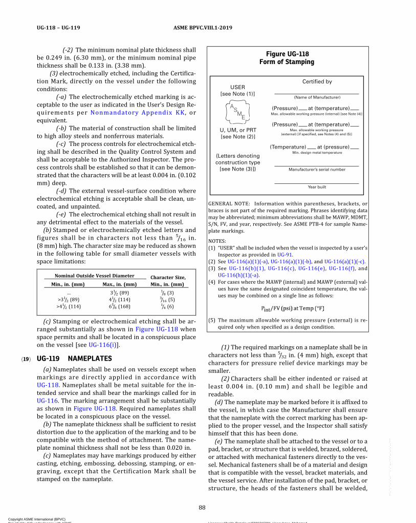
ð19Þ
(-2) The minimum nominal plate thickness shallbe 0.249 in. (6.30 mm), or the minimum nominal pipethickness shall be 0.133 in. (3.38 mm).
(3) electrochemically etched, including the Certifica-tion Mark, directly on the vessel under the followingconditions:
(-a) The electrochemically etched marking is ac-ceptable to the user as indicated in the User’s Design Re-quirements per Nonmandatory Appendix KK, orequivalent.
(-b) The material of construction shall be limitedto high alloy steels and nonferrous materials.
(-c) The process controls for electrochemical etch-ing shall be described in the Quality Control System andshall be acceptable to the Authorized Inspector. The pro-cess controls shall be established so that it can be demon-strated that the characters will be at least 0.004 in. (0.102mm) deep.
(-d) The external vessel-surface condition whereelectrochemical etching is acceptable shall be clean, un-coated, and unpainted.
(-e) The electrochemical etching shall not result inany detrimental effect to the materials of the vessel.(b) Stamped or electrochemically etched letters and
figures shall be in characters not less than 5/16 in.(8 mm) high. The character size may be reduced as shownin the following table for small diameter vessels withspace limitations:
Nominal Outside Vessel Diameter Character Size,Min., in. (mm)Min., in. (mm) Max., in. (mm)
… 31/2 (89)1/8 (3)
>31/2 (89) 41/2 (114)3/16 (5)
>41/2 (114) 65/8 (168)1/4 (6)
(c) Stamping or electrochemical etching shall be ar-ranged substantially as shown in Figure UG-118 whenspace permits and shall be located in a conspicuous placeon the vessel [see UG-116(i)].
UG-119 NAMEPLATES(a) Nameplates shall be used on vessels except when
markings are directly applied in accordance withUG-118. Nameplates shall be metal suitable for the in-tended service and shall bear the markings called for inUG-116. The marking arrangement shall be substantiallyas shown in Figure UG-118. Required nameplates shallbe located in a conspicuous place on the vessel.(b) The nameplate thickness shall be sufficient to resist
distortion due to the application of the marking and to becompatible with the method of attachment. The name-plate nominal thickness shall not be less than 0.020 in.(c) Nameplates may have markings produced by either
casting, etching, embossing, debossing, stamping, or en-graving, except that the Certification Mark shall bestamped on the nameplate.
(1) The required markings on a nameplate shall be incharacters not less than 5/32 in. (4 mm) high, except thatcharacters for pressure relief device markings may besmaller.
(2) Characters shall be either indented or raised atleast 0.004 in. (0.10 mm) and shall be legible andreadable.(d) The nameplate may be marked before it is affixed to
the vessel, in which case the Manufacturer shall ensurethat the nameplate with the correct marking has been ap-plied to the proper vessel, and the Inspector shall satisfyhimself that this has been done.(e) The nameplate shall be attached to the vessel or to a
pad, bracket, or structure that is welded, brazed, soldered,or attached with mechanical fasteners directly to the ves-sel. Mechanical fasteners shall be of a material and designthat is compatible with the vessel, bracket materials, andthe vessel service. After installation of the pad, bracket, orstructure, the heads of the fasteners shall be welded,
Figure UG-118Form of Stamping
{Letters denotingconstruction type
[see Note (3)]}
Certified by
(Pressure) at (temperature)
(Name of Manufacturer)
Manufacturer’s serial number
Year built
Max. allowable working pressure (internal) [see Note (4)]
(Temperature) at (pressure) Min. design metal temperature
(Pressure) at (temperature) Max. allowable working pressure
(external) [if specified, see Notes (4) and (5)]U, UM, or PRT[see Note (2)]
USER[see Note (1)]
GENERAL NOTE: Information within parentheses, brackets, orbraces is not part of the required marking. Phrases identifying datamay be abbreviated; minimum abbreviations shall be MAWP, MDMT,S/N, FV, and year, respectively. See ASME PTB-4 for sample Name-plate markings.
NOTES:(1) “USER” shall be included when the vessel is inspected by a user’s
Inspector as provided in UG-91.(2) See UG-116(a)(1)(-a), UG-116(a)(1)(-b), and UG-116(a)(1)(-c).(3) See UG-116(b)(1), UG-116(c), UG-116(e), UG-116(f), and
UG-116(h)(1)(-a).(4) For cases where the MAWP (internal) and MAWP (external) val-
ues have the same designated coincident temperature, the val-ues may be combined on a single line as follows:
(5) The maximum allowable working pressure (external) is re-quired only when specified as a design condition.
88
ASME BPVC.VIII.1-2019UG-118 – UG-119
Copyright ASME International (BPVC) Provided by IHS under license with ASME Licensee=Khalda Petroleum/5986215001, User=Amer, Mohamed
Not for Resale, 07/02/2019 13:29:04 MDTNo reproduction or networking permitted without license from IHS
--`,``,``,,`,`,,````,`,``,,,`-`-`,,`,,`,`,,`---
ð19Þ
brazed, or soldered to the pad, bracket, or structure thatsupports the nameplate. The nameplate shall be locatedwithin 30 in. (760 mm) of the vessel. Removal shall re-quire the willful destruction of the nameplate, or its at-tachment system. (See M-3.)
(1) Nameplates may be attached either by welding,brazing, or soldering.
(2) Nameplates may be attached by tamper‐resistantmechanical fasteners of suitable metal construction.
(3) Nameplates may be attached with pressure‐sensitive acrylic adhesive systems provided that, in addi-tion to the requirements of this paragraph, those of Man-datory Appendix 18 are met.
(f) An additional nameplate in accordance with (a)through (d) may be installed on the skirt, supports, jacket,or other permanent attachment to a vessel. All data on theadditional plate, including the Certification Mark with theDesignator, shall be as required for the mandatory name-plate. The marking need not be witnessed by the Inspec-tor. The additional nameplate shall be marked:“DUPLICATE.”
(g)When a nameplate is employed, the Manufacturer’sname or identifying trademark, and vessel serial number(or National Board Number, if applicable,) may also bemarked directly on the vessel in close proximity to thenameplate attachment. The marking shall be of a visiblepermanent type that is not detrimental to the vessel,and its location shall be indicated on the Data Report.
(1) If the thickness limitations of UG-118 precludemarking directly on the vessel shell or heads, it may beapplied to the skirt, supports, jacket, or other permanentattachment to the vessel.
UG-120 DATA REPORTS(a) A Data Report shall be filled out on Form U-1, U-1A,
or U-1P by the Manufacturer and shall be signed by theManufacturer and the Inspector for each pressure vesselmarked with the Certification Mark with the U Designator.
(1) Same day production of vessels may be reportedon a single Form, provided all of the following require-ments are met:
(-a) vessels must be identical;(-b) vessels must be manufactured for stock or for
the same user or his designated agent;(-c) serial numbers must be in uninterrupted se-
quence; and(-d) the Manufacturer’s written Quality Control
System includes procedures to control the development,distribution, and retention of the Data Reports.
(2) For guidance in preparing the Manufacturer'sData Report Forms, see Nonmandatory Appendix W. Hor-izontal spacing for information on each line may be al-tered as necessary. All information must be addressed;however, footnotes described in the “Remarks” blockare acceptable, e.g., for multiple cases of “none” or “notapplicable.”
(3) The Manufacturer shall(-a) furnish a copy of the Manufacturer’s Data Re-
port to the user and, upon request, to the Inspector:(-b) submit a copy of the Manufacturer’s Data Re-
port to the appropriate enforcement authority in the jur-isdiction in which the vessel is to be installed, whererequired by law;
(-c) keep a copy of the Manufacturer’s Data Reporton file in a safe repository for at least 3 years.
In lieu of (-c) above, the vessel may be registered andthe Data Report filed with the National Board of Boilerand Pressure Vessel Inspectors, 1055 Crupper Avenue,Columbus, Ohio 43229. Where acceptable to the appro-priate enforcement authority in the jurisdiction in whichthe vessel is to be installed, the vessel may be registeredand the Data Report filed with the National Board of Boil-er and Pressure Vessel Inspectors in lieu of (-b) above.
(4) A Manufacturer’s Certificate of Compliance onForm U-3, U-3A, or U-3P shall be completed and signedby the Manufacturer for each pressure vessel markedwith the Certification Mark with the UM Designator. ThisCertificate shall be maintained by the Manufacturer for 5years and a copy made available upon request, or the ves-sel may be registered and the Data Report filed with theNational Board of Boiler and Pressure Vessel Inspectors,1055 Crupper Avenue, Columbus, OH 43229. Where ac-ceptable to the appropriate enforcement authority inthe jurisdiction in which the vessel is to be installed, thevessel may be registered and the Data Report filed withthe National Board of Boiler and Pressure Vessel Inspec-tors. Identical vessels up to 1 day’s production may be re-corded on a single Certificate of Compliance.
(b) Combination Units(1) Those chambers included within the scope of this
Division shall be described on the same Data Report. Thisincludes the following, as applicable:
(-a) for differential pressure design, the maximumdifferential design pressure for each common elementand the name of the higher pressure chamber [seeUG-19(a)(2)]
(-b) for mean metal temperature design, the max-imum mean metal design temperature for each commonelement [see UG-19(a)(3)]
(-c) for a common element adjacent to a chambernot included within the scope of this Division, the com-mon element design conditions from that chamber
(2) It is recommended that those chambers not in-cluded within the scope of this Division be described inthe “Remarks” section of the Data Report.
(3) For a fixed tubesheet heat exchanger, as definedin UHX-3.2, Form U-5 shall be filled out with the informa-tion required by UHX-19.3.2, signed by the Manufacturerand Inspector, and included with the Manufacturer’s DataReport.
89
ASME BPVC.VIII.1-2019 UG-119 – UG-120
Copyright ASME International (BPVC) Provided by IHS under license with ASME Licensee=Khalda Petroleum/5986215001, User=Amer, Mohamed
Not for Resale, 07/02/2019 13:29:04 MDTNo reproduction or networking permitted without license from IHS
--`,``,``,,`,`,,````,`,``,,,`-`-`,,`,,`,`,,`---
(c) Partial Data Reports(1) Data Reports to document the construction activ-
ities of pressure vessel parts requiring inspection underthis Division that are furnished by a parts Manufacturerother than the Manufacturer responsible for the com-pleted vessel shall be executed on the applicable PartialData Report, Form U-2 or Form U-2A, by the parts Manu-facturer and his Inspector in accordance with the require-ments of this Division. The Manufacturer's Partial DataReport shall be forwarded, in duplicate, to the Manufac-turer of the completed vessel [see U-2(b)]. Form U-2Amay be used for this purpose, provided all the applicableinformation is recorded on this Form; otherwise FormU-2 shall be used. These Partial Data Reports, togetherwith his own inspection, shall be the final Inspector’sauthority to witness the application of a CertificationMark to the vessel [see UG-90(c)]. When Form U-2 orForm U-2A is used, it shall be attached to the associatedForm U-1, U-1A, or U-1P by the Manufacturer of the vesselto be marked with the Certification Mark. Manufacturersand Assemblers of parts who do not perform or assumeany design responsibility for the parts they manufactureshall identify on the Partial Data Report the organizationresponsible for the design of the part.
(-a) Data Reports for those parts of a pressure ves-sel which are furnished by a parts Manufacturer to theuser of an existing Code vessel as replacement or repairparts shall be executed on Form U-2 or Form U-2A bythe parts Manufacturer and his Inspector in accordancewith the requirements of this Division. A copy of the partsManufacturer’s Partial Data Report shall be furnished tothe user or his designated agent and maintained in accor-dance with (a) above.
(-b) The parts Manufacturer shall indicate under“Remarks” the extent he has performed any or all of thedesign functions. When the parts Manufacturer performsonly a portion of the design, he shall state which portionsof the design he performed.
(-c) Same day production of vessel parts may bereported on a single Form U-2 or Form U-2A, providedall of the following are met:
(-1) vessel parts shall be identical;(-2) Manufacturer’s serial numbers must be in
uninterrupted sequence; and(-3) The Manufacturer’s written Quality Control
System includes procedures to control the development,distribution, and retention of the Partial Data Reports.
(-d) For guidance in preparing Partial Data Re-ports, see Nonmandatory Appendix W.
(-e) Manufacturers with multiple locations underthe operational control of a single organization40, each lo-cation with its own Certificate of Authorization, maytransfer welded or brazed pressure vessel parts, or com-pletely welded pressure vessels that have not been pres-sure tested or received final inspection, from one locationto another without Partial Data Reports, provided the
Quality Control System describes the method of identifi-cation, transfer, and receipt of the parts. These methodsshall include the following requirements:
(-1) Identification requirements shall includedetails of the specific marking to be applied. Identificationshall be on each part and shall be legible, permanent, andnot detrimental to the part.
(-2) The Certificate Holder shall have a trans-mittal form that is included with each transfer. It shall listall items with corresponding identification number, withindication that the items do not contain the CertificationMark. This form shall be signed by the Certificate Holder.
(-3) The receiving location shall inspect eachitem upon receipt.
(-4) The Manufacturer of the completed vesselshall retain all transfer forms as part of the vessel records;see Mandatory Appendix 10, 10-13.
(-f)For cases in which a Manufacturer has multiplelocations that include both shop and field locations, andthe field assembly of a vessel is completed by one Manu-facturer’s location that is different from the part Manufac-turer ’s location(s), the name of the Manufacturerresponsible for field assembly shall be shown on Line 1of the Manufacturer’s Data Report. The Manufacturer re-sponsible for field assembly shall complete and sign boththe Shop and Field portions of the Manufacturer’s DataReport.
(2) A Manufacturer with multiple locations, eachholding its own Certificate of Authorization, may transferpressure vessel parts from one of its locations to anotherwithout Partial Data Reports, provided the Quality Con-trol System describes the method of identification, trans-fer, and receipt of the parts. For cases in which aManufacturer has multiple locations that include bothshop and field locations, and the field assembly of the ves-sel is completed by one Manufacturer’s location that isdifferent from the part Manufacturer’s location(s), thename of the Manufacturer responsible for field assemblyshall be shown on Line 1 of the Manufacturer’s Data Re-port. The Manufacturer responsible for field assemblyshall complete and sign both the Shop and Field portionsof the Manufacturer’s Data Report.(d) This Division, in paragraphs such as UW-2, UF-1,
UF-32(b), UB-1, UB-22, UCS-66, UNF-56, UHA-51,UCL-27, and UHT-6, establishes special requirements toqualify a vessel for certain “special services.” (Paragraphs,such as UW-2, prohibit certain types of construction ormaterials in some special services.) The special servicesto which special requirements are applicable are classi-fied as follows:
(1) lethal service [for example, see UW-2(a)];(2) services below certain temperatures (for exam-
ple, see UW-2(b), UCS-65, UHA-51, and UHT-6);(3) unfired steam boiler [for example, see UW-2(c)];(4) direct firing [for example, see UW-2(d)].
90
ASME BPVC.VIII.1-2019UG-120
Copyright ASME International (BPVC) Provided by IHS under license with ASME Licensee=Khalda Petroleum/5986215001, User=Amer, Mohamed
Not for Resale, 07/02/2019 13:29:04 MDTNo reproduction or networking permitted without license from IHS
--`,``,``,,`,`,,````,`,``,,,`-`-`,,`,,`,`,,`---
When a vessel is intended for such special services, thespecial service and the paragraphs of special require-ments complied with shall be indicated on the DataReports.
(e) Pressure-retaining covers and their attaching bolt-ing and nuts shall be listed in the Remarks section ofthe Manufacturer’s Data Report or on an attached FormU-4 when required. The minimum information shall in-clude the material specification, material grade, size,and thread designation.
(f) An unfired steam boiler, referenced in U-1(g)(1),shall have its maximum designed steaming capacity re-corded in the “Remarks” section of the Data Report.
(g) For sample forms and guidance in their preparation,see Nonmandatory Appendix W.
OVERPRESSURE PROTECTION
UG-125 GENERAL(a) Other than unfired steam boilers, all pressure ves-
sels within the scope of this Division, irrespective of sizeor pressure, shall be provided with overpressure protec-tion in accordance with the requirements of UG-125through UG-138, or with overpressure protection by sys-tem design in accordance with the requirements ofUG-140, or a combination of the two. Unfired steam boil-ers shall be provided with overpressure protection in ac-cordance with the requirements of UG-125 throughUG-138. In addition, the following shall apply:
(1) It is the user’s or his/her designated agent’s re-sponsibility to identify all potential overpressure scenar-ios and the method of overpressure protection used tomitigate each scenario.
(2) It is the responsibility of the user to ensure thatthe required overpressure protection system is properlyinstalled prior to initial operation.
(3) If a pressure relief device(s) is to be installed, it isthe responsibility of the user or his/her designated agentto size and select the pressure relief device(s) based on itsintended service. Intended service considerations shallinclude, but not necessarily be limited to, the following:
(-a) normal operating and upset conditions(-b) fluids(-c) fluid phases
(4) The overpressure protection system need not besupplied by the vessel Manufacturer.
(5) Unless otherwise defined in this Division, the de-finitions relating to pressure relief devices in Section 2 ofASME PTC 25 shall apply.
(b) An unfired steam boiler shall be equipped withpressure relief devices required by Section I insofar asthey are applicable to the service of the particularinstallation.
(c) Other than unfired steam boilers, when a pressurerelief device is provided, it shall prevent the pressurefrom rising more than 10% or 3 psi (20 kPa), whichever
is greater, above the maximum allowable working pres-sure except as permitted in (1) and (2) below andUG-127(d)(3). (See UG-134 for pressure settings.)
(1)When multiple pressure relief devices are pro-vided and set in accordance with UG-134(a), they shallprevent the pressure from rising more than 16% or4 psi (30 kPa), whichever is greater, above the maximumallowable working pressure.
(2)When a pressure vessel can be exposed to fire orother unexpected sources of external heat, the pressurerelief device(s) shall be capable of preventing the pres-sure from rising more than 21% above the maximum al-lowable working pressure. Supplemental pressure reliefdevices shall be installed to protect against this sourceof excessive pressure if the pressure relief devices usedto satisfy the capacity requirements of (c) and (1) have in-sufficient capacity to provide the required protection. SeeNonmandatory Appendix M, M-13 for cases where themetal temperature due to fire or other sources of externalheat can cause vessel failure prior to reaching the MAWP.
(3) Pressure relief devices, intended primarily forprotection against exposure of a pressure vessel to fireor other unexpected sources of external heat installedon vessels having no permanent supply connection andused for storage at ambient temperatures of nonrefriger-ated liquefied compressed gases,41 are excluded from therequirements of (1) and (2) above, provided:
(-a) the pressure relief devices are capable of pre-venting the pressure from rising more than 20% abovethe maximum allowable working pressure of the vessels;
(-b) the set pressure marked on these devicesshall not exceed the maximum allowable working pres-sure of the vessels;
(-c) the vessels have sufficient ullage to avoid a li-quid full condition;
(-d) the maximum allowable working pressure ofthe vessels on which these pressure relief devices are in-stalled is greater than the vapor pressure of the stored li-quefied compressed gas at the maximum anticipatedtemperature42 that the gas will reach under atmosphericconditions; and
(-e) pressure relief valves used to satisfy theseprovisions also comply with the requirements ofUG-129(a)(5), UG-131(c)(2), and UG-134(d)(2).
(d) Pressure relief devices shall be constructed, located,and installed so that they are readily accessible for test-ing, inspection, replacement, and repair and so that theycannot be readily rendered inoperative (see Nonmanda-tory Appendix M).
(e) Pressure relief valves or nonreclosing pressure re-lief devices43 may be used to protect against overpres-sure. Nonreclosing pressure relief devices may be usedeither alone or, if applicable, in combination with pres-sure relief valves on vessels.
91
ASME BPVC.VIII.1-2019 UG-120 – UG-125
Copyright ASME International (BPVC) Provided by IHS under license with ASME Licensee=Khalda Petroleum/5986215001, User=Amer, Mohamed
Not for Resale, 07/02/2019 13:29:04 MDTNo reproduction or networking permitted without license from IHS
--`,``,``,,`,`,,````,`,``,,,`-`-`,,`,,`,`,,`---
NOTE: Use of nonreclosing pressure relief devices of some types maybe advisable on vessels containing substances that may render apressure relief valve inoperative, where a loss of valuable materialby leakage should be avoided, or where contamination of the atmo-sphere by leakage of noxious fluids must be avoided. The use of rup-ture disk devices may also be advisable when very rapid rates ofpressure rise may be encountered.
(f) Vessels that are to operate completely filled with li-quid shall be equipped with pressure relief devices de-signed for liquid service, unless otherwise protectedagainst overpressure.(g) The pressure relief devices required in (a) above
need not be installed directly on a pressure vessel wheneither of the following conditions apply:
(1) the source of pressure is external to the vesseland is under such positive control that the pressure inthe vessel cannot exceed the maximum allowable workingpressure at the operating temperature except as per-mitted in (c) above (see UG-98), or under the conditionsset forth in Nonmandatory Appendix M.
(2) there are no intervening stop valves between thevessel and the pressure relief device or devices except aspermitted under UG-135(d).
NOTE: Pressure reducing valves and similar mechanical or electricalcontrol instruments, except for pilot-operated pressure relief valvesas permitted in UG-126(b), are not considered as sufficiently positivein action to prevent excess pressures from being developed.
(h) Pressure relief valves for steam service shall meetthe requirements of UG-131(b).
UG-126 PRESSURE RELIEF VALVES44
(a) Safety, safety relief, and relief valves shall be of thedirect spring-loaded type.(b) Pilot-operated pressure relief valves may be used,
provided that the pilot is self‐actuated and the main valvewill open automatically at not over the set pressure andwill discharge its full rated capacity if some essential partof the pilot should fail.(c) The set pressure tolerances, plus or minus, of pres-
sure relief valves shall not exceed 2 psi (15 kPa) for pres-sures up to and including 70 psi (500 kPa) and 3% forpressures above 70 psi (500 kPa).
UG-127 NONRECLOSING PRESSURE RELIEFDEVICES
(a) Rupture Disk Devices45
(1) General. Every rupture disk shall have a markedburst pressure established by rules of UG-137(d)(3) with-in a manufacturing design range46 at a specified disktemperature47 and shall be marked with a lot48 number.The burst pressure tolerance at the specified disk tem-perature shall not exceed ±2 psi (±15 kPa) for markedburst pressure up to and including 40 psi (300 kPa)and ±5% for marked burst pressure above 40 psi(300 kPa).
(2) Relieving Capacity. Rupture disk devices certifiedusing the flow resistance method shall use (-a), and rup-ture disk devices certified using the coefficient of dis-charge method shall use (-b) below
(-a) The rated flow capacity of a pressure reliefsystem that uses a rupture disk device as the sole reliev-ing device shall be determined by a value calculated un-der the requirements of (-1) or (-2) below.
(-1) When the rupture disk device dischargesdirectly to the atmosphere and
(+a) is installed within eight pipe diametersfrom the vessel nozzle entry; and
(+b)with a length of discharge pipe not great-er than five pipe diameters from the rupture disk device;and
(+c) the nominal diameters of the inlet anddischarge piping are equal to or greater than the stampedNPS (DN) designator of the device, the calculated reliev-ing capacity of a pressure relief system shall not exceeda value based on the applicable theoretical flow equation[see UG-131(e)(2) and Mandatory Appendix 11] for thevarious media multiplied by a coefficient of discharge Kequal to 0.62. The area A in the theoretical flow equationshall be the minimum net flow area49 as specified by therupture disk device Manufacturer.
(-2) The calculated capacity of any pressure re-lief system may be determined by analyzing the total sys-tem resistance to flow. This analysis shall take intoconsideration the flow resistance of the rupture disk de-vice, piping and piping components including the exitnozzle on the vessels, elbows, tees, reducers, and valves.The calculation shall be made using accepted engineeringpractices for determining fluid flow through pipingsystems. This calculated relieving capacity shall be multi-plied by a factor of 0.90 or less to allow for uncertaintiesinherent with this method. The certified flow resistance50
KR for the rupture disk device, expressed as the velocityhead loss, shall be determined in accordance withUG-131(n) through UG-131(u).
(-b) The relieving capacity of the pressure reliefsystem that uses a rupture disk device as the sole reliev-ing device shall be determined by taking into considera-tion the certified capacity marked on the device and thecharacteristics of the system fluid and system compo-nents upstream and downstream of the rupture disk de-vice. The certified coefficient of discharge KD for therupture disk device shall be determined in accordancewith UG-131(b) through UG-131(j).
(3) Application of Rupture Disks(-a) A rupture disk device may be used as the sole
pressure-relieving device on a vessel.
92
ASME BPVC.VIII.1-2019UG-125 – UG-127
Copyright ASME International (BPVC) Provided by IHS under license with ASME Licensee=Khalda Petroleum/5986215001, User=Amer, Mohamed
Not for Resale, 07/02/2019 13:29:04 MDTNo reproduction or networking permitted without license from IHS
--`,``,``,,`,`,,````,`,``,,,`-`-`,,`,,`,`,,`---
NOTE: When rupture disk devices are used, it is recommended thatthe design pressure of the vessel be sufficiently above the intendedoperating pressure to provide sufficient margin between operatingpressure and rupture disk bursting pressure to prevent prematurefailure of the rupture disk due to fatigue or creep.
Application of rupture disk devices to liquid service should becarefully evaluated to assure that the design of the rupture disk de-vice and the dynamic energy of the system on which it is installedwill result in sufficient opening of the rupture disk.
(-b) A rupture disk device may be installed be-tween a pressure relief valve51 and the vessel, provided:
(-1) the combination of the pressure relief valveand the rupture disk device is ample in capacity to meetthe requirements of UG-125(c);
(-2) the marked capacity of a pressure reliefvalve (nozzle type) when installed with a rupture disk de-vice between the inlet of the valve and the vessel shall bemultiplied by a factor of 0.90 of the rated relieving capac-ity of the valve alone, or alternatively, the capacity of sucha combination shall be established in accordance with(-3) below;
(-3) the capacity of the combination of the rup-ture disk device and the pressure relief valve may be es-tablished in accordance with the appropriate paragraphsof UG-132;
(-4) the space between a rupture disk deviceand a pressure relief valve shall be provided with a pres-sure gage, a try cock, free vent, or suitable telltale indica-tor. This arrangement permits detection of disk ruptureor leakage.52
(-5) the opening49 provided through the rup-ture disk, after burst, is sufficient to permit a flow equalto the capacity of the valve [(-2) and (-3) above], andthere is no chance of interference with proper functioningof the valve; but in no case shall this area be less than thearea of the inlet of the valve unless the capacity and func-tioning of the specific combination of rupture disk deviceand pressure relief valve have been established by test inaccordance with UG-132.
(-c) A rupture disk device may be installed on theoutlet side53 of a pressure relief valve which is opened bydirect action of the pressure in the vessel, provided:
(-1) the pressure relief valve will not fail to openat its proper pressure setting regardless of any back pres-sure that can accumulate between the pressure reliefvalve disk and the rupture disk. The space between thepressure relief valve disk and the rupture disk shall bevented or drained to prevent accumulation of pressure,or suitable means shall be provided to ensure that an ac-cumulation of pressure does not affect the proper opera-tion of the pressure relief valve.54
(-2) the pressure relief valve is ample in capac-ity to meet the requirements of UG-125(c);
(-3) the marked burst pressure of the rupturedisk at the specified disk temperature plus any pressurein the outlet piping shall not exceed the design pressureof the outlet portion of the pressure relief valve and anypipe or fitting between the valve and the rupture disk
device. However, in no case shall the marked burst pres-sure of the rupture disk at the specified disk temperatureplus any pressure in the outlet piping exceed the maxi-mum allowable working pressure of the vessel or theset pressure of the pressure relief valve.
(-4) the opening provided through the rupturedisk device after breakage is sufficient to permit a flowequal to the rated capacity of the attached pressure reliefvalve without exceeding the allowable overpressure;
(-5) any piping beyond the rupture disk cannotbe obstructed by the rupture disk or fragment;
(-6) the system is designed to consider the ad-verse effects of any leakage through the pressure reliefvalve or through the outlet side rupture disk device, to en-sure system performance and reliability.55
(-7) the bonnet of a balancing bellows or dia-phragm type pressure relief valve shall be vented to pre-vent accumulation of pressure in the bonnet.
(b) Pin Device56
(1) General. Every pin device shall have a marked setpressure established by the rules of UG-138(d)(4) andUG-138(d)(5) at a specified pin temperature.57 The setpressure tolerance shall not exceed ±2 psi (±15 kPa) formarked set pressures up to and including 40 psi(300 kPa) and ±5% for marked set pressures above40 psi (300 kPa).
(2) Relieving Capacity. Pin devices certified using theflow resistance method shall use (-a) and pin devices cer-tified using the coefficient of discharge method shall use(-b) below.
(-a) The rated flow capacity of a pressure reliefsystem that uses a pin device as the sole relieving deviceshall be determined by a value calculated under the re-quirements of (-1) or (-2) below.
(-1) When the pin device discharges directly toatmosphere and
(+a) is installed within eight pipe diametersfrom the vessel nozzle entry.
(+b)with a length of discharge pipe not great-er than five pipe diameters from the pin device.
(+c) the nominal diameters of the inlet anddischarge piping are equal to or greater than the stampedNPS (DN) designator of the device, the calculated reliev-ing capacity of a pressure relief system shall not exceeda value based on the applicable theoretical flow equation[see UG-131(e)(2) and Mandatory Appendix 11] for thevarious media multiplied by a coefficient of discharge Kequal to 0.62. The area A in the theoretical flow equationshall be the minimum net flow area49 as specified by thepin device Manufacturer.
(-2) The calculated capacity of any pressure re-lief system may be determined by analyzing the total sys-tem resistance to flow. This analysis shall take intoconsideration the flow resistance of the pin device, pipingand piping components including the exit nozzle on thevessels,elbows, tees, reducers, and valves. The calculationshall be made using accepted engineering practices for
93
ASME BPVC.VIII.1-2019 UG-127
Copyright ASME International (BPVC) Provided by IHS under license with ASME Licensee=Khalda Petroleum/5986215001, User=Amer, Mohamed
Not for Resale, 07/02/2019 13:29:04 MDTNo reproduction or networking permitted without license from IHS
--`,``,``,,`,`,,````,`,``,,,`-`-`,,`,,`,`,,`---
ð19Þ
determining fluid flow through piping systems. This cal-culated relieving capacity shall be multiplied by a factorof 0.90 or less to allow for uncertainties inherent with thismethod. The certified flow resistance50 KR for the pin de-vice, expressed as the velocity head loss, shall be deter-mined in accordance with UG-131(n) through UG-131(u).
(-b) The relieving capacity of the pressure reliefsystem that uses a pin device as the sole relieving deviceshall be determined by taking into consideration the cer-tified capacity marked on the device and the characteris-tics of the system fluid and system components upstreamand downstream of the pin device. The certified coeffi-cient of discharge KD for the pin device shall be deter-mined in accordance with UG-131(b) through UG-131(j).
(3) Application of Pin Devices(-a) A pin device may be used as the sole
pressure-relieving device on a vessel.(-b) A pin device may be installed between a pres-
sure relief valve and the vessel, provided(-1) the combination of the pressure relief valve
and the pin device is ample in capacity to meet the re-quirements of UG-125(c)
(-2) the combined capacity of the pressure reliefvalve and pin device shall be the rated capacity of thevalve multiplied by a factor of 0.90 provided the appropri-ate resistance factor KRG, KRGL, or KRL of the device is lessthan 6.0 or by a combination capacity factor establishedin accordance with the appropriate paragraphs ofUG-132.
(-3) the space between a pin device and a pres-sure relief valve shall be provided with a pressure gage, atry cock, free vent, or suitable telltale indicator.
(-4) the opening49 provided through the pin de-vice, after activation, is sufficient to permit flow equal tothe capacity of the valve [(-2) above], and there is nochance of interference with proper functioning of thevalve; but in no case shall this area be less than the areaof the inlet of the valve unless the capacity and function-ing of the specific combination of pin device and pressurerelief valve have been established by test in accordancewith UG-132.
(-5) The set pressure of the pin device is equalto or greater than 90% of the set pressure of the pressurerelief valve.
(-c) A pin device shall not be installed on the out-let side of a pressure relief valve that is opened by directaction of the pressure in the vessel.
(-d) A pin-actuated pilot-operated pressure reliefdevice may be used to satisfy the requirements ofUG-125, provided the requirements of UG-125 throughUG-136 for pilot-operated pressure relief valves are met.(c) Spring-Loaded Nonreclosing Pressure Relief Device
(1) A spring-loaded nonreclosing pressure relief de-vice, pressure actuated by means which permit thespring-loaded portion of the device to open at the speci-fied set pressure and remain open until manually reset,may be used provided the design of the spring-loaded
nonreclosing device is such that if the actuating meansfail, the device will achieve full opening at or below itsset pressure. Such a device may not be used in combina-tion with any other pressure relief device. The toleranceon opening point shall not exceed ±5%.
(2) The calculated capacity rating of a spring-loadednonreclosing pressure relief device shall not exceed a val-ue based on the applicable theoretical formula (seeUG-131) for the various media , mult ip l ied by:K = coefficient = 0.62.
The area A (square inches) in the theoretical formulashall be the flow area through the minimum opening ofthe spring-loaded nonreclosing pressure relief device.
(3) In lieu of the method of capacity rating in (2)above, a Manufacturer may have the capacity of a spring-loaded nonreclosing pressure relief device design certi-fied in general accordance with the procedures ofUG-131, as applicable.(d) Open Flow Paths or Vents
(1) Flow paths or vents, open directly or indirectly tothe atmosphere, may be used as the sole pressure-relieving device on a vessel.
(2) The calculated capacity of any pressure relief sys-tem may be determined by analyzing the total system re-s is tance to f low. This analys is sha l l take intoconsideration the flow resistance of the piping and pipingcomponents including the exit nozzle on the vessels, el-bows, tees, reducers, and valves. The calculation shallbe made using accepted engineering practices for deter-mining fluid flow through piping systems. This calculatedrelieving capacity shall be multiplied by a factor of 0.90 orless to allow for uncertainties inherent in this method.
(3) The aggregate capacity of the open flow paths, orvents, shall be sufficient to prevent overpressure in ex-cess of those specified in UG-125(c). When the MAWP is15 psi (105 kPa) or less, in no case shall the pressurebe allowed to rise more than 21% above the MAWP.
UG-128 LIQUID PRESSURE RELIEF VALVESAny liquid pressure relief valve used shall be at least
NPS 1/2 (DN 15).
UG-129 MARKING(a) Safety, Safety Relief, Relief, Liquid Pressure Relief,
and Pilot-Operated Pressure Relief Valves. Each safety,safety relief, relief, liquid pressure relief, and pilot-operated pressure relief valve NPS 1/2 (DN 15) and largershall be plainly marked by the Manufacturer or Assemblerwith the required data in such a way that the marking willnot be obliterated in service. The marking may be placedon the valve or on a metal plate or plates securely fas-tened to the valve.
(1) the name, or an acceptable abbreviation, of theManufacturer and the Assembler;
(2)Manufacturer’s design or type number;(3) NPS size (DN) (the nominal pipe size of
the valve inlet);
94
ASME BPVC.VIII.1-2019UG-127 – UG-129
Copyright ASME International (BPVC) Provided by IHS under license with ASME Licensee=Khalda Petroleum/5986215001, User=Amer, Mohamed
Not for Resale, 07/02/2019 13:29:04 MDTNo reproduction or networking permitted without license from IHS
--`,``,``,,`,`,,````,`,``,,,`-`-`,,`,,`,`,,`---

(4) set pressure psi (kPa), and, if applic-able per UG-136(d)(4)(-d)
(-a) cold differential test pressure psi(kPa)
(-b) superimposed back pressure psi(kPa)
(5) certified capacity (as applicable):(-a) lb/hr (kg/hr) of saturated steam at an over-
pressure of 10% or 3 psi (20 kPa), whichever is greaterfor valves certified on steam complying with UG-131(b);or
(-b) gal/min (l/min) of water at 70°F (20°C) at anoverpressure of 10% or 3 psi (20 kPa), whichever isgreater for valves certified on water; or
(-c) SCFM (standard cubic feet per minute at 60°Fand 14.7 psia) [m3/min (cubic meters per minute at 20°Cand 101 kPa)], or lb/min (kg/min), of air at an overpres-sure of 10% or 3 psi (kPa), whichever is greater. Valvesthat are capac i ty cert i f ied in accordance withUG-131(c)(2) shall be marked “at 20% overpressure.”
(-d) In addition to one of the fluids specifiedabove, the Manufacturer may indicate the capacity inother fluids (see Mandatory Appendix 11).
(6) year built, or alternatively, a coding may bemarked on the valve such that the valve Manufactureror Assembler can identify the year the valve was as-sembled or tested;
(7) the Certification Mark with the UV Designatorplaced under the Mark, as shown in Figure UG-129.1. Amarking method other than the stamp issued by the So-ciety may be used, provided it is acceptable to the ASMEDesignated Organization. The pilot of a pilot-operatedpressure relief valve shall be plainly marked by the Man-ufacturer or Assembler showing the name of the Manufac-turer, the Manufacturer’s design or type number, the setpressure in pounds per square inch (kPa), and the yearbuilt, or alternatively, a coding that the Manufacturercan use to identify the year built.
On valves smaller than NPS 1/2 (DN 15), the markingsmay be made on a metal plate attached by wire or adhe-sive meeting the requirements of Mandatory Appendix 18or other means suitable for the service conditions.
(8) restricted lift in. (mm) (For restrictedlift valves only)
(b) Safety and safety relief valves certified for a steamdischarging capacity under the provisions of Section Iand bearing the Certification Mark with the V Designatorfor safety valves may be used on pressure vessels. Therated capacity in terms of other fluids shall be determinedby the method of conversion given in Mandatory Appen-dix 11. [See UG-131(h).]
(c) Pressure Relief Valves in Combination With RuptureDisk Devices. Pressure relief valves in combination withrupture disk devices shall be marked with the capacityas established in accordance with UG-127(a)(3)(-b)(-2)(using 0.90 factor) or the combination capacity factor es-tablished by test in accordance with UG-132(a) or
UG-132(b), in addition to the marking of (a) and (e) be-low. The marking may be placed on the pressure reliefvalve or rupture disk device or on a plate or plates thatsatisfy the requirements of UG-119. The marking shall in-clude the following:
(1) name of Manufacturer of valve;(2) design or type number of valve;(3) name of Manufacturer of rupture disk device;(4) design or type number of rupture disk device;(5) capacity or combination capacity factor;(6) name of organization responsible for this mark-
ing. This shall be either the vessel user, vessel Manufac-turer, rupture disk Manufacturer, or pressure reliefvalve Manufacturer.
(d) Pressure Relief Valves in Combination With Pin De-vices. Pressure relief valves in combination with pin de-vices shall be marked with the capacity as establishedin accordance with UG-127(b)(3)(-b)(-2) (using 0.90 fac-tor) or the combination capacity factor established by testin accordance with UG-132(a) or UG-132(b), in additionto the marking of (a) and (f) below. The marking maybe placed on the pressure relief valve or pin device oron a metal plate or plates securely fastened to the device.The marking shall include the following:
(1) name of Manufacturer of valve;
Figure UG-129.1Official Certification Mark to Denote the
American Society of Mechanical Engineers’Standard for Pressure Relief Valves
UV
Figure UG-129.2Official Certification Mark to Denote the
American Society of Mechanical Engineers’Standard for Nonreclosing Pressure Relief
Devices
UD
95
ASME BPVC.VIII.1-2019 UG-129
Copyright ASME International (BPVC) Provided by IHS under license with ASME Licensee=Khalda Petroleum/5986215001, User=Amer, Mohamed
Not for Resale, 07/02/2019 13:29:04 MDTNo reproduction or networking permitted without license from IHS
--`,``,``,,`,`,,````,`,``,,,`-`-`,,`,,`,`,,`---

(2) design or type number of valve;(3) name of Manufacturer of pin device;(4) design or type number of pin device;(5) capacity or combination capacity factor;(6) name of organization responsible for this mark-
ing. This shall be either the vessel user, vessel Manufac-turer, pin device Manufacturer, or pressure relief valveManufacturer.(e) Rupture Disk Devices. Every rupture disk and holder
shall be plainly marked by the Manufacturer in such a waythat the marking will not be obliterated in service.
(1) Each rupture disk shall be marked with the fol-lowing information. The markings may be placed on theflange of the disk or a metal tag. The metal tag either shallbe securely fastened to the disk or, when attaching the tagis impracticable, shall accompany the disk, provided thelot number is also marked on the disk. See UG-135(g).
(-a) the name or an acceptable abbreviation of theManufacturer;
(-b) Manufacturer’s design or type number;(-c) lot number;(-d) disk material;(-e) size [NPS (DN) of rupture disk
holder];(-f)marked burst pressure psi ( kPa);(-g) specified disk temperature °F (°C);(-h) for capacity certified devices
(-1) lb/hr (kg/hr) of saturated steam at an over-pressure of 10% or 3 psi (20 kPa), whichever is greaterfor devices cert i f ied on steam complying withUG-131(b), or
(-2) gal/min (l/min) of water at 70°F (20°C) atan overpressure of 10% or 3 psi (20 kPa), whichever isgreater for devices certified on water, or
(-3) SCFM (standard cubic feet per minute at60°F and 14.7 psia) (m3/min at 20°C and 101 kPa), orlb/min (kg/min) of air, at an overpressure of 10% or 3psi, whichever is greater. Devices that are capacity certi-fied in accordance with the UG-131(c)(2) shall be marked“at 20% overpressure.”
(-4) In addition to one of the fluids specifiedabove, the Manufacturer may indicate the capacity inother fluids (see Mandatory Appendix 11).
(-i) for flow resistance certified devices(-1) minimum net flow area in.2 (mm2)(-2) certified flow resistance (one or more as
applicable)(+a) KRG for rupture disks certified
on air or gases(+b) KRL for rupture disks certified
on liquid(+c) KRGL for rupture disks certi-
fied on air or gases, and liquid
(-j) Certification Mark with the UD Designatorplaced under the Mark, as shown in Figure UG-129.2. Amarking method other than the stamp issued by the So-ciety may be used, provided it is acceptable to the ASMEDesignated Organization.
(-k) year built, or alternatively, a coding may bemarked on the rupture disk such that the rupture disk de-vice Manufacturer can identify the year the rupture diskdevice was assembled and tested.
(2) Each holder shall be marked with items (1)(-a),(1)(-b), (1)(-e), (1)(-j), and (1)(-k) above and flowdirection.(f) Pin Devices and Pin-Actuated Pilot-Operated Pres-
sure Relief Devices. Pin devices shall be plainly markedby the Manufacturer with the required data in such away that the marking will not be obliterated in service.The marking may be placed on the device housing or ona metal plate or plates securely fastened to the device.The marking shall include the following:
(1) the name, or an acceptable abbreviation of theManufacturer
(2)Manufacturer’s design or type number(3) NPS (DN) size (the nominal pipe size of
the device inlet)(4) set pressure psi (kPa)(5) flow direction(6) pin to pin device identifier(7) for capacity certified devices(-a) lb/hr of saturated steam at an overpressure
10% or 3 psi (20 kPa), whichever is greater for devicescertified on steam complying with UG-131(b), or
(-b) gal/min of water at 70°F (20°C) at an over-pressure of 10% or 3 psi (20 kPa), whichever is greaterfor devices certified on water, or
(-c) SCFM (standard cubic feet per minute at 60°Fand 14.7 psia) (m3/min at 20°C and 101 kPa), or lb/min,of air at an overpressure of 10% or 3 psi, whichever isgreater. Devices that are capacity certified in accordancewi th UG -131( c ) (2 ) sha l l b e marked “a t 20%overpressure.”
(-d) In addition to one of the fluids specifiedabove, the Manufacturer may indicate the capacity inother fluids (see Mandatory Appendix 11).
(8) for flow resistance certified devices:(-a) minimum net flow area in.2 (mm2)(-b) certified flow resistance (one or more as
applicable)(-1) KRG for pin devices certified on
air or gases(-2) KRL for pin devices certified on
liquid(-3) KRGL for pin devices certified on
air or gases, and liquid
96
ASME BPVC.VIII.1-2019UG-129
Copyright ASME International (BPVC) Provided by IHS under license with ASME Licensee=Khalda Petroleum/5986215001, User=Amer, Mohamed
Not for Resale, 07/02/2019 13:29:04 MDTNo reproduction or networking permitted without license from IHS
--`,``,``,,`,`,,````,`,``,,,`-`-`,,`,,`,`,,`---

ð19Þ
(9) Certification Mark with the UD Designator placedunder the Mark, as shown in Figure UG-129.2. A markingmethod other than the stamp issued by the Society maybe used, provided it is acceptable to the ASME DesignatedOrganization.
(10) year built, or alternatively, a coding may bemarked on the device such that the device Manufacturercan identify the year the device was tested
(11) The pin shall be marked according to one of thefollowing methods:
(-a) for pin devices using a replaceable pin to con-trol set pressure, the pin shall be marked with its lot num-ber, pin temperature57 °F (°C) and the informationrequired by (1), (4), (6), (10), or
NOTE: When the pin size or configuration does not permit the use ofan attached metal tag, a metal tag may be attached using a nonme-tallic connector with an adhesive that complies with MandatoryAppendix 18 of this Division.
(-b) for pin devices that are single use and perma-nently assembled, the marking requirements of (8)(-a),(8)(-b), and (-a) shall be applied to the device, or
(-c) for pin devices that have a replaceable pinwithin the sealed body per UG-138, the pin shall bemarked with its lot number.
(g) Spring-Loaded Nonreclosing Pressure Relief Devices.Spring-loaded nonreclosing pressure relief devices shallbe marked in accordance with (a) above except that theCertification Mark is to be applied only when the capacityhas been established and certified in accordance withUG-127(c)(3) and all other requirements of UG-130 havebeen met.
(h) For units other than those included above, see U-4.
UG-130 CERTIFICATION MARKEach pressure relief device58 to which the Certification
Mark with the appropriate Designator (see FiguresUG-129.1 and UG-129.2) will be applied shall have beenfabricated or assembled by a Manufacturer or Assemblerholding a valid Certificate of Authorization (UG-117) andcapacity certified in accordance with the requirements ofthis Division. A Certified Individual (CI) shall provideoversight as required by UG-117(a). Each use of the Cer-tification Mark with the appropriate Designator shall alsobe documented on a Certificate of Conformance FormUV-1 or UD-1, as appropriate.
UG-131 CERTIFICATION OF CAPACITY OFPRESSURE RELIEF DEVICES
(a) Before the Certification Mark is applied to any pres-sure relief device, the device Manufacturers shall have thecapacity of their devices certified in accordance with theprovisions of these paragraphs except where noted.
(1) For pressure relief valves and pin devices to becertified for capacity, (b) through (m) apply.
(2) For rupture disks or pin devices to be certified forcapacity, (b) through (j) apply.
(3) For rupture disks to be certified for flow resis-tance, (n) through (u) apply.
(4) For pin devices to be certified for flow resistance,(k) through (p) and (r) through (u) shall apply.
(b) See below.(1) Capacity certification tests for pressure relief de-
vices for compressible fluids shall be conducted on dry sa-turated steam, or air, or gas. When dry saturated steam isused, the limits for test purposes shall be 98% minimumquality and 20°F (10°C) maximum superheat. Correctionfromwithin these limits may bemade to the dry saturatedcondition. Pressure relief devices for steam service maybe rated as above, but at least one device of each seriesshall be tested on steam to demonstrate the steam capac-ity and performance.
(2) Capacity certification tests for pressure relief de-vices for incompressible fluids shall be conducted onwater at a temperature between 40°F (5°C) and 125°F(50°C).
(c) See below.(1) Capacity certification tests shall be conducted at a
pressure which does not exceed the pressure for whichthe pressure relief device is set to operate by more than10% or 3 psi (20 kPa), whichever is greater, except asprovided in (2) below. For pressure relief valves mini-mum pressure for capacity certification tests shall be atleast 3 psi (20 kPa) above set pressure. The reseatingpressure shall be noted and recorded.
(2) Capacity certification tests of pressure relief de-vices for use in accordance with UG-125(c)(3) may beconducted at a pressure not to exceed 120% of thestamped set pressure of the device.
(3) See below.(-a) Pressure relief valves for compressible fluids
having an adjustable blowdown construction shall be ad-justed prior to testing so that the blowdown does not ex-ceed 5% of the set pressure or 3 psi (20 kPa), whicheveris greater.
(-b) The blowdown of pressure relief valves for in-compressible fluids and pressure relief valves for com-pressible fluids having nonadjustable blowdown shall benoted and recorded.
(4) Capacity certification of pilot-operated pressurerelief devices may be based on tests without the pilot de-vices installed, provided prior to capacity tests it has beendemonstrated by test to the satisfaction of the AuthorizedObserver that the pilot device will cause the main deviceto open fully at a pressure which does not exceed the setpressure by more than 10% or 3 psi (20 kPa), whicheveris greater, and that the pilot device in combination withthe main device will meet all the requirements of thisDivision.
(d) See below.(1) A capacity certification test is required on a set of
three devices for each combination of size, design, andpressure setting. The stamped capacity rating for eachcombination of design, size, and test pressure shall not
97
ASME BPVC.VIII.1-2019 UG-129 – UG-131
Copyright ASME International (BPVC) Provided by IHS under license with ASME Licensee=Khalda Petroleum/5986215001, User=Amer, Mohamed
Not for Resale, 07/02/2019 13:29:04 MDTNo reproduction or networking permitted without license from IHS
--`,``,``,,`,`,,````,`,``,,,`-`-`,,`,,`,`,,`---

exceed 90% of the average capacity of the three devicestested. The capacity for each set of three devices shall fallwithin a range of ±5% of the average capacity. Failure tomeet this requirement shall be cause to refuse certifica-tion of that particular pressure relief device design.
(2) If a Manufacturer wishes to apply the Certifica-tion Mark to a design of pressure relief devices, four de-vices of each combination of pipe size and orifice sizeshall be tested. These four devices shall be set at pres-sures which cover the approximate range of pressuresfor which the device will be used or covering the rangeavailable at the certified test facility that shall conductthe tests. The capacities based on these four tests shallbe as follows:
(-a) For compressible fluids, the slope, Sm , of themeasured capacity versus the absolute flow-rating pres-sure shall be determined for each test point as follows:
where
Pf = absolute flow-rating pressure, psia (kPa)Sm = slope, lb/hr/psia (kg/h/kPa) or SCFM/psia
(m3/min/kPa)W = measured capacity, lb/hr (kg/h) of saturated steam
or SCFM air at 60°F and 14.7 psia (m3/min at 20°Cand 101 kPa)
The average slope, S a v g , shall be the arithmeticmean of all calculated slope values, Sm . All experimentallydetermined slope values, Sm , shall fall within a range of±5% of the average slope, S a v g . If all slope values, Sm ,are not within ±5% of the average slope, Savg , two addi-tional devices shall be tested for each device beyond the±5% range, up to a limit of four additional devices.
The average slope, S a v g , shall be multiplied by0.90, and this product shall be taken as the rated slope,S , for that design and orifice size combination. The reliev-ing capacity to be stamped on the device shall not exceedthe rated slope, S , multiplied by the absolute relievingpressure.
For direct spring-loaded valves, the results may beextrapolated to valves with set pressures higher than thehighest set pressure used in the capacity certificationtests, if the spring in the valve with the higher set pres-sure meets the requirements of UG-136(a)(2).
(-b) For incompressible fluids, the flow factor, Fm ,shall be determined from the ratio of the measured volu-metric capacity versus the square root of the differentialflow-rating pressure for each test point as follows:
where
Fm =
Pd = absolute discharge pressure, psia (kPa)Pf = absolute flow-rating pressure, psia (kPa)Q = measured volumetric capacity, gal/min (L/min),
corrected to 70°F (20°C)
The average flow factor, F a v g , shall be the arith-metic mean of all calculated flow factors, Fm . All experi-mentally determined flow factors, Fm , shall fall within arange of ±5% of the average flow factor, F a v g . If all theflow factors, Fm , are not within ±5% of F av g , two addi-tional devices shall be tested for each device beyond the±5% range, up to a limit of four additional devices.
The average flow factor, Favg , shall be multipliedby 0.90, and this product shall be taken as the flow factor,F , for that design and orifice size combination. The reliev-ing capacity to be stamped on the device shall not exceedthe flow factor, F , multiplied by the square root of the dif-ferential relieving pressure.
For direct spring-loaded valves, the results may beextrapolated to valves with set pressures higher than thehighest set pressure used in the capacity certificationtests, if the spring in the valve with the higher set pres-sure meets the requirements of UG-136(a)(2).(e) Instead of individual capacity certification as pro-
vided in (d) above, a coefficient of discharge K may be es-tablished for a specific pressure relief device designaccording to the following procedure.
(1) For each design, the pressure relief device Manu-facturer shall submit for test at least three devices foreach of three different sizes (a total of nine devices) to-gether with detailed drawings showing the device con-struction. Each device of a given size shall be set at adifferent pressure.
For each valve design intended to be restricted in lift,the Manufacturer shall have capacity tests conducted onthree valves of different sizes. Each size valve shall betested for capacity at the minimum lift for which certifica-tion is required, and at two intermediate lift points be-tween the full rated lift and minimum lift certificationpoints. Each of the three test valves shall be set at a differ-ent pressure.
For each restricted lift valve tested, it shall be veri-fied that actual measured capacity at restricted lift willequal or exceed the ASME rated capacity at full rated liftmultiplied by the ratio of measured restricted lift to fullrated lift.
(2) Tests shall be made on each pressure relief deviceto determine its capacity‐lift (if applicable), set pressureand blow‐down pressures (for pressure relief valves),and actual capacity in terms of the fluid used in the test.A coefficient KD shall be established for each test run asfollows:
98
ASME BPVC.VIII.1-2019UG-131
Copyright ASME International (BPVC) Provided by IHS under license with ASME Licensee=Khalda Petroleum/5986215001, User=Amer, Mohamed
Not for Resale, 07/02/2019 13:29:04 MDTNo reproduction or networking permitted without license from IHS
--`,``,``,,`,`,,````,`,``,,,`-`-`,,`,,`,`,,`---
where actual flow is determined quantitatively by test,and theoretical flow is calculated by the appropriate for-mula which follows:
For tests with dry saturated steam,
NOTE: For dry saturated steam pressures over 1,500 psig(10.3 MPa gage) and up to 3,200 psig (22.1 MPa gage), the valueof WT, calculated by the above equation, shall be corrected by beingmultiplied by the following factors, which shall be used only if it is1.0 or greater.
(U.S. Customary Units)
(SI Units)
For tests with air,
For tests with natural gas,
For tests with water,
where
A = actual discharge area through the device at devel-oped lift, in.2
C = constant for gas or vapor based on the ratio of spe-cific heatsk = cp/cv (see Figure 11-1)
M = molecular weightP = (set pressure × 1.10) plus atmospheric pressure,
psia, or set pressure plus 3 psi (20 kPa) plus atmo-spheric pressure, whichever is greater
Pd = pressure at discharge from deviceT = absolute temperature at inlet, °F + 460°F (273°C)w = specific weight of water at device inlet conditions
WT = theoretical flowZ = compressibility factor corresponding to P and T
All experimentally determined coefficients, KD , shallfall within a range of ±5% of the average KD found. Theaverage of the coefficients, KD , of the nine tests requiredshall be multiplied by 0.90, and this product shall be taken
as the coefficient, K , of that design. The coefficient of thedesign shall not be greater than 0.878 (the product of0.9 × 0.975).
To convert lb/hr of water to gal/min of water, multi-ply the capacity in lb/hr by 1/500.
(3) The official relieving capacity of all sizes andpressures of a given design, for which K has been estab-lished under the provisions of (2) above, that are manu-factured subsequently shall not exceed the valuecalculated by the appropriate formula in (2) above multi-plied by the coefficient K (see Mandatory Appendix 11).
(4) The coefficient shall not be applied to deviceswhose beta ratio (ratio of valve throat to inlet diameter)lies outside the range of 0.15 to 0.75, unless tests have de-monstrated that the individual coefficient of discharge KD
for devices at the extreme ends of a larger range is with-in ±5% of the average coefficient K . For designs where thelift is used to determine the flow area, all devices shallhave the same nominal lift‐to‐seat diameter ratio (L/D).
(5) The coefficient shall not be applied to directspring-loaded valves with springs that do not meet the re-quirements of UG-136(a)(2).
(6) For direct spring-loaded valves, the results maybe extrapolated to valves with set pressures higher thanthe highest set pressure used in the capacity certificationtests if the spring in the valve with the higher set pressuremeets the requirements of UG-136(a)(2).
(7) For pressure relief valves, the results may be ex-trapolated to valves larger or smaller than the valves usedin the capacity certification tests, provided all dimensionsof the flow path and all dimensions of the parts that canaffect the overall thrust exercised by the medium on themoving parts are scaled with the corresponding dimen-sions of the valves used in the capacity certificationtesting.
(f) Capacity and flow-resistance certification shall beconducted in accordance with ASME PTC 25. Testing shallbe conducted by an accredited testing laboratory withAuthorized Observers. Testing laboratories shall be accre-dited, and test supervisors shall have been accepted asAuthorized Observers, in accordance with the rules ofASME CA-1.
(g) Capacity test data reports for each device model,type, and size, signed by the Manufacturer and theAuthorized Observer witnessing the tests shall be sub-mitted to the ASME Designated Organization for reviewand acceptance.59 Where changes are made in the design,capacity certification tests shall be repeated.
(h) For absolute pressures up to 1,500 psia (10 MPa)absolute), it is permissible to rate safety valves under Sec-tion I, PG‐69.1.2 with capacity ratings at a flow pressureof 103% of the set pressure, for use on pressure vessels,without further test. In such instances, the capacity ratingof the valve may be increased to allow for the flow pres-sure permitted in (c)(1) and (c)(3) above, namely, 110%of the set pressure, by the multiplier,
99
ASME BPVC.VIII.1-2019 UG-131
Copyright ASME International (BPVC) Provided by IHS under license with ASME Licensee=Khalda Petroleum/5986215001, User=Amer, Mohamed
Not for Resale, 07/02/2019 13:29:04 MDTNo reproduction or networking permitted without license from IHS
--`,``,``,,`,`,,````,`,``,,,`-`-`,,`,,`,`,,`---

(U.S. Customary Units)
(SI Units)
where
p = set pressure, psig (kPa gage)
Such valves shall be marked in accordance withUG-129. This multiplier shall not be used as a divisor totransform test ratings from a higher to a lower flow.For steam pressures above 1,500 psig (10.3 MPa gage),
the above multiplier is not applicable. For pressure reliefvalves with relieving pressures between 1,500 psig(10.9 MPa gage) and 3,200 psig (22.1 MPa gage), the ca-pacity shall be determined by using the equation forsteam and the correction factor for high pressure steamin (e)(2) above with the permitted absolute relievingpressure (for Customary units, 1.10p + 14.7; for SI units,1.10p + 101) and the coefficient K for that valve design.(i) Rating of nozzle type pressure relief valves, i.e.,
coefficient KD, greater than 0.90 and nozzle construction,for saturated water shall be according to 11-2.(j) When changes are made in the design of a pressure
relief device in such a manner as to affect the flow path,lift, or performance characteristics of the device, newtests in accordance with this Division shall be performed.(k) If the design exceeds the laboratory pressure cap-
ability, (d)(2), (e), or (r) shall be followed with the excep-tion that the valves shall be tested with their disks fixed atthe minimum design lift to establish the rated capacity.(l) If the design exceeds the laboratory size or capacity
capability, (e) or (r) shall be followed with the exceptionthat flow models of three different sizes, each tested atthree different pressures, shall be used in place of valvesrequired in (e)(1) or (r). Such flow models shall be sizedconsistent with the capabilities of the accepted test labo-ratory where the test will be conducted, and shall accu-rately model those features that affect flow capacity,such as orifice size, valve lift, and internal flow configura-tion. The test models need not be functional pressure re-lief valves but shall be geometrically similar to the finalproduct.(m) In the case of either (k) or (l), the valve design (i.e.,
parameters such as spring properties, seat geometry, andmechanical valve lift) shall be evaluated to ensure thatproduction valves will achieve design lift as modeledabove.(n) The certified flow resistance KR of the nonreclosing
pressure rel ief device used in UG-127(a)(2) orUG-127(b)(2) shall be either KR = 2.4, or as determinedin accordance with (o) through (u) below.
(o) Flow resistance certification tests for nonreclosingpressure relief device for air or gas service KRG shall beactivated and flow tested with air or gas. Flow resistancecertification tests for liquid service KRL shall be activatedwith water and flow tested with air or gas. Nonreclosingpressure relief device for air or gas and liquid serviceKRGL may be certified with air or gas as above, but at leastone device of the number required under (r) below foreach size of each series shall be activated with waterand flow tested with air or gas to demonstrate the liquidservice flow resistance.(p) Flow resistance certification tests shall be con-
ducted at an inlet pressure which does not exceed110% of the device set pressure.(q) See below.
(1) The flow resistance for devices tested with non-pressure-containing items, such as seals, support rings,and vacuum supports, is applicable for the same devicedesign without seals, support rings, or vacuum supports.
(2) A change in material for rupture disks and theirnon-pressure-containing disk items, such as seals, sup-port rings, and vacuum supports, is not considered a de-sign change and does not require retesting.
(3) Additional linings, coatings, or platings may beused for the same design of devices, provided:
(-a) the certificate holder has performed a verifi-cation test with the additional linings, coatings, or plat-ings and has documented that the addition of thesematerials does not affect the device opening configura-tion; and
(-b) such verification tests shall be conducted withdevices of the smallest size and minimum set pressure forwhich the certified flow resistance with additional mate-rials is to be used.(r) Flow resistance certification shall be determined by
one of the following methods:(1) One Size Method(-a) For each nonreclosing pressure relief device
design, three activation components from the same lotshall be individually activated and the device tested in ac-cordance with (s) below. The set pressure shall be theminimum of the nonreclosing pressure relief device de-sign of the size tested.
(-b) The certified flow resistance KR determinedin (s) below shall apply only to the nonreclosing pressurerelief device design of the size tested.
(-c) When additional activation components of thesame design are constructed at a later date, the test re-sults on the original components may be included as ap-plicable in the three size method described in (2) below.
(2) Three Size Method(-a) This method of flow resistance certification
may be used for a nonreclosing pressure relief device de-sign of three or more sizes. The set pressure shall be theminimum of the activation component for each of thesizes submitted for test.
100
ASME BPVC.VIII.1-2019UG-131
Copyright ASME International (BPVC) Provided by IHS under license with ASME Licensee=Khalda Petroleum/5986215001, User=Amer, Mohamed
Not for Resale, 07/02/2019 13:29:04 MDTNo reproduction or networking permitted without license from IHS
--`,``,``,,`,`,,````,`,``,,,`-`-`,,`,,`,`,,`---

(-b) For each nonreclosing pressure relief devicedesign, three activation components from the same lotshall be activated and the device flow tested in accor-dance with (s) below for each of three different sizes ofthe same design.
(-c) The certified flow resistance KR shall apply toall sizes and pressures of the design of the nonreclosingpressure relief device tested.
(s) A certified flow resistance KRmay be established fora specific nonreclosing pressure relief device design ac-cording to the following procedure.
(1) For each design, the nonreclosing pressure reliefdevice Manufacturer shall submit for test the required de-vices in accordance with (r) above together with the crosssection drawings showing the device design.
(2) Tests shall be made on each device to determineits set pressure and flow resistance at a facility whichmeets the requirements of (f) above.
(3) Calculate an average flow resistance using the in-dividual flow resistances determined in (2) above. All in-dividual flow resistances shall fall within the average flowresistance by an acceptance band of plus or minus threetimes the average of the absolute values of the deviationsof the individual flow resistances from the average flowresistance. Any individual flow resistance that falls out-side of this band shall be replaced on a two for one basis.A new average flow resistance shall be computed and theindividual flow resistances evaluated as stated above.
(4) The certified flow resistance KR for a nonreclos-ing pressure relief device design shall not be less thanzero and shall not be less than the sum of the average flowresistance plus three times the average of the absolutevalues of the deviations of individual flow resistancesfrom the average flow resistance.
(t) Flow resistance test data reports for each nonre-closing pressure relief device design, signed by the Man-ufacturer and the Authorized Observer witnessing thetests, shall be submitted to the ASME Designated Organi-zation for review and acceptance.59
(u)When changes are made in the design of a nonre-closing pressure relief device which affect the flow pathor activation performance characteristics of the device,new tests in accordance with this Division shall beperformed.
UG-132 CERTIFICATION OF CAPACITY OFPRESSURE RELIEF VALVES INCOMBINATION WITH NONRECLOSINGPRESSURE RELIEF DEVICES
(a) Capacity of Pressure Relief Valves in CombinationWith a Nonreclosing Pressure Relief Device at the Inlet
(1) For each combination of pressure relief valve de-sign and nonreclosing pressure relief device design, thepressure relief valve Manufacturer or the nonreclosingpressure relief device Manufacturer may have the capac-ity of the combination certified as prescribed in (3) and(4) below.
(2) Capacity certification tests shall be conducted onsaturated steam, air, or natural gas. When saturatedsteam is used, corrections for moisture content of thesteam shall be made.
(3) The pressure relief valve Manufacturer or thenonreclosing pressure relief device Manufacturer maysubmit for tests the smallest nonreclosing pressure reliefdevice size with the equivalent size of pressure reliefvalve that is intended to be used as a combination device.The pressure relief valve to be tested shall have the lar-gest orifice used in the particular inlet size.
(4) Tests may be performed in accordance with thefollowing subparagraphs. The nonreclosing pressure re-lief device and pressure relief valve combination to betested shall be arranged to duplicate the combination as-sembly design.
(-a) The test shall embody the minimum set pres-sure of the nonreclosing pressure relief device designwhich is to be used in combination with the pressure re-lief valve design. The marked set pressure of the nonre-closing pressure relief device shall be between 90% and100% of the marked set pressure of the valve.
(-b) The test procedure to be used shall be asfollows:
The pressure relief valve (one valve) shall betested for capacity as an individual valve, without thenonreclosing pressure relief device at a pressure 10%or 3 psi (20 kPa), whichever is greater, above the valveset pressure.
The nonreclosing pressure relief device shall thenbe installed at the inlet of the pressure relief valve and thenonreclosing pressure relief device activated to operatethe valve. The capacity test shall be performed on thecombination at 10% or 3 psi (20 kPa), whichever is great-er, above the valve set pressure duplicating the individualpressure relief valve capacity test.
(-c) Tests shall be repeated with two additionalactivation components of the same nominal rating for atotal of three activation components to be tested withthe single pressure relief valve. The results of the test ca-pacity shall fall within a range of 10% of the average ca-pac i ty of the three tests . Fa i lure to meet th isrequirement shall be cause to require retest for determi-nation of cause of the discrepancies.
(-d) From the results of the tests, a CombinationCapacity Factor shall be determined. The Combination Ca-pacity Factor is the ratio of the average capacity deter-mined by the combination tests to the capacitydetermined on the individual valve.
The Combination Capacity Factor shall be used as amultiplier to make appropriate changes in the ASMErated relieving capacity of the pressure relief valve inall sizes of the design. The value of the Combination Ca-pacity Factor shall not be greater than one. The Combina-tion Capacity Factor shall apply only to combinations ofthe same design of pressure relief valve and the same de-sign of nonreclosing pressure relief device as those tested.
101
ASME BPVC.VIII.1-2019 UG-131 – UG-132
Copyright ASME International (BPVC) Provided by IHS under license with ASME Licensee=Khalda Petroleum/5986215001, User=Amer, Mohamed
Not for Resale, 07/02/2019 13:29:04 MDTNo reproduction or networking permitted without license from IHS
--`,``,``,,`,`,,````,`,``,,,`-`-`,,`,,`,`,,`---
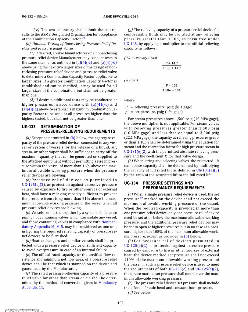
(-e) The test laboratory shall submit the test re-sults to the ASME Designated Organization for acceptanceof the Combination Capacity Factor.60
(b) Optional Testing of Nonreclosing Pressure Relief De-vices and Pressure Relief Valves
(1) If desired, a valve Manufacturer or a nonreclosingpressure relief device Manufacturer may conduct tests inthe same manner as outlined in (a)(4)(-c) and (a)(4)(-d)above using the next two larger sizes of the design of non-reclosing pressure relief device and pressure relief valveto determine a Combination Capacity Factor applicable tolarger sizes. If a greater Combination Capacity Factor isestablished and can be certified, it may be used for alllarger sizes of the combination, but shall not be greaterthan one.
(2) If desired, additional tests may be conducted athigher pressures in accordance with (a)(4)(-c) and(a)(4)(-d) above to establish a maximum Combination Ca-pacity Factor to be used at all pressures higher than thehighest tested, but shall not be greater than one.
UG-133 DETERMINATION OFPRESSURE-RELIEVING REQUIREMENTS
(a) Except as permitted in (b) below, the aggregate ca-pacity of the pressure relief devices connected to any ves-sel or system of vessels for the release of a liquid, air,steam, or other vapor shall be sufficient to carry off themaximum quantity that can be generated or supplied tothe attached equipment without permitting a rise in pres-sure within the vessel of more than 16% above the max-imum allowable working pressure when the pressurerelief devices are blowing.(b) Pre s su r e r e l i e f d ev i c e s a s pe rm i t t ed in
UG-125(c)(2), as protection against excessive pressurecaused by exposure to fire or other sources of externalheat, shall have a relieving capacity sufficient to preventthe pressure from rising more than 21% above the max-imum allowable working pressure of the vessel when allpressure relief devices are blowing.(c) Vessels connected together by a system of adequate
piping not containing valves which can isolate any vessel,and those containing valves in compliance with Nonman-datory Appendix M, M-5, may be considered as one unitin figuring the required relieving capacity of pressure re-lief devices to be furnished.(d) Heat exchangers and similar vessels shall be pro-
tected with a pressure relief device of sufficient capacityto avoid overpressure in case of an internal failure.(e) The official rated capacity, or the certified flow re-
sistance and minimum net flow area, of a pressure reliefdevice shall be that which is stamped on the device andguaranteed by the Manufacturer.(f) The rated pressure-relieving capacity of a pressure
relief valve for other than steam or air shall be deter-mined by the method of conversion given in MandatoryAppendix 11.
(g) The relieving capacity of a pressure relief device forcompressible fluids may be prorated at any relievingpressure greater than 1.10p , as permitted underUG-125, by applying a multiplier to the official relievingcapacity as follows:
(U.S. Customary Units)
(SI Units)
where
P = relieving pressure, psig (kPa gage)p = set pressure, psig (kPa gage)
For steam pressures above 1,500 psig (10 MPa gage),the above multiplier is not applicable. For steam valveswith relieving pressures greater than 1,500 psig(10 MPa gage) and less than or equal to 3,200 psig(22.1 MPa gage), the capacity at relieving pressures great-er than 1.10p shall be determined using the equation forsteam and the correction factor for high pressure steam inUG-131(e)(2) with the permitted absolute relieving pres-sure and the coefficient K for that valve design.(h)When sizing and selecting valves, the restricted lift
nameplate capacity shall be determined by multiplyingthe capacity at full rated lift as defined in UG-131(e)(3)by the ratio of the restricted lift to the full rated lift.
UG-134 PRESSURE SETTINGS ANDPERFORMANCE REQUIREMENTS
(a)When a single pressure relief device is used, the setpressure60 marked on the device shall not exceed themaximum allowable working pressure of the vessel.When the required capacity is provided in more thanone pressure relief device, only one pressure relief deviceneed be set at or below the maximum allowable workingpressure, and the additional pressure relief devices maybe set to open at higher pressures but in no case at a pres-sure higher than 105% of the maximum allowable work-ing pressure, except as provided in (b) below.(b) For pressure re l i e f dev ices permi t ted in
UG-125(c)(2) as protection against excessive pressurecaused by exposure to fire or other sources of externalheat, the device marked set pressure shall not exceed110% of the maximum allowable working pressure ofthe vessel. If such a pressure relief device is used to meetthe requirements of both UG-125(c) and UG-125(c)(2),the device marked set pressure shall not be over the max-imum allowable working pressure.(c) The pressure relief device set pressure shall include
the effects of static head and constant back pressure.(d) See below.
102
ASME BPVC.VIII.1-2019UG-132 – UG-134
Copyright ASME International (BPVC) Provided by IHS under license with ASME Licensee=Khalda Petroleum/5986215001, User=Amer, Mohamed
Not for Resale, 07/02/2019 13:29:04 MDTNo reproduction or networking permitted without license from IHS
--`,``,``,,`,`,,````,`,``,,,`-`-`,,`,,`,`,,`---

(1) The set pressure tolerance for pressure reliefvalves shall not exceed ±2 psi (15 kPa) for pressures upto and including 70 psi (500 kPa) and ±3% for pressuresabove 70 psi (500 kPa), except as covered in (2) below.
(2) The set pressure tolerance of pressure reliefvalves which comply with UG-125(c)(3) shall bewithin −0%, +10%.
(e) The burst pressure tolerance for rupture disk de-vices at the specified disk temperature shall not exceed±2 psi (15 kPa) of marked burst pressure up to and in-cluding 40 psi (300 kPa) and ±5% of marked burst pres-sure above 40 psi (300 kPa).
(f) The set pressure tolerance for pin devices shall notexceed ±2 psi (15 kPa) of marked set pressure up to andincluding 40 psi (300 kPa) and ±5% of marked set pres-sures above 40 psi (300 kPa) at speci f ied pintemperature.
(g) Pressure relief valves shall be designed and con-structed such that when installed per UG-135, the valveswill operate without chattering and shall not flutter at theflow‐rated pressure in a way that either would interferewith the measurement of capacity or would result indamage.
UG-135 INSTALLATION(a) Pressure relief devices intended for relief of com-
pressible fluids shall be connected to the vessel in the va-por space above any contained liquid or to pipingconnected to the vapor space in the vessel which is tobe protected. Pressure relief devices intended for reliefof liquids shall be connected below the liquid level. Alter-native connection locations are permitted, depending onthe potential vessel overpressure scenarios and the typeof relief device selected, provided the requirements ofUG-125(a)(3) and UG-125(c) are met.
(b) See below.(1) The opening through all pipe, fittings, and nonre-
closing pressure relief devices (if installed) between apressure vessel and its pressure relief valve shall haveat least the area of the pressure relief valve inlet. Thecharacteristics of this upstream system shall be such thatthe pressure drop will not reduce the relieving capacitybelow that required or adversely affect the proper opera-tion of the pressure relief valve.
(2) The opening in the vesse l wal l sha l l bedesigned to provide unobstructed flow betweenthe vesse l and i ts pressure re l ie f dev ice (seeNonmandatory Appendix M).61
(c) When two or more required pressure relief devicesare placed on one connection, the inlet internal cross‐sectional area of this connection shall be either sized toavoid restricting flow to the pressure relief devices ormade at least equal to the combined inlet areas of thesafety devices connected to it. The flow characteristicsof the upstream system shall satisfy the requirements of(b) above. (See Nonmandatory Appendix M.)
(d) There shall be no intervening stop valves betweenthe vessel and its pressure relief device or devices, or be-tween the pressure relief device or devices and the pointof discharge, except:
(1)when these stop valves are so constructed or po-sitively controlled that the closing of the maximum num-ber of block valves possible at one time will not reducethe pressure-relieving capacity provided by the unaf-fected pressure relief devices below the required reliev-ing capacity; or
(2) under conditions set forth in NonmandatoryAppendix M.
(e) The pressure relief devices on all vessels shall be soinstalled that their proper functioning will not be hin-dered by the nature of the vessel’s contents.
(f) Discharge lines from pressure relief devices shall bedesigned to facilitate drainage or shall be fitted withdrains to prevent liquid from lodging in the discharge sideof the pressure relief device, and such lines shall lead to asafe place of discharge. The size of the discharge linesshall be such that any pressure that may exist or developwill not reduce the relieving capacity of the pressure re-lief devices below that required to properly protect thevessel, or adversely affect the proper operation of thepressure relief devices. [See UG-136(a)(8) and Nonman-datory Appendix M.]
(g) For rupture disks that are marked with only a lotnumber in accordance with UG-129(e)(1), following theinstallation of the disk, the metal tag shall be sealed tothe installation in a manner that will prevent removal ofthe disk without breaking the seal. The seal shall identifythe organization responsible for performing theinstallation.
UG-136 MINIMUM REQUIREMENTS FORPRESSURE RELIEF VALVES
(a) Mechanical Requirements(1) The design shall incorporate guiding arrange-
ments necessary to ensure consistent operation andtightness.
(2) The spring shall be designed so that the full liftspring compression shall be no greater than 80% of thenominal solid deflection. The permanent set of the spring(defined as the difference between the free height andheight measured 10 min after the spring has been com-pressed solid three additional times after presetting atroom temperature) shall not exceed 0.5% of the freeheight.
For direct spring-loaded valves that have set pres-sures above the maximum pressure used in the capacitycertification tests, the spring force ratio shall not exceed1.1 times the spring force ratio of the valve with the high-est set pressure that was used in the capacity certificationtests. For direct spring-loaded valves that have orificeslarger than the largest size used in the capacity certifica-tion tests, the spring force ratio shall not exceed 1.1 times
103
ASME BPVC.VIII.1-2019 UG-134 – UG-136
Copyright ASME International (BPVC) Provided by IHS under license with ASME Licensee=Khalda Petroleum/5986215001, User=Amer, Mohamed
Not for Resale, 07/02/2019 13:29:04 MDTNo reproduction or networking permitted without license from IHS
--`,``,``,,`,`,,````,`,``,,,`-`-`,,`,,`,`,,`---
the spring force ratio of the valve with the largest size or-ifice in the capacity certification tests. The spring force ra-tio, Rsf, shall be calculated as follows:
where
Fsc = force exerted by the spring when the valve isclosed or seated
Fso = force exerted by the spring when the valve is atrated lift
(3) Each pressure relief valve on air, water at thevalve inlet that exceeds 140°F (60°C), excluding overpres-sure or relief events, or steam service shall have a sub-stantial lifting device which when activated will releasethe seating force on the disk when the pressure reliefvalve is subjected to a pressure of at least 75% of theset pressure of the valve. Pilot-operated pressure reliefvalves used on these services shall be provided witheither a lifting device as described above or means forconnecting and applying pressure to the pilot adequateto verify that the moving parts critical to proper opera-tion are free to move.
(4) The seat of a pressure relief valve shall be fas-tened to the body of the pressure relief valve in such away that there is no possibility of the seat lifting.
(5) In the design of the body of the pressure reliefvalve, consideration shall be given to minimizing the ef-fects of deposits.
(6) Pressure relief valves having threaded inlet oroutlet connections shall be provided with wrenching sur-faces to allow for normal installation without damagingoperating parts.
(7)Means shall be provided in the design of all pres-sure relief valves for use under this Division for sealing allinitial adjustments which can be made without disassem-bly of the valve. Seals shall be installed by the Manufac-turer or Assembler at the time of initial adjustment.Seals shall be installed in a manner to prevent changingthe adjustment without breaking the seal. For pressurerelief valves larger than NPS 1/2 (DN 15), the seal shallserve as a means of identifying the Manufacturer or As-sembler making the initial adjustment.
(8) If the design of a pressure relief valve is such thatliquid can collect on the discharge side of the disk, exceptas permitted in (9) below, the valve shall be equippedwith a drain at the lowest point where liquid can collect(for installation, see UG-135).
(9) Pressure relief valves that cannot be equippedwith a drain as required in (8) above because of designor application may be used provided:
(-a) the pressure relief valves are used only on gasservice where there is neither liquid discharged from thevalve nor liquid formed by condensation on the dischargeside of the valve; and
(-b) the pressure relief valves are provided with acover or discharge piping per UG-135(f) to prevent liquidor other contaminant from entering the discharge side ofthe valve; and
(-c) the pressure relief valve is marked FOR GASSERVICE ONLY in addition to the requirements ofUG-129.
(10) For pressure relief valves of the diaphragm type,the space above the diaphragm shall be vented to preventa buildup of pressure above the diaphragm. Pressure re-lief valves of the diaphragm type shall be designed so thatfailure or deterioration of the diaphragmmaterial will notimpair the ability of the valve to relieve at the ratedcapacity.
(11) Valve capacity, including valves certified perUG-131, may be restricted by restricting the lift of a valveprovided the following requirements are met:
(-a) The valve size shall be NPS ¾ (DN 20) orlarger.
(-b) No changes shall be made in the design of thevalve except to change the valve lift by use of a lift re-straining device described in (-c) below.
(-c) The restriction of valve capacity shall be per-mitted only by the use of a lift restraining device that shalllimit valve lift and shall not otherwise interfere with flowthrough the valve. The design of the lift restraining deviceshall be subject to review by an ASME DesignatedOrganization.
(-d) The lift restraining device shall be designed sothat, if adjustable, the adjustable feature can be sealed.Seals shall be installed by the valve Manufacturer or As-sembler at the time of initial adjustment.
(-e) Valves shall not have their lifts restricted to avalue less than 30% of full rated lift, or less than 0.080 in.(2 mm).(b) Material Selections
(1) Cast iron seats and disks are not permitted.(2) Adjacent sliding surfaces such as guides and disks
or disk holders shall both be of corrosion resistant mate-rial. Springs of corrosion resistant material or having acorrosion resistant coating are required. The seats anddisks of pressure relief valves shall be of suitable materialto resist corrosion by the fluid to be contained.
The Manufacturer shall consider the potential forgalling and the effects on the performance of the pressurerelief valve in the selection of materials for sliding sur-faces. The Manufacturer shall consider the potential forbrinelling and the effects on the performance of the pres-sure relief valve in the selection of materials for the seat-ing surfaces.
104
ASME BPVC.VIII.1-2019UG-136
Copyright ASME International (BPVC) Provided by IHS under license with ASME Licensee=Khalda Petroleum/5986215001, User=Amer, Mohamed
Not for Resale, 07/02/2019 13:29:04 MDTNo reproduction or networking permitted without license from IHS
--`,``,``,,`,`,,````,`,``,,,`-`-`,,`,,`,`,,`---

ð19Þ
ð19Þ
NOTE: The degree of corrosion resistance, appropriate to the in-tended service, shall be a matter of agreement between the Manufac-turer and the user or his designated agent.
(3)Materials used in bodies, bonnets or yokes, andbody‐to‐bonnet or body‐to‐yoke bolting shall be listedin Section II and this Division. Bodies, bonnets or yokes,and body-to-bonnet or body-to-yoke bolting shall meetall applicable requirements of Subsection C.
(4)Materials used in all other parts required for thepressure-relieving or pressure-retaining function shall be
(-a) listed in Section II; or(-b) listed in ASTM specifications; or(-c) controlled by the Manufacturer of the pres-
sure relief valve by a specification ensuring control ofchemical and physical properties and quality at leastequivalent to ASTM standards.
(c) Inspection of Manufacturing and/or Assembly ofPressure Relief Valves
(1) A Manufacturer or Assembler shall demonstrateto the satisfaction of a representative from an ASME De-signated Organization that his manufacturing, production,and testing facilities and quality control procedures willinsure close agreement between the performance of ran-dom production samples and the performance of thosevalves submitted for Capacity Certification.
(2)Manufacturing, assembly, inspection, and test op-erations including capacity are subject to inspections atany time by a representative from an ASME DesignatedOrganization.
(3) A Manufacturer or Assembler may be grantedpermission to apply the Certification Mark with the UVDesignator to production pressure relief valves capacitycertified in accordance with UG-131 provided the follow-ing tests are successfully completed. This permission shallexpire on the sixth anniversary of the date it is initiallygranted. The permission may be extended for 6 year per-iods if the following tests are successfully repeated withinthe 6‐month period before expiration.
(-a) Two sample production pressure relief valvesof a size and capacity within the capability of anASME-accepted laboratory shall be selected by a repre-sentative from an ASME Designated Organization. Pres-sure rel ief valves having adjustable blowdownconstruction shall have the control elements positionedby the Manufacturer or Assembler for a blowdown typicalof production methods.
(-b) Operational and capacity tests shall be con-ducted in the presence of a representative from an ASMEDesignated Organization at an ASME-accepted laboratory.The pressure relief valve Manufacturer or Assembler shallbe notified of the time of the test and may have represen-tatives present to witness the test. If a pressure reliefvalve with adjustable blowdown construction selectedfrom a Manufacturer exhibits a blowdown that exceeds7% of the set pressure or 3 psi (20 kPa), whichever isgreater, during operational and capacity tests, then an ad-justment shall be made to meet this performance
condition, and the operational and capacity tests shallbe repeated. This adjustment may be made on the flowtest facility.
(-c) Should any pressure relief valve fail to relieveat or above its certified capacity or should it fail to meetperformance requirements in UG-134, the test shall be re-peated at the rate of two replacement pressure reliefvalves, selected in accordance with (-a) above, for eachpressure relief valve that failed.
(-d) Should any of the replacement pressure reliefvalves fail to meet the capacity or performance require-ments of this Division, the Manufacturer or Assemblershall determine the cause of failure and take correctiveaction to guard against future occurrence. This cause offailure and corrective action shall be documented andsubmitted to the ASME Designated Organization within60 days of the failure or be cause for revocation of theauthorization to use the Certification Mark on that parti-cular type of valve. Upon acceptance of the submitted cor-rective action by the ASME Designated Organization, therequirements of (3) above shall apply.
(4) For valves that exceed the laboratory testing cap-abilities and for which lift at rated overpressure can bemeasured, the alternative method described below shallbe used in lieu of the test requirements of (3)(-a) through(3)(-c).
(-a) Two production valves that are representa-tive of the design shall be tested per ASME PTC 25, PartIII to demonstrate to the satisfaction of the representativeof the ASME Designated Organization that
(-1) the measured set pressure is consistentwith the stamped set pressure within the tolerances re-quired by UG-134(d)
(-2) the valve will achieve the minimum lift forits certified capacity
(-3) the valve will operate without chatter orflutter
If only one valve of the design will be produced within the6-yr period within which the permission is granted, onlythat valve need be tested as stated above.
(-b) The testing shall be performed at a facilitythat is mutually agreeable to the manufacturer, the repre-sentative of an ASME Designated Organization, and the fa-c i l i t y owner . The fac i l i t y sha l l be capab le o fdemonstrating the characteristics stated in (-a)(-1)through (-a)(-3).
(-c) In the event of failure of the tests, (3)(-d) shallapply.
(5) For valves that exceed the laboratory testing cap-abilities and for which lift at rated overpressure cannot bemeasured, the alternative method described below shallbe used.
105
ASME BPVC.VIII.1-2019 UG-136
Copyright ASME International (BPVC) Provided by IHS under license with ASME Licensee=Khalda Petroleum/5986215001, User=Amer, Mohamed
Not for Resale, 07/02/2019 13:29:04 MDTNo reproduction or networking permitted without license from IHS
--`,``,``,,`,`,,````,`,``,,,`-`-`,,`,,`,`,,`---
(-a) For initial certification, two functional modelsthat are representative of the design shall be used pro-vided the test requirements of (3)(-a) through (3)(-d)are followed and the following additional tests are com-pleted satisfactorily:
(-1) Two production valves that are representa-tive of the design shall be tested per ASME PTC 25, Part IIIto demonstrate to the satisfaction of the representative ofthe ASME Designated Organization that
(+a) the measured set pressure is consistentwith the stamped set pressure within the tolerances re-quired by UG-134(d)
(+b) seat tightness and a secondary pressurezone leakage test are demonstrated in accordance with(d)(3) and (d)(5)
If only one valve of the design will be produced within the6-yr period within which the permission is granted, onlythat valve need be tested as stated above.
(-2) The testing shall be performed at a facilitythat is mutually agreeable to the manufacturer, the repre-sentative of an ASME Designated Organization, and the fa-c i l i t y owner . The fac i l i t y sha l l be capab le o fdemonstrating the characteristics stated in (-1)(+a) and(-1)(+b).
(-3) In the event of failure of the tests, (3)(-d)shall apply.
(-b) For 6-yr renewal of capacity certification,(-a)(-1) through (-a)(-3) shall apply.
(6) Use of the Certification Mark by an Assembler in-dicates the use of original, unmodified parts in strict ac-cordance with the instructions of the Manufacturer ofthe pressure relief valve.
(-a) An assembler may transfer original and un-modified pressure relief parts produced by the Manufac-turer to other Assemblers provided the followingconditions are met:
(-1) both Assemblers have been granted per-mission to apply the Certification Mark with the V or UVDesignator to the specific valve type in which the partsare to be used;
(-2) the Quality Control System of the Assem-bler receiving the pressure relief valve parts shall definethe controls for the procurement and acceptance of thoseparts; and
(-3) the pressure relief valve parts are appropri-ately packaged, marked, or sealed by the Manufacturer toensure that the parts are:
(+a) produced by the Manufacturer; and(+b) the parts are original and unmodified.
(-b) However, an Assembler may convert originalfinished parts by either machining to another finishedpart or applying a corrosion‐resistant coating to valvesprings for a specific application under the followingconditions:
(-1) Conversions shall be specified by the Manu-facturer. Drawings and/or written instructions used forpart conversion shall be obtained from the Manufacturerand shall include a drawing or description of the con-verted part before and after the conversion.
(-2) The Assembler’s quality control system, asaccepted by a representative from an ASME DesignatedOrganization, must describe in detail the conversion oforiginal parts, provisions for inspection and acceptance,personnel training, and control of current Manufacturer’sdrawings and/or written instructions.
(-3) The Assembler must document each use ofa converted part and that the part was used in strict ac-cordance with the instructions of the Manufacturer.
(-4) The Assembler must demonstrate to theManufacturer the ability to perform each type of conver-sion. The Manufacturer shall document all authorizationsgranted to perform part conversions. The Manufacturerand Assembler shall maintain a file of such authorizations.
(-5) For an Assembler to offer restricted liftvalves, the Assembler must demonstrate to the satisfac-tion of the Manufacturer the ability to perform valve liftrestrictions. The Manufacturer shall document all author-izations granted to restrict the lift of the valves, and shallmaintain records of lift restrictions made by the Assem-bler. The Assembler shall maintain a file of suchauthorizations.
(-6) At least annually a review shall be per-formed by the Manufacturer of an Assembler’s systemand conversion capabilities. The Manufacturer shall docu-ment the results of these reviews. A copy of this documen-tation shall be kept on file by the Assembler. The reviewresults shall be made available to a representative froman ASME Designated Organization.
(7) In addition to the requirements of UG-129, themarking shall include the name of the Manufacturer andthe final Assembler. The Certification Mark shall be thatof the final Assembler.
NOTE: Within the requirements of (c) and (d): AManufacturer is de-fined as a person or organization who is completely responsible fordesign, material selection, capacity certification, manufacture of allcomponent parts, assembly, testing, sealing, and shipping of pres-sure relief valves certified under this Division. An Assembler is de-fined as a person or organization who purchases or receives froma Manufacturer or another Assembler the necessary componentparts or pressure relief valves and assembles, adjusts, tests, seals,and ships pressure relief valves certified under this Division, at ageographical location other than and using facilities other than thoseused by the Manufacturer. An Assembler may be organizationally in-dependent of a Manufacturer or may be wholly or partly owned by aManufacturer.
(d) Product ion Test ing by Manufacturers andAssemblers
(1) Each pressure relief valve to which the Certifica-tion Mark is to be applied shall be subjected to the follow-ing tests by the Manufacturer or Assembler . A
106
ASME BPVC.VIII.1-2019UG-136
Copyright ASME International (BPVC) Provided by IHS under license with ASME Licensee=Khalda Petroleum/5986215001, User=Amer, Mohamed
Not for Resale, 07/02/2019 13:29:04 MDTNo reproduction or networking permitted without license from IHS
--`,``,``,,`,`,,````,`,``,,,`-`-`,,`,,`,`,,`---

ð19Þ
Manufacturer or Assembler shall have a documented pro-gram for the application, calibration, and maintenance ofgages and instruments used during these tests.
(2) Pressure Testing(-a) The pressure-containing parts of the shell of
each valve are subject to pressure testing. The valve shellis defined by parts, such as the body, bonnet, and cap, thatisolate primary or secondary pressure from atmosphere.
(-b) A valve shell part is exempt from pressuretesting if
(-1) the stress that would be applied under hy-drostatic test conditions does not exceed 50% of the al-lowable stress, and
(-2) the part is not cast or welded(-c) A valve shell part requiring pressure testing
shall be tested either(-1) hydrostatically at a minimum 1.5 times the
design pressure of the part, or(-2) pneumatically at a minimum 1.25 times the
design pressure of the part. Pneumatic testing can be haz-ardous; it is therefore recommended that special precau-tions be taken when conducting a pneumatic test.
(-d) Pressure testing may be done in the part orassembled condition.
(-e) Pressure testing shall be conducted after allmachining and welding operations have been completed.
(-f)Parts subjected to pressure testing shall not ex-hibit a sign of leakage.
(3) The secondary pressure zone of each closed bon-net pressure relief valve exceeding NPS 1 (DN 25) inletsize when such pressure relief valves are designed for dis-charge to a closed system shall be tested with air or othergas at a pressure of at least 30 psi (200 kPa). Parts sub-jected to pressure testing shall not exhibit a sign ofleakage.62
(4) Each pressure relief valve shall be tested to de-monstrate its set pressure. Test fixtures and test drums,where applicable, shall be of adequate size and capacityto ensure that pressure relief valve action is consistentwith the stamped set pressure within the tolerances re-quired by UG-134(d). Testing shall be performed in accor-dance with the following:
(-a) Pressure relief valves marked for liquid ser-vice shall be tested with water or other suitable liquid.
(-b) Pressure relief valves marked for gas or vaporservice shall be tested with air or other suitable gas, ex-cept as permitted in (-e) below.
(-c) Pressure relief valves marked for steam ser-vice or having special internal parts for steam serviceshall be tested with steam, except as permitted in (-e)below.
(-d) When pressure relief valve service conditionsdiffer from test stand conditions due to superimposedback pressure and/or temperature, the actual test pres-sure (cold differential test pressure) shall be adjustedand marked on the valve per UG-129(a)(4)(-a). When
superimposed back pressure contributes to the cold dif-ferential test pressure, it shall also be marked on the valveper UG-129(a)(4)(-b).
(-e) When pressure relief valves in (-b) or (-c) arebeyond the capability of the production test facility, eitherbecause of size or set pressure, the valves may be testedusing alternative test media. Steam service valves may betested on air or other gas. Gas or vapor service valves maybe tested on steam. The test pressure using an alternativemedium shall be the product of the Manufacturer’s cor-rection factor for the differential between steam and airor gas multiplied by the set pressure. If a cold differentialtest pressure is applicable due to superimposed backpressure and/or service temperature, then the Manufac-turer’s correction factor shall be applied to the cold differ-ential test pressure. The correction factor between steamand air or gas shall not be included in the cold differentialtest pressure marked on the valve per UG-129(a)(4)(-a).
(-f)When a direct spring‐loaded pressure reliefvalve is beyond the production test equipment capabil-ities, an alternative test method presented in (-5) or(-6) may be used, provided all of the conditions of (-1)through (-4) are met:
(-1) testing the valve at full pressure may causedamage to the valve;
(-2) the valve lift has been mechanically verifiedto meet or exceed the required lift;
(-3) for valves with adjustable blowdown, theblowdown control elements are set to the valve manufac-turer’s specification, and
(-4) the valve design is compatible with the al-ternative test method selected.
(-5) The valve, with its lift temporarily re-stricted during the test, if required to prevent valve dam-age, shall be tested on the appropriate medium todemonstrate popping or set pressure.
(-6) The valve may be fitted with an auxiliarylift-assist device and tested on the appropriate mediumat a pressure less than the valve set pressure. Thelift-assist device and test procedure shall be calibratedto provide the set pressure setting with the tolerance ofUG-134(d)(1).
(5) After completion of the tests required by (4)above, a seat tightness test shall be conducted. Unlessotherwise designated by a Manufacturer’s publishedpressure relief valve specification or another specificationagreed to by the user, the seat tightness test and accep-tance criteria shall be in accordance with API 527.
(6) Testing time on steam pressure relief valves shallbe sufficient, depending on size and design, to insure thattest results are repeatable and representative of fieldperformance.
(e) Design Requirements. At the time of the submissionof pressure relief valves for capacity certification, or test-ing in accordance with (c)(3) above, the ASME DesignatedOrganization has the authority to review the design for
107
ASME BPVC.VIII.1-2019 UG-136
Copyright ASME International (BPVC) Provided by IHS under license with ASME Licensee=Khalda Petroleum/5986215001, User=Amer, Mohamed
Not for Resale, 07/02/2019 13:29:04 MDTNo reproduction or networking permitted without license from IHS
--`,``,``,,`,`,,````,`,``,,,`-`-`,,`,,`,`,,`---
ð19Þ
conformity with the requirements of (a) and (b) and to re-ject or require modification of designs which do not con-form, prior to capacity testing.(f) Welding and Other Requirements. All welding, braz-
ing, heat treatment, and nondestructive examination usedin the construction of bodies, bonnets, and yokes shall beperformed in accordance with the applicable require-ments of this Division.(g) Set Pressure Change. The set pressure of a valve may
be changed after completion of the Form UV-1 but priorto putting the valve in service for overpressure protec-tion, provided all of the following requirements are met:
(1) All parts conversions, valve adjustments, testing,and updating of the existing Form UV-1 or creating anew Form UV-1 shall be performed by the Manufactureror an Assembler that has been granted permission to ap-ply the Certification Mark with the UV Designator to thespecific valve type.
(2) The change to the set pressure shall be validatedper (d)(4).
(3) The set pressure and capacity marked on thevalve shall be obliterated. The new set pressure and ca-pacity shall be marked in accordance with UG-129. Whenmarking is accomplished by metal nameplate, the originalnameplate shall be removed and destroyed, and a newnameplate affixed to the valve.
(4) All other requirements of this Section for the useof the Certification Mark with the UV Designator shall ap-ply, in particular leak testing per (d)(3) and (d)(5), andresealing adjustments per (a)(7).
UG-137 MINIMUM REQUIREMENTS FORRUPTURE DISK DEVICES
(a) Mechanical Requirements(1) The design shall incorporate arrangements nec-
essary to ensure consistent operation and tightness.(2) Rupture disk devices having threaded inlet or
outlet connections shall be designed to allow for normalinstallation without damaging the rupture disk.(b) Material Selections
(1) The rupture disk material is not required to con-form to a material specification listed in Section II. Therupture disk material shall be controlled by the Manufac-turer of the rupture disk device by a specification ensur-ing the control of material properties.
(2)Materials used in rupture disk holders and theirpressure-retaining bolting shall be listed in Section IIand this Division. Rupture disk holders and theirpressure-retaining bolting shall meet all applicable re-quirements of Subsection C.
(3)Materials used in all other parts required for thepressure-relieving or pressure-retaining function shall be
(-a) listed in Section II; or(-b) listed in ASTM specifications; or
(-c) controlled by the Manufacturer of the rupturedisk device by a specification insuring control of chemicaland physical properties and quality at least equivalent toASTM standards.(c) Inspection of Manufacturing of Rupture Disk Devices
(1) A Manufacturer shall demonstrate to the satisfac-tion of a representative of an ASME Designated Organiza-tion that its manufacturing, production, and testingfacilities and quality control procedures will insure closeagreement between the performance of random produc-tion samples and the performance of those devices sub-mitted for Certification.
(2)Manufacturing, assembly, inspection, and test op-erations are subject to inspections at any time by anASME designee.
(3) AManufacturer may be granted permission to ap-ply the Certification Mark with the UD Designator to pro-duction rupture disk devices certified in accordance withUG-131 provided the following tests are successfully com-pleted. This permission shall expire on the sixth anniver-sary of the date it is initially granted. The permission maybe extended for 6-year periods if the following tests aresuccessfully repeated within the 6‐month period beforeexpiration:
(-a) Two production sample rupture disk devicesof a size and capacity within the capability of anASME-accepted laboratory shall be selected by a repre-sentative of an ASME Designated Organization.
(-b) Burst and flow testing shall be conducted inthe presence of a representative of an ASME DesignatedOrganization at a place which meets the requirementsof UG-131(f). The device Manufacturer shall be notifiedof the time of the test and may have representatives pres-ent to witness the test.
(-c) Should any device fail to meet or exceed theperformance requirements (burst pressure, minimumnet flow area, and flow resistance) of UG-127, the testshall be repeated at the rate of two replacement devices,selected and tested in accordance with (-a) and (-b) abovefor each device that failed.
(-d) Should any of the replacement devices fail tomeet the capacity or performance requirements of thisDivision, the Manufacturer shall determine the cause offailure and take corrective action to guard against futureoccurrence. This cause of failure and corrective actionshall be documented and submitted to the ASME Desig-nated Organization within 60 days of the failure or because for revocation of the authorization to use the Certi-fication Mark on that particular type of device. Upon ac-ceptance of the submitted corrective action by theASME Designated Organization, the requirements of (3)above shall apply.(d) Production Testing by Manufacturers
(1) Each rupture disk device to which the Certifica-tion Mark is to be applied shall be subjected to the follow-ing tests by the Manufacturer. The Manufacturer shall
108
ASME BPVC.VIII.1-2019UG-136 – UG-137
Copyright ASME International (BPVC) Provided by IHS under license with ASME Licensee=Khalda Petroleum/5986215001, User=Amer, Mohamed
Not for Resale, 07/02/2019 13:29:04 MDTNo reproduction or networking permitted without license from IHS
--`,``,``,,`,`,,````,`,``,,,`-`-`,,`,,`,`,,`---
ð19Þ
have a documented program for the application, calibra-tion, and maintenance of gages and instruments used dur-ing these tests.
(2) Pressure Testing(-a) The pressure-containing parts of each rupture
disk holder are subject to pressure testing.(-b) A rupture disk holder part is exempt from
pressure testing if(-1) the stress that would be applied under hy-
drostatic test conditions does not exceed 50% of the al-lowable stress and the part is not cast or welded, or
(-2) the part is downstream of the rupture diskwhen the outlet of the rupture disk device is not designedto contain pressure, or
(-3) the part is fully contained within the holder(-c) A rupture disk holder part requiring pressure
testing shall be tested either(-1) hydrostatically at a minimum 1.5 times the
design pressure of the part, or(-2) pneumatically at a minimum 1.25 times the
design pressure of the part. Pneumatic testing can be haz-ardous; it is therefore recommended that special precau-tions be taken when conducting a pneumatic test.
(-d) Pressure testing may be done in the part orassembled condition.
(-e) Pressure testing shall be conducted after allmachining and welding operations have been completed.
(-f)Parts subjected to pressure testing shall not ex-hibit a sign of leakage.
(3) Each lot of rupture disks shall be tested in accor-dance with one of the following methods. All tests of disksfor a given lot shall be made in a holder of the same formand pressure area dimensions as that being used in ser-vice. Sample rupture disks, selected from each lot of rup-ture disks, shall be made from the same material and ofthe same size as those to be used in service. Test resultsshall be applicable only to rupture disks used in diskholders supplied by the rupture disk Manufacturer.
(-a) At least two sample rupture disks from eachlot of rupture disks shall be burst at the specified disktemperature. The marked burst pressure shall be deter-mined so that the sample rupture disk burst pressuresare within the burst pressure tolerance specified byUG-127(a)(1).
(-b) At least four sample rupture disks, but notless than 5% from each lot of rupture disks, shall be burstat four different temperatures distributed over the applic-able temperature range for which the disks will be used.This data shall be used to establish a smooth curve ofburst pressure versus temperature for the lot of disks.The burst pressure for each data point shall not deviatefrom the curve more than the burst pressure tolerancespecified in UG-127(a)(1).
The value for the marked burst pressure shall bederived from the curve for a specified temperature.
(-c) For prebulged solid metal disks or graphitedisks only, at least four sample rupture disks using onesize of disk from each lot of material shall be burst at fourdifferent temperatures, distributed over the applicabletemperature range for which this material will be used.These data shall be used to establish a smooth curve ofpercent change of burst pressure versus temperaturefor the lot of material. The acceptance criteria of smoothcurve shall be as in (-b) above.
At least two disks from each lot of disks, madefrom this lot of material and of the same size as thoseto be used, shall be burst at the ambient temperature toestablish the room temperature rating of the lot of disks.The percent change shall be used to establish the markedburst pressure at the specified disk temperature for thelot of disks.
(e) Design Requirements. At the time of the inspectionin accordance with (c)(3) above, a representative froman ASME Designated Organization has the authority to re-view the design for conformity with the requirements of(a) and (b) and to reject or require modification of de-signs that do not conform, prior to capacity testing.
(f) Welding and Other Requirements. All welding, braz-ing, heat treatment, and nondestructive examination usedin the construction of rupture disk holders and pressureparts shall be performed in accordance with the applic-able requirements of this Division.
UG-138 MINIMUM REQUIREMENTS FOR PINDEVICES
(a) Mechanical Requirements(1) The design shall incorporate guiding arrange-
ments necessary to ensure consistent operation andtightness.
(2) The seat of a pin device shall be fastened to thebody of the pin device in such a way that there is no pos-sibility of the seat moving from its required position.
(3) In the design of the pin device, consideration shallbe given to minimize the effects of deposits.
(4) Pin devices having threaded inlet or outlet con-nections shall be provided with wrenching surfaces to al-low for normal installation without damaging operatingparts.
(5)Means shall be provided in the design for sealingall critical parts to ensure that these parts are original andunmodified. Seals shall be installed in a manner to pre-vent changing or modifying parts without breaking theseal. If the pin is replaceable, this component is not re-quired to be sealed if it is marked in accordance withUG-129(f)(11)(-a). Seals shall be installed by the Manu-facturer. For pin devices larger than NPS 1/2 (DN15), theseal shall serve as a means of identifying the deviceManufacturer.
109
ASME BPVC.VIII.1-2019 UG-137 – UG-138
Copyright ASME International (BPVC) Provided by IHS under license with ASME Licensee=Khalda Petroleum/5986215001, User=Amer, Mohamed
Not for Resale, 07/02/2019 13:29:04 MDTNo reproduction or networking permitted without license from IHS
--`,``,``,,`,`,,````,`,``,,,`-`-`,,`,,`,`,,`---
(6) If the design of the pin device is such that liquidcan collect on the discharge side, except as permitted in(7) below, the device shall be equipped with a drain atthe lowest point where liquid can collect (for installation,see UG-135).
(7) Devices that cannot be equipped with a drain asrequired in (6) above because of design or applicationmay be used provided
(-a) the devices are used only on gas servicewhere there is neither liquid discharged from the devicenor liquid formed by condensation on the discharge sideof the device
(-b) the devices are provided with a cover or dis-charge piping per UG-135(f) to prevent liquid or othercontaminant from entering the discharge side of thedevice
(-c) the device is marked FOR GAS SERVICE ONLYin addition to the other required marking
(8) Pins shall be manufactured by the deviceManufacturer.(b) Material Selections
(1) Cast iron seats and disks are not permitted.(2) Adjacent sliding and sealing surfaces shall both
be of a corrosion‐resistant material suitable for use withthe fluid to be contained.
(3)Materials used in bodies and pressure-containingmembers, excluding proprietary pin material, shall belisted in Section II and this Division. Bodies and pressure-containing members, excluding proprietary pin material,shall meet all applicable requirements of Subsection C.
(4)Materials used in all other parts required for thepressure-relieving or pressure-retaining function shall be
(-a) listed in Section II; or(-b) listed in ASTM specifications; or(-c) controlled by the Manufacturer of the pin de-
vice by a specification ensuring control of chemical andphysical properties and quality at least equivalent toASTM specifications.
(5)Materials used for pins shall be controlled by theManufacturer of the device by a specification ensuring thecontrol of material properties.(c) Inspection of Manufacturing of Pin Devices
(1) A Manufacturer shall demonstrate to the satisfac-tion of a representative from an ASME Designated Organi-zation that his manufacturing, production, and testingfacilities and quality control procedures will ensure closeagreement between the performance of random produc-tion samples and the performance of those devices sub-mitted for Certification.
(2)Manufacturing, assembly, inspection, and test op-erations including capacity are subject to inspections atany time by a representative from an ASME DesignatedOrganization.
(3) AManufacturer may be granted permission to ap-ply the Certification Mark with the UD Designator to pro-duction pin devices certified in accordance with UG-131provided the following tests are successfully completed.
This permission shall expire on the sixth anniversary ofthe date it is initially granted. The permission may be ex-tended for 6‐yr periods if the following tests are success-fully repeated within the 6‐month period beforeexpiration.
(-a) Two production sample pin devices of a sizeand capacity within the capability of an ASME-acceptedlaboratory shall be selected by a representative of anASME Designated Organization.
(-b) Operational and capacity tests shall be con-ducted in the presence of a representative from an ASMEDesignated Organization at an ASME-accepted laboratory.The pin device Manufacturer shall be notified of the timeof the test and may have representatives present to wit-ness the test.
(-c) Should any pin device fail to meet or exceedperformance requirements (set pressure and certified ca-pacity or flow resistance) of UG-127, the test shall be re-peated at the rate of two replacement devices, selectedand tested in accordance with (-a) and (-b) above for eachdevice that failed.
(-d) Should any of the replacement devices fail tomeet the capacity or performance requirements of thisDivision, the Manufacturer shall determine the cause offailure and take corrective action to guard against futureoccurrence. This cause of failure and corrective actionshall be documented and submitted to the ASME Desig-nated Organization within 60 days of the failure or because for revocation of the authorization to use the Certi-fication Mark on that particular type of device. Upon ac-ceptance of the submitted corrective action by theASME Designated Organization, the requirements of (3)above shall apply.
(4) For valves that exceed the laboratory testing cap-abilities and for which lift at rated overpressure can bemeasured, the alternative method described below shallbe used in lieu of the test requirements of (3)(-a) through(3)(-c).
(-a) Two production valves that are representa-tive of the design shall be tested per ASME PTC 25, PartIII to demonstrate to the satisfaction of the representativeof the ASME Designated Organization that
(-1) the measured set pressure is consistentwith the stamped set pressure within the tolerances re-quired by UG-134(f)
(-2) the valve will achieve complete opening orthe minimum lift required to meet its certified capacity
(-3) the valve will operate without chatter orflutter
If only one valve of the design will be produced within the6-yr period within which the permission is granted, onlythat valve need be tested as stated above.
(-b) The testing shall be performed at a facilitythat is mutually agreeable to the manufacturer, the repre-sentative of an ASME Designated Organization, and the
110
ASME BPVC.VIII.1-2019UG-138
Copyright ASME International (BPVC) Provided by IHS under license with ASME Licensee=Khalda Petroleum/5986215001, User=Amer, Mohamed
Not for Resale, 07/02/2019 13:29:04 MDTNo reproduction or networking permitted without license from IHS
--`,``,``,,`,`,,````,`,``,,,`-`-`,,`,,`,`,,`---
facility owner. The facility shall be capable of demonstrat-ing the characteristics stated in (-a)(-1) through (-a)(-3).
(-c) In the event of failure of the tests, (3)(-d) shallapply.
(5) For valves that exceed the laboratory testing cap-abilities and for which lift at rated overpressure cannot bemeasured, the alternative method described below shallbe used.
(-a) For initial certification, two functional modelsthat are representative of the design shall be used, pro-vided the test requirements of (3)(-a) through (3)(-d)are followed and the following additional tests are com-pleted satisfactorily:
(-1) Two production valves that are representa-tive of the design shall be tested per ASME PTC 25, Part IIIto demonstrate to the satisfaction of the representative ofthe ASME Designated Organization that
(+a) the measured set pressure is consistentwith the stamped set pressure within the tolerances re-quired by UG-134(f)
(+b) seat tightness and a secondary pressurezone leakage test are demonstrated in accordance with(d)(3) and (d)(6)
If only one valve of the design will be produced within the6-yr period within which the permission is granted, onlythat valve need be tested as stated above.
(-2) The testing shall be performed at a facilitythat is mutually agreeable to the manufacturer, the repre-sentative of an ASME Designated Organization, andthe facility owner. The facility shall be capable of demon-strating the characteristics stated in (-1)(+a) and (-1)(+b).
(-3) In the event of failure of the tests, (3)(-d)shall apply.
(-b) For 6-yr renewal of capacity certification,(-a)(-1) through (-a)(-3) shall apply.
(d) Production Testing by Manufacturers(1) Each device to which the Certification Mark is to
be applied shall be subjected to the following tests by theManufacturer. The Manufacturer shall have a documentedprogram for the application, calibration, and maintenanceof gages and instruments used during these tests.
(2) Pressure Testing(-a) The pressure-containing parts of each pin de-
vice are subject to pressure testing.(-b) A pin device part is exempt from pressure
testing if(-1) the stress that would be applied under hy-
drostatic test conditions does not exceed 50% of the al-lowable stress and the part is not cast or welded, or
(-2) the part is downstream of the pressure-containing element for a device designed for dischargingdirectly to atmosphere, or
(-3) the part is downstream of the pressure-containing element and fully within the holder
(-c) A pin device part requiring pressure testingshall be tested either
(-1) hydrostatically at a minimum 1.5 times thedesign pressure of the part, or
(-2) pneumatically at a minimum 1.25 times thedesign pressure of the part. Pneumatic testing can be haz-ardous; it is therefore recommended that special precau-tions be taken when conducting a pneumatic test.
(-d) Pressure testing may be done in the part orassembled condition.
(-e) Pressure testing shall be conducted after allmachining and welding operations have been completed.
(-f)Parts subjected to pressure testing shall not ex-hibit a sign of leakage.
(3) The secondary pressure zone exceeding NPS 1(DN 25) inlet size, when such devices are designed for dis-charge to a closed system, shall be tested with air or othergas at a pressure of at least 30 psi (200 kPa). There shallbe no visible signs of leakage.62
(4) Set pressure qualification of a pin device shall beaccomplished by completing set pressure testing in thedevice. At least two pins from the same lot shall be testedin the device. For single use permanently assembled pindevices having the same specification and configuration,to be supplied as a single lot, at least two completed de-vices shall be tested. The tests shall be conducted at thepin temperature or according to (5)(-d) below. The testsshall be within the tolerance defined in UG-127(b)(1).
(5) For all pin lot qualification testing:(-a) Sample pins selected from each lot shall be
made from the same material, heat and of the same criti-cal dimension as those to be used in service.
(-b) Test results shall be applicable only to pinsused in pin devices supplied by the device Manufacturer.
(-c) At least two pins or two single‐use perma-nently assembled pin devices from the same lot shall betested.
(-d) Tests shall be conducted at ambient tempera-ture or the pin temperature (as agreed between deviceManufacturer and user).63 The manufacturer shall estab-lish a temperature range for which testing at ambienttemperature is applicable. For qualification of a pin lotat a single pin temperature at least two pin tests shallbe conducted at the specified pin temperature.
(-e) Pin testing shall be completed in the actualpin device(s) or using one or more of methods (-1) or(-2) below.
(-1) Lot qualification testing shall be done in atest pin device of the same form and pressure area dimen-sions as that in which the pins will be used. At least twoset pressure tests shall be completed at the pin tempera-ture in accordance with (-d). The tests shall be within thetolerance defined in UG-127(b)(1).
(-2) The set pressure of a lot of pins for a pin de-vice may be verified by a characterization test that deter-mines the activation loading (force) under device openingconditions. The following characterization test conditionsshall apply:
111
ASME BPVC.VIII.1-2019 UG-138
Copyright ASME International (BPVC) Provided by IHS under license with ASME Licensee=Khalda Petroleum/5986215001, User=Amer, Mohamed
Not for Resale, 07/02/2019 13:29:04 MDTNo reproduction or networking permitted without license from IHS
--`,``,``,,`,`,,````,`,``,,,`-`-`,,`,,`,`,,`---

(+a) The pin retaining arrangement shall bethe same for all characterization tests applied to a pindevice.
(+b) Using pins from the same lot as testedunder (4) or (-1), at least two pins shall be tested to de-termine the activation force that correlates to the pin de-vice tested set pressure. The average of these tests definesthe base force that shall be used to permit further pinqualification using characterization rather than pin deviceset pressure testing. The following shall be used to definea corrected base force that corresponds to the nominal setpressure of the pin device:
(+c) The qualification of additional pin quan-tities or lots may use this corrected base force in placeof pin device set pressure testing provided the pins func-tion at activation forces that are within ±3% of the cor-rected base force for set pressures above 40 psi(275 kPa). For set pressures below 40 psi (275 kPa),the tested components shall function at activation forceswithin a plus/minus tolerance of the corrected base forcedetermined as follows:
(6) A seat tightness test shall be conducted on eachpin device. The test conditions and acceptance criteriashall be in accordance with the Manufacturer’s publishedpin device specification or another specification agreed toby the user and the Manufacturer.(e) Design Requirements. At the time of the inspection
in accordance with (c)(3) above, a representative froman ASME Designated Organization has the authority to re-view the design for conformity with the requirements of(a) and (b) and to reject or require modification of de-signs that do not conform, prior to capacity testing.(f) Welding and Other Requirements. All welding, braz-
ing, heat treatment, and nondestructive examination usedin the construction of bodies, bonnets, and yokes shall beperformed in accordance with the applicable require-ments of this Division.
UG-140 OVERPRESSURE PROTECTION BYSYSTEM DESIGN
(a) A pressure vessel does not require a pressure reliefdevice if the pressure is self‐limiting (e.g., the maximumdischarge pressure of a pump or compressor), and this
pressure is less than or equal to the MAWP of the vesselat the coincident temperature and the following condi-tions are met:
(1) The decision to limit the pressure by system de-sign is the responsibility of the user. The user shall re-quest that the Manufacturer’s data report state thatoverpressure protection is provided by system designper (a).
(2) The user shall conduct a detailed analysis to iden-tify and examine all potential overpressure scenarios. The“Causes of Overpressure” described in ANSI/API Standard521, Pressure‐Relieving and Depressuring Systems, shallbe considered. Other standards or recommended prac-tices that are more appropriate to the specific applicationmay also be considered. A multidisciplinary team experi-enced in methods such as hazards and operability analy-sis (HazOp); failure modes, effects, and criticality analysis(FMECA); “what‐if” analysis; or other equivalent metho-dology shall establish that there are no sources of pres-sure that can exceed the MAWP at the coincidenttemperature.
(3) The results of the analysis shall be documentedand signed by the individual in responsible charge ofthe management of the operation of the vessel. This doc-umentation shall include as a minimum the following:
(-a) detailed process and instrument flow dia-grams (P&IDs), showing all pertinent elements of the sys-tem associated with the vessel
(-b) a description of all operating and upset sce-narios, including scenarios involving fire and those thatresult from operator error, and equipment and/or instru-mentation malfunctions
(-c) an analysis showing the maximum coincidentpressure and temperature that can result from each of thescenarios listed in item (-b) above does not exceed theMAWP at that temperature(b) If the pressure is not self‐limiting, a pressure vessel
may be protected from overpressure by system design orby a combination of overpressure by system design andpressure relief devices, if the following conditions aremet. The rules below are not intended to allow for normalopera t ion above the MAWP at the co inc identtemperature.
(1) The vessel is not exclusively in air, water, orsteam service except where any of the following apply:
(-a) These services are critical to preventing therelease of fluids that may result in safety or environmen-tal concerns.
(-b) Failure or premature opening of the pressurerelief device would result in an unacceptably high prob-ability of failure or damage to the vessel or other equip-ment in the system.
(-c) Failure or premature opening of the pressurerelief device would result in significant operationalupset(s).
112
ASME BPVC.VIII.1-2019UG-138 – UG-140
Copyright ASME International (BPVC) Provided by IHS under license with ASME Licensee=Khalda Petroleum/5986215001, User=Amer, Mohamed
Not for Resale, 07/02/2019 13:29:04 MDTNo reproduction or networking permitted without license from IHS
--`,``,``,,`,`,,````,`,``,,,`-`-`,,`,,`,`,,`---

(2) The decision to limit the overpressure by systemdesign is the responsibility of the user. The user shall re-quest that the Manufacturer’s data report state that over-pressure protection is provided by system design per (b)if no pressure relief device compliant with UG-125through UG-138 is to be installed. If no pressure relief de-vice is to be installed, acceptance of the jurisdiction maybe required.
(3) The user shall conduct a detailed analysis to iden-tify and examine all scenarios that could result in an over-pressure condition and magnitude of the overpressure.The “Causes of Overpressure” as described in ANSI/APIStandard 521, Pressure‐Relieving and Depressuring Sys-tems, shall be considered. Other standards or recom-mended practices that are more appropriate to thespecific application may also be considered. A multidisci-plinary team experienced in methods such as hazards andoperability analysis (HazOp); failure modes, effects, andcriticality analysis (FMECA); “what‐if” analysis; or otherequivalent methodology shall conduct the analysis.
(4) The overpressure scenario shall be readily appar-ent so that operators or protective instrumentation willtake corrective action to prevent operation above theMAWP at the coincident temperature.
(5) There shall be no credible overpressure scenarioin which the pressure exceeds 116% of the MAWP timesthe ratio of the allowable stress value at the temperature
of the overpressure scenario to the allowable stress valueat the design temperature. The overpressure limit shallnot exceed the test pressure. Credible events or scenarioanalysis as described in WRC Bulletin 498 “Guidance onthe Application of Code Case 2211 — Overpressure Pro-tection by Systems Design” shall be considered.
(6) The results of the analysis shall be documentedand signed by the individual in responsible charge ofthe management of the operation of the vessel. This doc-umentation shall include as a minimum the following:
(-a) detailed process and instrument flow dia-grams (P&IDs), showing all pertinent elements of the sys-tem associated with the vessel
(-b) a description of all operating and upset sce-narios, including those involving fire and those that resultfrom operator error, and equipment and/or instrumenta-tion malfunctions
(-c) a detailed description of any safety critical in-strumentation used to limit the system pressure, includ-ing the ident i f icat ion of a l l tru ly independentredundancies and a reliability evaluation (qualitative orquantitative) of the overall safety system
(-d) an analysis showing the maximum pressurethat can result from each of the scenarios
113
ASME BPVC.VIII.1-2019 UG-140
Copyright ASME International (BPVC) Provided by IHS under license with ASME Licensee=Khalda Petroleum/5986215001, User=Amer, Mohamed
Not for Resale, 07/02/2019 13:29:04 MDTNo reproduction or networking permitted without license from IHS
--`,``,``,,`,`,,````,`,``,,,`-`-`,,`,,`,`,,`---
ð19Þ
SUBSECTION BREQUIREMENTS PERTAINING TO METHODSOF FABRICATION OF PRESSURE VESSELS
PART UWREQUIREMENTS FOR PRESSURE VESSELS FABRICATED BY
WELDING
GENERAL
UW-1 SCOPEThe rules in Part UW are applicable to pressure vessels
and vessel parts that are fabricated by welding and shallbe used in conjunction with the general requirements inSubsection A, and with the specific requirements in Sub-section C that pertain to the class of material used.
UW-2 SERVICE RESTRICTIONS(a)When vessels are to contain lethal64 substances,
either liquid or gaseous, all butt-welded joints shall befully radiographed in accordance with UW-51, exceptfor butt welds subject to the provisions of (2) and (3) be-low and UW-11(a)(4), and butt welds in stiffening ringsdesigned under the rules of UG-29. ERW pipe or tube isnot permitted to be used as a shell or nozzle in lethal ser-vice applications. When fabricated of carbon or low alloysteel, such vessels shall be postweld heat treated in accor-dance with Table UCS-56, unless otherwise exempted byGeneral Note (b)(3) of Table UCS-56-1. When a vessel isto contain fluids of such a nature that a very small amountmixed or unmixed with air is dangerous to life when in-haled, it shall be the responsibility of the user and/orhis designated agent to determine if it is lethal. If deter-mined as lethal, the user and/or his designated agent[see U-2(a)] shall so advise the designer and/or Manufac-turer. It shall be the responsibility of the Manufacturer tocomply with the applicable Code provisions (see UCI-2and UCD-2).
(1) The joints of various categories (see UW-3) shallbe as follows:
(-a) Except for welded tubes and pipes internal toheat exchanger shells, all joints of Category A shall beType No. (1) of Table UW-12.
(-b) All Category B and C joints shall be Type No.(1) or No. (2) of Table UW-12.
(-c) Category C joints for lap joint stub ends shallbe as follows:
(-1) The finished stub end shall be attached toits adjacent shell with a Type No. (1) or Type No. (2) jointof Table UW-12. The finished stub end can be made froma forging or can be machined from plate material. [SeeUW-13(h).]
(-2) The lap joint stub end shall be fabricated asfollows:
(+a) The weld is made in two steps as shownin Figure UW-13.5.
(+b) Before making weld No. 2, weld No. 1 isexamined by full radiography in accordance withUW-51, regardless of size. The weld and fusion betweenthe weld buildup and neck is examined by ultrasonics inaccordance with Mandatory Appendix 12.
(+c) Weld No. 2 is examined by full radiogra-phy in accordance with UW-51.
(-3) The finished stub end may either conformto ASME B16.9 dimensional requirements or be made toa non‐standard size, provided all requirements of this Di-vision are met.
(-d) All joints of Category D shall be full penetra-tion welds extending through the entire thickness of thevessel wall or nozzle wall.
(2) Radiographic examination of the welded seam inexchanger tubes and pipes, to a material specification per-mitted by this Division, which are butt welded withoutthe addition of filler metal may be waived, provided thetube or pipe is totally enclosed within a shell of a vesselwhich meets the requirements of (a).
(3) If only one side of a heat exchanger contains alethal substance, the other side need not be built to therules for a vessel in lethal service if:
114
ASME BPVC.VIII.1-2019UW-1 – UW-2
Copyright ASME International (BPVC) Provided by IHS under license with ASME Licensee=Khalda Petroleum/5986215001, User=Amer, Mohamed
Not for Resale, 07/02/2019 13:29:04 MDTNo reproduction or networking permitted without license from IHS
--`,``,``,,`,`,,````,`,``,,,`-`-`,,`,,`,`,,`---

(-a) exchanger tubes are seamless; or(-b) exchanger tubes conform to a tube specifica-
tion permitted by this Division, are butt welded withoutaddition of filler metal, and receive in lieu of full radiogra-phy all of the following nondestructive testing andexamination:
(-1) hydrotest in accordance with the applicablespecification;
(-2) pneumatic test under water in accordancewith the applicable material specification, or if not speci-fied, in accordance with SA-688;
(-3) ultrasonic or nondestructive electric exam-ination of sufficient sensitivity to detect surface calibra-tion notches in any direction in accordance withSA-557, S1 or S3.
No improvement in longitudinal joint efficiencyis permitted because of the additional nondestructivetests.
(4) All elements of a combination vessel in contactwith a lethal substance shall be constructed to the rulesfor lethal service.
(b)When vessels are to operate below certain tempera-tures designated by Part UCS (see UCS-68), or impacttests of the material or weld metal are required by PartUHA, the joints of various categories (see UW-3) shallbe as follows:
(1) All joints of Category A shall be Type No. (1) ofTable UW-12 except that for austenitic chromium–nickelstainless steel Types 304, 304L, 316, 316L, 321, and 347,which satisfy the requirements of UHA-51(f), Type No.(2) joints may be used.
(2) All joints of Category B shall be Type No. (1) orNo. (2) of Table UW-12.
(3) All joints of Category C shall be full penetrationwelds extending through the entire section at the joint.
(4) All joints of Category D shall be full penetrationwelds extending through the entire thickness of the vesselwall or nozzle wall except that partial penetration weldsmay be used between materials listed in Table UHA-23as follows:
(-a) for materials shown in UHA-51(d)(1)(-a) andUHA-51(d)(2)(-a) at minimum design metal tempera-tures (MDMTs) of −320°F (−196°C) and warmer;
(-b) for materials shown in UHA-51(d)(1)(-b) andUHA-51(d)(2)(-b) at MDMTs of −50°F (−45°C) andwarmer.
(c) Unfired steam boilers with design pressures ex-ceeding 50 psi (343 kPa)shall satisfy all of the followingrequirements:
(1) All joints of Category A (see UW-3) shall be in ac-cordance with Type No. (1) of Table UW-12, and all jointsin Category B shall be in accordance with Type No. (1) orNo. (2) of Table UW-12.
(2) All butt-welded joints shall be fully radiographedexcept under the provisions of UW-11(a)(4) and exceptfor ERW pipe weld seams. When using ERW pipe as theshell of an unfired steam boiler, its thickness shall not
exceed ½ in. (13 mm), its diameter shall not exceed 24 in.(DN 600), and the ERW weld shall be completed usinghigh frequency (HFI) welding.
(3) When fabricated of carbon or low-alloy steel,such vessels shall be postweld heat treated.
(4) See also U-1(g)(1), UG-16(b), and UG-125(b).(d) Pressure vessels or parts subject to direct firing [see
U-1(h)] may be constructed in accordance with all applic-able rules of this Division and shall meet the followingrequirements:
(1) All welded joints in Category A (see UW-3) shallbe in accordance with Type No. (1) of Table UW-12, andall welded joints in Category B, when the thickness ex-ceeds 5/8 in. (16 mm), shall be in accordance with TypeNo. (1) or No. (2) of Table UW-12. No welded joints ofType No. (3) of Table UW-12 are permitted for either Cat-egory A or B joints in any thickness.
(2)When the thickness at welded joints exceeds5/8 in. (16 mm) for carbon (P‐No. 1) steels and for all thick-nesses for low alloy steels (other than P‐No. 1 steels),postweld heat treatment is required. For all other materi-al and in any thickness, the requirements for postweldheat treatment shall be in conformance with the applic-able Subsections of this Division. See also U-1(h),UG-16(b), and UCS-56.
(3) The user, his designated agent, or the Manufac-turer of the vessel shall make available to the Inspectorthe calculations used to determine the design tempera-ture of the vessel. The provisions of UG-20 shall apply ex-cept that pressure parts in vessel areas having jointsother than Type Nos. (1) and (2) of Table UW-12, subjectto direct radiation and/or the products of combustion,shall be designed for temperatures not less than the max-imum surface metal temperatures expected under operat-ing conditions.
UW-3 WELDED JOINT CATEGORYThe term “Category” as used herein defines the location
of a joint in a vessel, but not the type of joint. The“Categories” established by this paragraph are for useelsewhere in this Division in specifying special require-ments regarding joint type and degree of inspection forcertain welded pressure joints. Since these special re-quirements, which are based on service, material, andthickness, do not apply to every welded joint, only thosejoints to which special requirements apply are includedin the categories. The special requirements will apply tojoints of a given category only when specifically so stated.The joints included in each category are designated asCategory A, B, C, and D joints below. Figure UW-3 illus-trates typical joint locations included in each category.Welded joints not defined by the category designationsinclude but are not limited to Figure 5-1, sketches (a),(c), and (d) corner joints; Figure 9-5 jacket-closure-to-shell welds; and Figure 26-13 fillet welds. Unless limited
115
ASME BPVC.VIII.1-2019 UW-2 – UW-3
Copyright ASME International (BPVC) Provided by IHS under license with ASME Licensee=Khalda Petroleum/5986215001, User=Amer, Mohamed
Not for Resale, 07/02/2019 13:29:04 MDTNo reproduction or networking permitted without license from IHS
--`,``,``,,`,`,,````,`,``,,,`-`-`,,`,,`,`,,`---
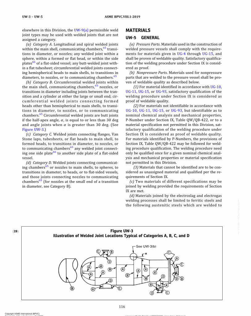
elsewhere in this Division, the UW-9(a) permissible weldjoint types may be used with welded joints that are notassigned a category.(a) Category A. Longitudinal and spiral welded joints
within the main shell, communicating chambers,65 transi-tions in diameter, or nozzles; any welded joint within asphere, within a formed or flat head, or within the sideplates66 of a flat‐sided vessel; any butt-welded joint with-in a flat tubesheet; circumferential welded joints connect-ing hemispherical heads to main shells, to transitions indiameters, to nozzles, or to communicating chambers.65
(b) Category B. Circumferential welded joints withinthe main shell, communicating chambers,65 nozzles, ortransitions in diameter including joints between the tran-sition and a cylinder at either the large or small end; cir-cumferent ia l welded joints connect ing formedheads other than hemispherical to main shells, to transi-tions in diameter, to nozzles, or to communicatingchambers.65 Circumferential welded joints are butt jointsif the half‐apex angle, α , is equal to or less than 30 degand angle joints when α is greater than 30 deg. (SeeFigure UW-3.)(c) Category C. Welded joints connecting flanges, Van
Stone laps, tubesheets, or flat heads to main shell, toformed heads, to transitions in diameter, to nozzles, orto communicating chambers65 any welded joint connect-ing one side plate66 to another side plate of a flat‐sidedvessel.(d) Category D. Welded joints connecting communicat-
ing chambers65 or nozzles to main shells, to spheres, totransitions in diameter, to heads, or to flat‐sided vessels,and those joints connecting nozzles to communicatingchambers65 (for nozzles at the small end of a transitionin diameter, see Category B).
MATERIALS
UW-5 GENERAL(a) Pressure Parts. Materials used in the construction of
welded pressure vessels shall comply with the require-ments for materials given in UG-4 through UG-15, andshall be proven of weldable quality. Satisfactory qualifica-tion of the welding procedure under Section IX is consid-ered as proof.(b) Nonpressure Parts. Materials used for nonpressure
parts that are welded to the pressure vessel shall be pro-ven of weldable quality as described below.
(1) For material identified in accordance with UG-10,UG-11, UG-15, or UG-93, satisfactory qualification of thewelding procedure under Section IX is considered asproof of weldable quality.
(2) For materials not identifiable in accordance withUG-10, UG-11, UG-15, or UG-93, but identifiable as tonominal chemical analysis and mechanical properties,P‐Number under Section IX, Table QW/QB‐422, or to amaterial specification not permitted in this Division, sat-isfactory qualification of the welding procedure underSection IX is considered as proof of weldable quality.For materials identified by P‐Numbers, the provisions ofSection IX, Table QW/QB‐422 may be followed for weld-ing procedure qualification. The welding procedure needonly be qualified once for a given nominal chemical anal-ysis and mechanical properties or material specificationnot permitted in this Division.
(3)Materials that cannot be identified are to be con-sidered as unassigned material and qualified per the re-quirements of Section IX.(c) Two materials of different specifications may be
joined by welding provided the requirements of SectionIX are met.(d)Materials joined by the electroslag and electrogas
welding processes shall be limited to ferritic steels andthe following austenitic steels which are welded to
ð19Þ Figure UW-3Illustration of Welded Joint Locations Typical of Categories A, B, C, and D
116
ASME BPVC.VIII.1-2019UW-3 – UW-5
Copyright ASME International (BPVC) Provided by IHS under license with ASME Licensee=Khalda Petroleum/5986215001, User=Amer, Mohamed
Not for Resale, 07/02/2019 13:29:04 MDTNo reproduction or networking permitted without license from IHS
--`,``,``,,`,`,,````,`,``,,,`-`-`,,`,,`,`,,`---

ð19Þ
produce a ferrite containing weld metal: SA-240 Types304, 304L, 316, and 316L; SA-182 F304, F304L, F316,and F316L; SA-351 CF3, CF3A, CF3M, CF8, CF8A, andCF8M.
(e) Welding of SA-841 by the electroslag or electrogaswelding process is prohibited.
(f) Materials joined by the inertia and continuous drivefriction welding processes shall be limited to materials as-signed P‐Numbers in Section IX and shall not includerimmed or semikilled steel.
UW-6 NONMANDATORY GUIDELINES FORWELDING MATERIAL SELECTIONS
The Manufacturer is responsible for the selection ofwelding consumables and welding processes. These non-mandatory guidelines for welding material selections areintended to achieve suitable vessel performance for theintended service conditions, but may not be appropriatefor every condition in the absence of specific technicalreasons to do otherwise. The user or his designated agentshould inform the Manufacturer when a specific filler me-tal selection is necessary to achieve satisfactory vesselperformance for the intended service conditions.
(a) The tensile strength of the weld should equal or ex-ceed that of the base metals to be joined. When base me-tals of different strengths are to be joined by welding, thetensile strength of the weld metal should equal or exceedthat of the weaker of the two base metals.
(b)When considerations such as corrosion resistance,toughness, or fatigue resistance require selecting weldingconsumables or processes that produce weld joints of alesser strength than either of the base metals, thestrength of the resulting joint should be reviewed andthe design adjusted as appropriate for the intended ser-vice conditions.
(c) When welding materials of like composition, thenominal composition of the weld metal should be analo-gous to the nominal composition of the base metal, exceptwhen creep or corrosion performance is an overridingconsideration.
(d)When welding materials of different nominal com-position, the nominal composition of the weld metalshould be analogous to one of the base metals, or be ofan acceptable alternative composition.
(e) When joining nonferrous base metals, filler metalselections should follow the recommendations of themanufacturer of the nonferrous metal or applicable in-dustry associations.
DESIGN
UW-8 GENERALThe rules in the following paragraphs apply specifically
to the design of pressure vessels and vessel parts that arefabricated by welding and shall be used in conjunction
with the general requirements for Design in SubsectionA, and with the specific requirements for Design in Sub-section C that pertain to the class of material used.
UW-9 DESIGN OF WELDED JOINTS(a) Permissible Types. The types of welded joints per-
mitted for Category A, B, C, and D joints are listed in TableUW-12, together with the limiting plate thickness per-mitted for each type. Other types of welded joints are spe-cifically allowed in this Subsection. Only butt-type jointsmay be used with the permitted welding processes inUW-27 that include the application of pressure.
(b) Welding Grooves. The dimensions and shape of theedges to be joined shall be such as to permit complete fu-sion and complete joint penetration. Qualification of thewelding procedure, as required in UW-28, is acceptableas proof that the welding groove is satisfactory.
(c) Tapered Transitions(1) A tapered transition having a length not less than
three times the offset between the adjacent surfaces ofabutting sections, as shown in Figure UW-9-1, shall beprovided at joints between sections that differ in thick-ness by more than one‐fourth of the thickness of the thin-ner section, or by more than 1/8 in. (3 mm), whichever isless. The transition may be formed by any process thatwill provide a uniform taper. When the transition isformed by removing material from the thicker section,the minimum thickness of that section, after the materialis removed, shall not be less than that required byUG-23(c). When the transition is formed by adding addi-tional weld metal beyond what would otherwise be theedge of the weld, such additional weld metal buildup shallbe subject to the requirements of UW-42. The butt weldmay be partly or entirely in the tapered section or adja-cent to it. This paragraph also applies when there is a re-duction in thickness within a spherical shell or cylindricalshell course and to a taper at a Category A joint within aformed head. Provisions for tapers at circumferential,butt welded joints connecting formed heads to mainshells are contained in UW-13.
(2) The centerline of a butt weld attaching a compo-nent (flange, pipe, etc.) to a thickened neck nozzle that hasa taper transition angle, α , less than 71.5 deg shall be lo-cated a minimum of 1.5t n from the taper (see FigureUW-9-2), where tn is the nominal thickness of the nozzlewall at the butt weld.
(d) Except when the longitudinal joints are radio-graphed 4 in. (100 mm) each side of each circumferentialwelded intersection, vessels made up of two or morecourses shall have the centers of the welded longitudinaljoints of adjacent courses staggered or separated by a dis-tance of at least five times the thickness of the thickerplate.
(e) Lap Joints. For lapped joints, the surface overlapshall be not less than four times the thickness of the innerplate except as otherwise provided for heads in UW-13.
117
ASME BPVC.VIII.1-2019 UW-5 – UW-9
Copyright ASME International (BPVC) Provided by IHS under license with ASME Licensee=Khalda Petroleum/5986215001, User=Amer, Mohamed
Not for Resale, 07/02/2019 13:29:04 MDTNo reproduction or networking permitted without license from IHS
--`,``,``,,`,`,,````,`,``,,,`-`-`,,`,,`,`,,`---
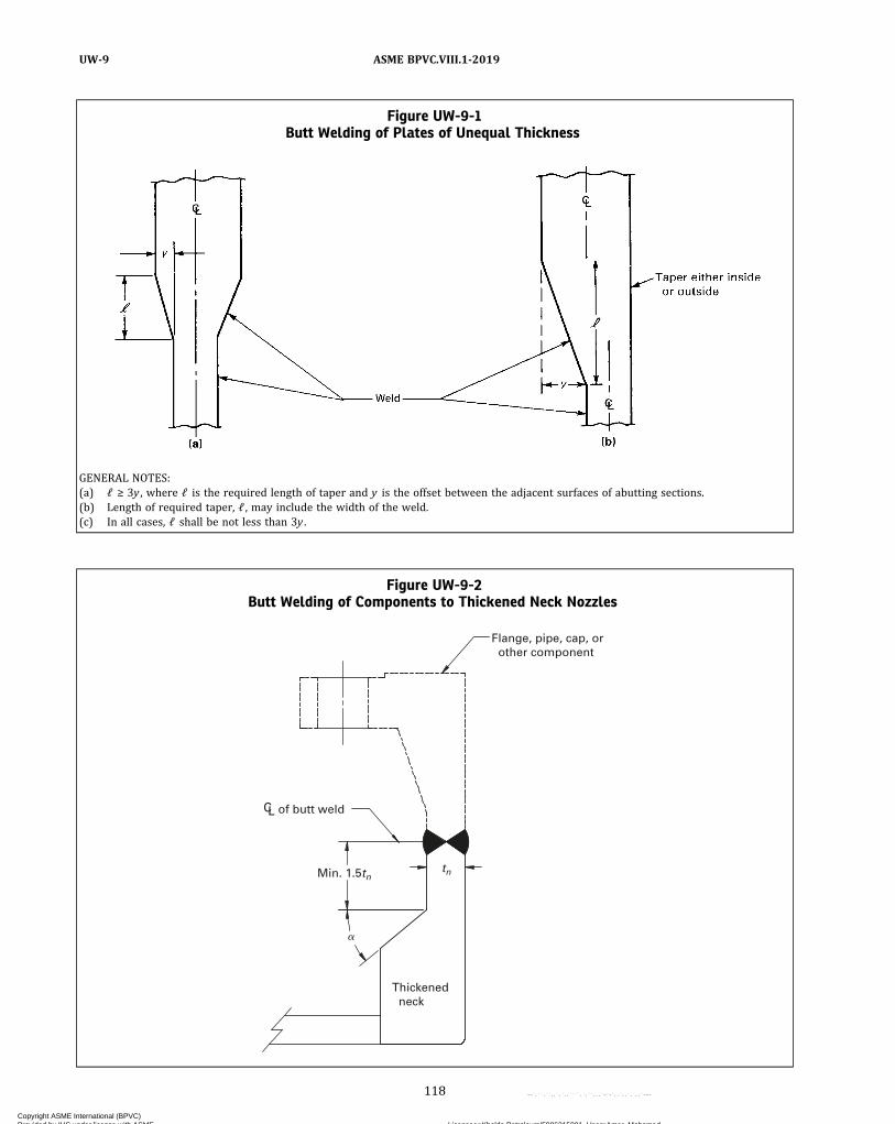
Figure UW-9-1Butt Welding of Plates of Unequal Thickness
GENERAL NOTES:(a) ℓ ≥ 3y , where ℓ is the required length of taper and y is the offset between the adjacent surfaces of abutting sections.(b) Length of required taper, ℓ , may include the width of the weld.(c) In all cases, ℓ shall be not less than 3y .
Figure UW-9-2Butt Welding of Components to Thickened Neck Nozzles
Flange, pipe, cap, or other component
CL of butt weld
Thickened neck
tn Min. 1.5tn
�
118
ASME BPVC.VIII.1-2019UW-9
Copyright ASME International (BPVC) Provided by IHS under license with ASME Licensee=Khalda Petroleum/5986215001, User=Amer, Mohamed
Not for Resale, 07/02/2019 13:29:04 MDTNo reproduction or networking permitted without license from IHS
--`,``,``,,`,`,,````,`,``,,,`-`-`,,`,,`,`,,`---
ð19Þ
(f) Welded Joints Subject to Bending Stresses. Exceptwhere specific details are permitted in other paragraphs,fillet welds shall be added where necessary to reducestress concentration. Corner joints, with fillet welds only,shall not be used unless the plates forming the corner areproperly supported independently of such welds. (SeeUW-18.)
(g) MinimumWeld Sizes. Sizing of fillet and partial pen-etration welds shall take into consideration the loadingconditions in UG-22 but shall not be less than the mini-mum sizes specified elsewhere in this Division.
UW-10 POSTWELD HEAT TREATMENTPressure vessels and pressure vessel parts shall be
postweld heat treated as prescribed in UW-40 when post-weld heat treatment is required in the applicable part ofSubsection C.
UW-11 RADIOGRAPHIC AND ULTRASONICEXAMINATION
(a) Full Radiography. The following welded joints shallbe examined radiographically for their full length in themanner prescribed in UW-51:
(1) all butt welds in the shell and heads of vesselsused to contain lethal substances [see UW-2(a)];
(2) all butt welds in the shell and heads of vessels inwhich the nominal thickness [see (g) below] at thewelded joint exceeds 11/2 in. (38 mm), or exceeds the les-ser thicknesses prescribed in UCS-57, UNF-57, UHA-33,UCL-35, or UCL-36 for the materials covered therein, oras otherwise prescr ibed in UHT-57 , ULW-51 ,ULW-52(d), ULW-54, or ULT-57;
(3) all butt welds in the shell and heads of unfiredsteam boilers having design pressures
(-a) exceeding 50 psi (350 kPa) [see UW-2(c)];(-b) not exceeding 50 psi (350 kPa) [see UW-2(c)]
but with nominal thickness at the welded joint exceedingthe thickness specified in (2) above;
(4) all butt welds in nozzles, communicating cham-bers, etc., with the nominal thickness at the welded jointthat exceeds the thickness in (2) above or attached to theshell or heads of vessels under (1)or (3) above that are re-quired to be fully radiographed; however, except as re-quired by UHT-57(a), Category B and C butt welds innozzles and communicating chambers that neither exceedNPS 10 (DN 250) nor 11/8 in. (29 mm) wall thickness donot require any radiographic examination;
(5) all Category A and D butt welds in the shell andheads of vessels where the design of the joint or part isbased on a joint efficiency permitted by UW-12(a), inwhich case:
(-a) Category A and B welds connecting the shellor heads of vessels shall be of Type No. (1) or Type No.(2) of Table UW-12;
(-b) Category B or C butt welds [but not includingthose in nozzles and communicating chambers except asrequired in (4) above] which intersect the Category A butt
welds in the shell or heads of vessels or connect seamlessvessel shell or heads shall, as a minimum, meet the re-quirements for spot radiography in accordance withUW-52. Spot radiographs required by this paragraph shallnot be used to satisfy the spot radiography rules as ap-plied to any other weld increment.
(6) all butt welds joined by electrogas welding withany single pass greater than 11/2 in. (38 mm) and all buttwelds joined by electroslag welding;
(7) all Category A welds in a tubesheet shall be ofType (1) of Table UW-12;
(8) exemptions from radiographic examination forcertain welds in nozzles and communicating chambersas described in (2), (4), and (5) above take precedenceover the radiographic requirements of Subsection C ofthis Division.
(b) Spot Radiography. Except when spot radiography isrequired for Category B or C butt welds by (a)(5)(-b)above, butt-welded joints made in accordance with TypeNo. (1) or (2) of Table UW-12 which are not required tobe fully radiographed by (a) above, may be examined byspot radiography. Spot radiography shall be in accor-dance with UW-52. If spot radiography is specified forthe entire vessel, radiographic examination is not re-quired of Category B and C butt welds in nozzles and com-municating chambers that exceed neither NPS 10(DN 250) nor 11/8 in. (29 mm) wall thickness.
NOTE: This requirement specifies spot radiography for butt welds ofType No. (1) or No. (2) that are used in a vessel, but does not pre-clude the use of fillet and/or corner welds permitted by other para-graphs, such as for nozzle and manhole attachments, welded stays,flat heads, etc., which need not be spot radiographed.
(c) No Radiography. Except as required in (a) above,no radiographic examination of welded joints is requiredwhen the vessel or vessel part is designed for externalpressure only, or when the joint design complies withUW-12(c).
(d) Electrogas welds in ferritic materials with any sin-gle pass greater than 11/2 in. (38 mm) and electroslagwelds in ferritic materials shall be ultrasonically exam-ined throughout their entire length in accordance withthe requirements of Mandatory Appendix 12. This ultra-sonic examination shall be done following the grain refin-ing (austenitizing) heat treatment or postweld heattreatment.
(e) In addition to the requirements in (a) and (b) above,all welds made by the electron beam or laser beam pro-cess shall be ultrasonically examined for their entirelength in accordance with the requirements of MandatoryAppendix 12. Ultrasonic examination may be waived ifthe following conditions are met:
(1) The nominal thickness at the welded joint doesnot exceed 1/4 in. (6 mm).
119
ASME BPVC.VIII.1-2019 UW-9 – UW-11
Copyright ASME International (BPVC) Provided by IHS under license with ASME Licensee=Khalda Petroleum/5986215001, User=Amer, Mohamed
Not for Resale, 07/02/2019 13:29:04 MDTNo reproduction or networking permitted without license from IHS
--`,``,``,,`,`,,````,`,``,,,`-`-`,,`,,`,`,,`---
ð19Þ
(2) For ferromagnetic materials, the welds are eitherexamined by the magnetic particle examination techniquein accordance with Mandatory Appendix 6 or examinedby the liquid penetrant examination technique in accor-dance with Mandatory Appendix 8.
(3) For nonferromagnetic materials, the welds areexamined by the liquid penetrant examination techniquein accordance with Mandatory Appendix 8.(f) When radiography is required for a welded joint in
accordance with (a) and (b) above, and the weld is madeby the inertia and continuous drive friction welding pro-cesses, the welded joints shall also be ultrasonically ex-amined for their entire length in accordance withMandatory Appendix 12.(g) For radiographic and ultrasonic examination of butt
welds, the definition of nominal thickness at the weldedjoint under consideration shall be the nominal thicknessof the thinner of the two parts joined. Nominal thicknessis defined in 3-2.
UW-12 JOINT EFFICIENCIESTable UW-12 gives the joint efficiencies, E , to be used
in the equations of this Division for welded joints. Exceptas required by UW-11(a)(5), a joint efficiency dependsonly on the type of joint and on the extent of examinationof the joint and does not depend on the extent of exami-nation of any other joint. The user or his designated agent[see U-2(a)] shall establish the type of joint and the extentof examination when the rules of this Division do notmandate specific requirements. Rules for determiningthe applicability of the efficiencies are found in the var-ious paragraphs covering design equations [for example,see UG-24(a) and UG-27]. For further guidance, see Non-mandatory Appendix L.(a) A value of E not greater than that given in column
(a) of Table UW-12 shall be used in the design calcula-tions for fully radiographed butt joints [see UW-11(a)],except that when the requirements of UW-11(a)(5) arenot met, a value of E not greater than that given in column(b) of Table UW-12 shall be used.(b) A value of E not greater than that given in column
(b) of Table UW-12 shall be used in the design calcula-tions for spot radiographed butt-welded joints [seeUW-11(b)].(c) A value of E not greater than that given in column
(c) of Table UW-12 shall be used in the design calculationsfor welded joints that are neither fully radiographed norspot radiographed [see UW-11(c)].(d) Seamless vessel sections or heads shall be consid-
ered equivalent to welded parts of the same geometryin which all Category A welds are Type No. 1. For calcula-tions involving circumferential stress in seamless vesselsections or for thickness of seamless heads, E = 1.0 whenthe spot radiography requirements of UW-11(a)(5)(-b)are met . E = 0 .85 when the spot rad iography
requirements of UW-11(a)(5)(-b) are not met, or whenthe Category A or B welds connecting seamless vessel sec-tions or heads are Type No. 3, 4, 5, 6, or 8 of Table UW-12.(e) Welded pipe or tubing shall be treated in the same
manner as seamless, but with allowable tensile stress ta-ken from the welded product values of the stress tables,and the requirements of (d) applied.(f) A value of E not greater than 0.80 may be used in
the equations of this Division for joints completed byany of the permitted welding processes in UW-27(b) thatinclude the application of pressure, except for electric re-sistance welding, provided the welding process used ispermitted by the rules in the applicable parts of Subsec-tion C for the material being welded. The quality of suchwelds used in vessels or parts of vessels shall be provedas follows: Test specimens shall be representative of theproduction welding on each vessel. They may be removedfrom the shell itself or from a prolongation of the shell in-cluding the longitudinal joint, or, in the case of vessels notcontaining a longitudinal joint, from a test plate of thesame material and thickness as the vessel and weldedin accordance with the same procedure. One reduced‐section tension test and two side‐bend tests shall be madein accordance with, and shall meet the requirements ofSection IX, QW-150 and QW-160.
UW-13 ATTACHMENT DETAILS(a) Definitions
th = nominal thickness of headtp = minimum distance from outside surface of flat head
to edge of weld preparation measured as shown inFigure UW-13.2
t s = nominal thickness of shell
(See UG-27, UG-28, UG-32, UG-34, and other para-graphs for additional definitions.)(b) See below.
(1) Ellipsoidal, torispherical, and other types offormed heads shall be attached to the shell with a buttweld, or as illustrated in the applicable Figure UW-13.1,sketches (a), (b), (c), (d), and (i). The construction shownin sketch (e) may also be used for end heads when thethickness of the shell section of the vessel does not exceed5/8 in. (16 mm) [see also (c) below]. Limitations relative tothe use of these attachments shall be as given in thesketches and related notes and in Table UW-12. FigureUW-13.1, sketches (f), (g), and (h) are examples of attach-ment methods which are not permissible.
(2) Formed heads, concave or convex to the pressure,shall have a skirt length not less than that shown in FigureUW-13.1, using the applicable sketch. Heads that arefitted inside or over a shell shall have a driving fit beforewelding.
(3) A tapered transition having a length not less thanthree times the offset between the adjacent surfaces ofabutting sections as shown in Figure UW-13.1, sketches(j) and (k) shall be provided at joints between formed
120
ASME BPVC.VIII.1-2019UW-11 – UW-13
Copyright ASME International (BPVC) Provided by IHS under license with ASME Licensee=Khalda Petroleum/5986215001, User=Amer, Mohamed
Not for Resale, 07/02/2019 13:29:04 MDTNo reproduction or networking permitted without license from IHS
--`,``,``,,`,`,,````,`,``,,,`-`-`,,`,,`,`,,`---
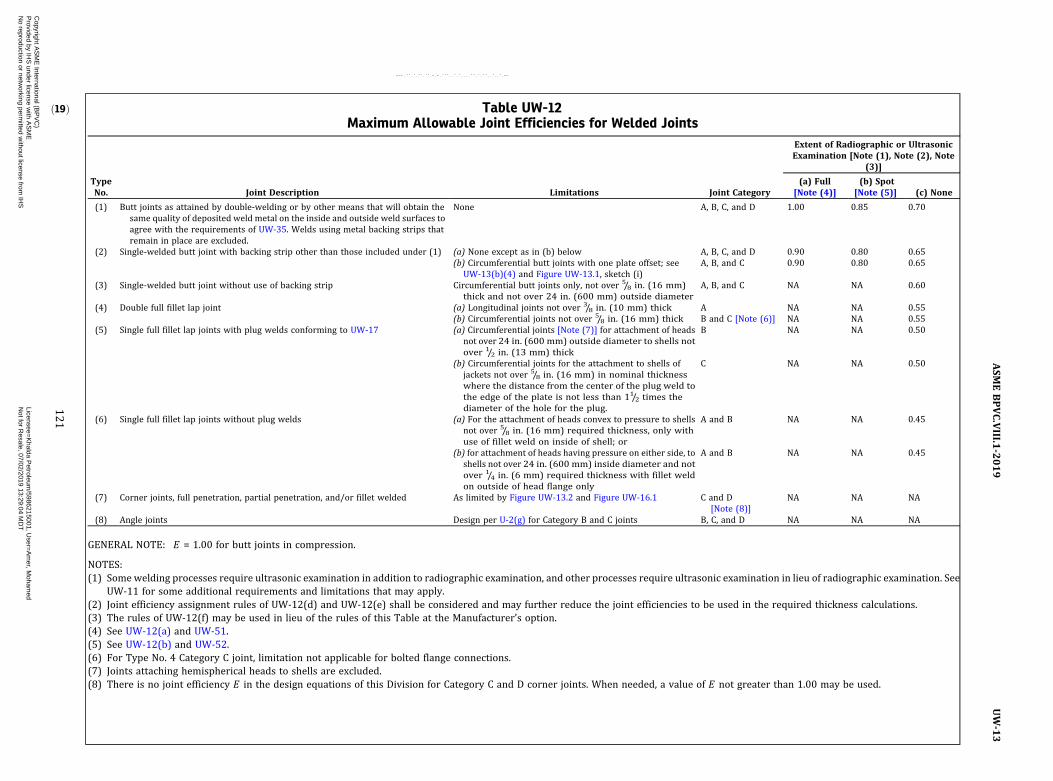
ð19Þ Table UW-12Maximum Allowable Joint Efficiencies for Welded Joints
TypeNo. Joint Description Limitations Joint Category
Extent of Radiographic or UltrasonicExamination [Note (1), Note (2), Note
(3)]
(a) Full[Note (4)]
(b) Spot[Note (5)] (c) None
(1) Butt joints as attained by double‐welding or by other means that will obtain thesame quality of deposited weld metal on the inside and outside weld surfaces toagree with the requirements of UW-35. Welds using metal backing strips thatremain in place are excluded.
None A, B, C, and D 1.00 0.85 0.70
(2) Single‐welded butt joint with backing strip other than those included under (1) (a) None except as in (b) below A, B, C, and D 0.90 0.80 0.65(b) Circumferential butt joints with one plate offset; see
UW-13(b)(4) and Figure UW-13.1, sketch (i)A, B, and C 0.90 0.80 0.65
(3) Single‐welded butt joint without use of backing strip Circumferential butt joints only, not over 5/8 in. (16 mm)thick and not over 24 in. (600 mm) outside diameter
A, B, and C NA NA 0.60
(4) Double full fillet lap joint (a) Longitudinal joints not over 3/8 in. (10 mm) thick A NA NA 0.55(b) Circumferential joints not over 5/8 in. (16 mm) thick B and C [Note (6)] NA NA 0.55
(5) Single full fillet lap joints with plug welds conforming to UW-17 (a) Circumferential joints [Note (7)] for attachment of headsnot over 24 in. (600 mm) outside diameter to shells notover 1/2 in. (13 mm) thick
B NA NA 0.50
(b) Circumferential joints for the attachment to shells ofjackets not over 5/8 in. (16 mm) in nominal thicknesswhere the distance from the center of the plug weld tothe edge of the plate is not less than 11/2 times thediameter of the hole for the plug.
C NA NA 0.50
(6) Single full fillet lap joints without plug welds (a) For the attachment of heads convex to pressure to shellsnot over 5/8 in. (16 mm) required thickness, only withuse of fillet weld on inside of shell; or
A and B NA NA 0.45
(b) for attachment of heads having pressure on either side, toshells not over 24 in. (600 mm) inside diameter and notover 1/4 in. (6 mm) required thickness with fillet weldon outside of head flange only
A and B NA NA 0.45
(7) Corner joints, full penetration, partial penetration, and/or fillet welded As limited by Figure UW-13.2 and Figure UW-16.1 C and D[Note (8)]
NA NA NA
(8) Angle joints Design per U-2(g) for Category B and C joints B, C, and D NA NA NA
GENERAL NOTE: E = 1.00 for butt joints in compression.
NOTES:(1) Somewelding processes require ultrasonic examination in addition to radiographic examination, and other processes require ultrasonic examination in lieu of radiographic examination. See
UW-11 for some additional requirements and limitations that may apply.(2) Joint efficiency assignment rules of UW-12(d) and UW-12(e) shall be considered and may further reduce the joint efficiencies to be used in the required thickness calculations.(3) The rules of UW-12(f) may be used in lieu of the rules of this Table at the Manufacturer’s option.(4) See UW-12(a) and UW-51.(5) See UW-12(b) and UW-52.(6) For Type No. 4 Category C joint, limitation not applicable for bolted flange connections.(7) Joints attaching hemispherical heads to shells are excluded.(8) There is no joint efficiency E in the design equations of this Division for Category C and D corner joints. When needed, a value of E not greater than 1.00 may be used.
121
ASM
EBPVC.VIII.1
-2019
UW-13
Copyright A
SM
E International (B
PV
C)
Provided by IH
S under license w
ith AS
ME
Licensee=
Khalda P
etroleum/5986215001, U
ser=A
mer, M
ohamed
Not for R
esale, 07/02/2019 13:29:04 MD
TN
o reproduction or networking perm
itted without license from
IHS
--`,``,``,,`,`,,````,`,``,,,`-`-`,,`,,`,`,,`---
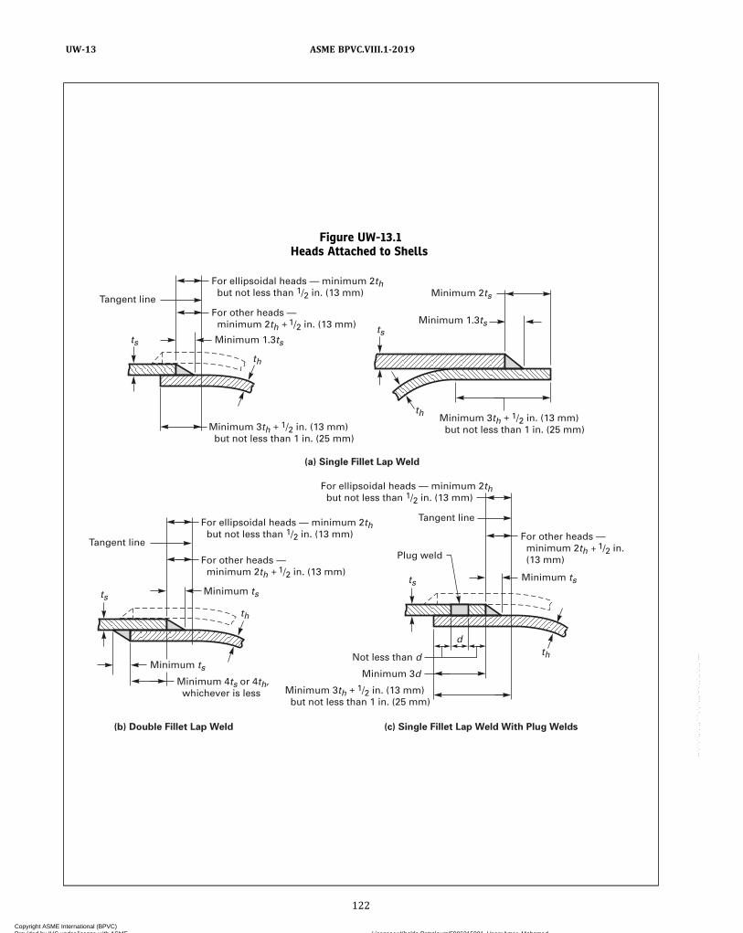
Figure UW-13.1Heads Attached to Shells
Minimum ts
For other heads — minimum 2th 1/2 in. (13 mm)
For ellipsoidal heads — minimum 2th but not less than 1/2 in. (13 mm)
For other heads — minimum 2th 1/2 in. (13 mm)
For ellipsoidal heads — minimum 2th but not less than 1/2 in. (13 mm)
Tangent line
Tangent line
(a) Single Fillet Lap Weld
(c) Single Fillet Lap Weld With Plug Welds (b) Double Fillet Lap Weld
Plug weld Tangent line
For ellipsoidal heads — minimum 2th but not less than 1/2 in. (13 mm)
For other heads — minimum 2th 1/2 in. (13 mm)
Minimum ts
Minimum 4ts or 4th, whichever is less
Minimum ts
Minimum 2ts
Minimum 1.3ts
Minimum 1.3ts
ts
th
th
ts
th
ts
Minimum 3d
Not less than d
d
Minimum 3th 1/2 in. (13 mm) but not less than 1 in. (25 mm)
Minimum 3th 1/2 in. (13 mm) but not less than 1 in. (25 mm)
Minimum 3th 1/2 in. (13 mm) but not less than 1 in. (25 mm)
ts
th
122
ASME BPVC.VIII.1-2019UW-13
Copyright ASME International (BPVC) Provided by IHS under license with ASME Licensee=Khalda Petroleum/5986215001, User=Amer, Mohamed
Not for Resale, 07/02/2019 13:29:04 MDTNo reproduction or networking permitted without license from IHS
--`,``,``,,`,`,,````,`,``,,,`-`-`,,`,,`,`,,`---

Figure UW-13.1Heads Attached to Shells (Cont'd)
th
ts
ts2
t1 t
tststs
ththth
ts1
th
Minimum 2ts
See Note (4)See Note (4)
21/2t maximum 1t minimum
As desired 11/2t minimum
Bevel optional
Avoid sharp break
t or t1 = 5/8 maximum [see Note (5)]
Depth of offset = t1
(d) Single Fillet Lap Weld (e) Intermediate Head [See Notes (2) and (3)]
(h) Not Permissible(g) Not Permissible(f-2) Not Permissible(f-1) Not Permissible
(i) Butt Weld With One Plate Edge Offset
2th minimum
Need not exceed 1 in. (25 mm)
Tangent point
I.D.
Butt weld
15 deg – 20 deg Seal or fillet weld [Note (1)]
1/2 in. (13 mm) minimum Minimum ts
Minimum 3th but need not exceed 11/2 in. (38 mm)
Tangent line
Minimum 1.3ts Taper optional
123
ASME BPVC.VIII.1-2019 UW-13
Copyright ASME International (BPVC) Provided by IHS under license with ASME Licensee=Khalda Petroleum/5986215001, User=Amer, Mohamed
Not for Resale, 07/02/2019 13:29:04 MDTNo reproduction or networking permitted without license from IHS
--`,``,``,,`,`,,````,`,``,,,`-`-`,,`,,`,`,,`---
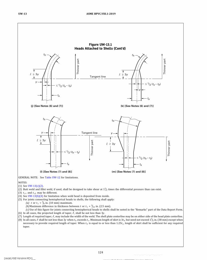
Figure UW-13.1Heads Attached to Shells (Cont'd)
Th
inn
er p
art
th
3y
1/2 (ts – th)
ts
y
Th
inn
er p
art
th
3y
1/2 (ts – th)
ts
y
(j) [See Notes (6) and (7)]
Th
inn
er p
art
Th
inn
er p
art
th
3y
1/2 (th – ts)
ts
y
(l) [See Notes (7) and (8)]
th
3y
1/2 (th – ts)
ts
y
(m) [See Notes (7) and (8)]
(k) [See Notes (6) and (7)]
Tangent line
Tangent line
GENERAL NOTE: See Table UW-12 for limitations.
NOTES:(1) See UW-13(c)(2).(2) Butt weld and fillet weld, if used, shall be designed to take shear at 11/2 times the differential pressure than can exist.(3) t s1 and t s2 may be different.(4) See UW-13(b)(4) for limitation when weld bead is deposited from inside.(5) For joints connecting hemispherical heads to shells, the following shall apply:
(a) t or t1 = 3/8 in. (10 mm) maximum.(b)Maximum difference in thickness between t or t1 = 3/32 in. (2.5 mm).(c) Use of this figure for joints connecting hemispherical heads to shells shall be noted in the “Remarks” part of the Data Report Form.
(6) In all cases, the projected length of taper, ℓ , shall be not less than 3y .(7) Length of required taper, ℓ , may include the width of the weld. The shell plate centerline may be on either side of the head plate centerline.(8) In all cases, ℓ shall be not less than 3y when th exceeds t s . Minimum length of skirt is 3th but need not exceed 11/2 in. (38 mm) except when
necessary to provide required length of taper. When th is equal to or less than 1.25t s , length of skirt shall be sufficient for any requiredtaper.
124
ASME BPVC.VIII.1-2019UW-13
Copyright ASME International (BPVC) Provided by IHS under license with ASME Licensee=Khalda Petroleum/5986215001, User=Amer, Mohamed
Not for Resale, 07/02/2019 13:29:04 MDTNo reproduction or networking permitted without license from IHS
--`,``,``,,`,`,,````,`,``,,,`-`-`,,`,,`,`,,`---
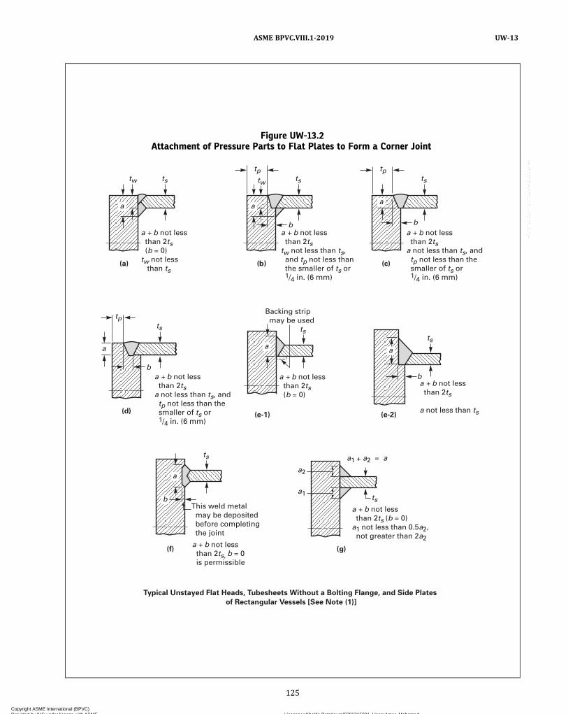
Figure UW-13.2Attachment of Pressure Parts to Flat Plates to Form a Corner Joint
a
a a
a
b
b
a
tw
(a) (b) (c)
(d) (e-1) (e-2)
Typical Unstayed Flat Heads, Tubesheets Without a Bolting Flange, and Side Plates of Rectangular Vessels [See Note (1)]
(f) (g)
twts
Backing strip may be used
tsts
ts
a2
a1ts
This weld metal may be deposited before completing the joint
ts
tp
a
a
b
ts
ts
a b not less than 2tsa not less than ts, and tp not less than the smaller of ts or 1/4 in. (6 mm)
a b not less than 2tsa not less than ts, and tp not less than the smaller of ts or 1/4 in. (6 mm)
a b not less than 2tstw not less than ts, and tp not less than the smaller of ts or 1/4 in. (6 mm)
a b not less than 2ts (b = 0)tw not less than ts
a b not less than 2ts (b = 0)
a b not less than 2ts
a not less than ts
a b not less than 2ts, b = 0 is permissible
a b not less than 2ts (b = 0)a1 not less than 0.5a2, not greater than 2a2
a1 a2 = a
b
b
tp
tp
125
ASME BPVC.VIII.1-2019 UW-13
Copyright ASME International (BPVC) Provided by IHS under license with ASME Licensee=Khalda Petroleum/5986215001, User=Amer, Mohamed
Not for Resale, 07/02/2019 13:29:04 MDTNo reproduction or networking permitted without license from IHS
--`,``,``,,`,`,,````,`,``,,,`-`-`,,`,,`,`,,`---
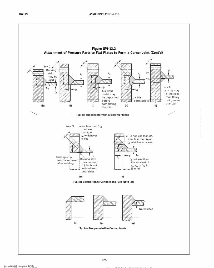
Figure UW-13.2Attachment of Pressure Parts to Flat Plates to Form a Corner Joint (Cont'd)
Backing strip may be used if joint is not welded from both sides
Not welded
a not less than 3tn c not less than tn or tx, whichever is less
tp not less than the smallest of tn, tx, or 1/4 in. (6 mm)
tpb tntn
c
c
Backing strip may be removed after welding
(b = 0)
a b not less than 3tn c not less than tn or tx, whichever is less
Typical Bolted Flange Connections [See Note (2)]
(m) (n)
Typical Nonpermissible Corner Joints
(o) (p) (q)
aa
Typical Tubesheets With a Bolting Flange
(j)(i)(h) (k) (l)
c
c c cc
aa aa
ts
ts ts ts
ts
bb
b
Backing strip may be used
This weld metal may be deposited before completing the joint
a1
a2
b = 0 is permissible
b = 0a = a1 a2 a1 not less than 0.5a2 not greater than 2a2
b = 0
126
ASME BPVC.VIII.1-2019UW-13
Copyright ASME International (BPVC) Provided by IHS under license with ASME Licensee=Khalda Petroleum/5986215001, User=Amer, Mohamed
Not for Resale, 07/02/2019 13:29:04 MDTNo reproduction or networking permitted without license from IHS
--`,``,``,,`,`,,````,`,``,,,`-`-`,,`,,`,`,,`---
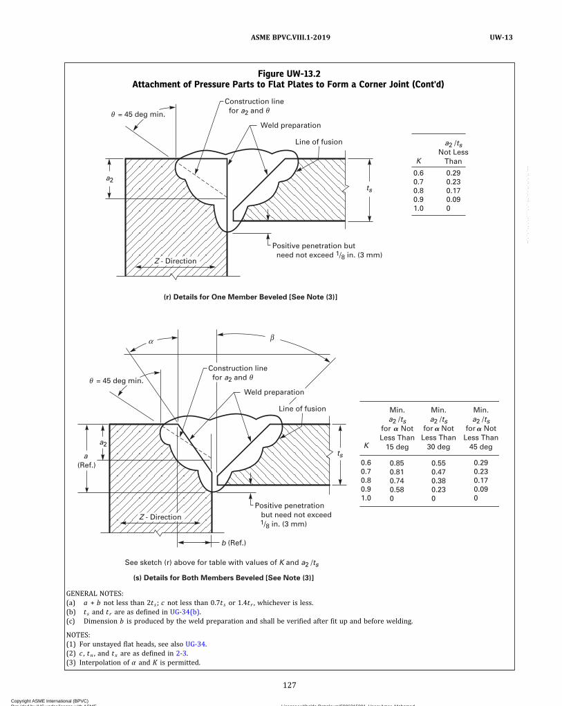
Figure UW-13.2Attachment of Pressure Parts to Flat Plates to Form a Corner Joint (Cont'd)
ts
ts
b (Ref.)
a (Ref.)
a2
a2
Positive penetration but need not exceed 1/8 in. (3 mm)
Positive penetration but need not exceed 1/8 in. (3 mm)
Line of fusion
Weld preparation
Construction line for a2 and
Line of fusion
(r) Details for One Member Beveled [See Note (3)]
(s) Details for Both Members Beveled [See Note (3)]
See sketch (r) above for table with values of K and a2 /ts
Weld preparation
Construction line for a2 and
= 45 deg min.
= 45 deg min.
Z - Direction
Z - Direction
0.6 0.7 0.8 0.9 1.0
0.29 0.23 0.17 0.09 0
K
a2 /ts Not Less
Than
K
Min. a2 /ts
for Not Less Than
15 deg
0.6 0.7 0.8 0.9 1.0
0.29 0.23 0.17 0.09 0
Min. a2 /ts
for Not Less Than
45 deg
Min. a2 /ts
for Not Less Than
30 deg
0.85 0.81 0.74 0.58 0
0.55 0.47 0.38 0.23 0
� � �
GENERAL NOTES:(a) a + b not less than 2t s ; c not less than 0.7t s or 1.4tr , whichever is less.(b) t s and t r are as defined in UG-34(b).(c) Dimension b is produced by the weld preparation and shall be verified after fit up and before welding.
NOTES:(1) For unstayed flat heads, see also UG-34.(2) c , tn , and tx are as defined in 2-3.(3) Interpolation of α and K is permitted.
127
ASME BPVC.VIII.1-2019 UW-13
Copyright ASME International (BPVC) Provided by IHS under license with ASME Licensee=Khalda Petroleum/5986215001, User=Amer, Mohamed
Not for Resale, 07/02/2019 13:29:04 MDTNo reproduction or networking permitted without license from IHS
--`,``,``,,`,`,,````,`,``,,,`-`-`,,`,,`,`,,`---
ð19Þ
heads and shells that differ in thickness by more thanone‐fourth the thickness of the thinner section or by morethan 1/8 in. (3 mm), whichever is less. When a taper is re-quired on any formed head thicker than the shell and in-tended for butt-welded attachment [Figure UW-13.1,sketches (l) and (m)], the skirt shall be long enough sothat the required length of taper does not extend beyondthe tangent line. When the transition is formed by remov-ing material from the thicker section, the minimum thick-ness of that section, after the material is removed, shallnot be less than that required by UG-23(c). When thetransition is formed by adding additional weld metal be-yond what would otherwise be the edge of the weld, suchadditional weld metal buildup shall be subject to the re-quirements of UW-42. The centerline misalignment be-tween shell and head shall be no greater than one‐halfthe difference between the actual shell and head thick-ness, as illustrated in Figure UW-13.1, sketches (j), (k),(l), and (m).
(4) Shells and heads may be attached to shells orheads using a butt weld with one plate offset as shownin Figure UW-13.1, sketch (i). The weld bead may be de-posited on the inside of the vessel only when the weldis accessible for inspection after the vessel is completed.The offset shall be smooth and symmetrical and shallnot be machined or otherwise reduced in thickness. Thereshall be a uniform force fit with the mating section at theroot of the weld. Should the offset contain a longitudinaljoint, the following shall apply:
(-a) The longitudinal weld within the area of theoffset shall be ground substantially flush with the parentmetal prior to the offsetting operation.
(-b) The longitudinal weld from the edge of theplate through the offset shall be examined by the mag-netic particle method after the offsetting operation.Cracks and cracklike defects are unacceptable and shallbe repaired or removed.
(-c) As an acceptable alternative to magnetic par-ticle examination or when magnetic particle methods arenot feasible because of the nonferromagnetic character ofthe weld deposit, a liquid penetrant method shall be used.Cracks and cracklike defects are unacceptable and shallbe repaired or removed.
(5) Non‐butt-welded bolting flanges shall be attachedto formed heads as illustrated in Figure 1-6.(c) See below.
(1) Intermediate heads, without limit to thickness, ofthe type shown in Figure UW-13.1, sketch (e) may be usedfor all types of vessels provided that the outside diameterof the head skirt is a close fit inside the overlapping endsof the adjacent length of cylinder.
(2) The butt weld and fillet weld shall be designed totake shear based on 11/2 times the maximum differentialpressure that can exist. The allowable stress value forthe butt weld shall be 70% of the stress value for the ves-sel material and that of the fillet 55%. The area of the buttweld in shear is the width at the root of the weld times the
length of weld. The area of the fillet weld is the minimumleg dimension times the length of weld. The fillet weldmay be omitted if the construction precludes access tomake the weld, and the vessel is in noncorrosive service.(d) The requirements for the attachment of welded un-
stayed flat heads to shells are given in UG-34 and in (e)and (f) hereunder.(e) When shells, heads, or other pressure parts are
welded to a forged or rolled plate to form a corner joint,as in Figure UW-13.2, the joint shall meet the following re-quirements [see also UG-93(d)(3)]:
(1) On the cross section through the welded joint, theline of fusion between the weld metal and the forged orrolled plate being attached shall be projected on planesboth parallel to and perpendicular to the surface of theplate being attached, in order to determine the dimen-sions a and b , respectively (see Figure UW-13.2).
(2) For flange rings of bolted flanged connections, asshown in Figure UW-13.2, sketches (m) and (n), the sumof a and b shall be not less than three times the nominalwall thickness of the abutting pressure part.
(3) For other components, the sum a and b shall benot less than two times the nominal wall thickness ofthe abutting pressure part unless the provisions of (f)are satisfied. Examples of such components are flat heads,tubesheets with or without a projection having holes for abolted connection, and the side plates of a rectangularvessel.
(4) Other dimensions at the joint shall be in accor-dance with details as shown in Figure UW-13.2.
(5) Joint details that have a dimension through thejoint less than the thickness of the shell, head or otherpressure part, or that provide attachment eccentric there-to, are not permissible. See Figure UW-13.2, sketches (o),(p), and (q).(f) When a multipass corner weld joint is constructed
in accordance with Figure UW-13.2, sketch (r) or sketch(s), all rules in the Code pertaining to welded joints shallapply except that the requirement “a + b not less than2t s ” of (e)(3) shall be replaced with the followingrequirements:
(1) A sample corner weld joint shall be prepared toqualify the weld procedure, and a sample corner weldjoint shall be prepared to qualify each welder or weldingoperator. The Manufacturer shall prepare the sample cor-ner weld joint with nominal thickness and configurationmatching that to be employed with the followingtolerances:
(-a) The sample thinner plate shall match thethickness of the production thinner plate within ±1/4 in.(±6 mm).
(-b) The sample thicker plate shall be at least 1.5times the thickness of the sample thinner plate.
The sample shall be sectioned, polished, andetched to clearly delineate the line of fusion. Acceptabilityshall be determined by measurements of the line of fusionfor use in the calculations for compliance with Figure
128
ASME BPVC.VIII.1-2019UW-13
Copyright ASME International (BPVC) Provided by IHS under license with ASME Licensee=Khalda Petroleum/5986215001, User=Amer, Mohamed
Not for Resale, 07/02/2019 13:29:04 MDTNo reproduction or networking permitted without license from IHS
--`,``,``,,`,`,,````,`,``,,,`-`-`,,`,,`,`,,`---
UW-13.2, sketch (r) or sketch (s). The sample shall be freefrom slag, cracks, and lack of fusion. A sample corner weldshall be prepared for each P‐Number, except that a sam-ple prepared to qualify a joint made from material witha given value for K [see (4)] may be used to qualify a jointmade from material having an equal or higher value for Kbut not vice versa.
(2) This sample corner weld joint is an addition tothe Welding Procedure Specification Qualification andthe Welder and Welding Operator Performance Qualifica-tion requirements of Section IX. The following essentialvariables apply for both the procedure and performancequalification, in addition to those of Section IX:
(-a) a change in the nominal size of the electrodeor electrodes used and listed in the PQR;
(-b) a change in the qualified root gap exceeding±1/16 in. (±1.5 mm);
(-c) addition or deletion of nonmetallic retainersor nonfusing metal retainers;
(-d) a change in the SFA specification filler metalclassification or to a weld metal or filler metal composi-tion not covered in the specifications;
(-e) the addition of welding positions other thanthose qualified;
(-f) for fill passes, a change in amperage exceeding±25 amp, change in voltage exceeding ±3 V;
(-g) a change in contact tube to work distance ex-ceeding 1/4 in. (6 mm);
(-h) a change from single electrode to multipleelectrodes, or vice versa;
(-i) a change in the electrode spacing;(-j) a change from manual or semiautomatic to ma-
chine or automatic welding or vice versa.(3) After production welding, the back side of the
weld shall be subjected to a visual examination to ensurethat complete fusion and penetration have been achievedin the root, except where visual examination is locallyprevented by an internal member covering the weld.
(4) K , the ratio of through‐thickness (Z direction)tensile strength to the specified minimum tensilestrength, shall be taken as 0.6. Higher values for K , butnot higher than 1.0, may be used if through‐thickness ten-sile strength is determined in accordance with Specifica-tion SA-770. The test results, including the UTS inaddition to the reduction in area, shall be reported onthe Material Test Report, in addition to the informationrequired by Specification SA-20 when the testing in accor-dance with Specification SA-770 is performed by the ma-terial manufacturer. If the testing is performed by thevessel Manufacturer, the test result shall be reported onthe Manufacturer’s Data Report. See UG-93(b) andUG-93(c).
(5) The maximum value of t s [see Figure UW-13.2,sketch (r) or sketch (s)] shall be limited to 3 in. (75 mm).
(6) Both members may be beveled as shown inFigure UW-13.2, sketch (s). When the bevel angle, α, islarge enough to satisfy the (e)(3) requirements, these
alternative rules do not apply. When the bevel angle, α, re-sults in weld fusion dimensions that do not satisfy the(e)(3) requirement that a + b is not less than 2ts, the fol-lowing shall be satisfied:
(-a) The angle α shall be equal to or greater than15 deg.
(-b) The dimension a2 shall be measured from theprojected surface of the plate being attached as shown inFigure UW-13.2, sketch (s).
(-c) The angle β shall be equal to or greater than15 deg.
(-d) When a2/t s is equal to or exceeds the valuecorresponding to the K shown in the table in FigureUW-13.2, sketch (s), the requirements in (1) and (2) neednot be satisfied. When a2/t s is less than this value, allother requirements of (f) shall be satisfied.
(g)When used, the hub of a tubesheet or flat head shallhave minimum dimensions in accordance with FigureUW-13.3 and shall meet the following requirements:
(1)When the hub is integrally forged with the tube-sheet or flat head, or is machined from a forging, thehub shall have the minimum tensile strength and elonga-tion specified for the material, measured in the directionparallel to the axis of the vessel. Proof of this shall be furn-ished by a tension test specimen (subsize if necessary) ta-ken in this direction and as close to the hub as practical.67
(2)When the hub is machined from plate, the re-quirements of Mandatory Appendix 20 shall be met.
(h)When the hub of a lap joint stub end is machinedfrom plate with the hub length in the through thicknessdirection of the plate, the requirements of MandatoryAppendix 20 shall be met.
(i) In the case of nozzle necks which attach to piping[see U-1(e)(1)(-a)] of a lesser wall thickness, a taperedtransition from the weld end of the nozzle may be pro-vided to match the piping thickness although that thick-ness is less than otherwise required by the rules of thisDivision. This tapered transition shall meet the limita-tions as shown in Figure UW-13.4.
UW-14 OPENINGS IN OR ADJACENT TO WELDS(a) Any type of opening that meets the requirements
for reinforcement given in UG-37 or UG-39 may be lo-cated in a welded joint.
(b) Single openings meeting the requirements given inUG-36(c)(3) may be located in head‐to‐shell or CategoryB or C butt-welded joints, provided the weld meets theradiographic requirements in UW-51 for a length equalto three times the diameter of the opening with the centerof the hole at midlength. Defects that are completely re-moved in cutting the hole shall not be considered in jud-ging the acceptability of the weld.
(c) In addition to meeting the radiographic require-ments of (b) above, when multiple openings meetingthe requirements given in UG-36(c)(3) are in line in a
129
ASME BPVC.VIII.1-2019 UW-13 – UW-14
Copyright ASME International (BPVC) Provided by IHS under license with ASME Licensee=Khalda Petroleum/5986215001, User=Amer, Mohamed
Not for Resale, 07/02/2019 13:29:04 MDTNo reproduction or networking permitted without license from IHS
--`,``,``,,`,`,,````,`,``,,,`-`-`,,`,,`,`,,`---

Figure UW-13.3Typical Pressure Parts With Butt-Welded Hubs
tsr ts
tsh
See Note (1)
Tension test specimen
Tension test specimen
e is not less than ts nor less than the required thickness for a flat head or tubesheet
(a) (b) (c)
e
r
GENERAL NOTES:(a) Refer to Figure UG-34, sketch (b‐2) for dimensional requirements.(b) Not permissible if machined from rolled plate unless in accordance with Mandatory Appendix 20. See UW-13(g).(c) Tension test specimen may be located inside or outside the hub.
NOTE:(1) h is the greater of 3/4 in. (19 mm) or 1.5ts, but need not exceed 2 in. (50 mm).
Figure UW-13.4Nozzle Necks Attached to Piping of Lesser Wall Thickness
tn[Note (1)]
tn[Note (1)]
t1 [Note (3)]
trn
trn
1/4 in. min. (6 mm) radius
1/4 in. (6 mm) min. radius
1/4 in. (6 mm) min. radius
See Note (2)
See Note (2)
18.5 deg max.; 14 deg min.
(a) (b)
18.5 deg max.; 14 deg min.
30 deg max.
18.5 deg max.; 14 deg min.
30 deg max.
30 deg max.
t1 [Note (3)]
NOTES:(1) As defined in UG-40. tn shall not be less than the thickness required by UG-45.(2) Weld bevel is shown for illustration only.(3) t1 is not less than the greater of
(a) 0.8t rn , where t rn = required thickness of seamless nozzle wall(b)minimum wall thickness of connecting pipe
130
ASME BPVC.VIII.1-2019UW-14
Copyright ASME International (BPVC) Provided by IHS under license with ASME Licensee=Khalda Petroleum/5986215001, User=Amer, Mohamed
Not for Resale, 07/02/2019 13:29:04 MDTNo reproduction or networking permitted without license from IHS
--`,``,``,,`,`,,````,`,``,,,`-`-`,,`,,`,`,,`---

ð19Þ
head‐to‐shell or Category B or C butt-welded joint, the re-quirements of UG-53 shall be met or the openings shall bereinforced in accordance with UG-37 through UG-42.
(d) Except when the adjacent butt weld satisfies the re-quirement for radiography in (b) above, the edge of open-ings in solid plate meeting the requirements ofUG-36(c)(3) shall not be placed closer than 1/2 in.(13 mm) from the edge of a Category A, B, or C weld formaterial 11/2 in. (38 mm) thick or less.
UW-15 WELDED CONNECTIONS(a) Nozzles, other connections, and their reinforce-
ments may be attached to pressure vessels by welding.Sufficient welding shall be provided on either side ofthe line through the center of the opening parallel tothe longitudinal axis of the shell to develop the strengthof the reinforcing parts as prescribed in UG-41 throughshear or tension in the weld, whichever is applicable.The strength of groove welds shall be based on the areasubjected to shear or to tension. The strength of filletwelds shall be based on the area subjected to shear (com-puted on the minimum leg dimension). The inside dia-meter of a fillet weld shall be used in figuring its length.
(b) Strength calculations for nozzle attachment weldsfor pressure loading are not required for the following:
(1) Figure UW-16.1, sketches (a), (b), (c), (d), (e),(f‐1), (f‐2), (f‐3), (f‐4), (g), (x‐1), (y‐1), and (z‐1), and allthe sketches in Figures UHT-18.1 and UHT-18.2
(2) openings that are exempt from the reinforcementrequirements by UG-36(c)(3)
(3) openings designed in accordance with the rulesfor ligaments in UG-53
(c) The allowable stress values for groove and filletwelds in percentages of stress values for the vessel mate-rial, which are used with UG-41 calculations, are asfollows:
(1) groove‐weld tension, 74%(2) groove‐weld shear, 60%
(3) fillet‐weld shear, 49%
NOTE: These values are obtained by combining the following factors:871/2% for combined end and side loading, 80% for shear strength,and the applicable joint efficiency factors.
UW-16 MINIMUM REQUIREMENTS FORATTACHMENT WELDS AT OPENINGS
(a) General(1) The terms: nozzles, connections, reinforcements,
necks, tubes, fittings, pads, and other similar terms usedin this paragraph define essentially the same type con-struction and form a Category D weld joint between thenozzle (or other term) and the shell, head, etc., as definedin UW-3(d).
(2) The location and minimum size of attachmentwelds for nozzles and other connections shall conformto the requirements of this paragraph in addition to thestrength calculations required in UW-15.
(b) Symbols. The symbols used in this paragraph and inFigures UW-16.1 and UW-16.2 are defined as follows:
Do = outside diameter of neck or tube attached bywelding on inside of vessel shell only
G = radial clearance between hole in vessel walland outside diameter of nozzle neck or tube
r1 = minimum inside corner radius, the lesser of1/4t or
1/8 in. (3 mm)Radius = 1/8 in. (3 mm) minimum blend radius
t = nominal thickness of vessel shell or head,t1 or t2 = not less than the smaller of 1/4 in. (6 mm) or
0.7tmin
tc = not less than the smaller of 1/4 in. (6 mm) or0.7tmin (inside corner welds may be furtherlimited by a lesser length of projection of thenozzle wall beyond the inside face of the ves-sel wall)
te = thickness of reinforcing plate, as defined inUG-40
tmin = the smaller of 3/4 in. (19 mm) or the thicknessof the thinner of the parts joined by a fillet,single‐bevel, or single‐J weld
tn = nominal thickness of nozzle walltw = dimension of attachment welds (fillet, single‐
bevel, or single‐J), measured as shown inFigure UW-16.1
(c) Necks Attached by a Full Penetration Weld. Necksabutting a vessel wall shall be attached by a full penetra-tion groove weld. See Figure UW-16.1, sketches (a) and(b) for examples. Necks inserted through the vessel wallmay be attached by a full penetration groove weld. SeeFigure UW-16.1, sketches (c), (d), and (e). When completejoint penetration cannot be verified by visual inspectionor other means permitted in this Division, backing stripsor equivalent shall be used with full penetration welds de-posited from one side.
Figure UW-13.5Fabricated Lap Joint Stub Ends for Lethal
Service
3/8 in. (10 mm) min.
Weld No. 1
Weld No. 2
131
ASME BPVC.VIII.1-2019 UW-14 – UW-16
Copyright ASME International (BPVC) Provided by IHS under license with ASME Licensee=Khalda Petroleum/5986215001, User=Amer, Mohamed
Not for Resale, 07/02/2019 13:29:04 MDTNo reproduction or networking permitted without license from IHS
--`,``,``,,`,`,,````,`,``,,,`-`-`,,`,,`,`,,`---

ð19Þ
Figu
reUW-16.1
SomeAccep
tableTy
pesof
Welde
dNoz
zles
andOther
Con
nections
toSh
ells,H
eads
,etc.
132
ASME BPVC.VIII.1-2019UW-16
Copyright ASME International (BPVC) Provided by IHS under license with ASME Licensee=Khalda Petroleum/5986215001, User=Amer, Mohamed
Not for Resale, 07/02/2019 13:29:04 MDTNo reproduction or networking permitted without license from IHS
--`,``,``,,`,`,,````,`,``,,,`-`-`,,`,,`,`,,`---
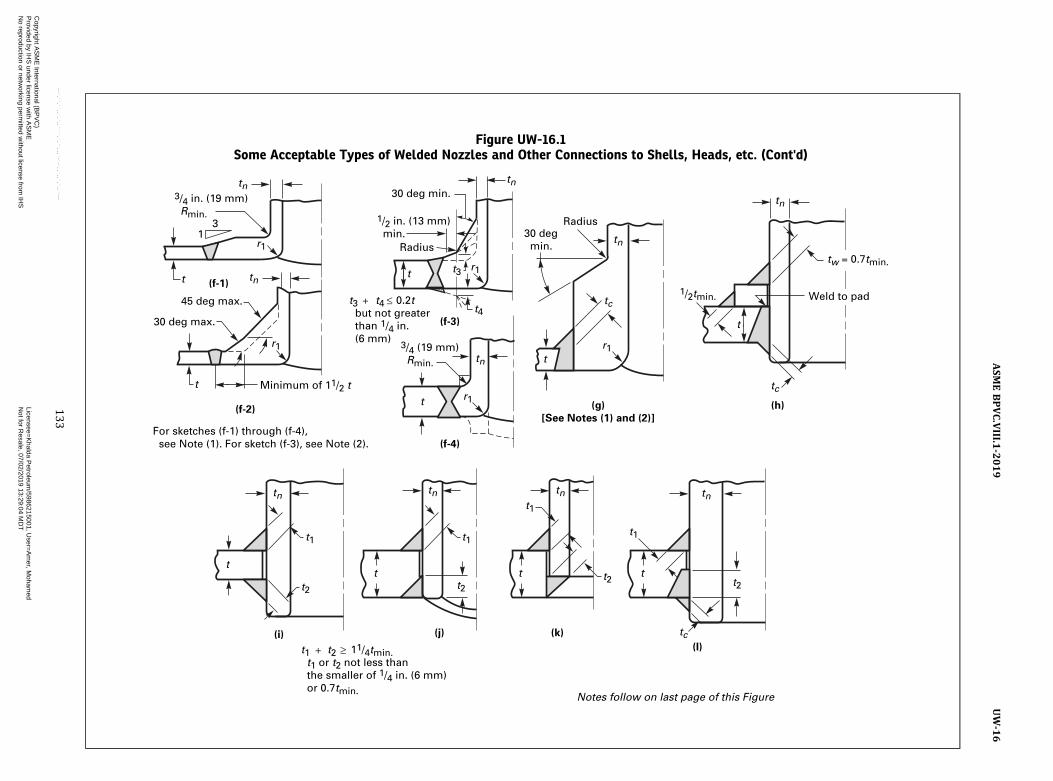
Figure UW-16.1Some Acceptable Types of Welded Nozzles and Other Connections to Shells, Heads, etc. (Cont'd)
t
t
t
13
30 deg max.
Minimum of 11/2 t
For sketches (f-1) through (f-4), see Note (1). For sketch (f-3), see Note (2).
Notes follow on last page of this Figure
t1 t2 11/4tmin. t1 or t2 not less than the smaller of 1/4 in. (6 mm) or 0.7tmin.
1/2 in. (13 mm) min.
1/2tmin.
3/4 (19 mm) Rmin.
45 deg max.
3/4 in. (19 mm) Rmin.
30 deg min.
t3 t4 0.2t but not greater than 1/4 in. (6 mm)
Radius
Radius30 deg min.
(f-4)
(f-3)
(g)
[See Notes (1) and (2)]
(h)
(l)
(k)(j)(i)
(f-2)
(f-1)
r1
r1
r1
tn
tn
tn
tn
tn
tc
tct
t
t
r1
r1tn
t4
t3
tt
tc
tntntn
t2
t1
t1
t2t
t1
t2
tw = 0.7tmin.
tn
t
t1
t2
Weld to pad
133
ASM
EBPVC.VIII.1
-2019
UW-16
Copyright A
SM
E International (B
PV
C)
Provided by IH
S under license w
ith AS
ME
Licensee=
Khalda P
etroleum/5986215001, U
ser=A
mer, M
ohamed
Not for R
esale, 07/02/2019 13:29:04 MD
TN
o reproduction or networking perm
itted without license from
IHS
--`,``,``,,`,`,,````,`,``,,,`-`-`,,`,,`,`,,`---
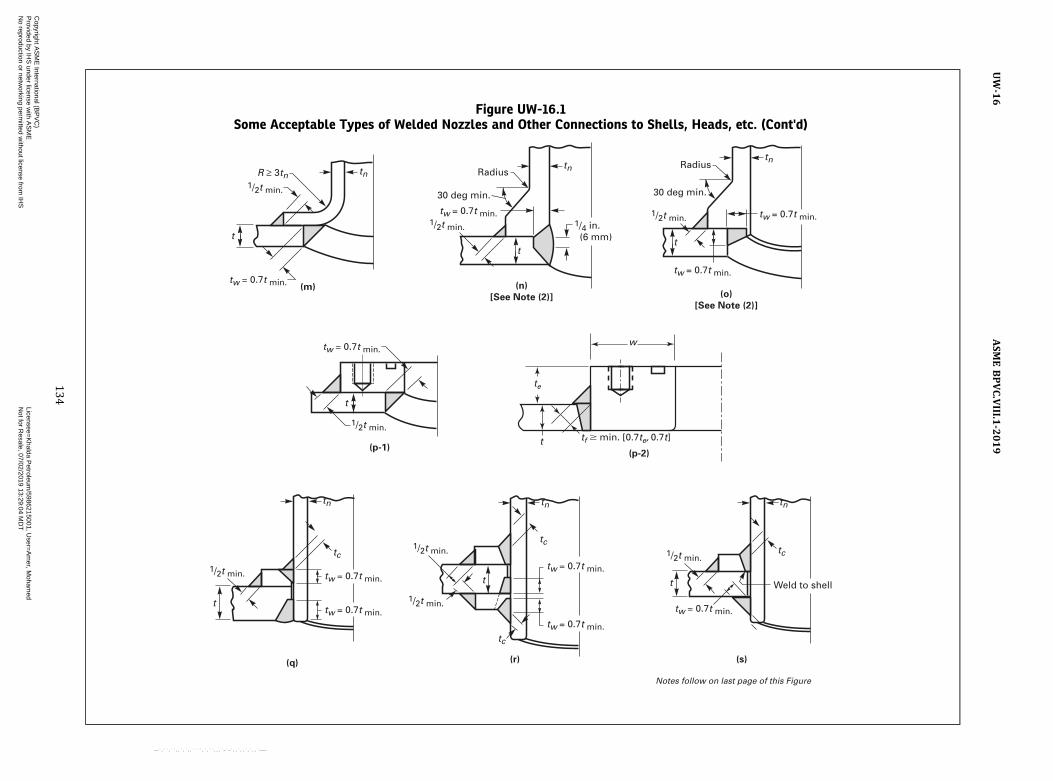
Figure UW-16.1Some Acceptable Types of Welded Nozzles and Other Connections to Shells, Heads, etc. (Cont'd)
tw = 0.7t min.
tw = 0.7t min.tw = 0.7t min.
tw = 0.7t min.
tw = 0.7t min.
Weld to shell
Notes follow on last page of this Figure
tw = 0.7t min.
tw = 0.7t min.
tw = 0.7t min.
tntntn
tn tn
tc
tc
RadiusRadiusR 3tn
30 deg min.30 deg min.
1/2t min.1/4 in. (6 mm)
tw = 0.7t min.
(q)
(p-1)
(m) (n)
[See Note (2)] (o)
[See Note (2)]
(r) (s)
tw = 0.7t min.
tc
1/2t min.
1/2t min.
1/2t min.
1/2t min.
1/2t min.1/2t min.
t
t
t
t
t
tn
tc1/2t min.
t
t
(p-2)
w
t
te
tf � min. [0.7te, 0.7t]
134
ASM
EBPVC.VIII.1
-2019
UW-16
Copyright A
SM
E International (B
PV
C)
Provided by IH
S under license w
ith AS
ME
Licensee=
Khalda P
etroleum/5986215001, U
ser=A
mer, M
ohamed
Not for R
esale, 07/02/2019 13:29:04 MD
TN
o reproduction or networking perm
itted without license from
IHS
--`,``,``,,`,`,,````,`,``,,,`-`-`,,`,,`,`,,`---

Figure UW-16.1Some Acceptable Types of Welded Nozzles and Other Connections to Shells, Heads, etc. (Cont'd)
1/16 in. (1.5 mm) recess
1/16 in. (1.5 mm) recess
tn but not less than 1/4 in. (6 mm)
Typical Tube Connections
(When used for other than square, round, or oval headers, round off corners)
tn but not less than 1/4 in. (6 mm)
(t) (u)
(w-2)
[See Note (3)]
(w-1)
[See Note (3)]
(v-2)
[See Note (3)]
(v-1)
[See Note (3)]
Section A–A
tc tn tw
tn
tc
A
tw
tc
tn
G G
Do Outside
11/4tmin
Do Outside
11/4tmin
11/4tmin
G
Do Outside
11/4tmin
G
Do Outside
Notes follow on last page of this Figure.
A
135
ASM
EBPVC.VIII.1
-2019
UW-16
Copyright A
SM
E International (B
PV
C)
Provided by IH
S under license w
ith AS
ME
Licensee=
Khalda P
etroleum/5986215001, U
ser=A
mer, M
ohamed
Not for R
esale, 07/02/2019 13:29:04 MD
TN
o reproduction or networking perm
itted without license from
IHS
--`,``,``,,`,`,,````,`,``,,,`-`-`,,`,,`,`,,`---

Figure UW-16.1Some Acceptable Types of Welded Nozzles and Other Connections to Shells, Heads, etc. (Cont'd)
tc
NPS 3 (DN 80) max.
t1 t2 11/4tmin t1 or t2 not less than the smaller of 1/4 in. (6 mm) or 0.7tmin
1/2tmin
tw [See UW-16(f)(4)]
tc tc
tc
tc
t1
t1
t1
t2 t2
t2
tw = 0.7tmin
Either method of attachment is satisfactory
(aa)
[See Note (4)]
(x-1) (x-2)
[See Notes (1) and (4)]
(y-1) (y-2)
[See Notes (1) and (4)]
(z-1) (z-2)
[See Notes (1) and (4)]
(bb)
[See Note (4)]
NOTES:(1) Sketches (a), (b), (c), (d), (e), (f-1) through (f-4), (g), (x-1), (y-1), and (z-1) are examples of nozzles with integral reinforcement.(2) Where the term Radius appears, provide a 1/8 in. (3 mm) minimum blend radius.(3) For sketches (v-1) through (w-2):
(a) For applications where there are no external loads, G = 1/8 in. (3 mm) max.(b)With external loadsG = 0.005 for Do ≤ 1 in. (25 mm); G = 0.010 for 1 in. (25 mm) < Do ≤ 4 in. (100 mm); G = 0.015 for 4 in. (100 mm) < Do ≤ 65/8 in. (170 mm)
(4) For NPS 3 (DN 80) and smaller, see exemptions in UW-16(f)(2).
136
ASM
EBPVC.VIII.1
-2019
UW-16
Copyright A
SM
E International (B
PV
C)
Provided by IH
S under license w
ith AS
ME
Licensee=
Khalda P
etroleum/5986215001, U
ser=A
mer, M
ohamed
Not for R
esale, 07/02/2019 13:29:04 MD
TN
o reproduction or networking perm
itted without license from
IHS
--`,``,``,,`,`,,````,`,``,,,`-`-`,,`,,`,`,,`---

ð19Þ
If additional reinforcement is required, it shall be pro-vided as integral reinforcement as described in (1) below,or by the addition of separate reinforcement elements(plates) attached by welding as described in (2) below.
(1) Integral reinforcement is that reinforcement pro-vided in the form of extended or thickened necks, thick-ened shell plates, forging type inserts, or weld buildupwhich is an integral part of the shell or nozzle wall and,where required, is attached by full penetration welds.See Figure UW-16.1, sketches (a), (b), (c), (d), (e), (f‐1),(f‐2), (f‐3), (f‐4), (g), (x‐1), (y‐1), and (z‐1) for examplesof nozzles with integral reinforcement where the F factorin Figure UG-37 may be used.
(2) Separate reinforcement elements (plates) may beadded to the outside surface of the shell wall, the insidesurface of the shell wall, or to both surfaces of the shellwall. When this is done, the nozzle and reinforcement isno longer considered a nozzle with integral reinforcementand the F factor in UG-37(a) shall be F = 1.0. FigureUW-16.1, sketches (a‐1), (a‐2), and (a‐3) depict variousapplications of reinforcement elements added to sketch(a). Any of these applications of reinforcement elementsmay be used with necks of the types shown in FigureUW-16.1, sketches (b), (c), (d), and (e) or any other inte-gral reinforcement types listed in (1) above. The rein-forcement plates shall be attached by welds at the outeredge of the plate, and at the nozzle neck periphery or in-ner edge of the plate if no nozzle neck is adjacent to theplate.
(-a) The weld at the outer edge of the reinforce-ment plate shall be a continuous fillet weld with a mini-mum throat dimension of 1/2tmin.
(-b) The weld at the inner edge of the reinforce-ment plate which does not abut a nozzle neck shall be acontinuous fillet weld with a minimum throat dimension1/2tmin [see Figure UW-16.1, sketches (a‐2) and (a‐3)].
(-c) The weld at the inner edge of the reinforce-ment plate when the reinforcement plate is full penetra-tion welded to the nozzle neck shall be a continuousfillet weld with a minimum throat dimension of tc [seeFigure UW-16.1, sketches (a‐1) and (a‐3)].
(-d) The weld at the inner edge of the reinforce-ment plate when the reinforcement plate is not full pene-tration welded to the nozzle neck shall be a continuousfil let weld with a minimum throat dimension oftw = 0.7tmin [see Figure UW-16.1, sketch (h)].
(d) Neck Attached by Fillet or Partial Penetration Welds(1) Necks inserted into or through the vessel wall
may be attached by fillet or partial penetration welds,one on each face of the vessel wall. The welds may beany desired combination of fillet, single‐bevel, andsingle‐J welds. The dimension of t1 or t2 for each weldshall be not less than the smaller of 1/4 in. (6 mm) or0.7tmin, and their sum shall be not less than 11/4tmin. SeeFigure UW-16.1, sketches (i), (j), (k), and (l).
If additional reinforcement is required, it may beprovided in the form of extended or thickened necks,thickened shell plates, forgings, and/or separate rein-forcement elements (plates) attached by welding. Weldrequirements shall be the same as given in (c)(2) above,except as follows. The welds attaching the neck to the ves-sel wall or to the reinforcement plate shall consist of oneof the following:
(-a) a single‐bevel or single‐J weld in the shellplate, and a single‐bevel or single‐J weld in each reinforce-ment plate. The dimension tw of each weld shall be notless than 0.7tmin. See Figure UW-16.1, sketches (q) and(r).
(-b) a full penetration groove weld in each rein-forcement plate, and a fillet, single‐bevel, or single‐J weldwith a weld dimension tw not less than 0.7tmin in the shellplate. See Figure UW-16.1, sketch (s).
(2) Nozzle necks, flared necks, and studding outlettype flanges may be attached by fillet welds or partialpenetration welds between the outside diameter or theattachment and the outside surface of the shell and atthe inside of the opening in the shell. The throat dimen-sion of the outer attachment weld shall not be less than1/2tmin. The dimension tw of the weld at the inside of theshell cutout shall not be less than 0.7tmin. See FigureUW-16.1, sketches (m), (n), (o), and (p-1). Studding-outlet-type flanges may also be attached by full-penetration welds as shown in Figure UW-16.1, sketch(p-2).
(e) Necks and Tubes Up to and Including NPS 6 (DN 150)Attached From One Side Only. Necks and tubes not exceed-ing NPS 6 (DN 150) may be attached from one side onlyon either the outside or inside surface of the vessel.
(1) The depth of the welding groove or the throat ofthe fillet weld shall be at least equal to 11/4tmin. The radialclearance between the vessel hole and the nozzle outsidediameter at the unwelded side shall not exceed the toler-ances given in Figure UW-16.1, sketches (v‐1), (v‐2),(w‐1), and (w‐2). When welded from the outside only,the neck or tube shall extend to be at least flush to the in-side surface of the vessel wall. Such attachments shall sa-tisfy the rules for reinforcement of openings, except thatno material in the nozzle neck shall be counted asreinforcement.
(2) As an alternative to (1) above, when the neck ortube is attached from the outside only, a welding grooveshall be cut into the surface to a depth of not less thantn on the longitudinal axis of the opening. It is recom-mended that a recess 1/16 in. (1.5 mm) deep be providedat the bottom of the groove, in which to center the nozzle.The dimension tw of the attachment weld shall be not lessthan tn nor less than
1/4 in. (6 mm). See Figure UW-16.1,sketches (t) and (u).
(f) Standard Fittings: ASME/ANSI or Manufacturer’sStandard. The attachment of standard fittings shall meetthe following requirements; see (g) for the attachmentof bolting pads:
137
ASME BPVC.VIII.1-2019 UW-16
Copyright ASME International (BPVC) Provided by IHS under license with ASME Licensee=Khalda Petroleum/5986215001, User=Amer, Mohamed
Not for Resale, 07/02/2019 13:29:04 MDTNo reproduction or networking permitted without license from IHS
--`,``,``,,`,`,,````,`,``,,,`-`-`,,`,,`,`,,`---
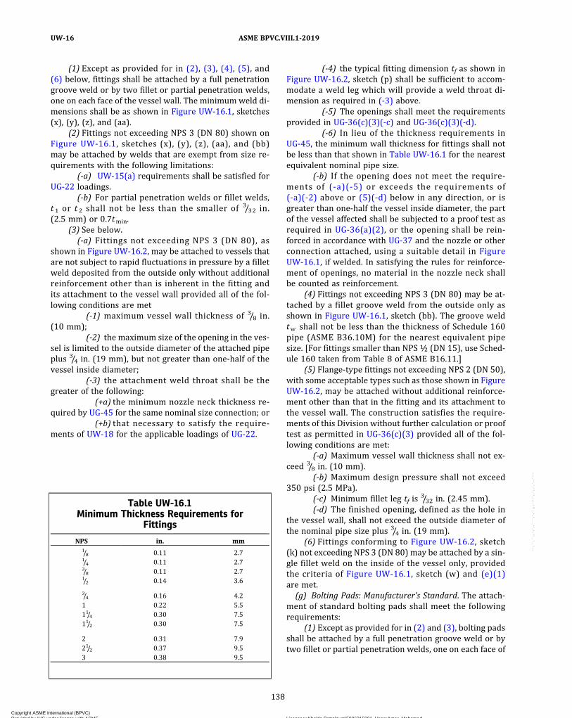
(1) Except as provided for in (2), (3), (4), (5), and(6) below, fittings shall be attached by a full penetrationgroove weld or by two fillet or partial penetration welds,one on each face of the vessel wall. The minimumweld di-mensions shall be as shown in Figure UW-16.1, sketches(x), (y), (z), and (aa).
(2) Fittings not exceeding NPS 3 (DN 80) shown onFigure UW-16.1, sketches (x), (y), (z), (aa), and (bb)may be attached by welds that are exempt from size re-quirements with the following limitations:
(-a) UW-15(a) requirements shall be satisfied forUG-22 loadings.
(-b) For partial penetration welds or fillet welds,t 1 or t 2 shall not be less than the smaller of 3/32 in.(2.5 mm) or 0.7tmin.
(3) See below.(-a) Fittings not exceeding NPS 3 (DN 80), as
shown in Figure UW-16.2, may be attached to vessels thatare not subject to rapid fluctuations in pressure by a filletweld deposited from the outside only without additionalreinforcement other than is inherent in the fitting andits attachment to the vessel wall provided all of the fol-lowing conditions are met
(-1) maximum vessel wall thickness of 3/8 in.(10 mm);
(-2) the maximum size of the opening in the ves-sel is limited to the outside diameter of the attached pipeplus 3/4 in. (19 mm), but not greater than one‐half of thevessel inside diameter;
(-3) the attachment weld throat shall be thegreater of the following:
(+a) the minimum nozzle neck thickness re-quired by UG-45 for the same nominal size connection; or
(+b) that necessary to satisfy the require-ments of UW-18 for the applicable loadings of UG-22.
(-4) the typical fitting dimension tf as shown inFigure UW-16.2, sketch (p) shall be sufficient to accom-modate a weld leg which will provide a weld throat di-mension as required in (-3) above.
(-5) The openings shall meet the requirementsprovided in UG-36(c)(3)(-c) and UG-36(c)(3)(-d).
(-6) In lieu of the thickness requirements inUG-45, the minimum wall thickness for fittings shall notbe less than that shown in Table UW-16.1 for the nearestequivalent nominal pipe size.
(-b) If the opening does not meet the require-ments of (-a)(-5) or exceeds the requirements of(-a)(-2) above or (5)(-d) below in any direction, or isgreater than one‐half the vessel inside diameter, the partof the vessel affected shall be subjected to a proof test asrequired in UG-36(a)(2), or the opening shall be rein-forced in accordance with UG-37 and the nozzle or otherconnection attached, using a suitable detail in FigureUW-16.1, if welded. In satisfying the rules for reinforce-ment of openings, no material in the nozzle neck shallbe counted as reinforcement.
(4) Fittings not exceeding NPS 3 (DN 80) may be at-tached by a fillet groove weld from the outside only asshown in Figure UW-16.1, sketch (bb). The groove weldtw shall not be less than the thickness of Schedule 160pipe (ASME B36.10M) for the nearest equivalent pipesize. [For fittings smaller than NPS ½ (DN 15), use Sched-ule 160 taken from Table 8 of ASME B16.11.]
(5) Flange‐type fittings not exceeding NPS 2 (DN 50),with some acceptable types such as those shown in FigureUW-16.2, may be attached without additional reinforce-ment other than that in the fitting and its attachment tothe vessel wall. The construction satisfies the require-ments of this Division without further calculation or prooftest as permitted in UG-36(c)(3) provided all of the fol-lowing conditions are met:
(-a) Maximum vessel wall thickness shall not ex-ceed 3/8 in. (10 mm).
(-b) Maximum design pressure shall not exceed350 psi (2.5 MPa).
(-c) Minimum fillet leg tf is3/32 in. (2.45 mm).
(-d) The finished opening, defined as the hole inthe vessel wall, shall not exceed the outside diameter ofthe nominal pipe size plus 3/4 in. (19 mm).
(6) Fittings conforming to Figure UW-16.2, sketch(k) not exceeding NPS 3 (DN 80) may be attached by a sin-gle fillet weld on the inside of the vessel only, providedthe criteria of Figure UW-16.1, sketch (w) and (e)(1)are met.(g) Bolting Pads: Manufacturer’s Standard. The attach-
ment of standard bolting pads shall meet the followingrequirements:
(1) Except as provided for in (2) and (3), bolting padsshall be attached by a full penetration groove weld or bytwo fillet or partial penetration welds, one on each face of
Table UW-16.1Minimum Thickness Requirements for
Fittings
NPS in. mm1/8 0.11 2.71/4 0.11 2.73/8 0.11 2.71/2 0.14 3.6
3/4 0.16 4.21 0.22 5.511/4 0.30 7.511/2 0.30 7.5
2 0.31 7.921/2 0.37 9.53 0.38 9.5
138
ASME BPVC.VIII.1-2019UW-16
Copyright ASME International (BPVC) Provided by IHS under license with ASME Licensee=Khalda Petroleum/5986215001, User=Amer, Mohamed
Not for Resale, 07/02/2019 13:29:04 MDTNo reproduction or networking permitted without license from IHS
--`,``,``,,`,`,,````,`,``,,,`-`-`,,`,,`,`,,`---
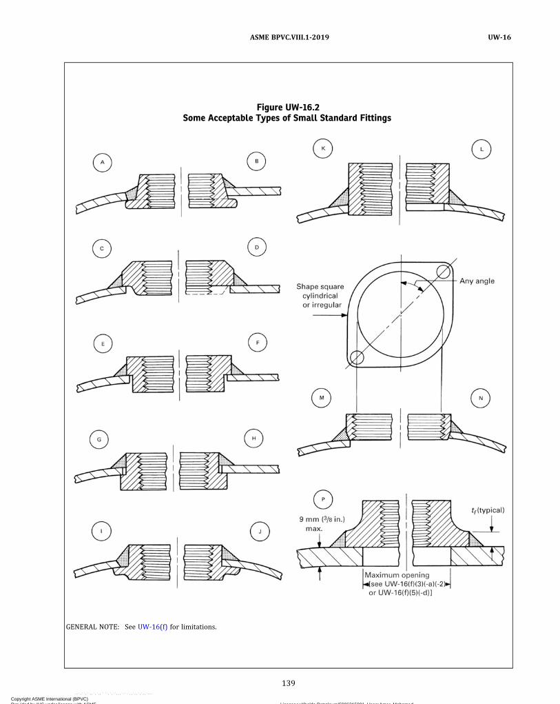
Figure UW-16.2Some Acceptable Types of Small Standard Fittings
GENERAL NOTE: See UW-16(f) for limitations.
139
ASME BPVC.VIII.1-2019 UW-16
Copyright ASME International (BPVC) Provided by IHS under license with ASME Licensee=Khalda Petroleum/5986215001, User=Amer, Mohamed
Not for Resale, 07/02/2019 13:29:04 MDTNo reproduction or networking permitted without license from IHS
--`,``,``,,`,`,,````,`,``,,,`-`-`,,`,,`,`,,`---
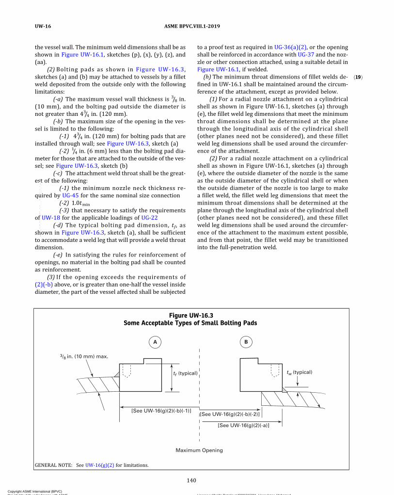
ð19Þ
the vessel wall. The minimumweld dimensions shall be asshown in Figure UW-16.1, sketches (p), (x), (y), (z), and(aa).
(2) Bolting pads as shown in Figure UW-16.3,sketches (a) and (b) may be attached to vessels by a filletweld deposited from the outside only with the followinglimitations:
(-a) The maximum vessel wall thickness is 3/8 in.(10 mm), and the bolting pad outside the diameter isnot greater than 43/4 in. (120 mm).
(-b) The maximum size of the opening in the ves-sel is limited to the following:
(-1) 43/4 in. (120 mm) for bolting pads that areinstalled through wall; see Figure UW-16.3, sketch (a)
(-2) 1/4 in. (6 mm) less than the bolting pad dia-meter for those that are attached to the outside of the ves-sel; see Figure UW-16.3, sketch (b)
(-c) The attachment weld throat shall be the great-est of the following:
(-1) the minimum nozzle neck thickness re-quired by UG-45 for the same nominal size connection
(-2) 1.0tmin
(-3) that necessary to satisfy the requirementsof UW-18 for the applicable loadings of UG-22
(-d) The typical bolting pad dimension, tf, asshown in Figure UW-16.3, sketch (a), shall be sufficientto accommodate a weld leg that will provide a weld throatdimension.
(-e) In satisfying the rules for reinforcement ofopenings, no material in the bolting pad shall be countedas reinforcement.
(3) If the opening exceeds the requirements of(2)(-b) above, or is greater than one‐half the vessel insidediameter, the part of the vessel affected shall be subjected
to a proof test as required in UG-36(a)(2), or the openingshall be reinforced in accordance with UG-37 and the noz-zle or other connection attached, using a suitable detail inFigure UW-16.1, if welded.(h) The minimum throat dimensions of fillet welds de-
fined in UW‐16.1 shall be maintained around the circum-ference of the attachment, except as provided below.
(1) For a radial nozzle attachment on a cylindricalshell as shown in Figure UW‐16.1, sketches (a) through(e), the fillet weld leg dimensions that meet the minimumthroat dimensions shall be determined at the planethrough the longitudinal axis of the cylindrical shell(other planes need not be considered), and these filletweld leg dimensions shall be used around the circumfer-ence of the attachment.
(2) For a radial nozzle attachment on a cylindricalshell as shown in Figure UW‐16.1, sketches (a) through(e), where the outside diameter of the nozzle is the sameas the outside diameter of the cylindrical shell or whenthe outside diameter of the nozzle is too large to makea fillet weld, the fillet weld leg dimensions that meet theminimum throat dimensions shall be determined at theplane through the longitudinal axis of the cylindrical shell(other planes need not be considered), and these filletweld leg dimensions shall be used around the circumfer-ence of the attachment to the maximum extent possible,and from that point, the fillet weld may be transitionedinto the full‐penetration weld.
Figure UW-16.3Some Acceptable Types of Small Bolting Pads
A
3/8 in. (10 mm) max.
tf (typical)
Maximum Opening
[See UW-16(g)(2)(-b)(-1)]
B
[See UW-16(g)(2)(-a)]
[See UW-16(g)(2)(-b)(-2)]
GENERAL NOTE: See UW-16(g)(2) for limitations.
140
ASME BPVC.VIII.1-2019UW-16
Copyright ASME International (BPVC) Provided by IHS under license with ASME Licensee=Khalda Petroleum/5986215001, User=Amer, Mohamed
Not for Resale, 07/02/2019 13:29:04 MDTNo reproduction or networking permitted without license from IHS
--`,``,``,,`,`,,````,`,``,,,`-`-`,,`,,`,`,,`---

ð19ÞUW-17 PLUG WELDS(a) Plug welds may be used in lap joints, in reinforce-
ments around openings and in nonpressure structural at-tachments. They shall be properly spaced to carry theirproportion of the load, but shall not be considered to takemore than 30% of the total load to be transmitted.
(b) Plug weld holes shall have a diameter not less thant + 1/4 in. (6 mm) and not more than 2t + 1/4 in. (6 mm),where t is the thickness in inches of the plate or attachedpart in which the hole is made.
(c) Plug weld holes shall be completely filled with weldmetal when the thickness of the plate, or attached part, inwhich the weld is made is 5/16 in. (8 mm) or less; for thick-er plates or attached parts the holes shall be filled to adepth of at least half the plate thickness or 5/16 of the holediameter, whichever is larger, but in no case less than5/16 in. (8 mm).
(d) The allowable working load on a plug weld in eithershear or tension shall be computed by the followingformula:
(U.S. Customary Units)
(SI Units)
where
d = the bottom diameter of the hole in which the weldis made
P = total allowable working load on the plug weldS = maximum allowable stress value for the material in
which the weld is made (see UG-23)
UW-18 FILLET WELDS(a) Fillet welds may be employed as strength welds for
pressure parts within the limitations given elsewhere inthis Division. Particular care shall be taken in the layoutof joints in which fillet welds are to be used in order toassure complete fusion at the root of the fillet.
(b) Corner or tee joints may be made with fillet weldsprovided the plates are properly supported indepen-dently of such welds, except that independent supportsare not required for joints used for the purposes enumer-ated in UG-55.
(c) Figures UW-13.1 and UW-13.2 show several con-struction details that are not permissible.
(d) Unless the sizing basis is given elsewhere in this Di-vision, the maximum allowable load on fillet welds shallequal the product of the weld area (based on minimumleg dimension), the maximum allowable stress value intension of the material being welded, and a joint effi-ciency of 55%.
UW-19 WELDED STAYED CONSTRUCTION(a)Welded‐in staybolts shall meet the following
requirements:(1) the arrangement shall substantially conform to
one of those illustrated in Figure UW-19.1;(2) the required thickness of the plate shall not ex-
ceed 11/2 in. (38 mm), except for Figure UW-19.1, sketches(e), (g), and (h). For plate thicknesses greater than 3/4 in.(19 mm), the staybolt pitch shall not exceed the smaller of20 in. (500 mm) or the limits established in UG-47(f).
(3) the provisions of UG-47 and UG-49 shall be fol-lowed; and
(4) the required area of the staybolt shall be deter-mined in accordance with the requirements in UG-50.
(b)Welded stays, substantially as shown in FigureUW-19.2, may be used to stay jacketed pressure vesselsprovided:
(1) the pressure does not exceed 300 psi (2 MPa);(2) the required thickness of the plate does not ex-
ceed 1/2 in. (13 mm);(3) the size of the fillet welds is not less than the plate
thickness;(4) the inside welds are properly inspected before
the closing plates are attached;(5) the allowable load on the fillet welds is computed
in accordance with UW-18(d);(6) the maximum diameter or width of the hole in the
plate does not exceed 11/4 in. (32 mm);(7) the welders are qualified under the rules of Sec-
tion IX;(8) the maximum spacing of stays is determined by
the formula in UG-47(a), using C = 2.1 if either plate isnot over 7/16 in. (11 mm) thick, C = 2.2 if both plates areover 7/16 in. (11 mm) thick.
(c) Welded stayed construction, as shown in FigureUW-19.2 or consisting of a dimpled or embossed platewelded to another like plate or to a plain plate, may beused, provided
(1) the welded attachment is made by fillet weldsaround holes or slots as shown in Figure UW-19.2 or ifthe thickness of the plate having the hole or slot is1/2 in. (12 mm) or less, and the hole is 1 in. (25 mm) or lessin diameter, the holes may be completely filled with weldmetal. The allowable load on the weld shall equal the pro-duct of the thickness of the plate having the hole or slot,the circumference or perimeter of the hole or slot, the al-lowable stress value in tension of the weaker of the mate-rials being joined and a joint efficiency of 55%.
(2) the maximum allowable working pressure of thedimpled or embossed components is established in accor-dance with the requirements of UG-101. The joint effi-ciency, E , used in UG-101 to calculate the MAWP of thedimpled panel shall be taken as 0.80. This proof testmay be carried out on a representative panel. If a repre-sentative panel is used, it shall be rectangular in shapeand at least 5 pitches in each direction, but not less than
141
ASME BPVC.VIII.1-2019 UW-17 – UW-19
Copyright ASME International (BPVC) Provided by IHS under license with ASME Licensee=Khalda Petroleum/5986215001, User=Amer, Mohamed
Not for Resale, 07/02/2019 13:29:04 MDTNo reproduction or networking permitted without license from IHS
--`,``,``,,`,`,,````,`,``,,,`-`-`,,`,,`,`,,`---
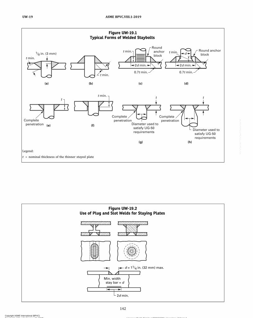
Figure UW-19.1Typical Forms of Welded Staybolts
1/8 in. (3 mm)
2d min.
d
0.7t min.
Round anchor block
Round anchor block
0.7t min.
2d min.
t min.
t min. t t
t min.
Complete penetration
Complete penetration
Complete penetration
(h)(g)
(f)(e)
(d)(c)(b)(a)
Diameter used to satisfy UG-50 requirements
Diameter used to satisfy UG-50 requirements
t min. t min.
t
Legend:
t = nominal thickness of the thinner stayed plate
Figure UW-19.2Use of Plug and Slot Welds for Staying Plates
2d min.
Min. width stay bar = d
d = 11/4 in. (32 mm) max.
142
ASME BPVC.VIII.1-2019UW-19
Copyright ASME International (BPVC) Provided by IHS under license with ASME Licensee=Khalda Petroleum/5986215001, User=Amer, Mohamed
Not for Resale, 07/02/2019 13:29:04 MDTNo reproduction or networking permitted without license from IHS
--`,``,``,,`,`,,````,`,``,,,`-`-`,,`,,`,`,,`---
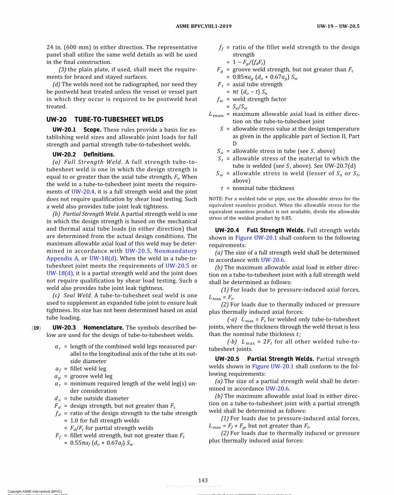
ð19Þ
24 in. (600 mm) in either direction. The representativepanel shall utilize the same weld details as will be usedin the final construction.
(3) the plain plate, if used, shall meet the require-ments for braced and stayed surfaces.
(d) The welds need not be radiographed, nor need theybe postweld heat treated unless the vessel or vessel partin which they occur is required to be postweld heattreated.
UW-20 TUBE-TO-TUBESHEET WELDSUW-20.1 Scope. These rules provide a basis for es-
tablishing weld sizes and allowable joint loads for fullstrength and partial strength tube‐to‐tubesheet welds.
UW-20.2 Definitions.(a) Full Strength Weld . A full strength tube‐to‐
tubesheet weld is one in which the design strength isequal to or greater than the axial tube strength, Ft. Whenthe weld in a tube‐to‐tubesheet joint meets the require-ments of UW-20.4, it is a full strength weld and the jointdoes not require qualification by shear load testing. Sucha weld also provides tube joint leak tightness.
(b) Partial StrengthWeld. A partial strength weld is onein which the design strength is based on the mechanicaland thermal axial tube loads (in either direction) thatare determined from the actual design conditions. Themaximum allowable axial load of this weld may be deter-mined in accordance with UW-20.5, NonmandatoryAppendix A, or UW-18(d). When the weld in a tube‐to‐tubesheet joint meets the requirements of UW-20.5 orUW-18(d), it is a partial strength weld and the joint doesnot require qualification by shear load testing. Such aweld also provides tube joint leak tightness.
(c) Seal Weld. A tube‐to‐tubesheet seal weld is oneused to supplement an expanded tube joint to ensure leaktightness. Its size has not been determined based on axialtube loading.
UW-20.3 Nomenclature. The symbols described be-low are used for the design of tube‐to‐tubesheet welds.
ac = length of the combined weld legs measured par-allel to the longitudinal axis of the tube at its out-side diameter
af = fillet weld legag = groove weld legar = minimum required length of the weld leg(s) un-
der considerationdo = tube outside diameterFd = design strength, but not greater than Ftfd = ratio of the design strength to the tube strength
= 1.0 for full strength welds= Fd/Ft for partial strength welds
Ff = fillet weld strength, but not greater than Ft= 0.55πaf (do + 0.67af) Sw
f f = ratio of the fillet weld strength to the designstrength
= 1 − Fg/(fdFt)Fg = groove weld strength, but not greater than Ft
= 0.85πag (do + 0.67ag) SwFt = axial tube strength
= πt (do − t) Safw = weld strength factor
= Sa/SwLmax = maximum allowable axial load in either direc-
tion on the tube‐to‐tubesheet jointS = allowable stress value at the design temperature
as given in the applicable part of Section II, PartD
Sa = allowable stress in tube (see S , above)St = allowable stress of the material to which the
tube is welded (see S , above). See UW-20.7(d)Sw = allowable stress in weld (lesser of Sa or St,
above)t = nominal tube thickness
NOTE: For a welded tube or pipe, use the allowable stress for theequivalent seamless product. When the allowable stress for theequivalent seamless product is not available, divide the allowablestress of the welded product by 0.85.
UW-20.4 Full Strength Welds. Full strength weldsshown in Figure UW-20.1 shall conform to the followingrequirements:
(a) The size of a full strength weld shall be determinedin accordance with UW-20.6.
(b) The maximum allowable axial load in either direc-tion on a tube‐to‐tubesheet joint with a full strength weldshall be determined as follows:
(1) For loads due to pressure‐induced axial forces,Lmax = Ft.
(2) For loads due to thermally induced or pressureplus thermally induced axial forces:
(-a) Lmax = Ft for welded only tube‐to‐tubesheetjoints, where the thickness through the weld throat is lessthan the nominal tube thickness t ;
(-b) Lmax = 2Ft for all other welded tube‐to‐tubesheet joints.
UW-20.5 Partial Strength Welds. Partial strengthwelds shown in Figure UW-20.1 shall conform to the fol-lowing requirements:
(a) The size of a partial strength weld shall be deter-mined in accordance UW-20.6.
(b) The maximum allowable axial load in either direc-tion on a tube‐to‐tubesheet joint with a partial strengthweld shall be determined as follows:
(1) For loads due to pressure‐induced axial forces,Lmax = Ff + Fg, but not greater than Ft.
(2) For loads due to thermally induced or pressureplus thermally induced axial forces:
143
ASME BPVC.VIII.1-2019 UW-19 – UW-20.5
Copyright ASME International (BPVC) Provided by IHS under license with ASME Licensee=Khalda Petroleum/5986215001, User=Amer, Mohamed
Not for Resale, 07/02/2019 13:29:04 MDTNo reproduction or networking permitted without license from IHS
--`,``,``,,`,`,,````,`,``,,,`-`-`,,`,,`,`,,`---
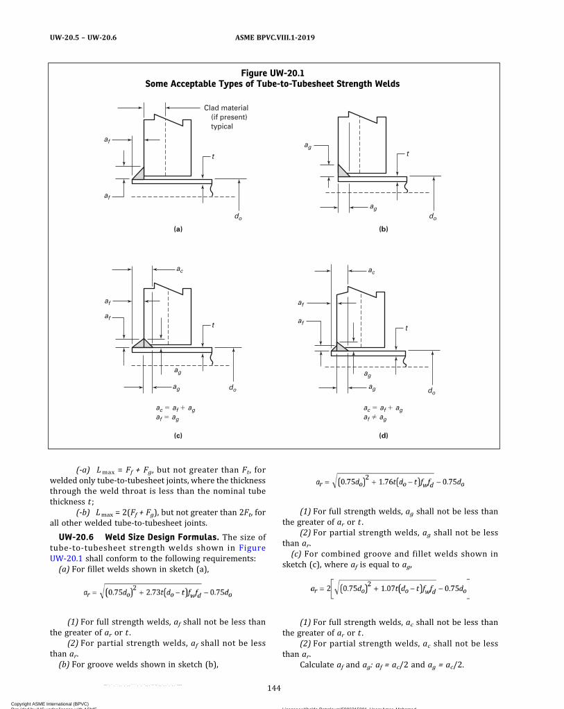
(-a) Lmax = Ff + Fg, but not greater than Ft, forwelded only tube‐to‐tubesheet joints, where the thicknessthrough the weld throat is less than the nominal tubethickness t ;
(-b) Lmax = 2(Ff + Fg), but not greater than 2Ft, forall other welded tube‐to‐tubesheet joints.
UW-20.6 Weld Size Design Formulas. The size oftube‐to‐tubesheet strength welds shown in FigureUW-20.1 shall conform to the following requirements:(a) For fillet welds shown in sketch (a),
(1) For full strength welds, af shall not be less thanthe greater of ar or t .
(2) For partial strength welds, af shall not be lessthan ar.(b) For groove welds shown in sketch (b),
(1) For full strength welds, ag shall not be less thanthe greater of ar or t .
(2) For partial strength welds, ag shall not be lessthan ar.(c) For combined groove and fillet welds shown in
sketch (c), where af is equal to ag,
(1) For full strength welds, ac shall not be less thanthe greater of ar or t .
(2) For partial strength welds, ac shall not be lessthan ar.
Calculate af and ag: af = ac/2 and ag = ac/2.
Figure UW-20.1Some Acceptable Types of Tube-to-Tubesheet Strength Welds
(a) (b)
(c) (d)
t
af
af
do
Clad material(if present)typical
tag
agdo
t
af
af
ag
ag
ac � af � agaf � ag
ac � af � agaf � ag
ac
do
taf
af
ac
ag
ag
do
144
ASME BPVC.VIII.1-2019UW-20.5 – UW-20.6
Copyright ASME International (BPVC) Provided by IHS under license with ASME Licensee=Khalda Petroleum/5986215001, User=Amer, Mohamed
Not for Resale, 07/02/2019 13:29:04 MDTNo reproduction or networking permitted without license from IHS
--`,``,``,,`,`,,````,`,``,,,`-`-`,,`,,`,`,,`---

ð19Þ
(d) For combined groove and fillet welds shown insketch (d), where af is not equal to ag, ar shall be deter-mined as follows: Choose ag. Calculate ar:
(1) For full strength welds, ac shall not be less thanthe greater of (ar + ag) or t .
(2) For partial strength welds, ac shall not be lessthan (ar + ag).
Calculate af : af = ac − ag.
UW-20.7 Clad Tubesheets.(a) Tube-to-tubesheet welds in the cladding of either
integral or weld metal overlay clad tubesheets may beconsidered strength welds (full or partial), provided thewelds meet the design requirements of UW-20. In addi-tion, when the strength welds are to be made in the cladmaterial of integral clad tubesheets, the integral clad ma-terial to be used for tubesheets shall meet the require-ments in (1) and (2) for any combination of clad andbase materials. The shear strength test and ultrasonic ex-amination specified in (1) and (2) are not required forweld metal overlay clad tubesheets.
(1) Integral clad material shall be shear strengthtested in accordance with SA-263. One shear test shallbe made on each integral clad plate or forging and the re-sults shall be reported on the material test report.
(2) Integral clad material shall be ultrasonically ex-amined for bond integrity in accordance with SA-578, in-cluding Supplementary Requirement S1, and shall meetthe acceptance criteria given in SA-263 for Quality LevelClass 1.
(b)When the design calculations for clad tubesheetsare based on the total thickness including the cladding,the clad material shall meet any additional requirementsspecified in Part UCL.
(c) When tubesheets are constructed using linings, orintegral cladding that does not meet the requirementsof (a)(1) and (a)(2), the strength of the tube-to-tubesheetjoint shall not be dependent upon the connection betweenthe tubes and the lining or integral cladding, as applicable.
(d)When the tubes are strength welded (full or partial)to integral or weld metal overlay clad tubesheets, St shallbe the allowable stress value of the integral cladding orthe wrought material whose chemistry most closely ap-proximates that of the weld metal overlay cladding. Thethickness of the integral or weld metal clad overlay mate-rial shall be sufficient to prevent any of the strength weldfrom extending into the base material.
UW-21 ASME B16.5 SOCKET AND SLIP-ONFLANGE WELDS
(a) ASME B16.5 socket weld flanges shall be weldedusing an external fillet weld. See Figure UW-21, sketch(4).
(b) ASME B16.5 slip‐on flanges shall be welded using aninternal and an external weld. See Figure UW-21, sketches(1), (2), and (3).
(c) Nomenclature
tn = nominal thickness of the shell or nozzleXmin = the lesser of 1.4tn or the thickness of the hub
(d)When ASME B16.5 slip-on flanges are shown tocomply with all the requirements provided in MandatoryAppendix 2 of this Division, the weld sizes in MandatoryAppendix 2 may be used as an alternative to the require-ments in (b).
FABRICATION
UW-26 GENERAL(a) The rules in the following paragraphs apply specifi-
cally to the fabrication of pressure vessels and vesselparts that are fabricated by welding and shall be usedin conjunction with the general requirements for Fabrica-tion in Subsection A, and with the specific requirementsfor Fabrication in Subsection C that pertain to the classof material used.
(b) Each Manufacturer or parts Manufacturer shall beresponsible for the quality of the welding done by his or-ganization and shall conduct tests not only of the weldingprocedure to determine its suitability to ensure weldsthat will meet the required tests, but also of the weldersand welding operators to determine their ability to applythe procedure properly.
(c) No production welding shall be undertaken untilafter the welding procedures which are to be used havebeen qualified. Only welders and welding operators whoare qualified in accordance with Section IX shall be usedin production.
(d) The Manufacturer (Certificate Holder) may engageindividuals by contract or agreement for their servicesas welders68 at the shop location shown on the Certificateof Authorization and at field sites (if allowed by the Cer-tificate of Authorization) for the construction of pressurevessels or vessel parts, provided all of the following con-ditions are met:
(1) All Code construction shall be the responsibilityof the Manufacturer.
(2) All welding shall be performed in accordancewith the Manufacturer’s welding procedure specificationsin accordance with the requirements of Section IX.
(3) All welders shall be qualified by the Manufacturerin accordance with the requirements of Section IX.
(4) The Manufacturer’s Quality Control System shallinclude as a minimum:
(-a) a requirement for complete and exclusive ad-ministrative and technical supervision of all welders bythe Manufacturer;
145
ASME BPVC.VIII.1-2019 UW-20.6 – UW-26
Copyright ASME International (BPVC) Provided by IHS under license with ASME Licensee=Khalda Petroleum/5986215001, User=Amer, Mohamed
Not for Resale, 07/02/2019 13:29:04 MDTNo reproduction or networking permitted without license from IHS
--`,``,``,,`,`,,````,`,``,,,`-`-`,,`,,`,`,,`---
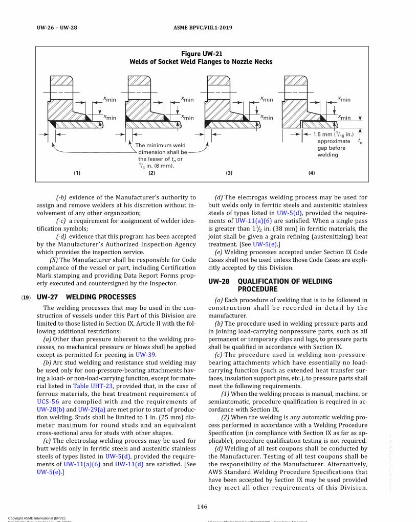
ð19Þ
(-b) evidence of the Manufacturer’s authority toassign and remove welders at his discretion without in-volvement of any other organization;
(-c) a requirement for assignment of welder iden-tification symbols;
(-d) evidence that this program has been acceptedby the Manufacturer’s Authorized Inspection Agencywhich provides the inspection service.
(5) The Manufacturer shall be responsible for Codecompliance of the vessel or part, including CertificationMark stamping and providing Data Report Forms prop-erly executed and countersigned by the Inspector.
UW-27 WELDING PROCESSESThe welding processes that may be used in the con-
struction of vessels under this Part of this Division arelimited to those listed in Section IX, Article II with the fol-lowing additional restrictions:(a) Other than pressure inherent to the welding pro-
cesses, no mechanical pressure or blows shall be appliedexcept as permitted for peening in UW-39.(b) Arc stud welding and resistance stud welding may
be used only for non-pressure‐bearing attachments hav-ing a load- or non-load‐carrying function, except for mate-rial listed in Table UHT-23, provided that, in the case offerrous materials, the heat treatment requirements ofUCS-56 are complied with and the requirements ofUW-28(b) and UW-29(a) are met prior to start of produc-tion welding. Studs shall be limited to 1 in. (25 mm) dia-meter maximum for round studs and an equivalentcross‐sectional area for studs with other shapes.(c) The electroslag welding process may be used for
butt welds only in ferritic steels and austenitic stainlesssteels of types listed in UW-5(d), provided the require-ments of UW-11(a)(6) and UW-11(d) are satisfied. [SeeUW-5(e).]
(d) The electrogas welding process may be used forbutt welds only in ferritic steels and austenitic stainlesssteels of types listed in UW-5(d), provided the require-ments of UW-11(a)(6) are satisfied. When a single passis greater than 11/2 in. (38 mm) in ferritic materials, thejoint shall be given a grain refining (austenitizing) heattreatment. [See UW-5(e).](e) Welding processes accepted under Section IX Code
Cases shall not be used unless those Code Cases are expli-citly accepted by this Division.
UW-28 QUALIFICATION OF WELDINGPROCEDURE
(a) Each procedure of welding that is to be followed inconstruction shall be recorded in detai l by themanufacturer.(b) The procedure used in welding pressure parts and
in joining load‐carrying nonpressure parts, such as allpermanent or temporary clips and lugs, to pressure partsshall be qualified in accordance with Section IX.(c) The procedure used in welding non-pressure‐
bearing attachments which have essentially no load‐carrying function (such as extended heat transfer sur-faces, insulation support pins, etc.), to pressure parts shallmeet the following requirements.
(1)When the welding process is manual, machine, orsemiautomatic, procedure qualification is required in ac-cordance with Section IX.
(2)When the welding is any automatic welding pro-cess performed in accordance with a Welding ProcedureSpecification (in compliance with Section IX as far as ap-plicable), procedure qualification testing is not required.(d)Welding of all test coupons shall be conducted by
the Manufacturer. Testing of all test coupons shall bethe responsibility of the Manufacturer. Alternatively,AWS Standard Welding Procedure Specifications thathave been accepted by Section IX may be used providedthey meet all other requirements of this Division.
Figure UW-21Welds of Socket Weld Flanges to Nozzle Necks
xmin
xmin
xmin
xmin
xmin
xmin
xmin
tn
xmin
1.5 mm (1/16 in.) approximate gap before welding
The minimum weld dimension shall be the lesser of tn or 1/4 in. (6 mm).
(1) (2) (3) (4)
146
ASME BPVC.VIII.1-2019UW-26 – UW-28
Copyright ASME International (BPVC) Provided by IHS under license with ASME Licensee=Khalda Petroleum/5986215001, User=Amer, Mohamed
Not for Resale, 07/02/2019 13:29:04 MDTNo reproduction or networking permitted without license from IHS
--`,``,``,,`,`,,````,`,``,,,`-`-`,,`,,`,`,,`---
Qualification of a welding procedure by one Manufacturershall not qualify that procedure for any other Manufac-turer except as provided in Section IX, QG-106.
UW-29 TESTS OF WELDERS AND WELDINGOPERATORS
(a) The welders and welding operators used in weldingpressure parts and in joining load‐carrying nonpressureparts (attachments) to pressure parts shall be qualifiedin accordance with Section IX.
(1) The qualification test for welding operators ofmachine welding equipment shall be performed on a se-parate test plate prior to the start of welding or on thefirst workpiece.
(2)When stud welding is used to attach load‐carrying studs, a production stud weld test of each welderor welding operator shall be performed on a separate testplate or tube prior to the start of welding on each workshift. This weld test shall consist of five studs, weldedand tested by the bend or torque stud weld testing proce-dure described in Section IX.
(b) The welders and welding operators used in weldingnon-pressure‐bearing attachments, which have essen-tially no load‐carrying function (such as extended heattransfer surfaces, insulation support pins, etc.), to pres-sure parts shall comply with the following:
(1)When the welding process is manual, machine, orsemiautomatic, qualification in accordance with SectionIX is required.
(2)When welding is done by any automatic weldingprocess, performance qualification testing is not required.
(3)When stud welding is used, a production studweld test, appropriate to the end use application require-ments, shall be specified by the Manufacturer and carriedout on a separate test plate or tube at the start of eachshift.
(c) Each welder and welding operator shall be assignedan identifying number, letter, or symbol by the manufac-turer which shall be used to identify the work of thatwelder or welding operator in accordance with UW-37(f).
(d) The Manufacturer shall maintain a record of thewelders and welding operators showing the date and re-sult of tests and the identification mark assigned to each.These records shall be maintained in accordance withSection IX.
(e) Welding of all test coupons shall be conducted bythe Manufacturer. Testing of all test coupons shall bethe responsibility of the Manufacturer. A performancequalification test conducted by one Manufacturer shallnot qualify a welder or welding operator to do work forany other Manufacturer except as provided in SectionIX, QG-106.
UW-30 LOWEST PERMISSIBLE TEMPERATURESFOR WELDING
It is recommended that no welding of any kind be donewhen the temperature of the base metal is lower than 0°F(−20°C). At temperatures between 32°F (0°C) and 0°F(−20°C), the surface of all areas within 3 in. (75 mm) ofthe point where a weld is to be started should be heatedto a temperature at least warm to the hand [estimated tobe above 60°F (15°C)] before welding is started. It is rec-ommended also that no welding be done when surfacesare wet or covered with ice, when snow is falling on thesurfaces to be welded, or during periods of high wind, un-less the welders or welding operators and the work areproperly protected.
UW-31 CUTTING, FITTING, AND ALIGNMENT(a)When plates are shaped by oxygen or arc cutting,
the edges to be welded shall be uniform and smoothand shall be freed of all loose scale and slag accumulationsbefore welding (see UG-76 and UCS-5).
(b) Plates that are being welded shall be fitted, aligned,and retained in position during the welding operation.
(c) Bars, jacks, clamps, tack welds, or other appropriatemeans may be used to hold the edges of parts in align-ment. Tack welds used to secure alignment shall eitherbe removed completely when they have served their pur-pose, or their stopping and starting ends shall be properlyprepared by grinding or other suitable means so that theymay be satisfactorily incorporated into the final weld.Tack welds, whether removed or left in place, shall bemade using a fillet weld or butt weld procedure qualifiedin accordance with Section IX. Tack welds to be left inplace shall be made by welders qualified in accordancewith Section IX, and shall be examined visually for defects,and if found to be defective shall be removed.
Provided that the work is done under the provisions ofU-2(b), it is not necessary that a subcontractor makingsuch tack welds for a vessel or parts manufacturer be aholder of a Code Certificate of Authorization. The require-ments of UW-26(d) do not apply to such tack welds.
(d) The edges of butt joints shall be held during weldingso that the tolerances of UW-33 are not exceeded in thecompleted joint. When fitted girth joints have deviationsexceeding the permitted tolerances, the head or shell ring,whichever is out‐of‐true, shall be reformed until the er-rors are within the limits specified. Where fillet weldsare used, the lapped plates shall fit closely and be keptin contact during welding.
147
ASME BPVC.VIII.1-2019 UW-28 – UW-31
Copyright ASME International (BPVC) Provided by IHS under license with ASME Licensee=Khalda Petroleum/5986215001, User=Amer, Mohamed
Not for Resale, 07/02/2019 13:29:04 MDTNo reproduction or networking permitted without license from IHS
--`,``,``,,`,`,,````,`,``,,,`-`-`,,`,,`,`,,`---

(e) When joining two parts by the inertia and continu-ous drive friction welding processes, one of the two partsmust be held in a fixed position and the other part ro-tated. The two faces to be joined must be essentially sym-metrical with respect to the axis of rotation. Some of thebasic types of applicable joints are solid round to solidround, tube to tube, solid round to tube, solid round toplate, and tube to plate.
UW-32 CLEANING OF SURFACES TO BE WELDED(a) The surfaces to be welded shall be clean and free of
scale, rust, oil, grease, slag, detrimental oxides, and otherdeleterious foreign material. The method and extent ofcleaning should be determined based on the material tobe welded and the contaminants to be removed. Whenweld metal is to be deposited over a previously weldedsurface, all slag shall be removed by a roughing tool, chi-sel, chipping hammer, or other suitable means so as toprevent inclusion of impurities in the weld metal.(b) Cast surfaces to be welded shall be machined,
chipped, or ground to remove foundry scale and to exposesound metal.(c) The requirements in (a) and (b) above are not in-
tended to apply to any process of welding by which prop-er fusion and penetration are otherwise obtained and bywhich the weld remains free from defects.
UW-33 ALIGNMENT TOLERANCE(a) Alignment of sections at edges to be butt welded
shall be such that the maximum offset is not greater thanthe applicable amount for the welded joint category (seeUW-3) under consideration, as listed in Table UW-33. Thesection thickness t is the nominal thickness of the thinnersection at the joint.(b) Any offset within the allowable tolerance provided
above shall be faired at a three to one taper over thewidth of the finished weld, or if necessary, by adding ad-ditional weld metal beyond what would otherwise be theedge of the weld. Such additional weld metal buildup shallbe subject to the requirements of UW-42.
UW-34 SPIN-HOLESSpin‐holes are permitted within heads or segments
thereof to facilitate forming. Spin-holes not exceedingthe size limitations of UG-36(c)(3)(-a) may be closed witha full‐penetration weld using either a welded plug or weldmetal. The weld and plug shall be no thinner than thehead material adjacent to the spin‐hole.The finished weld shall be examined69 and shall meet
the acceptance requirements of Mandatory Appendix 6or Mandatory Appendix 8 of this Division. Radiographicexamination, if required by UW-11(a), and additional in-spections, if required by the material specification, shallbe performed.
This weld is a butt weld, but it is not categorized. Itshall not be considered in establishing the joint efficiencyof any part of the head or of the head‐to‐shell weld.
UW-35 FINISHED LONGITUDINAL ANDCIRCUMFERENTIAL JOINTS
(a) Butt-welded joints shall have complete penetrationand full fusion. As‐welded surfaces are permitted; how-ever, the surface of welds shall be sufficiently free fromcoarse ripples, grooves, overlaps, and abrupt ridges andvalleys to permit proper interpretation of radiographicand other required nondestructive examinations. If thereis a question regarding the surface condition of the weldwhen interpreting a radiographic film, the film shall becompared to the actual weld surface for determinationof acceptability.(b) A reduction in thickness due to the welding process
is acceptable provided all of the following conditions aremet:
(1) The reduction in thickness shall not reduce thematerial of the adjoining surfaces below the design thick-ness at any point.
(2) The reduction in thickness shall not exceed1/32 in. (1 mm) or 10% of the nominal thickness of the ad-joining surface, whichever is less.70
(c) When a single‐welded butt joint is made by using abacking strip which is left in place [Type No. (2) of TableUW-12], the requirement for reinforcement applies onlyto the side opposite the backing strip.(d) To assure that the weld grooves are completely
filled so that the surface of the weld metal at any pointdoes not fall below the surface of the adjoining base
Table UW-33
Customary Units
Section Thickness, in.
Joint Category
A B, C, and D
Up to 1/2, incl.1/4t
1/4tOver 1/2 to
3/4, incl.1/8 in.
1/4tOver 3/4 to 11/2, incl.
1/8 in.3/16 in.
Over 11/2 to 2, incl. 1/8 in.1/8t
Over 2 Lesser of 1/16t or3/8 in.
Lesser of 1/8t or3/4 in.
SI Units
Section Thickness, mm
Joint Category
A B, C, and D
Up to 13, incl. 1/4t1/4t
Over 13 to 19, incl. 3 mm 1/4tOver 19 to 38, incl. 3 mm 5 mmOver 38 to 51, incl. 3 mm 1/8tOver 51 Lesser of 1/16t or
10 mmLesser of 1/8t or19 mm
148
ASME BPVC.VIII.1-2019UW-31 – UW-35
Copyright ASME International (BPVC) Provided by IHS under license with ASME Licensee=Khalda Petroleum/5986215001, User=Amer, Mohamed
Not for Resale, 07/02/2019 13:29:04 MDTNo reproduction or networking permitted without license from IHS
--`,``,``,,`,`,,````,`,``,,,`-`-`,,`,,`,`,,`---

materials,71 weld metal may be added as reinforcementon each face of the weld. The thickness of the weld rein-forcement on each face shall not exceed the following:
Customary Units
Material NominalThickness, in.
Maximum Reinforcement, in.
Category B and CButt Welds
OtherWelds
Less than 3/323/32
1/323/32 to
3/16, incl.1/8
1/16Over 3/16 to
1/2, incl.5/32
3/32Over 1/2 to 1, incl. 3/16
3/32Over 1 to 2, incl. 1/4
1/8Over 2 to 3, incl. 1/4
5/32Over 3 to 4, incl. 1/4
7/32Over 4 to 5, incl. 1/4
1/4Over 5 5/16
5/16
SI Units
Material NominalThickness, mm
Maximum Reinforcement, mm
Category B and CButt Welds
OtherWelds
Less than 2.4 2.5 0.82.4 to 4.8, incl. 3 1.5Over 4.8 to 13, incl. 4 2.5Over 13 to 25, incl. 5 2.5Over 25 to 51, incl. 6 3Over 51 to 76, incl. 6 4Over 76 to 102, incl. 6 5.5Over 102 to 127, incl. 6 6Over 127 8 8
UW-36 FILLET WELDSIn making fillet welds, the weld metal shall be depos-
ited in such a way that adequate penetration into the basemetal at the root of the weld is secured. The reduction ofthe thickness of the base metal due to the welding processat the edges of the fillet weld shall meet the same require-ments as for butt welds [see UW-35(b)].
UW-37 MISCELLANEOUS WELDINGREQUIREMENTS
(a) The reverse side of double‐welded joints shall beprepared by chipping, grinding, or melting out, so as to se-cure soundmetal at the base of weld metal first deposited,before applying weld metal from the reverse side.
(b) The requirements in (a) above are not intended toapply to any process of welding by which proper fusionand penetration are otherwise obtained and by whichthe base of the weld remains free from defects.
(c) If the welding is stopped for any reason, extra careshall be taken in restarting to get the required penetra-tion and fusion. For submerged arc welding, chippingout a groove in the crater is recommended.
(d)Where single‐welded joints are used, particularcare shall be taken in aligning and separating the compo-nents to be joined so that there will be complete penetra-tion and fusion at the bottom of the joint for its full length.
(e) In welding plug welds, a fillet around the bottom ofthe hole shall be deposited first.
(f) Welder and Welding Operator Identification(1) Each welder and welding operator shall stamp
the identifying number, letter, or symbol assigned bythe Manufacturer, on or adjacent to and at intervals ofnot more than 3 ft (1 m) along the welds which he makesin steel plates 1/4 in. (6 mm) and over in thickness and innonferrous plates 1/2 in. (13 mm) and over in thickness; ora record shall be kept by the Manufacturer of welders andwelding operators employed on each joint which shall beavailable to the Inspector. For identifying welds on ves-sels in which the wall thickness is less than 1/4 in.(6 mm) for steel material and less than 1/2 in. (13 mm)for nonferrous material, suitable stencil or other surfacemarkings shall be used; or a record shall be kept by theManufacturer of welders and welding operators em-ployed on each joint which shall be available to the In-spector; or a stamp may be used provided the vesselpart is not deformed and the following additional require-ments are met:
(-a) for ferrous materials:(-1) the materials shall be limited to P‐No. 1 Gr.
Nos. 1 and 2;(-2) the minimum nominal plate thickness shall
be 3/16 in. (5 mm), or the minimum nominal pipe wallthickness shall be 0.154 in. (3.91 mm);
(-3) the minimum design metal temperatureshall be no colder than −20°F (−29°C);
(-b) for nonferrous materials:(-1) the materials shall be limited to aluminum
as follows: SB-209 Alloys 3003, 5083, 5454, and 6061;SB-241 Alloys 3003, 5083, 5086, 5454, 6061, and 6063;and SB-247 Alloys 3003, 5083, and 6061;
(-2) the minimum nominal plate thickness shallbe 0.249 in. (6.32 mm), or the minimum nominal pipethickness shall be 0.133 in. (3.37 mm).
(2)When a multiple number of permanent nonpres-sure part load bearing attachment welds, nonload‐bearing welds such as stud welds, or special welds suchas tube‐to‐tubesheet welds are made on a vessel, theManufacturer need not identify the welder or welding op-erator that welded each individual joint provided:
(-a) the Manufacturer’s Quality Control System in-cludes a procedure that will identify the welders or weld-ing operators that made such welds on each vessel so thatthe Inspector can verify that the welders or welding op-erators were all properly qualified;
(-b) the welds in each category are all of the sametype and configuration and are welded with the samewelding procedure specification.
(3) Permanent identification of welders or weldingoperators making tack welds that become part of the finalpressure weld is not required provided the Manufac-turer’s Quality Control System includes a procedure topermit the Inspector to verify that such tack welds weremade by qualified welders or welding operators.
149
ASME BPVC.VIII.1-2019 UW-35 – UW-37
Copyright ASME International (BPVC) Provided by IHS under license with ASME Licensee=Khalda Petroleum/5986215001, User=Amer, Mohamed
Not for Resale, 07/02/2019 13:29:04 MDTNo reproduction or networking permitted without license from IHS
--`,``,``,,`,`,,````,`,``,,,`-`-`,,`,,`,`,,`---
(g) The welded joint between two members joined bythe inertia and continuous drive friction welding pro-cesses shall be a full penetration weld. Visual examinationof the as‐welded flash roll of each weld shall be made asan in-process check. The weld upset shall meet the speci-fied amount within ±10%. The flash shall be removed tosound metal.(h) Capacitor discharge welding may be used for weld-
ing temporary attachments and permanent nonstructuralattachments without postweld heat treatment, providedthe following requirements are met:
(1) A welding procedure specification shall be pre-pared in accordance with Section IX, insofar as possibledescribing the capacitor discharge equipment, the combi-nation of materials to be joined, and the technique of ap-plication. Qualification of the welding procedure is notrequired.
(2) The energy output shall be limited to 125 W‐sec.
UW-38 REPAIR OF WELD DEFECTSDefects, such as cracks, pinholes, and incomplete fu-
sion, detected visually or by the hydrostatic or pneumatictest or by the examinations prescribed in UW-11 shall beremoved by mechanical means or by thermal gougingprocesses, after which the joint shall be rewelded [seeUW-40(e)].
UW-39 PEENING(a)Weld metal and heat-affected zones may be peened
by manual, electric, or pneumatic means when it isdeemed necessary or helpful to control distortion, to re-lieve residual stresses, or to improve the quality of theweld. Peening shall not be used on the initial (root) layerof weld metal nor on the final (face) layer unless the weldis subsequently postweld heat treated. In no case, how-ever, is peening to be performed in lieu of any postweldheat treatment required by these rules.(b) Controlled shot peening and other similar methods
which are intended only to enhance surface properties ofthe vessel or vessel parts shall be performed after anynondestructive examinations and pressure tests requiredby these rules.
UW-40 PROCEDURES FOR POSTWELD HEATTREATMENT
(a) The operation of postweld heat treatment shall beperformed in accordance with the requirements givenin the applicable Part in Subsection C using one of the fol-lowing procedures. In the procedures that follow, thesoak band is defined as the volume of metal required tomeet or exceed the minimum PWHT temperatures listedin Tables UCS-56-1 through UCS-56-11. As a minimum,the soak band shall contain the weld, heat-affected zone,and a portion of base metal adjacent to the weld beingheat treated. The minimum width of this volume is thewidest width of weld plus 1t or 2 in. (50 mm), whichever
is less, on each side or end of the weld. The term t is thenominal thickness as defined in (f) below. For additionaldetailed recommendations regarding implementationand performance of these procedures, refer to WeldingResearch Council (WRC) Bulletin 452, June 2000, “Recom-mended Practices for Local Heating of Welds in PressureVessels.”
(1) heating the vessel as a whole in an enclosed fur-nace. This procedure is preferable and should be usedwhenever practicable.
(2) heating the vessel in more than one heat in a fur-nace, provided the overlap of the heated sections of thevessel is at least 5 ft (1.5 m). When this procedure is used,the portion outside of the furnace shall be shielded so thatthe temperature gradient is not harmful. The cross sec-tion where the vessel projects from the furnace shallnot intersect a nozzle or other structural discontinuity.
(3) heating of shell sections and/or portions of ves-sels to postweld heat treat longitudinal joints or compli-cated welded details before joining to make thecompleted vessel. When the vessel is required to be post-weld heat treated, and it is not practicable to postweldheat treat the completed vessel as a whole or in two ormore heats as provided in (2) above, any circumferentialjoints not previously postweld heat treated may be there-after locally postweld heat treated by heating such jointsby any appropriate means that will assure the requireduniformity. For such local heating, the soak band shall ex-tend around the full circumference. The portion outsidethe soak band shall be protected so that the temperaturegradient is not harmful. This procedure may also be usedto postweld heat treat portions of new vessels afterrepairs.
(4) heating the vessel internally by any appropriatemeans and with adequate indicating and recording tem-perature devices to aid in the control and maintenanceof a uniform distribution of temperature in the vesselwall. Previous to this operation, the vessel should be fullyenclosed with insulating material, or the permanent insu-lation may be installed provided it is suitable for the re-quired temperature. In this procedure the internalpressure should be kept as low as practicable, but shallnot exceed 50% of the maximum allowable working pres-sure at the highest metal temperature expected duringthe postweld heat treatment period.
(5) heating a circumferential band containing nozzlesor other welded attachments that require postweld heattreatment in such a manner that the entire band shallbe brought up uniformly to the required temperatureand held for the specified time. Except as modified in thisparagraph below, the soak band shall extend around theentire vessel, and shall include the nozzle or welded at-tachment. The circumferential soak band width may bevaried away from the nozzle or attachment weld requir-ing PWHT, provided the required soak band around thenozzle or attachment weld is heated to the required tem-perature and held for the required time. As an alternative
150
ASME BPVC.VIII.1-2019UW-37 – UW-40
Copyright ASME International (BPVC) Provided by IHS under license with ASME Licensee=Khalda Petroleum/5986215001, User=Amer, Mohamed
Not for Resale, 07/02/2019 13:29:04 MDTNo reproduction or networking permitted without license from IHS
--`,``,``,,`,`,,````,`,``,,,`-`-`,,`,,`,`,,`---

to varying the soak band width, the temperature withinthe circumferential band away from the nozzle or attach-ment may be varied and need not reach the required tem-perature, provided the required soak band around thenozzle or attachment weld is heated to the required tem-perature, held for the required time, and the temperaturegradient is not harmful throughout the heating and cool-ing cycle. The portion of the vessel outside of the circum-ferential soak band shall be protected so that thetemperature gradient is not harmful. This proceduremay also be used to postweld heat treat portions of ves-sels after repairs.
(6) heating the circumferential joints of pipe or tub-ing by any appropriate means using a soak band that ex-tends around the entire circumference. The portionoutside the soak band shall be protected so that the tem-perature gradient is not harmful. The proximity to theshell increases thermal restraint, and the designer shouldprovide adequate length to permit heat treatment with-out harmful gradients at the nozzle attachment or heata full circumferential band around the shell, includingthe nozzle.
(7) heating a local area around nozzles or welded at-tachments in the larger radius sections of a double curva-ture head or a spherical shell or head in such a mannerthat the area is brought up uniformly to the required tem-perature and held for the specified time. The soak bandshall include the nozzle or welded attachment. The soakband shall include a circle that extends beyond the edgesof the attachment weld in all directions by a minimum of tor 2 in. (50 mm), whichever is less. The portion of the ves-sel outside of the soak band shall be protected so that thetemperature gradient is not harmful.
(8) heating of other configurations. Local area heat-ing of other configurations such as “spots” or “bulls eye”local heating not addressed in (1) through (7) above ispermitted, provided that other measures (based uponsufficiently similar, documented experience or evalua-tion) are taken that consider the effect of thermal gradi-ents, all significant structural discontinuities (such asnozzles, attachments, head to shell junctures), and anymechanical loads which may be present during PWHT.The portion of the vessel or component outside the soakband shall be protected so that the temperature gradientis not harmful.
(b) The temperatures and rates of heating and coolingto be used in postweld heat treatment of vessels con-structed of materials for which postweld heat treatmentmay be required are given in UCS-56, UHT-56, UNF-56,and UHA-32.
(c) The minimum temperature for postweld heat treat-ment given in Tables UCS-56-1 through UCS-56-11, TableUHT-56, and Tables UHA-32-1 through UHA-32-7, and inUNF-56, shall be the minimum temperature of the platematerial of the shell or head of any vessel. Where morethan one pressure vessel or pressure vessel part are post-weld heat treated in one furnace charge, thermocouples
shall be placed on vessels at the bottom, center, and topof the charge, or in other zones of possible temperaturevariation so that the temperature indicated shall be truetemperature for all vessels or parts in those zones.72
(d) It is recognized that some postweld heat treatmentsmay have detrimental effects on the properties of somematerials. When pressure parts of two differentP-Numbers are joined by welding, engineering judgmentshall be applied when selecting the postweld heat treat-ment temperature and holding time to produce materialproperties suitable for the intended service. Alternativessuch as welding with buttering as described in SectionIX, QW-283 may be considered.
(e) Postweld heat treatment, when required, shall bedone before the hydrostatic test and after any welded re-pairs except as permitted by UCS-56(f). A preliminary hy-drostatic test to reveal leaks prior to postweld heattreatment is permissible.
(f) The term nominal thickness as used in TablesUCS-56-1 through UCS-56-11, UCS-56.1, UHA-32-1through UHA-32-7, and UHT-56, is the thickness of thewelded joint as defined below. For pressure vessels orparts of pressure vessels being postweld heat treated ina furnace charge, it is the greatest weld thickness for allweld types as defined in (1) through (6) below in any ves-sel or vessel part that has not previously been postweldheat treated.
(1)When the welded joint connects parts of the samethickness, using a full penetration buttweld, the nominalthickness is the total depth of the weld exclusive of anypermitted weld reinforcement.
(2) For groove welds, the nominal thickness is thedepth of the groove. For single- or double-sided groovewelds, the nominal thickness is the total depth of thegroove.
(3) For fillet welds, the nominal thickness is thethroat dimension. If a fillet weld is used in conjunctionwith a groove weld, the nominal thickness is the depthof the groove or the throat dimension, whichever isgreater.
(4) For stud welds, the nominal thickness shall be thediameter of the stud.
(5)When a welded joint connects parts of unequalthicknesses, the nominal thickness shall be the following:
(-a) the thinner of two adjacent butt‐welded partsincluding head to shell connections
(-b) the thickness of the shell or the fillet weld,whichever is greater, in connections to intermediateheads of the type shown in Figure UW-13.1, sketch (e);
(-c) the thickness of the shell in connections totubesheets, flat heads, covers, flanges (except for weldedparts depicted in Figure 2-4, sketch (7), where the thick-ness of the weld shall govern), or similar constructions;
(-d) in Figures UW-16.1 and UW-16.2, the thick-ness of the weld across the nozzle neck or shell or heador reinforcing pad or attachment fillet weld, whicheveris the greater;
151
ASME BPVC.VIII.1-2019 UW-40
Copyright ASME International (BPVC) Provided by IHS under license with ASME Licensee=Khalda Petroleum/5986215001, User=Amer, Mohamed
Not for Resale, 07/02/2019 13:29:04 MDTNo reproduction or networking permitted without license from IHS
--`,``,``,,`,`,,````,`,``,,,`-`-`,,`,,`,`,,`---
ð19Þ
(-e) the thickness of the nozzle neck at the joint innozzle neck to flange connections;
(-f) the thickness of the weld at the point of attach-ment when a nonpressure part is welded to a pressurepart;
(-g) the thickness of the tube in tube‐to‐tubesheetconnections.
(-h) the thickness of the weld metal overlay whenweld metal overlay is the only welding applied
(6) For repairs, the nominal thickness is the depth ofthe repair weld.
(7) The thickness of the head, shell, nozzle neck, orother parts as used in (1) through (6) above shall bethe wall thickness of the part at the welded joint underconsideration. For plate material, the thickness as shownon the Material Test Report or material Certificate ofCompliance before forming may be used, at the Manufac-turer’s option, in lieu of measuring the wall thickness atthe welded joint.
UW-41 SECTIONING OF WELDED JOINTSWelded joints may be examined by sectioning when
agreed to by user and Manufacturer, but this examinationshall not be considered a substitute for spot radiographicexamination. This type of examination has no effect on thejoint factors in Table UW-12. The method of closing thehole by welding is subject to acceptance by the Inspector.Some acceptable methods are given in NonmandatoryAppendix K.
UW-42 SURFACE WELD METAL BUILDUP(a) Construction in which deposits of weld metal are
applied to the surface of base metal for the purpose of re-storing the thickness of the base metal for strength con-sideration; or modifying the configuration of weld jointsin order to provide the tapered transition requirementsof UW-9(c) and UW-33(b) shall be performed in accor-dance with the rules in (b) and (c).(b) Procedure Qualification. A butt welding procedure
qualification in accordance with provisions of Section IXshall be performed for the thickness of weld metal depos-ited, prior to production welding.(c) Examination Requirements
(1) All weld metal buildup shall be examined over thefull surface of the deposit by either magnetic particle ex-amination to the requirements of Mandatory Appendix 6,or by liquid penetrant examination to the requirements ofMandatory Appendix 8.
(2)When such surface weld metal buildup is used inwelded joints which require full or spot radiographic ex-amination, the weld metal buildup shall be included in theexamination.
INSPECTION AND TESTS
UW-46 GENERALThe rules in the following paragraphs apply specifically
to the inspection and testing of pressure vessels and ves-sel parts that are fabricated by welding and shall be usedin conjunction with the general requirements for Inspec-tion and Tests in Subsection A, and with the specific re-quirements for Inspection and Tests in Subsection C thatpertain to the class of material used. [For tests on reinfor-cing plates, see UG-37(g).]
UW-47 CHECK OF WELDING PROCEDUREThe Inspector shall assure himself that the welding pro-
cedure employed in the construction of a vessel has beenqualified under the provisions of Section IX. The Manufac-turer shall submit evidence to the Inspector that the re-quirements have been met.
UW-48 CHECK OF WELDER AND WELDINGOPERATOR QUALIFICATIONS
(a) The Manufacturer shall certify that the welding on avessel has been done only by welders and welding opera-tors who have been qualified under the requirements ofSection IX and the Inspector shall assure himself that onlyqualified welders and welding operators have been used.(b) The Manufacturer shall make available to the In-
spector the record of the qualification tests of each welderand welding operator. The Inspector shall have the rightat any time to call for and witness tests of the weldingprocedure or of the ability of any welder and weldingoperator.
UW-49 CHECK OF POSTWELD HEATTREATMENT PRACTICE
The Inspector shall satisfy himself that all postweldheat treatment has been correctly performed and thatthe temperature readings conform to the requirements.
UW-50 NONDESTRUCTIVE EXAMINATION OFWELDS ON PNEUMATICALLY TESTEDVESSELS
(a) On welded pressure vessels to be pneumaticallytested in accordance with UG-100, the full length of thefollowing welds shall be examined69 before the pneu-matic test is performed, for the purpose of detectingcracks:
(1) all welds around openings(2) all attachment welds having a throat thickness
greater than 1/4 in. (6 mm), including welds attaching non-pressure parts to pressure parts(b) The weld joint examination requirements given in
(a) may be waived when the maximum allowable workingpressure of the vessel is no greater than 500 psi (3.5 MPa)and the following applicable requirement is met:
152
ASME BPVC.VIII.1-2019UW-40 – UW-50
Copyright ASME International (BPVC) Provided by IHS under license with ASME Licensee=Khalda Petroleum/5986215001, User=Amer, Mohamed
Not for Resale, 07/02/2019 13:29:04 MDTNo reproduction or networking permitted without license from IHS
--`,``,``,,`,`,,````,`,``,,,`-`-`,,`,,`,`,,`---
ð19Þ
(1) For Part UCS materials, the governing thicknessas defined in UCS-66(a) shall be limited to a maximumgoverning thickness of 1/2 in. (13 mm) for materials as-signed to Curve A, and 1 in. (25 mm) for materials as-signed to Curve B, C, or D in Figure UCS-66.
(2) For austenitic chromium–nickel stainless steels304, 304L, 316, 316L, 321, and 347 in Part UHA, the max-imum nominal material thickness shall be 3/4 in. (19 mm).
(3) For aluminum, aluminum alloy 3000 series, alu-minum alloy 5000 series, and aluminum alloy 6061-T6in Part UNF, the maximum nominal material thicknessshall be 1 in. (25 mm).
UW-51 RADIOGRAPHIC EXAMINATION OFWELDED JOINTS
(a) All welded joints to be radiographed shall be exam-ined in accordance with Section V, Article 2, except as spe-cified below.
(1) A complete set of radiographic images and exam-ination records, as described in Section V, Article 2, foreach vessel or vessel part shall be retained by the Manu-facturer, as follows:
(-a) radiographic images until the Manufacturer’sData Report has been signed by the Inspector
(-b) examination records as required by this Divi-sion (10-13)
(2) Demonstration of acceptable density on radio-graphic films and the ability to see the prescribed imagequality indicator (IQI) image and the specified hole orthe designated wire of a wire IQI shall be considered sat-isfactory evidence of compliance with Section V, Article 2.
(3) The requirements of Section V, Article 2, T-274.2,are to be used only as a guide for film-based radiography.
(4) As an alternative to the radiographic examinationrequirements above, all welds in which the thinner of themembers joined is 1/4 in. (6 mm) thick and greater may beexamined using the ultrasonic (UT) method specified byUW-53(b).
(b) Indications revealed by radiography within a weldthat exceed the following criteria are unacceptable andtherefore are defects. Defects shall be repaired as pro-vided in UW-38, and the repaired area shall be reexam-ined. In lieu of reexamination by radiography, therepaired weld may be ultrasonically examined in accor-dance with Mandatory Appendix 12 at the Manufacturer’soption. For material thicknesses in excess of 1 in.(25 mm), the concurrence of the user shall be obtained.This ultrasonic examination shall be noted under Re-marks on the Manufacturer’s Data Report Form:
(1) any indication characterized as a crack or zone ofincomplete fusion or penetration;
(2) any other elongated indication on the radiographwhich has length greater than:
(-a) 1/4 in. (6 mm) for t up to 3/4 in. (19 mm)(-b) 1/3t for t from 3/4 in. (19 mm) to 21/4 in.
(57 mm)(-c) 3/4 in. (19 mm) for t over 21/4 in. (57 mm)
where
t = the thickness of the weld excluding any allowable re-inforcement. For a butt weld joining two membershaving different thicknesses at the weld, t is the thin-ner of these two thicknesses. If a full penetrationweld includes a fillet weld, the thickness of the throatof the fillet shall be included in t .
(3) any group of aligned indications that have an ag-gregate length greater than t in a length of 12t , exceptwhen the distance between the successive imperfectionsexceeds 6L where L is the length of the longest imperfec-tion in the group;
(4) rounded indications in excess of that specified bythe acceptance standards given in Mandatory Appendix 4.
UW-52 SPOT EXAMINATION OF WELDED JOINTS
NOTE: Spot radiographing of a welded joint is recognized as an effec-tive inspection tool. The spot radiography rules are also consideredto be an aid to quality control. Spot radiographs made directly after awelder or an operator has completed a unit of weld proves that thework is or is not being done in accordance with a satisfactory proce-dure. If the work is unsatisfactory, corrective steps can then be takento improve the welding in the subsequent units, which unquestion-ably will improve the weld quality.
Spot radiography in accordance with these rules will not ensure afabrication product of predetermined quality level throughout. Itmust be realized that an accepted vessel under these spot radiogra-phy rules may still contain defects which might be disclosed onfurther examination. If all radiographically disclosed weld defectsmust be eliminated from a vessel, then 100% radiography must beemployed.
(a) Butt-welded joints that are to be spot radiographedshall be examined locally as provided herein.
(b) Minimum Extent of Spot Radiographic Examination(1) One spot shall be examined on each vessel for
each 50 ft (15 m) increment of weld or fraction thereoffor which a joint efficiency from column (b) of TableUW-12 is selected. However, for identical vessels or parts,each with less than 50 ft (15 m) of weld for which a jointefficiency from column (b) of Table UW-12 is selected,50 ft (15 m) increments of weld may be represented byone spot examination.
(2) For each increment of weld to be examined, a suf-ficient number of spot radiographs shall be taken to ex-amine the welding of each welder or welding operator.Under conditions where two or more welders or weldingoperators make weld layers in a joint, or on the two sidesof a double‐welded butt joint, one spot may represent thework of all welders or welding operators.
(3) Each spot examination shall be made as soon aspracticable after completion of the increment of weld tobe examined. The location of the spot shall be chosenby the Inspector after completion of the increment ofwelding to be examined, except that when the Inspectorhas been notified in advance and cannot be present orotherwise make the selection, the Manufacturer may ex-ercise his own judgment in selecting the spots.
153
ASME BPVC.VIII.1-2019 UW-50 – UW-52
Copyright ASME International (BPVC) Provided by IHS under license with ASME Licensee=Khalda Petroleum/5986215001, User=Amer, Mohamed
Not for Resale, 07/02/2019 13:29:04 MDTNo reproduction or networking permitted without license from IHS
--`,``,``,,`,`,,````,`,``,,,`-`-`,,`,,`,`,,`---
ð19Þ
(4) Radiographs required at specific locations to sa-tisfy the rules of other paragraphs, such as UW-9(d),UW-11(a)(5)(-b), and UW-14(b), shall not be used to sa-tisfy the requirements for spot radiography.(c) Standards for Spot Radiographic Examination. Spot
examination by radiography shall be made in accordancewith the technique prescribed in UW-51(a). The mini-mum length of spot radiograph shall be 6 in. (150 mm).Spot radiographs may be retained or be discarded bythe Manufacturer after acceptance of the vessel by the In-spector. The acceptability of welds examined by spotradiography shall be judged by the following standards:
(1)Welds in which indications are characterized ascracks or zones of incomplete fusion or penetration shallbe unacceptable.
(2)Welds having indications characterized as slag in-clusions or cavities are unacceptable when the indicationlength exceeds 2/3t , where t is defined as shown inUW-51(b)(2). For all thicknesses, indications less than1/4 in. (6 mm) are acceptable, and indications greater than3/4 in. (19 mm) are unacceptable. Multiple aligned indica-tions meeting these acceptance criteria are acceptablewhen the sum of their longest dimensions indicationsdoes not exceed t within a length of 6t (or proportionallyfor radiographs shorter than 6t), and when the longestlength L for each indication is separated by a distancenot less than 3L from adjacent indications.
(3) Rounded indications are not a factor in the ac-ceptability of welds not required to be fully radiographed.(d) Evaluation and Retests
(1)When a spot, radiographed as required in (b)(1)or (b)(2) above, is acceptable in accordance with (c)(1)and (c)(2) above, the entire weld increment representedby this radiograph is acceptable.
(2)When a spot, radiographed as required in (b)(1)or (b)(2) above, has been examined and the radiographdiscloses welding which does not comply with the mini-mum quality requirements of (c)(1) or (c)(2) above,two additional spots shall be radiographically examinedin the same weld increment at locations away from theoriginal spot. The locations of these additional spots shallbe determined by the Inspector or fabricator as providedfor the original spot examination in (b)(3) above.
(-a) If the two additional spots examined showwelding which meets the minimum quality requirementsof (c)(1) and (c)(2) above, the entire weld increment
represented by the three radiographs is acceptable pro-vided the defects disclosed by the first of the three radio-graphs are removed and the area repaired by welding.The weld repaired area shall be radiographically exam-ined in accordance with the foregoing requirements ofUW-52.
(-b) If either of the two additional spots examinedshows welding which does not comply with the minimumquality requirements of (c)(1) or (c)(2) above, the entireincrement of weld represented shall be rejected. The en-tire rejected weld shall be removed and the joint shall berewelded or, at the fabricator’s option, the entire incre-ment of weld represented shall be completely radio-graphed and only defects need be corrected.
(-c) Repair welding shall be performed using aqualified procedure and in a manner acceptable to the In-spector. The rewelded joint, or the weld repaired areas,shall be spot radiographically examined at one locationin accordance with the foregoing requirements of UW-52.
UW-53 ULTRASONIC EXAMINATION OF WELDEDJOINTS
(a) Ultrasonic examination of welded joints whose jointefficiency is not determined by ultrasonic examinationsmay be performed and evaluated in accordance with Man-datory Appendix 12.(b) Ultrasonic examination of welds per UW-51(a)(4)
shall be performed and evaluated in accordance withthe requirements of Section VIII, Division 2, 7.5.5.
UW-54 QUALIFICATION OF NONDESTRUCTIVEEXAMINATION PERSONNEL
Personnel performing nondestructive examinations inaccordance with UW-51, UW-52, or UW-53 shall be qual-ified and certified in accordance with the requirements ofSection V, Article 1, T-120(e), T-120(f), T-120(g),T-120(i), T-120(j), or T-120(k), as applicable.
MARKING AND REPORTS
UW-60 GENERALThe provisions for marking and reports, UG-115
through UG-120, shall apply without supplement towelded pressure vessels.
154
ASME BPVC.VIII.1-2019UW-52 – UW-60
Copyright ASME International (BPVC) Provided by IHS under license with ASME Licensee=Khalda Petroleum/5986215001, User=Amer, Mohamed
Not for Resale, 07/02/2019 13:29:04 MDTNo reproduction or networking permitted without license from IHS
--`,``,``,,`,`,,````,`,``,,,`-`-`,,`,,`,`,,`---
ð19Þ
PART UFREQUIREMENTS FOR PRESSURE VESSELS FABRICATED BY
FORGING
GENERAL
UF-1 SCOPEThe rules in Part UF are applicable to forged pressure
vessels without longitudinal joints, including their com-ponent parts that are fabricated of carbon and low alloysteels or of high alloy steels within the limitations of PartUHA. These rules shall be used in conjunction with the ap-plicable requirements in Subsection A, and with the spe-cific requirements in Subsection C that pertain to therespective classes of all materials used.
MATERIALS
UF-5 GENERAL(a)Materials used in the construction of forged pres-
sure vessels shall comply with the requirements for mate-rials given in UG-4 through UG-14, except as specificallylimited or extended in (b) and (c) below, and in UF-6.
(b) The heat analysis of forgings to be fabricated bywelding shall not exceed carbon 0.35%. However, whenthe welding involves only minor nonpressure attach-ments as limited in UF-32, seal welding of threaded con-nections as permitted in UF-43, or repairs as limited byUF-37, the carbon content shall not exceed 0.50% by heatanalysis. When by heat analysis the carbon analysis ex-ceeds 0.50% no welding is permitted.
(c) SA-372 materials that are subjected to liquidquench and temper heat treatment and that have a speci-fied minimum tensile strength exceeding 95 ksi (655MPa) may be subjected to accelerated cooling or may bequenched and tempered to attain their specified mini-mum properties provided
(1) after heat treatment, inspection for injurious de-fects shall be performed according to UF-31(b)(1);
(2) tensile strength shall not be greater than20,000 psi (140 MPa) above their specified minimum ten-sile strength.
(d) For vessels constructed of SA-372 Grade J, Class 110or Grade L material, transverse impact tests shall be madeat the minimum allowable temperature in accordancewith Part UHT of this Division, except in no case shallthe test temperature be higher than −20°F (−29°C). Certi-fication is required. An ultrasonic examination shall bemade in accordance with UF-55.
UF-6 FORGINGSAll materials subject to stress due to pressure shall con-
form to one of the specifications given in Section II andlimited to those listed in Tables UCS-23 and UHA-23 forforgings or to plates, and seamless pipe and tube whensuch material is further processed by a forging operation.
UF-7 FORGED STEEL ROLLS USED FORCORRUGATING PAPER MACHINERY
Materials and rules of construction to be applied in themanufacture of forged steel corrugating and pressurerolls used in machinery for producing corrugated paperare covered in Section II, Part A, SA-649.
DESIGN
UF-12 GENERALThe rules in the following paragraphs apply specifically
to vessels or main sections of vessels that are forged fromingots, slabs, billets, plate, pipe, or tubes, and shall beused to supplement the requirements for design whichare applicable, as given in UG-16 through UG-55, andthose given in UCS-16 through UCS-67, and UHA-20through UHA-34. Sections of vessels may be joined byany method permitted in the several parts of this Divisionexcept as limited in UF-5(b) and UF-5(c).
Vessels constructed of SA-372 Grade A, B, C, or D; GradeE, Class 55, 65, or 70; Grade F, Class 55, 65, or 70; Grade G,Class 55, 65, or 70; Grade H, Class 55, 65, or 70; Grade J,Class 55, 65, 70, or 110; Grade L; or Grade M, Class A or Bmust be of streamlined design, and stress raisers, such asabrupt changes in section, shall be minimized. Openingsin vessels constructed of liquid quenched and temperedmaterials, other than austenitic steel, shall be reinforcedin accordance with UG-37; UG-36(c)(3) shall not apply.
The nominal wall thickness of the cylindrical shell ofvessels constructed of SA-372 Grade J, Class 110 shallnot exceed 2 in. (50 mm).
UF-13 HEAD DESIGN(a) The minimum required thickness of forged heads
shall be computed using the equations of UG-32. Whenheads are made separate from the body forging they
155
ASME BPVC.VIII.1-2019 UF-1 – UF-13
Copyright ASME International (BPVC) Provided by IHS under license with ASME Licensee=Khalda Petroleum/5986215001, User=Amer, Mohamed
Not for Resale, 07/02/2019 13:29:04 MDTNo reproduction or networking permitted without license from IHS
--`,``,``,,`,`,,````,`,``,,,`-`-`,,`,,`,`,,`---
ð19Þ
ð19Þ
may be attached by any method permitted in the severalparts of this Division except as limited in UF-5(b) andUF-5(c).(b) The juncture of a forged conical head with the body
shall be a knuckle, the inside radius of which shall be notless than 6% of the internal diameter of the vessel. Thethickness at the knuckle shall be not less than that ofthe cylinder and shall be faired into that of the head atthe base of the cone.(c) Except for the 3t requirements in UG-32(i) the de-
sign of the head shall comply with the applicable provi-sions of UG-32, UG-33, UG-34, and 1-6.
UF-25 CORROSION ALLOWANCEProvision shall be made for corrosion in accordance
with the requirements in UG-25.
FABRICATION
UF-26 GENERALThe rules in the following paragraphs supplement the
applicable requirements for fabrication given in UG-75through UG-84 and UCS-79. For high alloy steel forgedvessels, the applicable paragraphs of Part UHA shall alsoapply.
UF-27 TOLERANCES ON BODY FORGINGS(a) The inner surface of the body shall be true‐to‐round
to the degree that the maximum difference between anytwo diameters at 90 deg to each other, determined forany critical cross section, does not exceed 1% of the meandiameter at that section. Chip marks and minor depres-sions in the inner surface may be filled by welding to meetthese tolerances when the welding is done as permitted inUF-32.(b) If out‐of‐roundness exceeds the limit in (a) and the
condition cannot be corrected, the forging shall be re-jected except that if the out‐of‐roundness does not exceed3%, the forging may be certified for a lower pressure inthe formula:
and in which
where
D1 , D2 = the inside diameters maximum and minimum,respectively, as measured for the critical sec-tion, and for one additional section in each di-rection therefrom at a distance not exceeding
0.2D2 . The average of the three readings for D1
and D2 , respectively, shall be inserted in theformula.
E = modulus of elasticity of material at designtemperature
P = maximum allowable working pressure for forg-ing meeting the requirements of (a)
R1 = average inside radius at critical section= 1/4 (D1 + D2)
Ra = average radius to middle of shell wall at criticalsection
= 1/4 (D1 + D2) + t/2S = design stress value, psi (kPa), at metal service
temperatureSb = bending stress at metal service temperaturet = the average (mean) thickness
NOTES:
(1) Use P ′ = P when Sb is less than 0.25S .(2) In all measurements, correct for corrosion allowance if
specified.
UF-28 METHODS OF FORMING FORGED HEADSForged heads shall be made either by closing in exten-
sions of the body of such shape and dimensions as may berequired to produce the final form desired, or by separateforgings [see UF-13(a)].
UF-29 TOLERANCE ON FORGED HEADSForged heads shall be as true as it is practicable to
make them to the shape shown on the design drawings.Any deviations therefrom shall merge smoothly into thegeneral shape of the head and shall not evidence a de-crease of strength for the sections as required by theequations for design.
UF-30 LOCALIZED THIN AREASForgings are permitted to have small areas thinner
than required if the adjacent areas surrounding each havesufficient thickness to provide the necessary reinforce-ment according to the rules for reinforcement in UG-40.
UF-31 HEAT TREATMENT(a) Normalized or Annealed Material
(1) After all forging is completed, each vessel orforged part fabricated without welding shall be heat treat-ed in accordance with the applicable material specifica-tion. When defects are repaired by welding, subsequentheat treatment may be necessary in accordance withUF-37(b).
(2) Vessels fabricated by welding of forged parts re-quiring heat treatment shall be heat treated in accordancewith the applicable material specification as follows:
(-a) after all welding is completed; or(-b) prior to welding, followed by postweld heat
treatment of the finished weld in accordance with UW-40;
156
ASME BPVC.VIII.1-2019UF-13 – UF-31
Copyright ASME International (BPVC) Provided by IHS under license with ASME Licensee=Khalda Petroleum/5986215001, User=Amer, Mohamed
Not for Resale, 07/02/2019 13:29:04 MDTNo reproduction or networking permitted without license from IHS
--`,``,``,,`,`,,````,`,``,,,`-`-`,,`,,`,`,,`---

(-c) when the welding involves only minor non-pressure attachments to vessels having carbon contentexceeding 0.35% but not exceeding 0.50% by ladle anal-ysis, requirements of UF-32(b) shall govern.
In the case of austenitic steels, the heat treatment proce-dures followed shall be in accordance with UHA-32.
(b) Liquid Quenched SA-372. Vessels fabricated fromSA-372 forging material to be liquid quenched and tem-pered shall be subjected to this heat treatment in accor-dance with the applicable material specifications afterthe completion of all forging, welding of nonpressure at-tachments as permitted by UF-32, and repair welding aslimited by UF-37. Seal welding of threaded connections,as permitted in UF-43, may be performed either beforeor after this heat treatment.
(1) After final heat treatment, such vessels shall beexamined for the presence of cracks on the outside sur-face of the shell portion and on the inside surface wherepracticable. This examination shall be made by liquid pen-etrant when the material is nonferromagnetic and by li-quid penetrant or magnetic particle examination whenthe material is ferromagnetic.
(2) After final heat treatment, liquid quenched andtempered vessels, except as provided in (3) below, shallbe subjected to Brinell hardness tests at 5 ft (1.5 m) inter-vals with a minimum of four readings at each of not lessthan three different sections representing approximatelythe center and each end of the heat-treated shell. Theaverage of the individual Brinell hardness numbers ateach section shall be not less than 10% below, nor morethan 25% above the number obtained by dividing 500into the specified minimum tensile strength of the mate-rial, and the highest average hardness number shall notexceed the lowest average value on an individual vesselby more than 40. Reheat treatment is permitted.
NOTE: Other hardness testing methods may be used and convertedto Brinell numbers by means of the Table in ASTM E140.
(3) For vessels which are integrally forged, having anoverall length less than 5 ft (1.5 m) and a nominal thick-ness not exceeding 1/2 in. (13 mm), the requirements of(2) above may be modified by taking a minimum of twohardness readings at each end of the vessel. These fourhardness readings shall satisfy the requirements of (2)above as if the four hardnesses were applicable to onesection.
(c) Non-Heat‐Treated Material. Postweld heat treat-ment of vessels fabricated by welding of forged partsnot requiring heat treatment shall meet with the require-ments of UCS-56.
UF-32 WELDING FOR FABRICATION(a) All welding used in connection with the fabrication
of forged vessels or components shall comply with the ap-plicable requirements of Parts UW, UCS, and UHA andUF-5(b) except as modified in (b) and (c) below. Proce-dure qualification in accordance with Section IX shall be
performed with the heat treatment condition of the basemetal and weld metal as in UF-31 as contemplated for theactual work.
(b)When the carbon content of the material exceeds0.35% by ladle analysis, the vessel or part shall be fabri-cated without welding of any kind, except for repairs [seeUF-37(b)], for seal welding of threaded connections aspermitted in UF-43, and for minor nonpressure attach-ments. Minor nonpressure attachments shall be joinedby fillet welds of not over 1/4 in. (6 mm) throat dimen-sions. Such welding shall be allowed under the followingconditions:
(1) The suitability of the electrode and procedureshall be established by making a groove weld specimenas shown in Section IX, Figure QW-461.2 in material ofthe same analysis and of thickness in conformance withSection IX, QW-451. The specimen before welding shallbe in the same condition of heat treatment as the workit represents, and after welding the specimen shall besubjected to heat treatment equivalent to that contem-plated for the work. Tensile and bend tests, as shown inSection IX, Figures QW-462.1(a) through QW-462.1(e)and Figures QW-462.2 and QW-462.3(a), shall be made.These tests shall meet the requirements of Section IX,QW-150 and QW-160. The radius of the mandrel usedin the guided bend test shall be as follows:
SpecimenThickness
Radius of Mandrel, B[Note (1)]
Radius of Die, D[Note (1)]
3/8 in. (10 mm) 11/2 in. (38 mm) 111/16 in. (42 mm)t 31/3t 41/3t +
1/16 in. (1.5 mm)
NOTE:(1) Corresponds to dimensions B and D in Section IX, Figure
QW-466.1, and other dimensions to be in proportion.
Any cutting and gouging processes used in the repairwork shall be included as part of the procedurequalification.
(2)Welders shall be qualified for fillet welding speci-fied by making and testing a specimen in accordance withSection IX, QW-180 and Figure QW-462.4(b). Weldersshall be qualified for repair welding by making a test platein accordance with Section IX, Figure QW-461.3 fromwhich the bend tests outlined in Section IX, QW-452 shallbe made. The electrode used in making these tests shallbe of the same classification number as that specified inthe procedure. The material for these tests can be carbonsteel plate or pipe provided the test specimens are pre-heated, welded and postheated in accordance with theprocedure specification for the type of electrode involved.
(3) The finished weld shall be postweld heat treatedor given a further heat treatment as required by the ap-plicable material specification. The types of welding per-mitted in (b) shall be performed prior to final heattreatment except for seal welding of threaded openingswhich may be performed either before or after final heattreatment.
157
ASME BPVC.VIII.1-2019 UF-31 – UF-32
Copyright ASME International (BPVC) Provided by IHS under license with ASME Licensee=Khalda Petroleum/5986215001, User=Amer, Mohamed
Not for Resale, 07/02/2019 13:29:04 MDTNo reproduction or networking permitted without license from IHS
--`,``,``,,`,`,,````,`,``,,,`-`-`,,`,,`,`,,`---
(4) The finished welds shall be examined after post-weld heat treatment by liquid penetrant when the mate-rial is nonferromagnetic and by liquid penetrant ormagnetic particle examination using the prod methodwhen the material is ferromagnetic.(c) The following requirements shall be used to qualify
welding procedure and welder performance for sealwelding of threaded connections in seamless forged pres-sure vessels of SA-372 Grades A, B, C, D, E, F, G, H, and Jmaterials:
(1) The suitability of the welding procedure, includ-ing electrode, and the welder performance shall be estab-lished by making a seal weld in the welding position to beused for the actual work and in a full‐size prototype of thevessel neck, including at least some portion of the inte-grally forged head, conforming to the requirements ofUF-43 and the same geometry, thickness, vessel materialtype, threaded‐plug material type, and heat treatment asthat for the production vessel it represents.
(2) The seal weld in the prototype at the threadedconnection of the neck and plug shall be cross sectionedto provide four macro‐test specimens taken 90 deg apart.
(3) One face of each cross section shall be smoothedand etched with suitable etchant (see Section IX, QW‐470)to give a clear definition of the weld metal andheat-affected zone. Visual examination of the cross sec-tions of the weld metal and heat-affected zone shall showcomplete fusion and freedom from cracks.
(4) All production welding shall be done in accor-dance with the procedure qualification of (1) above, in-cluding the preheat and the electrode of the sameclassification as that specified in the procedure, and withwelders qualified using that procedure.
(5) Seal welding of threaded connections may be per-formed either before or after final heat treatment.
(6) The finished weld shall be examined by liquidpenetrant or magnetic particle examination using theprod method.
UF-37 REPAIR OF DEFECTS IN MATERIAL(a) Surface defects, such as chip marks, blemishes, or
other irregularities, shall be removed by grinding or ma-chining and the surface exposed shall be blendedsmoothly into the adjacent area where sufficient wallthickness permits thin areas in compliance with the re-quirements of UF-30.(b) Thinning to remove imperfections beyond those
permitted in UF-30 may be repaired by welding only afteracceptance by the Inspector. Defects shall be removed tosound metal as shown by acid etch or any other suitablemethod of examination. The welding shall be as outlinedbelow.
(1) Material Having Carbon Content of 0.35% or Less(by Ladle Analysis)
(-a) The welding procedure and welders shall bequalified in accordance with Section IX.
(-b) Postweld heat treatment after welding shallbe governed as follows.
(-1) All welding shall be postweld heat treated ifUCS-56 requires postweld heat treatment, for all thick-nesses of material of the analysis being used.
(-2) Fillet welds need not be postweld heattreated unless required by (-1) above or unless the filletwelds exceed the limits given in UCS-56.
(-3) Repair welding shall be postweld heattreated when required by (-1) above or if it exceeds6 in.2 (4 000 mm2) at any spot or if the maximum depthexceeds 1/4 in. (6 mm).
(-c) Repair welding shall be radiographed if themaximum depth exceeds 3/8 in. (10 mm). Repair welds3/8 in. (10 mm) and under in depth which exceed 6 in.2
(4 000 mm2) at any spot and those made in materials re-quiring postweld heat treatment shall be examined byradiographing, magnetic particle or liquid penetrant ex-amination, or any alternative method suitable for reveal-ing cracks.
(-d) For liquid quenched and tempered steels,other than austenitic steels, welding repairs shall be in ac-cordance with (3).
(2) Material Having Carbon Content Over 0.35% (byLadle Analysis)
(-a) Welding repairs shall conform with UF-32(b)except that if the maximum weld depth exceeds 1/4 in.(6 mm), radiography, in addition to magnetic particle orliquid penetrant examination, shall be used.
(-b) For liquid quenched and tempered steels,other than austenitic steel, welding repair shall be in ac-cordance with (3) below.
(3)Welding repairs of materials which are to be orhave been liquid quenched and tempered, regardless ofdepth or area of repairs, shall have the repaired arearadiographed and examined by magnetic particle or li-quid penetrant examination.
UF-38 REPAIR OF WELD DEFECTSThe repair of welds of forgings having carbon content
not exceeding 0.35% by ladle analysis shall follow the re-quirements of UW-38.
UF-43 ATTACHMENT OF THREADED NOZZLESTO INTEGRALLY FORGED NECKS ANDTHICKENED HEADS ON VESSELS
Threaded openings, over NPS 3 (DN 80), but not ex-ceeding the smaller of one‐half of the vessel diameter orNPS 8, may be used in the heads of vessels having inte-grally forged heads and necks that are so shaped andthickened as to provide a center opening, which shallmeet the rules governing openings and reinforcementscontained elsewhere in the Code. Length of thread shallbe calculated for the opening design, but shall not be lessthan shown in Table UG-43. Threaded connections em-ploying straight threads shall provide for mechanicalseating of the assembly by a shoulder or similar means.
158
ASME BPVC.VIII.1-2019UF-32 – UF-43
Copyright ASME International (BPVC) Provided by IHS under license with ASME Licensee=Khalda Petroleum/5986215001, User=Amer, Mohamed
Not for Resale, 07/02/2019 13:29:04 MDTNo reproduction or networking permitted without license from IHS
--`,``,``,,`,`,,````,`,``,,,`-`-`,,`,,`,`,,`---
ð19Þ
When seal welding is employed in the installation of athreaded nozzle, the work shall be performed and in-spected in the shop of the vessel manufacturer. Seal weld-ing shall comply with UF-32.
INSPECTION AND TESTS
UF-45 GENERALThe rules in the following paragraphs apply specifically
to the inspection and testing of forged vessels and theircomponent parts. These rules shall be used to supplementthe applicable requirements for inspection and tests giv-en throughout this Part and in UG-90 through UG-102.All forged vessels shall be examined as manufacture pro-ceeds, to assure freedom from loose scale, gouges orgrooves, and cracks or seams that are visible. After fabri-cation has passed the machining stage, the vessel bodyshall be measured at suitable intervals along its lengthto get a record of variations in wall thickness, and the noz-zles for connecting piping and other important detailsshall be checked for conformity to the design dimensions.
UF-46 ACCEPTANCE BY INSPECTORSurfaces which are not to be machined shall be care-
fully inspected for visible defects such as seams, laps, orfolds. On surfaces to be machined the inspection shallbe made after machining. Regions from which defectivematerial has been removed shall be inspected after re-moval and again after any necessary repair.
UF-47 PARTS FORGING(a)When welding is used in the fabrication of parts
forgings completed elsewhere, the parts forging manufac-turer shall furnish a Form U-2 Partial Data Report.
(b) All parts forgings completed elsewhere shall bemarked with the manufacturer’s name and the forgingidentification, including material designation. Shouldidentifying marks be obliterated in the fabrication pro-cess, and for small parts, other means of identificationshall be used. The forging manufacturer shall furnish re-ports of chemical and mechanical properties of the mate-rial and certification that each forging conforms to allrequirements of Part UF.
(c) Parts forgings furnished as material for which partsData Reports are not required need not be inspected atthe plant of the forging manufacturer, but the manufac-turer shall furnish a report of the extent and location ofany repairs together with certification that they weremade in accordance with all other requirements ofUF-37 and UF-38. If desired, welding repairs of such forg-ings may be made, inspected, and tested at the shop of thepressure vessel manufacturer.
UF-52 CHECK OF HEAT TREATMENT ANDPOSTWELD HEAT TREATMENT
The Inspector shall check the provisions made for heattreatment to assure himself that the heat treatment is car-ried out in accordance with provisions of UF-31 andUF-32. He shall also assure himself that postweld heattreatment is done after repair welding when required un-der the rules of UF-37.
UF-53 TEST SPECIMENSWhen test specimens are to be taken under the applic-
able specification, the Inspector shall be allowed to wit-ness the selection, place the identifying stamping onthem, and witness the testing of these specimens.
UF-54 TESTS AND RETESTSTests and retests shall be made in accordance with the
requirements of the material specification.
UF-55 ULTRASONIC EXAMINATION(a) For vessels constructed of SA-372 Grade J, Class 110
material, the completed vessel after heat treatment shallbe examined ultrasonically in accordance with SA-388.The reference specimen shall have the same nominalthickness, composition, and heat treatment as the vesselit represents. Angle beam examination shall be calibratedwith a notch of a depth equal to 5% of the nominal sectionthickness, a length of approximately 1 in. (25 mm), and awidth not greater than twice its depth.
(b) A vessel is unacceptable if examination results showone or more imperfections which produce indications ex-ceeding in amplitude the indication from the calibratednotch. Round bottom surface imperfections, such as pits,scores, and conditioned areas, producing indications ex-ceeding the amplitude of the calibrated notch shall be ac-ceptable if the thickness below the indication is not lessthan the design wall thickness of the vessel, and its sidesare faired to a ratio of not less than three to one.
MARKING AND REPORTS
UF-115 GENERALThe rules of UG-115 through UG-120 shall apply to
forged vessels as far as practicable. Vessels constructedof liquid quenched and tempered material, other thanaustenitic steels, shall be marked on the thickened head,unless a nameplate is used.
159
ASME BPVC.VIII.1-2019 UF-43 – UF-115
Copyright ASME International (BPVC) Provided by IHS under license with ASME Licensee=Khalda Petroleum/5986215001, User=Amer, Mohamed
Not for Resale, 07/02/2019 13:29:04 MDTNo reproduction or networking permitted without license from IHS
--`,``,``,,`,`,,````,`,``,,,`-`-`,,`,,`,`,,`---
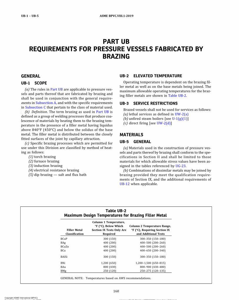
PART UBREQUIREMENTS FOR PRESSURE VESSELS FABRICATED BY
BRAZING
GENERAL
UB-1 SCOPE(a) The rules in Part UB are applicable to pressure ves-
sels and parts thereof that are fabricated by brazing andshall be used in conjunction with the general require-ments in Subsection A, and with the specific requirementsin Subsection C that pertain to the class of material used.(b) Definition. The term brazing as used in Part UB is
defined as a group of welding processes that produce coa-lescence of materials by heating them to the brazing tem-perature in the presence of a filler metal having liquidusabove 840°F (450°C) and below the solidus of the basemetal. The filler metal is distributed between the closelyfitted surfaces of the joint by capillary attraction.(c) Specific brazing processes which are permitted for
use under this Division are classified by method of heat-ing as follows:
(1) torch brazing(2) furnace brazing(3) induction brazing(4) electrical resistance brazing(5) dip brazing — salt and flux bath
UB-2 ELEVATED TEMPERATUREOperating temperature is dependent on the brazing fil-
ler metal as well as on the base metals being joined. Themaximum allowable operating temperatures for the braz-ing filler metals are shown in Table UB-2.
UB-3 SERVICE RESTRICTIONSBrazed vessels shall not be used for services as follows:(a) lethal services as defined in UW-2(a)(b) unfired steam boilers [see U-1(g)(1)](c) direct firing [see UW-2(d)]
MATERIALS
UB-5 GENERAL(a)Materials used in the construction of pressure ves-
sels and parts thereof by brazing shall conform to the spe-cifications in Section II and shall be limited to thosematerials for which allowable stress values have been as-signed in the tables referenced by UG-23.(b) Combinations of dissimilar metals may be joined by
brazing provided they meet the qualification require-ments of Section IX, and the additional requirements ofUB-12 when applicable.
Table UB-2Maximum Design Temperatures for Brazing Filler Metal
Filler MetalClassification
Column 1 Temperature,°F (°C), Below Which
Section IX Tests Only AreRequired
Column 2 Temperature Range,°F (°C), Requiring Section IX
and Additional Tests
BCuP 300 (150) 300–350 (150–180)BAg 400 (200) 400–500 (200–260)BCuZn 400 (200) 400–500 (200–260)BCu 400 (200) 400–650 (200–340)
BAISi 300 (150) 300–350 (150–180)
BNi 1,200 (650) 1,200–1,500 (650–815)BAu 800 (430) 800–900 (430–480)BMg 250 (120) 250–275 (120–135)
GENERAL NOTE: Temperatures based on AWS recommendations.
160
ASME BPVC.VIII.1-2019UB-1 – UB-5
Copyright ASME International (BPVC) Provided by IHS under license with ASME Licensee=Khalda Petroleum/5986215001, User=Amer, Mohamed
Not for Resale, 07/02/2019 13:29:04 MDTNo reproduction or networking permitted without license from IHS
--`,``,``,,`,`,,````,`,``,,,`-`-`,,`,,`,`,,`---
UB-6 BRAZING FILLER METALSThe selection of the brazing filler metal for a specific
application shall depend upon its suitability for the basemetals being joined and the intended service. Satisfactoryqualification of the brazing procedure under Section IXand when necessary based on design temperature, withthe additional requirements of this Section, is consideredproof of the suitability of the filler metal. Brazing withbrazing filler metals other than those listed in Section II,Part C, SFA-5.8 shall be separately qualified for both pro-cedure and performance qualification in accordance withSection IX and when necessary with the additional re-quirements of this Section.
UB-7 FLUXES AND ATMOSPHERESSuitable fluxes or atmospheres or combinations of
fluxes and atmospheres shall be used to prevent oxidationof the brazing filler metal and the surfaces to be joined.Satisfactory qualification of the brazing procedure underSection IX and when necessary based on design tempera-ture, with the additional requirements of this Section, isconsidered proof of the suitability of the flux and/oratmosphere.
DESIGN
UB-9 GENERALThe rules in the following paragraphs apply specifically
to pressure vessels and parts thereof that are fabricatedby brazing and shall be used in conjunction with the gen-eral requirements for Design in Subsection A, and the spe-cific requirements for Design in Subsection C that pertainto the class of material used.
UB-10 STRENGTH OF BRAZED JOINTSIt is the responsibility of the Manufacturer to determine
from suitable tests or from experience that the specificbrazing filler metal selected can produce a joint whichwill have adequate strength at design temperature. Thestrength of the brazed joint shall not be less than thestrength of the base metal, or the weaker of two base me-tals in the case of dissimilar metal joints.
UB-11 QUALIFICATION OF BRAZED JOINTS FORDESIGN TEMPERATURES UP TO THEMAXIMUM SHOWN IN COLUMN 1 OFTABLE UB-2
Satisfactory qualification of the brazing procedure inaccordance with Section IX, Part QB is considered evi-dence of the adequacy of the base materials, the brazingfiller metal, the flux and/or atmosphere, and other vari-ables of the procedure.
UB-12 QUALIFICATION OF BRAZED JOINTS FORDESIGN TEMPERATURES IN THE RANGESHOWN IN COLUMN 2 OF TABLE UB-2
For design temperatures in the range shown in Column2 of Table UB-2, tests in addition to those in UB-11 are re-quired. These tests shall be considered a part of the qua-lification procedure. For such design temperatures, twotension tests on production type joints are required,one at the design temperature, T , and one at 1.05T .Neither of these production type joints shall fail in thebraze metal.
UB-13 CORROSION(a) Provision shall be made for corrosion in accordance
with the requirements in UG-25.(b) Corrosion of the brazing filler metal and galvanic ac-
tion between the brazing filler metal and the base metalsshall be considered in selecting the brazing filler metal.
(c) The plate thickness in excess of that computed for aseamless vessel taking into account the applicable load-ings in UG-22 may be taken as allowance for corrosionin vessels that have longitudinal joints of double‐strapbutt joint construction. Additional corrosion allowanceshall be provided when needed, particularly on the innerbuttstraps.
(d) The rules in this Part are not intended to apply tobrazing used for the attachment of linings of corrosion re-sistant material that are not counted on to carry load.
UB-14 JOINT EFFICIENCY FACTORS(a) The joint efficiency factor to be used in the appro-
priate design equations of pressure vessels and partsthereof shall be 1.0 for joints in which visual examinationassures that the brazing filler metal has penetrated theentire joint [see Figure UB-14, sketch (a)].
(b) The joint efficiency factor to be used in the appro-priate design equations of pressure vessels and partsthereof shall be 0.5 for joints in which visual examinationwill not provide proof that the brazing filler metal has pe-netrated the entire joint. [see Figure UB-14, sketch (b);UB-15(b) and UB-15(c).]
(c) The appropriate joint efficiency factor to be used indesign equations for seamless flat heads and seamlessformed heads, excluding seamless hemispherical heads,is 1.0. The appropriate joint efficiency factor to be usedin design equations for circumferential stress in seamlesscylindrical or conical shells is 1.0.
UB-15 APPLICATION OF BRAZING FILLERMETAL
(a) The design shall provide for the application of thebrazing filler metal as part of the design of the joint.Where practicable, the brazing filler metal shall be ap-plied in such a manner that it will flow into the joint orbe distributed across the joint and produce visible evi-dence that it has penetrated the joint.
161
ASME BPVC.VIII.1-2019 UB-6 – UB-15
Copyright ASME International (BPVC) Provided by IHS under license with ASME Licensee=Khalda Petroleum/5986215001, User=Amer, Mohamed
Not for Resale, 07/02/2019 13:29:04 MDTNo reproduction or networking permitted without license from IHS
--`,``,``,,`,`,,````,`,``,,,`-`-`,,`,,`,`,,`---
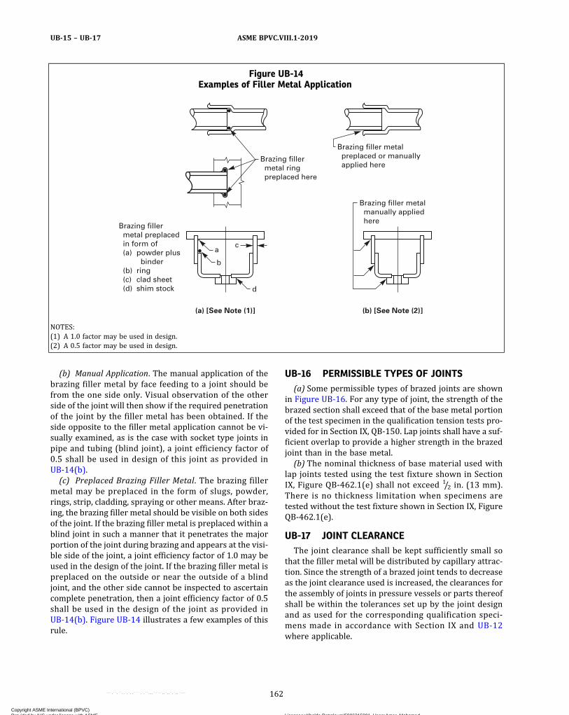
(b) Manual Application. The manual application of thebrazing filler metal by face feeding to a joint should befrom the one side only. Visual observation of the otherside of the joint will then show if the required penetrationof the joint by the filler metal has been obtained. If theside opposite to the filler metal application cannot be vi-sually examined, as is the case with socket type joints inpipe and tubing (blind joint), a joint efficiency factor of0.5 shall be used in design of this joint as provided inUB-14(b).(c) Preplaced Brazing Filler Metal. The brazing filler
metal may be preplaced in the form of slugs, powder,rings, strip, cladding, spraying or other means. After braz-ing, the brazing filler metal should be visible on both sidesof the joint. If the brazing filler metal is preplaced within ablind joint in such a manner that it penetrates the majorportion of the joint during brazing and appears at the visi-ble side of the joint, a joint efficiency factor of 1.0 may beused in the design of the joint. If the brazing filler metal ispreplaced on the outside or near the outside of a blindjoint, and the other side cannot be inspected to ascertaincomplete penetration, then a joint efficiency factor of 0.5shall be used in the design of the joint as provided inUB-14(b). Figure UB-14 illustrates a few examples of thisrule.
UB-16 PERMISSIBLE TYPES OF JOINTS(a) Some permissible types of brazed joints are shown
in Figure UB-16. For any type of joint, the strength of thebrazed section shall exceed that of the base metal portionof the test specimen in the qualification tension tests pro-vided for in Section IX, QB‐150. Lap joints shall have a suf-ficient overlap to provide a higher strength in the brazedjoint than in the base metal.(b) The nominal thickness of base material used with
lap joints tested using the test fixture shown in SectionIX, Figure QB‐462.1(e) shall not exceed 1/2 in. (13 mm).There is no thickness limitation when specimens aretested without the test fixture shown in Section IX, FigureQB‐462.1(e).
UB-17 JOINT CLEARANCEThe joint clearance shall be kept sufficiently small so
that the filler metal will be distributed by capillary attrac-tion. Since the strength of a brazed joint tends to decreaseas the joint clearance used is increased, the clearances forthe assembly of joints in pressure vessels or parts thereofshall be within the tolerances set up by the joint designand as used for the corresponding qualification speci-mens made in accordance with Section IX and UB-12where applicable.
Figure UB-14Examples of Filler Metal Application
Brazing filler metal manually applied here
(a) [See Note (1)] (b) [See Note (2)]
Brazing filler metal preplaced or manually applied here
Brazing filler metal ring preplaced here
a
b
d
c
Brazing filler metal preplaced in form of (a) (b) (c) (d)
powder plus binderringclad sheetshim stock
NOTES:(1) A 1.0 factor may be used in design.(2) A 0.5 factor may be used in design.
162
ASME BPVC.VIII.1-2019UB-15 – UB-17
Copyright ASME International (BPVC) Provided by IHS under license with ASME Licensee=Khalda Petroleum/5986215001, User=Amer, Mohamed
Not for Resale, 07/02/2019 13:29:04 MDTNo reproduction or networking permitted without license from IHS
--`,``,``,,`,`,,````,`,``,,,`-`-`,,`,,`,`,,`---

NOTE: For guidance, see Table UB-17 which gives recommendedjoint clearances at brazing temperature for various types of brazingfiller metal. Brazing alloys will exhibit maximum unit strength ifclearances are maintained within these limits.
UB-18 JOINT BRAZING PROCEDUREA joint brazing procedure shall be developed for each
different type of joint of a brazed assembly. A recom-mended form for recording the brazing procedure isshown in Section IX, Form QB‐482. If more than one jointoccurs in a brazed assembly, the brazing sequence shallbe specified on the drawing or in instructions accompany-ing the drawing. If welding and brazing are to be done on
the same assembly, the welding shall precede the brazingunless it is determined that the heat of welding will notadversely affect the braze previously made.
UB-19 OPENINGS(a) Openings for nozzles and other connections shall be
far enough away from any main brazed joint so that thejoint and the opening reinforcement plates do not inter-fere with one another.
(b) Openings for pipe connections in vessels havingbrazed joints may be made by inserting pipe couplings,not exceeding NPS 3 (DN 80), or similar devices in theshell or heads and securing them by welding, without ne-cessitating the application of the restrictive stamping pro-visions of UG-116, provided the welding is performed bywelders who have been qualified under the provisions ofSection IX for the welding position and type of joint used.Such attachments shall conform to the rules for weldedconnections in UW-15 and UW-16.
UB-20 NOZZLES(a) Nozzles may be integral or attached to the vessel by
any of the methods provided for in UG-43.(b) For nozzle fittings having a bolting flange and an in-
tegral flange for brazing, the thickness of the flange at-tached to the pressure vessel shall not be less than thethickness of the neck of the fitting.
UB-21 BRAZED CONNECTIONSConnections, such as saddle type fittings and fittings in-
serted into openings formed by outward flanging of thevessel wall, in sizes not exceeding NPS 3 (DN 80), maybe attached to pressure vessels by lap joints of brazedconstruction. Sufficient brazing shall be provided on
Figure UB-16Some Acceptable Types of Brazed Joints
GENERAL NOTE: Other equivalent geometries yielding substantially equal results are also acceptable.
Table UB-17Recommended Joint Clearances at Brazing
Temperature
Brazing Filler Metal Clearance, in. (mm) [Note (1)]
BAISi 0.006–0.010 (0.15–0.25) for laps less thanor equal to 1/4 in. (6 mm)
0.010–0.025 (0.25–0.64) for laps greaterthan 1/4 in. (6 mm)
BCuP 0.001–0.005 (0.02–0.13)BAg 0.002–0.005 (0.05–0.13)BCuZn 0.002–0.005 (0.05–0.13)BCu 0.000–0.002 (0.05–0.13) [Note (2)]BNi 0.001–0.005 (0.02–0.13)
NOTES:(1) In the case of round or tubular members, clearance on the radius
is intended.(2) For maximum strength, use the smallest possible clearance.
163
ASME BPVC.VIII.1-2019 UB-17 – UB-21
Copyright ASME International (BPVC) Provided by IHS under license with ASME Licensee=Khalda Petroleum/5986215001, User=Amer, Mohamed
Not for Resale, 07/02/2019 13:29:04 MDTNo reproduction or networking permitted without license from IHS
--`,``,``,,`,`,,````,`,``,,,`-`-`,,`,,`,`,,`---
either side of the line through the center of the openingparallel to the longitudinal axis of the shell to developthe strength of the reinforcement as prescribed inUG-41 through shear in the brazing.
UB-22 LOW TEMPERATURE OPERATIONImpact tests shall be made of the brazed joints in pres-
sure vessels and parts thereof fabricated from materialsfor which impact tests are required in Subsection C. Thetests shall be made in accordance with UG-84 except thatterms referring to welding shall be interpreted as refer-ring to brazing.
FABRICATION
UB-30 GENERAL(a) The rules in the following paragraphs apply specifi-
cally to the fabrication of pressure vessels and partsthereof that are fabricated by brazing and shall be usedin conjunction with the requirements for Fabrication inSubsection A, and with the specific requirements for Fab-rication in Subsection C that pertain to the class of mate-rial used.(b) Each manufacturer or contractor shall be responsi-
ble for the quality of the brazing done by his organizationand shall conduct tests not only of the brazing procedureto determine its suitability to ensure brazes which willmeet the required tests, but also of the brazers and braz-ing operators to determine their ability to apply the pro-cedure properly.(c) No production work shall be undertaken until both
the brazing procedure and the brazers or brazing opera-tors have been qualified.(d) The Manufacturer (Certificate Holder) may engage
individuals by contract or agreement for their servicesas brazers at the shop location shown on the Certificateof Authorization and at field sites (if allowed by the Cer-tificate of Authorization) for the construction of pressurevessels or vessel parts, provided all the following condi-tions are met:
(1) All Code construction shall be the responsibilityof the Manufacturer.
(2) All brazing shall be performed in accordance withthe Manufacturer’s Brazing Procedure Specificationswhich have been qualified by the Manufacturer in accor-dance with the requirements of Section IX.
(3) All brazers shall be qualified by the Manufacturerin accordance with the requirements of Section IX.
(4) The Manufacturer’s Quality Control System shallinclude as a minimum:
(-a) a requirement for complete and exclusive ad-ministrative and technical supervision of all brazers bythe Manufacturer;
(-b) evidence of the Manufacturer’s authority toassign and remove brazers at his discretion without theinvolvement of any other organization;
(-c) a requirement for assignment of brazer iden-tification symbols;
(-d) evidence that this program has been acceptedby the Manufacturer’s Authorized Inspection Agencywhich provides the inspection service.
(5) The Manufacturer shall be responsible for Codecompliance of the vessel or part, including CertificationMark stamping and providing completed Data ReportForms.
UB-31 QUALIFICATION OF BRAZINGPROCEDURE
(a) Each procedure of brazing that is to be followed inconstruction shall be recorded in detail by the Manufac-turer. Each brazing procedure shall be qualified in accor-dance with Section IX and when necessary determined bydesign temperature, with the additional requirements ofthis Section.(b) The procedure used in brazing pressure parts and
in joining load‐carrying nonpressure parts, such as allpermanent or temporary clips and lugs, to pressure partsshall be qualified in accordance with Section IX.(c) The procedure used in brazing nonpressure‐
bearing attachments which have essentially no load‐carrying function (such as extended heat transfer sur-faces, insulation support pins, etc.) to pressure parts shallmeet the following requirements:
(1)When the brazing process is manual, machine, orsemiautomatic, procedure qualification is required in ac-cordance with Section IX.
(2)When the brazing is any automatic brazing pro-cess performed in accordance with a Brazing ProcedureSpecification (in compliance with Section IX as far as ap-plicable), procedure qualification testing is not required.(d) Brazing of all test coupons shall be conducted by the
Manufacturer. Testing of all test coupons shall be the re-sponsibility of the Manufacturer. Qualification of a braz-ing procedure by one Manufacturer shall not qualifythat procedure for any other Manufacturer, except as pro-vided in Section IX, QG-106.
UB-32 QUALIFICATION OF BRAZERS ANDBRAZING OPERATORS
(a) The brazers and brazing operators used in brazingpressure parts and in joining load‐carrying nonpressureparts (attachments) to pressure parts shall be qualifiedin accordance with Section IX.The qualification test for brazing operators of machine
brazing equipment shall be performed on a separate testplate prior to the start of brazing or on the firstworkpiece.(b) The brazers and brazing operators used in brazing
non-pressure‐bearing attachments, which have essen-tially no load‐carrying function (such as extended heattransfer surfaces, insulation support pins, etc.), to pres-sure parts shall comply with the following:
164
ASME BPVC.VIII.1-2019UB-21 – UB-32
Copyright ASME International (BPVC) Provided by IHS under license with ASME Licensee=Khalda Petroleum/5986215001, User=Amer, Mohamed
Not for Resale, 07/02/2019 13:29:04 MDTNo reproduction or networking permitted without license from IHS
--`,``,``,,`,`,,````,`,``,,,`-`-`,,`,,`,`,,`---
(1)When the brazing process is manual, machine, orsemiautomatic, qualification in accordance with SectionIX is required.
(2)When brazing is done by any automatic brazingprocess, performance qualification testing is not required.
(c) Each brazer or brazing operator shall be assignedan identifying number, letter, or symbol by the Manufac-turer which shall be used to identify the work of that bra-zer or brazing operator in accordance with UW-37(f).
(d) The Manufacturer shall maintain a record of thebrazers and brazing operators showing the date and re-sult of tests and the identification mark assigned to each.These records shall be maintained in accordance withSection IX.
(e) Brazing of all test coupons shall be conducted by theManufacturer. Testing of all test coupons shall be the re-sponsibility of the Manufacturer. A performance qualifica-tion test conducted by one Manufacturer shall not qualifya brazer or brazing operator to do work for any otherManufacturer.
UB-33 BUTTSTRAPS(a) Buttstraps shall be formed to the curvature of the
shell with which they are to be used.(b)When the buttstraps of a longitudinal joint do not
extend the full length of a shell section, the abutting edgesof the shell plate may be welded provided the length ofthe weld between the end of the buttstraps and the edgeof the head or adjoining shell plate is not greater than fourtimes the shell plate thickness. When so constructed, therestrictive stamping provisions of UG-116 shall not applyprovided the welding is performed by welders who havebeen qualified under the provisions of Section IX for thewelding position and type of joint used. The welds shallbe completed before brazing is begun.
UB-34 CLEANING OF SURFACES TO BE BRAZEDThe surfaces to be brazed shall be clean and free from
grease, paint, oxides, scale and foreign matter of any kind.Any chemical or mechanical cleaning method may be usedthat will provide a surface suitable for brazing.
UB-35 CLEARANCE BETWEEN SURFACES TO BEBRAZED
The clearances between surfaces to be brazed shall bemaintained within the tolerances provided for by the jointdesign and used in the qualifying procedure. If greater tol-erances are to be used in production, the joint must be re-qualified for those greater tolerances. The control oftolerances required may be obtained by using spot weld-ing, crimping, or other means which will not interferewith the quality of the braze. If such means are employedin production, they must also be employed in qualificationof procedure, brazer, and operator.
UB-36 POSTBRAZING OPERATIONSBrazed joints shall be thoroughly cleaned of flux resi-
due by any suitable means after brazing and prior toinspection.73 Other postbrazing operations such as ther-mal treatments shall be performed in accordance withthe qualified procedure.
UB-37 REPAIR OF DEFECTIVE BRAZINGBrazed joints which have been found to be defective
may be rebrazed, where feasible, after thorough cleaning,and by employing the same brazing procedure used forthe original braze. See UB-44. If a different brazing proce-dure is employed, i.e., torch repair of furnace brazedparts, a repair brazing procedure shall be establishedand qualified.
When a repair brazing procedure is established, it shallmeet Section IX and other conditions set forth in thisSection.
INSPECTION AND TESTS
UB-40 GENERALThe rules in the following paragraphs apply specifically
to the inspection and testing of pressure vessels and partsthereof that are fabricated by brazing and shall be used inconjunction with the general requirements for Inspectionand Tests in Subsection A and with the specific require-ments for Inspection and Tests in Subsection C that pertainto the class of material used.
UB-41 INSPECTION DURING FABRICATIONThe Manufacturer shall submit the vessel or other pres-
sure parts for inspection at such stages of the work asmay be designated by the Inspector.
UB-42 PROCEDUREThe Inspector shall assure himself that the brazing pro-
cedure for each type of joint being produced is qualified inaccordance with the requirements of Section IX and whennecessary the additional requirements of this Section. Heshall satisfy himself that each joint has been fabricated inaccordance with the procedure. Where there is evidenceof consistent poor quality, the Inspector shall have theright at any time to call for and witness tests of the braz-ing procedure.
UB-43 BRAZER AND BRAZING OPERATOR(a) The manufacturer shall certify that the brazing on a
vessel or part thereof has been done by brazers or brazingoperators who are qualified under the requirements ofSection IX and the Inspector shall assure himself that onlyqualified brazers or brazing operators have been used.
165
ASME BPVC.VIII.1-2019 UB-32 – UB-43
Copyright ASME International (BPVC) Provided by IHS under license with ASME Licensee=Khalda Petroleum/5986215001, User=Amer, Mohamed
Not for Resale, 07/02/2019 13:29:04 MDTNo reproduction or networking permitted without license from IHS
--`,``,``,,`,`,,````,`,``,,,`-`-`,,`,,`,`,,`---
(b) The manufacturer shall make available to the In-spector the record of the qualification tests of each brazerand brazing operator. The Inspector shall have the rightat any time to call for and witness tests of the ability ofa brazer or brazing operator.
UB-44 VISUAL EXAMINATION(a)Where possible, the Inspector shall visually inspect
both sides of each brazed joint after flux residue removal.Where it is not possible to inspect one side of a brazedjoint (blind joint), the Inspector shall check the designto determine that the proper joint factor has been em-ployed, unless he can assure himself that the brazing fillermetal has been preplaced in such a manner that it satis-fies UB-15(b) and UB-15(c).(b) There shall be evidence that the brazing filler metal
has penetrated the joint. In a butt braze there shall be noconcavity. The braze may be repaired or rebrazed.(c) The presence of a crack in the brazing filler metal
shall be cause for rejection. Dye penetrant inspectionmay be used if desired. The braze may be repaired or re-brazed. See UB-37.(d) The presence of a crack in the base metal adjacent
to a braze shall be cause for rejection even if the crackis filled with brazing alloy. Such cracking shall not berepaired.
(e) Pinholes or open defects in the braze shall be causefor rejection. The joint may be rebrazed.(f) Rough fillets, particularly those with a convex ap-
pearance, are cause for rejection. Such joints may be re-paired or rebrazed.
UB-50 EXEMPTIONSCertain brazed joints regardless of their service tem-
peratures may be exempt from the additional mechanicaltesting of this Section providing that the design applica-tion does not assume any benefit from the brazed jointstrength. It shall, however, meet the requirements ofthose qualification tests required by Section IX of theCode.
MARKING AND REPORTS
UB-55 GENERALThe provisions for marking and reports given in
UG-115 through UG-120 shall apply without supplementto brazed pressure vessels and parts thereof.
166
ASME BPVC.VIII.1-2019UB-43 – UB-55
Copyright ASME International (BPVC) Provided by IHS under license with ASME Licensee=Khalda Petroleum/5986215001, User=Amer, Mohamed
Not for Resale, 07/02/2019 13:29:04 MDTNo reproduction or networking permitted without license from IHS
--`,``,``,,`,`,,````,`,``,,,`-`-`,,`,,`,`,,`---

SUBSECTION CREQUIREMENTS PERTAINING TO CLASSES OF
MATERIALS
PART UCSREQUIREMENTS FOR PRESSURE VESSELS CONSTRUCTED OF
CARBON AND LOW ALLOY STEELS74
GENERAL
UCS-1 SCOPEThe rules in Part UCS are applicable to pressure vessels
and vessel parts that are constructed of carbon and lowalloy steels and shall be used in conjunction with the gen-eral requirements in Subsection A, and with the specificrequirements in Subsection B that pertain to the methodof fabrication used.
MATERIALS
UCS-5 GENERAL(a) All carbon and low alloy steel material subject to
stress due to pressure shall conform to one of the Speci-fications given in Section II and shall be limited to thoselisted in Table UCS-23 except as otherwise provided inUG-10 and UG-11.
(b) In addition to the requirements of UG-4(a), backingstrips which remain in place need not conform to a mate-rial specification permitted by this Division if all of the fol-lowing are met:
(1) The specification maximum composition limits orcertificate values for the backing strip material shall notexceed those of the material specification for the pressurepart to which it is attached.
(2) Either of the following requirements shall be met:(-a) The backing strip base metal, and its asso-
ciated HAZ, and the weld metal shall be impact tested inaccordance with UG-84 at the MDMT shown on the name-plate with a butt weld test specimen to the pressure partmaterial or to a material with the same P‐No. and GroupNo. as the pressure part.
(-b) The material is assigned to Curve A and is ex-empt from impact testing at the MDMT shown on thenameplate by Figure UCS-66 alone (i.e., MDMT reductionper Figure UCS-66.1 is not permitted), and both of the fol-lowing apply:
(-1) The backing strip material specificationminimum tensile strength shall not exceed that of thepressure part material specification.
(-2) The backing strip material specificationminimum percent elongation shall be at least equal to thatfor the pressure part material specification.
(c) Carbon or low alloy steel having a carbon content ofmore than 0.35% by heat analysis shall not be used inwelded construction or be shaped by oxygen cutting (ex-cept as provided in Part UF in this Division).
(d) Smal l parts used under the provis ions ofUG-11(a)(2) in welded construction shall be of goodweldable quality.
UCS-6 STEEL PLATES(a) Approved specifications for carbon and low alloy
steel plates are given in Table UCS-23. A tabulation of al-lowable stress values at different temperatures are givenin Section II, Part D, Subpart 1, Table 1A (see UG-5).
(b) S t e e l p l a t e s c o n f o rm i n g t o S A - 3 6 , S A /CSA‐G40.21 38W, and SA-283 Grades A, B, C, and D maybe used for pressure parts in pressure vessels providedall of the following requirements are met:
(1) The vessels are not used to contain lethal sub-stances, either liquid or gaseous.
(2) The material is not used in the construction of un-fired steam boilers [see U-1(g)(1)].
(3)With the exception of flanges, flat bolted covers,and stiffening rings, the thickness of plates on whichstrength welding is applied does not exceed 5/8 in.(16 mm).
167
ASME BPVC.VIII.1-2019 UCS-1 – UCS-6
Copyright ASME International (BPVC) Provided by IHS under license with ASME Licensee=Khalda Petroleum/5986215001, User=Amer, Mohamed
Not for Resale, 07/02/2019 13:29:04 MDTNo reproduction or networking permitted without license from IHS
--`,``,``,,`,`,,````,`,``,,,`-`-`,,`,,`,`,,`---

ð19Þ
(c) Except for local heating, such as cutting and weld-ing, heating of SA-841 above 1,200°F (649°C) during fab-rication is prohibited.
UCS-7 STEEL FORGINGSApproved specifications for forgings of carbon and low
alloy steel are given in Table UCS-23. A tabulation of al-lowable stress values at different temperatures are givenin Section II, Part D, Subpart 1, Table 1A (see UG-6).
UCS-8 STEEL CASTINGSApproved specifications for castings of carbon and low
alloy steel are given in Table UCS-23. A tabulation of al-lowable stress values at different temperatures are givenin Section II, Part D, Subpart 1, Table 1A. These stress val-ues are to be multiplied by the casting quality factors ofUG-24. Castings that are to be welded shall be of weldablegrade.
UCS-9 STEEL PIPE AND TUBESApproved specifications for pipe and tubes of carbon
and low alloy steel are given in Table UCS-23. A tabulationof allowable stress values of the materials from which thepipe or tubes are manufactured are given in Section II,Part D, Subpart 1, Table 1A. Net allowable stress valuesfor pipe or tubes of welded manufacture are given in Sec-tion II, Part D, Subpart 1, Table 1A.
UCS-10 BOLT MATERIALS(a) Approved specifications for bolt materials of carbon
steel and low alloy steel are given in Table UCS-23. A ta-bulation of allowable stress values at different tempera-tures (see UG-12) are given in Section II, Part D,Subpart 1, Table 3.(b) Nonferrous and high alloy steel bolts, studs, and
nuts may be used provided they are suitable for the appli-cation. They shall conform to the requirements of PartUNF or UHA, as applicable.
UCS-11 NUTS AND WASHERS(a) Except as otherwise provided in (b)(4) below, mate-
rials for nuts shall conform to SA-194, SA-563, or to therequirements for nuts in the specification for the boltingmaterial with which they are to be used. Nuts of specialdesign, such as wing nuts, may be made of any suitablewrought material listed in Table UCS-23 or TableUHA-23 and shall be either: hot or cold forged; or ma-chined from hot‐forged, hot‐rolled, or cold‐drawn bars.Washers may be made from any suitable material listedin Table UCS-23 and Table UHA-23.(b)Materials for nuts and washers shall be selected as
follows:(1) Carbon steel nuts and carbon steel washers may
be used with carbon steel bolts or studs.
(2) Carbon or alloy steel nuts and carbon or alloysteel washers of approximately the same hardness asthe nuts may be used with alloy steel bolts or studs formetal temperatures not exceeding 900°F (480°C).
(3) Alloy steel nuts shall be used with alloy steelstuds or bolts for metal temperatures exceeding 900°F(480°C). Washers, if used, shall be of alloy steel equivalentto the nut material.
(4) Nonferrous nuts and washers may be used withferrous bolts and studs provided they are suitable forthe application. Consideration shall be given to the differ-ences in thermal expansion and possible corrosion result-ing from the combination of dissimilar metals. Nonferrousnuts and washers shall conform to the requirements ofUNF-13.(c) Nuts shall be semifinished, chamfered, and
trimmed. Nuts shall be threaded to Class 2B or finer toler-ances according to ASME B1.1. For use with flanges con-forming to the standards listed in UG-44(a), nuts shallconform at least to the dimensions given in ASMEB18.2.2 for Heavy Series nuts. For use with connectionsdesigned in accordance with the rules in MandatoryAppendix 2, nuts may be of the ANSI Heavy Series, or theymay be of other dimensions as permitted in (d) below.(d) Nuts of special design or of dimensions other than
ANSI Heavy Series may be used provided their strengthis equal to that of the bolting, giving due considerationto bolt hole clearance, bearing area, thread form and classof fit, thread shear, and radial thrust from threads [seeU-2(g)].
UCS-12 BARS AND SHAPES(a) Approved specifications for bar and shape materials
of carbon steel are given in Table UCS-23. A tabulation ofallowable stress values at different temperatures are giv-en in Section II, Part D, Subpart 1, Table 1A.(b) Bolt materials as described in UCS-10 may be used
as bar materials.(c) Parts made from bars, on which welding is done,
shall be of material for which a P‐Number for procedurequalification is given in Section IX, Table QW/QB‐422(see UW-5).
DESIGN
UCS-16 GENERALThe rules in the following paragraphs apply specifically
to the design of pressure vessels and vessel parts that areconstructed of carbon and low alloy steel and shall beused in conjunction with the general requirements for De-sign in Subsection A and with the specific requirementsfor Design in Subsection B that pertain to the method offabrication used.
168
ASME BPVC.VIII.1-2019UCS-6 – UCS-16
Copyright ASME International (BPVC) Provided by IHS under license with ASME Licensee=Khalda Petroleum/5986215001, User=Amer, Mohamed
Not for Resale, 07/02/2019 13:29:04 MDTNo reproduction or networking permitted without license from IHS
--`,``,``,,`,`,,````,`,``,,,`-`-`,,`,,`,`,,`---

UCS-19 WELDED JOINTSWhen radiographic examination is required for butt-
welded joints by UCS-57, Category A and B joints (seeUW-3) shall be of Type No. (1) or No. (2) of Table UW-12.
UCS-23 MAXIMUM ALLOWABLE STRESS VALUESSection II, Part D, Subpart 1, Table 3 for bolting and
Table 1A for other materials give the maximum allowablestress values at the temperature indicated for materialsconforming to the specifications listed therein.75 Valuesmay be interpolated for intermediate temperatures.(See UG-23.) For vessels designed to operate at a tem-perature below −20°F (−29°C), the allowable stress val-ues to be used in design shall not exceed those given inSection II, Part D, Subpart 1, Table 1A or Table 3 for100°F (40°C).
UCS-27 SHELLS MADE FROM PIPE(a) Shells of pressure vessels may be made from seam-
less pipe or tubing listed in Section II, Part D, Subpart 1,Table 1A, provided the material of the pipe is manufac-tured by the open‐hearth, basic oxygen, or electric‐furnace process.
(b) Shells of pressure vessels may be made from elec-tric resistance-welded pipe or tubing listed in Section II,Part D, Subpart 1, Table 1A in nominal diameters up to30 in. (750 mm)provided the material is manufacturedby the open‐hearth, basic oxygen, or electric‐furnace pro-cess [see UG-16(d)].
Table UCS-23Carbon and Low Alloy Steel
Spec. No. Type/Grade
SA-36 …SA-53 E/A, E/B, S/A, S/BSA-105 …SA-106 A, B, CSA-135 A, BSA-178 A, CSA-179 …SA-181 …SA-182 FR, F1, F2, F3V, F3VCb, F5, F5a, F9,
F11 Cl. 1 & 2, F12 Cl. 1 & 2, F21,F22 Cl. 1 & 3, F22V, F91
SA-192 …SA-193 B5, B7, B7M, B16SA-203 A, B, D, E, FSA-204 A, B, CSA-209 T1, T1a, T1bSA-210 A‐1, CSA-213 T2, T5, T5b, T5c, T9, T11, T12, T17,
T21, T22, T91SA-214 …SA-216 WCA, WCB, WCCSA-217 C12, C5, WC1, WC4, WC5, WC6, WC9SA-225 CSA-234 WPB, WPC, WPR, WP1, WP5, WP9,
WP11 Cl. 1, WP12 Cl. 1, WP22Cl. 1
SA-250 T1, T1a, T1bSA-266 1, 2, 3, 4SA-283 A, B, C, DSA-285 A, B, CSA-299 A, BSA-302 A, B, C, DSA-307 A, BSA-320 L7, L7A, L7M, L43SA-325 1
Spec. No. Type/Grade
SA-333 1, 3, 4, 6, 7, 9SA-334 1, 3, 6, 7, 9SA-335 P1, P2, P5, P5b, P5c, P9, P11, P12,
P15, P21, P22, P91SA-336 F1, F3V, F3VCb, F5, F5A, F9, F11 Cl.
2 & 3, F12, F21 Cl. 1 & 3, F22 Cl. 1& 3, F22V, F91
SA-350 LF1, LF2, LF3, LF5, LF9SA-352 LCB, LC1, LC2, LC3SA-354 BC, BDSA-369 FP1, FP2, FP5, FP9, FP11, FP12,
FP21, FP22SA-372 A; B; C; D; E Cl. 55, 65, & 70; F Cl. 55,
65, & 70; G Cl. 55, 65, & 70; H Cl.55, 65, & 70; J Cl. 55, 65, 70, &110; L; M Cl. 85 & 100
SA-387 2, 5, 11, 12, 21, 22, 91SA-414 A, B, C, D, E, F, GSA-420 WPL 3, WPL 6, WPL 9SA-423 1, 2SA-437 B4B, B4CSA-449 …SA-455 …SA-487 1 Cl. A & B, 2 Cl. A & B, 4 Cl. A, 8 Cl. ASA-508 1, 1A, 2 Cl. 1, 2 Cl. 2, 3 Cl. 1, 3 Cl. 2,
3V, 3VCb, 4N Cl. 3, 22 Cl. 3SA-515 60, 65, 70SA-516 55, 60, 65, 70SA-524 I, IISA-533 A Cl. 1 & 2, B Cl. 1 & 2, C Cl. 1 & 2, D
Cl. 2, E Cl. 1 & 2SA-537 Cl. 1, 2, & 3SA-540 B21, B22, B23, B24, B24VSA-541 1, 1A, 2 Cl. 1, 2 Cl. 2, 3 Cl. 1, 3 Cl. 2,
3V, 3VCb, 22 Cl. 3, 22V
Spec. No. Type/Grade
SA-542 B Cl. 4, C Cl. 4a, D Cl. 4a, E Cl. 4aSA-556 A2, B2, C2SA-557 A2, B2, C2SA-562 …SA-574 4037, 4042, 4140, 4340, 5137M,
51B37MSA-587 …SA-612 …SA-662 A, B, CSA-675 45, 50, 55, 60, 65, 70SA-727 …SA-737 B, CSA-738 A, B, CSA-739 B11, B22SA-765 I, II, III, IVSA-832 21V, 22V, 23VSA-836 …SA-841 A Cl. 1, B Cl. 2SA-1008 CS‐A, CS‐BSA/AS
1548PT430, PT460, PT490
SA/CSA‐G40.21
38W, 44W, 50W
SA/EN10028‐2
P235GH, P265GH, P295GH,P355GH, 13CrMo4–5,10CrMo9–10
SA/EN10028‐3
P275NH
SA/EN10216-2
P235GH, P265GH, 16Mo3,13CrMo4–5, 10CrMo9–10
SA/EN10222-2
P280GH, P305GH, 13CrMo4–5,11CrMo9–10
SA/GB 713 Q345R
GENERAL NOTE: Maximum allowable stress values in tension for the materials listed in the above table are contained in Section II, Part D,Subpart 1 (see UG-23).
169
ASME BPVC.VIII.1-2019 UCS-19 – UCS-27
Copyright ASME International (BPVC) Provided by IHS under license with ASME Licensee=Khalda Petroleum/5986215001, User=Amer, Mohamed
Not for Resale, 07/02/2019 13:29:04 MDTNo reproduction or networking permitted without license from IHS
--`,``,``,,`,`,,````,`,``,,,`-`-`,,`,,`,`,,`---

ð19Þ
ð19Þ
UCS-28 THICKNESS OF SHELLS UNDEREXTERNAL PRESSURE
(a) Cylindrical and spherical shells under external pres-sure shall be designed by the rules in UG-28, using the ap-plicable figures in Section II, Part D, Subpart 3 and thetemperature limits of UG-20(c).(b) Corrugated shells subject to external pressure may
be used in pressure vessels in accordance with Section I,PFT-19.
UCS-29 STIFFENING RINGS FOR SHELLS UNDEREXTERNAL PRESSURE
Rules covering the design of stiffening rings are given inUG-29.
UCS-30 ATTACHMENT OF STIFFENING RINGS TOSHELL
Rules covering the attachment of stiffening rings aregiven in UG-30.
UCS-33 FORMED HEADS, PRESSURE ON CONVEXSIDE
Ellipsoidal, torispherical, hemispherical, and conicalheads having pressure on the convex side (minus heads)shall be designed by the rules of UG-33, using the applic-able figures in Section II, Part D, Subpart 3.
UCS-56 REQUIREMENTS FOR POSTWELD HEATTREATMENT
(a) Before applying the detailed requirements and ex-emptions in these paragraphs, satisfactory weld proce-dure qualifications of the procedures to be used shall beperformed in accordance with all the essential variablesof Section IX including conditions of postweld heat treat-ment or lack of postweld heat treatment and includingother restrictions listed below.Except as otherwise specifically provided in the notes
to Tables UCS-56-1 through UCS-56-11 and TableUCS-56.1, all welds in pressure vessels or pressure vesselparts shall be given a postweld heat treatment at a tem-perature not less than specified in those Tables whenthe nominal thickness, as defined in UW-40(f), includingcorrosion allowance, exceeds the limits in those Tables.The exemptions provided in Tables UCS-56-1 throughUCS-56-11 or Table UCS-56.1 are not permitted whenpostweld heat treatment is a service requirement as setforth in UCS-68, when welding ferritic materials greaterthan 1/8 in. (3 mm) thick with the electron beam weldingprocess, or when welding P‐No. 3, P‐No. 4, P‐Nos. 5A, 5B,and 5C, P‐No. 10, and P‐No. 15Ematerials of any thicknessusing the inertia and continuous drive friction weldingprocesses. Electroslag welds in ferritic materials over11/2 in. (38 mm) thickness at the joint shall be given agrain refining (austenitizing) heat treatment. Electrogaswelds in ferritic materials with any single pass greaterthan 11/2 in. (38 mm) shall be given a grain refining
(austenitizing) heat treatment. For P‐No. 1 materials only,the heating and cooling rate restrictions of (d)(2) and(d)(5) below do not apply when the heat treatment fol-lowing welding is in the austenitizing range.The materials in Tables UCS-56-1 through UCS-56-11
are listed in accordance with Section IX P‐Number mate-rial groupings of Section IX, Table QW/QB-422 and alsolisted in Table UCS-23. When there is a conflict inP-Number or Group Number, the numbers in Section IXgovern.(b) Except where prohibited in Tables UCS-56-1
through UCS-56-11, holding temperatures and/or holdingtimes in excess of the minimum values given in TablesUCS-56-1 through UCS-56-11 may be used. Intermediatepostweld heat treatments need not conform to the re-quirements of Tables UCS-56-1 through UCS-56-11. Theholding time at temperature as specified in TablesUCS-56-1 through UCS-56-11 need not be continuous. Itmay be an accumulation of time of multiple postweld heattreatment cycles.(c) When pressure parts of two different P‐Number
groups are joined by welding, engineering judgment shallbe applied when selecting the postweld heat treatmenttemperature and holding time to produce material prop-erties suitable for the intended service. Alternatives suchas welding with buttering as described in Section IX,QW-283 may be considered. When nonpressure partsare welded to pressure parts, the postweld heat treat-ment temperature of the pressure part shall control.(d) The operation of postweld heat treatment shall be
carried out by one of the procedures given in UW-40 inaccordance with the following requirements:
(1) The temperature of the furnace shall not exceed800°F (425°C) at the time the vessel or part is placed in it.
(2) Above 800°F (425°C), the rate76 of heating shallbe not more than 400°F/hr (222°C/h) divided by themaximum metal thickness of the shell or head plate ininches, but in no case more than 400°F/hr (222°C/h).During the heating period there shall not be a greater var-iation in temperature throughout the portion of the vesselbeing heated than 250°F (140°C) within any 15 ft (4.6 m)interval.
(3) The vessel or vessel part shall be held at or abovethe temperature specified in Tables UCS-56-1 throughUCS-56-11 or Table UCS-56.1 for the period of time speci-fied in the Tables. During the holding period, there shallnot be a greater difference than 150°F (83°C) betweenthe highest and lowest temperature throughout the por-tion of the vessel being heated, except where the rangeis further limited in Tables UCS-56-1 through UCS-56-11.
(4) During the heating and holding periods, the fur-nace atmosphere shall be so controlled as to avoid exces-sive oxidation of the surface of the vessel. The furnaceshall be of such design as to prevent direct impingementof the flame on the vessel.
170
ASME BPVC.VIII.1-2019UCS-28 – UCS-56
Copyright ASME International (BPVC) Provided by IHS under license with ASME Licensee=Khalda Petroleum/5986215001, User=Amer, Mohamed
Not for Resale, 07/02/2019 13:29:04 MDTNo reproduction or networking permitted without license from IHS
--`,``,``,,`,`,,````,`,``,,,`-`-`,,`,,`,`,,`---
(5) Above 800°F (425°C), cooling shall be done in aclosed furnace or cooling chamber at a rate76 not greaterthan 500°F/hr (280°C/h) divided by the maximum metalthickness of the shell or head plate in inches, but in nocase more than 500°F/hr (280°C/h). At temperaturesabove 800°F (425°C), temperature variations within theheated portion during the cooling phase shall not begreater than 250°F (140°C) within any 15 ft (4.6 m) inter-val. From 800°F (425°C), the vessel may be cooled in stillair.
(e) Except as permitted in (f) below, vessels or parts ofvessels that have been postweld heat treated in accor-dance with the requirements of this paragraph shall againbe postweld heat treated after welded repairs have beenmade.
(f) Weld repairs to P‐No. 1 Group Nos. 1, 2, and 3 ma-terials and to P‐No. 3 Group Nos. 1, 2, and 3 materials andto the weld metals used to join these materials may bemade after the final PWHT but prior to the final hydro-static test, without additional PWHT, provided that PWHTis not required as a service requirement in accordancewith UW-2(a), except for the exemptions in TablesUCS-56-1 through UCS-56-11, or as a service requirementin accordance with UCS-68. The welded repairs shall meetthe requirements of (1) through (6) below. These require-ments do not apply when the welded repairs are minorrestorations of the material surface, such as those re-quired after removal of construction fixtures, and pro-vided that the surface is not exposed to the vesselcontents.
(1) The Manufacturer shall give prior notification ofthe repair to the user or to his designated agent and shallnot proceed until acceptance has been obtained. Such re-pairs shall be recorded on the Data Report.
(2) The total repair depth shall not exceed 11/2 in.(38 mm) for P‐No. 1 Group Nos. 1, 2, and 3 materialsand 5/8 in. (16 mm) for P‐No. 3 Group Nos. 1, 2, and 3 ma-terials. The total depth of a weld repair shall be taken asthe sum of the depths for repairs made from both sides ofa weld at a given location.
(3) After removal of the defect, the groove shall beexamined, using either the magnetic particle or the liquidpenetrant examination methods, in accordance with Man-datory Appendix 6 for MT and Mandatory Appendix 8 forPT.
(4) In addition to the requirements of Section IX forqualification of Welding Procedure Specifications forgroove welds, the following requirements shall apply:
(-a) The weld metal shall be deposited by themanual shielded metal arc process using low hydrogenelectrodes. The electrodes shall be properly conditionedin accordance with Section II, Part C, SFA-5.1, Annex A,A6.11; and SFA-5.5, Annex A, A6.12. The maximum beadwidth shall be four times the electrode core diameter.
(-b) For P‐No. 1 Group Nos. 1, 2, and 3 materials,the repair area shall be preheated and maintained at aminimum temperature of 200°F (95°C) during welding.
(-c) For P‐No. 3 Group Nos. 1, 2, and 3 materials,the repair weld method shall be limited to the half beadweld repair and weld temper bead reinforcement tech-nique. The repair area shall be preheated and maintainedat a minimum temperature of 350°F (175°C) during weld-ing. The maximum interpass temperature shall be 450°F(230°C). The initial layer of weld metal shall be depositedover the entire area using 1/8 in. (3 mm) maximum dia-meter electrodes. Approximately one‐half the thicknessof this layer shall be removed by grinding before deposit-ing subsequent layers. The subsequent weld layers shallbe deposited using 5/32 in. (4 mm) maximum diameterelectrodes in such a manner as to assure tempering ofthe prior weld beads and their heat-affected zones. A finaltemper bead weld shall be applied to a level above thesurface being repaired without contacting the base mate-rial but close enough to the edge of the underlying weldbead to assure tempering of the base materia lheat-affected zone. After completing all welding, the re-pair area shall be maintained at a temperature of 400°Fto 500°F (205°C to 260°C) for a minimum period of4 hr. The final temper bead reinforcement layer shall beremoved substantially flush with the surface of the basematerial.
(5) After the finished repair weld has reached ambi-ent temperature, it shall be inspected using the same non-destructive examination that was used in (3) above,except that for P‐No. 3, Group No. 3 materials, the exam-ination shall be made after the material has been at ambi-ent temperature for a minimum period of 48 hr todetermine the presence of possible delayed cracking ofthe weld. If the examination is by the magnetic particlemethod, only the alternating current yoke type is accept-able. In addition, welded repairs greater than 3/8 in.(10 mm) deep in materials and in welds that are requiredto be radiographed by the rules of this Division, shall beradiographically examined to the requirements of UW-51.
(6) The vessel shall be hydrostatically tested aftermaking the welded repair.
(g) Capacitor discharge or electric resistance weldingmay be used for attaching bare-wire thermocouples,without subsequent postweld heat treatment, providedthe energy output for welding is limited to 125 W-secmax. and any requirements specified in the applicablenotes as found in Tables UCS-56-1 through UCS-56-11shall apply. A welding procedure specification shall beprepared, and the content shall describe, as a minimum,the capacitor discharge equipment, the combination ofmaterials to be joined, and the technique of application.Qualification of the welding procedure is not required.
171
ASME BPVC.VIII.1-2019 UCS-56
Copyright ASME International (BPVC) Provided by IHS under license with ASME Licensee=Khalda Petroleum/5986215001, User=Amer, Mohamed
Not for Resale, 07/02/2019 13:29:04 MDTNo reproduction or networking permitted without license from IHS
--`,``,``,,`,`,,````,`,``,,,`-`-`,,`,,`,`,,`---
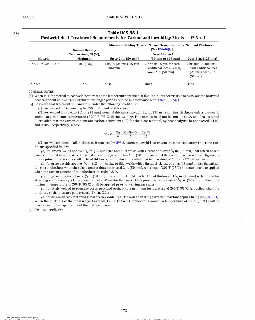
ð19Þ Table UCS-56-1Postweld Heat Treatment Requirements for Carbon and Low Alloy Steels — P-No. 1
Material
Normal HoldingTemperature, °F (°C),
Minimum
Minimum Holding Time at Normal Temperature for Nominal Thickness[See UW-40(f)]
Up to 2 in. (50 mm)Over 2 in. to 5 in.
(50 mm to 125 mm) Over 5 in. (125 mm)
P‐No. 1 Gr. Nos. 1, 2, 3 1,100 (595) 1 hr/in. (25 mm), 15 minminimum
2 hr plus 15 min for eachadditional inch (25 mm)over 2 in. (50 mm)
2 hr plus 15 min foreach additional inch(25 mm) over 2 in.(50 mm)
Gr. No. 4 NA None None None
GENERAL NOTES:(a) When it is impractical to postweld heat treat at the temperature specified in this Table, it is permissible to carry out the postweld
heat treatment at lower temperatures for longer periods of time in accordance with Table UCS-56.1.(b) Postweld heat treatment is mandatory under the following conditions:
(1) for welded joints over 11/2 in. (38 mm) nominal thickness;(2) for welded joints over 11/4 in. (32 mm) nominal thickness through 11/2 in. (38 mm) nominal thickness unless preheat is
applied at a minimum temperature of 200°F (95°C) during welding. This preheat need not be applied to SA-841 Grades A andB, provided that the carbon content and carbon equivalent (CE) for the plate material, by heat analysis, do not exceed 0.14%and 0.40%, respectively, where
(3) for welded joints of all thicknesses if required by UW-2, except postweld heat treatment is not mandatory under the con-ditions specified below:
(a) for groove welds not over 1/2 in. (13 mm) size and fillet welds with a throat not over 1/2 in. (13 mm) that attach nozzleconnections that have a finished inside diameter not greater than 2 in. (50 mm), provided the connections do not form ligamentsthat require an increase in shell or head thickness, and preheat to a minimum temperature of 200°F (95°C) is applied;
(b) for groove welds not over 1/2 in. (13 mm) in size or fillet welds with a throat thickness of 1/2 in. (13 mm) or less that attachtubes to a tubesheet when the tube diameter does not exceed 2 in. (50 mm). A preheat of 200°F (95°C) minimum must be appliedwhen the carbon content of the tubesheet exceeds 0.22%.
(c) for groove welds not over 1/2 in. (13 mm) in size or fillet welds with a throat thickness of 1/2 in. (13 mm) or less used forattaching nonpressure parts to pressure parts. When the thickness of the pressure part exceeds 11/4 in. (32 mm), preheat to aminimum temperature of 200°F (95°C) shall be applied prior to welding each pass;
(d) for studs welded to pressure parts, provided preheat to a minimum temperature of 200°F (95°C) is applied when thethickness of the pressure part exceeds 11/4 in. (32 mm);
(e) for corrosion resistant weld metal overlay cladding or for welds attaching corrosion resistant applied lining (see UCL-34).When the thickness of the pressure part exceeds 11/4 in. (32 mm), preheat to a minimum temperature of 200°F (95°C) shall bemaintained during application of the first weld layer.
(c) NA = not applicable
172
ASME BPVC.VIII.1-2019UCS-56
Copyright ASME International (BPVC) Provided by IHS under license with ASME Licensee=Khalda Petroleum/5986215001, User=Amer, Mohamed
Not for Resale, 07/02/2019 13:29:04 MDTNo reproduction or networking permitted without license from IHS
--`,``,``,,`,`,,````,`,``,,,`-`-`,,`,,`,`,,`---

Table UCS-56-2Postweld Heat Treatment Requirements for Carbon and Low Alloy Steels — P-No. 3
Material
Normal HoldingTemperature, °F (°C),
Minimum
Minimum Holding Time at Normal Temperature for Nominal Thickness[See UW-40(f)]
Up to 2 in. (50 mm)Over 2 in. to 5 in.
(50 mm to 125 mm) Over 5 in. (125 mm)
P‐No. 3 Gr. Nos. 1, 2, 3 1,100 (595) 1 hr/in. (25 mm),15 min minimum
2 hr plus 15 min for eachadditional inch (25 mm)over 2 in. (50 mm)
2 hr plus 15 min foreach additional inch(25 mm) over 2 in.(50 mm)
GENERAL NOTES:(a) When it is impractical to postweld heat treat at the temperatures specified in this Table, it is permissible to carry out the postweld heat
treatment at lower temperatures for longer periods of time in accordance with Table UCS-56.1.(b) Postweld heat treatment is mandatory on P‐No. 3 Gr. No. 3 material in all thicknesses.(c) Except for the exemptions in General Note (d), postweld heat treatment is mandatory under the following conditions:
(1) on P‐No. 3 Gr. No. 1 and P‐No. 3 Gr. No. 2 over 5/8 in. (16 mm) nominal thickness. For these materials, postweld heat treatment ismandatory on material up to and including 5/8 in. (16 mm) nominal thickness unless a welding procedure qualification described inUCS-56(a) has been made in equal or greater thickness than the production weld.(2) on material in all thicknesses if required by UW-2.
(d) For welding connections and attachments to pressure parts, postweld heat treatment is not mandatory under the conditions specifiedbelow:(1) for attaching to pressure parts that have a specified maximum carbon content of not more than 0.25% (SAmaterial specification
carbon content, except when further limited by the purchaser to a value within the specification limits) or nonpressure parts withgroove welds not over 1/2 in. (13 mm) in size or fillet welds that have a throat thickness of 1/2 in. (13 mm) or less, provided preheatto a minimum temperature of 200°F (95°C) is applied;(2) for circumferential butt welds in pipe or tube where the pipe or tube have both a nominal wall thickness of 1/2 in. (13 mm) or
less and a specified maximum carbon content of not more than 0.25% (SA material specification carbon content, except when furtherlimited by the purchaser to a value within the specification limits);(3) for studs welded to pressure parts that have a specified maximum carbon content of not more than 0.25% (SA material spec-
ification carbon content, except when further limited by the purchaser to a value within the specification limits), provided preheat to aminimum temperature of 200°F (95°C) is applied;(4) for corrosion resistant weld metal overlay cladding or for welds attaching corrosion resistant applied lining (see UCL-34) when
welded to pressure parts which have a specified maximum carbon content of not more than 0.25% (SA material specification carboncontent, except when further limited by the purchaser to a value within the specification limits), provided preheat to a minimum tem-perature of 200°F (95°C) is maintained during application of the first layer;(5) for tubes or pressure-retaining handhole and inspection plugs or fittings that are secured by mechanical means (tube expansion,
shoulder construction, machine threads, etc.) and seal welded, provided the seal weld has a throat thickness of 3/8 in. (10 mm) or less,and preheat to a minimum temperature of 200°F (95°C) is applied when the thickness of either part exceeds 5/8 in. (16 mm).
173
ASME BPVC.VIII.1-2019 UCS-56
Copyright ASME International (BPVC) Provided by IHS under license with ASME Licensee=Khalda Petroleum/5986215001, User=Amer, Mohamed
Not for Resale, 07/02/2019 13:29:04 MDTNo reproduction or networking permitted without license from IHS
--`,``,``,,`,`,,````,`,``,,,`-`-`,,`,,`,`,,`---
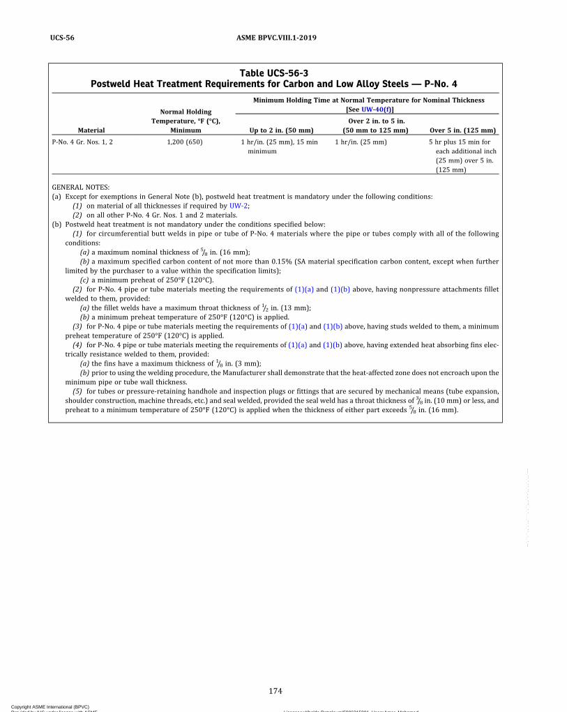
Table UCS-56-3Postweld Heat Treatment Requirements for Carbon and Low Alloy Steels — P-No. 4
Material
Normal HoldingTemperature, °F (°C),
Minimum
Minimum Holding Time at Normal Temperature for Nominal Thickness[See UW-40(f)]
Up to 2 in. (50 mm)Over 2 in. to 5 in.
(50 mm to 125 mm) Over 5 in. (125 mm)
P‐No. 4 Gr. Nos. 1, 2 1,200 (650) 1 hr/in. (25 mm), 15 minminimum
1 hr/in. (25 mm) 5 hr plus 15 min foreach additional inch(25 mm) over 5 in.(125 mm)
GENERAL NOTES:(a) Except for exemptions in General Note (b), postweld heat treatment is mandatory under the following conditions:
(1) on material of all thicknesses if required by UW-2;(2) on all other P‐No. 4 Gr. Nos. 1 and 2 materials.
(b) Postweld heat treatment is not mandatory under the conditions specified below:(1) for circumferential butt welds in pipe or tube of P‐No. 4 materials where the pipe or tubes comply with all of the following
conditions:(a) a maximum nominal thickness of 5/8 in. (16 mm);(b) a maximum specified carbon content of not more than 0.15% (SA material specification carbon content, except when further
limited by the purchaser to a value within the specification limits);(c) a minimum preheat of 250°F (120°C).
(2) for P‐No. 4 pipe or tube materials meeting the requirements of (1)(a) and (1)(b) above, having nonpressure attachments filletwelded to them, provided:
(a) the fillet welds have a maximum throat thickness of 1/2 in. (13 mm);(b) a minimum preheat temperature of 250°F (120°C) is applied.
(3) for P‐No. 4 pipe or tube materials meeting the requirements of (1)(a) and (1)(b) above, having studs welded to them, a minimumpreheat temperature of 250°F (120°C) is applied.(4) for P‐No. 4 pipe or tube materials meeting the requirements of (1)(a) and (1)(b) above, having extended heat absorbing fins elec-
trically resistance welded to them, provided:(a) the fins have a maximum thickness of 1/8 in. (3 mm);(b) prior to using the welding procedure, the Manufacturer shall demonstrate that the heat‐affected zone does not encroach upon the
minimum pipe or tube wall thickness.(5) for tubes or pressure-retaining handhole and inspection plugs or fittings that are secured by mechanical means (tube expansion,
shoulder construction, machine threads, etc.) and seal welded, provided the seal weld has a throat thickness of 3/8 in. (10 mm) or less, andpreheat to a minimum temperature of 250°F (120°C) is applied when the thickness of either part exceeds 5/8 in. (16 mm).
174
ASME BPVC.VIII.1-2019UCS-56
Copyright ASME International (BPVC) Provided by IHS under license with ASME Licensee=Khalda Petroleum/5986215001, User=Amer, Mohamed
Not for Resale, 07/02/2019 13:29:04 MDTNo reproduction or networking permitted without license from IHS
--`,``,``,,`,`,,````,`,``,,,`-`-`,,`,,`,`,,`---

Table UCS-56-4Postweld Heat Treatment Requirements for Carbon and Low Alloy Steels — P-Nos. 5A, 5B, and 5C
Material
Normal HoldingTemperature, °F (°C),
Minimum
Minimum Holding Time at Normal Temperature for Nominal Thickness[See UW-40(f)]
Up to 2 in. (50 mm)Over 2 in. to 5 in.
(50 mm to 125 mm) Over 5 in. (125 mm)
P‐Nos. 5A, 5B Gr. No. 1, and5C Gr. No. 1
1,250 (675) 1 hr/in. (25 mm), 15 minminimum
1 hr/in. (25 mm) 5 hr plus 15 min foreach additional inch(25 mm) over 5 in.(125 mm)
GENERAL NOTES:(a) Except for exemptions in General Notes (b) and (d), postweld heat treatment is mandatory under all conditions.(b) Postweld heat treatment is not mandatory under the following conditions:
(1) for circumferential butt welds in pipe or tube where the pipe or tubes comply with all of the following conditions:(a) a maximum specified chromium content of 3.00%;(b) a maximum nominal thickness of 5/8 in. (16 mm);(c) a maximum specified carbon content of not more than 0.15% (SA material specification carbon content, except when further
limited by the purchaser to a value within the specification limits);(d) a minimum preheat of 300°F (150°C) is applied.
(2) for pipe or tube materials meeting the requirements of (1)(a), (1)(b), and (1)(c) having nonpressure attachments fillet weldedto them, provided:
(a) the fillet welds have a maximum throat thickness of 1/2 in. (13 mm);(b) a minimum preheat temperature of 300°F (150°C) is applied.
(3) for pipe or tube materials meeting the requirements of (1)(a), (1)(b), and (1)(c) having studs welded to them, provided a mini-mum preheat temperature of 300°F (150°C) is applied.(4) for pipe or tube materials meeting the requirements of (1)(a) and (1)(b) above, having extended heat absorbing fins electrically
resistance welded to them, provided:(a) the fins have a maximum thickness of 1/8 in. (3 mm);(b) prior to using the welding procedure, the Manufacturer shall demonstrate that the heat‐affected zone does not encroach upon
the minimum pipe or tube wall thickness.(5) for tubes or pressure-retaining handhole and inspection plugs or fittings in P-No. 5A materials with a specified maximum chro-
mium content of 6% that are secured by mechanical means (tube expansion, shoulder construction, machine threads, etc.) and sealwelded, provided the seal weld has a throat thickness of 3/8 in. (10 mm) or less, and preheat to a minimum temperature of 300°F(150°C) is applied when the thickness of either part exceeds 5/8 in. (16 mm).
(c) When it is impractical to postweld heat P‐Nos. 5A, 5B Gr. No. 1, and 5C Gr. No. 1 materials at the temperature specified in this Table, it ispermissible to perform the postweld heat treatment at 1,200°F (650°C) minimum provided that, for material up to 2 in. (50 mm) nom-inal thickness, the holding time is increased to the greater of 4 hr minimum or 4 hr/in. (25 mm) of thickness; for thickness over 2 in.(50 mm), the specified holding times are multiplied by 4. The requirements of UCS-85 must be accommodated in this reduction inpostweld heat treatment.
(d) Postweld heat treatment is not mandatory for attaching bare-wire thermocouples by capacitor discharge welding or electric resistancewelding, provided(1) the requirements of UCS-56(g) are met(2) the maximum carbon content of the base material is restricted to 0.15%(3) the minimum wall thickness is 0.20 in. (5 mm)
175
ASME BPVC.VIII.1-2019 UCS-56
Copyright ASME International (BPVC) Provided by IHS under license with ASME Licensee=Khalda Petroleum/5986215001, User=Amer, Mohamed
Not for Resale, 07/02/2019 13:29:04 MDTNo reproduction or networking permitted without license from IHS
--`,``,``,,`,`,,````,`,``,,,`-`-`,,`,,`,`,,`---
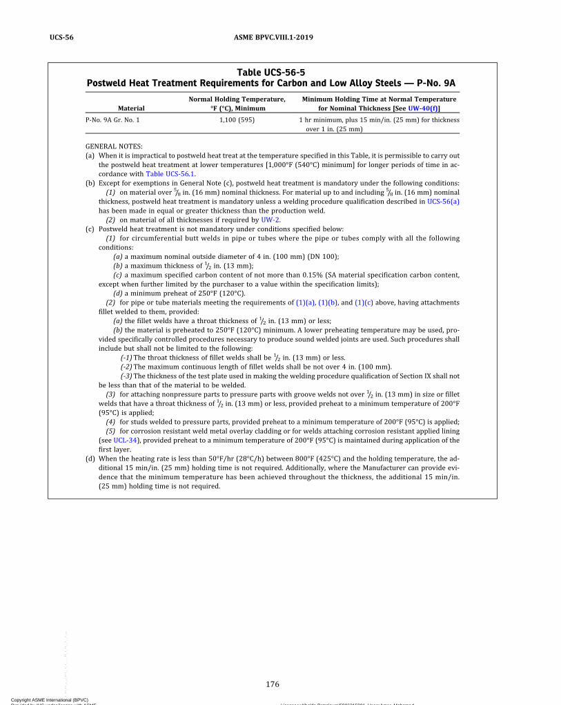
Table UCS-56-5Postweld Heat Treatment Requirements for Carbon and Low Alloy Steels — P-No. 9A
MaterialNormal Holding Temperature,
°F (°C), MinimumMinimum Holding Time at Normal Temperature
for Nominal Thickness [See UW-40(f)]
P‐No. 9A Gr. No. 1 1,100 (595) 1 hr minimum, plus 15 min/in. (25 mm) for thicknessover 1 in. (25 mm)
GENERAL NOTES:(a) When it is impractical to postweld heat treat at the temperature specified in this Table, it is permissible to carry out
the postweld heat treatment at lower temperatures [1,000°F (540°C) minimum] for longer periods of time in ac-cordance with Table UCS-56.1.
(b) Except for exemptions in General Note (c), postweld heat treatment is mandatory under the following conditions:(1) on material over 5/8 in. (16 mm) nominal thickness. For material up to and including 5/8 in. (16 mm) nominal
thickness, postweld heat treatment is mandatory unless a welding procedure qualification described in UCS-56(a)has been made in equal or greater thickness than the production weld.(2) on material of all thicknesses if required by UW-2.
(c) Postweld heat treatment is not mandatory under conditions specified below:(1) for circumferential butt welds in pipe or tubes where the pipe or tubes comply with all the following
conditions:(a) a maximum nominal outside diameter of 4 in. (100 mm) (DN 100);(b) a maximum thickness of 1/2 in. (13 mm);(c) a maximum specified carbon content of not more than 0.15% (SA material specification carbon content,
except when further limited by the purchaser to a value within the specification limits);(d) a minimum preheat of 250°F (120°C).
(2) for pipe or tube materials meeting the requirements of (1)(a), (1)(b), and (1)(c) above, having attachmentsfillet welded to them, provided:
(a) the fillet welds have a throat thickness of 1/2 in. (13 mm) or less;(b) the material is preheated to 250°F (120°C) minimum. A lower preheating temperature may be used, pro-
vided specifically controlled procedures necessary to produce sound welded joints are used. Such procedures shallinclude but shall not be limited to the following:
(-1)The throat thickness of fillet welds shall be 1/2 in. (13 mm) or less.(-2)The maximum continuous length of fillet welds shall be not over 4 in. (100 mm).(-3)The thickness of the test plate used in making the welding procedure qualification of Section IX shall not
be less than that of the material to be welded.(3) for attaching nonpressure parts to pressure parts with groove welds not over 1/2 in. (13 mm) in size or fillet
welds that have a throat thickness of 1/2 in. (13 mm) or less, provided preheat to a minimum temperature of 200°F(95°C) is applied;(4) for studs welded to pressure parts, provided preheat to a minimum temperature of 200°F (95°C) is applied;(5) for corrosion resistant weld metal overlay cladding or for welds attaching corrosion resistant applied lining
(see UCL-34), provided preheat to a minimum temperature of 200°F (95°C) is maintained during application of thefirst layer.
(d) When the heating rate is less than 50°F/hr (28°C/h) between 800°F (425°C) and the holding temperature, the ad-ditional 15 min/in. (25 mm) holding time is not required. Additionally, where the Manufacturer can provide evi-dence that the minimum temperature has been achieved throughout the thickness, the additional 15 min/in.(25 mm) holding time is not required.
176
ASME BPVC.VIII.1-2019UCS-56
Copyright ASME International (BPVC) Provided by IHS under license with ASME Licensee=Khalda Petroleum/5986215001, User=Amer, Mohamed
Not for Resale, 07/02/2019 13:29:04 MDTNo reproduction or networking permitted without license from IHS
--`,``,``,,`,`,,````,`,``,,,`-`-`,,`,,`,`,,`---
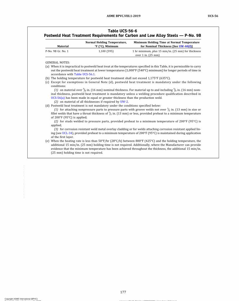
Table UCS-56-6Postweld Heat Treatment Requirements for Carbon and Low Alloy Steels — P-No. 9B
MaterialNormal Holding Temperature,
°F (°C), MinimumMinimum Holding Time at Normal Temperature
for Nominal Thickness [See UW-40(f)]
P‐No. 9B Gr. No. 1 1,100 (595) 1 hr minimum, plus 15 min/in. (25 mm) for thicknessover 1 in. (25 mm)
GENERAL NOTES:(a) When it is impractical to postweld heat treat at the temperatures specified in this Table, it is permissible to carry
out the postweld heat treatment at lower temperatures [1,000°F (540°C) minimum] for longer periods of time inaccordance with Table UCS-56.1.
(b) The holding temperature for postweld heat treatment shall not exceed 1,175°F (635°C).(c) Except for exemptions in General Note (d), postweld heat treatment is mandatory under the following
conditions:(1) on material over 5/8 in. (16 mm) nominal thickness. For material up to and including 5/8 in. (16 mm) nom-
inal thickness, postweld heat treatment is mandatory unless a welding procedure qualification described inUCS-56(a) has been made in equal or greater thickness than the production weld.(2) on material of all thicknesses if required by UW-2.
(d) Postweld heat treatment is not mandatory under the conditions specified below:(1) for attaching nonpressure parts to pressure parts with groove welds not over 1/2 in. (13 mm) in size or
fillet welds that have a throat thickness of 1/2 in. (13 mm) or less, provided preheat to a minimum temperatureof 200°F (95°C) is applied;(2) for studs welded to pressure parts, provided preheat to a minimum temperature of 200°F (95°C) is
applied;(3) for corrosion resistant weld metal overlay cladding or for welds attaching corrosion resistant applied lin-
ing (see UCL-34), provided preheat to a minimum temperature of 200°F (95°C) is maintained during applicationof the first layer.
(e) When the heating rate is less than 50°F/hr (28°C/h) between 800°F (425°C) and the holding temperature, theadditional 15 min/in. (25 mm) holding time is not required. Additionally, where the Manufacturer can provideevidence that the minimum temperature has been achieved throughout the thickness, the additional 15 min/in.(25 mm) holding time is not required.
177
ASME BPVC.VIII.1-2019 UCS-56
Copyright ASME International (BPVC) Provided by IHS under license with ASME Licensee=Khalda Petroleum/5986215001, User=Amer, Mohamed
Not for Resale, 07/02/2019 13:29:04 MDTNo reproduction or networking permitted without license from IHS
--`,``,``,,`,`,,````,`,``,,,`-`-`,,`,,`,`,,`---

Table UCS-56-7Postweld Heat Treatment Requirements for Carbon and Low Alloy Steels — P-No. 10A
MaterialNormal Holding Temperature,
°F (°C), MinimumMinimum Holding Time at Normal Temperature
for Nominal Thickness [See UW-40(f)]
P‐No. 10A Gr. No. 1 1,100 (595) 1 hr minimum, plus 15 min/in. (25 mm) for thicknessover 1 in. (25 mm)
GENERAL NOTES:(a) See below.
(1) When it is impractical to postweld heat treat at the temperature specified in this Table, it is permissible tocarry out the postweld heat treatment at lower temperatures for longer periods of time in accordance with TableUCS-56.1.(2) Consideration should be given for possible embrittlement of materials containing up to 0.15% vanadium
when postweld heat treating at the minimum temperature and at lower temperature for longer holding times.(b) Except for exemptions in General Note (c), postweld heat treatment is mandatory under the following
conditions:(1) on all thicknesses of SA-487 Class 1Q material;(2) on all other P‐No. 10A materials over 5/8 in. (16 mm) nominal thickness. For these materials up to and
including 5/8 in. (16 mm) nominal thickness, postweld heat treatment is mandatory unless a welding procedurequalification described in UCS-56(a) has been made in equal or greater thickness than the production weld.(3) on material of all thicknesses if required by UW-2.
(c) Postweld heat treatment is not mandatory under the conditions specified below:(1) for attaching to pressure parts that have a specified maximum carbon content of not more than 0.25% (SA
material specification carbon content, except when further limited by the purchaser to a value within the spec-ification limits) or nonpressure parts with groove weld not over 1/2 in. (13 mm) in size or fillet welds having athroat thickness of 1/2 in. (13 mm) or less, provided preheat to a minimum temperature of 200°F (95°C) isapplied;(2) for circumferential butt welds in pipes or tube where the pipe or tube has both a nominal wall thickness of
1/2 in. (13 mm) or less and a specified maximum carbon content of not more than 0.25% (SA material specifica-tion carbon content, except when further limited by purchaser to a value within the specification limits), pro-vided preheat to a minimum temperature of 200°F (95°C) is applied;(3) for studs welded to pressure parts that have a specified maximum carbon content of not more than 0.25%
(SA material specification carbon content, except when further limited by purchaser to a value within the spec-ification limits), provided preheat to a minimum temperature of 200°F (95°C) is applied;(4) for corrosion resistant weld metal overlay cladding or for welds attaching corrosion resistant applied lin-
ing (see UCL-34) when welded to pressure parts that have a specified maximum carbon content of not more than0.25% (SA material specification carbon content, except when further limited by the purchaser to a value withinthe specification limits), provided preheat to a minimum temperature of 200°F (95°C) is maintained during ap-plication of the first layer.
(d) When the heating rate is less than 50°F/hr (28°C/h) between 800°F (425°C) and the holding temperature, theadditional 15 min/in. (25 mm) holding time is not required. Additionally, where the Manufacturer can provideevidence that the minimum temperature has been achieved throughout the thickness, the additional 15 min/in.(25 mm) holding time is not required.
Table UCS-56-8Postweld Heat Treatment Requirements for Carbon and Low Alloy Steels — P-No. 10B
MaterialNormal Holding Temperature,
°F (°C), MinimumMinimum Holding Time at Normal Temperature
for Nominal Thickness [See UW-40(f)]
P‐No. 10B Gr. No. 1 1,100 (595) 1 hr minimum, plus 15 min/in. (25 mm) for thicknessover 1 in. (25 mm)
GENERAL NOTES:(a) Postweld heat treatment is mandatory for P‐No. 10B materials for all thicknesses.(b) When the heating rate is less than 50°F/hr (28°C/h) between 800°F (425°C) and the holding temperature, the
additional 15 min/in. (25 mm) holding time is not required. Additionally, where the Manufacturer can provideevidence that the minimum temperature has been achieved throughout the thickness, the additional 15 min/in.(25 mm) holding time is not required.
178
ASME BPVC.VIII.1-2019UCS-56
Copyright ASME International (BPVC) Provided by IHS under license with ASME Licensee=Khalda Petroleum/5986215001, User=Amer, Mohamed
Not for Resale, 07/02/2019 13:29:04 MDTNo reproduction or networking permitted without license from IHS
--`,``,``,,`,`,,````,`,``,,,`-`-`,,`,,`,`,,`---
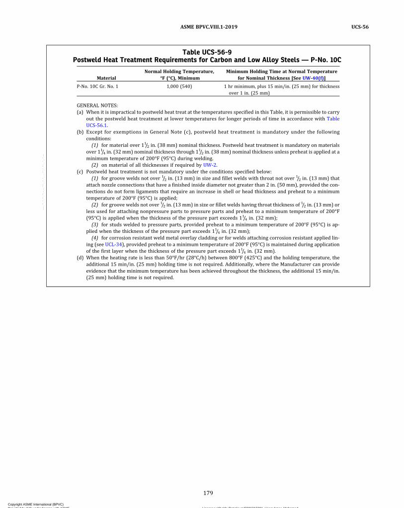
Table UCS-56-9Postweld Heat Treatment Requirements for Carbon and Low Alloy Steels — P-No. 10C
MaterialNormal Holding Temperature,
°F (°C), MinimumMinimum Holding Time at Normal Temperature
for Nominal Thickness [See UW-40(f)]
P‐No. 10C Gr. No. 1 1,000 (540) 1 hr minimum, plus 15 min/in. (25 mm) for thicknessover 1 in. (25 mm)
GENERAL NOTES:(a) When it is impractical to postweld heat treat at the temperatures specified in this Table, it is permissible to carry
out the postweld heat treatment at lower temperatures for longer periods of time in accordance with TableUCS-56.1.
(b) Except for exemptions in General Note (c), postweld heat treatment is mandatory under the followingconditions:(1) for material over 11/2 in. (38 mm) nominal thickness. Postweld heat treatment is mandatory on materials
over 11/4 in. (32 mm) nominal thickness through 11/2 in. (38 mm) nominal thickness unless preheat is applied at aminimum temperature of 200°F (95°C) during welding.(2) on material of all thicknesses if required by UW-2.
(c) Postweld heat treatment is not mandatory under the conditions specified below:(1) for groove welds not over 1/2 in. (13 mm) in size and fillet welds with throat not over 1/2 in. (13 mm) that
attach nozzle connections that have a finished inside diameter not greater than 2 in. (50 mm), provided the con-nections do not form ligaments that require an increase in shell or head thickness and preheat to a minimumtemperature of 200°F (95°C) is applied;(2) for groove welds not over 1/2 in. (13 mm) in size or fillet welds having throat thickness of 1/2 in. (13 mm) or
less used for attaching nonpressure parts to pressure parts and preheat to a minimum temperature of 200°F(95°C) is applied when the thickness of the pressure part exceeds 11/4 in. (32 mm);(3) for studs welded to pressure parts, provided preheat to a minimum temperature of 200°F (95°C) is ap-
plied when the thickness of the pressure part exceeds 11/4 in. (32 mm);(4) for corrosion resistant weld metal overlay cladding or for welds attaching corrosion resistant applied lin-
ing (see UCL-34), provided preheat to a minimum temperature of 200°F (95°C) is maintained during applicationof the first layer when the thickness of the pressure part exceeds 11/4 in. (32 mm).
(d) When the heating rate is less than 50°F/hr (28°C/h) between 800°F (425°C) and the holding temperature, theadditional 15 min/in. (25 mm) holding time is not required. Additionally, where the Manufacturer can provideevidence that the minimum temperature has been achieved throughout the thickness, the additional 15 min/in.(25 mm) holding time is not required.
179
ASME BPVC.VIII.1-2019 UCS-56
Copyright ASME International (BPVC) Provided by IHS under license with ASME Licensee=Khalda Petroleum/5986215001, User=Amer, Mohamed
Not for Resale, 07/02/2019 13:29:04 MDTNo reproduction or networking permitted without license from IHS
--`,``,``,,`,`,,````,`,``,,,`-`-`,,`,,`,`,,`---
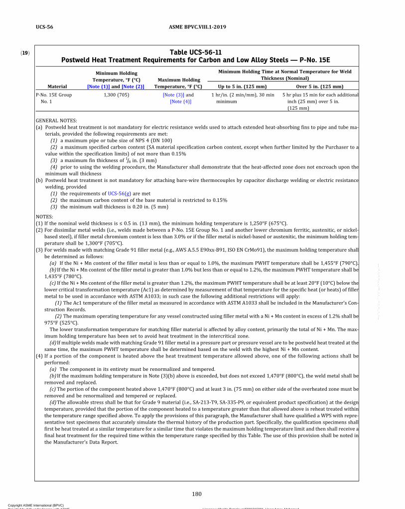
ð19Þ Table UCS-56-11Postweld Heat Treatment Requirements for Carbon and Low Alloy Steels — P-No. 15E
Material
Minimum HoldingTemperature, °F (°C)
[Note (1)] and [Note (2)]Maximum Holding
Temperature, °F (°C)
Minimum Holding Time at Normal Temperature for WeldThickness (Nominal)
Up to 5 in. (125 mm) Over 5 in. (125 mm)
P‐No. 15E GroupNo. 1
1,300 (705) [Note (3)] and[Note (4)]
1 hr/in. (2 min/mm), 30 minminimum
5 hr plus 15 min for each additionalinch (25 mm) over 5 in.(125 mm)
GENERAL NOTES:(a) Postweld heat treatment is not mandatory for electric resistance welds used to attach extended heat‐absorbing fins to pipe and tube ma-
terials, provided the following requirements are met:(1) a maximum pipe or tube size of NPS 4 (DN 100)(2) a maximum specified carbon content (SA material specification carbon content, except when further limited by the Purchaser to a
value within the specification limits) of not more than 0.15%(3) a maximum fin thickness of 1/8 in. (3 mm)(4) prior to using the welding procedure, the Manufacturer shall demonstrate that the heat‐affected zone does not encroach upon the
minimum wall thickness(b) Postweld heat treatment is not mandatory for attaching bare-wire thermocouples by capacitor discharge welding or electric resistance
welding, provided(1) the requirements of UCS-56(g) are met(2) the maximum carbon content of the base material is restricted to 0.15%(3) the minimum wall thickness is 0.20 in. (5 mm)
NOTES:(1) If the nominal weld thickness is ≤ 0.5 in. (13 mm), the minimum holding temperature is 1,250°F (675°C).(2) For dissimilar metal welds (i.e., welds made between a P‐No. 15E Group No. 1 and another lower chromium ferritic, austenitic, or nickel‐
based steel), if filler metal chromium content is less than 3.0% or if the filler metal is nickel‐based or austenitic, the minimum holding tem-perature shall be 1,300°F (705°C).
(3) For welds made with matching Grade 91 filler metal (e.g., AWS A.5.5 E90xx-B91, ISO EN CrMo91), the maximum holding temperature shallbe determined as follows:(a) If the Ni + Mn content of the filler metal is less than or equal to 1.0%, the maximum PWHT temperature shall be 1,455°F (790°C).(b) If the Ni + Mn content of the filler metal is greater than 1.0% but less than or equal to 1.2%, the maximum PWHT temperature shall be
1,435°F (780°C).(c) If the Ni + Mn content of the filler metal is greater than 1.2%, the maximum PWHT temperature shall be at least 20°F (10°C) below the
lower critical transformation temperature (Ac1) as determined by measurement of that temperature for the specific heat (or heats) of fillermetal to be used in accordance with ASTM A1033; in such case the following additional restrictions will apply:
(1) The Ac1 temperature of the filler metal as measured in accordance with ASTM A1033 shall be included in the Manufacturer’s Con-struction Records.
(2) The maximum operating temperature for any vessel constructed using filler metal with a Ni + Mn content in excess of 1.2% shall be975°F (525°C).The lower transformation temperature for matching filler material is affected by alloy content, primarily the total of Ni + Mn. The max-
imum holding temperature has been set to avoid heat treatment in the intercritical zone.(d) If multiple welds made with matching Grade 91 filler metal in a pressure part or pressure vessel are to be postweld heat treated at the
same time, the maximum PWHT temperature shall be determined based on the weld with the highest Ni + Mn content.(4) If a portion of the component is heated above the heat treatment temperature allowed above, one of the following actions shall be
performed:(a) The component in its entirety must be renormalized and tempered.(b) If the maximum holding temperature in Note (3)(b) above is exceeded, but does not exceed 1,470°F (800°C), the weld metal shall be
removed and replaced.(c) The portion of the component heated above 1,470°F (800°C) and at least 3 in. (75 mm) on either side of the overheated zone must be
removed and be renormalized and tempered or replaced.(d)The allowable stress shall be that for Grade 9 material (i.e., SA-213‐T9, SA-335‐P9, or equivalent product specification) at the design
temperature, provided that the portion of the component heated to a temperature greater than that allowed above is reheat treated withinthe temperature range specified above. To apply the provisions of this paragraph, the Manufacturer shall have qualified a WPS with repre-sentative test specimens that accurately simulate the thermal history of the production part. Specifically, the qualification specimens shallfirst be heat treated at a similar temperature for a similar time that violates the maximum holding temperature limit and then shall receive afinal heat treatment for the required time within the temperature range specified by this Table. The use of this provision shall be noted inthe Manufacturer’s Data Report.
180
ASME BPVC.VIII.1-2019UCS-56
Copyright ASME International (BPVC) Provided by IHS under license with ASME Licensee=Khalda Petroleum/5986215001, User=Amer, Mohamed
Not for Resale, 07/02/2019 13:29:04 MDTNo reproduction or networking permitted without license from IHS
--`,``,``,,`,`,,````,`,``,,,`-`-`,,`,,`,`,,`---

ð19Þ
UCS-57 RADIOGRAPHIC EXAMINATIONIn addition to the requirements of UW-11, complete
radiographic examination is required for each butt-welded joint at which the thinner of the plate or vesselwall thicknesses at the welded joint exceeds the thicknesslimit above which full radiography is required in TableUCS-57.
LOW TEMPERATURE OPERATION
UCS-65 SCOPEThe following paragraphs contain requirements for
vessels and vessel parts constructed of carbon and low al-loy steels with respect to minimum design metaltemperatures.
UCS-66 MATERIALS(a) Unless exempted by the rules of UG-20(f) or other
rules of this Division, Figure UCS-66 shall be used to es-tablish impact testing exemptions for steels listed in PartUCS. When Figure UCS-66 is used, impact testing is re-quired for a combination of minimum design metal tem-perature (see UG-20) and governing thickness (asdefined below) that is below the curve assigned to thesubject material. If a minimum design metal temperatureand governing thickness combination is on or above thecurve, impact testing is not required by the rules of thisDiv is ion , except as required by ( j ) below andUCS-67(a)(3) for weld metal. Components, such as shells,heads, nozzles, manways, reinforcing pads, flanges, tube-sheets, flat cover plates, backing strips which remain inplace, and attachments which are essential to the struc-tura l in tegr i t y o f the vesse l when we lded topressure-retaining components, shall be treated as sepa-rate components. Each component shall be evaluated forimpact test requirements based on its individual materialclassification, governing thickness as defined in (1) and(2) below, and the minimum design metal temperature.
(1) The following governing thickness definitions ap-ply when using Figure UCS-66:
(-a) Excluding castings, the governing thickness tgof a welded part is as follows:
(-1) for butt joints except those in flat heads andtubesheets, the nominal thickness of the thickest weldedjoint [see Figure UCS-66.3, sketch (a)].
(-2) for corner, fillet, or lap-welded joints, in-cluding attachments as defined above, the thinner of thetwo parts joined.
(-3) for flat heads or tubesheets, the larger of(-2) above or the flat component thickness divided by 4.
(-4) for welded assemblies comprised of morethan two components (e.g., nozzle‐to‐shell joint with rein-forcing pad), the governing thickness and permissibleminimum design metal temperature of each of the indivi-dual welded joints of the assembly shall be determined,and the warmest of the minimum design metal tempera-tures shall be used as the permissible minimum designmetal temperature of the welded assembly. [See FigureUCS-66.3, sketch (b).]
(-5) if the governing thickness at any weldedjoint exceeds 4 in. (100mm) and the minimum design me-tal temperature is colder than 120°F (50°C), impact testedmaterial shall be used.
(-b) The governing thickness of a casting shall beits largest nominal thickness.
Table UCS-56.1Alternative Postweld Heat Treatment
Requirements for Carbon and Low AlloySteels
Decrease inTemperature BelowMinimum Specified
Temperature,°F (°C)
Minimum Holding Time[Note (1)] at Decreased
Temperature, hr Notes
50 (28) 2 …100 (56) 4 …150 (83) 10 (2)200 (111) 20 (2)
GENERAL NOTE: Applicable only when permitted in TablesUCS-56-1 through UCS-56-11.
NOTES:(1) Minimum holding time for 1 in. (25 mm) thickness or less. Add
15 min per inch (25 mm) of thickness for thicknesses greaterthan 1 in. (25 mm).
(2) These lower postweld heat treatment temperatures permittedonly for P‐No. 1 Gr. Nos. 1 and 2 materials.
Table UCS-57Thickness Above Which Full Radiographic
Examination of Butt-Welded Joints IsMandatory
P‐No. and Group No.Classification of Material
Nominal Thickness AboveWhich Butt-Welded Joints Shall
Be Fully Radiographed,in. (mm)
1 Gr. 1, 2, 3 11/4 (32)3 Gr. 1, 2, 3 3/4 (19)4 Gr. 1, 2 5/8 (16)5A Gr. 1, 2 0 (0)5B Gr. 1 0 (0)5C Gr. 1 0 (0)15E, Gr. 1 0 (0)
9A Gr. 1 5/8 (16)9B Gr. 1 5/8 (16)10A Gr. 1 3/4 (19)10B Gr. 1 5/8 (16)10C Gr. 1 5/8 (16)
181
ASME BPVC.VIII.1-2019 UCS-57 – UCS-66
Copyright ASME International (BPVC) Provided by IHS under license with ASME Licensee=Khalda Petroleum/5986215001, User=Amer, Mohamed
Not for Resale, 07/02/2019 13:29:04 MDTNo reproduction or networking permitted without license from IHS
--`,``,``,,`,`,,````,`,``,,,`-`-`,,`,,`,`,,`---
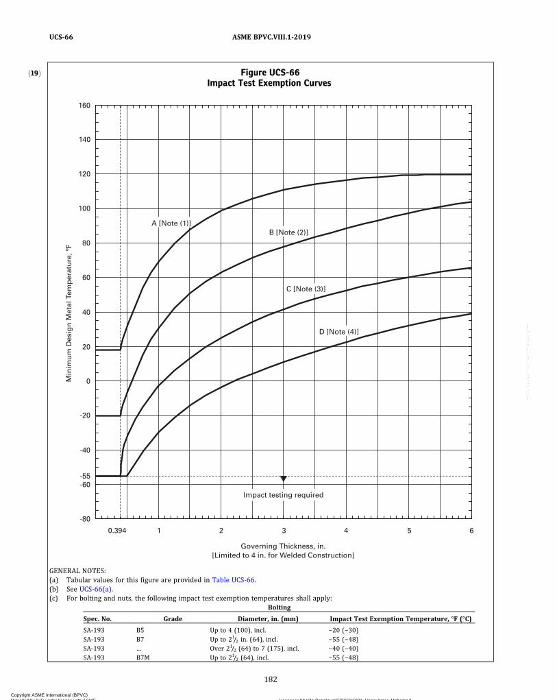
ð19Þ Figure UCS-66Impact Test Exemption Curves
Min
imu
m D
esig
n M
etal
Tem
per
atu
re, º
F
-80
Governing Thickness, in.[Limited to 4 in. for Welded Construction]
Impact testing required -60
-40
-55
-20
0
20
40
60
80
100
120
140
0.394 1 2 3 4 5 6
160
A [Note (1)] B [Note (2)]
C [Note (3)]
D [Note (4)]
GENERAL NOTES:(a) Tabular values for this figure are provided in Table UCS-66.(b) See UCS-66(a).(c) For bolting and nuts, the following impact test exemption temperatures shall apply:
Bolting
Spec. No. Grade Diameter, in. (mm) Impact Test Exemption Temperature, °F (°C)
SA-193 B5 Up to 4 (100), incl. −20 (−30)SA-193 B7 Up to 21/2 in. (64), incl. −55 (−48)SA-193 … Over 21/2 (64) to 7 (175), incl. −40 (−40)SA-193 B7M Up to 21/2 (64), incl. −55 (−48)
182
ASME BPVC.VIII.1-2019UCS-66
Copyright ASME International (BPVC) Provided by IHS under license with ASME Licensee=Khalda Petroleum/5986215001, User=Amer, Mohamed
Not for Resale, 07/02/2019 13:29:04 MDTNo reproduction or networking permitted without license from IHS
--`,``,``,,`,`,,````,`,``,,,`-`-`,,`,,`,`,,`---
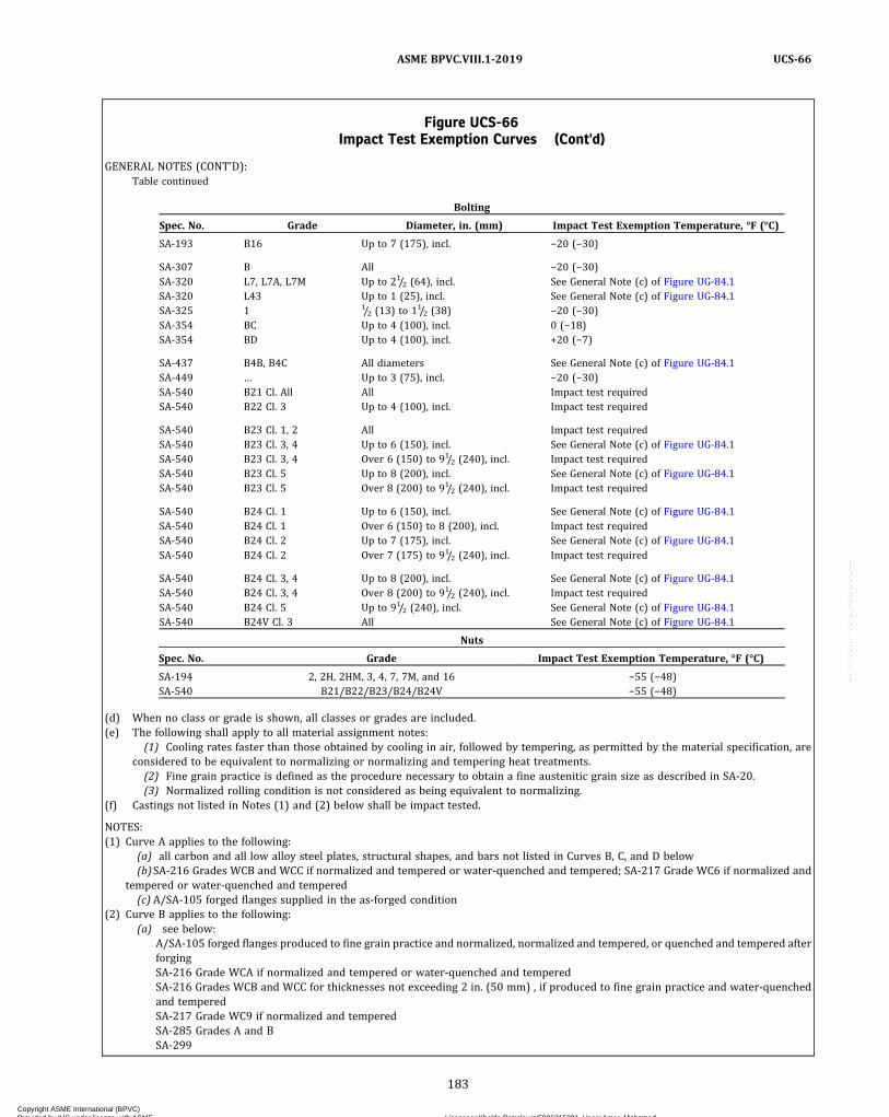
Figure UCS-66Impact Test Exemption Curves (Cont'd)
GENERAL NOTES (CONT'D):Table continued
Bolting
Spec. No. Grade Diameter, in. (mm) Impact Test Exemption Temperature, °F (°C)
SA-193 B16 Up to 7 (175), incl. −20 (−30)
SA-307 B All −20 (−30)SA-320 L7, L7A, L7M Up to 21/2 (64), incl. See General Note (c) of Figure UG-84.1SA-320 L43 Up to 1 (25), incl. See General Note (c) of Figure UG-84.1SA-325 1 1/2 (13) to 11/2 (38) −20 (−30)SA-354 BC Up to 4 (100), incl. 0 (−18)SA-354 BD Up to 4 (100), incl. +20 (−7)
SA-437 B4B, B4C All diameters See General Note (c) of Figure UG-84.1SA-449 … Up to 3 (75), incl. −20 (−30)SA-540 B21 Cl. All All Impact test requiredSA-540 B22 Cl. 3 Up to 4 (100), incl. Impact test required
SA-540 B23 Cl. 1, 2 All Impact test requiredSA-540 B23 Cl. 3, 4 Up to 6 (150), incl. See General Note (c) of Figure UG-84.1SA-540 B23 Cl. 3, 4 Over 6 (150) to 91/2 (240), incl. Impact test requiredSA-540 B23 Cl. 5 Up to 8 (200), incl. See General Note (c) of Figure UG-84.1SA-540 B23 Cl. 5 Over 8 (200) to 91/2 (240), incl. Impact test required
SA-540 B24 Cl. 1 Up to 6 (150), incl. See General Note (c) of Figure UG-84.1SA-540 B24 Cl. 1 Over 6 (150) to 8 (200), incl. Impact test requiredSA-540 B24 Cl. 2 Up to 7 (175), incl. See General Note (c) of Figure UG-84.1SA-540 B24 Cl. 2 Over 7 (175) to 91/2 (240), incl. Impact test required
SA-540 B24 Cl. 3, 4 Up to 8 (200), incl. See General Note (c) of Figure UG-84.1SA-540 B24 Cl. 3, 4 Over 8 (200) to 91/2 (240), incl. Impact test requiredSA-540 B24 Cl. 5 Up to 91/2 (240), incl. See General Note (c) of Figure UG-84.1SA-540 B24V Cl. 3 All See General Note (c) of Figure UG-84.1
Nuts
Spec. No. Grade Impact Test Exemption Temperature, °F (°C)
SA-194 2, 2H, 2HM, 3, 4, 7, 7M, and 16 −55 (−48)SA-540 B21/B22/B23/B24/B24V −55 (−48)
(d) When no class or grade is shown, all classes or grades are included.(e) The following shall apply to all material assignment notes:
(1) Cooling rates faster than those obtained by cooling in air, followed by tempering, as permitted by the material specification, areconsidered to be equivalent to normalizing or normalizing and tempering heat treatments.(2) Fine grain practice is defined as the procedure necessary to obtain a fine austenitic grain size as described in SA-20.(3) Normalized rolling condition is not considered as being equivalent to normalizing.
(f) Castings not listed in Notes (1) and (2) below shall be impact tested.
NOTES:(1) Curve A applies to the following:
(a) all carbon and all low alloy steel plates, structural shapes, and bars not listed in Curves B, C, and D below(b)SA-216 Grades WCB and WCC if normalized and tempered or water‐quenched and tempered; SA-217 Grade WC6 if normalized and
tempered or water‐quenched and tempered(c) A/SA-105 forged flanges supplied in the as-forged condition
(2) Curve B applies to the following:(a) see below:
A/SA-105 forged flanges produced to fine grain practice and normalized, normalized and tempered, or quenched and tempered afterforgingSA-216 Grade WCA if normalized and tempered or water‐quenched and temperedSA-216 Grades WCB and WCC for thicknesses not exceeding 2 in. (50 mm) , if produced to fine grain practice and water‐quenchedand temperedSA-217 Grade WC9 if normalized and temperedSA-285 Grades A and BSA-299
183
ASME BPVC.VIII.1-2019 UCS-66
Copyright ASME International (BPVC) Provided by IHS under license with ASME Licensee=Khalda Petroleum/5986215001, User=Amer, Mohamed
Not for Resale, 07/02/2019 13:29:04 MDTNo reproduction or networking permitted without license from IHS
--`,``,``,,`,`,,````,`,``,,,`-`-`,,`,,`,`,,`---
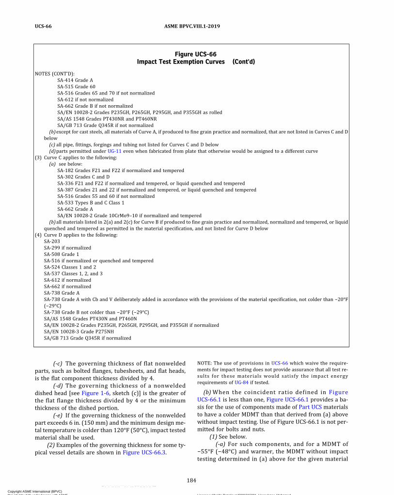
(-c) The governing thickness of flat nonweldedparts, such as bolted flanges, tubesheets, and flat heads,is the flat component thickness divided by 4.
(-d) The governing thickness of a nonweldeddished head [see Figure 1-6, sketch (c)] is the greater ofthe flat flange thickness divided by 4 or the minimumthickness of the dished portion.
(-e) If the governing thickness of the nonweldedpart exceeds 6 in. (150 mm) and the minimum design me-tal temperature is colder than 120°F (50°C), impact testedmaterial shall be used.
(2) Examples of the governing thickness for some ty-pical vessel details are shown in Figure UCS-66.3.
NOTE: The use of provisions in UCS-66 which waive the require-ments for impact testing does not provide assurance that all test re-sults for these materials would satisfy the impact energyrequirements of UG-84 if tested.
(b)When the coincident ratio defined in FigureUCS-66.1 is less than one, Figure UCS-66.1 provides a ba-sis for the use of components made of Part UCS materialsto have a colder MDMT than that derived from (a) abovewithout impact testing. Use of Figure UCS-66.1 is not per-mitted for bolts and nuts.
(1) See below.(-a) For such components, and for a MDMT of
−55°F (−48°C) and warmer, the MDMT without impacttesting determined in (a) above for the given material
Figure UCS-66Impact Test Exemption Curves (Cont'd)
NOTES (CONT'D):SA-414 Grade ASA-515 Grade 60SA-516 Grades 65 and 70 if not normalizedSA-612 if not normalizedSA-662 Grade B if not normalizedSA/EN 10028‐2 Grades P235GH, P265GH, P295GH, and P355GH as rolledSA/AS 1548 Grades PT430NR and PT460NRSA/GB 713 Grade Q345R if not normalized
(b)except for cast steels, all materials of Curve A, if produced to fine grain practice and normalized, that are not listed in Curves C and Dbelow(c) all pipe, fittings, forgings and tubing not listed for Curves C and D below(d)parts permitted under UG-11 even when fabricated from plate that otherwise would be assigned to a different curve
(3) Curve C applies to the following:(a) see below:
SA-182 Grades F21 and F22 if normalized and temperedSA-302 Grades C and DSA-336 F21 and F22 if normalized and tempered, or liquid quenched and temperedSA-387 Grades 21 and 22 if normalized and tempered, or liquid quenched and temperedSA-516 Grades 55 and 60 if not normalizedSA-533 Types B and C Class 1SA-662 Grade ASA/EN 10028-2 Grade 10CrMo9–10 if normalized and tempered
(b)all materials listed in 2(a) and 2(c) for Curve B if produced to fine grain practice and normalized, normalized and tempered, or liquidquenched and tempered as permitted in the material specification, and not listed for Curve D below
(4) Curve D applies to the following:SA-203SA-299 if normalizedSA-508 Grade 1SA-516 if normalized or quenched and temperedSA-524 Classes 1 and 2SA-537 Classes 1, 2, and 3SA-612 if normalizedSA-662 if normalizedSA-738 Grade ASA-738 Grade A with Cb and V deliberately added in accordance with the provisions of the material specification, not colder than −20°F(−29°C)SA-738 Grade B not colder than −20°F (−29°C)SA/AS 1548 Grades PT430N and PT460NSA/EN 10028‐2 Grades P235GH, P265GH, P295GH, and P355GH if normalizedSA/EN 10028‐3 Grade P275NHSA/GB 713 Grade Q345R if normalized
184
ASME BPVC.VIII.1-2019UCS-66
Copyright ASME International (BPVC) Provided by IHS under license with ASME Licensee=Khalda Petroleum/5986215001, User=Amer, Mohamed
Not for Resale, 07/02/2019 13:29:04 MDTNo reproduction or networking permitted without license from IHS
--`,``,``,,`,`,,````,`,``,,,`-`-`,,`,,`,`,,`---

ð19ÞFigure UCS-66MImpact Test Exemption Curves
20
30
40
Min
imu
m D
esig
n M
etal
Tem
per
atu
re, º
C
Governing Thickness, mm[Limited to 100 mm for Welded Construction]
Impact testing required
-60
-50 -48
-40
-30
-20
-10
0
10
50
60
70
10 20 40 60 80 100 120 140
A [Note (1)]
B [Note (2)]
C [Note (3)]
D [Note (4)]
GENERAL NOTES:(a) Tabular values for this figure are provided in Table UCS-66.(b) See UCS-66(a).(c) For bolting and nuts, the following impact test exemption temperatures shall apply:
Bolting
Spec. No. Grade Diameter, in. (mm) Impact Test Exemption Temperature, °F (°C)
SA-193 B5 Up to 4 (100), incl. −20 (−30)SA-193 B7 Up to 21/2 in. (64), incl. −55 (−48)SA-193 … Over 21/2 (64) to 7 (175), incl. −40 (−40)SA-193 B7M Up to 21/2 (64), incl. −55 (−48)
185
ASME BPVC.VIII.1-2019 UCS-66
Copyright ASME International (BPVC) Provided by IHS under license with ASME Licensee=Khalda Petroleum/5986215001, User=Amer, Mohamed
Not for Resale, 07/02/2019 13:29:04 MDTNo reproduction or networking permitted without license from IHS
--`,``,``,,`,`,,````,`,``,,,`-`-`,,`,,`,`,,`---

Figure UCS-66MImpact Test Exemption Curves (Cont'd)
GENERAL NOTES (CONT'D):Table continued
Bolting
Spec. No. Grade Diameter, in. (mm) Impact Test Exemption Temperature, °F (°C)
SA-193 B16 Up to 7 (175), incl. −20 (−30)
SA-307 B All −20 (−30)SA-320 L7, L7A, L7M Up to 21/2 (64), incl. See General Note (c) of Figure UG-84.1SA-320 L43 Up to 1 (25), incl. See General Note (c) of Figure UG-84.1SA-325 1 1/2 (13) to 11/2 (38) −20 (−30)SA-354 BC Up to 4 (100), incl. 0 (−18)SA-354 BD Up to 4 (100), incl. +20 (−7)
SA-437 B4B, B4C All diameters See General Note (c) of Figure UG-84.1SA-449 … Up to 3 (75), incl. −20 (−30)SA-540 B21 Cl. All All Impact test requiredSA-540 B22 Cl. 3 Up to 4 (100), incl. Impact test required
SA-540 B23 Cl. 1, 2 All Impact test requiredSA-540 B23 Cl. 3, 4 Up to 6 (150), incl. See General Note (c) of Figure UG-84.1SA-540 B23 Cl. 3, 4 Over 6 (150) to 91/2 (240), incl. Impact test requiredSA-540 B23 Cl. 5 Up to 8 (200), incl. See General Note (c) of Figure UG-84.1SA-540 B23 Cl. 5 Over 8 (200) to 91/2 (240), incl. Impact test required
SA-540 B24 Cl. 1 Up to 6 (150), incl. See General Note (c) of Figure UG-84.1SA-540 B24 Cl. 1 Over 6 (150) to 8 (200), incl. Impact test requiredSA-540 B24 Cl. 2 Up to 7 (175), incl. See General Note (c) of Figure UG-84.1SA-540 B24 Cl. 2 Over 7 (175) to 91/2 (240), incl. Impact test required
SA-540 B24 Cl. 3, 4 Up to 8 (200), incl. See General Note (c) of Figure UG-84.1SA-540 B24 Cl. 3, 4 Over 8 (200) to 91/2 (240), incl. Impact test requiredSA-540 B24 Cl. 5 Up to 91/2 (240), incl. See General Note (c) of Figure UG-84.1SA-540 B24V Cl. 3 All See General Note (c) of Figure UG-84.1
Nuts
Spec. No. Grade Impact Test Exemption Temperature, °F (°C)
SA-194 2, 2H, 2HM, 3, 4, 7, 7M, and 16 −55 (−48)SA-540 B21/B22/B23/B24/B24V −55 (−48)
(d) When no class or grade is shown, all classes or grades are included.(e) The following shall apply to all material assignment notes:
(1) Cooling rates faster than those obtained by cooling in air, followed by tempering, as permitted by the material specification, areconsidered to be equivalent to normalizing or normalizing and tempering heat treatments.(2) Fine grain practice is defined as the procedure necessary to obtain a fine austenitic grain size as described in SA-20.(3) Normalized rolling condition is not considered as being equivalent to normalizing.
(f) Castings not listed in Notes (1) and (2) below shall be impact tested.
NOTES:(1) Curve A applies to the following:
(a) all carbon and all low alloy steel plates, structural shapes, and bars not listed in Curves B, C, and D below(b)SA-216 Grades WCB and WCC if normalized and tempered or water‐quenched and tempered; SA-217 Grade WC6 if normalized and
tempered or water‐quenched and tempered(c) A/SA-105 forged flanges supplied in the as-forged condition
(2) Curve B applies to the following:(a) see below:
A/SA-105 forged flanges produced to fine grain practice and normalized, normalized and tempered, or quenched and tempered afterforgingSA-216 Grade WCA if normalized and tempered or water‐quenched and temperedSA-216 Grades WCB and WCC for thicknesses not exceeding 2 in. (50 mm) , if produced to fine grain practice and water‐quenchedand temperedSA-217 Grade WC9 if normalized and temperedSA-285 Grades A and BSA-299
186
ASME BPVC.VIII.1-2019UCS-66
Copyright ASME International (BPVC) Provided by IHS under license with ASME Licensee=Khalda Petroleum/5986215001, User=Amer, Mohamed
Not for Resale, 07/02/2019 13:29:04 MDTNo reproduction or networking permitted without license from IHS
--`,``,``,,`,`,,````,`,``,,,`-`-`,,`,,`,`,,`---
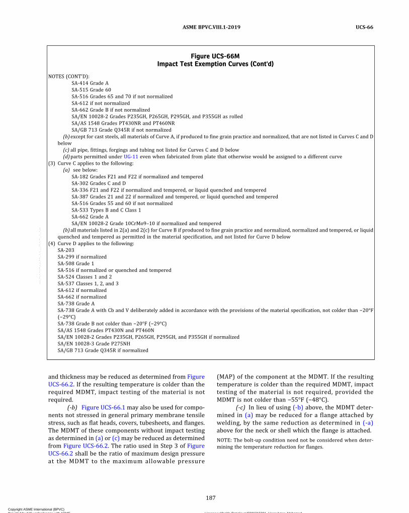
and thickness may be reduced as determined from FigureUCS-66.2. If the resulting temperature is colder than therequired MDMT, impact testing of the material is notrequired.
(-b) Figure UCS-66.1 may also be used for compo-nents not stressed in general primary membrane tensilestress, such as flat heads, covers, tubesheets, and flanges.The MDMT of these components without impact testingas determined in (a) or (c) may be reduced as determinedfrom Figure UCS-66.2. The ratio used in Step 3 of FigureUCS-66.2 shall be the ratio of maximum design pressureat the MDMT to the maximum allowable pressure
(MAP) of the component at the MDMT. If the resultingtemperature is colder than the required MDMT, impacttesting of the material is not required, provided theMDMT is not colder than −55°F (−48°C).
(-c) In lieu of using (-b) above, the MDMT deter-mined in (a) may be reduced for a flange attached bywelding, by the same reduction as determined in (-a)above for the neck or shell which the flange is attached.
NOTE: The bolt‐up condition need not be considered when deter-mining the temperature reduction for flanges.
Figure UCS-66MImpact Test Exemption Curves (Cont'd)
NOTES (CONT'D):SA-414 Grade ASA-515 Grade 60SA-516 Grades 65 and 70 if not normalizedSA-612 if not normalizedSA-662 Grade B if not normalizedSA/EN 10028‐2 Grades P235GH, P265GH, P295GH, and P355GH as rolledSA/AS 1548 Grades PT430NR and PT460NRSA/GB 713 Grade Q345R if not normalized
(b)except for cast steels, all materials of Curve A, if produced to fine grain practice and normalized, that are not listed in Curves C and Dbelow(c) all pipe, fittings, forgings and tubing not listed for Curves C and D below(d)parts permitted under UG-11 even when fabricated from plate that otherwise would be assigned to a different curve
(3) Curve C applies to the following:(a) see below:
SA-182 Grades F21 and F22 if normalized and temperedSA-302 Grades C and DSA-336 F21 and F22 if normalized and tempered, or liquid quenched and temperedSA-387 Grades 21 and 22 if normalized and tempered, or liquid quenched and temperedSA-516 Grades 55 and 60 if not normalizedSA-533 Types B and C Class 1SA-662 Grade ASA/EN 10028-2 Grade 10CrMo9–10 if normalized and tempered
(b)all materials listed in 2(a) and 2(c) for Curve B if produced to fine grain practice and normalized, normalized and tempered, or liquidquenched and tempered as permitted in the material specification, and not listed for Curve D below
(4) Curve D applies to the following:SA-203SA-299 if normalizedSA-508 Grade 1SA-516 if normalized or quenched and temperedSA-524 Classes 1 and 2SA-537 Classes 1, 2, and 3SA-612 if normalizedSA-662 if normalizedSA-738 Grade ASA-738 Grade A with Cb and V deliberately added in accordance with the provisions of the material specification, not colder than −20°F(−29°C)SA-738 Grade B not colder than −20°F (−29°C)SA/AS 1548 Grades PT430N and PT460NSA/EN 10028‐2 Grades P235GH, P265GH, P295GH, and P355GH if normalizedSA/EN 10028‐3 Grade P275NHSA/GB 713 Grade Q345R if normalized
187
ASME BPVC.VIII.1-2019 UCS-66
Copyright ASME International (BPVC) Provided by IHS under license with ASME Licensee=Khalda Petroleum/5986215001, User=Amer, Mohamed
Not for Resale, 07/02/2019 13:29:04 MDTNo reproduction or networking permitted without license from IHS
--`,``,``,,`,`,,````,`,``,,,`-`-`,,`,,`,`,,`---
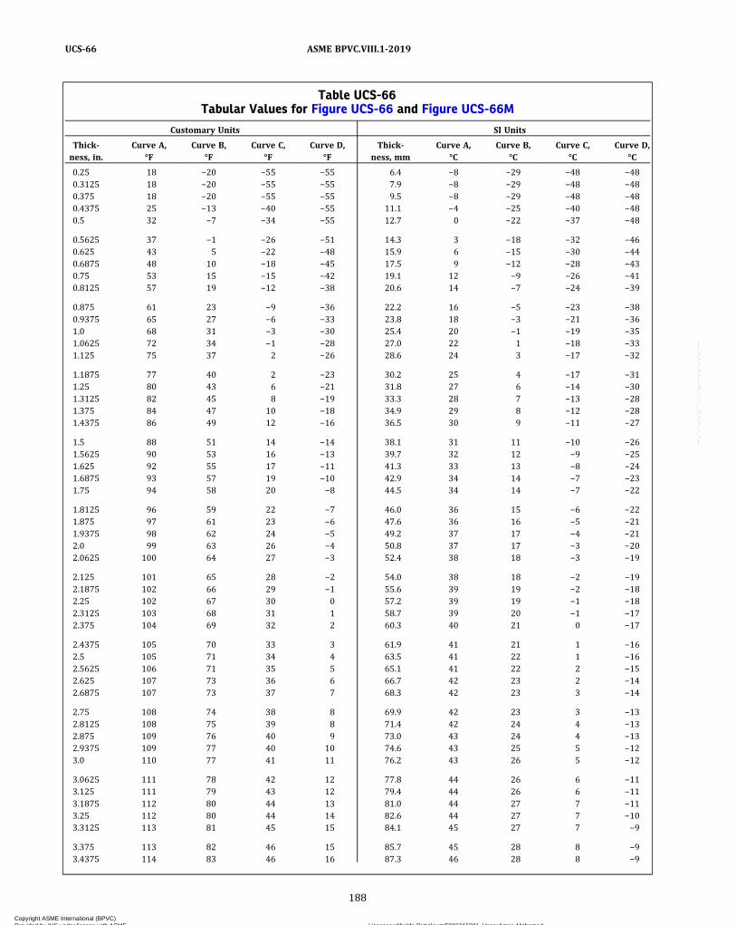
Table UCS-66Tabular Values for Figure UCS-66 and Figure UCS-66M
Customary Units SI Units
Thick-ness, in.
Curve A,°F
Curve B,°F
Curve C,°F
Curve D,°F
Thick-ness, mm
Curve A,°C
Curve B,°C
Curve C,°C
Curve D,°C
0.25 18 −20 −55 −55 6.4 −8 −29 −48 −480.3125 18 −20 −55 −55 7.9 −8 −29 −48 −480.375 18 −20 −55 −55 9.5 −8 −29 −48 −480.4375 25 −13 −40 −55 11.1 −4 −25 −40 −480.5 32 −7 −34 −55 12.7 0 −22 −37 −48
0.5625 37 −1 −26 −51 14.3 3 −18 −32 −460.625 43 5 −22 −48 15.9 6 −15 −30 −440.6875 48 10 −18 −45 17.5 9 −12 −28 −430.75 53 15 −15 −42 19.1 12 −9 −26 −410.8125 57 19 −12 −38 20.6 14 −7 −24 −39
0.875 61 23 −9 −36 22.2 16 −5 −23 −380.9375 65 27 −6 −33 23.8 18 −3 −21 −361.0 68 31 −3 −30 25.4 20 −1 −19 −351.0625 72 34 −1 −28 27.0 22 1 −18 −331.125 75 37 2 −26 28.6 24 3 −17 −32
1.1875 77 40 2 −23 30.2 25 4 −17 −311.25 80 43 6 −21 31.8 27 6 −14 −301.3125 82 45 8 −19 33.3 28 7 −13 −281.375 84 47 10 −18 34.9 29 8 −12 −281.4375 86 49 12 −16 36.5 30 9 −11 −27
1.5 88 51 14 −14 38.1 31 11 −10 −261.5625 90 53 16 −13 39.7 32 12 −9 −251.625 92 55 17 −11 41.3 33 13 −8 −241.6875 93 57 19 −10 42.9 34 14 −7 −231.75 94 58 20 −8 44.5 34 14 −7 −22
1.8125 96 59 22 −7 46.0 36 15 −6 −221.875 97 61 23 −6 47.6 36 16 −5 −211.9375 98 62 24 −5 49.2 37 17 −4 −212.0 99 63 26 −4 50.8 37 17 −3 −202.0625 100 64 27 −3 52.4 38 18 −3 −19
2.125 101 65 28 −2 54.0 38 18 −2 −192.1875 102 66 29 −1 55.6 39 19 −2 −182.25 102 67 30 0 57.2 39 19 −1 −182.3125 103 68 31 1 58.7 39 20 −1 −172.375 104 69 32 2 60.3 40 21 0 −17
2.4375 105 70 33 3 61.9 41 21 1 −162.5 105 71 34 4 63.5 41 22 1 −162.5625 106 71 35 5 65.1 41 22 2 −152.625 107 73 36 6 66.7 42 23 2 −142.6875 107 73 37 7 68.3 42 23 3 −14
2.75 108 74 38 8 69.9 42 23 3 −132.8125 108 75 39 8 71.4 42 24 4 −132.875 109 76 40 9 73.0 43 24 4 −132.9375 109 77 40 10 74.6 43 25 5 −123.0 110 77 41 11 76.2 43 26 5 −12
3.0625 111 78 42 12 77.8 44 26 6 −113.125 111 79 43 12 79.4 44 26 6 −113.1875 112 80 44 13 81.0 44 27 7 −113.25 112 80 44 14 82.6 44 27 7 −103.3125 113 81 45 15 84.1 45 27 7 −9
3.375 113 82 46 15 85.7 45 28 8 −93.4375 114 83 46 16 87.3 46 28 8 −9
188
ASME BPVC.VIII.1-2019UCS-66
Copyright ASME International (BPVC) Provided by IHS under license with ASME Licensee=Khalda Petroleum/5986215001, User=Amer, Mohamed
Not for Resale, 07/02/2019 13:29:04 MDTNo reproduction or networking permitted without license from IHS
--`,``,``,,`,`,,````,`,``,,,`-`-`,,`,,`,`,,`---
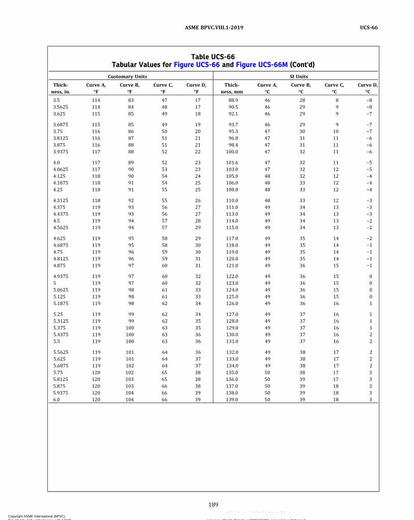
Table UCS-66Tabular Values for Figure UCS-66 and Figure UCS-66M (Cont'd)
Customary Units SI Units
Thick-ness, in.
Curve A,°F
Curve B,°F
Curve C,°F
Curve D,°F
Thick-ness, mm
Curve A,°C
Curve B,°C
Curve C,°C
Curve D,°C
3.5 114 83 47 17 88.9 46 28 8 −83.5625 114 84 48 17 90.5 46 29 9 −83.625 115 85 49 18 92.1 46 29 9 −7
3.6875 115 85 49 19 93.7 46 29 9 −73.75 116 86 50 20 95.3 47 30 10 −73.8125 116 87 51 21 96.8 47 31 11 −63.875 116 88 51 21 98.4 47 31 11 −63.9375 117 88 52 22 100.0 47 32 11 −6
4.0 117 89 52 23 101.6 47 32 11 −54.0625 117 90 53 23 103.0 47 32 12 −54.125 118 90 54 24 105.0 48 32 12 −44.1875 118 91 54 25 106.0 48 33 12 −44.25 118 91 55 25 108.0 48 33 12 −4
4.3125 118 92 55 26 110.0 48 33 12 −34.375 119 93 56 27 111.0 49 34 13 −34.4375 119 93 56 27 113.0 49 34 13 −34.5 119 94 57 28 114.0 49 34 13 −24.5625 119 94 57 29 115.0 49 34 13 −2
4.625 119 95 58 29 117.0 49 35 14 −24.6875 119 95 58 30 118.0 49 35 14 −14.75 119 96 59 30 119.0 49 35 14 −14.8125 119 96 59 31 120.0 49 35 14 −14.875 119 97 60 31 121.0 49 36 15 −1
4.9375 119 97 60 32 122.0 49 36 15 05 119 97 60 32 123.0 49 36 15 05.0625 119 98 61 33 124.0 49 36 15 05.125 119 98 61 33 125.0 49 36 15 05.1875 119 98 62 34 126.0 49 36 16 1
5.25 119 99 62 34 127.0 49 37 16 15.3125 119 99 62 35 128.0 49 37 16 15.375 119 100 63 35 129.0 49 37 16 15.4375 119 100 63 36 130.0 49 37 16 25.5 119 100 63 36 131.0 49 37 16 2
5.5625 119 101 64 36 132.0 49 38 17 25.625 119 101 64 37 133.0 49 38 17 25.6875 119 102 64 37 134.0 49 38 17 25.75 120 102 65 38 135.0 50 38 17 35.8125 120 103 65 38 136.0 50 39 17 35.875 120 103 66 38 137.0 50 39 18 35.9375 120 104 66 39 138.0 50 39 18 36.0 120 104 66 39 139.0 50 39 18 3
189
ASME BPVC.VIII.1-2019 UCS-66
Copyright ASME International (BPVC) Provided by IHS under license with ASME Licensee=Khalda Petroleum/5986215001, User=Amer, Mohamed
Not for Resale, 07/02/2019 13:29:04 MDTNo reproduction or networking permitted without license from IHS
--`,``,``,,`,`,,````,`,``,,,`-`-`,,`,,`,`,,`---

Figure UCS-66.1Reduction in Minimum Design Metal Temperature Without Impact Testing
Rat
io: t
rE*/
(tn
– c
) [N
ote
(1)
]
0.00
0.10
0.20
0.30
0.40
0.50
0.60
0.70
0.80
0.90
1.00
0 20 40 60 80 100 120 140
ºF [Note (2)]
0.35
See UCS-66(b)(3) when ratios are 0.35 and smaller
c = corrosion allowance, in.E* = as defined in Figure UCS-66.2, Note (3)tn = nominal thickness of the component under consideration before corrosion allowance is deducted, in.tr = required thickness of the component under consideration in the corroded condition for all applicable loadings
[Figure UCS-66.2, Note (2)], based on the applicable joint efficiency E [Figure UCS-66.2, Note (3)], in.
NOTES:(1) Alternative Ratio = S* E* divided by the product of the maximum allowable stress value from Table UCS-23 times E , where S* is the applied
general primary membrane tensile stress and E and E* are as defined in Figure UCS-66.2, Note (3)(2) See UCS-66(b).
190
ASME BPVC.VIII.1-2019UCS-66
Copyright ASME International (BPVC) Provided by IHS under license with ASME Licensee=Khalda Petroleum/5986215001, User=Amer, Mohamed
Not for Resale, 07/02/2019 13:29:04 MDTNo reproduction or networking permitted without license from IHS
--`,``,``,,`,`,,````,`,``,,,`-`-`,,`,,`,`,,`---

Figure UCS-66.1MReduction in Minimum Design Metal Temperature Without Impact Testing
Rat
io: t
rE*/
(tn –
c)
[No
te (
1)]
0.00
0.10
0.20
0.30
0.40
0.50
0.60
0.70
0.80
0.90
1.00
0 10 20 30 40 50 60 70 80
ºC [Note (2)]
0.35
See UCS-66(b)(3) when ratios are 0.35 and smaller
c = corrosion allowance, mmE* = as defined in Figure UCS-66.2, Note (3)tn = nominal thickness of the component under consideration before corrosion allowance is deducted, mmt r = required thickness of the component under consideration in the corroded condition for all applicable loadings
[Figure UCS-66.2, Note (2)], based on the applicable joint efficiency E [Figure UCS-66.2, Note (3)], mm
NOTES:(1) Alternative Ratio = S* E* divided by the product of the maximum allowable stress value from Table UCS-23 times E , where S* is the applied
general primary membrane tensile stress and E and E* are as defined in Figure UCS-66.2, Note (3)(2) See UCS-66(b).
191
ASME BPVC.VIII.1-2019 UCS-66
Copyright ASME International (BPVC) Provided by IHS under license with ASME Licensee=Khalda Petroleum/5986215001, User=Amer, Mohamed
Not for Resale, 07/02/2019 13:29:04 MDTNo reproduction or networking permitted without license from IHS
--`,``,``,,`,`,,````,`,``,,,`-`-`,,`,,`,`,,`---

Figure UCS-66.2Diagram of UCS-66 Rules for Determining Lowest Minimum Design Metal Temperature (MDMT) Without
Impact Testing
Repeat for all governing thicknesses [Note (5)] and take warmest value as the lowest allowable MDMT to be marked on nameplate for the zone under consideration [Note (10)]. See UG-116. See UG-99(h) for coldest recommended metal temperature during hydrostatic test [Note (6)]. See UG-100(c) for coldest metal temperature permitted during pneumatic test [Note (6)].
Determine adjusted MDMT for governing thickness under consideration.
Requirement
Legend
Optional
Using Ratio from Step 3 to enter ordinate of Fig. UCS-66.1, determine reduction in Step 2 MDMT [Note (9)].
Select MDMT from Fig. UCS-66 [Note (4)] for each nominal noncorroded governing thickness [Note (5)].
Step 1
Step 2
Step 3
Step 4
Step 5
Step 6
Establish nominal thickness [Note (1)] of welded parts, nonwelded parts, and attachments under consideration both before and after corrosion allowance is deducted (tn and tn – c, respectively), and other pertinent data applicable to the nominal thickness, such as:
All applicable loadings [Note (2)] and coincident minimum design metal temperature (MDMT) Materials of construction E tn tr
c
= = = =
joint efficiency [Note (3)] nominal noncorroded thickness [Note (1)], in. (mm) required thickness in corroded condition for all applicable loadings [Note (2)], based on the applicable joint efficiency [Note (3)], in. (mm) corrosion allowance, in. (mm)
Applicable curve(s) of Fig. UCS-66
Determine Ratio: [Notes (3), (6), (7), and (8)]
trE tn – c
NOTES:(1) For pipe where a mill undertolerance is allowed by the material specification, the thickness after mill undertolerance has been deducted
shall be taken as the noncorroded nominal thickness tn for determination of the MDMT to be stamped on the nameplate. Likewise, forformed heads, the minimum specified thickness after forming shall be used as tn .
(2) Loadings, including those listed in UG-22, which result in general primary membrane tensile stress at the coincident MDMT.
192
ASME BPVC.VIII.1-2019UCS-66
Copyright ASME International (BPVC) Provided by IHS under license with ASME Licensee=Khalda Petroleum/5986215001, User=Amer, Mohamed
Not for Resale, 07/02/2019 13:29:04 MDTNo reproduction or networking permitted without license from IHS
--`,``,``,,`,`,,````,`,``,,,`-`-`,,`,,`,`,,`---

(2) For minimum design metal temperatures colderthan −55°F (−48°C), impact testing is required for all ma-terials, except as allowed in (3) below and in UCS-68(c).
(3)When the minimum design metal temperature iscolder than −55°F (−48°C) and no colder than −155°F(−105°C), and the coincident ratio defined in FigureUCS-66.1 is less than or equal to 0.35, impact testing isnot required.
(c) Impact testing is not required for the ferritic steelflanges shown below when they are produced to fine-grain practice and supplied in the heat-treated condition(normalized, normalized and tempered, or quenched andtempered after forging) when used at design tempera-tures no colder than –20°F (–29°C) and no colder than0°F (–18°C) when supplied in the as-forged condition.
(1) ASME B16.5 flanges.(2) ASME B16.47 flanges.(3) long weld neck flanges, defined as forged nozzles
that meet the dimensional requirements of a flanged fit-ting given in ASME B16.5 but have a straight hub/neck.The inside diameter of the neck shall not be less thanthe nominal size of the flange, and the outside diameterof the neck and any nozzle reinforcement shall not exceedthe diameter of the hub as specified in ASME B16.5.
(d) No impact testing is required for Part UCS materials0.10 in. (2.5 mm) in thickness and thinner, but such ex-empted Part UCS materials shall not be used at design me-tal temperatures colder than −55°F (−48°C). For vesselsor components made from NPS 4 (DN 100) or smallertubes or pipe of P‐No. 1 materials, the following
exemptions from impact testing are also permitted as afunction of the material specified minimum yield strength(SMYS) for metal temperatures of −155°F (−105°C) andwarmer:
SMYS, ksi (MPa) Thickness, in. (mm)
20 to 35 (140 to 240) 0.237 (6.0)36 to 45 (250 to 310) 0.125 (3.2)46 (320) and higher 0.10 (2.5)
(e) The material manufacturer’s identification markingrequired by the material specification shall not bestamped on plate material less than 1/4 in. (6 mm) in thick-ness unless the following requirements are met.
(1) The materials shall be limited to P‐No. 1 Gr. Nos. 1and 2.
(2) The minimum nominal plate thickness shall be3/16 in. (5 mm), or the minimum nominal pipe wall thick-ness shall be 0.154 in. (3.91 mm).
(3) The minimum design metal temperature shall beno colder than −20°F (−29°C).
(f) Materials, other than bolting materials, having aspecified minimum yield strength greater than 65 ksi(450 MPa) shall be impact tested. However, they maybe used at temperatures colder than the minimum designmetal temperature as limited in (1) and (2) below.
(1)When the coincident ratio defined in FigureUCS-66.1 is 0.35 or less, the corresponding minimum de-sign metal temperature shall not be colder than –155°F(–104°C).
Figure UCS-66.2Diagram of UCS-66 Rules for Determining Lowest Minimum Design Metal Temperature (MDMT)
Without Impact Testing (Cont'd)
NOTES (CONT'D):(3) E is the joint efficiency (Table UW-12) used in the calculation of t r ; E* has a value equal to E except that E* shall not be less than 0.80. For
castings, use quality factor or joint efficiency, E , whichever governs design.(4) The construction of Figure UCS-66 is such that the MDMT so selected is considered to occur coincidentally with an applied general pri-
mary membrane tensile stress at the maximum allowable stress value in tension from Section II, Part D, Subpart 1, Table 1A. Tabularvalues for Figure UCS-66 are shown in Table UCS-66.
(5) See UCS-66(a)(1)(-a), (a)(1)(-b), and (a)(1)(-c) for definitions of governing thickness.(6) If the basis for calculated test pressure is greater than the design pressure [UG-99(c) test], a Ratio based on the t r determined from the
basis for calculated test pressure and associated appropriate value of tn − c shall be used to determine the recommended coldest metaltemperature during hydrostatic test and the coldest metal temperature permitted during the pneumatic test. See UG-99(h) andUG-100(c).
(7) Alternatively, a Ratio of S* E* divided by the product of the maximum allowable stress value in tension from Section II, Part D, Subpart 1,Table 1A times E may be used, where S* is the applied general primary membrane tensile stress and E and E* are as defined in Note (3).
(8) For UCS-66(b)(1)(-b) and UCS-66(i)(2), a ratio of the maximum design pressure at the MDMT to the maximum allowable pressure (MAP)at the MDMT shall be used. The MAP is defined as the highest permissible pressure as determined by the design equations for a compo-nent using the nominal thickness less corrosion allowance and the maximum allowable stress value from the Section II, Part D, Subpart 1,Table 1A at the MDMT. For ferritic steel flanges defined in UCS-66(c), the flange rating at the warmer of the MDMT or 100°F (38°C) maybe used as the MAP.
(9) For reductions in MDMT up to and including 40°F (22°C), the reduction can be determined by: reduction in MDMT = (1 − Ratio) 100°F(56°C).
(10) A colder MDMT may be obtained by selective use of impact tested materials as appropriate to the need (see UG-84). See also UCS-68(c).
193
ASME BPVC.VIII.1-2019 UCS-66
Copyright ASME International (BPVC) Provided by IHS under license with ASME Licensee=Khalda Petroleum/5986215001, User=Amer, Mohamed
Not for Resale, 07/02/2019 13:29:04 MDTNo reproduction or networking permitted without license from IHS
--`,``,``,,`,`,,````,`,``,,,`-`-`,,`,,`,`,,`---
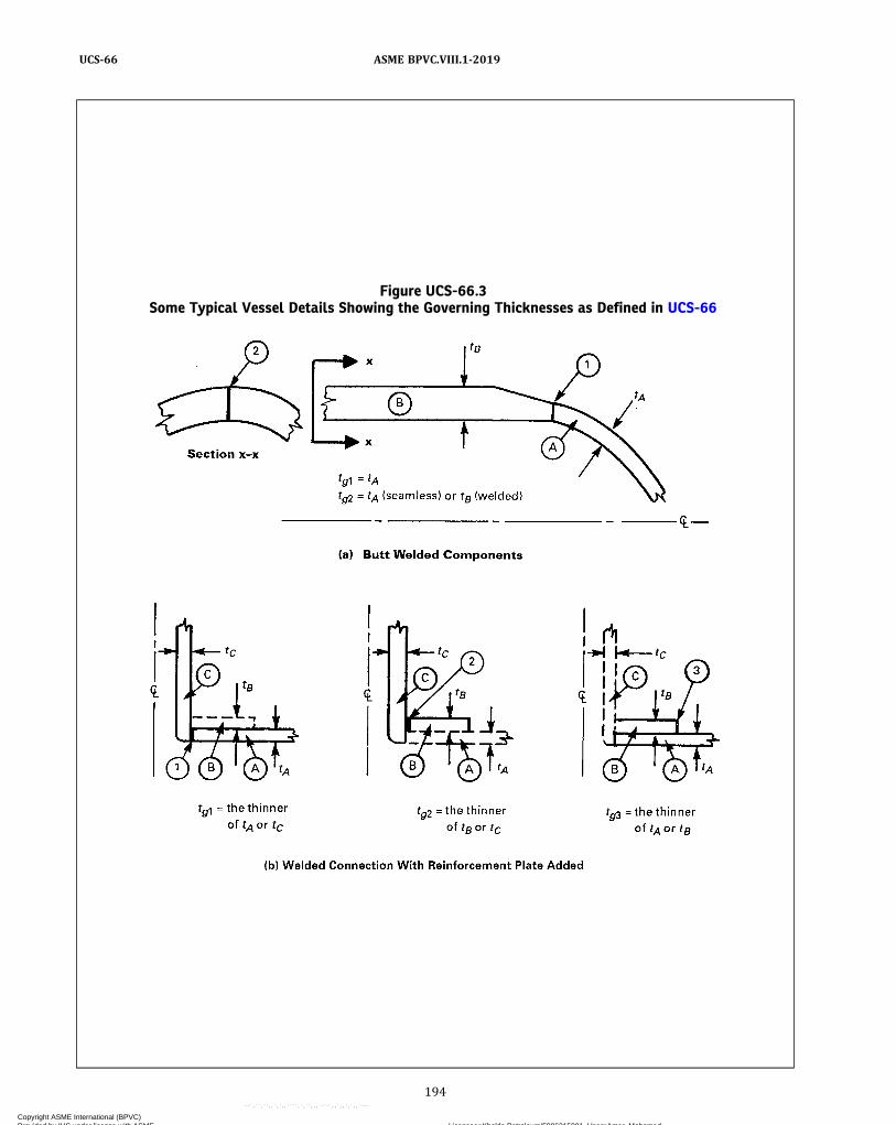
Figure UCS-66.3Some Typical Vessel Details Showing the Governing Thicknesses as Defined in UCS-66
194
ASME BPVC.VIII.1-2019UCS-66
Copyright ASME International (BPVC) Provided by IHS under license with ASME Licensee=Khalda Petroleum/5986215001, User=Amer, Mohamed
Not for Resale, 07/02/2019 13:29:04 MDTNo reproduction or networking permitted without license from IHS
--`,``,``,,`,`,,````,`,``,,,`-`-`,,`,,`,`,,`---
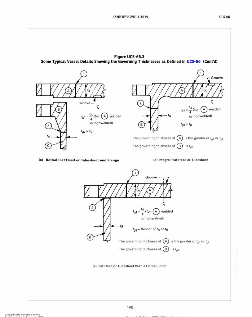
Figure UCS-66.3Some Typical Vessel Details Showing the Governing Thicknesses as Defined in UCS-66 (Cont'd)
195
ASME BPVC.VIII.1-2019 UCS-66
Copyright ASME International (BPVC) Provided by IHS under license with ASME Licensee=Khalda Petroleum/5986215001, User=Amer, Mohamed
Not for Resale, 07/02/2019 13:29:04 MDTNo reproduction or networking permitted without license from IHS
--`,``,``,,`,`,,````,`,``,,,`-`-`,,`,,`,`,,`---

(2)When the coincident ratio defined in FigureUCS-66.1 is greater than 0.35, the corresponding mini-mum design metal temperature shall not be colder thanthe impact test temperature less the allowable tempera-ture reduction permitted in Figure UCS-66.1 and shall inno case be colder than –155°F (–104°C).(g)Materials produced and impact tested in accor-
dance with the requirements of the specifications listedin Figure UG-84.1, General Note (c), are exempt from im-pact testing by the rules of this Division at minimum de-sign metal temperatures not more than 5°F (3°C) colderthan the test temperature required by the specification.(h) No impact testing is required for metal backing
strips which remain in place made of materials assignedto Curve A of Figure UCS-66 in thicknesses not exceeding1/4 in. (6 mm) when the minimum design metal tempera-ture is −20°F (−29°C) or warmer.
(i) For components made of Part UCS materials thatare impact tested, Figure UCS-66.1 provides a basis forthe use of these components at an MDMT colder thanthe impact test temperature.
(1) For such components, the MDMT shall not becolder than the impact test temperature less the allow-able temperature reduction as determined from FigureUCS-66.2.
(2) Figure UCS-66.1 may also be used for compo-nents not stressed in general primary membrane tensilestress, such as flat heads, covers, tubesheets, and flanges.The MDMT shall not be colder than the impact test tem-perature less the allowable temperature reduction as de-termined from Figure UCS-66.2. The ratio used in Step 3of Figure UCS-66.2 shall be the ratio of maximum designpressure at the MDMT to the maximum allowable pres-sure (MAP) of the component at the MDMT.
Figure UCS-66.3Some Typical Vessel Details Showing the Governing Thicknesses as Defined in UCS-66 (Cont'd)
tA
tAtC
tB
tA
tB
Pressure partPressure part
1
A
B
1 1
A
B
tg1 � thinner of tA or tB
(f) Welded Attachments as Defined in UCS-66(a)
tg1 � thinner of tA or tC
(g) Integrally Reinforced Welded Connection
1A
C
GENERAL NOTES:(a) Using tg1, tg2, and tg3, determine the warmest MDMT and use that as the permissible MDMT for the welded assembly.(b) tg = governing thickness of the welded joint as defined in UCS-66.
196
ASME BPVC.VIII.1-2019UCS-66
Copyright ASME International (BPVC) Provided by IHS under license with ASME Licensee=Khalda Petroleum/5986215001, User=Amer, Mohamed
Not for Resale, 07/02/2019 13:29:04 MDTNo reproduction or networking permitted without license from IHS
--`,``,``,,`,`,,````,`,``,,,`-`-`,,`,,`,`,,`---
(3) In lieu of using (2) above, the MDMT for a flangeattached by welding shall not be colder than the impacttest temperature less the allowable temperature reduc-tion as determined in (1) above for the neck or shell towhich the flange is attached.
(4) The MDMT adjustment as determined in (1)above may be used for impact tested welding proceduresor production welds.
(5) The MDMT for the component shall not be colderthan −155°F (−105°C).
(j) When the base metal is exempt from impact testingby (g) above or by Figure UCS-66, Curve C or Curve D,−20°F (−29°C) is the coldest MDMT to be assigned forwelded components that do not meet the requirementsof UCS-67(a)(3).
UCS-67 IMPACT TESTS OF WELDINGPROCEDURES
Except as exempted in UG-20(f), UCS-66, and UCS-68,the welding procedure qualification shall include impacttests of the weld metal and heat-affected zones (HAZ) inaccordance with UG-84 when required by the followingprovisions. The minimum design metal temperature(MDMT) used below shall be either the MDMT stampedon the nameplate or the exemption temperature of thewelded component before applying the temperature re-duction permitted by UCS-66(b) or UCS-68(c).
(a)Welds made with filler metal shall be depositedusing welding procedures qualified with impact testingin accordance with UG-84 when any of the followingapply:
(1)when either base metal is required to be impacttested by the rules of this Division; or
(2)when the thickness of any individual weld passexceeds 1/2 in. (13 mm) and the MDMT is colder than70°F (21°C); or
(3)when joining base metals exempt from impacttesting by UCS-66(g) or Figure UCS-66, Curve C or Dand the MDMT is colder than −20°F (−29°C) but notcolder than –55°F (–48°C). Qualification of the weldingprocedure with impact testing is not required when no in-dividual weld pass in the production weld exceeds 1/4 in.(6 mm) in thickness; and each heat and/or lot of filler me-tal or combination of heat and/or lot of filler metal andbatch of flux has been classified by their manufacturerthrough impact testing per the applicable SFA specifica-tion at a temperature not warmer than the MDMT. Addi-tional testing beyond the scope of the SFA specificationmay be performed by the filler metal and/or flux manu-facturer to expand their classification for a broader rangeof temperatures; or
(4)when joining base metals exempt from impacttesting by UCS-66(g) and the MDMT is colder than–55°F (–48°C).
(b) Except for welds made as part of the material spec-ification, welds in Part UCS materials made without fillermetal shall be completed using welding procedures qual-ified with impact testing any of the following conditionsapply:
(1)when either base metal is required to be impacttested by the rules of this Division; or
(2) the thickness at the weld exceeds 1/2 in. (13 mm)regardless of the MDMT; or
(3)when the thickness at the weld exceeds 5/16 in.(8 mm) and the MDMT is colder than 50°F (10°C); or
(4)when joining base metals exempt from impacttesting by UCS-66(g) and the MDMT is colder than–55°F (–48°C).
UCS-68 DESIGN77
(a)Welded joints shall comply with UW-2(b) when theminimum design metal temperature is colder than −55°F(−48°C), unless the coincident ratio defined in FigureUCS-66.1 is less than 0.35.
(b)Welded joints shall be postweld heat treated in ac-cordance with the requirements of UW-40 when requiredby other rules of this Division. When the minimum designmetal temperature is colder than −55°F (−48°C), and thecoincident ratio defined in Figure UCS-66.1 is 0.35 orgreater, postweld heat treatment is required, except thatthis requirement does not apply to the following weldedjoints, in vessels or vessel parts fabricated of P‐No. 1 ma-terials that are impact tested at the MDMT or colder in ac-cordance with UG-84. The minimum average energyrequirement for base metals and weldments shall be25 ft‐lb (34 J) instead of the values shown in FigureUG-84.1:
(1) Type 1 Category A and B joints, not includingcone‐to‐cylinder junctions, which have been 100% radio-graphed. Category A and B joints attaching sections of un-equal thickness shall have a transition with a slope notexceeding 3:1.
(2) the following welds:(-a) fillet welds having leg dimensions not exceed-
ing 3/8 in. (10 mm) attaching lightly loaded attachments,provided the attachment material and the attachmentweld meet requirements of UCS-66 and UCS-67. “Lightlyloaded attachment,” for this application, is defined as anattachment for which the stress in the attachment welddoes not exceed 25% of the allowable stress.
(-b) seal welds defined in UW-20.2(c).
All such welds as described in (-a) and (-b) shall be exam-ined by magnetic particle or liquid penetrant examinationin accordance with Mandatory Appendix 6 or MandatoryAppendix 8.
(c) If postweld heat treating of a pressure-retainingweld is performed when it is not otherwise a requirementof this Division, a 30°F (17°C) reduction in impact testingexemption temperature may be given to the minimumpermissible temperature from Figure UCS-66 for P‐No. 1
197
ASME BPVC.VIII.1-2019 UCS-66 – UCS-68
Copyright ASME International (BPVC) Provided by IHS under license with ASME Licensee=Khalda Petroleum/5986215001, User=Amer, Mohamed
Not for Resale, 07/02/2019 13:29:04 MDTNo reproduction or networking permitted without license from IHS
--`,``,``,,`,`,,````,`,``,,,`-`-`,,`,,`,`,,`---
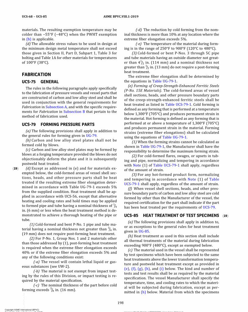
ð19Þ
ð19Þ
materials. The resulting exemption temperature may becolder than −55°F (−48°C) when the PWHT exemptionin (b) is applicable.(d) The allowable stress values to be used in design at
the minimum design metal temperature shall not exceedthose given in Section II, Part D, Subpart 1, Table 3 forbolting and Table 1A for other materials for temperaturesof 100°F (38°C).
FABRICATION
UCS-75 GENERALThe rules in the following paragraphs apply specifically
to the fabrication of pressure vessels and vessel parts thatare constructed of carbon and low alloy steel and shall beused in conjunction with the general requirements forFabrication in Subsection A, and with the specific require-ments for Fabrication in Subsection B that pertain to themethod of fabrication used.
UCS-79 FORMING PRESSURE PARTS(a) The following provisions shall apply in addition to
the general rules for forming given in UG-79.(b) Carbon and low alloy steel plates shall not be
formed cold by blows.(c) Carbon and low alloy steel plates may be formed by
blows at a forging temperature provided the blows do notobjectionably deform the plate and it is subsequentlypostweld heat treated.(d) Except as addressed in (e) and for materials ex-
empted below, the cold-formed areas of vessel shell sec-tions, heads, and other pressure parts shall be heattreated if the resulting extreme fiber elongation deter-mined in accordance with Table UG-79-1 exceeds 5%from the supplied condition. Heat treatment shall be ap-plied in accordance with UCS-56, except that alternativeheating and cooling rates and hold times may be appliedto formed pipe and tube having a nominal thickness of 1/4in. (6 mm) or less when the heat treatment method is de-monstrated to achieve a thorough heating of the pipe ortube.
(1) Cold-formed and bent P-No. 1 pipe and tube ma-terial having a nominal thickness not greater than 3/4 in.(19 mm) does not require post-forming heat treatment.
(2) For P-No. 1, Group Nos. 1 and 2 materials otherthan those addressed by (1), post-forming heat treatmentis required when the extreme fiber elongation exceeds40% or if the extreme fiber elongation exceeds 5% andany of the following conditions exist:
(-a) The vessel will contain lethal liquid or gas-eous substances (see UW-2).
(-b) The material is not exempt from impact test-ing by the rules of this Division, or impact testing is re-quired by the material specification.
(-c) The nominal thickness of the part before coldforming exceeds 5/8 in. (16 mm).
(-d) The reduction by cold forming from the nom-inal thickness is more than 10% at any location where theextreme fiber elongation exceeds 5%.
(-e) The temperature of the material during form-ing is in the range of 250°F to 900°F (120°C to 480°C).
(3) Cold-formed or bent P‐Nos. 3 through 5C pipeand tube materials having an outside diameter not great-er than 41/2 in. (114 mm) and a nominal thickness notgreater than 1/2 in. (13 mm) do not require a post-formingheat treatment.The extreme fiber elongation shall be determined by
the equations in Table UG-79-1.(e) Forming of Creep-Strength-Enhanced Ferritic Steels
(P-No. 15E Materials). The cold-formed areas of vesselshell sections, heads, and other pressure boundary partsof the creep-strength-enhanced ferritic steels shall beheat treated as listed in Table UCS-79-1. Cold forming isdefined as any forming that is performed at a temperaturebelow 1,300°F (705°C) and produces permanent strain inthe material. Hot forming is defined as any forming that isperformed at or above a temperature of 1,300°F (705°C)and produces permanent strain in the material. Formingstrains (extreme fiber elongations) shall be calculatedusing the equations of Table UG-79-1.
(1)When the forming strains cannot be calculated asshown in Table UG-79-1, the Manufacturer shall have theresponsibility to determine the maximum forming strain.
(2) For cold-formed flares, swages, or upsets in tub-ing and pipe, normalizing and tempering in accordancewith Note (1) of Table UCS-79-1 shall apply, regardlessof the amount of strain.
(3) For any hot-formed product form, normalizingand tempering in accordance with Note (1) of TableUCS-79-1 shall apply, regardless of the amount of strain.(f) When vessel shell sections, heads, and other pres-
sure boundary parts of carbon and low alloy steel are coldformed by other than the Manufacturer of the vessel, therequired certification for the part shall indicate if the parthas been heat treated per the requirements of UCS-79.
UCS-85 HEAT TREATMENT OF TEST SPECIMENS(a) The following provisions shall apply in addition to,
or as exceptions to the general rules for heat treatmentgiven in UG-85.(b) Heat treatment as used in this section shall include
all thermal treatments of the material during fabricationexceeding 900°F (480°C), except as exempted below.(c) The material used in the vessel shall be represented
by test specimens which have been subjected to the sameheat treatments above the lower transformation tempera-ture and postweld heat treatment except as provided in(e), (f), (g), (h), and (i) below. The kind and number oftests and test results shall be as required by the materialspecification. The vessel Manufacturer shall specify thetemperature, time, and cooling rates to which the materi-al will be subjected during fabrication, except as per-mitted in (h) below. Material from which the specimens
198
ASME BPVC.VIII.1-2019UCS-68 – UCS-85
Copyright ASME International (BPVC) Provided by IHS under license with ASME Licensee=Khalda Petroleum/5986215001, User=Amer, Mohamed
Not for Resale, 07/02/2019 13:29:04 MDTNo reproduction or networking permitted without license from IHS
--`,``,``,,`,`,,````,`,``,,,`-`-`,,`,,`,`,,`---
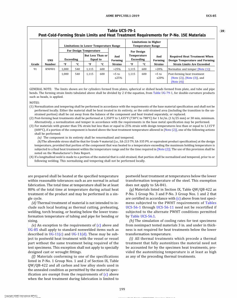
are prepared shall be heated at the specified temperaturewithin reasonable tolerances such as are normal in actualfabrication. The total time at temperature shall be at least80% of the total time at temperature during actual heattreatment of the product and may be performed in a sin-gle cycle.
(d) Thermal treatment of material is not intended to in-clude such local heating as thermal cutting, preheating,welding, torch brazing, or heating below the lower trans-formation temperature of tubing and pipe for bending orsizing.
(e) An exception to the requirements of (c) above andUG-85 shall apply to standard nonwelded items such asdescribed in UG-11(c) and UG-11(d). These may be sub-ject to postweld heat treatment with the vessel or vesselpart without the same treatment being required of thetest specimens. This exception shall not apply to speciallydesigned cast or wrought fittings.
(f) Materials conforming to one of the specificationslisted in P‐No. 1 Group Nos. 1 and 2 of Section IX, TableQW/QB-422 and all carbon and low alloy steels used inthe annealed condition as permitted by the material spec-ification are exempt from the requirements of (c) abovewhen the heat treatment during fabrication is limited to
postweld heat treatment at temperatures below the lowertransformation temperature of the steel. This exemptiondoes not apply to SA-841.
(g)Materials listed in Section IX, Table QW/QB-422 asP‐No. 1 Group No. 3 and P‐No. 3 Group Nos. 1 and 2 thatare certified in accordance with (c) above from test speci-mens subjected to the PWHT requirements of TablesUCS-56-1 through UCS-56-11 need not be recertified ifsubjected to the alternate PWHT conditions permittedby Table UCS-56.1.
(h) The simulation of cooling rates for test specimensfrom nonimpact tested materials 3 in. and under in thick-ness is not required for heat treatments below the lowertransformation temperature.
(i) All thermal treatments which precede a thermaltreatment that fully austenitizes the material need notbe accounted for by the specimen heat treatments, pro-vided the austenitizing temperature is at least as highas any of the preceding thermal treatments.
ð19ÞTable UCS-79-1Post-Cold-Forming Strain Limits and Heat Treatment Requirements for P-No. 15E Materials
GradeUNS
Number
Limitations in Lower Temperature RangeLimitations in HigherTemperature Range
Required Heat Treatment WhenDesign Temperature and Forming
Strain Limits Are Exceeded
For Design Temperature
AndFormingStrains
For DesignTemperatureExceeding
AndFormingStrains
ExceedingBut Less Than or
Equal to
°F °C °F °C °F °C
91 K90901 1,000 540 1,115 600 >25% 1,115 600 >20% Normalize and temper [Note (1)]
1,000 540 1,115 600 >5 to≤25%
1,115 600 >5 to≤20%
Post-forming heat treatment[Note (2)], [Note (3)], and[Note (4)]
GENERAL NOTE: The limits shown are for cylinders formed from plates, spherical or dished heads formed from plate, and tube and pipebends. The forming strain limits tabulated above shall be divided by 2 if the equation, from Table UG-79-1, for double-curvature productssuch as heads, is applied.
NOTES:(1) Normalization and tempering shall be performed in accordance with the requirements of the base material specification and shall not be
performed locally. Either the material shall be heat treated in its entirety, or the cold-strained area (including the transition to the un-strained portion) shall be cut away from the balance of the component and heat treated separately, or replaced.
(2) Post-forming heat treatments shall be performed at 1,350°F to 1,435°F (730°C to 780°C) for 1 hr/in. (1 h/25 mm) or 30 min, minimum.Alternatively, a normalization and temper in accordance with the requirements in the base metal specification may be performed.
(3) For materials with greater than 5% strain but less than or equal to 25% strain with design temperatures less than or equal to 1,115°F(600°C), if a portion of the component is heated above the heat treatment temperature allowed in [Note (2)], one of the following actionsshall be performed:(a) The component in its entirety shall be renormalized and tempered.(b)The allowable stress shall be that for Grade 9 material (i.e., SA-213 T9, SA-335 P9, or equivalent product specification) at the design
temperature, provided that portion of the component that was heated to a temperature exceeding the maximum holding temperature issubjected to a final heat treatment within the temperature range and for the time required in [Note (2)]. The use of this provision shall benoted on the Manufacturer's Data Report.
(4) If a longitudinal weld is made to a portion of the material that is cold strained, that portion shall be normalized and tempered, prior to orfollowing welding. This normalizing and tempering shall not be performed locally.
199
ASME BPVC.VIII.1-2019 UCS-85
Copyright ASME International (BPVC) Provided by IHS under license with ASME Licensee=Khalda Petroleum/5986215001, User=Amer, Mohamed
Not for Resale, 07/02/2019 13:29:04 MDTNo reproduction or networking permitted without license from IHS
--`,``,``,,`,`,,````,`,``,,,`-`-`,,`,,`,`,,`---

INSPECTION AND TESTS
UCS-90 GENERALThe provisions for inspection and testing in Subsec-
tions A and B shall apply without supplement to vesselsconstructed of carbon and low alloy steels.
MARKING AND REPORTS
UCS-115 GENERALThe provisions for marking and reports in UG-115
through UG-120 shall apply without supplement to pres-sure vessels constructed of carbon and low alloy steels.
200
ASME BPVC.VIII.1-2019UCS-90 – UCS-115
Copyright ASME International (BPVC) Provided by IHS under license with ASME Licensee=Khalda Petroleum/5986215001, User=Amer, Mohamed
Not for Resale, 07/02/2019 13:29:04 MDTNo reproduction or networking permitted without license from IHS
--`,``,``,,`,`,,````,`,``,,,`-`-`,,`,,`,`,,`---
NONMANDATORY APPENDIX UCS-A
UCS-A-1 GENERAL
See Section II, Part D, Nonmandatory Appendix A,A-100.
UCS-A-2 CREEP–RUPTURE PROPERTIES OFCARBON STEELS
See Section II, Part D, Nonmandatory Appendix A,A-200.
UCS-A-3 VESSELS OPERATING ATTEMPERATURES COLDER THANTHE MDMT STAMPED ON THENAMEPLATE
(a) Vessels or components may be operated at tem-peratures colder than the MDMT stamped on the name-plate, provided the provisions of UCS-66, UCS-67, andUCS-68 are met when using the reduced (colder) operat-ing temperature as the MDMT, but in no case shall the op-erating temperature be colder than −155°F (−105°C).
(b) As an alternative to (a) above, for vessels or compo-nents whose thicknesses are based on pressure loadingonly, the coincident operating temperature may be as cold
as the MDMT stamped on the nameplate less the allow-able temperature reduction as determined from FigureUCS-66.2. The ratio used in Step 3 of Figure UCS-66.2 shallbe the ratio of maximum pressure at the coincident oper-ating temperature to the MAWP of the vessel at thestamped MDMT, but in no case shall the operating tem-perature be colder than −155°F (−105°C).NOTE: One common usage of the exemptions in (a) and (b) is for ves-sels in which the internal pressure is dependent on the vapor pres-sure of the contents (e.g., vessels in refrigeration or hydrocarbonprocessing plants with operating systems that do not permit im-mediate repressurization). For such services, the primary thicknesscalculations (shell and head) are normally made for the maximumdesign pressure coincident with the design temperature (MDMT).The ratio of required thickness to nominal thickness as defined inFigure UCS-66.2, Step 3, for the design condition is then calculated.Thickness calculations are also made for other expected pressuresat coincident temperature, along with the ΔT difference from theMDMT at design pressure, and the thickness ratio defined in Step3 of Figure UCS-66.2. The ratio/ΔT points are then plotted on FigureUCS-66.1. Ratio/ΔT points that are on or below the Figure UCS-66.1curve are acceptable, but in no case may the operating temperaturebe colder than −155°F (−104°C). See also ASME PTB-4–2012, exam-ple 3.3. Comparison of pressure–temperature or stress–temperaturecoincident ratios may also be used as noted in Figure UCS-66.1.
201
ASME BPVC.VIII.1-2019 UCS-A-1 – UCS-A-3
Copyright ASME International (BPVC) Provided by IHS under license with ASME Licensee=Khalda Petroleum/5986215001, User=Amer, Mohamed
Not for Resale, 07/02/2019 13:29:04 MDTNo reproduction or networking permitted without license from IHS
--`,``,``,,`,`,,````,`,``,,,`-`-`,,`,,`,`,,`---
PART UNFREQUIREMENTS FOR PRESSURE VESSELS CONSTRUCTED OF
NONFERROUS MATERIALS
GENERAL
UNF-1 SCOPEThe rules in Part UNF are applicable to pressure vessels
and vessel parts that are constructed of nonferrous mate-rials and shall be used in conjunction with the general re-quirements in Subsection A, and with the specificrequirements in Subsection B that pertain to the methodof fabrication used.
UNF-3 USESSome of the uses of nonferrous materials are to resist
corrosion, to facilitate cleaning of vessels for processingfoods, to provide strength or scaling‐resistance at hightemperatures, and to provide notch toughness at lowtemperatures.
UNF-4 CONDITIONS OF SERVICESpecific chemical compositions, heat‐treatment proce-
dures, fabrication requirements, and supplementary testsmay be required to assure that the vessel will be in itsmost favorable condition for the intended service. Thisis particularly true for vessels subject to severe corrosion.These rules do not indicate the selection of nonferrousmaterial suitable for the intended service or the amountof the corrosion allowance to be provided. It is recom-mended that users assure themselves by appropriatetests, or otherwise, that the nonferrous material selectedwill be suitable for the intended service both with respectto corrosion and to retention of satisfactory mechanicalproperties during the desired service life, taking into ac-count any heating or heat treatment that might be per-formed during fabrication. See also Section II, Part D,Nonmandatory Appendix A, A-400.
MATERIALS
UNF-5 GENERAL(a) All nonferrous materials subject to stress due to
pressure shall conform to one of the specifications givenin Section II and shall be limited to those listed in TablesUNF-23.1 through UNF-23.5 except as otherwise pro-vided in UG-10 and UG-11.(b) Nonmandatory Appendix UNF-A of this Division of
Section VIII and the paragraph entitled Basis of Purchaseand the appendix of the applicable material specification
contain information relative to the fabricating character-istics of the material. They are intended to help the man-ufacturer in ordering the correct material, and infabricating it, and to help the producer to select the mate-rial best able to fulfill the requirements of the fabricatingprocedures to be used.
UNF-6 NONFERROUS PLATEApproved specifications for nonferrous plates are given
in Tables UNF-23.1 through UNF-23.5. A tabulation of al-lowable stress values at different temperatures is given inSection II, Part D, Subpart 1, Table 1B (see UG-5).
UNF-7 FORGINGSApproved specifications for nonferrous forgings are
given in Tables UNF-23.1 through UNF-23.5. A tabulationof allowable stress values at different temperatures is giv-en in Section II, Part D, Subpart 1, Table 1B (see UG-6).
UNF-8 CASTINGSApproved specifications for nonferrous castings are
given in Tables UNF-23.1 through UNF-23.5. A tabulationof allowable stress values at different temperatures is giv-en in Section II, Part D, Subpart 1, Table 1B. These stressvalues are to be multiplied by the casting quality factorsof UG-24. Castings that are to be welded shall be of aweldable grade.
UNF-12 BOLT MATERIALS(a) Approved specifications for bolt materials are given
in Tables UNF-23.1 through UNF-23.5. A tabulation of al-lowable stress values at different temperatures is given inSection II, Part D, Subpart 1, Table 3.(b)When bolts are machined from heat treated, hot
rolled, or cold worked material and are not subsequentlyhot worked or annealed, the allowable stress values inSection II, Part D, Subpart 1, Table 3 to be used in designshall be based on the condition of the material selected.(c) When bolts are fabricated by hot‐heading, the al-
lowable stress values for annealed material in Section II,Part D, Subpart 1, Table 3 shall apply unless the manufac-turer can furnish adequate control data to show that thetensile properties of hot rolled bars or hot finished forg-ings are being met, in which case the allowable stress val-ues for the material in the hot finished condition may beused.
202
ASME BPVC.VIII.1-2019UNF-1 – UNF-12
Copyright ASME International (BPVC) Provided by IHS under license with ASME Licensee=Khalda Petroleum/5986215001, User=Amer, Mohamed
Not for Resale, 07/02/2019 13:29:04 MDTNo reproduction or networking permitted without license from IHS
--`,``,``,,`,`,,````,`,``,,,`-`-`,,`,,`,`,,`---
ð19Þ
(d)When bolts are fabricated by cold heading, the al-lowable stress values for annealed material in Section II,Part D, Subpart 1, Table 3 shall apply unless the manufac-turer can furnish adequate control data to show that high-er design stresses, as agreed upon, may be used. In nocase shall such stresses exceed the allowable stress valuesgiven in Section II, Part D, Subpart 1, Table 3 for coldworked bar stock.
(e) Ferrous bolts, studs, and nuts may be used providedthey are suitable for the application. They shall conformto the requirements of UCS-10 and UCS-11.
UNF-13 NUTS AND WASHERSNuts and washers may be made from any suitable ma-
terial listed in Tables UNF-23.1 through UNF-23.5. Nutsmay be of any dimension or shape provided their strengthis equal to that of the bolting, giving due consideration tobolt hole clearance, bearing area, thread form and class offit, thread shear, and radial thrust from threads [seeU-2(g)].
UNF-14 RODS, BARS, AND SHAPESRods, bars and shapes shall conform to one of the spe-
cifications in Tables UNF-23.1 through UNF-23.5.
UNF-15 OTHER MATERIALS(a) Other materials, either ferrous or nonferrous, may
be used for parts of vessels provided that they are suit-able for the purpose intended.
(b) The user shall satisfy himself that the coupling ofdissimilar metals will have no harmful effect on the corro-sion rate or service life of the vessel for the serviceintended.
(c) Other materials used in conjunction with nonfer-rous metals shall meet the requirements given for thosematerials in other parts of this Division.
DESIGN
UNF-16 GENERALThe rules in the following paragraphs apply specifically
to the design of pressure vessels and vessel parts of non-ferrous materials and shall be used in conjunction withthe general requirements for Design in Subsection A,and with the specific requirements for Design in Subsec-tion B that pertain to the method of fabrication used.
UNF-19 WELDED JOINTS(a) For vessels constructed of titanium or zirconium
and their alloys, all Category A and B joints shall be ofType No. (1) or No. (2) of Table UW-12.
(b) Titanium or zirconium and their alloys shall not bewelded to other materials.
(c) For vessels constructed of UNS N06625, all Catego-ry A and B joints shall be Type No. (1) or No. (2) of TableUW-12. All Category C and D joints shall be Type No. (1)or No. (2) of Table UW-12 when the design temperatureis 1,000°F (540°C) or higher.
(d) For vessels constructed of UNS N12160, the nom-inal thickness of the base material at the weld shall notexceed 0.5 in. (13 mm). When welding is performed withfiller metal of the same nominal composition as the basemetal, only GMAW or GTAW processes are allowed andthe nominal weld deposit thickness shall not exceed0.5 in. (13 mm).
(e) For vessels constructed of UNS N06230 and UNSN06210 and when welding is performed with filler metalof the same nominal composition as the base metal, onlyGMAW or GTAW processes are allowed. For applicationsusing UNS N06230 above 1,650°F (900°C), welding shallbe limited to the GTAW and GMAW welding processesusing SFA-5.14, ERNiCrWMo‐1.
(f) For vessels constructed of UNS R31233 during weldprocedure qualification testing, when using a matchingfiller metal composition, the minimum specified tensilestrength of the weld metal shall be 120 ksi (828 MPa).Longitudinal bend tests are permitted per Section IX,QW‐160.
UNF-23 MAXIMUM ALLOWABLE STRESS VALUES(a) Section II, Part D, Subpart 1, Table 3 for bolting and
Table 1B for other materials give the maximum allowablestress values at the temperatures indicated for materialsconforming to the specifications listed therein. Valuesmay be interpolated for intermediate temperatures (seeUG-23). For vessels designed to operate at a temperaturecolder than −20°F (−29°C), the allowable stress values tobe used in design shall not exceed those given for tem-peratures of −20°F to 100°F (−29°C to 38°C).
(b) Shells of pressure vessels may be made fromwelded pipe or tubing listed in Tables UNF-23.1,UNF-23.2, UNF-23.3, UNF-23.4, and UNF-23.5.
(c) When welding or brazing is to be done on materialhaving increased tensile strength produced by hot or coldworking, the allowable stress value for the material in theannealed condition shall be used for joint design. One‐piece heads and seamless shells may be designed on thebasis of the actual temper of the material.
(d)When welding or brazing is to be done on materialhaving increased tensile strength produced by heat treat-ment, the allowable stress value for the material in the an-nealed condition shall be used for the joint design unlessthe stress values for welded construction are given in Sec-tion II, Part D, Subpart 1, Table 1B or Table 3 or unless thefinished construction is subjected to the same heat treat-ment as that which produced the temper in the “as‐received” material, provided the welded joint and thebase metal are similarly affected by the heat treatment.
203
ASME BPVC.VIII.1-2019 UNF-12 – UNF-23
Copyright ASME International (BPVC) Provided by IHS under license with ASME Licensee=Khalda Petroleum/5986215001, User=Amer, Mohamed
Not for Resale, 07/02/2019 13:29:04 MDTNo reproduction or networking permitted without license from IHS
--`,``,``,,`,`,,````,`,``,,,`-`-`,,`,,`,`,,`---

Table UNF-23.1Nonferrous Metals — Aluminum and Aluminum Alloy Products
Spec.No. Alloy Designation/UNS No.
SB-26 A02040, A03560, A24430SB-108 A02040, A03560SB-209 Alclad 3003, 3004, 6061; A91060, A91100, A93003,
A93004, A95052, A95083, A95086, A95154,A95254, A95454, A95456, A95652, A96061
SB-210 Alclad 3003; A91060, A93003, A95052, A95154,A96061, A96063
SB-211 A92014, A92024, A96061SB-221 A91060, A91100, A92024, A93003, A95083, A95086,
A95154, A95454, A95456, A96061, A96063
Spec.No. Alloy Designation/UNS No.
SB-234 Alclad 3003; A91060, A93003, A95052, A95454,A96061
SB-241 Alclad 3003; A91060, A91100, A93003, A95052,A95083, A95086, A95454, A95456, A96061,A96063
SB-247 A92014, A93003, A95083, A96061SB-308 A96061SB-928 A95083, A95086, A95456
GENERAL NOTE: Maximum allowable stress values in tension for the materials listed in the above table are contained in Section II, PartD, Subpart 1 (see UG-23).
ð19Þ Table UNF-23.2Nonferrous Metals — Copper and Copper Alloys
Spec.No. UNS No.
SB-42 C10200, C12000, C12200SB-43 C23000SB-61 C92200SB-62 C83600SB-75 C10200, C12000, C12200, C14200SB-96 C65500SB-98 C65100, C65500, C66100SB-111 C10200, C12000, C12200, C14200, C19200,
C23000, C28000, C44300, C44400, C44500,C60800, C68700, C70400, C70600, C70620,C71000, C71500, C71520, C72200
SB-135 C23000SB-148 C95200, C95400, C95820SB-150 C61400, C62300, C63000, C64200SB-152 C10200, C10400, C10500, C10700, C11000,
C12200, C12300SB-169 C61400SB-171 C36500, C44300, C44400, C44500, C46400,
C46500, C61400, C63000, C70600, C70620,C71500, C71520
Spec.No. UNS No.
SB-187 C10200, C11000SB-271 C95200SB-283 C37700, C64200, C70620, C71520SB-315 C65500SB-359 C12200, C44300, C44400, C44500, C70600,
C70620, C71000, C71500, C71520SB-395 C10200, C12000, C12200, C14200, C19200,
C23000, C44300, C44400, C44500, C60800,C68700, C70600, C70620, C71000, C71500,C71520
SB-466 C70600, C70620, C71000, C71500, C71520SB-467 C70600, C70620SB-543 C12200, C19400, C23000, C44300, C44400,
C44500, C68700, C70400, C70600, C70620,C71500, C71520
SB-584 C92200, C93700, C97600SB-956 C70600, C70620, C71500, C71520
GENERAL NOTE: Maximum allowable stress values in tension for the materials listed in the above table are contained in Section II,Part D, Subpart 1 (see UG-23).
204
ASME BPVC.VIII.1-2019UNF-23
Copyright ASME International (BPVC) Provided by IHS under license with ASME Licensee=Khalda Petroleum/5986215001, User=Amer, Mohamed
Not for Resale, 07/02/2019 13:29:04 MDTNo reproduction or networking permitted without license from IHS
--`,``,``,,`,`,,````,`,``,,,`-`-`,,`,,`,`,,`---
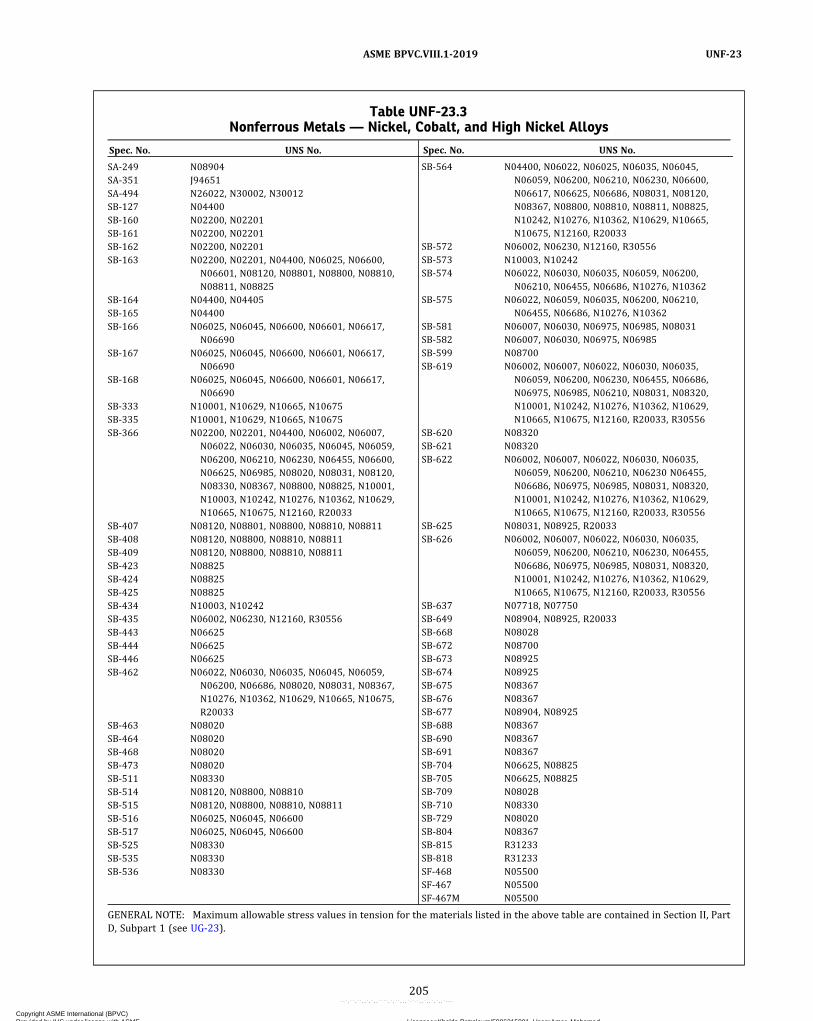
Table UNF-23.3Nonferrous Metals — Nickel, Cobalt, and High Nickel Alloys
Spec. No. UNS No.
SA-249 N08904SA-351 J94651SA-494 N26022, N30002, N30012SB-127 N04400SB-160 N02200, N02201SB-161 N02200, N02201SB-162 N02200, N02201SB-163 N02200, N02201, N04400, N06025, N06600,
N06601, N08120, N08801, N08800, N08810,N08811, N08825
SB-164 N04400, N04405SB-165 N04400SB-166 N06025, N06045, N06600, N06601, N06617,
N06690SB-167 N06025, N06045, N06600, N06601, N06617,
N06690SB-168 N06025, N06045, N06600, N06601, N06617,
N06690SB-333 N10001, N10629, N10665, N10675SB-335 N10001, N10629, N10665, N10675SB-366 N02200, N02201, N04400, N06002, N06007,
N06022, N06030, N06035, N06045, N06059,N06200, N06210, N06230, N06455, N06600,N06625, N06985, N08020, N08031, N08120,N08330, N08367, N08800, N08825, N10001,N10003, N10242, N10276, N10362, N10629,N10665, N10675, N12160, R20033
SB-407 N08120, N08801, N08800, N08810, N08811SB-408 N08120, N08800, N08810, N08811SB-409 N08120, N08800, N08810, N08811SB-423 N08825SB-424 N08825SB-425 N08825SB-434 N10003, N10242SB-435 N06002, N06230, N12160, R30556SB-443 N06625SB-444 N06625SB-446 N06625SB-462 N06022, N06030, N06035, N06045, N06059,
N06200, N06686, N08020, N08031, N08367,N10276, N10362, N10629, N10665, N10675,R20033
SB-463 N08020SB-464 N08020SB-468 N08020SB-473 N08020SB-511 N08330SB-514 N08120, N08800, N08810SB-515 N08120, N08800, N08810, N08811SB-516 N06025, N06045, N06600SB-517 N06025, N06045, N06600SB-525 N08330SB-535 N08330SB-536 N08330
Spec. No. UNS No.
SB-564 N04400, N06022, N06025, N06035, N06045,N06059, N06200, N06210, N06230, N06600,N06617, N06625, N06686, N08031, N08120,N08367, N08800, N08810, N08811, N08825,N10242, N10276, N10362, N10629, N10665,N10675, N12160, R20033
SB-572 N06002, N06230, N12160, R30556SB-573 N10003, N10242SB-574 N06022, N06030, N06035, N06059, N06200,
N06210, N06455, N06686, N10276, N10362SB-575 N06022, N06059, N06035, N06200, N06210,
N06455, N06686, N10276, N10362SB-581 N06007, N06030, N06975, N06985, N08031SB-582 N06007, N06030, N06975, N06985SB-599 N08700SB-619 N06002, N06007, N06022, N06030, N06035,
N06059, N06200, N06230, N06455, N06686,N06975, N06985, N06210, N08031, N08320,N10001, N10242, N10276, N10362, N10629,N10665, N10675, N12160, R20033, R30556
SB-620 N08320SB-621 N08320SB-622 N06002, N06007, N06022, N06030, N06035,
N06059, N06200, N06210, N06230 N06455,N06686, N06975, N06985, N08031, N08320,N10001, N10242, N10276, N10362, N10629,N10665, N10675, N12160, R20033, R30556
SB-625 N08031, N08925, R20033SB-626 N06002, N06007, N06022, N06030, N06035,
N06059, N06200, N06210, N06230, N06455,N06686, N06975, N06985, N08031, N08320,N10001, N10242, N10276, N10362, N10629,N10665, N10675, N12160, R20033, R30556
SB-637 N07718, N07750SB-649 N08904, N08925, R20033SB-668 N08028SB-672 N08700SB-673 N08925SB-674 N08925SB-675 N08367SB-676 N08367SB-677 N08904, N08925SB-688 N08367SB-690 N08367SB-691 N08367SB-704 N06625, N08825SB-705 N06625, N08825SB-709 N08028SB-710 N08330SB-729 N08020SB-804 N08367SB-815 R31233SB-818 R31233SF-468 N05500SF-467 N05500SF-467M N05500
GENERAL NOTE: Maximum allowable stress values in tension for the materials listed in the above table are contained in Section II, PartD, Subpart 1 (see UG-23).
205
ASME BPVC.VIII.1-2019 UNF-23
Copyright ASME International (BPVC) Provided by IHS under license with ASME Licensee=Khalda Petroleum/5986215001, User=Amer, Mohamed
Not for Resale, 07/02/2019 13:29:04 MDTNo reproduction or networking permitted without license from IHS
--`,``,``,,`,`,,````,`,``,,,`-`-`,,`,,`,`,,`---

ð19Þ
ð19Þ
UNF-28 THICKNESS OF SHELLS UNDEREXTERNAL PRESSURE
Cylindrical and spherical shells under external pres-sure shall be designed by the rules in UG-28, using the ap-plicable figures in Section II, Part D, Subpart 3 and thetemperature limits of UG-20(c).
UNF-30 STIFFENING RINGSRules covering the design and attachment of stiffening
rings are given in UG-29 and UG-30.
UNF-33 FORMED HEADS, PRESSURE ONCONVEX SIDE
Ellipsoidal, torispherical, hemispherical, and conicalheads having pressure on the convex side (minus heads)shall be designed by the rules of UG-33, using the applic-able figures in Section II, Part D, Subpart 3.
UNF-56 POSTWELD HEAT TREATMENT(a) Postweld heat treatment of nonferrous materials is
not normally necessary nor desirable.(b) Except as in (c) and (d) below, no postweld heat
treatment shall be performed except by agreement be-tween the user and the Manufacturer. The temperature,time and method of heat treatment shall be covered byagreement.
(c) Within 14 days after welding, all products of zirco-nium Grade R60705 shall be heat treated at 1,000°F to1,100°F (540°C to 595°C) for a minimum of 1 hr for thick-nesses up to 1 in. (25 mm) plus 1/2 hr for each additionalinch of thickness. Above 800°F (425°C), cooling shall bedone in a closed furnace or cooling chamber at a ratenot greater than 500°F/hr (278°C/h) divided by the max-imum metal thickness of the shell or head plate in inchesbut in no case more than 500°F/hr (278°C/h). From800°F (425°C), the vessel may be cooled in still air.(d) Postweld Heat Treatment of UNS Nos. N08800,
N08810, and N08811 Alloys(1) Pressure boundary welds and welds to pressure
boundaries in vessels with design temperatures above1000°F fabricated from UNS No. N08800 (Alloy 800),UNS No. N08810 (Alloy 800H), and UNS No. N08811 (Al-loy 800HT) shall be postweld heat treated. The postweldheat treatment shall consist of heating to a minimum tem-perature of 1,625°F (885°C) for 11/2 hr for thicknesses upto 1 in. (25 mm), and for 11/2 hr + 1 hr/in. of thickness forthicknesses in excess of 1 in. (25 mm). Cooling and heat-ing rates shall be by agreement between the user or hisdesignated agent and the Manufacturer. As an alternative,solution annealing in accordance with the material spec-ification is acceptable. Postweld heat treatment of tube‐to‐tubesheet and expansion bellows attachment welds isneither required nor prohibited.
Table UNF-23.4Nonferrous Metals — Titanium and Titanium Alloys
Spec.No. UNS No.
SB-265 R50250, R50400, R50550, R52250, R52252, R52254,R52400, R52402, R52404, R53400, R56320, R56323
SB-338 R50250, R50400, R50550, R52400, R52402, R52404,R53400, R56320, R56323
SB-348 R50250, R50400, R50550, R52400, R52402, R52404,R53400, R56323
SB-363 R50250, R50400, R50550, R52400, R52404, R53400,R56323
Spec.No. UNS No.
SB-367 R50400, R50550, R52400SB-381 R50250, R50400, R50550, R52400, R52402, R52404,
R53400, R56323SB-861 R50250, R50400, R50550, R52400, R52402, R52404,
R53400, R56320, R56323SB-862 R50250, R50400, R50550, R52400, R52402, R52404,
R53400, R56320, R56323
GENERAL NOTE: Maximum allowable stress values in tension for the materials listed in the above table are contained inSection II, Part D, Subpart 1 (see UG-23).
Table UNF-23.5Nonferrous Metals — Zirconium
Spec.No. UNS No.
SB-493 R60702, R60705SB-523 R60702, R60705SB-550 R60702, R60705
Spec.No. UNS No.
SB-551 R60702, R60705SB-653 R60702, R60705SB-658 R60702, R60705
GENERAL NOTE: Maximum allowable stress values in tension for the materials listed in the abovetable are contained in Section II, Part D, Subpart 1 (see UG-23).
206
ASME BPVC.VIII.1-2019UNF-28 – UNF-56
Copyright ASME International (BPVC) Provided by IHS under license with ASME Licensee=Khalda Petroleum/5986215001, User=Amer, Mohamed
Not for Resale, 07/02/2019 13:29:04 MDTNo reproduction or networking permitted without license from IHS
--`,``,``,,`,`,,````,`,``,,,`-`-`,,`,,`,`,,`---
(2) Except as permitted in (3) below, vessels or partsof vessels that have been postweld heat treated in accor-dance with the requirements of this paragraph shall againbe postweld heat treated after welded repairs have beenmade.
(3)Weld repairs to the weld metal and heat-affectedzone in welds joining these materials may be made afterthe final PWHT, but prior to the final hydrostatic test,without additional PWHT. The weld repairs shall meetthe requirements of (-a) through (-d) below.
(-a) The Manufacturer shall give prior notificationof the repair to the user or to his designated agent andshall not proceed until acceptance has been obtained.
(-b) The total repair depth shall not exceed 1/2 in.(13 mm) or 30% of the material thickness, whichever isless. The total depth of a weld repair shall be taken asthe sum of the depths for repairs made from both sidesof a weld at a given location.
(-c) After removal of the defect, the groove shallbe examined. The weld repair area must also be exam-ined. The liquid penetrant examination method, in accor-dance with Mandatory Appendix 8, shall be used.
(-d) The vessel shall be hydrostatically tested aftermaking the welded repair.
(e) Postweld heat treatment of UNS R31233 is requiredprior to cold forming when the cold forming bend radiusat the weld is less than 4 times the thickness of the com-ponent. Postweld treatment shall consist of annealing at2,050°F (1 121°C) immediately followed by waterquenching.
UNF-57 RADIOGRAPHIC EXAMINATION(a) Vessels or parts of vessels constructed of nonfer-
rous materials shall be radiographed in accordance withthe requirements of UW-11.
(b) In addition, for vessels constructed of titanium orzirconium and their alloys, all Category A and B jointsshall be fully radiographed in accordance with UW-51.
(c) Welded butt joints in vessels constructed of materi-als listed in Table UNF-23.3, with the exception of alloys200 (UNS No. N02200), 201 (UNS No. N02201), 400(UNS No. N04400), 401 (UNS No. N04401), and 600(UNS No. N06600), shall be examined radiographicallyfor their full length as prescribed in UW-51 when the thin-ner of the plate or vessel wall thicknesses at the weldedjoint exceeds 3/8 in. (10 mm).(d)Where a defect is removed and welding repair is not
necessary, care shall be taken to contour notches or cor-ners. The contoured surface shall then be reinspected bythe same means originally used for locating the defect tobe sure it has been completely removed.
UNF-58 LIQUID PENETRANT EXAMINATION(a) All welds, both groove and fillet, in vessels con-
structed of materials covered by UNS N06625 (for Grade2 only in SB-443, SB-444, and SB-446), UNS N10001, andUNS N10665 shall be examined for the detection of cracks
by the liquid penetrant method. This examination shall bemade following heat treatment if heat treatment is per-formed. All cracks shall be removed by grinding, or grind-ing and filing. Where a defect is removed and weldingrepair is not necessary, care shall be taken to contournotches or corners. The contoured surface shall then bereinspected by the same means originally used for locat-ing the defect to be sure it has been completely removed.
(b) All joints in vessels constructed of titanium or zirco-nium and their alloys shall be examined by the liquid pen-etrant method of Mandatory Appendix 8.
(c) Welded joints in vessels or parts of vessels, con-structed of materials listed in Table UNF-23.3, with theexception of alloys 200 (UNS No. N02200), 201 (UNSNo. N02201), 400 (UNS No. N04400), 405 (UNS No.N04405), and 600 (UNS No. N06600), shall be examinedby the liquid penetrant method when they are not re-quired to be fully radiographed.
(d) Laser and resistance-welded lap joints are exemptfrom liquid penetrant examination requirements of (a),(b), and (c) above.
UNF-65 LOW TEMPERATURE OPERATIONThe materials listed in Tables UNF-23.1 through
UNF-23.5, together with deposited weld metal withinthe range of composition for material in that Table, donot undergo a marked drop in impact resistance at sub-zero temperature. Therefore, no additional requirementsare specified for wrought aluminum alloys when they areused at temperatures down to −452°F (−269°C); for cop-per and copper alloys, nickel and nickel alloys, and castaluminum alloys when they are used at temperaturesdown to −325°F (−198°C); and for titanium or zirconiumand their alloys used at temperatures down to −75°F(−59°C). The materials listed in Tables UNF-23.1 throughUNF-23.5 may be used at lower temperatures than thosespecified herein and for other weld metal compositions,provided the user satisfies himself by suitable test resultssuch as determinations of tensile elongation and sharp‐notch tensile strength (compared to unnotched tensilestrength) that the material has suitable ductility at the de-sign temperature.
FABRICATION
UNF-75 GENERALThe rules in the following paragraphs apply specifically
to the fabrication of pressure vessels and vessel parts thatare constructed of nonferrous materials and shall be usedin conjunction with the general requirements for Fabrica-tion in Subsection A, and with the specific requirementsfor Fabrication in Subsection B that pertain to the methodof fabrication used.
207
ASME BPVC.VIII.1-2019 UNF-56 – UNF-75
Copyright ASME International (BPVC) Provided by IHS under license with ASME Licensee=Khalda Petroleum/5986215001, User=Amer, Mohamed
Not for Resale, 07/02/2019 13:29:04 MDTNo reproduction or networking permitted without license from IHS
--`,``,``,,`,`,,````,`,``,,,`-`-`,,`,,`,`,,`---
ð19Þ
ð19Þ
UNF-77 FORMING SHELL SECTIONS AND HEADSThe following provisions shall apply in addition to the
general rules for forming given in UG-79:(a) The selected thickness of material shall be such that
the forming processes will not reduce the thickness of thematerial at any point below the minimum value requiredby the design computation.(b) Relatively small local bulges and buckles may be re-
moved from formed parts for shells and heads by ham-mering or by local heating and hammering. For limitingtemperatures see Nonmandatory Appendix UNF-A.(c) A shell section that has been formed by rolling may
be brought true‐to‐round for its entire length by pressing,rolling, or hammering.
UNF-78 WELDINGWelding of titanium or zirconium and their alloys is to
be by the gas‐shielded tungsten arc process, the gas‐shielded metal arc (consumable‐electrode) process, theplasma arc welding process, the electron beam process,the laser beam process, or the resistance welding process,meeting the requirements of Section IX or MandatoryAppendix 17 of this Division, whichever is applicable.
UNF-79 REQUIREMENTS FORPOSTFABRICATION HEAT TREATMENTDUE TO STRAINING
(a) The following rules shall apply in addition to gener-al rules for forming given in UNF-77.
(1) If the following conditions prevail, the coldformed areas of pressure‐retaining components manufac-tured of austenitic alloys shall be solution annealed byheating at the temperatures given in Table UNF-79 for20 min/in. (20 min/25 mm) of thickness followed by ra-pid cooling:
(-a) the finishing‐forming temperature is belowthe minimum heat‐treating temperature given in TableUNF-79; and
(-b) the design metal temperature and the formingstrains exceed the limits shown in Table UNF-79.
(2) Forming strains shall be determined by the equa-tions in Table UG-79-1.(b)When forming strains cannot be calculated as
shown in (a) above, the Manufacturer shall have the re-sponsibility to determine the maximum forming strain.For flares, swages, or upsets, heat treatment in accor-dance with Table UNF-79 shall apply, regardless of theamount of strain.
INSPECTION AND TESTS
UNF-90 GENERALThe rules in the following paragraphs apply specifically
to the inspection and testing of pressure vessels and ves-sel parts that are constructed of nonferrous materials andshall be used in conjunction with the general require-ments for Inspection Tests in Subsection A, and with thespecific requirements for Inspection and Tests in Subsec-tion B that pertain to the method of fabrication used.
UNF-91 REQUIREMENTS FOR THE IMAGEQUALITY INDICATOR
If the filler metal is radiographically similar78 to thebase metal, the image quality indicator may be placed ad-jacent to the weld; otherwise it shall be placed on the de-posited weld metal.
UNF-95 WELDING TEST PLATESIf a vessel of welded titanium or zirconium and their al-
loys construction incorporates joints of Category A or B asdescribed in UW-3, a production test plate of the samespecification, grade, and thickness shall be made of suffi-cient size to provide at least one face and one root bendspecimen or two side bend specimens dependent uponplate thickness. Where longitudinal joints are involved,the test plate shall be attached to one end of the longitu-dinal joint and welded continuously with the joint. Wherecircumferential joints only are involved, the test plateneed not be attached but shall be welded along with thejoint and each welder or welding operator shall depositweld metal in the test plate at the location and propor-tional to that deposited in the production weld. Testplates shall represent each welding process or combina-tion of processes or a change from machine to manualor vice versa. At least one test plate is required for eachvessel provided not over 100 ft of Category A or B jointsare involved. An additional test plate, meeting the samerequirements as outlined above, shall be made for eachadditional 100 ft of Category A or B joints involved. Thebend specimens shall be prepared and tested in accor-dance with Section IX, QW‐160. Failure of either bendspecimen constitutes rejection of the weld.
MARKING AND REPORTS
UNF-115 GENERALThe provisions for marking and reports in UG-115
through UG-120 shall apply without supplement to pres-sure vessels constructed of nonferrous materials.
208
ASME BPVC.VIII.1-2019UNF-77 – UNF-115
Copyright ASME International (BPVC) Provided by IHS under license with ASME Licensee=Khalda Petroleum/5986215001, User=Amer, Mohamed
Not for Resale, 07/02/2019 13:29:04 MDTNo reproduction or networking permitted without license from IHS
--`,``,``,,`,`,,````,`,``,,,`-`-`,,`,,`,`,,`---

ð19ÞTable UNF-79Postfabrication Strain Limits and Required Heat Treatment
Grade
UNSNum-ber
Limitation in Lower Temperature RangeLimitations in HigherTemperature Range Minimum Heat Treatment
Temperature, °F (°C), WhenDesign Temperature andForming Strain Limits Are
Exceeded [Note (1)], [Note (2)]
For Design Temperature, °F (°C)And Forming
StrainsExceeding, %
For DesignTempera-
ture, °F (°C),Exceeding
And FormingStrain
Exceeding, %ExceedingBut Less Than or
Equal To
… N06002 1,000 (540) 1,250 (675) 15 1,250 (675) 10 2,025 (1 105)… N06022 1,075 (580) 1,250 (675) 15 … … 2,050 (1 120)… N06025 1,075 (580) 1,200 (650) 20 1,200 (650) 10 2,200 (1 205)… N06045 1,100 (595) 1,250 (675) 15 1,250 (675) 10 2,150 (1 175)… N06059 1,075 (580) 1,250 (675) 15 1,250 (675) 10 2,050 (1 120)… N06230 1,100 (595) 1,400 (760) 15 1,400 (760) 10 2,200 (1 205)600 N06600 1,075 (580) 1,200 (650) 20 1,200 (650) 10 1,900 (1 040)601 N06601 1,075 (580) 1,200 (650) 20 1,200 (650) 10 1,900 (1 040)617 N06617 1,000 (540) 1,250 (675) 15 1,250 (675) 10 2,100 (1 150)625 N06625 1,000 (540) 1,250 (675) 15 1,250 (675) 10 2,000 (1 095)690 N06690 1,075 (580) 1,200 (650) 20 1,200 (650) 10 1,900 (1 040)… N08120 1,100 (595) 1,250 (675) 15 1,250 (675) 10 2,175 (1 190)… N08330 1,100 (595) 1,250 (675) 15 1,250 (675) 10 1,900 (1 040)800 N08800 1,100 (595) 1,250 (675) 15 1,250 (675) 10 1,800 (980)800H N08810 1,100 (595) 1,250 (675) 15 1,250 (675) 10 2,050 (1 120)… N08811 1,100 (595) 1,250 (675) 15 1,250 (675) 10 2,100 (1 150)… N10003 1,100 (595) 1,250 (675) 15 1,250 (675) 10 2,150 (1 175)… N10276 1,050 (565) 1,250 (675) 15 1,250 (675) 10 2,050 (1 120)… N12160 1,050 (565) 1,250 (675) 15 1,250 (675) 10 1,950 (1 065)… R30556 1,100 (595) 1,250 (675) 15 1,250 (675) 10 2,150 (1 175)
GENERAL NOTES:(a) The limits shown are for cylinders formed from plates, spherical or dished heads formed from plate, and tube and pipe bends.(b) When the forming strains cannot be calculated as shown in UNF-79(a), the forming strain limits shall be half those tabulated in this Table
[see UNF-79(b)].
NOTES:(1) Rate of cooling from heat‐treatment temperature is not subject to specific control limits.(2) The temperature indicated is the minimum furnace set point, and load temperatures as much as 25°F (15°C) below the set temperature are
acceptable.
209
ASME BPVC.VIII.1-2019 UNF-115
Copyright ASME International (BPVC) Provided by IHS under license with ASME Licensee=Khalda Petroleum/5986215001, User=Amer, Mohamed
Not for Resale, 07/02/2019 13:29:04 MDTNo reproduction or networking permitted without license from IHS
--`,``,``,,`,`,,````,`,``,,,`-`-`,,`,,`,`,,`---
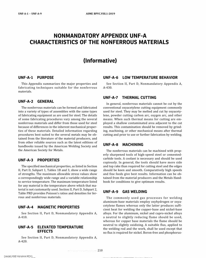
NONMANDATORY APPENDIX UNF-ACHARACTERISTICS OF THE NONFERROUS MATERIALS
(Informative)
UNF-A-1 PURPOSE
This Appendix summarizes the major properties andfabricating techniques suitable for the nonferrousmaterials.
UNF-A-2 GENERAL
The nonferrous materials can be formed and fabricatedinto a variety of types of assemblies with the same typesof fabricating equipment as are used for steel. The detailsof some fabricating procedures vary among the severalnonferrous materials and differ from those used for steelbecause of differences in the inherent mechanical proper-ties of these materials. Detailed information regardingprocedures best suited to the several metals may be ob-tained from the literature of the material producers, andfrom other reliable sources such as the latest editions ofhandbooks issued by the American Welding Society andthe American Society for Metals.
UNF-A-3 PROPERTIES
The specified mechanical properties, as listed in SectionII, Part D, Subpart 1, Tables 1B and 3, show a wide rangeof strengths. The maximum allowable stress values showa correspondingly wide range and a variable relationshipto service temperature. The maximum temperature listedfor any material is the temperature above which that ma-terial is not customarily used. Section II, Part D, Subpart 2,Table PRD provides Poisson’s ratios and densities for fer-rous and nonferrous materials.
UNF-A-4 MAGNETIC PROPERTIES
See Section II, Part D, Nonmandatory Appendix A,A-410.
UNF-A-5 ELEVATED TEMPERATUREEFFECTS
See Section II, Part D, Nonmandatory Appendix A,A-420.
UNF-A-6 LOW TEMPERATURE BEHAVIOR
See Section II, Part D, Nonmandatory Appendix A,A-430.
UNF-A-7 THERMAL CUTTING
In general, nonferrous materials cannot be cut by theconventional oxyacetylene cutting equipment commonlyused for steel. They may be melted and cut by oxyacety-lene, powder cutting carbon arc, oxygen arc, and othermeans. When such thermal means for cutting are em-ployed a shallow contaminated area adjacent to the cutresults. This contamination should be removed by grind-ing, machining, or other mechanical means after thermalcutting and prior to use or further fabrication by welding.
UNF-A-8 MACHINING
The nonferrous materials can be machined with prop-erly sharpened tools of high‐speed steel or cemented‐carbide tools. A coolant is necessary and should be usedcopiously. In general, the tools should have more sideand top rake than required for cutting steel and the edgesshould be keen and smooth. Comparatively high speedsand fine feeds give best results. Information can be ob-tained from the material producers and the Metals Hand-book for conditions to give optimum results.
UNF-A-9 GAS WELDING
The commonly used gas processes for weldingaluminum‐base materials employ oxyhydrogen or oxya-cetylene flames whereas only the latter produces suffi-cient heat for welding the copper‐base and nickel‐basealloys. For the aluminum, nickel and cupro‐nickel alloysa neutral to slightly reducing flame should be used,whereas for copper base materials the flame should beneutral to slightly oxidizing. A suitable flux, applied tothe welding rod and the work, shall be used except thatno flux is required for nickel. Boron‐free and phosphorus‐
210
ASME BPVC.VIII.1-2019UNF-A-1 – UNF-A-9
Copyright ASME International (BPVC) Provided by IHS under license with ASME Licensee=Khalda Petroleum/5986215001, User=Amer, Mohamed
Not for Resale, 07/02/2019 13:29:04 MDTNo reproduction or networking permitted without license from IHS
--`,``,``,,`,`,,````,`,``,,,`-`-`,,`,,`,`,,`---
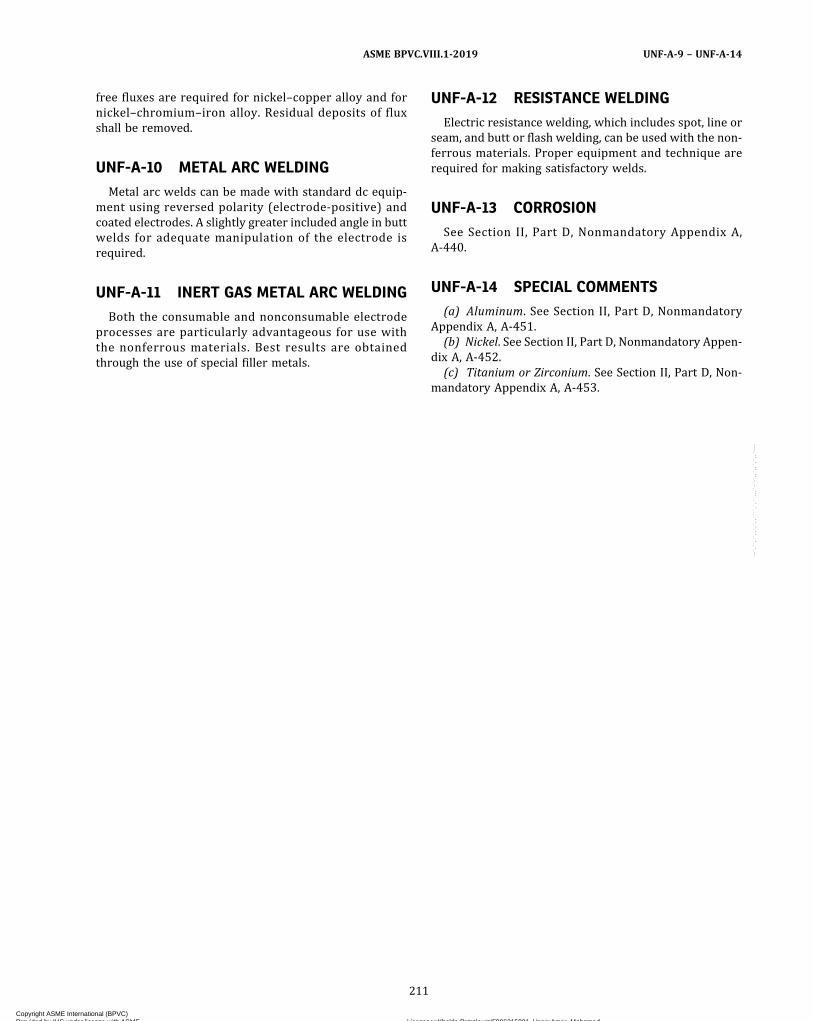
free fluxes are required for nickel–copper alloy and fornickel–chromium–iron alloy. Residual deposits of fluxshall be removed.
UNF-A-10 METAL ARC WELDING
Metal arc welds can be made with standard dc equip-ment using reversed polarity (electrode‐positive) andcoated electrodes. A slightly greater included angle in buttwelds for adequate manipulation of the electrode isrequired.
UNF-A-11 INERT GAS METAL ARC WELDING
Both the consumable and nonconsumable electrodeprocesses are particularly advantageous for use withthe nonferrous materials. Best results are obtainedthrough the use of special filler metals.
UNF-A-12 RESISTANCE WELDING
Electric resistance welding, which includes spot, line orseam, and butt or flash welding, can be used with the non-ferrous materials. Proper equipment and technique arerequired for making satisfactory welds.
UNF-A-13 CORROSION
See Section II, Part D, Nonmandatory Appendix A,A-440.
UNF-A-14 SPECIAL COMMENTS
(a) Aluminum. See Section II, Part D, NonmandatoryAppendix A, A-451.
(b) Nickel. See Section II, Part D, Nonmandatory Appen-dix A, A-452.
(c) Titanium or Zirconium. See Section II, Part D, Non-mandatory Appendix A, A-453.
211
ASME BPVC.VIII.1-2019 UNF-A-9 – UNF-A-14
Copyright ASME International (BPVC) Provided by IHS under license with ASME Licensee=Khalda Petroleum/5986215001, User=Amer, Mohamed
Not for Resale, 07/02/2019 13:29:04 MDTNo reproduction or networking permitted without license from IHS
--`,``,``,,`,`,,````,`,``,,,`-`-`,,`,,`,`,,`---

PART UHAREQUIREMENTS FOR PRESSURE VESSELS CONSTRUCTED OF
HIGH ALLOY STEEL
GENERAL
UHA-1 SCOPEThe rules in Part UHA are applicable to pressure ves-
sels and vessel parts that are constructed of high alloysteel and shall be used in conjunction with the general re-quirements in Subsection A, and with the specific require-ments in Subsection B that pertain to the method offabrication used.
UHA-5 USESSome of the uses of high alloy steel are to resist corro-
sion, to avoid contamination of contents with iron, to fa-cilitate cleaning of vessels for processing foods, toprovide strength or scaling resistance at high tempera-tures , and to provide impact resistance at lowtemperatures.
UHA-6 CONDITIONS OF SERVICESpecific chemical compositions, heat treatment proce-
dures, fabrication requirements, and supplementary testsmay be required to assure that the vessel will be in itsmost favorable condition for the intended service. Thisis particularly true for vessels subject to severe corrosion.These rules do not indicate the selection of an alloy suit-able for the intended service or the amount of the corro-sion allowance to be provided.It is recommended that users assure themselves by ap-
propriate tests, or otherwise, that the high alloy steel se-lected and its heat treatment during fabrication will besuitable for the intended service both with respect to cor-rosion resistance and to retention of satisfactory mechan-ical properties during the desired service life. (SeeNonmandatory Appendix UHA-A, Suggestions on the Se-lection and Treatment of Austenitic Chromium–NickelSteels.)
UHA-8 MATERIAL(a) Approved specifications for castings of high alloy
steel are given in Table UHA-23. A tabulation of allowablestress values at different temperatures is given in SectionII, Part D, Subpart 1, Table 3 for bolting and Table 1A forother materials. These stress values are to be multipliedby the casting quality factors of UG-24. Castings that areto be welded shall be of weldable grade.
(b) Cast high alloy steel flanges and fittings complyingwith ASME B16.5 shall be used within the ratings as-signed in these standards.
MATERIALS
UHA-11 GENERAL(a) All materials subject to stress due to pressure shall
conform to one of the specifications given in Section II,and shall be limited to those listed in Table UHA-23 ex-cept as otherwise provided in (b) and UG-4.(b) The specifications listed in Section II, Part D, Sub-
part 1, Tables 1A and 3 do not use a uniform system fordesignating the Grade number of materials that have ap-proximately the same range of chemical composition. Toprovide a uniform system of reference, these tables in-clude a column of UNS (Unified Numbering System) num-bers assigned to identify the various alloy compositions.When these particular UNS numbers were assigned, thefamiliar AISI type numbers for stainless steels were incor-porated into the designation. These type numbers areused in the rules of Part UHA whenever reference is madeto materials of approximately the same chemical compo-sition that are furnished under more than one approvedspecification or in more than one product form.
UHA-12 BOLT MATERIALS(a) Approved specifications for bolt materials of carbon
steel and low alloy steel are listed in Table UCS-23 and ofhigh alloy steel in Table UHA-23. A tabulation of allowablestress values at different temperatures (see UG-12) is giv-en in Section II, Part D, Subpart 1, Table 3.(b) Nonferrous bolts, studs, and nuts may be used pro-
vided they are suitable for the application. They shall con-form to the requirements of Part UNF.
UHA-13 NUTS AND WASHERSNuts and washers shall conform to the requirements in
UCS-11.
212
ASME BPVC.VIII.1-2019UHA-1 – UHA-13
Copyright ASME International (BPVC) Provided by IHS under license with ASME Licensee=Khalda Petroleum/5986215001, User=Amer, Mohamed
Not for Resale, 07/02/2019 13:29:04 MDTNo reproduction or networking permitted without license from IHS
--`,``,``,,`,`,,````,`,``,,,`-`-`,,`,,`,`,,`---

ð19Þ
ð19Þ
ð19ÞDESIGN
UHA-20 GENERALThe rules in the following paragraphs apply specifically
to the design of pressure vessels and vessel parts that areconstructed of high alloy steel and shall be used in con-junction with the general requirements for Design in Sub-section A, and with the specific requirements for Designin Subsection B that pertain to the method of fabricationused.
UHA-21 WELDED JOINTSWhen radiographic examination is required for butt-
welded joints by UHA-33, Category A and B joints (seeUW-3) shall be of Type Nos. (1) and (2) of Table UW-12.
UHA-23 MAXIMUM ALLOWABLE STRESSVALUES
(a) Section II, Part D, Subpart 1, Table 3 for bolting andTable 1A for other materials give the maximum allowablestress values at the temperatures indicated for the mate-rials conforming to the specifications listed therein. Val-ues may be interpolated for intermediate temperatures(see UG-23).
(b) Shells of pressure vessels may be made fromwelded pipe or tubing listed in Table UHA-23.
(c) For vessels designed to operate at a temperaturebelow −20°F (−30°C), the allowable stress values to beused in design shall not exceed those given in Section II,Part D, Subpart 1, Table 1A or Table 3 for temperaturesof −20°F to 100°F (−30°C to 40°C).
UHA-28 THICKNESS OF SHELLS UNDEREXTERNAL PRESSURE
Cylindrical and spherical shells under external pres-sure shall be designed by the rules in UG-28, using the ap-plicable figures in Section II, Part D, Subpart 3 and thetemperature limits of UG-20(c).
UHA-29 STIFFENING RINGS FOR SHELLS UNDEREXTERNAL PRESSURE
Rules covering the design of stiffening rings are given inUG-29.
UHA-30 ATTACHMENT OF STIFFENING RINGSTO SHELL
Rules covering the attachment of stiffening rings aregiven in UG-30.
UHA-31 FORMED HEADS, PRESSURE ONCONVEX SIDE
Ellipsoidal, torispherical, hemispherical, and conicalheads, having pressure on the convex side (minus heads),shall be designed by the rules of UG-33, using the applic-able figures in Section II, Part D, Subpart 3.
UHA-32 REQUIREMENTS FOR POSTWELD HEATTREATMENT
(a) Before applying the detailed requirements and ex-emptions in these paragraphs, satisfactory weld proce-dure qualifications of the procedures to be used shall beperformed in accordance with all the essential variablesof Section IX including conditions of postweld heat treat-ment or lack of postweld heat treatment and includingother restrictions listed below. Welds in pressure vesselsor pressure vessel parts shall be given a postweld heattreatment at a temperature not less than specified inTables UHA-32-1 through UHA-32-7 when the nominalthickness, as defined in UW-40(f), including corrosion al-lowance, exceeds the limits in the Notes to TablesUHA-32-1 through UHA-32-7. The exemptions providedfor in the Notes to Tables UHA-32-1 through UHA-32-7are not permitted when welding ferritic materials greaterthan 1/8 in. (3 mm) thick with the electron beam weldingprocess, or when welding P‐Nos. 6 and 7 (except for Type405 and Type 410S) materials of any thickness using theinertia and continuous drive friction welding processes.The materials in Tables UHA-32-1 through UHA-32-7are listed in accordance with the Section IX P‐Numbermaterial groupings of Section IX, Table QW-432 and arealso listed in Table UHA-23.
(b) Holding temperatures and/or holding times in ex-cess of the minimum values given in Tables UHA-32-1through UHA-32-7 may be used. The holding time at tem-perature as specified in Tables UHA-32-1 throughUHA-32-7 need not be continuous. It may be an accumu-lation of time of multiple postweld heat treat cycles. Longtime exposure to postweld heat treatment temperaturesmay cause sigma phase formation (see NonmandatoryAppendix UHA-A).
(c) When pressure parts of two different P‐Numbergroups are joined by welding, engineering judgment shallbe applied when selecting the postweld heat treatmenttemperature and holding time to produce material prop-erties suitable for the intended service. Alternatives suchas welding with buttering as described in Section IX,QW-283 may be considered. When nonpressure partsare welded to pressure parts, the postweld heat treat-ment temperature of the pressure part shall control. Fer-ritic steel parts, when used in conjunction with austeniticchromium–nickel stainless steel parts or austenitic/ferri-tic duplex steel, shall not be subjected to the solution heattreatment described in Nonmandatory Appendix UHA-A.
(d) The operation of postweld heat treatment shall becarried out by one of the procedures given in UW-40 inaccordance with the requirements of UCS-56(d) exceptas modified by the Notes to Tables UHA-32-1 throughUHA-32-7.
(e) Vessels or parts of vessels that have been postweldheat treated in accordance with the requirements of thisparagraph shall again be postweld heat treated after re-pairs have been made.
213
ASME BPVC.VIII.1-2019 UHA-20 – UHA-32
Copyright ASME International (BPVC) Provided by IHS under license with ASME Licensee=Khalda Petroleum/5986215001, User=Amer, Mohamed
Not for Resale, 07/02/2019 13:29:04 MDTNo reproduction or networking permitted without license from IHS
--`,``,``,,`,`,,````,`,``,,,`-`-`,,`,,`,`,,`---

ð19Þ Table UHA-23High Alloy Steel
Spec. No. UNS No. Type/Grade
SA-182 N08904 F904LS20910 FXM‐19S21904 FXM‐11S30400 F304S30403 F304LS30409 F304HS30453 F304LNS30815 F45S31000 F310S31050 F310MoLNS31254 F44S31266 F58S31600 F316S31603 F316LS31609 F316HS31700 F317S31703 F317LS31803 F51S32100 F321S32109 F321HS32202 F66S32205 F60S32750 …S32750 F53S32760 F55S34700 F347S34709 F347HS34800 F348S34809 F348HS39274 F54S41000 F6a Cl. 1 & 2S44627 FXM‐27Cb
SA-193 S21800 B8S, B8SAS30400 B8 Cl. 1 & 2S30451 B8NA Cl. 1AS30500 B8P Cl. 1 & 2S31600 B8M Cl. 1 & 2, B8M2
Cl. 2S31651 B8MNA Cl. 1AS32100 B8T Cl. 1 & 2S34700 B8C Cl. 1 & 2S41000 B6
SA-213 S20910 XM‐19S30400 TP304S30403 TP304LS30409 TP304HS30451 TP304NS30453 TP304LNS30815 …S30908 TP309SS30909 TP309HS30940 TP309CbS31008 TP310SS31009 TP310HS31040 TP310CbS31050 TP310MoLNS31254 …S31277 …S31600 TP316S31603 TP316L
Spec. No. UNS No. Type/Grade
SA-213 S31609 TP316HS31651 TP316NS31725 …S32100 TP321S32109 TP321HS34700 TP347S34709 TP347HS34751 TP347LNS34800 TP348S34809 TP348HS38100 XM‐15S38815 …
SA-217 J91150 CA15SA-240 N08904 904L
S20100 201‐1, 201‐2S20153 201LNS20400 204S20910 XM‐19S24000 XM‐29S30100 301S30200 302S30400 304S30403 304LS30409 304HS30451 304NS30453 304LNS30815 …S30908 309SS30909 309HS30940 309CbS31008 310SS31009 310HS31040 310CbS31050 310MoLNS31200 …S31254 …S31260 …S31266 …S31277 …S31600 316S31603 316LS31609 316HS31635 316TiS31640 316CbS31651 316NS31700 317S31703 317LS31725 …S31803 …S32003 …S32100 321S32101 …S32109 321HS32202 …S32205 2205S32304 …S32550 …S32750 …S32760 …S32900 329
Spec. No. UNS No. Type/Grade
SA-240 S32906 …S32950 …S34700 347S34709 347HS34800 348S38100 XM‐15S38815 …S40500 405S40910 …S40920 …S40930 …S41000 410S41008 410SS42900 429S43000 430S44400 …S44626 XM‐33S44627 XM‐27S44635 …S44660 26‐3‐3S44700 …S44800 …
SA-249 S20910 TPXM‐19S24000 TPXM‐29S30400 TP304S30403 TP304LS30409 TP304HS30451 TP304NS30453 TP304LNS30815 …S30908 TP309SS30909 TP309HS30940 TP309CbS31008 TP310SS31009 TP310HS31040 TP310CbS31050 TP310MoLNS31254 …S31277 …S31600 TP316S31603 TP316LS31609 TP316HS31651 TP316NS31700 TP317S31703 TP317LS31725 …S32100 TP321S32109 TP321HS34700 TP347S34709 TP347HS34800 TP348S34809 TP348HS38100 TPXM‐15S38815 …
SA-268 S40500 TP405S40800 …S40900 TP409S41000 TP410S42900 TP429S43000 TP430
214
ASME BPVC.VIII.1-2019UHA-32
Copyright ASME International (BPVC) Provided by IHS under license with ASME Licensee=Khalda Petroleum/5986215001, User=Amer, Mohamed
Not for Resale, 07/02/2019 13:29:04 MDTNo reproduction or networking permitted without license from IHS
--`,``,``,,`,`,,````,`,``,,,`-`-`,,`,,`,`,,`---
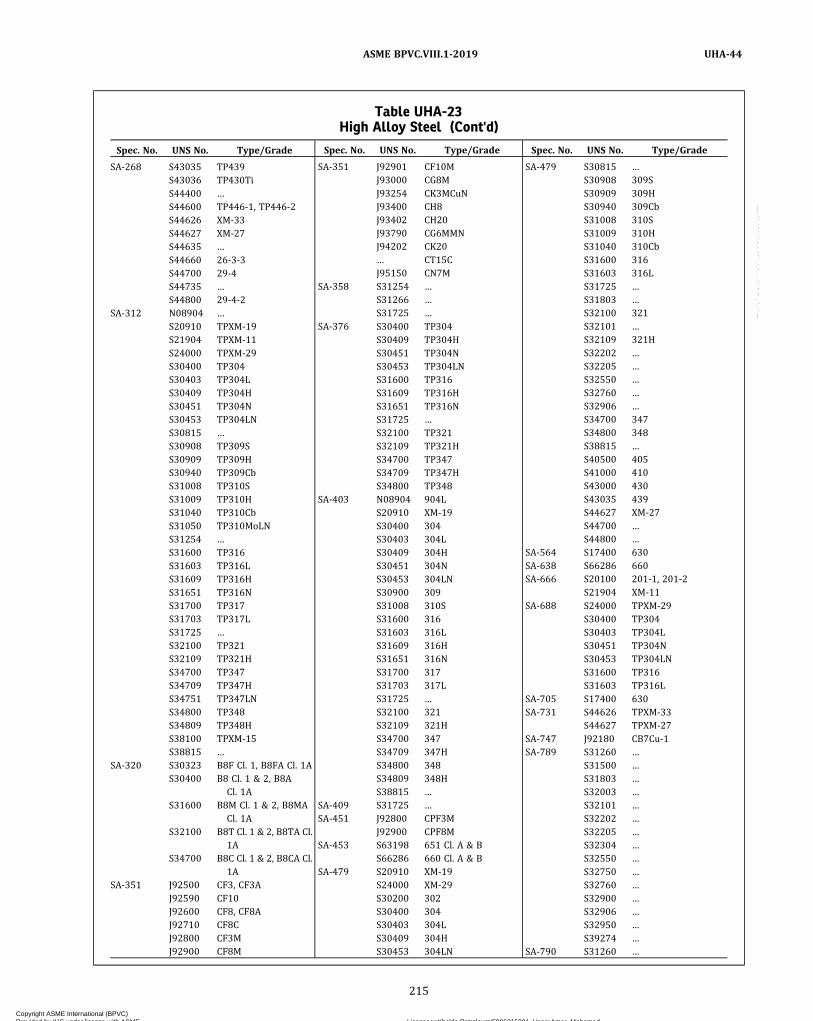
Table UHA-23High Alloy Steel (Cont'd)
Spec. No. UNS No. Type/Grade
SA-268 S43035 TP439S43036 TP430TiS44400 …S44600 TP446‐1, TP446‐2S44626 XM‐33S44627 XM‐27S44635 …S44660 26‐3‐3S44700 29‐4S44735 …S44800 29‐4‐2
SA-312 N08904 …S20910 TPXM‐19S21904 TPXM‐11S24000 TPXM‐29S30400 TP304S30403 TP304LS30409 TP304HS30451 TP304NS30453 TP304LNS30815 …S30908 TP309SS30909 TP309HS30940 TP309CbS31008 TP310SS31009 TP310HS31040 TP310CbS31050 TP310MoLNS31254 …S31600 TP316S31603 TP316LS31609 TP316HS31651 TP316NS31700 TP317S31703 TP317LS31725 …S32100 TP321S32109 TP321HS34700 TP347S34709 TP347HS34751 TP347LNS34800 TP348S34809 TP348HS38100 TPXM‐15S38815 …
SA-320 S30323 B8F Cl. 1, B8FA Cl. 1AS30400 B8 Cl. 1 & 2, B8A
Cl. 1AS31600 B8M Cl. 1 & 2, B8MA
Cl. 1AS32100 B8T Cl. 1 & 2, B8TA Cl.
1AS34700 B8C Cl. 1 & 2, B8CA Cl.
1ASA-351 J92500 CF3, CF3A
J92590 CF10J92600 CF8, CF8AJ92710 CF8CJ92800 CF3MJ92900 CF8M
Spec. No. UNS No. Type/Grade
SA-351 J92901 CF10MJ93000 CG8MJ93254 CK3MCuNJ93400 CH8J93402 CH20J93790 CG6MMNJ94202 CK20… CT15CJ95150 CN7M
SA-358 S31254 …S31266 …S31725 …
SA-376 S30400 TP304S30409 TP304HS30451 TP304NS30453 TP304LNS31600 TP316S31609 TP316HS31651 TP316NS31725 …S32100 TP321S32109 TP321HS34700 TP347S34709 TP347HS34800 TP348
SA-403 N08904 904LS20910 XM‐19S30400 304S30403 304LS30409 304HS30451 304NS30453 304LNS30900 309S31008 310SS31600 316S31603 316LS31609 316HS31651 316NS31700 317S31703 317LS31725 …S32100 321S32109 321HS34700 347S34709 347HS34800 348S34809 348HS38815 …
SA-409 S31725 …SA-451 J92800 CPF3M
J92900 CPF8MSA-453 S63198 651 Cl. A & B
S66286 660 Cl. A & BSA-479 S20910 XM‐19
S24000 XM‐29S30200 302S30400 304S30403 304LS30409 304HS30453 304LN
Spec. No. UNS No. Type/Grade
SA-479 S30815 …S30908 309SS30909 309HS30940 309CbS31008 310SS31009 310HS31040 310CbS31600 316S31603 316LS31725 …S31803 …S32100 321S32101 …S32109 321HS32202 …S32205 …S32550 …S32760 …S32906 …S34700 347S34800 348S38815 …S40500 405S41000 410S43000 430S43035 439S44627 XM‐27S44700 …S44800 …
SA-564 S17400 630SA-638 S66286 660SA-666 S20100 201‐1, 201‐2
S21904 XM‐11SA-688 S24000 TPXM‐29
S30400 TP304S30403 TP304LS30451 TP304NS30453 TP304LNS31600 TP316S31603 TP316L
SA-705 S17400 630SA-731 S44626 TPXM‐33
S44627 TPXM‐27SA-747 J92180 CB7Cu‐1SA-789 S31260 …
S31500 …S31803 …S32003 …S32101 …S32202 …S32205 …S32304 …S32550 …S32750 …S32760 …S32900 …S32906 …S32950 …S39274 …
SA-790 S31260 …
215
ASME BPVC.VIII.1-2019 UHA-44
Copyright ASME International (BPVC) Provided by IHS under license with ASME Licensee=Khalda Petroleum/5986215001, User=Amer, Mohamed
Not for Resale, 07/02/2019 13:29:04 MDTNo reproduction or networking permitted without license from IHS
--`,``,``,,`,`,,````,`,``,,,`-`-`,,`,,`,`,,`---
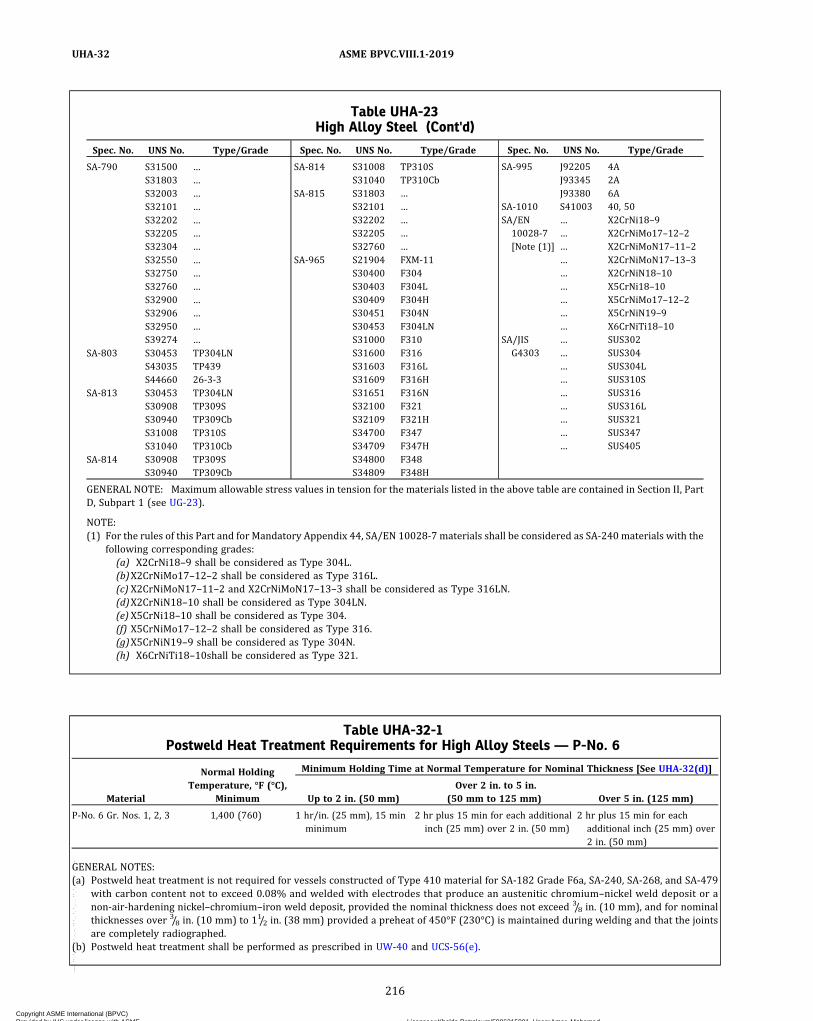
Table UHA-23High Alloy Steel (Cont'd)
Spec. No. UNS No. Type/Grade
SA-790 S31500 …S31803 …S32003 …S32101 …S32202 …S32205 …S32304 …S32550 …S32750 …S32760 …S32900 …S32906 …S32950 …S39274 …
SA-803 S30453 TP304LNS43035 TP439S44660 26‐3‐3
SA-813 S30453 TP304LNS30908 TP309SS30940 TP309CbS31008 TP310SS31040 TP310Cb
SA-814 S30908 TP309SS30940 TP309Cb
Spec. No. UNS No. Type/Grade
SA-814 S31008 TP310SS31040 TP310Cb
SA-815 S31803 …S32101 …S32202 …S32205 …S32760 …
SA-965 S21904 FXM‐11S30400 F304S30403 F304LS30409 F304HS30451 F304NS30453 F304LNS31000 F310S31600 F316S31603 F316LS31609 F316HS31651 F316NS32100 F321S32109 F321HS34700 F347S34709 F347HS34800 F348S34809 F348H
Spec. No. UNS No. Type/Grade
SA-995 J92205 4AJ93345 2AJ93380 6A
SA-1010 S41003 40, 50SA/EN10028‐7[Note (1)]
… X2CrNi18–9… X2CrNiMo17–12–2… X2CrNiMoN17–11–2… X2CrNiMoN17–13–3… X2CrNiN18–10… X5CrNi18–10… X5CrNiMo17–12–2… X5CrNiN19–9… X6CrNiTi18–10
SA/JISG4303
… SUS302… SUS304… SUS304L… SUS310S… SUS316… SUS316L… SUS321… SUS347… SUS405
GENERAL NOTE: Maximum allowable stress values in tension for the materials listed in the above table are contained in Section II, PartD, Subpart 1 (see UG-23).
NOTE:(1) For the rules of this Part and for Mandatory Appendix 44, SA/EN 10028-7 materials shall be considered as SA-240 materials with the
following corresponding grades:(a) X2CrNi18–9 shall be considered as Type 304L.(b)X2CrNiMo17–12–2 shall be considered as Type 316L.(c) X2CrNiMoN17–11–2 and X2CrNiMoN17–13–3 shall be considered as Type 316LN.(d)X2CrNiN18–10 shall be considered as Type 304LN.(e) X5CrNi18–10 shall be considered as Type 304.(f) X5CrNiMo17–12–2 shall be considered as Type 316.(g)X5CrNiN19–9 shall be considered as Type 304N.(h) X6CrNiTi18–10shall be considered as Type 321.
Table UHA-32-1Postweld Heat Treatment Requirements for High Alloy Steels — P-No. 6
Normal HoldingTemperature, °F (°C),
Minimum
Minimum Holding Time at Normal Temperature for Nominal Thickness [See UHA-32(d)]
Material Up to 2 in. (50 mm)Over 2 in. to 5 in.
(50 mm to 125 mm) Over 5 in. (125 mm)
P‐No. 6 Gr. Nos. 1, 2, 3 1,400 (760) 1 hr/in. (25 mm), 15 minminimum
2 hr plus 15 min for each additionalinch (25 mm) over 2 in. (50 mm)
2 hr plus 15 min for eachadditional inch (25 mm) over2 in. (50 mm)
GENERAL NOTES:(a) Postweld heat treatment is not required for vessels constructed of Type 410 material for SA-182 Grade F6a, SA-240, SA-268, and SA-479
with carbon content not to exceed 0.08% and welded with electrodes that produce an austenitic chromium–nickel weld deposit or anon‐air‐hardening nickel–chromium–iron weld deposit, provided the nominal thickness does not exceed 3/8 in. (10 mm), and for nominalthicknesses over 3/8 in. (10 mm) to 11/2 in. (38 mm) provided a preheat of 450°F (230°C) is maintained during welding and that the jointsare completely radiographed.
(b) Postweld heat treatment shall be performed as prescribed in UW-40 and UCS-56(e).
216
ASME BPVC.VIII.1-2019UHA-32
Copyright ASME International (BPVC) Provided by IHS under license with ASME Licensee=Khalda Petroleum/5986215001, User=Amer, Mohamed
Not for Resale, 07/02/2019 13:29:04 MDTNo reproduction or networking permitted without license from IHS
--`,``,``,,`,`,,````,`,``,,,`-`-`,,`,,`,`,,`---

ð19ÞTable UHA-32-2Postweld Heat Treatment Requirements for High Alloy Steels — P-No. 7
Normal HoldingTemperature, °F (°C),
Minimum
Minimum Holding Time at Normal Temperature for Nominal Thickness [See UHA-32(d)]
Material Up to 2 in. (50 mm)Over 2 in. to 5 in.
(50 mm to 125 mm) Over 5 in. (125 mm)
P‐No. 7 Gr. Nos. 1, 2 1,350 (730) 1 hr/in. (25 mm), 15 minminimum
2 hr plus 15 min for each additionalinch (25 mm) over 2 in. (50 mm)
2 hr plus 15 min for eachadditional inch (25 mm) over2 in. (50 mm)
GENERAL NOTES:(a) Postweld heat treatment is not required for vessels constructed of SA-1010 UNS S41003 Type 405, Type 410S, or Type 430 Ti materials for
SA-240 and SA-268 with carbon content not to exceed 0.08%, welded with electrodes that produce an austenitic–chromium–nickel welddeposit or a non‐air‐hardening nickel–chromium–iron weld deposit, provided the nominal thickness does not exceed 3/8 in. (10 mm) andfor thicknesses over 3/8 in. (10 mm) to 11/2 in. (38 mm) provided a preheat of 450°F (230°C) is maintained during welding and that thejoints are completely radiographed.
(b) Postweld heat treatment shall be performed as prescribed in UW-40 and UCS-56(e) except that the cooling rate shall be a maximum of100°F/hr (56°C/h) in the range above 1,200°F (650°C) after which the cooling rate shall be sufficiently rapid to prevent embrittlement.
(c) Postweld heat treatment is not required for vessels constructed of Grade TP XM-8 material for SA-268 and SA-479 or of Grade TP18Cr–2Mo for SA-240 and SA-268.
(d) The following alloys are exempt from PWHT: UNS S40910, S40920, S40930, S40935, S40936, S40945, S40975, S40977, S43932, andS43940.
ð19ÞTable UHA-32-3Postweld Heat Treatment Requirements for High Alloy Steels — P-No. 8
Material
Normal HoldingTemperature, °F (°C),
Minimum
Minimum Holding Time at Normal Temperature for Nominal Thickness [See UHA-32(d)]
Up to 2 in. (50 mm)Over 2 in. to 5 in.
(50 mm to 125 mm) Over 5 in. (125 mm)
P‐No. 8 Gr. Nos. 1, 2, 3, 4 … … … …
GENERAL NOTES:(a) Postweld heat treatment is neither required nor prohibited for joints between austenitic stainless steels of the P‐No. 8 group. See Non-
mandatory Appendix UHA-A.(b) If postweld heat treatment is performed for P-No. 8 materials, the Manufacturer shall consider the steps necessary to avoid embrittlement,
sensitization, and the precipitation of deleterious phases. See Section II, Part D, Nonmandatory Appendix A, A-207 through A-210.
217
ASME BPVC.VIII.1-2019 UHA-32
Copyright ASME International (BPVC) Provided by IHS under license with ASME Licensee=Khalda Petroleum/5986215001, User=Amer, Mohamed
Not for Resale, 07/02/2019 13:29:04 MDTNo reproduction or networking permitted without license from IHS
--`,``,``,,`,`,,````,`,``,,,`-`-`,,`,,`,`,,`---
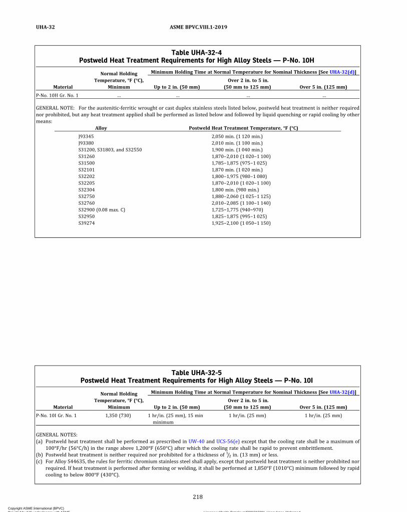
Table UHA-32-4Postweld Heat Treatment Requirements for High Alloy Steels — P-No. 10H
Material
Normal HoldingTemperature, °F (°C),
Minimum
Minimum Holding Time at Normal Temperature for Nominal Thickness [See UHA-32(d)]
Up to 2 in. (50 mm)Over 2 in. to 5 in.
(50 mm to 125 mm) Over 5 in. (125 mm)
P‐No. 10H Gr. No. 1 … … … …
GENERAL NOTE: For the austenitic‐ferritic wrought or cast duplex stainless steels listed below, postweld heat treatment is neither requirednor prohibited, but any heat treatment applied shall be performed as listed below and followed by liquid quenching or rapid cooling by othermeans:
Alloy Postweld Heat Treatment Temperature, °F (°C)
J93345 2,050 min. (1 120 min.)J93380 2,010 min. (1 100 min.)S31200, S31803, and S32550 1,900 min. (1 040 min.)S31260 1,870−2,010 (1 020−1 100)S31500 1,785−1,875 (975−1 025)S32101 1,870 min. (1 020 min.)S32202 1,800−1,975 (980−1 080)S32205 1,870−2,010 (1 020−1 100)S32304 1,800 min. (980 min.)S32750 1,880−2,060 (1 025−1 125)S32760 2,010−2,085 (1 100−1 140)S32900 (0.08 max. C) 1,725−1,775 (940−970)S32950 1,825−1,875 (995−1 025)S39274 1,925−2,100 (1 050−1 150)
Table UHA-32-5Postweld Heat Treatment Requirements for High Alloy Steels — P-No. 10I
Normal HoldingTemperature, °F (°C),
Minimum
Minimum Holding Time at Normal Temperature for Nominal Thickness [See UHA-32(d)]
Material Up to 2 in. (50 mm)Over 2 in. to 5 in.
(50 mm to 125 mm) Over 5 in. (125 mm)
P‐No. 10I Gr. No. 1 1,350 (730) 1 hr/in. (25 mm), 15 minminimum
1 hr/in. (25 mm) 1 hr/in. (25 mm)
GENERAL NOTES:(a) Postweld heat treatment shall be performed as prescribed in UW-40 and UCS-56(e) except that the cooling rate shall be a maximum of
100°F/hr (56°C/h) in the range above 1,200°F (650°C) after which the cooling rate shall be rapid to prevent embrittlement.(b) Postweld heat treatment is neither required nor prohibited for a thickness of 1/2 in. (13 mm) or less.(c) For Alloy S44635, the rules for ferritic chromium stainless steel shall apply, except that postweld heat treatment is neither prohibited nor
required. If heat treatment is performed after forming or welding, it shall be performed at 1,850°F (1010°C) minimum followed by rapidcooling to below 800°F (430°C).
218
ASME BPVC.VIII.1-2019UHA-32
Copyright ASME International (BPVC) Provided by IHS under license with ASME Licensee=Khalda Petroleum/5986215001, User=Amer, Mohamed
Not for Resale, 07/02/2019 13:29:04 MDTNo reproduction or networking permitted without license from IHS
--`,``,``,,`,`,,````,`,``,,,`-`-`,,`,,`,`,,`---
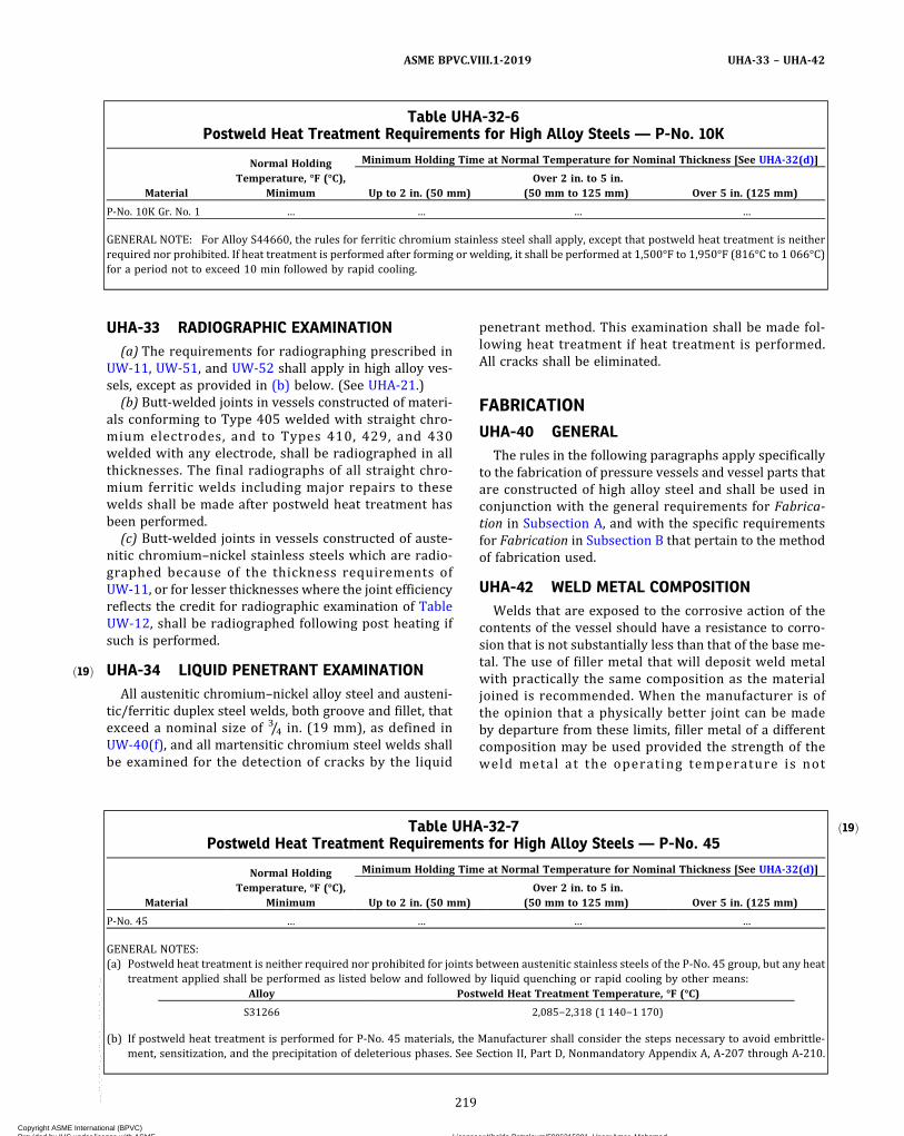
ð19Þ
UHA-33 RADIOGRAPHIC EXAMINATION(a) The requirements for radiographing prescribed in
UW-11, UW-51, and UW-52 shall apply in high alloy ves-sels, except as provided in (b) below. (See UHA-21.)
(b) Butt-welded joints in vessels constructed of materi-als conforming to Type 405 welded with straight chro-mium electrodes, and to Types 410, 429, and 430welded with any electrode, shall be radiographed in allthicknesses. The final radiographs of all straight chro-mium ferritic welds including major repairs to thesewelds shall be made after postweld heat treatment hasbeen performed.
(c) Butt-welded joints in vessels constructed of auste-nitic chromium–nickel stainless steels which are radio-graphed because of the thickness requirements ofUW-11, or for lesser thicknesses where the joint efficiencyreflects the credit for radiographic examination of TableUW-12, shall be radiographed following post heating ifsuch is performed.
UHA-34 LIQUID PENETRANT EXAMINATIONAll austenitic chromium–nickel alloy steel and austeni-
tic/ferritic duplex steel welds, both groove and fillet, thatexceed a nominal size of 3/4 in. (19 mm), as defined inUW-40(f), and all martensitic chromium steel welds shallbe examined for the detection of cracks by the liquid
penetrant method. This examination shall be made fol-lowing heat treatment if heat treatment is performed.All cracks shall be eliminated.
FABRICATION
UHA-40 GENERALThe rules in the following paragraphs apply specifically
to the fabrication of pressure vessels and vessel parts thatare constructed of high alloy steel and shall be used inconjunction with the general requirements for Fabrica-tion in Subsection A, and with the specific requirementsfor Fabrication in Subsection B that pertain to the methodof fabrication used.
UHA-42 WELD METAL COMPOSITIONWelds that are exposed to the corrosive action of the
contents of the vessel should have a resistance to corro-sion that is not substantially less than that of the base me-tal. The use of filler metal that will deposit weld metalwith practically the same composition as the materialjoined is recommended. When the manufacturer is ofthe opinion that a physically better joint can be madeby departure from these limits, filler metal of a differentcomposition may be used provided the strength of theweld metal at the operating temperature is not
Table UHA-32-6Postweld Heat Treatment Requirements for High Alloy Steels — P-No. 10K
Material
Normal HoldingTemperature, °F (°C),
Minimum
Minimum Holding Time at Normal Temperature for Nominal Thickness [See UHA-32(d)]
Up to 2 in. (50 mm)Over 2 in. to 5 in.
(50 mm to 125 mm) Over 5 in. (125 mm)
P‐No. 10K Gr. No. 1 … … … …
GENERAL NOTE: For Alloy S44660, the rules for ferritic chromium stainless steel shall apply, except that postweld heat treatment is neitherrequired nor prohibited. If heat treatment is performed after forming or welding, it shall be performed at 1,500°F to 1,950°F (816°C to 1 066°C)for a period not to exceed 10 min followed by rapid cooling.
ð19ÞTable UHA-32-7Postweld Heat Treatment Requirements for High Alloy Steels — P-No. 45
Material
Normal HoldingTemperature, °F (°C),
Minimum
Minimum Holding Time at Normal Temperature for Nominal Thickness [See UHA-32(d)]
Up to 2 in. (50 mm)Over 2 in. to 5 in.
(50 mm to 125 mm) Over 5 in. (125 mm)
P‐No. 45 … … … …
GENERAL NOTES:(a) Postweld heat treatment is neither required nor prohibited for joints between austenitic stainless steels of the P-No. 45 group, but any heat
treatment applied shall be performed as listed below and followed by liquid quenching or rapid cooling by other means:Alloy Postweld Heat Treatment Temperature, °F (°C)
S31266 2,085−2,318 (1 140−1 170)
(b) If postweld heat treatment is performed for P-No. 45 materials, the Manufacturer shall consider the steps necessary to avoid embrittle-ment, sensitization, and the precipitation of deleterious phases. See Section II, Part D, Nonmandatory Appendix A, A-207 through A-210.
219
ASME BPVC.VIII.1-2019 UHA-33 – UHA-42
Copyright ASME International (BPVC) Provided by IHS under license with ASME Licensee=Khalda Petroleum/5986215001, User=Amer, Mohamed
Not for Resale, 07/02/2019 13:29:04 MDTNo reproduction or networking permitted without license from IHS
--`,``,``,,`,`,,````,`,``,,,`-`-`,,`,,`,`,,`---

ð19Þ
appreciably less than that of the high alloy material to bewelded, and the user is satisfied that its resistance to cor-rosion is satisfactory for the intended service. The colum-bium content of weld metal shall not exceed 1.00%,except that ENiCrMo‐3, ERNiCrMo‐3, and ENiCrMo‐12weld filler metal made to SFA-5.11 and SFA-5.14 maybe used to weld S31254, S31603, S31703, S31725, andS31726 to a maximum design temperature of 900°F(482°C).
UHA-44 REQUIREMENTS FORPOSTFABRICATION HEAT TREATMENTDUE TO STRAINING
(a) The following rules shall apply in addition to gener-al rules for forming given in UHA-40.
(1) If the following conditions prevail, the coldformed areas of pressure‐retaining components manufac-tured of austenitic alloys shall be solution annealed byheating at the temperatures given in Table UHA-44 for20 min/in. (20 min/25 mm) of thickness followed by ra-pid cooling:
(-a) the finishing‐forming temperature is belowthe minimum heat‐treating temperature given in TableUHA-44; and
(-b) the design metal temperature and the formingstrains exceed the limits shown in Table UHA-44.
(2) Forming strains shall be determined by the equa-tions in Table UG-79-1.(b)When forming strains cannot be calculated as
shown in (a) above, the Manufacturer shall have the re-sponsibility to determine the maximum forming strain.For flares, swages, or upsets, heat treatment in accor-dance with Table UHA-44 shall apply, regardless of theamount of strain.
INSPECTION AND TESTS
UHA-50 GENERALThe rules in the following paragraphs apply specifically
to the inspection and testing of pressure vessels and ves-sel parts that are constructed of high alloy steel and shallbe used in conjunction with the general requirements forInspection and Tests in Subsection A, and with the specificrequirements for Inspection and Tests in Subsection B thatpertain to the method of fabrication used.
UHA-51 IMPACT TESTSImpact tests, as prescribed in (a), shall be performed
on materials listed in Table UHA-23 for all combinationsof materials and minimum design metal temperatures(MDMTs) except as exempted in (d), (e), (f), (g), (h), or(i). Impact testing is required for UNS S17400 materials.Impact tests are not required where the maximum obtain-able Charpy specimen has a width along the notch lessthan 0.099 in. (2.5 mm). As an alternative method to im-pact tests, ASTM E1820 J I C tests are allowed when the
MDMT is colder than −320°F (−196°C). See FiguresJJ-1.2-1 through JJ-1.2-5 for flowchart illustrations of im-pact testing requirements.(a) Requ i r ed Impac t Te s t i ng o f Ba s e Me ta l ,
Heat‐Affected Zones, and Weld Metal(1) Impact test shall be made from sets of three spe-
cimens. A set shall be tested from the base metal, a setshall be tested from the heat-affected zone (HAZ), and aset shall be tested from the weld metal. Specimens shallbe subjected to the same thermal treatments79 as the partor vessel that the specimens represent. Test procedures,size, location, and orientation of the specimens shall bethe same as required in UG-84.
(2)When the MDMT is −320°F (−196°C) and war-mer, impact tests shall be performed at the MDMT orcolder, and the following requirements shall be met:
(-a) Each of the three specimens tested in each setshall have a lateral expansion opposite the notch not lessthan 0.015 in. (0.38 mm) for MDMTs of −320°F (−196°C)and warmer.
(-b) When the MDMT is −320°F (−196°C) and war-mer, and the value of lateral expansion for one specimenof a set is less than 0.015 in. (0.38 mm) but not less than0.010 in. (0.25 mm), a retest of three additional speci-mens may be made, each of which must equal or exceed0.015 in. (0.38 mm). Such a retest shall be permitted onlywhen the average value of the three specimens equals orexceeds 0.015 in. (0.38 mm). If the required values arenot obtained in the retest or if the values in the initial testare less than minimum required for retest, the materialmay be reheat treated. After reheat treatment, new setsof specimens shall be made and retested; all specimensmust meet the lateral expansion value of 0.015 in.minimum.
(3)When the MDMT is colder than −320°F (−196°C),production welding processes shall be limited to shieldedmetal arc welding (SMAW), gas metal arc welding(GMAW), submerged arc welding (SAW), plasma arcwelding (PAW), and gas tungsten arc welding (GTAW).Each heat, lot, or batch of filler metal and filler metal/fluxcombination shall be pre‐use tested as required by(f)(4)(-a) through (f)(4)(-c). Exemption from pre‐use test-ing as allowed by (f)(4)(-d) and (f)(4)(-e) is not applic-able. Notch toughness testing shall be performed asspecified in (-a) or (-b) below, as appropriate.
(-a) If using Type 316L weld filler metal, or Type308L filler metal welded with the GTAW or GMAWprocess
(-1) weld metal deposited from each heat ofType 316L filler metal shall have a Ferrite Number (FN)not greater than 10, and a weld metal deposited fromeach heat of Type 308L filler metal shall have a FN inthe range of 4 to 14, as measured by a ferritescope ormagna gauge calibrated in accordance with AWS A4.2,or as determined by applying the chemical compositionfrom the test weld to Figure UHA-51-1
220
ASME BPVC.VIII.1-2019UHA-42 – UHA-51
Copyright ASME International (BPVC) Provided by IHS under license with ASME Licensee=Khalda Petroleum/5986215001, User=Amer, Mohamed
Not for Resale, 07/02/2019 13:29:04 MDTNo reproduction or networking permitted without license from IHS
--`,``,``,,`,`,,````,`,``,,,`-`-`,,`,,`,`,,`---

Table UHA-44Postfabrication Strain Limits and Required Heat Treatment
GradeUNS
Number
Limitations in Lower Temperature Range Limitations in HigherTemperature Range
Minimum Heat‐TreatmentTemperature, °F (°C), WhenDesign Temperature andForming Strain Limits AreExceeded [Note (1)] and
[Note (2)]
For Design Temperature, °F (°C)
And FormingStrains
Exceeding, %ExceedingBut Less Than or
Equal to
For DesignTemperature,
°F (°C),Exceeding
And FormingStrains
Exceeding, %
201‐1 S20100heads
All All All All All 1,950 (1 065)
201‐1 S20100 allothers
All All 4 All 4 1,950 (1 065)
201‐2 S20100heads
All All All All All 1,950 (1 065)
201‐2 S20100 allothers
All All 4 All 4 1,950 (1 065)
201LN S20153heads
All All All All All 1,950 (1 065)
201LN S20153 allothers
All All 4 All 4 1,950 (1 065)
204 S20400heads
All All All All All 1,950 (1 065)
204 S20400 allothers
All All 4 All 4 1,950 (1 065)
304 S30400 1,075 (580) 1,250 (675) 20 1,250 (675) 10 1,900 (1 040)304H S30409 1,075 (580) 1,250 (675) 20 1,250 (675) 10 1,900 (1 040)304L S30403 1,075 (580) 1,250 (675) 20 1,250 (675) 10 1,900 (1 040)304N S30451 1,075 (580) 1,250 (675) 15 1,250 (675) 10 1,900 (1 040)309S S30908 1,075 (580) 1,250 (675) 20 1,250 (675) 10 2,000 (1 095)310H S31009 1,075 (580) 1,250 (675) 20 1,250 (675) 10 2,000 (1 095)310S S31008 1,075 (580) 1,250 (675) 20 1,250 (675) 10 2,000 (1 095)316 S31600 1,075 (580) 1,250 (675) 20 1,250 (675) 10 1,900 (1 040)316H S31609 1,075 (580) 1,250 (675) 20 1,250 (675) 10 1,900 (1 040)316N S31651 1,075 (580) 1,250 (675) 15 1,250 (675) 10 1,900 (1 040)321 S32100 1,000 (540) 1,250 (675) 15 [Note (3)] 1,250 (675) 10 1,900 (1 040)321H S32109 1,000 (540) 1,250 (675) 15 [Note (3)] 1,250 (675) 10 2,000 (1 095)347 S34700 1,000 (540) 1,250 (675) 15 1,250 (675) 10 1,900 (1 040)347H S34709 1,000 (540) 1,250 (675) 15 1,250 (675) 10 2,000 (1 095)347LN S34751 1,000 (540) 1,250 (675) 15 1,250 (675) 10 1,900 (1 040)348 S34800 1,000 (540) 1,250 (675) 15 1,250 (675) 10 1,900 (1 040)348H S34809 1,000 (540) 1,250 (675) 15 1,250 (675) 10 2,000 (1 095)
GENERAL NOTES:(a) The limits shown are for cylinders formed from plates, spherical or dished heads formed from plate, and tube and pipe bends.(b) When the forming strains cannot be calculated as shown in UHA-44(a), the forming strain limits shall be half those tabulated in this Table
[see UHA-44(b)].
NOTES:(1) Rate of cooling from heat‐treatment temperature is not subject to specific control limits.(2) While minimum heat‐treatment temperatures are specified, it is recommended that the heat‐treatment temperature range be limited to
150°F (85°C) above that minimum [250°F (140°C) for 347, 347H, 347LN, 348, and 348H].(3) For simple bends of tubes or pipes whose outside diameter is less than 3.5 in. (88 mm), this limit is 20%.
221
ASME BPVC.VIII.1-2019 UHA-51
Copyright ASME International (BPVC) Provided by IHS under license with ASME Licensee=Khalda Petroleum/5986215001, User=Amer, Mohamed
Not for Resale, 07/02/2019 13:29:04 MDTNo reproduction or networking permitted without license from IHS
--`,``,``,,`,`,,````,`,``,,,`-`-`,,`,,`,`,,`---
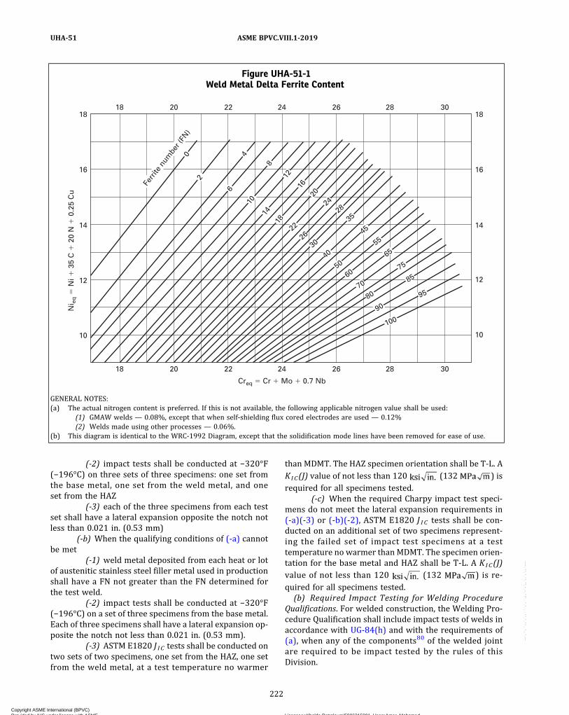
(-2) impact tests shall be conducted at −320°F(−196°C) on three sets of three specimens: one set fromthe base metal, one set from the weld metal, and oneset from the HAZ
(-3) each of the three specimens from each testset shall have a lateral expansion opposite the notch notless than 0.021 in. (0.53 mm)
(-b) When the qualifying conditions of (-a) cannotbe met
(-1) weld metal deposited from each heat or lotof austenitic stainless steel filler metal used in productionshall have a FN not greater than the FN determined forthe test weld.
(-2) impact tests shall be conducted at −320°F(−196°C) on a set of three specimens from the base metal.Each of three specimens shall have a lateral expansion op-posite the notch not less than 0.021 in. (0.53 mm).
(-3) ASTM E1820 J IC tests shall be conducted ontwo sets of two specimens, one set from the HAZ, one setfrom the weld metal, at a test temperature no warmer
than MDMT. The HAZ specimen orientation shall be T-L. AKIC(J) value of not less than 120 (132 ) isrequired for all specimens tested.
(-c) When the required Charpy impact test speci-mens do not meet the lateral expansion requirements in(-a)(-3) or (-b)(-2), ASTM E1820 J I C tests shall be con-ducted on an additional set of two specimens represent-ing the failed set of impact test specimens at a testtemperature no warmer than MDMT. The specimen orien-tation for the base metal and HAZ shall be T-L. A KIC(J)value of not less than 120 (132 ) is re-quired for all specimens tested.(b) Required Impact Testing for Welding Procedure
Qualifications. For welded construction, the Welding Pro-cedure Qualification shall include impact tests of welds inaccordance with UG-84(h) and with the requirements of(a), when any of the components80 of the welded jointare required to be impact tested by the rules of thisDivision.
Figure UHA-51-1Weld Metal Delta Ferrite Content
18
10
12
14
16
18
10
12
14
16
18
20 22 24
Creq � Cr � Mo � 0.7 Nb
Ni e
q �
Ni �
35
C �
20
N �
0.2
5 C
u
26 28 30
18 20
Ferr
ite n
umbe
r (FN
)0
22 24 26 28 30
2
4
6
8
12
16
18
14
10
20
24
22
26
28
30
35
40
45
50
70
80
90
100
55
65
75
85
95
60
GENERAL NOTES:(a) The actual nitrogen content is preferred. If this is not available, the following applicable nitrogen value shall be used:
(1) GMAW welds — 0.08%, except that when self-shielding flux cored electrodes are used — 0.12%(2) Welds made using other processes — 0.06%.
(b) This diagram is identical to the WRC‐1992 Diagram, except that the solidification mode lines have been removed for ease of use.
222
ASME BPVC.VIII.1-2019UHA-51
Copyright ASME International (BPVC) Provided by IHS under license with ASME Licensee=Khalda Petroleum/5986215001, User=Amer, Mohamed
Not for Resale, 07/02/2019 13:29:04 MDTNo reproduction or networking permitted without license from IHS
--`,``,``,,`,`,,````,`,``,,,`-`-`,,`,,`,`,,`---

ð19Þ
(c) Required Impact Testing When Thermal TreatmentsAre Performed. Impact tests are required at the test tem-perature in accordance with (a) but not warmer than70°F (20°C) whenever thermal treatments79 within thetemperature ranges listed for the following materialsare applied:
(1) austenitic stainless steels thermally treated attemperatures between 900°F (480°C) and 1650°F(900°C); however, Types 304, 304L, 316, and 316L thatare thermally treated at temperatures between 900°F(480°C) and 1,300°F (705°C) are exempt from impacttesting provided the MDMT is −20°F (−29°C) or warmerand vessel (production) impact tests of the thermallytreated weld metal are performed for Category A and Bjoints;
(2) austenitic‐ferritic duplex stainless steels ther-mally treated at temperatures between 600°F (315°C)and 1,750°F (955°C);
(3) ferritic chromium stainless steels thermally treat-ed at temperatures between 800°F (425°C) and 1,350°F(730°C);
(4)martensitic chromium stainless steels thermallytreated at temperatures between 800°F (425°C) and1,350°F (730°C).
(d) Exemptions from Impact Testing for Base Metals andHAZs. Impact testing is not required for Table UHA-23base metals for the following combinations of base metalsand HAZs (if welded) and MDMTs, except as modified in(c):
(1) for austenitic chromium–nickel stainless steels asfollows:
(-a) having a carbon content not exceeding 0.10%at MDMTs of −320°F (−196°C) and warmer;
(-b) having carbon content exceeding 0.10% atMDMTs of −55°F (−48°C) and warmer;
(-c) for castings at MDMTs of −20°F (−29°C) andwarmer;
(2) for austenitic chromium–manganese–nickelstainless steels (200 series) as follows:
(-a) having a carbon content not exceeding 0.10%at MDMTs of −320°F (−196°C) and warmer;
(-b) having a carbon content exceeding 0.10% atMDMTs of −55°F (−48°C) and warmer;
(-c) for castings at MDMTs of −20°F (−29°C) andwarmer;
(3) for the following steels in all product forms atMDMTs of −20°F (−29°C) and warmer:
(-a) austenitic ferritic duplex steels with a nom-inal material thickness of 3/8 in. (10 mm) and thinner;
(-b) ferritic chromium stainless steels with a nom-inal material thickness of 1/8 in. (3 mm) and thinner;
(-c) martensitic chromium stainless steels with anominal material thickness of 1/4 in. (6 mm) and thinner.
The nominal thickness of plates and pipes as definedin Mandatory Appendix 3 shall be used for determiningthe nominal material thickness for toughness require-ments. For other product forms, the nominal materialthickness shall be determined as follows:
– castings: maximum thickness between two castcoincidental surfaces
– hollow cylindrical forgings: maximum radialthickness
– disk forgings: maximum thickness, including thelength of an integral hub if a hub is present
– weld neck flanges: the larger of the thickness ofthe flange ring or the neck
Carbon content as used in (1) and (2) above is as spe-cified by the purchaser and must be within the limits ofthe material specification.
(e) Exemptions from Impact Testing for Welding Proce-dure Qualifications. For Welding Procedure Qualifications,impact testing is not required for the following combina-tions of weld metals and MDMTs except as modified in(c):
(1) for austenitic chromium–nickel stainless steelbase materials having a carbon content not exceeding0.10% welded without the addition of filler metal, atMDMTs of −155°F (−104°C) and warmer;
(2) for austenitic weld metal:(-a) having a carbon content not exceeding 0.10%
and produced with filler metals conforming to SFA-5.4,SFA-5.9, SFA-5.11, SFA-5.14, and SFA-5.22 at MDMTs of−155°F (−104°C) and warmer;
(-b) having a carbon content exceeding 0.10% andproduced with filler metals conforming to SFA-5.4,SFA-5.9, SFA-5.11, SFA-5.14, and SFA-5.22 at MDMTs of−55°F (−48°C) and warmer;
(3) for the following weld metal, when the base metalof similar chemistry is exempt as stated in (d)(3), thenthe weld metal shall also be exempt at MDMTs of −20°F(−29°C) and warmer:
(-a) austenitic ferritic duplex steels;(-b) ferritic chromium stainless steels;(-c) martensitic chromium stainless steels.
Carbon content as used in (2) above is for weld metalproduced with the addition of filler metal.
(f) Required Impact Testing for Austenitic StainlessSteel Welding Consumables With MDMTs Colder Than−155°F (−104°C). For production welds at MDMTs colderthan −155°F (−104°C), all of the following conditions shallbe satisfied:
(1) The welding processes are limited to SMAW,SAW, GMAW, GTAW, and PAW.
(2) The applicable Welding Procedure Specifications(WPSs) are supported by Procedure Qualification Records(PQRs) with impact testing in accordance with the re-quirements of (a) or when the applicable PQR is ex-empted from impact testing by other provisions of thisDivision.
223
ASME BPVC.VIII.1-2019 UHA-51
Copyright ASME International (BPVC) Provided by IHS under license with ASME Licensee=Khalda Petroleum/5986215001, User=Amer, Mohamed
Not for Resale, 07/02/2019 13:29:04 MDTNo reproduction or networking permitted without license from IHS
--`,``,``,,`,`,,````,`,``,,,`-`-`,,`,,`,`,,`---

(3) The weld metal (produced with or without theaddition of filler metal) has a carbon content not exceed-ing 0.10%.
(4) The weld metal is produced by filler metal con-forming to SFA-5.4, SFA-5.9, SFA-5.11, SFA-5.14, andSFA-5.22 as modified below.
(-a) Each heat and/or lot of welding consumablesto be used in production welding with the SMAW andGMAW processes shall be pre‐use tested by conductingimpact tests in accordance with the requirements of (a).Test coupons shall be prepared in accordance with Sec-tion II, Part C, SFA-5.4, A9.3.5 utilizing the WPS to be usedin production welding.
(-b) Each heat of filler metal and batch of flux com-bination to be used in production welding with the SAWprocess shall be pre‐use tested by conducting impact testsin accordance with the requirements of (a). Test couponsshall be prepared in accordance with Section II, Part C,SFA-5.4, A9.3.5 utilizing the WPS to be used in productionwelding.
(-c) Combining more than one welding process ormore than one heat, lot, and/or batch of welding materialinto a single test coupon is unacceptable. Pre‐use testingin accordance with the requirements of (a) may be con-ducted by the welding consumable manufacturer, pro-vided mil l test reports are furnished with theconsumables.
(-d) The following filler metals may be used with-out pre‐use testing of each heat, lot, and/or batch, pro-vided that procedure qualification impact testing inaccordance with UG-84(h) at the MDMT or colder is per-formed using the samemanufacturer brand and type fillermetal: ENiCrFe‐2, ENiCrFe‐3, ENiCrMo‐3, ENiCrMo‐4,ENiCrMo‐6, ERNiCr‐3, ERNiCrMo‐3, ERNiCrMo‐4,SFA-5.4 E310‐15 or 16.
(-e) The following filler metals may be used with-out pre‐use testing of each heat and/or lot, provided thatprocedure qualification impact testing in accordance withUG-84(h) at the MDMT or colder is performed: ER308L,ER316L, and ER310 used with the GTAW or PAWprocesses.(g) Exemption From Impact Testing Because of Low
Stress . Impact testing of materials listed in TableUHA-23 is not required, except as modified by (c), for ves-sels when the coincident ratio of design stress81 in ten-sion to allowable tensile stress is less than 0.35. Thisexemption also applies to the welding procedures andproduction welds for the component.
(h) Vessel (Production) Impact Tests(1) For welded construction of duplex stainless
steels, ferritic stainless steels, and martensitic stainlesssteels, vessel (production) impact tests in accordancewith UG-84(i) are required if the Weld Procedure Qualifi-cation requires impact testing, unless otherwise ex-empted by the rules of this Division.
(2) For welded construction of austenitic stainlesssteels, vessel (production) impact tests in accordancewith UG-84(i) are required unless exempted in (-a) and(-b) below.
(-a) At MDMTs of −155°F (−104°C) and warmer,vessel (production) impact tests are exempted providedthat the impact test exemption requirements for the ap-plicable Weld Procedure Qualification in (e) are satisfied.
(-b) At MDMTs colder than −155°F (−104°C) butnot colder than −320°F (−196°C), vessel (production) im-pact tests are exempted provided that the preuse test re-quirements in (f) are satisfied.
(-c) At MDMTs colder than −320°F (−196°C), ves-sel (production) impact tests or ASTM E1820 J I C testsshall be conducted in accordance with (a)(3).(i) Vessel (Production) Impact Tests for Autogenous
Welds in Austenitic Stainless Steels. For autogenous welds(welded without filler metal) in austenitic stainless steels,vessel (production) impact tests are not required whenboth of the following conditions are satisfied:
(1) The material is solution annealed after welding.(2) The MDMT is not colder than −320°F (−196°C).
UHA-52 WELDED TEST PLATES(a) For welded vessels constructed of Type 405 materi-
al which are not postweld heat treated, welded test platesshall be made to include material from each melt of platesteel used in the vessel. Plates from two different meltsmay be welded together and be represented by a singletest plate.(b) From each welded test plate there shall be taken
two face‐bend test specimens as prescribed in SectionIX, Figure QW-461.2; these shall meet the requirementsof Section IX, QW-160.
MARKING AND REPORTS
UHA-60 GENERALThe provisions for marking and reports in UG-115
through UG-120 shall apply without supplement to ves-sels constructed of high alloy steels.
224
ASME BPVC.VIII.1-2019UHA-51 – UHA-60
Copyright ASME International (BPVC) Provided by IHS under license with ASME Licensee=Khalda Petroleum/5986215001, User=Amer, Mohamed
Not for Resale, 07/02/2019 13:29:04 MDTNo reproduction or networking permitted without license from IHS
--`,``,``,,`,`,,````,`,``,,,`-`-`,,`,,`,`,,`---
ð19ÞNONMANDATORY APPENDIX UHA-ASUGGESTIONS ON THE SELECTION AND TREATMENT OFAUSTENITIC CHROMIUM–NICKEL AND FERRITIC AND
MARTENSITIC HIGH CHROMIUM STEELS
(Informative)
UHA-A-1 GENERAL
The selection of the proper metal composition to resista given corrosive medium and the choice of the properheat treatment and surface preparation of the materialselected are not within the scope of this Division. SectionII, Part D, Nonmandatory Appendix A discusses some ofthe factors that should be considered in arriving at aproper selection.
UHA-A-2 DISSIMILAR WELD METAL
The difference between the coefficients of expansion ofthe base material and the weld should receive careful con-sideration before undertaking the welding of ferritic typestainless steels with austenitic electrodes for services in-volving severe temperature conditions, particularly thoseof a cyclic nature.
UHA-A-3 FABRICATION
It is recommended that the user of austeniticchromium–nickel steel vessels in corrosive service con-sider the following additional fabrication test.
A welded guided‐bend test specimen should be made asprescribed in Section IX, QW-161.2 from one of the heatsof material used in the shell. The test plate should bewelded by the procedure used in the longitudinal jointsof the vessel and should be heat treated using the sametemperature cycle as used for the vessel. The operationson the test plate should be such as to duplicate as closelyas possible the physical conditions of the material in thevessel itself.
Grind and polish the specimen and immerse it for notless than 72 hr in a boiling solution consisting of 47 mlconcentrated sulfuric acid and 13 g of crystalline coppersulfate (CuSO4 · 5H2O) per liter of water. Then bend thespecimen so as to produce an elongation of not less than
20% at a section in the base metal 1/4 in. (6 mm) from theedge of the weld. The metal shall show no sign of disinte-gration after bending.
UHA-A-4 RELAXATION CRACKING
Relaxation cracking82can occur in P-No. 8 materials notonly in cold-formed areas but also in welds where high-level residual tensile stress exists. Unless one or moreof the following conditions are satisfied, PWHT at thetemperature listed in Table UHA-44 for the specific mate-rial grade may be advisable to avoid relaxation cracking:
(a) The design temperature does not exceed 1,000°F(540°C).
(b) The welding is limited to the following (singularlyor in combination):
(1) circumferential butt welds in pressure parts witha nominal base metal thickness of 1/2 in. (13 mm) or less atthe weld.
(2) circumferential fillet welds with a throat thick-ness of 1/2 in. (13 mm) or less, and combination grooveand fillet welds with a weld thickness of 1/2 in. (13 mm)or less.
(3) attaching extended heat-absorbing fins to pipeand tube materials by electric resistance welding, pro-vided the following requirements are met:
(-a) a maximum pipe or tube size of NPS 4(DN 100)
(-b) a maximum specified carbon content (SA ma-terial specification carbon content, except when furtherlimited by the purchaser to a value within the specifica-tion limits) of not more that 0.15%
(-c) a maximum fin thickness of 1/8 in. (3 mm)
In addition, prior to using the welding procedure, theManufacturer shall demonstrate that the heat-affectedzone does not encroach upon the minimum wallthickness.
225
ASME BPVC.VIII.1-2019 UHA-A-1 – UHA-A-4
Copyright ASME International (BPVC) Provided by IHS under license with ASME Licensee=Khalda Petroleum/5986215001, User=Amer, Mohamed
Not for Resale, 07/02/2019 13:29:04 MDTNo reproduction or networking permitted without license from IHS
--`,``,``,,`,`,,````,`,``,,,`-`-`,,`,,`,`,,`---

(4) attaching non-load-carrying studs not exceeding1/2 in. (13 mm) in diameter when using an automatic arcstud welding or automatic resistance stud weldingprocess.
(5) attaching bare-wire thermocouples by capacitordischarge welding or electric resistance welding underthe requirements of UCS-56(g) with a nominal base metalthickness not less than 0.2 in. (5 mm).
226
ASME BPVC.VIII.1-2019UHA-A-4
Copyright ASME International (BPVC) Provided by IHS under license with ASME Licensee=Khalda Petroleum/5986215001, User=Amer, Mohamed
Not for Resale, 07/02/2019 13:29:04 MDTNo reproduction or networking permitted without license from IHS
--`,``,``,,`,`,,````,`,``,,,`-`-`,,`,,`,`,,`---
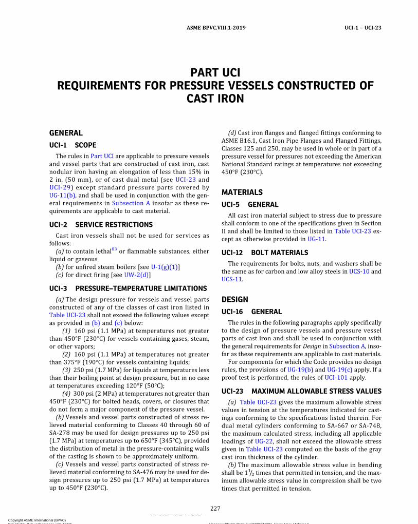
PART UCIREQUIREMENTS FOR PRESSURE VESSELS CONSTRUCTED OF
CAST IRON
GENERAL
UCI-1 SCOPEThe rules in Part UCI are applicable to pressure vessels
and vessel parts that are constructed of cast iron, castnodular iron having an elongation of less than 15% in2 in. (50 mm), or of cast dual metal (see UCI-23 andUCI-29) except standard pressure parts covered byUG-11(b), and shall be used in conjunction with the gen-eral requirements in Subsection A insofar as these re-quirements are applicable to cast material.
UCI-2 SERVICE RESTRICTIONSCast iron vessels shall not be used for services as
follows:(a) to contain lethal83 or flammable substances, either
liquid or gaseous(b) for unfired steam boilers [see U-1(g)(1)](c) for direct firing [see UW-2(d)]
UCI-3 PRESSURE–TEMPERATURE LIMITATIONS(a) The design pressure for vessels and vessel parts
constructed of any of the classes of cast iron listed inTable UCI-23 shall not exceed the following values exceptas provided in (b) and (c) below:
(1) 160 psi (1.1 MPa) at temperatures not greaterthan 450°F (230°C) for vessels containing gases, steam,or other vapors;
(2) 160 psi (1.1 MPa) at temperatures not greaterthan 375°F (190°C) for vessels containing liquids;
(3) 250 psi (1.7 MPa) for liquids at temperatures lessthan their boiling point at design pressure, but in no caseat temperatures exceeding 120°F (50°C);
(4) 300 psi (2 MPa) at temperatures not greater than450°F (230°C) for bolted heads, covers, or closures thatdo not form a major component of the pressure vessel.
(b) Vessels and vessel parts constructed of stress re-lieved material conforming to Classes 40 through 60 ofSA-278 may be used for design pressures up to 250 psi(1.7 MPa) at temperatures up to 650°F (345°C), providedthe distribution of metal in the pressure-containing wallsof the casting is shown to be approximately uniform.
(c) Vessels and vessel parts constructed of stress re-lieved material conforming to SA-476 may be used for de-sign pressures up to 250 psi (1.7 MPa) at temperaturesup to 450°F (230°C).
(d) Cast iron flanges and flanged fittings conforming toASME B16.1, Cast Iron Pipe Flanges and Flanged Fittings,Classes 125 and 250, may be used in whole or in part of apressure vessel for pressures not exceeding the AmericanNational Standard ratings at temperatures not exceeding450°F (230°C).
MATERIALS
UCI-5 GENERALAll cast iron material subject to stress due to pressure
shall conform to one of the specifications given in SectionII and shall be limited to those listed in Table UCI-23 ex-cept as otherwise provided in UG-11.
UCI-12 BOLT MATERIALSThe requirements for bolts, nuts, and washers shall be
the same as for carbon and low alloy steels in UCS-10 andUCS-11.
DESIGN
UCI-16 GENERALThe rules in the following paragraphs apply specifically
to the design of pressure vessels and pressure vesselparts of cast iron and shall be used in conjunction withthe general requirements for Design in Subsection A, inso-far as these requirements are applicable to cast materials.
For components for which the Code provides no designrules, the provisions of UG-19(b) and UG-19(c) apply. If aproof test is performed, the rules of UCI-101 apply.
UCI-23 MAXIMUM ALLOWABLE STRESS VALUES(a) Table UCI-23 gives the maximum allowable stress
values in tension at the temperatures indicated for cast-ings conforming to the specifications listed therein. Fordual metal cylinders conforming to SA-667 or SA-748,the maximum calculated stress, including all applicableloadings of UG-22, shall not exceed the allowable stressgiven in Table UCI-23 computed on the basis of the graycast iron thickness of the cylinder.
(b) The maximum allowable stress value in bendingshall be 11/2 times that permitted in tension, and the max-imum allowable stress value in compression shall be twotimes that permitted in tension.
227
ASME BPVC.VIII.1-2019 UCI-1 – UCI-23
Copyright ASME International (BPVC) Provided by IHS under license with ASME Licensee=Khalda Petroleum/5986215001, User=Amer, Mohamed
Not for Resale, 07/02/2019 13:29:04 MDTNo reproduction or networking permitted without license from IHS
--`,``,``,,`,`,,````,`,``,,,`-`-`,,`,,`,`,,`---
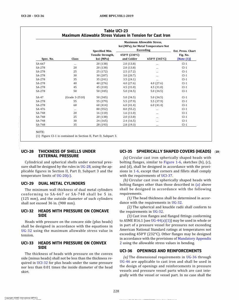
ð19ÞUCI-28 THICKNESS OF SHELLS UNDEREXTERNAL PRESSURE
Cylindrical and spherical shells under external pres-sure shall be designed by the rules in UG-28, using the ap-plicable figures in Section II, Part D, Subpart 3 and thetemperature limits of UG-20(c).
UCI-29 DUAL METAL CYLINDERSThe minimum wall thickness of dual metal cylinders
conforming to SA-667 or SA-748 shal l be 5 in .(125 mm), and the outside diameter of such cylindersshall not exceed 36 in. (900 mm).
UCI-32 HEADS WITH PRESSURE ON CONCAVESIDE
Heads with pressure on the concave side (plus heads)shall be designed in accordance with the equations inUG-32 using the maximum allowable stress value intension.
UCI-33 HEADS WITH PRESSURE ON CONVEXSIDE
The thickness of heads with pressure on the convexside (minus heads) shall not be less than the thickness re-quired in UCI-32 for plus heads under the same pressurenor less than 0.01 times the inside diameter of the headskirt.
UCI-35 SPHERICALLY SHAPED COVERS (HEADS)(a) Circular cast iron spherically shaped heads with
bolting flanges, similar to Figure 1-6, sketches (b), (c),and (d), shall be designed in accordance with the provi-sions in 1-6, except that corners and fillets shall complywith the requirements of UCI-37.(b) Circular cast iron spherically shaped heads with
bolting flanges other than those described in (a) aboveshall be designed in accordance with the followingrequirements.
(1) The head thickness shall be determined in accor-dance with the requirements in UG-32.
(2) The spherical and knuckle radii shall conform tothe requirements in UG-32.
(3) Cast iron flanges and flanged fittings conformingto ASME B16.1 [see UG-44(a)(1)] may be used in whole orin part of a pressure vessel for pressures not exceedingAmerican National Standard ratings at temperatures notexceeding 450°F (232°C). Other flanges may be designedin accordance with the provisions of Mandatory Appendix2 using the allowable stress values in bending.
UCI-36 OPENINGS AND REINFORCEMENTS(a) The dimensional requirements in UG-36 through
UG-46 are applicable to cast iron and shall be used inthe design of openings and reinforcements in pressurevessels and pressure vessel parts which are cast inte-grally with the vessel or vessel part. In no case shall the
Table UCI-23Maximum Allowable Stress Values in Tension for Cast Iron
Spec. No. Class
Specified Min.Tensile Strength,
ksi (MPa)
Maximum Allowable Stress,ksi (MPa), for Metal Temperature Not
Exceeding Ext. Press. ChartFig. No.
[Note (1)]450°F (230°C)and Colder 650°F (345°C)
SA-667 … 20 (138) 2.0 (13.8) … CI‐1SA-278 20 20 (138) 2.0 (13.8) … CI‐1SA-278 25 25 (172) 2.5 (17.2) … CI‐1SA-278 30 30 (207) 3.0 (20.7) … CI‐1SA-278 35 35 (241) 3.5 (24.1) … CI‐1SA-278 40 40 (276) 4.0 (27.6) 4.0 (27.6) CI‐1SA-278 45 45 (310) 4.5 (31.0) 4.5 (31.0) CI‐1SA-278 50 50 (345) 5.0 (34.5) 5.0 (34.5) CI‐1
SA-47 (Grade 3‐2510) 50 (345) 5.0 (34.5) 5.0 (34.5) CI‐1SA-278 55 55 (379) 5.5 (37.9) 5.5 (37.9) CI‐1SA-278 60 60 (414) 6.0 (41.4) 6.0 (41.4) CI‐1SA-476 … 80 (552) 8.0 (55.2) … CI‐1SA-748 20 16 (110) 1.6 (11.0) … CI‐1SA-748 25 20 (138) 2.0 (13.8) … CI‐1SA-748 30 24 (165) 2.4 (16.5) … CI‐1SA-748 35 28 (193) 2.8 (19.3) … CI‐1
NOTE:(1) Figure CI‐1 is contained in Section II, Part D, Subpart 3.
228
ASME BPVC.VIII.1-2019UCI-28 – UCI-36
Copyright ASME International (BPVC) Provided by IHS under license with ASME Licensee=Khalda Petroleum/5986215001, User=Amer, Mohamed
Not for Resale, 07/02/2019 13:29:04 MDTNo reproduction or networking permitted without license from IHS
--`,``,``,,`,`,,````,`,``,,,`-`-`,,`,,`,`,,`---
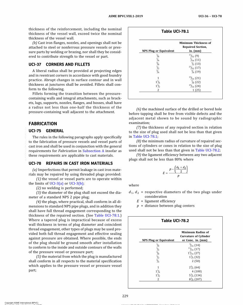
thickness of the reinforcement, including the nominalthickness of the vessel wall, exceed twice the nominalthickness of the vessel wall.
(b) Cast iron flanges, nozzles, and openings shall not beattached to steel or nonferrous pressure vessels or pres-sure parts by welding or brazing, nor shall they be consid-ered to contribute strength to the vessel or part.
UCI-37 CORNERS AND FILLETSA liberal radius shall be provided at projecting edges
and in reentrant corners in accordance with good foundrypractice. Abrupt changes in surface contour and in wallthickness at junctures shall be avoided. Fillets shall con-form to the following.
Fillets forming the transition between the pressure-containing walls and integral attachments, such as brack-ets, lugs, supports, nozzles, flanges, and bosses, shall havea radius not less than one‐half the thickness of thepressure-containing wall adjacent to the attachment.
FABRICATION
UCI-75 GENERALThe rules in the following paragraphs apply specifically
to the fabrication of pressure vessels and vessel parts ofcast iron and shall be used in conjunction with the generalrequirements for Fabrication in Subsection A insofar asthese requirements are applicable to cast materials.
UCI-78 REPAIRS IN CAST IRON MATERIALS(a) Imperfections that permit leakage in cast iron mate-
rials may be repaired by using threaded plugs provided:(1) the vessel or vessel parts are to operate within
the limits of UCI-3(a) or UCI-3(b);(2) no welding is performed;(3) the diameter of the plug shall not exceed the dia-
meter of a standard NPS 2 pipe plug;(4) the plugs, where practical, shall conform in all di-
mensions to standard NPS pipe plugs, and in addition theyshall have full thread engagement corresponding to thethickness of the repaired section. (See Table UCI-78.1.)Where a tapered plug is impractical because of excesswall thickness in terms of plug diameter and coincidentthread engagement, other types of plugs may be used pro-vided both full thread engagement and effective sealingagainst pressure are obtained. Where possible, the endsof the plug should be ground smooth after installationto conform to the inside and outside contours of the wallsof the pressure vessel or pressure part;
(5) the material from which the plug is manufacturedshall conform in all respects to the material specificationwhich applies to the pressure vessel or pressure vesselpart;
(6) the machined surface of the drilled or bored holebefore tapping shall be free from visible defects and theadjacent metal shown to be sound by radiographicexamination;
(7) the thickness of any repaired section in relationto the size of plug used shall not be less than that givenin Table UCI-78.1;
(8) the minimum radius of curvature of repaired sec-tions of cylinders or cones in relation to the size of plugused shall not be less than that given in Table UCI-78.2;
(9) the ligament efficiency between any two adjacentplugs shall not be less than 80% where
where
d1 , d2 = respective diameters of the two plugs underconsideration
E = ligament efficiencyp = distance between plug centers
Table UCI-78.1
NPS Plug or Equivalent
Minimum Thickness ofRepaired Section,
in. (mm)1/8
11/32 (9)1/4
7/16 (11)3/8
1/2 (13)1/2
21/32 (17)3/4
3/4 (19)
1 13/16 (21)11/4
7/8 (22)11/2
15/16 (24)2 1 (25)
Table UCI-78.2
NPS Plug or Equivalent
Minimum Radius ofCurvature of Cylinderor Cone, in. (mm)
1/89/16 (14)
1/411/16 (17)
3/8 11/16 (27)1/2 11/4 (32)3/4 2 (50)
1 21/2 (64)11/4 4 (100)11/2 51/4 (134)2 81/8 (207)
229
ASME BPVC.VIII.1-2019 UCI-36 – UCI-78
Copyright ASME International (BPVC) Provided by IHS under license with ASME Licensee=Khalda Petroleum/5986215001, User=Amer, Mohamed
Not for Resale, 07/02/2019 13:29:04 MDTNo reproduction or networking permitted without license from IHS
--`,``,``,,`,`,,````,`,``,,,`-`-`,,`,,`,`,,`---

(10) the pressure vessel or pressure vessel partmeets the standard hydrostatic test prescribed in UCI-99.(b) Surface imperfections, such as undue roughness,
which do not permit leakage in cast iron materials maybe repaired using driven plugs, provided:
(1) the vessel or vessel parts operate within the lim-its of UCI-3(a)(1), UCI-3(a)(2), or UCI-3(a)(4);
(2) no welding is performed;(3) the material from which the plug is manufactured
conforms in all respects to the material specificationwhich applies to the pressure vessel or pressure vesselpart;
(4) the depth of the plug is not greater than 20% ofthe thickness of the section and its diameter is not greaterthan the larger of 3/8 in. (10 mm) or 20% of the thicknessof the section;
(5) the pressure vessel or pressure vessel part meetsthe standard hydrostatic test prescribed in UCI-99.(c) Surface imperfections, such as undue roughness,
which do not permit leakage in cast iron vessels thatare to operate under the limits of UCI-3(a)(3) may be re-paired under (a) or (b) above or by welding. Where weld-ing is used, the weld and the metal adjacent to it shall beexamined by either the magnetic particle or liquid pene-trant method and shown to be free of linear indications.
INSPECTION AND TESTS
UCI-90 GENERALThe rules in the following paragraphs apply specifically
to the inspection and testing of pressure vessels and ves-sel parts of cast iron and shall be used in conjunction withthe general requirements for Inspection and Tests in Sub-section A insofar as these requirements are applicable tocast material.
UCI-99 STANDARD HYDROSTATIC TEST(a) Cast iron pressure vessels shall be hydrostatically
tested by the method prescribed in UG-99 except thatthe test pressure shall be two times the maximum allow-able working pressure to be marked on the vessel formaximum allowable working pressures greater than30 psi (200 kPa) and 21/2 times the maximum allowableworking pressure but not to exceed 60 psi (400 kPa)for maximum allowable working pressure under 30 psi(200 kPa).
(b) Cast iron pressure vessels and cast iron pressurevessel parts shall not be painted or otherwise coatedeither internally or externally prior to the hydrostaticpressure test.
UCI-101 HYDROSTATIC TEST TO DESTRUCTION(a) The maximum allowable working pressure of iden-
tical cast iron vessels or vessel parts, based on testing oneof them to destruction, limited to the service conditionsspecified in UCI-3 and in accordance with UG-101(m)shall be
where
PB = destruction test pressurePR = maximum allowable working pressure at operating
temperatures listed in Table UCI-23
The principle of UG-101(c) shall be followed.
NOTE: It is assumed that failure will occur in bending.
(b) The value of the average tensile strength of test spe-cimens in the foregoing equation shall be determinedfrom the test results of three test bars from the same ladleof iron as used in the part, or from three test specimenscut from the part.(c) All vessels or vessel parts of the same material, de-
sign, and construction, whose maximum allowable work-ing pressure is based on a test to destruction of a samplevessel in accordance with (a) above, shall be consideredto have a design pressure equal to the maximum allow-able working pressure thus determined, except as limitedby the rules of UCI-3, and shall be subjected to a hydro-static test pressure in conformity with the rules of UCI-99.
MARKING AND REPORTS
UCI-115 GENERALThe provisions for marking and reports in UG-115
through UG-120 shall apply without supplement to ves-sels constructed of cast iron.
230
ASME BPVC.VIII.1-2019UCI-78 – UCI-115
Copyright ASME International (BPVC) Provided by IHS under license with ASME Licensee=Khalda Petroleum/5986215001, User=Amer, Mohamed
Not for Resale, 07/02/2019 13:29:04 MDTNo reproduction or networking permitted without license from IHS
--`,``,``,,`,`,,````,`,``,,,`-`-`,,`,,`,`,,`---
PART UCLREQUIREMENTS FOR WELDED PRESSURE VESSELS
CONSTRUCTED OF MATERIAL WITH CORROSION RESISTANTINTEGRAL CLADDING, WELD METAL OVERLAY CLADDING, OR
APPLIED LININGS
GENERAL
UCL-1 SCOPEThe rules in Part UCL are applicable to pressure vessels
or vessel parts that are constructed of base material withcorrosion resistant integral or weld metal overlay clad-ding and to vessels and vessel parts that are fully or par-tially lined inside or outside with corrosion resistantplate, sheet, or strip, attached by welding to the baseplates before or after forming or to the shell, heads, andother parts during or after assembly into the completedvessel.13 These rules shall be used in conjunction withthe general requirements in Subsection A and with thespecific requirements in the applicable Parts of Subsec-tion B.
UCL-2 METHODS OF FABRICATIONVessels and vessel parts of base material with corrosion
resistant integral or weld metal overlay cladding con-struction shall be fabricated by welding. Corrosion resis-tant linings may be attached by welding to vesselsfabricated by any method of construction permitted un-der the rules of this section.
UCL-3 CONDITIONS OF SERVICESpecific chemical compositions, heat treatment proce-
dures, fabrication requirements, and supplementary testsmay be required to assure that the vessel will be suitablefor the intended service. This is particularly true for ves-sels subject to severe corrosive conditions, and also thosevessels operating in a cyclic temperature service. Theserules do not indicate the selection of an alloy suitablefor the intended service or the amount of the corrosion al-lowance to be provided. See also informative and non-mandatory guidance regarding metallurgical phenomenain Section II, Part D, Nonmandatory Appendix A.
It is recommended that users assure themselves by ap-propriate tests, or otherwise, that the alloy material se-lected and its heat treatment during fabrication will besuitable for the intended service.
NOTE: Attention is called to the difficulties that have been experi-enced in welding materials differing greatly in chemical composition.Mixtures of uncertain chemical composition and physical propertiesare produced at the line of fusion. Some of these mixtures are brittleand may give rise to cracks during solidification or afterward. Toavoid weld embrittlement, special care is required in the selectionof lining material and welding electrodes, and in the application ofcontrols over the welding process and other fabrication procedures.
MATERIALS
UCL-10 GENERALThe base materials used in the construction of clad ves-
sels and of those having applied corrosion linings shallcomply with the requirements for materials given inUCS-5, UF-5, UHT-5, or ULW-5.
UCL-11 INTEGRAL AND WELD METAL OVERLAYCLAD MATERIAL
(a) Clad material used in constructions in which the de-sign calculations are based on the total thickness includ-ing cladding [see UCL-23(c)] shall conform to one of thefollowing specifications:
(1) SA-263, Stainless Chromium Steel‐Clad Plate(2) SA-264, Stainless Chromium–Nickel Steel‐Clad
Plate(3) SA-265, Nickel and Nickel‐Base Alloy‐Clad Steel
PlateIn addition to the above, weld metal overlay cladding
may be used as defined in this Part.(b) Base material with corrosion resistant integral or
weld metal overlay cladding used in constructions inwhich the design calculations are based on the base mate-rial thickness, exclusive of the thickness of the claddingmaterial, may consist of any base material satisfying therequirements of UCL-10 and any metallic corrosion resis-tant integral or weld metal overlay cladding material ofweldable quality that in the judgment of the user is suit-able for the intended service.
(c) Base material with corrosion resistant integral clad-ding in which any part of the cladding is included in thedesign calculations, as permitted in UCL-23(c), shall showa minimum shear strength of 20,000 psi (140 MPa) when
231
ASME BPVC.VIII.1-2019 UCL-1 – UCL-11
Copyright ASME International (BPVC) Provided by IHS under license with ASME Licensee=Khalda Petroleum/5986215001, User=Amer, Mohamed
Not for Resale, 07/02/2019 13:29:04 MDTNo reproduction or networking permitted without license from IHS
--`,``,``,,`,`,,````,`,``,,,`-`-`,,`,,`,`,,`---
tested in the manner described in the clad plate specifica-tion. One shear test shall be made on each such clad plateas rolled, and the results shall be reported on the materialtest report.When the composite thickness of the clad material is
3/4 in. (19 mm) or less, and/or when the cladding metalthickness is nominally 0.075 in. (1.9 mm) or less, the“Bond Strength” test, as described in SA-263, SA-264, orSA-265, may be used in lieu of the bond “Shear Strength”test to fulfill the criteria for acceptable minimum shearstrength, except that the bend test specimen shall be11/2 in. (38 mm) wide by not more than 3/4 in. (19 mm)in thickness and shall be bent, at room temperature,through an angle of 180 deg to the bend diameter pro-vided for in the material specifications applicable to thebacking metal. The results of the “Bond Strength” testshall be reported on the material test report.(d) A shear or bond strength test is not required for
weld metal overlay cladding.(e) When any part of the cladding thickness is specified
as an allowance for corrosion, such added thickness shallbe removed before mill tension tests are made. When cor-rosion of the cladding is not expected, no part of the clad-ding need be removed before testing, even though excessthickness seems to have been provided or is available ascorrosion allowance.(f) Base material with corrosion-resistant integral
cladding in which any part of the cladding is included inthe design calculations, as permitted in UCL-23(c), thatis constructed of multiple cladding plates welded togetherprior to being bonded to the base material shall have thecladding-alloy-to-cladding-alloy welding that is per-formed prior to bonding to the base material
(1) performed by a Manufacturer holding a Certifi-cate of Authorization.
(2) radiographically examined for its full length inthe manner prescribed in UW-51. In place of radiographicexamination, welds may be ultrasonically examined fortheir full length (see UW-53).
(3) be supplied with a Partial Data Report if thatwelding is not performed by the vessel Manufacturer.
UCL-12 LININGMaterial used for applied corrosion resistant lining may
be any metallic material of weldable quality that in thejudgment of the user is suitable for the intended purpose.
DESIGN
UCL-20 GENERAL(a) The rules in the following paragraphs apply specifi-
cally to pressure vessels and vessel parts constructed ofbase material with corrosion resistant integral or weldmetal overlay cladding and those having applied corro-sion resistant linings and shall be used in conjunction
with the general requirements for Design in SubsectionA, and with the specific requirements for Design in Sub-section B that pertain to the method of fabrication used.(b) Minimum Thickness of Shells and Heads. The mini-
mum thickness specified in UG-16(b) shall be the totalthickness for clad material with corrosion resistant inte-gral or weld metal overlay cladding and the base‐materialthickness for applied‐lining construction.
UCL-23 MAXIMUM ALLOWABLE STRESS VALUES(a) Applied Corrosion Resistant Linings. The thickness
of material used for applied lining shall not be includedin the computation for the required thickness of any linedvessel. The maximum allowable stress value shall be thatgiven for the base material in Table UCS-23, or UNF-23.(b) Integrally Clad Material Without Credit for Full Clad-
ding Thickness. Except as permitted in (c) below, designcalculations shall be based on the total thickness of theclad material less the specified nominal minimum thick-ness of cladding. A reasonable excess thickness either ofthe actual cladding or of the same thickness of corrosionresistant weld metal may be included in the design calcu-lations as an equal thickness of base material. The maxi-mum allowable stress value shall be that given for thebase material referenced in Table UCS-23, UF-6, orUHT-23 and listed in Section II, Part D, Subpart 1,Table 1A.(c) Base Material with Corrosion Resistant Integral or
Weld Metal Overlay Cladding With Credit for CladdingThickness. When the base material with corrosion resis-tant integral cladding conforms to one of the specifica-tions listed in UCL-11(a), or consists of an acceptablebase material with corrosion resistant weld metal overlayand the joints are completed by depositing corrosion re-sisting weld metal over the weld in the base material torestore the cladding, the design calculations may be basedon a thickness equal to the nominal thickness of the basematerial plus Sc/Sb times the nominal thickness of thecladding after any allowance provided for corrosion hasbeen deducted, where
Sb = maximum allowable stress value for the base mate-rial at the design temperature
Sc = maximum allowable stress value for the integralcladding at the design temperature, or for corrosionresistant weld metal overlay cladding, that of thewrought material whose chemistry most closely ap-proximates that of the cladding, at the designtemperature
Where Sc is greater than Sb , the multiplier Sc/Sb shallbe taken equal to unity. The maximum allowable stressvalue shall be that given for the base material referencedin Table UCS-23, UF-6, or UHT-23 and listed in Section II,Part D, Subpart 1, Table 1A. Vessels in which the claddingis included in the computation of required thickness shallnot be constructed for internal pressure under the provi-sions of Table UW-12, column (c).
232
ASME BPVC.VIII.1-2019UCL-11 – UCL-23
Copyright ASME International (BPVC) Provided by IHS under license with ASME Licensee=Khalda Petroleum/5986215001, User=Amer, Mohamed
Not for Resale, 07/02/2019 13:29:04 MDTNo reproduction or networking permitted without license from IHS
--`,``,``,,`,`,,````,`,``,,,`-`-`,,`,,`,`,,`---
The thickness of the corrosion resistant weld metaloverlay cladding deposited by manual processes shallbe verified by electrical or mechanical means. One exam-ination shall be made for every head, shell course, or anyother pressure-retaining component for each weldingprocess used. The location of examinations shall be cho-sen by the Inspector except that, when the Inspectorhas been duly notified in advance and cannot be presentor otherwise make the selection, the fabricator may exer-cise his own judgment in selecting the locations.
UCL-24 MAXIMUM ALLOWABLE WORKINGTEMPERATURE
(a)When the design calculations are based on thethickness of base material exclusive of lining or claddingthickness, the maximum service metal temperature ofthe vessel shall be that allowed for the base material.
(b)When the design calculations are based on the fullthickness of base material with corrosion resistant inte-gral or weld metal overlay cladding as permitted inUCL-23(c), the maximum service metal temperature shallbe the lower of the values allowed for the base materialreferenced in Table UCS-23, UF-6, or UHT-23 and listedin Section II, Part D, Subpart 1, Table 1A, or refer toUCL-23(c) for corrosion resistant weld metal overlaycladding and the cladding material referenced in TableUHA-23 or Tables UNF-23.1 through UNF-23.5.
(c) The use of corrosion resistant integral or weld me-tal overlay cladding or lining material of chromium‐alloystainless steel with a chromium content of over 14% isnot recommended for service metal temperatures above800°F (425°C).
UCL-25 CORROSION OF CLADDING OR LININGMATERIAL
(a)When corrosion or erosion of the cladding or liningmaterial is expected, the cladding or lining thickness shallbe increased by an amount that in the judgment of theuser will provide the desired service life.
(b) Telltale Holes. The requirements of UG-25(e) andUG-46(b) shall apply when telltale holes are used in clador lined vessels, except that such holes may extend to thecladding or lining.
UCL-26 THICKNESS OF SHELLS AND HEADSUNDER EXTERNAL PRESSURE
The thickness of shells or heads under external pres-sure shall satisfy the requirements of the Part of Subsec-tion C applicable to the base material. The cladding maybe included in the design calculations for clad materialto the extent provided in UCL-23(b) and UCL-23(c).
UCL-27 LOW TEMPERATURE OPERATIONSThe base materials used in the construction of vessels
shall satisfy the requirements of UCS-66, UCS-67,UCS-68, Part UF, or UHT-5.
FABRICATION
UCL-30 GENERALThe rules in the following paragraphs apply specifically
to pressure vessels and vessel parts constructed of basematerial with corrosion resistant integral or weld metaloverlay cladding and those having applied corrosion re-sistant linings, and shall be used in conjunction with thegeneral requirements for Fabrication in Subsection A,and with the specific requirements for Fabrication in Sub-section B that pertain to the method of fabrication used.
UCL-31 JOINTS IN INTEGRAL OR WELD METALOVERLAY CLADDING AND APPLIEDLININGS
(a) The types of joints and welding procedure usedshall be such as to minimize the formation of brittle weldcomposition by the mixture of metals of corrosion resis-tant alloy and the base material.
(b)When a shell, head, or other pressure part is weldedto form a corner joint, as in Figure UW-13.2, the weld shallbe made between the base materials either by removingthe clad material prior to welding the joint or by usingweld procedures that will assure the base materials arefused. The corrosion resistance of the joint may be pro-vided by using corrosion resistant and compatible weldfiller material or may be restored by any other appropri-ate means.
NOTE: Because of the different thermal coefficients of expansion ofdissimilar metals, caution should be exercised in design and con-struction under the provisions of these paragraphs in order to avoiddifficulties in service under extreme temperature conditions, or withunusual restraint of parts such as may occur at points of stressconcentration.
UCL-32 WELD METAL COMPOSITIONWelds that are exposed to the corrosive action of the
contents of the vessel should have a resistance to corro-sion that is not substantially less than that of the corro-sion resistant integral or weld metal overlay cladding orlining. The use of filler metal that will deposit weld metalwith practically the same composition as the materialjoined is recommended. Weld metal of different composi-tion may be used provided it has better mechanical prop-erties in the opinion of the manufacturer, and the user issatisfied that its resistance to corrosion is satisfactory forthe intended service. The columbium content ofcolumbium‐stabilized austenitic stainless steel weld me-tal shall not exceed 1.00%, except when a higher colum-bium content is permitted in the material being welded.
UCL-33 INSERTED STRIPS IN CLAD MATERIALThe thickness of inserted strips used to restore clad-
ding at joints shall be equal to that of the nominal mini-mum thickness of cladding specified for the material
233
ASME BPVC.VIII.1-2019 UCL-23 – UCL-33
Copyright ASME International (BPVC) Provided by IHS under license with ASME Licensee=Khalda Petroleum/5986215001, User=Amer, Mohamed
Not for Resale, 07/02/2019 13:29:04 MDTNo reproduction or networking permitted without license from IHS
--`,``,``,,`,`,,````,`,``,,,`-`-`,,`,,`,`,,`---

backed, if necessary, with corrosion resistant weld metaldeposited in the groove to bring the insert flush with thesurface of the adjacent cladding.
UCL-34 POSTWELD HEAT TREATMENT
CAUTION: Postweld heat treatment may be in the carbide‐precipitation range for unstabilized austenitic chromium–nickel steels, as well as within the range where a sigma phasemay form, and if used indiscriminately could result in materialof inferior physical properties and inferior corrosion resis-tance, which ultimately could result in failure of the vessel.
(a) Vessels or parts of vessels constructed of base ma-terial with corrosion resistant integral or weld metaloverlay cladding or applied corrosion resistant lining ma-terial shall be postweld heat treated when the base mate-rial is required to be postweld heat treated.When the thickness of the base material requires post-
weld heat treatment, it shall be performed after the appli-cation of corrosion resistant weld metal overlay claddingor applied corrosion resistant lining unless exempted bythe Notes of Tables UCS-56-1 through UCS-56-11.(b) Vessels or parts of vessels constructed of chromium
stainless steel integral or weld metal overlay cladding andthose lined with chromium stainless steel applied liningsshall be postweld heat treated in all thicknesses, exceptvessels that are integrally clad or lined with Type 405or Type 410S and welded with an austenitic electrodeor non‐air‐hardening nickel–chromium–iron electrodeneed not be postweld heat treated unless required by(a) above.
UCL-35 RADIOGRAPHIC EXAMINATION(a) General. Vessels or parts of vessels constructed of
base material with corrosion resistant integral or weldmetal overlay cladding and those having applied corro-sion resistant linings shall be radiographed when re-quired by the rules in UW-11, UCS-57, UHT-57, andUCL-36. The material thickness specified under theserules shall be the total material thickness for clad con-struc t ion and the base mater ia l th ickness forapplied‐lining construction, except as provided in (c)below.(b) Base Material Weld Protected by a Strip Covering.
When the base material weld in clad or lined constructionis protected by a covering strip or sheet of corrosion re-sistant material applied over the weld in the base materialto complete the cladding or lining, any radiographic ex-amination required by the rules of UW-11, UHT-57, andUCS-57 may be made on the completed weld in the basematerial before the covering is attached.(c) Base Material Weld Protected by an Alloy Weld. The
radiographic examination required by the rules inUW-11, UHT-57, and UCS-57 shall be made after the joint,including the corrosion resistant layer, is complete, ex-cept that the radiographic examination may be made on
the weld in the base material before the alloy cover weldis deposited, provided the following requirements aremet.
(1) The thickness of the base material at the weldedjoint is not less than required by the design calculation.
(2) The corrosion resistant alloy weld deposit is non‐air‐hardening.
(3) The completed alloy weld deposit is spot exam-ined by any method that will detect cracks.
(4) The thickness of the base material shall be usedin determining the radiography requirement in (a) above.
UCL-36 EXAMINATION OF CHROMIUMSTAINLESS STEEL CLADDING OR LINING
The alloy weld joints between the edges of adjacentchromium stainless steel cladding layers or liner sheetsshall be examined for cracks as follows.(a) Joints welded with straight chromium stainless
steel filler metal shall be examined throughout their fulllength. The examination shall be by radiographic methodswhen the chromium stainless steel welds are in continu-ous contact with the welds in the base metal. Liner weldsthat are attached to the base metal, but merely cross theseams in the base metal, may be examined by any methodthat will disclose surface cracks.(b) Joints welded with austenitic chromium–nickel
stee l f i l ler metal or non‐air ‐hardening nickel–chromium–iron filler metal shall be given a radiographicspot examination in accordance with UW-52. For linedconstruction, at least one spot examination shall includea portion of the liner weld that contacts weld metal inthe base material.
UCL-40 WELDING PROCEDURESWelding procedures for corrosion resistant weld over-
lay, composite (clad) metals, and attachment of appliedlinings shall be prepared and qualified in accordance withthe requirements of Section IX.
UCL-42 ALLOY WELDS IN BASE METALGroove joints in base material and parts may be made
with corrosion resistant alloy‐steel filler metal, or groovejoints may be made between corrosion resistant alloysteel and carbon or low alloy steel, provided the weldingprocedure and the welders have been qualified in accor-dance with the requirements of Section IX for the combi-nation of materials used. Some applications of this ruleare base metal welded with alloy‐steel electrodes, and al-loy nozzles welded to steel shells.
UCL-46 FILLET WELDSFillet welds of corrosion resistant metal deposited in
contact with two materials of dissimilar compositionmay be used for shell joints under the limitations ofUW-12, for connection attachments under the limitationsof UW-15 and UW-16, and for any other uses permitted
234
ASME BPVC.VIII.1-2019UCL-33 – UCL-46
Copyright ASME International (BPVC) Provided by IHS under license with ASME Licensee=Khalda Petroleum/5986215001, User=Amer, Mohamed
Not for Resale, 07/02/2019 13:29:04 MDTNo reproduction or networking permitted without license from IHS
--`,``,``,,`,`,,````,`,``,,,`-`-`,,`,,`,`,,`---
ð19Þ
by this Division. The qualification of the welding proce-dures and welders to be used on fillet welds for agiven combination of materials and alloy weld metal shallbe made in accordance with the rules prescribed in Sec-tion IX.
INSPECTION AND TESTS
UCL-50 GENERALThe rules in the following paragraphs apply specifically
to the inspection and testing of pressure vessels and ves-sel parts constructed of base material with corrosion re-sistant integral or weld metal overlay cladding andthose having applied corrosion resistant linings, and shallbe used in conjunction with the general requirements forInspection and Tests in Subsection A, and with the specificrequirements for Inspection and Tests in Subsection B thatpertain to the method of fabrication used.
UCL-51 TIGHTNESS OF APPLIED LININGA test for tightness of the applied lining that will be ap-
propriate for the intended service is recommended, butthe details of the test shall be a matter for agreement be-tween the user and the manufacturer. The test should besuch as to assure freedom from damage to the load carry-ing base material. When rapid corrosion of the base mate-rial is to be expected from contact with the contents of thevessel, particular care should be taken in devising and ex-ecuting the tightness test.
Following the hydrostatic pressure test, the interior ofthe vessel shall be inspected to determine if there is anyseepage of the test fluid through the lining. Seepage of
the test fluid behind the applied lining may cause seriousdamage to the liner when the vessel is put in service.When seepage occurs, F-4 shall be considered and the lin-ing shall be repaired by welding. Repetition of the radio-graphy, and heat treatment, or the hydrostatic test of thevessel after lining repairs is not required except whenthere is reason to suspect that the repair welds may havedefects that penetrate into the base material, in whichcase the Inspector shall decide which one or more shallbe repeated.
UCL-52 HYDROSTATIC TEST(a) The requirements for standard hydrostatic test in
UG-99 shall apply to pressure vessels fabricated in accor-dance with the rules of Part UCL.
(b) The requirements of UG-99(k) are not applicable forpressure vessels and vessel parts constructed of base ma-terial with corrosion-resistant integral or weld metaloverlay cladding.
MARKING AND REPORTS
UCL-55 GENERALThe provisions for marking and reports in UG-115
through UG-120 shall apply to vessels that are con-structed of base material with corrosion resistant integralor weld metal overlay cladding and those having appliedcorrosion resistant linings, with the following supple-ments to the Data Reports.
(a) Include specification and type of lining material.(b) Include applicable paragraph in UCL-23 under
which the shell and heads were designed.
235
ASME BPVC.VIII.1-2019 UCL-46 – UCL-55
Copyright ASME International (BPVC) Provided by IHS under license with ASME Licensee=Khalda Petroleum/5986215001, User=Amer, Mohamed
Not for Resale, 07/02/2019 13:29:04 MDTNo reproduction or networking permitted without license from IHS
--`,``,``,,`,`,,````,`,``,,,`-`-`,,`,,`,`,,`---
PART UCDREQUIREMENTS FOR PRESSURE VESSELS CONSTRUCTED OF
CAST DUCTILE IRON
GENERAL
UCD-1 SCOPEThe rules in Part UCD are applicable to pressure vessels
and pressure vessel parts that are constructed of cast duc-tile iron,84 and shall be used in conjunction with the gen-eral requirements in Subsection A insofar as theserequirements are applicable to cast material.
UCD-2 SERVICE RESTRICTIONSCast ductile iron pressure vessels shall not be used for
services as follows:(a) to contain lethal83 substances, either liquid or
gaseous(b) for unfired steam boilers [see U-1(g)(1)](c) for direct firing [see UW-2(d)]
UCD-3 PRESSURE–TEMPERATURE LIMITATIONS(a) The maximum design temperature shall not be
higher than 650°F (345°C). The minimum design tem-perature shall not be less than −20°F (−29°C), and the de-sign pressure shall not exceed 1,000 psi (7 MPa) unlessthe requirements in UG-24 for a casting quality factor of90% are met, and the vessel contains liquids only.(b) Cast ductile iron flanges and fittings covered by
ASME B16.42 may be used in whole or as a part of a pres-sure vessel at the pressure–temperature ratings listed inthat standard.
NOTE: Cast ductile iron flanges and fittings conforming in dimensionto the Class 125 and 250 American National Standard for cast ironflanges and fittings may be used in whole or as a part of a pressurevessel at the pressure–temperature ratings listed in ASME B16.42,except that NPS 31/2 and smaller screwed and tapped flanges con-forming in dimensions to the Class 125 ASME B16.1 for cast ironflanged fittings shall have identical ratings specified in ASME B16.1.
(c) Cast ductile iron flanges and fittings, Class 400 andhigher, conforming in dimension to the carbon steel pipeflanges and flanged fittings in ASME B16.5 may be used inwhole or as a part of a pressure vessel at the pressure–temperature ratings for carbon steel, material category1.4, in that standard provided the temperature is not lessthan −20°F (−29°C) nor greater than 650°F (345°C) andprovided that the pressure does not exceed 1,000 psi(7 MPa).
MATERIALS
UCD-5 GENERALAll cast ductile iron material subject to stress due to
pressure shall conform to the specifications given in Sec-tion II and shall be limited to those listed in Table UCD-23except as otherwise provided in UG-11.
UCD-12 BOLT MATERIALSThe requirements for bolt materials, nuts, and washers
shall be the same as for carbon and low alloy steels inUCS-10 and UCS-11.
DESIGN
UCD-16 GENERALThe rules in the following paragraphs apply specifically
to the design of pressure vessels and pressure vesselparts of cast ductile iron and shall be used in conjunctionwith the general requirements for Design in Subsection Ainsofar as these requirements are applicable to castmaterials.For components for which the Code provides no design
rules, the provisions of UG-19(b) and UG-19(c) apply. If aproof test is performed, the rules of UCD-101 apply.
UCD-23 MAXIMUM ALLOWABLE STRESS VALUESTable UCD-23 gives the maximum allowable stress val-
ues at the temperatures indicated for castings conformingto the Specification listed therein. These stress valuesshall be limited to the stress values in Table UCD-23 mul-tiplied by the applicable casting quality factor given inUG-24.
UCD-28 THICKNESS OF SHELLS UNDEREXTERNAL PRESSURE
Cylindrical and spherical shells under external pres-sure shall be designed by the rules in UG-28, using the ap-plicable figures in Section II, Part D, Subpart 3 and thetemperature limits of UG-20(c).
236
ASME BPVC.VIII.1-2019UCD-1 – UCD-28
Copyright ASME International (BPVC) Provided by IHS under license with ASME Licensee=Khalda Petroleum/5986215001, User=Amer, Mohamed
Not for Resale, 07/02/2019 13:29:04 MDTNo reproduction or networking permitted without license from IHS
--`,``,``,,`,`,,````,`,``,,,`-`-`,,`,,`,`,,`---

UCD-32 HEADS WITH PRESSURE ON CONCAVESIDE
Heads with pressure on the concave side (plus heads)shall be designed in accordance with the equations inUG-32.
UCD-33 HEADS WITH PRESSURE ON CONVEXSIDE
The thickness of heads with pressure on the convexside (minus heads) shall not be less than the thickness re-quired in UG-33.
UCD-35 SPHERICALLY SHAPED COVERS(HEADS)
(a) Circular cast ductile iron spherically shaped headswith bolting flanges, similar to Figure 1-6, sketches (b),(c), and (d) shall be designed in accordance with the pro-visions in 1-6, except that corners and fillets shall complywith the requirements of UCD-37.
(b) Circular cast ductile iron spherically shaped headswith bolting flanges other than those described in (a)above shall be designed in accordance with the followingrequirements.
(1) The head thickness shall be determined in accor-dance with the requirements in UG-32.
(2) The spherical and knuckle radii shall conform tothe requirements in UG-32.
(3) Flanges made of cast ductile iron in compliancewith SA-395 and conforming in dimensions to AmericanNational Standard for carbon steel given in ASME B16.5may be used at pressures not exceeding 80% of the pres-sures permitted in those standards at their listed tem-peratures provided the temperature is not less than−20°F (−29°C) nor greater than 650°F (345°C) and pro-vided that the adjusted service pressure does not exceed1,000 psi (7 MPa).
NOTE: Cast ductile iron flanges conforming in dimension to the125 lb and 250 lb American National Standard for cast iron flangesmay be used for pressures not exceeding 80% of the American Na-tional Standard pressure ratings for 150 lb and 300 lb carbon steelflanges, respectively, at their listed temperatures provided the tem-perature is not less than −20°F (−29°C) nor greater than 650°F(345°C), except as in Note to UCD-3(b).
UCD-36 OPENINGS AND REINFORCEMENTS(a) The dimensional requirements in UG-36 through
UG-46 are applicable to cast ductile iron and shall be usedin the design of openings and reinforcements in pressurevessels and pressure vessel parts which are cast inte-grally with the vessel or vessel part. In no case shall thethickness of the reinforcement, including the nominalthickness of the vessel wall, exceed twice the nominalthickness of the vessel wall.
(b) Cast ductile iron flanges, nozzles, and openings shallnot be attached to steel or nonferrous pressure vessels orpressure parts by welding or brazing, nor shall they beconsidered to contribute strength to the vessel or part.
UCD-37 CORNERS AND FILLETSA liberal radius shall be provided at projecting edges
and in reentrant corners in accordance with good foundrypractice. Abrupt changes in surface contour and in wallthickness at junctures shall be avoided. Fillets shall con-form to the following:
(a) Fillets forming the transition between the pressure-containing walls and integral attachments, such as brack-ets, lugs, supports, nozzles, flanges, and bosses, shall havea radius not less than one‐half the thickness of thepressure-containing wall adjacent to the attachment.
FABRICATION
UCD-75 GENERALThe rules in the following paragraphs apply specifically
to the fabrication of pressure vessels and pressure vesselparts of cast ductile iron and shall be used in conjunctionwith the general requirements for Fabrication in Subsec-tion A insofar as these requirements are applicable to castmaterials.
UCD-78 REPAIRS IN CAST DUCTILE IRONMATERIAL
(a) Imperfections which permit leakage in cast ductileiron materials may be repaired by using threaded plugsprovided:
(1) the vessel or vessel parts operate within the tem-perature limits of UCD-3(a), and the design pressure doesnot exceed 1,000 psi (7 MPa);
(2) no welding is performed;(3) the diameter of the plug shall not exceed the dia-
meter of a standard NPS 2 pipe plug;
Table UCD-23Maximum Allowable Stress Values in Tension
for Cast Ductile Iron, ksi (MPa)
Spec.No. Grade Note
SpecifiedMin.
TensileStrength[Note (1)]
For Metal Temp.Not Exceeding−20°F to 650°F(−29°C to 345°C)
Ext.PressureChart Fig.
No.[Note (2)]
SA-395 60-40-18 (1) 60 (414) 12.0 (82.7) CD‐165-45-15 (1) 65 (450) 13.0 (89.6) CD-1
GENERAL NOTE: To these stress values, a quality factor as speci-fied in UG-24 shall be applied.
NOTES:(1) The yield stresses in compression and tension for cast ductile
iron are not sufficiently different to justify an increase in theallowable stress for bending except as permitted in 2-8(a).
(2) Refer to Section II, Part D, Subpart 3.
237
ASME BPVC.VIII.1-2019 UCD-32 – UCD-78
Copyright ASME International (BPVC) Provided by IHS under license with ASME Licensee=Khalda Petroleum/5986215001, User=Amer, Mohamed
Not for Resale, 07/02/2019 13:29:04 MDTNo reproduction or networking permitted without license from IHS
--`,``,``,,`,`,,````,`,``,,,`-`-`,,`,,`,`,,`---
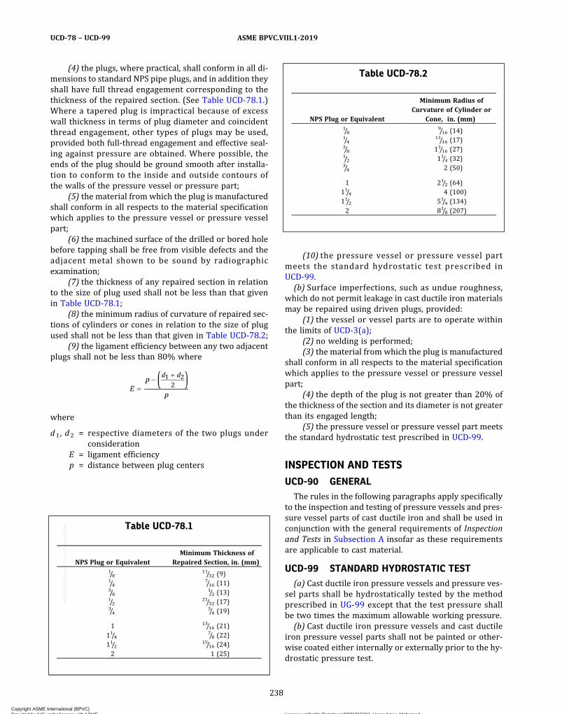
(4) the plugs, where practical, shall conform in all di-mensions to standard NPS pipe plugs, and in addition theyshall have full thread engagement corresponding to thethickness of the repaired section. (See Table UCD-78.1.)Where a tapered plug is impractical because of excesswall thickness in terms of plug diameter and coincidentthread engagement, other types of plugs may be used,provided both full-thread engagement and effective seal-ing against pressure are obtained. Where possible, theends of the plug should be ground smooth after installa-tion to conform to the inside and outside contours ofthe walls of the pressure vessel or pressure part;
(5) the material from which the plug is manufacturedshall conform in all respects to the material specificationwhich applies to the pressure vessel or pressure vesselpart;
(6) the machined surface of the drilled or bored holebefore tapping shall be free from visible defects and theadjacent metal shown to be sound by radiographicexamination;
(7) the thickness of any repaired section in relationto the size of plug used shall not be less than that givenin Table UCD-78.1;
(8) the minimum radius of curvature of repaired sec-tions of cylinders or cones in relation to the size of plugused shall not be less than that given in Table UCD-78.2;
(9) the ligament efficiency between any two adjacentplugs shall not be less than 80% where
where
d1 , d2 = respective diameters of the two plugs underconsideration
E = ligament efficiencyp = distance between plug centers
(10) the pressure vessel or pressure vessel partmeets the standard hydrostatic test prescribed inUCD-99.(b) Surface imperfections, such as undue roughness,
which do not permit leakage in cast ductile iron materialsmay be repaired using driven plugs, provided:
(1) the vessel or vessel parts are to operate withinthe limits of UCD-3(a);
(2) no welding is performed;(3) the material from which the plug is manufactured
shall conform in all respects to the material specificationwhich applies to the pressure vessel or pressure vesselpart;
(4) the depth of the plug is not greater than 20% ofthe thickness of the section and its diameter is not greaterthan its engaged length;
(5) the pressure vessel or pressure vessel part meetsthe standard hydrostatic test prescribed in UCD-99.
INSPECTION AND TESTS
UCD-90 GENERALThe rules in the following paragraphs apply specifically
to the inspection and testing of pressure vessels and pres-sure vessel parts of cast ductile iron and shall be used inconjunction with the general requirements of Inspectionand Tests in Subsection A insofar as these requirementsare applicable to cast material.
UCD-99 STANDARD HYDROSTATIC TEST(a) Cast ductile iron pressure vessels and pressure ves-
sel parts shall be hydrostatically tested by the methodprescribed in UG-99 except that the test pressure shallbe two times the maximum allowable working pressure.(b) Cast ductile iron pressure vessels and cast ductile
iron pressure vessel parts shall not be painted or other-wise coated either internally or externally prior to the hy-drostatic pressure test.
Table UCD-78.1
NPS Plug or EquivalentMinimum Thickness of
Repaired Section, in. (mm)1/8
11/32 (9)1/4
7/16 (11)3/8
1/2 (13)1/2
21/32 (17)3/4
3/4 (19)
1 13/16 (21)11/4
7/8 (22)11/2
15/16 (24)2 1 (25)
Table UCD-78.2
NPS Plug or Equivalent
Minimum Radius ofCurvature of Cylinder or
Cone, in. (mm)1/8
9/16 (14)1/4
11/16 (17)3/8 11/16 (27)1/2 11/4 (32)3/4 2 (50)
1 21/2 (64)11/4 4 (100)11/2 51/4 (134)2 81/8 (207)
238
ASME BPVC.VIII.1-2019UCD-78 – UCD-99
Copyright ASME International (BPVC) Provided by IHS under license with ASME Licensee=Khalda Petroleum/5986215001, User=Amer, Mohamed
Not for Resale, 07/02/2019 13:29:04 MDTNo reproduction or networking permitted without license from IHS
--`,``,``,,`,`,,````,`,``,,,`-`-`,,`,,`,`,,`---
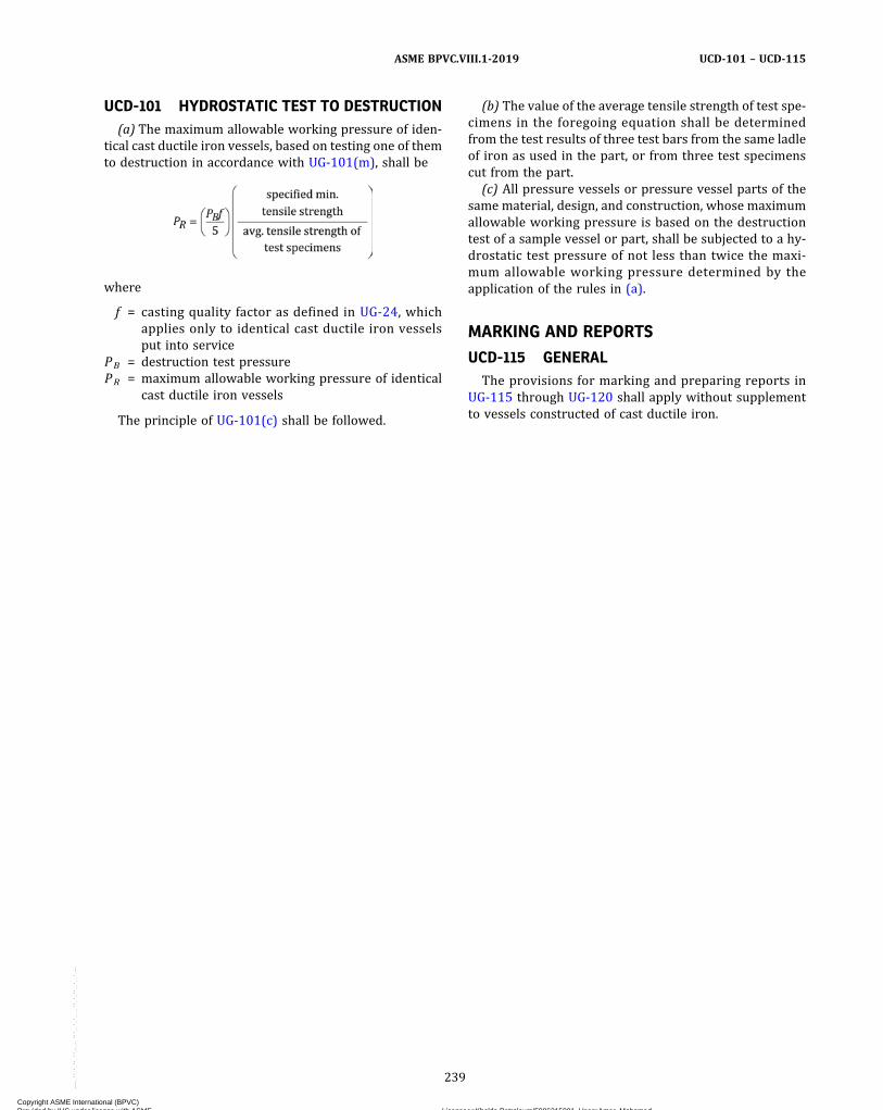
UCD-101 HYDROSTATIC TEST TO DESTRUCTION(a) The maximum allowable working pressure of iden-
tical cast ductile iron vessels, based on testing one of themto destruction in accordance with UG-101(m), shall be
where
f = casting quality factor as defined in UG-24, whichapplies only to identical cast ductile iron vesselsput into service
PB = destruction test pressurePR = maximum allowable working pressure of identical
cast ductile iron vessels
The principle of UG-101(c) shall be followed.
(b) The value of the average tensile strength of test spe-cimens in the foregoing equation shall be determinedfrom the test results of three test bars from the same ladleof iron as used in the part, or from three test specimenscut from the part.
(c) All pressure vessels or pressure vessel parts of thesame material, design, and construction, whose maximumallowable working pressure is based on the destructiontest of a sample vessel or part, shall be subjected to a hy-drostatic test pressure of not less than twice the maxi-mum allowable working pressure determined by theapplication of the rules in (a).
MARKING AND REPORTS
UCD-115 GENERALThe provisions for marking and preparing reports in
UG-115 through UG-120 shall apply without supplementto vessels constructed of cast ductile iron.
239
ASME BPVC.VIII.1-2019 UCD-101 – UCD-115
Copyright ASME International (BPVC) Provided by IHS under license with ASME Licensee=Khalda Petroleum/5986215001, User=Amer, Mohamed
Not for Resale, 07/02/2019 13:29:04 MDTNo reproduction or networking permitted without license from IHS
--`,``,``,,`,`,,````,`,``,,,`-`-`,,`,,`,`,,`---
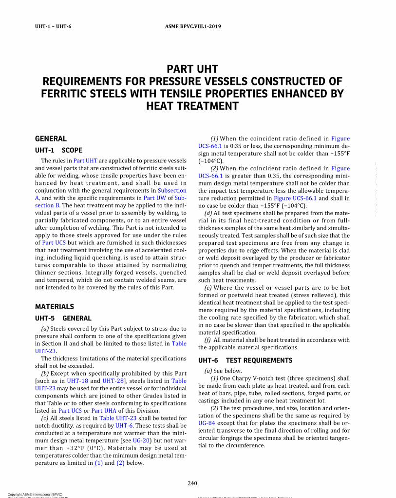
PART UHTREQUIREMENTS FOR PRESSURE VESSELS CONSTRUCTED OFFERRITIC STEELS WITH TENSILE PROPERTIES ENHANCED BY
HEAT TREATMENT
GENERAL
UHT-1 SCOPEThe rules in Part UHT are applicable to pressure vessels
and vessel parts that are constructed of ferritic steels suit-able for welding, whose tensile properties have been en-hanced by heat treatment, and shall be used inconjunction with the general requirements in SubsectionA, and with the specific requirements in Part UW of Sub-section B. The heat treatment may be applied to the indi-vidual parts of a vessel prior to assembly by welding, topartially fabricated components, or to an entire vesselafter completion of welding. This Part is not intended toapply to those steels approved for use under the rulesof Part UCS but which are furnished in such thicknessesthat heat treatment involving the use of accelerated cool-ing, including liquid quenching, is used to attain struc-tures comparable to those attained by normalizingthinner sections. Integrally forged vessels, quenchedand tempered, which do not contain welded seams, arenot intended to be covered by the rules of this Part.
MATERIALS
UHT-5 GENERAL(a) Steels covered by this Part subject to stress due to
pressure shall conform to one of the specifications givenin Section II and shall be limited to those listed in TableUHT-23.The thickness limitations of the material specifications
shall not be exceeded.(b) Except when specifically prohibited by this Part
[such as in UHT-18 and UHT-28], steels listed in TableUHT-23 may be used for the entire vessel or for individualcomponents which are joined to other Grades listed inthat Table or to other steels conforming to specificationslisted in Part UCS or Part UHA of this Division.(c) All steels listed in Table UHT-23 shall be tested for
notch ductility, as required by UHT-6. These tests shall beconducted at a temperature not warmer than the mini-mum design metal temperature (see UG-20) but not war-mer than +32°F (0°C). Materials may be used attemperatures colder than the minimum design metal tem-perature as limited in (1) and (2) below.
(1)When the coincident ratio defined in FigureUCS-66.1 is 0.35 or less, the corresponding minimum de-sign metal temperature shall not be colder than −155°F(−104°C).
(2)When the coincident ratio defined in FigureUCS-66.1 is greater than 0.35, the corresponding mini-mum design metal temperature shall not be colder thanthe impact test temperature less the allowable tempera-ture reduction permitted in Figure UCS-66.1 and shall inno case be colder than −155°F (−104°C).(d) All test specimens shall be prepared from the mate-
rial in its final heat-treated condition or from full‐thickness samples of the same heat similarly and simulta-neously treated. Test samples shall be of such size that theprepared test specimens are free from any change inproperties due to edge effects. When the material is clador weld deposit overlayed by the producer or fabricatorprior to quench and temper treatments, the full thicknesssamples shall be clad or weld deposit overlayed beforesuch heat treatments.(e) Where the vessel or vessel parts are to be hot
formed or postweld heat treated (stress relieved), thisidentical heat treatment shall be applied to the test speci-mens required by the material specifications, includingthe cooling rate specified by the fabricator, which shallin no case be slower than that specified in the applicablematerial specification.(f) All material shall be heat treated in accordance with
the applicable material specifications.
UHT-6 TEST REQUIREMENTS(a) See below.
(1) One Charpy V‐notch test (three specimens) shallbe made from each plate as heat treated, and from eachheat of bars, pipe, tube, rolled sections, forged parts, orcastings included in any one heat treatment lot.
(2) The test procedures, and size, location and orien-tation of the specimens shall be the same as required byUG-84 except that for plates the specimens shall be or-iented transverse to the final direction of rolling and forcircular forgings the specimens shall be oriented tangen-tial to the circumference.
240
ASME BPVC.VIII.1-2019UHT-1 – UHT-6
Copyright ASME International (BPVC) Provided by IHS under license with ASME Licensee=Khalda Petroleum/5986215001, User=Amer, Mohamed
Not for Resale, 07/02/2019 13:29:04 MDTNo reproduction or networking permitted without license from IHS
--`,``,``,,`,`,,````,`,``,,,`-`-`,,`,,`,`,,`---
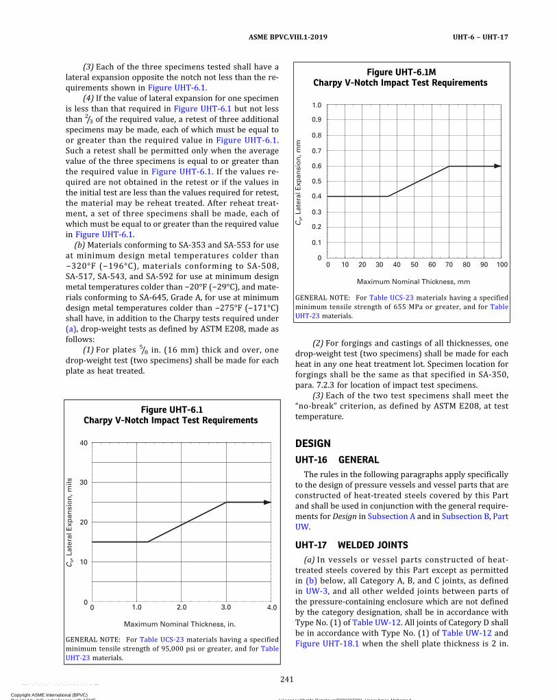
(3) Each of the three specimens tested shall have alateral expansion opposite the notch not less than the re-quirements shown in Figure UHT-6.1.
(4) If the value of lateral expansion for one specimenis less than that required in Figure UHT-6.1 but not lessthan 2/3 of the required value, a retest of three additionalspecimens may be made, each of which must be equal toor greater than the required value in Figure UHT-6.1.Such a retest shall be permitted only when the averagevalue of the three specimens is equal to or greater thanthe required value in Figure UHT-6.1. If the values re-quired are not obtained in the retest or if the values inthe initial test are less than the values required for retest,the material may be reheat treated. After reheat treat-ment, a set of three specimens shall be made, each ofwhich must be equal to or greater than the required valuein Figure UHT-6.1.
(b)Materials conforming to SA-353 and SA-553 for useat minimum design metal temperatures colder than−320°F (−196°C), materials conforming to SA-508,SA-517, SA-543, and SA-592 for use at minimum designmetal temperatures colder than −20°F (−29°C), and mate-rials conforming to SA-645, Grade A, for use at minimumdesign metal temperatures colder than −275°F (−171°C)shall have, in addition to the Charpy tests required under(a), drop‐weight tests as defined by ASTM E208, made asfollows:
(1) For plates 5/8 in. (16 mm) thick and over, onedrop‐weight test (two specimens) shall be made for eachplate as heat treated.
(2) For forgings and castings of all thicknesses, onedrop‐weight test (two specimens) shall be made for eachheat in any one heat treatment lot. Specimen location forforgings shall be the same as that specified in SA-350,para. 7.2.3 for location of impact test specimens.
(3) Each of the two test specimens shall meet the“no‐break” criterion, as defined by ASTM E208, at testtemperature.
DESIGN
UHT-16 GENERALThe rules in the following paragraphs apply specifically
to the design of pressure vessels and vessel parts that areconstructed of heat-treated steels covered by this Partand shall be used in conjunction with the general require-ments for Design in Subsection A and in Subsection B, PartUW.
UHT-17 WELDED JOINTS(a) In vessels or vessel parts constructed of heat-
treated steels covered by this Part except as permittedin (b) below, all Category A, B, and C joints, as definedin UW-3, and all other welded joints between parts ofthe pressure-containing enclosure which are not definedby the category designation, shall be in accordance withType No. (1) of Table UW-12. All joints of Category D shallbe in accordance with Type No. (1) of Table UW-12 andFigure UHT-18.1 when the shell plate thickness is 2 in.
Figure UHT-6.1Charpy V-Notch Impact Test Requirements
0
Cv,
Lat
eral
Exp
ansi
on
, mils
0
10
20
30
40
1.0 2.0 3.0 4.0
Maximum Nominal Thickness, in.
GENERAL NOTE: For Table UCS-23 materials having a specifiedminimum tensile strength of 95,000 psi or greater, and for TableUHT-23 materials.
Figure UHT-6.1MCharpy V-Notch Impact Test Requirements
Cv,
Lat
eral
Exp
ansi
on
, mm
0
0.1
0.2
0.3
0.4
0.5
0.6
0.7
0.8
0.9
1.0
0 10 20 30 40 50 60 70 80 90 100
Maximum Nominal Thickness, mm
GENERAL NOTE: For Table UCS-23 materials having a specifiedminimum tensile strength of 655 MPa or greater, and for TableUHT-23 materials.
241
ASME BPVC.VIII.1-2019 UHT-6 – UHT-17
Copyright ASME International (BPVC) Provided by IHS under license with ASME Licensee=Khalda Petroleum/5986215001, User=Amer, Mohamed
Not for Resale, 07/02/2019 13:29:04 MDTNo reproduction or networking permitted without license from IHS
--`,``,``,,`,`,,````,`,``,,,`-`-`,,`,,`,`,,`---
ð19Þ
(50 mm) or less. When the thickness exceeds 2 in.(50 mm), the weld detail may be as permitted for nozzlesin Figure UHT-18.1 and Figure UHT-18.2.(b) For materials SA-333 Grade 8, SA-334 Grade 8,
SA-353, SA-522, SA-553, and SA-645, Grade A, the jointsof various categories (see UW-3) shall be as follows:
(1) All joints of Category A shall be Type No. (1) ofTable UW-12.
(2) All joints of Category B shall be Type No. (1) or(2) of Table UW-12.
(3) All joints of Category C shall be full penetrationwelds extending through the entire section at the joint.
(4) All joints of Category D attaching a nozzle neck tothe vessel wall and to a reinforcing pad, if used, shall befull penetration groove welds.
UHT-18 NOZZLES(a) All openings regardless of size shall meet the re-
quirements for reinforcing, nozzle geometry, and nozzleattachments and shall conform to details shown in FigureUHT-18.1 or as shown in Figure UHT-18.2 or sketch (y‐l)or (z‐l) in Figure UW-16.1 when permitted by the provi-sions of UHT-17(a), or as shown in Figure UW-16.1 whenpermitted by the provisions of UHT-17(b).(b) Except for nozzles covered in (c) below, all nozzles
and reinforcement pads shall be made of material with aspecified minimum yield strength within ± 20% of that ofthe shell to which they are attached; however, pipeflanges, pipe, or communicating chambers may be of car-bon, low, or high alloy steel welded to nozzle necks of therequired material, provided:
(1) the joint is a circumferential butt weld located
not less than which, except for the nozzle type
shown in Figure UHT-18.1, sketch (f), is measured fromthe limit of reinforcement as defined in UG-40. For Figure
UHT-18.1, sketch (f), the is measured as shown on
that Figure. In these equations,
R = inside radius of the nozzle neck except for FigureUHT-18.1, sketch (f) where it is the inside radiusof the vessel opening as shown in that Figure
tn = nominal thickness of the nozzle
(2) the design of the nozzle neck at the joint is madeon the basis of the allowable stress value of the weakermaterial;
(3) the slope of the nozzle neck does not exceed threeto one for at least a distance of 1.5tn from the center of thejoint;
(4) the diameter of the nozzle neck does not exceedthe limits given in 1-7 for openings designed to UG-36through UG-44(a).(c) Nozzles of nonhardenable austenitic‐type stainless
steel may be used in vessels constructed of steels con-forming to SA-353; SA-553 Types I, II, and III; orSA-645, Grade A, provided the construction meets all ofthe following conditions:
(1) The nozzles are nonhardenable austenitic‐typestainless steel conforming to one of the following specifi-cations: SA-182, SA-213, SA-240, SA-312, SA-336, SA-403,SA-430, or SA-479.
(2) The maximum nozzle size is limited to NPS 4.(3) None of the nozzles is located in a Category A or B
joint.(4) The nozzles are located so that the reinforcement
area of one nozzle does not overlap the reinforcementarea of an adjacent nozzle.
UHT-19 CONICAL SECTIONSConical sections shall be provided with a skirt having a
length not less than (where r is the inside radiusof the adjacent cylinder and t is the thickness of the cone)or 11/2 in. (38 mm), whichever is larger. A knuckle shall beprovided at both ends of the conical section; the knuckleradius shall not be less than 10% of the outside diameterof the skirt, but in no case less than three times the conethickness.
UHT-20 JOINT ALIGNMENTThe requirements of UW-33 shall be met except that
the following maximum permissible offset values shallbe used in place of those given in UW-33(a):
Section Thickness,in. (mm)
Joint Direction
Longitudinal Circumferential
Up to 1/2 (13), incl. 0.2t 0.2tOver 1/2 to
15/16(13 to 24), incl.
3/32 in. (2.5 mm) 0.2t
Over 15/16 to 11/2(24 to 38), incl.
3/32 in. (2.5 mm) 3/16 in. (5 mm)
Over 11/2 (38)3/32 in. (2.5 mm) Lesser of 1/8 t or
1/4 in. (6 mm)
UHT-23 MAXIMUMALLOWABLE STRESS VALUES(a) Section II, Part D, Subpart 1, Table 1A gives the max-
imum allowable stress values at the temperatures indi-cated for materials conforming to the specificationslisted therein. Values may be interpolated for intermedi-ate temperatures (see UG-23). For vessels designed to op-erate at a temperature colder than −20°F (−29°C), theallowable stress values to be used in design shall not ex-ceed those given for temperatures of −20°F (−29°C) to100°F (38°C).(b) Shells of pressure vessels may be made from
welded pipe or tubing listed in Table 1A.
UHT-25 CORROSION ALLOWANCEProvision for possible deterioration due to the environ-
ment in which the vessel operates is the responsibility ofthe designer.
242
ASME BPVC.VIII.1-2019UHT-17 – UHT-25
Copyright ASME International (BPVC) Provided by IHS under license with ASME Licensee=Khalda Petroleum/5986215001, User=Amer, Mohamed
Not for Resale, 07/02/2019 13:29:04 MDTNo reproduction or networking permitted without license from IHS
--`,``,``,,`,`,,````,`,``,,,`-`-`,,`,,`,`,,`---

Figure UHT-18.1Acceptable Welded Nozzle Attachment Readily Radiographed to Code Standards
t
tt1
330 deg max.
11/2 t min.
1/2 in. (13 mm) min.
45 deg max.
30 deg min.
(c)
(b)(a)
r1 r1
r2 r2
r2
r2
r2
r1
r2
t3
t4
r2
tn
tn
tn
t
(d)
r1
tn
2
1
r2
Backing ring, if used, shall be removed
t
t
(e)
(f)
r1
tn
(c-1)
A
A
r2
r1r1
r2
r2
r2
t
r2
r2
tn tn45 deg max.45 deg max.
30 deg max.18.5 deg max.
Max. = 0.2t
30 deg max.
Section A–A
Sections perpendicular and parallel to the cylindrical vessel axis
Limits of reinforcement
t (actual) shell
45 deg min.
45 deg Rad. = 1/2tn with a min. = 1/4 in. (6 mm)
Area to be compensated A, B, C, D
Limits of reinforcement
Reinforcement may be distributed within the limits prescribed by this Division
2R or (R t tn)whichever is greater
1/2 in. (13 mm) min.
DC
B
A
Min. thickness (forging)
N
N r2
tp
2tn min.
R = inside radius of vessel opening
tn
r2
tC
r1
r1
r1
Rt n
N ≤ 21/2tnr1 = 1/8t to
1/2tr2 ≥ 3/4 in. (19 mm)t = nominal thickness of shell or head
tn = nominal thickness of nozzletp = nominal thickness of attached pipe
243
ASME BPVC.VIII.1-2019 UHT-25
Copyright ASME International (BPVC) Provided by IHS under license with ASME Licensee=Khalda Petroleum/5986215001, User=Amer, Mohamed
Not for Resale, 07/02/2019 13:29:04 MDTNo reproduction or networking permitted without license from IHS
--`,``,``,,`,`,,````,`,``,,,`-`-`,,`,,`,`,,`---

Figure UHT-18.2Acceptable Full Penetration Welded Nozzle Attachments Radiographable With Difficulty and Generally
Requiring Special Techniques Including Multiple Exposures to Take Care of Thickness Variations
Backing strip, if used, shall be removed
Backing strip, if used, shall be removed
tn
tc r1
Backing strip, if used, shall be removed
tn
tcr1t
tn
tcr1t
t
tn
tc r1t
tn
tntn
tc
tc
tc
tc
tn min.
r1
r1r1
r2
Section A–A
(g)
(f)
(e)
(c) (d)
(a) (b)
A
A
r2
r4r4
t
t
t
tn
tcr1t
Sections perpendicular and parallel to the cylindrical vessel axis
r1 = 1/8t to1/2t
r2 ≥ 3/4 in. (19 mm)r4 ≥ 1/4 in. (6 mm)t = nominal thickness of shell or headt c ≥ 0.7tn or 1/4 in. (6 mm), whichever is lesstn = nominal thickness of nozzle
244
ASME BPVC.VIII.1-2019UHT-25
Copyright ASME International (BPVC) Provided by IHS under license with ASME Licensee=Khalda Petroleum/5986215001, User=Amer, Mohamed
Not for Resale, 07/02/2019 13:29:04 MDTNo reproduction or networking permitted without license from IHS
--`,``,``,,`,`,,````,`,``,,,`-`-`,,`,,`,`,,`---
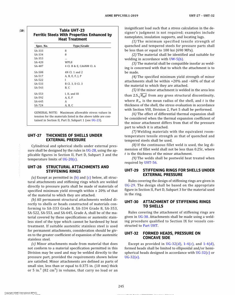
UHT-27 THICKNESS OF SHELLS UNDEREXTERNAL PRESSURE
Cylindrical and spherical shells under external pres-sure shall be designed by the rules in UG-28, using the ap-plicable figures in Section II, Part D, Subpart 3 and thetemperature limits of UG-20(c).
UHT-28 STRUCTURAL ATTACHMENTS ANDSTIFFENING RINGS
(a) Except as permitted in (b) and (c) below, all struc-tural attachments and stiffening rings which are weldeddirectly to pressure parts shall be made of materials ofspecified minimum yield strength within ± 20% of thatof the material to which they are attached.
(b) All permanent structural attachments welded di-rectly to shells or heads constructed of materials con-forming to SA-333 Grade 8, SA-334 Grade 8, SA-353,SA-522, SA-553, and SA-645, Grade A, shall be of the ma-terial covered by these specifications or austenitic stain-less steel of the type which cannot be hardened by heattreatment. If suitable austenitic stainless steel is usedfor permanent attachments, consideration should be giv-en to the greater coefficient of expansion of the austeniticstainless steel.
(c) Minor attachments made from material that doesnot conform to a material specification permitted in thisDivision may be used and may be welded directly to thepressure part, provided the requirements shown beloware satisfied. Minor attachments are defined as parts ofsmall size, less than or equal to 0.375 in. (10 mm) thickor 5 in.3 (82 cm3) in volume, that carry no load or an
insignificant load such that a stress calculation in the de-signer’s judgment is not required; examples includenameplates, insulation supports, and locating lugs.
(1) The minimum specified tensile strength ofquenched and tempered steels for pressure parts shallbe less than or equal to 100 ksi (690 MPa).
(2) The material shall be identified and suitable forwelding in accordance with UW-5(b).
(3) The material shall be compatible insofar as weld-ing is concerned with that to which the attachment is tobe made.
(4) The specified minimum yield strength of minorattachments shall be within +20% and −60% of that ofthe material to which they are attached.
(5) If the minor attachment is welded in the area less
than from any gross structural discontinuity,
where Rm is the mean radius of the shell, and t is thethickness of the shell, the stress evaluation in accordancewith Section VIII, Division 2, Part 5 shall be performed.
(6) The effect of differential thermal expansion shallbe considered when the thermal expansion coefficient ofthe minor attachment differs from that of the pressurepart to which it is attached.
(7)Welding materials with the equivalent room-temperature tensile strength as that of quenched andtempered steels shall be used.
(8) If the continuous fillet weld is used, the leg di-mension of fillet weld shall not be less than 0.25t , wheret is the thickness of the minor attachment.
(9) The welds shall be postweld heat treated whenrequired by UHT-56.
UHT-29 STIFFENING RINGS FOR SHELLS UNDEREXTERNAL PRESSURE
Rules covering the design of stiffening rings are given inUG-29. The design shall be based on the appropriatefigure in Section II, Part D, Subpart 3 for the material usedin the ring.
UHT-30 ATTACHMENT OF STIFFENING RINGSTO SHELLS
Rules covering the attachment of stiffening rings aregiven in UG-30. Attachments shall be made using a weld-ing procedure qualified to Section IX for vessels con-structed to Part UHT.
UHT-32 FORMED HEADS, PRESSURE ONCONCAVE SIDE
Except as provided in UG-32(d), 1-4(c), and 1-4(d),formed heads shall be limited to ellipsoidal and/or hemi-spherical heads designed in accordance with UG-32(c) orUG-32(e).
ð19Þ Table UHT-23Ferritic Steels With Properties Enhanced by
Heat Treatment
Spec. No. Type/Grade
SA-333 8SA-334 8SA-353 …SA-420 WPL8SA-487 4 Cl. B & E, CA6NM Cl. A
SA-508 4N Cl. 1 and 2SA-517 A, B, E, F, J, PSA-522 ISA-533 B Cl. 3, D Cl. 3SA-543 B, C
SA-553 I, II, and IIISA-592 A, E, FSA-645 ASA-724 A, B, C
GENERAL NOTE: Maximum allowable stress values intension for the materials listed in the above table are con-tained in Section II, Part D, Subpart 1 (see UG-23).
245
ASME BPVC.VIII.1-2019 UHT-27 – UHT-32
Copyright ASME International (BPVC) Provided by IHS under license with ASME Licensee=Khalda Petroleum/5986215001, User=Amer, Mohamed
Not for Resale, 07/02/2019 13:29:04 MDTNo reproduction or networking permitted without license from IHS
--`,``,``,,`,`,,````,`,``,,,`-`-`,,`,,`,`,,`---
ð19Þ
UHT-33 FORMED HEADS, PRESSURE ONCONVEX SIDE
Ellipsoidal, hemispherical, and conical heads havingpressure on the convex side (minus heads) shall be de-signed by the rules of UG-33, using the applicable externalpressure charts referenced in Section II, Part D, Subpart 1,Table 1A and given in Section II, Part D, Subpart 3.
UHT-34 HEMISPHERICAL HEADSWhen hemispherical heads are used, the head‐to‐shell
transition of Figure UW-13.1, sketch (j) or FigureUW-13.1, sketch (l) shall be used. When the weld is inor adjacent to the tapered section, it shall be finished ina manner that will maintain the required uniform slopefor the full length of the tapered section.
UHT-40 MATERIALS HAVING DIFFERENTCOEFFICIENTS OF EXPANSION
When welding materials with austenitic electrodes, thedifferences between the coefficients of expansion and thestrengths of the base material and the weld metal shouldbe carefully considered, particularly for applications in-volving cyclic stresses.
UHT-56 POSTWELD HEAT TREATMENT(a) Before applying the detailed requirements and ex-
emptions in these paragraphs, satisfactory weld proce-dure qualifications of the procedures to be used shall beperformed in accordance with all of the variables in Sec-tion IX including conditions of postweld heat treatment orlack of postweld heat treatment and including restrictionslisted below. When determining the thickness requiringpostweld treatment in Table UHT-56 for clad or weld de-posit overlayed vessels or parts of vessels, the total thick-ness of the material, including the clad and weld depositoverlay, shall be employed.(b) Vessels or vessel parts constructed of steels listed in
Table UHT-23 shall be postweld heat treated when re-quired in Table UHT-56, except that postweld heat treat-ment shall be required for all thicknesses when joiningthe materials with the inertia and continuous drive fric-tion welding processes.(c) Postweld heat treatment shall be performed in ac-
cordance with UCS-56 as modified by the requirementsof Table UHT-56. In no case shall the PWHT temperatureexceed the tempering temperature. PWHT and temperingmay be accomplished concurrently. The maximum cool-ing rate established in UCS-56(d)(5) need not apply.Where accelerated cooling from the tempering tempera-ture is required by the material specification, the sameminimum cooling rate shall apply to PWHT.
(d) All welding of connections and attachments shall bepostweld heat treated whenever required by TableUHT-56 based on the greatest thickness of material atthe point of attachment of the head or shell [see (b) and(c)].(e) When material of SA-333 Grade 8, SA-334 Grade 8,
SA-353, SA-522, SA-553, and SA-645, Grade A are post-weld heat treated, the complete vessel or vessel compo-nent being so heat treated shall be maintained withinthe permissible temperature range defined in TableUHT-56.
UHT-57 EXAMINATION(a) Radiography. Radiographic examination for the
complete length of weld in accordance with the require-ments of UW-51 is required for all welded joints of TypeNo. (1) of Table UW-12. The required radiographic exam-ination shall be made after any corrosion‐resistant alloycover weld has been deposited.(b) Nozzle Attachment Welds. Nozzle attachment welds
as provided for in UHT-18, Figures UHT-18.1 andUHT-18.2 shall be radiographically examined in accor-dance with the requirements of UW-51, except that FigureUHT-18.2 type nozzles having an inside diameter of 2 in.(50 mm) or less shall be examined by a magnetic particleor liquid penetrant method. For nozzle attachments illu-strated as sketches (a), (b), and (f) of Figure UHT-18.2,the exposed cross section of the vessel wall at the openingshall be included in the examination.(c) All corrosion resistant overlay weld deposits shall
be examined by the liquid penetrant method.(d) Magnetic Particle Method. All welds, including
welds for attaching nonpressure parts to heat-treatedsteels covered by this Part, shall be examined by the mag-netic particle method after the hydrostatic test, exceptthat those surfaces not accessible after the hydrostatictest shall be examined by the magnetic particle methodat the last feasible stage of vessel fabrication. A magneti-zation method shall be used that will avoid arc strikes.Cracks shall be repaired or removed.(e) Liquid Penetrant Method. As an acceptable alterna-
tive to magnetic particle examination or when magneticparticle methods are not feasible because of the nonferro-magnetic character of the weld deposits, a liquid pene-trant method shall be used. For vessels constructed ofSA-333 Grade 8; SA-334 Grade 8; SA-353; SA-522;SA-553 Types I, II, and III; and SA-645 materials, weldsnot examined radiographically shall be examined by theliquid penetrant method either before or after the hydrot-est. Cracks are unacceptable and shall be repaired or re-moved. Relevant indications are those which result fromimperfections. Linear indications are those indicationsin which the length is more than three times the width.Any relevant linear indications greater than 1/16 in.(1.5 mm) shall be repaired or removed.
246
ASME BPVC.VIII.1-2019UHT-33 – UHT-57
Copyright ASME International (BPVC) Provided by IHS under license with ASME Licensee=Khalda Petroleum/5986215001, User=Amer, Mohamed
Not for Resale, 07/02/2019 13:29:04 MDTNo reproduction or networking permitted without license from IHS
--`,``,``,,`,`,,````,`,``,,,`-`-`,,`,,`,`,,`---

ð19ÞTable UHT-56Postweld Heat Treatment Requirements for Materials in Table UHT-23
Spec. No. Grade or TypeP‐No./Gr. No.
Nominal ThicknessRequiring PWHT,
in. (mm) Notes PWHT Temp., °F (°C)
Holding Time
hr/in.(25 mm)
Minimum,hr
Plate SteelsSA-353 9Ni 11A/1 Over 2 (50) … 1,025−1,085 (550−585) 1 2SA-517 Grade A 11B/1 Over 0.58 (15) (1) 1,000−1,100 (540−595) 1 1/4SA-517 Grade B 11B/4 Over 0.58 (15) (1) 1,000−1,100 (540−595) 1 1/4SA-517 Grade E 11B/2 Over 0.58 (15) (1) 1,000−1,100 (540−595) 1 1/4SA-517 Grade F 11B/3 Over 0.58 (15) (1) 1,000−1,100 (540−595) 1 1/4SA-517 Grade J 11B/6 Over 0.58 (15) (1) 1,000−1,100 (540−595) 1 1/4SA-517 Grade P 11B/8 Over 0.58 (15) (1) 1,000−1,100 (540−595) 1 1/4
SA-533 Types B, D, Cl. 3 11A/4 Over 0.58 (15) … 1,000−1,050 (540−565) 1/21/2
SA-543 Types B, C, Cl. 1 11A/5 … (2) 1,000−1,050 (540−565) 1 1SA-543 Types B, C, Cl. 2 11B/10 … (2) 1,000−1,050 (540−565) 1 1SA-543 Types B, C, Cl. 3 11A/5 … (2) 1,000−1,050 (540−565) 1 1SA-553 Types I, II, III 11A/1 Over 2 (50) … 1,025−1,085 (550−585) 1 2SA-645 Grade A 11A/2 Over 2 (50) … 1,025−1,085 (550−585) 1 2SA-724 Grade A, B 1/4 None … NA NA NASA-724 Grade C 1/4 Over 11/2 (38) … 1,050−1,150 (565−620) 1 1/2
CastingsSA-487 Class 4B 11A/3 Over 0.58 (15) … 1,000−1,050 (540−565) 1 1/4SA-487 Class 4E 11A/3 Over 0.58 (15) … 1,000−1,050 (540−565) 1 1/4SA-487 Class CA 6NM 6/4 Over 0.58 (15) … 1,050−1,150 (565−620) 1 1/4
Pipes and TubesSA-333 Grade 8 11A/1 Over 2 (50) … 1,025−1,085 (550−585) 1 2SA-334 Grade 8 11A/1 Over 2 (50) … 1,025−1,085 (550−585) 1 2
ForgingsSA-508 Grade 4N Cl. 1 11A/5 … (2) 1,000−1,050 (540−565) 1 1SA-508 Grade 4N Cl. 2 11B/10 … (2) 1,000−1,050 (540−565) 1 1SA-522 Type I 11A/1 Over 2 (50) … 1,025−1,085 (550−585) 1 2SA-592 Grade A 11B/1 Over 0.58 (15) (1) 1,000−1,100 (540−595) 1 1/4SA-592 Grade E 11B/2 Over 0.58 (15) (1) 1,000−1,100 (540−595) 1 1/4SA-592 Grade F 11B/3 Over 0.58 (15) (1) 1,000−1,100 (540−595) 1 1/4
GENERAL NOTE: NA = not applicable.
NOTES:(1) See UHT-82(g).(2) PWHT is neither required nor prohibited. Consideration should be given to the possibility of temper embrittlement. The cooling rate
from PWHT, when used, shall not be slower than that obtained by cooling in still air.
247
ASME BPVC.VIII.1-2019 UHT-57
Copyright ASME International (BPVC) Provided by IHS under license with ASME Licensee=Khalda Petroleum/5986215001, User=Amer, Mohamed
Not for Resale, 07/02/2019 13:29:04 MDTNo reproduction or networking permitted without license from IHS
--`,``,``,,`,`,,````,`,``,,,`-`-`,,`,,`,`,,`---

FABRICATION
UHT-75 GENERALThe rules in the following paragraphs apply specifically
to the fabrication of pressure vessels and vessel parts thatare constructed of heat-treated steels covered by this Partand shall be used in conjunction with the general require-ments for Fabrication in Subsection A, and, when applic-able, with the specific requirements for Fabrication inSubsection B, Part UW.
UHT-79 FORMING PRESSURE PARTSThe selected thickness of material shall be such that the
forming processes will not reduce the thickness of thematerial at any point below the minimum value requiredby the rules.(a) Pieces that are formed after heat treatment at a
temperature lower than the final tempering shall be heattreated in accordance with Table UHT-56 when the ex-treme fiber elongation from forming exceeds 5% as deter-mined by the equations in Table UG-79-1.(b) Pieces that are formed at temperatures equal to or
higher than the original tempering shall be reheat treatedin accordance with the applicable material specification,either before or after welding into the vessel.
UHT-80 HEAT TREATMENT(a) Heating Furnace. Furnaces for heating, for quench-
ing, for normalizing, and for tempering shall be providedwith suitable equipment for the automatic recording oftemperatures. The temperature of the vessel or vesselpart during the holding period shall be recorded and shallbe controlled within ±25°F (±15°C).(b) Liquid quenching of flat plates and individual parts
shall be done as required by the applicable materialspecifications.(c) Formed plates for shell sections and heads may be
quenched by sprays or immersion.(d) Entire vessels, after completion of all welding op-
erations, may be quenched by sprays or immersion.(e) The design and operation of spray equipment and
the size of tanks and provision for forced circulation shallbe such as to produce a severity of quench in thequenched item sufficient to meet, in representative testspecimens after tempering, the requirements of the mate-rials specifications.
UHT-81 HEAT TREATMENT VERIFICATIONTESTS
(a) Tests shall be made to verify that the heat treat-ments, and subsequent thermal treatments, performedby the fabricator have produced the required properties.(b) One or more test coupons representative of the ma-
terial and the welding in each vessel or vessel componentshall be heat treated with the vessel or vessel component.
The requirements of (c) and (d) below are to be takenas minimum steps toward these objectives.(c) See below.
(1) One or more test coupons from each lot of mate-rial in each vessel [see (d)] shall be quenched with thevessel or vessel component. A lot is defined as materialfrom the same melt, quenched or normalized simulta-neously and whose thicknesses are within plus or minus20% or 1/2 in. (13 mm) of nominal thickness, whichever issmaller. The test coupons shall be so proportionated thattensile and impact tests may be taken from the same loca-tions relative to thickness as are required by the applic-able material specifications. Weld metal tests shall betaken from the same locations relative to thickness asare required by the materials specifications for platesused in the component to be treated. The gage length oftensile specimens and the middle third of the length ofimpact specimens must be located at a minimum distanceof 1 × t from the quenched edge and/or end of the testcoupon, where t is the thickness of the material whichthe test coupon represents. If desired, the effect of thisdistance may be achieved by temporary attachment ofsuitable thermal buffers. The effectiveness of such buffersshall be demonstrated by tests.
(2) In cases where the test coupon is not attached tothe part being treated, it shall be quenched from the sameheat treatment charge and under the same conditions asthe part it represents. It shall be so proportioned that testspecimens may be taken from the locations prescribed in(1) above.(d) Tempering
(1) Attached Test Coupons. The coupons shall remainattached to the vessel or vessel component during tem-pering, except that any thermal buffers may be removedafter quenching. After the tempering operation and afterremoval from the component, the coupon shall be sub-jected to the same thermal treatment(s), if any, to whichthe vessel or vessel component will be later subjected.The holding time at temperature shall not be less thanthat applied to the vessel or vessel component (exceptthat the total time at each temperature may be appliedin one heating cycle) and the cooling rate shall be nofaster.
(2) Separate Test Coupons. Test coupons which arequenched separately as described in (c)(2) above shallbe tempered similarly and simultaneously with the vesselor component they represent. The conditions for subject-ing the test coupons to subsequent thermal treatment(s)shall be as described in (c)(1) above.(e) Number of Tests. One tensile test and one impact
test shall be made on material from coupons representingeach lot of material in each vessel or vessel componentheat treated. A lot is defined as material from the samemelt quenched simultaneously and whose thicknessesare within plus or minus 20%, or 1/2 in. (13 mm), of nom-inal thickness, whichever is smaller.
248
ASME BPVC.VIII.1-2019UHT-75 – UHT-81
Copyright ASME International (BPVC) Provided by IHS under license with ASME Licensee=Khalda Petroleum/5986215001, User=Amer, Mohamed
Not for Resale, 07/02/2019 13:29:04 MDTNo reproduction or networking permitted without license from IHS
--`,``,``,,`,`,,````,`,``,,,`-`-`,,`,,`,`,,`---
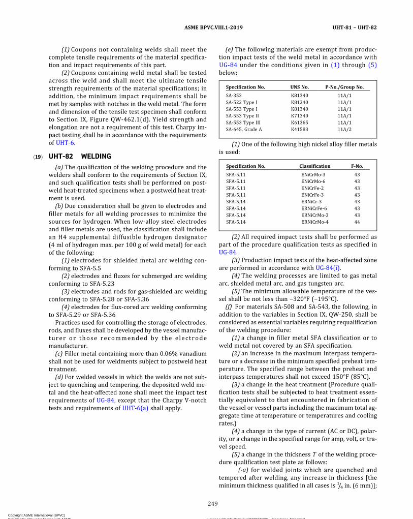
ð19Þ
(1) Coupons not containing welds shall meet thecomplete tensile requirements of the material specifica-tion and impact requirements of this part.
(2) Coupons containing weld metal shall be testedacross the weld and shall meet the ultimate tensilestrength requirements of the material specifications; inaddition, the minimum impact requirements shall bemet by samples with notches in the weld metal. The formand dimension of the tensile test specimen shall conformto Section IX, Figure QW-462.1(d). Yield strength andelongation are not a requirement of this test. Charpy im-pact testing shall be in accordance with the requirementsof UHT-6.
UHT-82 WELDING(a) The qualification of the welding procedure and the
welders shall conform to the requirements of Section IX,and such qualification tests shall be performed on post-weld heat-treated specimens when a postweld heat treat-ment is used.
(b) Due consideration shall be given to electrodes andfiller metals for all welding processes to minimize thesources for hydrogen. When low-alloy steel electrodesand filler metals are used, the classification shall includean H4 supplemental diffusible hydrogen designator(4 ml of hydrogen max. per 100 g of weld metal) for eachof the following:
(1) electrodes for shielded metal arc welding con-forming to SFA-5.5
(2) electrodes and fluxes for submerged arc weldingconforming to SFA-5.23
(3) electrodes and rods for gas-shielded arc weldingconforming to SFA-5.28 or SFA-5.36
(4) electrodes for flux-cored arc welding conformingto SFA-5.29 or SFA-5.36
Practices used for controlling the storage of electrodes,rods, and fluxes shall be developed by the vessel manufac-turer or those recommended by the e lectrodemanufacturer.
(c) Filler metal containing more than 0.06% vanadiumshall not be used for weldments subject to postweld heattreatment.
(d) For welded vessels in which the welds are not sub-ject to quenching and tempering, the deposited weld me-tal and the heat-affected zone shall meet the impact testrequirements of UG-84, except that the Charpy V‐notchtests and requirements of UHT-6(a) shall apply.
(e) The following materials are exempt from produc-tion impact tests of the weld metal in accordance withUG-84 under the conditions given in (1) through (5)below:
Specification No. UNS No. P‐No./Group No.
SA-353 K81340 11A/1SA-522 Type I K81340 11A/1SA-553 Type I K81340 11A/1SA-553 Type II K71340 11A/1SA-553 Type III K61365 11A/1SA-645, Grade A K41583 11A/2
(1) One of the following high nickel alloy filler metalsis used:
Specification No. Classification F‐No.
SFA-5.11 ENiCrMo‐3 43SFA-5.11 ENiCrMo‐6 43SFA-5.11 ENiCrFe‐2 43SFA-5.11 ENiCrFe‐3 43SFA-5.14 ERNiCr‐3 43SFA-5.14 ERNiCrFe‐6 43SFA-5.14 ERNiCrMo‐3 43SFA-5.14 ERNiCrMo‐4 44
(2) All required impact tests shall be performed aspart of the procedure qualification tests as specified inUG-84.
(3) Production impact tests of the heat-affected zoneare performed in accordance with UG-84(i).
(4) The welding processes are limited to gas metalarc, shielded metal arc, and gas tungsten arc.
(5) The minimum allowable temperature of the ves-sel shall be not less than −320°F (−195°C).
(f) For materials SA-508 and SA-543, the following, inaddition to the variables in Section IX, QW‐250, shall beconsidered as essential variables requiring requalificationof the welding procedure:
(1) a change in filler metal SFA classification or toweld metal not covered by an SFA specification.
(2) an increase in the maximum interpass tempera-ture or a decrease in the minimum specified preheat tem-perature. The specified range between the preheat andinterpass temperatures shall not exceed 150°F (85°C).
(3) a change in the heat treatment (Procedure quali-fication tests shall be subjected to heat treatment essen-tially equivalent to that encountered in fabrication ofthe vessel or vessel parts including the maximum total ag-gregate time at temperature or temperatures and coolingrates.)
(4) a change in the type of current (AC or DC), polar-ity, or a change in the specified range for amp, volt, or tra-vel speed.
(5) a change in the thickness T of the welding proce-dure qualification test plate as follows:
(-a) for welded joints which are quenched andtempered after welding, any increase in thickness [theminimum thickness qualified in all cases is 1/4 in. (6 mm)];
249
ASME BPVC.VIII.1-2019 UHT-81 – UHT-82
Copyright ASME International (BPVC) Provided by IHS under license with ASME Licensee=Khalda Petroleum/5986215001, User=Amer, Mohamed
Not for Resale, 07/02/2019 13:29:04 MDTNo reproduction or networking permitted without license from IHS
--`,``,``,,`,`,,````,`,``,,,`-`-`,,`,,`,`,,`---
(-b) for welded joints which are not quenched andtempered after welding, any change as follows:
T less than 5/8 in. (16 mm) Any decrease in thickness (themaximum thickness qualified is 2T)
5/8 in. (16 mm) and over Any departure from the range of 5/8 in.(16 mm) to 2T
(6) for the shielded metal arc, submerged arc, andgas-shielded and flux-cored arc welding processes, an in-crease in the supplemental diffusible hydrogen designa-tor from that used during procedure qualification.
(7) preheat shall be 100°F (38°C) minimum for mate-rial thickness up to and including 1/2 in. (13 mm); 200°F(95°C) minimum for material above 1/2 in. (13 mm) toand including 11/2 in. (38 mm); 300°F (150°C) minimumabove 11/2 in. (38 mm). Preheat temperature shall bemaintained for a minimum of 2 hr after completion ofthe weld joint.(g) For SA-517 and SA-592 materials the requirements
of (f)(1), (f)(2), (f)(3), (f)(4), and (f)(6), in addition to thevariables in Section IX, QW‐250, shall be considered as es-sential variables requiring requalification of the weldingprocedure.(h) The PWHT as required by Table UHT-56 may be
waived for SA-517 and SA-592 materials with a nominalthickness over 0.58 in. to 11/4 in. (15 mm to 32 mm), inclu-sive, provided the following conditions are met:
(1) a minimum preheat of 200°F (95°C) and a maxi-mum interpass of 400°F (205°C) is used;
(2) after completion of welding and without allowingthe weldment to cool below the minimum preheat tem-perature, the temperature of the weldment is raised toa minimum of 400°F (205°C) and maintained at that tem-perature for at least 4 hr; and
(3) all welds are examined by nondestructive exami-nation in accordance with the provisions of this Part.
UHT-83 METHODS OF METAL REMOVAL(a) Plate edges, welding bevels, chamfering and other
operations involving the removal of metal shall be by ma-chining, chipping, or grinding except as provided in (b)below.(b)When metal removal is accomplished by methods
involving melting, such as gas cutting or arc‐air gouging,etc., it shall be done with due precautions to avoid crack-ing. Where the cut surfaces are not to be subsequentlyeliminated by fusion with weld deposits, they shall be re-moved by machining or grinding to a depth of at least1/16 in. (1.5 mm) followed by inspection by magnetic par-ticle or liquid penetrant methods.
CAUTION: The properties of the base metal may be adversely af-fected by excessive local heat inputs.
UHT-84 WELD FINISHThe requirements of UW-35(a) and UW-51(b) shall be
met except that for SA-517 material the maximum weldreinforcement shall not exceed 10% of the plate thicknessor 1/8 in. (3.0 mm), whichever is less. The edge of the welddeposits shall merge smoothly into the base metal with-out undercuts or abrupt transitions; this requirementshall apply to fillet and groove welds as well as to buttwelds.
UHT-85 STRUCTURAL AND TEMPORARY WELDS(a)Welds for pads, lifting lugs and other nonpressure
parts, as well as temporary lugs for alignment, shall bemade by qualified welders in full compliance with a qual-ified welding procedure.(b) Temporary welds shall be removed and the metal
surface shall be restored to a smooth contour. The areashall be inspected by magnetic particle or liquid pene-trant method for the detection and elimination of cracks.If repair welding is required, it shall be in accordance withqualified procedures, and the finished weld surface shallbe inspected as required in UHT-57(b) or UHT-57(c).Temporary welds and repair welds shall be consideredthe same as all other welds so far as requirements forqualified operators and procedures and for heat treat-ment are concerned.
UHT-86 MARKING ON PLATES AND OTHERMATERIALS
Any steel stamping shall be done with “low stress”stamps as commercially available. Steel stamping of alltypes may be omitted on material below 1/2 in. (13 mm)in thickness. For the use of other markings in lieu ofstamping, see UG-77(b).
INSPECTION AND TESTS
UHT-90 GENERALThe provisions for inspection and testing in Subsec-
tions A and B shall apply to vessels and vessel parts con-structed of steels covered by this Part.
MARKING AND REPORTS
UHT-115 GENERALThe provisions for marking and reports in UG-115
through UG-120 shall apply to pressure vessels or partsconstructed in whole or in part of steels covered by thisPart, except that the use of nameplates is mandatory forshell thicknesses below 1/2 in. (13 mm). Nameplates arepreferred on vessels constructed of steels covered by thisPart in all thicknesses in preference to stamping. In addi-tion to the required marking, the letters UHT shall be ap-plied below the Certification Mark and U or PRTDesignator.
250
ASME BPVC.VIII.1-2019UHT-82 – UHT-115
Copyright ASME International (BPVC) Provided by IHS under license with ASME Licensee=Khalda Petroleum/5986215001, User=Amer, Mohamed
Not for Resale, 07/02/2019 13:29:04 MDTNo reproduction or networking permitted without license from IHS
--`,``,``,,`,`,,````,`,``,,,`-`-`,,`,,`,`,,`---

PART ULWREQUIREMENTS FOR PRESSURE VESSELS FABRICATED BY
LAYERED CONSTRUCTION
INTRODUCTION
The rules in Section VIII, Divisions 1 and 2 to cover theconstruction of layered vessels have been developed toparallel each other as far as can be done within the para-meters of each Division. The design criteria may influencethe selection of the Division. There are several manufac-turing techniques used to fabricate layered vessels, andthese rules have been developed to cover most tech-niques used today for which there is extensive documen-ted construction and operational data. Some acceptablelayered shell types are shown in Figure ULW-2.1. Someacceptable layered head types are shown in FigureULW-2.2.
ULW-1 SCOPEThe rules in Part ULW are applicable to pressure ves-
sels or parts thereof fabricated by layered constructionas defined in 3-2 and ULW-2. These rules shall be usedin conjunction with the requirements of Subsections A,B, and C, except for directly fired vessels described inUW-2(d) in Subsection B and except for Parts UCI andUCD in Subsection C, or except as otherwise required inthis Part. The requirements for vessels that are to containlethal substances, UW-2(a), apply only to the inner shelland the inner heads. Brazing of layered parts is not per-mitted except for the inner shell, inner head, and specialsolid wall fittings. The Manufacturer’s Quality ControlSystem as required by U-2(h) and Mandatory Appendix10 shall include the construction procedure that will out-line the sequence and method of application of layers andmeasurement of layer gaps.
ULW-2 NOMENCLATUREThe following terms are used in Part ULW relative to
layered vessels:(a) Layered Vessel. A vessel having a shell and/or heads
made up of two or more separate layers.(b) Inner Shell. The inner cylinder that forms the pres-
sure tight membrane.(c) Inner Head. The inner head that forms the pressure
tight membrane.(d) Shell Layer. Layers may be cylinders formed from
plate, sheet, or forging, or the equivalent formed by coil-ing, or by helically wound interlocking strips. (This doesnot include wire winding.)
(e) Head Layer. Any one of the head layers of a layeredvessel except the inner head.
(f) Overwraps. Layers added to the basic shell or headthickness for the purpose of building up the thickness of alayered vessel for reinforcing shell or head openings, ormaking a transition to thicker sections of the layeredvessel.
(g) Dummy Layer. A layer used as a filler between theinner shell (or inner head) and other layers, and not con-sidered as part of the required total thickness.
MATERIAL
ULW-5 GENERALMaterial used for pressure parts shall conform to one of
the specifications permitted in the applicable Parts ofSubsections A, B, and C, except for 5%, 8%, and 9% nickelsteel materials which are permitted only for inner shellsand inner heads.
DESIGN
ULW-16 GENERAL(a) The design of layered pressure vessels shall con-
form to the design requirements given in UG-16 throughUG-46 except that:
(1) reinforcement of openings is required as illu-strated in Figure ULW-18.1;
(2) in calculating the requirements for vacuum perUG-28, only the inner shell or inner head thickness shallbe used;
(3) layered shells under axial compression shall becalculated using UG-23, and utilizing the total shellthickness.
(b) The inner shell or inner head material which has alower allowable design stress than the layer materialsmay only be included as credit for part of the total wallthickness if S1 is not less than 0.50SL by considering itseffective thickness to be
where
S1 = design stress of inner shell or inner head
251
ASME BPVC.VIII.1-2019 ULW-1 – ULW-16
Copyright ASME International (BPVC) Provided by IHS under license with ASME Licensee=Khalda Petroleum/5986215001, User=Amer, Mohamed
Not for Resale, 07/02/2019 13:29:04 MDTNo reproduction or networking permitted without license from IHS
--`,``,``,,`,`,,````,`,``,,,`-`-`,,`,,`,`,,`---
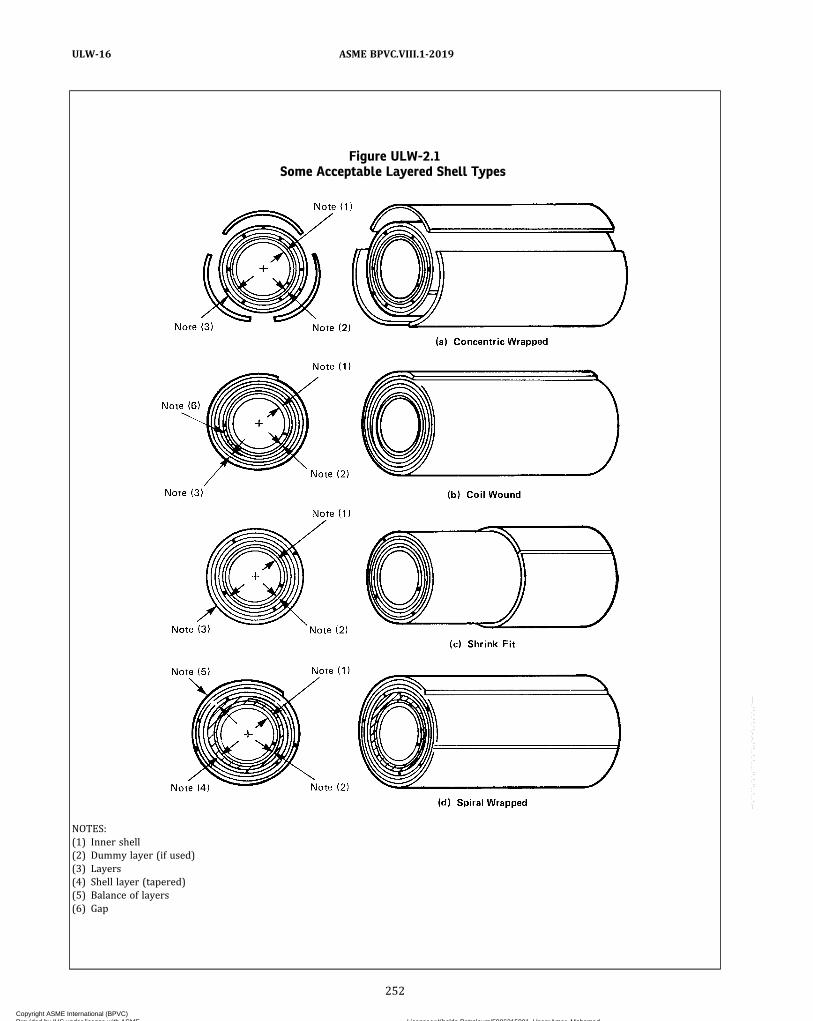
Figure ULW-2.1Some Acceptable Layered Shell Types
NOTES:(1) Inner shell(2) Dummy layer (if used)(3) Layers(4) Shell layer (tapered)(5) Balance of layers(6) Gap
252
ASME BPVC.VIII.1-2019ULW-16
Copyright ASME International (BPVC) Provided by IHS under license with ASME Licensee=Khalda Petroleum/5986215001, User=Amer, Mohamed
Not for Resale, 07/02/2019 13:29:04 MDTNo reproduction or networking permitted without license from IHS
--`,``,``,,`,`,,````,`,``,,,`-`-`,,`,,`,`,,`---

Figure ULW-2.2Some Acceptable Layered Head Types
NOTES:(1) Inner head(2) Dummy layer (if used)(3) Head layers
253
ASME BPVC.VIII.1-2019 ULW-16
Copyright ASME International (BPVC) Provided by IHS under license with ASME Licensee=Khalda Petroleum/5986215001, User=Amer, Mohamed
Not for Resale, 07/02/2019 13:29:04 MDTNo reproduction or networking permitted without license from IHS
--`,``,``,,`,`,,````,`,``,,,`-`-`,,`,,`,`,,`---

SL = design stress of layerstac t = nominal thickness of inner shell or inner headte f f = effective thickness of inner shell or inner head
(c) Layers in which the maximum allowable stress val-ue of the materials is within 20% of the other layers maybe used by prorating the maximum allowable stress of thelayers in the thickness formula, provided the materialsare compatible in modulus of elasticity and coefficientof thermal expansion.(d) The minimum thickness of any layer shall not be
less than 1/8 in. (3 mm).(e) Torispherical layered heads are not permitted.
ULW-17 DESIGN OF WELDED JOINTS(a) Category A and B joints of inner shells and inner
heads of layered sections shall be as follows:(1) Category A joints shall be Type No. (1) of Table
UW-12.(2) Category B joints shall be Type No. (1) or (2) of
Table UW-12.(b) Category A joints of layered sections shall be as
follows:(1) Category A joints of layers over 7/8 in. (22 mm). in
thickness shall be Type No. (1) of Table UW-12.(2) Category A joints of layers 7/8 in. (22 mm) or less
in thickness shall be of Type No. (1) or (2) of TableUW-12, except the final outside weld joint of spiralwrapped layered shells may be a single lap weld.(c) Category B joints of layered shell sections to layered
shell sections, or layered shell sections to solid shell sec-tions, shall be of Type (1) or (2) of Table UW-12.
(1) Category B joints of layered sections to layeredsections of unequal thickness shall have transitions asshown in Figure ULW-17.1, sketch (a) or (b).
(2) Category B joints of layered sections to solid sec-tions of unequal thickness shall have transitions as shownin Figure ULW-17.1, sketch (c), (d), (e), or (f).
(3) Category B joints of layered sections to layeredsections of equal thickness shall be as shown in FigureULW-17.6, sketch (b), (c), (f), or (g).
(4) Category B joints of layered sections to solid sec-tions of equal thickness shall be as shown in FigureULW-17.6, sketch (a) or (e).(d) Category A joints of solid hemispherical heads to
layered shell sections shall be of Type (1) or (2) of TableUW-12.
(1) Transit ions shal l be as shown in FigureULW-17.2, sketch (a), (b‐1), (b‐2), or (b‐3) when thehemispherical head thickness is less than the thicknessof the layered shell section and the transition is made inthe layered shell section.
(2) Transit ions shal l be as shown in FigureULW-17.2, sketch (c), (d‐1), or (e) when the hemispheri-cal head thickness is greater than the thickness of thelayered shell section and transition is made in the layeredshell section.
(3) Transition shall be as shown in Figure ULW-17.2,sketch (f) when the hemispherical head thickness is lessthan the thickness of the layered shell section and thetransition is made in the hemispherical head section.(e) Category B joints of solid elliptical, torispherical, or
conical heads to layered shell sections shall be of Type (1)or (2) of Table UW-12. Transitions shall be as shown inFigure ULW-17.2, sketch (c), (d‐1), (d‐2), (e), or (f).(f) Category C joints of solid flat heads and tubesheets
to layered shell sections shall be of Type (1) or (2) ofTable UW-12 as indicated in Figure ULW-17.3. Transi-tions, if applicable, shall be used as shown in FigureULW-17.1, sketch (c), (d), (e), or (f).(g) Category C joints attaching solid flanges to layered
shell sections and layered flanges to layered shell sectionsshall be of Type (1) or (2) of Table UW-12 as indicated inFigure ULW-17.4.(h) Category A joints of layered hemispherical heads to
layered shell sections shall be of Type (1) or (2) of TableUW-12 with a transition as shown in Figure ULW-17.5,sketch (a‐1) or (a‐2).(i) Category B joints of layered conical heads to layered
shell sections shall be of Type (1) or (2) of Table UW-12with transitions as shown in Figure ULW-17.5, sketch(b‐1).(j) Category B joints of layered shells to layered shell
sections or layered shell sections to solid heads or shellsmay be butt joints as shown in Figure ULW-17.6, sketches(c), (d), and (e), or step welds as shown in FigureULW-17.6, sketches (a), (b), (f), and (g).(k) Category D joints of solid nozzles, manholes, and
other connections to layered shell or layered head sec-tions shall be full penetration welds as shown in FigureULW-18.1 except as permitted in sketch (i), (j), (k), or(l). Category D joints between layered nozzles and shellsor heads are not permitted.(l) When layers of Category A joints as shown in Figure
ULW-17.2, sketches (a), (b‐1), (b‐2), and (b‐3) and FigureULW-17.5, sketches (a‐1) and (a‐2) are welded with filletwelds having a taper less than 3:1, the longitudinal loadresisted by the weld shall not exceed the allowable loadas defined in UW-18(d). No resistance due to friction shallbe used in determining the longitudinal load at the welds.The longitudinal load resisted by the weld shall considerthe load transferred from the remaining outer layers.
ULW-18 NOZZLE ATTACHMENTS AND OPENINGREINFORCEMENT
(a) All openings, except as provided in (b) below, shallmeet the requirements for reinforcing per UG-36 throughUG-46. All reinforcements required for openings shall beintegral with the nozzle or provided in the layered sectionor both. Additional layers may be included for requiredreinforcement. Some acceptable nozzle geometries andattachments are shown in Figure ULW-18.1. Openingsare not permitted in the shell sections of helically woundinterlocking strip construction.
254
ASME BPVC.VIII.1-2019ULW-16 – ULW-18
Copyright ASME International (BPVC) Provided by IHS under license with ASME Licensee=Khalda Petroleum/5986215001, User=Amer, Mohamed
Not for Resale, 07/02/2019 13:29:04 MDTNo reproduction or networking permitted without license from IHS
--`,``,``,,`,`,,````,`,``,,,`-`-`,,`,,`,`,,`---

Figure ULW-17.1Transitions of Layered Shell Sections
Taper line
(b) Details of Taper forLayers 5/8 in. (16 mm)or Less in Thickness
(a) For Layers Over 5/8 in. (16 mm) Thickness
(d) For Layers 5/8 in. (16 mm) or Less in Thickness
(c) For Layers Over 5/8 in. (16 mm) Thickness
(f) For Layers 5/8 in. (16 mm) or Less in Thickness
(e) For Layers Over 5/8 in. (16 mm) Thickness
tL or Y
3:1 taper min., see detail sketch (b)
3:1 taper min.3:1 taper min.
3:1 taper, see detail sketch (a)
Optional weld line (Category B)
Weld line (Category B)
Weld line (Category B)
Weld line (Category B)Weld optional
Weld optional 0.7tL min.
tLtL
Y
3tL min.
2/3tL min.
GENERAL NOTES:(a) Taper may be inside or outside or both.(b) ℓ ≥ 3Y , where ℓ is required length of taper and Y is the offset. tL is the thickness of one layer. The length of required taper may include the
width of the weld. The transition may be on either or both sides.
255
ASME BPVC.VIII.1-2019 ULW-18
Copyright ASME International (BPVC) Provided by IHS under license with ASME Licensee=Khalda Petroleum/5986215001, User=Amer, Mohamed
Not for Resale, 07/02/2019 13:29:04 MDTNo reproduction or networking permitted without license from IHS
--`,``,``,,`,`,,````,`,``,,,`-`-`,,`,,`,`,,`---

Figure ULW-17.2Some Acceptable Solid Head Attachments to Layered Shell Sections
tS
tS tL
tS
tL
tS
Y
tL
tL
tH
Taper line
Butt weld line (Category A)
Taper line Tangent line
Tangent line
(b-2) Details of Taper for
Layers 7/8 in. (22 mm)
or Less in Thickness
(b-3) Details of Taper for
Layers 5/8 in. (16 mm)
or Less in Thickness
Hemispherical
Heads Only
(a) For Layers Over 5/8 in. (16 mm)
in Thickness
(b-1) Details of Taper for
Layers 7/8 in. (22 mm)
or Less in Thickness
Hemispherical
Heads Only
0.7tL min.
0.7tL min.
tL
3tL min.
3tL min.
Taper line
Butt weld line (Category A)
Weld [See Note (1)]
0.7tL min.
3tL min.
2/3tL min. for chamfered layers
Y
Y
Y
3Y
3Y 3Y
3Y
tH tH
tH
256
ASME BPVC.VIII.1-2019ULW-18
Copyright ASME International (BPVC) Provided by IHS under license with ASME Licensee=Khalda Petroleum/5986215001, User=Amer, Mohamed
Not for Resale, 07/02/2019 13:29:04 MDTNo reproduction or networking permitted without license from IHS
--`,``,``,,`,`,,````,`,``,,,`-`-`,,`,,`,`,,`---
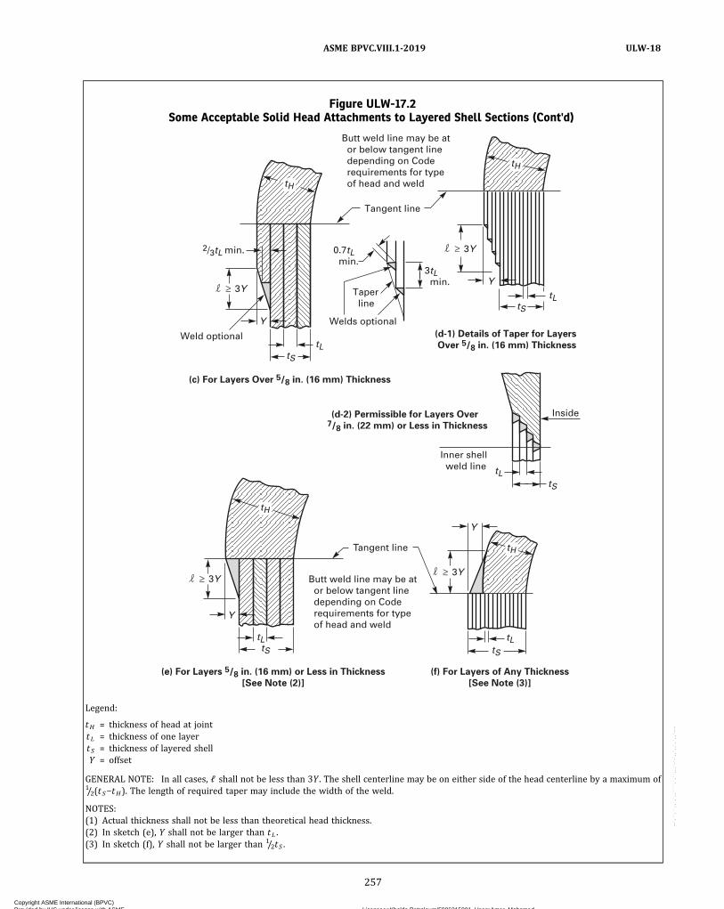
Figure ULW-17.2Some Acceptable Solid Head Attachments to Layered Shell Sections (Cont'd)
Welds optional
Weld optional
Taper line
Tangent line
3tL min.
0.7tL min.
Tangent line
(c) For Layers Over 5/8 in. (16 mm) Thickness
(f) For Layers of Any Thickness
[See Note (3)]
(e) For Layers 5/8 in. (16 mm) or Less in Thickness
[See Note (2)]
(d-1) Details of Taper for Layers
Over 5/8 in. (16 mm) Thickness
(d-2) Permissible for Layers Over 7/8 in. (22 mm) or Less in Thickness
Inner shell weld line
Inside
Butt weld line may be at or below tangent line depending on Code requirements for type of head and weld
Butt weld line may be at or below tangent line depending on Code requirements for type of head and weld
Y
tL tS
tL tS
Y tL
tS
Y
tL tS
2/3tL min.
3Y 3Y
3Y
Y
tL tS
3Y
tH
tH
tH
tH
Legend:
tH = thickness of head at jointtL = thickness of one layertS = thickness of layered shellY = offset
GENERAL NOTE: In all cases, ℓ shall not be less than 3Y . The shell centerline may be on either side of the head centerline by a maximum of1/2(tS−tH). The length of required taper may include the width of the weld.
NOTES:(1) Actual thickness shall not be less than theoretical head thickness.(2) In sketch (e), Y shall not be larger than tL .(3) In sketch (f), Y shall not be larger than 1/2tS .
257
ASME BPVC.VIII.1-2019 ULW-18
Copyright ASME International (BPVC) Provided by IHS under license with ASME Licensee=Khalda Petroleum/5986215001, User=Amer, Mohamed
Not for Resale, 07/02/2019 13:29:04 MDTNo reproduction or networking permitted without license from IHS
--`,``,``,,`,`,,````,`,``,,,`-`-`,,`,,`,`,,`---
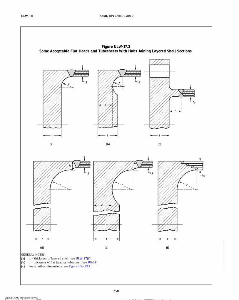
Figure ULW-17.3Some Acceptable Flat Heads and Tubesheets With Hubs Joining Layered Shell Sections
h
tS
tS tStS
rtS
tS
ttt
(a) (b) (c)
e
e
r
r rr
t
(f)
t
(d)
t
(e)
tf tf
GENERAL NOTES:(a) ts = thickness of layered shell [see ULW-17(f)](b) t = thickness of flat head or tubesheet [see UG-34](c) For all other dimensions, see Figure UW-13.3.
258
ASME BPVC.VIII.1-2019ULW-18
Copyright ASME International (BPVC) Provided by IHS under license with ASME Licensee=Khalda Petroleum/5986215001, User=Amer, Mohamed
Not for Resale, 07/02/2019 13:29:04 MDTNo reproduction or networking permitted without license from IHS
--`,``,``,,`,`,,````,`,``,,,`-`-`,,`,,`,`,,`---

Figure ULW-17.4Some Acceptable Flanges for Layered Shells
tS tS tS
Weld line
tS = thickness of layered shell
1
3
1
3
1
3
1
3
1
3 1
3
1
3
Weld line optional
Weld overlay 15 bolt dia. min. but not less than 3/8 in. (10 mm)
Weld line optional
Weld line optional
Weld line optional
Retaining ring
Retaining ring
Retaining ring
(g-1)
[See Note (2)]
(g)
[See Note (2)]
(e), (e-1), (f), (f-1), (g), (g-1)
[See Notes (2) and (3)]
(f-1)
[See Notes (2) and (3)]
(f)
[See Notes (2) and (3)]
(e-1)
[See Notes (2) and (3)]
(e)
[See Notes (2) and (3)]
(a) [See Note (1)] (b) [See Note (1)] (c) (d)
Tapped holes
Weld line
tS
NOTES:(1) For sketches (a) and (b), see Figure 2-4 for all dimensions and requirements.(2) The following limitations apply to sketches (e), (e-1), (f), (f-1), (g), and (g-1):
(a) The weld overlay shall tie the overlay, the overwraps, and layers together.(b)The bolt circle shall not exceed the outside diameter of the shell.
(3) For sketches (e), (e-1), (f), and (f-1), the angle of transition and size of fillet welds are optional. The bolt circle diameter shall be less thanthe outside diameter of the layered shell.
259
ASME BPVC.VIII.1-2019 ULW-18
Copyright ASME International (BPVC) Provided by IHS under license with ASME Licensee=Khalda Petroleum/5986215001, User=Amer, Mohamed
Not for Resale, 07/02/2019 13:29:04 MDTNo reproduction or networking permitted without license from IHS
--`,``,``,,`,`,,````,`,``,,,`-`-`,,`,,`,`,,`---

Figure ULW-17.5Some Acceptable Layered Head Attachments to Layered Shells
tL
tL
tS
1/2(tS – tH)tL
Y
tH
60 deg min.
Weld line(Category B)
Tangent line
(a-2)(a-1)
(b-1)
Butt weld line(Category A)
3:1 taper
Taper line
Detail of taper0.7tL min.
0.7tL min.
3tL min.
tL
tLtH
tL
tL
tH
tL
tS
tS
3Y
Legend:
tH = thickness of layered headtL = thickness of one layertS = thickness of layered shellY = offset
260
ASME BPVC.VIII.1-2019ULW-18
Copyright ASME International (BPVC) Provided by IHS under license with ASME Licensee=Khalda Petroleum/5986215001, User=Amer, Mohamed
Not for Resale, 07/02/2019 13:29:04 MDTNo reproduction or networking permitted without license from IHS
--`,``,``,,`,`,,````,`,``,,,`-`-`,,`,,`,`,,`---
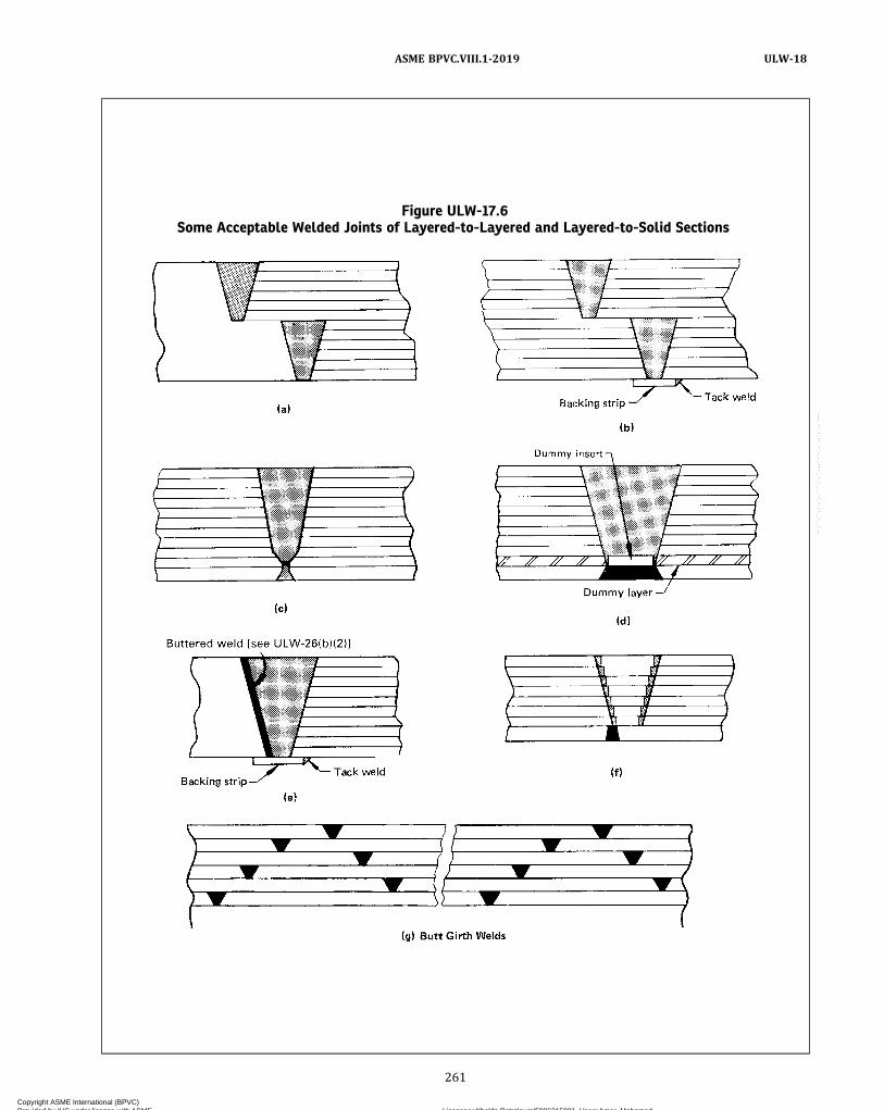
Figure ULW-17.6Some Acceptable Welded Joints of Layered-to-Layered and Layered-to-Solid Sections
261
ASME BPVC.VIII.1-2019 ULW-18
Copyright ASME International (BPVC) Provided by IHS under license with ASME Licensee=Khalda Petroleum/5986215001, User=Amer, Mohamed
Not for Resale, 07/02/2019 13:29:04 MDTNo reproduction or networking permitted without license from IHS
--`,``,``,,`,`,,````,`,``,,,`-`-`,,`,,`,`,,`---
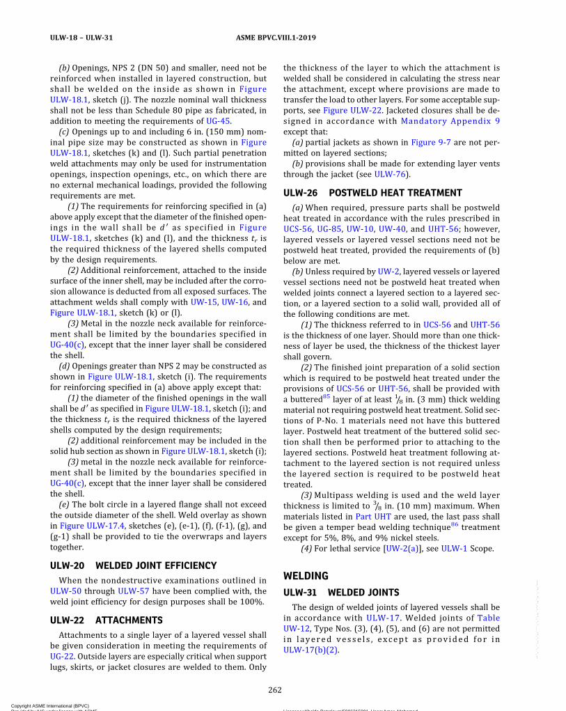
(b) Openings, NPS 2 (DN 50) and smaller, need not bereinforced when installed in layered construction, butshall be welded on the inside as shown in FigureULW-18.1, sketch (j). The nozzle nominal wall thicknessshall not be less than Schedule 80 pipe as fabricated, inaddition to meeting the requirements of UG-45.(c) Openings up to and including 6 in. (150 mm) nom-
inal pipe size may be constructed as shown in FigureULW-18.1, sketches (k) and (l). Such partial penetrationweld attachments may only be used for instrumentationopenings, inspection openings, etc., on which there areno external mechanical loadings, provided the followingrequirements are met.
(1) The requirements for reinforcing specified in (a)above apply except that the diameter of the finished open-ings in the wall shall be d ′ as specified in FigureULW-18.1, sketches (k) and (l), and the thickness tr isthe required thickness of the layered shells computedby the design requirements.
(2) Additional reinforcement, attached to the insidesurface of the inner shell, may be included after the corro-sion allowance is deducted from all exposed surfaces. Theattachment welds shall comply with UW-15, UW-16, andFigure ULW-18.1, sketch (k) or (l).
(3)Metal in the nozzle neck available for reinforce-ment shall be limited by the boundaries specified inUG-40(c), except that the inner layer shall be consideredthe shell.(d) Openings greater than NPS 2 may be constructed as
shown in Figure ULW-18.1, sketch (i). The requirementsfor reinforcing specified in (a) above apply except that:
(1) the diameter of the finished openings in the wallshall be d ′ as specified in Figure ULW-18.1, sketch (i); andthe thickness tr is the required thickness of the layeredshells computed by the design requirements;
(2) additional reinforcement may be included in thesolid hub section as shown in Figure ULW-18.1, sketch (i);
(3)metal in the nozzle neck available for reinforce-ment shall be limited by the boundaries specified inUG-40(c), except that the inner layer shall be consideredthe shell.(e) The bolt circle in a layered flange shall not exceed
the outside diameter of the shell. Weld overlay as shownin Figure ULW-17.4, sketches (e), (e‐1), (f), (f‐1), (g), and(g‐1) shall be provided to tie the overwraps and layerstogether.
ULW-20 WELDED JOINT EFFICIENCYWhen the nondestructive examinations outlined in
ULW-50 through ULW-57 have been complied with, theweld joint efficiency for design purposes shall be 100%.
ULW-22 ATTACHMENTSAttachments to a single layer of a layered vessel shall
be given consideration in meeting the requirements ofUG-22. Outside layers are especially critical when supportlugs, skirts, or jacket closures are welded to them. Only
the thickness of the layer to which the attachment iswelded shall be considered in calculating the stress nearthe attachment, except where provisions are made totransfer the load to other layers. For some acceptable sup-ports, see Figure ULW-22. Jacketed closures shall be de-signed in accordance with Mandatory Appendix 9except that:(a) partial jackets as shown in Figure 9-7 are not per-
mitted on layered sections;(b) provisions shall be made for extending layer vents
through the jacket (see ULW-76).
ULW-26 POSTWELD HEAT TREATMENT(a)When required, pressure parts shall be postweld
heat treated in accordance with the rules prescribed inUCS-56, UG-85, UW-10, UW-40, and UHT-56; however,layered vessels or layered vessel sections need not bepostweld heat treated, provided the requirements of (b)below are met.(b) Unless required by UW-2, layered vessels or layered
vessel sections need not be postweld heat treated whenwelded joints connect a layered section to a layered sec-tion, or a layered section to a solid wall, provided all ofthe following conditions are met.
(1) The thickness referred to in UCS-56 and UHT-56is the thickness of one layer. Should more than one thick-ness of layer be used, the thickness of the thickest layershall govern.
(2) The finished joint preparation of a solid sectionwhich is required to be postweld heat treated under theprovisions of UCS-56 or UHT-56, shall be provided witha buttered85 layer of at least 1/8 in. (3 mm) thick weldingmaterial not requiring postweld heat treatment. Solid sec-tions of P‐No. 1 materials need not have this butteredlayer. Postweld heat treatment of the buttered solid sec-tion shall then be performed prior to attaching to thelayered sections. Postweld heat treatment following at-tachment to the layered section is not required unlessthe layered section is required to be postweld heattreated.
(3)Multipass welding is used and the weld layerthickness is limited to 3/8 in. (10 mm) maximum. Whenmaterials listed in Part UHT are used, the last pass shallbe given a temper bead welding technique86 treatmentexcept for 5%, 8%, and 9% nickel steels.
(4) For lethal service [UW-2(a)], see ULW-1 Scope.
WELDING
ULW-31 WELDED JOINTSThe design of welded joints of layered vessels shall be
in accordance with ULW-17. Welded joints of TableUW-12, Type Nos. (3), (4), (5), and (6) are not permittedin layered vesse l s , except as prov ided for inULW-17(b)(2).
262
ASME BPVC.VIII.1-2019ULW-18 – ULW-31
Copyright ASME International (BPVC) Provided by IHS under license with ASME Licensee=Khalda Petroleum/5986215001, User=Amer, Mohamed
Not for Resale, 07/02/2019 13:29:04 MDTNo reproduction or networking permitted without license from IHS
--`,``,``,,`,`,,````,`,``,,,`-`-`,,`,,`,`,,`---
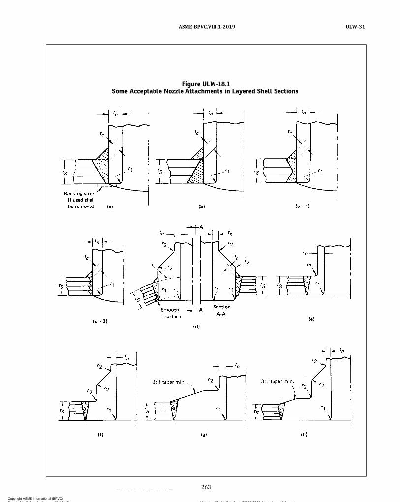
Figure ULW-18.1Some Acceptable Nozzle Attachments in Layered Shell Sections
263
ASME BPVC.VIII.1-2019 ULW-31
Copyright ASME International (BPVC) Provided by IHS under license with ASME Licensee=Khalda Petroleum/5986215001, User=Amer, Mohamed
Not for Resale, 07/02/2019 13:29:04 MDTNo reproduction or networking permitted without license from IHS
--`,``,``,,`,`,,````,`,``,,,`-`-`,,`,,`,`,,`---

Figure ULW-18.1Some Acceptable Nozzle Attachments in Layered Shell Sections (Cont'd)
11/4tn min.
11/4tn min.
Inner shell
Reinforcing pad
Integral nozzle reinforcement
1 3 (min.) Chamfer
Full circumferential reinforcement layers (over wraps)
1/2tL min.
d'
d' C max.
C max.
tc
tc
tL
tL
tn
r1
r2
tS
d'
C max.
tn
r1
r1 tS
tn
11/4tn min.
Vent for liner
d'
C max.
Inner shell
(i) [See Note (1)] (j) [See Note (1)]
(k) [See Note (1)] (l) [See Note (1)]
Solid hub with integral reinforcement
r3 r2
r1 tS
tn
C max. = 1/8 in. (3 mm) radial clearance between nozzle neckand vessel opening
d ′ = finished opening in the wall (refer to ULW-18 formaximum permissible diameter)
r1 min. = 1/4tn or 1/8 in. (3 mm), whichever is lessr2 = 1/4 in. (6 mm) minimum
r3 min. = 1/4tn or 3/4 in. (19 mm), whichever is less
t c = not less than 1/4 in. (6 mm) or 0.7 of the smaller of3/4 in. (19 mm) or tn
tL = thickness of one layert min. = the smaller of 3/4 in. (19 mm) or tn
tn = nominal thickness of nozzle walltS = thickness of layered shell
NOTE:(1) Provide means, other than by seal welding, to prevent entry of external foreign matter into the annulus between the layers and the nozzle
neck O.D. for sketches (i), (j), (k), and (l).
264
ASME BPVC.VIII.1-2019ULW-31
Copyright ASME International (BPVC) Provided by IHS under license with ASME Licensee=Khalda Petroleum/5986215001, User=Amer, Mohamed
Not for Resale, 07/02/2019 13:29:04 MDTNo reproduction or networking permitted without license from IHS
--`,``,``,,`,`,,````,`,``,,,`-`-`,,`,,`,`,,`---

Figure ULW-22Some Acceptable Supports for Layered Vessels
NOTE:(1) For other than hemi-heads, special consideration shall be given to the discontinuity stress.
265
ASME BPVC.VIII.1-2019 ULW-31
Copyright ASME International (BPVC) Provided by IHS under license with ASME Licensee=Khalda Petroleum/5986215001, User=Amer, Mohamed
Not for Resale, 07/02/2019 13:29:04 MDTNo reproduction or networking permitted without license from IHS
--`,``,``,,`,`,,````,`,``,,,`-`-`,,`,,`,`,,`---
ð19Þ
ULW-32 WELDING PROCEDURE QUALIFICATIONWelding procedure qualifications shall be in accor-
dance with Section IX except as modified herein.(a) The minimum and maximum thicknesses qualified
by procedure qualification test plates shall be as shownin Section IX, Tables QW-451.1 through QW-451.4, exceptthat:
(1) for the longitudinal joints of the layer section ofthe shell, the qualification shall be based upon the thick-ness of the thickest individual layer, exclusive of the innershell or inner head;
(2) for circumferential joint procedure qualification,the thickness of the layered test plate need not exceed3 in. (75 mm), shall consist of at least 2 layers, but shallnot be less than 2 in. (50 mm) in thickness;
(3) for circumferential weld joints made individuallyfor single layers and spaced at least one layer thicknessapart, the procedure qualification for the longitudinaljoint applies.(b) The longitudinal weld joint of the inner shell or in-
ner head and the longitudinal weld joint of layer shell orlayer head shall be qualified separately except if of thesame P‐Number material. The weld gap of the longitudi-nal layer weld joint shall be the minimum width used inthe procedure qualification for layers 7/8 in. (22 mm)and less in thickness.(c) The circumferential weld joint of the layered to
layered sections shall be qualified with a simulated layertest plate as shown in Figure ULW-32.1 for layer thick-nesses 7/8 in. (22 mm) and under. A special type of jointtensile specimen shall be made from the layer test couponas shown in Figure ULW-32.2. (See also FigureULW-32.4.) Face and root bend specimens shall be madeof both the inner and outer weld to the thickness of thelayer by cutting the weld to the layer thickness.(d) The circumferential weld joint of the layer shell for
layer thicknesses 7/8 in. (22 mm) and under to the solidhead, flange, or end closure shall be qualified with a sim-ulated layer test coupon as shown in Figure ULW-32.1wherein the one side of the test coupon is solid through-out its entire thickness. A special type of joint tensile spe-cimen shall be made from the test coupon as shown inFigure ULW-32.3. (See also Figure ULW-32.4.) Face androot bend specimens shall be made of both the innerand outer weld to the thickness of the layer by slicingthe weld and solid portion to the layer thickness.
ULW-33 PERFORMANCE QUALIFICATIONWelding shall be performed only by welders and weld-
ing operators who have been qualified as given in SectionIX. The minimum and maximum thicknesses qualified byany welder test plate shall be as shown on Section IX,QW-452 tables.
NONDESTRUCTIVE EXAMINATION OFWELDED JOINTS
ULW-50 GENERALThe rules of the following paragraphs apply specifically
to the nondestructive examination of pressure vesselsand vessel parts that are fabricated using layeredconstruction.
ULW-51 INNER SHELLS AND INNER HEADSCategory A and B joints in the inner shells of layered
shell sections, and in the inner heads of layered heads be-fore application of the layers, shall be examined through-out their entire length by radiography and meet therequirements of UW-51.
ULW-52 LAYERS — WELDED JOINTS(a) Category A joints in layers 1/8 in. (3 mm) through
5/16 in. (8 mm) in thickness welded to the previous surfaceshall be examined for 100% of their length in accordancewith Mandatory Appendix 6 by the magnetic particlemethod using direct current only when the material is fer-romagnetic. The liquid penetrant method in accordancewith Mandatory Appendix 8 shall be used when the mate-rial is nonferromagnetic.(b) Category A joints in layers over 5/16 in. (8 mm)
through 5/8 in. (16 mm) in thickness welded to the pre-vious surface shall be examined for 100% of their lengthin accordance with Mandatory Appendix 6 by the mag-netic particle method using direct current only whenthe material is ferromagnetic. The liquid penetrant meth-od in accordance with Mandatory Appendix 8 shall beused when the material is nonferromagnetic. In addition,these joints shall be examined for 10% of their length atrandom in accordance with Mandatory Appendix 12 ul-trasonic method except that for the bottom 10% of theweld thickness the distance amplitude correction curveor reference level may be raised by 6 dB. The random spotexamination shall be performed as specified in ULW-57.(c) Category A joints in layers over 5/8 in. (16 mm)
through 7/8 in. (22 mm) in thickness welded to the pre-vious surface shall be examined for 100% of their lengthin accordance with Mandatory Appendix 12 ultrasonicmethod except that for the bottom 10% of the weld thick-ness the distance amplitude correction curve or referencelevel may be raised by 6 dB.(d) Category A joints in layers not welded to the pre-
vious surface shall be examined before assembly for100% of their length by radiography and meet the re-quirements of UW-51.(e) Welds in spirally wound strip construction with a
winding or spiral angle of 75 deg or less measured fromthe vessel axial centerline shall be classified as CategoryA joints and examined accordingly.
266
ASME BPVC.VIII.1-2019ULW-32 – ULW-52
Copyright ASME International (BPVC) Provided by IHS under license with ASME Licensee=Khalda Petroleum/5986215001, User=Amer, Mohamed
Not for Resale, 07/02/2019 13:29:04 MDTNo reproduction or networking permitted without license from IHS
--`,``,``,,`,`,,````,`,``,,,`-`-`,,`,,`,`,,`---
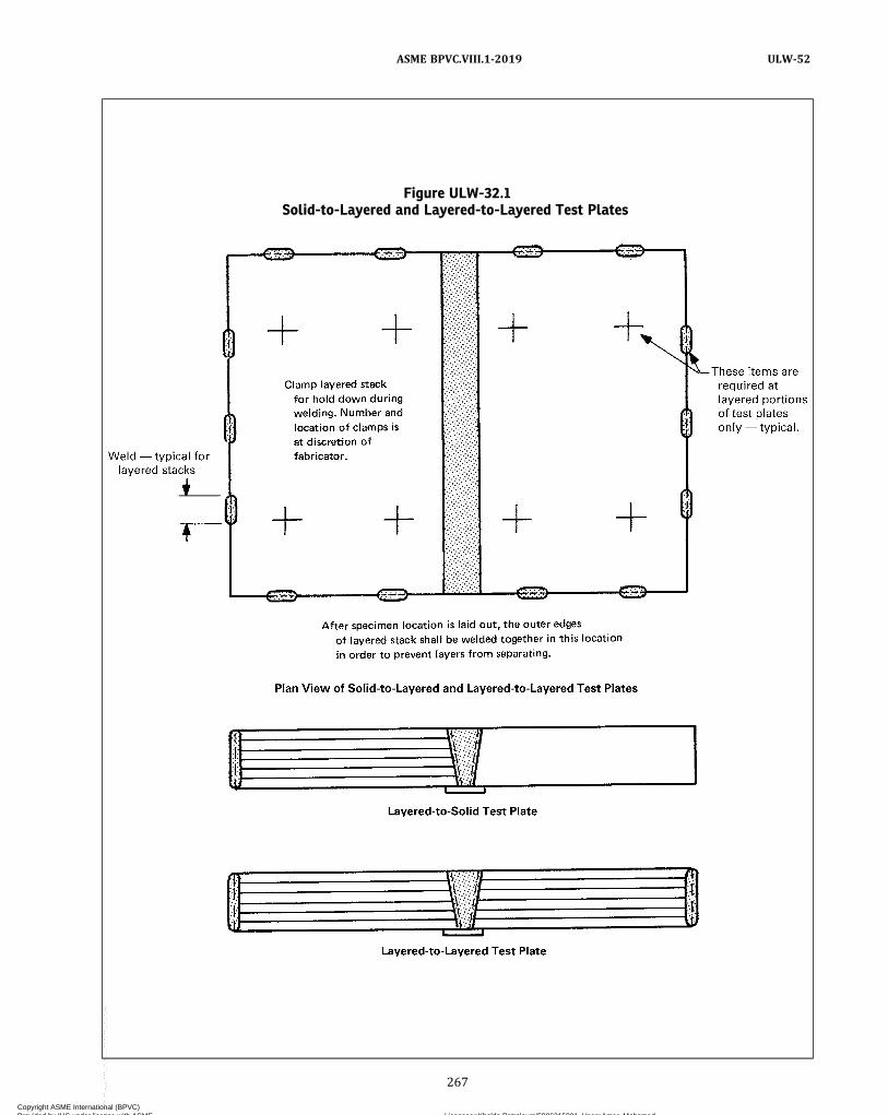
Figure ULW-32.1Solid-to-Layered and Layered-to-Layered Test Plates
267
ASME BPVC.VIII.1-2019 ULW-52
Copyright ASME International (BPVC) Provided by IHS under license with ASME Licensee=Khalda Petroleum/5986215001, User=Amer, Mohamed
Not for Resale, 07/02/2019 13:29:04 MDTNo reproduction or networking permitted without license from IHS
--`,``,``,,`,`,,````,`,``,,,`-`-`,,`,,`,`,,`---
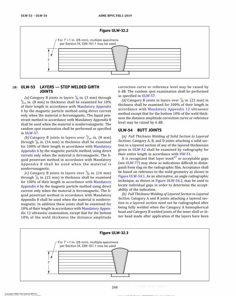
ð19Þ ULW-53 LAYERS — STEP WELDED GIRTHJOINTS
(a) Category B joints in layers 1/8 in. (3 mm) through5/16 in. (8 mm) in thickness shall be examined for 10%of their length in accordance with Mandatory Appendix6 by the magnetic particle method using direct currentonly when the material is ferromagnetic. The liquid pen-etrant method in accordance with Mandatory Appendix 8shall be used when the material is nonferromagnetic. Therandom spot examination shall be performed as specifiedin ULW-57.(b) Category B joints in layers over 5/16 in. (8 mm)
through 5/8 in. (16 mm) in thickness shall be examinedfor 100% of their length in accordance with MandatoryAppendix 6 by the magnetic particle method, using directcurrent only when the material is ferromagnetic. The li-quid penetrant method in accordance with MandatoryAppendix 8 shal l be used when the material isnonferromagnetic.(c) Category B joints in layers over 5/8 in. (16 mm)
through 7/8 in. (22 mm) in thickness shall be examinedfor 100% of their length in accordance with MandatoryAppendix 6 by the magnetic particle method using directcurrent only when the material is ferromagnetic. The li-quid penetrant method in accordance with MandatoryAppendix 8 shall be used when the material is nonferro-magnetic. In addition these joints shall be examined for10% of their length in accordance with Mandatory Appen-dix 12 ultrasonic examination, except that for the bottom10% of the weld thickness the distance amplitude
correction curve or reference level may be raised by6 dB. The random spot examination shall be performedas specified in ULW-57.(d) Category B joints in layers over 7/8 in. (22 mm) in
thickness shall be examined for 100% of their length inaccordance with Mandatory Appendix 12 ultrasonicmethod except that for the bottom 10% of the weld thick-ness the distance amplitude correction curve or referencelevel may be raised by 6 dB.
ULW-54 BUTT JOINTS(a) Full Thickness Welding of Solid Section to Layered
Sections. Category A, B, and D joints attaching a solid sec-tion to a layered section of any of the layered thicknessesgiven in ULW-52 shall be examined by radiography fortheir entire length in accordance with UW-51.It is recognized that layer wash87 or acceptable gaps
(see ULW-77) may show as indications difficult to distin-guish from slag on the radiographic film. Acceptance shallbe based on reference to the weld geometry as shown inFigure ULW-54.1. As an alternative, an angle radiographictechnique, as shown in Figure ULW-54.2, may be used tolocate individual gaps in order to determine the accept-ability of the indication.(b) Full Thickness Welding of Layered Section to Layered
Section. Category A and B joints attaching a layered sec-tion to a layered section need not be radiographed afterbeing fully welded when the Category A hemisphericalhead and Category B welded joints of the inner shell or in-ner head made after application of the layers have been
Figure ULW-32.2
T
For T 1 in. (25 mm), multiple specimens per Section IX, QW-151.1 may be used
Figure ULW-32.3
T
For T 1 in. (25 mm), multiple specimens per Section IX, QW-151.1 may be used
268
ASME BPVC.VIII.1-2019ULW-53 – ULW-54
Copyright ASME International (BPVC) Provided by IHS under license with ASME Licensee=Khalda Petroleum/5986215001, User=Amer, Mohamed
Not for Resale, 07/02/2019 13:29:04 MDTNo reproduction or networking permitted without license from IHS
--`,``,``,,`,`,,````,`,``,,,`-`-`,,`,,`,`,,`---
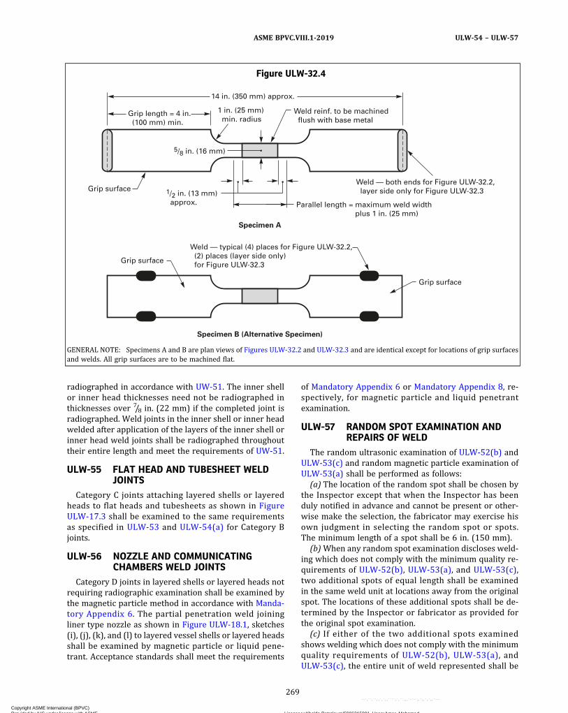
radiographed in accordance with UW-51. The inner shellor inner head thicknesses need not be radiographed inthicknesses over 7/8 in. (22 mm) if the completed joint isradiographed. Weld joints in the inner shell or inner headwelded after application of the layers of the inner shell orinner head weld joints shall be radiographed throughouttheir entire length and meet the requirements of UW-51.
ULW-55 FLAT HEAD AND TUBESHEET WELDJOINTS
Category C joints attaching layered shells or layeredheads to flat heads and tubesheets as shown in FigureULW-17.3 shall be examined to the same requirementsas specified in ULW-53 and ULW-54(a) for Category Bjoints.
ULW-56 NOZZLE AND COMMUNICATINGCHAMBERS WELD JOINTS
Category D joints in layered shells or layered heads notrequiring radiographic examination shall be examined bythe magnetic particle method in accordance with Manda-tory Appendix 6. The partial penetration weld joiningliner type nozzle as shown in Figure ULW-18.1, sketches(i), (j), (k), and (l) to layered vessel shells or layered headsshall be examined by magnetic particle or liquid pene-trant. Acceptance standards shall meet the requirements
of Mandatory Appendix 6 or Mandatory Appendix 8, re-spectively, for magnetic particle and liquid penetrantexamination.
ULW-57 RANDOM SPOT EXAMINATION ANDREPAIRS OF WELD
The random ultrasonic examination of ULW-52(b) andULW-53(c) and random magnetic particle examination ofULW-53(a) shall be performed as follows:
(a) The location of the random spot shall be chosen bythe Inspector except that when the Inspector has beenduly notified in advance and cannot be present or other-wise make the selection, the fabricator may exercise hisown judgment in selecting the random spot or spots.The minimum length of a spot shall be 6 in. (150 mm).
(b)When any random spot examination discloses weld-ing which does not comply with the minimum quality re-quirements of ULW-52(b), ULW-53(a), and ULW-53(c),two additional spots of equal length shall be examinedin the same weld unit at locations away from the originalspot. The locations of these additional spots shall be de-termined by the Inspector or fabricator as provided forthe original spot examination.
(c) If either of the two additional spots examinedshows welding which does not comply with the minimumquality requirements of ULW-52(b), ULW-53(a), andULW-53(c), the entire unit of weld represented shall be
Figure ULW-32.4
Grip length = 4 in. (100 mm) min.
14 in. (350 mm) approx.
Weld reinf. to be machined flush with base metal
1/2 in. (13 mm) approx.
5/8 in. (16 mm)
Grip surface
Grip surface
Grip surface
Specimen B (Alternative Specimen)
Specimen A
Weld — both ends for Figure ULW-32.2, layer side only for Figure ULW-32.3
Weld — typical (4) places for Figure ULW-32.2, (2) places (layer side only) for Figure ULW-32.3
Parallel length = maximum weld width plus 1 in. (25 mm)
1 in. (25 mm) min. radius
GENERAL NOTE: Specimens A and B are plan views of Figures ULW-32.2 and ULW-32.3 and are identical except for locations of grip surfacesand welds. All grip surfaces are to be machined flat.
269
ASME BPVC.VIII.1-2019 ULW-54 – ULW-57
Copyright ASME International (BPVC) Provided by IHS under license with ASME Licensee=Khalda Petroleum/5986215001, User=Amer, Mohamed
Not for Resale, 07/02/2019 13:29:04 MDTNo reproduction or networking permitted without license from IHS
--`,``,``,,`,`,,````,`,``,,,`-`-`,,`,,`,`,,`---
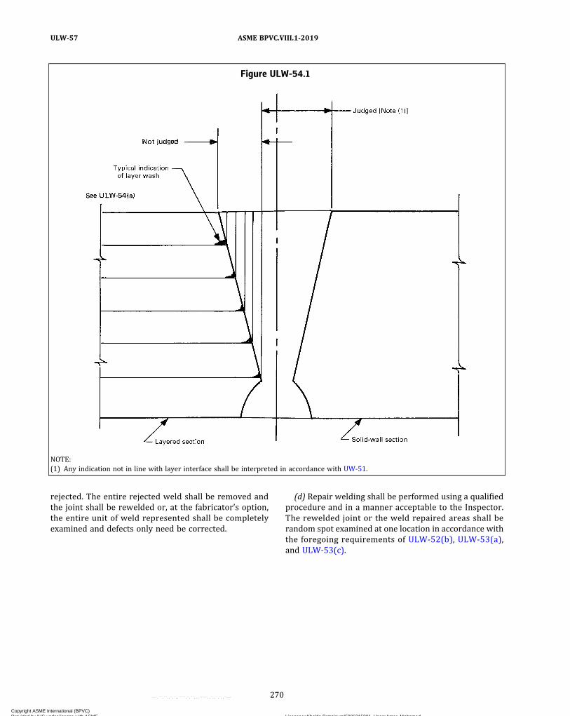
rejected. The entire rejected weld shall be removed andthe joint shall be rewelded or, at the fabricator’s option,the entire unit of weld represented shall be completelyexamined and defects only need be corrected.
(d) Repair welding shall be performed using a qualifiedprocedure and in a manner acceptable to the Inspector.The rewelded joint or the weld repaired areas shall berandom spot examined at one location in accordance withthe foregoing requirements of ULW-52(b), ULW-53(a),and ULW-53(c).
Figure ULW-54.1
NOTE:(1) Any indication not in line with layer interface shall be interpreted in accordance with UW-51.
270
ASME BPVC.VIII.1-2019ULW-57
Copyright ASME International (BPVC) Provided by IHS under license with ASME Licensee=Khalda Petroleum/5986215001, User=Amer, Mohamed
Not for Resale, 07/02/2019 13:29:04 MDTNo reproduction or networking permitted without license from IHS
--`,``,``,,`,`,,````,`,``,,,`-`-`,,`,,`,`,,`---

Figure ULW-54.2
271
ASME BPVC.VIII.1-2019 ULW-57
Copyright ASME International (BPVC) Provided by IHS under license with ASME Licensee=Khalda Petroleum/5986215001, User=Amer, Mohamed
Not for Resale, 07/02/2019 13:29:04 MDTNo reproduction or networking permitted without license from IHS
--`,``,``,,`,`,,````,`,``,,,`-`-`,,`,,`,`,,`---

FABRICATION
ULW-75 GENERALThe rules in the following paragraphs apply to layered
shells, layered heads, and layered transition sections thatare fabricated by welding and shall be used in conjunctionwith the general requirements for Fabrication in Subsec-tion A, UG-75 through UG-85, with the exception ofUG-83. For layered vessels, the minimum thickness per-mitted for layers is 1/8 in. (3 mm).
ULW-76 VENT HOLESVent holes shall be provided to detect leakage of the in-
ner shell and to prevent buildup of pressure within thelayers as follows:(a) In each shell course or head segment a layer may be
made up of one or more plates. Each layer plate shall haveat least two vent holes 1/4 in. (6 mm) minimum diameter.Holes may be drilled radially through the multiple layersor may be staggered in individual layer plates.(b) For continuous coil wrapped layers, each layered
section shall have at least four vent holes 1/4 in. (6 mm)minimum diameter. Two of these vent holes shall be lo-cated near each end of the section and spaced approxi-mately 180 deg apart.(c) The minimum requirement for spirally wound strip
layered construction shall be 1/4 in. (6 mm) minimum dia-meter vent holes drilled near both edges of the strip. Theyshall be spaced for the full length of the strip and shall belocated a distance of approximately πR tan θ from eachother where
R = the mean radius of the shellθ = the acute angle of spiral wrap measured from longi-
tudinal centerline, deg
If a strip weld covers a vent hole, partially or totally, anadditional vent hole shall be drilled on each side of the ob-structed hole.In lieu of the above, holes may be drilled radially
through the multiple layers.(d) Vent holes shall not be obstructed. If a monitoring
system is used, it shall be designed to prevent buildupof pressure within the layers.
ULW-77 CONTACT BETWEEN LAYERS(a) Category A weld joints shall be ground to ensure
contact between the weld area and the succeeding layer,before application of the layer.(b) Category A weld joints of layered shell sections shall
be in an offset pattern so that the centers of the weldedlongitudinal joints of adjacent layers are separated cir-cumferentially by a distance of at least five times the layerthickness.(c) Category A weld joints in layered heads may be in
an offset pattern; if offset, the joints of adjacent layersshall be separated by a distance of at least five timesthe layer thickness.
(d) After weld preparation and before welding circum-ferential seams, the height of the radial gaps between anytwo adjacent layers shall be measured at the ends of thelayered shell section or layered head section at right an-gles to the vessel axis, and also the length of the relevantradial gap in inches shall be measured [neglecting radialgaps of less than 0.010 in. (0.25 mm) as nonrelevant].An approximation of the area of the gap shall be calcu-lated as indicated in Figure ULW-77.The gap area Ag shall not exceed the thickness of a layer
expressed in square inches. The maximum length of anygap shall not exceed the inside diameter of the vessel.Where more than one gap exists between any two adja-cent layers, the sum of the gap lengths shall not exceedthe inside diameter of the vessel. The maximum heightof any gap shall not exceed 3/16 in. (5 mm).It is recognized that there may be vessels of dimensions
wherein it would be desirable to calculate a maximumpermissible gap area. This procedure is provided for inSection VIII, Division 2 rules for layered vessels in lieuof the maximum gap area empirically given above, exceptthat the maximum allowable stress S given in Section II,Part D, Subpart 1, Tables 1A and 1B shall be used insteadof the stress intensity Sm given in Section II, Part D, Sub-part 1, Tables 2A and 2B.(e) In the case of layered spheres or layered heads, if
the gaps cannot be measured as required in (d) above,measurement of gap heights shall be taken through ventholes in each layer course to assure that the height oflayer gaps between any two layers does not exceed thegap permitted in (d) above. The spacing of the vent holesshall be such that gap lengths can be determined. In theevent an excessive gap height is measured through a venthole, additional vent holes shall be drilled as required todetermine the gap length. There shall be at least one venthole per layer segment.
ULW-78 ALTERNATIVE TO MEASURINGCONTACT BETWEEN LAYERS DURINGCONSTRUCTION
As an alternative to ULW-77, the following measure-ments shall be taken at the time of the hydrostatic testto check on the contact between successive layers, andthe effect of gaps which may or may not be present be-tween layers.(a) The circumference shall be measured at the mid-
point between adjacent circumferential joints, or betweena circumferential joint and any nozzle in a shell course.Measurements shall be taken at zero pressure, and fol-lowing application of hydrostatic test pressure, at the de-sign pressure. The difference in measurements shall beaveraged for each course in the vessel and the results re-corded as average middle circumferential expansion em ininches (millimeters).
272
ASME BPVC.VIII.1-2019ULW-75 – ULW-78
Copyright ASME International (BPVC) Provided by IHS under license with ASME Licensee=Khalda Petroleum/5986215001, User=Amer, Mohamed
Not for Resale, 07/02/2019 13:29:04 MDTNo reproduction or networking permitted without license from IHS
--`,``,``,,`,`,,````,`,``,,,`-`-`,,`,,`,`,,`---
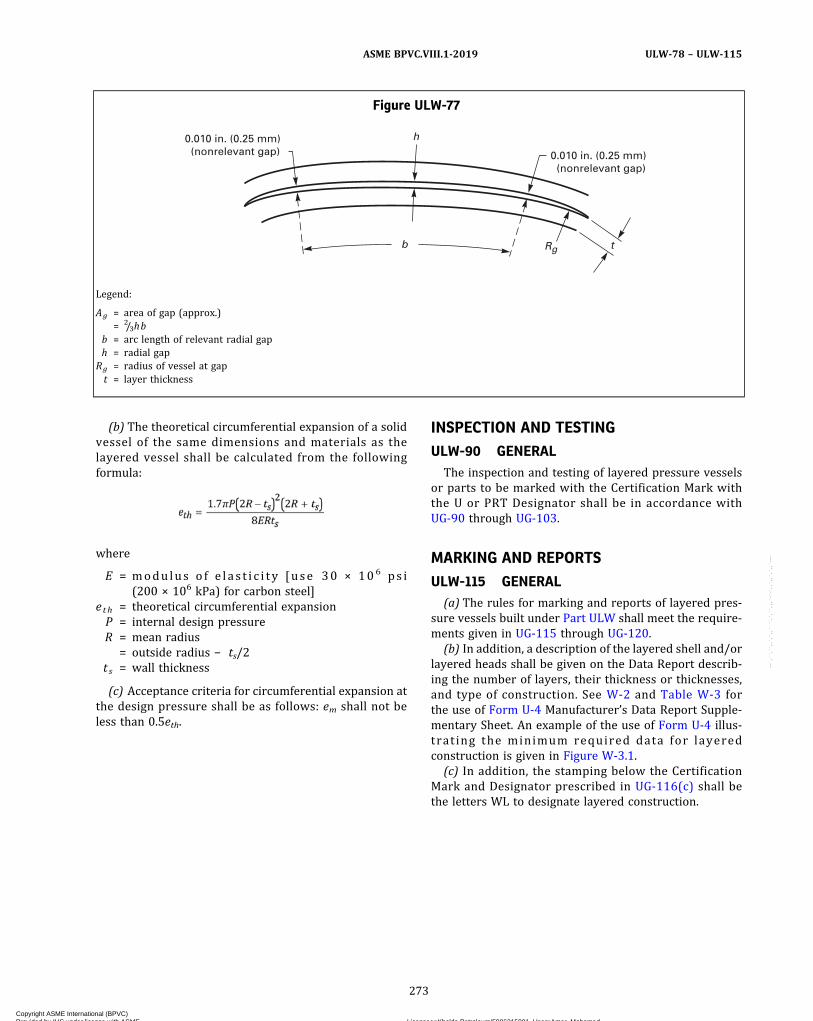
(b) The theoretical circumferential expansion of a solidvessel of the same dimensions and materials as thelayered vessel shall be calculated from the followingformula:
where
E = modu lus o f e l a s t i c i t y [use 30 × 106 ps i(200 × 106 kPa) for carbon steel]
eth = theoretical circumferential expansionP = internal design pressureR = mean radius
= outside radius − ts/2t s = wall thickness
(c) Acceptance criteria for circumferential expansion atthe design pressure shall be as follows: em shall not beless than 0.5eth.
INSPECTION AND TESTING
ULW-90 GENERALThe inspection and testing of layered pressure vessels
or parts to be marked with the Certification Mark withthe U or PRT Designator shall be in accordance withUG-90 through UG-103.
MARKING AND REPORTS
ULW-115 GENERAL(a) The rules for marking and reports of layered pres-
sure vessels built under Part ULW shall meet the require-ments given in UG-115 through UG-120.
(b) In addition, a description of the layered shell and/orlayered heads shall be given on the Data Report describ-ing the number of layers, their thickness or thicknesses,and type of construction. See W-2 and Table W-3 forthe use of Form U-4 Manufacturer’s Data Report Supple-mentary Sheet. An example of the use of Form U-4 illus-trating the minimum required data for layeredconstruction is given in Figure W-3.1.
(c) In addition, the stamping below the CertificationMark and Designator prescribed in UG-116(c) shall bethe letters WL to designate layered construction.
Figure ULW-77
t
h
b
0.010 in. (0.25 mm) (nonrelevant gap) 0.010 in. (0.25 mm)
(nonrelevant gap)
Rg
Legend:
Ag = area of gap (approx.)= 2/3hb
b = arc length of relevant radial gaph = radial gap
Rg = radius of vessel at gapt = layer thickness
273
ASME BPVC.VIII.1-2019 ULW-78 – ULW-115
Copyright ASME International (BPVC) Provided by IHS under license with ASME Licensee=Khalda Petroleum/5986215001, User=Amer, Mohamed
Not for Resale, 07/02/2019 13:29:04 MDTNo reproduction or networking permitted without license from IHS
--`,``,``,,`,`,,````,`,``,,,`-`-`,,`,,`,`,,`---
ð19Þ
PART ULTALTERNATIVE RULES FOR PRESSURE VESSELS CONSTRUCTEDOF MATERIALS HAVING HIGHER ALLOWABLE STRESSES AT LOW
TEMPERATURE
GENERAL
ULT-1 SCOPEThe alternative rules in Part ULT are applicable to pres-
sure vessels or vessel parts that are constructed of mate-rials for which increased design stress values have beenestablished for low temperature applications. When ap-plied, these rules shall be used in conjunction with the re-quirements in Subsection A and Part UW of Subsection B.The requirements of Subsection C do not apply exceptwhen referenced in Part ULT.
ULT-2 CONDITIONS OF SERVICE(a)Measures shall be taken to avoid stresses at any
temperature that are in excess of the maximum allowablestress applicable to that temperature. For example, themembrane stress at the maximum allowable workingpressure at 150°F (65°C) shall never exceed the maxi-mum allowable stress for 150°F (65°C). See ULT-27.(b) Vessel use shall be restricted to fluids specifically
considered for the design of the vessel. The physical char-acteristics of the contained fluid shall be such that a max-imum operating temperature can be determined for theliquid phase at the maximum allowable working pressureof the vessel. The safety relief valve setting thus controlsthe maximum operating temperature of the vessel for thespecific fluid.(c) The allowable stress at 150°F (65°C) shall be used
for the design of vessel parts that are exposed to the statichead of cryogenic fluid but are not actually contacted bythe fluid, such as, as in a dead‐end cylinder connectedto the bottom of a vessel that contains a gas cushion.(d) Insulation shall be applied external to the pressure
vessel.
ULT-5 GENERAL(a)Materials covered by this Part subject to stress due
to pressure shall conform to one of the specifications giv-en in Section II and shall be limited to those listed in TableULT-23. The allowable stress values of Table ULT-23 arelimited to those materials which will be in contact withthe cold liquid when subject to liquid head.
(b)Materials not covered by Part ULT may be used forvessel parts, provided such materials shall conform to oneof the specifications in Section II and shall be limited tothose materials permitted by another Part of SubsectionC. The maximum allowable stress for such parts shall bedetermined at 150°F (65°C). All applicable requirementsof that Part of Subsection C shall be met including any re-quired impact tests.(c) The 5%, 7%, 8%, and 9% nickel steels listed in
Table ULT-23 shall be tested for notch ductility as re-quired by UHT-5(d) and UHT-5(e) and UHT-6. These duc-tility tests shall be conducted at the lowest temperature atwhich pressure will be applied to the vessel or the mini-mum allowable temperature to be marked on the vessel,whichever is lower.(d) For 5083 aluminum the provisions and require-
ments of UNF-65 for low temperature operation apply.(e) For 5%, 7%, 8%, and 9% nickel steel vessels, all
structural attachments and stiffening rings which arewelded directly to pressure parts shall be made of mate-rials of specified minimum strength equal to or greaterthan that of the material to which they are attached.(f) The weldments of Types 304 and 316 stainless
steels shall be Charpy impact tested as required byUG-84(h), except that the exemptions of UHA-51 do notapply. These impact tests shall be conducted at the lowesttemperature at which pressure will be applied to the ves-sel or the minimum allowable temperature to be markedon the vessel, whichever is lower. The applicable mini-mum lateral expansion opposite the notch for all speci-men sizes shall be as required in UHT-6(a)(3) andUHT-6(a)(4). All requirements of UHT-6(a)(3) andUHT-6(a)(4) shall apply.(g) For Types 304 and 316 stainless steel vessels, all
structural attachments and stiffening rings that arewelded directly to pressure parts shall be made of eitherType 304 or Type 316 stainless steel.
274
ASME BPVC.VIII.1-2019ULT-1 – ULT-5
Copyright ASME International (BPVC) Provided by IHS under license with ASME Licensee=Khalda Petroleum/5986215001, User=Amer, Mohamed
Not for Resale, 07/02/2019 13:29:04 MDTNo reproduction or networking permitted without license from IHS
--`,``,``,,`,`,,````,`,``,,,`-`-`,,`,,`,`,,`---
ð19Þ
ð19Þ
ð19Þ
DESIGN
ULT-16 GENERALThe rules in ULT-17 through ULT-57 apply specifically
to the design of pressure vessels and vessel parts that areconstructed of materials listed in Table ULT-23 and shallbe used in conjunction with the requirements for Designin Subsection A and Part UW of Subsection B.
(a) The thermal stresses resulting from the differencesbetween the base metal and the weld metal shall be con-sidered in the design.
(b) For vessels made of 5%, 7%, 8%, and 9% nickelsteels, the minimum thickness after forming of a sectionsubject to pressure shall be 3/16 in. (5 mm) and the max-imum thickness of the base metal at welds shall be 2 in.(51 mm).
ULT-17 WELDED JOINTS(a) All Category A, B, C, and D joints (UW-3) shall be full
penetration welds.(b) The alignment of longitudinal joints in adjacent cy-
lindrical sections or heads shall be displaced at least fivetimes the thickness of the thicker material.
(c) In vessels of 5%, 7%, 8%, or 9% nickel steels, allCategory D joints shall be in accordance with FigureUHT-18.1 or UHT-18.2 when the nominal shell thicknessat the opening exceeds 1 in. (25 mm).
(1) All joints of Category D attaching a nozzle neck tothe vessel wall, and to a reinforcing pad if used, shall befull penetration groove weld conforming to FigureUHT-18.1 or UHT-18.2 or any of the sketches in FigureUW-16.1 having full penetration welds.
(2) All joints of Category A shall be Type No. (1) ofTable UW-12.
(3) All joints of Category B shall be Type No. (1) or(2) of Table UW-12.
(4) All joints of Category C shall be full penetrationwelds extending through the entire section at the joint.
(5) Joint alignment requirements of UHT-20 shall bemet.
(d) Butt welds with one plate edge offset [FigureUW-13.1, sketch (i)] are prohibited anywhere in thevessel.
ULT-18 NOZZLES AND OTHER CONNECTIONS(a) Nozzles shall not be located in Category A or B
joints. When adjacent to Category A or B joints, the near-est edge of the nozzle‐to‐shell weld shall be at least fivetimes the nominal thickness of the shell from the nearestedge of the Category A or B joint.
(b) The attachment of pipe and nozzle necks to vesselwalls shall be by welded construction only.
ULT-23 MAXIMUM ALLOWABLE STRESS VALUESTable ULT-23 gives the maximum allowable stress val-
ues at the temperatures indicated for materials conform-ing to the specifications listed therein. Values may beinterpolated for intermediate temperatures (see UG-23).
ULT-27 THICKNESS OF SHELLSThe minimum thickness of any vessel part shall be the
greater of the following:(a) the thickness based on the MAWP at the top of the
vessel in its normal operating position plus any otherloadings per UG-22, including the static head of the mostdense cryogenic liquid to be contained. The permissiblestress value shall be determined for the applicable mate-rial in Table ULT-23 at the operating temperature corre-sponding to the saturation temperature at MAWP of thewarmest cryogenic fluid contained. The maximum allow-able compressive stress shall be determined in accor-dance with UG-23(b) at 150°F (65°C) and therequirements of UG-23(c) shall be met.
(b) the thickness determined by using the permissiblestress value at 150°F (65°C) based on the MAWP at thetop of the vessel in its normal operating position plusany other loadings per UG-22, except that no static headneed be included.
ULT-28 THICKNESS OF SHELLS UNDEREXTERNAL PRESSURE
Cylindrical and spherical shells under external pres-sure shall be designed by the rules in UG-28 using the ap-plicable figures in Section II, Part D, Subpart 3 at 150°F(65°C).
ULT-29 STIFFENING RINGS FOR SHELLS UNDEREXTERNAL PRESSURE
Rules covering the design of stiffening rings are given inUG-29. The design shall be based on the appropriate chartin Section II, Part D, Subpart 3 for the material used in thering at 150°F (65°C).
ULT-30 STRUCTURAL ATTACHMENTS(a) See ULT-5(e) for limitations on material used in
permanent structural attachments in 5%, 7%, 8%, or9% nickel steel vessels. See ULT-5(g) for limitations onmaterial used in permanent structural attachments inTypes 304 and 316 stainless steel vessels.
(b) The structural details of supporting lugs, rings, sad-dles, straps, and other types of supports shall be givenspecial design consideration to minimize local stressesin attachment areas.
(c) Attachments to 5%, 7%, 8%, or 9% nickel steel ves-sels shall be made using a weld procedure qualified toSection IX.
(d) Attachments to Types 304 and 316 stainless steelvessels shall be made using a weld procedure meetingULT-82.
275
ASME BPVC.VIII.1-2019 ULT-16 – ULT-30
Copyright ASME International (BPVC) Provided by IHS under license with ASME Licensee=Khalda Petroleum/5986215001, User=Amer, Mohamed
Not for Resale, 07/02/2019 13:29:04 MDTNo reproduction or networking permitted without license from IHS
--`,``,``,,`,`,,````,`,``,,,`-`-`,,`,,`,`,,`---
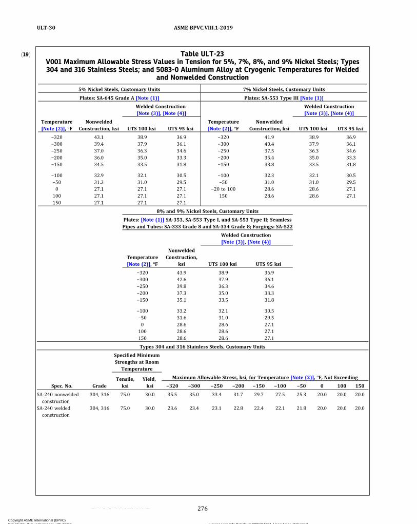
ð19Þ Table ULT-23V001 Maximum Allowable Stress Values in Tension for 5%, 7%, 8%, and 9% Nickel Steels; Types304 and 316 Stainless Steels; and 5083-0 Aluminum Alloy at Cryogenic Temperatures for Welded
and Nonwelded Construction
5% Nickel Steels, Customary Units 7% Nickel Steels, Customary Units
Plates: SA-645 Grade A [Note (1)] Plates: SA-553 Type III [Note (1)]
Welded Construction[Note (3)], [Note (4)]
Welded Construction[Note (3)], [Note (4)]
Temperature[Note (2)], °F
NonweldedConstruction, ksi UTS 100 ksi UTS 95 ksi
Temperature[Note (2)], °F
NonweldedConstruction, ksi UTS 100 ksi UTS 95 ksi
−320 43.1 38.9 36.9 −320 41.9 38.9 36.9−300 39.4 37.9 36.1 −300 40.4 37.9 36.1−250 37.0 36.3 34.6 −250 37.5 36.3 34.6−200 36.0 35.0 33.3 −200 35.4 35.0 33.3−150 34.5 33.5 31.8 −150 33.8 33.5 31.8
−100 32.9 32.1 30.5 −100 32.3 32.1 30.5−50 31.3 31.0 29.5 −50 31.0 31.0 29.50 27.1 27.1 27.1 −20 to 100 28.6 28.6 27.1
100 27.1 27.1 27.1 150 28.6 28.6 27.1150 27.1 27.1 27.1
8% and 9% Nickel Steels, Customary Units
Plates: [Note (1)] SA-353, SA-553 Type I, and SA-553 Type II; SeamlessPipes and Tubes: SA-333 Grade 8 and SA-334 Grade 8; Forgings: SA-522
Welded Construction[Note (3)], [Note (4)]
Temperature[Note (2)], °F
NonweldedConstruction,
ksi UTS 100 ksi UTS 95 ksi
−320 43.9 38.9 36.9−300 42.6 37.9 36.1−250 39.8 36.3 34.6−200 37.3 35.0 33.3−150 35.1 33.5 31.8
−100 33.2 32.1 30.5−50 31.6 31.0 29.50 28.6 28.6 27.1
100 28.6 28.6 27.1150 28.6 28.6 27.1
Types 304 and 316 Stainless Steels, Customary Units
Specified MinimumStrengths at Room
Temperature
Tensile,ksi
Yield,ksi
Maximum Allowable Stress, ksi, for Temperature [Note (2)], °F, Not Exceeding
Spec. No. Grade −320 −300 −250 −200 −150 −100 −50 0 100 150
SA-240 nonweldedconstruction
304, 316 75.0 30.0 35.5 35.0 33.4 31.7 29.7 27.5 25.3 20.0 20.0 20.0
SA-240 weldedconstruction
304, 316 75.0 30.0 23.6 23.4 23.1 22.8 22.4 22.1 21.8 20.0 20.0 20.0
276
ASME BPVC.VIII.1-2019ULT-30
Copyright ASME International (BPVC) Provided by IHS under license with ASME Licensee=Khalda Petroleum/5986215001, User=Amer, Mohamed
Not for Resale, 07/02/2019 13:29:04 MDTNo reproduction or networking permitted without license from IHS
--`,``,``,,`,`,,````,`,``,,,`-`-`,,`,,`,`,,`---
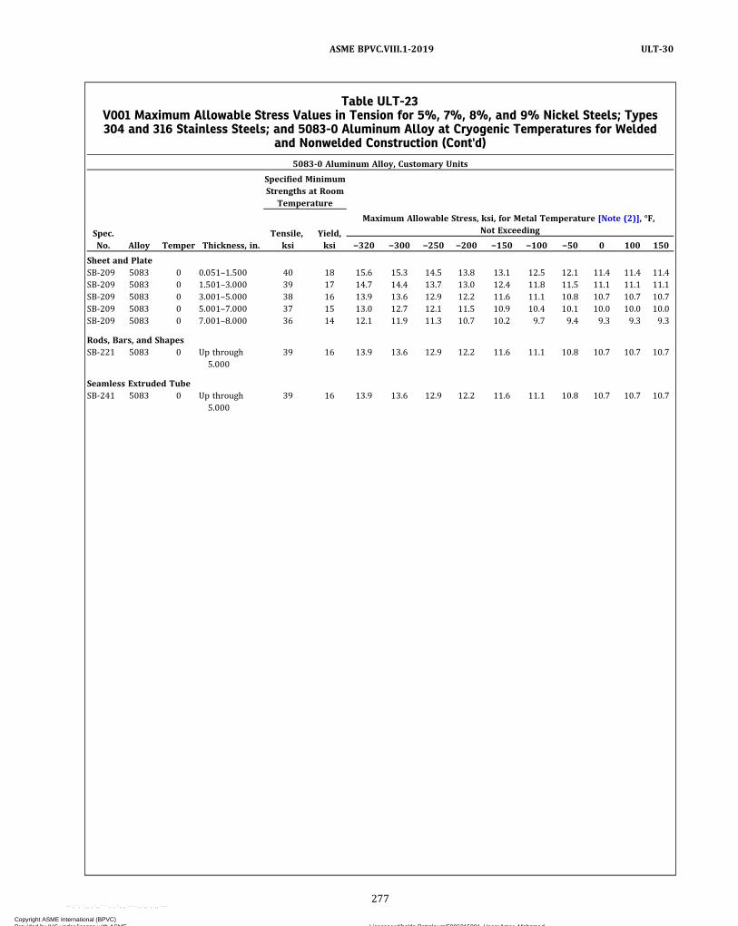
Table ULT-23V001 Maximum Allowable Stress Values in Tension for 5%, 7%, 8%, and 9% Nickel Steels; Types304 and 316 Stainless Steels; and 5083-0 Aluminum Alloy at Cryogenic Temperatures for Welded
and Nonwelded Construction (Cont'd)
5083‐0 Aluminum Alloy, Customary Units
Specified MinimumStrengths at Room
Temperature
Spec.No.
Tensile,ksi
Yield,ksi
Maximum Allowable Stress, ksi, for Metal Temperature [Note (2)], °F,Not Exceeding
Alloy Temper Thickness, in. −320 −300 −250 −200 −150 −100 −50 0 100 150
Sheet and PlateSB-209 5083 0 0.051–1.500 40 18 15.6 15.3 14.5 13.8 13.1 12.5 12.1 11.4 11.4 11.4SB-209 5083 0 1.501–3.000 39 17 14.7 14.4 13.7 13.0 12.4 11.8 11.5 11.1 11.1 11.1SB-209 5083 0 3.001–5.000 38 16 13.9 13.6 12.9 12.2 11.6 11.1 10.8 10.7 10.7 10.7SB-209 5083 0 5.001–7.000 37 15 13.0 12.7 12.1 11.5 10.9 10.4 10.1 10.0 10.0 10.0SB-209 5083 0 7.001–8.000 36 14 12.1 11.9 11.3 10.7 10.2 9.7 9.4 9.3 9.3 9.3
Rods, Bars, and ShapesSB-221 5083 0 Up through
5.00039 16 13.9 13.6 12.9 12.2 11.6 11.1 10.8 10.7 10.7 10.7
Seamless Extruded TubeSB-241 5083 0 Up through
5.00039 16 13.9 13.6 12.9 12.2 11.6 11.1 10.8 10.7 10.7 10.7
277
ASME BPVC.VIII.1-2019 ULT-30
Copyright ASME International (BPVC) Provided by IHS under license with ASME Licensee=Khalda Petroleum/5986215001, User=Amer, Mohamed
Not for Resale, 07/02/2019 13:29:04 MDTNo reproduction or networking permitted without license from IHS
--`,``,``,,`,`,,````,`,``,,,`-`-`,,`,,`,`,,`---

Table ULT-23V001 Maximum Allowable Stress Values in Tension for 5%, 7%, 8%, and 9% Nickel Steels; Types304 and 316 Stainless Steels; and 5083-0 Aluminum Alloy at Cryogenic Temperatures for Welded
and Nonwelded Construction (Cont'd)
5% Nickel Steels, SI Units 7% Nickel Steels, SI Units
Plates: SA-645 [Note (1)] Plates: SA-553 Type III [Note (1)]
NonweldedConstruction,
MPa
Welded Construction[Note (3)], [Note (4)] Nonwelded
Construction,MPa
Welded Construction[Note (3)], [Note (4)]
Temperature[Note (2)], °C UTS 690 MPa UTS 655 MPa
Temperature[Note (2)], °C UTS 690 MPa
UTS655 MPa
−195 296 268 254 −195 289 268 254−170 257 255 243 −170 267 255 243−145 253 247 235 −145 252 247 235−120 245 238 226 −120 240 238 226−95 235 229 217 −95 231 229 217−70 226 221 210 −70 222 220 210−45 215 213 203 −45 214 214 203−20 187 187 187 −30 to 40 197 197 18740 187 187 187 65 197 197 18765 187 187 187
8% and 9% Nickel Steels, SI Units
Plates: SA-353, SA-553 Type I, and SA-553 Type II; Seamless Pipes andTubes: SA-333 Grade 8 and SA-334 Grade 8; Forgings: SA-522 [Note (1)]
Welded Construction[Note (3)], [Note (4)]
Temperature[Note (2)], °C
NonweldedConstruction,
MPa UTS 690 MPa UTS 655 MPa
−195 302 268 254−170 283 255 243−145 267 247 235−120 252 238 226−95 239 229 217
−70 228 220 210−45 218 214 203−40 197 197 18740 197 197 18765 197 197 187
Types 304 and 316 Stainless Steels, SI Units
Specified MinimumStrengths at Room
Temperature
Tensile,MPa
Yield,MPa
Maximum Allowable Stress, MPa, for Temperature [Note (2)], °C, Not Exceeding
Spec. No. Grade −195 −170 −145 −120 −95 −70 −45 −20 40 65
SA-240 nonweldedconstruction
304, 316 515 205 243 234 223 212 199 187 173 137 137 137
SA-240 weldedconstruction
304, 316 515 205 161 159 157 155 153 151 149 137 137 137
278
ASME BPVC.VIII.1-2019ULT-30
Copyright ASME International (BPVC) Provided by IHS under license with ASME Licensee=Khalda Petroleum/5986215001, User=Amer, Mohamed
Not for Resale, 07/02/2019 13:29:04 MDTNo reproduction or networking permitted without license from IHS
--`,``,``,,`,`,,````,`,``,,,`-`-`,,`,,`,`,,`---

ð19Þ
ð19Þ
ð19Þ
ULT-56 POSTWELD HEAT TREATMENT(a) For 5%, 7%, 8%, or 9% nickel steels, the provisions
of UHT-56, UHT-80, and UHT-81 apply.(b) For 5083 aluminum, the provisions of UNF-56
apply.(c) For Types 304 and 316 stainless steel vessels, the
provisions of UHA-32 apply.
ULT-57 EXAMINATION(a) All butt joints shall be examined by 100%
radiography.(b) All attachment welds, and all welded joints subject
to pressure not examined by radiography or ultrasonictesting, shall be given a liquid penetrant examinationeither before or after hydrotest. Relevant indicationsare those which result from imperfections. Any relevantlinear indication greater than 1/16 in. (1.6 mm) shall be re-paired or removed.
When a pneumatic test is conducted in accordance withULT-100, these liquid penetrant examinations shall beperformed prior to the pneumatic test.
(c) For 5083 aluminum, the requirements of UNF-91apply.
FABRICATION
ULT-75 GENERALThe rules in the following paragraphs apply specifically
to the fabrication of pressure vessels and vessel parts thatare constructed to this Part and shall be used in conjunc-tion with the requirements for Fabrication in SubsectionA and Part UW of Subsection B.
ULT-79 FORMING SHELL SECTIONS AND HEADSThe requirements and limitations of UNF-77 apply for
5083 aluminum, and of UHT-79 for 5%, 7%, 8%, or 9%nickel steel.
ULT-82 WELDING(a) A separate welding procedure qualification shall be
made, as prescribed in Section IX, Part QW, except thatthe procedure qualification tests on tension specimensconforming to Section IX, Figures QW-462.1(a) through
Table ULT-23V001 Maximum Allowable Stress Values in Tension for 5%, 7%, 8%, and 9% Nickel Steels; Types304 and 316 Stainless Steels; and 5083-0 Aluminum Alloy at Cryogenic Temperatures for Welded
and Nonwelded Construction (Cont'd)
5083‐0 Aluminum Alloy, SI Units
Specified MinimumStrengths at Room
Temperature
Spec.No.
Tensile,MPa
Yield,MPa
Maximum Allowable Stress, MPa, for Metal Temperature [Note (2)], °C,Not Exceeding
Alloy Temper Thickness, mm −195 −170 −145 −120 −95 −70 −45 −20 40 65
Sheet and PlateSB-209 5083 0 1.30–38.10 276 124 107 103 97.9 93.6 89.3 85.8 83.4 78.8 78.8 78.8SB-209 5083 0 38.13–76.20 269 117 101 96.8 92.4 88.3 84.5 81.0 79.3 76.8 76.8 76.8SB-209 5083 0 76.23–127.00 262 110 95.7 91.2 86.9 82.7 79.1 76.2 74.4 73.5 73.5 73.5SB-209 5083 0 127.03–177.80 255 103 89.5 85.3 81.7 77.9 74.3 71.4 69.6 69.0 69.0 69.0SB-209 5083 0 199.83–203.20 248 97 83.4 80.0 76.1 72.6 69.5 66.5 64.8 64.4 64.4 64.4
Rods, Bars, and ShapesSB-221 5083 0 Up through
127.00269 110 95.7 91.2 86.9 82.7 79.1 76.2 74.4 73.5 73.5 73.5
Seamless Extruded TubeSB-241 5083 0 Up through
127.00269 110 95.7 91.2 86.9 82.7 79.1 76.2 74.4 73.5 73.5 73.5
NOTES:(1) Minimum thickness after forming any section subject to pressure shall be 3/16 in. (5 mm), and maximum thickness of the base metal at
welds shall be 2 in. (51 mm).(2) Stress values at intermediate temperatures may be interpolated.(3) The minimum tensile strength of the reduced tension specimen in accordance with Section IX, Figures QW-462.1(a) through QW-462.1(e)
shall not be less than 100 ksi (690 MPa) or 95 ksi (655 MPa), respectively, at room temperature. Choice of UTS depends on welding pro-cess and filler metal used in the construction.
(4) Welded construction allowable stresses apply only to butt joints.
279
ASME BPVC.VIII.1-2019 ULT-56 – ULT-82
Copyright ASME International (BPVC) Provided by IHS under license with ASME Licensee=Khalda Petroleum/5986215001, User=Amer, Mohamed
Not for Resale, 07/02/2019 13:29:04 MDTNo reproduction or networking permitted without license from IHS
--`,``,``,,`,`,,````,`,``,,,`-`-`,,`,,`,`,,`---
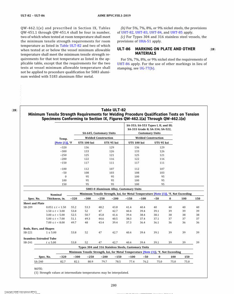
ð19Þ
QW-462.1(e) and prescribed in Section IX, TablesQW-451.1 through QW-451.4 shall be four in number,two of which when tested at room temperature shall meetthe minimum tensile strength requirements for roomtemperature as listed in Table ULT-82 and two of whichwhen tested at or below the vessel minimum allowabletemperature shall meet the minimum tensile strength re-quirements for that test temperature as listed in the ap-plicable table, except that the requirements for the twotests at vessel minimum allowable temperature shallnot be applied to procedure qualification for 5083 alumi-num welded with 5183 aluminum filler metal.
(b) For 5%, 7%, 8%, or 9% nickel steels, the provisionsof UHT-82, UHT-83, UHT-84, and UHT-85 apply.(c) For Types 304 and 316 stainless steel vessels, the
provisions of UHA-51 apply.
ULT-86 MARKING ON PLATE AND OTHERMATERIALS
For 5%, 7%, 8%, or 9% nickel steel the requirements ofUHT-86 apply. For the use of other markings in lieu ofstamping, see UG-77(b).
ð19Þ Table ULT-82Minimum Tensile Strength Requirements for Welding Procedure Qualification Tests on Tension
Specimens Conforming to Section IX, Figures QW-462.1(a) Through QW-462.1(e)
Temp.[Note (1)], °F
SA-645, Customary Units
SA-353; SA-553 Types I, II, and III;SA-333 Grade 8; SA-334; SA-522,
Customary Units
Welded Construction Welded Construction
UTS 100 ksi UTS 95 ksi UTS 100 ksi UTS 95 ksi
−320 136 129 136 129−300 133 126 133 126−250 125 121 125 121−200 122 116 122 116−150 117 111 117 111
−100 112 107 112 107−50 108 103 108 103
0 95 95 100 95100 95 95 100 95150 95 95 100 95
5083‐0 Aluminum Alloy, Customary Units
Spec. No.Nominal
Thickness, in.
Minimum Tensile Strength, ksi, for Metal Temperature [Note (1)], °F, Not Exceeding
−320 −300 −250 −200 −150 −100 −50 0 100 150
Sheet and PlateSB-209 0.051 ≤ t < 1.50 55.2 53.3 48.2 43.8 41.4 40.4 40 40 40 40
1.50 ≤ t < 3.00 53.8 52 47 42.7 40.4 39.4 39.1 39 39 393.00 ≤ t < 5.00 52.5 50.7 45.8 41.6 39.4 38.4 38.1 38 38 385.00 ≤ t < 7.00 51.1 49.3 44.6 40.5 38.3 37.4 37.1 37 37 377.00 ≤ t < 8.00 49.7 48 43.4 39.4 37.3 36.4 36.1 36 36 36
Rods, Bars, and ShapesSB-221 1 ≤ 5.00 53.8 52 47 42.7 40.4 39.4 39.1 39 39 39
Seamless Extruded TubeSB-241 t ≤ 5.00 53.8 52 47 42.7 40.4 39.4 39.1 39 39 39
Types 304 and 316 Stainless Steels, Customary Units
Spec. No.
Minimum Tensile Strength, ksi, for Metal Temperature [Note (1)], °F, Not Exceeding
−320 −300 −250 −200 −150 −100 −50 0 100 150
SA-240 82.7 82.1 80.9 79.7 78.5 77.4 76.2 75.0 75.0 75.0
NOTE:(1) Strength values at intermediate temperatures may be interpolated.
280
ASME BPVC.VIII.1-2019ULT-82 – ULT-86
Copyright ASME International (BPVC) Provided by IHS under license with ASME Licensee=Khalda Petroleum/5986215001, User=Amer, Mohamed
Not for Resale, 07/02/2019 13:29:04 MDTNo reproduction or networking permitted without license from IHS
--`,``,``,,`,`,,````,`,``,,,`-`-`,,`,,`,`,,`---
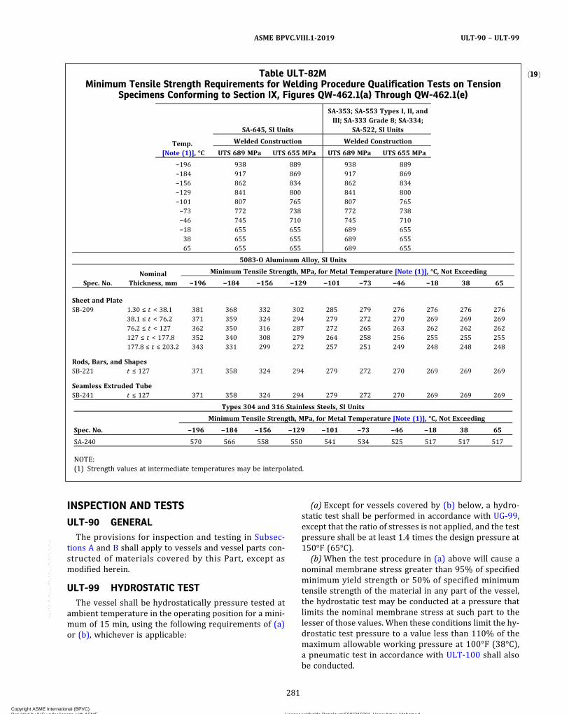
INSPECTION AND TESTS
ULT-90 GENERALThe provisions for inspection and testing in Subsec-
tions A and B shall apply to vessels and vessel parts con-structed of materials covered by this Part, except asmodified herein.
ULT-99 HYDROSTATIC TESTThe vessel shall be hydrostatically pressure tested at
ambient temperature in the operating position for a mini-mum of 15 min, using the following requirements of (a)or (b), whichever is applicable:
(a) Except for vessels covered by (b) below, a hydro-static test shall be performed in accordance with UG-99,except that the ratio of stresses is not applied, and the testpressure shall be at least 1.4 times the design pressure at150°F (65°C).
(b)When the test procedure in (a) above will cause anominal membrane stress greater than 95% of specifiedminimum yield strength or 50% of specified minimumtensile strength of the material in any part of the vessel,the hydrostatic test may be conducted at a pressure thatlimits the nominal membrane stress at such part to thelesser of those values. When these conditions limit the hy-drostatic test pressure to a value less than 110% of themaximum allowable working pressure at 100°F (38°C),a pneumatic test in accordance with ULT-100 shall alsobe conducted.
ð19ÞTable ULT-82MMinimum Tensile Strength Requirements for Welding Procedure Qualification Tests on Tension
Specimens Conforming to Section IX, Figures QW-462.1(a) Through QW-462.1(e)
Temp.[Note (1)], °C
SA-645, SI Units
SA-353; SA-553 Types I, II, andIII; SA-333 Grade 8; SA-334;
SA-522, SI Units
Welded Construction Welded Construction
UTS 689 MPa UTS 655 MPa UTS 689 MPa UTS 655 MPa
−196 938 889 938 889−184 917 869 917 869−156 862 834 862 834−129 841 800 841 800−101 807 765 807 765−73 772 738 772 738−46 745 710 745 710−18 655 655 689 65538 655 655 689 65565 655 655 689 655
5083‐O Aluminum Alloy, SI Units
Spec. No.Nominal
Thickness, mm
Minimum Tensile Strength, MPa, for Metal Temperature [Note (1)], °C, Not Exceeding
−196 −184 −156 −129 −101 −73 −46 −18 38 65
Sheet and PlateSB-209 1.30 ≤ t < 38.1 381 368 332 302 285 279 276 276 276 276
38.1 ≤ t < 76.2 371 359 324 294 279 272 270 269 269 26976.2 ≤ t < 127 362 350 316 287 272 265 263 262 262 262127 ≤ t < 177.8 352 340 308 279 264 258 256 255 255 255177.8 ≤ t ≤ 203.2 343 331 299 272 257 251 249 248 248 248
Rods, Bars, and ShapesSB-221 t ≤ 127 371 358 324 294 279 272 270 269 269 269
Seamless Extruded TubeSB-241 t ≤ 127 371 358 324 294 279 272 270 269 269 269
Types 304 and 316 Stainless Steels, SI Units
Spec. No.
Minimum Tensile Strength, MPa, for Metal Temperature [Note (1)], °C, Not Exceeding
−196 −184 −156 −129 −101 −73 −46 −18 38 65
SA-240 570 566 558 550 541 534 525 517 517 517
NOTE:(1) Strength values at intermediate temperatures may be interpolated.
281
ASME BPVC.VIII.1-2019 ULT-90 – ULT-99
Copyright ASME International (BPVC) Provided by IHS under license with ASME Licensee=Khalda Petroleum/5986215001, User=Amer, Mohamed
Not for Resale, 07/02/2019 13:29:04 MDTNo reproduction or networking permitted without license from IHS
--`,``,``,,`,`,,````,`,``,,,`-`-`,,`,,`,`,,`---
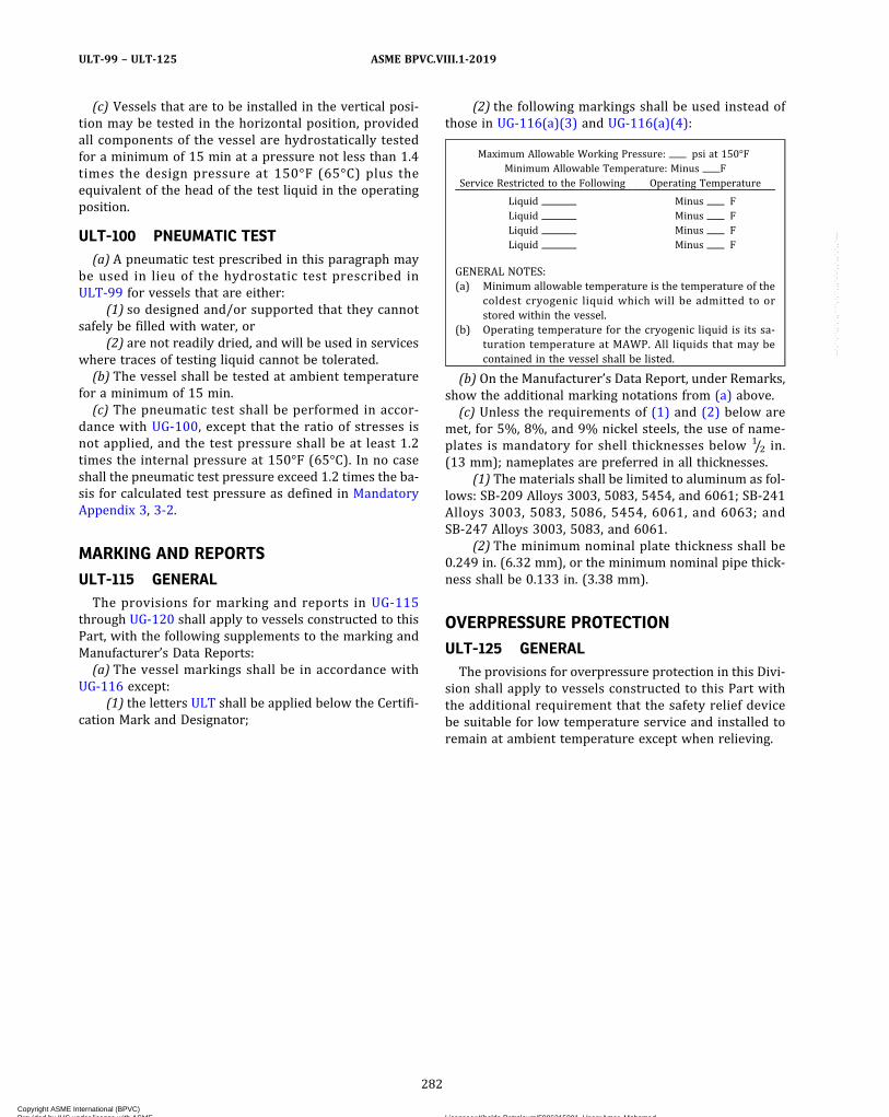
(c) Vessels that are to be installed in the vertical posi-tion may be tested in the horizontal position, providedall components of the vessel are hydrostatically testedfor a minimum of 15 min at a pressure not less than 1.4times the design pressure at 150°F (65°C) plus theequivalent of the head of the test liquid in the operatingposition.
ULT-100 PNEUMATIC TEST(a) A pneumatic test prescribed in this paragraph may
be used in lieu of the hydrostatic test prescribed inULT-99 for vessels that are either:
(1) so designed and/or supported that they cannotsafely be filled with water, or
(2) are not readily dried, and will be used in serviceswhere traces of testing liquid cannot be tolerated.(b) The vessel shall be tested at ambient temperature
for a minimum of 15 min.(c) The pneumatic test shall be performed in accor-
dance with UG-100, except that the ratio of stresses isnot applied, and the test pressure shall be at least 1.2times the internal pressure at 150°F (65°C). In no caseshall the pneumatic test pressure exceed 1.2 times the ba-sis for calculated test pressure as defined in MandatoryAppendix 3, 3-2.
MARKING AND REPORTS
ULT-115 GENERALThe provisions for marking and reports in UG-115
through UG-120 shall apply to vessels constructed to thisPart, with the following supplements to the marking andManufacturer’s Data Reports:(a) The vessel markings shall be in accordance with
UG-116 except:(1) the letters ULT shall be applied below the Certifi-
cation Mark and Designator;
(2) the following markings shall be used instead ofthose in UG-116(a)(3) and UG-116(a)(4):
Maximum Allowable Working Pressure: psi at 150°FMinimum Allowable Temperature: Minus F
Service Restricted to the Following Operating Temperature
Liquid Minus FLiquid Minus FLiquid Minus FLiquid Minus F
GENERAL NOTES:(a) Minimum allowable temperature is the temperature of the
coldest cryogenic liquid which will be admitted to orstored within the vessel.
(b) Operating temperature for the cryogenic liquid is its sa-turation temperature at MAWP. All liquids that may becontained in the vessel shall be listed.
(b) On the Manufacturer’s Data Report, under Remarks,show the additional marking notations from (a) above.(c) Unless the requirements of (1) and (2) below are
met, for 5%, 8%, and 9% nickel steels, the use of name-plates is mandatory for shell thicknesses below 1/2 in.(13 mm); nameplates are preferred in all thicknesses.
(1) The materials shall be limited to aluminum as fol-lows: SB-209 Alloys 3003, 5083, 5454, and 6061; SB-241Alloys 3003, 5083, 5086, 5454, 6061, and 6063; andSB-247 Alloys 3003, 5083, and 6061.
(2) The minimum nominal plate thickness shall be0.249 in. (6.32 mm), or the minimum nominal pipe thick-ness shall be 0.133 in. (3.38 mm).
OVERPRESSURE PROTECTION
ULT-125 GENERALThe provisions for overpressure protection in this Divi-
sion shall apply to vessels constructed to this Part withthe additional requirement that the safety relief devicebe suitable for low temperature service and installed toremain at ambient temperature except when relieving.
282
ASME BPVC.VIII.1-2019ULT-99 – ULT-125
Copyright ASME International (BPVC) Provided by IHS under license with ASME Licensee=Khalda Petroleum/5986215001, User=Amer, Mohamed
Not for Resale, 07/02/2019 13:29:04 MDTNo reproduction or networking permitted without license from IHS
--`,``,``,,`,`,,````,`,``,,,`-`-`,,`,,`,`,,`---
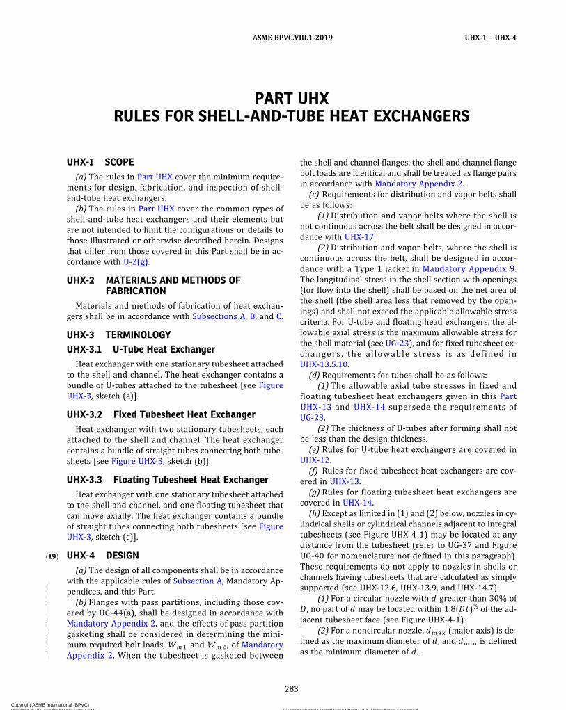
ð19Þ
PART UHXRULES FOR SHELL-AND-TUBE HEAT EXCHANGERS
UHX-1 SCOPE(a) The rules in Part UHX cover the minimum require-
ments for design, fabrication, and inspection of shell‐and‐tube heat exchangers.
(b) The rules in Part UHX cover the common types ofshell-and-tube heat exchangers and their elements butare not intended to limit the configurations or details tothose illustrated or otherwise described herein. Designsthat differ from those covered in this Part shall be in ac-cordance with U-2(g).
UHX-2 MATERIALS AND METHODS OFFABRICATION
Materials and methods of fabrication of heat exchan-gers shall be in accordance with Subsections A, B, and C.
UHX-3 TERMINOLOGYUHX-3.1 U-Tube Heat Exchanger
Heat exchanger with one stationary tubesheet attachedto the shell and channel. The heat exchanger contains abundle of U‐tubes attached to the tubesheet [see FigureUHX-3, sketch (a)].
UHX-3.2 Fixed Tubesheet Heat ExchangerHeat exchanger with two stationary tubesheets, each
attached to the shell and channel. The heat exchangercontains a bundle of straight tubes connecting both tube-sheets [see Figure UHX-3, sketch (b)].
UHX-3.3 Floating Tubesheet Heat ExchangerHeat exchanger with one stationary tubesheet attached
to the shell and channel, and one floating tubesheet thatcan move axially. The heat exchanger contains a bundleof straight tubes connecting both tubesheets [see FigureUHX-3, sketch (c)].
UHX-4 DESIGN(a) The design of all components shall be in accordance
with the applicable rules of Subsection A, Mandatory Ap-pendices, and this Part.
(b) Flanges with pass partitions, including those cov-ered by UG-44(a), shall be designed in accordance withMandatory Appendix 2, and the effects of pass partitiongasketing shall be considered in determining the mini-mum required bolt loads, Wm1 and Wm2 , of MandatoryAppendix 2. When the tubesheet is gasketed between
the shell and channel flanges, the shell and channel flangebolt loads are identical and shall be treated as flange pairsin accordance with Mandatory Appendix 2.
(c) Requirements for distribution and vapor belts shallbe as follows:
(1) Distribution and vapor belts where the shell isnot continuous across the belt shall be designed in accor-dance with UHX-17.
(2) Distribution and vapor belts, where the shell iscontinuous across the belt, shall be designed in accor-dance with a Type 1 jacket in Mandatory Appendix 9.The longitudinal stress in the shell section with openings(for flow into the shell) shall be based on the net area ofthe shell (the shell area less that removed by the open-ings) and shall not exceed the applicable allowable stresscriteria. For U-tube and floating head exchangers, the al-lowable axial stress is the maximum allowable stress forthe shell material (see UG-23), and for fixed tubesheet ex-changers , the al lowable stress is as def ined inUHX-13.5.10.
(d) Requirements for tubes shall be as follows:(1) The allowable axial tube stresses in fixed and
floating tubesheet heat exchangers given in this PartUHX-13 and UHX-14 supersede the requirements ofUG-23.
(2) The thickness of U‐tubes after forming shall notbe less than the design thickness.
(e) Rules for U‐tube heat exchangers are covered inUHX-12.
(f) Rules for fixed tubesheet heat exchangers are cov-ered in UHX-13.
(g) Rules for floating tubesheet heat exchangers arecovered in UHX-14.
(h) Except as limited in (1) and (2) below, nozzles in cy-lindrical shells or cylindrical channels adjacent to integraltubesheets (see Figure UHX-4-1) may be located at anydistance from the tubesheet (refer to UG-37 and FigureUG-40 for nomenclature not defined in this paragraph).These requirements do not apply to nozzles in shells orchannels having tubesheets that are calculated as simplysupported (see UHX-12.6, UHX-13.9, and UHX-14.7).
(1) For a circular nozzle with d greater than 30% ofD , no part of d may be located within 1.8(Dt)
1/2 of the ad-jacent tubesheet face (see Figure UHX-4-1).
(2) For a noncircular nozzle, dmax (major axis) is de-fined as the maximum diameter of d , and dmin is definedas the minimum diameter of d .
283
ASME BPVC.VIII.1-2019 UHX-1 – UHX-4
Copyright ASME International (BPVC) Provided by IHS under license with ASME Licensee=Khalda Petroleum/5986215001, User=Amer, Mohamed
Not for Resale, 07/02/2019 13:29:04 MDTNo reproduction or networking permitted without license from IHS
--`,``,``,,`,`,,````,`,``,,,`-`-`,,`,,`,`,,`---
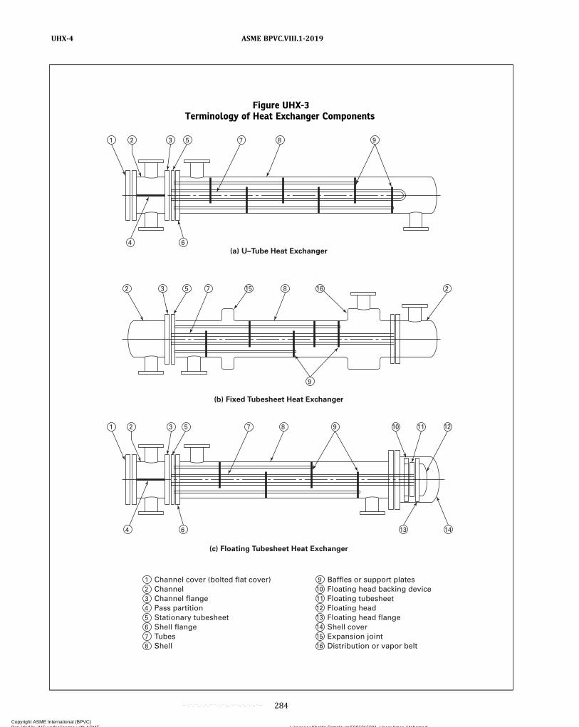
Figure UHX-3Terminology of Heat Exchanger Components
Channel cover (bolted flat cover) Channel Channel flange Pass partition Stationary tubesheet Shell flange Tubes Shell
(a) U–Tube Heat Exchanger
(b) Fixed Tubesheet Heat Exchanger
(c) Floating Tubesheet Heat Exchanger
1
1 2 3 5 7 8 9 10 11 12
13 6 4
2
4 6
1 2 3 5 7 8 9
3 5 7 15 8 16 2
9
14
2 3 4 5 6 7 8
Baffles or support plates Floating head backing device Floating tubesheet Floating head Floating head flange Shell cover Expansion joint Distribution or vapor belt
9 10 11 12 13 14 15 16
284
ASME BPVC.VIII.1-2019UHX-4
Copyright ASME International (BPVC) Provided by IHS under license with ASME Licensee=Khalda Petroleum/5986215001, User=Amer, Mohamed
Not for Resale, 07/02/2019 13:29:04 MDTNo reproduction or networking permitted without license from IHS
--`,``,``,,`,`,,````,`,``,,,`-`-`,,`,,`,`,,`---
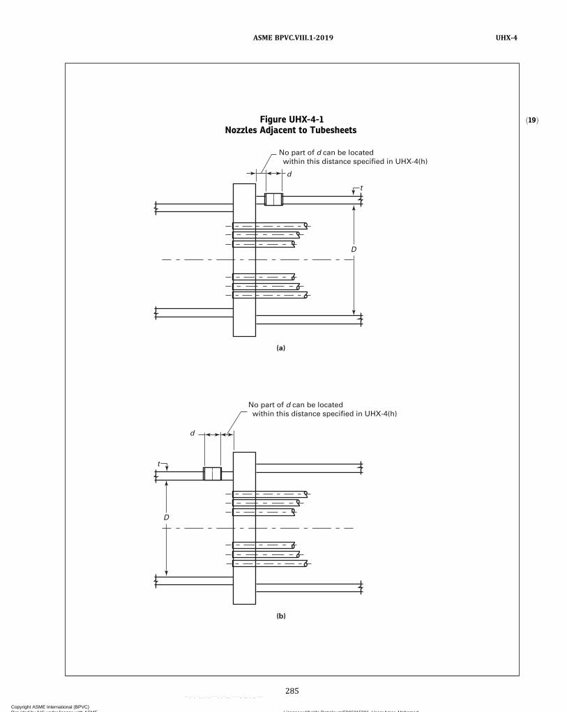
ð19ÞFigure UHX-4-1Nozzles Adjacent to Tubesheets
t
D
d
(a)
No part of d can be located within this distance specified in UHX-4(h)
t
D
d
(b)
No part of d can be located within this distance specified in UHX-4(h)
285
ASME BPVC.VIII.1-2019 UHX-4
Copyright ASME International (BPVC) Provided by IHS under license with ASME Licensee=Khalda Petroleum/5986215001, User=Amer, Mohamed
Not for Resale, 07/02/2019 13:29:04 MDTNo reproduction or networking permitted without license from IHS
--`,``,``,,`,`,,````,`,``,,,`-`-`,,`,,`,`,,`---
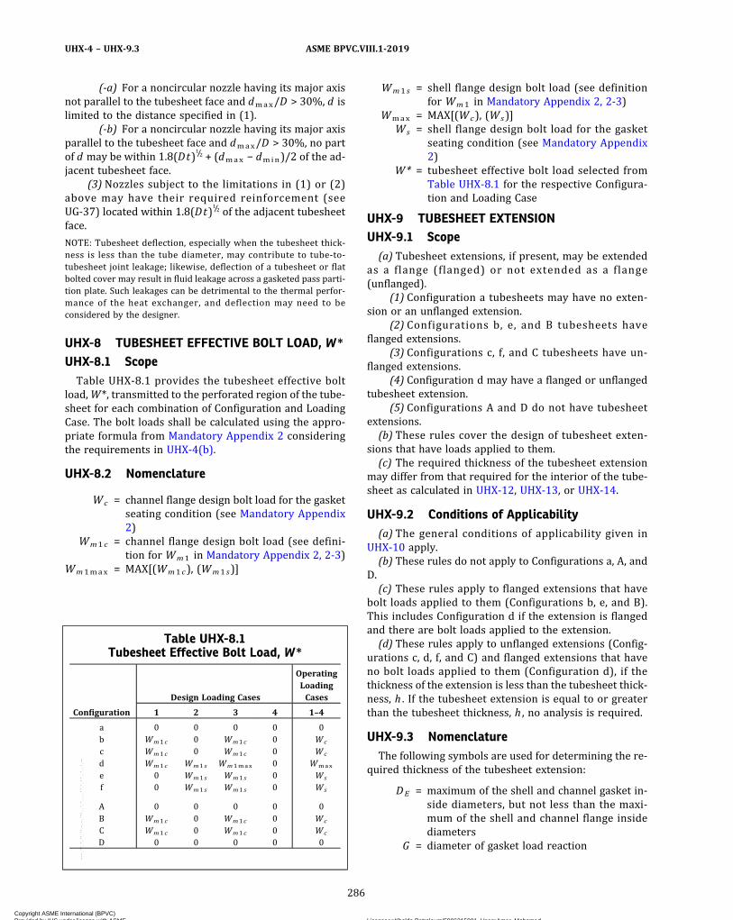
(-a) For a noncircular nozzle having its major axisnot parallel to the tubesheet face and dmax/D > 30%, d islimited to the distance specified in (1).
(-b) For a noncircular nozzle having its major axisparallel to the tubesheet face and dmax/D > 30%, no partof d may be within 1.8(Dt)
1/2 + (dmax − dmin)/2 of the ad-jacent tubesheet face.
(3) Nozzles subject to the limitations in (1) or (2)above may have their required reinforcement (seeUG-37) located within 1.8(Dt)
1/2 of the adjacent tubesheetface.
NOTE: Tubesheet deflection, especially when the tubesheet thick-ness is less than the tube diameter, may contribute to tube-to-tubesheet joint leakage; likewise, deflection of a tubesheet or flatbolted cover may result in fluid leakage across a gasketed pass parti-tion plate. Such leakages can be detrimental to the thermal perfor-mance of the heat exchanger, and deflection may need to beconsidered by the designer.
UHX-8 TUBESHEET EFFECTIVE BOLT LOAD, W*
UHX-8.1 ScopeTable UHX-8.1 provides the tubesheet effective bolt
load,W*, transmitted to the perforated region of the tube-sheet for each combination of Configuration and LoadingCase. The bolt loads shall be calculated using the appro-priate formula from Mandatory Appendix 2 consideringthe requirements in UHX-4(b).
UHX-8.2 Nomenclature
Wc = channel flange design bolt load for the gasketseating condition (see Mandatory Appendix2)
Wm1 c = channel flange design bolt load (see defini-tion for Wm1 in Mandatory Appendix 2, 2-3)
Wm1max = MAX[(Wm1 c), (Wm1 s)]
Wm1 s = shell flange design bolt load (see definitionfor Wm1 in Mandatory Appendix 2, 2-3)
Wmax = MAX[(Wc), (Ws)]Ws = shell flange design bolt load for the gasket
seating condition (see Mandatory Appendix2)
W* = tubesheet effective bolt load selected fromTable UHX-8.1 for the respective Configura-tion and Loading Case
UHX-9 TUBESHEET EXTENSIONUHX-9.1 Scope(a) Tubesheet extensions, if present, may be extended
as a flange (flanged) or not extended as a flange(unflanged).
(1) Configuration a tubesheets may have no exten-sion or an unflanged extension.
(2) Configurations b, e, and B tubesheets haveflanged extensions.
(3) Configurations c, f, and C tubesheets have un-flanged extensions.
(4) Configuration d may have a flanged or unflangedtubesheet extension.
(5) Configurations A and D do not have tubesheetextensions.(b) These rules cover the design of tubesheet exten-
sions that have loads applied to them.(c) The required thickness of the tubesheet extension
may differ from that required for the interior of the tube-sheet as calculated in UHX-12, UHX-13, or UHX-14.
UHX-9.2 Conditions of Applicability(a) The general conditions of applicability given in
UHX-10 apply.(b) These rules do not apply to Configurations a, A, and
D.(c) These rules apply to flanged extensions that have
bolt loads applied to them (Configurations b, e, and B).This includes Configuration d if the extension is flangedand there are bolt loads applied to the extension.(d) These rules apply to unflanged extensions (Config-
urations c, d, f, and C) and flanged extensions that haveno bolt loads applied to them (Configuration d), if thethickness of the extension is less than the tubesheet thick-ness, h . If the tubesheet extension is equal to or greaterthan the tubesheet thickness, h , no analysis is required.
UHX-9.3 NomenclatureThe following symbols are used for determining the re-
quired thickness of the tubesheet extension:
DE = maximum of the shell and channel gasket in-side diameters, but not less than the maxi-mum of the shell and channel flange insidediameters
G = diameter of gasket load reaction
Table UHX-8.1Tubesheet Effective Bolt Load, W*
Configuration
Design Loading Cases
OperatingLoadingCases
1 2 3 4 1–4
a 0 0 0 0 0b Wm1 c 0 Wm1 c 0 Wc
c Wm1 c 0 Wm1 c 0 Wc
d Wm1 c Wm1 s Wm1max 0 Wmax
e 0 Wm1 s Wm1 s 0 Ws
f 0 Wm1 s Wm1 s 0 Ws
A 0 0 0 0 0B Wm1 c 0 Wm1 c 0 Wc
C Wm1 c 0 Wm1 c 0 Wc
D 0 0 0 0 0
286
ASME BPVC.VIII.1-2019UHX-4 – UHX-9.3
Copyright ASME International (BPVC) Provided by IHS under license with ASME Licensee=Khalda Petroleum/5986215001, User=Amer, Mohamed
Not for Resale, 07/02/2019 13:29:04 MDTNo reproduction or networking permitted without license from IHS
--`,``,``,,`,`,,````,`,``,,,`-`-`,,`,,`,`,,`---

ð19Þ
= Gc for tubesheet configuration b of a U‐tubetubesheet heat exchanger
= Gs for tubesheet configuration e of a U‐tubetubesheet heat exchanger
= Gc for tubesheet configuration b of a fixedtubesheet heat exchanger
= Gc for stationary tubesheet configuration b ofa floating tubesheet exchanger
= Gs for stationary tubesheet configuration e ofa floating tubesheet exchanger
= Gc for floating tubesheet configuration B of afloating tubesheet exchanger
= Gc or Gs for tubesheet configuration d whenapplicable (e.g., hydrotest)
hG = gasket moment arm, equal to the radial dis-tance from the centerline of the bolts to theline of the gasket reaction as shown in Table2-5.2
hr = minimum required thickness of the tube-sheet extension
MAX [(a),(b),(c),...] = greatest of a, b, c,...
Ps = shell side design pressure. For shell side vac-uum, use a negative value for Ps .
Pt = tube side design pressure. For tube side vac-uum, use a negative value for Pt .
Sa = allowable stress for the material of the tube-sheet extension at ambient temperature (seeUG-23)
Sfe = allowable stress for the material of the tube-sheet extension at tubesheet extension de-sign temperature (see UG-23)
W = flange design bolt load from eq. 2-5(e)(5)considering UHX-4(b)
Wm1 = flange design bolt load from eq. 2-5(c)(1)(1)considering UHX-4(b)
UHX-9.4 Design Considerations(a) The designer shall take appropriate consideration
of the stresses resulting from the pressure test requiredby UG-99 or UG-100 [see UG-99(b) and UG-99(d)]. Specialconsideration shall be required for tubesheets that aregasketed on both sides when the pressure test in eachchamber is conducted independently and the bolt loadingis only applied to the flanged extension during the pres-sure test.
(b) If the tubesheet is grooved for a peripheral gasket,the net thickness under the groove or between the grooveand the outer edge of the tubesheet shall not be less thanhr. Figure UHX-9 depicts thickness hr for some represen-tative configurations.
UHX-9.5 Calculation Procedure(a) For flanged extensions that have bolt loads applied
to them [Configurations b, d (extended for bolting), e, andB], the procedure for calculating the minimum requiredthickness of the extension, hr , is as follows:
(b) For unflanged Configurations c and f, the minimumrequired thickness of the extension, hr , shall be calculatedin accordance with Mandatory Appendix 2, 2-8(c) forloose-type flanges with laps.
(c) For unflanged Configurations d and C and forflanged Configuration d having no bolt loads applied tothe extension, the minimum required thickness of the ex-tension, hr , shall be the maximum of the values deter-mined for each design loading case as follows:
UHX-10 GENERAL CONDITIONS OFAPPLICABILITY FOR TUBESHEETS
(a) The tubesheet shall be flat and circular.(b) The tubesheet shall be of uniform thickness, except
that the thickness of a tubesheet extension as determinedin UHX-9 may differ from the center thickness as deter-mined in UHX-12, UHX-13, and UHX-14. The outside dia-meter, A , used for the tubesheet calculations shall notexceed the diameter at which the thickness of the tube-sheet extension is less than the minimum of 0.75h or h– 0.375 in. (h – 10 mm).
(c) The tubesheet shall be uniformly perforated over anominally circular area, in either equilateral triangular orsquare patterns. However, untubed lanes for pass parti-tions are permitted.
(d) The channel component integral with the tubesheet(UHX-12.5, UHX-13.5, and UHX-14.5; configurations a, e,f, and A) shall be either a cylinder or a hemispherical head(see Figure UHX-10). The hemispherical head rules shallbe used when the head is attached directly to the tube-sheet and there are no cylindrical sections between thehead and the tubesheet. If a hemispherical head is at-tached to the hub of a tubesheet, the hub may be consid-ered part of the hemispherical head and not require anintervening cylinder, provided the hub complies withone of the following conditions:
(1) It is shaped as a continuation of the head in accor-dance with Figure UHX-10, sketch (b).
(2) It meets the requirements of Figure UHX-10,sketch (c).
For both cases, the tangent line of the head is coincidentwith the adjacent face of the tubesheet.
287
ASME BPVC.VIII.1-2019 UHX-9.3 – UHX-10
Copyright ASME International (BPVC) Provided by IHS under license with ASME Licensee=Khalda Petroleum/5986215001, User=Amer, Mohamed
Not for Resale, 07/02/2019 13:29:04 MDTNo reproduction or networking permitted without license from IHS
--`,``,``,,`,`,,````,`,``,,,`-`-`,,`,,`,`,,`---

ð19Þ
(e) The tube side and shell side pressures are assumedto be uniform. These rules do not cover weight loadingsor pressure drop.(f) The design pressure or operating pressure defined
in the nomenclature is the applicable pressure in the shellside or tube side chamber, including any static head, notthe coincident pressure defined in UG-21. For thedesign-pressure-only conditions (design loading cases),the design pressure shall be used. For the operating-thermal-pressure conditions (operating loading cases),either the operating pressure or design pressure shallbe used.(g) The design rules in UHX-12, UHX-13, and UHX-14
are based on a fully assembled heat exchanger. If pressureis to be applied to a partially assembled heat exchangerhaving a Configuration d tubesheet that is extended forbolting, special consideration, in addition to the rules giv-en in UHX-9, UHX-12, UHX-13, and UHX-14, shall be givento ensure that the tubesheet is not overstressed for thecondition considered.
UHX-11 TUBESHEET CHARACTERISTICSUHX-11.1 ScopeThese rules cover the determination of the ligament ef-
ficiencies, effective depth of the tube side pass partitiongroove, and effective elastic constants to be used in thecalculation of U‐tube, fixed, and floating tubesheets.
UHX-11.2 Conditions of ApplicabilityThe general conditions of applicability given UHX-10
apply.
UHX-11.3 NomenclatureThe symbols described below are used for determining
the effective elastic constants.
AL = total area of untubed lanes= UL1LL1 + UL2LL2 + … (limited to 4Dop)
ct = tubesheet corrosion allowance on the tubeside
= 0 in the uncorroded conditionDo = equivalent diameter of outer tube limit cir-
cle [see Figure UHX-11.3-1, sketch (a)]d = diameter of tube holedt = nominal outside diameter of tubesd* = effective tube hole diameterE = modulus of elasticity for tubesheet material
at tubesheet design temperatureEtT = modulus of elasticity for tube material at
tubesheet design temperatureE* = effective modulus of elasticity of tubesheet
in perforated regionh = tubesheet thicknesshg = tube side pass partition groove depth [see
Figure UHX-11.3-1, sketch (c)]= effective tube side pass partition groove
depthLL1 , LL2… = length(s) of untubed lane(s) (see Figure
UHX-11.3-2)ℓ t x = expanded length of tube in tubesheet
(0 ≤ ℓ t x ≤ h) [see Figure UHX-11.3-1, sketch(b)]. An expanded tube‐to‐tubesheet joint isproduced by applying pressure inside thetube such that contact is established be-tween the tube and tubesheet. In selectingan appropriate value of expanded length,the designer shall consider the degree of in-itial expansion, differences in thermal ex-pansion, or other factors that could resultin loosening of the tubes within thetubesheet.
Figure UHX-9Some Representative Configurations Describing the Minimum Required Thickness of the Tubesheet
Flanged Extension, hr
(a) Raised Face
hr
(b) Grooved for Ring Gasket
hr
288
ASME BPVC.VIII.1-2019UHX-10 – UHX-11.3
Copyright ASME International (BPVC) Provided by IHS under license with ASME Licensee=Khalda Petroleum/5986215001, User=Amer, Mohamed
Not for Resale, 07/02/2019 13:29:04 MDTNo reproduction or networking permitted without license from IHS
--`,``,``,,`,`,,````,`,``,,,`-`-`,,`,,`,`,,`---

ð19ÞFigure UHX-10Integral Channels
Dc
tc
(a) Cylindrical Channel [Note (1)] (b) Hemispherical Channel [Notes (2) and (3)]
(c) Hemispherical Channel With Tubesheet Hub Thicker Than Channel
3:1 min. hub taper
Hemispherical shape fully within tubesheet hub
NOTES:(1) Length of cylinder shall be .
(2) Head shall be 180 deg with no intervening cylinders.(3) These rules also apply to channels integral with tubesheets having extensions.
289
ASME BPVC.VIII.1-2019 UHX-11.3
Copyright ASME International (BPVC) Provided by IHS under license with ASME Licensee=Khalda Petroleum/5986215001, User=Amer, Mohamed
Not for Resale, 07/02/2019 13:29:04 MDTNo reproduction or networking permitted without license from IHS
--`,``,``,,`,`,,````,`,``,,,`-`-`,,`,,`,`,,`---

MAX [(a),(b),(c),...] = greatest of a, b, c,...MIN [(a),(b),(c),...] = smallest of a, b, c,...
p = tube pitchp* = effective tube pitchro = radius to outermost tube hole center [see
Figure UHX-11.3-1, sketch (a)]S = allowable stress for tubesheet material at
tubesheet design temperature (see UG-23)StT = allowable stress for tube material at tube-
sheet design temperature (see UG-23)
NOTE: For a welded tube or pipe, use the allowablestress for the equivalent seamless product. Whenthe allowable stress for the equivalent seamlessproduct is not available, divide the allowable stressof the welded product by 0.85.
T ′ = tubesheet metal temperature at the rim(see Figure UHX-11.3-3)
t t = nominal tube wall thicknessUL1 , UL2 ... = center‐to‐center distance(s) between adja-
cent tube rows of untubed lane(s), but notto exceed 4p (see Figure UHX-11.3-2)
μ = basic ligament efficiency for shearμ* = effective ligament efficiency for bendingν* = effective Poisson’s ratio in perforated re-
gion of tubesheetρ = tube expansion depth ratio = ℓ t x /h ,
(0 ≤ ρ ≤ 1)
UHX-11.4 Design Considerations(a) Elastic moduli and allowable stresses shall be taken
at the design temperatures. However, for cases involvingthermal loading, it is permitted to use the operating tem-peratures instead of the design temperatures.(b)When the values calculated in this section are to be
used for fixed tubesheets, they shall be determined inboth the corroded and uncorroded conditions.(c) ρ may be either calculated or chosen as a constant.
UHX-11.5 Calculation ProcedureUHX-11.5.1 Determination of Effective Dimensions
and Ligament Efficiencies. From the geometry (seeFigure UHX-11.3-1 and Figure UHX-11.3-2) and materialproperties of the exchanger, calculate the required para-meters in accordance with (a) or (b) below.(a) For geometries where the tubes extend through the
tubesheet [see Figure UHX-11.3-1, sketch (b)], calculate
Do , μ , d*, p*, μ*, and .
(b) For tubes welded to the backside of the tubesheet[see Figure UHX-11.3-1, sketch (d)], calculate Do, μ , p*,
μ*, and .
UHX-11.5.2 Determination of Effective Elastic Prop-erties. Determine the values for E*/E and ν* relative toh/p using either Figure UHX-11.5.2-1 (equilateral trian-gular pattern) or Figure UHX-11.5.2-2 (square pattern).
UHX-12 RULES FOR THE DESIGN OF U-TUBETUBESHEETS
UHX-12.1 ScopeThese rules cover the design of tubesheets for U‐tube
heat exchangers. The tubesheet may have one of the sixconfigurations shown in Figure UHX-12.1:(a) Configuration a: tubesheet integral with shell and
channel;(b) Configuration b: tubesheet integral with shell and
gasketed with channel, extended as a flange;(c) Configuration c: tubesheet integral with shell and
gasketed with channel, not extended as a flange;(d) Configuration d: tubesheet gasketed with shell and
channel;
290
ASME BPVC.VIII.1-2019UHX-11.3 – UHX-12.1
Copyright ASME International (BPVC) Provided by IHS under license with ASME Licensee=Khalda Petroleum/5986215001, User=Amer, Mohamed
Not for Resale, 07/02/2019 13:29:04 MDTNo reproduction or networking permitted without license from IHS
--`,``,``,,`,`,,````,`,``,,,`-`-`,,`,,`,`,,`---

ð19ÞFigure UHX-11.3-1Tubesheet Geometry
p
Do
h
tt
dt
d
h
tt
dt
tx
hgh
(c) Tube Side Pass Partition Groove Depth (d) Tubes Welded to Back Side of Tubesheet [See Note (1)]
(a) Tubesheet Layout (b) Expanded Tube Joint
ro
NOTE:(1) dt − 2t t ≤ d < dt
291
ASME BPVC.VIII.1-2019 UHX-12.1
Copyright ASME International (BPVC) Provided by IHS under license with ASME Licensee=Khalda Petroleum/5986215001, User=Amer, Mohamed
Not for Resale, 07/02/2019 13:29:04 MDTNo reproduction or networking permitted without license from IHS
--`,``,``,,`,`,,````,`,``,,,`-`-`,,`,,`,`,,`---

ð19Þ Figure UHX-11.3-2Typical Untubed Lane Configurations
Do
Do
(a) One Lane
UL1UL1
UL2
LL1LL1
AL � UL1 LL1
(b) Two Lanes
LL2 � LL1 � UL1
(c) Three Lanes
AL � UL1LL1 � UL2LL2 � UL3LL3
AL � UL1LL1 � UL2LL2
Do
UL1
UL2
LL1
LL3UL3
LL2
292
ASME BPVC.VIII.1-2019UHX-12.1
Copyright ASME International (BPVC) Provided by IHS under license with ASME Licensee=Khalda Petroleum/5986215001, User=Amer, Mohamed
Not for Resale, 07/02/2019 13:29:04 MDTNo reproduction or networking permitted without license from IHS
--`,``,``,,`,`,,````,`,``,,,`-`-`,,`,,`,`,,`---

ð19Þ
(e) Configuration e: tubesheet gasketed with shell andintegral with channel, extended as a flange;
(f) Configuration f: tubesheet gasketed with shell andintegral with channel, not extended as a flange.
UHX-12.2 Conditions of ApplicabilityThe general conditions of applicability given in UHX-10
apply.
UHX-12.3 NomenclatureThe symbols described below are used for the design of
the tubesheet. Symbols Do, E*, h′g, μ , μ*, and ν* are de-fined in UHX-11.
A = outside diameter of tubesheet, except as lim-ited by UHX-10(b)
Ap = total area enclosed by CpC = bolt circle diameter (see Mandatory Appen-
dix 2)Cp = perimeter of the tube layout measured step-
wise in increments of one tube pitch fromthe center‐to‐center of the outermost tubes(see Figure UHX-12.2 )
Dc = inside channel diameterDs = inside shell diameter
E = modulus of elasticity for tubesheet materialat design temperature
Ec = modulus of elasticity for channel material atdesign temperature
Es = modulus of elasticity for shell material at de-sign temperature
G1 = midpoint of contact between flange andtubesheet
Gc = diameter of channel gasket load reaction (seeMandatory Appendix 2)
Gs = diameter of shell gasket load reaction (seeMandatory Appendix 2)
h = tubesheet thicknessMAX [(a),(b),(c),...] = greatest of a, b, c,...
P s = shell side design pressure. For shell side vac-uum, use a negative value for Ps
Psd ,max = maximum shell side design pressurePsd ,min = minimum shell side design pressure (nega-
tive if vacuum is specified, otherwise zero)Pt = tube side design pressure. For tube side vac-
uum, use a negative value for Pt
Ptd ,max = maximum tube side design pressurePtd ,min = minimum tube side design pressure (nega-
tive if vacuum is specified, otherwise zero)S = allowable stress for tubesheet material at
tubesheet design temperature (see UG-23)Sc = allowable stress for channel material at de-
sign temperatureSs = allowable stress for shell material at design
temperature
NOTE: For a welded tube or pipe, use the allowablestress for the equivalent seamless product. Whenthe allowable stress for the equivalent seamless pro-duct is not available, divide the allowable stress ofthe welded product by 0.85.
Sy = yield strength for tubesheet material at tube-sheet design temperature
Sy , c = yield strength for channel material at designtemperature
Sy , s = yield strength for shell material at designtemperature
NOTE: The yield strength shall be taken from SectionII, Part D, Subpart 1, Table Y-1. When a yield strengthvalue is not listed in Table Y‐1, one may be obtainedby using the procedure in UG-28(c)(2), Step 3.
tc = channel thicknesst s = shell thickness
W* = tubesheet effective bolt load determined inaccordance with UHX-8
νc = Poisson’s ratio of channel materialν s = Poisson’s ratio of shell material
ð19Þ Figure UHX-11.3-3Location of Tubesheet Metal Temperature, T' ,
at Rim
Dc
Pt Ps
h
tc ts
Location of T ‘
293
ASME BPVC.VIII.1-2019 UHX-12.1 – UHX-12.3
Copyright ASME International (BPVC) Provided by IHS under license with ASME Licensee=Khalda Petroleum/5986215001, User=Amer, Mohamed
Not for Resale, 07/02/2019 13:29:04 MDTNo reproduction or networking permitted without license from IHS
--`,``,``,,`,`,,````,`,``,,,`-`-`,,`,,`,`,,`---
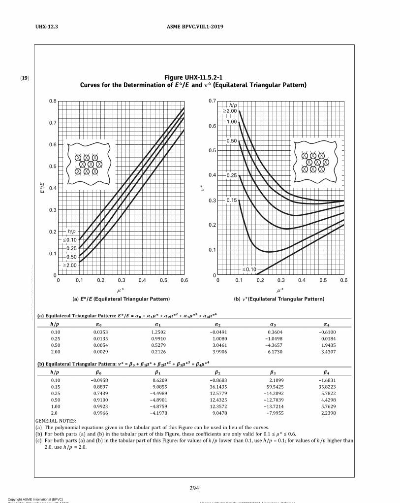
ð19Þ Figure UHX-11.5.2-1Curves for the Determination of E*/E and ν* (Equilateral Triangular Pattern)
0.25
h/p
0.50
0.10
2.00
0.8
0.7
0.6
0.5
0.4
0.3
0.2
0.1
00.10 0.2 0.3 0.4 0.5 0.6
0.7
0.6
0.4
0.5
0.3
0.2
0.1
00.10 0.2 0.3 0.4 0.5 0.6
0.25
0.50
1.00
0.15
2.00
0.10
h/p
(b) (Equilateral Triangular Pattern)(a) E*/E (Equilateral Triangular Pattern)
E /
E
(a) Equilateral Triangular Pattern: E*/E = α0 + α1μ* + α2μ*2 + α3μ*
3 + α4μ*4
h/p α0 α1 α2 α3 α4
0.10 0.0353 1.2502 −0.0491 0.3604 −0.61000.25 0.0135 0.9910 1.0080 −1.0498 0.01840.50 0.0054 0.5279 3.0461 −4.3657 1.94352.00 −0.0029 0.2126 3.9906 −6.1730 3.4307
(b) Equilateral Triangular Pattern: ν* = β0 + β1μ* + β2μ*2 + β3μ*
3 + β4μ*4
h/p β0 β1 β2 β3 β4
0.10 −0.0958 0.6209 −0.8683 2.1099 −1.68310.15 0.8897 −9.0855 36.1435 −59.5425 35.82230.25 0.7439 −4.4989 12.5779 −14.2092 5.78220.50 0.9100 −4.8901 12.4325 −12.7039 4.42981.00 0.9923 −4.8759 12.3572 −13.7214 5.76292.0 0.9966 −4.1978 9.0478 −7.9955 2.2398
GENERAL NOTES:(a) The polynomial equations given in the tabular part of this Figure can be used in lieu of the curves.(b) For both parts (a) and (b) in the tabular part of this Figure, these coefficients are only valid for 0.1 ≤ μ* ≤ 0.6.(c) For both parts (a) and (b) in the tabular part of this Figure: for values of h/p lower than 0.1, use h/p = 0.1; for values of h/p higher than
2.0, use h/p = 2.0.
294
ASME BPVC.VIII.1-2019UHX-12.3
Copyright ASME International (BPVC) Provided by IHS under license with ASME Licensee=Khalda Petroleum/5986215001, User=Amer, Mohamed
Not for Resale, 07/02/2019 13:29:04 MDTNo reproduction or networking permitted without license from IHS
--`,``,``,,`,`,,````,`,``,,,`-`-`,,`,,`,`,,`---

ð19ÞFigure UHX-11.5.2-2Curves for the Determination of E*/E and ν* (Square Pattern)
0
0.1
0.2
0.3
0.4
0.5
0.6
0.8
0.7
0 0.1 0.2 0.3 0.4 0.5 0.6
(a) E*/E (Square Pattern)
*
E*
/E
h/p
h/p
0
0.1
0.2
0.3
0.4
0 0.1
�0.10
�2.00
�2.00
�0.10
0.15
0.50
0.25
0.25
0.50
1.00
0.2 0.3 0.4 0.5 0.6
(b) v* (Square Pattern)
*
v*
(a) Square Pattern: E*/E = α0 + α1μ* + α2μ*2 + α3μ*
3 + α4μ*4
h/p α0 α1 α2 α3 α4
0.10 0.0676 1.5756 −1.2119 1.7715 −1.26280.25 0.0250 1.9251 −3.5230 6.9830 −5.00170.50 0.0394 1.3024 −1.1041 2.8714 −2.39942.00 0.0372 1.0314 −0.6402 2.6201 −2.1929
(b) Square Pattern: ν* = β0 + β1μ* + β2μ*2 + β3μ*
3 + β4μ*4
h/p β0 β1 β2 β3 β4
0.10 −0.0791 0.6008 −0.3468 0.4858 −0.36060.15 0.3345 −2.8420 10.9709 −15.8994 8.35160.25 0.4296 −2.6350 8.6864 −11.5227 5.85440.50 0.3636 −0.8057 2.0463 −2.2902 1.18621.00 0.3527 −0.2842 0.4354 −0.0901 −0.15902.00 0.3341 0.1260 −0.6920 0.6877 −0.0600
GENERAL NOTES:(a) The polynomial equations given in the tabular part of this Figure can be used in lieu of the curves.(b) For both parts (a) and (b) in the tabular part of this Figure, these coefficients are only valid for 0.1 ≤ μ* ≤ 0.6.(c) For both parts (a) and (b) in the tabular part of this Figure: for values of h/p lower than 0.1, use h/p = 0.1; for values of h/p higher than
2.0, use h/p = 2.0.
295
ASME BPVC.VIII.1-2019 UHX-12.3
Copyright ASME International (BPVC) Provided by IHS under license with ASME Licensee=Khalda Petroleum/5986215001, User=Amer, Mohamed
Not for Resale, 07/02/2019 13:29:04 MDTNo reproduction or networking permitted without license from IHS
--`,``,``,,`,`,,````,`,``,,,`-`-`,,`,,`,`,,`---

Figure UHX-12.1U-Tube Tubesheet Configurations
C
Gc Ds
A
ts
PsPt
h
(b) Configuration b:
Tubesheet Integral With Shell and Gasketed
With Channel, Extended as a Flange
Dc Ds
Ps
tstc
APt
(a) Configuration a:
Tubesheet Integral With Shell and Channel
h
Gc
C
A(not
extended)
(d) Configuration d:
Tubesheet Gasketed With Shell and Channel
A (extended)
Gs
PsPt
h
Dc
A
C
Gs
tc
PsPt
h
(e) Configuration e:
Tubesheet Gasketed With Shell and Integral
With Channel, Extended as a Flange
CGc Ds
AC
PsPt
h
(c) Configuration c:
Tubesheet Integral With Shell and Gasketed
With Channel, Not Extended as a Flange
A
Dc Gs
C
tc
PsPt
h
(f) Configuration f:
Tubesheet Gasketed With Shell and Integral
With Channel, Not Extended as a Flange
G1
ts
Ds
G1
296
ASM
EBPVC.VIII.1
-2019
UHX-12.3
Copyright A
SM
E International (B
PV
C)
Provided by IH
S under license w
ith AS
ME
Licensee=
Khalda P
etroleum/5986215001, U
ser=A
mer, M
ohamed
Not for R
esale, 07/02/2019 13:29:04 MD
TN
o reproduction or networking perm
itted without license from
IHS
--`,``,``,,`,`,,````,`,``,,,`-`-`,,`,,`,`,,`---

Figure UHX-12.2Tube Layout Perimeter
(a) Equilateral Triangular Pattern
(b) Square Pattern
GENERAL NOTE: Cp (perimeter) is the length of the heavy line.
297
ASME BPVC.VIII.1-2019 UHX-12.3
Copyright ASME International (BPVC) Provided by IHS under license with ASME Licensee=Khalda Petroleum/5986215001, User=Amer, Mohamed
Not for Resale, 07/02/2019 13:29:04 MDTNo reproduction or networking permitted without license from IHS
--`,``,``,,`,`,,````,`,``,,,`-`-`,,`,,`,`,,`---

UHX-12.4 Design Considerations(a) The various loading conditions to be considered
shall include, but not be limited to, normal operating,startup, shutdown, cleaning, and upset conditions, whichmay govern the design of the tubesheet.For each of these conditions, the following loading
cases shall be considered:(1) Design Loading Cases. Table UHX-12.4-1 provides
the load combinations required to evaluate the heat ex-changer for the design condition. When P s d ,m i n andP t d ,m i n are both zero, design loading case 4 does notneed to be considered.
(2)When differential design pressure is specified bythe user or his designated agent, the design shall be basedonly on loading case 3. If the tube side is the higher‐pressure side, Pt shall be the tube side design pressureand Ps shall be Pt less the differential design pressure. Ifthe shell side is the higher‐pressure side, Ps shall be theshell side design pressure and Pt shall be Ps less the differ-ential design pressure.
(3) The designer should take appropriate considera-tion of the stresses resulting from the pressure test re-quired by UG-99 or UG-100 [see UG-99(d)].(b) As the calculation procedure is iterative, a value h
shall be assumed for the tubesheet thickness to calculateand check that the maximum stresses in tubesheet, shell,and channel are within the maximum permissible stresslimits.(c) The designer may consider the tubesheet as simply
supported in accordance with UHX-12.6.
UHX-12.5 Calculation ProcedureThe procedure for the design of a tubesheet for a
U‐tube heat exchanger is as follows:
UHX-12.5.1 Step 1. Determine Do, μ , μ*, and from
UHX-11.5.1.
UHX-12.5.2 Step 2. Calculate diameter ratios ρ s andρc . Configurations a, b, and c:
Configurations d, e, and f:
Configurations a, e, and f:
Configurations b, c, and d:
For each loading case, calculate moment MTS due topressures Ps and Pt acting on the unperforated tubesheetrim.
UHX-12.5.3 Step 3. Calculate h/p. If ρ changes, recal-culate d* and μ* from UHX-11.5.1.Determine E * /E and ν * relative to h /p from
UHX-11.5.2.Configurations a, b, c, e, and f: Proceed to UHX-12.5.4.Configuration d: Proceed to UHX-12.5.5.
UHX-12.5.4 Step 4. Configurations a, b, and c: Calcu-late shell coefficients β s , ks, λ s , δ s , and ω s .
Configurations a, e, and f: Calculate channel coefficientsβ c , kc, λ c , δc , and ωc .
Table UHX-12.4-1
DesignLoadingCase
Shell SideDesign
Pressure, Ps
Tube SideDesign
Pressure, Pt
1 Psd ,min Ptd ,max
2 Psd ,max Ptd ,min
3 Psd ,max Ptd ,max
4 Psd ,min Ptd ,min
298
ASME BPVC.VIII.1-2019UHX-12.4 – UHX-12.5.4
Copyright ASME International (BPVC) Provided by IHS under license with ASME Licensee=Khalda Petroleum/5986215001, User=Amer, Mohamed
Not for Resale, 07/02/2019 13:29:04 MDTNo reproduction or networking permitted without license from IHS
--`,``,``,,`,`,,````,`,``,,,`-`-`,,`,,`,`,,`---
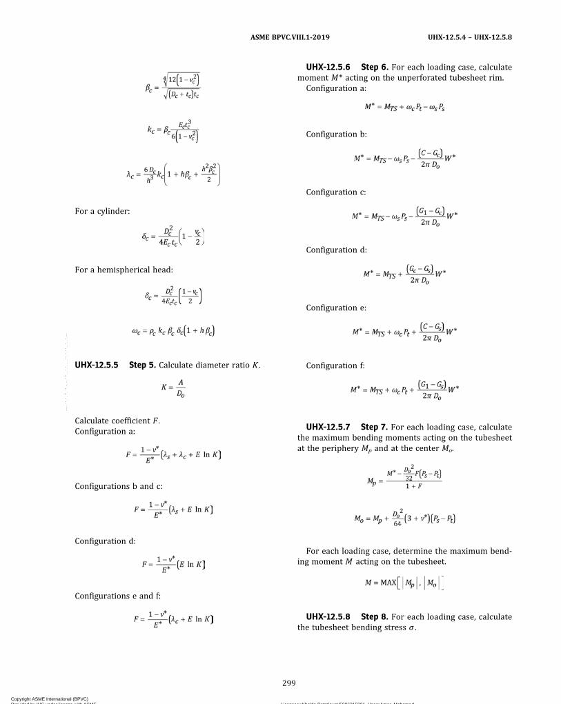
For a cylinder:
For a hemispherical head:
UHX-12.5.5 Step 5. Calculate diameter ratio K .
Calculate coefficient F .Configuration a:
Configurations b and c:
Configuration d:
Configurations e and f:
UHX-12.5.6 Step 6. For each loading case, calculatemoment M* acting on the unperforated tubesheet rim.
Configuration a:
Configuration b:
Configuration c:
Configuration d:
Configuration e:
Configuration f:
UHX-12.5.7 Step 7. For each loading case, calculatethe maximum bending moments acting on the tubesheetat the periphery Mp and at the center Mo.
For each loading case, determine the maximum bend-ing moment M acting on the tubesheet.
UHX-12.5.8 Step 8. For each loading case, calculatethe tubesheet bending stress σ .
299
ASME BPVC.VIII.1-2019 UHX-12.5.4 – UHX-12.5.8
Copyright ASME International (BPVC) Provided by IHS under license with ASME Licensee=Khalda Petroleum/5986215001, User=Amer, Mohamed
Not for Resale, 07/02/2019 13:29:04 MDTNo reproduction or networking permitted without license from IHS
--`,``,``,,`,`,,````,`,``,,,`-`-`,,`,,`,`,,`---

ð19Þ
If σ ≤ 2S , the assumed tubesheet thickness is accept-able for bending. Otherwise, increase the assumed tube-sheet thickness h and return to the step in UHX-12.5.1.
UHX-12.5.9 Step 9. For each loading case, calculatethe average shear stress in the tubesheet at the outer edgeof the perforated region, if required.
(a) If , the shear stress is not re-
quired to be calculated. Proceed to the step in (c).(b) Calculate the average shear stress, τ .
If τ ≤MIN[0.8S , 0.533Sy], the assumed tubesheet thick-ness is acceptable for shear. Otherwise, increase the as-sumed tubesheet thickness, h , and return to UHX-12.5.1.(c) Configurations a, b, c , e , and f: Proceed to
UHX-12.5.10. Configuration d: The calculation procedureis complete.
UHX-12.5.10 Step 10. For each loading case, calculatethe stresses in the shell and/or channel integral with thetubesheet.Configurations a, b, and c: The shell shall have a uni-
form thickness of ts for a minimum length of ad-
jacent to the tubesheet. Calculate the axial membranestress σ s , m , axial bending stress σ s , b , and total axialstress σ s , in the shell at its junction to the tubesheet.
Configurations a, e, and f: A cylindrical channel shallhave a uniform thickness of tc for a minimum length of
adjacent to the tubesheet. Calculate the axial
membrane stress σc ,m , axial bending stress σ c , b , and totalaxial stress σ c , in the channel at its junction to thetubesheet.
Configuration a: If σ s ≤ 1.5Ss and σ c ≤ 1.5Sc, the shelland channel designs are acceptable and the calculationprocedure is complete . Otherwise , proceed toUHX-12.5.11.Configurations b and c: If σ s ≤ 1.5Ss, the shell design is
acceptable and the calculation procedure is complete.Otherwise, proceed to UHX-12.5.11.Configurations e and f: If σ c ≤ 1.5Sc, the channel design
is acceptable and the calculation procedure is complete.Otherwise, proceed to UHX-12.5.11.
UHX-12.5.11 Step 11. The design shall be reconsid-ered. One or a combination of the following three optionsmay be used.Option 1. Increase the assumed tubesheet thickness h
and return to UHX-12.5.1.Option 2. Increase the integral shell and/or channel
thickness as follows:Configurations a, b, and c: If σ s > 1.5Ss, increase the
shell thickness ts.Configurations a, e, and f: If σ c > 1.5Sc increase the
channel thickness tc.Return to UHX-12.5.1.Option 3. Perform a simplified elastic–plastic calcula-
tion for each applicable loading case by using a reducedeffective modulus for the integral shell and/or channelto reflect the anticipated load shift resulting from plasticaction at the integral shell and/or channel‐to‐tubesheetjunction. This may result in a higher tubesheet bendingstress σ . This option shall not be used at temperatureswhere the time‐dependent properties govern the allow-able stress.Configuration a: This option may only be used when
σ s ≤ SPS,s and σ c ≤ SPS,c. In UHX-12.5.4, if σ s > 1.5 Ss, re-
place Es with and recalculate ks and
λs . If σ c > 1.5 Sc, replace Ecwith and re-
calculate kc and λc .Configurations b and c: This option may only be used
when σ s ≤ SPS , s . In UHX-12.5.4, replace Es with
and recalculate ks and λs .
300
ASME BPVC.VIII.1-2019UHX-12.5.8 – UHX-12.5.11
Copyright ASME International (BPVC) Provided by IHS under license with ASME Licensee=Khalda Petroleum/5986215001, User=Amer, Mohamed
Not for Resale, 07/02/2019 13:29:04 MDTNo reproduction or networking permitted without license from IHS
--`,``,``,,`,`,,````,`,``,,,`-`-`,,`,,`,`,,`---
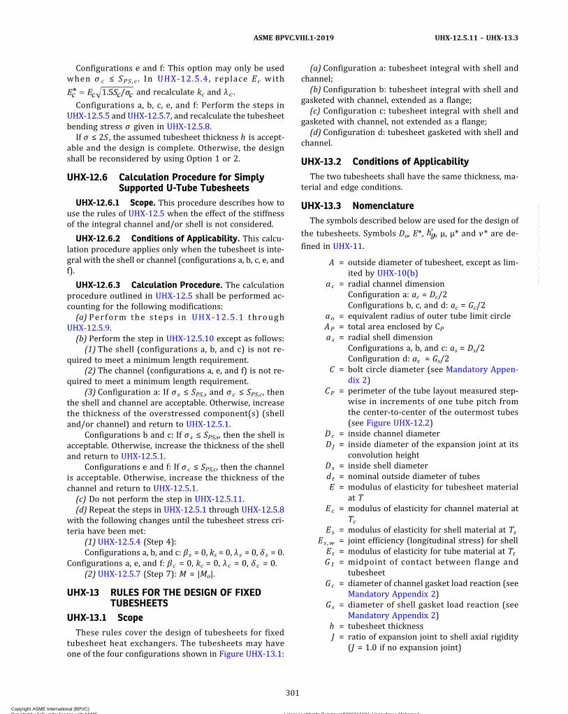
Configurations e and f: This option may only be usedwhen σ c ≤ SPS ,c . In UHX-12.5.4, replace Ec with
and recalculate kc and λc .
Configurations a, b, c, e, and f: Perform the steps inUHX-12.5.5 and UHX-12.5.7, and recalculate the tubesheetbending stress σ given in UHX-12.5.8.
If σ ≤ 2S , the assumed tubesheet thickness h is accept-able and the design is complete. Otherwise, the designshall be reconsidered by using Option 1 or 2.
UHX-12.6 Calculation Procedure for SimplySupported U-Tube Tubesheets
UHX-12.6.1 Scope. This procedure describes how touse the rules of UHX-12.5 when the effect of the stiffnessof the integral channel and/or shell is not considered.
UHX-12.6.2 Conditions of Applicability. This calcu-lation procedure applies only when the tubesheet is inte-gral with the shell or channel (configurations a, b, c, e, andf).
UHX-12.6.3 Calculation Procedure. The calculationprocedure outlined in UHX-12.5 shall be performed ac-counting for the following modifications:
(a) Perform the steps in UHX-12 .5 .1 throughUHX-12.5.9.
(b) Perform the step in UHX-12.5.10 except as follows:(1) The shell (configurations a, b, and c) is not re-
quired to meet a minimum length requirement.(2) The channel (configurations a, e, and f) is not re-
quired to meet a minimum length requirement.(3) Configuration a: If σ s ≤ SPS,s and σ c ≤ SPS,c, then
the shell and channel are acceptable. Otherwise, increasethe thickness of the overstressed component(s) (shelland/or channel) and return to UHX-12.5.1.
Configurations b and c: If σ s ≤ SPS,s, then the shell isacceptable. Otherwise, increase the thickness of the shelland return to UHX-12.5.1.
Configurations e and f: If σ c ≤ SPS,c, then the channelis acceptable. Otherwise, increase the thickness of thechannel and return to UHX-12.5.1.
(c) Do not perform the step in UHX-12.5.11.(d) Repeat the steps in UHX-12.5.1 through UHX-12.5.8
with the following changes until the tubesheet stress cri-teria have been met:
(1) UHX-12.5.4 (Step 4):Configurations a, b, and c: β s = 0, ks = 0, λ s = 0, δ s = 0.
Configurations a, e, and f: β c = 0, kc = 0, λ c = 0, δc = 0.(2) UHX-12.5.7 (Step 7): M = |Mo|.
UHX-13 RULES FOR THE DESIGN OF FIXEDTUBESHEETS
UHX-13.1 ScopeThese rules cover the design of tubesheets for fixed
tubesheet heat exchangers. The tubesheets may haveone of the four configurations shown in Figure UHX-13.1:
(a) Configuration a: tubesheet integral with shell andchannel;
(b) Configuration b: tubesheet integral with shell andgasketed with channel, extended as a flange;
(c) Configuration c: tubesheet integral with shell andgasketed with channel, not extended as a flange;
(d) Configuration d: tubesheet gasketed with shell andchannel.
UHX-13.2 Conditions of ApplicabilityThe two tubesheets shall have the same thickness, ma-
terial and edge conditions.
UHX-13.3 NomenclatureThe symbols described below are used for the design of
the tubesheets. Symbols Do, E*, , μ, μ* and ν* are de-
fined in UHX-11.
A = outside diameter of tubesheet, except as lim-ited by UHX-10(b)
ac = radial channel dimensionConfiguration a: ac = Dc/2Configurations b, c, and d: ac = Gc/2
ao = equivalent radius of outer tube limit circleAP = total area enclosed by CPas = radial shell dimension
Configurations a, b, and c: as = Ds/2Configuration d: as = Gs/2
C = bolt circle diameter (see Mandatory Appen-dix 2)
CP = perimeter of the tube layout measured step-wise in increments of one tube pitch fromthe center‐to‐center of the outermost tubes(see Figure UHX-12.2)
Dc = inside channel diameterDJ = inside diameter of the expansion joint at its
convolution heightDs = inside shell diameterdt = nominal outside diameter of tubesE = modulus of elasticity for tubesheet material
at TEc = modulus of elasticity for channel material at
TcEs = modulus of elasticity for shell material at Ts
Es ,w = joint efficiency (longitudinal stress) for shellEt = modulus of elasticity for tube material at TtG1 = midpoint of contact between flange and
tubesheetGc = diameter of channel gasket load reaction (see
Mandatory Appendix 2)Gs = diameter of shell gasket load reaction (see
Mandatory Appendix 2)h = tubesheet thicknessJ = ratio of expansion joint to shell axial rigidity
(J = 1.0 if no expansion joint)
301
ASME BPVC.VIII.1-2019 UHX-12.5.11 – UHX-13.3
Copyright ASME International (BPVC) Provided by IHS under license with ASME Licensee=Khalda Petroleum/5986215001, User=Amer, Mohamed
Not for Resale, 07/02/2019 13:29:04 MDTNo reproduction or networking permitted without license from IHS
--`,``,``,,`,`,,````,`,``,,,`-`-`,,`,,`,`,,`---

k = constant accounting for the method of sup-port for the unsupported tube span underconsideration
= 0.6 for unsupported spans between twotubesheets
= 0.8 for unsupported spans between a tube-sheet and a tube support
= 1.0 for unsupported spans between two tubesupports
KJ = axial rigidity of expansion joint, total force/elongation
L = tube length between inner tubesheet faces= Lt − 2h
Lt = tube length between outer tubesheet facesMAX [(a),(b),(c),...] = greatest of a, b, c,...
Nt = number of tubesPe = effective pressure acting on tubesheetPs = shell side design or operating pressure, as
applicable. For shell side vacuum, use a nega-tive value for Ps
Psd ,max = maximum shell side design pressurePsd ,min = minimum shell side design pressure (nega-
tive if vacuum is specified, otherwise zero)Psox ,max = max.(0, maximum shell side operating pres-
sure for operating condition x)Psox ,min = min.(0, minimum shell side operating pres-
sure for operating condition x)Pt = tube side design or operating pressure, as ap-
plicable. For tube side vacuum, use a negativevalue for Pt
Ptd ,max = maximum tube side design pressurePtd ,min = minimum tube side design pressure (nega-
tive if vacuum is specified, otherwise zero)Ptox ,max = max.(0, maximum tube side operating pres-
sure for operating condition x)Ptox ,min = min.(0, minimum tube side operating pres-
sure for operating condition x)S = allowable stress for tubesheet material at TSc = allowable stress for channel material at Tc
SPS = allowable primary plus secondary stress fortubesheet material at T per UG-23(e)
SPS , c = allowable primary plus secondary stress forchannel material at Tc per UG-23(e)
SPS , s = allowable primary plus secondary stress forshell material at Ts per UG-23(e)
Ss = allowable stress for shell material at TsSs , b = maximum allowable longitudinal compres-
sive stress in accordance with UG-23(b) forthe shell
St = allowable stress for tube material at TtNOTE: For a welded tube or pipe, use the allowablestress for the equivalent seamless product. Whenthe allowable stress for the equivalent seamless pro-duct is not available, divide the allowable stress of thewelded product by 0.85.
Sy = yield strength for tubesheet material at T
Sy , c = yield strength for channel material at TcSy , s = yield strength for shell material at TsSy , t = yield strength for tube material at Tt
NOTE: The yield strength shall be taken from SectionII, Part D, Subpart 1, Table Y-1. When a yield strengthvalue is not listed in Table Y-1, one may be obtainedby using the procedure in UG-28(c)(2), Step 3.
T = tubesheet design temperature for the designcondition or operating metal temperature foroperating condition x , as applicable [seeUHX-13.4(b)]
Tc = channel design temperature for the designcondition or operating metal temperaturefor operating condition x , as applicable [seeUHX-13.4(b)]
tc = channel thicknessTs = shell design temperature for the design con-
dition or operating metal temperature for op-erating condition x , as applicable [seeUHX-13.4(b)]
t s = shell thicknessTs ,m = mean shell metal temperature along shell
lengthTs ,mx = shell axial mean metal temperature for oper-
ating condition x , as applicableTt = tube design temperature for the design con-
dition or operating metal temperature for op-erating condition x , as applicable [seeUHX-13.4(b)]
t t = nominal tube wall thicknessTt ,m = mean tube metal temperature along tube
lengthTt ,mx = tube axial mean metal temperature for oper-
ating condition x , as applicableWt = tube-to-tubesheet joint loadW* = tubesheet effective bolt load determined in
accordance with UHX-8x = 1, 2, 3, ..., n , integer denoting applicable oper-
ating condition under consideration (e.g.,normal operating, start-up, shutdown, clean-ing, upset)
ℓ = unsupported tube span under considerationα s ,m = mean coefficient of thermal expansion of
shell material at Ts ,m
α t ,m = mean coefficient of thermal expansion oftube material at Tt ,m
γ = axial differential thermal expansion betweentubes and shell
Δ J = axial displacement over the length of thethin-walled bellows element (see UHX-16)
Δ s = shell axial displacement over the length be-tween the inner tubesheet faces, L [seeUHX-17(c)]
ν = Poisson’s ratio of tubesheet materialνc = Poisson’s ratio of channel materialν s = Poisson’s ratio of shell material
302
ASME BPVC.VIII.1-2019UHX-13.3
Copyright ASME International (BPVC) Provided by IHS under license with ASME Licensee=Khalda Petroleum/5986215001, User=Amer, Mohamed
Not for Resale, 07/02/2019 13:29:04 MDTNo reproduction or networking permitted without license from IHS
--`,``,``,,`,`,,````,`,``,,,`-`-`,,`,,`,`,,`---
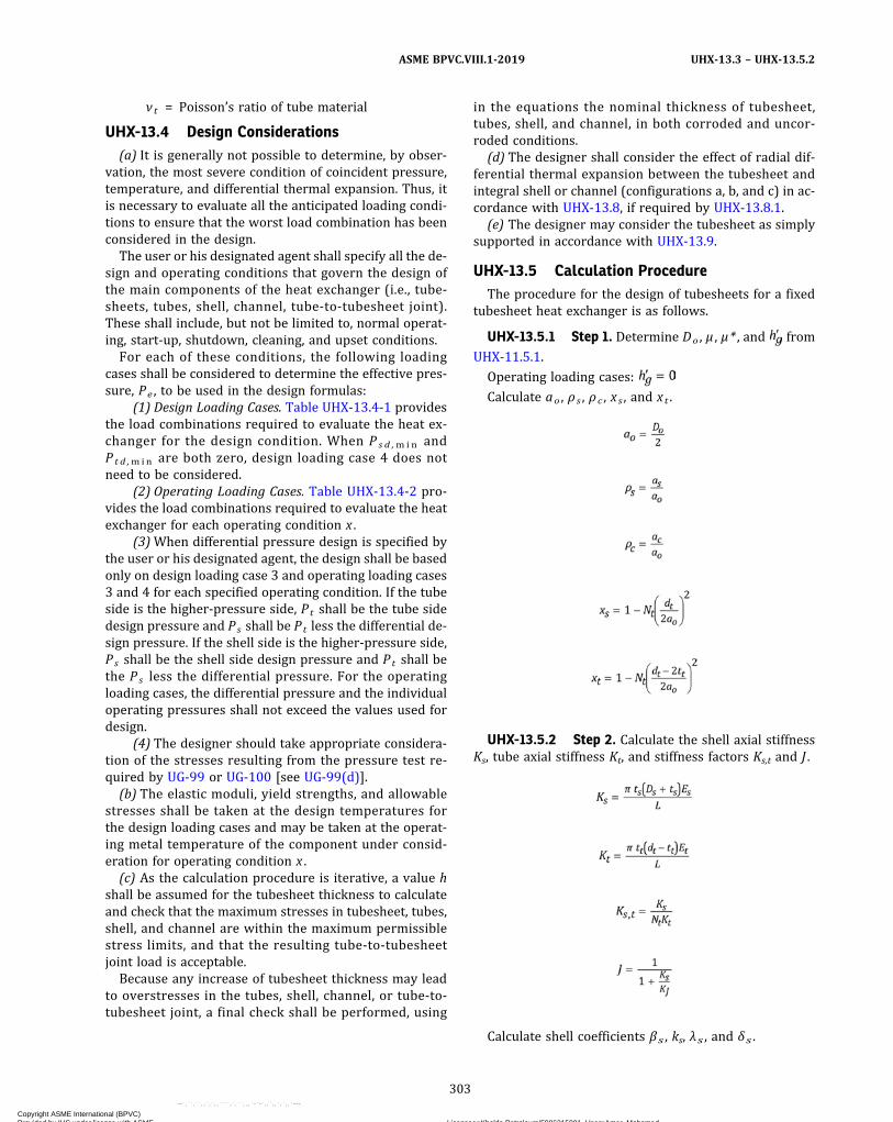
ν t = Poisson’s ratio of tube material
UHX-13.4 Design Considerations(a) It is generally not possible to determine, by obser-
vation, the most severe condition of coincident pressure,temperature, and differential thermal expansion. Thus, itis necessary to evaluate all the anticipated loading condi-tions to ensure that the worst load combination has beenconsidered in the design.
The user or his designated agent shall specify all the de-sign and operating conditions that govern the design ofthe main components of the heat exchanger (i.e., tube-sheets, tubes, shell, channel, tube-to-tubesheet joint).These shall include, but not be limited to, normal operat-ing, start-up, shutdown, cleaning, and upset conditions.
For each of these conditions, the following loadingcases shall be considered to determine the effective pres-sure, Pe , to be used in the design formulas:
(1) Design Loading Cases. Table UHX-13.4-1 providesthe load combinations required to evaluate the heat ex-changer for the design condition. When P s d ,m i n andP t d ,m i n are both zero, design loading case 4 does notneed to be considered.
(2) Operating Loading Cases. Table UHX-13.4-2 pro-vides the load combinations required to evaluate the heatexchanger for each operating condition x .
(3)When differential pressure design is specified bythe user or his designated agent, the design shall be basedonly on design loading case 3 and operating loading cases3 and 4 for each specified operating condition. If the tubeside is the higher-pressure side, Pt shall be the tube sidedesign pressure and Ps shall be Pt less the differential de-sign pressure. If the shell side is the higher-pressure side,Ps shall be the shell side design pressure and Pt shall bethe Ps less the differential pressure. For the operatingloading cases, the differential pressure and the individualoperating pressures shall not exceed the values used fordesign.
(4) The designer should take appropriate considera-tion of the stresses resulting from the pressure test re-quired by UG-99 or UG-100 [see UG-99(d)].
(b) The elastic moduli, yield strengths, and allowablestresses shall be taken at the design temperatures forthe design loading cases and may be taken at the operat-ing metal temperature of the component under consid-eration for operating condition x .
(c) As the calculation procedure is iterative, a value hshall be assumed for the tubesheet thickness to calculateand check that the maximum stresses in tubesheet, tubes,shell, and channel are within the maximum permissiblestress limits, and that the resulting tube-to-tubesheetjoint load is acceptable.
Because any increase of tubesheet thickness may leadto overstresses in the tubes, shell, channel, or tube-to-tubesheet joint, a final check shall be performed, using
in the equations the nominal thickness of tubesheet,tubes, shell, and channel, in both corroded and uncor-roded conditions.
(d) The designer shall consider the effect of radial dif-ferential thermal expansion between the tubesheet andintegral shell or channel (configurations a, b, and c) in ac-cordance with UHX-13.8, if required by UHX-13.8.1.
(e) The designer may consider the tubesheet as simplysupported in accordance with UHX-13.9.
UHX-13.5 Calculation ProcedureThe procedure for the design of tubesheets for a fixed
tubesheet heat exchanger is as follows.
UHX-13.5.1 Step 1. Determine Do , μ , μ* , and from
UHX-11.5.1.
Operating loading cases:
Calculate ao , ρ s , ρ c , xs , and xt .
UHX-13.5.2 Step 2. Calculate the shell axial stiffnessKs, tube axial stiffness Kt, and stiffness factors Ks,t and J .
Calculate shell coefficients βs , ks, λs , and δs .
303
ASME BPVC.VIII.1-2019 UHX-13.3 – UHX-13.5.2
Copyright ASME International (BPVC) Provided by IHS under license with ASME Licensee=Khalda Petroleum/5986215001, User=Amer, Mohamed
Not for Resale, 07/02/2019 13:29:04 MDTNo reproduction or networking permitted without license from IHS
--`,``,``,,`,`,,````,`,``,,,`-`-`,,`,,`,`,,`---
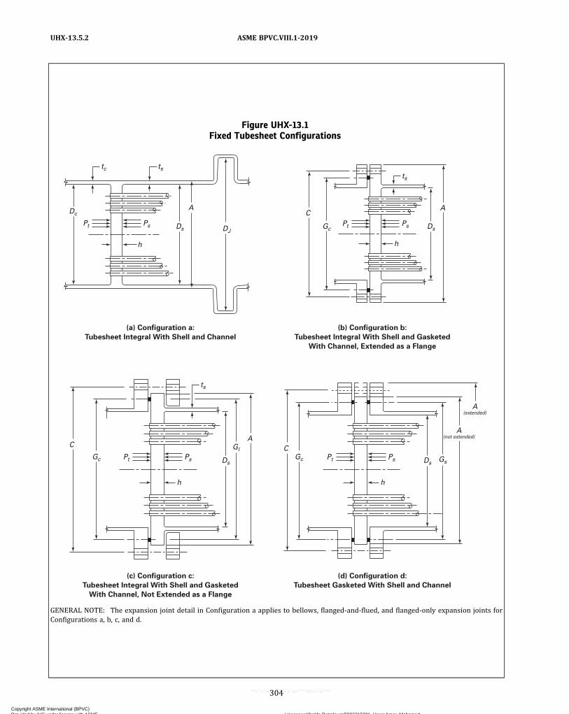
Figure UHX-13.1Fixed Tubesheet Configurations
(a) Configuration a:
Tubesheet Integral With Shell and Channel
(b) Configuration b:
Tubesheet Integral With Shell and Gasketed
With Channel, Extended as a Flange
(c) Configuration c:
Tubesheet Integral With Shell and Gasketed
With Channel, Not Extended as a Flange
(d) Configuration d:
Tubesheet Gasketed With Shell and Channel
GENERAL NOTE: The expansion joint detail in Configuration a applies to bellows, flanged‐and‐flued, and flanged‐only expansion joints forConfigurations a, b, c, and d.
304
ASME BPVC.VIII.1-2019UHX-13.5.2
Copyright ASME International (BPVC) Provided by IHS under license with ASME Licensee=Khalda Petroleum/5986215001, User=Amer, Mohamed
Not for Resale, 07/02/2019 13:29:04 MDTNo reproduction or networking permitted without license from IHS
--`,``,``,,`,`,,````,`,``,,,`-`-`,,`,,`,`,,`---
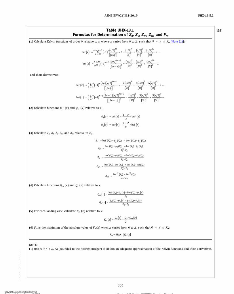
ð19ÞTable UHX-13.1Formulas for Determination of Zd, Zv, Zm, Zw, and Fm
(1) Calculate Kelvin functions of order 0 relative to x, where x varies from 0 to Xa such that [Note (1)]:
and their derivatives:
(2) Calculate functions ψ1 (x) and ψ2 (x) relative to x :
(3) Calculate Za, Zd, Zv, Zw, and Zm relative to Xa :
(4) Calculate functions Qm (x) and Qv (x) relative to x:
(5) For each loading case, calculate Fm (x) relative to x:
(6) Fm is the maximum of the absolute value of Fm(x) when x varies from 0 to Xa such that :
NOTE:(1) Use m = 4 + Xa/2 (rounded to the nearest integer) to obtain an adequate approximation of the Kelvin functions and their derivatives.
305
ASME BPVC.VIII.1-2019 UHX-13.5.2
Copyright ASME International (BPVC) Provided by IHS under license with ASME Licensee=Khalda Petroleum/5986215001, User=Amer, Mohamed
Not for Resale, 07/02/2019 13:29:04 MDTNo reproduction or networking permitted without license from IHS
--`,``,``,,`,`,,````,`,``,,,`-`-`,,`,,`,`,,`---

Configurations a, b, and c:
Configuration d: β s = 0, ks = 0, λ s = 0, δ s = 0Calculate channel coefficients β c , kc , λ c , and δc .
Configuration a:
For a cylinder:
Table UHX-13.2Formulas for Determination of Ft ,min and Ft ,max
Step No. Description
1 Follow steps (1), (2), and (3) in Table UHX-13.1.2 Calculate functions Zd(x) and Zw(x) relative to x :
3 For each loading case, calculate Ft(x) relative to x in accordance with a or b below.(a) When Pe ≠ 0
(b) When Pe = 0
4 Calculate the minimum and maximum values, Ft,min and Ft,max, of Ft (x) when x varies from 0 to Xa such that 0 ≤ x ≤ Xa. Ft,min
and Ft,max may be positive or negative.
When Pe ≠ 0, see Figures LL-1 and LL-2 in Nonmandatory Appendix LL for a graphical representation of Ft,min and Ft,max.
306
ASME BPVC.VIII.1-2019UHX-13.5.2
Copyright ASME International (BPVC) Provided by IHS under license with ASME Licensee=Khalda Petroleum/5986215001, User=Amer, Mohamed
Not for Resale, 07/02/2019 13:29:04 MDTNo reproduction or networking permitted without license from IHS
--`,``,``,,`,`,,````,`,``,,,`-`-`,,`,,`,`,,`---

For a hemispherical head:
Configurations b, c, d: β c = 0, kc = 0, λ c = 0, δc = 0
UHX-13.5.3 Step 3. Calculate h/p. If ρ changes, recal-culate d* and μ* from UHX-11.5.1.
Determine E * /E and ν * relative to h /p fromUHX-11.5.2.
Calculate Xa.
Figure UHX-13.2Zd, Zv, Zw, and Zm Versus Xa
Zm
Zv = Zw
Zd
Zd, Z
v, Z
w, o
r Z
m
Xa
0.80
0.70
0.60
0.50
2 4 6 8 10 120
0.40
0.30
0.20
0.10
0
GENERAL NOTES:(a) Curves giving Zd, Zv, Zw, or Zm are valid for v* = 0.4. They are sufficiently accurate to be used for other values of v*.(b) For Xa > 12.0, see Table UHX-13.1.
Table UHX-13.4-1
DesignLoadingCase
Shell SideDesign
Pressure, Ps
Tube SideDesign
Pressure, Pt
1 Psd ,min Ptd ,max
2 Psd ,max Ptd ,min
3 Psd ,max Ptd ,max
4 Psd ,min Ptd ,min
307
ASME BPVC.VIII.1-2019 UHX-13.5.2 – UHX-13.5.3
Copyright ASME International (BPVC) Provided by IHS under license with ASME Licensee=Khalda Petroleum/5986215001, User=Amer, Mohamed
Not for Resale, 07/02/2019 13:29:04 MDTNo reproduction or networking permitted without license from IHS
--`,``,``,,`,`,,````,`,``,,,`-`-`,,`,,`,`,,`---

Using the calculated value of Xa, enter either TableUHX-13.1 or Figure UHX-13.2 to determine Zd, Zv, Zw,and Zm.
UHX-13.5.4 Step 4. Calculate diameter ratio K andcoefficient F .
Calculate Φ, Q1, QZ1, QZ2, and U .
UHX-13.5.5 Step 5.(a) Calculate γ .Design loading cases: γ = 0.Operating loading cases:
(b) Calculate ωs , , and ωc , .
Table UHX-13.4-2
OperatingLoading Case
Operating Pressure Axial Mean Metal Temperature
Shell Side, Ps Tube Side, Pt Tubes, Tt ,m Shell, Ts ,m
1 Psox ,min Ptox ,max Tt ,mx Ts ,mx
2 Psox ,max Ptox ,min Tt ,mx Ts ,mx
3 Psox ,max Ptox ,max Tt ,mx Ts ,mx
4 Psox ,min Ptox ,min Tt ,mx Ts ,mx
ð19Þ Figure UHX-13.4Different Shell Thicknesses and/or Material Adjacent to the Tubesheets
Configurationa, b, or c
Configurationa, b, or c
Tub
esh
eet
Lt
L
Dc Ds
ts,1 ts,1
ts�s,m,1Es,1
�s,mEs
h
Tub
esh
eet
h
tc tc
L– –1 1 1
Dc
1
308
ASME BPVC.VIII.1-2019UHX-13.5.3 – UHX-13.5.5
Copyright ASME International (BPVC) Provided by IHS under license with ASME Licensee=Khalda Petroleum/5986215001, User=Amer, Mohamed
Not for Resale, 07/02/2019 13:29:04 MDTNo reproduction or networking permitted without license from IHS
--`,``,``,,`,`,,````,`,``,,,`-`-`,,`,,`,`,,`---

ð19Þ
(c) Calculate γb .Configuration a:
Configuration b:
Configuration c:
Configuration d:
UHX-13.5.6 Step 6. For each loading case, calculate, , Pγ , PW, Prim, and effective pressure Pe.
UHX-13.5.7 Step 7. For each loading case, calculateQ2.
For each loading case, calculate the maximum bendingstress in the tubesheet in accordance with (a) or (b)below.
(a)When Pe ≠ 0:(1) Calculate Q3.
(2) For each loading case, determine coefficient Fmfrom either Table UHX-13.1 or Figures UHX-13.5.7-1and UHX-13.5.7-2 and calculate the maximum bendingstress σ .
(b)When Pe = 0, calculate the maximum bendingstress σ .
For the design loading cases, if |σ | ≤ 1.5S , and for theoperating loading cases, if |σ | ≤ SPS, the assumed tube-sheet thickness is acceptable for bending. Otherwise, in-crease the assumed tubesheet thickness h and return tothe step in UHX-13.5.1.
UHX-13.5.8 Step 8. For each loading case, calculatethe average shear stress in the tubesheet at the outer edgeof the perforated region, if required.
(a) If , the shear stress is not required to
be calculated. Proceed to UHX-13.5.9.(b) Calculate the average shear stress, τ .
309
ASME BPVC.VIII.1-2019 UHX-13.5.5 – UHX-13.5.8
Copyright ASME International (BPVC) Provided by IHS under license with ASME Licensee=Khalda Petroleum/5986215001, User=Amer, Mohamed
Not for Resale, 07/02/2019 13:29:04 MDTNo reproduction or networking permitted without license from IHS
--`,``,``,,`,`,,````,`,``,,,`-`-`,,`,,`,`,,`---
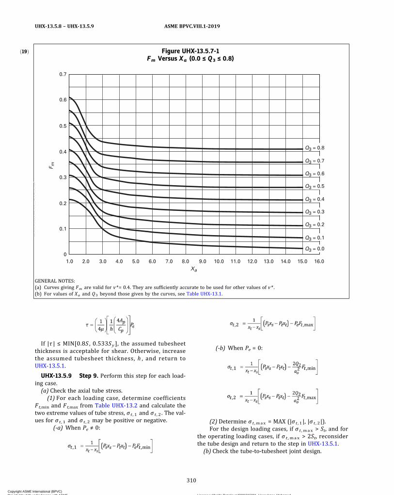
If |τ | ≤ MIN[0.8S , 0.533S y ], the assumed tubesheetthickness is acceptable for shear. Otherwise, increasethe assumed tubesheet thickness, h , and return toUHX-13.5.1.
UHX-13.5.9 Step 9. Perform this step for each load-ing case.(a) Check the axial tube stress.
(1) For each loading case, determine coefficientsFt,min and Ft,max from Table UHX-13.2 and calculate thetwo extreme values of tube stress, σ t ,1 and σ t ,2 . The val-ues for σ t ,1 and σ t ,2 may be positive or negative.
(-a) When Pe ≠ 0:
(-b) When Pe = 0:
(2) Determine σ t ,max = MAX (|σ t ,1|, |σ t ,2|).For the design loading cases, if σ t ,max > St, and for
the operating loading cases, if σ t ,max > 2St, reconsiderthe tube design and return to the step in UHX-13.5.1.(b) Check the tube-to-tubesheet joint design.
ð19Þ Figure UHX-13.5.7-1Fm Versus Xa (0.0 ≤ Q3 ≤ 0.8)
0.4
0.5
0.6
0.7
0.3
0.2
2.0 3.0 4.0 5.0 6.0 7.0 8.0 9.0Xa
F m
10.0 11.0 12.0 13.0 14.0 15.0 16.0
Q3 = 0.0
Q3 = 0.1
Q3 = 0.2
Q3 = 0.3
Q3 = 0.4
Q3 = 0.5
Q3 = 0.6
Q3 = 0.7
Q3 = 0.8
1.0
0.1
0
GENERAL NOTES:(a) Curves giving Fm are valid for v*= 0.4. They are sufficiently accurate to be used for other values of v* .(b) For values of Xa and Q3 beyond those given by the curves, see Table UHX-13.1.
310
ASME BPVC.VIII.1-2019UHX-13.5.8 – UHX-13.5.9
Copyright ASME International (BPVC) Provided by IHS under license with ASME Licensee=Khalda Petroleum/5986215001, User=Amer, Mohamed
Not for Resale, 07/02/2019 13:29:04 MDTNo reproduction or networking permitted without license from IHS
--`,``,``,,`,`,,````,`,``,,,`-`-`,,`,,`,`,,`---

(1) Calculate the largest tube-to-tubesheet joint load,Wt .
(2) Determine the maximum allowable load for thetube-to-tubesheet joint design, Lm a x . For tube-to-tubesheet joints with full strength welds, Lmax shall bedetermined in accordance with UW-20. For tube-to-tubesheet joints with partial strength welds, Lmax shallbe determined in accordance with UW-20, UW-18(d), orNonmandatory Appendix A, as applicable. For all othertube joints, Lmax shall be determined in accordance withNonmandatory Appendix A.
If Wt > Lmax , reconsider the tube-to-tubesheet jointdesign.
If Wt ≤ Lm a x , tube-to-tubesheet joint design isacceptable.
If σ t ,1 or σ t ,2 is negative, proceed to (c) below.If σ t ,1 and σ t ,2 are positive, the tube design is ac-
ceptable. Proceed to the step in UHX-13.5.10.(c) Check the tubes for buckling.
(1) Calculate the largest equivalent unsupportedbuckling length of the tube ℓ t considering the unsup-ported tube spans ℓ and their corresponding method ofsupport k .
(2) Calculate r t , Ft , and Ct .
ð19ÞFigure UHX-13.5.7-2Fm Versus Xa (−0.8 ≤ Q3 ≤ 0.0)
0.4
0.3
0.2
2.0 3.0 4.0 5.0 6.0 7.0 8.0 9.0Xa
F m
10.0 11.0 12.0 13.0 14.0 15.0 16.0
Q3 = 0.0
Q3 = –0.1
Q3 = –0.2
Q3 = –0.3
Q3 = –0.4
Q3 = –0.5
Q3 = –0.6
Q3 = –0.7
Q3 = –0.8
1.0
0.1
0
GENERAL NOTES:(a) Curves giving Fm are valid for v*= 0.4. They are sufficiently accurate to be used for other values of v* .(b) For values of Xa and Q3 beyond those given by the curves, see Table UHX-13.1.
311
ASME BPVC.VIII.1-2019 UHX-13.5.9
Copyright ASME International (BPVC) Provided by IHS under license with ASME Licensee=Khalda Petroleum/5986215001, User=Amer, Mohamed
Not for Resale, 07/02/2019 13:29:04 MDTNo reproduction or networking permitted without license from IHS
--`,``,``,,`,`,,````,`,``,,,`-`-`,,`,,`,`,,`---
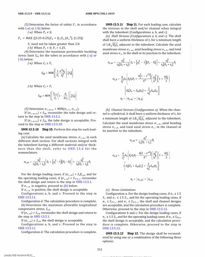
(3) Determine the factor of safety Fs in accordancewith (-a) or (-b) below:
(-a) When Pe ≠ 0,
Fs = MAX {[3.25-0.25(Zd + Q3Zw)Xa4], [1.25]}
Fs need not be taken greater than 2.0.(-b) When Pe = 0, Fs = 1.25.
(4) Determine the maximum permissible bucklingstress limit Stb for the tubes in accordance with (-a) or(-b) below:
(-a) When Ct ≤ Ft
(-b) When Ct > Ft
(5) Determine σ t ,min = MIN(σ t ,1 , σ t ,2).If |σ t ,min | > Stb, reconsider the tube design and re-
turn to the step in UHX-13.5.1.If |σ t ,min| ≤ Stb, the tube design is acceptable. Pro-
ceed to the step in UHX-13.5.10.
UHX-13.5.10 Step 10. Perform this step for each load-ing case.(a) Calculate the axial membrane stress, σ s ,m , in each
different shell section. For shell sections integral withthe tubesheet having a different material and/or thick-ness than the shel l , re fer to UHX-13 .6 for thenomenclature.
For the design loading cases, if |σ s ,m | > SsEs,w, and forthe operating loading cases, if |σ s ,m | > SPS , s , reconsiderthe shell design and return to the step in UHX-13.5.1.If σ s ,m is negative, proceed to (b) below.If σ s ,m is positive, the shell design is acceptable.Configurations a, b, and c: Proceed to the step in
UHX-13.5.11.Configuration d: The calculation procedure is complete.(b) Determine the maximum allowable longitudinal
compressive stress, Ss,b.If |σ s ,m | > Ss,b, reconsider the shell design and return to
the step in UHX-13.5.1.If |σ s ,m | ≤ Ss,b, the shell design is acceptable.Configurations a, b, and c: Proceed to the step in
UHX-13.5.11.Configuration d: The calculation procedure is complete.
UHX-13.5.11 Step 11. For each loading case, calculatethe stresses in the shell and/or channel when integralwith the tubesheet (Configurations a, b, and c).(a) Shell Stresses (Configurations a, b, and c). The shell
shall have a uniform thickness of ts for a minimum length
of adjacent to the tubesheet. Calculate the axial
membrane stress σ s ,m , axial bending stress σ s , b , and totalaxial stress σ s , in the shell at its junction to the tubesheet.
(b) Channel Stresses (Configuration a). When the chan-nel is cylindrical, it shall have a uniform thickness of tc for
a minimum length of adjacent to the tubesheet.
Calculate the axial membrane stress σ c ,m , axial bendingstress σ c , b , and total axial stress σ c , in the channel atits junction to the tubesheet.
(c) Stress LimitationsConfiguration a: For the design loading cases, if σ s ≤ 1.5
Ss and σ c ≤ 1.5 Sc , and for the operating loading cases, ifσ s ≤ SPS , s and σ c ≤ SPS , c , the shell and channel designsare acceptable, and the calculation procedure is complete.Otherwise, proceed to the step in UHX-13.5.12.Configurations b and c: For the design loading cases, if
σ s ≤ 1.5 Ss, and for the operating loading cases, if σ s ≤ SPS,s,the shell design is acceptable, and the calculation proce-dure is complete. Otherwise, proceed to the step inUHX-13.5.12.
UHX-13.5.12 Step 12. The design shall be reconsid-ered by using one or a combination of the following threeoptions:
312
ASME BPVC.VIII.1-2019UHX-13.5.9 – UHX-13.5.12
Copyright ASME International (BPVC) Provided by IHS under license with ASME Licensee=Khalda Petroleum/5986215001, User=Amer, Mohamed
Not for Resale, 07/02/2019 13:29:04 MDTNo reproduction or networking permitted without license from IHS
--`,``,``,,`,`,,````,`,``,,,`-`-`,,`,,`,`,,`---
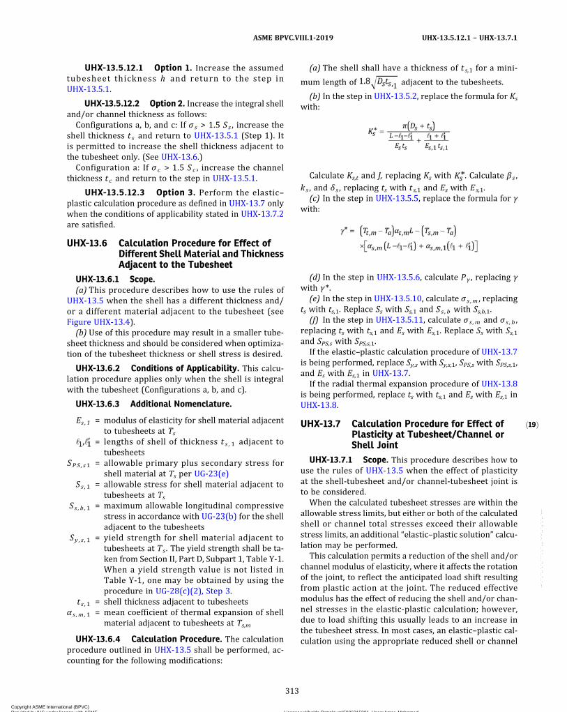
ð19Þ
UHX-13.5.12.1 Option 1. Increase the assumedtubesheet thickness h and return to the step inUHX-13.5.1.
UHX-13.5.12.2 Option 2. Increase the integral shelland/or channel thickness as follows:
Configurations a, b, and c: If σ s > 1.5 Ss , increase theshell thickness t s and return to UHX-13.5.1 (Step 1). Itis permitted to increase the shell thickness adjacent tothe tubesheet only. (See UHX-13.6.)
Configuration a: If σ c > 1.5 S c , increase the channelthickness t c and return to the step in UHX-13.5.1.
UHX-13.5.12.3 Option 3. Perform the elastic–plastic calculation procedure as defined in UHX-13.7 onlywhen the conditions of applicability stated in UHX-13.7.2are satisfied.
UHX-13.6 Calculation Procedure for Effect ofDifferent Shell Material and ThicknessAdjacent to the Tubesheet
UHX-13.6.1 Scope.(a) This procedure describes how to use the rules of
UHX-13.5 when the shell has a different thickness and/or a different material adjacent to the tubesheet (seeFigure UHX-13.4).
(b) Use of this procedure may result in a smaller tube-sheet thickness and should be considered when optimiza-tion of the tubesheet thickness or shell stress is desired.
UHX-13.6.2 Conditions of Applicability. This calcu-lation procedure applies only when the shell is integralwith the tubesheet (Configurations a, b, and c).
UHX-13.6.3 Additional Nomenclature.
Es ,1 = modulus of elasticity for shell material adjacentto tubesheets at Ts
= lengths of shell of thickness t s , 1 adjacent totubesheets
SPS , s1 = allowable primary plus secondary stress forshell material at Ts per UG-23(e)
Ss ,1 = allowable stress for shell material adjacent totubesheets at Ts
Ss , b ,1 = maximum allowable longitudinal compressivestress in accordance with UG-23(b) for the shelladjacent to the tubesheets
Sy , s ,1 = yield strength for shell material adjacent totubesheets at Ts . The yield strength shall be ta-ken from Section II, Part D, Subpart 1, Table Y-1.When a yield strength value is not listed inTable Y-1, one may be obtained by using theprocedure in UG-28(c)(2), Step 3.
t s ,1 = shell thickness adjacent to tubesheetsα s ,m ,1 = mean coefficient of thermal expansion of shell
material adjacent to tubesheets at Ts,m
UHX-13.6.4 Calculation Procedure. The calculationprocedure outlined in UHX-13.5 shall be performed, ac-counting for the following modifications:
(a) The shell shall have a thickness of t s,1 for a mini-
mum length of adjacent to the tubesheets.
(b) In the step in UHX-13.5.2, replace the formula for Ks
with:
Calculate Ks,t and J, replacing Ks with . Calculate β s ,
ks , and δ s , replacing ts with t s,1 and Es with Es,1.(c) In the step in UHX-13.5.5, replace the formula for γ
with:
(d) In the step in UHX-13.5.6, calculate Pγ , replacing γwith γ*.
(e) In the step in UHX-13.5.10, calculate σ s ,m , replacingts with ts,1. Replace Ss with Ss,1 and Ss , b with Ss,b,1.
(f) In the step in UHX-13.5.11, calculate σ s ,m and σ s , b ,replacing ts with ts,1 and Es with Es,1. Replace Ss with Ss,1and SPS,s with SPS,s,1.
If the elastic–plastic calculation procedure of UHX-13.7is being performed, replace Sy,s with Sy,s,1, SPS,s with SPS,s,1,and Es with Es,1 in UHX-13.7.
If the radial thermal expansion procedure of UHX-13.8is being performed, replace ts with ts,1 and Es with Es,1 inUHX-13.8.
UHX-13.7 Calculation Procedure for Effect ofPlasticity at Tubesheet/Channel orShell Joint
UHX-13.7.1 Scope. This procedure describes how touse the rules of UHX-13.5 when the effect of plasticityat the shell‐tubesheet and/or channel‐tubesheet joint isto be considered.
When the calculated tubesheet stresses are within theallowable stress limits, but either or both of the calculatedshell or channel total stresses exceed their allowablestress limits, an additional “elastic–plastic solution” calcu-lation may be performed.
This calculation permits a reduction of the shell and/orchannel modulus of elasticity, where it affects the rotationof the joint, to reflect the anticipated load shift resultingfrom plastic action at the joint. The reduced effectivemodulus has the effect of reducing the shell and/or chan-nel stresses in the elastic-plastic calculation; however,due to load shifting this usually leads to an increase inthe tubesheet stress. In most cases, an elastic–plastic cal-culation using the appropriate reduced shell or channel
313
ASME BPVC.VIII.1-2019 UHX-13.5.12.1 – UHX-13.7.1
Copyright ASME International (BPVC) Provided by IHS under license with ASME Licensee=Khalda Petroleum/5986215001, User=Amer, Mohamed
Not for Resale, 07/02/2019 13:29:04 MDTNo reproduction or networking permitted without license from IHS
--`,``,``,,`,`,,````,`,``,,,`-`-`,,`,,`,`,,`---
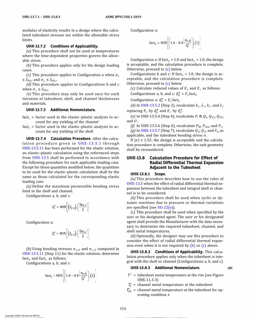
ð19Þ
modulus of elasticity results in a design where the calcu-lated tubesheet stresses are within the allowable stresslimits.
UHX-13.7.2 Conditions of Applicability.(a) This procedure shall not be used at temperatures
where the time‐dependent properties govern the allow-able stress.(b) This procedure applies only for the design loading
cases.(c) This procedure applies to Configuration a when σ s
≤ SPS,s and σ c ≤ SPS,c.(d) This procedure applies to Configurations b and c
when σ s ≤ SPS,s.(e) This procedure may only be used once for each
iteration of tubesheet, shell, and channel thicknessesand materials.
UHX-13.7.3 Additional Nomenclature.
factc = factor used in the elastic–plastic analysis to ac-count for any yielding of the channel
facts = factor used in the elastic–plastic analysis to ac-count for any yielding of the shell
UHX-13.7.4 Calculation Procedure. After the calcu-lat ion procedure given in UHX-13.5 .1 throughUHX-13.5.11 has been performed for the elastic solution,an elastic–plastic calculation using the referenced stepsfrom UHX-13.5 shall be performed in accordance withthe following procedure for each applicable loading case.Except for those quantities modified below, the quantitiesto be used for the elastic–plastic calculation shall be thesame as those calculated for the corresponding elasticloading case.(a) Define the maximum permissible bending stress
limit in the shell and channel.Configurations a, b, and c:
Configuration a:
(b) Using bending stresses σ s , b and σ c , b computed inUHX-13.5.11 (Step 11) for the elastic solution, determinefacts and factc as follows:Configurations a, b, and c:
Configuration a:
Configuration a: If facts = 1.0 and factc = 1.0, the designis acceptable, and the calculation procedure is complete.Otherwise, proceed to (c) below.Configurations b and c: If facts = 1.0, the design is ac-
ceptable, and the calculation procedure is complete.Otherwise, proceed to (c) below.(c) Calculate reduced values of Es and Ec as follows:Configurations a, b, and c: = Es facts
Configuration a: = Ec factc(d) In UHX-13.5.2 (Step 2), recalculate ks , λ s , kc , and λ c
replacing Es by and Ec by .
(e) In UHX-13.5.4 (Step 4), recalculate F, Φ, Q1, QZ1, QZ2,and U .(f) In UHX-13.5.6 (Step 6), recalculate PW, Prim, and Pe .(g) In UHX-13.5.7 (Step 7), recalculate Q2, Q3, and Fm as
applicable, and the tubesheet bending stress σ .If |σ | ≤ 1.5S , the design is acceptable and the calcula-
tion procedure is complete. Otherwise, the unit geometryshall be reconsidered.
UHX-13.8 Calculation Procedure for Effect ofRadial Differential Thermal ExpansionAdjacent to the Tubesheet
UHX-13.8.1 Scope.(a) This procedure describes how to use the rules of
UHX-13.5 when the effect of radial differential thermal ex-pansion between the tubesheet and integral shell or chan-nel is to be considered.(b) This procedure shall be used when cyclic or dy-
namic reactions due to pressure or thermal variationsare specified [see UG-22(e)].(c) This procedure shall be used when specified by the
user or his designated agent. The user or his designatedagent shall provide the Manufacturer with the data neces-sary to determine the required tubesheet, channel, andshell metal temperatures.(d) Optionally, the designer may use this procedure to
consider the effect of radial differential thermal expan-sion even when it is not required by (b) or (c) above.
UHX-13.8.2 Conditions of Applicability. This calcu-lation procedure applies only when the tubesheet is inte-gral with the shell or channel (Configurations a, b, and c).
UHX-13.8.3 Additional Nomenclature.
T ′ = tubesheet metal temperature at the rim (see FigureUHX-11.3-3)
= channel metal temperature at the tubesheet= channel metal temperature at the tubesheet for op-
erating condition x
314
ASME BPVC.VIII.1-2019UHX-13.7.1 – UHX-13.8.3
Copyright ASME International (BPVC) Provided by IHS under license with ASME Licensee=Khalda Petroleum/5986215001, User=Amer, Mohamed
Not for Resale, 07/02/2019 13:29:04 MDTNo reproduction or networking permitted without license from IHS
--`,``,``,,`,`,,````,`,``,,,`-`-`,,`,,`,`,,`---

= shell metal temperature at the tubesheet= shell metal temperature at the tubesheet for oper-
ating condition x= tubesheet metal temperature at the rim for operat-
ing condition xα ′ = mean coefficient of thermal expansion of tubesheet
material at T ′= mean coefficient of thermal expansion of channel
material at= mean coefficient of thermal expansion of shell ma-
terial at
UHX-13.8.4 Calculation Procedure. The calculationprocedure given in UHX-13.5 and UHX-13.6, if applicable,shall be performed only for the operating loading casesaccounting for the modifications given in (a) through (g).
Table UHX-13.8.4-1 provides the load combinations re-quired to evaluate the heat exchanger for each operatingcondition x .
(a) Determine the average temperature of the unperfo-rated rim Tr .
Configuration a:
Configurations b and c:
For conservative values of and , Tr = T′ may beused.
(b) Determine the average temperature of the shell
and channel at their junction to the tubesheet as
follows:Configurations a, b, and c:
Configuration a:
For conservative values of and , and
may be used.
(c) Calculate and .Configurations a, b, and c:
Configuration a:
Configurations b and c:
(d) Calculate Pω .
(e) In UHX-13.5.6 (Step 6), replace the formula for Pewith:
Table UHX-13.8.4-1
OperatingLoading Case
Operating PressureAxial Mean MetalTemperature Metal Temperature
Shell Side, Ps Tube Side, Pt Tubes, Tt ,m Shell, Ts ,m
Tubesheet atthe Rim,
Channel at
Tubesheet,
Shell at
Tubesheet,
1 Psox ,min Ptox ,max Tt ,mx Ts ,mx
2 Psox ,max Ptox ,min Tt ,mx Ts ,mx
3 Psox ,max Ptox ,max Tt ,mx Ts ,mx
4 Psox ,min Ptox ,min Tt ,mx Ts ,mx
315
ASME BPVC.VIII.1-2019 UHX-13.8.3 – UHX-13.8.4
Copyright ASME International (BPVC) Provided by IHS under license with ASME Licensee=Khalda Petroleum/5986215001, User=Amer, Mohamed
Not for Resale, 07/02/2019 13:29:04 MDTNo reproduction or networking permitted without license from IHS
--`,``,``,,`,`,,````,`,``,,,`-`-`,,`,,`,`,,`---

(f) In UHX-13.5.7 (Step 7), replace the formula for Q2
with:
(g) In UHX-13.5.11 (Step 11), replace the equations forσ s , b and σc , b with:
UHX-13.9 Calculation Procedure for SimplySupported Fixed Tubesheets
UHX-13.9.1 Scope. This procedure describes how touse the rules of UHX-13.5 when the effect of the stiffnessof the integral channel and/or shell is not considered.
UHX-13.9.2 Conditions of Applicability. This calcu-lation procedure applies only when the tubesheet is inte-gral with the shell or channel (configurations a, b, and c).
UHX-13.9.3 Calculation Procedure. The calculationprocedure given in UHX-13.5 shall be performed account-ing for the following modifications.(a) Perform Steps 1 through 10.(b) Perform Step 11 except as follows:
(1) The shell (configurations a, b, and c) is not re-quired to meet a minimum length requirement. The shellis exempt from the minimum length requirement inUHX-13.6.4(a).
(2) The channel (configuration a) is not required tomeet a minimum length requirement.
(3) Configuration a: If σ s ≤ SPS,s and σ c ≤ SPS,c, theshell and channel are acceptable. Otherwise, increasethe thickness of the overstressed component(s) (shelland/or channel) and return to Step 1.
Configurations b and c: If σs ≤ SPS,s, the shell is ac-ceptable. Otherwise, increase the thickness of the shelland return to Step 1.(c) Do not perform Step 12.(d) Repeat Steps 1 through 7 for the design loading
cases, with the following changes to Step 2, until the tube-sheet stress criteria have been met:Configurations a, b, and c: β s = 0, ks = 0, λ s = 0, δ s = 0.Configuration a: β c = 0, kc = 0, λ c = 0, δc = 0.
UHX-13.10 Calculation Procedure for KettleShell Exchangers With FixedTubesheets
UHX-13.10.1 Scope. This procedure describes how touse the rules of UHX-13.5 when an eccentric cone andsmall cylinder exist between the large shell side cylinderand the tubesheet on both sides.
UHX-13.10.2 Conditions of Applicability.(a) The two eccentric cones are identical in geometry
and material.(b) The small shell cylinders adjacent to the tubesheet
are identical in geometry and material. They shall meetthe length requirements of UHX-13.5.11(a) unless thesimply supported rules of UHX-13.9 are applied. The rulesof UHX-13.6 shall not be used. The rules of UHX-13.8 maybe used only if the length requirements of UHX-13.5.11(a)are met by the small shell cylinders.(c) This procedure applies only when θ e c c ≤ 30 deg.
This procedure accounts for the stiffness and loadingsin the shell of the eccentric cones used in the design ofthe tubesheet. This procedure does not evaluate the ac-ceptability of the shell-to-cone transition. Other require-ments in this Division pertaining to shell-to-conetransitions shall be satisfied [e.g., UW-3(b), 1-5, and 1-8].(d) T h i s p r o c e d u r e a p p l i e s o n l y w h e n
.
(e) This procedure applies only when D e c c , L ≤2.17Dec c , S .(f) These rules assume that an expansion joint, if pres-
ent, is located in the small shell cylinder.(g) For cone-to-cylinder junctions without a transition
knuckle, use the following for design cases (pressure-onlycases) in 1-5. The cone-to-cylinder junctions do not needto be evaluated for the operating cases (cases includingdifferential thermal expansion).
where
(h) For cone-to-cylinder junctions without a transitionknuckle, use the following for design cases (pressure-onlycases) in 1-8. The cone-to-cylinder junctions do not needto be evaluated for the operating cases (cases includingdifferential thermal expansion).
316
ASME BPVC.VIII.1-2019UHX-13.8.4 – UHX-13.10.2
Copyright ASME International (BPVC) Provided by IHS under license with ASME Licensee=Khalda Petroleum/5986215001, User=Amer, Mohamed
Not for Resale, 07/02/2019 13:29:04 MDTNo reproduction or networking permitted without license from IHS
--`,``,``,,`,`,,````,`,``,,,`-`-`,,`,,`,`,,`---
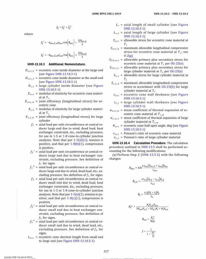
where
UHX-13.10.3 Additional Nomenclature.
Decc , L = eccentric cone inside diameter at the large end(see Figure UHX-13.10.3-1)
Decc , S = eccentric cone inside diameter at the small end(see Figure UHX-13.10.3-1)
Ds ,L = large cylinder inside diameter (see FigureUHX-13.10.3-1)
Eecc = modulus of elasticity for eccentric cone materi-al at Ts
Eecc ,w = joint efficiency (longitudinal stress) for ec-centric cone
Es ,L = modulus of elasticity for large cylinder materi-al at Ts
Es , L ,w = joint efficiency (longitudinal stress) for largecylinder
f1 = axial load per unit circumference at conical re-ducer large end due to wind, dead load, heatexchanger constraint, etc., excluding pressure,for use in 1-5 or 1-8 cone-to-cylinder junctionanalyses. Note that per 1-5(d)(1), tension ispositive, and that per 1-8(b)(1), compressionis positive.
f1 ′ = axial load per unit circumference at conical re-ducer large end due to heat exchanger con-straint, excluding pressure. See definition off1 for signs.
f1″ = axial load per unit circumference at conical re-ducer large end due to wind, dead load, etc., ex-cluding pressure. See definition of f1 for signs.
f2 = axial load per unit circumference at conical re-ducer small end due to wind, dead load, heatexchanger constraint, etc., excluding pressure,for use in 1-5 or 1-8 cone-to-cylinder junctionanalyses. Note that per 1-5(e)(1), tension is po-sitive, and that per 1-8(c)(1), compression ispositive.
f2 ′ = axial load per unit circumference at conical re-ducer small end due to heat exchanger con-straint, excluding pressure. See definition off2 for signs.
f2″ = axial load per unit circumference at conical re-ducer small end due to wind, dead load, etc.,excluding pressure. See definition of f 2 forsigns.
Lecc = eccentric cone shortest length from small endto large end (see Figure UHX-13.10.3-1)
Ls = axial length of small cylinder (see FigureUHX-13.10.3-1)
Ls , L = axial length of large cylinder (see FigureUHX-13.10.3-1)
Secc = allowable stress for eccentric cone material atTs
Secc , b = maximum allowable longitudinal compressivestress for eccentric cone material at Ts ; seeU-2(g)
SPS ,ecc = allowable primary plus secondary stress foreccentric cone material at Ts per UG-23(e)
SPS , s , L = allowable primary plus secondary stress forlarge cylinder material at Ts per UG-23(e)
Ss , L = allowable stress for large cylinder material atTs
Ss , L , b = maximum allowable longitudinal compressivestress in accordance with UG-23(b) for largecylinder material at Ts
tecc = eccentric cone wall thickness (see FigureUHX-13.10.3-1)
t s , L = large cylinder wall thickness (see FigureUHX-13.10.3-1)
αecc ,m = mean coefficient of thermal expansion of ec-centric cone material at Ts ,m
α s ,m , L = mean coefficient of thermal expansion of largecylinder material at Ts ,m
θecc = eccentric cone half-apex angle, deg (see FigureUHX-13.10.3-1)
νecc = Poisson’s ratio of eccentric cone materialν s , L = Poisson’s ratio of large cylinder material
UHX-13.10.4 Calculation Procedure. The calculationprocedure outlined in UHX-13.5 shall be performed ac-counting for the following modifications:
(a) Perform Step 2 (UHX-13.5.2) with the followingchanges:
317
ASME BPVC.VIII.1-2019 UHX-13.10.2 – UHX-13.10.4
Copyright ASME International (BPVC) Provided by IHS under license with ASME Licensee=Khalda Petroleum/5986215001, User=Amer, Mohamed
Not for Resale, 07/02/2019 13:29:04 MDTNo reproduction or networking permitted without license from IHS
--`,``,``,,`,`,,````,`,``,,,`-`-`,,`,,`,`,,`---
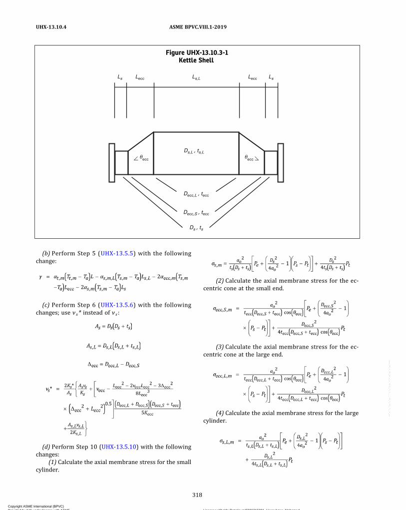
(b) Perform Step 5 (UHX-13.5.5) with the followingchange:
(c) Perform Step 6 (UHX-13.5.6) with the followingchanges; use ν s* instead of ν s :
(d) Perform Step 10 (UHX-13.5.10) with the followingchanges:
(1) Calculate the axial membrane stress for the smallcylinder.
(2) Calculate the axial membrane stress for the ec-centric cone at the small end.
(3) Calculate the axial membrane stress for the ec-centric cone at the large end.
(4) Calculate the axial membrane stress for the largecylinder.
Figure UHX-13.10.3-1Kettle Shell
Ls Ls,L
Ds,L , ts,L
Lecc LsLecc
�
Decc,L , tecc
Decc,S , tecc
Ds , ts
�eccecc
318
ASME BPVC.VIII.1-2019UHX-13.10.4
Copyright ASME International (BPVC) Provided by IHS under license with ASME Licensee=Khalda Petroleum/5986215001, User=Amer, Mohamed
Not for Resale, 07/02/2019 13:29:04 MDTNo reproduction or networking permitted without license from IHS
--`,``,``,,`,`,,````,`,``,,,`-`-`,,`,,`,`,,`---

(5) Acceptance Criteria(-a) Design loading case acceptance criteria:
|σ s , m | ≤ S s E s , w and |σ e c c , S , m | ≤ S e c c E e c c , w and|σecc , L ,m | ≤ SeccEec c ,w and |σ s , L ,m | ≤ Ss ,LEs ,L ,w
(-b) Operating loading case acceptance criteria:|σ s ,m | ≤ SPS , s and |σe c c , S ,m | ≤ SPS , e c c and |σe c c , L ,m | ≤SPS ,ecc and |σ s , L ,m | ≤ SPS , s , L
(-c) If axial membrane stress is negative (designand operating): |σ s , m | ≤ S s , b and |σ e c c , S , m | ≤ S e c c , b
and |σecc , L ,m | ≤ Secc , b and |σ s , L ,m | ≤ Ss , L , bIf any of these acceptance criteria are not satisfied,
reconsider the design of the failing components and re-turn to (a).
UHX-14 RULES FOR THE DESIGN OF FLOATINGTUBESHEETS
UHX-14.1 Scope(a) These rules cover the design of tubesheets for float-
ing tubesheet heat exchangers that have one stationarytubesheet and one floating tubesheet. Three types offloating tubesheet heat exchangers are covered as shownin Figure UHX-14.1.
(1) Sketch (a), immersed floating head;(2) Sketch (b), externally sealed floating head;(3) Sketch (c), internally sealed floating tubesheet.
(b) Stationary tubesheets may have one of the six con-figurations shown in Figure UHX-14.2:
(1) Configuration a: tubesheet integral with shell andchannel;
(2) Configuration b: tubesheet integral with shell andgasketed with channel, extended as a flange;
(3) Configuration c: tubesheet integral with shell andgasketed with channel, not extended as a flange;
(4) Configuration d: tubesheet gasketed with shelland channel;
(5) Configuration e: tubesheet gasketed with shelland integral with channel, extended as a flange;
(6) Configuration f: tubesheet gasketed with shelland integral with channel, not extended as a flange.
(c) Floating tubesheets may have one of the four config-urations shown in Figure UHX-14.3:
(1) Configuration A: tubesheet integral;(2) Configuration B: tubesheet gasketed, extended as
a flange;(3) Configuration C: tubesheet gasketed, not ex-
tended as a flange;(4) Configuration D: tubesheet internally sealed.
UHX-14.2 Conditions of ApplicabilityThe two tubesheets shall have the same thickness and
material.
UHX-14.3 NomenclatureThe symbols described below are used for the design of
the stationary and floating tubesheets. Symbols Do, E*, ,
μ , μ* , and ν* are defined in UHX-11.
A = outside diameter of tubesheet, except as lim-ited by UHX-10(b)
ac = radial channel dimensionConfigurations a, e, f, and A: ac = Dc/2Configurations b, c, d, B, and C: ac = Gc/2Configuration D: ac = A/2
ao = equivalent radius of outer tube limit circleAP = total area enclosed by CP
as = radial shell dimensionConfigurations a, b, and c: as = Ds/2Configurations d, e, and f: as = Gs/2Configurations A, B, C, and D: as = ac
C = bolt circle diameter (see Mandatory Appen-dix 2)
Cp = perimeter of the tube layout measured step-wise in increments of one tube pitch fromthe center‐to‐center of the outermost tubes(see Figure UHX-12.2)
Dc = inside channel diameterDs = inside shell diameterdt = nominal outside diameter of tubesE = modulus of elasticity for tubesheet material
at TEc = modulus of elasticity for channel material at
Tc
Es = modulus of elasticity for shell material at Ts
Et = modulus of elasticity for tube material at Tt
G1 = midpoint of contact between flange andtubesheet
Gc = diameter of channel gasket load reaction (seeMandatory Appendix 2)
Gs = diameter of shell gasket load reaction (seeMandatory Appendix 2)
h = tubesheet thicknessk = constant accounting for the method of sup-
port for the unsupported tube span underconsideration
= 0.6 for unsupported spans between twotubesheets
= 0.8 for unsupported spans between a tube-sheet and a tube support
= 1.0 for unsupported spans between two tubesupports
L = tube length between inner tubesheet faces= Lt – 2h
l = unsupported tube span under considerationLt = tube length between outer tubesheet faces
MAX [(a),(b),(c),...] = greatest of a, b, c, ...
Nt = number of tubesPe = effective pressure acting on tubesheetPs = shell side design or operating pressure, as
applicable. For shell side vacuum, use a nega-tive value for Ps .
Psd ,max = maximum shell side design pressurePsd ,min = minimum shell side design pressure (nega-
tive if vacuum is specified, otherwise zero)
319
ASME BPVC.VIII.1-2019 UHX-13.10.4 – UHX-14.3
Copyright ASME International (BPVC) Provided by IHS under license with ASME Licensee=Khalda Petroleum/5986215001, User=Amer, Mohamed
Not for Resale, 07/02/2019 13:29:04 MDTNo reproduction or networking permitted without license from IHS
--`,``,``,,`,`,,````,`,``,,,`-`-`,,`,,`,`,,`---
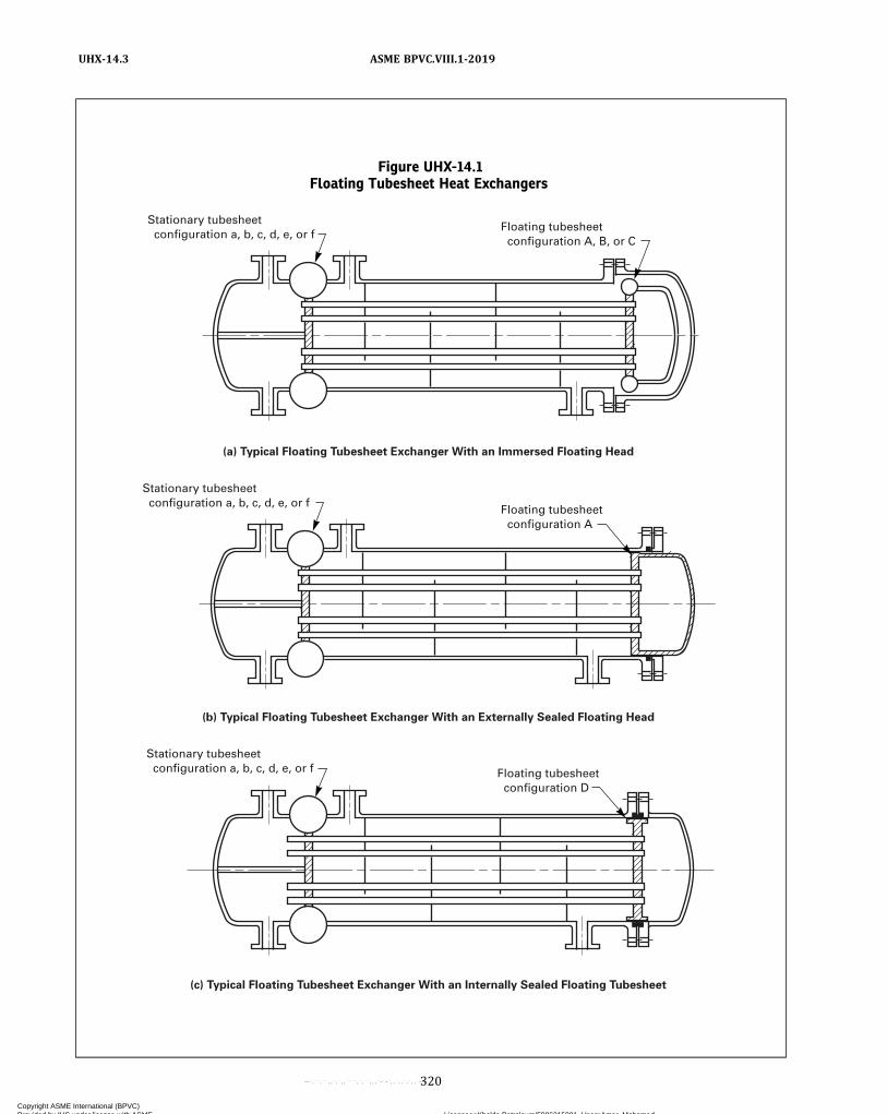
Figure UHX-14.1Floating Tubesheet Heat Exchangers
(c) Typical Floating Tubesheet Exchanger With an Internally Sealed Floating Tubesheet
(b) Typical Floating Tubesheet Exchanger With an Externally Sealed Floating Head
(a) Typical Floating Tubesheet Exchanger With an Immersed Floating Head
Floating tubesheet configuration D
Stationary tubesheet configuration a, b, c, d, e, or f
Floating tubesheet configuration A
Stationary tubesheet configuration a, b, c, d, e, or f
Floating tubesheet configuration A, B, or C
Stationary tubesheet configuration a, b, c, d, e, or f
320
ASME BPVC.VIII.1-2019UHX-14.3
Copyright ASME International (BPVC) Provided by IHS under license with ASME Licensee=Khalda Petroleum/5986215001, User=Amer, Mohamed
Not for Resale, 07/02/2019 13:29:04 MDTNo reproduction or networking permitted without license from IHS
--`,``,``,,`,`,,````,`,``,,,`-`-`,,`,,`,`,,`---
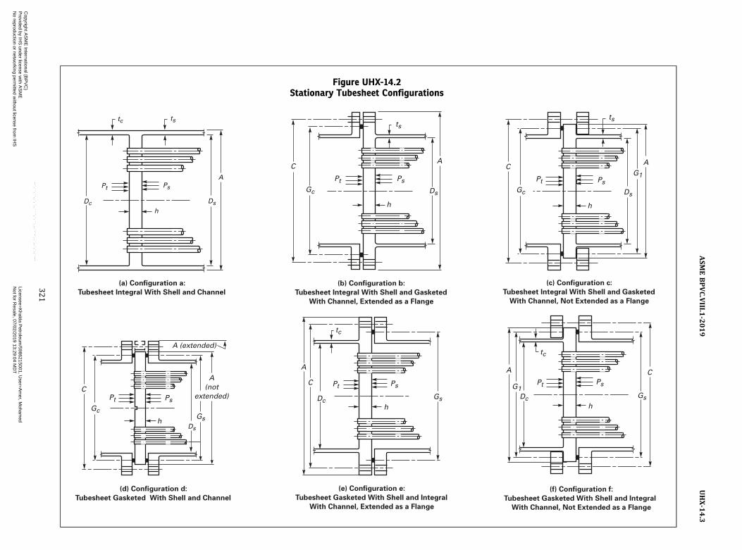
Figure UHX-14.2Stationary Tubesheet Configurations
C
Gc Ds
A
ts
PsPt
h
(b) Configuration b:
Tubesheet Integral With Shell and Gasketed
With Channel, Extended as a Flange
Dc Ds
Ps
tstc
APt
(a) Configuration a:
Tubesheet Integral With Shell and Channel
h
Gc
C
A(not
extended)
(d) Configuration d:
Tubesheet Gasketed With Shell and Channel
A (extended)
Gs
PsPt
h
Dc
A
C
Gs
tc
PsPt
h
(e) Configuration e:
Tubesheet Gasketed With Shell and Integral
With Channel, Extended as a Flange
CGc Ds
AC
PsPt
h
(c) Configuration c:
Tubesheet Integral With Shell and Gasketed
With Channel, Not Extended as a Flange
A
Dc Gs
C
tc
PsPt
h
(f) Configuration f:
Tubesheet Gasketed With Shell and Integral
With Channel, Not Extended as a Flange
G1
ts
Ds
G1
321
ASM
EBPVC.VIII.1
-2019
UHX-14.3
Copyright A
SM
E International (B
PV
C)
Provided by IH
S under license w
ith AS
ME
Licensee=
Khalda P
etroleum/5986215001, U
ser=A
mer, M
ohamed
Not for R
esale, 07/02/2019 13:29:04 MD
TN
o reproduction or networking perm
itted without license from
IHS
--`,``,``,,`,`,,````,`,``,,,`-`-`,,`,,`,`,,`---
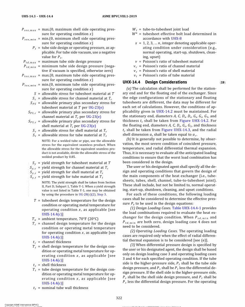
ð19Þ
Psox ,max = max.(0, maximum shell side operating pres-sure for operating condition x)
Psox ,min = min.(0, minimum shell side operating pres-sure for operating condition x)
Pt = tube side design or operating pressure, as ap-plicable. For tube side vacuum, use a negativevalue for Pt .
Ptd ,max = maximum tube side design pressurePtd ,min = minimum tube side design pressure (nega-
tive if vacuum is specified, otherwise zero)Ptox ,max = max.(0, maximum tube side operating pres-
sure for operating condition x)Ptox ,min = min.(0, minimum tube side operating pres-
sure for operating condition x)S = allowable stress for tubesheet material at TSc = allowable stress for channel material at Tc
SPS = allowable primary plus secondary stress fortubesheet material at T per UG-23(e)
SPS , c = allowable primary plus secondary stress forchannel material at Tc per UG-23(e)
SPS , s = allowable primary plus secondary stress forshell material at Ts per UG-23(e)
Ss = allowable stress for shell material at TsSt = allowable stress for tube material at Tt
NOTE: For a welded tube or pipe, use the allowablestress for the equivalent seamless product. Whenthe allowable stress for the equivalent seamless pro-duct is not available, divide the allowable stress of thewelded product by 0.85.
Sy = yield strength for tubesheet material at TSy , c = yield strength for channel material at TcSy , s = yield strength for shell material at TsSy , t = yield strength for tube material at Tt
NOTE: The yield strength shall be taken from SectionII, Part D, Subpart 1, Table Y-1. When a yield strengthvalue is not listed in Table Y-1, one may be obtainedby using the procedure in UG-28(c)(2), Step 3.
T = tubesheet design temperature for the designcondition or operating metal temperature foroperating condition x , as applicable [seeUHX-14.4(c)]
Ta = ambient temperature, 70°F (20°C)Tc = channel design temperature for the design
condition or operating metal temperaturefor operating condition x , as applicable [seeUHX-14.4(c)]
tc = channel thicknessTs = shell design temperature for the design con-
dition or operating metal temperature for op-erating condition x , as applicable [seeUHX-14.4(c)]
t s = shell thicknessTt = tube design temperature for the design con-
dition or operating metal temperature for op-erating condition x , as applicable [seeUHX-14.4(c)]
t t = nominal tube wall thickness
Wt = tube-to-tubesheet joint loadW* = tubesheet effective bolt load determined in
accordance with UHX-8x = 1, 2, 3, … n , integer denoting applicable oper-
ating condition under consideration (e.g.,normal operating, start-up, shutdown, clean-ing, upset)
ν = Poisson’s ratio of tubesheet materialνc = Poisson’s ratio of channel materialν s = Poisson’s ratio of shell materialν t = Poisson’s ratio of tube material
UHX-14.4 Design Considerations(a) The calculation shall be performed for the station-
ary end and for the floating end of the exchanger. Sincethe edge configurations of the stationary and floatingtubesheets are different, the data may be different foreach set of calculations. However, the conditions of ap-plicability given in UHX-14.2 must be maintained. Forthe stationary end, diameters A, C, Ds, Dc, Gs, Gc, G1, andthickness tc shall be taken from Figure UHX-14.2. Forthe floating end, diameters A, C, Dc, Gc, G1, and thicknesstc shall be taken from Figure UHX-14.3, and the radialshell dimension as shall be taken equal to ac .(b) It is generally not possible to determine, by obser-
vation, the most severe condition of coincident pressure,temperature, and radial differential thermal expansion.Thus, it is necessary to evaluate all the anticipated loadingconditions to ensure that the worst load combination hasbeen considered in the design.The user or his designated agent shall specify all the de-
sign and operating conditions that govern the design ofthe main components of the heat exchanger (i.e., tube-sheets, tubes, shell, channel, tube-to-tubesheet joint).These shall include, but not be limited to, normal operat-ing, start-up, shutdown, cleaning, and upset conditions.For each of these conditions, the following loading
cases shall be considered to determine the effective pres-sure Pe to be used in the design equations:
(1) Design Loading Cases. Table UHX-14.4-1 providesthe load combinations required to evaluate the heat ex-changer for the design condition. When P s d ,m i n andP t d ,m i n are both zero, design loading case 4 does notneed to be considered.
(2) Operating Loading Cases. The operating loadingcases are required only when the effect of radial differen-tial thermal expansion is to be considered [see (e)].
(3)When differential pressure design is specified bythe user or his designated agent, the design shall be basedonly on design loading case 3 and operating loading cases3 and 4 for each specified operating condition. If the tubeside is the higher-pressure side, Pt shall be the tube sidedesign pressure, and Ps shall be Pt less the differential de-sign pressure. If the shell side is the higher-pressure side,Ps shall be the shell side design pressure, and Pt shall bePs less the differential design pressure. For the operating
322
ASME BPVC.VIII.1-2019UHX-14.3 – UHX-14.4
Copyright ASME International (BPVC) Provided by IHS under license with ASME Licensee=Khalda Petroleum/5986215001, User=Amer, Mohamed
Not for Resale, 07/02/2019 13:29:04 MDTNo reproduction or networking permitted without license from IHS
--`,``,``,,`,`,,````,`,``,,,`-`-`,,`,,`,`,,`---

Figure UHX-14.3Floating Tubesheet Configurations
(a) Configuration A:Tubesheet Integral
(b) Configuration B:Tubesheet Gasketed, Extended as a Flange
(c) Configuration C:Tubesheet Gasketed, Not Extended as a Flange
(d) Configuration D:Tubesheet Internally Sealed
tc
Dc
PtPs
h
A
Pt
Gc APs
h
C
Pt
Gc A
Ps
h
G1C
Pt
A
Ps
h
323
ASME BPVC.VIII.1-2019 UHX-14.4
Copyright ASME International (BPVC) Provided by IHS under license with ASME Licensee=Khalda Petroleum/5986215001, User=Amer, Mohamed
Not for Resale, 07/02/2019 13:29:04 MDTNo reproduction or networking permitted without license from IHS
--`,``,``,,`,`,,````,`,``,,,`-`-`,,`,,`,`,,`---

loading cases, the differential pressure and the individualoperating pressures shall not exceed the values used fordesign.
(4) The designer should take appropriate considera-tion of the stresses resulting from the pressure test re-quired by UG-99 or UG-100 [see UG-99(d)].(c) The elastic moduli, yield strengths, and allowable
stresses shall be taken at the design temperatures forthe design loading cases and may be taken at the operat-ing metal temperature of the component under consid-eration for operating condition x .(d) As the calculation procedure is iterative, a value h
shall be assumed for the tubesheet thickness to calculateand check that the maximum stresses in tubesheet, tubes,shell, and channel are within the maximum permissiblestress limits and that the resulting tube-to-tubesheet jointload is acceptable.(e) The designer shall consider the effect of radial dif-
ferential thermal expansion adjacent to the tubesheet inaccordance with UHX-14.6, if required by UHX-14.6.1.(f) The designer may consider the tubesheet as simply
supported in accordance with UHX-14.7.
UHX-14.5 Calculation ProcedureThe procedure for the design of tubesheets for a float-
ing tubesheet heat exchanger is as follows. Calculationsshall be performed for both the stationary tubesheetand the floating tubesheet.
UHX-14.5.1 Step 1. Determine Do, μ , μ* , and from
UHX-11.5.1.
Operating loading cases:
Calculate ao, ρ s , ρ c , xs , and xt .
UHX-14.5.2 Step 2. Calculate shell coefficients β s , ks,λ s , and δ s .Configurations a, b, and c:
Configurations d, e, f, A, B, C, and D: β s = 0, ks = 0, λ s = 0,δ s = 0Calculate channel coefficients β c , kc, λ c , and δ c .Configurations a, e, f, and A:
For a cylinder:
Table UHX-14.4-1
DesignLoadingCase
Shell SideDesign
Pressure, Ps
Tube SideDesign
Pressure, Pt
1 Psd ,min Ptd ,max
2 Psd ,max Ptd ,min
3 Psd ,max Ptd ,max
4 Psd ,min Ptd ,min
324
ASME BPVC.VIII.1-2019UHX-14.4 – UHX-14.5.2
Copyright ASME International (BPVC) Provided by IHS under license with ASME Licensee=Khalda Petroleum/5986215001, User=Amer, Mohamed
Not for Resale, 07/02/2019 13:29:04 MDTNo reproduction or networking permitted without license from IHS
--`,``,``,,`,`,,````,`,``,,,`-`-`,,`,,`,`,,`---
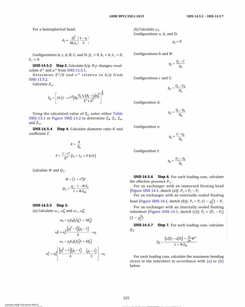
For a hemispherical head:
Configurations b, c, d, B, C, and D: β c = 0, kc = 0, λ c = 0,δ c = 0
UHX-14.5.3 Step 3. Calculate h/p. If ρ changes, recal-culate d* and μ* from UHX-11.5.1.
Determine E*/E and ν * re lat ive to h/p f romUHX-11.5.2.
Calculate Xa .
Using the calculated value of Xa, enter either TableUHX-13.1 or Figure UHX-13.2 to determine Zd, Zv, Zw,and Zm.
UHX-14.5.4 Step 4. Calculate diameter ratio K andcoefficient F.
Calculate Φ and Q1.
UHX-14.5.5 Step 5.(a) Calculate ω s , and ω c , .
(b) Calculate γb .Configurations a, A, and D:
Configurations b and B:
Configurations c and C:
Configuration d:
Configuration e:
Configuration f:
UHX-14.5.6 Step 6. For each loading case, calculatethe effective pressure Pe .
For an exchanger with an immersed floating head[Figure UHX-14.1, sketch (a)]: Pe = Ps − Pt
For an exchanger with an externally sealed floating
head [Figure UHX-14.1, sketch (b)]: Pe = Ps (1 − ) − Pt
For an exchanger with an internally sealed floatingtubesheet [Figure UHX-14.1, sketch (c)]: Pe = (Ps − Pt)
(1 − )
UHX-14.5.7 Step 7. For each loading case, calculateQ2.
For each loading case, calculate the maximum bendingstress in the tubesheet in accordance with (a) or (b)below.
325
ASME BPVC.VIII.1-2019 UHX-14.5.2 – UHX-14.5.7
Copyright ASME International (BPVC) Provided by IHS under license with ASME Licensee=Khalda Petroleum/5986215001, User=Amer, Mohamed
Not for Resale, 07/02/2019 13:29:04 MDTNo reproduction or networking permitted without license from IHS
--`,``,``,,`,`,,````,`,``,,,`-`-`,,`,,`,`,,`---

ð19Þ
(a)When Pe ≠ 0:(1) Calculate Q3.
(2) For each loading case, determine coefficient Fmfrom either Table UHX-13.1 or Figures UHX-13.5.7-1and UHX-13.5.7-2 and calculate the maximum bendingstress σ .
(b)When Pe = 0, calculate the maximum bendingstress σ .
For the design loading cases, if |σ | ≤ 1.5S, and for theoperating loading cases, if |σ | ≤ SPS, the assumed tube-sheet thickness is acceptable for bending. Otherwise, in-crease the assumed tubesheet thickness h and return toUHX-14.5.1 (Step 1).Configurations a, b, c, d, e, and f: Proceed to UHX-14.5.8
(Step 8).Configuration A: Proceed to UHX-14.5.10 (Step 10).Configurations B, C, and D: The calculation procedure is
complete.
UHX-14.5.8 Step 8. For each loading case, calculatethe average shear stress in the tubesheet at the outer edgeof the perforated region, if required.
(a) If , the shear stress is not required to
be calculated. Proceed to UHX-14.5.9.(b) Calculate the average shear stress, τ .
If |τ | ≤ MIN[0.8S , 0.533S y ], the assumed tubesheetthickness is acceptable for shear. Otherwise, increasethe assumed tubesheet thickness, h , and return toUHX-14.5.1.
UHX-14.5.9 Step 9. Perform this step for each load-ing case.(a) Check the axial tube stress.
(1) For each loading case, determine coefficientsFt,min and Ft,max from Table UHX-13.2 and calculate thetwo extreme values of tube stress, σ t ,1 and σ t ,2. The val-ues for σ t ,1 and σ t ,2 may be positive or negative.
(-a) When Pe ≠ 0:
(-b) When Pe = 0:
(2) Determine σ t,max = MAX(|σ t,1|, |σ t,2|).For the design loading cases, if σ t ,max > St, and for
the operating loading cases, if σ t,max > 2St, reconsiderthe tube design and return to UHX-14.5.1 (Step 1).(b) Check the tube-to-tubesheet joint design.
(1) Calculate the largest tube-to-tubesheet joint load,Wt .
(2) Determine the maximum allowable load for thetube-to-tubesheet joint design, Lm a x . For tube-to-tubesheet joints with full strength welds, Lmax shall bedetermined in accordance with UW-20. For tube-totubesheet joints with partial strength welds, Lmax shallbe in accordance with UW-18(d), UW-20, or Nonmanda-tory Appendix A, as applicable. For all other tube joints,Lmax shall be determined in accordance with Nonmanda-tory Appendix A.
If Wt > Lmax , reconsider the tube-to-tubesheet jointdesign.
If Wt ≤ Lm a x , tube-to-tubesheet joint design isacceptable.
If σ t,1 or σ t,2 is negative, proceed to (c) below.If σ t,1 and σ t,2 are positive, the tube design is accept-
able. Proceed to UHX-14.5.10 (Step 10).(c) Check the tubes for buckling.
(1) Calculate the largest equivalent unsupportedbuckling length of the tube ℓ t considering the unsup-ported tube spans ℓ and their corresponding method ofsupport k.
326
ASME BPVC.VIII.1-2019UHX-14.5.7 – UHX-14.5.9
Copyright ASME International (BPVC) Provided by IHS under license with ASME Licensee=Khalda Petroleum/5986215001, User=Amer, Mohamed
Not for Resale, 07/02/2019 13:29:04 MDTNo reproduction or networking permitted without license from IHS
--`,``,``,,`,`,,````,`,``,,,`-`-`,,`,,`,`,,`---
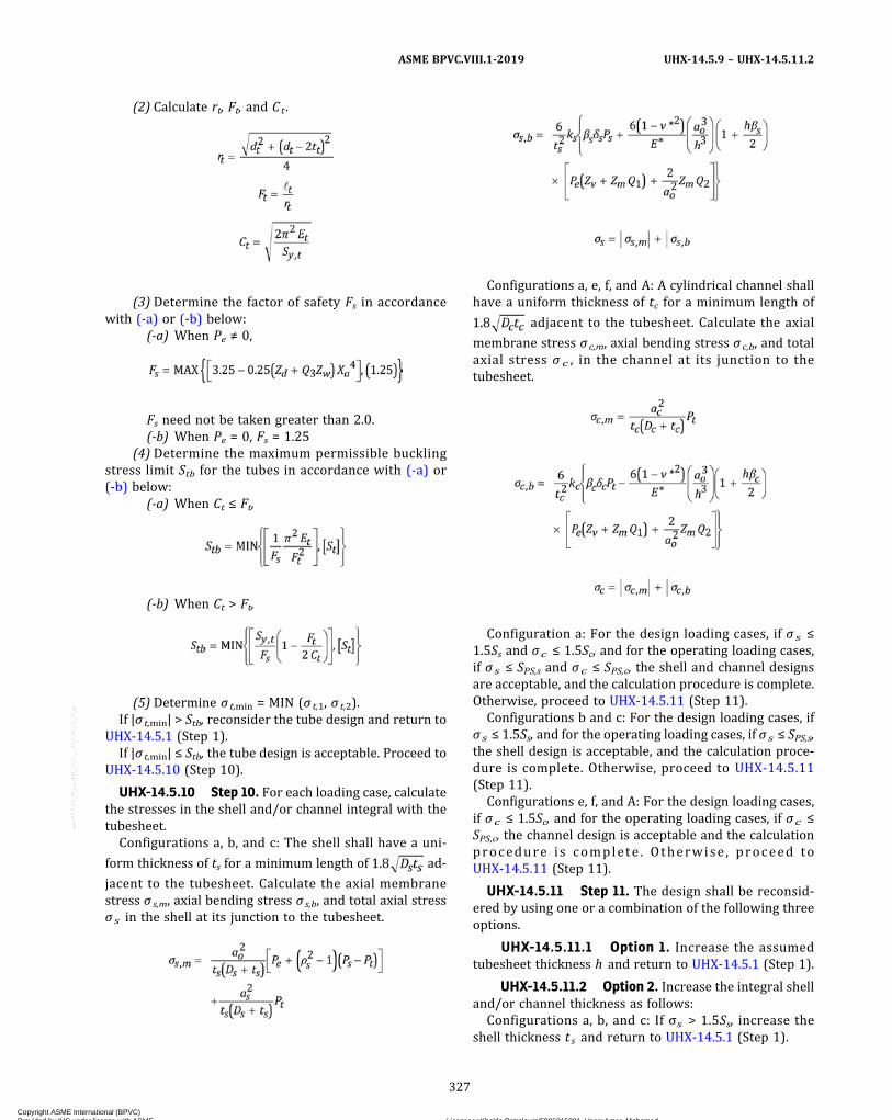
(2) Calculate rt, Ft, and Ct .
(3) Determine the factor of safety Fs in accordancewith (-a) or (-b) below:
(-a) When Pe ≠ 0,
Fs need not be taken greater than 2.0.(-b) When Pe = 0, Fs = 1.25
(4) Determine the maximum permissible bucklingstress limit Stb for the tubes in accordance with (-a) or(-b) below:
(-a) When Ct ≤ Ft,
(-b) When Ct > Ft,
(5) Determine σ t,min = MIN (σ t,1, σ t,2).If |σ t,min| > Stb, reconsider the tube design and return to
UHX-14.5.1 (Step 1).If |σ t,min| ≤ Stb, the tube design is acceptable. Proceed to
UHX-14.5.10 (Step 10).
UHX-14.5.10 Step 10. For each loading case, calculatethe stresses in the shell and/or channel integral with thetubesheet.
Configurations a, b, and c: The shell shall have a uni-
form thickness of ts for a minimum length of ad-
jacent to the tubesheet. Calculate the axial membranestress σ s,m, axial bending stress σ s,b, and total axial stressσs in the shell at its junction to the tubesheet.
Configurations a, e, f, and A: A cylindrical channel shallhave a uniform thickness of tc for a minimum length of
adjacent to the tubesheet. Calculate the axial
membrane stress σ c,m, axial bending stress σc,b, and totalaxial stress σ c , in the channel at its junction to thetubesheet.
Configuration a: For the design loading cases, if σ s ≤1.5Ss and σc ≤ 1.5Sc, and for the operating loading cases,if σs ≤ SPS,s and σc ≤ SPS,c, the shell and channel designsare acceptable, and the calculation procedure is complete.Otherwise, proceed to UHX-14.5.11 (Step 11).
Configurations b and c: For the design loading cases, ifσs ≤ 1.5Ss, and for the operating loading cases, if σs ≤ SPS,s,the shell design is acceptable, and the calculation proce-dure is complete. Otherwise, proceed to UHX-14.5.11(Step 11).
Configurations e, f, and A: For the design loading cases,if σc ≤ 1.5Sc, and for the operating loading cases, if σc ≤SPS,c, the channel design is acceptable and the calculationprocedure is complete . Otherwise , proceed toUHX-14.5.11 (Step 11).
UHX-14.5.11 Step 11. The design shall be reconsid-ered by using one or a combination of the following threeoptions.
UHX-14.5.11.1 Option 1. Increase the assumedtubesheet thickness h and return to UHX-14.5.1 (Step 1).
UHX-14.5.11.2 Option 2. Increase the integral shelland/or channel thickness as follows:
Configurations a, b, and c: If σs > 1.5Ss, increase theshell thickness t s and return to UHX-14.5.1 (Step 1).
327
ASME BPVC.VIII.1-2019 UHX-14.5.9 – UHX-14.5.11.2
Copyright ASME International (BPVC) Provided by IHS under license with ASME Licensee=Khalda Petroleum/5986215001, User=Amer, Mohamed
Not for Resale, 07/02/2019 13:29:04 MDTNo reproduction or networking permitted without license from IHS
--`,``,``,,`,`,,````,`,``,,,`-`-`,,`,,`,`,,`---
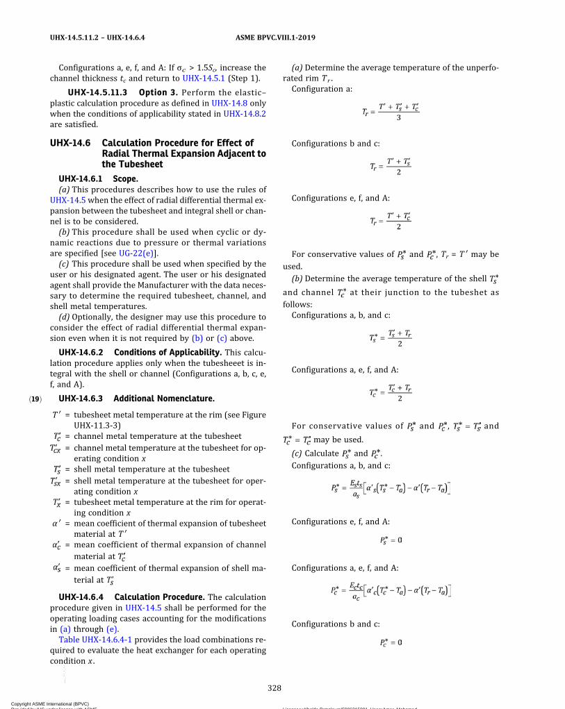
ð19Þ
Configurations a, e, f, and A: If σc > 1.5Sc, increase thechannel thickness tc and return to UHX-14.5.1 (Step 1).
UHX-14.5.11.3 Option 3. Perform the elastic–plastic calculation procedure as defined in UHX-14.8 onlywhen the conditions of applicability stated in UHX-14.8.2are satisfied.
UHX-14.6 Calculation Procedure for Effect ofRadial Thermal Expansion Adjacent tothe Tubesheet
UHX-14.6.1 Scope.(a) This procedures describes how to use the rules of
UHX-14.5 when the effect of radial differential thermal ex-pansion between the tubesheet and integral shell or chan-nel is to be considered.(b) This procedure shall be used when cyclic or dy-
namic reactions due to pressure or thermal variationsare specified [see UG-22(e)].(c) This procedure shall be used when specified by the
user or his designated agent. The user or his designatedagent shall provide the Manufacturer with the data neces-sary to determine the required tubesheet, channel, andshell metal temperatures.(d) Optionally, the designer may use this procedure to
consider the effect of radial differential thermal expan-sion even when it is not required by (b) or (c) above.
UHX-14.6.2 Conditions of Applicability. This calcu-lation procedure applies only when the tubesheeet is in-tegral with the shell or channel (Configurations a, b, c, e,f, and A).
UHX-14.6.3 Additional Nomenclature.
T ′ = tubesheet metal temperature at the rim (see FigureUHX-11.3-3)
= channel metal temperature at the tubesheet= channel metal temperature at the tubesheet for op-
erating condition x= shell metal temperature at the tubesheet= shell metal temperature at the tubesheet for oper-
ating condition x= tubesheet metal temperature at the rim for operat-
ing condition xα ′ = mean coefficient of thermal expansion of tubesheet
material at T ′= mean coefficient of thermal expansion of channel
material at= mean coefficient of thermal expansion of shell ma-
terial at
UHX-14.6.4 Calculation Procedure. The calculationprocedure given in UHX-14.5 shall be performed for theoperating loading cases accounting for the modificationsin (a) through (e).Table UHX-14.6.4-1 provides the load combinations re-
quired to evaluate the heat exchanger for each operatingcondition x .
(a) Determine the average temperature of the unperfo-rated rim Tr .Configuration a:
Configurations b and c:
Configurations e, f, and A:
For conservative values of and , Tr = T ′ may be
used.(b) Determine the average temperature of the shell
and channel at their junction to the tubeshet asfollows:Configurations a, b, and c:
Configurations a, e, f, and A:
For conservative values of and , and
may be used.
(c) Calculate and .
Configurations a, b, and c:
Configurations e, f, and A:
Configurations a, e, f, and A:
Configurations b and c:
328
ASME BPVC.VIII.1-2019UHX-14.5.11.2 – UHX-14.6.4
Copyright ASME International (BPVC) Provided by IHS under license with ASME Licensee=Khalda Petroleum/5986215001, User=Amer, Mohamed
Not for Resale, 07/02/2019 13:29:04 MDTNo reproduction or networking permitted without license from IHS
--`,``,``,,`,`,,````,`,``,,,`-`-`,,`,,`,`,,`---

ð19Þ
(d) In UHX-14.5.7 (Step 7), replace the formula for Q2
with:
(e) In UHX-14.5.10 (Step 10), replace the equations forσ s,b and σ c,b with:
UHX-14.7 Calculation Procedure for SimplySupported Floating Tubesheets
UHX-14.7.1 Scope. This procedure describes how touse the rules of UHX-14.5 when the effect of the stiffnessof the integral channel and/or shell is not considered.
UHX-14.7.2 Conditions of Applicability. This calcu-lation procedure applies only when the tubesheet is inte-gral with the shell or channel (configurations a, b, c, e, f,and A).
UHX-14.7.3 Calculation Procedure. The calculationprocedure outlined in UHX-14.5 shall be performed ac-counting for the following modifications.
(a) Perform the steps in UHX-14.5 .1 throughUHX-14.5.9.
(b) Perform the step in UHX-14.5.10 except as follows:(1) The shell (configurations a, b, and c) is not re-
quired to meet a minimum length requirement.
(2) The channel (configurations a, e, f, and A) is notrequired to meet a minimum length requirement.
(3) Configuration a: If σ s ≤ SPS,s and σ c ≤ SPS,c, thenthe shell and channel are acceptable. Otherwise, increasethe thickness of the overstressed component(s) (shelland/or channel) and return to UHX-14.5.1 (Step 1).
Configurations b and c: If σ s ≤ SPS,s, then the shell is ac-ceptable. Otherwise, increase the thickness of the shelland return to UHX-14.5.1 (Step 1).
Configurations e, f, and A: If σc ≤ SPS,c, then the channelis acceptable. Otherwise increase the thickness of thechannel and return to UHX-14.5.1 (Step 1).
(c) Do not perform UHX-14.5.11 (Step 11).(d) Repeat the steps in UHX-14.5.1 through UHX-14.5.7
for the design loading cases, with the following changes toUHX-14.5.2 (Step 2), until the tubesheet stress criteriahave been met:
Configurations a, b, and c: β s = 0, ks = 0, λ s = 0, δ s = 0.Configurations a, e, f, and A: β c = 0, kc = 0, λ c = 0, δ c = 0.
UHX-14.8 Calculation Procedure for Effect ofPlasticity at Tubesheet/Channel orShell Joint
UHX-14.8.1 Scope. This procedure describes how touse the rules of UHX-14.5 when the effect of plasticity atthe shell–tubesheet and/or channel–tubesheet joint is tobe considered.
When the calculated tubesheet stresses are within theallowable stress limits, but either or both of the calculatedshell or channel total stresses exceed their allowablestress limits, an additional “elastic–plastic solution” calcu-lation may be performed.
This calculation permits a reduction of the shell and/orchannel modulus of elasticity, where it affects the rotationof the joint, to reflect the anticipated load shift resultingfrom plastic action at the joint. The reduced effectivemodulus has the effect of reducing the shell and/or chan-nel stresses in the elastic–plastic calculation; however,due to load shifting this usually leads to an increase inthe tubesheet stress. In most cases, an elastic–plastic cal-culation using the appropriate reduced shell or channel
Table UHX-14.6.4-1
OperatingLoading Case
Operating Pressure Metal Temperature
Shell Side, Ps Tube Side, Pt
Tubesheet at theRim,
Channel at
Tubesheet,
Shell at
Tubesheet,
1 Psox ,min Ptox ,max
2 Psox ,max Ptox ,min
3 Psox ,max Ptox ,max
4 Psox ,min Ptox ,min
329
ASME BPVC.VIII.1-2019 UHX-14.6.4 – UHX-14.8.1
Copyright ASME International (BPVC) Provided by IHS under license with ASME Licensee=Khalda Petroleum/5986215001, User=Amer, Mohamed
Not for Resale, 07/02/2019 13:29:04 MDTNo reproduction or networking permitted without license from IHS
--`,``,``,,`,`,,````,`,``,,,`-`-`,,`,,`,`,,`---
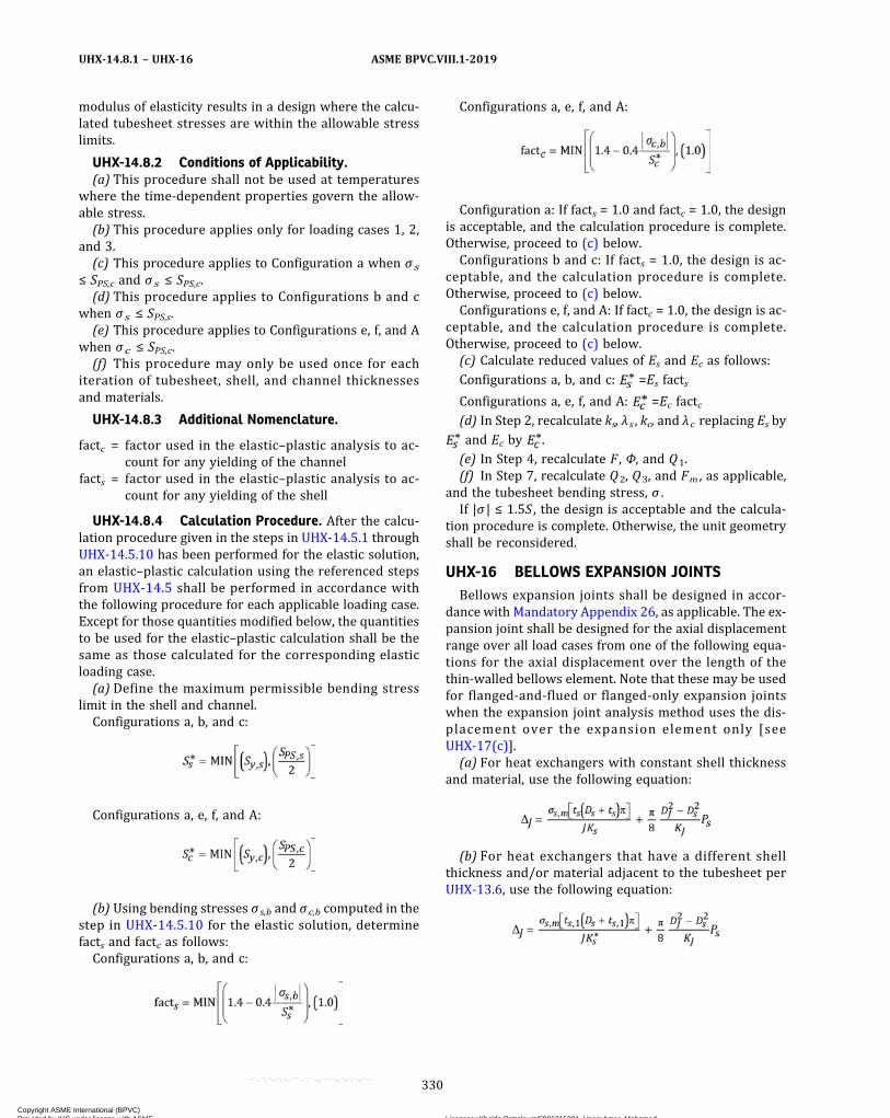
modulus of elasticity results in a design where the calcu-lated tubesheet stresses are within the allowable stresslimits.
UHX-14.8.2 Conditions of Applicability.(a) This procedure shall not be used at temperatures
where the time-dependent properties govern the allow-able stress.(b) This procedure applies only for loading cases 1, 2,
and 3.(c) This procedure applies to Configuration a when σs
≤ SPS,c and σs ≤ SPS,c.(d) This procedure applies to Configurations b and c
when σs ≤ SPS,s.(e) This procedure applies to Configurations e, f, and A
when σc ≤ SPS,c.(f) This procedure may only be used once for each
iteration of tubesheet, shell, and channel thicknessesand materials.
UHX-14.8.3 Additional Nomenclature.
factc = factor used in the elastic–plastic analysis to ac-count for any yielding of the channel
facts = factor used in the elastic–plastic analysis to ac-count for any yielding of the shell
UHX-14.8.4 Calculation Procedure. After the calcu-lation procedure given in the steps in UHX-14.5.1 throughUHX-14.5.10 has been performed for the elastic solution,an elastic–plastic calculation using the referenced stepsfrom UHX-14.5 shall be performed in accordance withthe following procedure for each applicable loading case.Except for those quantities modified below, the quantitiesto be used for the elastic–plastic calculation shall be thesame as those calculated for the corresponding elasticloading case.(a) Define the maximum permissible bending stress
limit in the shell and channel.Configurations a, b, and c:
Configurations a, e, f, and A:
(b) Using bending stresses σ s,b and σc,b computed in thestep in UHX-14.5.10 for the elastic solution, determinefacts and factc as follows:Configurations a, b, and c:
Configurations a, e, f, and A:
Configuration a: If facts = 1.0 and factc = 1.0, the designis acceptable, and the calculation procedure is complete.Otherwise, proceed to (c) below.Configurations b and c: If facts = 1.0, the design is ac-
ceptable, and the calculation procedure is complete.Otherwise, proceed to (c) below.Configurations e, f, and A: If factc = 1.0, the design is ac-
ceptable, and the calculation procedure is complete.Otherwise, proceed to (c) below.(c) Calculate reduced values of Es and Ec as follows:
Configurations a, b, and c: =Es facts
Configurations a, e, f, and A: =Ec factc(d) In Step 2, recalculate ks, λ s , kc, and λ c replacing Es byand Ec by .(e) In Step 4, recalculate F , Φ, and Q1.(f) In Step 7, recalculate Q2, Q3, and Fm , as applicable,
and the tubesheet bending stress, σ .If |σ | ≤ 1.5S , the design is acceptable and the calcula-
tion procedure is complete. Otherwise, the unit geometryshall be reconsidered.
UHX-16 BELLOWS EXPANSION JOINTSBellows expansion joints shall be designed in accor-
dance with Mandatory Appendix 26, as applicable. The ex-pansion joint shall be designed for the axial displacementrange over all load cases from one of the following equa-tions for the axial displacement over the length of thethin-walled bellows element. Note that these may be usedfor flanged-and-flued or flanged-only expansion jointswhen the expansion joint analysis method uses the dis-placement over the expansion element only [seeUHX-17(c)].(a) For heat exchangers with constant shell thickness
and material, use the following equation:
(b) For heat exchangers that have a different shellthickness and/or material adjacent to the tubesheet perUHX-13.6, use the following equation:
330
ASME BPVC.VIII.1-2019UHX-14.8.1 – UHX-16
Copyright ASME International (BPVC) Provided by IHS under license with ASME Licensee=Khalda Petroleum/5986215001, User=Amer, Mohamed
Not for Resale, 07/02/2019 13:29:04 MDTNo reproduction or networking permitted without license from IHS
--`,``,``,,`,`,,````,`,``,,,`-`-`,,`,,`,`,,`---
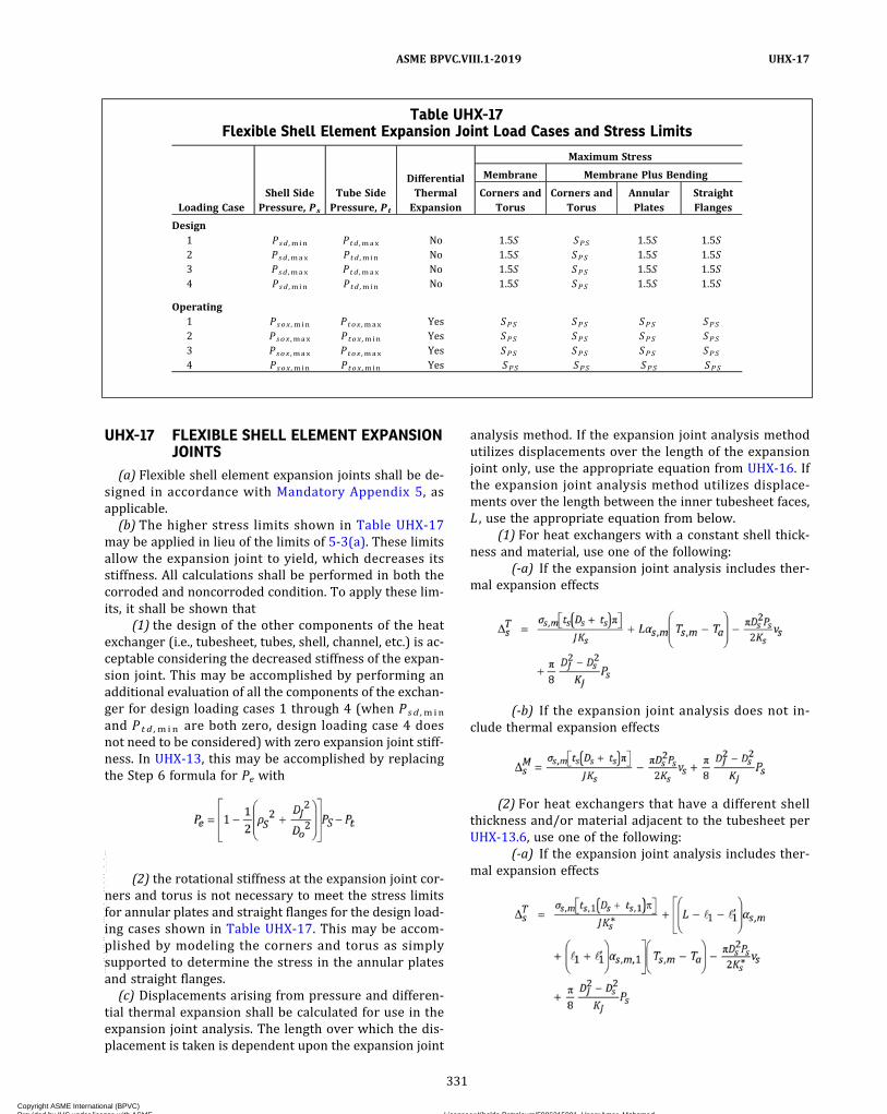
UHX-17 FLEXIBLE SHELL ELEMENT EXPANSIONJOINTS
(a) Flexible shell element expansion joints shall be de-signed in accordance with Mandatory Appendix 5, asapplicable.
(b) The higher stress limits shown in Table UHX-17may be applied in lieu of the limits of 5-3(a). These limitsallow the expansion joint to yield, which decreases itsstiffness. All calculations shall be performed in both thecorroded and noncorroded condition. To apply these lim-its, it shall be shown that
(1) the design of the other components of the heatexchanger (i.e., tubesheet, tubes, shell, channel, etc.) is ac-ceptable considering the decreased stiffness of the expan-sion joint. This may be accomplished by performing anadditional evaluation of all the components of the exchan-ger for design loading cases 1 through 4 (when Psd ,min
and P t d ,min are both zero, design loading case 4 doesnot need to be considered) with zero expansion joint stiff-ness. In UHX-13, this may be accomplished by replacingthe Step 6 formula for Pe with
(2) the rotational stiffness at the expansion joint cor-ners and torus is not necessary to meet the stress limitsfor annular plates and straight flanges for the design load-ing cases shown in Table UHX-17. This may be accom-plished by modeling the corners and torus as simplysupported to determine the stress in the annular platesand straight flanges.
(c) Displacements arising from pressure and differen-tial thermal expansion shall be calculated for use in theexpansion joint analysis. The length over which the dis-placement is taken is dependent upon the expansion joint
analysis method. If the expansion joint analysis methodutilizes displacements over the length of the expansionjoint only, use the appropriate equation from UHX-16. Ifthe expansion joint analysis method utilizes displace-ments over the length between the inner tubesheet faces,L , use the appropriate equation from below.
(1) For heat exchangers with a constant shell thick-ness and material, use one of the following:
(-a) If the expansion joint analysis includes ther-mal expansion effects
(-b) If the expansion joint analysis does not in-clude thermal expansion effects
(2) For heat exchangers that have a different shellthickness and/or material adjacent to the tubesheet perUHX-13.6, use one of the following:
(-a) If the expansion joint analysis includes ther-mal expansion effects
Table UHX-17Flexible Shell Element Expansion Joint Load Cases and Stress Limits
Loading CaseShell Side
Pressure, Ps
Tube SidePressure, Pt
DifferentialThermalExpansion
Maximum Stress
Membrane Membrane Plus Bending
Corners andTorus
Corners andTorus
AnnularPlates
StraightFlanges
Design1 Psd ,min Ptd ,max No 1.5S SPS 1.5S 1.5S2 Psd ,max Ptd ,min No 1.5S SPS 1.5S 1.5S3 Psd ,max Ptd ,max No 1.5S SPS 1.5S 1.5S4 Psd ,min Ptd ,min No 1.5S SPS 1.5S 1.5S
Operating1 Psox ,min Ptox ,max Yes SPS SPS SPS SPS2 Psox ,max Ptox ,min Yes SPS SPS SPS SPS3 Psox ,max Ptox ,max Yes SPS SPS SPS SPS4 Psox ,min Ptox ,min Yes SPS SPS SPS SPS
331
ASME BPVC.VIII.1-2019 UHX-17
Copyright ASME International (BPVC) Provided by IHS under license with ASME Licensee=Khalda Petroleum/5986215001, User=Amer, Mohamed
Not for Resale, 07/02/2019 13:29:04 MDTNo reproduction or networking permitted without license from IHS
--`,``,``,,`,`,,````,`,``,,,`-`-`,,`,,`,`,,`---

(-b) If the expansion joint analysis does not in-clude thermal expansion effects
UHX-18 PRESSURE TEST REQUIREMENTS(a) The shell side and the tube side of the heat exchan-
ger shall be subjected to a pressure test in accordancewith UG-99 or UG-100.(b) Shipping bars on bellows expansion joints may be
required to maintain assembly length during shipmentand vessel fabrication. Shipping bars shall not be engagedor otherwise provide any restraint of the expansion jointduring vessel pressure testing and operation [see26-4.1(c) and 26-4.1(d)].
UHX-19 HEAT EXCHANGER MARKING ANDREPORTS
UHX-19.1 Required MarkingThe marking of heat exchangers shall be in accordance
with UG-116 using the specific requirements ofUG-116(j) for combination units (multi‐chamber vessels).When the markings are grouped in one location in accor-dance with requirements of UG-116(j)(1) and abbrevia-tions for each chamber are used, they shall be as follows:(a) For markings in accordance with UG-116(a)(3) and
UG-116(a)(4), the chambers shall be abbreviated as:(1) SHELL for shell side(2) TUBES for tube sideThis abbreviation shall precede the appropriate de-
sign data. For example, use:(3) SHELL FV&300 psi (FV&2000 kPa) at 500°F
(260°C) for the shell side maximum allowable workingpressure
(4) TUBES 150 psi (1 000 kPa) at 350°F (175°C) forthe tube side maximum allowable working pressure(b)When the mark i n g s i n a c co rdan c e w i t h
UG-116(b)(1), UG-116(c), UG-116(e) and UG-116(f) aredifferent for each chamber, the chambers shall be abbre-viated as:
(1) S for shell side(2) T for tube side
This abbreviation shall follow the appropriate letterdesignation and shall be separated by a hyphen. For ex-ample, use:
(3) L‐T for lethal service tube side(4) RT 1‐S for full radiography on the shell side
UHX-19.2 Supplemental MarkingA supplemental tag or marking shall be supplied on the
heat exchanger to caution the user if there are any restric-tions on the design, testing, or operation of the heat ex-changer. The marking shall meet the requirements ofUG-118 or UG-119, except that height of the characters
for the caution required by UHX-19.2.2 shall be at least1/8 in. (3 mm) high. Supplemental marking shall be re-quired for, but not limited to, the following:
UHX-19.2.1 Common Elements. Shell‐and‐tube heatexchangers are combination units as defined inUG-19(a) and the tubes and tubesheets are common ele-ments. The following marking is required when the com-mon elements are designed for conditions less severethan the design conditions for which its adjacent cham-bers are stamped.(a) Differential Pressure Design. When common ele-
ments such as tubes and tubesheets are designed for a dif-ferential design pressure, the heat exchanger shall bemarked “Differential Design” in addition to meeting allthe requirements of UG-19(a)(2) [see UG-116(j)]. If thetubes and tubesheets are designed for a differential pres-sure of 150 psi, an example of the marking would be
DIFFERENTIAL DESIGN: TUBES& TUBESHEETS 150 psi
(b) Mean Metal Temperature Design. When commonelements such as tubes and tubesheets are designed fora maximum mean metal design temperature that is lessthan the maximum of the shell side and tube side designtemperatures, the heat exchanger shall be marked “MaxMean Metal Temp” in addition to meeting all the require-ments of UG-19(a)(3) [see UG-116(j)]. If the tubes are de-signed for a maximum mean metal temperature of 400°F,an example of the marking would be
UHX-19.2.2 Fixed Tubesheet Heat Exchangers.Fixed tubesheet heat exchangers shall be marked withthe following caution:
CAUTION: The heat exchanger design has been evaluated for therange of conditions listed on Form U-5 of the MDR. It shall be re-evaluated for conditions outside this range before being oper-ated at them.
UHX-19.3 Manufacturer’s Data ReportsUHX-19.3.1 Common Elements. When common ele-
ments such as tubes and tubesheets are designed for a dif-ferential pressure, or a mean metal temperature, or both,that is less severe than the design conditions for which itsadjacent chambers are stamped, the data for each com-mon element that differs from the data for the corre-sponding chamber shall be indicated as required byUG-19(a) and UG-120(b) in the “Remarks” section of theManufacturer’s Data Report.
UHX-19.3.2 Fixed Tubesheet Heat Exchangers. Foreach design and operating condition, the following infor-mation shall be indicated on Form U-5 of the Manufac-turer’s Data Report Supplementary Sheet for Shell-and-Tube Heat Exchangers. The operating conditions
332
ASME BPVC.VIII.1-2019UHX-17 – UHX-19.3.2
Copyright ASME International (BPVC) Provided by IHS under license with ASME Licensee=Khalda Petroleum/5986215001, User=Amer, Mohamed
Not for Resale, 07/02/2019 13:29:04 MDTNo reproduction or networking permitted without license from IHS
--`,``,``,,`,`,,````,`,``,,,`-`-`,,`,,`,`,,`---

may be combined on this form where they are boundedby the operating pressure range, maximum metal tem-peratures, and axial differential thermal expansion range.
(a) Name of Condition. The first condition shown shallbe the design condition. If there is more than one designcondition or a differential pressure design condition, mul-tiple lines may be used. Each different operating condi-tion or range of operating conditions shall be listed.
(b) Design/Operating Pressure Ranges. Range of shellside and tube side pressures for each condition shall belisted.
(c) Design/Operating Metal Temperatures. For eachcondition, the temperature at which the allowable stresswas taken for the shell, channel, tube, and tubesheet shallbe listed. Any metal temperature between the MDMT and
the listed temperature is permitted, provided the result-ing axial differential thermal expansion is within thelisted range.
(d) Axial Differential Thermal Expansion Range. Theminimum and maximum axial differential thermal expan-sion for each operating condition shall be listed. If theminimum value is positive, zero shall be used for theminimum value. If the maximum value is negative, zeroshall be used for the maximum value. Within the listedrange of operating temperature and pressure, any combi-nation of shell and tube axial mean metal temperatures ispermitted, provided the resulting axial differential ther-mal expansion is within the listed range.
UHX-20 EXAMPLESSee UG-16(f).
333
ASME BPVC.VIII.1-2019 UHX-19.3.2 – UHX-20
Copyright ASME International (BPVC) Provided by IHS under license with ASME Licensee=Khalda Petroleum/5986215001, User=Amer, Mohamed
Not for Resale, 07/02/2019 13:29:04 MDTNo reproduction or networking permitted without license from IHS
--`,``,``,,`,`,,````,`,``,,,`-`-`,,`,,`,`,,`---
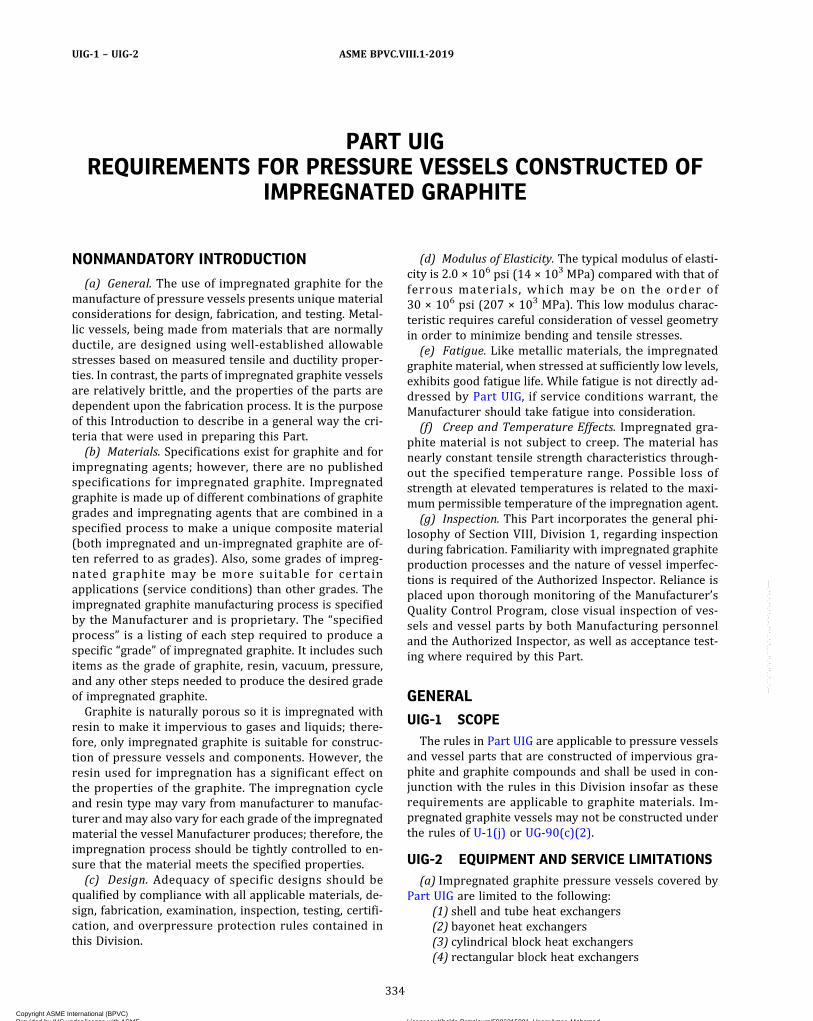
PART UIGREQUIREMENTS FOR PRESSURE VESSELS CONSTRUCTED OF
IMPREGNATED GRAPHITE
NONMANDATORY INTRODUCTION
(a) General. The use of impregnated graphite for themanufacture of pressure vessels presents unique materialconsiderations for design, fabrication, and testing. Metal-lic vessels, being made from materials that are normallyductile, are designed using well‐established allowablestresses based on measured tensile and ductility proper-ties. In contrast, the parts of impregnated graphite vesselsare relatively brittle, and the properties of the parts aredependent upon the fabrication process. It is the purposeof this Introduction to describe in a general way the cri-teria that were used in preparing this Part.(b) Materials. Specifications exist for graphite and for
impregnating agents; however, there are no publishedspecifications for impregnated graphite. Impregnatedgraphite is made up of different combinations of graphitegrades and impregnating agents that are combined in aspecified process to make a unique composite material(both impregnated and un‐impregnated graphite are of-ten referred to as grades). Also, some grades of impreg-nated graphite may be more suitable for certainapplications (service conditions) than other grades. Theimpregnated graphite manufacturing process is specifiedby the Manufacturer and is proprietary. The “specifiedprocess” is a listing of each step required to produce aspecific “grade” of impregnated graphite. It includes suchitems as the grade of graphite, resin, vacuum, pressure,and any other steps needed to produce the desired gradeof impregnated graphite.Graphite is naturally porous so it is impregnated with
resin to make it impervious to gases and liquids; there-fore, only impregnated graphite is suitable for construc-tion of pressure vessels and components. However, theresin used for impregnation has a significant effect onthe properties of the graphite. The impregnation cycleand resin type may vary from manufacturer to manufac-turer andmay also vary for each grade of the impregnatedmaterial the vessel Manufacturer produces; therefore, theimpregnation process should be tightly controlled to en-sure that the material meets the specified properties.(c) Design. Adequacy of specific designs should be
qualified by compliance with all applicable materials, de-sign, fabrication, examination, inspection, testing, certifi-cation, and overpressure protection rules contained inthis Division.
(d) Modulus of Elasticity. The typical modulus of elasti-city is 2.0 × 10⁶ psi (14 × 103 MPa) compared with that offerrous materials, which may be on the order of30 × 106 psi (207 × 103 MPa). This low modulus charac-teristic requires careful consideration of vessel geometryin order to minimize bending and tensile stresses.(e) Fatigue. Like metallic materials, the impregnated
graphite material, when stressed at sufficiently low levels,exhibits good fatigue life. While fatigue is not directly ad-dressed by Part UIG, if service conditions warrant, theManufacturer should take fatigue into consideration.(f) Creep and Temperature Effects. Impregnated gra-
phite material is not subject to creep. The material hasnearly constant tensile strength characteristics through-out the specified temperature range. Possible loss ofstrength at elevated temperatures is related to the maxi-mum permissible temperature of the impregnation agent.(g) Inspection. This Part incorporates the general phi-
losophy of Section VIII, Division 1, regarding inspectionduring fabrication. Familiarity with impregnated graphiteproduction processes and the nature of vessel imperfec-tions is required of the Authorized Inspector. Reliance isplaced upon thorough monitoring of the Manufacturer’sQuality Control Program, close visual inspection of ves-sels and vessel parts by both Manufacturing personneland the Authorized Inspector, as well as acceptance test-ing where required by this Part.
GENERAL
UIG-1 SCOPEThe rules in Part UIG are applicable to pressure vessels
and vessel parts that are constructed of impervious gra-phite and graphite compounds and shall be used in con-junction with the rules in this Division insofar as theserequirements are applicable to graphite materials. Im-pregnated graphite vessels may not be constructed underthe rules of U-1(j) or UG-90(c)(2).
UIG-2 EQUIPMENT AND SERVICE LIMITATIONS(a) Impregnated graphite pressure vessels covered by
Part UIG are limited to the following:(1) shell and tube heat exchangers(2) bayonet heat exchangers(3) cylindrical block heat exchangers(4) rectangular block heat exchangers
334
ASME BPVC.VIII.1-2019UIG-1 – UIG-2
Copyright ASME International (BPVC) Provided by IHS under license with ASME Licensee=Khalda Petroleum/5986215001, User=Amer, Mohamed
Not for Resale, 07/02/2019 13:29:04 MDTNo reproduction or networking permitted without license from IHS
--`,``,``,,`,`,,````,`,``,,,`-`-`,,`,,`,`,,`---
(5) plate heat exchangers(6) cylindrical vessels
(b) Impregnated graphite pressure vessels have the fol-lowing limitations:
(1)maximum external design pressure: 350 psi(2.4 MPa)
(2)maximum internal design pressure: 350 psi(2.4 MPa)
(3)minimum design temperature: −100°F (−73°C)(4)maximum design temperature: 400°F (204°C)
(c) Metal parts used in conjunction with impregnatedgraphite pressure vessels, including those for lethal ser-vice, shall be constructed in accordance with the require-ments of this Division.
UIG-3 TERMINOLOGY
batch: that quantity of material contained in a single im-pregnation cycle.
cementing: the process of joining parts using graphite ce-ment followed by a curing process.
certified materials: may only be manufactured by a Certi-ficate Holder.
impervious materials: graphite in which pores are filledwith impregnation agents, and that have a coefficient ofpermeability of not more than 4.5 × 10⁻⁶ in.2/sec(2.9 × 10−3 mm2/sec) as measured in accordance withMandatory Appendix 39.
graphite cement: mix of carbonaceous or graphite pow-der and/or resin.
graphite compound: graphite material mixed with highcorrosion resistant binder systems and with a minimumgraphite content of 50% rendering it impervious to a per-meation rate of not more than 4.5 × 10⁻⁶ in.2/sec(2.9 × 10−3 mm2/s) as measured in accordance with Man-datory Appendix 39.
grade: material manufacturer’s designation for a raw orcertified material.
graphite part: any impregnated graphite component cer-tified by a Certificate Holder.
graphite pressure vessel: a pressure vessel constructed ofcertified materials.
graphitization: a solid‐state transformation of carbon intographite by means of heat treatment.
lot: a “lot” is that quantity of certified material producedwithin a 3‐mo period from a specific grade of graphiteand resin that meets established specifications for mate-rial properties. Furthermore, the impregnation processmust be controlled to a process specification. (SeeUIG-84.)
raw materials: include graphite material and impregna-tion agent.
graphite material: a bonded granular carbon bodywhose matrix has been subjected to a temperature in ex-cess of 4,350°F (2 400°C), and whose matrix is thermallystable below that temperature.
impregnation agent: material used to render carbonand graphite materials impervious.
MATERIALS
UIG-5 RAW MATERIAL CONTROL(a) Rawmaterials used in the manufacturing of the cer-
tified material shall be identified by its source and grade,and documented on the Certified Material QualificationForm (CMQ) by the Certificate Holder.
(b) Graphite material and the impregnating agent usedin the construction of graphite pressure vessels, and ves-sel parts shall be the same as the materials specified in theCertified Material Specification (CMS) (see UIG-77). Eachof these materials shall be traceable in accordance withUIG-112(b).
UIG-6 CERTIFIED MATERIAL CONTROL(a) All material used in the construction of graphite
pressure vessels shall be certified by the Manufacturerof the material to meet the properties in Table UIG-6and all other requirements in Part UIG.
(b) The Manufacturer of certified material shall preparea Certified Material Test Report (CMTR) that shall includethe following, as a minimum (see UIG-84)
(1)Manufacturer’s name(2) lot number(3) grade(4) lot specific room temperature compressive
strength values(5) lot specific room temperature tensile strength
values(6) date tested(7) tensile strength values at the maximum allowable
material temperature(c) The Manufacturer of certified material shall per-
form testing to meet the minimum properties in TableUIG-6-1 and test frequency for strength per UIG-84. TheManufacturer shall additionally prepare a Certified Ce-ment Specification, CCS (see UIG-78). The cement materi-al and cementing procedure (see UIG-79) shall bequalified. Tensile testing shall be performed per Manda-tory Appendix 37.
335
ASME BPVC.VIII.1-2019 UIG-2 – UIG-6
Copyright ASME International (BPVC) Provided by IHS under license with ASME Licensee=Khalda Petroleum/5986215001, User=Amer, Mohamed
Not for Resale, 07/02/2019 13:29:04 MDTNo reproduction or networking permitted without license from IHS
--`,``,``,,`,`,,````,`,``,,,`-`-`,,`,,`,`,,`---

UIG-7 ADDITIONAL PROPERTIESThe modulus of elasticity tested per ASTM C747 and
ASTM C769 is typically 2.0 × 10⁶ psi, and the Poisson’s ra-tio for impervious graphite is typically 0.15. The coeffi-cient of thermal expansion for impervious graphiteexhibits a typical range of 1.5 to 3.5 × 10⁻⁶ in./in./°F.
UIG-8 TOLERANCES FOR IMPREGNATEDGRAPHITE TUBES
Extruded graphite tubes 3 in. O.D. and under shall meetthe following tolerances:(a) outside diameter: ±0.062 in. (1.5 mm)(b) inside diameter: ±0.062 in. (1.5 mm)(c) wall thickness variation: −0.062 in. (–1.5 mm)(d) out‐of roundness: 0.04 in. (1.0 mm)(e) bow: 0.70% of unit length
DESIGN
UIG-22 LOADINGSThe loadings described in UG-22 shall be considered in
the design of graphite pressure vessels and vessel parts.Flexible joints (expansion joints/flexible bellows) shouldbe used for all connections to graphite components tominimize loads on nozzles and other connections. Theuser shall make provisions for the reaction forces frompressure relief devices on graphite components.
UIG-23 MAXIMUM ALLOWABLE STRESS VALUESFOR CERTIFIED MATERIAL
(a) The design factor to be used for graphite pressurevessel parts shall be not less than 6.0 except as statedin (c).(b) The maximum allowable tensile stress value to be
used in design shall be 80% of the determined value atthe design temperature, divided by the design factor of6.0 (7.0 for lethal service; see UIG-60).(c) See below.
(1) The maximum allowable compressive stress val-ue to be used in design shall be 80% of the determinedvalue at the design temperature, divided by the designfactor of 6.0 (7.0 for lethal service; see UIG-60).
(2) The maximum allowable compressive stress val-ue to be used in design of graphite pressure vessel partsunder the gasket of a flanged joint resulting from the de-sign bolt load, W (see Mandatory Appendix 2), shall belimited to 60% of the determined compressive strengthvalue at the design temperature.(d) The design value for tensile and compressive stress-
es at the design temperature shall be determined usingthe strength variation value from Form CMQ.
UIG-27 THICKNESS OF CYLINDRICAL SHELLSMADE OF CERTIFIED MATERIALS UNDERINTERNAL PRESSURE
The minimum thickness or the maximum allowableworking pressure (MAWP) of cylindrical shells, made ofcertified materials and subject to internal pressure, shallbe calculated in accordance with the equations in UG-27or Mandatory Appendix 1, as applicable, using a joint
Table UIG-6-1Properties of Certified Material
Tube [Note (1)]Material
Block [Note (1)]Material
Compound [Note (2)]Material
Cement [Note (3)]Material
Minimum tensile strengthat room temperature
3,800 psi (26.2 MPa) 2,000 psi (13.8 MPa) 1,500 psi (10.3 MPa) 1,500 psi (10.3 MPa)
Minimum tensile strengthat maximum designtemperature
3,000 psi (20.7 MPa) 1,600 psi (11.0 MPa) 900 psi (6.2 MPa) 900 psi (6.2 MPa)
Minimum flexuralstrength
5,700 psi (39.3 MPa) N/A [Note (4)] N/A [Note (4)] N/A [Note (4)]
Minimum compressivestrength
10,000 psi (69 MPa) 6,500 psi (45 MPa) 4,500 psi (31 MPa) N/A [Note (4)]
Maximum coefficient ofpermeability
4.5 × 10⁻⁶ in.2/sec(2.9 × 10−3 mm2/s)
4.5 × 10⁻⁶ in.2/sec(2.9 × 10−3 mm2/s)
4.5 × 10⁻⁶ in.2/sec(2.9 × 10−3 mm2/s)
N/A [Note (4)]
NOTES:(1) Resin impregnated graphite.(2) Resin bonded graphite.(3) Resin with graphite filler and catalyst.(4) N/A: not applicable
336
ASME BPVC.VIII.1-2019UIG-7 – UIG-27
Copyright ASME International (BPVC) Provided by IHS under license with ASME Licensee=Khalda Petroleum/5986215001, User=Amer, Mohamed
Not for Resale, 07/02/2019 13:29:04 MDTNo reproduction or networking permitted without license from IHS
--`,``,``,,`,`,,````,`,``,,,`-`-`,,`,,`,`,,`---
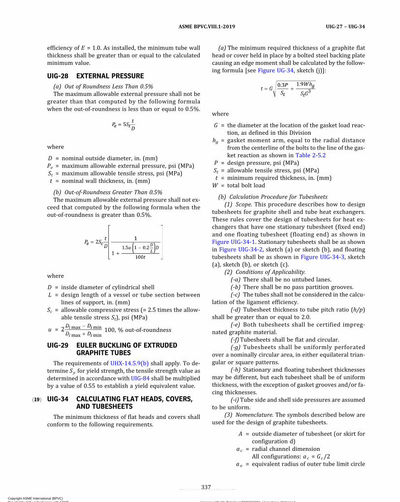
ð19Þ
efficiency of E = 1.0. As installed, the minimum tube wallthickness shall be greater than or equal to the calculatedminimum value.
UIG-28 EXTERNAL PRESSURE(a) Out of Roundness Less Than 0.5%The maximum allowable external pressure shall not be
greater than that computed by the following formulawhen the out‐of‐roundness is less than or equal to 0.5%.
where
D = nominal outside diameter, in. (mm)Pe = maximum allowable external pressure, psi (MPa)St = maximum allowable tensile stress, psi (MPa)t = nominal wall thickness, in. (mm)
(b) Out‐of‐Roundness Greater Than 0.5%The maximum allowable external pressure shall not ex-
ceed that computed by the following formula when theout‐of‐roundness is greater than 0.5%.
where
D = inside diameter of cylindrical shellL = design length of a vessel or tube section between
lines of support, in. (mm)Sc = allowable compressive stress (= 2.5 times the allow-
able tensile stress St), psi (MPa)
u = 100, % out‐of‐roundness
UIG-29 EULER BUCKLING OF EXTRUDEDGRAPHITE TUBES
The requirements of UHX-14.5.9(b) shall apply. To de-termine Sy for yield strength, the tensile strength value asdetermined in accordance with UIG-84 shall be multipliedby a value of 0.55 to establish a yield equivalent value.
UIG-34 CALCULATING FLAT HEADS, COVERS,AND TUBESHEETS
The minimum thickness of flat heads and covers shallconform to the following requirements.
(a) The minimum required thickness of a graphite flathead or cover held in place by a bolted steel backing platecausing an edge moment shall be calculated by the follow-ing formula [see Figure UG-34, sketch (j)]:
where
G = the diameter at the location of the gasket load reac-tion, as defined in this Division
hg = gasket moment arm, equal to the radial distancefrom the centerline of the bolts to the line of the gas-ket reaction as shown in Table 2-5.2
P = design pressure, psi (MPa)St = allowable tensile stress, psi (MPa)t = minimum required thickness, in. (mm)
W = total bolt load
(b) Calculation Procedure for Tubesheets(1) Scope. This procedure describes how to design
tubesheets for graphite shell and tube heat exchangers.These rules cover the design of tubesheets for heat ex-changers that have one stationary tubesheet (fixed end)and one floating tubesheet (floating end) as shown inFigure UIG-34-1. Stationary tubesheets shall be as shownin Figure UIG-34-2, sketch (a) or sketch (b), and floatingtubesheets shall be as shown in Figure UIG-34-3, sketch(a), sketch (b), or sketch (c).
(2) Conditions of Applicability.(-a) There shall be no untubed lanes.(-b) There shall be no pass partition grooves.(-c) The tubes shall not be considered in the calcu-
lation of the ligament efficiency.(-d) Tubesheet thickness to tube pitch ratio (h/p)
shall be greater than or equal to 2.0.(-e) Both tubesheets shall be certified impreg-
nated graphite material.(-f)Tubesheets shall be flat and circular.(-g) Tubesheets shall be uniformly perforated
over a nominally circular area, in either equilateral trian-gular or square patterns.
(-h) Stationary and floating tubesheet thicknessesmay be different, but each tubesheet shall be of uniformthickness, with the exception of gasket grooves and/or fa-cing thicknesses.
(-i)Tube side and shell side pressures are assumedto be uniform.
(3) Nomenclature. The symbols described below areused for the design of graphite tubesheets.
A = outside diameter of tubesheet (or skirt forconfiguration d)
ac = radial channel dimensionAll configurations: ac = Gc/2
ao = equivalent radius of outer tube limit circle
337
ASME BPVC.VIII.1-2019 UIG-27 – UIG-34
Copyright ASME International (BPVC) Provided by IHS under license with ASME Licensee=Khalda Petroleum/5986215001, User=Amer, Mohamed
Not for Resale, 07/02/2019 13:29:04 MDTNo reproduction or networking permitted without license from IHS
--`,``,``,,`,`,,````,`,``,,,`-`-`,,`,,`,`,,`---
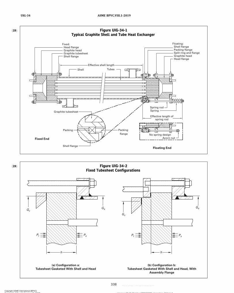
ð19Þ Figure UIG-34-1Typical Graphite Shell and Tube Heat Exchanger
Floating: Shell flange Packing flange Split ring and flange Graphite head Head flange
Shell
Packing flange
Acorn nutNo spring design
Effective length ofspring rod
Packing
Fixed End
Graphite tubesheet
Tubes
Fixed: Head flange Graphite head Graphite tubesheet Shell flange
Effective shell length
Shell flange
Spring rodSpring
Floating End
ð19Þ Figure UIG-34-2Fixed Tubesheet Configurations
(a) Configuration a:
Tubesheet Gasketed With Shell and Head
(b) Configuration b:
Tubesheet Gasketed With Shell and Head, With
Assembly Flange
GsGc
Pt Ps Pt
Gc
h
Ps
Gs
h
338
ASME BPVC.VIII.1-2019UIG-34
Copyright ASME International (BPVC) Provided by IHS under license with ASME Licensee=Khalda Petroleum/5986215001, User=Amer, Mohamed
Not for Resale, 07/02/2019 13:29:04 MDTNo reproduction or networking permitted without license from IHS
--`,``,``,,`,`,,````,`,``,,,`-`-`,,`,,`,`,,`---
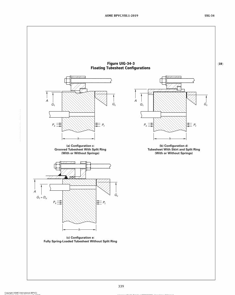
ð19ÞFigure UIG-34-3Floating Tubesheet Configurations
(a) Configuration c:
Grooved Tubesheet With Split Ring
(With or Without Springs)
(b) Configuration d:
Tubesheet With Skirt and Split Ring
(With or Without Springs)
(c) Configuration e:
Fully Spring-Loaded Tubesheet Without Split Ring
G1 Gc
PtPs
h
AG1 Gc
PtPs
h
A
G1 = DoGc
PtPs
h
A
339
ASME BPVC.VIII.1-2019 UIG-34
Copyright ASME International (BPVC) Provided by IHS under license with ASME Licensee=Khalda Petroleum/5986215001, User=Amer, Mohamed
Not for Resale, 07/02/2019 13:29:04 MDTNo reproduction or networking permitted without license from IHS
--`,``,``,,`,`,,````,`,``,,,`-`-`,,`,,`,`,,`---

as = radial shell dimensionconfigurations a and b: as = Gs/2configurations c, d, and e: as = A/2
d = diameter of tube hole in tubesheetDo = equivalent diameter of outer tube limit cir-
cle [see Figure UIG-34-4, sketch (a)]dr = nominal diameter of spring rodsDs = inside shell diameterdt = nominal outside diameter of tubesE = modulus of elasticity for tubesheet
materialE* = effective modulus of elasticity of tubesheet
in perforated regionEr = modulus of elasticity for spring rod
materialEs = modulus of elasticity for shell material at
Ts
Es ,w = joint efficiency (longitudinal stress) forshell
Et = modulus of elasticity for tube materialG1 = midpoint of contact between the split
shear ring and tubesheetGc = diameter of channel gasket load reaction
(see Mandatory Appendix 2)Gs = diameter of shell gasket load reaction (see
Mandatory Appendix 2)h = tubesheet thicknessJ = ratio of spring rigidity, KJNr , to the effec-
tive axial rigidity of the shell and springrods, Ksr
= 1.0 if there are no springsk = constant accounting for the method of sup-
port for the unsupported tube span underconsideration
= 0.6 for unsupported spans between twotubesheets
= 0.8 for unsupported spans between a tube-sheet and a tube support
= 1.0 for unsupported spans between twotube supports
KJ = axial rigidity of spring or spring stack oneach spring rod
Kr = axial rigidity of each spring rodKs = axial rigidity of shellKsr = effective axial rigidity of shell and spring
rodsKsr t = ratio of effective axial rigidity of shell and
spring rods to axial rigidity of tubesKt = axial rigidity of each tubeL = tube length between inner tubesheet faces
= Lt − 2Lc
ℓ = u n s u p p o r t e d t u b e s p a n u n d e rconsideration
Lc = tube counter bore depth in tubesheet [seeFigure UIG-34-4, sketch (b)]
Lr = effective length of spring rods (see FigureUIG-34-1)
Ls = effective shell length (see Figure UIG-34-1)Lt = tube length
MAX[(a) ,(b) ,(c) , . . . ] = greatest of a , b , c ,...
Nr = number of spring rodsNt = number of tubesp = tube pitch [see Figure UIG-34-4, sketch
(a)]Pe = effective pressure acting on tubesheetPs = shell side design or operating pressure, as
applicable. For shell side vacuum, use a ne-gative value for Ps .
Psd ,max = maximum shell side design pressurePsd ,min = minimum shell side design pressure (ne-
gative if vacuum is specified, otherwisezero)
Psox = shell side operating pressure for operatingcondition x (positive, negative, or zero op-erating pressure)
Pt = tube side design or operating pressure, asapplicable. For tube side vacuum, use a ne-gative value for Pt .
Ptd ,max = maximum tube side design pressurePtd ,min = minimum tube side design pressure (nega-
tive if vacuum is specified, otherwise zero)Ptox = tube side operating pressure for operating
condition x (positive, negative, or zero op-erating pressure)
ro = radius to outermost tube hole center [seeFigure UIG-34-4, sketch (a)]
S = allowable stress for tubesheet material atT
Ss = allowable stress for shell material at Ts
St = allowable tensile stress for tube materialat Tt
Stc = allowable compressive stress for tube ma-terial at Tt
T = tubesheet design temperature for the de-sign condition or operating temperaturefor operating condition x , as applicable[see (4)(-b)]
Ta = ambient temperatureTs = shell design temperature for the design
condition or operating metal temperaturefor operating condition x , as applicable[see (4)(-b)]
t s = shell thicknessTs ,m = mean shell metal temperature along shell
lengthTs ,mx = shell axial mean metal temperature for op-
erating condition x , as applicableTt = tube design temperature for the design
condition or operating temperature foroperating condition x, as applicable [see(4)(-b)]
t t = nominal tube wall thicknessTt ,m = mean tube temperature along tube length
340
ASME BPVC.VIII.1-2019UIG-34
Copyright ASME International (BPVC) Provided by IHS under license with ASME Licensee=Khalda Petroleum/5986215001, User=Amer, Mohamed
Not for Resale, 07/02/2019 13:29:04 MDTNo reproduction or networking permitted without license from IHS
--`,``,``,,`,`,,````,`,``,,,`-`-`,,`,,`,`,,`---
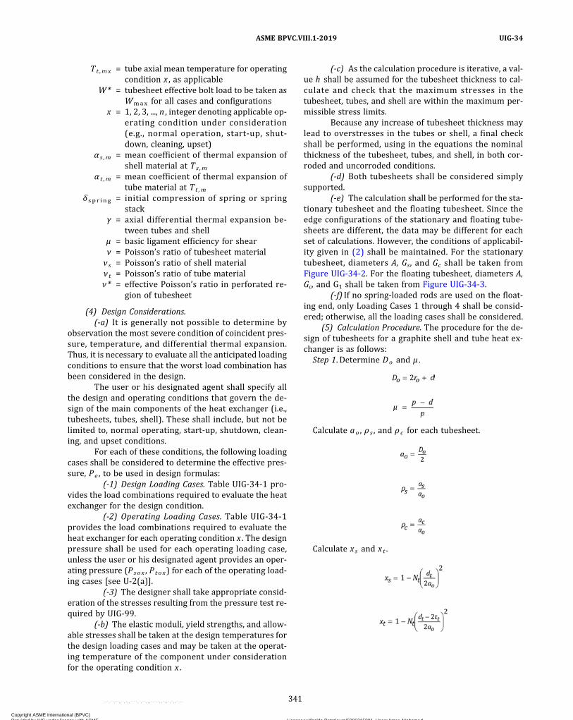
Tt ,mx = tube axial mean temperature for operatingcondition x , as applicable
W* = tubesheet effective bolt load to be taken asWmax for all cases and configurations
x = 1, 2, 3, ..., n , integer denoting applicable op-erating condition under consideration(e.g., normal operation, start-up, shut-down, cleaning, upset)
α s ,m = mean coefficient of thermal expansion ofshell material at Ts ,m
α t ,m = mean coefficient of thermal expansion oftube material at Tt ,m
δ spr ing = initial compression of spring or springstack
γ = axial differential thermal expansion be-tween tubes and shell
μ = basic ligament efficiency for shearν = Poisson’s ratio of tubesheet materialν s = Poisson’s ratio of shell materialν t = Poisson’s ratio of tube materialν* = effective Poisson’s ratio in perforated re-
gion of tubesheet
(4) Design Considerations.(-a) It is generally not possible to determine by
observation the most severe condition of coincident pres-sure, temperature, and differential thermal expansion.Thus, it is necessary to evaluate all the anticipated loadingconditions to ensure that the worst load combination hasbeen considered in the design.
The user or his designated agent shall specify allthe design and operating conditions that govern the de-sign of the main components of the heat exchanger (i.e.,tubesheets, tubes, shell). These shall include, but not belimited to, normal operating, start‐up, shutdown, clean-ing, and upset conditions.
For each of these conditions, the following loadingcases shall be considered to determine the effective pres-sure, Pe , to be used in design formulas:
(-1) Design Loading Cases. Table UIG‐34‐1 pro-vides the load combinations required to evaluate the heatexchanger for the design condition.
(-2) Operating Loading Cases. Table UIG‐34‐1provides the load combinations required to evaluate theheat exchanger for each operating condition x . The designpressure shall be used for each operating loading case,unless the user or his designated agent provides an oper-ating pressure (Psox , Ptox) for each of the operating load-ing cases [see U‐2(a)].
(-3) The designer shall take appropriate consid-eration of the stresses resulting from the pressure test re-quired by UIG‐99.
(-b) The elastic moduli, yield strengths, and allow-able stresses shall be taken at the design temperatures forthe design loading cases and may be taken at the operat-ing temperature of the component under considerationfor the operating condition x .
(-c) As the calculation procedure is iterative, a val-ue h shall be assumed for the tubesheet thickness to cal-culate and check that the maximum stresses in thetubesheet, tubes, and shell are within the maximum per-missible stress limits.
Because any increase of tubesheet thickness maylead to overstresses in the tubes or shell, a final checkshall be performed, using in the equations the nominalthickness of the tubesheet, tubes, and shell, in both cor-roded and uncorroded conditions.
(-d) Both tubesheets shall be considered simplysupported.
(-e) The calculation shall be performed for the sta-tionary tubesheet and the floating tubesheet. Since theedge configurations of the stationary and floating tube-sheets are different, the data may be different for eachset of calculations. However, the conditions of applicabil-ity given in (2) shall be maintained. For the stationarytubesheet, diameters A, Gs, and Gc shall be taken fromFigure UIG-34-2. For the floating tubesheet, diameters A,Gc, and G1 shall be taken from Figure UIG-34-3.
(-f) If no spring-loaded rods are used on the float-ing end, only Loading Cases 1 through 4 shall be consid-ered; otherwise, all the loading cases shall be considered.
(5) Calculation Procedure. The procedure for the de-sign of tubesheets for a graphite shell and tube heat ex-changer is as follows:
Step 1. Determine Do and μ .
Calculate ao , ρ s , and ρ c for each tubesheet.
Calculate xs and xt .
341
ASME BPVC.VIII.1-2019 UIG-34
Copyright ASME International (BPVC) Provided by IHS under license with ASME Licensee=Khalda Petroleum/5986215001, User=Amer, Mohamed
Not for Resale, 07/02/2019 13:29:04 MDTNo reproduction or networking permitted without license from IHS
--`,``,``,,`,`,,````,`,``,,,`-`-`,,`,,`,`,,`---
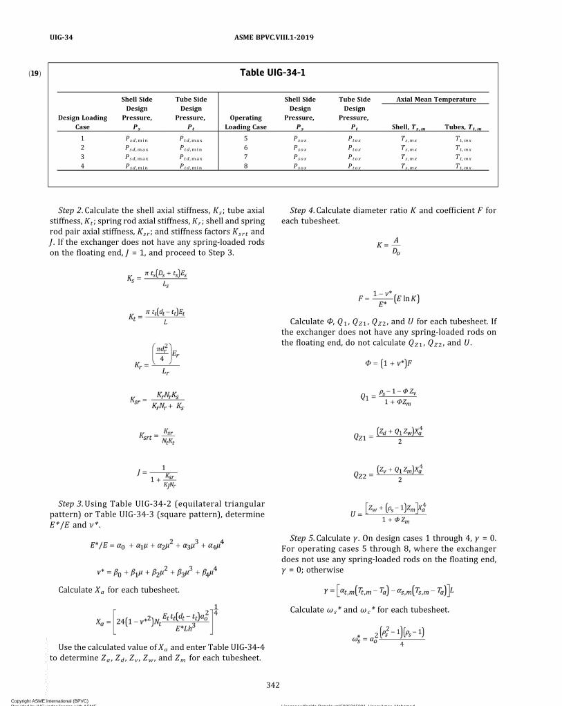
Step 2. Calculate the shell axial stiffness, Ks ; tube axialstiffness, Kt ; spring rod axial stiffness, Kr ; shell and springrod pair axial stiffness, Ksr ; and stiffness factors Ksr t andJ . If the exchanger does not have any spring-loaded rodson the floating end, J = 1, and proceed to Step 3.
Step 3. Using Table UIG‐34‐2 (equilateral triangularpattern) or Table UIG‐34‐3 (square pattern), determineE*/E and ν* .
Calculate Xa for each tubesheet.
Use the calculated value of Xa and enter Table UIG-34-4to determine Za , Zd , Zv , Zw , and Zm for each tubesheet.
Step 4. Calculate diameter ratio K and coefficient F foreach tubesheet.
Calculate Φ, Q1 , QZ1 , QZ2 , and U for each tubesheet. Ifthe exchanger does not have any spring-loaded rods onthe floating end, do not calculate QZ1 , QZ2 , and U .
Step 5. Calculate γ . On design cases 1 through 4, γ = 0.For operating cases 5 through 8, where the exchangerdoes not use any spring-loaded rods on the floating end,γ = 0; otherwise
Calculate ω s* and ωc* for each tubesheet.
ð19Þ Table UIG-34-1
Design LoadingCase
Shell SideDesign
Pressure,Ps
Tube SideDesign
Pressure,Pt
OperatingLoading Case
Shell SideDesign
Pressure,Ps
Tube SideDesign
Pressure,Pt
Axial Mean Temperature
Shell, Ts ,m Tubes, Tt ,m
1 Psd ,min Ptd ,max 5 Psox Ptox Ts ,mx Tt ,mx
2 Psd ,max Ptd ,min 6 Psox Ptox Ts ,mx Tt ,mx
3 Psd ,max Ptd ,max 7 Psox Ptox Ts ,mx Tt ,mx
4 Psd ,min Ptd ,min 8 Psox Ptox Ts ,mx Tt ,mx
342
ASME BPVC.VIII.1-2019UIG-34
Copyright ASME International (BPVC) Provided by IHS under license with ASME Licensee=Khalda Petroleum/5986215001, User=Amer, Mohamed
Not for Resale, 07/02/2019 13:29:04 MDTNo reproduction or networking permitted without license from IHS
--`,``,``,,`,`,,````,`,``,,,`-`-`,,`,,`,`,,`---
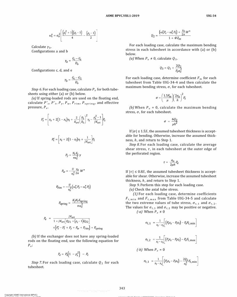
Calculate γb .Configurations a and b
Configurations c, d, and e
Step 6. For each loading case, calculate Pe for both tube-sheets using either (a) or (b) below.
(a) If spring-loaded rods are used on the floating end,calculate P ’ s , P ’ t , P γ , Pw , P r im , P s p r i n g , and effectivepressure, Pe .
(b) If the exchanger does not have any spring-loadedrods on the floating end, use the following equation forPe :
Step 7. For each loading case, calculate Q 2 for eachtubesheet.
For each loading case, calculate the maximum bendingstress in each tubesheet in accordance with (a) or (b)below.
(a)When Pe ≠ 0, calculate Q3 .
For each loading case, determine coefficient Fm for eachtubesheet from Table UIG‐34‐4 and then calculate themaximum bending stress, σ , for each tubesheet.
(b)When P e = 0, calculate the maximum bendingstress, σ , for each tubesheet.
If |σ | ≤ 1.5S , the assumed tubesheet thickness is accept-able for bending. Otherwise, increase the assumed thick-ness, h , and return to Step 1.
Step 8. For each loading case, calculate the averageshear stress, τ , in each tubesheet at the outer edge ofthe perforated region.
If |τ | ≤ 0.8S , the assumed tubesheet thickness is accept-able for shear. Otherwise, increase the assumed tubesheetthickness, h , and return to Step 1.
Step 9. Perform this step for each loading case.(a) Check the axial tube stress.(1) For each loading case, determine coefficients
F t ,m i n and F t ,ma x from Table UIG‐34‐5 and calculatethe two extreme values of tube stress, σ t , 1 and σ t , 2 .The values for σ t ,1 and σ t ,2 may be positive or negative.
(-a) When Pe ≠ 0
(-b) When Pe = 0
343
ASME BPVC.VIII.1-2019 UIG-34
Copyright ASME International (BPVC) Provided by IHS under license with ASME Licensee=Khalda Petroleum/5986215001, User=Amer, Mohamed
Not for Resale, 07/02/2019 13:29:04 MDTNo reproduction or networking permitted without license from IHS
--`,``,``,,`,`,,````,`,``,,,`-`-`,,`,,`,`,,`---
ð19Þ
(2) Determine σ t ,max = MAX(σ t ,1 , σ t ,2). If σ t ,max ispositive and |σ t ,max| > St , reconsider the design and re-turn to Step 1.
(3) Determine σ t ,min = MIN(σ t ,1 , σ t ,2). If σ t ,min isnegative and |σ t ,min| > Stc , reconsider the design and re-turn to Step 1.(b) Check the tubes for buckling. If σ t ,min is positive,
skip this step and proceed to Step 10.(1) Calculate the largest equivalent unsupported
buckling length of the tube, ℓ t , considering the unsup-ported tube spans, ℓ , and their corresponding methodof support, k .
(2) Calculate r t and Ft .
(3) Determine the design factor, Fs , in accordancewith (-a) or (-b) below.
(-a) When Pe ≠ 0
Fs need not be taken as greater than 2.0.(-b) When Pe = 0, Fs = 1.25.
(4) Determine the maximum permissible bucklingstress limit, Stb , for the tubes.
(5) If |σ t ,min| > Stb , reconsider the design and returnto Step 1. If |σ t ,min| ≤ Stb , the tube design is acceptable.Proceed to Step 10.Step 10. If spring-loaded rods are used on the floating
end, perform this step.Calculate the axial membrane stress, σ s ,m , in each dif-
ferent shell section.
For all cases, if |σ s ,m | > SsEs ,w , reconsider the designand return to Step 1.If σ s ,m is negative, that indicates complete spring re-
laxation. Reconsider the spring design and return toStep 1.If σ s ,m is positive, the shell design is acceptable and the
calculation procedure is complete.
UIG-36 OPENINGS AND REINFORCEMENTSThe rules for the reinforcement of openings in graphite
pressure vessels and vessel parts shall be used in con-junction with the general requirements of Openings andReinforcements in Part UG of this Division insofar as theyare applicable to graphite pressure vessels. Unacceptablenozzle configurations include those shown in FigureUIG-36-1. The acceptable nozzle configurations include,but are not limited to, those shown in Figure UIG-36-2.
UIG-45 NOZZLE NECK THICKNESSThe minimum nozzle neck thickness shall be 1/2 in.
(13 mm) for nozzles of 3 in. (75 mm) nominal inside dia-meter or larger, and 1/4 in. (6 mm) for nozzles less than3 in. (75 mm) nominal inside diameter, but in no case lessthan the thickness required by UIG-27 or UIG-28 asappropriate.
UIG-60 LETHAL SERVICEGraphite pressure vessels and vessel parts to be used
for lethal service, as defined in UW-2(a), shall meet thefollowing additional requirements:(a) The design factor shall be 7.0 for lethal service.(b) In addition to the testing requirements in Table
UIG-84-1, all graphite components for lethal service, ex-cluding tubes, shall be tested per UIG-84 requirementsat room temperature to determine mechanical properties.(c) All interior corners of pressure components shall
have a 1/2 in. (13 mm) minimum radius.(d) Exposed graphite shall be shielded with a metal
shroud. This shroud shall be constructed per the rulesof this Division, but is exempt from NDE and pressuretesting requirements.It is strongly recommended that owners/users monitor
the permeability of graphite equipment in lethal service.
344
ASME BPVC.VIII.1-2019UIG-34 – UIG-60
Copyright ASME International (BPVC) Provided by IHS under license with ASME Licensee=Khalda Petroleum/5986215001, User=Amer, Mohamed
Not for Resale, 07/02/2019 13:29:04 MDTNo reproduction or networking permitted without license from IHS
--`,``,``,,`,`,,````,`,``,,,`-`-`,,`,,`,`,,`---

ð19ÞTable UIG-34-2Values for Determining E*/E and v* Equilateral Triangular Pattern
Coefficient [Note (1)] Value Coefficient [Note (1)] Value
α0 −0.0029 β0 0.9966α1 0.2126 β1 −4.1978α2 3.9906 β2 9.0478α3 −6.173 β3 −7.9955α4 3.4307 β4 2.2398
NOTE:(1) These coefficients are valid only for 0.1 ≤ μ ≤ 0.6.
ð19ÞTable UIG-34-3Values for Determining E*/E and v* Equilateral Square Pattern
Coefficient [Note (1)] Value Coefficient [Note (1)] Value
α0 0.0372 β0 0.3341α1 1.0314 β1 0.1260α2 −0.6402 β2 −0.6920α3 2.6201 β3 0.6877α4 −2.1929 β4 −0.0600
NOTE:(1) These coefficients are valid only for 0.1 ≤ μ ≤ 0.6.
345
ASME BPVC.VIII.1-2019 UIG-60
Copyright ASME International (BPVC) Provided by IHS under license with ASME Licensee=Khalda Petroleum/5986215001, User=Amer, Mohamed
Not for Resale, 07/02/2019 13:29:04 MDTNo reproduction or networking permitted without license from IHS
--`,``,``,,`,`,,````,`,``,,,`-`-`,,`,,`,`,,`---
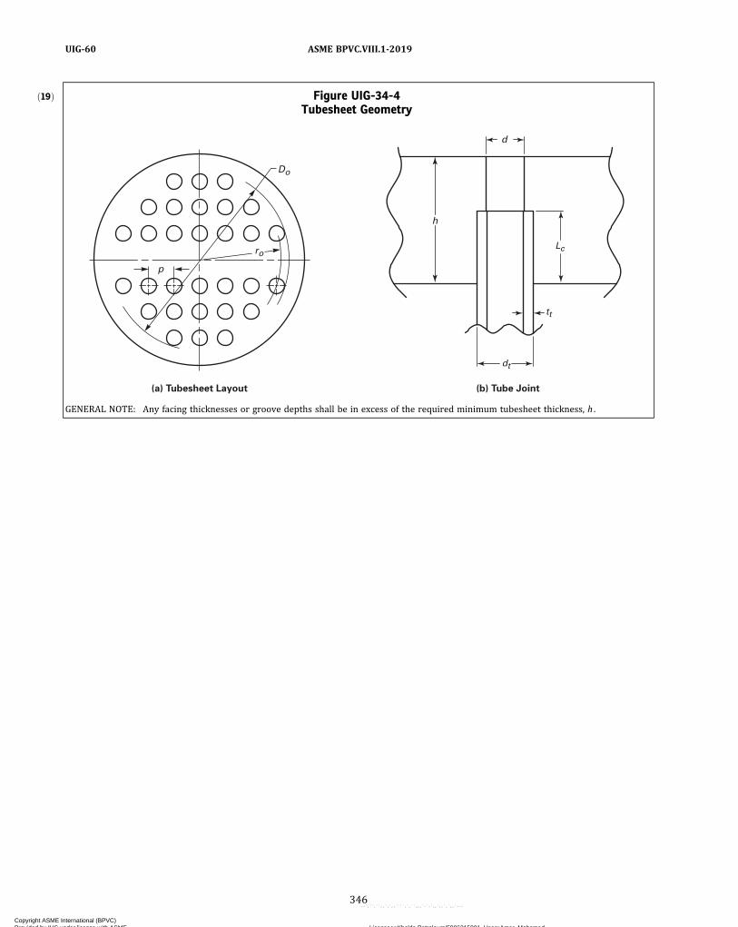
ð19Þ Figure UIG-34-4Tubesheet Geometry
p
Do
h
tt
dt
(a) Tubesheet Layout (b) Tube Joint
ro
d
Lc
GENERAL NOTE: Any facing thicknesses or groove depths shall be in excess of the required minimum tubesheet thickness, h .
346
ASME BPVC.VIII.1-2019UIG-60
Copyright ASME International (BPVC) Provided by IHS under license with ASME Licensee=Khalda Petroleum/5986215001, User=Amer, Mohamed
Not for Resale, 07/02/2019 13:29:04 MDTNo reproduction or networking permitted without license from IHS
--`,``,``,,`,`,,````,`,``,,,`-`-`,,`,,`,`,,`---

ð19ÞTable UIG-34-4Formulas for Determination of Zd, Zv, Zm, Zw, and Fm
(1) Calculate Kelvin functions of order 0 relative to x, where x varies from 0 to Xa such that [Note (1)]:
and their derivatives:
(2) Calculate functions ψ1 (x) and ψ2 (x) relative to x :
(3) Calculate Za, Zd, Zv, Zw, and Zm relative to Xa :
(4) Calculate functions Qm (x) and Qv (x) relative to x:
(5) For each loading case, calculate Fm (x) relative to x:
(6) Fm is the maximum of the absolute value of Fm(x) when x varies from 0 to Xa such that :
NOTE:(1) Use m = 4 + Xa/2 (rounded to the nearest integer) to obtain an adequate approximation of the Kelvin functions and their derivatives.
347
ASME BPVC.VIII.1-2019 UIG-60
Copyright ASME International (BPVC) Provided by IHS under license with ASME Licensee=Khalda Petroleum/5986215001, User=Amer, Mohamed
Not for Resale, 07/02/2019 13:29:04 MDTNo reproduction or networking permitted without license from IHS
--`,``,``,,`,`,,````,`,``,,,`-`-`,,`,,`,`,,`---
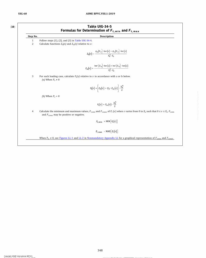
ð19Þ Table UIG-34-5Formulas for Determination of Ft ,min and Ft ,max
Step No. Description
1 Follow steps (1), (2), and (3) in Table UIG-34-4.2 Calculate functions Zd(x) and Zw(x) relative to x :
3 For each loading case, calculate Ft(x) relative to x in accordance with a or b below.(a) When Pe ≠ 0
(b) When Pe = 0
4 Calculate the minimum and maximum values, Ft,min and Ft,max, of Ft (x) when x varies from 0 to Xa such that 0 ≤ x ≤ Xa. Ft,min
and Ft,max may be positive or negative.
When Pe ≠ 0, see Figures LL-1 and LL-2 in Nonmandatory Appendix LL for a graphical representation of Ft,min and Ft,max.
348
ASME BPVC.VIII.1-2019UIG-60
Copyright ASME International (BPVC) Provided by IHS under license with ASME Licensee=Khalda Petroleum/5986215001, User=Amer, Mohamed
Not for Resale, 07/02/2019 13:29:04 MDTNo reproduction or networking permitted without license from IHS
--`,``,``,,`,`,,````,`,``,,,`-`-`,,`,,`,`,,`---

Figure UIG-36-1Unacceptable Nozzle Attachment Details
Graphite head
Graphite head
Graphite nozzle
Graphite nozzle
No counterbore [Note (1)]
No counterbore [Note (1)]
Nozzle stud
Steel flange
d
(b)
(a)
NOTE:(1) See Figure UIG-36-2, sketch (b) for acceptable version.
349
ASME BPVC.VIII.1-2019 UIG-60
Copyright ASME International (BPVC) Provided by IHS under license with ASME Licensee=Khalda Petroleum/5986215001, User=Amer, Mohamed
Not for Resale, 07/02/2019 13:29:04 MDTNo reproduction or networking permitted without license from IHS
--`,``,``,,`,`,,````,`,``,,,`-`-`,,`,,`,`,,`---

Figure UIG-36-2Some Acceptable Nozzle Attachment Details in Impregnated Graphite Pressure Vessels
(b) Split Ring
(a) Insert Joint
d
t
d
Cement
tn
tn
Bolt
Steel flange with split ring
Graphite nozzle
Graphite head and nozzle
Graphite head
Bolt
1/8 in. min. 1/2t max.
t
Cement 1/8 in. min. 1/2t max.
350
ASME BPVC.VIII.1-2019UIG-60
Copyright ASME International (BPVC) Provided by IHS under license with ASME Licensee=Khalda Petroleum/5986215001, User=Amer, Mohamed
Not for Resale, 07/02/2019 13:29:04 MDTNo reproduction or networking permitted without license from IHS
--`,``,``,,`,`,,````,`,``,,,`-`-`,,`,,`,`,,`---
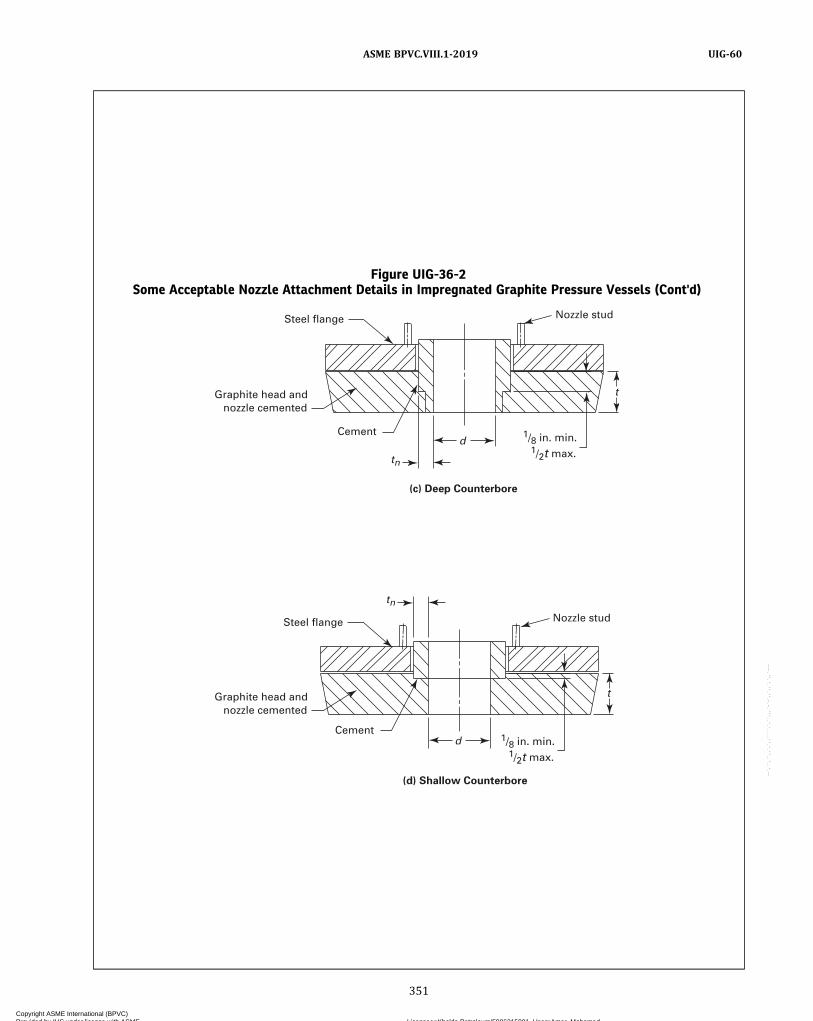
Figure UIG-36-2Some Acceptable Nozzle Attachment Details in Impregnated Graphite Pressure Vessels (Cont'd)
(c) Deep Counterbore
(d) Shallow Counterbore
Steel flange Nozzle stud
Graphite head and nozzle cemented
1/8 in. min. 1/2t max.
Cementd
d
t
t
tn
tn
Steel flange Nozzle stud
Cement1/8 in. min. 1/2t max.
Graphite head and nozzle cemented
351
ASME BPVC.VIII.1-2019 UIG-60
Copyright ASME International (BPVC) Provided by IHS under license with ASME Licensee=Khalda Petroleum/5986215001, User=Amer, Mohamed
Not for Resale, 07/02/2019 13:29:04 MDTNo reproduction or networking permitted without license from IHS
--`,``,``,,`,`,,````,`,``,,,`-`-`,,`,,`,`,,`---
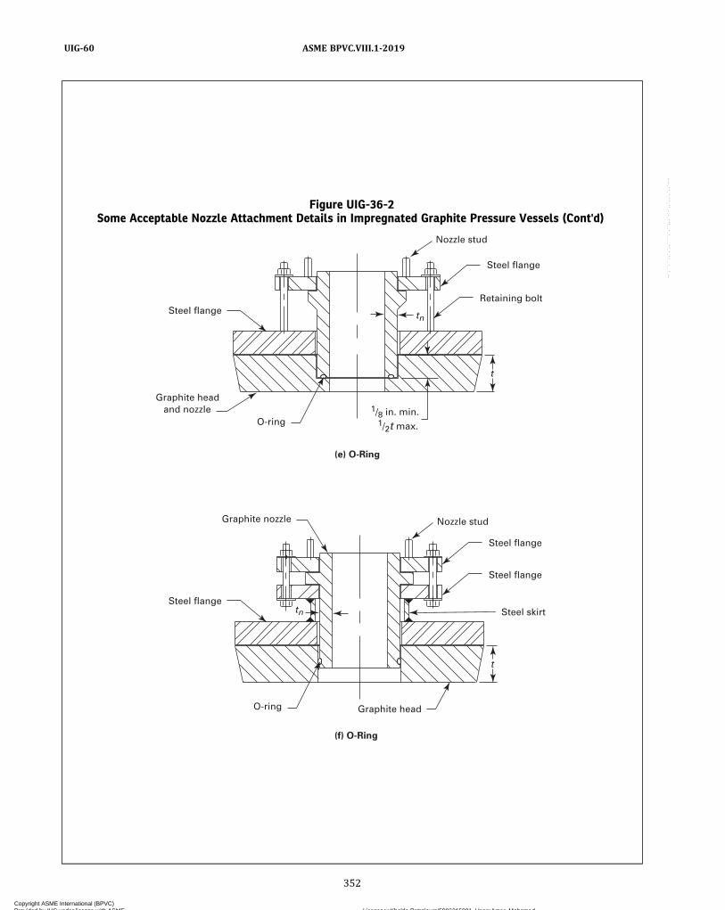
Figure UIG-36-2Some Acceptable Nozzle Attachment Details in Impregnated Graphite Pressure Vessels (Cont'd)
(f) O-Ring
(e) O-Ring
t
t
tn
Nozzle stud
Nozzle stud
O-ring Graphite head
O-ring1/8 in. min. 1/2t max.
Graphite head and nozzle
Steel flange
Steel flange
Steel flange
Steel flange
Retaining bolt
Steel flange
Steel skirt
Graphite nozzle
tn
352
ASME BPVC.VIII.1-2019UIG-60
Copyright ASME International (BPVC) Provided by IHS under license with ASME Licensee=Khalda Petroleum/5986215001, User=Amer, Mohamed
Not for Resale, 07/02/2019 13:29:04 MDTNo reproduction or networking permitted without license from IHS
--`,``,``,,`,`,,````,`,``,,,`-`-`,,`,,`,`,,`---

Figure UIG-36-2Some Acceptable Nozzle Attachment Details in Impregnated Graphite Pressure Vessels (Cont'd)
(h) Split Ring Flanged
(g) Shrouded Flanged
t
t
tn
Cement 1/8 in. min. 1/2t max.
1/8 in. min. 1/2t max.
Graphite head
CementGraphite head
Steel flange
Steel flange
Steel flange
Steel flange Steel skirt
Steel ring flange
Graphite nozzle
Graphite nozzle
353
ASME BPVC.VIII.1-2019 UIG-60
Copyright ASME International (BPVC) Provided by IHS under license with ASME Licensee=Khalda Petroleum/5986215001, User=Amer, Mohamed
Not for Resale, 07/02/2019 13:29:04 MDTNo reproduction or networking permitted without license from IHS
--`,``,``,,`,`,,````,`,``,,,`-`-`,,`,,`,`,,`---
FABRICATION
UIG-75 GENERAL REQUIREMENTSThe fabrication of graphite pressure vessels and vessel
parts shall conform to the general requirements of this Di-vision and to the specific requirements for Fabricationgiven in Part UIG.(a) Each Manufacturer shall be responsible for the
quality of the materials, processes, and personnel usedby their organization, and shall conduct tests of the pro-cesses to ensure that materials and completed joints com-ply with the requirements of this Part.(b) The design of pressure-containing and structural-
cemented joints shall be limited to those qualified in ac-cordance with the Manufacturer’s cementing procedurequalification (see UIG-79).(c) No production cementing shall be undertaken until
after the cementing procedures and the cementing techni-cians to be used in production have been qualified.(d) Each cementing technician shall be assigned an
identifying number, letter, or symbol by the Manufac-turer, which shall be used to identify his work.(e) The Manufacturer shall maintain a continuity re-
cord for each cementing technician showing the date,the results of tests, and the identification mark assignedto each. These records shall be certified by the Manufac-turer and shall be accessible to the Authorized Inspector.(f) The cementing technician shall mark the work, or
the Manufacturer may record the cementing technician’sI.D. number on a drawing or similar document traceableto the joint or seam. When multiple operators are cement-ing tubes to tubesheets, the Manufacturer shall record allcementing technicians’ identification numbers on a draw-ing or similar document.(g) The bulk temperature of the material to be joined
shall be between 50°F (10°C) and 125°F (52°C) duringthe cementing operation.
UIG-76 PROCEDURE AND PERSONNELQUALIFICATION
(a)Material manufacturing shall not be undertaken un-til after the material specifications have been qualified.Production cementing activities shall not be undertakenuntil after the cementing procedures and cementing tech-nicians have been qualified (see UIG-79 and UIG-80).(b) Tensile test specimens shall comply with Figure
UIG-76-1, UIG-76-2, UIG-76-3, UIG-76-4, or UIG-76-5.(c) Tensile tests shall be performed as described in
Mandatory Appendix 37.
(d) Compressive strength tests shall be performed asdescribed in Mandatory Appendix 38.(e) Flexural strength tests shall be performed as de-
scribed in Mandatory Appendix 36.
UIG-77 CERTIFIED MATERIAL SPECIFICATION(a) The Manufacturer shall prepare a Certified Material
Specification (CMS) to ensure that the material meets therequirements of Table UIG-6-1. The CMS shall include theraw materials and processes necessary to manufacturecertified material. The CMS shall include all essentialand non‐essential variables with tolerance ranges.(b) The Manufacturer shall qualify the Certified Materi-
al Specification (CMS) using the Certified Material Qualifi-cation (CMQ) form. Ten specimens are required for eachtest.(c) Any change to any essential variable, including the
tolerance range, requires requalification of the CMS.(d) The essential variables to be included in the qualifi-
cation of a CMS are as follows:(1) Carbon or graphite material:(-a) manufacturer(-b) grade or number(-c) density range(-d) grain size range
(2) Impregnation agent:(-a) manufacturer(-b) type / resin system(-c) specific gravity range(-d) viscosity range at room temperature(-e) significant ingredients with range
(3) Impregnation or curing process:(-a) process pressure ranges(-b) process time ranges
(-1) under vacuum(-2) under pressure(-3) at temperature
(-c) process temperature ranges(-d) vacuum ranges
(e) Nonessential variables are those elements that theManufacturer may include in the CMS to provide directionin producing certified material, but that do not affect theresulting properties of the material. Changes to nonessen-tial variables do not require requalification of the CMS.(f) Tests to be included for Certified Material Qualifica-
tion shall include flexural strength (tubes only), compres-sion strength, coefficient of thermal expansion, coefficientof permeability, and tensile strength at both room and atmaximum allowable material temperatures.
354
ASME BPVC.VIII.1-2019UIG-75 – UIG-77
Copyright ASME International (BPVC) Provided by IHS under license with ASME Licensee=Khalda Petroleum/5986215001, User=Amer, Mohamed
Not for Resale, 07/02/2019 13:29:04 MDTNo reproduction or networking permitted without license from IHS
--`,``,``,,`,`,,````,`,``,,,`-`-`,,`,,`,`,,`---
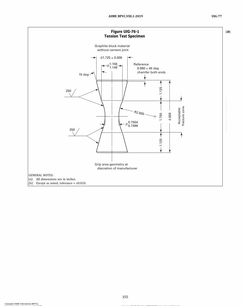
ð19ÞFigure UIG-76-1Tension Test Specimen
250
250
1.725 ± 0.006
1.158
15 deg
1.148
0.75040.7496
R2.000
1.75
01.
125
1.12
5
4.00
0
Acc
epta
ble
frac
ture
zo
ne
Reference 0.060 × 45 deg chamfer both ends
Graphite block material without cement joint
Grip area geometry at discretion of manufacturer
GENERAL NOTES:(a) All dimensions are in inches.(b) Except as noted, tolerance = ±0.010.
355
ASME BPVC.VIII.1-2019 UIG-77
Copyright ASME International (BPVC) Provided by IHS under license with ASME Licensee=Khalda Petroleum/5986215001, User=Amer, Mohamed
Not for Resale, 07/02/2019 13:29:04 MDTNo reproduction or networking permitted without license from IHS
--`,``,``,,`,`,,````,`,``,,,`-`-`,,`,,`,`,,`---
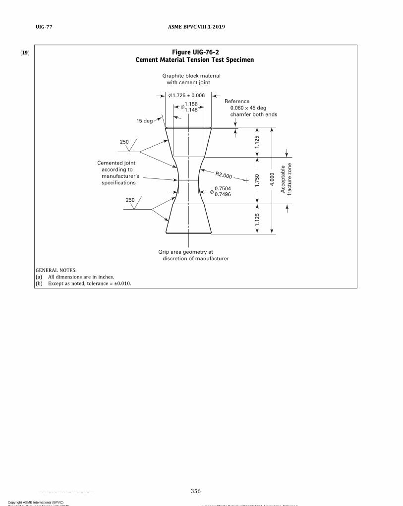
ð19Þ Figure UIG-76-2Cement Material Tension Test Specimen
250
250
1.725 ± 0.006
0.75040.7496
R2.000
1.75
01.
125
1.12
5
4.00
0
Acc
epta
ble
frac
ture
zo
ne
Reference 0.060 × 45 deg chamfer both ends
Graphite block material with cement joint
Grip area geometry at discretion of manufacturer
1.158
15 deg
1.148
Cemented joint according to manufacturer’s specifications
GENERAL NOTES:(a) All dimensions are in inches.(b) Except as noted, tolerance = ±0.010.
356
ASME BPVC.VIII.1-2019UIG-77
Copyright ASME International (BPVC) Provided by IHS under license with ASME Licensee=Khalda Petroleum/5986215001, User=Amer, Mohamed
Not for Resale, 07/02/2019 13:29:04 MDTNo reproduction or networking permitted without license from IHS
--`,``,``,,`,`,,````,`,``,,,`-`-`,,`,,`,`,,`---

Figure UIG-76-3Tube-to-Tubesheet Tension Test Specimen
15 deg reference
1.250 reference
1.750 reference
.875 reference
Tube as supplied by manufacturer
Cemented joint according to manufacturer’s specifications both ends
2.500reference
2.00
0re
fere
nce
2.00
0re
fere
nce
4.00
01.
406
8.00
0
.060 × 45 deg
Graphite tube material without cement joint
Grip area geometry at discretion of manufacturer
GENERAL NOTES:(a) All dimensions are in inches.(b) Except as noted, tolerance = ±.010.
357
ASME BPVC.VIII.1-2019 UIG-77
Copyright ASME International (BPVC) Provided by IHS under license with ASME Licensee=Khalda Petroleum/5986215001, User=Amer, Mohamed
Not for Resale, 07/02/2019 13:29:04 MDTNo reproduction or networking permitted without license from IHS
--`,``,``,,`,`,,````,`,``,,,`-`-`,,`,,`,`,,`---

Figure UIG-76-4Tube Cement Joint Tension Test Specimen
15 deg reference
1.250 reference
1.750 reference
.875 reference
Tube as supplied by manufacturer
Cemented joint according to manufacturer’s specifications
2.500reference
2.00
0re
fere
nce
2.00
0re
fere
nce
4.00
0
Acc
epta
ble
fra
ctu
re z
on
e
1.40
6
8.00
0
.060 × 45 deg
Graphite tube material with cement joint
Grip area geometry at discretion of manufacturer
GENERAL NOTES:(a) All dimensions are in inches.(b) Except as noted, tolerance = ±.010.
358
ASME BPVC.VIII.1-2019UIG-77
Copyright ASME International (BPVC) Provided by IHS under license with ASME Licensee=Khalda Petroleum/5986215001, User=Amer, Mohamed
Not for Resale, 07/02/2019 13:29:04 MDTNo reproduction or networking permitted without license from IHS
--`,``,``,,`,`,,````,`,``,,,`-`-`,,`,,`,`,,`---
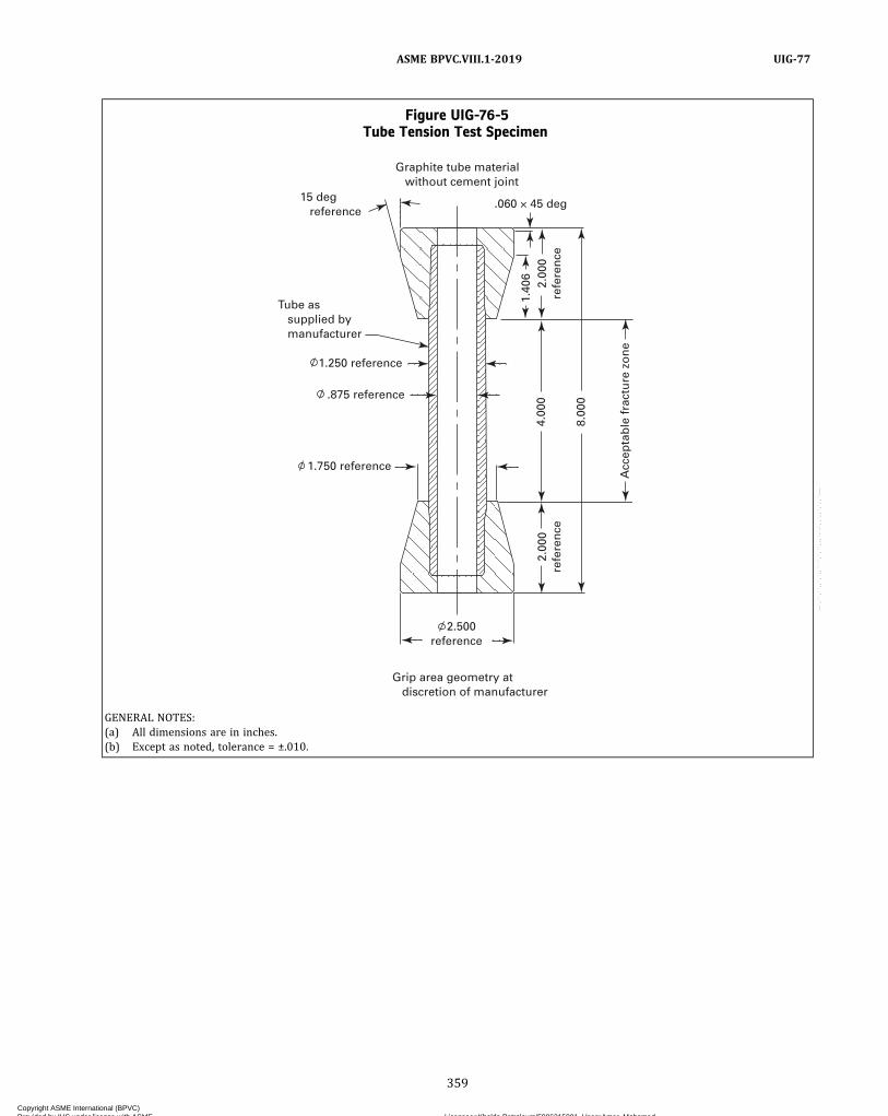
Figure UIG-76-5Tube Tension Test Specimen
15 deg reference
1.250 reference
1.750 reference
.875 reference
Tube as supplied by manufacturer
2.500reference
2.00
0re
fere
nce
2.00
0re
fere
nce
4.00
01.
406
8.00
0
.060 × 45 deg
Graphite tube material without cement joint
Grip area geometry at discretion of manufacturer
Acc
epta
ble
fra
ctu
re z
on
e
GENERAL NOTES:(a) All dimensions are in inches.(b) Except as noted, tolerance = ±.010.
359
ASME BPVC.VIII.1-2019 UIG-77
Copyright ASME International (BPVC) Provided by IHS under license with ASME Licensee=Khalda Petroleum/5986215001, User=Amer, Mohamed
Not for Resale, 07/02/2019 13:29:04 MDTNo reproduction or networking permitted without license from IHS
--`,``,``,,`,`,,````,`,``,,,`-`-`,,`,,`,`,,`---
UIG-78 CERTIFIED CEMENT SPECIFICATION(a) The Manufacturer shall prepare a Certified Cement
Specification (CCS). The CCS shall include the raw materi-als and processes necessary to manufacturer certified ce-ment. The CCS shall include all essential and non‐essentialvariables with tolerance ranges, including shelf life andstorage recommendations.(b) The manufacturer shall qualify the Certified Cement
Specification (CCS) using a Certified Cement QualificationForm (CCQ). The CCQ shall include all essential variablesand the actual test results.(c) Any change to any essential variable, including the
tolerance range, shall require requalification of the CCS.(d) The essential variables to be included in the qualifi-
cation of a CCS are as follows:(1) Cement material data(-a) filler material(-b) resin material(-c) accelerator material
(2) Curing process (i.e., time, temperature)(e) Nonessential variables are those elements that the
Manufacturer may include in the CCS to provide directionin producing certified cement, but that do not affect theresulting properties of the material. Changes to nonessen-tial variables do not require requalification of the CCS.The Certified Cement Specification (CCS) qualification
shall include tensile strength testing at both room andmaximum allowable material temperatures. (See Manda-tory Appendix 37.)
UIG-79 CERTIFIED CEMENTING PROCEDURESPECIFICATION
(a) The Manufacturer shall prepare a Cementing Proce-dure Specification (CPS). The CPS shall include the mate-rials and processes necessary to manufacture items usingcertified material and certified cement. The CPS shall in-clude all essential and non‐essential variables with toler-ance ranges.(b) The Manufacturer shall qualify the Cementing Pro-
cedure Specification using a Cementing Procedure Quali-fication (CPQ). The CPQ shall include all essentialvariables and the actual test results.(c) Any change to any essential variable, including the
tolerance range, shall require requalification of the CPS.(d) The essential variables to be included in the qualifi-
cation of a CPS are as follows:(1) joint design with clearances(2) certified cement specification(3) surface preparation(4) curing time and temperature range
(e) Tests to be included for Certified Cementing Proce-dure Qualification (CPQ) shall include tensile strength(see Mandatory Appendix 37).
UIG-80 CEMENTING TECHNICIANQUALIFICATION
(a) A cementing technician is any individual who is re-sponsible for proper joint preparation, cleaning of partsto be joined, mixing cement, applying cement, securingthe joint during curing, and monitoring the curingprocess.(b) The Manufacturer shall qualify technicians to be
used in fabrication of graphite vessels and parts. TheManufacturer shall document qualification of the techni-cian using a Cementing Technician Qualification (CTQ)form.(c) Tests to be included for Cement Technician Qualifi-
cation shall include four tensile strength tests using speci-mens shown in Figure UIG-76-2.(d) Technicians shall be requalified when they have not
been actively engaged in production of graphite pressurevessels within 6 mo or when there is a reason to questiontheir ability to complete a sound joint.
UIG-81 REPAIR OF MATERIALS(a)Materials may be repaired using qualified proce-
dures, provided that the concurrence of the AuthorizedInspector is first obtained for the method and extent of re-pairs. Defective material that cannot be satisfactorily re-paired shall be rejected.(b) Only certified materials shall be used for repairs,
and such materials shall possess properties that equalor exceed the properties of the material to be repaired.UIG-97 provides relevant rules for methods andstandards.
UIG-84 REQUIRED TESTS(a) The required tests of certified material shall be con-
ducted at the frequency specified in Table UIG-84-1.(b) Block and Compound Material
(1) The tensile strength test defined in MandatoryAppendix 37 and the compressive strength test definedin Mandatory Appendix 38 shall be used to establish thestrength of certified block material.
(2) The test specimens shall be taken in accordancewith Mandatory Appendices 37 and 38.
(3) For each lot of material, the tensile and compres-sive strength values shall be within 20% of the averagevalue determined during the certified material qualifica-tion test.
(4)When the average value of the five specimenstested in accordance with UIG-84 exceeds the minimumvalue permitted for a single specimen, and when the valueof one specimen is below the minimum value permittedfor a single specimen, a retest of five additional specimensshall be made. If the second set fails, the batch is rejected.
(5) The tensile strength and compressive strengthvalues obtained in accordance with UIG-84 shall be equalto or greater than the values listed in Table UIG-6-1.
360
ASME BPVC.VIII.1-2019UIG-78 – UIG-84
Copyright ASME International (BPVC) Provided by IHS under license with ASME Licensee=Khalda Petroleum/5986215001, User=Amer, Mohamed
Not for Resale, 07/02/2019 13:29:04 MDTNo reproduction or networking permitted without license from IHS
--`,``,``,,`,`,,````,`,``,,,`-`-`,,`,,`,`,,`---
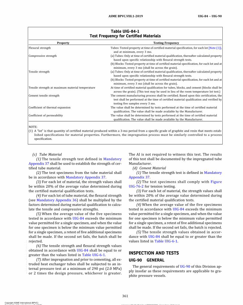
(c) Tube Material(1) The tensile strength test defined in Mandatory
Appendix 37 shall be used to establish the strength of cer-tified tube material.
(2) The test specimens from the tube material shallbe in accordance with Mandatory Appendix 37.
(3) For each lot of material, the strength values shallbe within 20% of the average value determined duringthe certified material qualification tests.
(4) For each lot of tube material, the flexural strength(see Mandatory Appendix 36) shall be multiplied by thefactors determined during material qualification to calcu-late the tensile and compressive strengths.
(5)When the average value of the five specimenstested in accordance with UIG-84 exceeds the minimumvalue permitted for a single specimen, and when the valuefor one specimen is below the minimum value permittedfor a single specimen, a retest of five additional specimensshall be made. If the second set fails, the batch shall berejected.
(6) The tensile strength and flexural strength valuesobtained in accordance with UIG-84 shall be equal to orgreater than the values listed in Table UIG-6-1.
(7) After impregnation and prior to cementing, all ex-truded heat exchanger tubes shall be subjected to an in-ternal pressure test at a minimum of 290 psi (2.0 MPa)or 2 times the design pressure, whichever is greater.
The AI is not required to witness this test. The resultsof this test shall be documented by the impregnated tubeManufacturer.
(d) Cement Material(1) The tensile strength test is defined in Mandatory
Appendix 37.(2) The test specimens shall comply with Figure
UIG-76-2 for tension testing.(3) For each lot of material, the strength values shall
be within 20% of the average value determined duringthe certified material qualification tests.
(4)When the average value of the five specimenstested in accordance with UIG-84 exceeds the minimumvalue permitted for a single specimen, and when the valuefor one specimen is below the minimum value permittedfor a single specimen, a retest of five additional specimensshall be made. If the second set fails, the batch is rejected.
(5) The tensile strength values obtained in accor-dance with UIG-84 shall be equal to or greater than thevalues listed in Table UIG-6-1.
INSPECTION AND TESTS
UIG-90 GENERALThe general requirements of UG-90 of this Division ap-
ply insofar as these requirements are applicable to gra-phite pressure vessels.
Table UIG-84-1Test Frequency for Certified Materials
Property Testing Frequency
Flexural strength Tubes: Tested property at time of certified material specification, for each lot [Note (1)],and at minimum, every 3 mo.
Compressive strength (a) Tubes: Only at time of certified material qualification, thereafter calculated propertybased upon specific relationship with flexural strength tests.
(b) Blocks: Tested property at time of certified material specification, for each lot and atminimum, every 3 mo (shall be across the grain).
Tensile strength (a) Tubes: Only at time of certified material qualification, thereafter calculated propertybased upon specific relationship with flexural strength tests.
(b) Blocks: Tested property at time of certified material specification, for each lot and atminimum, every 3 mo (shall be across the grain).
Tensile strength at maximum material temperature At time of certified material qualification for tubes, blocks, and cement (blocks shall beacross the grain). (This test may be used in lieu of the room temperature lot test.)
Cement tensile strength The cement manufacturing process shall be certified. Based upon this certification, thetest shall be performed at the time of certified material qualification and verified bytesting five samples every 3 mo.
Coefficient of thermal expansion The value shall be determined by tests performed at the time of certified materialqualification. The value shall be made available by the Manufacturer.
Coefficient of permeability The value shall be determined by tests performed at the time of certified materialqualification. The value shall be made available by the Manufacturer.
NOTE:(1) A “lot” is that quantity of certified material produced within a 3‐mo period from a specific grade of graphite and resin that meets estab-
lished specifications for material properties. Furthermore, the impregnation process must be similarly controlled to a processspecification.
361
ASME BPVC.VIII.1-2019 UIG-84 – UIG-90
Copyright ASME International (BPVC) Provided by IHS under license with ASME Licensee=Khalda Petroleum/5986215001, User=Amer, Mohamed
Not for Resale, 07/02/2019 13:29:04 MDTNo reproduction or networking permitted without license from IHS
--`,``,``,,`,`,,````,`,``,,,`-`-`,,`,,`,`,,`---
ð19Þ
UIG-95 VISUAL EXAMINATION(a) Parts, material, finished joints, and completed ves-
sels shall be visually examined by the Manufacturer overthe full surface to detect defects. Surfaces that are acces-sible for visual examination after the vessel is completedneed not be examined before completion of the vessel orvessel parts; however, such examination shall occur priorto the final pressure test.(b) The Manufacturer shall prepare and qualify a writ-
ten procedure that meets the requirements of Section V,Article 9 (Visual Examination). The procedure qualifica-tion shall be subject to and demonstrated to the Author-ized Inspector.(c) The Manufacturer shall designate qualified person-
nel for Visual Examination.(d) All cemented nozzles must be examined to ensure
that cement has flowed around the entire perimeter andthat full penetration through the depth of the joint hasbeen achieved.
UIG-96 QUALIFICATION OF VISUALEXAMINATION PERSONNEL
Personnel who perform the Visual Examinations shallbe qualified and certified for this method in accordancewith a program established by the employer of the per-sonnel being certified, which shall be based on the follow-ing minimum requirements:(a) instruction in the fundamentals of the visual exam-
ination method.(b) on‐the‐job training to familiarize the personnel
with the appearance and interpretation of indications ofdefects. The length of time for such training shall be suffi-cient to ensure adequate assimilation of the knowledgerequired.(c) An eye examination shall be performed per the re-
quirements of Section V, Article 9 to determine near‐distance acuity of personnel to perform the requiredexamination.(d) Upon completion of (a) and (b) above, the person-
nel shall be given an oral or written examination and per-formance examination to determine if the personnel arequalified to perform the required examination and inter-pret the results.(e) Certified personnel whose work has not included
performance of visual examination for a period of 1 yror more shall be re‐certified by completing (a) through(d) above.
UIG-97 ACCEPTANCE STANDARDS ANDDOCUMENTATION
(a) The surface shall be free of any visible laminations,spalling, or cracks. Cracks in tubes shall not be repairedand shall be considered cause for rejection.(b) For tubes, scratches shall not exceed 1/32 in.
(0.8 mm) in depth. For all other material, scratch depthshall not exceed 1/8 in. (3 mm).
(c) Unacceptable discontinuities may be repaired by re-moving the discontinuity in its entirety, and the materialrepaired in accordance with a repair procedure writtenand qualified by the Manufacturer with the concurrenceof the Authorized Inspector. The repair shall neither re-sult in sharp edges nor in the finished thickness being lessthan the minimum design thickness. Cracks and voidsshall not be repaired by adding cement only.(d) The examination shall be documented in accor-
dance with Section V, Article 9, T‐990, Documentation.UIG-81 provides rules for Repair of Material.
UIG-99 PRESSURE TESTSCompleted pressure vessels shall be subjected to a hy-
drostatic test in accordance with the requirements ofUG-99. The lowest ratio for impregnated graphite materi-al for the stress value at the test temperature to the stressvalue at the design temperature shall be taken as 1.0. Theinspection for leaks of all joints and connections shall bemade at a pressure not less than the MAWP.
UIG-112 QUALITY CONTROL REQUIREMENTSThe Manufacturer’s quality control manual shall, in ad-
dition to the provisions of Mandatory Appendix 10, in-clude the following:(a) The Authorized Inspector may, with cause, call for
the requalification of procedures and personnel.(b) The Manufacturer shall include sufficient provision
for material control to ensure that all material is traceableto the manufacturing lot number. The Manufacturer shallmaintain traceability of all materials used in constructionof vessels and vessel parts until such time that the Manu-facturer’s Data Report has been completed and the Certi-fication Mark applied.
UIG-115 MARKINGS AND REPORTSThe provisions of UG-115 through UG-120 shall apply
to complete graphite pressure vessels or parts except asmodified in UIG-116 through UIG-121.
UIG-116 REQUIRED MARKINGS(a) Each graphite pressure vessel and graphite pres-
sure vessel part requiring inspection under this Part shallbe marked in accordance with the requirements ofUG-116 except as modified herein.(b) The type of construction shall be indicated directly
below the Certification Mark and U or PRT Designator byapplying the letter “G” [see UG-116(b)(1)].(c) The stamping may be applied to metallic parts, a
nameplate, or a permanent impression on the graphiteusing cement (see Nonmandatory Appendix MM). Name-plates may be attached to either metallic or graphiteparts.(d) For multiple identical items from a single lot, such
as tubes, the Manufacturer shall apply the partial stamp-ing nameplate to the bundle or container. Each piece shall
362
ASME BPVC.VIII.1-2019UIG-95 – UIG-116
Copyright ASME International (BPVC) Provided by IHS under license with ASME Licensee=Khalda Petroleum/5986215001, User=Amer, Mohamed
Not for Resale, 07/02/2019 13:29:04 MDTNo reproduction or networking permitted without license from IHS
--`,``,``,,`,`,,````,`,``,,,`-`-`,,`,,`,`,,`---

be identified by permanent marking with the Manufac-turer’s name, date, and serial number. (A coded markingsystem with traceability of these data is acceptable.)The subsequent Manufacturer shall maintain the name-plate until all of the multiple pieces have been used, andshall then obliterate the Certification Mark with the Uor PRT Designator from the nameplate. Obliteration ofthe Certification Mark with the U or PRT Designatorstamping shall be witnessed by the Authorized Inspector.
NOTE: Permanent shall mean any method of marking that will en-sure that the marking is present until the item is incorporated intoa completed vessel, and the Authorized Inspector has signed the datareport.
UIG-120 DATA REPORTS(a) Form U-1B, Manufacturer’s Supplementary Data
Report for Graphite Pressure Vessels, shall be completedand certified by the Manufacturer, and shall be signed bythe Authorized Inspector for each graphite pressure ves-sel or part marked with the Certification Mark with the U
or PRT Designator. Form U-1B shall be completed asotherwise required for Data Reports as specified inUG-120.
(b) Form U-1B shall be attached to and referenced onthe applicable Data Report specified in UG-120.
UIG-121 RECORDSThe Manufacturer shall maintain records of the proce-
dures employed in fabricating vessels and vessel partsand in cementing parts together. The Manufacturer shallalso maintain records of the tests and their results bywhich the Procedure Specifications were qualified for fab-rication. The Manufacturer shall maintain the records ofdesign calculations, certified material test reports, visualexamination, the procedure specifications that detail thematerials used, fabrication procedures and quality con-trol records. All records shall be dated and shall be certi-fied by the Manufacturer and made available to theAuthorized Inspector. The Manufacturer shall keep theserecords on file for at least 5 yr after production hasceased.
363
ASME BPVC.VIII.1-2019 UIG-116 – UIG-121
Copyright ASME International (BPVC) Provided by IHS under license with ASME Licensee=Khalda Petroleum/5986215001, User=Amer, Mohamed
Not for Resale, 07/02/2019 13:29:04 MDTNo reproduction or networking permitted without license from IHS
--`,``,``,,`,`,,````,`,``,,,`-`-`,,`,,`,`,,`---

Block
Tensile strength at room temperature Tensile strength at maximum allowable material temperature after 1 hr exposure Flexural strength at room temperature Compressive strength room temperature Coefficient of permeability at room temperature Coefficient of thermal expansion
Tube Material Graphite Compound
Certified material qualification no. _____________________________________________________________________________________
Certified material manufacturer ____________________________________________________________ Date _________________________
Qualification of certified material specification (CMS) no. ________________________________________________________________
Raw material manufacturer ____________________________________________________________________________________________
Material _______________________________________________________________________________________________________
Grade _________________________________________________________________________________________________________
Material _______________________________________________________________________________________________________
GENERAL NOTE: Test program to certify requirements per Table UIG-6-1.
Grade _________________________________________________________________________________________________________
Specification no. _______________________________________________________________________________________________
Impregnation agent manufacturer ______________________________________________________________________________________
NOTES:
(1) All graphite block tensile and compressive samples are tested across grain, and all tube samples are tested with grain.
(2) All test results shall meet the requirements of Table UIG-6-1.
Specification no. _______________________________________________________________________________________________
Materials:
FORM CMQ CERTIFIED MATERIAL QUALIFICATION FORM
(Used in the Construction of Graphite Pressure Vessels)
10 test samples __________ 10 test samples __________ 10 test samples __________
10 test samples __________ 10 test samples __________ 10 test samples __________
10 test samples __________ 10 test samples __________ 10 test samples __________
N/A 10 test samples __________ N/A
10 test samples __________ 10 test samples __________ 10 test samples __________
10 test samples __________ 10 test samples __________ 10 test samples __________
Certified by _____________________________________________________________________________ Date __________________________
(03/09)
364
ASME BPVC.VIII.1-2019UIG-121
Copyright ASME International (BPVC) Provided by IHS under license with ASME Licensee=Khalda Petroleum/5986215001, User=Amer, Mohamed
Not for Resale, 07/02/2019 13:29:04 MDTNo reproduction or networking permitted without license from IHS
--`,``,``,,`,`,,````,`,``,,,`-`-`,,`,,`,`,,`---

Flexural Strength, psi (MPa)
FORM CMQ CERTIFIED MATERIAL QUALIFICATION FORM
(Used in the Construction of Graphite Pressure Vessels) (Cont’d)
TEST PROCEDURES AND RESULTS
(a) Flexural strength: See the test method for determining the flexural strength of certified materials using three point loading in Mandatory Appendix 36 (tube). 1. Test performed at _________________________________________________________________________________________________ By ___________________________________________________________ Date ________________________________
Sample No.
1
2
3
4
5
6
7
8
9
10
Average value
Test deviation in % from average value
Permissible deviation
UIG-6, minimum value, psi (MPa)
±20%
5,700 (39.3)
Tube Material
(03/09)
365
ASME BPVC.VIII.1-2019 UIG-121
Copyright ASME International (BPVC) Provided by IHS under license with ASME Licensee=Khalda Petroleum/5986215001, User=Amer, Mohamed
Not for Resale, 07/02/2019 13:29:04 MDTNo reproduction or networking permitted without license from IHS
--`,``,``,,`,`,,````,`,``,,,`-`-`,,`,,`,`,,`---

Tensile Strength, psi (MPa)
FORM CMQ CERTIFIED MATERIAL QUALIFICATION FORM
(Used in the Construction of Graphite Pressure Vessels) (Cont’d)
(b) Tensile Strength: See test method in Mandatory Appendix 37. (1) Fig. UIG-76-1 Block Fig. UIG-76-5 Tubes (2) Test Performed at _________________________________________________________________________________________________ By ___________________________________________________________ Date ________________________________
Sample No.
1
2
3
4
5
6
7
8
9
10
Average value
Test deviation in % from average value
Permissible deviation
UIG-6, minimum value, psi (MPa)
Tube
Room Temperature Maximum Material Temperature
Compound Block Tube Compound Block
±20%
2,000 (13.8)
±20%
3,800 (26.2)
±20%
1,500 (10.3)
±20%
900 (6.2)
±20%
1,600 (11.0)
±20%
3,000 (20.7)
(07/15)
366
ASME BPVC.VIII.1-2019UIG-121
Copyright ASME International (BPVC) Provided by IHS under license with ASME Licensee=Khalda Petroleum/5986215001, User=Amer, Mohamed
Not for Resale, 07/02/2019 13:29:04 MDTNo reproduction or networking permitted without license from IHS
--`,``,``,,`,`,,````,`,``,,,`-`-`,,`,,`,`,,`---

(c) Compressive Strength: See Mandatory Appendix 38 for determining the compressive strength of certified materials. (1) Test performed at _________________________________________________________________________________________________ By _________________________________________________________________________ Date _________________
Compressive Strength, psi (MPa)
Sample No.
1
2
3
4
5
6
7
8
9
10
Average value
Test deviation in % from average value
Permissible deviation
UIG-6, minimum value, psi (MPa)
Block Material Tube Material Graphite Compound Material
±20%
6,500 (45)
±20%
10,000 (69)
±20%
4,500 (31)
FORM CMQ CERTIFIED MATERIAL QUALIFICATION FORM
(Used in the Construction of Graphite Pressure Vessels) (Cont’d)
(03/09)
367
ASME BPVC.VIII.1-2019 UIG-121
Copyright ASME International (BPVC) Provided by IHS under license with ASME Licensee=Khalda Petroleum/5986215001, User=Amer, Mohamed
Not for Resale, 07/02/2019 13:29:04 MDTNo reproduction or networking permitted without license from IHS
--`,``,``,,`,`,,````,`,``,,,`-`-`,,`,,`,`,,`---

(d) Coefficient of Permeability: See Mandatory Appendix 39 for determining the coefficient of permeability of certified materials. (1) Test performed at ________________________________________________________________________________________________ By _________________________________________________________________________ Date _________________
Permeation Rate in in.2/sec (mm2/s)
Sample No.
1
2
3
4
5
6
7
8
9
10
UIG-6, maximum value, psi (MPa)
Block Tube Material Graphite Compound Material
4.5 × 10⁻⁶ in.2/sec (2.90 × 10⁻³ mm2/s)
4.5 × 10⁻⁶ in.2/sec (2.90 × 10⁻³ mm2/s)
4.5 × 10⁻⁶ in.2/sec (2.90 × 10⁻³ mm2/s)
FORM CMQ CERTIFIED MATERIAL QUALIFICATION FORM
(Used in the Construction of Graphite Pressure Vessels) (Cont’d)
(03/09)
368
ASME BPVC.VIII.1-2019UIG-121
Copyright ASME International (BPVC) Provided by IHS under license with ASME Licensee=Khalda Petroleum/5986215001, User=Amer, Mohamed
Not for Resale, 07/02/2019 13:29:04 MDTNo reproduction or networking permitted without license from IHS
--`,``,``,,`,`,,````,`,``,,,`-`-`,,`,,`,`,,`---

Coefficient of Thermal Expansion (in./in./°F)
(e) Coefficient of Linear Thermal Expansion: The test method for determining the coefficient of linear thermal expansion is described in Mandatory Appendix 40. (1) Test temperature: room temperature to 300ºF (149ºC) (2) Test performed at _________________________________________________________________________________________________ By _________________________________________________________________________ Date _________________
Sample No.
1
2
3
4
5
6
7
8
9
10
Block Material Tube Material Graphite Compound Material
FORM CMQ CERTIFIED MATERIAL QUALIFICATION FORM
(Used in the Construction of Graphite Pressure Vessels) (Cont’d)
(03/09)
369
ASME BPVC.VIII.1-2019 1-1
Copyright ASME International (BPVC) Provided by IHS under license with ASME Licensee=Khalda Petroleum/5986215001, User=Amer, Mohamed
Not for Resale, 07/02/2019 13:29:04 MDTNo reproduction or networking permitted without license from IHS
--`,``,``,,`,`,,````,`,``,,,`-`-`,,`,,`,`,,`---

Record of Qualification Results
CMS no. _____________________________________________________________________________________________________________
CMQ no. _____________________________________________________________________________________________________________
(1) Physical properties at room temperature:
Physical Properties Value
Flexural strength, tube psi (MPa)
Flexural strength, graphite compound psi (MPa)
Tensile strength, block psi (MPa)
Tensile strength, tube psi (MPa)
Tensile strength, graphite compound psi (MPa)
Compressive strength, block psi (MPa)
Compressive strength, tube psi (MPa)
Compressive strength, graphite compound psi (MPa)
Coefficient of permeability in.2/sec (mm2/s)
Coefficient of thermal expansion in./in./ºF (mm/mm/ºC)
(2) Maximum material temperature for this certified material __________________
(3) Decrease in tensile strength over temperature range:
The tensile strength decrease shall be considered linear between room temperature and the maximum material temperature.
For this certified material the decrease is __________% per each 10ºF (ºC) rise above room temperature.
(4) Strength relationship between tensile, flexural, and compressive strength:
Flexural strength _______________ psi (MPa) (tubes only)
Tensile strength _______________ psi (MPa)
Compressive strength ___________ psi (MPa)
(5) Correlation factors: Flexural strength / tensile strength __________________________________________
(Tubes only) Flexural strength / compressive strength ____________________________________
FORM CMQ CERTIFIED MATERIAL QUALIFICATION FORM
(Used in the Construction of Graphite Pressure Vessels) (Cont’d)
(03/09)
370
ASME BPVC.VIII.1-2019UIG-121
Copyright ASME International (BPVC) Provided by IHS under license with ASME Licensee=Khalda Petroleum/5986215001, User=Amer, Mohamed
Not for Resale, 07/02/2019 13:29:04 MDTNo reproduction or networking permitted without license from IHS
--`,``,``,,`,`,,````,`,``,,,`-`-`,,`,,`,`,,`---

Certified cement qualification (CCQ) no.
Qualification of certified material specification (CCS) no.
Cementing technician
Manufacturer
Designation
Joint configuration
Cement:
FORM CCQ CERTIFIED CEMENT QUALIFICATION FORM
(Used in the Construction of Graphite Pressure Vessels)
(Date) (Mark or Symbol No.) (Name)
(Date) (Mark or Symbol No.) (Name)
Tested Tensile Strength, psi (MPa)
Sample No.
1
2
3
4
5
6
7
8
9
10
Average, psi (MPa)
Test deviation in % from average value
Permissible deviation
UIG-6, minimum value, psi (MPa)
At Room Temperature At Maximum Material Temperature
±20%
1,500 (10.3)
±20%
900 (6.2)
Testing:
(a) Test results shall meet the requirements of Table UIG-6-1. (b) The qualification results shall be recorded.
BLOCK JOINT Fig. UIG-76-2 (10 samples)
(Drawing #)
(07/15)
Certified by Date
371
ASME BPVC.VIII.1-2019 UIG-121
Copyright ASME International (BPVC) Provided by IHS under license with ASME Licensee=Khalda Petroleum/5986215001, User=Amer, Mohamed
Not for Resale, 07/02/2019 13:29:04 MDTNo reproduction or networking permitted without license from IHS
--`,``,``,,`,`,,````,`,``,,,`-`-`,,`,,`,`,,`---

FORM CCQ CERTIFIED CEMENT QUALIFICATION FORM (Cont’d)
Essential Variables:
Composition (% by weight)
Material
Curing conditions
Resin Accelerator Filler Material
_______________________ minutes @ _______________________ ºF (ºC)
(07/17)
372
ASME BPVC.VIII.1-2019UIG-121
Copyright ASME International (BPVC) Provided by IHS under license with ASME Licensee=Khalda Petroleum/5986215001, User=Amer, Mohamed
Not for Resale, 07/02/2019 13:29:04 MDTNo reproduction or networking permitted without license from IHS
--`,``,``,,`,`,,````,`,``,,,`-`-`,,`,,`,`,,`---
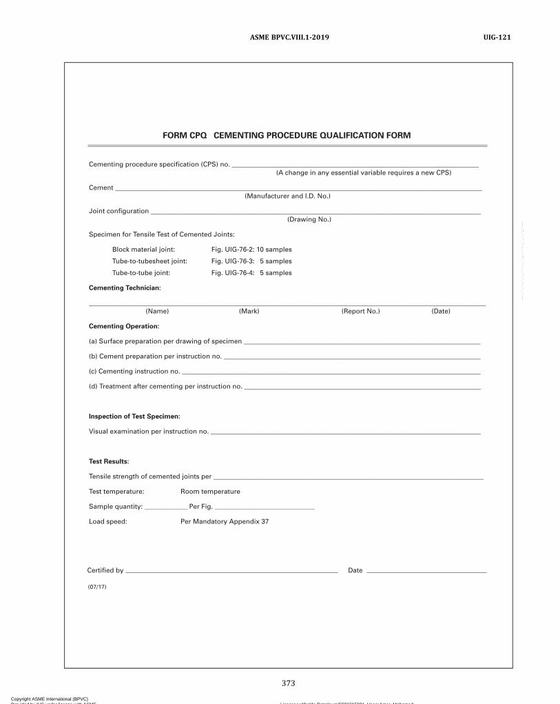
Cementing procedure specification (CPS) no. __________________________________________________________________________ (A change in any essential variable requires a new CPS)
Cement ______________________________________________________________________________________________________________ (Manufacturer and I.D. No.)
Joint configuration ___________________________________________________________________________________________________ (Drawing No.)
Specimen for Tensile Test of Cemented Joints:
Block material joint: Fig. UIG-76-2: 10 samples
Tube-to-tubesheet joint: Fig. UIG-76-3: 5 samples
Tube-to-tube joint: Fig. UIG-76-4: 5 samples
Cementing Technician:
_______________________________________________________________________________________________________________________ (Name) (Mark) (Report No.) (Date)
Cementing Operation:
(a) Surface preparation per drawing of specimen _______________________________________________________________________
(b) Cement preparation per instruction no. _____________________________________________________________________________
(c) Cementing instruction no. __________________________________________________________________________________________
(d) Treatment after cementing per instruction no. _______________________________________________________________________
Inspection of Test Specimen:
Visual examination per instruction no. _________________________________________________________________________________
Test Results:
Tensile strength of cemented joints per _________________________________________________________________________________
Test temperature: Room temperature
Sample quantity: _____________ Per Fig. ______________________________
Load speed: Per Mandatory Appendix 37
FORM CPQ CEMENTING PROCEDURE QUALIFICATION FORM
(07/17)
Certified by Date
373
ASME BPVC.VIII.1-2019 UIG-121
Copyright ASME International (BPVC) Provided by IHS under license with ASME Licensee=Khalda Petroleum/5986215001, User=Amer, Mohamed
Not for Resale, 07/02/2019 13:29:04 MDTNo reproduction or networking permitted without license from IHS
--`,``,``,,`,`,,````,`,``,,,`-`-`,,`,,`,`,,`---
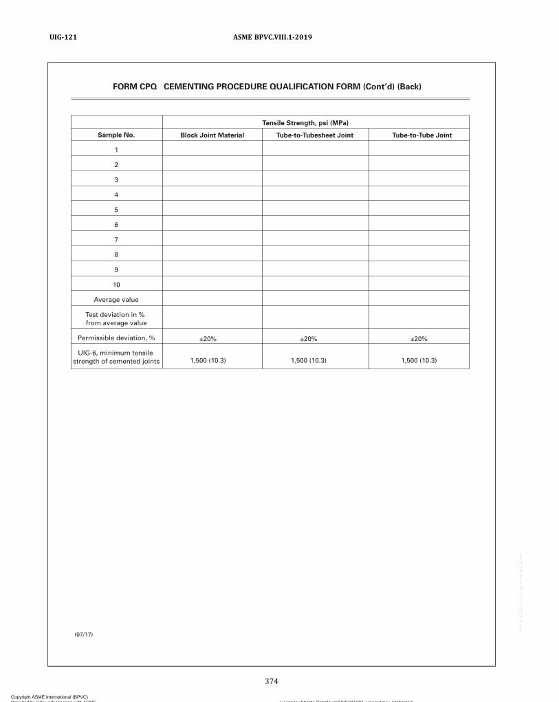
Tensile Strength, psi (MPa)
Sample No.
1
2
3
4
5
6
7
8
9
10
Average value
Test deviation in % from average value
Permissible deviation, %
UIG-6, minimum tensile strength of cemented joints
±20%
1,500 (10.3)
±20%
1,500 (10.3)
±20%
1,500 (10.3)
Tube-to-Tubesheet Joint Tube-to-Tube JointBlock Joint Material
FORM CPQ CEMENTING PROCEDURE QUALIFICATION FORM (Cont’d) (Back)
(07/17)
374
ASME BPVC.VIII.1-2019UIG-121
Copyright ASME International (BPVC) Provided by IHS under license with ASME Licensee=Khalda Petroleum/5986215001, User=Amer, Mohamed
Not for Resale, 07/02/2019 13:29:04 MDTNo reproduction or networking permitted without license from IHS
--`,``,``,,`,`,,````,`,``,,,`-`-`,,`,,`,`,,`---

FORM CTQ CEMENTING TECHNICIAN QUALIFICATION FORM
(Used in Cementing Parts of Graphite Pressure Vessels)
Name of technician __________________________________________________________________________________________________
Cementing procedure specification (CPS) no. __________________________________________________________________________
Tensile Strength, psi (MPa)
1,500 psi (10.3 MPa) (See Fig. UIG-76-2)
Sample No.
1
2
3
4
UIG-6, minimum value
Test report no. _______________________________________________________________________________________________________
We certify that the statements made in this report are correct:
Date __________________________________ Signed _________________________________________________________________ (Manufacturer’s representative)
(03/09)
375
ASME BPVC.VIII.1-2019 UIG-121
Copyright ASME International (BPVC) Provided by IHS under license with ASME Licensee=Khalda Petroleum/5986215001, User=Amer, Mohamed
Not for Resale, 07/02/2019 13:29:04 MDTNo reproduction or networking permitted without license from IHS
--`,``,``,,`,`,,````,`,``,,,`-`-`,,`,,`,`,,`---

MANDATORY APPENDIX 1SUPPLEMENTARY DESIGN FORMULAS
1-1 THICKNESS OF CYLINDRICAL ANDSPHERICAL SHELLS
The following equations, in terms of the outside radius,are equivalent to and may be used instead of those givenin UG-27(c) and UG-27(d):(a) For cylindrical shells (circumferential stress),
ð1Þ
where
Ro = outs ide radius of the she l l course underconsideration
(b) For spherical shells,
ð2Þ
Other symbols are as defined in UG-27.
1-2 CYLINDRICAL SHELLS
(a) Circumferential Stress (Longitudinal Joints). Whenthe thickness of the cylindrical shell under internal designpressure exceeds one‐half of the inside radius, or when Pexceeds 0.385SE, the following equations shall apply. Thefollowing equations may be used in lieu of those given inUG-27(c):When P is known and t is desired,
ð1Þ
Where t is known and P is desired,
ð2Þ
(b) Longitudinal Stress (Circumferential Joints). Whenthe thickness of the cylindrical shell under internal designpressure exceeds one‐half of the inside radius, or when Pexceeds 1.25SE, the following equations shall apply:When P is known and t is desired,
ð3Þ
where
Z =
When t is known and P is desired,
ð4Þ
where
Z =
Symbols are as defined in UG-27 and 1-1.
1-3 SPHERICAL SHELLS
When the thickness of the shell of a wholly sphericalvessel or of a hemispherical head under internal designpressure exceeds 0.356R, or when P exceeds 0.665SE,the following equations shall apply. The following equa-tions may be used in lieu of those given in UG-27(d).When P is known and t is desired,
ð1Þ
When t is known and P is desired,
ð2Þ
Symbols are as defined in UG-27 and 1-1.
1-4 FORMULAS FOR THE DESIGN OFFORMED HEADS UNDER INTERNALPRESSURE
(a) The equations of this paragraph provide for the de-sign of formed heads of proportions other than those giv-en in UG-32, in terms of inside and outside diameter.
ASME BPVC.VIII.1-20191-1 – 1-4
376
Copyright ASME International (BPVC) Provided by IHS under license with ASME Licensee=Khalda Petroleum/5986215001, User=Amer, Mohamed
Not for Resale, 07/02/2019 13:29:04 MDTNo reproduction or networking permitted without license from IHS
--`,``,``,,`,`,,````,`,``,,,`-`-`,,`,,`,`,,`---
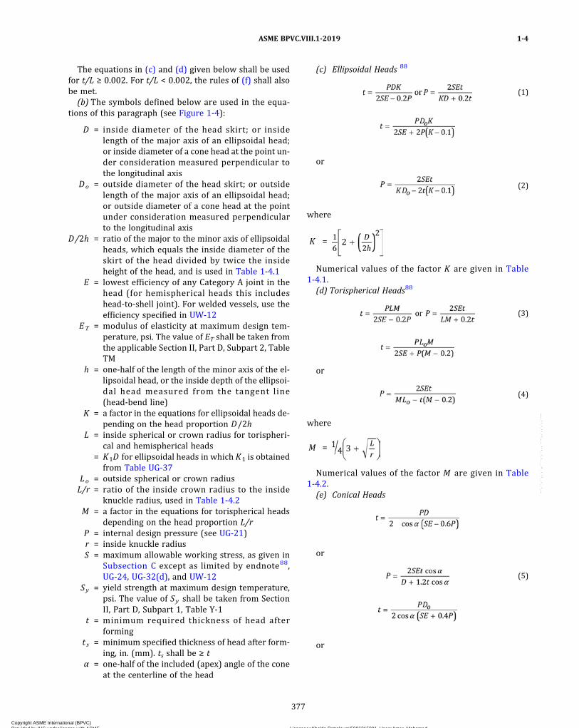
The equations in (c) and (d) given below shall be usedfor t/L ≥ 0.002. For t/L < 0.002, the rules of (f) shall alsobe met.
(b) The symbols defined below are used in the equa-tions of this paragraph (see Figure 1-4):
D = inside diameter of the head skirt; or insidelength of the major axis of an ellipsoidal head;or inside diameter of a cone head at the point un-der consideration measured perpendicular tothe longitudinal axis
Do = outside diameter of the head skirt; or outsidelength of the major axis of an ellipsoidal head;or outside diameter of a cone head at the pointunder consideration measured perpendicularto the longitudinal axis
D/2h = ratio of the major to the minor axis of ellipsoidalheads, which equals the inside diameter of theskirt of the head divided by twice the insideheight of the head, and is used in Table 1-4.1
E = lowest efficiency of any Category A joint in thehead (for hemispherical heads this includeshead‐to‐shell joint). For welded vessels, use theefficiency specified in UW-12
ET = modulus of elasticity at maximum design tem-perature, psi. The value of ET shall be taken fromthe applicable Section II, Part D, Subpart 2, TableTM
h = one‐half of the length of the minor axis of the el-lipsoidal head, or the inside depth of the ellipsoi-dal head measured from the tangent line(head‐bend line)
K = a factor in the equations for ellipsoidal heads de-pending on the head proportion D/2h
L = inside spherical or crown radius for torispheri-cal and hemispherical heads
= K1D for ellipsoidal heads in which K1 is obtainedfrom Table UG-37
Lo = outside spherical or crown radiusL/r = ratio of the inside crown radius to the inside
knuckle radius, used in Table 1-4.2M = a factor in the equations for torispherical heads
depending on the head proportion L/rP = internal design pressure (see UG-21)r = inside knuckle radiusS = maximum allowable working stress, as given in
Subsection C except as limited by endnote88,UG-24, UG-32(d), and UW-12
Sy = yield strength at maximum design temperature,psi. The value of Sy shall be taken from SectionII, Part D, Subpart 1, Table Y-1
t = minimum required thickness of head afterforming
t s = minimum specified thickness of head after form-ing, in. (mm). ts shall be ≥ t
α = one‐half of the included (apex) angle of the coneat the centerline of the head
(c) Ellipsoidal Heads 88
ð1Þ
or
ð2Þ
where
K =
Numerical values of the factor K are given in Table1-4.1.
(d) Torispherical Heads88
ð3Þ
or
ð4Þ
where
M =
Numerical values of the factor M are given in Table1-4.2.
(e) Conical Heads
or
ð5Þ
or
ASME BPVC.VIII.1-2019 1-4
377
Copyright ASME International (BPVC) Provided by IHS under license with ASME Licensee=Khalda Petroleum/5986215001, User=Amer, Mohamed
Not for Resale, 07/02/2019 13:29:04 MDTNo reproduction or networking permitted without license from IHS
--`,``,``,,`,`,,````,`,``,,,`-`-`,,`,,`,`,,`---

ð6Þ
(f) Design of Heads With ts/L < 0.002. The followingrules shall be used when the maximum design tempera-ture is less than or equal to the temperature limit givenin Table 1-4.3. See U-2(g) for maximum design tempera-ture exceeding the temperature limit given in Table 1-4.3
(1) Torispherical Heads With ts/L < 0.002. The mini-mum required thickness of a torispherical head having0.0005 ≤ ts/L < 0.002 shall be larger of the thickness cal-culated by the equations in UG-32(d) or in (d) above, orby the equations given below.
(-a) Calculate a coefficient, C1.
(-b) Calculate the elastic buckling stress, Se .
(-c) Calculate a coefficient, C2.
Figure 1-4Principal Dimensions of Typical Heads
Table 1-4.1Values of Factor K
D/2h 3.0 2.9 2.8 2.7 2.6 2.5 2.4 2.3 2.2 2.1 2.0K 1.83 1.73 1.64 1.55 1.46 1.37 1.29 1.21 1.14 1.07 1.00
D/2h 1.9 1.8 1.7 1.6 1.5 1.4 1.3 1.2 1.1 1.0 …K 0.93 0.87 0.81 0.76 0.71 0.66 0.61 0.57 0.53 0.50 …
GENERAL NOTE: Use nearest value of D/2h ; interpolation unnecessary.
ASME BPVC.VIII.1-20191-4
378
Copyright ASME International (BPVC) Provided by IHS under license with ASME Licensee=Khalda Petroleum/5986215001, User=Amer, Mohamed
Not for Resale, 07/02/2019 13:29:04 MDTNo reproduction or networking permitted without license from IHS
--`,``,``,,`,`,,````,`,``,,,`-`-`,,`,,`,`,,`---
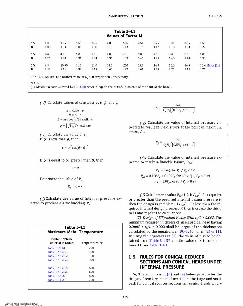
(-d) Calculate values of constants a , b , β , and ϕ .
(-e) Calculate the value of c .If ϕ is less than β , then
If ϕ is equal to or greater than β , then
Determine the value of Re.
(-f)Calculate the value of internal pressure ex-pected to produce elastic buckling, Pe .
(-g) Calculate the value of internal pressure ex-pected to result in yield stress at the point of maximumstress, Py .
(-h) Calculate the value of internal pressure ex-pected to result in knuckle failure, Pck .
(-i)Calculate the value Pck/1.5. If Pck/1.5 is equal toor greater than the required internal design pressure P,then the design is complete. If Pck/1.5 is less than the re-quired internal design pressure P, then increase the thick-ness and repeat the calculations.
(2) Design of Ellipsoidal Heads With ts/L < 0.002. Theminimum required thickness of an ellipsoidal head having0.0005 ≤ ts/L < 0.002 shall be larger of the thicknessescalculated by the equations in UG-32(c), or in (c) or (1).In using the equations in (1), the value of L is to be ob-tained from Table UG-37 and the value of r is to be ob-tained from Table 1-4.4.
1-5 RULES FOR CONICAL REDUCERSECTIONS AND CONICAL HEADS UNDERINTERNAL PRESSURE
(a) The equations of (d) and (e) below provide for thedesign of reinforcement, if needed, at the large and smallends for conical reducer sections and conical heads where
Table 1-4.2Values of Factor M
L/r 1.0 1.25 1.50 1.75 2.00 2.25 2.50 2.75 3.00 3.25 3.50M 1.00 1.03 1.06 1.08 1.10 1.13 1.15 1.17 1.18 1.20 1.22
L/r 4.0 4.5 5.0 5.5 6.0 6.5 7.0 7.5 8.0 8.5 9.0M 1.25 1.28 1.31 1.34 1.36 1.39 1.41 1.44 1.46 1.48 1.50
L/r 9.5 10.00 10.5 11.0 11.5 12.0 13.0 14.0 15.0 16.0 162/3 [Note (1)]M 1.52 1.54 1.56 1.58 1.60 1.62 1.65 1.69 1.72 1.75 1.77
GENERAL NOTE: Use nearest value of L/r ; interpolation unnecessary.
NOTE:(1) Maximum ratio allowed by UG-32(i) when L equals the outside diameter of the skirt of the head.
Table 1-4.3Maximum Metal Temperature
Table in WhichMaterial Is Listed Temperature, °F
Table UCS-23 700Table UNF-23.1 300Table UNF-23.2 150Table UNF-23.3 900
Table UNF-23.4 600Table UNF-23.5 600Table UHA-23 800Table UHT-23 700
ASME BPVC.VIII.1-2019 1-4 – 1-5
379
Copyright ASME International (BPVC) Provided by IHS under license with ASME Licensee=Khalda Petroleum/5986215001, User=Amer, Mohamed
Not for Resale, 07/02/2019 13:29:04 MDTNo reproduction or networking permitted without license from IHS
--`,``,``,,`,`,,````,`,``,,,`-`-`,,`,,`,`,,`---

all the elements have a common axis and the half‐apex an-gle α ≤ 30 deg. Subparagraph (g) below provides for spe-c ia l analys is in the design of cone ‐ to ‐cyl inderintersections with or without reinforcing rings where αis greater than 30 deg.In the design of reinforcement at the large and small
ends of cones and conical reducers, the requirements ofUG-41 shall be met.(b) Nomenclature
AeL = effective area of reinforcement at large endintersection
Aes = effective area of reinforcement at small endintersection
ArL = required area of reinforcement at large end ofcone
Ars = required area of reinforcement at small end ofcone
E1 = efficiency of longitudinal joint in cylinder. Forcompression (such as at large end of cone), E1 =1.0 for butt welds.
E2 = efficiency of longitudinal joint in cone. For com-pression, E2 = 1.0 for butt welds.
Ec = modulus of elasticity of cone materialEr = modulus of elasticity of reinforcing ring materialEs = modulus of elasticity of cylinder materialf1 = axial load per unit circumference at large end due
to wind, dead load, etc., excluding pressuref2 = axial load per unit circumference at small end due
to wind, dead load, etc., excluding pressureP = internal design pressure (see UG-21)
QL = algebraical sum of PRL/2 and f1Qs = algebraical sum of PRs/2 and f2RL = inside radius of large cylinder at large end of coneRs = inside radius of small cylinder at small end of coneSc = allowable stress of cone material at design
temperature
Sr = allowable stress of reinforcing ring material at de-sign temperature
Ss = allowable stress of cylinder material at designtemperature
t = minimum required thickness of cylinder at cone‐to‐cylinder junction
tc = nominal thickness of cone at cone‐to‐cylinderjunction
t r = minimum required thickness of cone at cone‐to‐cylinder junction
t s = nominal thickness of cylinder at cone‐to‐cylinderjunction
y = cone‐to‐cylinder factor= SsEs for reinforcing ring on shell= ScEc for reinforcing ring on cone
Δ = angle indicating need for reinforcement at cone‐to‐cylinder junction having a half‐apex angle α ≤30 deg. When Δ ≥ α , no reinforcement is requiredat the junction (see Tables 1-5.1 and 1-5.2), deg.
α = half‐apex angle of cone or conical section, deg.
(c) For conical reducers and conical heads, the follow-ing values shall be determined at large end and again atthe small end in order that both the large end and thesmall end can be examined:
(1)When a cylinder having a minimum length of
2.0 is attached to the large end of the cone, deter-
mine P/SsE1 and then determine Δ at the large end fromTable 1-5.1.
NOTE: If a cylinder is not present or does not meet the minimumlength requirement, Δ is not calculated.
(2)When a cylinder having a minimum length of
1.4 is attached to the small end of the cone, deter-
mine P/SSE1 and then determine Δ at the small end fromTable 1-5.2.
(3) Determine k:
k = 1 when additional area of reinforcement is notrequired
= y/SrEr when a stiffening ring is required, but k is notless than 1.0
(d) Reinforcement shall be provided at the large end ofthe cone when required by the following:
Table 1-4.4Values of Knuckle Radius, r
D/2h r/D
3.0 0.102.8 0.112.6 0.122.4 0.132.2 0.15
2.0 0.171.8 0.201.6 0.241.4 0.291.2 0.371.0 0.50
GENERAL NOTE: Interpolationpermitted for intermediate values.
Table 1-5.1Values of Δ for Junctions at the Large
Cylinder for α ≤ 30 deg
P/SsE1 0.001 0.002 0.003 0.004 0.005Δ, deg 11 15 18 21 23
P/SsE1 0.006 0.007 0.008 0.009 [Note (1)] …Δ, deg 25 27 28.5 30 …
NOTE:(1) Δ = 30 deg for greater values of P/SsE1.
ASME BPVC.VIII.1-20191-5
380
Copyright ASME International (BPVC) Provided by IHS under license with ASME Licensee=Khalda Petroleum/5986215001, User=Amer, Mohamed
Not for Resale, 07/02/2019 13:29:04 MDTNo reproduction or networking permitted without license from IHS
--`,``,``,,`,`,,````,`,``,,,`-`-`,,`,,`,`,,`---
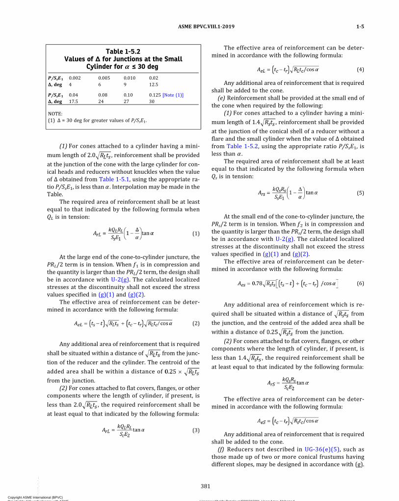
(1) For cones attached to a cylinder having a mini-
mum length of 2.0 , reinforcement shall be provided
at the junction of the cone with the large cylinder for con-ical heads and reducers without knuckles when the valueof Δ obtained from Table 1-5.1, using the appropriate ra-tio P/SsE1, is less than α . Interpolation may be made in theTable.
The required area of reinforcement shall be at leastequal to that indicated by the following formula whenQL is in tension:
ð1Þ
At the large end of the cone‐to‐cylinder juncture, thePRL/2 term is in tension. When f1 is in compression andthe quantity is larger than the PRL/2 term, the design shallbe in accordance with U-2(g). The calculated localizedstresses at the discontinuity shall not exceed the stressvalues specified in (g)(1) and (g)(2).
The effective area of reinforcement can be deter-mined in accordance with the following formula:
ð2Þ
Any additional area of reinforcement that is required
shall be situated within a distance of from the junc-
tion of the reducer and the cylinder. The centroid of the
added area shall be within a distance of
from the junction.(2) For cones attached to flat covers, flanges, or other
components where the length of cylinder, if present, is
less than 2.0 , the required reinforcement shall be
at least equal to that indicated by the following formula:
ð3Þ
The effective area of reinforcement can be deter-mined in accordance with the following formula:
ð4Þ
Any additional area of reinforcement that is requiredshall be added to the cone.
(e) Reinforcement shall be provided at the small end ofthe cone when required by the following:
(1) For cones attached to a cylinder having a mini-
mum length of 1.4 , reinforcement shall be provided
at the junction of the conical shell of a reducer without aflare and the small cylinder when the value of Δ obtainedfrom Table 1-5.2, using the appropriate ratio P/SsE1, isless than α .
The required area of reinforcement shall be at leastequal to that indicated by the following formula whenQs is in tension:
ð5Þ
At the small end of the cone‐to‐cylinder juncture, thePRs/2 term is in tension. When f2 is in compression andthe quantity is larger than the PRs/2 term, the design shallbe in accordance with U-2(g). The calculated localizedstresses at the discontinuity shall not exceed the stressvalues specified in (g)(1) and (g)(2).
The effective area of reinforcement can be deter-mined in accordance with the following formula:
ð6Þ
Any additional area of reinforcement which is re-
quired shall be situated within a distance of from
the junction, and the centroid of the added area shall be
within a distance of from the junction.
(2) For cones attached to flat covers, flanges, or othercomponents where the length of cylinder, if present, is
less than 1.4 , the required reinforcement shall be
at least equal to that indicated by the following formula:
The effective area of reinforcement can be deter-mined in accordance with the following formula:
Any additional area of reinforcement that is requiredshall be added to the cone.
(f) Reducers not described in UG-36(e)(5), such asthose made up of two or more conical frustums havingdifferent slopes, may be designed in accordance with (g).
Table 1-5.2Values of Δ for Junctions at the Small
Cylinder for α ≤ 30 deg
P/SsE1 0.002 0.005 0.010 0.02Δ, deg 4 6 9 12.5
P/SsE1 0.04 0.08 0.10 0.125 [Note (1)]Δ, deg 17.5 24 27 30
NOTE:(1) Δ = 30 deg for greater values of P/SsE1.
ASME BPVC.VIII.1-2019 1-5
381
Copyright ASME International (BPVC) Provided by IHS under license with ASME Licensee=Khalda Petroleum/5986215001, User=Amer, Mohamed
Not for Resale, 07/02/2019 13:29:04 MDTNo reproduction or networking permitted without license from IHS
--`,``,``,,`,`,,````,`,``,,,`-`-`,,`,,`,`,,`---

(g)When the half‐apex angle α is greater than 30 deg(0.52 rad), cone‐to‐cylinder junctions without a knucklemay be used, with or without reinforcing rings, if the de-sign is based on special analysis, such as the beam‐on‐elastic‐foundation analysis of Timoshenko, Hetenyi, orWatts and Lang. See U-2(g). When such an analysis ismade, the calculated localized stresses at the discontinu-ity shall not exceed the following values:
(1)Membrane hoop stress plus average discontinu-ity hoop stress shall not be greater than 1.5S, where the“average discontinuity hoop stress” is the average hoopstress across the wall thickness due to the discontinuityat the junction, disregarding the effect of Poisson’s ratiotimes the longitudinal stress at the surfaces.
(2)Membrane longitudinal stress plus discontinuitylongitudinal stress due to bending shall not be greaterthan SPS [see UG-23(e)].The angle joint (see 3-2) between the cone and cylinder
shall be designed equivalent to a double butt‐weldedjoint, and because of the high bending stress, there shallbe no weak zones around the angle joint. The thicknessof the cylinder may have to be increased to limit the dif-ference in thickness so that the angle joint has a smoothcontour.
1-6 DISHED COVERS (BOLTED HEADS)
(a) Dished heads with bolting flanges, both concave andconvex to the pressure and conforming to the severaltypes illustrated in Figure 1-6, shall be designed in accor-dance with the equations which follow.(b) The symbols used in the equations of this paragraph
are defined as follows:
A = outside diameter of flangeB = inside diameter of flangeC = bolt circle, diameterL = inside spherical or crown radius
Mo = the total moment determined as in 2-6 for headsconcave to pressure and 2-11 for heads convex topressure; except that for heads of the type shownin Figure 1-6, sketch (d), HD and hD shall be as de-fined below, and an additional moment Hrhr (whichmay add or subtract) shall be included where
HD = axial component of the membrane load inthe spherical segment acting at the insideof the flange ring
= 0.785 B2PhD = radial distance from the bolt circle to the in-
side of the flange ringHr = radial component of the membrane load in
the spherical segment acting at the intersec-tion of the inside of the flange ring with thecenterline of the dished cover thickness
= HD cot β1
hr = lever arm of force Hr about centroid of flangering
β1 = angle formed by the tangent to the center‐line of the dished cover thickness at its pointof intersection with the flange ring, and aline perpendicular to the axis of the dishedcover
= arc sin
NOTE: Since Hrhr in some cases will subtract from the totalmoment, the moment in the flange ring when the internalpressure is zero may be the determining loading for flangedesign.
P = internal pressure (see UG-21) for the pressure onconcave side, and external pressure for the pres-sure on convex side [see UG-28(f)]
r = inside knuckle radiusS = maximum allowable stress value (see UG-23)T = flange thicknesst = minimum required thickness of head plate after
forming
(c) It is important to note that the actual value of thetotal moment Mo may calculate to be either plus or minusfor both the heads concave to pressure and the heads con-vex to pressure. However, for use in all of the equationsthat follow, the absolute values for both P and Mo areused.(d) Heads of the type shown in Figure 1-6, sketch (a):
(1) the thickness of the head t shall be determined bythe appropriate formula in UG-32 for pressure on concaveside, and UG-33 for pressure on convex side; the thicknessof the skirt shall be determined by the formula for cylind-rical shell in UG-27 for pressure on concave side andUG-28 for pressure on convex side;
(2) the head radius L or the knuckle radius r shallcomply with the limitations given in UG-32;
(3) the flange shall comply at least with the require-ments of Figure 2-4 and shall be designed in accordancewith the provisions of 2-1 through 2-8 for pressure onconcave side, and 2-11 for pressure on convex side. Whena slip-on flange conforming to the standards listed inTable U-3 is used, design calculations per MandatoryAppendix 2 need not be done provided the designpressure– temperature is within the pressure ‐temperature rating permitted in the flange standard.(e) Heads of the type shown in Figure 1-6, sketch (b)
(no joint efficiency factor is required):(1) head thickness(-a) for pressure on concave side,
ð1Þ
(-b) for pressure on convex side, the head thick-ness shall be determined based on UG-33(c) using theoutside radius of the spherical head segment;
ASME BPVC.VIII.1-20191-5 – 1-6
382
Copyright ASME International (BPVC) Provided by IHS under license with ASME Licensee=Khalda Petroleum/5986215001, User=Amer, Mohamed
Not for Resale, 07/02/2019 13:29:04 MDTNo reproduction or networking permitted without license from IHS
--`,``,``,,`,`,,````,`,``,,,`-`-`,,`,,`,`,,`---

Figure 1-6Dished Covers With Bolting Flanges
Flange Gasket
Skirt
Tangent line See Note (1) Knuckle
radius
t
t
Ellipsoidal or torispherical head
Toriconical head
Hemispherical head Edge of weld shall not overlap knuckle
(a) [Notes (2) and (3)]
(b) (c)
(d)
Loose Flange Type Integral Flange Type
Tangent line
Not less than 2t and in no case less than 1/2 in. (13 mm)
Preferably 2t min. Preferably
2t min.
Ring gasket shown
Ring gasket shown
T* � T � t
0.7t min.
Full penetration weld
Use any suitable type of gasket
Shown as welded. Smooth weld both sides.
Point of HD action
Centroid
HD
Hr
1 t
T L
hr
Ellipsoidal or torispherical head
Toriconical head
Hemispherical head
Knuckle radius
Flange Gasket
Skirt
t
T L
L T*
t
1/2 B 1/2 C
1/2 B
1/2 C
1/2 A
1/2 A
t
t
t
1/2 C
1/2 B
1/4 (A � B)
See Note (1)
NOTES:(1) For head and skirt of different thicknesses, see Figure UW-13.1 for transition requirement.(2) Welding details as shown are for illustrating the distance between the toe of the fillet weld and the tangent line of the head. Welding details
shall be per Figure 2-4.(3) An optional flange can be designed as loose type or integral type. When an optional flange is attached to a formed head per this sketch, the
distance between the toe of the fillet weld and the tangent line of the head shall be as shown.
ASME BPVC.VIII.1-2019 1-6
383
Copyright ASME International (BPVC) Provided by IHS under license with ASME Licensee=Khalda Petroleum/5986215001, User=Amer, Mohamed
Not for Resale, 07/02/2019 13:29:04 MDTNo reproduction or networking permitted without license from IHS
--`,``,``,,`,`,,````,`,``,,,`-`-`,,`,,`,`,,`---
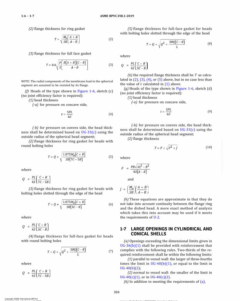
(2) flange thickness for ring gasket
ð2Þ
(3) flange thickness for full face gasket
ð3Þ
NOTE: The radial components of the membrane load in the sphericalsegment are assumed to be resisted by its flange.
(f) Heads of the type shown in Figure 1-6, sketch (c)(no joint efficiency factor is required):
(1) head thickness(-a) for pressure on concave side,
ð4Þ
(-b) for pressure on convex side, the head thick-ness shall be determined based on UG-33(c) using theoutside radius of the spherical head segment;
(2) flange thickness for ring gasket for heads withround bolting holes
ð5Þ
where
Q =
(3) flange thickness for ring gasket for heads withbolting holes slotted through the edge of the head
ð6Þ
where
Q =
(4) flange thickness for full‐face gasket for headswith round bolting holes
ð7Þ
where
Q =
(5) flange thickness for full‐face gasket for headswith bolting holes slotted through the edge of the head
ð8Þ
where
Q =
(6) the required flange thickness shall be T as calcu-lated in (2), (3), (4), or (5) above, but in no case less thanthe value of t calculated in (1) above.(g) Heads of the type shown in Figure 1-6, sketch (d)
(no joint efficiency factor is required):(1) head thickness(-a) for pressure on concave side,
ð9Þ
(-b) for pressure on convex side, the head thick-ness shall be determined based on UG-33(c) using theoutside radius of the spherical head segment;
(2) flange thickness
ð10Þ
where
F =
and
J =
(h) These equations are approximate in that they donot take into account continuity between the flange ringand the dished head. A more exact method of analysiswhich takes this into account may be used if it meetsthe requirements of U-2.
1-7 LARGE OPENINGS IN CYLINDRICAL ANDCONICAL SHELLS
(a) Openings exceeding the dimensional limits given inUG-36(b)(1) shall be provided with reinforcement thatcomplies with the following rules. Two‐thirds of the re-quired reinforcement shall be within the following limits:
(1) parallel to vessel wall: the larger of three‐fourthstimes the limit in UG-40(b)(1), or equal to the limit inUG-40(b)(2);
(2) normal to vessel wall: the smaller of the limit inUG-40(c)(1), or in UG-40(c)(2).(b) In addition to meeting the requirements of (a),
ASME BPVC.VIII.1-20191-6 – 1-7
384
Copyright ASME International (BPVC) Provided by IHS under license with ASME Licensee=Khalda Petroleum/5986215001, User=Amer, Mohamed
Not for Resale, 07/02/2019 13:29:04 MDTNo reproduction or networking permitted without license from IHS
--`,``,``,,`,`,,````,`,``,,,`-`-`,,`,,`,`,,`---

(1) openings for radial nozzles that exceed the limitsin UG-36(b)(1) and that also are within the range definedby the following limits shall meet the requirements in (2),(3), and (4) below:
(-a) vesse l d iameters greater than 60 in .(1 520 mm) I.D.;
(-b) nozz le d iameters that exceed 40 in .(1 020 mm) I.D. and also exceed ; the terms Rand t are defined in Figures 1-7-1 and 1-7-2;
(-c) the ratio Rn/R does not exceed 0.7; for nozzleopenings with Rn/R exceeding 0.7, refer to U-2(g).
The rules are limited to radial nozzles in cylindricaland conical shells (with the half‐apex angle equal to orless than 30 deg) that do not have internal projections,and do not include any analysis for stresses resultingfrom externally applied mechanical loads. For such cases,U-2(g) shall apply.
(2) The membrane stress Sm as calculated by eq.(4)(1) or (4)(2) below shall not exceed S, as defined inUG-37 for the applicable materials at design conditions.The maximum combined membrane stress Sm and bend-ing stress Sb shall not exceed 1.5S at design conditions.Sb shall be calculated by eq. (4)(5) below.
(3) Evaluation of combined stresses from pressureand external loads shall be made in accordance withU-2(g).
(4) For membrane stress calculations, use the limitsdefined in Figure 1-7-1, and comply with the strength ofreinforcement requirements of UG-41. For bending stresscalculation, the greater of the limits defined in Figure1-7-1 or Figure 1-7-2 may be used. The strength reduc-tion ratio requirements of UG-41 need not be applied,provided that the allowable stress ratio of the materialin the nozzle neck, nozzle forging, reinforcing plate,and/or nozzle flange divided by the shell material allow-able stress is at least 0.80.
NOTE: The bending stress Sb calculated by eq. (5) is valid and applic-able only at the nozzle neck‐shell junction. It is a primary bendingstress because it is a measure of the stiffness required to maintainequilibrium at the longitudinal axis junction of the nozzle‐shell inter-section due to the bending moment calculated by eq. (3).
Case A (see Figure 1-7-1)
ð1Þ
Case B (see Figure 1-7-1)
ð2Þ
Cases A and B (See Figure 1-7-1 or Figure 1-7-2)
ð3Þ
ð4Þ
ð5Þ
(5) Nomenclature. Symbols used in Figures 1-7-1and 1-7-2 are as defined in UG-37(a) and as follows:
As = shaded (cross‐hatched) area in Figure 1-7-1, CaseA or Case B
a = distance between neutral axis of the shaded areain Figure 1-7-1 or Figure 1-7-2 and the inside ofvessel wall
e = distance between neutral axis of the shaded areaand midwall of the shell
I = moment of inertia of the larger of the shadedareas in Figure 1-7-1 or Figure 1-7-2 about neu-tral axis
P = internal or external pressureRm = mean radius of shell
Rnm = mean radius of nozzle neckSb = bending stress at the intersection of inside of the
nozzle neck and inside of the vessel shell alongthe vessel shell longitudinal axis
Sm = membrane stress calculated by eq. (4)(1) or eq.(4)(2)
Sy = yield strength of the material at test temperature;see Section II, Part D, Subpart 1, Table Y-1
(c) In the design and fabrication of large openings, theManufacturer should consider details that may be appro-priate to minimize distortion and localized stressesaround the opening. For example, reinforcement oftenmay be advantageously obtained by use of heavier shellplate for a vessel course or inserted locally around theopening; weld may be ground to concave contour andthe inside corners of the opening rounded to a generousradius to reduce stress concentrations. The user and theManufacturer should agree on the extent and type of non-destructive examination of welds that may be appropriatefor the intended service conditions and the materials ofconstruction. Proof testing may be appropriate in extremecases of large openings approaching full vessel diameter,openings of unusual shape, etc.
ASME BPVC.VIII.1-2019 1-7
385
Copyright ASME International (BPVC) Provided by IHS under license with ASME Licensee=Khalda Petroleum/5986215001, User=Amer, Mohamed
Not for Resale, 07/02/2019 13:29:04 MDTNo reproduction or networking permitted without license from IHS
--`,``,``,,`,`,,````,`,``,,,`-`-`,,`,,`,`,,`---

Figure 1-7-1
Figure 1-7-2
Neutral axis of shaded area
Shell centerline
Nozzle centerline
te � 16tn tn
te
16t
Rn
Rm R
t
Rnm
a e
Case A: Nozzle With
Reinforcing Pad
Case B: Nozzle With
Integral-Type Reinforcement
Neutral axis of shaded area
Shell centerline
Nozzle centerline
16tn tn
16t
Rn
Rm
t
Rnm
a e
R
GENERAL NOTE: When any part of a flange is located within the greater of the or 16tn + te limit as indicated in Figure 1-7-1 or
Figure 1-7-2 Case A, or the greater of or 16tn for Figure 1-7-1 or Figure 1-7-2 Case B, the flange may be included as part of the section
that resists bending moment.
ASME BPVC.VIII.1-20191-7
386
Copyright ASME International (BPVC) Provided by IHS under license with ASME Licensee=Khalda Petroleum/5986215001, User=Amer, Mohamed
Not for Resale, 07/02/2019 13:29:04 MDTNo reproduction or networking permitted without license from IHS
--`,``,``,,`,`,,````,`,``,,,`-`-`,,`,,`,`,,`---
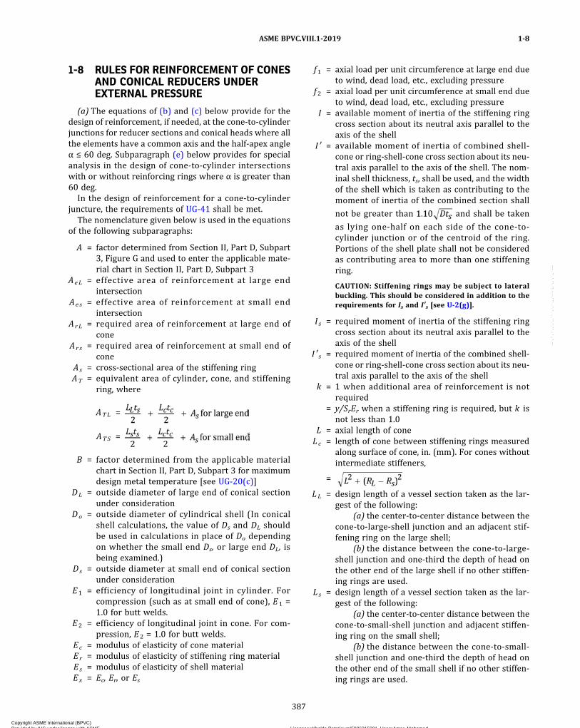
1-8 RULES FOR REINFORCEMENT OF CONESAND CONICAL REDUCERS UNDEREXTERNAL PRESSURE
(a) The equations of (b) and (c) below provide for thedesign of reinforcement, if needed, at the cone‐to‐cylinderjunctions for reducer sections and conical heads where allthe elements have a common axis and the half‐apex angleα ≤ 60 deg. Subparagraph (e) below provides for specialanalysis in the design of cone‐to‐cylinder intersectionswith or without reinforcing rings where α is greater than60 deg.
In the design of reinforcement for a cone‐to‐cylinderjuncture, the requirements of UG-41 shall be met.
The nomenclature given below is used in the equationsof the following subparagraphs:
A = factor determined from Section II, Part D, Subpart3, Figure G and used to enter the applicable mate-rial chart in Section II, Part D, Subpart 3
AeL = effective area of reinforcement at large endintersection
Aes = effective area of reinforcement at small endintersection
ArL = required area of reinforcement at large end ofcone
Ars = required area of reinforcement at small end ofcone
As = cross‐sectional area of the stiffening ringAT = equivalent area of cylinder, cone, and stiffening
ring, where
ATL =
ATS =
B = factor determined from the applicable materialchart in Section II, Part D, Subpart 3 for maximumdesign metal temperature [see UG-20(c)]
DL = outside diameter of large end of conical sectionunder consideration
Do = outside diameter of cylindrical shell (In conicalshell calculations, the value of Ds and DL shouldbe used in calculations in place of Do dependingon whether the small end Ds, or large end DL, isbeing examined.)
Ds = outside diameter at small end of conical sectionunder consideration
E1 = efficiency of longitudinal joint in cylinder. Forcompression (such as at small end of cone), E1 =1.0 for butt welds.
E2 = efficiency of longitudinal joint in cone. For com-pression, E2 = 1.0 for butt welds.
Ec = modulus of elasticity of cone materialEr = modulus of elasticity of stiffening ring materialEs = modulus of elasticity of shell materialEx = Ec, Er, or Es
f1 = axial load per unit circumference at large end dueto wind, dead load, etc., excluding pressure
f2 = axial load per unit circumference at small end dueto wind, dead load, etc., excluding pressure
I = available moment of inertia of the stiffening ringcross section about its neutral axis parallel to theaxis of the shell
I ′ = available moment of inertia of combined shell‐cone or ring‐shell‐cone cross section about its neu-tral axis parallel to the axis of the shell. The nom-inal shell thickness, ts, shall be used, and the widthof the shell which is taken as contributing to themoment of inertia of the combined section shall
not be greater than and shall be taken
as lying one‐half on each side of the cone‐to‐cylinder junction or of the centroid of the ring.Portions of the shell plate shall not be consideredas contributing area to more than one stiffeningring.
CAUTION: Stiffening rings may be subject to lateralbuckling. This should be considered in addition to therequirements for Is and I′s [see U-2(g)].
I s = required moment of inertia of the stiffening ringcross section about its neutral axis parallel to theaxis of the shell
I ′ s = required moment of inertia of the combined shell‐cone or ring‐shell‐cone cross section about its neu-tral axis parallel to the axis of the shell
k = 1 when additional area of reinforcement is notrequired
= y/SrEr when a stiffening ring is required, but k isnot less than 1.0
L = axial length of coneLc = length of cone between stiffening rings measured
along surface of cone, in. (mm). For cones withoutintermediate stiffeners,
=
LL = design length of a vessel section taken as the lar-gest of the following:
(a) the center‐to‐center distance between thecone‐to‐large‐shell junction and an adjacent stif-fening ring on the large shell;
(b) the distance between the cone‐to‐large‐shell junction and one‐third the depth of head onthe other end of the large shell if no other stiffen-ing rings are used.
Ls = design length of a vessel section taken as the lar-gest of the following:
(a) the center‐to‐center distance between thecone‐to‐small‐shell junction and adjacent stiffen-ing ring on the small shell;
(b) the distance between the cone‐to‐small‐shell junction and one‐third the depth of head onthe other end of the small shell if no other stiffen-ing rings are used.
ASME BPVC.VIII.1-2019 1-8
387
Copyright ASME International (BPVC) Provided by IHS under license with ASME Licensee=Khalda Petroleum/5986215001, User=Amer, Mohamed
Not for Resale, 07/02/2019 13:29:04 MDTNo reproduction or networking permitted without license from IHS
--`,``,``,,`,`,,````,`,``,,,`-`-`,,`,,`,`,,`---
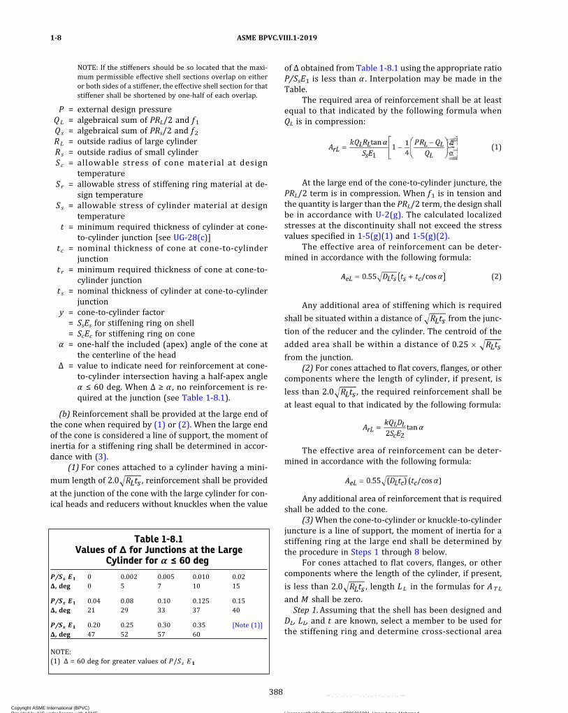
NOTE: If the stiffeners should be so located that the maxi-mum permissible effective shell sections overlap on eitheror both sides of a stiffener, the effective shell section for thatstiffener shall be shortened by one‐half of each overlap.
P = external design pressureQL = algebraical sum of PRL/2 and f1Qs = algebraical sum of PRs/2 and f2RL = outside radius of large cylinderRs = outside radius of small cylinderSc = allowable stress of cone material at design
temperatureSr = allowable stress of stiffening ring material at de-
sign temperatureSs = allowable stress of cylinder material at design
temperaturet = minimum required thickness of cylinder at cone‐
to‐cylinder junction [see UG-28(c)]tc = nominal thickness of cone at cone‐to‐cylinder
junctiont r = minimum required thickness of cone at cone‐to‐
cylinder junctiont s = nominal thickness of cylinder at cone‐to‐cylinder
junctiony = cone‐to‐cylinder factor
= SsEs for stiffening ring on shell= ScEc for stiffening ring on cone
α = one‐half the included (apex) angle of the cone atthe centerline of the head
Δ = value to indicate need for reinforcement at cone‐to‐cylinder intersection having a half‐apex angleα ≤ 60 deg. When Δ ≥ α , no reinforcement is re-quired at the junction (see Table 1-8.1).
(b) Reinforcement shall be provided at the large end ofthe cone when required by (1) or (2). When the large endof the cone is considered a line of support, the moment ofinertia for a stiffening ring shall be determined in accor-dance with (3).
(1) For cones attached to a cylinder having a mini-
mum length of 2.0 , reinforcement shall be provided
at the junction of the cone with the large cylinder for con-ical heads and reducers without knuckles when the value
of Δ obtained from Table 1-8.1 using the appropriate ratioP/SsE1 is less than α . Interpolation may be made in theTable.
The required area of reinforcement shall be at leastequal to that indicated by the following formula whenQL is in compression:
ð1Þ
At the large end of the cone‐to‐cylinder juncture, thePRL/2 term is in compression. When f1 is in tension andthe quantity is larger than the PRL/2 term, the design shallbe in accordance with U-2(g). The calculated localizedstresses at the discontinuity shall not exceed the stressvalues specified in 1-5(g)(1) and 1-5(g)(2).
The effective area of reinforcement can be deter-mined in accordance with the following formula:
ð2Þ
Any additional area of stiffening which is required
shall be situated within a distance of from the junc-
tion of the reducer and the cylinder. The centroid of the
added area shall be within a distance of
from the junction.(2) For cones attached to flat covers, flanges, or other
components where the length of cylinder, if present, is
less than 2.0 , the required reinforcement shall be
at least equal to that indicated by the following formula:
The effective area of reinforcement can be deter-mined in accordance with the following formula:
Any additional area of reinforcement that is requiredshall be added to the cone.
(3)When the cone‐to‐cylinder or knuckle‐to‐cylinderjuncture is a line of support, the moment of inertia for astiffening ring at the large end shall be determined bythe procedure in Steps 1 through 8 below.
For cones attached to flat covers, flanges, or othercomponents where the length of the cylinder, if present,
is less than , length LL in the formulas for ATL
and M shall be zero.Step 1. Assuming that the shell has been designed and
DL, LL, and t are known, select a member to be used forthe stiffening ring and determine cross‐sectional area
Table 1-8.1Values of Δ for Junctions at the Large
Cylinder for α ≤ 60 deg
P/Ss E1 0 0.002 0.005 0.010 0.02Δ, deg 0 5 7 10 15
P/Ss E1 0.04 0.08 0.10 0.125 0.15Δ, deg 21 29 33 37 40
P/Ss E1 0.20 0.25 0.30 0.35 [Note (1)]Δ, deg 47 52 57 60
NOTE:(1) Δ = 60 deg for greater values of P/Ss E1
ASME BPVC.VIII.1-20191-8
388
Copyright ASME International (BPVC) Provided by IHS under license with ASME Licensee=Khalda Petroleum/5986215001, User=Amer, Mohamed
Not for Resale, 07/02/2019 13:29:04 MDTNo reproduction or networking permitted without license from IHS
--`,``,``,,`,`,,````,`,``,,,`-`-`,,`,,`,`,,`---
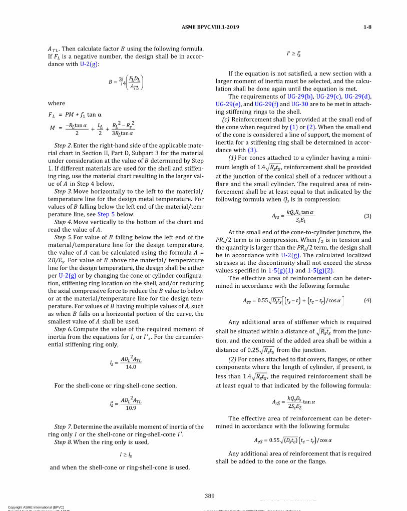
ATL . Then calculate factor B using the following formula.If FL is a negative number, the design shall be in accor-dance with U-2(g):
where
FL = PM + f1 tan α
M =
Step 2. Enter the right‐hand side of the applicable mate-rial chart in Section II, Part D, Subpart 3 for the materialunder consideration at the value of B determined by Step1. If different materials are used for the shell and stiffen-ing ring, use the material chart resulting in the larger val-ue of A in Step 4 below.
Step 3. Move horizontally to the left to the material/temperature line for the design metal temperature. Forvalues of B falling below the left end of the material/tem-perature line, see Step 5 below.
Step 4. Move vertically to the bottom of the chart andread the value of A.
Step 5. For value of B falling below the left end of thematerial/temperature line for the design temperature,the value of A can be calculated using the formula A =2B/Ex. For value of B above the material/ temperatureline for the design temperature, the design shall be eitherper U-2(g) or by changing the cone or cylinder configura-tion, stiffening ring location on the shell, and/or reducingthe axial compressive force to reduce the B value to belowor at the material/temperature line for the design tem-perature. For values of B having multiple values of A, suchas when B falls on a horizontal portion of the curve, thesmallest value of A shall be used.
Step 6. Compute the value of the required moment ofinertia from the equations for Is or I ′ s . For the circumfer-ential stiffening ring only,
For the shell‐cone or ring‐shell‐cone section,
Step 7. Determine the available moment of inertia of thering only I or the shell‐cone or ring‐shell‐cone I ′ .
Step 8.When the ring only is used,
and when the shell‐cone or ring‐shell‐cone is used,
If the equation is not satisfied, a new section with alarger moment of inertia must be selected, and the calcu-lation shall be done again until the equation is met.
The requirements of UG-29(b), UG-29(c), UG-29(d),UG-29(e), and UG-29(f) and UG-30 are to be met in attach-ing stiffening rings to the shell.
(c) Reinforcement shall be provided at the small end ofthe cone when required by (1) or (2). When the small endof the cone is considered a line of support, the moment ofinertia for a stiffening ring shall be determined in accor-dance with (3).
(1) For cones attached to a cylinder having a mini-
mum length of 1.4 , reinforcement shall be provided
at the junction of the conical shell of a reducer without aflare and the small cylinder. The required area of rein-forcement shall be at least equal to that indicated by thefollowing formula when Qs is in compression:
ð3Þ
At the small end of the cone‐to‐cylinder juncture, thePRs/2 term is in compression. When f2 is in tension andthe quantity is larger than the PRs/2 term, the design shallbe in accordance with U-2(g). The calculated localizedstresses at the discontinuity shall not exceed the stressvalues specified in 1-5(g)(1) and 1-5(g)(2).
The effective area of reinforcement can be deter-mined in accordance with the following formula:
ð4Þ
Any additional area of stiffener which is required
shall be situated within a distance of from the junc-
tion, and the centroid of the added area shall be within a
distance of from the junction.
(2) For cones attached to flat covers, flanges, or othercomponents where the length of cylinder, if present, is
less than 1.4 , the required reinforcement shall be
at least equal to that indicated by the following formula:
The effective area of reinforcement can be deter-mined in accordance with the following formula:
Any additional area of reinforcement that is requiredshall be added to the cone or the flange.
ASME BPVC.VIII.1-2019 1-8
389
Copyright ASME International (BPVC) Provided by IHS under license with ASME Licensee=Khalda Petroleum/5986215001, User=Amer, Mohamed
Not for Resale, 07/02/2019 13:29:04 MDTNo reproduction or networking permitted without license from IHS
--`,``,``,,`,`,,````,`,``,,,`-`-`,,`,,`,`,,`---
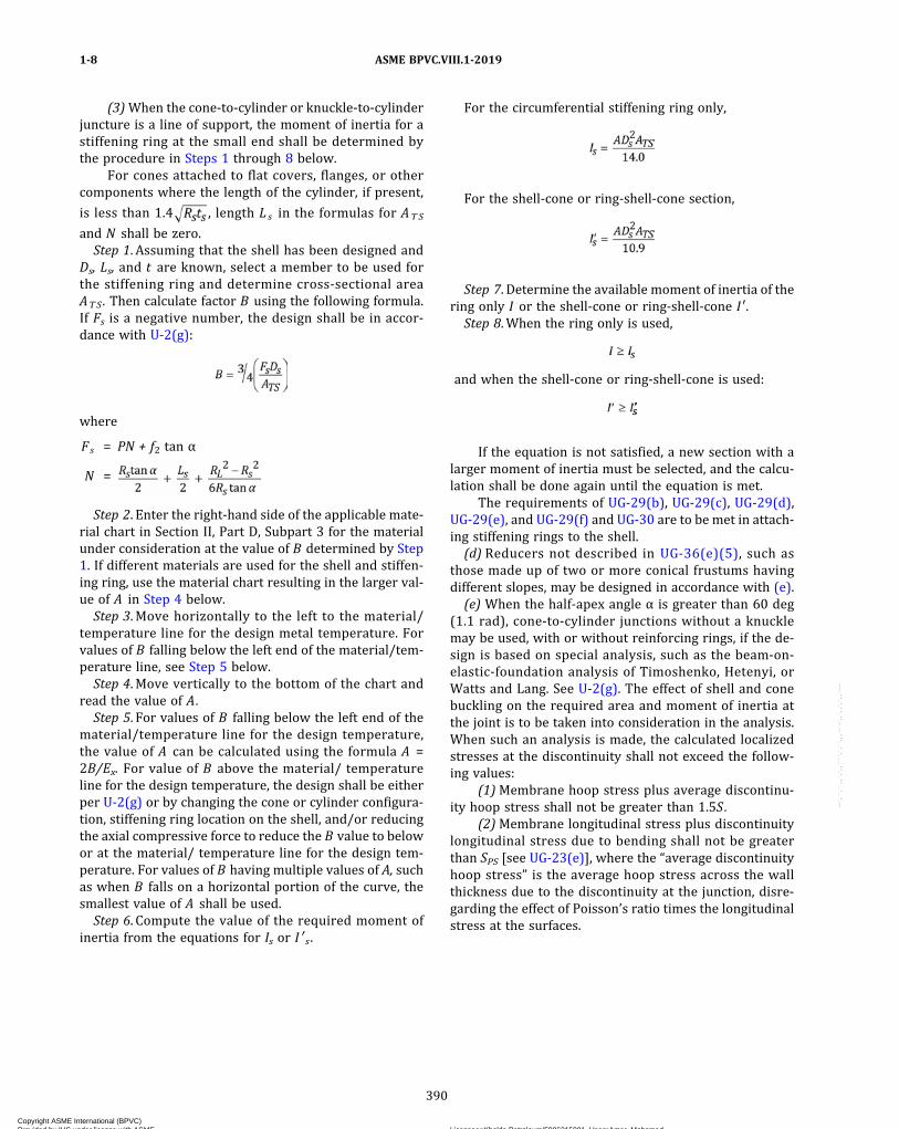
(3)When the cone‐to‐cylinder or knuckle‐to‐cylinderjuncture is a line of support, the moment of inertia for astiffening ring at the small end shall be determined bythe procedure in Steps 1 through 8 below.
For cones attached to flat covers, flanges, or othercomponents where the length of the cylinder, if present,
is less than 1.4 , length Ls in the formulas for ATS
and N shall be zero.Step 1. Assuming that the shell has been designed and
Ds, Ls, and t are known, select a member to be used forthe stiffening ring and determine cross‐sectional areaATS . Then calculate factor B using the following formula.If Fs is a negative number, the design shall be in accor-dance with U-2(g):
where
Fs = PN + f2 tan α
N =
Step 2. Enter the right‐hand side of the applicable mate-rial chart in Section II, Part D, Subpart 3 for the materialunder consideration at the value of B determined by Step1. If different materials are used for the shell and stiffen-ing ring, use the material chart resulting in the larger val-ue of A in Step 4 below.Step 3. Move horizontally to the left to the material/
temperature line for the design metal temperature. Forvalues of B falling below the left end of the material/tem-perature line, see Step 5 below.Step 4. Move vertically to the bottom of the chart and
read the value of A.Step 5. For values of B falling below the left end of the
material/temperature line for the design temperature,the value of A can be calculated using the formula A =2B/Ex. For value of B above the material/ temperatureline for the design temperature, the design shall be eitherper U-2(g) or by changing the cone or cylinder configura-tion, stiffening ring location on the shell, and/or reducingthe axial compressive force to reduce the B value to belowor at the material/ temperature line for the design tem-perature. For values of B having multiple values of A, suchas when B falls on a horizontal portion of the curve, thesmallest value of A shall be used.Step 6. Compute the value of the required moment of
inertia from the equations for Is or I ′ s .
For the circumferential stiffening ring only,
For the shell‐cone or ring‐shell‐cone section,
Step 7. Determine the available moment of inertia of thering only I or the shell‐cone or ring‐shell‐cone I ′.Step 8.When the ring only is used,
and when the shell‐cone or ring‐shell‐cone is used:
If the equation is not satisfied, a new section with alarger moment of inertia must be selected, and the calcu-lation shall be done again until the equation is met.
The requirements of UG-29(b), UG-29(c), UG-29(d),UG-29(e), and UG-29(f) and UG-30 are to be met in attach-ing stiffening rings to the shell.(d) Reducers not described in UG-36(e)(5), such as
those made up of two or more conical frustums havingdifferent slopes, may be designed in accordance with (e).(e) When the half‐apex angle α is greater than 60 deg
(1.1 rad), cone‐to‐cylinder junctions without a knucklemay be used, with or without reinforcing rings, if the de-sign is based on special analysis, such as the beam‐on‐elastic‐foundation analysis of Timoshenko, Hetenyi, orWatts and Lang. See U-2(g). The effect of shell and conebuckling on the required area and moment of inertia atthe joint is to be taken into consideration in the analysis.When such an analysis is made, the calculated localizedstresses at the discontinuity shall not exceed the follow-ing values:
(1)Membrane hoop stress plus average discontinu-ity hoop stress shall not be greater than 1.5S .
(2)Membrane longitudinal stress plus discontinuitylongitudinal stress due to bending shall not be greaterthan SPS [see UG-23(e)], where the “average discontinuityhoop stress” is the average hoop stress across the wallthickness due to the discontinuity at the junction, disre-garding the effect of Poisson’s ratio times the longitudinalstress at the surfaces.
ASME BPVC.VIII.1-20191-8
390
Copyright ASME International (BPVC) Provided by IHS under license with ASME Licensee=Khalda Petroleum/5986215001, User=Amer, Mohamed
Not for Resale, 07/02/2019 13:29:04 MDTNo reproduction or networking permitted without license from IHS
--`,``,``,,`,`,,````,`,``,,,`-`-`,,`,,`,`,,`---

ð19Þ
ð19Þ
MANDATORY APPENDIX 2RULES FOR BOLTED FLANGE CONNECTIONS WITH RING TYPE
GASKETS
2-1 SCOPE
(a) The rules in Mandatory Appendix 2 apply specifi-cally to the design of bolted flange connections with gas-kets that are entirely within the circle enclosed by the boltholes and with no contact outside this circle, and are to beused in conjunction with the applicable requirements inSubsections A, B, and C of this Division. The hub thicknessof weld neck flanges designed to this Appendix shall alsocomply with the minimum thickness requirements inSubsection A of this Division. These rules are not to beused for the determination of the thickness of tubesheetsintegral with a bolting flange as illustrated in FigureUW-13.2, sketches (h) through (l) or Figure UW-13.3,sketch (c). Nonmandatory Appendix S provides discus-sion on Design Considerations for Bolted FlangedConnections.
These rules provide only for hydrostatic end loads andgasket seating. The flange design methods outlined in 2-4through 2-8 are applicable to circular flanges under inter-nal pressure. Modifications of these methods are outlinedin 2-9 and 2-10 for the design of split and noncircularflanges. See 2-11 for flanges with ring type gaskets subjectto external pressure, 2-12 for flanges with nut‐stops, and2-13 for reverse flanges. Rules for calculating rigidity fac-tors for flanges are provided in 2-14. Recommendationsfor qualification of assembly procedures and assemblersare in 2-15. Proper allowance shall be made if connec-tions are subject to external loads other than externalpressure.
(b) The design of a flange involves the selection of thegasket (material, type, and dimensions), flange facing,bolting, hub proportions, flange width, and flange thick-ness. See Note in 2-5(c)(1). Flange dimensions shall besuch that the stresses in the flange, calculated in accor-dance with 2-7, do not exceed the allowable flange stress-es specified in 2-8. Except as provided for in 2-14(a),flanges designed to the rules of this Appendix shall alsomeet the rigidity requirements of 2-14. All calculationsshall be made on dimensions in the corroded condition.
(c) It is recommended that bolted flange connectionsconforming to the standards listed in UG-44(a) be usedfor connections to external piping. These standards may
be used for other bolted flange connections and dishedcovers within the limits of size in the standards and thepressure–temperature ratings permitted in UG-44(a).The ratings in these standards are based on the hub di-mensions given or on the minimum specified thicknessof flanged fittings of integral construction. Flanges fabri-cated from rings may be used in place of the hub flangesin these standards provided that their strength, calculatedby the rules in this Appendix, is not less than that calcu-lated for the corresponding size of hub flange.
(d) Except as otherwise provided in (c) above, boltedflange connections for unfired pressure vessels shall sa-tisfy the requirements in this Appendix.
(e) The rules of this Appendix should not be construedto prohibit the use of other types of flanged connections,provided they are designed in accordance with good engi-neering practice and method of design is acceptable to theInspector. Some examples of flanged connections whichmight fall in this category are as follows:
(1) flanged covers as shown in Figure 1-6;(2) bolted flanges using full‐face gaskets;(3) flanges using means other than bolting to restrain
the flange assembly against pressure and other appliedloads.
2-2 MATERIALS
(a)Materials used in the construction of bolted flangeconnections shall comply with the requirements givenin UG-4 through UG-14.
(b) Flanges made from ferritic steel and designed in ac-cordance with this Appendix shall be full‐annealed, nor-malized, normalized and tempered, or quenched andtempered when the thickness of the flange, t (see Figure2-4), exceeds 3 in. (75 mm).
(c) Material on which welding is to be performed shallbe proved of good weldable quality. Satisfactory qualifica-tion of the welding procedure under Section IX is consid-ered as proof. Welding shall not be performed on steelthat has a carbon content greater than 0.35%. All weldingon flange connections shall comply with the requirementsfor postweld heat treatment given in this Division.
ASME BPVC.VIII.1-2019 2-1 – 2-2
391
Copyright ASME International (BPVC) Provided by IHS under license with ASME Licensee=Khalda Petroleum/5986215001, User=Amer, Mohamed
Not for Resale, 07/02/2019 13:29:04 MDTNo reproduction or networking permitted without license from IHS
--`,``,``,,`,`,,````,`,``,,,`-`-`,,`,,`,`,,`---

ð19Þ
(d) Flanges with hubs that are machined from plate, barstock, or billet shall not be machined from plate or barmaterial [except as permitted in UG-14(b)] unless the ma-terial has been formed into a ring and the following addi-tional conditions are met:
(1) In a ring formed from plate, the original plate sur-faces are parallel to the axis of the finished flange. (This isnot intended to imply that the original plate surfaceshould be present in the finished flange.)
(2) The joints in the ring are welded butt joints thatconform to the requirements of this Division. Thicknessto be used to determine postweld heat treatment andradiography requirements shall be the lesser of
where these symbols are as defined in 2-3.(3) The back of the flange and the outer surface of the
hub are examined by either the magnetic particle methodas per Mandatory Appendix 6 or the liquid penetrantmethod as per Mandatory Appendix 8.(e) Bolts, studs, nuts, and washers shall comply with
the requirements in this Division. It is recommended thatbolts and studs have a nominal diameter of not less than1/2 in. (13 mm). If bolts or studs smaller than 1/2 in.(13 mm) are used, ferrous bolting material shall be of al-loy steel. Precautions shall be taken to avoid over‐stressing small‐diameter bolts.
2-3 NOTATION
The symbols described below are used in the equationsfor the design of flanges (see also Figure 2-4):
A = outside diameter of flange or, where slottedholes extend to the outside of the flange, thediameter to the bottom of the slots
a = nominal bolt diameterAb = cross‐sectional area of the bolts using the root
diameter of the thread or least diameter of un-threaded position, if less
Am = total required cross‐sectional area of bolts, ta-ken as the greater of Am1 and Am2
Am1 = total cross‐sectional area of bolts at root ofthread or section of least diameter under stress,required for the operating conditions
= Wm1 / SbAm2 = total cross‐sectional area of bolts at root of
thread or section of least diameter under stress,required for gasket seating
= Wm2 / SaB = inside diameter of flange. When B is less than
20g1, it will be optional for the designer to sub-stitute B1 for B in the formula for longitudinalstress SH.
b = effective gasket or joint‐contact‐surface seatingwidth [see Note in 2-5(c)(1)]
B1 = B + g1 for loose type flanges and for integraltype flanges that have calculated values h / hoand g1 / go which would indicate an f value ofless than 1.0, although the minimum value of fpermitted is 1.0.
= B + go for integral type flanges when f is equalto or greater than one
bo = basic gasket seating width (from Table 2-5.2)Bs = bolt spacing. The bolt spacing may be taken as
the bolt circle circumference divided by thenumber of bolts or as the chord length betweenadjacent bolt locations.
Bsc = bolt spacing factorBsmax = maximum bolt spacing
C = bolt‐circle diameterc = basic dimension used for the minimum sizing of
welds equal to tn or tx, whichever is lessCb = conversion factor
= 0.5 for U.S. Customary calculations; 2.5 for SIcalculations
d = factor
= for integral type flanges
= for loose type flanges
e = factor
= for integral type flanges
= for loose type flanges
F = factor for integral type flanges (from Figure2-7.2)
f = hub stress correction factor for integral flangesfrom Figure 2-7.6 (When greater than one, thisis the ratio of the stress in the small end of hubto the stress in the large end.) (For values belowlimit of figure, use f = 1.)
FL = factor for loose type flanges (from Figure 2-7.4)G = diameter at location of gasket load reaction. Ex-
cept as noted in sketch (1) of Figure 2-4, G is de-fined as follows (see Table 2-5.2):
(a)when bo ≤ 1/4 in. (6 mm), G = mean dia-meter of gasket contact face
(b) when bo >1/4 in. (6 mm), G = outside dia-
meter of gasket contact face less 2bg1 = thickness of hub at back of flangego = thickness of hub at small end
(a) for optional type flanges calculated as in-tegral and for integral type flanges per Figure2-4, sketch (7), go = tn
(b) for other integral type flanges, go = thesmaller of tn or the thickness of the hub at thesmall end
H = total hydrostatic end force= 0.785G2P
h = hub length
ASME BPVC.VIII.1-20192-2 – 2-3
392
Copyright ASME International (BPVC) Provided by IHS under license with ASME Licensee=Khalda Petroleum/5986215001, User=Amer, Mohamed
Not for Resale, 07/02/2019 13:29:04 MDTNo reproduction or networking permitted without license from IHS
--`,``,``,,`,`,,````,`,``,,,`-`-`,,`,,`,`,,`---
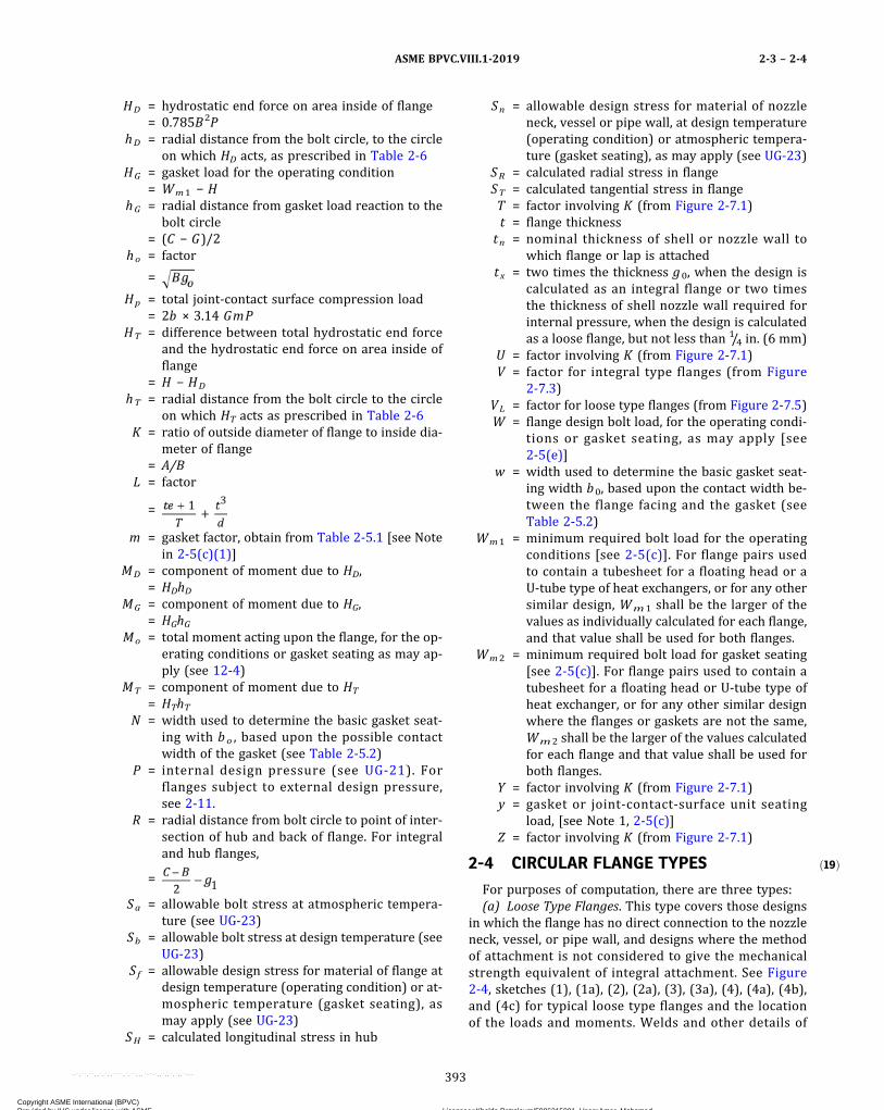
ð19Þ
HD = hydrostatic end force on area inside of flange= 0.785B2P
hD = radial distance from the bolt circle, to the circleon which HD acts, as prescribed in Table 2-6
HG = gasket load for the operating condition= Wm1 − H
hG = radial distance from gasket load reaction to thebolt circle
= (C − G)/2ho = factor
=
Hp = total joint‐contact surface compression load= 2b × 3.14 GmP
HT = difference between total hydrostatic end forceand the hydrostatic end force on area inside offlange
= H − HD
hT = radial distance from the bolt circle to the circleon which HT acts as prescribed in Table 2-6
K = ratio of outside diameter of flange to inside dia-meter of flange
= A/BL = factor
=
m = gasket factor, obtain from Table 2-5.1 [see Notein 2-5(c)(1)]
MD = component of moment due to HD,= HDhD
MG = component of moment due to HG,= HGhG
Mo = total moment acting upon the flange, for the op-erating conditions or gasket seating as may ap-ply (see 12-4)
MT = component of moment due to HT
= HThTN = width used to determine the basic gasket seat-
ing with bo , based upon the possible contactwidth of the gasket (see Table 2-5.2)
P = internal design pressure (see UG-21). Forflanges subject to external design pressure,see 2-11.
R = radial distance from bolt circle to point of inter-section of hub and back of flange. For integraland hub flanges,
=
Sa = allowable bolt stress at atmospheric tempera-ture (see UG-23)
Sb = allowable bolt stress at design temperature (seeUG-23)
Sf = allowable design stress for material of flange atdesign temperature (operating condition) or at-mospheric temperature (gasket seating), asmay apply (see UG-23)
SH = calculated longitudinal stress in hub
Sn = allowable design stress for material of nozzleneck, vessel or pipe wall, at design temperature(operating condition) or atmospheric tempera-ture (gasket seating), as may apply (see UG-23)
SR = calculated radial stress in flangeST = calculated tangential stress in flangeT = factor involving K (from Figure 2-7.1)t = flange thickness
tn = nominal thickness of shell or nozzle wall towhich flange or lap is attached
tx = two times the thickness g0, when the design iscalculated as an integral flange or two timesthe thickness of shell nozzle wall required forinternal pressure, when the design is calculatedas a loose flange, but not less than 1/4 in. (6 mm)
U = factor involving K (from Figure 2-7.1)V = factor for integral type flanges (from Figure
2-7.3)VL = factor for loose type flanges (from Figure 2-7.5)W = flange design bolt load, for the operating condi-
tions or gasket seating, as may apply [see2-5(e)]
w = width used to determine the basic gasket seat-ing width b0, based upon the contact width be-tween the flange facing and the gasket (seeTable 2-5.2)
Wm1 = minimum required bolt load for the operatingconditions [see 2-5(c)]. For flange pairs usedto contain a tubesheet for a floating head or aU‐tube type of heat exchangers, or for any othersimilar design, Wm1 shall be the larger of thevalues as individually calculated for each flange,and that value shall be used for both flanges.
Wm2 = minimum required bolt load for gasket seating[see 2-5(c)]. For flange pairs used to contain atubesheet for a floating head or U‐tube type ofheat exchanger, or for any other similar designwhere the flanges or gaskets are not the same,Wm2 shall be the larger of the values calculatedfor each flange and that value shall be used forboth flanges.
Y = factor involving K (from Figure 2-7.1)y = gasket or joint‐contact‐surface unit seating
load, [see Note 1, 2-5(c)]Z = factor involving K (from Figure 2-7.1)
2-4 CIRCULAR FLANGE TYPES
For purposes of computation, there are three types:(a) Loose Type Flanges. This type covers those designs
in which the flange has no direct connection to the nozzleneck, vessel, or pipe wall, and designs where the methodof attachment is not considered to give the mechanicalstrength equivalent of integral attachment. See Figure2-4, sketches (1), (1a), (2), (2a), (3), (3a), (4), (4a), (4b),and (4c) for typical loose type flanges and the locationof the loads and moments. Welds and other details of
ASME BPVC.VIII.1-2019 2-3 – 2-4
393
Copyright ASME International (BPVC) Provided by IHS under license with ASME Licensee=Khalda Petroleum/5986215001, User=Amer, Mohamed
Not for Resale, 07/02/2019 13:29:04 MDTNo reproduction or networking permitted without license from IHS
--`,``,``,,`,`,,````,`,``,,,`-`-`,,`,,`,`,,`---
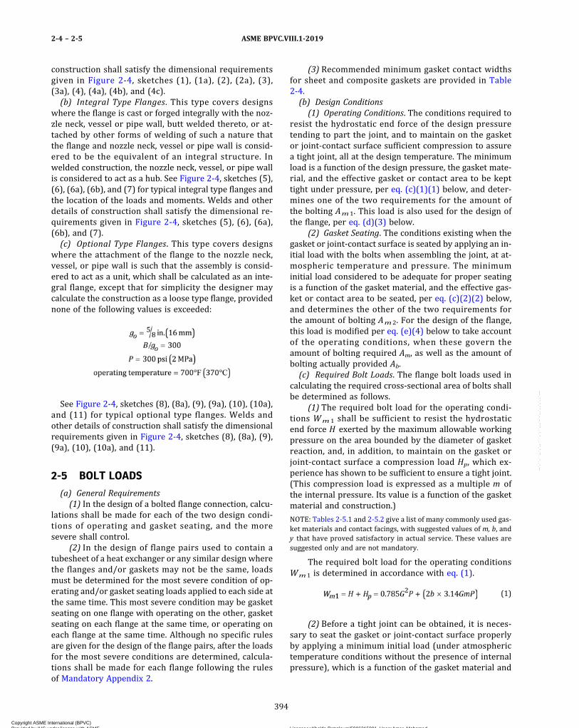
construction shall satisfy the dimensional requirementsgiven in Figure 2-4, sketches (1), (1a), (2), (2a), (3),(3a), (4), (4a), (4b), and (4c).(b) Integral Type Flanges. This type covers designs
where the flange is cast or forged integrally with the noz-zle neck, vessel or pipe wall, butt welded thereto, or at-tached by other forms of welding of such a nature thatthe flange and nozzle neck, vessel or pipe wall is consid-ered to be the equivalent of an integral structure. Inwelded construction, the nozzle neck, vessel, or pipe wallis considered to act as a hub. See Figure 2-4, sketches (5),(6), (6a), (6b), and (7) for typical integral type flanges andthe location of the loads and moments. Welds and otherdetails of construction shall satisfy the dimensional re-quirements given in Figure 2-4, sketches (5), (6), (6a),(6b), and (7).(c) Optional Type Flanges. This type covers designs
where the attachment of the flange to the nozzle neck,vessel, or pipe wall is such that the assembly is consid-ered to act as a unit, which shall be calculated as an inte-gral flange, except that for simplicity the designer maycalculate the construction as a loose type flange, providednone of the following values is exceeded:
See Figure 2-4, sketches (8), (8a), (9), (9a), (10), (10a),and (11) for typical optional type flanges. Welds andother details of construction shall satisfy the dimensionalrequirements given in Figure 2-4, sketches (8), (8a), (9),(9a), (10), (10a), and (11).
2-5 BOLT LOADS
(a) General Requirements(1) In the design of a bolted flange connection, calcu-
lations shall be made for each of the two design condi-tions of operating and gasket seating, and the moresevere shall control.
(2) In the design of flange pairs used to contain atubesheet of a heat exchanger or any similar design wherethe flanges and/or gaskets may not be the same, loadsmust be determined for the most severe condition of op-erating and/or gasket seating loads applied to each side atthe same time. This most severe condition may be gasketseating on one flange with operating on the other, gasketseating on each flange at the same time, or operating oneach flange at the same time. Although no specific rulesare given for the design of the flange pairs, after the loadsfor the most severe conditions are determined, calcula-tions shall be made for each flange following the rulesof Mandatory Appendix 2.
(3) Recommended minimum gasket contact widthsfor sheet and composite gaskets are provided in Table2-4.(b) Design Conditions
(1) Operating Conditions. The conditions required toresist the hydrostatic end force of the design pressuretending to part the joint, and to maintain on the gasketor joint‐contact surface sufficient compression to assurea tight joint, all at the design temperature. The minimumload is a function of the design pressure, the gasket mate-rial, and the effective gasket or contact area to be kepttight under pressure, per eq. (c)(1)(1) below, and deter-mines one of the two requirements for the amount ofthe bolting Am1. This load is also used for the design ofthe flange, per eq. (d)(3) below.
(2) Gasket Seating. The conditions existing when thegasket or joint‐contact surface is seated by applying an in-itial load with the bolts when assembling the joint, at at-mospheric temperature and pressure. The minimuminitial load considered to be adequate for proper seatingis a function of the gasket material, and the effective gas-ket or contact area to be seated, per eq. (c)(2)(2) below,and determines the other of the two requirements forthe amount of bolting Am2. For the design of the flange,this load is modified per eq. (e)(4) below to take accountof the operating conditions, when these govern theamount of bolting required Am, as well as the amount ofbolting actually provided Ab.(c) Required Bolt Loads. The flange bolt loads used in
calculating the required cross‐sectional area of bolts shallbe determined as follows.
(1) The required bolt load for the operating condi-tions Wm 1 shall be sufficient to resist the hydrostaticend force H exerted by the maximum allowable workingpressure on the area bounded by the diameter of gasketreaction, and, in addition, to maintain on the gasket orjoint‐contact surface a compression load Hp, which ex-perience has shown to be sufficient to ensure a tight joint.(This compression load is expressed as a multiple m ofthe internal pressure. Its value is a function of the gasketmaterial and construction.)
NOTE: Tables 2-5.1 and 2-5.2 give a list of many commonly used gas-ket materials and contact facings, with suggested values of m, b, andy that have proved satisfactory in actual service. These values aresuggested only and are not mandatory.
The required bolt load for the operating conditionsWm1 is determined in accordance with eq. (1).
ð1Þ
(2) Before a tight joint can be obtained, it is neces-sary to seat the gasket or joint‐contact surface properlyby applying a minimum initial load (under atmospherictemperature conditions without the presence of internalpressure), which is a function of the gasket material and
ASME BPVC.VIII.1-20192-4 – 2-5
394
Copyright ASME International (BPVC) Provided by IHS under license with ASME Licensee=Khalda Petroleum/5986215001, User=Amer, Mohamed
Not for Resale, 07/02/2019 13:29:04 MDTNo reproduction or networking permitted without license from IHS
--`,``,``,,`,`,,````,`,``,,,`-`-`,,`,,`,`,,`---
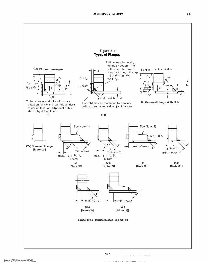
Figure 2-4Types of Flanges
See Note (1)
(3a)
[Note (2)]
Loose-Type Flanges [Notes (3) and (4)]
(4)
[Note (2)]
(4a)
[Note (2)]
(3)
[Note (2)]
(1) (1a)
(2) Screwed Flange With Hub
(2a) Screwed Flange
[Note (2)]
See Note (1)
Full penetration weld, single or double. The full penetration weld may be through the lap (tl) or through the wall (tn).
Gasket
This weld may be machined to a corner radius to suit standard lap joint flanges.
To be taken at midpoint of contact between flange and lap independent of gasket location. (Optional hub is shown by dotted line.)
Gasket
Gasket
hG or hT HG HT
min. = 0.7c
h
go g1
r r
B
A
G
A
G
C go g1
HD
hD C
B
W W
t ht
min. = 0.7c
1/2t (max.)
min. = 0.7c
min. = 0.7c
min. = 0.7c
max. = c 1/4 in. (6 mm)
max. = c 1/4 in. (6 mm)
1/2t (max.)
HD HG
HT
hD hT
tn
hG
tl
tl tn
(4b)
[Note (2)]
(4c)
[Note (2)]
min. = 0.7cmin. = 0.7c
ASME BPVC.VIII.1-2019 2-5
395
Copyright ASME International (BPVC) Provided by IHS under license with ASME Licensee=Khalda Petroleum/5986215001, User=Amer, Mohamed
Not for Resale, 07/02/2019 13:29:04 MDTNo reproduction or networking permitted without license from IHS
--`,``,``,,`,`,,````,`,``,,,`-`-`,,`,,`,`,,`---

Figure 2-4Types of Flanges (Cont'd)
Gasket
(5)
(7)
Integral-Type Flanges [Notes (3) and (4)]
(6)
(6a) hD hD
h
hT
HT HT HG
hG A
R
R
C
W W
r
t
B G
HD
HD
HD g1/2 g1/2
g1/2
g1
go
go g1
go
g1
g1 � go B
C R
B
hD hT
hG
t h
W A
HG
HT G
A
C
G
hT
t
r
Gasket Slope 1:3 (max.)
Weld
Slope exceeds 1:3
1.5 go (min.)
Where hub slope adjacent to flange exceeds 1:3, use sketches (6a) or (6b)
0.25go but not less than 1/4 in. (6 mm), the minimum for either leg. This weld may be machined to a corner radius as permitted in sketch (5), in which case g1 � go.
Gasket
h � 1.5 go
hG
HG
C L
(6b)
h
go
g1
Weld
Slope exceeds 1:3
Slope 1:3 (max.)
1.5 go (min.)
C L
ASME BPVC.VIII.1-20192-5
396
Copyright ASME International (BPVC) Provided by IHS under license with ASME Licensee=Khalda Petroleum/5986215001, User=Amer, Mohamed
Not for Resale, 07/02/2019 13:29:04 MDTNo reproduction or networking permitted without license from IHS
--`,``,``,,`,`,,````,`,``,,,`-`-`,,`,,`,`,,`---

Figure 2-4Types of Flanges (Cont'd)
(8a) (9)
(8)
(9a)
(11)
Optional-Type Flanges [Notes (5), (6), and (7)]
(12) For Flanged Nozzles 18 in. (460 mm)
and Smaller Nominal Size
(12a) For Flanged Nozzles Over
18 in. (460 mm) Nominal Size
Flanges With Nut Stops [Note (8)]
(10a) (10)
min. = c Full penetration and backchip [see Fig. UW-13.2 sketches (m) and (n) and UG-93(d)(3)]
All other details as shown in sketch (12)
min. = c but not less than 1/4 in. (6 mm)
3/16 in. (5 mm)
r = 1/4 in. (6 mm)
min. = c
min. = 0.7c max. = c 1/4 in. (6 mm)
min. = c
Nut stop diameter
Subtype (c)
Subtype (b)Subtype (a)
Inside diameter
Subtype (d)go
g1
5/16 in. (8 mm)
r = 3/8 in. (10 mm)
Inside diameter
g1
For integrally reinforced nozzles, min. = nut height 1/4 in. (6 mm)
NOTES:(1) For hub tapers 6 deg or less, use go = g1.(2) Loading and dimensions for sketches (2a), (3), (3a), (4), (4a), (4b), and (4c) not shown are the same as for sketch (2).(3) Fillet radius r to be at least 0.25 g1 but not less than
3/16 in. (5 mm).
ASME BPVC.VIII.1-2019 2-5
397
Copyright ASME International (BPVC) Provided by IHS under license with ASME Licensee=Khalda Petroleum/5986215001, User=Amer, Mohamed
Not for Resale, 07/02/2019 13:29:04 MDTNo reproduction or networking permitted without license from IHS
--`,``,``,,`,`,,````,`,``,,,`-`-`,,`,,`,`,,`---

the effective gasket area to be seated. The minimum initialbolt load required for this purpose Wm2 shall be deter-mined in accordance with eq. (2).
ð2Þ
The need for providing sufficient bolt load to seat thegasket or joint‐contact surfaces in accordance with eq. (2)will prevail on many low‐pressure designs and with fa-cings and materials that require a high seating load, andwhere the bolt load computed by eq. (1)(1) for the oper-ating conditions is insufficient to seat the joint. Accord-ingly, it is necessary to furnish bolting and to pretightenthe bolts to provide a bolt load sufficient to satisfy bothof these requirements, each one being individually inves-tigated. When eq. (2) governs, flange proportions will bea function of the bolting instead of internal pressure.
(3) Bolt loads for flanges using gaskets of the self‐energizing type differ from those shown above.
(-a) The required bolt load for the operating con-ditions Wm1 shall be sufficient to resist the hydrostaticend force H exerted by the maximum allowable workingpressure on the area bounded by the outside diameterof the gasket. Hp is to be considered as 0 for all self‐energizing gaskets except certain seal configurationswhich generate axial loads which must be considered.
(-b) Wm2 = 0.
Self‐energizing gaskets may be considered to re-quire an inconsequential amount of bolting force to pro-duce a seal. Bolting, however, must be pretightened toprovide a bolt load sufficient to withstand the hydrostaticend force H .(d) Total Required and Actual Bolt Areas, Am and Ab. The
total cross‐sectional area of bolts Am required for both theoperating conditions and gasket seating is the greater ofthe values for Am 1 and Am 2, where Am 1 = Wm 1/Sband Am2 = Wm2/Sa. A selection of bolts to be used shallbe made such that the actual total cross‐sectional area ofbolts Ab will not be less than Am . For vessels in lethal ser-vice or when specified by the user or his designated agent,the maximum bolt spacing shall not exceed the value cal-culated in accordance with eq. (3).
ð3Þ
(e) Flange Design Bolt Load W. The bolt loads used inthe design of the flange shall be the values obtained fromeqs. (4) and (5). For operating conditions,
ð4Þ
For gasket seating,
ð5Þ
Sa used in eq. (5) shall be not less than that tabulated inthe stress tables (see UG-23). In addition to the minimumrequirements for safety, eq. (5) provides a margin againstabuse of the flange from overbolting. Since the marginagainst such abuse is needed primarily for the initial,bolting‐up operation which is done at atmospheric tem-perature and before application of internal pressure, theflange design is required to satisfy this loading only undersuch conditions.
Figure 2-4Types of Flanges (Cont'd)
NOTES (CONT'D):(4) Facing thicknesses or groove depths greater than 1/16 in. (1.5 mm) shall be in excess of the required minimum flange thickness, t ; those
equal to or less than 1/16 in. (1.5 mm) may be included in the overall flange thickness.(5) Optional-type flanges may be calculated as either loose or integral type. See 2-4.(6) Loadings and dimensions not shown in sketches (8), (8a), (9), (9a), (10), and (10a) are the same as shown in sketch (2) when the flange is
calculated as a loose-type flange, and as shown in sketch (7) when the flange is calculated as an integral-type flange.(7) The groove and fillet welds between the flange back face and the shell given in sketch (8) also apply to sketches (8a), (9), (9a), (10), and
(10a).(8) For subtypes (a) and (b), go is the thickness of the hub at the small end. For subtypes (c) and (d), go = g1.
Table 2-4Recommended Minimum Gasket ContactWidths for Sheet and Composite Gaskets
Flange IDGasket Contact
Width
24 in. (600 mm) < ID ≤ 36 in. (900 mm) 1 in. (25 mm)36 in. (900 mm) < ID < 60 in. (1500 mm) 11/4 in. (32 mm)ID ≥ 60 in. (1500 mm) 11/2 (38 mm)
ASME BPVC.VIII.1-20192-5
398
Copyright ASME International (BPVC) Provided by IHS under license with ASME Licensee=Khalda Petroleum/5986215001, User=Amer, Mohamed
Not for Resale, 07/02/2019 13:29:04 MDTNo reproduction or networking permitted without license from IHS
--`,``,``,,`,`,,````,`,``,,,`-`-`,,`,,`,`,,`---
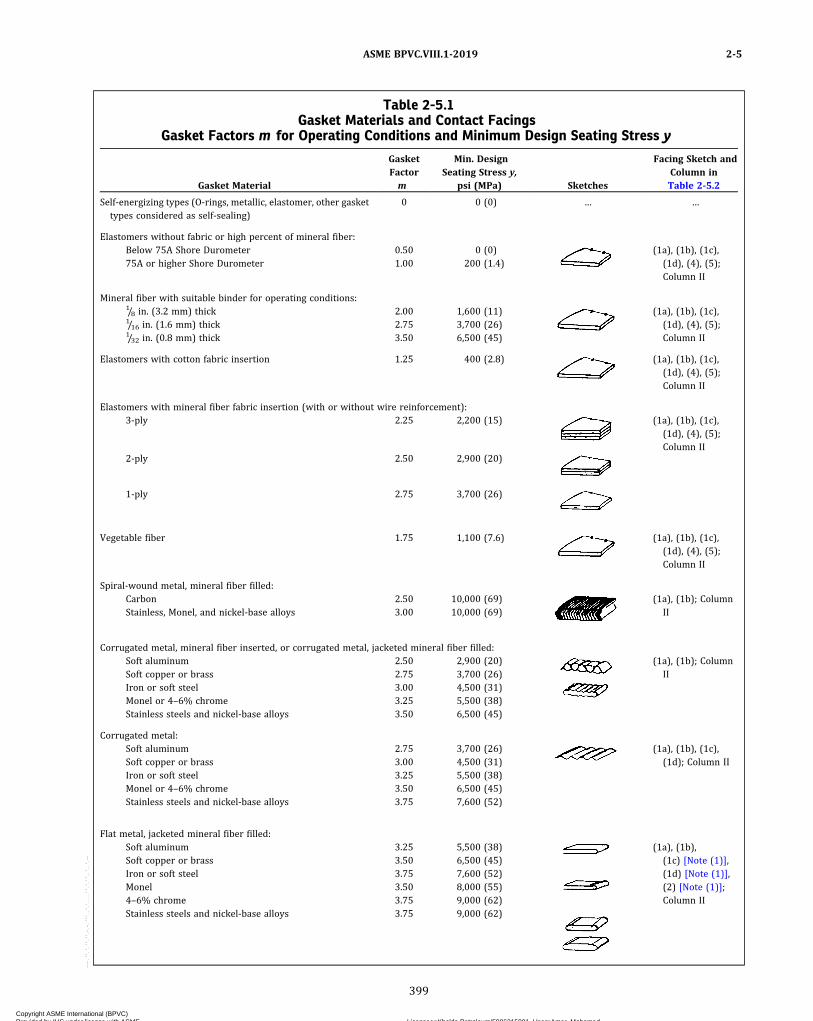
Table 2-5.1Gasket Materials and Contact Facings
Gasket Factors m for Operating Conditions and Minimum Design Seating Stress y
Gasket Material
GasketFactorm
Min. DesignSeating Stress y,
psi (MPa) Sketches
Facing Sketch andColumn inTable 2-5.2
Self‐energizing types (O-rings, metallic, elastomer, other gaskettypes considered as self‐sealing)
0 0 (0) … …
Elastomers without fabric or high percent of mineral fiber:Below 75A Shore Durometer 0.50 0 (0) (1a), (1b), (1c),
(1d), (4), (5);Column II
75A or higher Shore Durometer 1.00 200 (1.4)
Mineral fiber with suitable binder for operating conditions:1/8 in. (3.2 mm) thick 2.00 1,600 (11) (1a), (1b), (1c),
(1d), (4), (5);Column II
1/16 in. (1.6 mm) thick 2.75 3,700 (26)1/32 in. (0.8 mm) thick 3.50 6,500 (45)
Elastomers with cotton fabric insertion 1.25 400 (2.8) (1a), (1b), (1c),(1d), (4), (5);Column II
Elastomers with mineral fiber fabric insertion (with or without wire reinforcement):3‐ply 2.25 2,200 (15) (1a), (1b), (1c),
(1d), (4), (5);Column II
2‐ply 2.50 2,900 (20)
1‐ply 2.75 3,700 (26)
Vegetable fiber 1.75 1,100 (7.6) (1a), (1b), (1c),(1d), (4), (5);Column II
Spiral‐wound metal, mineral fiber filled:Carbon 2.50 10,000 (69) (1a), (1b); Column
IIStainless, Monel, and nickel‐base alloys 3.00 10,000 (69)
Corrugated metal, mineral fiber inserted, or corrugated metal, jacketed mineral fiber filled:Soft aluminum 2.50 2,900 (20) (1a), (1b); Column
IISoft copper or brass 2.75 3,700 (26)Iron or soft steel 3.00 4,500 (31)Monel or 4–6% chrome 3.25 5,500 (38)Stainless steels and nickel‐base alloys 3.50 6,500 (45)
Corrugated metal:Soft aluminum 2.75 3,700 (26) (1a), (1b), (1c),
(1d); Column IISoft copper or brass 3.00 4,500 (31)Iron or soft steel 3.25 5,500 (38)Monel or 4–6% chrome 3.50 6,500 (45)Stainless steels and nickel‐base alloys 3.75 7,600 (52)
Flat metal, jacketed mineral fiber filled:Soft aluminum 3.25 5,500 (38) (1a), (1b),
(1c) [Note (1)],(1d) [Note (1)],(2) [Note (1)];Column II
Soft copper or brass 3.50 6,500 (45)Iron or soft steel 3.75 7,600 (52)Monel 3.50 8,000 (55)4–6% chrome 3.75 9,000 (62)Stainless steels and nickel‐base alloys 3.75 9,000 (62)
ASME BPVC.VIII.1-2019 2-5
399
Copyright ASME International (BPVC) Provided by IHS under license with ASME Licensee=Khalda Petroleum/5986215001, User=Amer, Mohamed
Not for Resale, 07/02/2019 13:29:04 MDTNo reproduction or networking permitted without license from IHS
--`,``,``,,`,`,,````,`,``,,,`-`-`,,`,,`,`,,`---
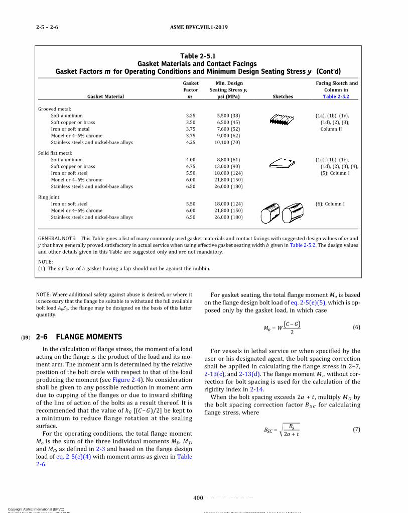
ð19Þ
NOTE: Where additional safety against abuse is desired, or where itis necessary that the flange be suitable to withstand the full availablebolt load AbSa, the flange may be designed on the basis of this latterquantity.
2-6 FLANGE MOMENTS
In the calculation of flange stress, the moment of a loadacting on the flange is the product of the load and its mo-ment arm. The moment arm is determined by the relativeposition of the bolt circle with respect to that of the loadproducing the moment (see Figure 2-4). No considerationshall be given to any possible reduction in moment armdue to cupping of the flanges or due to inward shiftingof the line of action of the bolts as a result thereof. It isrecommended that the value of hG [(C−G)/2] be kept toa minimum to reduce flange rotation at the sealingsurface.For the operating conditions, the total flange moment
Mo is the sum of the three individual moments MD, MT,and MG, as defined in 2-3 and based on the flange designload of eq. 2-5(e)(4) with moment arms as given in Table2-6.
For gasket seating, the total flange moment Mo is basedon the flange design bolt load of eq. 2-5(e)(5), which is op-posed only by the gasket load, in which case
ð6Þ
For vessels in lethal service or when specified by theuser or his designated agent, the bolt spacing correctionshall be applied in calculating the flange stress in 2–7,2-13(c), and 2-13(d). The flange momentMo without cor-rection for bolt spacing is used for the calculation of therigidity index in 2-14.When the bolt spacing exceeds 2a + t , multiply MO by
the bolt spacing correction factor BS C for calculatingflange stress, where
ð7Þ
Table 2-5.1Gasket Materials and Contact Facings
Gasket Factors m for Operating Conditions and Minimum Design Seating Stress y (Cont'd)
Gasket Material
GasketFactorm
Min. DesignSeating Stress y,
psi (MPa) Sketches
Facing Sketch andColumn inTable 2-5.2
Grooved metal:Soft aluminum 3.25 5,500 (38) (1a), (1b), (1c),
(1d), (2), (3);Column II
Soft copper or brass 3.50 6,500 (45)Iron or soft metal 3.75 7,600 (52)Monel or 4–6% chrome 3.75 9,000 (62)Stainless steels and nickel‐base alloys 4.25 10,100 (70)
Solid flat metal:Soft aluminum 4.00 8,800 (61) (1a), (1b), (1c),
(1d), (2), (3), (4),(5); Column I
Soft copper or brass 4.75 13,000 (90)Iron or soft steel 5.50 18,000 (124)Monel or 4–6% chrome 6.00 21,800 (150)Stainless steels and nickel‐base alloys 6.50 26,000 (180)
Ring joint:Iron or soft steel 5.50 18,000 (124) (6); Column IMonel or 4–6% chrome 6.00 21,800 (150)Stainless steels and nickel‐base alloys 6.50 26,000 (180)
GENERAL NOTE: This Table gives a list of many commonly used gasket materials and contact facings with suggested design values ofm andy that have generally proved satisfactory in actual service when using effective gasket seating width b given in Table 2-5.2. The design valuesand other details given in this Table are suggested only and are not mandatory.
NOTE:(1) The surface of a gasket having a lap should not be against the nubbin.
ASME BPVC.VIII.1-20192-5 – 2-6
400
Copyright ASME International (BPVC) Provided by IHS under license with ASME Licensee=Khalda Petroleum/5986215001, User=Amer, Mohamed
Not for Resale, 07/02/2019 13:29:04 MDTNo reproduction or networking permitted without license from IHS
--`,``,``,,`,`,,````,`,``,,,`-`-`,,`,,`,`,,`---
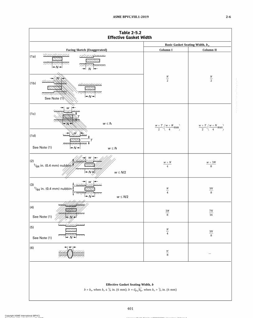
Table 2-5.2Effective Gasket Width
Basic Gasket Seating Width, bo
Facing Sketch (Exaggerated) Column I Column II
N N
(1a)
N
N
(1b)
See Note (1)
T
N
w
(1c)
w N
T
N
w(1d)
See Note (1) w N
1/64 in. (0.4 mm) nubbin
w
N
(2)
w N/2
w
N
1/64 in. (0.4 mm) nubbin(3)
w N/2
N
(4)
See Note (1)
N
(5)
See Note (1)
w(6)…
Effective Gasket Seating Width, b
b = bo, when bo ≤ 1/4 in. (6 mm); b = , when bo >1/4 in. (6 mm)
ASME BPVC.VIII.1-2019 2-6
401
Copyright ASME International (BPVC) Provided by IHS under license with ASME Licensee=Khalda Petroleum/5986215001, User=Amer, Mohamed
Not for Resale, 07/02/2019 13:29:04 MDTNo reproduction or networking permitted without license from IHS
--`,``,``,,`,`,,````,`,``,,,`-`-`,,`,,`,`,,`---
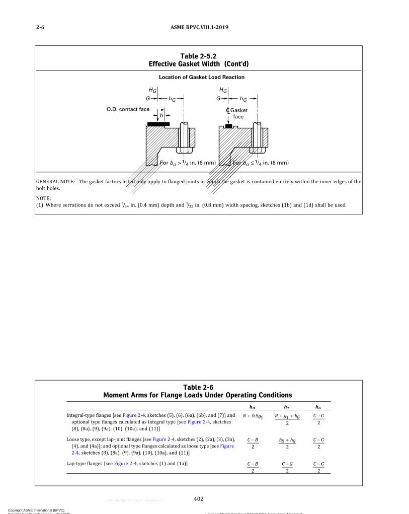
Table 2-5.2Effective Gasket Width (Cont'd)
hG
HG
G
O.D. contact face
Location of Gasket Load Reaction
Gasket face
For bo 1/4 in. (6 mm) For bo 1/4 in. (6 mm)
b
hG
HG
G
C
GENERAL NOTE: The gasket factors listed only apply to flanged joints in which the gasket is contained entirely within the inner edges of thebolt holes.
NOTE:(1) Where serrations do not exceed 1/64 in. (0.4 mm) depth and 1/32 in. (0.8 mm) width spacing, sketches (1b) and (1d) shall be used.
Table 2-6Moment Arms for Flange Loads Under Operating Conditions
hD hT hG
Integral-type flanges [see Figure 2-4, sketches (5), (6), (6a), (6b), and (7)] andoptional type flanges calculated as integral type [see Figure 2-4, sketches(8), (8a), (9), (9a), (10), (10a), and (11)]
Loose type, except lap‐joint flanges [see Figure 2-4, sketches (2), (2a), (3), (3a),(4), and (4a)]; and optional type flanges calculated as loose type [see Figure2-4, sketches (8), (8a), (9), (9a), (10), (10a), and (11)]
Lap‐type flanges [see Figure 2-4, sketches (1) and (1a)]
ASME BPVC.VIII.1-20192-6
402
Copyright ASME International (BPVC) Provided by IHS under license with ASME Licensee=Khalda Petroleum/5986215001, User=Amer, Mohamed
Not for Resale, 07/02/2019 13:29:04 MDTNo reproduction or networking permitted without license from IHS
--`,``,``,,`,`,,````,`,``,,,`-`-`,,`,,`,`,,`---

ð19Þ
ð19Þ
2-7 CALCULATION OF FLANGE STRESSES
The stresses in the flange shall be determined for boththe operating conditions and gasket seating condition,whichever controls, in accordance with the followingequations:
(a) for integral type flanges [Figure 2-4, sketches (5),(6), (6a), (6b), and (7)], for optional type flanges calcu-lated as integral type [Figure 2-4, sketches (8), (8a), (9),(9a), (10), (10a), and (11)], and for loose type flangeswith a hub which is considered [Figure 2-4, sketches(1), (1a), (2), (2a), (3), (3a), (4), (4a), (4b), and (4c)]:
Longitudinal hub stress
ð8Þ
Radial flange stress
ð9Þ
Tangential flange stress
ð10Þ
(b) for loose type flanges without hubs and loose typeflanges with hubs which the designer chooses to calculatewithout considering the hub [Figure 2-4, sketches (1),(1a), (2), (2a), (3), (3a), (4), (4a), (4b), and (4c)] and op-tional type flanges calculated as loose type [Figure 2-4,sketches (8), (8a), (9), (9a), (10), (10a), and (11)]:
ð11Þ
2-8 ALLOWABLE FLANGE DESIGN STRESSES
(a) The flange stresses calculated by the equations in2–7 shall not exceed the following values:
(1) longitudinal hub stress SH not greater than Sf forcast iron89 and, except as otherwise limited by (-a) and(-b) below, not greater than 1.5Sf for materials other thancast iron:
(-a) longitudinal hub stress SH not greater than thesmaller of 1.5Sf or 1.5Sn for optional type flanges designedas integral [Figure 2-4, sketches (8), (8a), (9), (9a), (10),(10a), and (11)], also integral type [Figure 2-4, sketch(7)] where the neck material constitutes the hub of theflange;
(-b) longitudinal hub stress SH not greater than thesmaller of 1.5Sf or 2.5Sn for integral type flanges with hubwelded to the neck, pipe or vessel wall [Figure 2-4,sketches (6), (6a), and (6b)].
(2) radial flange stress SR not greater than Sf ;(3) tangential flange stress ST not greater than Sf ;(4) also (SH + SR)/2 not greater than Sf and (SH + ST)/
2 not greater than Sf.(b) For hub flanges attached as shown in Figure 2-4,
sketches (2), (2a), (3), (3a), (4), (4a), (4b), and (4c), thenozzle neck, vessel or pipe wall shall not be consideredto have any value as a hub.
(c) In the case of loose type flanges with laps, as shownin Figure 2-4, sketches (1) and (1a), where the gasket isso located that the lap is subjected to shear, the shearingstress shall not exceed 0.8 Sn for the material of the lap, asdefined in 2-3. In the case of welded flanges, shown inFigure 2-4, sketches (3), (3a), (4), (4a), (4b), (4c), (7),(8), (8a), (9), (9a), (10), and (10a) where the nozzle neck,vessel, or pipe wall extends near to the flange face andmay form the gasket contact face, the shearing stress car-ried by the welds shall not exceed 0.8 Sn. The shearingstress shall be calculated on the basis of Wm1 or Wm2
as defined in 2-3, whichever is greater. Similar caseswhere flange parts are subjected to shearing stress shallbe governed by the same requirements.
2-9 SPLIT LOOSE FLANGES90
Loose flanges split across a diameter and designed un-der the rules given in this Appendix may be used underthe following provisions.
(a)When the flange consists of a single split flange orflange ring, it shall be designed as if it were a solid flange(without splits), using 200% of the total moment Mo asdefined in 12-4.
(b)When the flange consists of two split rings each ringshall be designed as if it were a solid flange (withoutsplits), using 75% of the total moment Mo as defined in12-4. The pair of rings shall be assembled so that thesplits in one ring shall be 90 deg from the splits in theother ring.
(c) The splits should preferably be midway betweenbolt holes.
(d) It is not a requirement that the flange rigidity rulesof 2-14 be applied to split loose flanges.
ASME BPVC.VIII.1-2019 2-7 – 2-9
403
Copyright ASME International (BPVC) Provided by IHS under license with ASME Licensee=Khalda Petroleum/5986215001, User=Amer, Mohamed
Not for Resale, 07/02/2019 13:29:04 MDTNo reproduction or networking permitted without license from IHS
--`,``,``,,`,`,,````,`,``,,,`-`-`,,`,,`,`,,`---
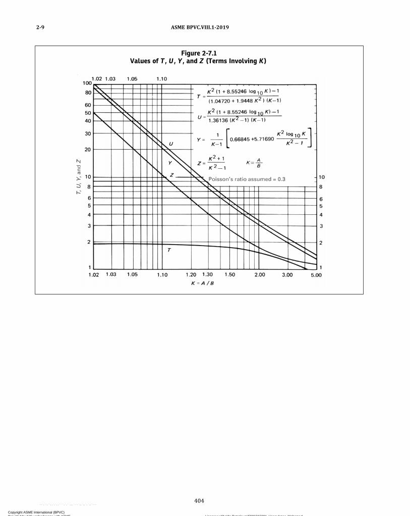
Figure 2-7.1Values of T , U , Y , and Z (Terms Involving K)
ASME BPVC.VIII.1-20192-9
404
Copyright ASME International (BPVC) Provided by IHS under license with ASME Licensee=Khalda Petroleum/5986215001, User=Amer, Mohamed
Not for Resale, 07/02/2019 13:29:04 MDTNo reproduction or networking permitted without license from IHS
--`,``,``,,`,`,,````,`,``,,,`-`-`,,`,,`,`,,`---
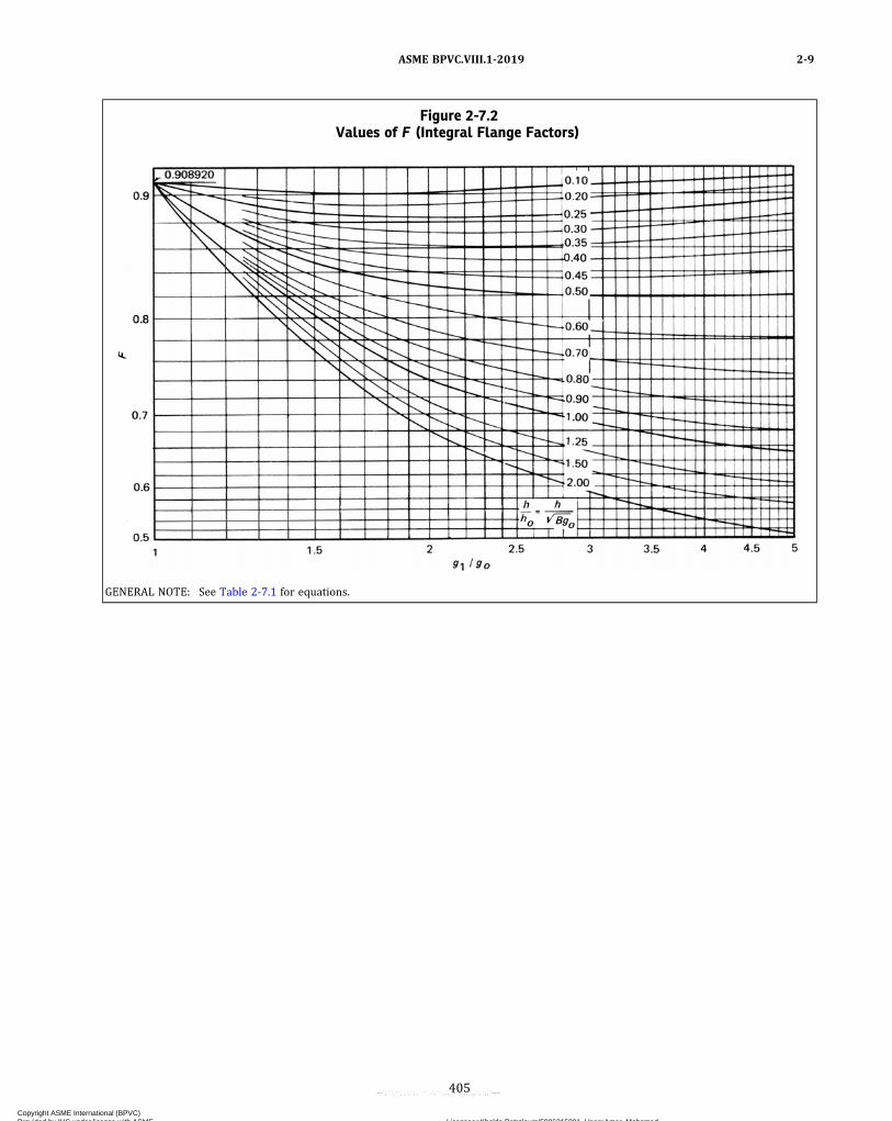
Figure 2-7.2Values of F (Integral Flange Factors)
GENERAL NOTE: See Table 2-7.1 for equations.
ASME BPVC.VIII.1-2019 2-9
405
Copyright ASME International (BPVC) Provided by IHS under license with ASME Licensee=Khalda Petroleum/5986215001, User=Amer, Mohamed
Not for Resale, 07/02/2019 13:29:04 MDTNo reproduction or networking permitted without license from IHS
--`,``,``,,`,`,,````,`,``,,,`-`-`,,`,,`,`,,`---
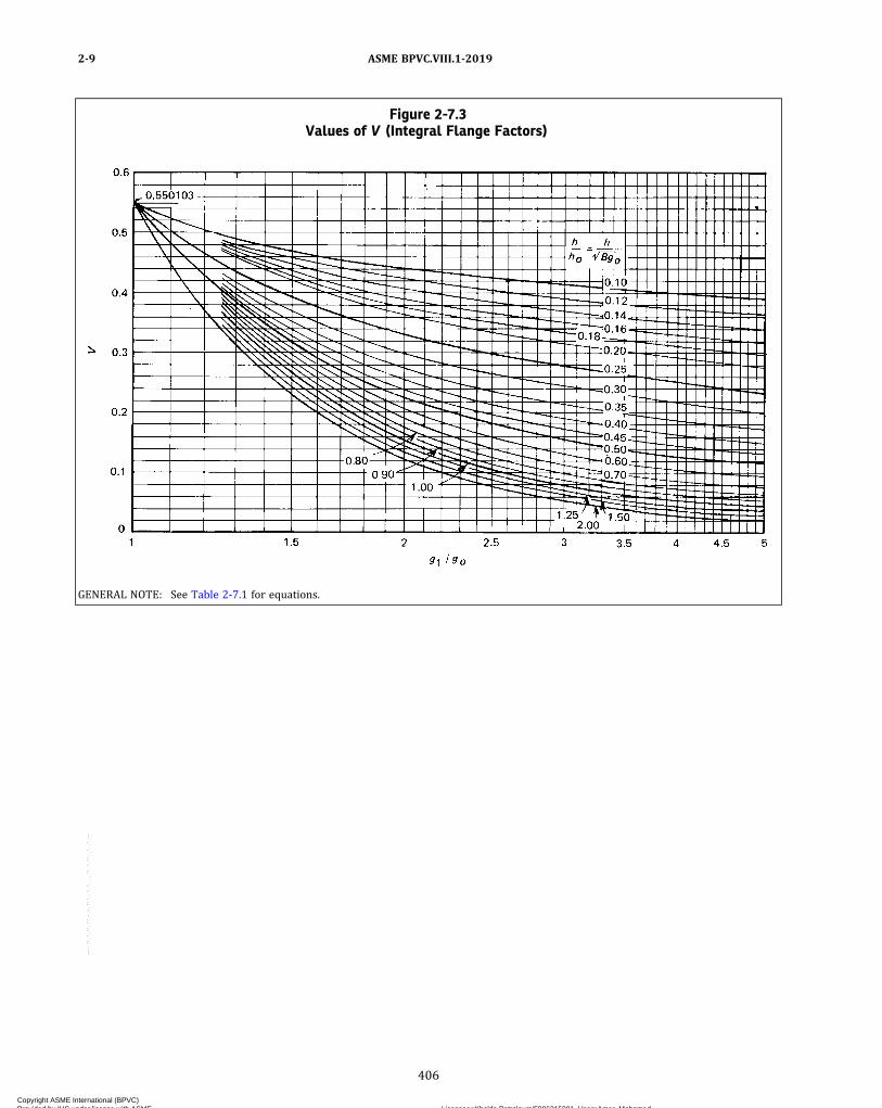
Figure 2-7.3Values of V (Integral Flange Factors)
GENERAL NOTE: See Table 2-7.1 for equations.
ASME BPVC.VIII.1-20192-9
406
Copyright ASME International (BPVC) Provided by IHS under license with ASME Licensee=Khalda Petroleum/5986215001, User=Amer, Mohamed
Not for Resale, 07/02/2019 13:29:04 MDTNo reproduction or networking permitted without license from IHS
--`,``,``,,`,`,,````,`,``,,,`-`-`,,`,,`,`,,`---
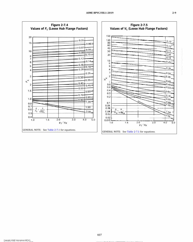
Figure 2-7.4Values of FL (Loose Hub Flange Factors)
GENERAL NOTE: See Table 2-7.1 for equations.
Figure 2-7.5Values of VL (Loose Hub Flange Factors)
GENERAL NOTE: See Table 2-7.1 for equations.
ASME BPVC.VIII.1-2019 2-9
407
Copyright ASME International (BPVC) Provided by IHS under license with ASME Licensee=Khalda Petroleum/5986215001, User=Amer, Mohamed
Not for Resale, 07/02/2019 13:29:04 MDTNo reproduction or networking permitted without license from IHS
--`,``,``,,`,`,,````,`,``,,,`-`-`,,`,,`,`,,`---
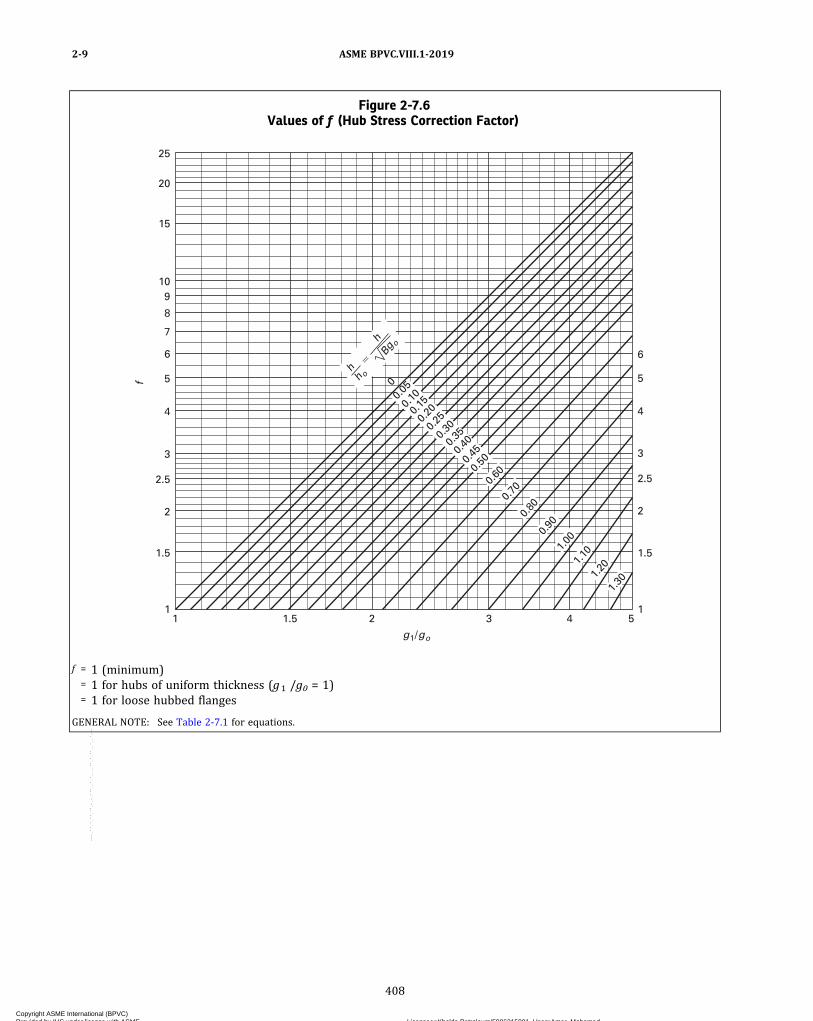
Figure 2-7.6Values of f (Hub Stress Correction Factor)
1
1.5 1.5
2
2.5
4
5
6
3
1
2.5
2
3
4
5
6
8
10
15
20
25
9
7
1 1.5 2 3
g1/go
4 5
0
0.05
0.10
0.20
0.25
0.35 0.3
0
0.40
0.45
0.50
0.15
0.60
0.70
0.80
0.
90
1.00
1.
10
1.20
1.
30
h h o
h Bg
o
f
f = 1 (minimum)= 1 for hubs of uniform thickness (g1 /g0 = 1)= 1 for loose hubbed flanges
GENERAL NOTE: See Table 2-7.1 for equations.
ASME BPVC.VIII.1-20192-9
408
Copyright ASME International (BPVC) Provided by IHS under license with ASME Licensee=Khalda Petroleum/5986215001, User=Amer, Mohamed
Not for Resale, 07/02/2019 13:29:04 MDTNo reproduction or networking permitted without license from IHS
--`,``,``,,`,`,,````,`,``,,,`-`-`,,`,,`,`,,`---
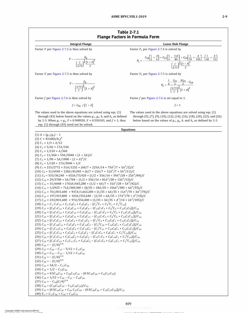
Table 2-7.1Flange Factors in Formula Form
Integral Flange Loose Hub Flange
Factor F per Figure 2-7.2 is then solved by Factor FL per Figure 2-7.4 is solved by
Factor V per Figure 2-7.3 is then solved by Factor VL per Figure 2-7.5 is solved by
Factor f per Figure 2-7.6 is then solved by Factor f per Figure 2-7.6 is set equal to 1.
The values used in the above equations are solved using eqs. (1)through (45) below based on the values g1, go, h, and ho as definedby 2-3. When g1 = go, F = 0.908920, V = 0.550103, and f = 1; thuseqs. (1) through (45) need not be solved.
The values used in the above equations are solved using eqs. (1)through (5), (7), (9), (10), (12), (14), (16), (18), (20), (23), and (26)below based on the values of g1, go, h, and ho as defined by 2-3.
Equations
(1) A = (g1/go) − 1(2) C = 43.68(h/ho)
4
(3) C1 = 1/3 + A/12(4) C2 = 5/42 + 17A/336(5) C3 = 1/210 + A/360(6) C4 = 11/360 + 59A/5040 + (1 + 3A)/C(7) C5 = 1/90 + 5A/1008 − (1 + A)3/C(8) C6 = 1/120 + 17A/5040 + 1/C(9) C7 = 215/2772 + 51A/1232 + (60/7 + 225A/14 + 75A2/7 + 5A3/2)/C(10) C8 = 31/6930 + 128A/45,045 + (6/7 + 15A/7 + 12A2/7 + 5A3/11)/C(11) C9 = 533/30,240 + 653A/73,920 + (1/2 + 33A/14 + 39A2/28 + 25A3/84)/C(12) C10 = 29/3780 + 3A/704 − (1/2 + 33A/14 + 81A2/28 + 13A3/12)/C(13) C11 = 31/6048 + 1763A/665,280 + (1/2 + 6A/7 + 15A2/28 + 5A3/42)/C(14) C12 = 1/2925 + 71A/300,300 + (8/35 + 18A/35 + 156A2/385 + 6A3/55)/C(15) C13 = 761/831,600 + 937A/1,663,200 + (1/35 + 6A/35 + 11A2/70 + 3A3/70)/C(16) C14 = 197/415,800 + 103A/332,640 − (1/35 + 6A/35 + 17A2/70 + A3/10)/C(17) C15 = 233/831,600 + 97A/554,400 + (1/35 + 3A/35 + A2/14 + 2A3/105)/C(18) C16 = C1 C7C12 + C2 C8C3 + C3C8C2 − (C3
2C7 + C82C1 + C2
2C12)(19) C17 = [C4C7C12 + C2C8C13 + C3C8C9 − (C13C7C3 + C8
2C4 + C12C2C9)]/C16
(20) C18 = [C5C7C12 + C2C8C14 + C3C8C10 − (C14C7C3 + C82C5 + C12C2C10)]/C16
(21) C19 = [C6C7C12 + C2C8C15 + C3C8C11 − (C15C7C3 + C82C6 + C12C2C11)]/C16
(22) C20 = [C1C9C12 + C4C8C3 + C3C13C2 − (C32C9 + C13C8C1 + C12C4C2)]/C16
(23) C21 = [C1C10C12 + C5C8C3 + C3C14C2 − (C32C10 + C14C8C1 + C12C5C2)]/C16
(24) C22 = [C1C11C12 + C6C8C3 + C3C15C2 − (C32C11 + C15C8C1 + C12C6C2)]/C16
(25) C23 = [C1C7C13 + C2C9C3 + C4C8C2 − (C3C7C4 + C8C9C1 + C22C13)]/C16
(26) C24 = [C1C7C14 + C2C10C3 + C5C8C2 − (C3C7C5 + C8C10C1 + C22C14)]/C16
(27) C25 = [C1C7C15 + C2C11C3 + C6C8C2 − (C3C7C6 + C8C11C1 + C22C15)]/C16
(28) C26 = − (C/4)1/4
(29) C27 = C20 − C17 − 5/12 + C17C26
(30) C28 = C22 − C19 − 1/12 + C19C26
(31) C29 = − (C/4)1/2
(32) C30 = − (C/4)3/4
(33) C31 = 3A/2 − C17C30
(34) C32 = 1/2 − C19C30
(35) C33 = 0.5C26C32 + C28C31C29 − (0.5C30C28 + C32C27C29)(36) C34 = 1/12 + C18 − C21 − C18C26
(37) C35 = − C18(C/4)3/4
(38) C36 = (C28C35C29 − C32C34C29)/C33
(39) C37 = [0.5C26C35 + C34 C31C29 − (0.5C30C34 + C35C27C29)]/C33
(40) E1 = C17C36 + C18 + C19C37
ASME BPVC.VIII.1-2019 2-9
409
Copyright ASME International (BPVC) Provided by IHS under license with ASME Licensee=Khalda Petroleum/5986215001, User=Amer, Mohamed
Not for Resale, 07/02/2019 13:29:04 MDTNo reproduction or networking permitted without license from IHS
--`,``,``,,`,`,,````,`,``,,,`-`-`,,`,,`,`,,`---

ð19Þ
ð19Þ
2-10 NONCIRCULAR SHAPED FLANGESWITH CIRCULAR BORE
The outside diameter A for a noncircular flange with acircular bore shall be taken as the diameter of the largestcircle, concentric with the bore, inscribed entirely withinthe outside edges of the flange. Bolt loads and moments,as well as stresses, are then calculated as for circularflanges, using a bolt circle drawn through the centers ofthe outermost bolt holes.
2-11 FLANGES SUBJECT TO EXTERNALPRESSURES
(a) The design of flanges for external pressure only [seeUG-99(f)]91 shall be based on the equations given in 2–7for internal pressure except that for operating conditions:
ð10Þ
For gasket seating,
ð11Þ
where
W = (11a)
HD = (11b)
HT = (11c)
H = (11d)
Pe = external design pressure
See 2-3 for definitions of other symbols. Sa used in eq.(11a) shall be not less than that tabulated in the stresstables (see UG-23).(b)When flanges are subject at different times during
operation to external or internal pressure, the designshall satisfy the external pressure design requirementsgiven in (a) above and the internal pressure design re-quirements given elsewhere in this Appendix.
NOTE: The combined force of external pressure and bolt loading mayplastically deform certain gaskets to result in loss of gasket contactpressure when the connection is depressurized. To maintain a tightjoint when the unit is repressurized, consideration should be givento gasket and facing details so that excessive deformation of the gas-ket will not occur. Joints subject to pressure reversals, such as in heatexchanger floating heads, are in this type of service.
2-12 FLANGES WITH NUT-STOPS
(a)When flanges are designed per this Appendix, or arefabricated to the dimensions of ASME B16.5 or other ac-ceptable standards [see UG-44(a)(2)], except that the di-mension R is decreased to provide a nut‐stop, the filletradius relief shall be as shown in Figure 2-4, sketches(12) and (12a) except that:
(1) for flanges designed to this Appendix, the mini-mum dimension g 1 must be the lesser of 2t (t fromUG-27) or 4r , but in no case less than 1/2 in. (13 mm),where
r = the radius of the undercut
(2) for ASME B16.5 or other standard flanges, the di-mension of the hub go shall be increased as necessary toprovide a nut‐stop.
2-13 REVERSE FLANGES
(a) Flanges with the configuration as indicated inFigure 2-13.1 shall be designed as integral reverse flangesand those in Figure 2-13.2 shall be designed as loose ringtype reverse flanges. These flanges shall be designed inconformance with the rules in 2-3 through 2-8, but withthe modifications as described in the following. Manda-tory use of these rules is limited to K ≤ 2. When K > 2, re-sults become increasingly conservative and U-2(g) maybe used.
(1) Integral Type Reverse Flange. The shell‐to‐flangeattachment of integral type reverse flanges may be at-tached as shown in Figure 2-4, sketches (5) through(11), as well as Figure UW-13.2, sketches (a) and (b).The requirements of 2-4(c) apply to Figure 2-4, sketches(8) through (11) as well as Figure UW-13.2, sketches (a)and (b).
Table 2-7.1Flange Factors in Formula Form (Cont'd)
Equations (Cont'd)
(41) E2 = C20C36 + C21 + C22C37
(42) E3 = C23C36 + C24 + C25C37
(43) E4 = 1/4 + C37/12 + C36/4 − E3/5 − 3E2/2 − E1
(44) E5 = E1(1/2 + A/6) + E2(1/4 + 11A/84) + E3(1/70 + A/105)(45) E6 = E5 − C36 (7/120 + A/36 + 3A/C) − 1/40 − A/72 − C37(1/60 + A/120 + 1/C)
ASME BPVC.VIII.1-20192-10 – 2-13
410
Copyright ASME International (BPVC) Provided by IHS under license with ASME Licensee=Khalda Petroleum/5986215001, User=Amer, Mohamed
Not for Resale, 07/02/2019 13:29:04 MDTNo reproduction or networking permitted without license from IHS
--`,``,``,,`,`,,````,`,``,,,`-`-`,,`,,`,`,,`---
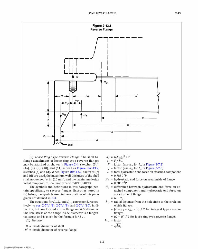
(2) Loose Ring Type Reverse Flange. The shell‐to‐flange attachment of loose ring type reverse flangesmay be attached as shown in Figure 2-4, sketches (3a),(4a), (8), (9), (10), and (11) as well as Figure UW-13.2,sketches (c) and (d). When Figure UW-13.2, sketches (c)and (d) are used, the maximum wall thickness of the shellshall not exceed 3/8 in. (10 mm), and the maximum designmetal temperature shall not exceed 650°F (340°C).
The symbols and definitions in this paragraph per-tain specifically to reverse flanges. Except as noted in(b) below, the symbols used in the equations of this para-graph are defined in 2-3.
The equations for SH, SR, and ST1 correspond, respec-tively, to eqs. 2-7(a)(8), 2-7(a)(9), and 2-7(a)(10), in di-rection, but are located at the flange outside diameter.The sole stress at the flange inside diameter is a tangen-tial stress and is given by the formula for ST2.
(b) Notation
B = inside diameter of shellB ′ = inside diameter of reverse flange
dr = Urhorgo2 / V
er = F / horF = factor (use hor for ho in Figure 2-7.2)f = factor (use hor for ho in Figure 2-7.6)H = total hydrostatic end force on attached component
= 0.785G2PHD = hydrostatic end force on area inside of flange
= 0.785B2PHT = difference between hydrostatic end force on at-
tached component and hydrostatic end force onarea inside of flange
= H − HD
hD = radial distance from the bolt circle to the circle onwhich HD acts
= (C + g1 − 2go − B) / 2 for integral type reverseflanges
= (C − B) / 2 for loose ring type reverse flangeshor = factor
=
Figure 2-13.1Reverse Flange
ASME BPVC.VIII.1-2019 2-13
411
Copyright ASME International (BPVC) Provided by IHS under license with ASME Licensee=Khalda Petroleum/5986215001, User=Amer, Mohamed
Not for Resale, 07/02/2019 13:29:04 MDTNo reproduction or networking permitted without license from IHS
--`,``,``,,`,`,,````,`,``,,,`-`-`,,`,,`,`,,`---
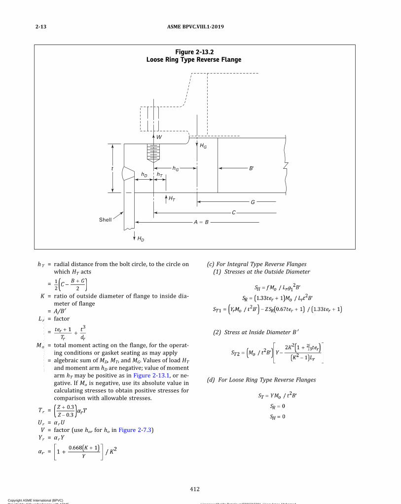
hT = radial distance from the bolt circle, to the circle onwhich HT acts
=
K = ratio of outside diameter of flange to inside dia-meter of flange
= A/B′Lr = factor
=
Mo = total moment acting on the flange, for the operat-ing conditions or gasket seating as may apply
= algebraic sum of MD, MT, and MG. Values of load HT
and moment arm hD are negative; value of momentarm hT may be positive as in Figure 2-13.1, or ne-gative. If Mo is negative, use its absolute value incalculating stresses to obtain positive stresses forcomparison with allowable stresses.
Tr =
Ur = α rUV = factor (use hor for ho in Figure 2-7.3)Yr = α rY
αr =
(c) For Integral Type Reverse Flanges(1) Stresses at the Outside Diameter
(2) Stress at Inside Diameter B ′
(d) For Loose Ring Type Reverse Flanges
Figure 2-13.2Loose Ring Type Reverse Flange
Shell
B�
HG
hG
W
hT
HT
hD
t
HD
C
A � B
G
ASME BPVC.VIII.1-20192-13
412
Copyright ASME International (BPVC) Provided by IHS under license with ASME Licensee=Khalda Petroleum/5986215001, User=Amer, Mohamed
Not for Resale, 07/02/2019 13:29:04 MDTNo reproduction or networking permitted without license from IHS
--`,``,``,,`,`,,````,`,``,,,`-`-`,,`,,`,`,,`---
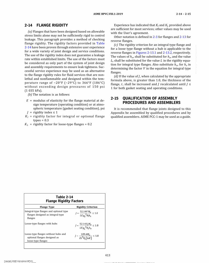
2-14 FLANGE RIGIDITY
(a) Flanges that have been designed based on allowablestress limits alone may not be sufficiently rigid to controlleakage. This paragraph provides a method of checkingflange rigidity. The rigidity factors provided in Table2-14 have been proven through extensive user experiencefor a wide variety of joint design and service conditions.The use of the rigidity index does not guarantee a leakagerate within established limits. The use of the factors mustbe considered as only part of the system of joint designand assembly requirements to ensure leak tightness. Suc-cessful service experience may be used as an alternativeto the flange rigidity rules for fluid services that are non-lethal and nonflammable and designed within the tem-perature range of −20°F (−29°C) to 366°F (186°C)without exceeding design pressures of 150 psi(1 035 kPa).
(b) The notation is as follows:
E = modulus of elasticity for the flange material at de-sign temperature (operating condition) or at atmo-spheric temperature (gasket seating condition), psi
J = rigidity index ≤ 1KI = rigidity factor for integral or optional flange
types = 0.3KL = rigidity factor for loose‐type flanges = 0.2
Experience has indicated that KI and KL provided aboveare sufficient for most services; other values may be usedwith the User’s agreement.
Other notation is defined in 2-3 for flanges and 2-13 forreverse flanges.
(c) The rigidity criterion for an integral type flange andfor a loose type flange without a hub is applicable to thereverse flanges in Figures 2-13.1 and 2-13.2, respectively.The values of hor shall be substituted for ho, and the valueLr shall be substituted for the value L in the rigidity equa-tion for integral type flanges. Also substitute hor for ho indetermining the factor V in the equation for integral typeflanges.
(d) If the value of J , when calculated by the appropriateformula above, is greater than 1.0, the thickness of theflange, t , shall be increased and J recalculated until J ≤1 for both gasket seating and operating conditions.
2-15 QUALIFICATION OF ASSEMBLYPROCEDURES AND ASSEMBLERS
It is recommended that flange joints designed to thisAppendix be assembled by qualified procedures and byqualified assemblers. ASME PCC‐1 may be used as a guide.
Table 2-14Flange Rigidity Factors
Flange Type Rigidity Criterion
Integral-type flanges and optional typeflanges designed as integral-typeflanges
Loose-type flanges with hubs
Loose-type flanges without hubs andoptional flanges designed asloose-type flanges
ASME BPVC.VIII.1-2019 2-14 – 2-15
413
Copyright ASME International (BPVC) Provided by IHS under license with ASME Licensee=Khalda Petroleum/5986215001, User=Amer, Mohamed
Not for Resale, 07/02/2019 13:29:04 MDTNo reproduction or networking permitted without license from IHS
--`,``,``,,`,`,,````,`,``,,,`-`-`,,`,,`,`,,`---
ð19Þ
MANDATORY APPENDIX 3DEFINITIONS
3-1 INTRODUCTION
This Appendix contains definitions of terms generallyused in this Division. Definitions relating to specific appli-cations, such as for layered vessels, may be found in re-lated parts of this Division.
3-2 DEFINITIONS OF TERMS
acceptance by the Inspector, accepted by the Inspector: anindication that the Inspector has reviewed a subject in ac-cordance with his duties as required by the rules of thisDivision and after such review is able to sign the Certifi-cate of Inspection for the applicable Manufacturer’s DataReport Form.
ASME Designated Organization: see ASME CA-1.
ASME designee: see ASME CA-1.
basic material specification: a description of the identify-ing characteristics of a material (product form, rangesof composition, mechanical properties, methods of pro-duction, etc.) together with the sampling, testing, and ex-amination procedures to be applied to production lots ofsuch material to verify acceptable conformance to the in-tended characteristics.
bolt: a threaded fastener with a head on one end.
calculated test pressure: the requirements for determiningthe test pressure based on calculations are outlined inUG-99(c) for the hydrostatic test and in UG-100(b) forthe pneumatic test. The basis for calculated test pressurein either of these paragraphs is the highest permissible in-ternal pressure as determined by the design equations,for each element of the vessel using nominal thicknesseswith corrosion allowances included and using the allow-able stress values given in Section II, Part D, Subpart 1for the temperature of the test.
Certificate of Authorization: a document issued by the So-ciety that authorizes the use of the ASME CertificationMark and appropriate designator for a specified timeand for a specified scope of activity.
certificate of compliance: a document that states that thematerial represented has been manufactured, sampled,tested, and inspected in accordance with the require-ments of the material specification (including year of is-sue) and any other requirements specified in the
purchase order or contract shown on the certificate, andhas been found to meet such requirements. This docu-ment may be combined with a Material Test Report as asingle document.
Certification Designator (Designator): the symbol used inconjunction with the Certification Mark for the scope ofactivity described in a Manufacturer’s Certificate ofAuthorization.
Certification Mark: An ASME symbol identifying a productas meeting Code Requirements.
Certification Mark Stamp: a metallic stamp issued by theSociety for use in impressing the Certification Mark.
clad vessel: a vessel made from a base material having acorrosion resistant material either integrally bonded orweld metal overlaid to the base of less resistant material.
completed pressure vessel: an assemblage of pressure ves-sel parts of which no further welding, assembly, or testingis required, and to which a Certification Mark and Desig-nator has been applied and for which a Form U-1 or FormU-1A has been completed.
construction: an all-inclusive term comprising material,design, fabrication, examination, inspection, testing, certi-fication, and overpressure protection.
design pressure: the pressure used in the design of a vesselcomponent together with the coincident design metaltemperature, for the purpose of determining the mini-mum permissible thickness or physical characteristics ofthe different zones of the vessel. When applicable, statichead shall be added to the design pressure to determinethe thickness of any specific zone of the vessel (seeUG-21).
design temperature: see UG-20.
efficiency of a welded joint: the efficiency of a welded jointis expressed as a numerical (decimal) quantity and is usedin the design of a joint as a multiplier of the appropriateallowable stress value taken from the applicable table inSection II, Part D, Subpart 1 (see UW-12).
full vacuum (FV): a condition where the internal absolutepressure is 0 psi (0 kPa) and the external absolute pres-sure on the vessel is 15 psi (103 kPa)(see UG-116).
joints: for the purpose of this Division, the following defi-nitions are applicable:
ASME BPVC.VIII.1-20193-1 – 3-2
414
Copyright ASME International (BPVC) Provided by IHS under license with ASME Licensee=Khalda Petroleum/5986215001, User=Amer, Mohamed
Not for Resale, 07/02/2019 13:29:04 MDTNo reproduction or networking permitted without license from IHS
--`,``,``,,`,`,,````,`,``,,,`-`-`,,`,,`,`,,`---
(a) angle joint: a joint between two members located inintersecting planes with an angle greater than 30 deg butless than 90 deg.
(b) butt joint: a joint between two members located inintersecting planes between 0 deg and 30 deg, inclusive.
(c) corner joint: a joint between two members locatedin intersecting planes at approximately 90 deg.
layered vessel: a vessel having a shell and/or heads madeup of two or more separate layers.
lined vessel: a vessel having a corrosion resistant lining at-tached intermittently to the vessel wall.
liquid penetrant examination (PT): a method of nondes-tructive examination that provides for the detection ofimperfections open to the surface in ferrous and nonfer-rous materials that are nonporous. Typical imperfectionsdetectable by this method are cracks, seams, laps, coldshuts, and laminations.
magnetic particle examination (MT): a method of detect-ing cracks and similar imperfections at or near the surfacein iron and the magnetic alloys of steel. It consists of prop-erly magnetizing the material and applying finely dividedmagnetic particles that form patterns indicating theimperfections.
material: any substance or product form covered by aspecification in Section II, Part A, Part B, or Part C, orany other substance or product form permitted for usein pressure vessel construction by this Division.
material manufacturer: the organization responsible forthe production of products meeting the requirements ofthe material specification, and accepting the responsibil-ity for any statements or data in any required certificateof compliance or Material Test Report representing thematerial.
Material Test Report: a document in which the results oftests, examinations, repairs, or treatments required bythe material specification to be reported are recorded, in-cluding those of any supplementary requirements orother requirements stated in the order for the material.This document may be combined with a certificate ofcompliance as a single document.
maximum allowable stress value: the maximum unit stresspermissible for any specified material that may be used inthe design equations given in this Division (see UG-23).
maximum allowable working pressure: the maximum gagepressure permissible at the top of a completed vessel inits normal operating position at the designated coincidenttemperature for that pressure. This pressure is the leastof the values for the internal or external pressure to bedetermined by the rules of this Division for any of thepressure boundary parts, including the static head there-on, using nominal thicknesses exclusive of allowances forcorrosion and considering the effects of any combination
of loadings listed in UG-22 that are likely to occur (seeUG-98) at the designated coincident temperature [seeUG-20(a)]. It is the basis for the pressure setting of thepressure-relieving devices protecting the vessel. The de-sign pressure may be used in all cases in which calcula-tions are not made to determine the value of themaximum allowable working pressure.
membrane stress: the component of normal stress that isuniformly distributed and equal to the average value ofstress across the thickness of the section underconsideration.
nominal pipe size (NPS): nominal pipe size as usedthroughout this Division is defined as the pipe outsidediameter for a given pipe size in accordance with ASMEB36.10M.
normal operation: operation within the design limits forwhich the vessel has been stamped. [See UG-116(a).]Any coincident pressure and temperature during a specif-ic operation are permissible, provided they do not consti-tute a more severe condition than that assumed in thedesign of the vessel.
operating or working temperature: the temperature thatwill be maintained in the metal of the part of the vesselbeing considered for the specified operation of the vessel(see UG-20 and UG-23).
operating pressure: the pressure at the top of a vessel atwhich it normally operates. It shall not exceed the maxi-mum allowable working pressure, and it is usually keptat a suitable level below the setting of the pressure-relieving devices to prevent their frequent opening (seeM-9).
porosity: gas pockets or voids in metal.
pressure vessel part: an integral piece of the pressure ves-sel that is required to contain the specified design pres-sure (internal or external) and/or the hydrostatic orpneumatic test pressure of the contents of the pressurevessel within the allowable stress limits of this Division.If this part were completely removed, the pressure vesselwould not be able to contain the design and/or hydro-static or pneumatic test pressure within the allowablestress limits. Excess thickness and material extensionsare included in the pressure part.
primary stress: a stress developed by the imposed loadingthat is necessary to satisfy the simple laws of equilibriumof external and internal forces and moments. Primarystress can be either membrane or bending stress.
Primary membrane stress may be of two types: generaland local. A general primary membrane stress is one thatis so distributed in the structure that no redistribution ofload occurs as a result of yielding. A local primary mem-brane stress is one that is produced by pressure or other
ASME BPVC.VIII.1-2019 3-2
415
Copyright ASME International (BPVC) Provided by IHS under license with ASME Licensee=Khalda Petroleum/5986215001, User=Amer, Mohamed
Not for Resale, 07/02/2019 13:29:04 MDTNo reproduction or networking permitted without license from IHS
--`,``,``,,`,`,,````,`,``,,,`-`-`,,`,,`,`,,`---

mechanical loading and that is associated with a primaryand/or discontinuity effect. Examples of primary stressare(a) general membrane stress in a circular cylinder or a
spherical shell due to internal pressure or to distributedloads;(b) bending stress in the central portion of a flat head
due to pressure.
radiographic examination (RT): a method of detecting im-perfections in materials by passing X‐ray or nuclear radia-tion through the material and presenting their image on arecording medium.
safety valve set pressure: see ASME PTC 25.
spiral weld: a weld joint having a helical seam [seeUW-3(a)].
stationary pressure vessel: a pressure vessel to be installedand operated as a fixed geographical location.
stud: a threaded fastener without a head, with threads onone end or both ends, or threaded full length.
thickness of vessel wall:(a) design thickness: the sum of the required thickness
and the corrosion allowance (see UG-25).
(b) required thickness: that computed by the equationsin this Division before corrosion allowance is added(see UG-22).(c) nominal thickness: except as defined in UW-40(f)
and modified in UW-11(g), the nominal thickness is thethickness selected as commercially available, and sup-plied to the Manufacturer. For plate material, the nominalthickness shall be, at the Manufacturer’s option, either thethickness shown on the Material Test Report {or materialCertificate of Compliance [UG-93(a)(1)]} before forming,or the measured thickness of the plate at the joint or loca-tion under consideration.
ultrasonic examination (UT): a method for detecting im-perfections in materials by passing ultrasonic vibrations(frequencies normally 1 MHz to 5 MHz) through thematerial.
vessel Manufacturer: any Manufacturer who constructs anitem such as a pressure vessel, vessel component, or partin accordance with rules of this Division and who holds anASME Certificate of Authorization to apply the Certifica-tion Mark and the appropriate Designator to such an item.
ASME BPVC.VIII.1-20193-2
416
Copyright ASME International (BPVC) Provided by IHS under license with ASME Licensee=Khalda Petroleum/5986215001, User=Amer, Mohamed
Not for Resale, 07/02/2019 13:29:04 MDTNo reproduction or networking permitted without license from IHS
--`,``,``,,`,`,,````,`,``,,,`-`-`,,`,,`,`,,`---

MANDATORY APPENDIX 4ROUNDED INDICATIONS CHARTS ACCEPTANCE STANDARD FORRADIOGRAPHICALLY DETERMINED ROUNDED INDICATIONS IN
WELDS
4-1 APPLICABILITY OF THESE STANDARDS
These standards are applicable to ferritic, austenitic,and nonferrous materials.
4-2 TERMINOLOGY
(a) Rounded Indications. Indications with a maximumlength of three times the width or less on the radiographare defined as rounded indications. These indications maybe circular, elliptical, conical, or irregular in shape andmay have tails. When evaluating the size of an indication,the tail shall be included. The indication may be from anyimperfection in the weld, such as porosity, slag, ortungsten.
(b) Aligned Indications. A sequence of four or morerounded indications shall be considered to be alignedwhen they touch a line parallel to the length of the welddrawn through the center of the two outer roundedindications.
(c) Thickness t . t is the thickness of the weld, excludingany allowable reinforcement. For a butt weld joining twomembers having different thicknesses at the weld, t is thethinner of these two thicknesses. If a full penetration weldincludes a fillet weld, the thickness of the throat of the fil-let shall be included in t .
4-3 ACCEPTANCE CRITERIA
(a) Image Density. Density within the image of the indi-cation may vary and is not a criterion for acceptance orrejection.
(b) Relevant Indications. (See Table 4-1 for examples.)Only those rounded indications which exceed the follow-ing dimensions shall be considered relevant.
(1) 1/10t for t less than1/8 in. (3 mm)
(2) 1/64 in. for t from1/8 in. to
1/4 in. (3 mm to 6 mm),incl.
(3) 1/32 in. for t greater than 1/4 in. to 2 in. (6 mmto 50 mm), incl.
(4) 1/16 in. for t greater than 2 in. (50 mm)(c) Maximum Size of Rounded Indication. (See Table
4-1 for examples.) The maximum permissible size ofany indication shall be 1/4t , or
5/32 in. (4 mm), whicheveris smaller; except that an isolated indication separatedfrom an adjacent indication by 1 in. (25 mm) or moremay be 1/3t , or
1/4 in. (6 mm), whichever is less. For tgreater than 2 in. (50 mm) the maximum permissible sizeof an isolated indication shall be increased to 3/8 in.(10 mm).
Table 4-1
Customary Units
Thickness, t , in.
Maximum Size ofAcceptable Rounded
Indication, in.Maximum Size of
NonrelevantIndication, in.Random Isolated
Less than 1/81/4 t
1/3 t1/10 t
1/8 0.031 0.042 0.0153/16 0.047 0.063 0.0151/4 0.063 0.083 0.0155/16 0.078 0.104 0.0313/8 0.091 0.125 0.0317/16 0.109 0.146 0.0311/2 0.125 0.168 0.0319/16 0.142 0.188 0.0315/8 0.156 0.210 0.03111/16 0.156 0.230 0.0313/4 to 2, incl. 0.156 0.250 0.031Over 2 0.156 0.375 0.063
SI Units
Thickness, t , mm
Maximum Size ofAcceptable Rounded
Indication, mmMaximum Size of
NonrelevantIndication, mmRandom Isolated
Less than 3 1/4 t1/3 t
1/10 t3 0.79 1.07 0.385 1.19 1.60 0.386 1.60 2.11 0.388 1.98 2.64 0.7910 2.31 3.18 0.7911 2.77 3.71 0.7913 3.18 4.27 0.7914 3.61 4.78 0.7916 3.96 5.33 0.7917 3.96 5.84 0.7919.0 to 50, incl. 3.96 6.35 0.79Over 50 3.96 9.53 1.60
GENERAL NOTE: This Table contains examples only.
ASME BPVC.VIII.1-2019 4-1 – 4-3
417
Copyright ASME International (BPVC) Provided by IHS under license with ASME Licensee=Khalda Petroleum/5986215001, User=Amer, Mohamed
Not for Resale, 07/02/2019 13:29:04 MDTNo reproduction or networking permitted without license from IHS
--`,``,``,,`,`,,````,`,``,,,`-`-`,,`,,`,`,,`---
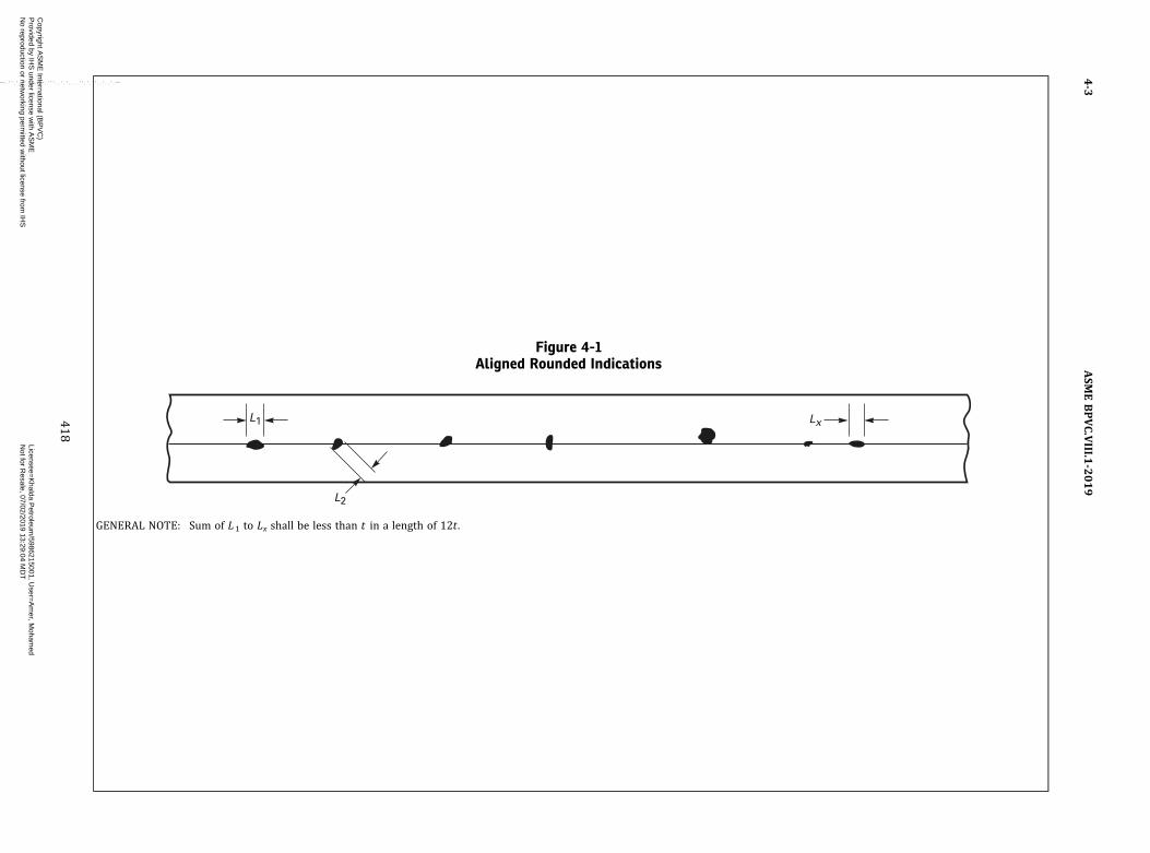
Figure 4-1Aligned Rounded Indications
L1
L2
Lx
GENERAL NOTE: Sum of L1 to Lx shall be less than t in a length of 12t .
ASM
EBPVC.VIII.1
-2019
4-3
418
Copyright A
SM
E International (B
PV
C)
Provided by IH
S under license w
ith AS
ME
Licensee=
Khalda P
etroleum/5986215001, U
ser=A
mer, M
ohamed
Not for R
esale, 07/02/2019 13:29:04 MD
TN
o reproduction or networking perm
itted without license from
IHS
--`,``,``,,`,`,,````,`,``,,,`-`-`,,`,,`,`,,`---
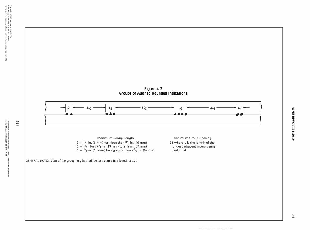
Figure 4-2Groups of Aligned Rounded Indications
L1 3L2 3L3 3L3 L2 L3 L4
Maximum Group Length
LLL
1/4 in. (6 mm) for t less than 3/4 in. (19 mm)1/3t for t 3/4 in. (19 mm) to 21/4 in. (57 mm)3/4 in. (19 mm) for t greater than 21/4 in. (57 mm)
===
Minimum Group Spacing
3L where L is the length of the longest adjacent group being evaluated
GENERAL NOTE: Sum of the group lengths shall be less than t in a length of 12t .
ASM
EBPVC.VIII.1
-2019
4-3
419
Copyright A
SM
E International (B
PV
C)
Provided by IH
S under license w
ith AS
ME
Licensee=
Khalda P
etroleum/5986215001, U
ser=A
mer, M
ohamed
Not for R
esale, 07/02/2019 13:29:04 MD
TN
o reproduction or networking perm
itted without license from
IHS
--`,``,``,,`,`,,````,`,``,,,`-`-`,,`,,`,`,,`---

(d) Aligned Rounded Indications. Aligned rounded indi-cations are acceptable when the summation of the dia-meters of the indications is less than t in a length of12t . See Figure 4-1. The length of groups of alignedrounded indications and the spacing between the groupsshall meet the requirements of Figure 4-2.(e) Spacing. The distance between adjacent rounded
indications is not a factor in determining acceptance orrejection, except as required for isolated indications orgroups of aligned indications.(f) Rounded Indication Charts. The rounded indications
characterized as imperfections shall not exceed thatshown in the charts. The charts in Figures 4-3 through4-8 illustrate various types of assorted, randomly dis-persed and clustered rounded indications for differentweld thicknesses greater than 1/8 in. (3 mm). These chartsrepresent the maximum acceptable concentration limitsfor rounded indications. The charts for each thicknessrange represent full‐scale 6 in. (150 mm) radiographs,
and shall not be enlarged or reduced. The distributionsshown are not necessarily the patterns that may appearon the radiograph, but are typical of the concentrationand size of indications permitted.(g) Weld Thickness t Less Than 1/8 in. (3 mm). For t less
than 1/8 in. (3 mm) the maximum number of rounded in-dications shall not exceed 12 in a 6 in. (150 mm) lengthof weld. A proportionally fewer number of indicationsshall be permitted in welds less than 6 in. (150 mm) inlength.(h) Clustered Indications. The illustrations for clustered
indications show up to four times as many indications in alocal area, as that shown in the illustrations for randomindications. The length of an acceptable cluster shall notexceed the lesser of 1 in. (25 mm) or 2t . Where more thanone cluster is present, the sum of the lengths of the clus-ters shall not exceed 1 in. (25 mm) in a 6 in. (150 mm)length weld.
Figure 4-3Charts for t Equal to 1/8 in. to 1/4 in. (3 mm to 6 mm), Inclusive
1 in. (25 mm)
(c) Cluster
1 in. (25 mm)
(a) Random Rounded Indications [See Note (1)]
(b) Isolated Indication [See Note (2)]
NOTES:(1) Typical concentration and size permitted in any 6 in. (150 mm) length of weld.(2) Maximum size per Table 4-1.
ASME BPVC.VIII.1-20194-3
420
Copyright ASME International (BPVC) Provided by IHS under license with ASME Licensee=Khalda Petroleum/5986215001, User=Amer, Mohamed
Not for Resale, 07/02/2019 13:29:04 MDTNo reproduction or networking permitted without license from IHS
--`,``,``,,`,`,,````,`,``,,,`-`-`,,`,,`,`,,`---
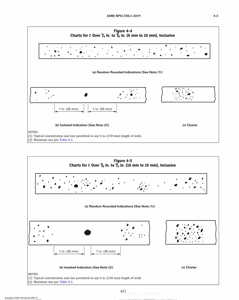
Figure 4-4Charts for t Over 1/4 in. to 3/8 in. (6 mm to 10 mm), Inclusive
(c) Cluster
1 in. (25 mm)1 in. (25 mm)
(a) Random Rounded Indications [See Note (1)]
(b) Isolated Indication [See Note (2)]
NOTES:(1) Typical concentration and size permitted in any 6 in. (150 mm) length of weld.(2) Maximum size per Table 4-1.
Figure 4-5Charts for t Over 3/8 in. to
3/4 in. (10 mm to 19 mm), Inclusive
(c) Cluster
1 in. (25 mm)1 in. (25 mm)
(a) Random Rounded Indications [See Note (1)]
(b) Isolated Indication [See Note (2)]
NOTES:(1) Typical concentration and size permitted in any 6 in. (150 mm) length of weld.(2) Maximum size per Table 4-1.
ASME BPVC.VIII.1-2019 4-3
421
Copyright ASME International (BPVC) Provided by IHS under license with ASME Licensee=Khalda Petroleum/5986215001, User=Amer, Mohamed
Not for Resale, 07/02/2019 13:29:04 MDTNo reproduction or networking permitted without license from IHS
--`,``,``,,`,`,,````,`,``,,,`-`-`,,`,,`,`,,`---
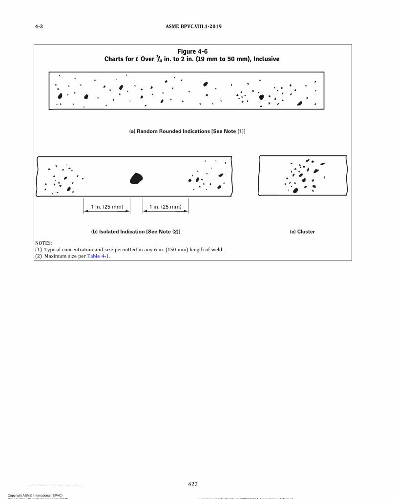
Figure 4-6Charts for t Over 3/4 in. to 2 in. (19 mm to 50 mm), Inclusive
(c) Cluster
1 in. (25 mm)1 in. (25 mm)
(a) Random Rounded Indications [See Note (1)]
(b) Isolated Indication [See Note (2)]
NOTES:(1) Typical concentration and size permitted in any 6 in. (150 mm) length of weld.(2) Maximum size per Table 4-1.
ASME BPVC.VIII.1-20194-3
422
Copyright ASME International (BPVC) Provided by IHS under license with ASME Licensee=Khalda Petroleum/5986215001, User=Amer, Mohamed
Not for Resale, 07/02/2019 13:29:04 MDTNo reproduction or networking permitted without license from IHS
--`,``,``,,`,`,,````,`,``,,,`-`-`,,`,,`,`,,`---

Figure 4-7Charts for t Over 2 in. to 4 in. (50 mm to 100 mm), Inclusive
(c) Cluster
1 in. (25 mm)1 in. (25 mm)
(a) Random Rounded Indications [See Note (1)]
(b) Isolated Indication [See Note (2)]
NOTES:(1) Typical concentration and size permitted in any 6 in. (150 mm) length of weld.(2) Maximum size per Table 4-1.
ASME BPVC.VIII.1-2019 4-3
423
Copyright ASME International (BPVC) Provided by IHS under license with ASME Licensee=Khalda Petroleum/5986215001, User=Amer, Mohamed
Not for Resale, 07/02/2019 13:29:04 MDTNo reproduction or networking permitted without license from IHS
--`,``,``,,`,`,,````,`,``,,,`-`-`,,`,,`,`,,`---
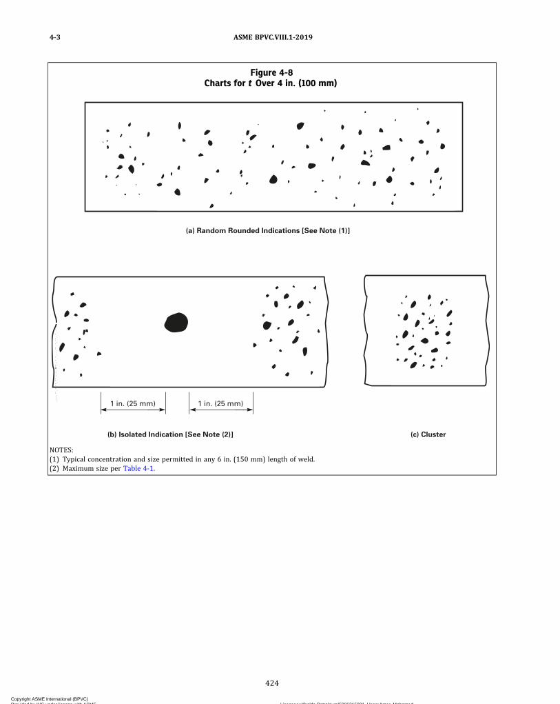
Figure 4-8Charts for t Over 4 in. (100 mm)
(a) Random Rounded Indications [See Note (1)]
(b) Isolated Indication [See Note (2)] (c) Cluster
1 in. (25 mm)1 in. (25 mm)
NOTES:(1) Typical concentration and size permitted in any 6 in. (150 mm) length of weld.(2) Maximum size per Table 4-1.
ASME BPVC.VIII.1-20194-3
424
Copyright ASME International (BPVC) Provided by IHS under license with ASME Licensee=Khalda Petroleum/5986215001, User=Amer, Mohamed
Not for Resale, 07/02/2019 13:29:04 MDTNo reproduction or networking permitted without license from IHS
--`,``,``,,`,`,,````,`,``,,,`-`-`,,`,,`,`,,`---
MANDATORY APPENDIX 5FLEXIBLE SHELL ELEMENT EXPANSION JOINTS
5-1 GENERAL
(a) Flexible shell element expansion joints used as anintegral part of heat exchangers or other pressure vesselsshall be designed to provide flexibility for thermal expan-sions and also function as pressure-containing elements.The rules in this Appendix are intended to apply to typicalsingle-layer flexible shell element expansion joints shownin Figure 5-1 and are limited to applications involvingonly axial deflections. The suitability of the expansionjoint for the specified design, pressure, and temperatureshall be determined by methods described in thisAppendix.
(b) In all vessels with expansion joints, the hydrostaticend force caused by pressure and/or the joint springforce shall be contained by adequate restraining elements(i.e., tube bundle, tubesheets or shell, external bolting, an-chors, etc.). The average primary membrane stress [seeUG-23(c)] in these restraining elements shall not exceedthe maximum allowable stress at the design temperaturefor the material given in the tables given in Section II, PartD, Subpart 1.
(c) If expansion-joint flexible elements are to be ex-tended, compressed, rotated, or laterally offset to accom-modate connecting parts that are not properly aligned,such movements shall be considered in the design.
(d) The rules of this Appendix do not address cyclicloading conditions; therefore, consideration of cyclic load-ing for flexible shell element expansion joints is not re-quired unless it is specified for the vessel. The user orhis designated agent is cautioned that the design of somepressure vessels containing expansion joints (especiallyexpansion joints with corners) may be governed by cyclicloading. It is recommended that cyclic conditions be in-cluded with the specification (see Nonmandatory Appen-dix KK).
(e) Elastic moduli, yield strengths, and allowablestresses shall be taken at the design temperatures. How-ever, for cases involving thermal loading, it is permittedto use the operating metal temperature instead of the de-sign temperature.
(f) The rules in this Appendix cover the common typesof flexible shell element expansion joints but are not in-tended to limit configurations or details to those illu-strated or otherwise described herein. Designs thatdiffer from those covered in this Appendix (e.g. ,
multilayer, asymmetric geometries or loadings having athick liner or other attachments) shall be in accordancewith U-2(g).
5-2 MATERIALS
Materials for pressure-retaining components shall con-form to the requirements of UG-4. For carbon and low al-loy steels, minimum thickness exclusive of corrosionallowance shall be 0.125 in. (3 mm) for all pressure-containing parts. The minimum thickness for high alloysteel shall conform to requirements of UG-16.
5-3 DESIGN
The design of expansion joints shall conform to the re-quirements of Part UG and those of (a) through (f) below.
(a) Except as permitted by UHX-17(b), the design of ex-pansion joint flexible elements shall satisfy the followingstress limits [see (b) below]. These stress limits shall bemet in both the corroded and noncorroded conditions.
(1) Mechanical Loads Only. Mechanical loads includepressure and pressure‐induced axial deflection. The max-imum stress in the joint is limited to 1.5S [where S is themaximum allowable stress value (see UG-23) for the jointmaterial].
(2) Thermally Induced Displacements Only. The max-imum stress in the joint is limited to SPS [see UG-23(e)].
(3) Mechanical Loads Plus Thermally Induced Displa-cements. The maximum stress in the joint is limited to SPS.
(b) The calculation of the individual stress componentsand their combination shall be performed by a method ofstress analysis that can be shown to be appropriate for ex-pansion joints.
(c) The knuckle radius ra or rb of any formed elementshall not be less than three times the element thicknesst as shown in Figure 5-1.
(d) The spring rate of the expansion joint assembly maybe determined either by calculation or by testing.
(e) Thinning of any flexible element as a result of form-ing operations shall be considered in the design and spe-cifications of material thickness.
(f) Extended straight flanges between the inner torusand the shell and between both outer tori are permissible.An outer shell element between the outer tori is permis-sible. Extended straight flanges between the inner torusand the shell, between the outer tori and the outer shellelement, and between both outer tori that do not have
ASME BPVC.VIII.1-2019 5-1 – 5-3
425
Copyright ASME International (BPVC) Provided by IHS under license with ASME Licensee=Khalda Petroleum/5986215001, User=Amer, Mohamed
Not for Resale, 07/02/2019 13:29:04 MDTNo reproduction or networking permitted without license from IHS
--`,``,``,,`,`,,````,`,``,,,`-`-`,,`,,`,`,,`---
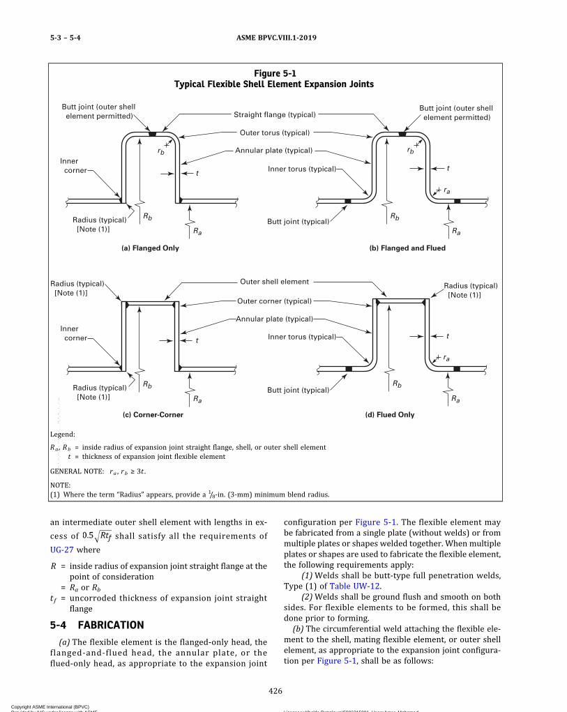
an intermediate outer shell element with lengths in ex-
cess of shall satisfy all the requirements of
UG-27 where
R = inside radius of expansion joint straight flange at thepoint of consideration
= Ra or Rbt f = uncorroded thickness of expansion joint straight
flange
5-4 FABRICATION
(a) The flexible element is the flanged-only head, theflanged-and-flued head, the annular plate, or theflued-only head, as appropriate to the expansion joint
configuration per Figure 5-1. The flexible element maybe fabricated from a single plate (without welds) or frommultiple plates or shapes welded together. When multipleplates or shapes are used to fabricate the flexible element,the following requirements apply:
(1)Welds shall be butt-type full penetration welds,Type (1) of Table UW-12.
(2)Welds shall be ground flush and smooth on bothsides. For flexible elements to be formed, this shall bedone prior to forming.(b) The circumferential weld attaching the flexible ele-
ment to the shell, mating flexible element, or outer shellelement, as appropriate to the expansion joint configura-tion per Figure 5-1, shall be as follows:
Figure 5-1Typical Flexible Shell Element Expansion Joints
Rb
rb
Straight flange (typical)
Outer torus (typical)
Annular plate (typical)
(b) Flanged and Flued(a) Flanged Only
Inner torus (typical)Inner corner
Rb
Ra
ra
rb
t
Ra
Butt joint (outer shell element permitted)
Butt joint (typical)Radius (typical) [Note (1)]
t
Butt joint (outer shell element permitted)
Inner corner
Radius (typical) [Note (1)]
Radius (typical) [Note (1)]
Rb
Ra
Butt joint (typical)
t
Annular plate (typical)
Outer corner (typical)
Outer shell element Radius (typical) [Note (1)]
t
ra
Rb
Ra
Inner torus (typical)
(c) Corner-Corner (d) Flued Only
Legend:
Ra, Rb = inside radius of expansion joint straight flange, shell, or outer shell elementt = thickness of expansion joint flexible element
GENERAL NOTE: ra , rb ≥ 3t .
NOTE:(1) Where the term “Radius” appears, provide a 1/8-in. (3-mm) minimum blend radius.
ASME BPVC.VIII.1-20195-3 – 5-4
426
Copyright ASME International (BPVC) Provided by IHS under license with ASME Licensee=Khalda Petroleum/5986215001, User=Amer, Mohamed
Not for Resale, 07/02/2019 13:29:04 MDTNo reproduction or networking permitted without license from IHS
--`,``,``,,`,`,,````,`,``,,,`-`-`,,`,,`,`,,`---

(1) Butt joints shall be full penetration welds, Type(1) of Table UW-12.
(2) Corner joints shall be full penetration welds witha covering fillet and no backing strip. The covering filletshall be located on the inside of the corner and shall havea throat at least equal to 0.7 times the minimum thicknessof the elements being joined, or 1/4 in. (6 mm) (note that afatigue evaluation may require a larger weld). It is per-mitted for the corner weld to be full penetration througheither element being joined.
(c) Nozzles, backing strips, clips, or other attachmentsshall not be located in highly stressed areas of the expan-sion joint, i.e., inner torus, annular plate, and outer torus.
As an exception, a thin cylindrical liner, having approxi-mately the shell inside diameter, may be attached to an in-ner torus or an annular plate inner corner. A liner isconsidered thin when its thickness is no more than t/3;however, it need not be thinner than 1/16 in. (1.6 mm).This liner shall be attached to only one side. The weld at-taching the liner shall have a maximum dimension(groove depth or either fillet leg) no larger than the linerthickness. Nozzles or other attachments located in theouter straight flange or outer shell element shall satisfythe axial spacing requirements of Figure 5-2.
Figure 5-2Typical Nozzle Attachment Details Showing Minimum Length of Straight Flange or Outer Shell Element
Rb
tf
(b) Reinforced Nozzle on Straight Flange(a) Nonreinforced Nozzle on Straight Flange
Rb
tf
Rb
to
(c) Nonreinforced Nozzle on Outer Shell Element
o
o
Rb
to
(d) Reinforced Nozzle on Outer Shell Element
Legend:
Rb = inside radius of expansion joint straight flanget f = uncorroded thickness of expansion joint straight flangeto = uncorroded thickness of expansion joint outer shell element
ASME BPVC.VIII.1-2019 5-4
427
Copyright ASME International (BPVC) Provided by IHS under license with ASME Licensee=Khalda Petroleum/5986215001, User=Amer, Mohamed
Not for Resale, 07/02/2019 13:29:04 MDTNo reproduction or networking permitted without license from IHS
--`,``,``,,`,`,,````,`,``,,,`-`-`,,`,,`,`,,`---

(d) The welds within the shell courses adjacent to flex-ible elements shall be full penetration butt welds, Type(1) of Table UW-12 , for a distance of , where Ris Ra or Rb , and t is the thickness of the shell or outershell element, as applicable.(e) Alignment tolerances of the completed expansion
joint attached to the shell shall meet the tolerances speci-fied by UW-33.
5-5 INSPECTION AND TESTS
(a) Expansion joint flexible elements shall be visuallyexamined and found free of unacceptable surface condi-tions, such as notches, crevices, and weld spatter, whichmay serve as points of local stress concentration. Suspectsurface areas shall be further examined by the magneticparticle or liquid penetrant method in accordance withMandatory Appendix 6 or Mandatory Appendix 8.(b)Welds within the flexible element shall be 100% ex-
amined in accordance with UW-51. These welds shall beexamined 100% on both sides by the magnetic particleor liquid penetrant method in accordance with Manda-tory Appendix 6 or Mandatory Appendix 8. For flexibleelements to be formed, this surface inspection shall beafter forming.(c) The circumferential welds attaching the flexible ele-
ment to the shell, mating flexible element, or outer shellelement, as appropriate to the expansion joint configura-tion per Figure 5-1, shall be examined 100% on bothsides, where accessible, by the magnetic particle or liquidpenetrant method in accordance with Mandatory Appen-dix 6 or Mandatory Appendix 8. The accessibility of weldsshall be subject to the acceptance of the Inspector.
(d) The completed expansion joint shall be pressuretested in accordance with UG-99 or UG-100. The pressuretesting may be performed as a part of the final vesselpressure test, provided the joint is accessible for inspec-tion during pressure testing.(e) Expansion joint restraining elements shall also be
pressure tested in accordance with UG-99 or UG-100 asa part of the initial expansion joint pressure test or as apart of the final vessel pressure test after installation ofthe joint.(f) In addition to inspecting the expansion joint for
leaks and structural integrity during the pressure test, ex-pansion joints shall be inspected before, during, and afterthe pressure test for visible permanent distortion.
5-6 MARKING AND REPORTS
The expansion joint Manufacturer, whether the vesselManufacturer or a parts Manufacturer, shall have a validASME Code U Certificate of Authorization and shall com-plete the appropriate Data Report in accordance withUG-120.(a) The Manufacturer responsible for the expansion
joint design shall include the following additional dataand statements on the appropriate Data Report:
(1) uncorroded and corroded spring rate(2) axial movement (+ and −) and associated loading
condition, if applicable(3) that the expansion joint has been constructed to
the rules of this Appendix(b) A parts Manufacturer shall identify the vessel for
which the expansion joint is intended on the Partial DataReport.(c) Markings shall not be stamped on the flexible ele-
ments of the expansion joint.
ASME BPVC.VIII.1-20195-4 – 5-6
428
Copyright ASME International (BPVC) Provided by IHS under license with ASME Licensee=Khalda Petroleum/5986215001, User=Amer, Mohamed
Not for Resale, 07/02/2019 13:29:04 MDTNo reproduction or networking permitted without license from IHS
--`,``,``,,`,`,,````,`,``,,,`-`-`,,`,,`,`,,`---
MANDATORY APPENDIX 6METHODS FOR MAGNETIC PARTICLE EXAMINATION (MT)
6-1 SCOPE
(a) This Appendix provides for procedures which shallbe followed whenever magnetic particle examination isspecified in this Division.
(b) Section V, Article 7 shall be applied for the detail re-quirements in methods and procedures, and the addi-tional requirements specified within this Appendix.
(c) Magnetic particle examination shall be performedin accordance with a written procedure, certified by theManufacturer to be in accordance with the requirementsof Section V, Article 1, T-150
(d) Documentation showing that the required examina-tions have been performed and that the results are ac-ceptable shall be made available to the Inspector.
6-2 CERTIFICATION OF COMPETENCY FORNONDESTRUCTIVE EXAMINATIONPERSONNEL
The manufacturer shall certify that each magnetic par-ticle examiner meets the following requirements:
(a) He/she has vision, with correction if necessary, toenable him/her to read a Jaeger Type No. 2 StandardChart at a distance of not less than 12 in., and is capableof distinguishing and differentiating contrast betweencolors used. These requirements shall be checkedannually.
(b) He/she is competent in the techniques of the mag-netic particle examination method for which he/she iscertified, including making the examination and inter-preting and evaluating the results, except that wherethe examination method consists of more than one opera-tion, he/she may be certified as being qualified only forone or more of these operations.
6-3 EVALUATION OF INDICATIONS
Indications will be revealed by retention of magneticparticles. All such indications are not necessarily imper-fections, however, since excessive surface roughness,magnetic permeability variations (such as at the edge ofheat-affected zones) , etc . , may produce similarindications.
An indication of an imperfection may be larger than theimperfection that causes it; however, the size of the indi-cation is the basis for acceptance evaluation. Only indica-tions which have any dimension greater than 1/16 in.(1.5 mm) shall be considered relevant.
(a) A linear indication is one having a length greaterthan three times the width.
(b) A rounded indication is one of circular or ellipticalshape with a length equal to or less than three times itswidth.
(c) Any questionable or doubtful indications shall bereexamined to determine whether or not they arerelevant.
6-4 ACCEPTANCE STANDARDS
These acceptance standards shall apply unless othermore restrictive standards are specified for specific mate-rials or applications within this Division.
All surfaces to be examined shall be free of:(a) relevant linear indications;(b) relevant rounded indications greater than 3/16 in.
(5 mm);(c) four or more relevant rounded indications in a line
separated by 1/16 in. (1.5 mm) or less, edge to edge.
6-5 REPAIR REQUIREMENTS
The defect shall be removed or reduced to an imperfec-tion of acceptable size. Whenever an imperfection is re-moved by chipping or grinding and subsequent repairby welding is not required, the excavated area shall beblended into the surrounding surface so as to avoid sharpnotches, crevices, or corners. Where welding is requiredafter removal of an imperfection, the area shall be cleanedand welding performed in accordance with a qualifiedwelding procedure.
(a) Treatment of Indications Believed Nonrelevant. Anyindication which is believed to be nonrelevant shall be re-garded as an imperfection unless it is shown by reexam-ination by the same method or by the use of othernondestructive methods and/or by surface conditioningthat no unacceptable imperfection is present.
(b) Examination of Areas From Which ImperfectionsHave Been Removed. After a defect is thought to have beenremoved and prior to making weld repairs, the area shallbe examined by suitable methods to ensure it has been re-moved or reduced to an acceptably sized imperfection.
ASME BPVC.VIII.1-2019 6-1 – 6-5
429
Copyright ASME International (BPVC) Provided by IHS under license with ASME Licensee=Khalda Petroleum/5986215001, User=Amer, Mohamed
Not for Resale, 07/02/2019 13:29:04 MDTNo reproduction or networking permitted without license from IHS
--`,``,``,,`,`,,````,`,``,,,`-`-`,,`,,`,`,,`---
(c) Reexamination of Repair Areas. After repairs havebeen made, the repaired area shall be blended into thesurrounding surface so as to avoid sharp notches, cre-vices, or corners and reexamined by the magnetic particle
method and by all other methods of examination thatwere originally required for the affected area, except that,when the depth of repair is less than the radiographicsensitivity required, reradiography may be omitted.
ASME BPVC.VIII.1-20196-5
430
Copyright ASME International (BPVC) Provided by IHS under license with ASME Licensee=Khalda Petroleum/5986215001, User=Amer, Mohamed
Not for Resale, 07/02/2019 13:29:04 MDTNo reproduction or networking permitted without license from IHS
--`,``,``,,`,`,,````,`,``,,,`-`-`,,`,,`,`,,`---

ð19Þ
ð19Þ
MANDATORY APPENDIX 7EXAMINATION OF STEEL CASTINGS
7-1 SCOPE
This Appendix covers examination requirements thatshall be observed for all steel castings to which a 100%quality factor is to be applied in accordance withUG-24(a)(5). Except for applications involving lethal ser-vice, steel castings made to an accepted standard, such asASME B16.5, are not required to comply with the provi-sions of this Appendix.
7-2 EXAMINATION TECHNIQUES
Examination techniques shall be carried out in accor-dance with the following:
(a)Magnetic particle examinations shall be per Manda-tory Appendix 6 except that acceptance standards shallbe as given in 7-3(a)(3) of this Appendix.
(b) Liquid penetrant examinations shall be per Manda-tory Appendix 8 except that acceptance standards shallbe as given in 7-3(a)(4) of this Appendix.
(c) Radiographic examinations shall be per Section V,Article 2 with acceptance standards as given in7-3(a)(1) or 7-3(b)(3) of this Appendix.
(1) A written radiographic examination procedure isnot required. Demonstration of density and image qualityindicator (IQI) image requirements on production ortechnique radiographs shall be considered satisfactoryevidence of compliance with Section V, Article 2.
(2) The requirements of Section V, Article 2, T-285are to be used only as a guide. Final acceptance of radio-graphs shall be based on the ability to see the prescribedIQI image and the specified hole or the designated wire ora wire IQI.
(d) Ultrasonic examinations shall be per Section V,Article 5 with acceptance standards as given in7-3(b)(3) of this Appendix.
7-3 EXAMINATION REQUIREMENTS
All steel castings shall be examined in accordance with(a) or (b) as applicable.
(a) All castings having a maximum body thickness lessthan 41/2 in. (115 mm) shall be examined as follows:
(1) All critical sections17 shall be radiographed. Forcastings having radiographed thicknesses up to 2 in.(51 mm), the radiographs shall be compared to those inASTM E446, Standard Reference Radiographs for Steel
Castings up to 2 in. (51 mm) in Thickness. The maximumacceptable severity levels for imperfections shall be asfollows:
Maximum Severity Level
Imperfection Category Thicknesses <1 in.Thicknesses 1 in.
to <2 in.
A — Gas porosity 1 2B — Sand and slag 2 3C — Shrinkage (four types) 1 3D — Cracks 0 0E — Hot tears 0 0F — Inserts 0 0G — Mottling 0 0
For castings having radiographed thicknesses from 2in. to 41/2 in. (51 mm to 114 mm), the radiographs shall becompared to those in ASTM E186, Standard ReferenceRadiographs for Heavy‐Walled [2 to 41/2 in. (50.8 to 114mm)] Steel Castings. The maximum acceptable severitylevels for imperfections shall be as follows:
Imperfection Category Maximum Severity Level
A — Gas porosity 2B — Sand and slag inclusions 2C — ShrinkageType 1 1Type 2 2Type 3 3
D — Cracks 0E — Hot tear 0F — Inserts 0
(2) All surfaces including machined gasket seatingsurfaces shall be examined by the magnetic particle orthe liquid penetrant method. When the casting specifica-tion requires heat treatment, these examinations shall beconducted after that heat treatment.
(3) Surface indications determined by magnetic par-ticle examination shall be compared with those indicatedin ASTM E125, Standard Reference Photographs for Mag-netic Particle Indications on Ferrous Castings, and shallbe removed if they exceed the following limits:
Type Degree
I. Linear discontinuities (hot tearsand cracks)
All
II. Shrinkage 2III. Inclusions 3IV. Chills and chaplets 1V. Porosity 1
ASME BPVC.VIII.1-2019 7-1 – 7-3
431
Copyright ASME International (BPVC) Provided by IHS under license with ASME Licensee=Khalda Petroleum/5986215001, User=Amer, Mohamed
Not for Resale, 07/02/2019 13:29:04 MDTNo reproduction or networking permitted without license from IHS
--`,``,``,,`,`,,````,`,``,,,`-`-`,,`,,`,`,,`---

(4) Surface indications determined by liquid pene-trant examination are unacceptable if they exceed the fol-lowing limits:
(-a) all cracks and hot tears;(-b) any group of more than six linear indications
other than those in (-a) above in any rectangular area of11/2 in. × 6 in. (38 mm × 150 mm) or less or any circulararea having a diameter of 31/2 in. (88 mm) or less, theseareas being taken in the most unfavorable location rela-tive to the indications being evaluated;
(-c) other linear indications more than 1/4 in.(6 mm) long for thicknesses up to 3/4 in. (19 mm) inclu-sive, more than one‐third of the thickness in length forthicknesses from 3/4 in. to 21/4 in. (19 mm to 57 mm),and more than 3/4 in. (19 mm) long for thicknesses over21/4 in. (57 mm) (aligned acceptable imperfections sepa-rated from one another by a distance equal to the lengthof the longer imperfection are acceptable);
(-d) all indications of nonlinear imperfectionswhich have any dimension exceeding 3/16 in. (5 mm).
(5)When more than one casting of a particular de-sign is produced, each of the first five shall be examinedto the full extent prescribed herein. When more than fivecastings are being produced, examinations as prescribedshall be performed on the first five and on one additionalcasting for each additional five castings produced. If anyof these additional castings proves to be unacceptable,each of the remaining four castings of that group shallbe examined fully.(b) All castings having maximum body thickness 41/2 in.
(114 mm) and greater and castings of lesser thicknesswhich are intended for severe service applications92 shallbe examined as follows.
(1) Each casting shall be subjected to 100% visual ex-amination and to complete surface examination by eitherthe magnetic particle or the liquid penetrant method.When the casting specification requires heat treatment,these examinations shall be conducted after that heattreatment. Acceptability limits for surface imperfectionsshall be as given in (a)(3) and (a)(4) above.
(2) All parts of castings up to 12 in. (300 mm) inthickness shall be subjected to radiographic examinationand the radiographs compared to those given in ASTME280, Standard Reference Radiographs for Heavy‐Walled[41/2‐in. to 12‐in. (114‐mm to 305‐mm)] Steel Castings.The maximum acceptable severity levels for imperfec-tions shall be as follows:
Imperfection Category Maximum Severity Level
A — Gas porosity 2B — Sand and slag inclusions 2C — ShrinkageType 1 2Type 2 2Type 3 2
D — Cracks 0E — Hot tears 0F — Inserts 0
(3) For castings having a maximum thickness in ex-cess of 12 in. (300 mm), all thicknesses which are lessthan 12 in. (300 mm) shall be examined radiographicallyin accordance with the preceding paragraph. All parts ofsuch castings having thicknesses in excess of 12 in.(300 mm) shall be examined ultrasonically in accordancewith Section V, Article 5. Any imperfections which do notproduce indications exceeding 20% of the straight beamback reflection or do not reduce the height of the back re-flection by more than 30% during a total movement of thetransducer of 2 in. (50 mm) in any direction shall be con-sidered acceptable. Imperfections exceeding these limitsshall be repaired unless proved to be acceptable by otherexamination methods.
7-4 REPAIRS
(a)Whenever an imperfection is repaired, the exca-vated areas shall be examined by the magnetic particleor liquid penetrant method to ensure it has been removedor reduced to an acceptable size.(b)Whenever a surface imperfection is repaired by re-
moving less than 5% of the intended thickness of metal atthat location, welding need not be employed in making re-pairs. Where this is the case, the excavated area shall beblended into the surrounding surface so as to avoid anysharp contours.(c) Castings of nonweldable materials which contain
imperfections in excess of acceptable limits as given in7-3 shall be rejected.(d) For any type of defect, if the repair will entail re-
moval of more than 75% of the thickness or a length inany direction of 6 in. (150 mm) or more, approval ofthe user or his designated agent responsible for purchas-ing the casting shall be obtained prior to making repairs.(e) The finished surface of all repair welds shall be ex-
amined by the magnetic particle or liquid penetrant meth-od. When subsequent heat treatment is required, thisexamination of the repaired area shall be conducted afterheat treatment.(f) See below.
(1) Except as provided in (2) and (3) below, all weldrepairs shall be examined by radiography.
(2)Where the depth of repair is less than 1 in. or20% of the section thickness, whichever is the lesser,and where the repaired section cannot be radiographedeffectively, the first layer of each 1/4 in. (6 mm) thicknessof deposited weld metal shall be examined by the mag-netic particle or the liquid penetrant method.
(3)Weld repairs which are made as a result of ultra-sonic examination shall be reexamined by the same meth-od when completed.(g)When repair welding is done after the casting has
been heat treated and when required by either the rulesof this Section or the requirements of the casting specifi-cation, the repaired casting shall be postweld heattreated.
ASME BPVC.VIII.1-20197-3 – 7-4
432
Copyright ASME International (BPVC) Provided by IHS under license with ASME Licensee=Khalda Petroleum/5986215001, User=Amer, Mohamed
Not for Resale, 07/02/2019 13:29:04 MDTNo reproduction or networking permitted without license from IHS
--`,``,``,,`,`,,````,`,``,,,`-`-`,,`,,`,`,,`---
(h) All welding shall be performed using procedurequalifications in accordance with Section IX. The proce-dure qualification shall be performed on a test specimenof the same P‐Number and same group as the productioncasting. The test specimen shall be subjected to the sameheat treatment both before and after welding as will beapplied to the production casting. All welders and opera-tors performing this welding shall be qualified in accor-dance with Section IX.
7-5 IDENTIFICATION AND MARKING
Each casting shall be marked with the manufacturer’sname and casting identification, including the applicablecasting quality factor and material identification. Themanufacturer shall furnish reports of the chemical andmechanical properties and certification that each castingconforms to all applicable requirements of this Appendix.The certification for castings for lethal service shall indi-cate the nature, location, and extent of any repairs.
ASME BPVC.VIII.1-2019 7-4 – 7-5
433
Copyright ASME International (BPVC) Provided by IHS under license with ASME Licensee=Khalda Petroleum/5986215001, User=Amer, Mohamed
Not for Resale, 07/02/2019 13:29:04 MDTNo reproduction or networking permitted without license from IHS
--`,``,``,,`,`,,````,`,``,,,`-`-`,,`,,`,`,,`---

MANDATORY APPENDIX 8METHODS FOR LIQUID PENETRANT EXAMINATION (PT)
NOTE: Satisfactory application of this method of examination re-quires special skills in the techniques involved and in interpretingthe results. The requirements specified herein presume applicationby suitably experienced personnel.
8-1 SCOPE
(a) This Appendix describes methods which shall beemployed whenever liquid penetrant examination is spe-cified in this Division.(b) Section V, Article 6 shall be applied for detail re-
quirements in methods and procedures, unless otherwisespecified within this Appendix.(c) Liquid penetrant examination shall be performed in
accordance with a written procedure, certified by theManufacturer to be in accordance with the requirementsof Section V, Article 1, T-150.(d) Documentation showing that the required examina-
tions have been performed and that the results are ac-ceptable shall be made available to the Inspector.
8-2 CERTIFICATION OF COMPETENCY OFNONDESTRUCTIVE EXAMINATIONPERSONNEL
The manufacturer shall certify that each liquid pene-trant examiner meets the following requirements.(a) He has vision, with correction if necessary, to en-
able him to read a Jaeger Type No. 2 Standard Chart ata distance of not less than 12 in. (300 mm), and is capableof distinguishing and differentiating contrast betweencolors used. These requirements shall be checkedannually.(b) He is competent in the techniques of the liquid pen-
etrant examination method for which he is certified, in-cluding making the examination and interpreting andevaluating the results, except that, where the examinationmethod consists of more than one operation, he may becertified as being qualified only for one or more of theseoperations.
8-3 EVALUATION OF INDICATIONS
An indication of an imperfection may be larger than theimperfection that causes it; however, the size of the indi-cation is the basis for acceptance evaluation. Only indica-tions with major dimensions greater than 1/16 in.(1.5 mm) shall be considered relevant.(a) A linear indication is one having a length greater
than three times the width.(b) A rounded indication is one of circular or elliptical
shape with the length equal to or less than three timesthe width.(c) Any questionable or doubtful indications shall be
reexamined to determine whether or not they arerelevant.
8-4 ACCEPTANCE STANDARDS
These acceptance standards shall apply unless othermore restrictive standards are specified for specific mate-rials or applications within this Division.All surfaces to be examined shall be free of:(a) relevant linear indications;(b) relevant rounded indications greater than 3/16 in.
(5 mm);(c) four or more relevant rounded indications in a line
separated by 1/16 in. (1.5 mm) or less (edge to edge).
8-5 REPAIR REQUIREMENTS
Unacceptable imperfections shall be repaired and reex-amination made to assure removal or reduction to an ac-ceptable size. Whenever an imperfection is repaired bychipping or grinding and subsequent repair by weldingis not required, the excavated area shall be blended intothe surrounding surface so as to avoid sharp notches, cre-vices, or corners. Where welding is required after repairof an imperfection, the area shall be cleaned and weldingperformed in accordance with a qualified weldingprocedure.(a) Treatment of Indications Believed Nonrelevant. Any
indication which is believed to be nonrelevant shall be re-garded as an imperfection unless it is shown by reexam-ination by the same method or by the use of othernondestructive methods and/or by surface conditioningthat no unacceptable imperfection is present.
ASME BPVC.VIII.1-20198-1 – 8-5
434
Copyright ASME International (BPVC) Provided by IHS under license with ASME Licensee=Khalda Petroleum/5986215001, User=Amer, Mohamed
Not for Resale, 07/02/2019 13:29:04 MDTNo reproduction or networking permitted without license from IHS
--`,``,``,,`,`,,````,`,``,,,`-`-`,,`,,`,`,,`---
(b) Examination of Areas From Which Defects HaveBeen Removed. After a defect is thought to have been re-moved and prior to making weld repairs, the area shallbe examined by suitable methods to ensure it has been re-moved or reduced to an acceptably sized imperfection.
(c) Reexamination of Repair Areas. After repairs havebeen made, the repaired area shall be blended into thesurrounding surface so as to avoid sharp notches,
crevices, or corners and reexamined by the liquid pene-trant method and by all other methods of examinationthat were originally required for the affected area, exceptthat, when the depth of repair is less than the radio-graphic sensitivity required, reradiography may beomitted.
ASME BPVC.VIII.1-2019 8-5
435
Copyright ASME International (BPVC) Provided by IHS under license with ASME Licensee=Khalda Petroleum/5986215001, User=Amer, Mohamed
Not for Resale, 07/02/2019 13:29:04 MDTNo reproduction or networking permitted without license from IHS
--`,``,``,,`,`,,````,`,``,,,`-`-`,,`,,`,`,,`---

MANDATORY APPENDIX 9JACKETED VESSELS
9-1 SCOPE
(a) The rules in Mandatory Appendix 9 cover minimumrequirements for the design, fabrication, and inspection ofthe jacketed portion of a pressure vessel. The jacketedportion of the vessel is defined as the inner and outerwalls, the closure devices, and all other penetrations orparts within the jacket which are subjected to pressurestresses. Parts such as nozzle closure members and stif-fening or stay rings are included.(b) All other Parts of this Division shall apply unless
otherwise stated in this Appendix.(c) Where the internal design pressure is 15 psi
(100 kPa) or less, and any combination of pressuresand vacuum in the vessel and jacket will produce a totalexternal pressure greater than 15 psi (100 kPa) on the in-ner vessel wall, then the entire jacket shall be interpretedas within the scope of this part.(d) For the purpose of this Appendix, jackets are as-
sumed to be integral pressure chambers, attached to avessel for one or more purposes such as:
(1) to heat the vessel and its contents;(2) to cool the vessel and its contents;(3) to provide a sealed insulation chamber for the
vessel.(e) As stated in U-2(g), this Division does not contain
rules to cover all details of design and construction. Theserules are therefore established to cover most commonjacket types, but are not intended to limit configurationsto those illustrated or otherwise described herein.(f) Half‐pipe jackets are not within the scope of this
Appendix.
9-2 TYPES OF JACKETED VESSELS
This Appendix shall apply to jacketed vessels havingjackets which cover the shell or heads as illustrated inFigure 9-2 and partial jackets as illustrated in Figure9-7. Jackets, as shown in Figure 9-2, shall be continuouscircumferentially for Types 1, 2, 4, or 5 shown and shallbe circular in cross section for Type 3. The use of anycombination of the types shown is permitted on anyone vessel, provided the individual requirements for eachare met. Nozzles or other openings in Type 1, 2, 4, or 5jackets that also penetrate the vessel shell or head shallbe designed in accordance with UG-37(d)(2). Dimpledjackets are not covered in this Appendix (see UW-19).
9-3 MATERIALS
Materials used in the fabrication of jackets shall be inaccordance with Subsection A.
9-4 DESIGN OF JACKET SHELLS ANDJACKET HEADS
Design shall comply with the applicable requirementsof Subsection A except where otherwise provided for inthis Appendix.(a) Shell and head thickness shall be determined by the
appropriate formula given in Subsection A. In considera-tion of the loadings given in UG-22, particular attention tothe effects of local internal and external loads and expan-sion differentials at design temperatures shall be given.Where vessel supports are attached to the jacket, consid-eration shall be given to the transfer of the supported loadof the inner vessel and contents.(b) The requirements for inspection openings as pre-
scribed in UG-46 shall apply to jackets except that themaximum size of opening need not exceed 2 in.(50 mm) pipe size (DN 50) for all diameter vessels.(c) The use of impingement plates or baffles at the jack-
et inlet connection to reduce erosion of the inner wallshall be considered for media where vapors are con-densed, i.e., steam.(d) Jacketed vessels may be designed utilizing braced
and stayed surfaces as given in UG-47, provided the jacketwall in addition to meeting the requirements of UG-47(a)also meets the applicable requirements of UG-27(c) andUG-27(d) and UG-32. This paragraph is not intended toapply to dimpled jackets. (See UW-19.)
9-5 DESIGN OF CLOSURE MEMBER OFJACKET TO VESSEL
(a) This paragraph gives rules for the design of closuremembers shown herein. Closures of geometries otherthan those illustrated may be used if the strength require-ments of UG-101 are met.(b) Symbols used in Figures 9-5 and 9-6 are as follows:
a, b , c ,Y , Z = minimum weld dimensions for attachment of
closure member to inner vessel measured asshown in Figures 9-5 and 9-6
ASME BPVC.VIII.1-20199-1 – 9-5
436
Copyright ASME International (BPVC) Provided by IHS under license with ASME Licensee=Khalda Petroleum/5986215001, User=Amer, Mohamed
Not for Resale, 07/02/2019 13:29:04 MDTNo reproduction or networking permitted without license from IHS
--`,``,``,,`,`,,````,`,``,,,`-`-`,,`,,`,`,,`---
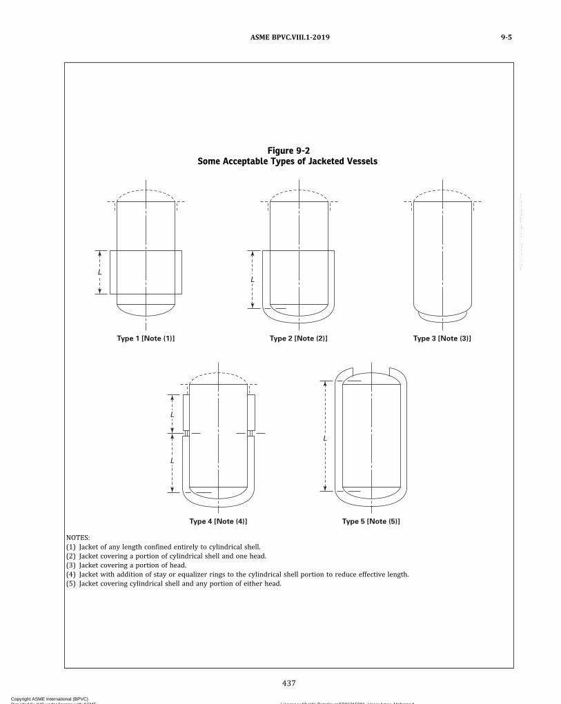
Figure 9-2Some Acceptable Types of Jacketed Vessels
Type 1 [Note (1)]
L
Type 2 [Note (2)]
L
Type 3 [Note (3)]
Type 4 [Note (4)]
L
L
Type 5 [Note (5)]
L
NOTES:(1) Jacket of any length confined entirely to cylindrical shell.(2) Jacket covering a portion of cylindrical shell and one head.(3) Jacket covering a portion of head.(4) Jacket with addition of stay or equalizer rings to the cylindrical shell portion to reduce effective length.(5) Jacket covering cylindrical shell and any portion of either head.
ASME BPVC.VIII.1-2019 9-5
437
Copyright ASME International (BPVC) Provided by IHS under license with ASME Licensee=Khalda Petroleum/5986215001, User=Amer, Mohamed
Not for Resale, 07/02/2019 13:29:04 MDTNo reproduction or networking permitted without license from IHS
--`,``,``,,`,`,,````,`,``,,,`-`-`,,`,,`,`,,`---
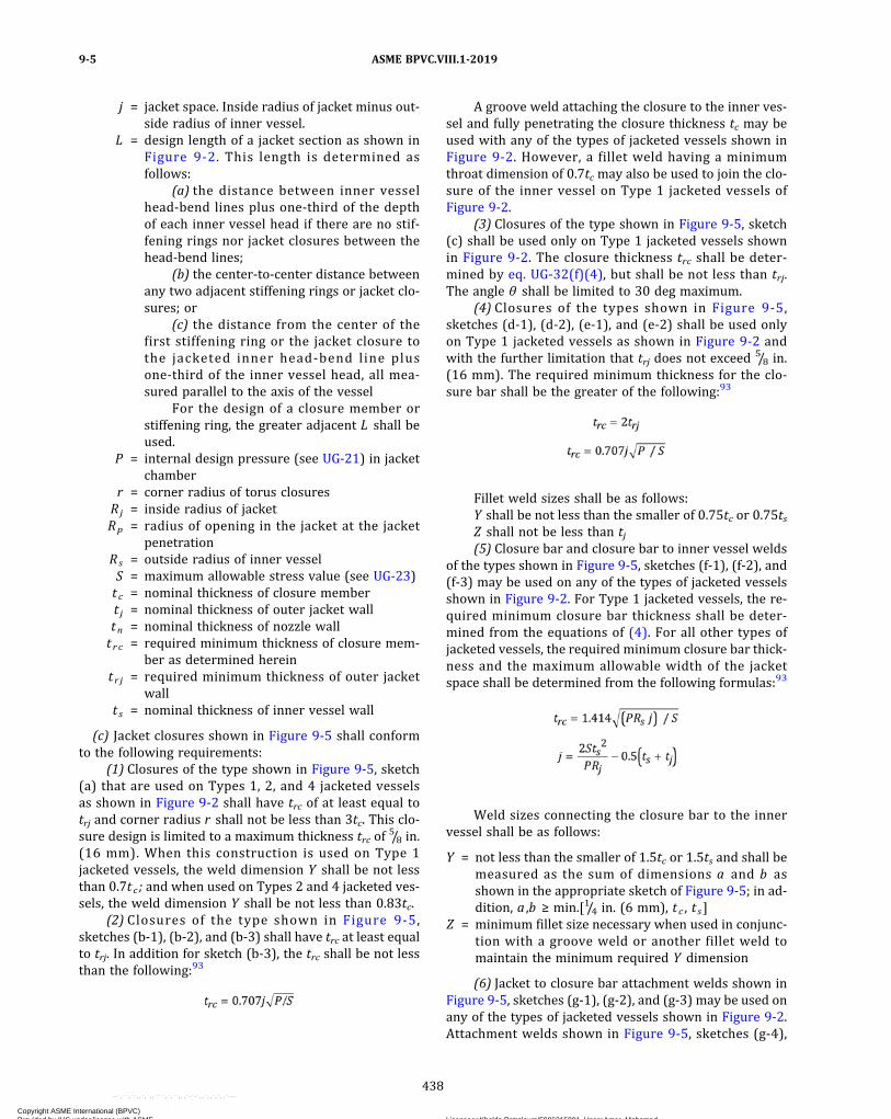
j = jacket space. Inside radius of jacket minus out-side radius of inner vessel.
L = design length of a jacket section as shown inFigure 9-2. This length is determined asfollows:
(a) the distance between inner vesselhead‐bend lines plus one‐third of the depthof each inner vessel head if there are no stif-fening rings nor jacket closures between thehead‐bend lines;
(b) the center‐to‐center distance betweenany two adjacent stiffening rings or jacket clo-sures; or
(c) the distance from the center of thefirst stiffening ring or the jacket closure tothe jacketed inner head‐bend line plusone‐third of the inner vessel head, all mea-sured parallel to the axis of the vessel
For the design of a closure member orstiffening ring, the greater adjacent L shall beused.
P = internal design pressure (see UG-21) in jacketchamber
r = corner radius of torus closuresRj = inside radius of jacketRp = radius of opening in the jacket at the jacket
penetrationRs = outside radius of inner vesselS = maximum allowable stress value (see UG-23)t c = nominal thickness of closure membert j = nominal thickness of outer jacket walltn = nominal thickness of nozzle wallt r c = required minimum thickness of closure mem-
ber as determined hereint r j = required minimum thickness of outer jacket
wallt s = nominal thickness of inner vessel wall
(c) Jacket closures shown in Figure 9-5 shall conformto the following requirements:
(1) Closures of the type shown in Figure 9-5, sketch(a) that are used on Types 1, 2, and 4 jacketed vesselsas shown in Figure 9-2 shall have trc of at least equal totrj and corner radius r shall not be less than 3tc. This clo-sure design is limited to a maximum thickness trc of
5/8 in.(16 mm). When this construction is used on Type 1jacketed vessels, the weld dimension Y shall be not lessthan 0.7tc ; and when used on Types 2 and 4 jacketed ves-sels, the weld dimension Y shall be not less than 0.83tc.
(2) Closures of the type shown in Figure 9-5,sketches (b‐1), (b‐2), and (b‐3) shall have trc at least equalto trj. In addition for sketch (b‐3), the trc shall be not lessthan the following:93
A groove weld attaching the closure to the inner ves-sel and fully penetrating the closure thickness tc may beused with any of the types of jacketed vessels shown inFigure 9-2. However, a fillet weld having a minimumthroat dimension of 0.7tc may also be used to join the clo-sure of the inner vessel on Type 1 jacketed vessels ofFigure 9-2.
(3) Closures of the type shown in Figure 9-5, sketch(c) shall be used only on Type 1 jacketed vessels shownin Figure 9-2. The closure thickness trc shall be deter-mined by eq. UG-32(f)(4), but shall be not less than trj.The angle θ shall be limited to 30 deg maximum.
(4) Closures of the types shown in Figure 9-5,sketches (d‐1), (d‐2), (e‐1), and (e‐2) shall be used onlyon Type 1 jacketed vessels as shown in Figure 9-2 andwith the further limitation that trj does not exceed
5/8 in.(16 mm). The required minimum thickness for the clo-sure bar shall be the greater of the following:93
Fillet weld sizes shall be as follows:Y shall be not less than the smaller of 0.75tc or 0.75tsZ shall not be less than tj(5) Closure bar and closure bar to inner vessel welds
of the types shown in Figure 9-5, sketches (f‐1), (f‐2), and(f‐3) may be used on any of the types of jacketed vesselsshown in Figure 9-2. For Type 1 jacketed vessels, the re-quired minimum closure bar thickness shall be deter-mined from the equations of (4). For all other types ofjacketed vessels, the required minimum closure bar thick-ness and the maximum allowable width of the jacketspace shall be determined from the following formulas:93
Weld sizes connecting the closure bar to the innervessel shall be as follows:
Y = not less than the smaller of 1.5tc or 1.5ts and shall bemeasured as the sum of dimensions a and b asshown in the appropriate sketch of Figure 9-5; in ad-dition, a ,b ≥ min.[1/4 in. (6 mm), t c , t s]
Z = minimum fillet size necessary when used in conjunc-tion with a groove weld or another fillet weld tomaintain the minimum required Y dimension
(6) Jacket to closure bar attachment welds shown inFigure 9-5, sketches (g‐1), (g‐2), and (g‐3) may be used onany of the types of jacketed vessels shown in Figure 9-2.Attachment welds shown in Figure 9-5, sketches (g‐4),
ASME BPVC.VIII.1-20199-5
438
Copyright ASME International (BPVC) Provided by IHS under license with ASME Licensee=Khalda Petroleum/5986215001, User=Amer, Mohamed
Not for Resale, 07/02/2019 13:29:04 MDTNo reproduction or networking permitted without license from IHS
--`,``,``,,`,`,,````,`,``,,,`-`-`,,`,,`,`,,`---
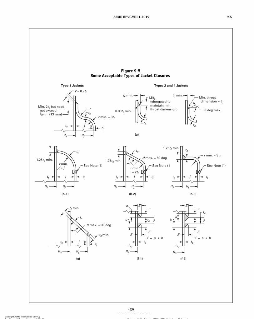
Figure 9-5Some Acceptable Types of Jacket Closures
See Note (1)
1.25tc min.r min. = j r min.
= 2tc
max. = 30 deg
(f-2)(f-1)(c)
(b-1) (b-2)
(a)
Types 2 and 4 JacketsType 1 Jackets
(b-3)
ts
Rs
tc
tc
tc
RsRjRs
tstj
tc min.
tc min.
tc
ts j
RjRs
tjts j
RjRs
tjts j
1.25tc min.
Min. throat dimension = tc (elongated to
maintain min. throat dimension) 30 deg max.
r min. = 3tc
r min. = 3tc
0.83tc min.Min. 2tc but need not exceed 1/2 in. (13 mm)
Y = 0.7tc
r
tc
tc
tc
tctc
Z
Y = a bY = a b
Z
Z
ZZ
Z
b
a
ba
Z
Z
See Note (1
1.25tc min.
RjRs
tj tjts j
See Note (1)
RjRs
tc min.tc min.1.5tc
ts j
max. = 60 deg
ASME BPVC.VIII.1-2019 9-5
439
Copyright ASME International (BPVC) Provided by IHS under license with ASME Licensee=Khalda Petroleum/5986215001, User=Amer, Mohamed
Not for Resale, 07/02/2019 13:29:04 MDTNo reproduction or networking permitted without license from IHS
--`,``,``,,`,`,,````,`,``,,,`-`-`,,`,,`,`,,`---

Figure 9-5Some Acceptable Types of Jacket Closures (Cont'd)
ASME BPVC.VIII.1-20199-5
440
Copyright ASME International (BPVC) Provided by IHS under license with ASME Licensee=Khalda Petroleum/5986215001, User=Amer, Mohamed
Not for Resale, 07/02/2019 13:29:04 MDTNo reproduction or networking permitted without license from IHS
--`,``,``,,`,`,,````,`,``,,,`-`-`,,`,,`,`,,`---
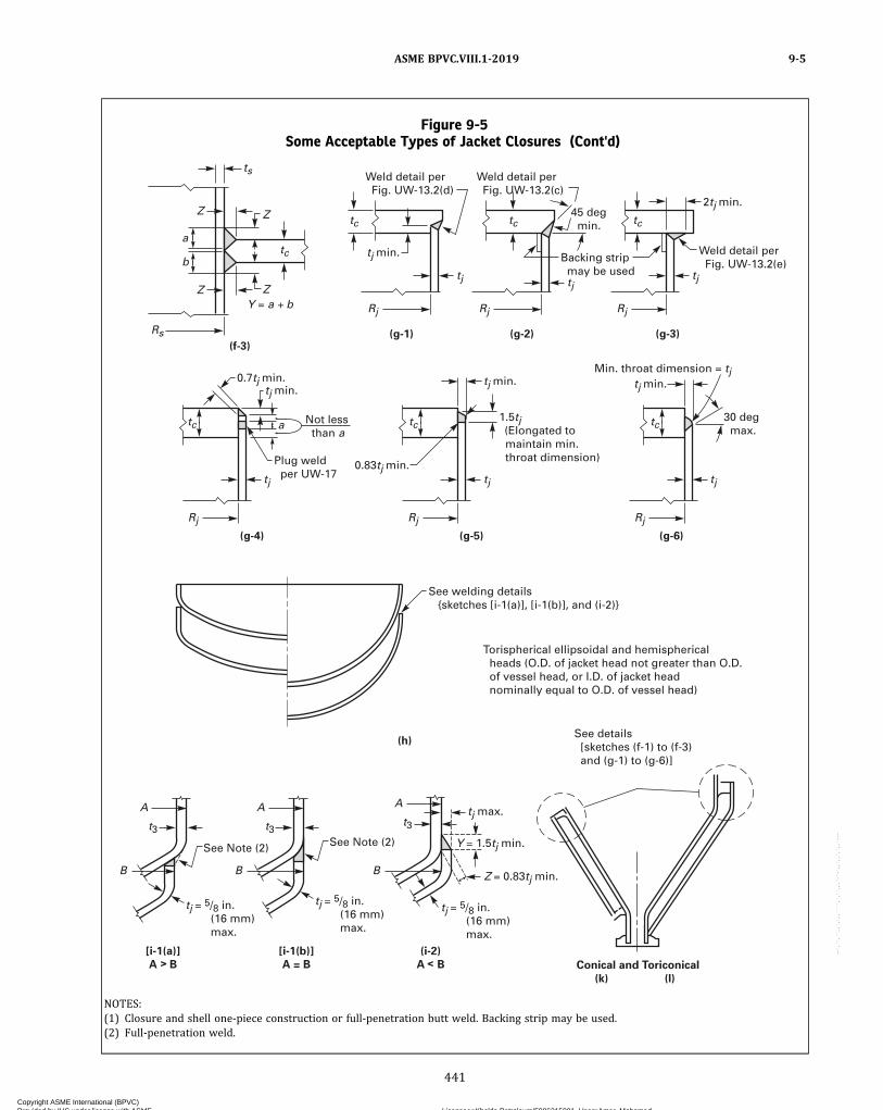
Figure 9-5Some Acceptable Types of Jacket Closures (Cont'd)
(h)
(g-5)(g-4)
(g-1) (g-2) (g-3)(f-3)
(g-6)
ts
Rs
a
btc
tc tc tc
tctctc
2tj min.
tj
tj min.
45 deg min.
Backing strip may be used
Weld detail per Fig. UW-13.2(e)
Z
t3
tj = 5/8 in. (16 mm) max.
See Note (2)
t3t3
See Note (2)
tj = 5/8 in. (16 mm) max.
tj = 5/8 in. (16 mm) max.
Z = 0.83tj min.
Y = 1.5tj min.
tj max.
tj
tj
tj min.
tj
Rj Rj Rj
Rj
tj
tj min.
1.5tj (Elongated to maintain min. throat dimension)
0.83tj min.
Rj
tj
0.7tj min.tj min.
a
Plug weld per UW-17
Not less than a
See welding details {sketches [i-1(a)], [i-1(b)], and (i-2)}
Weld detail per Fig. UW-13.2(d)
Weld detail per Fig. UW-13.2(c)
Torispherical ellipsoidal and hemispherical heads (O.D. of jacket head not greater than O.D. of vessel head, or I.D. of jacket head nominally equal to O.D. of vessel head)
Conical and Toriconical
(k) (l)
(i-2)
A B
[i-1(b)]
A = B
[i-1(a)]
A B
See details [sketches (f-1) to (f-3) and (g-1) to (g-6)]
Rj
B B
A A
B
A
Z
Z
ZY = a b
30 deg max.
Min. throat dimension = tj
NOTES:(1) Closure and shell one-piece construction or full-penetration butt weld. Backing strip may be used.(2) Full-penetration weld.
ASME BPVC.VIII.1-2019 9-5
441
Copyright ASME International (BPVC) Provided by IHS under license with ASME Licensee=Khalda Petroleum/5986215001, User=Amer, Mohamed
Not for Resale, 07/02/2019 13:29:04 MDTNo reproduction or networking permitted without license from IHS
--`,``,``,,`,`,,````,`,``,,,`-`-`,,`,,`,`,,`---
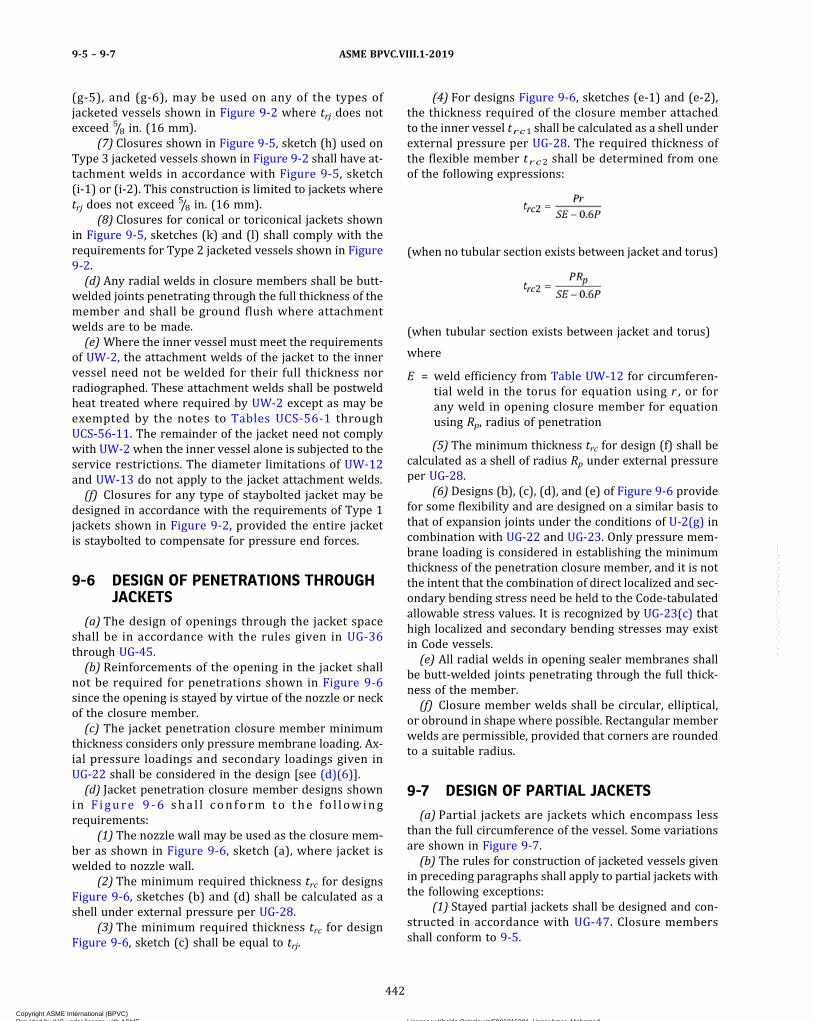
(g‐5), and (g‐6), may be used on any of the types ofjacketed vessels shown in Figure 9-2 where trj does notexceed 5/8 in. (16 mm).
(7) Closures shown in Figure 9-5, sketch (h) used onType 3 jacketed vessels shown in Figure 9-2 shall have at-tachment welds in accordance with Figure 9-5, sketch(i‐1) or (i‐2). This construction is limited to jackets wheretrj does not exceed
5/8 in. (16 mm).(8) Closures for conical or toriconical jackets shown
in Figure 9-5, sketches (k) and (l) shall comply with therequirements for Type 2 jacketed vessels shown in Figure9-2.(d) Any radial welds in closure members shall be butt-
welded joints penetrating through the full thickness of themember and shall be ground flush where attachmentwelds are to be made.(e) Where the inner vessel must meet the requirements
of UW-2, the attachment welds of the jacket to the innervessel need not be welded for their full thickness norradiographed. These attachment welds shall be postweldheat treated where required by UW-2 except as may beexempted by the notes to Tables UCS-56-1 throughUCS-56-11. The remainder of the jacket need not complywith UW-2 when the inner vessel alone is subjected to theservice restrictions. The diameter limitations of UW-12and UW-13 do not apply to the jacket attachment welds.(f) Closures for any type of staybolted jacket may be
designed in accordance with the requirements of Type 1jackets shown in Figure 9-2, provided the entire jacketis staybolted to compensate for pressure end forces.
9-6 DESIGN OF PENETRATIONS THROUGHJACKETS
(a) The design of openings through the jacket spaceshall be in accordance with the rules given in UG-36through UG-45.(b) Reinforcements of the opening in the jacket shall
not be required for penetrations shown in Figure 9-6since the opening is stayed by virtue of the nozzle or neckof the closure member.(c) The jacket penetration closure member minimum
thickness considers only pressure membrane loading. Ax-ial pressure loadings and secondary loadings given inUG-22 shall be considered in the design [see (d)(6)].(d) Jacket penetration closure member designs shown
in F igure 9 -6 sha l l con form to the fo l l owingrequirements:
(1) The nozzle wall may be used as the closure mem-ber as shown in Figure 9-6, sketch (a), where jacket iswelded to nozzle wall.
(2) The minimum required thickness trc for designsFigure 9-6, sketches (b) and (d) shall be calculated as ashell under external pressure per UG-28.
(3) The minimum required thickness trc for designFigure 9-6, sketch (c) shall be equal to trj.
(4) For designs Figure 9-6, sketches (e‐1) and (e‐2),the thickness required of the closure member attachedto the inner vessel trc1 shall be calculated as a shell underexternal pressure per UG-28. The required thickness ofthe flexible member trc2 shall be determined from oneof the following expressions:
(when no tubular section exists between jacket and torus)
(when tubular section exists between jacket and torus)
where
E = weld efficiency from Table UW-12 for circumferen-tial weld in the torus for equation using r , or forany weld in opening closure member for equationusing Rp, radius of penetration
(5) The minimum thickness trc for design (f) shall becalculated as a shell of radius Rp under external pressureper UG-28.
(6) Designs (b), (c), (d), and (e) of Figure 9-6 providefor some flexibility and are designed on a similar basis tothat of expansion joints under the conditions of U-2(g) incombination with UG-22 and UG-23. Only pressure mem-brane loading is considered in establishing the minimumthickness of the penetration closure member, and it is notthe intent that the combination of direct localized and sec-ondary bending stress need be held to the Code‐tabulatedallowable stress values. It is recognized by UG-23(c) thathigh localized and secondary bending stresses may existin Code vessels.(e) All radial welds in opening sealer membranes shall
be butt-welded joints penetrating through the full thick-ness of the member.(f) Closure member welds shall be circular, elliptical,
or obround in shape where possible. Rectangular memberwelds are permissible, provided that corners are roundedto a suitable radius.
9-7 DESIGN OF PARTIAL JACKETS
(a) Partial jackets are jackets which encompass lessthan the full circumference of the vessel. Some variationsare shown in Figure 9-7.(b) The rules for construction of jacketed vessels given
in preceding paragraphs shall apply to partial jackets withthe following exceptions:
(1) Stayed partial jackets shall be designed and con-structed in accordance with UG-47. Closure membersshall conform to 9-5.
ASME BPVC.VIII.1-20199-5 – 9-7
442
Copyright ASME International (BPVC) Provided by IHS under license with ASME Licensee=Khalda Petroleum/5986215001, User=Amer, Mohamed
Not for Resale, 07/02/2019 13:29:04 MDTNo reproduction or networking permitted without license from IHS
--`,``,``,,`,`,,````,`,``,,,`-`-`,,`,,`,`,,`---

Figure 9-6Some Acceptable Types of Penetration Details
NOTE:(1) Attach per Figure UW-13.2, sketch (e)(1), (e)(2), (f), or (g).
ASME BPVC.VIII.1-2019 9-7
443
Copyright ASME International (BPVC) Provided by IHS under license with ASME Licensee=Khalda Petroleum/5986215001, User=Amer, Mohamed
Not for Resale, 07/02/2019 13:29:04 MDTNo reproduction or networking permitted without license from IHS
--`,``,``,,`,`,,````,`,``,,,`-`-`,,`,,`,`,,`---

(2) Partial jackets that by virtue of their service orconfiguration do not lend themselves to staybolt con-struction may be fabricated by other means providingthey are designed using appropriate stress values andare proof tested in accordance with UG-101(p).
9-8 FABRICATION
(a) Fabrication of vessels shall be in accordance withapplicable Parts of Subsection A and Subsection B, PartUW. The requirements of UW-13(e) do not apply to clo-sure rings.(b) This Appendix covers fabrication of jacketed vessels
by welding. Other methods of fabrication are permitted,provided the requirements of applicable parts of this Di-vision are met.(c) Where only the inner vessel is subjected to lethal
service, the requirements of UW-2 shall apply only towelds in the inner vessel and those welds attaching thejacket to the inner vessel. Welds attaching the jacket tothe inner vessel need not be radiographed and may be fil-let welded. Postweld heat treatment shall be as requiredby Tables UCS-56-1 through UCS-56-11.
9-10 INSPECTION
Inspection and testing shall be carried out as stated inSubsection A.
Figure 9-7
ASME BPVC.VIII.1-20199-7 – 9-10
444
Copyright ASME International (BPVC) Provided by IHS under license with ASME Licensee=Khalda Petroleum/5986215001, User=Amer, Mohamed
Not for Resale, 07/02/2019 13:29:04 MDTNo reproduction or networking permitted without license from IHS
--`,``,``,,`,`,,````,`,``,,,`-`-`,,`,,`,`,,`---
MANDATORY APPENDIX 10QUALITY CONTROL SYSTEM
10-1 GENERAL
The Manufacturer or Assembler shall have and main-tain a quality control system which will establish thatall Code requirements,4 including material, design, fabri-cation, examination (by the Manufacturer or Assembler),and for vessels and vessel parts, inspection (by theAuthorized Inspector), will be met. The Quality ControlSystems of Certificate Holders with UM, UV, or UD Desig-nators shall include duties of a Certified Individual, as re-quired by this Division. The Certified Individualauthorized to provide oversight may also serve as the Cer-tificate Holder’s authorized representative responsiblefor signing data reports or certificates of conformance.Provided that Code requirements are suitably identified,the system may include provisions for satisfying any re-quirements by the Manufacturer, Assembler, or userwhich exceed minimum Code requirements and may in-clude provisions for quality control of non‐Code work.In such systems, the Manufacturer of vessels or vesselparts may make changes in parts of the system whichdo not affect the Code requirements without securing ac-ceptance by the Inspector. [See UG-117(d).] Before imple-mentation, revisions to quality control systems ofManufacturers and Assemblers of pressure relief valvesshall have been found acceptable to the ASME DesignatedOrganization if such revisions affect Code requirements.
The system that the Manufacturer or Assembler uses tomeet the requirements of this Division must be one suit-able for his own circumstances. The necessary scope anddetail of the system shall depend on the complexity of thework94 performed and on the size and complexity of theManufacturer’s organization.95 A written description ofthe system the Manufacturer or Assembler will use toproduce a Code item shall be available for review. De-pending upon the circumstances, the description may bebrief or voluminous.
The written description may contain information of aproprietary nature relating to the Manufacturer’s or As-sembler’s processes. Therefore, the Code does not requireany distribution of this information except for the Inspec-tor, ASME designee, or an ASME Designated Organizationas covered by 10-15(c) and 10-16(c). It is intended thatinformation learned about the system in connection withthe evaluation will be treated as confidential and that allloaned descriptions will be returned to the Manufactureror Assembler upon completion of the evaluation.
10-2 OUTLINE OF FEATURES TO BEINCLUDED IN THE WRITTENDESCRIPTION OF THE QUALITYCONTROL SYSTEM
The following is a guide to some of the features whichshould be covered in the written description of the Qual-ity Control System and which is equally applicable to bothshop and field work.
10-3 AUTHORITY AND RESPONSIBILITY
The authority and responsibility of those in charge ofthe Quality Control System shall be clearly established.Persons performing quality control functions shall havesufficient and well‐defined responsibility, the authority,and the organizational freedom to identify quality controlproblems and to initiate, recommend and providesolutions.
10-4 ORGANIZATION
An organization chart showing the relationship be-tween management and engineering, purchasing, manu-facturing, construction, inspection, and quality control isrequired to reflect the actual organization. The purposeof this chart is to identify and associate the various orga-nizational groups with the particular function for whichthey are responsible. The Code does not intend to en-croach on the Manufacturer’s right to establish, and fromtime to time to alter, whatever form of organization theManufacturer considers appropriate for its Code work.
10-5 DRAWINGS, DESIGN CALCULATIONS,AND SPECIFICATION CONTROL
(a) The Manufacturer’s or Assembler’s Quality ControlSystem shall provide procedures that will ensure thatthe latest applicable drawings, design calculations, speci-fications, and instructions required by the Code, as well asauthorized changes, are used for manufacture, examina-tion, inspection, and testing.
(b) For Manufacturers or Assemblers of parts who donot perform or assume any design responsibility for theparts they manufacture, the Quality Control System needonly describe how the design documents, including speci-fications, drawings, and sketches, that are received from
ASME BPVC.VIII.1-2019 10-1 – 10-5
445
Copyright ASME International (BPVC) Provided by IHS under license with ASME Licensee=Khalda Petroleum/5986215001, User=Amer, Mohamed
Not for Resale, 07/02/2019 13:29:04 MDTNo reproduction or networking permitted without license from IHS
--`,``,``,,`,`,,````,`,``,,,`-`-`,,`,,`,`,,`---
ð19Þ
the purchaser of the part are controlled, and how theparts are controlled while in the custody of the parts Man-ufacturer or Assembler.
10-6 MATERIAL CONTROL
The Manufacturer or Assembler shall include a systemof receiving control which will ensure that the materialreceived is properly identified and has documentation in-cluding required Certificates of Compliance or MaterialTest Reports to satisfy Code requirements as ordered.The required Certificates of Compliance or Material TestReports may be electronically transmitted from the mate-rial manufacturer or supplier to the Certificate Holder.The material control system shall ensure that only the in-tended material is used in Code construction.
10-7 EXAMINATION AND INSPECTIONPROGRAM
The Manufacturer’s or Assembler’s Quality Control Sys-tem shall describe the fabrication operations, includingexaminations, sufficiently to permit the Inspector, ASMEdesignee, or an ASME Designated Organization to deter-mine at what stages specific inspections are to beperformed.
10-8 CORRECTION OF NONCONFORMITIES
There shall be a system agreed upon with the Inspectorfor correction of nonconformities. A nonconformity is anycondition which does not comply with the applicablerules of this Division. Nonconformities must be correctedor eliminated in some way before the completed compo-nent can be considered to comply with this Division.
10-9 WELDING
The Quality Control System shall include provisions forindicating that welding conforms to requirements of Sec-tion IX as supplemented by this Division. Manufacturersintending to use AWS Standard Welding Procedures shalldescribe control measures used to assure that weldingmeets the requirements of this Division and Section IX.
10-10 NONDESTRUCTIVE EXAMINATION
The Quality Control System shall include provisions foridentifying nondestructive examination procedures theManufacturer or Assembler will apply to conform withthe requirements of this Division.
10-11 HEAT TREATMENT
The Quality Control System shall provide controls to in-sure that heat treatments as required by the rules of thisDivision are applied. Means shall be indicated by whichthe Inspector, ASME designee, or an ASME Designated Or-ganization can satisfy himself that these Code heat treat-ment requirements are met. This may be by review offurnace time–temperature records or by other methodsas appropriate.
10-12 CALIBRATION OF MEASUREMENTAND TEST EQUIPMENT
The Manufacturer or Assembler shall have a system forthe calibration of examination, measuring, and test equip-ment used in fulfillment of requirements of this Division.
10-13 RECORDS RETENTION
(a) The Manufacturer or Assembler shall have a systemfor the maintenance of radiographs (UW-51), Manufac-turer’s Data Reports (UG-120), and Certificates of Compli-ance/Conformance (UG-120) as required by this Division.(b) The Manufacturer or Assembler shall maintain the
documents outlined below for a period of at least 3 yr:(1)Manufacturer’s Partial Data Reports(2)manufacturing drawings(3) design calculations, including any applicable
Proof Test Reports(4)Mater ia l Tes t Repor ts and/or mater i a l
certifications(5) Pressure parts documentation and certifications(6)Welding Procedure Specifications and Procedure
Qualification Records(7)Welder/Welding Operator Performance Qualifi-
cation Records for each welder who welded on the vessel(8) NDE interpretation reports(9) repair procedure and records(10) process control sheets(11) heat treatment records and test results(12) postweld heat treatment records(13) nonconformances and dispositions(14) pressure test records(15) transfer forms [see UG-120(c)(1)(-e)]
(c) For Manufacturers of vessels bearing the UM Desig-nator or vessels constructed under the provisions ofUG-90(c)(2) rules, the records listed in (b) above, forsix representative vessels per year, shall be maintainedas follows:
(1) vessels bearing the UM Designator for a period of1 yr
(2) vessels constructed under the provisions ofUG-90(c)(2) rules for a period of 3 yr
ASME BPVC.VIII.1-201910-5 – 10-13
446
Copyright ASME International (BPVC) Provided by IHS under license with ASME Licensee=Khalda Petroleum/5986215001, User=Amer, Mohamed
Not for Resale, 07/02/2019 13:29:04 MDTNo reproduction or networking permitted without license from IHS
--`,``,``,,`,`,,````,`,``,,,`-`-`,,`,,`,`,,`---

10-14 SAMPLE FORMS
The forms used in the Quality Control System and anydetailed procedures for their use shall be available for re-view. The written description shall make necessary refer-ences to these forms.
10-15 INSPECTION OF VESSELS AND VESSELPARTS
(a) Inspection of vessels and vessel parts shall be by theInspector as defined in UG-91.
(b) The written description of the Quality Control Sys-tem shall include reference to the Inspector.
(c) The Manufacturer shall make available to the In-spector, at the Manufacturer’s plant or construction site,a current copy of the written description of the QualityControl System.
(d) The Manufacturer’s Quality Control System shallprovide for the Inspector at the Manufacturer’s plant tohave access to all drawings, calculations, specifications,procedures, process sheets, repair procedures, Proof TestReports, records, test results, and any other documents asnecessary for the Inspector to perform his duties in accor-dance with this Division. The Manufacturer may providesuch access either to his own files of such documents orby providing copies to the Inspector.
10-16 INSPECTION OF PRESSURE RELIEFVALVES
(a) Inspection of manufacturing and/or assembly ofpressure relief valves shall be by a representative froman ASME Designated Organization as described inUG-136(c).
(b) The written description of the Quality Control Sys-tem shall include reference to the ASME DesignatedOrganization.
(c) The valve Manufacturer or Assembler shall makeavailable to a representative from an ASME DesignatedOrganization, at the Manufacturer’s or Assembler’s plant,a current copy of the written description of the applicableQuality Control System.
(d) The valve Manufacturer’s or Assembler’s QualityControl System shall provide for a representative froman ASME Designated Organization to have access to alldrawings, calculations, specifications, procedures, pro-cess sheets, repair procedures, records, test results, andany other documents as necessary for the ASME designeeor a representative from an ASME Designated Organiza-tion to perform his duties in accordance with this Divi-sion. The Manufacturer may provide such access eitherto his own files of such documents or by providing copiesto the ASME designee.
10-17 CERTIFICATIONS
(a)Methods other than written signature may be usedfor indicating certifications, authorizations, and approvalswhere allowed and as described elsewhere in thisDivision.
(b)Where other methods are employed, controls andsafeguards shall be provided and described to ensurethe integrity of the certification, authorization, andapproval.
ASME BPVC.VIII.1-2019 10-14 – 10-17
447
Copyright ASME International (BPVC) Provided by IHS under license with ASME Licensee=Khalda Petroleum/5986215001, User=Amer, Mohamed
Not for Resale, 07/02/2019 13:29:04 MDTNo reproduction or networking permitted without license from IHS
--`,``,``,,`,`,,````,`,``,,,`-`-`,,`,,`,`,,`---

MANDATORY APPENDIX 11CAPACITY CONVERSIONS FOR SAFETY VALVES
11-1
The capacity of a safety or relief valve in terms of a gasor vapor other than the medium for which the valve wasofficially rated shall be determined by application of thefollowing formulas:96
For steam,
where
CN = 51.5 for U.S. Customary calculations= 5.25 for SI calculations
For air,
where
C = 356 for U.S. Customary calculations= 27.03 for SI calculations
M = 28.97 mol/wt.T = 520 when Wa is the rated capacity (for U.S. Cus-
tomary calculations)= 293 when Wa is the rated capacity (for SI
calculations)
For any gas or vapor,
where
A = actual discharge area of the safety valve ,in.2 (mm2)
C = constant for gas or vapor which is function of theratio of specific heats, k = cp/cv (see Figure 11-1)
K = coefficient of discharge [see UG-131(d) andUG-131(e)]
M = molecular weightP = (set pressure × 1.10) plus atmospheric pressure,
psia (MPaabs)T = absolute temperature at inlet [(°F + 460) (K)]W = flow of any gas or vapor, lb/hrWa = rated capacity, converted to lb/hr (kg/h) of air at
60°F (20°C), inlet temperatureWs = rated capacity, lb/hr (kg/h) of steam
These formulas may also be used when the requiredflow of any gas or vapor is known and it is necessary tocompute the rated capacity of steam or air.Molecular weights of some of the common gases and
vapors are given in Table 11-1.For hydrocarbon vapors, where the actual value of k is
not known, the conservative value k = 1.001 has beencommonly used and the formula becomes
where
C = 315 for U.S. Customary calculations= 23.95 for SI calculations
When desired, as in the case of light hydrocarbons, thecompressibility factor Z may be included in the formulasfor gases and vapors as follows:
EXAMPLE 1GIVEN: A safety valve bears a certified capacity rating
of 3,020 lb/hr of steam for a pressure setting of 200 psi.PROBLEM: What is the relieving capacity of that valve
in terms of air at 100°F for the same pressure setting?SOLUTION:For steam
ASME BPVC.VIII.1-201911-1
448
Copyright ASME International (BPVC) Provided by IHS under license with ASME Licensee=Khalda Petroleum/5986215001, User=Amer, Mohamed
Not for Resale, 07/02/2019 13:29:04 MDTNo reproduction or networking permitted without license from IHS
--`,``,``,,`,`,,````,`,``,,,`-`-`,,`,,`,`,,`---
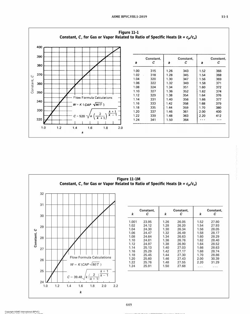
Figure 11-1Constant, C , for Gas or Vapor Related to Ratio of Specific Heats (k = cp/cv)
Figure 11-1MConstant, C , for Gas or Vapor Related to Ratio of Specific Heats (k = cp/cv)
1.0011.02 1.041.061.081.10 1.121.141.161.181.20 1.221.24
23.9524.1224.3024.4724.6424.8124.9725.1325.2925.4525.6025.7625.91
1.261.281.301.321.341.361.381.401.421.441.461.481.50
26.0526.2026.3426.4926.6326.7626.9027.0327.1727.3027.4327.5527.68
1.521.541.561.581.601.621.641.661.681.702.002.20 . . .
27.8027.9328.0528.1728.2928.4028.5228.6328.7428.8630.3931.29. . .
kConstant,
C kConstant,
C kConstant,
C
32
31
30
29
28
27
26
25
24
Co
nsta
nt,
C
1.0 1.2 1.4 1.6
k
1.8 2.0 2.2
� �
Flow Formula Calculations
W � K (CAP M /T )
C � 39.48 2
k � 1k
k � 1k � 1
ASME BPVC.VIII.1-2019 11-1
449
Copyright ASME International (BPVC) Provided by IHS under license with ASME Licensee=Khalda Petroleum/5986215001, User=Amer, Mohamed
Not for Resale, 07/02/2019 13:29:04 MDTNo reproduction or networking permitted without license from IHS
--`,``,``,,`,`,,````,`,``,,,`-`-`,,`,,`,`,,`---
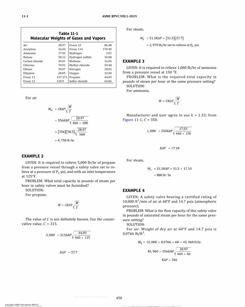
For air
EXAMPLE 2GIVEN: It is required to relieve 5,000 lb/hr of propane
from a pressure vessel through a safety valve set to re-lieve at a pressure of Ps, psi, and with an inlet temperatureat 125°F.PROBLEM: What total capacity in pounds of steam per
hour in safety valves must be furnished?SOLUTION:For propane,
The value of C is not definitely known. Use the conser-vative value, C = 315.
For steam,
EXAMPLE 3GIVEN: It is required to relieve 1,000 lb/hr of ammonia
from a pressure vessel at 150 °F.PROBLEM: What is the required total capacity in
pounds of steam per hour at the same pressure setting?SOLUTION:For ammonia,
Manufacturer and user agree to use k = 1.33; fromFigure 11-1, C = 350.
For steam,
EXAMPLE 4GIVEN: A safety valve bearing a certified rating of
10,000 ft3/min of air at 60°F and 14.7 psia (atmosphericpressure).PROBLEM: What is the flow capacity of this safety valve
in pounds of saturated steam per hour for the same pres-sure setting?SOLUTION:For air: Weight of dry air at 60°F and 14.7 psia is
0.0766 lb/ft3.
Table 11-1Molecular Weights of Gases and Vapors
Air 28.97Acetylene 26.04Ammonia 17.03Butane 58.12Carbon dioxide 44.01Chlorine 70.91Ethane 30.07Ethylene 28.05Freon 11 137.371Freon 12 120.9
Freon 22 86.48Freon 114 170.90Hydrogen 2.02Hydrogen sulfide 34.08Methane 16.04Methyl chloride 50.48Nitrogen 28.02Oxygen 32.00Propane 44.09Sulfur dioxide 64.06
ASME BPVC.VIII.1-201911-1
450
Copyright ASME International (BPVC) Provided by IHS under license with ASME Licensee=Khalda Petroleum/5986215001, User=Amer, Mohamed
Not for Resale, 07/02/2019 13:29:04 MDTNo reproduction or networking permitted without license from IHS
--`,``,``,,`,`,,````,`,``,,,`-`-`,,`,,`,`,,`---

For steam,
NOTE: Before converting the capacity of a safety valve from any gasto steam, the requirements of UG-131(b) must be met.
11-2
(a) Since it is realized that the saturated water capacityis configuration sensitive, the following applies only tothose safety valves that have a nozzle type construction(throat to inlet diameter ratio of 0.25 to 0.80 with a con-tinuously contoured change and have exhibited a coeffi-cient KD in excess of 0.90). No saturated water ratingshall apply to other types of construction.
NOTE: The manufacturer, user, and Inspector are all cautioned thatfor the following rating to apply, the valve shall be continuously sub-jected to saturated water. If, after initial relief the flow mediachanges to quality steam, the valve shall be rated as per dry satu-rated steam. Valves installed on vessels or lines containing steam–water mixture shall be rated on dry saturated steam.
(b) To determine the saturated water capacity of avalve currently rated under UG-131 and meeting the re-quirements of (a) above, refer to Figure 11-2. Enter thegraph at the set pressure of the valve, move vertically up-ward to the saturated water line and read horizontally the
relieving capacity. This capacity is the theoretical, isentro-pic value arrived at by assuming equilibrium flow and cal-culated values for the critical pressure ratio.
Figure 11-2Flow Capacity Curve for Rating Nozzle-TypeSafety Valves on Saturated Water (Based on
10% Overpressure)
Figure 11-2MFlow Capacity Curve for Rating Nozzle-TypeSafety Valves on Saturated Water (Based on
10% Overpressure)
16
14
10
8
6
2
05 10 15 20 250
Flo
w C
apac
ity
× 10
–7, k
g/h
/m2
Set Pressure, MPa
4
12
18
20
Saturated water
ASME BPVC.VIII.1-2019 11-1 – 11-2
451
Copyright ASME International (BPVC) Provided by IHS under license with ASME Licensee=Khalda Petroleum/5986215001, User=Amer, Mohamed
Not for Resale, 07/02/2019 13:29:04 MDTNo reproduction or networking permitted without license from IHS
--`,``,``,,`,`,,````,`,``,,,`-`-`,,`,,`,`,,`---

MANDATORY APPENDIX 12ULTRASONIC EXAMINATION OF WELDS (UT)
12-1 SCOPE
(a) This Appendix describes methods which shall beemployed when ultrasonic examination of welds is speci-fied in this Division.(b) Section V, Article 4 shall be applied for detail re-
quirements in methods and procedures, unless otherwisespecified in this Appendix.(c) Ultrasonic examination shall be performed in accor-
dance with a written procedure, certified by the Manufac-turer to be in accordance with the requirements ofSection V, Article 1, T-150.
12-2 CERTIFICATION OF COMPETENCE OFNONDESTRUCTIVE EXAMINER
Personnel performing and evaluating ultrasonic exam-inations required by this Division shall meet the require-ments of UW-54.
12-3 ACCEPTANCE–REJECTION STANDARDS
These Standards shall apply unless other standards arespecified for specific applications within this Division.Imperfections which produce a response greater than
20% of the reference level shall be investigated to the ex-tent that the operator can determine the shape, identity,and location of all such imperfections and evaluate themin terms of the acceptance standards given in (a) and (b)below.
(a) Indications characterized as cracks, lack of fusion,or incomplete penetration are unacceptable regardlessof length.(b) Other imperfections are unacceptable if the indica-
tions exceed the reference level amplitude and havelengths which exceed:
(1) 1/4 in. (6 mm) for t up to 3/4 in. (19 mm);(2) 1/3t for t from
3/4 in. to 21/4 in. (19 mm to 57 mm);(3) 3/4 in. (19 mm) for t over 21/4 in. (57 mm).
where t is the thickness of the weld excluding any allow-able reinforcement. For a butt weld joining two membershaving different thicknesses at the weld, t is the thinner ofthese two thicknesses. If a full penetration weld includes afillet weld, the thickness of the throat of the fillet shall beincluded in t .
12-4 REPORT OF EXAMINATION
The Manufacturer shall prepare a report of the ultraso-nic examination and a copy of this report shall be retainedby the Manufacturer as required by this Division (10-13).The report shall contain the information required by Sec-tion V. In addition, a record of repaired areas shall benoted as well as the results of the reexamination of the re-paired areas. The Manufacturer shall also maintain a re-cord of all reflections from uncorrected areas havingresponses that exceed 50% of the reference level. This re-cord shall locate each area, the response level, the dimen-sions, the depth below the surface, and the classification.
ASME BPVC.VIII.1-201912-1 – 12-4
452
Copyright ASME International (BPVC) Provided by IHS under license with ASME Licensee=Khalda Petroleum/5986215001, User=Amer, Mohamed
Not for Resale, 07/02/2019 13:29:04 MDTNo reproduction or networking permitted without license from IHS
--`,``,``,,`,`,,````,`,``,,,`-`-`,,`,,`,`,,`---
ð19Þ
MANDATORY APPENDIX 13VESSELS OF NONCIRCULAR CROSS SECTION
13-1 SCOPE
(a) The rules in Mandatory Appendix 13 cover mini-mum requirements for the design, fabrication, and inspec-tion of single wall vessels having a rectangular orobround cross section. The rules of this Appendix applyto the walls and parts of the vessels subject to pressurestresses including stiffening, reinforcing and stayingmembers.
(b) All other parts of this Division shall apply unlessotherwise stated in this Appendix.
(c) As stated in U-2(g), this Division does not containrules to cover all details of design and construction. Theserules are, therefore, established to cover some commontypes of noncircular cross section vessels but are not in-tended to limit configurations to those illustrated orotherwise described herein.
(d) In 13-18 special consideration is given to the calcu-lation of applied and allowable stresses when the struc-ture contains butt-welded joints or row of holes atlocations other than at side plate midlengths.
13-2 TYPES OF VESSELS
The design equations given in this Appendix shall applyto the single wall vessels as illustrated in Figure 13-2(a)for vessels of rectangular cross section, in Figure13-2(b) for vessels having an obround cross section,and in Figure 13-2(c) for vessels of circular section witha single diametral stay plate.
(a) Rectangular Vessels. Figure 13-2(a) illustrates somebasic types of vessels as follows:
(1) Figure 13-2(a), sketch (1) shows a vessel of rec-tangular cross section in which the opposite sides havethe same wall thickness. Two opposite sides may have awall thickness different than that of the other two oppo-site sides.
(2) Figure 13-2(a), sketch (2) shows a vessel of rec-tangular cross section in which two opposite membershave the same thickness and the other two members havetwo different thicknesses.
(3) Figure 13-2(a), sketch (3) shows a vessel of rec-tangular cross section having uniform wall thickness andcorners bent to a radius. For corners that are cold formed,the provisions of UG-79 and UCS-79 or UHT-79 shallapply.
(4) Figure 13-2(a), sketch (4) shows a vessel of rec-tangular cross section [as in (1) above] but reinforced bywelded‐on members.
(5) Figure 13-2(a), sketch (5) shows a vessel of rec-tangular cross section [as in (3) above] but externally re-inforced by members welded to the flat surfaces of thevessel.
(6) Figure 13-2(a), sketch (6) shows a vessel of rec-tangular cross section with chamfered corner segmentsjoined to the adjacent sides by small curved segmentswith constant radii and with external reinforcing mem-bers welded to the flat sides of the vessel.
(7) Figure 13-2(a), sketch (7) shows a vessel of rec-tangular cross section [as in (1) above] but having two op-posite sides stayed at midlength.
(8) Figure 13-2(a), sketch (8) shows a vessel of rec-tangular cross section [as in (1) above] but having two op-posite sides stayed at the third points.
(9) Figure 13-2(a), sketches (9) and (10) show ves-sels of rectangular cross section [as in (1) above] but hav-ing two opposite sides stayed such that the compartmentshave different dimensions. There is no restriction on thenumber of staying members used.
(b) Obround Vessels. Figure 13-2(b) illustrates somebasic types of vessels as follows:
(1) Figure 13-2(b), sketch (1) shows a vessel ofobround cross section in which the opposite sides havethe same wall thickness. The flat side walls may have adifferent thickness than the wall thickness of the semicy-lindrical parts.
(2) Figure 13-2(b), sketch (2) shows a vessel ofobround cross section [as in (1) above] but reinforcedby welded‐on members.
(3) Figure 13-2(b), sketch (3) shows a vessel ofobround cross section [as in (1) above] but having the flatside plates stayed at midlength.
(c) Stayed Vessel of Circular Cross Section. Figure13-2(c) illustrates a vessel of circular cross section con-taining a single diametral staying plate that also acts asa pressure surface when the two compartments of thevessel are subject to different internal pressures.
13-3 MATERIALS
Materials used in the fabrication of vessels describedherein shall be in accordance with Subsection A.
ASME BPVC.VIII.1-2019 13-1 – 13-3
453
Copyright ASME International (BPVC) Provided by IHS under license with ASME Licensee=Khalda Petroleum/5986215001, User=Amer, Mohamed
Not for Resale, 07/02/2019 13:29:04 MDTNo reproduction or networking permitted without license from IHS
--`,``,``,,`,`,,````,`,``,,,`-`-`,,`,,`,`,,`---
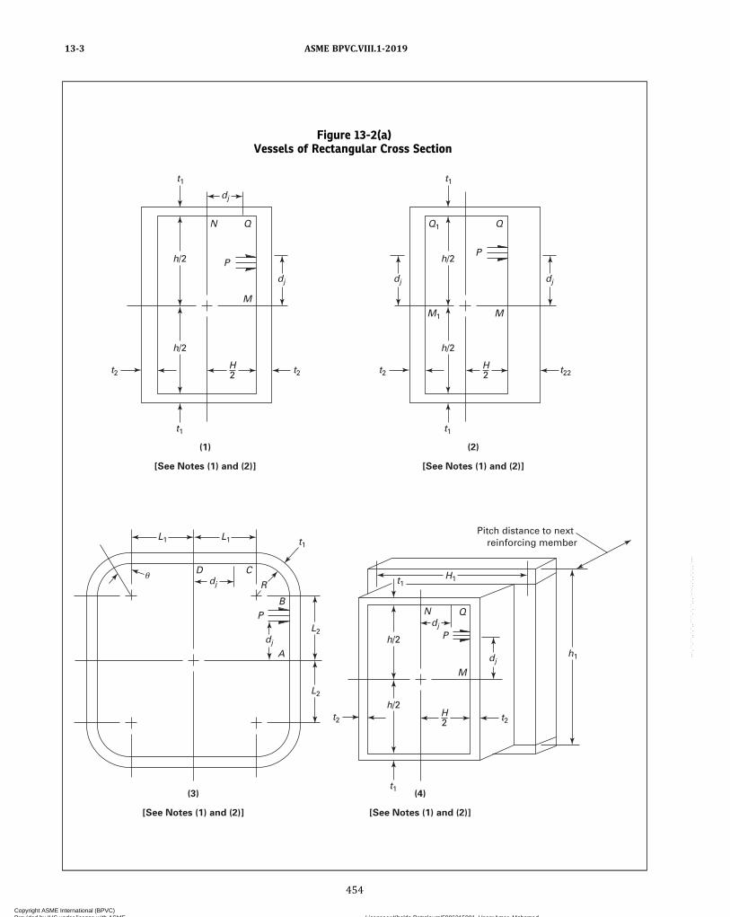
Figure 13-2(a)Vessels of Rectangular Cross Section
t1
t2 t2
t1
dj
N
P h/2
h/2
2
(1)
[See Notes (1) and (2)]
(3)
[See Notes (1) and (2)]
(4)
[See Notes (1) and (2)]
Q
M
H
dj
dj
D �
C
B P
R
A
t1
t22 t2
t1
L2
L1 t1 L1
L2
P h/2
h/2
2
Pitch distance to next reinforcing member
(2)
[See Notes (1) and (2)]
Q Q1
M M1
H
dj
t1
t2
t1
h/2
h/2
dj
dj
t2 2 H
P
Q
M
N
h1
H1
dj
dj
ASME BPVC.VIII.1-201913-3
454
Copyright ASME International (BPVC) Provided by IHS under license with ASME Licensee=Khalda Petroleum/5986215001, User=Amer, Mohamed
Not for Resale, 07/02/2019 13:29:04 MDTNo reproduction or networking permitted without license from IHS
--`,``,``,,`,`,,````,`,``,,,`-`-`,,`,,`,`,,`---
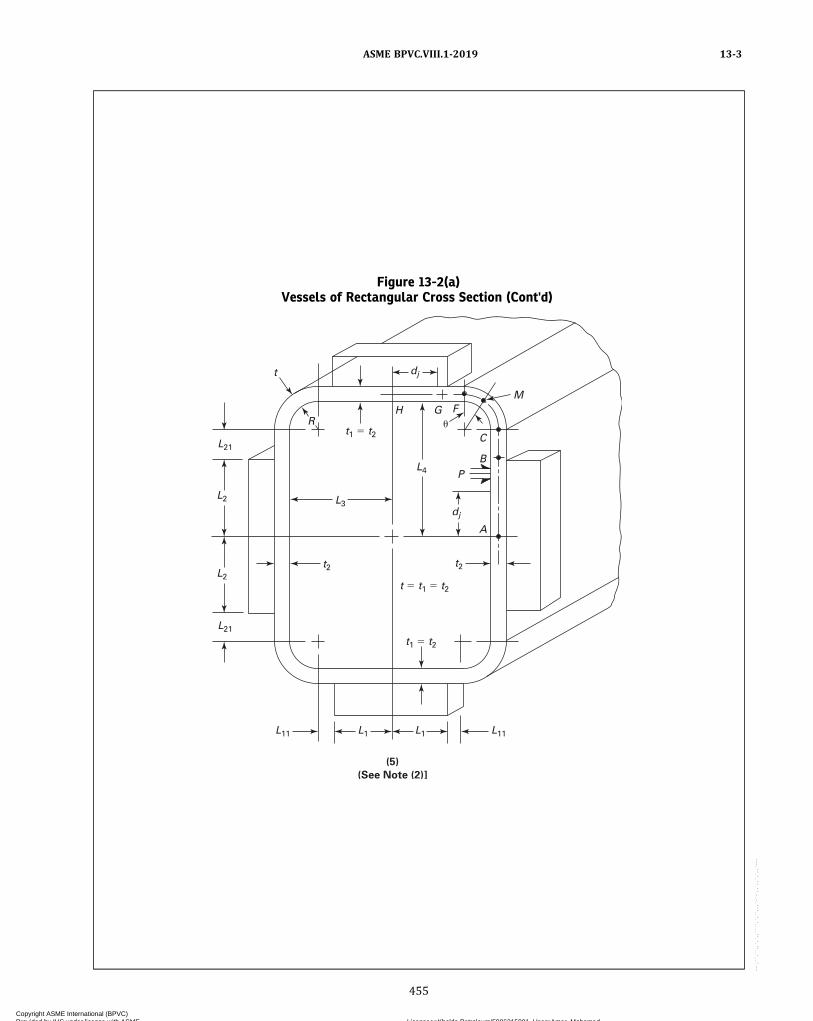
Figure 13-2(a)Vessels of Rectangular Cross Section (Cont'd)
(5)
(See Note (2)]
t1 � t2
t1 � t2
t2 t2
L3
L2
L2
L21
L21
L11 L11 L1 L1
L4
dj
dj
t
R H G
�
F
C
B
A
P
M
t � t1 � t2
ASME BPVC.VIII.1-2019 13-3
455
Copyright ASME International (BPVC) Provided by IHS under license with ASME Licensee=Khalda Petroleum/5986215001, User=Amer, Mohamed
Not for Resale, 07/02/2019 13:29:04 MDTNo reproduction or networking permitted without license from IHS
--`,``,``,,`,`,,````,`,``,,,`-`-`,,`,,`,`,,`---
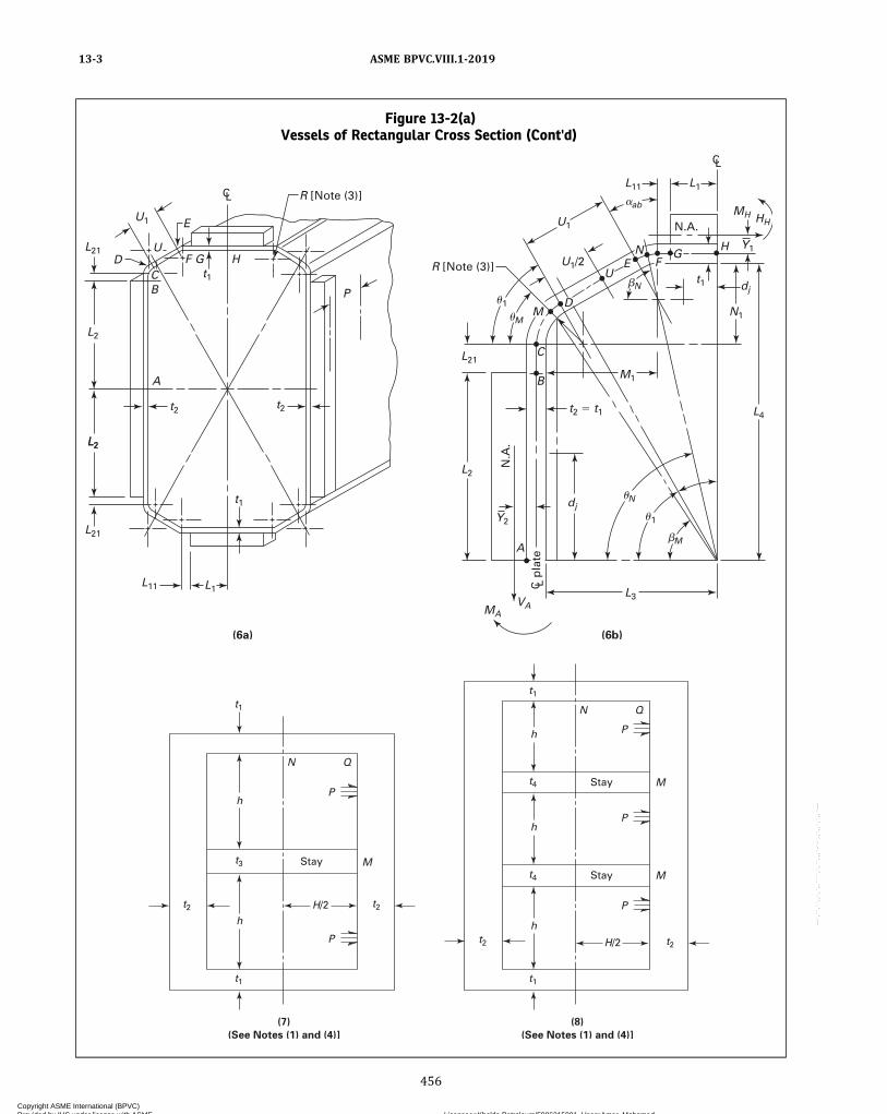
Figure 13-2(a)Vessels of Rectangular Cross Section (Cont'd)
(6a) (6b)
H G F
E
U D
C B
A
P dj
dj
N
M �
ab �
1 �
M
N �
1 �
MH HH
MA VA
A
L2
L2
U1
R [Note (3)]
R [Note (3)]
N.A
.
pla
te
L2
L21
L21
L11 L1
t1
t2 t2
t1
U1
L21
t1
H G
N.A.
F N
E
M D
C
B
U
M1
t2 � t1
N1
L4
Y1
L1 L11
U1/2
L2
L3
C L
C L
C L
Y2
(7)
(See Notes (1) and (4)]
(8)
(See Notes (1) and (4)]
t2
P
t1
t1
t3
N Q
N Q
h
h
t2 H/2
Stay Stay
M M
Stay M
H/2 t2 t2
t1
t4
t4
t1
h
h
h
P
P
P
P
ASME BPVC.VIII.1-201913-3
456
Copyright ASME International (BPVC) Provided by IHS under license with ASME Licensee=Khalda Petroleum/5986215001, User=Amer, Mohamed
Not for Resale, 07/02/2019 13:29:04 MDTNo reproduction or networking permitted without license from IHS
--`,``,``,,`,`,,````,`,``,,,`-`-`,,`,,`,`,,`---
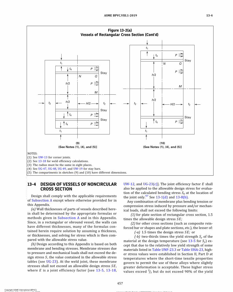
13-4 DESIGN OF VESSELS OF NONCIRCULARCROSS SECTION
Design shall comply with the applicable requirementsof Subsection A except where otherwise provided for inthis Appendix.
(a)Wall thicknesses of parts of vessels described here-in shall be determined by the appropriate formulas ormethods given in Subsection A and in this Appendix.Since, in a rectangular or obround vessel, the walls canhave different thicknesses, many of the formulas con-tained herein require solution by assuming a thickness,or thicknesses, and solving for stress which is then com-pared with the allowable stress value.
(b) Design according to this Appendix is based on bothmembrane and bending stresses. Membrane stresses dueto pressure and mechanical loads shall not exceed the de-sign stress S , the value contained in the allowable stresstables (see UG-23). At the weld joint, these membranestresses shall not exceed an allowable design stress SE ,where E is a joint efficiency factor [see 13-5, 13-18,
UW-12, and UG-23(c)]. The joint efficiency factor E shallalso be applied to the allowable design stress for evalua-tion of the calculated bending stress Sb at the location ofthe joint only.97 See 13-1(d) and 13-8(b).
Any combination of membrane plus bending tension orcompression stress induced by pressure and/or mechan-ical loads, shall not exceed the following limits:
(1) for plate section of rectangular cross section, 1.5times the allowable design stress SE;
(2) for other cross sections (such as composite rein-forced bar or shapes and plate sections, etc.), the lesser of:
(-a) 1.5 times the design stress SE; or(-b) two‐thirds times the yield strength Sy of the
material at the design temperature (see 13-5 for Sy) ex-cept that due to the relatively low yield strength of somematerials listed in Table UNF-23.3 or Table UHA-23, high-er stress values were established in Section II, Part D attemperatures where the short‐time tensile propertiesgovern to permit the use of these alloys where slightlygreater deformation is acceptable. These higher stressvalues exceed 2/3 but do not exceed 90% of the yield
Figure 13-2(a)Vessels of Rectangular Cross Section (Cont'd)
(9)
(See Notes (1), (4), and (5)]
(10)
(See Notes (1), (4), and (5)]
t2
P
t1
N Q
N Q
h/2
t2 H/2
Stay
Stay
Stay
M
Stay
Stay
M
H/2 t2 t2 h/2
t1
t4
t4
t4
h/2
h/2
t4
t4
t1
t1
P P
P
P
P
P
NOTES:(1) See UW-13 for corner joints.(2) See 13-18 for weld efficiency calculations.(3) The radius must be the same in eight places.(4) See UG-47, UG-48, UG-49, and UW-19 for stay bars.(5) The compartments in sketches (9) and (10) have different dimensions.
ASME BPVC.VIII.1-2019 13-4
457
Copyright ASME International (BPVC) Provided by IHS under license with ASME Licensee=Khalda Petroleum/5986215001, User=Amer, Mohamed
Not for Resale, 07/02/2019 13:29:04 MDTNo reproduction or networking permitted without license from IHS
--`,``,``,,`,`,,````,`,``,,,`-`-`,,`,,`,`,,`---
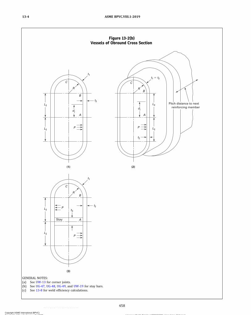
Figure 13-2(b)Vessels of Obround Cross Section
(1)
t2
t1
L2
L2
dj
P
A
B
R
C
(3)
t1
t2
t3
L2
L2
P
P
R
C
B
A
(2)
t2
t1 � t2
dj
P
A
B R
Pitch distance to next reinforcing member
Stay
C
L2
L2
GENERAL NOTES:(a) See UW-13 for corner joints.(b) See UG-47, UG-48, UG-49, and UW-19 for stay bars.(c) See 13-8 for weld efficiency calculations.
ASME BPVC.VIII.1-201913-4
458
Copyright ASME International (BPVC) Provided by IHS under license with ASME Licensee=Khalda Petroleum/5986215001, User=Amer, Mohamed
Not for Resale, 07/02/2019 13:29:04 MDTNo reproduction or networking permitted without license from IHS
--`,``,``,,`,`,,````,`,``,,,`-`-`,,`,,`,`,,`---
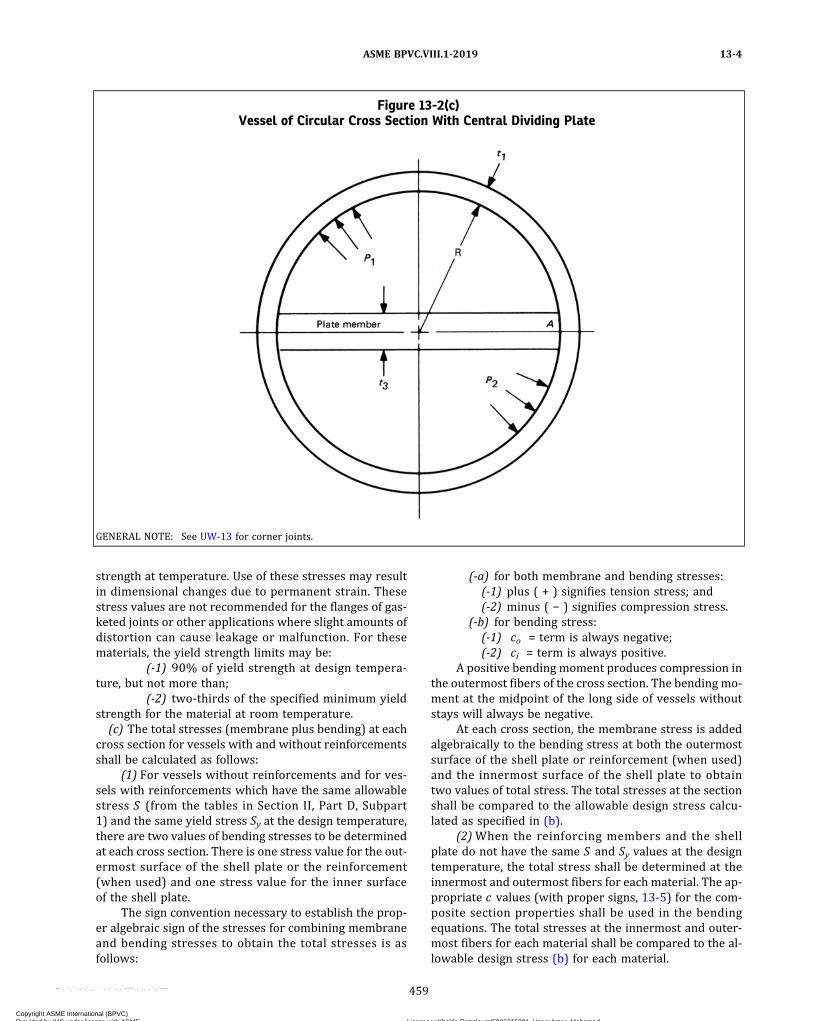
strength at temperature. Use of these stresses may resultin dimensional changes due to permanent strain. Thesestress values are not recommended for the flanges of gas-keted joints or other applications where slight amounts ofdistortion can cause leakage or malfunction. For thesematerials, the yield strength limits may be:
(-1) 90% of yield strength at design tempera-ture, but not more than;
(-2) two‐thirds of the specified minimum yieldstrength for the material at room temperature.
(c) The total stresses (membrane plus bending) at eachcross section for vessels with and without reinforcementsshall be calculated as follows:
(1) For vessels without reinforcements and for ves-sels with reinforcements which have the same allowablestress S (from the tables in Section II, Part D, Subpart1) and the same yield stress Sy at the design temperature,there are two values of bending stresses to be determinedat each cross section. There is one stress value for the out-ermost surface of the shell plate or the reinforcement(when used) and one stress value for the inner surfaceof the shell plate.
The sign convention necessary to establish the prop-er algebraic sign of the stresses for combining membraneand bending stresses to obtain the total stresses is asfollows:
(-a) for both membrane and bending stresses:(-1) plus ( + ) signifies tension stress; and(-2) minus ( − ) signifies compression stress.
(-b) for bending stress:(-1) co = term is always negative;(-2) ci = term is always positive.
A positive bending moment produces compression inthe outermost fibers of the cross section. The bending mo-ment at the midpoint of the long side of vessels withoutstays will always be negative.
At each cross section, the membrane stress is addedalgebraically to the bending stress at both the outermostsurface of the shell plate or reinforcement (when used)and the innermost surface of the shell plate to obtaintwo values of total stress. The total stresses at the sectionshall be compared to the allowable design stress calcu-lated as specified in (b).
(2)When the reinforcing members and the shellplate do not have the same S and Sy values at the designtemperature, the total stress shall be determined at theinnermost and outermost fibers for each material. The ap-propriate c values (with proper signs, 13-5) for the com-posite section properties shall be used in the bendingequations. The total stresses at the innermost and outer-most fibers for each material shall be compared to the al-lowable design stress (b) for each material.
Figure 13-2(c)Vessel of Circular Cross Section With Central Dividing Plate
GENERAL NOTE: See UW-13 for corner joints.
ASME BPVC.VIII.1-2019 13-4
459
Copyright ASME International (BPVC) Provided by IHS under license with ASME Licensee=Khalda Petroleum/5986215001, User=Amer, Mohamed
Not for Resale, 07/02/2019 13:29:04 MDTNo reproduction or networking permitted without license from IHS
--`,``,``,,`,`,,````,`,``,,,`-`-`,,`,,`,`,,`---

(d) Particular attention shall be given to the effects oflocal internal and external loads and expansion differen-tials at design temperature, including reactions at sup-porting lugs, piping, and other types of attachments, asspecified in UG-22.(e) Except as otherwise specified in this Appendix, ves-
sel parts of noncircular cross section subject to externalpressure shall be designed in accordance with U-2(g).(f) The end closures for vessels of this type shall be de-
signed in accordance with the provisions of U-2(g) and/or UG-101 except in cases where the ends are flat platessubject to rating under the rules of UG-34. Unstayed flatheads used as welded end plates for vessels describedin this Appendix shall conform to the rules of UG-34 ex-cept that a C factor of 0.20 shall be used in all cases.(g) The requirements for ligaments prescribed in
UG-53 shall apply except as modified in 13-6 for the caseof multidiameter holes in plates. [See 13-18(b).]The ligament efficiencies em and eb shall only be applied
to the calculated stresses for the plates containing theligaments.
(1)When em and eb are less than the joint efficiency E(see 13-5 and UW-12), which would be used if there wereno ligaments in the plate, the membrane and bendingstresses calculated based on the gross area of the sectionshall be divided by em and eb, respectively, to obtain thestresses based on the net area for the section. The allow-able design stresses for membrane and membrane plusbending shall be calculated as described in (b) usingE = 1.0.
(2)When em and eb are greater than the joint effi-ciency E , which would be used if there were no ligamentsin the plate, the stresses shall be calculated as if therewere no ligaments in the plate. The allowable designstresses for membrane and membrane plus bending shallbe calculated as described in (b) using the appropriate Efactor required by UW-12.(h) The design equations in this Appendix are based on
vessels in which the length Lv to side dimension (H or h)ratio (aspect ratio) is greater than 4. These equations areconservatively applicable to vessels of aspect ratio lessthan 4 and may thus be used as specified in this Appendix.Vessel sideplates with aspect ratios less than 4 arestrengthened by the interaction of the end closures andmay be designed in accordance with the provisions ofU-2(g) by using established techniques of structural anal-ysis. Membrane and bending stresses shall be determinedthroughout the structure and shall not exceed the allow-able values established in this Appendix. Short unrein-forced or unstayed vessels of rectangular cross sectionhaving an aspect ratio not greater than 2.0 may be de-signed in accordance with 13-18(b) and 13-18(c).(i) Bolted full‐side or end plates and flanges may be
provided for vessels of rectangular cross section. Manyacceptable configurations are possible. Therefore, rulesfor specific designs are not provided, and these parts shallbe designed in accordance with the provisions of UG-34
for unstayed flat plates and U-2(g) for the flange assem-bly. Analysis of the components must consider gasket re-actions, bolting forces, and resulting moments, as well aspressure and other mechanical loading.(j) Openings may be provided in vessels of noncircular
cross section as follows:(1) Openings in noncircular vessels do not require
reinforcement other than that inherent in the construc-tion, provided they meet the conditions given inUG-36(c)(3).
(2) As a minimum, the reinforcement of other open-ings in noncircular vessels shall comply with UG-39, ex-cept the required th ickness to be used in thereinforcement calculations shall be the thickness requiredto satisfy the stress criteria in (b). Compensation foropenings in noncircular vessels must account for thebending strength as well as the membrane strength ofthe side with the opening. In addition, openings may sig-nificantly affect the stresses in adjacent sides. Becausemany acceptable configurations are possible, rules forspecific designs are not provided [see U-2(g)].(k) For vessels without reinforcements and for vessels
with stay plates and stay rods (13-7, 13-9, 13-10, 13-12,and 13-13), the moments of inertia are calculated on aper‐unit‐width basis. That is, I = bt3/12, where b = 1.0.For vessels with reinforcements that do not extendaround the corners of the vessel (13-8 and 13-11), themoments of inertia are calculated using the traditional de-finition, I = pt2/12. For width of cross section for vesselswith reinforcements, see 13-8(d). For unreinforced ves-sels of rectangular cross section (13-7), the given mo-ments are defined on a per‐unit‐width basis. That is, MA
and Mr have dimensions (length × force/length) = force.
13-5 NOMENCLATURE
Symbols used in this Appendix are as follows:
A = R(2γ + πα2)A1 = cross‐sectional area of reinforcing member
only attached to plate of thickness t1A2 = cross‐sectional area of reinforcing member
attached to plate of thickness t2A3 = r(2γ1 + π)B = R2(γ2 + πγα2 + 2α2)b1 = p − d1 (Figure 13-6)b2 = p − d2 (Figure 13-6)bn = p − dn (Figure 13-6)bo = p − do (Figure 13-6)C = plate coefficient, UG-47c = distance from neutral axis of cross section to
extreme fibers (see ci and co). The appropri-ate ci or co value shall be substituted for thec term in the stress equations.
C1 = R2(2γ2 + 3γπα2 + 12α2)C2 = r2(2γ1
2 + 3πγ1 + 12)
ASME BPVC.VIII.1-201913-4 – 13-5
460
Copyright ASME International (BPVC) Provided by IHS under license with ASME Licensee=Khalda Petroleum/5986215001, User=Amer, Mohamed
Not for Resale, 07/02/2019 13:29:04 MDTNo reproduction or networking permitted without license from IHS
--`,``,``,,`,`,,````,`,``,,,`-`-`,,`,,`,`,,`---

c i = distance from neutral axis of cross section ofplate, composite section, or section with mul-tidiameter holes (see 2-12) to the inside sur-face of the vessel. Sign is always positive ( + ).
co = distance from neutral axis of cross section ofplate, composite section, or section with mul-tidiameter holes (see 2-12) to the extremeoutside surface of the section. Sign is alwaysnegative ( − ).
±cx = distance from neutral axis of cross section toany intermediate point. Sign is positive ( + )when inward and sign is negative ( − ) whenoutward.
D1 = R3(γ3 + 2πγ2α2 + 12γα2 + 2πα2)d1 = diameter of hole of length T1 (pitch diameter
for threaded hole) (Figure 13-6)d2 = diameter of hole of length T2 (pitch diameter
for threaded hole) (Figure 13-6)DE = equivalent uniform diameter of multidia-
meter holedj = distance frommidlength of plate to weld joint
or centerline of row of holes in the straightsegment of the plate
dn = diameter of hole of length Tn (pitch diameterfor threaded hole) (Figure 13-6)
do = diameter of hole of length To (pitch diameterfor threaded hole) (Figure 13-6)
E = joint efficiency factor as required by UW-12for all Category A butt joints (see UW-3)and to any Category C or D butt97 joints.The joint efficiency factor is used as de-scribed in 13-4(b) and 13-4(g) to calculatethe allowable design membrane and mem-brane plus bending stresses.
E1 = R3(4γ3 + 6πγ2α2 + 24γα2 + 3πα2)E2 = modulus of elasticity at design temperatureE3 = modulus of elasticity at ambient temperatureeb = bending ligament efficiency [see 13-4(g),
2-12, and 13-18(b)]em = membrane ligament efficiency [see 13-4(g),
2-12, and 13-18(b)]F = (3AD1 − 2BC1)/(AE1 − 6B2)H = inside length of short side of rectangular
vessel= 2(L 1 + L 11) for equations in 13-8(d) for
Figure 13-2(a), sketches (5) and (6)h = inside length of long side of unstayed rectan-
gular vessel; or dimension perpendicular tothe H dimension in stayed vessels as shownin Figure 13-2(a), sketches (7), (8), (9), and(10), in which case h may be greater than,equal to, or less than H ,
= 2(L 2 + L 21) for equations in 13-8(d) forFigure 13-2(a), sketches (5) and (6)
= 2L 2 for equations in 13-8(d) for Figure13-2(b), sketch (2)
H0 = outside length of short side of rectangularvessel
H1 = centroidal length of reinforcing member onshort side of rectangular vessel
h1 = centroidal length of reinforcing member onlong side of rectangular vessel
ho = outside length of long side of rectangularvessel
I = moment of inertiaI1 = moment of inertia of strip of thickness98 t1I2 = moment of inertia of strip of thickness98 t2I3 = moment of inertia of strip of thickness98 t3
I11 = moment of inertia of combined reinforcingmember and effective width of plate w ofthickness t1
I21 = moment of inertia of combined reinforcingmember and effective width of plate w ofthickness t2
I22 = moment of inertia of strip of thickness98 t22I e = moment of inertia about axis parallel to long
side of rectangular vessel and passingthrough centroid of cross‐sectional area
J = plate parameter, Table 13-8(d)J1 = plate parameter, Table 13-13(c)K = vessel parameter (I2/I1)αk = reinforcement member parameter
= (I21/I11)α1K1 = 2k2 + 3k1 = I22/I2K2 = 3k1 + 2k2
k2 = I22α/I1K3 = factor for unreinforced rectangular vessel
[Figure 13-2(a), sketch (3)]K4 = factor for reinforced rectangular vessel
[Figure 13-2(a), sketch (5)]L1 = half‐length of short side of rounded or cham-
fered corner vessel without reinforcements;half‐length of reinforcement on short side ofreinforced vessel
L2 = half‐length of long side plate of obround androunded or chamfered corner rectangularvessels without reinforcements; half‐lengthof reinforcement on long side of reinforcedvessel
L3 , L4 = dimensions of rectangular vessel [Figure13-2(a), sketches (5) and (6)]
L21 , L11 = dimensions of rectangular vessel [Figure13-2(a), sketches (5) and (6)]
Lv = length of vesselM = bending moment
MA, MM = bending moment at midpoint of long side.99
Positive sign results in a compression stressin the outermost fibers in the cross section.
Mj = bending moment at weld joint99
N = K1K2 − k22
P = internal design pressure (see UG-21)
ASME BPVC.VIII.1-2019 13-5
461
Copyright ASME International (BPVC) Provided by IHS under license with ASME Licensee=Khalda Petroleum/5986215001, User=Amer, Mohamed
Not for Resale, 07/02/2019 13:29:04 MDTNo reproduction or networking permitted without license from IHS
--`,``,``,,`,`,,````,`,``,,,`-`-`,,`,,`,`,,`---

ð19Þ
p = pitch distance; distance between reinforcingmembers; plate width between edges of rein-forcing members
P1 , P2 = i n t e r n a l d e s i g n p r e s s u r e s i n two ‐compartment vessel [Figure 13-2(c)] whereP1 > P2
Pe = external design pressureR = inside radiusr = radius to centroidal axis of reinforcement
member on obround vesselR1 = least radius of gyration of noncircular cross‐
sectional vesselS = allowable tensile stress values (see UG-23)Sb = b e n d i n g s t r e s s ( + = t e n s i o n ,
− = compression)Sm = membrane stressST = total stress (Sm + Sb)Sy = yield strength of material at design tempera-
ture from Section II, Part D, Subpart 1, TableY-1
t = plate thicknessT1 = length of hole of diameter d1
t1 = thickness of short‐side plates of vesselT2 = length of hole of diameter d2
t2 = thickness of long‐side plates of vesselt3 = thickness or diameter of staying membert4 = thickness or diameter of staying membert5 = thickness of end closure plate or head of
vesselt22 = thickness of long‐side plates of vesselTn = length of hole of diameter dnTo = length of hole of diameter dow = width of plate included in moment of inertia
calculation of reinforced section= distance from base of plate to neutral axis= distance from geometric center of end plate
to centroid of cross‐sectional area of a rectan-gular vessel. If both long‐side plates are ofequal thickness te, then = 0.
= distance between centroid of reinforcedcross section with I11 and centerline of shellplate with t1 [Figure 13-2(a), sketch (6)]
= distance between centroid of reinforcedcross section with I21 and centerline of shellplate with t2 [Figure 13-2(a), sketch (6)]
Z = plate parameter, UG-34Δ = material parameter associated with w [Table
13-8(e)]α = rectangular vessel parameter
= H/hα1 = rectangular vessel reinforcement parameter
= H1/h1
α2 = I2/I1α3 = L2/L1
β = h/p, H/p, or 2R/pγ = L2/R
γ1 = L2/r
θ = angleν = Poisson’s ratioπ = 3.1415ϕ = R/L 1
13-6 LIGAMENT EFFICIENCY OFMULTIDIAMETER HOLES IN PLATES
In calculations made according to this Appendix for thecase of a plate with uniform diameter holes, the ligamentefficiency factors em and eb for membrane and bendingstresses, respectively, are considered to be the same.See 13-4(g) and 13-18(b) for application of ligament effi-ciency factors. In the case of multidiameter holes, the neu-tral axis of the ligament may no longer be at midthicknessof the plate; in this case, for bending loads, the stress ishigher at one of the plate surfaces than at the othersurface.(a) Ligament Efficiency of Plate With Multidiameter
Holes Subject to Membrane Stress. Figure 13-6 shows aplate with multidiameter holes. In the case of membranestresses, the ligament efficiency is as follows:
ð1Þ
where
ð2Þ
(b) Ligament Efficiency of Plate With MultidiameterHoles Subject to Bending Stress. Figure 13-6 shows a platewith multidiameter holes. In the case of bending loads,the ligament efficiency is given by
ð3Þ
where
ð4Þ
ð5Þ
ASME BPVC.VIII.1-201913-5 – 13-6
462
Copyright ASME International (BPVC) Provided by IHS under license with ASME Licensee=Khalda Petroleum/5986215001, User=Amer, Mohamed
Not for Resale, 07/02/2019 13:29:04 MDTNo reproduction or networking permitted without license from IHS
--`,``,``,,`,`,,````,`,``,,,`-`-`,,`,,`,`,,`---

ð6Þ
c = the larger of or
13-7 UNREINFORCED VESSELS OFRECTANGULAR CROSS SECTION
For the equations in these paragraphs, the momentsand moments of inertia are calculated on a per‐unit‐widthbasis. That is, I = bt3/12, where b = 1.0. The momentsMA
and Mr have dimensions (force × length/length) = force.See 13-4(k).
(a) Vessel per Figure 13-2(a), Sketch (1)(1) Membrane StressShort‐side plates:
ð1Þ
Long‐side plates:
ð2Þ
(2) Bending StressShort‐side plates:
ð3Þ
ð4Þ
Long‐side plates:
ð5Þ
ð6Þ
(3) Total StressShort‐side plates:
ð7Þ
ð8Þ
Long‐side plates:
ð9Þ
ð10Þ
(b) Vessel per Figure 13-2(a), Sketch (2). In this type ofvessel, the maximum stress occurs either at the corners ofthe vessel or at the midpoint of the long sides.
Figure 13-6Plate With Multidiameter Hole Pattern
ASME BPVC.VIII.1-2019 13-6 – 13-7
463
Copyright ASME International (BPVC) Provided by IHS under license with ASME Licensee=Khalda Petroleum/5986215001, User=Amer, Mohamed
Not for Resale, 07/02/2019 13:29:04 MDTNo reproduction or networking permitted without license from IHS
--`,``,``,,`,`,,````,`,``,,,`-`-`,,`,,`,`,,`---

(1) Membrane StressShort‐side plates:
ð11Þ
Long‐side plates:
ð12AÞ
ð12BÞ
(2) Bending StressShort‐side plates:
ð13Þ
ð14Þ
Long‐side plates
ð15Þ
ð16Þ
ð17Þ
ð18Þ
(3) Total StressShort‐side plates:
ð19Þ
ð20Þ
Long‐side plates:
ð21Þ
ð22Þ
ð23Þ
ð24Þ
(c) Vessel per Figure 13-2(a), Sketch (3)(1) Membrane StressShort‐side plates:
ð25Þ
Long‐side plates:
ð26Þ
Corner sections:
ð27Þ
(2) Bending StressShort‐side plates:
ð28Þ
ð29Þ
Long‐side plates:
ð30Þ
ð31Þ
Corner sections:
ð32Þ
where (Sb)B ‐C maximum at
ASME BPVC.VIII.1-201913-7
464
Copyright ASME International (BPVC) Provided by IHS under license with ASME Licensee=Khalda Petroleum/5986215001, User=Amer, Mohamed
Not for Resale, 07/02/2019 13:29:04 MDTNo reproduction or networking permitted without license from IHS
--`,``,``,,`,`,,````,`,``,,,`-`-`,,`,,`,`,,`---
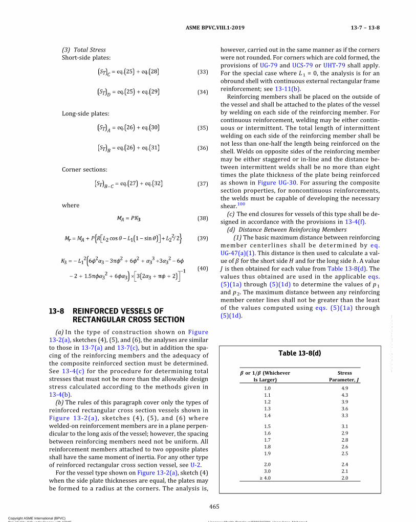
(3) Total StressShort‐side plates:
ð33Þ
ð34Þ
Long‐side plates:
ð35Þ
ð36Þ
Corner sections:
ð37Þ
where
ð38Þ
ð39Þ
ð40Þ
13-8 REINFORCED VESSELS OFRECTANGULAR CROSS SECTION
(a) In the type of construction shown on Figure13-2(a), sketches (4), (5), and (6), the analyses are similarto those in 13-7(a) and 13-7(c), but in addition the spa-cing of the reinforcing members and the adequacy ofthe composite reinforced section must be determined.See 13-4(c) for the procedure for determining totalstresses that must not be more than the allowable designstress calculated according to the methods given in13-4(b).
(b) The rules of this paragraph cover only the types ofreinforced rectangular cross section vessels shown inFigure 13-2(a), sketches (4), (5), and (6) wherewelded‐on reinforcement members are in a plane perpen-dicular to the long axis of the vessel; however, the spacingbetween reinforcing members need not be uniform. Allreinforcement members attached to two opposite platesshall have the same moment of inertia. For any other typeof reinforced rectangular cross section vessel, see U-2.
For the vessel type shown on Figure 13-2(a), sketch (4)when the side plate thicknesses are equal, the plates maybe formed to a radius at the corners. The analysis is,
however, carried out in the same manner as if the cornerswere not rounded. For corners which are cold formed, theprovisions of UG-79 and UCS-79 or UHT-79 shall apply.For the special case where L1 = 0, the analysis is for anobround shell with continuous external rectangular framereinforcement; see 13-11(b).
Reinforcing members shall be placed on the outside ofthe vessel and shall be attached to the plates of the vesselby welding on each side of the reinforcing member. Forcontinuous reinforcement, welding may be either contin-uous or intermittent. The total length of intermittentwelding on each side of the reinforcing member shall benot less than one‐half the length being reinforced on theshell. Welds on opposite sides of the reinforcing membermay be either staggered or in‐line and the distance be-tween intermittent welds shall be no more than eighttimes the plate thickness of the plate being reinforcedas shown in Figure UG-30. For assuring the compositesection properties, for noncontinuous reinforcements,the welds must be capable of developing the necessaryshear.100
(c) The end closures for vessels of this type shall be de-signed in accordance with the provisions in 13-4(f).
(d) Distance Between Reinforcing Members(1) The basic maximum distance between reinforcing
member centerlines shall be determined by eq.UG-47(a)(1). This distance is then used to calculate a val-ue of β for the short side H and for the long side h . A valueJ is then obtained for each value from Table 13-8(d). Thevalues thus obtained are used in the applicable eqs.(5)(1a) through (5)(1d) to determine the values of p1
and p2. The maximum distance between any reinforcingmember center lines shall not be greater than the leastof the values computed using eqs. (5)(1a) through(5)(1d).
Table 13-8(d)
β or 1/β (WhicheverIs Larger)
StressParameter, J
1.0 4.91.1 4.31.2 3.91.3 3.61.4 3.3
1.5 3.11.6 2.91.7 2.81.8 2.61.9 2.5
2.0 2.43.0 2.1
≥ 4.0 2.0
ASME BPVC.VIII.1-2019 13-7 – 13-8
465
Copyright ASME International (BPVC) Provided by IHS under license with ASME Licensee=Khalda Petroleum/5986215001, User=Amer, Mohamed
Not for Resale, 07/02/2019 13:29:04 MDTNo reproduction or networking permitted without license from IHS
--`,``,``,,`,`,,````,`,``,,,`-`-`,,`,,`,`,,`---
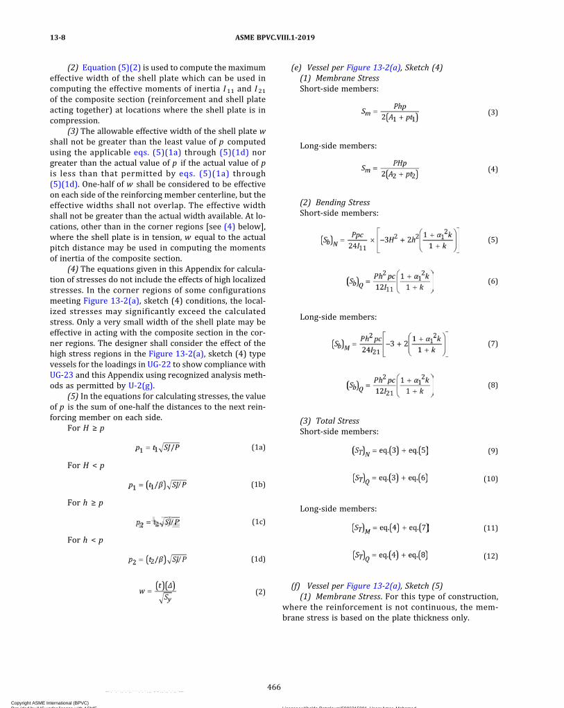
(2) Equation (5)(2) is used to compute the maximumeffective width of the shell plate which can be used incomputing the effective moments of inertia I11 and I21of the composite section (reinforcement and shell plateacting together) at locations where the shell plate is incompression.
(3) The allowable effective width of the shell plate wshall not be greater than the least value of p computedusing the applicable eqs. (5)(1a) through (5)(1d) norgreater than the actual value of p if the actual value of pis less than that permitted by eqs. (5)(1a) through(5)(1d). One‐half of w shall be considered to be effectiveon each side of the reinforcing member centerline, but theeffective widths shall not overlap. The effective widthshall not be greater than the actual width available. At lo-cations, other than in the corner regions [see (4) below],where the shell plate is in tension, w equal to the actualpitch distance may be used in computing the momentsof inertia of the composite section.
(4) The equations given in this Appendix for calcula-tion of stresses do not include the effects of high localizedstresses. In the corner regions of some configurationsmeeting Figure 13-2(a), sketch (4) conditions, the local-ized stresses may significantly exceed the calculatedstress. Only a very small width of the shell plate may beeffective in acting with the composite section in the cor-ner regions. The designer shall consider the effect of thehigh stress regions in the Figure 13-2(a), sketch (4) typevessels for the loadings in UG-22 to show compliance withUG-23 and this Appendix using recognized analysis meth-ods as permitted by U-2(g).
(5) In the equations for calculating stresses, the valueof p is the sum of one‐half the distances to the next rein-forcing member on each side.
For H ≥ p
ð1aÞFor H < p
ð1bÞFor h ≥ p
ð1cÞFor h < p
ð1dÞ
ð2Þ
(e) Vessel per Figure 13-2(a), Sketch (4)(1) Membrane StressShort‐side members:
ð3Þ
Long‐side members:
ð4Þ
(2) Bending StressShort‐side members:
ð5Þ
ð6Þ
Long‐side members:
ð7Þ
ð8Þ
(3) Total StressShort‐side members:
ð9Þ
ð10Þ
Long‐side members:
ð11Þ
ð12Þ
(f) Vessel per Figure 13-2(a), Sketch (5)(1) Membrane Stress. For this type of construction,
where the reinforcement is not continuous, the mem-brane stress is based on the plate thickness only.
ASME BPVC.VIII.1-201913-8
466
Copyright ASME International (BPVC) Provided by IHS under license with ASME Licensee=Khalda Petroleum/5986215001, User=Amer, Mohamed
Not for Resale, 07/02/2019 13:29:04 MDTNo reproduction or networking permitted without license from IHS
--`,``,``,,`,`,,````,`,``,,,`-`-`,,`,,`,`,,`---

Short‐side plates:
ð13Þ
Long‐side plates:
ð14Þ
Corner sections:
ð15Þ
(2) Bending StressShort‐side members:
ð16Þ
ð17Þ
ð18Þ
Long‐side members:
ð19Þ
ð20Þ
ð21Þ
Corner sections:
ð22Þ
where (Sb)C ‐F maximum occurs at Section M for MM = Mr
maximum when
(3) Total StressShort‐side members:
ð23Þ
ð24Þ
ð25Þ
Long‐side members:
ð26Þ
ð27Þ
ð28Þ
Corner sections:
ð29Þ
where
ð30Þ
ð31Þ
ASME BPVC.VIII.1-2019 13-8
467
Copyright ASME International (BPVC) Provided by IHS under license with ASME Licensee=Khalda Petroleum/5986215001, User=Amer, Mohamed
Not for Resale, 07/02/2019 13:29:04 MDTNo reproduction or networking permitted without license from IHS
--`,``,``,,`,`,,````,`,``,,,`-`-`,,`,,`,`,,`---
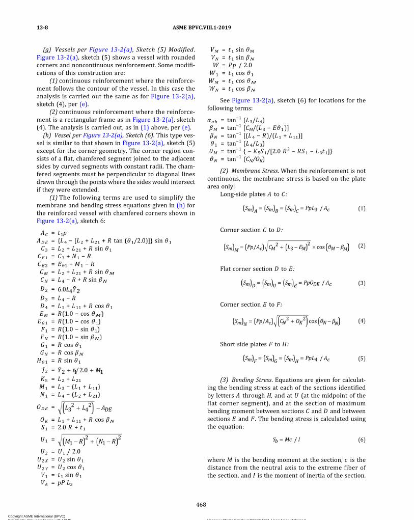
(g) Vessels per Figure 13-2(a), Sketch (5) Modified.Figure 13-2(a), sketch (5) shows a vessel with roundedcorners and noncontinuous reinforcement. Some modifi-cations of this construction are:
(1) continuous reinforcement where the reinforce-ment follows the contour of the vessel. In this case theanalysis is carried out the same as for Figure 13-2(a),sketch (4), per (e).
(2) continuous reinforcement where the reinforce-ment is a rectangular frame as in Figure 13-2(a), sketch(4). The analysis is carried out, as in (1) above, per (e).(h) Vessel per Figure 13-2(a), Sketch (6). This type ves-
sel is similar to that shown in Figure 13-2(a), sketch (5)except for the corner geometry. The corner region con-sists of a flat, chamfered segment joined to the adjacentsides by curved segments with constant radii. The cham-fered segments must be perpendicular to diagonal linesdrawn through the points where the sides would intersectif they were extended.
(1) The following terms are used to simplify themembrane and bending stress equations given in (h) forthe reinforced vessel with chamfered corners shown inFigure 13-2(a), sketch 6:
AC = t1pADE = {L4 − [L2 + L21 + R tan (θ1/2.0)]} sin θ1
C3 = L2 + L21 + R sin θ1
CE1 = C3 + N1 − RCE2 = Eθ1 + M1 − RCM = L2 + L21 + R sin θMCN = L4 − R + R sin βND2 =
D3 = L4 − RD4 = L1 + L11 + R cos θ1
EM = R(1.0 − cos θM)Eθ1 = R(1.0 − cos θ1)F1 = R(1.0 − sin θ1)FN = R(1.0 − sin βN)G1 = R cos θ1
GN = R cos βNHθ1 = R sin θ1
J2 =
K5 = L2 + L21
M1 = L3 − (L1 + L11)N1 = L4 − (L2 + L21)
ODE =
OK = L1 + L11 + R cos βNS1 = 2.0 R + t1
U1 =
U2 = U1 / 2.0U2X = U2 sin θ1
U2Y = U2 cos θ1
V1 = t1 sin θ1
VA = pP L3
VM = t1 sin θM
VN = t1 sin βNW = Pp / 2.0
W1 = t1 cos θ1
WM = t1 cos θMWN = t1 cos βN
See Figure 13-2(a), sketch (6) for locations for thefollowing terms:
αab = tan−1 (L3/L4)βM = tan−1 [CM/(L3 − Eθ1)]βN = tan−1 [(L4 − R)/(L1 + L11)]θ1 = tan−1 (L4/L3)θM = tan−1 { − K5S1/[2.0 R2 − RS1 − L3t1]}θN = tan−1 (CN/OK)
(2) Membrane Stress. When the reinforcement is notcontinuous, the membrane stress is based on the platearea only:
Long‐side plates A to C:
ð1Þ
Corner section C to D:
ð2Þ
Flat corner section D to E:
ð3Þ
Corner section E to F:
ð4Þ
Short side plates F to H:
ð5Þ
(3) Bending Stress. Equations are given for calculat-ing the bending stress at each of the sections identifiedby letters A through H, and at U (at the midpoint of theflat corner segment), and at the section of maximumbending moment between sections C and D and betweensections E and F . The bending stress is calculated usingthe equation:
ð6Þ
where M is the bending moment at the section, c is thedistance from the neutral axis to the extreme fiber ofthe section, and I is the moment of inertia of the section.
ASME BPVC.VIII.1-201913-8
468
Copyright ASME International (BPVC) Provided by IHS under license with ASME Licensee=Khalda Petroleum/5986215001, User=Amer, Mohamed
Not for Resale, 07/02/2019 13:29:04 MDTNo reproduction or networking permitted without license from IHS
--`,``,``,,`,`,,````,`,``,,,`-`-`,,`,,`,`,,`---
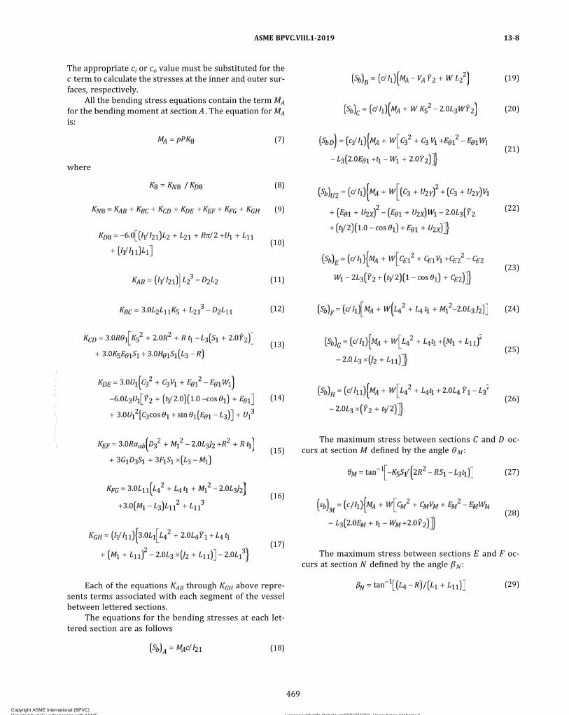
The appropriate ci or co value must be substituted for thec term to calculate the stresses at the inner and outer sur-faces, respectively.
All the bending stress equations contain the term MA
for the bending moment at section A . The equation forMA
is:
ð7Þ
where
ð8Þ
ð9Þ
ð10Þ
ð11Þ
ð12Þ
ð13Þ
ð14Þ
ð15Þ
ð16Þ
ð17Þ
Each of the equations KAB through KGH above repre-sents terms associated with each segment of the vesselbetween lettered sections.
The equations for the bending stresses at each let-tered section are as follows
ð18Þ
ð19Þ
ð20Þ
ð21Þ
ð22Þ
ð23Þ
ð24Þ
ð25Þ
ð26Þ
The maximum stress between sections C and D oc-curs at section M defined by the angle θM :
ð27Þ
ð28Þ
The maximum stress between sections E and F oc-curs at section N defined by the angle βN :
ð29Þ
ASME BPVC.VIII.1-2019 13-8
469
Copyright ASME International (BPVC) Provided by IHS under license with ASME Licensee=Khalda Petroleum/5986215001, User=Amer, Mohamed
Not for Resale, 07/02/2019 13:29:04 MDTNo reproduction or networking permitted without license from IHS
--`,``,``,,`,`,,````,`,``,,,`-`-`,,`,,`,`,,`---
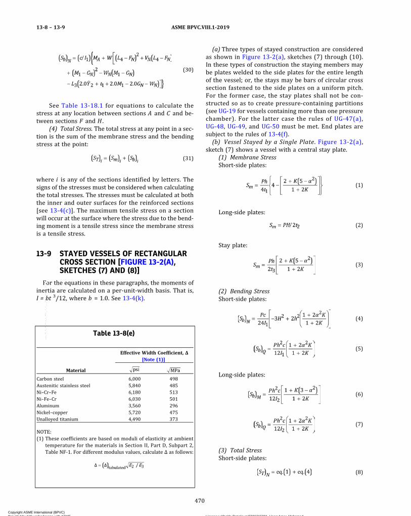
ð30Þ
See Table 13-18.1 for equations to calculate thestress at any location between sections A and C and be-tween sections F and H .
(4) Total Stress. The total stress at any point in a sec-tion is the sum of the membrane stress and the bendingstress at the point:
ð31Þ
where i is any of the sections identified by letters. Thesigns of the stresses must be considered when calculatingthe total stresses. The stresses must be calculated at boththe inner and outer surfaces for the reinforced sections[see 13-4(c)]. The maximum tensile stress on a sectionwill occur at the surface where the stress due to the bend-ing moment is a tensile stress since the membrane stressis a tensile stress.
13-9 STAYED VESSELS OF RECTANGULARCROSS SECTION [FIGURE 13-2(A),SKETCHES (7) AND (8)]
For the equations in these paragraphs, the moments ofinertia are calculated on a per‐unit‐width basis. That is,I = bt 3/12, where b = 1.0. See 13-4(k).
(a) Three types of stayed construction are consideredas shown in Figure 13-2(a), sketches (7) through (10).In these types of construction the staying members maybe plates welded to the side plates for the entire lengthof the vessel; or, the stays may be bars of circular crosssection fastened to the side plates on a uniform pitch.For the former case, the stay plates shall not be con-structed so as to create pressure-containing partitions(see UG-19 for vessels containing more than one pressurechamber). For the latter case the rules of UG-47(a),UG-48, UG-49, and UG-50 must be met. End plates aresubject to the rules of 13-4(f).(b) Vessel Stayed by a Single Plate. Figure 13-2(a),
sketch (7) shows a vessel with a central stay plate.(1) Membrane StressShort‐side plates:
ð1Þ
Long‐side plates:
ð2Þ
Stay plate:
ð3Þ
(2) Bending StressShort‐side plates:
ð4Þ
ð5Þ
Long‐side plates:
ð6Þ
ð7Þ
(3) Total StressShort‐side plates:
ð8Þ
Table 13-8(e)
Material
Effective Width Coefficient, Δ[Note (1)]
Carbon steel 6,000 498Austenitic stainless steel 5,840 485Ni–Cr–Fe 6,180 513Ni–Fe–Cr 6,030 501Aluminum 3,560 296Nickel–copper 5,720 475Unalloyed titanium 4,490 373
NOTE:(1) These coefficients are based on moduli of elasticity at ambient
temperature for the materials in Section II, Part D, Subpart 2,Table NF-1. For different modulus values, calculate Δ as follows:
ASME BPVC.VIII.1-201913-8 – 13-9
470
Copyright ASME International (BPVC) Provided by IHS under license with ASME Licensee=Khalda Petroleum/5986215001, User=Amer, Mohamed
Not for Resale, 07/02/2019 13:29:04 MDTNo reproduction or networking permitted without license from IHS
--`,``,``,,`,`,,````,`,``,,,`-`-`,,`,,`,`,,`---
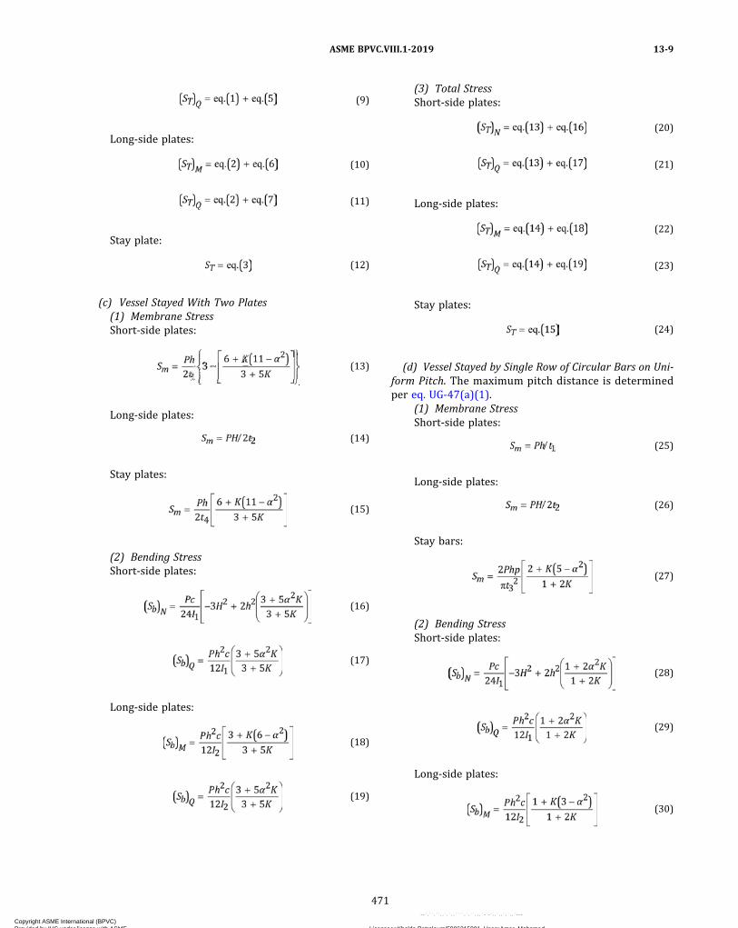
ð9Þ
Long‐side plates:
ð10Þ
ð11Þ
Stay plate:
ð12Þ
(c) Vessel Stayed With Two Plates(1) Membrane StressShort‐side plates:
ð13Þ
Long‐side plates:
ð14Þ
Stay plates:
ð15Þ
(2) Bending StressShort‐side plates:
ð16Þ
ð17Þ
Long‐side plates:
ð18Þ
ð19Þ
(3) Total StressShort‐side plates:
ð20Þ
ð21Þ
Long‐side plates:
ð22Þ
ð23Þ
Stay plates:
ð24Þ
(d) Vessel Stayed by Single Row of Circular Bars on Uni-form Pitch. The maximum pitch distance is determinedper eq. UG-47(a)(1).
(1) Membrane StressShort‐side plates:
ð25Þ
Long‐side plates:
ð26Þ
Stay bars:
ð27Þ
(2) Bending StressShort‐side plates:
ð28Þ
ð29Þ
Long‐side plates:
ð30Þ
ASME BPVC.VIII.1-2019 13-9
471
Copyright ASME International (BPVC) Provided by IHS under license with ASME Licensee=Khalda Petroleum/5986215001, User=Amer, Mohamed
Not for Resale, 07/02/2019 13:29:04 MDTNo reproduction or networking permitted without license from IHS
--`,``,``,,`,`,,````,`,``,,,`-`-`,,`,,`,`,,`---
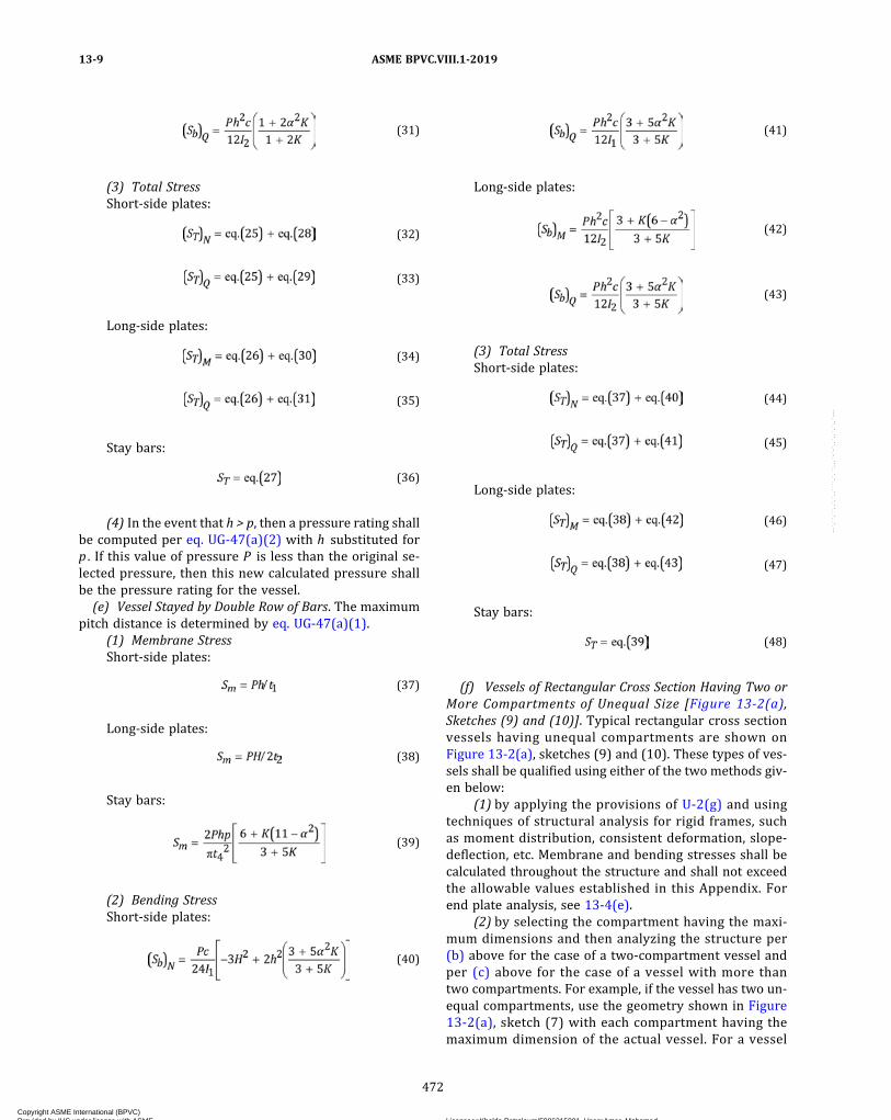
ð31Þ
(3) Total StressShort‐side plates:
ð32Þ
ð33Þ
Long‐side plates:
ð34Þ
ð35Þ
Stay bars:
ð36Þ
(4) In the event that h > p, then a pressure rating shallbe computed per eq. UG-47(a)(2) with h substituted forp . If this value of pressure P is less than the original se-lected pressure, then this new calculated pressure shallbe the pressure rating for the vessel.(e) Vessel Stayed by Double Row of Bars. The maximum
pitch distance is determined by eq. UG-47(a)(1).(1) Membrane StressShort‐side plates:
ð37Þ
Long‐side plates:
ð38Þ
Stay bars:
ð39Þ
(2) Bending StressShort‐side plates:
ð40Þ
ð41Þ
Long‐side plates:
ð42Þ
ð43Þ
(3) Total StressShort‐side plates:
ð44Þ
ð45Þ
Long‐side plates:
ð46Þ
ð47Þ
Stay bars:
ð48Þ
(f) Vessels of Rectangular Cross Section Having Two orMore Compartments of Unequal Size [Figure 13-2(a),Sketches (9) and (10)]. Typical rectangular cross sectionvessels having unequal compartments are shown onFigure 13-2(a), sketches (9) and (10). These types of ves-sels shall be qualified using either of the two methods giv-en below:
(1) by applying the provisions of U-2(g) and usingtechniques of structural analysis for rigid frames, suchas moment distribution, consistent deformation, slope‐deflection, etc. Membrane and bending stresses shall becalculated throughout the structure and shall not exceedthe allowable values established in this Appendix. Forend plate analysis, see 13-4(e).
(2) by selecting the compartment having the maxi-mum dimensions and then analyzing the structure per(b) above for the case of a two‐compartment vessel andper (c) above for the case of a vessel with more thantwo compartments. For example, if the vessel has two un-equal compartments, use the geometry shown in Figure13-2(a), sketch (7) with each compartment having themaximum dimension of the actual vessel. For a vessel
ASME BPVC.VIII.1-201913-9
472
Copyright ASME International (BPVC) Provided by IHS under license with ASME Licensee=Khalda Petroleum/5986215001, User=Amer, Mohamed
Not for Resale, 07/02/2019 13:29:04 MDTNo reproduction or networking permitted without license from IHS
--`,``,``,,`,`,,````,`,``,,,`-`-`,,`,,`,`,,`---

with more than two compartments, use the geometryshown in Figure 13-2(a), sketch (8) with three compart-ments having the maximum dimensions of the actual ves-sel (thus, a five‐ or six‐compartment vessel for examplewould be analyzed as if it had only three compartments).
13-10 UNREINFORCED VESSELS HAVING ANOBROUND CROSS SECTION[FIGURE 13-2(B), SKETCH (1)]
For the equations in these paragraphs, the moments ofinertia are calculated on a per‐unit‐width basis. That is,I = bt3/12, where b = 1.0. See 13-4(k).
(a) Membrane StressSemicylindrical sections:
ð1Þ
ð2Þ
Side plates:
ð3Þ
(b) Bending StressSemicylindrical sections:
ð4Þ
ð5Þ
Side plates:
ð6Þ
ð7Þ
(c) Total StressSemicylindrical sections:
ð8Þ
ð9Þ
Side plates:
ð10Þ
ð11Þ
13-11 REINFORCED VESSELS OF OBROUNDCROSS SECTION [FIGURE 13-2(B),SKETCH (2)]
(a) In the type of construction shown in Figure 13-2(b),sketch (2), the analysis is similar to that in 13-10, but inaddition, the spacing of the reinforcing members andthe adequacy of the reinforced section must bedetermined.
(b) The rules of this part of this Appendix cover onlythe type of reinforced obround cross section vessel shownin Figure 13-2(b), sketch (2) where welded‐on reinforce-ment [see 13-8(b)] either following the contour of thevessel or being in the form of a rectangular frame, is con-tinuous in a plane perpendicular to the longitudinal axisof the vessel; however, the spacing between reinforcingmembers need not be uniform. In the case where the re-inforcement is in the form of a rectangular frame, theanalysis is carried out the same as if the reinforcementfollowed the contour of the vessel. All reinforcementmembers must have the same moment of inertia. Forany other type of reinforced obround cross section vessel,see U-2.
(c) The end closures for vessels of this type shall be de-signed in accordance with the provisions in 13-4(f).
(d) Distance Between Reinforcing Members. The dis-tance between reinforcing members and the effectivewidth of plate w shall be determined by the proceduregiven in 13-8(d) except that eqs. 13-8(d)(5)(1a) and13-8(d)(5)(1b) are not applicable.
(e) Strength of Composite Plate and ReinforcingMember
(1) Membrane StressSemicylindrical sections:
ð1Þ
ð2Þ
Side plates:
ð3Þ
(2) Bending StressSemicylindrical sections:
ð4Þ
ASME BPVC.VIII.1-2019 13-9 – 13-11
473
Copyright ASME International (BPVC) Provided by IHS under license with ASME Licensee=Khalda Petroleum/5986215001, User=Amer, Mohamed
Not for Resale, 07/02/2019 13:29:04 MDTNo reproduction or networking permitted without license from IHS
--`,``,``,,`,`,,````,`,``,,,`-`-`,,`,,`,`,,`---

ð5Þ
Side plates:
ð6Þ
ð7Þ
(3) Total StressSemicylindrical sections:
ð8Þ
ð9Þ
Side plates:
ð10Þ
ð11Þ
13-12 STAYED VESSELS OF OBROUNDCROSS SECTION [FIGURE 13-2(B),SKETCH (3)]
For the equations in these paragraphs, the moments ofinertia are calculated on a per‐unit‐width basis. That is,I = bt 3/12, where b = 1.0. See 13-4(k).(a) The type of stayed construction considered in this
Appendix is shown on Figure 13-2(b), sketch (3). Thestaying member may be a plate welded to the side platesfor the entire length of the vessel, or the stays can be barsof circular cross section fastened to the side plates on auniform pitch. For the former case, the stay plates shallnot be constructed so as to create pressure-containingpartitions (see UG-19 for vessels containing more thanone pressure chamber). For the latter case, the rules ofUG-47(a), UG-48, UG-49, and UG-50 must be met. Endplates are subject to the rules of 13-4(f).(b) Vessel Stayed by a Single Plate. Figure 13-2(b),
sketch (3) shows a vessel with a central stay plate.(1) Membrane StressSemicylindrical sections:
ð1Þ
ð2Þ
Side plates:
ð3Þ
Stay plate:
ð4Þ
(2) Bending StressSemicylindrical sections:
ð5Þ
ð6Þ
Side plates:
ð7Þ
ð8Þ
(3) Total StressSemicylindrical sections:
ð9Þ
ð10Þ
Side plates:
ð11Þ
ð12Þ
Stay plate:
ð13Þ
(c) Vessel Stayed by Single Row of Circular Cross SectionBars on Uniform Pitch [Figure 13-2(b), Sketch (3)]. Themaximum pitch distance is determined per eq.UG-47(a)(1).
ASME BPVC.VIII.1-201913-11 – 13-12
474
Copyright ASME International (BPVC) Provided by IHS under license with ASME Licensee=Khalda Petroleum/5986215001, User=Amer, Mohamed
Not for Resale, 07/02/2019 13:29:04 MDTNo reproduction or networking permitted without license from IHS
--`,``,``,,`,`,,````,`,``,,,`-`-`,,`,,`,`,,`---

(1) Membrane StressSemicylindrical sections:
ð14Þ
ð15Þ
Side plates:
ð16Þ
Stay bars:
ð17Þ
(2) Bending StressSemicylindrical sections:
ð18Þ
ð19Þ
Side plates:
ð20Þ
ð21Þ
(3) Total StressSemicylindrical sections:
ð22Þ
ð23Þ
Side plates:
ð24Þ
ð25Þ
Stay bars:
ð26Þ
(4) In the event that (L2 + R/2) > p, then compute apossible new pressure rating per 13-9(d)(4).
13-13 VESSELS OF CIRCULAR CROSSSECTION HAVING A SINGLEDIAMETRAL STAYING MEMBER[FIGURE 13-2(C)]
For the equations in these paragraphs, the moments ofinertia are calculated on a per‐unit‐width basis. That is, I =bt3/12, where b = 1.0. See 13-4(k).
(a) The cylindrical shell and diametral stay plate aresized such that the various vessel members will not beoverstressed when there is full pressure in both vesselcompartments or when there is full pressure in one com-partment and zero pressure in the other compartment.End closure plates or heads are subject to the rules of13-4(f) and shall be designed for the maximum pressurecondition in the compartments. Stresses need to be com-puted only at the shell‐plate junction since this is the loca-tion of maximum stress.
(b) For the case of equal pressure in both compart-ments, stresses are as follows:
(1) Membrane StressShell section:
ð1Þ
Diametral plate:
ð2Þ
(2) Bending StressShell section:
ð3Þ
(3) Total StressShell section:
ð4Þ
Diametral plate:
ð5Þ
ASME BPVC.VIII.1-2019 13-12 – 13-13
475
Copyright ASME International (BPVC) Provided by IHS under license with ASME Licensee=Khalda Petroleum/5986215001, User=Amer, Mohamed
Not for Resale, 07/02/2019 13:29:04 MDTNo reproduction or networking permitted without license from IHS
--`,``,``,,`,`,,````,`,``,,,`-`-`,,`,,`,`,,`---

ð19Þ
(c) For the case of unequal pressures in the compart-ments, stresses are as follows, where P is the maximumvalue P1 or P2:
(1) Membrane StressShell section:
ð6Þ
Diametral plate:
ð7Þ
(2) Bending StressShell section:
ð8Þ
Diametral plate:For Lv ≤ 2R,
ð9Þ
For Lv > 2R,
ð10Þ
where J1 is given in Table 13-13(c).
(3) Total StressShell section:
ð11Þ
Diametral plate:
ð12Þ
13-14 VESSELS OF NONCIRCULAR CROSSSECTION SUBJECT TO EXTERNALPRESSURE
Rectangular cross section vessels per Figure 13-2(a),sketches (1) and (2) subject to external pressure shallmeet the following requirements:(a) The stresses shall be calculated in accordance with
13-7(a) and 13-7(b) except that Pe shall be substituted forP . These stresses shall meet the allowable stress criteriaas for the case of internal pressure in accordance with13-4.(b) The four side plates and the two end plates shall be
checked for stability in accordance with eq. (1). In the fol-lowing equations, the plate thickness t and the modulusof elasticity E2 must be adjusted if the plate is perforated.In equations for SmA and SmB, multiply t by em; in equa-tions for ScrA and ScrB, no adjustment of t shall be made.
A = subscript to identify stress or load acting indirection parallel to long dimension of panelbeing considered
B = subscript to identify stress or load acting indirection parallel to short dimension of pan-el being considered
KA; KB = plate buckling coefficients, obtained fromFigure 13-14(a), as used in equations forcalculating ScrA and ScrB, respectively
ScrA ; ScrB = plate buckling stress when panel is sub-jected to stresses on two opposite edges indirections indicated by subscripts A and B[see Figure 13-14(b)]
SmA = compression stress applied to short edge ofside panels due to external pressure on theend plates [see Figure 13-14(b)]
SmB = compression stress applied to long edge ofside panels and end panels due to externalpressure on the adjacent side plates [seeFigure 13-14(b)]
ð1Þ
where
ScrA = S′crA when S′crA ≤ Sy/2
Table 13-13(c)
Ratio of Long to ShortSide of Plate Element
PlateParameter, J1
1.0 0.05131.1 0.05811.2 0.06391.3 0.06941.4 0.0755
1.5 0.08121.6 0.08621.7 0.09081.8 0.09481.9 0.0985
2.0 0.10173.0 0.11894.0 0.1235
≥ 5.0 0.1246
ASME BPVC.VIII.1-201913-13 – 13-14
476
Copyright ASME International (BPVC) Provided by IHS under license with ASME Licensee=Khalda Petroleum/5986215001, User=Amer, Mohamed
Not for Resale, 07/02/2019 13:29:04 MDTNo reproduction or networking permitted without license from IHS
--`,``,``,,`,`,,````,`,``,,,`-`-`,,`,,`,`,,`---

= S″crA when S′crA > Sy/2
ScrB = S′crB when S′crB ≤ Sy/2= S″crB when S′crB > Sy/2
Short‐side plates:
ð2Þ
NOTE: These equations apply to vessels in which the long‐side platesare of equal thickness. If thicknesses are not equal, replace 2t2 with(t2 + t22).
ð3Þ
ð4AÞ
ð4BÞ
ð5AÞ
ð5BÞ
Long‐side plates:
ð6Þ
NOTE: These equations apply to vessels in which the long‐side platesare of equal thickness. If thicknesses are not equal, replace 2t2 with(t2 + t22).
ð7Þ
NOTE: These equations apply to vessels in which the long‐side platesare of equal thickness. If thicknesses are unequal, then use eqs.13-7(b)(1)(12A) and 13-7(b)(1)(12B).
ð8AÞ
ð8BÞ
ð9AÞ
Figure 13-14(a)
GENERAL NOTES:(a) Use KA = 5.5 for ratios greater than 5.(b) When ratio is less than 0.258, use KB = 1.0 and Lv = (short side
dimension, H or h) in equations for calculating S ′ c rB .
Figure 13-14(b)Orientation of Panel Dimensions and Stresses
GENERAL NOTES:(a) h ≥ H(b) Lv ≥ h
ASME BPVC.VIII.1-2019 13-14
477
Copyright ASME International (BPVC) Provided by IHS under license with ASME Licensee=Khalda Petroleum/5986215001, User=Amer, Mohamed
Not for Resale, 07/02/2019 13:29:04 MDTNo reproduction or networking permitted without license from IHS
--`,``,``,,`,`,,````,`,``,,,`-`-`,,`,,`,`,,`---
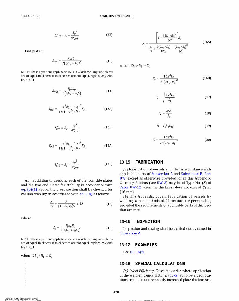
ð9BÞ
End plates:
ð10Þ
NOTE: These equations apply to vessels in which the long‐side platesare of equal thickness. If thicknesses are not equal, replace 2t2 with(t2 + t22).
ð11Þ
ð12AÞ
ð12BÞ
ð13AÞ
ð13BÞ
(c) In addition to checking each of the four side platesand the two end plates for stability in accordance witheq. (b)(1) above, the cross section shall be checked forcolumn stability in accordance with eq. (14) as follows:
ð14Þ
where
ð15Þ
NOTE: These equations apply to vessels in which the long‐side platesare of equal thickness. If thicknesses are not equal, replace 2t2 with(t2 + t22).
when
ð16AÞ
when
ð16BÞ
ð17Þ
ð18Þ
ð19Þ
ð20Þ
13-15 FABRICATION
(a) Fabrication of vessels shall be in accordance withapplicable parts of Subsection A and Subsection B, PartUW, except as otherwise provided for in this Appendix.Category A joints (see UW-3) may be of Type No. (3) ofTable UW-12 when the thickness does not exceed 5/8 in.(16 mm).(b) This Appendix covers fabrication of vessels by
welding. Other methods of fabrication are permissible,provided the requirements of applicable parts of this Sec-tion are met.
13-16 INSPECTION
Inspection and testing shall be carried out as stated inSubsection A.
13-17 EXAMPLES
See UG-16(f).
13-18 SPECIAL CALCULATIONS
(a) Weld Efficiency. Cases may arise where applicationof the weld efficiency factor E (13-5) at non‐welded loca-tions results in unnecessarily increased plate thicknesses.
ASME BPVC.VIII.1-201913-14 – 13-18
478
Copyright ASME International (BPVC) Provided by IHS under license with ASME Licensee=Khalda Petroleum/5986215001, User=Amer, Mohamed
Not for Resale, 07/02/2019 13:29:04 MDTNo reproduction or networking permitted without license from IHS
--`,``,``,,`,`,,````,`,``,,,`-`-`,,`,,`,`,,`---

If the butt weld occurs at one of the locations for whichequations are provided in this Appendix, then no reliefcan be provided. However, if the weld occurs at some in-termediate location, it is permissible to calculate thebending stress at the weld location. Then, if the totalstress at the joint location is within the limits of the allow-able design stress SE[see 13-4(b)], using the appropriateE factor, the design will be considered satisfactory for theconditions imposed.
Consider Figure 13-2(a), sketch (1) to have, instead of abutt joint at locations M and/or N , a joint between loca-tions M and Q and a distance dj from location M . Sincebending stress is given by M(c/I), eq. 13-7(a)(2)(5) canbe written
from which the bending moment at M is
The counter‐moment at distance dj from M is so
that the total moment at the joint is
The bending stress is then
and the total stress (bending plus membrane) is
where (Sb)j may be either positive or negative dependingon whether the inside or the outside surface is consid-ered. See 13-4(b) and 13-5.
NOTE: For the equations within (a), the moments of inertia are cal-culated on a per‐unit‐width basis. That is, I = bt3/12, where b = 1.0.The moments MM and Mj have dimensions (force × length/length)= force. See 13-4(k).
A summary of equations for various geometries is givenin Table 13-18.1.
(b) Ligament Efficiencies. The applied membrane andbending stresses at a location containing a row of holesare higher than at the location without holes. When thereare no holes at the location where the highest bending
moments occur, e.g., at the midpoint of the sides and inthe corner regions in vessels without stays, the applica-tion of the ligament efficiency factors may result in an un-necessary increase in required plate thickness.
Rows of holes may be located in regions of relativelylow bending moments to keep the required plate thick-ness to a minimum. Therefore, it is permissible to calcu-late the stresses at the center line of each row of holesclosest to the locations where the highest bending mo-ments occurs, i.e., at the midpoint of the sides and atthe corners. If the diameter of all the holes are not thesame, the stresses must be calculated for each set of emand eb values.
The applied gross area stresses may be calculated usingthe same procedure as for calculating the stresses at ajoint [refer to (a) above]. The value of dj to be used inthe equations is the distance from the midpoint of the sideto the plane containing the centerlines of the holes.
The net area stresses are calculated according to theprocedures in 13-4(g). The total (net area) stresses aredetermined by the methods given in 13-4(c) and com-pared with the allowable design stresses according to13-4(g) and 13-4(b).
(c) Vessels per Figure 13-2(a), sketch (1) with aspectratios of Lv/H or Lv/h between 1.0 and 2.0 and with flatheads welded to the sides visible in the sketch, may be de-signed in accordance with the rules of (1), (2), and (3) be-low. For such vessels with aspect ratios of Lv/H or Lv/hless than 1.0, the axis of the vessel shall be rotated so thatthe largest dimension becomes the length Lv, and new ra-tios Lv/H and Lv/h are 1.0 or larger. All stresses shall berecalculated using the new orientation.
(1) Membrane Stress. Equations 13-7(a)(1)(1) and13-7(a)(1)(2) shall be used to determine the membranestresses.
(2) Bending Stress . Equations 13-7(a)(2)(3),13-7(a)(2)(4), 13-7(a)(2)(5), and 13-7(a)(2)(6) multi-plied by the plate parameters of Table 13-18(b) shall beused to determine the bending stresses as follows:
Short‐side plates:
Long‐side plates:
ASME BPVC.VIII.1-2019 13-18
479
Copyright ASME International (BPVC) Provided by IHS under license with ASME Licensee=Khalda Petroleum/5986215001, User=Amer, Mohamed
Not for Resale, 07/02/2019 13:29:04 MDTNo reproduction or networking permitted without license from IHS
--`,``,``,,`,`,,````,`,``,,,`-`-`,,`,,`,`,,`---

ð19Þ Table 13-18.1
Figure 13-2Location of Weld
Between Bending Stress at Joint ± (Sb)j , psi (MPa) Notes
13-2(a), sketch (1) M and Q (1)
13-2(a), sketch (1) N and Q (1)
13-2(a), sketch (2) M and Q (1)
13-2(a), sketch (2) M1 and Q1 (1)
13-2(a), sketch (3) A and B (1), (2)
13-2(a), sketch (3) D and C (1), (2)
13-2(a), sketch (4) M and Q …
13-2(a), sketch (4) N and Q …
13-2(a), sketch (5) A and B …
13-2(a), sketch (5) B and C …
13-2(a), sketch (5) H and G …
13-2(a), sketch (5) G and F …
13-2(a), sketch (6) A and B (c/I21)…
13-2(a), sketch (6) B and C (c/I1)…
13-2(a), sketch (6) F and G (c/I1)[MA + W[L42 + L4t1 + 2.0L4 - L3
2 - 2.0L3 ( + t1/2)] + ] …
13-2(a), sketch (6) H and G (c/I11)[MA + W[L42 + L4t1 + 2.0L4 - L3
2 - 2.0L3 ( + t1/2)] + ] …
13-2(b), sketch (1) A and B (1)
13-2(b), sketch (2) A and B …
NOTES:(1) For this equation, the moments of inertia are calculated on a per‐unit‐width basis. That is, I = bt 3/12, where b = 1.0. See 13-4(k).(2) For this equation, moment MA has dimensions, force × length/length = force. See 13-4(k).
ASME BPVC.VIII.1-201913-18
480
Copyright ASME International (BPVC) Provided by IHS under license with ASME Licensee=Khalda Petroleum/5986215001, User=Amer, Mohamed
Not for Resale, 07/02/2019 13:29:04 MDTNo reproduction or networking permitted without license from IHS
--`,``,``,,`,`,,````,`,``,,,`-`-`,,`,,`,`,,`---
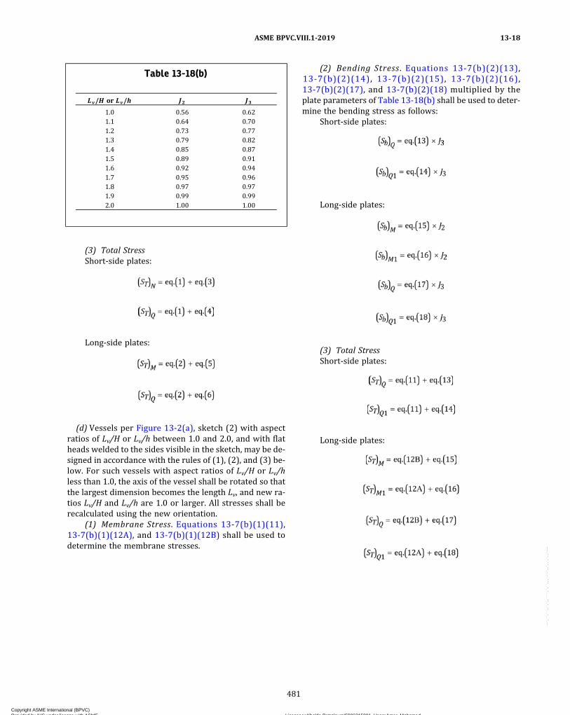
(3) Total StressShort‐side plates:
Long‐side plates:
(d) Vessels per Figure 13-2(a), sketch (2) with aspectratios of Lv/H or Lv/h between 1.0 and 2.0, and with flatheads welded to the sides visible in the sketch, may be de-signed in accordance with the rules of (1), (2), and (3) be-low. For such vessels with aspect ratios of Lv/H or Lv/hless than 1.0, the axis of the vessel shall be rotated so thatthe largest dimension becomes the length Lv, and new ra-tios Lv/H and Lv/h are 1.0 or larger. All stresses shall berecalculated using the new orientation.
(1) Membrane Stress. Equations 13-7(b)(1)(11),13-7(b)(1)(12A), and 13-7(b)(1)(12B) shall be used todetermine the membrane stresses.
(2) Bending Stress . Equations 13-7(b)(2)(13),13-7(b)(2)(14), 13-7(b)(2)(15), 13-7(b)(2)(16),13-7(b)(2)(17), and 13-7(b)(2)(18) multiplied by theplate parameters of Table 13-18(b) shall be used to deter-mine the bending stress as follows:
Short‐side plates:
Long‐side plates:
(3) Total StressShort‐side plates:
Long‐side plates:
Table 13-18(b)
Lv/H or Lv/h J2 J3
1.0 0.56 0.621.1 0.64 0.701.2 0.73 0.771.3 0.79 0.821.4 0.85 0.871.5 0.89 0.911.6 0.92 0.941.7 0.95 0.961.8 0.97 0.971.9 0.99 0.992.0 1.00 1.00
ASME BPVC.VIII.1-2019 13-18
481
Copyright ASME International (BPVC) Provided by IHS under license with ASME Licensee=Khalda Petroleum/5986215001, User=Amer, Mohamed
Not for Resale, 07/02/2019 13:29:04 MDTNo reproduction or networking permitted without license from IHS
--`,``,``,,`,`,,````,`,``,,,`-`-`,,`,,`,`,,`---

MANDATORY APPENDIX 14INTEGRAL FLAT HEADS WITH A LARGE, SINGLE, CIRCULAR,
CENTRALLY LOCATED OPENING
14-1 SCOPE
(a) In accordance with UG-39(c)(1), flat heads whichhave a single, circular, centrally located opening that ex-ceeds one‐half of the head diameter shall be designed ac-cording to the rules which follow. The shell‐to‐flat headjuncture shall be either integral, as shown in FigureUG-34, sketches (a), (b‐1), (b‐2), (d), and (g), or a buttweld, or a full penetration corner weld similar to thejoints shown in Figure UW-13.2, sketches (a), (b), (c),(d), (e), and (f). When Figure UW-13.2, sketches (c) and(d) are used, the maximum wall thickness of the shellshall not exceed 3/8 in. (10 mm) and the maximum designmetal temperature shall not exceed 650°F (345°C). Thecentral opening in the flat head may have a nozzle whichis integral or integrally attached by a full penetrationweld or may have an opening without an attached nozzleor hub. For openings in which the nozzle is attached withnon‐integral welds (i.e., a double fillet or partial penetra-tion weld) use the design rules for an opening without anattached nozzle or hub.(b) A general arrangement of an integral flat head with
or without a nozzle attached at the central opening isshown in Figure 14-1.(c) The head thickness does not have to be calculated
by UG-34 rules. The thickness which satisfies all the re-quirements of this Appendix meets the requirements ofthe Code.
14-2 NOMENCLATURE
Except as given below, the symbols used in the equa-tions of this Appendix are defined in 2-3.
A = outside diameter of flat head and shellBn = diameter of central opening (for nozzle, this is in-
side diameter and for opening without nozzle,diameter of opening)
Bs = inside diameter of shell (measured below ta-pered hub, if one exists)
(Eθ)* = slope of head with central opening or nozzletimes the modulus of elasticity, disregardingthe interaction of the integral shell at the outsidediameter of the head, psi (MPa)
MH = moment acting at shell‐to‐flat head junctureP = internal design pressure (see UG-21)t = flat head nominal thickness
B1, F, SH, SR, ST, V, f, go, g 1, and ho are defined in 2-3.These terms may refer to either the shell‐to‐flat headjuncture or to the central opening‐to‐flat head junctureand depend upon details at those junctures.
14-3 DESIGN PROCEDURE
(a) Disregard the shell attached to the outside diameterof the flat head and then analyze the flat head with a cen-tral opening (with or without a nozzle) in accordancewith these rules.
(1) Calculate the operating moment Mo according to2-6. (There is no Mo for gasket seating to be considered.)The formulas in Mandatory Appendix 2 for loads (2-3)and moment arms (Table 2-6) shall be used directly withthe following definitions and terms substituted for termsin Mandatory Appendix 2:
Let C = G = inside diameter of shell Bs ; B = Bn , whereBn is as shown in Figure 14-1 depending on an integralnozzle or no nozzle.
The moment arm hg in Table 2-6 will be equal to zerowhen using the rules of this Appendix. The MG momentwill therefore be equal to zero.
(2)With K = A/Bn , use 2-7 to calculate the stressesSH , SR , and ST . The SH and SR stresses are equal to zerofor the case of an opening without a nozzle.(b) Calculate (Eθ)*:
(1) for an integrally attached nozzle,
(2) for an opening without a nozzle or with a nozzleor hub attached with a non‐integral weld,
where go, g1, B1, V, f, ho, and Bn all pertain to the openingin the flat head as described in (a).
ASME BPVC.VIII.1-201914-1 – 14-3
482
Copyright ASME International (BPVC) Provided by IHS under license with ASME Licensee=Khalda Petroleum/5986215001, User=Amer, Mohamed
Not for Resale, 07/02/2019 13:29:04 MDTNo reproduction or networking permitted without license from IHS
--`,``,``,,`,`,,````,`,``,,,`-`-`,,`,,`,`,,`---
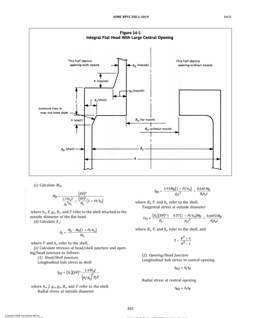
(c) Calculate MH:
where ho, V, go, B1, and F refer to the shell attached to theoutside diameter of the flat head.
(d) Calculate X1:
where F and ho refer to the shell.(e) Calculate stresses at head/shell juncture and open-
ing/head juncture as follows:(1) Head/Shell JunctureLongitudinal hub stress in shell
where ho, f, go, g1, Bs, and V refer to the shell.Radial stress at outside diameter
where Bs, F, and ho refer to the shell.Tangential stress at outside diameter
where Bs, F, and ho refer to the shell, and
(2) Opening/Head JunctureLongitudinal hub stress in central opening
Radial stress at central opening
Figure 14-1Integral Flat Head With Large Central Opening
ASME BPVC.VIII.1-2019 14-3
483
Copyright ASME International (BPVC) Provided by IHS under license with ASME Licensee=Khalda Petroleum/5986215001, User=Amer, Mohamed
Not for Resale, 07/02/2019 13:29:04 MDTNo reproduction or networking permitted without license from IHS
--`,``,``,,`,`,,````,`,``,,,`-`-`,,`,,`,`,,`---

Tangential stress at diameter of central opening
where F, Bs, and ho refer to the shell, and
(f) The calculated stresses above shall meet the allow-able stresses in 2-8.
14-4 DATA REPORTS
When all the requirements of this Division and the sup-plemental requirements of this Appendix have been met,the following notation shall be entered on the Manufac-turer’s Data Report under Remarks: “Constructed in Con-formance with Mandatory Appendix 14, Integral FlatHeads with a Large, Single, Circular, Centrally LocatedOpening.”
ASME BPVC.VIII.1-201914-3 – 14-4
484
Copyright ASME International (BPVC) Provided by IHS under license with ASME Licensee=Khalda Petroleum/5986215001, User=Amer, Mohamed
Not for Resale, 07/02/2019 13:29:04 MDTNo reproduction or networking permitted without license from IHS
--`,``,``,,`,`,,````,`,``,,,`-`-`,,`,,`,`,,`---
ð19Þ
MANDATORY APPENDIX 17DIMPLED OR EMBOSSED ASSEMBLIES
17-1 SCOPE
(a) The rules in this Appendix cover minimum require-ments for the design, fabrication, and examination ofpressure vessel assemblies limited to the following types:
(1) dimpled or embossed prior to welding;(2) dimpled or embossed form achieved by using hy-
draulic or pneumatic pressure after welding.(b)Welding processes covered under the rules of this
Appendix include “weld‐through” processes in whichwelding is done by penetrating through one or moremembers into, but not through, another member (seeFigures 17-1 through 17-6). These welding processesare as follows:
(1) resistance spot welding;(2) resistance seam welding;(3) gas‐metal arc spot welding in which a spot weld
is produced between two overlapping metal parts byheating with a timed electric arc between a consumablemetal electrode and the work. The spot weld is madewithout preparing a hole in either member or with a holein the dimpled or embossed member. Filler metal is ob-tained from the consumable electrode, and shielding isobtained from a single gas, a gas mixture (which may con-tain an inert gas), or a gas and a flux. See Figure 17-4.
(4)machine, automatic, or semiautomatic gas tung-sten arc seam welding without the addition of filler metal;
(5)machine, automatic, or semiautomatic gastungsten‐arc spot welding without the addition of fillermetal;
(6)machine or automatic plasma arc seam weldingwithout the addition of filler metal;
(7)machine or automatic submerged‐arc seam weld-ing with filler metal obtained from the electrode andshielding provided by the flux;
(8)machine or automatic laser beam seam weldingwithout the addition of filler metal.
(c) Welding processes covered under the rules of thisAppendix defined as “complete penetration” processesin which welding penetrates through all members to bejoined (see Figure 17-17) are as follows:
(1)machine or automatic laser beam seam weldingwithout the addition of filler metal
(2) plasma arc seam welding with or without the ad-dition of filler metal
(d) For the purposes of specifying special requirementsand degree of examination, the weld joints made by theprocesses covered under the rules of this Appendix shallbe considered as Category C joints.
(e) Embossed or dimpled assemblies may be made inone or more of the following manners:
(1) two embossed or two dimpled plates welded to-gether as shown in Figures 17-1 and 17-2 or an embossedor dimpled plate welded to a plain plate as shown inFigures 17-3, 17-4, and 17-5 using a welding process de-scribed in (b) or (c) above;
(2) two outer embossed or two outer dimpled plateswelded to a third, intermediate plate, frame, or series ofspacers to form a three‐ply assembly as shown in Figure17-6 using a welding process described in (b)(1) or(b)(2) above.
(f) Dimpled or Embossed Assemblies, which consist ofa dimpled or embossed plate welded to another like plateor to a plain plate and for which the welded attachment ismade by fillet welds around holes or slots, shall be con-structed in accordance with the requirements ofUW-19(c).
(g) The minimum thickness limitations of UG-16(b) donot apply to Dimpled and Embossed Assemblies designedto this Appendix.
17-2 SERVICE RESTRICTIONS
(a) Assemblies as defined in this Appendix shall not beused for the containment of substances defined as lethalby UW-2(a).
(b) Assemblies defined in 17-1(a)(2) shall not be usedas unfired steam boilers or as vessels subject to directfiring.
(c) Low Temperature Operation. Welds made in accor-dance with 17-1(b)(1) and 17-1(b)(2) do not require qua-lification with toughness testing when joining permittedPart UHA and Part UNF materials.
17-3 MATERIALS
Materials used in the pressure-containing parts of ves-sels covered by this Appendix shall be limited to thosepermitted by other parts of this Section or Division andqualified for welding per 17-7.
ASME BPVC.VIII.1-2019 17-1 – 17-3
485
Copyright ASME International (BPVC) Provided by IHS under license with ASME Licensee=Khalda Petroleum/5986215001, User=Amer, Mohamed
Not for Resale, 07/02/2019 13:29:04 MDTNo reproduction or networking permitted without license from IHS
--`,``,``,,`,`,,````,`,``,,,`-`-`,,`,,`,`,,`---
17-4 THICKNESS LIMITATIONS
The range of thickness of pressure-containing partswhich may be welded under the provisions of this Appen-dix shall be limited to that qualified by the welding proce-dure under the provisions of 17-7. The nominal thicknessfor plate shall not be less than 0.030 in. (0.8 mm).
17-5 MAXIMUM ALLOWABLE WORKINGPRESSURE (MAWP)
The MAWP shall be the lowest pressure established by(a) and (b) below.(a) Proof Test
(1) For assemblies constructed under the provisionof 17-1(a)(1), a proof test shall be conducted in accor-dance with UG-101. In using the formulas for calculatingthe MAWP, a value of 0.8 shall be used for E , the weldjoint efficiency factor. This test may be a separate testor part of the test in 17-7(a)(1)(-a).
(2) For assemblies constructed under the provisionsof 17-1(a)(2), a proof test shall be conducted in accor-dance with the requirements of UG-101 of this Divisionusing the bursting test procedures of UG-101(m) exceptprovisions of UG-101(c) need not be followed providedthat, when performing the proof test, the application ofpressure is continuous until burst or until the proof testis stopped. In using the formulas for calculating the max-imum allowable working pressure, a value of 0.80 shall beused for E , the weld joint efficiency factor. If the spot‐welded and seam‐welded sheets are formed to any shapeother than flat plates prior to the inflating process whichresults in the dimpled formation, the proof tested vesselor representative panel shall be of a configuration whosecurvature is to a radius no greater than that which will beused in production vessels. The representative panel shallutilize the same weld details as will be used in the finalconstruction.(b) Calculations
(1) For assemblies using plain plate welded in accor-dance with 17-1(b)(2) , 17-1(b)(4), 17-1(b)(6),17-1(b)(7), 17-1(b)(8), and 17-1(c), calculate the MAWPor minimum thickness of the plain plate by the followingformulas:
ð1Þ
ð2Þ
where
P = internal design pressure (see UG-21), psi (kPa)p = maximum pitch measured between adjacent seam
weld center lines, in. (mm)
S = maximum allowable stress value given in Section II,Part D, psi (kPa)
t = minimum thickness of plate, in. (mm)
(2) For assemblies using plain plate welded in accor-dance with 17-1(b)(1), 17-1(b)(3), and 17-1(b)(5), calcu-late the MAWP of the plain plate in accordance with therequirements for braced and stayed surfaces. See UG-47.
17-6 DESIGN LIMITATIONS
For assemblies constructed under the provisions of17-1(a)(2), the following design limitations shall apply:(a) A change in any of the following variables will re-
quire requalification of the design using the proof testof 17-5(a)(2):
(1) an increase in the spot or seam pitch exceeding1/16 in. (1.5 mm);
(2) a change in the specification, type, thickness, orgrade of material for either sheet or both sheets;
(3) a change in the electrode size or electrodematerial;
(4) in formed construction when the radius of thecurvature is less than the radius in the proof section[see 17-5(a)(2)].(b) A test panel duplicating that used to establish the
maximum allowable working pressure shall be inflatedto a pressure at least 5% greater than the maximum form-ing pressure to be used in production. The rate of pres-surization shall be the same as that used in the bursttest. The panel shall be sectioned to show at least six spotwelds (see Figure 17-14). The weld cross sections shall besubjected to macroetch examinations and shall show nocracks. The maximum pillow heights measured, as shownin Figure 17-15, of vessels made in production shall notexceed 95% of the maximum pillow height of this dupli-cate test panel. The maximum forming pressure shallnot exceed 80% of the burst pressure.
17-7 WELDING CONTROL
(a)Welding Procedure Qualification shall be performedin accordance with the requirements of (1). PerformanceQualification shall be performed in accordance with Sec-tion IX or one of the following alternative requirements:
(1) Proof Testing for Procedure and PerformanceQualification
(-a) For assemblies constructed under the provi-sions of 17-1(a)(1), a pressure proof test to destructionshall be conducted on a finished vessel or representativepanel. The test shall be conducted as specified inUG-101(m). If a representative panel is used, it shall berectangular in shape and at least 5 pitches in each direc-tion, but not less than 24 in. (600 mm) in either direction.
(-b) For assemblies constructed under the provi-sions of 17-1(a)(2), a pressure proof test to destructionas set forth in 17-5(a)(2) shall be conducted on a finished
ASME BPVC.VIII.1-201917-4 – 17-7
486
Copyright ASME International (BPVC) Provided by IHS under license with ASME Licensee=Khalda Petroleum/5986215001, User=Amer, Mohamed
Not for Resale, 07/02/2019 13:29:04 MDTNo reproduction or networking permitted without license from IHS
--`,``,``,,`,`,,````,`,``,,,`-`-`,,`,,`,`,,`---

vessel or representative panel. This test may be a sepa-rate test or a part of the test in 17-5(a)(2). If a represen-tative panel is used, it shall be rectangular in shape and atleast 5 pitches in each direction but not less than 24 in.(600 mm) in either direction.
(-c) Duplicate parts or geometrically similar partsthat are fabricated using the same welding process, andmee t t h e r equ i r emen t s o f UG - 101 ( d ) ( 1 ) o rUG-101(d)(2), need not be tested.
(2) Workmanship Samples(-a) For assemblies for two‐ply joints constructed
under the provisions of 17-1(b)(1), 17-1(b)(2),17-1(b)(4), 17-1(b)(5), 17-1(b)(6), 17-1(b)(7),17-1(b)(8), or 17-1(c), three single spot welded speci-mens or one seam welded specimen, as shown in Figures17-7 and 17-8, shall be made immediately before andafter the welding of the proof test vessel.
Similarly, for assemblies for three‐ply joints con-structed under the provisions of 17-1(b)(1) and/or17-1(b)(2), three single spot welded specimens and/orone seam welded specimen, as shown in Figures 17-9and 17-10 for three‐ply joints shall be made immediatelybefore and after welding of the proof test vessel. Thesetest specimens shall be representative of the manufactur-ing practice employed in the fabrication of the proof testvessel.
When resistance welding and a difference in theamount of magnetic material in the throat of the machineor the part geometry preclude the welding of satisfactorytest specimens at the samemachine settings as those usedfor the proof test vessel, sufficient material shall be placedin the throat of the welding machine to compensate forthe difference in size of the proof test panel and the smalltest specimens.
The spot welded specimens shall be subjected totensile loading for ultimate strength and be visually in-spected for nugget size, electrode indentation, and evi-dence of defects. The seam weld specimens shall besimilarly tested for ultimate strength and prepared formacrographic examination to reveal nugget size, spacing,penetration, soundness, and surface condition. In addi-tion, a typical spot welded sample and seam welded sam-ple shall be cut from the proof test vessel or panel afterfailure. A portion of each sample shall be sectioned formacroetch examination.
Also for two‐ply assemblies constructed under theprovisions of 17-1(b)(4), 17-1(b)(6), 17-1(b)(7),17-1(b)(8), or 17-1(c), additional test specimens asshown in Figure 17-13 shall be made; one immediatelybefore and one immediately after the welding of the prooftest vessel, using the same plate thicknesses and materialgrade used in the proof test vessel. These welds shall berepresentative of the manufacturing practice employedin the fabrication of the proof test vessel and of the prac-tice to be used for the production vessels. One cross sec-tion shall be taken from each weld test assembly, asshown in Figure 17-13, and shall be suitably polished
and etched to show clearly the demarcation betweenthe weld metal and the base metal. The etched macrosec-tions shall reveal sound weld metal with complete fusionalong the bond line and complete freedom from cracks inthe weld metal and the heat affected base metals. Thewidth of the weld at the interface shall be measuredand recorded as a workmanship reference value.
Bend tests shall be made on each of the test weldassemblies, as shown in Figure 17-13. The bend speci-mens shall be tested in accordance with Section IX,QW-160, except that after bending, the convex surfaceof the specimens, in the weld and the heat affected basemetal, shall show not more than two cracks or other opendefects, neither of which shall measure more than 1/16 in.(1.5 mm) in length in any direction.
One cross section from each of any two welds con-structed under the provisions of 17-1(b)(4), 17-1(b)(6),17-1(b)(7), 17-1(b)(8), or 17-1(c) shall be cut from theproof test vessel after failure and these shall be subjectedto macroetch examination as above.
(-b) For assemblies constructed under the provi-sion of 17-1(b)(3), a test block of five or more arc‐spotwelds, as shown in Figure 17-11, shall be made immedi-ately before and after welding of the proof test vessel,using the same plate thickness and material of the samespecification and grade as used in the proof test vessel.These welds shall be representative of the manufacturingpractice employed in the fabrication of the proof test ves-sel and of the practice to be used for the production ves-sels. The arc‐spot welds shall be visually inspected forsurface soundness, fusion, and external nugget shapeand size Do. At least three welds from each test block shallbe cross‐sectioned and suitably etched to show clearly thedemarcation between the weld metal and the base metal.The etched macrosections shall reveal sound weld metalwith complete fusion along the bond line and completefreedom from cracks in the weld metal and the heat af-fected base metals. The nugget diameter Di at the fayingsurface shall be reasonably consistent in all specimens,and the penetration P2 into the backup member shall beless than the thickness t2 of that member. At least twowelds from each test block shall be broken in tension orpeel‐tested. In addition to the test‐block welds, five ormore typical arc‐spot weld samples shall be cut fromthe proof test vessel, after it has been tested to destruc-tion, for cross sectioning and macroscopic examinationfor nugget size, penetration, and configuration. Any com-bination of carbon steels P‐No. 1 material listed in TableUCS-23 shall be considered as a similar‐material combi-nation. Any combination of stainless steels listed in TableUHA-23 shall be considered as a similar‐material combi-nation. Any combination of nonferrous materials listedin Tables UNF-23.1 through UNF-23.5 shall be consideredas a similar‐material combination. For qualification ofarc‐spot welds in dissimilar combinations of carbonsteels, stainless steels, and SB-168 (Ni–Cr–Fe alloy), anadditional block of four arc‐spot welds shall be prepared
ASME BPVC.VIII.1-2019 17-7
487
Copyright ASME International (BPVC) Provided by IHS under license with ASME Licensee=Khalda Petroleum/5986215001, User=Amer, Mohamed
Not for Resale, 07/02/2019 13:29:04 MDTNo reproduction or networking permitted without license from IHS
--`,``,``,,`,`,,````,`,``,,,`-`-`,,`,,`,`,,`---
for bend tests, as shown in Figure 17-12, immediately be-fore and after the welding of the proof test vessel. Thebend specimens shall be tested in accordance with Sec-tion IX, Figures QW-466.1 through QW-466.6, except thatafter bending, the convex surface of the specimens, in theweld and the heat-affected base metal, shall show notmore than two cracks or other open defects, neither ofwhich shall measure more than 1/16 in. (1.5 mm) in lengthin any direction.(b) Machine Settings and Controls
(1) For vessels constructed under the provisions ofthis Appendix, all applicable parameters used in the mak-ing of the proof test vessel and workmanship samplesshall be recorded. Parameters to be recorded are asfollows:
(-a) all Essential, Nonessential, and Supplemen-tary Essential (if required) Variables listed in Section IXfor procedure qualifications of the applicable process;
(-b) all preheat, postweld heat treatments, and ex-amination procedures;
(-c) applicable material specification, includingtype, grade, and thickness of the material welded;
(-d) parameters recorded above shall be includedin a written Welding Procedure Specification and willserve as procedure and performance qualifications for fu-ture production.
(2) Except for minor variations permitted by thewelding variables in Section IX, the settings recordedper (1) above shall be used in the fabrication of all vesselsin a given production run. See 17-8(a)(1).
(3) If equipment other than that used for the initialproof test vessel and the workmanship samples is to beused in production, each additional machine and weldingprocedure shall be qualified in full accordance with (1)above. The performance of the additional proof test ves-sels shall substantiate the allowable working pressurepreviously established for the specific pressure vessel de-sign. In assemblies welded per 17-1(b)(3), any majorcomponent change or replacement of welding equipmentpreviously qualified shall require requalification. (Rou-tine maintenance and replacement of expendable items,such as contact tubes and shielding nozzles, areexcluded.)(c) Miscellaneous Welding Requirements
(1) Lap joints may only be resistance spot or seamwelded per 17-1(b)(1) or 17-1(b)(2); or machine, auto-matic, or semiautomatic gas tungsten‐arc welded per17-1(b)(4) or 17-1(b)(5); or machine or automaticplasma‐arc welded per 17-1(b)(6); or machine or auto-matic submerged‐arc welded per 17-1(b)(7); or machineor automatic laser beam welded per 17-1(b)(8) or17-1(c).
(2) For assemblies welded per 17-1(b)(3), the gasmetal arc‐spot welding equipment used in the qualifica-tion tests and in production shall be semiautomatic (witha timed arc) or fully automatic. Manual arc‐spot weldingwhere the welder has manual control of arc time is not
permitted under the rules of this Appendix, nor are edgeor fillet type arc‐spot welds. All gas metal arc‐spot weld-ing shall be done in the downhand position, with thework, at the location of the spot weld, in a substantiallyhorizontal plane. The required size and spacing of thegas metal arc‐spot welds shall be demonstrated by calcu-lation and by the pressure proof test [see 17-5(a)].
(3) For assemblies constructed under the provisionsof 17-1(a)(2), and having sheets formed within dieswhere the dies control the shape of the pillow (Figure17-15) and restrain the welds so that the bending in thesheet is outside of the heat-affected zone, the weldingmay be done before or after forming; and the require-ments and limitations of 17-6(b) do not apply.(d)Welding other than that permitted by this Appen-
dix, used for the attachment of nozzles, tubes and fittings,for the closing of peripheral seams, for the making of plugand slot welds, or for the fillet welding of holes and slots,shall be conducted in accordance with the requirementsof this Division.
17-8 QUALITY CONTROL
(a) Definitions(1) production run — a group of vessels or assem-
blies all produced during the same 24 hr day using thesame welding processes, materials, and materialthicknesses
(2) peel test — a test performed in accordance withFigure 17-16
(3) tension test — a destructive test performed in atension test machine employing specimens shown inFigures 17-7, 17-8, 17-9, 17-10, and 17-11(b) Test Requirements. At the beginning of each produc-
tion run, at least one test shall be made as follows:(1) For assemblies constructed under 17-1(b)(1),
17-1(b)(2), 17-1(b)(4), 17-1(b)(5), 17-1(b)(6),17-1(b)(7), 17-1(b)(8), or 17-1(c), a peel test, a tensiontest, or a macroetch examination shall be performed.The acceptance criteria for the peel and tension tests shallbe that the parent metal adjacent to the weld must fail be-fore the weld itself fails. The macroetch examination shallbe performed on one test specimen by cross sectioningand exam in i ng the we ld i n a c co rdan ce w i th17-7(a)(2)(-b).
(2) For assemblies constructed under 17-1(b)(3), amacroetch examination shall be performed in accordancewith 17-7(a)(2)(-b) except that only one weld need becross sectioned and examined.
17-9 RECORDS
As specified in 17-7(b), records shall be maintained forall data obtained during the fabrication of the proof testvessels and the workmanship samples. Such records shall
ASME BPVC.VIII.1-201917-7 – 17-9
488
Copyright ASME International (BPVC) Provided by IHS under license with ASME Licensee=Khalda Petroleum/5986215001, User=Amer, Mohamed
Not for Resale, 07/02/2019 13:29:04 MDTNo reproduction or networking permitted without license from IHS
--`,``,``,,`,`,,````,`,``,,,`-`-`,,`,,`,`,,`---
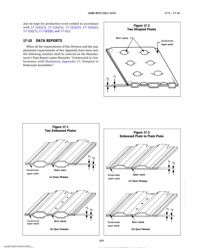
also be kept for production work welded in accordancewith 17-1(b)(3), 17-1(b)(4), 17-1(b)(5), 17-1(b)(6),17-1(b)(7), 17-1(b)(8), and 17-1(c).
17-10 DATA REPORTS
When all the requirements of this Division and the sup-plemental requirements of this Appendix have been met,the following notation shall be entered on the Manufac-turer’s Data Report under Remarks: “Constructed in Con-formance with Mandatory Appendix 17, Dimpled orEmbossed Assemblies.”
Figure 17-1Two Embossed Plates
Figure 17-2Two Dimpled Plates
Figure 17-3Embossed Plate to Plain Plate
ASME BPVC.VIII.1-2019 17-9 – 17-10
489
Copyright ASME International (BPVC) Provided by IHS under license with ASME Licensee=Khalda Petroleum/5986215001, User=Amer, Mohamed
Not for Resale, 07/02/2019 13:29:04 MDTNo reproduction or networking permitted without license from IHS
--`,``,``,,`,`,,````,`,``,,,`-`-`,,`,,`,`,,`---
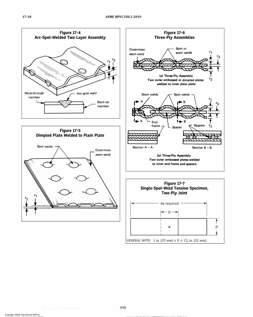
Figure 17-4Arc-Spot-Welded Two-Layer Assembly
Figure 17-5Dimpled Plate Welded to Plain Plate
Figure 17-6Three-Ply Assemblies
Figure 17-7Single-Spot-Weld Tension Specimen,
Two-Ply Joint
As required
D
D
GENERAL NOTE: 1 in. (25 mm) ≤ D ≤ 11/4 in. (32 mm).
ASME BPVC.VIII.1-201917-10
490
Copyright ASME International (BPVC) Provided by IHS under license with ASME Licensee=Khalda Petroleum/5986215001, User=Amer, Mohamed
Not for Resale, 07/02/2019 13:29:04 MDTNo reproduction or networking permitted without license from IHS
--`,``,``,,`,`,,````,`,``,,,`-`-`,,`,,`,`,,`---

Figure 17-8Seam-Weld Specimen for Tension and
Macrosection, Two-Ply Joint
D
D
D
As required
2 in. (50 mm) min.
Tension
Tension
Macrosection on of seam weld
C
GENERAL NOTE: 1 in. (25 mm) ≤ D ≤ 11/4 in. (32 mm).
Figure 17-9Single Spot-Weld Tension Specimen for
Three-Ply Joint
Filler as required for tension-test grip
D
D
As required
GENERAL NOTE: 1 in. (25 mm) ≤ D ≤ 11/4 in. (32 mm).
Figure 17-10Seam-Weld Specimen for Tension andMacrosection for Three-Ply Joint
D
D
D
As required
Macrosection on of seam weld
C
GENERAL NOTE: 1 in. (25 mm) ≤ D ≤ 11/4 in. (32 mm).
ASME BPVC.VIII.1-2019 17-10
491
Copyright ASME International (BPVC) Provided by IHS under license with ASME Licensee=Khalda Petroleum/5986215001, User=Amer, Mohamed
Not for Resale, 07/02/2019 13:29:04 MDTNo reproduction or networking permitted without license from IHS
--`,``,``,,`,`,,````,`,``,,,`-`-`,,`,,`,`,,`---
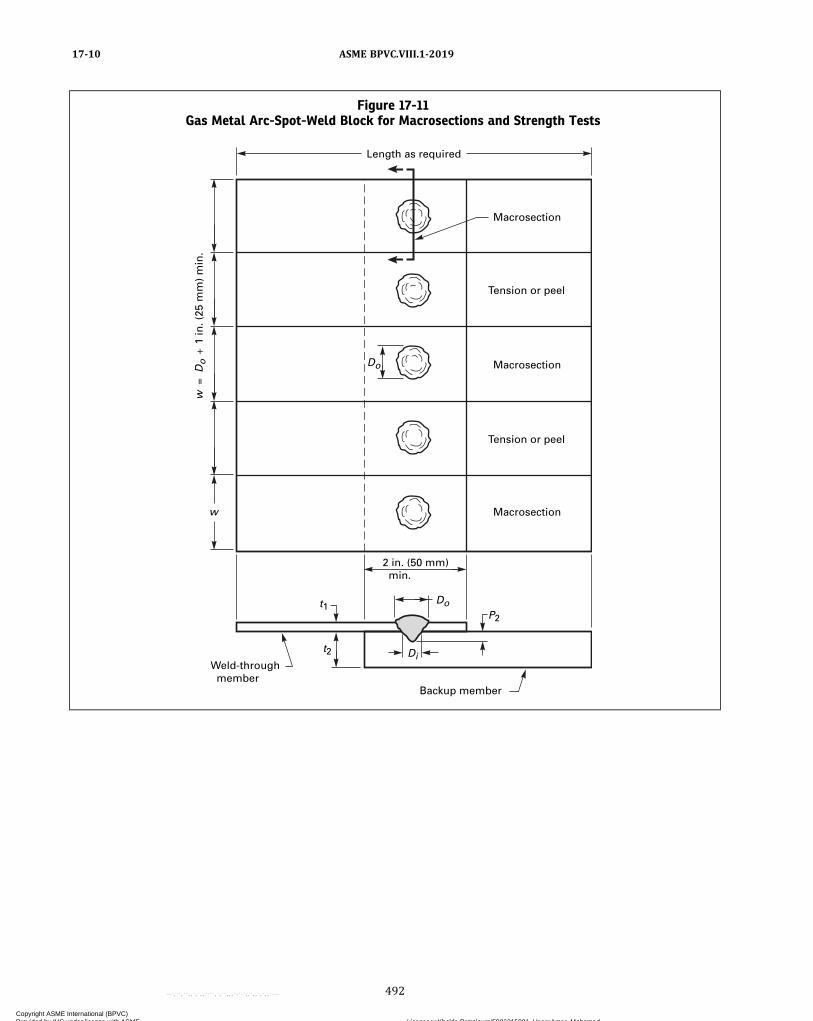
Figure 17-11Gas Metal Arc-Spot-Weld Block for Macrosections and Strength Tests
w
Do
DoP2
t1
t2 Di
Length as required
w =
Do
1 in
. (25
mm
) m
in.
2 in. (50 mm) min.
Macrosection
Tension or peel
Macrosection
Tension or peel
Macrosection
Weld-through member
Backup member
ASME BPVC.VIII.1-201917-10
492
Copyright ASME International (BPVC) Provided by IHS under license with ASME Licensee=Khalda Petroleum/5986215001, User=Amer, Mohamed
Not for Resale, 07/02/2019 13:29:04 MDTNo reproduction or networking permitted without license from IHS
--`,``,``,,`,`,,````,`,``,,,`-`-`,,`,,`,`,,`---
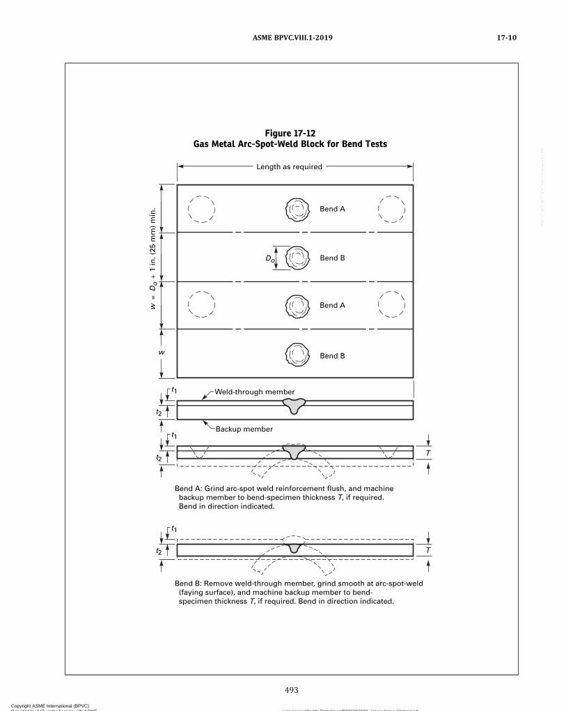
Figure 17-12Gas Metal Arc-Spot-Weld Block for Bend Tests
w
Weld-through member
Do
t1
t2
Length as required
w =
Do
1 in
. (25
mm
) m
in.
Bend B
Bend A
Bend B
Bend A
t1
t2
Bend B: Remove weld-through member, grind smooth at arc-spot-weld (faying surface), and machine backup member to bend- specimen thickness T, if required. Bend in direction indicated.
Bend A: Grind arc-spot weld reinforcement flush, and machine backup member to bend-specimen thickness T, if required. Bend in direction indicated.
t1
t2 T
T
Backup member
ASME BPVC.VIII.1-2019 17-10
493
Copyright ASME International (BPVC) Provided by IHS under license with ASME Licensee=Khalda Petroleum/5986215001, User=Amer, Mohamed
Not for Resale, 07/02/2019 13:29:04 MDTNo reproduction or networking permitted without license from IHS
--`,``,``,,`,`,,````,`,``,,,`-`-`,,`,,`,`,,`---

Figure 17-13Gas Tungsten-Arc SeamWeld, Plasma-Arc SeamWeld, Submerged-Arc SeamWeld, and Laser Beam Seam
Weld Test Specimen for Bend Tests
Weld-through membert1
t2
Length as required
1 /2
in.
(13
mm
)11
/ 2 in
. (
38 m
m)
Discard
Bend B
Bend A
Bend B
Bend A
Macrospecimen
Backup membert1
t2
Bend B: Remove weld-through member, grind smooth at weld interface, and machine backup member to bend-specimen thickness T, if required. Bend in direction indicated.
Bend A: Grind weld reinforcement flush, and machine backup member to bend-specimen thickness T, if required. Bend in direction indicated.
t1
t2 T
T
GENERAL NOTE: Refer to Section IX, Figures QW-462.3(a) and QW-462.3(b) and Figures QW-466.1 through QW-466.6.
ASME BPVC.VIII.1-201917-10
494
Copyright ASME International (BPVC) Provided by IHS under license with ASME Licensee=Khalda Petroleum/5986215001, User=Amer, Mohamed
Not for Resale, 07/02/2019 13:29:04 MDTNo reproduction or networking permitted without license from IHS
--`,``,``,,`,`,,````,`,``,,,`-`-`,,`,,`,`,,`---
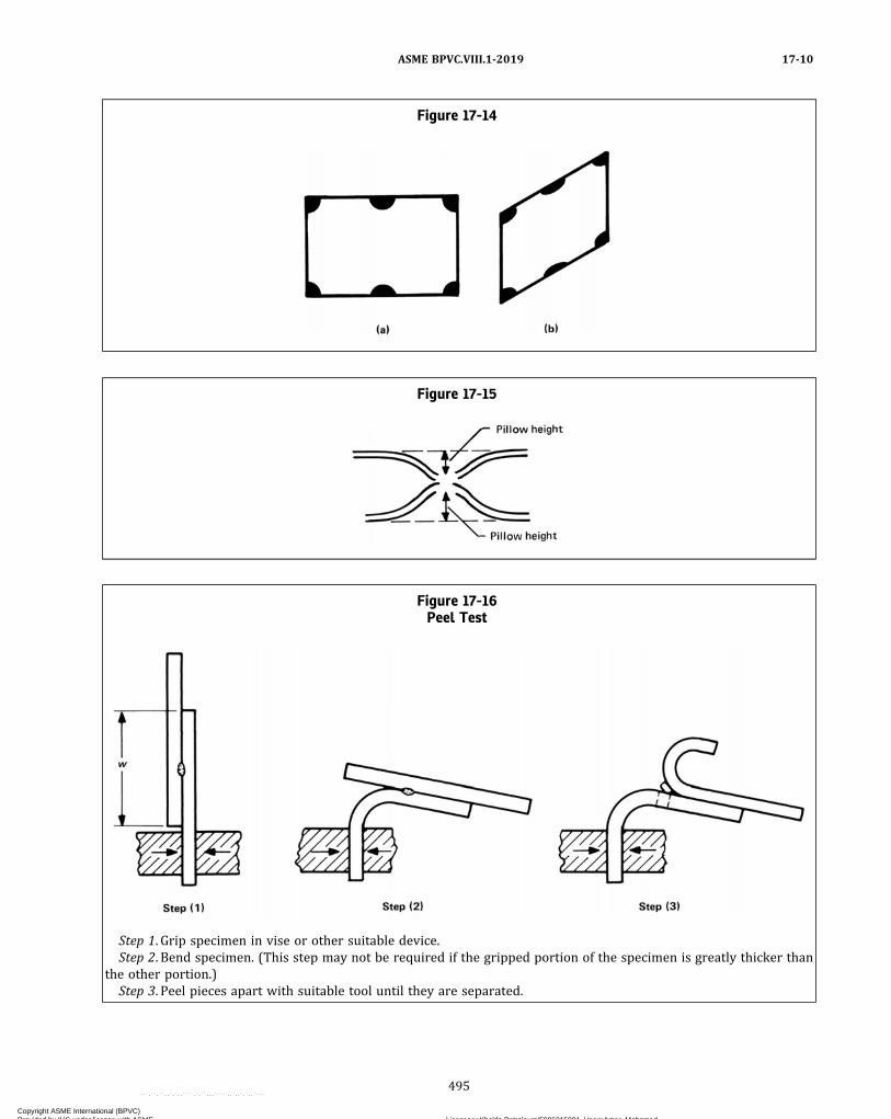
Figure 17-14
Figure 17-15
Figure 17-16Peel Test
Step 1. Grip specimen in vise or other suitable device.Step 2. Bend specimen. (This step may not be required if the gripped portion of the specimen is greatly thicker than
the other portion.)Step 3. Peel pieces apart with suitable tool until they are separated.
ASME BPVC.VIII.1-2019 17-10
495
Copyright ASME International (BPVC) Provided by IHS under license with ASME Licensee=Khalda Petroleum/5986215001, User=Amer, Mohamed
Not for Resale, 07/02/2019 13:29:04 MDTNo reproduction or networking permitted without license from IHS
--`,``,``,,`,`,,````,`,``,,,`-`-`,,`,,`,`,,`---
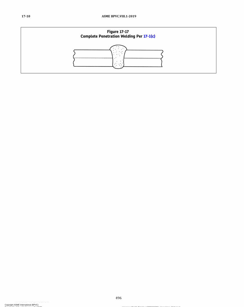
Figure 17-17Complete Penetration Welding Per 17-1(c)
ASME BPVC.VIII.1-201917-10
496
Copyright ASME International (BPVC) Provided by IHS under license with ASME Licensee=Khalda Petroleum/5986215001, User=Amer, Mohamed
Not for Resale, 07/02/2019 13:29:04 MDTNo reproduction or networking permitted without license from IHS
--`,``,``,,`,`,,````,`,``,,,`-`-`,,`,,`,`,,`---

MANDATORY APPENDIX 18ADHESIVE ATTACHMENT OF NAMEPLATES
18-1 SCOPE
(a) The rules in this Appendix cover minimum require-ments for the use of adhesive systems for the attachmentof nameplates, limited to:
(1) the use of pressure‐sensitive acrylic adhesivesthat have been preapplied by the nameplate manufac-turer to a nominal thickness of at least 0.005 in.(0.13 mm) and that are protected with a moisture‐stableliner;
(2) use for vessels with design temperatures withinthe range of −40°F to 300°F (−40°C to 150°C), inclusive;
(3) application to clean, bare metal surfaces, with at-tention being given to removal of antiweld spatter com-pound that may contain silicone;
(4) use of prequalified application procedures as out-lined in 18-2;
(5) use of the preapplied adhesive within an intervalof 2 years after adhesive application.
18-2 NAMEPLATE APPLICATIONPROCEDURE QUALIFICATION
(a) The Manufacturer’s Quality Control System [seeU-2(h)] shall define that written procedures, acceptableto the Inspector, for the application of adhesive‐backednameplates shall be prepared and qualified.
(b) The application procedure qualification shall in-clude the following essential variables, using the adhesiveand nameplate manufacturers’ recommendations whereapplicable:
(1) description of the pressure‐sensitive acrylic ad-hesive system employed, including generic composition;
(2) the qualified temperature range [the cold box testtemperature shall be −40°F (−40°C) for all applications];
(3)materials of nameplate and substrate when themean coefficient of expansion at design temperature ofone material is less than 85% of that for the othermaterial;
(4) finish of the nameplate and substrate surfaces;(5) the nominal thickness and modulus of elasticity
at application temperature of the nameplate when name-plate preforming is employed. A change of more than 25%in the quantity [(nameplate nominal thickness)2 × name-plate modulus of elasticity at application temperature]will require requalification.
(6) the qualified range of preformed nameplate andcompanion substrate contour combinations when pre-forming is employed;
(7) cleaning requirements for the substrate;(8) application temperature range and application
pressure technique;(9) application steps and safeguards.
(c) Each procedure used for nameplate attachment bypressure‐sensitive acrylic adhesive systems shall be qual-ified for outdoor exposure in accordance with StandardUL‐969, Marking and Labeling Systems, with the follow-ing additional requirements:
(1)Width of nameplate test strip shall not be lessthan 1 in. (25 mm).
(2) Nameplates shall have an average adhesion of notless than 8 lb/in. (36 N/25 mm) of width after all expo-sure conditions, including low temperature.
(d) Any c h an g e i n ( b ) a bo v e s h a l l r e qu i r erequalification.
(e) Each lot or package of nameplates shall be identi-fied with the adhesive application date.
ASME BPVC.VIII.1-2019 18-1 – 18-2
497
Copyright ASME International (BPVC) Provided by IHS under license with ASME Licensee=Khalda Petroleum/5986215001, User=Amer, Mohamed
Not for Resale, 07/02/2019 13:29:04 MDTNo reproduction or networking permitted without license from IHS
--`,``,``,,`,`,,````,`,``,,,`-`-`,,`,,`,`,,`---
MANDATORY APPENDIX 19ELECTRICALLY HEATED OR GAS-FIRED JACKETED STEAM
KETTLES
19-1 SCOPE
The rules in Mandatory Appendix 19 provide additionalrequirements for electrically heated or gas-fired jacketedsteam kettles constructed under the rules of this Division.
19-2 SERVICE RESTRICTIONS
No steam or water shall be withdrawn from the jacketfor use external to the vessel and the operating pressureof the jacket shall not exceed 50 psi (350 kPa).
19-3 MATERIALS
When in contact with products of combustion, austeni-tic stainless steel parts shall be of either the low carbon orstabilized grades. Structural grade carbon steel, SA-36and SA-283 (Grades A, B, C, and D), shall not be usedfor any pressure part.
19-4 DESIGN
Welded Category A and B joints in contact with pro-ducts of combustion shall be of Type No. 1 of TableUW-12.
19-5 INSPECTION AND STAMPING
Electrically heated or gas-fired jacketed steam kettlesshall be inspected by an Inspector and shall not bemarked with the Certification Mark with the UM Designa-tor regardless of volume [see U-1(j)].
19-6 PRESSURE RELIEF
The capacity of the safety valve in pounds of steam perhour shall be at least equal to the Btu per hour rating ofthe burner divided by 1,000 or the kilowatt rating ofthe electric heating element multiplied by 3.5.
19-7 APPURTENANCES AND CONTROLS
The jacket shall be furnished with the following mini-mum appurtenances and controls [see U-2(a)(4)]:(a) a pressure gage;(b) a water gage glass; or alternatively, for electrically
heated jacketed steam kettles with immersion type heat-ing elements, a low level warning light;(c) a separate connection, fitted with a stop valve, for
venting air or adding water to the jacket (the watermay be added while the vessel is not under pressure);(d) an electric heater control or automatic gas valve
controlled by pressure or temperature to maintain thesteam pressure in the jacket below the safety valvesetting;(e) a low water cutoff that will cut off the fuel to the
burner or power to the electric heating element if thewater in the jacket drops below the lowest permissiblewater level established by the manufacturer;(f) a safety pilot control that will cut off the fuel to both
the main burner and the pilot burner in case of pilot flamefailure.
19-8 DATA REPORTS
When all the requirements of this Division and the sup-plemental requirements of this Appendix have been met,the following notation shall be entered on the Manufac-turer’s Data Report under Remarks, “Constructed in Con-formance with Mandatory Appendix 19, ElectricallyHeated or Gas-Fired Jacketed Steam Kettles.”
ASME BPVC.VIII.1-201919-1 – 19-8
498
Copyright ASME International (BPVC) Provided by IHS under license with ASME Licensee=Khalda Petroleum/5986215001, User=Amer, Mohamed
Not for Resale, 07/02/2019 13:29:04 MDTNo reproduction or networking permitted without license from IHS
--`,``,``,,`,`,,````,`,``,,,`-`-`,,`,,`,`,,`---
MANDATORY APPENDIX 20HUBS MACHINED FROM PLATE
20-1 SCOPE
This Appendix covers the requirements for hubs oftubesheets, lap joint stub ends, and flat heads machinedfrom plate when the hub length is in the through thick-ness direction of the plate.
20-2 MATERIAL
Plate shall be manufactured by a process that producesmaterial having through thickness properties which areat least equal to those specified in the material specifica-tion. Such plate can be, but is not limited to, that producedby methods such as electroslag (ESR) and vacuum arc re-melt (VAR). The plate must be tested and examined in ac-cordance with the requirements of the materialspecification and the additional requirements specifiedin the following paragraphs:
Test specimens, in addition to those required by thematerial specifications, shall be taken in a direction paral-lel to the axis of the hub and as close to the hub as prac-tical, as shown in Figure UW-13.3. At least two tensile testspecimens shall be taken from the plate in the proximityof the hub with one specimen taken from the center thirdof the plate width as rolled, and the second specimen ta-ken at 90 deg around the circumference from the otherspecimen. Both specimens shall meet the tensile and yieldrequirements of the SA material specification. All dimen-sional requirements of Figure UW-13.3 shall apply.
Subsize test specimens conforming to the requirementsof Figure 4 of SA-370 may be used if necessary, in whichcase the value for “elongation in 2 in. (50 mm),” requiredby the material specification, shall apply to the gagelength specified in Figure 4.
The reduction‐of‐area shall not be less than 30%. (Forthose materials for which the material specification re-quires a reduction‐of‐area value greater than 30%, thehigher value must be met.)
20-3 EXAMINATION REQUIREMENTS
Each part shall be examined as follows:(a) Before and after machining, the part, regardless of
thickness, shall be ultrasonically examined by the straightbeam technique in accordance with SA-388. The examina-tion shall be in two directions approximately at right an-gles, that is, from the cylindrical or flat rectangularsurfaces of the hub and in the axial direction of the hub.
The part shall be unacceptable:(1) if the examination results show one or more indi-
cations accompanied by loss of back reflection larger than60% of the reference back reflection;
(2) if the examination results show indications largerthan 40% of the reference back reflection when accompa-nied by a 40% loss of back reflection.
(b) Before welding the hub of the tubesheet or flat headto the adjacent shell, the hub shall be examined by mag-netic particle or liquid penetrant methods in accordancewith Mandatory Appendix 6 or Mandatory Appendix 8.
(c) After welding, the weld and the area of the hub forat least 1/2 in. (13 mm) from the edge of the weld shall be100% radiographed in accordance with UW-51. As an al-ternative, the weld and hub area adjacent to the weld maybe ultrasonically examined in accordance with MandatoryAppendix 12.
20-4 DATA REPORTS
When all the requirements of this Division and the sup-plemental requirements of this Appendix have been met,the following notation shall be entered on the Manufac-turer’s Data Report under Remarks: “Constructed in Con-formance with Mandatory Appendix 20, Hubs MachinedFrom Plate.”
ASME BPVC.VIII.1-2019 20-1 – 20-4
499
Copyright ASME International (BPVC) Provided by IHS under license with ASME Licensee=Khalda Petroleum/5986215001, User=Amer, Mohamed
Not for Resale, 07/02/2019 13:29:04 MDTNo reproduction or networking permitted without license from IHS
--`,``,``,,`,`,,````,`,``,,,`-`-`,,`,,`,`,,`---

MANDATORY APPENDIX 21JACKETED VESSELS CONSTRUCTED OF WORK-HARDENED
NICKEL
21-1 SCOPE
Jacketed vessels having an inner shell constructed ofnickel sheet or plate that meets the requirements ofSB-162 and that has been work‐hardened by a planishingoperation over its entire surface during fabrication, with acorresponding increase in strength against collapse, shallmeet the requirements of this Division, provided that theadditional provisions which follow are met.
21-2 DESIGN REQUIREMENTS
(a) The maximum size of any vessel shall be 8 ft (2.4 m)I.D.(b) The maximum operating temperature shall not ex-
ceed 400°F (205°C).(c) Any cylindrical skirt (flange) on a hemispherical
head that is subject to external pressure shall be designedas a cylinder.(d) The thickness of the inner shell of each vessel shall
be such as to withstand without failure a hydrostatic testpressure in the jacket space of not less than three timesthe desired maximum allowable working pressure.(e) In no case shall the thickness of the inner shell or
head be less than that determined from the external pres-sure chart in Section II, Part D, Subpart 3, Figure NFA-4.
(f) The required moment of inertia of stiffening ringsshall be determined from the appropriate chart in SectionII, Part D, Subpart 3 for the material used for the rings.(g) The outer shell and head shall be designed for in-
creased strength, if necessary, to accommodate the testpressure specified in (d) above, in order to avoid rejectionof the vessel under UG-99(d).
21-3 FABRICATION
Any butt weld that is subject to the external pressureshall be ground flush with the base metal, and the depos-ited weld metal and the heat-affected zone shall be work‐hardened in the same manner as the base metal.
21-4 DATA REPORTS
When all the requirements of this Division and the sup-plemental requirements of this Appendix have been met,the following notation shall be entered on the Manufac-turer’s Data Report under Remarks, “Constructed in Con-formance with Mandatory Appendix 21, Jacketed VesselsConstructed of Work‐Hardened Nickel.”
ASME BPVC.VIII.1-201921-1 – 21-4
500
Copyright ASME International (BPVC) Provided by IHS under license with ASME Licensee=Khalda Petroleum/5986215001, User=Amer, Mohamed
Not for Resale, 07/02/2019 13:29:04 MDTNo reproduction or networking permitted without license from IHS
--`,``,``,,`,`,,````,`,``,,,`-`-`,,`,,`,`,,`---
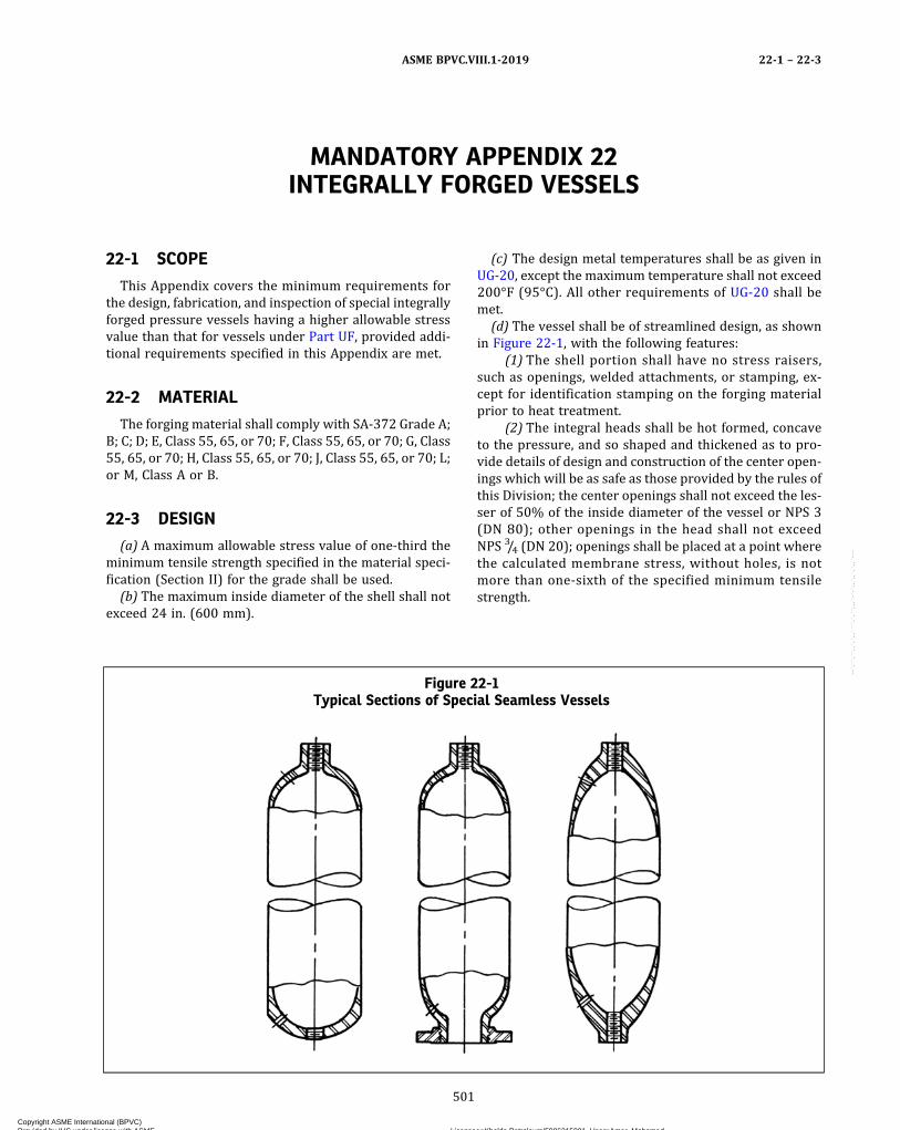
MANDATORY APPENDIX 22INTEGRALLY FORGED VESSELS
22-1 SCOPE
This Appendix covers the minimum requirements forthe design, fabrication, and inspection of special integrallyforged pressure vessels having a higher allowable stressvalue than that for vessels under Part UF, provided addi-tional requirements specified in this Appendix are met.
22-2 MATERIAL
The forging material shall comply with SA-372 Grade A;B; C; D; E, Class 55, 65, or 70; F, Class 55, 65, or 70; G, Class55, 65, or 70; H, Class 55, 65, or 70; J, Class 55, 65, or 70; L;or M, Class A or B.
22-3 DESIGN
(a) A maximum allowable stress value of one‐third theminimum tensile strength specified in the material speci-fication (Section II) for the grade shall be used.
(b) The maximum inside diameter of the shell shall notexceed 24 in. (600 mm).
(c) The design metal temperatures shall be as given inUG-20, except the maximum temperature shall not exceed200°F (95°C). All other requirements of UG-20 shall bemet.
(d) The vessel shall be of streamlined design, as shownin Figure 22-1, with the following features:
(1) The shell portion shall have no stress raisers,such as openings, welded attachments, or stamping, ex-cept for identification stamping on the forging materialprior to heat treatment.
(2) The integral heads shall be hot formed, concaveto the pressure, and so shaped and thickened as to pro-vide details of design and construction of the center open-ings which will be as safe as those provided by the rules ofthis Division; the center openings shall not exceed the les-ser of 50% of the inside diameter of the vessel or NPS 3(DN 80); other openings in the head shall not exceedNPS 3/4 (DN 20); openings shall be placed at a point wherethe calculated membrane stress, without holes, is notmore than one‐sixth of the specified minimum tensilestrength.
Figure 22-1Typical Sections of Special Seamless Vessels
ASME BPVC.VIII.1-2019 22-1 – 22-3
501
Copyright ASME International (BPVC) Provided by IHS under license with ASME Licensee=Khalda Petroleum/5986215001, User=Amer, Mohamed
Not for Resale, 07/02/2019 13:29:04 MDTNo reproduction or networking permitted without license from IHS
--`,``,``,,`,`,,````,`,``,,,`-`-`,,`,,`,`,,`---
(3) The vessel shall have no welding, except for sealwelding of threaded connections performed either beforeor after heat treatment in accordance with UF-32.
22-4 HEAT TREATMENT
(a) The completed vessel, after all forging operations,shall be heat treated by one of the applicable methodsoutlined in SA-372.(b) The tensile properties shall be determined by the
testing method outlined in SA-372.(c) When liquid quenched and tempered, each vessel
shall be hardness tested as outlined in UF-31(b)(2).(d) After heat treatment, the outside surface of each
vessel, regardless of the type of heat treatment used, shallbe subjected to the magnetic particle test or the liquidpenetrant test as outlined in UF-31(b)(1).
22-5 MARKING
(a) The vessel shall be stamped on the thickened headportion with both the maximum allowable working pres-sure based on that for vessels under Part UF and also themaximum allowable working pressure based on a stressequal to one‐third the specified minimum tensilestrength.(b) The words “Mandatory Appendix 22” shall be
stamped following the latter pressure in (a) above.
22-6 DATA REPORTS
When all the requirements of this Division and the sup-plemental requirements of this Appendix have been met,the following notation shall be entered on the Manufac-turer’s Data Report under Remarks: “Constructed in Con-formance with Mandatory Appendix 22, Integrally ForgedVessels.”
ASME BPVC.VIII.1-201922-3 – 22-6
502
Copyright ASME International (BPVC) Provided by IHS under license with ASME Licensee=Khalda Petroleum/5986215001, User=Amer, Mohamed
Not for Resale, 07/02/2019 13:29:04 MDTNo reproduction or networking permitted without license from IHS
--`,``,``,,`,`,,````,`,``,,,`-`-`,,`,,`,`,,`---
MANDATORY APPENDIX 23EXTERNAL PRESSURE DESIGN OF COPPER, COPPER ALLOY, ANDTITANIUM ALLOY CONDENSER AND HEAT EXCHANGER TUBES
WITH INTEGRAL FINS
23-1 SCOPE
The rules in this Appendix cover the proof test proce-dure and criteria for determining the maximum allowableexternal working pressure of copper, copper alloy, and ti-tanium alloy condenser and heat exchanger tubes withhelical fins that are integrally extended from the tube wallas an alternative to the requirements of UG-8(b)(4). ThisAppendix may only be used when the specified corrosionallowance for the tubes is zero. In addition, when usingSB-543, this Appendix may only be used when the finningoperations are performed after the tubes have beenwelded, tested, and inspected according to SB-543.
23-2 MATERIALS
(a) Copper and copper alloy tubes shall meet SB-359,SB-543, or SB-956.
(b) Titanium alloy tubes shall meet SB-338.
23-3 TEST PROCEDURE
(a) Test three full size specimens to failure (visible col-lapse) by external hydrostatic pressure.
(b) The maximum allowable working pressure P shallbe determined by
where
B = minimum collapse pressure, psi (kPa)F = factor to adjust for change in strength due to design
temperature= S/S2
S = maximum allowable stress value for the tube mate-rial at design temperature, as given in the tables re-ferenced in UG-23 but not to exceed S2, psi
S2 = maximum allowable stress value for the tube mate-rial at test temperature, as given in the tables refer-enced in UG-23, psi
Ya = actual average yield strength determined from theunfinned length of the three specimens tested atroom temperature, psi (kPa)
Ys = specified minimum yield strength at room tem-perature, psi (kPa)
23-4 CRITERIA
(a) The design of copper and copper alloy finned tubesto this Appendix shall meet the following requirements:
(1) Design temperature shall be limited to the maxi-mum temperature listed in Section II, Part D, Subpart 1,Table 1B corresponding to the time independent allow-able stress, or the maximum temperature shown on theexternal pressure chart for the corresponding material,whichever is less.
(2) Tubes shall have external and/or internal inte-grally extended helical fins and the sum of external plusinternal fins shall be at least 10 fins/in. (10 fins/25 mm).
(3) Dimensions and permissible variations shall be asspecified in Item 15 of SB-359 or SB-956.
(b) The design of titanium alloy finned tubes to thisAppendix shall meet the following requirements:
(1) Design temperature shall not exceed 600°F(315°C).
(2) Tubes shall have external integrally extended he-lical fins only and shall have at least 10 fins/in.(10 fins/25 mm).
(3) Dimensions and permissible variations shall be asspecified in item 15 of SB-359 (Specification for Copperand Copper‐Alloy Seamless Condenser and Heat Exchan-ger Tubes With Integral Fins).
(c) Additional requirements for copper, copper alloy,and titanium alloy tubes designed to this Appendix areas follows.
(1) Test specimens shall be identical in fin geometryand pitch to production tubes.
(2) Test specimens of 50 outside diameters or morein length shall qualify all totally finned lengths.
(3) Unfinned length at the ends or at an intermediatesection shall qualify that length and all lesser unfinnedlengths.
(4) Nominal wall thickness under the fin and at theunfinned area shall qualify all thicker wall sections butwith no increase in P .
(5) Outside diameter of the finned section shall notexceed the outside diameter of the unfinned section.
ASME BPVC.VIII.1-2019 23-1 – 23-4
503
Copyright ASME International (BPVC) Provided by IHS under license with ASME Licensee=Khalda Petroleum/5986215001, User=Amer, Mohamed
Not for Resale, 07/02/2019 13:29:04 MDTNo reproduction or networking permitted without license from IHS
--`,``,``,,`,`,,````,`,``,,,`-`-`,,`,,`,`,,`---
(6) Tests shall be done in accordance with 23-3, wit-nessed by and subjected to the acceptance of theInspector.
23-5 DATA REPORTS
When all the requirements of this Division and the sup-plemental requirements of this Appendix have been met,the fol lowing notat ion shal l be entered on the
Manufacturer’s Data Report under Remarks: “Con-structed in Conformance with Mandatory Appendix 23,External Pressure Design of Copper, Copper Alloy, and Ti-tanium Alloy Condenser and Heat Exchanger Tubes WithIntegral Fins.”
ASME BPVC.VIII.1-201923-4 – 23-5
504
Copyright ASME International (BPVC) Provided by IHS under license with ASME Licensee=Khalda Petroleum/5986215001, User=Amer, Mohamed
Not for Resale, 07/02/2019 13:29:04 MDTNo reproduction or networking permitted without license from IHS
--`,``,``,,`,`,,````,`,``,,,`-`-`,,`,,`,`,,`---
ð19Þ
MANDATORY APPENDIX 24DESIGN RULES FOR CLAMP CONNECTIONS
24-1 SCOPE
(a) The rules in this Appendix apply specifically to thedesign of clamp connections for pressure vessels and ves-sel parts and shall be used in conjunction with the applic-able requirements in Subsections A, B, and C of thisDivision. These rules shall not be used for the determina-tion of thickness of tubesheets integral with a hub nor forthe determination of thickness of covers. These rules pro-vide only for hydrostatic end loads, assembly, and gasketseating. Consideration shall be given to loads other thanpressure, such as piping loads, that may act on the clampconnection. (See UG-22.)
(b) The design of a clamp connection involves the selec-tion of the gasket, bolting, hub, and clamp geometry. Bolt-ing shall be selected to satisfy the requirements of 24-4.Connection dimensions shall be such that the stresses inthe clamp and the hub, calculated in accordance with24-6 and 24-7, do not exceed the allowable stresses spe-cified in Table 24-8. All calculations shall be made on di-mensions in the corroded condition. Calculations forassembly, gasket seating, and operating conditions arerequired.
(c) It is recommended that either a pressure energizedand/or low seating load gasket be used to compensate forpossible nonuniformity in the gasket seating force distri-bution. Hub faces shall be designed such as to have metal‐to‐metal contact outside the gasket seal diameter. Thismay be provided by recessing the hub faces or by use ofa metal spacer (see Figure 24-1). The contact area shallbe sufficient to prevent yielding of either the hub faceor spacer under both operating and assembly loads.
(d) It is recognized that there are clamp designs thatutilize no wedging action during assembly since clampingsurfaces are parallel to the hub faces. Such designs are ac-ceptable and shall satisfy the bolting and correspondingclamp and hub requirements of a clamp connection de-signed for a total included clamping angle of 10 deg.
(e) The design method used herein to calculate stress-es, loads, and moments may also be used in designingclamp connections of shapes differing from those shownin Figures 24-1 and 24-2, and for clamps consisting ofmore than two circumferential segments. The design for-mulas used herein may be modified when designingclamp connections of shape differing from those shownin Figures 24-1 and 24-2, provided that the basis for the
modifications is in accordance with U-2(g). However,the requirements of (f) below shall be complied with forall clamp connections.
(f) Clamps designed to the rules of this Appendix shallbe provided with a bolt retainer. The retainer shall be de-signed to hold the clamps together independently in theoperating condition in case of failure of the primary bolt-ing. Clamp hub friction shall not be considered as a retai-ner method. Multiple bolting (two or more bolts per lug)is an acceptable alternative for meeting this requirement.
24-2 MATERIALS
(a)Materials used in the construction of clamp connec-tions shall comply with the requirements given in UG-5through UG-14.
(b) Hubs made from ferritic steel and designed in ac-cordance with the rules herein shall be given a normaliz-ing or full‐annealing heat treatment when the thickness ofthe hub neck section exceeds 3 in. (75 mm).
(c) Cast steel hubs and clamps shall be examined andrepaired in accordance with Mandatory Appendix 7.
(d) Hubs and clamps shall not be machined from plate.(e) Bolts and studs shall comply with UG-12. Minimum
diameter shall be 1/2 in. (13 mm). Nuts and washers shallcomply with UG-13.
24-3 NOTATION
The notation below is used in the formulas for the de-sign of clamp‐type connections (see also Figures 24-1and 24-2).
A = outside diameter of hubA1 = partial clamp area
= (Cw − 2Ct)Ct
A2 = partial clamp area= 1.571Ct
2
A3 = partial clamp area= (Cw − Cg)l c
AbL = total cross‐sectional area of the bolts per clamplug using the smaller of the root diameter ofthe thread or least diameter of unthreaded por-tion. Cross‐sectional area of bolt retainer shallnot be included in calculation of this area. Whenmultiple bolting is used in lieu of bolt retainer,the total cross‐sectional area of all the bolts perclamp lug shall be used.
ASME BPVC.VIII.1-2019 24-1 – 24-3
505
Copyright ASME International (BPVC) Provided by IHS under license with ASME Licensee=Khalda Petroleum/5986215001, User=Amer, Mohamed
Not for Resale, 07/02/2019 13:29:04 MDTNo reproduction or networking permitted without license from IHS
--`,``,``,,`,`,,````,`,``,,,`-`-`,,`,,`,`,,`---
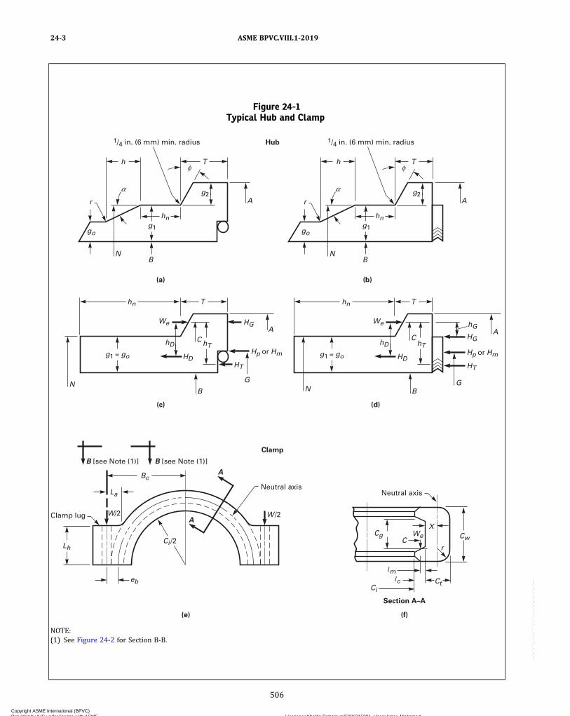
Figure 24-1Typical Hub and Clamp
Neutral axisNeutral axis
B [see Note (1)]B [see Note (1)]
X
CCw
Cg
CtCi
eb
Lh
La
Thn
HD
hD
We
W/2
hT
A
Hp or Hm Hp or Hmg1 = go
HG
G
B
C
(c)
(a) (b)
Hub
Clamp
Clamp lug
N
HT
Bc
Ci /2
W /2A
A
m
c
We
r
Thn
go
hng1
g2
HD
HG
hG
HT
hD
We
hTg1 = go
B
A
T
1/4 in. (6 mm) min. radius
h
r
NB
A
G
C
(d)
(f)
Section A–A
(e)
N
go
hng1
g2A
T
1/4 in. (6 mm) min. radius
h
r
NB
NOTE:(1) See Figure 24-2 for Section B-B.
ASME BPVC.VIII.1-201924-3
506
Copyright ASME International (BPVC) Provided by IHS under license with ASME Licensee=Khalda Petroleum/5986215001, User=Amer, Mohamed
Not for Resale, 07/02/2019 13:29:04 MDTNo reproduction or networking permitted without license from IHS
--`,``,``,,`,`,,````,`,``,,,`-`-`,,`,,`,`,,`---

Ac = total effective clamp cross‐sectional area= A1 + A2 + A3
Am1 = total cross‐sectional area of bolts per clamp lugat root of thread or section of least diameter un-der stress, required for the operating conditions
= Wm1/2SbAm2 = total cross‐sectional area of bolts per clamp lug
at root of thread or section of least diameter un-der stress, required for gasket seating
= Wm2/2SaAm3 = total cross‐sectional area of bolts per clamp lug
at root of thread or section of least diameter un-der stress, required for assembly conditions
= Wm3/2SaAmL = total required cross‐sectional area of bolts per
clamp lug taken as the greater of Am1 , Am2 , orAm3
B = inside diameter of hubb = effective gasket or joint‐contact‐surface seating
width (see Table 2-5.2)
Bc = radial distance from connection centerline tocenter of bolts [see Figure 24-1, sketch (e)]
bo = basic gasket or joint‐contact‐surface seatingwidth (see Table 2-5.2)
C = diameter of effective clamp‐hub reaction circle= (A + Ci)/2
Cg = effective clamp gap determined at diameter CCi = inside diameter of clampCt = effective clamp thickness (Ct shall be equal to or
greater than r)Cw = clamp widtheb = radial distance from center of the bolts to the
centroid of the clamp cross section= Bc − (Ci/2) − l c − X
f = hub stress correction factor from Figure 2-7.6.(This is the ratio of the stress in the small endof the hub to the stress in the large end.) (For val-ues below limit of the figure, use f = 1.0.)
G = diameter at location of gasket load reaction. Ex-cept as noted in Figure 24-1, G is defined as fol-lows (see Table 2-5.2):
Figure 24-2Typical Clamp Lug Configurations
GENERAL NOTE: See 24-1(f) for retainer requirements.
ASME BPVC.VIII.1-2019 24-3
507
Copyright ASME International (BPVC) Provided by IHS under license with ASME Licensee=Khalda Petroleum/5986215001, User=Amer, Mohamed
Not for Resale, 07/02/2019 13:29:04 MDTNo reproduction or networking permitted without license from IHS
--`,``,``,,`,`,,````,`,``,,,`-`-`,,`,,`,`,,`---

(a)when bo ≤1/4 in. (6 mm), G = mean diameterof gasket or joint contact face;(b) when bo > 1/4 in. (6 mm), G = outside dia-
meter of gasket contact face less 2b
g1 = thickness of hub neck at intersection with hubshoulder
g2 = height of hub shoulder (g2 shall not be largerthan T .)
go = thickness of hub neck at small end= radial distance from the hub inside diameter B to
the hub shoulder ring centroid
=
H = total hydrostatic end force= 0.785G2P
h = hub taper lengthh2 = average thickness of hub shoulder
= T − (g2 tan ϕ)/2HD = hydrostatic end force on bore area
= 0.785B2PhD = radial distance from effective clamp‐hub reaction
circle to the circle on which HD acts= [C − (B + g1)]/2
HG = difference between total effective axial clampingpreload and the sum of total hydrostatic endforce and total joint contact surface compression
= [1.571 W/tan (ϕ + μ)] − (H + Hp)hG = radial distance from effective clamp‐hub reaction
circle to the circle on which HG acts in. (mm) (forfull face contact geometries, hG = 0)
Hm = total axial gasket seating requirements for make-up (3.14bGy or the axial seating load for self‐energizing gaskets, if significant)
hn = hub neck length [minimum length of hn is 0.5g1
or 1/4 in. (6 mm), whichever is larger]
ho =
Hp = total joint contact surface compression load= 2b × 3.14GmP= (For self‐energized gaskets, use Hp = 0 or actual
retaining load if significant.)HT = difference between total hydrostatic end force
and hydrostatic end force on bore area= H − HD
hT = radial distance from effective clamp‐hub reactioncircle to the circle on which HT acts
= [C − (B + G)/2]/2= axial distance from the hub face to the hub
shoulder ring centroid
=
I c = moment of inertia of clamp relative to neutralaxis of entire section
=
Ih = moment of inertia of hub shoulder relative to itsneutral axis
=
La = distance fromW to the point where the clamp lugjoins the clamp body [see Figure 24-1, sketch (e)]
l c = effective clamp lip lengthLh = clamp lug height [see Figure 24-1, sketch (e)]lm = effective clamp lip moment arm
= lc − (C − Ci)/2Lw = clamp lug width (see Figure 24-2)m = gasket factor from Table 2-5.1
MD = moment due to HD
= HDhDMF = offset moment
= HD (g1 − go)/2MG = moment due to HG
= HG hG
MH = reaction moment at hub neck
=
Mo = total rotational moment on hub (see 24-5)MP = pressure moment
= 3.14 × PBT (T/2 − )
MR = radial clamp equilibriating moment
= 1.571 W { − T + [(C − N) tan ϕ]/2}
MT = moment due to HT
= HThT
N = outside diameter of hub neckP = internal design pressure (see UG-21)Q = reaction shear force at hub neck
=
r = clamp or hub cross section corner radius= 1/4 in. (6 mm) min., Ct max.
S1 = hub longitudinal stress on outside at hub neckS2 = maximum Lamé hoop stress at bore of hubS3 = maximum hub shear stress at shoulderS4 = maximum radial hub shear stress in neckS5 = clamp longitudinal stress at clamp body inner
diameterS6 = clamp tangential stress at clamp body outer
diameterS7 = maximum shear stress in clamp lipsS8 = clamp lug bending stressS9 = effective bearing stress between clamp and hubSa = allowable bolt stress at room temperature
SAC = allowable design stress for clamp material at (as-sembly condition) room temperature
SAH = allowable design stress for hub material at (as-sembly condition) room temperature
Sb = allowable bolt stress at design temperature
ASME BPVC.VIII.1-201924-3
508
Copyright ASME International (BPVC) Provided by IHS under license with ASME Licensee=Khalda Petroleum/5986215001, User=Amer, Mohamed
Not for Resale, 07/02/2019 13:29:04 MDTNo reproduction or networking permitted without license from IHS
--`,``,``,,`,`,,````,`,``,,,`-`-`,,`,,`,`,,`---
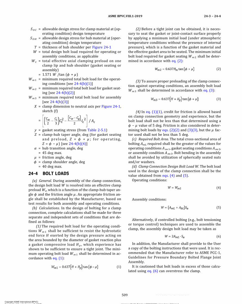
SOC = allowable design stress for clampmaterial at (op-erating condition) design temperature
SOH = allowable design stress for hub material at (oper-ating condition) design temperature
T = thickness of hub shoulder per Figure 24-1W = total design bolt load required for operating or
assembly conditions, as applicableWe = total effective axial clamping preload on one
clamp lip and hub shoulder (gasket seating orassembly)
= 1.571 W /tan (ϕ + μ)Wm1 = minimum required total bolt load for the operat-
ing conditions [see 24-4(b)(1)]Wm2 = minimum required total bolt load for gasket seat-
ing [see 24-4(b)(2)]Wm3 = minimum required total bolt load for assembly
[see 24-4(b)(3)]X = clamp dimension to neutral axis per Figure 24-1,
sketch (f)
=
y = gasket seating stress (from Table 2-5.1)Z = clamp‐hub taper angle, deg (for gasket seating
and pre load , Z = ϕ + μ ; for operat ing ,Z = ϕ − μ) [see 24-4(b)(4)]
α = hub transition angle, deg= 45 deg max.
μ = friction angle, degϕ = clamp shoulder angle, deg
= 40 deg max.
24-4 BOLT LOADS
(a) General. During assembly of the clamp connection,the design bolt load W is resolved into an effective clamppreloadWe, which is a function of the clamp‐hub taper an-gle ϕ and the friction angle μ . An appropriate friction an-gle shall be established by the Manufacturer, based ontest results for both assembly and operating conditions.
(b) Calculations. In the design of bolting for a clampconnection, complete calculations shall be made for threeseparate and independent sets of conditions that are de-fined as follows:
(1) The required bolt load for the operating condi-tions Wm1 shall be sufficient to resist the hydrostaticend force H exerted by the design pressure acting onthe area bounded by the diameter of gasket reaction plusa gasket compressive load Hp , which experience hasshown to be sufficient to ensure a tight joint. The mini-mum operating bolt load Wm1 shall be determined in ac-cordance with eq. (1):
ð1Þ
(2) Before a tight joint can be obtained, it is neces-sary to seat the gasket or joint‐contact surface properlyby applying a minimum initial load (under atmospherictemperature conditions without the presence of internalpressure), which is a function of the gasket material andthe effective gasket area to be seated. The minimum initialbolt load required for gasket seating Wm2 shall be deter-mined in accordance with eq. (2):
ð2Þ
(3) To assure proper preloading of the clamp connec-tion against operating conditions, an assembly bolt loadWm3 shall be determined in accordance with eq. (3):
ð3Þ
(4) In eq. (1)(1), credit for friction is allowed basedon clamp connection geometry and experience, but thebolt load shall not be less than that determined using aϕ − μ value of 5 deg. Friction is also considered in deter-mining bolt loads by eqs. (2)(2) and (3)(3), but the μ fac-tor used shall not be less than 5 deg.
(c) Required Bolt Area. The total cross‐sectional area ofbolting AmL required shall be the greater of the values foroperating conditions Am1, gasket seating conditions Am2,or assembly condition Am3. Bolt bending in the assemblyshall be avoided by utilization of spherically seated nutsand/or washers.
(d) Clamp Connection Design Bolt Load W. The bolt loadused in the design of the clamp connection shall be thevalue obtained from eqs. (4) and (5).
Operating conditions:
ð4Þ
Assembly conditions:
ð5Þ
Alternatively, if controlled bolting (e.g., bolt tensioningor torque control) techniques are used to assemble theclamp, the assembly design bolt load may be taken as
ð6ÞIn addition, the Manufacturer shall provide to the User
a copy of the bolting instructions that were used. It is rec-ommended that the Manufacturer refer to ASME PCC-1,Guidelines for Pressure Boundary Bolted Flange JointAssembly.
It is cautioned that bolt loads in excess of those calcu-lated using eq. (6) can overstress the clamp.
ASME BPVC.VIII.1-2019 24-3 – 24-4
509
Copyright ASME International (BPVC) Provided by IHS under license with ASME Licensee=Khalda Petroleum/5986215001, User=Amer, Mohamed
Not for Resale, 07/02/2019 13:29:04 MDTNo reproduction or networking permitted without license from IHS
--`,``,``,,`,`,,````,`,``,,,`-`-`,,`,,`,`,,`---
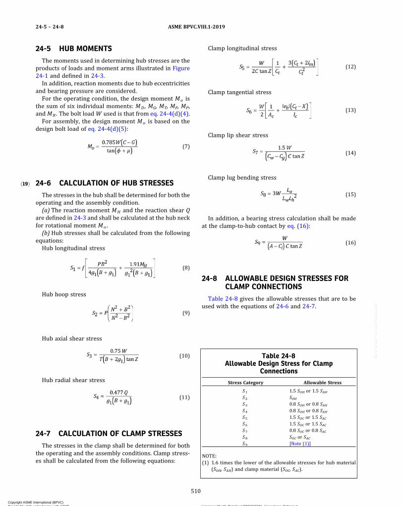
ð19Þ
24-5 HUB MOMENTS
The moments used in determining hub stresses are theproducts of loads and moment arms illustrated in Figure24-1 and defined in 24-3.In addition, reaction moments due to hub eccentricities
and bearing pressure are considered.For the operating condition, the design moment Mo is
the sum of six individual moments: MD, MG, MT, MF, MP,and MR . The bolt loadW used is that from eq. 24-4(d)(4).For assembly, the design moment Mo is based on the
design bolt load of eq. 24-4(d)(5):
ð7Þ
24-6 CALCULATION OF HUB STRESSES
The stresses in the hub shall be determined for both theoperating and the assembly condition.(a) The reaction moment MH and the reaction shear Q
are defined in 24-3 and shall be calculated at the hub neckfor rotational moment Mo .(b) Hub stresses shall be calculated from the following
equations:Hub longitudinal stress
ð8Þ
Hub hoop stress
ð9Þ
Hub axial shear stress
ð10Þ
Hub radial shear stress
ð11Þ
24-7 CALCULATION OF CLAMP STRESSES
The stresses in the clamp shall be determined for boththe operating and the assembly conditions. Clamp stress-es shall be calculated from the following equations:
Clamp longitudinal stress
ð12Þ
Clamp tangential stress
ð13Þ
Clamp lip shear stress
ð14Þ
Clamp lug bending stress
ð15Þ
In addition, a bearing stress calculation shall be madeat the clamp‐to‐hub contact by eq. (16):
ð16Þ
24-8 ALLOWABLE DESIGN STRESSES FORCLAMP CONNECTIONS
Table 24-8 gives the allowable stresses that are to beused with the equations of 24-6 and 24-7.
Table 24-8Allowable Design Stress for Clamp
Connections
Stress Category Allowable Stress
S1 1.5 SOH or 1.5 SAHS2 SOHS3 0.8 SOH or 0.8 SAHS4 0.8 SOH or 0.8 SAHS5 1.5 SOC or 1.5 SACS6 1.5 SOC or 1.5 SACS7 0.8 SOC or 0.8 SACS8 SOC or SACS9 [Note (1)]
NOTE:(1) 1.6 times the lower of the allowable stresses for hub material
(SOH, SAH) and clamp material (SOC, SAC).
ASME BPVC.VIII.1-201924-5 – 24-8
510
Copyright ASME International (BPVC) Provided by IHS under license with ASME Licensee=Khalda Petroleum/5986215001, User=Amer, Mohamed
Not for Resale, 07/02/2019 13:29:04 MDTNo reproduction or networking permitted without license from IHS
--`,``,``,,`,`,,````,`,``,,,`-`-`,,`,,`,`,,`---
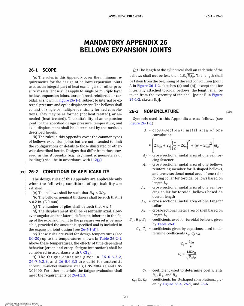
ð19Þ
ð19Þ
MANDATORY APPENDIX 26BELLOWS EXPANSION JOINTS
26-1 SCOPE
(a) The rules in this Appendix cover the minimum re-quirements for the design of bellows expansion jointsused as an integral part of heat exchangers or other pres-sure vessels. These rules apply to single or multiple layerbellows expansion joints, unreinforced, reinforced or tor-oidal, as shown in Figure 26-1-1, subject to internal or ex-ternal pressure and cyclic displacement. The bellows shallconsist of single or multiple identically formed convolu-tions. They may be as formed (not heat treated), or an-nealed (heat treated). The suitability of an expansionjoint for the specified design pressure, temperature, andaxial displacement shall be determined by the methodsdescribed herein.
(b) The rules in this Appendix cover the common typesof bellows expansion joints but are not intended to limitthe configurations or details to those illustrated or other-wise described herein. Designs that differ from those cov-ered in this Appendix (e.g., asymmetric geometries orloadings) shall be in accordance with U-2(g).
26-2 CONDITIONS OF APPLICABILITY
The design rules of this Appendix are applicable onlywhen the following conditions of applicability aresatisfied:
(a) The bellows shall be such that Nq ≤ 3Db.(b) The bellows nominal thickness shall be such that nt
≤ 0.2 in. (5.0 mm).(c) The number of plies shall be such that n ≤ 5.(d) The displacement shall be essentially axial. How-
ever angular and/or lateral deflection inherent in the fit‐up of the expansion joint to the pressure vessel is permis-sible, provided the amount is specified and is included inthe expansion joint design [see 26-4.1(d)].
(e) These rules are valid for design temperatures (seeUG-20) up to the temperatures shown in Table 26-2-1.Above these temperatures, the effects of time-dependentbehavior (creep and creep–fatigue interaction) shall beconsidered in accordance with U-2(g).
(f) The fat igue equations given in 26-6.6.3 .2 ,26-7.6.3.2, and 26-8.6.3.2 are valid for austeniticchromium‐nickel stainless steels, UNS N066XX and UNSN04400. For other materials, the fatigue evaluation shallmeet the requirements of 26-4.2.3.
(g) The length of the cylindrical shell on each side of the
bellows shall not be less than 1.8 . The length shall
be taken from the beginning of the end convolution [pointA in Figure 26-1-2, sketches (a) and (b)], except that forinternally attached toroidal bellows, the length shall betaken from the extremity of the shell [point B in Figure26-1-2, sketch (b)].
26-3 NOMENCLATURE
Symbols used in this Appendix are as follows (seeFigure 26-1-1):
A = cros s ‐ sec t i ona l me ta l a rea o f oneconvolution
=
Af = cross‐sectional metal area of one reinfor-cing fastener
Ar = cross‐sectional metal area of one bellowsreinforcing member for U-shaped bellows,and cross-sectional metal area of one rein-forcing collar for toroidal bellows based onlength Lr
Ar t = cross-sectional metal area of one reinfor-cing collar for toroidal bellows based onoverall length
Atc = cross-sectional metal area of one tangentcollar
Ats = cross-sectional metal area of shell based onlength Ls
B1 , B2 , B3 = coefficients used for toroidal bellows, givenby Table 26-8
C1 , C2 = coefficients given by equations, used to de-termine coefficients Cp, Cf, Cd
C3 = coefficient used to determine coefficientsB1 , B2 , and B3
Cp , Cf , Cd = coefficients for U‐shaped convolutions, giv-en by Figure 26-4, 26-5, and 26-6
ASME BPVC.VIII.1-2019 26-1 – 26-3
511
Copyright ASME International (BPVC) Provided by IHS under license with ASME Licensee=Khalda Petroleum/5986215001, User=Amer, Mohamed
Not for Resale, 07/02/2019 13:29:04 MDTNo reproduction or networking permitted without license from IHS
--`,``,``,,`,`,,````,`,``,,,`-`-`,,`,,`,`,,`---
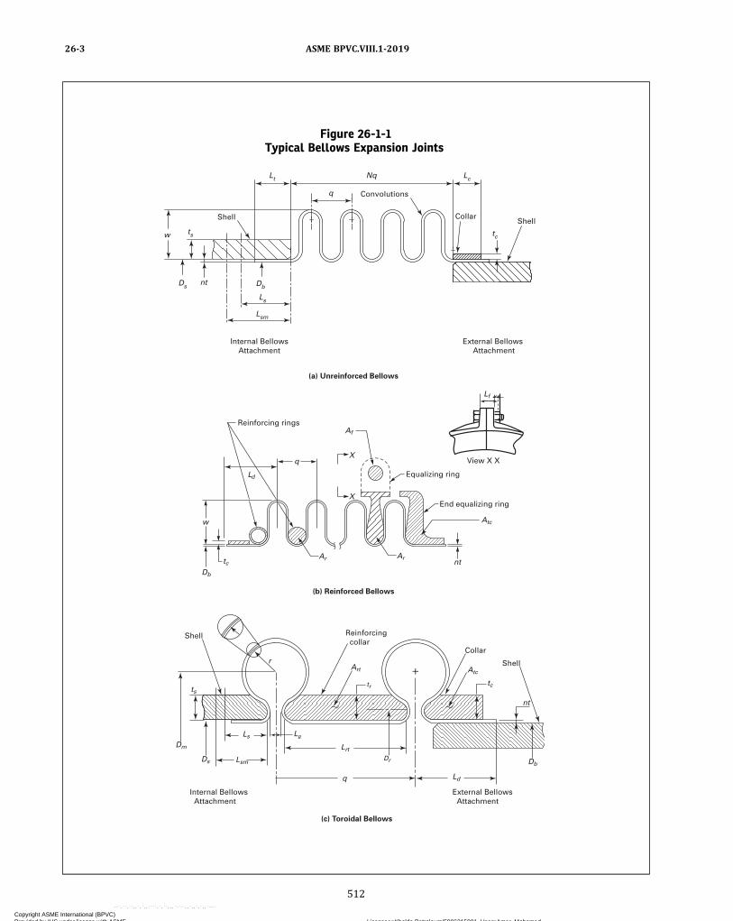
Figure 26-1-1Typical Bellows Expansion Joints
(a) Unreinforced Bellows
Reinforcing rings
Equalizing ring
End equalizing ring
View X X
(b) Reinforced Bellows
(c) Toroidal Bellows
qX
X
Db
tcAr
Af
Lf
w
Arnt
Reinforcing collar
Shell
Art
tr
r
Lsm
Ls
ts
Dm
Ds
Lg
Lrt
Dr
q
Atc
tc
Collar
Shell
nt
Db
Ld
External Bellows Attachment
Internal Bellows Attachment
Ld
Atc
Shell Shell
Internal BellowsAttachment
External Bellows Attachment
nt
w
q Convolutions
Collar
Lt Nq Lc
tc
Db
Ls
Lsm
ts
Ds
ASME BPVC.VIII.1-201926-3
512
Copyright ASME International (BPVC) Provided by IHS under license with ASME Licensee=Khalda Petroleum/5986215001, User=Amer, Mohamed
Not for Resale, 07/02/2019 13:29:04 MDTNo reproduction or networking permitted without license from IHS
--`,``,``,,`,`,,````,`,``,,,`-`-`,,`,,`,`,,`---

Cr = convolution height factor for reinforcedbellows
=
where
Kc = 0.6 if P is expressed in psi= 1,048 if P is expressed in MPa
Cwc = longitudinal weld joint efficiency of tangentcollar (see UW-12)
Cwr = longitudinal weld joint efficiency of reinfor-cing member (see UW-12)
Cws = longitudinal weld joint efficiency of shell(see UW-12)
Db = inside diameter of bellows convolution andend tangents
Dc = mean diameter of tangent collar
=
Figure 26-1-2Starting Points for the Measurement of the Length of Shell on Each Side of the Bellows
Collar
(a) U-Shaped Bellows
(b) Toroidal Bellows
Reinforcing collar
Shell
AB
Shell
A
AShell Shell
Internal BellowsAttachment
External Bellows Attachment
Internal BellowsAttachment
External Bellows Attachment
Table 26-2-1Maximum Design Temperatures for
Application of the Rules of MandatoryAppendix 26
Table in WhichMaterial Is Listed
MaximumTemperature
°F °C
UNF-23.1 300 150UNF-23.3 800 425UNF-23.4 600 315UNF-23.5 600 315UHA-23 800 425
ASME BPVC.VIII.1-2019 26-3
513
Copyright ASME International (BPVC) Provided by IHS under license with ASME Licensee=Khalda Petroleum/5986215001, User=Amer, Mohamed
Not for Resale, 07/02/2019 13:29:04 MDTNo reproduction or networking permitted without license from IHS
--`,``,``,,`,`,,````,`,``,,,`-`-`,,`,,`,`,,`---

Dm = mean diameter of bellows convolution= Db + w + nt for U‐shaped bellows
Dr = mean diameter of reinforcing collar for tor-oidal bellows
Ds = inside diameter of cylindrical shell or weldend on which the bellows is attached
Eb = modulus of elasticity of bellows material atdesign temperature
Ec = modulus of elasticity of collar material atdesign temperature
Ef = modulus of elasticity of reinforcing fastenermaterial at design temperature
Eo = modulus of elasticity of bellows material atroom temperature
Er = modulus of elasticity of reinforcing ringmember material at design temperature
Es = modulus of elasticity of shell or weld endmaterial at design temperature
Gb = modulus of rigidity of bellows material atdesign temperature
=
H = resultant total internal pressure force act-ing on the bellows and reinforcement
= PDmqk = factor considering the stiffening effect of
the attachment weld and the end convolu-tion on the pressure capacity of the endtangent
=
K0 , K1 ,K2 , K3 = coefficients determined by best curve fit of
bellows fatigue test dataK ′0 , K ′1 ,K ′2 , K ′3 = coefficients determined by best curve fit of
bellows fatigue test dataKb = bellows axial stiffnessKf = forming method factor
= 1.0 for expanding mandrel or roll forming= 0.6 for hydraulic, elastomeric, or pneumatic
tube formingLc = bellows collar lengthLd = length from attachment weld to the center
of the first convolution for externally at-tached bellows
Ldt = developed length of one convolution= A/ntp for U-shaped bellows
Lf = effective length of one reinforcing fastener.Distance between the mating face of thebolt head and mid-thickness of the nut ordistance between mid-thickness of thetwo nuts, as applicable
Lg = maximum distance across the inside open-ing of a toroidal convolution consideringall movements
Lr = effective reinforcing collar length
=
Lrt = overall length of reinforcing collarLs = effective shell length
=
Lsm = minimum required shell length havingthickness t s
L t = end tangent lengthM2 = torsional loadN = number of convolutionsn = number of plies
Na lw = allowable number of fatigue cyclesN spe = specified number of fatigue cycles
P = design pressure (see UG-21)
NOTE: If the MAWP of the bellows is significantlygreater than the required design pressure of thevessel, use of the larger MAWPmay adversely affectthe allowable number cycles that the bellows canexperience.
q = convolution pitch (see Figure 26-1-1)R = ratio of the internal pressure force resisted
by the bellows to the internal pressureforce resisted by the reinforcement. UseR1 or R2 as designated in the equations.
= R1 for integral reinforcing ring members
= R2 for reinforcing ring members joined byfasteners
r = mean r a d i u s o f t o r o i d a l b e l l ow sconvolution
r i = average internal torus radius of U-shapedbellows convolution (see 26-6.2)
rm = mean torus radius of U-shaped bellowsconvolution
= r i + (nt/2)S = allowable stress of bellows material at de-
sign temperatureS1 = circumferential membrane stress in bel-
lows tangent, due to pressure P= circumferential membrane stress in collar,
due to pressure P= circumferential membrane stress in shell,
due to pressure, P , for internally attachedbellows
ASME BPVC.VIII.1-201926-3
514
Copyright ASME International (BPVC) Provided by IHS under license with ASME Licensee=Khalda Petroleum/5986215001, User=Amer, Mohamed
Not for Resale, 07/02/2019 13:29:04 MDTNo reproduction or networking permitted without license from IHS
--`,``,``,,`,`,,````,`,``,,,`-`-`,,`,,`,`,,`---
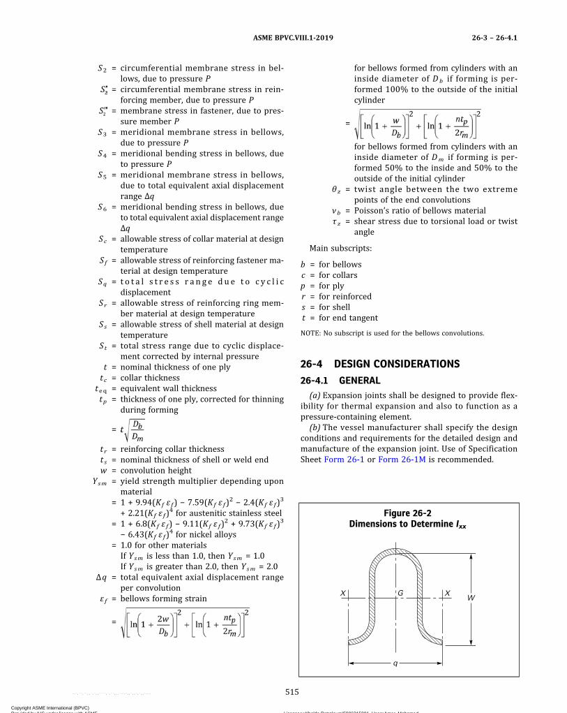
S2 = circumferential membrane stress in bel-lows, due to pressure P
= circumferential membrane stress in rein-forcing member, due to pressure P
= membrane stress in fastener, due to pres-sure member P
S3 = meridional membrane stress in bellows,due to pressure P
S4 = meridional bending stress in bellows, dueto pressure P
S5 = meridional membrane stress in bellows,due to total equivalent axial displacementrange Δq
S6 = meridional bending stress in bellows, dueto total equivalent axial displacement rangeΔq
Sc = allowable stress of collar material at designtemperature
Sf = allowable stress of reinforcing fastener ma-terial at design temperature
Sq = t o t a l s t r e s s r a n g e d u e t o c y c l i cdisplacement
Sr = allowable stress of reinforcing ring mem-ber material at design temperature
Ss = allowable stress of shell material at designtemperature
St = total stress range due to cyclic displace-ment corrected by internal pressure
t = nominal thickness of one plytc = collar thickness
teq = equivalent wall thicknesstp = thickness of one ply, corrected for thinning
during forming
=
tr = reinforcing collar thicknesst s = nominal thickness of shell or weld endw = convolution height
Ysm = yield strength multiplier depending uponmaterial
= 1 + 9.94(Kf ɛ f) − 7.59(Kf ɛ f)2 − 2.4(Kf ɛ f)
3
+ 2.21(Kf ɛ f)4 for austenitic stainless steel
= 1 + 6.8(Kf ɛ f) − 9.11(Kf ɛ f)2 + 9.73(Kf ɛ f)
3
− 6.43(Kf ɛ f)4 for nickel alloys
= 1.0 for other materialsIf Ysm is less than 1.0, then Ysm = 1.0If Ysm is greater than 2.0, then Ysm = 2.0
Δq = total equivalent axial displacement rangeper convolution
ε f = bellows forming strain
=
for bellows formed from cylinders with aninside diameter of Db if forming is per-formed 100% to the outside of the initialcylinder
=
for bellows formed from cylinders with aninside diameter of Dm if forming is per-formed 50% to the inside and 50% to theoutside of the initial cylinder
θ z = twist angle between the two extremepoints of the end convolutions
νb = Poisson’s ratio of bellows materialτ z = shear stress due to torsional load or twist
angle
Main subscripts:
b = for bellowsc = for collarsp = for plyr = for reinforceds = for shellt = for end tangent
NOTE: No subscript is used for the bellows convolutions.
26-4 DESIGN CONSIDERATIONS
26-4.1 GENERAL(a) Expansion joints shall be designed to provide flex-
ibility for thermal expansion and also to function as apressure-containing element.
(b) The vessel manufacturer shall specify the designconditions and requirements for the detailed design andmanufacture of the expansion joint. Use of SpecificationSheet Form 26-1 or Form 26-1M is recommended.
Figure 26-2Dimensions to Determine Ixx
q
WXX G
ASME BPVC.VIII.1-2019 26-3 – 26-4.1
515
Copyright ASME International (BPVC) Provided by IHS under license with ASME Licensee=Khalda Petroleum/5986215001, User=Amer, Mohamed
Not for Resale, 07/02/2019 13:29:04 MDTNo reproduction or networking permitted without license from IHS
--`,``,``,,`,`,,````,`,``,,,`-`-`,,`,,`,`,,`---

ð19Þ
(c) In all vessels with integral expansion joints, the hy-drostatic end force caused by pressure and/or the jointspring force shall be resisted by adequate restraint ele-ments (e.g., exchanger tubes or shell, external restraints,anchors, etc.). The stress [see UG-23(c)] in these restrain-ing elements shall not exceed the maximum allowablestress at the design temperature for the material givenin the tables referenced by UG-23.(d) See below.
(1) The expansion joints shall be provided with barsor other suitable members for maintaining the properoverall length dimension during shipment and vessel fab-rication. During a heat exchanger pressure test, these barsor members shall not carry load or limit expansion jointmovement.
(2) Expansion bellows shall not be extended, com-pressed, rotated, or laterally offset to accommodate con-necting parts that are not properly aligned, unless thedesign considers such movements. See 26-9.
(3) Care should be taken to ensure that any torsionalloads applied to expansion joints are kept to a minimumto prevent high shear stresses that may be detrimentalto their use. If torsional loads are present or expected,they shall be considered in the design. See 26-4.3.(e) The minimum thickness limitations of UG-16(b) do
not apply to bellows designed to this Appendix.(f) Bellows longitudinal weld seams shall have a joint
efficiency of 1.0.(g) Bellows circumferential attachment welds, shells or
shell weld ends, and collars shall be in accordance withFigure 26-13, as applicable.(h) The elastic moduli, yield strength, and allowable
stresses shall be taken at the design temperatures. How-ever, when performing the fatigue evaluation in accor-dance with 26-6.6 (unreinforced bellows), 26-7.6(reinforced bellows), and 26-8.6 (toroidal bellows), it ispermitted to use the operating metal temperature insteadof the design temperature.
26-4.2 FATIGUE26-4.2.1 Cumulative Damage. If there are two or
more types of stress cycles that produce significantstresses, their cumulative effect shall be evaluated as giv-en below.(a) Procedure
(1) Designate the specified number of times eachtype of stress cycle of Types 1, 2, 3, etc., of stress rangeSt1 , St2 , St3 , etc., will be repeated during the life of theexpansion joint as n1 , n2, n3 , etc., respectively.
(2) For each value St1 , St 2 , St 3 , etc., use the applic-able design fatigue curve to determine the maximumnumber of repetitions which would be allowable if thistype of cycle were the only one acting. Call these valuesN1 , N2 , N3 , etc.
(3) For each type of stress cycle, calculate the usagefactors U1 , U2 , U3 , etc., from
U1 = n1 / N1
U2 = n2 / N2
U3 = n3 / N3, etc.
(4) Calculate the cumulative usage factor U from:
U = U1 + U2 + U3 + ...
(5) The cumulative usage factor U shall not exceed1.0.(b) Cycle Counting. Stresses to be used for cycle count-
ing shall be based on the total equivalent axial displace-ment of each convolution, Δqe or Δq c , at the top andbottom of each cycle, as determined in 26-9.5, not therange, Δq , determined in 26-9.6. Only the displacementsshall be taken into account; pressure shall be neglected.The total equivalent axial displacement range, Δq , to beused for the calculation of the total stress range due to cy-clic displacement, St , in the fatigue evaluation in 26-6.6,26-7.6, or 26-8.6 shall be deduced from the stress range,Sq , obtained.
(1) Concurrent Conditions. When determining n1 , n2 ,n3 , etc., and Sq1 , Sq2 , Sq3 , etc., consideration shall be giv-en to the superposition of cycles of various origins thatproduces a total stress range greater than the stressranges of the individual cycles. For example, if one typeof stress cycle produces 1,000 cycles of a stress variationfrom −1,000 psi to +60,000 psi and another type of stresscycle produces 10,000 cycles of a stress variation from−1,000 psi to −50,000 psi, the two types of cycles to beconsidered are defined by the following parameters:
(-a) Type 1 Cycle
n1 = 1,000Sq1 = |60,000| − (−1,000)| + |−50,000 − (−1,000)|
= 110,000 psi
(-b) Type 2 Cycle
n2 = 10,000 − 1,000 = 9,000Sq2 = |0| + |−50,000 − (−1,000)| = 49,000 psi
(2) Independent Conditions. When no superpositionof cycles can occur, cycle counting shall be simply basedon the stress ranges of the individual cycles. For example,if one type of stress cycle produces 1,000 cycles of a stressvariation from −1,000 psi to +60,000 psi and another typeof stress cycle produces 10,000 cycles of a stress variationfrom −1,000 psi to −50,000 psi, the two types of cycles tobe considered are defined by the following parameters:
(-a) Type 1 Cycle
n1 = 1,000Sq1 = |60,000| − (−1,000)| = 61,000 psi
(-b) Type 2 Cycle
n2 = 10,000Sq2 = |−50,000 − (−1,000)| = 49,000 psi
ASME BPVC.VIII.1-201926-4.1 – 26-4.2.1
516
Copyright ASME International (BPVC) Provided by IHS under license with ASME Licensee=Khalda Petroleum/5986215001, User=Amer, Mohamed
Not for Resale, 07/02/2019 13:29:04 MDTNo reproduction or networking permitted without license from IHS
--`,``,``,,`,`,,````,`,``,,,`-`-`,,`,,`,`,,`---
(3) Alternatively, when the cyclic displacement his-tory is known, cycle counting may be performed by theRainflow Method described in Section VIII, Division 2, An-nex 5-B, or an equivalent method.
(4) If only the overall number of cycles of each rangeis known, or in case of doubt, cycle counting shall be per-formed considering concurrent conditions.
26-4.2.2 Fatigue Correlation Testing. Fatigue curvesin 26-6.6.3.2, 26-7.6.3.2, or 26-8.6.3.2 may be used to de-sign a bellows only if they have been correlated with ac-tual bellows test results obtained by proof or strain gagetesting (see UG-101) by the bellows Manufacturer to de-monstrate predictability of cyclic life on a consistent ser-ies of bellows of the same basic design (convolutionshape, reinforcement, number of plies, etc.) and formingprocess. Annealed and as-formed bellows are consideredas separate designs.
(a) The substantiation of the fatigue curves shall bebased on data obtained from five separate tests on bel-lows of the same basic design. When substantiating bel-lows designs with more than two convolutions in series,the test data shall have been obtained from bellows witha minimum of three convolutions. The effect of pressureshall be considered in the fatigue tests.
For each test data pair (St , N), two results shall be com-puted and compared to the applicable fatigue curve: oneresult with the number of cycles divided by a design fac-tor of 2.6 (St , N/2.6) and the other result with the equiva-lent stress divided by a design factor of 1.25 (St/1.25, N).For a result to be accepted, it must be above the applic-able fatigue curve.
If all the results meet the acceptance criterion, the sub-stantiation shall be considered valid. If any result does notmeet the acceptance criterion, a retest of five additionalbellows shall be made. If all the results of the retest, in-cluding design factors, meet the acceptance criterion,the substantiation shall be considered valid. Otherwise aspecific fatigue curve shall be established as describedin 26-4.2.3 and used for the fatigue design of the bellows.The original test and retest results shall be taken into ac-count to establish the specific fatigue curve.
(b)When St and the other appropriate factors are usedin the cycle life equations in 26-6.6.3.2, 26-7.6.3.2, or26-8.6.3.2, the specified number of fatigue cycles, N spe ,shall be less than the calculated cycles to failure basedon the data obtained by testing. The allowable numberof fatigue cycles, Na lw , may not be increased above thatobtained from the equations in these paragraphs regard-less of the test results.
(c) The test results shall be available for review by theInspector.
(d) The substantiation of the fatigue curve used by thebellows Manufacturer for a bellows design that hasshown a history of safe use can be waived provided themanufacturing process remains unchanged.
26-4.2.3 Fatigue Curves for Other Materials. Formaterials other than those specified in the applicablerules, 26-6.6.3.2, 26-7.6.3.2, or 26-8.6.3.2, specific fatiguecurves shall be built. The Manufacturer shall determinethe fatigue curve for the material intended for the bel-lows. This fatigue curve shall not be used for tempera-tures above the temperature shown in Table 26-2-1 forthe tested material. Annealed and as-formed bellows shallbe considered as being built with different materials. Dif-ferent forming methods may have either individualcurves established for each method or a single curve es-tablished by incorporating test results obtained from atleast two bellows formed by each different anticipatedforming method.
The procedure applied to determine the fatigue curveshall be as described below. The test results with the sub-sequent calculations used to determine the fatigue curveshall be available for review by the Inspector.
(a) A minimum of 25 fatigue tests shall be carried out.Each bellows in the test group shall have a minimum ofthree convolutions and varying geometries, including in-side diameter, convolution profile, and thickness. A mini-mum of three different heats of the intended materialshall be used.
(b) Each bellows in the test group shall be submitted tothree to five different amplitudes of axial movements witha constant internal pressure applied. To ensure that theequivalent fatigue stress, St , is due primarily to cyclic dis-placement and not to pressure, the pressure-inducedcomponent stress shall not be higher than 30% of theequivalent fatigue stress.
(c) The test results shall be obtained by proof or straingage testing (see UG-101) at room temperature.
(d) The fatigue curves shall be determined as follows:(1) The best fit curve for the relation between the
number of measured cycles to failure and the equivalentfatigue stress, S t , calculated according to 26-6.6.3.2,26-7.6.3.2, or 26-8.6.3.2, as applicable, shall be deter-mined and expressed as
(2) The curve shall then be adjusted such that all thetest results are on or above the curve. The curve is nowexpressed as
(3) The final fatigue curve shall be the lower boundcurve of the curve obtained by applying a factor of 2.6on numbers of cycles, expressed as
ASME BPVC.VIII.1-2019 26-4.2.1 – 26-4.2.3
517
Copyright ASME International (BPVC) Provided by IHS under license with ASME Licensee=Khalda Petroleum/5986215001, User=Amer, Mohamed
Not for Resale, 07/02/2019 13:29:04 MDTNo reproduction or networking permitted without license from IHS
--`,``,``,,`,`,,````,`,``,,,`-`-`,,`,,`,`,,`---
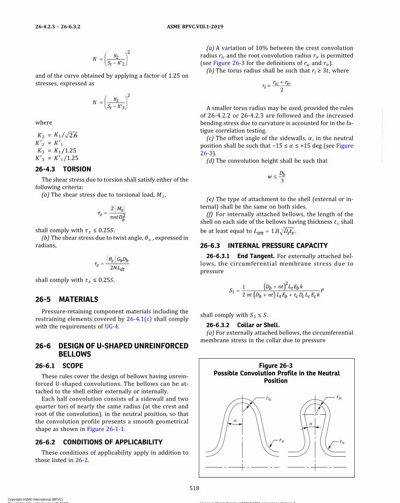
and of the curve obtained by applying a factor of 1.25 onstresses, expressed as
where
K2 = K1/K ′2 = K ′1K3 = K1/1.25K ′3 = K ′1/1.25
26-4.3 TORSIONThe shear stress due to torsion shall satisfy either of the
following criteria:(a) The shear stress due to torsional load, Mz ,
shall comply with τz ≤ 0.25S .(b) The shear stress due to twist angle, θ z , expressed in
radians,
shall comply with τz ≤ 0.25S .
26-5 MATERIALS
Pressure‐retaining component materials including therestraining elements covered by 26-4.1(c) shall complywith the requirements of UG-4.
26-6 DESIGN OF U-SHAPED UNREINFORCEDBELLOWS
26-6.1 SCOPEThese rules cover the design of bellows having unrein-
forced U‐shaped convolutions. The bellows can be at-tached to the shell either externally or internally.Each half convolution consists of a sidewall and two
quarter tori of nearly the same radius (at the crest androot of the convolution), in the neutral position, so thatthe convolution profile presents a smooth geometricalshape as shown in Figure 26-1-1.
26-6.2 CONDITIONS OF APPLICABILITYThese conditions of applicability apply in addition to
those listed in 26-2.
(a) A variation of 10% between the crest convolutionradius ric and the root convolution radius rir is permitted(see Figure 26-3 for the definitions of ric and rir).(b) The torus radius shall be such that ri ≥ 3t , where
A smaller torus radius may be used, provided the rulesof 26-4.2.2 or 26-4.2.3 are followed and the increasedbending stress due to curvature is accounted for in the fa-tigue correlation testing.(c) The offset angle of the sidewalls, α , in the neutral
position shall be such that −15 ≤ α ≤ +15 deg (see Figure26-3).(d) The convolution height shall be such that
(e) The type of attachment to the shell (external or in-ternal) shall be the same on both sides.(f) For internally attached bellows, the length of the
shell on each side of the bellows having thickness t s shall
be at least equal to .
26-6.3 INTERNAL PRESSURE CAPACITY26-6.3.1 End Tangent. For externally attached bel-
lows, the circumferential membrane stress due topressure
shall comply with S1 ≤ S .
26-6.3.2 Collar or Shell.(a) For externally attached bellows, the circumferential
membrane stress in the collar due to pressure
Figure 26-3Possible Convolution Profile in the Neutral
Position
r icr ic
r irr ir
ASME BPVC.VIII.1-201926-4.2.3 – 26-6.3.2
518
Copyright ASME International (BPVC) Provided by IHS under license with ASME Licensee=Khalda Petroleum/5986215001, User=Amer, Mohamed
Not for Resale, 07/02/2019 13:29:04 MDTNo reproduction or networking permitted without license from IHS
--`,``,``,,`,`,,````,`,``,,,`-`-`,,`,,`,`,,`---

Figure 26-4Coefficient Cp
Cp
C1
C2
0
0.1
0.2
0.3
0.4
0.5
0.6
0.7
0.8
0.9
1
0 0.1 0.2 0.3 0.4 0.5 0.6 0.7 0.8 0.9 1
4.03.5
3.0
2.0
1.6
1.4
1.2
0.60.40.2
0.81.0
2.5
GENERAL NOTE: Paragraph 26-15 gives polynomial approximations for these curves when 0.2 ≤ C2 ≤ 4.0.
ASME BPVC.VIII.1-2019 26-6.3.2
519
Copyright ASME International (BPVC) Provided by IHS under license with ASME Licensee=Khalda Petroleum/5986215001, User=Amer, Mohamed
Not for Resale, 07/02/2019 13:29:04 MDTNo reproduction or networking permitted without license from IHS
--`,``,``,,`,`,,````,`,``,,,`-`-`,,`,,`,`,,`---

Figure 26-5Coefficient Cf
Cf
C1
C2
0.05
3
0 0.1 0.2 0.3 0.4 0.5 0.6 0.7 0.8 0.9 1
4
2
1.5
1.00.9
0.8
0.7
0.6
0.5
0.4
0.3
0.2
0.15
0.100.09
0.08
0.07
0.06
3.5
3.0
2.0
1.6
1.4
1.2
1.0
0.8
0.4
0.2
0.6
2.5
GENERAL NOTE: Paragraph 26-15 gives polynomial approximations for these curves when 0.2 ≤ C2 ≤ 4.0.
ASME BPVC.VIII.1-201926-6.3.2
520
Copyright ASME International (BPVC) Provided by IHS under license with ASME Licensee=Khalda Petroleum/5986215001, User=Amer, Mohamed
Not for Resale, 07/02/2019 13:29:04 MDTNo reproduction or networking permitted without license from IHS
--`,``,``,,`,`,,````,`,``,,,`-`-`,,`,,`,`,,`---
shall comply with S ′1 ≤ Cwc Sc .(b) For internally attached bellows, the circumferential
membrane stress in the shell due to pressure
shall comply with ≤ CwsSs .
26-6.3.3 Bellows Convolutions.(a) The circumferential membrane stress due to
pressure(1) for end convolutions of externally attached bel-
lows when k is less than 1.0
shall comply with S2,E ≤ S;(2) for intermediate convolutions
shall comply with S2,I ≤ S.(b) The meridional membrane stress due to pressure is
given by
(c) The meridional bending stress due to pressure isgiven by
(d) The meridional membrane and bending stressesshall comply with
where
Km = 1.5Ysm for as‐formed bellows= 1.5 for annealed bellows
26-6.4 INSTABILITY DUE TO INTERNALPRESSURE
26-6.4.1 Column Instability. The allowable internaldesign pressure to avoid column instability is given by:
The internal pressure shall not exceed Psc: P ≤ Psc.
26-6.4.2 In-Plane Instability. The allowable internaldesign pressure based on in‐plane instability is given by
where
α =
δ =
and is the effective yield strength at design tempera-
ture (unless otherwise specified) of bellows material inthe as‐formed or annealed conditions.
In the absence of values for in material standards,
the following values shall be used:
= 2.3Sy for as‐formed bellows
= 0.75Sy for annealed bellows
where Sy is the yield strength of bellows material at de-sign temperature, given by Section II, Part D, Subpart 1,Table Y-1. For values not listed in Table Y-1, seeUG-28(c)(2), Step 3.
Higher values of may be used if justified by repre-
sentative tests.The internal pressure shall not exceed Psi: P ≤ Psi.
26-6.5 EXTERNAL PRESSURE STRENGTH26-6.5.1 External Pressure Capacity. The rules of
26-6.3 shall be applied taking P as the absolute value ofthe external pressure.
NOTE: When the expansion bellows is submitted to vacuum, the de-sign shall be performed assuming that only the internal ply resiststhe pressure. The pressure stress equations of 26-6.3 shall be ap-plied with n = 1.
26-6.5.2 Instability Due to External Pressure. Thisdesign shall be performed according to the rules ofUG-28 by replacing the bellows with an equivalent cylin-der, using:
(a) an equivalent outside diameter Deq given by
ASME BPVC.VIII.1-2019 26-6.3.2 – 26-6.5.2
521
Copyright ASME International (BPVC) Provided by IHS under license with ASME Licensee=Khalda Petroleum/5986215001, User=Amer, Mohamed
Not for Resale, 07/02/2019 13:29:04 MDTNo reproduction or networking permitted without license from IHS
--`,``,``,,`,`,,````,`,``,,,`-`-`,,`,,`,`,,`---
ð19Þ
ð19Þ
(b) an equivalent thickness teq given by
where Ixx is the moment of inertia of one convolutioncross section relative to the axis passing by the centerof gravity and parallel to the axis of the bellows (seeFigure 26-2).
NOTE: If Lt = 0, then Ixx is given by
26-6.6 FATIGUE EVALUATION26-6.6.1 Calculation of Stresses Due to the Total
Equivalent Axial Displacement Range Δq of Each Con-volution.(a)Meridional membrane stress:
(b)Meridional bending stress:
26-6.6.2 Calculation of Total Stress Range Due toCyclic Displacement.
26-6.6.3 Calculation of Allowable Number of Cy-cles.
26-6.6.3.1 General.(a) The specified number of cycles Nspe shall be stated
as consideration of the anticipated number of cycles ex-pected to occur during the operating life of the bellows.The allowable number of cycles N a lw , as derived in thissubclause, shall be at least equal to N spe : Na lw ≥ N spe .The allowable number of cycles given by the following
formulas includes a reasonable safety factor (2.6 on cyclesand 1.25 on stresses) and represents the maximum num-ber of cycles for the operating condition considered.Therefore, an additional safety factor should not be
applied. An overly conservative estimate of cycles can ne-cessitate a greater number of convolutions and result in abellows more prone to instability.(b) If the bellows is subjected to different cycles of
pressure or displacement, such as those produced bystartup or shutdown, their cumulative damage shall beconsidered as in 26-4.2.1.
26-6.6.3.2 Fatigue Equation. The following equa-tions are valid for(a) austenitic chromium‐nickel stainless steels, UNS
N066XX and UNS N04400 for metal temperatures not ex-ceeding 800°F (425°C). For other materials, the allowablenumber of cycles, Na lw , shall be calculated using the fol-lowing equations, replacing the constants with those ofcurves determined according to 26-4.2.3.(b) U‐shaped unreinforced bellows, as‐formed or
annealed.(c) basic designs and manufacturing processes that
have successfully undergone fatigue correlation testingper 26-4.2.2.The allowable number of cycles, Na lw , is given by the
following:
If St is expressed in psi, Ko = 5.2 × 10⁶ and So = 38,300.If St is expressed in MPa, Ko = 35 850 and So = 264.
If St is expressed in psi, Ko = 6.7 × 10⁶ and So = 30,600.If St is expressed in MPa, Ko = 46 200 and So = 211.
If ≤ 37,300 psi (257.2 MPa), then N a lw = 106
cycles.In the above formulas,
Kg = fatigue strength reduction factor that accounts forgeometrical stress concentration factors due tothickness variations, weld geometries, surfacenotches, and other surface or environmental condi-tions. The range Kg is 1.0 ≤ Kg ≤ 4.0 with its mini-mum value for smooth geometrical shapes and itsmaximum for 90 deg welded corners and filletwelds. Fatigue strength reduction factors may be
ASME BPVC.VIII.1-201926-6.5.2 – 26-6.6.3.2
522
Copyright ASME International (BPVC) Provided by IHS under license with ASME Licensee=Khalda Petroleum/5986215001, User=Amer, Mohamed
Not for Resale, 07/02/2019 13:29:04 MDTNo reproduction or networking permitted without license from IHS
--`,``,``,,`,`,,````,`,``,,,`-`-`,,`,,`,`,,`---
determined from theoretical, experimental, orphotoelastic studies. A factor has already been in-cluded in the above equations for N to accountfor normal effects of size, environment, and surfacefinish. For expansion bellows without circumferen-tial welds and meeting all the design and examina-tion requirements of this Appendix, a Kg of 1.0 maybe used.
26-6.7 AXIAL STIFFNESSThe theoretical axial stiffness of a bellows comprising N
convolutions may be evaluated by the following formula:
This formula is valid only in the elastic range.
NOTE: Outside of the elastic range, lower values can be used, basedupon manufacturer’s experience or representative test results.
26-7 DESIGN OF U-SHAPED REINFORCEDBELLOWS
26-7.1 SCOPEThese rules cover the design of bellows having
U‐shaped convolutions with rings to reinforce the bellowsagainst internal pressure. The bellows shall be attached tothe shell externally.
Each half convolution consists of a sidewall and twoquarter tori of the same radius (at the crest and root ofthe convolution), in the neutral position, so that the con-volution profile presents a smooth geometrical shape asshown in Figure 26-1-1.
26-7.2 CONDITIONS OF APPLICABILITYThe following conditions of applicability apply in addi-
tion to those listed in 26-2.(a) A variation of 10% between the crest convolution
radius ric and the root convolution radius rir is permitted(see Figure 26-3 for definitions of ric and rir).
(b) The torus radius shall be such that ri ≥ 3t , where
A smaller torus radius may be used, provided that therules of 26-4.2.2 or 26-4.2.3 are followed and the in-creased bending stress due to curvature is accountedfor in the fatigue correlation testing.
(c) The offset angle of the sidewalls, α , in the neutralposition shall be such that −15 ≤ α ≤ +15 deg (see Figure26-3).
(d) The convolution height shall be such that:
26-7.3 INTERNAL PRESSURE CAPACITY26-7.3.1 End Tangent. The circumferential mem-
brane stress due to pressure
shall comply with S1 ≤ S .
26-7.3.2 Collar. The circumferential membranestress due to pressure
shall comply with ≤ Cwc Sc.
26-7.3.3 Bellows Convolutions.(a) The circumferential membrane stress due to
pressure
where
R = R1 for integral reinforcing ring members= R2 for reinforcing fasteners
shall comply with S2 ≤ S .
NOTE: In the case of reinforcing members that are made in sectionsand joined by fasteners in tension, this equation assumes that thestructure used to retain the fastener does not bend so as to permitthe reinforcing member to expand diametrically. In addition, theend reinforcing members must be restrained against the longitudinalannular pressure load of the bellows.
(b) The meridional membrane stress due to pressure isgiven by
(c) The meridional bending stress due to pressure isgiven by
ASME BPVC.VIII.1-2019 26-6.6.3.2 – 26-7.3.3
523
Copyright ASME International (BPVC) Provided by IHS under license with ASME Licensee=Khalda Petroleum/5986215001, User=Amer, Mohamed
Not for Resale, 07/02/2019 13:29:04 MDTNo reproduction or networking permitted without license from IHS
--`,``,``,,`,`,,````,`,``,,,`-`-`,,`,,`,`,,`---

Figure 26-6Coefficient Cd
Cd
C1
C2
0.4
3.0
2.8
0 0.1 0.2 0.3 0.4 0.5 0.6 0.7 0.8 0.9 1
4
2.6
2.4
2.2
2.01.9
1.8
1.7
1.6
1.5
1.4
1.3
1.2
1.1
1.0
0.9
0.8
0.7
0.6
0.5 3.5
3.0
2.5
2.0
1.21.01.4
1.6
0.40.60.8
0.2
GENERAL NOTE: Paragraph 26-15 gives polynomial approximations for these curves when 0.2 ≤ C2 ≤ 4.0.
ASME BPVC.VIII.1-201926-7.3.3
524
Copyright ASME International (BPVC) Provided by IHS under license with ASME Licensee=Khalda Petroleum/5986215001, User=Amer, Mohamed
Not for Resale, 07/02/2019 13:29:04 MDTNo reproduction or networking permitted without license from IHS
--`,``,``,,`,`,,````,`,``,,,`-`-`,,`,,`,`,,`---
ð19Þ
ð19Þ
(d) The meridional membrane and bending stressesshall comply with
where
Km = 1.5Ysm for as‐formed bellows= 1.5 for annealed bellows
26-7.3.4 Reinforcing Ring Member. The circumfer-ential membrane stress due to pressure
shall comply with ≤ Cwr Sr.
NOTE: In the case of equalizing rings, this equation provides only thesimple membrane stress and does not include the bending stresscaused by the eccentric fastener location. Elastic analysis and/or ac-tual tests can determine these stresses.
26-7.3.5 Reinforcing Fastener. Themembrane stressdue to pressure
shall comply with ≤ Sf.
26-7.4 INSTABILITY DUE TO INTERNALPRESSURE
26-7.4.1 Column Instability. The allowable internaldesign pressure to avoid column instability is given by
The internal pressure shall not exceed Psc : P ≤ Psc .
26-7.4.2 In-Plane Instability. Reinforced bellows arenot prone to in‐plane instability.
26-7.5 EXTERNAL PRESSURE STRENGTH26-7.5.1 External Pressure Capacity. The rules of
26-6.3 relative to unreinforced bellows shall be appliedtaking P as the absolute value of the external pressure.
NOTE: When the expansion bellows is exposed to vacuum, the anal-ysis shall be performed assuming that only the internal ply resiststhe pressure. The pressure stress equations of 26-6.3 shall be ap-plied with n = 1.
26-7.5.2 Instability Due to External Pressure. Thecircumferential instability of a reinforced bellows shallbe calculated in the same manner as for unreinforced bel-lows. See 26-6.5.2.
26-7.6 FATIGUE EVALUATION26-7.6.1 Calculation of Stresses Due to the Total
Equivalent Axial Displacement Range of Δq of EachConvolution.
(a)Meridional membrane stress:
(b)Meridional bending stress:
26-7.6.2 Calculation of Total Stress Range.
26-7.6.3 Calculation of Allowable Number of Cy-cles.
26-7.6.3.1 General.(a) The specified number of cycles N spe shall be stated
as consideration of the anticipated number of cycles ex-pected to occur during the operating life of the bellows.The allowable number of cycles, Na lw , as derived in thissubclause, shall be at least equal to N spe : Na lw ≥ N spe .
The allowable number of cycles given by the followingformulas includes a reasonable safety factor (2.6 on cyclesand 1.25 on stresses) and represents the maximum num-ber of cycles for the operating condition considered.Therefore, an additional safety factor should not be ap-plied. An overly conservative estimate of cycles can neces-sitate a greater number of convolutions and result in abellows more prone to instability.
(b) If the bellows is submitted to different cycles ofpressure or displacement, such as those produced bystartup or shutdown, their cumulative damage shall beconsidered as in 26-4.2.1.
26-7.6.3.2 Fatigue Equation. The following equa-tions are valid for
(a) austenitic chromium‐nickel stainless steels, UNSN066XX and UNS N04400, for metal temperatures not ex-ceeding 800°F (425°C). For other materials, the allowablenumber of cycles, Na lw , shall be calculated using the fol-lowing equations, replacing the constants with those ofcurves determined according to 26-4.2.3.
(b) U‐shaped reinforced bellows, as‐ formed orannealed.
(c) basic designs and manufacturing processes thathave successfully undergone fatigue correlation testingper 26-4.2.2.
ASME BPVC.VIII.1-2019 26-7.3.3 – 26-7.6.3.2
525
Copyright ASME International (BPVC) Provided by IHS under license with ASME Licensee=Khalda Petroleum/5986215001, User=Amer, Mohamed
Not for Resale, 07/02/2019 13:29:04 MDTNo reproduction or networking permitted without license from IHS
--`,``,``,,`,`,,````,`,``,,,`-`-`,,`,,`,`,,`---

The allowable number of cycles, Na lw , is given by thefollowing:
If St is expressed in psi, Ko = 6.6 × 10⁶ and So = 48,500.If St is expressed in MPa, Ko = 45 505 and So = 334.
If St is expressed in psi, Ko = 8.5 × 10⁶ and So = 38,800.If St is expressed in MPa, Ko = 58 605.4 and So = 267.5.
If ≤47,300 psi (326.1 MPa), then N a lw = 106
cycles.In the above equations,
Kg = fatigue strength reduction factor that accounts forgeometrical stress concentration factors due tothickness variations, weld geometries, surfacenotches, and other surface or environmental condi-tions. The range Kg is 1.0 ≤ Kg ≤ 4.0 with its mini-mum value for smooth geometrical shapes and itsmaximum for 90 deg welded corners and filletwelds. Fatigue strength reduction factors may bedetermined from theoretical, experimental, orphotoelastic studies. A factor has already been in-cluded in the above equations for N to accountfor normal effects of size, environment, and surfacefinish. For expansion bellows without circumferen-tial welds and meeting all the design and examina-tion requirements of this Appendix, a Kg of 1.0 maybe used.
26-7.7 AXIAL STIFFNESSThe theoretical axial stiffness of a bellows comprising N
convolutions may be evaluated by the following formula:
This formula is valid only in the elastic range.
NOTE: Outside of the elastic range lower values can be used, basedupon manufacturer’s experience or representative test results.
26-8 DESIGN OF TOROIDAL BELLOWS
26-8.1 SCOPEThese rules cover the design of bellows having toroidal
convolutions. The bellows can be attached to the shelleither externally or internally. Each convolution consistsof a torus of radius r as shown in Figure 26-1-1.
26-8.2 CONDITIONS OF APPLICABILITYThe following conditions of applicability apply in addi-
tion to those listed in 26-2:(a) The type of attachment to the shell (external or in-
ternal) shall be the same on both sides.(b) Distance Lg shall be less than 0.75r in the maximum
extended position.(c) For internally attached bellows, the length of the
shell on each side of the bellows having thickness t s shall
be at least equal to Lsm = 1.8 .
26-8.3 INTERNAL PRESSURE CAPACITY26-8.3.1 End Tangent. For externally attached bel-
lows, the circumferential membrane stress due topressure
shall comply with S1 ≤ S .
26-8.3.2 Tangent Collar or Shell.(a) For externally attached bellows, the circumferential
membrane stress in the collar due to pressure
shall comply with ≤ Cwc Sc.(b) For internally attached bellows, the circumferential
membrane stress in the shell due to pressure
shall comply with .
26-8.3.3 Bellows Convolutions.(a) The circumferential membrane stress due to
pressure
shall comply with S2 ≤ S .(b) The meridional membrane stress due to pressure
ASME BPVC.VIII.1-201926-7.6.3.2 – 26-8.3.3
526
Copyright ASME International (BPVC) Provided by IHS under license with ASME Licensee=Khalda Petroleum/5986215001, User=Amer, Mohamed
Not for Resale, 07/02/2019 13:29:04 MDTNo reproduction or networking permitted without license from IHS
--`,``,``,,`,`,,````,`,``,,,`-`-`,,`,,`,`,,`---
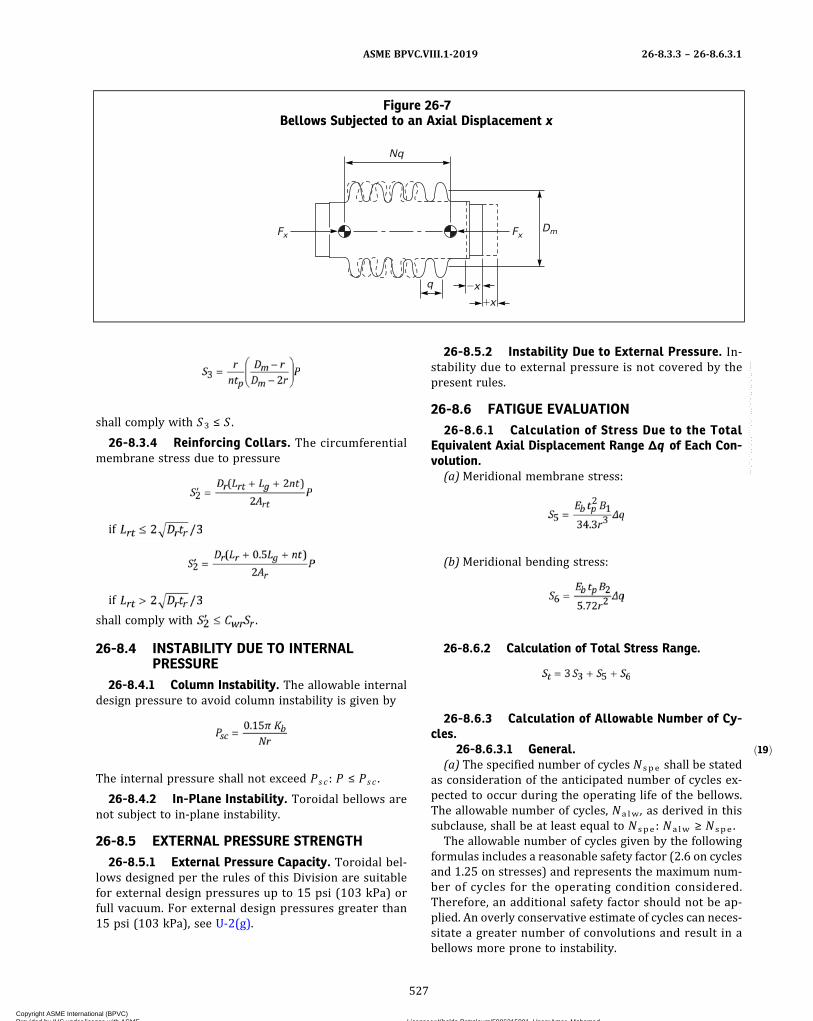
ð19Þ
shall comply with S3 ≤ S .
26-8.3.4 Reinforcing Collars. The circumferentialmembrane stress due to pressure
if
if
shall comply with .
26-8.4 INSTABILITY DUE TO INTERNALPRESSURE
26-8.4.1 Column Instability. The allowable internaldesign pressure to avoid column instability is given by
The internal pressure shall not exceed Psc : P ≤ Psc .
26-8.4.2 In-Plane Instability. Toroidal bellows arenot subject to in‐plane instability.
26-8.5 EXTERNAL PRESSURE STRENGTH26-8.5.1 External Pressure Capacity. Toroidal bel-
lows designed per the rules of this Division are suitablefor external design pressures up to 15 psi (103 kPa) orfull vacuum. For external design pressures greater than15 psi (103 kPa), see U-2(g).
26-8.5.2 Instability Due to External Pressure. In-stability due to external pressure is not covered by thepresent rules.
26-8.6 FATIGUE EVALUATION26-8.6.1 Calculation of Stress Due to the Total
Equivalent Axial Displacement Range Δq of Each Con-volution.
(a)Meridional membrane stress:
(b)Meridional bending stress:
26-8.6.2 Calculation of Total Stress Range.
26-8.6.3 Calculation of Allowable Number of Cy-cles.
26-8.6.3.1 General.(a) The specified number of cycles N spe shall be stated
as consideration of the anticipated number of cycles ex-pected to occur during the operating life of the bellows.The allowable number of cycles, Na lw , as derived in thissubclause, shall be at least equal to N spe : Na lw ≥ N spe .
The allowable number of cycles given by the followingformulas includes a reasonable safety factor (2.6 on cyclesand 1.25 on stresses) and represents the maximum num-ber of cycles for the operating condition considered.Therefore, an additional safety factor should not be ap-plied. An overly conservative estimate of cycles can neces-sitate a greater number of convolutions and result in abellows more prone to instability.
Figure 26-7Bellows Subjected to an Axial Displacement x
Nq
q
Fx Fx
�x�x
Dm
ASME BPVC.VIII.1-2019 26-8.3.3 – 26-8.6.3.1
527
Copyright ASME International (BPVC) Provided by IHS under license with ASME Licensee=Khalda Petroleum/5986215001, User=Amer, Mohamed
Not for Resale, 07/02/2019 13:29:04 MDTNo reproduction or networking permitted without license from IHS
--`,``,``,,`,`,,````,`,``,,,`-`-`,,`,,`,`,,`---

ð19Þ
(b) If the bellows is submitted to different cycles ofpressure or displacement, such as those produced bystartup or shutdown, their cumulative damage shall beconsidered as in 26-4.2.1.
26-8.6.3.2 Fatigue Equation. The following equa-tions are valid for:(a) austenitic chromium‐nickel stainless steels, UNS
N066XX and UNS N04400, for metal temperatures not ex-ceeding 800°F (425°C). For other materials, the allowablenumber of cycles, Na lw , shall be calculated using the fol-lowing equations, replacing the constants with those ofcurves determined according to 26-4.2.3.(b) toroidal reinforced bellows, as‐formed or annealed.(c) basic designs and manufacturing processes that
have successfully undergone fatigue correlation testingper 26-4.2.2.The allowable number of cycles N a lw is given by the
following:
If St is expressed in psi, Ko = 5.2 × 10⁶ and So = 38,300.If St is expressed in MPa, Ko = 35 850 and So = 264.
If St is expressed in psi, Ko = 6.7 × 10⁶ and So = 30,600.If St is expressed in MPa, Ko = 46 200 and So = 211.
If ≤ 37,300 psi (257.2 MPa), then N a lw = 106
cycles.In the above formulas,
Kg = fatigue strength reduction factor that accounts forgeometrical stress concentration factors due tothickness variations, weld geometries, surfacenotches, and other surface or environmental condi-tions. The range Kg is 1.0 ≤ Kg ≤ 4.0 with its mini-mum value for smooth geometrical shapes and itsmaximum for 90 deg welded corners and filletwelds. Fatigue strength reduction factors may bedetermined from theoretical, experimental, orphotoelastic studies. A factor has already been in-cluded in the above equations for N to accountfor normal effects of size, environment, and surface
finish. For expansion bellows without circumferen-tial welds and meeting all the design and examina-tion requirements of this Appendix, a Kg of 1.0 maybe used.
26-8.7 AXIAL STIFFNESSThe theoretical axial stiffness of a bellows comprising N
convolutions may be evaluated by the following formula:
This formula is valid only in the elastic range.
NOTE: Outside of the elastic range lower values can be used, basedupon manufacturer’s experience or representative test results.
26-9 BELLOWS SUBJECTED TO AXIAL,LATERAL, OR ANGULARDISPLACEMENTS
26-9.1 GENERALThe purpose of this subclause is to determine the
equivalent axial displacement of an expansion bellowssubjected at its ends to:(a) an axial displacement from the neutral position: x in
extension (x > 0), or in compression (x < 0)(b) a lateral deflection from the neutral position: y (y >
0)(c) an angular rotation from the neutral position: θ (θ
> 0)
26-9.2 AXIAL DISPLACEMENTWhen the ends of the bellows are subjected to an axial
displacement x (see Figure 26-7), the equivalent axial dis-placement per convolution is given by
where
x = positive for extension (x > 0)= negative for compression (x < 0)
Values of x in extension and compression may bedifferent.The corresponding axial force Fx applied to the ends of
the bellows is given by
26-9.3 LATERAL DEFLECTIONWhen the ends of the bellows are subjected to a lateral
deflection y (see Figure 26-8), the equivalent axial dis-placement per convolution is given by
ASME BPVC.VIII.1-201926-8.6.3.1 – 26-9.3
528
Copyright ASME International (BPVC) Provided by IHS under license with ASME Licensee=Khalda Petroleum/5986215001, User=Amer, Mohamed
Not for Resale, 07/02/2019 13:29:04 MDTNo reproduction or networking permitted without license from IHS
--`,``,``,,`,`,,````,`,``,,,`-`-`,,`,,`,`,,`---

ð19Þ
ð19Þ
where y shall be taken positive.The corresponding lateral force Fy applied to the ends
of the bellows is given by
The corresponding moment My applied to the ends ofthe bellows is given by
26-9.4 ANGULAR ROTATIONWhen the ends of the bellows are subjected to an angu-
lar rotation θ (see Figure 26-9), the equivalent axial dis-placement per convolution is given by
where θ , expressed in radians, shall be taken positive.The corresponding moment Mθ applied to the ends of
the bellows is given by
26-9.5 TOTAL EQUIVALENT AXIALDISPLACEMENT PER CONVOLUTION
Axial displacement leads to uniform deformation of theconvolutions. Lateral deflection and angular rotation leadto nonuniform deformation of the convolutions with oneside extended and the other side compressed as shown inFigures 26-8 and 26-9. The total equivalent axial displace-ments per convolution, on the extended side and the com-pressed side, are given by
NOTE: In case of axial displacement only, Δqe = Δqc = Δqx
26-9.6 TOTAL EQUIVALENT AXIALDISPLACEMENT RANGE PERCONVOLUTION
26-9.6.1 Bellows Installed Without Cold Spring.This subclause applies when the bellows is submitted todisplacements (see Figure 26-10):
(a) from the neutral position (x0 = 0, y0 = 0, θ0 = 0)(b) to the operating position (x1, y1, θ1)
Table 26-8Tabular Values for Coefficients B1 , B2, B3
C3 B1 B2 B3
0 1.0 1.0 1.01 1.1 1.0 1.12 1.4 1.0 1.33 2.0 1.0 1.54 2.8 1.0 1.95 3.6 1.0 2.36 4.6 1.1 2.8
7 5.7 1.2 3.38 6.8 1.4 3.89 8.0 1.5 4.4
10 9.2 1.6 4.911 10.6 1.7 5.412 12.0 1.8 5.913 13.2 2.0 6.4
14 14.7 2.1 6.915 16.0 2.2 7.416 17.4 2.3 7.917 18.9 2.4 8.518 20.3 2.6 9.019 21.9 2.7 9.520 23.3 2.8 10.0
GENERAL NOTE: Equations for B1 , B2 , and B3 are shown below.
where
C3 =
ASME BPVC.VIII.1-2019 26-9.3 – 26-9.6.1
529
Copyright ASME International (BPVC) Provided by IHS under license with ASME Licensee=Khalda Petroleum/5986215001, User=Amer, Mohamed
Not for Resale, 07/02/2019 13:29:04 MDTNo reproduction or networking permitted without license from IHS
--`,``,``,,`,`,,````,`,``,,,`-`-`,,`,,`,`,,`---

ð19Þ Figure 26-8Bellows Subjected to a Lateral Deflection y
Nq
y
FxDmMyMy
Fy
Fx
�x
�x
Compressed side
Compressed side
Extended side
Extended side
= point of application of external forces and moments
ð19Þ Figure 26-9Bellows Subjected to an Angular Rotation θ
Dm q
N convolutions
M�
M�
�
�
�
Compressed side
Extended side
= point of application of external forces and moments
ASME BPVC.VIII.1-201926-9.6.1
530
Copyright ASME International (BPVC) Provided by IHS under license with ASME Licensee=Khalda Petroleum/5986215001, User=Amer, Mohamed
Not for Resale, 07/02/2019 13:29:04 MDTNo reproduction or networking permitted without license from IHS
--`,``,``,,`,`,,````,`,``,,,`-`-`,,`,,`,`,,`---
The total equivalent axial displacements per convolu-tion, on the extended side and the compressed side, aregiven by
If x > 0: first formula controls.If x < 0: second formula controls.The total equivalent axial displacement range is given
by
NOTE: In case of axial displacement only, Δq = |Δqx ,1|.
26-9.6.2 Bellows Installed With Cold Spring. Thissubclause applies when the bellows is submitted to dis-placements (see Figure 26-11):
(a) from an initial position (x0, y0, θ0), which is not theneutral position
(b) to the operating position (x1, y1, θ1)
The total equivalent axial displacement range is givenby
Alternatively, if the neutral position for lateral deflec-tion and angular rotation is not passed between the initialposition and the operating position, the total equivalentaxial displacement range may be written as
NOTE: In case of axial displacement only, Δq = |Δqx ,1 − Δqx ,0|.
26-9.6.3 Bellows Operating Between Two OperatingPositions. This subclause applies when the bellows issubmitted to displacements (see Figure 26-12):
(a) from the operating position 1 (x1, y1, θ1)
(b) to the operating position 2 (x2, y2, θ2)
The total equivalent axial displacement range is givenby
Alternatively, if the neutral position for lateral deflec-tion and angular rotation is not passed between operatingpositions 1 and 2, the total equivalent axial displacementrange may be written as
NOTE: In case of axial displacement only, Δq = |Δqx ,2 − Δqx ,1|.
An initial cold spring [initial position (0)] has no effecton the results.
26-10 FABRICATION
(a) Longitudinal weld seams shall be butt‐type full pen-etration welds; Type (1) of Table UW-12.
(b) Circumferential welds attaching the bellows to theshell or weld end elements shall be full penetrationgroove welds or full fillet welds as shown in Figure 26-13.
(c) Other than the attachment welds, no circumferen-tial welds are permitted in the fabrication of bellowsconvolutions.
(d) U-shaped unreinforced and reinforced bellows shallbe manufactured to the tolerances listed in Table26-10-1.
(e) Toroidal bellows shall be manufactured to the toler-ances shown in Figure 26-14.
26-11 EXAMINATION
(a) Expansion joint flexible elements shall be visuallyexamined and found free of unacceptable surface condi-tions, such as notches, crevices, material buildup or upset-ting, and weld spatter, which may serve as points of localstress concentration. Suspect surface areas shall befurther examined by the liquid penetrant method.
ASME BPVC.VIII.1-2019 26-9.6.1 – 26-11
531
Copyright ASME International (BPVC) Provided by IHS under license with ASME Licensee=Khalda Petroleum/5986215001, User=Amer, Mohamed
Not for Resale, 07/02/2019 13:29:04 MDTNo reproduction or networking permitted without license from IHS
--`,``,``,,`,`,,````,`,``,,,`-`-`,,`,,`,`,,`---
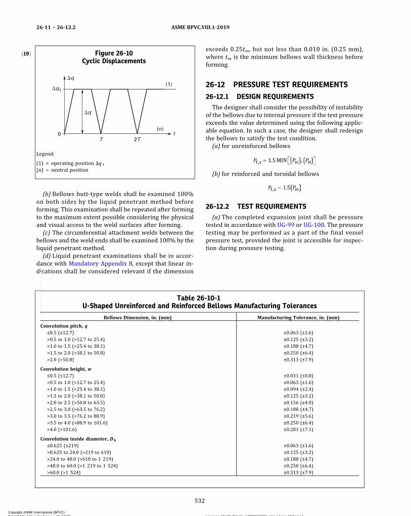
(b) Bellows butt‐type welds shall be examined 100%on both sides by the liquid penetrant method beforeforming. This examination shall be repeated after formingto the maximum extent possible considering the physicaland visual access to the weld surfaces after forming.(c) The circumferential attachment welds between the
bellows and the weld ends shall be examined 100% by theliquid penetrant method.(d) Liquid penetrant examinations shall be in accor-
dance with Mandatory Appendix 8, except that linear in-dications shall be considered relevant if the dimension
exceeds 0.25tm, but not less than 0.010 in. (0.25 mm),where tm is the minimum bellows wall thickness beforeforming.
26-12 PRESSURE TEST REQUIREMENTS
26-12.1 DESIGN REQUIREMENTSThe designer shall consider the possibility of instability
of the bellows due to internal pressure if the test pressureexceeds the value determined using the following applic-able equation. In such a case, the designer shall redesignthe bellows to satisfy the test condition.(a) for unreinforced bellows
(b) for reinforced and toroidal bellows
26-12.2 TEST REQUIREMENTS(a) The completed expansion joint shall be pressure
tested in accordance with UG-99 or UG-100. The pressuretesting may be performed as a part of the final vesselpressure test, provided the joint is accessible for inspec-tion during pressure testing.
ð19Þ Figure 26-10Cyclic Displacements
tT 2T
(n)
(1)�q
�q1
�q
0
Legend:
(1) = operating position Δq1
(n) = neutral position
Table 26-10-1U-Shaped Unreinforced and Reinforced Bellows Manufacturing Tolerances
Bellows Dimension, in. (mm) Manufacturing Tolerance, in. (mm)
Convolution pitch, q≤0.5 (≤12.7) ±0.063 (±1.6)>0.5 to 1.0 (>12.7 to 25.4) ±0.125 (±3.2)>1.0 to 1.5 (>25.4 to 38.1) ±0.188 (±4.7)>1.5 to 2.0 (>38.1 to 50.8) ±0.250 (±6.4)>2.0 (>50.8) ±0.313 (±7.9)
Convolution height, w≤0.5 (≤12.7) ±0.031 (±0.8)>0.5 to 1.0 (>12.7 to 25.4) ±0.063 (±1.6)>1.0 to 1.5 (>25.4 to 38.1) ±0.094 (±2.4)>1.5 to 2.0 (>38.1 to 50.8) ±0.125 (±3.2)>2.0 to 2.5 (>50.8 to 63.5) ±0.156 (±4.0)>2.5 to 3.0 (>63.5 to 76.2) ±0.188 (±4.7)>3.0 to 3.5 (>76.2 to 88.9) ±0.219 (±5.6)>3.5 to 4.0 (>88.9 to 101.6) ±0.250 (±6.4)>4.0 (>101.6) ±0.281 (±7.1)
Convolution inside diameter, Db
≤8.625 (≤219) ±0.063 (±1.6)>8.625 to 24.0 (>219 to 610) ±0.125 (±3.2)>24.0 to 48.0 (>610 to 1 219) ±0.188 (±4.7)>48.0 to 60.0 (>1 219 to 1 524) ±0.250 (±6.4)>60.0 (>1 524) ±0.313 (±7.9)
ASME BPVC.VIII.1-201926-11 – 26-12.2
532
Copyright ASME International (BPVC) Provided by IHS under license with ASME Licensee=Khalda Petroleum/5986215001, User=Amer, Mohamed
Not for Resale, 07/02/2019 13:29:04 MDTNo reproduction or networking permitted without license from IHS
--`,``,``,,`,`,,````,`,``,,,`-`-`,,`,,`,`,,`---

(b) Expansion joint restraining elements [see26-4.1(c)] shall also be pressure tested in accordancewith UG-99 or UG-100 as a part of the initial expansionjoint pressure test or as a part of the final vessel pressuretest after installation of the joint.
(c) In addition to inspecting the expansion joint forleaks and structural integrity during the pressure test, ex-pansion joints shall be inspected before, during, and afterthe pressure test for visible permanent distortion.
26-13 MARKING AND REPORTS
The expansion joint Manufacturer, whether the vesselManufacturer or a parts Manufacturer, shall have a validASME Code U Certificate of Authorization and shall com-plete the appropriate Data Report in accordance withUG-120.
(a) The Manufacturer responsible for the expansionjoint design shall include the following additional dataand statements on the appropriate Data Report:
(1) spring rate(2) axial movement (+ and −), associated design life
in cycles, and associated loading condition, if applicable(3) that the expansion joint has been constructed to
the rules of this Appendix(b) A parts Manufacturer shall identify the vessel for
which the expansion joint is intended on the Partial DataReport.
(c) Markings shall not be stamped on the flexible ele-ments of the expansion joint.
26-14 EXAMPLES
See UG-16(f).
26-15 POLYNOMIAL APPROXIMATION FORCOEFFICIENTS Cp , Cf , Cd
26-15.1 COEFFICIENT Cp
Coefficients αi are given by Table 26-15.1a if C1 ≤ 0.3or Table 26-15.1b if C1 > 0.3.
26-15.2 COEFFICIENT Cf
Coefficients β i are given by Table 26-15.2.
26-15.3 COEFFICIENT Cd
Coefficients γi are given by Table 26-15.3.
Figure 26-11Cyclic Displacements
t(n)
(1)�q
�q1
�q0
�q0
(0)
Legend:
(0) = initial position Δq0
(1) = operating position Δq1
(n) = neutral position
Figure 26-12Cyclic Displacements
t(n)
(2)�q
�q2
�q1
�q0
(0)
(1)
Legend:
(0) = initial position 0(n) = neutral position(1) = operating position 1(2) = operating position 2
ASME BPVC.VIII.1-2019 26-12.2 – 26-15.3
533
Copyright ASME International (BPVC) Provided by IHS under license with ASME Licensee=Khalda Petroleum/5986215001, User=Amer, Mohamed
Not for Resale, 07/02/2019 13:29:04 MDTNo reproduction or networking permitted without license from IHS
--`,``,``,,`,`,,````,`,``,,,`-`-`,,`,,`,`,,`---
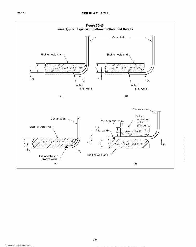
Figure 26-13Some Typical Expansion Bellows to Weld End Details
ts ts
Db
Shell or weld end
Full fillet weld
Full fillet weld
rmin. = 1/16 in. (1.5 mm)
Convolution
Shell or weld end
Db
rmin. = 1/16 in. (1.5 mm)
nt nt
nt
(a) (b)
Convolution
ts
tc
Bolted or welded collar (if required)
Full fillet weld rmin. = 1/16 in.
(1.5 mm)
1/4 in. (6 mm) max.
rmin. = 1/16 in. (1.5 mm) Db
Shell or weld end
(d)
ts
Db
Shell or weld end
Full penetration groove weld
nt
(c)
rmin = 1/16 in. (1.5 mm)
Convolution
ASME BPVC.VIII.1-201926-15.3
534
Copyright ASME International (BPVC) Provided by IHS under license with ASME Licensee=Khalda Petroleum/5986215001, User=Amer, Mohamed
Not for Resale, 07/02/2019 13:29:04 MDTNo reproduction or networking permitted without license from IHS
--`,``,``,,`,`,,````,`,``,,,`-`-`,,`,,`,`,,`---
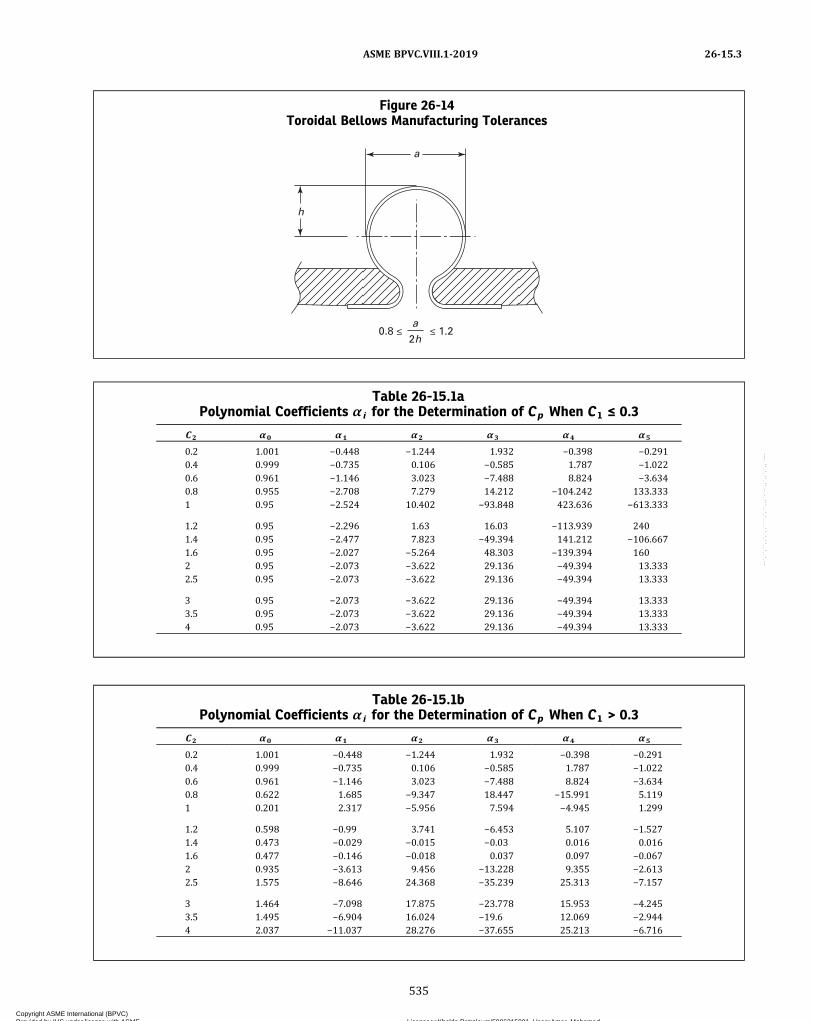
Figure 26-14Toroidal Bellows Manufacturing Tolerances
h
a
a
2h
Table 26-15.1aPolynomial Coefficients α i for the Determination of Cp When C1 ≤ 0.3
C2 α0 α1 α2 α3 α4 α5
0.2 1.001 −0.448 −1.244 1.932 −0.398 −0.2910.4 0.999 −0.735 0.106 −0.585 1.787 −1.0220.6 0.961 −1.146 3.023 −7.488 8.824 −3.6340.8 0.955 −2.708 7.279 14.212 −104.242 133.3331 0.95 −2.524 10.402 −93.848 423.636 −613.333
1.2 0.95 −2.296 1.63 16.03 −113.939 2401.4 0.95 −2.477 7.823 −49.394 141.212 −106.6671.6 0.95 −2.027 −5.264 48.303 −139.394 1602 0.95 −2.073 −3.622 29.136 −49.394 13.3332.5 0.95 −2.073 −3.622 29.136 −49.394 13.333
3 0.95 −2.073 −3.622 29.136 −49.394 13.3333.5 0.95 −2.073 −3.622 29.136 −49.394 13.3334 0.95 −2.073 −3.622 29.136 −49.394 13.333
Table 26-15.1bPolynomial Coefficients α i for the Determination of Cp When C1 > 0.3
C2 α0 α1 α2 α3 α4 α5
0.2 1.001 −0.448 −1.244 1.932 −0.398 −0.2910.4 0.999 −0.735 0.106 −0.585 1.787 −1.0220.6 0.961 −1.146 3.023 −7.488 8.824 −3.6340.8 0.622 1.685 −9.347 18.447 −15.991 5.1191 0.201 2.317 −5.956 7.594 −4.945 1.299
1.2 0.598 −0.99 3.741 −6.453 5.107 −1.5271.4 0.473 −0.029 −0.015 −0.03 0.016 0.0161.6 0.477 −0.146 −0.018 0.037 0.097 −0.0672 0.935 −3.613 9.456 −13.228 9.355 −2.6132.5 1.575 −8.646 24.368 −35.239 25.313 −7.157
3 1.464 −7.098 17.875 −23.778 15.953 −4.2453.5 1.495 −6.904 16.024 −19.6 12.069 −2.9444 2.037 −11.037 28.276 −37.655 25.213 −6.716
ASME BPVC.VIII.1-2019 26-15.3
535
Copyright ASME International (BPVC) Provided by IHS under license with ASME Licensee=Khalda Petroleum/5986215001, User=Amer, Mohamed
Not for Resale, 07/02/2019 13:29:04 MDTNo reproduction or networking permitted without license from IHS
--`,``,``,,`,`,,````,`,``,,,`-`-`,,`,,`,`,,`---
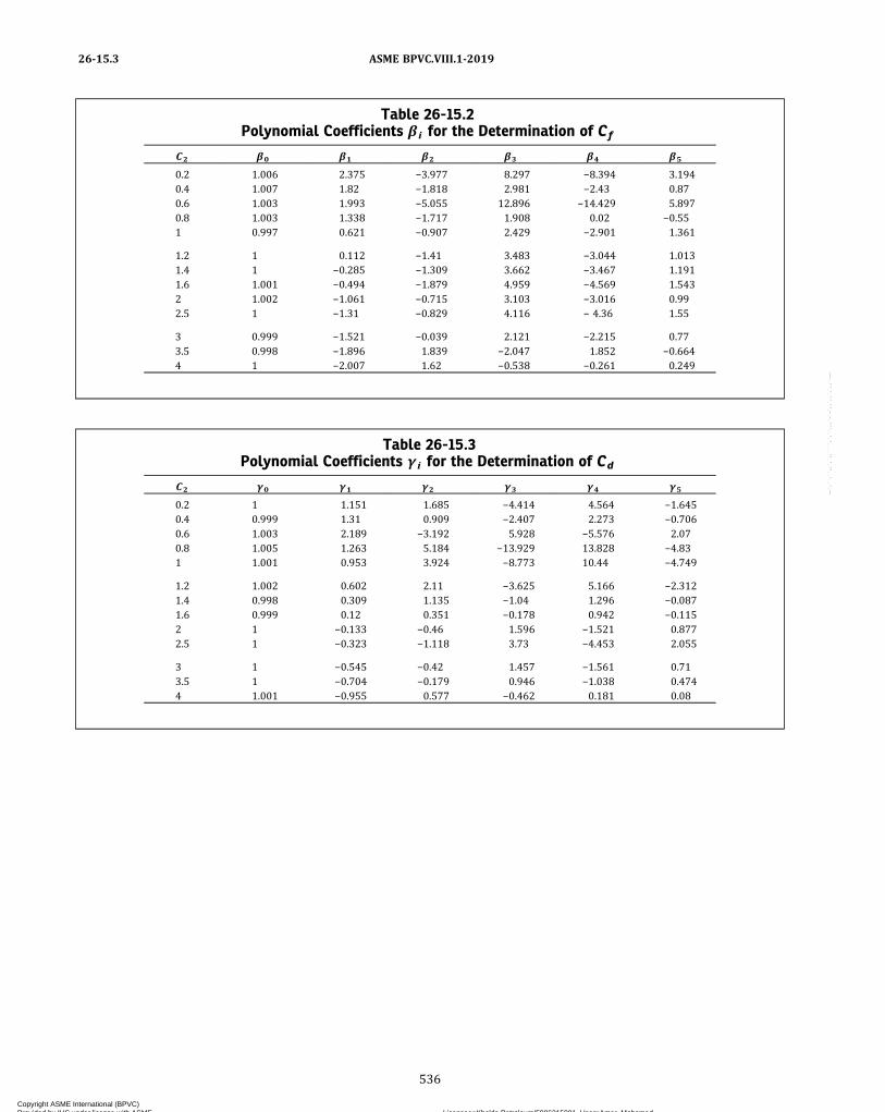
Table 26-15.2Polynomial Coefficients β i for the Determination of Cf
C2 β0 β1 β2 β3 β4 β5
0.2 1.006 2.375 −3.977 8.297 −8.394 3.1940.4 1.007 1.82 −1.818 2.981 −2.43 0.870.6 1.003 1.993 −5.055 12.896 −14.429 5.8970.8 1.003 1.338 −1.717 1.908 0.02 −0.551 0.997 0.621 −0.907 2.429 −2.901 1.361
1.2 1 0.112 −1.41 3.483 −3.044 1.0131.4 1 −0.285 −1.309 3.662 −3.467 1.1911.6 1.001 −0.494 −1.879 4.959 −4.569 1.5432 1.002 −1.061 −0.715 3.103 −3.016 0.992.5 1 −1.31 −0.829 4.116 − 4.36 1.55
3 0.999 −1.521 −0.039 2.121 −2.215 0.773.5 0.998 −1.896 1.839 −2.047 1.852 −0.6644 1 −2.007 1.62 −0.538 −0.261 0.249
Table 26-15.3Polynomial Coefficients γ i for the Determination of Cd
C2 γ0 γ1 γ2 γ3 γ4 γ5
0.2 1 1.151 1.685 −4.414 4.564 −1.6450.4 0.999 1.31 0.909 −2.407 2.273 −0.7060.6 1.003 2.189 −3.192 5.928 −5.576 2.070.8 1.005 1.263 5.184 −13.929 13.828 −4.831 1.001 0.953 3.924 −8.773 10.44 −4.749
1.2 1.002 0.602 2.11 −3.625 5.166 −2.3121.4 0.998 0.309 1.135 −1.04 1.296 −0.0871.6 0.999 0.12 0.351 −0.178 0.942 −0.1152 1 −0.133 −0.46 1.596 −1.521 0.8772.5 1 −0.323 −1.118 3.73 −4.453 2.055
3 1 −0.545 −0.42 1.457 −1.561 0.713.5 1 −0.704 −0.179 0.946 −1.038 0.4744 1.001 −0.955 0.577 −0.462 0.181 0.08
ASME BPVC.VIII.1-201926-15.3
536
Copyright ASME International (BPVC) Provided by IHS under license with ASME Licensee=Khalda Petroleum/5986215001, User=Amer, Mohamed
Not for Resale, 07/02/2019 13:29:04 MDTNo reproduction or networking permitted without license from IHS
--`,``,``,,`,`,,````,`,``,,,`-`-`,,`,,`,`,,`---
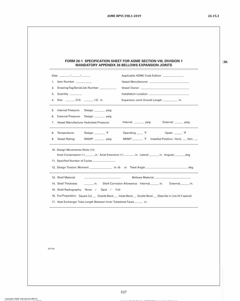
ð19ÞFORM 26-1 SPECIFICATION SHEET FOR ASME SECTION VIII, DIVISION 1
MANDATORY APPENDIX 26 BELLOWS EXPANSION JOINTS
Date
1.
2.
3.
4.
Item Number
Drawing/Tag/Serial/Job Number
Quantity
Size
5.
6.
7.
Internal Pressure:
External Pressure:
Vessel Manufacturer Hydrotest Pressure: Internal psig
Design
Design
psig
psig
O.D.
Applicable ASME Code Edition
Vessel Manufacturer
Vessel Owner
Installation Location
Expansion Joint Overall LengthI.D. in. in.
8.
9.
Temperature:
Vessel Rating:
Design
MAWP
Operating
MDMT Installed Position: Horiz. Vert.
12. Design Torsion: Moment in.-lb or Twist Angle deg
13.
14.
15.
16.
17.
Shell Material
Shell Thickness
Shell Radiography:
End Preparation:
Heat Exchanger Tube Length Between Inner Tubesheet Faces
in. Shell Corrosion Allowance: Internal in.
None
Outside Bevel Inside Bevel Double Bevel (Describe in Line 24 if special)
Spot Full//
in.
Upset ºF
External psig
Bellows Material
External in.
(07/19)
Square Cut
11. Specified Number of Cycles
10. Design Movements [Note (1)]:
Axial Compression (–) in. Axial Extension (+) in. Lateral in. Angular deg
ASME BPVC.VIII.1-2019 26-15.3
537
Copyright ASME International (BPVC) Provided by IHS under license with ASME Licensee=Khalda Petroleum/5986215001, User=Amer, Mohamed
Not for Resale, 07/02/2019 13:29:04 MDTNo reproduction or networking permitted without license from IHS
--`,``,``,,`,`,,````,`,``,,,`-`-`,,`,,`,`,,`---

18.
19.
20.
21.
22.
23.
24.
Maximum Bellows Spring Rate:
Internal Liner:
Drain Holes in Liner:
Liner Flush With Shell I.D.:
External Cover:
Preproduction Approvals Required:
Additional Requirements (e.g., bellows preset, ultrasonic inspection):
N
N
N
N
N
N
N Y
Y -
Y - Material
Y - Quantity/Size
Y - Telescoping Liners?
Y - Material
Y - Drawings / Bellows Calculations / Weld Procedures
lb/in.
NOTE:
FORM 26-1 SPECIFICATION SHEET FOR ASME SECTION VIII, DIVISION 1MANDATORY APPENDIX 26 BELLOWS EXPANSION JOINTS (Cont’d)
(07/19)
For multiple movements, Design movements (line 10) can be replaced by operating movements and described in line 24. For each one of them axial compression or axial extension, lateral deflection and angular rotation at each extremity of cycle, together with the specified number of cycles, should be indicated. When known, the order of occurrence of the movements should also be indicated.
(1)
ASME BPVC.VIII.1-201926-15.3
538
Copyright ASME International (BPVC) Provided by IHS under license with ASME Licensee=Khalda Petroleum/5986215001, User=Amer, Mohamed
Not for Resale, 07/02/2019 13:29:04 MDTNo reproduction or networking permitted without license from IHS
--`,``,``,,`,`,,````,`,``,,,`-`-`,,`,,`,`,,`---
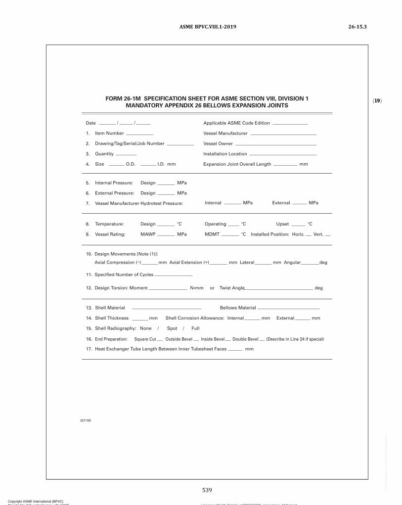
ð19Þ
Date
1.
2.
3.
4.
Item Number
Drawing/Tag/Serial/Job Number
Quantity
Size
5.
6.
7.
Internal Pressure:
External Pressure:
Vessel Manufacturer Hydrotest Pressure: Internal MPa
Design
Design
MPa
MPa
O.D.
Applicable ASME Code Edition
Vessel Manufacturer
Vessel Owner
Installation Location
Expansion Joint Overall LengthI.D. mm mm
8.
9.
Temperature:
Vessel Rating:
Design
MAWP
Operating
MDMT Installed Position: Horiz. Vert.
13.
14.
15.
16.
17.
Shell Material
Shell Thickness
Shell Radiography:
End Preparation:
Heat Exchanger Tube Length Between Inner Tubesheet Faces
mm Shell Corrosion Allowance: Internal mm
None Spot Full//
mm
Upset
External MPa
Bellows Material
External mm
Outside Bevel Inside Bevel Double Bevel (Describe in Line 24 if special)Square Cut
(07/19)
12. Design Torsion: Moment N•mm or Twist Angle deg
11. Specified Number of Cycles
10. Design Movements [Note (1)]:
Axial Compression (–) mm Axial Extension (+) mm Lateral mm Angular deg
FORM 26-1M SPECIFICATION SHEET FOR ASME SECTION VIII, DIVISION 1
MANDATORY APPENDIX 26 BELLOWS EXPANSION JOINTS
ASME BPVC.VIII.1-2019 26-15.3
539
Copyright ASME International (BPVC) Provided by IHS under license with ASME Licensee=Khalda Petroleum/5986215001, User=Amer, Mohamed
Not for Resale, 07/02/2019 13:29:04 MDTNo reproduction or networking permitted without license from IHS
--`,``,``,,`,`,,````,`,``,,,`-`-`,,`,,`,`,,`---
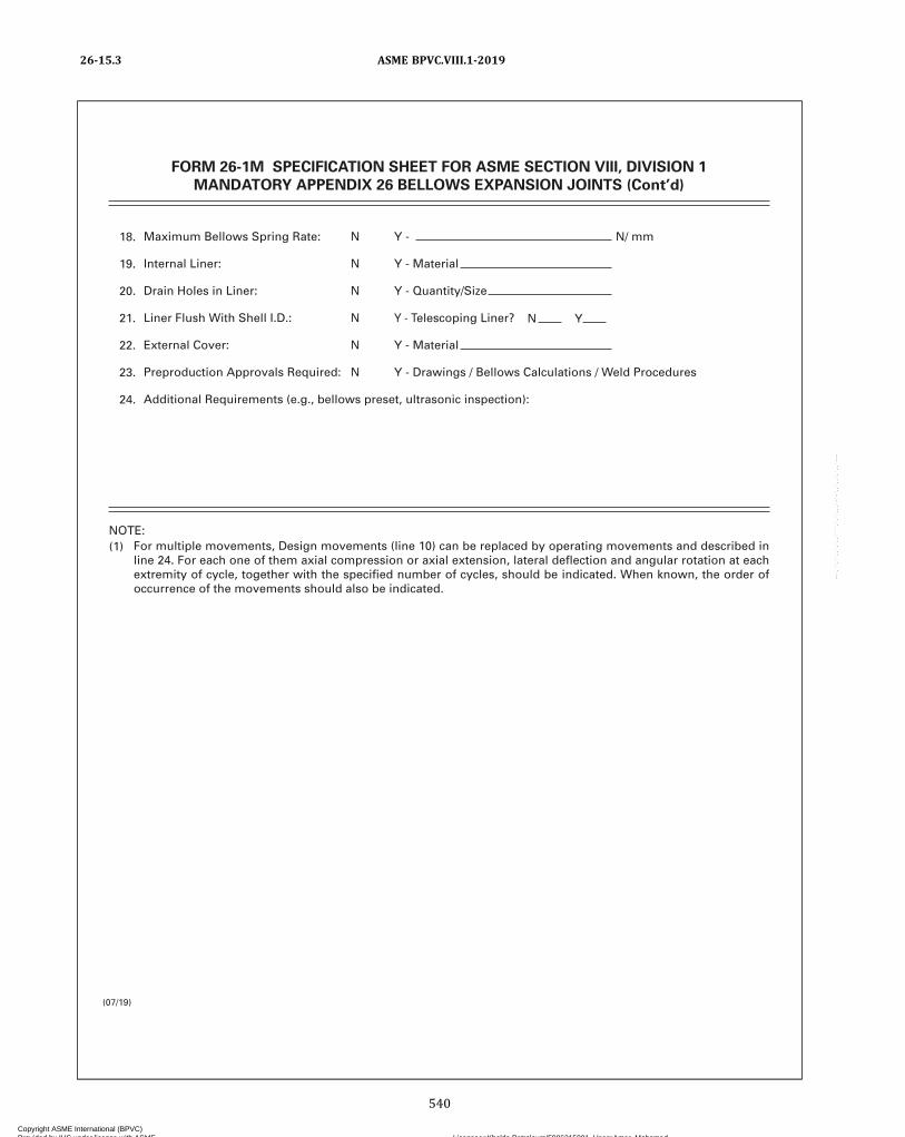
18.
19.
20.
21.
22.
23.
24.
Maximum Bellows Spring Rate:
Internal Liner:
Drain Holes in Liner:
Liner Flush With Shell I.D.:
External Cover:
Preproduction Approvals Required:
Additional Requirements (e.g., bellows preset, ultrasonic inspection):
N
N
N
N
N
N
N Y
Y -
Y - Material
Y - Quantity/Size
Y - Telescoping Liner?
Y - Material
Y - Drawings / Bellows Calculations / Weld Procedures
N/ mm
FORM 26-1M SPECIFICATION SHEET FOR ASME SECTION VIII, DIVISION 1MANDATORY APPENDIX 26 BELLOWS EXPANSION JOINTS (Cont’d)
(07/19)
NOTE:(1) For multiple movements, Design movements (line 10) can be replaced by operating movements and described in
line 24. For each one of them axial compression or axial extension, lateral deflection and angular rotation at each extremity of cycle, together with the specified number of cycles, should be indicated. When known, the order of occurrence of the movements should also be indicated.
ASME BPVC.VIII.1-201926-15.3
540
Copyright ASME International (BPVC) Provided by IHS under license with ASME Licensee=Khalda Petroleum/5986215001, User=Amer, Mohamed
Not for Resale, 07/02/2019 13:29:04 MDTNo reproduction or networking permitted without license from IHS
--`,``,``,,`,`,,````,`,``,,,`-`-`,,`,,`,`,,`---

MANDATORY APPENDIX 27ALTERNATIVE REQUIREMENTS FOR GLASS-LINED VESSELS
27-1 SCOPE
The rules of this Appendix cover acceptable alternativerequirements that are applicable to glass‐ l ined(enameled‐lined) vessels. All applicable requirements inthis Division are mandatory except as modified herein.
27-2 PERMISSIBLE OUT-OF-ROUNDNESS OFCYLINDRICAL SHELLS UNDERINTERNAL PRESSURE
If the out‐of‐roundness of a glass lined cylindrical ves-sel exceeds the limits in UG-80(a)(1), UG-80(a)(2), or inboth, and the condition cannot be corrected, the maxi-mum allowable working pressure may be calculated asfollows:
(a) The out‐of‐roundness, as determined by the maxi-mum difference between any two diameters for any crosssection, shall not exceed 3%.
(b) The shell shall be certified for a lower internal pres-sure by the following formula:
and in which
where
D1 and D2 = the inside diameters, maximum and mini-mum, respectively, as measured for the cri-tical section, and for one additional sectionin each direction therefrom at a distancenot exceeding 0.2D 2. The average of thethree readings for D1 and D2, respectively,shall be inserted in the formula.
E = modulus of elasticity at design temperatureP = maximum allowable working pressure for
she l l meet ing the requi rements o fUG-80(a)(1)
NOTE: Use P′ = P when Sb ≤ 0.25S
P ′ = reduced maximum allowable workingpressure to be stamped on the nameplateof the vessel and shown on the Manufac-turer’s Data Report
R1 = average inside radius at critical section= 1/4 (D1 + D2)
Ra = average radius to middle of shell wall at cri-tical section
= 1/4 (D1 + D2) + t/2S = design stress value at metal service
temperatureSb = b e n d i n g s t r e s s a t m e t a l s e r v i c e
temperaturet = nominal thickness of vessel shell
27-3 PERMISSIBLE TOLERANCE FORHEMISPHERICAL OR 2:1 ELLIPSOIDALHEADS
If a hemispherical or 2:1 ellipsoidal head exceeds thetolerance limits in UG-81(a) and the condition cannot becorrected, the head may be used providing the followingrequirements are met:
(a) The inner surface of the head shall not deviate out-side the specified shape by more than 3% of D nor insidethe specified shape by more than 3% of D , where D is thenominal inside diameter of the vessel shell at the point ofattachment. Such deviations shall be measured perpendi-cular to the specified shape and shall not be abrupt.
(b) The provisions of UG-81(c), UG-81(d), andUG-81(e) shall be met. UG-81(b) shall be met as regardsthe remaining spherical portions of the head.
(c) Deviations that exceed the limits in UG-81(a) shallbe outside of any areas used for reinforcing of openings.
(d) A comparative analysis shall be made between thedistorted shape and the undistorted shape to demon-strate that the design margins of the Code for internalpressure and, as appropriate, external pressure have beenmet [see U-2(g)].
27-4 HYDROSTATIC TEST
(a) The hydrostatic test pressure for glass‐lined vesselsshall be at least equal to, but need not exceed, the maxi-mum allowable working pressure to be marked on thevessel; the hydrostatic test pressure for jackets ofglass‐lined vessels shall be at least equal to, but neednot exceed, the maximum allowable working pressureto be marked on the jacket.
ASME BPVC.VIII.1-2019 27-1 – 27-4
541
Copyright ASME International (BPVC) Provided by IHS under license with ASME Licensee=Khalda Petroleum/5986215001, User=Amer, Mohamed
Not for Resale, 07/02/2019 13:29:04 MDTNo reproduction or networking permitted without license from IHS
--`,``,``,,`,`,,````,`,``,,,`-`-`,,`,,`,`,,`---
(b) Vessels, except those in lethal service, may bepainted or glass lined internally prior to the pressure test.However, the user is cautioned that such painting/coat-ing/lining may mask leaks that would otherwise be de-tected during the pressure test.
27-5 HEAT TREATMENT OF TESTSPECIMENS
(a) Except when impact testing per UCS-66 is required,and in lieu of the requirements of UCS-85, the plate, forg-ing, pipe, and strip steels used in the production ofglass‐lined vessels may be represented by test specimensthat meet the following requirements:
(1) the test specimens shall be heat treated twotimes, f irst to a temperature of 1,675°F ± 25°F(915°C ± 15°C), and then to a temperature that is nomin-ally equal to the last (lowest) temperature of the glassingcycle. The minimum holding time for each heat treatmentshall be 1/2 hr/in. (1 min/mm) of thickness;
(2) the materials shall be limited to SA-106, SA-285,SA-414, SA-516, and SA-836; and
(3) the multiple temperature cycles used in the glas-sing operation shall be within the range of 1,450°Fto 1,700°F (790°C to 925°C), with at least one cycle beingabove the upper transformation temperature of the mate-rial. The vessel is to be held at temperature approximately1/2 hr/in. (
1/2 hr/25 mm) of thickness, and still‐air‐cooledto ambient.(b) SA-106, SA-285, SA-414 Grades A and B, and
SA-516 materials used in the production of glass‐linedvessels may be exempt from the simulated test require-ments of UCS-85 when the following requirements aremet:
(1) the requirements of (a)(3) above;(2) the carbon content of the materials shall not ex-
ceed 0.25% by heat analysis;(3) the tensile strength and yield strength of the ma-
terial, as represented by mill test specimens, shall be atleast 10% higher than the minimum specified by the ma-terial specification;
(4) impact testing per UCS-66 is not required.
27-6 LOW TEMPERATURE OPERATION
Materials used in the fabrication of glass lined vesselsshall follow the impact testing requirements or exemp-tions as defined within this Division with the exceptionslisted below.(a) SA-285 Grade C, for glass lined vessels, may be as-
signed to Curve B in Figure UCS-66 under the followingconditions:
(1) the maximum carbon content limit is 0.18%; and(2) the glass operation shall be per 27-5(a)(3).
(b) Stainless steel vessels fabricated from SA-240 316Lplate, SA-182 F316L forgings, SA-312 TP316L pipe, andSA-213 TP316L tubing may be exempted from productionimpact tests per UHA-51, provided the following condi-tions are met:
(1) The Welding Procedure Qualification shall in-clude impact tests in accordance with UHA-51(b). Eachheat or lot of consumable welding electrodes shall be sotested. The test specimens shall be subjected to the glasslined 316L stainless steel vessel glassing cycle tempera-ture, time, and cooling rates, and a number of cycles thatis equal to or greater than that of the production vessels.
(2) The impact testing shall be done at a temperaturenot warmer than the MDMT of the vessels. The MDMT ofthe vessels shall be no colder than −155°F (−104°C).
(3) The multiple temperature cycles used in the glas-sing operation shall be within the range of 1,400°Fto 1,700°F (760°C to 927°C). The vessel is to be held attemperature approximately 1/2 hr/in. of thickness(0.20 hr/cm of thickness) per cycle, and still‐air‐cooled(nonquench) to ambient.
(4) As an alternative to (1) through (3) above, impacttesting is not required when the coincident ratio of designstress81 in tension to allowable tensile stress is less than0.35, provided that the welding electrodes are certified toSFA-5.4 Grade 316L‐15 with a ferrite number not to ex-ceed 3, and provided that the MDMT of the vessels is nocolder than −200°F (−129°C).
27-7 POSTWELD HEAT TREATMENT
The heat treatment provided in the temperature cyclefor the glassing operation may be used in lieu of the post-weld heat treatment requirements of UW-40 and UCS-56.The weld qualification test specimens required by UW-28and Section IX shall be heat treated per 27-5(a)(1). Innervessels which are so heat treated need not be again post-weld heat treated after the attachment to the jacket, if thejoining welds do not require postweld heat treatment.
27-8 DATA REPORTS
When all the requirements of this Division, as modifiedby the alternative requirements of this Appendix, havebeen met, the following notation shall be entered on theManufacturer’s Data Report under Remarks: “Con-structed in Conformance With Mandatory Appendix 27,Alternative Requirements for Glass‐Lined Vessels.”
ASME BPVC.VIII.1-201927-4 – 27-8
542
Copyright ASME International (BPVC) Provided by IHS under license with ASME Licensee=Khalda Petroleum/5986215001, User=Amer, Mohamed
Not for Resale, 07/02/2019 13:29:04 MDTNo reproduction or networking permitted without license from IHS
--`,``,``,,`,`,,````,`,``,,,`-`-`,,`,,`,`,,`---
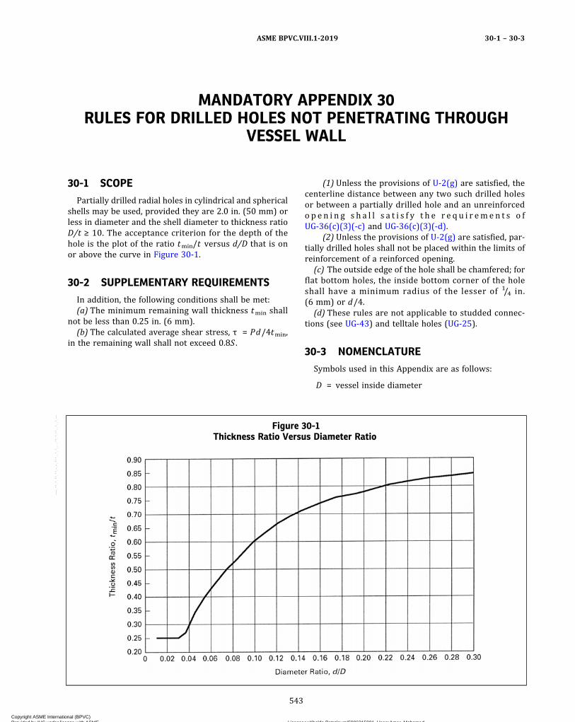
MANDATORY APPENDIX 30RULES FOR DRILLED HOLES NOT PENETRATING THROUGH
VESSEL WALL
30-1 SCOPE
Partially drilled radial holes in cylindrical and sphericalshells may be used, provided they are 2.0 in. (50 mm) orless in diameter and the shell diameter to thickness ratioD/t ≥ 10. The acceptance criterion for the depth of thehole is the plot of the ratio tmin/t versus d/D that is onor above the curve in Figure 30-1.
30-2 SUPPLEMENTARY REQUIREMENTS
In addition, the following conditions shall be met:(a) The minimum remaining wall thickness tmin shall
not be less than 0.25 in. (6 mm).(b) The calculated average shear stress, τ = Pd/4tmin,
in the remaining wall shall not exceed 0.8S .
(1) Unless the provisions of U-2(g) are satisfied, thecenterline distance between any two such drilled holesor between a partially drilled hole and an unreinforcedo p e n i n g s h a l l s a t i s f y t h e r e q u i r em e n t s o fUG-36(c)(3)(-c) and UG-36(c)(3)(-d).
(2) Unless the provisions of U-2(g) are satisfied, par-tially drilled holes shall not be placed within the limits ofreinforcement of a reinforced opening.
(c) The outside edge of the hole shall be chamfered; forflat bottom holes, the inside bottom corner of the holeshall have a minimum radius of the lesser of 1/4 in.(6 mm) or d/4.
(d) These rules are not applicable to studded connec-tions (see UG-43) and telltale holes (UG-25).
30-3 NOMENCLATURE
Symbols used in this Appendix are as follows:
D = vessel inside diameter
Figure 30-1Thickness Ratio Versus Diameter Ratio
ASME BPVC.VIII.1-2019 30-1 – 30-3
543
Copyright ASME International (BPVC) Provided by IHS under license with ASME Licensee=Khalda Petroleum/5986215001, User=Amer, Mohamed
Not for Resale, 07/02/2019 13:29:04 MDTNo reproduction or networking permitted without license from IHS
--`,``,``,,`,`,,````,`,``,,,`-`-`,,`,,`,`,,`---

d = diameter of drilled holeP = design pressure (see UG-21)S = maximum allowable stress valuet = nominal thickness in corroded condition
tmin = remaining wall thickness
ASME BPVC.VIII.1-201930-3
544
Copyright ASME International (BPVC) Provided by IHS under license with ASME Licensee=Khalda Petroleum/5986215001, User=Amer, Mohamed
Not for Resale, 07/02/2019 13:29:04 MDTNo reproduction or networking permitted without license from IHS
--`,``,``,,`,`,,````,`,``,,,`-`-`,,`,,`,`,,`---
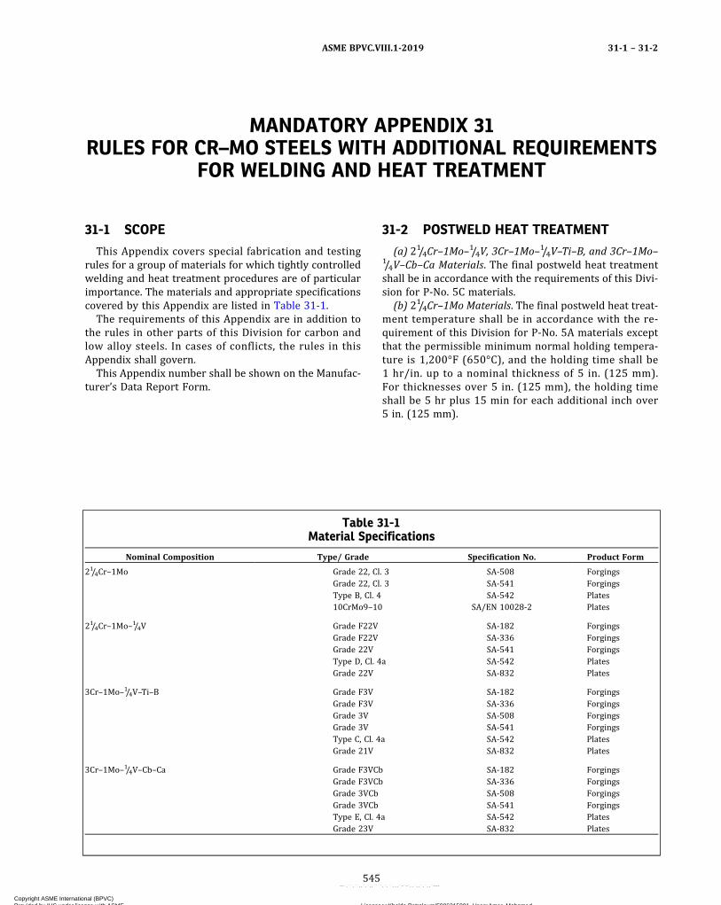
MANDATORY APPENDIX 31RULES FOR CR–MO STEELS WITH ADDITIONAL REQUIREMENTS
FOR WELDING AND HEAT TREATMENT
31-1 SCOPE
This Appendix covers special fabrication and testingrules for a group of materials for which tightly controlledwelding and heat treatment procedures are of particularimportance. The materials and appropriate specificationscovered by this Appendix are listed in Table 31-1.
The requirements of this Appendix are in addition tothe rules in other parts of this Division for carbon andlow alloy steels. In cases of conflicts, the rules in thisAppendix shall govern.
This Appendix number shall be shown on the Manufac-turer’s Data Report Form.
31-2 POSTWELD HEAT TREATMENT
(a) 21/4Cr–1Mo–1/4V, 3Cr–1Mo–1/4V–Ti–B, and 3Cr–1Mo–1/4V–Cb–Ca Materials. The final postweld heat treatmentshall be in accordance with the requirements of this Divi-sion for P‐No. 5C materials.
(b) 21/4Cr–1Mo Materials. The final postweld heat treat-ment temperature shall be in accordance with the re-quirement of this Division for P‐No. 5A materials exceptthat the permissible minimum normal holding tempera-ture is 1,200°F (650°C), and the holding time shall be1 hr/in. up to a nominal thickness of 5 in. (125 mm).For thicknesses over 5 in. (125 mm), the holding timeshall be 5 hr plus 15 min for each additional inch over5 in. (125 mm).
Table 31-1Material Specifications
Nominal Composition Type/ Grade Specification No. Product Form
21/4Cr–1Mo Grade 22, Cl. 3 SA-508 ForgingsGrade 22, Cl. 3 SA-541 ForgingsType B, Cl. 4 SA-542 Plates10CrMo9–10 SA/EN 10028-2 Plates
21/4Cr–1Mo–1/4V Grade F22V SA-182 ForgingsGrade F22V SA-336 ForgingsGrade 22V SA-541 ForgingsType D, Cl. 4a SA-542 PlatesGrade 22V SA-832 Plates
3Cr–1Mo–1/4V–Ti–B Grade F3V SA-182 ForgingsGrade F3V SA-336 ForgingsGrade 3V SA-508 ForgingsGrade 3V SA-541 ForgingsType C, Cl. 4a SA-542 PlatesGrade 21V SA-832 Plates
3Cr–1Mo–1/4V–Cb–Ca Grade F3VCb SA-182 ForgingsGrade F3VCb SA-336 ForgingsGrade 3VCb SA-508 ForgingsGrade 3VCb SA-541 ForgingsType E, Cl. 4a SA-542 PlatesGrade 23V SA-832 Plates
ASME BPVC.VIII.1-2019 31-1 – 31-2
545
Copyright ASME International (BPVC) Provided by IHS under license with ASME Licensee=Khalda Petroleum/5986215001, User=Amer, Mohamed
Not for Resale, 07/02/2019 13:29:04 MDTNo reproduction or networking permitted without license from IHS
--`,``,``,,`,`,,````,`,``,,,`-`-`,,`,,`,`,,`---

Figure 31-1
Heat Treatment Hold Time
Min
imu
m h
old
tim
e
25°F
(15
°C)
max
.
25°F
(15
°C)
m
ax.
Max
imu
m h
old
tim
e
Minimum temperature
Maximum temperature
Condition A
Hea
t Tr
eatm
ent
Tem
per
atu
re
Condition B
0.2 × min. hold time or less
0.2 × max. hold time or less
Table 31-2Composition Requirements for 21/4Cr–1Mo–1/4V Weld Metal
WeldingProcess C Mn Si Cr Mo P S V Cb
SAW 0.05–0.15 0.50–1.30 0.05–0.35 2.00–2.60 0.90–1.20 0.015 max. 0.015 max. 0.20–0.40 0.010–0.040SMAW 0.05–0.15 0.50–1.30 0.20–0.50 2.00–2.60 0.90–1.20 0.015 max. 0.015 max. 0.20–0.40 0.010–0.040GTAW 0.05–0.15 0.30–1.10 0.05–0.35 2.00–2.60 0.90–1.20 0.015 max. 0.015 max. 0.20–0.40 0.010–0.040GMAW 0.05–0.15 0.30–1.10 0.20–0.50 2.00–2.60 0.90–1.20 0.015 max. 0.015 max. 0.20–0.40 0.010–0.040
ASME BPVC.VIII.1-201931-2
546
Copyright ASME International (BPVC) Provided by IHS under license with ASME Licensee=Khalda Petroleum/5986215001, User=Amer, Mohamed
Not for Resale, 07/02/2019 13:29:04 MDTNo reproduction or networking permitted without license from IHS
--`,``,``,,`,`,,````,`,``,,,`-`-`,,`,,`,`,,`---

31-3 TEST SPECIMEN HEAT TREATMENT
(a) In fulfilling the requirements of UCS-85(b), two setsof tension specimens and one set of Charpy impact speci-mens shall be tested. One set each of the tension speci-mens shall be exposed to heat treatment Condition A.The second set of tension specimens and the set of Charpyimpact specimens shall be exposed to heat treatment Con-dition B.
Condition A: Temperature shall be no lower than the ac-tual maximum vessel‐portion temperature, less 25°F(15°C). Time at temperature shall be no less than 80%of the actual hold time of the vessel‐portion exposed tothe maximum vessel‐portion temperature.
Condition B: Temperature shall be no higher than theactual minimum vessel‐portion temperature, plus 25°F(15°C). Time at temperature shall be no more than120% of the actual hold time of the vessel‐portion ex-posed to the minimum vessel‐portion temperature.
(b) Suggested procedure for establishing test specimenheat treatment parameters:
(1) Establish maximum and minimum temperaturesand hold times for the vessel/component heat treatmentbased on experience/equipment.
(2) Determine Conditions A and B for the test speci-men heat treatments.
(3) Vessel heat treatment temperature and hold timelimitations and test specimen Conditions A and B areshown in Figure 31-1 (shaded area).
31-4 WELDING PROCEDURE QUALIFICATIONAND WELDING CONSUMABLESTESTING
(a)Welding procedure qualifications using weldingconsumables of the same classification or trade designa-tion as those to be used in production shall be made formaterial welded to itself or to other materials. The quali-fications shall conform to the requirements of Section IX,and the maximum tensile strength at room temperatureshall be 110 ksi (760 MPa) (for heat treatment ConditionsA and B). Welding shall be limited to submerged‐arc
(SAW) and shielded metal‐arc (SMAW) processes for3Cr–1Mo– 1/4V–Ti–B materials only. Gas tungsten‐a r c ( G TAW ) p r o c e s s m a y a l s o b e u s e d f o r3Cr–1Mo–1/4V–Cb–Ca material.
(b)Weld metal from each heat or lot of electrodes andfiller‐wire–flux combination shall be tested, unless specif-ic heat- or lot-traceable test reports meeting the addi-tional requirements of this Appendix related to weldingconsumables testing have been provided by the weldingconsumables manufacturer. The minimum and maximumtensile properties shall be met in PWHT Conditions A andB. The minimum CVN impact properties shall be met inPWHT Condition B. Testing shall be in general confor-mance with SFA-5.5 for covered electrodes andSFA-5.23 for filler‐wire–flux combinations.
(c) Duplicate testing in the PWHT Condition A andPWHT Condition B (see 31-3) is required. The minimumtensiles and CVN impact properties for the base materialshall be met. CVN impact testing is only required for Con-dition B.
For 21/4Cr–1Mo–1/4V material, the weld metal shallmeet the composition requirements listed in Table 31-2.For all other materials, the minimum carbon content ofthe weld metal shall be 0.05%.
31-5 TOUGHNESS REQUIREMENTS
The minimum toughness requirements for base metal,weld metal, and heat-affected zone, after exposure tothe simulated postweld heat treatment Condition B, shallbe as follows:
Number of Specimens Impact Energy, ft‐lb
Average of 3 40Only one in set 35 min.
GENERAL NOTE: Full size Charpy V‐notch, transverse, tested atthe MDMT.
If the material specification or other parts of this Divi-sion have more demanding toughness requirements, theyshall be met.
ASME BPVC.VIII.1-2019 31-3 – 31-5
547
Copyright ASME International (BPVC) Provided by IHS under license with ASME Licensee=Khalda Petroleum/5986215001, User=Amer, Mohamed
Not for Resale, 07/02/2019 13:29:04 MDTNo reproduction or networking permitted without license from IHS
--`,``,``,,`,`,,````,`,``,,,`-`-`,,`,,`,`,,`---

MANDATORY APPENDIX 32LOCAL THIN AREAS IN CYLINDRICAL SHELLS AND IN SPHERICAL
SEGMENTS OF SHELLS
32-1 SCOPE
The rules of this Appendix permit acceptable local thinareas (LTAs) in cylindrical shells or spherical segments ofshells (such as spherical vessel, hemispherical heads, andthe spherical portion of torispherical and ellipsoidalheads) under internal pressure be less than the requiredthickness required by UG-16, UG-27, or UG-32 as applic-able. Local thin areas on the inside or outside of cylindri-cal shells or spherical segments of shells designed forinternal pressure are acceptable, provided they meetthe requirements in this Appendix.
32-2 GENERAL REQUIREMENTS
(a) The Manufacturer shall maintain records of the cal-culations and the location and extent of all LTAs that areevaluated using this Appendix, and provide such informa-tion to the purchaser or the User or the User’s designatedagent if requested. This information shall be documentedin the design calculations made to meet the requirementsof this Appendix.(b) The maximum design temperature shall not exceed
the maximum temperature limits specified in Table 1-4.3.(c) This Appendix shall not be applied to Part UF
vessels.(d) The provisions of this Appendix do not apply to
corrosion‐resistant linings or overlays.(e) All other applicable requirements of this Division
shall be met.
32-3 NOMENCLATURE
C = projected circumferential length of LTA in a cy-lindrical shell, in.
D = per UG-32DL = maximum dimension of LTA in a spherical seg-
ment, in.L = projected axial length of LTA in a cylindrical shell,
in.LTA = local thin area
R = inside radius for cylindrical shell or spherical seg-ment; for ellipsoidal heads R = KoD where Ko isfrom Table UG-33.1, in.
t = required thickness per UG-27(c), UG-27(d),UG-32(c), UG-32(d), or UG-32(e), as applicable,but not less than thickness requirements ofUG-16, in.
tL = minimum thickness of LTA, in.θ = see Figure 32-3
Figure 32-3Nomenclature
LTA
L
C
(a)
Axial direction
Circumferential direction
Separation
Circumferential separation
LTA
LTA
(b)
L1
L2
�
ASME BPVC.VIII.1-201932-1 – 32-3
548
Copyright ASME International (BPVC) Provided by IHS under license with ASME Licensee=Khalda Petroleum/5986215001, User=Amer, Mohamed
Not for Resale, 07/02/2019 13:29:04 MDTNo reproduction or networking permitted without license from IHS
--`,``,``,,`,`,,````,`,``,,,`-`-`,,`,,`,`,,`---

32-4 ALLOWABLE LOCATIONS FOR LOCALTHIN AREAS
(a) For openings meeting UG-36(c)(3), the minimumdistance between the edge of the LTA and the center ofthe opening shall be equal to or greater than the insidediameter of the opening plus .
(b) For openings not meeting UG-36(c)(3), the mini-mum distance between the edge of the LTA and the rein-forcement limit of the opening shall be equal to or greaterthan .
(c) For torispherical and ellipsoidal heads, the edge ofan LTA shall not be closer than to the cylindricalshell side of the tangent line of the head-to-cylinderjunction.
(d) An LTA is not acceptable within the torus portion ofa torispherical head or an ellipsoidal head.
(e) The LTA for a torispherical head must lie entirelywithin the spherical portion of the head. See Figure32-4-1.
(f) The LTA for an ellipsoidal head must lie entirelywithin a circle, the center of which coincides with the axisof the vessel, and the diameter of which is equal to 80% ofthe shell inside diameter. See Figure 32-4-2.
(g) A constant-thickness head-to-cylinder junction for ahemispherical head is not considered an area of highstress for LTA rules. The LTA for a hemispherical headis acceptable within the entire head and shell region fora constant-thickness hemispherical head-to-cylinderjunction as shown in Figure 32-4-3, sketch (a). The loca-tion for an LTA is limited for a nonconstant-thicknesshemispherical head-to-cylinder junction as shown inFigure 32-4-3, sketch (b). For both constant-thicknessand nonconstant-thickness hemispherical head-to-cylinder junctions, LTAs are limited by (a), (b), and (h).
(h) The edge of an LTA shall not be closer thanto the centerline of a stiffing ring or structural support.
(i) A junction between two sections of the same thick-ness within a cylindrical shell, hemispherical head, tori-spherical head, or ellipsoidal head is not considered anarea of high stress for LTA rules and does not limit the al-lowable location of an LTA.
(j) An LTA is not acceptable within a flat head or a con-ical head.
Figure 32-4-1Limits for Torispherical Head
Tangent line
2.5 Rt
LTA not permitted in this area
Knuckle
Spherical portion LTA limit
ASME BPVC.VIII.1-2019 32-4
549
Copyright ASME International (BPVC) Provided by IHS under license with ASME Licensee=Khalda Petroleum/5986215001, User=Amer, Mohamed
Not for Resale, 07/02/2019 13:29:04 MDTNo reproduction or networking permitted without license from IHS
--`,``,``,,`,`,,````,`,``,,,`-`-`,,`,,`,`,,`---
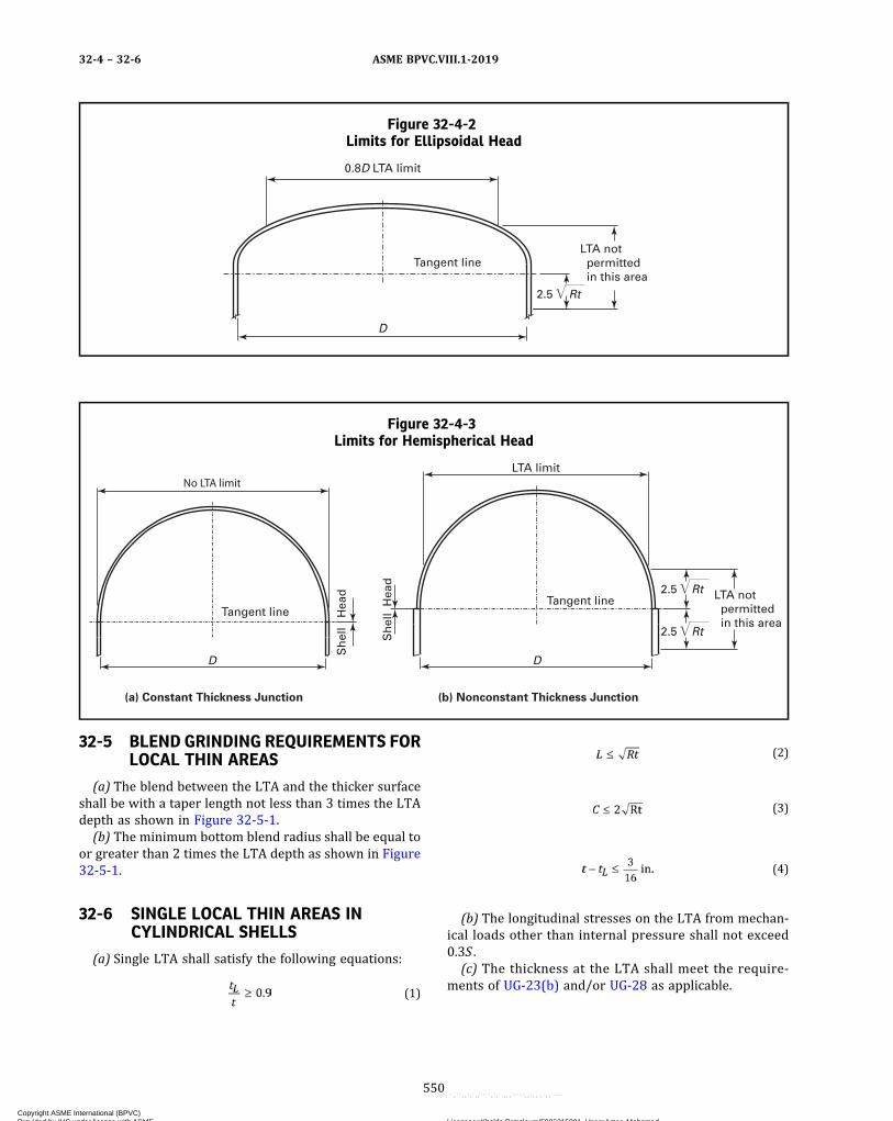
Figure 32-4-2Limits for Ellipsoidal Head
0.8D LTA limit
Tangent line
D
2.5 Rt
LTA not permitted in this area
Figure 32-4-3Limits for Hemispherical Head
(a) Constant Thickness Junction
LTA not permitted in this area
(b) Nonconstant Thickness Junction
Tangent lineTangent line
DD
No LTA limit
Sh
ell
Hea
d
LTA limit
Sh
ell
Hea
d
2.5 Rt
2.5 Rt
32-5 BLEND GRINDING REQUIREMENTS FORLOCAL THIN AREAS
(a) The blend between the LTA and the thicker surfaceshall be with a taper length not less than 3 times the LTAdepth as shown in Figure 32-5-1.(b) The minimum bottom blend radius shall be equal to
or greater than 2 times the LTA depth as shown in Figure32-5-1.
32-6 SINGLE LOCAL THIN AREAS INCYLINDRICAL SHELLS
(a) Single LTA shall satisfy the following equations:
ð1Þ
ð2Þ
ð3Þ
ð4Þ
(b) The longitudinal stresses on the LTA from mechan-ical loads other than internal pressure shall not exceed0.3S .(c) The thickness at the LTA shall meet the require-
ments of UG-23(b) and/or UG-28 as applicable.
ASME BPVC.VIII.1-201932-4 – 32-6
550
Copyright ASME International (BPVC) Provided by IHS under license with ASME Licensee=Khalda Petroleum/5986215001, User=Amer, Mohamed
Not for Resale, 07/02/2019 13:29:04 MDTNo reproduction or networking permitted without license from IHS
--`,``,``,,`,`,,````,`,``,,,`-`-`,,`,,`,`,,`---
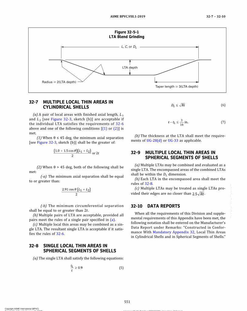
32-7 MULTIPLE LOCAL THIN AREAS INCYLINDRICAL SHELLS
(a) A pair of local areas with finished axial length, L1
and L 2 [see Figure 32-3, sketch (b)] are acceptable ifthe individual LTA satisfies the requirements of 32-6above and one of the following conditions [(1) or (2)] ismet.
(1)When θ ≤ 45 deg, the minimum axial separation[see Figure 32-3, sketch (b)] shall be the greater of:
(2)When θ > 45 deg, both of the following shall bemet:
(-a) The minimum axial separation shall be equalto or greater than:
(-b) The minimum circumferential separationshall be equal to or greater than 2t .
(b)Multiple pairs of LTA are acceptable, provided allpairs meet the rules of a single pair specified in (a).
(c) Multiple local thin areas may be combined as a sin-gle LTA. The resultant single LTA is acceptable if it satis-fies the rules of 32-6.
32-8 SINGLE LOCAL THIN AREAS INSPHERICAL SEGMENTS OF SHELLS
(a) The single LTA shall satisfy the following equations:
ð5Þ
ð6Þ
ð7Þ
(b) The thickness at the LTA shall meet the require-ments of UG-28(d) or UG-33 as applicable.
32-9 MULTIPLE LOCAL THIN AREAS INSPHERICAL SEGMENTS OF SHELLS
(a)Multiple LTAs may be combined and evaluated as asingle LTA. The encompassed areas of the combined LTAsshall be within the DL dimension.
(b) Each LTA in the encompassed area shall meet therules of 32-8.
(c) Multiple LTAs may be treated as single LTAs pro-vided their edges are no closer than .
32-10 DATA REPORTS
When all the requirements of this Division and supple-mental requirements of this Appendix have been met, thefollowing notation shall be entered on the Manufacturer’sData Report under Remarks: “Constructed in Confor-mance With Mandatory Appendix 32, Local Thin Areasin Cylindrical Shells and in Spherical Segments of Shells.”
Figure 32-5-1LTA Blend Grinding
Taper length � 3(LTA depth)
LTA depth
L, C, or DL
Radius � 2(LTA depth)
ASME BPVC.VIII.1-2019 32-7 – 32-10
551
Copyright ASME International (BPVC) Provided by IHS under license with ASME Licensee=Khalda Petroleum/5986215001, User=Amer, Mohamed
Not for Resale, 07/02/2019 13:29:04 MDTNo reproduction or networking permitted without license from IHS
--`,``,``,,`,`,,````,`,``,,,`-`-`,,`,,`,`,,`---

ð19Þ MANDATORY APPENDIX 33STANDARD UNITS FOR USE IN EQUATIONS
DELETED
ASME BPVC.VIII.1-201933
552
Copyright ASME International (BPVC) Provided by IHS under license with ASME Licensee=Khalda Petroleum/5986215001, User=Amer, Mohamed
Not for Resale, 07/02/2019 13:29:04 MDTNo reproduction or networking permitted without license from IHS
--`,``,``,,`,`,,````,`,``,,,`-`-`,,`,,`,`,,`---
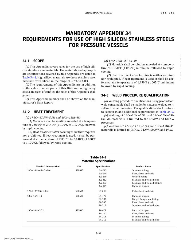
MANDATORY APPENDIX 34REQUIREMENTS FOR USE OF HIGH SILICON STAINLESS STEELS
FOR PRESSURE VESSELS
34-1 SCOPE
(a) This Appendix covers rules for the use of high sili-con stainless steel materials. The materials and appropri-ate specifications covered by this Appendix are listed inTable 34-1. High silicon materials are those stainless steelmaterials with silicon in the range of 3.7% to 6.0%.
(b) The requirements of this Appendix are in additionto the rules in other parts of this Division on high alloysteels. In cases of conflict, the rules of this Appendix shallgovern.
(c) This Appendix number shall be shown on the Man-ufacturer’s Data Report.
34-2 HEAT TREATMENT
(a) 17.5Cr–17.5Ni–5.3Si and 18Cr–15Ni–4Si(1)Materials shall be solution annealed at a tempera-
ture of 2,010°F to 2,140°F (1 100°C to 1 170°C), followedby rapid cooling.
(2) Heat treatment after forming is neither requirednor prohibited. If heat treatment is used, it shall be per-formed at a temperature of 2,010°F to 2,140°F (1 100°Cto 1 170°C), followed by rapid cooling.
(b) 14Cr–16Ni–6Si–Cu–Mo(1)Materials shall be solution annealed at a tempera-
ture of 1,950°F (1 065°C) minimum, followed by rapidcooling.
(2) Heat treatment after forming is neither requirednor prohibited. If heat treatment is used, it shall be per-formed at a temperature of 1,950°F (1 065°C) minimum,followed by rapid cooling.
34-3 WELD PROCEDURE QUALIFICATION
(a)Welding procedure qualifications using production‐weld consumable shall be made for material welded to it-self or to other materials. The qualifications shall conformto Section IX and additional requirements in Table 34-2.
(b)Welding of 18Cr–20Ni–5.5Si and 14Cr–16Ni–6Si–Cu–Mo materials is limited to the GTAW and GMAWprocesses.
(c) Welding of 17.5Cr–17.5Ni–5.3Si and 18Cr–15Ni–4Simaterials is limited to GMAW, GTAW, SMAW, and PAW.
Table 34-1Material Specifications
Nominal Composition UNS Specification Product Form
14Cr–16Ni–6Si–Cu–Mo S38815 SA-213 Seamless tubingSA-240 Plate, sheet, and stripSA-249 Welded tubingSA-312 Seamless and welded pipeSA-403 Seamless and welded fittingsSA-479 Bars and shapes
17.5Cr–17.5Ni–5.3Si S30601 SA-240 Plate, sheet, and strip
18Cr–15Ni–4Si S30600 SA-479 Bars and shapesSA-182 Forged flanges and fittingsSA-240 Plate, sheet, and stripSA-312 Seamless and welded pipe
18Cr–20Ni–5.5Si S32615 SA-479 Bars and shapesSA-240 Plate, sheet, and stripSA-213 Seamless tubingSA-312 Seamless and welded pipe
ASME BPVC.VIII.1-2019 34-1 – 34-3
553
Copyright ASME International (BPVC) Provided by IHS under license with ASME Licensee=Khalda Petroleum/5986215001, User=Amer, Mohamed
Not for Resale, 07/02/2019 13:29:04 MDTNo reproduction or networking permitted without license from IHS
--`,``,``,,`,`,,````,`,``,,,`-`-`,,`,,`,`,,`---

34-4 TOUGHNESS REQUIREMENTS
Minimum design metal temperature for the materialsin this Appendix shall be limited to −50°F (−46°C) andwarmer.
34-5 ADDITIONAL REQUIREMENTS
(a) The rules of Subsection C, Part UHA for austeniticstainless steels shall apply.(b) The additional requirements shown in Table 34-2
shall apply to these materials.
Table 34-2Additional Requirements
Nominal Composition UNS Requirements
14Cr–16Ni–6Si–Cu–Mo S38815 Separate welding procedure and performance qualifications shall be conducted inaccordance with Section IX.
17.5Cr–17.5Ni–5.3Si S30601 Maximum thickness of the material at the welds shall not exceed 1 in. (25 mm).Dimension “A” for the bend test jig in Section IX, Figure QW-466.1 shall be 4t
[11/2 in. (38 mm) for 3/8 in. (10 mm) thick specimen].
18Cr–15Ni–4Si S30600 Plate material shall not exceed 2 in. (50 mm) and bars and tube material shall notexceed 4 in. (100 mm) dia.
Dimension “A” for the bend test jig in Section IX, Figure QW-466.1 shall be 4t[11/2 in. (38 mm) for 3/8 in. (10 mm) thick specimen].
18Cr–20Ni–5.5Si S32615 Grain size of the material, determined in accordance with ASTM Methods E112,Plate II, shall be No. 3 or finer.
The maximum nominal thickness of the weld shall be limited to 1/2 in. (13 mm).
ASME BPVC.VIII.1-201934-4 – 34-5
554
Copyright ASME International (BPVC) Provided by IHS under license with ASME Licensee=Khalda Petroleum/5986215001, User=Amer, Mohamed
Not for Resale, 07/02/2019 13:29:04 MDTNo reproduction or networking permitted without license from IHS
--`,``,``,,`,`,,````,`,``,,,`-`-`,,`,,`,`,,`---

MANDATORY APPENDIX 35RULES FOR MASS PRODUCTION OF PRESSURE VESSELS
35-1 INTRODUCTION
This Appendix provides detailed requirements for themass production of pressure vessels bearing the U Desig-nator at a rate of production that makes it impracticablefor the Inspector [see UG-91(a)(1)] to perform the dutiesnormally assigned under UG-90(c)(1). The provisions ofthis Appendix allow the Manufacturer to assume respon-sibility for carrying out some of the Inspector’s normallyassigned duties by the development, acceptance, and im-plementation of a detailed inspection and quality controlprocedure as described in 35-4. The objective of such aprocedure is to ensure that Code compliance and pres-sure integrity of mass‐produced pressure vessels remainsessentially identical to vessels constructed underUG-90(c)(1). The Inspector must be satisfied the inspec-tion and quality control procedure and the Quality Con-trol System are being fully implemented, and completedvessels meet the applicable requirements of thisDivision.4
35-2 SCOPE
This Appendix provides rules allowing the Manufac-turer of mass‐produced pressure vessels bearing the UDesignator to assume responsibility for carrying out someof the Inspector’s duties normally assigned underUG-90(c)(1), in addition to the responsibilities normallyass igned to the Manufac turer in UG-90(b) . Amass‐production program for pressure vessel fabricationmay be implemented when the requirements of thisAppendix are met.
35-3 GENERAL
(a)Mass production is defined as the construction ofmultiple pressure vessels at a rate of production thatmakes it impracticable for the Inspector to perform allof the duties normally assigned under UG-90(c)(1). TheInspector and/or the Authorized Inspection Agency(AIA) shall determine the acceptability of applying themass‐production inspection and quality control proce-dure to the construction of any vessel or series of vessels.
(b) Construction of two or more pressure vessels pershift at a rate of production that affords the Inspector suf-ficient opportunity to perform the required duties givenin UG-90(c)(1) does not qualify for mass production.
(c) The rules of UG-90(c)(1) shall be applied when con-structing lethal service vessels, unfired steam boilers, ordirect fired pressure vessels.
(d) Pressure vessels constructed under this Appendixshall be identical, except for differences in fitting sizesand locations, shell lengths, and the location and config-uration of nonpressure attachments.
(e) The design and construction of pressure vesselsfabricated under this Appendix shall be reviewed and ac-cepted by the Inspector in accordance with the CertificateHolder’s Quality Control System [see 10-5].
(f) There is no size limitation on mass‐produced pres-sure vessels.
(g)Mass‐produced pressure vessels meeting both (d)above and the in c r emen t a l r equ i r emen t s o fUW-52(b)(1) may be used to establish the 50 ft (15 m)linear weld increment requirements for spot radiography.
35-4 QUALITY CONTROL PROCEDURES
(a) The Manufacturer and the Authorized InspectionAgency (AIA) of record shall collaborate on the prepara-tion of a detailed inspection and quality control proce-dure describing how some of the duties of the Inspectorwill be assumed by the Manufacturer. The inspectionand quality control procedure, along with the QualityControl System, shall be submitted by the Manufacturerto the AIA of record and the legal jurisdiction [seeUG-117(f)] for review and acceptance. The Manufacturershall then submit the inspection and quality control pro-cedure and the Quality Control System to the ASME de-s ignee for f inal acceptance in writ ing prior toimplementation. The final approved version of the inspec-tion and quality control procedure shall be included in theManufacturer’s written Quality Control System [seeUG-117(e)].
(b) The inspection and quality control procedure shallbe implemented at the location of the Manufacturernamed on the Certificate of Authorization. An Inspectoremployed and designated by the AIA of record shall be as-signed at each Manufacturer’s location where mass pro-duction of pressure vessels is being performed. Theassigned Inspector shall perform the required duties, in-cluding verification and oversight of implementation ofthe inspection and quality control procedure as statedin (c) below. A minimum of one full‐time (40 hr per week)Inspector shall be present during mass-production opera-tions to perform the required duties. The Inspector shall
ASME BPVC.VIII.1-2019 35-1 – 35-4
555
Copyright ASME International (BPVC) Provided by IHS under license with ASME Licensee=Khalda Petroleum/5986215001, User=Amer, Mohamed
Not for Resale, 07/02/2019 13:29:04 MDTNo reproduction or networking permitted without license from IHS
--`,``,``,,`,`,,````,`,``,,,`-`-`,,`,,`,`,,`---
ð19Þ
be present at all times during mass-production opera-tions when operating less than 40 hr per week. Whenmultiple shift mass-production operations are takingplace, the required Inspector presence beyond the full‐time requirement shall be a matter of agreement betweenthe AIA of record and the Manufacturer, as set forth in theaccepted inspection and quality control procedure. Manu-facturing personnel who implement the inspection andquality control procedure shall be trained and qualifiedfor their assigned duties in accordance with the Manufac-turer’s Quality Control System. All training and qualifica-tion documentation shall be maintained in accordancewith the Manufacturer’s Quality Control System.(c) The Inspector shall perform all duties specifically
assigned, and any necessary intermittent and unan-nounced inprocess inspections and other inspection ac-tivities required to ensure pressure vessels have beendesigned and constructed in accordance with the require-ments of this Division prior to applying the CertificationMark. The Inspector’s duties shall, as a minimum, includeverifying that
(1) the Manufacturer has a valid Certificate ofAuthorization [UG-117(a)] and is working to a QualityControl System [UG-117(e)]
(2) the applicable design calculations are available[U-2(b), U-2(c), 10-5, and 10-15(d)]
(3)materials used in the construction of the vesselcomply with the requirements of UG-4 through UG-14(UG-93)
(4) all welding and brazing procedures have beenqualified (UW-28, UW-47, and UB-42)
(5) all welders, welding operators, brazers, and braz-ing operators have been qualified (UW-29, UW-48, andUB-43)
(6) the heat treatments, including PWHT, have beenperformed (UG-85, UW-10, UW-40, UW-49, and UF-52)
(7)material imperfections repaired by welding wereacceptably repaired [UG-78, UW-52(d)(2)(-c), UF-37, andUF-47(c)]
(8) required volumetric nondestructive examina-tions, impact tests, and other tests have been performedand that the results are acceptable (UG-84, UW-50,UW-51, and UW-52)
(9) the inspection and quality control procedure isbeing implemented effectively, by monitoring all aspectsof its implementation completely each calendar year
(10) the vessel is in compliance with all the provi-sions of this Division, to the best of his knowledge and be-lief, prior to signing the Certificate of Inspection on theManufacturer’s Data Report(d) In addition to the responsibilities of the Manufac-
turer found in UG-90(b), the Manufacturer is responsiblefor the following duties, as provided in the inspection andquality control procedure described in (a) above:
(1) verifying that weld defects were acceptably re-paired [UW-51(b) and UW-52(c)]
(2)making a visual examination of the vessel to con-firm that the material identification numbers have beenproperly transferred (UG-77 and UG-94)
(3)making a visual examination of the vessel to con-firm that there are no material or dimensional defects(UG-95, UG-96, and UG-97)
(4) verifying that required surface nondestructiveexaminations and other tests have been performed andthat the results are acceptable (UG-93 and UB-44)
(5) performing internal and external examinations,and verifying that the hydrostatic or pneumatic tests havebeen performed (UG-96, UG-97, UG-99, UG-100, andUG-101)
(6) verifying that the required marking is provided(UG-115) and that any nameplate has been attached tothe proper vessel(e) When the Manufacturer wishes to make revisions to
the inspection and quality control procedure affectingcompliance with the requirements of this Division, theManufacturer shall submit the revised inspection andquality control procedure to the AIA of record and the le-gal jurisdiction for review and acceptance. The Manufac-turer shall then submit the accepted revisions to theinspection and quality control procedure to the ASME de-signee for f inal acceptance in writ ing prior toimplementation.
35-5 DATA REPORTS
(a) Form U-1, U-1A, or U-1P prepared by the Manufac-turer for pressure vessels constructed under amass‐production program shall include under “Remarks”the statement: “Constructed under the provisions ofUG-90(c)(2).” The Data Reports shall be certified by theManufacturer and Inspector when the completed vesselsare found to be in compliance with the requirements ofthis Division.(b) Same‐day construction of identical mass‐produced
pressure vessels may be reported on a single Form U-1,U-1A, or U-1P when the requirements of UG-120(a) aremet.
35-6 PNEUMATIC TESTING101
Mass‐produced pressure vessels that otherwise qualifyfor exemption from impact testing per UG-20(f) may bepneumatically tested as described below in lieu of the hy-drostatic test requirements of UG-20(f)(2):(a) The maximum allowable working pressure to be
stamped on the vessel shall not exceed 500 psig(3.5 MPa).(b)Materials used for pressure‐retaining portions of
the vessel, and for non‐pressure parts attached to pres-sure parts by welds having a throat thickness greater than1/4 in. (6 mm), shall be restricted to those listed in thenotes of Figure UCS-66.
ASME BPVC.VIII.1-201935-4 – 35-6
556
Copyright ASME International (BPVC) Provided by IHS under license with ASME Licensee=Khalda Petroleum/5986215001, User=Amer, Mohamed
Not for Resale, 07/02/2019 13:29:04 MDTNo reproduction or networking permitted without license from IHS
--`,``,``,,`,`,,````,`,``,,,`-`-`,,`,,`,`,,`---

(c) The following thickness limitations apply:(1) For butt joints, the nominal thickness at the thick-
est welded joint shall not exceed 1/2 in. (13 mm).(2) For corner joints or lap welds, the thinner of the
two parts joined shall not exceed 1/2 in. (13 mm).(3) ASME B16.5 ferritic steel flanges used at design
metal temperatures no colder than −20°F (−29°C) maybe used without thickness limitation.
(d) The minimum metal temperature during the pneu-matic test shall be maintained at least 30°F (18°C) abovethat given on Figure UCS-66 for the governing materialclassification and thickness combination in UCS-66(a).
(e) The UW-50 NDE requirements are not applicablefor mass‐produced pressure vessels.
(f) The pneumatic test pressure shall be at least equalto 1.3 times the maximum allowable working pressure tobe stamped on the vessel, multiplied by the lowest ratio(for the materials of which the vessel is constructed) ofthe stress value S for the test temperature of the vesselto the stress value S for the design temperature (seeUG-21). In no case shall the pneumatic test pressure ex-ceed 1.3 times the basis for calculated test pressure as de-fined in Mandatory Appendix 3, section 2 by more than10%. The pressure in the vessel shall be gradually in-creased to not more than one‐half of the test pressure.Thereafter, the test pressure shall be increased in stepsof approximately one‐tenth of the test pressure until therequired test pressure has been reached. Then the pres-sure shall be reduced to a value equal to the test pressuredivided by 1.3 and held for a sufficient time to permit in-spection of the vessel. This inspection may be performedas a separate test. The visual inspection of the vessel atthe required test pressure divided by 1.3 may be waived,provided
(1) a suitable gas leak test is applied(2) substitution of the gas leak test is by agreement
reached between Manufacturer and Inspector(3) all welded seams that will be hidden by assembly
are given a visual examination for workmanship prior toassembly
35-7 HYDROSTATIC TESTING
Single-chamber pressure vessels, constructed by aManufacturer under the provisions of UG-90(c)(2), maybe pressure tested separately from their removable
covers in a test fixture, and the corresponding boltedblind flange closures pressure tested only on a qualitycontrol basis, provided all of the following requirementsare met:
(a) Only one end of the pressure vessel may consist of abolted flat blind flange closure. The bolted flat blindflange closure and attachment flange shall comply withthe following requirements:
(1) All requirements of ASME B16.5 for boltedflanges shall be met.
(2) As an alternative to (1), a fabricated flat blindflange may be used, provided it is dimensionally identicalto an ASME B16.5 flange or designed in accordance withMandatory Appendix 2 and UG-34. A flange dimensionallyidentical to ASME B16.5 shall use the pressure–temperature rating for the flange construction materialand class. A cover and flange designed in accordance withMandatory Appendix 2 and UG-34 shall be designed to1.14 times the vessel MAWP at the design temperature.The vessel shell shall not exceed 30 in. (760 mm) outsidediameter. In addition, the ASME B16.5 surface finish andmachining requirements shall be met.
(3) The MAWP of the vessel shall not exceed 500 psi(3.45 MPa), and the maximum design temperature shallnot exceed 650°F (343°C).
(4) No welding shall be permitted on the flat blindflanges.
(b) The pressure vessel with open end shall be tested ina fixture that will permit achieving the test pressure re-quired by UG-99. The vessel shall be mounted to the testfixture in such a manner that the structural integrity andleak tightness of the body flange is established.
(c) One out of every 200 vessels, selected at random,from each day’s production shall be pressure tested perthe rules of UG-99 with its removable cover, service gas-ket, and service bolting installed. If this quality controlvessel fails the test, then all vessels produced in that day’sproduction shall be so tested. All vessels in the subjectproduction lot shall consist of identical vessels and designconditions.
(d) The vessel shall not be constructed and stamped for“lethal” service.
(e) The test fixture shall be designed such that thestress developed in the vessel during the hydrostatic testusing the test fixture shall be the same as the stress devel-oped in the vessel when tested with its removable cover.
ASME BPVC.VIII.1-2019 35-6 – 35-7
557
Copyright ASME International (BPVC) Provided by IHS under license with ASME Licensee=Khalda Petroleum/5986215001, User=Amer, Mohamed
Not for Resale, 07/02/2019 13:29:04 MDTNo reproduction or networking permitted without license from IHS
--`,``,``,,`,`,,````,`,``,,,`-`-`,,`,,`,`,,`---
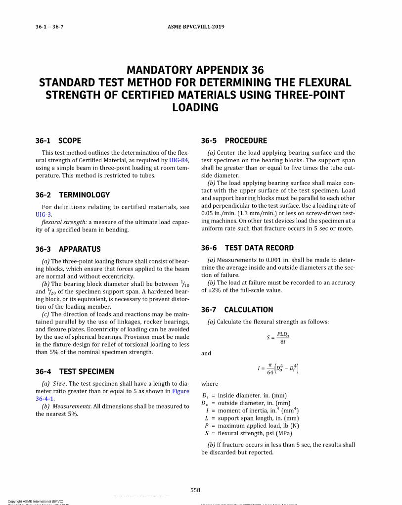
MANDATORY APPENDIX 36STANDARD TEST METHOD FOR DETERMINING THE FLEXURALSTRENGTH OF CERTIFIED MATERIALS USING THREE-POINT
LOADING
36-1 SCOPE
This test method outlines the determination of the flex-ural strength of Certified Material, as required by UIG-84,using a simple beam in three‐point loading at room tem-perature. This method is restricted to tubes.
36-2 TERMINOLOGY
For definitions relating to certified materials, seeUIG-3.flexural strength: a measure of the ultimate load capac-
ity of a specified beam in bending.
36-3 APPARATUS
(a) The three‐point loading fixture shall consist of bear-ing blocks, which ensure that forces applied to the beamare normal and without eccentricity.(b) The bearing block diameter shall be between 1/10
and 1/20 of the specimen support span. A hardened bear-ing block, or its equivalent, is necessary to prevent distor-tion of the loading member.(c) The direction of loads and reactions may be main-
tained parallel by the use of linkages, rocker bearings,and flexure plates. Eccentricity of loading can be avoidedby the use of spherical bearings. Provision must be madein the fixture design for relief of torsional loading to lessthan 5% of the nominal specimen strength.
36-4 TEST SPECIMEN
(a) Size . The test specimen shall have a length to dia-meter ratio greater than or equal to 5 as shown in Figure36-4-1.(b) Measurements. All dimensions shall be measured to
the nearest 5%.
36-5 PROCEDURE
(a) Center the load applying bearing surface and thetest specimen on the bearing blocks. The support spanshall be greater than or equal to five times the tube out-side diameter.(b) The load applying bearing surface shall make con-
tact with the upper surface of the test specimen. Loadand support bearing blocks must be parallel to each otherand perpendicular to the test surface. Use a loading rate of0.05 in./min. (1.3 mm/min.) or less on screw‐driven test-ing machines. On other test devices load the specimen at auniform rate such that fracture occurs in 5 sec or more.
36-6 TEST DATA RECORD
(a)Measurements to 0.001 in. shall be made to deter-mine the average inside and outside diameters at the sec-tion of failure.(b) The load at failure must be recorded to an accuracy
of ±2% of the full‐scale value.
36-7 CALCULATION
(a) Calculate the flexural strength as follows:
and
where
Di = inside diameter, in. (mm)Do = outside diameter, in. (mm)I = moment of inertia, in.4 (mm4)L = support span length, in. (mm)P = maximum applied load, lb (N)S = flexural strength, psi (MPa)
(b) If fracture occurs in less than 5 sec, the results shallbe discarded but reported.
ASME BPVC.VIII.1-201936-1 – 36-7
558
Copyright ASME International (BPVC) Provided by IHS under license with ASME Licensee=Khalda Petroleum/5986215001, User=Amer, Mohamed
Not for Resale, 07/02/2019 13:29:04 MDTNo reproduction or networking permitted without license from IHS
--`,``,``,,`,`,,````,`,``,,,`-`-`,,`,,`,`,,`---

36-8 REPORT
(a) The report of each test shall include the following:(1) specimen identification(2) average outside diameter to the nearest 0.001 in.
(0.025 mm)(3) average inside diameter to the nearest 0.001 in.
(0.025 mm)
(4) span length, in. (mm)(5) rate of loading, in./min (mm/min)(6)maximum applied load, lb (N)(7) flexural strength calculated to the nearest 10 psi
(0.07 MPa)(8) defects in specimen(9) failure mode and location
Figure 36-4-1Test Specimen Arrangement
Do
5 × Do
Di
ASME BPVC.VIII.1-2019 36-8
559
Copyright ASME International (BPVC) Provided by IHS under license with ASME Licensee=Khalda Petroleum/5986215001, User=Amer, Mohamed
Not for Resale, 07/02/2019 13:29:04 MDTNo reproduction or networking permitted without license from IHS
--`,``,``,,`,`,,````,`,``,,,`-`-`,,`,,`,`,,`---
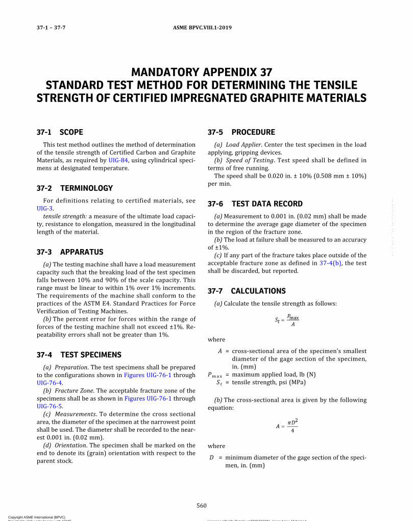
MANDATORY APPENDIX 37STANDARD TEST METHOD FOR DETERMINING THE TENSILE
STRENGTH OF CERTIFIED IMPREGNATED GRAPHITE MATERIALS
37-1 SCOPE
This test method outlines the method of determinationof the tensile strength of Certified Carbon and GraphiteMaterials, as required by UIG-84, using cylindrical speci-mens at designated temperature.
37-2 TERMINOLOGY
For definitions relating to certified materials, seeUIG-3.tensile strength: a measure of the ultimate load capaci-
ty, resistance to elongation, measured in the longitudinallength of the material.
37-3 APPARATUS
(a) The testing machine shall have a load measurementcapacity such that the breaking load of the test specimenfalls between 10% and 90% of the scale capacity. Thisrange must be linear to within 1% over 1% increments.The requirements of the machine shall conform to thepractices of the ASTM E4. Standard Practices for ForceVerification of Testing Machines.(b) The percent error for forces within the range of
forces of the testing machine shall not exceed ±1%. Re-peatability errors shall not be greater than 1%.
37-4 TEST SPECIMENS
(a) Preparation. The test specimens shall be preparedto the configurations shown in Figures UIG-76-1 throughUIG-76-4.(b) Fracture Zone. The acceptable fracture zone of the
specimens shall be as shown in Figures UIG-76-1 throughUIG-76-5.(c) Measurements. To determine the cross sectional
area, the diameter of the specimen at the narrowest pointshall be used. The diameter shall be recorded to the near-est 0.001 in. (0.02 mm).(d) Orientation. The specimen shall be marked on the
end to denote its (grain) orientation with respect to theparent stock.
37-5 PROCEDURE
(a) Load Applier. Center the test specimen in the loadapplying, gripping devices.(b) Speed of Testing. Test speed shall be defined in
terms of free running.The speed shall be 0.020 in. ± 10% (0.508 mm ± 10%)
per min.
37-6 TEST DATA RECORD
(a)Measurement to 0.001 in. (0.02 mm) shall be madeto determine the average gage diameter of the specimenin the region of the fracture zone.(b) The load at failure shall be measured to an accuracy
of ±1%.(c) If any part of the fracture takes place outside of the
acceptable fracture zone as defined in 37-4(b), the testshall be discarded, but reported.
37-7 CALCULATIONS
(a) Calculate the tensile strength as follows:
where
A = cross‐sectional area of the specimen’s smallestdiameter of the gage section of the specimen,in. (mm)
Pmax = maximum applied load, lb (N)St = tensile strength, psi (MPa)
(b) The cross‐sectional area is given by the followingequation:
where
D = minimum diameter of the gage section of the speci-men, in. (mm)
ASME BPVC.VIII.1-201937-1 – 37-7
560
Copyright ASME International (BPVC) Provided by IHS under license with ASME Licensee=Khalda Petroleum/5986215001, User=Amer, Mohamed
Not for Resale, 07/02/2019 13:29:04 MDTNo reproduction or networking permitted without license from IHS
--`,``,``,,`,`,,````,`,``,,,`-`-`,,`,,`,`,,`---

37-8 REPORTS
(a) The report of each test shall include the following:(1) sample identification(2)minimum gage diameter to the nearest 0.001 in.(3) rate of loading
(4)maximum applied load(5) tensile strength calculated to the nearest 10 psi(6) defects in specimens(7) orientation of specimen, with or against the grain(8) failure mode and location
ASME BPVC.VIII.1-2019 37-8
561
Copyright ASME International (BPVC) Provided by IHS under license with ASME Licensee=Khalda Petroleum/5986215001, User=Amer, Mohamed
Not for Resale, 07/02/2019 13:29:04 MDTNo reproduction or networking permitted without license from IHS
--`,``,``,,`,`,,````,`,``,,,`-`-`,,`,,`,`,,`---

MANDATORY APPENDIX 38STANDARD TEST METHOD FOR COMPRESSIVE STRENGTH OF
IMPREGNATED GRAPHITE
38-1 SCOPE
(a) This test method covers the determination of thecompressive strength of impervious carbon and graphiteat room temperature.(b) This Standard does not purport to address all of the
safety concerns, if any, associated with its use. It is the re-sponsibility of the user of this Standard to establish ap-propriate safety and health practices and determine theapplicability of regulatory limitations prior to use.
38-2 REFERENCED DOCUMENTS
ASTM C709, Standard Terminology Relating to Manufac-tured Carbon and Graphite
ASTM E4, Standard Practices for Force Verification ofTesting Machines
ASTM E177, Standard Practice for Use of the Terms Pre-cision and Bias in ASTM Test Methods
ASTM E691, Standard Practice for Conducting an Interla-boratory Study to Determine the Precision of a TestMethod
Publisher: American Society for Testing and Materials(ASTM International), 100 Barr Harbor Drive, P.O.Box C700, West Conshohocken, PA 19428-2959, (610)832-9585, (https://www.astm.org)
38-3 TERMINOLOGY
See UIG-3 for definitions of terms related to manufac-tured impregnated graphite.
38-4 SIGNIFICANCE AND USE
Impregnated graphite can usually support higher loadsin compression than in any other mode of stress. Thecompressive strength test, therefore, provides a measureof the maximum load‐bearing capability of carbon andgraphite objects and the results are used to generate ma-terial flexural‐compression strength ratios.
38-5 APPARATUS
(a) Test machine, conforming to Practice E4 and to therequirements for speed of testing prescribed in Section 8of this test method.(b) All load‐bearing machine and fixture surfaces shall
have a minimum hardness of 45 HRC and surface finishof 16 μin. (0.4 μm) rms maximum. Surfaces in contactw i th the spec imen sha l l b e f l a t t o l e s s than0.0005 in./in. (0.0005 mm/mm).(c) Examples of arrangements of the load train are
shown schematically in Figs. 1 and 2 in ASTM C695.
38-6 SAMPLING
Samples may be taken from locations and orientationsthat satisfy the objectives of the test.
38-7 TEST SPECIMEN
The test specimen shall be a 3/4 in. (19 mm) cube or anO.D./I.D. tube with height equal to the tube O.D. with endsmachined to yield planar and parallel faces. These facesshall be perpendicular to within 0.001 in. (0.025 mm) ofa length total indicator reading. Reasonable care shouldbe exercised to ensure that all edges are sharp and with-out chips or other flaws.
38-8 PROCEDURE
(a) Center the specimen in the machine between thecontact surfaces. The deviation of the specimen axis fromthe machine axis shall be less than 5% of the specimenlength. Centering can be assisted by appropriate circlesmarked on the contact surfaces.(b) Place an appropriate guard around the specimen to
deflect flying fragments at failure.(c) Apply the load continuously, and without shock un-
til ultimate failure.(d) If the test machine is equipped with a load or strain
pacing device, a constant load or strain rate may be used.
ASME BPVC.VIII.1-201938-1 – 38-8
562
Copyright ASME International (BPVC) Provided by IHS under license with ASME Licensee=Khalda Petroleum/5986215001, User=Amer, Mohamed
Not for Resale, 07/02/2019 13:29:04 MDTNo reproduction or networking permitted without license from IHS
--`,``,``,,`,`,,````,`,``,,,`-`-`,,`,,`,`,,`---
38-9 CALCULATION
Calculate the compressive strength of each specimen asfollows:
where
A = calculated area of the gage section of the specimen,in2 (mm2)
C = compressive strength of specimen, psi (MPa)W = total load on the specimen at failure, lbf (N)
38-10 REPORT
The report shall include the following:(a) type of testing machine, hydraulic or screw(b) type and size of contact blocks(c) general description of material being tested(d) dimensions, location, and orientation of specimens(e) details of specimen preparation
(f) rate of crosshead or platen movement, or load rate,or strain rate
(g) load of failure, failure mode, and compressivestrength of each specimen, and material tested
(h)mean compressive strength and standard deviationfor material tested
38-11 PRECISION AND BIAS
(a) Precision. The precision statements given in thissection are based on the comparison of the mean strengthby the Student “t” test and carrying out the statisticalanalysis of the data obtained in a round robin as recom-mended by Practice E 691. The round robin was carriedout on two materials.
(b) Comparison of the Means. The comparison of themeans by the Student’s t test leads to the conclusion thatthe average strength values measured by each laboratoryon each material is considered statistically equal at 95%confidence level.
ASME BPVC.VIII.1-2019 38-9 – 38-11
563
Copyright ASME International (BPVC) Provided by IHS under license with ASME Licensee=Khalda Petroleum/5986215001, User=Amer, Mohamed
Not for Resale, 07/02/2019 13:29:04 MDTNo reproduction or networking permitted without license from IHS
--`,``,``,,`,`,,````,`,``,,,`-`-`,,`,,`,`,,`---
ð19Þ
MANDATORY APPENDIX 39TESTING THE COEFFICIENT OF PERMEABILITY OF
IMPREGNATED GRAPHITE
39-1 SCOPE AND FIELD OF APPLICATION
The vacuum‐decay method specified in this standardserves to determine the coefficient of permeability of testspecimens made from carbon and graphite materials (so-lid matter) at room temperature. With this method usingair as experimental gas, coefficients of permeability be-tween about 101 and 10−9 in.2/sec can be determined.The coefficient of permeability gives the admittance ofgas through solid materials.
39-2 CONCEPT
(a) Coefficient of PermeabilityThe coefficient of permeability k(L) is the volume of air
flow through the test specimen divided by its cross sec-tion at a constant pressure difference.
where
A = the effective cross section of the test specimenin the direction of flow, in.2 (mm2)
dV/dt = the volume airflow within a time period,in.3/sec (mm3/s)
l = the effective length of the test specimen in thedirection of flow, in. (mm)
p = the average pressure (pa + pi)/2, lb/in.2 (MPa)
where
pa = the pressure of the air entering the testspecimen
pi = the pressure of the air leaving the testspecimen
Δp = the pressure difference pa− pi, lb/in.2 (MPa)
(b) Vacuum‐Decay MethodThe vacuum‐decay method uses air as experimental gas
to measure the coefficient of permeability, k(L), by deter-mination of the pressure increase in a constant volume.
where
A = the effective cross section of the test specimen,in.2 (mm2)
dpi/dt = the rate of the pressure increase in the measur-ing volume within a time period
Δp = the average pressure difference, pa − pi, lb/in.2
(MPa)
pa = the pressure of air entering the testspecimen
pi = the pressure of air leaving the test spe-cimen, to be calculated from pi = (p11 +p12)/2, where
p11 = the pressure of the air entering the testspecimen at the beginning of themeasurement
p12 = the pressure of the air leaving thetest spec imen at the end of themeasurement
V = the measuring volume, in.3 (mm3). The mea-suring volume is the volume in which the pres-sure of air as experimental gas varies duringthe test. In the case of tubular test specimens,the measuring volume is the sum of the cavityvolumes of the vacuum device and the test spe-cimen. The pore volume of the test specimen isnot taken into account.
39-3 PRINCIPLE
In an evacuated measuring volume, which is separatedfrom the outside air by the test specimen, the time depen-dent pressure increase caused by the inflowing air is de-termined. The coefficient of permeability is calculatedfrom this pressure increase (vacuum‐decay), from thepressure difference over the test specimen, the dimen-sions of the test specimen, and the measuring volume.
39-4 APPARATUS
Vacuum apparatus (see schematic diagram in Figure39-4-1)
ASME BPVC.VIII.1-201939-1 – 39-4
564
Copyright ASME International (BPVC) Provided by IHS under license with ASME Licensee=Khalda Petroleum/5986215001, User=Amer, Mohamed
Not for Resale, 07/02/2019 13:29:04 MDTNo reproduction or networking permitted without license from IHS
--`,``,``,,`,`,,````,`,``,,,`-`-`,,`,,`,`,,`---
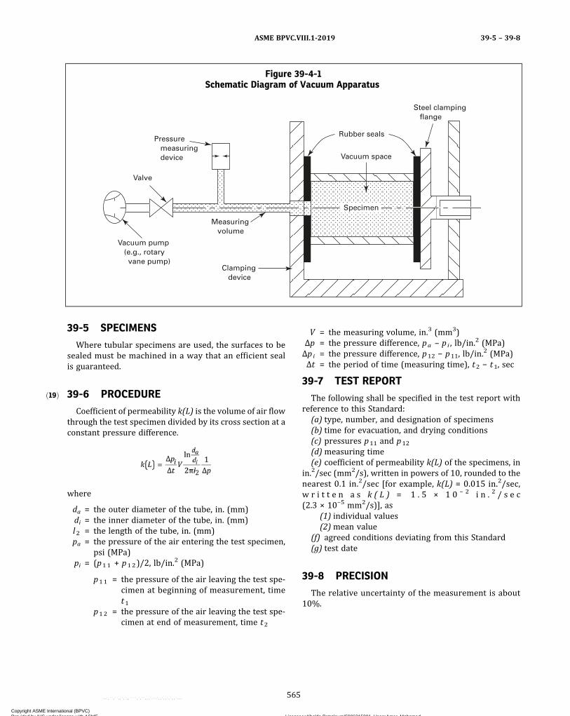
ð19Þ
39-5 SPECIMENS
Where tubular specimens are used, the surfaces to besealed must be machined in a way that an efficient sealis guaranteed.
39-6 PROCEDURE
Coefficient of permeability k(L) is the volume of air flowthrough the test specimen divided by its cross section at aconstant pressure difference.
where
da = the outer diameter of the tube, in. (mm)di = the inner diameter of the tube, in. (mm)l2 = the length of the tube, in. (mm)pa = the pressure of the air entering the test specimen,
psi (MPa)pi = (p11 + p12)/2, lb/in.
2 (MPa)
p11 = the pressure of the air leaving the test spe-cimen at beginning of measurement, timet1
p12 = the pressure of the air leaving the test spe-cimen at end of measurement, time t2
V = the measuring volume, in.3 (mm3)Δp = the pressure difference, pa – pi , lb/in.
2 (MPa)Δpi = the pressure difference, p12 − p11, lb/in.
2 (MPa)Δt = the period of time (measuring time), t2 − t1, sec
39-7 TEST REPORT
The following shall be specified in the test report withreference to this Standard:
(a) type, number, and designation of specimens(b) time for evacuation, and drying conditions(c) pressures p11 and p12
(d)measuring time(e) coefficient of permeability k(L) of the specimens, in
in.2/sec (mm2/s), written in powers of 10, rounded to thenearest 0.1 in.2/sec [for example, k(L) = 0.015 in.2/sec,w r i t t e n a s k ( L ) = 1 . 5 × 1 0 − 2 i n . 2 / s e c(2.3 × 10⁻⁵ mm2/s)], as
(1) individual values(2)mean value
(f) agreed conditions deviating from this Standard(g) test date
39-8 PRECISION
The relative uncertainty of the measurement is about10%.
Figure 39-4-1Schematic Diagram of Vacuum Apparatus
Pressure measuring device
Vacuum pump (e.g., rotary vane pump)
Valve
Measuring volume
Steel clamping flange
Specimen
Clamping device
Rubber seals
Vacuum space
ASME BPVC.VIII.1-2019 39-5 – 39-8
565
Copyright ASME International (BPVC) Provided by IHS under license with ASME Licensee=Khalda Petroleum/5986215001, User=Amer, Mohamed
Not for Resale, 07/02/2019 13:29:04 MDTNo reproduction or networking permitted without license from IHS
--`,``,``,,`,`,,````,`,``,,,`-`-`,,`,,`,`,,`---
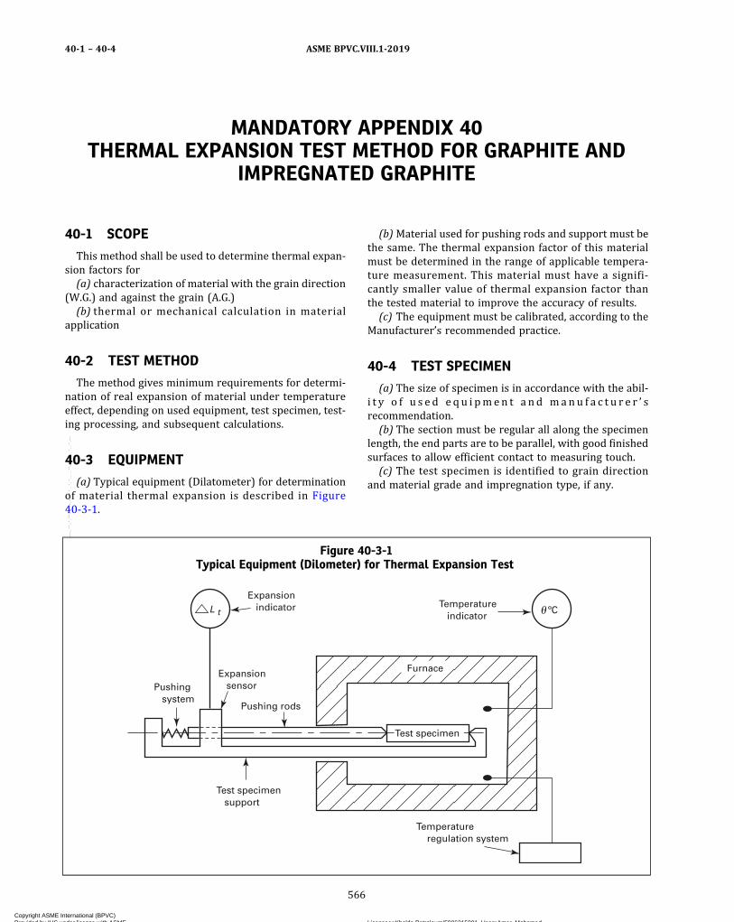
MANDATORY APPENDIX 40THERMAL EXPANSION TEST METHOD FOR GRAPHITE AND
IMPREGNATED GRAPHITE
40-1 SCOPE
This method shall be used to determine thermal expan-sion factors for(a) characterization of material with the grain direction
(W.G.) and against the grain (A.G.)(b) thermal or mechanical calculation in material
application
40-2 TEST METHOD
The method gives minimum requirements for determi-nation of real expansion of material under temperatureeffect, depending on used equipment, test specimen, test-ing processing, and subsequent calculations.
40-3 EQUIPMENT
(a) Typical equipment (Dilatometer) for determinationof material thermal expansion is described in Figure40-3-1.
(b)Material used for pushing rods and support must bethe same. The thermal expansion factor of this materialmust be determined in the range of applicable tempera-ture measurement. This material must have a signifi-cantly smaller value of thermal expansion factor thanthe tested material to improve the accuracy of results.(c) The equipment must be calibrated, according to the
Manufacturer’s recommended practice.
40-4 TEST SPECIMEN
(a) The size of specimen is in accordance with the abil-i t y o f u s e d e q u i pmen t a n d manu f a c t u r e r ’ srecommendation.(b) The section must be regular all along the specimen
length, the end parts are to be parallel, with good finishedsurfaces to allow efficient contact to measuring touch.(c) The test specimen is identified to grain direction
and material grade and impregnation type, if any.
Figure 40-3-1Typical Equipment (Dilometer) for Thermal Expansion Test
Pushing system
Expansion sensor
Pushing rods
Test specimen
Test specimen support
L tTemperature indicator
Expansion indicator
Temperature regulation system
ºC
Furnace
ASME BPVC.VIII.1-201940-1 – 40-4
566
Copyright ASME International (BPVC) Provided by IHS under license with ASME Licensee=Khalda Petroleum/5986215001, User=Amer, Mohamed
Not for Resale, 07/02/2019 13:29:04 MDTNo reproduction or networking permitted without license from IHS
--`,``,``,,`,`,,````,`,``,,,`-`-`,,`,,`,`,,`---
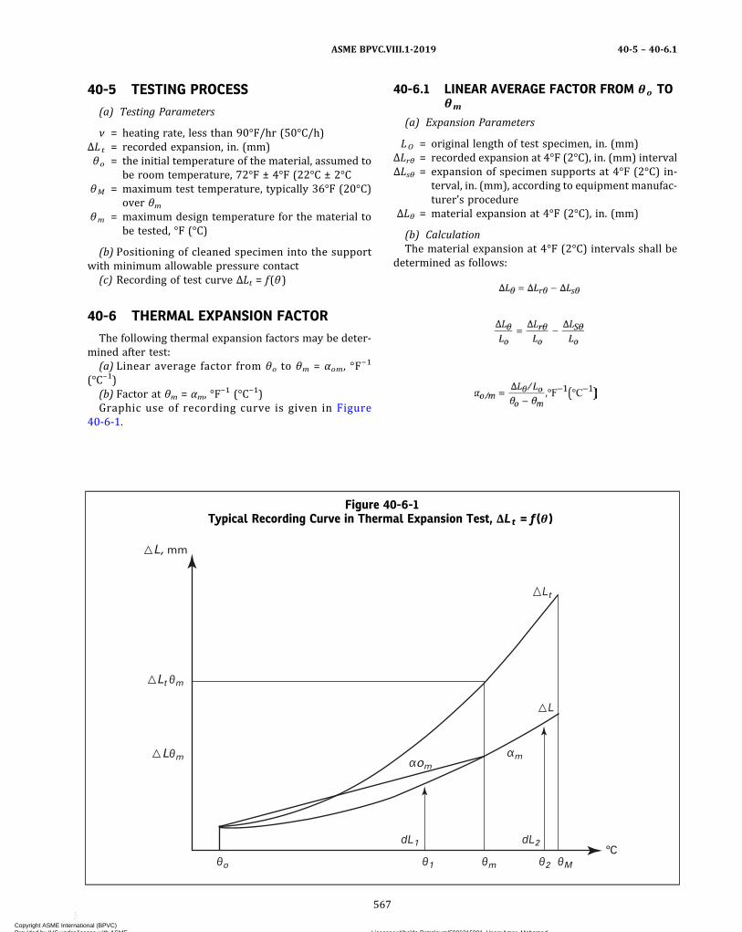
40-5 TESTING PROCESS
(a) Testing Parameters
ν = heating rate, less than 90°F/hr (50°C/h)ΔLt = recorded expansion, in. (mm)θo = the initial temperature of the material, assumed to
be room temperature, 72°F ± 4°F (22°C ± 2°CθM = maximum test temperature, typically 36°F (20°C)
over θmθm = maximum design temperature for the material to
be tested, °F (°C)
(b) Positioning of cleaned specimen into the supportwith minimum allowable pressure contact
(c) Recording of test curve ΔLt = f(θ)
40-6 THERMAL EXPANSION FACTOR
The following thermal expansion factors may be deter-mined after test:
(a) Linear average factor from θo to θm = αom, °F−1
(°C−1)(b) Factor at θm = αm, °F
−1 (°C−1)Graphic use of recording curve is given in Figure
40-6-1.
40-6.1 LINEAR AVERAGE FACTOR FROM θo TOθm
(a) Expansion Parameters
LO = original length of test specimen, in. (mm)ΔLrθ = recorded expansion at 4°F (2°C), in. (mm) intervalΔLsθ = expansion of specimen supports at 4°F (2°C) in-
terval, in. (mm), according to equipment manufac-turer’s procedure
ΔLθ = material expansion at 4°F (2°C), in. (mm)
(b) CalculationThe material expansion at 4°F (2°C) intervals shall be
determined as follows:
Figure 40-6-1Typical Recording Curve in Thermal Expansion Test, ΔLt = f(θ )
θ1θo θm
dL1 dL2
Lθm
θ2 θM
αomαm
Lt θm
L, mm
Lt
L
ºC
ASME BPVC.VIII.1-2019 40-5 – 40-6.1
567
Copyright ASME International (BPVC) Provided by IHS under license with ASME Licensee=Khalda Petroleum/5986215001, User=Amer, Mohamed
Not for Resale, 07/02/2019 13:29:04 MDTNo reproduction or networking permitted without license from IHS
--`,``,``,,`,`,,````,`,``,,,`-`-`,,`,,`,`,,`---

40-6.2 FACTOR AT θm
(a) This factor is given by the slope of a tangent line tothe material expansion curve on θm point.(b) This factor may be determined by graphic construc-
tion as indicated on Figure 40-6-1.
wheredL1 = obtained by construction on θ1 pointdL2 = obtained by construction on θ2 pointdθ = (θM − θm), °F (°C)θ1 = (θM − dθ), °F (°C)θ2 = (θm + dθ), °F (°C)
40-6.3 REPORTThe following information shall be included in the
report:(a) identification of test and recording(b) type of equipment‐support and pushing rod materi-
al, pushing level(c) test specimen dimensions, material grade/impreg-
nation, grain direction(d) heating rate, origin and maximal operating
temperature(e) test results α0m and/or αm; usually in E−6, °F−1 (°C−1)
unit(f) name, title, and date
ASME BPVC.VIII.1-201940-6.2 – 40-6.3
568
Copyright ASME International (BPVC) Provided by IHS under license with ASME Licensee=Khalda Petroleum/5986215001, User=Amer, Mohamed
Not for Resale, 07/02/2019 13:29:04 MDTNo reproduction or networking permitted without license from IHS
--`,``,``,,`,`,,````,`,``,,,`-`-`,,`,,`,`,,`---
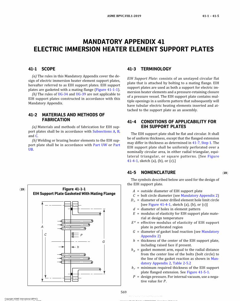
ð19Þ
MANDATORY APPENDIX 41ELECTRIC IMMERSION HEATER ELEMENT SUPPORT PLATES
41-1 SCOPE
(a) The rules in this Mandatory Appendix cover the de-sign of electric immersion heater element support plates,hereafter referred to as EIH support plates. EIH supportplates are gasketed with a mating flange (Figure 41-1-1).
(b) The rules of UG-34 and UG-39 are not applicable toEIH support plates constructed in accordance with thisMandatory Appendix.
41-2 MATERIALS AND METHODS OFFABRICATION
(a)Materials and methods of fabrication for EIH sup-port plates shall be in accordance with Subsections A, B,and C.
(b)Welding or brazing heater elements to the EIH sup-port plate shall be in accordance with Part UW or PartUB.
41-3 TERMINOLOGY
EIH Support Plate: consists of an unstayed circular flatplate that is attached by bolting to a mating flange. EIHsupport plates are used as both a support for electric im-mersion heater elements and a pressure-retaining closureof a pressure vessel. The EIH support plate contains mul-tiple openings in a uniform pattern that subsequently willhave tubular electric heating elements inserted and at-tached to the support plate as an assembly.
41-4 CONDITIONS OF APPLICABILITY FOREIH SUPPORT PLATES
The EIH support plate shall be flat and circular. It shallbe of uniform thickness, except that the flanged extensionmay differ in thickness as determined in 41-7, Step 1. TheEIH support plate shall be uniformly perforated over anominally circular area, in either radial triangular, equi-lateral triangular, or square patterns. [See Figure41-4-1, sketch (a), (b), or (c).]
41-5 NOMENCLATURE
The symbols described below are used for the design ofthe EIH support plate.
A = outside diameter of EIH support plateC = bolt circle diameter (see Mandatory Appendix 2)
Do = diameter of outer drilled element hole limit circle[see Figure 41-4-1, sketch (a), (b), or (c)]
d = diameter of holes in element patternE = modulus of elasticity for EIH support plate mate-
rial at design temperatureE* = effective modulus of elasticity of EIH support
plate in perforated regionG = diameter of gasket load reaction (see Mandatory
Appendix 2)h = thickness of the center of the EIH support plate,
including raised face if present.hg = gasket moment arm, equal to the radial distance
from the center line of the bolts (bolt circle) tothe line of the gasket reaction as shown in Man-datory Appendix 2, Table 2-5.2
hr = minimum required thickness of the EIH supportplate flanged extension. See Figure 41-5-1.
P = design pressure. For internal vacuum, use a nega-tive value for P .
ð19Þ Figure 41-1-1EIH Support Plate Gasketed With Mating Flange
A
C P
h
G
ASME BPVC.VIII.1-2019 41-1 – 41-5
569
Copyright ASME International (BPVC) Provided by IHS under license with ASME Licensee=Khalda Petroleum/5986215001, User=Amer, Mohamed
Not for Resale, 07/02/2019 13:29:04 MDTNo reproduction or networking permitted without license from IHS
--`,``,``,,`,`,,````,`,``,,,`-`-`,,`,,`,`,,`---

Figure 41-4-1Typical EIH Support Plate and Element Geometry
(a) Radial Triangular Element Pattern [Note (1)] (b) Equilateral Triangular Element Pattern
p
Do
ro
(c) Square Element Pattern
p
Do
ro
p
Do
ro
NOTE:(1) p = minimum spacing
ASME BPVC.VIII.1-201941-5
570
Copyright ASME International (BPVC) Provided by IHS under license with ASME Licensee=Khalda Petroleum/5986215001, User=Amer, Mohamed
Not for Resale, 07/02/2019 13:29:04 MDTNo reproduction or networking permitted without license from IHS
--`,``,``,,`,`,,````,`,``,,,`-`-`,,`,,`,`,,`---
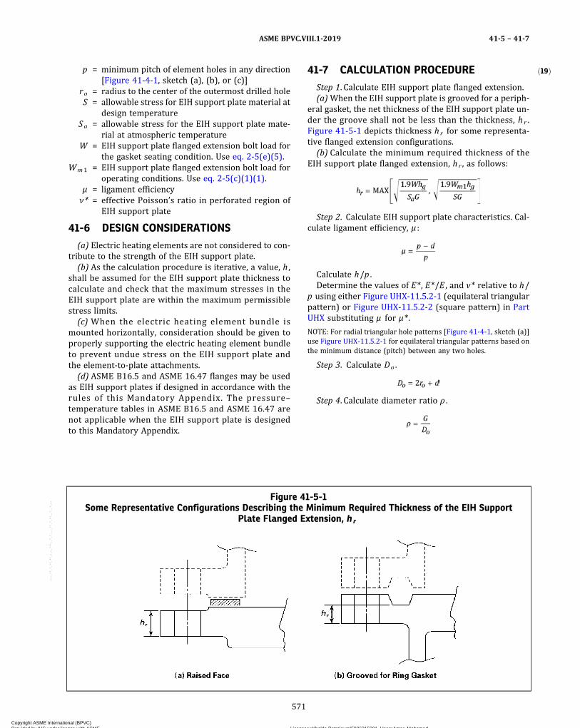
ð19Þp = minimum pitch of element holes in any direction[Figure 41-4-1, sketch (a), (b), or (c)]
ro = radius to the center of the outermost drilled holeS = allowable stress for EIH support plate material at
design temperatureSa = allowable stress for the EIH support plate mate-
rial at atmospheric temperatureW = EIH support plate flanged extension bolt load for
the gasket seating condition. Use eq. 2-5(e)(5).Wm1 = EIH support plate flanged extension bolt load for
operating conditions. Use eq. 2-5(c)(1)(1).μ = ligament efficiencyν* = effective Poisson’s ratio in perforated region of
EIH support plate
41-6 DESIGN CONSIDERATIONS
(a) Electric heating elements are not considered to con-tribute to the strength of the EIH support plate.
(b) As the calculation procedure is iterative, a value, h ,shall be assumed for the EIH support plate thickness tocalculate and check that the maximum stresses in theEIH support plate are within the maximum permissiblestress limits.
(c) When the electric heating element bundle ismounted horizontally, consideration should be given toproperly supporting the electric heating element bundleto prevent undue stress on the EIH support plate andthe element-to-plate attachments.
(d) ASME B16.5 and ASME 16.47 flanges may be usedas EIH support plates if designed in accordance with therules of this Mandatory Appendix. The pressure–temperature tables in ASME B16.5 and ASME 16.47 arenot applicable when the EIH support plate is designedto this Mandatory Appendix.
41-7 CALCULATION PROCEDURE
Step 1. Calculate EIH support plate flanged extension.(a)When the EIH support plate is grooved for a periph-
eral gasket, the net thickness of the EIH support plate un-der the groove shall not be less than the thickness, hr .Figure 41-5-1 depicts thickness hr for some representa-tive flanged extension configurations.
(b) Calculate the minimum required thickness of theEIH support plate flanged extension, hr , as follows:
Step 2. Calculate EIH support plate characteristics. Cal-culate ligament efficiency, μ :
Calculate h/p .Determine the values of E*, E*/E , and ν* relative to h/
p using either Figure UHX-11.5.2-1 (equilateral triangularpattern) or Figure UHX-11.5.2-2 (square pattern) in PartUHX substituting μ for μ*.
NOTE: For radial triangular hole patterns [Figure 41-4-1, sketch (a)]use Figure UHX-11.5.2-1 for equilateral triangular patterns based onthe minimum distance (pitch) between any two holes.
Step 3. Calculate Do .
Step 4. Calculate diameter ratio ρ .
Figure 41-5-1Some Representative Configurations Describing the Minimum Required Thickness of the EIH Support
Plate Flanged Extension, hr
ASME BPVC.VIII.1-2019 41-5 – 41-7
571
Copyright ASME International (BPVC) Provided by IHS under license with ASME Licensee=Khalda Petroleum/5986215001, User=Amer, Mohamed
Not for Resale, 07/02/2019 13:29:04 MDTNo reproduction or networking permitted without license from IHS
--`,``,``,,`,`,,````,`,``,,,`-`-`,,`,,`,`,,`---

Step 5. Calculate moment, MTS , due to pressure, P , act-ing on the unperforated EIH support plate rim:
Step 6. Calculate diameter ratio, K .
Step 7. Calculate coefficient, F .
Step 8. Calculate moment, M*, acting on the unperfo-rated EIH support plate rim.
Step 9. Calculate the maximum bending moments act-ing on the EIH support plate at the periphery, Mp , andat the center, Mo .
Step 10.Determine the maximum bending moment act-ing on the EIH support plate.
Step 11. Calculate the EIH support plate bendingstress, σ .
If σ ≤ 2S , the assumed EIH support plate thickness isacceptable for bending. Otherwise, increase the assumedthickness, h , and return to Step 2.Step 12. Calculate the average shear stress, τ , in the EIH
support plate at the outer edge of the perforated regionusing the absolute value of pressure, |P |.
If τ ≤ 0.8S , the assumed EIH support plate thickness isacceptable for shear. Otherwise, increase the assumedthickness, h , and return to Step 2.
41-8 PRESSURE TEST REQUIREMENT
The EIH support plate shall be subjected to a pressuretest in accordance with UG-99 or UG-100.
41-9 DATA REPORTS
When all the requirements of this Mandatory Appendixhave been met, the following notation shall be entered onthe Manufacturer’s Data Report under Remarks: “Con-struction in Conformance with Mandatory Appendix 41,Electric Immersion Heater Element Support Plates.”
41-10 EXAMPLE
An example illustrating the use of the design rules giv-en in this Mandatory Appendix is shown as follows.
41-10.1 DATA SUMMARY(a) The design pressure is 500 psi at the design tem-
perature of 500°F.(b) The mating flange is an ASME B16.5, NPS-8, CI 300
flange. Therefore, an ASME B16.5, NPS-8, CI 300 blindflange is chosen to construct the EIH support plate. Theflange thickness according to the specification is 1.62 in.thick in the center and 1.56 in. thick in the extension.The flange outside diameter is 15.00 in. with a bolt circleof 13.0 in. and twelve 7/8 in. SA-193-B7 bolts. The materialof the flange is SA-350 Grade LF2 (K03011) with a0.125 in. corrosion allowance. There are forty-eight0.500 in. diameter element insertion holes drilled in anequilateral triangle pattern with a minimum pitch of0.98425 in. The radius to the center of the outermost ele-ment hole center is 3.445 in.(c) The gasket is 10.5 in. OD and 9 in. ID and has a gas-
ket factor, m , of 2.0 and the minimum design seatingstress, y , of 2,500 psi.(d) Data Summaries. The data summaries consist of
those variables in the nomenclature, 41-5, that are applic-able to this configuration.
d = 0.500 in.E = 27.3 × 10⁶ psi at 500°F, Section II, Part D,
Subpart 2, Table TM-1G = 9.888 in.h = 1.62 in.hg = 1.556 in.P = 500 psi
ASME BPVC.VIII.1-201941-7 – 41-10.1
572
Copyright ASME International (BPVC) Provided by IHS under license with ASME Licensee=Khalda Petroleum/5986215001, User=Amer, Mohamed
Not for Resale, 07/02/2019 13:29:04 MDTNo reproduction or networking permitted without license from IHS
--`,``,``,,`,`,,````,`,``,,,`-`-`,,`,,`,`,,`---
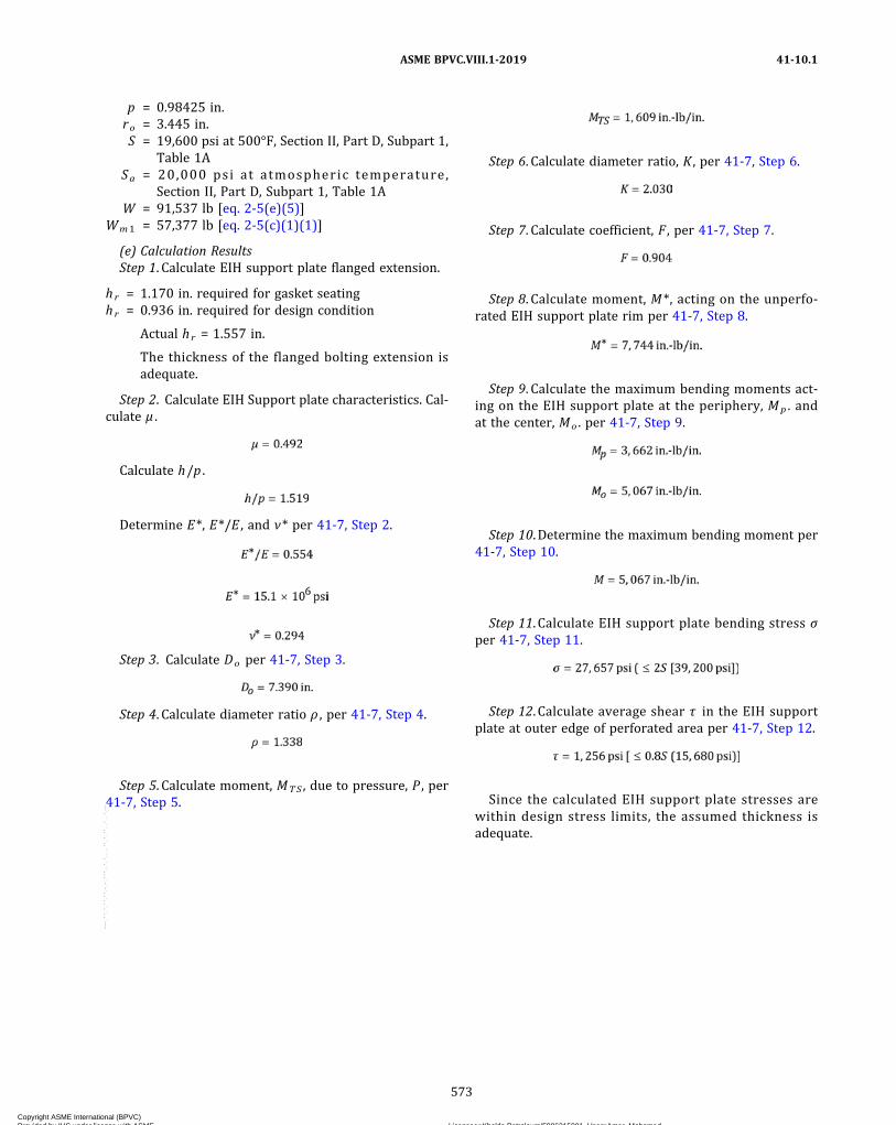
p = 0.98425 in.ro = 3.445 in.S = 19,600 psi at 500°F, Section II, Part D, Subpart 1,
Table 1ASa = 20,000 psi at atmospheric temperature,
Section II, Part D, Subpart 1, Table 1AW = 91,537 lb [eq. 2-5(e)(5)]
Wm1 = 57,377 lb [eq. 2-5(c)(1)(1)]
(e) Calculation ResultsStep 1. Calculate EIH support plate flanged extension.
hr = 1.170 in. required for gasket seatinghr = 0.936 in. required for design condition
Actual hr = 1.557 in.
The thickness of the flanged bolting extension isadequate.
Step 2. Calculate EIH Support plate characteristics. Cal-culate μ .
Calculate h/p .
Determine E*, E*/E , and ν* per 41-7, Step 2.
Step 3. Calculate Do per 41-7, Step 3.
Step 4. Calculate diameter ratio ρ , per 41-7, Step 4.
Step 5. Calculate moment, MTS , due to pressure, P , per41-7, Step 5.
Step 6. Calculate diameter ratio, K , per 41-7, Step 6.
Step 7. Calculate coefficient, F , per 41-7, Step 7.
Step 8. Calculate moment, M*, acting on the unperfo-rated EIH support plate rim per 41-7, Step 8.
Step 9. Calculate the maximum bending moments act-ing on the EIH support plate at the periphery, Mp . andat the center, Mo . per 41-7, Step 9.
Step 10.Determine the maximum bending moment per41-7, Step 10.
Step 11. Calculate EIH support plate bending stress σper 41-7, Step 11.
Step 12. Calculate average shear τ in the EIH supportplate at outer edge of perforated area per 41-7, Step 12.
Since the calculated EIH support plate stresses arewithin design stress limits, the assumed thickness isadequate.
ASME BPVC.VIII.1-2019 41-10.1
573
Copyright ASME International (BPVC) Provided by IHS under license with ASME Licensee=Khalda Petroleum/5986215001, User=Amer, Mohamed
Not for Resale, 07/02/2019 13:29:04 MDTNo reproduction or networking permitted without license from IHS
--`,``,``,,`,`,,````,`,``,,,`-`-`,,`,,`,`,,`---
MANDATORY APPENDIX 42DIFFUSION BONDING
42-1 GENERAL
This Mandatory Appendix establishes the requirementsfor procedure specifications for diffusion bonding in theconstruction of microchannel heat exchangers.
42-2 DIFFUSION BONDING PROCEDURESPECIFICATION (DBPS)
A DBPS is a written document that provides the instruc-tion for diffusion bonding.The manufacturer is responsible for ensuring that pro-
duction diffusion bonding is performed in accordancewith a qualified DBPS that meets the requirements of thisMandatory Appendix.The DBPS shall address as a minimum the specific vari-
ables, both essential and nonessential variables, as pro-vided in this Mandatory Appendix, for each diffusionbonding process to be used.
42-3 DIFFUSION BONDING PROCEDUREQUALIFICATION RECORD (PQR)
The purpose of qualifying a DBPS is to demonstratethat the bonded joint proposed for construction willachieve a suitable bond for its intended application. ThePQR establishes the suitability of the diffusion processto produce the required bonded joint, but does not ad-dress the skill of the bonding operator(s).The PQR documents the essential and nonessential
variables observed while producing the test bond joint,and the results of the associated mechanical testing andexamination.In addition, the PQR shall document other specific in-
formation required by this Mandatory Appendix for eachprocess qualified.
42-4 DIFFUSION BONDING PERFORMANCEQUALIFICATION (DBPQ)
The purpose of a DBPQ is to demonstrate the operatorapplying the joining process is capable of producing a dif-fusion bond that meets all mechanical requirements ofthe specification. The operator shall produce a test bondjoint under the supervision and control of the Manufac-turer while following a qualified DBPS.
A qualified diffusion bonding operator is qualified toany diffusion bonding procedure specification qualifiedin accordance with this Mandatory Appendix. The num-ber and type of test are specified in 42-6.
42-5 DIFFUSION BONDING VARIABLES
Variables are divided into essential and nonessentialvariables that apply to each diffusion bonding process.Essential variables are those in which a change is con-
sidered to affect the mechanical properties of the bondedjoint and shall require requalification of the DBPS.Nonessential variables are those in which a change is
not considered to affect the mechanical properties, andare included in the DBPS for instructional purposes. Non-essential variables may be changed at the Manufacturer’sdiscretion without requalification.
42-5.1 ESSENTIAL VARIABLES FOR ALLDIFFUSION BONDING PROCESSES
The essential variables applicable for all diffusionbonding processes are defined in Table 42-5.1-1.The Manufacturer may define additional essential
variables.
42-5.2 NONESSENTIAL VARIABLESThe nonessential variables for all diffusion bonding
processes are listed in Table 42-5.1-1. The Manufacturermay specify additional, nonessential variables applicablefor each process.
42-6 MECHANICAL TESTING OF DBPQ ANDDBPS DIFFUSION BONDED BLOCKS
The DBPQ and DBPS shall be qualified by mechanicallytesting a diffusion bonded test block whose bond was es-tablished following the proposed DBPS. The DBPQ testblock shall be a minimum thickness to allow at least 50bond lines to be tested and a length × width of 8 in.× 8 in. (200 mm × 200 mm).The mechanical properties in the through bond and
parent metal direction shall comply with those definedin the DBPS.
ASME BPVC.VIII.1-201942-1 – 42-6
574
Copyright ASME International (BPVC) Provided by IHS under license with ASME Licensee=Khalda Petroleum/5986215001, User=Amer, Mohamed
Not for Resale, 07/02/2019 13:29:04 MDTNo reproduction or networking permitted without license from IHS
--`,``,``,,`,`,,````,`,``,,,`-`-`,,`,,`,`,,`---

ð19Þ
42-6.1 NUMBER OF TEST SAMPLESAminimum of three test samples for through bond test-
ing and three test samples shall be taken perpendicular tothe through bond samples for parent metal direction.
42-6.2 MECHANICAL TESTING(a)Mechanical testing shall be conducted as per the re-
qui rements spec i f ied in the or ig ina l mater ia lspecification.
(b)Microstructural evaluation shall be conducted in ac-cordance with the requirements of ASTM E3. The sampleshall be polished and etched. The etched macro sampleshall show complete fusion along the bond line and com-plete freedom from cracks in the bond and parent metal.
42-7 PRODUCTION DIFFUSION BONDEXAMINATION
Production diffusion bond joints shall be examined inthe following sequence:
(a) ultrasonic examination of areas within T/2 of exter-nal attachment welds on the endplate in accordance withSection V, Article 5, T-571.1 and SA-435/SA-435M includ-ing supplementary requirement S1 (T is the thickness ofthe attachment).
(b) liquid penetrant examination shall be performed inaccordance with Mandatory Appendix 8. When machiningis performed, the examination shall be performed aftermachining.
(c) visual examination in accordance with Section V,Article 9. Acceptance criteria: no unbonded areas.
(d) Hydrostatic testing shall be applied in accordancewith UG-99, or pneumatic testing may be applied in lieuof hydrostatic testing in accordance with UG-100.
42-8 DESIGN
Design calculations prepared in accordance with , Man-datory Appendix 13, 13-9 shall apply a joint factor of 0.7in the through bond direction at the bond interface.
Alternatively, proof testing in accordance with UG-101may be used.
Table 42-5.1-1
Number Variable Essential Nonessential
1 Material grade X …2 Material sheet finish per material specification X …3 Method of preparing base metal surface prior to diffusion bonding X …4 Bonding minimum temperature / minimum time parameters X …5 Bonding atmosphere X …6 Post-bond heat treatment X …7 Post-bond heat treatment time, temperature, and minimum cooling rate X …8 Minimum block compression (original stack height compared to bonded height) X …9 Test block dimensions … X
10 Sample location … X
ASME BPVC.VIII.1-2019 42-6.1 – 42-8
575
Copyright ASME International (BPVC) Provided by IHS under license with ASME Licensee=Khalda Petroleum/5986215001, User=Amer, Mohamed
Not for Resale, 07/02/2019 13:29:04 MDTNo reproduction or networking permitted without license from IHS
--`,``,``,,`,`,,````,`,``,,,`-`-`,,`,,`,`,,`---
MANDATORY APPENDIX 43ESTABLISHING GOVERNING CODE EDITIONS AND CASES FOR
PRESSURE VESSELS AND PARTS
43-1 GENERAL
(a) After Code revisions are approved by ASME, theymay be used beginning with the date of issuance shownon the Code. Except as noted in (b) below, revisions be-come mandatory 6 months after the date of issuance.Code Cases are permissible and may be used beginningwith the date of approval by ASME. Only Code Cases thatare specifically identified as being applicable to this Sec-tion may be used. At the time a Code Case is applied, onlythe latest revision may be used. Code Cases that havebeen incorporated into this Section or have been annulledshall not be used.(b) Changes in the Code and Code Cases that have been
published prior to completion of the pressure vessel orpart may include details critical to the intended serviceconditions of the pressure vessel and therefore shouldbe considered by the Manufacturer. Application of suchchanges shall be a matter of agreement between the Man-ufacturer and the user. Specific incorporated Code provi-sions from later editions that have been applied toconstruction shall be noted in the “Remarks” section ofthe Manufacturer’s Data Report.
43-2 CONSTRUCTION
(a) The Manufacturer of any complete vessel or partthat is to be stamped with the ASME Certification Mark re-quired by this Section (see UG-120) has the responsibilityof ensuring through proper Code certification that allwork performed complies with the effective Code Edition,as follows:
(1) Vessels. The Code Edition used for construction ofa pressure vessel shall be either the Edition that is man-datory on the date the pressure vessel is contracted for
by the Manufacturer, or a published Edition issued byASME prior to the contract date, which is not yet manda-tory [refer to 43-1(a)].
(2) Subcontracted Parts. When a vessel Manufacturersubcontracts some of the construction to another Certifi-cate Holder, the part Manufacturer shall construct thepart to the Code Edition established for the entire pres-sure vessel.
(3) Parts Built for Stock. Parts built for stock shall beconstructed to either the Edition that is mandatory at thetime of Code certification, or a published Edition issuedby ASME prior to Code certification, which is not yet man-datory [refer to 43-1(a)].
(4) Parts Used From Stock. When a vessel Manufac-turer uses a part from stock, the vessel Manufacturer shallensure that the part fully satisfies all applicable Code re-quirements of the Code Edition used for construction ofthe complete vessel.(b) It is permitted to use overpressure protection re-
quirements from the Edition in effect when the vessel isplaced in service.
43-3 MATERIALS
For parts subject to stress due to pressure, the Manu-facturer shall use material conforming to one of the spe-cifications listed as approved for use in the Editionspecified for construction, or as approved for use in theGuideline for Acceptable ASTM Editions or in the Guide-line for Acceptable Non-ASTM Editions in Section II, PartA or Part B.
ASME BPVC.VIII.1-201943-1 – 43-3
576
Copyright ASME International (BPVC) Provided by IHS under license with ASME Licensee=Khalda Petroleum/5986215001, User=Amer, Mohamed
Not for Resale, 07/02/2019 13:29:04 MDTNo reproduction or networking permitted without license from IHS
--`,``,``,,`,`,,````,`,``,,,`-`-`,,`,,`,`,,`---
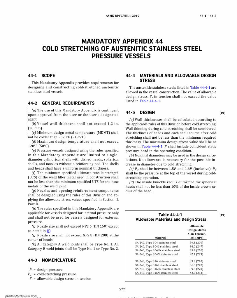
ð19Þ
MANDATORY APPENDIX 44COLD STRETCHING OF AUSTENITIC STAINLESS STEEL
PRESSURE VESSELS
44-1 SCOPE
This Mandatory Appendix provides requirements fordesigning and constructing cold-stretched austeniticstainless steel vessels.
44-2 GENERAL REQUIREMENTS
(a) The use of this Mandatory Appendix is contingentupon approval from the user or the user’s designatedagent.
(b) Vessel wall thickness shall not exceed 1.2 in.(30 mm).
(c) Minimum design metal temperature (MDMT) shallnot be colder than −320°F (−196°C).
(d)Maximum design temperature shall not exceed120°F (50°C).
(e) Pressure vessels designed using the rules specifiedin this Mandatory Appendix are limited to single-diameter cylindrical shells with dished heads, sphericalshells, and nozzles without a reinforcing pad. The shellsand heads shall have a uniform nominal thickness.
(f) The minimum specified ultimate tensile strength(UTS) of the weld filler metal used in construction shallnot be less than the minimum specified UTS for the basemetals of the weld joint.
(g) Nozzles and opening reinforcement componentsshall be designed using the rules of this Division and ap-plying the allowable stress values specified in Section II,Part D.
(h) The rules specified in this Mandatory Appendix areapplicable for vessels designed for internal pressure onlyand shall not be used for vessels designed for externalpressure.
(i) Nozzle size shall not exceed NPS 6 (DN 150) exceptas noted in (j).
(j) Nozzle size shall not exceed NPS 8 (DN 200) at thecenter of heads.
(k) All Category A weld joints shall be Type No. 1. AllCategory B weld joints shall be Type No. 1 or Type No. 2.
44-3 NOMENCLATURE
P = design pressurePc = cold-stretching pressureS = allowable design stress in tension
44-4 MATERIALS AND ALLOWABLE DESIGNSTRESS
The austenitic stainless steels listed in Table 44-4-1 areallowed in the vessel construction. The value of allowabledesign stress, S , in tension shall not exceed the valuelisted in Table 44-4-1.
44-5 DESIGN
(a)Wall thicknesses shall be calculated according tothe applicable rules of this Division before cold stretching.Wall thinning during cold stretching shall be considered.The thickness of heads and each shell course after coldstretching shall not be less than the minimum requiredthickness. The maximum design stress value shall be asshown in Table 44-4-1. P shall include coincident staticpressure head in the operating condition.
(b) Nominal diameters may be used in the design calcu-lations. No allowance is necessary for the possible in-crease in diameter due to cold stretching.
(c) Pc shall be between 1.5P and 1.6P (inclusive). Pc
shall be the pressure at the top of the vessel during cold-stretching operation.
(d) The inside knuckle radius of formed torisphericalheads shall not be less than 10% of the inside crown ra-dius of the head.
ð19ÞTable 44-4-1Allowable Materials and Design Stress
Material
AllowableDesign Stress,S , in Tension,ksi (MPa)
SA-240, Type 304 stainless steel 39.3 (270)SA-240, Type 304L stainless steel 36.0 (247)SA-240, Type 304LN stainless steel 39.3 (270)SA-240, Type 304N stainless steel 42.7 (293)
SA-240, Type 316 stainless steel 39.3 (270)SA-240, Type 316L stainless steel 36.0 (247)SA-240, Type 316LN stainless steel 39.3 (270)SA-240, Type 316N stainless steel 42.7 (293)
ASME BPVC.VIII.1-2019 44-1 – 44-5
577
Copyright ASME International (BPVC) Provided by IHS under license with ASME Licensee=Khalda Petroleum/5986215001, User=Amer, Mohamed
Not for Resale, 07/02/2019 13:29:04 MDTNo reproduction or networking permitted without license from IHS
--`,``,``,,`,`,,````,`,``,,,`-`-`,,`,,`,`,,`---
ð19Þ
(e) Butt-welded joints shall be fully radiographed perUW-51 or examined by ultrasonic examination in accor-dance with UW-51(a)(4).(f) All nozzles shall be attached with full-penetration
welds.(g) The thickness of a support pad shall not exceed the
thickness of the shell at the attachment location.(h) Full-thickness fillet welds shall be provided at
support-pad attachment locations.
44-6 FABRICATION PROCESS
44-6.1 WELDING AND EXAMINATION(a) For all Category A joints, the reinforcement shall not
exceed 10% of the plate thickness or 0.125 in. (3 mm),whichever is less. The weld deposits shall blend smoothlyinto the base metal without undercut or abrupt transition.All attachment welds shall be continuous and have asmooth contour with no undercut permitted.(b)Welder and welding operator identification shall be
marked with a paint pen or maintained by weld maps. Di-rect stamping of the vessel is not permitted. All markingmethods shall be approved by the Authorized Inspector.Stamping of the ASME Certification Mark shall be on anameplate attached to a standoff plate.(c) All butt joints shall be radiographically examined in
accordance with UW-51. Radiographic examinations shallbe performed prior to cold stretching. As an alternative tothe radiographic examination, ultrasonic examinationmay be used in accordance with UW-51(a)(4).(d) In areas such as nozzle-to-shell attachment loca-
tions, abrupt changes in thickness or contour, and othersimilar structural discontinuities, high local stress andstrain concentrations are anticipated during the cold-stretching process. To check for potential crack formationin these areas, after depressurization of the vessel follow-ing cold stretching, all Category A weld joints and all at-tachment welds shall be examined externally for theirentire lengths using the liquid penetrant method in accor-dance with Mandatory Appendix 8. If rejectable defectsare detected in the above inspections, all Category B weldjoints and attachment welds shall be examined in thesame manner.(e) Renewed cold stretching shall be performed if cold-
stretched parts of the vessel have been welded after coldstretching, except for attachment or tack welds less than0.25 in. (6 mm) in length. Such welds shall be examined asdescribed in (d).(f) Except when renewed cold stretching is to be per-
formed, the pressure test required by UG-99 or UG-100shall be applied after all welding on the pressure-retaining parts. The provisions of UG-99(c) shall not beused.
(g) Impact Test Requirements(1) The cold-stretched base materials listed in Table
44-4-1 need not be impact tested when used in vesselsconstructed in accordance with this Mandatory Appendix.
(2) The Welding Procedure Qualification shall beconducted in accordance with Section IX. When theMDMT is colder than −55°F (−48°C), the Welding Proce-dure Qualification shall include impact tests of weldsand heat-affected zones (HAZs) made in accordance withUG-84(h) and with requirements of UHA-51(a) at MDMT.The impact test specimens shall be tested from thewelded cold-stretched plate. The welded plate shall becold stretched by applying tensile stress across thewelded joint equal to or greater than 1.5 times the allow-able design stress listed in Table 44-4-1.
(3) The vessel (production) impact tests in accor-dance with UHA-51(h) are not required for vessels con-structed in accordance with this Mandatory Appendix.
44-6.2 COLD-STRETCHING OPERATIONThe cold-stretching operation shall be performed using
the following rules. These rules shall include the steps de-scribed in (a) through (e).(a) Fill the vessel with water, using adequate high-point
venting to ensure complete filling. Allow the vessel to sitwith the vents open for at least 15 min to allow any airdissolved in the water to escape. After venting, finish fill-ing the vessel completely and close the vents, top off, andseal the vessel.(b) Prior to applying the cold-stretching pressure, the
circumference of all shell courses shall be measuredwhere the largest increase in cross section is expected.All measurements shall be made with instruments thathave been calibrated to an accuracy of ±0.05%. This shallbe used to establish a baseline dimensional value. Addi-tional measurements of the vessel while under Pc shallbe taken as necessary to calculate the strain rate. Thestrain rate during the cold-stretching operation shall becalculated over the full circumference. Alternatively, thestrain rate may also be determined by recording time,pressure, and the elongation of circumference.(c) The cold-stretching operation shall be carried out
as follows:(1) The pressure shall be increased until P c is
reached. Pc shall be maintained until the calculated strainrate has dropped to less than 0.1%/hr.
(2) The minimum holding time under Pc shall be notless than 1 hr, except as described in (d).
(3) The calculated strain rate shall be determined byrepeated or continuous measurements of the circumfer-ence while the vessel is under Pc as described in (b).The required maximum strain rate of 0.1%/hr shall bemet during the last half hour.
CAUTION: Pressurized equipment contains stored energy cap-able of sudden release in the event of a catastrophic failure.The potential hazard is greater as the pressure is increased. A“safety zone” should be established and maintained around
ASME BPVC.VIII.1-201944-5 – 44-6.2
578
Copyright ASME International (BPVC) Provided by IHS under license with ASME Licensee=Khalda Petroleum/5986215001, User=Amer, Mohamed
Not for Resale, 07/02/2019 13:29:04 MDTNo reproduction or networking permitted without license from IHS
--`,``,``,,`,`,,````,`,``,,,`-`-`,,`,,`,`,,`---
the vessel while cold-stretching pressure is applied. Specialcare shall be taken tominimize the time personnel remain with-in the “safety zone” while taking the required measurements.
NOTE: The total time under Pc required to achieve the desired strainmay be substantial. The amount of time the vessel is subjected to Pc
may be reduced somewhat if a 5% higher Pc is applied during thefirst 30 min to 1 hr to accelerate strain formation.
(d) For pressure vessels having a diameter not morethan 79 in. (2 000 mm), the time under pressure maybe reduced to 30 min, provided the strain rate of 0.1%/hr is met during the last 15 min.
(e) The strengthening operation replaces the final pres-sure testing of the vessel. Should later pressure testing berequired, the requirements of UG-99 or UG-100 shall beapplied.
(f) The cold-stretching process shall be witnessed bythe Authorized Inspector.
(g) If the vessel requires welded repair, renewed coldstretching shall be carried out in accordance with therules of 44-6.2.
44-6.3 COLD-STRETCHING PROCEDURERECORD
A written record shall be prepared containing at leastthe following information:
(a) pressurizing sequence specifying pressure readingsand time
(b) circumference measurement before, during, andafter pressurization; or alternatively, time, pressure, andthe elongation of circumference
(c) strain-rate calculations(d) notes of any significant changes of shape and size
relevant to the functioning of the vessel(e) information for renewed cold stretching according
to 44-6.1(e) and 44-6.2(g).
44-7 STAMPING AND CERTIFICATION
(a) The Certification Mark on the nameplate shall in-clude marking with “CS” under the Certification Mark, in-dicating the vessel was constructed using cold-stretchingmethods.
(b) The Manufacturer shall indicate in the Remarks sec-tion of the Manufacturer’s Data Report: “This vessel hasbeen constructed using cold-stretching processes in ac-cordance with Mandatory Appendix 44.”
ASME BPVC.VIII.1-2019 44-6.2 – 44-7
579
Copyright ASME International (BPVC) Provided by IHS under license with ASME Licensee=Khalda Petroleum/5986215001, User=Amer, Mohamed
Not for Resale, 07/02/2019 13:29:04 MDTNo reproduction or networking permitted without license from IHS
--`,``,``,,`,`,,````,`,``,,,`-`-`,,`,,`,`,,`---

MANDATORY APPENDIX 45PLATE HEAT EXCHANGERS
45-1 SCOPE
The rules of this Appendix cover the minimum require-ments for design, fabrication, assembly, inspection, test-ing, and documentation of gasketed, semiwelded,welded, and brazed plate heat exchangers (PHEs).These rules cover the common types of PHEs and their
elements but are not intended to limit the configurationsor details to those illustrated or otherwise describedherein. Designs that differ from those covered in thisAppendix, as well as other types of PHEs, shall be in accor-dance with U-2(g).
45-2 MATERIALS OF CONSTRUCTION
All pressure-containing parts shall be constructedusing materials permitted by this Division. Metallic andnonmetallic materials not permitted by this Divisionmay be used specifically for heat transfer plates withinthe PHE, provided there is an applicable Code Case pub-lished for the limited use of this material as heat transferplates within a plate pack.
45-3 TERMINOLOGY
45-3.1 GENERAL
brazed plate heat exchanger (PHE): an assembly consist-ing of fully brazed heat transfer plates. The heat transferplates are stacked on top of each other and brazed to-gether. The nozzles can be located on any fixed endplate.
fully welded plate heat exchanger (PHE): an assembly con-sisting of fully welded heat transfer plates and its sup-porting frame. The frame provides structural supportand pressure containment and consists of two fixed end-plates and, if applicable, frame compression bolts. Theframe may be fully bolted, fully welded, or a combinationof bolted and welded. The heat transfer plates are fullywelded to form a plate pack, and one or more plate packscan be assembled in the frame. The nozzles or connec-tions can be located on the top, bottom, front, side, orback endplates.
gasketed or semiwelded plate heat exchanger (PHE): an as-sembly of components consisting of gasketed or semi-welded heat transfer plates and its supporting frame.The gaskets provide periphery sealing between the com-pressed heat transfer plates or between the semiwelded
plate pairs. The gaskets also provide additional sealingbetween adjacent heat transfer plates to prevent inter-mixing of the operating fluids. The frame provides struc-tural support and pressure containment and consists ofthe fixed endplate, movable endplate, upper carryingbar, lower guide bar, support column, and frame com-pression bolts. The gasketed or semiwelded gasketed heattransfer plates are compressed between the fixed end-plate and movable endplate by the frame compressionbolts. The heat transfer plates and movable endplate aresupported by the upper carrying bar and aligned withthe lower guide bar. The support column provides struc-tural support for the upper carrying bar and lower guidebar. The nozzles or connections can be located on thefixed endplate, movable endplate, or connection plate;see Figure 45-3.1-1.
45-3.2 DEFINITIONS OF GASKETED ORSEMIWELDED PHE COMPONENTS
connection plate: an intermediary “endplate” located inthe plate pack that permits additional nozzles, additionalfluids, and redirection of flow patterns.
divider plate: a plate that changes the direction of the flowof the fluid in a two-pass or larger heat exchanger. Alsocalled a turning plate.
fixed endplate: a fixed plate that provides pressure con-tainment and locations for the nozzles or connections; itmay or may not come with feet.
frame: a general term that describes structural supportand pressure-containment components. The componentsmay consist of a fixed endplate, a movable endplate,upper carrying and lower guide bars, a support column,and frame compression bolts.
frame compression bolt: a bolt assembly used to compressthe fixed endplate, movable endplate, and heat transferplates to affect a pressure seal.
gasket: a sealing element between single plates or semi-welded plate pairs.
heat transfer plate: a thin corrugated plate that makes upthe plate pack and is in contact with the process fluids.
movable endplate: a movable plate that provides pressurecontainment and locations for the nozzles or connections.
ASME BPVC.VIII.1-201945-1 – 45-3.2
580
Copyright ASME International (BPVC) Provided by IHS under license with ASME Licensee=Khalda Petroleum/5986215001, User=Amer, Mohamed
Not for Resale, 07/02/2019 13:29:04 MDTNo reproduction or networking permitted without license from IHS
--`,``,``,,`,`,,````,`,``,,,`-`-`,,`,,`,`,,`---

ð19Þ
plate pack: a collection of all gasketed or semiwelded heattransfer plates in the frame.
semiwelded plate pair: two adjacent heat transfer plateswelded together. The weld replaces the gasket betweenthe two adjacent plates. A gasket is required betweeneach plate pair.
support column: the structural component that supportsthe upper carrying and lower guide bars of the frame.
lower guide bar: a structural component that aligns theheat transfer plates and movable endplate.
upper carrying bar: a structural component that sup-ports the heat transfer plates, movable endplate, and in-ternal fluids.
45-3.3 DEFINITIONS OF FULLY WELDED PHECOMPONENTS
endplate: a plate that provides pressure containment andlocation for nozzles and/or connections.
frame: a general term that describes structural supportand pressure-containment components. The componentsmay consist of top and bottom endplates, front and backendplates, side plates, and, if applicable, frame compres-sion bolts.
frame compression bolts: bolts used to compress the top,bottom, front, back, and side plates to affect a pressureseal.
welded plate pack: a collection of heat transfer plates inwhich all plates are fully welded together. No gasketsare required between the plates of fully welded PHEs.
45-3.4 DEFINITIONS OF BRAZED PHECOMPONENTS
fixed endplate: a plate that provides pressure containmentand attachment of locations for the nozzles.
plate pack: a collection of heat transfer plates in which allplates are furnace brazed together. No gaskets are re-quired for a brazed PHE.
45-4 CONDITIONS OF APPLICABILITY
The design aspects covered in this Appendix apply tothe metallic, pressure-retaining components that are con-sidered in the calculation of the MAWP as described in45-5. Metallic or nonmetallic liners used to avoid contactof the process fluid with the components are not ad-dressed in this Appendix.
45-5 DESIGN CONSIDERATIONS
(a) Fixed and Movable Endplates. When the frame com-pression components (e.g., bolts) of the endplates have anonuniform pattern, the design of the fixed and movableendplates falls within the scope of U-2(g).
(b) Plate Packs Using Gaskets. Gasketed plate packsshall be designed to contain pressurized fluid withoutleaking to a pressure of at least 1.3 times the MAWP.The MAWP of gasketed plate packs may be determinedwithout performing proof testing or design calculationsfor the gasketed plate pack, provided the following re-quirements are met:
(1) The MAWP for the plate heat exchanger shall bedetermined considering all other pressure-retainingparts, including the endplates, bolting, and nozzles.
(2) The nominal thickness of a single-wall heat trans-fer plate or the combined thickness of a double-wall heattransfer plate shall not be less than 0.014 in. (0.35 mm).
(3) The heat exchanger shall not be used in lethal ser-vice [see UW-2(a)].
(c) Fully Welded PHEs. The MAWP of fully welded PHEsmay be determined using methods found in UG-101.
Figure 45-3.1-1Typical Plate Heat Exchanger
Legend:1 = feet (optional)2 = heat transfer plates3 = fixed endplate4 = movable endplate5 = support column
6 = frame compression bolts7 = upper carrying bar8 = lower guide bar9 = connections
ASME BPVC.VIII.1-2019 45-3.2 – 45-5
581
Copyright ASME International (BPVC) Provided by IHS under license with ASME Licensee=Khalda Petroleum/5986215001, User=Amer, Mohamed
Not for Resale, 07/02/2019 13:29:04 MDTNo reproduction or networking permitted without license from IHS
--`,``,``,,`,`,,````,`,``,,,`-`-`,,`,,`,`,,`---

ð19Þ
(d) Brazed PHEs. The MAWP of brazed PHEs may be de-termined using methods found in UG-101.(e) All Other PHE Components. Components of PHEs
that have applicable rules within this Division shall be de-signed in accordance with these rules.
45-6 CALCULATION PROCEDURE
(a) Fixed and Movable Endplates(1) Design calculations of fixed and movable end-
plates may be accomplished using “design by analysis”or by using a closed-form equation. The allowable stressvalues for the analysis shall be per UG-23.
(2) The design method shall be validated using apressure test, strain test, or similar method to validatethat the design analysis produces predictable results. Ifthe calculation procedure has been validated using a spe-cific methodology, then revalidation does not need to berepeated, unless there is a change in the calculation pro-cedure itself.(b) Nozzle Reinforcement. Nozzle reinforcement calcu-
lations shall be performed in accordance with UG-39.
(c) Welded Connections. Welded nozzle connectionsshall meet the requirements of UW-15 and UW-16.(d) Studded Connections. Studded connections shall
meet the requirements of UG-43.(e) Frame Compression Bolts. The bolting loads of frame
compression bolts shall be determined using the metho-dology described in 2-5.
45-7 PRESSURE TEST REQUIREMENTS
A PHE shall be hydrostatically tested in accordancewith UG-99, or pneumatically tested in accordance withUG-100. The heat transfer plates shall not be includedwhen determining the lowest stress ratio.
45-8 MANUFACTURER’S DATA REPORTS
A Manufacturer’s Data Report (Form U-1P or FormU-3P) shall be completed by the Manufacturer for eachPHE, or same-day production of identical vessels in accor-dance with Mandatory Appendix 35.
ASME BPVC.VIII.1-201945-5 – 45-8
582
Copyright ASME International (BPVC) Provided by IHS under license with ASME Licensee=Khalda Petroleum/5986215001, User=Amer, Mohamed
Not for Resale, 07/02/2019 13:29:04 MDTNo reproduction or networking permitted without license from IHS
--`,``,``,,`,`,,````,`,``,,,`-`-`,,`,,`,`,,`---
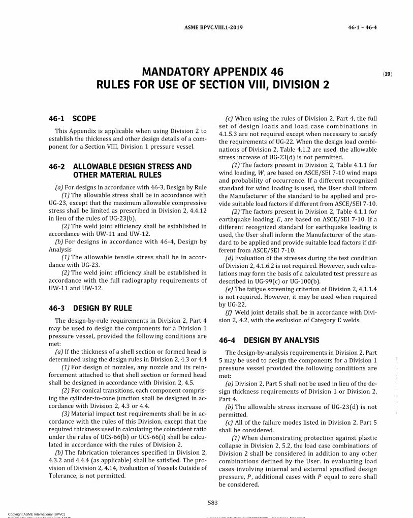
ð19ÞMANDATORY APPENDIX 46RULES FOR USE OF SECTION VIII, DIVISION 2
46-1 SCOPE
This Appendix is applicable when using Division 2 toestablish the thickness and other design details of a com-ponent for a Section VIII, Division 1 pressure vessel.
46-2 ALLOWABLE DESIGN STRESS ANDOTHER MATERIAL RULES
(a) For designs in accordance with 46-3, Design by Rule(1) The allowable stress shall be in accordance with
UG-23, except that the maximum allowable compressivestress shall be limited as prescribed in Division 2, 4.4.12in lieu of the rules of UG-23(b).
(2) The weld joint efficiency shall be established inaccordance with UW-11 and UW-12.
(b) For designs in accordance with 46-4, Design byAnalysis
(1) The allowable tensile stress shall be in accor-dance with UG-23.
(2) The weld joint efficiency shall be established inaccordance with the full radiography requirements ofUW-11 and UW-12.
46-3 DESIGN BY RULE
The design-by-rule requirements in Division 2, Part 4may be used to design the components for a Division 1pressure vessel, provided the following conditions aremet:
(a) If the thickness of a shell section or formed head isdetermined using the design rules in Division 2, 4.3 or 4.4
(1) For design of nozzles, any nozzle and its rein-forcement attached to that shell section or formed headshall be designed in accordance with Division 2, 4.5.
(2) For conical transitions, each component compris-ing the cylinder-to-cone junction shall be designed in ac-cordance with Division 2, 4.3 or 4.4.
(3)Material impact test requirements shall be in ac-cordance with the rules of this Division, except that therequired thickness used in calculating the coincident ratiounder the rules of UCS-66(b) or UCS-66(i) shall be calcu-lated in accordance with the rules of Division 2.
(b) The fabrication tolerances specified in Division 2,4.3.2 and 4.4.4 (as applicable) shall be satisfied. The pro-vision of Division 2, 4.14, Evaluation of Vessels Outside ofTolerance, is not permitted.
(c) When using the rules of Division 2, Part 4, the fullset of design loads and load case combinations in4.1.5.3 are not required except when necessary to satisfythe requirements of UG-22. When the design load combi-nations of Division 2, Table 4.1.2 are used, the allowablestress increase of UG-23(d) is not permitted.
(1) The factors present in Division 2, Table 4.1.1 forwind loading, W , are based on ASCE/SEI 7-10 wind mapsand probability of occurrence. If a different recognizedstandard for wind loading is used, the User shall informthe Manufacturer of the standard to be applied and pro-vide suitable load factors if different from ASCE/SEI 7-10.
(2) The factors present in Division 2, Table 4.1.1 forearthquake loading, E , are based on ASCE/SEI 7-10. If adifferent recognized standard for earthquake loading isused, the User shall inform the Manufacturer of the stan-dard to be applied and provide suitable load factors if dif-ferent from ASCE/SEI 7-10.
(d) Evaluation of the stresses during the test conditionof Division 2, 4.1.6.2 is not required. However, such calcu-lations may form the basis of a calculated test pressure asdescribed in UG-99(c) or UG-100(b).
(e) The fatigue screening criterion of Division 2, 4.1.1.4is not required. However, it may be used when requiredby UG-22.
(f) Weld joint details shall be in accordance with Divi-sion 2, 4.2, with the exclusion of Category E welds.
46-4 DESIGN BY ANALYSIS
The design-by-analysis requirements in Division 2, Part5 may be used to design the components for a Division 1pressure vessel provided the following conditions aremet:
(a) Division 2, Part 5 shall not be used in lieu of the de-sign thickness requirements of Division 1 or Division 2,Part 4.
(b) The allowable stress increase of UG-23(d) is notpermitted.
(c) All of the failure modes listed in Division 2, Part 5shall be considered.
(1)When demonstrating protection against plasticcollapse in Division 2, 5.2, the load case combinations ofDivision 2 shall be considered in addition to any othercombinations defined by the User. In evaluating loadcases involving internal and external specified designpressure, P , additional cases with P equal to zero shallbe considered.
ASME BPVC.VIII.1-2019 46-1 – 46-4
583
Copyright ASME International (BPVC) Provided by IHS under license with ASME Licensee=Khalda Petroleum/5986215001, User=Amer, Mohamed
Not for Resale, 07/02/2019 13:29:04 MDTNo reproduction or networking permitted without license from IHS
--`,``,``,,`,`,,````,`,``,,,`-`-`,,`,,`,`,,`---
(-a) When applying the elastic stress analysismethod in Division 2, 5.2.2, the allowable stress, S , shallbe as per 46-2(a).
(-b) When applying the limit-load analysis methodin Division 2, 5.2.3, the yield strength defining the plasticlimit shall equal 1.5S , where S shall be as per 46-2(a).
(-c) When applying the elastic–plastic stress anal-ysis method in Division 2, 5.2.4, in conjunction with Divi-sion 2, Table 5.5, β shall equal 3.5.
(-d) Evaluation of the test condition is not re-quired [see 46-3(d)].
(2)When demonstrating protection against local fail-ure in Division 2, 5.3, the load case combination of Divi-sion 2 shall be considered. The exemption provided inDivision 2, 5.3.1.1 is applicable to weld details in Division2, Part 4 only. There exist weld details in Division 1 thatare not permitted in Division 2 [subject to the provisionin 46-3(f)]; those details are not exempt from evaluationof protection against local failure.
(3)When demonstrating protection against collapsefrom buckling in Division 2, 5.4, the design margin ofthe Division 2 assessment procedure shall be used.
(4)When demonstrating protection against failurefrom cyclic loading: ratcheting in Division 2, 5.5.6 or5.5.7, the design margin of the Division 2 assessment pro-cedure shall be used, except that where it is used, the al-lowable stress, S , shall be per 46-2(a).
The assessment procedure for this failure mode re-quires the use of operating load ranges. This requires in-formation on the operating load cycle, which shall beprovided by the User. In the absence of such information,the Designer may use his or her judgment to determinethe worst case, taking into consideration the vector nat-ure of certain loads and their potential reversal, as wellas pressure cycles that may include vacuum conditions.
(5)When demonstrating protection against failurefrom cyclic loading: fatigue in Division 2, 5.5.3, 5.5.4, or5.5.5, the design margin of the Division 2 assessment pro-cedure shall be used, except that where it is used, the al-lowable stress, S , shall be per 46-2(a).
The assessment procedure for this failure mode re-quires the use of operating load ranges. This requires in-formation on the operating load cycle, which shall beprovided by the User. In the absence of such information,the Designer may use his or her judgment to determinethe worst case, taking into consideration the vector nat-ure of certain loads and their potential reversal, as wellas pressure cycles that may include vacuum conditions.
ASME BPVC.VIII.1-201946-4
584
Copyright ASME International (BPVC) Provided by IHS under license with ASME Licensee=Khalda Petroleum/5986215001, User=Amer, Mohamed
Not for Resale, 07/02/2019 13:29:04 MDTNo reproduction or networking permitted without license from IHS
--`,``,``,,`,`,,````,`,``,,,`-`-`,,`,,`,`,,`---
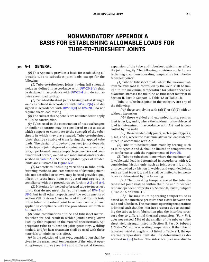
ð19Þ
NONMANDATORY APPENDIX ABASIS FOR ESTABLISHING ALLOWABLE LOADS FOR
TUBE-TO-TUBESHEET JOINTS
A-1 GENERAL
(a) This Appendix provides a basis for establishing al-lowable tube-to-tubesheet joint loads, except for thefollowing:
(1) Tube-to-tubesheet joints having full strengthwelds as defined in accordance with UW-20.2(a) shallbe designed in accordance with UW-20.4 and do not re-quire shear load testing.
(2) Tube-to-tubesheet joints having partial strengthwelds as defined in accordance with UW-20.2(b) and de-signed in accordance with UW-18(d) or UW-20.5 do notrequire shear load testing.
(b) The rules of this Appendix are not intended to applyto U‐tube construction.
(c) Tubes used in the construction of heat exchangersor similar apparatus may be considered to act as stayswhich support or contribute to the strength of the tube-sheets in which they are engaged. Tube‐to‐tubesheetjoints shall be capable of transferring the applied tubeloads. The design of tube‐to‐tubesheet joints dependson the type of joint, degree of examination, and shear loadtests, if performed. Some acceptable geometries and com-binations of brazed, welded, and mechanical joints are de-scribed in Table A-2. Some acceptable types of weldedjoints are illustrated in Figure A-2.
(1) Geometries, including variations in tube pitch,fastening methods, and combinations of fastening meth-ods, not described or shown, may be used provided qua-lification tests have been conducted and applied incompliance with the procedures set forth in A-3 and A-4.
(2)Materials for welded or brazed tube‐to‐tubesheetjoints that do not meet the requirements of UW-5 orUB-5, but in all other respects meet the requirements ofSection VIII, Division 1, may be used if qualification testsof the tube‐to‐tubesheet joint have been conducted andapplied in compliance with the procedures set forth inA-3 and A-4.
(d) Some combinations of tube and tubesheet materi-als, when welded, result in welded joints having lowerductility than required in the material specifications. Ap-propriate tube‐to‐tubesheet joint geometry, weldingmethod, and/or heat treatment shall be used with thesematerials to minimize this effect.
(e) In the selection of joint type, consideration shall begiven to the mean metal temperature of the joint at oper-ating temperatures (see 3-2) and differential thermal
expansion of the tube and tubesheet which may affectthe joint integrity. The following provisions apply for es-tablishing maximum operating temperature for tube‐to‐tubesheet joints:
(1) Tube‐to‐tubesheet joints where the maximum al-lowable axial load is controlled by the weld shall be lim-ited to the maximum temperature for which there areallowable stresses for the tube or tubesheet material inSection II, Part D, Subpart 1, Table 1A or Table 1B.
Tube‐to‐tubesheet joints in this category are any ofthe following:
(-a) those complying with (a)(1) or (a)(2) with orwithout expansion
(-b) those welded and expanded joints, such asjoint types f, g, and h, where the maximum allowable axialload is determined in accordance with A-2 and is con-trolled by the weld
(-c) those welded-only joints, such as joint types a,b, b-1, and e, where the maximum allowable load is deter-mined in accordance with A-2
(2) Tube‐to‐tubesheet joints made by brazing, suchas joint types c and d, shall be limited to temperaturesin conformance with the requirements of Part UB.
(3) Tube‐to‐tubesheet joints where the maximum al-lowable axial load is determined in accordance with A-2considering friction only, such as joint types i, j, and k,or is controlled by friction in welded and expanded joints,such as joint types f, g, and h, shall be limited to tempera-tures as determined by the following:
(-a) The operating temperature of the tube-to-tubesheet joint shall be within the tube and tubesheettime-independent properties of Section II, Part D, Subpart1, Table 1A or Table 1B.
(-b) The maximum operating temperature isbased on the interface pressure that exists between thetube and tubesheet. The maximum operating temperatureis limited such that the interface pressure due to expand-ing the tube at joint fabrication plus the interface pres-sure due to differential thermal expansion, (Po + PT ),does not exceed 58% of the smaller of the tube or tube-sheet yield strength listed in Section II, Part D, Subpart1, Table Y-1 at the operating temperature. If the tube ortubesheet yield strength is not listed in Table Y‐1, the op-erating temperature limit shall be determined as de-scribed in (-d) below. The interface pressure due to
ASME BPVC.VIII.1-2019 A-1
585
Copyright ASME International (BPVC) Provided by IHS under license with ASME Licensee=Khalda Petroleum/5986215001, User=Amer, Mohamed
Not for Resale, 07/02/2019 13:29:04 MDTNo reproduction or networking permitted without license from IHS
--`,``,``,,`,`,,````,`,``,,,`-`-`,,`,,`,`,,`---

ð19Þ
expanding the tube at fabrication or the interface pres-sure due to differential thermal expansion may be deter-mined analytically or experimentally.
(-c) Due to differential thermal expansion, thetube may expand less than the tubesheet. For this condi-tion, the interfacial pressure, PT , is a negative number.
(-d) When the maximum temperature is not deter-mined by (-b) above, or the tube expands less than orequal to the tubesheet, joint acceptability shall be deter-mined by shear load tests described in A-3. Two sets ofspecimens shall be tested. The first set shall be tested atthe proposed operating temperature. The second set shallbe tested at room temperature after heat soaking at theproposed operating temperature for 24 hr. The proposedoperating temperature is acceptable if the provisions ofA-5 are satisfied.(f) The Manufacturer shall prepare written procedures
for joints that are expanded (whether welded and ex-panded or expanded only) for joint strength (see Non-mandatory Appendix HH). The Manufacturer shallestablish the variables that affect joint repeatability inthese procedures. The procedures shall provide detaileddescriptions or sketches of enhancements, such asgrooves, serrations, threads, and coarse machining pro-files. The Manufacturer shall make these written proce-dures available to the Authorized Inspector.
A-2 MAXIMUM AXIAL LOADINGS
The maximum allowable axial load in either directionon tube‐to‐tubesheet joints shall be determined in accor-dance with the following:For joint types a, b, b‐1, c, d, e,
ð1Þ
For joint types f, g, h,
ð2Þ
For joint types i, j, k,
ð3Þ
where
At = tube cross‐sectional area= π(do − t)t
d i = nominal tube inside diameterdo = nominal tube outside diameterE = modulus of elasticity for tubesheet materi-
al at TEt = modulus of elasticity for tube material at Tfe = factor for the length of the expanded por-
tion of the tube. An expanded joint is ajoint between tube and tubesheet pro-duced by applying expanding force inside
the portion of the tube to be engaged in thetubesheet. Expanding force shall be set tovalues necessary to effect sufficient resi-dual interface pressure between the tubeand hole for joint strength.
= MIN[(l/do), (1.0)] for expanded tube jointswithout enhancements
= 1 .0 for expanded tube jo in ts wi thenhancements
f r = tube joint efficiency, which is set equal tothe value of f r (test) or f r (no test)
f r (test) = tube joint efficiency calculated from resultsof tests in accordance with A-4 or takenfrom Table A-2 for tube joints qualifiedby test, whichever is less, except as per-mitted in A-3(k)
f r (no test) = tube joint efficiency taken from Table A-2for tube joints not qualified by test
f r e = factor for the overall efficiency of weldedand expanded joints. This is the maximumof the efficiency of the weld alone, f r (b ),and the net efficiency of the welded and ex-panded joint.
= MAX[f e frfyfT, f r(b)]fT = factor to account for the increase or de-
crease of tube joint strength due to radialdifferential thermal expansion at thetube-to-tubesheet joint
= (Po + PT)/Po . Acceptable values of fT mayrange from 0 to greater than 1. When the fTvalue is negative, it shall be set to 0.
f y = factor for differences in the mechanicalproperties of tubesheet and tube materials
= MIN[(Sy/Sy,t), (1.0)] for expanded joints.When f y is less than 0.60, qualificationtests in accordance with A-3 and A-4 arerequired.
k = 1.0 for loads due to pressure-induced axialforces
= 1.0 for loads due to thermally induced orpressure plus thermally induced axialforces on welded-only joints where thethickness through the weld throat is lessthan the nominal tube wall thickness t
= 2.0 for loads due to thermally induced orpressure plus thermally induced axialforces on all other tube-to-tubesheet joints
ℓ = length of the expanded portion of the tubeLmax = maximum allowable axial load in either di-
rection on tube-to-tubesheet jointPe = tube expanding pressure. The following
equation may be used:
ASME BPVC.VIII.1-2019A-1 – A-2
586
Copyright ASME International (BPVC) Provided by IHS under license with ASME Licensee=Khalda Petroleum/5986215001, User=Amer, Mohamed
Not for Resale, 07/02/2019 13:29:04 MDTNo reproduction or networking permitted without license from IHS
--`,``,``,,`,`,,````,`,``,,,`-`-`,,`,,`,`,,`---

Po = interface pressure between the tube andtubesheet that remains after expandingthe tube at fabrication. This pressure maybe established analytically or experimen-tally, but shall consider the effect of changein material strength at operating tempera-ture. The following equation may be used:
PT = interface pressure between the tube andtubesheet due to differential thermalgrowth. This pressure may be establishedanalytically or experimentally. The follow-ing equation may be used:
Rm = mean tube radius= (ro – t/2)
ro = tube outside radiusS = maximum allowable stress value as given
in the applicable part of Section II, Part D.For a welded tube or pipe, use the allow-able stress for the equivalent seamlessproduct. When the allowable stress forthe equivalent seamless product is notavailable, divide the allowable stress ofthe welded product by 0.85.
Sa = allowable stress for tube material= kS
Sy = yield strength for tubesheet material at Tfrom Section II, Part D, Subpart 1, TableY-1. When a yield strength value is notlisted in Table Y-1, one may be obtainedby using the procedure in UG-28(c)(2),Step 3.
Sy,t = yield strength for tube material at T fromSection II, Part D, Subpart 1, Table Y-1.When a yield strength value is not listedin Table Y-1, one may be obtained by usingthe procedure in UG-28(c)(2), Step 3.
T = tubesheet design temperaturet = nominal tube wall thickness
Ta = ambient temperatureα = mean coefficient of thermal expansion of
tubesheet material at Tα t = mean coefficient of thermal expansion of
tube material at T
A-3 SHEAR LOAD TEST
(a) Flaws in the specimen may affect results. If any testspecimen develops flaws, the retest provisions of (k) be-low shall govern.
(b) If any test specimen fails because of mechanical rea-sons, such as failure of testing equipment or improperspecimen preparation, it may be discarded and anotherspecimen taken from the same heat.
(c) The shear load test subjects a full‐size specimen ofthe tube joint under examination to a measured load suf-ficient to cause failure. In general, the testing equipmentand methods are given in the Methods of Tension Testingof Metallic Materials (ASTM E8). Additional fixtures forshear load testing of tube‐to‐tubesheet joints are shownin Figure A-3.
(d) The test block simulating the tubesheet may be cir-cular, square or rectangular in shape, essentially in gener-al conformity with the tube pitch geometry. The testassembly shall consist of an array of tubes such that thetube to be tested is in the geometric center of the arrayand completely surrounded by at least one row of adja-cent tubes. The test block shall extend a distance of atleast one tubesheet ligament beyond the edge of the per-ipheral tubes in the assembly.
(e) All tubes in the test block array shall be from thesame heat and shall be installed using identicalprocedures.
(1) The finished thickness of the test block may beless but not greater than the tubesheet it represents.For expanded joints, made with or without welding, theexpanded area of the tubes in the test block may be lessbut not greater than that for the production joint to bequalified.
(2) The length of the tube used for testing the tubejoint need only be sufficient to suit the test apparatus.The length of the tubes adjacent to the tube joint to betested shall not be less than the thickness of the test blockto be qualified.
(f) The procedure used to prepare the tube‐to‐tubesheet joints in the test specimens shall be the sameas used for production.
(g) The tube‐to‐tubesheet joint specimens shall beloaded until mechanical failure of the joint or tube occurs.The essential requirement is that the load be transmittedaxially.
(h) Any speed of testing may be used, provided loadreadings can be determined accurately.
(i) The reading from the testing device shall be suchthat the applied load required to produce mechanical fail-ure of the tube‐to‐tubesheet joint can be determined.
(j) For determining fr (test) for joint types listed inTable A-2, a minimum of three specimens shall constitutea test. The value of fr (test) shall be calculated in accor-dance with A-4(a) using the lowest value of L (test). Inno case shall the value of fr (test) using a three specimentest exceed the value of fr (test) given in Table A-2. If the
ASME BPVC.VIII.1-2019 A-2 – A-3
587
Copyright ASME International (BPVC) Provided by IHS under license with ASME Licensee=Khalda Petroleum/5986215001, User=Amer, Mohamed
Not for Resale, 07/02/2019 13:29:04 MDTNo reproduction or networking permitted without license from IHS
--`,``,``,,`,`,,````,`,``,,,`-`-`,,`,,`,`,,`---
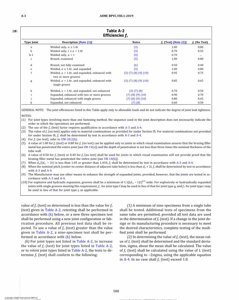
value of fr (test) so determined is less than the value for fr(test) given in Table A-2, retesting shall be performed inaccordance with (k) below, or a new three specimen testshall be performed using a new joint configuration or fab-rication procedure. All previous test data shall be re-jected. To use a value of fr (test) greater than the valuegiven in Table A-2, a nine‐specimen test shall be per-formed in accordance with (k) below.(k) For joint types not listed in Table A-2, to increase
the value of fr (test) for joint types listed in Table A-2,or to retest joint types listed in Table A-2, the tests to de-termine fr (test) shall conform to the following:
(1) A minimum of nine specimens from a single tubeshall be tested. Additional tests of specimens from thesame tube are permitted, provided all test data are usedin the determination of fr (test). If a change in the joint de-sign or its manufacturing procedure is necessary to meetthe desired characteristics, complete testing of the modi-fied joint shall be performed.
(2) In determining the value of fr (test), the mean val-ue of L (test) shall be determined and the standard devia-tion, sigma, about the mean shall be calculated. The valueof fr (test) shall be calculated using the value of L (test)corresponding to −2sigma, using the applicable equationin A-4. In no case shall fr (test) exceed 1.0.
ð19Þ Table A-2Efficiencies fr
Type Joint Description [Note (1)] Notes fr (Test) [Note (2)] fr (No Test)
a Welded only, a ≥ 1.4t (3) 1.00 0.80b Welded only, t ≤ a < 1.4t (3) 0.70 0.55b‐1 Welded only, a < t (4) 0.70 …c Brazed, examined (5) 1.00 0.80
d Brazed, not fully examined (6) 0.50 0.40e Welded, a ≥ 1.4t , and expanded (3) 1.00 0.80f Welded, a < 1.4t , and expanded, enhanced with
two or more grooves(3) (7) (8) (9) (10) 0.95 0.75
g Welded, a < 1.4t , and expanded, enhanced withsingle groove
(3) (7) (8) (9) (10) 0.85 0.65
h Welded, a < 1.4t , and expanded, not enhanced (3) (7) (8) 0.70 0.50i Expanded, enhanced with two or more grooves (7) (8) (9) (10) 0.90 0.70j Expanded, enhanced with single groove (7) (8) (9) (10) 0.80 0.65k Expanded, not enhanced (7) (8) 0.60 0.50
GENERAL NOTE: The joint efficiencies listed in this Table apply only to allowable loads and do not indicate the degree of joint leak tightness.
NOTES:(1) For joint types involving more than one fastening method, the sequence used in the joint description does not necessarily indicate the
order in which the operations are performed.(2) The use of the fr (test) factor requires qualification in accordance with A-3 and A-4.(3) The value of fr (no test) applies only to material combinations as provided for under Section IX. For material combinations not provided
for under Section IX, fr shall be determined by test in accordance with A-3 and A-4.(4) For fr (no test), refer to UW-20.2(b).(5) A value of 1.00 for fr (test) or 0.80 for fr (no test) can be applied only to joints in which visual examination assures that the brazing filler
metal has penetrated the entire joint [see UB-14(a)] and the depth of penetration is not less than three times the nominal thickness of thetube wall.
(6) A value of 0.50 for fr (test) or 0.40 for fr (no test) shall be used for joints in which visual examination will not provide proof that thebrazing filler metal has penetrated the entire joint [see UB-14(b)].
(7) When do/(do − 2t) is less than 1.05 or greater than 1.410, fr shall be determined by test in accordance with A-3 and A-4.(8) When the nominal pitch (center‐to‐center distance of adjacent tube holes) is less than do + 2t, fr shall be determined by test in accordance
with A-3 and A-4.(9) The Manufacturer may use other means to enhance the strength of expanded joints, provided, however, that the joints are tested in ac-
cordance with A-3 and A-4.(10) For explosive and hydraulic expansion, grooves shall be a minimum of 1.1[(do − t)t]0.5 wide. For explosively or hydraulically expanded
joints with single grooves meeting this requirement, f r for joint type f may be used in lieu of that for joint type g, and f r for joint type i maybe used in lieu of that for joint type j, as applicable.
ASME BPVC.VIII.1-2019A-3
588
Copyright ASME International (BPVC) Provided by IHS under license with ASME Licensee=Khalda Petroleum/5986215001, User=Amer, Mohamed
Not for Resale, 07/02/2019 13:29:04 MDTNo reproduction or networking permitted without license from IHS
--`,``,``,,`,`,,````,`,``,,,`-`-`,,`,,`,`,,`---

Figure A-2Some Acceptable Types of Tube-to-Tubesheet Welds
NOTES:(1) Sketches (a) through (d) show some acceptable weld geometries where a is not less than 1.4t .(2) Sketches (e) through (i) show some acceptable weld geometries where a is less than 1.4t .
ASME BPVC.VIII.1-2019 A-3
589
Copyright ASME International (BPVC) Provided by IHS under license with ASME Licensee=Khalda Petroleum/5986215001, User=Amer, Mohamed
Not for Resale, 07/02/2019 13:29:04 MDTNo reproduction or networking permitted without license from IHS
--`,``,``,,`,`,,````,`,``,,,`-`-`,,`,,`,`,,`---

Figure A-3Typical Test Fixtures for Expanded or Welded Tube-to-Tubesheet Joints
ASME BPVC.VIII.1-2019A-3
590
Copyright ASME International (BPVC) Provided by IHS under license with ASME Licensee=Khalda Petroleum/5986215001, User=Amer, Mohamed
Not for Resale, 07/02/2019 13:29:04 MDTNo reproduction or networking permitted without license from IHS
--`,``,``,,`,`,,````,`,``,,,`-`-`,,`,,`,`,,`---

A-4 ACCEPTANCE STANDARDS FOR frDETERMINED BY TEST
(a) The value of fr (test) shall be calculated as follows:For joint types a, b, b‐1, c, d, e,
ð4Þ
For joint types f, g, h, i, j, k,
ð5Þ
where
L (test) = axial load at which failure of the test speci-mens occurs [refer to A-3(j) or A-3(k), asapplicable]
ST = tensile strength for tube material from materi-al test report
At , f e , f y , and f r (test) are as defined in A-2.(b) The value of f r (test) shall be used for f r in the equa-
tion for Lmax .
A-5 ACCEPTANCE STANDARDS FORPROPOSED OPERATINGTEMPERATURES DETERMINED BY TEST
The proposed operating conditions shall be acceptableif both of the following conditions are satisfied:
ð6Þ
ð7Þ
where
L1 (test) = lowest axial load at which failure occurs atoperating temperature
L2 (test) = lowest axial load at which failure of heatsoaked specimen tested at room temperatureoccurs
Su = tensile strength for tube material at operat-ing temperature taken from Section II, PartD, Subpart 1, Table U
Sua = tensile strength for tube material at roomtemperature taken from Section II, Part D,Subpart 1, Table U
At, fe, and fy are as defined in A-2. ST is as defined in A-4.
ASME BPVC.VIII.1-2019 A-4 – A-5
591
Copyright ASME International (BPVC) Provided by IHS under license with ASME Licensee=Khalda Petroleum/5986215001, User=Amer, Mohamed
Not for Resale, 07/02/2019 13:29:04 MDTNo reproduction or networking permitted without license from IHS
--`,``,``,,`,`,,````,`,``,,,`-`-`,,`,,`,`,,`---
NONMANDATORY APPENDIX CSUGGESTED METHODS FOR OBTAINING THE OPERATING
TEMPERATURE OF VESSEL WALLS IN SERVICE
C-1 THERMOCOUPLE INSTALLATION
At least three thermocouples shall be installed on ves-sels that are to have contents at temperatures above thatat which the allowable stress value of the material is lessthan its allowable stress value at 100°F (40°C). One of thethermocouples shall be on the head that will be subject tothe higher temperature, and the other two shall be on theshell in the zone of maximum temperature. For a numberof vessels in similar service in the same plant, thermocou-ples need be attached to one vessel only of each group orbattery, provided that each vessel has a suitable tempera-ture measuring device to show the temperature of the en-tering fluid, in order that a comparison of the operation ofthe different vessels can be made and any abnormal op-eration immediately detected. Thermocouples shall be at-tached to the outside surface of the vessel by inserting the
terminals separately in two small holes drilled into theshell approximately 1/2 in. (13 mm) center‐to‐center andfirmly securing them therein, or by some other equallysatisfactory method.
C-2 ALTERNATIVE THERMOCOUPLEINSTALLATION
In lieu of the provisions in the preceding paragraph, itshall be optional to provide a thermocouple or other tem-perature measuring device for obtaining the temperatureof the fluid in the zone of the vessel having the highesttemperature. In this case, the metal temperature shallbe assumed to be the same as the maximum fluidtemperature.
ASME BPVC.VIII.1-2019C-1 – C-2
592
Copyright ASME International (BPVC) Provided by IHS under license with ASME Licensee=Khalda Petroleum/5986215001, User=Amer, Mohamed
Not for Resale, 07/02/2019 13:29:04 MDTNo reproduction or networking permitted without license from IHS
--`,``,``,,`,`,,````,`,``,,,`-`-`,,`,,`,`,,`---

NONMANDATORY APPENDIX DSUGGESTED GOOD PRACTICE REGARDING INTERNAL
STRUCTURES
D-1 INTRODUCTION
Pressure vessels that have heavy internal structuressuch as trays and baffles are subject to damage due to fail-ure of the connections that support the structures.
D-2 INTERNAL STRUCTURES SUPPORT
The designer should have this possible hazard in mindand provide supports of sufficient strength with due al-lowance for corrosion.
D-3 INTERNAL STRUCTURES SUPPORTGUIDELINES
The following are some suggestions that should be con-sidered in the design of internal structures:
(a) Connections to the vessel wall should be designedto prevent excessive tensile stress outward from the wallface due to the connection. (See UG-55.)
(b) Structures should rest on top of their supports inpreference to being suspended from them.
(c) Additional metal should be provided when corro-sion is expected. The corrosion allowance need not bethe same as in the vessel if the supports and structurescan be replaced more readily and economically than thevessel.
(d) Corrosion resistant metals may be used in the fabri-cation of the structures and supports.
ASME BPVC.VIII.1-2019 D-1 – D-3
593
Copyright ASME International (BPVC) Provided by IHS under license with ASME Licensee=Khalda Petroleum/5986215001, User=Amer, Mohamed
Not for Resale, 07/02/2019 13:29:04 MDTNo reproduction or networking permitted without license from IHS
--`,``,``,,`,`,,````,`,``,,,`-`-`,,`,,`,`,,`---
NONMANDATORY APPENDIX ESUGGESTED GOOD PRACTICE REGARDING CORROSION
ALLOWANCE102
E-1 GENERAL
From the standpoint of corrosion, pressure vessels maybe classified under one of the following groups:(a) vessels in which corrosion rates may be definitely
established from information available to the designer re-garding the chemical characteristics of the substancesthey are to contain. Such information may, in the case ofstandard commercial products, be obtained from pub-lished sources, or, where special processes are involved,from reliable records compiled from results of previousobservations by the user or others under similar condi-tions of operation.(b) vessels in which corrosion rates, while known to be
relatively high, are either variable or indeterminate inmagnitude;(c) vessels in which corrosion rates, while indetermi-
nate, are known to be relatively low;(d) vessels in which corrosion effects are known to be
negligible or entirely absent.
E-2 PREDICTABLE CORROSION RATE
When the rate of corrosion is closely predictable, addi-tional metal thickness over and above that required forthe initial operating conditions should be provided, whichshould be at least equal to the expected corrosion lossduring the desired life of the vessel.
E-3 INDETERMINATE CORROSION RATE
When corrosion effects are indeterminate prior to de-sign of the vessel, although known to be inherent to somedegree in the service for which the vessel is to be used, or
when corrosion is incidental, localized, and/or variable inrate and extent, the designer must exercise his best judg-ment in establishing a reasonable maximum excess shellthickness. This minimum allowance may, of course, be in-creased according to the designer’s judgment.
E-4 NEGLIGIBLE CORROSION RATE
When corrosion effects can be shown to be negligible orentirely absent, no excess thickness need be provided.
E-5 CORROSIVE SERVICE
When a vessel goes into corrosive service without pre-vious service experience, it is recommended that serviceinspections be made at frequent intervals until the natureand rate of corrosion in service can be definitely estab-lished. The data thus secured should determine the subse-quent intervals between service inspections and theprobable safe operating life of the vessel.
E-6 EXTERNAL ATTACHMENT CORROSIONRATE
For parts which are essential to vessel strength such asstiffener rings, the attachment of the part to the shellmust provide adequate corrosion allowance or protectionto assure the required strength throughout the servicelife. Some attachments, such as intermittent welds, re-quire protection on both face and root sides; alternatively,continuous welds or a suitably sized seal weld betweenthe strength welds will provide protection for the rootside.
ASME BPVC.VIII.1-2019E-1 – E-6
594
Copyright ASME International (BPVC) Provided by IHS under license with ASME Licensee=Khalda Petroleum/5986215001, User=Amer, Mohamed
Not for Resale, 07/02/2019 13:29:04 MDTNo reproduction or networking permitted without license from IHS
--`,``,``,,`,`,,````,`,``,,,`-`-`,,`,,`,`,,`---
NONMANDATORY APPENDIX FSUGGESTED GOOD PRACTICE REGARDING LININGS
F-1 GENERAL
When protective linings are used, the amount of addi-tional shell thickness provided to compensate for corro-sion effects will depend largely on the nature of theprotective material itself, as well as on the degree ofknowledge available regarding its resistivity under the in-tended operating conditions.
F-2 METAL LININGS
(a)When corrosion resistant metal linings are used,either as a surface layer integral with the shell plate, orin deposited form as applied with a so‐called metal gun,or in sheet form mechanically attached, the base platemay be only as thick as required for design operating con-ditions, provided, however, the thickness of such lining issufficient to afford an estimated life equal at least to twicethe length of the initial inspection period and that applica-tion of the material is such as to preclude any possibilityof contact between the corrosive agent and the steel shellby infiltration or seepage through or past the lining.
(b) Before strip lining or joint covering strips are ap-plied to carbon steel base plate, the surface shall be clo-sely inspected to assure that it is properly prepared and
that it is free of all foreign matter, rust, scale, and moist-ure. It may be necessary to sand‐blast or to hot‐air dry thesurface, or both.
F-3 PAINT
No paint of any type should be considered as a perma-nent protection. When paint is applied to the inside of avessel, corrosion allowance should be added to the wallthickness of the vessel as if it were unprotected.
F-4 HYDROTEST CONSIDERATIONS FORMETAL LININGS
When the test fluid seeps behind the applied liner,there is danger that the fluid will remain in place untilthe vessel is put in service. In cases where the operatingtemperature of the vessel is above the boiling point ofthe test fluid, the vessel should be heated slowly for a suf-ficient time to drive out all test fluid from behind the ap-plied liner without damage to the liner. This heatingoperation may be performed at the vessel manufacturingplant or at the plant where the vessel is being installed.After the test fluid is driven out, the lining should be re-paired by welding.
ASME BPVC.VIII.1-2019 F-1 – F-4
595
Copyright ASME International (BPVC) Provided by IHS under license with ASME Licensee=Khalda Petroleum/5986215001, User=Amer, Mohamed
Not for Resale, 07/02/2019 13:29:04 MDTNo reproduction or networking permitted without license from IHS
--`,``,``,,`,`,,````,`,``,,,`-`-`,,`,,`,`,,`---
NONMANDATORY APPENDIX GSUGGESTED GOOD PRACTICE REGARDING PIPING REACTIONS
AND DESIGN OF SUPPORTS AND ATTACHMENTS
G-1 GENERAL
A vessel supported in a vertical or horizontal positionwill have concentrated loads imposed on the shell in theregion where the supports are attached. Primary and sec-ondary stresses due to other loadings, such as the weightof water present for hydrostatic test, may exceed that dueto normal internal pressure. Calculations to resist theforces involved are not given here because they involveso many variables depending upon the size and weightof vessels, the temperature of service, the internal pres-sure, the arrangement of the supporting structure, andthe piping attached to the vessel as installed.
G-2 SUPPORTS CONSIDERATIONS
The details of supports should conform to good struc-tural practice, bearing in mind the following items (seeManual for Steel Construction, latest edition, by the Amer-ican Institute of Steel Construction).(a) All supports should be designed to prevent exces-
sive localized stresses due to temperature changes inthe vessel or deformations produced by the internalpressure.(b) External stays in ring girders, or any internal fram-
ing that may support other internal parts, may also exerta stiffening effect on the shell.(c) Columns supporting field assembled vessels and
bearing loads which may produce high secondary stressesin the vessel wall should be so designed at the attachmentto the wall that no high stress concentration can occurnear changes in shape, gusset plates if any, or at ends ofattachment welds. It is preferable to use details permit-ting continuous welds extending completely around theperiphery of the attachment and to avoid intermittentor deadend welds at which there may be local stress con-centration. A thicker wall plate at the support may serveto reduce secondary stresses and, if desired, a completering of thicker wall plates may be installed.(d)When superimposed forces on the vessel wall oc-
curring at the attachment for principal struts or gussetsand supports of any kind can produce high bendingstresses, and when thicker wall plates do not seem appro-priate, an oval or circular reinforcing plate may be used.
The attachment of such reinforcing plates should be de-signed to minimize flexing of the plate under forces nor-mal to the surface of the vessel.
G-3 VERTICAL VESSELS, POST SUPPORTED
Vertical vessels may be supported on a number of postswithout substantial ring girder bracing them around theshell, provided they attach to the shell where the latteris reinforced in an equivalent manner by the head of thevessel or by an intermediate partition.
G-4 VERTICAL VESSELS SUPPORTED ATSHELL
Where vertical vessels are supported by lugs, legs, orbrackets attached to the shell, the supporting membersunder these bearing attachments should be as close tothe shell as possible to minimize local bending stressesin the shell.
G-5 VERTICAL VESSELS, SKIRT SUPPORTED
For large and heavy vertical vessels to be supported byskirts, the conditions of loading under hydrostatic tests,before pressure is applied, or for any possible combina-tion of loadings (see UG-22) under the highest expectedmetal temperature in service for the normal operatingpressure, shall be compared in determining the best loca-tion for the line of skirt attachment. In applying UG-22and UG-23(a) to vertical vessels supported on skirts, thefollowing shall be considered in addition to pressureeffects:(a) the skirt reaction:
(1) the weight of vessel and contents transmitted incompression to the skirt by the shell above the level ofthe skirt attachment;
(2) the weight of vessel and contents transmitted tothe skirt by the weight in the shell below the level of skirtattachment;
(3) the load due to externally applied moments andforces when these are a factor, e.g., wind, earthquake, orpiping loads.(b) the stress in the vessel wall due to the effects enum-
erated in (a) above. Localized longitudinal bending andcircumferential compressive stresses of high order may
ASME BPVC.VIII.1-2019G-1 – G-5
596
Copyright ASME International (BPVC) Provided by IHS under license with ASME Licensee=Khalda Petroleum/5986215001, User=Amer, Mohamed
Not for Resale, 07/02/2019 13:29:04 MDTNo reproduction or networking permitted without license from IHS
--`,``,``,,`,`,,````,`,``,,,`-`-`,,`,,`,`,,`---
exist in the metal of the shell and skirt near the circle ofthe skirt attachment if the skirt reaction is not substan-tially tangent to the vessel wall. When the skirt is attachedbelow the head tangent line, localized stresses are intro-duced in proportion to the component of the skirt reac-tion which is normal to the head surface at the point ofattachment; when the mean diameter of skirt and shellapproximately coincide and a generous knuckle radiusis used (e.g., a 2:1 ellipsoidal head), the localized stressesare minimized and are not considered objectionable. Inother cases an investigation of local effects may be war-ranted depending on the magnitude of the loading, loca-tion of skirt attachment, etc. , and an additionalthickness of vessel wall or compression rings may benecessary.
G-6 HORIZONTAL VESSEL SUPPORTS
Horizontal vessels may be supported by means ofsaddles103 or equivalent leg supports. For other than verysmall vessels, the bearing afforded by the saddles shall ex-tend over at least one‐third of the circumference of theshell.
Supports should be as few in number as possible, pre-ferably two in the length of the vessel. The vessel may bereinforced by stiffening rings at intermediate sections.104
G-7 HORIZONTAL GAS STORAGE TANKSUPPORTS
Large horizontal storage tanks for gases under pres-sure may be supported by any combination of hangers,with ring girders, stiffeners, and such other reinforcementas may be necessary to prevent stresses in the shell in ex-cess of those allowed by UG-23 and to prevent excessivedistortion due to the weight of the vessel when the inter-nal pressure is near atmospheric.
G-8 ATTACHMENTS SUBJECT TO CYCLICLOADING
Certain attachments may serve to mount a pump, com-pressor, motor, internal combustion engine, mixer, or anyother rotating or reciprocating equipment upon a vessel.Such equipment can cause cyclic forces to act upon the at-tachment, upon the attachment weld to the vessel, uponthe vessel shell, and upon the vessel supports. For suchcyclic loading, the practices advocated in G-2(c) andG-2(d) above are of particular importance. It is importantto avoid resonance between the cyclic forces imposed bythe equipment and the natural frequency of the vesselwith the equipment in place.
G-9 ADDITIONAL REFERENCES
Additional guidance on the design of supports, attach-ments and piping reactions may be found in the followingreferences:
British Standard PD‐5500, Specification for Unfired Fu-sion Welded Pressure Vessels (Advanced Design andConstruction) for Use in the Chemical, Petroleum, andAllied Industries
Publisher: British Standards Institution, Inc. (BSI), 12950Worldgate Drive, Suite 800, Herndon, VA 20170, (800)862-4977, (703) 437-9000(https://www.bsigroup.com)
WRC Bulletin No. 107, Local Stresses in Spherical and Cy-lindrical Shells Due to External Loadings
WRC Bulletin No. 198, Part 1, Secondary Stress Indices forIntegral Structural Attachments to Straight Pipes; Part2, Stress Indices at Lug Supports on Piping Systems
WRC Bulletin No. 297, Local Stresses in Cylindrical ShellsDue to External Loadings on Nozzles, Supplement toWRC Bulletin No. 107
Publisher: Welding Research Council, Inc. (WRC), P.O. Box201547, Shaker Heights, OH 44120, (216) 658-3847(https://forengineers.org/welding-research-council)
ASME BPVC.VIII.1-2019 G-5 – G-9
597
Copyright ASME International (BPVC) Provided by IHS under license with ASME Licensee=Khalda Petroleum/5986215001, User=Amer, Mohamed
Not for Resale, 07/02/2019 13:29:04 MDTNo reproduction or networking permitted without license from IHS
--`,``,``,,`,`,,````,`,``,,,`-`-`,,`,,`,`,,`---

NONMANDATORY APPENDIX HGUIDANCE TO ACCOMMODATE LOADINGS PRODUCED BY
DEFLAGRATION
H-1 SCOPE
When an internal vapor‐air or dust‐air deflagration isdefined by the user or his designated agent as a load con-dition to be considered in the design, this Appendix pro-vides guidance for the designer to enhance the ability ofa pressure vessel to withstand the forces produced bysuch conditions.
H-2 GENERAL
Deflagration is the propagation of a combustion zone ata velocity that is less than the speed of sound in the un-reacted medium, whereas detonation is the propagationof a combustion zone at a velocity that is greater thanthe speed of sound in the unreacted medium. A detona-tion can produce significant dynamic effects in additionto pressure increases of great magnitude and very shortduration, and is outside the scope of this Appendix. ThisAppendix only addresses the lower and slower loadingsproduced by deflagrations that propagate in a gas‐phase.The magnitude of the pressure rise produced inside the
vessel by a deflagration is predictable with reasonablecertainty. Unvented deflagration pressures can be pre-dicted with more certainty than vented deflagration pres-sures. Methods are provided in the references listed inH-5 to bound this pressure rise. Other methods may alsobe used to determine pressure rise.
H-3 DESIGN LIMITATIONS
The limits of validity for deflagration pressure calcula-tions are described in References [1] and [2].
H-4 DESIGN CRITERIA
H-4.1 SAFETY MARGINAs described in NFPA‐69 (see Reference [1]), a vessel
may be designed to withstand the loads produced by adeflagration:(a)without significant permanent deformation; or(b) without rupture (see Reference [3]).A decision between these two design criteria should be
made by the user or his designated agent based upon thelikelihood of the occurrence and the consequences of sig-nificant deformation. It is noted that either (a) or (b)
above will result in stresses for a deflagration that arelarger than the basic Code allowable stress listed in Sec-tion II, Part D. Because of this, appropriate design detailsand nondestructive examination requirements shall beagreed upon between the user and designer.These two criteria are very similar in principle to the
Level C and Level D criteria, respectively, contained inSection III, Subsection NB for use with Class 1 vessels(see References [4] and [5]). The limited guidance inNFPA 69 requires the application of technical judgmentsmade by knowledgeable designers experienced in the se-lection and design of appropriate details. The Level C andLevel D criteria in Section III provide detailed methodol-ogy for design and analysis. The successful use of eitherNFPA 69 or Section III criteria for deflagration events re-quires the selection of materials of construction that willnot fail because of brittle fracture during the deflagrationpressure excursions.
H-4.2 LIKELIHOOD OF OCCURRENCEFor vapor‐air and dust‐air combustion, various meth-
ods of reducing the likelihood of occurrence are describedin Reference [2]. It is good engineering practice to mini-mize the likelihood of occurrence of these events, regard-less of the capability of the vessel to withstand them.
H-4.3 CONSEQUENCES OF OCCURRENCEIn deciding between designing to prevent significant
permanent deformation [see H-4.1(a)] or designing toprevent rupture [see H-4.1(b)], the consequences of sig-nificant distortion of the pressure boundary should beconsidered. Either the aforementioned NFPA or SectionIII design criteria may be used: Each has been usedsuccessfully.
H-4.4 STRAIN CONCENTRATIONWhen developing a design to withstand either of the
criteria cited above, the designer should avoid creatingweak sections in the vessel at which strain can be concen-trated. Examples of design details to avoid are partial‐penetration pressure boundary welds, cone to cylinderjunctions without transition knuckles, large openings inheads or cylindrical shells which require special designconsideration [see UG-36(b)(1)], etc.
ASME BPVC.VIII.1-2019H-1 – H-4.4
598
Copyright ASME International (BPVC) Provided by IHS under license with ASME Licensee=Khalda Petroleum/5986215001, User=Amer, Mohamed
Not for Resale, 07/02/2019 13:29:04 MDTNo reproduction or networking permitted without license from IHS
--`,``,``,,`,`,,````,`,``,,,`-`-`,,`,,`,`,,`---

H-5 REFERENCES
[1] National Fire Protection Association (NFPA) 69, Stan-dard on Explosion Prevention Systems, Chapter 5, De-flagration Pressure Containment, issue effective withthe applicable Addenda of the ASME Boiler and Pres-sure Vessel Code
[2] National Fire Protection Association (NFPA) 68, Guidefor Venting of Deflagrations, issue effective with the ap-plicable Addenda of the ASME Boiler and Pressure Ves-sel Code
[3] B.F. Langer, PVRC Interpretive Report of Pressure Ves-sel Research, Section 1 — Design Considerations, 1.4Bursting Strength, Welding Research Council Bulletin95, April 1964
[4] ASME Boiler and Pressure Vessel Code, Section III, Di-vision 1, NB‐3224, Level C Service Limits
[5] ASME Boiler and Pressure Vessel Code, Section III, Di-vision 1, NB‐3225 and Nonmandatory Appendix F, Lev-el D Service Limits
ASME BPVC.VIII.1-2019 H-5
599
Copyright ASME International (BPVC) Provided by IHS under license with ASME Licensee=Khalda Petroleum/5986215001, User=Amer, Mohamed
Not for Resale, 07/02/2019 13:29:04 MDTNo reproduction or networking permitted without license from IHS
--`,``,``,,`,`,,````,`,``,,,`-`-`,,`,,`,`,,`---

NONMANDATORY APPENDIX KSECTIONING OF WELDED JOINTS
K-1 ETCH TESTS
(a) Carbon and Low Alloy Steels. Etching solutions suit-able for carbon and low alloy steels, together with direc-tions for their use, are suggested as follows:
(1) Hydrochloric Acid. Hydrochloric (muriatic) acidand water equal parts by volume. The solution shouldbe kept at or near the boiling temperature during theetching process. The specimens are to be immersed inthe solution for a sufficient period of time to reveal alllack of soundness that might exist at their cross‐sectionalsurfaces.
(2) Ammonium Persulfate. One part of ammoniumpersulfate to nine parts of water by weight. The solutionshould be used at room temperature and should be ap-plied by vigorously rubbing the surface to be etched witha piece of cotton saturated with the solution. The etchingprocess should be continued until there is a clear defini-tion of the structure in the weld.
(3) Iodine and Potassium Iodide. One part of pow-dered iodine (solid form), two parts of powdered potas-sium iodide, and ten parts of water, all by weight. Thesolution should be used at room temperature andbrushed on the surface to be etched until there is a cleardefinition of outline of the weld.
(4) Nitric Acid. One part of nitric acid and three partsof water by volume.
CAUTION: Always pour the acid into the water. Nitric acidcauses bad stains and severe burns.
The solution may be used at room temperature andapplied to the surface to be etched with a glass stirringrod. The specimens may also be placed in a boiling solu-tion of the acid but the work should be done in a well‐ventilated room. The etching process should be continuedfor a sufficient period of time to reveal all lack of sound-ness that might exist at the cross‐sectional surfaces of theweld.(b) The appearance of the etched specimens may be
preserved by washing them in clear water after etching,removing the excess water, immersing them in ethyl alco-hol, and then drying them. The etched surface may thenbe preserved by coating it with a thin clear lacquer.
(c) Aluminum Alloy. The following etching solution issuggested for revealing the macrostructure of welded alu-minum alloy specimens:
Hydrochloric acid (conc.) 15 mlHydrofluoric acid (48%) 10 mlWater 85 ml
This solution is used at room temperature and etchingis accomplished by either swabbing or immersion of thespecimen. The surface to be etched should be smoothedby filing or machining or by grinding on No. 180 Aloxitepaper. With different alloys and tempers the etching per-iod will vary from 15 sec to several minutes and shouldbe continued until the desired contrast is obtained.
K-2 CLOSURE OF OPENINGS RESULTINGFROM SECTIONING
(a) Holes in welded joints left by the removal of tre-panned plug specimens may be closed by any weldingmethod approved by the authorized inspector. Some sug-gested methods for closing round plug openings by weld-ing are as follows:
(1) Insert and weld in special plugs, of which someacceptable types are shown in Figure K-2. Type (a) isadapted to welding from both sides and should be usedwherever that method is practicable, and Types (b) and(c) when access is possible only from one side. The dia-meter of the filler plug shall be such as to make a snugfit in the hole to be filled. Each layer of weld metal as de-posited shall be thoroughly peened to reduce residualstresses. The 1/4 in. (6 mm) hole in the center of the plugsshown in Figure K-2 may afterwards be closed by any rea-sonable method. Plain plugs without a hole may be used.
(2) For joints where the thickness of the thinnerplate at the joint is not greater than one‐third of the dia-meter of the hole, place a backing plate on the inside ofthe shell over the opening and fill the hole completelywith weld metal applied from the outside of the shell. Re-build fillet welds where cut.
(3) For joints where the thickness of the thinnerplate at the joint is not less than one‐third, nor greaterthan two‐thirds the diameter of the hole, fill the hole com-pletely with weld metal applied from both sides of theshell. Rebuild fillet welds where cut.
ASME BPVC.VIII.1-2019K-1 – K-2
600
Copyright ASME International (BPVC) Provided by IHS under license with ASME Licensee=Khalda Petroleum/5986215001, User=Amer, Mohamed
Not for Resale, 07/02/2019 13:29:04 MDTNo reproduction or networking permitted without license from IHS
--`,``,``,,`,`,,````,`,``,,,`-`-`,,`,,`,`,,`---
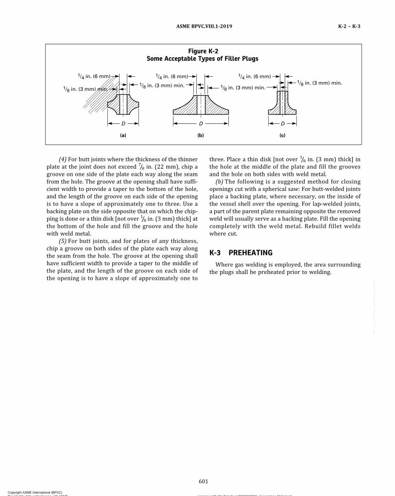
(4) For butt joints where the thickness of the thinnerplate at the joint does not exceed 7/8 in. (22 mm), chip agroove on one side of the plate each way along the seamfrom the hole. The groove at the opening shall have suffi-cient width to provide a taper to the bottom of the hole,and the length of the groove on each side of the openingis to have a slope of approximately one to three. Use abacking plate on the side opposite that on which the chip-ping is done or a thin disk [not over 1/8 in. (3 mm) thick] atthe bottom of the hole and fill the groove and the holewith weld metal.
(5) For butt joints, and for plates of any thickness,chip a groove on both sides of the plate each way alongthe seam from the hole. The groove at the opening shallhave sufficient width to provide a taper to the middle ofthe plate, and the length of the groove on each side ofthe opening is to have a slope of approximately one to
three. Place a thin disk [not over 1/8 in. (3 mm) thick] inthe hole at the middle of the plate and fill the groovesand the hole on both sides with weld metal.
(b) The following is a suggested method for closingopenings cut with a spherical saw: For butt-welded jointsplace a backing plate, where necessary, on the inside ofthe vessel shell over the opening. For lap‐welded joints,a part of the parent plate remaining opposite the removedweld will usually serve as a backing plate. Fill the openingcompletely with the weld metal. Rebuild fillet weldswhere cut.
K-3 PREHEATING
Where gas welding is employed, the area surroundingthe plugs shall be preheated prior to welding.
Figure K-2Some Acceptable Types of Filler Plugs
DDD
(c)(b)(a)
1/4 in. (6 mm)
1/8 in. (3 mm) min.1/8 in. (3 mm) min.
1/4 in. (6 mm)
1/8 in. (3 mm) min.1/8 in. (3 mm) min.
1/4 in. (6 mm)
ASME BPVC.VIII.1-2019 K-2 – K-3
601
Copyright ASME International (BPVC) Provided by IHS under license with ASME Licensee=Khalda Petroleum/5986215001, User=Amer, Mohamed
Not for Resale, 07/02/2019 13:29:04 MDTNo reproduction or networking permitted without license from IHS
--`,``,``,,`,`,,````,`,``,,,`-`-`,,`,,`,`,,`---

NONMANDATORY APPENDIX LAPPLICATION OF RULES FOR JOINT EFFICIENCY IN SHELLS AND
HEADS OF VESSELS WITH WELDED JOINTS
L-1 VESSELS UNDER INTERNAL PRESSURE
L-1.1 INTRODUCTIONThis Appendix provides guidelines for establishing the
appropriate joint efficiency for vessels of welded con-struction. The joint efficiencies are applied in various de-sign formulas which determine either the minimumrequired design thicknesses of vessel parts or the maxi-mum allowable working pressure for a given thickness.
L-1.2 REQUIREMENTS FOR RADIOGRAPHYRadiography is mandatory for certain vessel services
and material thicknesses (UW-11). When radiography isnot mandatory, the degree of radiography is optional,and the amount of radiography must be determined bythe user or his designated agent (U-2).Whether radiography is mandatory or optional, the
amount of radiography performed on each butt weld to-gether with the type of weld (UW-12) will determinethe joint efficiency to be applied in the various designformulas.
L-1.3 APPLICATION OF JOINT EFFICIENCYFACTORS
The longitudinal and circumferential directions ofstress are investigated separately to determine the mostrestrictive condition governing stresses in the vessel.[See UG-23(c).] In terms of the application of joint effi-ciencies, each weld joint is considered separately, and
the joint efficiency for that weld joint is then applied inthe appropriate design formula for the component underconsideration.
L-1.4 FLOWCHARTSFigures L-1.4-1 and L-1.4-2 provide step‐by‐step guide-
lines for determining required joint efficiencies for var-ious components. Alternatively, Figures L-1.4-3 andL-1.4-4 provide guidelines for determining joint efficien-cies for weld categories. Generally, the designer shouldconsider the following points:(a) Is radiography mandatory due to service or materi-
al thickness?(b) Are weld types mandated? For example, UW-2 re-
stricts weld types to Types 1 or 2 for Category A and Bwelds. If not, select appropriate types.(c) If radiography is not mandatory, the amount of
radiography performed is optional. The user or his desig-nated agent shall determine the extent of radiography tobe performed, or at his option, may permit the vesselmanufacturer to select the extent of radiography.(d) Does the degree of radiography performed on the
Category B weld joints in a cylindrical or conical shell af-fect the joint efficiency used on the Category A weldjoints? Remember, the minimum required thickness fora cylindrical or conical shell is calculated separately forthe circumferential and longitudinal directions and thelarger of these two thicknesses calculated selected.
ASME BPVC.VIII.1-2019L-1 – L-1.4
602
Copyright ASME International (BPVC) Provided by IHS under license with ASME Licensee=Khalda Petroleum/5986215001, User=Amer, Mohamed
Not for Resale, 07/02/2019 13:29:04 MDTNo reproduction or networking permitted without license from IHS
--`,``,``,,`,`,,````,`,``,,,`-`-`,,`,,`,`,,`---

Figure L-1.4-1Joint Efficiency and Weld Joint Type — Cylinders and Cones
Cylindrical andconical shells
UW-11(a)(1), (a)(2), and (a)(3)E � 1.0 Type 1E � 0.9 Type 2
Category A, B, C, and Dbutt welds
Yes No
Yes No
Select RTCategory B and C
butt welds
Select full RTCategory A and D butt
welds UW-11(a)(5)
SRT UW-11(b)Table UW-12,
col. (b)
No RT UW-11(c)Table UW-12,
col. (c)
Full RT
Category AE � 1.0 Type 1E � 0.9 Type 2
Categories B and CE � 1.0 Type 1E � 0.9 Type 2
SRTUW-11(a)(5)(-b)
Category AE � 1.0 Type 1E � 0.9 Type 2
Categories B and CE � 0.85 Type 1E � 0.80 Type 2
No RT
Category AE � 0.85 Type 1E � 0.80 Type 2
Categories B and CE � 0.70 Type 1E � 0.65 Type 2
Full RT mandatoryUW-11(a)
Seamless section
Category Ccorner joint
Category AE = 1.00 Type 1E = 0.90 Type 2
E = 0.85 Types 3, 4, 5, or 6
Category CE = 1.00 Type 7
GENERAL NOTES:(a) Thickness required for longitudinal stress in conical sections is as follows: t = PD/[4 cos (α) (SE + 0.4 P)].(b) See UW-11(a)(4) for Category B and C butt welds in nozzles and communicating chambers equal to or less than NPS 10 and thickness
11/8 in. (30 mm) or less.(c) Type 2 joints not allowed for Category A weld joints for UW-2(c) designs.(d) Type 2 joints allowed for Category A weld joints for UW-2(b) designs for austenitic stainless steel Type 304.
ASME BPVC.VIII.1-2019 L-1.4
603
Copyright ASME International (BPVC) Provided by IHS under license with ASME Licensee=Khalda Petroleum/5986215001, User=Amer, Mohamed
Not for Resale, 07/02/2019 13:29:04 MDTNo reproduction or networking permitted without license from IHS
--`,``,``,,`,`,,````,`,``,,,`-`-`,,`,,`,`,,`---
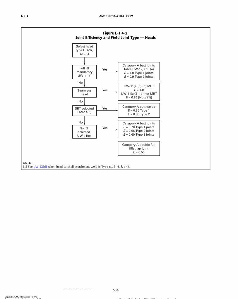
Figure L-1.4-2Joint Efficiency and Weld Joint Type — Heads
Yes
Yes
Yes
Yes
No
No
No
Select headtype UG-32,
UG-34
Full RTmandatoryUW-11(a)
Seamlesshead
SRT selectedUW-11(b)
No RTselectedUW-11(c)
Category A butt jointsTable UW-12, col. (a)E = 1.0 Type 1 jointsE = 0.9 Type 2 joints
Category A butt weldsE = 0.85 Type 1E = 0.80 Type 2
Category A butt jointsE = 0.70 Type 1 jointsE = 0.65 Type 2 jointsE = 0.60 Type 3 joints
Category A double fullfillet lap joint
E = 0.55
UW-11(a)(5)(-b) METE = 1.0
UW-11(a)(5)(-b) not METE = 0.85 [Note (1)]
NOTE:(1) See UW-12(d) when head-to-shell attachment weld is Type no. 3, 4, 5, or 6.
ASME BPVC.VIII.1-2019L-1.4
604
Copyright ASME International (BPVC) Provided by IHS under license with ASME Licensee=Khalda Petroleum/5986215001, User=Amer, Mohamed
Not for Resale, 07/02/2019 13:29:04 MDTNo reproduction or networking permitted without license from IHS
--`,``,``,,`,`,,````,`,``,,,`-`-`,,`,,`,`,,`---
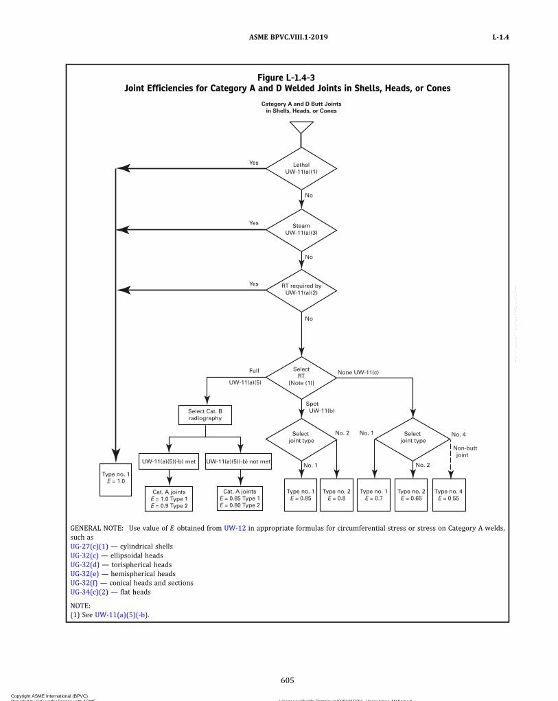
Figure L-1.4-3Joint Efficiencies for Category A and D Welded Joints in Shells, Heads, or Cones
Yes
Yes
Yes
Full
No
No
No
None UW-11(c)
UW-11(a)(5)
SelectRT
[Note (1)]
RT required byUW-11(a)(2)
SteamUW-11(a)(3)
LethalUW-11(a)(1)
Category A and D Butt Joints
in Shells, Heads, or Cones
No. 2Select joint type
Select joint type
Select Cat. Bradiography
UW-11(a)(5)(-b) met UW-11(a)(5)(-b) not met
Type no. 1E = 1.0
No. 1
No. 1 No. 2
No. 4
Non-butt joint
Spot UW-11(b)
Cat. A jointsE = 1.0 Type 1E = 0.9 Type 2
Cat. A jointsE = 0.85 Type 1E = 0.80 Type 2
Type no. 1E = 0.85
Type no. 2E = 0.8
Type no. 1E = 0.7
Type no. 2E = 0.65
Type no. 4E = 0.55
GENERAL NOTE: Use value of E obtained from UW-12 in appropriate formulas for circumferential stress or stress on Category A welds,such asUG-27(c)(1) — cylindrical shellsUG-32(c) — ellipsoidal headsUG-32(d) — torispherical headsUG-32(e) — hemispherical headsUG-32(f) — conical heads and sectionsUG-34(c)(2) — flat heads
NOTE:(1) See UW-11(a)(5)(-b).
ASME BPVC.VIII.1-2019 L-1.4
605
Copyright ASME International (BPVC) Provided by IHS under license with ASME Licensee=Khalda Petroleum/5986215001, User=Amer, Mohamed
Not for Resale, 07/02/2019 13:29:04 MDTNo reproduction or networking permitted without license from IHS
--`,``,``,,`,`,,````,`,``,,,`-`-`,,`,,`,`,,`---
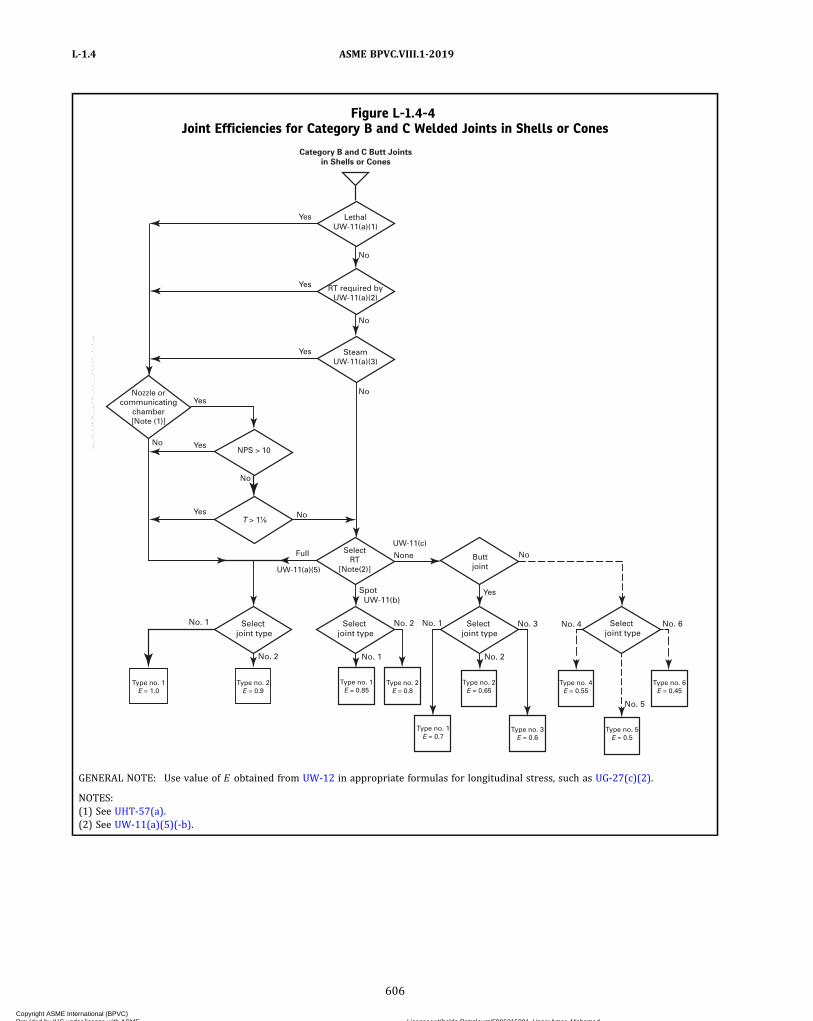
Figure L-1.4-4Joint Efficiencies for Category B and C Welded Joints in Shells or Cones
LethalUW-11(a)(1)
Category B and C Butt Joints
in Shells or Cones
Type no. 1E = 0.85
Yes
Yes
Yes
Yes
Yes
Yes
No
No
No
No
No
No
No
Yes
No. 2 Select joint type
Select joint type
Spot UW-11(b)
Type no. 1E = 1.0
Select joint type
Select joint type
No. 2 No. 1 No. 2
No. 1 No. 3 No. 4 No. 6
No. 5
Type no. 2E = 0.9
Type no. 2E = 0.8
Type no. 1E = 0.7
Type no. 2E = 0.65
Type no. 3E = 0.6
Type no. 5E = 0.5
Type no. 4E = 0.55
Type no. 6E = 0.45
UW-11(c)
UW-11(a)(5)
No. 1
Full None Buttjoint
SelectRT
[Note(2)]
NPS > 10
RT required byUW-11(a)(2)
SteamUW-11(a)(3)
Nozzle orcommunicating
chamber[Note (1)]
GENERAL NOTE: Use value of E obtained from UW-12 in appropriate formulas for longitudinal stress, such as UG-27(c)(2).
NOTES:(1) See UHT-57(a).(2) See UW-11(a)(5)(-b).
ASME BPVC.VIII.1-2019L-1.4
606
Copyright ASME International (BPVC) Provided by IHS under license with ASME Licensee=Khalda Petroleum/5986215001, User=Amer, Mohamed
Not for Resale, 07/02/2019 13:29:04 MDTNo reproduction or networking permitted without license from IHS
--`,``,``,,`,`,,````,`,``,,,`-`-`,,`,,`,`,,`---

ð19Þ
NONMANDATORY APPENDIX MINSTALLATION AND OPERATION
M-1 INTRODUCTION
(a) The rules in this Appendix are for general informa-tion only, because they pertain to the installation and op-eration of pressure vessels, which are the prerogative andresponsibility of the law enforcement authorities in thosestates and municipalities which have made provision forthe enforcement of Section VIII.
(b) It is permissible to use any departures suggestedherein from provisions in the mandatory parts of this Di-vision when granted by the authority having legal juris-diction over the installation of pressure vessels.
M-2 CORROSION
(a) Vessels subject to external corrosion shall be so in-stalled that there is sufficient access to all parts of the ex-terior to permit proper inspection of the exterior, unlessadequate protection against corrosion is provided or un-less the vessel is of such size and is so connected that itmay readily be removed from its permanent location forinspection.
(b) Vessels having manholes, handholes, or cover platesto permit inspection of the interior shall be so installedthat these openings are accessible.
(c) In vertical cylindrical vessels subject to corrosion,to insure complete drainage, the bottom head, if dished,should preferably be concave to pressure.
M-3 MARKING ON THE VESSEL
The marking required by this Division shall be so lo-cated that it will be accessible after installation and wheninstalled shall not be covered with insulation or other ma-terial that is not readily removable [see UG-116].
M-4 PRESSURE-RELIEVING DEVICES
The general provisions for the instal lation ofpressure-relieving devices are fully covered in UG-135.The following paragraphs contain details in arrangementof stop valves for shutoff control of pressure relief deviceswhich are sometimes necessary to the continuous opera-tion of processing equipment of such a complex naturethat the shutdown of any part of it is not feasible. Thereare also rules with regard to the design of inlet and dis-charge piping to and from pressure relief devices, whichcan only be general in nature because the design engineer
must fit the arrangement and proportions of such a sys-tem to the particular requirements in the operation ofthe equipment involved.
M-5 STOP VALVES LOCATED IN THE RELIEFPATH
M-5.1 GENERAL(a) Stop valve(s) located within the relief path is not al-
lowed except as provided for in M-5.5, M-5.6, M-5.7, andM-5.8, and only when specified by the user. The responsi-bilities of the user are summarized in M-5.3. The specificrequirements in M-5.5, M-5.6, M-5.7, and M-5.8 are not in-tended to allow for normal operation above the maximumallowable working pressure.
(b) The pressure relief path shall be designed such thatthe pressure in the equipment being protected does notexceed its maximum allowable working pressure beforethe pressure at the pressure relief device reaches its setpressure and the pressure does not exceed the limits ofUG-125(c).
M-5.2 DEFINITIONS
administrative controls: procedures that, in combinationwith mechanical locking elements, are intended to ensurethat personnel actions do not compromise the overpres-sure protection of the equipment. They include, as a mini-mum, Documented Operat ion and MaintenanceProcedures, and Training of Operator and MaintenancePersonnel in these procedures.
full area stop valve: a valve in which the flow area of thevalve is equal to or larger than the inlet flow area of thepressure relief device.
management system: the collective application of adminis-trative controls, valve operation controls, and valve fail-ure controls , in accordance with the applicablerequirements of this Division.
mechanical locking elements: elements that when installedon a stop valve, provide a physical barrier to the opera-tion of the stop valve, such that the stop valve is not cap-able of being operated unless a deliberate action is takento remove or disable the element. Such elements, whenused in combination with adminstrative controls, ensurethat the equipment overpressure protection is not com-promised by personnel actions. Examples of mechanical
ASME BPVC.VIII.1-2019 M-1 – M-5.2
607
Copyright ASME International (BPVC) Provided by IHS under license with ASME Licensee=Khalda Petroleum/5986215001, User=Amer, Mohamed
Not for Resale, 07/02/2019 13:29:04 MDTNo reproduction or networking permitted without license from IHS
--`,``,``,,`,`,,````,`,``,,,`-`-`,,`,,`,`,,`---

locking elements include locks (with or without chains)on the stop valve handwheels, levers, or actuators, andplastic or metal straps (car seals) that are secured tothe valve in such a way that the strap must be brokento operate the stop valve.
pressure relief path: consists of all equipment, pipe, fit-tings, and valves in the flow path between any protectedequipment and its pressure-relieving device, and betweenthe pressure-relieving device and the discharge point ofthe relieving stream. Stop valves within a pressure reliefpath include, but are not limited to, those located directlyupstream and downstream of the Pressure Relief Device(PRD) that may be provided exclusively for PRDmaintenance.
valve failure controls: measure taken in valve design, con-figuration, and/or orientation for the purpose of prevent-ing an internal failure of a stop valve from closing andblocking the pressure relief path. An example of valve fail-ure controls is the installation of gate valves with thevalve stem oriented at or below the horizontal position.
valve operation controls: devices used to ensure that stopvalves within the pressure relief path are in their proper(open/closed) position. They include the following:(a)mechanical interlocks which are designed to pre-
vent valve operations which could result in the blockingof a pressure relief path before an alternative pressure re-lief path is put into service. Mechanical interlocks includephysical linkages such as shaft or lever between stopvalves and key based interlocking systems.(b) instrumented interlocks which function similar to
mechanical interlocks, except that instrument permis-sives and/or overrides are used instead of mechanical lin-kages/devices to prevent valve positions that block thepressure relief path.(c) three‐way valves designed to prevent a flow path
from being blocked without another flow path being si-multaneously opened.
M-5.3 RESPONSIBILITIESThe User has the responsibility to establish and main-
tain a management system that ensures a vessel is not op-erated without overpressure protection. Theseresponsibilities include, but are not limited to, thefollowing:(a) Deciding and specifying if the overpressure protec-
tion system will allow the use of stop valve(s) located inthe relief path.(b) Establishing the pressure relief philosophy and the
administrative controls requirements.(c) Establishing the required level of reliability, redun-
dancy, and maintenance of instrumented interlocks, ifused.
NOTE: The procedures contained in ISA S‐84, “Application of SafetyInstrumented Systems for the Process Industries,” or IEC 61508,“Functional Safety of Electrical/Electronic/Programmable ElectronicSafety‐Related Systems,” may be used for this purpose and analysis.
(d) Establishing procedures to ensure that the equip-ment is adequately protected against overpressure.(e) Ensuring that authorization to operate identified
valves is clear and that personnel are adequately trainedfor this task.(f) Establishing management systems to ensure that
administrative controls are effective.(g) Establishing the analysis procedures and basis to be
used in determining the potential levels of pressure if thestop valve(s) were closed.(h) Ensuring that the analysis described in (g) is con-
ducted by personnel who are qualified and experiencedwith the analysis procedure.(i) Ensuring that the other system components are ac-
ceptable for the potential levels of pressure established in(g).(j) Ensuring that the results of the analysis described
in (g) are documented and are reviewed and acceptedin writing by the individual responsible for operation ofthe vessel and valves.(k) Ensuring that the administrative controls are re-
viewed and accepted in writing by the individual respon-sible for operation of the vessel and valves.
M-5.4 REQUIREMENTS OF PROCEDURES/MANAGEMENT SYSTEM
(a) Procedures shall specify that valves requiring me-chanical locking elements and/or valve operation con-trols and/or valve failure controls shall be documentedand clearly identified as such.(b) The Management System shall document the ad-
ministrative controls (training and procedures), the valvecontrols, and the performance of the administrative con-trols in an auditable form for management review.
M-5.5 STOP VALVES PROVIDED IN SYSTEMSFOR WHICH THE PRESSURE ORIGINATESEXCLUSIVELY FROM AN OUTSIDESOURCE
A vessel or system [see UG-133(c)] for which the pres-sure originates from an outside source exclusively mayhave individual pressure-relieving devices on each vessel,or connected to any point on the connecting piping, or onany one of the vessels to be protected. Under such an ar-rangement, there may be stop valve(s) between any ves-sel and the pressure-relieving devices, and these stopvalve(s) need not have any administrative controls, valveoperation controls, or valve failure controls, provided thatthe stop valves also isolate the vessel from the source ofpressure.
ASME BPVC.VIII.1-2019M-5.2 – M-5.5
608
Copyright ASME International (BPVC) Provided by IHS under license with ASME Licensee=Khalda Petroleum/5986215001, User=Amer, Mohamed
Not for Resale, 07/02/2019 13:29:04 MDTNo reproduction or networking permitted without license from IHS
--`,``,``,,`,`,,````,`,``,,,`-`-`,,`,,`,`,,`---
M-5.6 STOP VALVE(S) PROVIDED UPSTREAM ORDOWNSTREAM OF THE PRESSURE RELIEFDEVICE EXCLUSIVELY FORMAINTENANCE OF THAT DEVICE
Full area stop valve(s) may be provided upstream and/or downstream of the pressure-relieving device for thepurpose of inspection, testing, and repair of thepressure-relieving device or discharge header isolation,provided that, as a minimum, the following requirementsare complied with:
(a) Administrative controls are provided to prevent un-authorized valve operation.
(b) Valves are provided with mechanical lockingelements.
(c) Valve failure controls are provided to prevent acci-dental valve closure due to mechanical failure.
(d) Procedures are in place to provide pressure reliefprotection during the time when the system is isolatedfrom its pressure relief path. These procedures shall en-sure that when the system is isolated from its pressure re-lief path, an authorized person shall continuously monitorthe pressure conditions of the vessel and shall be capableof responding promptly with documented, pre‐definedactions, either stopping the source of overpressure oropening alternative means of pressure relief. This author-ized person shall be dedicated to this task and shall haveno other duties when performing this task.
(e) The system shall be isolated from its pressure reliefpath only for the time required to test, repair, and or re-place the pressure relief device.
M-5.7 STOP VALVE(S) PROVIDED IN THEPRESSURE RELIEF PATH WHERE THEREIS NORMALLY PROCESS FLOW
Stop valve(s), excluding remotely operated valves andprocess control valves, may be provided in the relief pathwhere there is normally a process flow, provided the re-quirements in (a) and (b), as a minimum, are compliedwith. These requirements are based on the potential over-pressure scenarios involving accidental closure of a singlestop valve within the relief path [see M-5.3(g)]. The acci-dental closure of these stop valve(s) in the pressure reliefsystem need not be considered in setting the design pres-sure per UG-21.
(a) The flow resistance of the valve in the full open po-sition does not reduce the relieving capacity below thatrequired by the rules of this Division.
(b) The closure of the valve will be readily apparent tothe operators such that corrective action, in accordancewith documented operating procedures, is required, and
(1) if the pressure due to closure of the valve can notexceed 116% of MAWP, then no administrative controls,mechanical locking elements, valve operation controls,or valve failure controls are required, or
(2) if the pressure due to closure of the valve can notexceed the following:
(-a) the documented test pressure, multiplied bythe ratio of the stress value at the design temperatureto the stress value at the test temperature, or
(-b) if the test pressure is calculated per UG-99(c)in addition to the ratio in (-a), the test pressure shall alsobe multiplied by the ratio of the nominal thickness minusthe corrosion allowance to the nominal thickness then, asa minimum, administrative controls and mechanical lock-ing elements are required, or
(3) if the pressure due to closure of the valve couldexceed the pressure in (2), then the user shall either
(-a) eliminate the stop valve, or(-b) apply administrative controls, mechanical
locking elements, valve failure controls, and valve opera-tion controls, or
(-c) provide a pressure relief device to protect theequipment that could be overpressured due to closure ofthe stop valve
M-5.8 STOP VALVES PROVIDED IN THE RELIEFPATH OF EQUIPMENT WHERE THERE ISNORMALLY PROCESS FLOW AND WHEREFIRE IS THE ONLY POTENTIAL SOURCEOF OVERPRESSURE
Full area stop valve(s) located in the relief path ofequipment where there is normally process flow andwhere fire is the only potential source of overpressuredo not require physical elements such as locks or carseals, valve operation controls, or valve failure controlsprovided the user has documented operating proceduresrequiring that equipment isolated from its pressure reliefpath is depressured and free of liquids.
M-6 INLET PRESSURE DROP FOR HIGH LIFT,TOP-GUIDED SAFETY, SAFETY RELIEF,AND PILOT-OPERATED PRESSURERELIEF VALVES IN COMPRESSIBLEFLUID SERVICE
(a) The nominal pipe size of all piping, valves and fit-tings, and vessel components between a pressure vesseland its safety, safety relief, or pilot-operated pressure re-lief valves shall be at least as large as the nominal size ofthe device inlet, and the flow characteristics of the up-stream system shall be such that the cumulative total ofall nonrecoverable inlet losses shall not exceed 3% ofthe valve set pressure. The inlet pressure losses will bebased on the valve nameplate capacity corrected for thecharacteristics of the flowing fluid.
(b)When two or more required safety, safety relief, orpilot-operated pressure relief valves are placed on oneconnection, the inlet internal cross‐sectional area of thisconnection shall be either sized to avoid restricting flowto the pressure relief valves or made at least equal tothe combined inlet areas of the safety valves connected
ASME BPVC.VIII.1-2019 M-5.6 – M-6
609
Copyright ASME International (BPVC) Provided by IHS under license with ASME Licensee=Khalda Petroleum/5986215001, User=Amer, Mohamed
Not for Resale, 07/02/2019 13:29:04 MDTNo reproduction or networking permitted without license from IHS
--`,``,``,,`,`,,````,`,``,,,`-`-`,,`,,`,`,,`---
to it. The flow characteristics of the upstream system shallmeet the requirements of (a) above with all valves reliev-ing simultaneously.
M-7 DISCHARGE LINES FROM PRESSURERELIEF DEVICES
(a)Where it is feasible, the use of a short dischargepipe or vertical riser, connected through long‐radius el-bows from each individual device, blowing directly tothe atmosphere, is recommended. Such discharge pipesshall be at least of the same size as the valve outlet. Wherethe nature of the discharge permits, telescopic (some-times called “broken”) discharge lines, whereby con-densed vapor in the discharge line, or rain, is collectedin a drip pan and piped to a drain, are recommended.105
(b)When discharge lines are long, or where outlets oftwo or more devices having set pressures within a com-parable range are connected into a common line, the ef-fect of the back pressure that may be developed thereinwhen certain devices operate must be considered [seeUG-135(f)]. The sizing of any section of a common‐discharge header downstream from each of the two ormore pressure-relieving devices that may reasonably beexpected to discharge simultaneously shall be based onthe total of their outlet areas, with due allowance forthe pressure drop in all downstream sections. Use of spe-cially designed devices suitable for use on high or variableback pressure service should be considered.(c) The flow characteristics of the discharge system of
high lift, top-guided safety, safety relief, or pilot-operatedpressure relief valves in compressible fluid service shallbe such that the static pressure developed at the dis-charge flange of a conventional direct spring-loaded valvewill not exceed 10% of the set pressure when flowing atstamp capacity. Other valve types exhibit various degreesof tolerance to back pressure and the manufacturer’s rec-ommendation should be followed.(d) All discharge lines shall be run as direct as is prac-
ticable to the point of final release for disposal. For thelonger lines, due consideration shall be given to the ad-vantage of long‐radius elbows, avoidance of closeup fit-tings, and the minimizing of excessive line strains byexpansion joints and well‐known means of support tominimize line‐sway and vibration under operatingconditions.(e) Provisions should be made in all cases for adequate
drainage of discharge lines.
NOTE: It is recognized that no simple rule can be applied generally tofit the many installation requirements, which vary from simple shortlines that discharge directly to the atmosphere to the extensivemanifold discharge piping systems where the quantity and rate ofthe product to be disposed of requires piping to a distant safe place.
M-8 PRESSURE DROP, NONRECLOSINGPRESSURE RELIEF DEVICES
Piping, valves and fittings, and vessel components com-prising part of a nonreclosing device pressure-relievingsystem shall be sized to prevent the vessel pressure fromrising above the allowable overpressure.
M-9 GENERAL ADVISORY INFORMATION ONTHE CHARACTERISTICS OF PRESSURERELIEF DEVICES DISCHARGING INTO ACOMMON HEADER
Because of the wide variety of types and kinds of pres-sure relief devices, it is not considered advisable to at-tempt a description in this Appendix of the effectsproduced by discharging them into a common header.Several different types of pressure relief devices may con-ceivably be connected into the same discharge header andthe effect of back pressure on each type may be radicallydifferent. Data compiled by the manufacturers of eachtype of pressure relief device used should be consultedfor information relative to its performance under the con-ditions anticipated.
M-10 PRESSURE DIFFERENTIALS FORPRESSURE RELIEF VALVES
Due to the variety of service conditions and the variousdesigns of safety and safety relief valves, only generalguidance can be given regarding the differential betweenthe set pressure of the valve (see UG-134) and the oper-ating pressure of the vessel. Operating difficulty will beminimized by providing an adequate differential for theapplication. The following is general advisory informationon the characteristics of the intended service and of thesafety or safety relief valves that may bear on the properpressure differential selection for a given application.These considerations should be reviewed early in the sys-tem design since they may dictate the MAWP of thesystem.(a) Consideration of the Process Characteristics in the
Establishment of the Operating Margin to Be Provided.To minimize operational problems, it is imperative thatthe user consider not only normal operating conditionsof fluids, pressures, and temperatures, but also start‐upand shutdown conditions, process upsets, anticipated am-bient conditions, instrument response times, pressuresurges due to quick closing valves, etc. When such condi-tions are not considered, the pressure-relieving device
ASME BPVC.VIII.1-2019M-6 – M-10
610
Copyright ASME International (BPVC) Provided by IHS under license with ASME Licensee=Khalda Petroleum/5986215001, User=Amer, Mohamed
Not for Resale, 07/02/2019 13:29:04 MDTNo reproduction or networking permitted without license from IHS
--`,``,``,,`,`,,````,`,``,,,`-`-`,,`,,`,`,,`---

may become, in effect, a pressure controller, a duty forwhich it is not designed. Additional consideration shouldbe given to hazard and pollution associated with the re-lease of the fluid. Larger differentials may be appropriatefor fluids which are toxic, corrosive, or exceptionallyvaluable.
(b) Consideration of Safety Relief Valve Characteristics.The blowdown characteristic and capability is the firstconsideration in selecting a compatible valve and operat-ing margin. After a self‐actuated release of pressure, thevalve must be capable of reclosing above the normal op-erating pressure. For example, if the valve is set at100 psig (700 kPa) with a 7% blowdown, it will close at93 psig (641 kPa). The operating pressure must be main-tained below 93 psig (641 kPa) in order to prevent leak-age or flow from a partially open valve. Users shouldexercise caution regarding the blowdown adjustment oflarge spring‐loaded valves. Test facilities, whether ownedby Manufacturers, repair houses, or users, may not havesufficient capacity to accurately verify the blowdown set-ting. The settings cannot be considered accurate unlessmade in the field on the actual installation.
Pilot‐operated valves represent a special case from thestandpoints of both blowdown and tightness. The pilotportion of some pilot‐operating valves can be set at blow-downs as short as 2%. This characteristic is not, however,reflected in the operation of the main valve in all cases.The main valve can vary considerably from the pilot de-pending on the location of the two components in the sys-tem. If the pilot is installed remotely from the main valve,significant time and pressure lags can occur, but reseatingof the pilot assures reseating of the main valve. The pres-sure drop in the connecting piping between the pilot andthe main valve must not be excessive; otherwise, the op-eration of the main valve will be adversely affected.
The tightness of the main valve portion of these combi-nations is considerably improved above that of conven-tional valves by pressure loading the main disk or bythe use of soft seats or both.
Despite the apparent advantages of pilot‐operatedvalves, users should be aware that they should not be em-ployed in abrasive or dirty service, in applications wherecoking, polymerization, or corrosion of the wetted pilotparts can occur, or where freezing or condensation ofthe lading fluid at ambient temperatures is possible. Forall applications the valve Manufacturer should be con-sulted prior to selecting a valve of this type.
Tightness capability is another factor affecting valve se-lection, whether spring loaded or pilot operated. It variessomewhat depending on whether metal or resilient seatsare specified, and also on such factors as corrosion ortemperature. The required tightness and test methodshould be specified to comply at a pressure no lower thanthe normal operating pressure of the process. A recom-mended procedure and acceptance standard is given inAPI 527. It should also be remembered that any degree
of tightness obtained should not be considered perma-nent. Service operation of a valve almost invariably re-duces the degree of tightness.
Application of special designs such as O‐rings or resili-en t sea t s shou ld be rev i ewed wi th the va lveManufacturer.
The anticipated behavior of the valves includes allow-ance for a plus‐or‐minus tolerance on set pressure whichvaries with the pressure level. Installation conditions,such as back pressure, variations, and vibrations, influ-ence selection of special types and an increase in differen-tial pressure.
(c) General Recommendations. The following pressuredifferentials are recommended unless the safety or safetyrelief valve has been designed or tested in a specific orsimilar service and a smaller differential has been recom-mended by the Manufacturer.
A minimum difference of 5 psi (35 kPa) is recommend-ed for set pressures to 70 psi (485 kPa). In this category,the set pressure tolerance is ±2 psi (±13.8 kPa)[UG-134(d)(1)], and the differential to the leak test pres-sure is 10% or 5 psi (35 kPa), whichever is greater.
A minimum differential of 10% is recommended for setpressures from 71 psi to 1,000 psi (490 kPa to 6.9 MPa).In this category, the set pressure tolerance is ±3% and thedifferential to the leak test pressure is 10%.
A minimum differential of 7% is recommended for setpressures above 1,000 psi (6.9 MPa). In this category,the set pressure tolerance is ±3% and the differential tothe leak test pressure should be 5%. Valves having smallseat sizes will require additional maintenance when thepressure differential approaches these recommendations.
M-11 INSTALLATION OF SAFETY ANDSAFETY RELIEF VALVES
Spring-loaded safety and safety relief valves normallyshould be installed in the upright position with the spin-dle vertical. Where space or piping configuration precludesuch an installation, the valve may be installed in otherthan the vertical position, provided that:
(a) the valve design is satisfactory for such position;(b) the media is such that material will not accumulate
at the inlet of the valve; and(c) drainage of the discharge side of the valve body and
discharge piping is adequate.
M-12 REACTION FORCES AND EXTERNALLYAPPLIED LOADS
(a) Reaction Thrust. The discharge of a pressure reliefdevice imposes reactive flow forces on the device and as-sociated piping. The design of the installation may requirecomputation of the bending moments and stresses in the
ASME BPVC.VIII.1-2019 M-10 – M-12
611
Copyright ASME International (BPVC) Provided by IHS under license with ASME Licensee=Khalda Petroleum/5986215001, User=Amer, Mohamed
Not for Resale, 07/02/2019 13:29:04 MDTNo reproduction or networking permitted without license from IHS
--`,``,``,,`,`,,````,`,``,,,`-`-`,,`,,`,`,,`---

piping and vessel nozzle. There are momentum effectsand pressure effects at steady state flow as well as transi-ent dynamic loads caused by opening.(b) External Loads. Mechanical forces may be applied
to the pressure relief device by discharge piping as a re-sult of thermal expansion, movement away from anchors,and weight of any unsupported piping. The resultantbending moments on a closed pressure relief devicemay cause device leakage, device damage, and excessivestress in inlet piping. The design of the installation shouldconsider these possibilities.
M-13 SIZING OF PRESSURE RELIEF DEVICESFOR FIRE CONDITIONS
(a) Excessive pressure may develop in pressure vesselsby vaporization of the liquid contents and/or expansionof vapor content due to heat influx from the surroundings,particularly from a fire. Pressure relief systems for fireconditions are usually intended to release only the quan-tity of product necessary to lower the pressure to a pre-determined safe level, without releasing an excessivequantity. This control is especially important in situationswhere release of the contents generates a hazard becauseof flammability or toxicity. Under fire conditions, consid-eration must also be given to the possibility that the safepressure level for the vessel will be reduced due to heat-ing of the vessel material, with a corresponding loss ofstrength. For some fire situations, there may be an insuf-ficient rise in pressure to activate a pressure relief device.The user should consult other references, which provideguidelines for protecting vessels from the effects of fire.(b) Several formulas have evolved over the years for
calculating the pressure relief capacity required underfire conditions. The major differences involve heat fluxrates. There is no single formula yet developed whichtakes into account all of the many factors which couldbe considered in making this determination. When fireconditions are a consideration in the design of a pressurevessel, the following references which provide recom-mendations for specific installations may be used:
API Recommended Practice 520, Sizing, Selection, andInstallation of Pressure‐Relieving Systems in Refineries,Part I — Sizing and Selection, Seventh Edition, Jaunary2000, American Petroleum Institute, Washington, DCAP I Recommended Prac t i c e 521 , Gu ide f o r
Pressure‐Relieving and Depressuring Systems, FourthEdition, March 1997, American Petroleum Institute, Wa-shington, DCAPI Standard 2000, Venting Atmospheric and Low‐
Pressure Storage Tanks (Nonrefrigerated and Refriger-ated), Fifth Edition, April 1998, American Petroleum Insti-tute, Washington, DCAAR Standard M‐1002, Specifications for Tank Cars,
1978, Association of American Railroads, Washington, DCSafety Relief Device Standards: S‐1.1, Cylinders for
Compressed Gases; S‐1.2, Cargo and Portable Tanks;and S‐1.3, Compressed Gas Storage Containers, Com-pressed Gas Association, Arlington, VANFPA Code Nos. 30, 58, 59, and 59A, National Fire Pro-
tection Association, 1 Batterymarch Park, Quincy, MA02169‐7471Pressure‐Relieving Systems for Marine Cargo Bulk Liquid
Containers, 1973, National Academy of Sciences, Washing-ton, DCBulletin E-2, How to Size Safety Relief Devices, Phillips
Petroleum Company, Bartlesville, OKA Study of Available Fire Test Data as Related to Tank
Car Safety Device Relieving Capacity Formulas, 1971, Phil-lips Petroleum Company, Bartlesville, OK
M-14 PRESSURE-INDICATING DEVICE
If a pressure-indicating device is provided to determinethe vessel pressure at or near the set pressure of the reliefdevice, one should be selected that spans the set pressureof the relief device and is graduated with an upper limitthat is neither less than 1.25 times the set pressure ofthe relief device nor more than twice the maximum allow-able working pressure of the vessel. Additional devicesmay be installed if desired.
ASME BPVC.VIII.1-2019M-12 – M-14
612
Copyright ASME International (BPVC) Provided by IHS under license with ASME Licensee=Khalda Petroleum/5986215001, User=Amer, Mohamed
Not for Resale, 07/02/2019 13:29:04 MDTNo reproduction or networking permitted without license from IHS
--`,``,``,,`,`,,````,`,``,,,`-`-`,,`,,`,`,,`---

NONMANDATORY APPENDIX PBASIS FOR ESTABLISHING ALLOWABLE STRESS VALUES FOR
UCI, UCD, AND ULT MATERIALS
P-1
The values in Tables UCI-23, ULT-23, and ULT-23 areestablished by the Committee only. In the determinationof allowable stress values for these materials, the Com-mittee is guided by successful experience in service, inso-far as evidence of satisfactory performance is available.Such evidence is considered equivalent to test data whereoperating conditions are known with reasonable cer-tainty. In the evaluation of new materials, the Committeeis guided to a certain extent by the comparison of test in-formation with available data on successful applicationsof similar materials.
(a) Nomenclature
NA = not applicableRT = ratio of the average temperature dependent
trend curve value of tensile strength to theroom temperature tensile strength
RY = ratio of the average temperature dependenttrend curve value of yield strength to the roomtemperature yield strength
SC = average stress to produce a creep rate of0.01%/1,000 hr
SRavg = average stress to cause rupture at the end of100,000 hr
SRmin = minimum stress to cause rupture at the end of100,000 hr
ST = specified minimum tensile strength at roomtemperature, ksi
SY = specified minimum yield strength at roomtemperature
The maximum allowable stress for Tables ULT-23,UCI-23, and UCD-23 shall be the lowest value obtainedfrom the criteria in Table P-1.
The stress criteria, mechanical properties considered,and the factors applied to establish the maximum allow-able stresses for other stress tables are given in SectionII, Part D, Mandatory Appendix 1.
Table P-1Criteria for Establishing Allowable Stress Values
Product/Material Table
Below Room Temperature Room Temperature and Above
TensileStrength Yield Strength Tensile Strength Yield Strength
Cast iron UCI-23 NA NA NA
Nodular iron UCD-23 2/3SY2/3SY
2/3SYRY
Wrought or castferrous andnonferrous
ULT-23 2/3SYRY NA NA NA NA
ASME BPVC.VIII.1-2019 P-1
613
Copyright ASME International (BPVC) Provided by IHS under license with ASME Licensee=Khalda Petroleum/5986215001, User=Amer, Mohamed
Not for Resale, 07/02/2019 13:29:04 MDTNo reproduction or networking permitted without license from IHS
--`,``,``,,`,`,,````,`,``,,,`-`-`,,`,,`,`,,`---

NONMANDATORY APPENDIX RPREHEATING
INTRODUCTION
Preheating may be employed during welding to assistin completion of the welded joint. The need for and tem-perature of preheat are dependent on a number of factors,such as the chemical analysis, degree of restraint of theparts being joined, elevated physical properties, and hea-vy thicknesses. Mandatory rules for preheating are, there-fore, not given in this Division except as required in theGeneral Notes that provide for exemptions to postweldheat treatment in Tables UCS-56-1 through UCS-56-11and Tables UHA-32-1 through UHA-32-7. Some practicesused for preheating are given below as a general guide forthe materials listed by P‐Numbers in Section IX. It is cau-tioned that the preheating temperatures listed below donot necessarily insure satisfactory completion of thewelded joint and requirements for individual materialswithin the P‐Number listing may have preheating moreor less restrictive than this general guide. The procedurespecification for the material being welded specifies theminimum preheating requirements under Section IX weldprocedure qualification requirements.The heat of welding may assist in maintaining preheat
temperatures after the start of welding and for inspectionpurposes, temperature checks can be made near the weld.The method or extent of application of preheat is nottherefore, specifically given. Normally when materials oftwo different P‐Number groups are joined by welding,the preheat used will be that of the material with the high-er preheat specified on the procedure specified on theprocedure specification.
R-1 P-NO. 1 GROUP NOS. 1, 2, AND 3(a) 175°F (79°C) for material which has both a speci-
fied maximum carbon content in excess of 0.30% and athickness at the joint in excess of 1 in. (25 mm);(b) 50°F (10°C) for all other materials in this
P‐Number.
R-2 P-NO. 3 GROUP NOS. 1, 2, AND 3(a) 175°F (79°C) for material which has either a speci-
fied minimum tensile strength in excess of 70,000 psi(480 MPa) or a thickness at the joint in excess of 5/8 in.(16 mm);(b) 50°F (10°C) for all other materials in this
P‐Number.
R-3 P-NO. 4 GROUP NOS. 1 AND 2(a) 250°F (121°C) for material which has either a spe-
cified minimum tensile strength in excess of 60,000 psi(410 MPa) or a thickness at the joint in excess of 1/2 in.(13 mm);(b) 50°F (10°C) for all other materials in this
P‐Number.
R-4 P-NOS. 5A AND 5B GROUP NO. 1(a) 400°F (204°C) for material which has either a spe-
cified minimum tensile strength in excess of 60,000 psi(410 MPa), or has both a specified minimum chromiumcontent above 6.0% and a thickness at the joint in excessof 1/2 in. (13 mm);(b) 300°F (149°C) for all other materials in these
P‐Numbers.
R-5 P-NO. 6 GROUP NOS. 1, 2, AND 3400°F (204°C)
R-6 P-NO. 7 GROUP NOS. 1 AND 2None
R-7 P-NO. 8 GROUP NOS. 1 AND 2None
R-8 P-NO. 9 GROUPS250°F (121°C) for P‐No. 9A Group No. 1 materials300°F (149°C) for P‐No. 9B Group No. 1 materials
R-9 P-NO. 10 GROUPS175°F (79°C) for P‐No. 10A Group No. 1 materials250°F (121°C) for P‐No. 10B Group No. 2 materials175°F (79°C) for P‐No. 10C Group No. 3 materialsFor P‐No. 10C Group No. 3 materials, preheat is neither
required nor prohibited, and consideration shall be givento the limitation of interpass temperature for variousthicknesses to avoid detrimental effects on the mechani-cal properties of heat-treated material.For P‐No. 10D Group No. 4 and P‐No. 10I Group No. 1
materials, 300°F (149°C) with interpass temperaturemaintained between 350°F and 450°F (177°C and 232°C)
R-10 P-NO. 11 GROUPS(a) P‐No. 11A GroupGroup No. 1 — None (see Note)Group No. 2 — Same as for P‐No. 5 (see Note)
ASME BPVC.VIII.1-2019R-1 – R-10
614
Copyright ASME International (BPVC) Provided by IHS under license with ASME Licensee=Khalda Petroleum/5986215001, User=Amer, Mohamed
Not for Resale, 07/02/2019 13:29:04 MDTNo reproduction or networking permitted without license from IHS
--`,``,``,,`,`,,````,`,``,,,`-`-`,,`,,`,`,,`---
Group No. 3 — Same as for P‐No. 5 (see Note)Group No. 4 — 250°F (121°C)(b) P‐No. 11B GroupGroup No. 1 — Same as for P‐No. 3 (see Note)Group No. 2 — Same as for P‐No. 3 (see Note)Group No. 3 — Same as for P‐No. 3 (see Note)Group No. 4 — Same as for P‐No. 3 (see Note)Group No. 5 — Same as for P‐No. 3 (see Note)Group No. 6 — Same as for P‐No. 5 (see Note)Group No. 7 — Same as for P‐No. 5 (see Note)
NOTE: Consideration shall be given to the limitation of interpasstemperature for various thicknesses to avoid detrimental effectson the mechanical properties of heat-treated materials.
R-11 P-NO. 15E GROUP NO. 1(a) 400°F (205°C) for material that has either a speci-
fied minimum tensile strength in excess of 60,000 psi(410 MPa) or has both a specified minimum chromiumcontent above 6.0% and a thickness at the joint in excessof 1/2 in. (13 mm).
(b) 300°F (150°C) for all other materials in thisgrouping.
ASME BPVC.VIII.1-2019 R-10 – R-11
615
Copyright ASME International (BPVC) Provided by IHS under license with ASME Licensee=Khalda Petroleum/5986215001, User=Amer, Mohamed
Not for Resale, 07/02/2019 13:29:04 MDTNo reproduction or networking permitted without license from IHS
--`,``,``,,`,`,,````,`,``,,,`-`-`,,`,,`,`,,`---

NONMANDATORY APPENDIX SDESIGN CONSIDERATIONS FOR BOLTED FLANGE CONNECTIONS
S-1 BOLTING
The primary purpose of the rules for bolted flange con-nections in Mandatory Appendix 2 and NonmandatoryAppendix Y is to ensure safety, but there are certain prac-tical matters to be taken into consideration in order to ob-tain a serviceable design. One of the most important ofthese is the proportioning of the bolting, i.e., determiningthe number and size of the bolts.In the great majority of designs the practice that has
been used in the past should be adequate, viz., to followthe design rules in Mandatory Appendix 2 and Nonman-datory Appendix Y and tighten the bolts sufficiently towithstand the test pressure without leakage. The consid-erations presented in the following discussion will be im-portant only when some unusual feature exists, such as avery large diameter, a high design pressure, a high tem-perature, severe temperature gradients, an unusual gas-ket arrangement, and so on.The maximum allowable stress values for bolting given
in Section II, Part D, Subpart 1, Table 3 are design valuesto be used in determining the minimum amount of boltingrequired under the rules. However, a distinction must bekept carefully in mind between the design value and thebolt stress that might actually exist or that might beneeded for conditions other than the design pressure.The initial tightening of the bolts is a prestressing opera-tion, and the amount of bolt stress developed must bewithin proper limits, to ensure, on the one hand, that itis adequate to provide against all conditions that tendto produce a leaking joint, and on the other hand, that itis not so excessive that yielding of the bolts and/orflanges can produce relaxation that also can result in leak-age. Remember that the torque to overcome thread fric-t ion plus the bolt-head or nut-turning fr ict ionconstitutes approximately 90% of the total applied tor-que, leaving only 10% to stretch the bolt. This is true evenunder the desired contact surface and lubrication condi-tions; thus the need to be mindful of these considerationsduring joint assembly (see ASME PCC-1, sections 4 and 7).The use of through-hardened washers may be appropri-ate (see ASME PCC-1, Appendix M).The first important consideration is the need for the
joint to be tight in the hydrostatic test. Therefore, an initi-al bolt stress of some magnitude greater than the designvalue must be provided. If it is not, further bolt strain de-velops during the test, which tends to part the joint andthereby to decompress the gasket enough to allow
leakage. It may be thought that 50% extra bolt stressabove the design value will be sufficient. However, thisis an oversimplification because, on the one hand, thesafety factor against leakage under test conditions in gen-eral need not be as great as under operating conditions.On the other hand, if a stress–strain analysis of the jointis made, it may indicate that an initial bolt stress still high-er than 11/2 times the design value is needed. Such ananalysis is one that considers the changes in bolt elonga-tion, flange deflection, and gasket load that take placewith the application of internal pressure, starting fromthe prestressed condition. In any event, it is evident thatan initial bolt stress higher than the design value may, andin most cases, must, be developed in the tightening opera-tion, and it is the intent of this Division that such a prac-tice is permissible, provided it includes necessary andappropriate provision to ensure against excessive flangedistortion and gross crushing of the gasket. See ASMEPCC-1, section 12, Target Torque Determination. Forguidance on troubleshooting flange joint leakage inci-dents, see ASME PCC-1, Appendix P.It is possible for the bolt stress to decrease after initial
tightening, because of initial slow creep or relaxation ofthe gasket, particularly in the case of the “soft” gasket ma-terials (see ASME PCC-1, Appendix D) and/or when theeffective stretching length of the bolt is short (see ASMEPCC-1, footnote 6). This may be the cause of leakage inthe hydrostatic test, in which case it may suffice merelyto retighten the bolts. A decrease in bolt stress can alsooccur in service at elevated temperatures, as a result ofcreep in the bolt and/or flange or gasket material, withconsequent relaxation. When this results in leakage underservice conditions, it is common practice to retighten thebolts, and sometimes a single such operation, or perhapsseveral repeated at long intervals, is sufficient to correctthe condition. To avoid chronic difficulties of this nature,however, it is advisable when designing a joint for hightemperature service to give attention to the relaxationproperties of the materials involved, especially for tem-peratures where creep is the controlling factor in design.This prestress should not be the controlling factor in de-sign. This prestress should not be confused with initialbolt stress St used in the design of Nonmandatory Appen-dix Y flanges (i.e., flat-face flanges with metal-to-metalcontact outside the bolt circle).In the other direction, excessive initial bolt stress can
present a problem in the form of yielding in the boltingitself, and may occur in the tightening operation to the
ASME BPVC.VIII.1-2019S-1
616
Copyright ASME International (BPVC) Provided by IHS under license with ASME Licensee=Khalda Petroleum/5986215001, User=Amer, Mohamed
Not for Resale, 07/02/2019 13:29:04 MDTNo reproduction or networking permitted without license from IHS
--`,``,``,,`,`,,````,`,``,,,`-`-`,,`,,`,`,,`---

extent of damage or even breakage. This is especiallylikely with bolts of small diameter and with bolt materialshaving a relatively low yield strength. The yield strengthof mild carbon steel, annealed solution-treated austeniticstainless steel (e.g., SA-193, Grade B8M, Class 1), and cer-tain of the nonferrous bolting materials can easily be ex-ceeded with ordinary wrench effort in the smaller boltsizes. These materials also have the tendency for threadgalling during tightening. Even if no damage is evident,any additional load generated when internal pressure isapplied can produce further yielding with possible leak-age. Such yielding can also occur when there is very littlemargin between initial bolt stress and yield strength.
An increase in bolt stress, above any that may be due tointernal pressure, might occur in service during startup orother transient conditions, or perhaps even under normaloperation. This can happen when there is an appreciabledifferential in temperature between the flanges and thebolts, or when the bolt material has a different coefficientof thermal expansion than the flange material. Any in-crease in bolt load due to this thermal effect, superposedon the load already existing, can cause yielding of the boltmaterial, whereas any pronounced decrease due to sucheffects can result in such a loss of bolt load as to be a di-rect cause of leakage. In either case, retightening of thebolts may be necessary, but it must not be forgotten thatthe effects of repeated retightening can be cumulative andmay ultimately make the joint unserviceable.
In addition to the difficulties created by yielding of thebolts as described above, the possibility of similar difficul-ties arising from yielding of the flange or gasket material,under like circumstances or from other causes, shouldalso be considered (see ASME PCC-1, Appendix O).
Excessive bolt stress, whatever the reason, may causethe flange to yield, even though the bolts may not yield.Any resulting excessive deflection of the flange, accompa-nied by permanent set, can produce a leaking joint whenother effects are superposed. It can also damage theflange by making it more difficult to effect a tight jointthereafter. For example, irregular permanent distortionof the flange due to uneven bolt load around the circum-ference of the joint can warp the flange face and its gasketcontact surface out of a true plane.
The gasket, too, can be overloaded, even without exces-sive bolt stress. The full initial bolt load is imposed en-tirely on the gasket, unless the gasket has a stop ring orthe flange face detail is arranged to provide the equiva-lent. Without such means of controlling the compressionof the gasket, consideration must be given to the selectionof gasket type, size and material that will prevent grosscrushing of the gasket.
From the foregoing, it is apparent that the bolt stresscan vary over a considerable range above the designstress value. The design stress values for bolting in Sec-tion II, Part D, Subpart 1, Table 3 have been set at a con-servative value to provide a factor against yielding. Atelevated temperatures, the design stress values are
governed by the creep rate and stress‐rupture strength.Any higher bolt stress existing before creep occurs in op-eration will have already served its purpose of seating thegasket and holding the hydrostatic test pressure, all at at-mospheric temperature, and is not needed at the designpressure and temperature.
Theoretically, the margin against flange yielding is notas great. The design values for flange materials may be ashigh as five‐eighths or two‐thirds of the yield strength.However, the highest stress in a flange is usually thebending stress in the hub or shell, and is more or less lo-calized. It is too conservative to assume that local yieldingis followed immediately by overall yielding of the entireflange. Even if a “plastic hinge” should develop, the ringportion of the flange takes up the portion of the loadthe hub and shell refuse to carry. Yielding is far more sig-nificant if it occurs first in the ring, but the limitation inthe rules on the combined hub and ring stresses providesa safeguard. In this connection, it should be noted that adual set of stresses is given for some of the materials inSection II, Part D, Subpart 1, Table 3, and that the lowervalues should be used in order to avoid yielding in theflanges.
Another very important item in bolting design is thequestion of whether the necessary bolt stress is actuallyrealized, and what special means of tightening, if any,must be employed. Most joints are tightened manuallyby ordinary wrenching, and it is advantageous to have de-signs that require no more than this. Some pitfalls mustbe avoided, however. The probable bolt stress developedmanually, when using standard wrenches, is
where
d = the nominal diameter of the boltS = the bolt stress
It can be seen that smaller bolts will have excessivestress unless judgment is exercised in pulling up on them.On the other hand, it will be impossible to develop the de-sired stress in very large bolts by ordinary hand wrench-ing. Impact wrenches may prove serviceable, but if not,resort may be had to such methods as preheating the bolt,or using hydraulically powered bolt tensioners. Withsome of these methods, control of the bolt stress is possi-ble by means inherent in the procedure, especially if ef-fective thread lubricants are employed, but in all casesthe bolt stress can be regulated within reasonable toler-ances by measuring the bolt elongation with suitable ex-tensometer equipment. Ordinarily, simple wrenchingwithout verification of the actual bolt stress meets allpractical needs, and measured control of the stress is em-ployed only when there is some special or important rea-son for doing so.
ASME BPVC.VIII.1-2019 S-1
617
Copyright ASME International (BPVC) Provided by IHS under license with ASME Licensee=Khalda Petroleum/5986215001, User=Amer, Mohamed
Not for Resale, 07/02/2019 13:29:04 MDTNo reproduction or networking permitted without license from IHS
--`,``,``,,`,`,,````,`,``,,,`-`-`,,`,,`,`,,`---

NONMANDATORY APPENDIX TTEMPERATURE PROTECTION
(a) Any pressure vessel in a service where it can bedamaged by overheating should be provided with meansby which the metal temperature can be controlled withinsafe limits or a safe shutdown can be effected.
(b) It is recognized that it is impracticable to specify de-tailed requirements to cover the multiplicity of means toprevent the operation of pressure vessels at overtem-perature. Any means that in principle will provide compli-ance with (a) above will meet the intent of this Division.
ASME BPVC.VIII.1-2019T
618
Copyright ASME International (BPVC) Provided by IHS under license with ASME Licensee=Khalda Petroleum/5986215001, User=Amer, Mohamed
Not for Resale, 07/02/2019 13:29:04 MDTNo reproduction or networking permitted without license from IHS
--`,``,``,,`,`,,````,`,``,,,`-`-`,,`,,`,`,,`---
NONMANDATORY APPENDIX WGUIDE FOR PREPARING MANUFACTURER’S DATA REPORTS
W-1 GUIDE FOR PREPARINGMANUFACTURER’S DATA REPORTS
(a) The instructions contained in this Appendix are toprovide general guidance for the Manufacturer in prepar-ing Data Reports as required in UG-120.
(b)Manufacturer’s Data Reports required by ASMECode rules are not intended for pressure vessels that donot meet the provisions of the Code, including those ofspecial design or construction that require and receiveapproval by jurisdictional authorities under the laws,rules, and regulations of the respective State or munici-pality in which the vessel is to be installed.
(c) The instructions for the Data Reports are identifiedby parenthesized numbers corresponding to circled num-bers on the sample Forms in this Nonmandatory Appen-dix (see Table W-3).
(d)Where more space than has been provided for onthe Form is needed for any item, indicate in the space,“See remarks,” “See attached Form U-4,” or “See attachedForm U-5,” as appropriate.
(e) For fixed tubesheet heat exchangers, Form U-5 shallbe completed.
(f) Any quantity to which units apply shall be enteredon the Manufacturer’s Data Report with the chosen units.
(g)Manufacturer’s Data Report Forms may be pre-printed or computer generated. Forms shall be identicalin size, arrangement, and content, as shown in this Appen-dix, or Form U-4 may be used.
When using forms that result in multiple pages, eachpage shall be marked to be traceable to the first page ofthe form. For Forms U-1, U-1A, U-1P, U-2, U-2A, U-3,and U-3A, each page shall contain, at the top of the page,as a minimum, the Manufacturer’s name, Manufacturer’sserial number, CRN (as applicable), and National Boardnumber (as applicable), as shown on the first page ofthe form.
Additionally, on all forms, each sheet shall contain thepage number of that page and the total number of pagesthat compose the complete form. These requirementsdo not apply to Forms U-1B, U-4, and U-5, which are in-tended to be single-page forms attached to another form.
W-2 GUIDE FOR PREPARINGSUPPLEMENTAL DATA REPORTS FORPARTS CONSTRUCTED OF GRAPHITE
This Supplementary Data Report shall be completed forpressure vessels or parts that are constructed of graphite.This Supplementary Data Report shall be attached and re-ferenced in the primary Manufacturer's Data Report(Form U-1, U-1A, U-1P, U-2, or U-2A).
Fill in information identical to that shown on the Man-ufacturer’s Data Report Form to which this sheet issupplementary.
Indicate the type of Certificate of Authorization, num-ber, expiration date, and signature of the companyrepresentative.
ASME BPVC.VIII.1-2019 W-1 – W-2
619
Copyright ASME International (BPVC) Provided by IHS under license with ASME Licensee=Khalda Petroleum/5986215001, User=Amer, Mohamed
Not for Resale, 07/02/2019 13:29:04 MDTNo reproduction or networking permitted without license from IHS
--`,``,``,,`,`,,````,`,``,,,`-`-`,,`,,`,`,,`---
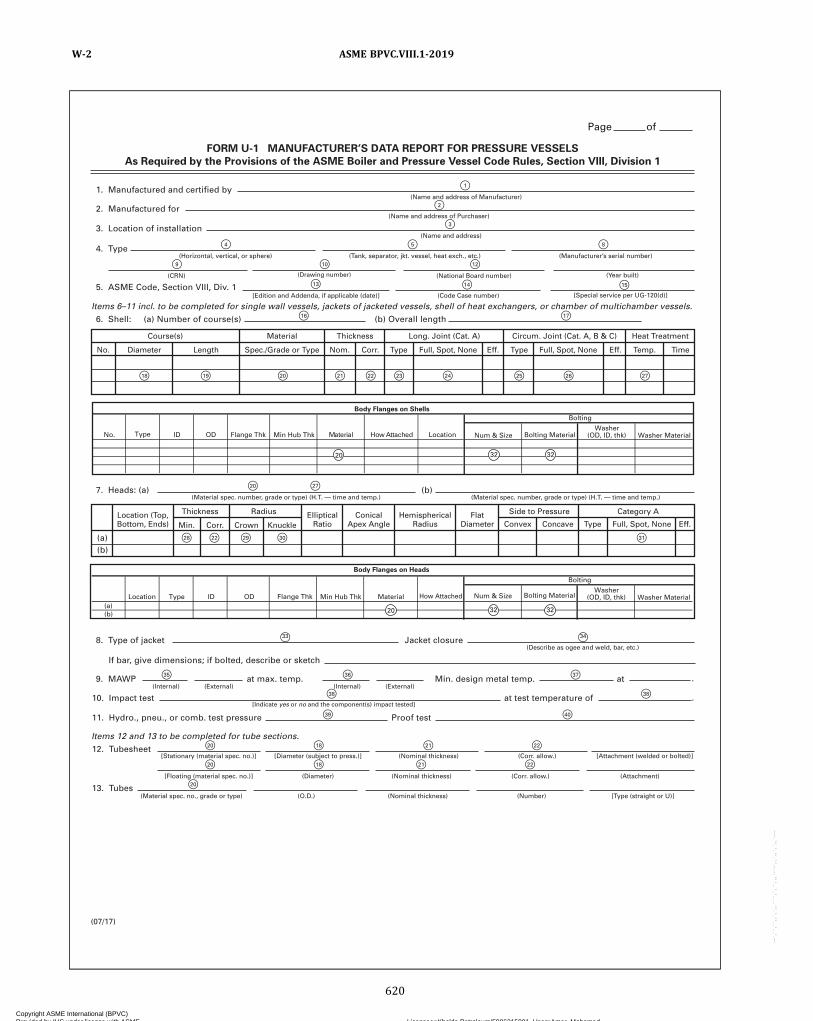
FORM U-1 MANUFACTURER’S DATA REPORT FOR PRESSURE VESSELS
As Required by the Provisions of the ASME Boiler and Pressure Vessel Code Rules, Section VIII, Division 1
1. Manufactured and certified by
Course(s) Material Thickness Long. Joint (Cat. A) Circum. Joint (Cat. A, B & C) Heat Treatment
Diameter Length Spec./Grade or Type Type Type Temp. TimeEff. Eff.Full, Spot, None Full, Spot, NoneNom. Corr.No.
(Name and address of Manufacturer)
8. Type of jacket
If bar, give dimensions; if bolted, describe or sketch
Jacket closure(Describe as ogee and weld, bar, etc.)
9. MAWP at max. temp. Min. design metal temp. at
10. Impact test at test temperature of
11. Hydro., pneu., or comb. test pressure Proof test
12. Tubesheet
2. Manufactured for(Name and address of Purchaser)
3. Location of installation(Name and address)
4. Type(Horizontal, vertical, or sphere) (Tank, separator, jkt. vessel, heat exch., etc.) (Manufacturer’s serial number)
(CRN) (Drawing number) (Year built)(National Board number)
5. ASME Code, Section VIII, Div. 1
Items 6–11 incl. to be completed for single wall vessels, jackets of jacketed vessels, shell of heat exchangers, or chamber of multichamber vessels.
Items 12 and 13 to be completed for tube sections.
(Code Case number) [Special service per UG-120(d)][Edition and Addenda, if applicable (date)]
7. Heads: (a)(Material spec. number, grade or type) (H.T. — time and temp.)
(Internal)
[Stationary (material spec. no.)] [Diameter (subject to press.)] (Nominal thickness) [Attachment (welded or bolted)](Corr. allow.)
[Floating (material spec. no.)] (Diameter) (Nominal thickness) (Attachment)(Corr. allow.)
13. Tubes(Material spec. no., grade or type) (O.D.) (Nominal thickness) (Number) [Type (straight or U)]
(External) (Internal)
[Indicate yes or no and the component(s) impact tested]
(External)
(Material spec. number, grade or type) (H.T. — time and temp.)(b)
(b)(a)
6. Shell: (a) Number of course(s) (b) Overall length
(07/17)
Thickness RadiusLocation (Top,Bottom, Ends)
EllipticalRatio
ConicalApex Angle
HemisphericalRadius
FlatDiameter Convex Type Eff.Full, Spot, NoneConcaveMin. Corr. Crown Knuckle
Side to Pressure Category A
.
.
Num & SizeWasher
(OD, ID, thk) Washer MaterialFlange Thk
Body Flanges on Shells
Bolting
No. LocationdehcattA woHlairetaMDODI Min Hub Thk Bolting Material
20 32 32
Type
Washer(OD, ID, thk) Washer Material
(a)(b)
Type ID OD Material
Bolting
Body Flanges on Heads
Location How AttachedFlange Thk Min Hub Thk Num & Size Bolting Material
Page of
F2
F3
F4
F9 F10 F12
F5 F8
F14 F15F13
F20
F28 F22 F29 F30 F31
F27
F16 F17
F1
F34F33
F36F35
F20 F18 F21 F22
F20 F18 F21 F22
F20
F37
F38 F38
F39 F40
F18 F19 F20 F21 F22 F23 F24 F25 F26 F27
32 3220
ASME BPVC.VIII.1-2019W-2
620
Copyright ASME International (BPVC) Provided by IHS under license with ASME Licensee=Khalda Petroleum/5986215001, User=Amer, Mohamed
Not for Resale, 07/02/2019 13:29:04 MDTNo reproduction or networking permitted without license from IHS
--`,``,``,,`,`,,````,`,``,,,`-`-`,,`,,`,`,,`---
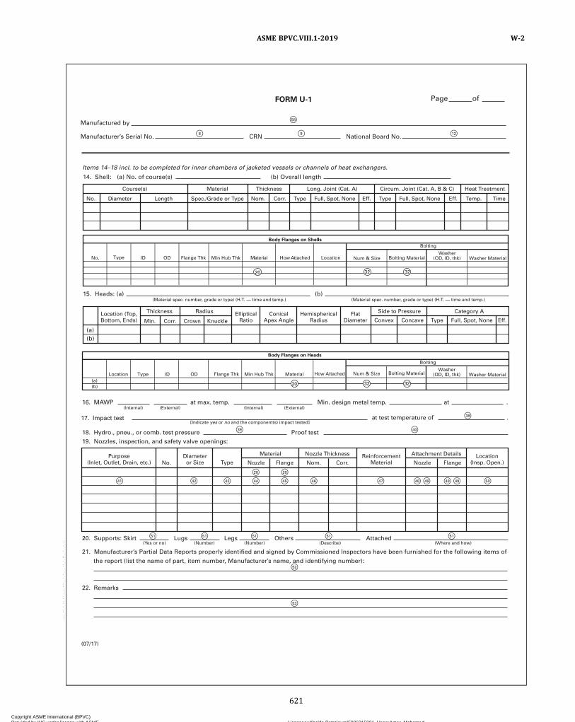
FORM U-1
16. MAWP at max. temp. Min. design metal temp. at .(Internal) (External)
17. Impact test
20. Supports: Skirt
22. Remarks
21. Manufacturer’s Partial Data Reports properly identified and signed by Commissioned Inspectors have been furnished for the following items of
the report (list the name of part, item number, Manufacturer’s name, and identifying number):
Lugs Legs Others
.at test temperature of[Indicate yes or no and the component(s) impact tested]
(Yes or no) (Number) (Number) (Describe)Attached
(Where and how)
18. Hydro., pneu., or comb. test pressure19. Nozzles, inspection, and safety valve openings:
Proof test
(Internal) (External)
(07/17)
Purpose(Inlet, Outlet, Drain, etc.)
Diameteror Size Type
ReinforcementMaterial
Location(Insp. Open.)
Material Nozzle Thickness Attachment Details
No. Nozzle Flange Corr.Nom. Nozzle Flange
Num & SizeWasher
(OD, ID, thk) Washer MaterialFlange Thk
Body Flanges on Shells
Bolting
No. LocationdehcattAwoHlairetaMDODI Min Hub Thk Bolting MaterialType
Washer(OD, ID, thk) Washer Material
(a)(b)
Type ID OD Material
Bolting
Body Flanges on Heads
Location How AttachedFlange Thk Min Hub Thk Num & Size Bolting Material
Manufactured by
Manufacturer’s Serial No. CRN National Board No.
Page of
Items 14–18 incl. to be completed for inner chambers of jacketed vessels or channels of heat exchangers.
14. Shell: (a) No. of course(s) (b) Overall length
15. Heads: (a) (b)(Material spec. number, grade or type) (H.T. — time and temp.) (Material spec. number, grade or type) (H.T. — time and temp.)
Course(s) Material Thickness Long. Joint (Cat. A) Circum. Joint (Cat. A, B & C) Heat Treatment
Diameter Length Spec./Grade or Type Type Type Temp. TimeEff. Eff.Full, Spot, None Full, Spot, NoneNom. Corr.No.
(b)(a)
Thickness RadiusLocation (Top,Bottom, Ends)
EllipticalRatio
ConicalApex Angle
HemisphericalRadius
FlatDiameter Convex Type Eff.Full, Spot, NoneConcaveMin. Corr. Crown Knuckle
Side to Pressure Category A
F38
F51 F51 F51 F51
F52
F53
F51
F41 F42 F43 F44 F45
F20
F39 F40
F20
F46 F47 F48 F49 F48 F49 F50
32 3220
20 32 32
F58
F8 F9 F12
ASME BPVC.VIII.1-2019 W-2
621
Copyright ASME International (BPVC) Provided by IHS under license with ASME Licensee=Khalda Petroleum/5986215001, User=Amer, Mohamed
Not for Resale, 07/02/2019 13:29:04 MDTNo reproduction or networking permitted without license from IHS
--`,``,``,,`,`,,````,`,``,,,`-`-`,,`,,`,`,,`---
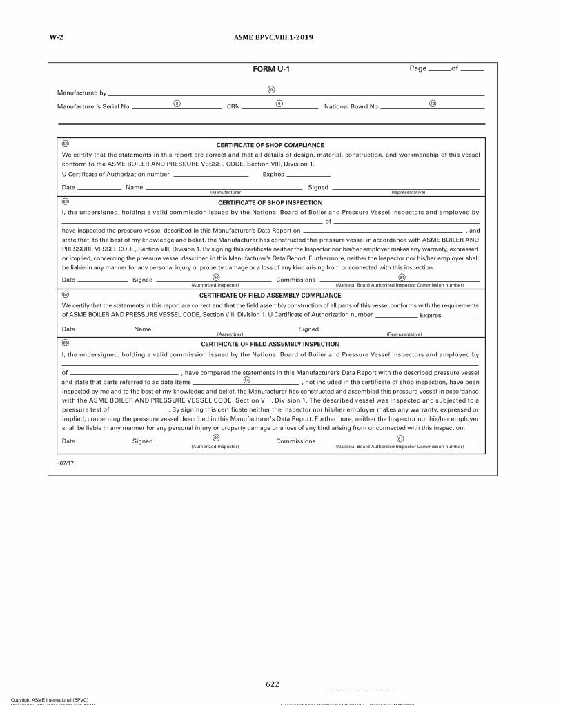
F58
F60
F62
F63
F61
F64
F60
F60 F61
F58
F8 F9 F12
inspected by me and to the best of my knowledge and belief, the Manufacturer has constructed and assembled this pressure vessel in accordance
with the ASME BOILER AND PRESSURE VESSEL CODE, Section VIII, Division 1. The described vessel was inspected and subjected to a
pressure test of . By signing this certificate neither the Inspector nor his/her employer makes any warranty, expressed or
implied, concerning the pressure vessel described in this Manufacturer's Data Report. Furthermore, neither the Inspector nor his/her employer
shall be liable in any manner for any personal injury or property damage or a loss of any kind arising from or connected with this inspection.
CERTIFICATE OF SHOP COMPLIANCE
CERTIFICATE OF SHOP INSPECTION
CERTIFICATE OF FIELD ASSEMBLY COMPLIANCE
CERTIFICATE OF FIELD ASSEMBLY INSPECTION
Date Signed Commissions(Authorized Inspector)
Date
have inspected the pressure vessel described in this Manufacturer’s Data Report on
of
, and
of , have compared the statements in this Manufacturer’s Data Report with the described pressure vessel
and state that parts referred to as data items , not included in the certificate of shop inspection, have been
U Certificate of Authorization number
I, the undersigned, holding a valid commission issued by the National Board of Boiler and Pressure Vessel Inspectors and employed by
I, the undersigned, holding a valid commission issued by the National Board of Boiler and Pressure Vessel Inspectors and employed by
Expires
Name Signed(Representative)(Manufacturer)
Date Name Signed
Expires .
(Representative)(Assembler)
(National Board Authorized Inspector Commission number)
Date Signed Commissions(Authorized Inspector) (National Board Authorized Inspector Commission number)
We certify that the statements in this report are correct and that all details of design, material, construction, and workmanship of this vessel
conform to the ASME BOILER AND PRESSURE VESSEL CODE, Section VIII, Division 1.
state that, to the best of my knowledge and belief, the Manufacturer has constructed this pressure vessel in accordance with ASME BOILER AND
PRESSURE VESSEL CODE, Section VIII, Division 1. By signing this certificate neither the Inspector nor his/her employer makes any warranty, expressed
or implied, concerning the pressure vessel described in this Manufacturer's Data Report. Furthermore, neither the Inspector nor his/her employer shall
be liable in any manner for any personal injury or property damage or a loss of any kind arising from or connected with this inspection.
We certify that the statements in this report are correct and that the field assembly construction of all parts of this vessel conforms with the requirements
of ASME BOILER AND PRESSURE VESSEL CODE, Section VIII, Division 1. U Certificate of Authorization number
(07/17)
FORM U-1
Manufactured by
Manufacturer’s Serial No. CRN National Board No.
Page of
ASME BPVC.VIII.1-2019W-2
622
Copyright ASME International (BPVC) Provided by IHS under license with ASME Licensee=Khalda Petroleum/5986215001, User=Amer, Mohamed
Not for Resale, 07/02/2019 13:29:04 MDTNo reproduction or networking permitted without license from IHS
--`,``,``,,`,`,,````,`,``,,,`-`-`,,`,,`,`,,`---
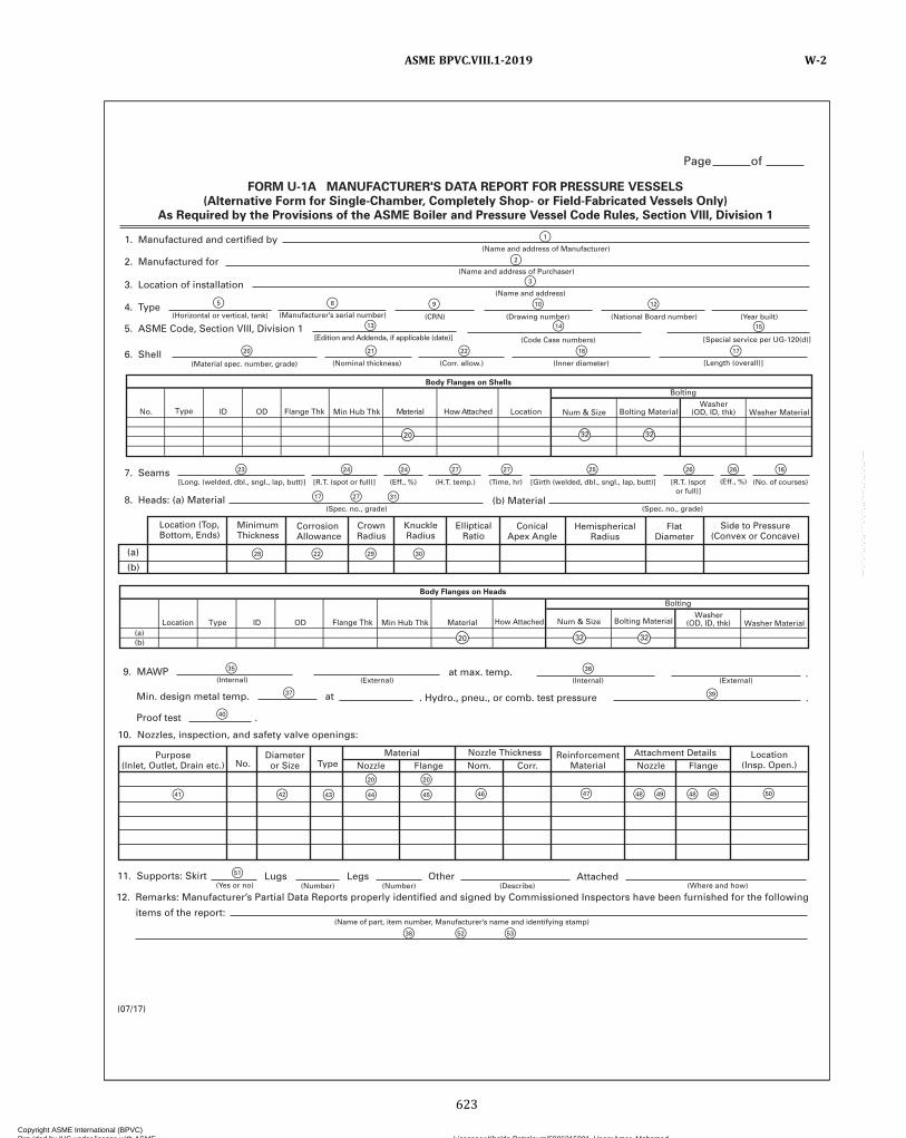
Purpose(Inlet, Outlet, Drain etc.) No.
(Yes or no) (Number)(Number) (Describe) (Where and how)
Diameteror Size
Attachment DetailsReinforcementMaterial
Nozzle Thickness Location(Insp. Open.)Type
MaterialNozzle Nom. Corr.Flange Nozzle Flange
10. Nozzles, inspection, and safety valve openings:
11. Supports: Skirt
12. Remarks: Manufacturer’s Partial Data Reports properly identified and signed by Commissioned Inspectors have been furnished for the following
items of the report:
Lugs Legs Other Attached
1. Manufactured and certified by(Name and address of Manufacturer)
(Name and address of Purchaser)
(Name and address)
(CRN) (Drawing number)
(Code Case numbers) [Special service per UG-120(d)]
(Horizontal or vertical, tank) (Manufacturer’s serial number)
(Material spec. number, grade)
(Spec. no., grade) (Spec. no., grade)
[Long. (welded, dbl., sngl., lap, butt)] (No. of courses)(Eff., %)(Eff., %) [R.T. (spotor full)]
(Time, hr)(H.T. temp.)[R.T. (spot or full)] [Girth (welded, dbl., sngl., lap, butt)]
(Corr. allow.)(Nominal thickness) (Inner diameter) [Length (overall)]
(National Board number) (Year built)
[Edition and Addenda, if applicable (date)]
2. Manufactured for
3. Location of installation
4. Type
5. ASME Code, Section VIII, Division 1
6. Shell
7. Seams
8. Heads: (a) Material (b) Material
(Internal) (Internal)(External) (External)9. MAWP at max. temp.
Min. design metal temp. . Hydro., pneu., or comb. test pressure .
.
at
Location (Top,Bottom, Ends)
MinimumThickness
CorrosionAllowance
CrownRadius
(a)
(b)
KnuckleRadius
EllipticalRatio
ConicalApex Angle
HemisphericalRadius
FlatDiameter
Side to Pressure(Convex or Concave)
Proof test .
FORM U-1A MANUFACTURER'S DATA REPORT FOR PRESSURE VESSELS
(Alternative Form for Single-Chamber, Completely Shop- or Field-Fabricated Vessels Only)
As Required by the Provisions of the ASME Boiler and Pressure Vessel Code Rules, Section VIII, Division 1
(Name of part, item number, Manufacturer’s name and identifying stamp)
Num & SizeWasher
(OD, ID, thk) Washer MaterialFlange Thk
Body Flanges on Shells
Bolting
No. LocationdehcattAwoHlairetaMDODI Min Hub Thk Bolting MaterialType
Washer(OD, ID, thk) Washer Material
(a)(b)
Type ID OD Material
Bolting
Body Flanges on Heads
Location How AttachedFlange Thk Min Hub Thk Num & Size Bolting Material
(07/17)
Page of
F37
F40
F42
F20
F47F46F43 F44
F20
F45
F38 F52 F53
F41
F36
F39
F48 F49 F48 F49 F50
F35
F51
F
F
F
1
2
3
F9
F14
F8F5 F10 F12
F15F13
F18F22F21F20
F23 F24 F24
F31
F27 F27 F25 F26 F26 F16
F17 F27
F28 F22 F29 F30
F17
32 3220
20 32 32
ASME BPVC.VIII.1-2019 W-2
623
Copyright ASME International (BPVC) Provided by IHS under license with ASME Licensee=Khalda Petroleum/5986215001, User=Amer, Mohamed
Not for Resale, 07/02/2019 13:29:04 MDTNo reproduction or networking permitted without license from IHS
--`,``,``,,`,`,,````,`,``,,,`-`-`,,`,,`,`,,`---

F58 F58
F61F60
F58
F58
F60
F58
F8 F9 F12
have inspected the component described in this Manufacturer's Data Report on , and state that, to the best of my knowledge and belief, the Manufacturer has constructed this pressure vessel in accordance with ASME BOILER AND PRESSURE VESSEL CODE, Section VIII, Division 1. By signing this certificate neither the Inspector nor his/her employer makes any warranty, expressed or implied, concerning the pressure vessel described in this Manufacturer's Data Report. Furthermore, neither the Inspector nor his/her employer shall be liable in any manner for any personal injury or property damage or a loss of any kind arising from or connected with this inspection.
CERTIFICATE OF SHOP/FIELD COMPLIANCE
CERTIFICATE OF SHOP/FIELD INSPECTION
expires
Date Co. name
.
Signed(Manufacturer) (Representative)
We certify that the statements made in this report are correct and that all details of design, material, construction, and workmanship of this vessel conform to the ASME BOILER AND PRESSURE VESSEL CODE, Section VIII, Division 1. “U” Certificate of Authorization number
Vessel constructed by at . I, the undersigned, holding a valid commission issued by the National Board of Boiler and Pressure Vessel Inspectors and employed by
Date Signed(Authorized Inspector)
Commissions
(07/17)
FORM U-1A
Manufactured by
Manufacturer’s Serial No. CRN National Board No.
Page of
of
(National Board Authorized Inspector Commission number)
ASME BPVC.VIII.1-2019W-2
624
Copyright ASME International (BPVC) Provided by IHS under license with ASME Licensee=Khalda Petroleum/5986215001, User=Amer, Mohamed
Not for Resale, 07/02/2019 13:29:04 MDTNo reproduction or networking permitted without license from IHS
--`,``,``,,`,`,,````,`,``,,,`-`-`,,`,,`,`,,`---

7
54
60 61
1. Manufactured and certified by ______________________________________________________________________________________
2. Manufactured for __________________________________________________________________________________________________
3. Location of installation _____________________________________________________________________________________________
4. Type __________________________ Use ______________________________ Manufacturer’s serial no. ____________________
CRN no. _____________ Dwg no. ______________ National Board no. __________________ Year built _________________
5. ASME Code Section VIII, Div. 1 edition/addenda ____________________ Code case ___________________________________
6. Graphite components:
Item Material Designation Compressive Strength Tensile Strength CMTR No.
Certificate of Authorization: Type __________________________ No. ______________________ Expires ______________________
Date ___________________ Name ______________________________________ Signed ______________________________________
Date _______________ Signed _____________________ Commissions ___________________________________________________
FORM U-1B MANUFACTURER’S SUPPLEMENTARY
DATA REPORT FOR GRAPHITE PRESSURE VESSELS
(As Required by the Provisions of the ASME Code Rules, Section VIII, Division 1)
(07/17)
(Name and address of Manufacturer)
(Name and address of Purchaser)
(Name and address)
(Horizontal, vertical) (Tank, vessel, heat exch., etc.) (Manufacturer’s serial no.)
(CRN) (Drawing number) (National Board number)
[Edition and Addenda (date)] (Code Case number)
(National Board Authorized Inspector Commission number)
ASME BPVC.VIII.1-2019 W-2
625
Copyright ASME International (BPVC) Provided by IHS under license with ASME Licensee=Khalda Petroleum/5986215001, User=Amer, Mohamed
Not for Resale, 07/02/2019 13:29:04 MDTNo reproduction or networking permitted without license from IHS
--`,``,``,,`,`,,````,`,``,,,`-`-`,,`,,`,`,,`---
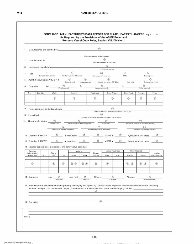
4. Type(Horizontal or vertical) (Gasketed, semiweld, brazed)
5. ASME Code, Section VIII, Div. 1[Edition (year)]
(b) (c)(Fixed material) (Movable material) (Other material)
7. Frame compression bolts and nuts
8. Impact test
9. Heat transfer plates
,
,
Qty. Type
Material
13. Supports:
15. Remarks:
14. Manufacturer’s Partial Data Reports properly identifying and signed by Commissioned Inspectors have been furnished for the following items of the report (list the name of the part, item number, and Manufacturer’s name and identifying number):
Lugs Legs Feet Others Attached
6. Endplates: (a)
No. Quantity Width Length Thickness Corr. Allow. Heat Treat Temp. Time
(Year built) (National Board no.)
10. Chamber 1, MAWP
(Quantitiy of plates at shipment) (Minimum tightening dimension) (Maximum tightening dimension)
at max. temp MDMT at Hydro/pneu. test press.
11. Chamber 2, MAWP
12. Nozzles, connections, inspections, and safety valve openings:
at max. temp MDMT at Hydro/pneu. test press.
(Quantitiy) (Quantitiy) (Describe) (Where and how)
Purpose(Inlet, Outlet,
Drain, etc)Dia. or
Size Nozzle FlangeFlangeRating
Nozzle Thickness How AttachedLocation
(Insp./Open.)Nom. C.A. Nozzle Flange
FORM U-1P MANUFACTURER’S DATA REPORT FOR PLATE HEAT EXCHANGERS
As Required by the Provisions of the ASME Boiler and
Pressure Vessel Code Rules, Section VIII, Division 1
1. Manufactured and certified by
(Name and address of Manufacturer)
2. Manufactured for(Name and address of Purchaser)
3. Location of installation(Name and address)
F1
F2
F3
F4 F71 F8 F9 F10
F13 F14 F15 F12
F32
F38
F73 F73
F73
F35 F36 F37
F37F36F35
F35
F35
F39
F39
F73 F73
F73
F72 F72 F21 F22 F27F27 F27
F41 F42 F43 F43 F46 F48 F49 F48 F49 F50F20 F44 F20 F45
F51 F51 F51 F51
F52
F53
F20 F20F20
F20
(Manufacturer’s serial no.) (Drawing no.)(CRN)
(Quantity, diameter, material specification, and grade)
[Indicate YES and the component(s) impact tested, or NO]
(Plate model) (Material specification and grade) (Thickness) (Maximum plate count for frame assembly)
(Code Case no.) [Special service per UG-120(d)]
(07/17)
Page of
ASME BPVC.VIII.1-2019W-2
626
Copyright ASME International (BPVC) Provided by IHS under license with ASME Licensee=Khalda Petroleum/5986215001, User=Amer, Mohamed
Not for Resale, 07/02/2019 13:29:04 MDTNo reproduction or networking permitted without license from IHS
--`,``,``,,`,`,,````,`,``,,,`-`-`,,`,,`,`,,`---
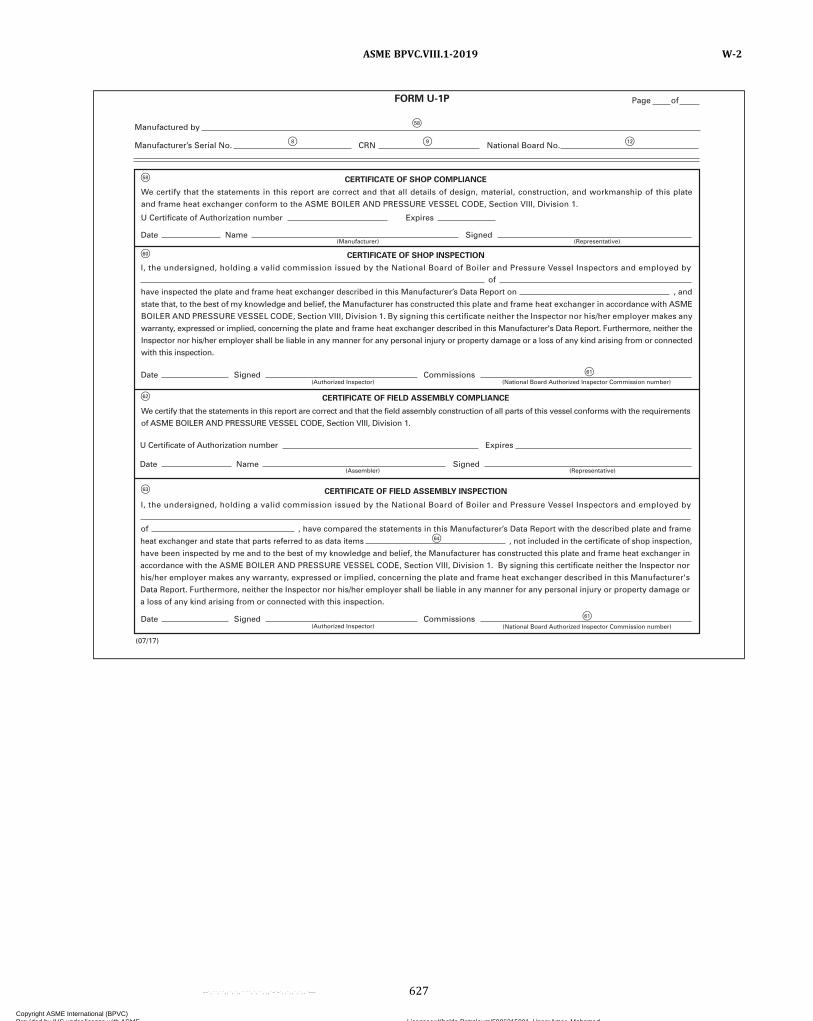
F58
F60
F62
F63
F61
F64
F61
F58
F8 F9 F12
have been inspected by me and to the best of my knowledge and belief, the Manufacturer has constructed this plate and frame heat exchanger in
accordance with the ASME BOILER AND PRESSURE VESSEL CODE, Section VIII, Division 1. By signing this certificate neither the Inspector nor
his/her employer makes any warranty, expressed or implied, concerning the plate and frame heat exchanger described in this Manufacturer's
Data Report. Furthermore, neither the Inspector nor his/her employer shall be liable in any manner for any personal injury or property damage or
a loss of any kind arising from or connected with this inspection.
CERTIFICATE OF SHOP COMPLIANCE
CERTIFICATE OF SHOP INSPECTION
CERTIFICATE OF FIELD ASSEMBLY COMPLIANCE
CERTIFICATE OF FIELD ASSEMBLY INSPECTION
Date Signed Commissions(Authorized Inspector)
Date
have inspected the plate and frame heat exchanger described in this Manufacturer’s Data Report on
of
, and
of , have compared the statements in this Manufacturer’s Data Report with the described plate and frame
heat exchanger and state that parts referred to as data items , not included in the certificate of shop inspection,
U Certificate of Authorization number
I, the undersigned, holding a valid commission issued by the National Board of Boiler and Pressure Vessel Inspectors and employed by
I, the undersigned, holding a valid commission issued by the National Board of Boiler and Pressure Vessel Inspectors and employed by
Expires
Name Signed(Representative)(Manufacturer)
Date Name Signed
Expires
(Representative)(Assembler)
Date Signed Commissions(Authorized Inspector) (National Board Authorized Inspector Commission number)
We certify that the statements in this report are correct and that all details of design, material, construction, and workmanship of this plate
and frame heat exchanger conform to the ASME BOILER AND PRESSURE VESSEL CODE, Section VIII, Division 1.
state that, to the best of my knowledge and belief, the Manufacturer has constructed this plate and frame heat exchanger in accordance with ASME
BOILER AND PRESSURE VESSEL CODE, Section VIII, Division 1. By signing this certificate neither the Inspector nor his/her employer makes any
warranty, expressed or implied, concerning the plate and frame heat exchanger described in this Manufacturer's Data Report. Furthermore, neither the
Inspector nor his/her employer shall be liable in any manner for any personal injury or property damage or a loss of any kind arising from or connected
with this inspection.
We certify that the statements in this report are correct and that the field assembly construction of all parts of this vessel conforms with the requirements
of ASME BOILER AND PRESSURE VESSEL CODE, Section VIII, Division 1.
(07/17)
FORM U-1P
U Certificate of Authorization number
Page of
Manufactured by
Manufacturer’s Serial No. CRN National Board No.
(National Board Authorized Inspector Commission number)
ASME BPVC.VIII.1-2019 W-2
627
Copyright ASME International (BPVC) Provided by IHS under license with ASME Licensee=Khalda Petroleum/5986215001, User=Amer, Mohamed
Not for Resale, 07/02/2019 13:29:04 MDTNo reproduction or networking permitted without license from IHS
--`,``,``,,`,`,,````,`,``,,,`-`-`,,`,,`,`,,`---
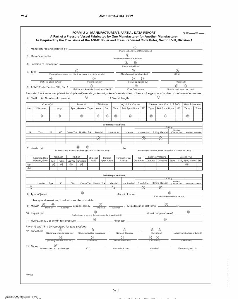
FORM U-2 MANUFACTURER’S PARTIAL DATA REPORT
A Part of a Pressure Vessel Fabricated by One Manufacturer for Another Manufacturer
As Required by the Provisions of the ASME Boiler and Pressure Vessel Code Rules, Section VIII, Division 1
1. Manufactured and certified by
Course(s) Material Thickness Long. Joint (Cat. A) Circum. Joint (Cat. A, B & C) Heat Treatment
Diameter Length Spec./Grade or Type Type Type Temp. TimeEff. Eff.Full, Spot, None Full, Spot, NoneNom. Corr.No.
(Name and address of Manufacturer)
8. Type of jacket
If bar, give dimensions; if bolted, describe or sketch
Jacket closure(Describe as ogee & weld, bar, etc.)
9. MAWP at max. temp. . Min. design metal temp. at .
10. Impact test at test temperature of .
11. Hydro., pneu., or comb. test pressure Proof test
12. Tubesheet
2. Manufactured for(Name and address of Purchaser)
3. Location of installation(Name and address)
4. Type[Description of vessel part (shell, two-piece head, tube bundle)] (Manufacturer’s serial number) (CRN)
(National Board number) (Drawing number) (Year built)(Drawing prepared by)
5. ASME Code, Section VIII, Div. 1
Items 6–11 incl. to be completed for single wall vessels, jackets of jacketed vessels, shell of heat exchangers, or chamber of multichamber vessels.
Items 12 and 13 to be completed for tube sections.
(Code Case number) [Special service per UG-120(d)][Edition and Addenda, if applicable (date)]
7. Heads: (a)(Material spec. number, grade or type) (H.T. — time and temp.)
(Internal)
[Stationary (material spec. no.)] [Diameter (subject to pressure)] (Nominal thickness) [Attachment (welded or bolted)](Corr. allow.)
[Floating (material spec. no.)] (Diameter) (Nominal thickness) (Attachment)(Corr. allow.)
13. Tubes(Material spec. no., grade or type) (O.D.) (Nominal thickness) (Number) [Type (straight or U)]
(External) (Internal)
[Indicate yes or no and the component(s) impact tested]
(External)
(Material spec. number, grade or type) (H.T. — time and temp.)(b)
(b)(a)
6. Shell: (a) Number of course(s) (b) Overall length
(07/17)
Thickness RadiusLocation (Top,Bottom, Ends)
EllipticalRatio
ConicalApex Angle
HemisphericalRadius
FlatDiameter Convex Type Eff.Full, Spot, NoneConcaveMin. Corr. Crown Knuckle
Side to Pressure Category A
Num & SizeWasher
(OD, ID, thk) Washer MaterialFlange Thk
Body Flanges on Shells
Bolting
No. LocationdehcattAwoHlairetaMDODI Min Hub Thk Bolting MaterialType
Washer(OD, ID, thk) Washer Material
(a)(b)
Type ID OD Material
Bolting
Body Flanges on Heads
Location How AttachedFlange Thk Min Hub Thk Num & Size Bolting Material
Page of
F2
F3
F1
F56
F7
F12 F10 F11 F57
F8 F9
F14 F15 F56F13
F20
F28 F22 F29 F30 F31
F27
F16 F17
F34F33
F36
F38
F35 F56
F20 F18 F21 F22
F20 F18 F21 F22
F56
F56
F20
F37
F38
F39 F40
F18 F19 F20 F21 F22 F23 F24 F25 F26 F27
32 3220
20 32 32
ASME BPVC.VIII.1-2019W-2
628
Copyright ASME International (BPVC) Provided by IHS under license with ASME Licensee=Khalda Petroleum/5986215001, User=Amer, Mohamed
Not for Resale, 07/02/2019 13:29:04 MDTNo reproduction or networking permitted without license from IHS
--`,``,``,,`,`,,````,`,``,,,`-`-`,,`,,`,`,,`---
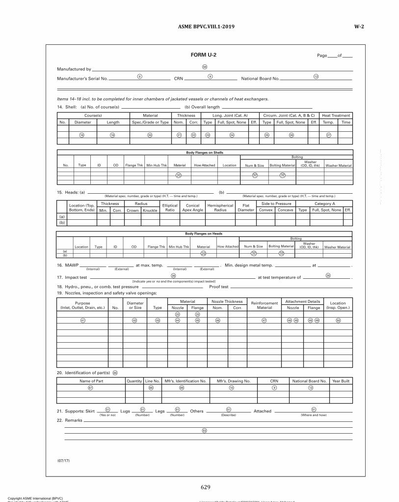
FORM U-2
16. MAWP at max. temp. . Min. design metal temp. at .(Internal) (External)(Internal)
21. Supports: Skirt
22. Remarks
Lugs(Yes or no)
Legs(Number)
Others(Number)
Attached(Describe) (Where and how)
15. Heads: (a) (b)(Material spec. number, grade or type) (H.T. — time and temp.) (Material spec. number, grade or type) (H.T. — time and temp.)
17. Impact test at test temperature of .
18. Hydro., pneu., or comb. test pressure19. Nozzles, inspection and safety valve openings:
20. Identification of part(s)
Proof test[Indicate yes or no and the component(s) impact tested]
(External)
(07/17)
(b)(a)
Thickness RadiusLocation (Top,Bottom, Ends)
Name of Part Mfr’s. Identification No. Mfr’s. Drawing No. National Board No.CRN Year BuiltQuantity Line No.
EllipticalRatio
ConicalApex Angle
HemisphericalRadius
FlatDiameter Convex Type Eff.Full, Spot, NoneConcaveMin. Corr. Crown Knuckle
Side to Pressure Category A
Purpose(Inlet, Outlet, Drain, etc.)
Diameteror Size Type
ReinforcementMaterial
Location(Insp. Open.)
Material Nozzle Thickness Attachment Details
No. Nozzle Flange Corr.Nom. Nozzle Flange
Items 14–18 incl. to be completed for inner chambers of jacketed vessels or channels of heat exchangers.
14. Shell: (a) No. of course(s) (b) Overall length
Course(s) Material Thickness Long. Joint (Cat. A) Circum. Joint (Cat. A, B & C) Heat Treatment
Diameter Length Spec./Grade or Type Type Type Temp. TimeEff. Eff.Full, Spot, None Full, Spot, NoneNom. Corr.No.
Num & SizeWasher
(OD, ID, thk) Washer MaterialFlange Thk
Body Flanges on Shells
Bolting
No. LocationdehcattAwoHlairetaMDODI Min Hub Thk Bolting MaterialType
Washer(OD, ID, thk) Washer Material
(a)(b)
Type ID OD Material
Bolting
Body Flanges on Heads
Location How AttachedFlange Thk Min Hub Thk Num & Size Bolting Material
Page of
Manufactured by
Manufacturer’s Serial No. CRN National Board No.
F38 F38
F41 F42
F67
F51 F51 F51 F51
F53
F51
F66
F68 F69 F10 F9 F12
F43 F44 F45
F20 F20
F46 F47 F48 F49 F48 F49 F50
F18 F19 F20 F21 F22 F23 F24 F25 F26 F27
32 3220
20 32 32
F58
F8 F9 F12
ASME BPVC.VIII.1-2019 W-2
629
Copyright ASME International (BPVC) Provided by IHS under license with ASME Licensee=Khalda Petroleum/5986215001, User=Amer, Mohamed
Not for Resale, 07/02/2019 13:29:04 MDTNo reproduction or networking permitted without license from IHS
--`,``,``,,`,`,,````,`,``,,,`-`-`,,`,,`,`,,`---
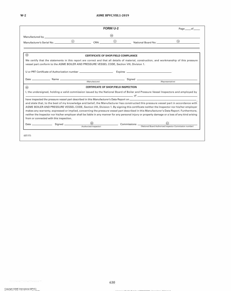
F58
F60
F61
F58
F8 F9 F12
F60
CERTIFICATE OF SHOP/FIELD COMPLIANCE
CERTIFICATE OF SHOP/FIELD INSPECTION
Date
U or PRT Certificate of Authorization number Expires
have inspected the pressure vessel part described in this Manufacturer’s Data Report on ,
ofI, the undersigned, holding a valid commission issued by the National Board of Boiler and Pressure Vessel Inspectors and employed by
Name Signed(Representative)(Manufacturer)
Date Signed Commissions(Authorized Inspector)
(07/17)
We certify that the statements in this report are correct and that all details of material, construction, and workmanship of this pressure
vessel part conform to the ASME BOILER AND PRESSURE VESSEL CODE, Section VIII, Division 1.
and state that, to the best of my knowledge and belief, the Manufacturer has constructed this pressure vessel part in accordance with
ASME BOILER AND PRESSURE VESSEL CODE, Section VIII, Division 1. By signing this certificate neither the Inspector nor his/her employer
makes any warranty, expressed or implied, concerning the pressure vessel part described in this Manufacturer's Data Report. Furthermore,
neither the Inspector nor his/her employer shall be liable in any manner for any personal injury or property damage or a loss of any kind arising
from or connected with this inspection.
FORM U-2 Page of
Manufactured by
Manufacturer’s Serial No. CRN National Board No.
(National Board Authorized Inspector Commission number)
ASME BPVC.VIII.1-2019W-2
630
Copyright ASME International (BPVC) Provided by IHS under license with ASME Licensee=Khalda Petroleum/5986215001, User=Amer, Mohamed
Not for Resale, 07/02/2019 13:29:04 MDTNo reproduction or networking permitted without license from IHS
--`,``,``,,`,`,,````,`,``,,,`-`-`,,`,,`,`,,`---

(07/17)
(Yes or no) (Number) (Number) (Describe) (Where and how)
11. Nozzles, inspection, and safety valve openings:
12. Identification of part(s)
13. Supports: Skirt
14. Remarks
Lugs Legs Other Attached
FORM U-2A MANUFACTURER’S PARTIAL DATA REPORT (ALTERNATIVE FORM)
A Part of a Pressure Vessel Fabricated by One Manufacturer for Another Manufacturer
As Required by the Provisions of the ASME Boiler and Pressure Vessel Code Rules, Section VIII, Division 1
1. Manufactured and certified by (Name and address of Manufacturer)
(Name and address of Purchaser)
(Name and address)
(Drawing number)(National Board number) (Drawing prepared by)
[Special service per UG-120(d)] (Code Case number) (Edition and Addenda, if applicable (date)]
(Internal) (External)
[Indicate yes or no and the component(s) impact tested]
(Internal) (External)
(Material spec. number, grade or type) (H.T. — time and temp.) (Material spec. number, grade or type) (H.T. — time and temp.)
(CRN) (Manufacturer’s serial number) [Description of vessel part (shell, two-piece head, tube bundle)]
(Year built)
2. Manufactured for
3. Location of installation
4. Type
5. ASME Code, Section VIII, Div. 1
6. Shell: (a) Number of course(s) (b) Overall length
7. Heads: (a) (b)
Location (Top,Bottom, Ends)
EllipticalRatio
ConicalApex Angle
Type
Diameteror Size
ReinforcementMaterial
Location(Insp. Open.)
Purpose(Inlet, Outlet, Drain, etc.)
FlatDiameter Convex Concave Type Full, Spot, None Eff.
HemisphericalRadius
Thickness Radius
Material Nozzle Thickness Attachment Details
NozzleNo.
Name of Part Quantity Line No. Mfr’s. Drawing No. CRN National Board No. Year BuiltMfr’s. Identification No.
Flange Nozzle FlangeNom. Corr.
Side to Pressure Category A
Corr. Crown KnuckleMin.
No. Diameter Length Spec./Grade or Type Nom. Corr. Type Type Temp. TimeFull, Spot, NoneFull, Spot, None Eff. Eff.
Course(s) Material Thickness Long. Joint (Cat. A) Heat TreatmentCircum. Joint (Cat. A, B & C)
8. MAWP at max. temp. . Min. design metal temp.
(b)
(a)
9. Impact test
10. Hydro., pneu., or comb. test pressure Proof test
at test temperature of .
at .
Num & SizeWasher
(OD, ID, thk) Washer MaterialFlange Thk
Body Flanges on Shells
Bolting
No. LocationdehcattAwoHlairetaMDODI Min Hub Thk Bolting MaterialType
Washer(OD, ID, thk) Washer Material
(a)(b)
Type ID OD Material
Bolting
Body Flanges on Heads
Location How AttachedFlange Thk Min Hub Thk Num & Size Bolting Material
Page of
F
F
F
1
2
3 F 56
F 13 F 14
F 7 F 8
F 10 F 12 F 11 F 57
F 9
F 15 F 56
F19F18
F 16
F20 F21
F56
F22 F23 F24 F25 F26 F27
F20 F27
F28 F22
F56
F29 F30
F51
F53
F51F51F51
F31
F36
F38
F39
F20
F44F43F42F41
F66
F67 F68 F69 F10 F9 F12
F20
F45 F46 F47 F48 F48F49 F49 F50
F37 F56
F38
F40
F35 F56
F51
F 17
32 3220
20 32 32
ASME BPVC.VIII.1-2019 W-2
631
Copyright ASME International (BPVC) Provided by IHS under license with ASME Licensee=Khalda Petroleum/5986215001, User=Amer, Mohamed
Not for Resale, 07/02/2019 13:29:04 MDTNo reproduction or networking permitted without license from IHS
--`,``,``,,`,`,,````,`,``,,,`-`-`,,`,,`,`,,`---

F58
F60
F61
F58
F8 F9 F12
F60
(07/17)
FORM U-2A
and state that, to the best of my knowledge and belief, the Manufacturer has constructed this pressure vessel part in accordance with ASME BOILER AND PRESSURE VESSEL CODE, Section VIII, Division 1. By signing this certificate neither the Inspector nor his/her employer makes any warranty, expressed or implied, concerning the pressure vessel part described in this Manufacturer's Data Report. Furthermore, neither the Inspector nor his/her employer shall be liable in any manner for any personal injury or property damage or a loss of any kind arising from or connected with this inspection.
CERTIFICATE OF SHOP/FIELD COMPLIANCE
CERTIFICATE OF SHOP/FIELD INSPECTION
U or PRT Certificate of Authorization no.
Date Name Signed(Manufacturer) (Representative)
We certify that the statements made in this report are correct and that all details of material, construction, and workmanship of this pressurevessel part conform to the ASME BOILER AND PRESSURE VESSEL CODE, Section VIII, Division 1.
Expires
I, the undersigned, holding a valid commission issued by the National Board of Boiler and Pressure Vessel Inspectors and employed by
ofhave inspected the pressure vessel part described in this Manufacturer’s Data Report on ,
Date Signed(Authorized Inspector)
Commissions
Page of
Manufactured by
Manufacturer’s Serial No. CRN National Board No.
(National Board Authorized Inspector Commission number)
ASME BPVC.VIII.1-2019W-2
632
Copyright ASME International (BPVC) Provided by IHS under license with ASME Licensee=Khalda Petroleum/5986215001, User=Amer, Mohamed
Not for Resale, 07/02/2019 13:29:04 MDTNo reproduction or networking permitted without license from IHS
--`,``,``,,`,`,,````,`,``,,,`-`-`,,`,,`,`,,`---
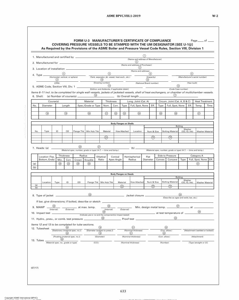
FORM U-3 MANUFACTURER’S CERTIFICATE OF COMPLIANCE
COVERING PRESSURE VESSELS TO BE STAMPED WITH THE UM DESIGNATOR [SEE U-1(j)]
As Required by the Provisions of the ASME Boiler and Pressure Vessel Code Rules, Section VIII, Division 1
1. Manufactured and certified by
Course(s) Material Thickness Long. Joint (Cat. A) Circum. Joint (Cat. A, B & C) Heat Treatment
Diameter Length Spec./Grade or Type Type Type Temp. TimeEff. Eff.Full, Spot, None Full, Spot, NoneNom. Corr.No.
(Name and address of Manufacturer)
8. Type of jacket
If bar, give dimensions; if bolted, describe or sketch
Jacket closure(Describe as ogee and weld, bar, etc.)
9. MAWP at max. temp. Min. design metal temp. at
10. Impact test at test temperature of
11. Hydro., pneu., or comb. test pressure Proof test
12. Tubesheet
2. Manufactured for(Name and address of Purchaser)
3. Location of installation(Name and address)
4. Type(Horizontal, vertical, or sphere) (Tank, separator, jkt. vessel, heat exch., etc.) (Manufacturer’s serial number)(Capacity)
(CRN) (Drawing number) (Year built)(National Board number)
5. ASME Code, Section VIII, Div. 1
Items 6–11 incl. to be completed for single wall vessels, jackets of jacketed vessels, shell of heat exchangers, or chamber of multichamber vessels.
Items 12 and 13 to be completed for tube sections.
(Code Case number)[Edition and Addenda, if applicable (date)]
7. Heads: (a)(Material spec. number, grade or type) (H.T. — time and temp.)
(Internal)
[Stationary (material spec. no.)] [Diameter (subject to press.)] (Nominal thickness) [Attachment (welded or bolted)](Corr. allow.)
[Floating (material spec. no.)] (Diameter) (Nominal thickness) (Attachment)(Corr. allow.)
13. Tubes(Material spec. no., grade or type) (O.D.) (Nominal thickness) (Number) [Type (straight or U)]
(External) (Internal)
[Indicate yes or no and the component(s) impact tested]
(External)
(Material spec. number, grade or type) (H.T. — time and temp.)(b)
(b)(a)
6. Shell: (a) Number of course(s) (b) Overall length
(07/17)
Thickness RadiusLocation (Top,Bottom, Ends)
EllipticalRatio
ConicalApex Angle
HemisphericalRadius
FlatDiameter Convex Type Eff.Full, Spot, NoneConcaveMin. Corr. Crown Knuckle
Side to Pressure Category A
.
.
Num & SizeWasher
(OD, ID, thk) Washer MaterialFlange Thk
Body Flanges on Shells
Bolting
No. LocationdehcattA woHlairetaMDODI Min Hub Thk Bolting Material
20 32 32
Type
Washer(OD, ID, thk) Washer Material
(a)(b)
Type ID OD Material
Bolting
Body Flanges on Heads
Location How AttachedFlange Thk Min Hub Thk Num & Size Bolting Material
Page of
F2
F3
F4
F9 F10 F12
F5 F8F6
F14F13
F20
F28 F22 F29 F30 F31
F27
F16 F17
F1
F34F33
F36F35
F20 F18 F21 F22
F20 F18 F21 F22
F20
F37
F38 F38
F39 F40
F18 F19 F20 F21 F22 F23 F24 F25 F26 F27
32 3220
ASME BPVC.VIII.1-2019 W-2
633
Copyright ASME International (BPVC) Provided by IHS under license with ASME Licensee=Khalda Petroleum/5986215001, User=Amer, Mohamed
Not for Resale, 07/02/2019 13:29:04 MDTNo reproduction or networking permitted without license from IHS
--`,``,``,,`,`,,````,`,``,,,`-`-`,,`,,`,`,,`---

FORM U-3
16. MAWP at max. temp. Min. design metal temp. at .(Internal) (External)
17. Impact test
20. Supports: Skirt
22. Remarks
21. Manufacturer’s Partial Data Reports properly identified and signed by Commissioned Inspectors have been furnished for the following items of
the report (list the name of part, item number, Manufacturer’s name, and identifying number):
Lugs Legs Others
.at test temperature of[Indicate yes or no and the component(s) impact tested]
(Yes or no) (Number) (Number) (Describe)Attached
(Where and how)
18. Hydro., pneu., or comb. test pressure19. Nozzles, inspection, and safety valve openings:
Proof test
(Internal) (External)
(07/17)
Purpose(Inlet, Outlet, Drain, etc.)
Diameteror Size Type
ReinforcementMaterial
Location(Insp. Open.)
Material Nozzle Thickness Attachment Details
No. Nozzle Flange Corr.Nom. Nozzle Flange
Num & SizeWasher
(OD, ID, thk) Washer MaterialFlange Thk
Body Flanges on Shells
Bolting
No. LocationdehcattAwoHlairetaMDODI Min Hub Thk Bolting MaterialType
Washer(OD, ID, thk) Washer Material
(a)(b)
Type ID OD Material
Bolting
Body Flanges on Heads
Location How AttachedFlange Thk Min Hub Thk Num & Size Bolting Material
CERTIFICATE OF SHOP COMPLIANCE
Date
UM Certificate of Authorization Number Expires
Name Signed(Representative)
Signed(Certified individual)
Certificate Number(National Board CI number)
(Manufacturer)
We certify that the statements in this report are correct and that all details of design, material, construction, and workmanship of this vessel
conform to the ASME BOILER AND PRESSURE VESSEL CODE, Section VIII, Division 1.
Page of
Manufactured by
Manufacturer’s Serial No. CRN National Board No.
Items 14–18 incl. to be completed for inner chambers of jacketed vessels or channels of heat exchangers.
14. Shell: (a) No. of course(s) (b) Overall length
15. Heads: (a) (b)(Material spec. number, grade or type) (H.T. — time and temp.) (Material spec. number, grade or type) (H.T. — time and temp.)
Course(s) Material Thickness Long. Joint (Cat. A) Circum. Joint (Cat. A, B & C) Heat Treatment
Diameter Length Spec./Grade or Type Type Type Temp. TimeEff. Eff.Full, Spot, None Full, Spot, NoneNom. Corr.No.
(b)(a)
Thickness RadiusLocation (Top,Bottom, Ends)
EllipticalRatio
ConicalApex Angle
HemisphericalRadius
FlatDiameter Convex Type Eff.Full, Spot, NoneConcaveMin. Corr. Crown Knuckle
Side to Pressure Category A
F38
F51 F51 F51 F51
F52
F53
F51
F41 F42 F43 F44 F45
F20
F39 F40
F20
F46 F47 F48 F49 F48 F49 F50
32 3220
20 32 32
F58
F65
F58
F8 F9 F12
F59
ASME BPVC.VIII.1-2019W-2
634
Copyright ASME International (BPVC) Provided by IHS under license with ASME Licensee=Khalda Petroleum/5986215001, User=Amer, Mohamed
Not for Resale, 07/02/2019 13:29:04 MDTNo reproduction or networking permitted without license from IHS
--`,``,``,,`,`,,````,`,``,,,`-`-`,,`,,`,`,,`---

FORM U-3A MANUFACTURER’S CERTIFICATE OF COMPLIANCE (ALTERNATIVE FORM)
COVERING PRESSURE VESSELS TO BE STAMPED WITH THE UM DESIGNATOR [SEE U-1(j)]
As Required by the Provisions of the ASME Boiler and Pressure Vessel Code Rules, Section VIII, Division 1
1. Manufactured and certified by
Course(s) Material Thickness Long. Joint (Cat. A) Circum. Joint (Cat. A, B, and C) Heat Treatment
Diameter Length Spec./Grade or Type Type Type Temp. Time Eff. Eff. Full, Spot, None Full, Spot, None Nom. Corr. No.
(Name and address of Manufacturer)
Purpose(Inlet, Outlet, Drain, etc.)
Diameteror Size Type
ReinforcementMaterial
Location(Insp. Open.)
Material Nozzle Thickness Attachment Details
No. Nozzle Flange Corr.Nom. Nozzle Flange
8. Type of jacket
If bar, give dimensions; if bolted, describe or sketch
Jacket closure(Describe as ogee & weld, bar, etc.)
9. MAWP at max. temp. . Min. design metal temp. at .
10. Impact test at test temperature of .
11. Hydro., pneu., or comb. test pressure Proof test12. Nozzles, inspection, and safety valve openings:
2. Manufactured for (Name and address of Purchaser)
3. Location of installation (Name and address)
4. Type (Horizontal, vertical, or sphere) (Tank, separator, etc.) (Capacity) (Manufacturer’s serial number)
(CRN) (Drawing number) (National Board Number) (Year built)
5. ASME Code, Section VIII, Div. 1 (Code Case number) [Edition and Addenda, if applicable (date)]
7. Heads: (a)(Material spec. number, grade or type) (H.T. — time and temp.)
(Internal)
13. Supports: Skirt
14. Manufacturer’s Partial Data Reports properly identified and signed by Commissioned Inspectors have been furnished for the following items of
the report (list the name of part, item number, Manufacturer’s name and identifying number):
Lugs Legs Others Attached
15. Remarks
(Yes or no) (No.) (No.) (Describe) (Where and how)
(External) (Internal)
[Indicate yes or no and the component(s) impact tested]
(External)
(Material spec. number, grade or type) (H.T. — time and temp.)(b)
(b)(a)
6. Shell: (a) Number of course(s) (b) Overall length
(07/17)
Thickness RadiusLocation (Top,Bottom, Ends)
EllipticalRatio
ConicalApex Angle
HemisphericalRadius
FlatDiameter Convex Type Eff.Full, Spot, NoneConcaveMin. Corr. Crown Knuckle
Side to Pressure Category A
Num & SizeWasher
(OD, ID, thk) Washer MaterialFlange Thk
Body Flanges on Shells
Bolting
No. LocationdehcattAwoHlairetaMDODI Min Hub Thk Bolting MaterialType
Washer(OD, ID, thk) Washer Material
(a)(b)
Type ID OD Material
Bolting
Body Flanges on Heads
Location How AttachedFlange Thk Min Hub Thk Num & Size Bolting Material
Page of
F 2
F 3
F 4
F 9 F 10
F 5 F 6 F 8
F 14
F 12
F 13
F20
F28 F22 F29 F30 F31
F27
F 16 F 17
F 56
F 1
F34F33
F36F35
F51 F51 F51 F51
F52
F53
F51
F37
F38 F38
F39 F40
F41 F42 F43 F44 F45
F20 F20
F46 F47 F48 F49 F48 F49 F50
F 18 F 19 F 20 F 21 F 22 F 23 F 24 F 25 F 26 F 27
32 3220
20 32 32
ASME BPVC.VIII.1-2019 W-2
635
Copyright ASME International (BPVC) Provided by IHS under license with ASME Licensee=Khalda Petroleum/5986215001, User=Amer, Mohamed
Not for Resale, 07/02/2019 13:29:04 MDTNo reproduction or networking permitted without license from IHS
--`,``,``,,`,`,,````,`,``,,,`-`-`,,`,,`,`,,`---
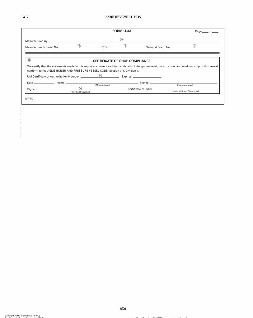
F58
F65
F58
F8 F9 F12
F59
FORM U-3A
(07/17)
CERTIFICATE OF SHOP COMPLIANCE
UM Certificate of Authorization Number Expires
SignedDate Name(Manufacturer) (Representative)
Signed(Certified Individual)
We certify that the statements made in this report are correct and that all details of design, material, construction, and workmanship of this vessel
conform to the ASME BOILER AND PRESSURE VESSEL CODE, Section VIII, Division 1.
Page of
Manufactured by
Manufacturer’s Serial No. CRN National Board No.
Certificate Number(National Board CI number)
ASME BPVC.VIII.1-2019W-2
636
Copyright ASME International (BPVC) Provided by IHS under license with ASME Licensee=Khalda Petroleum/5986215001, User=Amer, Mohamed
Not for Resale, 07/02/2019 13:29:04 MDTNo reproduction or networking permitted without license from IHS
--`,``,``,,`,`,,````,`,``,,,`-`-`,,`,,`,`,,`---

ð19Þ
4. Type(Horizontal or vertical) (Gasketed, semiweld, brazed)
5. ASME Code, Section VIII, Div. 1[Edition (year)]
(b) (c)(Fixed material) (Movable material) (Other material)
7. Frame compression bolts and nuts
8. Impact test
9. Heat transfer plates
,
,
Qty. Type
Material
13. Supports:
15. Remarks:
14. Manufacturer’s Partial Data Reports properly identifying and signed by Commissioned Inspectors have been furnished for the followingitems of the report (list the name of the part, item number, and Manufacturer’s name and identifying number):
Lugs Legs Feet Others Attached
6. Endplates: (a)
No. Quantity Width Length Thickness Corr. Allow. Heat Treat Temp. Time
(Year built) (National Board no.)
10. Chamber 1, MAWP
(Quantity of plates at shipment) (Minimum tightening dimension) (Maximum tightening dimension)
at max. temp MDMT at Hydro/pneu. test press.
11. Chamber 2, MAWP
12. Nozzles, connections, inspections, and safety valve openings:
at max. temp MDMT at Hydro/pneu. test press.
(Quantitiy) (Quantitiy) (Describe) (Where and how)
Purpose(Inlet, Outlet,
Drain, etc.)Dia. or
Size Nozzle FlangeFlangeRating
Nozzle Thickness How AttachedLocation
(Insp./Open.)Nom. C.A. Nozzle Flange
FORM U-3P MANUFACTURER’S CERTIFICATE OF COMPLIANCE
FOR PLATE HEAT EXCHANGERS
COVERING PRESSURE VESSELS TO BE STAMPED WITH THE UM DESIGNATOR [SEE U-1(j)]
As Required by the Provisions of the ASME Boiler and Pressure Vessel Code Rules, Section VIII, Division 1
1. Manufactured and certified by
(Name and address of Manufacturer)
2. Manufactured for(Name and address of Purchaser)
3. Location of installation(Name and address)
(Manufacturer’s serial no.) (Drawing no.)(CRN)
(Quantity, diameter, material specification, and grade)
[Indicate YES and the component(s) impact tested, or NO]
(Plate model) (Material specification and grade) (Thickness) (Maximum plate count for frame assembly)
(Code Case no.) (Capacity)
(07/19)
Page of
F1
F2
F3
F4 F71 F8 F9 F10
F13 F14 F6 F12
F32
F38
F73 F73
F73
F35 F36 F37
F37F36F35
F35
F35
F39
F39
F73 F73
F73
F72 F72 F21 F22 F27F27
F41 F42 F43 F43 F46 F48 F49 F48 F49 F50F20 F44 F20 F45
F51 F51 F51 F51
F52
F53
F20 F20F20
F20
F27
ASME BPVC.VIII.1-2019 W-2
637
Copyright ASME International (BPVC) Provided by IHS under license with ASME Licensee=Khalda Petroleum/5986215001, User=Amer, Mohamed
Not for Resale, 07/02/2019 13:29:04 MDTNo reproduction or networking permitted without license from IHS
--`,``,``,,`,`,,````,`,``,,,`-`-`,,`,,`,`,,`---
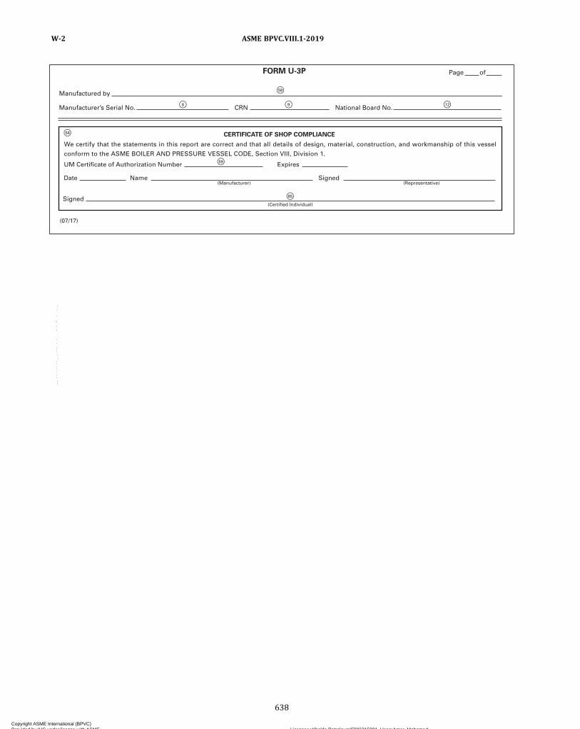
F58
F58
F8 F9 F12
F59
F65
CERTIFICATE OF SHOP COMPLIANCE
Signed(Certified Individual)
Date
UM Certificate of Authorization Number Expires
Name Signed(Representative)(Manufacturer)
We certify that the statements in this report are correct and that all details of design, material, construction, and workmanship of this vessel
conform to the ASME BOILER AND PRESSURE VESSEL CODE, Section VIII, Division 1.
(07/17)
FORM U-3P Page of
Manufactured by
Manufacturer’s Serial No. CRN National Board No.
ASME BPVC.VIII.1-2019W-2
638
Copyright ASME International (BPVC) Provided by IHS under license with ASME Licensee=Khalda Petroleum/5986215001, User=Amer, Mohamed
Not for Resale, 07/02/2019 13:29:04 MDTNo reproduction or networking permitted without license from IHS
--`,``,``,,`,`,,````,`,``,,,`-`-`,,`,,`,`,,`---
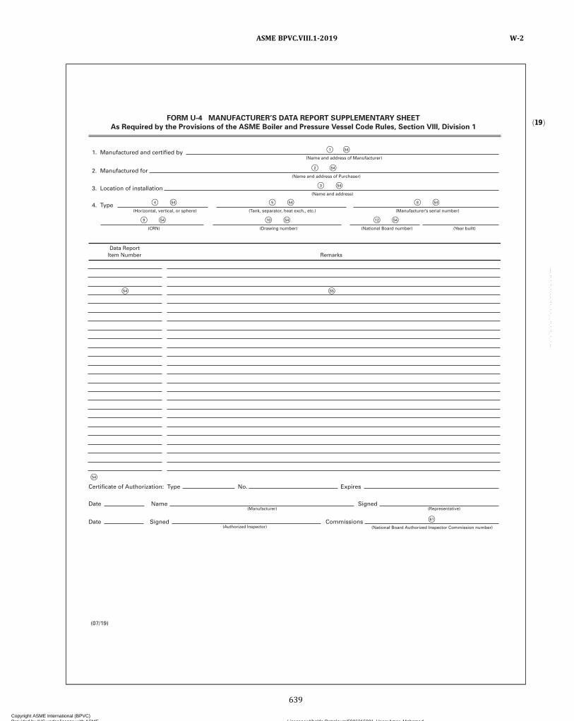
ð19Þ
F1 F54
F2 F54
F3 F54
F55F54
F4 F54 F5 F54 F8 F54
F9 F54 F10 F54 F12 F54
61
F54
FORM U-4 MANUFACTURER’S DATA REPORT SUPPLEMENTARY SHEET
As Required by the Provisions of the ASME Boiler and Pressure Vessel Code Rules, Section VIII, Division 1
1. Manufactured and certified by(Name and address of Manufacturer)
2. Manufactured for(Name and address of Purchaser)
3. Location of installation(Name and address)
4. Type(Horizontal, vertical, or sphere) (Tank, separator, heat exch., etc.) (Manufacturer’s serial number)
(CRN) (Drawing number) (National Board number) (Year built)
Date(Authorized Inspector)
Signed Commissions
Date(Manufacturer) (Representative)
Name Signed
Certificate of Authorization: Type No. Expires
Data ReportItem Number Remarks
(07/19)
(National Board Authorized Inspector Commission number)
ASME BPVC.VIII.1-2019 W-2
639
Copyright ASME International (BPVC) Provided by IHS under license with ASME Licensee=Khalda Petroleum/5986215001, User=Amer, Mohamed
Not for Resale, 07/02/2019 13:29:04 MDTNo reproduction or networking permitted without license from IHS
--`,``,``,,`,`,,````,`,``,,,`-`-`,,`,,`,`,,`---

ð19Þ
F1 F54
F2 F54
F3 F54
F55F54
F4 F54 F8 F54 F9 F54
F10 F54 F12 F54
61
F54
F70 F70 F70 F70 F70 F70
F35 F36 F36 F36 F36
F70
F35
F70 F70
0 0
FORM U-5 MANUFACTURER’S DATA REPORT SUPPLEMENTARY SHEET
SHELL-AND-TUBE HEAT EXCHANGERS
As Required by the Provisions of the ASME Boiler and Pressure Vessel Code Rules, Section VIII, Division 1
1. Manufactured and certified by(Name and address of Manufacturer)
2. Manufactured for(Name and address of Purchaser)
3. Location of installation(Name and address)
4. Type(Horizontal, vertical, or sphere) (Manufacturer’s serial number) (CRN)
(Drawing number) (National Board number) (Year built)
Date(Authorized Inspector)
Signed Commissions
Date(Manufacturer) (Representative)
Name Signed
Certificate of Authorization: Type No. Expires
Data ReportItem Number Remarks
(07/19)
FIXED TUBESHEET HEAT EXCHANGERS
Allowable Axial Differential Thermal
Expansion Range
(units) (units)
Design/Operating Pressure Ranges
Design/Operating Metal Temperatures
Shell Side
(units) (units)
Name of Condition Tube Side
Design
Shell Channel Tubes Tubesheet
(units) (units)
Min. Max.
F70
F35
F70
F35
(units) (units)
Min. Max.
(units) (units)
Min. Max.
(National Board Authorized Inspector Commission number)
ASME BPVC.VIII.1-2019W-2
640
Copyright ASME International (BPVC) Provided by IHS under license with ASME Licensee=Khalda Petroleum/5986215001, User=Amer, Mohamed
Not for Resale, 07/02/2019 13:29:04 MDTNo reproduction or networking permitted without license from IHS
--`,``,``,,`,`,,````,`,``,,,`-`-`,,`,,`,`,,`---
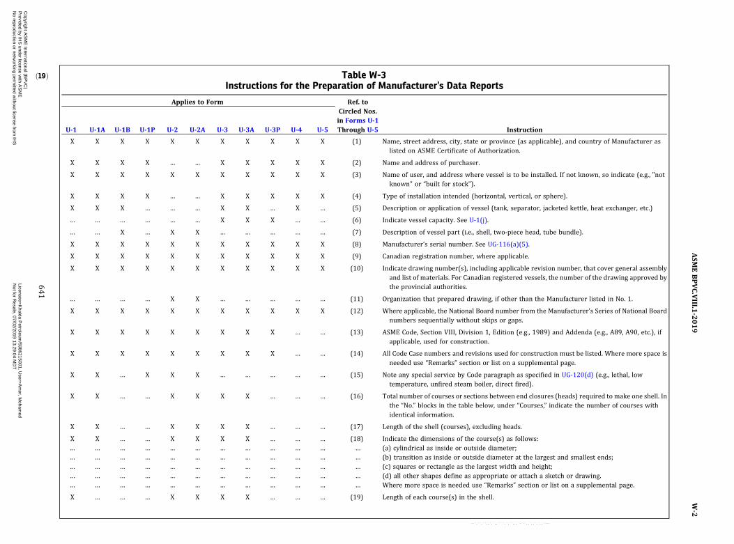
ð19Þ Table W-3Instructions for the Preparation of Manufacturer’s Data Reports
Applies to Form Ref. toCircled Nos.in Forms U-1Through U-5U-1 U-1A U-1B U-1P U-2 U-2A U-3 U-3A U-3P U-4 U-5 Instruction
X X X X X X X X X X X (1) Name, street address, city, state or province (as applicable), and country of Manufacturer aslisted on ASME Certificate of Authorization.
X X X X … … X X X X X (2) Name and address of purchaser.
X X X X X X X X X X X (3) Name of user, and address where vessel is to be installed. If not known, so indicate (e.g., "notknown" or “built for stock”).
X X X X … … X X X X X (4) Type of installation intended (horizontal, vertical, or sphere).
X X X … … … X X … X … (5) Description or application of vessel (tank, separator, jacketed kettle, heat exchanger, etc.)
… … … … … … X X X … … (6) Indicate vessel capacity. See U-1(j).
… … X … X X … … … … … (7) Description of vessel part (i.e., shell, two‐piece head, tube bundle).
X X X X X X X X X X X (8) Manufacturer’s serial number. See UG-116(a)(5).
X X X X X X X X X X X (9) Canadian registration number, where applicable.
X X X X X X X X X X X (10) Indicate drawing number(s), including applicable revision number, that cover general assemblyand list of materials. For Canadian registered vessels, the number of the drawing approved bythe provincial authorities.
… … … … X X … … … … … (11) Organization that prepared drawing, if other than the Manufacturer listed in No. 1.
X X X X X X X X X X X (12) Where applicable, the National Board number from the Manufacturer’s Series of National Boardnumbers sequentially without skips or gaps.
X X X X X X X X X … … (13) ASME Code, Section VIII, Division 1, Edition (e.g., 1989) and Addenda (e.g., A89, A90, etc.), ifapplicable, used for construction.
X X X X X X X X X … … (14) All Code Case numbers and revisions used for construction must be listed. Where more space isneeded use “Remarks” section or list on a supplemental page.
X X … X X X … … … … … (15) Note any special service by Code paragraph as specified in UG-120(d) (e.g., lethal, lowtemperature, unfired steam boiler, direct fired).
X X … … X X X X … … … (16) Total number of courses or sections between end closures (heads) required to make one shell. Inthe “No.” blocks in the table below, under “Courses,” indicate the number of courses withidentical information.
X X … … X X X X … … … (17) Length of the shell (courses), excluding heads.
X X … … X X X X … … … (18) Indicate the dimensions of the course(s) as follows:… … … … … … … … … … … … (a) cylindrical as inside or outside diameter;… … … … … … … … … … … … (b) transition as inside or outside diameter at the largest and smallest ends;… … … … … … … … … … … … (c) squares or rectangle as the largest width and height;… … … … … … … … … … … … (d) all other shapes define as appropriate or attach a sketch or drawing.… … … … … … … … … … … … Where more space is needed use “Remarks” section or list on a supplemental page.
X … … … X X X X … … … (19) Length of each course(s) in the shell.
ASM
EBPVC.VIII.1
-2019
W-2
641
Copyright A
SM
E International (B
PV
C)
Provided by IH
S under license w
ith AS
ME
Licensee=
Khalda P
etroleum/5986215001, U
ser=A
mer, M
ohamed
Not for R
esale, 07/02/2019 13:29:04 MD
TN
o reproduction or networking perm
itted without license from
IHS
--`,``,``,,`,`,,````,`,``,,,`-`-`,,`,,`,`,,`---

Table W-3Instructions for the Preparation of Manufacturer’s Data Reports (Cont'd)
Applies to Form Ref. toCircled Nos.in Forms U-1Through U-5U-1 U-1A U-1B U-1P U-2 U-2A U-3 U-3A U-3P U-4 U-5 Instruction
X X … X X X X X X … … (20) Show the complete ASME specification number and grade of the actual material used in thevessel. Material is to be as designated in Section VIII, Division 1 (e.g., “SA-285C”). Exceptions: Aspecification number for a material not identical to an ASME specification may be shown onlyif such material meets the criteria in the Code in conjunction with the Foreword of thisSection. When material is accepted through a Code Case, the applicable Case number shall beshown.
X X … X X X X X X … … (21) Thickness is the nominal thickness of the material used in the fabrication of the vessel shell. Itincludes corrosion allowance.
X X … X X X X X X … … (22) State corrosion allowance (see UG-25).
X X … … X X X X … … … (23) Type of longitudinal joint (e.g., Type 1, 2, 3, 4, 5, or 6) per Table UW-12. In case of brazing,explain type of joint per Figure UB-16. If seamless, indicate joint type as S, E for electricresistance welded, and W for autogenously welded.
X X … … X X X X … … … (24) Category A (longitudinal) welds— identify degree of examination (radiographic or if applicableultrasonic) employed: full, spot, or none (see UW-11). Also identify the joint efficiencyassociated with the circumferential stress calculations from Table UW-12 or UW-12. Wheremore space is needed, use“Remarks” section, supplemental page, or RT map, as applicable. Inthe case of parts, there is no need to identify the joint efficiency associated with these welds.(See Note (31) for heads of welded construction joints.)
X X … … X X X X … … … (25) Type of circumferential joint (e.g., Type 1, 2, 3, 4, 5, 6, 7, or 8) per Table UW-12. In the case ofbrazing, explain type of joint per Figure UB-16. For multiple course vessel, the Category Bwelds in the shell and head‐to‐shell joint (Category A, B, C) shall be listed bottom to top or leftto right as shown on drawing listed in (10).
X X … … X X X X … … … (26) Category A, B, and C (circumferential) welds — Identify degree of examination (radiographic orif applicable ultrasonic) employed: full, spot, or none (see UW-11) or spot radiography inaccordance with UW-11(a)(5). Also identify the joint efficiency associated with thelongitudinal stress calculations from Table UW-12. Where more space is needed, use“Remarks” section, supplemental page, or RT map, as applicable. In the case of parts, there isno need to identify the joint efficiency associated with these welds.
X X … X X X X X X … … (27) When heat treatment is performed by the Manufacturer, such as postweld heat treatment,annealing, or normalizing, give the holding temperature and time. Explain any special coolingprocedure under “Remarks.”
X X … … X X X X … … … (28) Specified minimum thickness of the head after forming. It includes corrosion allowance.
X X … … X X X X … … … (29) Indicate the crown radius (inside or outside) for torispherical heads.
X X … … X X X X … … … (30) Indicate the knuckle radius (inside or outside) for torispherical or toriconical heads.
X X … … X X X X … … … (31) For heads of welded construction joints, indicate the following:… … … … … … … … … … … … (a) type of joint in the head (Category A), e.g., Type 1, 2, 3, etc., per Table UW-12; in the case of
brazing, explain the type of joint per Figure UB-16.
ASM
EBPVC.VIII.1
-2019
W-2
642
Copyright A
SM
E International (B
PV
C)
Provided by IH
S under license w
ith AS
ME
Licensee=
Khalda P
etroleum/5986215001, U
ser=A
mer, M
ohamed
Not for R
esale, 07/02/2019 13:29:04 MD
TN
o reproduction or networking perm
itted without license from
IHS
--`,``,``,,`,`,,````,`,``,,,`-`-`,,`,,`,`,,`---
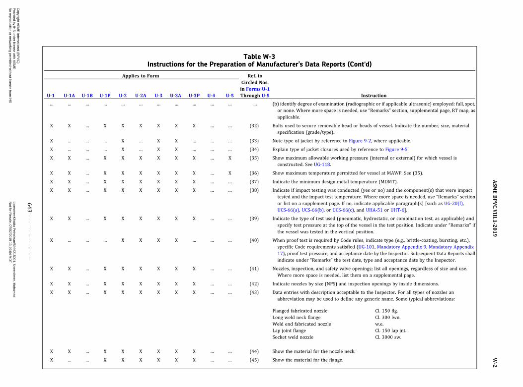
Table W-3Instructions for the Preparation of Manufacturer’s Data Reports (Cont'd)
Applies to Form Ref. toCircled Nos.in Forms U-1Through U-5U-1 U-1A U-1B U-1P U-2 U-2A U-3 U-3A U-3P U-4 U-5 Instruction
… … … … … … … … … … … … (b) identify degree of examination (radiographic or if applicable ultrasonic) employed: full, spot,or none. Where more space is needed, use “Remarks” section, supplemental page, RT map, asapplicable.
X X … X X X X X X … … (32) Bolts used to secure removable head or heads of vessel. Indicate the number, size, materialspecification (grade/type).
X … … … X … X X … … … (33) Note type of jacket by reference to Figure 9-2, where applicable.
X … … … X … X X … … … (34) Explain type of jacket closures used by reference to Figure 9-5.
X X … X X X X X X … X (35) Show maximum allowable working pressure (internal or external) for which vessel isconstructed. See UG-118.
X X … X X X X X X … X (36) Show maximum temperature permitted for vessel at MAWP. See (35).
X X … X X X X X X … … (37) Indicate the minimum design metal temperature (MDMT).
X X … X X X X X X … … (38) Indicate if impact testing was conducted (yes or no) and the component(s) that were impacttested and the impact test temperature. Where more space is needed, use “Remarks” sectionor list on a supplement page. If no, indicate applicable paragraph(s) [such as UG-20(f),UCS-66(a), UCS-66(b), or UCS-66(c), and UHA-51 or UHT-6].
X X … X X X X X X … … (39) Indicate the type of test used (pneumatic, hydrostatic, or combination test, as applicable) andspecify test pressure at the top of the vessel in the test position. Indicate under “Remarks” ifthe vessel was tested in the vertical position.
X … … … X X X X … … … (40) When proof test is required by Code rules, indicate type (e.g., brittle‐coating, bursting, etc.),specific Code requirements satisfied (UG-101, Mandatory Appendix 9, Mandatory Appendix17), proof test pressure, and acceptance date by the Inspector. Subsequent Data Reports shallindicate under “Remarks” the test date, type and acceptance date by the Inspector.
X X … X X X X X X … … (41) Nozzles, inspection, and safety valve openings; list all openings, regardless of size and use.Where more space is needed, list them on a supplemental page.
X X … X X X X X X … … (42) Indicate nozzles by size (NPS) and inspection openings by inside dimensions.
X X … X X X X X X … … (43) Data entries with description acceptable to the Inspector. For all types of nozzles anabbreviation may be used to define any generic name. Some typical abbreviations:
Flanged fabricated nozzle Cl. 150 flg.Long weld neck flange Cl. 300 lwn.Weld end fabricated nozzle w.e.Lap joint flange Cl. 150 lap jnt.Socket weld nozzle Cl. 3000 sw.
X X … X X X X X X … … (44) Show the material for the nozzle neck.
X … … X X X X X X … … (45) Show the material for the flange.
ASM
EBPVC.VIII.1
-2019
W-2
643
Copyright A
SM
E International (B
PV
C)
Provided by IH
S under license w
ith AS
ME
Licensee=
Khalda P
etroleum/5986215001, U
ser=A
mer, M
ohamed
Not for R
esale, 07/02/2019 13:29:04 MD
TN
o reproduction or networking perm
itted without license from
IHS
--`,``,``,,`,`,,````,`,``,,,`-`-`,,`,,`,`,,`---
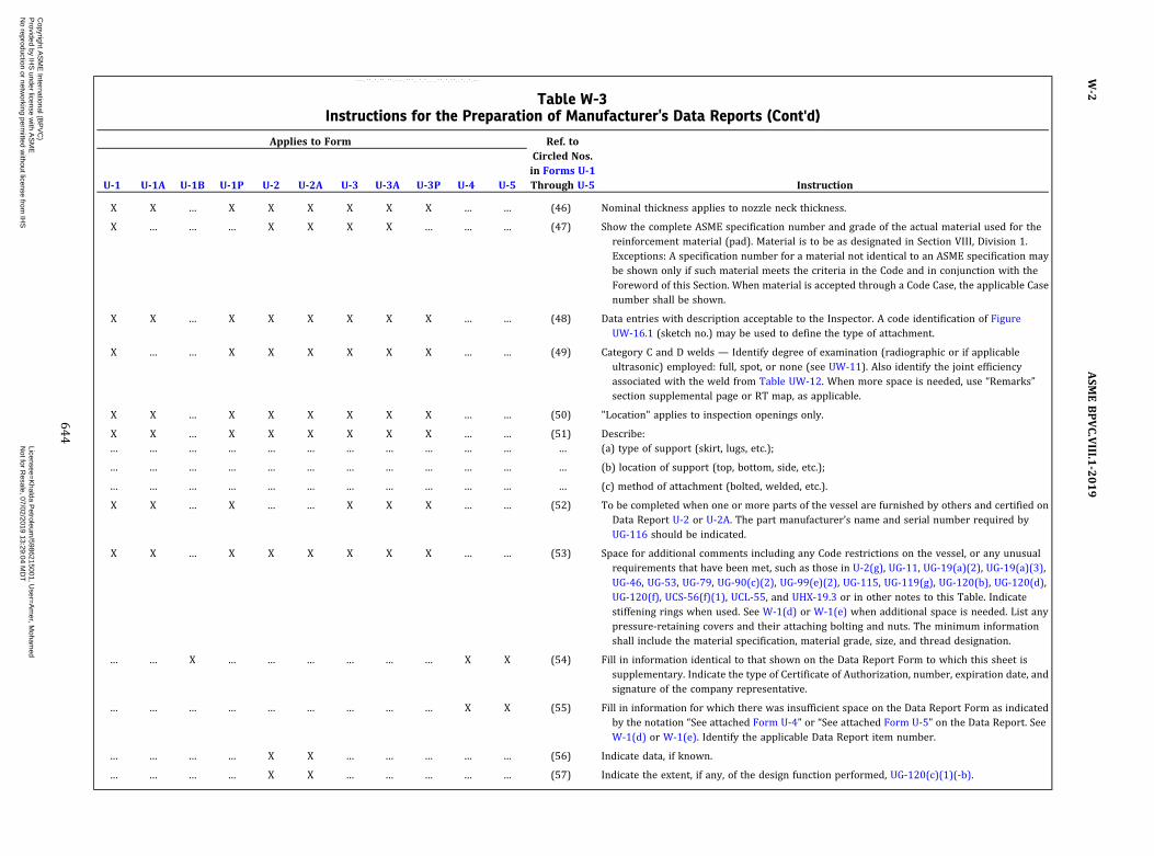
Table W-3Instructions for the Preparation of Manufacturer’s Data Reports (Cont'd)
Applies to Form Ref. toCircled Nos.in Forms U-1Through U-5U-1 U-1A U-1B U-1P U-2 U-2A U-3 U-3A U-3P U-4 U-5 Instruction
X X … X X X X X X … … (46) Nominal thickness applies to nozzle neck thickness.
X … … … X X X X … … … (47) Show the complete ASME specification number and grade of the actual material used for thereinforcement material (pad). Material is to be as designated in Section VIII, Division 1.Exceptions: A specification number for a material not identical to an ASME specification maybe shown only if such material meets the criteria in the Code and in conjunction with theForeword of this Section. When material is accepted through a Code Case, the applicable Casenumber shall be shown.
X X … X X X X X X … … (48) Data entries with description acceptable to the Inspector. A code identification of FigureUW-16.1 (sketch no.) may be used to define the type of attachment.
X … … X X X X X X … … (49) Category C and D welds — Identify degree of examination (radiographic or if applicableultrasonic) employed: full, spot, or none (see UW-11). Also identify the joint efficiencyassociated with the weld from Table UW-12. When more space is needed, use “Remarks”section supplemental page or RT map, as applicable.
X X … X X X X X X … … (50) "Location" applies to inspection openings only.
X X … X X X X X X … … (51) Describe:… … … … … … … … … … … … (a) type of support (skirt, lugs, etc.);
… … … … … … … … … … … … (b) location of support (top, bottom, side, etc.);
… … … … … … … … … … … … (c) method of attachment (bolted, welded, etc.).
X X … X … … X X X … … (52) To be completed when one or more parts of the vessel are furnished by others and certified onData Report U-2 or U-2A. The part manufacturer’s name and serial number required byUG-116 should be indicated.
X X … X X X X X X … … (53) Space for additional comments including any Code restrictions on the vessel, or any unusualrequirements that have been met, such as those in U-2(g), UG-11, UG-19(a)(2), UG-19(a)(3),UG-46, UG-53, UG-79, UG-90(c)(2), UG-99(e)(2), UG-115, UG-119(g), UG-120(b), UG-120(d),UG-120(f), UCS-56(f)(1), UCL-55, and UHX-19.3 or in other notes to this Table. Indicatestiffening rings when used. See W-1(d) or W-1(e) when additional space is needed. List anypressure‐retaining covers and their attaching bolting and nuts. The minimum informationshall include the material specification, material grade, size, and thread designation.
… … X … … … … … … X X (54) Fill in information identical to that shown on the Data Report Form to which this sheet issupplementary. Indicate the type of Certificate of Authorization, number, expiration date, andsignature of the company representative.
… … … … … … … … … X X (55) Fill in information for which there was insufficient space on the Data Report Form as indicatedby the notation “See attached Form U-4” or “See attached Form U-5” on the Data Report. SeeW-1(d) or W-1(e). Identify the applicable Data Report item number.
… … … … X X … … … … … (56) Indicate data, if known.
… … … … X X … … … … … (57) Indicate the extent, if any, of the design function performed, UG-120(c)(1)(-b).
ASM
EBPVC.VIII.1
-2019
W-2
644
Copyright A
SM
E International (B
PV
C)
Provided by IH
S under license w
ith AS
ME
Licensee=
Khalda P
etroleum/5986215001, U
ser=A
mer, M
ohamed
Not for R
esale, 07/02/2019 13:29:04 MD
TN
o reproduction or networking perm
itted without license from
IHS
--`,``,``,,`,`,,````,`,``,,,`-`-`,,`,,`,`,,`---
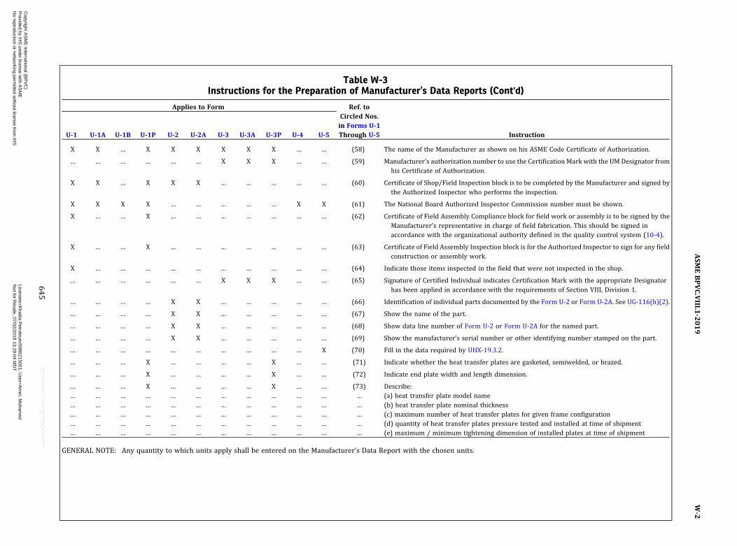
Table W-3Instructions for the Preparation of Manufacturer’s Data Reports (Cont'd)
Applies to Form Ref. toCircled Nos.in Forms U-1Through U-5U-1 U-1A U-1B U-1P U-2 U-2A U-3 U-3A U-3P U-4 U-5 Instruction
X X … X X X X X X … … (58) The name of the Manufacturer as shown on his ASME Code Certificate of Authorization.
… … … … … … X X X … … (59) Manufacturer’s authorization number to use the Certification Mark with the UMDesignator fromhis Certificate of Authorization.
X X … X X X … … … … … (60) Certificate of Shop/Field Inspection block is to be completed by the Manufacturer and signed bythe Authorized Inspector who performs the inspection.
X X X X … … … … … X X (61) The National Board Authorized Inspector Commission number must be shown.
X … … X … … … … … … … (62) Certificate of Field Assembly Compliance block for field work or assembly is to be signed by theManufacturer’s representative in charge of field fabrication. This should be signed inaccordance with the organizational authority defined in the quality control system (10-4).
X … … X … … … … … … … (63) Certificate of Field Assembly Inspection block is for the Authorized Inspector to sign for any fieldconstruction or assembly work.
X … … … … … … … … … … (64) Indicate those items inspected in the field that were not inspected in the shop.
… … … … … … X X X … … (65) Signature of Certified Individual indicates Certification Mark with the appropriate Designatorhas been applied in accordance with the requirements of Section VIII, Division 1.
… … … … X X … … … … … (66) Identification of individual parts documented by the Form U-2 or Form U-2A. See UG-116(h)(2).
… … … … X X … … … … … (67) Show the name of the part.
… … … … X X … … … … … (68) Show data line number of Form U-2 or Form U-2A for the named part.
… … … … X X … … … … … (69) Show the manufacturer’s serial number or other identifying number stamped on the part.
… … … … … … … … … … X (70) Fill in the data required by UHX-19.3.2.
… … … X … … … … X … … (71) Indicate whether the heat transfer plates are gasketed, semiwelded, or brazed.
… … … X … … … … X … … (72) Indicate end plate width and length dimension.
… … … X … … … … X … … (73) Describe:… … … … … … … … … … … … (a) heat transfer plate model name… … … … … … … … … … … … (b) heat transfer plate nominal thickness… … … … … … … … … … … … (c) maximum number of heat transfer plates for given frame configuration… … … … … … … … … … … … (d) quantity of heat transfer plates pressure tested and installed at time of shipment… … … … … … … … … … … … (e) maximum / minimum tightening dimension of installed plates at time of shipment
GENERAL NOTE: Any quantity to which units apply shall be entered on the Manufacturer’s Data Report with the chosen units.
ASM
EBPVC.VIII.1
-2019
W-2
645
Copyright A
SM
E International (B
PV
C)
Provided by IH
S under license w
ith AS
ME
Licensee=
Khalda P
etroleum/5986215001, U
ser=A
mer, M
ohamed
Not for R
esale, 07/02/2019 13:29:04 MD
TN
o reproduction or networking perm
itted without license from
IHS
--`,``,``,,`,`,,````,`,``,,,`-`-`,,`,,`,`,,`---
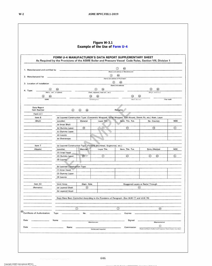
Figure W-3.1Example of the Use of Form U-4
ASME BPVC.VIII.1-2019W-2
646
Copyright ASME International (BPVC) Provided by IHS under license with ASME Licensee=Khalda Petroleum/5986215001, User=Amer, Mohamed
Not for Resale, 07/02/2019 13:29:04 MDTNo reproduction or networking permitted without license from IHS
--`,``,``,,`,`,,````,`,``,,,`-`-`,,`,,`,`,,`---
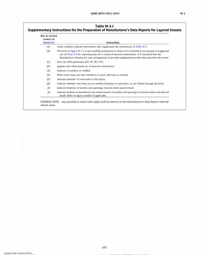
Table W-3.1Supplementary Instructions for the Preparation of Manufacturer’s Data Reports for Layered Vessels
Ref. to CircledLetters inForm U-4 Instruction
(A) Letter symbols indicate instructions that supplement the instructions of Table W-3.
(B) The form in Figure W-3.1 is not available preprinted as shown. It is intended as an example of suggesteduse of Form U-4 for reporting data for a vessel of layered construction. It is intended that theManufacturer develop his own arrangement to provide supplementary data that describes his vessel.
(C) Note the NDE performed (RT, PT, MT, UT).
(D) Applies only when heads are of layered construction.
(E) Indicate if seamless or welded.
(F) When more than one layer thickness is used, add lines as needed.
(G) Indicate diameter of vent holes in the layers.
(H) Indicate whether vent holes are in random locations in each layer, or are drilled through all layers.
(I) Indicate locations of nozzles and openings; layered shell; layered head.
(J) Indicate method of attachment and reinforcement of nozzles and openings in layered shells and layeredheads. Refer to figure number if applicable.
GENERAL NOTE: Any quantity to which units apply shall be entered on the Manufacturer’s Data Report with thechosen units.
ASME BPVC.VIII.1-2019 W-2
647
Copyright ASME International (BPVC) Provided by IHS under license with ASME Licensee=Khalda Petroleum/5986215001, User=Amer, Mohamed
Not for Resale, 07/02/2019 13:29:04 MDTNo reproduction or networking permitted without license from IHS
--`,``,``,,`,`,,````,`,``,,,`-`-`,,`,,`,`,,`---

1
2 3 4 5 6 7 8 9 10
14
15 16
18 17 18
11 12 13
FORM UV-1 MANUFACTURER’S OR ASSEMBLER’S CERTIFICATE OF CONFORMANCE FOR PRESSURE RELIEF VALVES
CERTIFICATE OF SHOP COMPLIANCE
As Required by the Provisions of the ASME Boiler and Pressure Vessel Code Rules, Section VIII, Division 1
1. Manufactured (or assembled) by
I.D. # Year Built
2. Table of Certification Mark stamped items:
3. Remarks
By the signature of the Certified Individual (CI) noted above, we certify that the statements made in this report are correct and that all details for design, material, construction, and workmanship of the pressure relief devices conform with the requirements of Section VIII, Division 1 of the ASME BOILER AND PRESSURE VESSEL CODE.
UV Certificate of Authorization No. Expires
Date Signed (responsible representative) (Manufacturer or Assembler)
Name
NB Cert. # Qty. Type Size
Set Pressure Capacity Test Fluid Date CI Name CI Signature
(07/13)
ASME BPVC.VIII.1-2019W-2
648
Copyright ASME International (BPVC) Provided by IHS under license with ASME Licensee=Khalda Petroleum/5986215001, User=Amer, Mohamed
Not for Resale, 07/02/2019 13:29:04 MDTNo reproduction or networking permitted without license from IHS
--`,``,``,,`,`,,````,`,``,,,`-`-`,,`,,`,`,,`---

1
2 3 4 5 19 6 7 20 21 22
14
24 7 6 19 5 3 11 12 13
15 16
18 17 18
23 9 11 12 13
2B. Table of Certification Mark stamped nonreclosing pressure relief device holder or body:
Date CI Name CI Signature Size Type Holder or Body
Material Year Built Qty. Pin to Pin
Device Identifier
FORM UD-1 MANUFACTURER’S CERTIFICATE OF CONFORMANCE FOR NONRECLOSING PRESSURE RELIEF DEVICES
CERTIFICATE OF SHOP COMPLIANCE
As Required by the Provisions of the ASME Boiler and Pressure Vessel Code Rules, Section VIII, Division 1
1. Manufactured by
Lot #
Marked Burst or Set
Pressure
Activation Component
Material Specified
Temp.
Min. Net
Flow Area
Certified Flow
Resistance Size Year Built
2A. Table of Certification Mark stamped activation components:
3. Remarks
By the signature of the Certified Individual (CI) noted above, we certify that the statements made in this report are correct and that all details for design, material, construction, and workmanship of the rupture disk or pin devices conform with the requirements of Section VIII, Division 1 of the ASME BOILER AND PRESSURE VESSEL CODE.
UD Certificate of Authorization No. Expires
Date Signed (responsible representative) (Manufacturer)
Name
Capacity NB
Cert. # Qty. Type Date CI
Name CI
Signature
(07/13)
ASME BPVC.VIII.1-2019 W-2
649
Copyright ASME International (BPVC) Provided by IHS under license with ASME Licensee=Khalda Petroleum/5986215001, User=Amer, Mohamed
Not for Resale, 07/02/2019 13:29:04 MDTNo reproduction or networking permitted without license from IHS
--`,``,``,,`,`,,````,`,``,,,`-`-`,,`,,`,`,,`---

Table W-3.2Supplementary Instructions for the Preparation of Manufacturer’s or Assembler’s Certificate of
Conformance Forms UV-1 and UD-1
Ref. to CircledNos. in Forms
UV-1 andUD-1 Instruction
(1) Name and address of Manufacturer or Assembler.
(2) Pressure relief device Manufacturer’s or Assembler’s unique identification number, such as serialnumber, work order number, or lot number.
(3) The year built or the pressure relief device Manufacturer’s or Assembler’s date code.
(4) The NB Certification Number.
(5) The quantity of identical devices for this line item.
(6) The Manufacturer’s Design or Type Number as marked on the nameplate.
(7) The inlet size of the pressure relief device.
(8) The nameplate set pressure of the pressure relief device.
(9) The nameplate capacity of the pressure relief device, as applicable.
(10) The fluid used for testing the pressure relief device.
(11) The date of completion of production of the pressure relief device.
(12) The name or unique ID Stamp of the Certified Individual.
(13) The signature of the Certified Individual. Required for each line item.
(14) Include any applicable remarks (referencing the identification number) that may pertain, such asidentification of a Code Case that requires marking on the device.
(15) The number of the pressure relief device Manufacturer’s or Assembler’s Certificate of Authorization.
(16) Expiration date of the pressure relief device Manufacturer’s or Assembler’s Certificate of Authorization.
(17) Date signed by the pressure relief device Manufacturer or Assembler’s authorized representative.
(18) The Certificate of Compliance block is to show the name of the Manufacturer or Assembler as shown onhis/her ASME Code Certificate of Authorization. This shall be signed in accordance withorganizational authority defined in the Quality Control System (see 10-4).
(19) The material of the activation component and/or activation component holder or body, as applicable.
(20) The marked burst or set pressure of the rupture disk or pin.
(21) The specified temperature of the rupture disk or pin.
(22) The minimum net flow area of the rupture disk or pin device, as applicable.
(23) The certified flow resistance (one or more as applicable) KRG, KRL, KRGL of the device, as applicable.
(24) Pin‐to‐pin device identifier, as applicable.
GENERAL NOTE: Any quantity to which units apply shall be entered on the Manufacturer’s Data Report with thechosen units.
ASME BPVC.VIII.1-2019W-2
650
Copyright ASME International (BPVC) Provided by IHS under license with ASME Licensee=Khalda Petroleum/5986215001, User=Amer, Mohamed
Not for Resale, 07/02/2019 13:29:04 MDTNo reproduction or networking permitted without license from IHS
--`,``,``,,`,`,,````,`,``,,,`-`-`,,`,,`,`,,`---

NONMANDATORY APPENDIX YFLAT FACE FLANGES WITH METAL-TO-METAL CONTACT
OUTSIDE THE BOLT CIRCLE
Y-1 GENERAL
(a) The rules in this Appendix apply to circular, boltedflanged connections where the assemblage is comprisedof identical or nonidentical flange pairs, and where theflanges are flat faced and are in uniform metal‐to‐metalcontact across their entire face during assembly beforethe bolts are tightened or after a small amount of preloadis applied to compress a gasket. The rules also apply whena pair of identical flat faced flanges are separated by a me-tal spacer. The rules are not intended for cases where thefaces are intentionally made nonparallel to each othersuch that initial contact is at the bore.
Construction details for attachment and configurationof the flange are not covered in this Appendix. Minimumweld sizes and geometric limitations given in Figure 2-4and Figure UW-13.2 apply to Nonmandatory Appendix Yflanges. Similarly, when applying the rules of this Appen-dix, use of the graphs in Mandatory Appendix 2 for ob-taining applicable design parameters is necessary;namely, Figures 2-7.1 through 2-7.6.
(b) It is assumed that a self‐sealing gasket is used ap-proximately in‐line with the wall of attached pipe or ves-sel. The rules provide for hydrostatic end loads only andassume that the gasket seating loads are small and may inmost cases be neglected. It is also assumed that the sealgenerates a negligible axial load under operating condi-tions. If such is not the case, allowance shall be madefor a gasket load HG dependent on the size and configura-tion of the seal and design pressure. Proper allowanceshall be made if connections are subject to external forcesor external pressure.
(c) As with flanges with ring type gaskets, the stress inthe bolts may vary appreciably with pressure. There is anadditional bolt stress generated due to a prying effect re-sulting from the flanges interacting beyond the bolt circle.As a result, fatigue of the bolts and other parts comprisingthe flanged connection may require consideration andadequate pretensioning of the bolts may be necessary. Itis important to note that the operating bolt stress is rela-tively insensitive to changes in prestress up to a certainpoint and that thereafter the two stresses are essentiallythe same. This is a desirable characteristic of Nonmanda-tory Appendix Y flanges; it means that if the assemblystress (prestress) in the bolts is close to the operating
design stress σb , then subsequent applications of pres-sure loadings ranging from zero to full load will have nosignificant effect on the actual operating stress in thebolts.
Unlike Mandatory Appendix 2 flanges and their boltswhich are stressed during assembly (although some read-justment in the stresses may occur during pressuriza-tion), Nonmandatory Appendix Y flanges becomestressed during pressurization; however, the effect ofpressurization on the operating stress in the bolts de-pends upon the extent to which the bolts are stressed dur-ing assembly.
(d) In the case of identical flange pairs, the analyticalprocedure described in this Appendix considers theflanges to be continuous, annular plates whose flexuralcharacteristics can be approximated by beam theory byconsidering the flanges to be comprised of a series of dis-crete, radial beams. For nonidentical flange pairs, beamtheory is supplemented by the theory of rigid body rota-tion so as to preserve equilibrium of moments and forces.Moments associated with beam theory are designated asbalanced moments, whereas moments used when the the-ory of rigid body rotations is applied are designated as un-balanced moments. Balanced and unbalanced momentsare designated Mb and Mu, respectively. When no sub-script appears, a balanced moment is intended, i.e., inthe equations for the analysis of identical flange pairs(Y-6.1).
(e) A reduction in flange‐to‐flange contact forces be-yond the bolt circle occurs when the flanges are stiff withrespect to the bolting and, in the extreme, flange separa-tion occurs. The rules in this Appendix provide little in-sight into the problem except when the reduction in thecontact force is due to the flange‐hub interaction moment.The problem is considered to be of little practical signifi-cance when the nuts are tightened during assembly usingordinary wrenching techniques.
(f) The design procedure is based on the assumptionthat the flanges are in tangential contact at their outsidediameter or at some lesser distance hC from the bolt cir-cle. [See Y-4(a)(2) and Y-8 when
ASME BPVC.VIII.1-2019 Y-1
651
Copyright ASME International (BPVC) Provided by IHS under license with ASME Licensee=Khalda Petroleum/5986215001, User=Amer, Mohamed
Not for Resale, 07/02/2019 13:29:04 MDTNo reproduction or networking permitted without license from IHS
--`,``,``,,`,`,,````,`,``,,,`-`-`,,`,,`,`,,`---

for additional requirements.] The diameter of the circlewhere the flanges are in tangential contact is a designvariable, the smaller the diameter of the contact circle
the greater the required prestress in the bolts, the higherthe ratio of prestress to operating bolt stress, Si/σb , andthe smaller the flange separation at the gasket. The re-quirement of tangential contact, even when it is assumedto occur at the outside diameter
of the flanges, automatically yields a high ratio of Si/σb
which means that the possibility of flange separation oran appreciable decrease in the flange‐to‐flange contactforces is no longer a problem even when the flanges arestiff with respect to the bolts.(g) The equation for the calculated strain length l of the
bolts is generally applicable. However, variations in thethickness of material actually clamped by each bolt, suchas sleeves, collars, or multiple washers placed between aflange and the bolt heads or nuts, or by counterboring,must be considered in establishing a value of l for usein the design equations. A large increase in l may causethe flanges to become abnormally stiff with respect tosuch bolts and the provision of tangential contact maynot yield a sufficiently high value of the ratio Si/σb unlesshC is reduced to cause an increase in the ratio.(h)Most of the calculated stresses are bending only so
that tensile and compressive stresses of the same magni-tude occur on opposite surfaces at the point under consid-eration. However, when a membrane stress occurs inconjunction with a bending stress, the combined stressrepresents the maximum absolute value at the pointand may be tension or compression (denoted by a − sign).
Y-2 MATERIALS
The rules in 2-2 apply.
Y-3 NOTATION
(a) The symbols described below are used in the for-mulas for the design of flanges:
A = outside diameter of flangeAb = cross‐sectional area of the bolts using the root
diameter of the thread or least diameter of un-threaded portion, if less
Am = total required cross‐sectional area of bolts, ta-ken as the greater of Am1 and Am2
Am1 = total cross‐sectional area of bolts at root ofthread or section of least diameter under stress,required for the operating conditions
= Wm1/Sb= bolt hole aspect ratio used in calculating bolt‐
hole flexibility factor rB
=
a = shape factor= (A + C)/2B1
B = inside diameter of flange. When B is less than20g1, it will be optional for the designer to sub-stitute B1 for B in the formula for longitudinalstress SH.
B1 = B + g1 for loose type flanges and for integraltype flanges that have calculated values h/h0and g1 / g0 which would indicate an f valueof less than 1.0, although the minimum valueof f permitted is 1.0
= B + g0 for integral type flanges when f is equalto or greater than one
= B for Category 3 (loose type) flangesb = effective gasket or joint‐contact‐surface seating
width [see Note in 2-5(c)(1)]b0 = basic gasket seating width, in. (from Table
2-5.2)C = bolt circle diameter
C1 = factor
= (1)
C2 = factor
= (2)
C3 = factor
= (3)
NOTE: C3 = C4 = 0 when F′1 = 0.
C4 = factor
= (4)
NOTE: C3 = C4 = 0 when F′1 = 0.
c = basic dimension used for the minimum sizing ofwelds, equal to tn or tx, whichever is less
D = diameter of bolt holed = factor
=
=
db = nominal diameter of boltE = modulus of elasticity of flange material, cor-
rected for operating temperatureEI* = factor
= E It I3
EI I* = factor= E IIt II
3
ASME BPVC.VIII.1-2019Y-1 – Y-3
652
Copyright ASME International (BPVC) Provided by IHS under license with ASME Licensee=Khalda Petroleum/5986215001, User=Amer, Mohamed
Not for Resale, 07/02/2019 13:29:04 MDTNo reproduction or networking permitted without license from IHS
--`,``,``,,`,`,,````,`,``,,,`-`-`,,`,,`,`,,`---
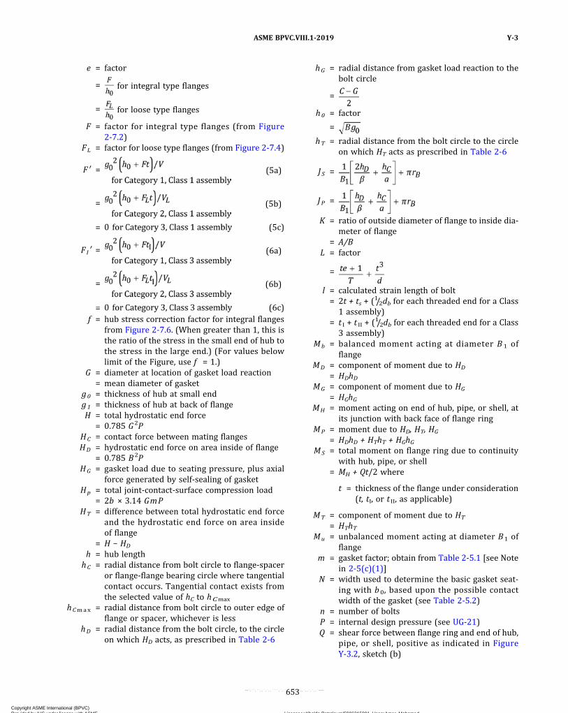
e = factor
= for integral type flanges
= for loose type flanges
F = factor for integral type flanges (from Figure2-7.2)
FL = factor for loose type flanges (from Figure 2-7.4)
F ′ = (5a)
= (5b)
= (5c)
FI ′ = (6a)
= (6b)
= (6c)f = hub stress correction factor for integral flanges
from Figure 2-7.6. (When greater than 1, this isthe ratio of the stress in the small end of hub tothe stress in the large end.) (For values belowlimit of the Figure, use f = 1.)
G = diameter at location of gasket load reaction= mean diameter of gasket
g0 = thickness of hub at small endg1 = thickness of hub at back of flangeH = total hydrostatic end force
= 0.785 G2PHC = contact force between mating flangesHD = hydrostatic end force on area inside of flange
= 0.785 B2PHG = gasket load due to seating pressure, plus axial
force generated by self‐sealing of gasketHp = total joint‐contact‐surface compression load
= 2b × 3.14 GmPHT = difference between total hydrostatic end force
and the hydrostatic end force on area insideof flange
= H − HD
h = hub lengthhC = radial distance from bolt circle to flange‐spacer
or flange‐flange bearing circle where tangentialcontact occurs. Tangential contact exists fromthe selected value of hC to hCmax
hCmax = radial distance from bolt circle to outer edge offlange or spacer, whichever is less
hD = radial distance from the bolt circle, to the circleon which HD acts, as prescribed in Table 2-6
hG = radial distance from gasket load reaction to thebolt circle
=
h0 = factor
=
hT = radial distance from the bolt circle to the circleon which HT acts as prescribed in Table 2-6
J S =
JP =
K = ratio of outside diameter of flange to inside dia-meter of flange
= A/BL = factor
=
l = calculated strain length of bolt= 2t + ts + (1/2db for each threaded end for a Class
1 assembly)= t I + t II + (1/2db for each threaded end for a Class
3 assembly)Mb = balanced moment acting at diameter B 1 of
flangeMD = component of moment due to HD
= HDhDMG = component of moment due to HG
= HGhGMH = moment acting on end of hub, pipe, or shell, at
its junction with back face of flange ringMP = moment due to HD, HT, HG
= HDhD + HThT + HGhGMS = total moment on flange ring due to continuity
with hub, pipe, or shell= MH + Qt/2 where
t = thickness of the flange under consideration(t, tI, or t II, as applicable)
MT = component of moment due to HT
= HThTMu = unbalanced moment acting at diameter B1 of
flangem = gasket factor; obtain from Table 2-5.1 [see Note
in 2-5(c)(1)]N = width used to determine the basic gasket seat-
ing with b0, based upon the possible contactwidth of the gasket (see Table 2-5.2)
n = number of boltsP = internal design pressure (see UG-21)Q = shear force between flange ring and end of hub,
pipe, or shell, positive as indicated in FigureY-3.2, sketch (b)
ASME BPVC.VIII.1-2019 Y-3
653
Copyright ASME International (BPVC) Provided by IHS under license with ASME Licensee=Khalda Petroleum/5986215001, User=Amer, Mohamed
Not for Resale, 07/02/2019 13:29:04 MDTNo reproduction or networking permitted without license from IHS
--`,``,``,,`,`,,````,`,``,,,`-`-`,,`,,`,`,,`---
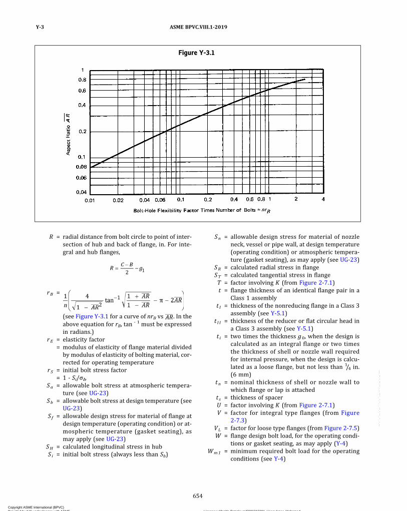
R = radial distance from bolt circle to point of inter-section of hub and back of flange, in. For inte-gral and hub flanges,
rB =
(see Figure Y-3.1 for a curve of nrB vs . In theabove equation for rB, tan
- 1 must be expressedin radians.)
rE = elasticity factor= modulus of elasticity of flange material divided
by modulus of elasticity of bolting material, cor-rected for operating temperature
rS = initial bolt stress factor= 1 - Si/σb
Sa = allowable bolt stress at atmospheric tempera-ture (see UG-23)
Sb = allowable bolt stress at design temperature (seeUG-23)
Sf = allowable design stress for material of flange atdesign temperature (operating condition) or at-mospheric temperature (gasket seating), asmay apply (see UG-23)
SH = calculated longitudinal stress in hubS i = initial bolt stress (always less than Sb)
Sn = allowable design stress for material of nozzleneck, vessel or pipe wall, at design temperature(operating condition) or atmospheric tempera-ture (gasket seating), as may apply (see UG-23)
SR = calculated radial stress in flangeST = calculated tangential stress in flangeT = factor involving K (from Figure 2-7.1)t = flange thickness of an identical flange pair in a
Class 1 assemblyt I = thickness of the nonreducing flange in a Class 3
assembly (see Y-5.1)t I I = thickness of the reducer or flat circular head in
a Class 3 assembly (see Y-5.1)t i = two times the thickness g0, when the design is
calculated as an integral flange or two timesthe thickness of shell or nozzle wall requiredfor internal pressure, when the design is calcu-lated as a loose flange, but not less than 1/4 in.(6 mm)
tn = nominal thickness of shell or nozzle wall towhich flange or lap is attached
t s = thickness of spacerU = factor involving K (from Figure 2-7.1)V = factor for integral type flanges (from Figure
2-7.3)VL = factor for loose type flanges (from Figure 2-7.5)W = flange design bolt load, for the operating condi-
tions or gasket seating, as may apply (Y-4)Wm1 = minimum required bolt load for the operating
conditions (see Y-4)
Figure Y-3.1
ASME BPVC.VIII.1-2019Y-3
654
Copyright ASME International (BPVC) Provided by IHS under license with ASME Licensee=Khalda Petroleum/5986215001, User=Amer, Mohamed
Not for Resale, 07/02/2019 13:29:04 MDTNo reproduction or networking permitted without license from IHS
--`,``,``,,`,`,,````,`,``,,,`-`-`,,`,,`,`,,`---

Figure Y-3.2Flange Dimensions and Forces
NOTES:(1) Integral (Category 1) illustrated.(2) See Y-3(a).
ASME BPVC.VIII.1-2019 Y-3
655
Copyright ASME International (BPVC) Provided by IHS under license with ASME Licensee=Khalda Petroleum/5986215001, User=Amer, Mohamed
Not for Resale, 07/02/2019 13:29:04 MDTNo reproduction or networking permitted without license from IHS
--`,``,``,,`,`,,````,`,``,,,`-`-`,,`,,`,`,,`---

w = width used to determine the basic gasket seat-ing width b0, based upon the contact width be-tween the flange facing and the gasket (seeTable 2-5.2)
X = factor= E I* / (E I* + E II*)
Y = factor involving K (from Figure 2-7.1)y = gasket or joint‐contact‐surface unit seating load
[see Note in 2-5(c)(1)]Z = factor involving K (from Figure 2-7.1)β = shape factor for full face metal‐to‐metal contact
flanges= (C + B1)/2B1
θA = slope of flange face at outside diameter, radθB = slope of flange face at inside diameter, radθ rb = change in slope which flange pair undergoes
due to an unbalanced moment, rad
(b) Subscripts I and II where noted are used to distin-guish between the flanges in a nonidentical flange pair(Class 2 or 3 assemblies). B1 without a subscript alwaysrefers to Flange I (the nonreducing flange) in a Class 2or 3 assembly.(c) Unless otherwise noted, B1 , Js , Jp , F1′ [eqs. (a)(6a),
(a)(6b), and (a)(6c)], andMp are based on the dimensionsof the nonreducing flange (Flange I) in a Class 2 or 3assembly.(d) All logarithms are to base 10.
Y-4 BOLT LOADS
(a) Required Bolt Load. The flange bolt load used in cal-culating the required cross‐sectional area of bolts shall bedetermined as follows.
(1) The required bolt load for the operating condi-tion Wm1 shall be sufficient to resist the sum of the hy-drostatic end force H exerted by the maximumallowable working pressure on the area bounded by thediameter of the gasket reaction, and the contact forceHC exerted by the mating flange on the annular areawhere the flange faces are in contact. To this shall beadded the gasket load HG for those designs where gasketseating requirements are significant.
(2) Before the contact force HC can be determined, itis necessary to obtain a value for its moment arm hC. Dueto the interaction between bolt elongation and flange de-flection, hC involves the flange thickness t , operating boltstress σb , initial bolt prestress factor rs, and calculatedstrain length l , elasticity factor rE, and total moment load-ing on the flange. This Appendix is based on starting a de-sign by assuming a value for hC and then calculating thevalue of the initial bolt stress, S i , which satisfies theassumption.
Although the distance hC from the bolt circle to theflange‐to‐flange contact circle is a design variable, forthe purpose of this Appendix the use of
to optimize stresses is considered to be a special situationrequiring controlled bolt tightening and verification (seeY-8). Except in special instances, setting hC equal to hCmax
should be satisfactory. It is inherent in the computationalprocess that the flanges will be in tangential contact be-tween the selected bearing circle
and the outside diameter of the flanges
(3) The hub–flange interaction moment Ms, whichacts on the flange, is expressed by eqs. Y-6.1(7),Y-6.3(a)(19), and Y-6.3(a)(20); for Category 3 flanges
The contact force HC is determined by eqs. Y-6.1(9)or Y-6.3(a)(27).
(4) The required bolt load for operating conditions isdetermined in accordance with the following equation:
(b) Total Required and Actual Bolt Areas, and FlangeDesign Bolt Load. The total required cross‐sectional areaof bolts Am equals Wm1 / Sb. A selection of bolts to beused shall be made such that the actual total cross‐sectional area of bolts Ab will not be less than Am. Theflange design bolt load W shall be taken equal to Wm1.
Y-5 CLASSIFICATION OF ASSEMBLIES ANDCATEGORIZATION OF INDIVIDUALFLANGES
It is necessary to classify the different types of flangedassemblies and to further categorize each flange whichcomprises the assembly under consideration.
Y-5.1 CLASSIFICATION OF A NONMANDATORYAPPENDIX Y ASSEMBLY
Since the flanges comprising an assembly are in contactoutside the bolt circle, the behavior of one flange is influ-enced by the stiffness of the other. For the purpose ofcomputation it is helpful to classify an assembly consist-ing of different types of flanges according to the waythe flanges influence the deformation of the assembly.(a) Class 1 Assembly.106 A pair of flanges which are
bolted together and which are nominally identical withrespect to shape, dimensions, physical properties, and
ASME BPVC.VIII.1-2019Y-3 – Y-5.1
656
Copyright ASME International (BPVC) Provided by IHS under license with ASME Licensee=Khalda Petroleum/5986215001, User=Amer, Mohamed
Not for Resale, 07/02/2019 13:29:04 MDTNo reproduction or networking permitted without license from IHS
--`,``,``,,`,`,,````,`,``,,,`-`-`,,`,,`,`,,`---
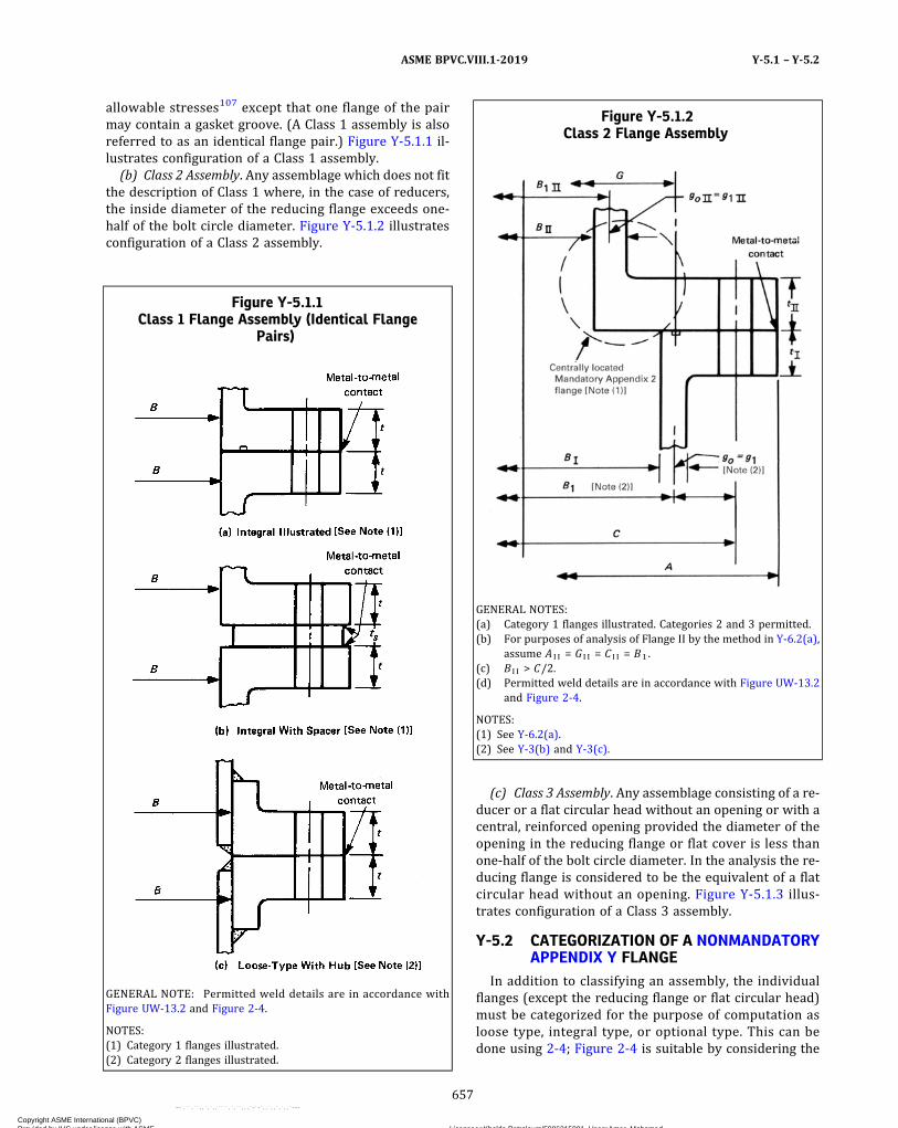
allowable stresses107 except that one flange of the pairmay contain a gasket groove. (A Class 1 assembly is alsoreferred to as an identical flange pair.) Figure Y-5.1.1 il-lustrates configuration of a Class 1 assembly.
(b) Class 2 Assembly. Any assemblage which does not fitthe description of Class 1 where, in the case of reducers,the inside diameter of the reducing flange exceeds one‐half of the bolt circle diameter. Figure Y-5.1.2 illustratesconfiguration of a Class 2 assembly.
(c) Class 3 Assembly. Any assemblage consisting of a re-ducer or a flat circular head without an opening or with acentral, reinforced opening provided the diameter of theopening in the reducing flange or flat cover is less thanone‐half of the bolt circle diameter. In the analysis the re-ducing flange is considered to be the equivalent of a flatcircular head without an opening. Figure Y-5.1.3 illus-trates configuration of a Class 3 assembly.
Y-5.2 CATEGORIZATION OF A NONMANDATORYAPPENDIX Y FLANGE
In addition to classifying an assembly, the individualflanges (except the reducing flange or flat circular head)must be categorized for the purpose of computation asloose type, integral type, or optional type. This can bedone using 2-4; Figure 2-4 is suitable by considering the
Figure Y-5.1.1Class 1 Flange Assembly (Identical Flange
Pairs)
GENERAL NOTE: Permitted weld details are in accordance withFigure UW-13.2 and Figure 2-4.
NOTES:(1) Category 1 flanges illustrated.(2) Category 2 flanges illustrated.
Figure Y-5.1.2Class 2 Flange Assembly
GENERAL NOTES:(a) Category 1 flanges illustrated. Categories 2 and 3 permitted.(b) For purposes of analysis of Flange II by the method in Y-6.2(a),
assume A I I = G I I = C I I = B1 .(c) B I I > C/2.(d) Permitted weld details are in accordance with Figure UW-13.2
and Figure 2-4.
NOTES:(1) See Y-6.2(a).(2) See Y-3(b) and Y-3(c).
ASME BPVC.VIII.1-2019 Y-5.1 – Y-5.2
657
Copyright ASME International (BPVC) Provided by IHS under license with ASME Licensee=Khalda Petroleum/5986215001, User=Amer, Mohamed
Not for Resale, 07/02/2019 13:29:04 MDTNo reproduction or networking permitted without license from IHS
--`,``,``,,`,`,,````,`,``,,,`-`-`,,`,,`,`,,`---
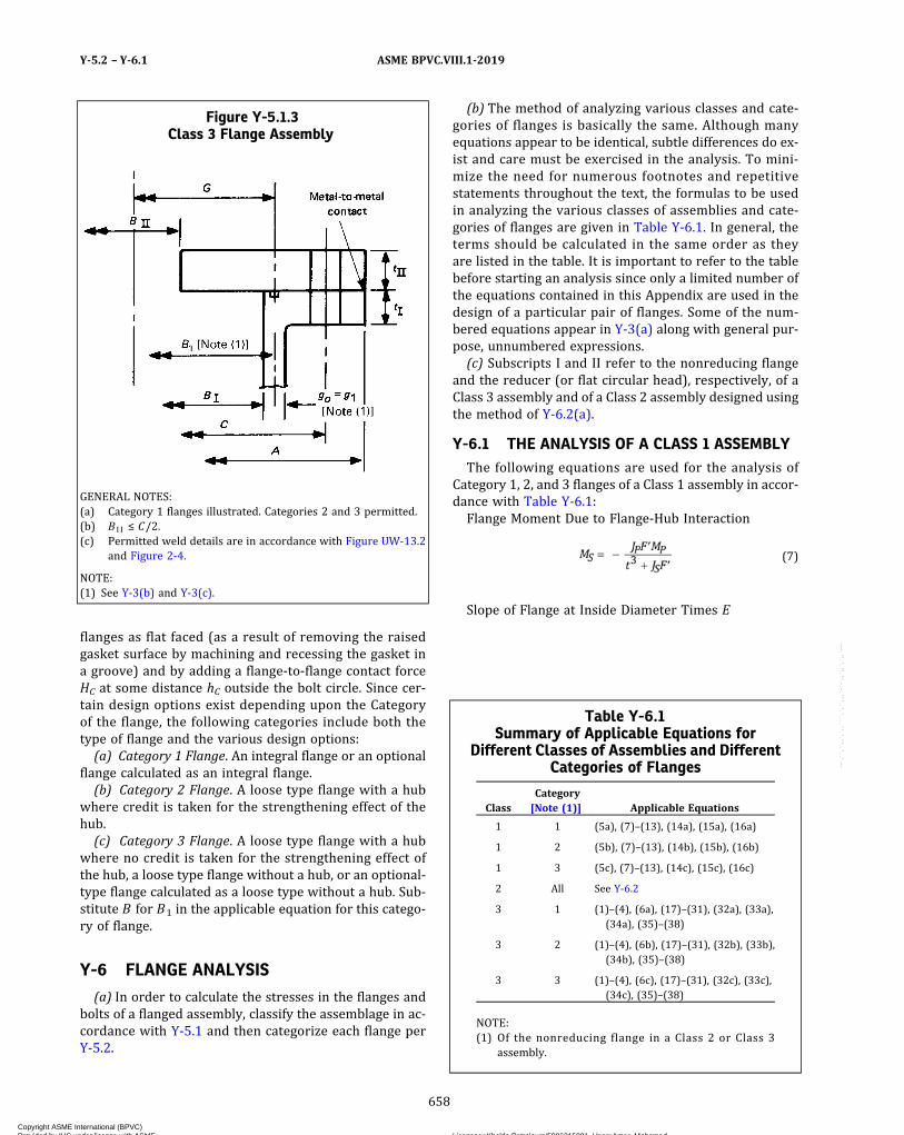
flanges as flat faced (as a result of removing the raisedgasket surface by machining and recessing the gasket ina groove) and by adding a flange‐to‐flange contact forceHC at some distance hC outside the bolt circle. Since cer-tain design options exist depending upon the Categoryof the flange, the following categories include both thetype of flange and the various design options:(a) Category 1 Flange. An integral flange or an optional
flange calculated as an integral flange.(b) Category 2 Flange. A loose type flange with a hub
where credit is taken for the strengthening effect of thehub.(c) Category 3 Flange. A loose type flange with a hub
where no credit is taken for the strengthening effect ofthe hub, a loose type flange without a hub, or an optional‐type flange calculated as a loose type without a hub. Sub-stitute B for B1 in the applicable equation for this catego-ry of flange.
Y-6 FLANGE ANALYSIS
(a) In order to calculate the stresses in the flanges andbolts of a flanged assembly, classify the assemblage in ac-cordance with Y-5.1 and then categorize each flange perY-5.2.
(b) The method of analyzing various classes and cate-gories of flanges is basically the same. Although manyequations appear to be identical, subtle differences do ex-ist and care must be exercised in the analysis. To mini-mize the need for numerous footnotes and repetitivestatements throughout the text, the formulas to be usedin analyzing the various classes of assemblies and cate-gories of flanges are given in Table Y-6.1. In general, theterms should be calculated in the same order as theyare listed in the table. It is important to refer to the tablebefore starting an analysis since only a limited number ofthe equations contained in this Appendix are used in thedesign of a particular pair of flanges. Some of the num-bered equations appear in Y-3(a) along with general pur-pose, unnumbered expressions.(c) Subscripts I and II refer to the nonreducing flange
and the reducer (or flat circular head), respectively, of aClass 3 assembly and of a Class 2 assembly designed usingthe method of Y-6.2(a).
Y-6.1 THE ANALYSIS OF A CLASS 1 ASSEMBLYThe following equations are used for the analysis of
Category 1, 2, and 3 flanges of a Class 1 assembly in accor-dance with Table Y-6.1:Flange Moment Due to Flange‐Hub Interaction
ð7Þ
Slope of Flange at Inside Diameter Times E
Figure Y-5.1.3Class 3 Flange Assembly
GENERAL NOTES:(a) Category 1 flanges illustrated. Categories 2 and 3 permitted.(b) B I I ≤ C/2.(c) Permitted weld details are in accordance with Figure UW-13.2
and Figure 2-4.
NOTE:(1) See Y-3(b) and Y-3(c).
Table Y-6.1Summary of Applicable Equations for
Different Classes of Assemblies and DifferentCategories of Flanges
ClassCategory[Note (1)] Applicable Equations
1 1 (5a), (7)–(13), (14a), (15a), (16a)
1 2 (5b), (7)–(13), (14b), (15b), (16b)
1 3 (5c), (7)–(13), (14c), (15c), (16c)
2 All See Y-6.2
3 1 (1)–(4), (6a), (17)–(31), (32a), (33a),(34a), (35)–(38)
3 2 (1)–(4), (6b), (17)–(31), (32b), (33b),(34b), (35)–(38)
3 3 (1)–(4), (6c), (17)–(31), (32c), (33c),(34c), (35)–(38)
NOTE:(1) Of the nonreducing flange in a Class 2 or Class 3
assembly.
ASME BPVC.VIII.1-2019Y-5.2 – Y-6.1
658
Copyright ASME International (BPVC) Provided by IHS under license with ASME Licensee=Khalda Petroleum/5986215001, User=Amer, Mohamed
Not for Resale, 07/02/2019 13:29:04 MDTNo reproduction or networking permitted without license from IHS
--`,``,``,,`,`,,````,`,``,,,`-`-`,,`,,`,`,,`---

ð8Þ
Contact Force Between Flanges at hC
ð9Þ
Bolt Load at Operating Conditions
ð10Þ
Operating Bolt Stress
ð11Þ
Design Prestress in Bolts
ð12Þ
Radial Flange Stress at Bolt Circle
ð13Þ
Radial Flange Stress at Inside Diameter
ð14aÞ
ð14bÞ
ð14cÞ
Tangential Flange Stress at Inside Diameter
ð15aÞ
ð15bÞ
ð15cÞ
Longitudinal Hub Stress
ð16aÞ
ð16bÞ
ð16cÞ
Y-6.2 THE ANALYSIS OF A CLASS 2 ASSEMBLY(a) The assembly may be analyzed using a variation of
the analysis for a Class 3 assembly (Y-6.3) that accountsfor the interaction of nonidentical flanges and the stiffen-ing effect of an integral nozzle or hub centrally located inthe reducing flange.
(1) The central nozzle of Flange II with diameter B II
shall be assumed for analysis purposes as an MandatoryAppendix 2 flange with outside diameter A , bolt circleC , and gasket circle G all equal to B1 of Flange I. See FigureY-5.1.2.
(2) In addition, it is necessary to categorize the cen-trally located Mandatory Appendix 2 flange (nozzle plusthe associated over plate to diameter B1) as a Category1, 2, or 3 flange in accordance with Y-5.2.
(3) The moment due to pressure shall be designatedMp ′ where
For Category 1, 2, or 3 flanges [(2) above],
For Category 1 or 2 flanges [(2) above],
For Category 3 flanges [(2) above],
ASME BPVC.VIII.1-2019 Y-6.1 – Y-6.2
659
Copyright ASME International (BPVC) Provided by IHS under license with ASME Licensee=Khalda Petroleum/5986215001, User=Amer, Mohamed
Not for Resale, 07/02/2019 13:29:04 MDTNo reproduction or networking permitted without license from IHS
--`,``,``,,`,`,,````,`,``,,,`-`-`,,`,,`,`,,`---

(4) The rules in Y-6.3 and the summary of TableY-6.1 for the analysis of a Class 3 assembly apply to theanalysis of a Class 2 assembly with the following addi-tions and substitutions:
C5 and C6 and all the symbols in equations in (-a)and (-b) below pertain only to the centrally located Man-datory Appendix 2 flange [nozzle plus the associated cov-er of thickness t I I to diameter B1 defined in (1) above].All terms in equations in (-c) and (-d) below, except C5
and C6 , refer to the nonreducing flange (Flange I).C1 and C2 of equations in (-c) and (-d) below replace
C1 and C2 of eqs. Y-3(a)(1) and Y-3(a)(2).(-a) Let
(-b) Let
for Category 3 flanges [see (2) above]. Let
for Category 1 or 2 flanges [see (2) above].(-c) Let
C1 = [1 − 2.095J S log (A/B1)] ÷ ( − C6 − 1.738J S)
(-d) Let
C2 = (1.738JPMP − C5C6 ) ÷ ( − C6 − 1.738J S)
(-e) Replace eq. Y-6.3(a)(26) with:
(-f)Delete eq. Y-6.3(a)(38). Subparagraphs (1),(2), and (3) above apply only for calculating C 5 (Mp ′)and C6 , and subsequently when using (5) below for calcu-lating the stresses in and adjacent to the nozzle in FlangeII.
(5) Stresses in the centrally located nozzle of FlangeII shall be calculated in accordance with the followingequations after M S I I has been found using (4) above.All terms, such as e , Y , and Z , apply to the centrally lo-cated Mandatory Appendix 2 flange as defined in (1)and (2) above.
For Category 1 or 2 flanges [(2) above]:Longitudinal Hub Stress
Radial Flange Stress Adjacent to Central Nozzle
Tangential Flange Stress Adjacent to Central Nozzle
For Category 3 Flanges [(2) above]:Tangential Flange Stress Adjacent to Central Nozzle
Radial and Longitudinal Hub Stress
(6) The stresses in Flange I and the remaining stress-es in Flange II shall be calculated in accordance with Y-6.3except as modified by (4).(b) As an alternative to the method in (a) above and at
the option of the designer, the assembly may be analyzedas if it is one flange of an identical pair in a Class 1 assem-bly using the procedure in Y-6.1. All stresses shall satisfyY-7. The same value of hC shall be used in both calcula-tions and the strain length l of the bolts shall be basedon the thickness of the flange under consideration. Thismethod is more conservative and more bolting may be re-quired than the method in (a) above.(c) The central nozzle or opening in Flange II of a Class
2 assembly determined by the rules in (a) or (b) abovemeets the general requirements of this Division and ofthis Appendix. The rules for determining thickness andreinforcing requirements of UG-34 and UG-39, respec-tively, are not applicable.
ASME BPVC.VIII.1-2019Y-6.2
660
Copyright ASME International (BPVC) Provided by IHS under license with ASME Licensee=Khalda Petroleum/5986215001, User=Amer, Mohamed
Not for Resale, 07/02/2019 13:29:04 MDTNo reproduction or networking permitted without license from IHS
--`,``,``,,`,`,,````,`,``,,,`-`-`,,`,,`,`,,`---

Y-6.3 THE ANALYSIS OF A CLASS 3 ASSEMBLY(a) The following equations are used for the analysis of
Category 1, 2, and 3 nonreducing flanges and the reducer(or flat circular head) of a Class 3 assembly:
Rigid Body Rotation of Flanges Times E*
ð17Þ
ð18Þ
Total Flange Moment at Diameter B1
ð19Þ
ð20Þ
Unbalanced Flange Moment at Diameter B1
ð21Þ
ð22Þ
Balanced Flange Moment at Diameter B1
ð23Þ
ð24Þ
Slope of Flange at Diameter B1 Times E
ð25Þ
ð26Þ
Contact Force Between Flanges at hC
ð27Þ
Bolt Load at Operating Conditions
ð28Þ
Operating Bolt Stress
ð29Þ
Design Prestress in Bolts
ð30Þ
Radial Stress in Flange I at Bolt Circle
ð31Þ
Radial Stress in Flange I at Inside Diameter
ð32aÞ
ð32bÞ
ð32cÞ
Tangential Stress in Flange I at Inside Diameter
ð33aÞ
ð33bÞ
ð33cÞ
Longitudinal Hub Stress in Flange I
ð34aÞ
ð34bÞ
ASME BPVC.VIII.1-2019 Y-6.3
661
Copyright ASME International (BPVC) Provided by IHS under license with ASME Licensee=Khalda Petroleum/5986215001, User=Amer, Mohamed
Not for Resale, 07/02/2019 13:29:04 MDTNo reproduction or networking permitted without license from IHS
--`,``,``,,`,`,,````,`,``,,,`-`-`,,`,,`,`,,`---
ð34cÞ
Radial Stress in Flange II at Bolt Circle
ð35Þ
Radial Stress in Flange II at Diameter B1
ð36Þ
Tangential Stress in Flange II at Diameter B1
ð37Þ
Radial and Tangential Stress at Center of Flange II
ð38Þ
(b) The thickness of Flange II of a Class 3 assembly de-termined by the above rules shall be used in lieu of thethickness that is determined by UG-34. However, any cen-trally located opening in Flange II shall be reinforced tomeet the rules of UG-39(b).
Y-7 ALLOWABLE FLANGE DESIGN STRESSES
The stresses calculated by the above equations,whether tensile or compressive ( − ), shall not exceedthe following values for all classes of assemblies:108
(a) operating bolt stress σb not greater than Sb for thedesign value of St ;(b) longitudinal hub stress SH not greater than Sf for
Category 1 and 2 cast iron flanges except as otherwiselimited by (1) and (2) below and not greater than 1.5 Sffor materials other than cast iron:
(1) longitudinal hub stress SH not greater than thesmaller of 1.5 Sf or 1.5 Sn for Category 1 flanges wherethe pipe or shell constitutes the hub;
(2) longitudinal hub stress SH not greater than thesmaller of 1.5 Sf or 2.5Sn for integral NonmandatoryAppendix Y flanges (Category 1) similar to the MandatoryAppendix 2 flanges shown as Figure 2-4, sketches (6),(6a), and (6b).(c) radial stress SR not greater than Sf;(d) tangential stress ST not greater than Sf;(e) also, (SH + SR)/2 not greater than Sf and (SH + ST)/2
not greater than Sf;
(f) SR and ST at the center of the reducing flange in aClass 3 assembly [see eq. 13-7(c)(3)(38)] shall not exceedSf.
Y-8 PRESTRESSING THE BOLTS
The design rules of this Appendix provide for tangentialcontact between the flanges at hCmax or some lesser valuehC beyond the bolt circle. As in the case of MandatoryAppendix 2 flanges, a Nonmandatory Appendix Y flangemust be designed so that the calculated value of the oper-ating bolt stress σb does not exceed Sb. Also, as in the caseof Mandatory Appendix 2 flanges, ordinary wrenchingtechniques without verification of the actual initial boltstress (assembly stress) is considered to meet all practicalneeds with control and verification reserved for specialapplications. For the purposes of this Appendix the use of
to optimize stresses is considered to be a special appli-cation unless it is also shown that all of the requirementsof this Appendix are also satisfied when
Y-9 ESTIMATING FLANGE THICKNESSESAND BOLTING
(a) The following simple equations are offered for cal-culating approximate values of t, tI, t II, and Ab before ap-plying the rules in Y-4 through Y-8. The equations are notintended to replace the rules; however, they should signif-icantly reduce the amount of work required to achieve asuitable design. Since the flanges are in metal‐to‐metalcontact and interact, the stresses in one flange are influ-enced by the stiffness of the mating flange and theoreti-cally an unlimited number of designs can be foundwhich satisfy the rules. In practice, however, economics,engineering judgment, and dimensional constraints willshow which is the “best” design. It should be noted thatthe equations in Table Y-9.1 assume that both flangescomprising an assembly have essentially the same modu-lus of elasticity and allowable stress.(b) Equations for Trial Flange Thickness and Bolting
ð39Þ
ð40Þ
tc = greater of ta or tb
ASME BPVC.VIII.1-2019Y-6.3 – Y-9
662
Copyright ASME International (BPVC) Provided by IHS under license with ASME Licensee=Khalda Petroleum/5986215001, User=Amer, Mohamed
Not for Resale, 07/02/2019 13:29:04 MDTNo reproduction or networking permitted without license from IHS
--`,``,``,,`,`,,````,`,``,,,`-`-`,,`,,`,`,,`---
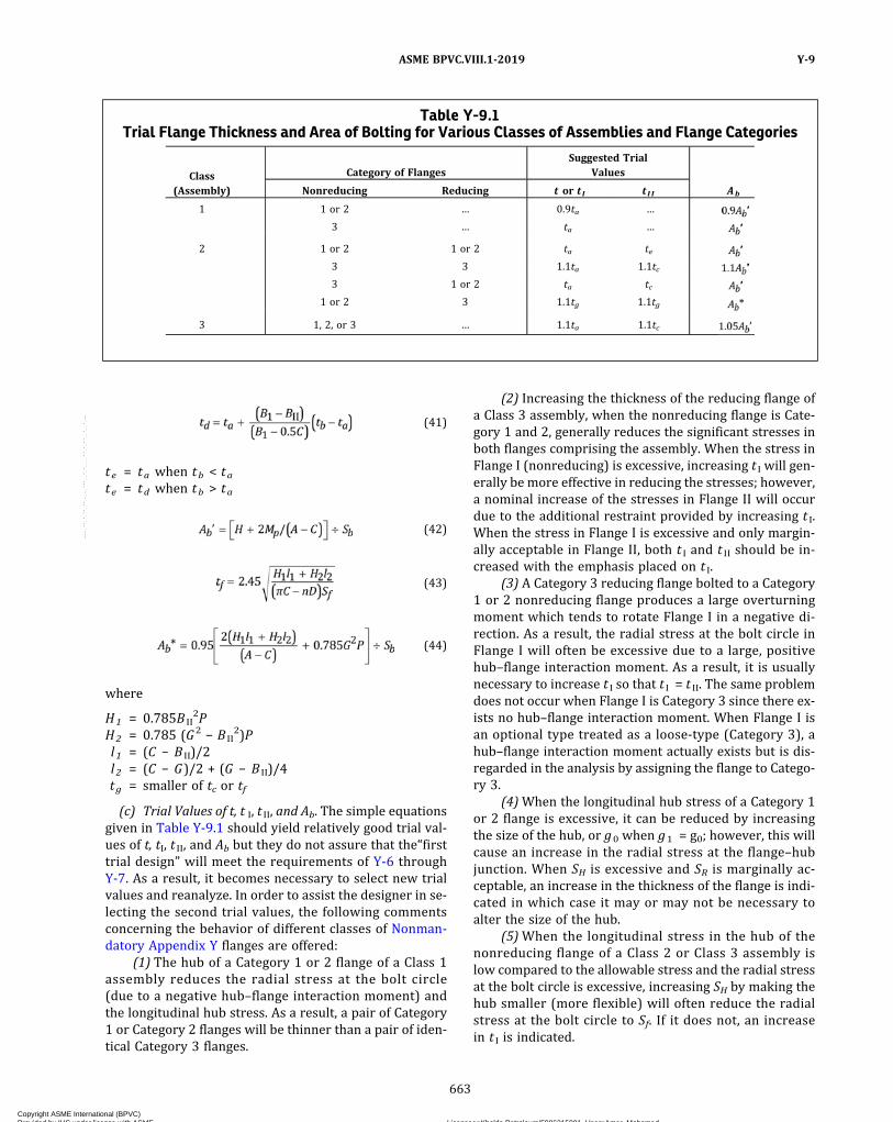
ð41Þ
te = ta when tb < tate = td when tb > ta
ð42Þ
ð43Þ
ð44Þ
where
H1 = 0.785B II2P
H2 = 0.785 (G2 − B II2)P
l1 = (C − B II)/2l 2 = (C − G)/2 + (G − B II)/4tg = smaller of tc or tf
(c) Trial Values of t, t I, t II, and Ab. The simple equationsgiven in Table Y-9.1 should yield relatively good trial val-ues of t, tI, t II, and Ab but they do not assure that the“firsttrial design” will meet the requirements of Y-6 throughY-7. As a result, it becomes necessary to select new trialvalues and reanalyze. In order to assist the designer in se-lecting the second trial values, the following commentsconcerning the behavior of different classes of Nonman-datory Appendix Y flanges are offered:
(1) The hub of a Category 1 or 2 flange of a Class 1assembly reduces the radial stress at the bolt circle(due to a negative hub–flange interaction moment) andthe longitudinal hub stress. As a result, a pair of Category1 or Category 2 flanges will be thinner than a pair of iden-tical Category 3 flanges.
(2) Increasing the thickness of the reducing flange ofa Class 3 assembly, when the nonreducing flange is Cate-gory 1 and 2, generally reduces the significant stresses inboth flanges comprising the assembly. When the stress inFlange I (nonreducing) is excessive, increasing t I will gen-erally be more effective in reducing the stresses; however,a nominal increase of the stresses in Flange II will occurdue to the additional restraint provided by increasing t I.When the stress in Flange I is excessive and only margin-ally acceptable in Flange II, both t I and t II should be in-creased with the emphasis placed on t I.
(3) A Category 3 reducing flange bolted to a Category1 or 2 nonreducing flange produces a large overturningmoment which tends to rotate Flange I in a negative di-rection. As a result, the radial stress at the bolt circle inFlange I will often be excessive due to a large, positivehub–flange interaction moment. As a result, it is usuallynecessary to increase t I so that t I = t II. The same problemdoes not occur when Flange I is Category 3 since there ex-ists no hub–flange interaction moment. When Flange I isan optional type treated as a loose‐type (Category 3), ahub–flange interaction moment actually exists but is dis-regarded in the analysis by assigning the flange to Catego-ry 3.
(4)When the longitudinal hub stress of a Category 1or 2 flange is excessive, it can be reduced by increasingthe size of the hub, or g0 when g1 = g0; however, this willcause an increase in the radial stress at the flange–hubjunction. When SH is excessive and SR is marginally ac-ceptable, an increase in the thickness of the flange is indi-cated in which case it may or may not be necessary toalter the size of the hub.
(5)When the longitudinal stress in the hub of thenonreducing flange of a Class 2 or Class 3 assembly islow compared to the allowable stress and the radial stressat the bolt circle is excessive, increasing SH by making thehub smaller (more flexible) will often reduce the radialstress at the bolt circle to Sf. If it does not, an increasein t I is indicated.
Table Y-9.1Trial Flange Thickness and Area of Bolting for Various Classes of Assemblies and Flange Categories
Class(Assembly)
Category of FlangesSuggested Trial
Values
Nonreducing Reducing t or t I t I I Ab
1 1 or 2 … 0.9ta …
3 … ta …
2 1 or 2 1 or 2 ta te
3 3 1.1ta 1.1tc
3 1 or 2 ta tc
1 or 2 3 1.1tg 1.1tg
3 1, 2, or 3 … 1.1ta 1.1tc
ASME BPVC.VIII.1-2019 Y-9
663
Copyright ASME International (BPVC) Provided by IHS under license with ASME Licensee=Khalda Petroleum/5986215001, User=Amer, Mohamed
Not for Resale, 07/02/2019 13:29:04 MDTNo reproduction or networking permitted without license from IHS
--`,``,``,,`,`,,````,`,``,,,`-`-`,,`,,`,`,,`---

Y-10
Additional guidance on the design of flat faced metal‐to‐metal contact flanges can be found in the followingreferences:Schneider, R. W., and Waters, E. O., The Background of
ASME Code Case 1828: A Simplified Model of AnalyzingPart B Flanges, Journal of Pressure Vessel Technology,ASME, Vol. 100, No. 2, May 1978, pp. 215–219
Schneider, R. W., and Waters, E. O., The Application ofASME Code Case 1828, Journal of Pressure Vessel Technol-ogy, ASME, Vol. 101, No. 1, February 1979, pp. 87–94It should be noted that the rules in Nonmandatory
Appendix Y were formerly contained in Code Case 1828,A Simplified Method for Analyzing Flat Face Flanges withMetal‐to‐Metal Contact Outside the Bolt Circle/SectionVIII, Division 1.
ASME BPVC.VIII.1-2019Y-10
664
Copyright ASME International (BPVC) Provided by IHS under license with ASME Licensee=Khalda Petroleum/5986215001, User=Amer, Mohamed
Not for Resale, 07/02/2019 13:29:04 MDTNo reproduction or networking permitted without license from IHS
--`,``,``,,`,`,,````,`,``,,,`-`-`,,`,,`,`,,`---

ð19ÞNONMANDATORY APPENDIX DDGUIDE TO INFORMATION APPEARING ON CERTIFICATE OF
AUTHORIZATION
DELETED
ASME BPVC.VIII.1-2019 DD
665
Copyright ASME International (BPVC) Provided by IHS under license with ASME Licensee=Khalda Petroleum/5986215001, User=Amer, Mohamed
Not for Resale, 07/02/2019 13:29:04 MDTNo reproduction or networking permitted without license from IHS
--`,``,``,,`,`,,````,`,``,,,`-`-`,,`,,`,`,,`---

NONMANDATORY APPENDIX EEHALF-PIPE JACKETS
EE-1 GENERAL
The calculation procedure in this Appendix shall beused only if both of the following conditions apply:(a) There is positive pressure inside the shell or head.(b) There is positive pressure inside the half‐pipe
jacket.
EE-2 HALF-PIPE JACKETS
The maximum permissible pressure P ′ in half‐pipejackets shall be determined from the following formula:
ð1Þ
where
P ′ = permissible jacket pressure, psiF = 1.5S - S ′
(F shall not exceed 1.5 S)S = maximum allowable tensile stress at design tem-
perature of shell or head material, psiS ′ = actual longitudinal tensile stress in shell or head
due to internal pressure and other axial forces,psi. When axial forces are negligible, S ′ shall be ta-ken as PR/2t . When the combination of axial forcesand pressure stress (PR/2t) is such that S ′ wouldbe a negative number, then S ′ shall be taken aszero.
K = factor obtained from Figure EE-1, Figure EE-2, orFigure EE-3
P = internal design pressure (see UG-21) in vessel, psi
R = inside shell or head radius, in.D = 2R
The minimum thickness of a half‐pipe jacket, when thethickness does not exceed one‐half of the inside pipe ra-dius or P does not exceed 0.385S1, is given by
ð2Þ
where
T = minimum thickness of half‐pipe jacket, in.r = inside radius of jacket defined in Figure EE-4, in.
S1 = allowable tensile stress of jacket material at designtemperature, psi
P1 = design pressure in jacket, psi. (P1 shall not exceedP ′.)
The fillet weld attaching the half‐pipe jacket to the ves-sel shall have a throat thickness not less than the smallerof the jacket or shell thickness. Through thickness jacketwelds with a fillet shall be considered when the jacketis in cyclic service.
EE-3 JACKETS WITH OTHER GEOMETRIES
For other jacket geometries such as shown in FigureEE-5, the permissible pressure P ′ may be obtained fromthe rules of UG-47 for stayed construction or 9-5 forjacketed vessels.
ASME BPVC.VIII.1-2019EE-1 – EE-3
666
Copyright ASME International (BPVC) Provided by IHS under license with ASME Licensee=Khalda Petroleum/5986215001, User=Amer, Mohamed
Not for Resale, 07/02/2019 13:29:04 MDTNo reproduction or networking permitted without license from IHS
--`,``,``,,`,`,,````,`,``,,,`-`-`,,`,,`,`,,`---
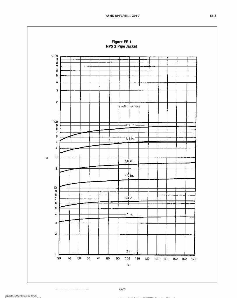
Figure EE-1NPS 2 Pipe Jacket
ASME BPVC.VIII.1-2019 EE-3
667
Copyright ASME International (BPVC) Provided by IHS under license with ASME Licensee=Khalda Petroleum/5986215001, User=Amer, Mohamed
Not for Resale, 07/02/2019 13:29:04 MDTNo reproduction or networking permitted without license from IHS
--`,``,``,,`,`,,````,`,``,,,`-`-`,,`,,`,`,,`---

Figure EE-2NPS 3 Pipe Jacket
1
2
30 40
D
K
50 60 70 80 90 100
2 in.
1 in.
3/4 in.
1/4 in.
1/2 in.
3/8 in.
3/16 in.
Shell thickness
110 120 130 140 150 160 170
3
4
5
6789
10
2
3
4
5
6789
100
2
3
4
5
6789
1000
ASME BPVC.VIII.1-2019EE-3
668
Copyright ASME International (BPVC) Provided by IHS under license with ASME Licensee=Khalda Petroleum/5986215001, User=Amer, Mohamed
Not for Resale, 07/02/2019 13:29:04 MDTNo reproduction or networking permitted without license from IHS
--`,``,``,,`,`,,````,`,``,,,`-`-`,,`,,`,`,,`---
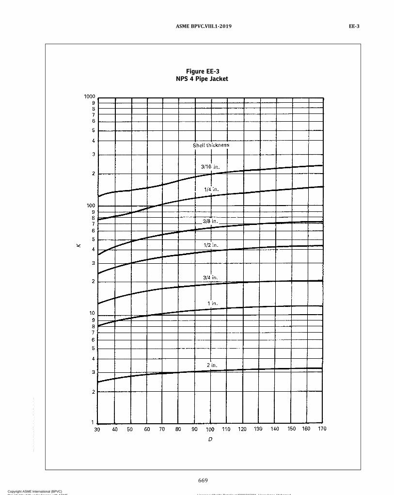
Figure EE-3NPS 4 Pipe Jacket
ASME BPVC.VIII.1-2019 EE-3
669
Copyright ASME International (BPVC) Provided by IHS under license with ASME Licensee=Khalda Petroleum/5986215001, User=Amer, Mohamed
Not for Resale, 07/02/2019 13:29:04 MDTNo reproduction or networking permitted without license from IHS
--`,``,``,,`,`,,````,`,``,,,`-`-`,,`,,`,`,,`---

Figure EE-4 Figure EE-5
ASME BPVC.VIII.1-2019EE-3
670
Copyright ASME International (BPVC) Provided by IHS under license with ASME Licensee=Khalda Petroleum/5986215001, User=Amer, Mohamed
Not for Resale, 07/02/2019 13:29:04 MDTNo reproduction or networking permitted without license from IHS
--`,``,``,,`,`,,````,`,``,,,`-`-`,,`,,`,`,,`---
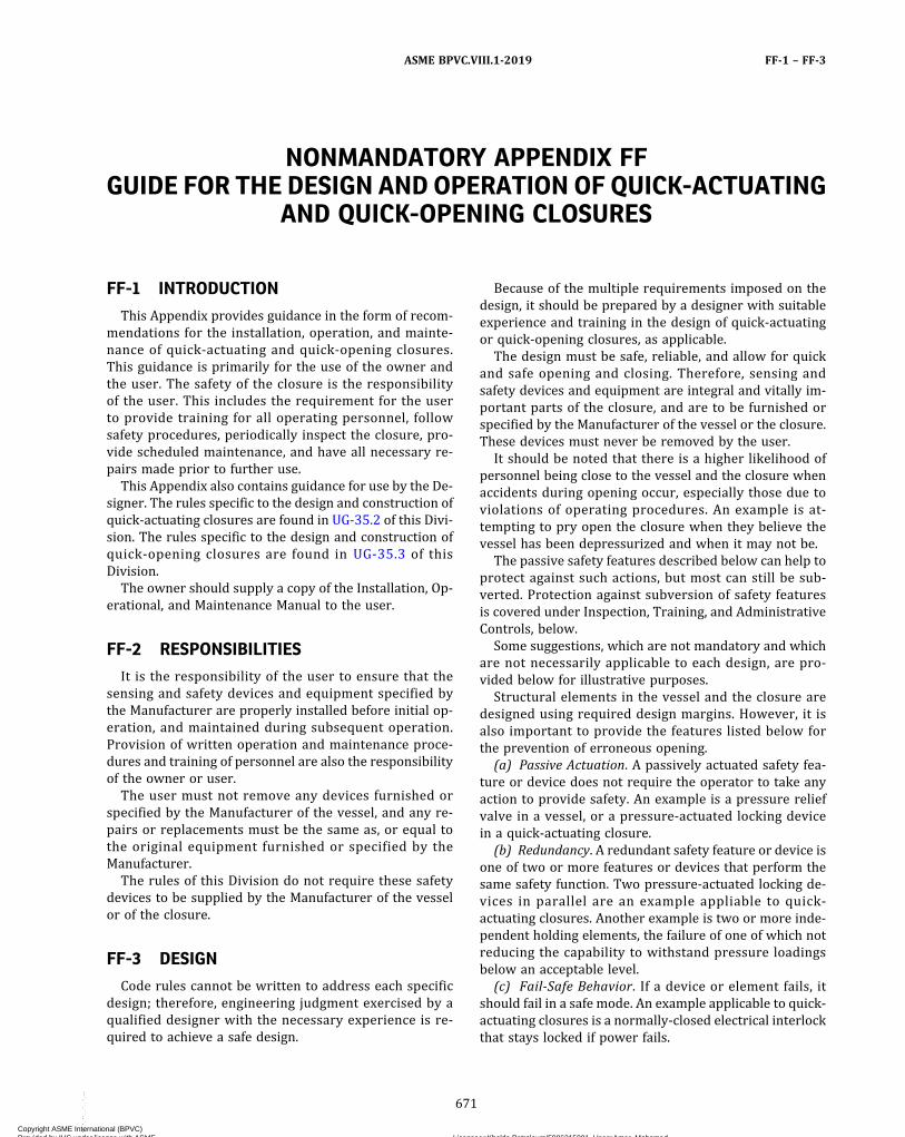
NONMANDATORY APPENDIX FFGUIDE FOR THE DESIGN AND OPERATION OF QUICK-ACTUATING
AND QUICK-OPENING CLOSURES
FF-1 INTRODUCTION
This Appendix provides guidance in the form of recom-mendations for the installation, operation, and mainte-nance of quick‐actuating and quick-opening closures.This guidance is primarily for the use of the owner andthe user. The safety of the closure is the responsibilityof the user. This includes the requirement for the userto provide training for all operating personnel, followsafety procedures, periodically inspect the closure, pro-vide scheduled maintenance, and have all necessary re-pairs made prior to further use.
This Appendix also contains guidance for use by the De-signer. The rules specific to the design and construction ofquick‐actuating closures are found in UG-35.2 of this Divi-sion. The rules specific to the design and construction ofquick-opening closures are found in UG-35.3 of thisDivision.
The owner should supply a copy of the Installation, Op-erational, and Maintenance Manual to the user.
FF-2 RESPONSIBILITIES
It is the responsibility of the user to ensure that thesensing and safety devices and equipment specified bythe Manufacturer are properly installed before initial op-eration, and maintained during subsequent operation.Provision of written operation and maintenance proce-dures and training of personnel are also the responsibilityof the owner or user.
The user must not remove any devices furnished orspecified by the Manufacturer of the vessel, and any re-pairs or replacements must be the same as, or equal tothe original equipment furnished or specified by theManufacturer.
The rules of this Division do not require these safetydevices to be supplied by the Manufacturer of the vesselor of the closure.
FF-3 DESIGN
Code rules cannot be written to address each specificdesign; therefore, engineering judgment exercised by aqualified designer with the necessary experience is re-quired to achieve a safe design.
Because of the multiple requirements imposed on thedesign, it should be prepared by a designer with suitableexperience and training in the design of quick‐actuatingor quick-opening closures, as applicable.
The design must be safe, reliable, and allow for quickand safe opening and closing. Therefore, sensing andsafety devices and equipment are integral and vitally im-portant parts of the closure, and are to be furnished orspecified by the Manufacturer of the vessel or the closure.These devices must never be removed by the user.
It should be noted that there is a higher likelihood ofpersonnel being close to the vessel and the closure whenaccidents during opening occur, especially those due toviolations of operating procedures. An example is at-tempting to pry open the closure when they believe thevessel has been depressurized and when it may not be.
The passive safety features described below can help toprotect against such actions, but most can still be sub-verted. Protection against subversion of safety featuresis covered under Inspection, Training, and AdministrativeControls, below.
Some suggestions, which are not mandatory and whichare not necessarily applicable to each design, are pro-vided below for illustrative purposes.
Structural elements in the vessel and the closure aredesigned using required design margins. However, it isalso important to provide the features listed below forthe prevention of erroneous opening.
(a) Passive Actuation. A passively actuated safety fea-ture or device does not require the operator to take anyaction to provide safety. An example is a pressure reliefvalve in a vessel, or a pressure‐actuated locking devicein a quick‐actuating closure.
(b) Redundancy. A redundant safety feature or device isone of two or more features or devices that perform thesame safety function. Two pressure‐actuated locking de-vices in parallel are an example appliable to quick‐actuating closures. Another example is two or more inde-pendent holding elements, the failure of one of which notreducing the capability to withstand pressure loadingsbelow an acceptable level.
(c) Fail‐Safe Behavior. If a device or element fails, itshould fail in a safe mode. An example applicable to quick-actuating closures is a normally‐closed electrical interlockthat stays locked if power fails.
ASME BPVC.VIII.1-2019 FF-1 – FF-3
671
Copyright ASME International (BPVC) Provided by IHS under license with ASME Licensee=Khalda Petroleum/5986215001, User=Amer, Mohamed
Not for Resale, 07/02/2019 13:29:04 MDTNo reproduction or networking permitted without license from IHS
--`,``,``,,`,`,,````,`,``,,,`-`-`,,`,,`,`,,`---

(d) Multiple Lines of Defense. This can consist of anycombination of two or more items from the list above.They should consist, at the very least, of warnings oralarms to keep operators and other personnel away froma quick-actuating closure.Pressure controls and sensors that operate well at
50 or 100 psi (350 or 700 kPa) or at a much greater pres-sure often do not operate well at very low pressure. Forexample, they may not sense a small, static head of hotwater. Certain accidents can occur because of release ofhot fluid under static head alone, or under very low pres-sure. To protect against such accidents, separate controlsand sensors may be used to maintain operating pressureon the one hand, and others may be required to preventinappropriate opening at low pressures.It may be necessary or desirable to utilize electrical or
electronic devices and interlocks. If these are used, carefulinstallation, operating, and maintenance instructions (seebelow) will be required.The effects of repetitive loading must be considered, as
required by UG-22. There are two phenomena that are ofmajor concern. The first is the wear produced by repeti-tive actuation of the mechanism. This can generally be mi-tigated by routine maintenance. The second is fatiguedamage produced in the vessel or in the closure by repe-titive actuation of the mechanism or by repetitive pres-surization and depressurization.The Code does not provide explicit guidance for the
evaluation or mitigation of wear. As well as proper main-tenance, the selection of suitable materials for matingwear surfaces and control of contract stresses is neces-sary during the design process to properly control wear.
FF-4 INSTALLATION
When installed, all vessels having quick-actuating orquick-opening closures should be provided with one ormore pressure-indicating devices visible from the operat-ing area and suitable for detecting pressure at the closure.The Manufacturer should provide clear instructions for
the installation of the closure itself and any adjustmentsthat are necessary in the field. An example is adjustmentof wedges or clamps. Instructions, preferably includingschematics and drawings, should be provided for the in-stallation, adjustment, and checkout of interlocks andwarning devices.It is recognized that sometimes pressure vessels with
quick-opening closures are used as part of assembliesfor air compressors, sandblasting units, and similar self-contained systems. For these units, the assembler of theequipment is equivalent to the user and as such, shouldfurnish the appropriate safety equipment to protect theworkers using the packaged unit. These assembliesshould be provided with the necessary instructions forthe care, operation, and maintenance of all componentsof the assembly.
FF-5 MAINTENANCE
Vessels with quick‐actuating or quick-opening closuresare commonly installed in industrial environments sub-ject to dirt, moisture, abrasive materials, etc. These envi-ronmental factors are detrimental to safe and reliableoperation of mechanical, electrical, and electronic sensorsand safety devices. Therefore, the user should establish asuitable cleaning and maintenance interval, and a meansto verify that the equipment has been properly cleanedand maintained.Specifically, accidents have occurred because gaskets
have stuck, and have released suddenly when pried open.Many soft gaskets (60–70 Shore A Scale) have a com-
bined shelf life and operating life of as little as six months.Aging can change the properties of the gasket materialand change the gasket dimensions, impeding its properfunction.
FF-6 INSPECTION
It is recommended that the user inspect the completedinstallation including the pressure gauges before it is per-mitted to operate. Records of these inspections should beretained.It is recommended that the user establishes and docu-
ments a periodic in‐service inspection program, and thatthis program is followed and documented.
FF-7 TRAINING
Many accidents involving closures have occurred be-cause the operators have been unfamiliar with the equip-ment or its safety features. The greater safety inherent incurrent designs has sometimes been produced by the useof sophisticated mechanical, electrical, and electronic con-trol devices. To ensure these features produce the maxi-mum safety, personnel should be properly trained intheir operation and maintenance.Note that accidents may occur because fluid remains
present in the vessel at atmospheric pressure or 2 psigto 3 psig (15 kPa to 20 kPa gage). When the vessel isforced open while under this pressure, injuries may oc-cur. Such specific accident‐sources should be guardedagainst by training and by administrative procedures.It is important that sound written operating proce-
dures, understandable by the operating personnel andmultilingual if necessary, exist for the closure, and thatthe operators be trained in the proper use of all inter-locks, sensing devices, and manual closure mechanisms.Provision of written operation and maintenance proce-
dures and training of personnel are the responsibility ofthe user.As part of the training program, testing should be per-
formed to assure that the trainee understands the materi-al he or she is trained in. Records should be retained bythe user.
ASME BPVC.VIII.1-2019FF-3 – FF-7
672
Copyright ASME International (BPVC) Provided by IHS under license with ASME Licensee=Khalda Petroleum/5986215001, User=Amer, Mohamed
Not for Resale, 07/02/2019 13:29:04 MDTNo reproduction or networking permitted without license from IHS
--`,``,``,,`,`,,````,`,``,,,`-`-`,,`,,`,`,,`---
FF-8 ADMINISTRATIVE CONTROLS
The user should provide administrative controls overtraining, cleanliness, operation, periodic inspection, andmaintenance of equipment with quick‐actuating orquick-opening closures. Records should be retained bythe user.
ASME BPVC.VIII.1-2019 FF-8
673
Copyright ASME International (BPVC) Provided by IHS under license with ASME Licensee=Khalda Petroleum/5986215001, User=Amer, Mohamed
Not for Resale, 07/02/2019 13:29:04 MDTNo reproduction or networking permitted without license from IHS
--`,``,``,,`,`,,````,`,``,,,`-`-`,,`,,`,`,,`---

ð19Þ
NONMANDATORY APPENDIX GGGUIDANCE FOR THE USE OF U.S. CUSTOMARY AND SI UNITS IN
THE ASME BOILER AND PRESSURE VESSEL CODE
GG-1 USE OF UNITS IN EQUATIONS
The equations in this Division are suitable for use onlywith either the U.S. Customary or the SI units provided inTable U-4-1, or with the units provided in the nomencla-tures associated with the equations. It is the responsibil-ity of the individual and organization performing thecalculations to ensure that appropriate units are used.Either U.S. Customary or SI units may be used as a consis-tent set. When SI units are selected, U.S. Customary valuesin referenced specifications may be converted to SI valuesto at least three significant figures for use in calculationsand other aspects of construction.
GG-2 GUIDELINES USED TO DEVELOP SIEQUIVALENTS
The following guidelines were used to develop SIequivalents:(a) SI units are placed in parentheses after the U.S. Cus-
tomary units in the text.(b) In general, separate SI tables are provided if inter-
polation is expected. The table designation (e.g., tablenumber) is the same for both the U.S. Customary and SItables, with the addition of suffix “M” to the designatorfor the SI table, if a separate table is provided. In the text,references to a table use only the primary table number(i.e., without the “M”). For some small tables, where inter-polation is not required, SI units are placed in parenthe-ses after the U.S. Customary unit.(c) Separate SI versions of graphical information
(charts) are provided, except that if both axes are dimen-sionless, a single figure (chart) is used.(d) In most cases, conversions of units in the text were
done using hard SI conversion practices, with some softconversions on a case‐by‐case basis, as appropriate. Thiswas implemented by rounding the SI values to the num-ber of significant figures of implied precision in the exist-ing U.S. Customary units. For example, 3,000 psi has animplied precision of one significant figure. Therefore,the conversion to SI units would typically be to20 000 kPa. This is a difference of about 3% from the “ex-act” or soft conversion of 20 684.27 kPa. However, theprecision of the conversion was determined by the Com-mittee on a case‐by‐case basis. More significant digits
were included in the SI equivalent if there was any ques-tion. The values of allowable stress in Section II, Part Dgenerally include three significant figures.(e) Minimum thickness and radius values that are ex-
pressed in fractions of an inch were generally convertedaccording to the following table:
Fraction, in.Proposed SI
Conversion, mm Difference, %1/32 0.8 −0.83/64 1.2 −0.81/16 1.5 5.53/32 2.5 −5.01/8 3 5.5
5/32 4 −0.83/16 5 −5.07/32 5.5 1.01/4 6 5.55/16 8 −0.8
3/8 10 −5.07/16 11 1.01/2 13 −2.49/16 14 2.05/8 16 −0.8
11/16 17 2.63/4 19 0.37/8 22 1.01 25 1.6
(f) For nominal sizes that are in even increments ofinches, even multiples of 25 mm were generally used. In-termediate values were interpolated rather than convert-ing and rounding to the nearest millimeter. See examplesin the following table. [Note that this table does not applyto nominal pipe sizes (NPS), which are covered in (g)below.]
Size, in. Size, mm
1 2511/8 2911/4 3211/2 382 50
21/4 5721/2 643 75
31/2 89
ASME BPVC.VIII.1-2019GG-1 – GG-2
674
Copyright ASME International (BPVC) Provided by IHS under license with ASME Licensee=Khalda Petroleum/5986215001, User=Amer, Mohamed
Not for Resale, 07/02/2019 13:29:04 MDTNo reproduction or networking permitted without license from IHS
--`,``,``,,`,`,,````,`,``,,,`-`-`,,`,,`,`,,`---

Table continued
Size, in. Size, mm
4 100
41/2 1145 1256 1508 20012 300
18 45020 50024 60036 90040 1 000
54 1 35060 1 50072 1 800
Size or Length, ft Size or Length, m
3 15 1.5
200 60
(g) For nominal pipe sizes, the following relationshipswere used:
U.S. Customary Practice SI Practice
NPS 1/8 DN 6NPS 1/4 DN 8NPS 3/8 DN 10NPS 1/2 DN 15NPS 3/4 DN 20
NPS 1 DN 25NPS 11/4 DN 32NPS 11/2 DN 40NPS 2 DN 50NPS 21/2 DN 65
NPS 3 DN 80NPS 31/2 DN 90NPS 4 DN 100NPS 5 DN 125NPS 6 DN 150
NPS 8 DN 200NPS 10 DN 250NPS 12 DN 300NPS 14 DN 350NPS 16 DN 400
NPS 18 DN 450NPS 20 DN 500NPS 22 DN 550NPS 24 DN 600NPS 26 DN 650
NPS 28 DN 700NPS 30 DN 750NPS 32 DN 800NPS 34 DN 850NPS 36 DN 900
Table continued
U.S. Customary Practice SI Practice
NPS 38 DN 950NPS 40 DN 1000NPS 42 DN 1050NPS 44 DN 1100NPS 46 DN 1150
NPS 48 DN 1200NPS 50 DN 1250NPS 52 DN 1300NPS 54 DN 1350NPS 56 DN 1400
NPS 58 DN 1450NPS 60 DN 1500
(h) Areas in square inches (in.2) were converted tosquare millimeters (mm2) and areas in square feet (ft2)were converted to square meters (m2). See examples inthe following table:
Area (U.S. Customary) Area (SI)
1 in.2 650 mm2
6 in.2 4 000 mm2
10 in.2 6 500 mm2
5 ft2 0.5 m2
(i) Volumes in cubic inches (in.3) were converted to cu-bic millimeters (mm3) and volumes in cubic feet (ft3)were converted to cubic meters (m3). See examples inthe following table:
Volume (U.S. Customary) Volume (SI)
1 in.3 16 000 mm3
6 in.3 100 000 mm3
10 in.3 160 000 mm3
5 ft3 0.14 m3
(j) Although the pressure should always be in MPa forcalculations, there are cases where other units are used inthe text. For example, kPa is used for small pressures.Also, rounding was to one significant figure (two at themost) in most cases. See examples in the following table.(Note that 14.7 psi converts to 101 kPa, while 15 psi con-verts to 100 kPa. While this may seem at first glance to bean anomaly , i t is consistent with the roundingphilosophy.)
Pressure (U.S. Customary) Pressure (SI)
0.5 psi 3 kPa2 psi 15 kPa3 psi 20 kPa
10 psi 70 kPa14.7 psi 101 kPa
15 psi 100 kPa30 psi 200 kPa
ASME BPVC.VIII.1-2019 GG-2
675
Copyright ASME International (BPVC) Provided by IHS under license with ASME Licensee=Khalda Petroleum/5986215001, User=Amer, Mohamed
Not for Resale, 07/02/2019 13:29:04 MDTNo reproduction or networking permitted without license from IHS
--`,``,``,,`,`,,````,`,``,,,`-`-`,,`,,`,`,,`---
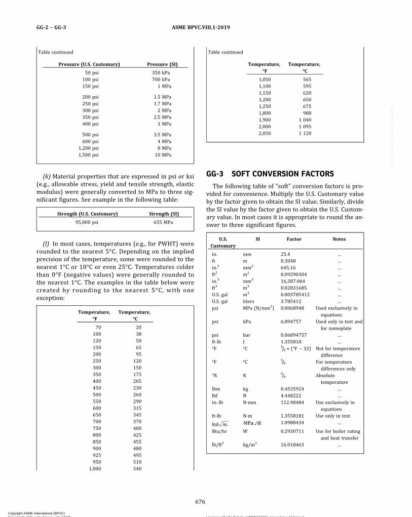
Table continued
Pressure (U.S. Customary) Pressure (SI)
50 psi 350 kPa100 psi 700 kPa150 psi 1 MPa
200 psi 1.5 MPa250 psi 1.7 MPa300 psi 2 MPa350 psi 2.5 MPa400 psi 3 MPa
500 psi 3.5 MPa600 psi 4 MPa
1,200 psi 8 MPa1,500 psi 10 MPa
(k) Material properties that are expressed in psi or ksi(e.g., allowable stress, yield and tensile strength, elasticmodulus) were generally converted to MPa to three sig-nificant figures. See example in the following table:
Strength (U.S. Customary) Strength (SI)
95,000 psi 655 MPa
(l) In most cases, temperatures (e.g., for PWHT) wererounded to the nearest 5°C. Depending on the impliedprecision of the temperature, some were rounded to thenearest 1°C or 10°C or even 25°C. Temperatures colderthan 0°F (negative values) were generally rounded tothe nearest 1°C. The examples in the table below werecreated by rounding to the nearest 5°C, with oneexception:
Temperature,°F
Temperature,°C
70 20100 38120 50150 65200 95250 120300 150350 175400 205450 230500 260550 290600 315650 345700 370750 400800 425850 455900 480925 495950 510
1,000 540
Table continued
Temperature,°F
Temperature,°C
1,050 5651,100 5951,150 6201,200 6501,250 6751,800 9801,900 1 0402,000 1 0952,050 1 120
GG-3 SOFT CONVERSION FACTORS
The following table of “soft” conversion factors is pro-vided for convenience. Multiply the U.S. Customary valueby the factor given to obtain the SI value. Similarly, dividethe SI value by the factor given to obtain the U.S. Custom-ary value. In most cases it is appropriate to round the an-swer to three significant figures.
U.S.Customary
SI Factor Notes
in. mm 25.4 …ft m 0.3048 …in.2 mm2 645.16 …ft2 m2 0.09290304 …in.3 mm3 16,387.064 …ft3 m3 0.02831685 …U.S. gal m3 0.003785412 …U.S. gal liters 3.785412 …psi MPa (N/mm2) 0.0068948 Used exclusively in
equationspsi kPa 6.894757 Used only in text and
for nameplatepsi bar 0.06894757 …ft‐lb J 1.355818 …°F °C 5/9 × (°F − 32) Not for temperature
difference°F °C 5/9 For temperature
differences only°R K 5/9 Absolute
temperaturelbm kg 0.4535924 …lbf N 4.448222 …in.‐lb N·mm 112.98484 Use exclusively in
equationsft‐lb N·m 1.3558181 Use only in text
1.0988434 …
Btu/hr W 0.2930711 Use for boiler ratingand heat transfer
lb/ft3 kg/m3 16.018463 …
ASME BPVC.VIII.1-2019GG-2 – GG-3
676
Copyright ASME International (BPVC) Provided by IHS under license with ASME Licensee=Khalda Petroleum/5986215001, User=Amer, Mohamed
Not for Resale, 07/02/2019 13:29:04 MDTNo reproduction or networking permitted without license from IHS
--`,``,``,,`,`,,````,`,``,,,`-`-`,,`,,`,`,,`---

NONMANDATORY APPENDIX HHTUBE EXPANDING PROCEDURES AND QUALIFICATION
HH-1 GENERAL
This Appendix establishes requirements for procedurespecifications for expanded tube‐to‐tubesheet joints
(a) designed using the test joint efficiencies, fr (test),listed in Table A-2 of Nonmandatory Appendix A;
(b) designed using the no‐test joint efficiencies, fr (notest), listed in Table A-2 of Nonmandatory Appendix A;and
(c) used in tubesheets designed in accordance with therules of Part UHX when the effective tube hole diameterdepends upon the expanded depth of the tube (ρ > 0).
Leak tightness of expanded joints is not a considerationin Part UHX and Nonmandatory Appendix A, and is there-fore not considered in Nonmandatory Appendix HH.
HH-2 SCOPE
The rules in this Appendix apply to preparation andqualification of tube expanding procedures for the typesof expanding processes permitted in this Appendix.
HH-3 TERMS AND DEFINITIONS
Some of the more common terms relating to tube ex-panding are as follows:
explosive expanding: uniform pressure expanding inwhich the force of an explosion is applied to the lengthof tube to be expanded.
groove: an annular machined depression in a tube hole.
hybrid expanding: hydroexpanding or explosive expand-ing to a percent wall reduction that ensures maintenanceof tube‐hole contact, followed by roller expanding to thefinal percent wall reduction.
hydroexpanding: uniform pressure expanding in whichhydraulic pressure is applied to the length of tube to beexpanded.
near contact kinetic expanding: see explosive expanding.
parallel tube roller: tube rolling tool in which the taper an-gle of the mandrel and the taper angle of the hardenedpins are approximately equal and opposite, thereby caus-ing the pins to bear uniformly on the tube surface.
percent wall reduction: reduction in tube wall thicknessdue to expanding, expressed as a percent of the measuredthickness of the tube.
progressive rolling: step rolling in which the first step be-gins at or near the front face of the tubesheet and succes-sive steps progress toward the rear face.
prosser: see segmental expander.
prossering: expanding tubes with a segmental expander.
regressive rolling: step rolling in which the first step be-gins at or near the rear face of the tubesheet and succes-sive steps progress toward the front face.
roller expanding: expanding by inserting a tube rollingtool into a tube aligned with a tube hole.
segmental expander: thick‐walled, flanged cylinder with atapered interior wall, cut axially into segments and heldtogether by bands. A mandrel with a reverse taper in con-tact with the taper of the interior of the cylinder is thrustforward, forcing the segments outward to contact and ex-pand the tube. The flange bears against the tube end ortubesheet face to maintain the position of the expanderrelative to the tube.
self‐feeding rolling tool: tube rolling tool with the slots inthe cage at an angle with the tool centerline such that ro-tating the mandrel in a clockwise direction causes the toolto feed into the tube and reversing the direction causes itto back out.
serrations: parallel, narrow grooves machined in a tubehole or on the exterior of a tube end.
step rolling: tube rolling in which successive, overlappingapplications of the tube roller are applied in order to rolltubes into tubesheets thicker than approximately 2 in.(50 mm).
torque control: an electronic, hydraulic control orcam-operated reversing mechanism that causes a rollingtool driver to reverse direction when a preset level of tor-que is reached.
transition zone: region of an expanded joint in which theexpanded part of the tube transitions to the unexpandedpart.
tube end enhancement: treatment to that part of the tubeO.D. to be expanded into a tubesheet hole to increase thestrength of the expanded tube‐to‐tubesheet joint.
ASME BPVC.VIII.1-2019 HH-1 – HH-3
677
Copyright ASME International (BPVC) Provided by IHS under license with ASME Licensee=Khalda Petroleum/5986215001, User=Amer, Mohamed
Not for Resale, 07/02/2019 13:29:04 MDTNo reproduction or networking permitted without license from IHS
--`,``,``,,`,`,,````,`,``,,,`-`-`,,`,,`,`,,`---
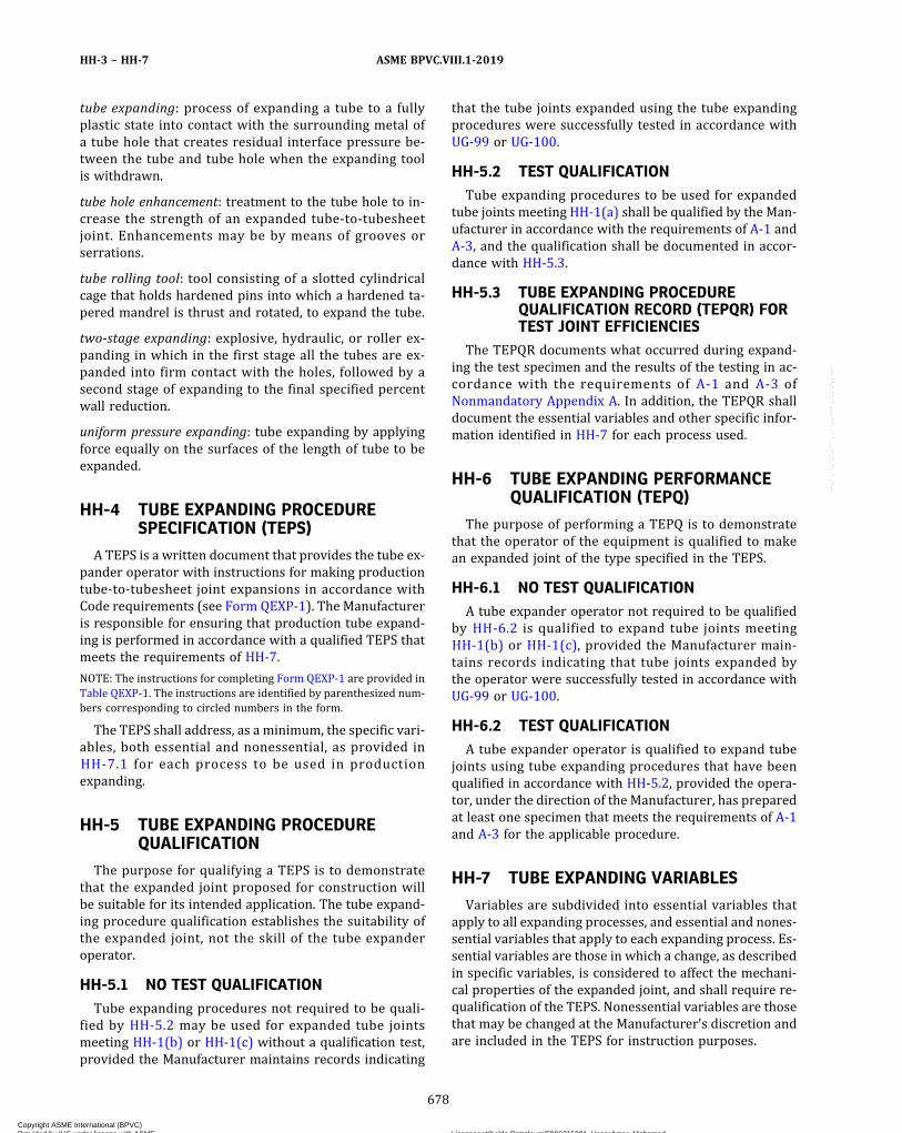
tube expanding: process of expanding a tube to a fullyplastic state into contact with the surrounding metal ofa tube hole that creates residual interface pressure be-tween the tube and tube hole when the expanding toolis withdrawn.
tube hole enhancement: treatment to the tube hole to in-crease the strength of an expanded tube‐to‐tubesheetjoint. Enhancements may be by means of grooves orserrations.
tube rolling tool: tool consisting of a slotted cylindricalcage that holds hardened pins into which a hardened ta-pered mandrel is thrust and rotated, to expand the tube.
two‐stage expanding: explosive, hydraulic, or roller ex-panding in which in the first stage all the tubes are ex-panded into firm contact with the holes, followed by asecond stage of expanding to the final specified percentwall reduction.
uniform pressure expanding: tube expanding by applyingforce equally on the surfaces of the length of tube to beexpanded.
HH-4 TUBE EXPANDING PROCEDURESPECIFICATION (TEPS)
A TEPS is a written document that provides the tube ex-pander operator with instructions for making productiontube‐to‐tubesheet joint expansions in accordance withCode requirements (see Form QEXP-1). The Manufactureris responsible for ensuring that production tube expand-ing is performed in accordance with a qualified TEPS thatmeets the requirements of HH-7.
NOTE: The instructions for completing Form QEXP-1 are provided inTable QEXP-1. The instructions are identified by parenthesized num-bers corresponding to circled numbers in the form.
The TEPS shall address, as a minimum, the specific vari-ables, both essential and nonessential, as provided inHH-7.1 for each process to be used in productionexpanding.
HH-5 TUBE EXPANDING PROCEDUREQUALIFICATION
The purpose for qualifying a TEPS is to demonstratethat the expanded joint proposed for construction willbe suitable for its intended application. The tube expand-ing procedure qualification establishes the suitability ofthe expanded joint, not the skill of the tube expanderoperator.
HH-5.1 NO TEST QUALIFICATIONTube expanding procedures not required to be quali-
fied by HH-5.2 may be used for expanded tube jointsmeeting HH-1(b) or HH-1(c) without a qualification test,provided the Manufacturer maintains records indicating
that the tube joints expanded using the tube expandingprocedures were successfully tested in accordance withUG-99 or UG-100.
HH-5.2 TEST QUALIFICATIONTube expanding procedures to be used for expanded
tube joints meeting HH-1(a) shall be qualified by the Man-ufacturer in accordance with the requirements of A-1 andA-3, and the qualification shall be documented in accor-dance with HH-5.3.
HH-5.3 TUBE EXPANDING PROCEDUREQUALIFICATION RECORD (TEPQR) FORTEST JOINT EFFICIENCIES
The TEPQR documents what occurred during expand-ing the test specimen and the results of the testing in ac-cordance with the requirements of A-1 and A-3 ofNonmandatory Appendix A. In addition, the TEPQR shalldocument the essential variables and other specific infor-mation identified in HH-7 for each process used.
HH-6 TUBE EXPANDING PERFORMANCEQUALIFICATION (TEPQ)
The purpose of performing a TEPQ is to demonstratethat the operator of the equipment is qualified to makean expanded joint of the type specified in the TEPS.
HH-6.1 NO TEST QUALIFICATIONA tube expander operator not required to be qualified
by HH-6.2 is qualified to expand tube joints meetingHH-1(b) or HH-1(c), provided the Manufacturer main-tains records indicating that tube joints expanded bythe operator were successfully tested in accordance withUG-99 or UG-100.
HH-6.2 TEST QUALIFICATIONA tube expander operator is qualified to expand tube
joints using tube expanding procedures that have beenqualified in accordance with HH-5.2, provided the opera-tor, under the direction of the Manufacturer, has preparedat least one specimen that meets the requirements of A-1and A-3 for the applicable procedure.
HH-7 TUBE EXPANDING VARIABLES
Variables are subdivided into essential variables thatapply to all expanding processes, and essential and nones-sential variables that apply to each expanding process. Es-sential variables are those in which a change, as describedin specific variables, is considered to affect the mechani-cal properties of the expanded joint, and shall require re-qualification of the TEPS. Nonessential variables are thosethat may be changed at the Manufacturer’s discretion andare included in the TEPS for instruction purposes.
ASME BPVC.VIII.1-2019HH-3 – HH-7
678
Copyright ASME International (BPVC) Provided by IHS under license with ASME Licensee=Khalda Petroleum/5986215001, User=Amer, Mohamed
Not for Resale, 07/02/2019 13:29:04 MDTNo reproduction or networking permitted without license from IHS
--`,``,``,,`,`,,````,`,``,,,`-`-`,,`,,`,`,,`---
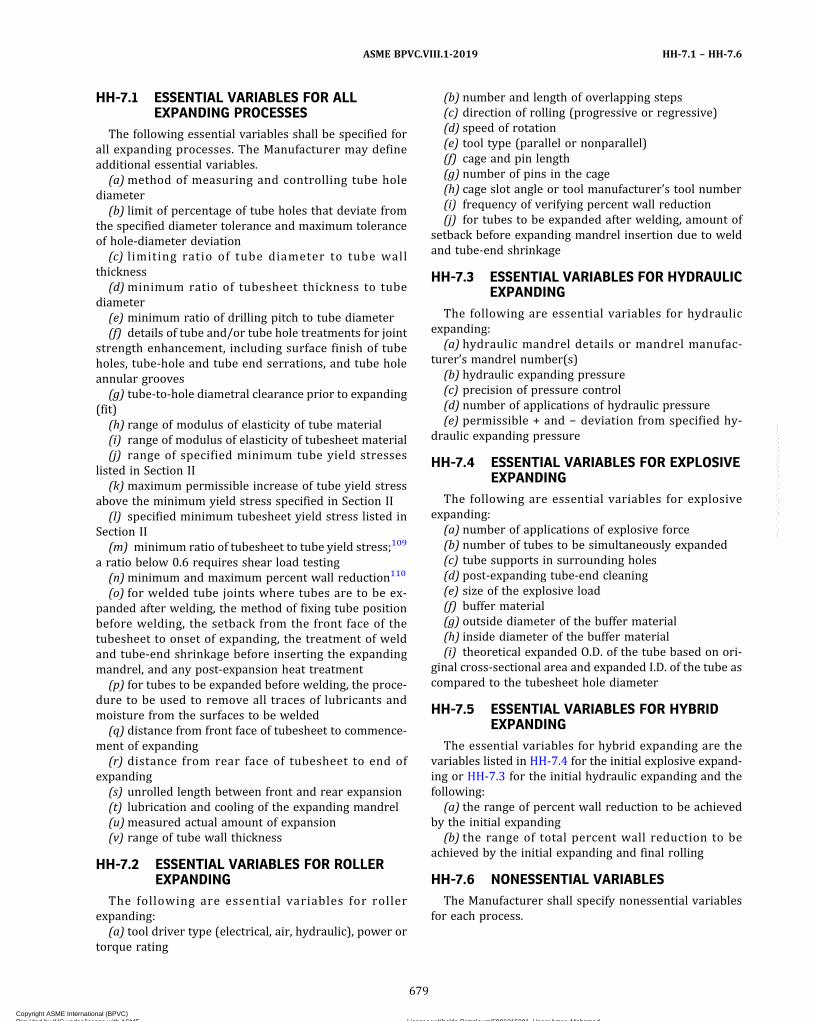
HH-7.1 ESSENTIAL VARIABLES FOR ALLEXPANDING PROCESSES
The following essential variables shall be specified forall expanding processes. The Manufacturer may defineadditional essential variables.
(a)method of measuring and controlling tube holediameter
(b) limit of percentage of tube holes that deviate fromthe specified diameter tolerance and maximum toleranceof hole‐diameter deviation
(c) limiting ratio of tube diameter to tube wallthickness
(d)minimum ratio of tubesheet thickness to tubediameter
(e) minimum ratio of drilling pitch to tube diameter(f) details of tube and/or tube hole treatments for joint
strength enhancement, including surface finish of tubeholes, tube‐hole and tube end serrations, and tube holeannular grooves
(g) tube‐to‐hole diametral clearance prior to expanding(fit)
(h) range of modulus of elasticity of tube material(i) range of modulus of elasticity of tubesheet material(j) range of specified minimum tube yield stresses
listed in Section II(k) maximum permissible increase of tube yield stress
above the minimum yield stress specified in Section II(l) specified minimum tubesheet yield stress listed in
Section II(m) minimum ratio of tubesheet to tube yield stress;109
a ratio below 0.6 requires shear load testing(n)minimum and maximum percent wall reduction110
(o) for welded tube joints where tubes are to be ex-panded after welding, the method of fixing tube positionbefore welding, the setback from the front face of thetubesheet to onset of expanding, the treatment of weldand tube‐end shrinkage before inserting the expandingmandrel, and any post‐expansion heat treatment
(p) for tubes to be expanded before welding, the proce-dure to be used to remove all traces of lubricants andmoisture from the surfaces to be welded
(q) distance from front face of tubesheet to commence-ment of expanding
(r) distance from rear face of tubesheet to end ofexpanding
(s) unrolled length between front and rear expansion(t) lubrication and cooling of the expanding mandrel(u)measured actual amount of expansion(v) range of tube wall thickness
HH-7.2 ESSENTIAL VARIABLES FOR ROLLEREXPANDING
The following are essential variables for rollerexpanding:
(a) tool driver type (electrical, air, hydraulic), power ortorque rating
(b) number and length of overlapping steps(c) direction of rolling (progressive or regressive)(d) speed of rotation(e) tool type (parallel or nonparallel)(f) cage and pin length(g) number of pins in the cage(h) cage slot angle or tool manufacturer’s tool number(i) frequency of verifying percent wall reduction(j) for tubes to be expanded after welding, amount of
setback before expanding mandrel insertion due to weldand tube‐end shrinkage
HH-7.3 ESSENTIAL VARIABLES FOR HYDRAULICEXPANDING
The following are essential variables for hydraulicexpanding:
(a) hydraulic mandrel details or mandrel manufac-turer’s mandrel number(s)
(b) hydraulic expanding pressure(c) precision of pressure control(d) number of applications of hydraulic pressure(e) permissible + and − deviation from specified hy-
draulic expanding pressure
HH-7.4 ESSENTIAL VARIABLES FOR EXPLOSIVEEXPANDING
The following are essential variables for explosiveexpanding:
(a) number of applications of explosive force(b) number of tubes to be simultaneously expanded(c) tube supports in surrounding holes(d) post‐expanding tube‐end cleaning(e) size of the explosive load(f) buffer material(g) outside diameter of the buffer material(h) inside diameter of the buffer material(i) theoretical expanded O.D. of the tube based on ori-
ginal cross‐sectional area and expanded I.D. of the tube ascompared to the tubesheet hole diameter
HH-7.5 ESSENTIAL VARIABLES FOR HYBRIDEXPANDING
The essential variables for hybrid expanding are thevariables listed in HH-7.4 for the initial explosive expand-ing or HH-7.3 for the initial hydraulic expanding and thefollowing:
(a) the range of percent wall reduction to be achievedby the initial expanding
(b) the range of total percent wall reduction to beachieved by the initial expanding and final rolling
HH-7.6 NONESSENTIAL VARIABLESThe Manufacturer shall specify nonessential variables
for each process.
ASME BPVC.VIII.1-2019 HH-7.1 – HH-7.6
679
Copyright ASME International (BPVC) Provided by IHS under license with ASME Licensee=Khalda Petroleum/5986215001, User=Amer, Mohamed
Not for Resale, 07/02/2019 13:29:04 MDTNo reproduction or networking permitted without license from IHS
--`,``,``,,`,`,,````,`,``,,,`-`-`,,`,,`,`,,`---
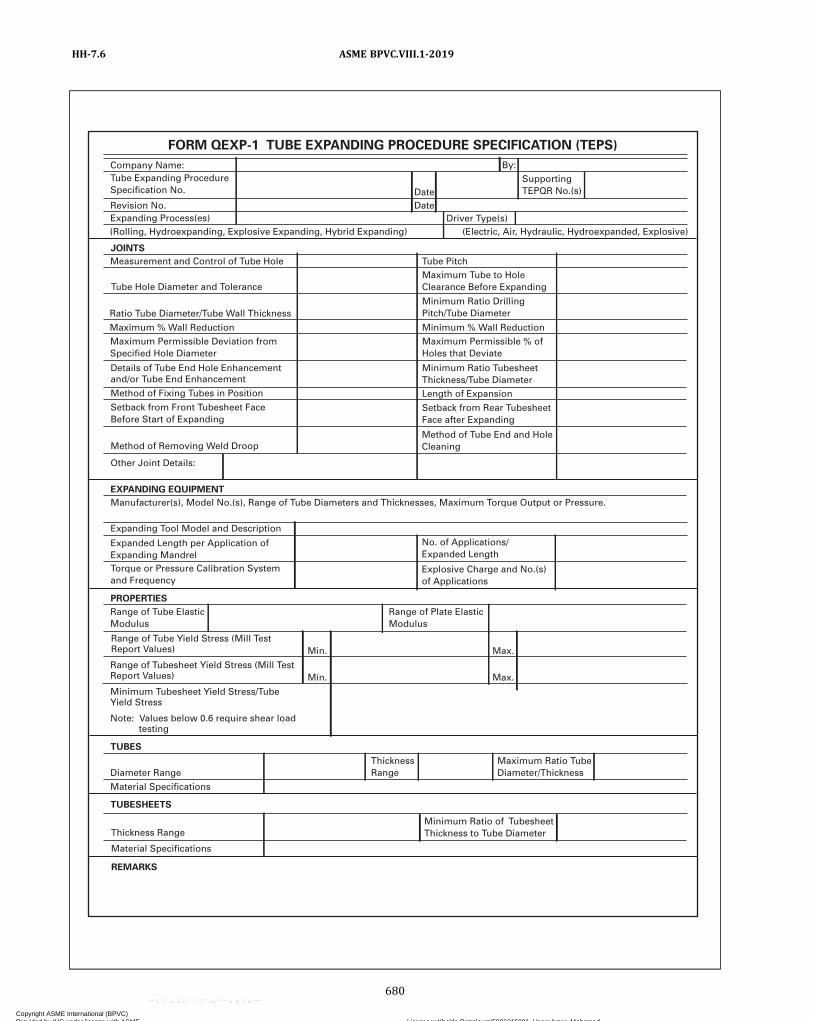
FORM QEXP-1 TUBE EXPANDING PROCEDURE SPECIFICATION (TEPS)
Company Name:Tube Expanding ProcedureSpecification No.
Revision No.Expanding Process(es)(Rolling, Hydroexpanding, Explosive Expanding, Hybrid Expanding) (Electric, Air, Hydraulic, Hydroexpanded, Explosive)
Driver Type(s)DateDate
By:SupportingTEPQR No.(s)
JOINTS
Measurement and Control of Tube Hole
Tube Hole Diameter and Tolerance
Ratio Tube Diameter/Tube Wall Thickness
Maximum % Wall ReductionMaximum Permissible Deviation fromSpecified Hole Diameter
Details of Tube End Hole Enhancementand/or Tube End Enhancement
Method of Fixing Tubes in Position
Method of Removing Weld Droop
Setback from Front Tubesheet FaceBefore Start of Expanding
Tube PitchMaximum Tube to HoleClearance Before Expanding
Minimum Ratio DrillingPitch/Tube Diameter
Minimum % Wall ReductionMaximum Permissible % ofHoles that Deviate
Minimum Ratio TubesheetThickness/Tube DiameterLength of Expansion
Setback from Rear TubesheetFace after Expanding
Method of Tube End and HoleCleaning
Other Joint Details:
EXPANDING EQUIPMENT
PROPERTIES
Manufacturer(s), Model No.(s), Range of Tube Diameters and Thicknesses, Maximum Torque Output or Pressure.
Expanding Tool Model and Description
Expanded Length per Application ofExpanding MandrelTorque or Pressure Calibration Systemand Frequency
No. of Applications/Expanded Length
Explosive Charge and No.(s)of Applications
Range of Tube ElasticModulus
Range of Plate ElasticModulus
Range of Tube Yield Stress (Mill TestReport Values)
Range of Tubesheet Yield Stress (Mill TestReport Values)
Minimum Tubesheet Yield Stress/TubeYield Stress
Note: Values below 0.6 require shear load testing
TUBES
Min.
Min.
Max.
Max.
TUBESHEETS
REMARKS
Diameter Range
Material Specifications
Thickness Range
Material Specifications
ThicknessRange
Maximum Ratio TubeDiameter/Thickness
Minimum Ratio of TubesheetThickness to Tube Diameter
ASME BPVC.VIII.1-2019HH-7.6
680
Copyright ASME International (BPVC) Provided by IHS under license with ASME Licensee=Khalda Petroleum/5986215001, User=Amer, Mohamed
Not for Resale, 07/02/2019 13:29:04 MDTNo reproduction or networking permitted without license from IHS
--`,``,``,,`,`,,````,`,``,,,`-`-`,,`,,`,`,,`---

21
1
3
6
8
2
5 4
7
9
10
12
14
16
18
20
22
24
26
19
17
15
13
23
25
27
28
29
30
31
33
32
34
35
37
39
41
36
38
40
42
45
46
48
43 44
47
49 50 51
11
, ,
FORM QEXP-1 TUBE EXPANDING PROCEDURE SPECIFICATION (TEPS)
Company Name: T ube Expanding Procedur e Specification No.
Revision No.
Expanding Process(es) Driver T yp e(s)
Date
Date
By: Supporting TEPQR No.(s)
JOINTS
Measurement and Control of T ube Hol e
T ube Hole Diameter an d T oleranc e
Ratio T ube Diameter/ T ub e W all Thicknes s
Maximum % W all Reductio n Maximum Permissible Deviation from Specified Hole Diamete r
Details of T ube End Hole Enhancemen t and/or T ube End Enhancemen t Method of Fixing T ubes in Positio n
Method of Removing W el d Droop
Setback from Front T ubesheet Fac e Before Start of Expanding
Tube Pitch
Maximum T ube to Hol e Clearance Before Expanding
Minimum Ratio Drilling Pitch/ T ube Diamete r
Minimum % W all Reductio n Maximum Permissible % of Holes that Deviate
Minimum Ratio T ubeshee t Thickness/ T ube Diamete r Length of Expansion
Setback from Rear T ubeshee t Face After Expanding
Method of T ube End and Hol e Cleaning
Other Joint Details:
EX P ANDING EQUIPMEN T
PROPE R TIE S
Manufacturer(s), Model No.(s), Range of T ube Diameters and Thicknesses, Maximum T orque Output or Pressure .
Expanding T ool Model and Descriptio n
Expanded Length per Application of Expanding Mandrel T orque or Pressure Calibration Syste m and Frequency
No. of Applications/ Expanded Length
Explosive Charge and No.(s) of Applications
Range of T ub e Elastic Modulus
Range of Plate Elastic Modulus
Range of T ube Y ield Stress
Range of T ubesheet Y iel d Stress (mill test report values)
Minimum T ubesheet Y ield Stress/ T ub e Yield Stress
NOTE: Values below 0.6 require shear load testing.
TUBES
Min.
Min.
Max.
Max.
TUBESHEETS
REMARKS:
Diameter Range
Material Specifications
Thickness Range
Material Specifications
Thickness Range
Maximum Ratio T ub e Diameter/Thickness
Minimum Ratio of T ubeshee t Thickness to T ube Diamete r
10
1
2
3
4
5
6
7
8
9
11
12
13
14
15 16
17
18
19
20
21
22
23
24
25
26
27
(mill test report values)
07/17
ASME BPVC.VIII.1-2019 HH-7.6
681
Copyright ASME International (BPVC) Provided by IHS under license with ASME Licensee=Khalda Petroleum/5986215001, User=Amer, Mohamed
Not for Resale, 07/02/2019 13:29:04 MDTNo reproduction or networking permitted without license from IHS
--`,``,``,,`,`,,````,`,``,,,`-`-`,,`,,`,`,,`---
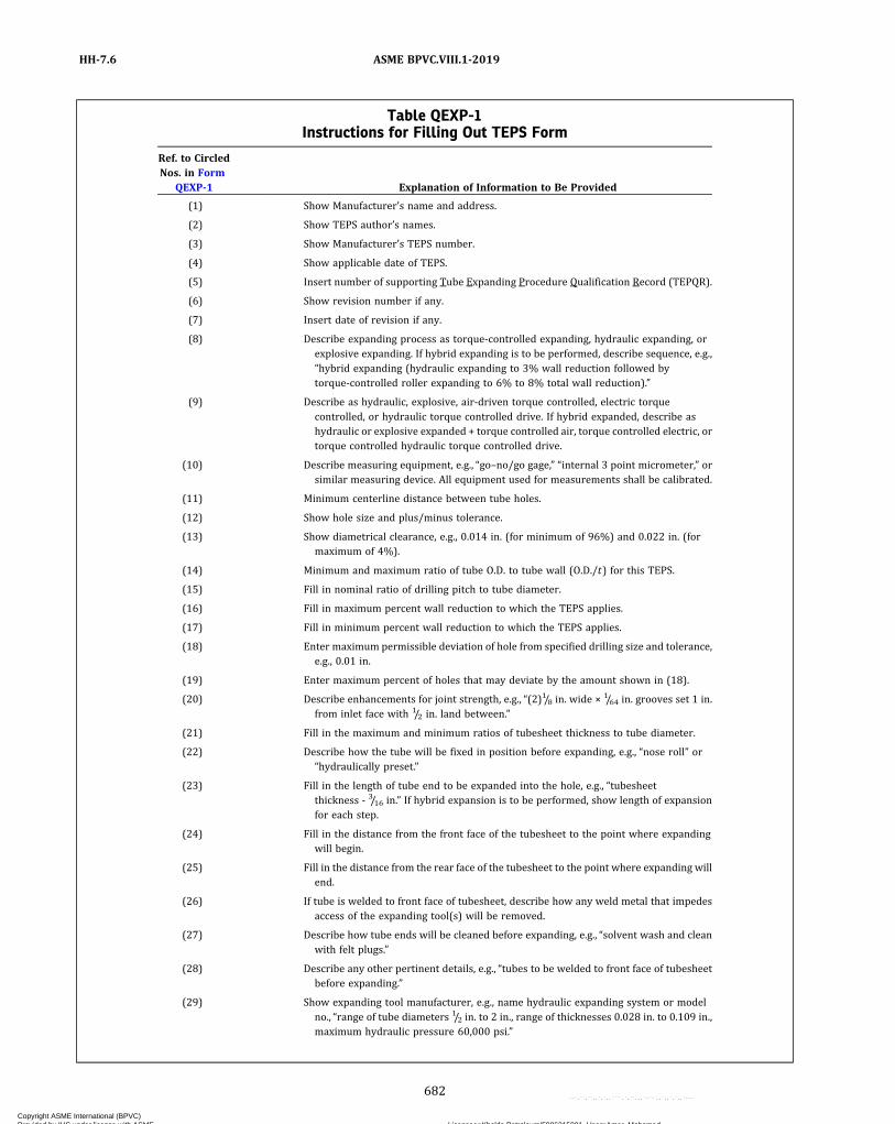
Table QEXP-1Instructions for Filling Out TEPS Form
Ref. to CircledNos. in Form
QEXP-1 Explanation of Information to Be Provided
(1) Show Manufacturer’s name and address.
(2) Show TEPS author’s names.
(3) Show Manufacturer’s TEPS number.
(4) Show applicable date of TEPS.
(5) Insert number of supporting Tube Expanding Procedure Qualification Record (TEPQR).
(6) Show revision number if any.
(7) Insert date of revision if any.
(8) Describe expanding process as torque‐controlled expanding, hydraulic expanding, orexplosive expanding. If hybrid expanding is to be performed, describe sequence, e.g.,“hybrid expanding (hydraulic expanding to 3% wall reduction followed bytorque‐controlled roller expanding to 6% to 8% total wall reduction).”
(9) Describe as hydraulic, explosive, air‐driven torque controlled, electric torquecontrolled, or hydraulic torque controlled drive. If hybrid expanded, describe ashydraulic or explosive expanded + torque controlled air, torque controlled electric, ortorque controlled hydraulic torque controlled drive.
(10) Describe measuring equipment, e.g., “go–no/go gage,” “internal 3 point micrometer,” orsimilar measuring device. All equipment used for measurements shall be calibrated.
(11) Minimum centerline distance between tube holes.
(12) Show hole size and plus/minus tolerance.
(13) Show diametrical clearance, e.g., 0.014 in. (for minimum of 96%) and 0.022 in. (formaximum of 4%).
(14) Minimum and maximum ratio of tube O.D. to tube wall (O.D./t) for this TEPS.
(15) Fill in nominal ratio of drilling pitch to tube diameter.
(16) Fill in maximum percent wall reduction to which the TEPS applies.
(17) Fill in minimum percent wall reduction to which the TEPS applies.
(18) Enter maximum permissible deviation of hole from specified drilling size and tolerance,e.g., 0.01 in.
(19) Enter maximum percent of holes that may deviate by the amount shown in (18).
(20) Describe enhancements for joint strength, e.g., “(2)1/8 in. wide × 1/64 in. grooves set 1 in.from inlet face with 1/2 in. land between.”
(21) Fill in the maximum and minimum ratios of tubesheet thickness to tube diameter.
(22) Describe how the tube will be fixed in position before expanding, e.g., “nose roll” or“hydraulically preset.”
(23) Fill in the length of tube end to be expanded into the hole, e.g., “tubesheetthickness - 3/16 in.” If hybrid expansion is to be performed, show length of expansionfor each step.
(24) Fill in the distance from the front face of the tubesheet to the point where expandingwill begin.
(25) Fill in the distance from the rear face of the tubesheet to the point where expanding willend.
(26) If tube is welded to front face of tubesheet, describe how any weld metal that impedesaccess of the expanding tool(s) will be removed.
(27) Describe how tube ends will be cleaned before expanding, e.g., “solvent wash and cleanwith felt plugs.”
(28) Describe any other pertinent details, e.g., “tubes to be welded to front face of tubesheetbefore expanding.”
(29) Show expanding tool manufacturer, e.g., name hydraulic expanding system or modelno., “range of tube diameters 1/2 in. to 2 in., range of thicknesses 0.028 in. to 0.109 in.,maximum hydraulic pressure 60,000 psi.”
ASME BPVC.VIII.1-2019HH-7.6
682
Copyright ASME International (BPVC) Provided by IHS under license with ASME Licensee=Khalda Petroleum/5986215001, User=Amer, Mohamed
Not for Resale, 07/02/2019 13:29:04 MDTNo reproduction or networking permitted without license from IHS
--`,``,``,,`,`,,````,`,``,,,`-`-`,,`,,`,`,,`---

Table QEXP-1Instructions for Filling Out TEPS Form (Cont'd)
Ref. to CircledNos. in Form
QEXP-1 Explanation of Information to Be Provided
(30) Fill in roller expanding tool or hydraulic mandrel number. If explosive expanding, fill indrawing number that describes the charges. If hybrid expanding, show thisinformation for Steps 1 and 2.
(31) Describe expanded length per application, e.g., “2 in. (roller length).”
(32) Show number of applications of expanding tool, e.g., “two applications required for rolldepth.” If hydraulic or explosive expanding, show length of expansion per applicationof hydraulic expanding pressure or explosive charge, e.g., “tubesheetthickness - 5/8 in.”
(33) Describe the system used to calibrate and control the rolling torque and frequency ofverification. Alternatively, describe the use of production control holes andexpansions.
(34) Describe the explosive charge and whether it will be single‐ or two‐stage explosiveexpansion.
(35) List the minimum and maximum elastic modulus of the tubes for this TEPS.
(36) List the minimum and maximum elastic modulus of the tubesheet(s) for this TEPS.
(37) List minimum permissible tube yield stress.
(38) List maximum permissible tube yield stress.
(39) List minimum permissible tubesheet yield stress.
(40) List maximum permissible tubesheet yield stress.
(41) Show the minimum ratio of tubesheet to tube yield stresses.
(42) List the range of tube diameters to which this TEPS applies.
(43) List the range of tube thicknesses to which this TEPS applies.
(44) Show the maximum ratio of tube diameter to thickness to which this TEPS applies.
(45) Show the tube specification number, e.g., “SA-688 TP304N.”
(46) Show the range of tubesheet thicknesses to which this TEPS applies, e.g., 1 in. to 5 in.
(47) Show the minimum ratio of tubesheet thickness to tube diameter to which this TEPSapplies.
(48) Show the tubesheet material specification numbers, e.g., “SA-350 LF2.”
(49) Describe pertinent job‐specific information.
(50) Describe such things as bundle setup and sequence of expansion operation. Refer todrawing numbers and manufacturer’s standards as appropriate.
(51) Refer to any attachment or supplement to the TEPS form.
ASME BPVC.VIII.1-2019 HH-7.6
683
Copyright ASME International (BPVC) Provided by IHS under license with ASME Licensee=Khalda Petroleum/5986215001, User=Amer, Mohamed
Not for Resale, 07/02/2019 13:29:04 MDTNo reproduction or networking permitted without license from IHS
--`,``,``,,`,`,,````,`,``,,,`-`-`,,`,,`,`,,`---
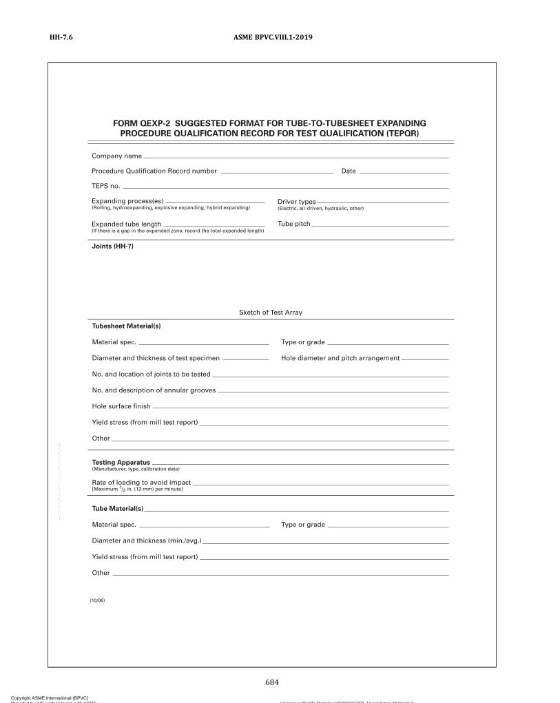
FORM QEXP-2 SUGGESTED FORMAT FOR TUBE-TO-TUBESHEET EXPANDING
PROCEDURE QUALIFICATION RECORD FOR TEST QUALIFICATION (TEPQR)
Company name
Procedure Qualification Record number Date
TEPS no.
Expanding process(es)(Rolling, hydroexpanding, explosive expanding, hybrid expanding)
Expanded tube length(If there is a gap in the expanded zone, record the total expanded length)
Driver types(Electric, air-driven, hydraulic, other)
Tube pitch
Joints (HH-7)
Sketch of Test Array
Tubesheet Material(s)
Material spec. Type or grade
Diameter and thickness of test specimen Hole diameter and pitch arrangement
No. and location of joints to be tested
No. and description of annular grooves
Hole surface finish
Yield stress (from mill test report)
Other
Testing Apparatus(Manufacturer, type, calibration date)
Rate of loading to avoid impact[Maximum 1/2 in. (13 mm) per minute]
Tube Material(s)
Material spec. Type or grade
Diameter and thickness (min./avg.)
Yield stress (from mill test report)
Other
(10/06)
ASME BPVC.VIII.1-2019HH-7.6
684
Copyright ASME International (BPVC) Provided by IHS under license with ASME Licensee=Khalda Petroleum/5986215001, User=Amer, Mohamed
Not for Resale, 07/02/2019 13:29:04 MDTNo reproduction or networking permitted without license from IHS
--`,``,``,,`,`,,````,`,``,,,`-`-`,,`,,`,`,,`---

FORM QEXP-2 (Back)
Shear Load Test (See Appendix A, Fig. A-3)
Mean value of L1 (test) Mean value of L2 (test)
Standard deviation Standard deviation Satisfactory (see Appendix A, A-5) fr (test) (see Appendix A, A-4)
Operator’s name Clock no.
Tube No.Position in
Array Diameter ThicknessCross-Sectional
Area L1 (test)Manner of
Failure
Tube No.Position in
ArrayCross-Sectional
Area L2 (test)Manner of
Failure
Manufacturer
ByDate
Remarks:
Test Temp.
Diameter ThicknessAmbientTemp.
10/06
ASME BPVC.VIII.1-2019 HH-7.6
685
Copyright ASME International (BPVC) Provided by IHS under license with ASME Licensee=Khalda Petroleum/5986215001, User=Amer, Mohamed
Not for Resale, 07/02/2019 13:29:04 MDTNo reproduction or networking permitted without license from IHS
--`,``,``,,`,`,,````,`,``,,,`-`-`,,`,,`,`,,`---
NONMANDATORY APPENDIX JJFLOWCHARTS ILLUSTRATING TOUGHNESS TESTING
REQUIREMENTS AND EXEMPTIONS FROM TOUGHNESS TESTINGBY THE RULES OF UHA-51
JJ-1 UHA-51 TOUGHNESS TESTREQUIREMENTS FOR HIGH ALLOYVESSELS
JJ-1.1 INTRODUCTIONThis Nonmandatory Appendix provides guidelines for
determining toughness test requirements for austenitic,austenitic‐ferritic duplex, ferritic chromium, and marten-sitic stainless steel vessels in accordance with the tough-ness test rules in UHA-51.
NOTE: The term “toughness testing” is used as an all-inclusive gen-eric reference to any and all toughness testing required by this Divi-sion, whether it be impact testing, drop testing, ASTM E1820 J I Ctesting, or some other referenced testing method.
JJ-1.2 FLOWCHARTSFigures JJ-1.2-1 through JJ-1.2-5 provide step‐by‐step
guidelines for determining the conditions where exemp-tions from toughness tests are permitted and, whentoughness tests are required, the applications that are re-quired to be toughness tested by UHA-51 rules.Figures JJ-1.2-1 through JJ-1.2-4 illustrate test require-
ment guidelines for austenitic base material and HAZ,welding procedure qualification, welding consumablepre‐use testing, and production impact testing. FigureJJ-1.2-5 provides guidelines of applicable requirementsfor application of the duplex, ferritic chromium, and mar-tensitic material grades.
ASME BPVC.VIII.1-2019JJ-1 – JJ-1.2
686
Copyright ASME International (BPVC) Provided by IHS under license with ASME Licensee=Khalda Petroleum/5986215001, User=Amer, Mohamed
Not for Resale, 07/02/2019 13:29:04 MDTNo reproduction or networking permitted without license from IHS
--`,``,``,,`,`,,````,`,``,,,`-`-`,,`,,`,`,,`---

Figure JJ-1.2-1Austenitic Stainless Steel Base Metal and HAZ Toughness Testing Requirements
Start: Assume all Part UHA base metals and HAZs require toughness testing unless otherwise exempted.
Is material acasting?
Isspecimenthickness> 0.099 in. (2.5 mm)?
Yes
No
Thermallytreated perUHA-51(c)?
No
No
No
Base metal and HAZ
toughness testing is not
required.
Base metal and HAZ
toughness testing is not
required.
No
Yes
Yes
Yes
Toughness testing of the base metal and HAZ
is required per UG-84.
UHA-51
UHA-51(d)(1)(-c) and (d)(2)(-c)
Carbon content
< 0.10%?
No
Yes Yes
UHA-51(d)(1)(-a)
Exempt per
UHA-51(g)?
No
See
UHA-51(c)(1)
for additional
toughness
testing
exemption
criteria.
Yes
UHA-51(c)(1)
Yes
No
UHA-51(d)(1)(-b)
MDMTcolder
than –320°F(–196°C)?
MDMTcolder
than –55°F(–48°C)?
MDMTcolder
than –20°F(–29°C)?
Toughness testing of the base
metal and HAZ is
required per UHA-51(a)(3).
GENERAL NOTE: See Figures JJ-1.2-2, JJ-1.2-3, and JJ-1.2-4 for additional toughness requirements.
ASME BPVC.VIII.1-2019 JJ-1.2
687
Copyright ASME International (BPVC) Provided by IHS under license with ASME Licensee=Khalda Petroleum/5986215001, User=Amer, Mohamed
Not for Resale, 07/02/2019 13:29:04 MDTNo reproduction or networking permitted without license from IHS
--`,``,``,,`,`,,````,`,``,,,`-`-`,,`,,`,`,,`---
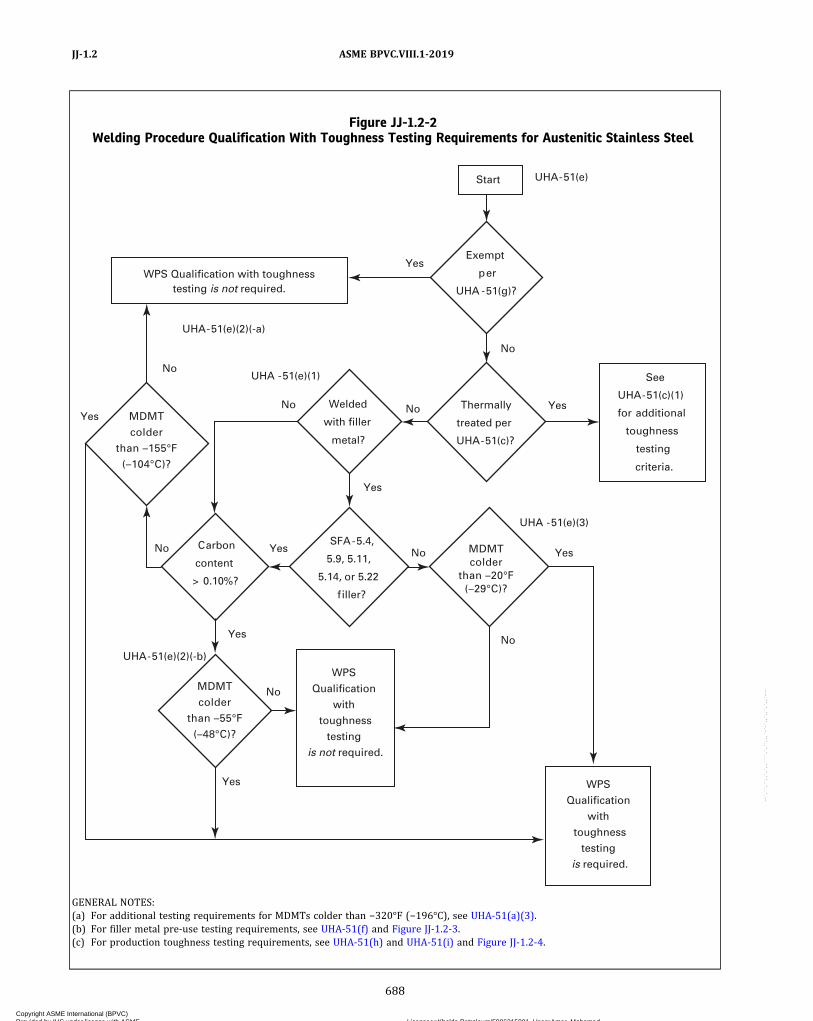
Figure JJ-1.2-2Welding Procedure Qualification With Toughness Testing Requirements for Austenitic Stainless Steel
Start UHA-51(e)
Welded
with filler
metal?
Yes
SFA-5.4,
5.9, 5.11,
5.14, or 5.22
filler?
UHA-51(e)(2)(-a)
No
No
Yes
WPS Qualification with toughnesstesting is not required.
No No
Yes
No
UHA -51(e)(1)
Exempt
per
UHA -51(g)?
Yes
No
No Thermally
treated per
UHA-51(c)?
Yes
Yes
UHA -51(e)(3)
Yes
NoSee
UHA-51(c)(1)
for additional
toughness
testing
criteria.
Carbon
content
> 0.10%?
Yes
UHA-51(e)(2)(-b)
MDMT
colder
than –155°F
(–104°C)?
MDMT
colder
than –55°F
(–48°C)?
MDMTcolder
than –20°F(–29°C)?
WPS
Qualification
with
toughness
testing
is not required.
WPS
Qualification
with
toughness
testing
is required.
GENERAL NOTES:(a) For additional testing requirements for MDMTs colder than −320°F (−196°C), see UHA-51(a)(3).(b) For filler metal pre-use testing requirements, see UHA-51(f) and Figure JJ-1.2-3.(c) For production toughness testing requirements, see UHA-51(h) and UHA-51(i) and Figure JJ-1.2-4.
ASME BPVC.VIII.1-2019JJ-1.2
688
Copyright ASME International (BPVC) Provided by IHS under license with ASME Licensee=Khalda Petroleum/5986215001, User=Amer, Mohamed
Not for Resale, 07/02/2019 13:29:04 MDTNo reproduction or networking permitted without license from IHS
--`,``,``,,`,`,,````,`,``,,,`-`-`,,`,,`,`,,`---

ð19ÞFigure JJ-1.2-3Welding Consumable Pre-Use Testing Requirements for Austenitic Stainless Steel
GTAW and PAW SAWSMAW and GMAW
Pre-use testing is notrequired. Ready forproduction welding.
Unacceptable for usewith MDMTs colder
than �155�F (�104�C)
Ready for production welding — only pre-use testedconsumables or exempted filler metal with
GTAW/PAW to be used
Unacceptablewithout pre-use
testing
Unacceptablewithout pre-use
testing
Welding Consumable Pre-UseTesting Requirements
Is fillermetal ENiCrFe-2,
ENiCrFe-3, ENiCrMo-3,ENiCrMo-4, ENiCrMo-6,ERNiCr-3, ERNiCrMo-3,
ERNiCrMo-4, orE310-15/16?
Is MDMTcolder than �155�F
(�104�C)?
1. Is WPS qualifiedwith impact tests?
2. Is welding process SMAW, SAW,GMAW, GTAW, or PAW?
3. Does weld metal conform to SFA-5.4, 5.9,5.11, 5.14, or 5.22?
4. Is weld metal � 0.10%carbon?
UHA-51(f)
UHA-51(f)(1), (f)(2), (f)(3), and (f)(4)
UHA-51(f)(4)(-d)
UHA-51(f)(4)(-e) UHA-51(f)(4)(-b)UHA-51(f)(4)(-a)
Yes
No
No
Yes
Yes
Yes
Yes Yes
No
No
Is eachheat/lot of fillermetal pre-use
tested?
Is filler metalER308L, ER316L,
or ER310?
Is each heat/batchcombination of wire
and flux pre-usetested?
No
No
Is MDMTcolder than �320�F
(�196�C)?
UHA-51(a)(3), UHA-51(f)
No
Unacceptable withoutpre-use testing
Yes
ASME BPVC.VIII.1-2019 JJ-1.2
689
Copyright ASME International (BPVC) Provided by IHS under license with ASME Licensee=Khalda Petroleum/5986215001, User=Amer, Mohamed
Not for Resale, 07/02/2019 13:29:04 MDTNo reproduction or networking permitted without license from IHS
--`,``,``,,`,`,,````,`,``,,,`-`-`,,`,,`,`,,`---

Figure JJ-1.2-4Production Toughness Testing Requirements for Austenitic Stainless Steel
Start
UHA-51(i)(1)
No
UHA-51(h)( 2 )(-c)
YesYes
Yes
No Yes
No
No
No
Yes
UHA-51(i)(2 )UHA-51(i)UHA-51(h)(2)(-a)
Thermally
treated as
defined in
UHA-51(c)?
Yes
No
No
Yes
Yes
No
UHA-51(h)(2)
UHA -51(h)(2)(-b)
Yes
No
MDMT
colder
than –320°F
(–196°C)?
MDMT
colder
than –155°F
(–104°C)?
MDMT
colder
than –20°F
(–29°C)?
MDMT
colder
than –320°F
(–196°C)?
Are all
requirements
of UHA-51(f)
met?
Welded
with filler
metal?
Is PQR
toughness
testing exempted
per UHA-51(e)?
Production
toughness
testing is
required.
Production
toughness
testing is
required.Production
toughness
testing is not
required.
Solution
annealed
after
welding?
See
UHA-51(c)
for special
production
toughness
testing
requirements.
ASME BPVC.VIII.1-2019JJ-1.2
690
Copyright ASME International (BPVC) Provided by IHS under license with ASME Licensee=Khalda Petroleum/5986215001, User=Amer, Mohamed
Not for Resale, 07/02/2019 13:29:04 MDTNo reproduction or networking permitted without license from IHS
--`,``,``,,`,`,,````,`,``,,,`-`-`,,`,,`,`,,`---
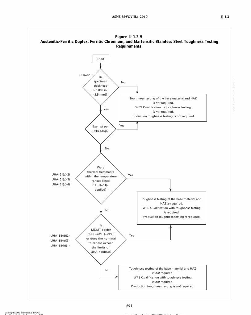
Figure JJ-1.2-5Austenitic-Ferritic Duplex, Ferritic Chromium, and Martensitic Stainless Steel Toughness Testing
Requirements
Start
Yes
No
No
UHA -51(d)(3)
UHA -51(e)(3)
UHA -51(h)(1)
UHA-51(c)(2)
UHA-51(c)(3)
UHA-51(c)(4)
UHA-51
No
No
Yes
Yes
Yes
Is
specimen
thickness
≥ 0.099 in.
(2.5 mm)?
Exempt per
UHA-51(g)?
Toughness testing of the base material and HAZ
is not required.
WPS Qualification by toughness testing
is not required.
Production toughness testing is not required.
Toughness testing of the base material and
HAZ is required.
WPS Qualification with toughness testing
is required.
Production toughness testing is required.
Toughness testing of the base material and HAZ
is not required.
WPS Qualification with toughness testing
is not required.
Production toughness testing is not required.
Is
MDMT colder
than –20°F (–29°C)
or does the nominal
thickness exceed
the limits of
UHA-51(d)(3)?
Were
thermal treatments
within the temperature
ranges listed
in UHA-51(c)
applied?
ASME BPVC.VIII.1-2019 JJ-1.2
691
Copyright ASME International (BPVC) Provided by IHS under license with ASME Licensee=Khalda Petroleum/5986215001, User=Amer, Mohamed
Not for Resale, 07/02/2019 13:29:04 MDTNo reproduction or networking permitted without license from IHS
--`,``,``,,`,`,,````,`,``,,,`-`-`,,`,,`,`,,`---

NONMANDATORY APPENDIX KKGUIDE FOR PREPARING USER’S DESIGN REQUIREMENTS
KK-1 INTRODUCTION
(a) The instructions contained in this NonmandatoryAppendix are to provide general guidance for the User[see U-2(a)] in preparing User’s Design Requirements asrecommended in U-2(a).(b) User’s Design Requirements Forms are neither re-
quired nor prohibited for pressure vessels constructedin accordance with U-1(j) or UG-90(c)(2).
(c) The instructions for the User’s Design Require-ments Forms are identified by parenthesized numberscorresponding to circled numbers on the sample formsin this Nonmandatory Appendix.(d)Where more space than has been provided for on
the form is needed for any item, indicate in the space,“See General Notes” or “See additional form,” asappropriate.(e) Any quantity to which units apply shall be entered
on the User’s Design Requirements Form with the chosenunits.
ASME BPVC.VIII.1-2019KK-1
692
Copyright ASME International (BPVC) Provided by IHS under license with ASME Licensee=Khalda Petroleum/5986215001, User=Amer, Mohamed
Not for Resale, 07/02/2019 13:29:04 MDTNo reproduction or networking permitted without license from IHS
--`,``,``,,`,`,,````,`,``,,,`-`-`,,`,,`,`,,`---
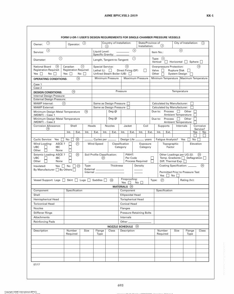
F1
F4
F7
F10
F14
F15
F17
F18
F19
F20
F21
F22
F26 F27
F28
F29
F25
F23
F22
F11 F12 F13
F7 F8
F6F5
F2
F3
F3F3
F24
FORM U-DR-1 USER’S DESIGN REQUIREMENTS FOR SINGLE-CHAMBER PRESSURE VESSELS
Owner:
Service:
Internal Design Pressure:External Design Pressure:
Diameter:
MAWP Internal:
Corrosion Allowance: Shell
Int. Ext.
Heads
Int. Ext.
Nozzles
Int. Ext.
Jacket
Int. Ext.
Coil
Int. Ext.
Supports
Int. Ext.
Internals CorrosiveService?
Yes No
Minimum Design Metal Temperature(MDMT) – Case 1
MAWP External:
OPERATING CONDITIONS:
DESIGN CONDITIONS:
MATERIALS
NOZZLE SCHEDULE
Case 1Case 2
Minimum Pressure
Pressure Temperature
Maximum Pressure Minimum Temperature Maximum Temperature
National BoardRegistration Required:Yes No
Length, Tangent-to-Tangent: Type:Vertical Horizontal Sphere
Item No.:Liquid Level:Specific Gravity:
Operator: Country of Installation: City of Installation:State/Province ofInstallation:
CanadianRegistration Required:Yes No
Special Service:Lethal (L) Direct Firing (DF)
Same as Design Pressure Calculated by Manufacturer:Same as Design Pressure
Deg @ Due to:
Calculated by Manufacturer:
Unfired Steam Boiler (UB)
Overpressure Protection:Valve Rupture Disk
Process Other
Cyclic Service: Cycles per Design Life yearsYes
UBC IBCOther None
Wind Loading: Wind Speed ClassificationCategory
ExposureCategory
TopographicFactor
ElevationASCE 7
UBC IBCOther None
Seismic Loading:Per CodeProcess Required
PWHT:Soil Profile Classification: Other Loadings per UG-22:ASCE 7
No
Vessel Support:
Component
Description
07/17
NumberRequired
Size FlangeType
Class Description NumberRequired
Size FlangeType
Class
Shell
Hemispherical Head
Toriconical Head
Nozzles
Stiffener Rings
Attachments
Reinforcing Pads
Specification Component
Ellipsoidal Head
Torispherical Head
Conical Head
Flanges
Pressure-Retaining Bolts
Internals
Other
Specification
Type: Rating (hr):Legs Skirt Lugs Saddles
Yes
Temp. GradientsDiff. Thermal Exp.
Deflagration
No
Type Thickness Density Coating Specification:ExternalInternal Permitted Prior to Pressure Test
Yes NoFireproofing:
Fatigue Analysis? Yes No
Ambient Temperature
Minimum Design Metal Temperature(MDMT) – Case 2
Deg @ Due to: Process OtherAmbient Temperature
Other System Design
Insulated: Yes NoBy Manufacturer By Others
ASME BPVC.VIII.1-2019 KK-1
693
Copyright ASME International (BPVC) Provided by IHS under license with ASME Licensee=Khalda Petroleum/5986215001, User=Amer, Mohamed
Not for Resale, 07/02/2019 13:29:04 MDTNo reproduction or networking permitted without license from IHS
--`,``,``,,`,`,,````,`,``,,,`-`-`,,`,,`,`,,`---
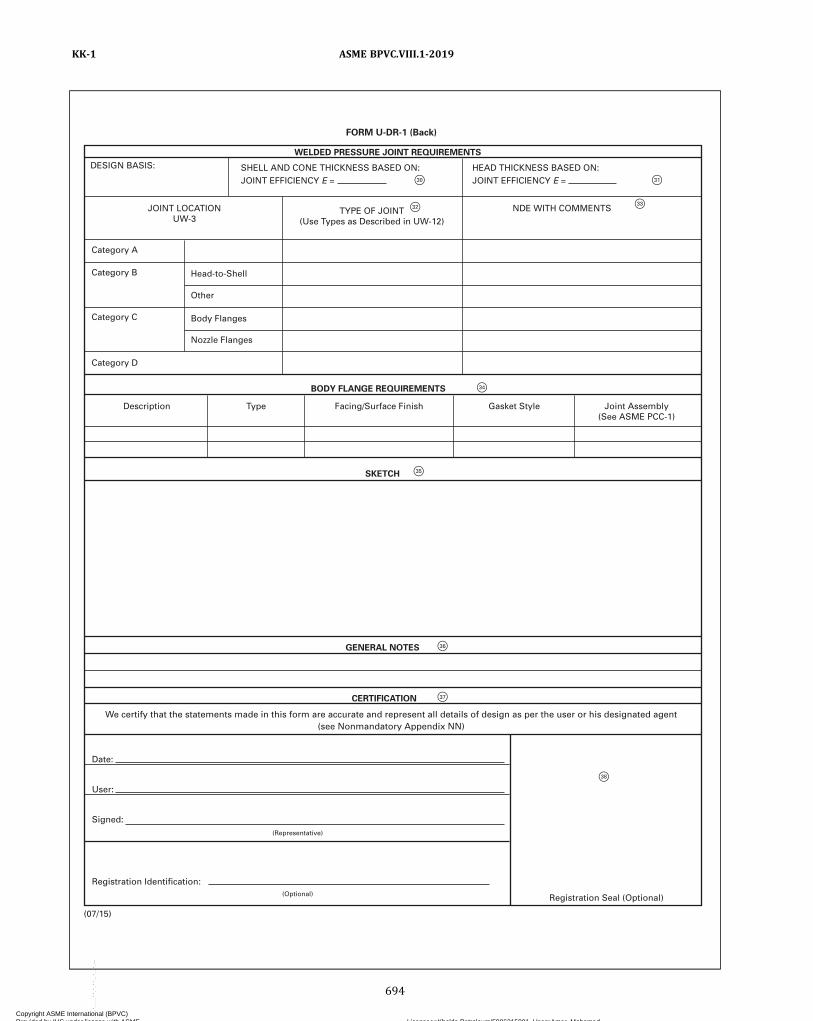
F 33
F 31 F 30
F 32
F 34
F 35
F 36
F 37
F 38
GENERAL NOTES
BODY FLANGE REQUIREMENTS
WELDED PRESSURE JOINT REQUIREMENTS
SKETCH
CE R TIFIC A TION
Date:
We certify that the statements made in this form are accurate and represent all details of design as per the user or his designated agent(see Nonmandatory Appendix NN)
Description
Category D
Category C
Category B Head-to-Shell
Other
Body Flanges
Nozzle Flanges
Category A
DESIGN BASIS:
JOINT LOC A TION U W -3
TYPE OF JOINT (Use T ypes as Described in U W -12)
NDE WITH COMMENTS
HEAD THICKNESS BASED ON: JOINT EFFICIENCY E =
SHELL AND CONE THICKNESS BASED ON: JOINT EFFICIENCY E =
T ype Facing/Surface Finish Gasket Style Joint Assembly (See ASME PCC-1)
User:
Signed:
Registration Identification:
Registration Seal (Optional)
(Representative)
(Optional)
(07/15)
FORM U-DR-1 (Back)
ASME BPVC.VIII.1-2019KK-1
694
Copyright ASME International (BPVC) Provided by IHS under license with ASME Licensee=Khalda Petroleum/5986215001, User=Amer, Mohamed
Not for Resale, 07/02/2019 13:29:04 MDTNo reproduction or networking permitted without license from IHS
--`,``,``,,`,`,,````,`,``,,,`-`-`,,`,,`,`,,`---

F1
F4
F7
F10
F14
F16
F17
F18
F19
F20
F21
F22
F24
F26 F27
F28
F29
F25
F23
F22
F11 F12 F13
F7
F9
F6F5
F2
F3
F3F3
FORM U-DR-2 USER’S DESIGN REQUIREMENTS FOR MULTICHAMBER PRESSURE VESSELS
Owner:
Service:
Internal Design Pressure:External Design Pressure:
Diameter:
Corrosion Allowance:Corrosive Service?
ShellInt. Ext.
HeadsInt. Ext.
NozzlesInt. Ext.
JacketInt. Ext.
CoilInt. Ext.
SupportsInt. Ext.
Tubesheet Tubes
Minimum Design Metal Temperature(MDMT) – Case 1
MAWP External:
OPERATING CONDITIONS:
DESIGN CONDITIONS:
MATERIALS
NOZZLE SCHEDULE
Chamber 1 – Case 1Chamber 2 – Case 1Chamber 1 – Case 2Chamber 2 – Case 2
Minimum Pressure
Chamber 1 Chamber 2
Maximum Pressure Minimum Temperature Maximum Temperature
National BoardRegistration Required:Yes No
Shell Length, Tangent-to-Tangent: Type:Shell and Tube
Item No.:Liquid Level:Specific Gravity:
Chamber 1Chamber 1
Operator: Country of Installation: City of Installation:State/Province ofInstallation:
CanadianRegistration Required:Yes No
Special Service:Lethal (L) Direct Firing (DF)
Same as DesignPressure:
@
@
@
@
@
Due to:
Calculated byManufacturer:
Same as DesignPressure:
Calculated byManufacturer:
MAWP Internal: Same as DesignPressure:
Calculated byManufacturer:
Same as DesignPressure:
Calculated byManufacturer:
Unfired Steam Boiler (UB)
Overpressure Protection:Valve Rupture Disk
Process Other
Cyclic Service: Cycles per Design Life yearsYes
UBC IBCOther None
Wind Loading: Wind Speed ClassificationCategory
ExposureCategory
TopographicFactor
ElevationASCE 7
UBC IBCOther None
Seismic Loading:Per CodeProcess Required
PWHT:Soil Profile Classification: Other Loadings per UG-22:ASCE 7
No
Insulated: Yes
Vessel Support:
Component
Description
07/17
NumberRequired
Size FlangeType
Class Description NumberRequired
Size FlangeType
Class
Toriconical HeadNozzlesStiffener RingsAttachmentsReinforcing PadsJacketTubesheet
Specification Component
Conical HeadHemispherical Head Torispherical HeadShell Ellipsoidal Head
FlangesPressure-Retaining BoltsInternalsCoilTubesOther
Specification
Type: Rating (hr):Legs Skirt Lugs Saddles
No
Yes NoBy Manufacturer
Type: Thickness Density Coating Specification:Chamber 1Chamber 2
Permitted Prior to Pressure Test
Yes NoFireproofing:
By Others
Fatigue Analysis? Yes No
Ambient Temperature
Minimum Design Metal Temperature(MDMT) – Case 2
@ Due to: Process
Yes No
OtherAmbient Temperature
Other System Design
Jacket Internal Coil
Chamber 2Chamber 2
SS TS Int. Ext.
Temp. GradientsDiff. Thermal Exp.
Deflagration
ASME BPVC.VIII.1-2019 KK-1
695
Copyright ASME International (BPVC) Provided by IHS under license with ASME Licensee=Khalda Petroleum/5986215001, User=Amer, Mohamed
Not for Resale, 07/02/2019 13:29:04 MDTNo reproduction or networking permitted without license from IHS
--`,``,``,,`,`,,````,`,``,,,`-`-`,,`,,`,`,,`---
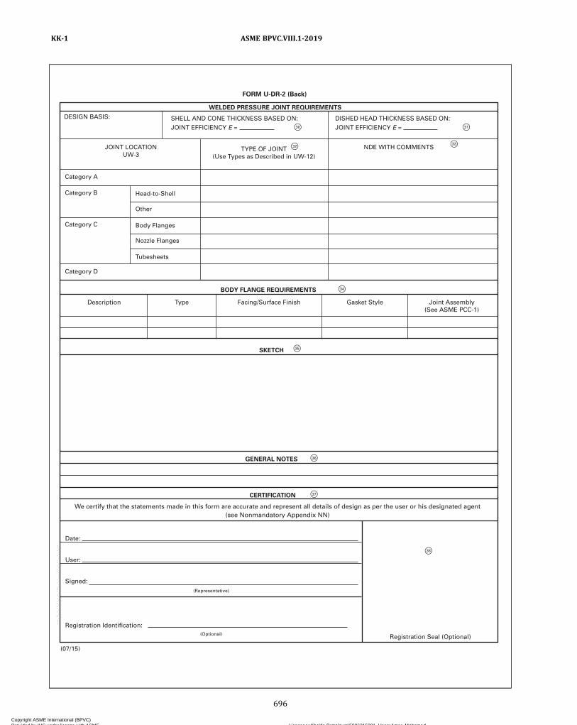
F 33
F 31 F 30
F 32
F 34
F 35
F 36
F 37
F 38
GENERAL NOTES
BODY FLANGE REQUIREMENTS
WELDED PRESSURE JOINT REQUIREMENTS
SKETCH
CE R TIFIC A TION
Date:
Description
Category D
Category C
Category B Head-to-Shell
Other
Body Flanges
Nozzle Flanges
T ubesheets
Category A
DESIGN BASIS:
JOINT LOC A TION U W -3
TYPE OF JOINT (Use T ypes as Described in U W -12)
NDE WITH COMMENTS
DISHED HEAD THICKNESS BASED ON: JOINT EFFICIENCY E =
SHELL AND CONE THICKNESS BASED ON: JOINT EFFICIENCY E =
T ype Facing/Surface Finish Gasket Style Joint Assembly (See ASME PCC-1)
User:
Signed:
Registration Identification:
Registration Seal (Optional)
(Representative)
(Optional)
(07/15)
FORM U-DR-2 (Back)
We certify that the statements made in this form are accurate and represent all details of design as per the user or his designated agent(see Nonmandatory Appendix NN)
ASME BPVC.VIII.1-2019KK-1
696
Copyright ASME International (BPVC) Provided by IHS under license with ASME Licensee=Khalda Petroleum/5986215001, User=Amer, Mohamed
Not for Resale, 07/02/2019 13:29:04 MDTNo reproduction or networking permitted without license from IHS
--`,``,``,,`,`,,````,`,``,,,`-`-`,,`,,`,`,,`---
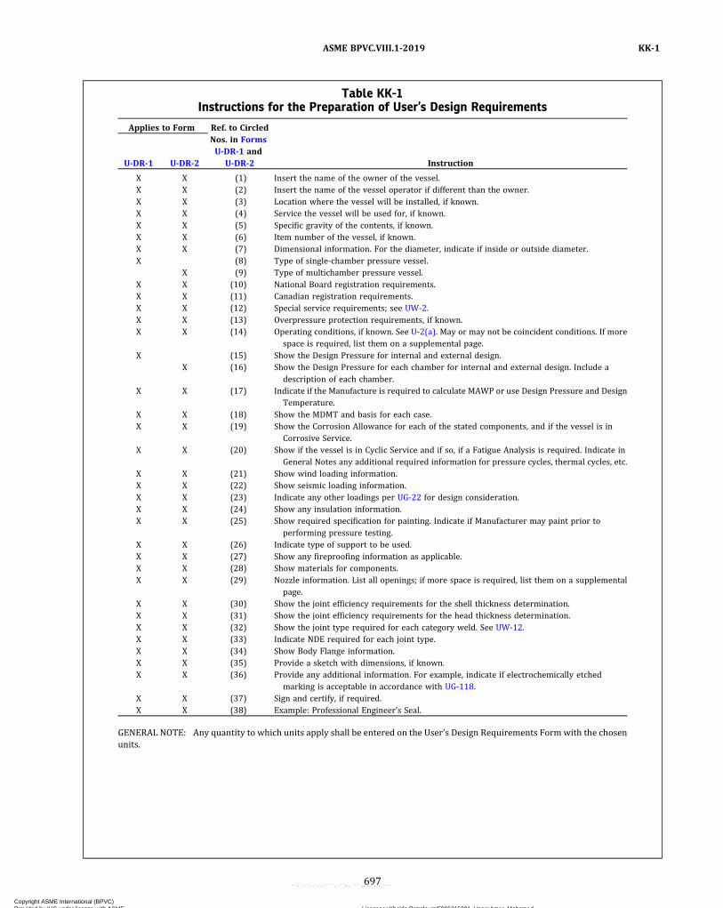
Table KK-1Instructions for the Preparation of User’s Design Requirements
Applies to Form Ref. to CircledNos. in FormsU-DR-1 and
U-DR-2U-DR-1 U-DR-2 Instruction
X X (1) Insert the name of the owner of the vessel.X X (2) Insert the name of the vessel operator if different than the owner.X X (3) Location where the vessel will be installed, if known.X X (4) Service the vessel will be used for, if known.X X (5) Specific gravity of the contents, if known.X X (6) Item number of the vessel, if known.X X (7) Dimensional information. For the diameter, indicate if inside or outside diameter.X (8) Type of single‐chamber pressure vessel.
X (9) Type of multichamber pressure vessel.X X (10) National Board registration requirements.X X (11) Canadian registration requirements.X X (12) Special service requirements; see UW-2.X X (13) Overpressure protection requirements, if known.X X (14) Operating conditions, if known. See U-2(a). May or may not be coincident conditions. If more
space is required, list them on a supplemental page.X (15) Show the Design Pressure for internal and external design.
X (16) Show the Design Pressure for each chamber for internal and external design. Include adescription of each chamber.
X X (17) Indicate if the Manufacture is required to calculate MAWP or use Design Pressure and DesignTemperature.
X X (18) Show the MDMT and basis for each case.X X (19) Show the Corrosion Allowance for each of the stated components, and if the vessel is in
Corrosive Service.X X (20) Show if the vessel is in Cyclic Service and if so, if a Fatigue Analysis is required. Indicate in
General Notes any additional required information for pressure cycles, thermal cycles, etc.X X (21) Show wind loading information.X X (22) Show seismic loading information.X X (23) Indicate any other loadings per UG-22 for design consideration.X X (24) Show any insulation information.X X (25) Show required specification for painting. Indicate if Manufacturer may paint prior to
performing pressure testing.X X (26) Indicate type of support to be used.X X (27) Show any fireproofing information as applicable.X X (28) Show materials for components.X X (29) Nozzle information. List all openings; if more space is required, list them on a supplemental
page.X X (30) Show the joint efficiency requirements for the shell thickness determination.X X (31) Show the joint efficiency requirements for the head thickness determination.X X (32) Show the joint type required for each category weld. See UW-12.X X (33) Indicate NDE required for each joint type.X X (34) Show Body Flange information.X X (35) Provide a sketch with dimensions, if known.X X (36) Provide any additional information. For example, indicate if electrochemically etched
marking is acceptable in accordance with UG-118.X X (37) Sign and certify, if required.X X (38) Example: Professional Engineer’s Seal.
GENERAL NOTE: Any quantity to which units apply shall be entered on the User’s Design Requirements Formwith the chosenunits.
ASME BPVC.VIII.1-2019 KK-1
697
Copyright ASME International (BPVC) Provided by IHS under license with ASME Licensee=Khalda Petroleum/5986215001, User=Amer, Mohamed
Not for Resale, 07/02/2019 13:29:04 MDTNo reproduction or networking permitted without license from IHS
--`,``,``,,`,`,,````,`,``,,,`-`-`,,`,,`,`,,`---

NONMANDATORY APPENDIX LLGRAPHICAL REPRESENTATIONS OF Ft ,min AND Ft ,max
The curves in Figures LL-1 and LL-2 are graphical representations of Ft ,min and Ft ,max , respectively, for ν* = 0.4when Pe ≠ 0. They are sufficiently accurate to be used for other values of ν*. For values of Xa and Q3 beyond those givenby the curves, see Table UHX-13.2.
ASME BPVC.VIII.1-2019LL
698
Copyright ASME International (BPVC) Provided by IHS under license with ASME Licensee=Khalda Petroleum/5986215001, User=Amer, Mohamed
Not for Resale, 07/02/2019 13:29:04 MDTNo reproduction or networking permitted without license from IHS
--`,``,``,,`,`,,````,`,``,,,`-`-`,,`,,`,`,,`---

Figure LL-1Graphical Representation of Ft ,min
–160.0000
–140.0000
–120.0000
–100.0000
–80.0000
–60.0000
–40.0000
–20.0000
0.0000
20.0000
1 2 3 4 5 6 7 8 9 10 11 12 13 14 15 16 17 18 19 20
F t, m
in
Xa
Q3 = –0.8
Q3 = –0.7
Q3 = –0.6
Q3 = –0.5
Q3 = –0.4
Q3 = –0.3
Q3 = –0.2
Q3 = –0.1
Q3 = 0
–40.0000
–35.0000
–30.0000
–25.0000
–20.0000
–15.0000
–10.0000
–5.0000
0.0000
5.0000
1 2 3 4 5 6 7 8 9 10 11 12 13 14 15 16 17 18 19 20
Xa
Q3 = 0
Q3 = 0.1
Q3 = 0.2
Q3 = 0.3
Q3 = 0.4
Q3 = 0.5
Q3 = 0.6
Q3 = 0.7
Q3 = 0.8
F t, m
in
ASME BPVC.VIII.1-2019 LL
699
Copyright ASME International (BPVC) Provided by IHS under license with ASME Licensee=Khalda Petroleum/5986215001, User=Amer, Mohamed
Not for Resale, 07/02/2019 13:29:04 MDTNo reproduction or networking permitted without license from IHS
--`,``,``,,`,`,,````,`,``,,,`-`-`,,`,,`,`,,`---

Figure LL-2Graphical Representation of Ft ,max
0.0000
5.0000
10.0000
15.0000
20.0000
25.0000
30.0000
35.0000
40.0000
1 2 3 4 5 6 7 8 9 10 11 12 13 14 15 16 17 18 19 20
F t, m
ax
Q3 = –0.8
Q3 = –0.7
Q3 = –0.6
Q3 = –0.5
Q3 = –0.4
Q3 = –0.3
Q3 = –0.2
Q3 = –0.1
Q3 = 0
Xa
(a) –0.8 � Q3 � 0
0.0000
20.0000
40.0000
60.0000
80.0000
100.0000
120.0000
140.0000
160.0000
180.0000
200.0000
1 2 3 4 5 6 7 8 9 10 11 12 13 14 15 16 17 18 19 20
F t, m
ax
Xa
Q3 = 0
Q3 = 0.1
Q3 = 0.2
Q3 = 0.3
Q3 = 0.4
Q3 = 0.5
Q3 = 0.6
Q3 = 0.7
Q3 = 0.8
(b) 0 � Q3 � 0.8
ASME BPVC.VIII.1-2019LL
700
Copyright ASME International (BPVC) Provided by IHS under license with ASME Licensee=Khalda Petroleum/5986215001, User=Amer, Mohamed
Not for Resale, 07/02/2019 13:29:04 MDTNo reproduction or networking permitted without license from IHS
--`,``,``,,`,`,,````,`,``,,,`-`-`,,`,,`,`,,`---

NONMANDATORY APPENDIX MMALTERNATIVE MARKING AND STAMPING OF GRAPHITE
PRESSURE VESSELS
MM-1 GENERAL REQUIREMENTS
(a) This procedure may be used to apply the Certifica-tion Mark to the graphite part.
(b) The required data as defined in UIG-116 shall be5/32 in. (4 mm) high, minimum.
(c) The Certification Mark stamp shall be used to makethe impression in the cement.
MM-2 APPLICATION OF THECERTIFICATION MARK
(a) The graphite surface shall be clean and smooth.(b) Apply a thin to medium coating of cement onto a
small section of the Code part. The mixed cement shouldhave a thick consistency (toothpaste).
(c) Apply heat to the cement so that it begins to form askin (cement is still soft, not cured).
(d) Apply a thinned coat of a release agent (such asAntisieze) to the tip of the Certification Mark stamp.
(e) Before the cement hardens, firmly press the Certifi-cation Mark stamp into the cement all the way to the bot-tom, and pull the stamp straight out of the cement.
(f) Do not disturb the impression.(g) Cure the impression as required.(h)When cured, confirm that the impression is legible.(i) The impression may be washed to remove excess
release agent.
MM-3 APPLICATION OF CHARACTERSDIRECTLY TO GRAPHITE
(a) Use a very thin template of a flexible material (e.g.,stainless steel; flexible and easily cleaned).
(b) Place and hold the template over a clean smoothsurface.
(c) Hold the template securely and trowel over with ap-proved cement to fill all of the template area.
(d) Carefully lift the template from the graphite partand examine the detail of the characters.
(e) If the characters are incorrect or damaged, wipe offthe cement with a compatible solvent and reapply.
(f) If acceptable, cure the cement.(g) As an alternative to (a) through (f) above, the gra-
phite surface may also be marked with a scribe or a tool.
NOTE: The preceding methods may be applied jointly to identify thegraphite part and to transfer the Certification Mark stamp.
MM-4 ACCEPTANCE CRITERION
The stamping must be legible and acceptable to theAuthorized Inspector.
ASME BPVC.VIII.1-2019 MM-1 – MM-4
701
Copyright ASME International (BPVC) Provided by IHS under license with ASME Licensee=Khalda Petroleum/5986215001, User=Amer, Mohamed
Not for Resale, 07/02/2019 13:29:04 MDTNo reproduction or networking permitted without license from IHS
--`,``,``,,`,`,,````,`,``,,,`-`-`,,`,,`,`,,`---

NONMANDATORY APPENDIX NNGUIDANCE TO THE RESPONSIBILITIES OF THE USER AND
DESIGNATED AGENT
NN-1 INTRODUCTION
This Nonmandatory Appendix provides a directory forlocating the specific Code-assigned responsibilities andother considerations assigned to the user or his desig-nated agent as applicable to the pressure vessel underconsideration. These responsibilities and considerationsare grouped into 11 categories as defined in NN-6(a),and the Code paragraphs relevant to each category aredetailed in Tables NN-6-1 through NN-6-11. Also, as anaid in understanding how these responsibilities and con-siderations are carried out, two common scenarios (seeNN-4) with associated examples (see NN-5) are provided.
NN-2 INFORMATION REGARDING THE“USER” DESIGNATION
(a) The user is responsible for providing, or causing tobe provided, the information pertinent to the design re-quirements for the pressure vessel to be constructed.
(1) It is important to note that a “user” as defined inthis Division is an entity that defines the design condi-tions and parameters of the pressure vessel under consid-eration and communicates these conditions andparameters to the Manufacturer. It is also important tonote that a user or a designated agent does not possessa Certificate of Authorization and is therefore not underthe authority of ASME in a manner similar to that of aManufacturer that possesses a Certificate of Authoriza-tion. Those who purchase a fully operational air compres-sor with a properly installed pressure relief device are nota “user” as referenced in this Division.
(2) The requirement for a pressure relief valve hasbeen a long-standing, well established rule in this Divi-sion. However, the “user” is not required to actually per-form the installation of the overpressure protectionsystem in accordance with UG-125(a) since the usermay delegate this activity to his designated agent; how-ever, the user retains the responsibility to ensure that itis done prior to initial operation.
(3) There may be some regulatory bodies and juris-dictions having authority over the installation of fully op-erational pressure vessels that recognize the ASMESection VIII, Division 1 rules which are directed to theuser or his designated agent.
(4) See Tables NN-6-1 through NN-6-11 for a full list-ing of paragraphs covering user and user-related respon-sibilities as well as associated collaborative andinteractive provisions that may apply.(b) The Code provides guidance to the user in the form
of recommendations and responsibilities for the user toconsider after the vessel or vessel system has been CodeStamped and is fully operational. These are as follows:
(1) by reference in UG-35.2(b) and UG-35.3(b), tomeet the user requirements in Nonmandatory AppendixFF relating to installation, operational, and maintenanceconsiderations for quick-actuating and quick-openingclosures
(2) by reference in UG-125(d), to meet the user re-quirements and considerations specified in Nonmanda-tory Appendix M
NN-3 INFORMATION REGARDING THEUSER’S “DESIGNATED AGENT”
(a) The designated agent may be(1) a design agency specifically engaged by the user(2) the Manufacturer of a system for a specific ser-
vice that includes a pressure vessel as a part that is pur-chased by the user, or
(3) an organization that offers pressure vessels forsale or lease for specific services(b) The user may select more than one designated
agent to obtain the most experience-based advice in sev-eral areas of expertise when needed (e.g., design, metal-lurgy, fabrication, pressure relief).(c) A designated agent may be self-appointed as such
by accepting certain responsibilities of a designatedagent, as in the case of vessels designed, manufactured(built) for stock, and intended for operation in a specificapplication.(d) See Tables NN-6-5 through NN-6-8 and Table
NN-6-10 for a full listing of paragraphs covering the re-sponsibilities and collaborative and interactive provisionsfor user’s designated agent(s).
ASME BPVC.VIII.1-2019NN-1 – NN-3
702
Copyright ASME International (BPVC) Provided by IHS under license with ASME Licensee=Khalda Petroleum/5986215001, User=Amer, Mohamed
Not for Resale, 07/02/2019 13:29:04 MDTNo reproduction or networking permitted without license from IHS
--`,``,``,,`,`,,````,`,``,,,`-`-`,,`,,`,`,,`---

NN-4 COMMON SCENARIOS INVOLVINGTHE “USER” OR “DESIGNATEDAGENT” RESPONSIBILITIES
The following list, although not all-inclusive, outlinescommon scenarios that reflect the collaborative actionsof the user, designated agent, and Manufacturer in theperformance of their Code responsibilities (see NN-6):
(a) A user specifies a pressure vessel, and a Manufac-turer constructs the vessel. The user ensures the requiredoverpressure protection system is properly installed andplaces the vessel in service. [See NN-5(a).]
(b) A user appoints a designated agent, the designatedagent specifies a pressure vessel, and a Manufacturer con-structs the vessel. The user ensures that the requiredoverpressure protection system is properly installedand places the vessel in service. [See NN-5(b).]
NN-5 EXAMPLES ILLUSTRATING THE NN-4COMMON SCENARIOS INVOLVINGTHE “USER OR HIS DESIGNATEDAGENT”
(a) Example 1. A user specifies a pressure vessel, and aManufacturer constructs the vessel. The user ensuresthe required overpressure protection system is properlyinstalled and places the vessel in service.
(1) Given(-a) an organization that requires a pressure
vessel(-b) a Manufacturer that can provide a pressure
vessel(2) Actions
(-a) The organization develops a specificationusing Code requirements and assigned responsibilitiesand guidelines, including matters of agreement betweenthe organization and the Manufacturer. The organizationspecifies the required overpressure protection system.
(-b) The Manufacturer constructs the pressurevessel and delivers it to the organization.
(-c) The organization installs the pressure vessel,ensures the required overpressure protection system isproperly installed, and provides the required documenta-tion and approvals if overpressure protection by systemdesign is used, and places the pressure vessel in service.
The organization is the user required to fulfill Code re-sponsibilities. The Manufacturer is the Manufacturer re-quired to fulfill Code responsibilities.
(b) Example 2. A user appoints a designated agent, thedesignated agent specifies a pressure vessel, and a Manu-facturer constructs the vessel. The user ensures the re-quired overpressure protection system is properlyinstalled and places the vessel in service.
(1) Given(-a) an organization that requires a pressure
vessel(-b) an agent acting on behalf of the organization(-c) a Manufacturer that can provide a pressure
vessel(2) Actions
(-a) The organization appoints an agent to act onits behalf.
(-b) The designated agent develops a specificationusing Code requirements and assigned responsibilitiesand guidelines, including matters of agreement betweenthe organization, the designated agent, and the Manufac-turer. The designated agent also sizes the pressure-relieving device, or specifies overpressure protection bysystem design at the instruction of the organization.
(-c) The Manufacturer constructs the pressurevessel and delivers it to the organization.
(-d) The organization installs the pressure vessel,ensures the overpressure protection system is properlyinstalled, and provides the required documentation andapprovals if overpressure by system design is used, andplaces the pressure vessel in service.
The organization is the user required to fulfill Code re-quirements. The designated agent is the Code-designatedagent required to fulfill Code requirements. The Manufac-turer is the Manufacturer required to fulfill Coderequirements.
NN-6 SPECIFIC CODE-ASSIGNEDRESPONSIBILITIES
(a) The Code-assigned responsibilities that relate to theuser or his designated agent have been grouped into 11categories, as follows:
(1) Responsibilities of the User(2)Matters of Agreement Between the User and the
Manufacturer(3) The Manufacturer’s Responsibility to the User(4) Recommendations to the User(5) Responsibilities of the User or His Designated
Agent(6)Matters of Agreement Between the User or His
Designated Agent and the Manufacturer(7) The Manufacturer’s Responsibility to the User or
His Designated Agent(8) Recommendations to the User or His Designated
Agent(9) Cautionary Advice Provided to the User(10) Guidance to Code Users or Their Designated
Agents
ASME BPVC.VIII.1-2019 NN-4 – NN-6
703
Copyright ASME International (BPVC) Provided by IHS under license with ASME Licensee=Khalda Petroleum/5986215001, User=Amer, Mohamed
Not for Resale, 07/02/2019 13:29:04 MDTNo reproduction or networking permitted without license from IHS
--`,``,``,,`,`,,````,`,``,,,`-`-`,,`,,`,`,,`---

(11) User–Manufacturer Rules(b) See Tables NN-6-1 through NN-6-11 for the
Code-assigned responsibilities and applicable paragraphsfor each of the categories listed in (a). The category num-ber given in (a) corresponds to the designator of the rele-vant table.
(c) Users, designated agents, and Manufacturers shouldbecome familiar with the Code-assigned responsibilitiesand associated rules to ensure that the responsibilitiesapplicable to their activities are covered when preparing(user or his designated agent) or reviewing (Manufac-turer) Form U-DR-1 or U-DR-2, as applicable; see Non-mandatory Appendix KK, Guide for Preparing User’sDesign Requirements. See also U-2(a) and U-2(b).
ASME BPVC.VIII.1-2019NN-6
704
Copyright ASME International (BPVC) Provided by IHS under license with ASME Licensee=Khalda Petroleum/5986215001, User=Amer, Mohamed
Not for Resale, 07/02/2019 13:29:04 MDTNo reproduction or networking permitted without license from IHS
--`,``,``,,`,`,,````,`,``,,,`-`-`,,`,,`,`,,`---

Table NN-6-1Responsibilities of the User
Responsibility Code Reference Additional Information
Refer to pertinent supplementarydocuments
Foreword, second paragraph …
Overpressure protection UG-125(a)(2) …
UG-129(c)(6) …
UG-140(a)(1) …
UG-140(a)(2) …
UG-140(b)(3) …
UG-140(b)(5) …
M-5.1(a) …
M-5.3 …
M-5.7(b)(3) …
M-5.8 …
M-10(a) …
M-10(b) …
Quick-actuating and quick-openingclosures
UG-35.2(c)(6) …
UG-35.3(c)(3) …
UG-35.2(b)(8) Provides reference to NonmandatoryAppendix FF that covers installation,operational, and maintenancerecommendations for the user
UG-35.3(b)(5)
FF-1 …
FF-2 …
FF-3 …
FF-5 …
FF-6 …
FF-7 …
FF-8 …
Proof tests UG-101(a)(4)(-a) …
Materials of construction UG-77(b) …
UNF-15(b) …
UNF-65 …
UHA-42 …
UCL-11(b) …
UCL-12 …
UCL-25(a) …
Heat exchanger design UHX-12.4(a) …
UHX-13.4 …
UHX-13.8.1(c) …
UHX-14.6.1(c) …
ASME BPVC.VIII.1-2019 NN-6
705
Copyright ASME International (BPVC) Provided by IHS under license with ASME Licensee=Khalda Petroleum/5986215001, User=Amer, Mohamed
Not for Resale, 07/02/2019 13:29:04 MDTNo reproduction or networking permitted without license from IHS
--`,``,``,,`,`,,````,`,``,,,`-`-`,,`,,`,`,,`---
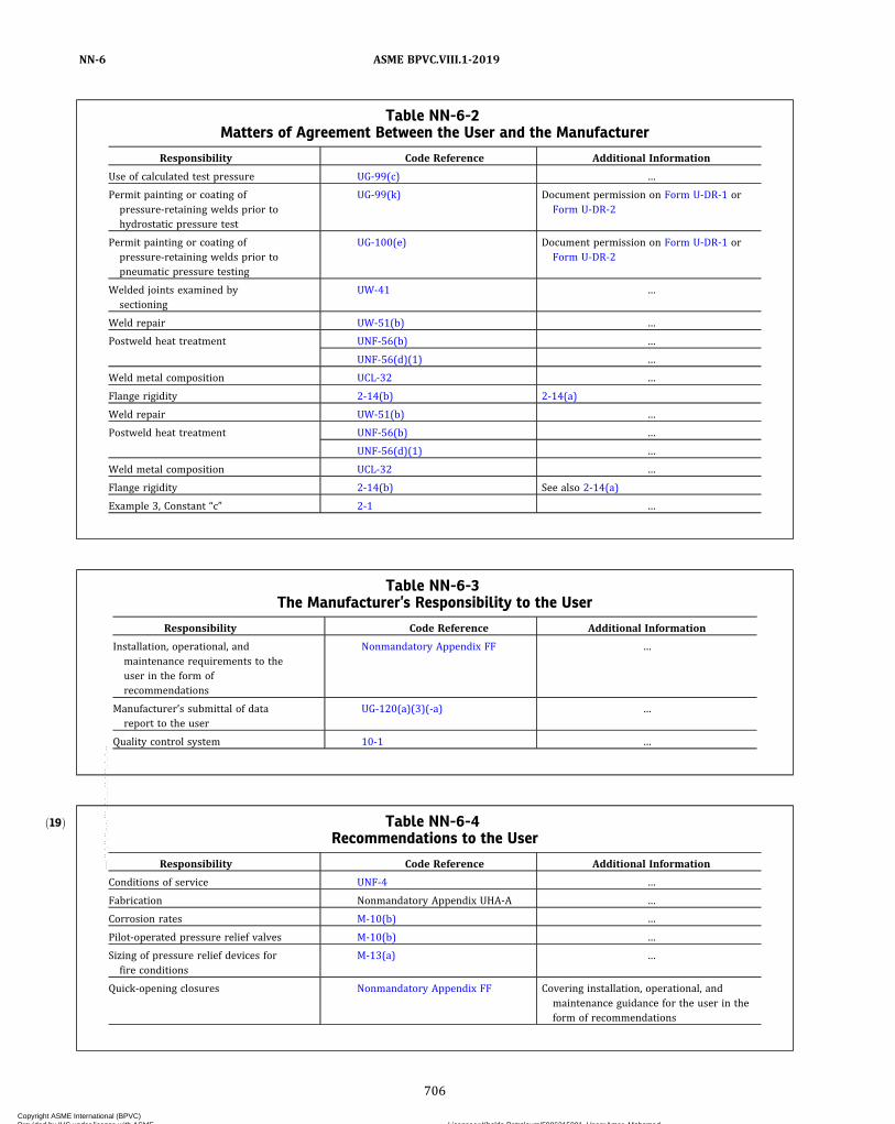
Table NN-6-2Matters of Agreement Between the User and the Manufacturer
Responsibility Code Reference Additional Information
Use of calculated test pressure UG-99(c) …
Permit painting or coating ofpressure-retaining welds prior tohydrostatic pressure test
UG-99(k) Document permission on Form U-DR-1 orForm U-DR-2
Permit painting or coating ofpressure-retaining welds prior topneumatic pressure testing
UG-100(e) Document permission on Form U-DR-1 orForm U-DR-2
Welded joints examined bysectioning
UW-41 …
Weld repair UW-51(b) …
Postweld heat treatment UNF-56(b) …
UNF-56(d)(1) …
Weld metal composition UCL-32 …
Flange rigidity 2-14(b) 2-14(a)
Weld repair UW-51(b) …
Postweld heat treatment UNF-56(b) …
UNF-56(d)(1) …
Weld metal composition UCL-32 …
Flange rigidity 2-14(b) See also 2-14(a)
Example 3, Constant “c” 2-1 …
Table NN-6-3The Manufacturer’s Responsibility to the User
Responsibility Code Reference Additional Information
Installation, operational, andmaintenance requirements to theuser in the form ofrecommendations
Nonmandatory Appendix FF …
Manufacturer’s submittal of datareport to the user
UG-120(a)(3)(-a) …
Quality control system 10-1 …
ð19Þ Table NN-6-4Recommendations to the User
Responsibility Code Reference Additional Information
Conditions of service UNF-4 …
Fabrication Nonmandatory Appendix UHA-A …
Corrosion rates M-10(b) …
Pilot-operated pressure relief valves M-10(b) …
Sizing of pressure relief devices forfire conditions
M-13(a) …
Quick-opening closures Nonmandatory Appendix FF Covering installation, operational, andmaintenance guidance for the user in theform of recommendations
ASME BPVC.VIII.1-2019NN-6
706
Copyright ASME International (BPVC) Provided by IHS under license with ASME Licensee=Khalda Petroleum/5986215001, User=Amer, Mohamed
Not for Resale, 07/02/2019 13:29:04 MDTNo reproduction or networking permitted without license from IHS
--`,``,``,,`,`,,````,`,``,,,`-`-`,,`,,`,`,,`---
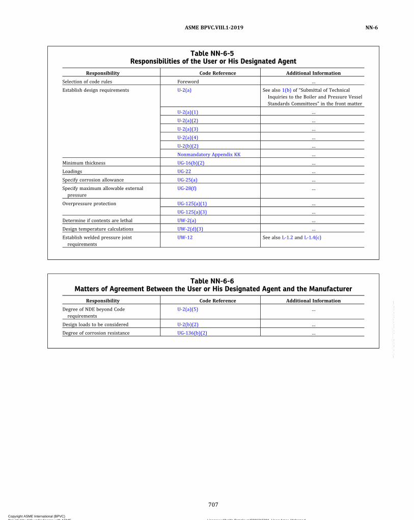
Table NN-6-5Responsibilities of the User or His Designated Agent
Responsibility Code Reference Additional Information
Selection of code rules Foreword …
Establish design requirements U-2(a) See also 1(b) of “Submittal of TechnicalInquiries to the Boiler and Pressure VesselStandards Committees” in the front matter
U-2(a)(1) …
U-2(a)(2) …
U-2(a)(3) …
U-2(a)(4) …
U-2(b)(2) …
Nonmandatory Appendix KK …
Minimum thickness UG-16(b)(2) …
Loadings UG-22 …
Specify corrosion allowance UG-25(a) …
Specify maximum allowable externalpressure
UG-28(f) …
Overpressure protection UG-125(a)(1) …
UG-125(a)(3) …
Determine if contents are lethal UW-2(a) …
Design temperature calculations UW-2(d)(3) …
Establish welded pressure jointrequirements
UW-12 See also L-1.2 and L-1.4(c)
Table NN-6-6Matters of Agreement Between the User or His Designated Agent and the Manufacturer
Responsibility Code Reference Additional Information
Degree of NDE beyond Coderequirements
U-2(a)(5) …
Design loads to be considered U-2(b)(2) …
Degree of corrosion resistance UG-136(b)(2) …
ASME BPVC.VIII.1-2019 NN-6
707
Copyright ASME International (BPVC) Provided by IHS under license with ASME Licensee=Khalda Petroleum/5986215001, User=Amer, Mohamed
Not for Resale, 07/02/2019 13:29:04 MDTNo reproduction or networking permitted without license from IHS
--`,``,``,,`,`,,````,`,``,,,`-`-`,,`,,`,`,,`---
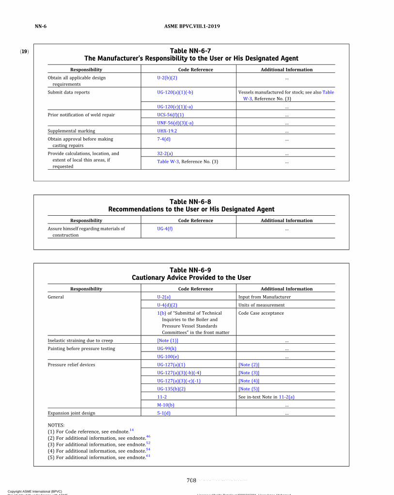
ð19Þ Table NN-6-7The Manufacturer’s Responsibility to the User or His Designated Agent
Responsibility Code Reference Additional Information
Obtain all applicable designrequirements
U-2(b)(2) …
Submit data reports UG-120(a)(1)(-b) Vessels manufactured for stock; see also TableW-3, Reference No. (3)
UG-120(c)(1)(-a) …
Prior notification of weld repair UCS-56(f)(1) …
UNF-56(d)(3)(-a) …
Supplemental marking UHX-19.2 …
Obtain approval before makingcasting repairs
7-4(d) …
Provide calculations, location, andextent of local thin areas, ifrequested
32-2(a) …
Table W-3, Reference No. (3) …
Table NN-6-8Recommendations to the User or His Designated Agent
Responsibility Code Reference Additional Information
Assure himself regarding materials ofconstruction
UG-4(f) …
Table NN-6-9Cautionary Advice Provided to the User
Responsibility Code Reference Additional Information
General U-2(a) Input from Manufacturer
U-4(d)(2) Units of measurement
1(b) of “Submittal of TechnicalInquiries to the Boiler andPressure Vessel StandardsCommittees” in the front matter
Code Case acceptance
Inelastic straining due to creep [Note (1)] …
Painting before pressure testing UG-99(k) …
UG-100(e) …
Pressure relief devices UG-127(a)(1) [Note (2)]
UG-127(a)(3)(-b)(-4) [Note (3)]
UG-127(a)(3)(-c)(-1) [Note (4)]
UG-135(b)(2) [Note (5)]
11-2 See in-text Note in 11-2(a)
M-10(b) …
Expansion joint design 5-1(d) …
NOTES:(1) For Code reference, see endnote.14
(2) For additional information, see endnote.46
(3) For additional information, see endnote.52
(4) For additional information, see endnote.54
(5) For additional information, see endnote.61
ASME BPVC.VIII.1-2019NN-6
708
Copyright ASME International (BPVC) Provided by IHS under license with ASME Licensee=Khalda Petroleum/5986215001, User=Amer, Mohamed
Not for Resale, 07/02/2019 13:29:04 MDTNo reproduction or networking permitted without license from IHS
--`,``,``,,`,`,,````,`,``,,,`-`-`,,`,,`,`,,`---
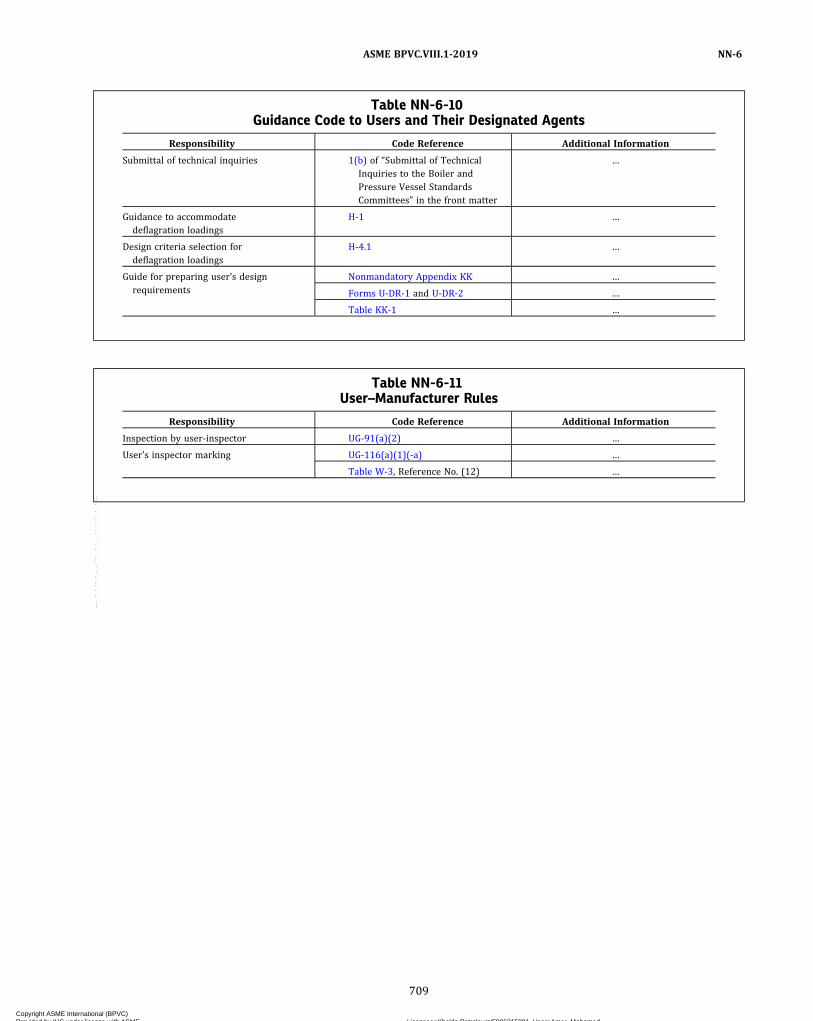
Table NN-6-10Guidance Code to Users and Their Designated Agents
Responsibility Code Reference Additional Information
Submittal of technical inquiries 1(b) of “Submittal of TechnicalInquiries to the Boiler andPressure Vessel StandardsCommittees” in the front matter
…
Guidance to accommodatedeflagration loadings
H-1 …
Design criteria selection fordeflagration loadings
H-4.1 …
Guide for preparing user’s designrequirements
Nonmandatory Appendix KK …
Forms U-DR-1 and U-DR-2 …
Table KK-1 …
Table NN-6-11User–Manufacturer Rules
Responsibility Code Reference Additional Information
Inspection by user-inspector UG-91(a)(2) …
User’s inspector marking UG-116(a)(1)(-a) …
Table W-3, Reference No. (12) …
ASME BPVC.VIII.1-2019 NN-6
709
Copyright ASME International (BPVC) Provided by IHS under license with ASME Licensee=Khalda Petroleum/5986215001, User=Amer, Mohamed
Not for Resale, 07/02/2019 13:29:04 MDTNo reproduction or networking permitted without license from IHS
--`,``,``,,`,`,,````,`,``,,,`-`-`,,`,,`,`,,`---

INTENTIONALLY LEFT BLANK
Copyright ASME International (BPVC) Provided by IHS under license with ASME Licensee=Khalda Petroleum/5986215001, User=Amer, Mohamed
Not for Resale, 07/02/2019 13:29:04 MDTNo reproduction or networking permitted without license from IHS
--`,``,``,,`,`,,````,`,``,,,`-`-`,,`,,`,`,,`---
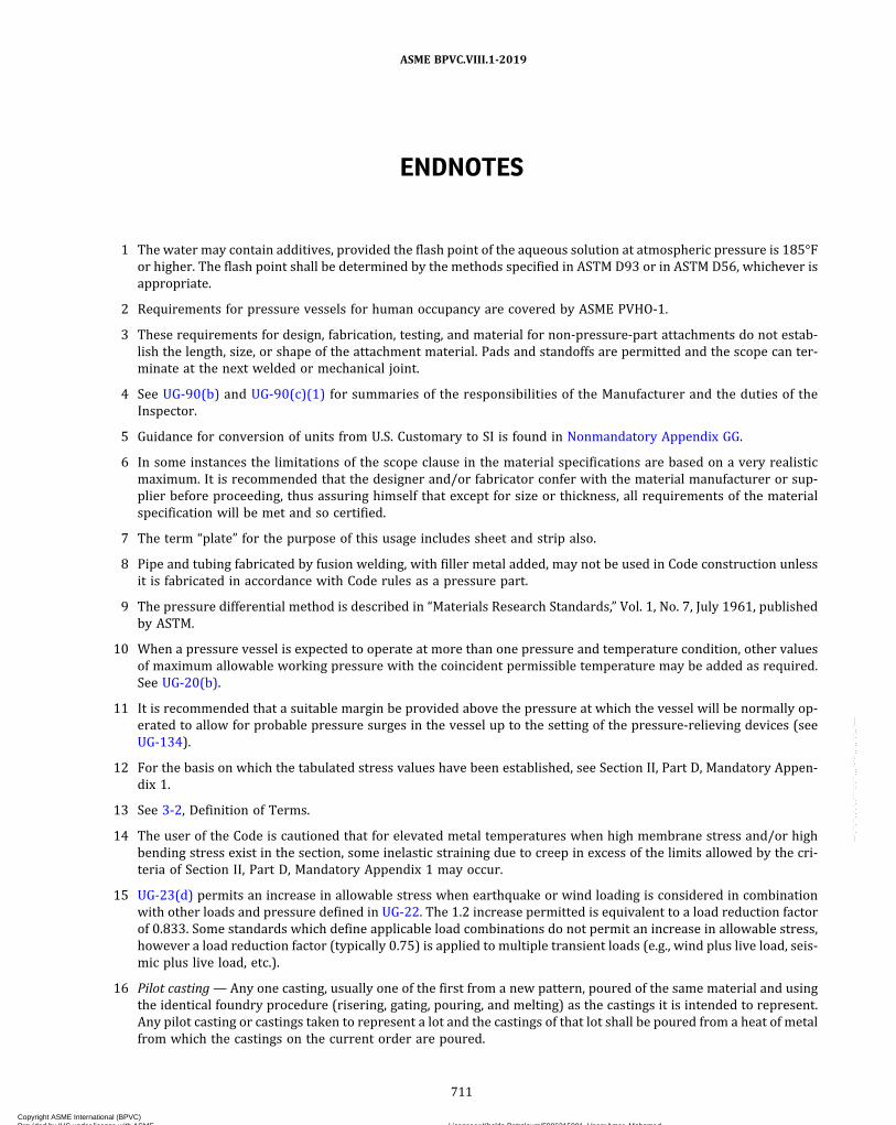
ENDNOTES
1 The water may contain additives, provided the flash point of the aqueous solution at atmospheric pressure is 185°For higher. The flash point shall be determined by the methods specified in ASTM D93 or in ASTM D56, whichever isappropriate.
2 Requirements for pressure vessels for human occupancy are covered by ASME PVHO‐1.
3 These requirements for design, fabrication, testing, and material for non-pressure-part attachments do not estab-lish the length, size, or shape of the attachment material. Pads and standoffs are permitted and the scope can ter-minate at the next welded or mechanical joint.
4 See UG-90(b) and UG-90(c)(1) for summaries of the responsibilities of the Manufacturer and the duties of theInspector.
5 Guidance for conversion of units from U.S. Customary to SI is found in Nonmandatory Appendix GG.
6 In some instances the limitations of the scope clause in the material specifications are based on a very realisticmaximum. It is recommended that the designer and/or fabricator confer with the material manufacturer or sup-plier before proceeding, thus assuring himself that except for size or thickness, all requirements of the materialspecification will be met and so certified.
7 The term “plate” for the purpose of this usage includes sheet and strip also.
8 Pipe and tubing fabricated by fusion welding, with filler metal added, may not be used in Code construction unlessit is fabricated in accordance with Code rules as a pressure part.
9 The pressure differential method is described in “Materials Research Standards,” Vol. 1, No. 7, July 1961, publishedby ASTM.
10 When a pressure vessel is expected to operate at more than one pressure and temperature condition, other valuesof maximum allowable working pressure with the coincident permissible temperature may be added as required.See UG-20(b).
11 It is recommended that a suitable margin be provided above the pressure at which the vessel will be normally op-erated to allow for probable pressure surges in the vessel up to the setting of the pressure-relieving devices (seeUG-134).
12 For the basis on which the tabulated stress values have been established, see Section II, Part D, Mandatory Appen-dix 1.
13 See 3-2, Definition of Terms.
14 The user of the Code is cautioned that for elevated metal temperatures when high membrane stress and/or highbending stress exist in the section, some inelastic straining due to creep in excess of the limits allowed by the cri-teria of Section II, Part D, Mandatory Appendix 1 may occur.
15 UG-23(d) permits an increase in allowable stress when earthquake or wind loading is considered in combinationwith other loads and pressure defined in UG-22. The 1.2 increase permitted is equivalent to a load reduction factorof 0.833. Some standards which define applicable load combinations do not permit an increase in allowable stress,however a load reduction factor (typically 0.75) is applied to multiple transient loads (e.g., wind plus live load, seis-mic plus live load, etc.).
16 Pilot casting— Any one casting, usually one of the first from a new pattern, poured of the same material and usingthe identical foundry procedure (risering, gating, pouring, and melting) as the castings it is intended to represent.Any pilot casting or castings taken to represent a lot and the castings of that lot shall be poured from a heat of metalfrom which the castings on the current order are poured.
ASME BPVC.VIII.1-2019
711
Copyright ASME International (BPVC) Provided by IHS under license with ASME Licensee=Khalda Petroleum/5986215001, User=Amer, Mohamed
Not for Resale, 07/02/2019 13:29:04 MDTNo reproduction or networking permitted without license from IHS
--`,``,``,,`,`,,````,`,``,,,`-`-`,,`,,`,`,,`---
17 Critical sections: For static castings, the sections where imperfections are usually encountered are abrupt changesin section and at the junctions of risers, gates, or feeders to the casting. For centrifugal castings, critical sectionsshall be interpreted to be any abrupt changes of section, the circumference for a distance of at least 3 in.(75 mm) from each end, and one additional circumferential band at least 3 in. (75 mm) wide and including the areaof the most severe indication detected by other examination methods.
18 Formulas in terms of the outside radius and for thicknesses and pressures beyond the limits fixed in this paragraphare given in 1-1 to 1-3.
19 For pipe, the inside radius R is determined by the nominal outside radius minus the nominal wall thickness.
20 These formulas will govern only when the circumferential joint efficiency is less than one‐half the longitudinal jointefficiency, or when the effect of supplementary loadings (UG-22) causing longitudinal bending or tension in con-junction with internal pressure is being investigated.
21 It is recommended that a suitable margin be provided when establishing the maximum allowable external workingpressure to allow for pressure variations in service.
22 In order to ensure that a finished head is not less than the minimum thickness required, it is customary to use athicker plate to take care of possible thinning during the process of forming. The neck of an opening in a head withan integrally flanged opening will thin out due to the fluing operation. This is permissible, provided the neck thick-ness is not less than the thickness required for a cylindrical shell subject to internal and/or external pressure, asapplicable, and having an inside diameter equal to the maximum diameter of the opening [see UG-38(a) andUG-46(j)].
23 Formulas in terms of outside dimensions and for heads of other proportions are given in 1-4.
24 Special consideration shall be given to the design of shells, nozzle necks or flanges to which noncircular heads orcovers are attached [see U-2(g)].
25 The formulas provide safe construction as far as stress is concerned. Greater thicknesses may be necessary if de-flection would cause leakage at threaded or gasketed joints.
26 The rules governing openings as given in this Division are based on the stress intensification created by the exis-tence of a hole in an otherwise symmetrical section. External loadings such as those due to the thermal expansionor unsupported weight of connecting piping have not been evaluated. These factors should be given attention inunusual designs or under conditions of cyclic loading.
27 The opening made by a pipe or a circular nozzle, the axis of which is not perpendicular to the vessel wall or head,may be considered an elliptical opening for design purposes.
28 An obround opening is one which is formed by two parallel sides and semicircular ends.
29 In the corroded condition, see UG-16(e).
30 All dimensions given, for size of vessel on which inspection openings are required, are nominal.
31 Dimensions referred to are nominal.
32 The minimum cross section is usually at the root of the thread.
33 The rules in this paragraph apply to ligaments between tube holes and not to single openings. They may give lowerefficiencies in some cases than those for symmetrical groups which extend a distance greater than the inside dia-meter of the shell as covered in (e) above. When this occurs, the efficiencies computed by the rules under (b) aboveshall govern.
34 Where applicable for Part UCS materials, the impact test temperature may be adjusted in accordance withUG-84(b)(2) and Table UG-84.4.
35 The maximum allowable working pressure may be assumed to be the same as the design pressure when calcula-tions are not made to determine the maximum allowable working pressure.
36 In some cases it is desirable to test vessels when partly filled with liquids. For such vessels a combined hydrostaticand pneumatic test may be used as an alternative to the pneumatic test of this paragraph, provided the liquid levelis set so that the maximum stress including the stress produced by pneumatic pressure at any point in the vessel
ASME BPVC.VIII.1-2019
712
Copyright ASME International (BPVC) Provided by IHS under license with ASME Licensee=Khalda Petroleum/5986215001, User=Amer, Mohamed
Not for Resale, 07/02/2019 13:29:04 MDTNo reproduction or networking permitted without license from IHS
--`,``,``,,`,`,,````,`,``,,,`-`-`,,`,,`,`,,`---

(usually near the bottom) or in the support attachments, does not exceed 1.3 times the allowable stress value of thematerial multiplied by the applicable joint efficiency. After setting the liquid level to meet this condition, the test isconducted as prescribed in (b) and (c) above.Air or gas is hazardous when used as a testing medium. It is therefore recommended that special precautions betaken when air or gas is used for test purposes.
37 Examples of the use of modeling techniques are found in UG-127(a)(2)(-a)(-1)(+b) and UG-131(d)(2)(-b), or referto textbooks on the subject.
38 The maximum allowable working pressure (external) is required only when specified as a design condition.
39 See UG-90(c)(2) for additional requirements applicable to mass produced pressure vessel fabrication.
40 In this usage, organization may be the same company at a single site, a multiplant company with separate Certi-ficates of Authorization, regardless of type, or a multiplant corporation with extended corporate Certificates ofAuthorization.
41 For the purpose of these rules, gases are considered to be substances having a vapor pressure greater than 40 psia(300 kPa absolute) at 100°F (40°C).
42 Normally this temperature should not be less than 115°F (45°C).
43 A pressure relief valve is a pressure relief device which is designed to reclose and prevent the further flow of fluidafter normal conditions have been restored. A nonreclosing pressure relief device is a pressure relief device de-signed to remain open after operation.
44 A safety valve is a pressure relief valve actuated by inlet static pressure and characterized by rapid opening or popaction. A relief valve is a pressure relief valve actuated by inlet static pressure which opens in proportion to theincrease in pressure over the opening pressure. A safety relief valve is a pressure relief valve characterized by rapidopening or pop action, or by opening in proportion to the increase in pressure over the opening pressure, depend-ing on application. A pilot-operated pressure relief valve is a pressure relief valve in which the major relieving deviceis combined with and is controlled by a self‐actuated auxiliary pressure relief valve.
45 A rupture disk device is a nonreclosing pressure relief device actuated by inlet static pressure and designed to func-tion by the bursting of a pressure-containing disk. A rupture disk is the pressure-containing and pressure-sensitiveactivation component of a rupture disk device. Rupture disks may be designed in several configurations, such asplain flat, prebulged, or reverse buckling. A rupture disk holder is the structure that encloses and clamps the rup-ture disk in position.
46 The manufacturing design range is a range of pressure within which the marked burst pressure must fall to be ac-ceptable for a particular requirement as agreed upon between the rupture disk Manufacturer and the user or hisdesignated agent. The manufacturing design range must be evaluated in conjunction with the specified burst pres-sure to ensure that the marked burst pressure of the rupture disk will always be within applicable limits of UG-134.Users are cautioned that certain types of rupture disks have manufacturing ranges that can result in a marked burstpressure greater than the specified burst pressure.
47 The specified disk temperature supplied to the rupture disk Manufacturer shall be the temperature of the diskwhen the disk is expected to burst.
48 A lot of rupture disks is those disks manufactured of a material at the same time, of the same size, thickness, type,heat, and manufacturing process including heat treatment.
49 The minimum net flow area is the calculated net area after a complete activation of the rupture disk or pin devicewith appropriate allowance for any structural members which may reduce the net flow area through the device.The net flow area for sizing purposes shall not exceed the nominal pipe size area of the rupture disk device.
50 The certified flow resistance KR is a dimensionless factor used to calculate the velocity head loss that results fromthe presence of a nonreclosing pressure relief device in a pressure relief system.
51 Use of a rupture disk device in combination with a pressure relief valve shall be carefully evaluated to ensure thatthe media being handled and the valve operational characteristics will result in opening of the valve coincidentwith the bursting of the rupture disk.
ASME BPVC.VIII.1-2019
713
Copyright ASME International (BPVC) Provided by IHS under license with ASME Licensee=Khalda Petroleum/5986215001, User=Amer, Mohamed
Not for Resale, 07/02/2019 13:29:04 MDTNo reproduction or networking permitted without license from IHS
--`,``,``,,`,`,,````,`,``,,,`-`-`,,`,,`,`,,`---

52 Users are warned that a rupture disk will not burst at its design pressure if back pressure builds up in the spacebetween the disk and the pressure relief valve which will occur should leakage develop in the rupture disk due tocorrosion or other cause.
53 This use of a rupture disk device in series with the pressure relief valve is permitted to minimize the loss by leakagethrough the valve of valuable or of noxious or otherwise hazardous materials, and where a rupture disk alone ordisk located on the inlet side of the valve is impracticable, or to prevent corrosive gases from a common dischargeline from reaching the valve internals.
54 Users are warned that many types of pressure relief valves will not open at the set pressure if pressure builds up inthe space between the pressure relief valve disk and the rupture disk device. A specially designed pressure reliefvalve such as a diaphragm valve, pilot-operated valve, or a valve equipped with a balancing bellows above the diskmay be required.
55 Some adverse effects resulting from leakage may include obstructing the flow path, corrosion of pressure reliefvalve components, and undesirable bursts of the outlet side rupture disk.
56 A pin device is a nonreclosing pressure relief device actuated by inlet static or differential pressure and designed tofunction by the activation of a load bearing section of a pin that supports a pressure-containing member. A pin isthe load bearing activation component of a pin device its crosssectional area is not limited to a circular shape. A pindevice body is the structure that encloses the pressure-containing members.
57 The specified temperature supplied to the pin manufacturer shall be the temperature of the pin when an emer-gency condition exists and the pin is expected to activate.
58 Vacuum relief devices are not covered by Certification Mark requirements.
59 Pressure relief device capacities flow resistances are published in “Pressure Relief Device Certifications.” This pub-lication may be obtained from the National Board of Boiler and Pressure Vessel Inspectors, 1055 Crupper Avenue,Columbus, OH 43229.
60 The set pressure is the value of increasing inlet static pressure at which a pressure relief device displays one of theoperational characteristics as defined by opening pressure, popping pressure, start‐to‐leak pressure, burst pres-sure, breaking pressure or buckling pressure. (The applicable operating characteristic for a specific device designis specified by the device Manufacturer.)
61 Users are warned that the proper operation of nonreclosing pressure relief devices depends upon following theManufacturer’s installation instructions closely with regard to the flow direction marked on the device. Some de-vice designs will burst at pressures much greater than their marked burst pressure when installed with the processpressure on the vent side of the device.
62 The User may specify a higher test pressure commensurate with the back pressure anticipated in service.
63 The pin temperature may be different from the operating temperature for devices where the pin is isolated fromoperating conditions.
64 By “lethal substances” are meant poisonous gases or liquids of such a nature that a very small amount of the gas orof the vapor of the liquid mixed or unmixed with air is dangerous to life when inhaled. For purposes of this Division,this class includes substances of this nature which are stored under pressure or may generate a pressure if storedin a closed vessel.
65 Communicating chambers are defined as appurtenances to the vessel which intersect the shell or heads of a vesseland form an integral part of the pressure-containing enclosure, e.g., sumps.
66 Side plates of a flat‐sided vessel are defined as any of the flat plates forming an integral part of the pressure-containing enclosure.
67 One test specimen may represent a group of forgings, provided they are of the same design, are from the same heatof material and are forged in the same manner.
68 Welder includes brazer, welding operator, and brazing operator.
69 Examination shall be by magnetic particle or liquid penetrant methods when the material is ferromagnetic, or bythe liquid penetrant method when the material is nonferromagnetic.
ASME BPVC.VIII.1-2019
714
Copyright ASME International (BPVC) Provided by IHS under license with ASME Licensee=Khalda Petroleum/5986215001, User=Amer, Mohamed
Not for Resale, 07/02/2019 13:29:04 MDTNo reproduction or networking permitted without license from IHS
--`,``,``,,`,`,,````,`,``,,,`-`-`,,`,,`,`,,`---
70 It is not the intent of this paragraph to require measurement of reductions in thickness due to the welding process.If a disagreement between the Manufacturer and the Inspector exists as to the acceptability of any reduction inthickness, the depth shall be verified by actual measurement.
71 Concavity due to the welding process on the root side of a single-welded circumferential butt weld is permittedwhen the resulting thickness of the weld is at least equal to the thickness of the thinner member of the two sectionsbeing joined and the contour of the concavity is smooth.
72 Furnace gas temperature measurement alone is not considered sufficiently accurate.
73 Flux residues can be extremely corrosive as well as interfering with visual inspection.
74 Low alloy steels — those alloy steels listed in Table UCS-23.
75 See Section II, Part D, Mandatory Appendix 1 for the basis on which the allowable stress values have beenestablished.
76 The rates of heating and cooling need not be less than 100°F/hr (56°C/h). However, in all cases consideration ofclosed chambers and complex structures may indicate reduced rates of heating and cooling to avoid structuraldamage due to excessive thermal gradients.
77 No provisions of this paragraph waive other requirements of this Division, such as UW-2(a), UW-2(d), UW-10, andUCS-56.
78 This is defined in Section V, Article 2, T-277, and A-1(a).
79 Thermal treatments of materials are not intended to include warming to temperatures not exceeding 600°F(315°C), thermal cutting, or welding.
80 Either base metal or weld metal.
81 Calculated stress from pressure and nonpressure loadings, including those listed in UG-22 which result in generalprimary membrane tensile stress.
82 See Section II, Part D, Nonmandatory Appendix A, A-206.
83 By “lethal substances” are meant poisonous gases or liquids of such a nature that a very small amount of the gas orof the vapor of the liquid mixed or unmixed with air is dangerous to life, when inhaled. For purposes of this Divi-sion, this class includes substances of this nature which are stored under pressure or may generate a pressure ifstored in a closed vessel.
84 It is the intent that cast ductile irons with an elongation of less than 15% in 2 in. (50 mm) be treated as cast ironand that vessels or pressure parts of such material be designed and fabricated in accordance with the rules inPart UCI.
85 Buttered means buildup overlay welding.
86 Temper bead welding technique is done when the final beads of welding are made over‐flush, deposited only onprevious beads of welding for tempering purposes without making contact with the base metal, and then removingthese final beads.
87 Layer wash is defined as the indications resulting from slight weld penetration at the layer interfaces.
88 Ellipsoidal heads designed under K > 1.0 and all torispherical heads made of materials having a specified minimumtensile strength exceeding 70,000 psi (485 MPa) shall be designed using a value of S equal to 20,000 psi (138 MPa)at room temperature and reduced in proportion to the reduction in maximum allowable stress values at tempera-ture for the material as shown in the appropriate table (see UG-23).
89 When the flange material is cast iron, particular care should be taken when tightening the bolts to avoid excessivestress that may break the flange. The longitudinal hub stress has been limited to Sf in order to minimize any crack-ing of flanges. An attempt should be made to apply no greater torque than is needed to assure tightness during thehydrostatic test.
90 Loose flanges of the type shown in Figure 2-4, sketch (1) are of the split design when it is necessary to install themafter heat treatment of a stainless steel vessel, or when for any reason it is desired to have them completely remo-vable from the nozzle neck or vessel.
ASME BPVC.VIII.1-2019
715
Copyright ASME International (BPVC) Provided by IHS under license with ASME Licensee=Khalda Petroleum/5986215001, User=Amer, Mohamed
Not for Resale, 07/02/2019 13:29:04 MDTNo reproduction or networking permitted without license from IHS
--`,``,``,,`,`,,````,`,``,,,`-`-`,,`,,`,`,,`---

91 When internal pressure occurs only during the required pressure test, the design may be based on external pres-sure, and auxiliary devices such as clamps may be used during the application of the required test pressure.
92 The Code as currently written provides minimum requirements for construction and it is recognized to be the re-sponsibility of the designing engineer to determine when the intended service is of a nature that requires supple-mentary requirements to ensure safety; consequently, the designer should determine when the service warrantsthat this class of inspection be specified for steel castings of less than 4 in. (100 mm) nominal body thickness.
93 The coefficients of these formulas include a factor that effectively increases the allowable stress for such construc-tion to 1.5S .
94 The complexity of the work includes factors such as design simplicity versus complexity, the types of materials andwelding procedures used, the thickness of materials, the types of nondestructive examinations applied, andwhether heat treatments are applied.
95 The size and complexity of the organization includes factors such as the number of employees, the experience levelof employees, the number of Code items produced, and whether the factors defining the complexity of the workcover a wide or narrow range.
96 Knowing the official rating capacity of a safety valve which is stamped on the valve, it is possible to determine theoverall value of KA in either of the following formulas in cases where the value of these individual terms is notknown:
Official Rating in Steam Official Rating in Air
This value for KA is then substituted in the above formulas to determine the capacity of the safety valve in terms ofthe new gas or vapor.
97 Use E = 1.0 for Category C and D joints that are not butt welded since stresses in these joints are controlled by theapplicable rules for sizing such joints. See Figures UG-34 and UW-13.2
98 I = bt 3/12 where b = 1.0 for vessels without reinforcements and for vessels with stay plates or stay rods. I = pt 3/12 for vessels with reinforcements that do not extend around the corners of the vessel [see Figure 13-2(a),sketches (5) and (6)].
99 For unreinforced vessels of rectangular cross section (13-7 and parts of 13-18), the given moments are defined ona per‐unit‐width basis. That is, moments have dimensions [Length × Force/Length] = [Force].
100 See Manual of Steel Construction, AISC, American Institute of Steel Construction, Inc., One East Wacker Drive, Chi-cago, IL 60601‐1802.
101 Air or gas is hazardous when used as a testing medium. It is therefore recommended the vessel be tested in such amanner as to ensure personnel safety from a release of the total internal energy of the vessel. See also ASME PCC‐2,Article 501, Mandatory Appendix 501-II, “tored Energy Calculations for Pneumatic Pressure Test,” and MandatoryAppendix 501-III, “Safe Distance Calculations for Pneumatic Pressure Test.”
102 When using high alloys and nonferrous materials either for solid wall or clad or lined vessels, refer to UHA-6,UCL-3, and UNF-4, as appropriate.
103 See “Stresses in Large Cylindrical Pressure Vessels on Two Saddle Supports,” p. 959, Pressure Vessels and Piping:Design and Analysis, A Decade of Progress, Volume Two, published by ASME.
104 See Transactions ASCE, Volume 98 — 1931 “Design of Large Pipe Lines.”
105 This construction has the further advantage of not transmitting discharge‐pipe strains to the valve. In these typesof installation, the back pressure effect will be negligible, and no undue influence upon normal valve operation canresult.
106 A Nonmandatory Appendix Y flange bolted to a rigid foundation may be analyzed as a Class 1 assembly by substi-tuting 2l for l in eq. Y-6.1(12) of Y-6.1.
ASME BPVC.VIII.1-2019
716
Copyright ASME International (BPVC) Provided by IHS under license with ASME Licensee=Khalda Petroleum/5986215001, User=Amer, Mohamed
Not for Resale, 07/02/2019 13:29:04 MDTNo reproduction or networking permitted without license from IHS
--`,``,``,,`,`,,````,`,``,,,`-`-`,,`,,`,`,,`---

107 Where the flanges are identical dimensionally and have the same elastic modulus E , but have different allowablestresses Sf , the assembly may be analyzed as a Class 1 assembly, provided the calculated stresses are evaluatedagainst the lower allowable stress.
108 The symbols for the various stresses in the case of a Class 3 assembly also carry the subscript I or II. For example,SH I represents the longitudinal hub stress in Flange I of the Class 3 assembly.
109 Manufacturers are cautioned to calculate the minimum ratio based upon mill test values of the tube and tubesheet.
110 The Manufacturer may correlate rolling torque, hydraulic expanding pressure, or explosive charge with shear loadtests. For explosive expanding, the Manufacturer may correlate interference of fit.
ASME BPVC.VIII.1-2019
717
Copyright ASME International (BPVC) Provided by IHS under license with ASME Licensee=Khalda Petroleum/5986215001, User=Amer, Mohamed
Not for Resale, 07/02/2019 13:29:04 MDTNo reproduction or networking permitted without license from IHS
--`,``,``,,`,`,,````,`,``,,,`-`-`,,`,,`,`,,`---

ASME Boiler andPressure Vessel CodeAN I N T E R N A T I O N A L C O D E
• referenced standards• related standards and guidelines• conformity assessment programs• personnel certification programs• learning and development solutions• ASME Press books and journals
You gain unrivaled insight direct from the BPVC source, along with the professional quality and real-world solutions you have come to expect from ASME.
For additional information and to order:Phone: 1.800.THE.ASME (1.800.843.2763)Email: [email protected]: go.asme.org/bpvc
2019Since its first issuance in 1914, the ASME Boiler and Pressure Vessel Code (BPVC) has been a flagship for modern international standards development. Each new edition reaffirms ASME’s commitment to enhance public safety and encourage technological advancement to meet the needs of a changing world. Sections of the BPVC have been incorporated into law in the United States and Canada, and are used in more than 100 countries. The BPVC has long been considered essential within the electric power generation, petrochemical, and transportation industries, among others. ASME also provides BPVC users with integrated suites of related offerings, including
Copyright ASME International (BPVC) Provided by IHS under license with ASME Licensee=Khalda Petroleum/5986215001, User=Amer, Mohamed
Not for Resale, 07/02/2019 13:29:04 MDTNo reproduction or networking permitted without license from IHS
--`,``,``,,`,`,,````,`,``,,,`-`-`,,`,,`,`,,`---