"half-bead (temper) repair welding for heavy-section steel
TRANSCRIPT
NUREG/CR-0113ORNL/NUREG/TM-177
A
Half-Bead (Temper) Repair Weldingfor Heavy-Section Steel Technology
Program Vessels
S. W. WismerP. H. Holz
, ,
" "
e#m
gE}k'~t' ,n n
,
Prepared for the U.S. Nuclear Regulatory CommissionOffice of Nuclear Regulatory Research
Under Interagency Agreenients DOE 40-551-75 and 40-552-75
,.;,_ __ _ . . . , . _ .
si
i
Ii
|
s
}
s.
i'
|-
]\ | ,1
1
N'
* g p g ge i. a ge i
: a
-3
.a
?s
--{ ,'l
$ Ii14
_ . , . . . . . . . . _ -
:
II
Ii
!
:i
!
k [9 i
9e8.
-
Printed in the United States of America. Available fromNational Technical Information Service
U.S. Departrnent of Commerce5285 Port Royal Road, Springfield, Virginia 22161
Price. Printed Cooy $7.25; Microfiche $3.00..
This report was prepared as an account of work sponscred by an agency of theUnitedStates Government Ne, thor the Un<ted states Governmer.t nor any agency thereof notany of their emp!oyees, contractors subcontractors. or their emp|oyees, rnakes anywarranty, expre5s or imphed. nor assumes any !egal habihty or responsib:h*y for anythird party's use or tN results of such use of any information, apparatus, product orprocess disclosed in this report. nor represents that its use by such third party wouldnot inf onge privateifcvv r :g n ts.
2194 130
_ _ . .. . . . . . . . _ _ . _ _ _ . . . . . _ _ _ _ . . . _ _ _ _ _
NUREG/CR-0113ORNL/NUREG/TM-177Dist. Category RS
Contract No. W-7405-eng-26
Engineering Technology Division
HALF-BEAD (TEMPER) REPAIR WELDING FOR HEAVY-SECTIONSTEEL TECHNOLOGY PROGRAM VESSELS
S. W. Wismer, Westinghouse Tampa DivisionP. P. Holz, Oak Ridge National Laboratory
Manuscript Completed - May 18, 1978Date Published - June 1978
Prepared for theU.S. Nuclear Regulatory Commission
Office of Nuclear Regulatory ResearchUnder Interagency Agreements DOE 40-551-75 and 40-552-75
NRC FIN No. B0119
Prepared by theOAK RIDGE NATIONAL LABORATORYOak Ridge, Tennessee 37830
operated byUNION CARBIDE CORPORATION
for theDEPARTMENT OF ENERGY
2194 13I
111
CONTENTS
Page
FOREWORD ....................................................... y
ABSTRACT ....................................................... 1
1. INTRODUCTION ............................................... 2
2. GENERAL.................................................... 6
2.1 Welding ............................................... 6
2.2 Electrode Baking ...................................... 6
2.3 Heating Techniques .................................... 7
3. WELDING SEQUENCE ........................................... 10
3.1 Prolongation .......................................... 10
3.2 Vessel V-7B ........................................... 22
3.3 Vessel V-8 ............................................ 35
3.4 Pl a t e 5 7 a nd We ld Co u pons . . . . . . . . . . . . . . . . . . . . . . . . . . . . . 38
3.5 Tensile Test Plates 39...................................
4. RECOMMENDATIONS ............................................ 43
ACKNOWLEDGMENTS 45................................................
REFERENCES ..................................................... 46
APPENDIX ....................................................... 47
2194 132

v
FDREWORD
"ais report is designated Heavy-Section Steel Technology Program
Tec'inical Report No. 49. Prior reports in this series are listed below.
1. S. Yukawa, Evaluation of Periodic Proof Testing and Warm PrestressingProcedures for Nuclear Reactor Vessels, HSSTP-TR-1, General ElectricCompany, Schenectady, N.Y. (July 1, 1969).
2. L. W. Loechel, The Effect of Section Size on the Transition Tempera-ture in Steel, MCR-69-189, Martin Marietta Corporation, Denver, Colo.(Nov. 20, 1969).
3. P. N. Randall, Gross Strain Measure of Eracture Toughness of Steels,HSSTP-TR-3, TRW Systems Group, Redondo Beach, Calif. (Nov. 1, 1969).
4. C. Visser, S. E. Gabrielse, and W. VanBuren, A Tbo-Dimensional Elastic-Plastic Analysis of Eracture Test Specimens, WCAP-7368, WestinghouseElectric Corporation, PWR Systems Division, Pittsburgh, Pa. (October1969).
5. T. R. Mager, F. O. Thomas, and W. S. Hazelton, Evaluation by LinearElastic Fracture Mechanics of Radiation Damage to Pressure VesselSteels, WCAP-7328 (Rev.), Westinghouse Electric Corporation, PWRSystems Division, Pittsburgh, Pa. (October 1969).
6. W. O. Shabbits, W. H. Pryle, and E. T. Wessel, Heavy Section FractureToughness Properties of A533 Grade B Class 1 Steel Plate and SubmergedArc V' ldment, WCAP-7414, Westinghouse Electric Corporation, PWR SystemseDivision, Pittsburgh, Pa. (December 1969).
7. F. J. Loss, Dynamic Tear Test Investigations of the Fracture Toughnessof 7 hick-Section Steel, NRL-7056, U.S. Naval Research Laboratory,Washington, D.C. (May 14, 1970).
8. P. B. Crosley and E. J. Ripling, Crack Arrest Eracture Toughness ofA533 Crade B Class 1 Pressure Vessel Steel, HSSTP-TR-8, MaterialsResearch Laboratory, Inc., Glenwood, Ill. (March 1970).
9. T. R. Mager, Post-Irradiation Testing of 2 T Compact Tension Specimens,WCAP-7561, Westinghouse Electric Corporation, PWR Systems Division,Pittsburgh, Pa. (August 1970).
10. T. R. Mager, Fracture Toughness Characterization Study of A 533,Crads B, Class 1 Steel, WCAP-7578, Westinghouse Electric Corporation,PWR Systems Division, Pittsburgh, Pa. (October 1970).
11. T. R. Mager, Notch Preparation in Compact Tension Specimens, WCAP-7579, Westinghouse Electric Corporation, PWR Systems Division,Pittsburgh, Pa. (November 1970).
2194 133
vi
12. N. Levy and P. V. Marcal, Three Dimensional Elastic-Plastic Stressand Strain Analysis for Fracture Mechanics, Phase I: Simple FlavedSpecimens, HSSTP-TR-12, Brown University, Providence, R.I. (Decerber1970).
13. W. O. Shabbits, Dynamic Fracture Toughness Properties of Heavy SectionA533 Crade B, Class 1 Steel Plate, WCAP-7623, Westinghouse ElectricCorporation, PWR Systems Division, Pittsburgh, Pa. (December 1970).
14. P. N. Randall, Gross Stmin Crack Tolerance of A533-B Steel, USSTP-TR-14, TRW Systems Group, Redondo Beach, Calif. (May 1, 1971).
15. H. T. Corten and R. H. Sailors, Relationship Between Material FractureToughness Using Fracture Mechanics and Transition Temperature Tests,T&AM Report 346, University of Illinois, Urbana, Ill. (Aug. 1, 1971).
16. T. R. Mager and V. J. McLoughlin, The Effect of an Environment ofHigh Temperature Primary Grade Nuclear Reactor Water and the FatigueCrack Grouth Characteristics of A 533 Grade B Class 1 Plate andWeldment Material, WCAP-7776, Westinghouse Electric Corporation, PWRSystems Division, Pittsburgh, Pa. (October 1971).
17. N. Levy and P. V. Marcal, Three-Dimensional Elastic-Plastic Stressand Strain Analysis for Fracture Mechanics, Phase II: ImprovedModeling, HSSTP-TR-17, Brown University, Providence, R.I. (November1971).
18. S. C. Grigory, Six-Inch-Thich Flaved Tencile Tests, First TechnicalSummary Report, Longitudinal Specimens 1 through 7, HSSTP-TR-18,Southwest Research Institute, San Antonio, Tex. (June 1972).
19. P. N. Randall, Effects of Strain Gradients on the Gross Strain CrackTolerance of A 533-B Steel, HSSTP-TR-19, TRW Systems Group, RedondoBeach, Calif. (May 1, 1972).
20. S. C. Grigory, Tests of Six-Inch-Thick Flaced Tensile Specimena,Second Technical Summry Report, Transverse Specimens Numbers 8through lo, Welded Specimens Numbers 11 through 13, HSSTP-TR-20,Southwest Research Institute, San Antonio, Tex. (June 1972).
21. L. A. James and J. A. Williams, Heavy Section Steel Technology ProgramTechnical Report No. 21, The Effect of Temperature and Neutron Irradi-ation upon the Fatigue-Crack Propagation Behavior of ASTM A533, GradeB, Class 1 Steel, HEDL-TME-72-132, Hanford Engineering DevelopmentLaboratory, Richland, Wash. (September 1972) .
22. S. C. Grigory, Tests of Six-Inch-Thick Flaced Tensile Specimens,Third Technical Summry Report, Longitudinal Specimens Numbers 14through 16, Unflawed Specimen Number 17, HSSTP-TR-22, SouthwestResearch Institute, San Antonio, Tex. (October 1972).
2194 134
vii
23. S. C. Grigory, Tests of Six-Inch-Thick Flaved Tensile Specimens,Fourth Technical Sumnary Report, Tests of One-Inch-Thick FlavedTensile Specimens for Size Effect Evaluation, HSSTP-TR-23, SouthuestResearch Institute, San Antonio, Tex. (June 1973).
24. S. P. Ying and S. C. Grigory, Tests of Six-Inch-Thick Tensile Speci-mens, Fifth Technical. Summary Report, Acoustic Emission Monitoringof One-Inch and Six-Inch-Thick Tensile Specimens, USSTP-TR-24,Southwest Research Institute, San Antonio, Tex. (November 1972).
25. R. W. Derby et al. , Test of 6-Inch-Thick Pressure Vessels, Series 1:Intermediate Test Vessels V-1 and V-2, ORNL-4895, Oak Ridge NationalLaboratory, Oak Ridge, Tenn. (February 1974).
26. W. J. Stelzman and R. G. Berggren, Radiation Strengthening and an-brittlement in Heavy Section Plates and Welds, ORNL-4871 (June 1973) .
27. P. B. Crosley and E. J. Ripling, Cmck Arrest in an Increasing x-Field, HSSTP-TR-27, Materials Research Laboratory, Glenwood, Ill.(January 1973).
28. P. V. Marcal, P. M. Stuart, and R. S. Bettes, Elastic-Plastic Be-havior of a Longitudinal and Semi-Elliptical Crack in a Thick Pres-surc Vessel, Brown University, Providence, R.I. (June 1973).
29. W. J. Stelzman, Characterization of HSST Plate 02 (in preparation) .
30. D. A. Canonico, Chameterization of Heavy Section Weldments in Pres-sure Vessel Steels (in preparation).
31. J. A. Williams, The Irradiation and Tempemture Dependence of Tensileand Fmeture Properties of ASTM A533, Grade B, Class 1 Steel Plataand Weldment, HEDL-TME 73-75, Hanford Engineering Development Labora-tory, Richland, Wash. (August 1973).
32. J. M. Steichen and J. A. Williams, High Strain Rate Tensile Proper-ties of Irradiated ASTM A533 Grade B Class 1 Pressure Vessel Steel,Hanford Engineering Development Laboratory, Richland, Wash. (July1973).
33. P. C. Riccardella and J. L. Swedlow, A Combined Analytical-F2perimentalFracture Study, WCAP-8224, Westinghouse Electric Corporation, PWRSystems Division, Pittsburgh, Pa. (October 1973).
34. R. J. Podlasek and R. J. Etber, Final Report on Investigation of ModeIIT Crack Extension in Reactor Piping, Battelle Columbus Laboratories,Columbus, Ohio (May 1974).
35. 'I. R. Mager et al., Interim Report on the Effect of Lou Frequenciesra the Fatigue Cmck Grouth Characteristics of A533 Grade B Class 1Plate in an Environment of High-Tcmperature Primary Grade NuclearReactor Water, WCAP-8256, Westinghouse Electric Corporation, Pitts-burgh, Pa. (December 1973) .
2194 IM
viii
36. J. A. Williams, The Irradiated Fracture Toughness of ASTM A533, GradeB, Class 1 Steel Measured with a Four Inch Thick Compact TensionSpecimen, HEDL-TME 75-10, Hanford Engineering Development Laboratory,Richland, Wash. (January 1975).
37. R. H. Eryan et a1. , Test of 6-Inch-Thick Pressure Vessels, Series 2:Intermediate Test Vessels V-3, V-4, and V-6, ORNL-5059, Oak RidgeNational Laboratory, Oak Ridge, Tenn. (November 1975).
38. T. R. Mager, S. E. Yanichko, and L. R. Singer, Fracture ToughnessCharacterization of HSST Intermediate Pressure Vessel Material, WCAP-8456, Westinghouse Electric Corporation, Pittsburgh, Pa. (December1974).
39. J. G. Merkle, G. D. Whitman, and R. H. Bryan, An Evaluation of theHSST Program Intermediate Pressure Vessel Tests in Tems of Light-Water Reactor Pressure Vessel Safety, ORNL/TM-5090, Oak Ridge NationalLaboratory, Oak Ridge, Tenn. (November 1975).
40. J. G. Merkle et al., Test of 6-Inch-Thick Pressure Vessels. Series 3:Intemediate Test Vessel V-7, ORNL/NUREG-1, Oak Ridge National Labora-tory, Oak Ridge, Tenn. (August 1976).
41. J. A. Davidson, L. J. Ceschini, R. P. Shogan, and G. V. Rao, TheIrradiated Dynamic Fracture Toughness of ASTM A533, Grade B, Class 1Steel Plate and Submerged Arc Weldment, WCAP-8775, Westinghouse Elec-tric Corporation, Pittsburgh, Pa. (October 1976).
42. R. D. Cheverton, Pressure Vessel Fracture Studies Pertaining to a PWRLOCA-ECC Themal Shock: Experiments TSE-1 and TSE-2, ORNL/NUREG|TM-31, Oak Ridge National Laboratory, Oak Ridge, Tenn. (September 1976).
43. J. G. Merk1e et al. , Test of 6-Inch-Thick Pressure Vessels. Series 4:Intermediate Test Vessels V-5 and V-9, ORNL/NUREG-7, Oak Ridge NationalLaboratory, Oak Ridge, Tenn. (August 1977).
44. J. A. M1111ams, The Ductile Fracture Toughness of Heavy Section SteelPlate, Hanford Engineering Development Laboratory, Richland, Wash.(in preparation).
45. R. H. Bryan et a1., Test of 6-in.-Thick Pressure Vessels. Series 3:Intemediate Test Vessel V-7A Under Sustained Loading, ORNL/NUREG-9,Oak Ridge National Laboratory, Oak Ridge, .enn. (February 1978).
46. R. D. Cheverton and S. E. Bolt, Pressure Vessel Fracture StudiesPertaining to a PWR LOCA-ECC Thermal Shock: Experimente TSE-3 andTSE-4, and Update of TSE-1 and TSE-2 Analysis, ORNL/NUREG-22, OakRidge National Laboratory, Oak Ridge, Tenn. (December 1977) .
47. D. A. Canonico, Significance of Reheat Cracks to the Integrity ofPressure Vessels for Light-Water Reactors, ORNL/NUREG-15, Oak RidgeNational Laboratory, Oak Ridge, Tenn. (July 1977).
2194 136

ix
48. G. C. Smith and P. P. Holz, Repair Weld Induced Residual Stresses inThick-Walled Steel Pressure Vessels, ORNL/NUREG/TM-153, Oak RidgeNational Laboratory, Oak Ridge, Tenn. (in preparation).
Copies of these reports may be obtained from Laboratory RecordsDepartment, Oak Ridge National Laboratory, P.O. Box X, Oak Ridge, TN
37830.
2194 137
HALF-BEAD (TEMPER) REPAIR WELDING FOR HEAVY-SECTIONSTEEL TECHNOLOGY PROGRAM VESSELS *
S. W. Wismer P. P. Holz
ABSTRACT
The " half-bead (temper) welding technique" performed toSection XI of the American Society of Mechanical Engineers(ASME) Boiler and Pressure Vessel Code guidelines was usedsuccessfully on cavities placed in three thick-walled pressurevessel models to simulate repair welding of operational nuclearreactor vessels. One of the models served as a qualification-procedure test specimen, as required by the Code, and wassubsequently utilized for detailed metallurgical examinations.The weld repair program was conducted by Westinghouse TampaDivision (WTD) in Tampa, Florida, under contract to Union Car-bide Corp., Nuclear Division, Oak Ridge National Laboratory(ORNL). The temper , or half-bead, technique, in theory, isstructu ed such that each weld pass is applied in a mannerwhich results in tempering the preceding weld pass. Thus,brittle transformation products created during welding willbe rendered ductile. Conventional postweld thermal stressrelief is not required.
The repair welding was performed on 152.4-mm-thick (6-in.) low-alloy steel vessel material (ASME SA-533, grade B,class 1) in the vertical position, using 2.4-mm-diam (3/32-in.) type 8018-C3 electrodes for the first layer and 3.2-mm-diam (1/8-in.) electrodes of the same type for subsequentpasses and for completing the weld. After welding, a low-temperature [260*C (500 F)} temper treatment, or postweldheat treatment (PWHT), was performed for 4 hr. Routine mag-netic-particle inspections were conducted for each of the firstthree weld passes and thereafter on alternate passes. Finalnondestructive repair inspections were made a minimum of 48hr after the vessels had cooled to ambient temperature. Mag-netic-particle surface inspections and ultrasonic inspectionsof the repairs revealed no indications of any delayed cracking.A second ultrasonic inspection of one of the vessel repairs byORNL approximately 12 weeks af ter postrepair welding also re-vealed no indications of delayed cracking. Final ultrasonicand radiographic test results were acceptable for all repairwelds.
*Performed by Westinghouse Electric Corporation, Westinghouse Tampa
Division, under Union Carbide Corporation, Nuclear Division, Oak RidgeNational Laboratory, Contract UCC-ND 75Y-13494V.
tWestinghouse Tampa Division.
2194 138
2
GARD, Inc.* used acoustic-emission equipment to recordsounds emitted during welding, and no significant or rejec-table indications were identified. Strain gage instrumenta-t.an to record the residual stresses induced by welding wasattached for repair operations and was monitored by ORNLpersonnel.
1. INTRODUCTION
Westinghouse Tampa Division (WTD), under contract to Union CarbideCorp., Nuclear Division (UCC-ND), Oak Ridge National Laboratory (ORNL)(Contract UCC-ND 75Y-13494V), used the " half-bead (temper) welding tech-
nique" to weld repair three Heavy-Section Steel Technology (HSST) Programsimulated reacter " vessels," with the vessels placed in a fixed vertical
position. These vessels (intermediate test vessels V-7B and V-8 and a
qualification test cylinder, or prolongation V-8) had 152-mm-thick (6-in.)walls. The vessel V-7B work involved a through-the-wall cavity repair;
the vessel V-8 wock involved a half-wall thickness repair; and the pro-
longation V-8 involved replications of both intermediate test vessel
repairs to qualify vessel repair procedures in accordance with ASME CodeSection XI requirements. The WTD contract work also included preliminary
practice and familiarization half-bead welding on test plate of similar
wall thickness and called for the preparation of tensile test plate speci-
mens to be furnished to ORNL for analysis.
The repairs made by WTD involved the previously used vessel V-7A, anew vessel V-8, and a new prolongation V-8. Their preparations for the
V-7B test included removing the V-7A flaw zone and forming appropriate
through-the-wall cavity boundaries for half-bead repair welding, as well
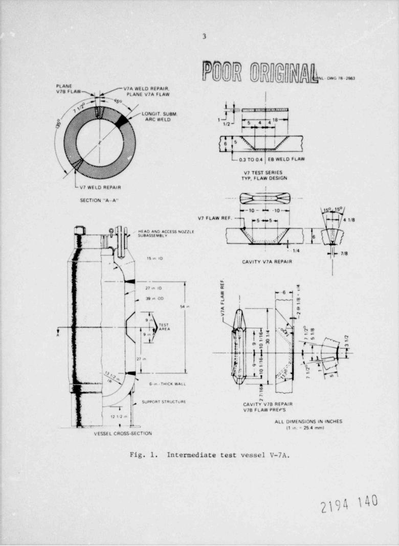
as similar cavity preparations on prolongation V-8. The vessels and re-
spective cavity details are shown in Fig. 1. The prolongation consisted
of an open-ended test cylinder which was manufactured from the same heat,
with heat treatment and stress relief identical to those for the vessels.
The prolongation had two test areas located 180 apart, one with a through-the-wall cavity similar to the cavity in the V-7B vessel and the other witha cavity about halfway through the wall similar to the cavity in the V-8
*GARD, Inc., subsidiary of GATX Corp., 7449 North Natchez Ave., Niles,
Ill. 60648.
2khk
3
0""]OD 'TT .
*
NL- owG 78-2863g g_
PLANE V7A WELD REPAIR.[tV7BFLAWPLANE V7A FLAW
b D*{n
$ (i; / LONGIT.SUBM.
~
ARC WELD 1 - 3 4 4 18 *o - s
= : : -
r '
{ { '5 h (. 0.3 TO O.4 EB WELD FLAW
5V7 TEST SERIES,
TYP, FLAW DESIGN
-V7 WE LD REPAIR I
SECTION "A- A"~^ ' ~
e 10 - -10 15"
V7 FLAW REF. - 41/8Sq+5
O SO :,15;fS Ev.5"$$~ ~ {% " */f_ t j'
!!!ew-
r -1/4'
= 7/8''*'O
y CAVITY V7A REPAIR, ,
{ #1
'i
% 27 in 10
.
e ,EI 1
0( fp-=
39 m OD ye,
| -t 64 .a 4 &4
% y%| { elej f 9e
IL I
I 1- ! | TEST; j o
I$ AREA r qn j , , ,
_,9 in A g . - / Q
', "E ",ei o -.
I ib(di -' I
. l,,.a .
| h oE I'Td,' o1
Ds
- !) , ~ M ~, o
l" R,s ' ' " -'e
(' -- -
,['a ., np 7*i6-m -THICK W At t
11g
., e ~
, '/ ~
l SUPPORT STRUCTURE#j g OVITY V78 REPAIR,#
, 6 V78 FLAW PREP'S
. h 12 1 2 mALL DIMENSIONS IN INCHES
__rli _ i - - d_ a (1 m. - 25 4 mm)VESSE L CROSS-SECTION
Fig. 1. Intermediate test vessel V-7A.
}}hk

4
vessel. The half-wall-tl.ickness cavities had been premachined into the
longitudinal seam welds of both the V-8 vessel and the V-8 prolongation
by ORNL. Ileavy crossbraces were welded to both ends of the prolongationcylindet for restraints.
Detailed accounts of earlier tests and repairs of vessels V-7 and V-7A
are documented in Refs. 1, 2, and 3. Post-repair-weld machining and flaw-
ing of vessel V-7B were centered in a longitudinal heat-affected zone of
the weld repair, and the vessel was pressure tested at upper-shelf test
temperature to approximately 2 1/4 times design pressure before leakageoccurred. A report" is in preparation to cover findings f rom the V-7Btest. Procedure qualification prolongation V-8 was destructively tested
at ORNL to determine the mechanical, physical, and structural properties
of the weld repair and to evaluate strain gage stress data taken in the
areas of the repair welds and in the areas adjacent to them to dutermine
repair-induced residual stress criteria."'S The final details of vessel
V-8 postrepair program activities are pending. The vessel is scheduled
to be flawed in a 1.'gh-residual-stress, low-toughness zone for pressure
testing in the transition temperature regime. This report provides
chronological listings and discussions for all half-bead weld repairs and
related work performed by WTD during late January and early February 1977.
UCC-ND Welding Specifications and WTD Process Specifications are included
in the App ndix.
The " half-bead (temper) welding technique" is unique because of itsuse of a controlled heat-affected-zone tempering process. About half of
the fire' - or " buttering," weld layer is ground off, and the heat from the
second layer refines and tempers the remaining heat-affected zone betweenthe first layer and the base metal. Thus, the properties of transformation
products of the heat-affected zone of the prior weld layer are improved
substantially. The second layer, another " buttering" layer, and subsequentfiller layers are not ground, because tempering is necessary only for the
first layer and for the base metal. Weld repairs using the half-bead (tem-
per) method may be accomplished when it is impossible or impractical toperform a postweld heat treatment (PWHT) at conventional, considerablyelevated temperatures. The requirements for half-bead weld repairs are
2194 141
5
listed in the ASME Code, Section XI. Paragraph IWB-4420, and in Section III,
Paragraph NB-4640.
Similar half-bead weld repairs had previously been successfully
performed by Combustion Engineering, Inc. , Chattanooga, Tenn. , in another
section of IISST vessel V-7.2 For Combustion Engineering's repairs, how-ever, cavity preparation and half-bead and filler welding were all done
with the vessel in a horizontal position. Flat-position welding was used.
Equally successful completion of half-bead weld repairs by WTD in verti-
cally placed vessels and welding in the vertical position proves that
acceptable repairs can clso be made to ASME Code guidelines for vesselsin the vertical position without conventional PWilT stress relief.
2194 142
6
2. GENERAL
2.1 Welding
All welding was done in the vertical position using stringer beads to
WTD Process Specification NPT-77, except 4-mm-diam (5/32-in.) electrodeswere not used because of excessive starting porosity. WTD Process Speci-
fication NPT-77, which is appended to this report, follows ASME Code,
Section XI guidelines for half-bead repair welding.
All layers of weld were staggered whenever physically possible, but
the starts and stops contained within a layer were in line with one
another for most expeditious grindout. Corner deposits were in line, and
most of the porosity was located in this area on the inside diameter,
as visually observed after removing the backing bar. Some trouble was
encountered with the fit of the two 3.2-mm-thick (1/8-in.) stacked andcontoured backing bars: the inner bar became distorted and separated
from the outer bar, thus leavint; a gap which in some cases was easy to
burn through. The backing bar arrangement is detailed in typical cross-
sectional views in WTD drawing ETSK-379614-J, which is appended to this
report.
2.2 Electrode Baking
The E8018-C3 electrodes supplied by ORNL were prebaked and scaled
in vacuum packs of 45.4 g (10 lb) each. The electrodes were removed from
their packs and placed into an oven at 121 ! 14 C (250 25*F) prior to
being transferred to the welding station where individual welders' ovenswere used to maintain the rods at temperature. The electrode properties
are given in Table 1.
The starting end and the coating of each electrode were inspected
before placin3 the rods into the oven and again after the rods were re-
moved from the oven. The welder also inspected each electrode end prior
to striking the arc. In this way, obvious coating cracks were eliminated.
The moisture content of the electrodes was determined for multiple
lot samples in each diameter of electrodes used and is recorded in Table
2. All moisture tests were in accordance with Specification SFA-5.5, AWS
2}h
7
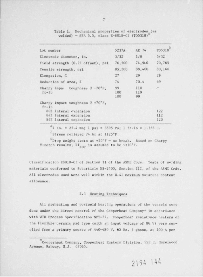
Table 1. Mechanical properties of electrodeswelded) - SFA 5.5, class E-8018-C3 (T05318)#(as
Lot number 5237A AE 74 T05318
Electrode diameter, in. 3/32 1/8 5/32
Yield strength (0.2% offset), psi 76,500 74,900 70,765
Tensile strength, psi 85,200 88,400 80,160
Elongation, % 27 29 29
Reduction of area, % 74 70.4 69
Charpy impar toughnesu @ -20*F, 99 110 eft-lb 100 119
100 99
Charpy impact toughness 0 +70*F,ft-lb80% lateral expansion 12284% lateral expansion 11286% lateral expansion 120
#1 in. - 25.4 mm; 1 psi = 6895 Pa; 1 ft-lb = 1.356 J.
bStress relieved 24 hr at 1125*F.#Drop weight test s at +20* F -- no break. Based on Charpy
V-notch results, RT is assumed to be %+10 F.NDT
Classification E8018-C3 of Section II of the ASME Code. Tests of wa? ding
materials conformed to Subarticle NB-2400, Section III, of the ASME Cede.
All electrodes used were well within the 0.4% naximum moisture contentallowance.
2.3 Heating Techniques _
All preheating and postweld heating operations of the vessels were
done under the direct control ef the Cooperheat Company * in accordancewith WTD Process Specification NPT-77. Cooperheat resistance heaters of
the flexible ceramic pad type (with an itaput voltage of 80 V) were sup-
plied from a primary source of 440-480 V, 60 Hz, 3 phase, at 200 A per
*Cooperheat Company, Cooperheat Eastern Division, 955 E. Hazelwood
Avenue, Rahway, N.J. 07065.
.\ 9
8
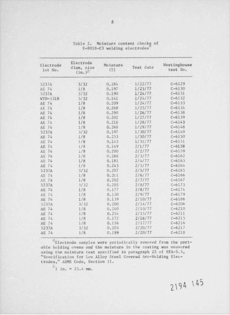
Table 2. Moisture content checks ofE-8018-C3 welding electrodes #
ElectrodeElectrode Moisture Westinghouse
est dat
'"" ' . ") f * (7.) test No.lot No. (in
5237A 3/32 0.184 1/22/77 C-6129AE 74 1/8 0.197 1/23/77 C-61305237A 3/32 0.190 1/24/77 C-6131WTD-5318 5/32 0.141 1/24/77 C-6132AE 74 1/8 0.209 1/24/77 C-6133AE 74 1/8 0.268 1/25/77 C-6134AE 74 1/8 0.290 1/26/77 C-6138AE 74 1/8 0.202 1/27/77 C-6139AE 74 1/8 0.218 1/28/77 C-6143AE 74 1/8 0.268 1/29/77 C-61485237A 3/32 0.197 1/30/77 C-6149AE 74 1/8 0.253 1/30/77 C-6150AE 74 J/8 0.143 1/31/77 C-6151AE 74 L/8 0.149 2/1/77 C-6158AE 74 1/8 0.200 2/2/77 C-6159AE 74 1/8 0.266 2/3/77 C-6162AE 74 1/8 0.181 2/4/77 C-6163AE 74 1/8 0.243 2/5/77 C-61645237A 3/32 0.207 2/5/77 C-6165AE 74 1/8 0.201 2/6/77 C-6166AE 74 1/8 0.202 2/7/77 C-61675237A 3/32 0.205 2/8/77 C-6173AE 74 1/8 0.177 2/8/77 C-6174AE 74 1/8 0.150 2/9/77 C-6179AE 74 1/8 0.139 2/10/77 C-61865237A 3/32 0.200 2/14/77 C-6206AE 74 1/8 0.240 2/10/77 C-6210AE 74 1/8 0.254 2/15/77 C-6211AE 74 1/8 0.172 2/16/77 C-6215AE 74 1/8 0.156 2/17/77 C-62165237A 3/32 0.203 2/20/77 C-6217AE 74 1/8 0.199 2/20/77 C-6218
#Electrode samples were periodically removed from the port-
able holding ovens and the moisture in the coating was measuredusing the moisture test specified in paragraph 25 of SFA-5.5," Specification for Low Alloy Steel Covered Arc-Welding Elec-trodes," ASME Code, Section II.
b1 in. = 25.4 mm.
}\k4
9
phase. All thermocouple circuitry was Chromel/Alumel Type K and regis-tered on a 24-point lioneywell 112 Type K recorder using a 12-hr scroll-type chart. The thermocouples were spot-welded onto the vessel andinsulated with ceramic high-temperature putty. Resistance heaters were
used on the inside of the vessel; ceramic fiber insulation was used on
the outside. The exception was the weld re-repair on the inside of ves-
sel V-7B, for which resistance heaters were strapped onto the vessel.'sexterior with a fiber padding cover superimposed.
During preparations, the test plates were heated locally with gastorches and postweld heated in an electric furnace.
Auxiliary gas-fired radiant heaters were available as backup equip-
ment, but they were not needed.
2194 146

10
3. WELDING SEQUENCE
3.1 Prolongation
The prolongation was 648 mm tall (25.5 in.), with a 686-mm ID (27-
in.), 991-mm OD (39-in.), and a 152-mm-thick (6-in.) wall, and is shown
with qualification test cylinder details in WTD drawing EDSK 379614-J,
which is appended to this report. Both ends of the cylinder were open.
The prolongation was received with the V-3-type cavity machined from the
exterior approximately halfway into the wall. The cavity was centered
midway up the cylinder and was located approximately halfway into the
longitudinal cylinder seam weld. The cavity measured 318 x 83 mm (12 1/23 1/4 in.) on the vessel's outer surface and was 89 mm deep (3 1/2 in.).x
Sidewalls were cut on radial planes; top and bottom ends were tapered on
45* slopes toward the cavity's center. The prolongation also included a
through-the-wall cavity positioned on the opposite side. This through-
the-wall V-7-type cavity [with the wall being 152 mm thick (6 in.)] was
prepared by Westinghouse by drilling and air-are gouging. E:;terior sur-
f ace measurements were %351 mm (%13.8 in.) vertical by %127 mm (%5 in.)across. Radial sides were on 97 1/2* angles -- the top sloped on a 142*included angle and the bottom at 112*.
The selection of typical weld repair zones for the prolongation pro-
vided specific locations for materials for subsequent detailed comparison
studies. Specimens were cut accordingly, and physical and material analy-
ses were performed later at ORNL. The V-8 cavity was a direct replication
for the vessel V-8 weld repair; the V-7-type prolongation cavity repre-
sented a reduced-size version for the vessel V-7B repair. The size of
the root opening of the through-the-wall prolongation cavity was increased
from 89 mm square (3 1/2 in.) to 92 mm square (3 5/8 in.) through a mach-
ining error. The thermal gouging and grinding operation resulted in a
slight undercut at the bottom of the joint, which, however, was considered
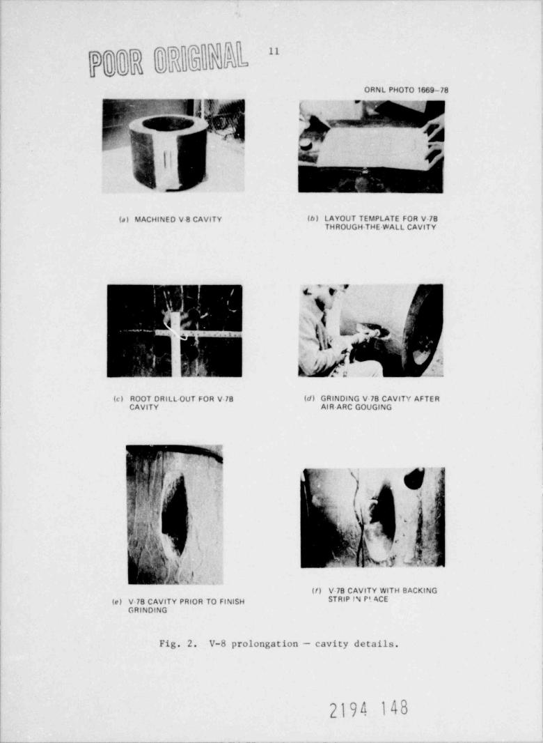
acceptable for the repair welding. See the photographs in Fig. 2.
The V-7B cavity backing bars consisted of two 3.2-mm-thick (1/8-in.)
carbon steel sheets rolled to the prolongation's inside diameter. The
first bar was welded all around and hammered in to ensure a good tight
fit. The second bar was then welded all around on top of the first bar.
2194 147
I LI LI
ORNL PHOTO 1669-78
t, w-
(a ) MACHINED V 8 CAVITY (b) LAYOUT TEMPLATE FOR 78
RE M(c) ROOT DRILL-OUT FOR V 78 (d) GRINDING V 78 CAVITY AFTER
,
d f h 4- ]w(/) V-78 CAVITY WITH BACKING
(e) V-78 C V TY PRIOR TO FINISH STRIP IN Pt ACE
Fig. 2. V-8 prolongation - cavity details.
2194 148
12
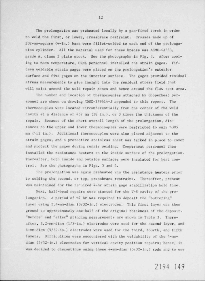
The prolongation was preheated locally by a gas-fired torch in order
to weld the first, or lower, crossbrace restraint. Crosses made up of
102-mm-square (4-in.) bars were fillet-welded to each end of the prolonga-
tion cylinder. All the material used for these braces was ASME-SA533,
grade A, class 2 plate stock. See the photographs in Fig. 3. After cool-
ing to room temperature, ORNL personnel installed the strain gages. Fif-
teen weldable strain gages were placed on the prolongation's exteriorsurface and five gages on the interior surface. The gages provided residual
stress measurements to give insight into the residual stress field that
will exist around the weld repair zones and hence around the flaw test area.
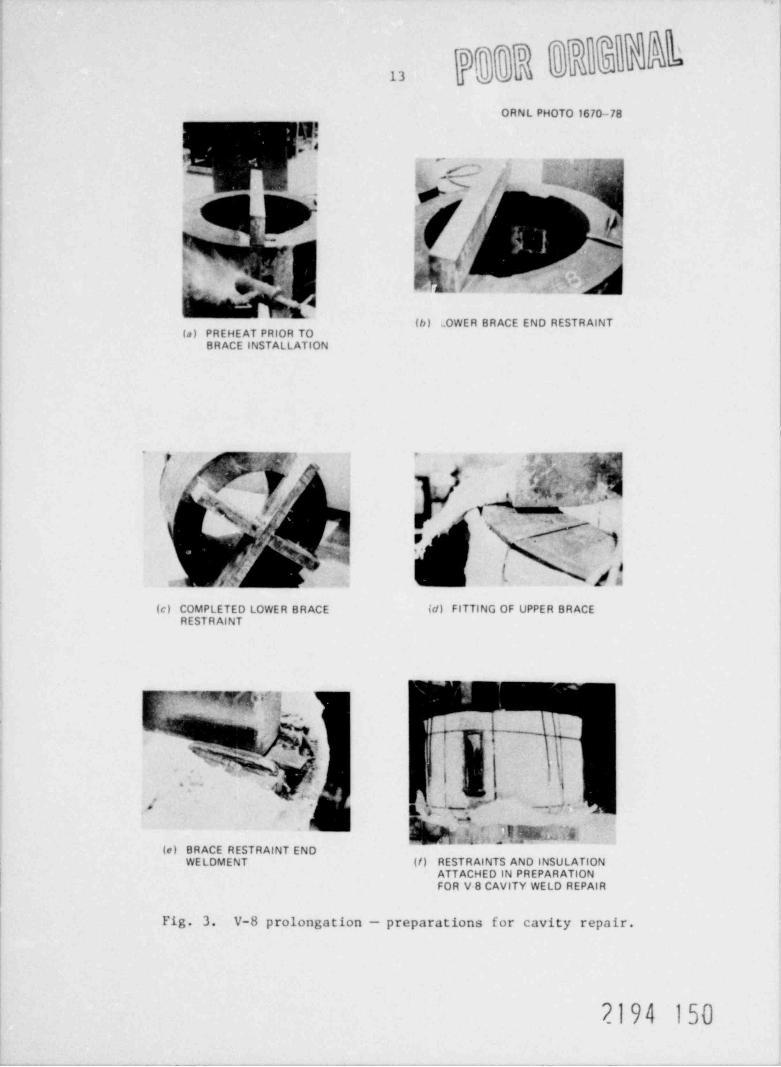
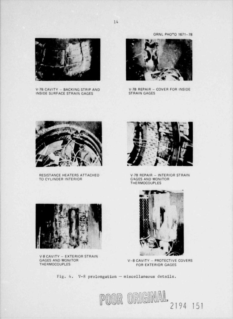
The number and location of thermocouples attached by Cooperheat per-sonnel are shown on dr., wing SDSX-379614-J appended to this report. The
thermocouples were located circumferentially from the center of the weld
cavity at a distance of 457 mm (18 in.), or 3 times the thickness of the
repair. Because of the short overall length of the prolongation, dis-
tances to the upper and lower thermocouples were restricted to only N305
mm (%12 in.). Additional thermocouples were also placed adjacent to the
strain gages, and a protective stainless sheet was tacked in place to cover
and protect the gages during repair welding. Cooperheat personnel then
installed the resistance heaters to the inside surface of the prolongation.
Thereafter, both inside and outside surfaces were insulated for heat con-
trol. See the photographs in Figs. 3 and 4.
The prolongation was again preheated via the resistance heaters prior
to welding the second, or top, crossbrace restraint. Thereafter, preheat
was maintained for the recoired 4-hr strain gage stabilization hold time.
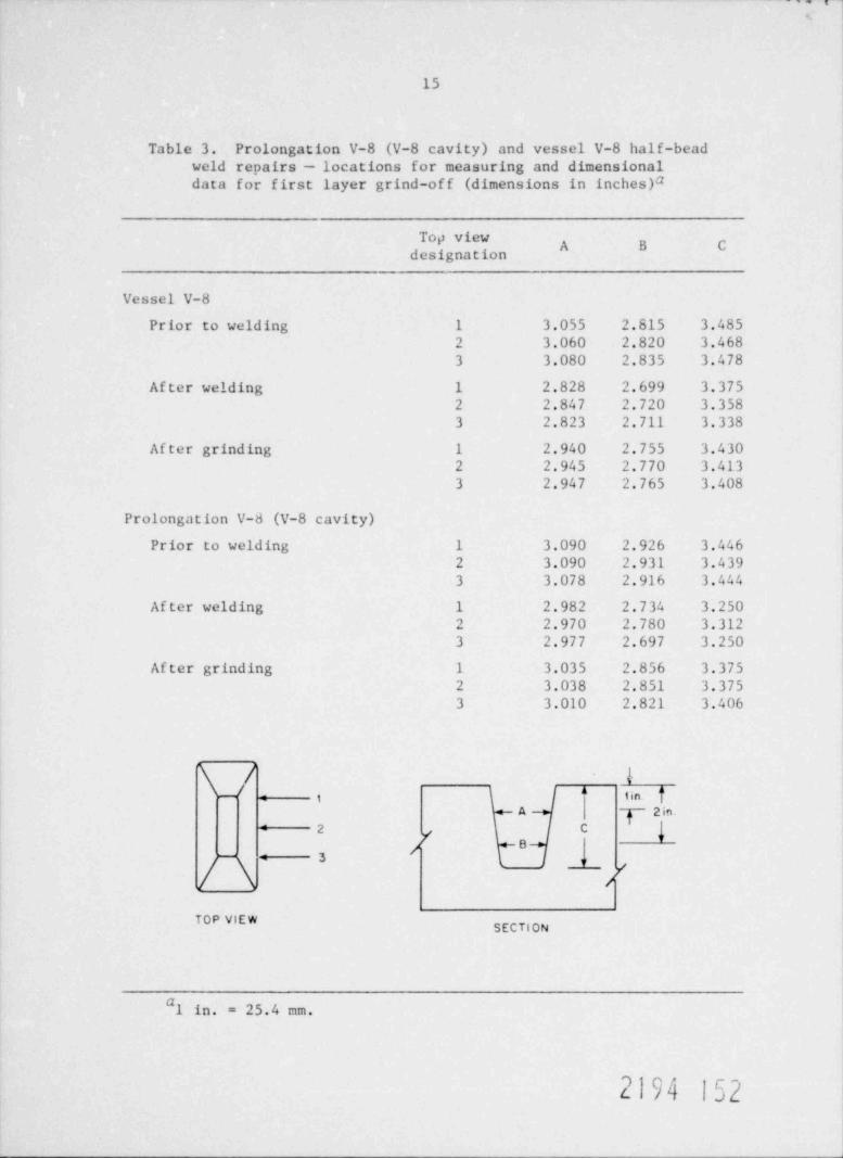
Next, half-bead repairs were started for the V-8 cavity of the pro-
longation. A period of %7 hr was required to deposit the " buttering"
layer using 2.4-mm-diam (3/32-in. ) electrodes. This first layer was then
ground to approximately one-half of the original thickness of the deposit.
"Before" and "after" grinding measurements are shown in Table 3. There-
after, 3.2-mm-diam (1/8-in.) electrodes were used for the second layer, and4-mm-diam (5/32-in.) electrodes were used for the third, fourth, and fifth
layers. Dif ficulties were encountered with the weldability of the 4-mm-
diam (5/32-in.) electrodes for vertical cavity position repairs; hence, it
was decided to discontinue using these 4-mm-diam (5/32-in. ) rods and to use
2194 149
13
ORNL PHOTO 1670-78
0!en
4̂ - . . , , ,'
fj' .> , '' :m st. % ~m,
|4
(a) PREHE AT PRIOR TOBRACE INSTALLATION
*y. ~rny y
- 4
' ? -,
_. . m .w, , .,
..
%,. ' /Y ["' ' p y , / :3
9- L jjw ..
(c) COMPLETED LOWER BRACE (d) FITTING OF UPPER BRACEREST R AINT
"Wf s Y
J,
7 ,-4 :- gy,
E_th?hl Y$^
[ 4 ,
(e) BRACE RESTRAINT ENDWELDMENT (/) RESTRAINTS AND INSULATION
ATTACHED IN PREPARATIONFOR V 8 CAVITY WELD REPAIR
Fig. 3. V-8 prolongation - preparations for cavity repair.
2194 150
14
ORNL PHOTO 1671-78
*
V 7B CAVITY - BACKING STRIP AND V 78 REPAIR - COVER FOR INSIDEINSIDE SURFACE STRAIN GAGES STRAIN GAGES
RESISTANCE HEATERS ATTACHED V-78 REPAIR - INTERIOR STRAINTO CYLINDER INTERIOR G AGES AND MONITOR
THERMOCOUPLES
T M 4[m gf
EN9 kj' ~ *
V-8 CAVITY - EXTERIOR STRAINGAGES AND MONITOR V-8 CAVITY - PROTECTIVE COVERSTHERMOCOUPLES FOR EXTERIOR GAGES
Fig. 4. V-8 prolongation - miscellaneous details,
b-
15
Table 3. Prolongation V-8 (V-8 cavity) and vessel V-8 half-beadweld repairs - locations for measuring and dimensionaldata for first layer grind-off (dimensions in inches)a
Top viewA B C
designation
Vessel V-8
Prior to welding 1 3.055 2.815 3.4852 3.060 2.820 3.4683 3.080 2.835 3.478
After welding 1 2.828 2.699 3.3752 2.847 2.720 3.3583 2.823 2.711 3.338
Af ter grinding 1 2.940 2.755 3.4302 2.945 2.770 3.4133 2.947 2.765 3.408
Prolongation V-8 (V-8 cavity)
Prior to welding 1 3.090 2.926 3.4462 3.090 2.931 3.4393 3.078 2.916 3.444
After welding 1 2.982 2.734 3.2502 2.970 2.780 3.3123 2.977 2.697 3.250
After grinding 1 3.035 2.856 3.3752 3.038 2.851 3.3753 3.010 2.821 3.406
\/ ii.
: 1 lin
A 2 in -9
{2 C
/ B- 3 y
TOP VIEWSECTION
#1 in. = 25.4 mm.
2194 152
16
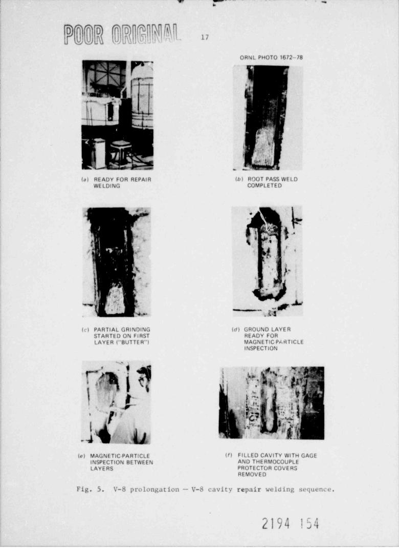
3.2-mm-diam (1/8-in.) electrodes for depositing all remaining layers.
Thirty layers were required to totally till the remaining cavity. Ap-
proximately 80 hr were spent in making the V-8 prolongation weld repair,
and 88 2.4.-mm-diam (3/3 -in.), 728 3.2-mm-diam (1/8-in.), and a few 4-
mm-diam (5/32-in.) electrodes were used to fill the cavity. Magnetic-
particle inspections were performed on the ground " buttering" layer andon the next 3.2-mm (1/8-in.) rod layer, and thereafter on alternate layers
and the final ground outer surface, with all results acce atable. Refar
to the photographs in Fig. 5, which illustrate the V-8 cavity repair
welding sequence.
Heat input to the inner surface resistance heaters was increased on
completion of the repair welding. One and one-half hours were required
to reach postweld tempering treatment temperatures. Prolongation tempera-
tures were then held in this 260 28 C (500 ! 50*F) range for 4 hr.
~hereafter, the vessel was stripped of insulation and cooled to room tem-
perature in about 24 hr at which time stabilized final strain gage re-
cordings were taken. Another day was spent installing five internal and
six external weldable strain gages for the prolongation's through-the-wall
V-7B cavity repair. Welding commenced about 8 hr later, with 4 hr required
to achieve preheat temperatures and another 4 hr at preheat for strain gage
stabilization.
Sixteen hours were required to deposit the first, or " butter" pass,
layer in the V-7B cavity of the prolongation, after which it was ground
down. The before- and after-grinding measurements are shown in Table 4.
It is important to note that the first weld layer deposit that covered
the backing bar was not ground. Half-bead temper effects for this zone
were eliminated by removing the backing bar from the interior surface by
grinding, which followed the completion of all repair welding. The re-
maining cavity required 59 layers, all of which were deposited with 3.2-
mm-diam (1/8-in. ) electrodes. Magnetic-particle examinations were per-
formed the same as before. The welders began to encounter porosity while
welding in the lower quadrant of the cavity. After light grinding, a
number of clusters of fine porosity could still be seen. Magnetic-particle
inspections revealed still other small indications and one relatively
large, 46.4-mm-long (%1/4-in.) longitudinally oriented defect. It was
2194 153
~6
oc .u.- UI
ORNL PHOTO 1672-78
f ->
ev,
'
*r> - a.
,
( -]. ,
m_-
.
y'
I
I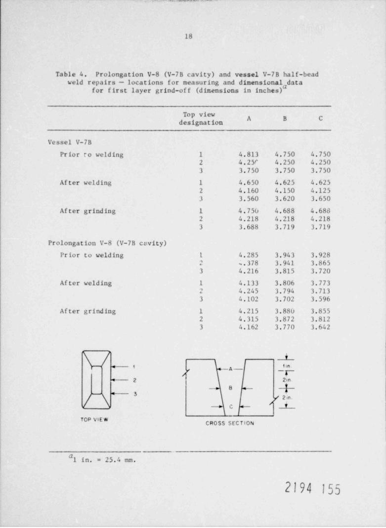
18
Table 4. Prolongation V-8 (V-7B cavity) and vessel V-7B half-beadweld repairs - locations for measuring and dimensional data
for first layer grind-of f (dimensions in inches)"
Top viewA B C
designation
Vessel V-7B
Prior to welding 1 4.813 4.750 4.7502 4.25r 4.250 4.2503 3.750 3.750 3.750
After welding 1 4.650 4.625 4.6252 4.160 4.150 4.1253 3.560 3.620 3.650
After grinding 1 4.750 4.688 4.6882 4.218 4.218 4.2183 3.688 3.719 3.719
Prolongation V-8 (V-7B cavity)
Prior to welding 1 4.285 3.943 3.9282 ~.378 3.941 3.8653 4.216 3.815 3.720
After welding 1 4.133 3.806 3.7732 4.245 3.794 3.7133 4.102 3.702 3.596
After grinding 1 4.215 3.880 3.8552 4.315 3.872 3.8123 4.162 3.770 3.642
*--- t i n.-A-g p*- 2
B+3
/ \ / 2in.+C
TOP VIEWCROSS SECTION
#1 in. = 25.4 mm.
2194 155
19
necessary to grind at least 5 mm (3/16 in.) deep for the full width of
the cavity to remove this af fected area, which was located %76 mm (%3 in.)vertically from the bottom of the cavity. Total time for completion of
the welding was N187 hr. One hundred ninety-six 2.4-mm-diam (3/32-in.)
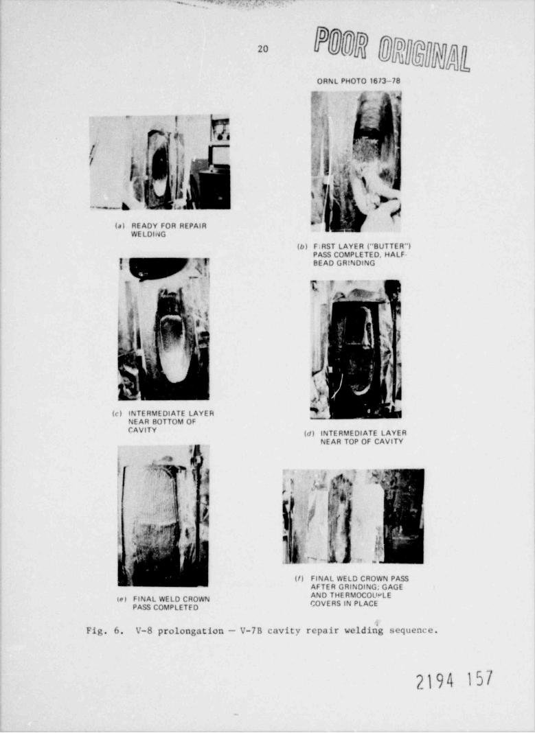
electrodes and 1624 3.2-mm-diam (1/8-in.) electrodes were used to fillthe V-7B cavity. See thc photographs in Fig. 6, which illustrate the
prolongation V-7B cavity repair welding sequence.
One event possibly worth noting during V-7B prototype cavity repairswas an interpass temperature excursion between 260 and 343*C (500 and
650*F) for 5 hr. A control thermocouple malfunctioned during the welding
of layers 51 and 52. These layers were located N13 mm (%1/2 in.) downfrom the vessel's outer surface. The welder continued welding for 2 hr
with the vessel temperature above 260*C (500*F) . After shutting off the
heat, 3 hr were required to bring the temperature below 260 C (500 F), atwhich time preheat was reapplied and repair welding continued.
The top cover pass was ground smooth and found to be acceptable bymagnetic-particle inspection during the 2 hr required to achieve PWHT tem-
perature. After holding the temperature at 260 28 C (500 50*F) for4 hr, the prolongation was stripped of insulation and cooled to room
temperature in 16 hr.
Strain gage readings were recorded after gages stabilized. Recordings
for evaluation by ORNL were also taken before, during, and after the re-
moval of the cross-braces.
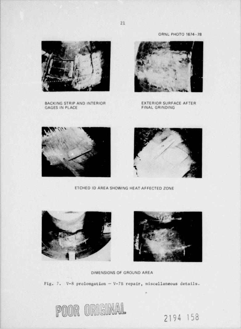
The backing bars were ground out next. All visual porosity was elim-
inated by grinding. Slightly recessed areas, or dimples, were formed bygrinding on the prolongation interior; however, minimum allowable vesselwall thickness dimensions were held within Code Standard tolerance limits,
fee the photographs in Fig. 7, which illustrate details of the V-7B repair
weld.
All the required final magnetic-particle, ultrasonic and radiographic
inspections were completed on both the prolongation welt its 48 hr later.
Results were acceptable to Code Standards.
2194 156
r.v , . ,, 3.. ,
ORNL PHOTO 1673-78
{ f f ' ",v.,}L; ,~
.
g 5
?. , k I
'I L' {'e 90' h- /
,,
['s
,
| [ , 'n i k' .<
** ~ k' ;. W,<
(a) READY FOR REPAIRWE LDING
(b) F;RST LAYER ('' BUTTER")PASS COMPLETED, HALF-
{~ BEAD GRINDING
' }~ - -*
,.
,)} /W7 b,
_
?,4 j .5)!=! $f r %
f.' .-,, ,
..
%'
!*
O g /j' ,f,
(c) INTERMEDIATE LAYER N#NEAR BOTTOM OFCAVITY (d) INTERMEDIATE LAYER
NEAR TOP OF CAVITY,
6 . . 's
),.
y (s *
Q. , .
f V""
a tr~ b t z, -
(/) FINAL WELD CROWN PASSAFTER GRINDING: GAGE
te) FINAL WELD CROWNOVERS IN PLACPASS COMPLETFD
Fig. 6. V-8 prolongation - V-7B cavity repair weldin'g sequence.
2194 157
-
21
ORNL PHOTO 1674-78
E5 E3BACKING STRIP AND INTERIOR EXTERIOR SURFACE AFTERGAGES IN PLACE FINAL GRINDING
ETCHED ID AREA SHOWING HEAT-AFFECTED ZONE
me. . ~ >
f'y.n ,
i:e, f <
j j I([
$Y . m:3- . .
.....
w M .; 7, y . ~Jf[A~
'
2, #,
i', ,,
DIMENSIONS OF GROUND AREAA
Fig. 7. V-8 prolongation - V-7B repair, miscellaneous details.
,
o")'o] Q' ' * ~
2194 158
22
3.2 Vessel V-7B
Vessel V-7B was 42.13 m tall (%7 f t), with a 686-mm ID (27-in.),
991-mm OD (39-in.), and a 152-mm-thick (6-in. ) wall and, less flanged
head, weighed about 7222 kg (8 tons) . Vessel details are shown in WTDdrawing EDSK-379614J appended to this report. A through-the-wall cavitywith outside surface dimensions of %768 mm (%301/4 in.) vertically (or
longitudinally) by 127 mm (5 in.) wide (circumferentially) was locatedabout midway up the vessel. Sidewalls w2re cut radially and formed 97 1/2*included angles. The cavity's top end (toward the vessel's dome end)sloped on a 142* included angle plane; the bottom end (toward the headflange end) sloped on a 112* plane. The opening dimensions of the cavityon the vessel's inner surf ace measured %514 mm long (%20 1/4 In.) by %90 mm
wide (%3 1/2 in.). ORNL had furnished the vessel with the cavity's 508-mm-long (20-in.) center portion sidewalls premachined in order to attain ac-
curate reference surfaces for their later use to index flaw planes in the
heat-affected zones of the weld repair. These zones are estimated to be
%2.0 to %2.3 mm (%80 to 90 mils) wide and are formed in the adjacent parent
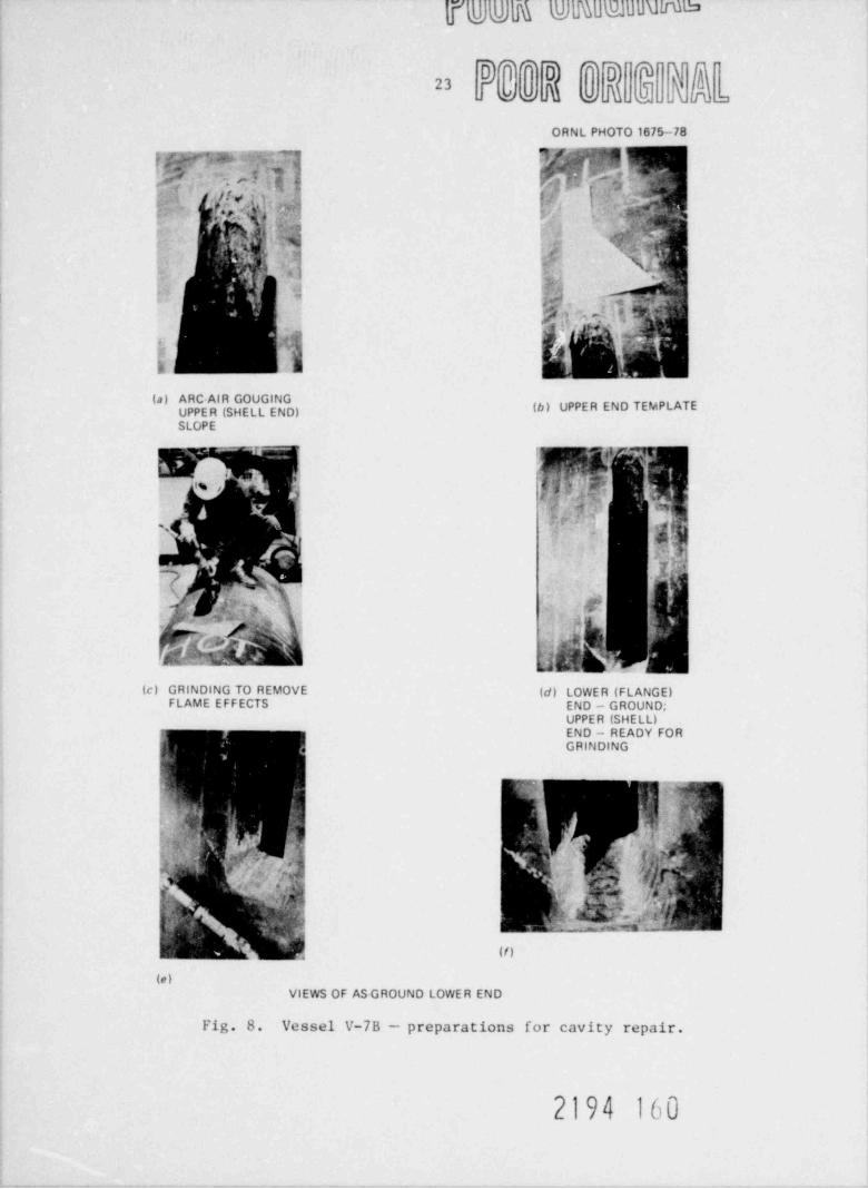
metal of the cavity sides. WTD prepared both connecting cavity ends by
thermal gouging to WDT Process Specification NPT-78, which appears inthe Appendix. All but the final 6.3-mm (1/4-in.) thickness was removedby air-arc gouging. Thereafter, manual grinding was used for final metal
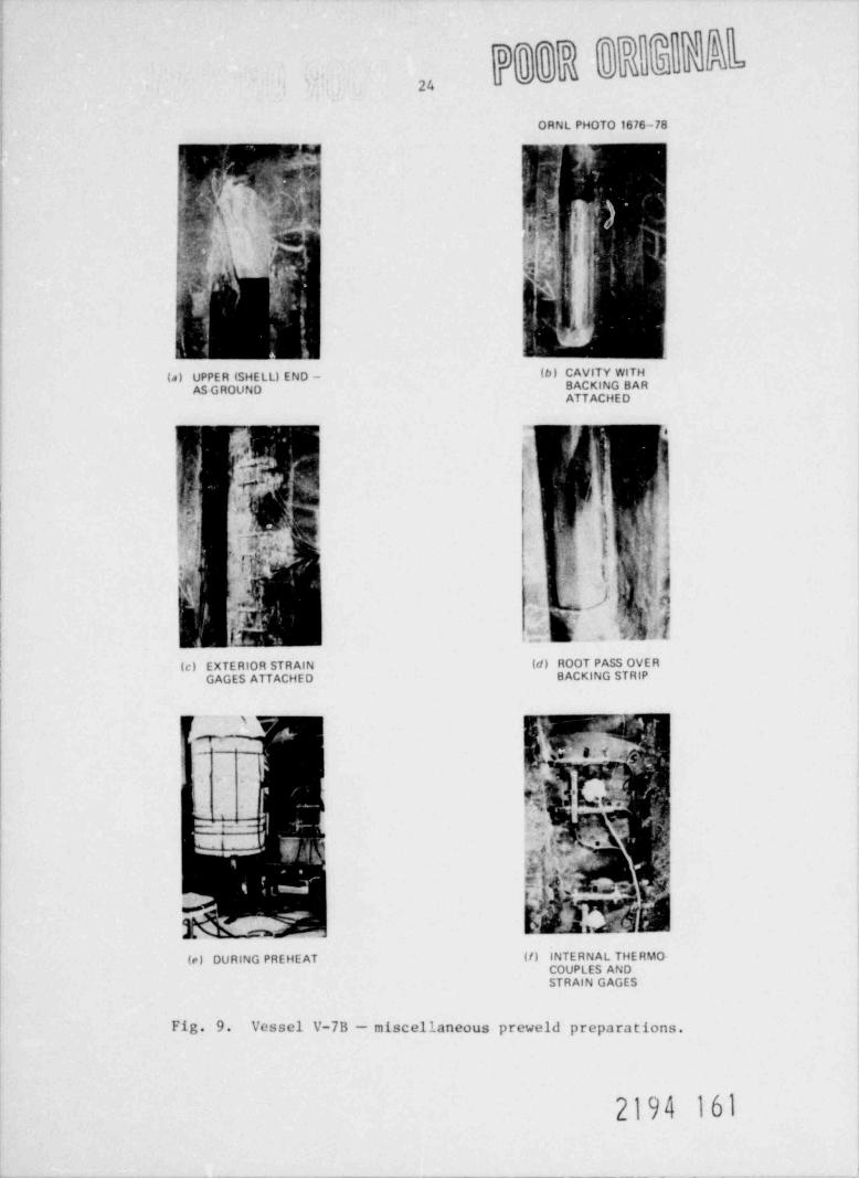
removal to eliminate any flame-induced heat-affected zones and/or carboncontami"ation within adjoining cavity boundary materials. Refer to the
photographs in Figs. 8 and 9, which illustrate the preparations for re-
pairing the cavity in vessel V-7B.
Backing bars were used to seal the cavity bottom; they consisted of
3.2-mm-thick (1/8-in.) carbon steel sheets rolled to the vessel's insided iamet er . Two bars were used to expedite postweld bar removal by manual
grinding. The first bar was welded all around and hammered in to ensure
a good, tight fit, and then the second bar was welded all around on top
of the first bar. Installation of the strain gages by ORNL personnel
followed.
ORNL personnel installed nine external and six internal strain gages,
and Cooperheat personnel installed eight thermocouples and banded internal
2194 159
yqDMnFUFIMlUUMM
D]* 'T~*
23' @ @ , .. D
ORNL PHOTO 1675-78
3' [''"
c ~gg p%,y ., $. :':M
''. l'
. , ''
.-
I ; .-4 ,*
, ,.
. 18 tif '',' ' ) . q:|. 'Y4
# ^(b) UPPER END TEMPLATEPP R SHELL E D)
SLOPE
,-
$ ') ,ik 'j'|'%
#4:
'
5 !" +7
';h
%2' . ,i n .. ' '', 4'{,
}*
E
(c) GRINDING TO REMOVE (d) LOWER (FLANGE)FLAME EFFECTS END - GROUND;
UPPER (SHELL)END - READY FOR,
g: GRINDING
?|i, m,
'.h ,[[.
~S''}.
{- , ,, i,!'.-i ,;? '; i
?/|p?s[b,
'} ''
r
f, ra g..P8 - :n' f-ik ' g&;i ' .;.
'
(/),
(e)VIEWS OF AS GROUND LOWER END
Fig. 8. Vessel V-7B preparations for cavity repair.
2194 160
' SL b
ORNL PHOTO 1676-78
if1"D ,\ h'V [ $.}- :
;i
~
Bk NG BARGROUPOATTACHED
>
'
AGE TTACHE B CKIN TR P
s-
, m- 3
g 5. j ,~~
d'' p$5r. , ;,
W l.s i
3 m
(e) DURING PREHEAT (/) INTERNAL THERMO-
STRAIN GAGES
Fig. 9. Vessel V-7B - miscellaneous preweld preparations.
2194 161

MM N _
25
resistance heaters. Control thermocouples were placed at a 3t (thick-
ness of repair) distance, or 457 mm (18 in.) from the center of the
cavity. Stainless steel sheet covers were applied to protect the gages
and thermocouples, and sheet blanket insulation was placed around the
inner and outer surfaces of the vessel, as shown in Fig. 9.
Approximately 9 hr were required '- ~ _: heat vessel V-7B up to 177*C(350*F), and this was followed by a 4-br hold at preheat temperature forgage stabilization.
Twenty hours were spent in welding the first " butter," or temper-bead
layer; and 354 electrodes, 2.4 mm in diameter (3/32 in.) were used. Manual
grinding to remove half of the temper bead followed. It was extremely
dif ficult to obtain accurate reproducible measurements in the cavity etabout 204*C (400*F) to determine when half of the bead had been groundoff. Measurements made before and after grinding are shown in Table 4.
No attempt was made to grind the bead deposit from atop the backing bars.
Final postrepair removal of the bars will ef fect similar tempering cures.
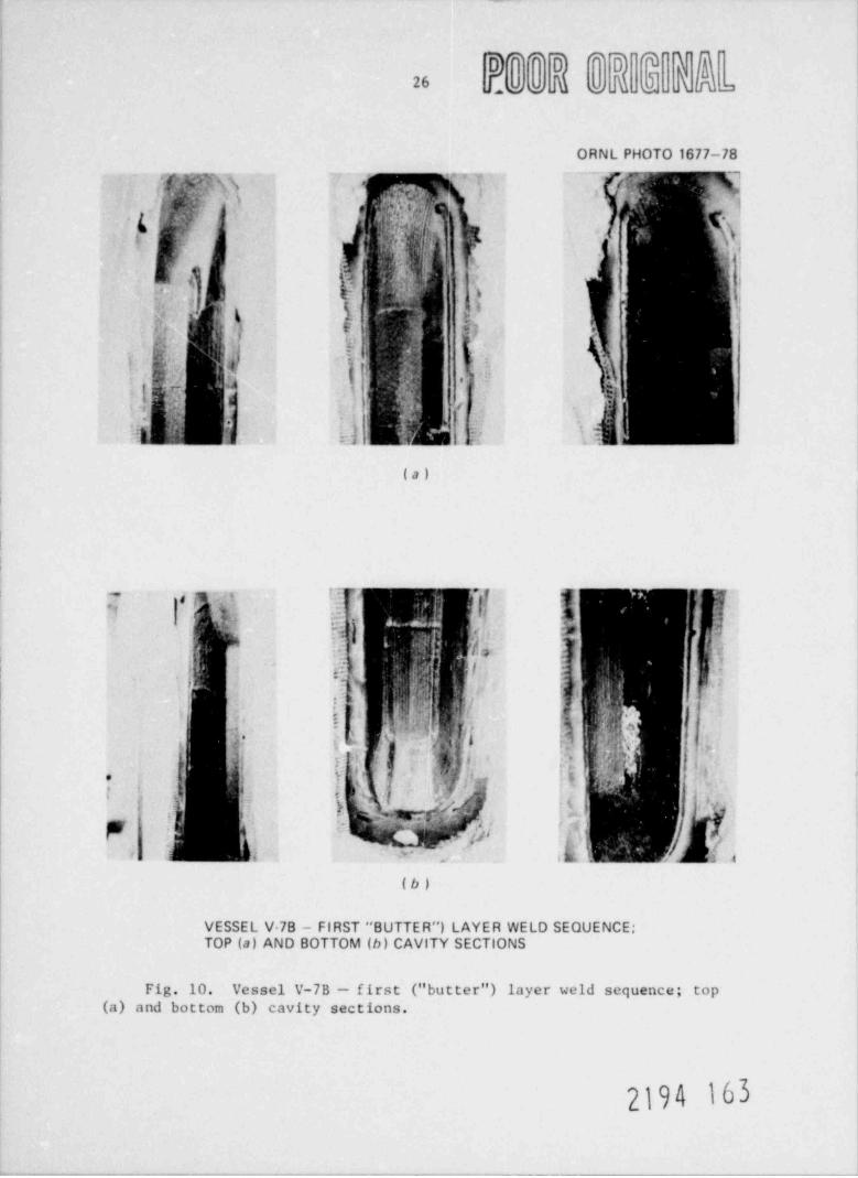
The first layer (" butter") vertical-deposit sequence is shown in the pho-
tographs of Fig. 10. The second layer was deposited with 3.2-mm-ditm(1/8-in.) electrodes and covered the first layer in the same vertical-pass-sequence buildup from the inside outwards for both bottom and sides.
The rod-buildup sequence for cavity bottom and sides was continued for a
third layer, using 3.2-mm-diam (1/8-in.) electrodes. The procedure stipu-
lated that cavity welding hereafter could be made as " fill" from the
interior up only, using 3.2-mm-diam (1/8-in.) or 4-mm-diam (5/32-in.)
electrodes.* Three such fill passes were deposited with 4-mm-diam (5/32-
in.) electrodes; however, difficulties with severe porosity formation wereencountered. The welding technicians reported that after burning a 4-am-
diam (5/32-in.) electrode for %76 mm (%3 in.), the remainder of the elec-
trode overheated and hence could not be used. It was also noted that the
area being welded overheated, resulting in excessive undercut occurences.
Attempts were made to reduce the heat input to the electrode, but lower-
ing the welding amperage made it extremely dif ficult to maintain an arc.
*Similar dif ficulties were also encountered on test plate and pro-
longation velding.
2194 102
oo o -
26 f,,
,( ,
ORNL PHOTO 1677-78~'' '-
P;M",Ts.N
QYk , ;' !- \9
,
,' t I '
; Vy \ L |'' '
,
3 i 5;.. .
U \ V
ghs$j
!'
d/ 1t'
G ', ,,,
i r.) L !, .
(a)
t :" r f [ q,
h,
,' .* i= ..'"- is , :1k }
* -*
) ,d I a i-.. ,
:,
<I i . ,
' '
NN \\ t |i :. +;-,
.
!;h ^Nh! '#j s'L dj
'*
,i
( i [.'f .? ::'
i
: g i-
,
)|h 3' i L. ' 2 4
(b)
VESSEL V 78 - FIRST " BUTTER") LAYER WELD SEQUENCE;TOP (a) AND BOTTOM (b) CAVITY SECTIONS
Fig. 10. Vessel V-7B - first (" butter") layer weld sequence; top(a) and bottom (b) cavity sections.
2194 163
27
Therefore, it was decided to complete filling operations using 3.2-mm-diam
(1/8-in.) electrodes.
Some seemingly minor porosity was also encountered while using the3.2-mm-diam (1/8-in.) rod electrodes to fill the cavity. For the most
part, such porosity appeared to be located in the start and stop zones.
All porosity indications were generally visible to the naked eye and were
eliminated by grinding, as confirmed by the routine magnetic-particle in-
spections that were conducted cn alternate layers.
Interpass temperature control was based on a thermocouple installedon the vessel's outer surface 76 mm (3 in.) in from the edge of the cavity.
This thermecouple registered every 20 sec on a separate te$1perature re-
corder. Temperatures did not exceed the 177 C (350*F) limit, even during
the welding of final cover passes.
Sixty-two layers were required to fill the cavity, and the work was
accomplished in 408 hr (17 days) of continuous welding. Many electrodes
were used in the welding: 371 2.4-mm-diam (3/32-in.) electrodes; 4876
3.2-mm-diam (1/8-in.) electrodes; and several boxes (estimated at %200 ea)
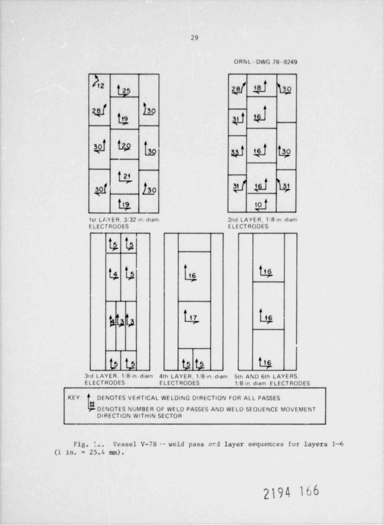
of 4-mm-diam (5/32-in.) electrodes. Typical welding and grinding sequences~
are shown in the photographs in Fig. 11, and typical pass and layer se-
quences are listed in Figs. 12 and 13.
An attempt was r.ade to save time by grinding the final cover pass to
bl?nd with the vessel's outer surface contour while increasing heater in-
pu,: to elevate vessel temperature to the PWHT temperature plateau of 260
2b M (500 50*F). Air-grinding operations, however, had an effect on
the uniformity of heatup: thermocouple recordings registered considerable
temperature spread between various vessel locations, and thermocouples un-
covered for the grinding were influenced by the constant stream of air
flow associated with the air-grinding process and hence indicated low
readings. Accordingly, heat input had to be reduced to preheat settings
until grinding was completed and the final magnetic-particle examination
was made. Thereafter, it required 3 hr to attain vessel PWHT temperature.
The vessel was then held at %260 C (500*F) for 4 hr before removal of in-sulation for cooldown. The vessel cooled down tc, ambient temperature in
about 2 days, at which time final strain gage readings were taken prior
to gage and thermocouple removal from the vessel.
2194 164

.
ORNL PHOTO 1678-78
* ) L- ~ ~..,.
,
jj . . - .I'' -
,
,I l'"
**4 ,,,
as::' '' ?) , ,
'
;1 i
i I'
,
N% {j l'~'
_. _ _ .
(a)
INTERMEDIATE LAYERS, REPAIR WELDING WITH STAGGERED WELDING 3EQUENCE
.
>1 i-
> .. .*
' ' ', |-|,
%* -j,-
i I -.
, .-;..- m,
(''
..
~~~ ,(,
; , f_'
A ,
(b)
TYPICAL GRINDING SEQUENCE BETWEL. LAYERS
Fig, 11. Vessel V-7B - repair details.
2194 165
29
ORNL-DWG 78-8249
5 2
24 h9g g g
zi y a e g gO
f30
b d1st Lt.YE R, 3'32 in. diam 2nd LAYE R.1/8 in. diamELECTRODES ELECTRODES
s
h 5 167 v
La .
"s u u u %3rd L AYE R,1/8 in. diam 4th LAYER,1/8 in.-diam 5th AND 6th LAYE RS,ELECTRODES ELECTRODES 1/8 in. diam ELECTRODES
KEY: '' DENOTES VERTICAL WELDING DIRECTION FOR ALL PASSES
DENOTES NUMBER OF WELD PASSES AND WELD SEQUENCE MOVEMENTDIRECTION WITHIN SECTOR
Fig. ?. 2 . Vessel V-7B -- weld pass ar.d layer sequences for layers 1-6(1 in. - 25.4 mm).
2194 166
30
ORNL-DWG 78-8250
t 12
[ 16 i 10%r-
i 16 f toW r
7th to 19th LAYERS 20th to 33rd LAYERS
i 14,
t 13 @
Wf 15
tL3'
Wts
t.n ta34th to 49th LAYERS 50th to 61st L AYERS
KEY: d DENOTES VERTICAL WELDING DIRECTION FOR ALL PASSES
DENOTES NUMBER OF WELD PASSES AND WELD SEQUENCE,
MOVEMENT DIRECTION WITHIN SECTOR
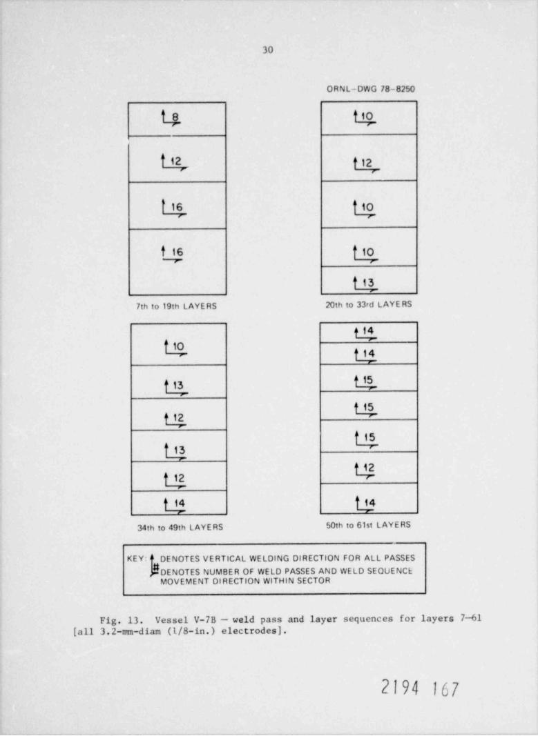
Fig. 13. Vessel V-7B - weld pass and layer sequences for layers 7--61[all 3.2-mm-diam (1/8-in.) electrodes).
2194 167
31
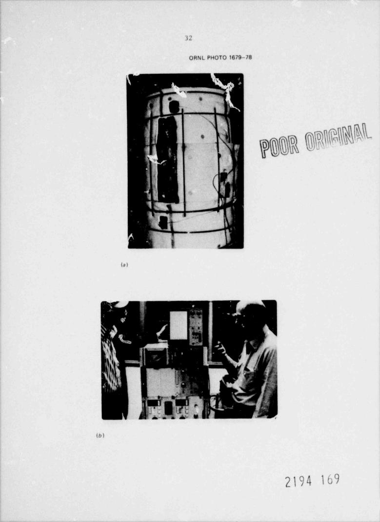
Acoustic-emission (AE) monitoring of the vessel was performed on a
continuous basis by personnel of GARD, In ., under the direction of D. W.
Prine, Project Engineer. Preheat, repair welding, PWHT, and the cooldown
operation were monitored using the GARD AE-monitoring equipment shown in
Fig. 14. AE sensors were attached to the vessel's outer surface just be-
yond each end of the repair cavity. The sensors were coupled to an adja-
cent mounted preamplifier, and cables connected to the prcamplifier trans-
mitted boosted signals to a console located near the work station where
the signals were processed, displayed, and stored.
The CARD AE weld monitor is built around commercial Dunegan Endevco
acoustic-emission equipment with a CARD-designed flaw alarm and signal-
processing system added to permit location of the AE sources that satisfy
the flaw alarm criteria. These criteria vary for material and welding
process and include AE burst energy, frequency, and burst rate. The flaw
location information is read out on a storage oscilloscope, and permanent
records are made by photographing the scope display. Raw AE data are
stored on magnetic tape for later playback using a GARD-modified Sony
video tape recorder. Data recording band width is 0.1-1 !!!!z. AE data are
also stored on paper strip chart recordings, which include burst energy
(signal ring down count) and AE alarms. Records are also made of weld
current vs time to help keep track of weld passes.
Weld repair backing bars were removed by grinding inside the vessel
with the grinder standing on the floor and inside the vessel's flanged
head opening. In removing the backing plates, the grinder encountered
visible porosity %254 mm (%10 in.) below the repair cavity centerline, or
near the junction of the vessel's inner surface and the 112* included cor-ner angle slope toward the vessel's flanged head end. Porous areas were
then ground out as verified by magnetic-particle inspection. The resultant
newly ground inner cavity measured approximately 127 mm (5 in.) wide cir-cumf rentially by 25.5 mm (1 in.) high vertically by 22 mm (7/8 in.) deep.
The entire weld repair zone of the vessel was next subjected to both
straight and 45* shear-wave ultrasonic and radiographic inspections toensure that no additional repairs were needed before commencing to reweld
2194 168
32
ORNL PHOTO 1679-78
. $
-
h
700R 6398#S, ;-
i
1 '
-_.-
,3
(a)
(b)
2194 169
33
the newly formed " corner ca-E ty." Generally acceptable ultrasonic indi-
cations were noted throughout. Questionable ultrasonic indications, how-
ever, were observed in an area near the intersection of the vessel wall
and the 142* slope. Ultrasonic shear-wave inspection recheck indicationsproduced signals equivalent to 20 to 30% of the distance amplitude correc-
tion (DAC) curve, and radiographic inspection confirmed these findings.
Radiography also revealed minor porosity indications adjacent to a pre-
drilled 1.6-mm-diam (1/16-in.) passage previously placed in the vesselto establish test pressure equalization on both sides of a patch liner.
(For the final vessel pressurization test, a patch is used on the inside
surface of the vessel below the flaw to deter or stop the pressurization
media frcm leaking through the cracked vessel wall.) Repeat radiography
via triangulation methods indicated that these porosity effects were lo-cated in various staggered thickness planes respectively separated byabout 25.. nm (1 in.) of solid metal. Hence, porosity was unstacked andnot continuous. Another area of minor porosity [s6.3 mm (%1/4 in.) in
diameter] was noted 4114 mm (%4 1/2 in.) f rom the 1.6-mm (1/16-in.) pas-sage toward the vessel's head flange end adjacent to the cavity wall onthe side of the hole. Radiography indicated that the porosity was locatedin two planes, 9.5 mm (3/8 in.) and 36.5 mm (1 7/16 in.), respectively,belos the ve-sel's outside surface. No cther defects were revealed by
radiography. The surfaces and all areas adjacent to the newly ground-outinner surface cavity appeared to be sound.
Wherever there were questionable implications of minor porosity and/orisolated slag inclusion based on the ultrasonic and radiographic findings,
these minute areas were separated by solid metal. It was therefore decided
to limit repairs to rewelding the ground-out cavity area at the vessel's
inside diameter to the 112" slope. ORNL and WTD agreed to accept all the
minor imperfections noted on the radiographic films. The fine porosity
indications were all passable within '.he Code, except possibly for the
single r arginal [%3.2 mm (%1/8 in.) x 16 mm (5/8 in.)] very thin hori-
zontal def ect noted near the dome end of the repair. It was also con-
sidered acceptable, however, based on repeat triangulation x rays and theintended end use of the vessel for test purposes.
2194 170
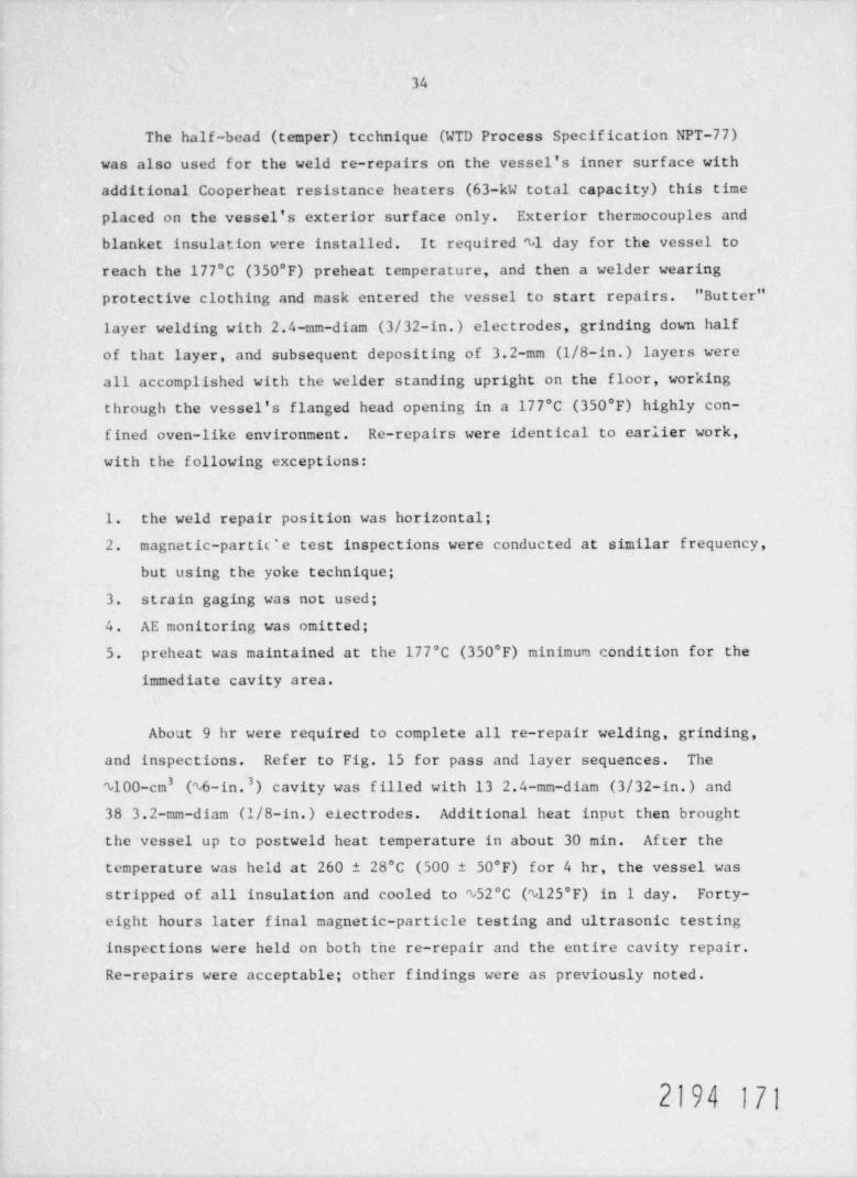
34
The half-bead (temper) technique (WTD Process Specification NPT-77)was also used for the weld re-repairs on the vessel's inner surface withadditional Cooperheat resistance heaters (63-kW total capacity) this timeplaced on the vessel's exterior surface only. Exterior thermocouples andblanket insulation vere installed. It required %1 day for the vessel to
reach the 177*C (350*F) preheat temperature, and then a welder wearing
protective clothing and mask entered the vessel to start repairs. " Butter"
layer welding with 2.4-mm-diam (3/32-in.) electrodes, grinding down halfof that layer, and subsequent depositing of 3.2-mm (1/8-in.) layers wereall accomplished with the welder standing upright on the floor, workingthrough the vessel's flanged head opening in a 177 C (350*F) highly con-fined oven-like environment. Re-repairs were identical to earlier work,with the following exceptions:
1. the weld repair position was horizontal;
2. magnetic-partic'e test inspections were conducted at similar frequency,but using the yoke technique;
3. strain gaging was not used;
4. AE monitoring was omitted;
5. preheat was maintained at the 177 C (350 F) minimum condition for theimmediate cavity area.
About 9 hr were required to complete all re-repair welding, grinding,
and inspections. Refer to Fig. 15 for pass and layer sequences. The
4100-cm (%6-in. 3) cavity was filled with 13 2.4-mm-diam (3/32-in.) and3
38 3.2-mm-diam (1/8-in.) electrodes. Additional heat input then brought
the vessel up to postweld heat temperature in about 30 min. After the
temperature was held at 260 28"C (500 50*F) for 4 hr, the vessel was
stripped of all insulation and cooled to %52 C (%125 F) in 1 day. Forty-
eight hours later final magnetic-particle testing and ultrasonic testing
inspections were held on both the re-repair and the entire cavity repair.
Re-repairs were acceptable; other findings were as previously noted.
2194 171

35
O RN L-DWG 78-8251
' B=9 B=8'
q A=4 'A=4
1st LAYE R, 3/32 in. dam 2nd LAYE R,1/8 in.-diamE LECTRODES ELECTRODES
%
3rd to 6th LAYE R, 7th LAYE R,1/8 in. diam1/8-in. diam ELECTRODESELECTRODES
8th AND FINAL LAYER,1/8 in. diam ELECTRODES
KEY: j ggDENOTES NUMBER OF WELD PASSES AND WELD SEQUENCE MOVEMENT(A = INITIAL SEQUENCE,8 = FINAL SEQUENCE)
-* DENOTES HORIZONTAL WELDING DIRECTION FOR ALL PASSES
Fig. 15. Vessel V-7B re-repair (half-bead repair to vessel interior);weld pass and layer sequences (1 in. = 25.4 mm).
3.3 Vessel V-8
The basic test vessels V-7B and V-8 are identical. Vessel V-7B had
previously been used in two tests; V-8 was an unused vessel. Only the re-
pair cavity and flaw sizes and the azimuth locations dif fered for the two
vassels. Vessel V-8 was furnished to Westinghouse with an approximately
half-wall-thickness premachined cavity midway up the vessel's cylindricalportion extending halfway into the vessel's seam weld. This cavity, iden-
tical to the prolongation V-8 cavity, measured 318 mm (12 1/2 in.) x 82.5
mm (3 1/4 in.) on the vessel's outer surface and was 90 mm (3 1/2 in.) deep.
2194 1/2

36
Sidewalls were cut on radial planes; top and bottom ends were tapered on
45* slopes toward the cavity's center, as shown on the appended drawingEDSK-379614J. The V-8 repair selections were made to simulate field re-
pairs to vessel weldments.
Actual vessel V-8 weld repairs were held up pending the completion
of the prolongation V-8 cavity repair to evaluate strain gage data and
to possibly alter strain gage locations. Preliminary data analysis, how-
ever, indicated that the gage number and placement selections were ade-quate, and the vessel was instrumented the same as the prolongation.
Thermocouples were also placed on the vessel in accordance with the Coderequirements; the outermost thermocouples were located at 3T (thicknessof work), or 457 mm (18 in.), f rom the cavity center.
The vessel was preheated to 177*C (350*F) in %14 hr; an additional4 hr were allowed for strain gage stabilization hold time. Thereafter,
%6 1/2 hr were required to deposit the " butter" layer with 2.4-mm-diam
(3/32-in.) electrodes, which was followed by grinding off half of the
deposit. The before- and after-grinding measurements are recorded in
Table 3. A period of 91 hr was required to complete the weldment, in-
cluding time for all prescribed magnetic-particle inspections. The final
18 layers were staggered to minimize and hopefully eliminate porosity
trends based on earlier experience with vessel V-7B repairs and ultrasonic
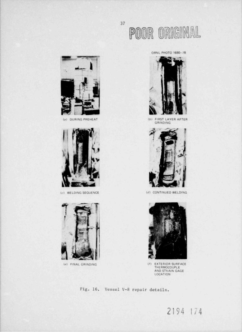
and radiographic inspections of those repairs. Photographs of the welding
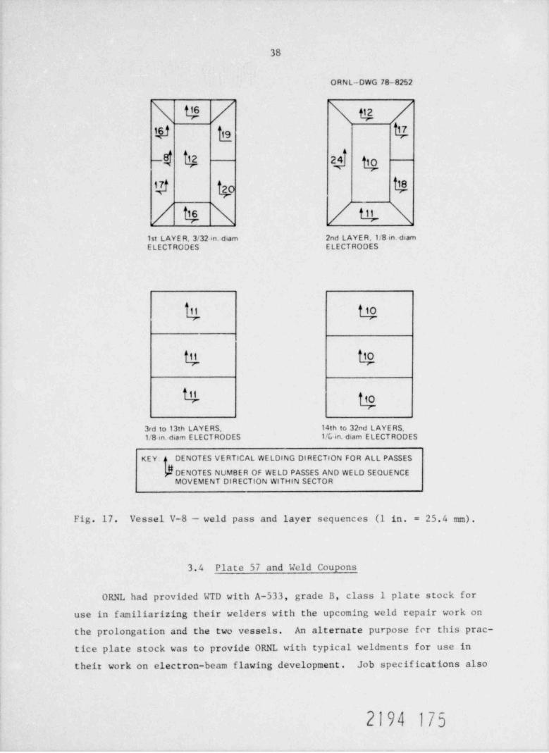
sequence are shown in Fig. 16. Figure 17 illustrates the typical pass and
layer sequences used. One hundred twenty-four 2.4-mm-diam (3/32-in.) and3771 3.2-mm-diam (1/8-in.) electrodes were used to fill the %1557-cm (%95-
in.3) cavity in vessel V-8.One 8-hr shift was spent in contour-grinding the cover pass and in
making the final magnetic-particle inspection, followed by a 2-hr heatupto postweld temper temperature - 260 28 C (500 50*F). After this
temperature was held for 4 hr, the vessel was stripped of insulation and
cooled to room temperature in %2 days. Forty-eight hours later, the re-
quired final magnetic-particle, ultrasonic, and radiographic inspections
were completed. These inspections indicated that the welding was accept-
able according to ASME Code requirements.
2194 173
37
3-}'mo m
J cc c - C
ORNL PHOTO 1680-78
%s -- # m3- *~ g ',* v -
% t-'
.
_ - , _ . _
f?1 w I
Elb fc
1 {} <7(a) DURING PREHEAT (b) FIRST AYER AFTER
| j > ,I v' h
I f/ l ,
k)' '
'} ,j! iy .
''
ig.' a
,; ,- ..
L :"' . .: g q f
.:
(c) WELDING SEQUENCE (d) CONTINUED WELDING
** - f~~ f-g
-
', R rl_
wfj (
b.?1 "rs
' .yLyg -
wA 1(e) FINAL GRINDING (f) ERIOR SURFACE
OCAT
Fig. 16. Vessel V-8 repair details.
2194 174
38
O R N L-DWG 78-8252
N e / N e /e$ 8-W ts af g$ 40 5
/ 15 N / tg N1st LAYE R, 3/32 in. diam 2nd LAYER.1/8 in. diamELECTRODES ELECTRODES
* 5
4 43rd to 13th LAYERS, 14th to 32nd LAYERS,1/8 in.-diam ELECTRODES 1/C in. diam E LECTRODES
DENOTES VERTICAL WELDING DIRECTION FOR ALL PASSESKEY: o
DENOTES NUMBER OF WELD PASSES AND WELD SEQUENCEMOVEMENT DIRECTION WITHIN SECTOR
Fig. 17. Vessel V-8 - weld pass and layer sequences (1 in. = 25.4 mm).
3.4 Plate 57 and Weld coupons
ORNL had provided WTD with A-533, grade B, class 1 plate stock foruse in familiarizing their welders with the upcoming weld repair work onthe prolongation and the two vessels. An alternate purpose for this prac-tice plate stock was to provide ORNL with typical weldments for use intheir work on electron-beam flawing development. Job specifications also
2194 175
39
called for all practice work to be performed to ASME Code half-bead repair
weld guidelines, except for substituting visual examinations for otherwise
timely magnetic-particle inspections of alternate layers.
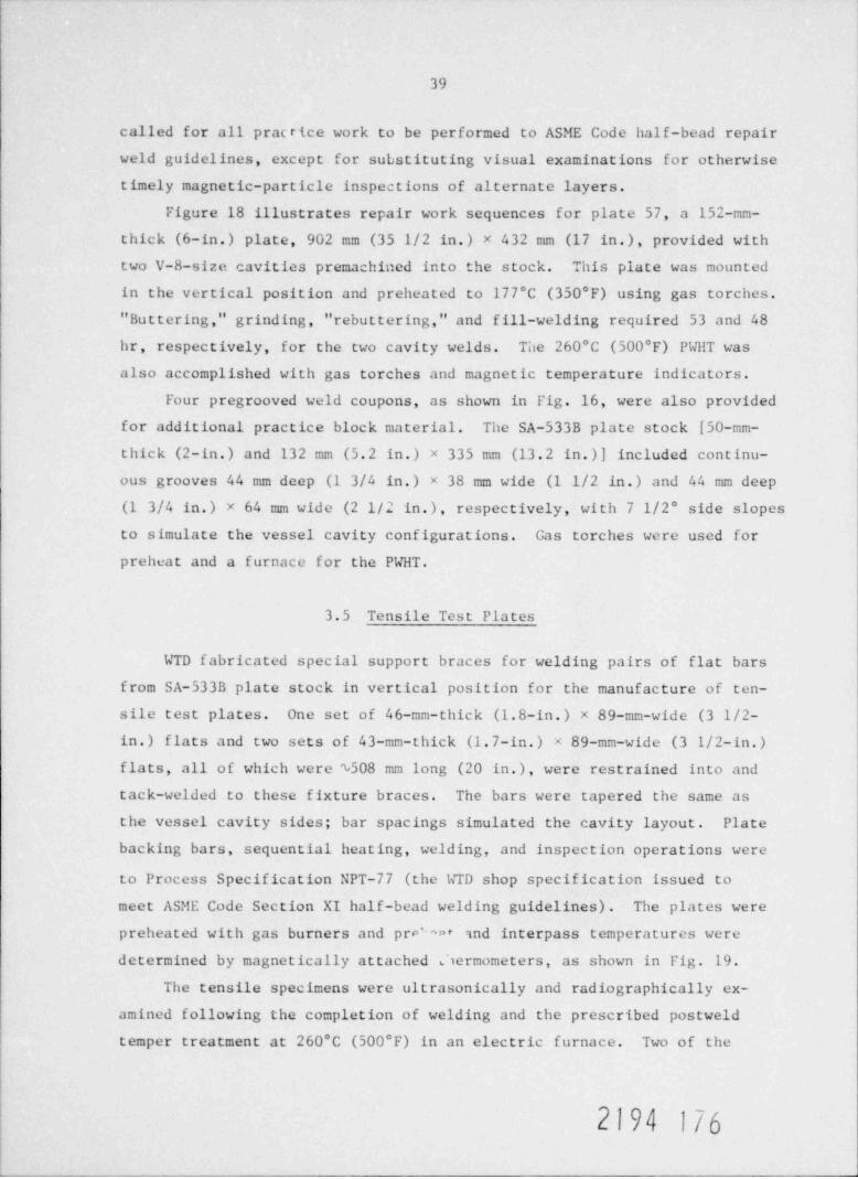
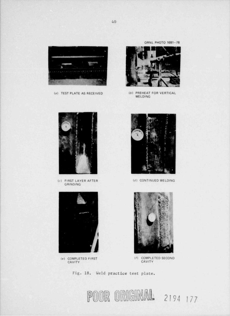
Figure 18 illustrates repair work sequences for plate 57, a 152-mm-
thick (6-in.) plate, 902 mm (35 1/2 in.) x 432 mm (17 in.), provided with
two V-8-size cavities premachined into the stock. This plate was mounted
in the vertical position and preheated to 177 C (350*F) using gas torches.
" Buttering," grinding, "rebuttering," and fill-welding required 53 and 48hr, respectively, for the two cavity welds. The 260 C (500 F) PNHT wasalso accomplished with gas torches and magnetic temperature indicators.
Four pregrooved weld coupons, as shown in Fig. 16, were also provided
for additional practice block material. The SA-533B plate stock [50-mm-
thick (2-in.) and 132 mm (5.2 in.) x 335 mm (13.2 in.)] included continu-ous grooves 44 mm deep (1 3/4 in.) x 38 mm wide (1 1/2 in.) and 44 mm deep(1 3/4 in.) x 64 mm wide (2 1/2 in.), respectively, with 7 1/2 side slopes
to simulate the vessel cavity configurations. Gas torches were used for
preheat and a furnace for the PWHT.
3.5 Tensile Test Plates
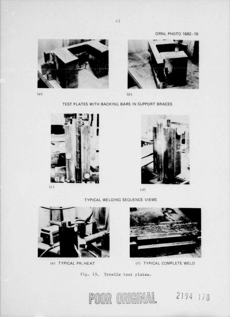
WTD fabricated special support braces for welding pairs of flat bars
from SA-533B plate stock in vertical position for the manufacture of ten-
sile test plates. One set of 46-mm-thick (1.8-in.) x 89-mm-wide (3 1/2-
in.) flats and two sets of 43-mm-thick (1.7-in.) x 89-mm-wide (3 1/2-in.)flats, all of which were %508 mm long (20 in.), were restrained into and
tack-welded to these fixture braces. The bars were tapered the same as
the vessel cavity sides; bar spacings simulated the cavity layout. Plate
backing bars, sequential heating, welding, and inspection operations were
to Process Specification NPT-77 (the WTD shop specification issued to
meet ASME Code Section XI half-bead welding guidelines) . The plates were
preheated with gas burners and prv'n t and interpass temperatures were
determined by magnetically attached Jiermometers, as shown in Fig. 19.
The tensile specimens were ultrasonically and radiographically ex-
amined following the completion of welding and the prescribed postweld
temper treatment at 260 C (500 F) in an electric furnace. Two of the
2194 176
40
ORNL PHOTO 1681-78
(a) TEST PLATE AS RECEIVED (b) PREH AT FOR VERTICAL
*. . .y . .-
' ''- . . , , ,
,
'^
k - .b, .
'
f ,''# \.,, 6
.,
fk(c) FIRST LAYER AFTER (d) CONTINUED WELDING
GRINDING
Iej"[k, ,;l
. ?[ , I[ (i .h'
gF ' %-h , . ' d i fi
j
. . <>- .
i didif ;ki;' !
31r*h|s .. \ '
(e) COMPLETED FIRST (/) COMPLETED SECONDCAVITY CAVITY
Fig. 18. Weld practice test plate.
NY $ bl 2194 177
41
ORNL PHOTO 1682-78
3;y . y- --
(a) (b)
TEST PLATES WITH BACKING BARS IN SUPPORT BRACES
!!F1 -4 lg IN
ETij!;Ag|i .j p;j](s9(g fj'?' g.v. ,,
-~ F ad,
aab.| bt :,_
.. I, , '|' '
.
(d)
TYPICAL WELDING SEQUENCE VIEWS
y - ~ '~ s _ y .a * -
(e) TYPICAL PRdHEAT (/) TYPICAL COMPLETE WELD
Fig. 19. Tensile test plates.
re e M M JJ } @hlD * * l0
*lD l
'
2|94 |/g
42
three specimens prepared met inspection acceptance standards, but thethird specimen was rejected based on porosity indications in excess ofthat permissible by the ASME Code. The tensile specimens were forwarded
to ORNL for analysis.
2194 179
43
4. RECOMMENDATIONS
For dcep vertical repair welds which are to be done manually, greater
access for welders must be provided by substantially increasing the wall
angle. Limited access hampers manual repair welding efforts, especially
for vertical-position welding. Welding the half-wall-thickness cavity in
the prolongation and in vessel V-8 did not present unusual welding problems
because, for these repairs, the maximum welding depth was limited to 89
mm (3 1/2 in.). The welders had sufficient working room, which afforded
easy access to the entire bottom of the repair area. The through-the-wall
155-mm (6-in.) repair cavities in both the prolongation and in vessel V-7B,
however, presented considerable problems for the welders. The primary dif-
ficulties were the limited access for weldi.ig, the 152-mm (6-in.) repair
depth, the narrowness of the area to be repaired, and the 7 1/2 angles on
each of the cavity's sidewalls.
Additional development work is suggested to test alternate techniques
for achieving proper tempering of the " butter" layer. The determination
of when the first, or " butter," layer has been ground off ends up as a
decision based on judgment. It is extremely difficult to establish ac-
curate reproducible depth measurements in a repair cavity at 177 to 204 C
(350 to 400*F). The literal interpretation of " grinding off half of :he
first layer" resulted in many hours of discussion and measurements before
agreement was reached as to when the surface approximating the half-layerwas reached. Care can be exercised to not grind off the entire layer, but
actual ground layer measurements should not be reyrired. The use of small
electrodes for the " buttering" layer followed by a second " buttering" layerapplied with larger-diameter electrodes may achieve adequate tempering ofthe initial layer and the adjacent base metal. It may even be possible to
omit grinding of the first layer altogether.
The suggested development efforts should also test repairs employingstaggered electrode sizes for early layers only -- omitting grinding.
Considerable savings could result if it were possible to eliminate grind-
ing operations without sacrificing tempering effects. If these suggested
tests prove to establish repair welds of a quality equivalent to the pres-
ent half-bead repairs, then combined efforts should be solicited from the
2194 180
44
developer and industry to revise the present Section III and Section XI
ASME Code requirements for half-bead welding.
Semiautomated or automated process welding repairs or such repairs
in conjunction with and following manual half-bead process welding of
early layers would help to greatly reduce the time required for repairs.
For in-service repairs at a nuclear facility, this night mean vastly reduced
welder exposure time. Research and development efforts should also be ex-
tended in this direction. The man-hour-to-cavity-fill deposit rate for
WTD half-bead repairs averaged only %8.2 cm (%0.5 in.3) of deposit for3
each man-hour spent. The number of man-hours includes the hours worked
by all personnel assigned to a shift generally two welders and a part-
time inspector. Equivalent clock-time-to-cavity-fill rates averaged 193 (1.16 in. 3) of deposit for each clock-hou ut operation.cm
The maximum extent of repair limitations (ASME Code, Section III,
Paragraph NB 4642.2) and extensive welding prc cedure and welder prequalifi-
cation requirements (ASME Code, Section XI, Paragraph IWB 4423.3) should
now be reviewed by Code committee personnel. Favorable Code changes to
establish increased depth of weld repair allowances and less extensive
prequalification requirements seem to be in order based on the success
of WTD and Combustion Engineering on HSST vessel half-bead weld repairs.
2194 181
45
ACKNOWLEDGMENTS
The authors wish to express their deep appreciation for efforts
far beyond the normal requirements by personnel of Cooperheat Company
and GARD, Inc., by M. L. Carpenter of Westinghouse Tampa Division, bythe Westinghouse welding technicians, and by C. E. Childress and T. A.King of Oak Ridge National Laboratory.
We also wish to thank Combustion Engineering, Inc., for giving us
a copy of Report EPRI-NP-179 covering their work on a similar assignment,which provided helpful background and direction.
2194 182
46
REFERENCES
1. J. G. Merkle et al. , Test; of C-in.-Thich Pressure Vessels. Series 3:Intermediate Test Vessel V-7, ORNL/NUREG-1 (August 1976).
2. W. D. Goins and D. L. Butler, Ucld Repair of Heavy Section Steel Tech-nology Program Vessel V-7, EPRI NP-179 (ORNL/Sub/88242-76/1), Combust-ion Engineering, Inc. (August 1976).
3. R. H. Bryan et al. , Test of C-in.-Thich Pressure Vessels, Series 3:Intermediate Test Vessel V-ZA, ORNL/NUREG-9 (February 1978).
4. R. H. Bryan et al. , Test of C-in.-Thick Pressure Vessels, Series 3:Intennediate Test Vessel V-7B, ORNL/NUREG-38 (in preparation) .
Smith and P. P. Holz, Repair W' ld Induced Residual Stresses in5. G. C. eThick-Ualled Steel Pressure Vessels, ORNL/NUREG/TM-153 (in preparation).
2194 183
47
APPENDIX
2194 184
49
Union Carbide Corporation, Nuclear Division(Oak Ridge National Laboratory)
WELDING SPECIFICATION W-HB-105
2194 185
50
10/8/76 Issue Date
WELDING SPECIFICATION NO. W-HB-105*t
LOW HYDROGEN ELECTRODE MANUAL SHIELDED METAL-ARC
WELDING FOR " HALF-BEAD" REPAIR WELDING
(Vessel positioned vertically)
Scope
This specification covers the Welding Procedure (Part I) and Welder Per-
formance Qualification and Procedure Qualification Tests (Part II) for manual
shielded metal-arc repair welding on 6-in.-thick low-alloy steel materials
using low-alloy, low-hydrogen steel electrodes comparable to Section XI re-
quirements. This weld procedure is specifically applicable for vessel weld
repairs from the exterior for vertically p, -ioned vessels using the " half-
bead" technique, whereby the entire cavity of the preheated vessel is " buttered"
using 3/32-in.-diam electrodes. The " buttered" deposit thickness is then hall
removed by grinding. Subsequently, the remainder of the cavity is then filled
using 1/8-in.- and/or 5/32-in.-diam electrodes. Removal of half of the initial
weld layer (buttering) permits the heat from the next weld pass to refine the
grain size of the base metal heat-affected zone, as well as for tempering pur-
poses. Prehea t is to be maintained throughout the entire welding operations.
The machined notch and the adjacent cracked and yielded zone of the ves-
sel shown in Fig. I will be repaired by this welding procedure. This procedure
*Reference: ASME Boiler and Pressure Vessel Code, Section XI (In-Service
Inspection), Subsubarticle IWB-4420 (Repair Procedure No. 4) .References to portions of the Code are to the 1974 edition with the
Summer 1974, 1975, and Winter 1975 addenda and are to Section XI unless statedotherwise.
i In this Welding Specification " fabricator" is used to mean the subcon-tractor in whose shop the welding is perf9rmed, and the "UCC-ND" is used tomean the Union Carbide Corporation, Nuclear Division.
2194 186
51
2
also requires the preparation and welding of a qualification test piece as
follows:
Qualification Test Piece: A UCC-ND furnished 6-in.-thick wallASTM A533, grade B, class 1 prolongation from a vessel, as shown
in Fig. 4, along with a bracing arrangement for the backing plates
and end restraints for the cylinder ends to be furnished by the
fabricator.
The same qualification test piece shall be used also to qualify thisprocedure for an apporximately half-wall thickness " half-bead weld
repair" to a submerged-arc longitudinal vessel seam weld as shownin Fig. 8. The two cavities shall be spaced at approximately 180'per Fig. 8 layout.
The weld repairs to the prolongation must be done sequentially. Theprolongation shall be allowed to cool to room temperature and then toremain at room temperature for a minimum of 24 hours in between
sequential weld repairs.
Test coupons shall also be furnished (refer to Fig. 3).
Individual welders must be qualified under Section IX of the Code for a
procedure having the same essential variables for welding performance qualifi-
cation ao the procedure of Part I, or they must weld the 3 in, qualification
plate shown in Fig. 2 of this specification to demonstrate qualification under
this procedure. The Weld Procedure Qualification Test Piece (Fig. 4) is used
to demonstrate the qualification of the procedures used by the welders for
repair of the vessel.
Participation of UCC-ND and CARD *
The UCC-ND shall be permitted access to the fabricator's facilities to
witness all work on this project and to make strain measurements as required.
*
General American Research Division, Inc. (Subsidiary of GATX Corporation).
?194 187

52
3
CARD personnel shall be permitted access as required to acoustic emission
monitor vessel repair welding.
UCC-ND and GARD shall furnish material, labor, and equipment for this
work; the fabricator shall provide utilities to support the work. UCC-ND work
may consist of the application of weldable strain gages that have been stabilized
to both the vessel and the prolong after the backing plate and suitable internal
brace restraints have been installed but prior to preheating. Strain gage
measurements will be recorded as follows:
1. pr.ior to the application of preheat;
2. four hours after the vessel reaches the specified preheat range but before
welding commences;
3. after all welding is completed but prior to the post-weld heat treatment;
4. af ter the post-weld heat treatment is completed but before cooling;
5. after the temperature has been at ambient temperature for a minimum of
2 hours but before removal of bracing and restraints;
6. af ter removal of bracing and restraints.
CARD personnel will attach sensors to the vessel and connect these
sensors to their console equipment for AE monitoring.
The fabricator shall notify UCC-ND and GARD of the testing schedule at
least 24 hours prior to each measuring hold point. Should test or monitoring
personnel be unavailable for testing during these hold points, on a reasonable
basis, the fabricator shall have the authority to bypass the required strain
or acoustic measurements.
Efforts should be made to electrically ground the test vessel symmetri-
cally for repair welding and MT examinations and thereby minimize the forma-'
tior: of asymmetric magnetic fields which tend to cause problems if electron-
beam ;relding means are used to subsequently artificially flaw the vessel.
}\9
53
4
Acceptacce of Work
The fabricator shall use UCC-ND supplied bar stock and furnish test cou-
pons made in accordance with NS-2430 of Section III of the Code for each lot
of electrodes. The coupon for each lot shall be of suf ficient width and thick-
ness such that tensile and impact specimens can be removed and shall be no less
than 48 in. in total length. Coupons shall also be welded, vertically placed,
and shall be adequately restrained to avoid warpage. A typical coupon is shown
in Fig. 3.
All test pieces, the prolong, and the repaired vessel shall be accepted
t, the UCC-ND upoa acceptance of the vessel i.. accordance with Section 13 of
Part I of this specification.
The fabricator shall furnish an ultrasonic calibration Llock appropriate
for use with inspections under Section XI, Fig.1-3131, Appendix 1 of the Code.
Records and Documentation
Appropriate records as follows shall be kept by the fabricator for in-
clusion in the final report. Information should also be transmitted inform-
ally to UCC-ND as requested and prior to issuing the final report in order
to expedite testing requirements of UCC-ND.
1. Copies of docur station qualifying welding electrode lots and methods of
handling.
2. Statements on welder certification.
3. Procedure for air-are gouging and grinding for cavity preparation.
4. Sketches showing as-fabricated cavity preparations in the vessel and the
qualification test piece,
k f0)
54
5
5. Procedures for grinding to insure thickness control of the " buttering
layer."
6. A detailed welding procedure.
7. A summary report of the evaluation made pursuant to Section 13 of Part I
of this specification.
8. Charts, or copies thereof, from temperature recording instruments and
sketches showing locations of thermocouples related to the charts for
the vessel.
9. Sketches showing size, location, and orientation of both repaired and
allowable flas indications found during post-weld nondestructive inspec-
tions.
|\9
55
PART I - WELDING PROCEDURE
1. Welding Qualification
All welding in accordance with this procedure shall be done by welders
qualified and currently certified under Part II (pages 13-19, or under Section IX.
Paragraph NB 4300, of the Code for a procedure having the same essential vari-
ables for welding performance qualification as this procedure. Welder certifi-
cation papers shall be available at the job site at all times.
2. Base Metal
The base metal will be low-alloy, high-strength carbon steel plate (ASTM
A533, grade B, class 1, or equal), P Number 3, Group 3 (Table QW 422, Section
IX of the Code).
3. Filler Metal
The filler metal shall be covered low-alloy steel electrodes and shall
conform to the requirements of Specification SFA-5.5, AWS Classification E8018-
C3 of Section II of the Code or, if the fabricator so elects, shall conform to
such other specifications as may be previously approved in writing by UCC-ND.
Electrodes shall be clean and dry, and the flux shall not be cracked or spalled.
(See Care of Welding Electrodes, Section 8 of Part I of this specification.)
Tests of welding materials shall conform to Subarticle NB-2400 of Section III.
Evaluation of each let of weld metal shall be based upon the manufacturer's
certification test report (supplied by the fabricator) and approved in writing
by UCC-ND.
4. Electrical Characteristics
The fabricator shall determine appropriate welding voltage and amperages.
2194 191
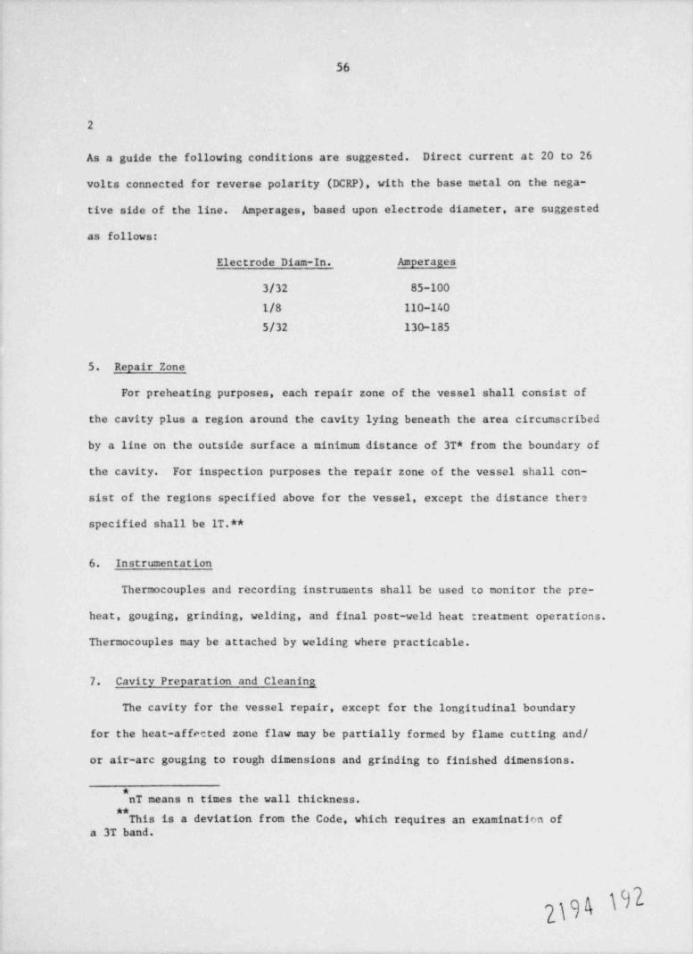
56
2
As a guide the following conditions are suggested. Direct current at 20 to 26
volts connected for reverse polarity (DCRP), with the base metal on the nega-
tive side of the line. Amperages, based upon electrode diameter, are suggested
as follows:
Electrode Diam-In. Amperages
3/32 85-100
1/8 110-140
5/32 130-185
5. Repair Zone
For preheating purposes, each repair zone of the vessel shall consist of
the cavity plus a region around the cavity lying beneath the area circumscribed
by a line on the outside surface a minimum distance of 3T* from the boundary of
the cavity. For inspection purposes the repair zone of the vessel shall con-
sist of the regions specified above for the vessel, except the distance there
specified shall be IT.**
6. Instrumentation
Thermocouples and recording instruments shall be used to monitor the pre-
heat, gouging, grinding, welding, and final post-weld heat treatment operations.
Thermocouples may be attached by welding where practicable.
7. Cavity Preparation and Cleaning
The cavity for the vessel repair, except for the longitudinal boundary
for the heat-affected zone flaw may be partially formed by flame cutting and/
or air-are gouging to rough dimensions and grinding to finished dimensions.
*nT means n times the wall thickness.
**This is a deviation from the Code, which requires an examinatinn of
a 3T band.
h*
}\ t

57
3
Finished dimensions are shown in Fig. 5 for the vessel. The repair zone shall
be preheated and maintained at temperature in the range of 350*F to 400*F until
flame or arc cutting and grinding are finished.* Af ter such cutting is completed,
a layer of metal under the cut area a minimum of 1/4-in. in depth shall be re-
moved by grinding.
Note: The vessel's longitudinal cavity surfacen have been premilled by
UCC-ND to establish final and optimum planes for subsequent : ost-weld repair
heat-affected zone flaw preparations. These longitudinal s.rfaces shall not
be ground. The layout for gouging the top and bottom cavity boundaries must
allow for 1/4-in. post gouge grinding and the b?ending of ground ends to the
premachined middle section. Care should be exercised in cavity corners to re-
tain minimum radii as shown in Figs. 4 and 5. Care must also be taken to pre-
serve the preground longitudinal sides.
The V-7B cavity for the procedure qualification prolongation shall be formed
by the fabricator entirely by air-are gouging and grinding. The cavity shall be
centered about the center lines now scribed to the vessel's outer surf ace. Cavity
end angles must match the angles of the vessel repair cavity ends. Dimensions
shown in Fig. 4 are finished (final ground) dimensions.
The V-8 repair cavity for the same prolongation and shown in Fig. 8 will be
furnished to the fabricator premachined and ready for half bead technique weldup.
Detailed procedures for cavity preparation and cleaning as prepared previ-
ously shall be kept and adhered to at the job site.
In final preparation for welding, the cavity shall be ground smooth and
clean, except as noted above, with beveled sides and edges slightly rounded
*This is a deviation from the Code which does not allow flame (thermal)
cutting. (With agreement of the Advisory Task Group on Weld Repair forPressure Vessels; PVRC, Atlanta Meeting 6/6/76) .
2194 193
58
4
to provide suitable accessibility for welding. The surfaces within IT distances
of the joint shall be cleaned of all dirt, oil, grease, paint and excessive
amounts of scale and rust. The cavities of the vessci and test pieces shall
be examined by magnetic particle inspection in accordance with the requirements
of IWA-2221 prior to welding. Additional grinding shall be performed with pre-
heat as necessary to remove indictrions of flaws. Actual dimensions and loca-
tion of the cavity shall be documented.
8. Care of Welding Electrodes
The moisture content in the protective coating of the low hydrogen elec-
trodes shall not exceed 0.47 by weight. The following steps shall be taken
to prevent moisture pickup; provided that, with prior written approval of
UCC-ND, minor deviations may be allowed.
All coated electrodes shall have been baked before use at temperatures
of 800*F 25*F for 30 minutes to one hour. The temperature of the oven shall
be at 300*F or lower when the electrodes are placed in the oven for baking.
During the baking cycle, the temperature shall not be raised more than 300*F
per hour when oven temperatures are above 500*F, and the total time above 500"F
shall not exceed five hours. Af ter baking, and before the electrodes are
allowed to cool below 150*F, they shall be repackaged in sealed containers.
The fabricator shall record and report moisture levels of each batch of elec-
trodes. Electrodes shall not be rebaked more than once.
During the repair, the electrodes shall be removed from their sealed con-
tainers and thereafter kept in portable heated ovens which shall be at the work
station. These ovens shall be at 225*F to 300*F. Electrodes shall not be out
of an oven more than 20 minutes prior to use. Electrodes not used within 20
2194 194
59
5
minutes af ter removal from the oven shall be returned to the holding oven and
held at 225*F to 300*F for at least 8 hours before reissue. Random moisture
contents rechecks should be conducted at least once a day on electrodes of
each size in use and taken from the portable heater ovens at the welder work
stations. The fabricator shall initiate and maintain tecords to indicate con-
formance to the above electrode bakeout and rod issuance regulations.
All electrode end conditione should be inspected carefully before use.
The small diameter electrodes are likely to have the flux coating chipped of f
at the start end. Electrode ends should be examined three times:
(1) when the electrode is rebaked,
(2) when the vacuum package is opened, and
(3) when the electrode is taken from the electrode holding oven by the
welder. Electrodes must be rejected whenever there are any signs of cracks in
the flux coating.
Detailed fabricator procedures for the care of electrodes must be for-
warded to UCC-ND for written approval within one week af ter contract award.
Upon approval, these procedures shall be kept and adhered to at the job site.
9. Conditions for Welding
The prolongation vessel and test coupons shall all be adequately braced
to prevent warpage. Test pieces shall be restrained to avoid warpage and to
simulate the restraint of the vessel. Backing plates shall be installed before
anchoring or bracing. Backing plates shall consist of two layers of precon-
toured standard fabricator steel backing material. Flat test pieces shall be
anchored to heavy support plates or welding tables. All work must be verti-
cally positioned for all welding.
|\hL
60
6
All subsequent repair worS shall be performed with preheat applied to the
base material. The preheat temperature in the repair zone shall be within the
temperature range of 350 to 500*F. The temperature shall not be allowed to
fall below 350*F until the completion of eit'..er an intermediate post-weld heat
treatment (PWHT)* of 450 to 550*F for 1/2 hour or af ter a final PWHT at the
same temperatures for four hours. If electrical heat is used, standby torches
shall be provided to maintain vessel temperature or perform an intermediate
PWHT in case of prolonged power outages or unanticipated equipment malfunctions.
A magnetic particle test of the weld cavity would be required following any
intermediate PWHT.
10. Position of Weld h
All welding shall be done with the longitudinal axis of the vessel and/or
prolong or test piece in the vertical pcultion. For the half-bead pass and at
least the first pass thereafter, welding shall be in the vertical position for
the cavity sides.
11. Weld :tal Deposition
Welding shall be done in general accordance with the illustrations of Fig. 6.
The cavity shall be buttered using 3/32-in. maximum diameter electrodes as
shown in Step 1, Fig. 6. Approximately one-half the thickness of this buttering
layer shall be removed by grinding before depositing a second layer. Special
procedures shall be established as needed to control the grinding of the butter-
ing layer. Such procedures may employ the use of workmanship specimens, dimen-
sional measurements, or other means to demonstrate compliance. The maximum
interpass temperature shall be held to 500*F. See Step 2. The second layer
*PWHT actually infers a post-weld tempering treatment only.
}_ \ h
61
7
shall be denosited with either 1/8-in.- or 5/32-in.-diameter electrodes. The
maximum bead width shall not exceed four times the electrode core diameter.
Bead povition shall be performed in a manner to temper the prior beads and their
heat-affected zcaes as shown in Step 3 of Fig. 6. The completed weld shall have
at least ene layer of wcld reinforcement (crown pass) deposited. This final
layer should overlap, but shall not extend beyond the " buttering" deposit of the
first pass This reinforcement shall thereafter be removed by grinding, making
the finished surface of the repair substantially flush with the surface of the
vessel surrounding the repair. Likewise following all welding and the post-
heat and cooldown, the backing plate shall be removed, and the interior repair
surface shall be contoured evenly to conform to vessel inside diameter dimen-
sions plus or minus 1/8 in. Back welding may be required to satisfy this re-
quirement. UCC-ND will be notified prior to ar.d shall approve any back welding
operations. Temper-bead techniques may again be required. Pgening shall not
be, employed for this weld repair.
Possible benefits of controlled peening, ;s permitted by Section XI, shall
not be evaluated in this weld repair.
Detailed procedures for grinding and controlling the thickness of the
buttering layer and, if elec.ed, controlled peening shall be kept at the job
site during this part of the work. Utmost care should be exercised to grind
off approximately half of the buttering layer as dimensional verification by
measurement is extremely difficult in a cavity at approximately 400*F.
2194 197
62
8
12. Inspection During Welding (Vessel and both prolongation welds)
A magnetic particle examination (MT) shall be performed on the ground
" buttered" layer, the next 1/8-in. layer, and thereafter on alternate layers
and the final groiad outside scr' ace.* The final MT shall be completed prior
to the start of the four-hour post-weld heat treatment. Layers not inspected
by Mr shall be visually inspected. Where necessary, weld defects shall be
removed and the repaired zone reinspected. If defects occur within 3/16 in,
of the base metal, such repairs shall be made using the " buttering" and half-
bead grinding technique. An MT examination shall be performed on the vessel ID
after grinding and backwelding (if required). MT indications shall be removed
by grinding and blending and u aubsequent MT exam shall be made to insure re-
moval of defects.
13. Post-Weld Nondestructive Inspection (Vessel and both prolongation welds)
The repair zone as defined above under Repair T.one shall be nondestructively
examined af ter the completed weld has been at ambient temperature for a period
of not less than 48 hours. A volumetric examination of the repair zone shall
be ma.le by radiography in accordance with IWA-2231 and ultrasonic examination in
accordance with IWA-2232, except that calibration block material of the same
specification as the base material shall be deemed to meet the requirement of
paragraph I-3121. A magnetic particle examination in accordance with IWA-2221
shall be made of the surfaces of the repair zone and of areas representing
locations of weld attachments. A visual examination shall be made in accord-
ance with IRA-2210.
*This deviation t' rom the Code, which calls for examining every layer (with
agreement of the Advisory Task Group on Weld Repair for Pressure Vessels, PVRC,Atlanta Meeting, 6/6/75).
.
63
9
Acceptance of the repaired vessel shall be determined in accordance with
IWB-3500 and Examination Category B-A. If necessary, repairs of the repair
zone of the vessel shall be made in accordance with the half-bead weld tech-
nique as described in the foregoing sections of Part I.
PART II - WELDER PERFORMANCE QUALIFICATION AND
PROCEDURE QUALIFICATION TESTS (IF APPLICABLE)*
1. General
All welding shall be in accordance with the requirements of Part I. The
welder performance and procedure qualification requirements will be satisfied
upon the successful completion of the tests described below.
2. Test Welds
Test A. Each welder to be qualified under this procedure shall be tested
by completing the welding of a plate as specified for the 3 in. qualification
plate, Fig. 2, which shall be tested in accordance with QW-302 and QW-304 of
Section IX of the Code. Each test piece of this type shall be stenciled with
the welder's stencil number on the upper surface where he originates the weld.
Figure 2 illustrates a typical setup for 3-in.-thick qualification plate weld
preparations. The fabricator will supply plate stock for this optional practice
work.
Test. B. Test B is a procedure qualiff tation. Test piece B, previously
referred to as the vessel prolongation furnished by UCC-ND and shown in Fig. 4,
*Refer to final paragraph under SCOPE, pg. 2 of this procedure. " Individual
welders must be qualified under Section IX of the Code for a procedure havingthe same essential variables for welding performance qualification as the pro-cedure of Part I, or they must qualify as out11aed in this Part II."
2}h
64
10
shall be prepared and welded in accordance with the procedure of Part I. Only
welders who have qualified under Test A or are qualified under Section IX of
the Code for a procedure having the same essential variables for welding per-
formance qualification as the_ procedure of Part I shall be permitted to weld
in Test B.
3. Welder Certification
A prequalified welder and or a welder passing Test A and thereafter
participating in the procedure qualification. Test B, shall be certified to
weld in accordance with W-HB-105.
4. Retests
A welder who fails to meet the requirements as set forth in Test A may
be retested af ter he has had further training or practice. A complete repeti-
tion of Test A shall be made. Retest specimens shall be tested and evaluated
by the same procedure used for the first test.
5. Period of Effectiveness
The qualification of a welder for this procedure shall be considered as
indefinite but shall expire upon termination of a 90-day period in which the
welder has not used this process. This qualification period may be extended to
six months if the welder is continuously employed in shielded metal-arc welding.
A welder's qualification may be withdrawn if the quality of his work is sub-
standard to the requirements of this procedure. When a welder leaves the em-
ployment of that particular manufacturer or contractor for whom he worked at
the time of his qualification, his qualification is automatically canceled.
_ 9
.
65
11
Renewal of Qualification:
Renewal of qualification may be obtained by Code Section IX provisions,
or by passing Test A.
Records:
Certified records of the welder qualification tests shall be originated
by the fabricator at the plant where the test was conducted. k* hen a welder
frcim an outside agency is qualified, a record of the test shall be submitted
to and become the responsibility of that agency. A suggested form for the
record is provided in Fig. 7.
2194 201
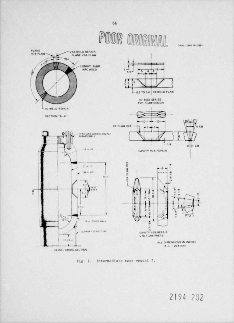
66
[MfF]D fPoD W ' n
WGA J 's, J|JuJ,, b onNL- owG 7s-7863
PLANE[V7A WELD REPAIR,V78 FLAW PLANE V7A FLAWy , *$ 0
$ y , .
va. .- - -
is s + / LONGIT. SUBM.i ARC WELD 1 18 ~o
1/2 }5 _
4 4S(
s,
s y e-[> A L' h j(, s
' 'a r' ~ ' @/
0 3 TO O.4 E8 WELD FLAW
Yi, /N$pj@hh@' V7 TEST SERIES'-- -'
TYP, FLAW DESIGN
-V7 WELD REPAIR !
SECTION "A- A" ... G + Q---10 - h 10 ,15'
|V7 FLAW HEF- 5 5 41/8
,
] { ', , su.AD A.N.D.AC.CE ss NollL E
g.-\k, . . .,. . . .f./ )
weAss L 6 !,,,
.
, ,
'l' I/4g r '
7/8[. U IS * 'D, .s..g CAylTV V7A REPA:R
,
f #\1
s --) --t
,
Mt
,
2 ! '" ' D "y w -6 ,
!39 m OD .a $~'
um < &I e- N
i 4 >*= lI *
; 9mL
4i g Apt A
~
-1 ? 3 $I ,/
N _' il E -f * 7 !'
,
<1' 4 ._.,.
,d.
.% -g--*-.iML I21 * .
y ,5 h 1
- 's ,,-- -
y - c- *
k ' m 6 m TH CK WALL &
hl "g 2 ~
surroni sinuC Tuaf CAVITY V78 REPAIR,
V78 FL AW PREP S
; 1212 aALL DIMENSIONS IN INCHES
t 1_ g .g , (1 in. 25 4 mm)_; _,
VESSEL CROS5-SECTION
Fig. 1. Intermediate test vessel 7.
2194 202

.. 67
|
A N ''
i
l|I
l .a'
q
O +a
I 'e
e
i .
I
f1i 6 ..
WEdY Qk b k%g W t n3m
', M I'
l'- 3 / 4" ||| 9 *
'
| Ji1/2",
e-- j- 3T=9" min.we ..- - 8- 5 / 8" >w- 3T=9" min. - *I 1i'
s .
l .
1
r . 76-5/8" min. _ _._ , ;
} [ ..15' incl.
%4-1/4" ref.
k:
e 5-5/8" ww 3" - M i *Simulated side 2-1/8" ref. -
3f.
plate obstructions f'
f ,,4- . g
I'\ (~ '
142-1/2** 112-1/2** :
' J,
/ i s'
/ h 3_ t i
e t: = .s: = --r.3 t= =.w = _ y e
|Q/4"4ef-|Grind Rootface 1/64" to 1/16" l-3J4"re .I 2 ea. 1/8" PLS 3
I 3-1/2" ref. I1" 3 1/2" ref.. we w 3/4"s- +.= ige 5"
NOTES: p- 5-1/2" M .-
1. * Same as for vessel.
2. Position plate vertically for welding; restrain and reinforce toprevent warpage.
3. ** Qualification plate is optional - refer to specifications.
Fig. 2. Suggested 3" qualification rate (optional - see specs).
2194 203
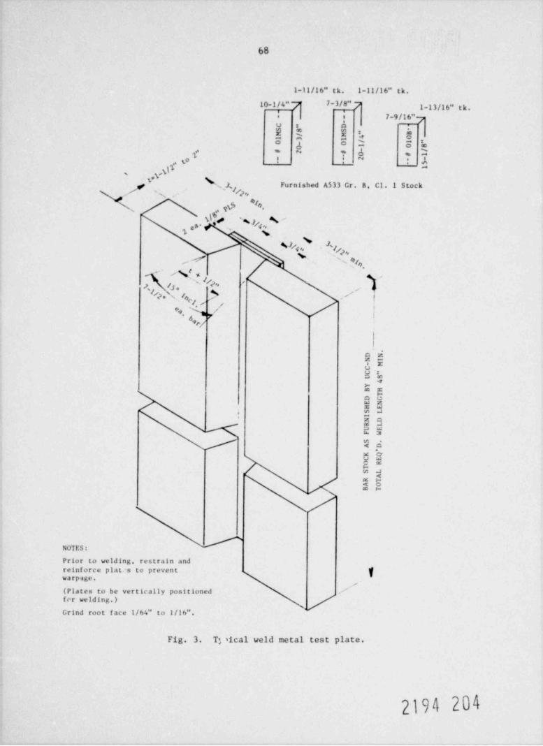
s&o
7 C~ e* " - 1 De: "w*.
oL x*:N ywQ M 7 WDe ne-- - ye@ s . e.--
.N-C
"8D
S S a B'M / M 4 0l 3 1O - 0 "8
/ 1
00 1
/s # 2 fe 0 # 1
eo - - 2 - -- - - 5
k 1
e'R,p
[<>
E,E& a D" nm' ". O * m gn"/4,p%c%
%\ ',,
e.g *s .O' s
e'f k**r*'g
p * ,- //
%,Q ,/s p-g '/4
/ e'c*\s\
;
t \-(r ,,
d_ s, ,
%*$r- N,
~/ s'. / % 'g .
4 \.
.
.
2.N s g- _/g s
_N- [y_.
.
D NN I
- MCC
"8U4
YB H
TD GE NH ES L
._ I
N DR LU EF WS ,
A D
K 'QC EO RTS L
AR TA OB T
zoAv-i
o- 0m O c -3Q- me m" a. uoaJ
me 5.3ne C r ", fA4
..O m m<cms %=
'
ia; nO E 442 nw x 3 "Fa \a :
n" c*.a 3 L
o Ea ,OOe ?nS Cee: na C 1: *
)n. w- Hu,>n4W tm " gmn$ "m(a" Oyn8'
.
4Nse -
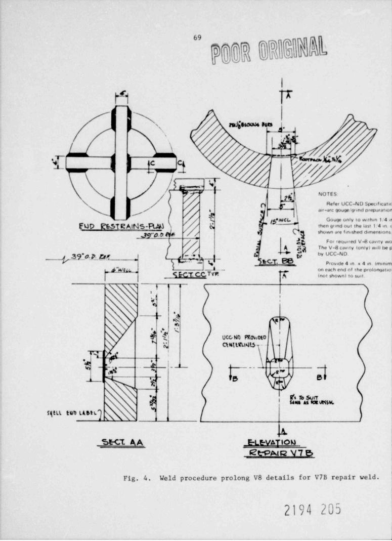
69 ,
J L
i
F1 7
rNy s. - ,- 3
'.
[s.
/ \~
U'Y's%[-- -- !"//c c,, a
[&* *
7 ( NOTES.# '
Refer UCC-ND Specificatiair-arc gouge /gr and preparatio
/ Gouge only to within 1/4 ig*WCt. ~then grind out the last 1/4 in.
s
FuD RESTEAINS-RM &., / shown ore finished dimensions
dg For re<iuired V-a cavity wo
A Sg The V4 cavity tonly) will be~ h by UCC-ND.
F'9~*0, p. pg ~ E C T. %j 3
~ ~ ~j . -- -? ' t, 1
M',- ( Provide 4 in. x 4 in. (mini4"WfIL A ---- ,, on each end of the prolongatio
;
9 E CT CC TfR ,A inot shown) io susi.
|#
4' ,
a wm
t8' UCCrNO PK09.0E0x ,)
N QMILELNt5 -- -,
.. 5 ,y'm-
Tag ( - ' -- L _,*R"
' i
PS eP'g
6 to wn@ , " " " * "9 j
rgtLt tun ustg l
.A.-SE-CE A A E-LE-VATIOM
3Et-pat R V 7 S
Fig. 4. Weld procedure prolong V8 details for V7B repair weld.
2194 205
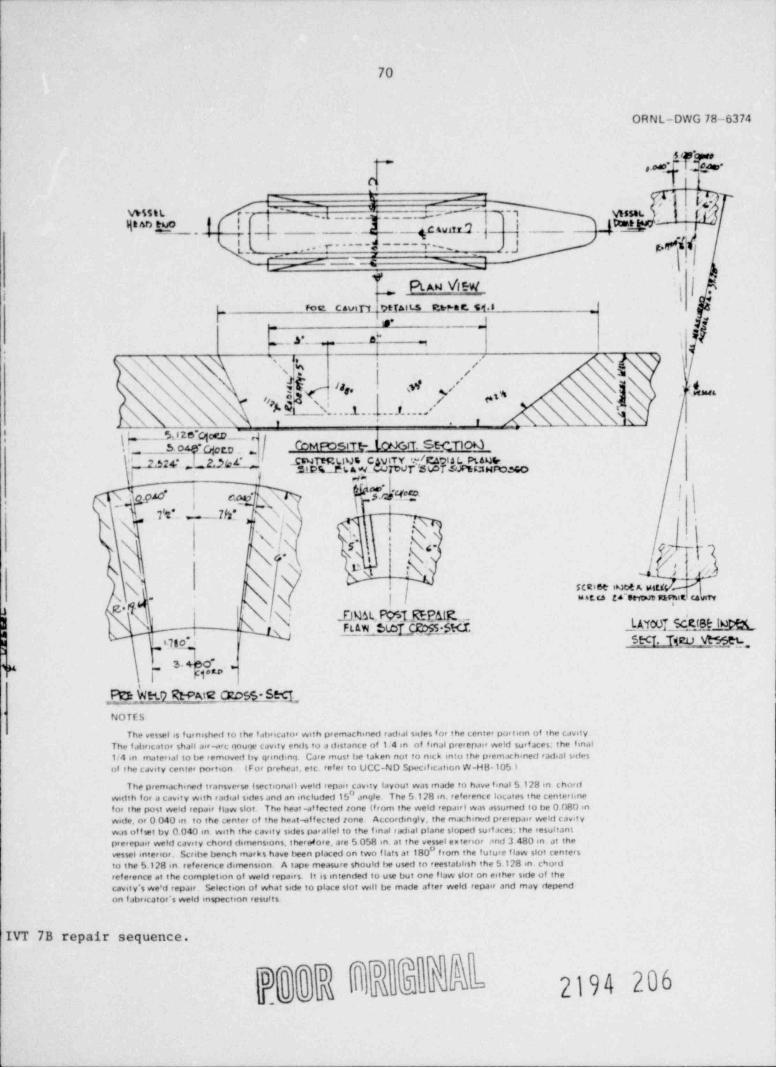
70
ORNL-DWG 78-6374
'' *o oao
ck ;; (-m
# W sm. l,fj ' ,..' __.___"'.__. _. -C4Wdd .p 7 .
- -.
.es
vnstL er1 Ij-_, ._ ._4
----r m ,j e. . . < - - - - -3 ,
'- ' '- C ,
i | I-PL AN \4W
Foc__C avlTLytJALL5Jerte r._S {.8_
W 5= _-
ke y -. .g" -
ti
8 / gN \INg x se, u,. sj g e,
i . . 1. . . . . .I . . . / '
I L ___% 8 2O'C|CG-__ c,'' , _ S og qc gp _ ,, DNSW kW bEENaygg *I* 2,3,~4 _ CENT 1tmNE C}VtTY ##CDI A L Ptaus-'31p%_1% AN s rJ7%T &&TSfssauros.oeI ( wa
JSM"gU !'ae I
N .o 9A0*N r. oaf N
f w _;_m >s, w x
s.#g .
f *\ Ih
\'\ *s p -
[-
N ,
l\p|\(I\- 5'\ f;
\ N :\ df| v
/SCRi6e int 4 A perf -
3 i ~ .- ~yys .
N L N .DmL P051 REMIR ._Y | -NMI NSMFL&W St.cI_QE"$E5t<J.;, I st<r. Tscu st m .; Imo .
I, 3 ACC"xj Fi*""
N_ 7_D33N5d%'
NO TE S
The veswl is f urnisheit to the f abricator with premachened radeal sittes for the tenter puvison of the cavityThe f abricator shall air-,erc qouije cavity ends to a distante of 1.4 m of fmal prerepair wetd surf aces. the final14 in mateenal to be removed by grindin(1 CJre must be taken not to n,<.k mio the premat h.ned radial sidesof the cavity center portion IFor preheat, etc. refer to UCC-ND Specification W-HB 105 i
The premachinest transverse (sectionat) weld repair cavity layout was m.xle to have final 5128 in chardwidth for a cavity with radial sides and an mcluded 15" angle The 5.128 in. reference totaves the tenterhnefor the post weld repair flaw slot. The heat-af fccted tone If rom the weld repairl was assumed to be 0 080 inwide, or 0 040 in to the ;. enter of the heat-effected tone Accordingly. the machirvrd prerepair wetd cavitywas of twt by 0.040 m. with the cavity sides gwallel to the final radial plane sloped surf aces. the resultantprerepair weld cavity chord dimensions, therefore, are 5 058 in. at the vessel enterior and 3 480 in at thevessel meerior, Scrshe bench marks have teen placed on two flats at 180" f rom the future flaw slot centersto the 5.128 en refererne dimension. A tape measure should le used to reestabhsh the 5.128 in. c%ordreference at the completeon of weld repairs. It is intended to use but one flaw slot on either side of thecavity's we'd repair. Selection of what sede 10 place slot well be made af ter weld repair and may dependon f abricafOr's Weld inspection results
IVT 7B repair sequence.11
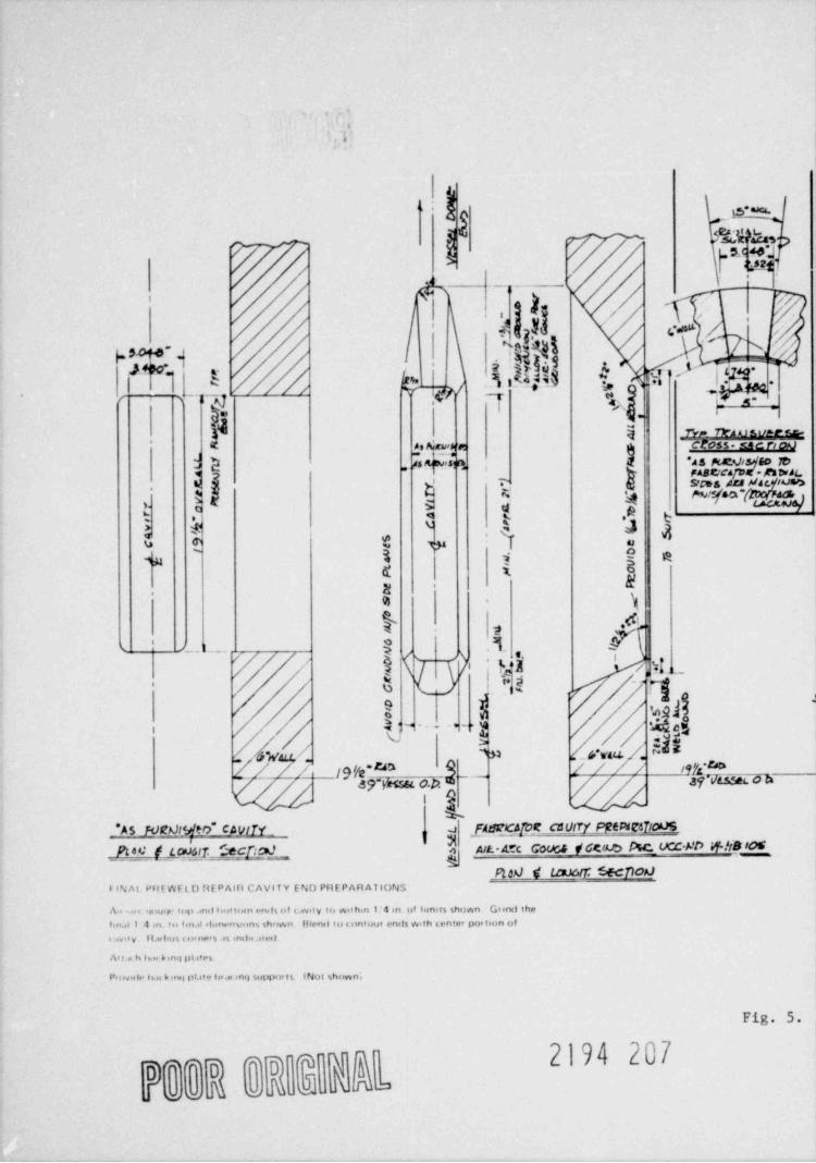
e
s
a
1
2 m,LS1C40*J/ | 4s2+
}a,
I
|, /,,
y / ,. ,
(*elSO' y f
h
"1'
. __ "
? e /' 6 i i,Lesi(9 .g ">' fp.-l 'a-*a :ce ,-
g.. .,
k p WA U st/SPe&-i
CfC55-E!Cf'tUO* d As Kwhr | '
h di Qr$'t} *AS Ma*.AltsfGO TD.J , ,
FABCCafD<= A*n>Jt'> Y SIMS 422 Y4L ILis%,
1 i ? ai ! ee n'
s s,,E( 1
\ &y .,
ys .
$ 4 I,
' tL_. 3 .9. &'
|b '),
I / ' '* * ' '
g4/ iOk
nc. ea/.- ,v. suw.
// //@ ge _ p.p yM e-o-- ,w wm
mL
fad 2Cb]De c80tTf_PftP4CSflO_US'AS F112h]IMto" Cb3!ITY - a(
Ptav f_p?tTf.;ecR1'_ 5 Alt.=f'C G0UC,5 WCtab NC-_UCCS'O WNO'OG__ __
ma c waar secnoaf IN AL PHE WE t D ftE PAtil CAVlf Y E ND PRE PARA TIONS
*p >uip ti p .anet lie,tioin enets of c.svity to wit hin l '4 en. of lernits shown Grenst theAo .e <
fin.1 1 4 in tes fin.el rione nsions shown Hienet to < ontour enits with tenter por tion ofe ivis y it.eeleus e or ners .n inelse .ite e!
As t., b hn b inq pl.ites
P oviele his k ini; pl.ita lo,se inq supporis (Not shown;
Fig. 5.
2194 207
akehmkkr- w
* 1L o
ORNL-DWG 78-6375,
- .u-w m . .a
W +48-105 for f abricator requ+ red,etc.
of the surf ace dimensions shown,ma ter ial. Drawinal demensions
k on sa ne prolong refer to Fig A 4emache ved to final cavity dimenseons
m) cross-43 race tsars for end restrains. Provide t>acking plate supporis
2194 208
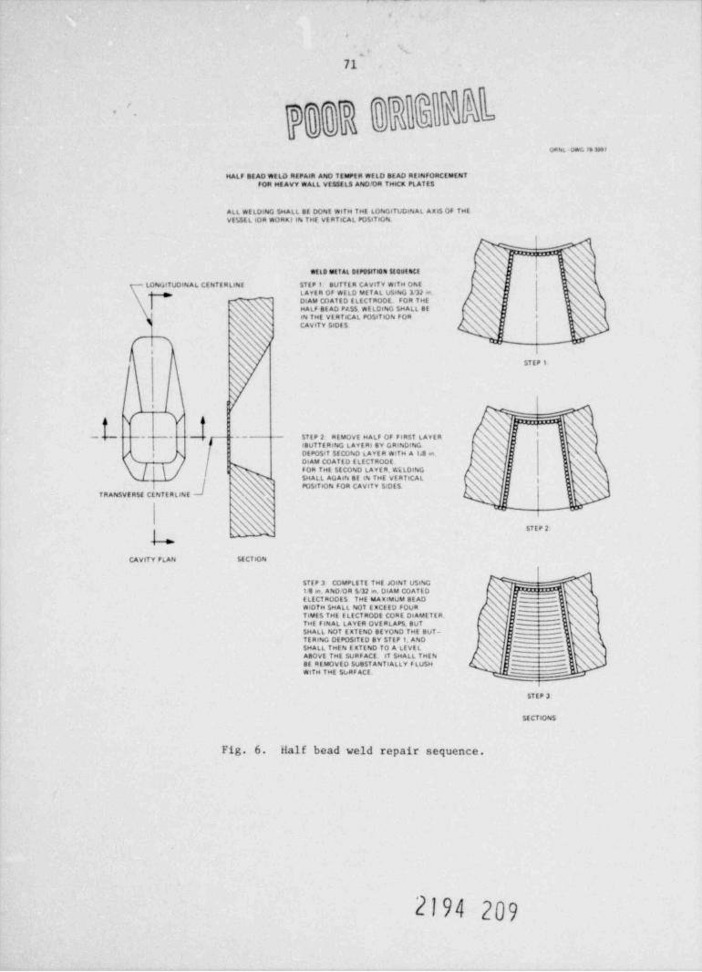
.
.
71
1
ceu. Onc rs w+r
HALF SEAD WELD REPAIR AND TEMPER WELD BEAD REINFORCEMENTFOR HE AVY WALL VESSELS ANDOR THICK PLATES
ALL WELDING SHALL BE DONE WITH THE LONGITUDINAL Axis OF THEVELSEL (OR WO6tK) IN THE VE RTICAL POSITION.
-
N N.I \
WEED RIETAL DEPOSIT 10R SEQUEliCE ,
LONGtTUDINAL CE NTE RLINE ST E P 1. BUTTER CAv1TV WITH ONEL AYE R OF WELD ME T AL UStNG 13J m.DIAM COATED ELECTRODE. FOR THE ,
HALF BE AD PASS. WE LOING SMALL BEI (\ IN THE VERTICAL POSITION FOR 8
CAVITY SIDES \'s s\s
|i
STEP 1.
s
I
v v x xHaN
--- ---- -- -- STEP 2 REMOVE HALF OF FIRST LAYER N \- I '
18UTTE RING LAYERI SY GRINDING.-
/ e N DEPOSfT SECOND LAYE R WITH A 1.3 m.
g
DIAM COATED ELECTRODE.FOR THE SECOND LAVER. WELDING
N'.SHALL AGAIN BE IN THE VERTICAL g
POSITION FOR CAvlTV SIDESTRANSVERSE CENTERLINE
STE P 2
CAvtTY PLAN SE CTION
STIP 3 COMPLETE THE JOINT USING11 m. AND OR 512 m. DIAM COATEDELECTRODES THE MAxlWUM BE AD
,_
WiOTH SHALL NOT E XCEED FOURTIMES THE ELECTRODE CORE DI AMETER. ---
DCs
THE FINAL LAYER OVERLAPS BUT j,
SHALL NOT EXTEND SEYOND THE BUT- _'"-TERING DEPOSITED SY STEP 1. AND QCSMALL THEN EXTEND TO A LEVEL y 0ABOVE THE SURF ACE. IT SHALL THEN %s
SE REMOVED SUBSTANTIALLY FLUSHWITH THE SURF ACE. ~ -
STEP 3
SECTIONS
Fig. 6. Half bead weld repair sequence.
2194 209
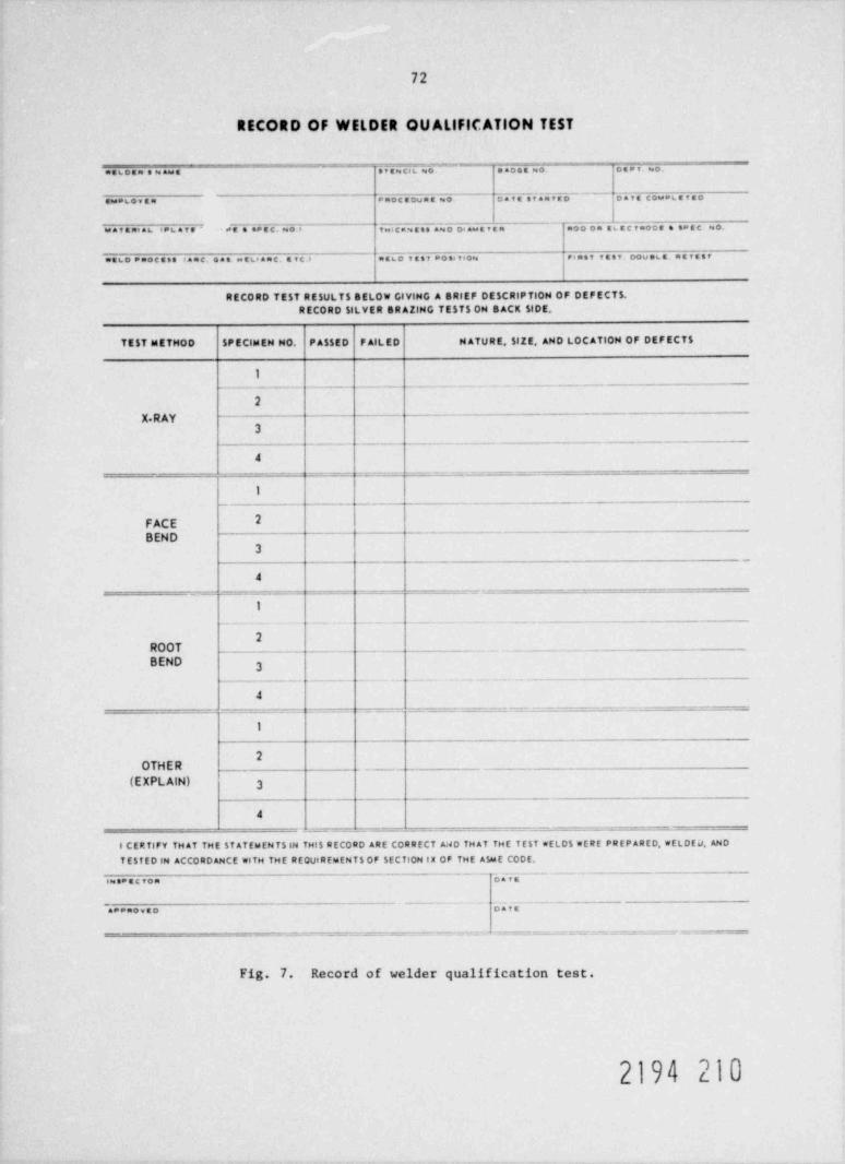
72
RECORD OF WELDER QUALIFICATION TEST
s f a scK 7.~o~~ e m o e s wo~ o s a v. =o.aa 6 c a n s = aw a
awesova= * aoc a nvaa =o on va staavao c a v a cowat a r a o
wa r a ni as <*6ava' es e en a c. =o . v icas ase ano o.awa v a m aoo on ac a c taoca e saac =o.
ma6o anocess saac. eae n anc. a rc anc o v a s r aos vio= riant vest.oove6a.aavasr
RECORD TEST RESULTS SELOW GIVING A BRIEF DESCRIPTION OF DEFECTS.RECORD SILVER BR AZING TEST 5 ON BACK SIDE.
TEST METHOD SP ECIMEN NO. PASSED F AIL ED N ATURE, SIZE, AND LOC ATION OF DEFECTS
1
2
X RAY3
_ _ _ . . . _ _ _ _ _ . _ _ _ . ..__.
4
__ . . _ _ - _ . . . _ . _ . _ _ .__.. .
I_ . _ __
FACE 2
BEND3
_
4
. x.- _ _ _ - - = . - _ = = - - - - = = . - _ = . =-.=_
1
-_ _ __ -. . . . - - . _.. . _ . . _ _ . . _ -
2ROOT __ _ . . _ _ _ . _ _ _ _ _
BEND 3_ . . - - _ . - - - . . . . _ _ _
4. - _ - _ . - -- = = . _ _ = = - = = = = - = __=_-----=.-: - ---
I
OTHER _ . _ _
(EXPLAIN) 3
4_ _ - - - . . _ _ . - . . . . - ______
1 CERTIFY TH AT THE ST ATEMENTSIN THl$ RECORD ARE CORRECT A.4D TH AT THE T EST * ELD $ *E RE PREPARED, WELDED AND
T E$f ED IN ACCORDANCE WITH THE REQUIREMENT $ OF SECTION IX OF THE A$ME CODE,
s=saacvon oava
a**aoveo Omfa
- - _ _ . - . . . _==-- =.=- = ,. - .---- = == ~ = = ..= ==. _ _ _ _ . - .
Fig. 7. Record of welder qualification test.
2194 210
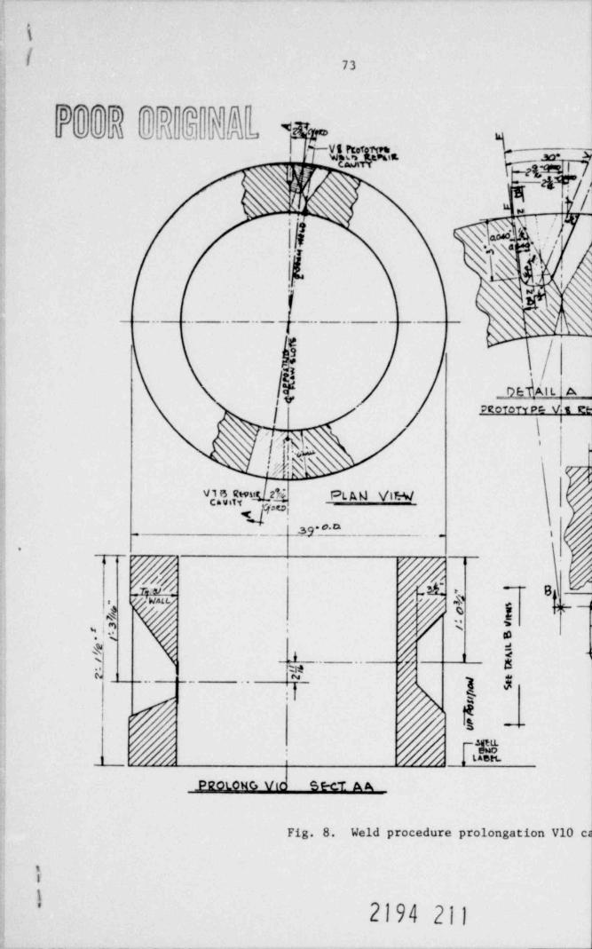
k
[ 73
mm m ' q'
JoaN v fu 2 I[ C9*~Vt reofg t m ._
-
' '' *EOrt QdI 7
tx h ||m -
| J.{,_
'S $'}/4'.
- -
_ _. . _ . . _ - --- -
|
1 '/
,41 L A.I
PROTofY P4 V 1 EI
\\
:
vgem 23 PL AM \/LS/'Ci'
_ _sy o * '.
~
-8/ wtc." 4,
j *-$ , g
'4 *! .? / '% *
h_J___. . .I
$. .
4,- n.
saen
pgoLOHG Vic S E-CT A A
Fig. 8. Weld Procedure prolongation V10 e
iI
2194 211
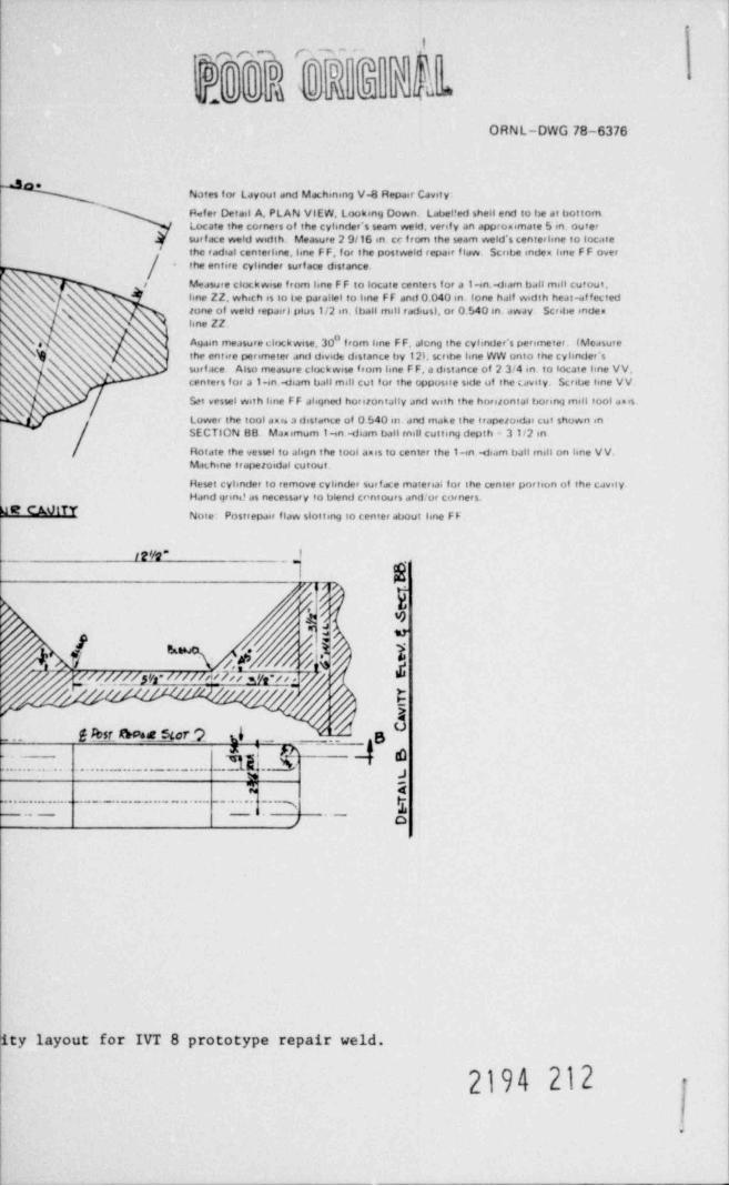
|
mmrm r"~-
0**3 *331, S,4_ma w M A h*
ORNL-DWG 78-6376
Nates for Layout and Machining V.8 Repair Cavity:
P fer Detail A. PLAN VIEW, Looking Down. Label!ed shell end to be at bottomLocate the corners of the cylinder's seam weld, verif y an appro.imate 5 in. outersur f ace weld width. Measure 2 9/16 in. cc f rom the seam weld's centerhne to loc.ite
# the radial centerline, line F F, f or the postweld repair fidw. Scribe inden line F F over. the entire cyhnder surf ace distance.
NN\/ Measure clor.k wise f rom line F F to locate centers for a 1-in.. diam ball mill cutout,
hne ZZ, which is to be parallel to hne FF and 0 040 m. fone half width heat-af fected'-s tone of weld repairj plus 1/2 in. (ball mill radius), or 0.540 in. dway Scribe indes
isne ZZ.'N '
e N Ayaan measure clockwise. 30 f rom kne F F, alcng the cyhnder's perimeter. (Measure's I the entire perimeter and divide distance by 12h scribe hne WW onto the cyhnder's\ surf ace Also measure clockwise f rom hne F F, a distance of 2 3/4 in. to locaie line VV,
centers for a 1.in -diam ball mill cut f or the opposue side of the cavity. Scribe hne VV.
Set vessel with line F F ahqned horsiontally JrMf Weih the horsiontal boring mill tool amis.
Lower the tool aus a distance of 0 540 in. arvi make the trapezoidas cut shown inSECTION 88. Maximum 1-in wjiam ball mill cutting depth ' 31/2 in
Rotate the vessel to align the tool auss to center the 1-in .di.sm ball mill on line VV.Machine trapezoidal cutout.
Reset cyhnder to remove cyhnder surface material for the center portion of the cavesyHand grind as necessary to blend cr'ntours and or corners.
R CAVITY Note- Postrepair flaw slotting to center about hne F F .
ItVQ" _)I k
o e
h50-
d er
/.h //MEpr m//cim qn
gun.. f ksr he stor? d,_
_
_
Ug
-. . . . .. ...... .... 3 k1a @ g
%J-
% 2g... -- . . . . . . _ . . . ., .. 3
._ _ ,. _ ,,
ty layout for IVT 8 prototype repair weld.
2194 212 :
\.
75
10/8/76 Issue Date
WELDING PROCEDURE W-ilB 105
STATEMENT OF WORK
" Field Demonstration of Section XI Weld Repair and Flaw Propagationin the IIeat-Af fected Zone of the Weld Repair"
(Vessel positioned vertically)
1. Introduction
A major activity in the Heavy-Section Steel Technology Program is the
testing of pressure vessels of a size intermediate between laboratory models
and full size nuclear components. Although the specific test vessel geore-
tries have not been designed to be scale models of typical nuclear com-
ponents, they have been designed to provide realistic demonstrations of
fracture mechanics principles. To date, eight vessels have been tested,
and all tests demonstrated a margin of safety in excess of design rules.
This project concerns one of these vessels which has already been tested
twice, ITV-7.
2. Objective
It is planned to reuse intermediate test vessel 7 for a third over-
pressure test, a hydrostatic test, at a test temperature of 91*C (196*F).
The objective of the test wilJ be to demonstrate the toughness of the heat-
affected zone of a half bead repair weld region utilizing a defect compar-
able in size to the previous tests. The heat-affected zone of such a tecper
bead technique weld repair performed to procedures listed in the AS5E Boiler
and Pressure Vessel Code, and without conventional post welding heat treat-
ment, represents a zone of high residual stress in the vessel. The zone
2194 213
76
2
also exhibits metal hardness with peak values up to 31 Rockwell "C" im-
mediately adjacent to the fusion line. The fracture toughness will be
determined from specimens obtained from the typical vessel prolongation
repair weld (Fig. 4) which is furnished for use in weld procedure qualifi-
cations.
Post repair machined slot and flaw indexing (relative to the heat-
affected zone) are shown in Fig. B.
3. Background
ITV-7 was flawed artificially on the outside surface to a configura-
tion approximately 45-cm long x 13-cm deep (18 in. x 5.3 in.). For both
the original June 1974 hydrostatic test and the subsequent June 1976 pneu-
matic test, uniform stable crack extension occurred around the flaw periph-
cry to result in leak without break. At testing pressures of 147 and 144
MPa (21,350 and 20,920 psi) the crack front penetrated the inside surface
of the vessel and leakage occurred. Subsequently, the crack closed upon
relief of the pressure. A residual pressure of about 124.2 MPa (18,000 psi)
could be maintained in the hydraulic test; an inside 1 1/2-en- thick (1/16-
in.) patch liner served to retain total vessel pressure when leaking occurred
in the pneumatic test.
Following the initial test, Combustion Engineering, Inc., Chattanooga,
Tennessee, repaired the vessel under Contract RP604-1 from the Electric
Power Research Institute, Palo Alto, California (CE Contract 10875). Repair
operations were performed in accordance with weld repair procedure W-HB-100
prepared by Union Carbide Corporation, Nuclear Division, with technical sup-
port from the Pressure Vessel Research Committee Advisory Task Group on Weld
f_ 9 -
77
3
Repairs. Weld Repair Procedure W-HB-100 was formulated in accordance with
Section XI of the ASME Boiler and Pressure Vessel Code, in particular,
Paragraph IWB 4420, " Procedure No. 4, Welding Low Alloy Steels," Weld
procedure qualifications and mechanical properties samples were also made.
The repaired vessel was next reflawed remote from the weld repair and
reinstrumented for the June 1976 pneumatically pressure sustained load re-
test. No abnormalities were noted during the test in the area repaired.
No tests have been conducted to date that endeavor to study vessel
behavior with flaws located in the heat-affected zone at the periphery of
a weld. Test data from a vessel pressurization test with a flaw artifici-
ally placed into this zone of a repair weld would provide realistic evalu-
ation and decision guides for possible future field repair needs in actual
nuclear systems. The recent V-7A pneumatic pressurization test proved that
temper bead technique repair welding performed under typical shop conditions
and meeting all Code provisions and inspection criteria will produce effec-
tive, acceptable repairs. The proposed ITV-7B hydrostatic pressurization
test with a known flaw placed into the vessel repair weld in the vessel wall
will demonstrate the margin of safety against failure in the presence of
residual stress When defects are present. The ITV-7B repairs will be velded
with the vessel positioned vertically to simulate field repair positioning.
The proposal to artificially place a flaw into a repair weld heat-
affected zone for a follow-up hydraulic vessel pressurization test in CY 1977
presupposes that it will be possible to sharpen such flaws via combination
electron beam welding and electrochemical hydrogen charging. We have already
_
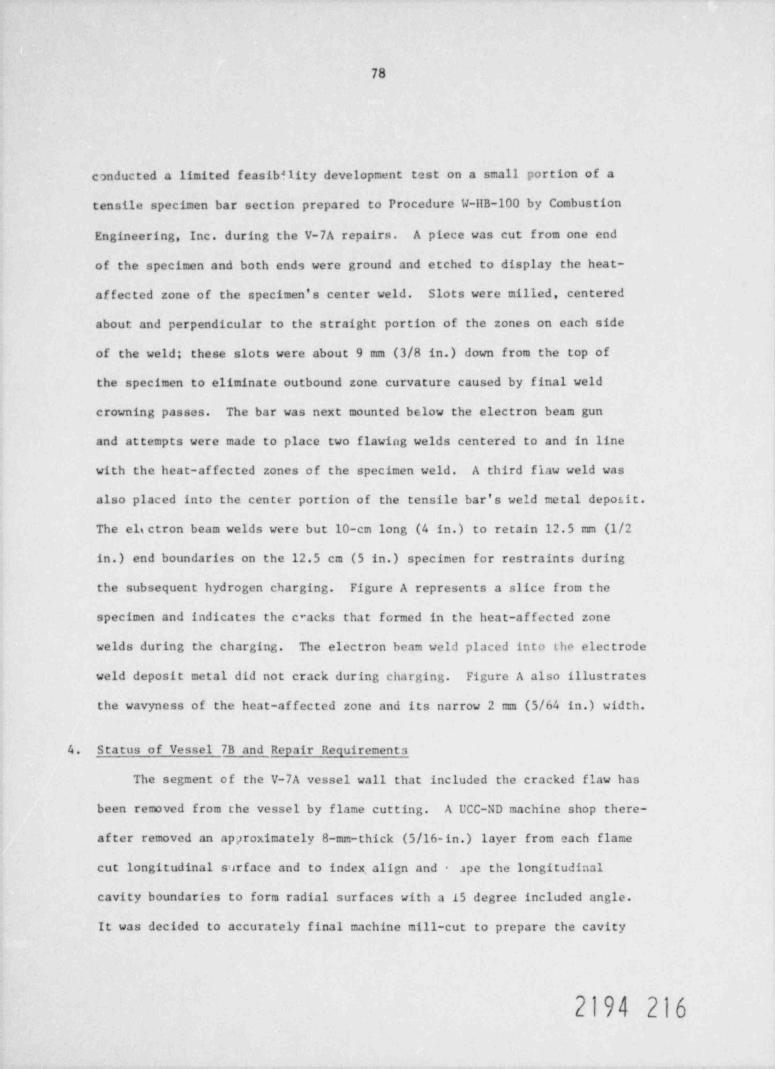
78
conducted a limited feasibility development test on a small portion of a
tensile specimen bar section prepared to Procedure W-ilB-100 by Combustion
Engineering, Inc. during the V-7A repairs. A piece was cut from one end
of the specimen and both ends were ground and etched to display the heat-
af fected zone of the specimen's center weld. Slots were milled, centered
about and perpendicular to the straight portion of the zones on each side
of the weld; these slots were about 9 mm (3/8 in.) down from the top of
the specimen to eliminate outbound zone curvature caused by final weld
crowning passes. The bar was next mounted below the electron beam gun
and attempts were made to place two flawing welds centered to and in line
with the heat-af fected zones of the specimen weld. A third flaw weld was
also placed into the center portion of the tensile bar's weld metal deposit.
The els ctron beam welds were but 10-cm long (4 in.) to retain 12.5 mm (1/2
in.) end boundaries on the 12.5 cm (5 in.) specimen for restraints during
the subsequent hydrogen charging. Figure A represents a slice from the
specimen and indicates the c*acks that formed in the heat-af fected zone
welds during the charging. The electron beam weld placed into the electrode
weld deposit metal did not crack during charging. Figure A also illustrates
the wavyness of the heat-affected zone and its narrow 2 mm (5/64 in.) width.
4. Status of Vessel 7B and Repair Requirements
The segment of the V-7A vessel wall that included the cracked flaw has
been removed from the vessel by flame cutting. A UCC-ND machine shop there-
af ter removed an approximately 8-mm-thick (5/16-in.) layer from each flame
cut longitudinal surface and to index. align and - ape the longitudinal
cavity boundaries to form radial surfaces with a 15 degree included angle.
It was decided to accurately final machine mill-cut to prepare the cavity
2194 216
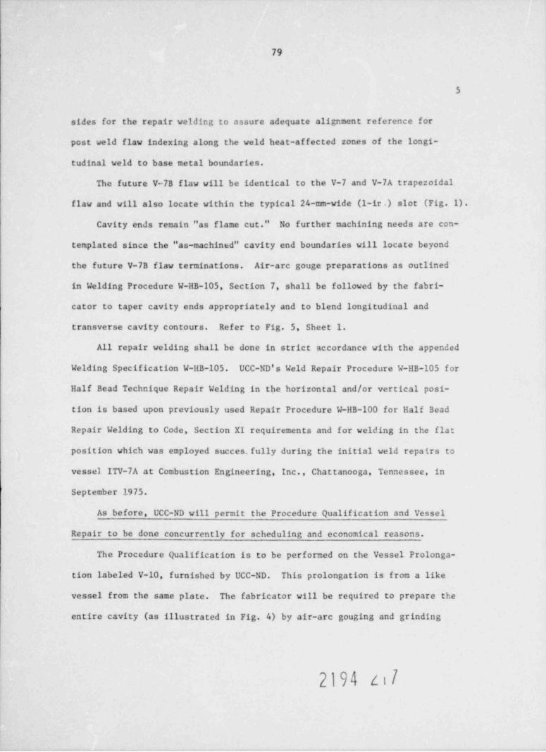
79
5
sides for the repair welding to assure adequate alignment reference for
post weld flaw indexing along the weld heat-affected zones of the longi-
tudinal weld to base metal boundaries.
The future V-7B flaw will be identical to the V-7 and V-7A trapezoidal
flaw and will also locate within the typical 24-mm-wide (1-ir .) slot (Fig. 1).
Cavity ends remain "as flame cut." No further machining needs are con-
templated since the "as-machined" cavity end boundaries will locate beyond
the future V-7B flaw terminations. Air-are gouge preparations as outlined
in Welding Procedure W-HB-105, Section 7, shall be followed by the fabri-
cator to taper cavity ends appropriately and to blend longitudinal and
transverse cavity contours. Refer to Fig. 5, Sheet 1.
All repair welding shall be done in strict accordance with the appended
Welding Specification W-HB-105. UCC-ND's Weld Repair Procedure W-HB-105 for
Half Bead Technique Repair Welding in the horizontal and/or vertical posi-
tion is based upon previously used Repair Procedure W-HB-100 for Half Bead
Repair Welding to Code, Section XI requirements and for welding in the flat
position which was employed succes. fully during the initial weld repairs to
vessel ITV-7A at Combustion Engineering, Inc., Chattanooga, Tennessee, in
September 1975.
As before, UCC-ND will permit the Procedure Qualification and Vessel
Repair to be done concurrently for scheduling and economical reasons.
The Procedure Qualification is to be performed on the Vessel Prolonga-
tion labeled V-10, furnished by UCC-ND. This prolongation is from a like
vessel from the same plate. The fabricator will be required to prepare the
entire cavity (as illustrated in Fig. 4) by air-are gouging and grinding
2194 zi7
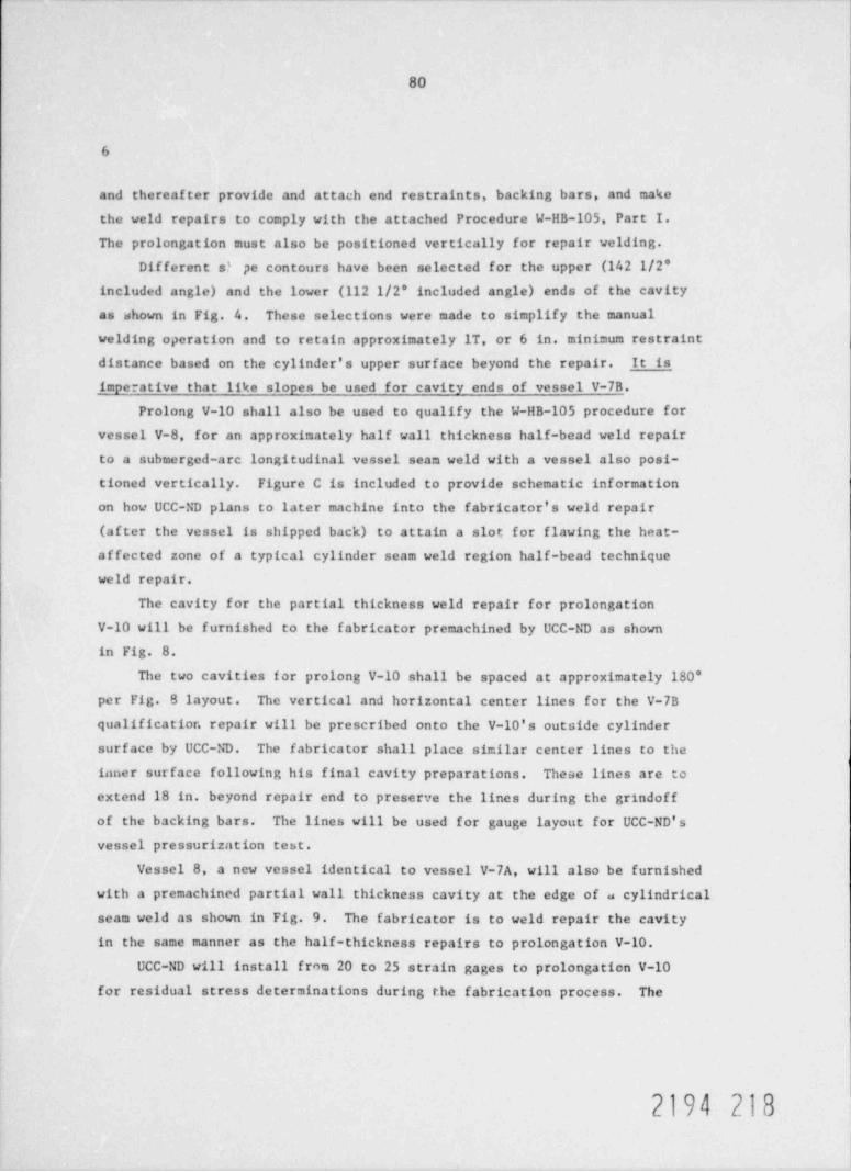
80
6
and thereafter provide and attach end restraints, backing bars, and make
the weld repairs to comply with the attached Procedure W-HB-105, Part I.The prolongation must also be positioned vertically for repair welding.
Different s? pe contours have been selected for the upper (142 1/2'included angle) and the lower (112 1/2' included angle) ends of the cavity
as shown in Fig. 4. These selections were made to simplify the manual
welding operation and to retain approximately 1T, or 6 in minimum restraint
distance based on the cylinder's upper surface beyond the repair. It is
impe ative that like slopes be used for cavity ends of vessel V-7B.
Prolong V-10 shall also be used to qualify the W-HB-105 procedure forvessel V-8, for an approximately half wall thickness half-bead weld repair
to a submerged-arc longitudinal vessel seam weld with a vessel also posi-
tioned vertically. Figure C is included to provide schematic information
on how UCC-ND plans to later machine into the fabricator's weld repair(af ter the vessel is shipped back) to attain a slot for flawing the heat-
affected zone of a typical cylinder seam weld region half-bead technique
weld repair.
The cavity for the partial thickness weld repair for prolongation
V-10 will be furnished to the fabricator premachined by UCC-ND as shownin Fig. 8.
The two cavities for prolong V-10 shall be spaced at approximately 180'per Fig. B layout. The vertical and horizontal center lines for the V-7B
qualificatior. repair will be prescribed onto the V-10's outside cylindersurface by UCC-ND. The fabricator shall place similar center lines to the
inner surface following his final cavity preparations. These lines are to
extend 18 in, beyond repair end to preserve the lines during the grindoffof the backing bars. The lines will be used for gauge layout for UCC-ND'svessel pressurization test.
Vessel 8, a new vessel identical to vessel V-7A, will also be furnished
with a premachined partial wall thickness cavity at the edge of a cylindrical
seam weld as shown in Fig. 9. The fabricator is to weld repair the cavity
in the same manner as the half-thickness repairs to prolongation V-10.UCC-ND will install from 20 to 25 strain gages to prolongatien V-10
for residual stress determinations during the fabrication process. The
2194 218
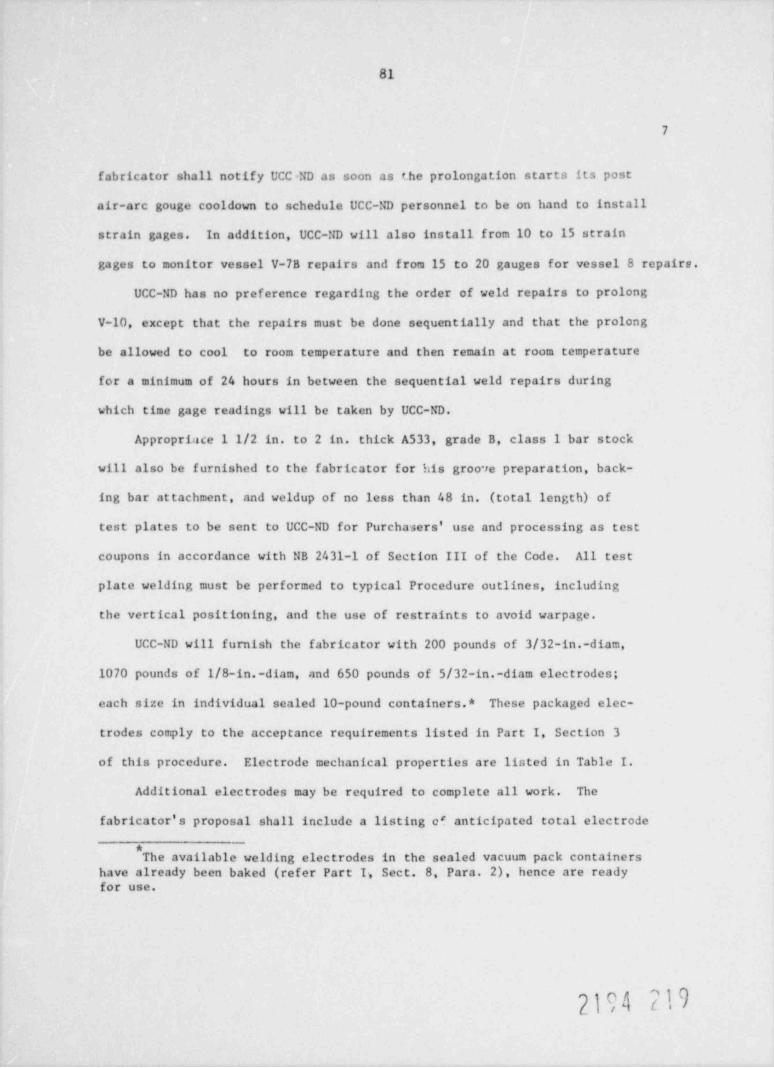
81
7
fabricator shall notify UCC=ND as soon as the prolongation starts its post
air-arc gouge cooldown to schedule UCC-ND personnel to be on hand to install
strain gages. In addition, UCC-ND will also install from 10 to 15 strain
gages to monitor vessel V-7B repairs and from 15 to 20 gauges for vessel 8 repairs.
UCC-ND has no preference regarding the order of weld repairs to prolong
V-10, except that the repairs must be done sequentially and that the prolong
be allowed to cool to room temperature and then remain at room temperature
for a minimum of 24 hours in between the sequential weld repairs during
which time gage readings will be taken by UCC-ND.
Approprince 1 1/2 in, to 2 in. thick A533, grade B, class 1 bar stock
will also be furnished to the fabricator for his groo re preparation, back-
ing bar attachment, and weldup of no less than 48 in. (total length) of
test plates to be sent to UCC-ND for Purchasers' use and processing as test
coupons in accordance with NB 2431-1 of Section III of the Code. All test
plate welding must be performed to typical Procedure outlines, including
the vertical positioning, and the use of restraints to avoid warpage.
UCC-ND will furnish the fabricator with 200 pounds of 3/32-in.-diam,
1070 pounds of 1/8-in.-diam, and 650 pounds of 5/32-in.-diam electrodes;
each size in individual scaled 10-pound containers.* These packaged elec-
trodes comply to the acceptance requirements listed in Part I, Section 3
of this procedure. Electrode mechanical properties are listed in Table I.
Additional electrodes may be required to complete all work. The
fabricator's proposal shall include a listing of anticipated total electrode
*The available welding electrodes in the sealed vacuum pack containers
have already been baked (refer Part I., Sect. 8, Para. 2), hence are readyfor use.
f\

82
8
requirements along with available sources for electrodes, if necessary.
Prior to the start of welding, the fabricator shall furnish UCC-ND a report
of the welding material properties for all supplemental welding electrodes.
The tensile and impact properties of the material must conform to the
Specfiications of SEA 5.5, AWS Classification E 8;.08-C3 of Section II of
the Code.
Table I.
MIL-E8018C3 Electrode Pechanical Properties
Lot Number 5237A AE 74 AE 77 AE 90
Electrode Size 3/32 1/8 5/32 5/32Yield Strength 76,500 74,900 76,900 70,100(0.2% offset)
Tensile Strength 85,200 88,400 83,400 82,000
Elongation (%) 27 29 30 30
Reduction of Area (%) 74 70.4 70.6 73.5Charpy Impacts at 99 110 87 93-20*F 100 119 91 97
100 99 82 91
5. Schedules
UCC-ND personnel shall be allowed access to the fabrication facilities,
as reasonable,to follow the repair operations and to monitor strain gage
and temperature measurements on the vessel. UCC-ND's sponsors, the
Division of Reactor Safety Research, Metallurgy and Materials Research
Branch, Nuclear Regulatory Commission, Washington, D.C. is also sponsoring
inspection of welding by acoustic emission with the General American
Research Division, Inc. (GARD), a subsidiary of CATX Corporation, and
2194 220
83
9
:
requests permission for CARD personnel to AE monitor vessel repair wald-
ing. CARD personnel shall afso be allowed access to the fabrication
facilities, as reasonable.
UCC-ND will pay for test coupon, prolong, and vessel shipping costs
to and from fabricator's plant.
Vessel ITV-7A, the prolongation and stock for weld metal test pieces
are all available for immediate shipment to the fabricator. Vessel repairs
and inspections should preferably be completed within a six (6) week period
for vessel return to UCC-ND, Oak Ridge, Tennessee, as soon as possible.
6. Reports
A final report shall be supplied to UCC-ND upon the completion of
all work. The report is to include the results of all testing, inspec-
tions, and a detailed chronology of the welding operations. Information
considered essential to this report is detailed in the welding specifica-
tion, W-HB-105. The report shall also include a discussion and evaluation
of the applied technique and recommendations for changes in procedures.
The report shall be supplied in draft form for approval within 30 days
af ter delivery of the vessel. Following review and approval, six (6)
copies and one camera-ready master shall be supplied to UCC-ND for repro-
duction.
2194 221
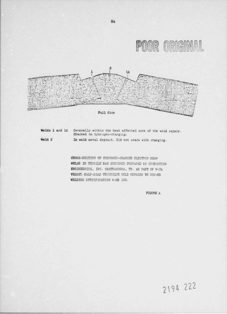
84
0**0) *]D'T'
foomoM.A. o
21 | 1A1
,: o r . 2,.,n. . :.a .. y*... . n .:. +:*,,,- a , # #,0 ij +... /a .. p... : , . . .
:. j ,e,. . w .+
? $ !:. J ',;,,. y;t : : n. . , . .;'. ,,,:. , ;,. . (|| .. , , . . ' . = .,, - . . ~: .. ~:.~'=.'. s , >g . .:.,. d. u: . --e,. : . .~um.. ~. ;w. w' 7.;,;u c
-
.- . . . .. .
. .
. m'' ~ .....:.;.. 4 :.s ,t.n,..w ;,.,*.".f:n ". : , '. . . . ; . y . . : ... . ... .. y . 2.:. p ; c..'*. ..:.- n .,. .a.r
5. ,; '
. :,;,',ii .'.D. M., . ' ,J ,'f .5.*, 'i... *y *' .h,.'
'.f. . Hc.~;' . ';.:'.)~i,.;/ . n; 7.h ', m'i.-: ?,. ~:. 'q .'i.;-|\., l)j .'6|;'. ,*-;. Q, ,go',,
i. . .- - ?Y t -. .. , . ..'. ,'. . ::- .L* .. : c'?~y ,,,Q.
. .*-
,- . . . . . i'i;; *~ :s y. '.. .a -; rs;, ,.)-%.;73 e:
c * g .-
.m. :7,13. L, !, e, \ * ( , I. , '.H'. .. ,
: ., , ,.
.., t
. c,' . . '(. ~. . . : .. . .. . : o ; ' e + , s. ,. -. a. v.x.e ;.x. ., . ,v,. 'a . 'y. *. ,...( . .d;., .. . ... . , . . , . .
-
:~..., . . - +n .I.~
.:: - - - *, g . ; ;:.s ,.. -' .'. i . . . . c . : . -a 3,:..':).
: .:.T 's . . , ). ' r :p.
, 1...:n..%,*,...-.
c-e.~- ~ ~ - ~ ~
,- .. c- . ..- .*s. . . . . . - %..,... ..
, ; ; .~ * - ,-e., .-% ; , . , - - 4 . .. , . ; 2,.., .h. .
..,..,..e:-
- .:. , ?~,.;g,;;. ,:.y;y.n*+G..a * Y. :n. ] ,..;,. .r. s r~.,, . ,,:..c.,,. ,.:.s , . . . ,, . .. n -.- a .,r.r;..: ;z+ ,. . c^ ;;; . j; . ... :: .;.. : .n.- ;. ~ ~ . - ~ ~' ' . -r.
2.:~:.= - - W, ,.. . W f-, :.. , .
- .
. 4 ' ..e .;n .p(M;e,.,... ,:1, :.VT:g . . . . . .. . . . .'a.h&: is' ' ' . :::
.m G1> G,^fy! E .. ' .
* * ' " *Full Size ,1
Welds 1 and 1A Generally within the heat affected zone of the veld re; air.Cracked en hydregen-charging.
Veld 2 In veld metal deposit. Did tot crack with charging.
CROSS-SECTIC:t CF 1m:30CEl-CHASCED ELECTPC:I BEA.M
WELIG El TC:3ILE EAR OFECI*C: PREPA.oED BY CC:'BUSTIO:3
CiGE.'EERE:G, E;C. CHATTA: COCA, T:1. AS PART CF V-7A
VEOSET, EALT-3EAD TECIC:I;UE W LD REFAIES TO UCC-tid
WELDI2iG SPECIFICATIC:t W-IG 100.
FIGURE A
|\
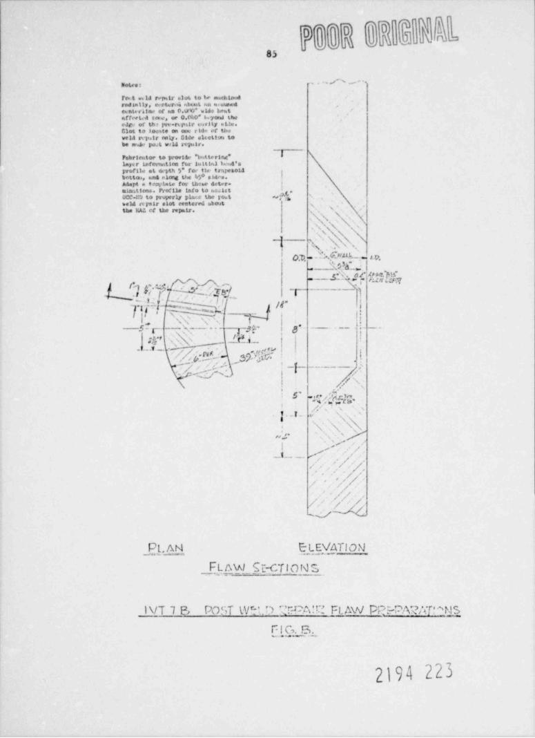
, |.
*' " 'Ilotes t
I'tw 4 vs 1J rer.itt e>1at to le auchiadrodaally, certer is eilanat seat mi uwedconte-rline of ha 0.tyO* wida lent
affectc4 ton.e, or 0.0h0" to yarna theeJrv of th s par-rs |*itr c swi ty es t.lv.Clot to Joerste on ein: rida of t1*wela avgs.f r rely. 0!Je altettwa tobe se.J.? gwt WL4 atluir.
Fabrirettor to prov1Sc *laittering* Ilaye r infoswittre fter lu ttial knd'sprtifile et depth '/ fon- the trnresota
!8bottoa, and clong the 36 siden.Atart a tcaidete for th ee deter- t
!mirntions. Pro'11e info to hselst .
UCC-!!D to properly pla<.c the tout es f ,'',bald rrpair slot centered inboat s
Nthe HA?. of the aspair. f. -
s \. N('s, .. . Kxxx .s
-1 ('.h'Ni o ,.. .: . e ,, ,.
'Wh*--
.7 M, ._ m%.l.W,-- p~4 ,-. atunw
s wix,.-s:7,-- i
T 1
T TT @wt y-- Q ".-
d
-
, ,m s
;!c' V;- N; - - _lrU _. |
g* - - - - ,.-5 g-' sy I t-
--~
'
L i .-.,/Q:%-- 3$QawG, \'
, , . ,p - l-
. / v.- v ..,
.. \;\ -
. x
.5, ~4*d T M ,,
.c- -,
T. I_ \.s
n y\\'N' \,; ,.
,.. .
,
_.t . _ . /'p- ,
,.',/-- /,
//,
'//a
// j,
UW
__ . AN E LEVATlONPt
___E!-f2ML SE-CT! O N S
l\/T 7 B POST WS' O T r#A'C' FL AW PPWARAT'*NS
F....I.G._. B. _..._
2194 223
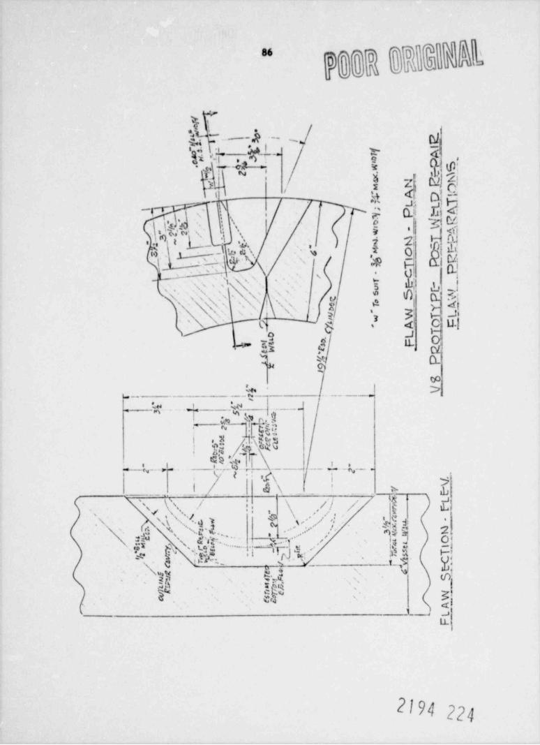
%Co_g2g@P#@gMtee )9 _) >
r
q; _
y~ '
E.p~ \ . i*/
I
n.-s f
m A
y%Imtg2'- .
- | ,t
n P :, _h* we
&"cF~ g_
x- Lm f g
- r A'
D." g
Ki L'
-
R t. -t;\ .
.
7[TLg,-w V. g.'.
e. t_ g.-.*- - ,. -
g '
SpI_- _\
. E- 9 M- ~ >
oi A- gs Dg\
' \f$ , E4
?. ,
/ TC p.
\ ,, -,
,_/' io
, r -.'
E E- _- .'/
- /./-
c
-
,/- ,O5_ P- g
f'
- x'/ ' ns
J,/.//- r,'
I-
' E 'w w J g,-
/- '
O/ O C''- A'
L I_r
m- okn F_ R-
t
we
U Pt gS
- V.
r| -| :' l
Is'3
.
4. ' ih' m..
,| jjo--
.,
am ha... s S
aa:em - .- - ,; f .I 'j'
;
,N~ c. ,/|
{f2!1 .
,-
V...- .
. -
.- y
E--
.-
'
P _-
K . g1, , , / - - WT_u L'
} '.
.y/'\,
N m' .i *
m%.A,*f__:.*yf".-,\ :
. ',.. , s.. .
" a~" -
./
'/z . *-3.w. M.-
.
%, -4
. O _.L - <, R
g"* .",Y> |
. & n' -{g,,.!
'.; ".;.. .y
. C./,"a E.c a- .
amfS_.
s
wM' '
an ,,
u, x]c,W ._
.,] .-
r -
ae .
-
A' LF
-
-
$ A
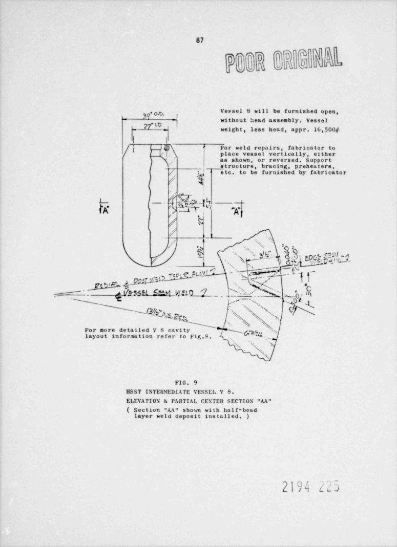
87
0
Vessel 8 will be furnished open,-
39' o.b. 9without head assembly. Vessel
27 weight, less head, appr. 16,500#=
I i
/j 1.T place vesset vertically, eithert,j)\ For weld repairs, fabricator to''
' as shown, or reversed. Support,
structure, bra cing', preheaters,
/, g, etc. to be furnished by fabricator# $
i
/~ue .Q @i --
qX t t , ,. "Kp. ,
2 W'! r_ t .,,/ % ^/ '+ 2 .p sg
y t''g _i_' **'/ -
,,
< .- y_L'Eh' , ~ $ '-.\w '.e* p [S$$El S hi Wfl0
'
c. Aj '2 , ['* ' (' ) Qf A1--
,
/ ^ ' , , ,_
4=q s s \ ..For more detailed V S cavity N pi, slayout infor: nation refer to Fig.8. *
y ,-
h,N
FIG. 9
IISST INTERMEDIATE VESSEL V 8.ELEVATION & PARTIAL CENTER SECTION "AA"
( Section "AA" shown with half-beadlayer weld deposit installed. )
2194 z25

t
*\
I
e
$%) hep %%T *t*/ ;,,mm . g. . Lo.r * m o m.a vo w 6-w.m s.%bT m WeggA% her%s %dC*Ee%%w*he N.T A
h t= awe.s %ss===.ww W. N h% *ws. w = o .w u.= s t i _ .~ Y~ -
,
<%% * ' ' saea w ,
___ -~ ,
M U.t U.', M,t'*~
'
:b'"fw_i,e
_
# ^*-' - 's1/;_ ,
~ _ . ,. - , , , ,u .-- -
..
L..%.2 w' .7- r, A..
'- - - - x.#
| t*** Mo hsv W.Te es .'==1%me.-,' j, ,
**a. %*Amwa -
m ,, _=%s s %--.-no.\wes. Ie asumn " "'OT'- ~&~ l .vu om, _ g~
%". as 'k "**Y'**m.,
,/- Ir~- ,! I | 4'
, .*Ir n1a -, - - -
_ _
g* * g
.,,
|I|| |"h Y . l
{- ,/ f=g~i
,| /b *
,d _i/ .--'
Is- - --._ =
JZe- - c -;.i
P.___ _ _ _ _ _ . s' ''w w----,,. . ,
--M 6 R E C E W ML D ._. .mw g., j
w "s.w.s=_s****nu m.a.m..sm - f////dm
h~w - -
"Ersau ht.m W weaa.. * ; y,~-e-. v=.s w.ws.4,
l| %As.*T m bggyb
' * " * * " * *% u.c w se u & A
\AY E % T D C AN\*'T*C Y%.khD( Asm . Awa ,%=o== u-= mww.= owww. bwsww w ,o
NO.S o \- % .C, w %M'ar C.E.wav m'. A N o9t.".TA o s . h%%4w wshu.v >Nuose m.h c w waww.s. Tsow .')
.
I
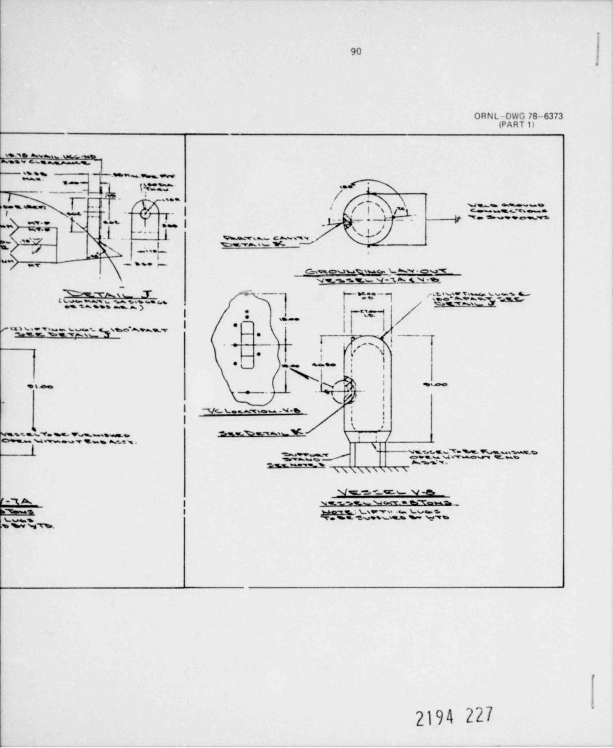
.
904
ORNL-DWG 78-6373(PART 1)
s-, e a ~ s .u.%s,
'E.%N 6%% 6 %
Os .=*%.~=~- -
-- - _1.L t.s,.
4s..---
/ \m- '
3 u..-.s =n I --| ,. e_s \ u s% ,**s..-=
! f I s Mj= -, c .e.,-.I m-r - -- T- .. m; L _- . y '* =- - * e== v'--
I" |~
Q)~~
N?c E"....
i.._. %T s ~- c ~ ,m,n ~ me.~ ,," -%'', W 's s
/ / N ... L.- .
=\ # - ss. f/ mye__.,m o v u v uc._ta.w-o u-e
- v__,s-s.r_v u-x* (N-e--
- \ gg - Q gQu w~-,s.~ w.m %. , d's-r== sa **s s % )
|, _,,
' * -e _1
| .-u w , , -- . mow ~, , ,
%g.w %s T Ass 8 --
* ; * * ''* 's! n.
e % += iu ,. ~ i!
.v. - I
i ,_,,_r y *
( '.
| -vc t ~-,se.- w -s i || t, :
,
%%1.E%Ye % YA%.as%MO j e- v ~ . ,s-- ,.
|s
N s. y.s"T ,= % h uss.wsw gssw;~= ~ . - . - e-7- _ ~ _ ~
\\ \\\\ \ \\ \
N/s-SCta" b- N/-E."3 A | N w -L=.4r s N ce<T * h*'9"esu"% _h-s | 'N o-w g. Es ,t -gs,.% L v4 sv. m.m. % vs e w Sw:f7%goggw w Nh.
r
'
2194 227
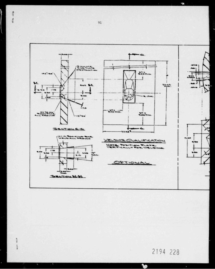
. . - . . . _ -
$
h
It 91
_.
.-g .
,i. i,
i t 1 -- '
%ks
{' e---,- '*
, , . , . -
. gr =.--
. \, \{
..--- -.
' .c-,
_ _ _ _ . .. -f-
Q- i s u. th ht.. .
ht, --1
% s. [ s:ts, _ _ , , _ . .._
, ,\ -[|.-- - \
~
___, ,
[ f_
gw 8 %. AM)47 0 i. _ _ . . . _ _ _ . _ _ _.
-
._ .
N.
gw 2,'*.n Eb. *%s - .
wi. w
(
.m ] ni ,
sn , . + - < - , V +- ^LLM ,
,-m
its1.%t hws% h%Tb--
ME(DO% AL\Y\CM\O M
bg,N _ e~i
gee
____tvssvw Ass.w v=w,%dsvens%. --i
s ~ ,{_ . ' I_L .ii su
- so-i -=
j g I-_
s ,, .
m- s - |o z m, - ~, .
,I --,ee 6.=M
%EC 7%cu M-R
__ _ -
1
1
1'
2194 228
_ ___ _ _ _ _ _ _ _._
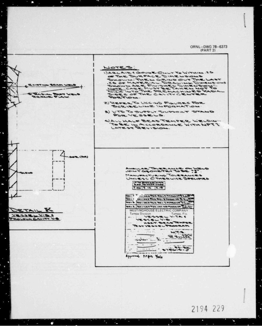
e
,
ORNL-DWG 78-6373(PART 2)
--
I;
Ii
k L cT W_,^. > *.i
I,
o A s o x.s w w o u - w , e - m v x . w x m m..s s-car Tvei.s ""bes.sw*'*-c %,% ses%u-= news
h %, ow I Wsw. 49%suw cw w hwN a sv.m o. m ~., , s,_~._ .% ~ s -am, .s-.
-
3dv- % =T- - - we _t .5
=i h':-e3,
,,%. A.ww ww s w_u.wvs.=w.w u-=,ww
ue, _- c %% ws., gr ss7: c . n o ,- T e7i
u c_w swToN% ME*=.s.mc wsuer.':.M:= h%s a w%s. h. ssa %sar m.ws cas._e., ocr '| wc c ws. sw c sw w-gs_v%,*a.=.w a s % ,sr s N,.i- _. g o,g.y ,
s ,,
b TyN>.svrs.a._9|'m Vc c.-wet:> Wwvse s.r N~ost! "" Sac 9.,s%cs.suT \w v=c;:ptv.Mm 7||" sow a. .
| s) N_t % 7 e -e,v v 9 sw % u w e A t- PAwo,
I , ,,,_ % m ._s._ m ..
| e O A.us,.>W,:._A.N we %9 m %7%W% %v , M 5t* s.hm.--! i x- e <. .=,, - e w s , - w
\ 8=.T w s v. %%N s==.se:,s .,
ii
:
~
,.. .. .
, _ . .
__ - . -
m4%I .ws%*.4>a)_| 8.
F-- 1i |
| % _, -,_m.,..;o~ vc.s w = v,
w ~ ~| | , ,; % a n-_| | | M m.s ,sagem.c.:v s., m.ms 7owim.wn.A c.u.s
v 4s.w s c ,w v w .4s <s. b m vss w. g-- .:
/ |O O'i*.*.*U'.'1
. r*- 2 mm. t. .a T..e.. .____t . ,
Y.uus. f aCoia.htesC _ 1%4.Sf,
I _.. as. vss s.,s w h -s,a::=. w.- s ===,.. ,ssws- - - . . .-% _ :.~
w. . --...- w p_
v.
- D 1|E.T A.M N WESTINGHOUSE ELECTHIC COMPANYTampa Division Tampa. Fla.- N N~''* *E ' **L vs %sm.s.N-7m 4, . . .
]Y94.e%.****.i C., AN %"'EN N4 . | N g,.g. ,gg,g,,,, N _ b .
g. w ss ,. s w.a = N',s.=se w.m%-a v NME.-twsM.wh9t.A9'Ni
.- . . . . . . . . . . . . . . . _ ._
.' *.-
M"'Trh.*
'.N%#hERS.* 4 >&p,g*.
* & , t._;bf'
__
***
. ... ,
8
! 3 -, .- . -_
e. %9 N; - , - - - - - - _ gm.ec, g .t>.%. y
-
-. - *,
j Ag r** 4 f P ( *i %2
5-
d..
:
I
! [-
i; {
-
; 2194 229:i . . . . . . . . _ . _ . _ .
t
t
%e
IS SU
1/5/7
S. W.'ilsmer
Chan
h&N
. s
-
, ^a 730
it
\
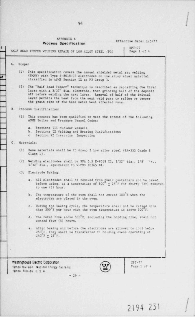
/I
94 |
^ Effective Date: 1/5/77Process Specification
1 NPT-77HALF BEAD TEMPER WELDING REPAIR OF LOW ALLOY STEEL (P3) Page 1 of 4-
-
A. Scope:
(1) This specification covers the manual shielded metal are welding7 (SMAW) with Type E-8018-C3 electrodes on low alloy steel material
classified in ASME Section IX as P3 Group 3.
(2) The " Half Bead Temper" technique is described as depositing the firstlayer with a 3/32" dia. electrode, then grinding half of the depositoff before welding the next layer. Removal of half of the initiallayer permits the heat frem the next veld pass to refine or temperthe grain size of the base metal heat affected zone.
B. Process Qualification:
(1) This process has been qualified to meet the intent of the followingASME Boiler and Pressure Vessel Codes:
a. Sections III Nuclear Vesselsb. Sections IX Welding and Brazing Qualificatiensc. Section XI Inservice Inspection
C. Materials:
(1) Base materials shall be P3 Group 3 1cw alloy steel (SA-533 Grade BClass 1).
(2) Welding electrodes shall be SFA 5.5 E-8018 C3, 3/32" dia., 1/8' '*e.,
5/32" dia., equivalent to W-PDS 10365 BA.
(31 Electrode Baking:
All electrodes shall be removed from gheir gontainers and be baked,a.before using, at a temperature of 800 125 F for thirty (30) minutesto one (1) hour.
b. The temperature of the oven shall not exceed 300 F when theelectrodes are placed in the oven.
c. During the baking cycle, the temperature shall not be raised =crethan 300 F per hour when the oven te=perature is above 300 F.
d. The total ti=e above 500 F, including the holding time, shall notexceed five (5) hours.
e. After baking and before the electrodes are allowed to cool below
250 F, cheg shall be transferred te holding ovens operating at250 F 1 25 F.
~
JWestegh0USS ElectfC CCf;Cfation N?T-77famoa Omston Nutteat Energy Systems Page 1 cf 4
fam:a Fienda U S A.- 29 -
2194 23I,
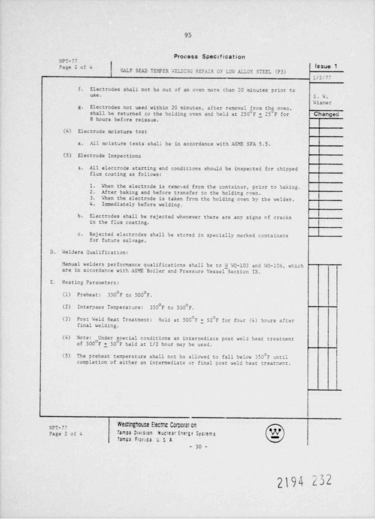
95
Process SpecificationNPT-77
. Issue 1"E' *
HALF BEAD TEMPER WELOING REPAIR OF LOW ALLOY STEEL (P3)1/5/77
f. Electrodes shall not be out of an oven more than 20 minutes prior touse. S. W.
Wisterg. Electrodes not used within 20 minutes, after removal from the oven,
shall be returned to the holding oven and held at 250 F + 25 F for Changed8 hours before reissue.
(4) Electrode moisture test
a. All moisture tests shall be in accordance with ASME SFA 5.5.
(5) Electrode Inspections
All electrode starting end conditions should be inspected for chipped1.
flux coating as follows:
1. When the electrode is removed from the containar, prior to baking.2. Af ter baking and before transfer to the holding even.3. %' hen the electrode is taken from the holding oven by the welder.4. I= mediately before velding.
b. Electrodes shall be rejected whenever there are any signs of cracksin the flux coating.
c. Rejected electrodes shall be stored in specially marked containersfor future salvage.
D. Welders Qualification:
Manual welders performance qualifications shall be to W WQ-103 and WQ-106, whichare in accordance with ASME Boiler and Pressure Vessel Sectica IX.
E. Heating Parameters:
(1) Preheat: 350 F to 500 F.
(2) Interpass Te:perature: 350 F to 500 F.
(3) Post Weld Heat Treatment: Hold at 500 + 50 F for f'our (4) hours afterfinal welding.
_
(4) Note: Under soecial conditions an inter:ediate post weld heat treatmentof 500 F + 50 'F held at 1/2 hour =ay be used.
(5) The preheat temperature shall not be allowed to fall belcw 350 F untilcompletion of either an intermediate or final post weld heat treatment.
Wesdnghou:e E!ecir:c Cer;:crat en3,7,77
Pa ge 2 o f 4 Tampa Omsson Nuclear Eneru SystemsTampa Flstica. U. S. A.
- 30 -
2194 232
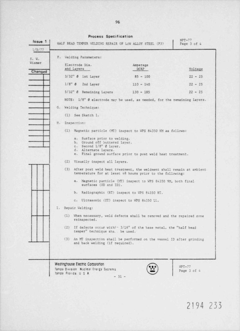
96
Process SpecificationNPT-77issa 1
HALF BEAD TEMPER WELDING REPAIR OF LOW ALLOY STEEL (P3) Page 3 of 4
1/5/77
F. Welding Parameters:g , y,'# Electrode Dia. A perage
and Lavers DCRP VoltateChanged
3/32" 6 1st Layer 85 - 100 22 - 25
1/8" 6 2nd Layer 110 - 140 22 - 25
5/32" d Remaining Layers 130 - 185 22 - 25
NOTE: 1/8" e electrode may be used, as needed, for the remaining layers.
G. Welding Technique:
(1) See Sketch 1.
H. Inspection:
(1) Magnetic particle (MI) inspect to WPS 84350 NM as follows:
a. Surface prior to welding.b. Ground off buttered layer.c. Second 1/8" d layer.d. Alternate layers.e. Final ground surface prior to post weld heat treatment.
(2) Visually inspect all layers.
(3) After post veld heat treatment, the veldrent shall re=ain at ambienttemoerature for at least 48 hours prior to the following:
a. Magnetic particle (MI) inspect to WPS 84350 NM, both finalsurfaces (OD and ID).
b. Radiographic (RT) inspect to k7S 84350 RT.
c. Ultrasonic (UT) inspect to WPS 84350 LL.
I. Repair Welding:
(1) When necessary, weld defects shall be removed and the repaired zenereinspected.
(2) If defects occur withf' 3/16" of the base metal, the " half beadte=per" technique sha. be used.
(3) An MT inapection shall be perforced on the vessel ID after grindingand back welding (if required) .
Westinghcuse E!ectric Ccrpcraften
Tampa Dmston Nuclear Energy Systems g NPT-77p,g, 3 og c,,,
Tampa Florida. U S A- 31 -
2194 233
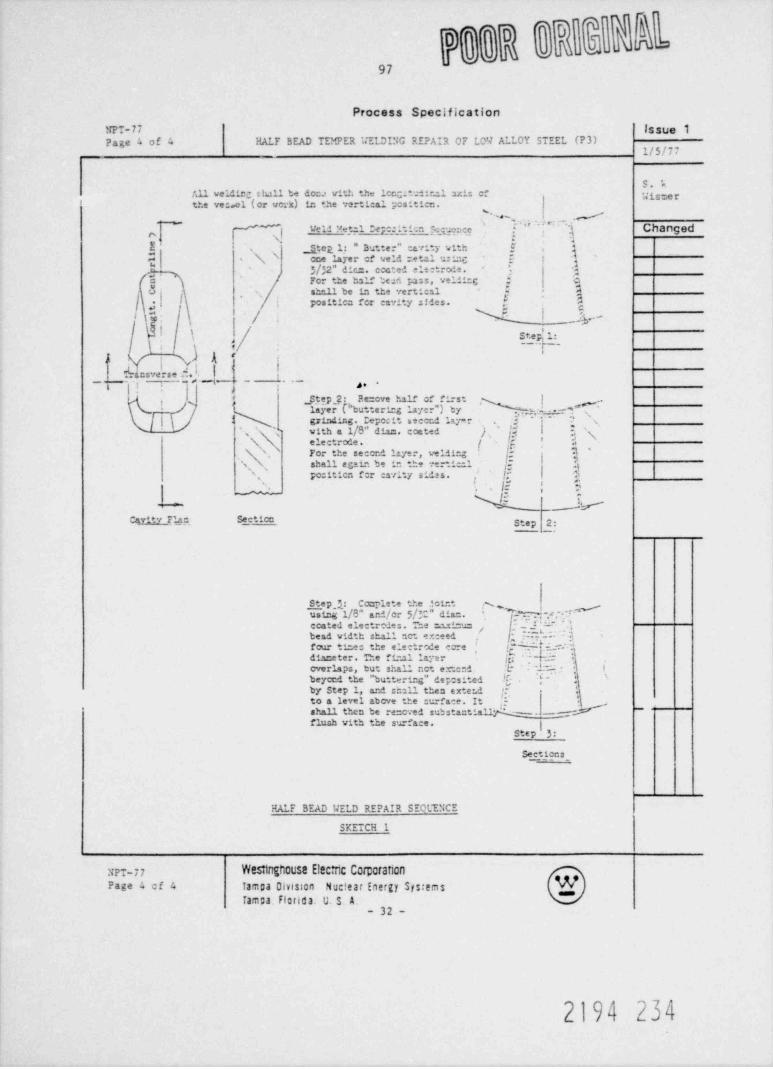
Process Specification
NPT-77 Issue 1Page 4 of 4 HALF BEAD TEMPER '..'ELDING REPAlR OF LOW ALLOY STEEL (P3)
1/5/77
S.kAll weldic; slull be doca with the longitdinal axis cf 'Jisme rthe ve:.el (or verk) in the vertical positten.
~ ~ * ~ .d~ d'*
[ "]N ve u yetal rep:1.ti n g gpce 1.. Changed
[ J tep l.: " Butter" cavity with ! ,
k\ one layer cf weld retal usinc", 3/32" dics. coated electroie.
'Es g3
c Fcr the half ted pass, welli:C : D5 sh!Lll be in the vertical N'
f. I positics for cavity sides. ,k 3,
/ Y __.by -
l' $:,
! k S_teg' .l:._.;)A'
_.,
__ fkn5ver"di _ ._,,
;
,
-( * Step 2: Pe=ove half of first |~ der Pbutteri=g layer") by, ,he.'"..! IA 1 _
| 3 grindir.g. Cepo:it necend lay =r ; [' s'
'c vith a 1/8'' dias. coated J ., 'y I 3 4s 'N electrode. [ g :!
, N' , For the second layer, velding jf }\ shall again be in the n-tical y ;is
N. po:itien f r esvity sidas. !;" 5,
S $jn
%:__._.s -' ,;N
-
S .tico Step 2:Cavity Elan tc
Step 1: Carlete the *oint x
D]-W; .",-#'E 65 1/8" a'd/or $/? " dia=. In'
_f * 'ccated electredes. The :nuinusbead width shall set exceed !.Y :- J
t.*% i.s g'four ti=es the electrcde cre
,
diaceter. The fir.21 layer
[[? f it . : -t-h
overlaps, but shall not er.cnd L- f
beycnd the " buttering * dep0 sited 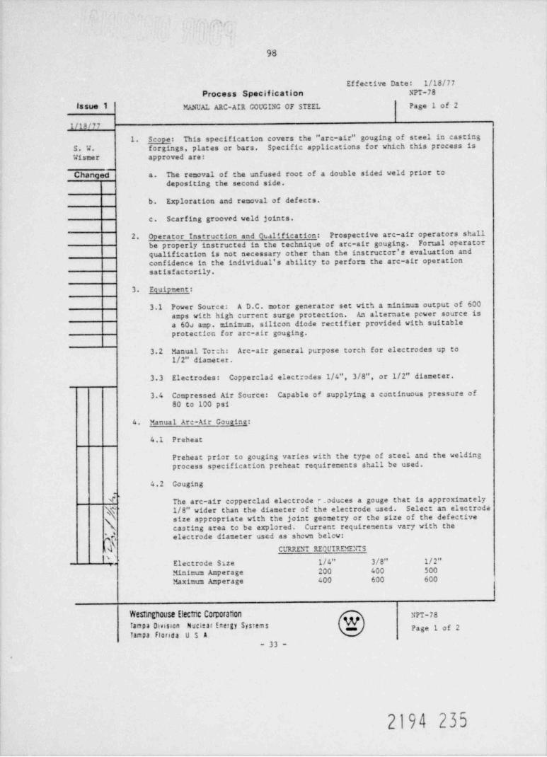
,i,
98
Effective Date: 1/18/77Process Specification NPT-78
issue 1 MANUAI. ARC-AIR COUGING OF STEEL Page 1 of 2
1/19/77
1. Scope: This specification covers the " arc-air" gouging of steel in castingS. W. forgings, plates or bars. Specific applications for which this process isWismer approved are:
Changed a. The removal of the unfused root of a double sided weld prior to
depositing the second side.
b. Exploration and removal of defects.
c. Scarfing grooved weld joints.
2. Ooerator Instruction and Cualification: Prospective arc-air operators shallbe properly instructed in the technique of arc-air gouging. Forual operatorqualification is not necessary other than the instructor's evaluation andconfidence in the individual's ability to perform the arc-air operationsatisfactorily.
3. Equipment:
3.1 Power Source: A D.C. motor generator set with a minimum output of 600amps with high current surge protection. An alternate power source isa 600 amp. minimum, silicon diode rectifier provided with suitableprotection for arc-air gouging.
3.2 Manual Torch: Arc-air general purpose torch for electrodes up to1/2" diameter.
3.3 Electrodes: Copperclad electrodes 1/4", 3/8", or 1/2" diameter.
3.4 Compressed Air Source: Capable of supplying a continuous pressure of80 to 100 psi-
4. Manual Arc-Air Couging:
4.1 Preheat
Preheat prior to gouging varies with the type of steel and the weldingprocess specification preheat requirements shall be used.
4.2 Gouging'
The arc-air copperclad electrode e_oduces a gouge that is approximately1/8" vider than the diameter of the electrode used. Select an electrodesize appropriate with the joint geometry or the size of the defective
N, casting area to be explored. Current requirements vary with theelectrode diameter used as shown belcw:, *
,
CL"4 RENT REOUIREMENTS
|s' Electrode Size 1/4" 3/8" 1/2"Minimus A=perage 200 400 500Maximus A=perage 400 600 600
WeSimgh0Use Electric Corporatt0n NPT-78famoa Omsson Nucitar Energy Systems p,g, y og 2,,,
Tampa Florida U S A.- 33 -
2194 235

99
Process Specification78
MANUAL ARC-AIR COUGING OF STEEL lssue 1P 2 of 2
1/18/77
4.2 Gouging (Continued) 3 , ,j ,
seerThe depth of cut varies with the angle between the electrode and the worksurface. The steeper the angle, that is, the nearer the electrode becomesnormal to the work surface, the deeper the cut and the greater the amperage Changed
require =ent. Generally, this angle is varied harveen 20 to 60 with thework.
Power and compressed air are brought to the torch through concentric cables.As the angle of the electrode is adjusted, the compressed air nozzleautomatically compensates so as to always direct the air stream toward theelectrode. The torch is held such that the air stream is always under theelectrode.
4.3 Cleaning
4.3.1 Arc-air gouged areas are clean except for a heatdiscoloration in the general area. Such reas are cleaned bywire brushing and chipping hammer to remove any pimples, scale,debris, etc.
4.3.2 Other areas in which the electrode is permitted to contact thework are clearly evident. They are covered with the black scotyremains of the electrode. These areas are to be ground smooth toremove a layer of metal .005" minimum, thus removing any area ofpossible carbon pick-up.
4.3.3 Special clean- 2 dimensions shall be shown on the drawing.
4.4 Inspection
L1 gouges and adjacent areas shall be magnetic particle inspected andcleared of all indications if required by drawing or process specification.
NPT-78 W2SMDghCUse E!ectnc Comcran0n WPage 2 of 2 Tampa Division Nuclear Energy Systems ""Tampa Floriaa. U. S. A.
- 34 -
2194 236
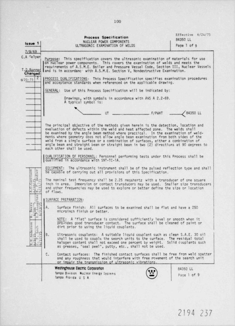
100
* *Process Specification
84350 RNUCLEAR POWER COMPONENTSlasue 1
ULTRASONIC EXAMINATION OF WELDS Page 1 of 9
7/9/69C.A Calyen Purpose: This specification covers the ultrasonic examination of materials for use
on nuclear power components. This covers the examination of welds and meets therequirements of A.S.M.E. Boiler and Pressure Vessel Code, Section III, Nuclear Vessels
T.D Rorre- and is in accordanc~ with A.S.M.E. Section V Nondestructive Examination.Changed
26/20/75 PROCESS QUALIFICATIONS: This Process Specification specifies examination proceduresand acceptance standards when referenced on the applicable drawing.
GENERAL: Use of this Process Specification will be indicated by:
Drawings, with symbols in accordance with AWS A 2.2-69.A typical symbol is:
UT F/PuiT /84350 LLN
The principal objective of the methods given herein is the detection, location andevaluation of defects within the weld and heat affected zone. The welds shallbe examined by the angle beam method where practical. In the examination of weld-ments where geometry does not allow angle beam examination from both sides of theweld from a single surface or a combination of surfaces, either a combination ofangle beam and straight beam or straight beam in two (2) directiuns at 90 cegrees to
- I each other shall be used.
QUALIFICATION OF PERSONNEL: Personnel perfaming tests under this Process shall bequalified in accordance with SNT-TC-1A.
EQUIPMENT: The ultrasonic instrument shall be of the pulsed reflection type and shall, ,
3 ,3 be capable of carrying out all provisions of this Specification.- ,
h$;c The nominal test frequency shall be 2.25 megahertz with a transducer of one squareqg inch in area. Immersion or contact transducers may be used. Smaller size transducersq q ,; and other frequencies may be used to explore or better define the size or location<w of flaws.
SURFACE PREPARATION:x ,n w
y A. Surface finish: All surfaces to be examined shall be flat and have a 250Ng; microinch finish or better.
NOTE: A " flat" surface is considered sufficiently level or smooth when itg proeides good transducer contact. The surface shall be cleaned of paint org g dirt prior to using the liquid couplants.
$ %g ,0 8. Ultrasonic couplants: A suitable liquid couplant such as clean S.A.E. 30 oilq:c shall be used to couple the search units to the surface. The residual total
h n halogen content shall not exceed one percent by weight. Solid couplants suchas greases, " seal peel", putty, etc., shall not be used.
C. Contact surfaces: The finished contact surfaces shall be free from weld spatterand any roughness that would interfere with free rmvement of the search unitor imoair the transmission of ultrasonic vibrations.
Westinghouse Electric Corpcration 84350 LLTampa Division Nu: lear Energy Systems Page 1 of 9Tampa florida U S A.
2194 237

101
Process Specification
84350 LL NUCLEAR POWER COMPONENTS lasue 1ULTRASONIC EXAMINATION OF WELDS
P 2 of 9
C.A.* 1 yenD. Welded surfaces: The finished weld surfaces where accessible, shall be of
adequate smoothness to prevent interference with the interpretation of theexamination. The weld surface shall merge smoothly into the surfaces of T.D.Rorrerthe adjacent base materials. Changed
E. Base material: After the weld is ccmpleted but before the angle beam examina- 2 6/20/75tion, the area of the base material through which the sound will travel inangle beam examination shall be completely scanned with a straight beam searchunit to detect reflectors which might affect the interpretation of angle beamresults. Consideration must be given to these reflectors during interpretationof weld examination results, but their detection is not a basis for rejectionof the base material.
EXAMINATION PROCEDURE:
Basic calibration reflectors: Drilled holes shall be used as basic calibrationreflectors to establish a primary reference response'of the equipment and to con-struct a distance-amplitude corrective curve. These holes shall be located eitherin production material or in a basic calibration block.
A. Basic calibration block: If a basic calibration block is used, it shall havea thickness relative to the production material thickness as shown by FigureNo. "A". Where two or more thicknesses are involved, the calibration thicknessshall be determined by the thickness of the production material to whic'h thesearch unit is applied. If the contact surface of the production material hasa radius of curvature of 10 inches or less, the curvature of the basic calibra-
tion block shall correspond to the radius of the production material within +,10 per cent.
B. Basic calibration hole: The basic calibration hole shall be drilled parallelto the contact surface of the basic calibration block or the productionmaterial. The iocation, depth, and diameter of this hole shall be as givenin the table in Figure No. "A".
C. Other calibration reflectors: In lieu of the abc<e, other calibration reflectorsare pemitted, provided equivalent response is demonstrated.
ANGLE BEAM METHOD:
A. Beam angle: The beam angle in the production material shall be in the rangeof 40 degrees to 75 degrees inclusive with respect to the perpendicular to thecontact surface.
B. Distance-amplitude correction: Compensation for the distance traversed by theultrasonic beam as it passes through the material shall be provided by the useof curves, as shown by Figure No. "B" or electronically.
C. Determination of curves: Distance-amplitude correction curves shall be con-structed by utilizing the responses from the basic calibration hole describedin Basic Calibration Reflectors. The first pcint on the curve is obtained byplacing the search unit as near as possible but not less than 3/8 vee-path, (vee-
84350 LL Westnghouse Electric CorporanonTampa Division Nuclear Energy Systems .
Page 2 of 9 Tampa. Oorida u. s. A.
2194 238
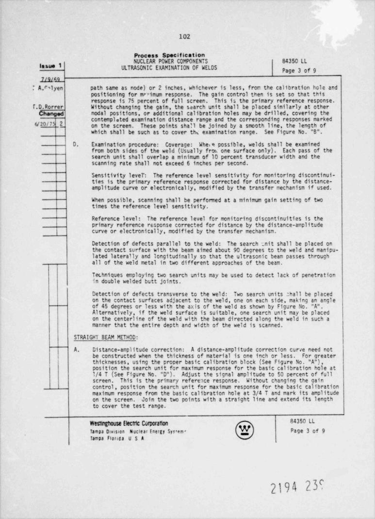
102
Process SpecificationNUCLEAR POWER COMPONENTS 84350 LL
lasue 1 ULTRASONIC EXAMINATION OF WELDS Page 3 of 9
.Z49/E9* A.hlyen path same as node) or 2 inches, whichever is less, from the calibration hole and
positioning for mnimum response. The gain control then is set so that thisresponse is 75 percent of full screen. This is the primary reference response.
I.D.Rorrer Without changing the gain, the search unit shall be placed similarly at otherChanged nodal positions, or additional calibration holes may be drilled, covering the
contemplated examination distance range and the corresponding responses markedU20 m 2 on the screen. These points shall be joined by a smooth line, the length of
which shall be such as to cover the examination range. See Figure No. "B".
D. Examination procedure: Coverage: Whem possible, welds shall be examinedfrom both sides of the weld (Usually fron. one surface only). Each pass of thesearch unit shall overlap a minimum of 10 percent transducer width and thescanning rate shall not exceed 6 inches per second.
Sensitivity level': The reference level sensitivity for monitoring discontinui-ties is the primary reference response corrected for distance by the distance-amplitude curve or electronically, modified by the transfer mechanism if used.
When possible, scanning shall be perfonted at a minimum gain setting of twotimes the reference level sensitivity.
Reference level: The reference level for monitoring discontinuities is theprimary reference response corrected for distance by the distance-amplitudecurve or electronically, modified by the transfer mechanism.
Detection of defects parallel to the weld: The search cnit shall be placed onthe contact surface with the beam aimed about 90 degrees to the weld and manipu-lated laterally and longitudinally so that the ultrasonic beam passes throughall of the weld metal in two different approaches of the beam.
Techniques employing two search units may be used to detect lack of penetrationin double welded butt joints.
Detection of defects transverse to the weld: Two search units : hall be placedon the contact surfaces adjacent to the weld, one on each side, making an angleof 45 degrees or less with the axis of the weld as shown by Figure No. "A".Alternatively, if the weld surface is suitable, one search unit may be placedon the centerline of the weld with the beam directed along the weld in such amanner that the entire depth and width of the weld is scanned.
STRAIGHT BEAM METHOD:
A. Distance-amplitude correction: A distance-amplitude correction curve need notbe constructed when the thickness of material is one inch or less. For greaterthicknesses, using the proper basic calibration block (See Figure No. "A"),position the search unit for maximum response for the basic calibration hole at1/4 T (See Figure No. "D"). Adjust the signal amplitude to 50 percent of fullscreen. This is the primary reference response. Without changing the gaincontrol, position the search unit for maximum response for the basic calibrationmaximum response from the basic calibration hole at 3/4 T and mark its amplitudeon the screen. Join the two points with a straight line and extend its lengthto cover the test range.
84350 LLWestinghouse Electric Ccrporation
Tampa Division Nuclear Energy Sys'em- Page 3 of 9Tampa Florida. U S A.
2M4 23?
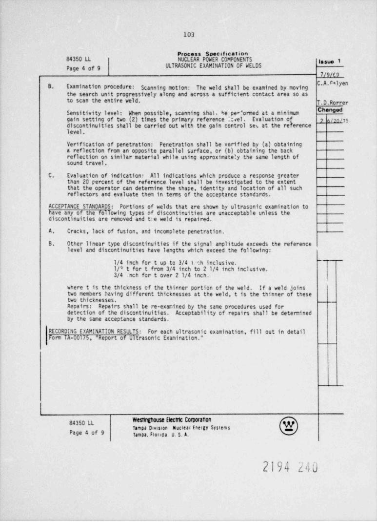
103
Process Specification84350 LL NUCLEAR POWER COMPONENTS lasue 1
ULTRASONIC EXAMINATION OF WELDSPage 4 of 97/9/E9
B. Examination procedure: Scanning motion: The weld shall be examined by moving*
the search unit progressively along and across a sufficient contact area so asto scan the entire weld. T.D.Rorrer
ChangedSensitivity level: When possible, scanning shal. be per"ormed at a minimumgain setting of two (2) times the primary reference .ael. Evaluationof 7 6/2M 75discontinuities shall be carried out with the gain control ses at the referencelevel.
Verification of penetration: Penetration shall be verified by (a) obtaininga reflection from an opposite parallel surface, or (b) obtaining the backreflection on similar material while using approximately the same length ofsound travel.
C. Evaluation of indication: All indications which produce a response greaterthan 20 percent of the reference level shall be investigated to the extentthat the operator can determine the shape, identity and location of all suchreflectors and evaluate them in terms of the acceptance stand:rds.
ACCEPTANCE STANDARDS: Portions of welds that are shown by ultrasonic examination tohave any of the following types of discontinuities are unacceptable unless thediscontinuities are removed and t:e weld is repaired.
A. Cracks, lack of fusion, and incomplete penetration.
B. Other linear type discontinuities if the signal amplitude exceeds the referencelevel and discontinuities have lengths which exceed the following:
1/4 inch for t up to 3/4 im h inclusive.-
1/'8 t for t from 3/4 inch to 2 1/4 inch inclusive.3/4 |nch for t over 21/4 inch.
where t is the thickness of the thinner portion of the weld. If a weld joinstwo members having different thicknesses at the weld, t is the thinner of thesetwo thicknesses.Repairs: Repairs shall be re-examined by the same procedures used fordetection of the discontinuities. Acceptability of repairs shall be determinedby the same acceptance standards.
RECORDING EXAMINATION RESULTS: For each ultrasonic examination, fill out in detailFonn TA-00175, " Report of Ultrasonic Examination."
Westinghouse Electric Corporation84350 LLTampa Omsson Nuclear Energy Systems
p ge 9 Tampa, Florida. U. S. A.
2194 240
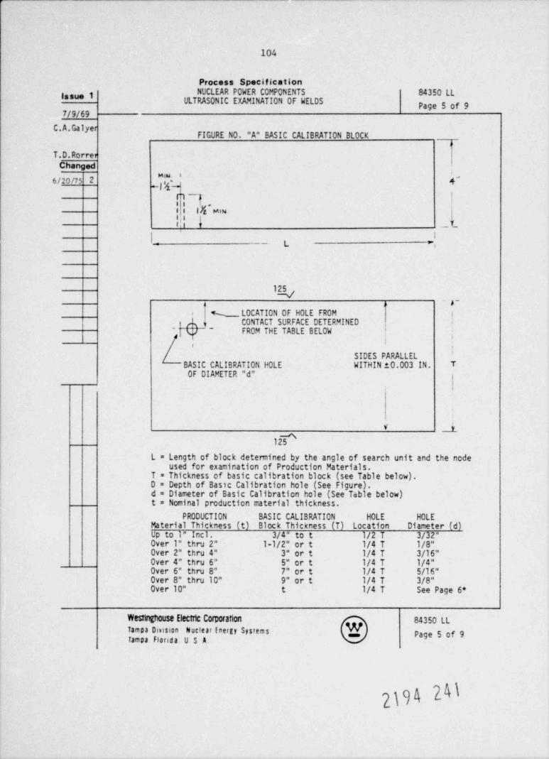
104
Process Specification
NUCLEAR POWER COMPONENTS 84350 LL388"* lULTRASONIC EXAMINATION OF WELDS Page 5 of 9
7/9/69
**
FIGURE NO. "A" BASIC CALIBRATION BLOCKo
T.D.RorrerChanged
.
6/20ns 2 k''-
hf"w IIfz Mi {
t. _L1 Ii _ L e,
kr~
% LOCATION OF HOLE FROM ii
CONTACT SURFACE DETERMINED ;* b- FROM THE TABLE BELOW '
'|
i i'
SIDES PARALLELBASIC CALIBRATION H0LE WITHIN 10.003 IN. TOF DIAMETER "d"
V __i_
12 [L = Length of block determined by the angle of search unit and the node
used for examination of Production Materials.T = Thickness of basic calibration block (see Table below).D = Depth of Basic Calibration hole (See Figure).d = Diameter of Basic Calibration hole (See Table below)t = Nominal production material thickness.
PRODUCTION BASIC CALIBRATION HOLE HOLEMaterial Thickness (t) Block Thickness (T) Location Diameter (d)Up to 1" Incl. 3/4" to t 1/2 T 3/32"Over 1" thru 2" l-1/2" or t 1/4 T 1/8"Over 2" thru 4" 3" or t 1/4 T 3/16"Over 4" thru 6" 5" or t 1/4 T 1/4"Over 6" thru 8" 7" or t 1/4 T 5/16"Over 8" thru 10" 9" or t 1/4 T 3/8"Over 10" t 1/4 T See Page 6*
Westinghouse Electric Corporation 84350 LLTampa Omsron Nuclear inergy Systems Page 5 of 9Tampa Florida. U S A.
|\
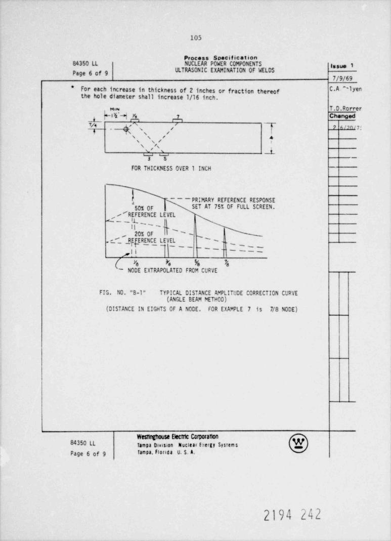
105
Process Specification84350 LL NUCLEAR POWER COMPONENTS issue 1
ULTRASONIC EXAMINATION OF WELDSPage 6 of 97/9/69
*For each increase in thickness of 2 inches or fraction thereof *^~ ""the hole diameter shall increase 1/16 inch.
em T.D.Rorrer
hlfi 4 4 Changed
Y/4f
,
Ys %'A' 9 A /an / 75j
,/s
\ ,'i 1 1-
3 5 _
FOR THICKNESS OVER 1 INCH
- -- PRIMARY REFERENCE RESPONSE,
50% OF SET AT 75% OF FULL SCREEN.
/ REFERENCE LEVEL
-|L~s, I
20% OF'
-- s'.c_'_ yrfERENCE LEVEL ). ,~ _ _~-
--i____ ___;,j i -
(~ N0DE EXTRAPOLATED FROM CURVEn n a r
FIG. NO. "B-1" TYPICAL DISTANCE AMPLITUDE CORRECTION CURVE(ANGLE BEAM METHOD)
(DISTANCE IN EIGHTS OF A NODE. FOR EXAMPLE 7 is 7/8 NODE)
Westinghouse Electric Corporation84350 LL Tampa Dmsion Nuclear (2ergy Systems
Page 6 of 9 Tampa. Florida U. S. A.
2194 242
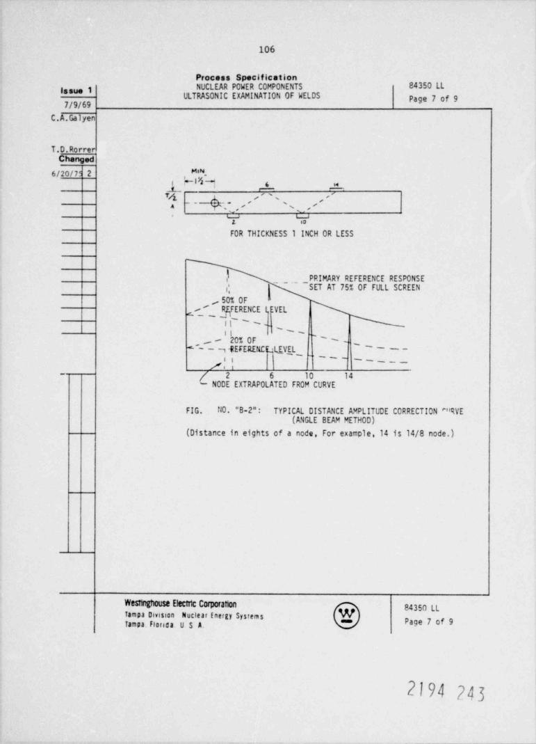
106
Process SpecificationNUCLEAR POWER COMPONENTS 84350 LLissue 1
ULTRASONIC EXAMINATION OF WELDS Page 7 of 9
C.A.Galyen
T.D.RorrerChanged
6/20/79 2 ,M'*-Vt ~139 6 w
_i_ - -
'' '%_,
4, '' ' -, ,4 Y- m e' \,
T Y'
FOR THICKNESS 1 INCH OR LESS
f PRIMARY REFERENCE RESPONSE
/, SET AT 75% OF FULL SCREEN
/ E NCE I EVEL~'
it' ~ __''-ii
- 20% OF ''-# ,fEFERENfr'11 VEL '
--
''--
i ___
/ 2 6 10 14- N0DE EXTRAPOLATED FROM CURVE
FIG. NO. "B-2"- TYPICAL DISTANCE AMPLITUDE CORRECTION ""RVE(ANGLE BEAM METHOD)
(Distance in eights of a node, For example,14 is 14/8 node.)
Weshnghouse Electric Corporation 84350 LLTampa Division Nuclear Energy SystemsTampa. florida. U $ A. Page 7 of 9
2194 243
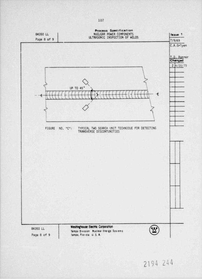
107
Process Specification
84350 LL NUCLEAR POWER COMPONENTS lasue 1ULTRASONIC INSPECTION OF WELDSPage 8 of 9
C.A.Galyen
T.D. PerrerChanged
2 6/20/75
h \UP TO 45' i
-
(Illl(Li f f l lil l\ U \ t i \ \ ( \ \ \ \ R A (\ ( \ ( \ \ \ t \ (l l l f l ^llitill 4,
\ ( \ \ \ \ \\- '
/
d<
FIGURE NO. "C": TYPICAL TWO SEARCH UNIT TECHNIOUE FOR DETECTINGTRANSVERSE DISCONTUNITIES
Westinghouse Electric Corporation84350 LL
Tampa Division Nuclear Energy Systems .
Page 8 of 9 Tampa, Florida. U. S. A.
2194 244
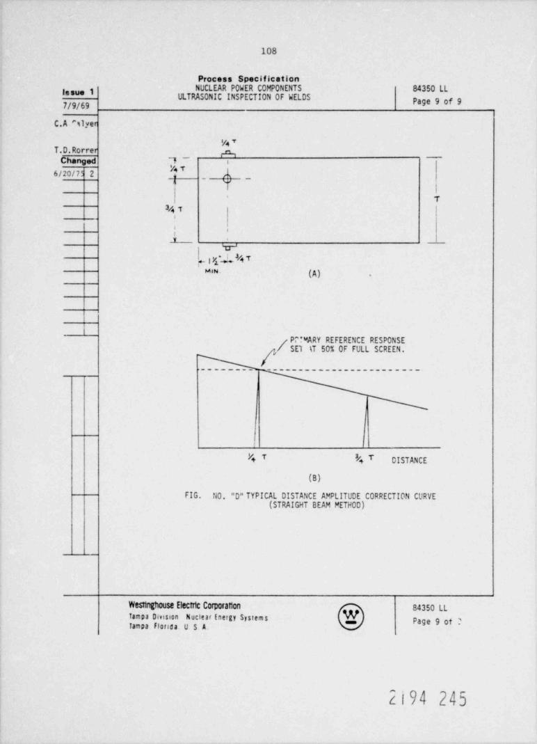
108
Process SpecificationNUCLEAR POWER COMPONENTS 84350 LLI'*"* I
ULTRASONIC INSPECTION OF WELDS Page 9 of 97/9/69
C.A Slyer
WTT.D.Rorrer 4
Changed 7__
i
6/20/75 2'
A~
yn
' T4T l
'6
i .
v
i -,xca#nT,
MIN. (A) .
Pr! WARY REFERENCE RESPONSE/ SET \T 50% OF FULL SCREEN.
----------------------- .
I
P+ T '4 T DISTANCE
(B)
FIG. NO. "D" TYPICAL DISTANCE AMPLITUDE CORRECTION CURVE(STRAIGHT BEAM PETHOD)
Westinghouse Electric Corporation 84350 LLTampa Omsson Nuclear Energy Systems Page 9 ot 2tampa fl0floa. U S A.
2194 245
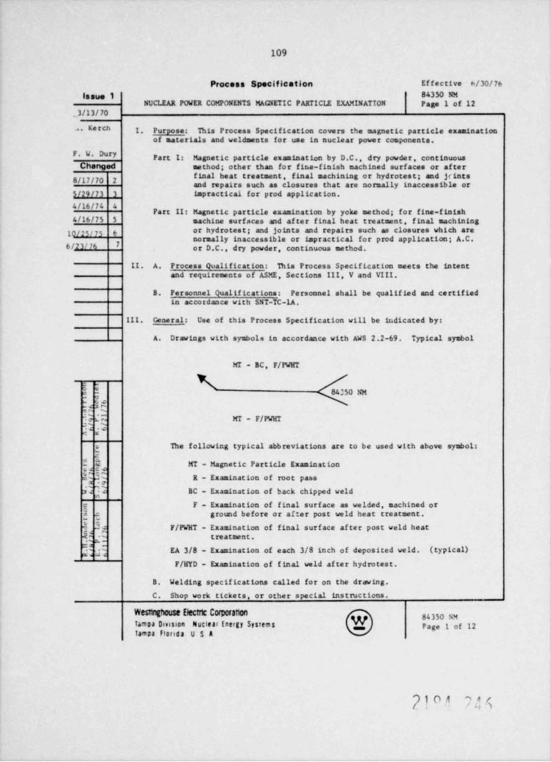
109
Process Specification Effective 6/30/76lasue 1 84350 NM
NUCLEAR POWER COMPONENTS MAGNETIC PARTICII EXAMINATION Page 1 of 12_3/13/70
. Kerch I. Purpose: This Process Specification covers the magnetic particle examinationof materials and weldments for use in nuclear power components.
F. W. DuryPart I: Magnetic particle examination by D.C., dry powder, continuous
Changed method; other than for fine-finish machined surfaces or af ter* **E E'*****" " " * ** "' 8 # I ' E** I "" "E"8/17/70 2 and repairs such as c'losures that are normally inaccessible or
5/29/73 3 impractical for prod application.
4/16/74 4Part II: Magnetic particle examination by yoke method; for fine-finish
4/16/75 5 machine surfaces and af ter final heat treatment, final machining
10/25/7s 6 or hydrotest; and joints and repairs such as closures which arenormally inaccessible or impractical for prod application; A.C.
6 /23/76 7 or D.C., dry powder, continuous method.
II. A. Process Qualification: This Process Specification meets the intentand requirements of ASME, Sections III, V and VIII.
B. Personnel Qualifications: Personnel shall be qualified and certifiedin accordance with SNT-TC-1A.
III. Gene ral: Use of this Process Specification will be it.dicated by:
A. Drawings with symbols in accordance with AWS 2.2-69. Typical symbol
MI - BC, F/WHT
$ $3 - 84250 NM
3en'tGG MT - F/PWHTC Ue 4
The following typical abbreviations are to be used with above symbolsu
2
{{ MT - Magnetic Particle Examination
s% R - Examination of root pass
E BC - Examination of back chipped weld
g F - Examination of final surface as welded, machined or
I, 5 ground before or af ter post weld heat treatment.
$ 3 F/PWHT - Examination of final surf ace af ter post veld heatgg t reatment .
2 g EA 3/8 - Examination of each 3/8 inch of deposited weld. (typical)F/HYD - Examination of final weld af ter hydrotest.
B. Welding specifications called for on the drawing.
C. Shop work tickets, or other special instructions.
Westinghouse Electric Corporation84350 NM
fampa Omston Nuclear Energy System 8 Page 1 of 12Tampa Florida U S A.
9 l. O A 9 /, (1/ - -
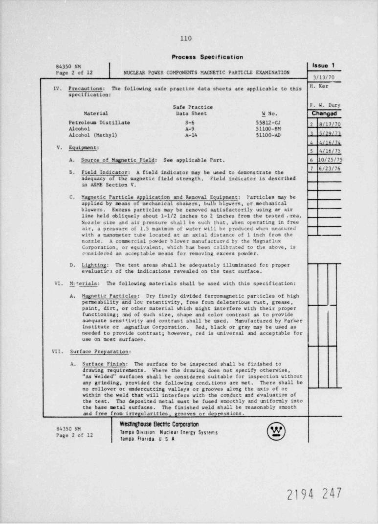
110
Process Specification
84350 hw lasue 1Page 2 of 12 NUCLEAR POWER COMPONE! TIS MAGNETIC PARTICLE EXAMINATION
3/13/70" * * *IV. P recaut ions : The following safe practice data sheets are applicable to this
specification:
Safe Practice F. W. Dury
Material Data Sheet W No. Changed
Petroleum Distillate S-6 55812-CJ 2 8/17/70Alcohol A-9 51100-BMAlcobol (Methyl) A-14 51100-AD I 5# N 3
4 4/16/74V. Equipment:
5 4/16/75
A. Source of Magnetic Field: See applicable Part. 6 10/25/75
5. Field Indicator: A field indicator may be used to demonstrate theadequacy of the magnetic field strength. Field indicator is describedin ASME Section V.
C. Magnetic Particle Application and Removal Equipment: Particles may beapplied by means of mechanical shakers, bulb blowers, or mechanicalblowers. Excess particles may be removed satisf actorily using ar airline held obliquely about 1-1/2 inches to 2 inches from the tested crea.
'
Nozzle size and air pressure shall be such that, when operating in f reeair, a pressure of 1.5 maximum of water will be produced when measuredwith a manometer tube located at an axial distance of 1 inch from thenozzle. A commercial powder blower manuf actured by the MagnailuxCorporation , or equivalent, which has been calibrated to the above, isconsidered an acceptable means for removing excess powder.
D. Ligh ting : The test areas shall be adequately illuminated fct p rope revaluatic.i of the indications revealed on the test surf ace.
VI. prerials: The following materials shall be used with this specification:
A. Magnetic Particles: Dry finely divided ferromagnetic particles of highpermeability and lov retentivity, f ree f rom deleterious rust, g rease ,pain t , dirt, or other material which might interfere with their properfunctioning; and of such size, shape and color contrast as to provideadequate sensitivity and contrast shall be used. Manufactured by ParkerIns titute or ..agnaflux Corporation. Red, black or gray may be used asneeded to provide contrast; however, red is universal and acceptable foruse on most surfaces.
VII. Surface Preparation:
A. Surface Finish: The surface to be inspected shall be finished todrawing requirements. Where the drawing does not specify otherwise,"As Welded" surf aces shall be considered suitable for inspection withoutany grinding, provided the following conditions are met. There shall beno rollover or undercutting valleys or grooves along the axis of orwithin the veld that will interfere with the conduct and evaluation ofthe test. Tha deposited metal must be fused smoothly and uniformly intothe base metal surfaces. The finished weld shall be reasonably smoothand f ree f rom irregularities , grooves or deoressions .
Westinghouse Electric Corporation
Tampa Omsion Nuclear Energy Systemsf 12
Tampa. Florida. U S A.
2194 247
111
Process Specification
issue 1 84350 NMNUCLEAR POWER COMPONENTS MAGNETIC PARTICLE EXAMINATION Page 3 of 12
3/13/70. Ke rch
VII. Surface Preparation (continued)
F. W. Dury A. (continued)Changed
Back-chipping of welds shall be sufficiently ground to prevent non-8/17/70 2 relevant indications. Root passes or subsequent layers of welds may
e 8pected h de "As WeM conMon pMed dere is no inter-%f20/73 3
fering rollover or undercutting.f.110, I T t. L
With the exception of inccmplete welds, all surfaces being tested shall",,,,,y gbe the finished surf aces. If any metal is removed by grinding,
10/25/75 A machining, or any other method subsequent to the magnetic particle6/23/76 7 inspection, the surf aces or areas so affected shall be reinspected.
B. Surface Conditioning: Rust, scale, slag, weld pimples, and other hardtenacious materials shall be removed by shot blasting, wire brushing,grinding or machining. A thin, adherent coating of aluminum or othernon-insulating paint will not interfere with the formation of indica-tions and is considered a suitable surface condition, if the coatingmaterial is firmly af fixed and there is no evidence oi peelir.g or otherseparation. When peeling or separation is evident, it is necessaryto remove the paint or coating from the area of inspection to insuremeaningful examination.
C. Magnetic Particle examination shall not be performed on surfacts whichexceed 600 F.
D. The Westingnouse Quality Control personnel conducting the examinationshall determine the acceptability of the surface for magnetic particleexamination.
VIII. Acceptance Standard: Any indication which is believed to be nonrelevantshall be regarded as a defect and shall be reexamined to verify whetheror not actual defects are present. Surface conditioning may precede thereexamination. Nonrelevant indications which would mask indications ofdefects are unacceptable .
Defects shall be evaluated to tha acceptance standards below.
Note: For the purpose of this specification, a rounded indication may beeither circular or elliptical in shape with the longer axis lesa than(3) times as long as the smaller axis and with no sharp corners.Thus a linear indication has the major axis three (3) times c,rgreater than the minor axis and/or exhibits sharp corners.
A. Examination Extent: Examination of welds or surf aces by the magneticparticle method shall be made over an area extending at least 1/2 inchbeyond the area of interest.
Westinghouse Electric Corporation et.35n NMfampa Omsion Nuclear Energy Systems Page 3 of 12Tampa Florida U $ A
21N 748
112
Process Specification
84350 NM |SSue 1? age 4 of 12 NUCLEAR POWER COMPONENTS MAGNETIC PARTICLE EXAMINATION
3/13/70B. Unless otherwise specified below, the following relevant indications are H. Ker
unacceptable. All surfaces shall be f ree of:
1. All cracks, laps, fissures and other linear defects. F. W. Dury
""2. All rounoed indications with dimensions greater than 3/16 inch.
2 8/17/703. Four or more rounded indications in a line separated by 1/16" or
3 5/29/73less edge-to-edge; other in-line porosity which appears as a linearaccumulation of test medium power shall also be removed. 4 4/16/74
5 '#4. Ten or more rounded indications in any six square inches of surface,with the major dimension of this area not to exceed 6 inches and with 6 10/25/75the area taken in the most unfavorable location relative to the indi- 7 6/23/76cations being evaluated.
C. Weld Edge Preparation:
1. All weld edge preparation surfaces in material 2 inches or morein thickness shall be examined for cracks, laminations, or otherdiscontinuities .
2. Laminar type indications:%
a. Laminar type indications are acceptable if they do not exceed1 inch in length.
b. Laminar type indications which exceed 1 inch in length requireUltrasonic Testing examination of the area for evaluation ofacceptance as to the LT requirements of the product form. IfUT inspection permits acceptance of the involved area, then theindications will be removed to a depth to accomplish eliminationor a maximum of 3/4 inch, whichever is lesser; and then be repairwelded to the applicable welding procedure. In event of materialbasis UT rejection, the ef fective repair must be to an extent topermit acceptance to the product form; in which situation repairsmay be more extensive than the 3/4 inch provision.
No te : Dependent on anticipated discontinuity removal or abilityto meet the one inch minimum length at a depth of removal beingless than the 3/4 inch maximum grinding, the U.T. examination forproduct form acceptance may be deferred until the initial grind-ing is performed.
3. Only indications with major dimensions greater than 1/16" shall beconsidered relevant. Further, separated, nonlaminar, relevant,linear indications not exceeding 3/16" are acceptable.
4 Indications in veld preparations other than those specified in thisparagraph will be evaluated to the requirements of Paragraph B,1,2 and 3 above.
Westinghouse Electric Corporation84350 NM WTampa omsion Nuclear Energy Systemsage 4 of L, ~
Tampa. Florida. U S A
2194 249
113
Process Specification
issue 1 84350 NMNUCLEAR P0h*ER COMPONENTS MAGNETIC PARTICLE EXAMINATION Page 5 of 12
3/13/70Kerch D. Forging, Casting and Plate Material.
In the conduct of examination of forging, casting and plate materialindications are unacceptable on the following basis in respect to
F. W. Dury material thickness:Maximum Maximum Major DimensionChanged
"t" Rounled of Linear ConsiderationM 7/70 ? Up to 5/8" greater than 1/8" greater than 1/16"5/29/73 3 5/8" - under 2" J/16" 1/8"" " " "
2" and greater 3/16" 3/16"" " " "g
For linearly disposed or cluster count acceptance, same as B. 3 and B. 4", 3,
above, with basis that indications with major dimensions greater than10/25/75 A 1/16" are considered relevant.6 /2 3/76 7
E. Plate material repairs; at supplier or in-house.Unacceptable surface defects shall be removed by grinding and/ormachining, provided the remaining section thickness is not reduced
'~ below drawing minimum; the depression, after defect removal, blendsuniformly, 4:1 minimum taper, into the surrounding surface, and isexamined by the magnetic particle method to the acceptance criteriaof Paragraph D above.
.
F. Only such defects need be removed as to render the surf ace acceptable tothe requirements of this specification. Areas containing unacceptabledefects shall be gound to remove the necessary defects. The ground-outareas shall be reinspected to insure the defect (s) being completelyeliminated. Minor cavities resulting f rom the removal of small discon-tinuities, that do not reduce the wall or veld deposited overlay belowdrawing requirements, or that do not affect machined surfaces or gasketfits, need not be repair welded. They shall, however, be blended to a4:1 minimum taper into the surrounding area. Other defects may be repairwelded by means of the original or other approved repair welding process.Completed repairs shall be, at a minimum, magnetic particle examined forfinal acceptance.
IX. Repair Welding: Specific approval for repair welding must be obtained inthe following cases:
A. Repair of base metal defects in pressure boundary application, excludingWeld 2dge Preparation discontinuities in accordance with Paragraph VIIIC.2.b., above, which meet material product form requirements, and repairs
| accomplished in accordance with TQAI 1.5.3. Non-pressure boundary materialc(internals) will require approval only in event of abnormal or multi-cycleconditions for which welding or Manuf acturing Engineering personnel requestassistance.
B. Repair of weld defects, except those repairs defined as permissible inthe appropriate veld process.
C. Repair of weld or base metal cracks or fissures which persist af terthe first cycle of repair.
D. Repairs necessary following any one or combination cf final heat t re atms.n t ,final radiographic examination or hydrostatic test.
_
WCSilngh0US8 88Cfric C0Q0f3?l00 8!.350 NMTampa Omsion Nuclear Energy Systems Page 5 of 12fampa Florida U S A
2194 250
114
Process Specification
84350 NM lssue 1Page 6 of 12 NUC1. EAR POWER COMPONENTS MAGNETIC PARTICLE EXAMINATION
3/13/70H. Kr -h
X. Demagnetization: Demagnetization following examination is required whereresidual magnetism will interfere with subsequent processes or usage. Inrespect to magnetic particle examination sequence, demagnetization of the F. W. Dury
specimen or section is recommended when a higher field has been imposed for *the first direction than that to be used for a subsequent examination.
2 8/17/70complete demagnetizrtion is practically impossible to attain, the process
3 5/2 W 3is thus limited to reducing the residual fields, as appropriate, to anacceptable level. Essentially, residual magnetism will result from D.C. 4 4/16/74magnetic particle examination, a result of penetration ef fect; A.C. test
5 4fl4f,$application residual ef fects are less severe.
6 10/25/75When direct current magnetization has been employed, demagnetization may
7 A/23/76be accomplished by repeatedly reversing and progressively decreasing theD.C. magnetizing current. The initial field strength used duringdemagnetization shall be greater than the original magnetizing force.When the current has been reduced to the vanishing point, the part should bedemagnetized.
When alternating current magnetization has been employed, A.C. demagnetiza-tion can be accomplished by decrewing the magnetizing current in smallsteps or continuously to a very low amperage. For small components ,demagnetization may be effected by passing the part through a coil with ACflowing, and removing the part at least 18 inches f rom the coil. Theinitial demagnetizing current shall be greater than that of the originalmagnetizing force.
PART I
Procedure for magnetic particle examination by D.C. dry powder, continuousmethod; other than for fine finish machine surfaces or af ter final heat treat-ment, final machining or hydrotest; and joints and repairs such as closuresthat are normally inaccessible or impractical for prod application.
I. Equipment: The magnetizing equipment, as a source of magnetic field, shallbe capable of inducing in the item under test a magnetic flux of suitableintensity in the desired direction by either the circular or longitudinalmethod. Direct current (D.C.) obtained f rom D.C. generators, storagebatteries or rectifiers shall be used to induce the magneti, flux.Alternating current (A.C.), as a magnetic flux inducing fiuld source maybe used onif when permitted by this process specification.
Half-Wave Direct Current (H.W.D.C.) is similarly suitable - even preferredas a magnetic field source as a function of pulsation and powder mobilityresponse.
For D.C. prod application, the open circuit voltage of the magnetizingsource shall not exceed 25V.
Westinghouse Electric Cogoration8 0 Tampa Dmsson Nuclear Energy Systems, 12 Tampa. Florida. U S. A
2194 251
115
Process Specification
issue 1 84350 NMNbCLEAR POWER COMPONENTS MAGNETIC PARTICLE EXAMINATION Page 7 of 12
1/13/70Kerch
11. P rocedu re :
F. W. DuryA. Pre-inspection
ChangedB. Pre-cleaning
5/?9/71 1 C. Application of magnetic field
' # M ' 7' 4 D. Application of magnetic particles4/u /7; 5
E. Removal of excess particles10/25/7% r.
A/'3/76 7 F. Examination and evaluation
G. Certification of Examination
H. Demagnetization
A. Pre-Inspection: Prior to magnetic particle examination, the surfaceshall be examined to determine its compliance to Paragraph VII and adimensional examination including, but not necessariliy limited tomachined sizes, fillet sizes, wall thickness, and weld suitability.All unacceptable conditions must be corrected prior to magnetic' particle examination. Lighting (Paragraph V.D) and materials(Paragraph VI) shall be checked for compliance to this specification.
B. P re-Cle anin g : 'Ihe materials or parts to be examined shall besuitably cleaned to remove all foreign matter which could interferewith the formation or evaluation of magnetic particle powder patternsor indications. Oil and grease shall be removed using petroleumdistillate (spirits) and/or alcohol or methyl-alcohol. Cleaning shallextend at least one inch on each side beyond the area to be examined.The use of alcohol shall always follow the use of petroleum distillate.
C. Application of Magnetic Field:
1. Direction: The magnetic field shall be induced in more than onedirection to insure detection of discontinuities in any direction.The second direction shall be at approximately 90 to theinitial direction.
2. Magnetizing Time: For application in either direct or indirectmagne tiz ation , the current shall be passed through the part orthrough the auxiliary conductor for a minimum of 1/5 second.
3. P recaution: Care shall be taken to prevent local overheating,arcing or burning the surface being inspected. The magnetizingcurrent shall not be turned on until the prods have been properlypositioned in contact with the surface, and the current shall beturned of f before the prods are rer.o ve d . Prod tips shall be keptcleaned and dressed.
WeSfif!gh00$8 EleCff!C CGrp0farion84350 NM
Tampa Dmsson Nuclear Energy Systems Page 7 of 12famDa fl00da L S A
2194 252
116
Process Spec:fication
84350 NM lasue 1Paga 8 of 12 NUCLEAR POWER COMPONEN13 MAGNETIC PARTICLE EXAMINATION
3/13/70
11. (continued) H. Ke r
C. Application of Magnetic Field (continued)F. W. Dury
4. Exception: When the surf ace being examined is a weld root pass, it is Changedpermissible to use alternating currelt.
? 9/17/705. Direct Magnetiz :icn: , ,.,,,,y
a. Field Strength: When prods are employed to produce direct,,, , , , , , , , ,,
circular magnetization, the current shall be at least 100 to 125amperes per inch of prod spacing, for normal application. 5 4/16/75
b. Prod Spacing: Prods will be spaces not less then three (3) inches A 10/25/75nor more than eight (8) inches , cat for normal operations. Any 7 6/23/76requirements for exception as a result of component configurationor other basis shall be reviewed by the Quality Assurance Engineeror Quality Control Supervisor,
c. Cable Length: Cable leads in excess of 30 feet, each, shall notbe employed under standard practice. For any requirement ofexce p tion , follow that of b. above.
d. Shet Sequence:
1. Welds, plate edges and joint geometry,
a. Longitudinal: Prods will be placed in line or not morethan approximately 10 off the centerline at selectedspacing. Overlap or back step of 1-1/2 to 2 inches willbe made to permit evaluation of area of previous prodplacement.
b. Transve rse : Progressive prod intervals of four (4) tofive (5) inches will be made at an approximate 90relationship to the " prod centerlines" employed in a.above. e. , applicable, if an edge, prods will be setback 1/2" to 1"; however, for joint seams or spot areas,set back will be 1" to 1-1/2" beyond weld joint edge.
c. All transverse shots may follow completion of longitudinalshots, or shots may be alternated, whithever is convenient.
d. For magnetic particle examination of plate edges or rootpsss or intermediate weld deposits where section thicknessis less than 3/4 inch, amperage of 90 to 110 per inch ofprod spacing shall be en: ployed.
2. Magnetic particle examination of surf aces.
a. Surface pattern: Mark off surface in approximate 4 inchsquares.
b. Performance: Apply prods at 7-1/2 inch to 8 inch spacingacross diagonal of square. This will permit prod spacing to -
extend beyond corners of the square by about one inch.Apply prods to opposite corners in the same manner. Proceedf rom one square to the next until the surf ace is completed.
Westnghouse Electric Corporation84350 SM g,Tamp? Dmsion Nuclear Energy hstemsPage 8 of 12 -
Tampa Florida U S A
-,
117
Process Specification
issue 1 | 84350 N'1NUCLEAR POVER COMPONENTS MAGNETIC PARTICLE EXAMINATION Page 9 of 12
-it3/7n
Kerch2. Magnetic particle examination of surfaces (continued).
c. "He ad Shot"' To impart circular magnetization to aF. W. Dury component by current flow from end to the other,Changed the magnetizing current shall be based on the external
diawnsion, exclusive of length, as follows:''
l. Up to 5 inch dimension of clameter or cross' "o'7' 1 section: 700 to 900 amperes per inch for HVDC.4/16/74 4 2. Frota 5 inch to 10 1nch diameter; 500 to 700 amperes4/'A/75 5 per inch.
1 /25/75 3. In excess of 10 inch dirension: 300 to 500 amperes0 g
6/21/76 7 ' *
_6. Indirect Magnetization:
a. Central conductor: Same as 5,d,2,c. above.
b. Through Coila: Same as 5,d,2,c. above divided by the numberof coils,
c. Coil or wrapped cable: Provides longitudinal magnetization.
1. Field Strength: For reliable test performance, L/D ratiomust not be less than 2 nor greater than 15. Amperage isestablished by formulas :
L/D ratio equelL/D ratio at least 2 45.000D 35.000but less than 4 AMPS LT
e t AMPSr. : Length of specimen or testing segmentsD: Diameter ci specimenT: Number of turns in coil or cable
2. When the magnetizing coil is made of cable wound aroundthe test part, the coils turns shall be closely spaced.The effective field extends for about six (6) inches oneither side of the coil; longer part a shall be magnetizedin sections.
d. For use of central conductor or coil, the magnetizing elementshall be in surface contact with the test specimen.
7. A different means than that of the first examination may be usedfor the second or necessan subsequent tests.
D. Application of Magnetic Particles: Dry magnetic particles shall beapplied in such a manner that a light, dust-like coating settles uponthe metal surf ace under tes t. The magnetic field shall be on whileL.2 particles are applied, seo Paragraph V, C.
E. Removal of Excess Particles: While magnetic field is on, excess parti-cles shall be removed by means of a dry air current of suf ficient forceto remove excess particles without disturbing those particles which areindicative of discontinuities. This removal may be accomplished by bulbblowers. If a commercial powder blower is employed for this purpose,refer to Paragraph V, C for use of equipment and procedures.
Wesunghouse Electric Corporation84350 NM
Tampa Dinston hdCitar Energy Systems w Page 9 of 12.samaa Florida U S A
2194 254
118
Process Specification
84350 Nn | lssue 1Page 10 of 12 NUCLEAR POWER COMPONENTS MAGNETIC PARTICLE EXAMit aTION
- 3ri,r7n
H . Ks i
F. Examination and Evaluation: Each area shall be examined immediately uponremoval of excess particles and prior to application of the magnetic fieldin another direction or location. Indications will appear as collections of F . L' . Durypowder which cannot be removed by a properly directed air corrent. ChangedEvaluation and acceptance shall be made in accordance with Paragraph VIII.
2 8/17/70Note: In that magnetic particle build-up and retention, during the appli-cation and removal cycle, is a function of the discontinuity to field 3 s/29/71o rie n t a*. ion , it is necessary to observe the area of exa '.ne;1on during the
' ' '#'course of the entire precedure cycle. Additional NI s'sts may thus benecessary in a repositioned direction with the field at approximately 90 to 5 4 tis r7sthe susnect discontinuity alignment to obtain maximum sensitivity.
,7$
G. Certification of Examination: A certification of examination completion 7 6/23/i6
shall be made immediately on final acceptsace.
ALTERNATE
G. Certification of Examination: Immediately upon final acceptance, the partyresponsible for conduct of the test shall certify completion by signing theInspection Poir.t Program, Operational Line-Up, or spplicable forms desig-nated by IPP, Line-Up, or other appropriate instructions.
H. Demagnetization: Refer to Paragraph X.
PART II
Procedure for magnetic particle examination by yoke method, for fine finish machinesurf ace and af te r final heat treatment, final machining or hydrotest; and jointsand repairs such as closures that are normally inaccessible or impractical forprod application; A.C. or D.C. , dry powder, continuous method.
I. Equipment: A hand-held electro-magnetic yoke capable of producing a highlymagnetized field in a uni-directional manner between the poles when placed uponferrous material. Equipment supplying either A.C. or D.C. , or both, may beused; with acknowledgement that D.C. is pre fe rred.
II. Procedure:
A. Pre-inspection
B. Pre-cleaning
C. Application of magnetic field
D. Application of magnetic particles
E. Removal of excess particles
F. Examination and evaluationG. Certification of inspection
H. Demagnetization
A. Pre-inspection: Same as Part I, Section II., A.
B. Pre-cleaning: Same as Part I, Section II., A.
Westinghouse E!ecnic Corporation84350 ,o, NPage 10 of 12 Tampa Omsion Nuclear Energ* Systems "
Tampa Florida U S A
2194 255
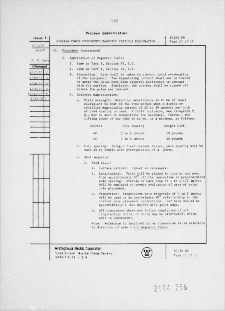
119
Process Specification
issue 1 84350 NMNCCIIAR POWER C0 9 0NENTS MAGNETIC PARTICLE EXAMINATION Page 11 of 12
3/13/70Kerch II. Procedure (continued)
C. Application of Magnetic Field:
1. Same as Part I, Section II, C.I.Changed
2. Same as Part I, Sectiott II, C.2.8/17/70 2
3. Precaution: Care shall be taken to prevent local overheating5/20/73 3 of the equipmen:. The magnetizing current shall not be turned
nn until the poles have been properly positioned in contacta f u , ,,, ,,
with the surface. Similarly, the current shall be turned of f1'''" " before the poles are removed.
10/M/7s 6 4 Indirect magnetization:
6/23 m 7a. Field strength: Detection sensitivity is to be at least
equivalent to that of the prod method when a direct orrectified magnetizing current of 25 to 30 amperes per inchof prod spacing is used. A field indicator, see Paragraph V.B., may be used to demonstrate the adequacy. Furthe e, thelif ting power of the yoke is to be, at a minimum, as follows:
Current Pole Spacing Weight Lift
AC 3 to 6 inches 10 poundsi
DC 3 to 6 inches 40 pounds
b. Tole spacing: Being a fixed current device, pole spacing will besuch as to comply with prerequisites of a. above,
c. Shot sequence:
1. Weld se os:a. Surf ace pattern: Layout as necessary.
b. Longitudinal: Poles will be placed in line or not morethan approximately 10 off the centerline at predeterminedpole spacing. Overlap or back step of 1 to 1-1/2 incheswill be employed to pemit evaluation of area of priorpole placement.
c. T ransve rse : Progressive pole intervals of 4 to 5 incheswill be used at an approximate 90 relationship to theinitial pole placement cen te rlines . Set back should beapproximately 1 inch beyond weld joint edge.
d. All transverse shots may follow completion of alllongitudinal shots, or shots may be alternated, which-ever is convenient-
Note: Reference to longitudinal or transverse is in referenceto direction of yoke - not magnetic field.
Westnghouse Electric Comoration W 84350 NMSmpa Omsson Nuclear Energy Sys' ems _ p 9g 2famDa Flonda USA
2194 256
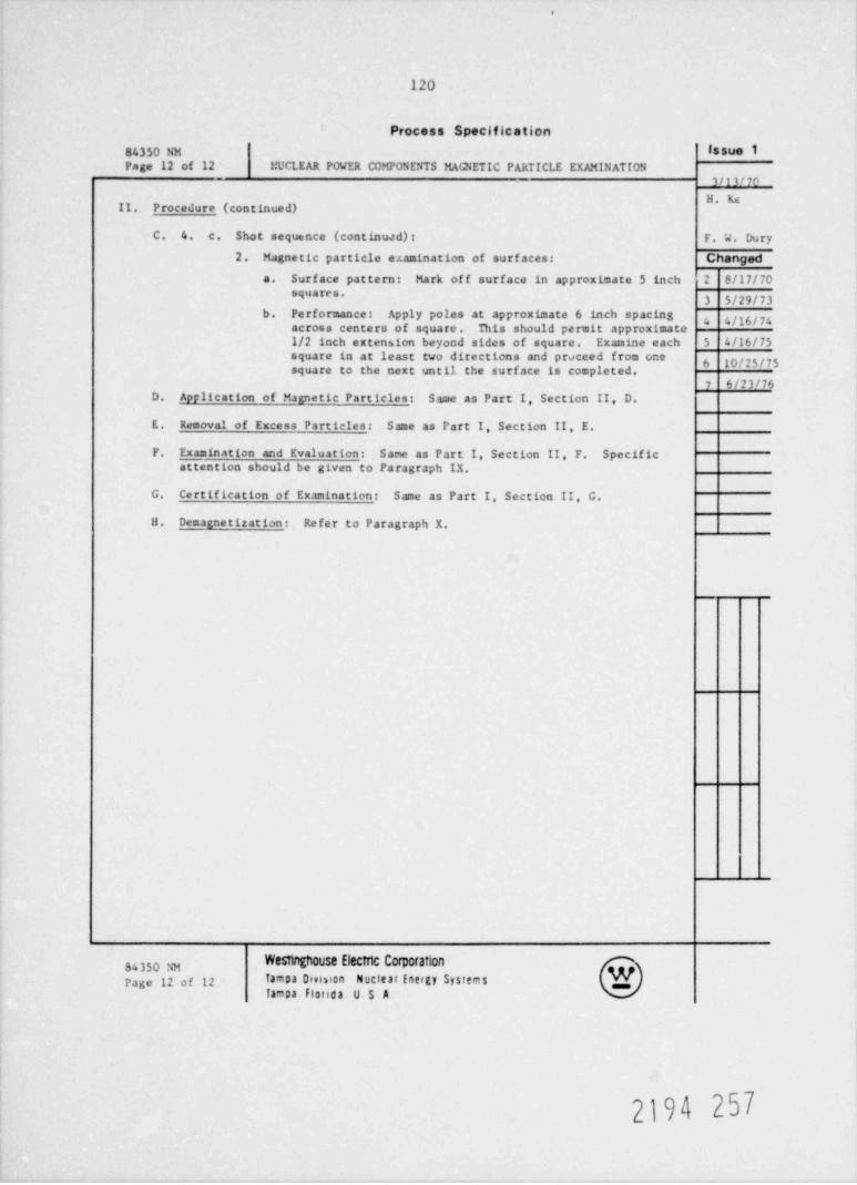
.
120
Process Specification
84350 NM issue 1Page 12 of 12 MUCLEAR POWER COMPONENTS MAGNETIC PARTICLE EXRtINATION
3/13/70
H . K4II. Procedure (continued)
C. 4. c. Shot sequence (continuad): F. W. Dury
2. Magnetic particle examination of surf aces: Changed
a. Surface pattern: Mark of f surface in approximate 5 inch 2 8/17/7089"*****
3 5/29/73b. Pe rformance : Apply poles at approximate 6 inch spacing
4 4/16/74across centers of square. This should permit app roximato1/2 inch extension beyond sides of square. Examine each 5 4/16/75square in at least two directions and proceed from one
6 10/25/75square to the next until the surface is completed.
7 6/23/76D. Application of Magnetic Particles: Same as Part I, Section II, D.
E. Removal of Excess Particles: Same as Part I, Section II, E.
F. E,xamination and Evaluation: Sane as Part I, Section II F. Specificxattention should be given to Paragraph IX.
G. Certification of Examination: Same as Part I, Section II, C.
H. Demagnetization: Refer to Paragraph X.
__
Westinghouse Electric Corporation84350 NMPage 12 of 12 Tampa Dimion Nuclear Energy Systems
Tampa Florida U S A
2194 257
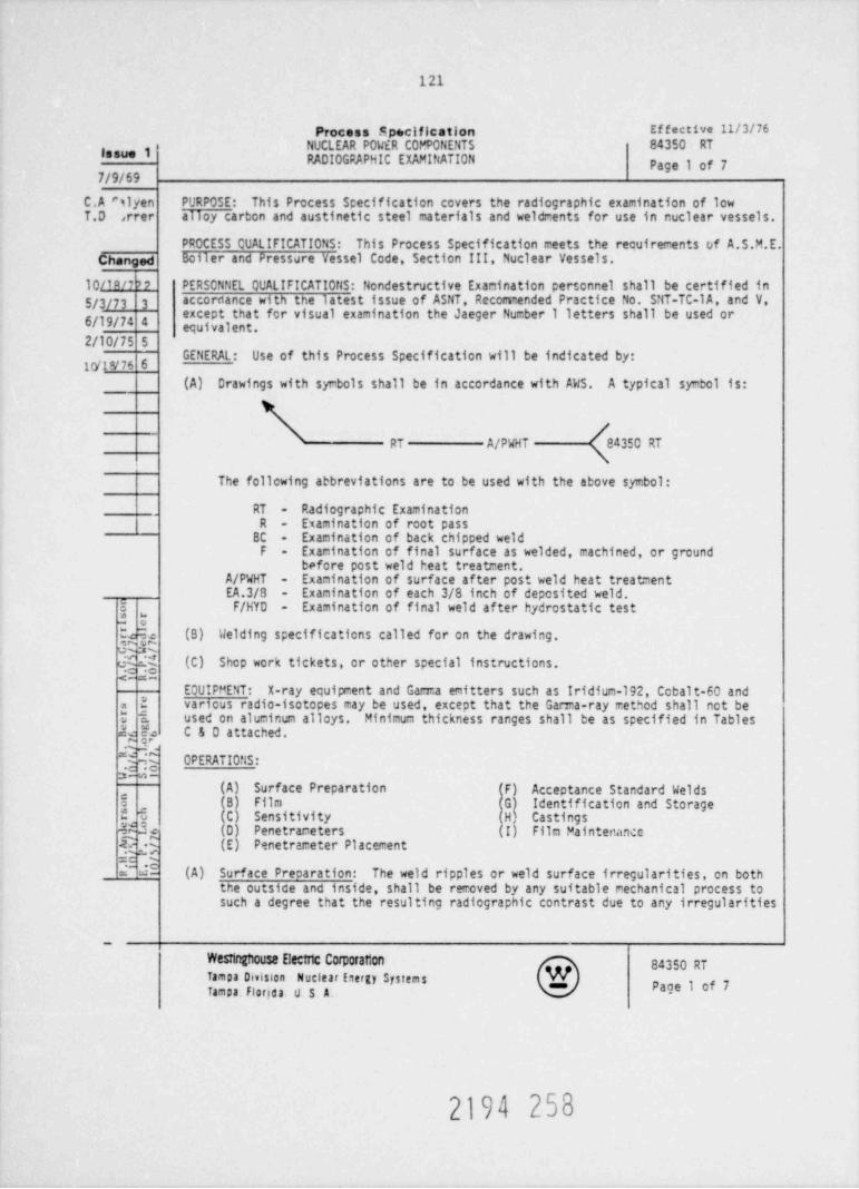
121
Process Specification Effective 11/3/76NUCLEAR POWER COMPONENTS 84350 RT
issue 1 PADIOGPAPHIC EXAMINATION Page 1 of 77/9/69
C.A Slyen PURPOSE: This Process Specification covers the radiographic examination of lowT.D ,rrer alloy carbon and austinetic steel materials and weldrents for use in nuclear vessels.
PROCESS CUALIFICATIONS: This Process Specification meets the reouirements of A.S.M.E.Changed Boiler and Pressare Vessel Code, Section III, Nuclear Vessels.
10/10n 0 PERSONNEL QUALIFICATIONS: Nondestructive Examination personnel shall be certified in5/3/73 3
accordance with the latest issue of ASNT, Recommended Practice No. SNT-TC-1 A, and V,except that for visual examination the Jaeger Number 1 letters shall be used or
6/19/74 4 equivalent.
2/10/75 S
** * ''** ** " U" " #8 * #10/1476 6
(A) Drawings with symbols shall be in accordance with AWS. A typical symbol is:
/RT A/PWHT 84350 RT
\The follcwing abbreviations are to be used with the above symbol:
, RT Radiographic Examination-
R - Examination of root passBC - Examination of back chipped weld
F Examination of final surface as welded, machined, or ground-
before post weld heat treatment.A/PWHT - Examination of surface after post weld heat treatmentEA.3/8 - Examination of each 3/8 inch of deposited weld.
j F/HYD - Examination of final weld after hydrostatic test,
(B) Welding specifications called for on the drawing.
Q3 'f (C) Shop work tickets, or other special instructions.<-s-
EQUIFPENT: X-ray equipment and Garza emitters such as Iridium-192, Ccbalt-60 and3 various radio-isotopes may be used, except that the Garra-ray method shall not bea
U i used on aluminum alloys. Minimum thickness ranges shall be as specified in TablesJe Ye C & D attached.
*{}-
OPERATIONS:,; ,
2-o-(A) Surface Preparation F) Acceptance Standard Welds
5, (B Film Identification and Storage
a t (C Sensitivity CastingsML (D) Penetrameters (I Film Maintenance(3 (E) Penetrameter Placement
(A) Surface Precaration: The weld ripples or weld surface irregularities, on boththe outside and inside, shall be removed by any suitable rechanical process tosuch a degree that the resulting radiographic contrast due to any irregularities
Westinghouse Electric Corporaton 84350 RTTampa Division Nuclear Energy Systems WTampa. Floriaa. U S A. age 1 of 7-
2194 258
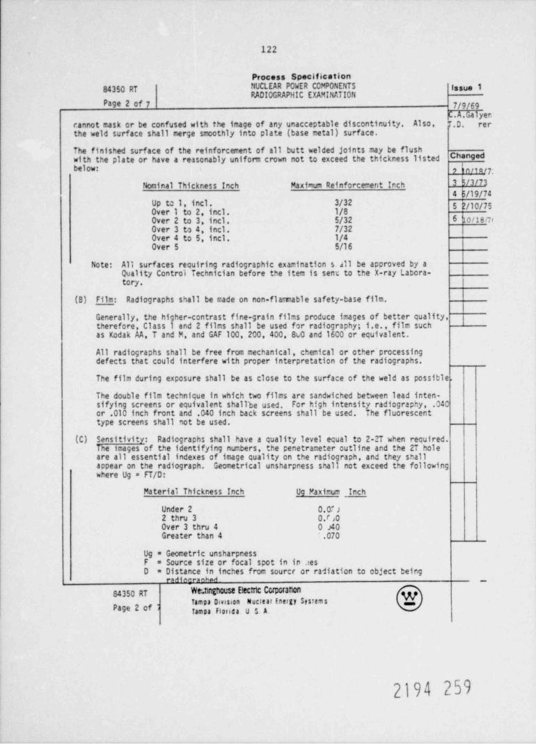
122
Process Specification
84350 RT NUCLEAR POWER COMPONENTS Issue 1RADIOGRAPHIC EXAMINATION
Page 2 of 7 7/9/69C.A.Galyen
cannot mask or be confused with the image of any unacceptable discontinuity. Also, T.D. rerthe weld surface shall merge smoothly into plate (base metal) surface.
The finished surface of the reinforcement of all butt welded joints may be flushwith the plate or have a reasonably unifom crown not to exceed the thickness listed Changed
below: ,) n/w/7;
3h/3/73Nominal Thickness Inch Maximum Reinforcement Inch4 $/19/74
Up to 1, incl. 3/32 5 2/10/75Over 1 to 2, incl. 1/8Over 2 to 3, incl. 5/32 6'io/teneOver 3 to 4. incl. 7/32Over 4 to 5, incl. 1/4Over 5 5/16
Note: All surfaces requiring radiographic examination s.all be approved by aQuality Control Technician before the item is sent to the X-ray Labora- I
tory.
(B) Film: Radiographs shall be made on non-flamable safety-base film.
Generally, the higher-centrast fine-grain films produce images of better quality,therefore, Class 1 and 2 films shall be used for radiography; i.e., film suchas Kodak AA, T and M, and GAF 100, 200, 400, 8c0 and 1600 or equivalent.
All radiographs shall be free from mechanical, chemical or other' processingdefects that could interfere with proper interpretation of the radiographs.
The film during exposure shall be as close to the surface of the weld as possible.
The double film technique in which two films are sandwiched between lead inten-sifying screens or equivalent shallbe used. For high intensity radiography, .04Cor .010 inch front and .040 inch back screens shall be used. The fluorescenttype screens shall not be used.
(C) Sensitivity: Radiographs shall have a quality level equal to 2-2T when required.The images of the identifying numbers, the penetrameter outline and the 2T holeare all essential indexes of image quality on the radiograph, and they shallappear on the radiograph. Geometrical unsharpness shall not exceed the followingwhere Ug = FT/D:
Material Thickness Inch Ug Maximum Inch
Under 2 0.0f ;
2 thru 3 0.r ,0
Over 3 thru 4 0 J40Greater than 4 .070
Ug = Geccetric unsharpnessF = Source size or focal spot in in .iesD = Distance in inches from source or radiation to object being
rM4mr= 6 A
84350 RT Wr tinghouse Electic CcrporanonTampa Omsion Nuclear Energy Systems
Page 2 of . Tampa Flonda. U S A.
2194 259
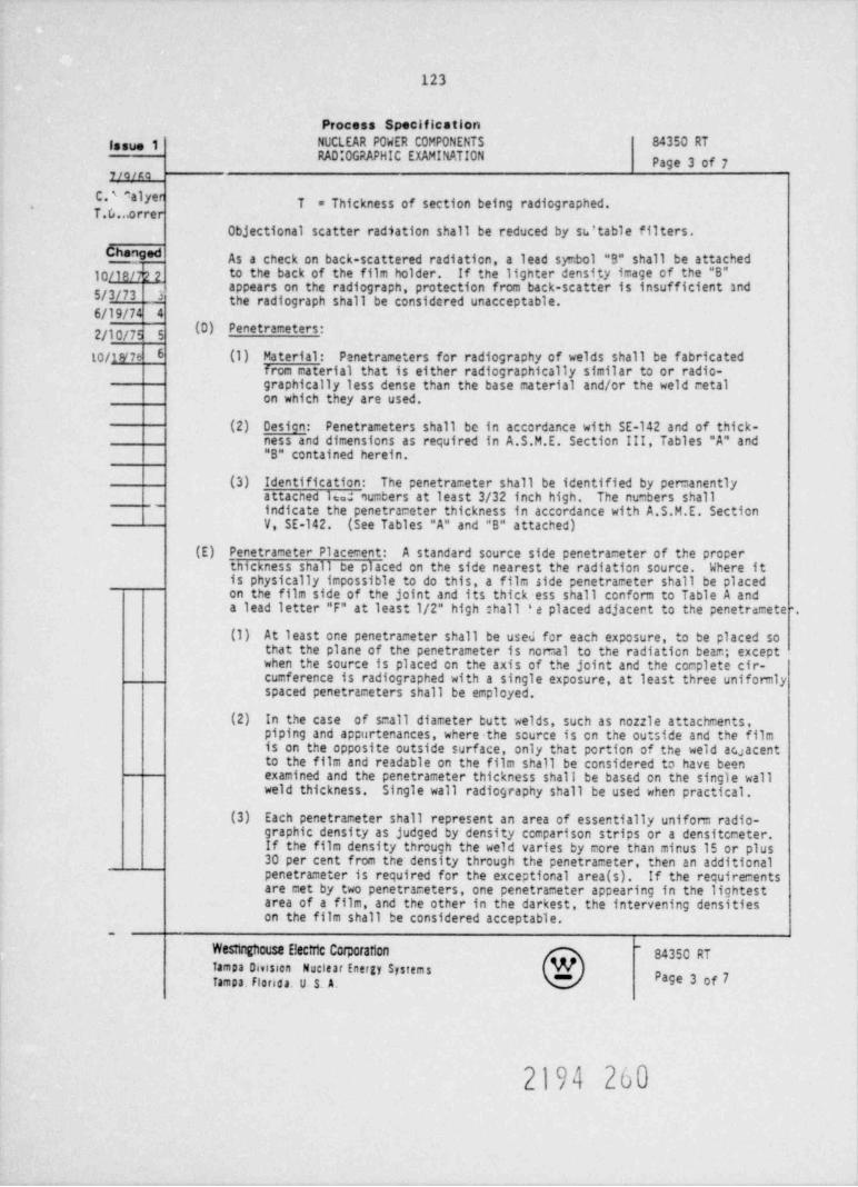
123
Process Specification
issue 1 NUCLEAR POWER COMPONENTS 84350 RTRAD'0 GRAPHIC EXAMINATION Page 3 of 7
7/Q/#Q
C.' *aly" T = Thickness of section being radiographed..
T . G ...o rre r
Objectional scatter radiation shall be reduced by sv table filters.Changed As a check on back-scattered radiation, a lead symbol "B" shall be attached
10/18/722 to the back of the film holder. If the lighter densi.ty image of the "B"appears on the radiograph, protection from back-scatter is insufficient and
5/3/73 J the radiograph shall be considcred unacceptable.6/19/74 4
(D) Penetrameters:2/10/75 5
10/1,y7s 6 (1) Material: Panetrameters for radiography of welds shall be fabricatedfrom material that is either radiographically similar to or radio-graphically less dense than the base material and/or the weld retalon which they are used.
(2) Desicn: Penetrameters shall be in accordance with SE-142 and of thick-ness and dimensions as required in A.S.M.E. Section III, Tables "A" and"B" contained herein.
(3) Identification: The penetrameter shall be identified by permanentlyattacned 1=. numbers at least 3/32 inch high. The numbers shall
' indicate the penetrameter thickness in accordance with A.S.M.E. SectionV, SE-142. (See Tables "A" and "B" attached)
(E) Penetrameter Placement: A standard source side penetrameter of the properthickness shall be placed on the side nearest the radiation source. Where itis physically impossible to do this, a film side penetrameter shall be placedon the film side of the joint and its thick ess shall conform to Table A anda lead letter "F" at least 1/2" high : hall ? e placed adjacent to the penetramete .
(1) At least one penetrameter shall be used for each exposure, to be placed sothat the plane of the penetrameter is nomal to the radiation beam; exceptwhen the source is placed en the axis of the joint and the coeplete cir-cumference is radiographed with a single exposure, at least three unifomlyspaced penetrameters shall be employed.
(2) In the case of small diameter butt welds, such as nozzle attachments,piping and appurtenances, where the scurce is en the outside and the filmis on the opposite outside surface, only that portion of the weld ac acentato the film and readable on the film shall be considered to have beenexamined and the penetrameter thickness shall be based on the single wallweld thickness. Single wall radiography shall be used when practical.
(3) Each penetrameter shall represent an area of essentially unifom radio-graphic density as judged by density ccmparison strips or a densitcceter.If the film density through the weld varies by more than minus 15 or plus30 per cent from the density through the penetrameter, then an additionalpenetrameter is required for the exceptional area (s). If the recuirecentsare met by two penetrameters, one penetrameter appearing in the lightestarea of a film, and the other in the darkest, the intervening densitieson the film shall be considered acceptable.
Wesunghcese Eectric Corpcraften - 84350 RTTampa Davision Nuclear Energy Systems NTampa. Florada. U S. A. Page 3 of 7-
2194 260
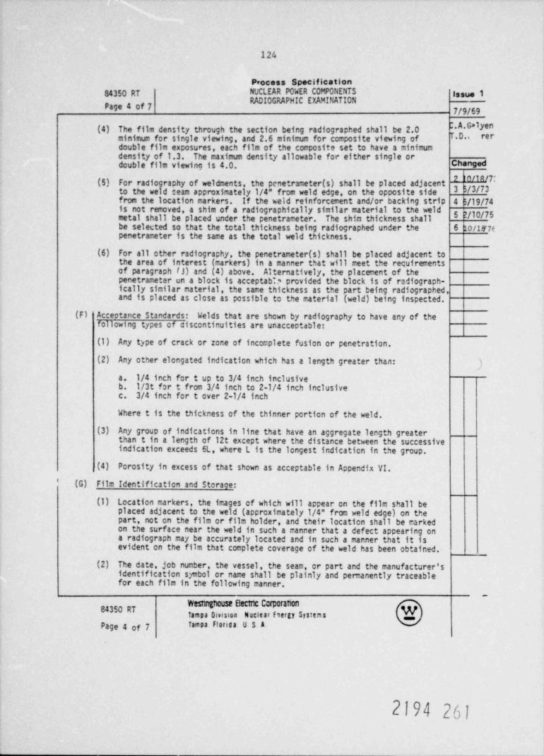
124
Process Specification
84350 RT NUCLEAR POWER COMPONENTS **"* 3RADIOGRAPHIC EXAMINATION
Page 4 of 7 7/9/69
(4) The film density through the section being radiographed shall be 2.0 .A.Galyen
minimum for single viewing, and 2.6 minimum for composite viewing of T.D.. rerdouble film exposures, each film of the composite set to have a minimumdensity of 1.3. The maximum density allowable for either single ordouble film viewing is 4.0. Changed
(5) For radio raphy of weldments, the penetrameter(s) shall be placed adjacentto the we d seam approximately 1/4" from weld edge, on the opposite side 3 b/3/73from the location markers. If the weld reinforcement and/or backing strip 4h/lg/74is not removed, a shim of a radiographically similar material to the weld
5 ?/10/75metal shall be placed under the penetrameter. The shim thickness shallbe selected so that the total thickness being radiographed under the 6 10/ly 7cpenetrameter is the same as the total weld thickness.
(6) For all other radiography, the penetrameter(s) shall be placed adjacent tothe area of interest (markers) in a manner that will meet the requirementsof paragraph (3) and (4) above. Alternatively, the placement of thepenetrameter un a block is acceptabb provided the block is of radiograph-ically similar material, the same thickness as the part being radiographed,and is placed as close as possible to the material (weld) being inspected.
(F) Acceptance Standards: Welds that are shown by radiography to have any of thefollowing types of ciscontinuities are unacceptable:
(1) Any type of crack or zone of incomplete fusion or penetration.
(2) Any other elongated indication which has a length greater than:})
a. 1/4 inch for t up to 3/4 inch inclusiveb. 1/3t for t from 3/4 inch to 2-1/4 inch inclusivec. 3/4 inch for t over 2-1/4 inch
Where t is the thickness of the thinner portion of the weld.
(3) Any group of indications in line that have an aggregate length greaterthan t in a length of 12t except where the distance between the successiveindication exceeds 6L, where L is the longest indication in the group.
(4) Porosity in excess of that shown as acceptable in Appendix VI.' (G) Film Identification and Storage:
(1) Location markers, the images of which will appear on the film shall beplaced adjacent to the weld (approximately 1/4" from weld edge) on thepart, not on the film or film holder, and their location shall be markedon the surface near the weld in such a manner that a defect appearing ona radiograph may be accurately located and in such a manner that it isevident on the film that complete coverage of the weld has been obtained.
(2) The date, job number, the vessel, the seam, or part and the manufacturer'sidentification symbol or name shall be plainly and pemanently traceablefor each film in the following manner.
84350 RT WTampa Division Nuclear hergy Systems .
Page 4 of 7 Tampa. Florida. U. S A.
2194 261
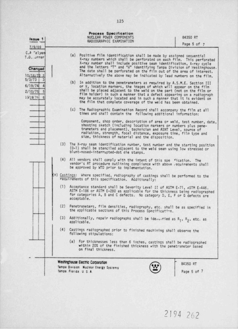
125
Process SpecificationNUCLEAR POWER COMPONENTS 84350 RT
lasued RADIOGRAPHIC EXAMINATI0ftPage 5 of 7
7/9/69C.A *alye
(a) Positive film identification shall be made by assigned sequentialT.D. a rer X-ray numbers which shall be perforated on each film. This perforatedX-ray number shall include positive seam identification, X-ray cycle
Changed and the letters "T" and "U" identifying Tampa Division of Westinghouse.The date shall be perforated on the film out of the area of interest.
10/19/7b ? Alternatively the above may be indicated by lead numbers on the film.
(b) In addition to the penetrameters as required by A.S.M.E. Section III6/19/74 4 or V, location markers, the images of which will appear on the film2/10/75 5 shall be placed adjacent to the weld on the part (not on the film or
film holder) in such a manner that a defect appearing on a radiograph10/1P176 6 may be accurately located and in such a manner that it is evident on
the film that complete coverage of the weid has been obtained.
(c) The Radiographic Examination Record shall accorpany the film at alltimes and shall contain the following additional information:
Component, shop order, description of area or weld, test number, date,shooting sketch (including location markers or numbers plus pene-trameters and placement), technician and ASNT Level, source ofradiation, strength, focal distance, exposure time, film type andsize, thickness of material and the disposition.
(3) The X-ray seam identification number, test number and the starting position(0-1) shall be stenciled adjacent to the weld seam using low stressed orblunt-nosed-interrupted-dot die stamps.
(4) All vendors shall comply with the intent of tnis spe 11 cation. Thevendor's RT procedure cutlining compliance with above requirements shallbe approved by WTD prior to implementation.
(H) Castinos: Where specified, radiography of castings shall be performed to therequirements of this specification. Additionally:
(1) Acceptance standard shall be Severity Level II of ASTM E-71. ASTM E-446,ASTM E-186 or ASTM E-280 as applicable for the thickness being radiographedfor categories A, B and C defects. No category D, E, F or G defects areacceptable.
(2) Penetrameters, film densities, radiography, etc. shall be as specified inthe applicable sections of this Process Specificatian.
(3) Additionally, repair radiographs shall be idemtied as R), R , etc. asapplicable. 2
(4) Castings radiographed prior to finished machining shall observe thefollowing stipulations:
(a) For thicknesses less than 6 inches, castings shall be radiographedwithin 20% of the finished thickness with the penetrameter basedon final thickness.
Wesunghouse Elec:ric Corporafon - 84350 RTTampa Omsson Nuclear Energy Systems N
""rampa. Flottaa. U S A. Page 5 of 7
2194 262
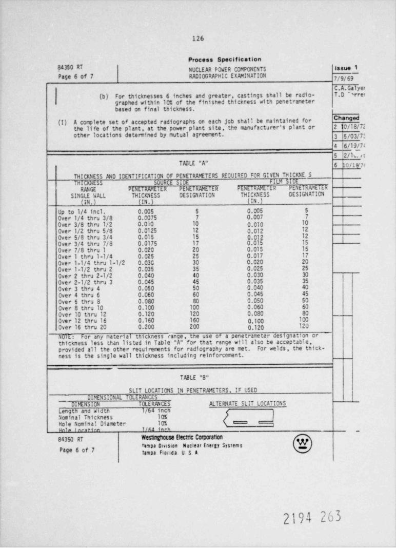
126
Process Specification
NUCLEAR P5WER COMPONENTS Issue 1Page 6 of 7 RADIOGRAPHIC EXMINATION 7/9/69
C.A.Galyer(b) For thicknesses 6 inches and greater, castings shall be radio- T.0 N rret
graphed within 10% of the finished thickness with penetrameterbased on final thickness.
Changed(I) A complete set of accepted radiographs on each job shall be maintained forthe life of the plant, at the power plant site, the manufacturer's plant or 210/18/72other locations determined by mutual agreement. 3 5/03/7'
4 6/19/74
5 2/16,i:
TABLE "A" 6 to /18/ 7e
THICKNESS MD ICENTIFICATION OF pENETRAMETERS REOUIRED FOR GIVEN THICKNE. S
THICKNESS SOURCE SICE fit}l SCRMGE PENETRAMETER PENET RMETE R PENETRAMETER PENETRMETE R
SINGLE WALL THICKNESS DESIG'lATION THICKNESS DESIGNATION
(IN.) (IN.) (IN.)Up to 1/4 incl. 0.005 5 0.005 5 |Over 1/4 thru 3/8 0.0075 7 0.007 7
Over 3/8 thru 1/2 0.010 10 0,010 10
Over 1/2 thru 5/8 0.0125 12 0.012 12
Over 5/8 thru 3/4 0.015 15 0.012 12
Over 3/4 thru 7/8 0.0175 17 0.015 15
Over 7/8 thru 1 0.020 20 0.015 15
Over 1 thru l-1/4 0.025 25 0.017 17
Over 1 1/4 thru l-1/2 0.03C 30 0.020 20
Over 1-1/2 thru 2 0.035 35 0.025 25
Over 2 thru 2-1/2 0.040 40 0.030 30
Over 2-1/2 thru 3 0.045 45 0.035 35
Over 3 thru 4 0.050 50 0.040 40
Over 4 thru 6 0.060 60 0.045 45
Over 6 thru 8 0.080 80 0.050 50
Over 8 thru 10 0.100 100 0.060 60
Over 10 thru 12 0.120 120 0.080 80
Over 12 thru 16 0.160 160 0,100 100
Over 16 thru 20 0.200 200 0.120 120
NOTE: For any material thickness range, tne use of a penetrameter designation orthickness less than listed in Table "A" for that range will also be acceptable,provided all the other requirements for radiography are met. For welds , the thick-ness is the single wall thickness including reinforcement.
TABLE "B"
SLIT LOCATIONS IN PENETRMETERS, IF USEDDIMENSIONAL TOLERANCES
_ DIFENSION TOLE RMCES ALTERNATE SLIT LOCATIONSLengtn and widtn 1/64 inchNominal Thickness 10%
Hole Nominal Diameter 10% ,
uale fen *ien 1/Ka inah ,
84350 RT WesungneuSe Electic Corporation
a Dmston Nuckar DW SWmsPa9e 6 of 7 fampa Florida. U S. A
2194 263

127
Process SpecificationNUCLEAR POWER COMPONENT 5 84350 RTissue 1RADIOGRAPHIC EXNi! NATION
7/9/69 Page 7 of 7
C.A.r lyeneT.D rrer TABLE "C"
RADICACTIVE ISOTOPES. MINIMUM THICKNESS DANGEChanged
MATERIAL IR10lLN-192 COBALT 6010/18/7P2
Steel 0.75 in. 1.50 in.5/03/7 l3 Copper /high nickel 0.65 in. 1.30 in.6/19/764 Alumintrn 2.5 in.
2/10/7 i5
10/18r76 6 TABLE "0"
( !20
15
10
8-
6 )/
#5 # /x 3 y g
2 /
n '
G$
'
1 MEV p p800 J f,
C /600 e j500
/400 7N /
y 300 70 ,/ -" 2@
/150
/100 .1 .15 .2 .3 .4 .6 .8 1.0 1.5 2 3 4 567810 15 20
MINIMUM THICKNESS (INCHES) MAXIMUM VOLTAGE FOR STEEL_
Wes:1nghouse Electric Comorattan 84350 RT
Tamp 3 Division Nuclear Energy Systems Page 7 of 7TamD3. Il0fida. U $. A.
2194 264
129
NUREG/CR-0113ORNL/NUREG/TM-177Dist. Category R5
Internal Distribution
1. R. G. Berggren 67. J. R. McGuffey2. S. E. Bolt 68-72. J. G. Merkle
3-13. R. H. Bryan 73. C. A. Mills14. J. P. Callahan 74. S. E. Moore
15-16. D. A. Canonico 75. F. R. Mynatt19. S. J. Chang 76. H. A. Pohto (Y-12)20. R. D. L..averton 77. H. Postma21. C. E. Childress 78. G. C. Robinson22. W. E. Cooper 79. C. D. St. Onge (Y-12)23. J. M. Corum 80. Myrtleen Sheldon24. W. B. Cottrell 81. G. M. Slaughter25. M. H. Fontana 82. C. B. Smith26. W. R. Gall 83-85. G. C. Smith27. W. L. Greenstreet 86. J. E. Smith28. R. C. Gwaltney 87. 1. Spiewak29. J. F. Harvey 88. W. J. Stelzman30. M. R. Hill 89. D. G. ' aomas
31-58. P. P. Holz 90. H. E. "ammeil59. H. W. Hoffman 91. D. R. uauger-
60. S. K. Iskand er 92. J. R deir, Jr.61. M. A. Karnitz 93-184. G. D. Whitman62. T. A. King 185. Patent Office63. K. K. Klindt 186-187. Central Research Library64. Milton Levenson 188. Document Refererce Section65. R. E. lbcPherson 189-193. Laboratory Records Department66. R. W. McClung 194. Laboratory Records (RC)
External Distibution
195-270. S. W. Wismer, Westinghouse Electric Corp., Westinghouse TampaDivision, P.O. Box 19218, Tampa, FL 33616
271-278. Director, Office of Nuclear Regulatory Research, Nuclear Regu-latory Commission, Washington, D.C. 20555
279. Director, Reactor Division, DOE, ORO2d0. Director, Research and Technical Support Division, DOE, ORO
281-448. Special HSST Distribution449-823. Given distribution under category RS (25 copies - NTIS)
2194 265