remotely operated vehicle (rov) prototype - utpedia
TRANSCRIPT
REMOTELY OPERATED VEHICLE (ROV) PROTOTYPE
MARTINA MUHAIZIRA BINTI MOHAMAD
ELECTRICAL & ELECTRONICSENGINEERING
UNIVERSITI TEKNOLOGI PETRONAS
MAY 2012
MA
RT
INA
MU
HA
IZIR
A B
INT
I MO
HA
MA
D B
. EN
G. (H
ON
S) E
LE
CT
RIC
AL
& E
LE
CT
RO
NIC
S E
NG
INE
ER
ING
MA
Y 2
012
REPORT: 2 COPIES
REMOTELY OPERATED VEHICLE (ROV) PROTOTYPE
By
MARTINA MUHAIZIRA BINTI MOHAMAD
FINAL PROJECT REPORT
Submitted to the Department of Electrical & Electronics Engineering
in Partial Fulfilment of the Requirements
for the Degree
Bachelor of Engineering (Hons)
(Electrical & Electronic Engineering)
Universiti Teknologi PETRONAS
Bandar Seri Iskandar
31750 Tronoh
Perak Darul Ridzuan
Copyright 2012
by
MARTINA MUHAIZIRA BINTI MOHAMAD, 2012
CERTIFICATION OF APPROVAL
REMOTELY OPERATED VEHICLE (ROV) PROTOTYPE
by
Martina Muhaizira Binti Mohamad
A project dissertation submitted to the
Department of Electrical & Electronics Engineering
Universiti Teknologi PETRONAS
in partial fulfilment of the requirement for the
Bachelor of Engineering (Hons)
(Electrical & Electronics Engineering)
Approved by,
__________________________
(Ir Dr Nursyarizal bin Mohd Nor)
Project Supervisor
UNIVERSITI TEKNOLOGI PETRONAS
TRONOH, PERAK
October 2012
i
CERTIFICATION OF ORIGINALITY
This is to certify that I am responsible for the work submitted in this project, that the
original work is my own except as specified in the references and acknowledgements,
and that the original work contained herein have not been undertaken or done by
unspecified sources or persons.
______________________________________
MARTINA MUHAIZIRA BINTI MOHAMAD
ii
ABSTRACT
This paper describes the Remotely Operated Vehicle (ROV) prototype where the
objectives are to study and theoretically design the prototype for Final Year Project
(FYP). This dissertation starts with the introduction of the whole idea of the project,
followed by the objectives to be achieved, literature review, methodology, and lastly
results and discussions. The scopes of ROV are first discussed based on the current
international applications, then focused down to Southeast Asia region and lastly, the
ROV applications in Malaysia. Generally, the work class ROV (Class III) is the most
famous ROV which currently being applied in the industry. However, the work class
ROV is big in size and came up with complex control. Thus, a ROV prototype is done as
a project that will be able to provide one alternative which can be further expanded in
terms of its functions into smaller and easier tasks that can be carried, such as for
educational purposes and fishery industries. Few steps are taken to ensure the successful
of the prototype. The theoretical studies are made to ensure that basic understandings of
the working of each basic part of ROV that includes lighting, propulsion, buoyancy,
camera and its frame shape are obtained. Based on theoretical studies, designs and
simulations made, all designs of each part are constructed into real circuits or prototype
The ROV prototype is designed with the most simple, reliable and also importantly to
meet the budgeted cost. The ROV prototype is also designed to ensure that its subsystem
is compatible with each other. As example, the creation of the frame is planned to be
constructed by using suitable material, which is combined together to form the rectangle
shape the frame. The same method applied to the other parts of ROV. Lastly, after all the
constructions are done, the prototype is being tested and modified accordingly to ensure
that it can work safely. Trough out the project, it is observed that a simple ROV can be
made to carry stated simple tasks. The project is considered success however more
underwater tests should be done to the prototype because a lot of enhancements
especially on the buoyancy and propulsion system can still be modified.
iii
ACKNOWLEDGEMENTS
Firstly, I would like to express my utmost gratitude to Allah S.W.T The
Almighty whom giving His blessings and give me the best health of mine to do my Final
Year Project (FYP) and make it progressed smoothly with a lot of meaningful
experiences and new knowledge hiding behind.
I would also like to express my gratitude for a lot of helps and guidance given by
my Final Year Project Supervisor, Ir. Dr. Nursyarizal bin Mohd Nor. Thousand thanks
for your support and understandings and also for your blessings trough out the two
semester period of implementing the project. Without your guidance I might not be able
to complete or to even do the project on my own.
Special thanks go to Ms. Liyana M. Fadhil Choong, whom the person in charge
of the ROV prototype project before. Thanks for all the information given regarding the
hardware and tools used for the prototype.
A very huge gratitude for my family and friends whose given their supports and
helps in order to help me achieved the objectives of the project.
Last but not least, thanks to all staffs and electrical lab technician for giving me
information and specification regarding the hardware that can be used to build the
prototype. Without all of you, I would not be able to complete the project within given
time. Again, thanks a lot.
iv
TABLE OF CONTENTS
CERTIFICATION OF APPROVAL . . . . . i
CERTIFICATION OF ORIGINALITY. . . . . . ii
ABSTRACT . . . . . . . . . iii
ACKNOWLEDGEMENT . . . . . . . iv
TABLE OF CONTENTS . . . . . . . v
LIST OF FIGURES . . . . . . . . viii
LIST OF TABLES . . . . . . . . xi
ABBREVIATIONS . . . . . . . . xii
CHAPTER 1: INTRODUCTION . . . . . . 1
1.1 Background of Study . . . . . 1
1.2 Problem Statement . . . . . 2
1.3 Significance of the Project . . . . 3
1.4 Main Objectives . . . . . 4
1.5 Scope of Study . . . . . 4
1.6 Project Relevance . . . . . 5
1.7 Project Feasibility . . . . . 5
CHAPTER 2: LITERATURE REVIEW . . . . . 6
2.1 Definition and Classifications . . . . 6
2.2 A Bit History . . . . . . 7
2.2.1 ROV at International Level . . . 7
v
2.2.2 ROV at SEA Region . . . . 9
2.2.3 ROV in Malaysia . . . . 10
2.3 ROV Basic Components . . . . 13
CHAPTER 3: METHODOLOGY . . . . . . 17
3.1 Procedure Identification . . . . 17
3.1.1 List of Itemization . . . . 19
3.1.2 Calculation of Overall Power Usage . 19
3.1.3 Determination of DC Power Supply Rating
and Power Distribution . . . 19
3.1.4 Lighting System PCB Design . . 19
3.1.5 The Control Navigation System Design . 19
3.1.6 ROV Vehicle and Buoyancy Structure Design,
Drawing and Layout . . . 20
3.1.7 The Signal Flow System Design . . 20
3.1.8 Build and Testing of Prototype . . 20
3.1.9 Modification and Improvement . . 20
3.2 Tools and Software . . . . . 21
CHAPTER 4: RESULTS AND DISCUSSION . . . . 22
4.1 List of Itemization . . . . . 22
4.2 Calculation of Overall Power Usage . . . 22
4.3 Lighting System PCB Design . . . . 23
4.4 The Control Navigation System Design . . 26
4.4.1 Bidirectional Motor Control Circuit Using
Voltage Regulation and MOSFETs . . 29
4.4.2 Double Pole Double Throw (DPDT)
Switch Motor Controller. . . . 31
4.4.3 Thrusters and Tethers Management. . 32
4.5 ROV Vehicle and Buoyancy Structure Design,
Drawing and Layout . . . . . 33
vi
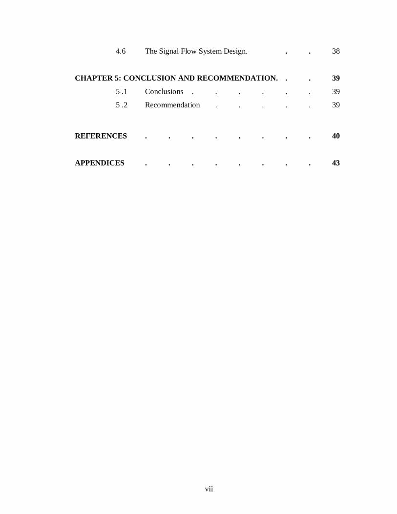
4.6 The Signal Flow System Design. . . 38
CHAPTER 5: CONCLUSION AND RECOMMENDATION. . . 39
5 .1 Conclusions . . . . . . 39
5 .2 Recommendation . . . . . 39
REFERENCES . . . . . . . . 40
APPENDICES . . . . . . . . 43
vii

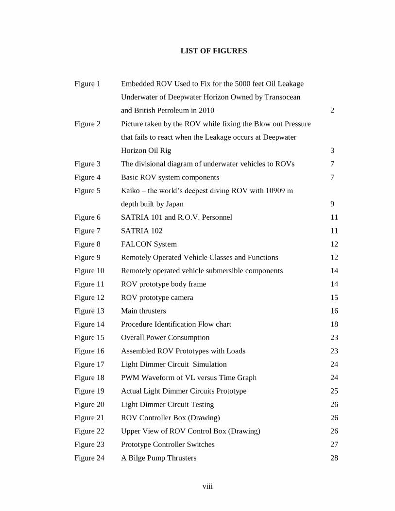
LIST OF FIGURES
Figure 1 Embedded ROV Used to Fix for the 5000 feet Oil Leakage
Underwater of Deepwater Horizon Owned by Transocean
and British Petroleum in 2010 2
Figure 2 Picture taken by the ROV while fixing the Blow out Pressure
that fails to react when the Leakage occurs at Deepwater
Horizon Oil Rig 3
Figure 3 The divisional diagram of underwater vehicles to ROVs 7
Figure 4 Basic ROV system components 7
Figure 5 Kaiko – the world‟s deepest diving ROV with 10909 m
depth built by Japan 9
Figure 6 SATRIA 101 and R.O.V. Personnel 11
Figure 7 SATRIA 102 11
Figure 8 FALCON System 12
Figure 9 Remotely Operated Vehicle Classes and Functions 12
Figure 10 Remotely operated vehicle submersible components 14
Figure 11 ROV prototype body frame 14
Figure 12 ROV prototype camera 15
Figure 13 Main thrusters 16
Figure 14 Procedure Identification Flow chart 18
Figure 15 Overall Power Consumption 23
Figure 16 Assembled ROV Prototypes with Loads 23
Figure 17 Light Dimmer Circuit Simulation 24
Figure 18 PWM Waveform of VL versus Time Graph 24
Figure 19 Actual Light Dimmer Circuits Prototype 25
Figure 20 Light Dimmer Circuit Testing 26
Figure 21 ROV Controller Box (Drawing) 26
Figure 22 Upper View of ROV Control Box (Drawing) 26
Figure 23 Prototype Controller Switches 27
Figure 24 A Bilge Pump Thrusters 28
viii
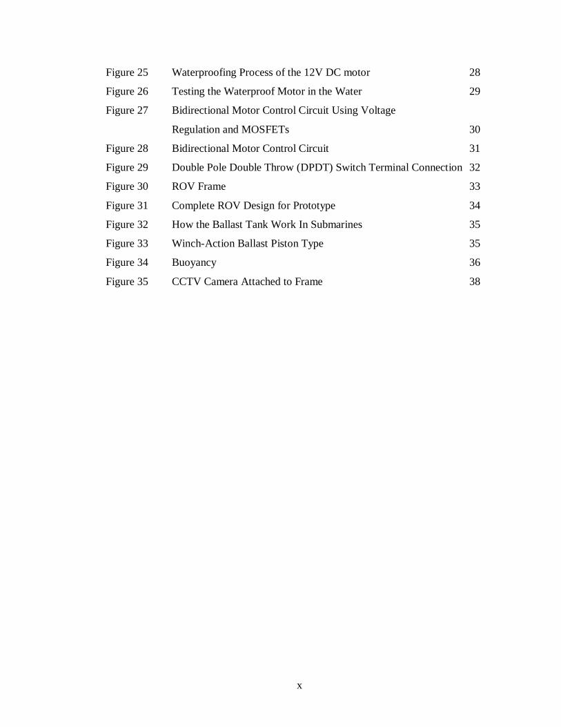
Figure 25 Waterproofing Process of the 12V DC motor 28
Figure 26 Testing the Waterproof Motor in the Water 29
Figure 27 Bidirectional Motor Control Circuit Using Voltage
Regulation and MOSFETs 30
Figure 28 Bidirectional Motor Control Circuit 31
Figure 29 Double Pole Double Throw (DPDT) Switch Terminal Connection 32
Figure 30 ROV Frame 33
Figure 31 Complete ROV Design for Prototype 34
Figure 32 How the Ballast Tank Work In Submarines 35
Figure 33 Winch-Action Ballast Piston Type 35
Figure 34 Buoyancy 36
Figure 35 CCTV Camera Attached to Frame 38
x
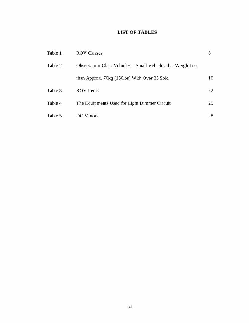
LIST OF TABLES
Table 1 ROV Classes 8
Table 2 Observation-Class Vehicles – Small Vehicles that Weigh Less
than Approx. 70kg (150lbs) With Over 25 Sold 10
Table 3 ROV Items 22
Table 4 The Equipments Used for Light Dimmer Circuit 25
Table 5 DC Motors 28
xi
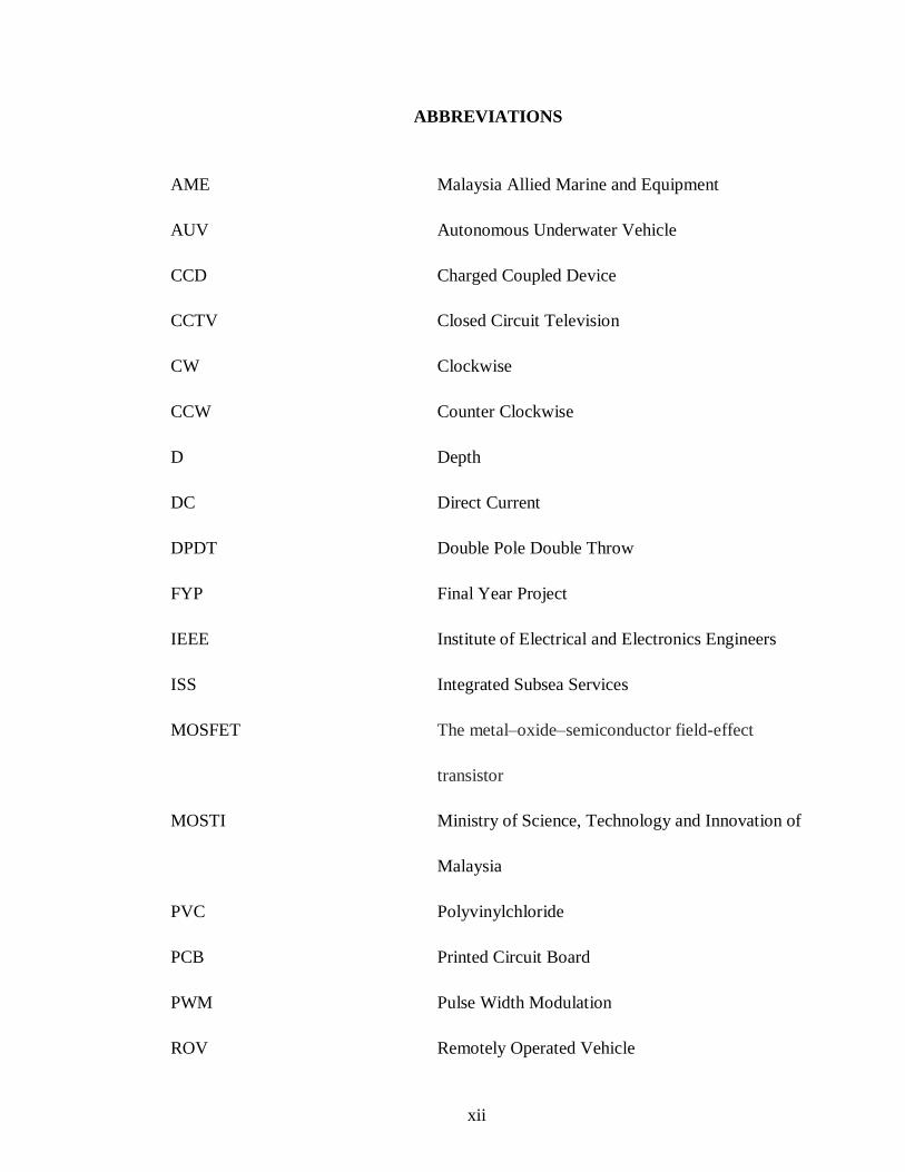
ABBREVIATIONS
AME Malaysia Allied Marine and Equipment
AUV Autonomous Underwater Vehicle
CCD Charged Coupled Device
CCTV Closed Circuit Television
CW Clockwise
CCW Counter Clockwise
D Depth
DC Direct Current
DPDT Double Pole Double Throw
FYP Final Year Project
IEEE Institute of Electrical and Electronics Engineers
ISS Integrated Subsea Services
MOSFET The metal–oxide–semiconductor field-effect
transistor
MOSTI Ministry of Science, Technology and Innovation of
Malaysia
PVC Polyvinylchloride
PCB Printed Circuit Board
PWM Pulse Width Modulation
ROV Remotely Operated Vehicle
xii
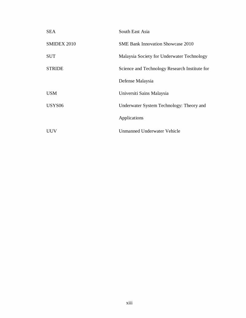
SEA South East Asia
SMIDEX 2010 SME Bank Innovation Showcase 2010
SUT Malaysia Society for Underwater Technology
STRIDE Science and Technology Research Institute for
Defense Malaysia
USM Universiti Sains Malaysia
USYS06 Underwater System Technology: Theory and
Applications
UUV Unmanned Underwater Vehicle
xiii
CHAPTER 1
INTRODUCTION
1.1 Background of study
Remotely Operated Vehicle (ROV) is a tethered underwater robot, commonly
used for the underwater tasks. ROV operation is conducted by a control box from a
remote location such as on land or on the surface of the vessel [1]. In details, basic parts
of ROV can consist of:
i. Controller and navigation circuit
ii. Thrusters for maneuvering (propulsion)
iii. Lamps
iv. Camera
v. Frame
vi. Buoyancy system
vii. Tether management
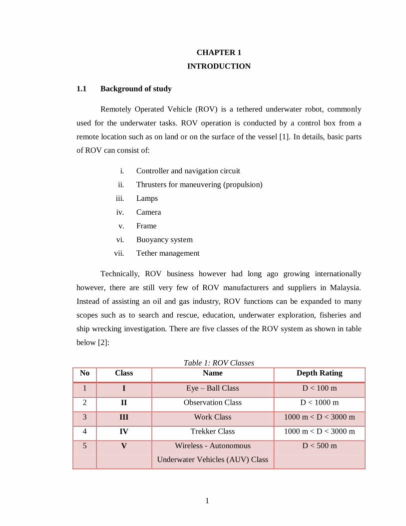
Technically, ROV business however had long ago growing internationally
however, there are still very few of ROV manufacturers and suppliers in Malaysia.
Instead of assisting an oil and gas industry, ROV functions can be expanded to many
scopes such as to search and rescue, education, underwater exploration, fisheries and
ship wrecking investigation. There are five classes of the ROV system as shown in table
below [2]:
Table 1: ROV Classes
No Class Name Depth Rating
1 I Eye – Ball Class D < 100 m
2 II Observation Class D < 1000 m
3 III Work Class 1000 m < D < 3000 m
4 IV Trekker Class 1000 m < D < 3000 m
5 V Wireless - Autonomous
Underwater Vehicles (AUV) Class
D < 500 m
1
1.2 Problem Statements
Subsea tasks and jobs are not widely known to the public as one of most famous
and important jobs. However, the fact where only people with certain skills and special
knowledge can undertake and implement underwater jobs successfully and hence,
ensuring that human life goes well. As examples, subsea jobs are said to be important
because if offers human with great values in modern technology as well as food supply,
hydrocarbon well and many others. Among the examples are:
i. Underwater electricity generation (wind and wave turbine)
ii. Exploration of oil and gas industry
iii. Fisheries industry
iv. Education
v. Discovery of earth core geology trough underwater medium
vi. Marine park and tourism
vii. Inspection of ship wreckage
viii. Marine biology and archeology
ix. Armed services and police
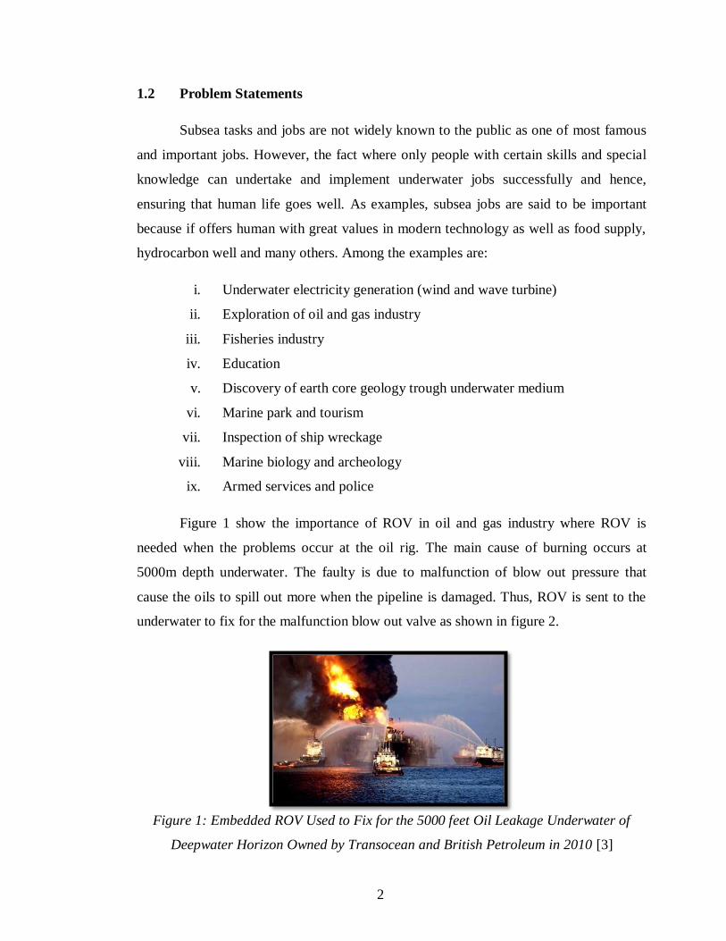
Figure 1 show the importance of ROV in oil and gas industry where ROV is
needed when the problems occur at the oil rig. The main cause of burning occurs at
5000m depth underwater. The faulty is due to malfunction of blow out pressure that
cause the oils to spill out more when the pipeline is damaged. Thus, ROV is sent to the
underwater to fix for the malfunction blow out valve as shown in figure 2.
Figure 1: Embedded ROV Used to Fix for the 5000 feet Oil Leakage Underwater of
Deepwater Horizon Owned by Transocean and British Petroleum in 2010 [3]
2
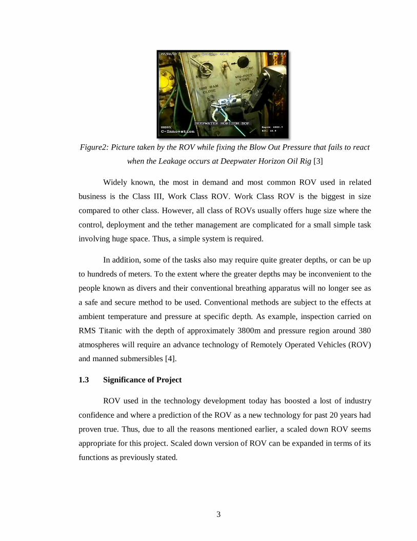
Figure2: Picture taken by the ROV while fixing the Blow Out Pressure that fails to react
when the Leakage occurs at Deepwater Horizon Oil Rig [3]
Widely known, the most in demand and most common ROV used in related
business is the Class III, Work Class ROV. Work Class ROV is the biggest in size
compared to other class. However, all class of ROVs usually offers huge size where the
control, deployment and the tether management are complicated for a small simple task
involving huge space. Thus, a simple system is required.
In addition, some of the tasks also may require quite greater depths, or can be up
to hundreds of meters. To the extent where the greater depths may be inconvenient to the
people known as divers and their conventional breathing apparatus will no longer see as
a safe and secure method to be used. Conventional methods are subject to the effects at
ambient temperature and pressure at specific depth. As example, inspection carried on
RMS Titanic with the depth of approximately 3800m and pressure region around 380
atmospheres will require an advance technology of Remotely Operated Vehicles (ROV)
and manned submersibles [4].
1.3 Significance of Project
ROV used in the technology development today has boosted a lost of industry
confidence and where a prediction of the ROV as a new technology for past 20 years had
proven true. Thus, due to all the reasons mentioned earlier, a scaled down ROV seems
appropriate for this project. Scaled down version of ROV can be expanded in terms of its
functions as previously stated.
3
The small size ROV, or ROV prototype, seems will be very useful for education
purposes where children can use the ROV prototype for exploration in rivers or lakes. As
for security industry, ROV prototype provides underwater closed-circuit television
(CCTV) security video for shipping business. In other words, it also offers a mean of
intervention, theoretically applied for all depths without any limitations. This tether
vehicle control signals and power for CCTV, lights, the propulsion and its buoyancy
system and the most important of its feature is the ability to provide human with
navigation and control.
Other than that, it will be very beneficial to the fishing industry where the
fisherman can use their own portable ROV to check for the location with high intensity
of fish population. By considering all the expanded functions of ROV, the prototype for
the Final Year Project (FYP) will be designed as portable, easy to handle and small in
size, easy enough for the user to carry around and accomplished simple tasks.
1.4 Main Objectives
i. To study and analyze ROV designs and improvised the system
ii. To develop electrical system configuration for the prototype
iii. To obtain an optimal design of ROV
1.5 Scopes of Study
The scope of this project is to understudy all the matters involve with the
designing, structuring and building the portable ROV system. After the studies has
complete, the fabricating process of the ROV prototype will be done, where the process
involve are:
i. Determination of power distribution system
ii. Navigation and control system
iii. Visual and light control system
iv. Buoyancy and propulsion system
Improvements and testing method take precedence in the end of the project.
4
1.6 Project Relevance
ROV prototype can give a lot of benefits to human being. As for achieving all the
objectives, ROV prototype is more than enough. The construction on ROV prototype can
be used for education where the children will be able to experience themselves on
maneuvering the ROV as the ROV is a tethered devices. The concept of controlling the
ROV is about the same with the controller used to the toy racing car and mini aircraft,
but it only differs in wireless control.
As for maximum of three meters depths, the material needed in order to build the
ROV might consume less cost with its basic functions stay the same. The model will also
helps a lot in fishing and in conserving the marine park activities that is crucial for the
future.
1.7 Project Feasibility
The project is planned to be done within two semesters. During the first semester,
focus will be more on the conceptual and theoretical design of the ROV, while the
second semester will be a lot more on constructing the ROV prototype according to the
design made during the first semester. Testing and improvisation of the ROV will also be
done after the construction process is done.
Furthermore, the design is focusing on the education and fisheries industry, so it
is supposedly to be used less cost as possible, but still reliable. The prototype will also
seem to be very useful in helping the students to learn the underwater scopes instead
only looking for the pictures themselves.
5
CHAPTER 2
LITERATURE REVIEW
2.1 Definition and Classification
In the advanced development of technology today, the use of robotics which is a
mixed application of mostly from mechanical and electrical area has be able to provide
humans with easiness in performing hard tasks and jobs onshore, offshore, on air and
underwater applications. However, we can see that the underwater technology and
machine has now become more interesting as the exploration of the sea is increasing and
developing.
Examples of the developing underwater technology and machines are the use of
wind and wave as renewable energy and the construction of underwater vehicles.
Underwater vehicles fall into two categories that are Unmanned Underwater Vehicles
(UUVs) and Manned Underwater Vehicles [5]. By referring to figure 3, classification of
these two categories can be further divided into the sub categories. According to
definition made by the US Navy, UUV in other terms can also be defined as
Autonomous Underwater Vehicles (AUVs) where UUV definition is;
Self-propelled submersible whose operation is either fully autonomous (pre-
programmed or real time adaptive mission control) or under minimal supervisory
control and is untethered except, possibly for data links such as a fiber optic cable. [5]
The difference between AUV and ROV is that the absence of direct hardwires
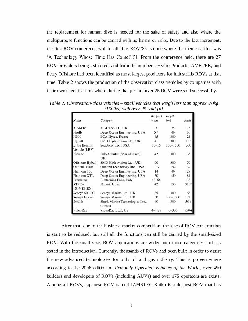
communication between the vehicle and the surface. Remotely Operated Vehicle (ROV)
is a tethered underwater robot, commonly used for the underwater jobs. A further detail
is shown in figure 4.
6
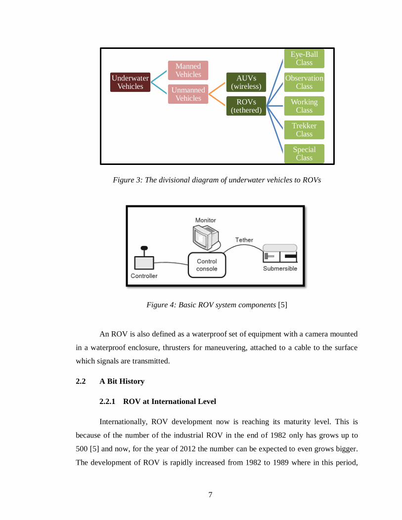
Figure 3: The divisional diagram of underwater vehicles to ROVs
Figure 4: Basic ROV system components [5]
An ROV is also defined as a waterproof set of equipment with a camera mounted
in a waterproof enclosure, thrusters for maneuvering, attached to a cable to the surface
which signals are transmitted.
2.2 A Bit History
2.2.1 ROV at International Level
Internationally, ROV development now is reaching its maturity level. This is
because of the number of the industrial ROV in the end of 1982 only has grows up to
500 [5] and now, for the year of 2012 the number can be expected to even grows bigger.
The development of ROV is rapidly increased from 1982 to 1989 where in this period,
Underwater Vehicles
Manned Vehicles
Unmanned Vehicles
AUVs (wireless)
ROVs (tethered)
Eye-Ball Class
Observation Class
Working Class
Trekker Class
Special Class
7
the replacement for human dive is needed for the sake of safety and also where the
multipurpose functions can be carried with no harms or risks. Due to the fast increment,
the first ROV conference which called as ROV‟83 is done where the theme carried was
„A Technology Whose Time Has Come!‟[5]. From the conference held, there are 27
ROV providers being exhibited, and from the numbers, Hydro Products, AMETEK, and
Perry Offshore had been identified as most largest producers for industrials ROVs at that
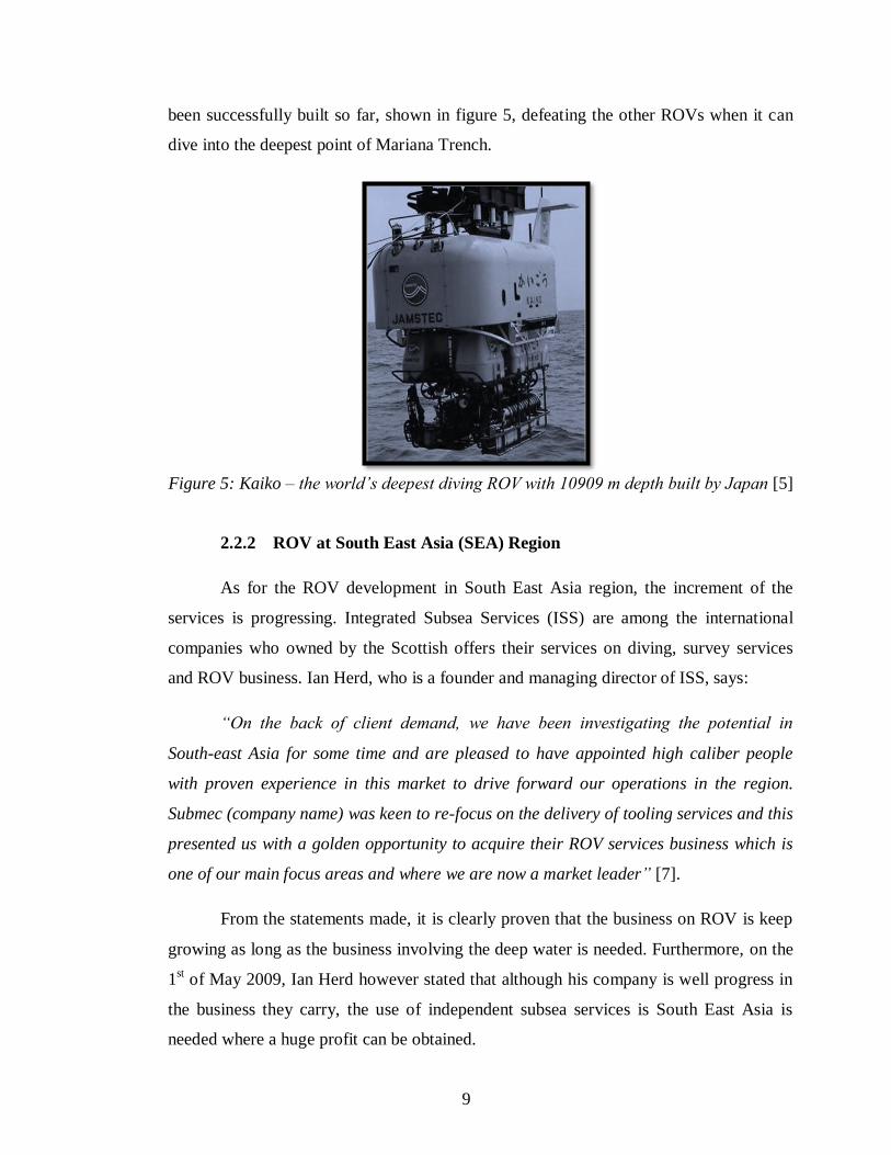
time. Table 2 shows the production of the observation class vehicles by companies with
their own specifications where during that period, over 25 ROV were sold successfully.
Table 2: Observation-class vehicles – small vehicles that weigh less than approx. 70kg
(150lbs) with over 25 sold [6]
After that, due to the business market competition, the size of ROV construction
is start to be reduced, but still all the functions can still be carried by the small-sized
ROV. With the small size, ROV applications are widen into more categories such as
stated in the introduction. Currently, thousands of ROVs had been built in order to assist
the new advanced technologies for only oil and gas industry. This is proven where
according to the 2006 edition of Remotely Operated Vehicles of the World, over 450
builders and developers of ROVs (including AUVs) and over 175 operators are exists.
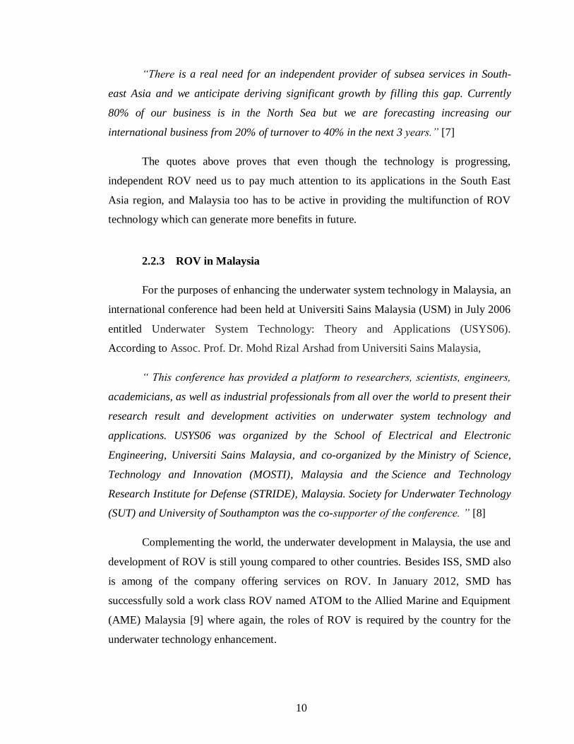
Among all ROVs, Japanese ROV named JAMSTEC Kaiko is a deepest ROV that has
8
been successfully built so far, shown in figure 5, defeating the other ROVs when it can
dive into the deepest point of Mariana Trench.
Figure 5: Kaiko – the world’s deepest diving ROV with 10909 m depth built by Japan [5]
2.2.2 ROV at South East Asia (SEA) Region
As for the ROV development in South East Asia region, the increment of the
services is progressing. Integrated Subsea Services (ISS) are among the international
companies who owned by the Scottish offers their services on diving, survey services
and ROV business. Ian Herd, who is a founder and managing director of ISS, says:
“On the back of client demand, we have been investigating the potential in
South-east Asia for some time and are pleased to have appointed high caliber people
with proven experience in this market to drive forward our operations in the region.
Submec (company name) was keen to re-focus on the delivery of tooling services and this
presented us with a golden opportunity to acquire their ROV services business which is
one of our main focus areas and where we are now a market leader” [7].
From the statements made, it is clearly proven that the business on ROV is keep
growing as long as the business involving the deep water is needed. Furthermore, on the
1st of May 2009, Ian Herd however stated that although his company is well progress in
the business they carry, the use of independent subsea services is South East Asia is
needed where a huge profit can be obtained.
9
“There is a real need for an independent provider of subsea services in South-
east Asia and we anticipate deriving significant growth by filling this gap. Currently
80% of our business is in the North Sea but we are forecasting increasing our
international business from 20% of turnover to 40% in the next 3 years.” [7]
The quotes above proves that even though the technology is progressing,
independent ROV need us to pay much attention to its applications in the South East
Asia region, and Malaysia too has to be active in providing the multifunction of ROV
technology which can generate more benefits in future.
2.2.3 ROV in Malaysia
For the purposes of enhancing the underwater system technology in Malaysia, an
international conference had been held at Universiti Sains Malaysia (USM) in July 2006
entitled Underwater System Technology: Theory and Applications (USYS06).
According to Assoc. Prof. Dr. Mohd Rizal Arshad from Universiti Sains Malaysia,
“ This conference has provided a platform to researchers, scientists, engineers,
academicians, as well as industrial professionals from all over the world to present their
research result and development activities on underwater system technology and
applications. USYS06 was organized by the School of Electrical and Electronic
Engineering, Universiti Sains Malaysia, and co-organized by the Ministry of Science,
Technology and Innovation (MOSTI), Malaysia and the Science and Technology
Research Institute for Defense (STRIDE), Malaysia. Society for Underwater Technology
(SUT) and University of Southampton was the co-supporter of the conference. ” [8]
Complementing the world, the underwater development in Malaysia, the use and
development of ROV is still young compared to other countries. Besides ISS, SMD also
is among of the company offering services on ROV. In January 2012, SMD has
successfully sold a work class ROV named ATOM to the Allied Marine and Equipment
(AME) Malaysia [9] where again, the roles of ROV is required by the country for the
underwater technology enhancement.
10
At present, there are only few companies in Malaysia that are responsible for
ROV and AUV services and productions. They are Subsea Explore Services (M) Sdn.
Bhd. and ROV Resources (M) Sdn. Bhd.. Most of the project studies on ROV systems
and construction are based on first Malaysian companies in ROV business that is Subsea
Explore Services (M) Sdn. Bhd. and various articles and research available in the
internet. Subsea Explore Services (M) Sdn. Bhd. is pioneered in 2005 where it
manufactures very own Malaysia ROV of Work Class, Class III [10]. The company
however mainly focuses on manufacturing world class ROV, provides the services and
also in house trainings for ROV pilots and technicians.
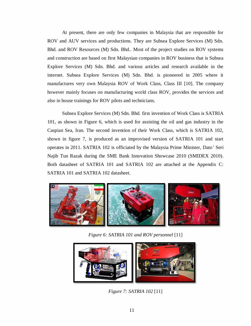
Subsea Explore Services (M) Sdn. Bhd. first invention of Work Class is SATRIA
101, as shown in Figure 6, which is used for assisting the oil and gas industry in the
Caspian Sea, Iran. The second invention of their Work Class, which is SATRIA 102,
shown in figure 7, is produced as an improvised version of SATRIA 101 and start
operates in 2011. SATRIA 102 is officiated by the Malaysia Prime Minister, Dato‟ Seri
Najib Tun Razak during the SME Bank Innovation Showcase 2010 (SMIDEX 2010).
Both datasheet of SATRIA 101 and SATRIA 102 are attached at the Appendix C:
SATRIA 101 and SATRIA 102 datasheet.
Figure 6: SATRIA 101 and ROV personnel [11]
Figure 7: SATRIA 102 [11]
11
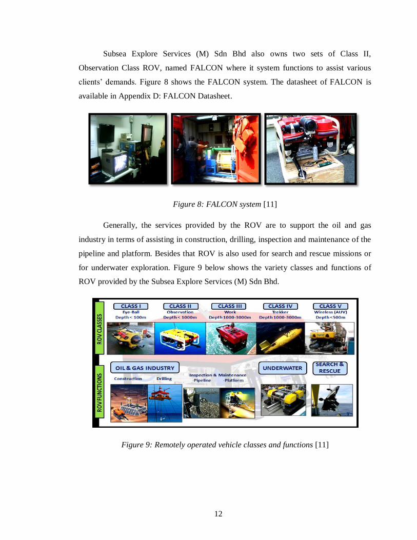
Subsea Explore Services (M) Sdn Bhd also owns two sets of Class II,
Observation Class ROV, named FALCON where it system functions to assist various
clients‟ demands. Figure 8 shows the FALCON system. The datasheet of FALCON is
available in Appendix D: FALCON Datasheet.
Figure 8: FALCON system [11]
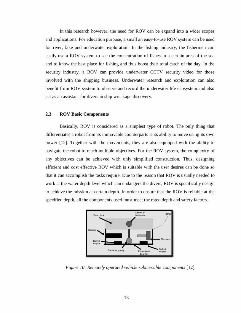
Generally, the services provided by the ROV are to support the oil and gas
industry in terms of assisting in construction, drilling, inspection and maintenance of the
pipeline and platform. Besides that ROV is also used for search and rescue missions or
for underwater exploration. Figure 9 below shows the variety classes and functions of
ROV provided by the Subsea Explore Services (M) Sdn Bhd.
Figure 9: Remotely operated vehicle classes and functions [11]
12
In this research however, the need for ROV can be expand into a wider scopes
and applications. For education purpose, a small an easy-to-use ROV system can be used
for river, lake and underwater exploration. In the fishing industry, the fishermen can
easily use a ROV system to see the concentration of fishes in a certain area of the sea
and to know the best place for fishing and thus boost their total catch of the day. In the
security industry, a ROV can provide underwater CCTV security video for those
involved with the shipping business. Underwater research and exploration can also
benefit from ROV system to observe and record the underwater life ecosystem and also
act as an assistant for divers in ship wreckage discovery.
2.3 ROV Basic Components
Basically, ROV is considered as a simplest type of robot. The only thing that
differentiates a robot from its immovable counterparts is its ability to move using its own
power [12]. Together with the movements, they are also equipped with the ability to
navigate the robot to reach multiple objectives. For the ROV system, the complexity of
any objectives can be achieved with only simplified construction. Thus, designing
efficient and cost effective ROV which is suitable with the user desires can be done so
that it can accomplish the tasks require. Due to the reason that ROV is usually needed to
work at the water depth level which can endangers the divers, ROV is specifically design
to achieve the mission at certain depth. In order to ensure that the ROV is reliable at the
specified depth, all the components used must meet the rated depth and safety factors.
Figure 10: Remotely operated vehicle submersible components [12]
13
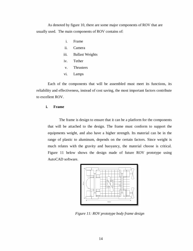
As denoted by figure 10, there are some major components of ROV that are
usually used. The main components of ROV contains of:
i. Frame
ii. Camera
iii. Ballast Weights
iv. Tether
v. Thrusters
vi. Lamps
Each of the components that will be assembled must meet its functions, its
reliability and effectiveness, instead of cost saving, the most important factors contribute
to excellent ROV.
i. Frame
The frame is design to ensure that it can be a platform for the components
that will be attached to the design. The frame must conform to support the
equipments weight, and also have a higher strength. Its material can be in the
range of plastic to aluminum, depends on the certain factors. Since weight is
much relates with the gravity and buoyancy, the material choose is critical.
Figure 11 below shows the design made of future ROV prototype using
AutoCAD software.
Figure 11: ROV prototype body frame design
14
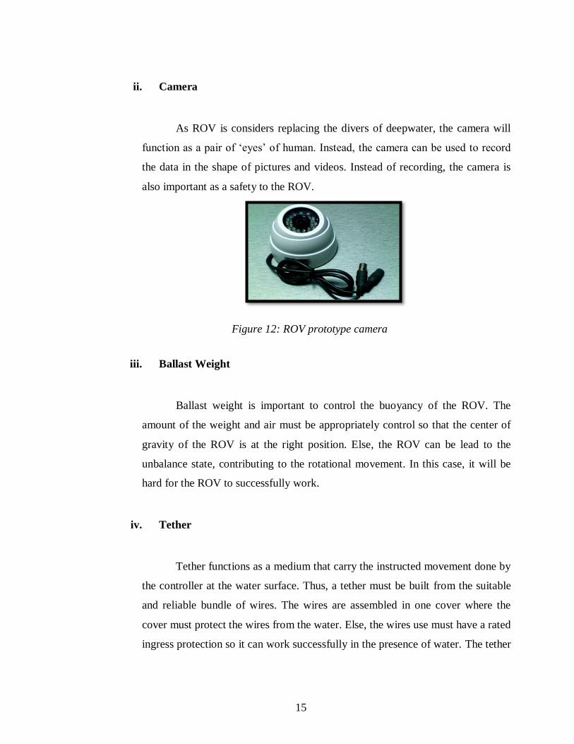
ii. Camera
As ROV is considers replacing the divers of deepwater, the camera will
function as a pair of „eyes‟ of human. Instead, the camera can be used to record
the data in the shape of pictures and videos. Instead of recording, the camera is
also important as a safety to the ROV.
Figure 12: ROV prototype camera
iii. Ballast Weight
Ballast weight is important to control the buoyancy of the ROV. The
amount of the weight and air must be appropriately control so that the center of
gravity of the ROV is at the right position. Else, the ROV can be lead to the
unbalance state, contributing to the rotational movement. In this case, it will be
hard for the ROV to successfully work.
iv. Tether
Tether functions as a medium that carry the instructed movement done by
the controller at the water surface. Thus, a tether must be built from the suitable
and reliable bundle of wires. The wires are assembled in one cover where the
cover must protect the wires from the water. Else, the wires use must have a rated
ingress protection so it can work successfully in the presence of water. The tether
15
must also be managed to protect the wires from scratch. Thus, strong, light and
flexible material must be chosen as best option of wire characteristics.
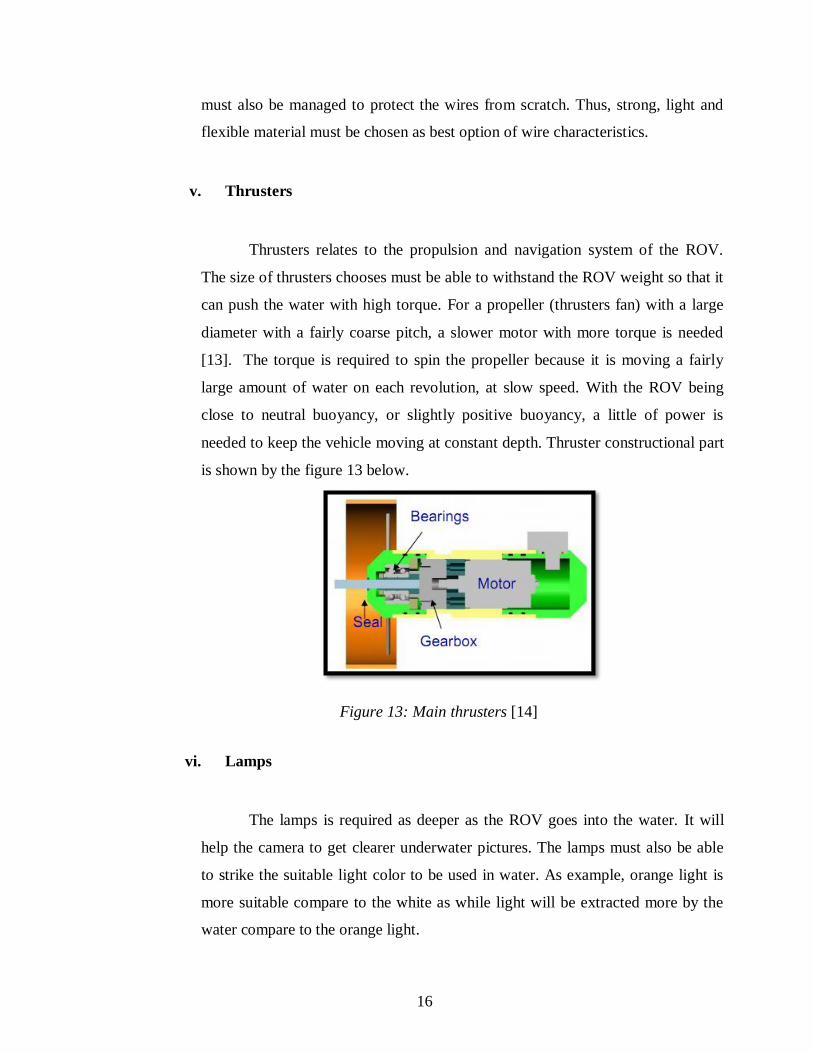
v. Thrusters
Thrusters relates to the propulsion and navigation system of the ROV.
The size of thrusters chooses must be able to withstand the ROV weight so that it
can push the water with high torque. For a propeller (thrusters fan) with a large
diameter with a fairly coarse pitch, a slower motor with more torque is needed
[13]. The torque is required to spin the propeller because it is moving a fairly
large amount of water on each revolution, at slow speed. With the ROV being
close to neutral buoyancy, or slightly positive buoyancy, a little of power is
needed to keep the vehicle moving at constant depth. Thruster constructional part
is shown by the figure 13 below.
Figure 13: Main thrusters [14]
vi. Lamps
The lamps is required as deeper as the ROV goes into the water. It will
help the camera to get clearer underwater pictures. The lamps must also be able
to strike the suitable light color to be used in water. As example, orange light is
more suitable compare to the white as while light will be extracted more by the
water compare to the orange light.
16
CHAPTER 3
METHODOLOGY
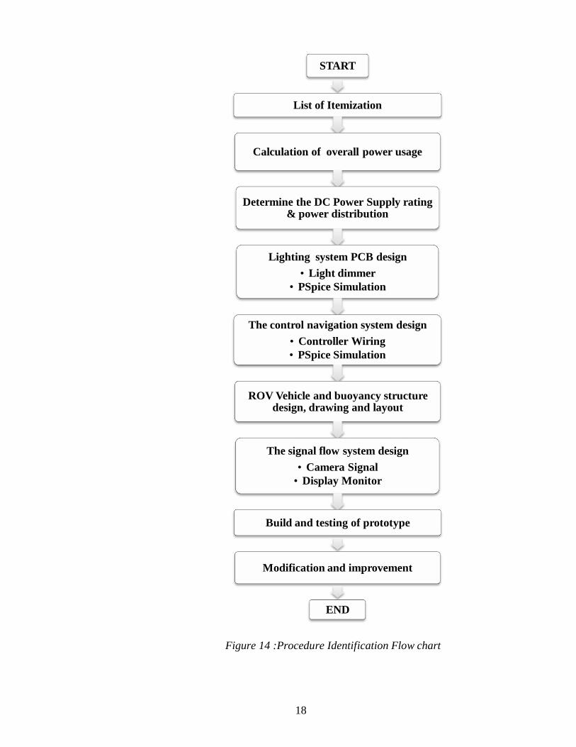
3.1 Procedure Identification
To ensure that the project is successfully completed, it is to be sure that all the
objectives can be accomplished. For the process of accomplishing the project, the
famous procedure of applying a flow chart method is applied and shown as in figure 14.
Financial review of all equipments and itemization needed is constructed so that
it meets the FYP budget estimation. As for the itemization process, the main parts
identified are thrusters with its motors, power supply, lighting system, camera, the
control screen, umbilical cord, buoyancy and control system.
Determination of the power supply needed can be find from the total power
consumed by all equipments in the design. As for the lighting system, a circuit which can
control the intensity of the light, called light dimmer circuit, must be design.
The intensity of the light and the movement of the thrusters must be able to be
controlled by the control navigation system design. By using PSpice software, the
obtained circuits can be simulated and modified accordingly. Then, the signal flow
system design, the ROV and its buoyancy structure designs drawings and layouts will be
carrying out.
In the end, the completed prototype will be tested and any improvements or
adjustments must be carried out.
17
START
List of Itemization
Calculation of overall power usage
Determine the DC Power Supply rating & power distribution
Lighting system PCB design
• Light dimmer
• PSpice Simulation
The control navigation system design
• Controller Wiring
• PSpice Simulation
ROV Vehicle and buoyancy structure design, drawing and layout
The signal flow system design
• Camera Signal
• Display Monitor
Build and testing of prototype
Modification and improvement
END
Figure 14 :Procedure Identification Flow chart
18
3.1.1 List of Itemization
Firstly, after all information is gathered, list of itemization is made. All
possible equipments that can contribute to the reliability, suitability and cost
efficient to the prototype is listing and choose.
3.1.2 Calculation of Overall Power Usage
When the items to be used are decided, the overall power usage is
determine by calculating the rated power use by each items. As example, power
consume by the lighting system is determine by calculating the current need
multiply with the voltage supply. Same method applies to the other devices.
3.1.3 Determine the DC Power Supply Rating and Power Distribution
When all power usages is determine, the suitable DC Power Supply rating
and power distribution is decided. In this case, DC power supply is use instead of
AC Power Supply because it will be simpler and easier for the portable ROV to
use battery instead of power supply by the generator.
3.1.4 Lighting System PCB Design
There are two things to be done which is first is to design a light dimmer
circuit using the PSpice simulations and second, build the circuits.
3.1.5 The Control Navigation System Design
Same as lighting system, control navigation system design will also
require simulation by PSpice software. Controller wiring diagram will be drawn
and tested as a control box for the operational purposes.
19
3.1.6 ROV Vehicle Structure and Buoyancy Design, Drawing and Layout
As soon as each parts of the prototype are theoretically determined, the
designs in shape of drawings are made using AutoCAD software. Drawings must
be done according to the specifications and ensure that right parameters such as
length is designed.
3.1.7 The Signal Flow System Design
As for the signal flow system design, camera signals will need to be sent
to the display monitor so each image underwater can be captured. Suitable
camera that meets the requirements of the project and budget is determined.
3.1.8 Build and Testing of Prototype
Surely after all other devices are set up and configures, the project can be
start by building and testing the project outside, and within the water. Control and
navigation system will be test so as lighting and propulsion system of the ROV
prototype.
3.1.9 Modification and Improvement
Last but not least, modifications, adjustments and improvements will be
done as to ensure that the objectives of the project are met. As the model is
considers as prototype, many improvements can be done to further expand the
ROV prototype functions.
20
3.2 Tools and Software
The list of tools and equipments that is used for this ROV prototype is listed as
below:
i. 12V DC Power Supply
ii. 12V DC Torchlight
iii. 12V DC Motor
iv. 12V CCTV Camera
v. PVC Pipes
vi. PTFE Tapes
vii. Electrical Tape
viii. Water Resistant Glue
ix. Soldering Kit
x. Cable Tie
xi. Controller Box
xii. Bottles
xiii. Wire Cover
As for the software used:
i. Microsoft Visio (drawings)
ii. AutoCAD (drawings)
iii. PSpice Software (circuit simulation)
21
CHAPTER 4
RESULTS AND DISCUSSION
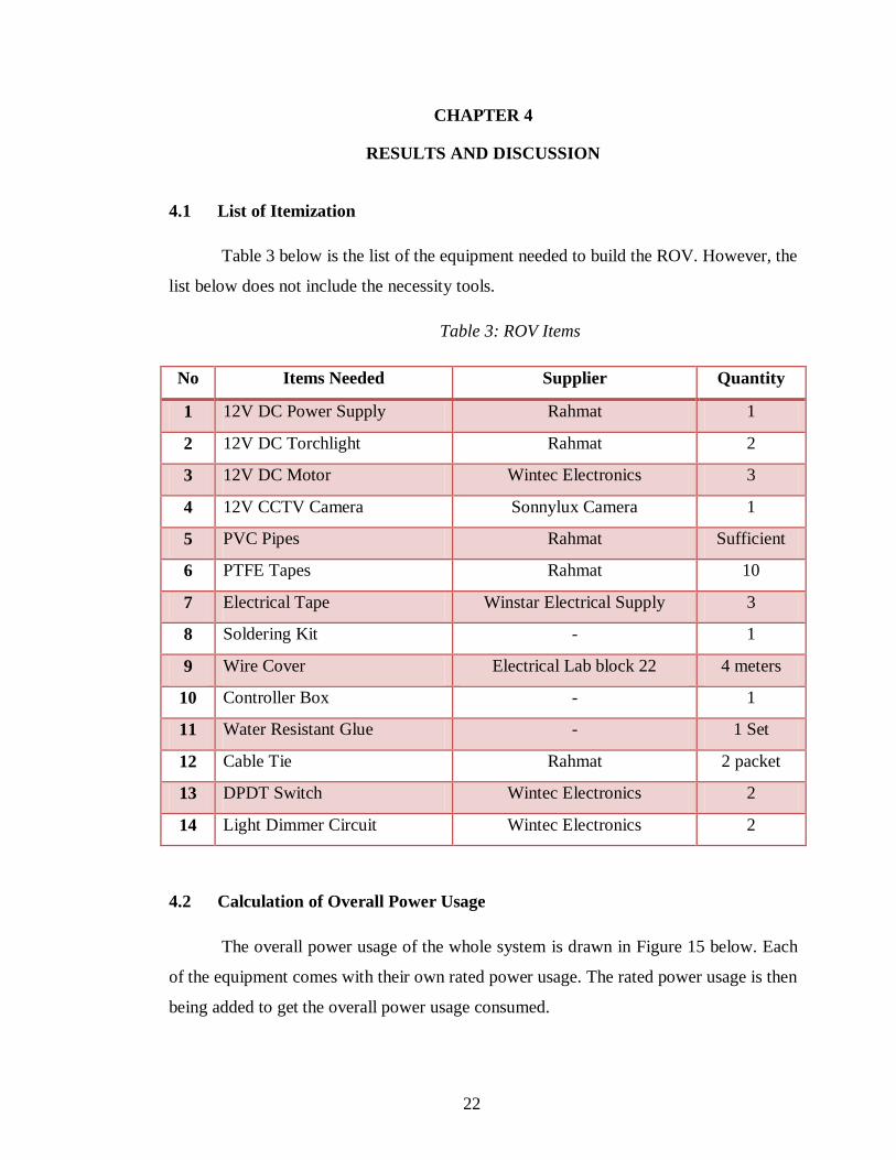
4.1 List of Itemization
Table 3 below is the list of the equipment needed to build the ROV. However, the
list below does not include the necessity tools.
Table 3: ROV Items
No Items Needed Supplier Quantity
1 12V DC Power Supply Rahmat 1
2 12V DC Torchlight Rahmat 2
3 12V DC Motor Wintec Electronics 3
4 12V CCTV Camera Sonnylux Camera 1
5 PVC Pipes Rahmat Sufficient
6 PTFE Tapes Rahmat 10
7 Electrical Tape Winstar Electrical Supply 3
8 Soldering Kit - 1
9 Wire Cover Electrical Lab block 22 4 meters
10 Controller Box - 1
11 Water Resistant Glue - 1 Set
12 Cable Tie Rahmat 2 packet
13 DPDT Switch Wintec Electronics 2
14 Light Dimmer Circuit Wintec Electronics 2
4.2 Calculation of Overall Power Usage
The overall power usage of the whole system is drawn in Figure 15 below. Each
of the equipment comes with their own rated power usage. The rated power usage is then
being added to get the overall power usage consumed.
22
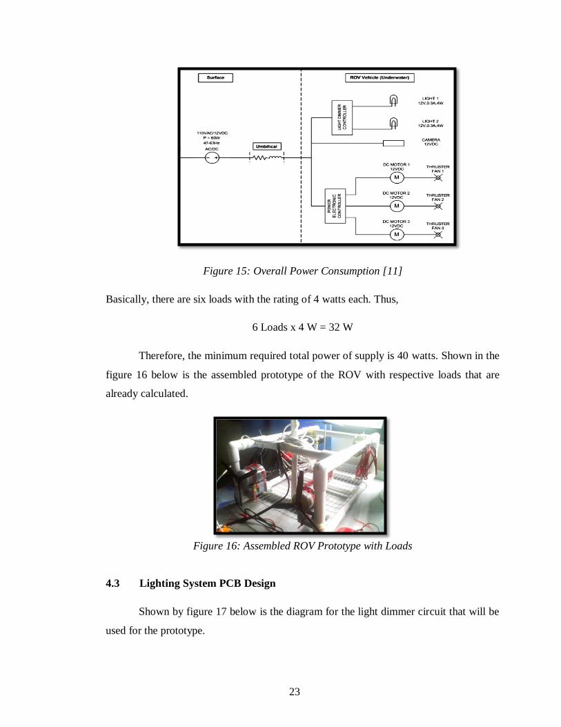
Figure 15: Overall Power Consumption [11]
Basically, there are six loads with the rating of 4 watts each. Thus,
6 Loads x 4 W = 32 W
Therefore, the minimum required total power of supply is 40 watts. Shown in the
figure 16 below is the assembled prototype of the ROV with respective loads that are
already calculated.
Figure 16: Assembled ROV Prototype with Loads
4.3 Lighting System PCB Design
Shown by figure 17 below is the diagram for the light dimmer circuit that will be
used for the prototype.
23
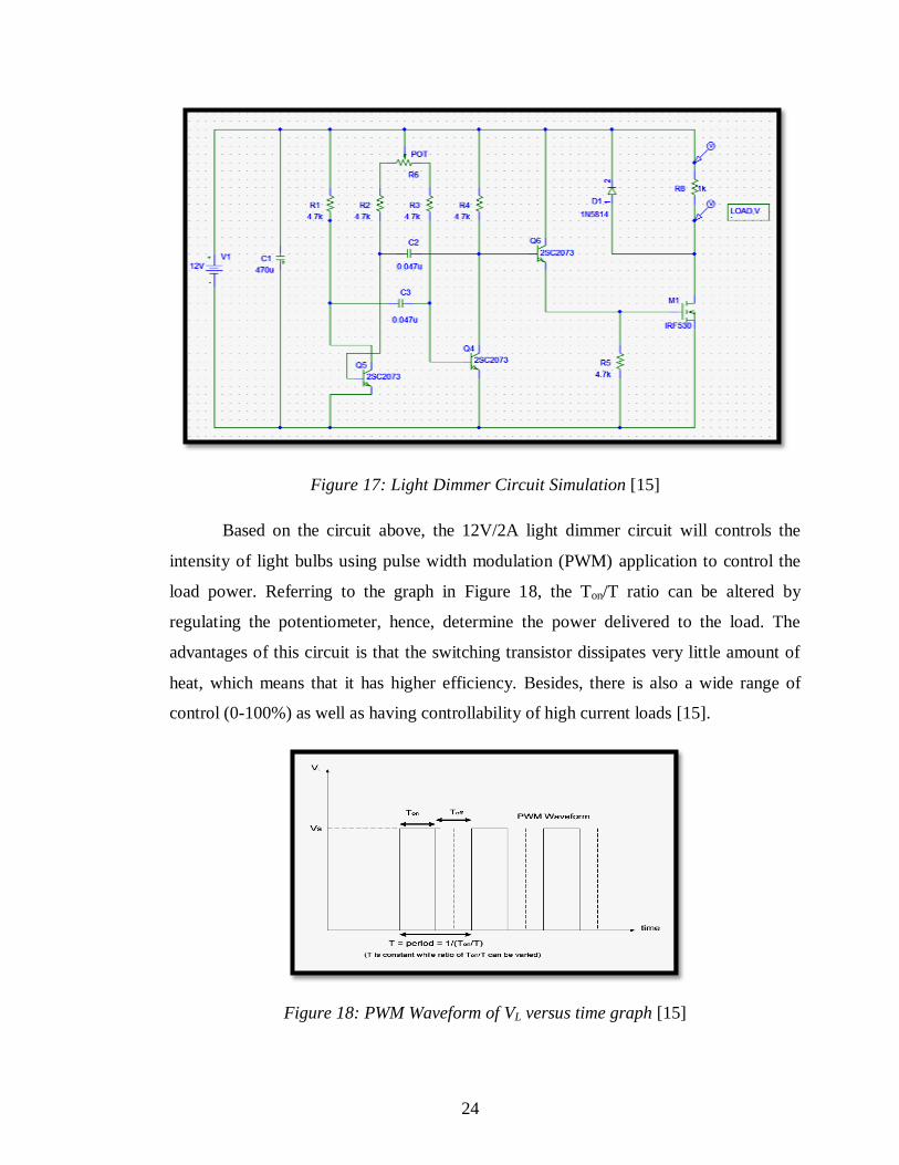
Figure 17: Light Dimmer Circuit Simulation [15]
Based on the circuit above, the 12V/2A light dimmer circuit will controls the
intensity of light bulbs using pulse width modulation (PWM) application to control the
load power. Referring to the graph in Figure 18, the Ton/T ratio can be altered by
regulating the potentiometer, hence, determine the power delivered to the load. The
advantages of this circuit is that the switching transistor dissipates very little amount of
heat, which means that it has higher efficiency. Besides, there is also a wide range of
control (0-100%) as well as having controllability of high current loads [15].
Figure 18: PWM Waveform of VL versus time graph [15]
24
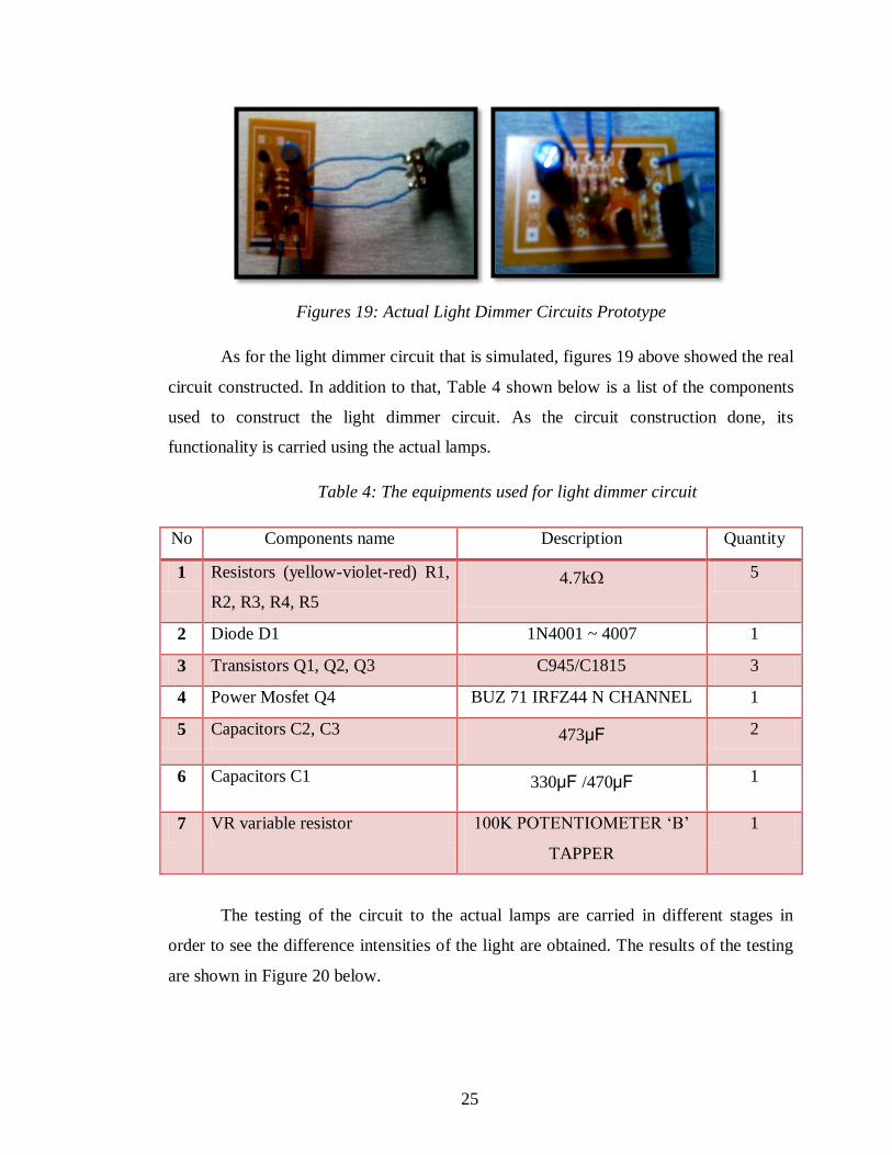
Figures 19: Actual Light Dimmer Circuits Prototype
As for the light dimmer circuit that is simulated, figures 19 above showed the real
circuit constructed. In addition to that, Table 4 shown below is a list of the components
used to construct the light dimmer circuit. As the circuit construction done, its
functionality is carried using the actual lamps.
Table 4: The equipments used for light dimmer circuit
No Components name Description Quantity
1 Resistors (yellow-violet-red) R1,
R2, R3, R4, R5
4.7kΩ 5
2 Diode D1 1N4001 ~ 4007 1
3 Transistors Q1, Q2, Q3 C945/C1815 3
4 Power Mosfet Q4 BUZ 71 IRFZ44 N CHANNEL 1
5 Capacitors C2, C3 473μF 2
6 Capacitors C1 330μF /470μF 1
7 VR variable resistor 100K POTENTIOMETER „B‟
TAPPER
1
The testing of the circuit to the actual lamps are carried in different stages in
order to see the difference intensities of the light are obtained. The results of the testing
are shown in Figure 20 below.
25
Figures 20: Light Dimmer Circuit Testing [11]
4.4 The Control Navigation System Design
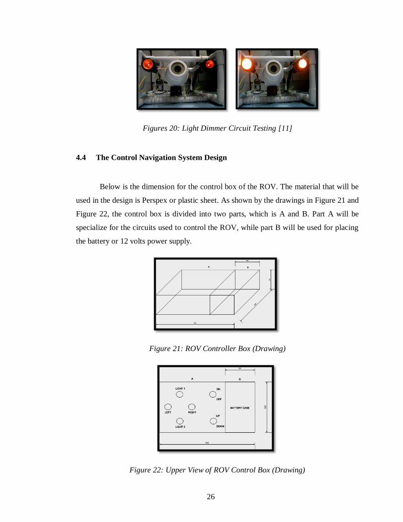
Below is the dimension for the control box of the ROV. The material that will be
used in the design is Perspex or plastic sheet. As shown by the drawings in Figure 21 and
Figure 22, the control box is divided into two parts, which is A and B. Part A will be
specialize for the circuits used to control the ROV, while part B will be used for placing
the battery or 12 volts power supply.
Figure 21: ROV Controller Box (Drawing)
Figure 22: Upper View of ROV Control Box (Drawing)
26
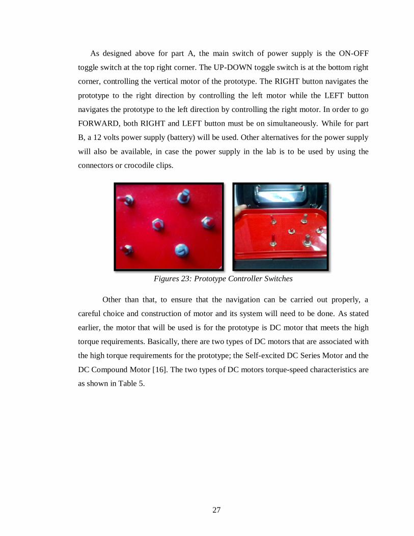
As designed above for part A, the main switch of power supply is the ON-OFF
toggle switch at the top right corner. The UP-DOWN toggle switch is at the bottom right
corner, controlling the vertical motor of the prototype. The RIGHT button navigates the
prototype to the right direction by controlling the left motor while the LEFT button
navigates the prototype to the left direction by controlling the right motor. In order to go
FORWARD, both RIGHT and LEFT button must be on simultaneously. While for part
B, a 12 volts power supply (battery) will be used. Other alternatives for the power supply
will also be available, in case the power supply in the lab is to be used by using the
connectors or crocodile clips.
Figures 23: Prototype Controller Switches
Other than that, to ensure that the navigation can be carried out properly, a
careful choice and construction of motor and its system will need to be done. As stated
earlier, the motor that will be used is for the prototype is DC motor that meets the high
torque requirements. Basically, there are two types of DC motors that are associated with
the high torque requirements for the prototype; the Self-excited DC Series Motor and the
DC Compound Motor [16]. The two types of DC motors torque-speed characteristics are
as shown in Table 5.
27
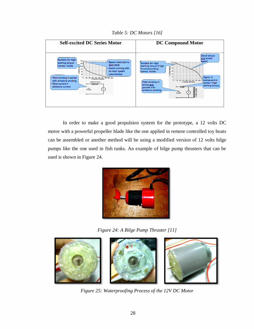
Table 5: DC Motors [16]
Self-excited DC Series Motor DC Compound Motor
In order to make a good propulsion system for the prototype, a 12 volts DC
motor with a powerful propeller blade like the one applied in remote controlled toy boats
can be assembled or another method will be using a modified version of 12 volts bilge
pumps like the one used in fish tanks. An example of bilge pump thrusters that can be
used is shown in Figure 24.
Figure 24: A Bilge Pump Thruster [11]
Figure 25: Waterproofing Process of the 12V DC Motor
28
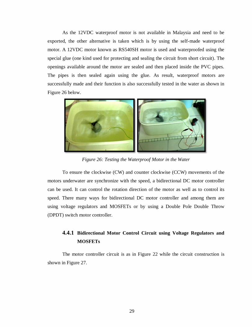
As the 12VDC waterproof motor is not available in Malaysia and need to be
exported, the other alternative is taken which is by using the self-made waterproof
motor. A 12VDC motor known as RS540SH motor is used and waterproofed using the
special glue (one kind used for protecting and sealing the circuit from short circuit). The
openings available around the motor are sealed and then placed inside the PVC pipes.
The pipes is then sealed again using the glue. As result, waterproof motors are
successfully made and their function is also successfully tested in the water as shown in
Figure 26 below.
Figure 26: Testing the Waterproof Motor in the Water
To ensure the clockwise (CW) and counter clockwise (CCW) movements of the
motors underwater are synchronize with the speed, a bidirectional DC motor controller
can be used. It can control the rotation direction of the motor as well as to control its
speed. There many ways for bidirectional DC motor controller and among them are
using voltage regulators and MOSFETs or by using a Double Pole Double Throw
(DPDT) switch motor controller.
4.4.1 Bidirectional Motor Control Circuit using Voltage Regulators and
MOSFETs
The motor controller circuit is as in Figure 22 while the circuit construction is
shown in Figure 27.
29
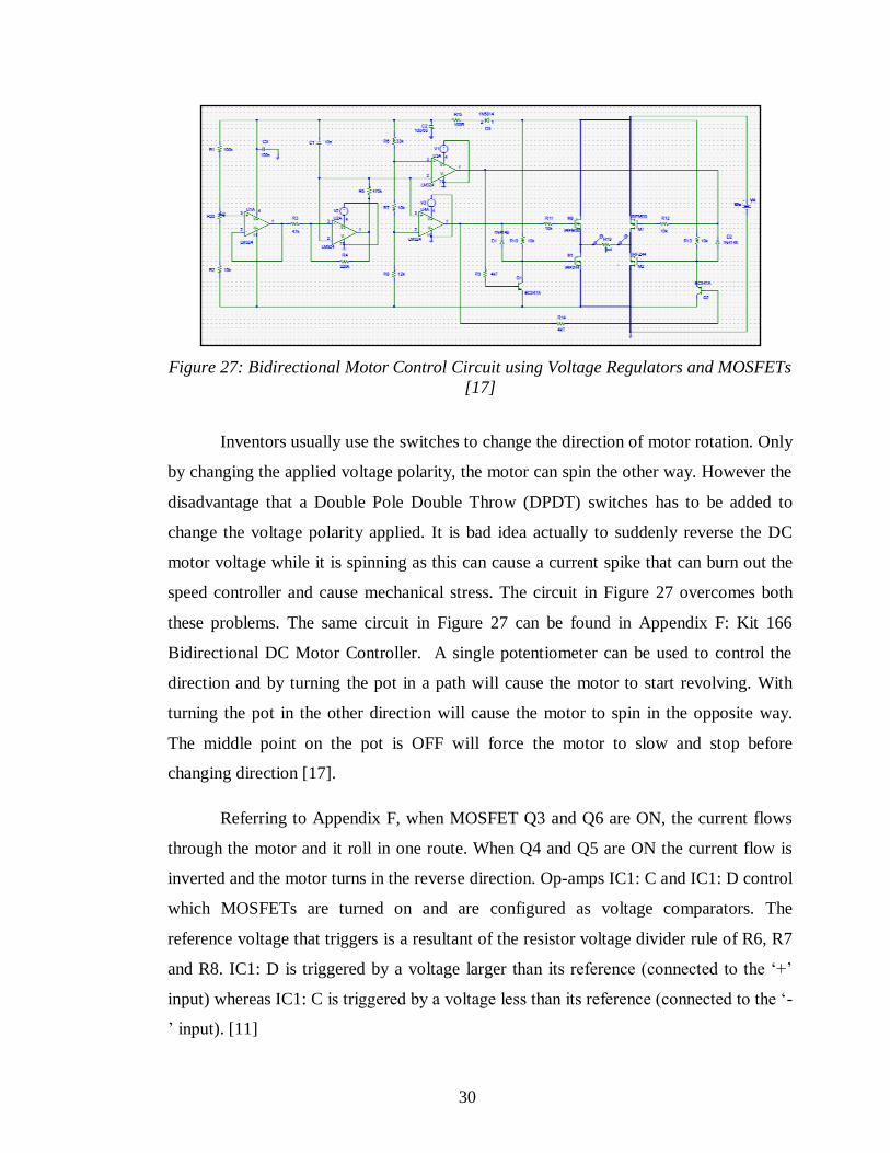
Figure 27: Bidirectional Motor Control Circuit using Voltage Regulators and MOSFETs
[17]
Inventors usually use the switches to change the direction of motor rotation. Only
by changing the applied voltage polarity, the motor can spin the other way. However the
disadvantage that a Double Pole Double Throw (DPDT) switches has to be added to
change the voltage polarity applied. It is bad idea actually to suddenly reverse the DC
motor voltage while it is spinning as this can cause a current spike that can burn out the
speed controller and cause mechanical stress. The circuit in Figure 27 overcomes both
these problems. The same circuit in Figure 27 can be found in Appendix F: Kit 166
Bidirectional DC Motor Controller. A single potentiometer can be used to control the
direction and by turning the pot in a path will cause the motor to start revolving. With
turning the pot in the other direction will cause the motor to spin in the opposite way.
The middle point on the pot is OFF will force the motor to slow and stop before
changing direction [17].
Referring to Appendix F, when MOSFET Q3 and Q6 are ON, the current flows
through the motor and it roll in one route. When Q4 and Q5 are ON the current flow is
inverted and the motor turns in the reverse direction. Op-amps IC1: C and IC1: D control
which MOSFETs are turned on and are configured as voltage comparators. The
reference voltage that triggers is a resultant of the resistor voltage divider rule of R6, R7
and R8. IC1: D is triggered by a voltage larger than its reference (connected to the „+‟
input) whereas IC1: C is triggered by a voltage less than its reference (connected to the „-
‟ input). [11]
30
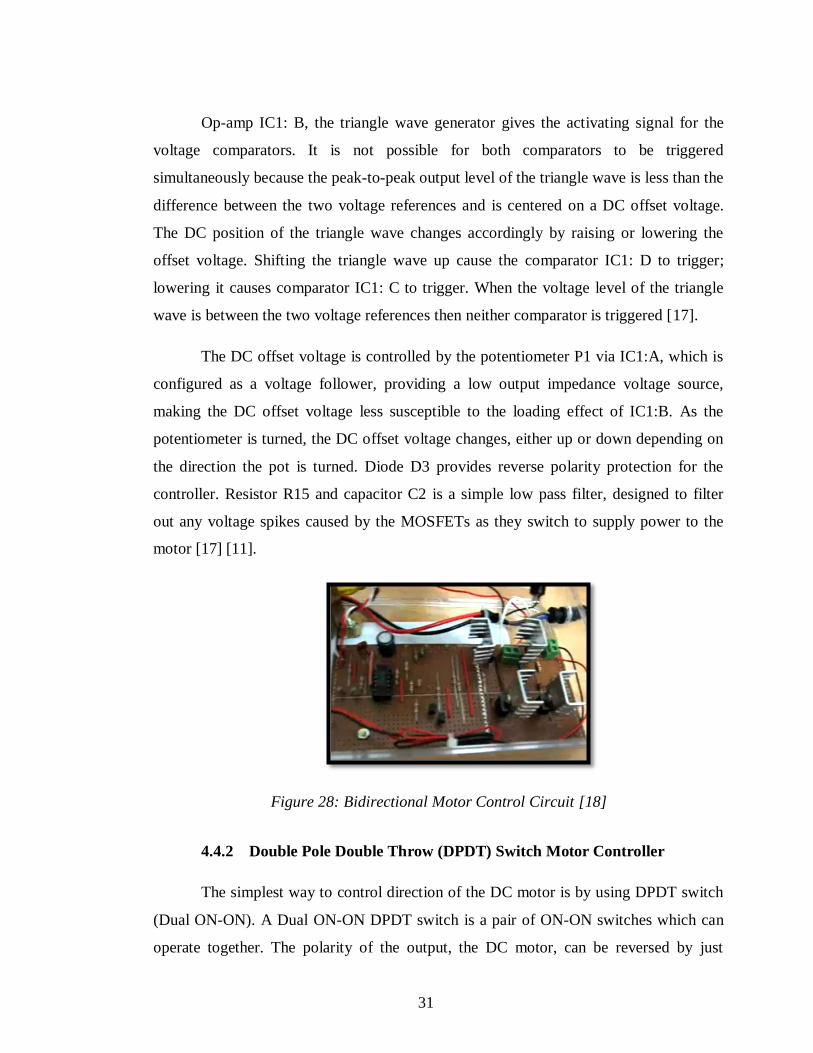
Op-amp IC1: B, the triangle wave generator gives the activating signal for the
voltage comparators. It is not possible for both comparators to be triggered
simultaneously because the peak-to-peak output level of the triangle wave is less than the
difference between the two voltage references and is centered on a DC offset voltage.
The DC position of the triangle wave changes accordingly by raising or lowering the
offset voltage. Shifting the triangle wave up cause the comparator IC1: D to trigger;
lowering it causes comparator IC1: C to trigger. When the voltage level of the triangle
wave is between the two voltage references then neither comparator is triggered [17].
The DC offset voltage is controlled by the potentiometer P1 via IC1:A, which is
configured as a voltage follower, providing a low output impedance voltage source,
making the DC offset voltage less susceptible to the loading effect of IC1:B. As the
potentiometer is turned, the DC offset voltage changes, either up or down depending on
the direction the pot is turned. Diode D3 provides reverse polarity protection for the
controller. Resistor R15 and capacitor C2 is a simple low pass filter, designed to filter
out any voltage spikes caused by the MOSFETs as they switch to supply power to the
motor [17] [11].
Figure 28: Bidirectional Motor Control Circuit [18]
4.4.2 Double Pole Double Throw (DPDT) Switch Motor Controller
The simplest way to control direction of the DC motor is by using DPDT switch
(Dual ON-ON). A Dual ON-ON DPDT switch is a pair of ON-ON switches which can
operate together. The polarity of the output, the DC motor, can be reversed by just
31
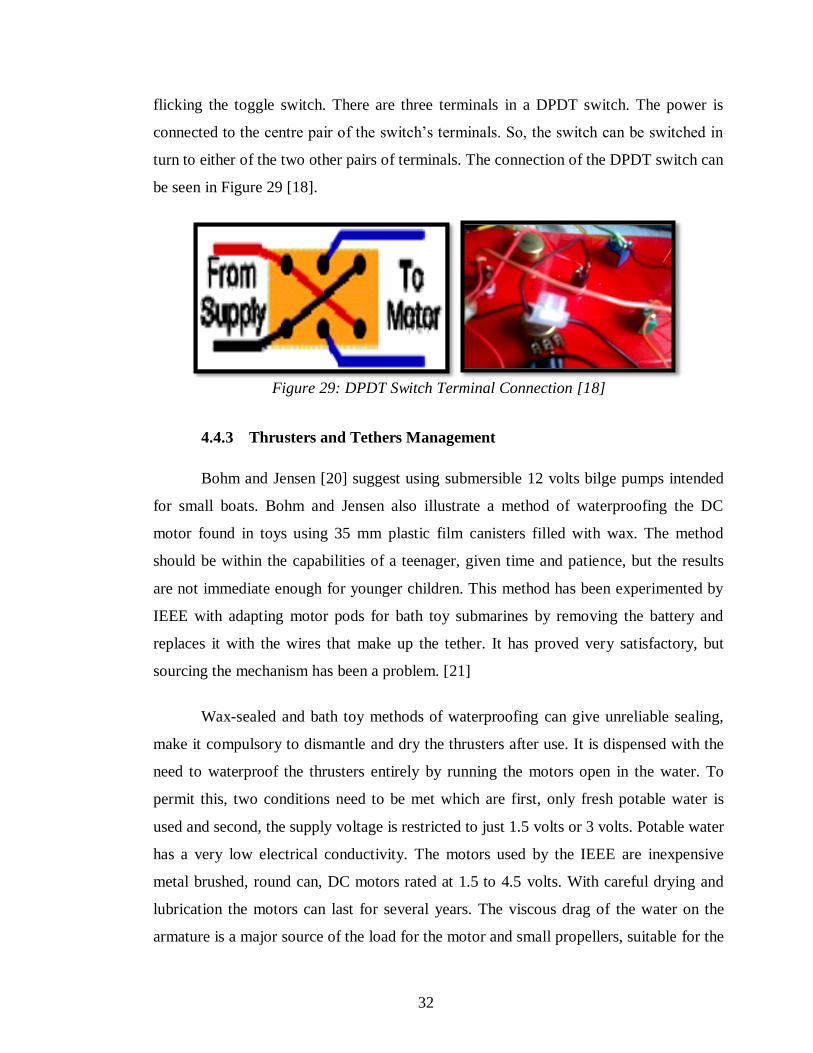
flicking the toggle switch. There are three terminals in a DPDT switch. The power is
connected to the centre pair of the switch‟s terminals. So, the switch can be switched in
turn to either of the two other pairs of terminals. The connection of the DPDT switch can
be seen in Figure 29 [18].
Figure 29: DPDT Switch Terminal Connection [18]
4.4.3 Thrusters and Tethers Management
Bohm and Jensen [20] suggest using submersible 12 volts bilge pumps intended
for small boats. Bohm and Jensen also illustrate a method of waterproofing the DC
motor found in toys using 35 mm plastic film canisters filled with wax. The method
should be within the capabilities of a teenager, given time and patience, but the results
are not immediate enough for younger children. This method has been experimented by
IEEE with adapting motor pods for bath toy submarines by removing the battery and
replaces it with the wires that make up the tether. It has proved very satisfactory, but
sourcing the mechanism has been a problem. [21]
Wax-sealed and bath toy methods of waterproofing can give unreliable sealing,
make it compulsory to dismantle and dry the thrusters after use. It is dispensed with the
need to waterproof the thrusters entirely by running the motors open in the water. To
permit this, two conditions need to be met which are first, only fresh potable water is
used and second, the supply voltage is restricted to just 1.5 volts or 3 volts. Potable water
has a very low electrical conductivity. The motors used by the IEEE are inexpensive
metal brushed, round can, DC motors rated at 1.5 to 4.5 volts. With careful drying and
lubrication the motors can last for several years. The viscous drag of the water on the
armature is a major source of the load for the motor and small propellers, suitable for the
32
needs to contribute to just a small additional load. Tests done by IEEE indicates that
motors will run for at least 24 hours continuously before failing by keeping the voltage
and shaft speed low, When the voltage is increased to the maximum rated voltage the
motors burn out within 2 to 3 hours, accompanied by the steady production of gas. When
examined, the brushes are found to be eroded away. It is speculated that at higher speeds,
the brushes start to break contact frequently. By removing the need to waterproof the
motors, construction of thrusters is reduced to attaching the supply wires forming the
tether, an inexpensive toy boat propeller (approximately 30 mm diameter) and providing
a means of attaching the thrusters to the frame [21]. Thus, these methods can be tested to
the ROV prototype construction with 12 volts DC motors being used.
4.5 ROV Vehicle Structure and Buoyancy Design, Drawing and Layout
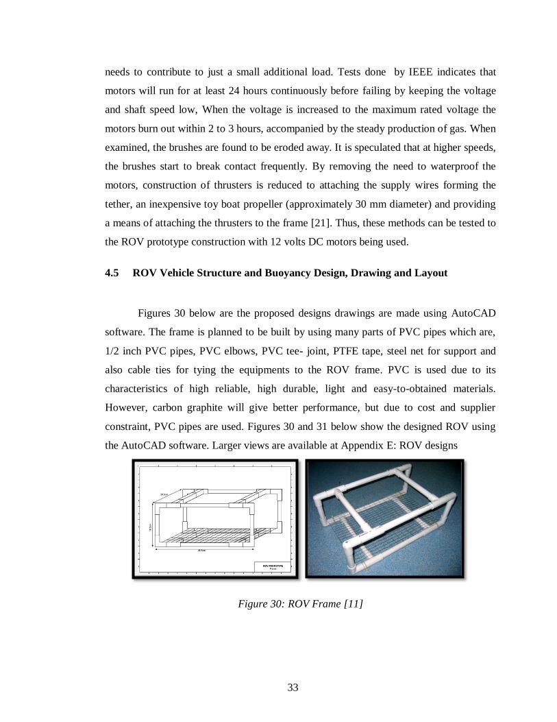
Figures 30 below are the proposed designs drawings are made using AutoCAD
software. The frame is planned to be built by using many parts of PVC pipes which are,
1/2 inch PVC pipes, PVC elbows, PVC tee- joint, PTFE tape, steel net for support and
also cable ties for tying the equipments to the ROV frame. PVC is used due to its
characteristics of high reliable, high durable, light and easy-to-obtained materials.
However, carbon graphite will give better performance, but due to cost and supplier
constraint, PVC pipes are used. Figures 30 and 31 below show the designed ROV using
the AutoCAD software. Larger views are available at Appendix E: ROV designs
Figure 30: ROV Frame [11]
33
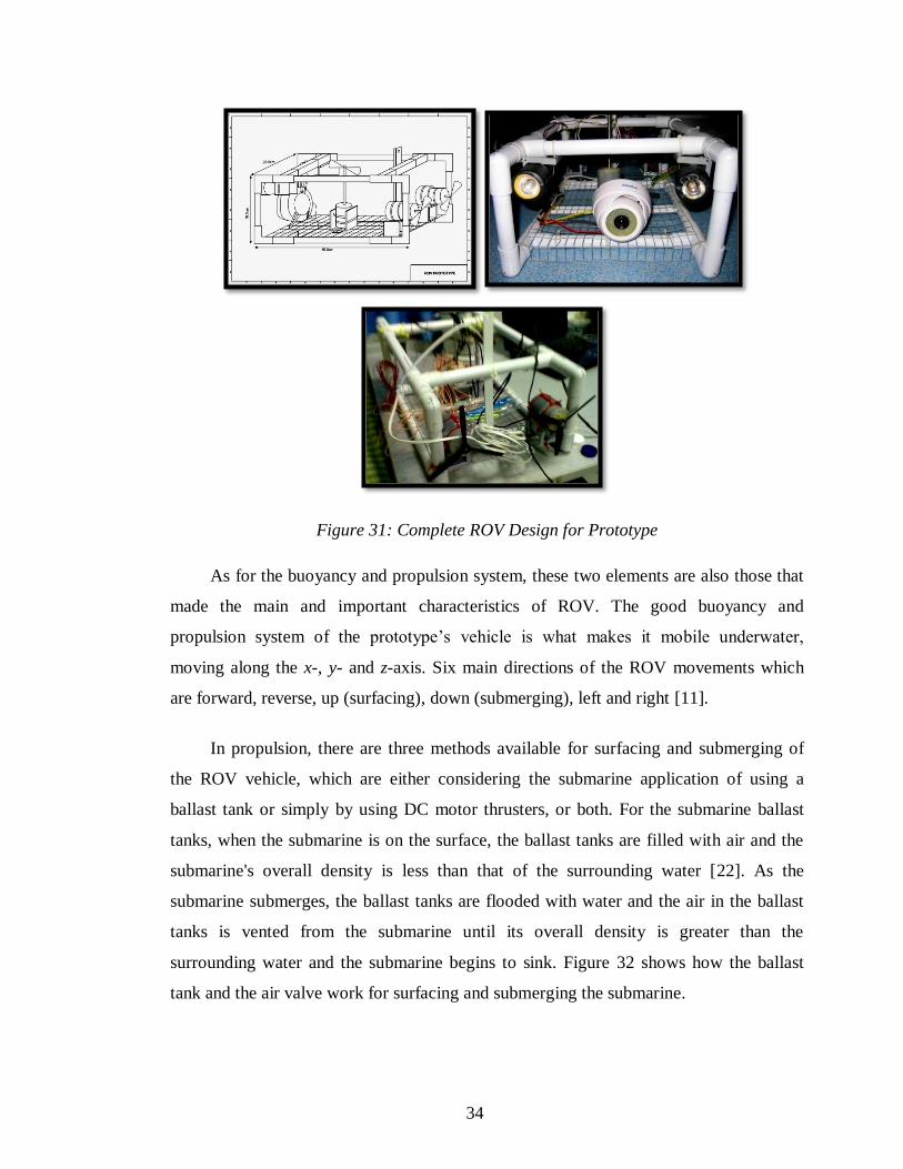
Figure 31: Complete ROV Design for Prototype
As for the buoyancy and propulsion system, these two elements are also those that
made the main and important characteristics of ROV. The good buoyancy and
propulsion system of the prototype‟s vehicle is what makes it mobile underwater,
moving along the x-, y- and z-axis. Six main directions of the ROV movements which
are forward, reverse, up (surfacing), down (submerging), left and right [11].
In propulsion, there are three methods available for surfacing and submerging of
the ROV vehicle, which are either considering the submarine application of using a
ballast tank or simply by using DC motor thrusters, or both. For the submarine ballast
tanks, when the submarine is on the surface, the ballast tanks are filled with air and the
submarine's overall density is less than that of the surrounding water [22]. As the
submarine submerges, the ballast tanks are flooded with water and the air in the ballast
tanks is vented from the submarine until its overall density is greater than the
surrounding water and the submarine begins to sink. Figure 32 shows how the ballast
tank and the air valve work for surfacing and submerging the submarine.
34
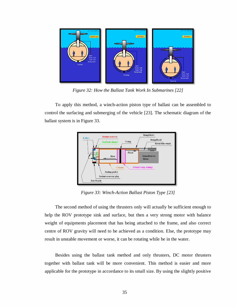
Figure 32: How the Ballast Tank Work In Submarines [22]
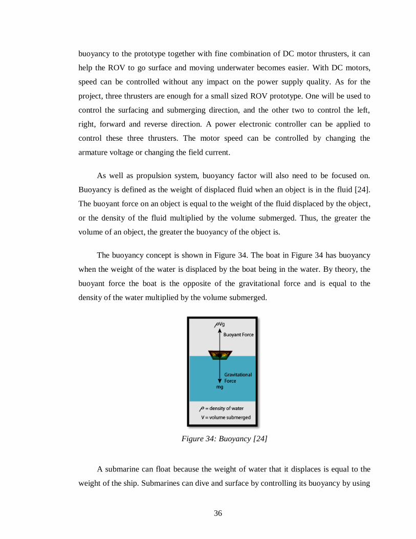
To apply this method, a winch-action piston type of ballast can be assembled to
control the surfacing and submerging of the vehicle [23]. The schematic diagram of the
ballast system is in Figure 33.
Figure 33: Winch-Action Ballast Piston Type [23]
The second method of using the thrusters only will actually be sufficient enough to
help the ROV prototype sink and surface, but then a very strong motor with balance
weight of equipments placement that has being attached to the frame, and also correct
centre of ROV gravity will need to be achieved as a condition. Else, the prototype may
result in unstable movement or worse, it can be rotating while be in the water.
Besides using the ballast tank method and only thrusters, DC motor thrusters
together with ballast tank will be more convenient. This method is easier and more
applicable for the prototype in accordance to its small size. By using the slightly positive
35
buoyancy to the prototype together with fine combination of DC motor thrusters, it can
help the ROV to go surface and moving underwater becomes easier. With DC motors,
speed can be controlled without any impact on the power supply quality. As for the
project, three thrusters are enough for a small sized ROV prototype. One will be used to
control the surfacing and submerging direction, and the other two to control the left,
right, forward and reverse direction. A power electronic controller can be applied to
control these three thrusters. The motor speed can be controlled by changing the
armature voltage or changing the field current.
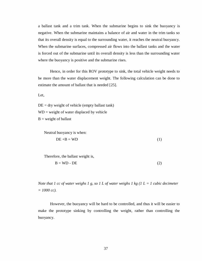
As well as propulsion system, buoyancy factor will also need to be focused on.
Buoyancy is defined as the weight of displaced fluid when an object is in the fluid [24].
The buoyant force on an object is equal to the weight of the fluid displaced by the object,
or the density of the fluid multiplied by the volume submerged. Thus, the greater the
volume of an object, the greater the buoyancy of the object is.
The buoyancy concept is shown in Figure 34. The boat in Figure 34 has buoyancy
when the weight of the water is displaced by the boat being in the water. By theory, the
buoyant force the boat is the opposite of the gravitational force and is equal to the
density of the water multiplied by the volume submerged.
Figure 34: Buoyancy [24]
A submarine can float because the weight of water that it displaces is equal to the
weight of the ship. Submarines can dive and surface by controlling its buoyancy by using
36
a ballast tank and a trim tank. When the submarine begins to sink the buoyancy is
negative. When the submarine maintains a balance of air and water in the trim tanks so
that its overall density is equal to the surrounding water, it reaches the neutral buoyancy.
When the submarine surfaces, compressed air flows into the ballast tanks and the water
is forced out of the submarine until its overall density is less than the surrounding water
where the buoyancy is positive and the submarine rises.
Hence, in order for this ROV prototype to sink, the total vehicle weight needs to
be more than the water displacement weight. The following calculation can be done to
estimate the amount of ballast that is needed [25].
Let,
DE = dry weight of vehicle (empty ballast tank)
WD = weight of water displaced by vehicle
B = weight of ballast
Neutral buoyancy is when:
DE +B = WD (1)
Therefore, the ballast weight is,
B = WD - DE (2)
Note that 1 cc of water weighs 1 g, so 1 L of water weighs 1 kg (1 L = 1 cubic decimeter
= 1000 cc).
However, the buoyancy will be hard to be controlled, and thus it will be easier to
make the prototype sinking by controlling the weight, rather than controlling the
buoyancy.
37
4.6 The Signal Flow System Design
As for the signal flow system design, a camera signal will needs to be sent to the
display monitor so each image underwater can be captured. Suitable camera which meets
the requirements of the project objectives and budget will be determined.
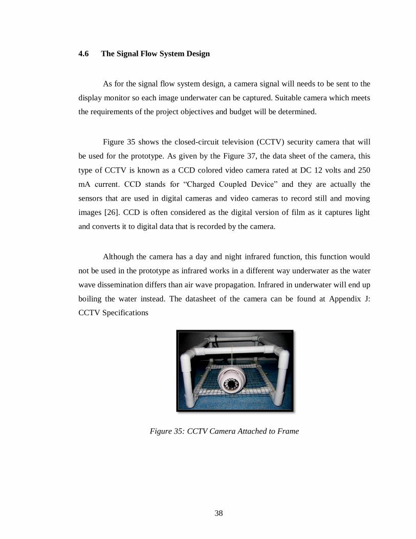
Figure 35 shows the closed-circuit television (CCTV) security camera that will
be used for the prototype. As given by the Figure 37, the data sheet of the camera, this
type of CCTV is known as a CCD colored video camera rated at DC 12 volts and 250
mA current. CCD stands for “Charged Coupled Device” and they are actually the
sensors that are used in digital cameras and video cameras to record still and moving
images [26]. CCD is often considered as the digital version of film as it captures light
and converts it to digital data that is recorded by the camera.
Although the camera has a day and night infrared function, this function would
not be used in the prototype as infrared works in a different way underwater as the water
wave dissemination differs than air wave propagation. Infrared in underwater will end up
boiling the water instead. The datasheet of the camera can be found at Appendix J:
CCTV Specifications
Figure 35: CCTV Camera Attached to Frame
38
CHAPTER 5
CONCLUSIONS AND RECOMMENDATIONS
5.1 Conclusions
Wrapping up all the information available, the project of Remotely Operated
Vehicle (ROV) is sure can be scaled down into a smaller size and the scope of function
can be expanded into the education, security and fishing industry. For the propulsion
system, bilge pumps made of DC motor and propeller can be used. A CCTV security
camera or webcam can be installed at the prototype as its eyes, and the ROV frame is
designed by using material of the PVC pipes. To help the CCTV gaining clear visions,
the lightings system consists of two 12 volts DC bulbs with a light dimmer circuit is
applied.
The project objectives of studying and analysis the ROV development as well as
developing the electrical system configuration (simulation) for the prototype are
achieved. Besides, the optimal design for the ROV can also be achieved giving many
tests should be done to the ROV prototype when its construction is finished. Thus, with
this, the Final Year Project 1 and 2 objectives which to plan and build (simulate and
construct) the prototype is a success.
5.2 Recommendations
The designs of the prototype can be modified according to its application. When
the prototype is built, more underwater test should be done and to rectify any error.
Additional studies, especially on the CCTV camera functions, the propulsion, buoyancy
in term of balancing the weight, and control unit system are needed. Enhancement can
also be made to the lighting system where waterproof torch light can be used to avoid the
vaporization inside the lamp and also to simplify the task of waterproofing them.
39
REFERENCES
[1] Salleh M.S.M., “Remotely Operated Underwater Vehicle (ROUV)”, Universiti
Teknologi Malaysia, May 2008
[2] Last G. and Williams P., “An Introduction to ROV Operation”, Oilfield
Publication Limited, May 1991.
[3] Bruce Smith, May 2010. Citing website. In Deepwater Horizon Fix Could Rely
on Submersibles with Embedded Systems. Retrieved February 15, 2012 from
http://technorati.com/technology/embedded/article/deepwater-horizon-fix-could-
rely-on/
[4] Diving and Undersea Vehicles, October 2011. Citing website SUT (Society for
Underwater Technology) Retrieved in 2012 from
http://www.sut.org.uk/htmfoldr/oceansoop/duseav.htm
[5] Christ R.D. and Wernli R.L., “The ROV Manual: A User Guide to Observation
Class Remotely Operated Vehicles”, Butterworth-Heinemann, August 2007.
Retrieved in 2012 from
http://books.google.com.my/books?id=pjW1QoX1KeIC&pg=PA1&dq=remotely
+operated+vehicles+history&hl=en&sa=X&ei=ezkqT-bjOsixrAeiu-
G7DA&ved=0CEsQ6AEwAg#v=onepage&q=remotely%20operated%20vehicle
s%20history&f=false
[6] “Remotely Operated Vehicles of the World”, 7th edition, Clarkson Research
Services Ltd., 2006/2007, ISBN 1-902157-75-3.
[7] BIG Partnership, May 2009. Citing websites. In ISS Extends its Reach in South
East Asia. Retrieved January 29, 2012 from
http://www.integratedsubsea.co.uk/index.php?option=com_content&view=sectio
n&layout=blog&id=5&Itemid=94&limitstart=8
[8] Hic Sunt Dracones, 2007. Citing websites. In Underwater Vehicle Platform (ROV
and AUV) Research in Malaysia.
[9] Marl Collins, 2012. Citing websites. In January 2012 SMD’s ROV business
stream is going from strength to strength. Retrieved February 5, 2012 from
40
http://smd.co.uk/news/smds-rov-business-stream-is-going-from-strength-to-
strength.htm
[10] Subsea Explore Services (M) Sdn Bhd, Retrieved 2010 from
www.subsearov.com
[11] Choong N.M.F., May 2011,” Remotely Operated Vehicle (ROV) Prototype”,
Universiti Teknologi PETRONAS, May 2011.
[12] 2012. Citing websites. In ROV Components. Retrieved February 9, 2012 from
http://books.google.com.my/books?id=pjW1QoX1KeIC&pg=PA1&dq=remotely
+operated+vehicles+history&hl=en&sa=X&ei=ezkqT-bjOsixrAeiu-
G7DA&ved=0CEsQ6AEwAg#v=onepage&q=remotely%20operated%20vehicle
s%20history&f=false
[13] Underwater ROV Forum, Retrieved in 2010
http://www.rcuniverse.com.com/forum/m_1492691/mpage_3/printable.htm
[14] MIT ROV Team, 2005. Citing websites. In main thrusters, TIM ROV designed
and built by MIT ROV Team. Retrieved February 9, 2012 from
http://rov.mit.edu/documents/2005/rovMATEPaper-2005.pdf
[15] ESCOL Electronic Hobby Kits, ES-32, Version 1.0.
[16] Power Electronics II, University Technology PETRONAS Lecture notes
[17] Kit 166. Bidirectional DC Motor Speed Controller, retrieved in 2010
http://www.kitsrus.com
[18] Switches Explained, Nick Duxfield, retrieved in February 2011,
www.gaugemaster.com/instructions/switches_explained.pdf
[19] DC Motor Reversing Circuit, retrieved in 2011, http://www.electronics-lab
.com/projects/motor_light/012/index.html
[20] H. Bohm and V. Jensen, op. cit., p. 130.
[21] Graeme R. A. Dunbar, Norrie S. Edward, Mamdud Hossain, Terry G. McKay,
John Still, “Simple Remotely Operated Vehicles for Students and
Schoolchildren”, IEEE, January 2007.
[22] Marshall Brain and Craig Freudenrich, How Submarines Work, Retrieved in 17
April 2012, at http://science.howstuffworks.com/transport/engines-
equipment/submarine1.htm
41
[23] Puremtc, Retrieved in April 2012, at
http://puremtc.com/info_faq/ballast_system/index.htm
[24] Buoyancy, retrieved in 2 October 2010, http://en.wikipedia.org/wiki/Buoyancy
[25] Buoyancy topic, retrieved in April 2012, at
http://rcudev.rcuniverse.com/forum/m_2396096/tm.htm
[26] Charged Coupled Device CCD colored video camera, retrieved in March 2012,
http://www.techterms.com/definition/ccd
42

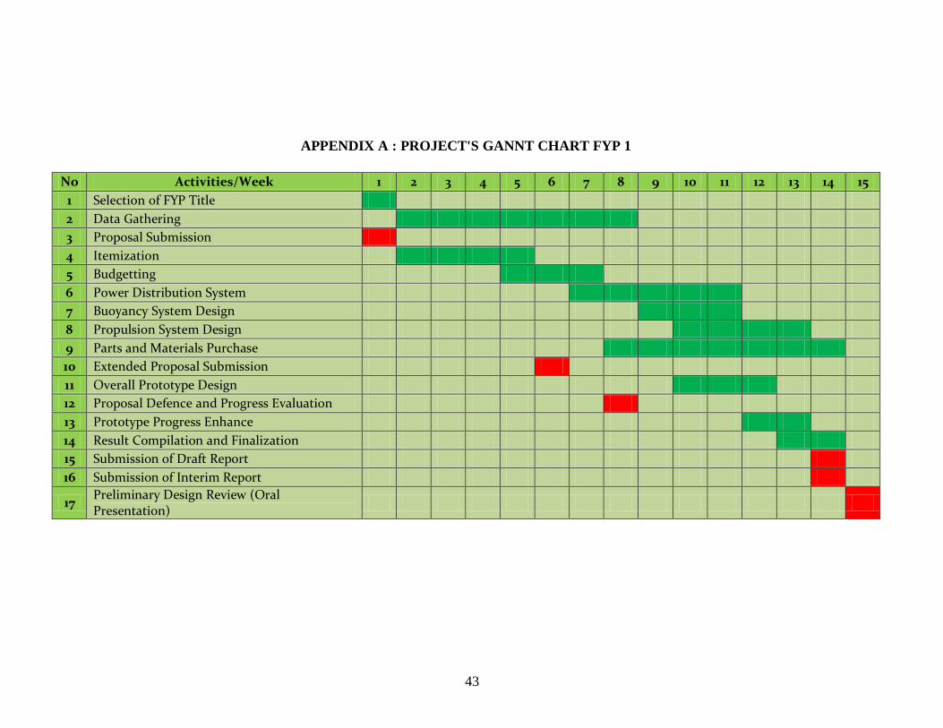
APPENDIX A : PROJECT'S GANNT CHART FYP 1
No Activities/Week 1 2 3 4 5 6 7 8 9 10 11 12 13 14 15
1 Selection of FYP Title
2 Data Gathering
3 Proposal Submission
4 Itemization
5 Budgetting
6 Power Distribution System
7 Buoyancy System Design
8 Propulsion System Design
9 Parts and Materials Purchase
10 Extended Proposal Submission
11 Overall Prototype Design
12 Proposal Defence and Progress Evaluation
13 Prototype Progress Enhance
14 Result Compilation and Finalization
15 Submission of Draft Report
16 Submission of Interim Report
17 Preliminary Design Review (Oral Presentation)
43
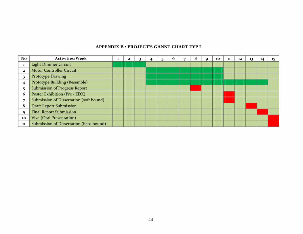
APPENDIX B : PROJECT'S GANNT CHART FYP 2
No Activities/Week 1 2 3 4 5 6 7 8 9 10 11 12 13 14 15
1 Light Dimmer Circuit
2 Motor Controller Circuit
3 Prototype Drawing
4 Prototype Building (Resemble)
5 Submission of Progress Report
6 Poster Exhibition (Pre - EDX)
7 Submission of Dissertation (soft bound)
8 Draft Report Submission
9 Final Report Submission
10 Viva (Oral Presentation)
11 Submission of Dissertation (hard bound)
44

APPENDIX C: SATRIA 101 DATASHEET
45
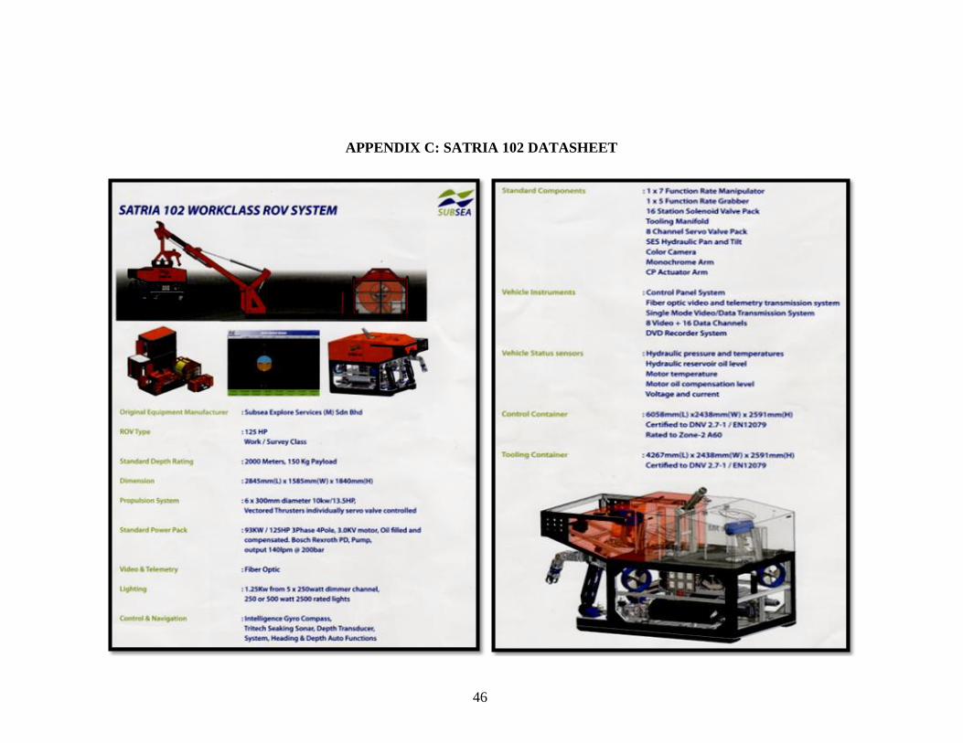
APPENDIX C: SATRIA 102 DATASHEET
46
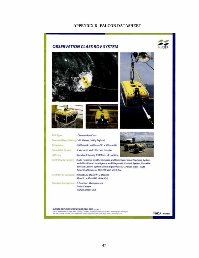
APPENDIX D: FALCON DATASHEET
47
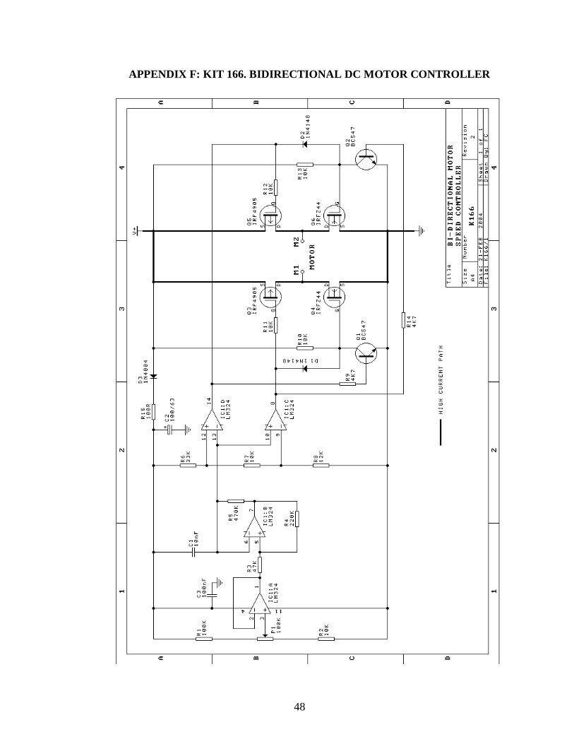
APPENDIX F: KIT 166. BIDIRECTIONAL DC MOTOR CONTROLLER
48
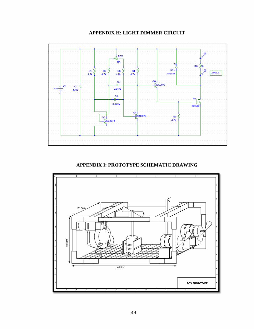
APPENDIX H: LIGHT DIMMER CIRCUIT
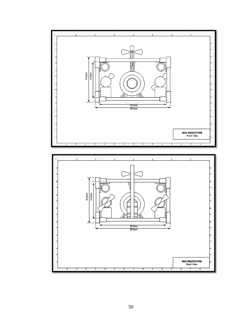
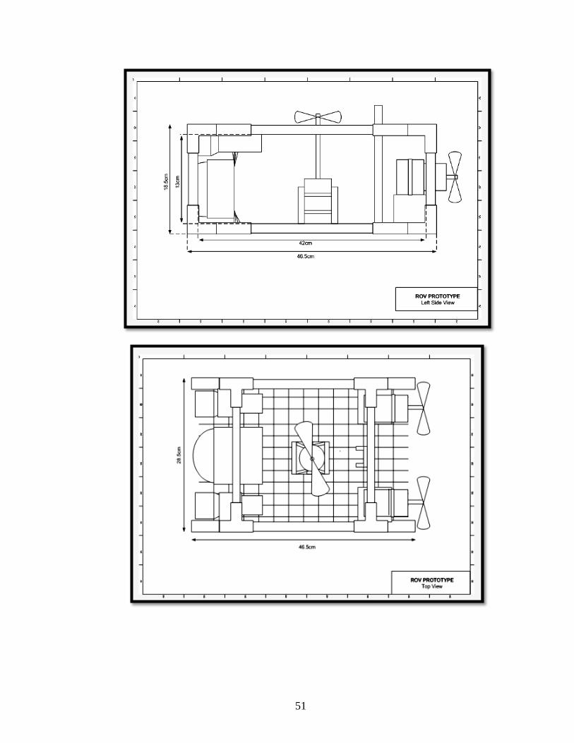
APPENDIX I: PROTOTYPE SCHEMATIC DRAWING
49
50
51
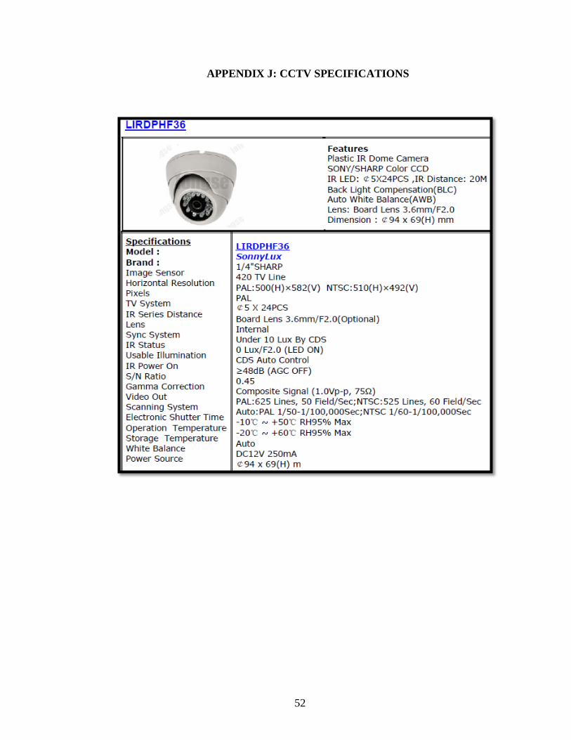
APPENDIX J: CCTV SPECIFICATIONS
52