millimeter-wave radars for remotely sensing clouds and precipitation
TRANSCRIPT

Millimeter-Wave Radars for Remotely Sensing Clouds and Precipitation JAMES B. MEAD, MEMBER, IEEE, ANDREW L. PAZMANY, MEMBER, IEEE, STEPHEN M. SEKELSKY, STUDENT MEMBER, IEEE, AND ROBERT E. MCINTOSH, FELLOW, IEEE
Invited Paper
Millimeter-H,ave radars have been used since the early 1950’s to study clouds and precipitation, but until recwitly these instru- ments were limited to simple backscatter power measurements and were plagued by hardware problems. However, development of solid-state millimeter-wave componentry and high-power klystron amplifiers has spurred the evolution of reliable, coherent radars operating up to 95 GHz. In addition, advances in digital signal processing technology ha1.e resulted in single-card processors that can simultaneously e.xecrite algorithms to compute reflectivity, Doppler, and polarimetric quantities in real time. A review of the current state of the art in millimeter-n>aw cloud radars is presented, including a discussion of transmitters, antennas, and receilvr components. Tnxo radar systems built by the Uniivrsity of Massachusetts are described, includiricq a mobile, dual-frequency (33- and 95-GHz) polarimetric radar, and an airborne 95-GHz polarimetric radar that Mfas recently flown in a cooperative exper- iment with the University pf Wyoming. Spaceborne applications are also discussed, especially the use of satellite-based 95-GH: radars for measuring the \?ertical distribution of clouds.
I . INTRODUCTION Engineers building radars to detect clouds and precipita-
tion have always recognized the advantages of increasing the operating frequency of the radar. The ability to use smaller antennas for the same spatial resolution and the tremendous gain in backscattering efficiency for small droplets are two compelling reasons to push the operating frequency to its practical limits. By the early 1950’s radar engineers and meteorologists had joined forces to apply millimeter-wave radars to cloud studies. These instruments were more sensitive to small cloud particles than con- ventional microwave radars and provided new insights into the rich small-scale structure of clouds and precip- itation. However, there were several drawbacks to these
Manuscript received January 25, 1994: revised June 9, 1994. The development and operation of the Cloud Profiling Radar System was funded by the Department of Energy’s Atmospheric Radiation Measure- ment program.
The authors are with the University of Massachusetts. Microwave Remote Sensing Laboratory, Amherst. MA 0 1 0 3 USA.
IEEE Log Number 9405555.
early millimeter-wave radar systems that prevented their widespread use. These problems included:
1) The lack of solid-state, low-noise millimeter-wave components, such as sources, mixers, and amplifiers, which resulted in noisy and unreliable receivers.
2 ) The scarcity of other millimeter-wave componentry, such as antennas, switches, and circulators.
3) The lack of devices and techniques for achieving phase coherence, which limited cloud radars to backscattered power measurements.
4) Limited understanding of propagation and scattering at millimeter wavelengths.
These problems, and the fact that a great deal of valu- able research was being carried out with lower frequency systems [ I ] , limited the use of millimeter-wave radars, the majority of which were operated by the Air Force during the 1950’s and 1960’s. And while there was considerable research activity at millimeter wavelengths during those years, a review of the literature shows that very little cloud research was being carried out at millimeter wavelengths during the 1970’s.
This hiatus did nothing to lessen the relative advantages of millimeter-wave systems, and eventually improvements in technology led to a resurgence of millimeter-wave cloud research in the 1980’s. At the present time, at least five universities and one govemment laboratory in the United States have operable millimeter-wave cloud radars.
A. Millimeter-Wave Cloud Radar Research ut the University ofMassachusetts
Since 1990 the University of Massachusetts Microwave Remote Sensing Laboratory has been actively developing innovative millimeter-wavelength radars intended specifi- cally for atmospheric remote sensing. These instruments take advantage of several major technological developments that have only recently become commercially available:
00 18-92 19/94$04.00 0 I994 IEEE
PROCEEDINGS OF THE IEEE. VOL. 82 , NO. 12, DECEMBER 1994 1891
.

Fig. 1. Photograph of University of Oklahoma tornado chase van with UMass 95-GHz radar configured lo raise OUI of an opening in the roof.
Fig. 2. Photograph of the UMass Cloud Profi!ing Radar Sy\tem (CPRS) at the Department of Energy’\ Cloud and Radiation Test site in Ponca City, OK.
1 ) Compact, high-power Extended Interaction Klystron Amplifiers (EIA’s) suitable for operation in the 35- and 95-GHz atmospheric transmission windows.
2) Solid-state, low-loss switches. allowing pulse-to- pulse polarization agility.
3) Commercial data acquisition and signal-processing hardware designed for the industry standard VXI-bus.
chusetts has recently built two millimeter-wave radar systems. a 95-GHz radar for airborne and highly portable ground-based applications shown in Fig. I , and the truck-mounted cloud profiling radar system (CPRS) that operates simultaneously at 33 and 95 GHz. shown in Fig. 2. These instruments are fully polarimetric: that is, they are able to measure the complex scattering matrix of the scene by transmitting a pair of orthogo- nally polarized pulses in rapid succession. Covariances of the individual terms of the scattering matrix are then used to compute meteorological radar parameters that give insight into cloud-particle orientation, shape. degree of randomness, and anisotropy. In 1992 and IY93 the 95- GHz polarimeter was flown in the University of Wyoming’s
The University of M
1x92
twin-engine King Air research aircraft. These missions demonstrated that a compact millimeter-wave radar can provide fine-scale reflectivity, polarimetric and Doppler imagery of a variety of cloud types.
During 1993, UMass also carried out preliminary mea- surements using the 33/95-GHz cloud profiling radar system in support of the Department of Energy’s Atmospheric Ra- diation Measurement (ARM) program. During forthcoming experiments, this radar will provide data on the spatial distribution of clouds in conjunction with other remote sensing instruments at ARM’S cloud and radiation test site in Northern Oklahoma.
11. HISTORY OF MILLIMETER-WAVE CLOUD RADARS I N THE UNITED STATES
As early as 1945, engineers at the U.S. Army’s Fort Monmouth Laboratories initiated the design of three radars intended specifically for meteorological applications in sup- port of the Army Air Corps: a wind-finding radar, a storm detection radar, and a cloud base and top detection radar [ 2 ] . While the wind detection radar was canceled, the storm detection radar, termed the CPS-9, was designed to operate at I O GHz and was later produced by Raytheon. The cloud detection radar, benefitting from a recently developed millimeter-wavelength magnetron, was targeted for 35-GHz operation. A contract was placed with Bendix Corporation in 1947 to design a transportable cloud detection radar. termed the ANRPQ-6. Although three experimental pro- totypes of this radar were built by the early 1950’s. the program was eventually canceled in 1952 131.
By 1951 researchers at the Air Force Cambridge Re- search Center were using a modified World War I1 surplus APS-34 28-GHz radar to assess the detectability of clouds [ 3 ] . This study showed that over half of the optically visible low-level clouds were detected by the radar. This suggested that a high-frequency radar could be effective in monitoring cloud distribution over a limited area, such as the airspace surrounding an airfield. Thus during the 1960’s the Air Force built 53 35-GHz AN-TPQ/l I Cloud Detection Radars for operational use by the Air Weather Service at various Air Force bases [SI.
Data collected with the AN-TPQ/l I during the 1960’s showed that 35-GHz radars could detect cloud top and base heights. identify the height of the melting layer, and predict the onset of frozen precipitation 151. All of this was done without the aid of velocity information, as the radars were noncoherent. Nonmeteorological echoes were also frequently detected, and were thought to be associated with particles such as “smoke plumes. insects, birds, milk weed seeds.. .and sharp gradients in the index of refraction. . .found under conditions of high humidity and sea breezes” [ 5 1.
Despite these successes, the AN-TPQ/I 1 was plagued by hardware problems and was eventually retired from service. This turned out to be a boon for atmospheric scien- tists, and by the late 1970’s surplus TPQ- I 1‘s were being modified for research applications. A major improvement
PKOCEEDINGS OF THE IEEE. VOL X?. UO. I?. IX-CEMBER IY9J

was the Dopplerization of the TPQ-11 to allow velocity measurements [6], 171.
The 1980’s also saw the development of the first 95-GHz radar system designed specifically for cloud remote sensing [8]-[ lo]. Although this system employed a modest I-kW peak-power transmitter and a 0.9-m-diameter antenna, it proved to be one of the most sensitive cloud radars in use. The transmitter employed an extended interaction klystron oscillator (EIO), introduced by Varian in the early 1970’s. By 1980 extended interaction amplifiers (EIA’s) were also available from Varian, having peak output powers in excess of 1 kW [ 1 I] at 35 and 95 GHz. The modest power supply and modulator requirements of these tubes made them ideal for radars intended for portable and airbome applications.
Studies of backscatter and propagation in clouds and precipitation were also carried out at frequencies from 35 to 230 GHz during the 1980’s [12]-[IS]. Systems operating above 100 GHz were found to have excellent sensitivity using compact antennas, and were effective at short ranges in detecting nonprecipitating clouds and fog [15]. However, absorption due to water vapor and liquid water is substantially worse in the 140- and 220-GHz atmospheric transmission windows, which limits the use of these systems to short ranges or high altitudes. The comparatively high cost of components above 100 GHz also makes operation at 140 and 220 GHz less attractive.
A. Current State of the Art
Modern millimeter-wave cloud radars resemble their pre- decessors in many respects, but their performance and relia- bility are considerably enhanced by advances in millimeter- wave and digital technology during the past two decades. Solid-state low phase noise sources, low-noise mixers, and amplifiers are now widely available from commercial sources, as well as power tubes, including magnetron oscillators, commonly used for 35-GHz cloud radars, and EIA’s [I61 providing more than 50-dB gain and I-2-kW peak power output at 95 GHz. The availability of low-loss switches and latching circulators has made pulse-to-pulse polarization agility practical, which now permits the study of cloud particle shape, orientation, and angular distribution through polarimetric techniques.
One of the most important technological advance affect- ing the utility of all cloud radars has been the develop- ment of programmable digital signal processors (DSP’s). Processor boards are now kommercially available for a variety of standard buses, including ISA, VME, VXI, Multi-bus, and others. These boards have as many as five independent floating-point processors, each of which can be configured to execute one or more real-time algorithms. Because cloud radars can easily generate data rates of more than 1 MByte.s-’ it is usually desirable to use real-time processing to reduce data rates to a manage- able level. Complete data acquisition systems, including analog-to-digital converters, processor boards, radar timing generators, and host computer, are now available for the VXI-bus. VXI’s hierarchical architecture greatly simplifies system configuration, programming, and debugging. All of
these developments have resulted in a substantial reduction in the engineering effort necessary to develop a custom data acquisition and processing system.
B. Outstanding Meteorological Research Issues
Millimeter-wave radars are currently being applied to a number of outstanding problems in cloud microphysics. These applications include estimating ice cloud particle sizes [ 171; studying internal circulations in fair weather Cumulus clouds [9]; remotely measuring drop-size dis- tributions in rain [lo]; and studying drizzle in shallow continental stratus [ 181. In addition: The possibility of flying a 95-GHz radar on a future LITE (Lidar In-Space Technology Experiment) [ 191 shuttle mission is being pro- posed to NASA; studies of the role of Cirrus clouds in the Earth’s radiation budget using a 95-GHz radar have been proposed by the GKSS institute in Germany; and a spacebome 95-GHz cloud profiling radar is currently being considered to monitor the vertical distribution of clouds over large regions of Earth’s atmosphere [67].
111. SENSITIVITY ANALYSIS AND COMPARISON OF EXISTING MILLIMETER-WAVE CLOUD RADAR SYSTEMS
A. Radar Range Equation for Volume Scatterers
The sensitivity of a meteorological radar can be expressed in terms of the minimum detectable volume backscattering coefficient q,,;, [20], [21]
10241n ( 2)7r2R2P, min
PtG2 X i P 2 cr Vmin =
where R is the range to the center of the volume cell under observation; P, min is the minimum detectable signal level; I‘, is the peak power of the transmitter; G is the gain of the antenna; Xo is the free-space wavelength; ,19 is the beam width of the antenna; and cr/2 is the length of the range cell in the direction of propagation.
7) (m2. m-3) may be related to 2 (mm6. m-’), the sixth moment of the drop size distribution, through
where K is related to the complex index of refraction n
(3)
Substitution of 2 for ri is only valid when the scat- terers fall within the Rayleigh region, that is, when the maximum drop diameter is less than approximately one tenth of a wavelength, a criterion which is valid for most nonprecipitating clouds at 35 GHz. However, for clouds that contain particles that do not satisfy the Rayleigh condition, an equivalent reflectivity, 2‘ is often used, and is computed from the measured volume backscattering coefficient through (2). Converting (1) to 10 log (2) = dBZ
MEAD et U / . : MILLIMETER-WAVE RADARS FOR SENSING CLOUDS AND PRECIPITATION 1893

Table 1 Comparison of Millimctcr-Wave Cloud Radar\ i n the US
Antenna Normal dBZ,,,,,, at Organiration Diameter AI? R = 1 kni In.;trunient Tranmiitter (111) (in) (LR = 75 nil Comments
NOAA 35 GHr
XS-hW I .2 m'igiietron
37,s -39 digital COR arbitrary tx. pol dual pol. rx 1241
Univ. of' Mass. 95 G H i 1.2 kW EIA I .2 W G H r airborne 1.2 kW EIA 0.3 CPRS: 33-GHr 12O-hW I . ( I section magne t r ~ n
1.5 liW EIA I .o 95-GHr section 60 W EIO 0. IS 215 GF/
Unit . of Miami 94 GHr I hW E l 0 0 . C )
Univ. of Utah 95 GH,. 1.9 k W EIA 0.9
Penn. State 94 CHI I hW E l 0 0.Y
Univ. of Wash. 35 GH/ XO-hW 2.13
magnetron
30 30 30
-40 -28 -39
portable: polarimetric [251 polarimetric 12.51
mobile: digital COR: polarirnetrrc
mobile: polarimetric portable 151: noncoherent
30 60
- 33 - 24
60 -42 portable: analog COR [ X I
portahle: polariinctric 30 - 40
60 -42 portablc; analog COR 1261
75 -36 digital COR 171
polarization. Measurement of the first and second columns of (6) are made on successive transmit pulses, separated by a time lag equal to the interpulse spacing T . Radars capable of characterizing S are termed polarimetric radars or polarimeters.
The complex scattering matrix describes the instanta- neous scattering characteristics of a distribution of scatter- ers. For atmospheric remote sensing, however, i t is usually more informative to consider covariances of the elements of S which provide information on the average polarization transformation properties of the scatterers [791-[ 3 I]. The well-known meteorological radar parameters derived from these covariances are the equivalent reflectivity factor at horizontal and vertical polarization Z;, and Zi , respectively, differential reflectivity (Zlll.). linear depolarization ratio (LDR). and copolarized correlation coefficient. p,, , , These parameters are related to the elements of S through
B , Comparison ( f E.vistincg Mil1inirter.- WUIY Cloud R U ~ ~ I S J
Table 1 lists the characteristics of a number of niillimeter- wavelength cloud radars and the theoretical single-pulse minimum detectable reflectivity, dBZ,,,,,,, assuming a range of 1 km. dBZ,,,;,l has been normalized to a range resoluticin of 75 m by multiplying by (g)'. All of these instru- ments, excepting the UMass 21.5-GHz radar, are capable of measuring radial velocity mean and variance; those systems using oscillator tubes achieve coherence through either analog 1221 or digital [23] coherent-on-receive (COR) techniques. The 95-GHz radar operated by the University of Utah was built by Quadrant Engineering. Hadley. MA.
( 7 ) Iv. POLARIMETRIC RADARS FOR CLOUD STUDIES
All of the cloud radar systems built by UMass, excluding the 2 15-GHz radar. are configured to measure the complex scattering matrix S [27]-[29]. by transmitting horizontally and vertically polarized waves, and measuring the magni- tude and phase of the horizontal and vertical components of the scattered field. The incident and scattered electric fields E' and E" are related to S through
where Sij are complete zero-mean random variables, cor- responding to the ith receive polarization, and j t h transmit
I X Y J PROCEEDINGS OF THE IEEE. VOL X7, NO 12 DECEhlBEK I9Y-l

- - - - 1 - - -
pulse-pair used to measure polarimetric quantities
Fig. 3. Polarimetric radar transmit pulse sequence
Simultaneous measurement of polarimetric quantities and velocity mean and variance are made using the transmit pulse sequence shown in Fig. 3. The U , U and h. h pairs are used to independently compute velocity mean and standard deviation through a conventional pulse-pair algorithm [ 321. The central U , h couplet is used to compute p h r . The groups are separated by more than the decorrelation time of the scene to provide independent samples, while the pulses within the groups are transmitted at an interpulse spacing of T = 12.5 to 50 p s to prevent aliasing. Since significant decorrelation can occur within this short time period it is necessary to correct p h r . by a term which independently estimates the decorrelation rate of the scene [33], [34].
V. SYSTEM DESIGN CONSIDERATIONS
A . Frequency Selection There are several important considerations affecting
the selection of operating frequency for a millimeter- wavelength radar system, including cost and availability of components, molecular absorption, and extinction due to liquid water. While commercially produced radar components are available up to 300 GHz, components are more widely available, less expensive, and more reliable below 100 GHz. Thus most millimeter-wave cloud radars have been built for operation in the 35- and 95-GHz atmospheric transmission windows, where absorption due to water vapor and oxygen are at a minimum.
35-GHz radars suffer considerably less attenuation due to water vapor, exhibiting only 0.1 dB . km-l in a standard atmosphere (water vapor density of 7.5 g . m-’j), which increases to 0.4 dB . km-I at 95 GHz. Attenuation by liquid water in the form of small, cloud droplets (diameter less than 0. I A) increases as approximately f’”’ [43], and can be severe in clouds of high liquid water content especially at 95 GHz (8 dB . km-’ for a liquid water content of 1 g . m-3 at OOC). Attenuation in rain can be severe, but is approximately independent of wavelength in the millimeter- wave band due to saturation of the Mie extinction efficiency for large particles.
Based on the above considerations, 35 GHz is preferable for ground-based observations of clouds, especially if high clouds are to be observed through intervening clouds layers. However, 95-GHz systems are well suited for mobile or airborne operation since they can achieve comparable
pulse-pairs used to measure velocity mean and standard deviation
sensitivity with much lower power and more compact transmitters.
B. Transmitter Power Sources Millimeter-wave versions of all of the commonly used
microwave tubes are available up to 100 GHz, includ- ing traveling-wave tube amplifiers (TWTA’s), magnetron oscillators, and klystron amplifiers and oscillators. For operation in the 35-GHz transmission window, magnetron oscillators provide at least an order of magnitude more peak power than TWTA’s or klystrons, but the phase of each transmit pulse must be monitored for coherent operation. High average power is possible with TWTA’s at 35 GHz, although power supply and modulator requirements for these tubes are substantially greater than for magnetrons and klystrons. Extended interaction klystron (EIK) amplifiers and oscillators can provide I-3-kW peak power at up to 10% duty cycle at both 35 and 95 GHz [44], [45]. For operation in the 95-GHz window, EIK’s are most commonly used, as they combine high output power, with long tube life and modest power supply and modulator requirements.
Gyrotron oscillators, capable of producing power levels in excess of 1 MW at frequencies exceeding 100 GHz, have been proposed for very-high-sensitivity atmospheric mea- surements [46]. Gyrotrons have not been used extensively for radar applications, because the high order waveguide modes used in gyrotrons are poorly suited for radiating a well-defined beam. However, efficient mode converters have been recently developed that can generate Gaussian beams suitable for illuminating lens or reflector antennas [47]. Other problems associated with gyrotrons are the difficulty of generating stable, single-mode output, and the need to provide very high magnetic fields, necessitating the use of cryogenic magnets.
C . Antennas Meteorological radars usually employ pencil-beam an-
tennas having beam widths on the order of 0.1-1.0”. To achieve these beam widths at S-band (3.0 GHz) requires an antenna on the order of 10- to 100-m diameter; the same beam width can be achieved at W-band (95 GHzj for antennas only 20-cm to 2-m diameter. Millimeter-wave antennas are not only easier to build and deploy than larger
MEAD er U / . : MILLIMETER-WAVE RADARS FOR SENSING CLOUDS AND PRECIPITATION 1895
.

0
-5
-ia
-15 n
U n
L -29
W
3
a 0 @L
-2s 4
-30
-35
i t I t
t I t
- 2 . 8 -1.5 -1.8 - 8 . 5 0 . 6 0 . 5 1.0 1.s 2 . 8
Azimuth CDegreesl
Fig. 4. dB below copolarized power
Principal-plane pattern for 9.5-GHz Cassegrain antenna showing cross-polari7ed power 27
microwave antennas, but can be operated at much closer ranges, since the far-field distance scales linearly with wavelength (far-field distance = 2A/[ j2). Millimeter-wave antennas are also less susceptible to ground clutter than microwave systems, due to their relatively short far-field distance and the rapid attenuation of millimeter-wave sig- nals propagating over terrain. Vertically pointed millimeter- wave cloud radars generally do not require clutter fences, even when observing weakly scattering clouds at short ranges.
The two most commonly used antennas for millimeter- wave cloud radars are Cassegrain and lens antennas. Both can be designed to use short waveguide runs between the feed and the radar to minimize loss. Cassegrain antennas have the advantage of being compact, but suffer from significant aperture blockage, unless a more complex offset design is used. Lenses are usually less compact. but have no aperture blockage.
I ) Center-Fed Cassegt-ain: The simplest Cassegrain an- tenna uses a subreflector suspended above the center of the main reflector. The center-fed Cassegrain typically has high near-in sidelobes due to aperture blockage. but is oth- erwise well suited for meteorological applications. Cro\s- polarization isolation is predominantly dependent upon the characteristics of the feed system and the wavelength- to-diameter ratio of the main reflector [48], [49], while curvature of the main reflector is of secondary importance [ S O / . Good cross-polarization isolation is usually achieved by use of a hybrid mode feed, such as a scalar (corrugated) feedhom. A typical principal-plane pattem for a 0.9-m diameter antenna. (main reflector f / d = 0.44) utilizing a scalar feedhom, is shown in Fig. 4. This antenna exhibits a first sidelobe level (SLL) of 17 dB and -27-dB peak cross- polarization isolation. While the peak cross-polarization isolation is a good indicator of overall isolation. an accurate measure of the total cross-polarization isolation is found
by summing the product of the co-polarized and cross- polarized patterns over all space [SI]. A practical way to measure the total polarization isolation is to make vertical observations of light rain or a liquid water cloud. Backscat- ter from these scatterers should be very highly polarized, therefore, any signal present in the cross-polarized receiver channel will be due primarily to the antenna and orthomode transducer.
2) O f s e t Cassegrciin: Cassegrain antennas employing offset subreflectors are used when high aperture efficiency is desired. Offset Cassegrain antennas are categorized as I ) open Cassegrain, where the subreflector is offset but the feed is placed at the center of the main reflector; and 2) double-offset, where both the subreflector and the feed are offset from the main reflector [52) . The double-offset configuration has no aperture blockage, and the feed and subreflector can be designed to yield zero cross-polarization 1521. In practice, diffraction from the subreflector generates significant cross-polarization, but for subreflectors greater than 2SX cross-polarization isolation of greater than 40 dB should be possible 1521. The 1.2-m diameter double- offset Cassegrain antenna built by Millitech Corporation for the NOAA 35-GHz radar exhibited first SLL of -23 dB and cross-polarization isolation of 38 dB as measured by vertical observations of drizzle [ 5 3 ] .
3 ) Lens Antennas: Lens antennas are easy to design 1.541 and build, do not suffer from aperture blockage. and can give excellent polarization isolation when illuminated by a scalar feedhom. Lens materials commonly used are Rexolite (trade name for cross-linked polystyrene. index of refraction =1.59); and TPX (trade name for poly 4- methylpentene-I, index of refraction = 1.46). While both materials have good loss characteristics below 100 GHz, measurements have shown TPX to be considerably less lossy that Rexolite at 247 and 526 GHz [SS]. Corrugations are sometimes used to reduce surface reflections in lens
1 X9h PROCEEDINGS OF THE IEEE. VOL X2. hO. 12. DtCEhlBER 1904

r
Fig. 5. Principal GHz. (b) 95 GHz:
plane
a 0
-5 -5
-ia -10
-15 -15
gj g -28 - f -25 I -36 a" -33
-35 -35
- 40 - 4a
-45 - 45
-56 -50 -3 -2 .5 -2 -1 .5 -1 -6 .56 0.5 I 1.5 2 2.5 3 -3 -2 .5 -2 -1 .5 -1 -6 .50 6.5 I 1.5 2 2.5 3
Al l ru th ' b q J E l e v a t i o n (Oqr
(a)
a -5
-:a -15
- -28 5 f a" -33
-35
- 40
- 45 -w
0
-5
- I 0
-15
- -28
-25
2 -38
-35
-48
3 5
-45 -iil
- 3 - 2 . 5 - 2 - 1 . 5 - 1 - 0 . 5 0 0 .5 I 1.5 2 2 . 5 3 -3 -2 .5 -2 -1 .5 -1 -0 .5 0 0.5 I 1.5 2 2.5 3
Azimuth l k q l Elevation fDeq1
(b)
pattems measured for the UMass I-m-diameter CPRS antenna. (a) 33
antennas in order to improve VSWR and efficiency [56]. Plano-convex lenses, having their curved face nearest the feed, usually employ corrugations to avoid high VSWR. The Friedlander Lens, which has its flat face closest to the feed, does not suffer from high VSWR due to reflections, and can be used without corrugations. Loss in efficiency due to surface reflections for low-dielectric-constant plastic lenses is usually less than 1 dB without corrugations.
The UMass cloud profiling radar system employs a 1- m-diameter lens antenna (focal length to diameter ratio of 1.8) that utilizes a dual-frequency, dual-polarization feed. Principal plane pattems measured for this antenna at 33 and 95 GHz are shown in Fig. 5. Integrated cross-polarization isolation of 30 dB at 33 GHz and 27 dB at 95 GHz was derived from vertical observations in drizzle.
D. Dynamic Range Considerations
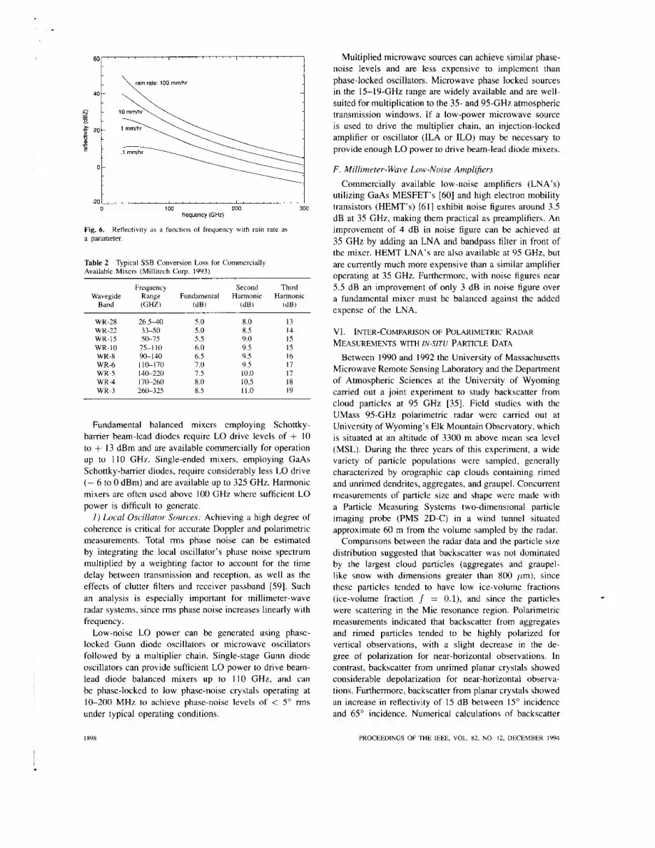
The dynamic range of meteorological radars can be estimated by computing the ratio of noise-equivalent reflec- tivity to the maximum expected reflectivity for the nearest range gate of the radar. In Fig. 6, expected reflectivity is displayed as a function of frequency assuming the Marshall-Palmer drop-size distribution [57] for various rain rates. Since rain rates of 100 mm . h-' are extremely heavy, the maximum reflectivity is not likely to exceed 48 dBZ at 33 GHz, while at 95 GHz the maximum reflectivity
should not exceed 30 dBZ. Considering the UMass CPRS system described in Table 1, the maximum dynamic range at 95 GHz for R = 1 km is 63 dB and increases to 87 dB at 33 GHz. An additional 20 dB of dynamic range is necessary to account for random fluctuations in the signal, to avoid clipping the strongest signals, and to allow accurate measurements below the mean noise floor. Thus over 100- dB dynamic range is necessary for a 33-GHz system to be able to handle all possible conditions without saturation.
E. Receiver Technology
Millimeter-wave receivers typically employ fundamental or harmonic mixers followed by a low-noise amplifier. The overall single-sideband noise figure F,,, (in dB) is given by
where La,,, (dB) includes all losses of the antenna and feed network; Fmixer (dB) is single-sideband (SSB) noise figure of the mixer; and Flna (dB) is the noise figure of the low-noise amplifier. The SSB noise figure of the mixer is typically 1.5 dB greater than its SSB conversion loss, due to additive noise generated by the mixer diode [58]. Typical SSB conversion loss values for commercially available fundamental and harmonic mixers are given in Table 2.
.
MEAD et al.: MILLIMETER-WAVE RADARS FOR SENSING CLOUDS AND PRECIPITATION I897
6o G 40 -
w - D . - 5 20-
g m -
0-
\ rain rale: 100 mmlhr 1
.
-20 100 200 300
frequency (GHz)
Fig. 6. a parameter.
Reflectivity as a function of frequency with rain rate as
Table 2 Available Mixers (Millitech Corp. 1993)
Typical SSB Conversion Loss for Commercially
Frequency Second Third Wavegide Range Fundamental Harmonic Harmonic
Band ( G W (dB) (dB) (dB)
WR-28 WR-22 WR-I5 WR-I0 WR-8 WR-6 WR-5 WR-4 WR-3
26.540 33-50 50-75
75-1 10 90- I40 1 1 ~ 1 7 0 140-220 I7S260 260-315
5.0 5.0 5.5 6.0 6.5 7.0 7.5 8.0 8.5
8.0
9.0 9.5 9.5 9.5 10.0 10.5 11.0
x.5 13 14 15 15 16 17 17 18 19
Fundamental balanced mixers employing Schottky- barrier beam-lead diodes require LO drive levels of + 10 to + 13 dBm and are available commercially for operation up to 110 GHz. Single-ended mixers, employing GaAs Schottky-barrier diodes, require considerably less LO drive (- 6 to 0 dBm) and are available up to 32.5 GHz. Harmonic mixers are often used above 100 GHz where sufficient LO power is difficult to generate.
I ) Local Oscillator- Sources: Achieving a high degree of coherence is critical for accurate Doppler and polarimetric measurements. Total rms phase noise can be estimated by integrating the local oscillator's phase noise spectrum multiplied by a weighting factor to account for the time delay between transmission and reception, as well as the effects of clutter filters and receiver passband [S9]. Such an analysis is especially important for millimeter-wave radar systems, since rms phase noise increases linearly with frequency.
Low-noise LO power can be generated using phase- locked Gunn diode oscillators or microwave oscillators followed by a multiplier chain. Single-stage Gunn diode oscillators can provide sufficient LO power to drive beam- lead diode balanced mixers up to 110 GHz, and can be phase-locked to low phase-noise crystals operating at I s 2 0 0 MHz to achieve phase-noise levels of < 5" rms under typical operating conditions.
I898
Multiplied microwave sources can achieve similar phase- noise levels and are less expensive to implement than phase-locked oscillators. Microwave phase locked sources in the 15-19-GHz range are widely available and are well- suited for multiplication to the 35- and 95-GHz atmospheric transmission windows. If a low-power microwave source is used to drive the multiplier chain, an injection-locked amplifier or oscillator (ILA or ILO) may be necessary to provide enough LO power to drive beam-lead diode mixers.
F . Millimeter-Wave Low-Noise Amplifiers Commercially available low-noise amplifiers (LNA's)
utilizing GaAs MESFET's [60] and high electron mobility transistors (HEMT's) [6 I ] exhibit noise figures around 3.5 dB at 35 GHz, making them practical as preamplifiers. An improvement of 4 dB in noise figure can be achieved at 35 GHz by adding an LNA and bandpass filter in front of the mixer. HEMT LNA's are also available at 95 GHz, but are currently much more expensive than a similar amplifier operating at 35 GHz. Furthermore, with noise figures near 5.5 dB an improvement of only 3 dB in noise figure over a fundamental mixer must be balanced against the added expense of the LNA.
VI. INTER-COMPARISON OF POLARIMETRIC RADAR MEASUREMENTS WITH IN-SITU PARTICLE DAT.4
Between 1990 and 1992 the University of Massachusetts Microwave Remote Sensing Laboratory and the Department of Atmospheric Sciences at the University of Wyoming carried out a joint experiment to study backscatter from cloud particles at 95 GHz [35]. Field studies with the UMass 95-GHz polarimetric radar were carried out at University of Wyoming's Elk Mountain Observatory, which is situated at an altitude of 3300 m above mean sea level (MSL). During the three years of this experiment, a wide variety of particle populations were sampled, generally characterized by orographic cap clouds containing rimed and unrimed dendrites, aggregates, and graupel. Concurrent measurements of particle size and shape were made with a Particle Measuring Systems two-dimensional particle imaging probe (PMS 2D-C) in a wind tunnel situated approximate 60 m from the volume sampled by the radar.
Comparisons between the radar data and the particle size distribution suggested that backscatter was not dominated by the largest cloud particles (aggregates and graupel- like snow with dimensions greater than 800 pm), since these particles tended to have low ice-volume fractions (ice-volume fraction f = O . l ) , and since the particles were scattering in the Mie resonance region. Polarimetric measurements indicated that backscatter from aggregates and rimed particles tended to be highly polarized for vertical observations, with a slight decrease in the de- gree of polarization for near-horizontal observations. In contrast, backscatter from unrimed planar crystals showed considerable depolarization for near-horizontal observa- tions. Furthermore, backscatter from planar crystals showed an increase in reflectivity of 15 dB between 15' incidence and 65" incidence. Numerical calculations of backscatter
PROCEEDINGS OF THE IEEE, VOL. 82. NO. 12, DECEMBER 1994

Ponoo oiu. OK Juni P I , 1883
ascns Fue: 1961P8
0.0 0.5 1.0 1 .5 2.0
2.5
3 b 2.0
1 1 s 3 1.0 -!
0.6
0.0 0.0 0.5 1.0 1.5
7 % ~ (min) 2.0
using the finite-difference time-domain niethod applied to idealized crystal shapes sitnilat- tu [ t iox sampled using the PMS 2D-C showed good agreenieirt with ixdar-der ivcd reflectivities and polarimetric quatititic, such a h difteiential reHectivity and degree of polarii.atioir 1361. 1.371.
vI1. ~ l L l ~ l M € ' ~ L K - w A V t BAcKSC.;\T I ER I & C'LbAK AIR
Many instances of clear-air bachhcattct at 11-iillimctei - wavelengths have beeii cited in the liteidture [3XJ. (39J. atid have been visible to altitude5 a5 high a:, 4.V hili 151. 'There is experimental cvidcncc of eiihanced cleai -air backscatter in layered region, aswcratcd w i t h e a breeleh. where strong index ot reftaction gtadiciith wete piesent IS] . [3YJ. By 1970. however. theotetlcal and expeiinicnral evidence indicated that the duiiiiiiant W U I C C ~ ut cle;u air bachscattcr above I U GHL ate bitds atid insect\ I4OJ 1421.
Figure 7 is a typical example of a vertical ptutilc 01 reflectivity and Dopplet froin itixct5. as inea~ured by die UMass YS-GHL gt-ourid- based radiit- i i i tiurttiei-ii Ohlahunia during the suilltlle1' of IYY.3. Bachscatter ftotir inwcts a id birds i 4 readily identitiable due to the cotiereiit rriituic of the echoes. A single irisect has sufticietit c t o ~ xctioti t o
be readily visible to the tadar at low altitudes. tlietctotc. the echoes at-e often viaible as reflectivity 5pihcs. persibtirig for a few seconds or less.
dual-tteyuency. mobile polaritnett ic radar system intended to nionitot the spatial distribution and motion of clouds. I n addition, reseaich is planned with this instrument to detet tnine whethet i t is possible to discriminate between liquid 01- solid cloud particles. Figure 2 shows the CPRS bystem as it was deployed during the suninier of 1994. The hy5tem i b completely mobile and can be set up for operation 111 only a teu hours.
I n Fig. X. ground-based measurements of reflectivity, LUK. and Doppler generated by the UMas:, CPKS systern ate shown. The 33-GHz section ot CPRS was more readily able IO detect the Cirrus layer through the underlying precipitation. bince attenuation due to rain and water vapor i5 conbidclably higher at 95 GHz. 'The inelring layer is clearly visible at an altitude of approximately 4 hni (above giound I cx l ) i n all rhiee types ot images. but is most rcadilq seen i n the Dopplei image, where the iticreased \clocity of' tairi drops bclvw the melting band is seen: also the iiiclting band is seeti clearly in the LDR image. where a region o f higher depulariLatiun niarks the oii:,et of melting in ice c r y d h . 'This effect ha, been observed pteviously at S-band (621 as well as at .Y-band 1631 and A-tr-band 161.
I)(. ~ E S C R l P r l O N OF UMASS AIR~OKN~/GROUND-BASED YS-GHL POLARIMETRIC RADAR S Y S T ~ M
I n 199 I the University of Massachusetts began devel- opinelit ot a compact 9S-CiHz polarimetric radar intended \pecifically for airborne and highly portable operation 1251, I64l. '1.his radar b'as tirst flown in late 1902. during a joint

Lincoln, NE CPRS 33GHz Jul 27, 1993
Reflectivitv (dBZe)
0 2 4 6 8 IO 12
Linear Depolarization Ratio (a)
0 2 4 6 8 10 12
Vertical Velocitzl (m/s)
0 2 4 6 8 10 12 TIME (minutes)
04:02:44 04: 14:42 ( a )
Fig. 8. measured using the UMass CPRS polarimetric radar at 33 GHz.
(a) Vertical renectivity and Dopplcr, and LDK images of Stratocumulus and Cirrus clouds
measurement program with the University of Wyoming. The radar system consists of a pulsed. dual-polarization radar, a VXI-based data acquisition and processing system. and a 300-MByte optical disk for data storage. Specifica- tions for the system are given in Table 3. The imaging resolution of the radar is 20 m x I O m x 30 m at 1 kni, established by 0.7" antenna beam, averaged over a 10-iii flight distance, using 30-m transmit pulses.
A. Airborne Measurement3 with the UMoss 95-GH: Rudur Airborne experiments with the 95-GHz polarimetric radar
were carried out at Laramie, WY, during October, 1992, from the University of Wyoming's King Air research aircraft [65] , [66], [ 181. An externally mounted aluminum plate shrouded by an airfoil was used to reflect the an-
tenna beam for vertical observations, and was removed for horizontal observations.
I ) Hot-ixntal Observations of Convective Clouds: Figure 9 displays reflectivity (Zc) and LDR images of a convective cell observed with the antenna beam pointed horizontally over a 7-km path for ranges between 0.1 and 2.9 km. These observations were made on October 6, over the Laramie valley at an altitude of approximately 5.5 km above MSL (temperature: - 17.5 to -203°C). Simultaneous in siru measurements using PMS 2D-C/2D-P probes observed a predominance of spherical graupel having diameters of 1-2 mm, with some rimed, branched crystals in lower concentrations. Very little depolarization was observed, with typical LDR values of -20 dB. In contrast. Fig. 10 shows reflectivity and LDR images of a convective cloud
I900 PROCEEDINGS OF THE IEEE. VOL. 82. NO 12. DECEMBER IY91

Limoln. NE Junt 26, I999
CPRS 95GHa File: 22 1549
0 2 4 6 8 10 12
LDR
12 - i o
10
8
6 -30
4
2
0 0 e 4 6 8 10 12
V w i i e a l Veb-
0 P 4 6 8 10 12
( h )
fime (min)
Fig. 8. measured using the UMass CPRS polarimetric radar at 95 GHz.
(h) Vertical reflectivity and Doppler. and LDK images of Stratocumulus and Cirrus clouds
measured 20 min earlier at an altitude of 4 km (temperature: -10.2 to -1 1.0"C) which contain regions of strong depo- larization (maximum LDR of -6 dB). 2D-C/2D-P images showed that all of the cloud particles were rimed with over 90% of the particles being nearly spherical graupel of 2-3- mm diameter, A few rimed branched crystals were also observed, but in much lower concentration. The high levels of LDR in Fig. 10 cannot be readily explained from the ill
situ data, which differed little from the case exhibiting low levels of depolarization.
2 j Vertical Observations of'lce Clouds: Figure 1 1 presents images of reflectivity ( F ) , LDR, vertical velocity, and velocity spectral width taken near the top of a convective cloud in the Laramie Valley on October 27. 1993. The aircraft was flying 4.2 km above MSL (temperature: -6.4
to 7.0"C) through a cloud comprised of aggregates up to 4-mm diameter; graupel up to 3-mm diameter; and a few needles up to I-mm diameter. The vertical velocity image shows mixing of air into the cloud top by the yellow/red regions, which indicates strong downward particle motion. These regions occur on the right side of cloud excursions, indicating a left to right relative air motion above the cloud. The mixing of air creates circulations within the cloud, which are highlighted in the yellow/red regions of downdraft and greenblack regions of updraft.
This cloud also contains a highly depolarizing region of ice particles that can be seen in the LDR image between 0.2- and 0.5-km vertical height and 2.1 to 2.5 km along the flight path. Strong downdrafts occur in this region, as can be seen in the vertical velocity image. Doppler spectral
MEAD er a/ MlLLlMETER-W4VE RADARS FOR SEWING CLOUDS A U D PRECIPITA'IION 1901

Laramie. Vyoming Ootobrs 06, 1332 HH Refhotivify
t
Fib: 192225 Flight dlitude: 5.5 km
0 I 2 3 4 5 6 7
LDR dR
0 t e 3 4 5 6 7 Flight Path ( k m ) t7:23:0 1 17:24: 1 1
Fig. 9. airborne 95-GHr radar.
Zb and LDR images for horizontal observation\ o f ;I coiivcctivc cloud nlea\ured with
Laramir, V#omiag Ootobw 06, 1332 HH Refiotivify t
Fib: 170066 FlQht al(iMr: 4.0 km
0 t 2 3 4 5 6 7
LDR
. ..
0 t 2 9 4 5 6 7 17:OZ: t 4 Fltght Path ( k m ) 17:01:04
Fig. 10. depolarizing regions.
Z;, and LDR images for horimntal ohservntions c i f ;I cotiwctibe cloud that coiitiiln\
1902 PROCEEDINGS OF THE IEEE. VOL. X2. NO. I?. DECEMBER IYY-l

0 1 2 3 4 5 6 7
(b)
0 1 P 8 4 5 6 7 14:18:45 FKgAt Path (km) 14: I 797
( C )
DappLer Vel. Std. 0.v.
0 1 2 3 4 5 6 7
(d)
Fig. 11. convective ice cloud.
Vertical pointing observations of Z' . LDR, vertical velocity. and spectral width for a
MEAD er a/.: MILLIMETER-WAVE RADARS FOR SENSING CLOUDS AND PRECIPITATION

Table 3 95-GHz Polarimeter System Suecitications
Parameter Value
Transmit frequency Peak power Pulse duration Pulse repetition frequency Antenna diameter Antenna gain Beam width Far-field distance Polarization Receiver noise figure Receiver dynamic range Receiver bandwidth Receiver channels Receiver front-end lo\, Transmitter front-end Ios\
94.92 GHz 1.2 kW 50-2000 ns IO kHz 0.3 m 423 dH 0.7’ 60 m V and H R.S dB 80 dR 5 MHr
3.5 d B 2.5 dB
l\.l.l, .~1~.1HI.1,~.0, ,
width (standard deviation) exhibits a region of enhanced width, which roughly corresponds to the region of higher depolarization. Spectral width can be broadened both by turbulence within the resolution cell and by a wide particle size distribution.
X. CONCLUDING REMARKS
The utility of millimeter-wave radars in cloud research be summarized as follows: Portable millimeter-wave radars can achieve sensi- tivity comparable to that of much larger and more powerful microwave-radar systems. Millimeter-wave radars are ideally suited for airborne cloud measurements, which often require small anten- nas and lightweight equipment. Millimeter-wave radars generally suffer less from ground clutter than do comparable microwave sys- tems. allowing atmospheric sampling at low altitudes. Millimeter-wave radars are insensitive to hackscat- ter from clear-air turbulence, ensuring that nearly all scattered signals are from distributions of point scatterers.
The main disadvantages of millimeter-wave radars for cloud research are primarily related to propagation and scattering effects. Attenuation in the moist atmosphere can seriously degrade the maximum range of a millimeter radar, especially in humid environments. Furthermore. scattering by hydrometeors can lead to excessive attenuation in clouds of high liquid water content and rain.
The small size and light weight of millimeter-wave systems. which is crucial for airbome operations. also has advantages for ground-based experiments. Researchers from UMass recently installed the 95-GHz airborne po- larimeter in University of Oklahoma’s tomado chase van. as shown in Fig. I . On days when tornadoes were anticipated. the van was driven as much as 700 mi to try to get clow enough to study tornadic activity with the radar. Once the van sped to within 1 to 3 km of an event. less than 5 niin were usually available-to start the radar. take data. and then get out of the way of the oncoming storm. Reflectivity and Doppler images of a shear front at ranges from 2-5
km and a wall cloud associated with a low-precipitation storm at ranges of 1-12 km were captured during the 1993 tornado season.
The low power consumption and high sensitivity of millimeter-wave radars make them well-suited for space- borne applications. A recent workshop, held under the auspices of the Global Energy and Water Cycle Experiment (GEWEX) [67], assessed the potential for a spacebome millimeter-wave radar to measure cloud vertical structure over large regions of the atmosphere. The distribution of ice and liquid water in clouds is a critical parameter in undergtanding the Earth’s radiation budget but no existing spaceborne instruments are currently available to measure the vertical structure of clouds.
A nadir-looking 95-GHz pulsed radar with a 2-m- diameter antenna and 500-m range resolution could detect clouds of approximately -30 dBZ reflectivity from an altitude of 200 km. Such a system would not be able to detect weakly scattering liquid water clouds such as Cumulus, Stratocumulus, and Altocumulus but would be capable of detecting a substantial percentage of ice clouds and liquid clouds having larger drop sizes. Potential opportunities for a spacebome millimeter-wave cloud radar include a Japanese J-1 rocket mission as early as 1997. the Japanese Experiment Module on the Space Station around the year 2000, or a future NASA Delta-class mission [68].
ACKNOWLEDGMENT The authors wish to thank R. Kropfli of NOAAWPL,
N. Deo of Millitech, Corporation, C. Nilsen of Varian, Canada, and D. Swingle for helpful discussions relating to millimeter-wave hardware and the history of millimeter- wave cloud measurements. We also wish to acknowledge Prof. G. Vali and Prof. R. Kelly of the Department of At- mospheric Sciences. University of Wyoming. who were co- investigators for the airborne cloud measurement program. which is supported by the National Science Foundation. Office of Physical Meteorology.
REFERENCES
11 ] D. Atlas. Ed., Ktrrkur-s i r i Mcteoi .o /o ,yy . Bo\ton. MA: Amer. Meteorological Soc.. 1990.
121 D. M. Swingle. “Weather radar in the United States Army.\ Fort Monmouth Laboratories.” in D. Atlas. Ed.. Rtrtkrr~ i i i Mercwo/o,g?. Boston. MA: Amer. Meteorological Soc.. 1990. pp. 8-15.
131 -. private communications, 1993. [4] W. H. Paulsen. V. G . Plank, and D. Atlas. ”The nature and
detectability of clouds and precipitation as determined by 1.25- centimeter radar,” .I. Mt,rcwo/o,yy, vol. I?. pp. 358-378. Aug. 1955.
1.51 W. H. Paulsen. P. J . Petrocchi, and G. McLean. “Operational utilization of the AN/TPQ- I I cloud detection radar,” Air Force Cambridse Res. Lab.. Tech Rep. AFCRL-70-033.5. 1970.
[ h ] F. Pasqualucci. B. W. Bartram, R. A. KropHi. and W. R. Moninger. “A millimeter-wavelength dual-polariiation doppler radar tor cloud and precipitation studies,” ./. C‘liniutr, Appkicd Mcr.. \ol. 22. pp. 758-765. May 1983.
171 P. V. Hobb3. N. T. Funk, R. R. Weiss Sr.. J. D. Locarelli. and K. R. Riswas. “Evaluation of a 35 GHr radar for cloud physics research.” ./. Arnio.7. O~.curr. Twh.. vol. 2. no. I. pp. 3548, Mar. 1985.
1901 PROCEEOIYGS OF THE IEEE. VOL 82, NO. 12. DECEMBER 1994

[ X I R. Lhermitte, “A W G H L Doppler radar for cloud observa- tions,” .I. Atmo.s. O(.rwn. Trch.. vol. 4. no. 2, pp, 3-8, 1987.
[ Y ] R. M. Lhermitte, “Cloud and precipitation remote sensing at 94 GHz,” IEEE Trutrs. Grosci. Rcniotc Sensing, vol. 26. pp.
[IO] R. M. Lhermitte, “Observations of rain at vertical incidence with a 94 GHz Doppler radar: An insight on mie scattering,” G U J ~ ~ I K Y . Res. Lert.. vol. 15, pp. I 125-1 118, 1988.
I I I I C. Nilsen. private communications, Varian. Canada, 1993. 1121 V. W. Richard. J. E. Kammerer. and H. B. Wallace, “Rain
backscatter measurement5 at millimeter wavelengths.” IEEE Truns. Geosci. Rrniote Seti.siti,y. vol. 26, no. 3. pp. 244-252, May 1988.
[ I31 J. Nemarich, R. J. Wellman. and J. Lacombe. ”Backscatter and attenuation by tallins snow and rain at 96, 140 and 225 GHz,” IEEE Trutis. GCOSU. Keniow . S o n s i r i q , vol. 26. no. 3, pp. 319-330. May 1988
1141 R. A. Bohlander. R. W. McMillan. E. M. Patterson. S. F. Clifford, R. J . Hill. J. T. Priesily. and W. P. Schoenfeld, “Fluctuations in millimeter-wave signals propagated through inclement weather.” lEEE Trrtns. Ccocc i. Kcwrotr S c w i / i , y , vol. 26. no. 3 . pp. 343-354. May 198X.
151 J. B. Mead. R. E. McIntosh. D. Vandemark, and C. T. Swift, “Remote sewing of’ clouds and fog with a I .4-mm radar.” ./. Atmoxph. Occwnic. E d / . , vol. 6. no. 6. pp. 1090-1097. Dec. 1989.
I 161 C. Nilben. B. Steer. A. Larsen, and C. Olewn, “Radar transmit- ter drives rf pulses to 1 kW at Ka-band.” M i c ~ r - r ~ ~ u w s k RF, Apr. 19x8.
1171 S. Y . Matrowv. T. Uttal. J. B. Snider. and R. A. Kropfli. “Estimation of ice-cloud parameters from ground-based infrared radiometer and radar measurements.” ./. Gt,op/f?..\ Re.\.. vol. 97. no. D1 1. pp. 11.567-1 1574, July 1991.
[ 1x1 G. Vali, R. Kelly, A L. Pazmany. and R. E. McIntosh. “Air- home radar and in-situ observations 0 1 a shallow stratu\ with drizzle.” ./. Appl. Mercor. . submitted. 199.1.
[ 191 M. P. McCormick. D. M. Winker. E. V . Browell, J . A. Caokley. C. S. Gardner. R. M. Hoff. G. S. Kent, S. H. Melti. R. T. Mewies. C. M. R. Platt. D. A. Randall. and J. A. Reagan. ”Sci- entitic investigations planned for the lidar in-space technology experiment (LITE).” B i d / . Anirr . Mrrcor-ol. Soc c. vol. 74. no. 2.
1201 J . R. Probert-Jones, “The radar equation in meteorology,” Qiturt. ./. Roy. Mrrc~or-ol. Soc.., vol. XX. no. 378. pp. 4x5495. Oct. 1962.
121 I F. T. Ulaby, R. K. Moore. and A. K. Fung. M~(~I .YJW/LY Kcmore S e n s i n g . Ac t i \v ( t n d Pu.t \ iw. vol. 1. Norwood, MA: Artech House, 1981. p. 330.
1221 M. I . Skolnik. /ntrod/icrion to Rutlur .Sysrcws. New York: McGraw Hill, 19x0. p. 106.
1231 B. Nutten. P. Amayenc, M. Chong. 1). Hawer, F. Roux, and J . Testud, “The RONSARD radars: A versatile C-band dual Doppler faciliiy,” lEEE Truns. Gcwsc.i. E/cc .~ / -on . . vol. GE- 17. no. 4. pp. 281-287, Oct. 1979.
1241 B. E. Martner and R. A. KropHi, “Observations of multi-layered clouds using K-band radar,” in f r o c AfAA 3 / s / AC~OS/JUY, Sc.ienc.es Mectin,q tincl E.ihihit (Reno. NV. Jan. lY93), doc. AIAA 93-0393.
1251 A. L. Pazmany. K. E. McIntosh. R. Kelly, and G. Vali. “An airborne 9.5 GHL dual polarizated radar for cloud \tutlies,” IEEE Trur7 s. Gcosci. Rrmote S r n x i n y . submitted. 1993.
1261 T. P. Ackerman, B. A. Alhrecht. M. A. Miller. E. Clothiaux, R. M. Perters, and W. Syrett. “Remote sensing of cloud properties using a 94 GHL radar.” i n ConJ Prsx 7iip/(.ul S ~ V I / J . otr
(Albuquerque, NM. 1993). 1271 G. Sinclair, “The tranmission and reception of elliptically
polariLed waves.” P n u . IRE. vol. 3X, pp. l48-lSl. 1950. 1781 J. J . VanZyl, H. A. Zebker. and C. Elachi. “Imaging radar
polarimtion signatures: theory anti o h v m ation>.” Rtrclio .Sc.i ,
[ 29 F. T. (!laby and C. Elachi. Rnrlur P o l r o - i n r c ~ t r - ~ for Gro,sc.icJnc.p Applkcrri(n/.
[ 301 M. Born and E. Wolt, P~- tnc , ip / e .~ of’ Op~ic\.Nev, York: Perpa- mon. 1965.
13 I ] D. S. Zrnic, ”Complete polarimetric and Doppler measurements with ;I single receiver radar,” ./. Atn/o.\plre-. Oc.cc{ri. T d . . vol. X. no. I , pp. 159-165. Feb. 1991.
207-216, 1988.
pp. 205-214. Feb. 1993.
~ ‘ l > ~ l / h i ~ / l ’ d Oii/ ic~ul-M/o.r~o~~ui~e bIUt’/// ( I l k / .~/tJi(J.~/>hc’l~l~ . ~ c l / , \ / / / g
vol. 21. pp. 529-541. 19x7.
Norwood. MA: Artech Houw. I990.
321 K. S. Miller and M. M. Rochwarger, “A covariance approach to spectral moment estimation,” IEEE Truns. Ir~formot. Theory, vol. IT-18, no. 5, Sept. 1972.
331 N. Balakrishnan and D. S. Zmic, “Use of polarization to charac- terize precipitation and discriminate large hail.” J . Atmospher. Oceutiic Tech., vol. 4. pp. 1525-1540, 1990.
341 J . B. Mead, A. L. Pazmany, P. S. Chang, and R. E. McIntosh. “A comparison of coherent and noncoherent polarimetric radar measurement techniques at 95 GHz.” Rudio Sr i . , Aubmitted. Dec. 1993.
1351 A. L. Pazmany, J. B. Mead, R. E. McIntosh, M. Hervig. R. Kelly, and G. Vali, “95 GHz polarimetric radar measurements of orographic cap clouds,” .I. Afmo.spher. Oceanic, Ter,h., vol. 12, Jan. 1994.
[ 3 h ] K. Aydin, C . Tang, A. L. Pazmany, J. B. Mead, R. E. McIntosh, M. E. Hervig, R. Kelly, and G. Vali, “94 GHz polarimetric radar scattering from ice crystals,” in Proc. 11th In/. Conj: on Clouds trnrl P ri,cipitu/ion (Montreal, Que., Canada, 1992).
1371 ~, “94 GHz polarimetric radar measurements in cloud compared with model computations,” Arnios. Rrs . . submitted. 1993.
13x1 J. 1. Metcalf and K. M. Glover, “A history of weather radar research in the U.S. Air Force.” in D. Atlas, Ed.,Rurlurs in M I , ~ W ~ ~ J / O , ~ ~ . Boston, MA: Amer. Meteorological Soc.. 1990.
[39] D. Atlas, “Meteorological “angel” echoes,” . I . Metror . vol. 16. no. I , pp. 61 I , Feb. 1959.
I30I K. R. Hardy. D. Atlas, and K. M. Glover, “Multiwavelength hachscater from the clear atmosphere,” J . Geoplrys. Res.. vol.
[ 3 I I L. J. Battan, R u h r Oh.sr~ri~ion of‘ the Amrospherr,. Chicago, IL: Univ. of Chicage Press, 1973.
1.121 K. R. Hardy and K. S. Gage, “The history of radar studies of the clear atmosphere.” in D. Atlas, Ed.,Rudti/..s i r i Meteorolo~q?.. Boston. MA: Amer. Meteorological Soc.. 1990, pp. 130-142.
1431 A. Benoit, “Signal attenuation due to neutral oxygen and water vapor, rain and clouds,” MicroMwe J . . vol. 1 I, pp. 73-80, I 96X.
144) G. W. Ewell. D. S. Ladd. and J. C. Butterworth, “High power millimeter-wave radar transmitters.” Mirrow~uve .I., vol. 23, no.
[35] D. S. Ladd, G. W. Ewell, and J. C. Butterworth, “A modulator for cathode-pulsed millimeter wave extended interaction oscil- lators with fine control of pulse shape,” in Proc.. 14th Pulse PoMvr Morlula/or Symp. (Orlando, FL, 1980). pp. 164-168.
14hl W. M. Manheimer. “On the Possibility of gyrotrons for super runge resolution radar and atmospheric applications,” NRL, Memo. Rep. 6830, 1991.
[37] M. Blank, J. A. Casey, K. E. Kreihcher, R. J. Temkin, and T. Price, “Experimental study of a high efficiency quasi-optical mode converter for whispering gallery mode gyrotrons,” I t i t . J .
[18l M. Safak and P. P. Delogne, “Cross polarization in Cassegrainian and front-fed paraboloid antennas.” IEEE Trnn.s. Antennus Propagut., vol. AP-24. pp. 497-50 1. July 1976.
1491 P. J . B. Clarricoats and G. T. Poulton, “High-efficiency mi- crowave reflector antennas-A review,” Proc,. IEEE. vol. 65, pp. 1470-1504, Oct. 1977.
[SO] A. W. Rudge, K. Milne, A. D. Olver, and P. Knight, Eds., Thc Hutidhook of’ Ailtennu Desigri, vol. 1. London. UK: Peter Peregrinus. 1982, p. 172.
[ 5 I I F. T. Ulaby, R. K. Moore. and A. K. Fung, MicroM,ul,c, Reniotr S e n s i t f g , A d r e ctrid Pussivr. vol. 111. Norwood. MA: Artech House, 1986. pp. 1238-1240.
1521 A. W. Rudge and N . A. Adatia, “Offset-parabolic-reHector antennas: areview,”P,.oc,.IEEE, vol. 66, no. 12,pp. 1592-161X, Dec. 1078.
[53] R. Kropfli, NOAA-WPL, private communications. 1993. [S4) C. A. Balanis. Anretinu T/irorx, Anulysis und D r s i , y n . New
York: Harper and Row, 1982, pp. 648450 . 1.551 R. W. McMillan, R. A. Bohlander, D. S. Ladd, R. E. Forsythe,
A. McSweeney. J . M. Newton, 0. A. Simpson, M. J . Sinclair, and J. C. Butterworth, ”Near millimeter wave radar technol- ogy,” Georgia Inst. Technol.. Rep. A-2445. 1982.
[%I T. Morita and S. B. Cohn, ”Microwave lens matching by simulated quarter-wave transformers,” IRE Tt-trns. ,Anrc/inu.s P/.opt,qo/.. vol. AP-4. pp. 33-39. Jan. 1956.
pp. 8-15.
71. pp. 1537-1552, 1966.
x, pp. 57-70. 1980.
E/l’c’//YJ/f., Vol. 72, pp. 1093-1 102, 1992.

[57J J. S. Marshall and W. McK. Palmer. “The distribution of
[58J N . Deo, Millitech Corp., private communications, 1993. [50] M. 1. Skolnik, Radar Handbook. Second Edition. New York:
McGraw-Hill, 1990, pp. 15.48-15.52. [60] Hughes Aircraft Microwave Products Division, Torrance. CA.
HugIres Millimeter- Waw Products Catulo,q, 1990. [bl] Milliwave. Diamond Springs, CA. Mi// imefc,r /Mic,r /J~,al ,~~ A n -
p/Ifier Technologj Catalog. 1621 R. G. Huniphries and B. L. Barge, “Polariration and duai-
wavelength radar observations of the bright band.” IEEE Tram. Geosci. Elecfrrin., vol. GE-17, no. 4. pp. 19&195. Oct. 1970.
1631 P. H. Herregh and A. R. Jameson, “Observing precipitation through dual-polarization radar measurements,” Bull. Anwr Mcfeorolog. Sor,.. vol. 73, no. 9. pp. 1365-1.374, 1992.
[64] A. L. Pazmany, J . Galloway, I. Popstefanija, R . E. McIntosh, R. Kelly, and G. Vali, “A three millimeter airborne radar for high resolution cloud measurements.” presented at the Int. Conf. on Geoscience and Remote Sensing, Tokyo, Japan, 1993.
[65] A. L. Pazmany, “A high spatial resolution 95 GHL polarimetric radar for remote sensing clouds.” Ph.D. dissertation, Univ. Mass., 1993.
[66] G. Vali, R. Kelly, A. L. Pazmany, J . B. Mead, and R. E. McIntosh, “Observations of clouds with an airborne, 95 CH7 polarimetric radar,” in Pro(,. 2hrh In / . Con/: otr R U ~ U I - Mrtcw-. (Norman, OK. 1993).
[67] R f y w r i f the GEWEX Wwkshop on rhe Utiliry und Fcwsihilirs ( f a Cloud Prr$/ing Radar (Pasadena, CA. June 1993).
Rtidur (Boulder. CO, Feb. 1994).
raindrops with size,” J . Merrorol., vol. 5. pp. 165-166, 1948.
1681 S ~ ~ m m u i ~ <.f fhc’ SeC.Oi/d GEWEX W/Wk.Sh>/> /VI CIOd Pt./$/itt,q
James B. Mead (Member. IEEE) was bom in Morristown, NJ, in 19.58. He received the B.S.E.E. degree in 1981 from the University of Virginia, Charlottesville. and the Ph.D. degree in 1989 from the University of Mas\achuseltc. Amherst.
From 1981 to 1986 he wii\ with Singer Kear- fott Division. Wayne, NJ , designing microstrip and leaky wave antennas for Doppler navigation \ystems. In June 1986 he joined the Microwave Remote Senaing Laboratory of the University
of Massachusetts, wherc his graduate work involved the development of millimeter-wave polarimetric radars at 95 and 225 GHz. and the use of millimeter-wave radars for cloud research. Since 1990, he has been employed by the University of Massachusetts, where his research includes polarimetric scattering from natural wrfaces. airhomew and land-based remote sensing of clouds, high-resolution ocean surface imaging, and atmospheric turbulence remote sensing.
Dr. Mead is a memhcr of URSI, Commission F and the American Meteorolotical Society.
Andrew I.. Pazmany (Member, IEEE) was born in Hungary. He received the B.S.E.E.. M.S.E.E.. and Ph.D. degrees from the Univer\ity of Mass- achusetts, Amherst, in 1986. 1988. and 1003. respectively.
From 1988 to 1990 he was a Member of the Technical Staff in the Radar Technology Group at Rockwell International, Anaheim, CA. designing millimeter-wave radar guidance \y \ - tems. Since 1990 he has been with the Mi- crowave Remote Sensing Laboratory at the Uni-
versity of Massachusettu, %,here his current research includes the de- velopment and application of millimeter-wave polarimetric airborne and ground-hased radars for atmospheric remote sen\ing.
Stephen M. Sekelsky was bom in Washington. DC, in 1968. He received the B.S. degree in electrical engineering in 19x9 froin Rensselear Polytechnic Institute. Troy, NY. He is currently a Ph.D. candidate in the Microwave Remote Sensing Laboratory at the University of Massa- chusetts, Amherst. where his work has included designing aand fabricaling the 33/95 GHz Cloud Protiling Radar Systems. and interpreting dual- . - frequency meteorological measurements. He ha\ also worked as a consultant to Quadrant Engi-
neering, Inc.. Hadley. MA. where he oversaw the constraction o f a 9.5-GHz cloud radar.
Robert E. McIntosh (Fellow,. IEEE) was born in Hartford, CT. He received the B.S. degree in electrical engineering from Worce\ter Poly- technic Institute in 1962, the S.M. degree from Harvard University in 1964, and the Ph.D. de- gree from the Univerhity of Iowa in 1967.
He was a Member of the Technical Staff of Beli Telephone Laboratories. Inc.. in North Andover. MA. from 1962 to 1966. *here he worked in a microwave networks group. In 1967 he joined the Department of Electrical
and Computer Engineering at the University of Massachusetts. Amherst. where he is now a professor. He spent 1973-1974 academic !ear a s a Guest Professor of Experimental Physics at the University of Nijmegen i n The Netherlands, and IY8O-IY8 I with the Electromagnetic Research Branch at NASA Langley Research center. He served a\ coordinator of the Microwave Electronics Group from 1981 until 1987. and now drrech the Microwave Re~iote Sensing Laboratory with Prof. C. T. Swift. His teaching and research interests are in electroma@netic tield theory. microwrave engineering. wave propagation. and reinole sensing. He received the Senior Faculty Scholarship Awmd Iron1 the College of Engineering Alumni in 1984, the General Electric Teaching Award i n 1988, ahd ECE Departmenl HKN Teaching Awards in 1987 and 1990. In 1993. he was selected as 21 speaker for the University’s distinguished faculty lecture series. He consults for industry and various governmental agencies and has participated in numerous NSF, DOD, NASA, and NAS panels and work\hops. He cofounded Quadrant Engineering, Inc.. in 1982. He also received the Centennial Medal from the IEEE and the Di\tinguished Service Award from the IEEE Geoscience and Remote Sensing Society in 1985.
He \erved on the Administrative Committee of the IEEE Geoscience and Remote Sen\ing Society (GRS-S) and the IEEE Antenna\ and Propagation Society (AP-S), and was elected President of the GRS-S in 1984 and AP-S in 19x5. He has been member of the United States National Committee of URSI since 1984. He served as Associate Editor and as Editor-in-Chief of the IEEE TRANSACTIONS ON ANTENNAS AND PROPAGATION. Hc was also an Associate Editor of Radio Sc ierrr.c, . a Guest Editor for special issue\ of the IEEE TRANSACTIONS ON GEOSCIENCE AND REMOTE SENSING and the IEEE TRANSACTIONS ON EDLICATION. He w~is the general chairman of the 1976 lntemational AP-SIl’RSI Symposium and the 1985 International Geoscience and Remote Sen\ing Symposium held in Amherst, and was the Technical Program Chairnxin for the I990 URSl Commission F Intemational Symposium on Micrrnvave Signatures in Remote Sensing in Hyannis. MA. As a member of the Technical Activities Board of the IEEE and Commissions B. C. F. and H of the USNCt’URSI. he ha\ served on numerous technical suhconimittees. Hc is a member of the American Physical Society. the Americnn Geophysical Union, Sigma XI , TAU Beta Pi. Phi Kappa Phi, and Eta Kappa N u .
!
PROCEEDINGS OF THE IEEE. VOL 82. NO 12. DECEMBER I9Y4