chapter 1 - utpedia - universiti teknologi petronas
TRANSCRIPT


i
CERTIFICATION OF APPROVAL
Designing Air Intake System for Engine Performance and
Efficiency Optimisation
by
Mohamed Faiz bin Mohamed Amin
A project dissertation submitted to the
Mechanical Engineering Programme
Universiti Teknologi PETRONAS
in partial fulfilment of the requirement for the
BACHELOR OF ENGINEERING (Hons)
(MECHANICAL ENGINEERING)
Approved by.
____________________
(Ir. Idris Ibrahim)
Main Supervisor
Universiti Teknologi PETRONAS
Tronoh, Perak
April 2008

ii
CERTIFICATION OF ORIGINALITY
This is to certify that I am responsible for the work submitted in this project, that the
original work is my own except as specified in the references and
acknowledgements, and that the original work contained herein have not been
undertaken or done by unspecified sources or persons.
___________________________________
MOHAMED FAIZ B MOHAMED AMIN

iii
ABSTRACT
Continuous improvements are being achieved in adsorption process for wastewater
treatment where alternative adsorbents that are better and cheaper are always needed
to improve the efficiency of the adsorption process. This study is aimed to study the
feasibility of using fish scale as the adsorbent to remove heavy metal from its
aqueous solution. The adsorption nature of three types of metals namely Copper
(Cu), Nickel (Ni) and Lead (Pb) on fish scale are studied independently, in a binary
metal environment, where another competitive metal is also present during the
adsorption process and finally in a continuous adsorption process.
These objectives were achieved via batch equilibrium experiments and also the
continuous equilibrium experiment. Atomic Absorption Spectrometry (A.A.S) and
Inductively Coupled Plasma (I.C.P) were used to determine the concentration of
identified metal in the particular solution. Apart from A.A.S and I.C.P, other
experimental apparatus were also used to achieve the study’s objectives.
From the experiments done, it could be seen that fish scales could indeed be used to
adsorb heavy metals, comparable to the performance of other adsorbents that are
more famous. It is seen that the Lead ions are the most favorable ion between the
three being tested, followed by Copper ions and lastly Nickel. In the binary metal
adsorption, it is seen that the adsorption of Lead and Nickel ions were affected by
the Copper ions when they change from being the majority to the minority element
in the solution. Copper in the other hand would be affected by the competing ion in
all molar ratios.
In the continuous adsorption experiment, it is found that fish scales are also able to
adsorb in a continuous process, with a maximum saturation loading of 2.55 mg Cu
adsorbed / g fish scale. More studies are strongly recommended to fully utilize the
great potential of fish scales as the heavy metal adsorbent in the future.

iv
ACKNOWLEDGEMENT
I would like to take this opportunity to acknowledge and thank everyone that has
given me all the supports and guidance throughout the whole period of completing
the final year project. Firstly, many thanks to the university and the Final Year
Project coordinators that have coordinated and made the necessary arrangements.
I must also acknowledge the endless help and support received from my supervisor,
Mr. Ir. Idris Ibrahim, Mr. Ahmad Faruq Ahmad Termizi and Mr. Mior Azman
throughout the whole period of completing the final year project. Those guidance
and advices are very much appreciated. Apart from that, many thanks to the
Southwest Research Institute, Texas, USA, Mr. Martin B Treuhaft for helping me in
doing research air filters filtration testing. Apart from that, I must also thank to Mr.
Azmi Othman from Petronas Research Centre for helping me throughout the study
of variable length intake manifold and testing method.
I would also like to thank Mr. Adi Akmal & Mr. Ezran for his endless support in
terms of the simulation guidance for this study. Their continuous support and help
throughout the whole period of simulation are very much appreciated.
Finally, thanks to my fellow colleagues for their help and ideas throughout the
completion of this study. Thank you all.

v
TABLE OF CONTENTS
CERTIFICATION OF APPROVAL ............................................................................ i
CERTIFICATION OF ORIGINALITY ...................................................................... ii
ABSTRACT ................................................................................................................iii
ACKNOWLEDGEMENT .......................................................................................... iv
CHAPTER 2: INTRODUCTION ............................................................................. 2
1.1 Background of Study .................................................................. 2
1.2 Problem Statement ...................................................................... 3
1.2.1 Problem Identification ....................................................... 3
1.3 Objectives and Scope of Study ................................................... 4
1.3.1 Objectives .......................................................................... 4
1.3.2 Scope of Study ................................................................... 4
CHAPTER 2: LITERATURE REVIEW AND THEORY ....................................... 5
2.1 Theory ......................................................................................... 5
2.1.1 Helmholtz Theory & Application ...................................... 5
2.1.2 Principles of Air ................................................................. 6
2.2 Literature Reviews ...................................................................... 7
CHAPTER 3: METHODOLOGY ............................................................................ 9
3.1 Methodology Flow Chart ............................................................ 9
3.1.1 Problem Identification ..................................................... 10
3.1.2 Lab Experiment of VLIM ................................................ 10
3.1.3 Design Selection .............................................................. 11
3.1.4 Simulation ........................................................................ 11
CHAPTER 4: RESULTS AND DISCUSSION ...................................................... 12
4.1 Results & Discussion ................................................................ 12
4.1.1 Mean Effective Pressure .................................................. 12
4.1.2 Designing Air Intake ........................................................ 13
4.1.3 Volumetric & Combustion Efficiency Factor .................. 13
4.1.4 Design Outcome ............................................................... 14
4.2 Design Simulation ..................................................................... 16
4.2.1 Air Filter Design Simulation ............................................ 17
4.2.2 VLIM Design Simulation ................................................ 19

vi
CHAPTER 5: CONCLUSION AND RECOMMENDATIONS ............................ 23
CHAPTER 6: REFERENCES ................................................................................ 24
APPENDICES ........................................................... Error! Bookmark not defined.
Appendix 1: Isometric View of Integrated Air filter & VLIM .................................. 26
Appendix 2: Front View of Integrated Air filter & VLIM ........................................ 27
Appendix 3: Side View of Integrated Air filter & VLIM .......................................... 26

vii
LIST OF FIGURES
Figure 3.1: Methodology Flow Chart
Figure 4.1: Final Design of Integrated Air Filter & VLIM
Figure 4.2: Air Filter Internal Diagram
Figure 4.3: VLIM Snorkel Part A
Figure 4.4: VLIM Snorkel Part B
Figure 4.5: Comparison between OEM and 3rd
Party Brand Air Filter
Figure 4.6: ‘Design 1’ Air Flow Simulation
Figure 4.7: ‘Design 2’ Air Flow Simulation
Figure 4.8: ‘Design 2’ Air Flow Velocity Changes Area
Figure 4.9: Result of Power & Torque Curve (Simulation 1)
Figure 4.10: Result of Power & Torque Curve (Simulation 2)
Figure 4.11: Result of Power & Torque Curve (Simulation 3)

1
ABBREVIATIONS AND NOMENCLATURES
ISO = International Organisation of Standardised
VLIM = Variable Length Intake Manifold
VVT = Variable Valve Timing
VRIS = variable Resonance Induction System
DOHC = Double Over Head Cam
OEM = Original Equipment Manufactured
SAE = Society of Automotive Engineering
SCFM = Standard Cubic Feet per Minute [f3/m]
CC = Centimetre cubic [cm3]

2
CHAPTER 1
INTRODUCTION
1.1 Background of Study
The primary function of an air filter is to deliver both high airflow and superior dirt
protection. The design of air filters suppose to provide minimum restriction for
allowing high airflow into an engine. In the vast majority of cases increased airflow
will increase engine performance measured by horsepower and throttle response
(torque). The performance benefits of maximum airflow are clear, compelling and
well documented. Most of the professional racers are willing to run expensive
vehicles with no air filter, as opposed to installing a disposable air filter. Those
racers are seeking the additional horsepower and throttle response which needed to
win the race. Besides, some of the normal car owners also do the same thing with the
reason of easier to overtake. The ability of an air filter to protect your engine is
generally measured in accordance with testing procedure ISO 5011. Because no two
air filters are alike, the specific airflow and overall filtration efficiency will vary
depending on the filter in question. Both air flow and dirt protection are critical to
engine performance. For this reason a consumer should always evaluate an air filter
based on both its filtration efficiency and air flow capabilities. The variable runner
length intake air manifold is operative to optimize the performance of an internal
combustion engine over a wide range of engine speeds. The manifold includes a
housing formed of upper and lower halves fixedly attached via conventional
fastening means. The upper and lower halves define a plurality of runners having
constant cross-sectional areas but different cross-sectional shapes. A tapered drum is
disposed within the housing and includes one open end and a plurality of openings
formed in the outer surfaces that communicate with corresponding runners of the
housing. The tapered drum is rotatable mounted within the housing such that the

3
effective runner length or airflow path of the manifold is made adjustable by varying
the angular position of the tapered drum disposed within the housing.
Variable intake manifold is employed to boost low to medium speed torque without
any drawback in fuel consumption or high speed power, thus improve flexibility of
the engine. An ordinary fixed intake manifold has its geometry optimized for high
speed power, or low speed torque, or a compromise between them. Variable intake
manifolds introduce one or two more stages to deal with different engine speeds. The
result sounds like variable valve timing, but a variable intake manifold benefits more
low-speed torque than high-end power. Therefore it is very useful for saloons which
are heavier and heavier these days with better drivability, there are also increasingly
more sports cars featuring variable intake manifold alongside VVT, these including
Ferrari 360 M and 550M. Compared with VVT, variable intake manifold is cheaper.
What it needs are just some cast manifolds and a few electric-operated valves. In
contrast, VVT need some elegant and precise hydraulic actuators, or even some
special cam followers and camshafts. There are two kinds of variable intake
manifolds: variable length intake manifolds and resonance intake. Both of them
make use of the geometry of intake manifolds to reach the same goal. In this report,
writer designing and simulating an engine with air intake which combined high flow
air intake and variable length intake manifold.
1.2 Problem Statement
1.2.1 Problem Identification
The primary function of an air filter is to deliver both high airflow and superior dirt
protection. The standard air filter provided from car manufacturer is having a high
restriction for air to flow into the engine. The reason is they tried to design the
engine compartment with good packaging and spacing. Anyhow, the design of the
air filter and the air box has affected the volumetric air flow into the engine. The
function of air box is to avoid the intake system from taking the hot air produce by
the engine. Hot air has less dense and cause less power for engine combustion. Other
than that, most of the car has fixed geometry of the air intake while the engine is
running in varies speed. Different engine speed will need different quantity of air to

4
combust. With a right volume of air for different speed will create a stoichiometric
combustion. If the intake manifold has fix geometry, the area of air flow will be too
small when the engine is run at high speed and too big when the engine is in idle
condition. This will cause less fuel efficiency and lack of power. Instead of changing
to new car with this technology, a new design needs to be done which applicable to
most existing car. This will help car owner having the same benefits of latest engine
technology without spend higher.
1.3 Objectives and Scope of Study
1.3.1 Objectives
The objectives of this project are as follow.
1. To relate the relationship between variable length air intake system (VLM) with
engine horsepower and torque.
2. To design a high volumetric air flow air filter.
3. To design a variable geometry intake manifold.
4. To simulate the variable length of intake manifold and air filter.
1.3.2 Scope of Study
1. Variable Length Intake Manifold Testing
Engineering performs the air flow testing on a single cylinder test bed engine.
The single cylinder test bed engine capable of measuring velocity of air &
temperature, RPM, torque, and output temperature.
2. Design and High Air Flow Air Filter
Creating a new design which have high volumetric air flow air filter which has a
high filtration and breathe from cool / low temperature air.
3. Simulate Air Flow of the Air Filter
Using Ansys software to study and simulate the characteristics of the air flow
inside the air filter.

5
4. Power & Torque Testing
The horsepower/torque testing is performed by using software analysis. From the
software, the output of the engine characteristic could be determined before
applying fabrication process. The power and torque curves will be compared
with the standard one to measure the improvement.
5. Engineering Air Flow Testing
Engineering performs the air flow testing on a air flow bench. The air flow
bench capable of measuring airflow rates by cubic feet per minute (SCFM).
CHAPTER 2
LITERATURE REVIEW AND THEORY
2.1 Theory
2.1.1 Helmholtz theory and application
In this study, three heavy metals have been identified as the adsorbent for the
adsorption process. These metals have been selected due to their identification as
heavy metals and also priority pollutants. Furthermore, these materials are also
available abundantly in a typical industrial effluent. In this section, the general
information about Helmholtz theory and its application are discussed briefly (Simon,
2001).
A tuned intake path can have a light pressurizing effect similar to a low-pressure
supercharger due to Helmholtz resonance. However, this effect occurs only over a
narrow engine speed band. A variable intake can create two or more pressurized "hot
spots", increasing engine output. When the intake air speed is higher, the dynamic
pressure pushing the air (and/or mixture) inside the engine is increased. The dynamic
pressure is proportional to the square of the inlet air speed, so by making the passage
6
narrower or longer the speed/dynamic pressure is increased. Many automobile
manufacturers use similar technology with different names. Another common term
for this technology is Variable Resonance Induction System (VRIS).
Demeter, Olga, Geoff and Willy (2007) assessed Helmholtz resonance is the
phenomenon of air resonance in a cavity. When air is forced into a cavity, the
pressure inside will increases. Once the external force that forces the air into the
cavity disappears, the higher-pressure air inside will flow out. However, this surge of
air flowing out will tend to over-compensate, due to the inertia of the air in the neck,
and the cavity will be left at a pressure slightly lower than the outside, causing air to
be drawn back in. This process repeats with the magnitude of the pressure changes
decreasing each time. The air in the port is the mass. Since it is in motion, it
possesses some momentum. A longer port would make for a larger mass, and vice-
versa. The diameter of the port is related to the mass of air and the volume of the
chamber. A port that is too small in area for the chamber volume will choke the flow
while one that is too large in area for the chamber volume tends to reduce the
momentum of the air in the port.
2.1.2 Principles of Air Flow
In air flow, it has been identified that there are generally three types of principles
that involves in air flow. They are interception, impaction and diffusion. Nyberg
(2004) has explained these principles in greater details.
There are scientific principles that determine how an air filter removes dirt particles
from the air stream. The first of these principles is known as interception, which
applies to dirt particles traveling with the air stream. Air flow will always take the
shortest path and as the air is forced to flow around the filter’s fibers some of the
particles will contact the sides of the fibers and be captured. These particles are then
held in place by the oil or tacking agent in the fiber.
Another principle is known as impaction, which mostly affects larger or heavier dirt
particles. Impaction occurs when the inertia or momentum of the particle causes it to
deviate from the flow path. In other words the heavy particles do not follow the air

7
stream around the filter’s fibers but instead they run straight into the fibers and are
captured.
The most important principle for our use is diffusion, which deals with the laws of
physics that govern the motion of very small dirt particles. Small particles are highly
affected by the forces in the air stream. Forces such as velocity changes, pressure
changes, turbulence caused by other particles and interaction with the air molecules
cause these very small particles to become random and chaotic. As a result, these
particles do not follow the air stream and their erratic motion causes them to collide
with the filter’s fibers. This phenomenon enables an air filter to capture dirt particles
that are much smaller than the openings.
2.2 Literature Reviews
There were many literatures found about the principle of fluid mechanics and
techniques in improving internal engine combustion. A lot of the examples are air
ram charging effect, supercharger and turbocharger. As no literatures could be found
about previous studies that have used air filter integrated with variable length intake
manifold, these literatures would be able to help in explaining the results that are
obtained by using air filter integrated with variable length intake manifold.
Nyberg (2004) the primary function of an air filter is to deliver both high airflow and
superior dirt protection. The design of air filters should provide minimum restriction
allowing high airflow into an engine. In the vast majority of cases increased airflow
will increase engine performance measured by horsepower and throttle response
(torque). The performance benefits of maximum airflow are clear, compelling and
well documented. That is why so many professional racers are willing to run
expensive vehicles with no air filter, as opposed to installing a disposable air filter.
They are seeking the additional horsepower and throttle response needed to win the
race.
Thomas (2004) have examined the ability of an air filter to protect the engine is
generally measured in accordance with testing procedure ISO 5011. This test
procedure using Coarse Test Dust, which includes particles ranging in size from less
8
than 5.5 microns to 176 microns. At its most basic level, an engine is an air pump.
More air entering the engine increases the efficiency of the combustion process
creating more horsepower and torque. Maintaining optimal, unrestricted air flow
becomes a problem when it must pass through a filtering medium. The level of air
resistance varies depending on the size, surface area and physical attributes of the
filtering medium. Studies have shown most engine wear is caused by particles 10 to
20 microns in size.
In 2000, Variable Length Intake Manifold (VLIM) is an automobile engine manifold
technology. As the name implies, VLIM can vary the length of the intake tract in
order to optimize power and torque, as well as provide better fuel efficiency. There
are two main effects of variable intake geometry which are swirl effect and
pressurization.
Mahle (2007) have examined variable geometry can create a beneficial air swirl
pattern in the combustion chamber. The swirls help distribute the fuel and form a
homogeneous air-fuel mixture which ignites without engine knocking. At low rpm,
the speed of the airflow is increased by directing the air through a longer path with
limited capacity but the shorter and larger path opens when the load increases so that
a greater amount of air can enter the chamber. In Double Over Head Cam (DOHC)
designs, the air paths are often connected to separate intake valves so the shorter path
can be excluded by de-activating the intake valve itself.

9
CHAPTER 3
METHODOLOGY
3.1 Methodology Flow Chart
Figure 3.1 Methodology Flow Chart
IDENTIFY THE PROBLEMS
DESIGNING &
SIMULATION 1
SIMULATION
PROCESS 2
LITERATURE REVIEW
SIMULATION 3
FINAL DESIGN
PROCESS
FINAL
SIMULATION
DOCUMENTATION

10
3.1.1 Problem Identification
1. An online discussion was held with Mr. Martin b Treuhaft, Manager for
Filtration and Fine Particle Technology, Vehicle Systems Research Department,
South West Research Institute (SwRI). The discussion was discussed about the
methods of air filter testing, equipments and also the testing procedure. From the
discussion, the author had been informed about the International Society
Organisation, ISO standard and also criteria that need to be considered in running
air filter performance testing. The author also managed to get few 3rd
party
performance air filters testing result from SwRI which helps to determine the
material and design selection.
2. A brief discussion was held with Mr. Azmi Othman, the person incharge for
PETRONAS E-01powertrain from Petronas Research Centre (PRSS). From the
discussion, the author was being informed about designing engine and the
criteria that bring performance. Mr. Azmi also did inform the author how to
apply simple variable length intake manifold testing to prove Helmholtz theory.
3. An interview had been made by the author with manager of Powerfil Auto Parts
Sdn Bhd which located in Gombak, Selangor. Powerfil Auto Parts is a
manufacturer for most local car manufacturer OEM air filter and oil filter. From
the interview, the author had gained more knowledge in manufacturing process,
quality and the problems to produce from the design process.
4. A few meetings also was held between the author and a few senior lecture from
automotive department of Universiti Teknologi Petronas in determining the best
way to improve air intake system for engine performance and optimise the
efficiency.
3.1.2 Lab experiment of variable length intake manifold
One lab experiment was held to prove the Helmholtz theory in improving engine
torque and power by designing variable length intake manifold. The test was done on
engine test bed located at block 15, Universiti Teknologi Petronas. It was a single
cylinder engine with capacity of 230CC and was run by using diesel fuel.

11
1. Test bed engine was connected to dynamometer with power and torque indicator
and the meter had being collaborated to 0 reading. A 5.2cm diameter of PVC
piping was cut into few various lengths and an anemometer used to measure the
air flow speed was prepared.
2. For each of the piping, a small 1cm hole was made at the center to put the air
flow speed sensor. The piping lengths were 6cm, 10cm and 15cm accordingly.
3. The engine air inlet was tapped with masking tape to ensure the piping is fitted
correctly.
4. The engine was started using 3 different length of piping started with 6cm until
15cm and different speed from 1000rpm to 3500rpm.
5. The torque and power reading were plotted against the engine speed.
3.1.3 Design Selection
Design comparison process was made to converge or minimise the design criteria
based on the existing 3rd
party performance air filter design and the OEM product.
Because of the air flow testing workbench was not available in the university, the
author managed to get help from South West Research Institute to get the result. The
3rd
party air filter was using oil cotton while the OEM air filter was using paper as
filter element. The test results were presents the air flow resistance, initial and
cumulative efficiency, and dust capacity. Both tests were conducted in accordance
with SAE ISO procedures with respect to the SAE J726 Jun93 air cleaner test code
and ISO 5011:2000. The testing were conducted at 160scfm (101.3kPa, 20oc) using
PTI SAE ISO Fine Test Dust (Batch 5190F) at concentration of 1.0g/m3
air
(0.028g/ft3) for 30 minutes. The results obtained were recorded in the table.
3.1.4 Simulation
In the simulation process, there are three types of software that being used. The first
one is CATIA 3D modelling software and the second one is ANSYS and the last one
is GT Power software.

12
1. CATIA software was used to develop three dimension modelling. A CATIA
software version P3 V5R14 is used for the modelling process.
2. After finish modelling, the design was constructed into ANSYS simulation
software and the air flow characteristic was studied. When the outcome of the
design was not meet early assumption and specification, the process was return
back to modelling before proceed to next step.
3. When the outcome met early assumption and specification, the design dimension
was used to re-design in GT Power Software and simulations were done for a
few times.
4. After getting result of torque and power curve, graph was analysed and
comparisons were made.
CHAPTER 4
RESULTS AND DISCUSSION
4.1 Results and Discussions
After finish doing some research and knowledge sharing with a few expertises inside
and outside the country, the author had gained more detail about the project and all
the parameters that need to be considered. These include the volumetric efficiency,
combustion efficiency and thermal efficiency. By considering the entire factor, the
indicated mean effective pressure (imep) will increase; hence increase the engine
performance and efficiency.
4.1.1 Mean Effective Pressure
MEP is stand for mean effective pressure. MEP is the work done per unit
displacement volume. It scales out the effect of engine size. Two useful mean
effective pressure parameters are imep and bmep. The indicated mean effective
pressure (imep) is the net work per unit displacement volume done by the gas during
compression and expansion. The pressure in the cylinder initially increases during

13
the expansion stroke due to the heat addition from the fuel and then decreases due to
the volume increase. The brake mean effective pressure (bmep) is the external shaft
work per unit volume done by the engine. Friction mean effective pressure (fmep) is
work done by overcome engine friction to drive the engine.
imep = imep – fmep
imep (net) = imep (gross) – fmep
4.1.2 Designing Air Intake
In designing the air intake system, the author aim is to archive higher indicated mean
effective pressure compare to standard air intake. Increase the oxygen that be burned
with the fuel inside the engine chamber will help increase the pressure. After doing a
research, the author had found that oxygen or air inside the engine cylinder can be
increased by
Increase the volumetric efficiency
Use oxygenated fuel
Use nitrous oxide
Increase the thermal efficiency
Increase the combustion efficiency
4.1.3 Volumetric & Combustion Efficiency Factor
High volumetric efficiency enables more air to be inducted in the cylinder. The more
air goes inside the cylinder, the more fuel could be burned. Therefore, more power
could be generated. When the engine run in high rpm, the engine need more air to be
inducted but it is not 100% air could be filled inside the cylinder chamber. This is
due to hydro-dynamics effect. This problem could be solved by using turbocharger,
supercharger or intake manifold air ram charging. Turbocharger and supercharger
are using turbine to pull the air inside go the engine while the air ram charging is
using variable length of intake manifold (VLIM). Therefore, the author had decided
to optimize the current concept of VLIM so that is will works in production car. The
14
VLIM is used to shift the torque peak to the higher end. When higher volumetric
efficiency is achieved, thermal efficiency also could be achieved.
Combustion efficiency is a calculated measurement (in percent) of how well the
heating equipment is converting a specific fuel into useable heat energy at a specific
period of time in the operation of a heating system. Thermodynamics shows that
higher power output could be achieve by having large temperature gradient (T1-T0).
From there, the air intake will be designed facing outside of the engine compartment
and tilted to the ground. This is to ensure the air that goes in is cold and not affected
by heat from the engine.
4.1.4 Design Outcome
4.1.4.1 Final Design Air Filter
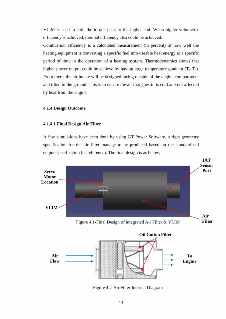
A few simulations have been done by using GT Power Software, a right geometry
specification for the air filter manage to be produced based on the standardized
engine specification (as reference). The final design is as below;
Figure 4.1-Final Design of integrated Air Filter & VLIM
Figure 4.2-Air Filter Internal Diagram
Servo
Motor
Location
VLIM
Air
Filter
IAT
Sensor
Port
Oil Cotton Filter
Air
Flow
To
Engine

15
4.1.4.2 Final Design VLIM
A few simulations have been done by using GT Power Software, a new design that
meets our expectation performance manage to be produced by using the simulations.
In GT Power Software, we have tried few designs and simulate it. Finally, the right
design with right geometry manages to be produced. The movement of VLIM will
be drove by servo motor and gears which is collaborated with engine speed. The
design is as below;
Figure 4.3-VLIM Snorkel Part A
Figure 4.4-VLIM Snorkel Part B
Servo
Motor
Location
Jig Lock
Jig Lock
Holder

16
4.1.4.2 Final Design Element Selection
From the comparison made from the results between 3rd
party brand air filter and
OEM product, the author had made spider web chart. The results as below;
0
20
40
60
80Filtration
Less
Pressure
Drop
EfficiencyPrice
Availability
OEM
After Market
New Design
Expectation
Figure 4.5-Comparison between OEM and 3rd
Party Air Filter
(0: poor, 100: excellent)
*OEM= Original Equipment Manufactured
*After Market = K&N and AEM Cone Type (SwRI Project No. 03.10955.008)
*New Design = Expected Outcome
*Test Condition- (PTI ISO 12103-1), Air Flow: 160scfm, Pressure: 101.3 kPa,
Temperature: 20oC, Time: 30 min, Concentration: 0.028g/ft
3
There are many differences between aftermarket product and OEM product.
Aftermarket air filter is use oil cotton as the filtration element while the OEM air
filter is using paper element. From the figure 4.8, it shows the difference between
both product and also expected outcome of the new design in terms of filtration, less
pressure drop, cumulative efficiency, price and its availability. In terms of filtration,
less pressure drop and cumulative efficiency, the aftermarket air filter is better than

17
OEM air filter. This result is based on SwRI project report. Aftermarket products
also available for various vehicle while OEM products only specific to certain
vehicle. However, OEM product is cheaper due to no cost use for research and
development. For the new design, the author try to hit the most excellent which suit
to its expected performance and marketable.
4.2 Design Simulation
4.2.1 Air Filter Design Simulation
From the 3D CATIA modeling, the ‘Design 1’ air filter has been simulated in
ANSYS software application as below;
Figure 4.6 ‘Design 1; Air Flow Simulation
From the figure 4.6, the air flow speed increase tremendously which will bring more
air into the engine inlet. However, the author did not satisfy with the design due to
an air separation/weigh occur before reaching the air filter outlet.

18
Figure 4.7 ‘Design 2’ Air Flow Simulation
From the figure 4.7, some adjustment had been made in the centre fin where the
sharp edge had been redesign with fillet curve. The simulation shows that the
velocity of the air is faster, smooth air flow and more air was generated to the air
filter outlet.
Figure 4.8 ‘Design 2’ Air Flow Velocity Changes Area

19
4.2.2 VLIM Design Simulation
A few simulations have been done by using GT Power Software, a new design
which that meets our expectation performance manage to be produced by using
the simulations. In GT Power Software, engine specification that been used is as
below;
Table 4.2.2(a)-Standard Engine Geometry (as reference)
Bore [mm] 93.0
Stroke [mm] 81.0
Connecting Rod Length [mm] 157.0
Piston Pin Offset [mm] 0.00
Displacement/Cylinder [liter] 0.550
Total Displacement [liter] 2.201
Number of Cylinders 4
Compression Ratio 8.90
Bore/Stroke 1.148
IVC [CA] -110
EVO [CA] 134
IVO [CA] 357
EVC [CA] 376
From the above engine specification, an air filter with standard geometry has
been attached to the engine GT Power simulation program as below;
Table 4.2.2(b) Standard Air Filter Geometry (as reference)
Diameter at Inlet End mm 150
Diameter at Outlet End mm 150
Length mm 150
Discretization Length mm [dxi]
Surface Roughness mm 0.025
Wall Temperature K 300
Heat Conduction Object ign

20
As a result, the simulation has come out with power and torque curve as below;
Figure 4.9-Result of Power and Torque curve (Simulation 1)
From the above graph, the torque curve is inclining slowly at the beginning of the
engine speed and only achieves its pick at around 4000rpm with 184N-m while for
power curve; it is only achieve 83kW at 5000rpm. From the graph, it shows that
pressure drop at the idling engine speed is too high. Therefore, the air filter has been
re-designed to get better output.

21
As a result, the simulation has come out with better power and torque curve as
below;
Figure 4.10-Result of Power and Torque curve (Simulation 2)
From the above graph, the torque curve is inclining drastically at the beginning of
the engine speed and achieves its 2nd
pick at around 4000rpm with 183N-m while for
power curve; it manage to achieve 60kW in early stage at 3000rpm. From the graph,
it shows that pressure drop at the idling engine speed is better. Therefore, the air
intake system has been developed with variable length intake manifold (VLIM) to
get the best output. The best power and torque curves occurred as figure 4.14;

22
Figure 4.11-Result of Power and Torque curve (Simulation 3)
From the above graph, the torque curve is inclining tremendously at the beginning of
the engine speed and achieves its 1st pick at 3000rpm with 187N-m and 2
nd pick at
4000rpm with 184N-m while for power curve; it manage to achieve 60kW in early
stage at 3000rpm and 78kW at 4000rpm. From the graph, it shows that the variable
length intake manifold has helped the engine to achieve higher torque at lower rpm
and produce more power at higher rpm.
Table 4.15 - Engine MEP, Torque and Power (SI Units)
Indicated Crankshaft Friction Attachments Brake
MEP [bar] 11.0 11.0 -1.8 0.0 9.1
Torque [N-m] 192.1 192.1 -32.0 0.0 160.1
Power [kW] 100.6 100.6 -16.8 0.0 83.8

23
CHAPTER 5
CONCLUSION AND RECOMMENDATIONS
After the study has been conducted, the author is able to know all the information
needs that vital in designing engine air intake. Researchers around the globe have
developed variable length intake manifold for last few years, however putting it into
production vehicle is still less. Besides, they are more towards developing new air
filter design. The author has decided to develop both. Variable length intake
manifold which integrated with air filter is something new and the studies could give
more impact on engine performance and efficiency. In this report, the author shows
that the design that has been developed is approved based on its simulation. The
result shows that the new design has capability to give more torque during at the
lower speed and bring more power at higher speed. The good thing is the design also
applicable to most existing cars. Thus, it will give more economic value to users.
However, a prototype needs to be implemented to ensure its capability in real engine.
24
CHAPTER 6
REFERENCES
1. Mahle makes air filtration acquisition
Filtration Industry Analyst, Volume 2007, Issue 1, January 2007, Page 4
2. Individual Cylinder characteristic estimation for a spark injection
engine
Automatica, Volume 39, Issue 7, July 2003, Pages 1157-1169
L. Benvenuti, M. D. Di Benedetto, S. Di Gennaro, A. Sangiovanni-
Vincentelli
3. Cylinder air-charge estimation for advanced intake valve operation in
variable cam timing engines
JSAE Review, Volume 22, Issue 4, October 2001, Pages 445-452
Mrdjan Jankovic, Steve W. Magner
4. Low permeation sealing of air intake manifolds
Sealing Technology, Volume 2002, Issue 9, 1 September 2001, Pages 7-9
Simon Atkinson
5. Automatic design of diagnosis systems with application to an automotive
engine
Control Engineering Practice, Volume 7, Issue 8, August 1999, Pages 993-
1005
Mattias Nyberg
6. Finite element analysis with staggered gradient elasticity
Computers & Structures, Volume 86, Issues 11-12, June 2008, Pages 1266-
1279
Harm Askes, Irene Morata, Elias C. Aifantis
7. Design for a high energy density Kelvin–Helmholtz experiment
High Energy Density Physics, In Press, Corrected Proof, Available online 6
March 2008
O.A. Hurricane

25
8. The generalized finite element method for Helmholtz equation. Part II:
Effect of choice of handbook functions, error due to absorbing boundary
conditions and its assessment
Computer Methods in Applied Mechanics and Engineering,
Volume 197, Issue 5, 1 January 2008, Pages 364-380
Theofanis Strouboulis, Realino Hidajat, Ivo Babuška
9. Contact symmetries of the Helmholtz form
Differential Geometry and its Applications, Volume 25, Issue 5, October
2007, Pages 518-542
Demeter Krupka, Olga Krupková, Geoff Prince, Willy Sarlet
10. The Helmholtz equation in a non-smooth inclusion
Nonlinear Analysis: Theory, Methods & Applications, In Press, Corrected
Proof, Available online 29 August 2007
Guozheng Yan

26
APPENDICES
Appendix 1: Isometric View of Integrated Air Filter & VLIM

Appendix 2: Front View of Integrated Air Filter & VLIM

Appendix 3: Side View of Integrated Air Filter & VLIM

Designing Air Intake System for Engine Performance and
Efficiency Optimisation
By
Mohamed Faiz bin Mohamed Amin
Dissertation submitted in partial fulfilment of
the requirements for the
Bachelor of Engineering (Hons)
(Mechanical Engineering)
April 2008
Universiti Teknologi PETRONAS
Bandar Seri Iskandar
31750 Tronoh
Perak Darul Ridzuan