ping pong simulation by dissertation submitted in partial ... - utpedia
TRANSCRIPT
Ping Pong Simulation
by
Mohd Zulkhairi Bin Radzi
Dissertation submitted in partial fulfillment ofthe requirements for the
Bachelor of Technology (Hons)(Information and Communication Technology)
Universiti Teknologi PETRONASBandar Sen Iskandar
31750 Tronoh
Perak Darul Ridzuan
JAN 2008
Approved by,
CERTIFICATION OF APPROVAL
Table Tennis Simulation
by
Mohd Zulkhairi Bin Radzi (6505)
Dissertation submitted in partial fulfilment of
the requirement for the
Bachelor of Technology (Hons)
(Information and Communication Technology)
JANUARY 2008
(Y?w Kwang Hooi)
Universiti Teknologi PETRONAS
Bandar Seri Iskandar
31750 Tronoh
Perak Darul Ridzuan
CERTIFICATION OF ORIGINALITY
This is to certify that I am responsible for the work submitted in this project, that the
original work is my own except as specified in references and acknowledgements,
and that original work contained herein have not been undertaken or done by
unspecific sources or persons.
7
Mohd Zulkhairi Bin Radzi
11
ABSTRACT
The purpose of this project is to come out with a working prototype of the Ping Pong
game where the user can play Ping Pong game by using wireless detector of Ping
Pong bat that is already equipped with infra red LED. Since normal virtual reality
application requires a complex virtual reality system with a lot of wires and
sophisticated gadgets to handle the application, this prototype of virtual reality Ping
Pong game can be played by only using webcam and modified Ping Pong bat and the
system requirement for the application is only average running PC that equip with
Intel Pentium 4 or AMD Athlon. This project requires me to develop a game engine
by using either DirectX or OpenGL graphic libraries. Both offer inherent advantages
and disadvantages, hence warranting a study about these libraries and come out with
a better solution. This project use waterfall method where the project consist of 3
phases that consist of all development step in waterfall model. Waterfall model is
relevant because the project does not involve with customer. Hardware setup and
basic application is done where the motion capture device is ready to be used and the
application with basic functionality has completed. There is a lot of improvement
that can be made to improve the whole system, both hardware and software. But
there are limit where I can improve the hardware since the driver for motion capture
is confidential.
in
ACKNOWLEDGEMENT
I would like to express my deep and sincere gratitude to my supervisor, Mr Yew
Kwang Hooi for his wide knowledge and creative way of thinking in assisting this
project. His understanding, encouraging and personal guidance have provide a good
basis for the present report.
I wish to express our warm and sincere thanks to Dr Fun Wey for allowing me to use
his technology, 3DXense for the purpose of learning and completing this project.
And also his great ideas and support help me in developing this project. Also not to
forget Mr Phyar from China, for allowing me to use his physics engine in the project.
His great support help me in developing this project to a better way.
My warm thanks are due to those who have directly or indirectly assisted me in this
study, be from local or from worldwide community. Their kind support and guidance
have been of great value in this study.
Not to forget to all my family, my friends and whoever involve in assisting me in this
project.
IV
TABLE OF CONTENT
CERTIFICATION OF APPROVAL i
CERTIFICATION OF ORIGINALITY ii
ABSTRACT , iii
ACKNOWLEDGEMENT iv
TABLE OF CONTENT v
LIST OF FIGURES vi
LIST OF EQUATION vii
CHAPTER 1 INTRODUCTION 1
1.1 Background Study 1
1.2 Problem Statement 2
1.2.1 Problem Identification 2
1.2.2 Significant of the Project 2
1.3 Objectives and Scope 3
1.3.1 Objectives 3
1.3.2 Scope of Studies 3
CHAPTER 2:LITERATURE REVIEW 5
2.1 DirectX Graphics Library 5
2.1.1 Introduction 5
2.1.2 Direct3D 5
2.2 OpenGL Graphics Library 6
2.2.1 Introduction 6
2.2.2 Khronos Group 6
2.2.3 OpenGL Design 7
2.3 3DXense 8
2.3.1 Introduction 8
2.3.2 How Does it Works 8
2.3.3 Integration of 3DXense into the application 10
2.3.4 Limitation of 3DXense 12
2.3.5 Advantage of 3DXense 12
2.4 In Game Physics 14
2.4.1 Vector 15
v
2.4.2 Mass, Center of Mass 15
2.4.3 Kinematics 16
2.4.4 SPE Physics Engine 20
CHAPTER 3 METHODOLOGY 23
3.1 Phase 1 23
3.1.1 Requirement 23
3.1.2 Specification 24
3.1.3 Design 24
3.2 Phase 2 and 3 32
3.2.1 Implementation 32
3.2.2 Bug Fixing 32
3.2.3 Integration 32
3.3 Methodology Diagram 33
CHAPTER 4:RESULT AND DISCUSSION 34
4.1 Result 34
4.1.1 Hardware Setup 34
4.1.2 Problem Encountered and Solution 37
4.2 Discussion 38
CHAPTER 5:CONCLUSION AND RECOMMENDATION 39
5.1 Conclusion 39
5.2 Recommendation 39
REFERENCES 40
APPENDICES 41
VI
LIST OF FIGURES
Figure 1: Changes in the LED size 9
Figure 2: Interaction between the application and driver 11
Figure 3: The movement of the ball in 2D particle kinematic 16
Figure 4: Sample of 3D particle kinematics problem 19
Figure 5: Flow chart for the ball physics 25
Figure 6:-Ball angle or direction 26
Figure 7: Flow chart for the whole application 28
Figure 8: Flow chart for Init Direct 3D 29
Figure 9: Flow chart for Init Geometry 30
Figure 10: Flow chart for Render 31
Figure 11: Methodology 33
Figure 12: Modified ping pong bat 34
Figure 13: Camera used for the motion capture. 35
Figure 14: Hardware setup 36
Figure 15: Screenshot of the simulation 37
vn

LIST OF EQUATION
Equation 1: Velocity 17
Equation 2: Acceleration 17
Equation 3: 3D particle calculation 19
vm
1.0 CHAPTER 1: INTRODUCTION
1.1 Background Study
Game always being associated with the traditional ways of input device such as
keyboards and joy pads. Since games industry nowadays has evolve in many
different ways, there are lots more that developer can explore in giving gamers
different kind of ways to plays games. With the release of Nintendo Wii, gamers now
have another choice of how they can enjoy playing games. Nintendo Wii use
different kind approach by modifying their controller to be used with motion
detection. Say goodbye to the conventional ways of pressing button. Nintendo Wii's
controller called Nunchuck can detect the acceleration and 2D movement of the
players hand and thus user can have a lots of ways for example to play tennis game.
Note that Nunchuck can only detect 2D movement and acceleration, not 3D
movement detection, thus can limit the capability of the game. What if the user
swings theNunchuck in different kind of style while playing tennis game? This gives
developer opportunityto explore more into motiondetection games.
Affmeontech is a company that develop the technology to detect 3D motion using
infrared LED. The technology not onlycan detect flat 2D movement of the LED, but
also back and forth movement of the LED making it perfectly suit the virtual reality
world where the movement of the LED will be reflected real time into the
application. Although it doesn't have any accelerometer to detect the acceleration of
the movement, but with the size calculation of the LED represented by the dot in the
driver, it can calculate the acceleration and speed of the movement.
1.2 Problem Statement
1.2.1 Problem Identification
Virtual reality is very expensive and not many people can it. Since the space required
to set up the system is huge and the complexity of the system is complex, it is not
suitable for fun usage and gaming purpose. Game associated with the virtual reality
technology is interesting to explore, but because of the limitation of current system, it
make the development of games using virtual reality technology is not practical at
all. It is interesting to see if games can evolve where we can actually punch the
enemy using our own style and play tennis games with the real racquet, not just
pressing the button and the movement is already recorded thus making the game
pretty limited to play since it only repeat what have been recorded. Virtual reality can
also be used as a training simulation. There has been several simulation machine
develop to simulate the real time situation such as flight simulation and disaster
simulation. But there are no single simulation that can be used as a sports simulation
such as tennis and ping pong. This is because the limitation of virtual reality where
the space required is huge and also if sport simulation like tennis required racquet,
there will be a lot of wires connected to the racquet. So the challenge for the industry
is that they must come out with a more simple virtual reality technology that is
cheap, and doesn't require a lot of space and wires.
1.2.2 Significant of the Project
The goal of the project is to understand more about DirectX and openGL
programming where this two API is the key to explore more about game
development. Game development involves a lot more areas not only specific to
graphic programming, but also sound programming and artificial intelligence
programming.
The goal of the project is also to learn more about motion detection system as this
technology not only can be implemented in virtual reality, but also in other sector
such as security, manufacturing and weapon system.
1.3 Objectives and scope
1.3.1 Objectives
a) To develop a functional Ping Pong game by using infra red sensor so that the
user can play Ping Pong game using real Ping Pong bat.
b) To develop a simple artificial intelligence for opponent that player or user can
play Ping Pong game with the AI opponent.
c) To set up the system for Ping Pong game that require Ping Pong bat that has
been modified to make sure that the camera can detect the movement of the
bat.
1.3.2 Scope of Studies
The project research will focus on game development, artificial intelligence and
game programming. For game development, the author will study about related
methodology that has been used by other game developer to develop the game. There
are quite a few methodologies that are needed to note since the project will have
limited amount of time and resource. Artificial intelligence will be importantbecause
the game itself require opponent for the user to play. But this feature is optional
because of the limited time available have to develop the game. The last one will be
the programming itself where the author will study about the game programming
where it involve studying about DirectX and openGL.
The author will develop the game itself including the engine of the game and 3D
model in the game itself. For the motion detection functionality, the driver and the
hardware will be provided by Affineon Technologies Pte Ltd. The company will
provide me tweaked driver especially for my game which is Ping Pong game. The
motion detection engine has been loaned to me by the company including the camera
that will be used in the project.
By the end of the project development, there will have a working prototype of the
system and the game itself where the user can play Ping Pong game using the real
Ping Pong bat.
2.0 CHAPTER 2: LITERATURE REVIEW
2.1 DirectX graphic library
2.1.1 Introduction
DirectX is graphic library develop by Microsoft Corporation to cater the growing
need of standard graphic library for Windows platform. DirectX library include
interface for handling multimedia object such as graphic, 2D and 3D, audio, network
and video. Throughout the development of DirectX, some of the library has been
taken out from DirectX such as DirectPlay and DirectShow for handling task such as
network application and video processing.
2.1.2 Direct3D
Direct3D is the key component of DirectX where Direct3D is the interface for
programmer or developer to develop 3D application. Earlier version of DirectX
includes both DirectShow and Direct3D where Direct3D is only for 3D rendering
and all the 2D rendering is being process by DirectShow. But with the latest version
of DirectX, after DirectX 9.0a, DirectShow has been taken out from DirectX
interface. Most of 2D processing library is already included in Direct3D and if
developers need to develop 2D application, then Microsoft already provide developer
with graphic library for 2D image processing which is out from DirectX, Windows
GDI and Windows GDI+.
2.2 OpenGL Graphic Library
2.2.1 Introduction
Differ from DirectX, openGL graphic library focus solely on 2D and 3D graphic
processing. OpenGL does not have any library associated with other application such
as networking and audio processing. Company developing games with openGL
usually have their own set of library for other multimedia application such as
openAL for audio processing and C++ socket library for networking application.
Some of them develop from scratch their own library to cater the need for ever
evolving game industry. During early days, OpenGL only focus on engineering
application such as Computer Aided Design and hardly there is a games develop
using OpenGL.
2.2.2 Khronos Group
Khronos Group is the group of company that combine together to manage the flow of
openGL architecture. Before this, openGL is being monitored and revised by a group
called ARB, where ARB stands for OpenGL Architecture Review Board. On 21
September 2006, openGL Architecture ReviewBoard has been passed on to Khronos
Group and since that, they are the one who manage and review architecture of
openGL. Khronos Group consists of following member:
• AMD
• Creative Labs
• Intel
• id Software
• NVIDIA
• Sony Computer Entertainment
• Sun Microsystems
• Texas Instrument
2.2.3 OpenGL Design
OpenGL serve two main purposes;
• To hide the complexity of interfacing the different 3D accelerator, by
presenting the programmer with a single, uniform API.
• To hide the differing capabilities of hardware platform, by requiring that all
implementation support the full openGL feature set( using hardware
emulation of necessary)
OpenGL's basic operation is to accept primitive such as points, lines, and polygons,
and convert them into pixels. This is done by a graphics pipeline known as the
openGL state machine. Most openGL commands either issue primitives to the
graphic pipeline, or configure how the pipeline processes these primitives. Prior to
the introduction of openGL 2.0, each stage of the pipeline performed a fixed function
and was configurable only within tight limits. OpenGL 2.0 offers several stages that
are fully programmable using openGL ShaderLanguage.
OpenGL is a low level, procedural API, requiring the programmer to dictate the
exact steps required to render the scene. This contrast with the descriptive (aka scene
graph or retained mode) APIs where a programmer only need to describe a scene and
can let the library manage the details of rendering it. OpenGL's low-level design
requires programmers to have a good knowledge of graphic pipeline, but also give a
certain amount of freedom to implement novel rendering algorithms.
2.3 3DXense
2.3.1 Introduction
3DXense is the technology develops by Affinieon Technology Pte. Ltd. based on
Singapore. Affinieon Technology is the company specialized in developing motion
detection technology that deal with virtual reality. The company has release a few
games that related in virtual reality such as golf game and sword fighting game that
required the user to move like a real golfer or sword fighter. The technology is the
first that require only single camera to detect 6 degree of freedom which is roll, yaw
and pitch.
3DXense enable us to be able to use the normal webcam as a motion detector and not
like the normal virtual reality equipment which require a lot of wires and consume a
lot of spaces. The price for the development is also cheaper than the normal virtual
reality where games develop using 3Dxense technology cost no more than a
thousand but for the normal virtual reality, equipment itself cost more than a
thousand and not including the software, thus making it not suitable for home usage
and merely for lab or testing purpose only. 3DXense on the other hand only require
webcam and infra red led only and cost sometime not more than a hundred.
2.3.2 How does it works
3DXense will takes the coordinate of the infra red LED and translate it into real
world coordinate in 3D world. Note that when the driver captures the location of the
infra red LED, it is actually reverse from the actual world. This is because the user or
the object is actually facing the webcam and not back facing the webcam. The
problem was solved by translating the coordinate and inverse the coordinate to match
the real world mapping of the bat or the infra red LED.
The driver detects the motion and acceleration of the infra red LED by calculating
the size of the LED signal that varies between the range of the LED and the camera.
For example if the infra red LED is located close to the camera, the size of the dot
that appear in the driver will be bigger that the size ofthe infra red LED that located
far away from the camera. By using this information, we can calculate the
acceleration and the speed of the infra red LED or the bat since the bat is equipped
with infra red LED itself. The calculation will involve the size of the LED signal, and
how it varied between times.
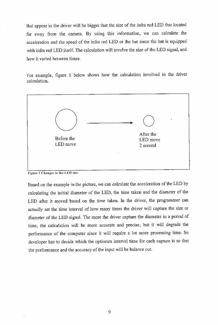
For example, figure 1 below shows how the calculation involved in the drivercalculation.
After theBefore the LED moveLED move 2 second
Figure I Changes in the LED size
Based on the example inthe picture, we can calculate the acceleration ofthe LED by
calculating the initial diameter of the LED, the time taken and the diameter of the
LED after it moved based on the time taken. In the driver, the programmer can
actually set the time interval of how many times the driver will capture the size or
diameter of the LED signal. The more the driver capture the diameter in a period of
time, the calculation will be more accurate and precise, but it will degrade the
performance of the computer since it will require a lot more processing time. So
developer has to decide which the optimum interval time for each capture is so that
the performance and the accuracy of the input will be balance out.
2.3.3 Integration of 3DXense into the application
In order for the application to get the coordinate of the Ping pong bat, it needs to
integrate with the 3DXense function. The developer of 3DXense has made it easier
by developing the function specially to get the information from the driver into the
application. The developer that wants to use the technology can just insert the
function into their application and then the function will do the underlying process to
communicate with the driver and get the coordinate of the infra red LED.
After the information and data regarding the coordinate of the infra red LED has
been acquired, the application will then translate it into the 3D world coordinate and
then match it with the coordinate of the virtual ping pong bat in the 3D world. The
theory is much the same as what they use in the motion capture technology in film
making industry. The actor will wear a cloth that have white or green dot at the
texture of the cloth. The dot usually located on the articulation point of human
anatomy. The dot than will be match with the artificial human in the 3D world or
monster in the 3D world just as what we see how 3D character in movies and games
move around.
10
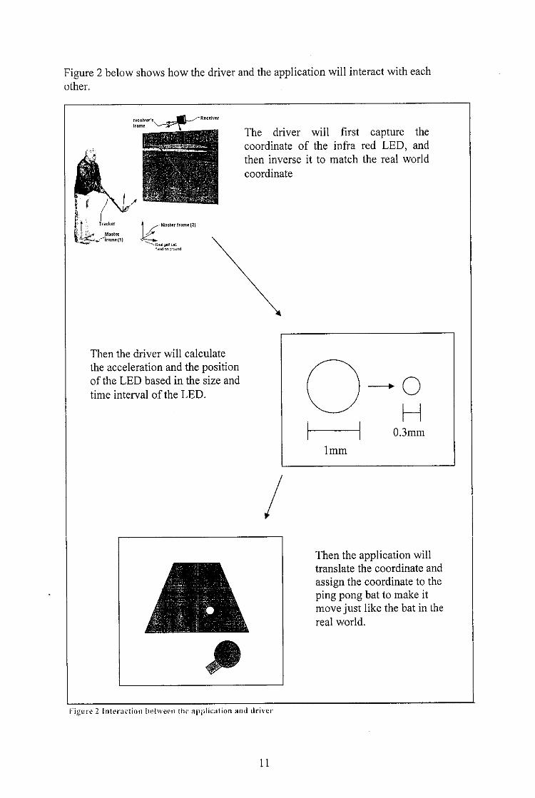
Figure 2 belowshows how the driver and the application will interact with eachother.
Then the driver will calculate
the acceleration and the positionof the LED based in the size and
time interval of the LED.
The driver will first capture thecoordinate of the infra red LED, andthen inverse it to match the real world
coordinate
Then the application willtranslate the coordinate and
assign the coordinate to theping pong bat to make itmove just like the bat in thereal world.
Figure 2 interaction behvmi itu: application and driver
11

2.3.4 Limitation of the 3DXense
3DXense can only detect the object movement and not the full body movement. This
will limit the possibility of the game or simulation where the developer cannot
develop a game or simulation that includes the motion of the character. The
simulation can be expanding to a state where the application can detect the
movement of the body including the ping pong bat movement.
Also the speed of the motion capture algorithm depends hardly on the capability of
the webcam and the shutter lenses. If the users use cheap webcam where the shutter
speed of the webcam is slow and can only process 5 frames per second where the
high performance webcam can takes more than 15 frames per second. This will make
the performance of the application degrade because the motion capture device cannot
take enough frames to make it accurate to calculate the movement of the ping pong
bat.
2.3.5 Advantage of 3DXense
The advantage of using 3DXense rather than the conventional virtual reality
technology is that the cost of the equipment to setup the environment for the motion
capture is cheap. The cost for the development in this project is less than RM 400
where else if the same project developed using conventional virtual reality
technology, it could cost more than a few thousand Ringgit.
Another advantage of using this technology is that 3DXense does not require a lot of
space to set up the environment. For ping pong simulation, the user can just put the
webcam in front of their monitor and start playing it in front their personal computer
without having to conserve a lot of space to set up the environment.
3DXense also does not require any wires connected to the ping pong bat. It is
because the camera or the tracker will only detect the signal emitted by the infra red
LED and then calculate it based on the movement and location of the LED. But for
the conventional virtual reality setup, it required a lot of wires and thus making it
12

hard for the user to do free movement. The user's movement also limited because of
the limitation on the length of the wires itself.
13
2,4 In Game Physics
Physics in ping pong game plays a major role in the movement of the ball. Newton's
Laws of Motion will be used throughout the development of the game where it
involved the ball's reaction to the ping pong bat, ping pong table, force, and gravity
force.
According to Physics for Game Developer(2002)
Law I
A body tends to remain at rest or continue to move in a straight line at
constant velocity unless it is acted upon by an external force. This is
the concept of inertia.
Law II
The acceleration of a body is proportional to the resultant force acting
on the body, and this acceleration is in the same direction as the
resultant force.
Law III
For every force acting on a body (action) there is an equal and
opposite reacting force (reaction) in which the reaction is collinear to
the acting force.
(p.g- 1)
Based on the above quote, there exist three laws that need to be considered when
designing the game physics.
Law I will be applicable when the ball is being thrown from the training machine,
then the ball will continue move, but in order to simulate real life physics, gravity,
and traction with the air need to be considered.
Law II is applicable when designing how the ball will react when ping pong bat hit
the ball. Initially the ball will move towards the player, then after player hit the ball
with ping pong bat, the ball movement will change according to the force and
direction of ping pong bat. Thus this will make it as close as real life physics.
14
Although the direction of the ping pong bat face should be considered when the ball,
for the sake of simplicity, that portion will be omitted and we will assume that ping
pong bat face will only constantly face on the same direction.
Law III will not be so important in this application as the physics engine that will be
coded will not use the opposite force that react on the ball. In fact, the force variable
itself will be fixed and no matter how strong the user hit the ball, the force that reacts
on the ball is still the same. Future improvement of the application will include
dynamic force variable.
2.4.1 Vector
Vector plays a major role in the game physics. This is because acceleration, velocity
and magnitude are vector. Vector operations will be used throughout the
development of the physics engine. The example of vector operation would be vector
addition, dot product and cross product.
2.4.2 Mass, Center of Mass
In order to determine how the ping pong ball react to the gravity, mass is needed and
with mass included in the calculation, center of mass need to be calculated as well. In
the game physics, we did not use mass to determine how heavy the object is, but it is
to determine how resistance the object to change direction or movement. By saying
this, it would mean the greater the mass, the harder the ball to change the direction.
More details about this will be discussed later in game physics.
Center of mass is important to when we want to calculate how the ping pong ball
reacts to the ping pong bat when the collision occur. Different center of mass would
give different result when collisions occur.
15
2.4.3 Kinematics
Kinematics will be the study of how ping pong ball motion in the game. At first, it
will be focused on 2D particle kinematic, then after the prototype for 2D kinematics
run successfully; we will focus on 3D particle kinematics.
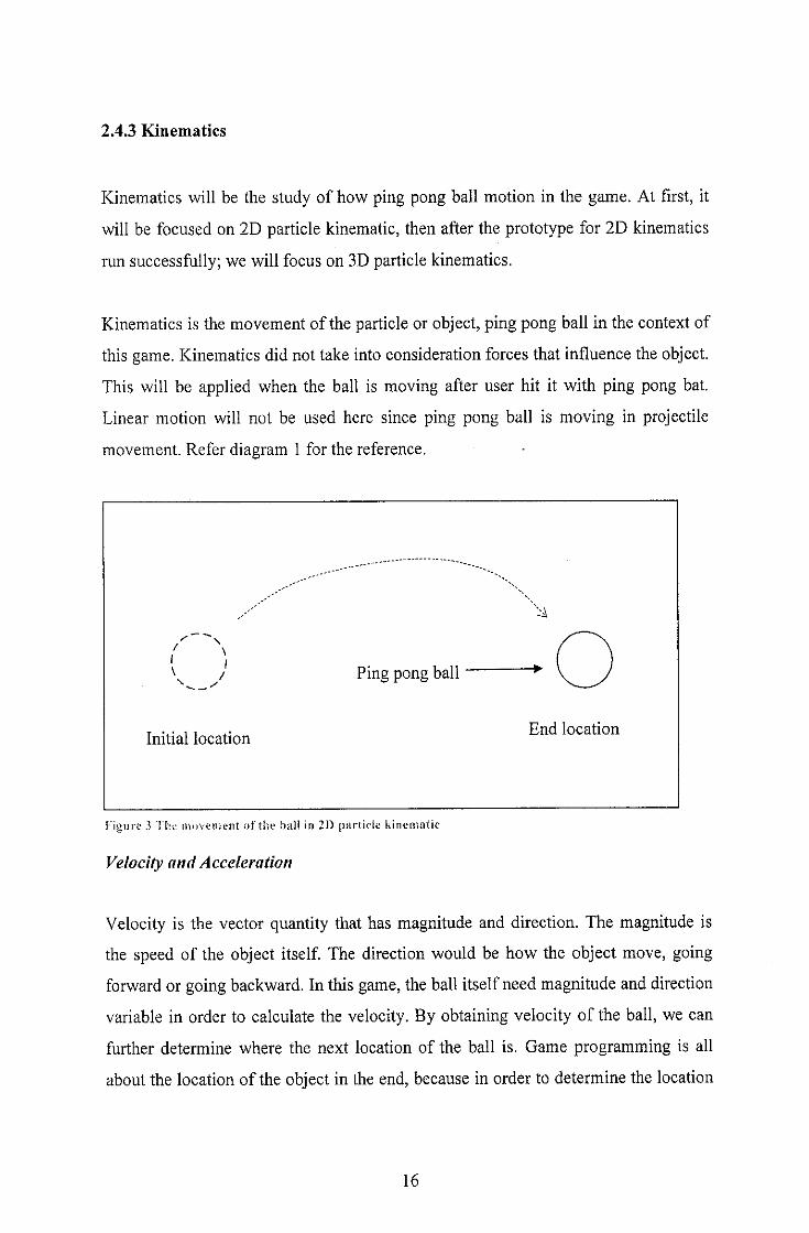
Kinematics is the movement of the particle or object, ping pong ball in the context of
this game. Kinematics did not take into consideration forces that influence the object.
This will be applied when the ball is moving after user hit it with ping pong bat.
Linear motion will not be used here since ping pong ball is moving in projectile
movement. Refer diagram 1 for the reference.
,' ^v,;
Initial location
Ping pong ball
^
End location
Figure 3 Tin; movement of the ball in 21) particle kinematic
Velocity and Acceleration
Velocity is the vector quantity that has magnitude and direction. The magnitude is
the speed of the object itself. The direction would be how the object move, going
forward or going backward. In this game, the ball itselfneed magnitude and direction
variable in order to calculate the velocity. By obtaining velocity of the ball, we can
further determine where the next location of the ball is. Game programming is all
about the location of the object in the end, because in order to determine the location
16
of the ball, we need velocity and the acceleration of the ball. The mathematical
expression for the velocity is
v = Aj/A/
Equation 1: Velocity
where s is the distance travel over time, t. But it programming, mathematical
expression will not do any good without changing it into programming language.
Thus the sample code to calculate velocity will be
/Velocity =/Distance//Time;
Acceleration is the rate of change of velocity over time. Mathematical
expression for acceleration is
a =Av/Ar
Equation 2: Acceleration
where v is the velocity of the object over time, t. The same goes for code in
programming language
/Acce = /Velocity //Time;
where fVelocity is taken from the result of calculation in velocity. Note that all of the
variable is in float because float is the most suitable type to be used in this
calculation because the number that we are going to calculated will not be very big,
but it also contain precisions points.
2D Particle kinematics
Before we look into 3D particle kinematics, it is better to study about 2D particle
kinematics first. 2D particle kinematics involve the movement of the object in x and
y axis only. Thus we are going to need three variable that will be used in the
17
calculation. This variable are; velocity, acceleration and displacement. This three
variables can will be included in a vector.
The movement of the object in 2D kinematics will be influenced by the gravity,
without taking into consideration wind and drag. Thus if the ball is being shoot by a
trainer machine, it will not go in straight line, but will travel in a curve line. Same
goes if we are designing shooting game, the bullet will not hit precisely at the target
but sway a little bit from the target. Throughout this application, the value of gravity
will be fixed to 9.8 m/s .
18
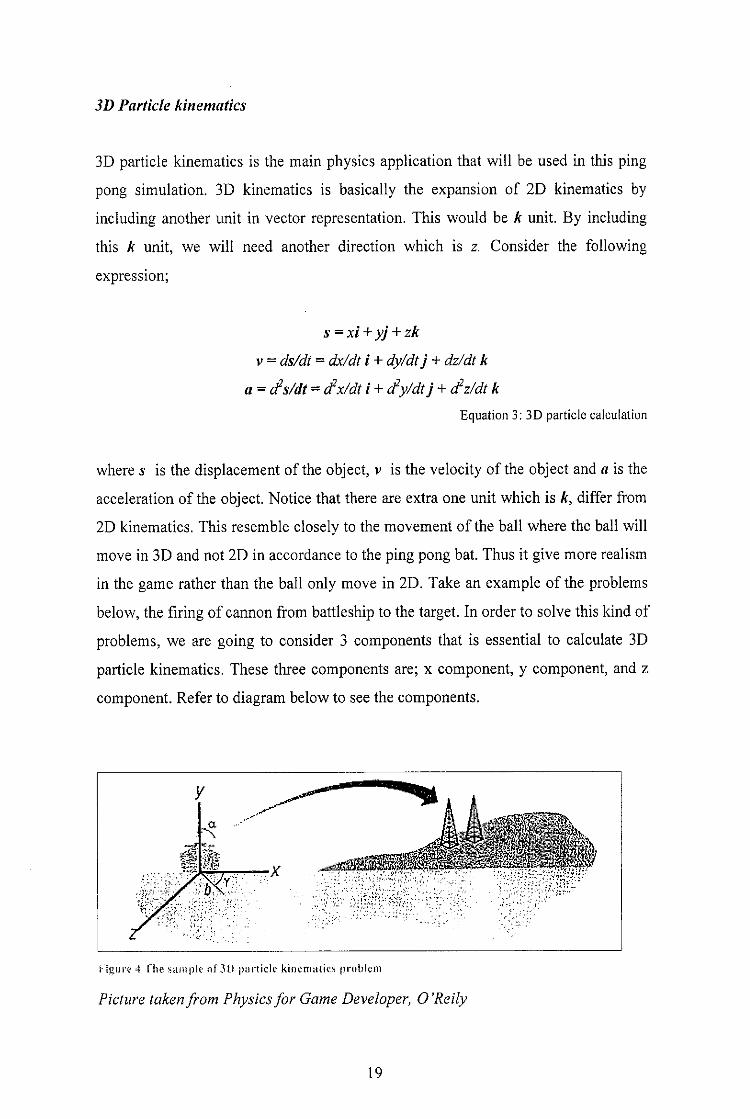
3D Particle kinematics
3D particle kinematics is the main physics application that will be used in this ping
pong simulation. 3D kinematics is basically the expansion of 2D kinematics by
including another unit in vector representation. This would be k unit. By including
this k unit, we will need another direction which is z. Consider the following
expression;
s = xi + yj + zk
v = ds/dt = dx/dt i + dy/dtj + dz/dt k
a =d2s/dt =Sx/dt i +Sy/dtj+Sz/dt kEquation 3: 3D particle calculation
where s is the displacement of the object, v is the velocity of the object and a is the
acceleration of the object. Notice that there are extra one unit which is A, differ from
2D kinematics. This resemble closely to the movement of the ball where the ball will
move in 3D and not 2D in accordance to the ping pong bat. Thus it give more realism
in the game rather than the ball only move in 2D. Take an example of the problems
below, the firing of cannon from battleship to the target. In order to solve this kind of
problems, we are going to consider 3 components that is essential to calculate 3D
particle kinematics. These three components are; x component, y component, and z
component. Refer to diagram below to see the components.
Kigui't' 4 ("he sample of 3D piirtide kinematics problem
Picture takenfrom Physics/or Game Developer, O'Reily
19
2.4.4 SPE physics engine
Introduction
SPE physics is Simple Physics Engine develop by Mr. Phiar from China for
educational use and the commercial use. This physics engine has all the basic
function for physic calculation in game environment. This engine can be used for the
either DirectX or OpenGL. Current stable version for SPE physics engine is version
3.0.
Getting start
To be able to use SPE physics engine, we need to include the library and the header
file included in the SDK where these two will handle all the function calls and
calculation required to run the engine.
Although SPE physics engine have all the basics functions to deal with physics in the
game, knowledge in real world physics is a must in order to understand how the
engine works, since the function name in the engine uses real world physics terms
and this can be quite confusing if the programmer does not know any physics terms.
Function usage
There are two major calculations that I use SPE physics engine to handle the
calculation. The first one is the movement of the ball. This is prior to the general
movement of the ping pong ball. Different ball moves different way than another.
For example, tennis ball react differently when we hit it with a bat and ping pong ball
itself react differently when we hit it with a bat. This is because of the differences of
mass and elasticity. Two function in the SPE physics engine handle this calculation
which is:
virtual void SetElasticity(float elasticity) = 0;
and
20
virtual void SetMass (float mass) = 0;
As the name implies, SetElasticity and SetMass will set both of the parameter of the
ball and this information will be used to determine how the ball moves.
Next is the collision detection for the ball and the object surrounding either ping
pong bat or the table. The coding below shows how coding for the collision detection
is being handled in the program.
Parti:
LPSPERIGIDBODY speBody, batBody;speBody=speWorld->CreateRigidBody(pShape);batBody=speWorld->CreateRigidBody(pShape);
Part 2:
speBody->GetState()->SetPosition(pos);speBody->GetNewState()->SetPosition(npos);batBody->GetState()->SetPosition(pos);batBody->GetNewState()->SetPosition(npos);
Part 3:
SPEArray list;
list.push(speBody);
list.push(batBody) ;
speWorld->DetectCollisions(list);
The code has been divided into three parts where each part is separated and their
location is different. Part 1 need to be initialize once and it reside in the geometry
initialization function where this function will initialize and create all the objects and
3D model in the game.
Part 2 and part 3 is ongoing process where every each time the game draw the 3D
objects in the game, these two part need to be executed. These two code reside in the
21

render function since before the game render all the 3D objects in the game, the
function will initialize the location of the object and then determine if the object
collide or not. If collisions occur, the engine will handle the reaction based on the
ball movement calculation stated before.
22
3.0 CHAPTER 3: METHODOLOGY
I am using waterfall model for the development of the project. The project will be
divided into three phases where the first phase will be documentation of the project.
The other two phases will be the actual coding and implementation of the project.
The different between phase 2 and phase 3 is, for phase 2, I will be developing the
game itself including major function that need to be in the game. Phase 3 will follow
the exact flow of phase 2 but the different is for the phase 3, I will be developing
extra or optional functionality for the game such as artificial intelligence for the
opponent.
Waterfall model is relevant to my project because of the project need to be developed
in sequence order. This project requires me to study about the motion detection and
graphic programming before I can proceed with the development. After all the
information required for the project has been collected, design and implementation of
the project will commence and thus make waterfall model suitable for this project.
Another reason why waterfall model is because this project does not involve
customer since this project purpose is to develop an application to test the technology
of motion detection. Thus my project development does not need to flexible to meet
the customer requirements since there is no customer involve in this project.
3.1 Phase 1
3.1.1 Requirement
In the requirement phase, I will rectify all the problem specification or problem
statement. In this phase also, I will identify all the constrain that involve in
developing the game.
The deliverable of this phase is problem statement and system constrains.
23
3.1.2 Specification
In this phase, I will come out with the system specification derive from problem
statement from requirement phase. In the system specification, I will clearly define
the function of the game and also optional functionality that will be added.
The deliverable of this phase is system specification.
3.1.3 Design
System specification from the specification phase will be translated into software
representation that includes:
a) Data structure
b) Software architecture
c) Algorithmic detail
d) Interface representation
In this phase also, I will come out with the system requirement of the project. This
includes minimum system requirement and also optimal system requirement.
The deliverable of this phase is system design.
24
Algorithm
Flow chart/or ballphysic
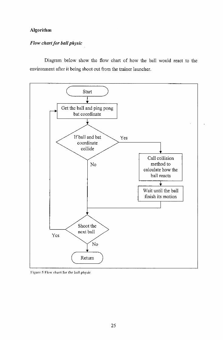
Diagram below show the flow chart of how the ball would react to the
environment after it being shoot out from the trainer launcher.
Start
Get the ball and ping pon^bat coordinate
•ijinre 5 Flow ch.nl for the ball physic
25
Yes
Call collision
method to
calculate how the
ball reacts
IWait until the ball
finish its motion
Based on Figure 5, if the bail and the bat collide, the program will call the collisionmethod to determine how the ball will react to the collision. This method is importantto make sure that the ball will react accordingly based on the real world physics. Thealgorithm to get the correspondent angle and acceleration for the ball is defined here.
Ball from the frame n-1
''~n Ball from the frame n1 \ • / /
\ / /\ / /
\ / /
Q /ri>^
Ping pongbat^-— / \
Angle A Angle B Angle C
Figure (\ Ball single or direction
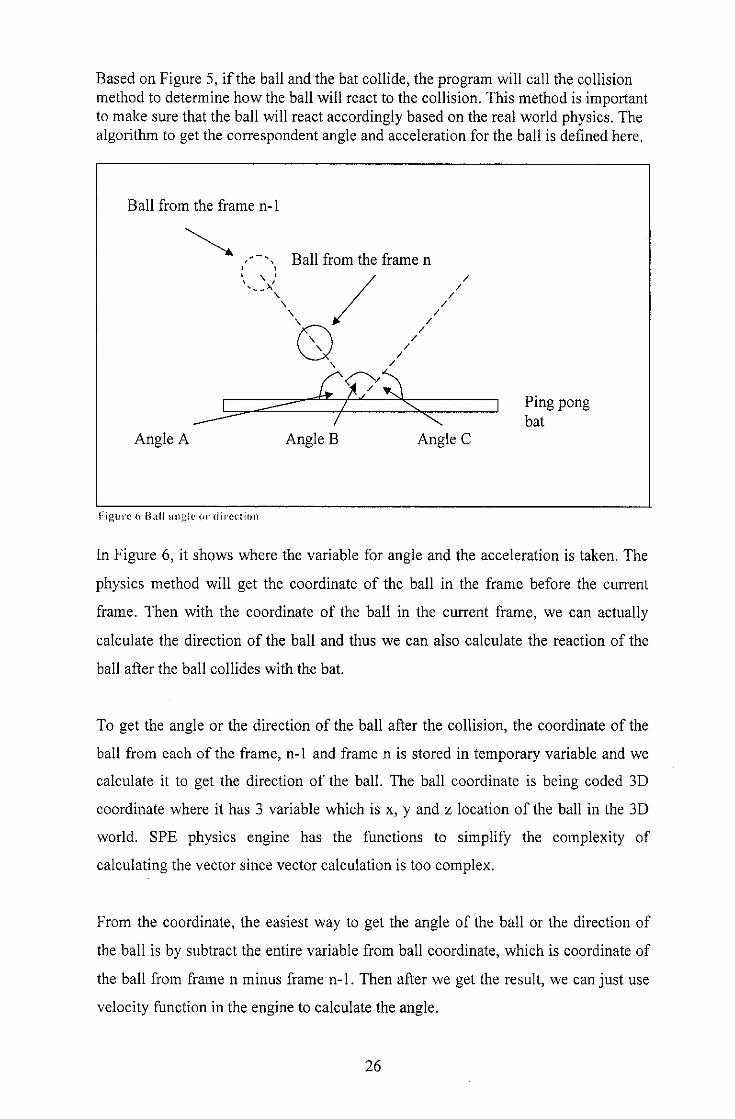
In Figure 6, it shows where the variable for angle and the acceleration is taken. The
physics method will get the coordinate of the ball in the frame before the current
frame. Then with the coordinate of the ball in the current frame, we can actually
calculate the direction of the ball and thus we can also calculate the reaction of the
ball after the ball collides with the bat.
To get the angle or the direction of the ball after the collision, the coordinate of the
ball from each of the frame, n-1 and frame n is stored in temporary variable and we
calculate it to get the direction of the ball. The ball coordinate is being coded 3D
coordinate where it has 3 variable which is x, y and z location of the ball in the 3D
world. SPE physics engine has the functions to simplify the complexity of
calculating the vector since vector calculation is too complex.
From the coordinate, the easiest way to get the angle of the ball or the direction of
the ball is by subtract the entire variable from ball coordinate, which is coordinate of
the ball from frame n minus frame n-1. Then after we get the result, we can just use
velocity function in the engine to calculate the angle.
26
To determine how the ball reacts to the bat, we need angle C from Figure 6. Angle C
comes from the angle that we get from the velocity function in the physics engine but
is being negate so that the angle is reflecting and not repeating the old path. Thus, by
accomplish this, we get simple collision detection in the application. Note that this
collision detecting is not using the real physics theory in the real world theory, but by
manipulating some of the functions in the physics engine and also graphics engine,
which is DirectX, we can get a collision detection that can resemble the real physics.
27
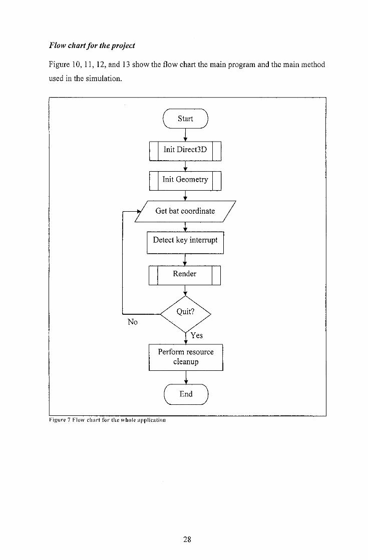
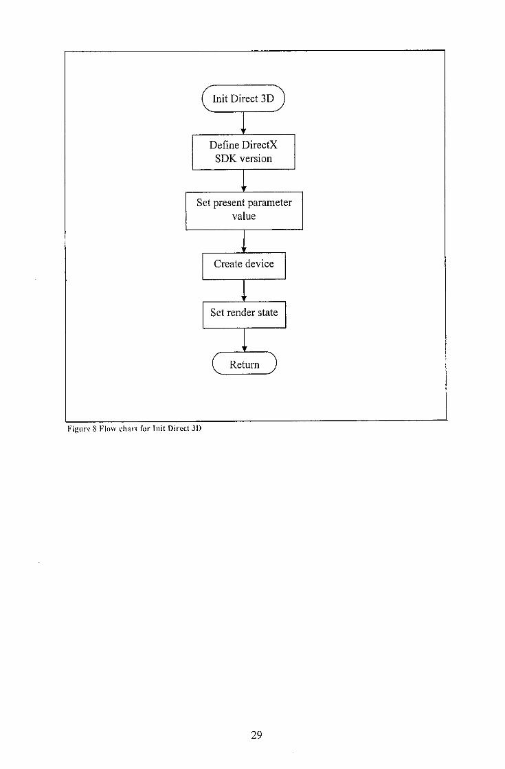
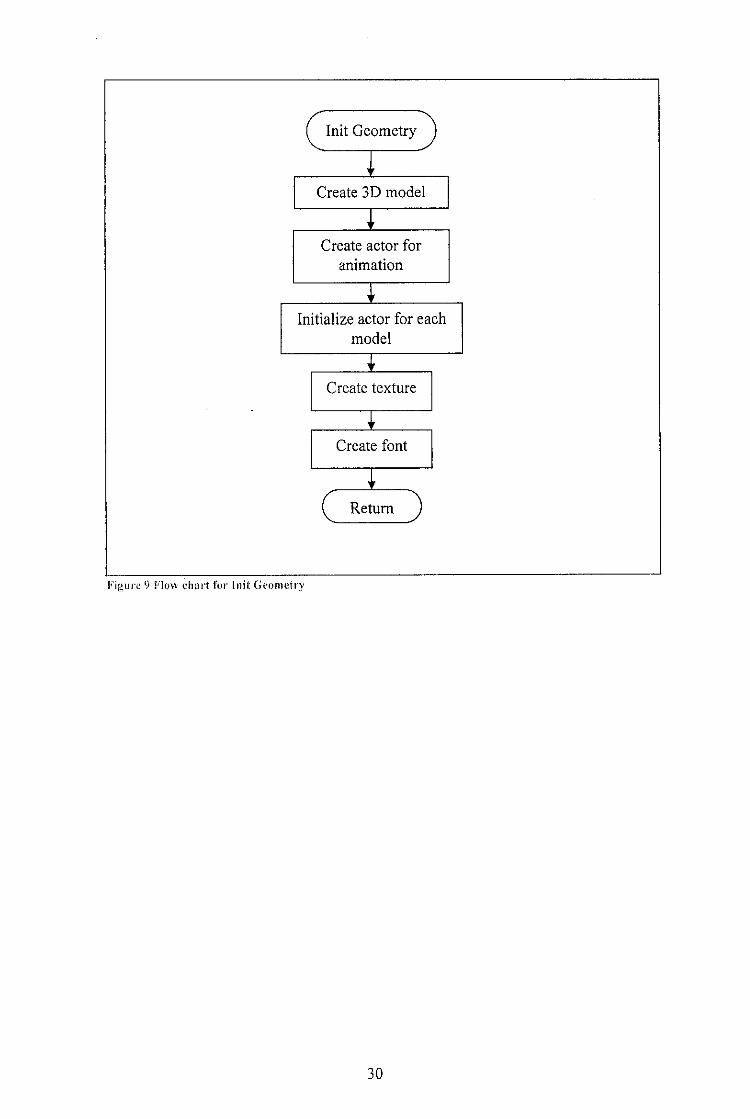
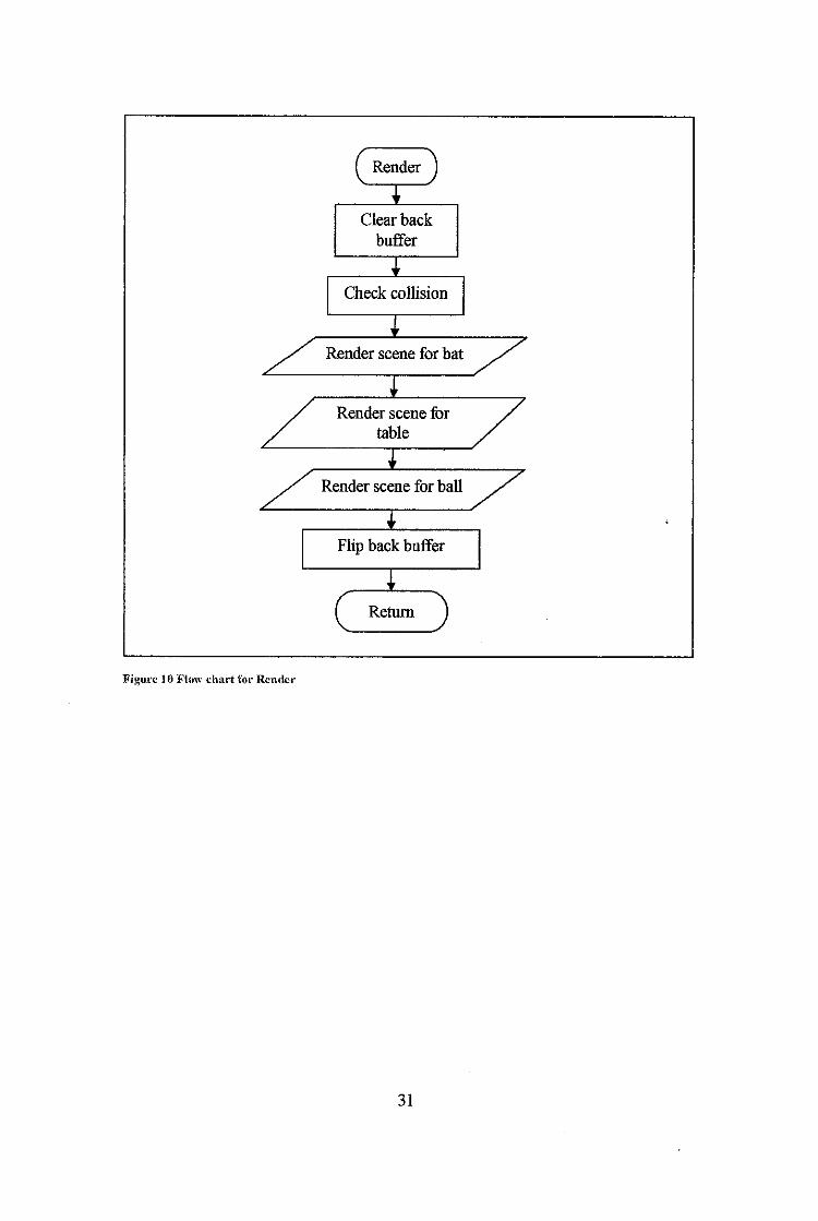
Flow chart/or the project
Figure 10, 11, 12, and 13 show the flow chart the main program and the main method
used in the simulation.
Start
Init Direct3D
Init Geometry
-w Get bat coordinate
No
Detect key interrupt
IRender
Perform resource
cleanup
iEnd
•igure 7 Flow char! for the whole application
28
Init Direct 3D
Define DirectX
SDK version
Set present parametervalue
Create device
Set render state
Return
Figure 8 Flow chart for Init Direct 3D
29
( Init Geometry )''
Create 3D model
''
Create actor for
animation
"
Initialize actor for each
model
1'
Create texture
1Create font
1'
(^ Return J
Figure ') Flow chart for Inil: Geometry
30
f Render JI
Clear back
buffer
''
Check collision
1'
Render scene for bat
iRender scene for
table
iRender scene for ball
i *
Flip back buffer
l( Return )
Figure 10 Flow chart lor Render
31
3.2 Phase 2 and 3
3.2.1 Implementation
System design from design phase will be translated into codes where in this phase,
programming is involved. After the coding is complete, I will conduct unit level
testing to test every each component of the software to make sure that each function
is working fine.
The deliverable of this phase is the prototypeof the product.
3.2.2 Bug Fixing
Bug fixing phase is optional and it only occur if there are major bug that affect the
system and it only come after the prototype is done. Testing will occur after the bug
has been cleared out.
3.2.3 Integration
Integrationphase is the phase for installationand pilot run of the product. It includes
setting up the system and all the hardware setup to run the program. System testing
will occur in this phase and the test will run by other people and not the programmer
of the system.
32
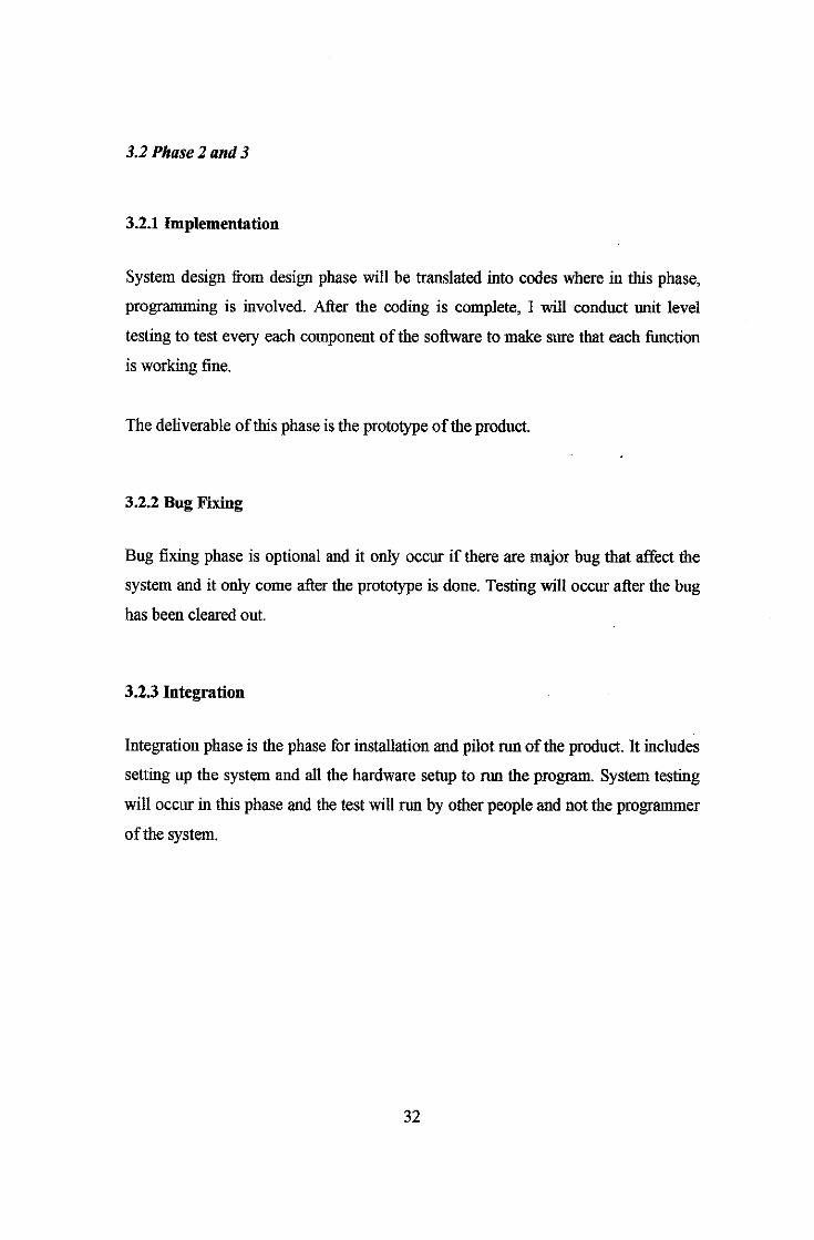
3.3 Methodology Diagram
Phase 1
RequirementVerify
ji pty~ c«/M-h**rt
SpecificationVerify
5 p-€Ci rt<-wen*
Phase 2 and 3
Integration
Testing
Figure 1.1 Methodology
Design
VerifyJ^/^u- £)U*I f%
Bug FixingTesting
33
ImplementationTesting
Phase 3
4.0 CHAPTER 4: RESULT AND DISCUSSION
4.1 Result
The application development has been going well. The engine for the 3D graphics
and motion capture semp is has been developed and tested .Physics engine using SPE
physics engine has been successfully integrated into the game.
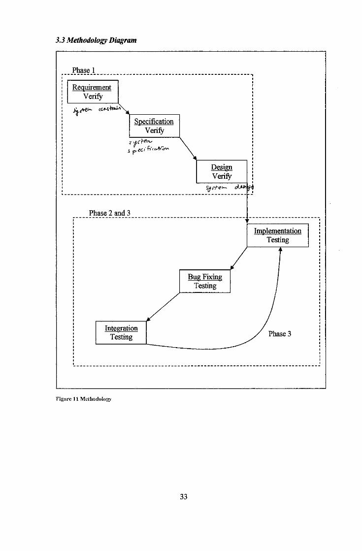
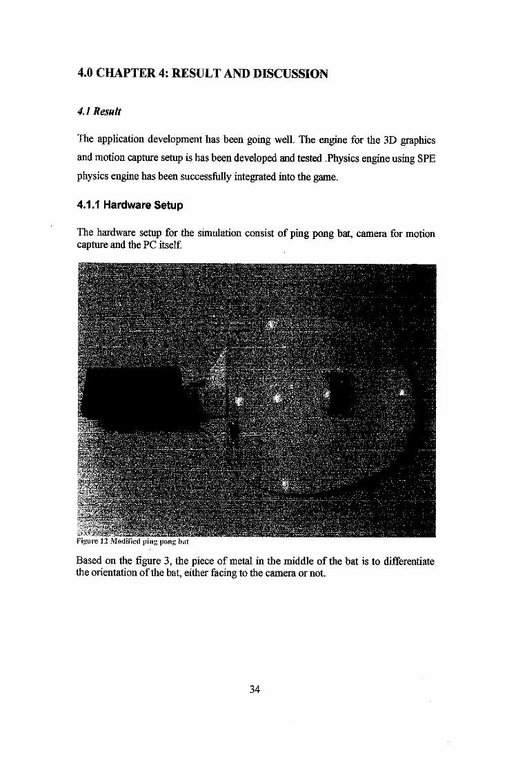
4.1.1 Hardware Setup
The hardware setup for the simulation consist of ping pong bat, camera for motioncapture and the PC itself.
4 - i.«!
**K
- - _^ . -Tiri ,1 -*, '*#
'.'id
i »•
1 * . *to«j*T' fcfl**"
*• *»«i'rf*
Based on the figure 3, the piece of metal in the middle of the bat is to differentiatethe orientation of the bat, either facing to the camera or not.
34
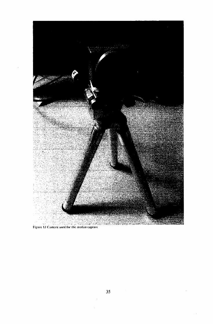
Figtite 13 CuncrA u«d tor (he motioti tapttirt
35

I anhvure setup
36
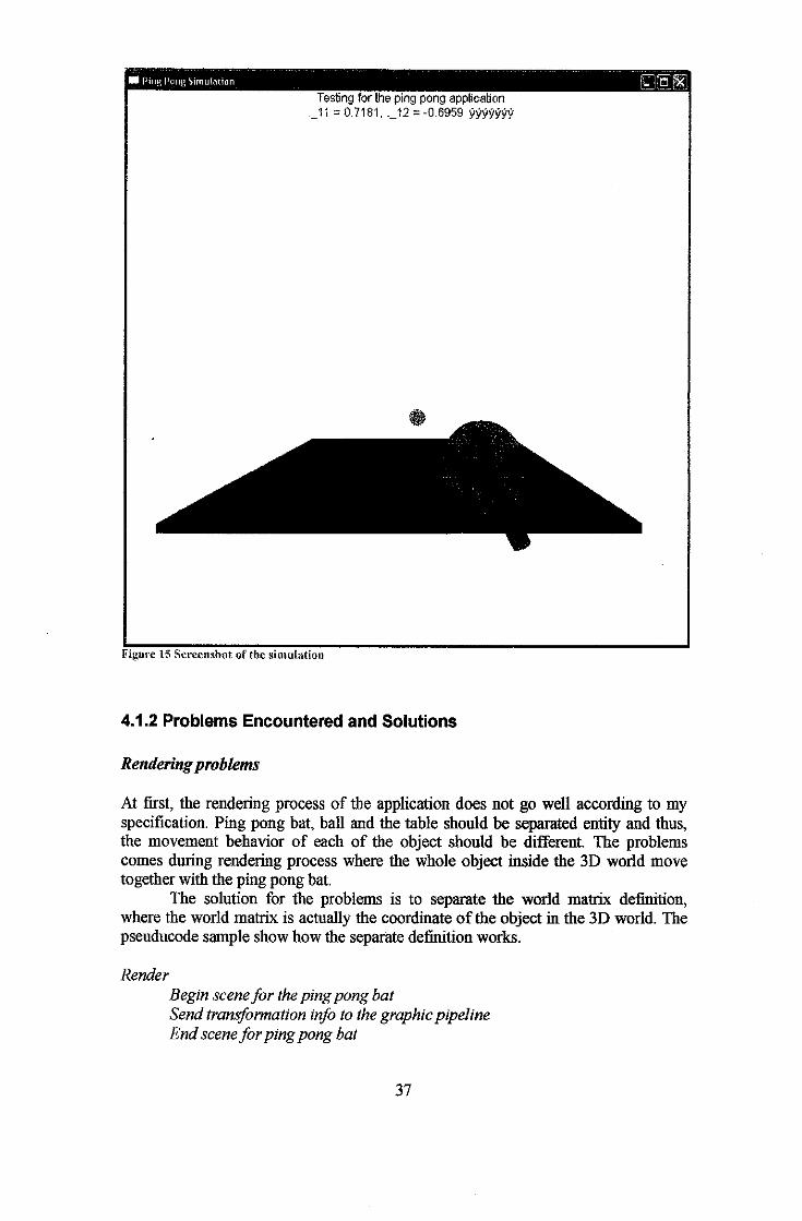
•I PingPont1, Simulation
Testing for the ping pong application._11 =0.7181. ._12 = -0.6959 yyyyy^y
Figure 15 Screciishot of the simulation
4.1.2 Problems Encountered and Solutions
Renderingproblems
At first, the rendering process of the application does not go well according to myspecification. Ping pong bat, ball and the table should be separated entity and thus,the movement behavior of each of the object should be different. The problemscomes during rendering process where the whole object inside the 3D world movetogether with the ping pong bat.
The solution for the problems is to separate the world matrix definition,where the world matrix is actually the coordinate of the object in the 3D world. Thepseuducode sample show how the separate definition works.
Render
Begin scenefor thepingpong batSendtransformation info to thegraphicpipelineEndsceneforping pong bat
37
Begin scene/or the tableSend transformation info to the graphicpipelineEndscenefor the tableBegin scene/or the ballSendtransformation info to the graphicpipelineEndscenefor the ball
Return
4.2 Discussion
Hardware integration and physics engine integration completed. Since there is
already proven working physics engine available for the academic use, integrate the
available physics engine eliminate the time required for the physics engine
development.
Learn SPE physics enginetakes 2 weeks, and integrate it into the simulation takes 2
weeks, which make it a month to complete thephysics engine part. Butthebehavior
of theball still does not follow thereal ping pong ball physics. This is because of the
incompatibility of the SPEphysics engine and the simulation. The simulation needto
be tweak in order to solvethisproblem.
Integrating Artificial Intelligence for this project is still pending because the
simulation itself is still not finish yet. Thus integrating any extra functionality will
make it hard to complete the simulation.
While the integrating between hardware part and software part, there are few
problems that related to the cahbration of thecamera. This problem gives some error
and misses coordination of the ping pong bat. The location captured by the camera
does not seem to be consistent where thebat seems to fly out ofnowhere even when
the real bat is actually static.
The problem has been identified where the camera focus need to be adjusted so that
thecamera lens will focus on the ping pong bat. And the optimum range between the
camera and ping pong bat would be around 1 meter. Any more or less will make it
hard for the camera to determine the bat coordinate and this would result in miss
placed of the ping pong bat in the 3D world.
38
5.0 CHAPTER 5: CONCLUSION RECOMMENDATION
5.1 Conclusion
As a conclusion, the author hopes that this project will produce a great result where
the apphcation can play Ping Pong game with opponent. As for the extra
functionality, network play will be implemented if there is enough time to develop
the project where the user can play with other player throughout the local area
network.
The author also hopes that the technology can improve the current technology
available for virtual reality either in learning purpose or for fun purpose. With the
completion of the project, there will a lot more that can be improve and the project
canalso be improve to beused in training for theping pong team. The project should
be accurate enough to imitate the realping pong physics andmovement.
Also the project can open more opportunities for the student to learn more on how
virtual reality and motion capture works. Theproject is free and the source code for
the project is open so that the student can learn more on the motion detection and
game development.
5.2 Recommendation
The physics for the ball stillnot according to therealworld physics and thecollision
detection stillnot working so well becausethere are times whenthe ball did not react
to the ping pong bat. This can still be improved to make sure that the program run
according to the specification.
Motion detection still have the some weakness where the camera sometimes does not
recognize the position of the bat. Thisproblem lieson the driverspecification andthe
problemswill be forwarded to the developer of the morion detection since the driver
is confidential.
39
REFERENCES
1. Fun Wey Ph.D. Embedded Graphics Driver Architect, Infrastructure
Processor Division, CIG Asia, Intel Microelectronics (M) Sdn. Bhd.
www.3dxense.com
2. Direct3D 10,DavidBlythe, Microsoft Corporation, Presentation Paper
SIGGRAPH 2006
3. Luna, Frank. Introduction to 3D GAMEProgrammhig withDirectX
9.0.Wordware Publishing, Inc, 2003.
http://www.moon-labs.com/
4. David M. Bourg, Physics for Game Developers 1st Edition, O'Reily &
Associates, Inc. 2002
5. Kovach, Peter. Gamasutra: Inside Direct3D: StencilBuffers [08.07.00].
http://www.gamasutra.com/features/20000807/kovach Ol.htm
6. Microsoft. DirectX 9.0 SDK documentation.
http://msdn.nnCTOSoftxom/library/defaiilt.asp?tirl^/librarv/en-
us/directx9_c/directx/directx9cpp.asp
7. David Conger, Ron Little. CreatingGamesin C++: A Step-by-Step Guide.
New Riders. February 21,2006
8. Kris Gray. MicrosoftDirectX9 Programmable Graphics Pipeline. Microsoft
Press. 2003
9. Derek Pierson (3LeafDevelopment). Coding4fun: BeginningGame
Development Series. Microsoft Corporation
http:^logs.msan.com/codmg4fun/archive/2006/ll/02/938703.aspx
10. Britt L. Hannah. Object-Oriented Game Design, Amodular and logical
method of designing games. August 8 2004.
http://www.devmaster.net/articles/oo-game-design/
11. Tom Miller. Managed DirectX 9 Kick Start: Graphics and Game
Programming. Microsoft Press. 2003
40
APPENDICES
SOURCE CODE
//-
// File: Meshes.cpp//
#include <Windows.h>
#include <mmsystem.h>#include <d3dx9.h>
#include <dinput.h>#include "SPE.h"
#pragma warning{ disable : 4996 ) // disable deprecated warning#include <strsafe.h>
#pragma warning( default : 4996 )#pragma comment (lib, "dinput. lib")#pragma comment (lib, "dinputS .lib")#pragma comment (lib, "dxguid.lib")
#include "magic.h" //magic_specificframe^data g_frame; //magic_specificD3DXMATRIXA16 matWorld; //magic specificD3DXMATRIX matWorldBall;
//
// Dinput declaration//
LPDIRECTINPUT8 din; //pointer to direct input interfaceLPDIRECTINPUTDEVICE9 dinkeyboard; //pointer to keyboard device
//
// Global variables//
LPDIRECT3D9 g_pD3D = NULL; // Used to create the D3DDeviceLPDIRECT3DDEVICE9 g_pd3dDevice = NULL; // Our rendering device
LPD3DXMESH g_pTable; //mesh for tableLPD3DXMESH gj?Ball; //mesh for the ballLPDIRECT3DTEXTURE9 g_pTexl;LPDIRECT3DTEXTURE9 g_pTex2;LPD3DXMESH g_J>Mesh = NULL; // Our mesh object in sysraemLPD3DXMESH g_pBox, g_pBox2;LPSPEWORLD speWorld; //interface for the spe physicsLPSPERIGIDBODY speBody, batBody; //lang pointer tothe spe rigid body
LPD3DXF0NT g_pFont;D3DMATERIAL9* g_pMeshMaterial3 - NULL; // Materials for our meshLPDIRECT3DTEXTURE9* g_pMeshTextures = NULL; // Textures for our meshDW0RD g_dwNumMaterial3 = OL; // Number of mesh materialsDW0RD g_dwNumMaterials2 - OL; // Number of mesh materialsfloat time;Float cam_angle = 0;//
// Function prototype for the direct input// F
//void initDInput(HINSTANCE hinstance, HWND hWnd);//void detect_keys(void);//void cleanDInput(void);
//
// Name: InitD3D()// Desc: Initializes Direct3D//
HRESULT InitD3D( HWND hWnd ){
// Create the D3D object.iff NULL = ( g_pD3D = Direct3DCreate9( D3D_SDK_VERSION ) ) )
return E FAIL;
41
// Set up the structure used to create the DSDDevice. Since we are now// using more complex geometry, we will create a device with a zbuffer.D3DPRESENT_PARAMETERS d3dpp;ZeroMemory{ &d3dpp, sizeof(d3dpp) );d3dpp. Windowed = TRUE;
d3dpp.SwapEffect = D3DSWAPEFFECT_DISCARD;d3dpp.BackBu£ferFormat - D3DFMT_UNKNOWN;d3dpp.EnableAutoDepthStencil = TRUE;d3dpp.AutoDepthStencilFormat = D3DFMTJ316;
// Create the D3DDevice
if( FAILED( g_pD3D->CreateDevice( D3DADAPTERJ3EFAULT, D3DDEVTYPE_HAL, hWnd,D3DCREATE_SOFTWARE_VERTEXPROCESSING,Sd3dpp, sg_pd3dDevice ) ) )
(
return E__FAIL;}
// Turn on the zbuffer
g_pd3dDevice->SetRenderState ( D3DRS__ZENABLE, TRUE );
// Turn on ambient lightingg_pd3dDevice->SetRenderState( D3DRS_AMBIENT, Oxffffffff );
return S OK;
void initDInput(HINSTANCE hinstance, HWND hWhd){
DirectlnputSCreate(hinstance,
DIRECTINPUT_VERSION,IID_IDirectInput8,(void**)&din,NULL);
din->CreateDevice(GUID_SysKeyboard,&dinkeyboard,NULL);
dinkeyboard->5etDataFormat(&c_dfDIKeyboard);
dinkeyboard->SetCooperativeLevel(hWnd,
DISCL_NONEXCLUSIVE | DISCX_BACKGROUND) ,-
return;
)
void detect_keys(void){
static BYTE keystate[256];
dinkeyboard->Acquire();
dinkeyboard->GetDeviceState(256, (LPVOID)keystate);
if(keystate[DIK_A] & 0x80){
//MessageBox(NULL, L"testing for key A", L"Message", MB_OK);speBody->SetPosition(SPEVector(3.0f, O.Of, -3Q0.0f));speBody->SetVelocity(SPEVector(0.Of, 0.Of, 170.Of));speBody->SetAngularVelocity(SPEVector(O.Of, O.Of, -1360.0f));time = 0;
1
if(keystate[DIK_LEFT] S 0x80)cam_angle = cam_angle + 1;
if(keystate[DIK_RIGHT] & 0x80)cam_angle = cam_angle -1;
return;
}
void InitShape(ISPEShape* pShape, ID3DXMesh* pMesh){
BYTE* pVB;void* pIB;pMesh->LockVertexBuffer(D3DL0CKJX)NOTWAIT, (void**)SpVB);
42

pMesh->Lock!ndexBuffer (D3DL0CK_D0N0TWAIT, (void**)ipIB);if(pMesh->GetOptions() & D3DXMESH 32BIT) // 32BIT index{
pShape->Initialize (pVB, pMesh->GetNumBytesPerVertex (},(int*)pIB, pMesh->GetNumFaces ()),-
}else // 16BIT index
{
pShape->Initialize (pVB, pMesh->GetNumBytesPerVertex (),(W0RD*)pIB, pMesh->GetNumFaces ());
}
pMesh->UnlockVertexBuffer ();pMesh->UnlockIndexBuffer ();
}//
// Name: InitGeometry()// Desc: Load the mesh and build the material and texture arrays//
HRESULT InitGeometry{){
//create the table using default rectangle functionD3DXCreateBox(g_pd3dDevice, 100.Of, 50.Of, 3.Of, Sg_pTable, NULL);//create the ball using default sphere functionD3DXCreateSphere(g__pd3dDevice, 2.5f, 20, 20, Sg_pBall, NULL);//create texture for the table
D3DXCreateTextureFromFile{ g_pd3dDevice, L"texture.bngV', &g_pTexl);//Create texture for the ball
D3DXCreateTextureFromFile( gj?d3dDevice, L"ball.fanp", Sg_pTex2);
LPD3DXBUFFER pD3DXMtrlBuffer2;D3DXLoadMeshFromX(L"box.x", D3DXMESH_SYSTEMMEM,
g_pd3dDevice, NULL,spD3DXMtrlBuffer2, NULL,sg__dwNumMaterials2, Sg_pBox) ;
//try using this mesh for initshape, the problem might be because defaultshape does not have vertex buffer to initialise the vertices
speWorld = CreateSPEWorld();
speWorld->SetGravity(SP£Vector(0, 9.8f, 0 ));
LPSPESHAPE pShape = speWorld->CreateShape{);Initshape (pShape, g_pBall) ;speBody = speWorld->AddRigidBody(pShape);speBody->SetPosition(SPEVector(3.0f, O.Of, -300.Of)),-speBody->SetVelocity(SPEVector{0.0f, O.Of, 370.Of));speBody->SetAngularVelocity(SPEVector(O.Of, O.Of, -1360.0f));
speBody->GetState()->SetPosition(SPEVector(3.Of, O.Of, -300.Of));
//create font object that will be used throughout the applicationD3DXCreateFont(g_pd3dDevice, 20, 0,
FW_NORMAL,1, false,DEFAULT_CHARSET,OUT_DEFAULT_PRECIS,DEFAULT_QUALITY,DEFAULT_PITCH | FF_DONTCARE,L"Arial",
Sg__pFont) ;
LPD3DXBUFFER pD3DXMtrlBuffer;
// Load the mesh from the specified fileif( FAILED! D3DXLoadMeshFromX( L"bat.x", D3DXMESH_SYSTEMMEM,
g_pd3dDevice, NULL,SpD3DXMtrlBuffer, NULL, £g_dwNumMaterials,Sg_pMesh ) ) )
// If model is not in current folder, try parent folderif{ FAILED( D3DXLoadMeshFromX( L"..\\bat.x", D3DXMESH_SYSTEMMEM,
g_pd3dDevice, NULL,&pD3DXMtrlBuffer, NULL, Sg_dwNumMaterials,&g_pMesh ) ) )
{
43
MessageBox(NULL, L"Could not find tiger.x", L"Meshes.exe", MB_OK);return E FAIL;
J
LPD3DXBUFFER pD3DXMtrlBuffer3;D3DXLoadMeshFroitiX (L"box. x", D3DXMESH_SYSTEMMEM,
g_pd3dDevice, NULL,5pD3DXMtrlBuffer3, NULL, sg_dwNumMaterials2
&g_pBox2);
LPSPESHAPE pShapeBat = speWorld->CreateShape{);Initshape(pShapeBat, g_pMesh);batBody = speWorld->AddRigidBody(pShapeBat);batBody->SetPosition(SPEVector(matWorld._11, matWorld._12, matWorld._13)) ;batBody-X5etState()->SetPosition(batBody->GetPosition());
// We need to extract the material properties and texture names from the// pD3DXMtrlBuffer
D3DXMATERIAL* d3dxMaterials = {D3DXMATERIAL*)pD3DXMtrlBuffer->GetBufferPointer()g_pMeshMaterial3 = new D3DMATERIAL9fg_dwNumMaterials];if( g_pMeshMaterials == NULL )
return E_OUT0FMEMORY;
g_pMeshTextures = new LPDIRECT3DTEXTURE9[g_dwNumMaterials];if{ g__pMeahTextures — NULL }
return E_OUTOFMEMORY;
for( DWQRD i=0; i<g_dwNurnMaterials; i++ ){
// Copy the material
g.j)MeshMaterialsEi] = d3dxMaterials[i].MatD3D;
// Set the ambient color for the material (D3DX does not do this)g__pMeshMaterials[i] .Ambient = g_pMeshMaterials[i].Diffuse;
g_pMeshTextures[i] = NULL;if{ d3dxMaterials£i].pTextureFilename != NULL &&
lstrlenA(d3dxMaterials[i].pTextureFilename) >0 ){
// Create the texture
if( FAILED( D3DXCreateTextureFromFileA{ gj?d3dDevice,d3dxMaterials[iJ-pTextureFilename,&g_pMeshTextures[i] ) ) )
// If texture is not in current folder, try parent folderconst CHAR* strPrefix = "..\\";CHAR strTexture[MAX__PATH];StringCchCopyA( strTexture, MAX_PATH, strPrefix );StringCchCatA( strTexture, MAX_PATH,
d3dxMaterials[i].pTextureFilename );// If texture is not in current folder, try parent folderif{ FAILED( D3DXCreateTextureFromFileA( g__pd3dDevice,
strTexture,
Sg_pMe3hTextures[i] ) ) ){
MB_OK) ;
}
MessageBox(NULL, L"Could not find texture map", L"Meshes.exe",
// Done with the material buffer
pD3DXMtrlBuffer->Release();speWorld->ReleaaeShape(pShape);speWorld->ReleaseShape(pShapeBat)
return S OK;
//
// Name: Cleanup!)// Desc: Releases all previously initialized objects
44
//
VOID Cleanup()
{
if( g_pMeshMaterials != NULL )delete[] g_pMeshMaterials;
g_pTable->Release();dinkeyboard->Unacguire();din->Release();
if( g_pMeshTextures )f
for( DWORD i = 0; i < g_dwNumMaterials; i++ ){
if( g_pMeshTextures[i] )g___pMeshTextures[i3->Relea3e() ;
)
delete[J g_pMeshTextures;}iff g_pMesh != NULL )
g_pMesh->Release();
if( g_j>d3dDevice != NULL )g_j>d3dDevice->Release () ;
if{ g_pD3D != NULL )gj?D3D->Release() ;
//
// Name: SetupMatrices()// Desc: Sets up the world, view, and projection transform matrices.//
VOID SetupMatrices{)
{// Set up world matrixg_pd3dDevice->SetTransform{ D3DTS_WORLD, smatWorld );
// Set up our view matrix. A view matrix can be defined given an eye point,// a point to lookat, and a direction for which way is up. Here, we set the// eye five units back along the z-axis and up three units, look at the// origin, and define "up" to be in the y-direction.D3DXVECTOR3 vEyePt( O.Of + cam_angle, 3.Of + cam_angle,200.0f );
//magic_specific the default is 200.Of, i make it as 300 to make a littlebit far from the viewport
D3DXVECTOR3 vLookatPt( O.Of, O.Of , O.Of );D3DXVECTOR3 vUpVec( O.Of, -l.Of, O.Of );D3DXMATRIXA16 matView;
D3DXMatrixLookAtLH( SmatView, SvEyePt, SvLookatPt, SvUpVec );g_pd3dDevice->SetTransform( D3DTS_VIEW, smatView );
// For the projection matrix, we set up a perspective transform (which// transforms geometry from 3D view space to 2D viewport space, with// a perspective divide making objects smaller in the distance). To build// a perpsective transform, we need the field of view (1/4 pi is common),// the aspect ratio, and the near and far clipping planes (which define at// what distances geometry should be no longer be rendered).D3DXMATRIXA16 matProj;D3DXMatrixPerspectiveFovLH( SmatProj, D3DX_PI/4, l.Of, l.Of, 10000.Of );
//magic_specificg_pd3dDevice->SetTransform( D3DTS PROJECTION, SmatProj );
1
//setup the world transformation for all the 3tatic object in the applicationVOID SetupMatrices2(){
// Set up world matrix for the table
D3DXMATRIX matRotateY;
static float indexY = 1.55f;D3DXMatrixRotationY(&matRotateY, indexY);
D3DXMATRIX matRotateX;
static float indexX = 1.578f;D3DXMatrixRotationX(&matRotateX, indexX);
45
D3DXMATRIX matTranslation;D3DXMatrixTranslation(smatTranslation, 0.Of, 50.Of, -160.Of);
D3DXMATRIX matScale;
D3DXMatrixScaling(SmatScale, 3.Of, 3.Of, l.Of);
g_pd3dDevice->SetTranaform( D3DTS_WORLD, S(matScale * matRotateX * matRotateYmatTranslation ) );
//setup the world transformation for the ballVOID SetupMatrices3 (){
//setup the location of the ball, after the calculation is done,//the ball will be rendered using all the information that gathered//such as the speed and direction of the ball
//D3DXMATRIX matLocation;//D3DXMatrixTranslation( SmatLocation, 3.Of, O.Of, O.Of);speBody->GetTransformMesh(&matWorldBall);
g_pd3dDevice->SetTransform(D3DTS WORLD, SmatWorldBall);
//
// Name: Render()// Desc: Draws the scene//
VOID Render()
batBody->SetPo3ition(SPEVector (matWorld._41, matWorld._42, matWorld.__43]//batBody->SetOrientation(SPEMatrix(matWorld));speBody->GetNewState()->SetPosition{speBody->GetPosition());//batBody->GetNewState()->SetPosition(batBody->GetPositionO)7Z/batBody->GetNewState()->SetOrientation(batEody->GetOrientation());batBody->GetNewState()->SetPosition(batBody->GetPosition());
SPEArray<LPSPERIGIDBODY> list;
list.push(batBody);list.pushfspeBody);speWorld->DetectCollisions(list);
int numContact = speBody->GetNumContacts{);if(numContact > 0)
speBody->SetVelocity(SPEVector(10.0f, O.Of, -370.0f));
// Clear the backbuffer and the zbufferg_jpd3dDevice->Clear( 0, NULL, D3DCLEAR_TARGET|D3DCLEAR_2BUFFER,
D3DCOLOR_XRGB(255,255,255), l.Of, 0 );
////////////////Scene block for ball/////////////////////g_pd3dDevice->BeginScene();
SetupMatrices3{);
g_pd3dDevice->SetTexture(0, g_pTex2);g__pBall->DrawSubset (0);
g_pd3dDevice->EndScene() ;
//////////////Scene block for table////////////////////g_pd3dDevice->BeginScene();
static RECT textBox;
SetRect(6textBox, 0, 0, 800, 20);
g_pFont->DrawTextA(NULL, "Testing for the ping pong application",37, StextBox, DTJZENTER,
D3DCOLOR_ARGB(255, 0, 0,0 ));char datal[100];
_snprintf_s(datal, 50,100, "._11 = %.4f, ._12 - %.4f, matWorldBall. 11,matWorldBall._12);
LPSTR test = datal;
SetRect(&textBox, 0, 20, 800, 120);
46
g_pFont->DrawTextA(NULL, test, 37, StextBox, DT_CENTER, D3DC0LOR ARGB(255, 0,0,0 >);
SetupMatrices2[);
g_pd3dDevice->SetTexture(0, g_pTexl);g^pTable->DrawSubset(0);g_pd3dDevice->EndScene {} ,*/////////////////End of scene block////////////////////
///////////////////Scene block for bat///////////////////if( SUCCEEDED( g_pd3dDevice->BeginScene() ) ){
// Setup the world, view, and projection matricesSetupMatrices();
// Meshes are divided into subsets, one for each material. Render them in// a loopfor( DWORD i=0; i<g_dwNumMaterials; i++ ){
// Set the material and texture for this subsetg_pd3dDevice->SetMaterial( Sg_pMeshMaterials[i] ) ;g_pd3dDevice->SetTexture( 0, g_pMeshTextures[i] );
// Draw the mesh subset
g_j>Mesh->DrawSubset { i );
// End the scene
g_pd3dDevice->EndScene(};
1
///////////////////////End of scene block///////////////////////////
// Present the backbuffer contents to the displayg_pd3dDevice->Present( NULL, NULL, NULL, NULL };
}
//
// Name: MsgProc()
// Desc: The window's message handler//
LRESULT WINAPI MsgProc( HWND hWnd, UINT msg, WPARAM wParam, LPARAM IParam )t
switch{ msg )(
case WM_DESTROY:Cleanup();PostQuitMessage( 0 );return 0;
J
return DefWindowProc{ hWnd, msg, wParam, IParam );
//
// Name: WinMainO// Desc: The application's entry point//
INT WINAPI WWinMain( HINSTANCE hlnst, HINSTANCE, LPWSTR, INT ){
// Register the window classWNDCLASSEX wc = { sizeof(WNDCLASSEX), CS_CLASSDC, MsgProc, OL, 0L,
GetModuleHandle(NULL), NULL, NULL, NULL, HULL,L"Ping Pong Simulation", NULL };
RegisterClassEx( swc );
// Create the application's windowHWND hWnd = CreateWindow( L"Ping Pong Simulation", L"Ping Pong Simulation"
47
WS_OVERLAPPEDWIND0W, 100, 100, 800, 800,NULL, NULL, wc.hlnstance, NULL );
HINSTANCE hlnst2 = LoadLibrary{L"MagicJ:-dll"); //magic-specificif (hlnst2 = NULL) exit(l); //magic-specific
if (!l3D_initjdevice()) exit(1); //magic-specific
// Initialize Direct3D
iff SUCCEEDED( InitD3D( hWnd ) ) ){
// Create the scene geometryif( SUCCEEDED! InitGeometry() ) )(
// Show the window
initDInput(hlnst, hWnd);ShowWindow( hWnd, SW__SHOWDEFAULT );UpdateWindow( hWnd );
// Enter the message loopMSG msg;
ZeroMemory( smsg, sizeof(msg) );whilef msg.message!=WM_QUIT ){
if( PeekMessage( smsg, NULL, 0U, 0U, PM_REMOVE ) )t
TranslateMessage( smsg );DispatchMessage( smsg ),-
specific
}
else {
I3D_input_6DOF( &g_frame, SmatWorld); //magic-
speWorld->Update(time);detect_keysO;time++;
Render();
1
//RenderTable();
l3D_close_device(); //magic-specificUnregisterClass( L"Ping Pong Simulation", wc.hinstance );return 0;
48