recent developments in subterranean robotics
TRANSCRIPT

1
Smbgajm
1
i2
fl3
k
JP
Recent Developments inSubterranean Robotics
• • • • • • • • • • • • • • • • •
Aaron Morris, Dave Ferguson,Zachary Omohundro, David Bradley,David Silver, Chris Baker, Scott Thayer,Chuck Whittaker, and William WhittakerField Robotics CenterCarnegie Mellon UniversityPittsburgh, Pennsylvania 15213
Received 31 August 2005; accepted 1 November 2005
Robotic systems exhibit remarkable capability for exploring and mapping subterraneanvoids. Information about subterranean spaces has immense value for civil, security, andcommercial applications where problems, such as encroachment, collapse, flooding andsubsidence can occur. Contemporary method for underground mapping, such as humansurveys and geophysical techniques, can provide estimates of void location, but cannotachieve the coverage, quality, or economy of robotic approaches. This article presents thechallenges, mechanisms, sensing, and software of subterranean robots. Results obtainedfrom operations in active, abandoned, and submerged subterranean spaces will also beshown. © 2006 Wiley Periodicals, Inc.
. INTRODUCTION
ubterranean spaces, such as caves, sewers, and
alone, “tens of thousands, perhaps even hundreds ofthousands, of abandoned mines are believed to exist.Not even the Department of Surface Mines knows the
• • • • • • • • • • • • • •
ines �see Figure 1�, create problems for operations exact number, because federal recording of miningcWbst
dtpe
eriod.com
oth above and below the surface. Subsidence,round water contamination, and mine floods, suchs those of Quecreek,1 Zapadnaya,2 and Daxing3 are
ust a few consequences of poor or inaccurate docu-entation of subterranean voids. In the United States
June 2002: The Quecreek Coal Mine in Pennsylvania floods leav-ng 9 miners trapped for 3 days.October 2003: The Zapadnaya Coal Mine in southern Russiaoods leaving 46 miners trapped for 6 days.
August 2005: The Daxing Coal Mine in southern China floodsilling 123 miners.
ournal of Field Robotics 23(1), 35–57 (2006) © 2006 Wiley Published online in Wiley InterScience (www.interscience.wiley
laims was not required until 1976” �Belwood &augh, 1991�. With continued above-ground and
elow-ground operations encroaching upon suchpaces, the need for improved documentation of sub-erranean voids is clear.
Knowledge of subterranean spaces has tremen-ous value across a number of applications. In addi-
ion to preventing and mitigating the aforementionedroblems, void documentation plays key roles in ev-rything from the design, planning, and permitting of
icals, Inc.). • DOI: 10.1002/rob.20106

mtefasls
st
moscd�fei
4
sJ
36 • Journal of Field Robotics—2006
ines, sewer lines, and surface structures, to the ac-ive development and environmental upkeep of thesestablishments. Documentation of older voids, in theorm of maps and surveys �see Figure 2�, is often in-ccurate, illegible, or nonexistent. Correcting thisituation necessitates technologies that can obtain re-iable information and motivates the development ofubterranean robotics.
The current methods available for mapping andurveying underground spaces4 can be grouped intohree categories:
• Direct Observation places people into a voidfor first-hand inspection.
• Borehole Observation probes for subterra-nean voids by drilling a lattice of boreholesand deploying down-hole cameras to ob-serve void existence �see Figure 11�b� later in
For information on current mapping and mining methodologies,ee the Canadian Institute of Mining, Metallurgy, and Petroleumournal at www.cim.org.
Figure 1. Examples of vari
this paper� �Wells, 1999; Morris, Kurth, Hu-ber, Whittaker & Thayer, 2003�.
• Remote Sensing employs nonintrusive, geo-physical procedures that utilize electromag-netic waves and assumed soil composition tolocate voids without drilling. Techniques in-clude airborne multi-spectral imaging �Ellis& Dodd, 2000�, resistivity �Reynolds, 1997�,ground-penetrating radar, and seismicrefraction/reflection �Kearey, 2002�.
Of these methods, direct observation is un-atched in terms of the fidelity and sampling density
f data acquired. Borehole observation and remoteensing can procure satisfactory results in certain cir-umstances; however, these methods only supply in-irect evidence of void and rely heavily on inference
Morris et al., 2003�. Direct observation achieves irre-utable first-hand perspective on the state and geom-try of underground voids, and requires little to nonference or interpretation.
Subterranean robots offer a unique solution to
ubterranean environments.
Journal of Field Robotics DOI 10.1002/rob
ous s

vptrlsRasaorc
bsfiorfhm
mhNhf
fclmtepgcD
msnsas1
epsta
5
g
6
er7
Morris et al.: Recent Developments in Subterranean Robotics • 37
J
oid mapping and profiling. Robots can establish aresence in distant subterranean spaces without risk
o humans. Robots function in the harshest of envi-onments: both mechanisms and sensing can be tai-ored to contend with water, smoke, darkness, explo-ive gas, and countless other hostile conditions.obots can be compactly constructed to reach remotend space-constrained destinations that are inacces-ible to humans. Furthermore, robots can documentnd recall all sensory input throughout the durationf a void inspection. Data gathered by such means isich in content and excellent for analysis of voidonditions.
Despite the compelling case for subterranean ro-ots, relatively little attention has been paid to theubterranean realm by the robotics community. As aeld, robotics has extensively researched applicationsn land, in water, in air, and in space; yet only a fewesearchers have concentrated on developing robotsor underground operations. Of those that have, mostave addressed automating underground miningachines and not mapping voids.
As an example, robotic systems such as autono-ous guidance vehicles �AGVs�5 and CSIRO’s load-
aul-dump �LHD� truck �Scheding, Dissanayake,ebot & Durrant-Whyte, 1997; Roberts et al., 2000�,ave been designed to navigate active mine corridorsor the purpose of hauling extracted minerals and
See Automated Mining Systems �http://www.robominer.com/uidance.html�.
Figure 2. Example maps for v
ournal of Field Robotics DOI 10.1002/rob
quipment. AGV systems are guided by a support in-rastructure embedded in the corridor walls duringonstruction of the mine. The AGVs navigate by fol-owing a predetermined series of infrastructure land-
arks. The LHD system also moves unmannedhrough a mine, but requires no modification to thenvironment for localization. Navigation is accom-lished using a topological map6 and informationathered from prior runs to guide the vehicle fromorridor to corridor �Roberts, Duff & Corke, 2002;uff & Roberts, 2003; Duff, Roberts & Corke, 2003�.
Mineral extraction platforms, such as continuousiners,7 are also being automated for the purpose of
afe and efficient coal mining. These systems requireo embedded support infrastructure. The precise po-ition and orientation measurements necessary forlignment during mining are obtained from onboardensors that read off-board survey lasers �Stentz et al.,999�.
The first robot to capture map data from a minenvironment was “Terregator,” a six-wheeled multi-urpose research vehicle �Champeny-Bares, Copper-mith & Dowling, 1991�. Terregator achieved semiau-onomous navigation using a combination of sonarnd laser scanners for position estimation and ob-
A topological map is a graph representation where the nodes anddges of said graph correspond to distinct locations in the envi-onment �Kuipers & Byan, 1991�.See �http://www.frc.ri.cmu.edu/�axs/miner.html�.
s subterranean environments.
e
ariou
sti
SssimDea
aetdta
2S
Nabh
eattso
2
TvOcshdntdos
2
Uwem
8
9
38 • Journal of Field Robotics—2006
tacle avoidance. These sensors also enabled Terrega-or to acquire high-resolution scans of coal minenteriors.
In nonmaintained or natural environments,ANDIA’s cave robot, RATLER,8 and RedZone’sewer robots9 navigate within cluttered caves andewage-filled pipes, respectively, for the purpose ofnspection. These systems are teleoperated via com-
unication links, such as tethers or radio signals.ue to the difficulties encountered in nonmaintained
nvironments, these robots do not utilize autonomys part of operations.
The objective of subterranean robotics is to oper-te robots in caves, tunnels, sewers, mines, and cav-rnlike spaces for exploration, mapping, and charac-erization. This emerging field of study is poised toefine itself among the many fields of robotics given
he unique challenges and potential benefits of oper-ting robots within underground regions.
. CHARACTERISTICS OF SUBTERRANEANPACES
onmaintained or natural subterranean spaces aremong the most challenging environments for ro-otic operations. These spaces are characteristicallyigh in uncertainty, offer little a priori information,
See �http://www.ri.cmu.edu/projects/project�361.html�.See �http://www.redzone.com/index.cfm�.
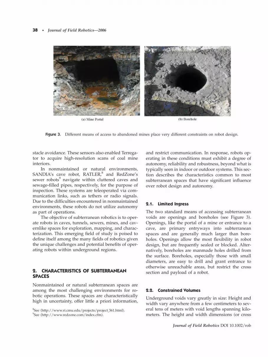
Figure 3. Different means of access to abandoned
nd restrict communication. In response, robots op-rating in these conditions must exhibit a degree ofutonomy, reliability and robustness, beyond what isypically seen in indoor or outdoor systems. This sec-ion describes the characteristics common to mostubterranean spaces that have significant influencever robot design and autonomy.
.1. Limited Ingress
he two standard means of accessing subterraneanoids are openings and boreholes �see Figure 3�.penings, like the portal of a mine or entrance to a
ave, are primary entryways into subterraneanpaces and are generally much larger than bore-oles. Openings allow the most flexibility in robotesign, but are frequently sealed or blocked. Alter-atively, boreholes are manmade holes drilled from
he surface. Boreholes, especially those with smalliameters, are easy to drill and grant entrance totherwise unreachable areas, but restrict the crossection and payload of a robot.
.2. Constrained Volumes
nderground voids vary greatly in size: Height andidth vary anywhere from a few centimeters to sev-
ral tens of meters with void lengths spanning kilo-eters. The height and width dimensions �or cross
es place very different constraints on robot design.
Journal of Field Robotics DOI 10.1002/rob
a
min

sta
2
MFsVcawtisfi
2
Dhditeet
2
Wt
tst
2
DbamtTn
2
Sta
2
Clnmafdb
FA
Morris et al.: Recent Developments in Subterranean Robotics • 39
J
ection� constrain robot size while the length �or ex-ent� of a void influences the required robot mobilitynd sensor range.
.3. Water
ost underground voids contain some water �seeigure 4�a��, whether the depth is as shallow as amall puddle or as deep as complete submersion.oids where the nominal water depth does not ex-eed a few centimeters are termed “dry,” voids thatre fully submerged are termed “wet,” and voidsith water depths in between these extremes are
ermed “mixed.” These categories impact the mobil-ty and sensing configuration of a robot �e.g., drypaces favor wheels and lasers and wet spaces favorns and sonar�.
.4. Gases
ry or mixed environments have the capacity toouse pockets of explosive or corrosive gas. In aban-oned mines and sewers, for instance, methane gas
s commonly encountered and may ignite if exposedo spark or open flame. Electric motors and openlectronics are possible sources of ignition; therefore,xplosive threats must be avoided through early de-ection by environmental sensing.
.5. Permissions
hen working in hazardous spaces, such as thosehat threaten explosion, safety is as much a concern
igure 4. �a� “Yellow boy,” an iron oxide and sulfate depbandoned for only a year, a roof beam collapsed bringin
ournal of Field Robotics DOI 10.1002/rob
or the robot as for the establishments near or abovehe void �see Figure 5�b��. Mandated safety regula-ions, which vary by jurisdiction, dictate the permis-ible electronics, construction materials, and func-ionality of a subterranean robot.
.6. Debris Content
ense obstacle distributions, such as the aggregateuildup of a sewer line or the fallen beams, rock,nd forgotten mining artifacts of an abandonedine, require a robot to get around, go over, or push
hrough a myriad of obstacles �see Figure 4�b��.hese conditions impose perception, mobility, andavigation challenges upon a robot.
.7. Lack of Illumination
ubterranean voids are generally dark. Robots mustherefore provide their own illumination or employctive sensors such as lasers or sonar.
.8. Communication
ommunication with a subterranean robot is estab-ished by either tether or radio; however, these tech-ologies are limited underground. Tethers hinderaneuverability and easily catch or become dam-
ged in the debris of subterranean voids. High-requency waves cannot penetrate rock, limiting ra-io communication to areas with line of sightetween the transceivers. In general, a global posi-
from acidic mine water. �b� An abandoned haulage-way.th it cabling, pipes, rock and roof bolts.
ft
ositg wi

tsrnlr
2
Ttlt5lt
3S
Tnrrscns
aaiaws
abaaattgesd
3D
Bfslts
Fo
40 • Journal of Field Robotics—2006
ioning system �GPS�, remote commands, or distressignals are not feasible underground. Subterraneanobots must, therefore, either: �1� Remain within sig-al range of the command station, or �2� possess re-
iable autonomy with robust failure detection andecovery mechanisms.
.9. Void Structure
he more cyclic and uniform the structure of a sub-erranean void, the greater the challenge a robot hasocalizing within the void. Highly cyclic spaces, likehat of room-and-pillar mines and caves �see Figure�a��, can quickly disorient a robot. As such, robustocalization is a critical requirement for mobile sub-erranean robots.
. ROBOTIC PLATFORMS FOR SUBTERRANEANPACES
he spectrum of conditions encountered in subterra-ean spaces calls for a variety of robotic systems inesponse. Depending upon the target environment, aobot may need to scale rock, tread mud, sink, orwim to collect information. No single robot designould be applicable to every conceivable subterra-ean space; therefore, specialization is essential inubterranean robot design.
igure 5. �a� This map demonstrates the highly cyclic andf surface damage cause by a mine fire.
The ensuing robot descriptions will be classifiedlong three dimensions: Mobility, void accessibility,nd submersion. Mobility covers actuation character-stics; void accessibility covers ingress capabilities;nd submersion covers the ability to operate underater. Figure 6 shows a diagram of this classification
pace.Each of the following robotic systems represents
particular region in this space of subterranean ro-otic configurations. These regions consist of staticnd mobile along the mobility axis, borehole and portallong the void accessibility axis, and dry and wetlong the submersion axis. In total, eight configura-ions encompass the subterranean robots that are ei-her in use or under development. Two of these re-ions, Static-Portal Dry and Static-Portal Wet,mbody the simple sensing platforms utilized on allubterranean robotic systems, and are therefore notiscussed explicitly.
.1. Borehole Deployable Lasers: Static-Boreholery
orehole deployable lasers �BDLs� are simple yet ef-ective tools for acquiring data from subterraneanpaces �see Figure 7�. BDLs consist of a primaryaser-range measurement sensor, a set of actuatorshat aim the sensor, inertial sensors that provide ab-olute device pose, and cameras or side-mounted
metric structure of room-and-pillar mines. �b� An example
Journal of Field Robotics DOI 10.1002/rob
sym

pT1mtmp
weacaIbto
s
Fd
Morris et al.: Recent Developments in Subterranean Robotics • 41
J
roximity sensors that assist during deployment.hese devices are compact �currently less than5.2 cm or 6 in. in diameter� to allow for deploy-ent into boreholes or pipes. BDLs are characteris-
ically tethered and offer linear mobility. Deploy-ent is achieved by lowering/raising or pushing/
ulling the device to a fixed position.BDLs are controlled remotely by an operator
ho monitors and modifies scan progress. Direct op-rator control allows for quick operational changesnd in-field analysis. The straightforward mechani-al designs of BDLs decrease the likelihood of failurend permit in-field repairs should an incident occur.n addition, experience has shown these systems toe extremely manageable, requiring only smalleams, typically two people, to perform fieldperations.
Figure 8�a� shows a standard deployment andcanning scenario. This procedure entails:
1. An existing or newly created borehole is se-lected for deployment. Newly created bore-holes are usually lined with pipes to reduce
igure 6. Varying constraints in terms of void accessibilitesigns.
ournal of Field Robotics DOI 10.1002/rob
device contact with mud, to prevent boreholecollapse, and to ensure the safe recovery ofthe device.
2. The device is lowered via a winch-and-pulleysystem from the surface into the void space.Cameras or side-mounted proximity sensorsare used to identify entry into the void breach�i.e., the point where a borehole opens intothe subterranean void�.
3. Once in the void, the range measurementsensor is actuated from a stationary vantagepoint to collect range data from all void sur-faces. At this point, the device operator mayalter the speed of the sensor actuators to in-crease or decrease the density of scan data.
4. Upon completion of a scan, the device may beraised or lowered to other vantages whereadditional scans are taken. Scan depths aredocumented from the surface with respect tothe top of the borehole.
5. Lastly, the device is recovered and surveymeasurements �i.e., GPS data on borehole lo-cation, relative measurement from other
bility, and submersion result in drastically different robot
y, mo
vtdamamtr
3pmarstl
rccF
42 • Journal of Field Robotics—2006
landmarks, etc.� are recorded. These mea-surements are used in conjunction with logdata for analysis during postprocessing.
The data recovered from BDL scans serve a wideariety of uses. Raw range data taken directly fromhe range sensor is converted into a three-imensional �3D� point cloud, as seen in Figures 9�a�nd 13�b�. Point clouds provide insight into the geo-etrical characteristics of a void. When a mesh is
pplied to a point cloud as in Figure 8�b�, these geo-etric shapes can be interpreted as structural fea-
ures, which provide clues to the history and integ-ity of the void.
Figure 7. Borehole deployable laser
Another property calculated from high-fidelityD range data is an estimate of volume. Volume canrovide an assessment for the amount of backfillaterial required to fill a subterranean void or the
mount of buildup that has collected and must beemoved. Volume can even indicate the structuraltatus of a void by providing a metric to calculatehe likelihood of collapse and to what extent the col-apse damage will affect the surface.
Scan data is also useful for registering and cor-ecting existing subterranean maps. Templates areonstructed from 3D point cloud data by extractingross sections parallel to the existing map plane �seeigure 10�. Templates are correlated to existing map
veloped to scan subterranean voids.
Journal of Field Robotics DOI 10.1002/rob
s de

rinstohfil
ctdptuttbcbc
akpT
pcF
amflldGs
mthfaDdmh
al
Fl�
Morris et al.: Recent Developments in Subterranean Robotics • 43
J
egions and locked into place using template match-ng techniques described in Olson �2000�. The origi-al map can then be corrected to reflect any mea-ured changes or inaccuracies. When multipleemplates are available, matches can be establishedver different map regions and correlated with bore-ole GPS data. Subterranean maps aligned to sur-ace coordinates have tremendous value when drill-ng additional boreholes or blocking-off hazardousocations on the surface.
The correlation of void geometry with surfaceoordinates has also led to the development of aechnique known as “frontier drilling.” Frontierrilling gives BDLs a more active role in the drillingrocess. A major problem with borehole drilling is
hat many boreholes miss the intended void �see Fig-re 11�b��. Surface-linked subterranean maps can op-
imize the placement of additional boreholes, savingime, money, and manpower by reducing the num-er of required boreholes. Once a subterranean ac-ess is established, BDLs can direct the remainingoreholes to be drilled over known areas of void lo-ation. Figure 11 gives an example of this method.
BDLs have proven invaluable for data collectionnd quick void analysis. The current platform,nown as Ferret III �see Figure 7�b��, has been de-loyed into both limestone and coal environments.he onboard laser averages 70 readings per second,
igure 8. �a� The deployment process of BDLs. �b� A rimestone mine 45 m below the surface. Visual features in tB� two mine columns, and �C� a debris pile formed durin
ournal of Field Robotics DOI 10.1002/rob
llowing reasonably high-resolution 3D scans �ap-roximately 0.5° azimuth�0.5° elevation� to be ac-rued in 80 min. Example results are shown inigure 9.
Ferret III’s minimum angular resolution isround 0.1° in both elevation and azimuth. Rangeeasurements are calibrated to 65 m on rock sur-
aces with a ±10 mm error. Deployment depth isogged to within 30 mm from a survey tape directlyinking the instrument to the surface. To date, alleployments have been less than 100 m deep andPS-surveyed surface coordinates have established
urface deployment locations.One common assumption in all BDL deploy-
ents is that boreholes are vertically straight fromhe surface position to the void breach. In reality,orizontal drift causes displacement relative to sur-ace coordinates. At long drill depths �i.e., aroundnd beyond 300 m�, drift may become significant.rilling companies have methods for recoveringrift measurements; however, past field deploy-ents have not yet reached such depths and drift
as not been a significant problem.During BDL deployment, orientation recovery is
more important concern than borehole drift. Abso-ute device heading is necessary to properly align
ring generated from laser data of a partially backfilledendering include �A� a slope of hardened backfill material,e borehole drilling process.
a
endehis rg th
Fyt
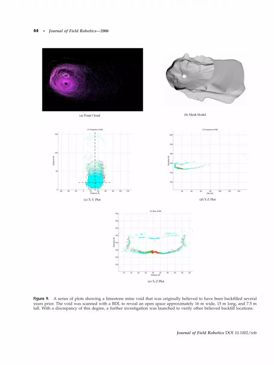
44 • Journal of Field Robotics—2006
igure 9. A series of plots showing a limestone mine void that was originally believed to have been backfilled severalears prior. The void was scanned with a BDL to reveal an open space approximately 16 m wide, 15 m long, and 7.5 mall. With a discrepancy of this degree, a further investigation was launched to verify other believed backfill locations.
Journal of Field Robotics DOI 10.1002/rob

sti
FpSst
FSs�a
Morris et al.: Recent Developments in Subterranean Robotics • 45
J
can data. Orientation recovery is accomplishedhrough mechanical alignment, sensing, scan match-ng, or map matching.
• Mechanical alignment uses interconnectingtubing to transfer the orientation of the BDL
igure 10. The process of map correction from templaterovide a baseline template for template-to-map matchingome interpretation may be required due to discrepanciecans are locked to a single map with GPS information to she map is warped to correlate with scan and GPS data.
igure 11. �a� The process of frontier drilling. To establishcan 1. The borehole for Scan 2 is then drilled by correlatinguccessive scan thereafter are used to place the next borehob� The number of boreholes that may be needed to establismount of area as frontier drilling.
ournal of Field Robotics DOI 10.1002/rob
to the surface where the heading is refer-enced. This method is extremely useful andreliable, but limited to shallow depths.
• Sensing uses a compass and/or gyroscope toestablish orientation. Sensing is useful pro-
ching. First, a point cloud is compressed into a plane tot, the template is matched to features in the existing map.
tween the map landmarks and scan data. Next, multipleronize scan coordinates with surface coordinates. Finally,
perimeter of this mine, an existing borehole is used to taken 1 data with surface coordinates. The scan data from eachntil the entire perimeter of the mine has been established.niform distribution of ground sampling to cover the same
mat. Nexs beynch
theSca
le, uh a u

tet
atjbbpsslS
3W
Aitrbhiu
atpswt
faBrtpo2amb
�sac
Bamqb
3D
Ssbgns1
46 • Journal of Field Robotics—2006
vided the device does not experience hardimpacts during deployment.
• Scan matching recovers heading by correlat-ing features from overlapping scans from dif-ferent borehole vantages into a commonmodel. This method, however, requires twoor more boreholes.
• Map matching involves orienting the modelto old map features, such as pillars, rails, andcorridors. This method assumes the existingmap is sufficiently reliable.
Field work conducted at Carnegie Mellon10 andhe NIOSH research mine near Pittsburgh, PA havenabled verification of these orientation recoveryechniques on prototype BDL systems.
The greatest caveat to these systems is that theyre highly limited by vantage obstruction. Scansaken from a single location suffer when nearby ob-ects obscure the sensor’s view. Careful selection oforehole placement can alleviate this problem, butorehole drilling is quite literally a “hit-or-miss”rocess. If a system could move around local ob-tructions, however, occlusions would not be an is-ue. The use of mobility and the additional chal-enges created by motion are addressed inection 3.3.
.2. Borehole Deployable Sonar: Static-Boreholeet
borehole-deployable sonar �BDS� is operationallydentical to a BDL with the primary difference beinghe technology �i.e., sonar over laser� used to acquireange measurements. Comparatively, broad sonareams are less accurate than laser in dry conditions;owever, acoustic range sensors outperform lasers
n water since light refracts and reflects whennderwater.
0See �www.subterraneanrobotics.org�.
Figure 12. A boreho
BDSs are similar in construction, mechanisms,nd inertial sensing to BDLs. The additional condi-ions that must be addressed for BDSs are water andressure. BDSs are sealed to prevent leakage fromhorting electronics and structurally enhanced toithstand pressure when hundreds of meters below
he water’s surface.The deployment process for BDSs is the same as
or BDLs. Scans are taken at incremental vantageslong the elevation of the void. Scan time varies forDSs since sonar measurement rates depend onange limitations and scan resolution. For example,he plot seen in Figure 13 consists of 68,872 dataoints taken over a void with an estimated volumef 4,500 cubic meters. These data are a composite of0 scans recorded at elevation increments of 0.3 mnd acquired in 3.2 h. The same orientation recoveryechanisms employed by BDL are likewise utilized
y BDS.The current BDS prototype, known as Wet Ferret
see Figure 12�, has been deployed into a number ofubmersed environments, including mines, sewers,nd drainage pipes. Results from these deploymentsan be seen in Figure 13.
Obstruction and limited vantage also restrictDSs in the same ways as BDLs. Furthermore, BDSsre also affected by water flow. Strong flow pushesaterial onto the sensor head and reduces scan
uality. Methods for dealing with flow are currentlyeing investigated.
.3. Subterranean Mobile Robots: Mobile-Portalry
ubterranean Mobile Robots �SMRs� define a class ofystems that navigate and sense subterranean spacesoth autonomously and under teleoperation. Navi-ating through cluttered and often hostile subterra-ean environments necessitates far greater systemophistication than seen in BDLs and BDSs. In ex-
ployable sonar unit.
Journal of Field Robotics DOI 10.1002/rob
le de

cdpt
tsaapch0lj7d
pth
cswEeqfwnutt
FiRco
Morris et al.: Recent Developments in Subterranean Robotics • 47
J
hange for added complexity, mobile systems enableata acquisition from multiple vantage points, thusroviding more diverse and content-rich datasets
han are possible with static systems.SMRs are typically slow moving with high
orque capabilities. High torque allows the robot tourmount more objects while low speed is moremenable to mapping and permits simplifications inutonomy software. For example, the Groundhoglatform �seen in Figure 14�a�� is based heavily onomponents from commercial all-terrain vehicles butas hydraulics motors that provide speeds of.15 m/s �1/3 mph� and 0.45 m/s �1 mph�. At theowest speed, Groundhog can easily surmount ob-ects 16 cm in height and climb slopes of 30° under a25 kg �1600 lbs� payload of electronics, motors, hy-raulics, and a steel-reinforced chassis. Slow mo-
igure 13. This series of plots was recorded in a zinc minn wet conditions. �a� Sonar data are logged as planar inteange points, which reflect the loudest echoes, are recordloud similar to the one created by laser. �c� This point clouf void geometry.
Figure 14. Groundhog and Cave Cra
ournal of Field Robotics DOI 10.1002/rob
ions also allow SMR navigation systems to planaths while ignoring vehicle dynamics, a simplifica-
ion not possible for a fast-moving robot of Ground-og’s weight.
Several other void characteristics dictate the me-hanical and structural design of an SMR. Void crossection and obstacle distributions determine theidth, ground clearance, and wheel base of an SMR.xplosive gas motivates the use of hydraulics overlectric motors that could spark. Water and mud re-uire waterproof enclosures and protective casingsor electronics. Sharp corners and narrow passage-
ays require drive systems that allow for tight ma-euvering. Cave Crawler, for example �seen in Fig-re 14�b��, has four independently steered wheels
hat allow it to spin in place, which is a useful fea-ure in narrow coal mine corridors.
m below ground and demonstrate the capability of sonarimages that encode the strength of an echoed signal. �b�
t incremental elevations and stacked to generate a pointn also be meshed to show wall structure and give a sense
our two subterranean mobile robots.
t
e 52nsityed ad ca
wler,

accmeftpfltai
dviaicphspietlteF
wt
talptugholt�paafismr
fe
1
t1
s
FIGt
48 • Journal of Field Robotics—2006
In addition to rugged mechanics, SMRs mustlso address capable sensing. Sensing is usually spe-ific to a particular subterranean environment. In thease of Groundhog designed for abandoned coalines, two scanning lasers, one mounted on each
nd of the platform, provide range measurementsor mapping and navigation. Two gas sensors moni-or air quality and prevent the robot from entering aotentially explosive pocket of methane gas. Eightotation switches line the bottom of the robot to de-
ect sinking in water or mud. A gyroscope, encoders,nd tilt sensors provide heading, velocity, and tiltnformation for odometry and rollover prevention.
SMR software must allow the robot to make pro-uctive decisions while operating in a subterraneanoid. One of the greatest demands in SMR software
s reliable localization. Limited a priori informationnd the absence of communication make localizationn subterranean environments exceptionally diffi-ult. Classical simultaneous localization and map-ing �SLAM� approaches do not perform well inighly cyclic spaces and are computationally expen-ive �Ferguson et al., 2003�. One approach that hasroven useful in coal mine environments employs
ncremental scan matching for short-term positionstimation and topological SLAM for global localiza-ion �Silver, Ferguson, Morris & Thayer, 2004�. Topo-ogical SLAM is achieved though construction of aopological map from features extracted inside thenvironment �such as mine corridor intersections�.igure 15 illustrates a topological map created online
igure 15. �Left� A survey map of a section of the Brucetntersections that were encountered by the robot were recorroundhog’s path from online pose estimation during this
ion differ each time it was detected, the topological map
uring a traverse in the Bruceton Research Minehere corridor intersections were used to localize
he robot.Many other algorithms are also responsible for
he decision-making capabilities of an SMR. Theselgorithms include exploration, navigation, goal se-ection, obstacle identification, motion planning, andath following. Currently, navigation is split into a
wo-tiered hierarchy. First, global navigation, whichses a topological map to choose goals, selects a tar-et area of the environment to explore based onigh-level objectives, such as perimeter discovery11
r complete coverage.12 Second, local navigation uti-izes 3D range data to produce local goals and mo-ion plans based on a kinematic model of the robotMorris, Silver, Ferguson & Thayer, 2005�. Figure 16resents a sample binary traversability map gener-ted from a mine intersection, along with a gener-ted path from an initial configuration to a goal con-guration. This navigation scheme has provenuccessful in test-mine conditions; however, muchore work will be needed to provide system
eliability.Although high reliability resides as future work
or these systems, the first steps toward fault recov-ry have already been examined. Some SMRs em-
1A planned series of goal points that will move the robot alonghe perimeter of the subterranean void.2A planned series of goal points that guarantees all unexploredections of void will be explored.
ine traversed by Groundhog during an autonomous run.as nodes in its topological map �marked as circles�. �Right�. Even though the pose estimates for a particular intersec-ides a mechanism for determining the correct location.
Journal of Field Robotics DOI 10.1002/rob
d
on mdedrun
prov

paecth
mmfa2ibMvpthd
t
T2ti�
ewoomctpai
imcGp1
FaT
FiT
Morris et al.: Recent Developments in Subterranean Robotics • 49
J
loy a hierarchy of degraded operation modes thatre triggered by changes in system status �Bakert al., 2004�. Errors in software modules or hardwareomponents trigger preprogrammed behaviors in-ended to drive the robot back to a location whereumans can recover the system.
Preliminary results from SMRs demonstrate tre-endous potential for automated subterraneanapping. Groundhog, for example, has been used
or exploring and mapping both research coal minesnd abandoned mines. From May until November of003, Groundhog performed a series of experimentsn the abandoned Mathies mine outside of Pitts-urgh, PA. Originally used as a coal haulageway,athies’s 3 km long central corridor was under in-
estigation by the PA-DEP13 for use as a possibleipeline route �see Figure 17�. To provide informa-
ion regarding the structural integrity of the mainaulageway, Groundhog was deployed to gatherata and produce an updated mine map.
Table I summarizes the Mathies campaign. In to-al, 800 m of the possible 2100 m of mine corridor
3Pennsylvania Department of Environmental Protection.
igure 16. �Left� A 3D point cloud generated at a corridobility map of the intersection. Also shown are the robot’she path planned from the initial configuration to the goa
igure 17. The prior survey map of Mathies Mine, withnterest run horizontally from left to right. Note the inaccurhe image represents approximately 1200 meters from left
ournal of Field Robotics DOI 10.1002/rob
ere mapped during eight different deployments.he robot also autonomously traversed in excess ofkm while in the process. Some of the results ob-
ained during these eight deployments are displayedn Figure 18, showing the resultant two-dimensional2D� maps and 3D mine scans.
In addition to exploration of isolated corridors,xperiments involving more general explorationere conducted in the Bruceton research coal mine
utside of Pittsburgh, PA. Each experiment consistedf an autonomous exploration of an acyclic environ-ent. For each exploration, a topological map was
onstructed, along with a log of detected intersec-ions. These experiments were designed to verify to-ological exploration where robot position and goalsre determined by detection of corridorntersections.
Figure 15 shows the topological map built dur-ng the largest single experiment. This topological
ap is superimposed on a survey map of the sameorresponding section of the mine. In this run,roundhog was teleoperated from the portal to aosition near the first intersection. Groundhog then
ersection in the Bruceton Mine. �Center� A binary travers-ial configuration �1� and its goal configuration �2�. �Right�figuration, taking into account steering constraints.
three portals labeled as �1�, �2� and �3�. The corridors ofin the map on the right side �the corridors are misaligned�.ight.
w
r intinit
l con
theacyto r

perGc
w�alntc23s
bmaqw
M
Smtvttwidmfrwaep
asTbgolmAlmpc
1
w
Table I. Summary of field deployments of Groundhog into the Mathies Mine during May and October 2003 �see Figure17 for port references�.
Mission Date Port Goal �m� Comp �m� Return caused by Duration �min� Egress Comments
FatTtt
50 • Journal of Field Robotics—2006
roceeded to autonomously explore as much of thenvironment as was traversable and autonomouslyeturned to the portal. Over the course of 2 hours,roundhog traversed more than 400 m of mine
orridor.At the time of these experiments, Groundhog
as unable to recognize cycles in the environmentknown as “closing the loop”� and so was limited tocyclic sections of mines. Known generally as theoop closure problem, Groundhog, unable to recog-ize previously visited locations, would endlessly
raverse a cycle believing it was exploring unseenorridors. Recent work �Silver, Carsten & Thayer,005� has demonstrated the feasibility of using localD information registered to topological features forolving this problem.
While great strides in system development haveeen made in Subterranean Mobile Robotics, there isuch more work to be done. The tremendous
mount of uncertainty in the subterranean world re-uire robustness and reliability that is still beingorked towards, but not yet achieved.
1 05/30 1 500 3082 10/01 2 100 100 Miss3 10/01 1 100 100 Miss4 10/01 3 100 60 Su5 10/08 2 500 1406 10/22 3 100 20 Soft7 10/22 3 100 10 Soft8 10/30 3 330 230 F
igure 18. Results from the Mathies Mine: The 2D mapsre approximately scaled and aligned to match the orien-ation in Figure 17. The 3D scans are, from left to right: �A�he roof-fall encountered 140 m into Portal 2, �B� the fallen
imber encountered 308 m into Portal 1, and �C� the fork inhe corridor encountered 200 m into Portal 3.
.4. Submersible Subterranean Robots:obile-Portal and Borehole Wet
ubmersible subterranean robots represent a class ofobile robots capable of mapping liquid filled sub-
erranean spaces. The operational challenges of tra-ersing and mapping wet voids are different thanhose of dry voids. For example, water permits mo-ion in a higher-dimensional space. Objects that
ould be obstacles to a vehicle constrained to crawl-ng on the floor are avoidable in this domain. In ad-ition, buoyant systems consume less power whenoving compared to locomotion over rough terrain
or a dry system. This enables buoyant or swimmingobots to traverse longer distances than dry mobilesith the same specific energy.14 The added mobility
nd maneuverability of submersible systems, how-ver, place higher demands on localization and pathlanning, especially in the presence of water flow.
Commercial submersible robots have alreadyddressed many of the platform design issues neces-ary for a subterranean system �Whitcomb, 2000�.hese vehicles are currently in operation for sea-ased tasks such as commercial missions, oceano-raphic research, and military excursions. Remotelyperated vehicles are tethered platforms that come
aden with sensors, manipulators, and video equip-ent for remote inspection and scientific research.utonomous underwater vehicles �or AUVs� are
ong-range fast moving submersibles designed toap coast lines, discover sunken equipment, and
atrol large offshore areas. Both platform types areonstructed for work in open sea; therefore, size con-
4The ratio of the energy output of a robot’s power source to itseight.
fall 155 No Hardware erroromplete 48 Yes Successomplete 43 Yes Success
rgence 30 Yes Stuck in mudfall 81 Yes Success
e failure 20 Yes Navigation errore failure 9 Yes Navigation error
cable 140 Yes Success
Journal of Field Robotics DOI 10.1002/rob
3
Roofion Cion CbmeRoofwarwar
allen
straints imposed by subterranean spaces requiremodification of these commercial system designs.
In the confined spaces of subterranean voids,submersible robots favor designs that allow tightc“dtstami
cTatbpabmd
ncptcapaspr
sspg�tdswhFs
Y
into use in underwater vehicles. Unfortunately, thenecessary hardware is often both large and heavy.While recent advances have resulted in systemssmall enough to be built into a borehole deployablert
tpsdd
ctmsmmhsvi
acFciwllTfSASps
fFbFa�td
Morris et al.: Recent Developments in Subterranean Robotics • 51
J
ornering and slow speed navigation. So-calledfast” subs rely on propellers for propulsion andive planes for orientation control. This coupling be-
ween propulsion and orientation control results inystems with large turning radii. Therefore, for sub-erranen voids thruster or impeller-based platformsre favored for their ability to turn in place andaintain position and orientation, even when fight-
ng currents.Deployment size constraints also restrict the
onstruction of submersible subterranean robots.he trade-offs between borehole and portal entriesre largely unchanged between wet and dry sys-ems. Portal systems can be larger with greater on-oard energy storage, improved sensing, and moreowerful computing; however, navigation and voidccessibility prefer small submersible robots toulkier systems. As a result, development of sub-ersibles has and will continue to focus on borehole
eployable systems.No longer constrained to crawl on the floor,
avigation and mapping in a 3D space requires re-overy of the vehicle’s pose in six dimensions: roll,itch, yaw, and three translational components. For
hruster-based submersibles, these six dimensionsan be reduced to four �yaw and three translationxes� by restricting roll and pitch motions throughroper buoyancy design. In addition, the translationxes corresponding to depth can be explicitly mea-ured to within centimeters by conductivity, tem-erature, and depth sensors. This further reduces theobots localization domain to three dimensions.
Recovery of yaw and the two translation axestill remains a difficult problem for autonomous oremiautonomous submersibles. A standard ap-roach to underwater robotic positioning and navi-ation is long baseline �LBL� acoustic navigationHunt et al., 1974�, which uses time of flight to fixedransponders. For LBL to work in the subterraneanomain, transponders would have to be placed inuch a manner as to ensure a continual line of sightith the robot, which would require multiple bore-
oles and knowledge of local geometric structure.or this reason, LBL is not a practical solution forubterranean spaces.
Doppler-based velocity estimation �Whitcomb,oerger & Singh, 1999� is another approach coming
ournal of Field Robotics DOI 10.1002/rob
obot, their weight and cost are still prohibitive athis time.
Sensor-based localization for underwater sys-ems, which rely on sonar for range sensing, is com-licated by the low angular resolution of sonar ver-us laser. However, with roll, pitch, and depthirectly measurable, the localization problem is re-uced to a planar problem.
Several algorithms have been developed re-ently to improve sonar-based underwater horizon-al localization. One such method for robust 2D scan
atching with sparse and noisy range data is pre-ented in Silver, Bradley & Thayer �2004�. Thisethod was validated for subterranean environ-ents by using laser data from several mines which
ave been subsampled and noise corrupted. The re-ulting data, when combined with a rotating field ofiew, are believed to simulate an underwater profil-
ng sonar.Any local scan-matching system, however, will
ccumulate error over time and requires a method tolose loops in order to maintain robust positioning.igure 19 shows a sonar-based feature for global lo-alization in flooded environments known as a slidemage �Bradley, Silver & Thayer, 2004�. This feature
as designed to minimize sensitivity to accumu-ated positioning errors and allow for reliable topo-ogical localization in flooded subterranean tunnels.his method has been tested on sonar data recorded
rom an underground tunnel system in Wakullaprings, Florida �Stone, Ende, Wefer & Jones, 2000�.n occupancy grid approach to underwater sonar
LAM, along with an analysis of the localizationerformance of several sonar configurations, is pre-ented in Fairfield, Kantor & Wettergreen �2005�.
Currently, development of a submersible unitor exploration of submerged mines is underway.igure 20 shows a conceptual rendering of aorehole-deployable submersible known as “Mineish.” When complete, the underwater localizationnd mapping methods of Silver, Bradley & Thayer2004� and Bradley et al. �2004� will enable Mine Fisho navigate the extents of abandoned mines and pro-uce maps that would otherwise be unobtainable.

Fp�a
52 • Journal of Field Robotics—2006
igure 19. Slide images create a descriptor for tunnel-like environments that is invariant to accumulated errors inositioning in the horizontal plane. A coordinate system for the most recent sensor data is defined by the gravity vector
dark black arrow� and an estimated tunnel axis vector �light arrow�. The points are then histogrammed by range andngle around the tunnel axis to create a compact feature vector.
Figure 20. Conceptual rendering of Mine Fish.
Journal of Field Robotics DOI 10.1002/rob

3M
Bbala
d
Ftc
dftbt
Table II. Mobile borehole robot concepts.
Concept Deployment Drive Steer Scan
Two-wheel gravity reactiond
Inflatable wheels Two-wheel drive Differential steering Serpentine path, fixed
FLdT
FIl
Morris et al.: Recent Developments in Subterranean Robotics • 53
J
.5. Borehole-Deployable Mobile Robots:obile-Borehole Dry
orehole-deployable Mobile Robots bridge the gapetween SMRs and BDLs. Small enough to fit withinborehole or pipe, these systems eliminate the prob-
em of limited vantage by providing mobility to seeround obstructions.
Four critical abilities that differentiate Borehole-eployable Mobile Robots from BDLs and SMRs are:
1. Self-reconfiguration from borehole compat-ible to subterranean void compatible,
2. Linear locomotion sufficient to overcome ex-pected void obstacles,
ifferential driveour wheel explicit steer inflatable Inflatable wheels Foinked independent differentialrives
Mechanicallydeployed wheels
Fo
wo roller explicit steer Mechanical reconfiguration
Tw
igure 21. Stowed and deployed configurations for four bnflatable differential drive with laser scan path shown; iinked differential drive concept with mechanically deploy
ournal of Field Robotics DOI 10.1002/rob
3. Steering consistent with navigation in nar-row passages, and
4. Scanning adequate to produce globally con-sistent 3D datasets.
rom these requirements a broad range of configura-ion concepts is possible, with four representativeoncepts outlined in Table II and Figure 21.
Figure 22 shows a transforming borehole-eployable mobile platform chosen for development
rom the four concepts shown above. When stowed,he robot has a cylindrical shape compatible withorehole deployment. Once deployed, it drives onwo-drive cylinders, much like a steamroller, that are
line scannerheel drive Hinged center link Tilting line scannerheel drive Coordinated differ-
ential steeringSerpentine path, fixedline scanner
rive rolls Explicit steering�each roll�
Tilting line scanner
ole deployable mobile robot configurations. From top left:able four-wheel explicit steer concept, with base station;heels; two roller helical drive/steer concept.
ur-wur-w
o d
orehnflated w
alptsisrqa
4
Icpmqmosmcnw
1Ssl
daopwte
Fh
54 • Journal of Field Robotics—2006
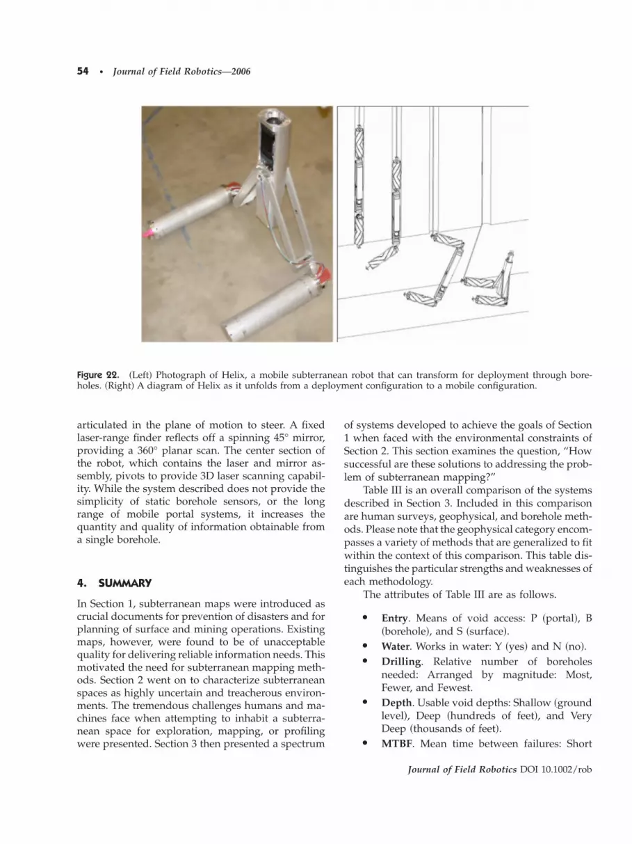
rticulated in the plane of motion to steer. A fixedaser-range finder reflects off a spinning 45° mirror,roviding a 360° planar scan. The center section of
he robot, which contains the laser and mirror as-embly, pivots to provide 3D laser scanning capabil-ty. While the system described does not provide theimplicity of static borehole sensors, or the longange of mobile portal systems, it increases theuantity and quality of information obtainable fromsingle borehole.
. SUMMARY
n Section 1, subterranean maps were introduced asrucial documents for prevention of disasters and forlanning of surface and mining operations. Existingaps, however, were found to be of unacceptable
uality for delivering reliable information needs. Thisotivated the need for subterranean mapping meth-
ds. Section 2 went on to characterize subterraneanpaces as highly uncertain and treacherous environ-ents. The tremendous challenges humans and ma-
hines face when attempting to inhabit a subterra-ean space for exploration, mapping, or profilingere presented. Section 3 then presented a spectrum
igure 22. �Left� Photograph of Helix, a mobile subterraoles. �Right� A diagram of Helix as it unfolds from a dep
f systems developed to achieve the goals of Sectionwhen faced with the environmental constraints of
ection 2. This section examines the question, “Howuccessful are these solutions to addressing the prob-em of subterranean mapping?”
Table III is an overall comparison of the systemsescribed in Section 3. Included in this comparisonre human surveys, geophysical, and borehole meth-ds. Please note that the geophysical category encom-asses a variety of methods that are generalized to fitithin the context of this comparison. This table dis-
inguishes the particular strengths and weaknesses ofach methodology.
The attributes of Table III are as follows.
• Entry. Means of void access: P �portal�, B�borehole�, and S �surface�.
• Water. Works in water: Y �yes� and N �no�.• Drilling. Relative number of boreholes
needed: Arranged by magnitude: Most,Fewer, and Fewest.
• Depth. Usable void depths: Shallow �groundlevel�, Deep �hundreds of feet�, and VeryDeep �thousands of feet�.
• MTBF. Mean time between failures: Short
robot that can transform for deployment through bore-ent configuration to a mobile configuration.
Journal of Field Robotics DOI 10.1002/rob
o
neanloym

svstamppcedm
tsvwoaShae
sMttt
mamdBBlSdba
5
Sairvtt
mrhtcl
Table III. Comparison of subterranean mapping methodologies.
Method Entry Water Drilling Depth MTBF Density Accuaracy
Human Survey P N — Shallow Very Long Sparse High
Morris et al.: Recent Developments in Subterranean Robotics • 55
J
�frequently needs repair�, Long �performsmultiple operations without repair�, andVery Long �rarely needs repair over entirelifetime�.
• Density. Quantity of data recovered: Sparse�very little quantitative information�, Dense�rich amount of data�, and Very Dense �vastamounts of data�.
• Accuracy. Reliability of data: Low �very am-biguous or not informative�, Med �have someambiguous properties�, Med-high �has am-biguous properties that can be statistically re-solved�, and High �has very little ambiguity�.
This table provides a general interpretation ofubterranean mapping methods. First, human sur-eying methods are among the most resource inten-ive with fewest results. A human requires both por-al entry and boreholes for surface-to-void correlationnd is restricted to shallow deployments. Where hu-ans are superior is their ability to cope with unex-
ected incidents. Geophysical methods prove to beowerful mapping tools; however, they are not appli-able to all domains �e.g., sewers� and are adverselyffected by increasing depth. In some cases, acquiredata are subject to so much ambiguity that alternativeethods are needed for verification.
Among the robotic systems, BDLs and BDSs arehe most applicable for immediately addressing theubterranean mapping problem. Together, they canenture into a myriad of subterranean conditionsith a high likelihood of survival. In addition, they
ffer much richer data than surveying, geophysical,nd borehole methods with very little ambiguity.MRs are systems currently under development, butave proven to excel at mapping when portals arevailable. The most promising of these systems, how-ver, are submersibles and borehole-deployable mo-
Geophysical S Y —Borehole S Y Most
BDL B N FewerBDS B Y Fewer
Mobile P N —Submersible B Y Fewest
Reconfigurable B N Fewest
ournal of Field Robotics DOI 10.1002/rob
ile robots. These systems have the deployment ver-atility of BDLs and BDSs with the capacity to move.
ovement from a borehole deployment will increasehe quantity of data acquired per borehole and allowhese methods to become the most economic for sub-erranean mapping.
The most likely solution to the subterraneanapping problem will not be a single approach, butcombination of techniques. For example, in a mineapping operation, geophysical methods could be
eployed to establish a rough idea of void location.oreholes can then be drilled, which would allow aDL or BDS to verify and map discovered void. In
ater scenarios, the autonomy methods developed onMRs will be adapted for submersibles and borehole-eployable mobile robots. These systems could thene able to augment or replace the BDLs and BDSsltogether.
. CONCLUSIONS
ubterranean robots are transforming the explorationnd mapping of underground voids and revolution-zing operations in sewers, mines, and caves. Theseobots are becoming competent agents for entering,iewing, and exploring voids as they evolve for fu-ure challenges, such as fire fighting, rescue, reclama-ion, and active mining operations.
This research chronicles the basics of void entry,obility, sensing, navigation, modeling, and subter-
anean operations. In this work, subterranean robotsave demonstrated huge advantages for moving
hrough underground voids that preclude human ac-ess. Superb void models have been created from vo-uminous range data. These models are valuable in
eep Very Long Dense MedDeep Very Long Sparse LowDeep Long Dense HighDeep Long Dense Med-high
allow Short Very Dense HighDeep Short Very Dense Med-highDeep Short Very Dense High
b
DVeryVeryVery
ShVeryVery
their own right as void maps, but have also showneven greater value for machine guidance and opera-tional autonomy.
This research is ongoing. Development is activeicpicwha
A
SnntDGRoHEtsogTs
R
B
B
B
C
Duff, E., & Roberts, J. �2003�. Wall following with con-strained active contours. Paper presented at theFourth International Conference on Field and ServiceRobotics.
Duff, E., Roberts, J., & Corke, P. �2003�. Automation of an
E
F
F
H
K
K
M
M
O
R
R
R
S
56 • Journal of Field Robotics—2006
n mechanisms, sensing, and software. Future ma-hines will become smaller, more reliable, and incor-orate new sensing configurations, such as thermal
maging, tactile, and pressure sensing. New classifi-ation algorithms, SLAM, and navigation methodsill emerge to yield more capable autonomous be-
avior. Together, these components will coalesce intobold future for subterranean robots.
CKNOWLEDGMENTS
pecial thanks to previous members of the subterra-ean robotics group at CMU, particularly Dirk Häh-el, Carlos Reverte, Mike Montemerlo, and Sebas-
ian Thrun, and students of the Mobile Robotevelopment class at CMU who helped buildroundhog. Thanks are also given to the Brucetonesearch Mine �Paul Stefko�, the National Institutef Occupational Health and Safety, Mine Safety, andealth Administration, Pennsylvania Department ofnvironmental Protection, and the various people in
he mining industry who provided guidance andupported this work. Many thanks go to John Hatch,wner of the Mathies site of Mon View Mining, forranting us access to his mine as well as Workhorseechnologies, LLC, for technical and operationalupport in all aspects of the project.
EFERENCES
aker, C., Morris, A., Ferguson, D., Thayer, S., Whittaker,C., Omohundro, Z., Reverte, C., Whittaker, W., Hah-nel, D., & Thrun, S. �2004�. A campaign in autono-mous mine mapping. Paper presented at the IEEE In-ternational Conference on Robotics and Automation�ICRA�, New Orleans, LA, pp. 2004–2009.
elwood, J., & Waugh, R. �1991�. Bats and mines: Aban-doned does not always mean empty. Bats, 9�3�, 13–16.
radley, D., Silver, D., & Thayer, S. �2004�. A regionalpoint descriptor for localization in subterranean envi-ronments. Paper presented at the IEEE Conference onRobotics Automation and Mechatronics �RAM 2005�,pp. 440–445.
hampeny-Bares, L., Coppersmith, L., & Dowling, K.�1991�. The terregator mobile robot �Tech. Rep. CMU-RI-TR-93-03�. Pittsburgh, PA: Carnegie Mellon Uni-versity, Robotics Institute.
underground mining vehicle using reactive naviga-tion and opportunistic localization. Paper presentedat the IEEE/RSJ International Conference on Intelli-gent Robots and Systems, pp. 3775–3780.
llis, J., & Dodd, H. �2000�. Applications and lessonslearned with airborne multispectral imaging. Paperpresented at the 14th International Conference on Ap-plied Geologic Remote Sensing.
airfield, N., Kantor, G., & Wettergreen, D. �2005�. Three-dimensional evidence grids for slam in complex un-derwater environments. Paper presented at the 14thInternational Symposium of Unmanned UntetheredSubmersible Technology �UUST�, Lee, NH: AUSI.
erguson, D., Morris, A., Hahnel, D., Baker, C., Omohun-dro, Z., Reverte, C., Thayer, S., Whittaker, C., & Whit-taker, W. �2003�. An autonomous robotic system formapping abandoned mines. Paper presented at theConference on Neural Information Processing Sys-tems �NIPS�.
unt, M.M., Marquet, W.M., Moller, D.A., Peal, K.R.,Smith, W.K., & Spindell, R.C. �1974�. An acoustic navi-gation system �Tech Rep. WHOI-74-6�. Woods Hole,MA: Woods Hole Oceanographic Institution.
earey, P. �2002�. An introduction to geophysical explora-tion, 3rd ed. Oxford, UK: Blackwell Science Ltd.
uipers, B., & Byan, Y. �1991�. A robot exploration andmapping strategy based on a semantic hierarchy ofspatial representations. J Robot Auton Syst, 8, 47–63.
orris, A., Silver, D., Ferguson, D., & Thayer, S. �2005�.Toward topological exploration of abandoned mines.Paper presented at the IEEE International Conferenceon Robotics and Automation.
orris, A., Kurth, D., Huber, D., Whittaker, C., & Thayer,S. �2003�. Case studies of a borehole deployable robotfor limestone profiling and mapping. Paper presentedat the International Conference on Field and ServiceRobotics �FSR�.
lson, C.F. �2000�. Maximum-likelihood template match-ing. Paper presented at the 2000 IEEE Computer Soci-ety Conference on Computer Vision and Pattern Rec-ognition �CVPR�, Vol. 2.
eynolds, J. �1997�. An introduction to applied and envi-ronmental physics. New York: Wiley.
oberts, J., Duff, E., & Corke, P. �2002�. Reactive navigationand opportunistic localization for autonomous under-ground mining vehicles. J Inf Sci, 145�1–2�, 127–146.
oberts, J., Duff, E., Corke, P., Sikka, P., Winstanley, G., &Cunningham, J. �2000�. Autonomous control of under-ground mining vehicles using reactive navigation. Pa-per presented at the IEEE International Conference onRobotics and Automation.
cheding, S., Dissanayake, G., Nebot, E., & Durrant-Whyte, H. �1997�. Slip modeling and aided inertialnavigation of an LHD. Paper presented at the IEEE
Journal of Field Robotics DOI 10.1002/rob
International Conference on Robotics andAutomation.
Silver, D., Carsten, J., & Thayer, S. �2005�. Topological glo-bal localization for subterranean voids. Paper pre-sented at the Fifth International Conference on Field
S
S
S
ternational Conference for Field and Service Robotics,pp. 299–304.
Stone, E., Ende, B., Wefer, F., & Jones, N. �2000�. Auto-mated 3D mapping of submarine tunnels. Paper pre-
W
W
W
Morris et al.: Recent Developments in Subterranean Robotics • 57
J
and Service Robotics, pp. 556–567.ilver, B., Bradley, D., & Thayer, S. �2004�. Scan matching
for flooded subterranean voids. Paper presented atthe IEEE Conference on Robotics and Mechatronics�RAM�, pp. 422–427.
ilver, D., Ferguson, D., Morris, A., & Thayer, S. �2004�.Feature extraction for topological maps. Paper pre-sented at the IEEE/RSJ Conference on Intelligent Ro-bots and Systems, pp. 773–779.
tentz, A., Ollis, M., Scheding, S., Herman, H., Fromme,C., Pedersen, J., Hegadorn, T., McCall, R., Bares, J., &Moore, R. �1999�. Position measurement for auto-mated mining machinery. Paper presented at the In-
ournal of Field Robotics DOI 10.1002/rob
sented at the Robotics 2000: ASCE Conference on Ro-botics for Challenging Environments.
ells, B. �1999�. The latest development in laser profiling,borehole deviation, and laser enhanced videometry.Aberdeen, UK: Measurement Devices, Ltd.
hitcomb, L.L. �2000�. Underwater robotics: Out of theresearch laboratory and into the field. Paper pre-sented at the IEEE International Conference on Robot-ics and Automation, pp. 706–716.
hitcomb, L.L., Yoerger, D., & Singh, H. �1999�. Advancesin Doppler-based navigation of underwater vehicles.Paper presented at the IEEE International Conferenceon Robotics and Automation, pp. 399–406.