priority metric based ad hoc routing for underwater sensor network
TRANSCRIPT

I. J. Computer Network and Information Security, 2013, 12, 1-11 Published Online October 2013 in MECS (http://www.mecs-press.org/) DOI: 10.5815/ijcnis.2013.12.01
Copyright © 2013 MECS I.J. Computer Network and Information Security, 2013, 12, 1-11
Priority Metric based Ad Hoc Routing for Underwater Sensor Network
1Md. Ashraf Uddin, 2Md. Mamun-or-Rashid, 3Md. MustafizurRahman 1Mawlana Bhashani Science and Technology University,2,3University of Dhaka
[email protected],[email protected], [email protected].
Abstract— Underwater sensor network has been burgeoned as an interesting research area which has to face a couple of challenges to provide scalable and efficient routing services because of its unique characteristics. In many aspects, it differs from the ground based terrestrial sensor network, Firstly, In UWSNs, acoustic signal is used instead of radio-frequency that attenuates much in underwater environment in comparison with radio-frequency channels. Acoustic channels attribute much lower bandwidth and the propagation speed of acoustic signals in water is several of magnitudes longer. Secondly, nodes of underwater sensor networks move with water current which results dynamic topology. Thirdly, underwater sensor networks consume more power than terrestrial networks due to the underwater channel characteristics and it has high error probability because of acoustic underwater channels' sensibility in noise, multi-path and Doppler spread. Some routing protocols have been proposed to deal with these challenges. But most of these protocols espouse the greedy technique to forward packets to the neighboring node which consumes a lot of energy when network is dense. In this thesis, we propose a Priority Metric Based Ad hoc Routing Protocol for UWSNs. The leading advantages of the protocol are that it consumes less energy in dense network as only one neighboring node needs to capture the packet and process it and it guarantees less number of packet loss in high mobile node environment. Extensive simulation is executed to attest the competence of the proposed routing protocol. The result and analysis bear the indication of the proposed routing protocol's surpassing the existing routing protocol in terms of total energy consumption and average end to end delay. Index Terms— UWSNs, Link Stability, Priority Metric, random node mobility, horizontal node mobility, updating time
I. INTRODUCTION
Wireless sensor networks have been a promising network technique that has been incorporated comprehensively in a lot of land-based applications. The earth is called a planet of water and about two-third of its surface is covered by oceans where a huge amount of resources and information lies and need to discover these
hidden resources and provides important information such as Tsunami and earthquake information from the bottom of oceans to the surface. Data mining in oceans can also be carried out through UWSNs. Accordingly, a quickly increasing development towards the application of sensor networks such as ocean sampling networks, environmental monitoring, undersea explorations, disaster prevention and mine reconnaissance[1][2][3]in underwater environments that is forming underwater sensor networks (UWSNs) have been observed in current several years. In underwater sensor network, many research issues have been continued to study for constructing the UWSNs protocol stack. Routing, sending packet from a source node to a destination is one of the innovative and potential issues of UWSNs to be revised.
A. Unique Characteristics of UWSNs An UWSNs can be differentiated from any ground-
based sensor network in the perspective of cost, deployment, power and memory of each node. In fact, it is very difficult to provide scalable and efficient routing services due to the unique characteristics of underwater sensor networks. Routing protocols need to meet the challenges of limited bandwidth, high bit error rates and temporary losses of connectivity (shadow zones). Underwater sensor nodes are prone to failures because of fouling and corrosion, limited battery power, high propagation delay, mobility of nodes.In details, firstly, radio frequency cannot be used as transmission media to guide a packet under water due to its fast attenuation. Acoustic communications are preferred in underwater environment but acoustics channels often suffer from low bandwidths and long propagation delays. For this reason the routing protocols that feature long end-to-end delays or high bandwidth requirement are not suitable in acoustic UWSNs. The available bandwidth is limited due to attenuation and high absorption factor of acoustic signals. The link quality is severely affected by the multi path fading and refractive properties of sound channels. Therefore, the bit error rates are typically very high. Secondly, UWSNs is a highly dynamic network topology because of most nodes' moving with water current (except that some gateway nodes are fixed at the water surface or anchored at the bottom). With a view to handling dynamic networks, using existing routing protocol for land based (static) sensor networks requires to update routing information frequently, which produces significant communication overhead. Thirdly, it is even
2 Priority Metric based Ad Hoc Routing for Underwater Sensor Network
Copyright © 2013 MECS I.J. Computer Network and Information Security, 2013, 12, 1-11
harder to recharge or replace the batteries used by the sensor nodes of UWSNs like land-based sensor nodes in hash underwater environments. Thus, another essential apprehension for UWSNs is energy. UWSNs are usually deployed in a 3-dimensional space. This is different from the 2-dimensional deployment of most land-based sensor networks. UWSNs are very differentfrom ground-based existing networks due to the intrinsic properties of the underwater environments.
B. Routing Challenges of UWSNs To save energy is considered the key apprehension in
UWSNsas like in terrestrial sensor networks. At the same time, UWSNsrouting should be able to handle node mobility. This requirementmakes most existing energy-efficient routing protocolsunsuitable for UWSNs [4]. Many routing protocols are proposedfor terrestrial sensor networks such as Directed Diffusion[5], and TTDD (Two-Tier Data Dissemination)[6].These protocols are designed for stationary network. Queryflooding is usually employed by these protocols to discoverdata delivery paths. In UWSNs, however, most sensor nodes are mobile, and the ”network topology” changes very rapidly even with small displacements. The frequent maintenanceand recovery of forwarding paths is very expensive in highdynamic networks, and even more expensive in dense 3-dimensional UWSNs. The multi-hop routing protocols interrestrial mobile ad hoc networks fall into two categories:proactive routing and reactive routing (aka. on-demand routing).In proactive ad hoc routing protocols like OLSR[7],TBRPF [8] and DSDV [9], the cost of proactive neighbordetection could be very expensive because of the largescale of UWSNs. On the other hand, in on-demand routing(with AODV [10] and DSR [11] as common examples),routing operation is triggered by the communication demandat sources. In the phase of route discovery, the source seeksto establish a route towards the destination by flooding aroute request message, which would be very costly in largescale UWSNs.It is clear that the routing protocol designed for terrestrialsensor networks is not suitable for UWSNs. In the recentyears, a major number of UWSNs routing protocol suchVBF [4], DBR[12], HH-VBF [13], FBR [14], DUCS[15],UWD[16] and MPT[17] has been developed. UWSNs routingprotocol can be divided into two categories: localizationbased routing protocol and localization free routing protocol.
All of these routing protocols have tried to address the UWSNs challenges but have not been able to meet all therequirements to be an efficient and scalable UWSNs routing protocol. No direct method has been followed by theseprotocols to handle node mobility. Most of these apply thegreedy method to forward packet which results a huge amountof energy consumption. To design a UWSNs routing protocolthat provides scalability, robustness and efficiency at thesame time is also a big challenge. Existing UWSNs routingprotocols are suited for specific environment. To developa UWSNs routing protocol which presents the same performancefor dense network and sparse network is anotherrouting challenge. In this paper, we target a mobile UWSNs(where most sensors
are not fixed, and they can float withwater current). This type of UWSNs is very useful in manyapplications, such as estuary dynamic monitoring and submarine detection [18], [19].
C. Contribution Our key concern is to erect a routing protocol for
UWSNs so that we can send data packet from source to destination efficiently meeting the challenges of UWSNs. With a view to saving energy, we have introduced unicast data packet forwarding technique. To handle node mobility, we calculate link stability and to maximize the update period, we present two methods for measuring the nodes’ survivability within a predefined region by considering both random node mobility and horizontal node mobility. Finally, we presume a priority metric based on depth, residual energy and link stability.
The rest of this paper is organized as follows. We describe related works in Section 2. Our proposed PriorityMetric based Ad hoc Routing Protocol for UWSNs ispresented in Section 3 and the simulation results are presentedin Section 4. Finally, we conclude the paper in Section5 along with future research direction.
II. RELATED WORKS
One of the primary topics for any network is routing and routing protocols are regard as indictment of determining and preserving the routes. Most of the research works pertaining to underwater sensor networks have been on the issues related to physical layer. On the other hand, routing techniques are comparatively new arena of network layer of UWSNs. Thus providing an efficient routing algorithm becomes a significant mission. Although underwater acoustic has been continued to study for decades, underwater networking and routing protocols are still at the infant stage of research.
Link Expiration Time Aware Routing Protocol for UWSNs(LETA)[20] is divided into three phases named selection of compatible forwarding node phase, routing table formation phase by sending node and target node selection phase by the sending node to send data packet. Each of the parts is discussed in this section. Selection of Compatible Forwarding Node phase: In this phase, most of the procedures are performed by the forwarding node. The sending node broadcast a hello message named RREQ to discover its one hop compatible forwarding node. Upon receiving the RREQ message of the sending node, the forwarding node estimates the probability of packet forwarding and packet discarding based on the depth difference of the forwarding node and sending node, residual energy and the distance from forwarding node to sending node. If the probability of packet forwarding is greater than that of packet discarding, the forwarding node responds to the sending node through RREP message incorporated its probability in the reply message. Routing Table Formation phase: After receiving RREP message from one hop neighbor node, the sending node reckons the link expiration time with each compatible forwarding node. The sending node keeps the forwarding
Priority Metric based Ad Hoc Routing for Underwater Sensor Network 3
Copyright © 2013 MECS I.J. Computer Network and Information Security, 2013, 12, 1-11
node in its routing table according to the decreasing order of the forwarding nodes' probability that means the node with highest probability is at first position in the routing table and the next highest is at second position. Target Node selection phase: After completing the formation of routing table, the sending node pick up the forwarding node with highest probability and corresponding link expiration time of the forwarding time in order to handle node mobility. The link expiration time is compared with the time to reach the packet to the forwarding node and return acknowledgement to the sending node from the forwarding node. If the link expiration time of the forwarding exceed the packet's reaching time and acknowledgement's receiving time, then the forwarding node is chosen as target node and the packet is forwarded to the node. Otherwise, another node is chosen in the same way. If no node in the routing table is found as target node, then routing table is formed anew[20].
In Energy Efficient Fitness based Routing for Underwater Sensor Network[21], it is assumed that the location of the sink node is known. First, the source node calculates the fitness ofits own and incorporates the fitness value and its positionin the data packet and broadcasts it. The one hop neighboringnodes which get the packet calculate their own fitnessthat actually define whether they forward the packet or simplydiscard. After receiving the packet, the forwarding nodecompares its fitness with the sending node’s fitness incorporatedin the packet. If the fitness of the forwarding node isgreater than that of the sending node, then it forwards thepacket otherwise it discards the packet. In this process, morenodes may take part in forwarding packet; In order to preventmore nodes to forward the same packet, the forwardingnodes wait for a time period which is assumed based on theresidual energy, depth, and distance from the sending nodeto the forwarding node. The holding time of the forwardingnodes vary from each other. The node which is the fittestwaits less time than that of other forwarding nodes. Consequently,other forwarding nodes overhear the same packetand avoid forwarding the packet[21].
An Energy Efficient Localization-Free Routing (EEDBR). In[22], the authors proposed an energy efficient localization freerouting protocol (EEDBR) for the greedy pressure-basedrouting group ofUWASNs.The aim of this protocol is to balancethe energy of nodes and improve the network lifetime.In the architecture of EEDBR, multiple sinks are deployedon the water surface and equipped with radio and acousticmodems, while ordinary nodes are randomly scattered in thearea of interest. They can move freely through water flow,and they are equipped with acoustic modem. Unlike DBRthat is a receiver-based routing protocol, EEDBR is a senderbasedrouting protocol in which sender node selects a set ofnext hop nodes based on their depth and residual energy.EEDBR is composed of two phases: knowledge acquisitionand data forwarding. In the first one, each node broadcastsits own depth and residual energy as a Hello packet to itsneighboring nodes. Therefore, all nodes collect and savetheir neighboring nodes’ information. In
the second phase,a subset of forwarder nodes is selected based on their depthinformation and residual energy. In other words, a group ofneighboring nodes with a depth smaller than that of sendernode that have suitable residual energy are selected as nexthop node candidates. The sender node embeds a list ofselected nodes ID in data packet and forwards it. The nodeson the list are sorted based on their residual energy, whichshows their priorities. In order to prevent redundant datapacket forwarding, each candidate node considers a holdingtime according to its residual energy and priority in which ashorter holding time is assigned to a node withmoreresidualenergy. In addition, the nodes with the same residual energy have different priority which results in different holding time for these nodes [23].
Depth Based Routing Protocol DBR (Depth based routing)[12] is an underwater sensor network routing protocol which isbased on the depth information of each sensor. In this routingprotocol, No complete dimensional information of locationof the sensor nodes is required and it can managea dynamic network. In DBR[12], to deliver a packet, it determinesthe closer to the destination the smaller the depth ofthe forwarding nodes becomes and to receive a packet itcompares depth dp retrieval of the previous hop and it’s receivingnode’s depth for the qualified candidates to forwardthe packet. DBR has good energy efficiency but not so muchgood performance for the dense network where it has significantend to end delay and high total energy consumption.
In this paper, we have proposed a novel UWSNs routingprotocol which takes into account of the water current and articulates the link stability between two sensor nodes. The proposed protocol takes advantages of multiple sink node and localization technique to predict the link stability.
III. DETAILS OF THE PROPOSED PROTOCOL
In this section, we present our priority metric based ad hoc routing protocol (PMA) in detail. Multiple-Sink underwater sensor network architecture has been applied in the proposed routing protocol. We have divided the protocol into two parts named route information accumulation phase and target sensor node selection phase. In route information accumulation phase, the sensor nodes broadcast a hello message named by RREQ to form routing table within their range. In target sensor node selection phase, the forwarding node selects the sensor node with the highest priority to forward the data packet.
A. Network Architecture It is pointed out before; the multiple-sink underwater
sensor network architecture [12] can be used by the proposed routing protocol, the Priority Metric based Ad hoc (PMA) routing protocol. Like DBR [12], it also takes advantages of the multiple-sink underwater sensor network architecture. An example of such networks is demonstrated in Fig 1.

4 Priority Metric based Ad Hoc Routing for Underwater Sensor Network
Copyright © 2013 MECS I.J. Computer Network and Information Security, 2013, 12, 1-11
Figure 1: Multiple-Sink underwater sensor network
architecture[12]
In this multiple-sink network, the water surface nodes that are called sink nodes are equipped with the modem that is capable of capturing both radio-frequency and acoustic signal. The nodes that send and receive only acoustic signal are deployed in the underwater environment. Underwater sensor nodes with acoustic modems are placed in the interested 3 − D area and each such node is assumed likely to be a data source. Underwater acoustic nodes can accumulate data and also assist to convey data to the sinks. When a sink node receives a packet from an underwater acoustic node, the sink node can converse with each other efficiently via radio channels. The protocol attempts to send a packet to any sink nodes on the surface because if a surface node receives a packet it can send the packet other sinks or remote data centers quickly due to the speed of radio- frequency (with a propagation speed of 3 × 10⁸m/s in air) which is five orders of magnitudes higher than sound propagation (at the speed of 1.5 × 10³m/s in water)[4]. Here, the protocol does not pay attention to the communication between surface nodes. Instead it tries to transmit a packet to any surfacesinks and assumes that the packet reaches to its destination. The protocol has been built by considering the fact that every node knows its depth which is the vertical distance from the node's position to the surface.
B. Overview of Priority Metric based Routing Protocol for Underwater Sensor Networks
Overall view of the proposed UWSNs routing protocol is described in two phases. Firstly, a brief discussion on routing table formation is given in route information accumulation phase and secondly, target sensor node selection phase has been described.Route Information Accumulation Phase:Route information accumulation phase includes the broadcasting control packet by the each sensor node to the one hop neighboring sensor nodes and receiving the depth and residual energy of the one hop neighboring sensor nodes by each other. In this phase the information required to form routing table is obtained by each sensor node. The phase works as the following way. In this phase each sensor node broadcasts control packet to its one hop neighboring sensor nodes and let them know its depth and residual energy. In this way, every sensor node within a fixed range knows each other
depth and residual energy. After that, each sensor node forms their routing table of its qualified one hop neighboring sensor nodes. During the formation of routing table, each sensor node takes into account only its neighboring sensor nodes which depth are less than that of the forwarding sensor node. Secondly, the each sensor node discards those neighboring sensor nodes which residual energy is less than threshold energy. Thirdly, it filters the neighboring sensor nodes which link stability does not permit to be stayed connected with its neighboring sensor node during the estimated time period. As a result the size of the routing table becomes small and it lessens the burden of storing so much information for all one hop neighboring sensor nodes. In UWSNs, the topology of the network changes frequently because of water current that forces each sensor node broadcast control packet to find the most suitable neighboring node which packet can be transmitted. Moreover, in harsh environment the sensor nodes tend to be more mobile. Therefore, each time after passing an estimated time, each sensor node has to update the routing table by broadcasting control packet. Generally, control packet overhead occurs for this kind of approach, for the purpose of reducing control packet overhead, we have estimated the update time based on node mobility. Two approaches for presuming updating time is discussed in this paper by considering the random node mobility and the horizontal node mobility.Target Node Selection Phase: In this phase, each sensor node qualifies only one node to forward the packet based on not only depth and residual energy but also link stability of the node that means how much time the target node and the forwarding node remain connected within a fixed range. When a sensor node finds the depth and residual energy of its one hop neighboring nodes, it calculates the link stability of the neighboring sensor nodes for the estimated time t. In this protocol, in order to control congestion and reduce total energy consumption, only one sensor node is selected to forward the packet. Hence,the link stability of the node is necessary to ensure that the node remains within the range up to the whole time of receiving the whole data from the forwarding node. To calculate the Link stability, to know the locationinformation of each sensor node is required which can be achieved through localization technique. The process for selecting the most suitable target node is to estimate a priority metric based on depth, link stability and residual energy where link stability and residual energy must exceed the threshold link stability and threshold residual energy respectively. The priority metric is stored in descending order in the routing table. If any neighboring sensor node's residual energy or link stability is below minimum requirements then its priority metric is not calculated and the protocol avoid storing it in the routing table and the sensor node prevents itself from further broadcasting control packet. The candidate sensor node with the highest priority metric of the routing table is picked to forward the packet and the selected candidate sensor node is called target sensor node. In this protocol, mobility of node is handled with the help of link stability. The protocol chooses it target forwarding sensor
Priority Metric based Ad Hoc Routing for Underwater Sensor Network 5
Copyright © 2013 MECS I.J. Computer Network and Information Security, 2013, 12, 1-11
node by considering the depth that helps packet to reach sink by using minimum number of hop, residual energy that ensure that the node has enough energy to forward the packet and link stability that guarantees the durability of the connection between the forwarding sensor node and the target node.
C. Reckoning Link Stability To identify the link stability of any two one hop
neighboring nodes, Distance between these two nodes for the time t is calculated. Link stability of any two nodes means the duration of the connectivity of the two nodes within a fixed range R.
When the distance between two nodes becomes larger than the transmission range R link stability Lst between any two nodes overtime period t can be calculated [20]:
𝐿𝐿𝑠𝑠𝑠𝑠 = 𝐷𝐷𝑅𝑅
D. Estimation of Updating Time In this section, we have estimated the update time of
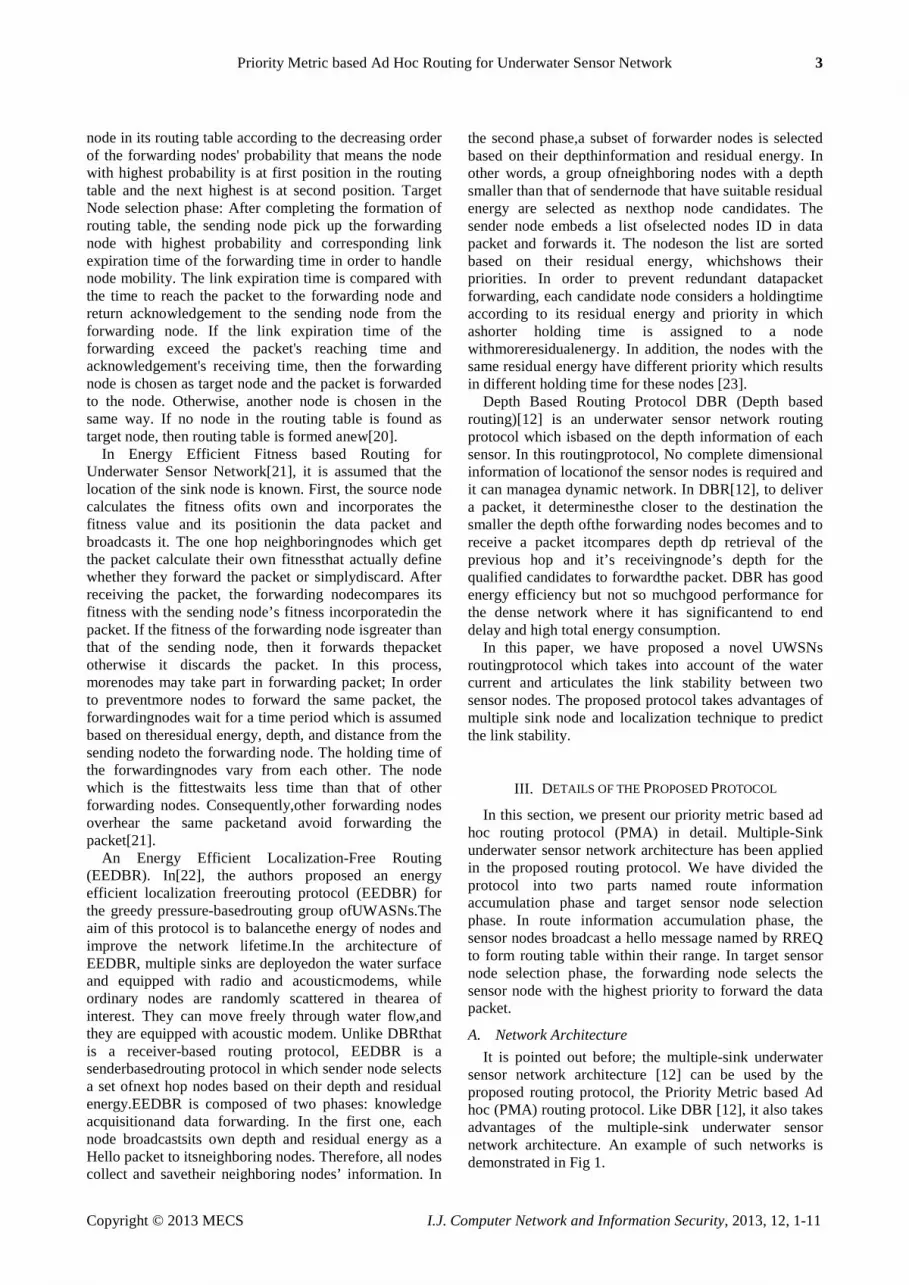
routing table for a sensor node. Our data forwarding technique is unicast so we can reduce the control packet overhead by increasing update time. This time is calculated based on the presumption that minimum required number of sensor nodes can be founded within range of the forwarding sensor node. We have calculated updating time in two ways, firstly we assume that the nodes randomly move and secondly the nodes move horizontally. Updating Time for Random Node Mobility: In Fig 2, we consider F as forwarding node. By broadcasting RREQ message, F can discover N1, N2 , N3, N4 , N5 and N6 candidate neighboring sensor nodes. These sensor nodes are called candidate because they accomplish the minimum constraint to be a candidate neighboring node.
Figure 2:Updating time for random node mobility
Now we would like to estimate a time t that makes
certain that most of these sensor (at least 80%) nodes will
stay within the upper half region of the R range. Here, we have assumed that the nodes can move in random direction with V velocity. As a node can take random movement, we have considered a circle by taking the sensor node’s position as the center of that circle and radius is min (|Zi − Zf|, R − di). Ziis the Z − axis value of the sensor node Ni ‘s position, and Zf is the Z −axis value of the forwarding sensor node. |Zi − Zf| is the distance of the parallel line drawn for the sensor node Ni ’s position to the plane AB and R − di is the minimum distance from the nodes position to circumstance of the circle whose radius is range R. Now, for the worst case scenario of each sensor node, we can estimate the lasting time within fixed half region of the range R as follows:
𝑠𝑠1 = |𝑍𝑍1 − 𝑍𝑍𝑓𝑓 |
𝑉𝑉
𝑠𝑠3 = |𝑅𝑅 − 𝑑𝑑3|
𝑉𝑉
Time (t1, t2, t3, t4, t5 and t6 for node (N1, N2 , N3, N4, N5, and N6) indicates the sustainability with in the half region of the range of the forwarding node. We are interested to prefer a time t among (t1, t2, t3, t4, t5 and t6) so that at least 80% of the candidate nodes (N1, N2 , N3, N4, N5, and N6) remain within the region during this period(t). If we choose the smallest time, then we can guarantee that 100% sensor nodes stay within this region over time period t.But it becomes too small period to choose for updating routing table. The routing table frequently updates it information consequently it causes congestion of control packet and consume additional energy for control packet. Thus, the minimum time is not opting for calculating stability and updating routing table. On the other hand if we choose the highest value of the calculated time, then we get very few nodes within our range after this time period. In the case of average time period, it has the possibility to have 50% sensor node within the region. Therefore, a time period (t) among this time period is needed to select so that 80% sensor node can be found within the region. To determine this expected time we can follow the following process.First, arrange the time period in ascending order by applying a sorting algorithm like merge sort.Second, use the percentile formula to know the value of nth position of the observances for a fixed percentage.We know, n = � P
100�× N + 1
2 where P =
Percentages, N = number of sensor node. n is the nth position of the observances that gives us P percentages of observances having to the left side of this position.Updating Time for Horizontal Node Mobility:The sensor nodes move with water currents in horizontal direction, and the movements in vertical direction are almost negligible [26].So in this section, we consider the horizontal node mobility and find out the updating time. Two cases happen in this calculation.We assume the forwarding node F stationary. First case, the

6 Priority Metric based Ad Hoc Routing for Underwater Sensor Network
Copyright © 2013 MECS I.J. Computer Network and Information Security, 2013, 12, 1-11
placement of C illustrated in Fig 3 is shown in right half region of FY vertical line.
Figure 3:Updating time for horizontal node mobility
Node C can move in the left and right direction. If the
C node moves in its right direction it passes CF distance. In this case, we calculate the distance CE and CH in the following way. From C, a perpendicular called CO is drawn. ∠COF = 90 ° , therefore, FO = √(CF2 −CO2) where we know CO = |Zf -Zc |. FGis perpendicular on the plane XX′ . So, ∠FGE = 90° and FG = √(FE2 −EG2 ) where FE = Rand EG = |Zf − Zc|. Now we can compute the distance OG = CE = FG− FO. The time (t) to pass the distance CE is CE
V where V is the velocity of
water current. Second case, the node C illustrated in Fig 4 exists in the left half region of FY vertical line, if the node’s movement is in direction left of the node then CE = FG− OF and if the node’s movement is in the direction of its right CH = OF + FI.
Figure 4:Updating time for horizontal node mobility
E. Estimation of Priority Metric It is not good decision to select the target node based
on only depth or link stability or residual energy. We need to develop a metric with the combining effect of depth, link stability and residual energy and this metric is the best selection criteria for choosing the best suitable target sensor node. We are interested to select a node with the smallest depth that means the smaller the depth, the more suitable target node is. We do also care for higher residual energy (RE) and link stability (Lst ), the larger the value of residual energy and link stability, the more reliable the target node is. So we can say that the best target sensor node’s selection metric is inversely proportional tothe range R divided by depth difference of the sending node (depths ) and forwarding node(depthf )and directly proportional to the product of its path stability and residual energy. The name of target selection is given priority metric (PM) which can be calculated as follows:
PM = RE ×LstR
depth s−depth f
(1)
F. Routing Table
Each node forms a routing table of two columns; candidate sensor nodes and theircorresponding priority metric calculated by using eq(1.) Routing table ofunderwater sensor network is demonstrated in Table1. Let the forwarding nodebe F and its one hop candidate neighboring sensor nodes be (N1 , N2 , … , Nn ) within rangeR. Routing table is updated over the estimated time because linkstability between forwarding node and the candidate sensor nodes alter becauseof water current.
TABLE 1: Routing table for PMA Node Priority Metric
N1 PM1
N2 PM2
N3 PM3
N4 PM4
G. Algorithm for PMA The proposed routing algorithm is divided into two
parts called routing table formation algorithm and target node selection algorithm that are illustrated in this section. In routing table formation algorithm, Ni represents the one hop neighboring node of the forwarding node and R is transmission range. In the algorithm, depthf indicates the depth of the forwarding node itself. The forwarding sensor node repeats the routing table formation algorithm whenever the update time elapses. The routing table formation algorithm is as follows.
Priority Metric based Ad Hoc Routing for Underwater Sensor Network 7
Copyright © 2013 MECS I.J. Computer Network and Information Security, 2013, 12, 1-11
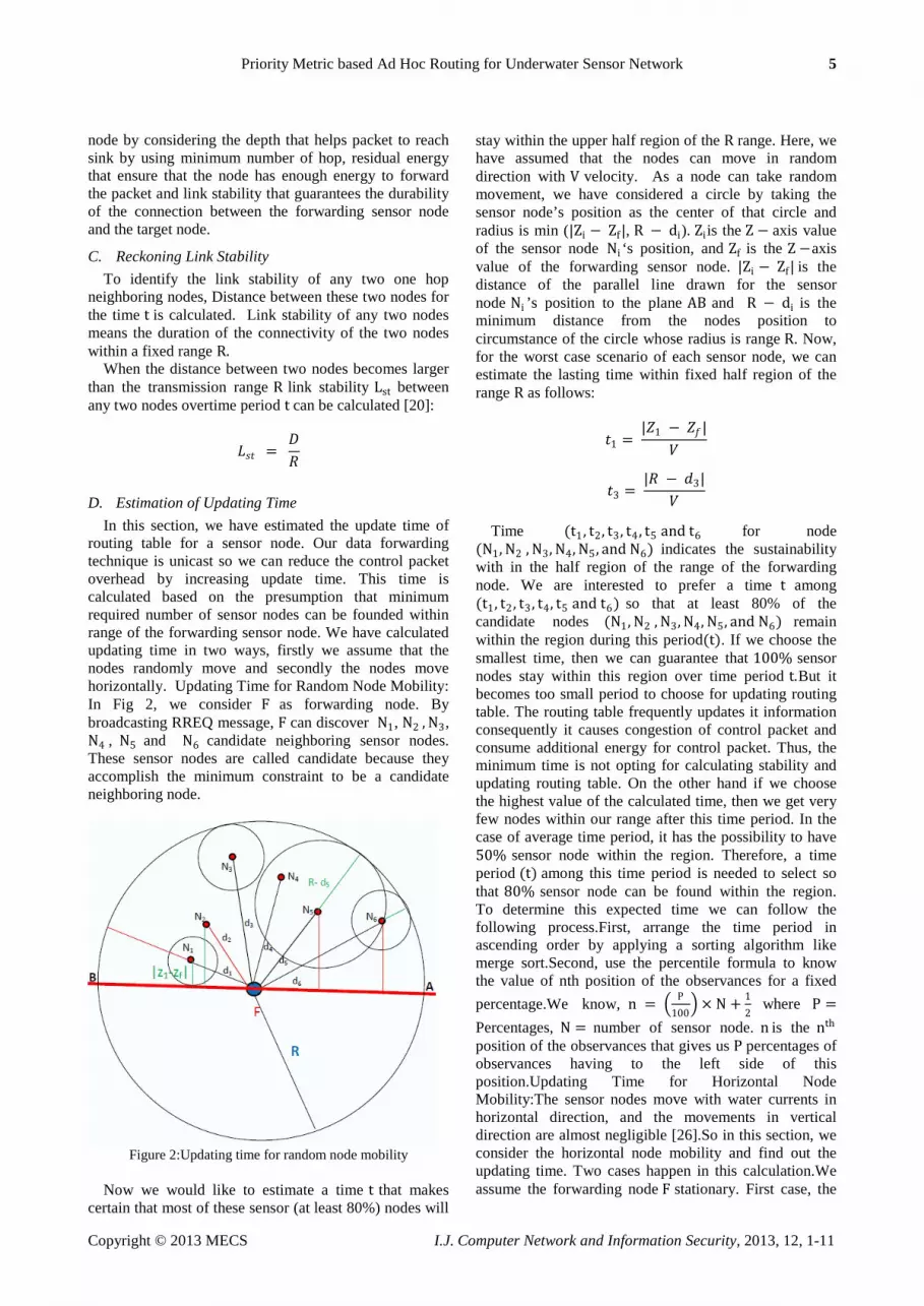
Algorithm 1Routing table formation algorithm Require: Sharing RREQ message Ensure: Routing table with priority metric
1. Extract depthi , ERi from one hop neighboring sensor nodes( N1 , ( N2, … , Nn ) broadcasting control packet
2. whilei< ndo 1. if depthi < depthf AND ERi >
Threshold Energythen i. Calculate Lst of node i for
time t ii. ifLst > 1then
1. Calculate MP and store it in routing table
iii. end if 2. end if
3. i←i+1 4. end while 5. return routing table
As the protocol forms its routing table in advance for
an estimated time period. So, the rest of the task for the sensor nodes is to store the data packet whenever it gets or detects and forward the data packet to the appropriate target node. The data packet forwarding algorithm is shown below.
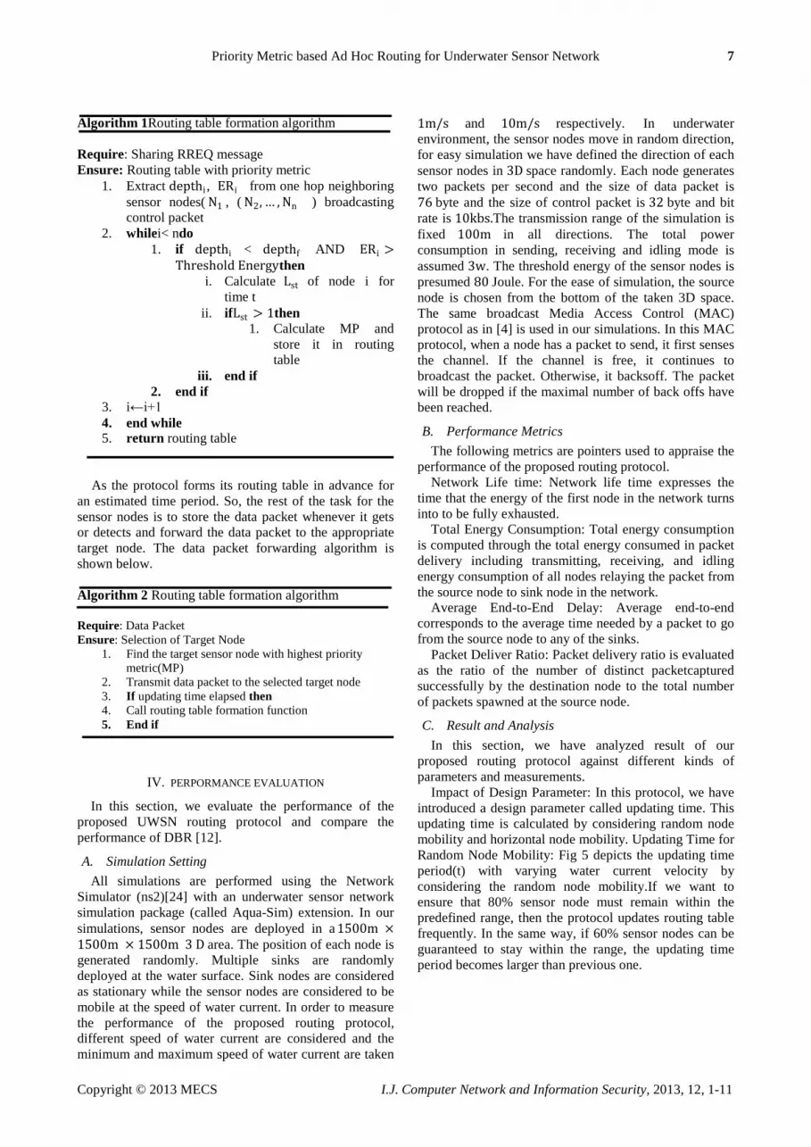
Algorithm 2 Routing table formation algorithm
Require: Data Packet Ensure: Selection of Target Node
1. Find the target sensor node with highest priority metric(MP)
2. Transmit data packet to the selected target node 3. If updating time elapsed then 4. Call routing table formation function 5. End if
IV. PERPORMANCE EVALUATION
In this section, we evaluate the performance of the proposed UWSN routing protocol and compare the performance of DBR [12].
A. Simulation Setting All simulations are performed using the Network
Simulator (ns2)[24] with an underwater sensor network simulation package (called Aqua-Sim) extension. In our simulations, sensor nodes are deployed in a 1500m ×1500m × 1500m 3 D area. The position of each node is generated randomly. Multiple sinks are randomly deployed at the water surface. Sink nodes are considered as stationary while the sensor nodes are considered to be mobile at the speed of water current. In order to measure the performance of the proposed routing protocol, different speed of water current are considered and the minimum and maximum speed of water current are taken
1m/s and 10m/s respectively. In underwater environment, the sensor nodes move in random direction, for easy simulation we have defined the direction of each sensor nodes in 3D space randomly. Each node generates two packets per second and the size of data packet is 76 byte and the size of control packet is 32 byte and bit rate is 10kbs.The transmission range of the simulation is fixed 100m in all directions. The total power consumption in sending, receiving and idling mode is assumed 3w. The threshold energy of the sensor nodes is presumed 80 Joule. For the ease of simulation, the source node is chosen from the bottom of the taken 3D space. The same broadcast Media Access Control (MAC) protocol as in [4] is used in our simulations. In this MAC protocol, when a node has a packet to send, it first senses the channel. If the channel is free, it continues to broadcast the packet. Otherwise, it backsoff. The packet will be dropped if the maximal number of back offs have been reached.
B. Performance Metrics The following metrics are pointers used to appraise the
performance of the proposed routing protocol. Network Life time: Network life time expresses the
time that the energy of the first node in the network turns into to be fully exhausted.
Total Energy Consumption: Total energy consumption is computed through the total energy consumed in packet delivery including transmitting, receiving, and idling energy consumption of all nodes relaying the packet from the source node to sink node in the network.
Average End-to-End Delay: Average end-to-end corresponds to the average time needed by a packet to go from the source node to any of the sinks.
Packet Deliver Ratio: Packet delivery ratio is evaluated as the ratio of the number of distinct packetcaptured successfully by the destination node to the total number of packets spawned at the source node.
C. Result and Analysis In this section, we have analyzed result of our
proposed routing protocol against different kinds of parameters and measurements.
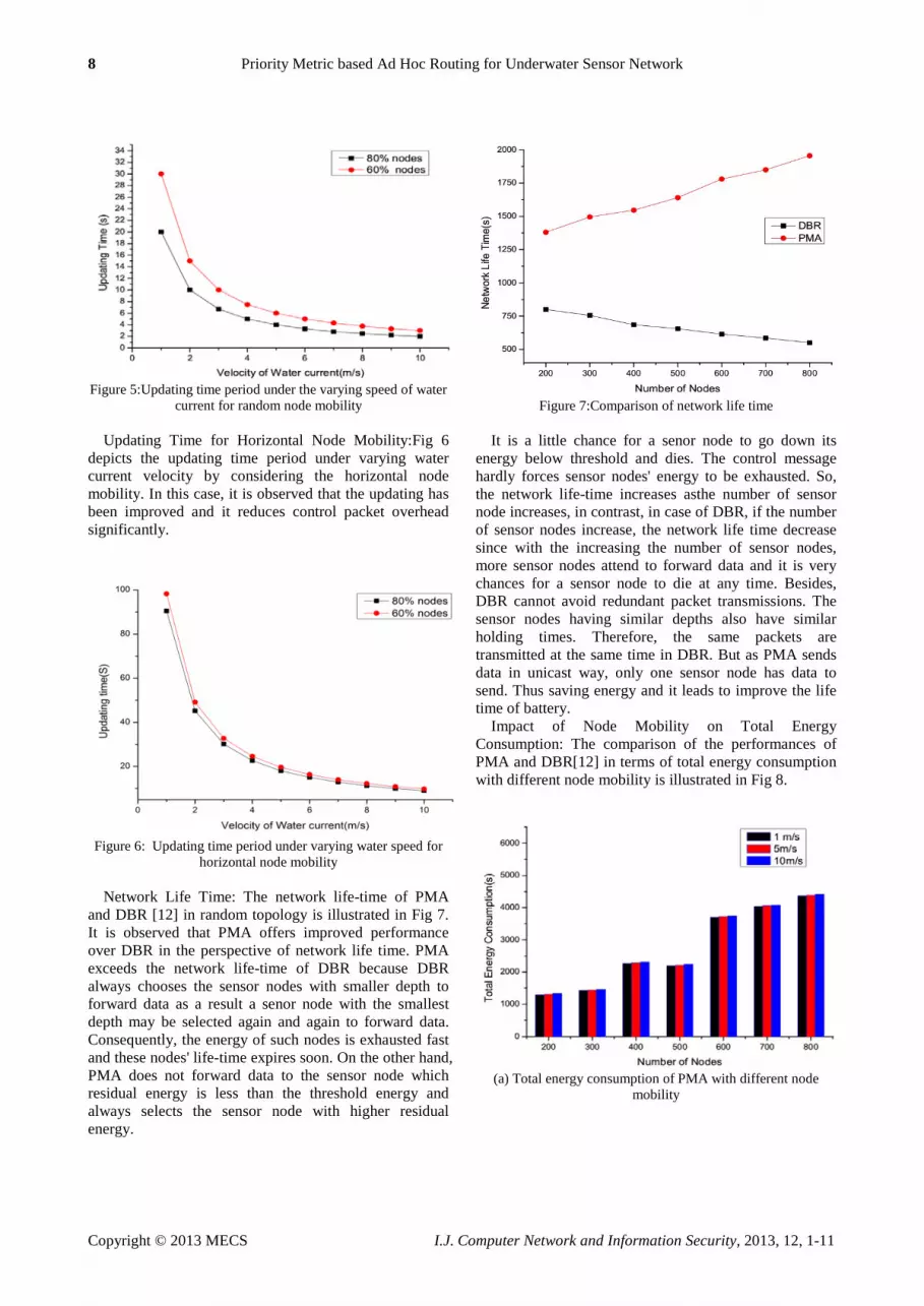
Impact of Design Parameter: In this protocol, we have introduced a design parameter called updating time. This updating time is calculated by considering random node mobility and horizontal node mobility. Updating Time for Random Node Mobility: Fig 5 depicts the updating time period(t) with varying water current velocity by considering the random node mobility.If we want to ensure that 80% sensor node must remain within the predefined range, then the protocol updates routing table frequently. In the same way, if 60% sensor nodes can be guaranteed to stay within the range, the updating time period becomes larger than previous one.
8 Priority Metric based Ad Hoc Routing for Underwater Sensor Network
Copyright © 2013 MECS I.J. Computer Network and Information Security, 2013, 12, 1-11
Figure 5:Updating time period under the varying speed of water
current for random node mobility
Updating Time for Horizontal Node Mobility:Fig 6 depicts the updating time period under varying water current velocity by considering the horizontal node mobility. In this case, it is observed that the updating has been improved and it reduces control packet overhead significantly.
Figure 6: Updating time period under varying water speed for
horizontal node mobility
Network Life Time: The network life-time of PMA and DBR [12] in random topology is illustrated in Fig 7. It is observed that PMA offers improved performance over DBR in the perspective of network life time. PMA exceeds the network life-time of DBR because DBR always chooses the sensor nodes with smaller depth to forward data as a result a senor node with the smallest depth may be selected again and again to forward data. Consequently, the energy of such nodes is exhausted fast and these nodes' life-time expires soon. On the other hand, PMA does not forward data to the sensor node which residual energy is less than the threshold energy and always selects the sensor node with higher residual energy.
Figure 7:Comparison of network life time
It is a little chance for a senor node to go down its
energy below threshold and dies. The control message hardly forces sensor nodes' energy to be exhausted. So, the network life-time increases asthe number of sensor node increases, in contrast, in case of DBR, if the number of sensor nodes increase, the network life time decrease since with the increasing the number of sensor nodes, more sensor nodes attend to forward data and it is very chances for a sensor node to die at any time. Besides, DBR cannot avoid redundant packet transmissions. The sensor nodes having similar depths also have similar holding times. Therefore, the same packets are transmitted at the same time in DBR. But as PMA sends data in unicast way, only one sensor node has data to send. Thus saving energy and it leads to improve the life time of battery.
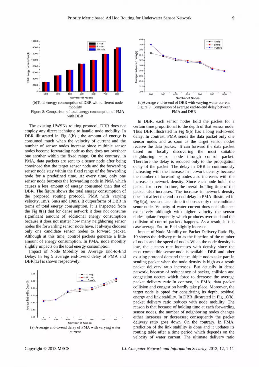
Impact of Node Mobility on Total Energy Consumption: The comparison of the performances of PMA and DBR[12] in terms of total energy consumption with different node mobility is illustrated in Fig 8.
(a) Total energy consumption of PMA with different node
mobility
Priority Metric based Ad Hoc Routing for Underwater Sensor Network 9
Copyright © 2013 MECS I.J. Computer Network and Information Security, 2013, 12, 1-11
(b)Total energy consumption of DBR with different node
mobility Figure 8: Comparison of total energy consumption of PMA
with DBR
The existing UWSNs routing protocol, DBR does not employ any direct technique to handle node mobility. In DBR illustrated in Fig 8(b) , the amount of energy is consumed much when the velocity of current and the number of sensor nodes increase since multiple sensor nodes become forwarding node as they does not overhear one another within the fixed range. On the contrary, in PMA, data packets are sent to a senor node after being convinced that the target sensor node and the forwarding sensor node stay within the fixed range of the forwarding node for a predefined time. At every time, only one sensor node becomes the forwarding node in PMA which causes a less amount of energy consumed than that of DBR. The figure shows the total energy consumption of the proposed routing protocol, PMA with varying velocity, 1m/s, 5m/s and 10m/s. It outperforms of DBR in terms of total energy consumption. It is inspected from the Fig 8(a) that for dense network it does not consume significant amount of additional energy consumption because it does not matter how many neighboring sensor nodes the forwarding sensor node have. It always chooses only one candidate sensor nodes to forward packet. Although at this time, control packets generate a little amount of energy consumption. In PMA, node mobility slightly impacts on the total energy consumption.
Impact of Node Mobility on Average End-to-End Delay: In Fig 9 average end-to-end delay of PMA and DBR[12] is shown respectively.
(a) Average end-to-end delay of PMA with varying water
current
(b)Average end-to-end of DBR with varying water current Figure 9: Comparison of average end-to-end delay between
PMA and DBR
In DBR, each sensor nodes hold the packet for a certain time proportional to the depth of that sensor node. Thus DBR illustrated in Fig 9(b) has a long end-to-end delay. In contrast, PMA sends the data packet only one sensor nodes and as soon as the target sensor nodes receive the data packet. It can forward the data packet based on locally discovering the most suitable neighboring sensor node through control packet. Therefore the delay is reduced only to the propagation delay of the packet. The delay in DBR is continuously increasing with the increase in network density because the number of forwarding nodes also increases with the increase in network density. Since each node holds the packet for a certain time, the overall holding time of the packet also increases. The increase in network density does not affect the end-to-end delay in PMA illustrated in Fig 9(a), because each time it chooses only one candidate senor node. Velocity of water current does not influence extensively although with higher velocity the sensor nodes update frequently which produces overhead and the collision of control packets happens. As a result, in this case average End-to-End slightly increase.
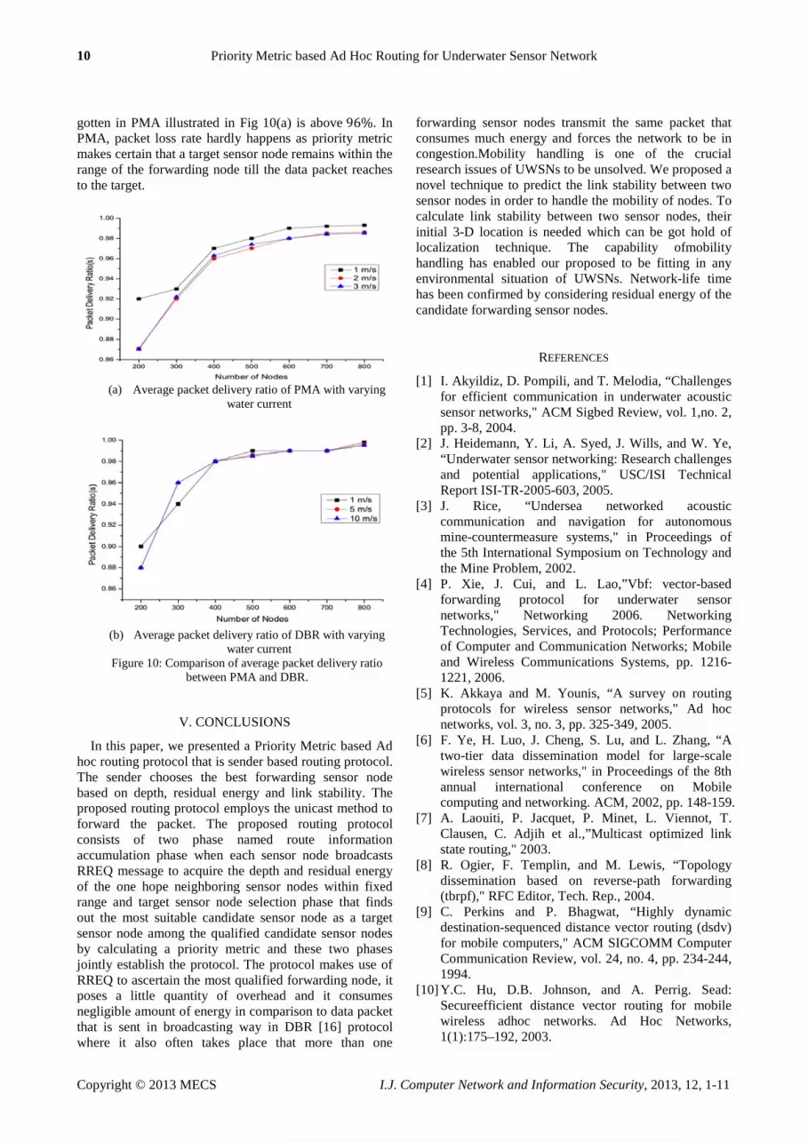
Impact of Node Mobility on Packet Delivery Ratio:Fig 10 shows the delivery ratio as the function of the number of nodes and the speed of nodes.When the node density is low, the success rate increases with density since the most compatible sensor node is available. DBR and other existing protocol demand that multiple nodes take part in sending packet when the node density is high as a result packet delivery ratio increases. But actually in dense network, because of redundancy of packet, collision and congestion occurs which force to decrease the average packet delivery ratio.In contrast, in PMA, data packet collision and congestion hardly take place. Moreover, the target node is opted for considering its depth, residual energy and link stability. In DBR illustrated in Fig 10(b), packet delivery ratio reduces with node mobility. The reason is that because of holding time at each forwarding sensor nodes, the number of neighboring nodes changes either increases or decreases; consequently the packet delivery ratio goes down. On the contrary, In PMA, prediction of the link stability is done and it updates its routing table after a time period which depends on the velocity of water current. The ultimate delivery ratio
10 Priority Metric based Ad Hoc Routing for Underwater Sensor Network
Copyright © 2013 MECS I.J. Computer Network and Information Security, 2013, 12, 1-11
gotten in PMA illustrated in Fig 10(a) is above 96%. In PMA, packet loss rate hardly happens as priority metric makes certain that a target sensor node remains within the range of the forwarding node till the data packet reaches to the target.
(a) Average packet delivery ratio of PMA with varying
water current
(b) Average packet delivery ratio of DBR with varying
water current Figure 10: Comparison of average packet delivery ratio
between PMA and DBR.
V. CONCLUSIONS
In this paper, we presented a Priority Metric based Ad hoc routing protocol that is sender based routing protocol. The sender chooses the best forwarding sensor node based on depth, residual energy and link stability. The proposed routing protocol employs the unicast method to forward the packet. The proposed routing protocol consists of two phase named route information accumulation phase when each sensor node broadcasts RREQ message to acquire the depth and residual energy of the one hope neighboring sensor nodes within fixed range and target sensor node selection phase that finds out the most suitable candidate sensor node as a target sensor node among the qualified candidate sensor nodes by calculating a priority metric and these two phases jointly establish the protocol. The protocol makes use of RREQ to ascertain the most qualified forwarding node, it poses a little quantity of overhead and it consumes negligible amount of energy in comparison to data packet that is sent in broadcasting way in DBR [16] protocol where it also often takes place that more than one
forwarding sensor nodes transmit the same packet that consumes much energy and forces the network to be in congestion.Mobility handling is one of the crucial research issues of UWSNs to be unsolved. We proposed a novel technique to predict the link stability between two sensor nodes in order to handle the mobility of nodes. To calculate link stability between two sensor nodes, their initial 3-D location is needed which can be got hold of localization technique. The capability ofmobility handling has enabled our proposed to be fitting in any environmental situation of UWSNs. Network-life time has been confirmed by considering residual energy of the candidate forwarding sensor nodes.
REFERENCES
[1] I. Akyildiz, D. Pompili, and T. Melodia, “Challenges for efficient communication in underwater acoustic sensor networks," ACM Sigbed Review, vol. 1,no. 2, pp. 3-8, 2004.
[2] J. Heidemann, Y. Li, A. Syed, J. Wills, and W. Ye, “Underwater sensor networking: Research challenges and potential applications," USC/ISI Technical Report ISI-TR-2005-603, 2005.
[3] J. Rice, “Undersea networked acoustic communication and navigation for autonomous mine-countermeasure systems," in Proceedings of the 5th International Symposium on Technology and the Mine Problem, 2002.
[4] P. Xie, J. Cui, and L. Lao,”Vbf: vector-based forwarding protocol for underwater sensor networks," Networking 2006. Networking Technologies, Services, and Protocols; Performance of Computer and Communication Networks; Mobile and Wireless Communications Systems, pp. 1216-1221, 2006.
[5] K. Akkaya and M. Younis, “A survey on routing protocols for wireless sensor networks," Ad hoc networks, vol. 3, no. 3, pp. 325-349, 2005.
[6] F. Ye, H. Luo, J. Cheng, S. Lu, and L. Zhang, “A two-tier data dissemination model for large-scale wireless sensor networks," in Proceedings of the 8th annual international conference on Mobile computing and networking. ACM, 2002, pp. 148-159.
[7] A. Laouiti, P. Jacquet, P. Minet, L. Viennot, T. Clausen, C. Adjih et al.,”Multicast optimized link state routing," 2003.
[8] R. Ogier, F. Templin, and M. Lewis, “Topology dissemination based on reverse-path forwarding (tbrpf)," RFC Editor, Tech. Rep., 2004.
[9] C. Perkins and P. Bhagwat, “Highly dynamic destination-sequenced distance vector routing (dsdv) for mobile computers," ACM SIGCOMM Computer Communication Review, vol. 24, no. 4, pp. 234-244, 1994.
[10] Y.C. Hu, D.B. Johnson, and A. Perrig. Sead: Secureefficient distance vector routing for mobile wireless adhoc networks. Ad Hoc Networks, 1(1):175–192, 2003.

Priority Metric based Ad Hoc Routing for Underwater Sensor Network 11
Copyright © 2013 MECS I.J. Computer Network and Information Security, 2013, 12, 1-11
[11] I. Park and I. Pu, “Energy efficient expanding ring search," in Modelling& Simulation, 2007. AMS'07. First Asia International Conference on. IEEE, 2007, pp. 198-199.
[12] H. Yan, Z. Shi, and J. Cui, “Dbr: depth-based routing for underwater sensor networks," NETWORKING 2008 Ad Hoc and Sensor Networks, Wireless Networks, Next Generation Internet, pp. 72-86, 2008.
[13] N. Nicolaou, A. See, P. Xie, J. Cui, and D. Maggiorini, “Improving the robustness of location-based routing forunderwater sensor networks," in OCEANS 2007-Europe. IEEE, 2007, pp. 1-6.
[14] Jornet, JosepMiquel, MilicaStojanovic, and Michele Zorzi. "Focused beam routing protocol for underwater acoustic networks." Proceedings of the third ACM international workshop on Underwater Networks. ACM, 2008.
[15] M. Domingo and R. Prior, “Design and analysis of a gps-free routing protocol for underwater wireless sensor networks in deep water," in Sensor Technologies and Applications, 2007. SensorComm 2007. International Conference on. IEEE, 2007, pp. 215-220.
[16] S. Gopi, G. Kannan, D. Chander, UB Desai, andSN Merchant. Pulrp: path unaware layered routing protocolfor underwater sensor networks. In Communications,2008. ICC’08. IEEE International Conference on,pages 3141–3145. IEEE, 2008.
[17] Z. Zhou and J.-H. Cui., “Energy efficient multi-path communication for time critical applications in underwater sensor networks," in 9th ACM International Symposium on Mobile Ad Hoc Networking and Computing (MobiHoc 2008), .vol. 2008, pp. 221-230, 2008.
[18] M. G. J.-H. Cui, J. Kong and S. Zhou, “Challenges: Building scalable and distributed underwater wireless sensor networks (uwsns) for aquatic applications," Technical report, UCONN CSE Technical Report, 2005.
[19] D. W. J. Kong, J.-H. Cui and M. Gerla., “Building Underwater Ad-hoc Networks and Sensor Networks for Large Scale Real-time Aquatic Applications," IEEE Military Communications Conference, 2005.
[20] Md. Ashraf Uddin and Mamun-or-Rashid, “Link Expiration Time-Aware Routing Protocol for UWSNs,” Journal of Sensors, vol. 2013, Article ID 625274, 9 pages, 2013. doi:10.1155/2013/625274.
[21] Md. Ashrafuddin, Md. Manowarul Islam, Md. Mamun-or-Rashid,"Energy Efficient Fitness Based Routing Protocol for Underwater Sensor Network", IJISA, vol.5, no.6, pp.61-69, 2013.DOI: 10.5815/ijisa.2013.06.08
[22] A. Wahid and D. Kim, “An energy efficient localization-freerouting protocol for underwater wireless sensor networks,”International Journal of Distributed Sensor Networks, vol. 2012,Article ID 307246, 11 pages, 2012.
[23] Mohammad TaghiKheirabadi and MohdMurtadhaMohamad, “Greedy Routing in Underwater Acoustic Sensor Networks: A Survey,”
International Journal of Distributed Sensor Networks, vol. 2013, Article ID 701834, 21 pages, 2013. doi:10.1155/2013/701834
[24] [Online].Accessed on December 2012, Available: http://www.isi.edu/nsnam/ns/doc/index.html,2002.
Md. Ashraf Uddin received the B.Sc. and M.S. degree in Computer Science and Engineering from the University of Dhaka, Bangladesh, in the year 2010 and 2012, respectively. He worked as a faculty member in Department of Computer Science and Engineering, Bangladesh University of Business and Technology, Bangladesh. He also worked as a faculty member in Department of Computer Science and Engineering, City University, Dhaka, Bangladesh. Currently, he is serving in the department of Computer Science and Engineering, MawlanaBhashani Science and Technology University, Tangail, Bangladesh as a lecturer. His research interest is in the area of modeling, analysis and optimization of protocols and architectures for underwater sensor networks, wireless sensor network, artificial intelligent, data mining etc. Md. Mamun-Or-Rashid received the B.Sc. and M.Sc. degree in Computer Science from the University of Dhaka, Bangladesh, in the year 2000 and 2002, respectively. He has received Ph.D. in February 2008 from Kyung Hee University, Korea. During 2003–2004, he worked as a faculty member in Department of Computer Science and Engineering, University of Dhaka, Bangladesh. He also worked as a postdoctoral researcher (2008-2009) in Institute of Multimedia Technology, Kyung Hee University, South Korea. Currently, he is serving in the department of Computer Science and Engineering, University of Dhaka as an Associate Professor. His research interest is in the area of modeling, analysis and optimization of protocols and architectures for wireless sensor networks, distributed systems, etc. Dr. Md. MustafizurRahman received the B.Sc. (Hons.) degree in applied physics and electronics and the M.Sc. degree in computer science from the University of Dhaka, Bangladesh, in 1997 and 1999, respectively. He received the Ph.D. degree in Computer Engineering in 2009 at Kyung Hee University, South Korea.Currently, he is working as associate professor with the Department of Computer Science and Engineering. His research interest includes Multiple Access Protocols, Routing, Localization and Network Security in Wireless Mobile Ad Hoc and Sensor Networks.