practical tests in quality control for hdpe pipes the effect of
TRANSCRIPT
I
Sudan University of science and Technology
College of Graduate Studies
Department of Plastic Engineering
Practical Tests in Quality Control for HDPE Pipes
The effect Of Thickness an Temperature on The burst
Pressure of HDPE Pipes
رة على الضغط االنفجاري النابيب البوىل ايثلني عاىل الكثافة تأثري السمك ودرجة احلرا
A Thesis Submitted in Partial Fulfillment of the Degree of M.Sc. in
Plastic Engineering
By:
Ahmed Braies Kazma Alanaaf
Supervisor:
Dr. Mohamed Deen Hussien
September 2017
I
يتاآل ٹ ٹ
ڀ ڀ ڀ ڀ پ پ پ پ ٻ ٻ ٻ ٻ ٱچ
ٹ ٹ ٹ ٹ ٿ ٿ ٿ ٿ ٺ ٺ ٺ ٺ
چ ڄ ڄ ڄ ڦ ڦ ڦ ڦ ڤ ڤ ڤ ڤ
(7__1سورة الفاحتة اآليات )
II
Acknowledgement
Surely all the thanks are for Allah
But I also remember the aid of those people and their grate helpfulness.
I thank my supervisor
Dr. Mohamed Den Hussein
For his precious time and useful advises.
Also I thank
Plastic department
Dr .alfateh agaboie
Wsam Pipe Company
Also I thank
Mr. Majde Hussein
Wsam Pipe Company (quality control)
And for any one helped me to go forward in this research.
I ask Allah to bless them all.
Finally, I would like to thank my dear parents and all my family,
and all my best friends; anyone helped me to finish this research.
III
Abstract
The hydrostatic pressure test was used for the high density polyethylene
HDPE-100 Pipes to determine the pressure and time for failure and the
relation between the two parameters. The study concluded the failure
take place at the portion of lowest thickness. The low thickness of the
pipe wall is a result of the fault in the setting of the gap in the angular
die which is a processing mistake. The research studied the relation
between the stress in the material and the working temperature. The least
square method was used to determine this relation.

IV
الوستخلص
غػ وسهي الفشل استخذم إختبار العغػ لوىاسيز البىلي إيثليي عالي الكثافت لتحذيذ ظ
وارتباغهوا هع بعط .
ووجذ اى السبب االساسي لفشل الواسىرة هى إًخفاض سوك الواسىرة عٌذ هٌطقت ها.
وإًخفاض السوك هى ًتيجه لخطأ في ظبػ القالب الحلقي للواسىرة.
كذلك تن دراست العالقه بيي اإلجهاد في هادة الواسىرة ودرجه الحزارة . وهي ثن تن تحذيذ
تزبطهوا بطزيقت الوزبعاث الصغز ه التيالوعادل
V
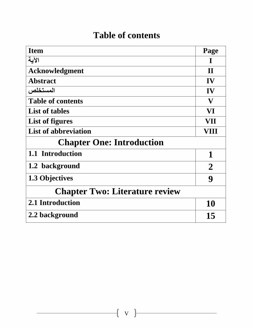
Table of contents
Item Page
I اآلية
Acknowledgment II
Abstract IV
IV المستخلص
Table of contents V
List of tables VI
List of figures VII
List of abbreviation VIII
Chapter One: Introduction
1.1 Introduction 1
1.2 background 2
1.3 Objectives 9
Chapter Two: Literature review
2.1 Introduction 10
2.2 background 15
VI
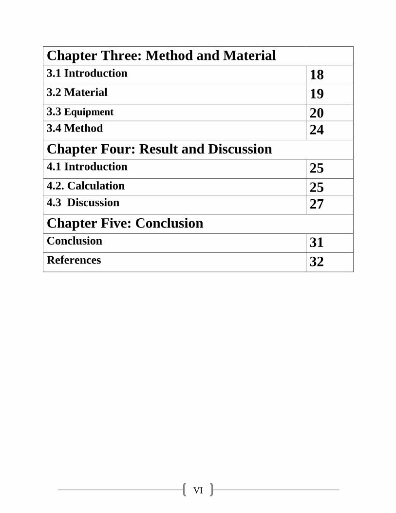
Chapter Three: Method and Material
3.1 Introduction 18
3.2 Material 19
3.3 Equipment 20 3.4 Method 24
Chapter Four: Result and Discussion
4.1 Introduction 25
4.2. Calculation 25 4.3 Discussion 27
Chapter Five: Conclusion
Conclusion 31
References 32
VII
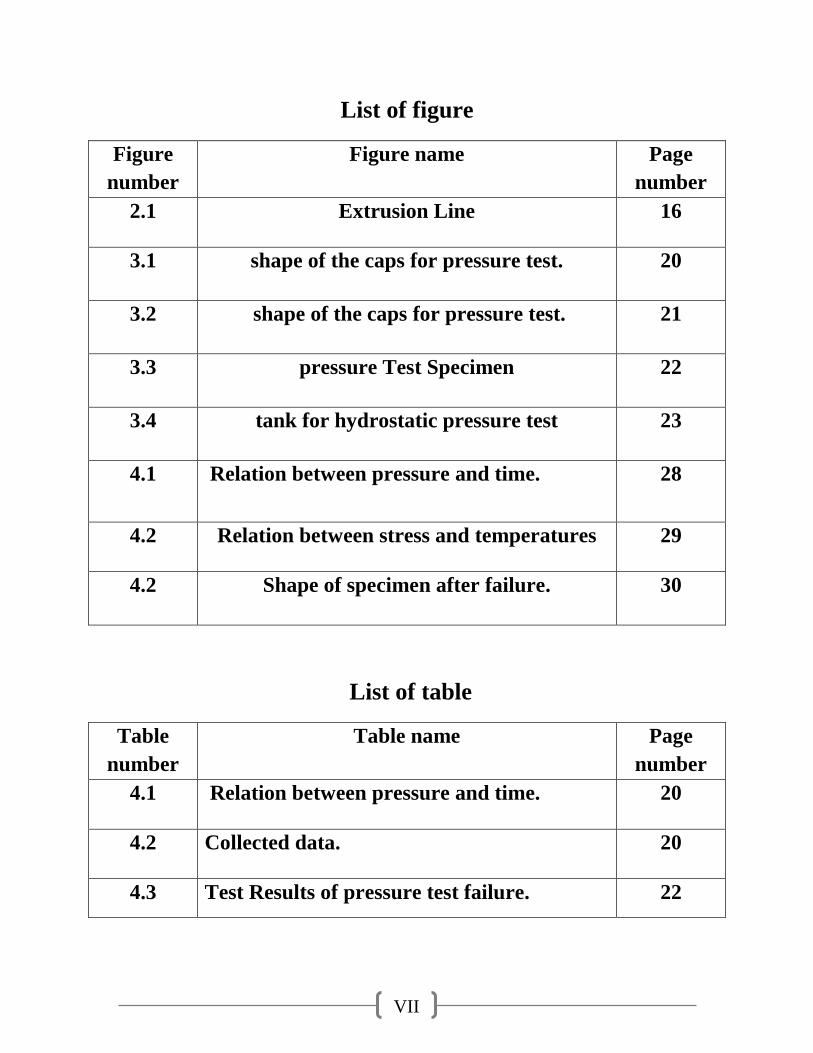
List of figure
Figure
number
Figure name Page
number
2.1 Extrusion Line
16
3.1 shape of the caps for pressure test.
20
3.2 shape of the caps for pressure test.
21
3.3 pressure Test Specimen
22
3.4 tank for hydrostatic pressure test
23
4.1 Relation between pressure and time. 28
4.2 Relation between stress and temperatures
29
4.2 Shape of specimen after failure.
30
List of table
Table
number
Table name Page
number
4.1 Relation between pressure and time.
20
4.2 Collected data.
20
4.3 Test Results of pressure test failure. 22
VIII
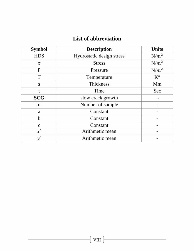
List of abbreviation
Symbol Description Units
HDS Hydrostatic design stress N/
σ Stress N/
P Pressure N/
T Temperature K°
s Thickness Mm
t Time Sec
SCG slow crack growth -
n Number of sample -
a Constant -
b Constant -
c Constant -
Arithmetic mean -
Arithmetic mean -

IX
Chapter One:
Introduction
1
Chapter One: Introduction
1.1 Preface:
-History of HDPE:
High Density Polyethylene (HDPE) is a versatile plastic that has many practical
uses, not the least of which is for the fabrication of pipe. English chemists
Reginald Gibson and Eric Fawcett created a solid form of polyethylene in 1935.
This discovery was first used commercially was an insulating material for radar
cables during World War II. In 1953, Karl Ziegler of the Kaiser Wilhelm institute
invented high density polyethylene. In 1955 HDPE was first used as a pipe. For his
invention of HDPE, Ziegler won the Nobel Prize for Chemistry in 1963. Since its
discovery in 1933, PE has grown to become one of the world’s most widely used
and recognized thermoplastic materials.(1) The versatility of this unique plastic
material is demonstrated by the diversity of its use and applications. The original
application for PE was as a substitute for rubber in electrical insulation during
World War II. PE has since become one of the world’s most widely utilized
thermoplastics. Today’s modern PE resins are highly engineered for much more
rigorous applications such as pressure-rated gas and water pipe, landfill
membranes, automotive fuel tanks and other demanding applications. PE’s use as a
piping material first occurred in the mid 1950’s. In North America, its original use
was in industrial applications, followed by rural water and then oil field production
where a flexible, tough and lightweight piping product was needed to fulfill the
needs of a rapidly developing oil and gas production industry. The success of PE’s
pipe in these installations quickly led to its use in natural gas distribution where a
coil able, corrosion-free piping material could be used in the field to assure a “leak-
free” method of transporting natural gas to homes and businesses. PE’s success in
this critical application has not gone without notice and today it is the material of
choice for the natural gas distribution industry. Sources now estimate that nearly
95% of all new gas distribution pipe installations in North America that are 12” in
diameter or smaller are PE piping.
The performance benefits of polyethylene pipe in these original oil and gas related
applications have led to its use in equally demanding piping installations such as
potable water distribution, industrial and mining pipe, force mains and other
2
critical applications where a tough, ductile material is needed to assure long-term
performance. It is these applications, representative of the expanding use of
polyethylene pipe that are the principle subject of this handbook. In the chapters
that follow, we shall examine all aspects of design and use of polyethylene pipe in
a broad array of applications. From engineering properties and material science to
fluid flow and burial design; from material handling and safety considerations to
modern installation practices such as horizontal directional drilling and/or pipe
bursting; from potable water lines to industrial slurries we will examine those
qualities, properties and design considerations which have led to the growing use
of polyethylene pipe in North America.
1.2Backgrounds:
• Features and Benefits of PE Pipe
When selecting pipe materials, designers, owners and contractors specify materials
that provide reliable, long-term service durability, and cost-effectiveness. Solid
wall PE pipes provide a cost-effective solution for a wide range of piping
applications including natural gas distribution, municipal water and sewer,
industrial, marine, mining, landfill, and electrical and communications duct
applications. PE pipe is also effective for above ground, buried, trenchless, floating
and marine installations. According to David A. Willoughby, P.O.E., “… one
major reason for the growth in the use of the plastic pipe is the cost savings in
installation, labor and equipment as compared to traditional piping materials. Add
to this the potential for lower maintenance costs and increased service life and
plastic pipe is a very competitive product.”(4) Natural gas distribution was among
the first applications for medium-density PE (MDPE) pipe. In fact, many of the
systems currently in use have been in continuous service since 1960 with great
success. Today, PE pipe represents over 95% of the pipe installed for natural gas
distribution in diameters up to 12” in the U.S. and Canada. PE is the material of
choice not only in North America, but also worldwide. PE pipe has been used in
potable water applications for almost 50 years, and has been continuously gaining
approval and growth in municipalities. PE pipe is specified and/or approved in
accordance with AWWA, NSF, and ASTM standards.
Some of the specific benefits of PE pipe are discussed in the paragraphs which
follow:
3
• Life Cycle Cost Savings – For municipal applications, the life cycle cost of
PE pipe can be significantly less than other pipe materials. The extremely smooth
inside surface of PE pipe maintains its exceptional flow characteristics, and heat
fusion joining eliminates leakage. This has proven to be a successful combination
for reducing total system operating costs.
• Leak Free, Fully Restrained Joints – PE heat fusion joining forms leak-free
joints that are as strong as, or stronger than, the pipe itself. For municipal
applications, fused joints eliminate the potential leak points that exist every 10 to
20 feet when using the bell and spigot type joints associated with other piping
products such as PVC or ductile iron. All these bell and spigot type joints employ
elastomeric gasket materials that age over time and thus have the potential for
leaks. As a result of this, the “allowable water leakage” for PE pipe is zero as
compared to the water leakage rates of 10% or greater typically associated with
these other piping products. PE pipe’s fused joints are also self-restraining,
eliminating the need for costly thrust restraints or thrust blocks while still insuring
the integrity of the joint. Notwithstanding the advantages of the butt fusion method
of joining, the engineer also has other available means for joining PE pipe and
fittings such as electro fusion and mechanical fittings. Electro fusion fittings join
the pipe and/or fittings together using embedded electric heating elements. In some
situations, mechanical fittings may be required to facilitate joining to other piping
products, valves or other system appurtenances. Specialized fittings for these
purposes have been developed and are readily available to meet the needs of most
demanding applications.
• Corrosion & Chemical Resistance – PE pipe will not rust, rot, pit,
corrode, tuberculation or support biological growth. It has superb chemical
resistance and is the material of choice for many harsh chemical environments.
Although unaffected by chemically aggressive native soil, installation of PE pipe
(as with any piping material) through areas where soils are contaminated with
organic solvents (oil, gasoline) may require installation methods that protect the PE
pipe against contact with organic solvents. It should be recognized that even in the
case of metallic and other pipe materials, which are joined by means of gaskets,
protection against permeation is also required. Protective installation measures that
assure the quality of the fluid being transported are typically required for all piping
systems that are installed in contaminated soils.
4
• Fatigue Resistance and Flexibility – PE pipe can be field bent to a radius
of about 30 times the nominal pipe diameter or less depending on wall thickness
(12” PE pipe, for example, can be cold formed in the field to a 32-foot radius).
This eliminates many of the fittings otherwise required for directional changes in
piping systems and it also facilitates installation. The long-term durability of PE
pipe has been extremely well researched. PE has exceptional fatigue resistance and
when, operating at maximum operating pressure, it can withstand multiple surge
pressure events up to 100% above its maximum operating pressure without any
negative effect to its long-term performance capability.
• Seismic Resistance – The toughness, ductility and flexibility of PE pipe
combined with its other special properties, such as its leak-free fully restrained heat
fused joints, make it well suited for installation in dynamic soil environments and
in areas prone to earthquakes.
• Construction Advantages – PE pipe’s combination of light weight,
flexibility and leak -free, fully restrained joints permits unique and cost-effective
installation methods that are not practical with alternate materials. Installation
methods such as horizontal directional drilling, pipe bursting, slip lining, plow and
plant, and submerged or floating pipe, can greatly simplify construction and save
considerable time and money on many installations. At approximately one-eighth
the weight of comparable sized steel pipe, and with integral and dependable leak
free joining methods, installation is simpler, and it does not need heavy lifting
equipment. PE pipe is produced in standard straight lengths to 50 feet or longer and
coiled in diameters up through 6”. Coiled lengths over 1000 feet are available in
certain diameters. PE pipe can withstand impact much better than PVC pipe,
especially in cold weather installations where other pipes are more prone to cracks
and breaks. Because heat fused PE joints are as strong as the pipe itself, it can be
joined into long runs conveniently above ground and later, installed directly into a
trench or pulled in via directional drilling or using the re-liner process. Of course,
the conditions at the construction site have a big impact on the preferred method of
installation.
• Durability – PE pipe installations are cost-effective and have long-term cost
advantages due to the pipe’s physical properties, leak-free joints and reduced
maintenance costs. The PE pipe industry estimates a service life for PE pipe to be,
5
conservatively, 50-100 years provided that the system has been properly designed,
installed and operated in accordance with industry established practice and the
manufacturer’s recommendations. This longevity confers savings in replacement
costs for generations to come. Properly designed and installed PE piping systems
require little on-going maintenance. PE pipe is resistant to most ordinary chemicals
and is not susceptible to galvanic corrosion or electrolysis.
• Hydraulically Efficient – The internal surface of PE pipe is devoid of any
roughness which places it in the “smooth pipe” category, a category that results in
the lowest resistance to fluid flow. For water applications, PE pipe’s Hazen
Williams C factor is 150 and does not change over time. The C factor for other
typical pipe materials declines dramatically over time due to corrosion and
tuberculation or biological build-up. Without corrosion, tuberculation, or biological
growth PE pipe maintains its smooth interior wall and its flow capabilities
indefinitely to insure hydraulic efficiency over the intended design life.
• Temperature Resistance – PE pipe’s typical operating temperature range is
from 0°F to 140°F for pressure service. However, for non-pressure and special
applications the material can easily handle much lower temperatures (e.g., to –
40°F and lower) and there are specially formulated materials that can service
somewhat higher temperatures. Extensive testing and very many applications at
very low ambient temperatures indicate that these conditions do not have an
adverse effect on pipe strength or performance characteristics. Many of the PE
resins used in PE pipe are stress rated not only at the standard temperature, 73° F,
but also at an elevated temperature, such as 140°F. Typically, PE materials retain
greater strength at elevated temperatures compared to other thermoplastic materials
such as PVC. At 140° F, PE materials retain about 50% of their 73°F strength,
compared to PVC which loses nearly 80% of its 73° F strength when placed in
service at 140°F.(5) As a result, PE pipe materials can be used for a variety of
piping applications across a very broad temperature range. The features and
benefits of PE are quite extensive, and some of the more notable qualities have
been delineated in the preceding paragraphs. The remaining chapters of this
Handbook provide more specific information regarding these qualities and the
research on which these performance attributes are based. Many of the
performance properties of PE piping are the direct result of two important physical
6
properties associated with PE pressure rated piping products. These are ductility
and viscous-elasticity. The reader is encouraged to keep these two properties in
mind when reviewing the subsequent chapters of this handbook.
• Ductility
Ductility is the ability of a material to deform in response to stress without fracture
or, ultimately, failure. It is also sometimes referred to as increased strain capacity
and it is an important performance feature of PE piping, both for above and below
ground service. For example, in response to earth loading, the vertical diameter of
buried PE pipe is slightly reduced. This reduction causes a slight increase in
horizontal diameter, which activates lateral soil forces that tend to stabilize the pipe
against further deformation. This yields a process that produces a soil-pipe
Introduction 11 structure that is capable of safely supporting vertical earth and
other loads that can fracture pipes of greater strength but lower strain capacity.
Ductile materials, including PE, used for water, natural gas and industrial pipe
applications have the capacity to safely handle localized stress intensifications that
are caused by poor quality installation where rocks, boulders or tree stumps may be
in position to impinge on the outside surface of the pipe. There are many other
construction conditions that may cause similar effects, e.g. bending the pipe
beyond a safe strain limit, inadequate support for the pipe, misalignment in
connections to rigid structures and so on. Non- ductile piping materials do not
perform as well when it comes to handling these types of localized high stress
conditions. Materials with low ductility or strain capacity respond differently.
Strain sensitive materials are designed on the basis of a complex analysis of
stresses and the potential for stress intensification in certain regions within the
material. When any of these stresses exceed the design limit of the material, crack
development occurs which can lead to ultimate failure of the part or product.
However, with materials like PE pipe that operate in the ductile state, a larger
localized deformation can take place without causing irreversible material damage
such as the development of small cracks. Instead, the resultant localized
deformation results in redistribution and a significant lessening of localized
stresses, with no adverse effect on the piping material. As a result, the structural
design with materials that perform in the ductile state can generally be based on
average stresses, a fact that greatly simplifies design protocol. To ensure the
availability of sufficient ductility (strain capacity) special requirements are
7
developed and included into specifications for structural materials intended to
operate in the ductile state; for example, the requirements that have been
established for “ductile iron” and mild steel pipes. On the other hand, ductility has
always been a featured and inherent property of PE pipe materials. And it is one of
the primary reasons why this product has been, by far, the predominant material of
choice for natural gas distribution in North America over the past 30 plus years.
The new or modern generation of PE pipe materials, also known as high
performance materials have significantly improved ductility performance
compared to the traditional versions which have themselves, performed so
successfully, not only in gas but also in a variety of other applications including,
water, sewer, industrial, marine and mining since they were first introduced about
50 years ago.
For a more detailed discussion of this unique property of PE material, especially
the modern high performance versions of the material, and the unique design
benefits it brings to piping applications.
Material Properties, Viscous-Elasticity PE pipe is a viscous-elastic construction
material, Due to its molecular nature, PE is a complex combination of elastic-like
and fluid-like elements. As a result, this material displays properties that are
intermediate to crystalline metals and very high viscosity fluids. This concept is
discussed in more detail in the chapter on Engineering Properties within this
handbook. The viscous-elastic nature of PE results in two unique engineering
characteristics that are employed in the design of PE water piping systems, creep
and stress relaxation.
• Creep is the time dependent viscous flow component of deformation. It refers
to the response of PE, over time, to a constant static load. When PE is subjected to
a constant static load, it deforms immediately to a strain predicted by the stress
strain modulus determined from the tensile stress-strain curve. At high loads, the
material continues to deform at an ever decreasing rate, and if the load is high
enough, the material may finally yield or rupture. PE piping materials are designed
in accordance with rigid industry standards to assure that, when used in accordance
with industry recommended practice, the resultant deformation due to sustained
loading, or creep, is too small to be of engineering concern.
• Stress relaxation is another unique property arising from the viscous-elastic
nature of PE. When subjected to a constant strain (deformation of a specific
8
degree) that is maintained over time, the load or stress generated by the
deformation slowly decreases over time, but it never relaxes completely. This
stress relaxation response to loading is of considerable importance to the design of
PE piping systems. It is a response that decreases the stress in pipe sections which
are subject to constant strain. As a viscous-elastic material, the response of PE
piping systems to loading is time dependent. The apparent modulus of elasticity is
significantly reduced by the duration of the loading because of the creep and stress
relaxation characteristics of PE. An instantaneous modulus for sudden events such
as water hammer is around 150,000 psi at 73°F. For slightly longer duration, but
short-term events such as soil settlement and live loadings, the short-term modulus
for PE is roughly 110,000 to 130,000 psi at 73° F, and as a long-term property, the
apparent modulus is reduced to something on the order of 20,000-30,000 psi. As
will be seen in the chapters that follow, this modulus is a key criterion for the long-
term design of pepping systems.
This same time-dependent response to loading also gives PE its unique resiliency
and resistance to sudden, comparatively short-term loading phenomena. Such is the
case with PE’s resistance to water hammer phenomenon which will be discussed in
more detail in subsequent sections of this handbook.
As can been seen from our brief discussions here, PE piping is a tough, durable
piping material with unique performance properties that allow for its use in a broad
range of applications utilizing a variety of different construction techniques based
upon project needs. The chapters that follow offer detailed information regarding
the engineering properties of PE, guidance on design of PE piping systems,
installation techniques as well as background information on how PE pipe and
fittings are produced, and appropriate material handling guidelines. Information
such as this is intended to provide the basis for sound design and the successful
installation and operation of PE piping systems. It is to this end, that members of
the Plastics Pipe Institute have prepared the information in this handbook.
1.3 Objectives of the research: The objectives of this study can be summarized in the following points:
1. The relation of the pipe wall thickness with the hydrostatic pressure.

9
Chapter Two:
Literature review
10
Chapter Two: Literature review
2.1 Introduction:
HDPE Pipes have been used for piping system in various industries primarily
because of its excellent resistance to cursive chemicals, its inherent toughness and
ease of installation. HDPE pipe is definitely not substitute for conventional pipes
but it is actually superior type product for many applications. The superiority of
HDPE pipes are especially proven in the following properties.
2.1.1 HDPE Background and Benefits: For the past 80 years, since its
discovery, Polyethylene has established itself as one of the most reliable and
versatile thermoplastics on the market. Recently, after the continued success and
development of bi-modal HDPE resins throughout Europe, North America has
followed suit in its implementation of PE4710 resins (preceded by PE3408 and
PE3608 resins). The introduction of these bi-modal resins has demonstrated
remarkable benefits, namely in the form of higher pressure ratings, less raw
material needed, increased resistance to environmental stress cracks, and longer
lifetimes.
2.1.2 Key Benefits of HDPE:
- Smooth interior surface of HDPE allows for high flow characteristics.-Long
service life – up to 100 years expected lifetime.
-Versatile – HDPE is used in geothermal, gas, potable water, sewage and
manufacturing.
- When HDPE fittings are correctly fused to HDPE pipe it creates a leak-free joint
that is just as strong, if not stronger, than the pipe itself.
- Corrosion and chemical resistant
-Toughness and durability of HDPE prevents the propagation of an initial small
failure into a large crack, particularly in areas with high seismic activity.
-HDPE has the ability to operate in extreme weather conditions, ranging from 0°F
to 140°F in typical pressure service installations. Many PE resins are stress rated
to an elevated temperature of 140°F, along with a standard measurement at 73°F.
According to the Plastic Pipe Institute, Typically, PE materials retain greater
strength at elevated temperatures compared to other thermo plastic materials such
as PVC. At 140° F, PE materials retain about 50% of their 73°F strength,
11
compared to PVC which loses nearly 80% of its 73°F strength when placed in
service at 140°F. As a result, PE pipe materials can be used for a variety of piping
application ns across a very broad temperature range.
2.2 Manufacturing Process
HDPE granules are fed into the hopper of the extruder which goes into the heated
cylinder of the extruder, where the granules melt and are Conveyed (pumped) to
the die exist. Now the melt passes through the Die and takes the shape of the die
i.e. circular shape and emerges from the exit of the die. It then passes through the
calibrator and is forced to take the shape of the inside of the calibrator which is
round in diameter by the inside air pressure. This melt solidifies and taken round
shape in the calibrator, which is cooled by passing chilled water through it
continuously. Now the solid pipe is taken out from the water and is drawn
continuously from the die. The speed is adjusted according to the thickness of the
pipe required and extruder output. The pipes is either cut into 5 meters length or
wound on the winder unit. Generally pipes up to 110 mm diameter can be made on
this extruder.
2.3 Characteristics:
The number one characteristic that sets HDPE apart from other pipe types is that it
can be made to be flexible. This quality opens HDPE pipe up to a different world
of applications than rigid pipe. Another quality of HDPE is that it can melt and re-
solidified a limitless number of times without losing any of its favorable qualities.
For this reason, most HDPE pressure pipe is made to be 'butt welded'. This is
where the ends of two sections of pipe are melted and then pushed and held
together, forming a single pipe. These two characteristics make HDPE pipe the
perfect candidate to be installed via directional drill. Long lengths of HDPE are
welded together and then installed under roads, creeks, rivers, etc by a Horizontal
Directional Drill (HDD) rig.
12
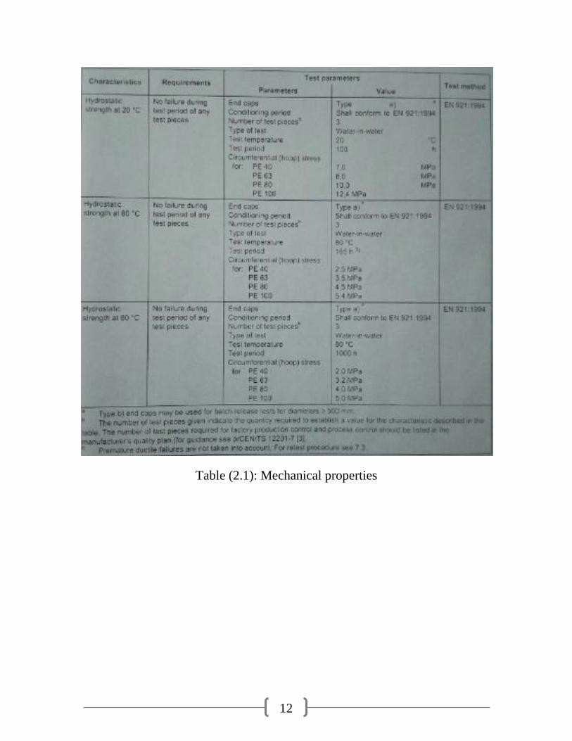
Table (2.1): Mechanical properties
13
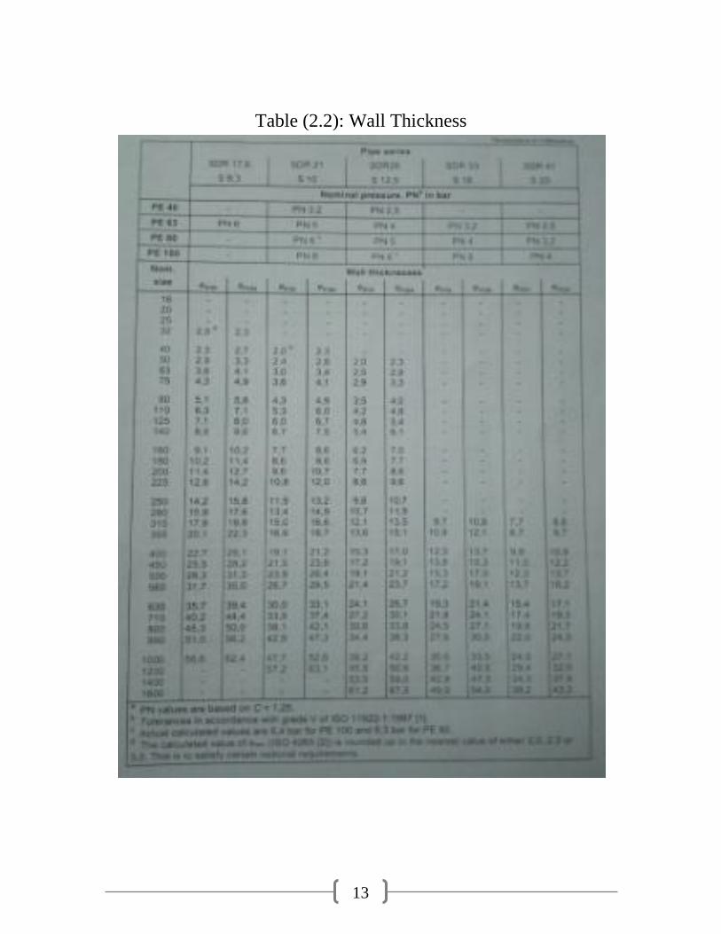
Table (2.2): Wall Thickness
14
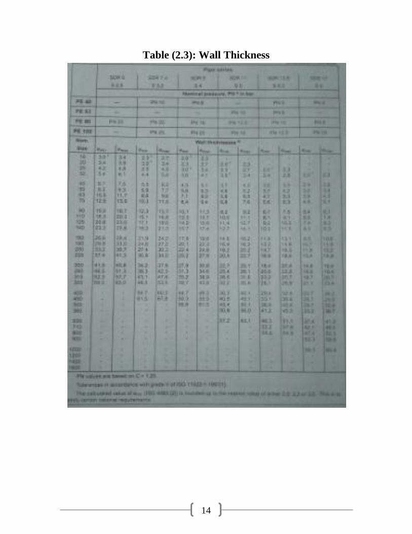
Table (2.3): Wall Thickness
15
2.4 Background:
2.4.1 HDPE Classification System:
The classification of HDPE materials is presented such that the first 2 letters (PE)
specify the resin (Polyethylene); followed by a 4-digit number system, where the
first digit denotes the resin's density; the second digit denotes its resistance to stress
crack; and the last two digits signify its HDS at 73°F in units of 100.
Thus, according to ASTM Standard D3350, resin identified as PE3608, with a
cell class of 345674C, specifically calls out:
◦ Density falling between 0.940 and 0.947 g/cm3,
◦ A PENT value of 100 hours.
◦ And an HDS of 800psi (with a design factor of 0.50).
Whereas resin identified as PE4710, with a cell class of 445474C, specifically
calls out:
◦ Density falling between 0.947 and 0.955 g/cm3.
◦ A PENT value of 500 hours (for slow crack growth resistance).
◦ And an HDS of 1000psi (with a design factor of 0.63).
2.4.2 Key Benefits of PE4710 Resin: Higher Density, which directly
relates to an increase in tensile strength and chemical resistance.
Higher density also allows PE4710 materials to use fewer raw materials than
PE3408/3608, while still accomplishing identical pressure ratings (more on this
below). This allows for a decreased wall thickness (increased ID) in PE4710 pipe,
which naturally increases water flow and improves thermal conductivity of the
system. As it relates to pipes, substituting PE4710 pipe for pipes of a lower cell
classification decreases system head loss, since the pipe's ID will increase.
2.4.3 Significant increase in SCG resistance: SCG is the most likely
cause of failure in HDPE piping systems. This can be attributed to several reasons,
such as poor backfill technique and rock impingements. According to the PPI,
“The PENT (Pennsylvania Notch Test - ASTM F 1473) measures relative
resistance to slow crack growth using a laboratory test method.
A specimen is cut from a compression molded plaque. It is precisely notched and
then exposed to a constant tensile stress at a temperature of 176°F (80°C). The
time to failure is recorded and this failure time is related to actual service life in the
field. The PENT test has proven to be a very good indicator of SCG in PE pipes.
16
A published paper in Plastic Pipe VIII conference provided data, which correlated
laboratory PENT values to field pipe performance. Based upon this data, a
laboratory PENT value of 10 to 20 hours, should correlate to a field life of at least
100 years with very few failures. PPI determined that a requirement of at least 500
hours PENT slow crack growth resistance would provide assurance that high
performance PE pipes will be highly unlikely to fail in the field in the slow crack
growth mode.” The requirement for PE3408 PENT is maintained at 10 hours,
PE3608 at 100 hours, and PE4710 at 500 hours.
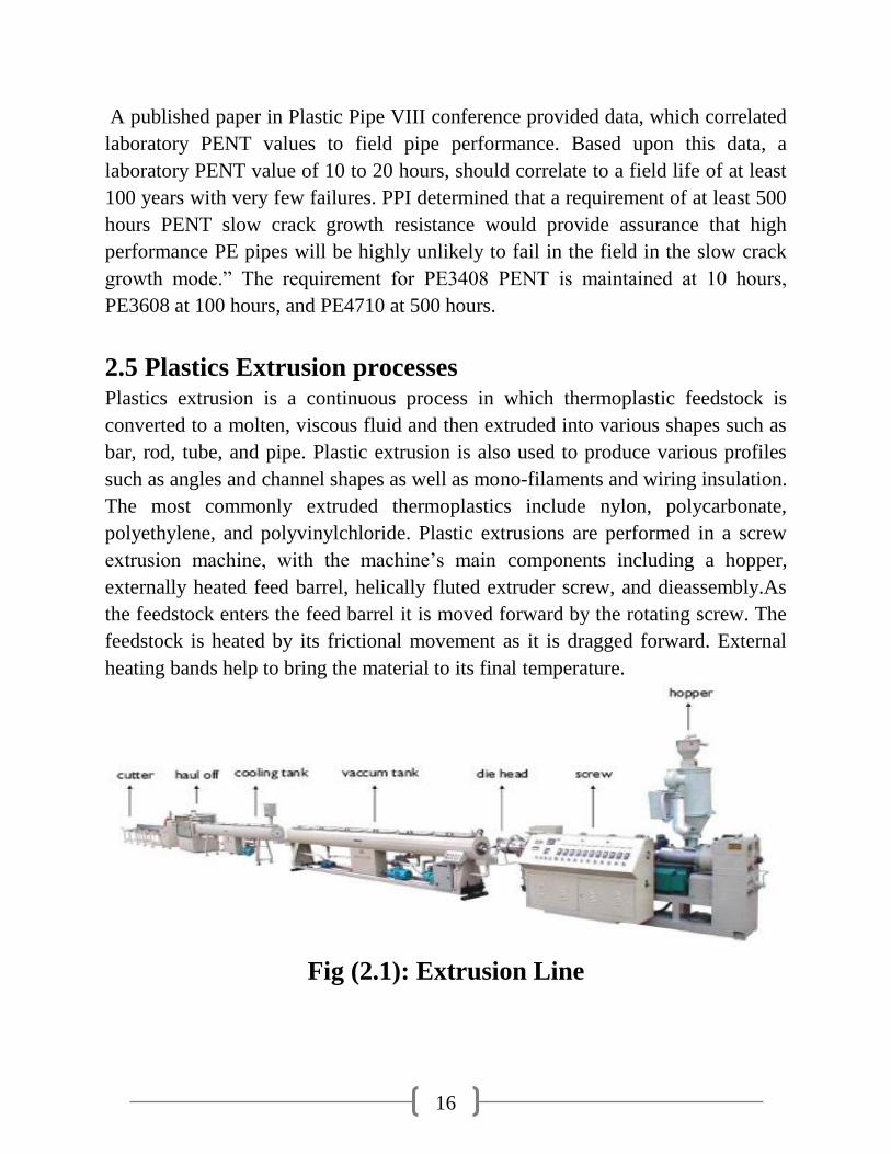
2.5 Plastics Extrusion processes Plastics extrusion is a continuous process in which thermoplastic feedstock is
converted to a molten, viscous fluid and then extruded into various shapes such as
bar, rod, tube, and pipe. Plastic extrusion is also used to produce various profiles
such as angles and channel shapes as well as mono-filaments and wiring insulation.
The most commonly extruded thermoplastics include nylon, polycarbonate,
polyethylene, and polyvinylchloride. Plastic extrusions are performed in a screw
extrusion machine, with the machine’s main components including a hopper,
externally heated feed barrel, helically fluted extruder screw, and dieassembly.As
the feedstock enters the feed barrel it is moved forward by the rotating screw. The
feedstock is heated by its frictional movement as it is dragged forward. External
heating bands help to bring the material to its final temperature.
Fig (2.1): Extrusion Line
17
2.6 Typical extruder moves the thermoplastic material
through four zones:
2.6.1 Feed zone– in which trapped air is forced from the stock. The feed zone
has a constant flight depth. The flight depth is the distance between the major
diameter at the top of the flight, and minor diameter of the screw at the base of the
flight.
2.6.2 Transition zone– in this zone the flight depth decreases, compressing and
plasticized the thermoplastic material.
2.6.3 Mixing zone– here the flight depth is constant and there may be a special
mixing element to ensure the feedstock is completely plasticized and mixed into a
homogenous blend.
2.6.4 Metering zone – the flight depth here is also constant but much smaller
than in the mixing zone. This section acts as a pump forcing the material through
the extruder die assembly.
2.7 The three principal plastic extrusion processes are:
1. Pipes extrusion.
2. Blown film extrusion.
3. Profile extrusion.
Profile extrusion is a horizontal process producing long continuous shapes which
are cooled in long cooling tanks filled with water after exiting the die assembly. A
final cutting operation reduces the extrusion to stock lengths for later use.
Blown film extrusion is a vertical process where molten plastic passes through a
die having a 360 degree annular opening. The tubular film produced is then filled
with air. As a result, the tube expands out into a bubble having a diameter larger
than the diameter of the annular opening of the die. As the tube cools, it is pulled
up and flattened as it passes through a series of rolls. These rolls maintain tension
on the plastic film as it is eventually wound into a coil for later use.
18
Chapter Three:
Materials and Methods
18
Chapter Three: Materials and methods
3.1 Introduction
3.1.1 Mechanical Properties of HDPE:
High-density polyethylene (HDPE) (0.941 < density < 0.965) is a thermo plastic
material composed of carbon and hydrogen atoms joined together forming high
molecular weight products ,then with the application of heat and pressure, The
polymer chain may be 500,000 to 1,000,000 carbon units long. Short and/or long
side chain molecules exist with the polymer’s long main chain molecules. The
longer the main chain, the greater the number of atoms, and consequently, the
greater the molecular weight. The molecular weight, the molecular weight
distribution and the amount of branching determine many of the mechanical and
chemical properties of the end product. Other common polyethylene (PE) materials
are medium-density polyethylene (MDPE)(0.926 < density < 0.940) used for low-
pressure gas pipelines; low-density polyethylene(LDPE) (0.910 <density < 0.925),
typical for small-diameter water-distribution pipes: Linear low-density
polyethylene (LLDPE), which retains much of the strength of HDPE and the
flexibility of LDPE, has application for drainage pipes. Less common PE materials
are ultra-high molecular weight polyethylene (UHMWPE) (density > 0.965) and
very low density polyethylene (VLDPE) (density < 0.910).
3.1.2 The most important applications are as follows:
- Drinking water supply line.
- Water lines in hilly areas. Here the property of flexibility of HDPE
is exploited to the fullest extent.
- Irrigation lines.
- Industrial effluent disposal lines.
- Sewage and gas lines.
- Fuel gas line.
- Mining Industry.
19
3.2 Materials:
High Density Polyethylene (HDPE) Pipes are manufactured all over the world by
extrusion technique. Sizing methods still vary but the trend is the pressure sizing
i.e. introducing air at the pressure of about 0.8kg/cm2 to 1 kg/cm2 through one of
the spider legs of the dies. HDPE Pipes are generally manufactured on single screw
extruder. HDPE Pipes find application in a variety of fields in India and abroad.
20
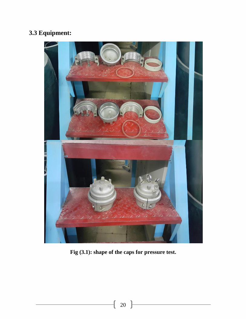
3.3 Equipment:
Fig (3.1): shape of the caps for pressure test.
21
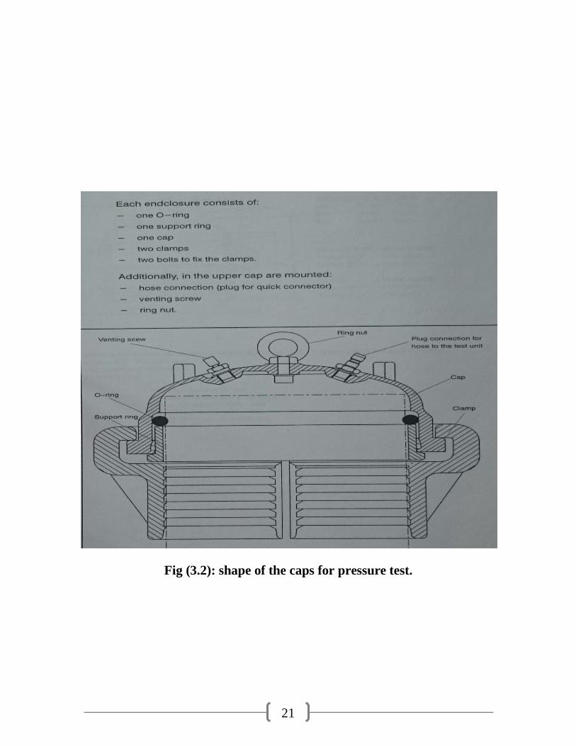
Fig (3.2): shape of the caps for pressure test.
22
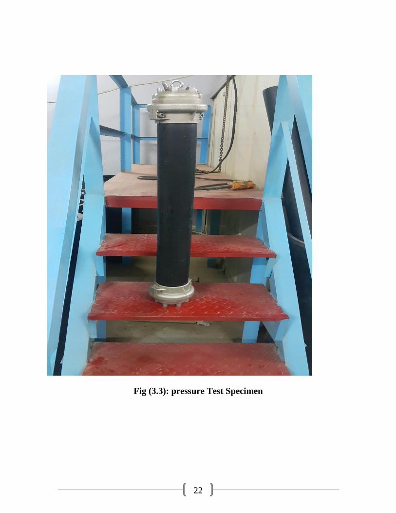
Fig (3.3): pressure Test Specimen
23
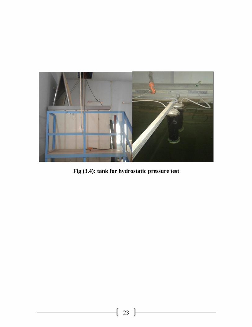
Fig (3.4): tank for hydrostatic pressure test
24
3.4 Method:
3.4.1Test Specimens:
The material high density polyethylene (HDPE-100), Pipe Specimen, Length is
1000mm; the nominal outside diameter of the pipe is( OD) 110mm, internal
diameter is ( ID)101.6mm, thickness (4.2 to 4.8), pressure applied 6 bar.
3.4.2Hydrostatic Pressure Tester
Pipe Tester Airless:
-Type 1575
With 1 to 50 pressurized terminals
-Type 1568
With 1 to 30 pressurized terminals
For the pressure testing of pipes and pipe components.
-Pressure range from 2 to 100 bars.
-The test parameters can be set by screen touch.
-Technical parameters input:
The limit values should be defined in accordance with the allowed margins
of error as specified in the respective test method applied.
- International standards:
EN standards, for instance, require: -1% to +2% and time values between 30
and 60 sec.
-Temperature settings:
The system accepts water temperature values for the test tank between (+19
C and +96 C with 1 decimal digit).
-Operational temperature of the test container (Oven or tank) +1%.

25
Chapter Four:
Results and Discussion
25
Chapter Four: Results and Discussion
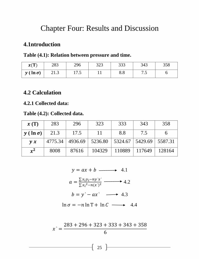
4.1ntroduction
Table (4.1): Relation between pressure and time.
283 296 323 333 343 358
( ) 21.3 17.5 11 8.8 7.5 6
4.2 Calculation
4.2.1 Collected data:
Table (4.2): Collected data.
(T) 283 296 323 333 343 358
( ) 21.3 17.5 11 8.8 7.5 6
4775.34 4936.69 5236.80 5324.67 5429.69 5587.31
8008 87616 104329 110889 117649 128164
4.1
∑
∑ 4.2
4.3
4.4
26
19
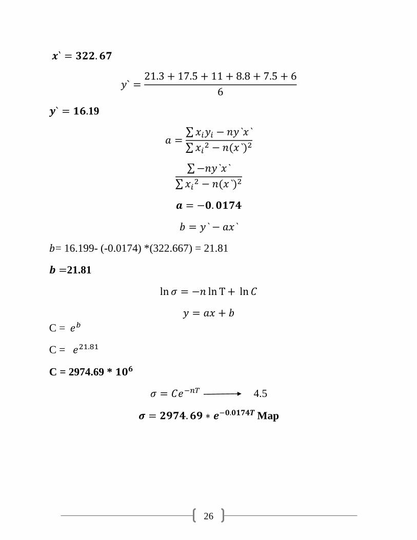
∑
∑
∑
∑
= 16.199- (-0.0174) *(322.667) = 21.81
21.81
C =
C =
C = 2974.69 *
4.5
Map
27
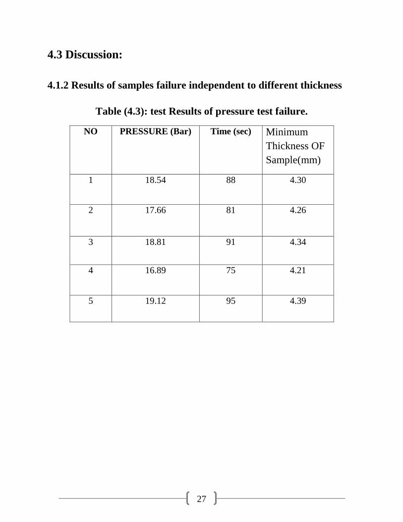
4.3 Discussion:
4.1.2 Results of samples failure independent to different thickness
Table (4.3): test Results of pressure test failure.
NO PRESSURE (Bar) Time (sec) Minimum
Thickness OF
Sample(mm)
1 18.54 88 4.30
2 17.66 81 4.26
3 18.81 91 4.34
4 16.89 75 4.21
5 19.12 95 4.39
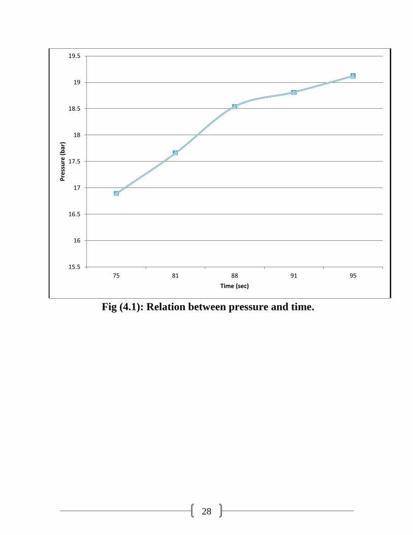
28
Fig (4.1): Relation between pressure and time.
15.5
16
16.5
17
17.5
18
18.5
19
19.5
75 81 88 91 95
Pre
ssu
re (
bar
)
Time (sec)
29
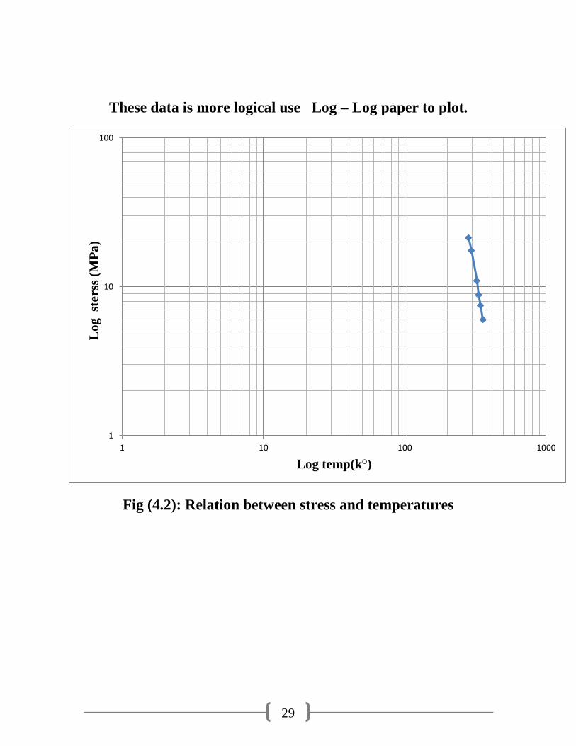
These data is more logical use Log – Log paper to plot.
Fig (4.2): Relation between stress and temperatures
1
10
100
1 10 100 1000
Lo
g st
erss
(M
Pa
)
Log temp(k°)
30
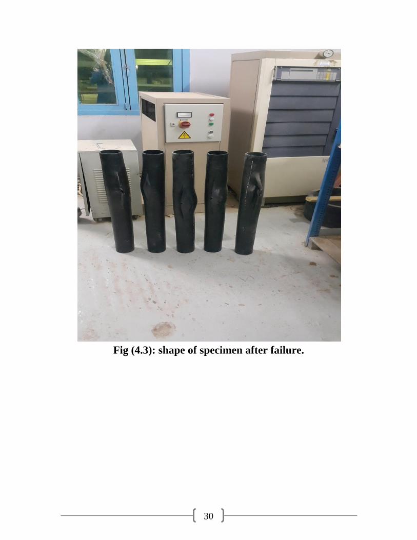
Fig (4.3): shape of specimen after failure.
31
Chapter Five:
Conclusions and
Recommendations
31
Chapter Five: Conclusions & Recommendations
5.1 Conclusions
i. All Results of pressure test are not equals values and the reasons of this case the
variation in thickness of samples.
ii. The higher value of pressure tester (19.12 Bar, at 95 Sec), and the lower value is
(16.89 Bar, at 75 Sec), and another values of Samples its (18.81 Bar, at 91 Sec),
(17.66 Bar, at 81Sec), (18.54 Bar, at 88Sec).
iii. The change in this results is due to different type in thickness for the Samples,
When the sample of tester higher thickness its required long time and pressure like
the sample NO (5), and at a lower thickness it’s not required long time and
pressure like the sample NO (4), the optimum results as: (19.12 Bar, at 95 Sec).
iiii. Finally, the result of this type of tester is dependent on many factors (the
thickness of sample , time of cooling rate for product , and grade of material; like
:(PE100 , PE80 , PE60 , PE40 ).
5.2 Recommendations
1. Would like to recommend to study such cases for another different size of
sample according to parameters of machine.
2. Experience of the operator is a must to properly adjust the gap in the angular
die. The uneven pipe wall thickness is the main reason for pipe failure.
3. The recycled material should not be used in the pipes 6 bar and diameter less
than or equal to 110 mm for higher pressures the recycled material can be
used since the pipe wall thickness is high greater than 4.5 mm.
4. The analysis of the failures.
5. The temperature effect upon the permissible hydrostatic pressure and the
pipe failure.
32
References
1. Handbook of polyethylene pipe, 2nd
Ed., plastics pipe Institute, Irving, TX,
USA (2008).
2. ASTM D1473-13, Standard Test Method for Notch Tensile Test to Measure
the Resistance to Slow Crack Growth of poly-ethylene pipes and Resins,
Annual Book of ASTM Standards, ASTM International, West
Conshohocken, PA (2013).
3. ASTM D638-10, Standard test method for tensile properties of plastics,
Annual Book of ASTM Standards, ASTM International, West
Conshohocken , PA (2010).
4. M. Chan and Williams, Slow stable crack growth in high density
polyethylene’s, polymer, 24(2) (1983)234-244.
5. Keener, Hsian, Lord, Stress Cracking Behavior of High Density
Polyethylene Geo membranes and Its Minimization, Geo synthetic Research
Institute, Drexel University, July 1992.
6. European Standard EN 12201-2:2003.
7. Tensile stress-strain properties and elastic modulus of PE4710 cell
classification 445574C high density polyethylene material, EPRI, Palo Alto,
CA (2012) 1025254.
8. B. Hartmann, G. F
9. . Lee and R. F. Cole, Tensile yield in polyethylene, polymer
Engineering & Science, 26(8) (1986) 554-559.
10. A. N. Haddad, ASME Code development roadmap for HDPE pipe in nuclear
service, ASME STP-NU-057, ASME Standards Technology, LLC, New
York, USA (2013).
10 . API 579-1/ASME FFS-1fitness-for-service, American Society of
Mechanical Engineers (2007).
11 . S. Kalyanam, D.-J. Shim, P. Krishnaswamy and Y. Hoe, Slow crack
growth resistance of parent and joint materials from PE4710 piping for
safety-related nuclear power plant piping, ASME 2011 pressure Vessels and
Piping Conference, Prague, Czech Republic (2011) 919-926.
12 . H. Tada, P. C. Paris and G. R. Irwin, The analysis of cracks handbook, 3rd
Ed. ASME Press, New York, USA (2000).
33
13 . N. Brown and X. Lu, The fracture mechanics of slow crack growth in
polyethylene, Int. J. Fractal., 69 (4) (1995) 371-377.
14 . Slow crack growth testing of high-density polyethylene pipe: 2011 Update,
EPRI, Palo Alto, CA (2011) 1022565.
15 . Development of crack growth curves and correlation to sustained pressure
test results for cell classification 445574C high-density polyethylene pipe
material, EPRI, Palo Alto, CA (2012) 102523
16 . Tensile testing of cell classification 445474C high density polyethylene
pipe material, EPRI, Palo Alto, CA (2008) 1018351.
17 . ASTM Annual Book of Standards, Volume 8.03 Plastics, (III): D 3100 -
Latest, American Society for Testing and Materials, West Conshohocken,
PA.
18 . ASTM Annual Book of Standards, Volume 8.04 Plastic Pipe and Building
Products, American Society for Testing and Materials, West Conshohocken,
PA.
19 . Plastics Pipe Institute, Various Technical Reports, Technical Notes, Model
Specifications, Irving, TX.