experiment 3 minor losses in pipes
TRANSCRIPT

Experiment 3
Minor Losses in Pipes
Lecturer: Laith Hamdan
: ليث حمدان التدريسياعداد
العلمي والبحث العالي وزارةالتعليم
المستنصرية الجامعة
كلية الهندسة البيئة هندسة قسم
Ministry of Higher Education and
Scientific Research
Al-Mustansiriayah University
College of Engineering
Environmental Engineering
Department

Objectives:
The goal of this laboratory is to study pressure losses due to viscous
(frictional) effects in fluid flows through pipes. These pressure losses are
a function of various geometric and flow parameters including pipe
diameter, length, internal surface roughness and type of fitting. In this
experiment, the influence of some these parameters on pressure losses in
pipe flows will be evaluated by measuring flow rates through different
types of pipes.
Equipments and apparatus:
The following apparatus will be used for this experiment:
1. The pipe flow rig with pipes of different diameters and lengths.
2. A large graduated cylinder used to measure the volume of water
flowing out of the system.
3. A stop watch used to measure the time required to collect the
water.
4. A pump for refilling the water reservoir.

Experimental Procedure
1. Measure and record the heights of the base of the reservoir and the
center of the pipes in the table in the data sheet.
2. Start with the reservoir filled to the highest level indicated in the
data sheet for the pipe you are examining.
3. Record the exact, initial height of water in the reservoir.
4. Ensure that all manual valves to all the pipes are closed.
5. Place a graduated cylinder at the exit of the pipe you are
examining. The graduated cylinder will have to be tilted to avoid
spillage.
6. Open the manual valve only to the pipe under study.
7. One person should operate the stop-watch and the solenoid switch,
which starts the flow.
8. Open the solenoid valve and start the stop-watch simultaneously.
9. Shut off the valve and the stop-watch simultaneously when the
water level drops to the next height on the table in the data sheet
for this pipe. Collect all the water flowing through the piping
system in the graduated cylinder.
10. Measure and record the actual height to which the water level has
dropped.
11. Measure and record the volume of water collected in the graduated
cylinder.
12. Record the time taken to collect the water.
13. Empty the water from the measuring cylinder into the bucket
provided.
14. Repeat steps 7 – 14 for all other reservoir levels indicated in the
Table for this pipe.
15. Close the manual valve for this pipe.
16. Repeat steps 2 –16 for the various pipe systems specified by the lab
instructor.

Theoretical background and Calculation:
Exit Loss :
Case of where pipe enters a tank – a very large enlargement. The
tank water is assumed to be stationery, that is, the velocity is zero.
Therefore all kinetic energy in pipe is dissipated, therefore K =1.0.
𝐡𝐋 = 𝟏. 𝟎 × (𝐯𝟏𝟐
𝟐𝐠)
Gradual Enlargement
If the enlargement is gradual (as opposed to our previous case) –
the energy losses are less. The loss again depends on the ratio of the pipe
diameters and the angle of enlargement.
𝐡𝐋 = 𝐊 × (𝐯𝟏𝟐/𝟐𝐠)
K can be determined from Fig below and table below:

2015
2016

Note :
➢ If angle increases (in pipe enlargement) – minor losses increase.
➢ If angle decreases – minor losses decrease, but you also need a longer
pipe to make the transition – that means more FRICTION losses -
therefore there is a tradeoff!
➢ Minimum loss including minor and friction losses occur for angle
of 7 degrees – OPTIMUM angle!

Sudden Contraction
Decrease in pipe diameter – Loss is given by –
𝐡𝐋 = 𝐊 × (𝐯𝟐𝟐/𝟐𝐠)
Note: that the loss is related to the velocity in the second (smaller) pipe.
The loss is associated with the contraction of flow and turbulence.
The section at which the flow is the narrowest – Vena Contracta. At vena
contracta, the velocity is maximum, K can be computed using Figure
below and table below – Again based on diameter ratio and velocity of
flow.

Energy losses for sudden contraction are less than those for sudden
enlargement.
Gradual Contraction
Again a gradual contraction will lower the energy loss (as opposed to
sudden contraction). θ is called the cone angle

𝐡𝐋 = 𝐊 × (𝐯𝟐
𝟐/𝟐𝐠)
K is given by Figures below

Note that K values increase for very small angles (less than 15 degrees).
Why – the plot values includes both the effect flow separation and
friction.
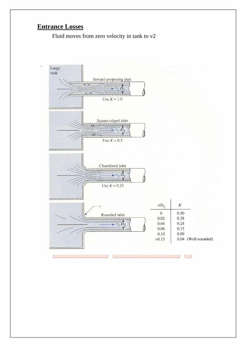
Entrance Losses
Fluid moves from zero velocity in tank to v2