minor modification - fcc
TRANSCRIPT
1. KNKA304 - 20A - Minor Mod - 130604New Cingular Wireless PCS, LLC (KNKA304)
Seattle-Everett WA CMA 20A FCC Form 601 Attachment 1
Minor Modification
PURPOSE
This minor modification is being filed to update site data in the Universal Licensing System (“ULS”) for the Seattle-
Everett WA cellular market area (“CMA”). These modifications do not increase Applicant’s existing Cellular Geographic
Service Area (“CGSA”).
PUBLIC INTEREST STATEMENT
The corrections detailed herein are intended to provide the most reliable data for ULS and therefore, grant of this
application serves the public interest, convenience, and necessity.
SABs AND EXISTING CGSA DETERMINATION
The service area boundaries (SAB) for the sites in this application were developed in accordance with Section 22.911(a),
reflect the network facilities existing as of the date of filing, and are depicted in the attached map prepared in
accordance with Section 22.929(c) of the Commission’s rules.
The existing CGSA shown on the attached map was derived from the most-recent CGSA submission filed with the
Commission for this Call Sign.
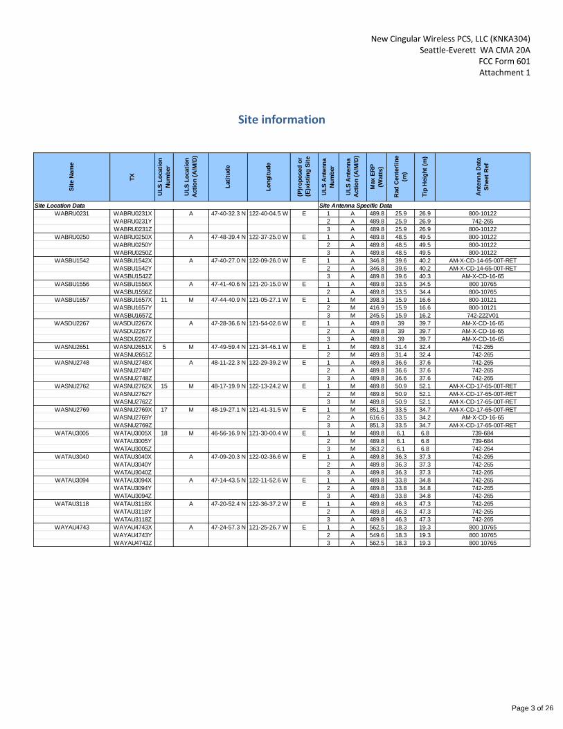
The engineering calculations use a minimum of 98’ HAAT, per FCC Rule 22.911(a)(3), and 0.1 Watt or 27 db less than
maximum ERP, per FCC Rule 22.911(a)(4). Site specific information is provided below and polar antenna radiation
patterns are appended hereto.
SAB EXTENSION AGREEMENTS
This application includes SAB extensions into one or more adjacent CGSAs. Applicant or its affiliate is either the licensee
of the adjacent CGSAs into which the SAB extends, and therefore no written SAB extension agreement is required, or
Applicant has the required written SAB extension agreement in its files.
EFFECTIVE RADIATED POWER - Greater than 500W
In this application, the following site(s) has a maximum ERP in excess of 500W. However, the site(s) is in a rural county
with a population density of less than 100 persons per square mile based upon Census 2000 figures. Therefore, the site
is permitted to operate at up to 1,000 Watts under Section 22.913(a).
Site Name County, State Population Density/sq. mi.
DARRINGTON, WASNU2769 Skagit, WA 68.5
SNOQUALMIE PASS GSM OVERLAY, WAYAU4743 Kittitas, WA 18.3
Page 1 of 26
New Cingular Wireless PCS, LLC (KNKA304) Seattle-Everett WA CMA 20A
FCC Form 601 Attachment 1
EFFECTIVE RADIATED POWER – Average SAB Greater than 40.2 km
In this application, the following sites have an average radial SAB distance greater than 40.2 km. Pursuant to Section
22.913(c), Applicant confirms that the site has been coordinated with all co-channel licensees within 121 km.
Site Name
DARRINGTON, WASNU2769
ADMINISTRATIVE INFORMATION
The five-year build-out period has expired for all markets involved and there is no un-served area involved in this
application.
Page 2 of 26
New Cingular Wireless PCS, LLC (KNKA304) Seattle-Everett WA CMA 20A
FCC Form 601 Attachment 1
Site information
Sit
e N
am
e
TX
UL
S L
ocati
on
Nu
mb
er
UL
S L
ocati
on
Acti
on
(A
/M/D
)
Lati
tud
e
Lo
ng
itu
de
(P)r
op
osed
or
(E)x
isti
ng
Sit
e
UL
S A
nte
nn
a
Nu
mb
er
UL
S A
nte
nn
a
Acti
on
(A
/M/D
)
Max E
RP
(Watt
s)
Rad
Cen
terl
ine
(m)
Tip
Heig
ht
(m)
An
ten
na D
ata
Sh
eet
Ref
Site Location Data Site Antenna Specific Data
WABRU0231 WABRU0231X A 47-40-32.3 N 122-40-04.5 W E 1 A 489.8 25.9 26.9 800-10122
WABRU0231Y 2 A 489.8 25.9 26.9 742-265
WABRU0231Z 3 A 489.8 25.9 26.9 800-10122
WABRU0250 WABRU0250X A 47-48-39.4 N 122-37-25.0 W E 1 A 489.8 48.5 49.5 800-10122
WABRU0250Y 2 A 489.8 48.5 49.5 800-10122
WABRU0250Z 3 A 489.8 48.5 49.5 800-10122
WASBU1542 WASBU1542X A 47-40-27.0 N 122-09-26.0 W E 1 A 346.8 39.6 40.2 AM-X-CD-14-65-00T-RET
WASBU1542Y 2 A 346.8 39.6 40.2 AM-X-CD-14-65-00T-RET
WASBU1542Z 3 A 489.8 39.6 40.3 AM-X-CD-16-65
WASBU1556 WASBU1556X A 47-41-40.6 N 121-20-15.0 W E 1 A 489.8 33.5 34.5 800 10765
WASBU1556Z 2 A 489.8 33.5 34.4 800-10765
WASBU1657 WASBU1657X 11 M 47-44-40.9 N 121-05-27.1 W E 1 M 398.3 15.9 16.6 800-10121
WASBU1657Y 2 M 416.9 15.9 16.6 800-10121
WASBU1657Z 3 M 245.5 15.9 16.2 742-222V01
WASDU2267 WASDU2267X A 47-28-36.6 N 121-54-02.6 W E 1 A 489.8 39 39.7 AM-X-CD-16-65
WASDU2267Y 2 A 489.8 39 39.7 AM-X-CD-16-65
WASDU2267Z 3 A 489.8 39 39.7 AM-X-CD-16-65
WASNU2651 WASNU2651X 5 M 47-49-59.4 N 121-34-46.1 W E 1 M 489.8 31.4 32.4 742-265
WASNU2651Z 2 M 489.8 31.4 32.4 742-265
WASNU2748 WASNU2748X A 48-11-22.3 N 122-29-39.2 W E 1 A 489.8 36.6 37.6 742-265
WASNU2748Y 2 A 489.8 36.6 37.6 742-265
WASNU2748Z 3 A 489.8 36.6 37.6 742-265
WASNU2762 WASNU2762X 15 M 48-17-19.9 N 122-13-24.2 W E 1 M 489.8 50.9 52.1 AM-X-CD-17-65-00T-RET
WASNU2762Y 2 M 489.8 50.9 52.1 AM-X-CD-17-65-00T-RET
WASNU2762Z 3 M 489.8 50.9 52.1 AM-X-CD-17-65-00T-RET
WASNU2769 WASNU2769X 17 M 48-19-27.1 N 121-41-31.5 W E 1 M 851.3 33.5 34.7 AM-X-CD-17-65-00T-RET
WASNU2769Y 2 A 616.6 33.5 34.2 AM-X-CD-16-65
WASNU2769Z 3 A 851.3 33.5 34.7 AM-X-CD-17-65-00T-RET
WATAU3005 WATAU3005X 18 M 46-56-16.9 N 121-30-00.4 W E 1 M 489.8 6.1 6.8 739-684
WATAU3005Y 2 M 489.8 6.1 6.8 739-684
WATAU3005Z 3 M 363.2 6.1 6.8 742-264
WATAU3040 WATAU3040X A 47-09-20.3 N 122-02-36.6 W E 1 A 489.8 36.3 37.3 742-265
WATAU3040Y 2 A 489.8 36.3 37.3 742-265
WATAU3040Z 3 A 489.8 36.3 37.3 742-265
WATAU3094 WATAU3094X A 47-14-43.5 N 122-11-52.6 W E 1 A 489.8 33.8 34.8 742-265
WATAU3094Y 2 A 489.8 33.8 34.8 742-265
WATAU3094Z 3 A 489.8 33.8 34.8 742-265
WATAU3118 WATAU3118X A 47-20-52.4 N 122-36-37.2 W E 1 A 489.8 46.3 47.3 742-265
WATAU3118Y 2 A 489.8 46.3 47.3 742-265
WATAU3118Z 3 A 489.8 46.3 47.3 742-265
WAYAU4743 WAYAU4743X A 47-24-57.3 N 121-25-26.7 W E 1 A 562.5 18.3 19.3 800 10765
WAYAU4743Y 2 A 549.6 18.3 19.3 800 10765
WAYAU4743Z 3 A 562.5 18.3 19.3 800 10765
Page 3 of 26
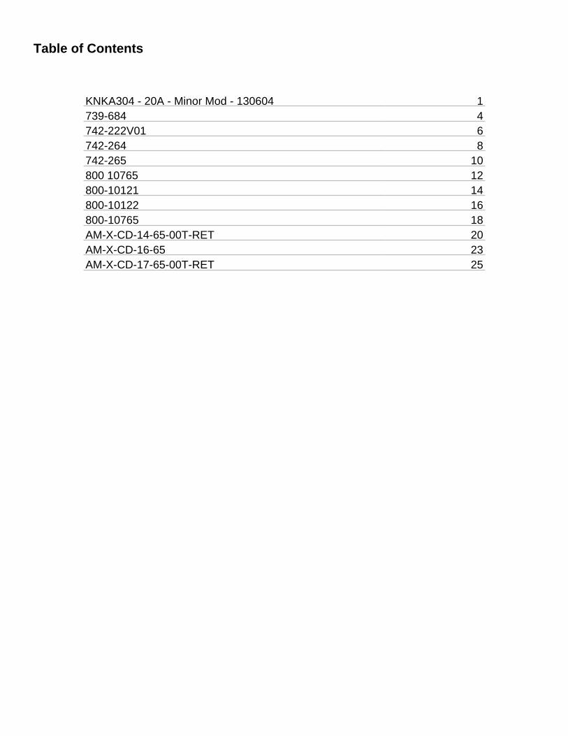
Table of Contents
KNKA304 - 20A - Minor Mod - 130604 1739-684 4742-222V01 6742-264 8742-265 10800 10765 12800-10121 14800-10122 16800-10765 18AM-X-CD-14-65-00T-RET 20AM-X-CD-16-65 23AM-X-CD-17-65-00T-RET 25

2. 739-684
Kathrein Inc., Scala Division Post Office Box 4580 Medford, OR 97501 (USA) Phone: (541) 779-6500 Fax: (541) 779-3991Email: [email protected] Internet: www.kathrein-scala.com
* Mechanical design is based on environmental conditions as stipulated in EIA-222-F (June 1996) and/or ETS 300 019-1-4 which include the static mechanical load imposed on an antenna by wind at maximum velocity. See the Engineering Section of the catalog for further details.
General specifications: Frequency range 806–960 MHz
VSWR <1.5:1
Impedance 50 ohms
Intermodulation (2x20w) IM3:< -150 dBc
Polarization +45° and -45°
Connector 2 x 7-16 DIN female
Isolation >30 dB
Maximum input power 400 watts (at 50°C) per input
Weight 30.9 lb (14 kg)
Dimensions 51 x 10.3 x 4.6 inches (1296 x 262 x 116 mm)
Equivalent flat plate area 4.81 ft2 (0.447 m2)
Wind survival rating* 120 mph (200 kph)
Shipping dimensions 61.5 x 11.3 x 6.5 inches (1562 x 287 x 165 mm)
Shipping weight 34.4 lb (15.6 kg)
Mounting Fixed mount options are available for 2 to 4.6 inch (50 to 115 mm) OD masts.
See reverse for order information.
Specifications: 806–866 MHz 824–894 MHz 880–960 MHzGain 14.5 dBi 14.7 dBi 15 dBi
Front-to-back ratio >25 dB (co-polar) >25 dB (co-polar) >25 dB (co-polar)
+45° and -45° polarization 70° (half-power) 68° (half-power) 65° (half-power) horizontal beamwidth
+45° and -45° polarization 16° (half-power) 15.5° (half-power) 15° (half-power) vertical beamwidth
Electrical downtilt 0°–14° 0°–14° 0°–14° continuously adjustable
Sidelobe suppression for 14 dB 15 dB 15 dB sector 0°–30° above main beam
Cross polar ratio Main direction 0° 25 dB (typical) 25 dB (typical) 25 dB (typical) Sector ±60° >10 dB >10 dB >10 dB
10755-D 936.2201/d
739 684
65° Panel Antenna
Kathrein X-polarized adjustable electrical downtilt antennas offer the wireless carrier the ability to tailor polarization diversity sites for optimum performance. Using variable downtilt, only a few models need be procured to accommodate the needs of widely varying conditions.
• 0-14° downtilt range.
• UV resistant pulltruded fiberglass radome…
• DC Grounded.
• No moving electrical connections.
• Wideband vector dipole technology.
• Remote control option.
Horizontal pattern ±45°- polarization
Vertical pattern ±45°- polarization
Page 4 of 26
All specifications are subject to change without notice. The latest specifications are available at www.kathrein-scala.com.
Kathrein Inc., Scala Division Post Office Box 4580 Medford, OR 97501 (USA) Phone: (541) 779-6500 Fax: (541) 779-3991Email: [email protected] Internet: www.kathrein-scala.com
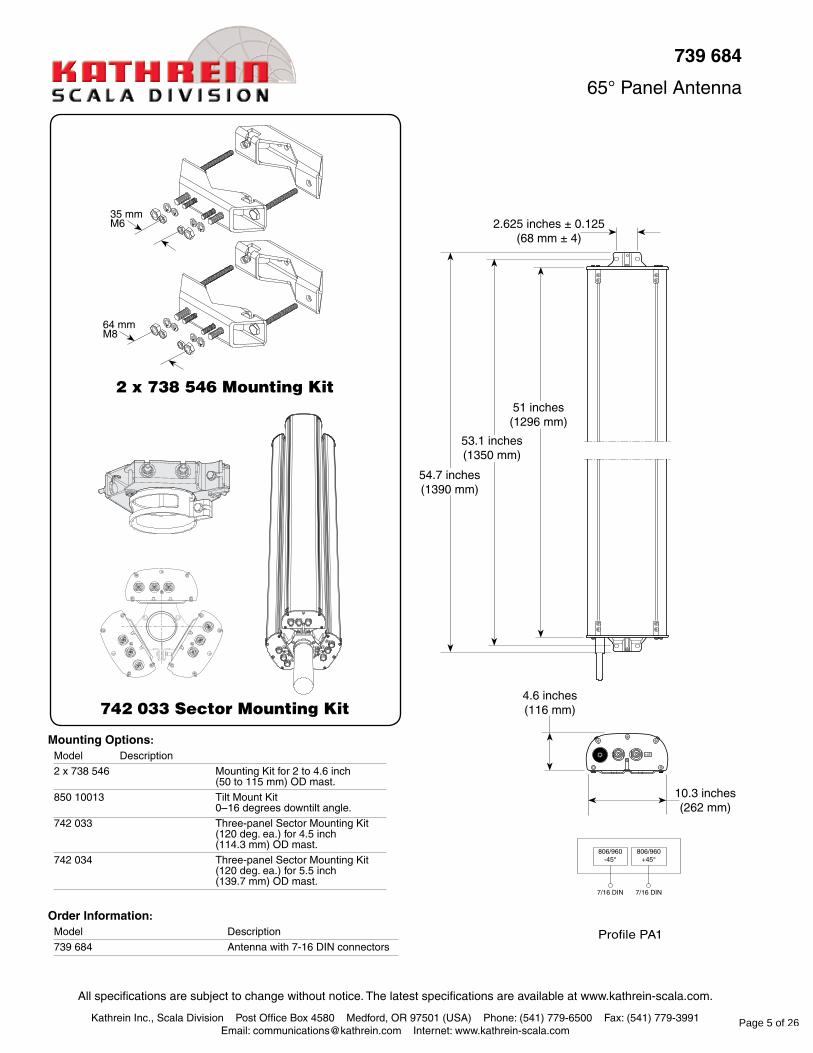
739 684
65° Panel Antenna
Order Information:Model Description
739 684 Antenna with 7-16 DIN connectors
2 x 738 546 Mounting Kit
742 033 Sector Mounting Kit
Mounting Options:Model Description
2 x 738 546 Mounting Kit for 2 to 4.6 inch (50 to 115 mm) OD mast.
850 10013 Tilt Mount Kit 0–16 degrees downtilt angle.
742 033 Three-panel Sector Mounting Kit (120 deg. ea.) for 4.5 inch (114.3 mm) OD mast.
742 034 Three-panel Sector Mounting Kit (120 deg. ea.) for 5.5 inch (139.7 mm) OD mast.
10.3 inches(262 mm)
54.7 inches(1390 mm)
51 inches(1296 mm)
53.1 inches(1350 mm)
4.6 inches(116 mm)
2.625 inches ± 0.125(68 mm ± 4)
35 mmM6
64 mmM8
806/960-45°
806/960+45°
7/16 DIN 7/16 DIN
Profile PA1
Page 5 of 26
3. 742-222V01
Kathrein Inc., Scala Division Post Office Box 4580 Medford, OR 97501 (USA) Phone: (541) 779-6500 Fax: (541) 779-3991Email: [email protected] Internet: www.kathrein-scala.com
General specifications: Frequency range 790–960 MHz
1710–2170 MHz
Impedance 50 ohms
VSWR <1.5:1
Intermodulation (2x20w) IM3: <-150 dBc
Polarization +45° and -45°
Connector 2 x 7-16 DIN female
Isolation intrasystem >30 dB
Weight 16.5 lb (7.5 kg) 20.9 lb (9.5 kg) clamps included
Dimensions 22.8 x 10.3 x 5.5 inches (579 x 262 x 139 mm)
Wind load at 93 mph (150kph) Front/Side/Rear 45 lbf / 21 lbf / 57 lbf (200 N) / (90 N) / (250 N) Mounting category M (Medium)
Wind survival rating* 120 mph (200 kph)
Shipping dimensions 29.8 x 11.1 x 6.8 inches (756 x 282 x 172 mm)
Shipping weight 24.3 lb (11 kg)
Mounting Fixed mounts for 2 to 4.6 inch (50 to 115 mm). OD masts are included and tilt options are available.
See reverse for order information.
* Mechanical design is based on environmental conditions as stipulated in TIA-222-G-2 (December 2009) and/or ETS 300 019-1-4 which include the static mechanical load imposed on an antenna by wind at maximum velocity. See the Engineering Section of the catalog for further details.
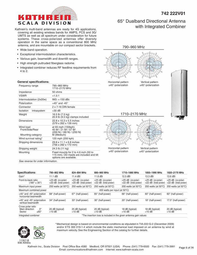
790–960 MHz
1710–2170 MHz
742 222V01
65° Dualband Directional Antennawith Integrated Combiner
11357-B 936.4059/a
Horizontal pattern ±45°-polarization
Vertical pattern ±45°-polarization
Horizontal pattern ±45°-polarization
Vertical pattern ±45°-polarization
Specifications: 790–862 MHz 824–894 MHz 880–960 MHz 1710–1880 MHz 1850–1990 MHz 1920–2170 MHzGain* 11.1 dBi 11.4 dBi 11.8 dBi 12.5 dBi 13.3 dBi 13.6 dBi
Front-to-back ratio >23 dB (co-polar) >23 dB (co-polar) >25 dB (co-polar) >25 dB (co-polar) >25 dB (co-polar) >25 dB (co-polar) (180° ± 30°) >20 dB (total power) >20 dB (total power) >22 dB (total power) >22 dB (total power) >22 dB (total power) >22 dB (total power)
Maximum input power 250 watts (at 50°C) 250 watts (at 50°C) 250 watts (at 50°C) 200 watts (at 50°C) 200 watts (at 50°C) 200 watts (at 50°C)
Maximum combined power 450 watts per input (at 50°C)
+45° and -45° polarization 68° (half-power) 67° (half-power) 65° (half-power) 66° (half-power) 60° (half-power) 60° (half-power) horizontal beamwidth
+45° and -45° polarization 34° (half-power) 33° (half-power) 30° (half-power) 20° (half-power) 18° (half-power) 17.5° (half-power) vertical beamwidth
Cross polar ratio Main direction 0° 25 dB (typical) 25 dB (typical) 25 dB (typical) 18 dB (typical) 18 dB (typical) 20 dB (typical) Sector ±60° >10 dB >10 dB >10 dB >10 dB >10 dB >10 dB
Integrated combiner *The insertion loss is included in the given antenna gain values
Kathrein’s multi-band antennas are ready for 4G applications, covering all existing wireless bands for AMPS, PCS and 3G/UMTS as well as all spectrum under consideration for future systems. These cross-polarized antennas offer diversity operation in the same space as a conventional 800 MHz antenna, and are mountable on our compact sector brackets.
• Widebandoperation.
• Exceptionalintermodulationcharacteristics.
• Variousgain,beamwidthanddowntiltranges.
• Highstrengthpultrudedfiberglassradome.
• IntegratedcombinerreducesRFfeedlinerequirementsfrom4 to 2.
0°
30°
60°
90°
120°150°180°21
0°
240°
270°
300°
330° 3
10
20
30
0°
30°
60°
90°
120°
150°180°210°
240°
270°
300°
330° 3
10
20
30
0°
30°
60°
90°
120°
150°180°210°
240°
270°
300°
330° 3
10
20
30
0°
30°
60°
90°
120°
150°180°210°
240°
270°
300°
330° 3
10
20
30
Page 6 of 26

Kathrein Inc., Scala Division Post Office Box 4580 Medford, OR 97501 (USA) Phone: (541) 779-6500 Fax: (541) 779-3991Email: [email protected] Internet: www.kathrein-scala.com
All specifications are subject to change without notice. The latest specifications are available at www.kathrein-scala.com.
Order Information:Model Description
742 222V01 Antenna with 7-16 DIN connectors
742 222V01
65° Dualband Directional Antennawith Integrated Combiner
22.8 inches(579 mm)
26.4 inches(670 mm)
24.8 inches(630 mm)
10.3 inches(262 mm)
5.5 inches(139 mm)
ProfilePA2
Mounting Options:Model Description
2 x 738 546 Mounting Kit for 2 to 4.6 inch (included) (50 to 115 mm) OD mast. 4.4 lb (2 kg)
850 10013 Tilt Mount Kit 0–34 degrees downtilt angle.
C C
61-761-7
790–960–45°
790–960+45°
1710–2170–45°
1710–2170+45°
2 x 738 546 Mounting Kit(included)
64 mmM8
Page 7 of 26
4. 742-264
Kathrein Inc., Scala Division Post Office Box 4580 Medford, OR 97501 (USA) Phone: (541) 779-6500 Fax: (541) 779-3991Email: [email protected] Internet: www.kathrein-scala.com
* Mechanical design is based on environmental conditions as stipulated in EIA-222-F (June 1996) and/or ETS 300 019-1-4 which include the static mechanical load imposed on an antenna by wind at maximum velocity. See the Engineering Section of the catalog for further details.
10633-K 936.2887/b
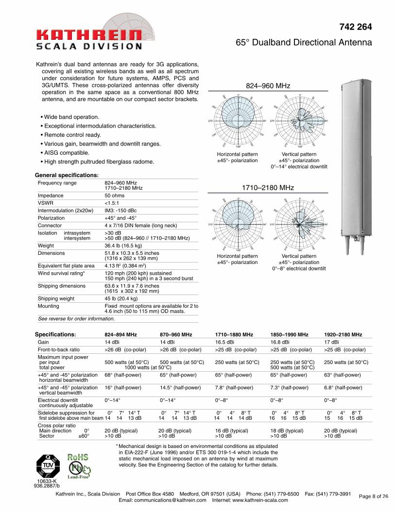
742264
65° Dualband Directional Antenna
Kathrein’s dual band antennas are ready for 3G applications, covering all existing wireless bands as well as all spectrum under consideration for future systems, AMPS, PCS and 3G/UMTS. These cross-polarized antennas offer diversity operation in the same space as a conventional 800 MHz antenna, and are mountable on our compact sector brackets.
• Wide band operation.
• Exceptional intermodulation characteristics.
• Remote control ready.
• Various gain, beamwidth and downtilt ranges.
• AISG compatible.
• High strength pultruded fiberglass radome.
Horizontal pattern±45°- polarization
Vertical pattern±45°- polarization
0°–8° electrical downtilt
Vertical pattern±45°- polarization
0°–14° electrical downtilt
Horizontal pattern±45°- polarization
824–960 MHz
1710–2180 MHz
Generalspecifications:Frequency range 824–960 MHz
1710–2180 MHz
Impedance 50 ohms
VSWR <1.5:1
Intermodulation (2x20w) IM3: -150 dBc
Polarization +45° and -45°
Connector 4 x 7/16 DIN female (long neck)
Isolation intrasystem >30 dB intersystem >50 dB (824–960 // 1710–2180 MHz)
Weight 36.4 lb (16.5 kg)
Dimensions 51.8 x 10.3 x 5.5 inches (1316 x 262 x 139 mm)
Equivalent flat plate area 4.13 ft2 (0.384 m2)
Wind survival rating* 120 mph (200 kph) sustained 150 mph (240 kph) in a 3 second burst
Shipping dimensions 63.6 x 11.9 x 7.6 inches (1615 x 302 x 192 mm)
Shipping weight 45 lb (20.4 kg)
Mounting Fixed mount options are available for 2 to 4.6 inch (50 to 115 mm) OD masts.
See reverse for order information.
Specifications: 824–894MHz 870–960MHz 1710–1880MHz 1850–1990MHz 1920–2180MHzGain 14 dBi 14 dBi 16.5 dBi 16.8 dBi 17 dBi
Front-to-back ratio >26 dB (co-polar) >26 dB (co-polar) >25 dB (co-polar) >25 dB (co-polar) >25 dB (co-polar)
Maximum input power per input 500 watts (at 50°C) 500 watts (at 50°C) 250 watts (at 50°C) 250 watts (at 50°C) 250 watts (at 50°C) total power 1000 watts (at 50°C) 500 watts (at 50°C)
+45° and -45° polarization 68° (half-power) 65° (half-power) 65° (half-power) 65° (half-power) 63° (half-power) horizontal beamwidth
+45° and -45° polarization 16° (half-power) 14.5° (half-power) 7.8° (half-power) 7.3° (half-power) 6.8° (half-power) vertical beamwidth
Electrical downtilt 0°–14° 0°–14° 0°–8° 0°–8° 0°–8° continuously adjustable
Sidelobe suppression for 0° 7° 14° T 0° 7° 14° T 0° 4° 8° T 0° 4° 8° T 0° 4° 8° T first sidelobe above main beam 14 14 13 dB 14 14 13 dB 14 14 14 dB 16 16 15 dB 15 16 15 dB
Cross polar ratio Main direction 0° 20 dB (typical) 20 dB (typical) 16 dB (typical) 18 dB (typical) 20 dB (typical) Sector ±60° >10 dB >10 dB >10 dB >10 dB >10 dB
Page 8 of 26
Kathrein Inc., Scala Division Post Office Box 4580 Medford, OR 97501 (USA) Phone: (541) 779-6500 Fax: (541) 779-3991Email: [email protected] Internet: www.kathrein-scala.com
All specifications are subject to change without notice. The latest specifications are available at www.kathrein-scala.com.
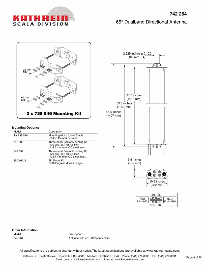
MountingOptions:Model Description
2 x 738 546 Mounting Kit for 2 to 4.6 inch (50 to 115 mm) OD mast.
742 033 Three-panel Sector Mounting Kit (120 deg. ea.) for 4.5 inch (114.3 mm mm) OD steel mast.
742 034 Three-panel Sector Mounting Kit (120 deg. ea.) for 5.5 inch (139.7 mm mm) OD steel mast.
850 10013 Tilt Mount Kit 0–16 Degrees downtilt angle.
OrderInformation:Model Description
742 264 Antenna with 7/16 DIN connectors
742264
65° Dualband Directional Antenna
10.3 inches(262 mm)
53.8 inches(1367 mm)
51.8 inches(1316 mm)
55.4 inches(1407 mm)
5.5 inches(139 mm)
2.625 inches ± 0.125(68 mm ± 4)
2 x 738 546 Mounting Kit
35 mmM6
64 mmM8
Page 9 of 26
5. 742-265
Kathrein Inc., Scala Division Post Office Box 4580 Medford, OR 97501 (USA) Phone: (541) 779-6500 Fax: (541) 779-3991Email: [email protected] Internet: www.kathrein-scala.com
General specifications: Frequency range 824–960 MHz
1710–2180 MHz
Impedance 50 ohms
VSWR <1.5:1
Intermodulation (2x20w) IM3:< -150 dBc
Polarization +45° and -45°
Connector 4 x 7-16 DIN female
Isolation intrasystem >30 dB intersystem >50 dB (824–960 // 1710–2180 MHz) typ.
Weight 48.5 lb (22 kg)
Dimensions 75.4 x 10.3 x 5.5 inches (1916 x 262 x 139 mm)
Equivalent flat plate area 6.16 ft2 (0.572 m2)
Wind survival rating* 120 mph (200 kph)
Shipping dimensions 87.2 x 11.9 x 7.6 inches (2215 x 302 x 192 mm)
Shipping weight 59.5 lb (27 kg)
Mounting Fixed mount options are available for 2 to 4.6 inch (50 to 115 mm) OD masts.
See reverse for order information.
* Mechanical design is based on environmental conditions as stipulated in EIA-222-F (June 1996) and/or ETS 300 019-1-4 which include the static mechanical load imposed on an antenna by wind at maximum velocity. See the Engineering Section of the catalog for further details.
10634-J 936.3218/a
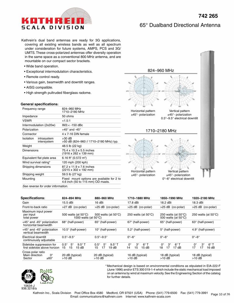
742 265
65° Dualband Directional Antenna
Horizontal pattern±45°- polarization
Vertical pattern±45°- polarization
0°–6° electrical downtilt
Vertical pattern±45°- polarization
0.5°–9.5° electrical downtilt
Horizontal pattern±45°- polarization
824–960 MHz
1710–2180 MHz
Kathrein’s dual band antennas are ready for 3G applications, covering all existing wireless bands as well as all spectrum under consideration for future systems, AMPS, PCS and 3G/UMTS. These cross-polarized antennas offer diversity operation in the same space as a conventional 800 MHz antenna, and are mountable on our compact sector brackets.
• Wide band operation.
• Exceptional intermodulation characteristics.
• Remote control ready.
• Various gain, beamwidth and downtilt ranges.
• AISG compatible.
• High strength pultruded fiberglass radome.
Specifications: 824–894 MHz 880–960 MHz 1710–1880 MHz 1850–1990 MHz 1920–2180 MHzGain 15.5 dBi 16 dBi 17.8 dBi 18.2 dBi 18.3 dBi
Front-to-back ratio >27 dB (co-polar) >25 dB (co-polar) >25 dB (co-polar) >25 dB (co-polar) >25 dB (co-polar)
Maximum input power per input 500 watts (at 50°C) 500 watts (at 50°C) 250 watts (at 50°C) 250 watts (at 50°C) 250 watts (at 50°C) total power 1000 watts (at 50°C) 500 watts (at 50°C)
+45° and -45° polarization 68° (half-power) 65° (half-power) 67° (half-power) 65° (half-power) 63° (half-power) horizontal beamwidth
+45° and -45° polarization 10.5° (half-power) 10° (half-power) 5.2° (half-power) 5° (half-power) 4.9° (half-power) vertical beamwidth
Electrical downtilt 0.5°–9.5° 0.5°–9.5° 0°–6° 0°–6° 0°–6° continuously adjustable
Sidelobe suppression for 0.5° 5° 9.5° T 0.5° 5° 9.5° T 0° 3° 6° T 0° 3° 6° T 0° 3° 6° T first sidelobe above horizon 15 15 15 dB 15 17 19 dB 14 15 15 dB 18 17 17 dB 17 17 16 dB
Cross polar ratio Main direction 0° 20 dB (typical) 20 dB (typical) 16 dB (typical) 18 dB (typical) 18 dB (typical) Sector ±60° >10 dB >10 dB >10 dB >10 dB >10 dB
Page 10 of 26
Kathrein Inc., Scala Division Post Office Box 4580 Medford, OR 97501 (USA) Phone: (541) 779-6500 Fax: (541) 779-3991Email: [email protected] Internet: www.kathrein-scala.com
All specifications are subject to change without notice. The latest specifications are available at www.kathrein-scala.com.
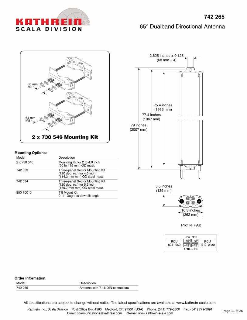
2.625 inches ± 0.125(68 mm ± 4)
Profile PA2
Order Information:Model Description
742 265 Antenna with 7-16 DIN connectors
742 265
65° Dualband Directional Antenna
10.3 inches(262 mm)
77.4 inches(1967 mm)
75.4 inches(1916 mm)
79 inches(2007 mm)
5.5 inches(139 mm)
Mounting Options:Model Description
2 x 738 546 Mounting Kit for 2 to 4.6 inch (50 to 115 mm) OD mast.
742 033 Three-panel Sector Mounting Kit (120 deg. ea.) for 4.5 inch (114.3 mm mm) OD steel mast.
742 034 Three-panel Sector Mounting Kit (120 deg. ea.) for 5.5 inch (139.7 mm mm) OD steel mast.
850 10013 Tilt Mount Kit 0–11 Degrees downtilt angle.
2 x 738 546 Mounting Kit
35 mmM6
64 mmM8
Page 11 of 26

6. 800 10765
Kathrein Inc., Scala Division Post Office Box 4580 Medford, OR 97501 (USA) Phone: (541) 779-6500 Fax: (541) 779-3991Email: [email protected] Internet: www.kathrein-scala.com
11093-FRO/c 936.A2693/b
* Mechanical design is based on environmental conditions as stipulated in EIA-222-F (June 1996) and/or ETS 300 019-1-4 which include the static mechanical load imposed on an antenna by wind at maximum velocity. See the Engineering Section of the catalog for further details.
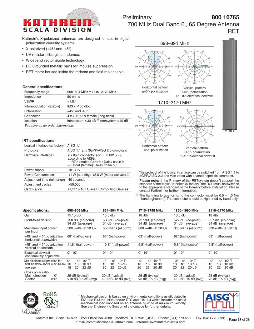
Preliminary 800 10765 700 MHz Dual Band 6', 65 Degree Antenna
RETKathrein’s X-polarized antennas are designed for use in digital
polarization diversity systems.
• X-polarized (+45° and -45°).
• UV resistant fiberglass radomes.
• Wideband vector dipole technology.
• DC Grounded metallic parts for impulse suppression.
• RET motor housed inside the radome and field replaceable.
Vertical pattern±45°- polarization
0°–10° electrical downtilt
Horizontal pattern±45°- polarization
1020
30
40
50
60
70
80
90
0
30
60
90
120
150
180210
240
270
300
3303020163 61020
3
6
10
20
BdBd
dB
%
1020
30
40
50
60
70
80
90
0
30
60
90
120
150
180210
240
270
300
330
3020163 61020
3
6
10
20
BdBd
dB
%
Vertical pattern±45°- polarization
0°–10° electrical downtilt
Horizontal pattern±45°- polarization
1020
30
40
50
60
70
80
90
0
30
60
90
120
150
180210
240
270
300
330
3020163 61020
3
6
10
20
BdBd
dB
%
1020
30
40
50
60
70
80
90
0
30
60
90
120
150
180210
240
270
300
330
3020163 61020
3
6
10
20
BdBd
dB
%
General specifications: Frequency range 698–894 MHz // 1710–2170 MHz
Impedance 50 ohms
VSWR <1.5:1
Intermodulation (2x20w) IM3:< -150 dBc
Polarization +45° and -45°
Connector 4 x 7-16 DIN female (long neck)
Isolation intrasystem >30 dB // intersystem >40 dB
See reverse for order information.
698–894 MHz
1710–2170 MHz
Specifications: 698–806 MHz 824–894 MHz 1710–1755 MHz 1850–1990 MHz 2110–2170 MHzGain 15.15 dBi 15.5 dBi 18 dBi 18.5 dBi 18 dBi
Front-to-back ratio >30 dB (co-polar) >30 dB (co-polar) >27 dB (co-polar) >27 dB (co-polar) >27 dB (co-polar) 34 dB (average) 34 dB (average) 34 dB (average) 34 dB (average) 34 dB (average)
Maximum input power 500 watts (at 50°C) 500 watts (at 50°C) 300 watts (at 50°C) 300 watts (at 50°C) 300 watts (at 50°C) per input
+45° and -45° polarization 68° (half-power) 65° (half-power) 63° (half-power) 62° (half-power) 63° (half-power) horizontal beamwidth
+45° and -45° polarization 11.8° (half-power) 10.8° (half-power) 5.8° (half-power) 5.8° (half-power) 5.8° (half-power) vertical beamwidth
Electrical downtilt 0°–10° 0°–10° 0°–10° 0°–10° 0°–10° continuously adjustable
Min sidelobe suppression for 0° 5° 10° T 0° 5° 10° T 0° 5° 10° T 0° 5° 10° T 0° 5° 10° T first sidelobe above main beam 16 16 18 dB 18 18 16 dB 18 18 18 dB 18 18 18 dB 18 18 18 dB average 18 20 22 dB 20 22 20 dB 20 22 20 dB 20 22 20 dB 20 22 20 dB
Cross polar ratio Main direction 0° 25 dB (typical) 20 dB (typical) 25 dB (typical) 30 dB (typical) 25 dB (typical) Sector ±60° >10 dB, 15 dB (avg) >10 dB, 12 dB (avg) >8 dB, 15 dB (avg) >10 dB, 15 dB (avg) >8 dB, 15 dB (avg)
IRT specifications: Logical interface ex factory1) AISG 1.1
Protocols AISG 1.1 and 3GPP/AISG 2.0 compliant
Hardware interface2) 2 x 8pin connector acc. IEC 60130-9; according to AISG: – IRTin (male): Control / Daisy chain in – IRTout (female): Daisy chain out
Power supply 10–30 V
Power Consumption <1 W (standby); <8.5 W (motor activated)
Adjustment time (full range) 40 seconds
Adjustment cycles >50,000
Certification FCC 15.107 Class B Computing Devices
1) The protocol of the logical interface can be switched from AISG 1.1 to 3GPP/AISG 2.0 and vice versa with a vendor specific command.
Please note: If the Primary of the RETsystem doesn’t support the standard of the ‘logical interface ex factory’, the RCU must be switched to the appropriate standard of the Primary before installation. Please contact Kathrein for further information.
2) The tightning torque for fixing the connector must be 0.5 – 1.0 Nm (‘hand-tightened’). The connector should be tightened by hand only!
Page 12 of 26
All specifications are subject to change without notice. The latest specifications are available at www.kathrein-scala.com.
Kathrein Inc., Scala Division Post Office Box 4580 Medford, OR 97501 (USA) Phone: (541) 779-6500 Fax: (541) 779-3991Email: [email protected] Internet: www.kathrein-scala.com
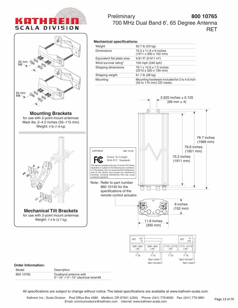
Preliminary 800 10765 700 MHz Dual Band 6', 65 Degree Antenna
RET
Order Information:Model Description
800 10765 Dualband antenna with 0°–10° // 0°–10° electrical downtilt
11.8 inches(300 mm)
75.2 inches(1911 mm)
2.625 inches ± 0.125(68 mm ± 4)
6 inches(152 mm)
35 mmM6
64 mmM8
Mounting Bracketsfor use with 2-point mount antennasMast dia. 2–4.5 inches (50–115 mm)
Weight: 4 lb (1.8 kg)
Mechanical Tilt Bracketsfor use with 2-point mount antennas
Weight: 7.4 lb (3.7 kg)
Note: Refer to part number 860 10145 for the specifications of the remote control actuator.
698–894–45
7-16
1710–2170+45
7-16
1710–2170–45
7-16
698–894+45
7-16
IRT outin
8pin male8pin female
IRT inout
8pin male8pin female
76.8 inches(1951 mm)
78.7 inches(1999 mm)
Mechanical specifications: Weight 50.7 lb (23 kg)
Dimensions 75.3 x 11.8 x 6 inches (1911 x 300 x 152 mm)
Equivalent flat plate area 9.81 ft2 (0.911 m2)
Wind survival rating* 150 mph (240 kph)
Shipping dimensions 79.1 x 12.6 x 7.5 inches (2010 x 320 x 190 mm)
Shipping weight 61.7 lb (28 kg)
Mounting Mounting hardware included for 2 to 4.6 inch (50 to 115 mm) OD masts.
This device complies with part 15 of the FCC Rules. Operation is subject to the following two conditions: (1) This device may not cause harmful interference, and (2) this device must accept any interference received, including interference that may cause undesired operation.
KATHREIN 860 10145
Tested To ComplyWith FCC Standards
Page 13 of 26

7. 800-10121
Kathrein Inc., Scala Division Post Office Box 4580 Medford, OR 97501 (USA) Phone: (541) 779-6500 Fax: (541) 779-3991Email: [email protected] Internet: www.kathrein-scala.com
* Mechanical design is based on environmental conditions as stipulated in EIA-222-F (June 1996) and/or ETS 300 019-1-4 which include the static mechanical load imposed on an antenna by wind at maximum velocity. See the Engineering Section of the catalog for further details.
General specifications: Frequency range 806–960 MHz
1710–2180 MHz
VSWR <1.5:1
Impedance 50 ohms
Intermodulation (2x20w) IM3: < -150 dBc
Polarization +45° and -45°
Connector 4 x 7/16 DIN female
Isolation intrasystem >30 dB intersystem >45 dB (806–960 // 1710–2180 MHz)
Weight 46.3 lb (21 kg)
Dimensions 54.5 x 10.3 x 5.9 inches (1384 x 262 x 149 mm)
Equivalent flat plate area 5.58 ft2 (0.518 m2)
Wind survival rating* 120 mph (200 kph) sustained 150 mph (240 kph) in a 3 second burst
Shipping dimensions 67.6 x 12 x 8 inches (1716 x 304 x 204 mm)
Shipping weight 50.7 lb (23 kg)
Mounting Fixed mount options are available for 2 to 4.6 inch (50 to 115 mm) OD masts.
See reverse for order information.
10724-H 936.2686/b
Kathrein’s dual band antennas are ready for 3G applications, covering all existing wireless bands as well as all spectrum under consideration for future systems, AMPS, PCS and 3G/UMTS. These cross-polarized antennas offer diversity operation in the same space as a conventional 800 MHz antenna, and are mountable on our compact sector brackets.
• Wide band operation.
• Exceptional intermodulation characteristics.
• Remote control ready.
• Various gain, beamwidth and downtilt ranges.
• AISG compatible.
• High strength pultruded fiberglass radome.
806–960 MHz
1710–2180 MHz
Horizontal pattern ±45°-polarization
Horizontal pattern ±45°-polarization
Vertical pattern ±45°-polarization
0.5°–12.5° electrical downtilt
Vertical pattern ±45°-polarization
0.5°–10° electrical downtilt
800 10121
Multiband Directional Antenna
Specifications: 806–866 MHz 824–896 MHz 880–960 MHz 1710–1880 MHz 1850–1990 MHz 1920–2180 MHz Average gain (dBi) 13.4 13.4 13.1 13.6 13.6 13.4 13.9 13.8 13.5 16.4 16.4 16.2 16.4 16.5 16 16.4 15.9 15.3 Tilt 0° 6° 12° 0° 6° 12° 0° 6° 12° 0° 5° 10° 0° 5° 10° 0° 5° 10°
Front-to-back ratio >23 dB (co-polar) >23 dB (co-polar) >23 dB (co-polar) >23 dB (co-polar) >23 dB (co-polar) >23 dB (co-polar)
Maximum input power 400 watts 400 watts 400 watts 250 watts 250 watts 250 watts per input (at 50°C)
+45° and -45° polarization 88° (half-power) 86° (half-power) 88° (half-power) 82° (half-power) 85° (half-power) 90° (half-power) horizontal beamwidth
+45° and -45° polarization 15° (half-power) 14.5° (half-power) 13.5° (half-power) 7.1° (half-power) 6.8° (half-power) 6.5° (half-power) vertical beamwidth
Electrical downtilt 0.5°–12.5° 0.5°–12.5° 0.5°–12.5° 0.5°–10° 0.5°–10° 0.5°–10° continuously adjustable (manual or optional remote control)
Vertical Pattern–min. side- 0° 6° 12° T 0° 6° 12° T 0° 6° 12° T 0° 5° 10° T 0° 5° 10° T 0° 5° 10° T lobe suppression for first 16 16 16 dB 16 16 16 dB 14 14 13 dB 17 17 16 dB 17 18 16 dB 18 16 16 dB sidelobe above main beam 17 17 19 dB 17 17 19 dB 17 16 16 dB 20 20 18 dB 21 22 17 dB 20 20 16 dB average
Front-to-back ratio (copolar) >23 dB >23 dB >23 dB >23 dB >23 dB >23 dB
Cross polar ratio (typical) Main direction 0° 18 dB 18 dB 20 dB 17 dB 16 dB 15 dB Sector ±60° >10 dB >10 dB >13 dB >10 dB >12 dB >10 dB average ±60° 16 dB 16 dB 19 dB 17 dB 19 dB 19 dB
Page 14 of 26

All specifications are subject to change without notice. The latest specifications are available at www.kathrein-scala.com.
Kathrein Inc., Scala Division Post Office Box 4580 Medford, OR 97501 (USA) Phone: (541) 779-6500 Fax: (541) 779-3991Email: [email protected] Internet: www.kathrein-scala.com
2 x 738 546 Mounting Kit
Mounting Options:Model Description
2 x 738 546 (shown) Mounting Kit for 2 to 4.6 inch (50 to 115 mm) OD mast.
850 10013 Tilt Mount Kit 0–15 degrees downtilt angle.
Order Information:Model Description
800 10121 Antenna with 7/16 DIN connectors
800 10121 Multiband Directional Antenna
10.3 inches(262 mm)
57.8 inches(1467 mm)
54.5 inches(1384 mm)
56.2 inches(1427 mm)
5.9 inches(149 mm)
2.625 inches ± 0.125(68 mm ± 4)
35 mmM6
64 mmM8
Page 15 of 26
8. 800-10122
Kathrein Inc., Scala Division Post Office Box 4580 Medford, OR 97501 (USA) Phone: (541) 779-6500 Fax: (541) 779-3991Email: [email protected] Internet: www.kathrein-scala.com
* Mechanical design is based on environmental conditions as stipulated in EIA-222-F (June 1996) and/or ETS 300 019-1-4 which include the static mechanical load imposed on an antenna by wind at maximum velocity. See the Engineering Section of the catalog for further details.
General specifications: Frequency range 806–960 MHz
1710–2180 MHz
Impedance 50 ohms
VSWR <1.5:1
Intermodulation (2x20w) IM3:< -150 dBc
Polarization +45° and -45°
Connector 4 x 7-16 DIN female (long neck)
Isolation intrasystem >30 dB intersystem >45 dB (806–960 // 1710–2180 MHz)
Weight 59.5 lb (27 kg)
Dimensions 75.5 x 10.3 x 5.9 inches (1917 x 262 x 149 mm)
Equivalent flat plate area 6.16 ft2 (0.572 m2)
Wind survival rating* 120 mph (200 kph)
Shipping dimensions 88.5 x 12 x 8 inches (2249 x 304 x 204 mm)
Shipping weight 66.1 lb (30 kg)
Mounting Fixed mount options are available for 2 to 4.6 inch (50 to 115 mm) OD masts.
See reverse for order information.
10726-E936.2900/b
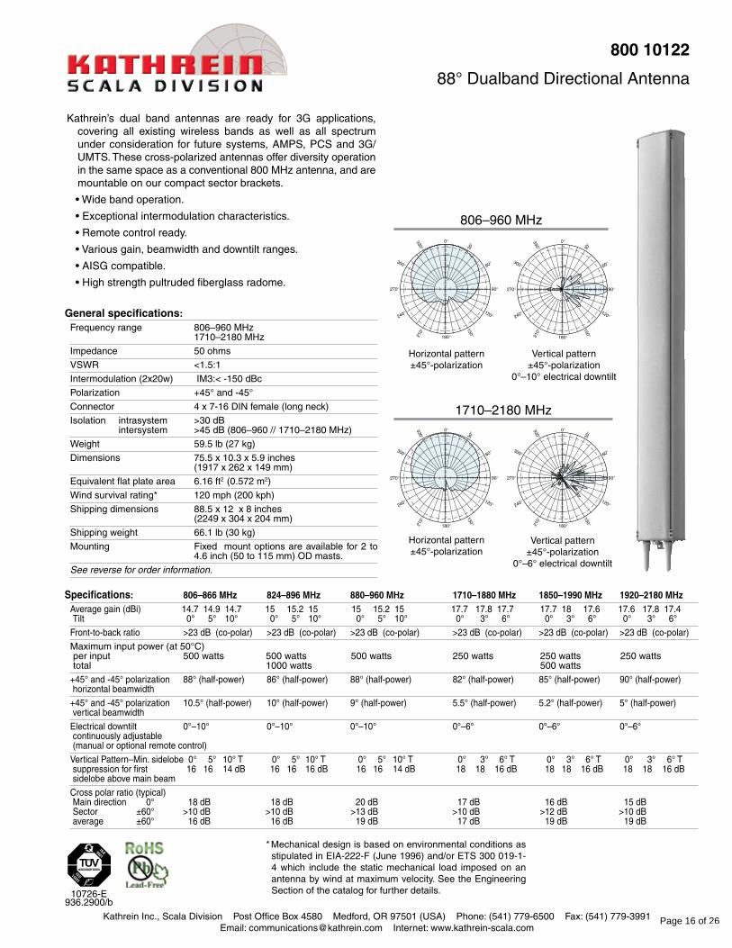
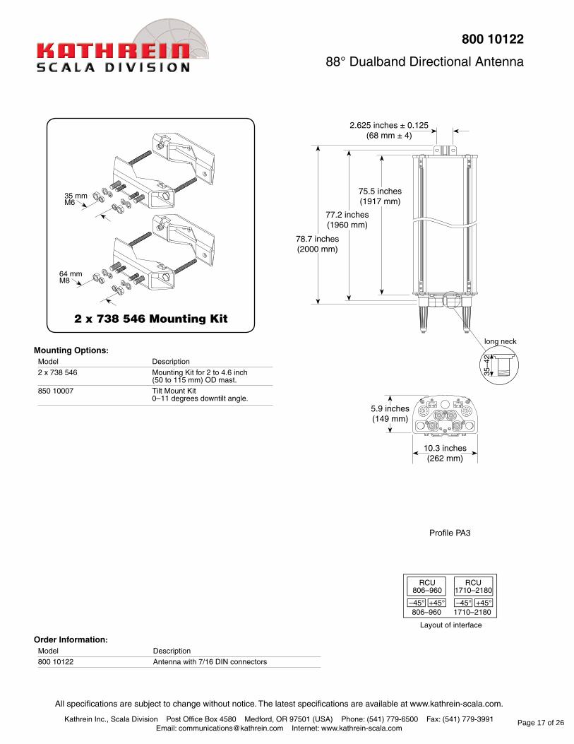
800 10122
88° Dualband Directional Antenna
Kathrein’s dual band antennas are ready for 3G applications, covering all existing wireless bands as well as all spectrum under consideration for future systems, AMPS, PCS and 3G/UMTS. These cross-polarized antennas offer diversity operation in the same space as a conventional 800 MHz antenna, and are mountable on our compact sector brackets.
• Wide band operation.
• Exceptional intermodulation characteristics.
• Remote control ready.
• Various gain, beamwidth and downtilt ranges.
• AISG compatible.
• High strength pultruded fiberglass radome.
806–960 MHz
1710–2180 MHz
Horizontal pattern ±45°-polarization
Horizontal pattern ±45°-polarization
Vertical pattern ±45°-polarization
0°–10° electrical downtilt
Vertical pattern ±45°-polarization
0°–6° electrical downtilt
Specifications: 806–866 MHz 824–896 MHz 880–960 MHz 1710–1880 MHz 1850–1990 MHz 1920–2180 MHz Average gain (dBi) 14.7 14.9 14.7 15 15.2 15 15 15.2 15 17.7 17.8 17.7 17.7 18 17.6 17.6 17.8 17.4 Tilt 0° 5° 10° 0° 5° 10° 0° 5° 10° 0° 3° 6° 0° 3° 6° 0° 3° 6°
Front-to-back ratio >23 dB (co-polar) >23 dB (co-polar) >23 dB (co-polar) >23 dB (co-polar) >23 dB (co-polar) >23 dB (co-polar)
Maximum input power (at 50°C) per input 500 watts 500 watts 500 watts 250 watts 250 watts 250 watts total 1000 watts 500 watts
+45° and -45° polarization 88° (half-power) 86° (half-power) 88° (half-power) 82° (half-power) 85° (half-power) 90° (half-power) horizontal beamwidth
+45° and -45° polarization 10.5° (half-power) 10° (half-power) 9° (half-power) 5.5° (half-power) 5.2° (half-power) 5° (half-power) vertical beamwidth
Electrical downtilt 0°–10° 0°–10° 0°–10° 0°–6° 0°–6° 0°–6° continuously adjustable (manual or optional remote control)
Vertical Pattern–Min. sidelobe 0° 5° 10° T 0° 5° 10° T 0° 5° 10° T 0° 3° 6° T 0° 3° 6° T 0° 3° 6° T suppression for first 16 16 14 dB 16 16 16 dB 16 16 14 dB 18 18 16 dB 18 18 16 dB 18 18 16 dB sidelobe above main beam
Cross polar ratio (typical) Main direction 0° 18 dB 18 dB 20 dB 17 dB 16 dB 15 dB Sector ±60° >10 dB >10 dB >13 dB >10 dB >12 dB >10 dB average ±60° 16 dB 16 dB 19 dB 17 dB 19 dB 19 dB
Page 16 of 26
All specifications are subject to change without notice. The latest specifications are available at www.kathrein-scala.com.
Kathrein Inc., Scala Division Post Office Box 4580 Medford, OR 97501 (USA) Phone: (541) 779-6500 Fax: (541) 779-3991Email: [email protected] Internet: www.kathrein-scala.com
Order Information:Model Description
800 10122 Antenna with 7/16 DIN connectors
800 10122
88° Dualband Directional Antenna
long neck
35–4
2
2 x 738 546 Mounting Kit
Mounting Options:Model Description
2 x 738 546 Mounting Kit for 2 to 4.6 inch (50 to 115 mm) OD mast.
850 10007 Tilt Mount Kit 0–11 degrees downtilt angle.
10.3 inches(262 mm)
78.7 inches(2000 mm)
75.5 inches(1917 mm)
77.2 inches(1960 mm)
5.9 inches(149 mm)
2.625 inches ± 0.125(68 mm ± 4)
35 mmM6
64 mmM8
Profile PA3
Page 17 of 26
9. 800-10765
Kathrein Inc., Scala Division Post Office Box 4580 Medford, OR 97501 (USA) Phone: (541) 779-6500 Fax: (541) 779-3991Email: [email protected] Internet: www.kathrein-scala.com
11093-FRO/c 936.A2693/b
* Mechanical design is based on environmental conditions as stipulated in EIA-222-F (June 1996) and/or ETS 300 019-1-4 which include the static mechanical load imposed on an antenna by wind at maximum velocity. See the Engineering Section of the catalog for further details.
Preliminary 800 10765 700 MHz Dual Band 6', 65 Degree Antenna
RETKathrein’s X-polarized antennas are designed for use in digital
polarization diversity systems.
• X-polarized (+45° and -45°).
• UV resistant fiberglass radomes.
• Wideband vector dipole technology.
• DC Grounded metallic parts for impulse suppression.
• RET motor housed inside the radome and field replaceable.
Vertical pattern±45°- polarization
0°–10° electrical downtilt
Horizontal pattern±45°- polarization
1020
30
40
50
60
70
80
90
0
30
60
90
120
150
180210
240
270
300
3303020163 61020
3
6
10
20
BdBd
dB
%
1020
30
40
50
60
70
80
90
0
30
60
90
120
150
180210
240
270
300
330
3020163 61020
3
6
10
20
BdBd
dB
%
Vertical pattern±45°- polarization
0°–10° electrical downtilt
Horizontal pattern±45°- polarization
1020
30
40
50
60
70
80
90
0
30
60
90
120
150
180210
240
270
300
330
3020163 61020
3
6
10
20
BdBd
dB
%
1020
30
40
50
60
70
80
90
0
30
60
90
120
150
180210
240
270
300
330
3020163 61020
3
6
10
20
BdBd
dB
%
General specifications: Frequency range 698–894 MHz // 1710–2170 MHz
Impedance 50 ohms
VSWR <1.5:1
Intermodulation (2x20w) IM3:< -150 dBc
Polarization +45° and -45°
Connector 4 x 7-16 DIN female (long neck)
Isolation intrasystem >30 dB // intersystem >40 dB
See reverse for order information.
698–894 MHz
1710–2170 MHz
Specifications: 698–806 MHz 824–894 MHz 1710–1755 MHz 1850–1990 MHz 2110–2170 MHzGain 15.15 dBi 15.5 dBi 18 dBi 18.5 dBi 18 dBi
Front-to-back ratio >30 dB (co-polar) >30 dB (co-polar) >27 dB (co-polar) >27 dB (co-polar) >27 dB (co-polar) 34 dB (average) 34 dB (average) 34 dB (average) 34 dB (average) 34 dB (average)
Maximum input power 500 watts (at 50°C) 500 watts (at 50°C) 300 watts (at 50°C) 300 watts (at 50°C) 300 watts (at 50°C) per input
+45° and -45° polarization 68° (half-power) 65° (half-power) 63° (half-power) 62° (half-power) 63° (half-power) horizontal beamwidth
+45° and -45° polarization 11.8° (half-power) 10.8° (half-power) 5.8° (half-power) 5.8° (half-power) 5.8° (half-power) vertical beamwidth
Electrical downtilt 0°–10° 0°–10° 0°–10° 0°–10° 0°–10° continuously adjustable
Min sidelobe suppression for 0° 5° 10° T 0° 5° 10° T 0° 5° 10° T 0° 5° 10° T 0° 5° 10° T first sidelobe above main beam 16 16 18 dB 18 18 16 dB 18 18 18 dB 18 18 18 dB 18 18 18 dB average 18 20 22 dB 20 22 20 dB 20 22 20 dB 20 22 20 dB 20 22 20 dB
Cross polar ratio Main direction 0° 25 dB (typical) 20 dB (typical) 25 dB (typical) 30 dB (typical) 25 dB (typical) Sector ±60° >10 dB, 15 dB (avg) >10 dB, 12 dB (avg) >8 dB, 15 dB (avg) >10 dB, 15 dB (avg) >8 dB, 15 dB (avg)
IRT specifications: Logical interface ex factory1) AISG 1.1
Protocols AISG 1.1 and 3GPP/AISG 2.0 compliant
Hardware interface2) 2 x 8pin connector acc. IEC 60130-9; according to AISG: – IRTin (male): Control / Daisy chain in – IRTout (female): Daisy chain out
Power supply 10–30 V
Power Consumption <1 W (standby); <8.5 W (motor activated)
Adjustment time (full range) 40 seconds
Adjustment cycles >50,000
Certification FCC 15.107 Class B Computing Devices
1) The protocol of the logical interface can be switched from AISG 1.1 to 3GPP/AISG 2.0 and vice versa with a vendor specific command.
Please note: If the Primary of the RETsystem doesn’t support the standard of the ‘logical interface ex factory’, the RCU must be switched to the appropriate standard of the Primary before installation. Please contact Kathrein for further information.
2) The tightning torque for fixing the connector must be 0.5 – 1.0 Nm (‘hand-tightened’). The connector should be tightened by hand only!
Page 18 of 26

All specifications are subject to change without notice. The latest specifications are available at www.kathrein-scala.com.
Kathrein Inc., Scala Division Post Office Box 4580 Medford, OR 97501 (USA) Phone: (541) 779-6500 Fax: (541) 779-3991Email: [email protected] Internet: www.kathrein-scala.com
Preliminary 800 10765 700 MHz Dual Band 6', 65 Degree Antenna
RET
Order Information:Model Description
800 10765 Dualband antenna with 0°–10° // 0°–10° electrical downtilt
11.8 inches(300 mm)
75.2 inches(1911 mm)
2.625 inches ± 0.125(68 mm ± 4)
6 inches(152 mm)
35 mmM6
64 mmM8
Mounting Bracketsfor use with 2-point mount antennasMast dia. 2–4.5 inches (50–115 mm)
Weight: 4 lb (1.8 kg)
Mechanical Tilt Bracketsfor use with 2-point mount antennas
Weight: 7.4 lb (3.7 kg)
Note: Refer to part number 860 10145 for the specifications of the remote control actuator.
698–894–45
7-16
1710–2170+45
7-16
1710–2170–45
7-16
698–894+45
7-16
IRT outin
8pin male8pin female
IRT inout
8pin male8pin female
76.8 inches(1951 mm)
78.7 inches(1999 mm)
Mechanical specifications: Weight 50.7 lb (23 kg)
Dimensions 75.3 x 11.8 x 6 inches (1911 x 300 x 152 mm)
Equivalent flat plate area 9.81 ft2 (0.911 m2)
Wind survival rating* 150 mph (240 kph)
Shipping dimensions 79.1 x 12.6 x 7.5 inches (2010 x 320 x 190 mm)
Shipping weight 61.7 lb (28 kg)
Mounting Mounting hardware included for 2 to 4.6 inch (50 to 115 mm) OD masts.
This device complies with part 15 of the FCC Rules. Operation is subject to the following two conditions: (1) This device may not cause harmful interference, and (2) this device must accept any interference received, including interference that may cause undesired operation.
KATHREIN 860 10145
Tested To ComplyWith FCC Standards
Page 19 of 26
10. AM-X-CD-14-65-00T-RET
KMW Communications Base Station Antennas For Mobile Communications
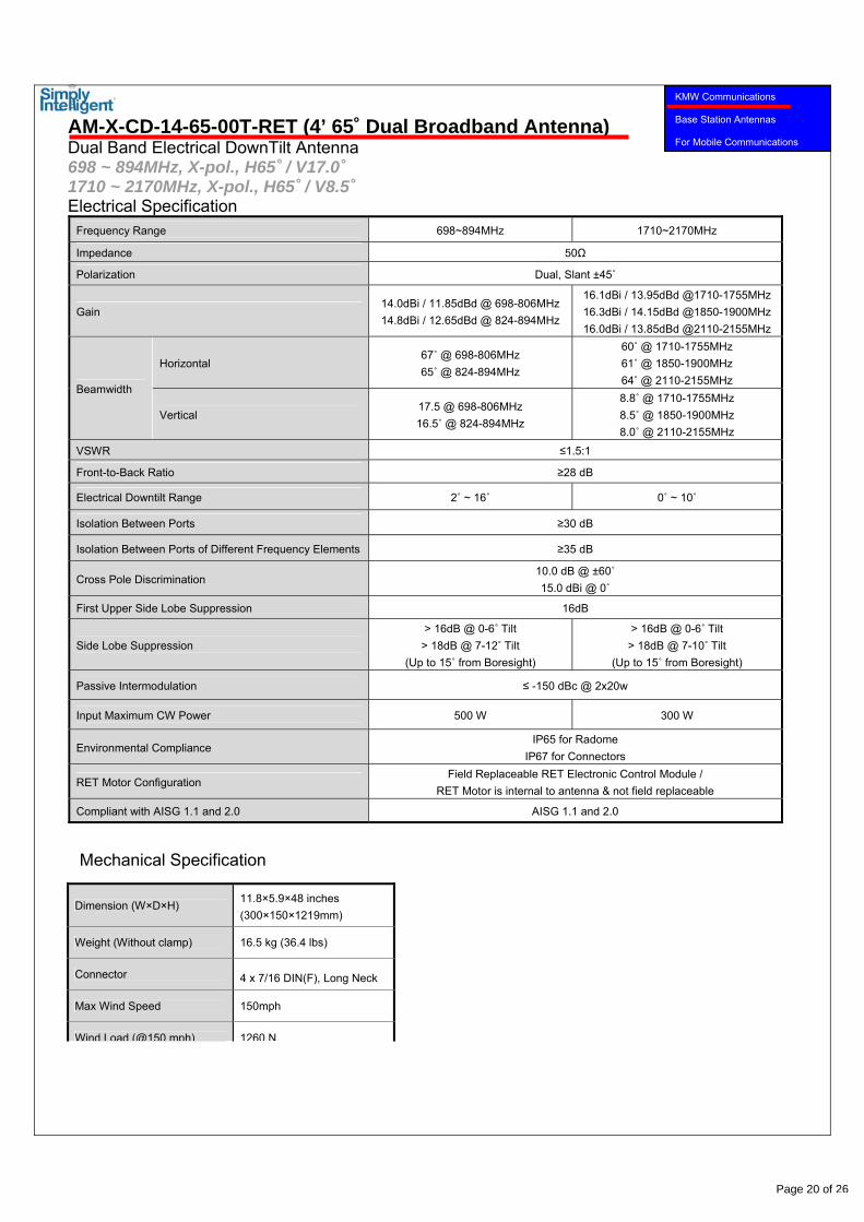
AM-X-CD-14-65-00T-RET (4’ 65˚ Dual Broadband Antenna) Dual Band Electrical DownTilt Antenna 698 ~ 894MHz, X-pol., H65˚ / V17.0˚ 1710 ~ 2170MHz, X-pol., H65˚ / V8.5˚ Electrical Specification
Frequency Range 698~894MHz 1710~2170MHz
Impedance 50Ω
Polarization Dual, Slant ±45˚
Gain 14.0dBi / 11.85dBd @ 698-806MHz 14.8dBi / 12.65dBd @ 824-894MHz
16.1dBi / 13.95dBd @1710-1755MHz 16.3dBi / 14.15dBd @1850-1900MHz 16.0dBi / 13.85dBd @2110-2155MHz
Beamwidth
Horizontal 67˚ @ 698-806MHz 65˚ @ 824-894MHz
60˚ @ 1710-1755MHz 61˚ @ 1850-1900MHz 64˚ @ 2110-2155MHz
Vertical 17.5 @ 698-806MHz 16.5˚ @ 824-894MHz
8.8˚ @ 1710-1755MHz 8.5˚ @ 1850-1900MHz 8.0˚ @ 2110-2155MHz
VSWR ≤1.5:1
Front-to-Back Ratio ≥28 dB
Electrical Downtilt Range 2˚ ~ 16˚ 0˚ ~ 10˚
Isolation Between Ports ≥30 dB
Isolation Between Ports of Different Frequency Elements ≥35 dB
Cross Pole Discrimination 10.0 dB @ ±60˚ 15.0 dBi @ 0˚
First Upper Side Lobe Suppression 16dB
Side Lobe Suppression > 16dB @ 0-6˚ Tilt
> 18dB @ 7-12˚ Tilt (Up to 15˚ from Boresight)
> 16dB @ 0-6˚ Tilt > 18dB @ 7-10˚ Tilt
(Up to 15˚ from Boresight)
Passive Intermodulation ≤ -150 dBc @ 2x20w
Input Maximum CW Power 500 W 300 W
Environmental Compliance IP65 for Radome
IP67 for Connectors
RET Motor Configuration Field Replaceable RET Electronic Control Module /
RET Motor is internal to antenna & not field replaceable
Compliant with AISG 1.1 and 2.0 AISG 1.1 and 2.0
Dimension (W×D×H) 11.8×5.9×48 inches (300×150×1219mm)
Weight (Without clamp) 16.5 kg (36.4 lbs)
Connector 4 x 7/16 DIN(F), Long Neck
Max Wind Speed 150mph
Wind Load (@150 mph) 1260 N
Mechanical Specification
Page 20 of 26
KMW Communications Base Station Antennas For Mobile Communications
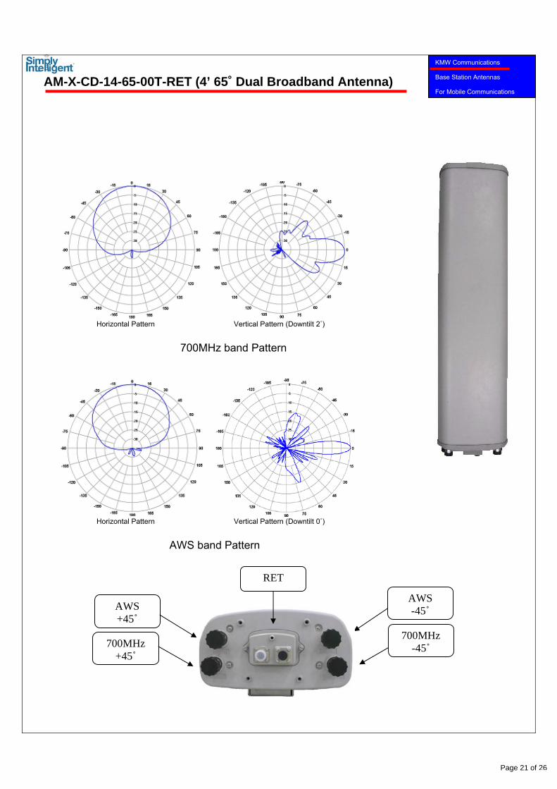
AM-X-CD-14-65-00T-RET (4’ 65˚ Dual Broadband Antenna)
Horizontal Pattern Vertical Pattern (Downtilt 2˚)
700MHz band Pattern
Horizontal Pattern Vertical Pattern (Downtilt 0˚)
AWS band Pattern
700MHz +45˚
700MHz -45˚
RET
AWS +45˚
AWS -45˚
Page 21 of 26
KMW Communications Base Station Antennas For Mobile Communications
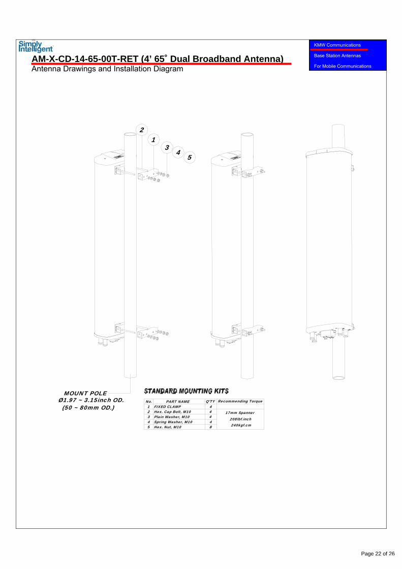
AM-X-CD-14-65-00T-RET (4’ 65˚ Dual Broadband Antenna) Antenna Drawings and Installation Diagram
MOUNT POLE
(50 ~ 80mm OD.)Ø1.97 ~ 3.15inch OD. PART NAME
23
1No.
54 Spring Washer, M10
FIXED CLAMP
Hex. Nut, M10
Plain Washer, M10Hex. Cap Bolt, M10
4Q'TY
4
84
4
240kgf.cm
17mm Spanner
Recommending Torque
208lbf.inch
543
21
Page 22 of 26
11. AM-X-CD-16-65
www.kmwcomm.com
KMW Communications Base Station Antennas For Mobile Communications
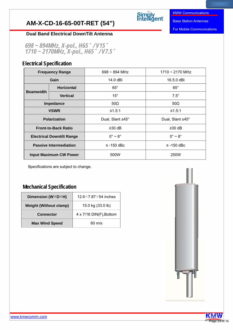
AM-X-CD-16-65-00T-RET (54”) Dual Band Electrical DownTilt Antenna
698 ~ 894MHz, X-pol., H65˚ / V15˚ 1710 ~ 2170MHz, X-pol., H65˚ / V7.5˚
Electrical Specification
Frequency Range 698 ~ 894 MHz 1710 ~ 2170 MHz
Gain 14.0 dBi 16.5.0 dBi
Beamwidth Horizontal 65° 65°
Vertical 15° 7.5°
Impedance 50Ω 50Ω
VSWR ≤1.5:1 ≤1.5:1
Polarization Dual, Slant ±45° Dual, Slant ±45°
Front-to-Back Ratio ≥30 dB ≥30 dB
Electrical Downtilt Range 0° ~ 8° 0° ~ 8°
Passive Intermediation ≤ -150 dBc ≤ -150 dBc
Input Maximum CW Power 500W 250W
Mechanical Specification
Dimension (W×D×H) 12.6×7.87×54 inches
Weight (Without clamp) 15.0 kg (33.0 lb)
Connector 4 x 7/16 DIN(F),Bottom
Max Wind Speed 60 m/s
Specifications are subject to change.
Page 23 of 26
www.kmwcomm.com
KMW Communications Base Station Antennas For Mobile Communications
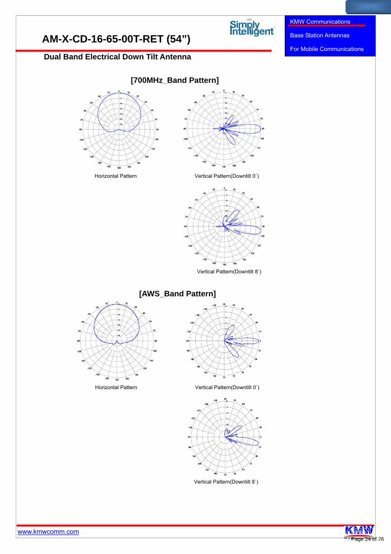
AM-X-CD-16-65-00T-RET (54”) Dual Band Electrical Down Tilt Antenna
[700MHz_Band Pattern]
Vertical Pattern(Downtilt 8˚)
Horizontal Pattern Vertical Pattern(Downtilt 0˚)
Vertical Pattern(Downtilt 8˚)
[AWS_Band Pattern]
Horizontal Pattern Vertical Pattern(Downtilt 0˚)
Page 24 of 26
12. AM-X-CD-17-65-00T-RET
www.kmwcomm.com
KMW Communications Base Station Antennas For Mobile Communications
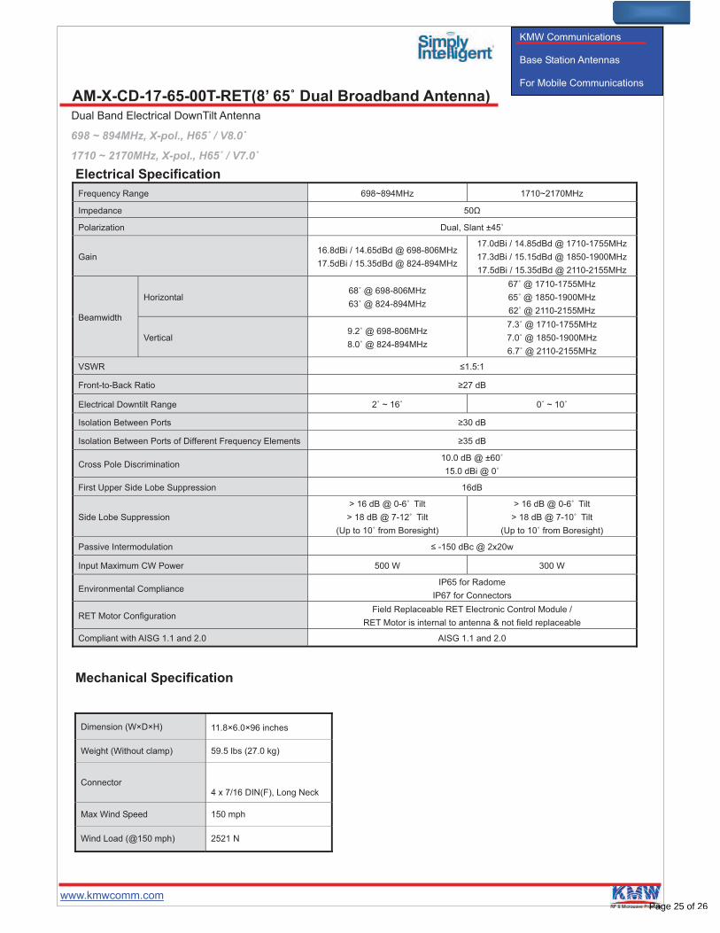
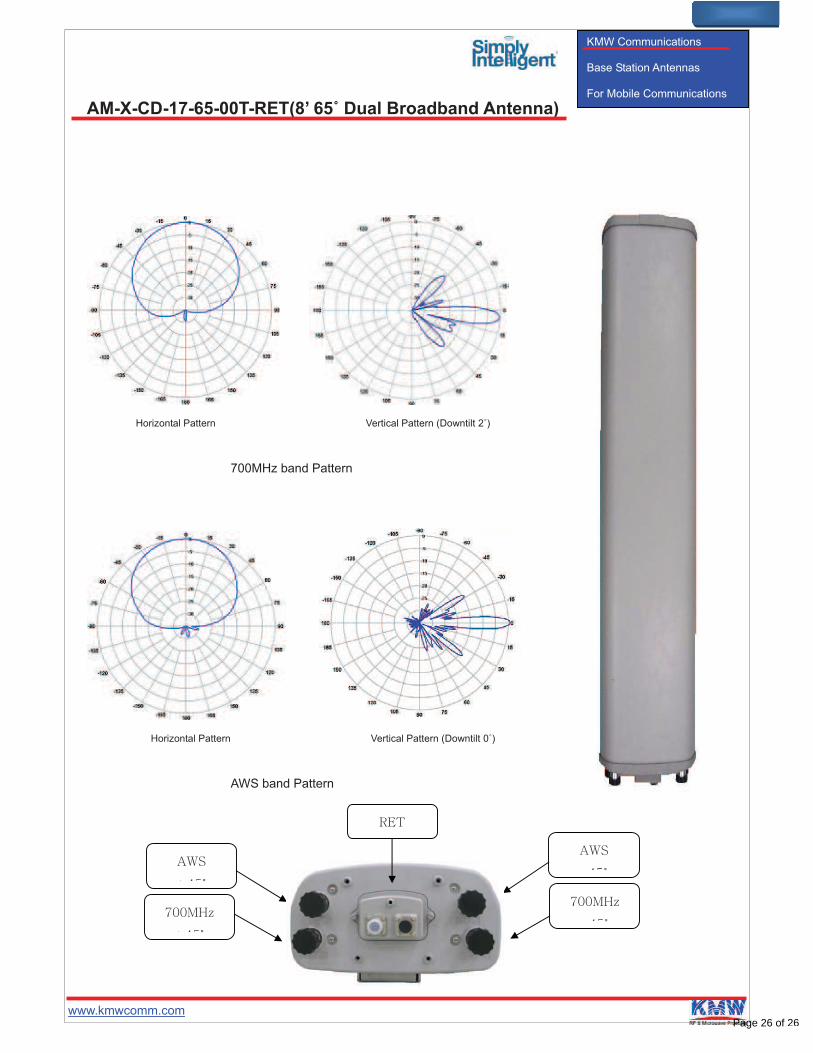
AM-X-CD-17-65-00T-RET(8’ 65˚ Dual Broadband Antenna) Dual Band Electrical DownTilt Antenna
698 ~ 894MHz, X-pol., H65˚ / V8.0˚
1710 ~ 2170MHz, X-pol., H65˚ / V7.0˚
Electrical Specification
Frequency Range 698~894MHz 1710~2170MHz
Impedance 50
Polarization Dual, Slant ±45û
Gain 16.8dBi / 14.65dBd @ 698-806MHz
17.5dBi / 15.35dBd @ 824-894MHz
17.0dBi / 14.85dBd @ 1710-1755MHz
17.3dBi / 15.15dBd @ 1850-1900MHz
17.5dBi / 15.35dBd @ 2110-2155MHz
Beamwidth
Horizontal 68û @ 698-806MHz
63û @ 824-894MHz
67û @ 1710-1755MHz
65û @ 1850-1900MHz
62û @ 2110-2155MHz
Vertical 9.2û @ 698-806MHz
8.0û @ 824-894MHz
7.3û @ 1710-1755MHz
7.0û @ 1850-1900MHz
6.7û @ 2110-2155MHz
VSWR !1.5:1
Front-to-Back Ratio "27 dB
Electrical Downtilt Range 2û ~ 16û 0û ~ 10û
Isolation Between Ports "30 dB
Isolation Between Ports of Different Frequency Elements "35 dB
Cross Pole Discrimination 10.0 dB @ ±60û
15.0 dBi @ 0û
First Upper Side Lobe Suppression 16dB
Side Lobe Suppression
> 16 dB @ 0-6 Tilt
> 18 dB @ 7-12 Tilt
(Up to 10û from Boresight)
> 16 dB @ 0-6 Tilt
> 18 dB @ 7-10 Tilt
(Up to 10û from Boresight)
Passive Intermodulation ! -150 dBc @ 2x20w
Input Maximum CW Power 500 W 300 W
Environmental Compliance IP65 for Radome
IP67 for Connectors
RET Motor Configuration Field Replaceable RET Electronic Control Module /
RET Motor is internal to antenna & not field replaceable
Compliant with AISG 1.1 and 2.0 AISG 1.1 and 2.0
Mechanical Specification
Dimension (W×D×H) 11.8×6.0×96 inches
Weight (Without clamp) 59.5 lbs (27.0 kg)
Connector
4 x 7/16 DIN(F), Long Neck
Max Wind Speed 150 mph
Wind Load (@150 mph) 2521 N
Page 25 of 26
www.kmwcomm.com
KMW Communications Base Station Antennas For Mobile Communications
AM-X-CD-17-65-00T-RET(8’ 65˚ Dual Broadband Antenna)
Horizontal Pattern Vertical Pattern (Downtilt 2 )
700MHz band Pattern
Horizontal Pattern Vertical Pattern (Downtilt 0 )
AWS band Pattern
ûû
ûû
Page 26 of 26