pneumatic actuation - camozzi automation
TRANSCRIPT

PNEUMATIC ACTUATION
CATALOGUE

ContactsCamozzi Automation S.p.A.Società UnipersonaleVia Eritrea, 20/I25126 BresciaItalyTel. +39 030 37921www.camozzi.com
Customer ServiceTel. +39 030 [email protected]
Export DepartmentTel. +39 030 [email protected]
WELCOME TO CAMOZZI AUTOMATION
Camozzi Automation offers range of products including components, systems and technologies for the industrial automation sector, the control of fluids – both liquids and gases – and for applications dedicated to the transportation and health industries.

Fieldbus and multipole systems1 Valve islands2 Multi-serial modules
Proportional technology1 Proportional valves2 Proportional regulators
Air treatment1 Series MX Modular FRL Units2 Series MC Modular FRL Units3 Series MD Modular FRL Units4 Series N FRL Units5 Pressure regulators6 Pressure switches and vacuum switches7 Accessories for air treatment
Pneumatic connection1 Super-rapid fittings2 Rapid fittings3 Universal fittings4 Fittings accessories5 Quick-release couplings6 Tubing, spirals and accessories
Pneumatic actuation1 Cylinders according standards2 Compact cylinders3 Stainless steel cylinders4 Guided cylinders5 Cylinders not according standards6 Rotary cylinders7 Rodless cylinders8 Proximity switches9 Clamping elements and shock absorbers
Electric actuation1 Electromechanical cylinders2 Electromechanical axes3 Drives4 Motors
Handling and vacuum1 Grippers2 Suction pads3 Ejectors4 Vacuum accessories5 Vacuum filters
Valves and solenoid valves1 Directly and indirectly operated 2/2, 3/2 solenoid valves2 Solenoid valves, pneumatic valves3 Mechanical and manual valves4 Logic valves5 Automatic valves6 Flow control valves7 Silencers
Our catalogues

PNEUMATIC ACTUATION 2019
General index
GENE
RAL I
NDEX
INTRODUCTION > GENERAL INDEX
2 Compact cylinders
Section Page
Series QN Short-stroke cylinders
2.05 136
Series QP, QPR Short-stroke cylinders
2.10 139
Series RPA Short stroke cylinderswith non-rotating rod
2.13 149
Series 31 Compact cylinders
2.15 153
Series 31 Compact cylinders, Tandem and Multi-position versions
2.20 168
Series ST Stopper cylinders
2.25 172
3 Stainless steel cylinders
Section Page
Series 90 Stainless steel cylinders ISO 15552DIN/ISO 6431 / VDMA 24562
3.05 179
Series 94, 95 Stainless steel mini-cylinders CETOP RP52-P / DIN/ISO 6432
3.15 189
Series 97 Stainless steel cylinders
3.20 195
4 Guided cylinders
Section Page
Series QCT, QCBCylinders with integrated guide
4.05 205
Series QCTF, QCBFCylinders with integrated guide
4.10 210
Series QX Twin cylinders
4.15 216
1 Cylinders according standards
Section Page
Series 16, 24, 25 Mini-cylinders CETOP RP52-P / DIN/ISO 6432
1.05 1
Series 40 Cylinders ISO 15552 DIN/ISO 6431 / VDMA 24562
1.10 10
Series 41 Cylinders - Aluminium profile DIN/ISO 6431 / VDMA 24562
1.15 19
Series 60 Cylinders ISO 15552 DIN/ISO 6431 / VDMA 24562
1.20 28
Series 61 Cylinders - Aluminium profile CETOP RP52-P / DIN/ISO 6432
1.25 44
Series 62 Cylinders - Aluminium profile ISO 15552 DIN/ISO 6431 / VDMA 24562
1.26 58
Series 6PF Positioning Feedback cylinders ISO 15552 DIN/ISO 6431 / VDMA 24562
1.27 70
Series 63 Cylinders - Aluminium tube and profile ISO 15552DIN/ISO 6431 / VDMA 24562
1.28 86
Series 32 Compact magnetic cylinders ISO 21287
1.30 109
Series 32 Compact cylinders, Tandem and Multi-position versions ISO 21287
1.31 126
Series 45 Anti-rotation guide units
1.35 130
New

PNEUMATIC ACTUATION 2019
GENE
RAL I
NDEX
INTRODUZIONE > INDICE GENERALE
8 Proximity switches
Section Page
Series CST - CSV - CSH CSB - CSC - CSD - CSG Magnetic proximity switches
8.05 280
Series CSN Proximity switches
8.10 300
Tables for the use of sensors
8.20 303
9 Clamping elements and shock absorbers
Section Page
Series 43 Hydrochecks
9.05 307
Series RL Rod lock
9.10 314
Series SA Shock absorbers
9.15 318
AppendixPage
Pneumatic symbolsSpring loads cylindersFlow and speed cylindersOutput forces double-acting cylindersTable showing air consumption of double-acting cylindersDimensioning guide for Shock Absorbers Series SA Quality: our priority commitmentInformation for the use of Camozzi productsDirective ATEX 2014/34/EU: products classified for the use in potentially esplosive atmospheres Camozzi around the worldCamozzi distributors around the world
a.01a.03a.05a.06a.08a.10a.13a. 14a.15
a.17a.18
5 Cylinders not according standards
Section Page
Series 14 Compact mini-cylinders
5.05 225
Series 27 Roundline cylinders
5.10 229
Series 42 Cylinders
5.15 237
6 Rotary cylinders
Section Page
Series 69 Rotary cylinders
6.10 245
Series 30 Rotary cylinders
6.15 250
Series ARP Rotary actuators
6.20 253
7 Rodless cylinders
Section Page
Series 50 Rodless cylinders
7.05 262
Series 52 Rodless cylinders
7.10 268
New

PNEUMATIC ACTUATION 2019AL
PHAN
UMER
IC IN
DEX
Model Series Section Page Model Series Section Page
14N1... 14 (Mini-cylinders) 5.05.02 22616N... 16 (Minicylinders ISO) 1.05.02 224N… 24 (ISO minicylinders) 1.05.02 225N... 25 (ISO minicylinders) 1.05.02 227M2A... 27 (Magnetic cylinders) 5.10.02 23027T2A... 27 (Magnetic cylinders) 5.10.02 23027U2A... 27 (Magnetic cylinders) 5.10.02 23030-... 30 (Rotary cylinders) 6.15.02 25131F... 31 (Magnetic compact cylinders) 2.15.02 15431M... 31 (Magnetic compact cylinders) 2.15.02 15431…N 31 (ISO compact cyl. - Multi-position) 2.20.02 16931…N2 31 (ISO compact cyl. - Tandem) 2.20.02 16931R... 31 (Magnetic compact cylinders) 2.15.02 15432…N 32 (ISO compact cyl. - Multi-position) 1.31.02 12732…N… 32 (ISO compact cyl. - Tandem) 1.31.02 12732F... 32 (ISO compact cylinders) 1.30.02 11032M… 32 (ISO compact cylinders) 1.30.02 11032R... 32 (ISO compact cylinders) 1.30.02 11040M... 40 (ISO cylinders) 1.10.02 1141M... 41 (ISO cyl. - Aluminium profile) 1.15.02 2042M... 42 (Magnetic cylinders) 5.15.02 23843... 43 (Hydrochecks) 9.05.02 30843N-40-... 43 (Accessories) 9.05.07 31343N-PMP 43 (Accessories) 9.05.07 31345N... 45 (Anti-rotation guide units) 1.35.02 13150M2… 50 (Rodless cylinders) 7.05.02 26352G… 52 (Rodless cylinders) 7.10.02 26952M… 52 (Rodless cylinders) 7.10.02 26952R… 52 (Rodless cylinders) 7.10.02 26960L… 60 (ISO cylinders) 1.20.02 2960M... 60 (ISO cylinders) 1.20.02 2960N... 60 (ISO cylinders) 1.20.02 2961L… 61 (ISO cyl. - Aluminium profile) 1.25.02 4561M... 61 (ISO cyl. - Aluminium profile) 1.25.02 4562M... 62 (ISO cylinders) 1.26.02 5963L… 63 (ISO 15552 cylinder) 1.28.02 8763M… 63 (ISO 15552 cylinder) 1.28.02 8763V… 63 (ISO 15552 cylinder) 1.28.02 8769-... 69 (Rotary cylinders) 6.10.02 2466PF3P… 6PF (Positioning Feedback cylinders) 1.27.03 7280-62/8C 60 (Accessories) 1.20.16 4380-62/8C 61 (Accessories) 1.25.14 5780-62/8C 62 (Accessories) 1.26.12 6980-62/8C 63 (Accessories) 1.28.23 10880-62/8C 6PF (Accessories) 1.27.14 8390M... 90 (Stainless steel cylinders) 3.05.02 18094N... 94 (Stainless steel mini-cylinders) 3.15.02 19095N... 95 (Stainless steel mini-cylinders) 3.15.02 19097A… 97 (Stainless steel cylinders) 3.20.02 19697F… 97 (Stainless steel cylinders) 3.20.02 19697M… 97 (Stainless steel cylinders) 3.20.02 19697S… 97 (Stainless steel cylinders) 3.20.02 19697T… 97 (Stainless steel cylinders) 3.20.02 196ARP-… ARP (Rotary cylinders) 6.20.02 254B-... 16, 24, 25 (Accessories) 1.05.06 6B-... 31 (Accessories) 2.15.10 162B-... 32 (Accessories) 1.30.10 118B-27-... 27 (Accessories) 5.10.05 233B-41-... 40 (Accessories) 1.10.06 15B-41-... 41 (Accessories) 1.15.06 24B-41-... 60 (Accessories) 1.20.08 35B-41-... 61 (Accessories) 1.25.07 50B-41-... 62 (Accessories) 1.26.06 63B-41-... 63 (Accessories) 1.28.14 99B-41-... 6PF (Accessories) 1.27.07 76B-50-... 50 (Accessories) 7.05.05 266B-52-... 52 (Accessories) 7.10.11 278B-90-... 90 (Accessories) 3.05.05 183B-94-… 94, 95 (Accessories) 3.15.05 193B-97-… 97 (Accessories) 3.20.07 201B-QP-... QP (Accessories) 2.10.10 148BA-52-... 52 (Accessories) 7.10.11 278BF-... 40 (Accessories) 1.10.08 17BF-... 41 (Accessories) 1.15.08 26BF-... 60 (Accessories) 1.20.12 39BF-... 61 (Accessories) 1.25.11 54BF-... 63 (Accessories) 1.28.20 105BF-... 6PF (Accessories) 1.27.11 80
BH-50-... 50 (Accessories) 7.05.06 267BH-52-... 52 (Accessories) 7.10.12 279BL-52-32 52 (Accessories) 7.10.12 279C+L+S 32 (Accessories) 1.30.13 121C+L+S 40 (Accessories) 1.10.08 17C+L+S 41 (Accessories) 1.15.08 26C+L+S 60 (Accessories) 1.20.11 38C+L+S 61 (Accessories) 1.25.10 53C+L+S 62 (Accessories) 1.26.09 66C+L+S 63 (Accessories) 1.28.19 104C+L+S 6PF (Accessories) 1.27.10 79C-31-... 31 (Accessories) 2.15.11 163C-41-... 32 (Accessories) 1.30.10 118C-41-... 60 (Accessories) 1.20.09 36C-41-... 61 (Accessories) 1.25.08 51C-41-... 62 (Accessories) 1.26.07 64C-41-... 63 (Accessories) 1.28.15 100C-41-50 6PF (Accessories) 1.27.08 77C-H-41-... 32 (Accessories) 1.30.10-11 118, 119C-H-41-... 40 (Accessories) 1.10.06 15C-H-41-... 41 (Accessories) 1.15.06 24C-H-41-... 60 (Accessories) 1.20.09 36C-H-41-... 61 (Accessories) 1.25.08 51C-H-41... 62 (Accessories) 1.26.07 64C-H-41-... 63 (Accessories) 1.28.15-16 100, 101C-H-41-... 6PF (Accessories) 1.27.08 77C-H-90-... 90 (Accessories) 3.05.06 184C-H-90-... 97 (Accessories) 3.20.07 201CF-50-... 50 (Accessories) 7.05.06 267CF-52-... 52 (Accessories) 7.10.12 279CR-90-... 90 (Accessories) 3.05.07 185CR-90-... 97 (Accessories) 3.20.08 202CS-… Connectors for proximity switches 8.05.18 297CS-DW… Connectors for proximity switches 8.05.19 298CS-L… 6PF (Connectors) 1.27.15-16 84, 85CSB-... CSB (Proximity switches) 8.05.03 282CSC-... CSC (Proximity switches) 8.05.03 282CSD-... CSD (Proximity switches) 8.05.03 282CSG-… CSG (Proximity switches) 8.05.04 283CSH-… CSH (Proximity switches) 8.05.02 281CSN-2032-0 CSN (Proximity switches) 8.10.03 302CST-... CST (Proximity switches) 8.05.02 281CSV-... CSV (Proximity switches) 8.05.02 281DC-31-... 31 (Accessories) 2.15.11 163DC-63… 63 (Accessories) 1.28.14 99D-E-... 31 (Accessories) 2.15.10 162D-E-... 32 (Accessories) 1.30.11 119D-E-41-... 40 (Accessories) 1.10.06 15D-E-41-... 41 (Accessories) 1.15.06 24D-E-41-... 60 (Accessories) 1.20.08 35D-E-41-... 61 (Accessories) 1.25.07 50D-E-41-... 62 (Accessories) 1.26.06 63D-E-41-... 63 (Accessories) 1.28.15 100D-E-41-... 6PF (Accessories) 1.27.07 76D-E-90-... 90 (Accessories) 3.05.05 183E-… 16, 24, 25 (Accessories) 1.05.06 6E-94-... 94, 95 (Accessories) 3.15.05 193F-… 40 (Accessories) 1.10.07 16F-... 60 (Accessories) 1.20.10 37F-... 63 (Accessories) 1.28.18 103F-41-... 41 (Accessories) 1.15.07 25F-61... 61 (Accessories) 1.25.09 52F-61-... 6PF (Accessories) 1.27.09 78FN-... 63 (Accessories) 1.28.17 102G-… 16, 24, 25 (Accessories) 1.05.07 7G-... 27 (Accessories) 5.10.06 234G-... 31 (Accessories) 2.15.14 166G-... 32 (Accessories) 1.30.15 123G-... 40 (Accessories) 1.10.08 17G-... 42 (Accessories) 5.15.06 242G-... 60 (Accessories) 1.20.14 41G-... 61 (Accessories) 1.25.13 56G-... 62 (Accessories) 1.26.11 68G-... 63 (Accessories) 1.28.22 107G-... 6PF (Accessories) 1.27.13 82G-… 94, 95 (Accessories) 3.15.06 194G-90... 90 (Accessories) 3.05.09 187G-90… 97 (Accessories) 3.20.09 203
INTRODUCTION > ALPHANUMERIC INDEX
Alphanumeric index

PNEUMATIC ACTUATION 2019
ALPH
ANUM
ERIC
INDE
X
Model Series Section Page Model Series Section Page
G-160-200 41 (Accessories) 1.15.08 26GA-… 16, 24, 25 (Accessories) 1.05.07 7GA-... 27 (Accessories) 5.10.07 235GA-... 31 (Accessories) 2.15.13 165GA-... 32 (Accessories) 1.30.16 124GA-... 40 (Accessories) 1.10.09 18GA-... 42 (Accessories) 5.15.07 243GA-... 60 (Accessories) 1.20.14 41GA-... 61 (Accessories) 1.25.13 56GA-... 62 (Accessories) 1.26.11 68GA-... 63 (Accessories) 1.28.21 106GA-... 6PF (Accessories) 1.27.13 82GA-... 94, 95 (Accessories) 3.15.06 194GA-160-200 41 (Accessories) 1.15.09 27GA-90... 90 (Accessories) 3.05.10 188GA-90… 97 (Accessories) 3.20.09 203GK-… 16, 24, 25 (Accessories) 1.05.09 9GK-… 27 (Accessories) 5.10.08 236GK-… 31 (Accessories) 2.15.15 167GK-… 32 (Accessories) 1.30.17 125GK-… 42 (Accessories) 5.15.08 244GK-… 60 (Accessories) 1.20.15 42GK-… 61 (Accessories) 1.25.14 57GK-… 62 (Accessories) 1.26.12 69GK-... 63 (Accessories) 1.28.22 107GK-... 6PF (Accessories) 1.27.14 83GK-160-200 40 (Accessories) 1.10.09 18GK-160-200 41 (Accessories) 1.15.09 27GKF-… 16, 24, 25 (Accessories) 1.05.09 9GKF-… 27 (Accessories) 5.10.08 236GKF-… 31 (Accessories) 2.15.15 167GKF-… 32 (Accessories) 1.30.17 125GKF-… 42 (Accessories) 5.15.08 244GKF-… 60 (Accessories) 1.20.15 42GKF-… 61 (Accessories) 1.25.14 57GKF-… 62 (Accessories) 1.26.12 69GKF-… 63 (Accessories) 1.28.23 108GKF-... 6PF (Accessories) 1.27.14 83GY-… 16, 24, 25 (Accessories) 1.05.08 8GY-... 27 (Accessories) 5.10.07 235GY-... 31 (Accessories) 2.15.14 166GY-... 32 (Accessories) 1.30.15 123GY-... 42 (Accessories) 5.15.07 243GY-... 60 (Accessories) 1.20.14 41GY-... 61 (Accessories) 1.25.13 56GY-... 62 (Accessories) 1.26.11 68GY-... 63 (Accessories) 1.28.21 106GY-... 6PF (Accessories) 1.27.13 82H-... 32 (Accessories) 1.30.11 119H-... 60 (Accessories) 1.20.09 36H-... 61 (Accessories) 1.25.08 51H-... 62 (Accessories) 1.26.07 64H-... 63 (Accessories) 1.28.16 101H-... 6PF (Accessories) 1.27.08 77I-… 16, 24, 25 (Accessories) 1.05.07 7I-... 31 (Accessories) 2.15.12 164I-20-25 32 (Accessories) 1.30.14 122I-27-... 27 (Accessories) 5.10.06 234I-42-... 42 (Accessories) 5.15.05 241I-94-… 94, 95 (Accessories) 3.15.05 193I-97-… 97 (Accessories) 3.20.07 201L-... 32 (Accessories) 1.30.12 120L-31-... 31 (Accessories) 2.15.13 165L-41-... 40 (Accessories) 1.10.07 16L-41-... 41 (Accessories) 1.15.07 25L-41-... 60 (Accessories) 1.20.10 37L-41-... 61 (Accessories) 1.25.09 52L-41-... 62 (Accessories) 1.26.08 65L-41-... 63 (Accessories) 1.28.16 101L-41-... 6PF (Accessories) 1.27.09 78L-90... 90 (Accessories) 3.05.06 184L-QP-... QP (Accessories) 2.10.10 148P-42-... 42 (Accessories) 5.15.05 241PCV-... 60 (Accessories) 1.20.13 40PCV-6... 61 (Accessories) 1.25.12 55PCV-6... 6PF (Accessories) 1.27.12 81PCV-62... 62 (Accessories) 1.26.10 67PCV-62... 63 (Accessories) 1.28.20 105
QCB2A... QCB (Cylinders with integrated guide) 4.05.02 206QCT2A... QCT (Cylinders with integrated guide) 4.05.02 206QCBF2A… QCBF (Slide units) 4.10.02 211QCTF2A… QCTF (Slide units) 4.10.02 211QN1A... QN (Short-stroke cylinders) 2.05.02 137QP... QP (Short-stroke cylinders) 2.10.02 140QPR... QPR (Non-rotating short-stroke cylinders) 2.10.02 140QX… QX (Twin cylinders) 4.15.02 217R-41-... 32 (Accessories) 1.30.12 120R-41-... 60 (Accessories) 1.20.12 39R-41-... 61 (Accessories) 1.25.11 54R-41-... 62 (Accessories) 1.26.08 65R-41-... 63 (Accessories) 1.28.17 102R-41-... 6PF (Accessories) 1.27.11 80R-90… 90 (Accessories) 3.05.07 185R-90… 97 (Accessories) 3.20.08 202RL... RL (Rod lock) 9.10.02 315RPA… RPA (short stroke cyl., non-rotating rod) 2.13.02 150S-... 32 (Accessories) 1.30.14 122S-... 40 (Accessories) 1.10.09 18S-... 60 (Accessories) 1.20.13 40S-... 61 (Accessories) 1.25.12 55S-... 62 (Accessories) 1.26.10 67S-... 63 (Accessories) 1.28.21 106S-... 6PF (Accessories) 1.27.12 81S-160-200 41 (Accessories) 1.15.09 27S21 CSN (Accessories) 8.10.03 302S53 CSN (Accessories) 8.10.03 302S-90... 90 (Accessories) 3.05.09 187S-90... 97 (Accessories) 3.20.10 204S-CST-01…21 CST, CSH, CSG (Accessories) 8.05.19 298S-CST-25…28 CST, CSH, CSG (Accessories) 8.05.20 299S-CST-45N… CST, CSH, CSG (Accessories) 8.05.20 299S-CST-500 CST, CSH (Accessories) 8.05.20 299SA-… SA (Shock absorber) 9.15.02 319SA-…SC SA (Accessories) 9.15.03 320SB… ARP (Accessories) 6.20.09 261SI… ARP (Accessories) 6.20.09 261ST… ST (Stopper cylinders) 2.25.02 173SR-90… 90 (Accessories) 3.05.10 188SR-90… 97 (Accessories) 3.20.10 204T-27-... 27 (Accessories) 5.10.05 233T-42-... 42 (Accessories) 5.15.06 242TR-32-… 32 (Accessories) 1.30.16 124TS-32-20 32 (Accessories) 1.30.16 124U-… 16, 24, 25 (Accessories) 1.05.08 8U-... 27 (Accessories) 5.10.07 235U-... 31 (Accessories) 2.15.13 165U-... 32 (Accessories) 1.30.16 124U-... 40 (Accessories) 1.10.09 18U-... 42 (Accessories) 5.15.07 243U-... 60 (Accessories) 1.20.15 42U-... 61 (Accessories) 1.25.13 56U-... 62 (Accessories) 1.26.11 68U-... 63 (Accessories) 1.28.22 107U-... 6PF (Accessories) 1.27.13 82U-... 94, 95 (Accessories) 3.15.06 194U-90... 90 (Accessories) 3.05.10 188U-90... 97 (Accessories) 3.20.09 203U-160-200 41 (Accessories) 1.15.09 27V-… 16, 24, 25 (Accessories) 1.05.08 8V-... 27 (Accessories) 5.10.07 235V-42-... 42 (Accessories) 5.15.06 242V-94-20-25 94, 95 (Accessories) 3.15.06 194V-97... 97 (Accessories) 3.20.10 204ZC-... 31 (Accessories) 2.15.12 164ZC-... 32 (Accessories) 1.30.13 121ZC-... 60 (Accessories) 1.20.11 38ZC-... 61 (Accessories) 1.25.10 53ZC-... 62 (Accessories) 1.26.09 66ZC-... 63 (Accessories) 1.28.19 104ZC-... 6PF (Accessories) 1.27.10 79ZC-90... 90 (Accessories) 3.05.08 186ZCR-90… 90 (Accessories) 3.05.08 186ZCR-90… 97 (Accessories) 3.20.08 202ZS-… 40 (Accessories) 1.10.07 16ZS-… 41 (Accessories) 1.15.07 25
INTRODUCTION > ALPHANUMERIC INDEX

Products designed for industrial applications. General terms and conditions for sale are available on www.camozzi.com.
SERIES 16, 24 AND 25 MINI-CYLINDERSINTERNATIONAL STANDARD CYLINDERS > PNEUMATIC ACTUATION 2019
11.05.01
SERI
ES 1
6, 2
4 AN
D 25
MIN
I-CYL
INDE
RS
Series 16, 24 and 25 mini-cylinders
Series 16: ø 8, 10, 12 mm Series 24: ø 16, 20, 25 mm - magnetic Series 25: ø 16, 20, 25 mm - magnetic, cushioned
Series 16, 24 and 25 mini-cylinders are designed according to the European Standard Specifications CETOP RP52-P and DIN/ISO 6432. The choice of materials and other design features have provided the basis for a complete range of versatile and very reliable cylinders.
The precise method of crimping the barrel at the head and cap ensures that all the parts are perfectly aligned. Since the Series 16 and 24 may operate at very high speeds, bumpers are attached to the piston as standard in order to reduce noice and wear resulting from high impact loads. Series 24 and 25 are suitable for mounting magnetic proximity switches. Series 25 has an adjustable pneumatic cushion and a magnetic piston. Various mounting accessories are available to enable the cylinders to function in a variety of applications.
» Single-acting and double-acting
» CETOP RP52-P DIN/ISO 6432
» Stainless steel rod and barrel
» Anodized aluminium end-blocks
GENERAL DATAType of construction crimpedOperation single-acting and double-actingMaterials anodized aluminium end-caps - stainless steel barrel and rod, aluminium piston - NBR/PU seals, other parts: see the coding exampleBrackets rod end - flange - feet - trunnionStroke min - max Series 16 ø 8 ÷ ø 10: 10 - 250 mm / Series 16: ø 12: 10 - 300 mm / Series 24 & 25 ø 16: 10 - 600 mm; ø 20 - ø 25: 10 - 1000 mmBores Series 16: ø 8, 10, 12 / Series 24 & 25: ø 16, 20, 25Operating temperature 0°C ÷ 80°C (with dry air -20°C)Operating pressure 1 ÷ 10 bar (double-acting); 2 ÷ 10 bar (single-acting)Fluid filtered air, without lubrication. If lubricated air is used, it is recommended to use oil ISO VG32.
Once applied the lubrication should never be interrupted.Speed 10 ÷ 1000 mm/sec (without load)

Products designed for industrial applications. General terms and conditions for sale are available on www.camozzi.com.
SERIES 16, 24 AND 25 MINI-CYLINDERSPNEUMATIC ACTUATION
21.05.02
2019 INTERNATIONAL STANDARD CYLINDERS
SERI
ES 1
6, 2
4 AN
D 25
MIN
I-CYL
INDE
RS
>
STANDARD STROKES FOR MINICYLINDERS SERIES 16 - 24 and 25
■ = Double-acting ✖ = Single-acting
STANDARD STROKES
Series Ø 10 25 40 50 80 100 125 160 200 250 300 320 400 500
16 8 ■✖ ■✖ ■✖ ■✖ ■ ■ ■ ■ ■
16 10 ■✖ ■✖ ■✖ ■✖ ■ ■ ■ ■ ■
16 12 ■✖ ■✖ ■✖ ■✖ ■ ■ ■ ■ ■ ■ ■
24 16 ■✖ ■✖ ■✖ ■✖ ■ ■ ■ ■ ■ ■ ■ ■ ■ ■
24 20 ■✖ ■✖ ■✖ ■✖ ■ ■ ■ ■ ■ ■ ■ ■ ■ ■
24 25 ■✖ ■✖ ■✖ ■✖ ■ ■ ■ ■ ■ ■ ■ ■ ■ ■
25 16 ■ ■ ■ ■ ■ ■ ■ ■ ■ ■ ■ ■ ■ ■
25 20 ■ ■ ■ ■ ■ ■ ■ ■ ■ ■ ■ ■ ■ ■
25 25 ■ ■ ■ ■ ■ ■ ■ ■ ■ ■ ■ ■ ■ ■
CODING EXAMPLE
24 SERIES 16 = non magnetic 24 = magnetic 25 = magnetic, adjustable cushioning
N VERSION N = standard
2 OPERATION 1 = single-acting, front spring, no cushion 2 = double-acting 3 = double-acting, through-rod 7 = single-acting, through-rod
PNEUMATIC SYMBOLS CS02 (s. 16) - CS06 (s. 24) CD01 (s. 16) - CD08 (s. 24) - CD09 (s. 25) CD05 (s. 16) - CD12 (s. 24) - CD13 (s. 25) CS04 (s. 16) - CS10 (s. 24)
A MATERIALS A = rolled stainless steel AISI 303 rod, stainless steel AISI 304 tube, anodized AL end-blocks
16 BORE 08 = 8 mm - 10 = 10 mm - 12 = 12 mm - 16 = 16 mm - 20 = 20 mm - 25 = 25 mm
A CONSTRUCTION A = Nose nut Mod. V + Piston rod lock nut Mod. U RL = cylinder with rod lock ø20 - ø25
100 STROKE (see the table)
= standard V = rod seal in FKM W = all seals in FKM, +130°C (for series 25 only)
24 N 2 A 16 A 100
PNEUMATIC SYMBOLS
The pneumatic symbols which have been indicated in the CODING EXAMPLE are shown below.

Products designed for industrial applications. General terms and conditions for sale are available on www.camozzi.com.
SERIES 16, 24 AND 25 MINI-CYLINDERSINTERNATIONAL STANDARD CYLINDERS > PNEUMATIC ACTUATION 2019
31.05.03
SERI
ES 1
6, 2
4 AN
D 25
MIN
I-CYL
INDE
RS
ACCESSORIES FOR MINICYLINDERS SERIES 16 - 24 - 25
Foot mount Mod. B Front/rear flange mount Mod. E
Rear trunnion bracket Mod. I
Rod fork end Mod. G Swivel ball joint Mod. GA
Piston rod socket joint Mod. GY
Piston rod lock nut Mod. U
Nose nut Mod. V Self aligning rod Mod. GK
Coupling piece Mod. GKF
All accessories are supplied separately, except for piston rod lock nut Mod. U and nose nut Mod. V

Products designed for industrial applications. General terms and conditions for sale are available on www.camozzi.com.
SERIES 16, 24 AND 25 MINI-CYLINDERSPNEUMATIC ACTUATION
41.05.04
2019 INTERNATIONAL STANDARD CYLINDERS
SERI
ES 1
6, 2
4 AN
D 25
MIN
I-CYL
INDE
RS
>
Series 16, 24 and 25 mini-cylinders
DIMENSIONS
Series Ø EW KW BE KK CD D1 EE ØD2 L1+ XC+ L2+ AM L3 L4 L5 L WF L6 L7 KV SW D D3 front/rear cushion stroke
16 8 8 7 M12x1,25 M4x0,7 4 9,3 M5 4 86 64 46 12 10 4,5 12 6 16 9 28 19 - 15 15 - / -
16 10 8 7 M12x1,25 M4x0,7 4 11,3 M5 4 86 64 46 12 10 4,5 12 6 16 9 28 19 - 15 15 - / -
16 12 12 8 M16x1,5 M6x1 6 13,3 M5 6 105 75 50 16 15 4,5 17 9 22 9 38 24 5 20.5 20 - / -
24-25 16 12 8 M16x1,5 M6x1 6 17,3 M5 6 111 82 56 16 15 5,5 17 9 22 10 38 24 5 20.5 20 10 / 10
24-25 20 16 10 M22x1,5 M8x1,25 8 21,3 G1/8 8 132 95 68 20 18 8 20 12 24 16 44 32 7 27 27 13 / 15
24-25 25 16 10 M22x1,5 M10x1,25 8 26,5 G1/8 10 141,5 104 69,5 22 20 8 22 12 28 16 50 32 9 27 27 16 / 14
+ = add the stroke
Series 16, 24 and 25 mini-cylinders with through-rod
DIMENSIONS
Series Ø KW BE KK ØD1 EE ØD2 L1++ L2+ AM L3 L4 L5 WF+ L6 L7+ KV SW front/rear cushion stroke
16 8 7 M12x1,25 M4x0,7 9,3 M5 4 102 46 12 10 4,5 12 16 9 28 19 - - / -
16 10 7 M12x1,25 M4x0,7 11,3 M5 4 102 46 12 10 4,5 12 16 9 28 19 - - / -
16 12 8 M16x1,5 M6x1 13,3 M5 6 126 50 16 15 4,5 17 22 9 38 24 5 - / -
24-25 16 8 M16x1,5 M6x1 17,3 M5 6 132 56 16 15 5,5 17 22 10 38 24 5 10 / 10
24-25 20 10 M22x1,5 M8x1,25 21,3 G1\8 8 156 68 20 18 8 20 24 16 44 32 7 13 / 15
24-25 25 10 M22x1,5 M10x1,25 26,5 G1\8 10 169,5 69,5 22 20 8 22 28 16 50 32 9 16 / 14
+ = add the stroke once ++ = add the stroke twice

Products designed for industrial applications. General terms and conditions for sale are available on www.camozzi.com.
SERIES 16, 24 AND 25 MINI-CYLINDERSINTERNATIONAL STANDARD CYLINDERS > PNEUMATIC ACTUATION 2019
51.05.05
SERI
ES 1
6, 2
4 AN
D 25
MIN
I-CYL
INDE
RS
Series 24 and 25 mini-cylinders with rod lock (Mod. RLC)
DIMENSIONS
Series Ø G7D WF L5 L7 XC+ L1+ F (N)
24-25 20 8 74 70 94 145 182 300
24-25 25 10 76 70 98 152 189,5 400
+ = add the stroke
Products designed for industrial applications. General terms and conditions for sale are available on www.camozzi.com.
SERIES 16, 24 AND 25 MINI-CYLINDERSPNEUMATIC ACTUATION
61.05.06
2019 INTERNATIONAL STANDARD CYLINDERS
SERI
ES 1
6, 2
4 AN
D 25
MIN
I-CYL
INDE
RS
>
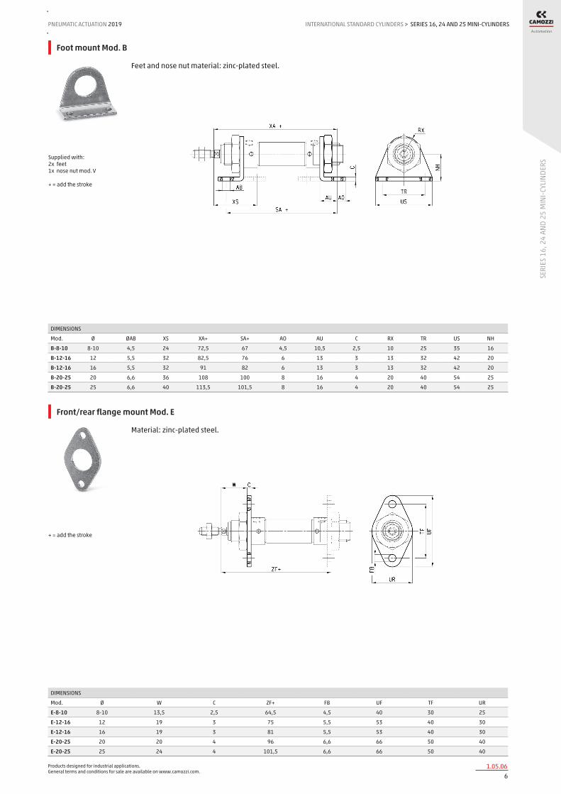
Foot mount Mod. B
Feet and nose nut material: zinc-plated steel.
DIMENSIONS
Mod. Ø ØAB XS XA+ SA+ AO AU C RX TR US NH
B-8-10 8-10 4,5 24 72,5 67 4,5 10,5 2,5 10 25 35 16
B-12-16 12 5,5 32 82,5 76 6 13 3 13 32 42 20
B-12-16 16 5,5 32 91 82 6 13 3 13 32 42 20
B-20-25 20 6,6 36 108 100 8 16 4 20 40 54 25
B-20-25 25 6,6 40 113,5 101,5 8 16 4 20 40 54 25
Supplied with: 2x feet 1x nose nut mod. V + = add the stroke
Front/rear flange mount Mod. E
Material: zinc-plated steel.
DIMENSIONS
Mod. Ø W C ZF+ FB UF TF UR
E-8-10 8-10 13,5 2,5 64,5 4,5 40 30 25
E-12-16 12 19 3 75 5,5 53 40 30
E-12-16 16 19 3 81 5,5 53 40 30
E-20-25 20 20 4 96 6,6 66 50 40
E-20-25 25 24 4 101,5 6,6 66 50 40
+ = add the stroke

Products designed for industrial applications. General terms and conditions for sale are available on www.camozzi.com.
SERIES 16, 24 AND 25 MINI-CYLINDERSINTERNATIONAL STANDARD CYLINDERS > PNEUMATIC ACTUATION 2019
71.05.07
SERI
ES 1
6, 2
4 AN
D 25
MIN
I-CYL
INDE
RS
Rear trunnion bracket Mod. I
Supplied with: 1x zinc-plated steel rear trunnion 1x stainless steel clevis pin 2x steel Seeger
DIMENSIONS
Mod. Ø EW ØAB US NH XC+ MR L G2 G G1 CD C
I-8-10 8-10 8 4,5 13,1 24 64 5 6 3,5 12,5 20 4 2,5
I-12-16 12 12 5,5 18,1 27 75 7 9 5 15 25 6 3
I-12-16 16 12 5,5 18,1 27 82 7 9 5 15 25 6 3
I-20-25 20 16 6,6 24,1 30 95 10 12 6 20 32 8 4
I-20-25 25 16 6,6 24,1 30 104 10 12 6 20 32 8 4
+ = add the stroke
Rod fork end Mod. G
ISO 8140 Material: zinc-plated steel.
DIMENSIONS
Mod. Ø CL ER CE B CM ØCK LE KK ØB1
G-8-10 8-10 8 5 16 11 4 4 8 M4x0,7 8
G-12-16 12-16 12 7 24 16 6 6 12 M6x1 10
G-20 20 16 10 32 22 8 8 16 M8x1,25 14
G-25-32 25 20 12 40 26 10 10 20 M10x1,25 18
Swivel ball joint Mod. GA
ISO 8139 Material: zinc-plated steel.
DIMENSIONS
Mod. Ø ØCN(H7) U EN ER AX CE KK ØT Z SW
GA-8-10 8-10 5 6 8 9 10 27 M4x0.7 9 6.5º 9
GA-12-16 12-16 6 7 9 10 12 30 M6X1 10 6.5º 11
GA-20 20 8 9 12 12 16 36 M8X1.25 12.5 6.5º 14
GA-32 25 10 10.5 14 14 20 43 M10X1.25 15 6.5º 17

Products designed for industrial applications. General terms and conditions for sale are available on www.camozzi.com.
SERIES 16, 24 AND 25 MINI-CYLINDERSPNEUMATIC ACTUATION
81.05.08
2019 INTERNATIONAL STANDARD CYLINDERS
SERI
ES 1
6, 2
4 AN
D 25
MIN
I-CYL
INDE
RS
>
Piston rod socket joint Mod. GY
ISO 8139 Material: zama and zinc-plated steel.
DIMENSIONS
Mod. Ø Z E SW ØT ØD ØC ØB KK L3 SW1 L1 L CE AX L2
GY-12-16 12-16 15 6 11 10 13 20 10 M6X1 11 8 12,2 55 28 15 5
GY-20 20 15 8 14 12,5 16 24 12 M8X1,25 12 10 16 65 32 16 5
GY-32 25 15 10 17 15 19 28 14 M10X1,25 15 11 19,5 74 35 18 6,5
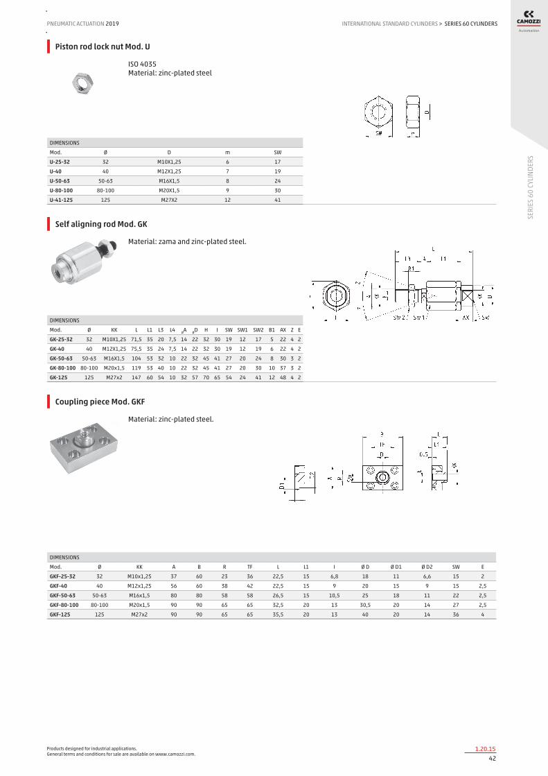
Piston rod lock nut Mod. U
ISO 4035 Material: zinc-plated steel.
DIMENSIONS
Mod. Ø SW m D
U-8-10 8-10 7 3 M4X0,7
U-12-16 12-16 10 4 M6X1
U-20 20 13 5 M8X1,25
U-25-32 25 17 6 M10X1,25
Nose nut Mod.V
ISO 4035 V-8-10 / V-20-25 not according standard. Material: zinc-plated steel
DIMENSIONS
Mod. Ø D m SW
V-8-10 8-10 M12X1,25 7 19
V-12-16 12-16 M16X1,5 8 24
V-20-25 20-25 M22X1,5 10 32

Products designed for industrial applications. General terms and conditions for sale are available on www.camozzi.com.
SERIES 16, 24 AND 25 MINI-CYLINDERSINTERNATIONAL STANDARD CYLINDERS > PNEUMATIC ACTUATION 2019
91.05.09
SERI
ES 1
6, 2
4 AN
D 25
MIN
I-CYL
INDE
RS
Self aligning rod Mod. GK
Material: zinc-plated steel.
DIMENSIONS
Mod. Ø H I Z ØA KK E L L3 L4 L1 B1 SW2 SW1 AX SW ØD
GK-12-16 12-16 14.5 13 3 6 M6x1 1 35 11 2.5 17.5 4 10 5 12.5 7 8.5
GK-20 20 19 17 4 8 M8x1,25 2 57 21 5 26 4 13 7 16 11 12.5
GK-25-32 25-32 32 30 4 14 M10x1,25 2 71.5 20 7.5 35 5 17 12 22 19 22
Coupling piece Mod. GKF
Material: zinc-plated steel.
DIMENSIONS
Mod. Ø Ø D1 I Ø D2 A R SW B TF Ø D E L L1 KK
GKF-20 20 5,5 - - 30 20 13 35 25 14 1,5 22,5 10 M8x1,25
GKF-25-32 25 11 6,8 6,6 37 23 15 60 36 18 2 22,5 15 M10x1,25

Products designed for industrial applications. General terms and conditions for sale are available on www.camozzi.com.
SERIES 40 CYLINDERSPNEUMATIC ACTUATION
101.10.01
2019 INTERNATIONAL STANDARD CYLINDERS
SERI
ES 4
0 CY
LIND
ERS
>
Series 40 cylinders
Double acting, cushioned, magnetic Ø 160 - 200 - 250 - 320 mm
Series 40 cylinders have been designed in compliance with ISO 15552 standards and with the previous DIN/ISO 6431 - VDMA 24562 standards. A permanent magnet on the piston of these cylinders is able to send, through proximity switches mounted on the cylinder sliding axis, electrical signals to indicate its position.
This series is normally equipped with end-stroke cushioning which can be adjusted through a screw on the end block. In order to quieten the impact of the piston on the end block, these cylinders are also equipped with mechanical cushioning.
» In compliance with ISO 15552 standards and with the previous DIN/ISO 6431 - VDMA 24562 standards
» Adjustable pneumatic cushioning
» Rolled stainless steel rod (Ø 160 - 200 mm)
» Chrome plated steel rod (Ø 250 - 320 mm)
» Rod scraper in brass
GENERAL DATAType of construction with tie-rodsOperation double-actingMaterials Coated AL end blocks and piston (Ø250-320 mm), rolled stainless steel AISI 420B (Ø 160-200 mm) or chrome plated steel (Ø250-320
mm) piston rod, zinc-plated steel piston rod nut, anodized AL tube, zinc-plated steel tie-rods and tie-rod nuts, NBR-PU rod - piston and cushion seals brass rod scraper ring
Mounting with tie-rods, front flange, rear flange, feet, centre trunnion, front and rear trunnion, swivel combinationStrokes min - max 10 ÷ 2500 mmOperating temperature 0°C ÷ 80°C (with dry air -20°C)Operating pressure 1 ÷ 10 barSpeed 10 ÷ 500 mm/sec (without load)Fluid filtered air, without lubrication. If lubricated air is used, it is recommended to use oil ISOVG32. Once applied the lubrication should
never be interrupted.

Products designed for industrial applications. General terms and conditions for sale are available on www.camozzi.com.
SERIES 40 CYLINDERSINTERNATIONAL STANDARD CYLINDERS > PNEUMATIC ACTUATION 2019
111.10.02
SERI
ES 4
0 CY
LIND
ERS
STANDARD STROKES FOR SERIES 40 CYLINDERS
■ = double-acting
Ø 25 50 75 80 100 125 150 160 200 250 300 320 400 500
160 ■ ■ ■ ■ ■ ■ ■ ■
200 ■ ■ ■ ■
250 ■ ■ ■ ■
320 ■ ■ ■ ■
CODING EXAMPLE
40 SERIES
M VERSION M = standard, magnetic
2 OPERATION 2 = double-acting, front and rear cushions 3 = double-acting, no cushion 4 = double-acting, rear cushions 5 = double-acting, front cushion 6 = double-acting, through-rod, front and rear cushions 8 = double-acting, through-rod, no cushion
PNEUMATIC SYMBOLS CD09 CD08 CD10 CD11 CD13 CD12
L MATERIALS L = see the GENERAL DATA table on the previous page T = stainless steel AISI 420B tie-rods - stainless steel AISI 303 tie-rod nuts C = rolled stainless steel AISI 303 piston rod, stainless steel AISI 304 piston rod nut U = rolled stainless steel AISI 303 piston rod, stainless steel AISI 304 piston-rod nut, stainless steel AISI 420B tie-rods, stainless steel AISI 303 tie-rod nuts W = rolled stainless steel AISI 304 piston rod, stainless steel AISI 304 piston-rod nut, stainless steel AISI 420B tie-rods, stainless steel AISI 303 tie-rod nuts Note: the rod of cylinders with bore of 250 and 320 mm is in C40 chrome plated steel.
160 BORE 160 = 160 mm - 200 = 200 mm - 250 = 250 mm - 320 = 320 mm
A TYPE OF BRACKET A = standard F = cylinder with centre trunnion
0200 STROKE (see the table)
= standard V = FKM rod seals W = all FKM seals +130°C C = PU coated cylinder. Colour: Grey * G = with brass rod scraper (chrome plated stainless steel AISI 420B rod, NBR rod seal) [ Ø 250 and 320 excluded ] ( _ _ _ ) = extended piston rod _ _ _ mm Notes: the C version is available on request. For further details, contact our technical dept. The W and C versions are available for diameters 160 and 200 only.
40 M 2 L 160 A 0200
PNEUMATIC SYMBOLS
The pneumatic symbols which have been indicated in the CODING EXAMPLE are shown below.

Products designed for industrial applications. General terms and conditions for sale are available on www.camozzi.com.
SERIES 40 CYLINDERSPNEUMATIC ACTUATION
121.10.03
2019 INTERNATIONAL STANDARD CYLINDERS
SERI
ES 4
0 CY
LIND
ERS
>
ACCESSORIES FOR SERIES 40 CYLINDERS
Rear trunnion, male Mod. L
Self aligning rod Mod. GK
Clevis pin Mod. S 90° Swivel combination Mod. ZS
Counter bracket for centre trunnion Mod. BF
Rod fork end Mod. G Front and rear flange Mod. D-E
Centre trunnion Mod. F Foot mount Mod. B Swivel ball joint Mod. GA
All accessories are supplied separately except for piston rod lock nut Mod. U. Details about proximity switches and their brackets can be found in the dedicated section.
Female trunnion Mod. C-H
Piston rod lock nut Mod. U

Products designed for industrial applications. General terms and conditions for sale are available on www.camozzi.com.
SERIES 40 CYLINDERSINTERNATIONAL STANDARD CYLINDERS > PNEUMATIC ACTUATION 2019
131.10.04
SERI
ES 4
0 CY
LIND
ERS
Series 40 cylinders
DIMENSIONS
Ø ØA KK ØB D G F AM H EE WH L1+ L2+ VD N P Q TG E SW1 SW2 SW3 SW4 front/rear cushion strokes
160 40 M36x2 65 25 12 53.5 72 6 G3\4 80 180 260 6 45 M16 26 140 176 36 17 4 55 29 / 36
200 40 M36x2 75 25 12 63.5 72 6 G3\4 95 180 275 6 45 M16 26 175 216 36 17 4 55 44 / 42
250 50 M42x2 90 31 12 67 84 10 G1 105 200 305 10 53 M20 30 220 270 46 36 4 65 50 / 50
320 63 M48x2 110 31 12 83 96 10 G1 120 220 340 12 55,5 M24 30 270 340 55 41 - 75 56 / 56
+ = add the stroke
Series 40 cylinders - through-rod
DIMENSIONS
Ø ØA KK ØB D G F AM EE WH L1+ L2++ VD N P Q TG E SW1 SW2 SW3 SW4 front/rear cushion strokes
160 40 M36x2 65 25 12 53.5 72 G3/4 80 180 340 6 45 M16 26 140 176 36 17 4 55 29 / 36
200 40 M36x2 75 25 12 63.5 72 G3/4 95 180 370 6 45 M16 26 175 216 36 17 4 55 44 / 42
250 50 M42x2 90 31 12 67 84 G1 105 200 410 10 53 M20 30 220 270 46 36 4 65 50 / 50
320 63 M48x2 110 31 12 83 96 G1 120 220 460 12 55.5 M24 30 270 340 55 41 - 75 56 / 56
+ = add the stroke once ++ = add the stroke twice
Products designed for industrial applications. General terms and conditions for sale are available on www.camozzi.com.
SERIES 40 CYLINDERSPNEUMATIC ACTUATION
141.10.05
2019 INTERNATIONAL STANDARD CYLINDERS
SERI
ES 4
0 CY
LIND
ERS
>
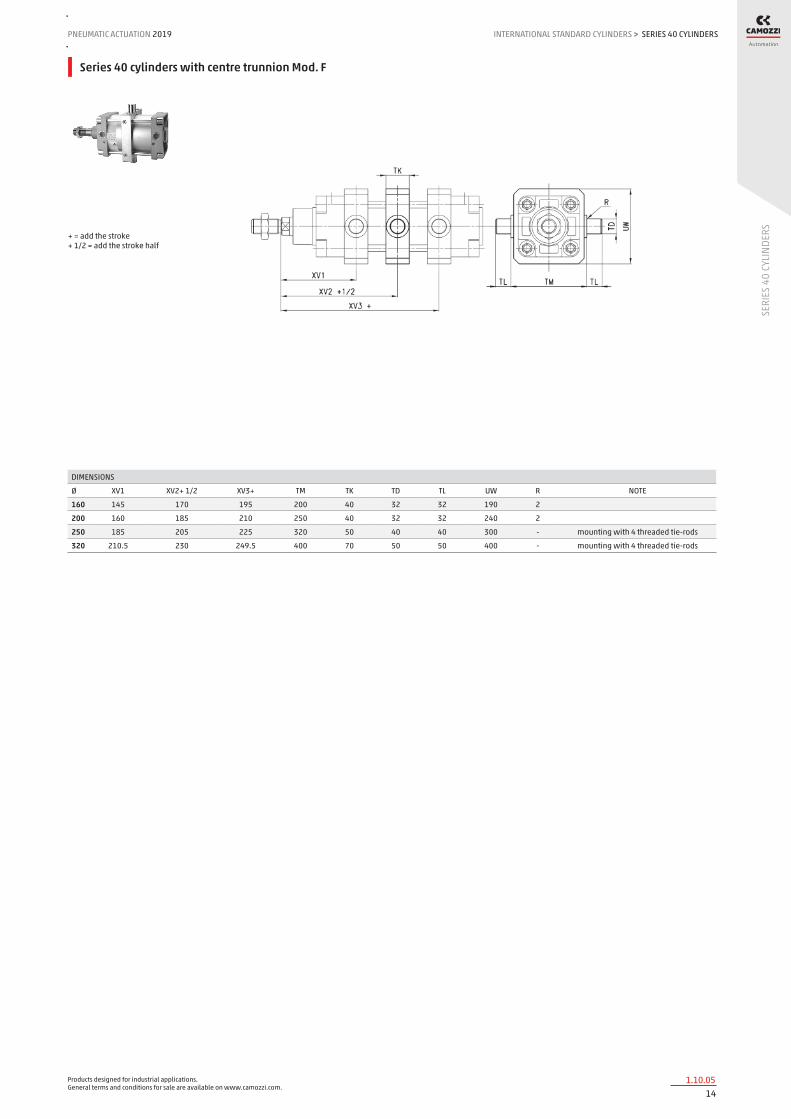
Series 40 cylinders with centre trunnion Mod. F
DIMENSIONS
Ø XV1 XV2+ 1/2 XV3+ TM TK TD TL UW R NOTE
160 145 170 195 200 40 32 32 190 2
200 160 185 210 250 40 32 32 240 2
250 185 205 225 320 50 40 40 300 - mounting with 4 threaded tie-rods
320 210.5 230 249.5 400 70 50 50 400 - mounting with 4 threaded tie-rods
+ = add the stroke + 1/2 = add the stroke half

Products designed for industrial applications. General terms and conditions for sale are available on www.camozzi.com.
SERIES 40 CYLINDERSINTERNATIONAL STANDARD CYLINDERS > PNEUMATIC ACTUATION 2019
151.10.06
SERI
ES 4
0 CY
LIND
ERS
Foot mount Mod. B
Supplied with: 2x feets in black-painted steel (cataphoresis) 4x white zinc plating screws For diameters 250 and 320 white zinc plating
DIMENSIONS
Mod. Ø AT SA+ XA+ TR E ØAB AH AO AU
B-41-160 160 10 300 320 115 175 18.5 115 25 60
B-41-200 200 12 320 345 135 238 24 135 35 70
B-41-250 250 14 350 380 165 270 26 165 25 75
B-41-320 320 20 390 425 200 353 35 200 45 85
+ = add the stroke
Front and rear flange Mod. D-E
Supplied with: 1x flange 4x screws
DIMENSIONS
Mod. Ø W MF ZB+ TF R UF E ØFB ZF+ Material
D-E-41-160 160 60 20 260 230 115 276 175 18 280 aluminium
D-E-41-200 200 70 25 275 270 135 312 215 22 300 aluminium
D-E-41-250 250 80 25 305 330 165 400 285 26 330 zinc-plated steel
D-E-41-320 320 90 30 340 400 200 470 334 33 370 stainless steel 304
+ = add the stroke
Front and rear female trunnion Mod. C-H
Supplied with: 1x female trunnion in Aluminium 4x screws
DIMENSIONS
Mod. Ø ØCD L FL D+ XD+ MR E CB UB
C-H-41-160 160 30 35 55 180 315 30 175 90 170
C-H-41-200 200 30 35 60 180 335 30 215 90 170
C-H-41-250 250 40 45 70 200 375 40 270 110 200
C-H-41-320 320 45 50 80 220 420 45 350 120 220
+ = add the stroke

Products designed for industrial applications. General terms and conditions for sale are available on www.camozzi.com.
SERIES 40 CYLINDERSPNEUMATIC ACTUATION
161.10.07
2019 INTERNATIONAL STANDARD CYLINDERS
SERI
ES 4
0 CY
LIND
ERS
>
Rear male trunnion Mod. L
Supplied with: 1x male trunnion in Aluminium * 4x screws * For Ø 320 black-painted steel (cataphoresis)
DIMENSIONS
Mod. Ø ØCD L FL XD+ MR E EW
L-41-160 160 30 35 55 315 30 175 90
L-41-200 200 30 35 60 335 30 215 90
L-41-250 250 40 45 70 375 40 270 110
L-41-320 320 45 50 80 420 45 350 110
+ = add the stroke
Centre trunnion Mod. F
Material: - zinc-plated steel (Ø 160 and 200) - painted cast iron (Ø 250 and 320)
DIMENSIONS
Mod. Ø XV1 XV + 1/2 XV3 + TM TK ØTD TL UW R NOTE
F-160 160 145 170 195 200 40 32 32 190 2
F-200 200 160 185 210 250 40 32 32 240 2
F-250 250 185 205 225 320 50 40 40 296 - mounting with 4 threaded tie-rods
F-320 320 210,5 230 249,5 400 70 50 50 400 - mounting with 4 threaded tie-rods
+ = add the stroke
90° Swivel combination Mod. ZS*
* not according to standard Supplied with: 1x 45° swivel combination in Aluminium
DIMENSIONS
Mod. Ø TR ØAB AH C G ØCD XD + G3
ZS-160 160 140 18 140 20 180 30 315 105
ZS-200 200 175 18 140 25 220 30 335 125
+ = add the stroke

Products designed for industrial applications. General terms and conditions for sale are available on www.camozzi.com.
SERIES 40 CYLINDERSINTERNATIONAL STANDARD CYLINDERS > PNEUMATIC ACTUATION 2019
171.10.08
SERI
ES 4
0 CY
LIND
ERS
Swivel combination Mod. C+L+S
DIMENSIONS
Mod. Ø E TG ØN D+ XD+ ØCD L FL I Z° (max)
C+L+S 160 175 140 17 180 315 30 35 55 20 25
C+L+S 200 215 175 17 180 335 30 35 60 25 20
C+L+S 250 270 220 22 200 375 40 45 70 25 33
C+L+S 320 350 270 30 220 420 40 50 80 30 30
+ = add the stroke
Counter bracket for centre trunnion Mod. BF
Supplied with 2 supports in Aluminium
DIMENSIONS
Mod. Ø ØCR NH C B3 TH UL FK FN B1 ØB2 ØHB
BF-160-200 160-200 32 35 17,5 4 60 92 30 60 16 26 18
Rod fork end Mod. G
ISO 8140 Material: - zinc-plated steel
DIMENSIONS
Mod. Ø ØCK LE CM CL ER CE KK B ØB1
G-160-200 160-200 35 72 35 70 44 144 M36X2 92 60
G-250 250 40 84 40 85 - 168 M42x2 96 70
G-320 320 50 96 50 90 73 192 M48x2 120 80

Products designed for industrial applications. General terms and conditions for sale are available on www.camozzi.com.
SERIES 40 CYLINDERSPNEUMATIC ACTUATION
181.10.09
2019 INTERNATIONAL STANDARD CYLINDERS
SERI
ES 4
0 CY
LIND
ERS
>
Swivel ball joint Mod. GA
ISO 8139
DIMENSIONS
Mod. Ø ØCN U EN ER AX CE KK ØT Z SW
GA-160-200 160-200 35 28 43 40 56 125 M36x2 46 6 50
GA-250 250 40 33 49 - 60 142 M42x2 55 17 55
GA-320 320 50 45 60 58.5 65 160 M48x2 65 12 65
Clevis pin Mod. S
Supplied with: 1x centering pin 2x seeger in steel
DIMENSIONS
Mod. Ø d L L1 L2 L3
S-160-200 160-200 30 180.5 172 1.6 4.25 stainless steel 303
S-250 250 40 210 202 1.85 4.5 zinc-plated steel
S-320 320 45 236 222 1.85 7 zinc-plated steel
Piston rod lock nut Mod. U
ISO 4035 Material: zinc-plated steel
DIMENSIONS
Mod. Ø D m SW
U-160-200 160-200 M36x2 14 55
U-250 250 M42x2 16 65
U-320 320 M48x2 24 75
Self aligning rod Mod. GK
Material: zama and zinc-plated steel.
DIMENSIONS
Mod. Ø KK L L1 L3 L4 ØA ØD H I SW SW1 SW2 B1 AX Z E
GK-160-200 160-200 M36x2 190 77 72 15.5 39 57 75 70 54 32 55 14 68 4 2
Products designed for industrial applications. General terms and conditions for sale are available on www.camozzi.com.
SERIES 41 CYLINDERSINTERNATIONAL STANDARD CYLINDERS > PNEUMATIC ACTUATION 2019
191.15.01
SERI
ES 4
1 CY
LIND
ERS
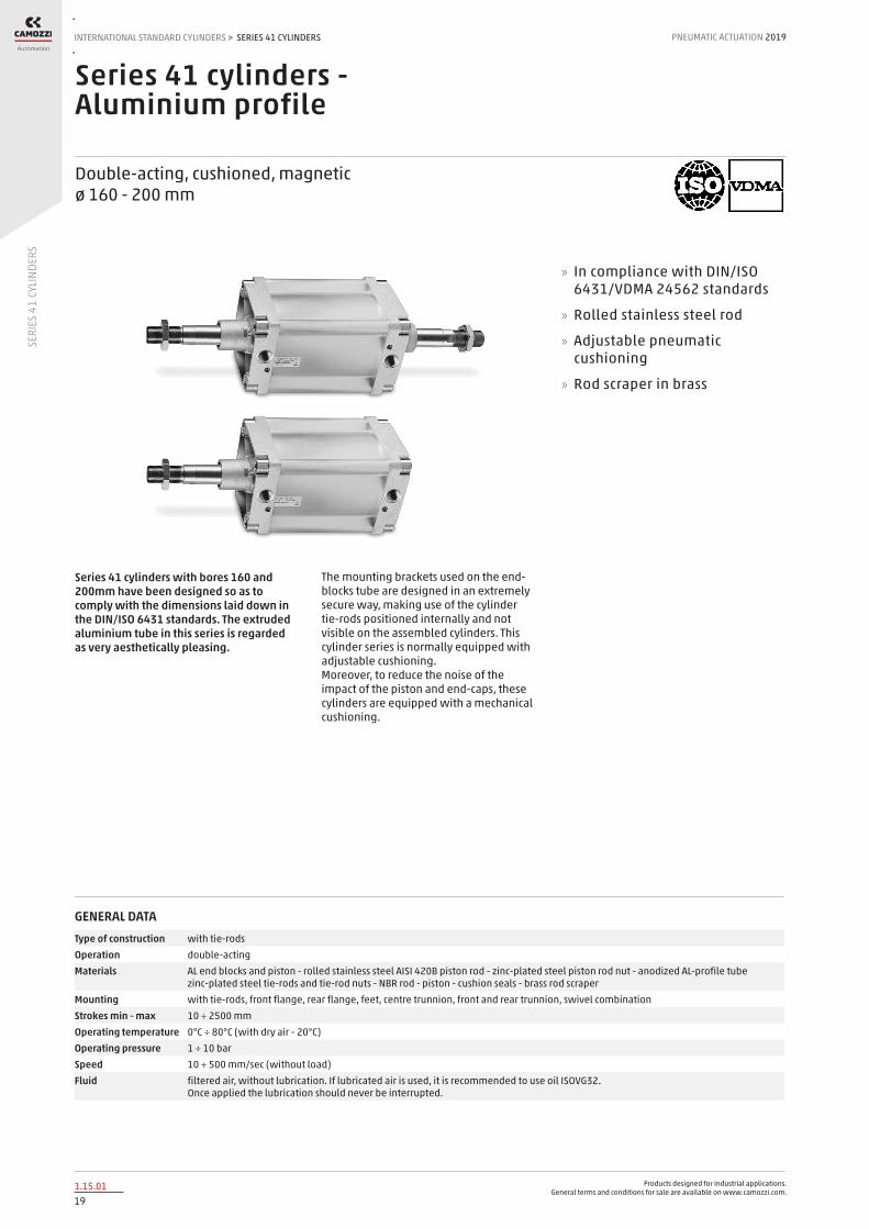
Series 41 cylinders - Aluminium profile
Double-acting, cushioned, magnetic ø 160 - 200 mm
Series 41 cylinders with bores 160 and 200mm have been designed so as to comply with the dimensions laid down in the DIN/ISO 6431 standards. The extruded aluminium tube in this series is regarded as very aesthetically pleasing.
The mounting brackets used on the end-blocks tube are designed in an extremely secure way, making use of the cylinder tie-rods positioned internally and not visible on the assembled cylinders. This cylinder series is normally equipped with adjustable cushioning. Moreover, to reduce the noise of the impact of the piston and end-caps, these cylinders are equipped with a mechanical cushioning.
» In compliance with DIN/ISO 6431/VDMA 24562 standards
» Rolled stainless steel rod
» Adjustable pneumatic cushioning
» Rod scraper in brass
GENERAL DATAType of construction with tie-rodsOperation double-actingMaterials AL end blocks and piston - rolled stainless steel AISI 420B piston rod - zinc-plated steel piston rod nut - anodized AL-profile tube
zinc-plated steel tie-rods and tie-rod nuts - NBR rod - piston - cushion seals - brass rod scraperMounting with tie-rods, front flange, rear flange, feet, centre trunnion, front and rear trunnion, swivel combinationStrokes min - max 10 ÷ 2500 mmOperating temperature 0°C ÷ 80°C (with dry air - 20°C)Operating pressure 1 ÷ 10 barSpeed 10 ÷ 500 mm/sec (without load)Fluid filtered air, without lubrication. If lubricated air is used, it is recommended to use oil ISOVG32.
Once applied the lubrication should never be interrupted.
Products designed for industrial applications. General terms and conditions for sale are available on www.camozzi.com.
SERIES 41 CYLINDERSPNEUMATIC ACTUATION
201.15.02
2019 INTERNATIONAL STANDARD CYLINDERS
SERI
ES 4
1 CY
LIND
ERS
>
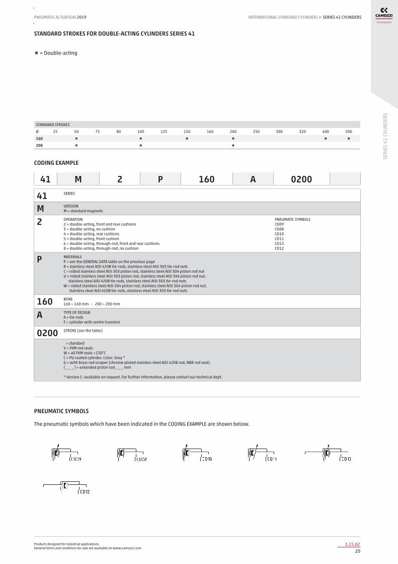
STANDARD STROKES FOR DOUBLE-ACTING CYLINDERS SERIES 41
✖ = Double-acting
STANDARD STROKES
Ø 25 50 75 80 100 125 150 160 200 250 300 320 400 500
160 ✖ ✖ ✖ ✖ ✖ ✖
200 ✖ ✖ ✖
CODING EXAMPLE
41 SERIES
M VERSION M = standard magnetic
2 OPERATION 2 = double-acting, front and rear cushions 3 = double-acting, no cushion 4 = double-acting, rear cushions 5 = double-acting, front cushion 6 = double-acting, through-rod, front and rear cushions 8 = double-acting, through-rod, no cushion
PNEUMATIC SYMBOLS CD09 CD08 CD10 CD11 CD13 CD12
P MATERIALS P = see the GENERAL DATA table on the previous page R = stainless steel AISI 420B tie-rods, stainless steel AISI 303 tie-rod nuts C = rolled stainless steel AISI 303 piston rod, stainless steel AISI 304 piston rod nut U = rolled stainless steel AISI 303 piston rod, stainless steel AISI 304 piston rod nut, stainless steel AISI 420B tie-rods, stainless steel AISI 303 tie-rod nuts W = rolled stainless steel AISI 304 piston rod, stainless steel AISI 304 piston rod nut, stainless steel AISI 420B tie-rods, stainless steel AISI 303 tie-rod nuts
160 BORE 160 = 160 mm - 200 = 200 mm
A TYPE OF DESIGN A = tie-rods F = cylinder with centre trunnion
0200 STROKE (see the table)
= standard V = FKM rod seals W = all FKM seals +130°C C = PU coated cylinder. Color: Grey * G = with brass rod scraper (chrome plated stainless steel AISI 420B rod, NBR rod seal) ( _ _ _ ) = extended piston rod _ _ _ mm * Version C: available on request. For further information, please contact our technical dept.
41 M 2 P 160 A 0200
PNEUMATIC SYMBOLS
The pneumatic symbols which have been indicated in the CODING EXAMPLE are shown below.

Products designed for industrial applications. General terms and conditions for sale are available on www.camozzi.com.
SERIES 41 CYLINDERSINTERNATIONAL STANDARD CYLINDERS > PNEUMATIC ACTUATION 2019
211.15.03
SERI
ES 4
1 CY
LIND
ERS
ACCESSORIES FOR CYLINDERS SERIES 41
Clevis pin Mod. S 90° swivel combination Mod. ZS
Rear trunnion, male Mod. L
Front and rear flange Mod. D-E
Counter bracket for centre trunnion Mod. BF
Centre trunnion Mod. F Foot mount Mod. B Rod fork end Mod. G
All accessories are supplied separately, except for the piston rod lock nut Mod. U
Front and rear female trunnion Mod. C-H
Swivel ball joint Mod. GA
Swivel combination Mod. C+L+S
Piston rod lock nut Mod. U
Self aligning rod Mod. GK

Products designed for industrial applications. General terms and conditions for sale are available on www.camozzi.com.
SERIES 41 CYLINDERSPNEUMATIC ACTUATION
221.15.04
2019 INTERNATIONAL STANDARD CYLINDERS
SERI
ES 4
1 CY
LIND
ERS
>
Cylinders Series 41
DIMENSIONS
Ø ØA KK ØB D G F AM H EE WH L1+ L2+ VD N P Q TG E SW1 SW2 SW3 SW4 front/rear cushion strokes
160 40 M36x2 65 25 12 53.5 72 6 G3\4 80 180 260 6 45 M16 26 140 176 36 17 4 55 29 / 36
200 40 M36x2 75 25 12 63.5 72 6 G3\4 95 180 275 6 45 M16 26 175 216 36 17 4 55 44 / 42
+ = add the stroke
Cylinders Series 41 - through-rod
DIMENSIONS
Ø A KK B D G F AM EE WH L1+ L2++ VD N P Q TG E SW1 SW2 SW3 SW4 front/rear cushion strokes
160 40 M36x2 65 25 12 53.5 72 G3\4 80 180 340 6 45 M16 26 140 176 36 17 4 55 29 / 36
200 40 M36x2 75 25 12 63.5 72 G3\4 95 180 370 6 45 M16 26 175 216 36 17 4 55 44 / 42
+ = add the stroke once ++ = add the stroke twice

Products designed for industrial applications. General terms and conditions for sale are available on www.camozzi.com.
SERIES 41 CYLINDERSINTERNATIONAL STANDARD CYLINDERS > PNEUMATIC ACTUATION 2019
231.15.05
SERI
ES 4
1 CY
LIND
ERS
Cylinders Series 41 with centre trunnion Mod. F
DIMENSIONS
Ø XV1 XV2 XV3 TM TK TD TL UW R
160 145 170 195 200 40 32 32 200 0,2
200 160 185 210 250 40 32 32 250 0,2
+ = add the stroke + 1/2 = add the stroke half

Products designed for industrial applications. General terms and conditions for sale are available on www.camozzi.com.
SERIES 41 CYLINDERSPNEUMATIC ACTUATION
241.15.06
2019 INTERNATIONAL STANDARD CYLINDERS
SERI
ES 4
1 CY
LIND
ERS
>
Foot mount Mod. B
Material: black-painted steel (cataphoresis) Supplied with: 2x feet 4x screws
DIMENSIONS
Mod. Ø AT SA+ XA+ TR E ØAB AH AO AU
B-41-160 160 10 300 320 115 175 18.5 115 25 60
B-41-200 200 12 320 345 135 238 24 135 35 70
+ = add the stroke
Front and rear flange Mod. D-E
Material: Aluminium. Supplied with: 1x flange 4x screws
DIMENSIONS
Mod. Ø W MF ZB+ TF R UF E ØFB ZF+
D-E-41-160 160 60 20 260 230 115 276 175 18 280
D-E-41-200 200 70 25 275 270 135 312 215 22 300
+ = add the stroke
Front and rear female trunnion Mod. C-H
Material: Aluminium. Supplied with: 1x female trunnion 4x screws
DIMENSIONS
Mod. Ø ØCD L FL D+ XD+ MR E CB UB
C-H-41-160 160 30 35 55 180 315 30 175 90 170
C-H-41-200 200 30 35 60 180 335 30 215 90 170
+ = add the stroke

Products designed for industrial applications. General terms and conditions for sale are available on www.camozzi.com.
SERIES 41 CYLINDERSINTERNATIONAL STANDARD CYLINDERS > PNEUMATIC ACTUATION 2019
251.15.07
SERI
ES 4
1 CY
LIND
ERS
Rear male trunnion Mod. L
Material: Aluminium Supplied with: 1x male trunnion 4x screws
DIMENSIONS
Mod. Ø ØCD L FL XD+ MR E EW -0.5 -1.2
L-41-160 160 30 35 55 315 30 175 90
L-41-200 200 30 35 60 335 30 215 90
+ = add the stroke
Centre trunnion Mod. F
Material: white zinc-plated steel. Supplied with: 1x centre trunnion 4x clamping elements 4x locking screws
DIMENSIONS
Mod. Ø XV1 XV+1/2 XV3+ TM h ØTD TL UW R
F-41-160 160 145 170 195 200 40 32 32 200 0.2
F-41-200 200 160 185 210 250 40 32 32 250 0.2
+ = add the stroke
90° Swivel combination Mod. ZS*
Material: Aluminium * not according to standard
DIMENSIONS
Mod. Ø TR ØAB AH C G ØCD XD+ G3
ZS-160 160 140 18 140 20 180 30 315 105
ZS-200 200 175 18 140 25 220 30 335 125
+ = add the stroke

Products designed for industrial applications. General terms and conditions for sale are available on www.camozzi.com.
SERIES 41 CYLINDERSPNEUMATIC ACTUATION
261.15.08
2019 INTERNATIONAL STANDARD CYLINDERS
SERI
ES 4
1 CY
LIND
ERS
>
Swivel combination Mod. C+L+S
DIMENSIONS
Mod. Ø ØCD L FL D+ XD+ TG E ØN I Z° (max)
C+L+S 160 30 35 55 180 315 140 175 17 20 25
C+L+S 200 30 35 60 180 335 175 215 17 25 20
+ = add the stroke
Counter bracket for centre trunnion Mod. BF
Material: Aluminium. Supplied with: 2x supports
DIMENSIONS
Mod. Ø ØCR NH C B3 TH UL FK FN B1 ØB2 ØHB
BF-160-200 160-200 32 35 17,5 4 60 92 30 60 16 26 18
Rod fork end Mod. G
ISO 8140. Material: zinc-plated steel.
DIMENSIONS
Mod. Ø ØCK LE CM CL ER CE KK B ØB1
G-160-200 160-200 35 72 35 70 44 144 M36X2 92 60

Products designed for industrial applications. General terms and conditions for sale are available on www.camozzi.com.
SERIES 41 CYLINDERSINTERNATIONAL STANDARD CYLINDERS > PNEUMATIC ACTUATION 2019
271.15.09
SERI
ES 4
1 CY
LIND
ERS
Swivel ball joint Mod. GA
ISO 8139. Material: zinc-plated steel.
DIMENSIONS
Mod. Ø ØCN U EN ER AX CE KK ØT Z SW
GA-160-200 160-200 35 28 43 40 56 125 M36x2 46 6 50
Clevis pin Mod. S
Supplied with: 1x centering pin in stainless steel 303 2x seeger in steel
DIMENSIONS
Mod. Ø d L L1 L2 L3
S-160-200 160-200 30 180.5 172 1.6 4.25
Piston rod lock nut Mod. U
ISO 4035 Material: zinc-plated steel
DIMENSIONS
Mod. Ø D m SW
U-160-200 160-200 M36x2 14 55
Self aligning rod Mod. GK
Material: zama and zinc-plated steel.
DIMENSIONS
Mod. Ø KK L L1 L3 L4 ØA ØD H I SW SW1 SW2 B1 AX Z E
GK-160-200 160-200 M36x2 190 77 72 15.5 39 57 75 70 54 32 55 14 68 4 2

Products designed for industrial applications. General terms and conditions for sale are available on www.camozzi.com.
SERIES 60 CYLINDERSPNEUMATIC ACTUATION
281.20.01
2019 INTERNATIONAL STANDARD CYLINDERS
SERI
ES 6
0 CY
LIND
ERS
>
Series 60 cylinders
Single and double-acting, magnetic, cushioned Standard, low friction, low temperatures and tandem versions ø 32, 40, 50, 63, 80, 100, 125mm
The Series 60 cylinders have been designed to comply with the dimensions laid down in the ISO 15552 standards. A permanent magnet, mounted on the piston, enables information to be received regarding the piston position by means of proximity switches positioned along the cylinder tube.
This cylinder series is normally equipped with adjustable end-stroke cushioning. Moreover, these cylinders are equipped with bumpers in order to reduce the impact of the piston as it reaches the end of the stroke.
» In compliance with ISO 15552 standards and with the previous DIN/ISO 6431 - VDMA 24562 standards
» Rolled stainless steel rod
» Adjustable pneumatic cushioning
» Available special versions TANDEM:
» Double thrust and traction forces LOW FRICTION:
» Friction force reduced by over 40% LOW TEMPERATURES:
» Versions for -40°C and for -50°C G VARIANT FOR DUSTY APPLICATIONS:
» Highly resistant to dust, cement, resin, mud, and wood residue
GENERAL DATAType of construction with tie-rodsOperation double-acting, single-acting, tandem. Low friction version: double-acting only.Materials standard: AL end-blocks and piston, rolled stainless steel AISI 420B rod, anodized AL tube, zinc-plated steel tie-rods and tie-rod nuts,
PU seals; low friction: standard materials with NBR piston seals and NBR rod seal (FKM rod seal on request) low temperatures: standard materials with chrome plated stainless steel AISI 420B rod, brass rod scraper ring, stainless steel AISI 303 nuts, stainless steel AISI 420B tie-rods, PU piston seals and NBR rod seal
Type of mounting with tie-rods, with front / rear flange, foot mounting, with centre / front / rear / swivel trunnionStrokes min - max 10 ÷ 2500 mmOperating temperature standard and low friction: 0°C ÷ 80°C (with dry air - 20°C)
low temperatures (-40°C version): -40°C ÷ 60°C (with dry air -40°C) low temperatures (-50°C version): -50°C ÷ 60°C (with dry air -50°C)
Operating pressure 1 ÷ 10 bar (standard and low temperatures); 0,1 ÷ 10 bar (low friction)Speed 10 ÷ 1000 mm/sec, no load (standard and low temperatures); 5 ÷ 1000 mm/sec, no load (low friction)Fluid filtered air, without lubrication. For standard versions only: if lubricated air is used, it is recommended to use oil ISOVG32. Once
applied the lubrication should never be interrupted.
Products designed for industrial applications. General terms and conditions for sale are available on www.camozzi.com.
SERIES 60 CYLINDERSINTERNATIONAL STANDARD CYLINDERS > PNEUMATIC ACTUATION 2019
291.20.02
SERI
ES 6
0 CY
LIND
ERS
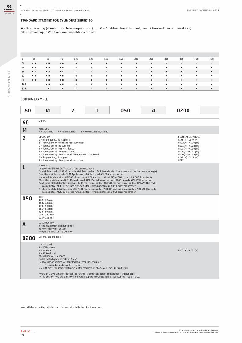
STANDARD STROKES FOR CYLINDERS SERIES 60
■ = Single-acting (standard and low temperatures) ✖ = Double-acting (standard, low friction and low temperatures) Other strokes up to 2500 mm are available on request.
Ø 25 50 75 100 125 150 160 200 250 300 320 400 500
32 ■ ✖ ■ ✖ ■ ✖ ✖ ✖ ✖ ✖ ✖ ✖ ✖ ✖ ✖ ✖
40 ■ ✖ ■ ✖ ■ ✖ ✖ ✖ ✖ ✖ ✖ ✖ ✖ ✖ ✖ ✖
50 ■ ✖ ■ ✖ ■ ✖ ✖ ✖ ✖ ✖ ✖ ✖ ✖ ✖ ✖ ✖
63 ■ ✖ ■ ✖ ■ ✖ ✖ ✖ ✖ ✖ ✖ ✖ ✖ ✖ ✖ ✖
80 ■ ✖ ■ ✖ ■ ✖ ✖ ✖ ✖ ✖ ✖ ✖ ✖ ✖ ✖ ✖
100 ■ ✖ ■ ✖ ✖ ✖ ✖ ✖ ✖ ✖ ✖ ✖ ✖ ✖
125 ✖ ✖ ✖ ✖ ✖ ✖ ✖ ✖ ✖ ✖ ✖ ✖
CODING EXAMPLE
60 M 2 L 050 A 0200
60 SERIES
M VERSIONS M = magnetic N = non magnetic L = low friction, magnetic
2 OPERATION 1 = single-acting, front spring 2 = double-acting, front and rear cushioned 3 = double-acting, no cushion 4 = double-acting, rear cushioned 5 = double-acting, front cushioned 6 = double-acting, through-rod, front and rear cushioned 7 = single-acting, through-rod 8 = double-acting, through-rod, no cushion
PNEUMATIC SYMBOLS CS03 (N) - CS07 (M) CD02 (N) - CD09 (M) CD01 (N) - CD08 (M) CD03 (N) - CD10 (M) CD04 (N) - CD11 (M) CD06 (N) - CD13 (M) CS05 (N) - CS11 (M) CD12
L MATERIALS L = see the GENERAL DATA table on the previous page T = stainless steel AISI 420B tie-rods, stainless steel AISI 303 tie-rod nuts, other materials (see the previous page) C = rolled stainless steel AISI 303 piston rod, stainless steel AISI 304 piston rod nut U = rolled stainless steel AISI 303 piston rod, AISI 304 piston-rod nut, AISI 420B tie-rods, AISI 303 tie-rod nuts W = rolled stainless steel AISI 304 piston rod, AISI 304 piston-rod nut, AISI 420B tie-rods, AISI 303 tie-rod nuts Z = chrome plated stainless steel AISI 420B rod, stainless steel AISI 304 rod nut, stainless steel AISI 420B tie-rods, stainless steel AISI 303 tie-rods nuts, seals for low temperatures (-40°C), brass rod scraper Y = chrome plated stainless steel AISI 420B rod, stainless steel AISI 304 rod nut, stainless steel AISI 420B tie-rods, stainless steel AISI 303 tie-rods nuts, seals for low temperatures (-50°C), brass rod scraper
050 BORE 032 = 32 mm 040 = 40 mm 050 = 50 mm 063 = 63 mm 080 = 80 mm 100 = 100 mm 125 = 125 mm
A CONSTRUCTION A = standard with lock nut for rod RL = cylinder with rod lock F = cylinder with centre trunnion
0200 STROKE (see the table)
= standard V = FKM rod seal N = tandem R = NBR rod seal W = all FKM seals + 130°C C = PU coated cylinder. Colour: Grey * L = low friction version without rod seal (rear supply only) ** ( _ _ _ ) = extended piston rod _ _ _ mm G = with brass rod scraper (chrome plated stainless steel AISI 420B rod, NBR rod seal) * Version C: available on request. For further information, please contact our technical dept. ** The possibility to order the cylinder without piston rod seal, further reduces the friction force.
CD8T (M) - CD9T (N)
Note: all double-acting cylinders are also available in the low friction version.

Products designed for industrial applications. General terms and conditions for sale are available on www.camozzi.com.
SERIES 60 CYLINDERSPNEUMATIC ACTUATION
301.20.03
2019 INTERNATIONAL STANDARD CYLINDERS
SERI
ES 6
0 CY
LIND
ERS
>
PNEUMATIC SYMBOLS [ Pneumatic symbols in the CODING EXAMPLE are shown below. ]

Products designed for industrial applications. General terms and conditions for sale are available on www.camozzi.com.
SERIES 60 CYLINDERSINTERNATIONAL STANDARD CYLINDERS > PNEUMATIC ACTUATION 2019
311.20.04
SERI
ES 6
0 CY
LIND
ERS
CYLINDER IN THRUST DRAWING NOTES: 1. Precision pressure regulator or proportional regulator 2. Low friction cylinder 3. Force direction 4. Band
CYLINDER IN TRACTION Note: in order to reach the highest performance, it is recommended to connect a precision pressure regulator or a proportional regulator with the low friction cylinder as shown in the drawing.
Series 60 low friction cylinders - APPLICATION EXAMPLES
1 = rod seal 2 = flexible ring 3 = metal scraper
Series 60 low temperatures cylinders - DETAIL
Products designed for industrial applications. General terms and conditions for sale are available on www.camozzi.com.
SERIES 60 CYLINDERSPNEUMATIC ACTUATION
321.20.05
2019 INTERNATIONAL STANDARD CYLINDERS
SERI
ES 6
0 CY
LIND
ERS
>
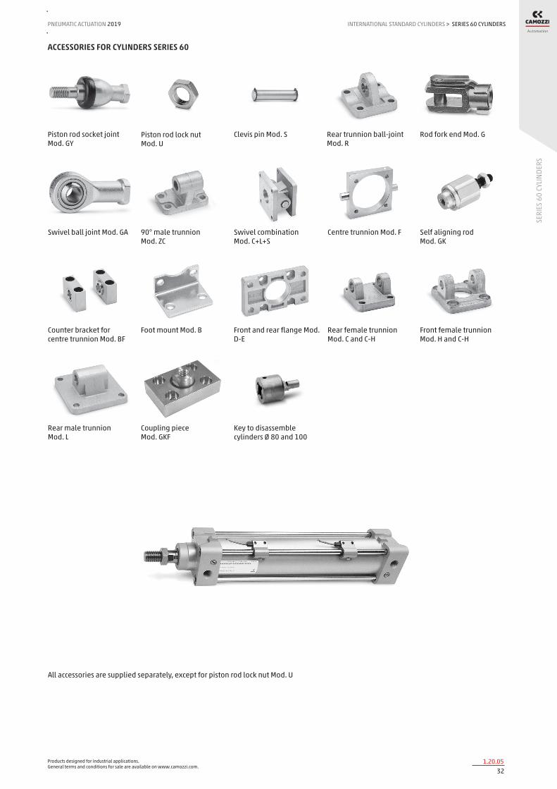
ACCESSORIES FOR CYLINDERS SERIES 60
Piston rod socket joint Mod. GY
Piston rod lock nut Mod. U
Clevis pin Mod. S Rear trunnion ball-joint Mod. R
Rod fork end Mod. G
Swivel ball joint Mod. GA 90° male trunnion Mod. ZC
Swivel combination Mod. C+L+S
Centre trunnion Mod. F Self aligning rod Mod. GK
Counter bracket for centre trunnion Mod. BF
Foot mount Mod. B Front and rear flange Mod. D-E
All accessories are supplied separately, except for piston rod lock nut Mod. U
Rear female trunnion Mod. C and C-H
Front female trunnion Mod. H and C-H
Rear male trunnion Mod. L
Coupling piece Mod. GKF
Key to disassemble cylinders Ø 80 and 100

Products designed for industrial applications. General terms and conditions for sale are available on www.camozzi.com.
SERIES 60 CYLINDERSINTERNATIONAL STANDARD CYLINDERS > PNEUMATIC ACTUATION 2019
331.20.06
SERI
ES 6
0 CY
LIND
ERS
Cylinders Series 60
Note: the single-acting cylinders’ sizes ZJ and L2 are increased by 25 mm.
DIMENSIONS
Ø AM B BG E EE G KK L1 L2+ L3 MM N PL R RT SW1 SW2 SW3 SW4 TG VA VD WH ZJ+ Front/rear cushion stroke
32 22 30 16 46 G1/8 5 M10x1,25 18 94 5 12 26 14 13 M6 10 6 2 17 32,5 4 5 26 120 17 / 12
40 24 35 16 55 G1/4 5 M12x1,25 21 105 5 16 29 15 13,5 M6 13 6 2 19 38 4 5 30 135 20 / 17
50 32 40 16 64,5 G1/4 8 M16x1,5 25 106 5 20 29,5 15 16 M8 17 8 3 24 46,5 4 6 37 143 15 / 14
63 32 45 16 75 G3/8 8 M16x1,5 26 121 5 20 36,5 21 28 M8 17 8 3 24 56,5 4 6 37 158 17 / 16
80 40 45 19 93 G3/8 8 M20x1,5 30 128 0 25 36 21 30 M10 22 * 5 30 72 4 7 46 174 20 / 20
100 40 55 19,5 110 G1/2 8 M20x1,5 35 138 0 25 38,5 23 40 M10 22 * 5 30 89 4 7 51 189 21 / 19
125 54 60 23 135 G1/2 10,5 M27x2 42 160 0 32 43 23,5 50 M12 27 12 4 41 110 6 8 65 225 26 / 25
+ = add the stroke Table note: * = special key 80-62/8C (see accessories)
Cylinders Series 60 - through-rod
Note: the single-acting cylinders’ sizes ZM and L2 are increased by 25 mm.
DIMENSIONS
Ø AM B BG E EE G KK L1 L2+ L3 MM N PL R RT SW1 SW2 SW3 SW4 TG VD WH ZM++ Front/rear cushion stroke
32 22 30 16 46 G1/8 5 M10x1,25 18 94 5 12 26 14 13 M6 10 6 2 17 32,5 5 26 146 17 / 12
40 24 35 16 55 G1/4 5 M12x1,25 21 105 5 16 29 15 13,5 M6 13 6 2 19 38 5 30 165 20 / 17
50 32 40 16 64,5 G1/4 8 M16x1,5 25 106 5 20 29,5 15 16 M8 17 8 3 24 46,5 6 37 180 15 / 14
63 32 45 16 75 G3/8 8 M16x1,5 26 121 5 20 36,5 21 28 M8 17 8 3 24 56,5 6 37 195 17 / 16
80 40 45 19 93 G3/8 8 M20x1,5 30 128 0 25 36 21 30 M10 22 * 5 30 72 7 46 220 20 / 20
100 40 55 19,5 110 G1/2 8 M20x1,5 35 138 0 25 38,5 23 40 M10 22 * 5 30 89 7 51 240 21 / 19
125 54 60 23 135 G1/2 10,5 M27x2 42 160 0 32 43 23,5 50 M12 27 12 4 41 110 8 65 290 26 / 25
+ = add the stroke once ++ = add the stroke twice Table note: * = special key 80-62/8C (see accessories)

Products designed for industrial applications. General terms and conditions for sale are available on www.camozzi.com.
SERIES 60 CYLINDERSPNEUMATIC ACTUATION
341.20.07
2019 INTERNATIONAL STANDARD CYLINDERS
SERI
ES 6
0 CY
LIND
ERS
>
Cylinders Series 60 - tandem version
DIMENSIONS
Ø EE L2 L3
32 G1/8 171,5 197,5
40 G1/4 191,5 221,5
50 G1/4 188 225
63 G3/8 204 241
80 G3/8 225,5 271,5
100 G1/2 231 282
125 G1/2 264 329
+ = add the stroke once ++ = add the stroke twice 1 = Cylinder’s outlet 2 = Cylinder’s return
Cylinders Series 60 with rod lock
DIMENSIONS
Ø ØD ØD1 ØD2 ØD3 A G H H1 L1 L2 L3 L4 L5 L6 L7 L8 L9+ L10+ M Z
32 12 30,5 35 25 32,5 M5 25,5 46,5 58 48 10 8 13 20,5 34 45 94 160 M6 M6X20
40 16 35 40 28 38 G1/8 30 53 65 55 10 8 13 22,5 38 50 105 178 M6 M6X20
50 20 40 50 35 46,5 G1/8 36 64 82 70 12 15 16 29,5 48 60 106 200 M8 M8X30
63 20 45 60 38 56,5 G1/8 40 75 82 70 12 15 16 29,5 49,5 70 121 215 M8 M8X30
80 25 45 80 48 72 G1/8 50 95 110 90 20 18 20 35 61 90 128 254 M10 M10X35
100 25 55 100 58 89 G1/8 58 110,5 115 100 15 18 20 39 69 105 138 269 M10 M10X35
125 32 60 130 65 110 G1/8 80 150 167 122 45 22 30 51 86,5 140 160 350 M12 M12X40
+ = add the stroke

Products designed for industrial applications. General terms and conditions for sale are available on www.camozzi.com.
SERIES 60 CYLINDERSINTERNATIONAL STANDARD CYLINDERS > PNEUMATIC ACTUATION 2019
351.20.08
SERI
ES 6
0 CY
LIND
ERS
Foot mount Mod. B
Material: zinc-plated steel
DIMENSIONS
Mod. Ø AT SA+ XA+ TR E AB AH AO AU torque force
B-41-32 32 4 142 144 32 45 7 32 11 24 6 Nm
B-41-40 40 4 161 163 36 53,5 10 36 15 28 6 Nm
B-41-50 50 4 170 175 45 62,5 10 45 15 32 13 Nm
B-41-63 63 5 185 190 50 73 10 50 15 32 13 Nm
B-41-80 80 6 210 216 63 92 12 63 20 41 19 Nm
B-41-100 100 6 220 230 75 108,5 14,5 71 25 41 22 Nm
B-41-125 125 7 250 270 90 132 16,5 90 25 45 26 Nm
Supplied wth: 2x feet 4x screws + = add the stroke
Front and rear flange Mod. D-E
Material: Aluminium
DIMENSIONS
Mod. Ø W MF ZB TF R UF E FB ZF torque force
D-E-41-32 32 16 10 120 64 32 86 45 7 130 6 Nm
D-E-41-40 40 20 10 135 72 36 88 52 9 145 6 Nm
D-E-41-50 50 25 12 143 90 45 110 63 9 155 13 Nm
D-E-41-63 63 25 12 158 100 50 116 73 9 170 13 Nm
D-E-41-80 80 30 16 174 126 63 148 95 12 190 19 Nm
D-E-41-100 100 35 16 189 150 75 176 115 14 205 22 Nm
D-E-41-125 125 45 20 225 180 90 224 135 16 245 26 Nm
Supplied with: 1x flange 4x screws + = add the stroke
Products designed for industrial applications. General terms and conditions for sale are available on www.camozzi.com.
SERIES 60 CYLINDERSPNEUMATIC ACTUATION
361.20.09
2019 INTERNATIONAL STANDARD CYLINDERS
SERI
ES 6
0 CY
LIND
ERS
>
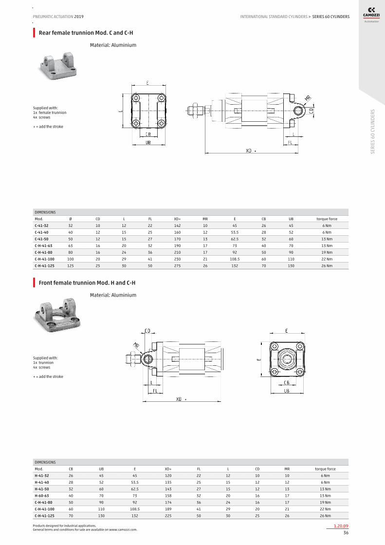
Rear female trunnion Mod. C and C-H
Material: Aluminium
DIMENSIONS
Mod. Ø CD L FL XD+ MR E CB UB torque force
C-41-32 32 10 12 22 142 10 45 26 45 6 Nm
C-41-40 40 12 15 25 160 12 53.5 28 52 6 Nm
C-41-50 50 12 15 27 170 13 62.5 32 60 13 Nm
C-H-41-63 63 16 20 32 190 17 73 40 70 13 Nm
C-H-41-80 80 16 24 36 210 17 92 50 90 19 Nm
C-H-41-100 100 20 29 41 230 21 108.5 60 110 22 Nm
C-H-41-125 125 25 30 50 275 26 132 70 130 26 Nm
Supplied with: 1x female trunnion 4x screws + = add the stroke
Front female trunnion Mod. H and C-H
Material: Aluminium
DIMENSIONS
Mod. CB UB E XD+ FL L CD MR torque force
H-41-32 26 45 45 120 22 12 10 10 6 Nm
H-41-40 28 52 53.5 135 25 15 12 12 6 Nm
H-41-50 32 60 62.5 143 27 15 12 13 13 Nm
H-60-63 40 70 73 158 32 20 16 17 13 Nm
C-H-41-80 50 90 92 174 36 24 16 17 19 Nm
C-H-41-100 60 110 108.5 189 41 29 20 21 22 Nm
C-H-41-125 70 130 132 225 50 30 25 26 26 Nm
Supplied with: 1x trunnion 4x screws + = add the stroke

Products designed for industrial applications. General terms and conditions for sale are available on www.camozzi.com.
SERIES 60 CYLINDERSINTERNATIONAL STANDARD CYLINDERS > PNEUMATIC ACTUATION 2019
371.20.10
SERI
ES 6
0 CY
LIND
ERS
Rear male trunnion Mod. L
Material: Aluminium
DIMENSIONS
Mod. Ø CD L FL XD+ MR E EW torque force
L-41-32 32 10 12 22 142 10 45 26 6 Nm
L-41-40 40 12 15 25 160 13 53.5 28 6 Nm
L-41-50 50 12 15 27 170 13 62.5 32 13 Nm
L-41-63 63 16 20 32 190 17 73 40 13 Nm
L-41-80 80 16 24 36 210 17 92 50 19 Nm
L-41-100 100 20 29 41 230 21 108.5 60 22 Nm
L-41-125 125 25 30 50 275 26 132 70 26 Nm
Supplied with: 2x male trunnions 4x screws + = add the stroke
Centre trunnion Mod. F
Material: zinc-plated steel
DIMENSIONS
Mod. Ø XV1 XV2 XV3 TM (h14) TK TD (e9) TL UW R
F-32 32 62 73 84 50 20 12 12 50 0.5
F-40 40 69 82,5 96 63 20 16 16 60 1
F-50 50 79 90 101 75 25 16 16 70 1
F-63 63 86 97,5 109 90 25 20 20 85 1
F-80 80 97 110 123 110 30 20 20 105 1
F-100 100 104,5 120 135,5 132 30 25 25 125 1.5
F-125 125 123 145 167 160 30 25 25 155 1.5
Supplied with: 1x intermediate trunnion 8x locking screws + = add the stroke +1/2 = add half of the stroke
Products designed for industrial applications. General terms and conditions for sale are available on www.camozzi.com.
SERIES 60 CYLINDERSPNEUMATIC ACTUATION
381.20.11
2019 INTERNATIONAL STANDARD CYLINDERS
SERI
ES 6
0 CY
LIND
ERS
>
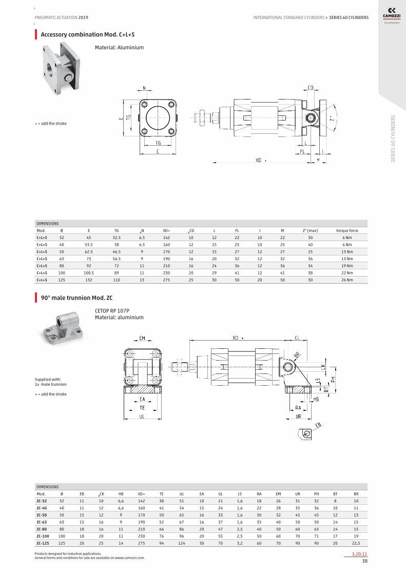
Accessory combination Mod. C+L+S
Material: Aluminium
DIMENSIONS
Mod. Ø E TG ØN XD+ ØCD L FL I M Z° (max) torque force
C+L+S 32 45 32.5 6.5 142 10 12 22 10 22 30 6 Nm
C+L+S 40 53.5 38 6.5 160 12 15 25 10 25 40 6 Nm
C+L+S 50 62.5 46.5 9 170 12 15 27 12 27 25 13 Nm
C+L+S 63 73 56.5 9 190 16 20 32 12 32 36 13 Nm
C+L+S 80 92 72 11 210 16 24 36 12 36 34 19 Nm
C+L+S 100 108.5 89 11 230 20 29 41 12 41 38 22 Nm
C+L+S 125 132 110 13 275 25 30 50 20 50 30 26 Nm
+ = add the stroke
90° male trunnion Mod. ZC
CETOP RP 107P Material: aluminium
DIMENSIONS
Mod. Ø EB ØCK HB XD+ TE UL EA GL L5 RA EM UR PH BT BR
ZC-32 32 11 10 6,6 142 38 51 10 21 1,6 18 26 31 32 8 10
ZC-40 40 11 12 6,6 160 41 54 15 24 1,6 22 28 35 36 10 11
ZC-50 50 15 12 9 170 50 65 16 33 1,6 30 32 45 45 12 13
ZC-63 63 15 16 9 190 52 67 16 37 1,6 35 40 50 50 14 15
ZC-80 80 18 16 11 210 66 86 20 47 2,5 40 50 60 63 14 15
ZC-100 100 18 20 11 230 76 96 20 55 2,5 50 60 70 71 17 19
ZC-125 125 20 25 14 275 94 124 30 70 3,2 60 70 90 90 20 22,5
Supplied with: 1x male trunnion + = add the stroke

Products designed for industrial applications. General terms and conditions for sale are available on www.camozzi.com.
SERIES 60 CYLINDERSINTERNATIONAL STANDARD CYLINDERS > PNEUMATIC ACTUATION 2019
391.20.12
SERI
ES 6
0 CY
LIND
ERS
Rear trunnion ball-joint Mod. R*
* This trunnion doesn’t comply with the ISO 15552 standard Material: Aluminium
DIMENSIONS
Mod. Ø ØCX L DL XN+ MS E EX EP Z torque force
R-41-32 32 10 12 22 142 18 45 14 10,5 4 6 Nm
R-41-40 40 12 15 25 160 18 53.5 16 12 4 6 Nm
R-41-50 50 12 * 15 27 170 21 62.5 16 * 12 * 4 13 Nm
R-41-63 63 16 20 32 190 23 73 21 15 4 13 Nm
R-41-80 80 16 * 24 36 210 28 92 21 * 15 * 4 19 Nm
R-41-100 100 20 29 41 230 30 108.5 25 18 4 22 Nm
R-41-125 125 30 30 50 275 40 140 37 25 4 26 Nm
Supplied with: 1x trunnion ball joint 4x screws + = add the stroke
Counter bracket for centre trunnion Mod. BF
Material: aluminium
DIMENSIONS
Mod. CR NH C b3 TH UL FK FN B1 B2 HB
BF-32 12 15 7,5 3 32 46 15 30 6,8 11 6,6
BF-40-50 16 18 9 3 36 55 18 36 9 15 9
BF-63-80 20 20 10 3 42 65 20 40 11 18 11
BF-100-125 25 25 12,5 3,5 50 75 25 50 13 20 14
Supplied with: 2x supports

Products designed for industrial applications. General terms and conditions for sale are available on www.camozzi.com.
SERIES 60 CYLINDERSPNEUMATIC ACTUATION
401.20.13
2019 INTERNATIONAL STANDARD CYLINDERS
SERI
ES 6
0 CY
LIND
ERS
>
Clevis pin Mod. S
DIMENSIONS
Mod. Ø d L L1 L2 L3
S-32 32 10 52 46 1,1 3
S-40 40 12 59 53 1,1 3
S-50 50 12 67 61 1,1 3
S-63 63 16 77 71 1,1 3
S-80 80 16 97 91 1,1 3
S-100 100 20 121 111 1,3 5
S-125 125 25 140,5 132 1,3 4,25
Suppied with: 1x clevis pin in stainless steel 303 2x Seeger in steel
Accessory for mounting valves on the cylinder
The mounting sub-base Mod. PCV enables the valve to be mounted directly on the cylinder and it’s fixed on it using screws Mod. 1635 or flow controllers, Mod. SCU. The other end of the plate has a threaded port.
DIMENSIONS
Mod. Ø A B C R S d*
PCV-32 32 G1/8 185 131,5 G1/8 16 G1/8
PCV-40-50 40 G1/8 188,5 140,5 G1/4 16 G1/4
PCV-40-50 50 G1/8 188,5 150 G1/4 16 G1/4
PCV-63-80 63 G1/4 215 167 G1/4 16 G3/8
PCV-63-80 80 G1/4 215 185 G1/4 16 G3/8
d* = mounting on the cylinder using Mod. 1635 or Mod. SCU. Note: the minimum possible stroke is 100mm.

Products designed for industrial applications. General terms and conditions for sale are available on www.camozzi.com.
SERIES 60 CYLINDERSINTERNATIONAL STANDARD CYLINDERS > PNEUMATIC ACTUATION 2019
411.20.14
SERI
ES 6
0 CY
LIND
ERS
Rod fork end Mod. G
ISO 8140 Material: zinc-plated steel
DIMENSIONS
CK LE CM CL ER CE KK B B1
G-25-32 10 20 10 20 12 40 M10X1,25 26 18
G-40 12 24 12 24 14 48 M12X1,25 32 20
G-50-63 16 32 16 32 19 64 M16X1,5 40 26
G-80-100 20 40 20 40 25 80 M20X1,5 48 34
G-41-125 30 54 30 55 38 110 M27X2 74 48
Swivel ball joint Mod. GA
ISO 8139. Material: zinc-plated steel.
DIMENSIONS
Mod. Ø ØCN(H7) U EN ER AX CE KK ØT Z SW
GA-32 32 10 10,5 14 14 20 43 M10X1,25 15 6,5 17
GA-40 40 12 12 16 16 22 50 M12X1,25 17,5 6,5 19
GA-50-63 50-63 16 15 21 21 28 64 M16X1,5 22 7,5 22
GA-80-100 80-100 20 18 25 25 33 77 M20x1,5 27,5 7 30
GA-41-125 125 30 25 37 35 51 110 M27x2 40 7,5 41
Piston rod socket joint Mod. GY
Material: zama and zinc-plated steel.
DIMENSIONS
Mod. Ø KK L CE L2 AX SW SW1 L1 L3 ØT ØD E ØB ØC Z
GY-32 32 M10X1,25 74 35 6,5 18 17 11 19,5 15 15 19 10 14 28 15
GY-40 40 M12X1,25 84 40 6,5 20 19 17 21 17 17,5 22 12 19 32 15
GY-50-63 50-63 M16X1,5 112 50 8 27 22 19 27,5 23 22 27 16 22 40 11
GY-80-100 80-100 M20x1,5 133 63 10 38 30 24 31,5 25 27,5 34 20 27 45 7,5
Products designed for industrial applications. General terms and conditions for sale are available on www.camozzi.com.
SERIES 60 CYLINDERSPNEUMATIC ACTUATION
421.20.15
2019 INTERNATIONAL STANDARD CYLINDERS
SERI
ES 6
0 CY
LIND
ERS
>
Piston rod lock nut Mod. U
ISO 4035 Material: zinc-plated steel
DIMENSIONS
Mod. Ø D m SW
U-25-32 32 M10X1,25 6 17
U-40 40 M12X1,25 7 19
U-50-63 50-63 M16X1,5 8 24
U-80-100 80-100 M20X1,5 9 30
U-41-125 125 M27X2 12 41
Self aligning rod Mod. GK
Material: zama and zinc-plated steel.
DIMENSIONS
Mod. Ø KK L L1 L3 L4 ØA ØD H I SW SW1 SW2 B1 AX Z E
GK-25-32 32 M10X1,25 71,5 35 20 7,5 14 22 32 30 19 12 17 5 22 4 2
GK-40 40 M12X1,25 75,5 35 24 7,5 14 22 32 30 19 12 19 6 22 4 2
GK-50-63 50-63 M16X1,5 104 53 32 10 22 32 45 41 27 20 24 8 30 3 2
GK-80-100 80-100 M20x1,5 119 53 40 10 22 32 45 41 27 20 30 10 37 3 2
GK-125 125 M27x2 147 60 54 10 32 57 70 65 54 24 41 12 48 4 2
Coupling piece Mod. GKF
Material: zinc-plated steel.
DIMENSIONS
Mod. Ø KK A B R TF L L1 I Ø D Ø D1 Ø D2 SW E
GKF-25-32 32 M10x1,25 37 60 23 36 22,5 15 6,8 18 11 6,6 15 2
GKF-40 40 M12x1,25 56 60 38 42 22,5 15 9 20 15 9 15 2,5
GKF-50-63 50-63 M16x1,5 80 80 58 58 26,5 15 10,5 25 18 11 22 2,5
GKF-80-100 80-100 M20x1,5 90 90 65 65 32,5 20 13 30,5 20 14 27 2,5
GKF-125 125 M27x2 90 90 65 65 35,5 20 13 40 20 14 36 4

Products designed for industrial applications. General terms and conditions for sale are available on www.camozzi.com.
SERIES 60 CYLINDERSINTERNATIONAL STANDARD CYLINDERS > PNEUMATIC ACTUATION 2019
431.20.16
SERI
ES 6
0 CY
LIND
ERS
Special key to disassemble cylinders Ø 80 and 100
Material: hardened steel.
Mod.
80-62/8C
Products designed for industrial applications. General terms and conditions for sale are available on www.camozzi.com.
SERIES 61 CYLINDERSPNEUMATIC ACTUATION
441.25.01
2019 INTERNATIONAL STANDARD CYLINDERS
SERI
ES 6
1 CY
LIND
ERS
>
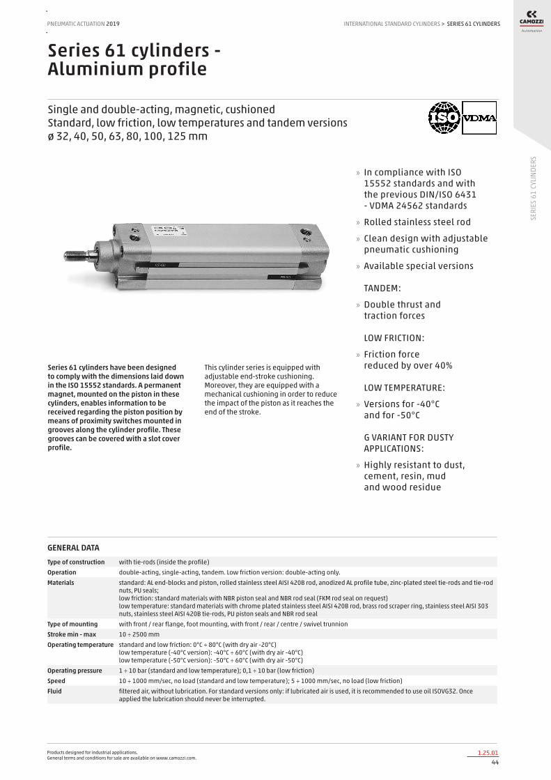
Series 61 cylinders - Aluminium profile
Single and double-acting, magnetic, cushioned Standard, low friction, low temperatures and tandem versions ø 32, 40, 50, 63, 80, 100, 125 mm
Series 61 cylinders have been designed to comply with the dimensions laid down in the ISO 15552 standards. A permanent magnet, mounted on the piston in these cylinders, enables information to be received regarding the piston position by means of proximity switches mounted in grooves along the cylinder profile. These grooves can be covered with a slot cover profile.
This cylinder series is equipped with adjustable end-stroke cushioning. Moreover, they are equipped with a mechanical cushioning in order to reduce the impact of the piston as it reaches the end of the stroke.
» In compliance with ISO 15552 standards and with the previous DIN/ISO 6431 - VDMA 24562 standards
» Rolled stainless steel rod
» Clean design with adjustable pneumatic cushioning
» Available special versions TANDEM:
» Double thrust and traction forces LOW FRICTION:
» Friction force reduced by over 40% LOW TEMPERATURE:
» Versions for -40°C and for -50°C G VARIANT FOR DUSTY APPLICATIONS:
» Highly resistant to dust, cement, resin, mud and wood residue
GENERAL DATAType of construction with tie-rods (inside the profile)Operation double-acting, single-acting, tandem. Low friction version: double-acting only.Materials standard: AL end-blocks and piston, rolled stainless steel AISI 420B rod, anodized AL profile tube, zinc-plated steel tie-rods and tie-rod
nuts, PU seals; low friction: standard materials with NBR piston seal and NBR rod seal (FKM rod seal on request) low temperature: standard materials with chrome plated stainless steel AISI 420B rod, brass rod scraper ring, stainless steel AISI 303 nuts, stainless steel AISI 420B tie-rods, PU piston seals and NBR rod seal
Type of mounting with front / rear flange, foot mounting, with front / rear / centre / swivel trunnionStroke min - max 10 ÷ 2500 mmOperating temperature standard and low friction: 0°C ÷ 80°C (with dry air -20°C)
low temperature (-40°C version): -40°C ÷ 60°C (with dry air -40°C) low temperature (-50°C version): -50°C ÷ 60°C (with dry air -50°C)
Operating pressure 1 ÷ 10 bar (standard and low temperature); 0,1 ÷ 10 bar (low friction)Speed 10 ÷ 1000 mm/sec, no load (standard and low temperature); 5 ÷ 1000 mm/sec, no load (low friction)Fluid filtered air, without lubrication. For standard versions only: if lubricated air is used, it is recommended to use oil ISOVG32. Once
applied the lubrication should never be interrupted.
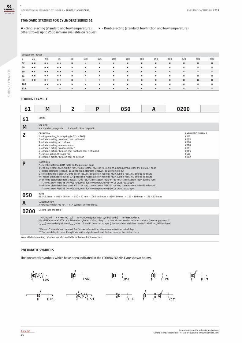
Products designed for industrial applications. General terms and conditions for sale are available on www.camozzi.com.
SERIES 61 CYLINDERSINTERNATIONAL STANDARD CYLINDERS > PNEUMATIC ACTUATION 2019
451.25.02
SERI
ES 6
1 CY
LIND
ERS
STANDARD STROKES FOR CYLINDERS SERIES 61
■ = Single-acting (standard and low temperature) ✖ = Double-acting (standard, low friction and low temperature) Other strokes up to 2500 mm are available on request.
STANDARD STROKES
Ø 25 50 75 80 100 125 150 160 200 250 300 320 400 500
32 ■ ✖ ■ ✖ ■ ✖ ✖ ✖ ✖ ✖ ✖ ✖ ✖ ✖ ✖ ✖ ✖
40 ■ ✖ ■ ✖ ■ ✖ ✖ ✖ ✖ ✖ ✖ ✖ ✖ ✖ ✖ ✖ ✖
50 ■ ✖ ■ ✖ ■ ✖ ✖ ✖ ✖ ✖ ✖ ✖ ✖ ✖ ✖ ✖ ✖
63 ■ ✖ ■ ✖ ■ ✖ ✖ ✖ ✖ ✖ ✖ ✖ ✖ ✖ ✖ ✖ ✖
80 ■ ✖ ■ ✖ ■ ✖ ✖ ✖ ✖ ✖ ✖ ✖ ✖ ✖ ✖ ✖ ✖
100 ■ ✖ ■ ✖ ✖ ✖ ✖ ✖ ✖ ✖ ✖ ✖ ✖ ✖ ✖
125 ✖ ✖ ✖ ✖ ✖ ✖ ✖ ✖ ✖ ✖ ✖ ✖ ✖
CODING EXAMPLE
61 SERIES
M VERSION M = standard, magnetic L = low friction, magnetic
2 OPERATION 1 = single-acting, front spring (ø 32 ± ø 100) 2 = double-acting, front and rear cushioned 3 = double-acting, no cushion 4 = double-acting, rear cushioned 5 = double-acting, front cushioned 6 = double-acting, through-rod, front and rear cushioned 7 = single-acting, through-rod 8 = double-acting, through-rod, no cushion
PNEUMATIC SYMBOLS CS07 CD09 CD08 CD10 CD11 CD13 CS11 CD12
P MATERIALS P = see the GENERAL DATA table on the previous page R = stainless steel AISI 420B tie-rods, stainless steel AISI 303 tie-rod nuts, other materials (see the previous page) C = rolled stainless steel AISI 303 piston rod, stainless steel AISI 304 piston rod nut U = rolled stainless steel AISI 303 piston rod, AISI 304 piston-rod nut, AISI 420B tie-rods, AISI 303 tie-rod nuts W = rolled stainless steel AISI 304 piston rod, AISI304 piston-rod nut, AISI 420B tie-rods, AISI 303 tie-rod nuts Z = chrome plated stainless steel AISI 420B rod, stainless steel AISI 304 rod nut, stainless steel AISI 420B tie-rods, stainless steel AISI 303 tie-rods nuts, seals for low temperature (-40°C), brass rod scraper Y = chrome plated stainless steel AISI 420B rod, stainless steel AISI 304 rod nut, stainless steel AISI 420B tie-rods, stainless steel AISI 303 tie-rods nuts, seals for low temperature (-50°C), brass rod scraper
050 BORE 032 = 32 mm - 040 = 40 mm - 050 = 50 mm - 063 = 63 mm - 080 = 80 mm - 100 = 100 mm - 125 = 125 mm
A CONSTRUCTION A = standard with rod nut - RL = cylinder with rod lock
0200 STROKE (see the table)
= standard V = FKM rod seal N = tandem (pneumatic symbol: CD8T) R = NBR rod seal W = all FKM seals +130°C C = PU coated cylinder. Colour: Grey* L = low friction version without rod seal (rear supply only) ** ( _ _ _ ) = extended piston rod _ _ _ mm G = with brass rod scraper (chrome plated stainless steel AISI 420B rod, NBR rod seal) * Version C: available on request. For further information, please contact our technical dept. ** The possibility to order the cylinder without piston rod seal, further reduces the friction force.
Note: all double-acting cylinders are also available in the low friction version.
61 M 2 P 050 A 0200
PNEUMATIC SYMBOLS
The pneumatic symbols which have been indicated in the CODING EXAMPLE are shown below.

Products designed for industrial applications. General terms and conditions for sale are available on www.camozzi.com.
SERIES 61 CYLINDERSPNEUMATIC ACTUATION
461.25.03
2019 INTERNATIONAL STANDARD CYLINDERS
SERI
ES 6
1 CY
LIND
ERS
>
CYLINDER IN THRUST DRAWING NOTES: 1. Precision pressure regulator or proportional regulator 2. Low friction cylinder 3. Force direction 4. Band
CYLINDER IN TRACTION Note: in order to reach the highest performance, it is recommended to connect a precision pressure regulator or a proportional regulator with the low friction cylinder as shown in the drawing.
Series 61 low friction cylinders - APPLICATION EXAMPLES
1 = rod seal 2 = flexible ring 3 = metal scraper
Series 61 low temperatures cylinders - DETAIL

Products designed for industrial applications. General terms and conditions for sale are available on www.camozzi.com.
SERIES 61 CYLINDERSINTERNATIONAL STANDARD CYLINDERS > PNEUMATIC ACTUATION 2019
471.25.04
SERI
ES 6
1 CY
LIND
ERS
CYLINDERS ACCESSORIES SERIES 61
Piston rod socket joint Mod. GY
Piston rod lock nut Mod. U
Clevis pin Mod. S Rear trunnion ball-joint Mod. R
Coupling piece Mod. GKF
Swivel ball joint Mod. GA 90° male trunnion Mod. ZC
Swivel Combination Mod. C+L+S
Front and rear flange Mod. D-E
Self aligning rod Mod. GK
Centre trunnion Mod. F Foot mount Mod. B Front female trunnion Mod. H and C-H
All accessories are supplied separately, except for piston rod lock nut Mod. U
Rear female trunnion Mod. C and C-H
Rod fork end Mod. G
Rear trunnion male Mod. L
Key to disassemble cylinders Ø 80 and 100
Counter bracket for centre trunnion Mod. BF

Products designed for industrial applications. General terms and conditions for sale are available on www.camozzi.com.
SERIES 61 CYLINDERSPNEUMATIC ACTUATION
481.25.05
2019 INTERNATIONAL STANDARD CYLINDERS
SERI
ES 6
1 CY
LIND
ERS
>
Cylinders Series 61
N.B. : the single-acting cylinders, sizes ZJ and L2 are increased by 25 mm.
DIMENSIONS
Ø AM B BG E EE G KK L1 L2+ L3 MM N PL R RT SW1 SW2 SW3 SW4 TG VA VD WH ZJ+ front/rear cushion stroke
32 22 30 16 46 G1/8 5 M10x1,25 18 94 5 12 26 14 13 M6 10 6 2 17 32,5 4 5 26 120 17 / 12
40 24 35 16 55 G1/4 5 M12x1,25 21 105 5 16 29 15 13,5 M6 13 6 2 19 38 4 5 30 135 20 / 17
50 32 40 16 64,5 G1/4 8 M16x1,5 25 106 5 20 29,5 15 16 M8 17 8 3 24 46,5 4 6 37 143 15 / 14
63 32 45 16 75 G3/8 8 M16x1,5 26 121 5 20 36,5 21 28 M8 17 8 3 24 56,5 4 6 37 158 17 / 16
80 40 45 19 93 G3/8 8 M20x1,5 30 128 0 25 36 21 30 M10 22 * 5 30 72 4 7 46 174 20 / 20
100 40 55 19,5 110 G1/2 8 M20x1,5 35 138 0 25 38,5 23 40 M10 22 * 5 30 89 4 7 51 189 21 / 19
125 54 60 23 135 G1/2 10,5 M27x2 42 160 0 32 43 23,5 50 M12 27 12 4 41 110 6 8 65 225 26 / 25
+ = add the stroke Table note: * = special key 80-62/8C (see accessories)
Cylinders Series 61 - through-rod
Note: the single-acting cylinders sizes ZM and L2 are increased by 25 mm.
DIMENSIONS
Ø AM B BG E EE G KK L1 L2+ L3 MM N PL R RT SW1 SW2 SW3 SW4 TG VD WH ZM++ front/rear cushion stroke
32 22 30 16 46 G1/8 5 M10x1,25 18 94 5 12 26 14 13 M6 10 6 2 17 32,5 5 26 146 17 / 12
40 24 35 16 55 G1/4 5 M12x1,25 21 105 5 16 29 15 13,5 M6 13 6 2 19 38 5 30 165 20 / 17
50 32 40 16 64,5 G1/4 8 M16x1,5 25 106 5 20 29,5 15 16 M8 17 8 3 24 46,5 6 37 180 15 / 14
63 32 45 16 75 G3/8 8 M16x1,5 26 121 5 20 36,5 21 28 M8 17 8 3 24 56,5 6 37 195 17 / 16
80 40 45 19 93 G3/8 8 M20x1,5 30 128 0 25 36 21 30 M10 22 * 5 30 72 7 46 220 20 / 20
100 40 55 19,5 110 G1/2 8 M20x1,5 35 138 0 25 38,5 23 40 M10 22 * 5 30 89 7 51 240 21 / 19
125 54 60 23 135 G1/2 10,5 M27x2 42 160 0 32 43 23,5 50 M12 27 12 4 41 110 8 65 290 26 / 25
+ = add the stroke once ++ = add the stroke twice Table note: * = special key 80-62/8C (see accessories)

Products designed for industrial applications. General terms and conditions for sale are available on www.camozzi.com.
SERIES 61 CYLINDERSINTERNATIONAL STANDARD CYLINDERS > PNEUMATIC ACTUATION 2019
491.25.06
SERI
ES 6
1 CY
LIND
ERS
Cylinders Series 61 - tandem version
DIMENSIONS
Ø EE L2+ L3+
32 G1/8 172,5 197,5
40 G1/4 191,5 221,5
50 G1/4 188 225
63 G3/8 204 241
80 G3/8 225,5 271,5
100 G1/2 231 282
125 G1/2 264 329
+ = add the stroke once ++ = add the stroke twice 1 = Cylinder’s outlet 2 = Cylinder’s return
Cylinders Series 61 with rod lock
DIMENSIONS
Ø ØD ØD1 ØD2 ØD3 A G H H1 L1 L2 L3 L4 L5 L6 L7 L8 L9+ L10+ M Z
32 12 30.5 35 25 32,5 M5 25,5 46,5 58 48 10 8 13 20,5 34 45 94 160 M6 M6x20
40 16 35 40 28 38 G1/8 30 53 65 55 10 8 13 22,5 38 50 105 178 M6 M6x20
50 20 40 50 35 46,5 G1/8 36 64 82 70 12 15 16 29,5 48 60 106 200 M8 M6x20
63 20 45 60 38 56,5 G1/8 40 75 82 70 12 15 16 29,5 49,5 70 121 215 M8 M8x30
80 25 45 80 48 72 G1/8 50 95 110 90 20 18 20 35 61 90 128 254 M10 M10x35
100 25 55 100 58 89 G1/8 58 110,5 115 100 15 18 20 39 69 105 138 269 M10 M10x35
125 32 60 130 65 110 G1/8 80 150 167 122 45 22 30 51 86,5 140 160 350 M12 M12x40
+ = add the stroke

Products designed for industrial applications. General terms and conditions for sale are available on www.camozzi.com.
SERIES 61 CYLINDERSPNEUMATIC ACTUATION
501.25.07
2019 INTERNATIONAL STANDARD CYLINDERS
SERI
ES 6
1 CY
LIND
ERS
>
Foot mount Mod. B
Material: zinc-plated steel
Mod. Ø AT SA+ XA+ TR E AB AH AO AU torque force
B-41-32 32 4 142 144 32 45 7 32 11 24 6 Nm
B-41-40 40 4 161 163 36 53,5 10 36 15 28 6 Nm
B-41-50 50 4 170 175 45 62,5 10 45 15 32 13 Nm
B-41-63 63 5 185 190 50 73 10 50 15 32 13 Nm
B-41-80 80 6 210 216 63 92 12 63 20 41 19 Nm
B-41-100 100 6 220 230 75 108,5 14,5 71 25 41 22 Nm
B-41-125 125 7 250 270 90 132 16,5 90 25 45 26 Nm
Supplied with: 2x feet 4x screws + = add the stroke
Front and rear flange Mod. D-E
Material: Aluminium
Mod. Ø W MF ZB+ TF R UF E FB ZF+ torque force
D-E-41-32 32 16 10 120 64 32 86 45 7 130 6 Nm
D-E-41-40 40 20 10 135 72 36 88 52 9 145 6 Nm
D-E-41-50 50 25 12 143 90 45 110 63 9 155 13 Nm
D-E-41-63 63 25 12 158 100 50 116 73 9 170 13 Nm
D-E-41-80 80 30 16 174 126 63 148 95 12 190 19 Nm
D-E-41-100 100 35 16 189 150 75 176 115 14 205 22 Nm
D-E-41-125 125 45 20 225 180 90 224 135 16 245 26 Nm
Supplied with: 1x flange 4x screws + = add the stroke

Products designed for industrial applications. General terms and conditions for sale are available on www.camozzi.com.
SERIES 61 CYLINDERSINTERNATIONAL STANDARD CYLINDERS > PNEUMATIC ACTUATION 2019
511.25.08
SERI
ES 6
1 CY
LIND
ERS
Rear female trunnion Mod. C and C-H
Material: Aluminium
Mod. Ø CD L FL XD+ MR E CB UB torque force
C-41-32 32 10 12 22 142 10 45 26 45 6 Nm
C-41-40 40 12 15 25 160 12 53.5 28 52 6 Nm
C-41-50 50 12 15 27 170 13 62.5 32 60 13 Nm
C-H-41-63 63 16 20 32 190 17 73 40 70 13 Nm
C-H-41-80 80 16 24 36 210 17 92 50 90 19 Nm
C-H-41-100 100 20 29 41 230 21 108.5 60 110 22 Nm
C-H-41-125 125 25 30 50 275 26 132 70 130 26 Nm
Supplied with: 1x female trunnion 4x screws + = add the stroke
Front female trunnion Mod. H and C-H
Material: Aluminium
Mod. Ø CB UB E XD FL L CD MR torque force
H-41-32 32 26 45 45 120 22 12 10 10 6 Nm
H-41-40 40 28 52 53.5 135 25 15 12 12 6 Nm
H-41-50 50 32 60 62.5 143 27 15 12 13 13 Nm
H-60-63 63 40 70 73 158 32 20 16 17 13 Nm
C-H-41-80 80 50 90 92 174 36 24 16 17 19 Nm
C-H-41-100 100 60 110 108.5 189 41 29 20 21 22 Nm
C-H-41-125 125 70 130 132 225 50 30 25 26 26 Nm
Supplied with: 1x female trunnion 4x screws + = add the stroke

Products designed for industrial applications. General terms and conditions for sale are available on www.camozzi.com.
SERIES 61 CYLINDERSPNEUMATIC ACTUATION
521.25.09
2019 INTERNATIONAL STANDARD CYLINDERS
SERI
ES 6
1 CY
LIND
ERS
>
Rear male trunnion Mod. L
Material: Aluminium
DIMENSIONS
Mod. Ø CD L FL XD+ MR E EW torque force
L-41-32 32 10 12 22 142 10 45 26 6 Nm
L-41-40 40 12 15 25 160 13 53.5 28 6 Nm
L-41-50 50 12 15 27 170 13 62.5 32 13 Nm
L-41-63 63 16 20 32 190 17 73 40 13 Nm
L-41-80 80 16 24 36 210 17 92 50 19 Nm
L-41-100 100 20 29 41 230 21 108.5 60 22 Nm
L-41-125 125 25 30 50 275 26 132 70 26 Nm
Supplied with: 1x male trunnion 4x screws + = add the stroke
Centre trunnion Mod. F
Material: zinc-plated steel
DIMENSIONS
Mod. Ø XV1 XV2 XV3 TM TK TD TL UW R
F-61-32 32 61 73 85 50 18 12 12 65 0,1
F-61-40 40 69 82,5 96 63 20 16 16 75 0,15
F-61-50 50 76,5 90 103,5 75 20 16 16 91 0,15
F-61-63 63 86 97,5 109 90 25 20 20 94 0,15
F-61-80 80 94,5 110 125,5 110 25 20 20 130 0,15
F-61-100 100 104,5 120 135,5 132 30 25 25 145 0,2
F-61-125 125 123 145 167 160 30 25 25 155 0,2
Supplied with: 1x centre trunnion 4x screws 4x fixing elements + = add the stroke

Products designed for industrial applications. General terms and conditions for sale are available on www.camozzi.com.
SERIES 61 CYLINDERSINTERNATIONAL STANDARD CYLINDERS > PNEUMATIC ACTUATION 2019
531.25.10
SERI
ES 6
1 CY
LIND
ERS
Accessory combination Mod. C+L+S
Material: aluminium
DIMENSIONS
Mod. Ø E TG ØN XD+ ØCD L FL I M Z° (max) torque force
C+L+S 32 45 32.5 6.5 142 10 12 22 10 22 30 6 Nm
C+L+S 40 53.5 38 6.5 160 12 15 25 10 25 40 6 Nm
C+L+S 50 62.5 46.5 9 170 12 15 27 12 27 25 13 Nm
C+L+S 63 73 56.5 9 190 16 20 32 12 32 36 13 Nm
C+L+S 80 92 72 11 210 16 24 36 12 36 34 19 Nm
C+L+S 100 108.5 89 11 230 20 29 41 12 41 38 22 Nm
C+L+S 125 132 110 13 275 25 30 50 25 50 30 26 Nm
+ = add the stroke
90° male trunnion Mod. ZC
CETOP RP 107P Material: Aluminium
DIMENSIONS
Mod. Ø EB CK HB XD+ TE UL EA GL L5 RA EM UR PH BT BR
ZC-32 32 11 10 6,6 142 38 51 10 21 1,6 18 26 31 32 8 10
ZC-40 40 11 12 6,6 160 41 54 15 24 1,6 22 28 35 36 10 11
ZC-50 50 15 12 9 170 50 65 16 33 1,6 30 32 45 45 12 13
ZC-63 63 15 16 9 190 52 67 16 37 1,6 35 40 50 50 14 15
ZC-80 80 18 16 11 210 66 86 20 47 2,5 40 50 60 63 14 15
ZC-100 100 18 20 11 230 76 96 20 55 2,5 50 60 70 71 17 19
ZC-125 125 20 25 14 275 94 124 30 70 3,2 60 70 90 90 20 22,5
Supplied with: 1x male support + = add the stroke

Products designed for industrial applications. General terms and conditions for sale are available on www.camozzi.com.
SERIES 61 CYLINDERSPNEUMATIC ACTUATION
541.25.11
2019 INTERNATIONAL STANDARD CYLINDERS
SERI
ES 6
1 CY
LIND
ERS
>
Trunnion ball-joint Mod. R*
* This trunnion doesn’t comply with the ISO 15552 standard Material: Aluminium
Mod. Ø ØCX L DL XN+ MS E EX EP Z torque force
R-41-32 32 10 12 22 142 18 45 14 10.5 4 6 Nm
R-41-40 40 12 15 25 160 18 53.5 16 12 4 6 Nm
R-41-50 50 12 * 15 27 170 21 62.5 16 * 12 * 4 13 Nm
R-41-63 63 16 20 32 190 23 73 21 15 4 13 Nm
R-41-80 80 16 * 24 36 210 28 92 21 * 15 * 4 19 Nm
R-41-100 100 20 29 41 230 30 108.5 25 18 4 22 Nm
R-41-125 125 30 30 50 275 40 140 37 25 4 26 Nm
Supplied with: 1x trunnion ball joint 4x screws + = add the stroke
Counter bracket for centre trunnion Mod. BF
Material: Aluminium
Mod. Ø ØCR NH C B3 TH UL FK FN B1 B2 HB
BF-32 32 12 15 7,5 3 32 46 15 30 6,8 11 6,6
BF-40-50 40 - 50 16 18 9 3 36 55 18 36 9 15 9
BF-63-80 63 - 80 20 20 10 3 42 65 20 40 11 18 11
BF-100-125 100 - 125 25 25 12,5 3,5 50 75 25 50 13 20 14
Supplied with: 2x supports

Products designed for industrial applications. General terms and conditions for sale are available on www.camozzi.com.
SERIES 61 CYLINDERSINTERNATIONAL STANDARD CYLINDERS > PNEUMATIC ACTUATION 2019
551.25.12
SERI
ES 6
1 CY
LIND
ERS
Accessory to mount valves on the cylinder
The mounting sub-base Mod. PCV enables the valve or solenoid valve to be mounted directly on the cylinder.
DIMENSIONS
Mod.
PCV-61-K3 to connect valves - solenoid valves Series 3
PCV-61-K4 to connect valves - solenoid valves Series 4 port G1/4
PCV-62-KEN to connect valves - solenoid valves Series EN
PCV-61-K8 to connect valves - solenoid valves Series 4 port G1/8 and Series 3 port G1/4
Clevis pin Mod. S
DIMENSIONS
Mod. Ø d L L1 L2 L3
S-32 32 10 52 46 1,1 3
S-40 40 12 59 53 1,1 3
S-50 50 12 67 61 1,1 3
S-63 63 16 77 71 1,1 3
S-80 80 16 97 91 1,1 3
S-100 100 20 121 111 1,3 5
S-125 125 25 140,5 132 1,3 4,25
Supplied with: 1x clevis pin in stainless steel 303 2x Seeger in steel

Products designed for industrial applications. General terms and conditions for sale are available on www.camozzi.com.
SERIES 61 CYLINDERSPNEUMATIC ACTUATION
561.25.13
2019 INTERNATIONAL STANDARD CYLINDERS
SERI
ES 6
1 CY
LIND
ERS
>
Swivel ball joint Mod. GA
ISO 8139. Material: zinc-plated steel.
Mod. ØCN(H7) U EN ER AX CE KK ØT Z SW
GA-32 10 10,5 14 14 20 43 M10X1,25 15 6,5 17
GA-40 12 12 16 16 22 50 M12X1,25 17,5 6,5 19
GA-50-63 16 15 21 21 28 64 M16X1,5 22 7,5 22
GA-80-100 20 18 25 25 33 77 M20x1,5 27,5 7 30
GA-41-125 30 25 37 37 51 110 M27x2 40 7,5 41
Piston rod socket joint Mod. GY
Material: zama and zinc-plated steel.
DIMENSIONS
Mod. Ø KK L CE L2 AX SW SW1 L1 L3 ØT ØD E ØB ØC Z
GY-32 32 M10X1,25 74 35 6,5 18 17 11 19,5 15 15 19 10 14 28 15
GY-40 40 M12X1,25 84 40 6,5 20 19 17 21 17 17,5 22 12 19 32 15
GY-50-63 50-63 M16X1,5 112 50 8 27 22 19 27,5 23 22 27 16 22 40 11
GY-80-100 80-100 M20x1,5 133 63 10 38 30 24 31,5 25 27,5 34 20 27 45 7,5
Rod fork end Mod. G
ISO 8140 Material: zinc-plated steel
Mod. ØCK LE CM CL ER CE KK B ØB1
G-25-32 10 20 10 20 12 40 M10 X 1,25 26 18
G-40 12 24 12 24 14 48 M12 X 1,25 32 20
G-50-63 16 32 16 32 19 64 M16 X 1,5 40 26
G-80-100 20 40 20 40 25 80 M20 X 1,5 48 34
G-41-125 30 54 30 55 38 110 M27 X 2 74 48
Piston rod lock nut Mod. U
ISO 4035 Material: zinc-plated steel.
Mod. D m SW
U-25-32 M10X1,25 6 17
U-40 M12X1,25 7 19
U-50-63 M16X1,5 8 24
U-80-100 M20x1,5 9 30
U-41-125 M27x2 12 41

Products designed for industrial applications. General terms and conditions for sale are available on www.camozzi.com.
SERIES 61 CYLINDERSINTERNATIONAL STANDARD CYLINDERS > PNEUMATIC ACTUATION 2019
571.25.14
SERI
ES 6
1 CY
LIND
ERS
Self aligning rod Mod. GK
Material: zinc-plated steel.
DIMENSIONS
Mod. Ø KK L L1 L3 L4 ØA ØD H I SW SW1 SW2 B1 AX Z E
GK-25-32 25-32 M10x1,25 71,5 35 20 7,5 14 22 32 30 19 12 17 5 22 4 2
GK-40 40 M12x1,25 75,5 35 24 7,5 14 22 32 30 19 12 19 6 22 4 2
GK-50-63 50-63 M16x1,5 104 53 32 10 22 32 45 41 27 20 24 8 30 3 2
GK-80-100 80-100 M20x1,5 119 53 40 10 22 32 45 41 27 20 30 10 37 3 2
GK-125 125 M27x2 147 60 54 10 32 57 70 65 54 24 41 12 48 4 2
Coupling piece Mod. GKF
Material: zinc-plated steel.
DIMENSIONS
Mod. Ø KK A B R TF L L1 I Ø D Ø D1 Ø D2 SW E
GKF-25-32 32 M10x1,25 37 60 23 36 22,5 15 6,8 18 11 6,6 15 2
GKF-40 40 M12x1,25 56 60 38 42 22,5 15 9 20 15 9 15 2,5
GKF-50-63 50-63 M16x1,5 80 80 58 58 26,5 15 10,5 25 18 11 22 2,5
GKF-80-100 80-100 M20x1,5 90 90 65 65 32,5 20 13 30,5 20 14 27 2,5
GKF-125 125 M27x2 90 90 65 65 35,5 20 13 40 20 14 36 4
Special key to disassemble cylinders Ø 80 and 100
Material: hardened steel
Mod.
80-62/8C
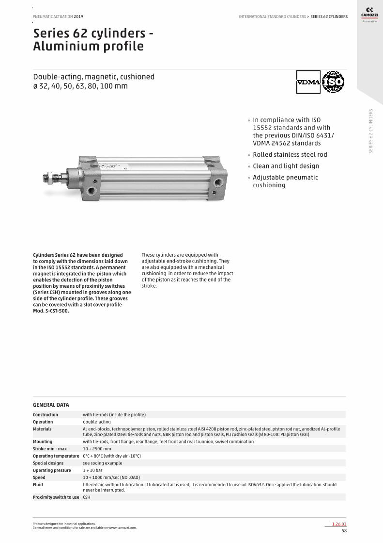
Products designed for industrial applications. General terms and conditions for sale are available on www.camozzi.com.
SERIES 62 CYLINDERSPNEUMATIC ACTUATION
581.26.01
2019 INTERNATIONAL STANDARD CYLINDERS
SERI
ES 6
2 CY
LIND
ERS
>
Series 62 cylinders - Aluminium profile
Double-acting, magnetic, cushioned ø 32, 40, 50, 63, 80, 100 mm
Cylinders Series 62 have been designed to comply with the dimensions laid down in the ISO 15552 standards. A permanent magnet is integrated in the piston which enables the detection of the piston position by means of proximity switches (Series CSH) mounted in grooves along one side of the cylinder profile. These grooves can be covered with a slot cover profile Mod. S-CST-500.
These cylinders are equipped with adjustable end-stroke cushioning. They are also equipped with a mechanical cushioning in order to reduce the impact of the piston as it reaches the end of the stroke.
» In compliance with ISO 15552 standards and with the previous DIN/ISO 6431/VDMA 24562 standards
» Rolled stainless steel rod
» Clean and light design
» Adjustable pneumatic cushioning
GENERAL DATAConstruction with tie-rods (inside the profile)Operation double-actingMaterials AL end-blocks, technopolymer piston, rolled stainless steel AISI 420B piston rod, zinc-plated steel piston rod nut, anodized AL-profile
tube, zinc-plated steel tie-rods and nuts, NBR piston rod and piston seals, PU cushion seals (Ø 80-100: PU piston seal)Mounting with tie-rods, front flange, rear flange, feet front and rear trunnion, swivel combinationStroke min - max 10 ÷ 2500 mmOperating temperature 0°C ÷ 80°C (with dry air -10°C)Special designs see coding exampleOperating pressure 1 ÷ 10 barSpeed 10 ÷ 1000 mm/sec (NO LOAD)Fluid filtered air, without lubrication. If lubricated air is used, it is recommended to use oil ISOVG32. Once applied the lubrication should
never be interrupted.Proximity switch to use CSH

Products designed for industrial applications. General terms and conditions for sale are available on www.camozzi.com.
SERIES 62 CYLINDERSINTERNATIONAL STANDARD CYLINDERS > PNEUMATIC ACTUATION 2019
591.26.02
SERI
ES 6
2 CY
LIND
ERS
STANDARD STROKES FOR CYLINDERS SERIES 62
Special strokes until 2500 mm available on request ✖ = Double-acting
STANDARD STROKES
Ø 25 50 75 80 100 125 150 160 200 250 300 320 400 500
32 ✖ ✖ ✖ ✖ ✖ ✖ ✖ ✖ ✖ ✖ ✖ ✖ ✖ ✖
40 ✖ ✖ ✖ ✖ ✖ ✖ ✖ ✖ ✖ ✖ ✖ ✖ ✖ ✖
50 ✖ ✖ ✖ ✖ ✖ ✖ ✖ ✖ ✖ ✖ ✖ ✖ ✖ ✖
63 ✖ ✖ ✖ ✖ ✖ ✖ ✖ ✖ ✖ ✖ ✖ ✖ ✖ ✖
80 ✖ ✖ ✖ ✖ ✖ ✖ ✖ ✖ ✖ ✖ ✖ ✖ ✖ ✖
100 ✖ ✖ ✖ ✖ ✖ ✖ ✖ ✖ ✖ ✖ ✖ ✖ ✖
CODING EXAMPLE
62 SERIES
M VERSION M = standard, magnetic
2 OPERATION 2 = double-acting, front + rear cushion 3 = double-acting, no cushion 4 = double-acting, rear cushion 5 = double-acting, front cushion 6 = double-acting, through-rod, front + rear cushion 8 = double-acting, through-rod, no cushion
PNEUMATIC SYMBOLS CD09 CD08 CD10 CD11 CD13 CD12
P MATERIALS P = see the GENERAL DATA table on the previous page R = stainless steel AISI 420B tie-rods, stainless steel AISI 303 tie-rod nuts C = rolled stainless steel AISI 303 piston rod , stainless steel AISI 304 piston rod nut U = rolled stainless steel AISI 303 piston rod, stainless steel AISI 304 piston rod nut, stainless steel AISI 420B tie-rod, stainless steel AISI 303 tie-rod nuts W = rolled stainless steel AISI 304 piston rod, stainless steel AISI304 piston rod nut, stainless steel AISI 420B tie-rods, stainless steel AISI 303 tie-rod nuts
050 BORE 032 = 32 mm - 040 = 40 mm - 050 = 50 mm - 063 = 63 mm - 080 = 80 mm - 100 = 100 mm
A CONSTRUCTION A = standard lock nut for rod RL = cylinder with rod lock
0200 STROKE: 10 ÷ 2500 mm
= standard V = FKM piston rod seal P = PU piston rod seal ( _ _ _ ) = extended piston rod _ _ _ mm
62 M 2 P 050 A 0200
PNEUMATIC SYMBOLS
The pneumatic symbols which have been indicated in the CODING EXAMPLE are shown below.
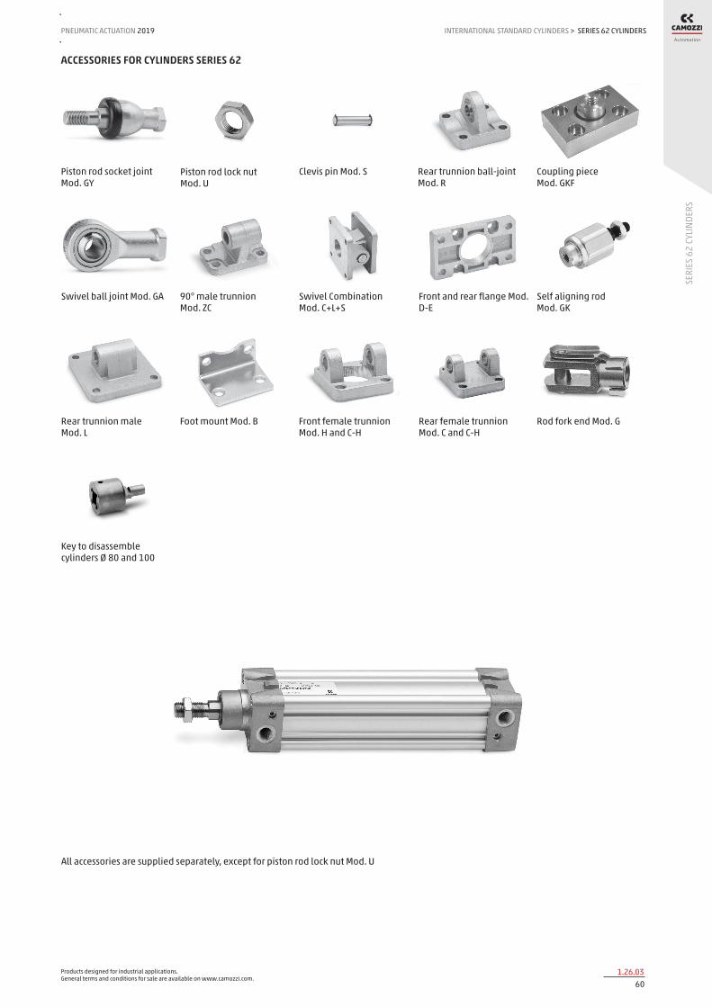
Products designed for industrial applications. General terms and conditions for sale are available on www.camozzi.com.
SERIES 62 CYLINDERSPNEUMATIC ACTUATION
601.26.03
2019 INTERNATIONAL STANDARD CYLINDERS
SERI
ES 6
2 CY
LIND
ERS
>
ACCESSORIES FOR CYLINDERS SERIES 62
Piston rod socket joint Mod. GY
Piston rod lock nut Mod. U
Clevis pin Mod. S Rear trunnion ball-joint Mod. R
Coupling piece Mod. GKF
Swivel ball joint Mod. GA 90° male trunnion Mod. ZC
Swivel Combination Mod. C+L+S
Front and rear flange Mod. D-E
Self aligning rod Mod. GK
Rear trunnion male Mod. L
Foot mount Mod. B Front female trunnion Mod. H and C-H
All accessories are supplied separately, except for piston rod lock nut Mod. U
Rear female trunnion Mod. C and C-H
Rod fork end Mod. G
Key to disassemble cylinders Ø 80 and 100
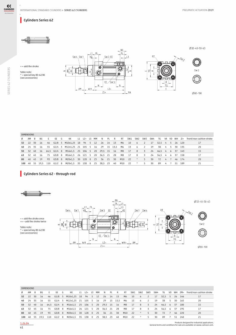
Products designed for industrial applications. General terms and conditions for sale are available on www.camozzi.com.
SERIES 62 CYLINDERSINTERNATIONAL STANDARD CYLINDERS > PNEUMATIC ACTUATION 2019
611.26.04
SERI
ES 6
2 CY
LIND
ERS
Cylinders Series 62
DIMENSIONS
Ø AM B BG E EE G KK L1 L2+ L3 MM N PL R RT SW1 SW2 SW3 SW4 TG VA VD WH ZJ+ front/rear cushion stroke
32 22 30 16 46 G1/8 5 M10x1,25 18 94 5 12 26 14 13 M6 10 6 2 17 32,5 4 5 26 120 17
40 24 35 16 55 G1/4 5 M12x1,25 21 105 5 16 29 15 13,5 M6 13 6 2 19 38 4 5 30 135 20
50 32 40 16 64,5 G1/4 8 M16x1,5 25 106 5 20 29,5 15 16 M8 17 8 3 24 46,5 4 6 37 143 15
63 32 45 16 75 G3/8 8 M16x1,5 26 121 5 20 36,5 21 28 M8 17 8 3 24 56,5 4 6 37 158 17
80 40 45 19 93 G3/8 8 M20x1,5 30 128 0 25 36 21 30 M10 22 * 5 30 72 4 7 46 174 20
100 40 55 19,5 110 G1/2 8 M20x1,5 35 138 0 25 38,5 23 40 M10 22 * 5 30 89 4 7 51 189 21
+ = add the stroke Table note: * = special key 80-62/8C (see accessories)
Cylinders Series 62 - through-rod
DIMENSIONS
Ø AM B BG E EE G KK L1 L2+ L3 MM N PL R RT SW1 SW2 SW3 SW4 TG VD WH ZM+ front/rear cushion stroke
32 22 30 16 46 G1/8 5 M10x1,25 18 94 5 12 26 14 13 M6 10 6 2 17 32,5 5 26 146 17
40 24 35 16 55 G1/4 5 M12x1,25 21 105 5 16 29 15 13,5 M6 13 6 2 19 38 5 30 165 20
50 32 40 16 64,5 G1/4 8 M16x1,5 25 106 5 20 29,5 15 16 M8 17 8 3 24 46,5 6 37 180 15
63 32 45 16 75 G3/8 8 M16x1,5 26 121 5 20 36,5 21 28 M8 17 8 3 24 56,5 6 37 195 17
80 40 45 19 93 G3/8 8 M20x1,5 30 128 0 25 36 21 30 M10 22 * 5 30 72 7 46 220 20
100 40 55 19,5 110 G1/2 8 M20x1,5 35 138 0 25 38,5 23 40 M10 22 * 5 30 89 7 51 240 21
+ = add the stroke once ++ = add the stroke twice Table note: * = special key 80-62/8C (see accessories)
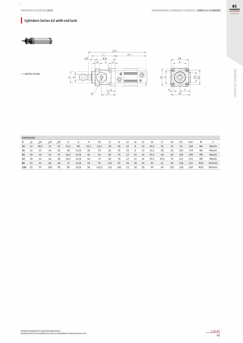
Products designed for industrial applications. General terms and conditions for sale are available on www.camozzi.com.
SERIES 62 CYLINDERSPNEUMATIC ACTUATION
621.26.05
2019 INTERNATIONAL STANDARD CYLINDERS
SERI
ES 6
2 CY
LIND
ERS
>
Cylinders Series 62 with rod lock
DIMENSIONS
Ø ØD ØD1 ØD2 ØD3 A G H H1 L1 L2 L3 L4 L5 L6 L7 L8 L9+ L10+ M Z
32 12 30,5 35 25 32,5 M5 25,5 46,5 58 48 10 8 13 20,5 34 45 94 160 M6 M6x20
40 16 35 40 28 38 G1/8 30 53 65 55 10 8 13 22,5 38 50 105 178 M6 M6x20
50 20 40 50 35 46,5 G1/8 36 64 82 70 12 15 16 29,5 48 60 106 200 M8 M6x20
63 20 45 60 38 56,5 G1/8 40 75 82 70 12 15 16 29,5 49,5 70 121 215 M8 M8x30
80 25 45 80 48 72 G1/8 50 95 110 90 20 18 20 35 61 90 128 254 M10 M10x35
100 25 55 100 58 89 G1/8 58 110,5 115 100 15 18 20 39 69 105 138 269 M10 M10x35
+ = add the stroke

Products designed for industrial applications. General terms and conditions for sale are available on www.camozzi.com.
SERIES 62 CYLINDERSINTERNATIONAL STANDARD CYLINDERS > PNEUMATIC ACTUATION 2019
631.26.06
SERI
ES 6
2 CY
LIND
ERS
Foot mount Mod. B
Material: zinc-plated steel
Mod. Ø AT SA+ XA+ TR E AB AH AO AU
B-41-32 32 4 142 144 32 45 7 32 11 24
B-41-40 40 4 161 163 36 53,5 10 36 15 28
B-41-50 50 4 170 175 45 62,5 10 45 15 32
B-41-63 63 5 185 190 50 73 10 50 15 32
B-41-80 80 6 210 216 63 92 12 63 20 41
B-41-100 100 6 220 230 75 108,5 14,5 71 25 41
Supplied with: 2x feet 4x screws + = add the stroke
Front and rear flange Mod. D-E
Material: aluminium
Mod. Ø W MF ZB+ TF R UF E FB ZF+ torque force
D-E-41-32 32 16 10 120 64 32 86 45 7 130 6 Nm
D-E-41-40 40 20 10 135 72 36 88 52 9 145 6 Nm
D-E-41-50 50 25 12 143 90 45 110 63 9 155 13 Nm
D-E-41-63 63 25 12 158 100 50 116 73 9 170 13 Nm
D-E-41-80 80 30 16 174 126 63 148 95 12 190 19 Nm
D-E-41-100 100 35 16 189 150 75 176 115 14 205 22 Nm
Supplied with: 1x flange 4x screws + = add the stroke

Products designed for industrial applications. General terms and conditions for sale are available on www.camozzi.com.
SERIES 62 CYLINDERSPNEUMATIC ACTUATION
641.26.07
2019 INTERNATIONAL STANDARD CYLINDERS
SERI
ES 6
2 CY
LIND
ERS
>
Rear female trunnion Mod. C and C-H
Material: Aluminium
Mod. Ø CD L FL XD+ MR E CB UB torque force
C-41-32 32 10 12 22 142 10 45 26 45 6 Nm
C-41-40 40 12 15 25 160 12 53.5 28 52 6 Nm
C-41-50 50 12 15 27 170 13 62.5 32 60 13 Nm
C-H-41-63 63 16 20 32 190 17 73 40 70 13 Nm
C-H-41-80 80 16 24 36 210 17 92 50 90 19 Nm
C-H-41-100 100 20 29 41 230 21 108.5 60 110 22 Nm
Supplied with: 1x female trunnion 4x screws + = add the stroke
Front female trunnion Mod. H and C-H
Material: Aluminium
Mod. Ø CB UB E XD FL L CD MR
H-41-32 32 26 45 45 120 22 12 10 10
H-41-40 40 28 52 53.5 135 25 15 12 12
H-41-50 50 32 60 62.5 143 27 15 12 13
H-60-63 63 40 70 73 158 32 20 16 17
C-H-41-80 80 50 90 92 174 36 24 16 17
C-H-41-100 100 60 110 108.5 189 41 29 20 21
Supplied with: 1x female trunnion 4x screws + = add the stroke

Products designed for industrial applications. General terms and conditions for sale are available on www.camozzi.com.
SERIES 62 CYLINDERSINTERNATIONAL STANDARD CYLINDERS > PNEUMATIC ACTUATION 2019
651.26.08
SERI
ES 6
2 CY
LIND
ERS
Rear trunnion, male Mod. L
Material: aluminium
DIMENSIONS
Mod. Ø ØCD L FL XD+ MR E EW torque force
L-41-32 32 10 12 22 142 10 45 26 6 Nm
L-41-40 40 12 15 25 160 13 53.5 28 6 Nm
L-41-50 50 12 15 27 170 13 62.5 32 13 Nm
L-41-63 63 16 20 32 190 17 73 40 13 Nm
L-41-80 80 16 24 36 210 17 92 50 19 Nm
L-41-100 100 20 29 41 230 21 108.5 60 22 Nm
Supplied with: 1x male trunnion 4x screws + = add the stroke
Trunnion ball-joint Mod. R*
* This trunnion doesn’t comply with the ISO 15552 standard Material: Aluminium
DIMENSIONS
Mod. Ø ØCX L DL XN+ MS E EX EP Z° torque force
R-41-32 32 10 12 22 142 18 45 14 10.5 4 6 Nm
R-41-40 40 12 15 25 160 18 53.5 16 12 4 6 Nm
R-41-50 50 12* 15 27 170 21 62.5 16* 12* 4 13 Nm
R-41-63 63 16 20 32 190 23 73 21 15 4 13 Nm
R-41-80 80 16* 24 36 210 28 92 21* 15* 4 19 Nm
R-41-100 100 20 29 41 230 30 108.5 25 18 4 22 Nm
Supplied with: 1x trunnion ball-joint 4x screws

Products designed for industrial applications. General terms and conditions for sale are available on www.camozzi.com.
SERIES 62 CYLINDERSPNEUMATIC ACTUATION
661.26.09
2019 INTERNATIONAL STANDARD CYLINDERS
SERI
ES 6
2 CY
LIND
ERS
>
Accessory combination Mod. C+L+S
Material: Aluminium
DIMENSIONS
Mod. Ø E TG ØN XD+ FL ØCD L M I Z° (max) torque force
C+L+S 32 45 32.5 6.5 142 22 10 12 22 10 30 6 Nm
C+L+S 40 53.5 38 6.5 160 25 12 15 25 10 40 6 Nm
C+L+S 50 62.5 46.5 9 170 27 12 15 27 12 25 13 Nm
C+L+S 63 73 56.5 9 190 32 16 20 32 12 36 13 Nm
C+L+S 80 92 72 11 210 36 16 24 36 12 34 19 Nm
C+L+S 100 108.5 89 11 230 41 20 29 41 12 38 22 Nm
+ = add the stroke
90° male trunnion Mod. ZC
CETOP RP 107P Material: Aluminium
DIMENSIONS
Mod. Ø EB CK HB XD+ TE UL EA GL L5 RA EM UR PH BT BR
ZC-32 32 11 10 6,6 142 38 51 10 21 1,6 18 26 31 32 8 10
ZC-40 40 11 12 6,6 160 41 54 15 24 1,6 22 28 35 36 10 11
ZC-50 50 15 12 9 170 50 65 16 33 1,6 30 32 45 45 12 13
ZC-63 63 15 16 9 190 52 67 16 37 1,6 35 40 50 50 14 15
ZC-80 80 18 16 11 210 66 86 20 47 2,5 40 50 60 63 14 15
ZC-100 100 18 20 11 230 76 96 20 55 3,2 50 60 70 71 17 19
Supplied with: 1x male support + = add the stroke

Products designed for industrial applications. General terms and conditions for sale are available on www.camozzi.com.
SERIES 62 CYLINDERSINTERNATIONAL STANDARD CYLINDERS > PNEUMATIC ACTUATION 2019
671.26.10
SERI
ES 6
2 CY
LIND
ERS
Accessory to mount valves on the cylinder
The mounting sub-base Mod. PCV enables the valve or solenoid valve to be mounted directly on the cylinder, thus forming a compact unit to apply.
Mod.
PCV-62-K3 to connect valves - solenoid valves Series 3
PCV-62-K4 to connect valves - solenoid valves Series 4 port G1/4
PCV-62-KEN to connect valves - solenoid valves Series EN
PCV-62-K8 to connect valves - solenoid valves Series 4 port G1/8 and Series 3 port G1/4
Make sure that the WW dimension of the valve to be mounted is smaller than the JJ cylinder dimension. Further information on http://catalogue.camozzi.com/downloads.
Clevis pin Mod. S
DIMENSIONS
Mod. Ø d L L1 L2 L3
S-32 32 10 52 46 1,1 3
S-40 40 12 59 53 1,1 3
S-50 50 12 67 61 1,1 3
S-63 63 16 77 71 1,1 3
S-80 80 16 97 91 1,1 3
S-100 100 20 121 111 1,3 5
Supplied with: 1x clevis pin in stainless steel 303 2x Seeger in steel

Products designed for industrial applications. General terms and conditions for sale are available on www.camozzi.com.
SERIES 62 CYLINDERSPNEUMATIC ACTUATION
681.26.11
2019 INTERNATIONAL STANDARD CYLINDERS
SERI
ES 6
2 CY
LIND
ERS
>
Swivel ball joint Mod. GA
Material: zinc-plated steel ISO 8139
DIMENSIONS
Mod. ØCN U EN ER AX CE KK T Z SW
GA-32 10 10,5 14 14 20 43 M10X1,25 15 6,5 17
GA-40 12 12 16 16 22 50 M12X1,25 17,5 6,5 19
GA-50-63 16 15 21 21 28 64 M16X1,5 22 7,5 22
GA-80-100 20 18 25 25 33 77 M20x1,5 27,5 7 30
Piston rod socket joint Mod. GY
Material: zama and zinc-plated steel
DIMENSIONS
Mod. Ø KK L CE L2 AX SW SW1 L1 L3 ØT ØD E ØB ØC Z
GY-32 32 M10X1,25 74 35 6,5 18 17 11 19,5 15 15 19 10 14 28 15
GY-40 40 M12X1,25 84 40 6,5 20 19 17 21 17 17,5 22 12 19 32 15
GY-50-63 50-63 M16X1,5 112 50 8 27 22 19 27,5 23 22 27 16 22 40 11
GY-80-100 80-100 M20x1,5 133 63 10 38 30 24 31,5 25 27,5 34 20 27 45 7,5
Rod fork end Mod. G
Material: zinc-plated steel ISO 8140
DIMENSIONS
Mod. ØCK LE CM CL ER CE KK B B1
G-25-32 10 20 10 20 12 40 M10 X 1,25 26 18
G-40 12 24 12 24 14 48 M12 X 1,25 32 20
G-50-63 16 32 16 32 19 64 M16 X 1,5 40 26
G-80-100 20 40 20 40 25 80 M20 X 1,5 48 34
Piston rod lock nut Mod. U
Material: zinc-plated steel ISO 4035
DIMENSIONS
Mod. D m SW
U-25-32 M10X1,25 6 17
U-40 M12X1,25 7 19
U-50-63 M16X1,5 8 24
U-80-100 M20x1,5 9 30

Products designed for industrial applications. General terms and conditions for sale are available on www.camozzi.com.
SERIES 62 CYLINDERSINTERNATIONAL STANDARD CYLINDERS > PNEUMATIC ACTUATION 2019
691.26.12
SERI
ES 6
2 CY
LIND
ERS
Self aligning rod Mod. GK
Material: zinc-plated steel
DIMENSIONS
Mod. Ø KK L L1 L3 L4 ØA ØD H I SW SW1 SW2 B1 AX Z E
GK-25-32 25-32 M10x1,25 71,5 35 20 7,5 14 22 32 30 19 12 17 5 22 4 2
GK-40 40 M12x1,25 75,5 35 24 7,5 14 22 32 30 19 12 19 6 22 4 2
GK-50-63 50-63 M16x1,5 104 53 32 10 22 32 45 41 27 20 24 8 30 3 2
GK-80-100 80-100 M20x1,5 119 53 40 10 22 32 45 41 27 20 30 10 37 3 2
Coupling piece Mod. GKF
Material: zinc-plated steel
DIMENSIONS
Mod. Ø KK A B R TF L L1 I Ø D Ø D1 Ø D2 SW E
GKF-25-32 32 M10x1,25 37 60 23 36 22,5 15 6,8 18 11 6,6 15 2
GKF-40 40 M12x1,25 56 60 38 42 22,5 15 9 20 15 9 15 2,5
GKF-50-63 50-63 M16x1,5 80 80 58 58 26,5 15 10,5 25 18 11 22 2,5
GKF-80-100 80-100 M20x1,5 90 90 65 65 32,5 20 13 30,5 20 14 27 2,5
Special key to disassemble cylinders Ø 80 and 100
Material: hardened steel
Mod.
80-62/8C
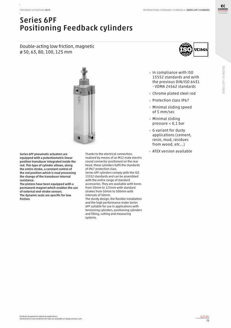
Products designed for industrial applications. General terms and conditions for sale are available on www.camozzi.com.
SERIES 6PF CYLINDERSPNEUMATIC ACTUATION
701.27.01
2019 INTERNATIONAL STANDARD CYLINDERS
SERI
ES 6
PF C
YLIN
DERS
>
Series 6PF Positioning Feedback cylinders
Double-acting low friction, magnetic ø 50, 63, 80, 100, 125 mm
Series 6PF pneumatic actuators are equipped with a potentiometric linear position transducer integrated inside the rod. This type of cylinder allows, along the entire stroke, a constant control of the rod position which is read processing the change of the transducer internal resistance. The pistons have been equipped with a permanent magnet which enables the use of external end-stroke sensors. The dynamic seals are specific for low friction.
Thanks to the electrical connection, realized by means of an M12 male electric round connector positioned on the rear head, these cylinders fulfil the standards of IP67 protection class. Series 6PF cylinders comply with the ISO 15552 standards and can be assembled with the entire range of standard accessories. They are available with bores from 50mm to 125mm with standard strokes from 50mm to 500mm with intervals of 50mm. The sturdy design, the flexible installation and the high performance make Series 6PF suitable for use in applications with tensioning cylinders, positioning cylinders and filling, cutting and measuring systems.
» In compliance with ISO 15552 standards and with the previous DIN/ISO 6431 - VDMA 24562 standards
» Chrome plated steel rod
» Protection class IP67
» Minimal sliding speed of 5 mm/sec
» Minimal sliding pressure < 0,1 bar
» G variant for dusty applications (cement, resin, mud, residues from wood, etc...)
» ATEX version available

Products designed for industrial applications. General terms and conditions for sale are available on www.camozzi.com.
SERIES 6PF CYLINDERSINTERNATIONAL STANDARD CYLINDERS > PNEUMATIC ACTUATION 2019
711.27.02
SERI
ES 6
PF C
YLIN
DERS
PNEUMATIC SECTION
Construction inner tie-rods
Operation double-acting low friction, not cushioned
Materials see the table on the following page
Mountings front and rear flange foot mounts
front / rear / swivel / intermediate trunnion
Bores 50, 63, 80, 100, 125 mm
Strokes (min - max) 50 ÷ 1000 mm (step 50 mm)
Operating Temperature 0°C ÷ 80°C (with dry air -20°C)
Operating pressure 0.1 ÷ 10 bar
Speed (min - max) 5 ÷ 1000 mm/sec (no load)
Max acceleration 10 m/sec²
Media filtered air class 5.4.4 according to ISO 8573-1. If lubricated air is used, it is recommended to use oil ISOVG32. Once applied the lubrication should never be interrupted.
Linearity 0.1% of the stroke
Repeatability 0.03% of the stroke
Resolution Infinite
Hysteresis < di 0.5 mm
Vibration test according EN 60068-2-6 severity level 3
Shock test according EN 60068-2-27 severity level 2
ELECTRICAL SECTION
Electrical connection male connector M12 4 poles IP 67 (EN 60529)
Max input voltage 40 V (stroke 50 mm) 60 V (strokes from 100 to 500 mm)
Max recommended cursor current < di 0,1 µA
Electrical resistance 5 kohm for strokes from 50 to 300 mm 10 kohm for strokes from 350 to 500 m
Tolerance on resistance +/- 20%
Max dissipation (40°C) 1 W for stroke 50 mm 2 W for stroke 100 mm
3 W for strokes from 150 to 500 mm
Suitable end-stroke sensors CST-532 (3 wires) CST-562 (M8)
Suitable M12 connectors CS-LF04HB (straight female connector 4 poles) CS-LR04HB (right angle female connector 4 poles)
CS-LF05HB-D200 (straight female wired connector 5 poles, 2 meters) ** CS-LF05HB-D500 (straight female wired connector 5 poles, 5 meters) **
CS-LR05HB-D200 (right angle female wired connector 5 poles, 2 meters) ** CS-LR05HB-D500 (right angle female wired connector 5 poles, 5 meters) **
** pin No 5 must not be connected
GENERAL AND TECHNICAL DATA

Products designed for industrial applications. General terms and conditions for sale are available on www.camozzi.com.
SERIES 6PF CYLINDERSPNEUMATIC ACTUATION
721.27.03
2019 INTERNATIONAL STANDARD CYLINDERS
SERI
ES 6
PF C
YLIN
DERS
>
STANDARD STROKES FOR SERIES 6PF CYLINDERS
✖ = Double-acting, low friction
STANDARD STROKES
Ø 50 100 150 200 250 300 350 400 450 500 550 600 650 700 750 800 850 900 950 1000
50 ✖ ✖ ✖ ✖ ✖ ✖ ✖ ✖ ✖ ✖ ✖ ✖ ✖ ✖ ✖ ✖ ✖ ✖ ✖ ✖
63 ✖ ✖ ✖ ✖ ✖ ✖ ✖ ✖ ✖ ✖ ✖ ✖ ✖ ✖ ✖ ✖ ✖ ✖ ✖ ✖
80 ✖ ✖ ✖ ✖ ✖ ✖ ✖ ✖ ✖ ✖ ✖ ✖ ✖ ✖ ✖ ✖ ✖ ✖ ✖ ✖
100 ✖ ✖ ✖ ✖ ✖ ✖ ✖ ✖ ✖ ✖ ✖ ✖ ✖ ✖ ✖ ✖ ✖ ✖ ✖ ✖
125 ✖ ✖ ✖ ✖ ✖ ✖ ✖ ✖ ✖ ✖ ✖ ✖ ✖ ✖ ✖ ✖ ✖ ✖ ✖ ✖
CODING EXAMPLE
6PF SERIES
3 OPERATION: 3 = double-acting low friction, no cushion
PNEUMATIC SYMBOLS CD22
P MATERIALS: P = see the table on the following page
050 BORES: 050 = 50 mm 063 = 63 mm 080 = 80 mm 100 = 100 mm 125 = 125 mm
A CONSTRUCTION: A = standard with rod nut RL = cylinder with rod lock
0200 STROKES (see the table)
VERSIONS: = standard P = PU rod seal V = FKM rod seal L = without rod seal (rear supply only) * G = with brass rod scraper EX = ATEX ( _ _ _ ) = extended piston rod _ _ _ mm * The possibility to order the cylinder without piston rod seal further reduces the friction force.
6PF 3 P 050 A 0200
PNEUMATIC SYMBOLS
The pneumatic symbols which have been indicated in the CODING EXAMPLE are shown below.

Products designed for industrial applications. General terms and conditions for sale are available on www.camozzi.com.
SERIES 6PF CYLINDERSINTERNATIONAL STANDARD CYLINDERS > PNEUMATIC ACTUATION 2019
731.27.04
SERI
ES 6
PF C
YLIN
DERS
GENERAL INFORMATION
To function properly, the potentiometer must be used as a voltage divider and not as a variable resistor. The measurement must be carried out detecting the voltage and not the resistance. The electrical connection must be done at an high impedance inlet. Information about pinout can be found in the instruction sheet or on the product itself.
LIST OF COMPONENTS
PARTS MATERIALS
1. Rod nut Steel
2. Rod seal NBR
3. Rod guide bush Sintered bronze
4. Rod Chrome plated steel
5. Piston guide element Acetal resin
6. Piston Aluminium
7. Piston seal NBR
8. Extrusion profile Anodized aluminium
9. OR seal NBR
10. M12 connector Nickel plated brass
11. Grain Steel
12. Rear endcap Aluminium
13. Magnetic actuator Neodymium
14. OR seal NBR
15. Positioning sensor -
NOTE TO THE CONNECTOR DRAWING: 1, 3 = inlet voltage 4 = outlet signal 2 = not used

Products designed for industrial applications. General terms and conditions for sale are available on www.camozzi.com.
SERIES 6PF CYLINDERSPNEUMATIC ACTUATION
741.27.05
2019 INTERNATIONAL STANDARD CYLINDERS
SERI
ES 6
PF C
YLIN
DERS
>
CYLINDERS ACCESSORIES SERIES 6PF
Piston rod socket joint Mod. GY
Piston rod lock nut Mod. U
Clevis pin Mod. S Rear trunnion ball-joint Mod. R
Coupling piece Mod. GKF
Swivel ball joint Mod. GA 90° male trunnion Mod. ZC
Swivel Combination Mod. C+L+S
Front and rear flange Mod. D-E
Self aligning rod Mod. GK
Centre trunnion Mod. F Foot mount Mod. B Front female trunnion Mod. H and C-H
All accessories are supplied separately, except for piston rod lock nut Mod. U
Rear female trunnion Mod. C and C-H
Rod fork end Mod. G
Rear trunnion male Mod. L Key to disassemble cylinders Ø 80 and 100
Counter bracket for centre trunnion Mod. BF
Straight conn. for power supply Mod. CS-LF04HB
Angular conn. for power supply Mod. CS-LR04HB
Cable Mod. CS-LF05HB-D...
Cable Mod. CS-LR05HB-D...

Products designed for industrial applications. General terms and conditions for sale are available on www.camozzi.com.
SERIES 6PF CYLINDERSINTERNATIONAL STANDARD CYLINDERS > PNEUMATIC ACTUATION 2019
751.27.06
SERI
ES 6
PF C
YLIN
DERS
Series 6PF cylinders
DIMENSIONS
Ø AM B BG E EE F G H KK L1 L2+ L3 MM N PL R RT SW1 SW2 SW3 SW4 TG VA VD WH ZJ+
50 32 40 16 64.5 G1/4 14 8 17 M16x1.5 25 106 5 20 29.5 15 16 M8 17 8 3 24 46.5 4 6 37 143
63 32 45 16 75 G3/8 14 8 24 M16x1.5 26 121 5 20 36.5 21 28 M8 17 8 3 24 56.5 4 6 37 158
80 40 45 19 93 G3/8 14 8 24 M20x1.5 30 128 0 25 36 21 30 M10 22 * 5 30 72 4 7 46 174
100 40 55 19.5 110 G1/2 14 8 26 M20x1.5 35 138 0 25 38.5 23 40 M10 22 * 5 30 89 4 7 51 189
125 54 60 23 135 G1/2 14 10.5 30 M27x2 42 160 0 32 43 23.5 50 M12 27 12 4 41 110 6 8 65 225
+ = add the stroke Table note: * = special key 80-62/8C (see accessories)
Series 6PF cylinders - with rod lock
DIMENSIONS
Ø ØD ØD1 ØD2 ØD3 A G H H1 L1 L2 L3 L4 L5 L6 L7 L8 L9+ L10+ M Z
50 20 40 50 35 46,5 G1/8 36 64 82 70 12 15 16 29,5 48 60 106 200 M8 M6x20
63 20 45 60 38 56,5 G1/8 40 75 82 70 12 15 16 29,5 49,5 70 121 215 M8 M8x30
80 25 45 80 48 72 G1/8 50 95 110 90 20 18 20 35 61 90 128 254 M10 M10x35
100 25 55 100 58 89 G1/8 58 110,5 115 100 15 18 20 39 69 105 138 269 M10 M10x35
125 32 60 130 65 110 G1/8 80 150 167 122 45 22 30 51 86,5 140 160 350 M12 M12x40
+ = add the stroke

Products designed for industrial applications. General terms and conditions for sale are available on www.camozzi.com.
SERIES 6PF CYLINDERSPNEUMATIC ACTUATION
761.27.07
2019 INTERNATIONAL STANDARD CYLINDERS
SERI
ES 6
PF C
YLIN
DERS
>
Foot mount Mod. B
Material: zinc-plated steel
Mod. Ø AT SA+ XA+ TR E AB AH AO AU torque force
B-41-50 50 4 170 175 45 62,5 10 45 15 32 13 Nm
B-41-63 63 5 185 190 50 73 10 50 15 32 13 Nm
B-41-80 80 6 210 216 63 92 12 63 20 41 19 Nm
B-41-100 100 6 220 230 75 108,5 14,5 71 25 41 22 Nm
B-41-125 125 7 250 270 90 132 16,5 90 25 45 26 Nm
Supplied with: 2x feet 4x screws + = add the stroke
Front and rear flange Mod. D-E
Material: Aluminium
Mod. Ø W MF ZB+ TF R UF E FB ZF+ torque force
D-E-41-50 50 25 12 143 90 45 110 63 9 155 13 Nm
D-E-41-63 63 25 12 158 100 50 116 73 9 170 13 Nm
D-E-41-80 80 30 16 174 126 63 148 95 12 190 19 Nm
D-E-41-100 100 35 16 189 150 75 176 115 14 205 22 Nm
D-E-41-125 125 45 20 225 180 90 224 135 16 245 26 Nm
Supplied with: 1x flange 4x screws + = add the stroke

Products designed for industrial applications. General terms and conditions for sale are available on www.camozzi.com.
SERIES 6PF CYLINDERSINTERNATIONAL STANDARD CYLINDERS > PNEUMATIC ACTUATION 2019
771.27.08
SERI
ES 6
PF C
YLIN
DERS
Rear female trunnion Mod. C and C-H
Material: Aluminium
Mod. Ø CD L FL XD+ MR E CB UB torque force
C-41-50 50 12 15 27 170 13 63 32 60 13 Nm
C-H-41-63 63 16 20 32 190 15 73 40 70 13 Nm
C-H-41-80 80 16 24 36 210 15 95 50 90 19 Nm
C-H-41-100 100 20 29 41 230 18 115 60 110 22 Nm
C-H-41-125 125 25 30 50 275 25 135 70 130 26 Nm
Supplied with: 1x female trunnion 4x screws + = add the stroke
Front female trunnion Mod. H and C-H
Material: Aluminium
Mod. Ø CB UB E XD FL L CD MR torque force
H-41-50 50 32 60 63 143 27 15 12 13 13 Nm
H-60-63 63 40 70 73 158 32 20 16 15 13 Nm
C-H-41-80 80 50 90 95 174 36 24 16 15 19 Nm
C-H-41-100 100 60 110 115 189 41 29 20 18 22 Nm
C-H-41-125 125 70 130 135 225 50 30 25 25 26 Nm
Supplied with: 1x female trunnion 4x screws + = add the stroke

Products designed for industrial applications. General terms and conditions for sale are available on www.camozzi.com.
SERIES 6PF CYLINDERSPNEUMATIC ACTUATION
781.27.09
2019 INTERNATIONAL STANDARD CYLINDERS
SERI
ES 6
PF C
YLIN
DERS
>
Rear male trunnion Mod. L
Material: Aluminium
DIMENSIONS
Mod. Ø CD L FL XD+ MR E EW torque force
L-41-50 50 12 15 27 170 13 63 32 13 Nm
L-41-63 63 16 20 32 190 15 73 40 13 Nm
L-41-80 80 16 24 36 210 15 95 50 19 Nm
L-41-100 100 20 29 41 230 18 115 60 22 Nm
L-41-125 125 25 30 50 275 25 135 70 26 Nm
Supplied with: 1x male trunnion 4x screws + = add the stroke
Centre trunnion Mod. F
Material: zinc-plated steel
DIMENSIONS
Mod. Ø XV1 XV2 XV3 TM TK TD TL UW R
F-61-50 50 76,5 90 103,5 75 20 16 16 91 0,15
F-61-63 63 86 97,5 109 90 25 20 20 94 0,15
F-61-80 80 94,5 110 125,5 110 25 20 20 130 0,15
F-61-100 100 104,5 120 135,5 132 30 25 25 145 0,2
F-61-125 125 123 145 167 160 30 25 25 155 0,2
Supplied with: 1x centre trunnion 4x screws 4x fixing elements + = add the stroke

Products designed for industrial applications. General terms and conditions for sale are available on www.camozzi.com.
SERIES 6PF CYLINDERSINTERNATIONAL STANDARD CYLINDERS > PNEUMATIC ACTUATION 2019
791.27.10
SERI
ES 6
PF C
YLIN
DERS
Accessory combination Mod. C+L+S
Material: aluminium
DIMENSIONS
Mod. Ø ØCD L FL XD+ TG E I M ØN torque force
C+L+S 50 12 15 27 170 46,5 63 13 27 9 13 Nm
C+L+S 63 16 20 32 190 56,5 73 15 32 9 13 Nm
C+L+S 80 16 24 36 210 72 95 15 36 11 19 Nm
C+L+S 100 20 29 41 230 89 115 18 41 11 22 Nm
C+L+S 125 25 30 50 275 110 135 25 50 13 26 Nm
+ = add the stroke
90° male trunnion Mod. ZC
CETOP RP 107P Material: Aluminium
DIMENSIONS
Mod. Ø EB CK HB XD+ TE UL EA GL L5 RA EM UR PH BT BR
ZC-50 50 15 12 9 170 50 65 16 33 1,6 30 32 45 45 12 13
ZC-63 63 15 16 9 190 52 67 16 37 1,6 35 40 50 50 14 15
ZC-80 80 18 16 11 210 66 86 20 47 2,5 40 50 60 63 14 15
ZC-100 100 18 20 11 230 76 96 20 55 2,5 50 60 70 71 17 19
ZC-125 125 20 25 14 275 94 124 30 70 3,2 60 70 90 90 20 22,5
Supplied with: 1x male support + = add the stroke

Products designed for industrial applications. General terms and conditions for sale are available on www.camozzi.com.
SERIES 6PF CYLINDERSPNEUMATIC ACTUATION
801.27.11
2019 INTERNATIONAL STANDARD CYLINDERS
SERI
ES 6
PF C
YLIN
DERS
>
Trunnion ball-joint Mod. R*
* This trunnion doesn’t comply with the ISO 15552 standard Material: Aluminium
Mod. Ø ØCX L DL XN+ MS E EX EP Z torque force
R-41-50 50 12 * 15 27 170 20 63 16 * 12 * 4 13 Nm
R-41-63 63 16 20 32 190 24 73 21 15 4 13 Nm
R-41-80 80 16 * 24 36 210 24 95 21 * 15 * 4 19 Nm
R-41-100 100 20 29 41 230 30 115 25 18 4 22 Nm
R-41-125 125 30 30 50 275 40 140 37 25 4 26 Nm
Supplied with: 1x trunnion ball joint 4x screws + = add the stroke
Counter bracket for centre trunnion Mod. BF
Material: Aluminium
Mod. Ø ØCR NH C B3 TH UL FK FN B1 B2 HB
BF-40-50 50 16 18 9 3 36 55 18 36 9 15 9
BF-63-80 63 - 80 20 20 10 3 42 65 20 40 11 18 11
BF-100-125 100 - 125 25 25 12,5 3,5 50 75 25 50 13 20 14
Supplied with: 2x supports

Products designed for industrial applications. General terms and conditions for sale are available on www.camozzi.com.
SERIES 6PF CYLINDERSINTERNATIONAL STANDARD CYLINDERS > PNEUMATIC ACTUATION 2019
811.27.12
SERI
ES 6
PF C
YLIN
DERS
Accessory to mount valves on the cylinder
The mounting sub-base Mod. PCV enables the valve or solenoid valve to be mounted directly on the cylinder.
DIMENSIONS
Mod.
PCV-61-K3 to connect valves - solenoid valves Series 3
PCV-61-K4 to connect valves - solenoid valves Series 4 port G1/4
PCV-62-KEN to connect valves - solenoid valves Series EN
PCV-61-K8 to connect valves - solenoid valves Series 4 port G1/8 and Series 3 port G1/4
Clevis pin Mod. S
Materials: Stainless steel 303 (clevis pin) / Steel (Seeger)
DIMENSIONS
Mod. Ø d L L1 L2 L3
S-50 50 12 67 61 1,1 3
S-63 63 16 77 71 1,1 3
S-80 80 16 97 91 1,1 3
S-100 100 20 121 111 1,3 5
S-125 125 25 140,5 132 1,3 4,25
Supplied with: 1x clevis pin 2x Seeger

Products designed for industrial applications. General terms and conditions for sale are available on www.camozzi.com.
SERIES 6PF CYLINDERSPNEUMATIC ACTUATION
821.27.13
2019 INTERNATIONAL STANDARD CYLINDERS
SERI
ES 6
PF C
YLIN
DERS
>
Swivel ball joint Mod. GA
ISO 8139. Material: zinc-plated steel.
Mod. ØCN(H7) U EN ER AX CE KK ØT Z SW
GA-50-63 16 15 21 21 28 64 M16X1,5 22 7,5 22
GA-80-100 20 18 25 25 33 77 M20x1,5 27,5 7 30
GA-41-125 30 25 37 37 51 110 M27x2 40 7,5 41
Piston rod socket joint Mod. GY
Material: zama and zinc-plated steel.
DIMENSIONS
Mod. Ø KK L CE L2 AX SW SW1 L1 L3 ØT ØD E ØB ØC Z
GY-50-63 50-63 M16X1,5 112 50 8 27 22 19 27,5 23 22 27 16 22 40 11
GY-80-100 80-100 M20x1,5 133 63 10 38 30 24 31,5 25 27,5 34 20 27 45 7,5
Rod fork end Mod. G
ISO 8140 Material: zinc-plated steel
Mod. ØCK LE CM CL ER CE KK B ØB1
G-50-63 16 32 16 32 19 64 M16 X 1,5 40 26
G-80-100 20 40 20 40 25 80 M20 X 1,5 48 34
G-41-125 30 54 30 55 38 110 M27 X 2 74 48
Piston rod lock nut Mod. U
ISO 4035 Material: zinc-plated steel.
Mod. D m SW
U-50-63 M16X1,5 8 24
U-80-100 M20x1,5 9 30
U-41-125 M27x2 12 41

Products designed for industrial applications. General terms and conditions for sale are available on www.camozzi.com.
SERIES 6PF CYLINDERSINTERNATIONAL STANDARD CYLINDERS > PNEUMATIC ACTUATION 2019
831.27.14
SERI
ES 6
PF C
YLIN
DERS
Self aligning rod Mod. GK
Material: zinc-plated steel.
DIMENSIONS
Mod. Ø KK L L1 L3 L4 ØA ØD H I SW SW1 SW2 B1 AX Z E
GK-50-63 50-63 M16x1,5 104 53 32 10 22 32 45 41 27 20 24 8 30 3 2
GK-80-100 80-100 M20x1,5 119 53 40 10 22 32 45 41 27 20 30 10 37 3 2
GK-125 125 M27x2 147 60 54 10 32 57 70 65 54 24 41 12 48 4 2
Coupling piece Mod. GKF
Material: zinc-plated steel.
DIMENSIONS
Mod. Ø KK A B R TF L L1 I Ø D Ø D1 Ø D2 SW E
GKF-50-63 50-63 M16x1,5 80 80 58 58 26,5 15 10,5 25 18 11 22 2,5
GKF-80-100 80-100 M20x1,5 90 90 65 65 32,5 20 13 30,5 20 14 27 2,5
GKF-125 125 M27x2 90 90 65 65 35,5 20 13 40 20 14 36 4
Special key to disassemble cylinders Ø 80 and 100
Material: hardened steel
Mod.
80-62/8C

Products designed for industrial applications. General terms and conditions for sale are available on www.camozzi.com.
SERIES 6PF CYLINDERSPNEUMATIC ACTUATION
841.27.15
2019 INTERNATIONAL STANDARD CYLINDERS
SERI
ES 6
PF C
YLIN
DERS
>
Straight connector for power supply
Mod. description type of connector connection cable length (m)
CS-LF04HB for wiring straight M12 A 4 pin female - Pin 5 is not connected
-
Angular connector for power supply
Mod. description type of connector connection cable length (m)
CS-LR04HB for wiring 90° M12 A 4 pin female - Pin 5 is not connected
-
Cable Mod. CS-LF05HB-D200/D500
Mod. Cable length (m)
CS-LF05HB-D200 2
CS-LF05HB-D500 5

Products designed for industrial applications. General terms and conditions for sale are available on www.camozzi.com.
SERIES 6PF CYLINDERSINTERNATIONAL STANDARD CYLINDERS > PNEUMATIC ACTUATION 2019
851.27.16
SERI
ES 6
PF C
YLIN
DERS
Cable Mod. CS-LR05HB-D200/D500
Mod. Cable length (m)
CS-LR05HB-D200 2
CS-LR05HB-D500 5

Products designed for industrial applications. General terms and conditions for sale are available on www.camozzi.com.
SERIES 63 CYLINDERSPNEUMATIC ACTUATION
861.28.01
2019 INTERNATIONAL STANDARD CYLINDERS
SERI
ES 6
3 CY
LIND
ERS
>
Series 63 ISO 15552 cylinders
Single and double-acting, magnetic, cushioned ø 32, 40, 50, 63, 80, 100, 125 mm
The Series 63 pneumatic cylinders have been developed to guarantee high performance and versatility. Thanks to a new system of adjustable pneumatic cushioning, the cylinders can always guarantee the best regulation whilst significantly reducing noise caused by the impact of the piston on the end block.
Besides the standard version, which can be used in many sectors, specific solutions have been developed for applications such as food processing, agriculture, in tensioning, dosing systems and dancer arms for winding applications. There are also versions for demanding application environments, capable of withstanding extreme temperatures, corrosive atmospheres etc.
» In compliance with the ISO 15552 standard
» Weight reduced by 25%
» Low noise
» More accurate with fine regulation of cushioning
» Flexibility and versatility VERSIONS AVAILABLE:
» Low friction
» Uniform movement (low speed)
» High and low temperatures
» Corrosion-resistant
» Hydrolytic environment
» Food and beverage
» Lube-free operation
» Dirty and dusty environments
» Protective bellows
» Back to back
» Tandem and multi-position
» With rod lock
» Polyurethane coating
» ATEX
GENERAL DATAType of construction profile (with screws) and round tube (with tie-rods)Design ISO 15552Operation single and double-actingType of mounting with front / rear flange, foot mounting, with front / rear / centre / swivel trunnionStroke min - max 10 ÷ 2500 mmOperating temperature standard and low friction: 0°C ÷ 80°C (with dry air -20°C)
high temperatures (version W): 0°C ÷ 150°C (with dry air -20°C) low temperatures (version Z): -40°C ÷ 60°C (with dry air -40°C) low temperatures (version Y): -50°C ÷ 60°C (with dry air -50°C)
Storage temperature 0°C ÷ 80°C (with dry air -20°C)Operating pressure 1 ÷ 10 bar (standard, high and low temperatures)
0.1 ÷ 10 bar (low friction)Speed 10 ÷ 1000 mm/sec, no load (standard, high and low temperatures)
5 ÷ 1000 mm/sec, no load (low friction and uniform movement)Fluid filtered air in class 7.8.4, according to ISO 8573-1.
If lubricated air is used, it is recommended to use oil ISOVG32. Once applied the lubrication should never be interrupted.Use with sensors model CSH
New versions

Products designed for industrial applications. General terms and conditions for sale are available on www.camozzi.com.
SERIES 63 CYLINDERSINTERNATIONAL STANDARD CYLINDERS > PNEUMATIC ACTUATION 2019
871.28.02
SERI
ES 6
3 CY
LIND
ERS
STANDARD STROKES FOR CYLINDERS SERIES 63
■ = Single-acting, front spring (standard, high/low temperatures); ▲ = Single-acting, rear spring (standard, high/low temperatures); ✖ = Double-acting (standard, low friction, high/low temperatures) Other strokes up to 2500 mm are available on request.
STANDARD STROKES
Ø 25 50 75 80 100 125 150 160 200 250 300 320 400 500
32 ■ ▲ ✖ ■ ▲ ✖ ■ ✖ ✖ ✖ ✖ ✖ ✖ ✖ ✖ ✖ ✖ ✖ ✖
40 ■ ▲ ✖ ■ ▲ ✖ ■ ✖ ✖ ✖ ✖ ✖ ✖ ✖ ✖ ✖ ✖ ✖ ✖
50 ■ ▲ ✖ ■ ▲ ✖ ■ ✖ ✖ ✖ ✖ ✖ ✖ ✖ ✖ ✖ ✖ ✖ ✖
63 ■ ▲ ✖ ■ ▲ ✖ ■ ✖ ✖ ✖ ✖ ✖ ✖ ✖ ✖ ✖ ✖ ✖ ✖
80 ■ ▲ ✖ ■ ▲ ✖ ■ ✖ ✖ ✖ ✖ ✖ ✖ ✖ ✖ ✖ ✖ ✖ ✖
100 ■ ▲ ✖ ■ ✖ ✖ ✖ ✖ ✖ ✖ ✖ ✖ ✖ ✖ ✖ ✖
125 ■ ▲ ✖ ■ ✖ ✖ ✖ ✖ ✖ ✖ ✖ ✖ ✖ ✖ ✖ ✖
CODING EXAMPLE
63 M P 2 C 050 A 0200 W
63 SERIES
M VERSION: M = standard, magnetic V = uniform movement (no stick slip), magnetic L = low friction, magnetic
P CONSTRUCTION: T = round tube P = profile
2 OPERATION: 1 = single-acting, front spring 2 = double-acting 6 = double-acting, through-rod 7 = single-acting, through-rod 9 = single-acting, rear spring
PNEUMATIC SYMBOLS: CS07/CS18 CD08 - CD09 - CD10 - CD11 CD13 CS11 CS14/CS17
C CUSHIONING: N = no cushioning (mechanical endstops) C = cushioning on both sides F = front cushioning R = rear cushioning
PNEUMATIC SYMBOLS: CD08 CD09/CD13 CD11 CD10
050 BORE: 032 = 32 mm 040 = 40 mm 050 = 50 mm 063 = 63 mm
080 = 80 mm 100 = 100 mm 125 = 125 mm
A CONSTRUCTIVE TYPE: A = standard with rod nut RL = cylinder with rod lock
DC = back to back cylinder with DC accessory [X1/X2] TR = back to back cylinder for round tube [X1/X2] F = cylinder with centre trunnion
0200 STROKE: = standard N = tandem / = more positions X1/X2 [X1<X2]
W TEMPERATURE RANGE: = standard (-20°/+80°) W = high temperatures (150°C)
Z = low temperatures (-40°C) Y = low temperatures (-50°C)
RESISTANCE TO CORROSION: = standard C1 = rod nut AISI 304 stainless steel, rod AISI 304 stainless steel C2 = end cap treated screws (profile) or AISI 303 tie-rods and AISI 420B tie-rods (round tube)
C3 = C2 + AISI 316 rod nut, AISI 316 rod C4 = C1 + C2 C5 = C3 + end caps with triple protection
ROD VARIATIONS: = standard (male rod thread) F = female rod thread K = end caps with Kanigen treatment L = without rod seal (rear air inlet only) V = FKM rod seal R = NBR rod seal U = unlubricated operation
H = hydrolytic environment A = use in food and other frequent washdown applications G = dry and dusty environments (with brass rod scraper and chrome-plated stainless steel AISI 420B rod) B = cylinder with NBR bellow rod protection B2 = cylinder with through rod and NBR bellow rod protection on both sides (_ _ _) = extended rod _ _ _ mm
OTHER: P = cylinder with RAL 7035 polyurethane coating
CERTIFICATIONS: EX = ATEX

Products designed for industrial applications. General terms and conditions for sale are available on www.camozzi.com.
SERIES 63 CYLINDERSPNEUMATIC ACTUATION
881.28.03
2019 INTERNATIONAL STANDARD CYLINDERS
SERI
ES 6
3 CY
LIND
ERS
>
PNEUMATIC SYMBOLS
The pneumatic symbols which have been indicated in the CODING EXAMPLE are shown below.
MATERIALS
LIST OF COMPONENTS
Standard, profile Standard, round tube Low friction (L) Rod scraper (G) Low temperatures (Z/Y)
High temperatures (W)
Resistance to corrosion (C1)
PARTS
1 - Rod AISI 420B AISI 420B AISI 420B Chrome-plated AISI 420B
Chrome-plated AISI 420B
AISI 420B AISI 304
2 - Rod seal PU PU NBR NBR PU for -40°C/-50°C FKM PU
3 - End-block Aluminium Aluminium Aluminium Aluminium Aluminium Aluminium Aluminium
4 - Counterbore seal NBR NBR NBR NBR NBR for -40°C/-50°C FKM NBR
5 - Extruded profile Anodized aluminium Anodized aluminium Anodized aluminium
Anodized aluminium
Anodized aluminium Anodized aluminium
Anodized aluminium
6 - Piston seal PU PU NBR PU PU for -40°C/-50°C FKM PU
7 - Piston Technopolymer (ø 32) or Aluminium (ø 40 ÷ 125)
Aluminium (ø 125) or Technopolymer (ø 32 ÷ 100)
Aluminium Aluminium Aluminium Aluminium Aluminium
8 - Cushion seal PU PU PU PU PU FKM PU
9 - Self-tapping screw Zinc-plated steel - Zinc-plated steel Zinc-plated steel Zinc-plated steel Zinc-plated steel Zinc-plated steel
10 - Tie-rod nut - Zinc-plated steel Zinc-plated steel Zinc-plated steel AISI 303 Zinc-plated steel Zinc-plated steel
11 - Tie-rod - Zinc-plated steel Zinc-plated steel Zinc-plated steel AISI 420B Zinc-plated steel Zinc-plated steel
12 - Rod scraper - - - Brass Brass - -
13 - Rod nut Zinc-plated steel Zinc-plated steel Zinc-plated steel Zinc-plated steel AISI 304 Zinc-plated steel AISI 304
14 - Rod guide bush Technopolymer Technopolymer Technopolymer Technopolymer Technopolymer Steel + PTFE Technopolymer

Products designed for industrial applications. General terms and conditions for sale are available on www.camozzi.com.
SERIES 63 CYLINDERSINTERNATIONAL STANDARD CYLINDERS > PNEUMATIC ACTUATION 2019
891.28.04
SERI
ES 6
3 CY
LIND
ERS
CYLINDER IN THRUST DRAWING NOTES: 1. Precision pressure regulator or proportional regulator 2. Low friction cylinder 3. Force direction 4. Band
CYLINDER IN TRACTION Note: in order to reach the highest performance, it is recommended to connect a precision pressure regulator or a proportional regulator with the low friction cylinder as shown in the drawing.
Series 63 low friction cylinders - APPLICATION EXAMPLES

Products designed for industrial applications. General terms and conditions for sale are available on www.camozzi.com.
SERIES 63 CYLINDERSPNEUMATIC ACTUATION
901.28.05
2019 INTERNATIONAL STANDARD CYLINDERS
SERI
ES 6
3 CY
LIND
ERS
>
SERIES 63 CYLINDERS ACCESSORIES
Piston rod socket joint Mod. GY
Piston rod lock nut Mod. U
Clevis pin Mod. S Rear trunnion ball-joint Mod. R
Coupling piece Mod. GKF
Swivel ball joint Mod. GA 90° male trunnion Mod. ZC
Swivel Combination Mod. C+L+S
Front and rear flange Mod. D-E
Self aligning rod Mod. GK
Centre trunnion Mod. F-63, profile cyl.
Foot mount Mod. B-41
Front female trunnion Mod. H and C-H
All accessories are supplied separately, except for piston rod lock nut Mod. U
Rear female trunnion Mod. C and C-H
Rod fork end Mod. G
Rear trunnion male Mod. L
Disassemble cyl. key Ø 80 and 100, round tube
Counter bracket for centre trunnion Mod. BF
Front/rear spot faced trunnion Mod. FN
Opposed cylinder coupler Mod. DC-63
Centre trunnion Mod. F, round tube cyl.

Products designed for industrial applications. General terms and conditions for sale are available on www.camozzi.com.
SERIES 63 CYLINDERSINTERNATIONAL STANDARD CYLINDERS > PNEUMATIC ACTUATION 2019
911.28.06
SERI
ES 6
3 CY
LIND
ERS
Series 63 cylinders - profile, double-acting
Versions: 63MP2... and 63LP2...
DIMENSIONS
Ø ØMM KK ØB PL L1 AM VA EE WH L2 L3 ZJ VD N BG RT G TG E SW1 SW2 SW4 Front/rear cushion stroke
32 12 M10x1.25 30 18.5 18 22 4 G1/8 26 94 5.5 120 5 27 16 M6 5 32.5 47 10 6 17 17
40 16 M12x1.25 35 19 21 24 4 G1/4 30 105 5.5 135 5 30 16 M6 5 38 55 13 6 19 18
50 20 M16x1.5 40 19.5 25 32 4 G1/4 37 106 6 143 6 30.5 16 M8 8 46.5 65 17 8 24 20
63 20 M16x1.5 45 24 26 32 4 G3/8 37 121 6 158 6 37.5 16 M8 8 56.5 75 17 8 24 22
80 25 M20x1.5 45 23.5 30 40 4 G3/8 46 128 0 174 7 37 19 M10 8 72 93 22 6 30 25
100 25 M20x1.5 55 24 35 40 4 G1/2 51 138 0 189 7 39.5 19.5 M10 8 89 110 22 6 30 26
125 32 M27x2 60 28 42 54 6 G1/2 65 160 6 225 8 44 23 M12 10.5 110 135 27 12 41 33
+ = add the stroke
Series 63 cylinders - round tube, double-acting
Versions: 63MT2... and 63LT2...
DIMENSIONS
Ø ØMM KK ØB PL L1 AM VA EE WH L2 L3 ZJ VD N BG RT G TG E SW1 SW2 SW4 Front/rear cushion stroke
32 12 M10x1.25 30 18.5 18 22 4 G1/8 26 94 5 120 5 27 16 M6 5 32.5 47 10 6 17 17
40 16 M12x1.25 35 19 21 24 4 G1/4 30 105 5 135 5 30 16 M6 5 38 55 13 6 19 18
50 20 M16x1.5 40 19.5 25 32 4 G1/4 37 106 5 143 6 30.5 16 M8 8 46.5 65 17 8 24 20
63 20 M16x1.5 45 24 26 32 4 G3/8 37 121 5 158 6 37.5 16 M8 8 56.5 75 17 8 24 22
80 25 M20x1.5 45 23.5 30 40 4 G3/8 46 128 0 174 7 37 19 M10 8 72 93 22 * 30 25
100 25 M20x1.5 55 24 35 40 4 G1/2 51 138 0 189 7 39.5 19.5 M10 8 89 110 22 * 30 26
125 32 M27x2 60 28 42 54 6 G1/2 65 160 6 225 8 44 23 M12 10.5 110 135 27 12 41 33
+ = add the stroke Table note: * = special key 80-62/8C (see accessories)
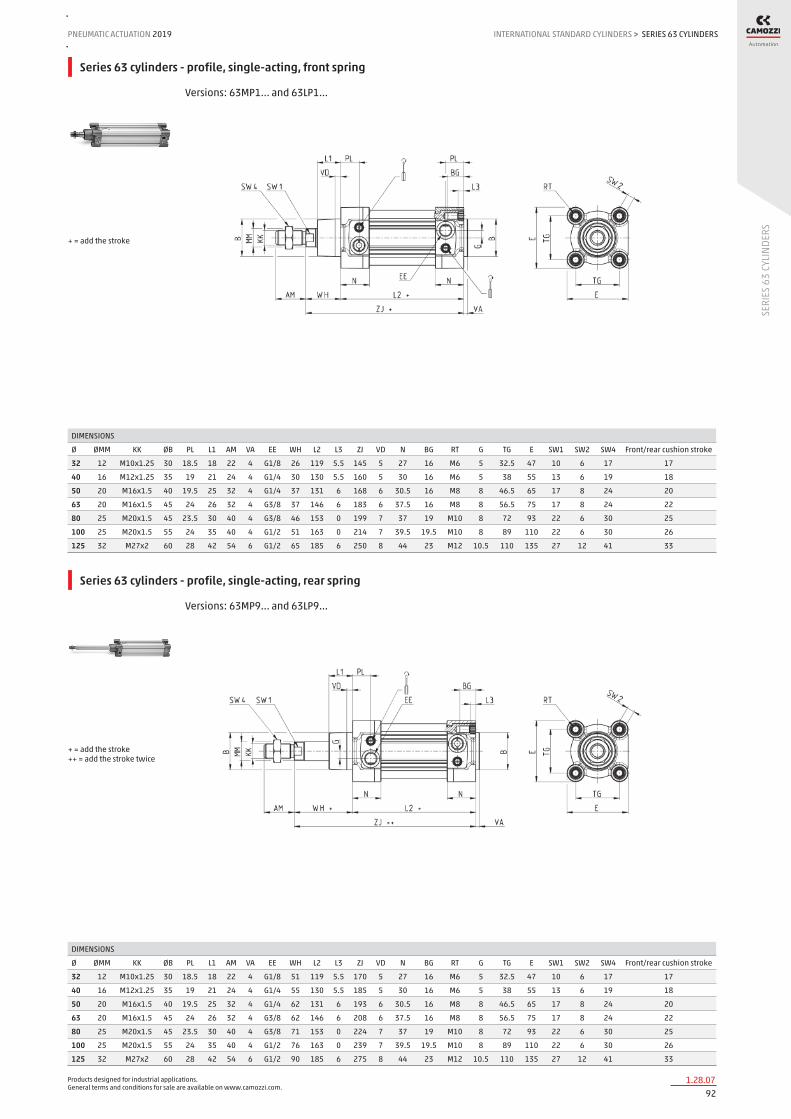
Products designed for industrial applications. General terms and conditions for sale are available on www.camozzi.com.
SERIES 63 CYLINDERSPNEUMATIC ACTUATION
921.28.07
2019 INTERNATIONAL STANDARD CYLINDERS
SERI
ES 6
3 CY
LIND
ERS
>
Series 63 cylinders - profile, single-acting, front spring
Versions: 63MP1... and 63LP1...
DIMENSIONS
Ø ØMM KK ØB PL L1 AM VA EE WH L2 L3 ZJ VD N BG RT G TG E SW1 SW2 SW4 Front/rear cushion stroke
32 12 M10x1.25 30 18.5 18 22 4 G1/8 26 119 5.5 145 5 27 16 M6 5 32.5 47 10 6 17 17
40 16 M12x1.25 35 19 21 24 4 G1/4 30 130 5.5 160 5 30 16 M6 5 38 55 13 6 19 18
50 20 M16x1.5 40 19.5 25 32 4 G1/4 37 131 6 168 6 30.5 16 M8 8 46.5 65 17 8 24 20
63 20 M16x1.5 45 24 26 32 4 G3/8 37 146 6 183 6 37.5 16 M8 8 56.5 75 17 8 24 22
80 25 M20x1.5 45 23.5 30 40 4 G3/8 46 153 0 199 7 37 19 M10 8 72 93 22 6 30 25
100 25 M20x1.5 55 24 35 40 4 G1/2 51 163 0 214 7 39.5 19.5 M10 8 89 110 22 6 30 26
125 32 M27x2 60 28 42 54 6 G1/2 65 185 6 250 8 44 23 M12 10.5 110 135 27 12 41 33
+ = add the stroke
Series 63 cylinders - profile, single-acting, rear spring
Versions: 63MP9... and 63LP9...
DIMENSIONS
Ø ØMM KK ØB PL L1 AM VA EE WH L2 L3 ZJ VD N BG RT G TG E SW1 SW2 SW4 Front/rear cushion stroke
32 12 M10x1.25 30 18.5 18 22 4 G1/8 51 119 5.5 170 5 27 16 M6 5 32.5 47 10 6 17 17
40 16 M12x1.25 35 19 21 24 4 G1/4 55 130 5.5 185 5 30 16 M6 5 38 55 13 6 19 18
50 20 M16x1.5 40 19.5 25 32 4 G1/4 62 131 6 193 6 30.5 16 M8 8 46.5 65 17 8 24 20
63 20 M16x1.5 45 24 26 32 4 G3/8 62 146 6 208 6 37.5 16 M8 8 56.5 75 17 8 24 22
80 25 M20x1.5 45 23.5 30 40 4 G3/8 71 153 0 224 7 37 19 M10 8 72 93 22 6 30 25
100 25 M20x1.5 55 24 35 40 4 G1/2 76 163 0 239 7 39.5 19.5 M10 8 89 110 22 6 30 26
125 32 M27x2 60 28 42 54 6 G1/2 90 185 6 275 8 44 23 M12 10.5 110 135 27 12 41 33
+ = add the stroke ++ = add the stroke twice

Products designed for industrial applications. General terms and conditions for sale are available on www.camozzi.com.
SERIES 63 CYLINDERSINTERNATIONAL STANDARD CYLINDERS > PNEUMATIC ACTUATION 2019
931.28.08
SERI
ES 6
3 CY
LIND
ERS
Series 63 cylinders - round tube, single-acting, front spring
Versions: 63MT1... and 63LT1...
DIMENSIONS
Ø ØMM KK ØB PL L1 AM VA EE WH L2 L3 ZJ VD N BG RT G TG E SW1 SW2 SW4 Front/rear cushion stroke
32 12 M10x1.25 30 18.5 18 22 4 G1/8 26 119 5 145 5 27 16 M6 5 32.5 47 10 6 17 17
40 16 M12x1.25 35 19 21 24 4 G1/4 30 130 5 160 5 30 16 M6 5 38 55 13 6 19 18
50 20 M16x1.5 40 19.5 25 32 4 G1/4 37 131 5 168 6 30.5 16 M8 8 46.5 65 17 8 24 20
63 20 M16x1.5 45 24 26 32 4 G3/8 37 146 5 183 6 37.5 16 M8 8 56.5 75 17 8 24 22
80 25 M20x1.5 45 23.5 30 40 4 G3/8 46 153 0 199 7 37 19 M10 8 72 93 22 * 30 25
100 25 M20x1.5 55 24 35 40 4 G1/2 51 163 0 214 7 39.5 19.5 M10 8 89 110 22 * 30 26
125 32 M27x2 60 28 42 54 6 G1/2 65 185 6 250 8 44 23 M12 10.5 110 135 27 12 41 33
+ = add the stroke Table note: * = special key 80-62/8C (see accessories)
Series 63 cylinders - round tube, single-acting, rear spring
Versions: 63MT9... and 63LT9...
DIMENSIONS
Ø ØMM KK ØB PL L1 AM VA EE WH L2 L3 ZJ VD N BG RT G TG E SW1 SW2 SW4 Front/rear cushion stroke
32 12 M10x1.25 30 18.5 18 22 4 G1/8 51 119 5 170 5 27 16 M6 5 32.5 47 10 6 17 17
40 16 M12x1.25 35 19 21 24 4 G1/4 55 130 5 185 5 30 16 M6 5 38 55 13 6 19 18
50 20 M16x1.5 40 19.5 25 32 4 G1/4 62 131 5 193 6 30.5 16 M8 8 46.5 65 17 8 24 20
63 20 M16x1.5 45 24 26 32 4 G3/8 62 146 5 208 6 37.5 16 M8 8 56.5 75 17 8 24 22
80 25 M20x1.5 45 23.5 30 40 4 G3/8 71 153 0 224 7 37 19 M10 8 72 93 22 * 30 25
100 25 M20x1.5 55 24 35 40 4 G1/2 76 163 0 239 7 39.5 19.5 M10 8 89 110 22 * 30 26
125 32 M27x2 60 28 42 54 6 G1/2 90 185 6 275 8 44 23 M12 10.5 110 135 27 12 41 33
+ = add the stroke Table note: * = special key 80-62/8C (see accessories)

Products designed for industrial applications. General terms and conditions for sale are available on www.camozzi.com.
SERIES 63 CYLINDERSPNEUMATIC ACTUATION
941.28.09
2019 INTERNATIONAL STANDARD CYLINDERS
SERI
ES 6
3 CY
LIND
ERS
>
Series 63 cylinders - profile, through rod
Versions: 63MP6..., 63MP7..., 63LP6... and 63LP7... For the single-acting cylinders, the dimensions L2 and ZM have to be increased with 25 mm.
DIMENSIONS
Ø ØMM KK ØB PL L1 AM EE WH L2 L3 ZM VD N BG RT G TG E ØF SW1 SW2 SW4 Front/rear cushion stroke
32 12 M10x1.25 30 18.5 18 22 G1/8 26 94 5.5 146 5 27 16 M6 5 32.5 47 - 10 6 17 17
40 16 M12x1.25 35 19 21 24 G1/4 30 105 5.5 165 5 30 16 M6 5 38 55 - 13 6 19 18
50 20 M16x1.5 40 19.5 25 32 G1/4 37 106 6 180 6 30.5 16 M8 8 46.5 65 8 17 8 24 20
63 20 M16x1.5 45 24 26 32 G3/8 37 121 6 195 6 37.5 16 M8 8 56.5 75 8 17 8 24 22
80 25 M20x1.5 45 23.5 30 40 G3/8 46 128 0 220 7 37 19 M10 8 72 93 8 22 6 30 25
100 25 M20x1.5 55 24 35 40 G1/2 51 138 0 240 7 39.5 19.5 M10 8 89 110 8 22 6 30 26
125 32 M27x2 60 28 42 54 G1/2 65 160 6 290 8 44 23 M12 10.5 110 135 - 27 12 41 33
+ = add the stroke ++ = add the stroke twice
Series 63 cylinders - round tube, through rod
Versions: 63MT6..., 63MT7..., 63LT6... and 63LT7... For the single-acting cylinders, the dimensions L2 and ZM have to be increased with 25 mm.
DIMENSIONS
Ø ØMM KK ØB PL L1 AM EE WH L2 L3 ZM VD N BG RT G TG E ØF SW1 SW2 SW4 Front/rear cushion stroke
32 12 M10x1.25 30 18.5 18 22 G1/8 26 94 5 146 5 27 16 M6 5 32.5 47 - 10 6 17 17
40 16 M12x1.25 35 19 21 24 G1/4 30 105 5 165 5 30 16 M6 5 38 55 - 13 6 19 18
50 20 M16x1.5 40 19.5 25 32 G1/4 37 106 5 180 6 30.5 16 M8 8 46.5 65 8 17 8 24 20
63 20 M16x1.5 45 24 26 32 G3/8 37 121 5 195 6 37.5 16 M8 8 56.5 75 8 17 8 24 22
80 25 M20x1.5 45 23.5 30 40 G3/8 46 128 0 220 7 37 19 M10 8 72 93 8 22 * 30 25
100 25 M20x1.5 55 24 35 40 G1/2 51 138 0 240 7 39.5 19.5 M10 8 89 110 8 22 * 30 26
125 32 M27x2 60 28 42 54 G1/2 65 160 6 290 8 44 23 M12 10.5 110 135 - 27 12 41 33
+ = add the stroke ++ = add the stroke twice Table note: * = special key 80-62/8C (see accessories)

Products designed for industrial applications. General terms and conditions for sale are available on www.camozzi.com.
SERIES 63 CYLINDERSINTERNATIONAL STANDARD CYLINDERS > PNEUMATIC ACTUATION 2019
951.28.10
SERI
ES 6
3 CY
LIND
ERS
Series 63 cylinders with rod lock
Versions: 63MT1... and 63LT1...
DIMENSIONS
Ø ØD ØD1 ØD2 ØD3 A G H H1 L1 L2 L3 L4 L5 L6 L7 L8 L9+ L10+ M Z
32 12 30.5 35 25 32.5 M5 25.5 46.5 58 48 10 8 13 20.5 34 45 94 160 M6 M6X20
40 16 35 40 28 38 G1/8 30 53 65 55 10 8 13 22.5 38 50 105 178 M6 M6X20
50 20 40 50 35 46.5 G1/8 36 64 82 70 12 15 16 29.5 48 60 106 200 M8 M6X20
63 20 45 60 38 56.5 G1/8 40 75 82 70 12 15 16 29.5 49.5 70 121 215 M8 M8X30
80 25 45 80 48 72 G1/8 50 95 110 90 20 18 20 35 61 90 128 254 M10 M10X35
100 25 55 100 58 89 G1/8 58 110.5 115 100 15 18 20 39 69 105 138 269 M10 M10X35
125 32 60 130 65 110 G1/8 80 150 167 122 45 22 30 51 86.5 140 160 350 M12 M12X40
+ = add the stroke
Series 63 cylinders with female rod thread
Ø AF Min KF D1 Ø T1 Max T2 WH
32 12 M6X1 6.4 16 2.6 26
40 12 M8X1.25 8.4 16 3.3 30
50 16 M10X1.5 10.5 21 4.7 37
63 16 M10X1.5 10.5 21 4.7 37
80 20 M12X1.75 13 26.5 6.1 46
100 20 M12X1.75 13 26.5 6.1 54
125 32 M16X2 17 40 8 65
New version
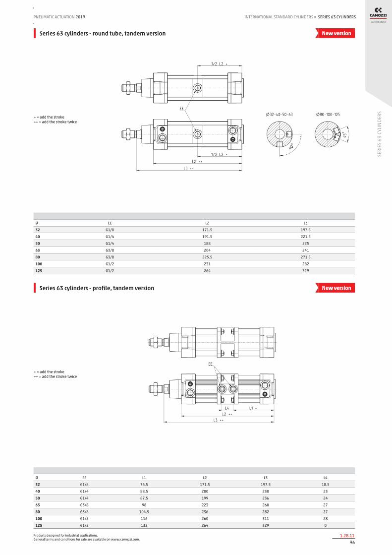
Products designed for industrial applications. General terms and conditions for sale are available on www.camozzi.com.
SERIES 63 CYLINDERSPNEUMATIC ACTUATION
961.28.11
2019 INTERNATIONAL STANDARD CYLINDERS
SERI
ES 6
3 CY
LIND
ERS
>
Series 63 cylinders - round tube, tandem version
Ø EE L2 L3
32 G1/8 171.5 197.5
40 G1/4 191.5 221.5
50 G1/4 188 225
63 G3/8 204 241
80 G3/8 225.5 271.5
100 G1/2 231 282
125 G1/2 264 329
+ = add the stroke ++ = add the stroke twice
New version
Series 63 cylinders - profile, tandem version
Ø EE L1 L2 L3 L4
32 G1/8 76.5 171.5 197.5 18.5
40 G1/4 88.5 200 230 23
50 G1/4 87.5 199 236 24
63 G3/8 98 223 260 27
80 G3/8 104.5 236 282 27
100 G1/2 116 260 311 28
125 G1/2 132 264 329 0
+ = add the stroke ++ = add the stroke twice
New version

Products designed for industrial applications. General terms and conditions for sale are available on www.camozzi.com.
SERIES 63 CYLINDERSINTERNATIONAL STANDARD CYLINDERS > PNEUMATIC ACTUATION 2019
971.28.12
SERI
ES 6
3 CY
LIND
ERS
Series 63 cylinders - round tube, multi-position version
Ø EE L1 L2 L3
32 G1/8 86 171.5 197.5
40 G1/4 96 191.5 221.5
50 G1/4 94 188 225
63 G3/8 102 204 241
80 G3/8 113 225.5 271.5
100 G1/2 115.5 231 282
125 G1/2 132 264 329
X1 = partial stroke X2 = total stroke
New version
Series 63 cylinders - profile, multi-position version
Ø EE L1 L2 L3 L4
32 G1/8 76.5 171.5 197.5 18.5
40 G1/4 88.5 200 230 23
50 G1/4 87.5 199 236 24
63 G3/8 98 223 260 27
80 G3/8 104.5 236 282 27
100 G1/2 116 260 311 28
125 G1/2 132 264 329 0
X1 = partial stroke X2 = total stroke
New version

Products designed for industrial applications. General terms and conditions for sale are available on www.camozzi.com.
SERIES 63 CYLINDERSPNEUMATIC ACTUATION
981.28.13
2019 INTERNATIONAL STANDARD CYLINDERS
SERI
ES 6
3 CY
LIND
ERS
>
Series 63 cylinders with protective bellow
Ø Stroke WH AM KK MM P R SW1 SW2
32 0 ÷ 245 88 22 M10X1.25 12 25 M5 10 17
32 246 ÷ 490 132 22 M10X1.25 12 25 M5 10 17
40 0 ÷ 245 89 24 M12X1.25 16 26 M5 13 19
40 246 ÷ 490 133 24 M12X1.25 16 26 M5 13 19
50 0 ÷ 245 99 32 M16X1.5 20 30 M5 17 24
50 246 ÷ 490 143 32 M16X1.5 20 30 M5 17 24
63 0 ÷ 245 76 32 M16X1.5 20 16.5 M5 17 24
63 246 ÷ 490 120 32 M16X1.5 20 16.5 M5 17 24
80 0 ÷ 285 86 40 M20X1.5 25 11.5 G1/8 22 30
80 286 ÷ 570 139 40 M20X1.5 25 11.5 G1/8 22 30
100 0 ÷ 285 86 40 M20X1.5 25 12 G1/8 22 30
100 286 ÷ 570 139 40 M20X1.5 25 12 G1/8 22 30
125 0 ÷ 285 108 54 M27X2 32 30 G1/8 29 41
125 286 ÷ 570 161 54 M27X2 32 30 G1/8 29 41
+ = add the stroke ++ = add the stroke twice
New version
Series 63 cylinders - round tube, back to back (TR)
Ø F1 ZJ+ max overall stroke (mm)
32 9 120 500
40 9 135 800
50 9 143 800
63 9 158 700
80 9 174 1000
100 9 189 900
125 20 225 1000
New version

Products designed for industrial applications. General terms and conditions for sale are available on www.camozzi.com.
SERIES 63 CYLINDERSINTERNATIONAL STANDARD CYLINDERS > PNEUMATIC ACTUATION 2019
991.28.14
SERI
ES 6
3 CY
LIND
ERS
Opposed cylinder coupler Mod. DC-63
Material: Aluminium
Mod. Ø F1 ZJ+ weight (g) max overall stroke (mm) torque force
DC-63-32 32 27 120 130 500 5 Nm
DC-63-40 40 27 135 160 800 5 Nm
DC-63-50 50 32 143 285 800 10 Nm
DC-63-63 63 28 158 340 700 10 Nm
DC-63-80 80 38 174 670 1000 15 Nm
DC-63-100 100 38 189 820 900 15 Nm
DC-63-125 125 48 225 1300 1000 20 Nm
Supplied with: 1x flange 8x locking screws 8x nuts + = add the stroke
Foot mount Mod. B-41
Material: zinc-plated steel
Mod. Ø AT SA+ XA+ TR E AB AH AO AU torque force
B-41-32 32 4 142 144 32 45 7 32 11 24 5 Nm
B-41-40 40 4 161 163 36 53,5 10 36 15 28 5 Nm
B-41-50 50 4 170 175 45 62,5 10 45 15 32 10 Nm
B-41-63 63 5 185 190 50 73 10 50 15 32 10 Nm
B-41-80 80 6 210 216 63 92 12 63 20 41 15 Nm
B-41-100 100 6 220 230 75 108,5 14,5 71 25 41 15 Nm
B-41-125 125 7 250 270 90 132 16,5 90 25 45 20 Nm
Supplied with: 2x feet 4x screws + = add the stroke

Products designed for industrial applications. General terms and conditions for sale are available on www.camozzi.com.
SERIES 63 CYLINDERSPNEUMATIC ACTUATION
1001.28.15
2019 INTERNATIONAL STANDARD CYLINDERS
SERI
ES 6
3 CY
LIND
ERS
>
Front and rear flange Mod. D-E
Material: Aluminium
Mod. Ø W MF ZB+ TF R UF E FB ZF+ torque force
D-E-41-32 32 16 10 120 64 32 86 45 7 130 5 Nm
D-E-41-40 40 20 10 135 72 36 88 52 9 145 5 Nm
D-E-41-50 50 25 12 143 90 45 110 63 9 155 10 Nm
D-E-41-63 63 25 12 158 100 50 116 73 9 170 10 Nm
D-E-41-80 80 30 16 174 126 63 148 95 12 190 15 Nm
D-E-41-100 100 35 16 189 150 75 176 115 14 205 15 Nm
D-E-41-125 125 45 20 225 180 90 224 135 16 245 20 Nm
Supplied with: 1x flange 4x screws + = add the stroke
Rear female trunnion Mod. C and C-H
Material: Aluminium
Mod. Ø CD L FL XD+ MR E CB UB torque force
C-41-32 32 10 12 22 142 10 45 26 45 5 Nm
C-41-40 40 12 15 25 160 12 53.5 28 52 5 Nm
C-41-50 50 12 15 27 170 13 62.5 32 60 10 Nm
C-H-41-63 63 16 20 32 190 17 73 40 70 10 Nm
C-H-41-80 80 16 24 36 210 17 92 50 90 15 Nm
C-H-41-100 100 20 29 41 230 21 108.5 60 110 15 Nm
C-H-41-125 125 25 30 50 275 26 132 70 130 20 Nm
Supplied with: 1x female trunnion 4x screws + = add the stroke

Products designed for industrial applications. General terms and conditions for sale are available on www.camozzi.com.
SERIES 63 CYLINDERSINTERNATIONAL STANDARD CYLINDERS > PNEUMATIC ACTUATION 2019
1011.28.16
SERI
ES 6
3 CY
LIND
ERS
Front female trunnion Mod. H and C-H
Material: Aluminium
Mod. Ø CB UB E XD FL L CD MR torque force
H-41-32 32 26 45 45 120 22 12 10 10 5 Nm
H-41-40 40 28 52 53.5 135 25 15 12 12 5 Nm
H-41-50 50 32 60 62.5 143 27 15 12 13 10 Nm
H-60-63 63 40 70 73 158 32 20 16 17 10 Nm
C-H-41-80 80 50 90 92 174 36 24 16 17 15 Nm
C-H-41-100 100 60 110 108.5 189 41 29 20 21 15 Nm
C-H-41-125 125 70 130 132 225 50 30 25 26 20 Nm
Supplied with: 1x female trunnion 4x screws + = add the stroke
Rear male trunnion Mod. L
Material: Aluminium
DIMENSIONS
Mod. Ø CD L FL XD+ MR E EW torque force
L-41-32 32 10 12 22 142 10 45 26 5 Nm
L-41-40 40 12 15 25 160 13 53.5 28 5 Nm
L-41-50 50 12 15 27 170 13 62.5 32 10 Nm
L-41-63 63 16 20 32 190 17 73 40 10 Nm
L-41-80 80 16 24 36 210 17 92 50 15 Nm
L-41-100 100 20 29 41 230 21 108.5 60 15 Nm
L-41-125 125 25 30 50 275 26 132 70 20 Nm
Supplied with: 1x male trunnion 4x screws + = add the stroke

Products designed for industrial applications. General terms and conditions for sale are available on www.camozzi.com.
SERIES 63 CYLINDERSPNEUMATIC ACTUATION
1021.28.17
2019 INTERNATIONAL STANDARD CYLINDERS
SERI
ES 6
3 CY
LIND
ERS
>
Front/rear spot faced trunnion Mod. FN
Material: zinc-plated steel
DIMENSIONS
Mod. Ø TK TY XH XL US TL TM TD R torque force
FN-32 32 14 6.5 19.5 126.5 46 12 50 12 1 5 Nm
FN-40 40 19 9 21 144 59 16 63 16 1.5 5 Nm
FN-50 50 19 9 28 152 69 16 75 16 1.6 10 Nm
FN-63 63 24 11.5 25.5 169.5 84 20 90 20 1.6 10 Nm
FN-80 80 24 11.5 34.5 185.5 102 20 110 20 1.6 15 Nm
FN-100 100 29 14 37 203 125 25 132 25 2 15 Nm
FN-125 125 30 15 50 240 150 25 160 25 2 20 Nm
Supplied with: 1x centre spot faced trunnion 4x screws + = add the stroke
Trunnion ball-joint Mod. R
* This trunnion doesn’t comply with the ISO 15552 standard Material: Aluminium
Mod. Ø ØCX L DL XN+ MS E EX EP Z torque force
R-41-32 32 10 12 22 142 18 45 14 10.5 4 5 Nm
R-41-40 40 12 15 25 160 18 53.5 16 12 4 5 Nm
R-41-50 50 12 * 15 27 170 21 62.5 16 * 12 * 4 10 Nm
R-41-63 63 16 20 32 190 23 73 21 15 4 10 Nm
R-41-80 80 16 * 24 36 210 28 92 21 * 15 * 4 15 Nm
R-41-100 100 20 29 41 230 30 108.5 25 18 4 15 Nm
R-41-125 125 30 30 50 275 40 140 37 25 4 20 Nm
Supplied with: 1x trunnion ball joint 4x screws + = add the stroke

Products designed for industrial applications. General terms and conditions for sale are available on www.camozzi.com.
SERIES 63 CYLINDERSINTERNATIONAL STANDARD CYLINDERS > PNEUMATIC ACTUATION 2019
1031.28.18
SERI
ES 6
3 CY
LIND
ERS
Centre trunnion Mod. F for round tube cylinders
Material: zinc-plated steel
DIMENSIONS
Mod. Ø XV1 XV2 XV3 TM (h14) TK TD (e9) TL UW R
F-32 32 62 73 84 50 20 12 12 50 0.5
F-40 40 69 82,5 96 63 20 16 16 60 1
F-50 50 79 90 101 75 25 16 16 70 1
F-63 63 86 97,5 109 90 25 20 20 85 1
F-80 80 97 110 123 110 30 20 20 105 1
F-100 100 104,5 120 135,5 132 30 25 25 125 1.5
F-125 125 123 145 167 160 30 25 25 155 1.5
Supplied with: 1x intermediate trunnion 8x locking screws + = add the stroke
Centre trunnion Mod. F for profile cylinders
Material: zinc-plated steel
DIMENSIONS
Mod. Ø XV1 XV2 XV3 TM TK TD TL UW R
F-63-32 32 63 73 83 50 20 12 12 62 0.5
F-63-40 40 70 82.5 95 61 20 16 16 70 1
F-63-50 50 80 90 100 71 25 16 16 91 1
F-63-63 63 87 97.5 108 84 25 20 20 90 1
F-63-80 80 98 110 122 106 30 20 20 115 1
F-63-100 100 105.5 120 134.5 128 30 25 25 135 1.5
F-63-125 125 124 145 166 156 30 25 25 162 1.5
Supplied with: 1x centre trunnion 8x locking screws 2x fixing screws + = add the stroke

Products designed for industrial applications. General terms and conditions for sale are available on www.camozzi.com.
SERIES 63 CYLINDERSPNEUMATIC ACTUATION
1041.28.19
2019 INTERNATIONAL STANDARD CYLINDERS
SERI
ES 6
3 CY
LIND
ERS
>
Accessory combination Mod. C+L+S
Material: Aluminium
DIMENSIONS
Mod. Ø E TG ØN XD+ ØCD L FL I M Z° (max) torque force
C+L+S 32 45 32.5 6.5 142 10 12 22 10 22 30 5 Nm
C+L+S 40 53.5 38 6.5 160 12 15 25 10 25 40 5 Nm
C+L+S 50 62.5 46.5 9 170 12 15 27 12 27 25 10 Nm
C+L+S 63 73 56.5 9 190 16 20 32 12 32 36 10 Nm
C+L+S 80 92 72 11 210 16 24 36 12 36 34 15 Nm
C+L+S 100 108.5 89 11 230 20 29 41 12 41 38 15 Nm
C+L+S 125 132 110 13 275 25 30 50 25 50 30 20 Nm
+ = add the stroke
90° male trunnion Mod. ZC
CETOP RP 107P Material: Aluminium
DIMENSIONS
Mod. Ø EB CK HB XD+ TE UL EA GL L5 RA EM UR PH BT BR
ZC-32 32 11 10 6,6 142 38 51 10 21 1,6 18 26 31 32 8 10
ZC-40 40 11 12 6,6 160 41 54 15 24 1,6 22 28 35 36 10 11
ZC-50 50 15 12 9 170 50 65 16 33 1,6 30 32 45 45 12 13
ZC-63 63 15 16 9 190 52 67 16 37 1,6 35 40 50 50 14 15
ZC-80 80 18 16 11 210 66 86 20 47 2,5 40 50 60 63 14 15
ZC-100 100 18 20 11 230 76 96 20 55 2,5 50 60 70 71 17 19
ZC-125 125 20 25 14 275 94 124 30 70 3,2 60 70 90 90 20 22,5
Supplied with: 1x male support + = add the stroke

Products designed for industrial applications. General terms and conditions for sale are available on www.camozzi.com.
SERIES 63 CYLINDERSINTERNATIONAL STANDARD CYLINDERS > PNEUMATIC ACTUATION 2019
1051.28.20
SERI
ES 6
3 CY
LIND
ERS
Counter bracket for centre trunnion Mod. BF
Material: Aluminium
Mod. Ø ØCR NH C B3 TH UL FK FN B1 B2 HB
BF-32 32 12 15 7,5 3 32 46 15 30 6,8 11 6,6
BF-40-50 40 - 50 16 18 9 3 36 55 18 36 9 15 9
BF-63-80 63 - 80 20 20 10 3 42 65 20 40 11 18 11
BF-100-125 100 - 125 25 25 12,5 3,5 50 75 25 50 13 20 14
Supplied with: 2x supports
Accessory to mount valves on the cylinder
The mounting sub-base Mod. PCV enables the valve or solenoid valve to be mounted directly on the cylinder, thus forming a compact unit to apply.
Mod.
PCV-62-K3 to connect valves - solenoid valves Series 3
PCV-62-K4 to connect valves - solenoid valves Series 4 port G1/4
PCV-62-KEN to connect valves - solenoid valves Series EN
PCV-62-K8 to connect valves - solenoid valves Series 4 port G1/8 and Series 3 port G1/4
Make sure that the WW dimension of the valve to be mounted is smaller than the JJ cylinder dimension. Further information on http://catalogue.camozzi.com/downloads.

Products designed for industrial applications. General terms and conditions for sale are available on www.camozzi.com.
SERIES 63 CYLINDERSPNEUMATIC ACTUATION
1061.28.21
2019 INTERNATIONAL STANDARD CYLINDERS
SERI
ES 6
3 CY
LIND
ERS
>
Clevis pin Mod. S
Supplied with: 1x centering pin in stainless steel 303 2x seeger in steel
DIMENSIONS
Mod. Ø d L L1 L2 L3
S-32 32 10 52 46 1.1 3
S-40 40 12 59 53 1.1 3
S-50 50 12 67 61 1.1 3
S-63 63 16 77 71 1.1 3
S-80 80 16 97 91 1.1 3
S-100 100 20 121 111 1.3 5
S-125 125 25 140.5 132 1.3 4.25
Swivel ball joint Mod. GA
ISO 8139. Material: zinc-plated steel.
Mod. ØCN(H7) U EN ER AX CE KK ØT Z SW
GA-32 10 10,5 14 14 20 43 M10X1,25 15 6,5 17
GA-40 12 12 16 16 22 50 M12X1,25 17,5 6,5 19
GA-50-63 16 15 21 21 28 64 M16X1,5 22 7,5 22
GA-80-100 20 18 25 25 33 77 M20x1,5 27,5 7 30
GA-41-125 30 25 37 37 51 110 M27x2 40 7,5 41
Piston rod socket joint Mod. GY
Material: zama and zinc-plated steel.
DIMENSIONS
Mod. Ø KK L CE L2 AX SW SW1 L1 L3 ØT ØD E ØB ØC Z
GY-32 32 M10X1,25 74 35 6,5 18 17 11 19,5 15 15 19 10 14 28 15
GY-40 40 M12X1,25 84 40 6,5 20 19 17 21 17 17,5 22 12 19 32 15
GY-50-63 50-63 M16X1,5 112 50 8 27 22 19 27,5 23 22 27 16 22 40 11
GY-80-100 80-100 M20x1,5 133 63 10 38 30 24 31,5 25 27,5 34 20 27 45 7,5

Products designed for industrial applications. General terms and conditions for sale are available on www.camozzi.com.
SERIES 63 CYLINDERSINTERNATIONAL STANDARD CYLINDERS > PNEUMATIC ACTUATION 2019
1071.28.22
SERI
ES 6
3 CY
LIND
ERS
Rod fork end Mod. G
ISO 8140 Material: zinc-plated steel
Mod. ØCK LE CM CL ER CE KK B ØB1
G-25-32 10 20 10 20 12 40 M10 X 1,25 26 18
G-40 12 24 12 24 14 48 M12 X 1,25 32 20
G-50-63 16 32 16 32 19 64 M16 X 1,5 40 26
G-80-100 20 40 20 40 25 80 M20 X 1,5 48 34
G-41-125 30 54 30 55 38 110 M27 X 2 74 48
Piston rod lock nut Mod. U
ISO 4035 Material: zinc-plated steel.
Mod. D m SW
U-25-32 M10X1,25 6 17
U-40 M12X1,25 7 19
U-50-63 M16X1,5 8 24
U-80-100 M20x1,5 9 30
U-41-125 M27x2 12 41
Self aligning rod Mod. GK
Material: zinc-plated steel.
DIMENSIONS
Mod. Ø KK L L1 L3 L4 ØA ØD H I SW SW1 SW2 B1 AX Z E
GK-25-32 25-32 M10x1,25 71,5 35 20 7,5 14 22 32 30 19 12 17 5 22 4 2
GK-40 40 M12x1,25 75,5 35 24 7,5 14 22 32 30 19 12 19 6 22 4 2
GK-50-63 50-63 M16x1,5 104 53 32 10 22 32 45 41 27 20 24 8 30 3 2
GK-80-100 80-100 M20x1,5 119 53 40 10 22 32 45 41 27 20 30 10 37 3 2
GK-125 125 M27x2 147 60 54 10 32 57 70 65 54 24 41 12 48 4 2

Products designed for industrial applications. General terms and conditions for sale are available on www.camozzi.com.
SERIES 63 CYLINDERSPNEUMATIC ACTUATION
1081.28.23
2019 INTERNATIONAL STANDARD CYLINDERS
SERI
ES 6
3 CY
LIND
ERS
>
Coupling piece Mod. GKF
Material: zinc-plated steel.
DIMENSIONS
Mod. Ø KK A B R TF L L1 I Ø D Ø D1 Ø D2 SW E
GKF-25-32 32 M10x1,25 37 60 23 36 22,5 15 6,8 18 11 6,6 15 2
GKF-40 40 M12x1,25 56 60 38 42 22,5 15 9 20 15 9 15 2,5
GKF-50-63 50-63 M16x1,5 80 80 58 58 26,5 15 10,5 25 18 11 22 2,5
GKF-80-100 80-100 M20x1,5 90 90 65 65 32,5 20 13 30,5 20 14 27 2,5
GKF-125 125 M27x2 90 90 65 65 35,5 20 13 40 20 14 36 4
Special key to disassemble cylinders Ø 80-100, round tube
Material: hardened steel
Mod.
80-62/8C

Products designed for industrial applications. General terms and conditions for sale are available on www.camozzi.com.
SERIES 32 CYLINDERSINTERNATIONAL STANDARD CYLINDERS > PNEUMATIC ACTUATION 2019
1091.30.01
SERI
ES 3
2 CY
LIND
ERS
Series 32 compact magnetic cylinders
Single and double-acting, non-rotating ø 20, 25, 32, 40, 50, 63, 80, 100 mm
Series 32 cylinders, thanks to their compactness, are suitable for installation in confined spaces. Being in compliance with the ISO 21287 Standard, the cylinders Series 32 have the advantage that they can be used in conjunction with mountings/accessories suitable for other standard cylinders DIN/ISO 6431 / VDMA 24562 (Series 60/61).
» In compliance with ISO 21287
» Compact design
» Wide range of models available in different diameters
GENERAL DATA
Construction compact profileOperation single and double acting, magneticMaterials anodized AL body and end-blocks - rolled stainless steel AISI 303 rod
anodized AL piston - rod seal, end-block OR and piston seal in PU high temperatures: rod seal, OR end-block and piston in FKM (140°)
Mounting with threaded holes on the end blocks flange - feet - trunnion
Stroke min and max (1) Series 32F, 32M, 32R Ø20-25 = 5-300 mm Series 32F, 32M, 32R Ø32-40-50-63 = 5-400 mm Series 32F, 32M, 32R Ø80-100 = 5-500 mm
Operating temperature 0°C ÷ 80°C (with dry air -20°C)Operating pressure 1 ÷ 10 bar (double-acting)
2 ÷ 10 bar (single-acting)Fluid clean air without lubrication. If lubricated air is used it is recommended to use oil ISOVG32. Once applied the lubrication should never
be interrupted.Operation speed 10 ÷ 1000mm/sec. (without load)
(1) the minimum stroke for the use of the sensors is 10 mm.

Products designed for industrial applications. General terms and conditions for sale are available on www.camozzi.com.
SERIES 32 CYLINDERSPNEUMATIC ACTUATION
1101.30.02
2019 INTERNATIONAL STANDARD CYLINDERS
SERI
ES 3
2 CY
LIND
ERS
>
STANDARD STROKES FOR CYLINDERS SERIES 32
✖= Non-rotating ●= Double-acting, male/female rod thread; ■= Single-acting, front/rear spring, male/female rod thread.
STANDARD STROKES
Ø 5 10 15 20 25 30 40 50 60 80
20 ✖● ■ ✖● ■ ✖● ■ ✖● ■ ✖● ■ ✖● ✖● ✖●
25 ✖● ■ ✖● ■ ✖● ■ ✖● ■ ✖● ■ ✖● ✖● ✖●
32 ✖● ■ ✖● ■ ✖● ■ ✖● ■ ✖● ■ ✖● ✖● ✖● ✖● ✖●
40 ✖● ■ ✖● ■ ✖● ■ ✖● ■ ✖● ■ ✖● ✖● ✖● ✖● ✖●
50 ✖● ■ ✖● ■ ✖● ■ ✖● ■ ✖● ✖● ✖● ✖● ✖●
63 ✖● ■ ✖● ■ ✖● ■ ✖● ■ ✖● ✖● ✖● ✖● ✖●
80 ✖● ■ ✖● ■ ✖● ■ ✖● ■ ✖● ✖● ✖● ✖● ✖●
100 ✖● ■ ✖● ■ ✖● ■ ✖● ■ ✖● ✖● ✖● ✖● ✖●
CODING EXAMPLE
32 SERIES
M VERSION M = male rod thread, mounted with rod nut Mod. U F = female rod thread R = antirotation with flange (not for single-acting version)
2 OPERATION 1 = single-acting, front spring 2 = double-acting 3 = double-acting, through-rod 4 = single-acting, rear spring
PNEUMATIC SYMBOLS CS06 CD08 CD12 CS08
A MATERIALS A = anodized aluminium body, end blocks and piston, PU seals (rod, end-blocks OR and piston)
032 BORES 020 = 20 mm - 025 = 25 mm - 032 = 32 mm - 040 = 40 mm 050 = 50 mm - 063 = 63 mm - 080 = 80 mm - 100 = 100 mm
A CONSTRUCTION A = standard
050 STROKE (see the table)
= standard S = special V = FKM rod seal W = high temperatures (double-acting, non-magnetic with FKM seals for high temperatures up to 140°C)
32 M 2 A 032 A 050
PNEUMATIC SYMBOLS
The pneumatic symbols which have been indicated in the CODING EXAMPLE are shown below.

Products designed for industrial applications. General terms and conditions for sale are available on www.camozzi.com.
SERIES 32 CYLINDERSINTERNATIONAL STANDARD CYLINDERS > PNEUMATIC ACTUATION 2019
1111.30.03
SERI
ES 3
2 CY
LIND
ERS
ACCESSORIES FOR CYLINDERS SERIES 32
Piston rod socket joint Mod. GY
Piston rod lock nut Mod. U
Clevis pin Mod. S Rear trunnion ball-joint Mod. R
Coupling piece Mod. GKF
Swivel ball joint Mod. GA 90° male trunnion Mod. ZC
Swivel combination Mod. C+L+S
Front and rear flange Mod. D-E
Self aligning rod Mod. GK
90° swivel combination for trunnion Mod. I
Foot mount Mod. B Front female trunnion Mod. H and C-H
All accessories are supplied separately.
Rear female trunnion Mod. C and C-H
Rod fork end Mod. G
Rear trunnion male Mod. L

Products designed for industrial applications. General terms and conditions for sale are available on www.camozzi.com.
SERIES 32 CYLINDERSPNEUMATIC ACTUATION
1121.30.04
2019 INTERNATIONAL STANDARD CYLINDERS
SERI
ES 3
2 CY
LIND
ERS
>
Standard. Transversal load ( F ) dependant on stroke ( X )
APPLICABLE LOADS
Through-rod. Transversal load ( F ) dependant on stroke ( X )
APPLICABLE LOADS

Products designed for industrial applications. General terms and conditions for sale are available on www.camozzi.com.
SERIES 32 CYLINDERSINTERNATIONAL STANDARD CYLINDERS > PNEUMATIC ACTUATION 2019
1131.30.05
SERI
ES 3
2 CY
LIND
ERS
It is possible to use longer strokes as indicated in the general data (excluding radial loads and torque moments). When imposing radial loads on the cylinder it is important to respect the maximum stroke of the centre of gravity. In the presence of torque moments, respect the maximum stroke as shown in the diagrams.
Torque moment (M) dependant on stroke (C).
APPLICABLE LOADS
Anti-rotation. Transversal load (F) dependant on stroke (X).
APPLICABLE LOADS

Products designed for industrial applications. General terms and conditions for sale are available on www.camozzi.com.
SERIES 32 CYLINDERSPNEUMATIC ACTUATION
1141.30.06
2019 INTERNATIONAL STANDARD CYLINDERS
SERI
ES 3
2 CY
LIND
ERS
>
Anti-rotation through-rod. Transversal load (F) dependant on stroke (X).
APPLICABLE LOADS
Mounting example for mounting cylinders Ø 32; 40; 50; 63; 80; 100. 1 = Rear mounting 2 = Through mounting N.B. For through mounting with screws through the cylinder it is recommended to use non-magnetic screws.
Mounting example for mounting cylinders Ø 20 ÷ 25. 1 = Rear mounting 2 = Through mounting N.B. For through mounting with screws through the cylinder it is recommended to use non-magnetic screws.
MOUNTING EXAMPLE

Products designed for industrial applications. General terms and conditions for sale are available on www.camozzi.com.
SERIES 32 CYLINDERSINTERNATIONAL STANDARD CYLINDERS > PNEUMATIC ACTUATION 2019
1151.30.07
SERI
ES 3
2 CY
LIND
ERS
Compact magnetic cylinders Mod. 32F and 32M
DIMENSIONS
Ø A AF BG G ØD D1 ØD2 ØD3 ØD4 E EE KF KK LA PL RT SW1 T1 T2 TG ZA ZB
20 16 11 20 10,9 10 9 - - 9 35,8 M5 M6 M8X1,25 5 6,5 M5 8 - 2,5 22 36,8 42,5
25 16 11 20 11,9 10 9 - - 9 40,7 M5 M6 M8X1,25 5 7 M5 8 - 2,5 26 38,8 44,5
32 19 13 - 14,3 12 - 30 24 9 49,6 G1/8 M8 M10X1,25 - 7,6 M6 10 2 2,5 32,5 44 51
40 19 13 - 14,3 12 - 35 29 9 57 G1/8 M8 M10X1,25 - 7,6 M6 10 2 2,5 38 45 52
50 22 16 - 14,3 16 - 40 34 12 69,6 G1/8 M10 M12X1,25 - 7,6 M8 13 2 3 46,5 45 53
63 22 16 - 14 16 - 45 39 12 79,6 G1/8 M10 M12X1,25 - 7,6 M8 13 2 3 56,5 49 57
80 28 20 - 14,8 20 - 45 39 12 95,6 G1/8 M12 M16X1,5 - 7,7 M10 17 2 3 72 54 63,5
100 28 20 - 17,8 25 - 55 49 12 115,6 G1/8 M12 M16X1,5 - 8 M10 22 2 3 89 66,8 76,5
+ = add the stroke 1 = groove for sensor

Products designed for industrial applications. General terms and conditions for sale are available on www.camozzi.com.
SERIES 32 CYLINDERSPNEUMATIC ACTUATION
1161.30.08
2019 INTERNATIONAL STANDARD CYLINDERS
SERI
ES 3
2 CY
LIND
ERS
>
Compact magnetic cylinders Mod. 32F3 and 32M3
DIMENSIONS
Ø A AF BG G ØD ØD1 ØD2 ØD3 E EE KF KK LA PL RT SW1 T1 TG ZA ZB ZC
20 16 11 20 10,9 10 9 - - 35,8 M5 M6 M8X1,25 5 6,5 M5 8 - 22 36,8 42,5 48,2
25 16 11 20 11,9 10 9 - - 40,7 M5 M6 M8X1,25 5 7 M5 8 - 26 38,8 44,5 50,2
32 19 13 - 14,3 12 - 30 24 49,6 G1/8 M8 M10X1,25 - 7,6 M6 10 2 32,5 44 51 58
40 19 13 - 14,3 12 - 35 29 57 G1/8 M8 M10X1,25 - 7,6 M6 10 2 38 45 52 59
50 22 16 - 14,3 16 - 40 34 69,6 G1/8 M10 M12X1,25 - 7,6 M8 13 2 46,5 45 53 61
63 22 16 - 14 16 - 45 39 79,6 G1/8 M10 M12X1,25 - 7,6 M8 13 2 56,5 49 57 65
80 28 20 - 14,8 20 - 45 39 95,6 G1/8 M12 M16X1,5 - 7,7 M10 17 2 72 54 63,5 73
100 28 20 - 17,8 25 - 55 49 115,6 G1/8 M12 M16X1,5 - 8 M10 22 2 89 66,8 76,5 86,2
+ = add the stroke once ++ = add the stroke twice 1 = groove for sensor

Products designed for industrial applications. General terms and conditions for sale are available on www.camozzi.com.
SERIES 32 CYLINDERSINTERNATIONAL STANDARD CYLINDERS > PNEUMATIC ACTUATION 2019
1171.30.09
SERI
ES 3
2 CY
LIND
ERS
Compact magnetic cylinders Mod. 32R
DIMENSIONS
Ø AF BG G ØD ØD1 ØD2 ØD3 ØD4 ØD5 ØD6 D7 ØD8 E EE H KF LA ØL4 PL RT SW1 T1 T2 T3 TG ZA ZB ZC
20 11 20 10.9 10 9 - - 9 6 - M4 4 35.8 M5 8 M6 5 17 6.5 M5 8 - 2.5 - 22 36.8 42.5 48.2
25 11 20 11.9 10 9 - - 9 6 14 M5 5 40.7 M5 8 M6 5 22 7 M5 8 - 2.5 6.5 26 38.8 44.5 50.2
32 13 - 14.3 12 - 30 24 9 6 17 M5 5 49.6 G1/8 10 M8 - 28 7.6 M6 10 2 2.5 6 32.5 44 51 58
40 13 - 14.3 12 - 35 29 9 6 17 M5 5 57 G1/8 10 M8 - 33 7.6 M6 10 2 2.5 6 38 45 52 59
50 16 - 14.3 16 - 40 34 12 10 22 M6 6 69.6 G1/8 12 M10 - 42 7.6 M8 13 2 3 7 46.5 45 53 61
63 16 - 14 16 - 45 39 12 10 22 M6 6 79.6 G1/8 12 M10 - 50 7.6 M8 13 2 3 7 56.5 49 57 65
80 20 - 14.8 20 - 45 39 12 12 24 M8 8 95.6 G1/8 14 M12 - 65 7.7 M10 17 2 3 10.5 72 54 63.5 73
100 20 - 18 25 - 55 49 12 12 24 M10 10 115.6 G1/8 14 M12 - 80 8 M10 22 2 3 10.5 89 67 76.7 86.2
+ = add the stroke once ++ = add the stroke twice 1 = groove for sensor

Products designed for industrial applications. General terms and conditions for sale are available on www.camozzi.com.
SERIES 32 CYLINDERSPNEUMATIC ACTUATION
1181.30.10
2019 INTERNATIONAL STANDARD CYLINDERS
SERI
ES 3
2 CY
LIND
ERS
>
Foot mount Mod. B
Material: zinc-plated steel.
DIMENSIONS
Mod. Ø ØAB AH AO AU AT E TR SA XA
B-32-20 20 6,5 27 9 16 4 35 22 68,8 58,5
B-31-25 25 6,5 29 9 16 4 39 26 70,8 60,5
B-41-32 32 7 32 11 24 4 45 32 92 75
B-41-40 40 10 36 15 28 4 53,5 36 101 80
B-41-50 50 10 45 15 32 4 62,5 45 109 85
B-41-63 63 10 50 15 32 5 73 50 113 89
B-41-80 80 12 63 20 41 6 92 63 136 104,5
B-41-100 100 14,5 71 25 41 6 108,5 71 148,8 117,5
Supplied with: 2x feet 4x screws + = add the stroke
Rear female trunnion Mod. C and C-H
Material: Aluminium.
DIMENSIONS
Mod. Ø ØCD E CB UB L FL MR XD
C-41-32 32 10 45 26 45 12 22 10 73
C-41-40 40 12 53,5 28 52 15 25 12 77
C-41-50 50 12 62,5 32 60 15 27 13 80
C-H-41-63 63 16 73 40 70 20 32 17 89
C-H-41-80 80 16 92 50 90 24 36 17 99,5
C-H-41-100 100 20 108,5 60 110 29 41 21 117,5
Supplied with: 1x female trunnion 4x screws + = add the stroke

Products designed for industrial applications. General terms and conditions for sale are available on www.camozzi.com.
SERIES 32 CYLINDERSINTERNATIONAL STANDARD CYLINDERS > PNEUMATIC ACTUATION 2019
1191.30.11
SERI
ES 3
2 CY
LIND
ERS
Front female trunnion Mod. H and C-H
Material: Aluminium.
DIMENSIONS
Mod. Ø ØCD E CB UB L FL MR XD
H-41-32 32 10 45 26 45 12 22 10 15
H-41-40 40 12 53,5 28 52 15 25 12 18
H-41-50 50 12 62,5 32 60 15 27 13 19
H-60-63 63 16 73 40 70 20 32 17 24
C-H-41-80 80 16 92 50 90 24 36 17 26,5
C-H-41-100 100 20 108,5 60 110 29 41 21 31,3
Supplied with: 1x female trunnion 4x screws
Front and rear flange Mod. D-E
Material: zinc-plated steel for Ø 20 - Ø 25; Aluminium for Ø 32 ÷ Ø 100.
DIMENSIONS
Mod. Ø ØFB E MF R TF UF ZF
D-E-32-20 20 6,6 36 10 - 55 70 52,5
D-E-32-25 25 6,6 40 10 - 60 76 54,5
D-E-41-32 32 7 45 10 32 64 86 61
D-E-41-40 40 9 52 10 36 72 88 62
D-E-41-50 50 9 63 12 45 90 110 65
D-E-41-63 63 9 73 12 50 100 116 69
D-E-41-80 80 12 95 16 63 126 148 79,5
D-E-41-100 100 14 115 16 75 150 176 92,5
Supplied with: 1x flange 4x screws + = add the stroke
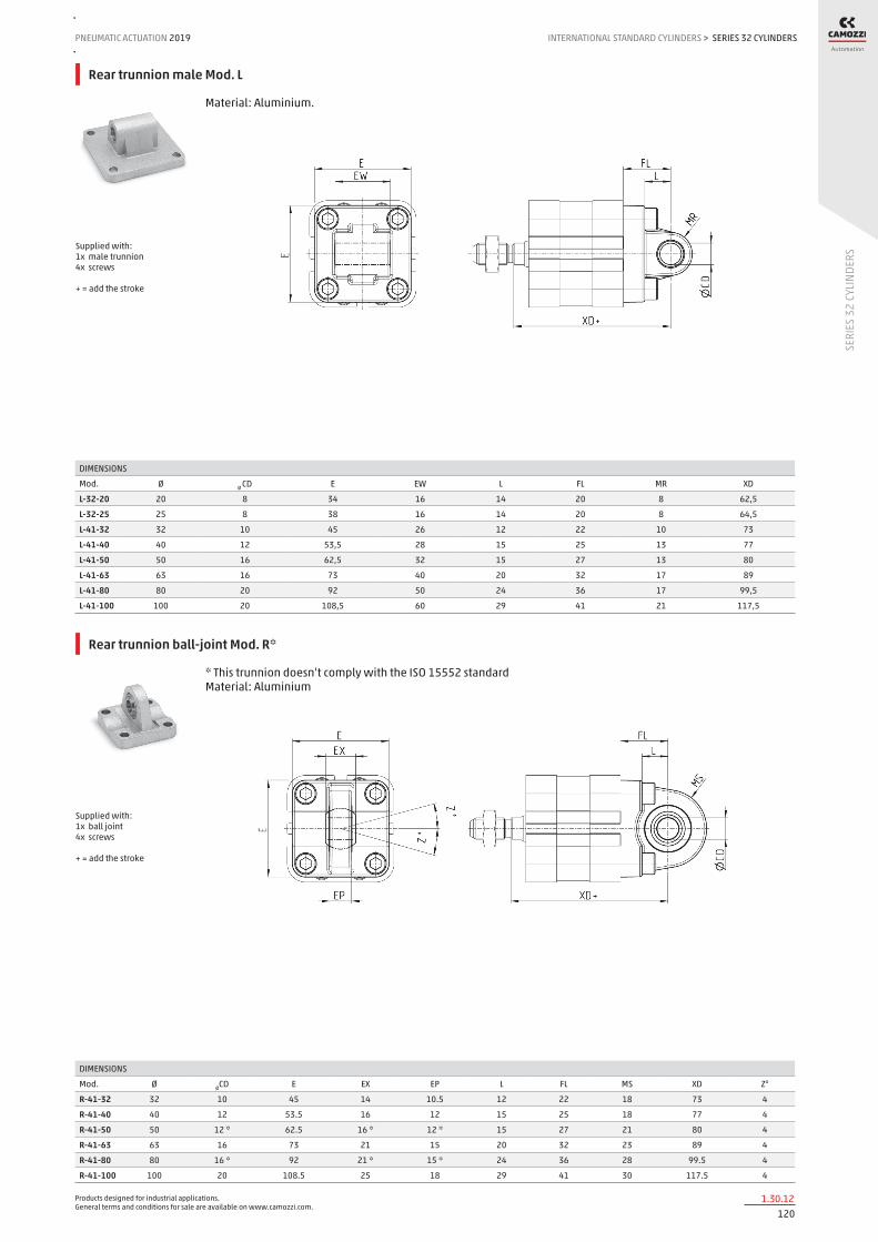
Products designed for industrial applications. General terms and conditions for sale are available on www.camozzi.com.
SERIES 32 CYLINDERSPNEUMATIC ACTUATION
1201.30.12
2019 INTERNATIONAL STANDARD CYLINDERS
SERI
ES 3
2 CY
LIND
ERS
>
Rear trunnion male Mod. L
Material: Aluminium.
DIMENSIONS
Mod. Ø Ø CD E EW L FL MR XD
L-32-20 20 8 34 16 14 20 8 62,5
L-32-25 25 8 38 16 14 20 8 64,5
L-41-32 32 10 45 26 12 22 10 73
L-41-40 40 12 53,5 28 15 25 13 77
L-41-50 50 16 62,5 32 15 27 13 80
L-41-63 63 16 73 40 20 32 17 89
L-41-80 80 20 92 50 24 36 17 99,5
L-41-100 100 20 108,5 60 29 41 21 117,5
Supplied with: 1x male trunnion 4x screws + = add the stroke
Rear trunnion ball-joint Mod. R*
* This trunnion doesn’t comply with the ISO 15552 standard Material: Aluminium
DIMENSIONS
Mod. Ø ØCD E EX EP L FL MS XD Z°
R-41-32 32 10 45 14 10.5 12 22 18 73 4
R-41-40 40 12 53.5 16 12 15 25 18 77 4
R-41-50 50 12 * 62.5 16 * 12 * 15 27 21 80 4
R-41-63 63 16 73 21 15 20 32 23 89 4
R-41-80 80 16 * 92 21 * 15 * 24 36 28 99.5 4
R-41-100 100 20 108.5 25 18 29 41 30 117.5 4
Supplied with: 1x ball joint 4x screws + = add the stroke

Products designed for industrial applications. General terms and conditions for sale are available on www.camozzi.com.
SERIES 32 CYLINDERSINTERNATIONAL STANDARD CYLINDERS > PNEUMATIC ACTUATION 2019
1211.30.13
SERI
ES 3
2 CY
LIND
ERS
Accessory combination Mod. C+L+S
Material: Aluminium.
DIMENSIONS
Mod. Ø ØCD E L FL M M1 TG XD+ Z° (max)
C+L+S 32 10 45 12 22 M6 10 32.5 73 30
C+L+S 40 12 53.5 15 25 M6 10 38 77 40
C+L+S 50 12 62.5 15 27 M8 13 46.5 80 25
C+L+S 63 16 73 20 32 M8 13 56.5 89 36
C+L+S 80 16 92 24 36 M10 16 72 99.5 34
C+L+S 100 20 108.5 29 41 M10 16 89 117.5 38
+ = add the stroke
90° male trunnion Mod. ZC
Material: Aluminium.
DIMENSIONS
Mod. Ø AH BT ØCD EA EW GL ØHB L5 MR RA UL UR TE XD
ZC-32 32 32 8 10 10 26 21 6,6 1,6 10 18 51 31 38 73
ZC-40 40 36 10 12 15 28 24 6,6 1,6 11 22 54 35 41 77
ZC-50 50 45 12 12 16 32 33 9 1,6 13 30 65 45 50 80
ZC-63 63 50 14 16 16 40 37 9 1,6 15 35 67 50 52 89
ZC-80 80 63 14 16 20 50 47 11 2,5 15 40 86 60 66 99,5
ZC-100 100 71 17 20 20 60 55 11 2,5 19 50 96 70 76 117,5
Supplied with: 1x male support + = add the stroke

Products designed for industrial applications. General terms and conditions for sale are available on www.camozzi.com.
SERIES 32 CYLINDERSPNEUMATIC ACTUATION
1221.30.14
2019 INTERNATIONAL STANDARD CYLINDERS
SERI
ES 3
2 CY
LIND
ERS
>
90° swivel combination for trunnion Mod. I
Material: zinc-plated steel.
DIMENSIONS
Mod. Ø AT BT ØCD CB GL ØHB MR RA UR XD
I-20-25 20 30 4 8 16,1 16 6,5 10 20 32 62,5
I-20-25 25 30 4 8 16,1 16 6,5 10 20 32 64,5
Supplied with: 1x female support 2x seeger 1x clevis pin + = add the stroke
Clevis pin Mod. S
DIMENSIONS
Mod. Ø D L L1 L2 L3
S-32 32 10 52 46 1,1 3
S-40 40 12 59 53 1,1 3
S-50 50 12 67 61 1,1 3
S-63 63 16 77 71 1,1 3
S-80 80 16 97 91 1,1 3
S-100 100 20 121 111 1,3 5
Supplied with: 1x clevis pin in stainless steel 2x Seeger in steel

Products designed for industrial applications. General terms and conditions for sale are available on www.camozzi.com.
SERIES 32 CYLINDERSINTERNATIONAL STANDARD CYLINDERS > PNEUMATIC ACTUATION 2019
1231.30.15
SERI
ES 3
2 CY
LIND
ERS
Rod fork end Mod. G
ISO 8140 Material: zinc-plated steel.
DIMENSIONS
Mod. Ø ØCK LE CM CL ER CE KK B ØB1
G-20 20-25 8 16 8 16 10 32 M8X1,25 22 14
G-25-32 32-40 10 20 10 20 12 40 M10x1,25 26 18
G-40 50-63 12 24 12 24 14 48 M12x1,25 32 20
G-50-63 80-100 16 32 16 32 19 64 M16x1,5 40 26
Piston rod socket joint Mod. GY
Material: zama and zinc-plated steel.
DIMENSIONS
Mod. Ø KK L CE L2 AX SW SW1 L1 L3 ØT ØD E ØB ØC Z
GY-20 20-25 M8X1,25 65 32 5 16 14 10 16 12 12,5 13 6 10 20 15
GY-32 32-40 M10X1,25 74 35 6,5 18 17 11 19,5 15 15 19 10 14 28 15
GY-40 50-63 M12X1,25 84 40 6,5 20 19 17 21 17 17,5 22 12 19 32 15
GY-50-63 80-100 M16X1,5 112 50 8 27 22 19 27,5 23 22 27 16 22 40 11

Products designed for industrial applications. General terms and conditions for sale are available on www.camozzi.com.
SERIES 32 CYLINDERSPNEUMATIC ACTUATION
1241.30.16
2019 INTERNATIONAL STANDARD CYLINDERS
SERI
ES 3
2 CY
LIND
ERS
>
Swivel ball joint Mod. GA
ISO 8139 Material: zinc-plated steel
DIMENSIONS
Mod. Ø ØCN U EN ER AX CE KK ØT Z SW
GA-20 20-25 8 9 12 12 16 36 M8X1,25 12,5 6,5 14
GA-32 32-40 10 10,5 14 14 20 43 M10x1,25 15 6,5 17
GA-40 50-63 12 12 16 16 22 50 M12X1.25 17,5 6,5 19
GA-50-63 80-100 16 15 21 21 28 64 M16x1,5 22 7,5 22
Piston rod lock nut Mod. U
ISO 4035 Materials: zinc-plated steel.
DIMENSIONS
Mod. Ø D M SW
U-20 20-25 M8X1.25 5 13
U-25-32 32-40 M10X1,25 6 17
U-40 50-63 M12X1,25 7 19
U-50-63 80-100 M16X1,5 8 24
Centring sleeve Mod. TR
Supplied with: 1x anodized AL centring ring Designed for the centring of both rear and front end caps with brackets Mod. B/D-E/C/C-H/H/L/R, as for the centring of the cylinder while mounting.
DIMENSIONS
Mod. Ø A ØB ØC D
TR-32-32 32 6 25 30 4
TR-32-40 40 6 30 35 4
TR-32-50 50 6 35 40 4
TR-32-63 63-80 7 40 45 5
TR-32-100 100 7 50 55 5
Centring pin Mod. TS-32-20
Material: anodized AL Designed for the centring of rear end caps with brackets L-32-20 / L-32-25 as for cylinder while mounting, it is also suitable in “a” holes of rear/front end caps of cyl. Ø20-25 or in the central hole of rear end caps of cyl. Ø32-40.
Mod.
TS-32-20

Products designed for industrial applications. General terms and conditions for sale are available on www.camozzi.com.
SERIES 32 CYLINDERSINTERNATIONAL STANDARD CYLINDERS > PNEUMATIC ACTUATION 2019
1251.30.17
SERI
ES 3
2 CY
LIND
ERS
Self aligning rod Mod. GK
Only for cylinders with male rod. Material: zinc-plated steel.
DIMENSIONS
Mod. Ø KK L L1 L3 L4 ØA ØD H I SW SW1 SW2 B1 AX Z E
GK-20 20-25 M8x1,25 57 26 21 5 8 12,5 19 17 11 7 13 4 16 4 2
GK-25-32 32-40 M10x1,25 71,5 35 20 7,5 14 22 32 30 19 12 17 5 22 4 2
GK-40 50-63 M12x1,25 75,5 35 24 7,5 14 22 32 30 19 12 19 6 22 4 2
GK-50-63 80-100 M16x1,5 104 53 32 10 22 32 45 41 27 20 24 8 30 3 2
Coupling piece Mod. GKF
Material: zinc-plated steel.
DIMENSIONS
Mod. Ø KK A B R TF L L1 I ØD ØD1 ØD2 SW E
GKF-20 20-25 M8x1,25 30 35 20 25 22,5 10 - 14 5,5 - 13 1,5
GKF-25-32 32-40 M10x1,25 37 60 23 36 22,5 15 6,8 18 11 6,6 15 2
GKF-40 50-63 M12x1,25 56 60 38 42 22,5 15 9 20 15 9 15 2,5
GKF-50-63 80-100 M16x1,5 80 80 58 58 26,5 15 10,5 25 18 11 22 2,5

Products designed for industrial applications. General terms and conditions for sale are available on www.camozzi.com.
SERIES 32 CYLINDERS - TANDEM AND MULTI-POSITIONPNEUMATIC ACTUATION
1261.31.01
2019 INTERNATIONAL STANDARD CYLINDERS
SERI
ES 3
2 CY
LIND
ERS
- TAN
DEM
AND
MUL
TI-P
OSIT
ION
>
Series 32 compact cylinders, Tandem and Multi-position versions
Double-acting, magnetic ø 25, 40, 63, 100 mm
Thanks to their great compactness Series 32 cylinders, Tandem and Multi-position, are suitable to be installed within confined spaces and can be used with the same mounting elements of other standard cylinders DIN/ISO 6431/VDMA 24562 (Series 60/61). The Tandem version enables to obtain up to 2 times the thrust force of a normal cylinder (standard traction force), while the Multi-position version can obtain up to three positions with one cylinder only.
» In compliance with ISO 21287
» Compact design
» Wide range of models available in different diameters
GENERAL DATA
Construction compact profileOperation double-acting, magneticMaterial body and end-blocks = anodized AL
rod = rolled stainless steel AISI 303 piston = anodized AL rod seal, OR end-block and piston seal = PU
Mounting with threaded holes on the end blocks flange – feet – trunnion
Strokes min. and max. (1) Multi-position
Series 32F, 32M Ø 25 = 5-300 mm (dimension x2) Series 32F, 32M Ø 40 - 63 = 5-400 mm (dimension x2) Series 32F, 32M Ø 100 = 5-500 mm (dimension x2)
Strokes min. and max. (1) Tandem
Series 32F, 32M Ø 25 = 5-80 mm Series 32F, 32M Ø 40 - 63 - 100 = 5-100 mm
Operating temperature 0°C ÷ 80°C (with dry air -20°C)Operating pressure 1 ÷ 10 barFluid clean air, without lubrication. If lubricated air is used, it is recommended to use oil ISOVG32. Once applied the lubrication should
never be interrupted.Operating speed 10 ÷ 1000 mm\sec (without load)
(1) the minimum stroke for the use of the sensors is 10 mm.

Products designed for industrial applications. General terms and conditions for sale are available on www.camozzi.com.
SERIES 32 CYLINDERS - TANDEM AND MULTI-POSITIONINTERNATIONAL STANDARD CYLINDERS > PNEUMATIC ACTUATION 2019
1271.31.02
SERI
ES 3
2 CY
LIND
ERS
- TAN
DEM
AND
MUL
TI-P
OSIT
ION
CODING EXAMPLE
32 SERIES compact magnetic
M VERSION M = male rod thread, mounted with rod nut Mod. U F = female rod thread
2 OPERATION 2 = double-acting
PNEUMATIC SYMBOLS CDPP
A MATERIALS A = anodized aluminium profile, end blocks and piston PU seals (rod - OR end block and piston)
040 BORE 025 = 25 mm 040 = 40 mm 063 = 63 mm 100 = 100 mm
CD5T, CD6T, CD7T CD5T, CD6T, CD7T CD2T, CD3T, CD4T CD5T, CD6T, CD7T
A CONSTRUCTION A = standard
050 STROKE - Tandem stroke in mm - Multi-position X1mm/X2mm. Insert the strokes without the initial 0 (see application scheme)
N Tandem and Multi-position
2 STAGES (for Tandem version only) 2 = 2 stages
32 M 2 A 040 A 050 N 2
PNEUMATIC SYMBOLS
The pneumatic symbols which have been indicated in the CODING EXAMPLE are shown below.
Operation scheme
Multi-position - Example: 32M2A040A25/75N X1 = 25 mm X2 = 75 mm
Tandem, stroke = 50 mm - Example: 32M2A040A050N2 In order to increase the speed of the rod’s return, it is possible to remove the covers from the intermediate end caps and supply the positive chambers from the outside

Products designed for industrial applications. General terms and conditions for sale are available on www.camozzi.com.
SERIES 32 CYLINDERS - TANDEM AND MULTI-POSITIONPNEUMATIC ACTUATION
1281.31.03
2019 INTERNATIONAL STANDARD CYLINDERS
SERI
ES 3
2 CY
LIND
ERS
- TAN
DEM
AND
MUL
TI-P
OSIT
ION
>
Tandem cylinders Mod. 32F2A/32M2A...N2
DIMENSIONS
Ø A AF BG ØD ØD2 ØD3 ØD4 E EE E1 H H1 H2 KF KK LA PL RT SW1 T1 T2 TG
25 16 11 16,5 10 - - 9 40,7 M5 - 76 81,7 44 M6 M8X1,25 5 7 M5 8 - 2,5 26
40 19 13 21,5 12 35 29 9 57 G1/8 - 86 93 48,2 M8 M10X1,25 5 7,6 M6 10 2 2,5 38
63 22 16 18,5 16 45 39 12 79,6 G1/8 12’5 93 101 - M10 M12X1,25 6 7,6 M8 13 2 3 56,5
100 28 20 20 25 55 49 12 115,6 G1/8 25 121 130,7 - M12 M16X1,5 6 8 M10 22 2 3 89
+ = add the stroke ++ = add the stroke two times 1 = Groove for sensor 2 = Positive stroke 3 = Negative stroke

Products designed for industrial applications. General terms and conditions for sale are available on www.camozzi.com.
SERIES 32 CYLINDERS - TANDEM AND MULTI-POSITIONINTERNATIONAL STANDARD CYLINDERS > PNEUMATIC ACTUATION 2019
1291.31.04
SERI
ES 3
2 CY
LIND
ERS
- TAN
DEM
AND
MUL
TI-P
OSIT
ION
Multi-position cylinders Mod. 32F2A/32M2A...X1/X2N
1 = Groove for sensor 2 = Positive stroke cylinder 1 3 = Positive stroke cylinder 2 4 = Negative stroke for both cylinders
DIMENSIONS
Ø A AF BG ØD ØD2 ØD3 ØD4 E EE E1 H H1 H2 KF KK LA PL RT SW1 T1 T2 TG
25 16 11 16,5 10 - - 9 40,7 M5 - 76 81,7 44 M6 M8X1,25 5 7 M5 8 - 2,5 26
40 19 13 21,5 12 35 29 9 57 G1/8 - 86 93 48,2 M8 M10X1,25 5 7,6 M6 10 2 2,5 38
63 22 16 18,5 16 45 39 12 79,6 G1/8 12,5 93 101 44 M10 M12X1,25 6 7,6 M8 13 2 3 56,5
100 28 20 20 25 55 49 12 115,6 G1/8 25 121 130,7 60,5 M12 M16X1,5 6 8 M10 22 2 3 89
X1 = Partial stroke X2 = Total stroke as operation scheme pag. 1.1.31.2
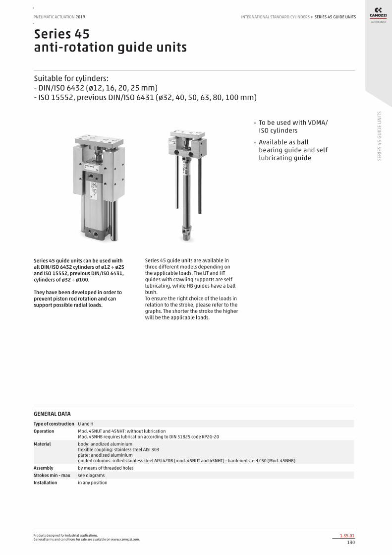
Products designed for industrial applications. General terms and conditions for sale are available on www.camozzi.com.
SERIES 45 GUIDE UNITSPNEUMATIC ACTUATION
1301.35.01
2019 INTERNATIONAL STANDARD CYLINDERS
SERI
ES 4
5 GU
IDE
UNIT
S
>
Series 45 anti-rotation guide units
Suitable for cylinders: - DIN/ISO 6432 (ø12, 16, 20, 25 mm) - ISO 15552, previous DIN/ISO 6431 (ø32, 40, 50, 63, 80, 100 mm)
Series 45 guide units can be used with all DIN/ISO 6432 cylinders of ø12 ÷ ø25 and ISO 15552, previous DIN/ISO 6431, cylinders of ø32 ÷ ø100. They have been developed in order to prevent piston rod rotation and can support possible radial loads.
Series 45 guide units are available in three different models depending on the applicable loads. The UT and HT guides with crawling supports are self lubricating, while HB guides have a ball bush. To ensure the right choice of the loads in relation to the stroke, please refer to the graphs. The shorter the stroke the higher will be the applicable loads.
» To be used with VDMA/ISO cylinders
» Available as ball bearing guide and self lubricating guide
GENERAL DATAType of construction U and HOperation Mod. 45NUT and 45NHT: without lubrication
Mod. 45NHB requires lubrication according to DIN 51825 code KP2G-20Material body: anodized aluminium
flexible coupling: stainless steel AISI 303 plate: anodized aluminium guided columns: rolled stainless steel AISI 420B (mod. 45NUT and 45NHT) - hardened steel C50 (Mod. 45NHB)
Assembly by means of threaded holesStrokes min - max see diagramsInstallation in any position

Products designed for industrial applications. General terms and conditions for sale are available on www.camozzi.com.
SERIES 45 GUIDE UNITSINTERNATIONAL STANDARD CYLINDERS > PNEUMATIC ACTUATION 2019
1311.35.02
SERI
ES 4
5 GU
IDE
UNIT
S
CODING EXAMPLE
45 SERIES
N VERSION N = standard
UT OPERATION UT = “U” self lubricating guide HT = “H” self lubricating guide HB = “H” ball guide
050 BORE 016 = Ø 12-16 mm (available only in the UT version with “U” self lubricating guide) 020 = 20 mm 025 = 25 mm 032 = 32 mm 040 = 40 mm 050 = 50 mm 063 = 63 mm 080 = 80 mm 100 = 100 mm
A MATERIALS A = anodized aluminium body - stainless steel AISI 420B columns for 45UT and 45HT - hardened steel C50 columns for 45HB
0100 STROKE in mm
45 N UT 050 A 0100
B = centre of gravity for applied load L = load X = fixed projection + stroke fixed projection = distance to the centre of gravity
Guide “U” moving on bush (45NUT)
45NUT GUIDES - APPLICABLE LOADS DEPENDING ON PROJECTION - GRAPH No 1

Products designed for industrial applications. General terms and conditions for sale are available on www.camozzi.com.
SERIES 45 GUIDE UNITSPNEUMATIC ACTUATION
1321.35.03
2019 INTERNATIONAL STANDARD CYLINDERS
SERI
ES 4
5 GU
IDE
UNIT
S
>
B = centre of gravity for applied load L = load X = fixed projection + stroke fixed projection = distance to the centre of gravity
Guide “HB” with linear ball bearing (45NHB)
45NHB GUIDES - APPLICABLE LOADS DEPENDING ON PROJECTION - GRAPH No 2
B = centre of gravity for applied load L = load X = fixed projection + stroke fixed projection = distance to the centre of gravity
Guide “HT” moving on bush (45NHT)
45NHT GUIDES - APPLICABLE LOADS DEPENDING ON PROJECTION - GRAPH No 3

Products designed for industrial applications. General terms and conditions for sale are available on www.camozzi.com.
SERIES 45 GUIDE UNITSINTERNATIONAL STANDARD CYLINDERS > PNEUMATIC ACTUATION 2019
1331.35.04
SERI
ES 4
5 GU
IDE
UNIT
S
Guides Mod. 45NUT for cylinders Series 16, 24, 25
Suitable for cylinders Series 16, 24 and 25 DIN/ISO 6432, ø 12 and 16. These guides do not need lubrication. For applicable loads see graph 1. Cylinders ø 12 and ø 16 use the same guides.
DIMENSIONS
Ø TF TG TH TI TM TL TN UF1 UF G1 ØA C1 H W C L L1 L2 L3 L4 L5 L6 P P1 T ØEA ØEB EC ØFA ØFB FC SW1 SW2 SW3
12 57 32 26,5 47 16 40 23 70 65 29 10 60 4 5 10 102,5 10 26 13 30 30 6,5 M5 M5 8 5,5 9 5,7 5,5 9,5 5,7 21 13 6
16 57 32 26,5 47 16 40 23 70 65 29 10 60 4 5 10 102,5 10 26 13 30 30 6,5 M5 M5 8 5,5 9 5,7 5,5 9,5 5,7 21 13 6
Supplied with: 1x fixing nut. Draw note: + = add the stroke
Guides Mod. 45NUT for cylinders Series 24, 25
Suitable for cylinders Series 24 and 25 DIN/ISO 6432, ø 20 and 25. These guides do not need lubrication. For applicable loads see graph 1.
DIMENSIONS
Ø TF TG TH TI TL UFI UF G1 ØA WH C1 H W C K L L1 L2 L3 L4 L5 L6 L7 L8 P P1 ØEA ØEB EC ØFA ØFB FC SW1 SW2
20 70 55 46,5 74 32 100 90 38 10 30 48 4 22 12 15 77 71 17 8 48+2 40 8,5 10 24 M6 M8 9 15 9 6,5 11 6,8 13 13
25 70 55 46,5 74 32 100 90 38 10 30 48 6 22 12 15 77 76 17 8 48+2 40 8,5 10 24 M6 M8 9 15 9 6,5 11 6,8 13 17
Supplied with: 1x fixing nut. Draw note: + = add the stroke
Guides Mod. 45NHT for cylinders Series 24, 25
Suitable for cylinders Series 24 and 25 DIN/ISO 6432, ø 20 and 25. These guides do not need lubrication. For applicable loads see graph 3.
DIMENSIONS
Ø TF TG TH TI TL TM TN UF G1 UF1 ØA WH C1 H W C K L L1 L2 L3 L4 L5 L6 L7 P P1 T ØEA ØEB EC ØFA ØFB FC SW1 SW2 SW3
20 68 40 38 58 32,5 20 23 76 32 79 10 17 108 4 22 12 58 160 15 37 34 37 71 65 8,5 M5 M6 14 6,5 11 6,8 5,5 10 5,7 13 13 6
25 68 40 38 58 32,5 20 23 76 32 79 10 17 108 6 17 12 58 160 15 37 34 37 76 65 8,5 M5 M6 14 6,5 11 6,8 5,5 10 5,7 13 17 6
Supplied with: 1x fixing nut. Draw note: + = add the stroke

Products designed for industrial applications. General terms and conditions for sale are available on www.camozzi.com.
SERIES 45 GUIDE UNITSPNEUMATIC ACTUATION
1341.35.05
2019 INTERNATIONAL STANDARD CYLINDERS
SERI
ES 4
5 GU
IDE
UNIT
S
>
Guides Mod. 45NHB for cylinders Series 24, 25
Suitable for cylinders Series 24 and 25 DIN/ISO 6432, ø 20 and 25. To lubricate these guides, use the special lubricator. For applicable loads see graph No 2.
DIMENSIONS
Ø TF TG TH TI TL TM TN UF G1 UF1 A WH C1 H W C K L L1 L2 L3 L4 L5 L6 L7 P P1 T ØEA ØEB EC ØFA ØFB FC SW1 SW2 SW3
20 68 40 38 58 32,5 20 23 76 32 79 10 17 108 4 22 12 58 160 15 37 34 37 71 65 8,5 M5 M6 14 6,5 11 6,8 5,5 10 5,7 13 13 6
25 68 40 38 58 32,5 20 23 76 32 79 10 17 108 6 17 12 58 160 15 37 34 37 76 65 8,5 M5 M6 14 6,5 11 6,8 5,5 10 5,7 13 17 6
Supplied with: 1x fixing nut. Draw note: + = add the stroke
Guides Mod. 45NUT for cylinders Series 60, 61, 62, 63, 6E, 6PF
Suitable for ISO 15552 (previous DIN/ISO 6431) cylinders Series 60, 61, 62, 63, 6E, 6PF, ø 32, 40, 50, 63, 80 and 100. These guides do not need lubrication. For applicable loads see graph No 1.
DIMENSIONS
Ø TF TG TH ØA T1 P FB UF G1 UF1 L C1 H W C L1 WH L2 L3 L4 L5 TL SW1 SW2 SW3
32 78 32,5 58 12 74 M6 6,6 90 45 100 106 48 6 22 12 94 17 7,8 52 48 7,8 32,5 15 17 6
40 84 38 64 12 80 M6 6,6 100 50 106 117 58 7 22 12 105 21 10 53 56 10 38 15 19 6
50 100 46,5 80 16 96 M8 9 120 60 125 129 59 8 26 15 106 25 6,2 64 66 6,3 46,5 22 24 6
63 105 56,5 95 16 104 M8 9 125 70 132 146 76 8 26 15 121 25 9,8 64 76 9,8 56,5 22 24 6
80 130 72 130 20 130 M10 11 155 90 165 170 90 9 32 16 128 34 9 72 98 20 50 27 30 6
100 150 89 150 20 150 M10 11 175 110 185 190 110 9 32 16 138 39 10,5 72 118 20 70 27 30 6
Supplied with: 4x fixing screws. Draw note: + = add the stroke

Products designed for industrial applications. General terms and conditions for sale are available on www.camozzi.com.
SERIES 45 GUIDE UNITSINTERNATIONAL STANDARD CYLINDERS > PNEUMATIC ACTUATION 2019
1351.35.06
SERI
ES 4
5 GU
IDE
UNIT
S
Guides Mod. 45NHT for cylinders Series 60, 61, 62, 63, 6E, 6PF
Suitable for ISO 15552 (previous DIN/ISO 6431) cylinders Series 60, 61, 62, 63, 6E, 6PF, ø 32, 40, 50, 63, 80 and 100. These guides do not need lubrication. For applicable loads see graph No 3.
DIMENSIONS
Ø TF TG TH TI UF G1 UF1 ØA WH C1 H W C K L L1 L2 L3 L4 L5 L6 L7 P T ØFA ØFB FC SW1 SW2 SW3
32 78 32.5 61 74 90 45 97 12 17 125 6 17 12 76 177 4.3 50.2 50 37 94 64 3 M6 14 6.5 11 6.8 13 17 6
40 84 38 69 87 110 54 115 16 21 140 7 22 12 81 192 11 58.2 58 37 105 74 3 M6 14 6.5 11 6.8 15 19 6
50 100 46.5 85 104 130 63 137 20 26 149 8 26 15 78.5 205 19.8 70.2 70 37.5 106 89 3 M8 16 9 15 9 22 24 6
63 105 56.5 100 119 145 80 152 20 26 178 8 26 15 111 237 15.3 85.2 85 37 121 89 7 M8 16 9 15 9 22 24 6
80 130 72 130 148 180 100 189 25 34 195 9 32 20 128 280 21 105.4 105 42 128 110 23 M10 20 11 18 11 27 30 6
100 150 89 150 172 200 120 213 25 39 220 9 32 20 128 280 24.5 130.4 130 37 138 115 3 M10 20 11 18 11 27 30 6
Supplied with: 4x fixing screws. Draw note: + = add the stroke
Guides Mod. 45NHB for cylinders Series 60, 61, 62, 63, 6E, 6PF
Suitable for ISO 15552 (previous DIN/ISO 6431) cylinders Series 60, 61, 62, 63, 6E, 6PF, ø 32, 40, 50, 63, 80 and 100. To lubricate these guides, use the special lubricator. For applicable loads see graph No 2.
DIMENSIONS
Ø TF TG TH TI UF G1 UF1 ØA WH C1 H W C K L L1 L2 L3 L4 L5 L6 L7 P T ØFA ØFB FC SW1 SW2 SW3
32 78 32.5 61 74 90 45 97 12 17 125 6 17 12 76 177 4.3 50.2 50 37 94 64 3 M6 14 6.5 11 6.8 13 17 6
40 84 38 69 87 110 54 115 16 21 140 7 22 12 81 192 11 58.2 58 37 105 74 3 M6 14 6.5 11 6.8 15 19 6
50 100 46.5 85 104 130 63 137 20 26 149 8 26 15 78,5 237 19.8 70.2 70 69.5 106 89 3 M8 16 9 15 9 22 24 6
63 105 56.5 100 119 145 80 152 20 26 178 8 26 15 111 237 15.3 85.2 85 37 121 89 7 M8 16 9 15 9 22 24 6
80 130 72 130 148 180 100 189 25 34 195 9 32 20 128 280 21 105.4 105 42 128 110 23 M10 20 11 18 11 27 30 6
100 150 89 150 172 200 120 213 25 39 220 9 32 20 128 280 24.5 130.4 130 37 138 115 3 M10 20 11 18 11 27 30 6
Supplied with: 4x fixing screws. Draw note: + = add the stroke

Products designed for industrial applications. General terms and conditions for sale are available on www.camozzi.com.
SERIES QN CYLINDERSPNEUMATIC ACTUATION
1362.05.01
2019 COMPACT / SHORT-STROKE CYLINDERS
SERI
ES Q
N CY
LIND
ERS
>
Series QN short-stroke cylinders
Single-acting, non magnetic ø 8, 12, 20, 32, 50, 63 mm
Series QN single-acting short-stroke cylinders have been designed so that they can be installed in very small spaces. Due to the compactness and sturdiness of these cylinders, they are mainly suitable for positioning and locking.
The available strokes are indicated in the tables.
GENERAL DATAType of construction compactOperation single-actingMaterials aluminium body - NBR seals - other materials in stainless steel and brassOperating pressure P. min 2 bar P. max 10 barOperating temperature 0°C ÷ 80°C (with dry air - 20°C)Fluid clean air, without lubrication. If lubricated air is used, it is recommended to use oil ISO VG32. Once applied the lubrication should
never be interrupted.Bore ø 8, 12, 20, 32, 50, 63Stroke see tableType of mounting by means of screws in the body

Products designed for industrial applications. General terms and conditions for sale are available on www.camozzi.com.
SERIES QN CYLINDERSCOMPACT / SHORT-STROKE CYLINDERS > PNEUMATIC ACTUATION 2019
1372.05.02
SERI
ES Q
N CY
LIND
ERS
STANDARD STROKES FOR CYLINDERS SERIES QN
STANDARD STROKES
Ø 4 5 10 25
8 ✖
12 ✖ ✖
20 ✖ ✖
32 ✖ ✖ ✖
50 ✖ ✖
63 ✖ ✖
CODING EXAMPLE
QN SERIES
1 OPERATING 1 = single-acting
PNEUMATIC SYMBOL CS01
A MATERIALS A = rolled stainless steel rod - aluminium body
50 BORE 08 = 8 mm 12 = 12 mm 20 = 20 mm 32 = 32 mm 50 = 50 mm 63 = 63 mm
A TYPE OF DESIGN A = standard
25 STROKE (see the table)
QN 1 A 50 A 25
PNEUMATIC SYMBOLS
The pneumatic symbols which have been indicated in the CODING EXAMPLE are shown below.

Products designed for industrial applications. General terms and conditions for sale are available on www.camozzi.com.
SERIES QN CYLINDERSPNEUMATIC ACTUATION
1382.05.03
2019 COMPACT / SHORT-STROKE CYLINDERS
SERI
ES Q
N CY
LIND
ERS
>
Short-stroke cylinders Series QN - bores ø 8, 12 and 20
DIMENSIONS
Mod. Ø A h8 B ØC D G H ØJ ØK L M N P Q H13 SW T+0,1 U V Z+0,10
QN1A08A04 8 18 11 4 20 16 5 3,2 5,8 3 - 17 - M5 - - 8 13,5 -
QN1A12A04 12 20 13 5 25 16 5 3,2 5,8 3 - 17 - M5 - - 9 16 -
QN1A12A10 12 20 13 5 25 26 5 3,2 5,8 3 - 30 - M5 - - 9 16 -
QN1A20A04 20 32 20 10 37 20 5 5,5 9 5 8 21 M5 M5 8 2,5 15 21 5,5
QN1A20A10 20 32 20 10 37 32 5 5,5 9 5 8 33 M5 M5 8 2,5 15 21 5,5
Short-stroke cylinders Series QN - bores ø 32, 50 and 63
DIMENSIONS
Mod. Ø A h8 B ØC D E F G H ØJ ØK L M N P Q H13 R SW T+0,1 U V Z+0,10
QN1A32A05 32 45 32 12 56 48,5 18 26 8,5 5,5 9 5 14,5 27 M6 G1\8 36 10 2,5 18 32 7
QN1A32A10 32 45 32 12 56 48,5 18 32 8,5 5,5 9 5 14,5 33 M6 G1\8 36 10 2,5 18 32 7
QN1A32A25 32 45 32 12 56 48,5 18 57,5 8,5 5,5 9 5 14,5 58,5 M6 G1\8 36 10 2,5 18 32 7
QN1A50A10 50 64 50 16 72 64 20 30 8,5 6,5 10,5 6,3 15,5 31 M8 G1\8 50 13 3,5 25 40 8,5
QN1A50A25 50 64 50 16 72 64 20 57,5 8,5 6,5 10,5 6,3 15,5 58,5 M8 G1\8 50 13 3,5 25 40 8,5
QN1A63A10 63 80 62 16 88 80 20 35 8,5 8,5 14 8,5 14,5 36 M8 G1\8 62 13 3,5 31 48 8,5
QN1A63A25 63 80 62 16 88 80 20 60,5 8,5 8,5 14 8,5 14,5 62,5 M8 G1\8 62 13 3,5 31 48 8,5

Products designed for industrial applications. General terms and conditions for sale are available on www.camozzi.com.
SERIES QP - QPR CYLINDERSCOMPACT / SHORT-STROKE CYLINDERS > PNEUMATIC ACTUATION 2019
1392.10.01
SERI
ES Q
P - Q
PR C
YLIN
DERS
Series QP - QPR short-stroke cylinders
Series QP: single and double-acting, magnetic Series QPR: double-acting magnetic, non-rotating ø 12, 16, 20, 25, 32, 40, 50, 63, 80, 100 mm
Series QP - QPR cylinders are available in 10 bore sizes, from ø12 to ø100. Their compact dimension allows the installation in small spaces. Because of their particular construction, they can be mounted by means of feet or trunnion.
The guides are manufactured in the external profile parallel to the sliding axis on three sides. These are used to locate the switches that sense the piston position. The non rotating guides make the QPR suitable for supply operations and for handling equipment.
GENERAL DATA
Type of construction Series QP: compact profile Series QPR: compact with non rotating guides
Operation Series QP: single and double-acting Series QPR: double-acting
Materials body: anodized AL rod: rolled stainless steel piston seals: PU rod seals: PU (Ø 12 ÷ 25 mm) - NBR (Ø 32 ÷ 100 mm)
Operating temperature 0°C ÷ 80°C (with dry air -20°C)Assembly by means of screws or bracketsOperating pressure 1 ÷ 10 bar (double-acting)
2 ÷ 10 bar (single-acting)Fluid filtered air, without lubrication.
If lubricated air is used, it is recommended to use oil ISOVG32. Once applied the lubrication should never be interrupted.Strokes (min-max) Series QP: 1 ÷ 150 mm (ø12 ÷ ø 25) - 1 ÷ 200 mm (ø 32 ÷ ø 100)
Series QPR: 1 ÷ 50 mm (ø 12) - 1 ÷ 75 mm (ø 16) - 1 ÷ 100 mm (ø 20 ÷ ø 100)Strokes the minimum stroke for use of the sensors is 10 mmBores ø 12, 16, 20, 25, 32, 40, 50, 63, 80, 100
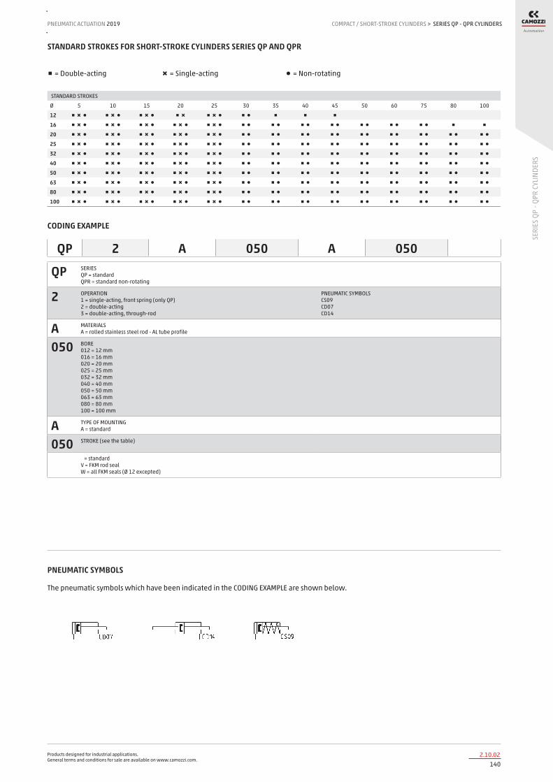
Products designed for industrial applications. General terms and conditions for sale are available on www.camozzi.com.
SERIES QP - QPR CYLINDERSPNEUMATIC ACTUATION
1402.10.02
2019 COMPACT / SHORT-STROKE CYLINDERS
SERI
ES Q
P - Q
PR C
YLIN
DERS
>
STANDARD STROKES FOR SHORT-STROKE CYLINDERS SERIES QP AND QPR
■ = Double-acting ✖ = Single-acting ● = Non-rotating
STANDARD STROKES
Ø 5 10 15 20 25 30 35 40 45 50 60 75 80 100
12 ■ ✖ ● ■ ✖ ● ■ ✖ ● ■ ✖ ■ ✖ ● ■ ● ■ ■ ■
16 ■ ✖ ● ■ ✖ ● ■ ✖ ● ■ ✖ ● ■ ✖ ● ■ ● ■ ● ■ ● ■ ● ■ ● ■ ● ■ ● ■ ■
20 ■ ✖ ● ■ ✖ ● ■ ✖ ● ■ ✖ ● ■ ✖ ● ■ ● ■ ● ■ ● ■ ● ■ ● ■ ● ■ ● ■ ● ■ ●
25 ■ ✖ ● ■ ✖ ● ■ ✖ ● ■ ✖ ● ■ ✖ ● ■ ● ■ ● ■ ● ■ ● ■ ● ■ ● ■ ● ■ ● ■ ●
32 ■ ✖ ● ■ ✖ ● ■ ✖ ● ■ ✖ ● ■ ✖ ● ■ ● ■ ● ■ ● ■ ● ■ ● ■ ● ■ ● ■ ● ■ ●
40 ■ ✖ ● ■ ✖ ● ■ ✖ ● ■ ✖ ● ■ ✖ ● ■ ● ■ ● ■ ● ■ ● ■ ● ■ ● ■ ● ■ ● ■ ●
50 ■ ✖ ● ■ ✖ ● ■ ✖ ● ■ ✖ ● ■ ✖ ● ■ ● ■ ● ■ ● ■ ● ■ ● ■ ● ■ ● ■ ● ■ ●
63 ■ ✖ ● ■ ✖ ● ■ ✖ ● ■ ✖ ● ■ ✖ ● ■ ● ■ ● ■ ● ■ ● ■ ● ■ ● ■ ● ■ ● ■ ●
80 ■ ✖ ● ■ ✖ ● ■ ✖ ● ■ ✖ ● ■ ✖ ● ■ ● ■ ● ■ ● ■ ● ■ ● ■ ● ■ ● ■ ● ■ ●
100 ■ ✖ ● ■ ✖ ● ■ ✖ ● ■ ✖ ● ■ ✖ ● ■ ● ■ ● ■ ● ■ ● ■ ● ■ ● ■ ● ■ ● ■ ●
CODING EXAMPLE
QP SERIES QP = standard QPR = standard non-rotating
2 OPERATION 1 = single-acting, front spring (only QP) 2 = double-acting 3 = double-acting, through-rod
PNEUMATIC SYMBOLS CS09 CD07 CD14
A MATERIALS A = rolled stainless steel rod - AL tube profile
050 BORE 012 = 12 mm 016 = 16 mm 020 = 20 mm 025 = 25 mm 032 = 32 mm 040 = 40 mm 050 = 50 mm 063 = 63 mm 080 = 80 mm 100 = 100 mm
A TYPE OF MOUNTING A = standard
050 STROKE (see the table)
= standard V = FKM rod seal W = all FKM seals (Ø 12 excepted)
QP 2 A 050 A 050
PNEUMATIC SYMBOLS
The pneumatic symbols which have been indicated in the CODING EXAMPLE are shown below.

Products designed for industrial applications. General terms and conditions for sale are available on www.camozzi.com.
SERIES QP - QPR CYLINDERSCOMPACT / SHORT-STROKE CYLINDERS > PNEUMATIC ACTUATION 2019
1412.10.03
SERI
ES Q
P - Q
PR C
YLIN
DERS
ACCESSORIES FOR SHORT-STROKE CYLINDERS SERIES QP
Foot mount Mod. B Male trunnion Mod. L
All accessories are supplied separately.
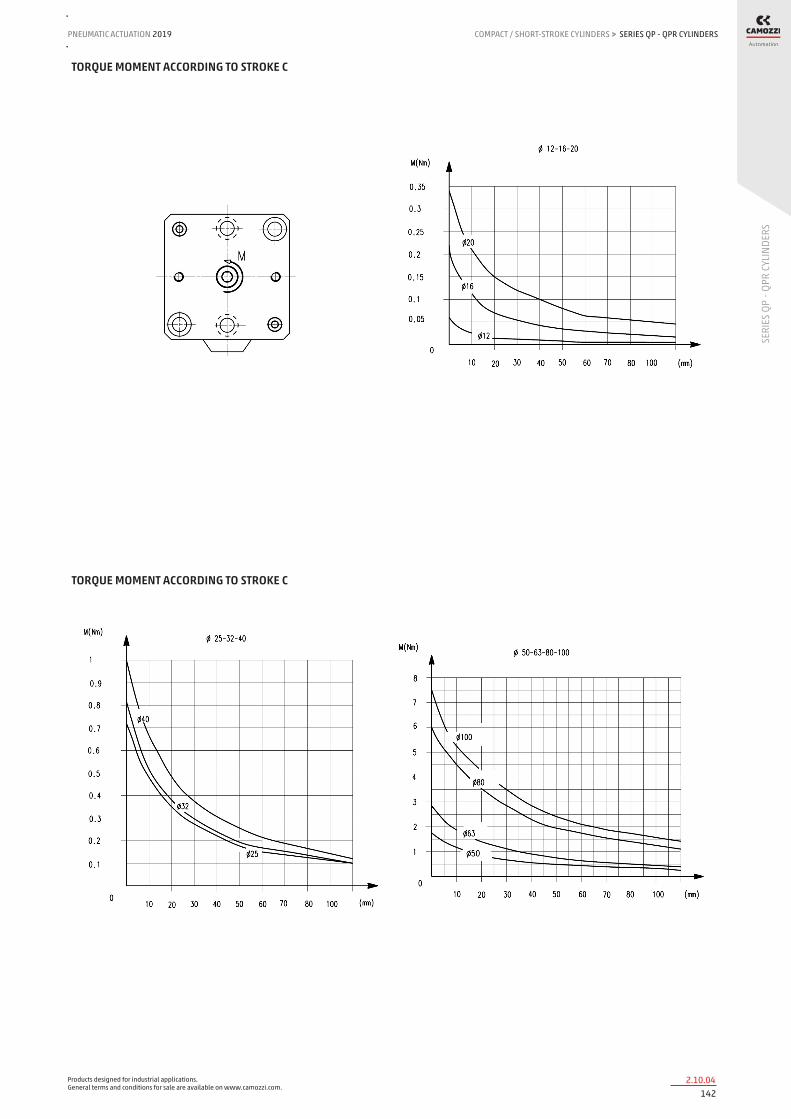
Products designed for industrial applications. General terms and conditions for sale are available on www.camozzi.com.
SERIES QP - QPR CYLINDERSPNEUMATIC ACTUATION
1422.10.04
2019 COMPACT / SHORT-STROKE CYLINDERS
SERI
ES Q
P - Q
PR C
YLIN
DERS
>
TORQUE MOMENT ACCORDING TO STROKE C
TORQUE MOMENT ACCORDING TO STROKE C

Products designed for industrial applications. General terms and conditions for sale are available on www.camozzi.com.
SERIES QP - QPR CYLINDERSCOMPACT / SHORT-STROKE CYLINDERS > PNEUMATIC ACTUATION 2019
1432.10.05
SERI
ES Q
P - Q
PR C
YLIN
DERS
TRANSVERSAL LOAD ACCORDING TO PROJECTION “ X “
F = transversal force
TRANSVERSAL LOAD ACCORDING TO PROJECTION “ X “

Products designed for industrial applications. General terms and conditions for sale are available on www.camozzi.com.
SERIES QP - QPR CYLINDERSPNEUMATIC ACTUATION
1442.10.06
2019 COMPACT / SHORT-STROKE CYLINDERS
SERI
ES Q
P - Q
PR C
YLIN
DERS
>
Short-stroke cylinders Series QP
Note: The cylinder’s end stop must be provided externally. For single-acting cylinders ø 12, 16, 20 and 25 add 5 mm to G+, G1+ and N+ dimensions.
DIMENSIONS
Ø A B B1 B2 ØC D E G + G1 + H1 H J J1 K L L1 M M1 N + ØO P Q R R1 R2 SW T U V Z
12 23.8 15.5 13 - 6 25 25 29.6 29.6 12.3 7.8 3.5 - 5.8 3 - 5.5 4.5 32.9 - M3 M5 15.5 16.75 - 5 - 9 13.15 -
16 29 20 - - 8 29 29 32 32.4 10.9 8.7 3.5 - 5.8 3 - 8 4.5 36.4 16.6 M4 M5 20 - - 6 - - 14.5 -
20 37 25.5 20 - 10 39.25 39.25 31.2 31.7 9.8 9.8 5.5 - 9 6 - 8 4.5 36 19.5 M6 M5 25.5 27.75 - 8 - 15 20.75 -
25 40 28 26 - 10 40 40 32.1 33.5 8 6.9 5.5 - 10 5.5 - 8 4.5 37.5 22 M6 M5 28 - - 8 - - 20 -
32 45 34 32 33 12 55.5 47 39.5 40 9.5 9.5 5.5 M8 10.5 6 21 10 7.5 44 23.5 M6 G1\8 34 36 35 10 2.5 - 32 7
40 52 - - 40 16 57 52 42.4 43.4 10.7 10.7 5.5 M8 9 6 21 13.5 7.5 47.9 29.6 M8 G1\8 - - 40 13 3.5 - 31 8.5
50 64 - - 50 16 72 64 42.2 44 11.2 11.2 6.5 M8 10.5 6 21 13.5 9 48.4 37.5 M8 G1\4 - - 50 13 3.5 - 40 8.5
63 80 62 60 61 20 88 80 49.5 50.1 13 13 8.5 M12 15 8.5 31.5 13.5 9 54 50 M8 G1\4 60 62 61 17 4 - 48 8.5
80 98 - - 77 25 104 98 57.5 58.1 16.2 16.2 10.5 M12 17 10.5 31.5 15 10.5 63.5 62 M16 G3\8 - - 77 22 4 - 55 16.5
100 117 - - 94 25 123.5 117 68.5 69.1 20.3 20.3 10.5 M12 17 10.5 31.5 15 10.5 74.5 80 M16 G3\8 - - 94 22 4 - 65 16.5
+ = add the stroke

Products designed for industrial applications. General terms and conditions for sale are available on www.camozzi.com.
SERIES QP - QPR CYLINDERSCOMPACT / SHORT-STROKE CYLINDERS > PNEUMATIC ACTUATION 2019
1452.10.07
SERI
ES Q
P - Q
PR C
YLIN
DERS
Short-stroke cylinders Series QP
Note: The cylinder’s end stop must be provided externally.
DIMENSIONS
Ø A B B1 B2 ØC h 8 D E G+ G1+ H1 H J J1 K L L1 M M1 N + + ØO P Q R R1 R2 SW T U V Z
12 23.8 15.5 13 - 6 25 25 34.5 34.5 12.3 12.3 3.5 - 5.8 3 - 5.5 4.5 41 - M3 M5 15.5 16.75 - 5 - 9 13.15 -
16 29 20 - - 8 29 29 38 38.8 10.9 10.9 3.5 - 5.8 3 - 8 4.5 46.4 16.6 M4 M5 20 - - 6 - - 14.5 -
20 37 25.5 20 - 10 39.25 39.25 38.1 39.1 9.8 9.8 5.5 - 9 6 - 8 4.5 47.7 19.5 M6 M5 25.5 27.75 - 8 - 15 20.75 -
25 40 28 26 - 10 40 40 36.3 39.1 8 8 5.5 - 10 5.5 - 8 4.5 47.1 22 M6 M5 28 - - 8 - - 20 -
32 45 34 32 33 12 55.5 47 39.5 40.5 9.5 9.5 5.5 M8 10.5 6 21 10 7.5 48.5 23.5 M6 G1\8 34 36 35 10 2.5 - 32 7
40 52 - - 40 16 57 52 42.4 44.4 10.7 10.7 5.5 M8 9 6 21 13.5 7.5 53.4 29.6 M8 G1\8 - - 40 13 3.5 - 31 8.5
50 64 - - 50 16 72 64 42.2 45.8 11.2 11.2 6.5 M8 10.5 6 21 13.5 9 54,8 37,5 M8 G1\4 - - 50 13 3,5 - 40 8,5
63 80 62 60 61 20 88 80 49.5 50.7 13 13 8.5 M12 15 8.5 31.5 13.5 9 58.5 50 M8 G1\4 60 62 61 17 4 - 48 8.5
80 98 - - 77 25 104 98 57.5 58.7 16.2 16.2 10.5 M12 17 10.5 31.5 15 10.5 69.5 62 M16 G3\8 - - 77 22 4 - 55 16.5
100 117 - - 94 25 123.5 117 68.5 69.7 20.3 20.3 10.5 M12 17 10.5 31.5 15 10.5 80.5 80 M16 G3\8 - - 94 22 4 - 65 16.5
+ = add the stroke once + = add the stroke twice

Products designed for industrial applications. General terms and conditions for sale are available on www.camozzi.com.
SERIES QP - QPR CYLINDERSPNEUMATIC ACTUATION
1462.10.08
2019 COMPACT / SHORT-STROKE CYLINDERS
SERI
ES Q
P - Q
PR C
YLIN
DERS
>
Short-stroke cylinder Series QPR
Note: The cylinder’s end stop must be provided externally.
DIMENSIONS
Ø A B D E G + H1 H J K L L1 N + N1 + Q R SW V AA BB ØCC ØDD EE FF LL MM NN RR VV
12 23.8 15.5 25 25 29.6 12.3 7.8 3.5 5.8 3 - 32.9 37.9 M5 15.5 5 13.15 5 3.5 6.2 3.2 5.8 M3 15.5 25 24 15.5 12
16 29 20 29 29 32 10.9 8.7 3.5 5.8 3 - 36.4 41.4 M5 20 6 14.5 5 3.5 6.2 3.2 6.5 M3 20 28 28 20 -
20 37 25.5 39.25 39.25 31.2 9.8 9.8 5.5 9 6 - 36 46 M5 25.5 8 20.75 10 4.6 8 4.2 9 M4 25.5 38.5 36 25.5 18
25 40 28 40 40 32.1 8 6.9 5.5 10 5.5 - 37.5 47.5 M5 28 8 20 10 4.6 8 4.2 10 M4 27 40 40 28 -
32 45 33 55.5 47 39.5 9.5 9.5 M8 10.5 6 21 44 54 G1\8 35 10 32 10 6 9 5.5 9 M5 32 47 45 36 -
40 52 40 57 52 42.4 10.7 10.7 M8 9 6 21 47.9 57.9 G1\8 40 13 31 10 6 9 5.5 9 M5 40 52 50 40 -
50 64 50 72 64 42.2 11.2 11.2 M8 10.5 6 21 48.4 60.4 G1\4 50 13 40 12 6.8 10.5 6.5 10 M6 50 65 65 50 -
63 80 61 88 80 49.5 13 13 M12 15 8.5 31.5 54 66 G1\4 61 17 48 12 8.5 14 9 15 M6 62 80 80 62 -
80 98 77 104 98 57.5 16.2 16.2 M12 17 10.5 31.5 63.5 78.5 G3\8 77 22 55 15 10 16.5 11 17 M8 77 100 100 77 -
100 117 94 123.5 117 68.5 20.3 20.3 M12 17 10.5 31.5 74.5 89.5 G3\8 94 22 65 15 10 16.5 11 17 M8 94 115 115 94 -
+ = add the stroke

Products designed for industrial applications. General terms and conditions for sale are available on www.camozzi.com.
SERIES QP - QPR CYLINDERSCOMPACT / SHORT-STROKE CYLINDERS > PNEUMATIC ACTUATION 2019
1472.10.09
SERI
ES Q
P - Q
PR C
YLIN
DERS
Short-stroke cylinder Series QPR - through-rod
Note: The cylinder’s end stop must be provided externally.
DIMENSIONS
Ø A B D E G + H1 H J K L L1 N + + N1 + + Q R SW V AA BB ØCC ØDD EE FF LL MM NN RR VV
12 23.8 15.5 25 25 37.3 12.3 12.3 3.5 5.8 3 - 41 46 M5 15.5 5 13.15 5 3.5 6.2 3.2 5.8 M3 15.5 25 24 15.5 12
16 29 20 29 29 38 10.9 10.9 3.5 5.8 3 - 47 52 M5 20 6 14.5 5 3.5 6.2 3.2 6.5 M3 20 28 28 20 -
20 37 25.5 39.25 39.25 38.1 9.8 9.8 5.5 9 6 - 47.7 57.7 M5 25.5 8 20.75 10 4.6 8 4.2 9 M4 25.5 38.5 36 25.5 18
25 40 28 40 40 36.3 8 8 5.5 10 5.5 - 47.1 57.1 M5 28 8 20 10 4.6 8 4.2 10 M4 27 40 40 28 -
32 45 33 55.5 47 39.5 9.5 9.5 M8 10.5 6 21 48.5 58.5 G1\8 35 10 32 10 6 9 5.5 9 M5 32 47 45 36 -
40 52 40 57 52 42.4 10.7 10.7 M8 9 6 21 53.4 63.4 G1\8 40 13 31 10 6 9 5.5 9 M5 40 52 50 40 -
50 64 50 72 64 42.2 11.2 11.2 M8 10.5 6 21 54.8 66.8 G1\4 50 13 40 12 6.8 10.5 6.5 10 M6 50 65 65 50 -
63 80 61 88 80 49.5 13 13 M12 15 8.5 31.5 58.5 70.5 G1\4 61 17 48 12 8.5 14 9 15 M6 62 80 80 62 -
80 98 77 104 98 57.5 16.2 16.2 M12 17 10.5 31.5 69.5 84.5 G3\8 77 22 55 15 10 16.5 11 17 M8 77 100 100 77 -
100 117 94 123.5 117 68.5 20.3 20.3 M12 17 10.5 31.5 80.5 95.5 G3\8 94 22 65 15 10 16.5 11 17 M8 94 115 115 94 -
+ = add the stroke once ++ = add the stroke twice

Products designed for industrial applications. General terms and conditions for sale are available on www.camozzi.com.
SERIES QP - QPR CYLINDERSPNEUMATIC ACTUATION
1482.10.10
2019 COMPACT / SHORT-STROKE CYLINDERS
SERI
ES Q
P - Q
PR C
YLIN
DERS
>
Male trunnion bracket Mod. L
Material: Aluminium
DIMENSIONS
Mod. Ø CDH9 MR L C XD+ F G EW
L-QP-32 32 10 9 12 22 66 33 35 26
L-QP-40 40 12 13 15 25 73 40 40 28
L-QP-50 50 12 13 15 27 75,5 50 50 32
L-QP-63 63 16 15 20 32 86 61 61 40
L-QP-80 80 16 15 24 36 99,5 77 77 50
L-QP-100 100 20 18 29 41 115,5 94 94 60
Supplied with: 1x trunnion 4x screws + = add the stroke
Feet bracket Mod. B
Material: zinc-plated steel.
DIMENSIONS
Mod. Ø C SA+ XA+ SB+ XB+ TR G AB AH AO
B-QP-32 32 3 61.9 55.2 23.1 35.8 57 71 6.6 30 8.8
B-QP-40 40 3 64.8 59.1 26 39.7 64 78 6.6 33 8.8
B-QP-50 50 4 71.6 63.1 20.8 37.7 79 95 9 39 10.3
B-QP-63 63 4 81.9 70.2 25.1 41.8 95 113 11 46 13.8
B-QP-80 80 6 96.5 83 30.5 49 118 140 13 59 10.5
B-QP-100 100 6 114.5 97.5 22.5 51.5 137 162 13 71 17
Supplied with: 2x feet 4x screws + = add the stroke

Products designed for industrial applications. General terms and conditions for sale are available on www.camozzi.com.
SERIES RPA CYLINDERSCOMPACT / SHORT-STROKE CYLINDERS > PNEUMATIC ACTUATION 2019
1492.13.01
SERI
ES R
PA C
YLIN
DERS
Series RPA short stroke cylinders with non-rotating rodDouble-effect, magnetic With hollow through rod and mounting stud Bores: 20 and 30 mm
The Series RPA short stroke cylinders are double acting actuators with aluminium hollow through rod and mounting stud. Available in two sizes, ø 20 and ø 30 mm, with different strokes and dimensions of the mounting stud, these actuators are equipped with the non-rotating function of the rod.
The Series RPA are prepared for the mounting of magnetic sensors (Series CSD), in fact, on the external profile, along the cylinder tube, you can find sensor positioning slots. Their compact and light design together with the adopted technical solutions make these cylinders suitable to be used, combined with suction pads, in End Of Arm Tooling (EOAT) systems, especially in the sector of plastic injection moulding.
» Clean and robust design
» Light
» Fixing from the body or with mounting stud
» Hard anodized aluminium rod
» Hollow through rod
» Non-rotating rod
» Slots on both sides for the positioning of magnetic proximity switches
» Large range of standard strokes and mounting stud dimensions
New
GENERAL DATAType of construction Short strokeOperation Double acting, hollow through rodMaterials Anodized aluminium body, piston and rod
HNBR sealsOperating pressure 2 ÷ 8 barOperating temperature 5°C ÷ 60°CMedium Filtered air in class 7.4.4 according to ISO 8573-1Lubrication Not necessary. A pre-lubrication is performed on the cylinder. In case lubricated air is used, we recommend ISOVG32 oil and to
never interrupt lubrication.Mounting Stud / threaded holes on the bodyUse with external sensors Slots on both sides for Series CSD sensorsAnti-rotation function With self-lubricating technopolymer anti-friction pads

Products designed for industrial applications. General terms and conditions for sale are available on www.camozzi.com.
SERIES RPA CYLINDERSPNEUMATIC ACTUATION
1502.13.02
2019 COMPACT / SHORT-STROKE CYLINDERS
SERI
ES R
PA C
YLIN
DERS
>
Technical specifications
Models RPA20R010A14 RPA20R010A20 RPA20R025A14 RPA30R015A20 RPA30R030A20 RPA30R050A20
Bore ø 20 mm ø 20 mm ø 20 mm ø 30 mm ø 30 mm ø 30 mm
Force (6 bar) 130 N 130 N 130 N 300 N 300 N 300 N
Stroke 10 mm 10 mm 25 mm 15 mm 30 mm 50 mm
Air consumption 5 cm³ 5 cm³ 12 cm³ 16 cm³ 30 cm³ 46 cm³
Actuation time 20 ms 20 ms 50 ms 60 ms 150 ms 250 ms
Stud ø 14 mm ø 20 mm ø 14 mm ø 20 mm ø 20 mm ø 20 mm
Weight 50 g 65 g 75 g 110 g 145 g 195 g
CODING EXAMPLE
RPA SERIES
20 BORE: 020 = 20 mm 030 = 30 mm
R VERSION: R = non-rotating
010 STROKE: 010 = 10 mm 015 = 15 mm 020 = 20 mm 025 = 25 mm 050 = 50 mm
A CONSTRUCTION: A = standard
20 STUD: 14 = 14 mm 20 = 20 mm
RPA 20 R 010 A 20

Products designed for industrial applications. General terms and conditions for sale are available on www.camozzi.com.
SERIES RPA CYLINDERSCOMPACT / SHORT-STROKE CYLINDERS > PNEUMATIC ACTUATION 2019
1512.13.03
SERI
ES R
PA C
YLIN
DERS
Series RPA short-stroke cylinders
Mod. Bore Stroke AF B BG D D2 D3 E E2 E3 EE F KF L P PL RT SW1 T1 TG ZA ZB ZC
RPA20R010A20 20 10 10 9 4 Ø10 Ø20 Ø4.2 24 25 12 M5 29 M5 1 16 13 M3 8 24 19 59 60 74.2
RPA20R010A14 20 10 10 9 4 Ø10 Ø14 Ø4.2 24 25 12 M5 29 M5 1 16 13 M3 8 24 19 59 60 74.2
RPA20R025A14 20 25 10 24 4 Ø10 Ø14 Ø4.2 24 25 12 M5 29 M5 1 31 13 M3 8 39 19 89 90 119.2
RPA30R015A20 30 15 10 7 6 Ø15 Ø20 Ø8.8 34 35 17 M5 39 G1/8 3 23.3 10.1 M4 13 25 28 67 68 87.2
RPA30R030A20 30 30 10 7 6 Ø15 Ø20 Ø8.8 34 35 17 M5 39 G1/8 3 38.3 10.1 M4 13 38 28 95 96 130.2
RPA30R050A20 30 50 10 27 6 Ø15 Ø20 Ø8.8 34 35 17 M5 39 G1/8 3 58.3 10.1 M4 13 58 28 135 136 190.2
+ = add the stroke ++ = add the stroke twice

Products designed for industrial applications. General terms and conditions for sale are available on www.camozzi.com.
SERIES RPA CYLINDERSPNEUMATIC ACTUATION
1522.13.04
2019 COMPACT / SHORT-STROKE CYLINDERS
SERI
ES R
PA C
YLIN
DERS
>
Mounting examples
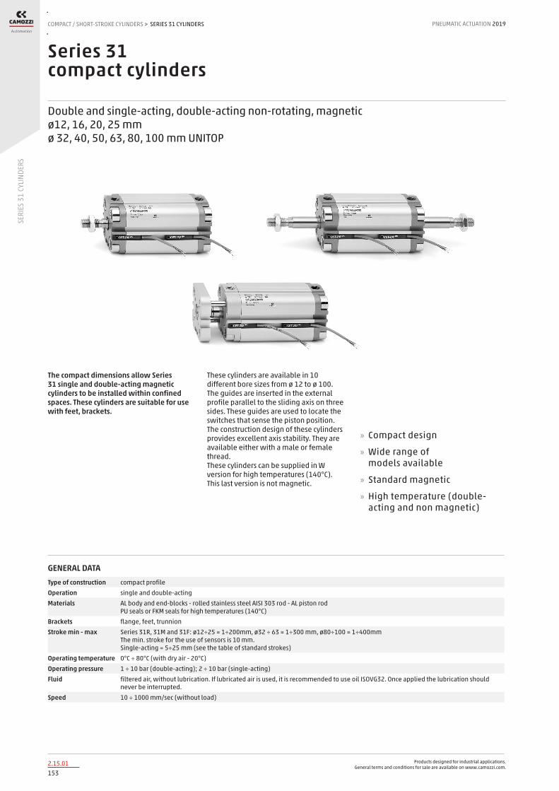
Products designed for industrial applications. General terms and conditions for sale are available on www.camozzi.com.
SERIES 31 CYLINDERSCOMPACT / SHORT-STROKE CYLINDERS > PNEUMATIC ACTUATION 2019
1532.15.01
SERI
ES 3
1 CY
LIND
ERS
Series 31 compact cylinders
Double and single-acting, double-acting non-rotating, magnetic ø12, 16, 20, 25 mm ø 32, 40, 50, 63, 80, 100 mm UNITOP
These cylinders are available in 10 different bore sizes from ø 12 to ø 100. The guides are inserted in the external profile parallel to the sliding axis on three sides. These guides are used to locate the switches that sense the piston position. The construction design of these cylinders provides excellent axis stability. They are available either with a male or female thread. These cylinders can be supplied in W version for high temperatures (140°C). This last version is not magnetic.
» Compact design
» Wide range of models available
» Standard magnetic
» High temperature (double-acting and non magnetic)
The compact dimensions allow Series 31 single and double-acting magnetic cylinders to be installed within confined spaces. These cylinders are suitable for use with feet, brackets.
GENERAL DATAType of construction compact profileOperation single and double-actingMaterials AL body and end-blocks - rolled stainless steel AISI 303 rod - AL piston rod
PU seals or FKM seals for high temperatures (140°C)Brackets flange, feet, trunnionStroke min - max Series 31R, 31M and 31F: ø12÷25 = 1÷200mm, ø32 ÷ 63 = 1÷300 mm, ø80÷100 = 1÷400mm
The min. stroke for the use of sensors is 10 mm. Single-acting = 5÷25 mm (see the table of standard strokes)
Operating temperature 0°C ÷ 80°C (with dry air - 20°C)Operating pressure 1 ÷ 10 bar (double-acting); 2 ÷ 10 bar (single-acting)Fluid filtered air, without lubrication. If lubricated air is used, it is recommended to use oil ISOVG32. Once applied the lubrication should
never be interrupted.Speed 10 ÷ 1000 mm/sec (without load)

Products designed for industrial applications. General terms and conditions for sale are available on www.camozzi.com.
SERIES 31 CYLINDERSPNEUMATIC ACTUATION
1542.15.02
2019 COMPACT / SHORT-STROKE CYLINDERS
SERI
ES 3
1 CY
LIND
ERS
>
STANDARD STROKES
■ = Double-acting female, male ✖ = Non-rotating ● = Single-acting female, male
STANDARD STROKES
Ø 5 10 15 20 25 30 40 50 60 80
12 ■ ✖ ● ■ ✖ ● ■ ✖ ■ ✖ ■ ✖ ■ ✖ ■ ✖
16 ■ ✖ ● ■ ✖ ● ■ ✖ ● ■ ✖ ● ■ ✖ ● ■ ✖ ■ ✖
20 ■ ✖ ● ■ ✖ ● ■ ✖ ● ■ ✖ ● ■ ✖ ● ■ ✖ ■ ✖ ■ ✖
25 ■ ✖ ● ■ ✖ ● ■ ✖ ● ■ ✖ ● ■ ✖ ● ■ ✖ ■ ✖ ■ ✖
32 ■ ✖ ● ■ ✖ ● ■ ✖ ● ■ ✖ ● ■ ✖ ● ■ ✖ ■ ✖ ■ ✖
40 ■ ✖ ● ■ ✖ ● ■ ✖ ● ■ ✖ ● ■ ✖ ● ■ ✖ ■ ✖ ■ ✖ ■ ✖ ■ ✖
50 ■ ✖ ● ■ ✖ ● ■ ✖ ● ■ ✖ ● ■ ✖ ■ ✖ ■ ✖ ■ ✖ ■ ✖
63 ■ ✖ ● ■ ✖ ● ■ ✖ ● ■ ✖ ● ■ ✖ ■ ✖ ■ ✖ ■ ✖ ■ ✖
80 ■ ✖ ● ■ ✖ ● ■ ✖ ● ■ ✖ ● ■ ✖ ■ ✖ ■ ✖ ■ ✖ ■ ✖
100 ■ ✖ ● ■ ✖ ● ■ ✖ ● ■ ✖ ● ■ ✖ ■ ✖ ■ ✖ ■ ✖ ■ ✖
CODING EXAMPLE
31 SERIES 31 = compact magnetic
M VERSION M = male rod thread, mounted with rod nut Mod. U F = female rod thread R = non-rotating with flange only double-acting
2 OPERATION 1 = single-acting, front spring 2 = double-acting 3 = double-acting, through-rod 4 = single-acting, rear spring 7 = single-acting, through-rod
PNEUMATIC SYMBOLS CS06 CD08 CD12 CS08 CS10
A MATERIALS A = rolled stainless steel AISI 303 rod - AL tube profile
032 BORE 012 = 12 mm 016 = 16 mm 020 = 20 mm 025 = 25 mm 032 = 32 mm 040 = 40 mm 050 = 50 mm 063 = 63 mm 080 = 80 mm 100 = 100 mm
A DESIGN TYPE A = standard
050 STROKE (see the table)
= standard V = rod seal FKM W = seals in FKM for high temperatures (140°C), only available in the double-acting, non magnetic version
31 M 2 A 032 A 050
PNEUMATIC SYMBOLS
The pneumatic symbols which have been indicated in the CODING EXAMPLE are shown below.

Products designed for industrial applications. General terms and conditions for sale are available on www.camozzi.com.
SERIES 31 CYLINDERSCOMPACT / SHORT-STROKE CYLINDERS > PNEUMATIC ACTUATION 2019
1552.15.03
SERI
ES 3
1 CY
LIND
ERS
ACCESSORIES FOR COMPACT MAGNETIC CYLINDERS SERIES 31
Swivel ball joint Mod. GA (cyl. Mod. 31M)
90° swivel combination for trunnion Mod. I
Rear trunnion Mod. C Rod fork end Mod. G (cyl. Mod. 31M)
Piston rod lock nut Mod. U (cyl. Mod. 31M)
90° swivel combin. for fem. trunnion Mod. ZC
Rear trunnion Mod. L Rear and front flange Mod. D
All accessories are supplied separately.
Foot mount Mod. B Coupling piece Mod. GKF
Self aligning rod Mod. GK
Piston rod socket joint Mod. GY (cyl. Mod. 31M)

Products designed for industrial applications. General terms and conditions for sale are available on www.camozzi.com.
SERIES 31 CYLINDERSPNEUMATIC ACTUATION
1562.15.04
2019 COMPACT / SHORT-STROKE CYLINDERS
SERI
ES 3
1 CY
LIND
ERS
>
It is possible to determine the strokes required as shown in the general data in the absence of radial loads and torque moments. When imposing radial loads on the cylinder it is important to respect the maximum projection of the baricenter. In the presence of torque moments, it is recommended to respect the maximum stroke as shown in the diagrams.
ANTI-ROTATION - Transversal load dependant on projection
It is possible to determine the strokes required as shown in the general data in the absence of radial loads and torque moments. When imposing radial loads on the cylinder it is important to respect the maximum projection of the baricenter. In the presence of torque moments, it is recommended to respect the maximum stroke as shown in the diagrams.
ANTI-ROTATION THROUGH-ROD - Transversal load dependant on projection

Products designed for industrial applications. General terms and conditions for sale are available on www.camozzi.com.
SERIES 31 CYLINDERSCOMPACT / SHORT-STROKE CYLINDERS > PNEUMATIC ACTUATION 2019
1572.15.05
SERI
ES 3
1 CY
LIND
ERS
It is possible to determine the strokes required as shown in the general data in the absence of radial loads and torque moments. When imposing radial loads on the cylinder it is important to respect the maximum projection of the baricenter. In the presence of torque moments, it is recommended to respect the maximum stroke as shown in the diagrams.
TORQUE MOMENT - dependant on stroke C
It is possible to determine the strokes required as shown in the general data in the absence of radial loads and torque moments. When imposing radial loads on the cylinder it is important to respect the maximum projection of the baricenter. In the presence of torque moments, it is recommended to respect the maximum stroke as shown in the diagrams.
TRANSVERSAL LOAD - dependant on projection

Products designed for industrial applications. General terms and conditions for sale are available on www.camozzi.com.
SERIES 31 CYLINDERSPNEUMATIC ACTUATION
1582.15.06
2019 COMPACT / SHORT-STROKE CYLINDERS
SERI
ES 3
1 CY
LIND
ERS
>
It is possible to determine the strokes required as shown in the general data in the absence of radial loads and torque moments. When imposing radial loads on the cylinder it is important to respect the maximum projection of the baricenter. In the presence of torque moments, it is recommended to respect the maximum stroke as shown in the diagrams.
TRANSVERSAL LOAD THROUGH-ROD - dependant on projection

Products designed for industrial applications. General terms and conditions for sale are available on www.camozzi.com.
SERIES 31 CYLINDERSCOMPACT / SHORT-STROKE CYLINDERS > PNEUMATIC ACTUATION 2019
1592.15.07
SERI
ES 3
1 CY
LIND
ERS
Compact magnetic cylinders Mod. 31F and 31M
DIMENSIONS
Ø ØD ØD1 D2 D3 ØD8 (H9) E1 F F1+ H+ H1+ H2 H3+ K1 L L1 L2 L3 T T1 T2 SW1
12 6 3,5 M4 M3 6 M5 8 30 38 42,5 18,5 58,5 M6 29 18 30 16 6 16 4 5
16 8 3,5 M4 M4 6 M5 8 30 38 42,5 18,5 62,5 M8 29 18 30 16 8 20 4 7
20 10 4,5 M5 M5 6 M5 8 30 38 42,5 18,5 64,5 M10x1,25 36 22 37,5 18 10 22 4 8
25 10 4,5 M5 M5 6 M5 8 31,5 39,5 45 18,5 67 M10x1,25 40 26 41,5 18 10 22 4 8
32 12 5,5 M6 M6 6 G1\8 8 36,5 44,5 50,5 21,5 72,5 M10x1,25 50 32 52 20 12 22 4 10
40 12 5,5 M6 M6 6 G1\8 8 37,5 45,5 52 21,5 74 M10x1,25 60 42 62,5 20 12 22 4 10
50 16 6,5 M8 M8 6 G1\8 8 37,5 45,5 53 22,5 77 M12x1,25 68 50 71 20 12 24 4 13
63 16 8,5 M10 M8 8 G1\8 8 42 50 57,5 24,5 81,5 M12x1,25 87 62 91 25 12 24 4 13
80 20 8,5 M10 M10 8 G1\8 8,5 47,5 56 64 24,5 96 M16x1,5 107 82 111 25 16 32 4 17
100 25 8,5 M10 M12 8 G1\4 10,5 56 66,5 76,5 31,5 116,5 M20x1,5 128 103 133 25 20 40 4 22
1 = Groove for sensor CST 2 = Keep to the minimum screwing depth. + = add the stroke

Products designed for industrial applications. General terms and conditions for sale are available on www.camozzi.com.
SERIES 31 CYLINDERSPNEUMATIC ACTUATION
1602.15.08
2019 COMPACT / SHORT-STROKE CYLINDERS
SERI
ES 3
1 CY
LIND
ERS
>
Compact magnetic cylinders Mod. 31F and 31M - through-rod
DIMENSIONS
Ø ØD ØD1 D2 D3 E1 F F1+ H+ H1+ H2 H3++ H4+ K1 L L1 L2 L3 T T1 SW1
12 6 3,5 M4 M3 M5 8 30 38 42,5 18,5 47 58,5 M6 29 18 30 16 6 16 5
16 8 3,5 M4 M4 M5 8 30 38 42,5 18,5 47 62,5 M8 29 18 30 16 8 20 7
20 10 4,5 M5 M5 M5 8 30 38 42,5 18,5 47 64,5 M10x1,25 36 22 37,5 18 10 22 8
25 10 4,5 M5 M5 M5 8 31,5 39,5 45 18,5 50,5 67 M10x1,25 40 26 41,5 18 10 22 8
32 12 5,5 M6 M6 G1\8 8 36,5 44,5 50,5 21,5 56,5 72,5 M10x1,25 50 32 52 20 12 22 10
40 12 5,5 M6 M6 G1\8 8 37,5 45,5 52 21,5 58,5 74 M10x1,25 60 42 62,5 20 12 22 10
50 16 6,5 M8 M8 G1\8 8 37,5 45,5 53 22,5 60,5 77 M12x1,25 68 50 71 20 12 24 13
63 16 8,5 M10 M8 G1\8 8 42 50 57,5 24,5 65 81,5 M12x1,25 87 62 91 25 12 24 13
80 20 8,5 M10 M10 G1\8 8,5 47,5 56 64 24,5 72 96 M16x1,5 107 82 111 25 16 32 17
100 25 8,5 M10 M12 G1\4 10,5 56 66,5 76,5 31,5 86,5 116,5 M20x1,5 128 103 133 25 20 40 22
1 = Groove for sensor CST 2 = Keep to the minimum screwing depth. + = add the stroke once ++ = add the stroke twice

Products designed for industrial applications. General terms and conditions for sale are available on www.camozzi.com.
SERIES 31 CYLINDERSCOMPACT / SHORT-STROKE CYLINDERS > PNEUMATIC ACTUATION 2019
1612.15.09
SERI
ES 3
1 CY
LIND
ERS
Compact magnetic cylinders Mod. 31R
DIMENSIONS
Ø ØD ØD1 D2 D3 ØD4(H9) D5 D8(H9)ØD9 D10 E1 F F1+ H+ H1+ H2 H3+ H4++ L L1 L2 L3 L4 T T2 SW1
12 6 3,5 M4 M3 3 M3 6 5 6 M5 8 30 38 42,5 18,5 48,5 47 29 18 30 16 9,9 6 4 5
16 8 3,5 M4 M4 3 M3 6 5 8 M5 8 30 38 42,5 18,5 48,5 47 29 18 30 16 9,9 8 4 7
20 10 4,5 M5 M5 4 M4 6 6 10 M5 8 30 38 42,5 18,5 50,5 47 36 22 37,5 18 12 10 4 8
25 10 4,5 M5 M5 5 M5 6 6 14 M5 8 31,5 39,5 45 18,5 53 50,5 40 26 41,5 18 15,6 10 4 8
32 12 5,5 M6 M6 5 M5 6 6 17 G1\8 8 36,5 44,5 50,5 21,5 60,5 56,5 50 32 52 20 19,8 12 4 10
40 12 5,5 M6 M6 5 M5 6 6 17 G1\8 8 37,5 45,5 52 21,5 62 58,5 60 42 62,5 20 23,3 12 4 10
50 16 6,5 M8 M8 6 M6 6 10 22 G1\8 8 37,5 45,5 53 22,5 65 60,5 68 50 71 20 29,7 12 4 13
63 16 8,5 M10 M8 6 M6 8 10 22 G1\8 8 42 50 57,5 24,5 69,5 65 87 62 91 25 35,4 12 4 13
80 20 8,5 M10 M10 8 M8 8 12 28 G1\8 8,5 47,5 56 64 24,5 78 72 107 82 111 25 46 16 4 17
100 25 8,5 M10 M12 10 M10 8 12 30 G1\4 10,5 56 66,5 76,5 31,5 90,5 86,5 128 103 133 25 56,6 20 4 22
1 = Groove for sensor CST 2 = Keep to the minimum screwing depth. + = add the stroke once ++ = add the stroke twice

Products designed for industrial applications. General terms and conditions for sale are available on www.camozzi.com.
SERIES 31 CYLINDERSPNEUMATIC ACTUATION
1622.15.10
2019 COMPACT / SHORT-STROKE CYLINDERS
SERI
ES 3
1 CY
LIND
ERS
>
Foot mount Mod. B
Material: zinc-plated steel
DIMENSIONS
Mod. Ø C SA+ XA+ TR ØAB AH AO AC
B-31-12-16 12 - 16 3 64 51 18 5,5 22 7 20
B-32-20 20 4 70 54 22 6,6 27 9 25
B-31-25 25 4 71,5 55,5 26 6,6 29 9 25
B-31-32 32 5 80,5 62,5 32 6,6 34 12 30
B-31-40 40 5 85,5 65,5 42 9 40,5 10 30
B-31-50 50 5,5 93,5 69,5 50 9 47 11 35
B-31-63 63 5,5 104 77 62 11 56,5 13 40
B-31-80 80 7,5 116 86 82 11 68,5 15 45
B-31-100 100 7,5 132,5 99,5 103 13,5 81 12 45
Supplied with: 2x feet 4x screws + = add the stroke
Rear and front flange Mod. D-E
Material: zinc-plated steel
DIMENSIONS
Mod. Ø C ZB+ TF R UF G1 ØFB
D-E-31-12-16 12 - 16 10 48 43 - 55 29 5,5
D-E-32-20 20 10 48 55 - 70 36 6,6
D-E-32-25 25 10 49,5 60 - 76 40 6,6
D-E-31-32 32 10 54,5 65 32 80 50 7
D-E-31-40 40 10 55,5 82 36 102 60 9
D-E-31-50 50 12 57,5 90 45 110 68 9
D-E-31-63 63 15 65 110 50 130 87 9
D-E-31-80 80 15 71 135 63 160 107 12
D-E-31-100 100 15 81,5 163 75 190 128 14
Supplied with: 1x flange 4x screws + = add the stroke

Products designed for industrial applications. General terms and conditions for sale are available on www.camozzi.com.
SERIES 31 CYLINDERSCOMPACT / SHORT-STROKE CYLINDERS > PNEUMATIC ACTUATION 2019
1632.15.11
SERI
ES 3
1 CY
LIND
ERS
Female rear trunnion Mod. C
Material: Aluminium
DIMENSIONS
Mod. Ø ØCD L C XD+ MR F G CB UB HB
C-31-32 32 10 13 21 66,5 11 32 50 26 45 54
C-31-40 40 12 16 25 70,5 13 42 60 28 52 62
C-31-50 50 12 16 27 72,5 13 50 68 32 60 70
C-31-63 63 16 21 32 82 17 62 87 40 70 82
C-31-80 80 16 23 36 92 17 82 102 50 90 102
C-31-100 100 20 26 41 107,5 21 103 128 60 110 126
Supplied with: 4x screws 1x clevis pin 1x centering pin 1x trunnion + = add the stroke
Intermediate bracket Mod. DC
Flange in aluminium
DIMENSIONS
Mod. Ø B H+ Max stroke (mm)
DC-31-12-16 12-16 12,5 38 400
DC-31-20 20 12,5 38 400
DC-31-25 25 13 39,5 400
DC-31-32 32 14,5 44,5 600
DC-31-40 40 14,5 45,5 600
DC-31-50 50 14,5 45,5 600
DC-31-63 63 14,5 50 600
DC-31-80 80 16,5 56 800
DC-31-100 100 19,5 66,5 800
Supplied with: 1x flange 1x centering pin 4x screws + = add the stroke

Products designed for industrial applications. General terms and conditions for sale are available on www.camozzi.com.
SERIES 31 CYLINDERSPNEUMATIC ACTUATION
1642.15.12
2019 COMPACT / SHORT-STROKE CYLINDERS
SERI
ES 3
1 CY
LIND
ERS
>
90° Swivel combination for female trunnion Mod. ZC
Male rear Material: aluminium
DIMENSIONS
Mod. Ø M ØCK ØS5 d+ K1 K2 L3 G1 L5 G2 EM G3 CA H6 R1
ZC-32 32 11 10 6,6 78,5 38 51 10 21 1,6 18 26 31 32 8 10
ZC-40 40 11 12 6,6 83,5 41 54 15 24 1,6 22 28 35 36 10 11
ZC-50 50 15 12 9 90,5 50 65 16 33 1,6 30 32 45 45 12 13
ZC-63 63 15 16 9 101,5 52 67 16 37 1,6 35 40 50 50 14 15
ZC-80 80 18 16 11 119 66 86 20 47 2,5 40 50 60 63 14 15
ZC-100 100 18 20 11 137,5 76 96 20 55 3,2 50 60 70 71 17 19
Supplied with: 1x male support + = add the stroke
90° swivel combination for trunnion Mod. I
Material: zinc-plated steel
DIMENSIONS
Mod. Ø ØCD C C1 ØC2 XD+ MR ØD9 E1 F G
I-12-16 12 6 25 15 5 54 7 5,5 3 27 12,1
I-12-16 16 6 25 15 5 54 7 5,5 3 27 12,1
I-20-25 20 8 32 20 6 58 10 6 4 30 16,1
I-20-25 25 8 32 20 6 59,5 10 6 4 30 16,1
Supplied with: 2x Seeger 1x female support 1x piston pin + = add the stroke

Products designed for industrial applications. General terms and conditions for sale are available on www.camozzi.com.
SERIES 31 CYLINDERSCOMPACT / SHORT-STROKE CYLINDERS > PNEUMATIC ACTUATION 2019
1652.15.13
SERI
ES 3
1 CY
LIND
ERS
Rear male trunnion Mod. L
Material: aluminium Supplied with: 4x screws 1x male trunnion 1x centering pin
DIMENSIONS
Ø ØCD L C XD+ MR F G B4
L-31-12-16 12 6 10 16 54 6 18 30 12
L-31-12-16 16 6 10 16 54 6 18 30 12
L-31-20 20 8 14 20 58 8 22 37,5 16
L-31-25 25 8 14 20 59,5 8 26 41,5 16
+ = add the stroke
Piston rod lock nut Mod. U
Material: zinc-plated steel ISO 4035
DIMENSIONS
Mod. Ø cylinder D m SW
U-12-16 12 M6X1 4 10
U-20 16 M8X1,25 5 13
U-25-32 20-40 M10X1,25 6 17
U-40 50-63 M12X1,25 7 19
U-50-63 80 M16X1,5 8 24
U-80-100 100 M20X1,5 9 30
Swivel ball joint Mod. GA
Material: zinc-plated steel ISO 8139
DIMENSIONS
Mod. Ø ØCN U EN ER AX CE KK T Z SW
GA-12-16 12 6 7 9 10 12 30 M6X1 10 6,5 11
GA-20 16 8 9 12 12 16 36 M8X1,25 12,5 6,5 14
GA-32 20÷40 10 10,5 14 14 20 43 M10X1,25 15 6,5 17
GA-40 50÷63 12 12 16 16 22 50 M12X1,25 17,5 6,5 19
GA-50-63 80 16 15 21 21 28 64 M16X1,5 22 7,5 22
GA-80-100 100 20 18 25 25 33 77 M20X1,5 27,5 7 30

Products designed for industrial applications. General terms and conditions for sale are available on www.camozzi.com.
SERIES 31 CYLINDERSPNEUMATIC ACTUATION
1662.15.14
2019 COMPACT / SHORT-STROKE CYLINDERS
SERI
ES 3
1 CY
LIND
ERS
>
Rod fork end Mod. G
ISO 8140 Material: zinc-plated steel
DIMENSIONS
Mod. Ø B ØB1 ØCK LE CM CL ER CE KK
G-12-16 12 16 10 6 12 6 12 7 24 M6X1
G-20 16 22 14 8 16 8 16 42 32 M8X1,25
G-25-32 20 ÷ 40 26 18 10 20 10 20 12 40 M10X1,25
G-40 50 ÷ 63 32 20 12 24 12 24 14 48 M12X1,25
G-50-63 80 40 26 16 32 16 32 19 64 M16X1,5
G-80-100 100 48 34 20 40 20 40 25 80 M20X1,5
Piston rod socket joint Mod. GY
Material: zama and zinc-plated steel
DIMENSIONS
Mod. Ø KK L CE L2 AX E ØB ØC ØT ØD L1 L3 SW1 SW Z
GY-12-16 12 M6X1 55 28 5 15 6 10 20 10 13 12,2 11 8 11 15
GY-20 16 M8X1,25 65 32 5 16 8 12 24 12,5 16 16 12 10 14 15
GY-32 20÷40 M10X1,25 74 35 6,5 18 10 14 28 15 19 19,5 15 11 17 15
GY-40 50÷63 M12X1,25 84 40 6,5 20 12 19 32 17,5 22 21 17 17 19 15
GY-50-63 80 M16X1,5 112 50 8 27 16 22 40 22 27 27,5 23 19 22 11
GY-80-100 100 M20X1,5 133 63 10 38 20 27 45 27,5 34 31,5 25 24 30 7,5

Products designed for industrial applications. General terms and conditions for sale are available on www.camozzi.com.
SERIES 31 CYLINDERSCOMPACT / SHORT-STROKE CYLINDERS > PNEUMATIC ACTUATION 2019
1672.15.15
SERI
ES 3
1 CY
LIND
ERS
Self aligning rod Mod. GK
For cylinders with male rod only. Material: zinc-plated steel
DIMENSIONS
Mod. Ø KK L L1 L3 L4 Ø A Ø D H I SW SW1 SW2 B1 AX Z E
GK-20 16 M8x1,25 57 26 21 5 8 12,5 19 17 11 7 13 4 16 4 2
GK-25-32 20-25-32-40 M10x1,25 71,5 35 20 7,5 14 22 32 30 19 12 17 5 22 4 2
GK-40 50-63 M12x1,25 75,5 35 24 7,5 14 22 32 30 19 12 19 6 22 4 2
GK-50-63 80 M16x1,5 104 53 32 10 22 32 45 41 27 20 24 8 30 3 2
GK-80-100 100 M20x1,5 119 53 40 10 22 32 45 41 27 20 30 10 37 3 2
Coupling piece Mod. GKF
Material: zinc-plated steel
DIMENSIONS
Mod. Ø KK A B R TF L L1 I Ø D Ø D1 Ø D2 SW E
GKF-20 16 M8x1,25 30 35 20 25 22,5 10 - 14 5,5 - 13 1,5
GKF-25-32 20-25-32-40 M10x1,25 37 60 23 36 22,5 15 6,8 18 11 6,6 15 2
GKF-40 50-63 M12x1,25 56 60 38 42 22,5 15 9 20 15 9 15 2,5
GKF-50-63 80 M16x1,5 80 80 58 58 26,5 15 10,5 25 18 11 22 2,5
GKF-80-100 100 M20x1,5 90 90 65 65 32,5 20 13 30,5 20 14 27 2,5

Products designed for industrial applications. General terms and conditions for sale are available on www.camozzi.com.
SERIES 31 CYLINDERS - TANDEM AND MULTI-POSITIONPNEUMATIC ACTUATION
1682.20.01
2019 COMPACT / SHORT-STROKE CYLINDERS
SERI
ES 3
1 CY
LIND
ERS
- TAN
DEM
AND
MUL
TI-P
OSIT
ION
>
Series 31 compact cylinders, Tandem and Multi-position versions
Double-acting, magnetic ø 12, 16, 20, 25, 32, 40, 50, 63, 80, 100 mm
The compact dimensions allow Series 31 cylinders to be installed within very small spaces. These cylinders are suitable for use with feet, flange and trunnion mountings.
In order to complete the compact cylinder series, two new versions have been introduced: tandem and multi-position. The new Tandem version with 2, 3 or 4 stages generates a thrust force which is 2, 3 or 4 times that of the normal cylinder (standard traction force). The Multi-position version allows a maximum of 3 different positions which are determined by the stroke of the individual actuators.
» Compact design
» Available in different diameters and strokes
» Standard magnetic
GENERAL DATA Type of construction compact profileOperation double-actingMaterials AL body and end-blocks - rolled stainless steel AISI 303 rod - AL piston - PU rod and piston sealsMounting flange - feet - trunnionMin and max strokes (for tandem 31M and 31F) Min and max strokes (for multi-position 31M and 31F)
ø12÷25 = 1÷80 mm ø32÷100 = 1÷100 mm ø12÷25 = dimension for X2 max 200 mm ø32÷63 = dimension for X2 max 300 mm ø80÷100 = dimension for X2 max 400 mm
Operating temperature 0°C ÷ 80°C (with dry air -20°C)Operating pressure 1 ÷ 10 barMedium: filtered air, without lubrication. If lubricated air is used, it is recommended to use ISO VG32 oil. Once
applied the lubrication should never be interrupted.Speed: 10 ÷ 1000 mm/sec (without load)

Products designed for industrial applications. General terms and conditions for sale are available on www.camozzi.com.
SERIES 31 CYLINDERS - TANDEM AND MULTI-POSITIONCOMPACT / SHORT-STROKE CYLINDERS > PNEUMATIC ACTUATION 2019
1692.20.02
SERI
ES 3
1 CY
LIND
ERS
- TAN
DEM
AND
MUL
TI-P
OSIT
ION
CODING EXAMPLE
31 SERIES
M VERSION M = male rod thread, mounted with rod nut Mod. U F = female rod thread
2 OPERATION 2 = double-acting
PNEUMATIC SYMBOLS CDPP
A MATERIALS A = rolled stainless steel rod AISI 303 - AL tube profile
032 BORE 012 = 12 mm - 016 = 16 mm - 020 = 20 mm - 025 = 25 mm 032 = 32 mm - 040 = 40 mm - 050 = 50 mm - 063 = 63 mm 080 = 80 mm - 100 = 100 mm
CD5T, CD6T, CD7T CD2T, CD3T, CD4T CD2T, CD3T, CD4T
A CONSTRUCTION TYPE A = standard
050 STROKE - tandem stroke (mm) - multi-position X1mm/X2mm. Insert stroke without the initial 0 (see application scheme).
N TANDEM AND MULTI-POSITION
2 STAGES (only for tandem) 2 = 2 stages - 3 = 3 stages - 4 = 4 stages
31 M 2 A 032 A 050 N 2
PNEUMATIC SYMBOLS
The pneumatic symbols which have been indicated in the CODING EXAMPLE are shown below.
Application schemes
Multi-position Example for ordering: X1 = 25 mm and X2 = 100 mm 31M2A032A25/100N
Tandem Example for ordering: stroke 25 mm 31M2A032A025N2 (2 stages)
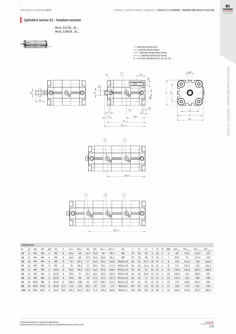
Products designed for industrial applications. General terms and conditions for sale are available on www.camozzi.com.
SERIES 31 CYLINDERS - TANDEM AND MULTI-POSITIONPNEUMATIC ACTUATION
1702.20.03
2019 COMPACT / SHORT-STROKE CYLINDERS
SERI
ES 3
1 CY
LIND
ERS
- TAN
DEM
AND
MUL
TI-P
OSIT
ION
>
Cylinders Series 31 - Tandem version
Mod. 31F2A...N... Mod. 31M2A...N...
DIMENSIONS
Ø ØD D2 D3 ØD8 E1 F H++ H1++ H2 H3+ H4++ H5+++ K1 L L1 L2 T T1 T2 SW1 3ST.H+++ 3ST.H1+++ 4ST.H++++ 4ST.H1++++
12 6 M4 M3 6 M5 8 63,5 68 12,5 34,5 60 85,5 M6 29 18 30 6 16 4 5 89 93,5 114,5 119
16 8 M4 M4 6 M5 8 63,5 68 12,5 34,5 60,5 86,5 M8 29 18 30 8 20 4 7 89,5 94 115,5 120
20 10 M5 M5 6 M5 8 78 82.5 17 43,5 83,5 123,5 M10x1,25 36 22 37,5 10 22 4 8 118 122,5 158 162,5
25 10 M5 M5 6 M5 8 78 83,5 17 39,1 78,1 117,1 M10x1,25 40 26 41,5 10 22 4 8 117 122,5 156 161,5
32 12 M6 M6 6 G1/8 8 90,5 96,5 21,5 46,5 92,6 138,7 M10x1,25 50 32 52 12 22 4 10 136,5 142,5 182,5 188,5
40 12 M6 M6 6 G1/8 8 90,5 97 21,5 46,5 90,2 135,2 M10x1,25 60 42 62,5 12 22 4 10 135,5 142 180,5 187
50 16 M8 M8 6 G1/8 8 90,5 98 18 47,5 92,5 137,5 M12x1,25 68 50 71 12 24 4 13 135,5 143 180 188
63 16 M10 M8 8 G1/8 8 100,5 108 26 50,2 100,7 151,2 M12x1,25 87 62 91 12 24 4 13 151 158,5 201,5 209
80 20 M10 M10 8 G1/8 8,5 112 120 26,5 59 115 171 M16x1,5 107 82 111 16 32 4 17 168 176 224 232
100 25 M10 M12 8 G1/4 10,5 135,5 145,5 26,5 71,3 140,4 209,5 M20x1,5 128 103 133 20 40 4 22 204,5 214,5 237,5 283,5
+ = add the stroke once ++ = add the stroke twice +++ = add the stroke three times ++++ = add the stroke four times ① = air inlet cylinders ø12, 16, 20, 25

Products designed for industrial applications. General terms and conditions for sale are available on www.camozzi.com.
SERIES 31 CYLINDERS - TANDEM AND MULTI-POSITIONCOMPACT / SHORT-STROKE CYLINDERS > PNEUMATIC ACTUATION 2019
1712.20.04
SERI
ES 3
1 CY
LIND
ERS
- TAN
DEM
AND
MUL
TI-P
OSIT
ION
Cylinders Series 31 - multi-position version
Mod. 31F2A...X1-X2N Mod. 31M2A...X1-X2N
DIMENSIONS
Ø ØD D2 D3 ØD8 E1 F H+x1 H1+x2+x1 H2 K1 L L1 L2 T T1 T2 SW1
12 6 M4 M3 6 M5 8 34,5 63,5 12,5 M6 29 18 30 6 16 4 5
16 8 M4 M4 6 M5 8 34,5 63,5 12,5 M8 29 18 30 8 20 4 7
20 10 M5 M5 6 M5 8 43,5 78 17 M10x1,25 36 22 37,5 10 22 4 8
25 10 M5 M5 6 M5 8 39,1 78 17 M10x1,25 40 26 41,5 10 22 4 8
32 12 M6 M6 6 G1/8 8 46,5 90,5 21,5 M10x1,25 50 32 52 12 22 4 10
40 12 M6 M6 6 G1/8 8 45 90,5 21,5 M10x1,25 60 42 62,5 12 22 4 10
50 16 M8 M8 6 G1/8 8 47 90,5 18 M12x1,25 68 50 71 12 24 4 13
63 16 M10 M8 8 G1/8 8 50 100,5 26 M12x1,25 87 62 91 12 24 4 13
80 20 M10 M10 8 G1/8 8,5 59 112 26,5 M16x1,5 107 82 111 16 32 4 17
100 25 M10 M12 8 G1/4 10,5 71 135,5 26,5 M20x1,5 128 103 133 20 40 4 22
X1 = stroke of stage 1 X2 = total stroke of application scheme + = add the stroke

Products designed for industrial applications. General terms and conditions for sale are available on www.camozzi.com.
SERIES ST STOPPER CYLINDERSPNEUMATIC ACTUATION
1722.25.01
2019 COMPACT / SHORT-STROKE CYLINDERS
SERI
ES S
T STO
PPER
CYL
INDE
RS
>
Series ST Stopper cylinders
Single and double-acting, magnetic, non-rotating Sizes 20, 32, 40, 50 mm
The Series ST Stopper cylinders are pneumatic actuators with rod, complying with UNITOP and ISO 21287 standards, where rod and bushing have been specifically enlarged to ensure high resistance to radial loads and shocks. These cylinders are available in two versions, double-acting and single-acting, and with rear spring. The non-rotating rod version is also available.
The detection of the piston position is enabled by means of proximity switches (Mod. CST or CSH) which are mounted in slots along three sides of the cylinder profile. It is possible to cover the slots with a proper profile (Mod. S-CST-500). The high resistance to shocks and radial loads and the easy mounting makes Series ST particularly suitable for use in transport/conveyor lines where it is required to stop the transit of workpieces and workpiece-holder pallets.
» In compliance with UNITOP and ISO 21287 standards
» Compact design
» Can be used with magnetic sensors
» Reliable and silent
» Non-rotating rod version
» Roller rod version
» Female threaded rod version
» High capacity to absorb kinetic energy of workpiece-holder pallets
» Mechanical end-stroke shock absorbers
» For sizing, please refer to the appendix of this catalogue.
GENERAL DATAConstruction Cylinder design Operation Sizes Strokes (min - max) Rod versions Non-rotating function
profile with self-tapping screws compact based on UNITOP and ISO 21287 standards double-acting, single-acting rear spring, double-acting rear spring 20, 32, 40 (Mod. ST32 only), 50 mm 5 ÷ 30 mm (see the table of standard strokes) without thread, with female thread, non-rotating, non-rotating with feemale thread, non-rotating with roller with technopolymer anti-friction ring
Fixing and mounting Type of cushioning
direct with holes on the end-caps, in any position mechanical end-stroke shock absorbers in rubber
Max frequency Working temperature Storage temperature Working pressure Max rotation play Max torque (for non-rotating version)
5 Hz (Ø 20, 32, 40 mm) - 3 Hz (Ø 50 mm) 0°C ÷ 80°C (with dry air -20°C) -20°C ÷ 100°C 1 ÷ 10 bar (double-acting) - 2 ÷ 10 bar (single-acting) ± 4° (Ø 20, 32 e 40 mm) - ± 3° (Ø 50 mm) 1.5 Nm (Ø 20 mm) - 2.5 Nm (Ø 32 e 40 mm) - 3.5 Nm (Ø 50 mm)
Medium Lubrication
filtered air in class 7.8.4 according to ISO 8573-1 standard. Not required. The cylinder is pre-lubricated. If lubricated air is used, it is recommended to use oil ISOVG32. Once applied the lubrication should never be interrupted.
Use with external sensors slots on the three sides for proximity switches Mod. CST and CSH
New

Products designed for industrial applications. General terms and conditions for sale are available on www.camozzi.com.
SERIES ST STOPPER CYLINDERSCOMPACT / SHORT-STROKE CYLINDERS > PNEUMATIC ACTUATION 2019
1732.25.02
SERI
ES S
T STO
PPER
CYL
INDE
RS
STANDARD STROKES
✖ = Single-acting and double-acting
STANDARD STROKES
Mod. Ø 10 15 20 25 30
ST31 20 ✖
ST31 32 ✖
ST31 50 ✖
ST32 20 ✖ ✖
ST32 32 ✖ ✖ ✖
ST32 40 ✖ ✖ ✖
ST32 50 ✖ ✖ ✖
CODING EXAMPLE
ST SERIES
31 CONSTRUCTION STANDARD: 31 = UNITOP 32 = ISO 21287
2 OPERATION: 2 = double-acting 4 = single-acting, rear spring 9 = double-acting, rear spring
PNEUMATIC SYMBOLS: CD20 / CD08 CS15 / CS08 CS16 / CS17
A DESIGN: A = standard R = non-rotating (for Mod. ST32 only)
050 BORE: 020 = 20 mm 032 = 32 mm 040 = 40 mm (for Mod. ST32 only) 050 = 50 mm
A CONSTRUCTION: A = standard R = with roller (for non-rotating version only) F = with female thread (for Mod. ST32 only)
030 STROKE (see the table)
VERSION: = standard ( _ _ _ ) = extended piston rod _ _ _ mm
ST 31 2 A 050 A 030
PNEUMATIC SYMBOLS
The pneumatic symbols which have been indicated in the CODING EXAMPLE are shown below.

Products designed for industrial applications. General terms and conditions for sale are available on www.camozzi.com.
SERIES ST STOPPER CYLINDERSPNEUMATIC ACTUATION
1742.25.03
2019 COMPACT / SHORT-STROKE CYLINDERS
SERI
ES S
T STO
PPER
CYL
INDE
RS
>
SERIES ST MATERIALS
PARTS MATERIALS
1 - Rod Stainless steel
2 - Profile Anodized aluminium
3 - Head Anodized aluminium
4 - Spring Steel
5 - Piston seal PU
6 - Magnet Plastoferrite
7 - Rod seal PU
8 - Rod guide bushing Technopolymer
9 - Non-rotating ring Technopolymer
10 - Roller Stainless steel
Fixing from below Fixing from above
EXAMPLES OF FIXING
Between the mass to stop and the stopper rod, an elastic bumper is assumed to be inserted, which is capable of absorbing the impact by deforming at least 1mm.
20 32 40 50
ST 1320 (N) 3200 (N) - 6200 (N)
ST...R 820 (N) 2600 (N) 4450 (N) 5900 (N)
IMPACT FORCE

Products designed for industrial applications. General terms and conditions for sale are available on www.camozzi.com.
SERIES ST STOPPER CYLINDERSCOMPACT / SHORT-STROKE CYLINDERS > PNEUMATIC ACTUATION 2019
1752.25.04
SERI
ES S
T STO
PPER
CYL
INDE
RS
Cylinders Ø 20 mm m = mass (kg) V = impact speed (m/min)
Cylinders Ø 32 mm m = mass (kg) V = impact speed (m/min)
DIAGRAMS OF MASS/ IMPACT SPEED
Cylinders Ø 40 mm m = mass (kg) V = impact speed (m/min)
Cylinders Ø 50 mm m = mass (kg) V = impact speed (m/min)

Products designed for industrial applications. General terms and conditions for sale are available on www.camozzi.com.
SERIES ST STOPPER CYLINDERSPNEUMATIC ACTUATION
1762.25.05
2019 COMPACT / SHORT-STROKE CYLINDERS
SERI
ES S
T STO
PPER
CYL
INDE
RS
>
Cylinders ø 20 mm, standard (A) and non-rotating (R) version P = Pressure (bar) F = applicable lateral Force (N)
Cylinders ø 32 mm, standard (A) and non-rotating (R) version P = Pressure (bar) F = applicable lateral Force (N)
DIAGRAMS OF APPLICABLE LATERAL FORCES DURING OPERATION
Cylinders ø 40 mm, standard (A) and non-rotating (R) version P = Pressure (bar) F = applicable lateral Force (N)
Cylinders ø 50 mm, standard (A) and non-rotating (R) version P = Pressure (bar) F = applicable lateral Force (N)

Products designed for industrial applications. General terms and conditions for sale are available on www.camozzi.com.
SERIES ST STOPPER CYLINDERSCOMPACT / SHORT-STROKE CYLINDERS > PNEUMATIC ACTUATION 2019
1772.25.06
SERI
ES S
T STO
PPER
CYL
INDE
RS
F = Force C = Stroke
DIAGRAM OF THE SPRING FORCES ACCORDING TO THE CYLINDER STROKE
Stopper cylinders Mod. ST31 (UNITOP)
Ø BG G ØD ØD1 ØD4 ØD7 E EE E1 L LA L1 PL RT T2 TG ZA ZB
20 18.5 12 12 26 6 4 35.5 G1/8 M2 38 5 11.5 8 M5 4.5 22 38 49.5
32 21.5 14.5 20 38 6 5 50 G1/8 M3 52 5 16 8 M6 4.5 32 45 60.5
50 20 14.5 32 53 6 6 68 G1/8 M3 71 6 24 8 M8 4.5 50 46 69.5

Products designed for industrial applications. General terms and conditions for sale are available on www.camozzi.com.
SERIES ST STOPPER CYLINDERSPNEUMATIC ACTUATION
1782.25.07
2019 COMPACT / SHORT-STROKE CYLINDERS
SERI
ES S
T STO
PPER
CYL
INDE
RS
>
Stopper cylinders Mod. ST32 (ISO 21287)
Ø AF BG B1 G ØD ØD1 ØD2 ØD3 ØD4 ØD5 ØD6 ØD7 E EE KF LA L1 L2 L4 P PL ØR RT SW1 T1 T2 T3 TG ZA ZB (ZB)
20 6 20 4 10.9 12 25 - - 9 5 9 4 35.8 M5 M3 5 9.5 68 73 2 6.5 10 M5 10 - 2.5 1.2 22 53.5 64 71
32 11 - 8 14.3 20 35 30 24 9 9 - 5 49.6 G1/8 M6 - 12 82 91 3.5 7.6 18 M6 17.5 2 2.5 2 32.5 61 74 88
40 14.5 - 8 14.3 25 45 35 29 12 12 - 5 57 G1/8 M8 - 12.5 90 101 5 7.6 22 M6 22 2 2.5 2.5 38 66.5 80 97
50 14.5 - 10 14.3 32 51 40 34 12 12 - 6 69.6 G1/8 M8 - 14.5 92.5 105 7 7.6 25 M8 28 2 3 2.5 46.5 65.5 81 100

Products designed for industrial applications. General terms and conditions for sale are available on www.camozzi.com.
SERIES 90 STAINLESS STEEL CYLINDERSSTAINLESS STEEL CYLINDERS > PNEUMATIC ACTUATION 2019
1793.05.01
SERI
ES 9
0 ST
AINL
ESS
STEE
L CYL
INDE
RS
Series 90 stainless steel cylinders
Single- and double-acting, cushioned, magnetic ø 32, 40, 50, 63, 80, 100 and 125 mm
The Series 90 cylinders can be used in critical applications in which a high corrosion resistance is required (for example off-shore, marine, food).
This series of cylinders is normally equipped with end of stroke buffers with adjustable pneumatic cushioning. Moreover, they are equipped with a mechanical cushioning that makes the impact of the piston less noisy as it reaches the end of the stroke.
» In compliance with ISO 15552 standards and with the previous DIN/ISO 6431/VDMA 24562 standards
» Clean design
» Stainless steel AISI 316
» End-stroke cushioning
GENERAL DATAConstruction with tie-rodsOperation single-acting or double-actingMaterials - end blocks, barrel and rod in stainless steel AISI 316
- seals in NBR - plastic guiding element, NSF H1-certified lubricant
Mountings several types of cylinders mounting brackets availableStroke 25 ÷ 800 mmOperating temperature 0°C ÷ 80°C (with dry air - 20°C)Operating pressure 1 ÷ 10 barSpeed 10 ÷ 1000 mm/sec (no load)Media Filtered air, without lubrication.
If lubricated air is used, it is recommended to use oil ISOVG32. Once applied the lubrication should never be interrupted.

Products designed for industrial applications. General terms and conditions for sale are available on www.camozzi.com.
SERIES 90 STAINLESS STEEL CYLINDERSPNEUMATIC ACTUATION
1803.05.02
2019 STAINLESS STEEL CYLINDERS
SERI
ES 9
0 ST
AINL
ESS
STEE
L CYL
INDE
RS
>
STANDARD STROKES FOR CYLINDER SERIES 90
✖ = Double-acting ● = Single-acting
STANDARD STROKES
Ø 25 50 80 100 125 150 160 200 250 300 320 400 500
32 ✖● ✖● ✖ ✖ ✖ ✖ ✖ ✖ ✖ ✖ ✖ ✖ ✖
40 ✖● ✖● ✖ ✖ ✖ ✖ ✖ ✖ ✖ ✖ ✖ ✖ ✖
50 ✖● ✖● ✖ ✖ ✖ ✖ ✖ ✖ ✖ ✖ ✖ ✖ ✖
63 ✖● ✖● ✖ ✖ ✖ ✖ ✖ ✖ ✖ ✖ ✖ ✖ ✖
80 ✖● ✖● ✖ ✖ ✖ ✖ ✖ ✖ ✖ ✖ ✖ ✖ ✖
100 ✖● ✖● ✖ ✖ ✖ ✖ ✖ ✖ ✖ ✖ ✖ ✖ ✖
125 ✖● ✖ ✖ ✖ ✖ ✖ ✖ ✖ ✖ ✖ ✖ ✖
CODING EXAMPLE
90 SERIES
M VERSION M = standard, magnetic
2 OPERATION 1 = single-acting, front spring 2 = double-acting, front and rear cushions 6 = double-acting, through-rod, front and rear cushions
PNEUMATIC SYMBOLS CS06 CD09 CD13
A MATERIALS A = stainless steel AISI 316, seals in NBR V = stainless steel AISI 316, all seals in FKM (150°C)
050 BORE 032 = 32 mm - 040 = 40 mm - 050 = 50 mm - 063 = 63 mm 080 = 80 mm - 100 = 100 mm - 125 = 125 mm
A TYPE OF DESIGN A = standard with piston rod lock nut Mod. U
0200 STROKE (see the table)
= standard V = rod seal in FKM
90 M 2 A 050 A 0200
PNEUMATIC SYMBOLS
The pneumatic symbols which have been indicated in the CODING EXAMPLE are shown below.

Products designed for industrial applications. General terms and conditions for sale are available on www.camozzi.com.
SERIES 90 STAINLESS STEEL CYLINDERSSTAINLESS STEEL CYLINDERS > PNEUMATIC ACTUATION 2019
1813.05.03
SERI
ES 9
0 ST
AINL
ESS
STEE
L CYL
INDE
RS
ACCESSORIES FOR STAINLESS STEEL CYLINDERS SERIES 90
Foot mount Mod. B Front and rear flange Mod. D-E
Rear trunnion, female Mod. C-H
Rear trunnion, male Mod. L
Tight rear female tr. bracket Mod. CR
Male tr. bracket with swivel ball joint Mod. R
90° male tr. bracket + sw. ball joint Mod. ZCR
90° male trunnion Mod. ZC
All accessories are supplied separately, except for the piston rod lock nut Mod. U
Rod fork end Mod. G-90 Clevis pin Mod. S-90
Anti-rotation clevis pin Mod. SR-90
Swivel ball joint Mod. GA-90
Piston rod lock nut Mod. U-90

Products designed for industrial applications. General terms and conditions for sale are available on www.camozzi.com.
SERIES 90 STAINLESS STEEL CYLINDERSPNEUMATIC ACTUATION
1823.05.04
2019 STAINLESS STEEL CYLINDERS
SERI
ES 9
0 ST
AINL
ESS
STEE
L CYL
INDE
RS
>
Cylinders Series 90
DIMENSIONS
Ø AM B BF BG E EE G KK L MM N PL RT R1 R2 SW SW1 T TG VA VD WH
32 22 30 10 16 45 G1/8 28 M10x1.25 94 12 4.5 14 M6 64 16 10 17 M5 32.5 4 20 26
40 24 35 10 16 55 G1/4 31.5 M12x1.25 105 16 5.5 16 M6 70 21 13 19 M6 38 4 22 30
50 32 40 12 16 65 G1/4 31.5 M16x1.5 106 20 8.5 21 M8 74 24 17 24 M8 46.5 4 28 37
63 32 45 12 16 80 G3/8 35 M16x1.5 121 20 8.5 22 M8 85 33 17 24 M8 56.5 4 28 37
80 40 45 15 16 95 G3/8 36 M20x1.5 128 25 8.5 23 M10 92 34 21 30 M10 72 4 34 46
100 40 55 15 16 115 G1/2 41 M20x1.5 138 25 10 26 M10 100 58 21 30 M10 89 4 38 51
125 54 60 24 20 140 G1/2 45 M27x2 160 32 12.5 30 M12 110 65 27 41 M12 110 5 50 65
+ = add the stroke
Cylinders Series 90 - through-rod
DIMENSIONS
Ø AM B BF BG E EE G KK L MM N PL RT R1 R2 SW SW1 T TG VD WH ZM
32 22 30 10 16 45 G1/8 28 M10x1.25 94 12 4.5 14 M6 64 16 10 17 M5 32.5 20 26 146
40 24 35 10 16 55 G1/4 31.5 M12x1.25 105 16 5.5 16 M6 70 21 13 19 M6 38 22 30 165
50 32 40 12 16 65 G1/4 31.5 M16x1.5 106 20 8.5 21 M8 74 24 17 24 M8 46.5 28 37 180
63 32 45 12 16 80 G3/8 35 M16x1.5 121 20 8.5 22 M8 85 33 17 24 M8 56.5 28 37 195
80 40 45 15 16 95 G3/8 36 M20x1.5 128 25 8.5 23 M10 92 34 21 30 M10 72 34 46 220
100 40 55 15 16 115 G1/2 41 M20x1.5 138 25 10 26 M10 100 58 21 30 M10 89 38 51 240
125 54 60 24 20 140 G1/2 45 M27x2 160 32 12.5 30 M12 110 65 27 41 M12 110 50 65 290
+ = add the stroke once ++ = add the stroke twice
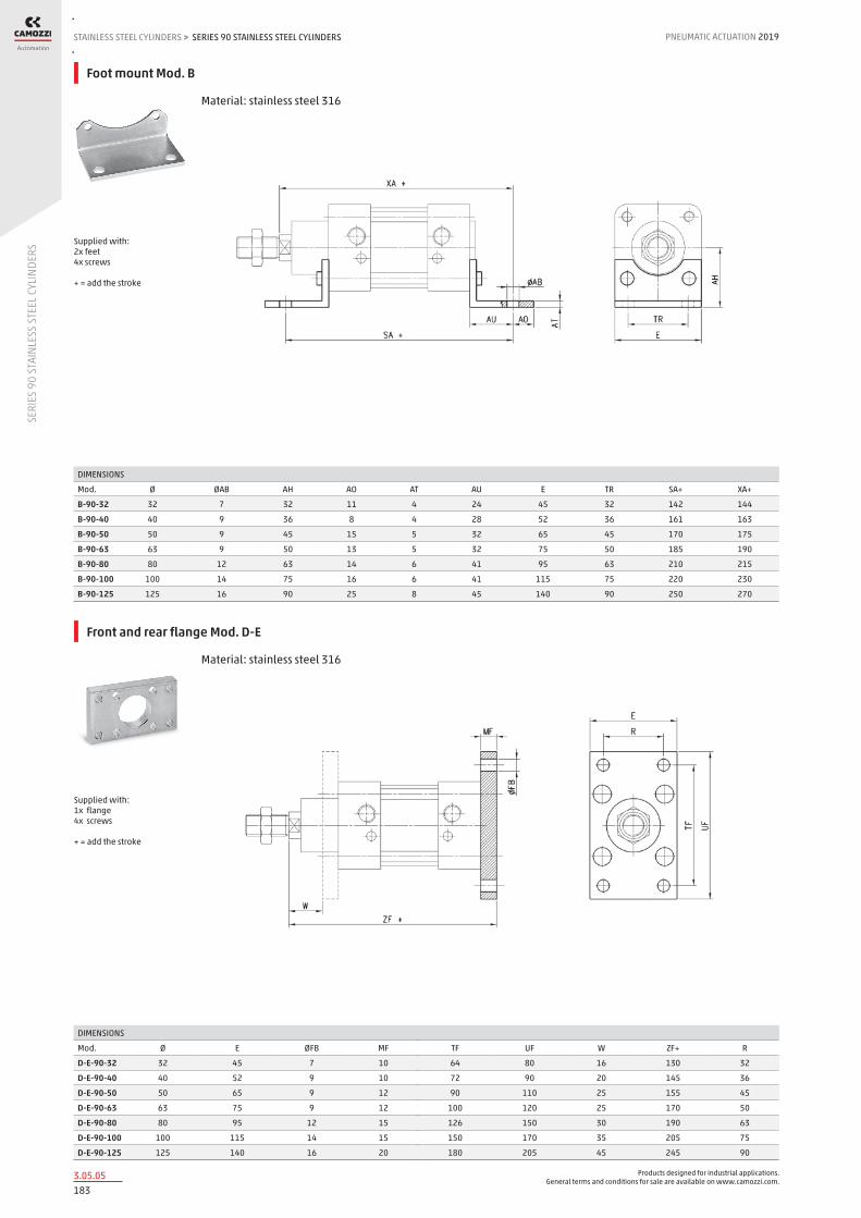
Products designed for industrial applications. General terms and conditions for sale are available on www.camozzi.com.
SERIES 90 STAINLESS STEEL CYLINDERSSTAINLESS STEEL CYLINDERS > PNEUMATIC ACTUATION 2019
1833.05.05
SERI
ES 9
0 ST
AINL
ESS
STEE
L CYL
INDE
RS
Foot mount Mod. B
Material: stainless steel 316
DIMENSIONS
Mod. Ø ØAB AH AO AT AU E TR SA+ XA+
B-90-32 32 7 32 11 4 24 45 32 142 144
B-90-40 40 9 36 8 4 28 52 36 161 163
B-90-50 50 9 45 15 5 32 65 45 170 175
B-90-63 63 9 50 13 5 32 75 50 185 190
B-90-80 80 12 63 14 6 41 95 63 210 215
B-90-100 100 14 75 16 6 41 115 75 220 230
B-90-125 125 16 90 25 8 45 140 90 250 270
Supplied with: 2x feet 4x screws + = add the stroke
Front and rear flange Mod. D-E
Material: stainless steel 316
DIMENSIONS
Mod. Ø E ØFB MF TF UF W ZF+ R
D-E-90-32 32 45 7 10 64 80 16 130 32
D-E-90-40 40 52 9 10 72 90 20 145 36
D-E-90-50 50 65 9 12 90 110 25 155 45
D-E-90-63 63 75 9 12 100 120 25 170 50
D-E-90-80 80 95 12 15 126 150 30 190 63
D-E-90-100 100 115 14 15 150 170 35 205 75
D-E-90-125 125 140 16 20 180 205 45 245 90
Supplied with: 1x flange 4x screws + = add the stroke

Products designed for industrial applications. General terms and conditions for sale are available on www.camozzi.com.
SERIES 90 STAINLESS STEEL CYLINDERSPNEUMATIC ACTUATION
1843.05.06
2019 STAINLESS STEEL CYLINDERS
SERI
ES 9
0 ST
AINL
ESS
STEE
L CYL
INDE
RS
>
Rear trunnion, female Mod. C-H
Material: stainless steel 316
DIMENSIONS
Mod. Ø CB CD E FL L MR UB XD+
C-H-90-32 32 26 10 45 22 12 10 45 142
C-H-90-40 40 28 12 55 25 15 12 52 161
C-H-90-50 50 32 12 65 27 17 12 60 170
C-H-90-63 63 40 16 75 32 20 16 70 185
C-H-90-80 80 50 16 95 36 22 16 90 210
C-H-90-100 100 60 20 115 41 25 20 110 230
C-H-90-125 125 70 25 140 50 30 25 130 275
Supplied: 1x female trunnion 4x screws + = add the stroke
Rear trunnion, male Mod. L
Material: stainless steel 316
DIMENSIONS
Mod. Ø EW CD E FL L MR XD+
L-90-32 32 26 10 45 22 12 10 142
L-90-40 40 28 12 55 25 15 12 161
L-90-50 50 32 12 65 27 17 12 170
L-90-63 63 40 16 75 32 20 16 185
L-90-80 80 50 16 95 36 22 16 210
L-90-100 100 60 20 115 41 25 20 230
L-90-125 125 70 25 140 50 30 25 275
Supplied: 1x male trunnion 4x screws + = add the stroke

Products designed for industrial applications. General terms and conditions for sale are available on www.camozzi.com.
SERIES 90 STAINLESS STEEL CYLINDERSSTAINLESS STEEL CYLINDERS > PNEUMATIC ACTUATION 2019
1853.05.07
SERI
ES 9
0 ST
AINL
ESS
STEE
L CYL
INDE
RS
Tight rear female trunnion bracket Mod. CR
Material: stainless steel 316
DIMENSIONS
Mod. Ø CB CD E FL L UB XD D3
CR-90-32 32 14 10 45 22 12 34 142 5.5
CR-90-40 40 16 12 55 25 25 40 161 5.5
CR-90-50 50 21 16 65 27 27 45 170 6.5
CR-90-63 63 21 16 75 32 32 51 185 6.5
CR-90-80 80 25 20 95 36 36 65 210 10
CR-90-100 100 25 20 114 41 41 75 230 10
CR-90-125 125 37 30 140 50 50 97 275 10
Supplied with: 1x female trunnion bracket 4x screws + = add the stroke
Male trunnion bracket with swivel ball joint Mod. R
Material: stainless steel 316
DIMENSIONS
Mod. Ø EW EW1 CD E FL L MR XD D3
R-90-32 32 10.5 14 10 45 22 12 15 142 5.5
R-90-40 40 12 16 12 55 25 15 18 161 5.5
R-90-50 50 15 21 16 65 27 17 20 170 6.5
R-90-63 63 15 21 16 75 32 20 23 185 6.5
R-90-80 80 18 25 20 95 36 22 27 210 10
R-90-100 100 18 25 20 115 41 25 30 230 10
R-90-125 125 25 37 30 140 50 30 40 275 10
Supplied with: 1x male trunnion bracket 4x screws + = add the stroke

Products designed for industrial applications. General terms and conditions for sale are available on www.camozzi.com.
SERIES 90 STAINLESS STEEL CYLINDERSPNEUMATIC ACTUATION
1863.05.08
2019 STAINLESS STEEL CYLINDERS
SERI
ES 9
0 ST
AINL
ESS
STEE
L CYL
INDE
RS
>
90° male trunnion bracket with swivel ball joint Mod. ZCR
Material: stainless steel 316
DIMENSIONS
Mod. Ø UL TE EA EM XD GL BR CK PH L5 BT HB RA UR HC
ZCR-90-32 32 51 38 10.5 14 142 21 15 10 32 1.5 10 6.6 18 31 11
ZCR-90-40 40 54 41 12 16 160 24 18 12 36 1.5 10 6.6 22 35 11
ZCR-90-50 50 65 50 15 21 170 33 20 16 45 1.5 12 9 30 45 15
ZCR-90-63 63 67 52 15 21 190 37 23 16 50 1.5 12 9 35 50 15
ZCR-90-80 80 86 66 18 25 210 47 27 20 63 2.5 14 11 40 60 18
ZCR-90-100 100 96 76 18 25 230 55 30 20 71 2.5 15 11 50 70 18
ZCR-90-125 125 124 94 25 37 275 70 40 30 90 3 20 13.5 60 90 20
Supplied with: 1x male trunnion bracket 4x screws + = add the stroke
90° male trunnion Mod. ZC
Material: stainless steel 316
DIMENSIONS
Mod. Ø BT CK EM GL ØHB PH RA TE UL UR XD+
ZC-90-32 32 8 10 26 21 6,6 32 18 38 51 31 142
ZC-90-40 40 10 12 28 24 6,6 36 22 41 54 35 161
ZC-90-50 50 12 12 32 33 9 45 30 50 65 45 170
ZC-90-63 63 12 16 40 37 9 50 35 52 67 50 185
ZC-90-80 80 14 16 50 47 11 63 40 66 86 60 210
ZC-90-100 100 15 20 60 55 11 71 50 76 96 70 230
ZC-90-125 125 20 25 70 70 14 90 60 94 124 90 275
Supplied with: 1x male support + = add the stroke

Products designed for industrial applications. General terms and conditions for sale are available on www.camozzi.com.
SERIES 90 STAINLESS STEEL CYLINDERSSTAINLESS STEEL CYLINDERS > PNEUMATIC ACTUATION 2019
1873.05.09
SERI
ES 9
0 ST
AINL
ESS
STEE
L CYL
INDE
RS
Rod fork end Mod. G-90
Material: stainless steel 303 ISO 8140
DIMENSIONS
Mod. Ø ØCK LE CM CL ER CE KK B ØB1
G-90-25-32 32 10 20 10 20 12 40 M10x1,25 26 18
G-90-40 40 12 24 12 24 14 48 M12x1,25 31 20
G-90-50-63 50-63 16 32 16 32 19 64 M16x1,5 39 26
G-90-80-100 80-100 20 40 20 40 25 80 M20x1,5 50 34
G-90-125 125 30 54 30 55 38 110 M27x2 67 48
Clevis pin Mod. S-90
Material: stainless steel 303
DIMENSIONS
Mod. Ø Ød L L1 L2 L3
S-90-32 32 10 53 46 1,1 3
S-90-40 40 12 60 53 1,1 3
S-90-50 50 12 68 61 1,1 3
S-90-63 63 16 78 71 1,1 3
S-90-80 80 16 98 91 1,1 3
S-90-100 100 20 118 111 1,3 5
S-90-125 125 25 139 132 1,3 4,2

Products designed for industrial applications. General terms and conditions for sale are available on www.camozzi.com.
SERIES 90 STAINLESS STEEL CYLINDERSPNEUMATIC ACTUATION
1883.05.10
2019 STAINLESS STEEL CYLINDERS
SERI
ES 9
0 ST
AINL
ESS
STEE
L CYL
INDE
RS
>
Antirotating clevis pin Mod. SR-90
Supplied with: 1x antirotating clevis pin (stainless steel 316) 1x seeger (steel)
DIMENSIONS
Mod. Ø A B C D E F G H L
SR-90-32 32 3 4.5 32.5 1.1 10 9.6 4 41 14
SR-90-40 40 4 6 38 1.1 12 11.5 4 48 46
SR-90-50 50 4 6 43 1.1 16 15.2 5 54 20
SR-90-63 63 4 6 49 1.1 16 15.2 5 60 20
Swivel ball joint Mod. GA-90
ISO 8139 Materials: - stainless steel 304 bracket - stainless steel 420 spherical ring - sintered bronze bushing
DIMENSIONS
Mod. Ø ØCN U EN ER AX CE KK ØT Z SW
GA-90-32 32 10 10,5 14 14 20 43 M10x1,25 15 6,5 17
GA-90-40 40 12 12 16 16 22 50 M12x1,25 17,5 6,5 19
GA-90-50-63 50-63 16 15 21 21 28 64 M16x1,5 22 7,5 22
GA-90-80-100 80-100 20 18 25 21 33 77 M20x1,5 27,5 7 30
GA-90-125 125 30 25 35 35 51 110 M27x2 40 7,5 41
Piston rod lock nut Mod. U-90
ISO 4035 Material: stainless steel 304
DIMENSIONS
Mod. Ø D m SW
U-90-25-32 32 M10x1,25 6 17
U-90-40 40 M12x1,25 7 19
U-90-50-63 50-63 M16x1,5 8 24
U-90-80-100 80-100 M20x1,5 9 30
U-90-125 125 M27x2 12 41

Products designed for industrial applications. General terms and conditions for sale are available on www.camozzi.com.
SERIES 94 AND 95 STAINLESS STEEL CYLINDERSSTAINLESS STEEL CYLINDERS > PNEUMATIC ACTUATION 2019
1893.15.01
SERI
ES 9
4 AN
D 95
STA
INLE
SS S
TEEL
CYL
INDE
RS
Series 94 and 95 stainless steel mini-cylinders
Single-acting and double-acting, magnetic Series 94: ø 16, 20, 25 mm Series 95: ø 25 mm, cushioned
The Series 94 and 95 cylinders can be used in critical applications in which a high corrosion resistance is required (for example off-shore, marine, food).
Their construction enables the replacement of all seals. Series 95 is normally equipped with adjustable end-stroke cushioning by means of a screw on the end block. In addition both Series 94 and 95 are equipped with a mechanical cushioning in order to make the impact of the piston less noisy as it reaches the end of the stroke.
» In compliance with Cetop RP52-P and DIN/ISO 6432 standards
» Clean design
» Stainless steel AISI 304 and AISI 316
GENERAL DATAConstruction end blocks secured to the tubeOperation single-acting and double-actingMaterials end blocks and rod in stainless steel AISI 316, seals in NBR,
plastic guiding element, NSF H1-certified lubricant Series 94: tube in stainless steel AISI 304 Series 95: tube in stainless steel AISI 316
Mounting several types of cylinders clamps availableStrokes min - max 10 ÷ 500 mmOperating temperature 0° - 80°C (with dry air -20°C)Operating pressure 1 ÷ 10 barSpeed 10 ÷ 1000 mm/sec (without load)Fluid clean air, without lubrication.
If lubricated air is used, it is recommended to use oil ISOVG32. Once applied the lubrication should never be interrupted.

Products designed for industrial applications. General terms and conditions for sale are available on www.camozzi.com.
SERIES 94 AND 95 STAINLESS STEEL CYLINDERSPNEUMATIC ACTUATION
1903.15.02
2019 STAINLESS STEEL CYLINDERS
SERI
ES 9
4 AN
D 95
STA
INLE
SS S
TEEL
CYL
INDE
RS
>
STANDARD STROKES FOR MINICYLINDERS SERIES 94 AND 95
● = single-acting ✖ = double-acting
STANDARD STROKES
Ø 10 25 40 50 80 100 125 160 200 250 300 320 400 500
94 16 ●✖ ●✖ ●✖ ●✖ ✖ ✖ ✖ ✖ ✖
94 20 ●✖ ●✖ ●✖ ●✖ ✖ ✖ ✖ ✖ ✖ ✖ ✖
94 25 ●✖ ●✖ ●✖ ●✖ ✖ ✖ ✖ ✖ ✖ ✖ ✖ ✖ ✖ ✖
95 25 ✖ ✖ ✖ ✖ ✖ ✖ ✖ ✖ ✖ ✖ ✖ ✖ ✖ ✖
CODING EXAMPLE
94 SERIES 94 = magnetic 95 = magnetic, cushioned
N VERSION N = standard
2 OPERATION 1 = single-acting, front spring 2 = double-acting 3 = double-acting, through-rod
PNEUMATIC SYMBOLS CS06 (S. 94) CD08 (S. 94) - CD09 (S. 95) CD12 (S. 94) - CD13 (S. 95)
A MATERIALS A = stainless steel, seals in NBR V = stainless steel, all seals in FKM (150°C)
16 BORE 16 = 16 mm - 20 = 20 mm - 25 = 25 mm
A TYPE OF DESIGN A = standard with locking ring for end cap Mod. V and piston rod lock nut Mod. U
100 STROKE (see the table)
= standard V = rod seal in FKM
94 N 2 A 16 A 100
PNEUMATIC SYMBOLS
The pneumatic symbols which have been indicated in the CODING EXAMPLE are shown below.

Products designed for industrial applications. General terms and conditions for sale are available on www.camozzi.com.
SERIES 94 AND 95 STAINLESS STEEL CYLINDERSSTAINLESS STEEL CYLINDERS > PNEUMATIC ACTUATION 2019
1913.15.03
SERI
ES 9
4 AN
D 95
STA
INLE
SS S
TEEL
CYL
INDE
RS
ACCESSORIES FOR STAINLESS STEEL MINICYLINDERS SERIES 94 AND 95
Foot mount Mod. B Flange bracket Mod. E Trunnion bracket Mod. I Rod fork end Mod. G-94/90
Swivel ball joint Mod.GA-94/90
Piston rod lock nut Mod. U-94/90
All accessories are supplied separately, except for piston rod lock nut Mod. U
Nose nut Mod. V-94 and Mod. U-90

Products designed for industrial applications. General terms and conditions for sale are available on www.camozzi.com.
SERIES 94 AND 95 STAINLESS STEEL CYLINDERSPNEUMATIC ACTUATION
1923.15.04
2019 STAINLESS STEEL CYLINDERS
SERI
ES 9
4 AN
D 95
STA
INLE
SS S
TEEL
CYL
INDE
RS
>
Cylinders Series 94 and 95
With threaded front and rear end blocks
DIMENSIONS
Mod. Ø A AM BE CD D EE EW KK KW KW1 L L2 L3 L4 L5 SW SW1 SW2 WF XC
94 16 6 16 M16x1.5 6 21.2 M5 12 M6 4 5 9 51 14 5.5 15 5 10 24 22 82
94 20 8 20 M22x1.5 8 26.2 G1/8 16 M8 5 5 12 59 17.5 8 19 7 13 32 24 95
94-95 25 10 22 M22x1.5 8 32.5 G1/8 16 M10x1.25 6 5 12 64 18.5 7.5 20 8 17 32 28 104
+ = add the stroke
Cylinders Series 94 and 95 - through-rod
With threaded end blocks
DIMENSIONS
Mod. Ø A AM BE D EE KK KW KW1 L1 L2 L3 L4 L5 SW SW1 SW2 WF
94 16 6 16 M16x1.5 21.2 M5 M6 4 5 100 56 14 5.5 15 5 10 24 22
94 20 8 20 M22x1.5 26.2 G1/8 M8 5 5 116 68 17.5 8 19 7 13 32 24
94-95 25 10 22 M22x1.5 32.5 G1/8 M10x1.25 6 5 125 69 18.5 7.5 20 8 17 32 28
+ = add the stroke once ++ = add the stroke twice

Products designed for industrial applications. General terms and conditions for sale are available on www.camozzi.com.
SERIES 94 AND 95 STAINLESS STEEL CYLINDERSSTAINLESS STEEL CYLINDERS > PNEUMATIC ACTUATION 2019
1933.15.05
SERI
ES 9
4 AN
D 95
STA
INLE
SS S
TEEL
CYL
INDE
RS
Foot mount Mod. B
Material: stainless steel 304 Supplied with: 2x feet 1x nut
DIMENSIONS
Mod. Ø ØAB XS XA+ SA+ AO AU C RX TR US NH
B-94-12-16 16 5,5 32 91 82 6 13 3 13 32 42 20
B-94-20-25 20 6,6 36 108 100 8 16 4 20 40 54 25
B-94-20-25 25 6,6 40 113 101 8 16 4 20 40 54 25
+ = add the stroke
Flange bracket Mod. E
Material: stainless steel 304 Supplied with: 1x flange
DIMENSIONS
Mod. Ø W C ZF+ FB UR TF UF
E-94-12-16 16 19 3 81 5,5 30 40 53
E-94-20-25 20 20 4 96 6,6 40 50 66
E-94-20-25 25 24 4 101 6,6 40 50 66
+ = add the stroke
Trunnion Bracket Mod. I
Material: stainless steel 304
DIMENSIONS
Mod. Ø AB C CD EW G G1 G2 MR NH US XC+
I-94-12-16 16 5,5 3 6 12 15 25 5 7 27 18,1 82
I-94-20-25 20 6,6 4 8 16 20 32 6 10 30 24,1 95
I-94-20-25 25 6,6 4 8 16 20 32 6 10 30 24,1 104

Products designed for industrial applications. General terms and conditions for sale are available on www.camozzi.com.
SERIES 94 AND 95 STAINLESS STEEL CYLINDERSPNEUMATIC ACTUATION
1943.15.06
2019 STAINLESS STEEL CYLINDERS
SERI
ES 9
4 AN
D 95
STA
INLE
SS S
TEEL
CYL
INDE
RS
>
Rod Fork End Mod. G-94/90
ISO 8140 Material: stainless steel 303
DIMENSIONS
Mod. Ø CK LE KK CM ER CE CL B B1
G-94-12-16 16 6 12 M6x1 6 7 24 12 16 10
G-94-20 20 8 16 M8x1,25 8 10 32 16 22 14
G-90-25-32 25 10 20 M10x1,25 10 12 40 20 26 18
Swivel Ball Joint Mod. GA-94/90
ISO 8139 Materials: - stainless steel 304 bracket - stainless steel 420 spherical ring - sintered bronze bushing
DIMENSIONS
Mod. Ø CN U EN ER AX CE KK T Z SW
GA-94-12-16 16 6 7 9 10 12 30 M6x1 10 6,5 11
GA-94-20 20 8 9 12 12 16 36 M8x1,25 12,5 6,5 14
GA-90-32 25 10 10,5 14 14 20 43 M10x1,25 15 6,5 17
Piston Rod Lock Nut Mod. U-94/90
ISO 4035 Material: stainless steel 304
DIMENSIONS
Mod. Ø D m SW
U-94-12-16 16 M6x1 4 10
U-94-20 20 M8x1,25 5 13
U-90-25-32 25 M10x1,25 6 17
Nose Nut Mod. V-94 and Mod. U-90
ISO 4035 Material: stainless steel 304
DIMENSIONS
Mod. Ø D m SW
U-90-50-63 16 M16x1,5 8 24
V-94-20-25 20-25 M22x1,5 10 32
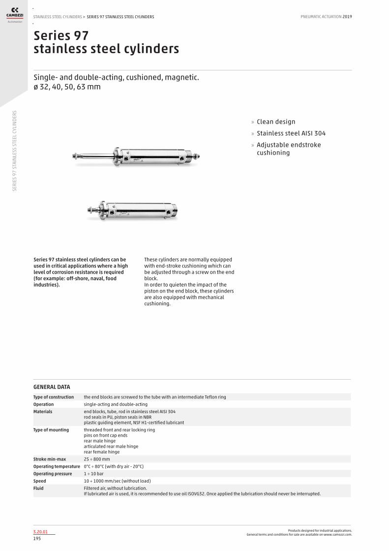
Products designed for industrial applications. General terms and conditions for sale are available on www.camozzi.com.
SERIES 97 STAINLESS STEEL CYLINDERSSTAINLESS STEEL CYLINDERS > PNEUMATIC ACTUATION 2019
1953.20.01
SERI
ES 9
7 ST
AINL
ESS
STEE
L CYL
INDE
RS
Series 97 stainless steel cylinders
Single- and double-acting, cushioned, magnetic. ø 32, 40, 50, 63 mm
Series 97 stainless steel cylinders can be used in critical applications where a high level of corrosion resistance is required (for example: off-shore, naval, food industries).
These cylinders are normally equipped with end-stroke cushioning which can be adjusted through a screw on the end block. In order to quieten the impact of the piston on the end block, these cylinders are also equipped with mechanical cushioning.
» Clean design
» Stainless steel AISI 304
» Adjustable endstroke cushioning
GENERAL DATAType of construction the end blocks are screwed to the tube with an intermediate Teflon ringOperation single-acting and double-actingMaterials end blocks, tube, rod in stainless steel AISI 304
rod seals in PU, piston seals in NBR plastic guiding element, NSF H1-certified lubricant
Type of mounting threaded front and rear locking ring pins on front cap ends rear male hinge articulated rear male hinge rear female hinge
Stroke min-max 25 ÷ 800 mmOperating temperature 0°C ÷ 80°C (with dry air - 20°C)Operating pressure 1 ÷ 10 barSpeed 10 ÷ 1000 mm/sec (without load)Fluid Filtered air, without lubrication.
If lubricated air is used, it is recommended to use oil ISOVG32. Once applied the lubrication should never be interrupted.

Products designed for industrial applications. General terms and conditions for sale are available on www.camozzi.com.
SERIES 97 STAINLESS STEEL CYLINDERSPNEUMATIC ACTUATION
1963.20.02
2019 STAINLESS STEEL CYLINDERS
SERI
ES 9
7 ST
AINL
ESS
STEE
L CYL
INDE
RS
>
STANDARD STROKES FOR CYLINDERS SERIES 97
● = Single-acting ✖ = Double-acting
STANDARD STROKES
Ø 25 50 75 80 100 125 150 160 200 250 300 320 400 500
32 ✖● ✖● ✖ ✖ ✖ ✖ ✖ ✖ ✖ ✖ ✖ ✖ ✖ ✖
40 ✖● ✖● ✖ ✖ ✖ ✖ ✖ ✖ ✖ ✖ ✖ ✖ ✖ ✖
50 ✖● ✖● ✖ ✖ ✖ ✖ ✖ ✖ ✖ ✖ ✖ ✖ ✖ ✖
63 ✖● ✖● ✖ ✖ ✖ ✖ ✖ ✖ ✖ ✖ ✖ ✖ ✖ ✖
CODING EXAMPLE
97 SERIES
M VERSIONS: M = rear male hinge S = articulated rear male hinge F = rear female hinge T = front and rear threaded end blocks A = front end block with pin
2 OPERATION: 1 = single-acting, front spring 2 = double-acting, front and rear cushions 6 = double-acting, through-rod, front and rear cushions (T and A versions only)
PNEUMATIC SYMBOLS: CS06 CD09 CD13
A MATERIALS: A = stainless steel AISI 304 - PU seals V = stainless steel AISI 304 - FKM seals (150°C)
050 BORE: 032 = 32 mm - 040 = 40 mm - 050 = 50 mm - 063 = 63 mm
A TYPE OF DESIGN: A = standard (locking ring for end cap V + lock nut for rod U)
0200 STROKE (see the table)
= standard V = rod seal in FKM
97 M 2 A 050 A 0200
PNEUMATIC SYMBOLS
The pneumatic symbols which have been indicated in the CODING EXAMPLE are shown below.

Products designed for industrial applications. General terms and conditions for sale are available on www.camozzi.com.
SERIES 97 STAINLESS STEEL CYLINDERSSTAINLESS STEEL CYLINDERS > PNEUMATIC ACTUATION 2019
1973.20.03
SERI
ES 9
7 ST
AINL
ESS
STEE
L CYL
INDE
RS
ACCESSORIES FOR STAINLESS STEEL CYLINDERS SERIES 97
Foot mount Mod. B Trunnion bracket Mod. I Rear female trunnion bracket Mod. C-H
Tight rear female tr. bracket Mod. CR
Male tr. bracket with swivel ball joint Mod. R
90° male tr. bracket + sw. ball joint Mod. ZCR
Rod fork end Mod. G-90 Swivel ball joint Mod. GA-90
All accessories are supplied separately, except for piston rod lock nut Mod. U and nose nut Mod. V.
Piston rod lock nut Mod. U-90
Nose nut Mod. V-97
Clevis pin Mod. S-90 Anti-rotation clevis pin Mod. SR-90

Products designed for industrial applications. General terms and conditions for sale are available on www.camozzi.com.
SERIES 97 STAINLESS STEEL CYLINDERSPNEUMATIC ACTUATION
1983.20.04
2019 STAINLESS STEEL CYLINDERS
SERI
ES 9
7 ST
AINL
ESS
STEE
L CYL
INDE
RS
>
Cylinders Series 97, Mod. T
With threaded front and rear end blocks
DIMENSIONS
Ø ØA AM ØB ØB2 EE F G KK PL SW1 KW1 SW2 U1 WH L1+ L2+ L3+ L4 L7 KW ØKV
32 12 22 M30x1.5 36 G1/8 5 38 M10x1.25 9 17 6 10 23 26 120 94 76 19.5 15 7 42
40 16 24 M38x1.5 45 G1/4 6 50 M12x1.25 12 19 7 13 27 30 135 105 81 22.5 15 8 55
50 20 32 M45x1.5 55 G1/4 6 53 M16x1.5 12 24 8 17 33 37 143 106 82 28 18 10 60
63 20 32 M45x1.5 68 G3/8 6 53 M16x1.5 13 24 8 17 40 37 158 121 95 28 18 10 60
+ = add the stroke
Cylinders Series 97, Mod. T - through-rod
With threaded end blocks
DIMENSIONS
Ø ØA AM ØB ØB2 EE F G KK PL SW1 KW1 SW2 U1 WH+ L2+ L3+ L4 KW ØKV ZC++
32 12 22 M30x1.5 36 G1/8 5 38 M10x1.25 9 17 6 10 23 26 94 76 19.5 7 42 146
40 16 24 M38x1.5 45 G1/4 6 50 M12x1.25 12 19 7 13 27 30 105 81 22.5 8 55 165
50 20 32 M45x1.5 55 G1/4 6 53 M16x1.5 12 24 8 17 33 37 106 82 28 10 60 180
63 20 32 M45x1.5 68 G3/8 6 53 M16x1.5 13 24 8 17 40 37 121 95 28 10 60 195
+ = add the stroke once ++ = add the stroke twice

Products designed for industrial applications. General terms and conditions for sale are available on www.camozzi.com.
SERIES 97 STAINLESS STEEL CYLINDERSSTAINLESS STEEL CYLINDERS > PNEUMATIC ACTUATION 2019
1993.20.05
SERI
ES 9
7 ST
AINL
ESS
STEE
L CYL
INDE
RS
Cylinders Series 97, Mod. M
With rear male trunnion bracket
DIMENSIONS
Ø ØA AM ØB2 CX EE EW KK PL SW1 KW1 SW2 U1 WH L1+ L2+ L3+ L LU XD+
32 12 22 36 10 G1/8 26 M10x1.25 23 17 6 10 23 26 151 125 76 13 9 142
40 16 24 45 12 G1/4 28 M12x1.25 26 19 7 13 27 34 170 136 81 16 10 160
50 20 32 55 12 G1/4 32 M16x1.5 32 24 8 17 33 37 182 145 82 16.5 12 170
63 20 32 68 16 G3/8 40 M16x1.5 29.5 24 8 17 40 50 202 152 95 21 12 190
+ = add the stroke
Cylinders Series 97, Mod. S
With articulated rear male trunnion bracket
DIMENSIONS
Ø ØA AM ØB2 CX EE EP EX KK PL SW1 KW1 SW2 U1 WH L1+ L2+ L3+ LT LU XD+ Z
32 12 22 36 10 G1/8 10.5 14 M10x1.25 37 17 6 10 23 18 157 139 76 13 15 142 13
40 16 24 45 12 G1/4 12 16 M12x1.25 47 19 7 13 27 22 179 157 81 16 19 160 13
50 20 32 55 16 G1/4 15 21 M16x1.5 49 24 8 17 33 28.5 190.5 162 82 16.5 20.5 170 15
63 20 32 68 16 G3/8 15 21 M16x1.5 60 24 8 17 40 31.5 214 182.5 95 21 24 190 15
+ = add the stroke

Products designed for industrial applications. General terms and conditions for sale are available on www.camozzi.com.
SERIES 97 STAINLESS STEEL CYLINDERSPNEUMATIC ACTUATION
2003.20.06
2019 STAINLESS STEEL CYLINDERS
SERI
ES 9
7 ST
AINL
ESS
STEE
L CYL
INDE
RS
>
Cylinders Series 97, Mod. F
With rear female trunnion bracket
DIMENSIONS
Ø ØA AM ØB2 CB CX EE KK PL SW1 KW1 SW2 U1 WH L1+ L2+ L3+ L LU XD+ UB
32 12 22 36 14 10 G1/8 M10x1.25 31 17 6 10 23 18 151 133 76 13 9 142 34
40 16 24 45 16 12 G1/4 M12x1.25 38 19 7 13 27 22 170 148 81 16 10 160 40
50 20 32 55 21 16 G1/4 M16x1.5 45.5 24 8 17 33 28.5 182 153.5 82 21 12 170 45
63 20 32 68 21 16 G3/8 M16x1.5 48 24 8 17 40 31.5 202 170.5 95 21 12 190 51
+ = add the stroke
Cylinders Series 97, Mod. A
With front end block with pins
DIMENSIONS
Ø ØA AM ØB2 EE KK SW SW1 KW1 SW2 U1 WH L1+ L2+ L3+ LU XG TD TL UT
32 12 22 36 G1/8 M10x1.25 8 17 6 10 23 9 120 111 76 9 27 10 7 58
40 16 24 45 G1/4 M12x1.25 8 19 7 13 27 13 135 122 81 12 33 12 9 71
50 20 32 55 G1/4 M16x1.5 8 24 8 17 33 18 143 125 82 12 40 14 9 81
63 20 32 68 G3/8 M16x1.5 12 24 8 17 40 22.5 158 135.5 95 13 45 16 12 104
+ = add the stroke

Products designed for industrial applications. General terms and conditions for sale are available on www.camozzi.com.
SERIES 97 STAINLESS STEEL CYLINDERSSTAINLESS STEEL CYLINDERS > PNEUMATIC ACTUATION 2019
2013.20.07
SERI
ES 9
7 ST
AINL
ESS
STEE
L CYL
INDE
RS
Foot mount Mod. B
Material: stainless steel 304 Supplied with: 1x nut 2x single feet
DIMENSIONS
Mod. Ø A B C D E SA+ F G ØH ØM XD+
B-97-32 32 4 53 35 24 42 142 32 32 30 7 142
B-97-40 40 4 63.5 36 28 55 161 36 36 38 10 160
B-97-50 50 5 77.5 47 32 65 170 45 45 45 10 170
B-97-63 63 5 82.5 45 32 65 185 50 50 45 10 190
+ = add the stroke
Trunnion bracket Mod. I
Material: stainless steel 304 Supplied with: 1x female trunnion 2x cartridges
DIMENSIONS
Mod. Ø C C1 C2 ØD1 E1 F G G1 G2 L1+ SW1
I-97-32 32 40 24 20 7 4 35 38 50 58 27 8
I-97-40 40 50 30 28 9 5 40 46 60 71 33 8
I-97-50 50 54 34 36 9 6 45 57 74 81 40 8
I-97-63 63 65 35 43 9 6 50 70 88 104 45 12
+ = add the stroke
Rear female trunnion bracket Mod. C-H
Material: stainless steel 316 Supplied with: 1x female trunnion bracket 4x screws
DIMENSIONS
Mod. Ø CB CD E FL L MR UB XD+
C-H-90-32 32 26 10 45 22 12 10 45 142
C-H-90-40 40 28 12 55 25 15 12 52 160
C-H-90-50 50 32 12 65 27 17 12 60 170
C-H-90-63 63 40 16 75 32 20 16 70 190
+ = add the stroke

Products designed for industrial applications. General terms and conditions for sale are available on www.camozzi.com.
SERIES 97 STAINLESS STEEL CYLINDERSPNEUMATIC ACTUATION
2023.20.08
2019 STAINLESS STEEL CYLINDERS
SERI
ES 9
7 ST
AINL
ESS
STEE
L CYL
INDE
RS
>
Tight rear female trunnion bracket Mod. CR
Material: stainless steel 316 Supplied with: 1x female trunnion bracket 4x screws
DIMENSIONS
Mod. Ø B1 B2 E CN FL XD+
CR-90-32 32 14 34 45 10 22 142
CR-90-40 40 16 40 55 12 25 160
CR-90-50 50 21 45 65 16 27 170
CR-90-63 63 21 51 75 16 32 190
+ = add the stroke
Male trunnion bracket with swivel ball joint Mod. R
Material: stainless steel 316 Supplied with: 1x male trunnion bracket 4x screws
DIMENSIONS
Mod. Ø E EN FL TG1 XD+
R-90-32 32 45 14 22 32.5 142
R-90-40 40 55 16 25 38 160
R-90-50 50 65 21 27 46.5 170
R-90-63 63 75 21 32 56.5 190
+ = add the stroke
90° male trunnion bracket with swivel ball joint Mod. ZCR
Material: stainless steel 316 Supplied with: 1x male trunnion bracket 4x screws
DIMENSIONS
Mod. Ø CH CN G1 G2 G3 H6 K1 K2 S5 XD+
ZCR-90-32 32 32 10 21 18 31 10 38 51 6.6 142
ZCR-90-40 40 36 12 24 22 35 10 41 54 6.6 160
ZCR-90-50 50 45 16 33 30 45 12 50 65 9 170
ZCR-90-63 63 50 16 37 35 50 12 52 67 14 190
+ = add the stroke

Products designed for industrial applications. General terms and conditions for sale are available on www.camozzi.com.
SERIES 97 STAINLESS STEEL CYLINDERSSTAINLESS STEEL CYLINDERS > PNEUMATIC ACTUATION 2019
2033.20.09
SERI
ES 9
7 ST
AINL
ESS
STEE
L CYL
INDE
RS
Rod fork end Mod. G-90
ISO 8140 Material: stainless steel 303
DIMENSIONS
Mod. Ø ØCK LE CM CL ER CE KK B ØB1
G-90-25-32 32 10 20 10 20 12 40 M10x1.25 26 18
G-90-40 40 12 24 12 24 14 48 M12x1.25 31 20
G-90-50-63 50-63 16 32 16 32 19 64 M16x1.5 39 26
Swivel ball joint Mod. GA-90
ISO 8139 Materials: - stainless steel 304 bracket - stainless steel 420 spherical ring - sintered bronze bushing
DIMENSIONS
Mod. Ø ØCN U EN ER AX CE KK ØT Z SW
GA-90-32 32 10 10.5 14 14 20 43 M10x1.25 15 6.5 17
GA-90-40 40 12 12 16 16 22 50 M12x1.25 17.5 6.5 19
GA-90-50-63 50-63 16 15 21 21 28 64 M16x1.5 22 7.5 22
Piston rod lock nut Mod. U-90
ISO 4035 Material: stainless steel 304
DIMENSIONS
Mod. Ø D m SW
U-90-25-32 32 M10x1.25 6 17
U-90-40 40 M12x1.25 7 19
U-90-63 50-63 M16x1.5 8 24

Products designed for industrial applications. General terms and conditions for sale are available on www.camozzi.com.
SERIES 97 STAINLESS STEEL CYLINDERSPNEUMATIC ACTUATION
2043.20.10
2019 STAINLESS STEEL CYLINDERS
SERI
ES 9
7 ST
AINL
ESS
STEE
L CYL
INDE
RS
>
Nose nut Mod. V-97
Material: stainless steel 304
DIMENSIONS
Mod. Ø A D ØD1 E C
V-97-32 32 7 M30x1.5 42 5 38
V-97-40 40 8 M38x1.5 55 6 50
V-97-50-63 50-63 10 M45x1.5 60 6 53
Clevis pin Mod. S-90
Supplied with: 1x clevis pin in stainless steel 303 2x seeger in steel
DIMENSIONS
Mod. Ø Ød L L1 L2 L3
S-90-32 32 10 53 46 1.1 3
S-90-40 40 12 60 53 1.1 3
S-90-50 50 12 68 61 1.1 3
S-90-63 63 16 78 71 1.1 3
Antirotating clevis pin Mod. SR-90
Supplied with: 1x antirotating clevis pin in stainless steel 316 1x seeger in steel
DIMENSIONS
Mod. Ø A B C D E F G H L
SR-90-32 32 3 4.5 32.5 1.1 10 9.6 4 41 14
SR-90-40 40 4 6 38 1.1 12 11.5 4 48 16
SR-90-50 50 4 6 43 1.1 16 15.2 5 54 20
SR-90-63 63 4 6 49 1.1 16 15.2 5 60 20

Products designed for industrial applications. General terms and conditions for sale are available on www.camozzi.com.
SERIES QC CYLINDERSGUIDED CYLINDERS > PNEUMATIC ACTUATION 2019
2054.05.01
SERI
ES Q
C CY
LIND
ERS
Series QCT and QCB cylinders with integrated guide
Double-acting, magnetic piston, guided ø 20, 25, 32, 40, 50, 63 mm
These actuators, suitable for use in very limited space, are available in two versions. QCT version: with sintered bronze bushes, suitable when the side loads applied to the cylinder are high. QCB version: with linear ball bearings, suitable for high precision and fast cycling applications.
Both versions are equipped with fixed cushioning to prevent direct impact with the end covers. The design of the cylinder body allows the mounting of the cylinder using either top, bottom or side faces. Several “T” shaped grooves in two faces allow sensors to be fitted in a number of positions. Out of standard strokes are available on demand only.
» Magnetic sensors can be mounted on both sides
» QCT: bronze bushings version
» QCB: ball bearing guide version
» Movement and guidance in one unit
GENERAL DATA
Type of construction compact guided QCT = sintered bronze bushes QCB = linear ball bearings
Operation double-actingMaterials body = anodized AL
flange = zinc-plated steel piston rod = rolled stainless steel AISI 303 QCT columns = rolled stainless steel 420B QCB columns = hardened steel C50 seals = PU
Mounting threaded and non-threaded holes in the bodyStrokes min. max see tableOperating temperature 0°C ÷ 80°C (with dry air - 20°C)Speed 50 ÷ 500 mm/sOperating pressure 1 ÷ 10 barFluid clean air, non lubricated. If lubricated air is used, it is recommended to use oil ISOVG32. Once applied the lubrication should never be
interrupted.

Products designed for industrial applications. General terms and conditions for sale are available on www.camozzi.com.
SERIES QC CYLINDERSPNEUMATIC ACTUATION
2064.05.02
2019 GUIDED CYLINDERS
SERI
ES Q
C CY
LIND
ERS
>
STANDARD STROKES FOR DOUBLE-ACTING CYLINDERS SERIES QC
■ = Double-acting Out of standard intermediate strokes available on request (strokes multiple of 5 mm)
STANDARD STROKES
Ø 20 25 30 40 50 75 100 125 150 175 200
20 ■ ■ ■ ■ ■ ■ ■ ■ ■ ■
25 ■ ■ ■ ■ ■ ■ ■ ■ ■ ■
32 ■ ■ ■ ■ ■ ■ ■ ■
40 ■ ■ ■ ■ ■ ■ ■ ■
50 ■ ■ ■ ■ ■ ■ ■ ■
63 ■ ■ ■ ■ ■ ■ ■ ■
CODING EXAMPLE
QC SERIES
T VERSION: T = sintered bronze bushes B = linear ball bearings
2 OPERATION: 2 = double-acting
PNEUMATIC SYMBOLS CD07
A MATERIALS: A = anodized aluminium body - rolled stainless steel AISI 303 piston rod rolled stainless steel AISI 420B columns for QCT - hardened steel C50 columns for QCB
020 BORE: 020 = 20 mm - 025 = 25 mm - 032 = 32 mm - 040 = 40 mm - 050 = 50 mm - 063 = 63 mm
A TYPE OF DESIGN: A = standard
050 STROKE (see the table)
QC T 2 A 020 A 050
PNEUMATIC SYMBOLS
The pneumatic symbols which have been indicated in the CODING EXAMPLE are shown below.

Products designed for industrial applications. General terms and conditions for sale are available on www.camozzi.com.
SERIES QC CYLINDERSGUIDED CYLINDERS > PNEUMATIC ACTUATION 2019
2074.05.03
SERI
ES Q
C CY
LIND
ERS
For sintered bronze bushes QCT version For linear ball bearings QCB version F (N) 1N = 0.102 kgf Ex.: QCT2A025A020 = F = 140N
STROKE
Ø Mod 20 25 30 40 50 75 100 125 150 175 200
20 QCT 100 - 93 81 73 114 93 98 85 75 67
25 QCT 140 - 120 115 103 165 135 150 131 116 104
32 QCT - 253 - - 214 225 208 225 198 176 159
40 QCT - 251 - - 197 215 206 224 196 175 157
50 QCT - 317 - - 273 267 299 257 225 200 179
63 QCT - 316 - - 273 267 299 257 225 200 179
20 QCB 110 - 100 125 121 90 86 69 58 49 43
25 QCB 142 - 85 154 148 106 82 97 81 70 61
32 QCB - 222 - - 91 167 129 145 122 104 90
40 QCB - 221 - - 93 167 128 145 121 104 90
50 QCB - 203 - - 152 161 193 156 130 110 95
63 QCB - 201 - - 151 158 195 157 130 110 94
TABLE OF PERMISSABLE LOADS (F)
For sintered bronze bushes QCT version For linear ball bearings QCB version M (N*m) 1N*m = 0,102 kgf *m Ex.: QCT2A025A020 = M = 3,4 Nm
STROKE
Ø Mod 20 25 30 40 50 75 100 125 150 175 200
20 QCT 1,7 - 1,5 1,2 1,0 2,9 2,8 2,6 2,3 2,0 1,8
25 QCT 3,4 - 2,9 3,6 3,3 4,2 4,3 3,8 3,2 2,7 2,3
32 QCT - 6,7 - - 6,5 7,2 7,0 6,6 5,6 4,8 4,1
40 QCT - 8,7 - - 7,3 9,2 8,8 9,6 8,4 7,5 6,7
50 QCT - 15,4 - - 12,9 12,6 13,4 12,1 11,3 10,7 8,8
63 QCT - 15,1 - - 14,3 16,6 17 14 11,3 9,7 9,1
20 QCB 3,0 - 2,7 3,4 3,3 2,4 2,3 1,9 1,6 1,3 1,2
25 QCB 3,5 - 2,7 4,9 4,7 3,4 2,6 3,1 2,6 2,2 2,0
32 QCB - 6,3 - - 3,6 6,5 5,1 5,7 4,8 4,1 3,5
40 QCB - 8,5 - - 4,0 7,2 5,5 6,2 5,2 4,5 3,9
50 QCB - 11,1 - - 8,3 8,8 10,6 8,6 7,1 6,0 5,2
63 QCB - 8,3 - - 7,2 9,8 12,1 9,7 8,1 6,8 5,8
TABLE OF PERMISSABLE MOMENTS (M)

Products designed for industrial applications. General terms and conditions for sale are available on www.camozzi.com.
SERIES QC CYLINDERSPNEUMATIC ACTUATION
2084.05.04
2019 GUIDED CYLINDERS
SERI
ES Q
C CY
LIND
ERS
>
Note: for out of standard intermediate strokes (ex. stroke 35), consider the immediately higher stroke dimensions (ex. stroke 40).
DIMENSIONS
Ø A ØD E1 E2 F F1 F2 F3 F4 F5 F6 G1 G2 H H1 L1 L2 M1 M2 N 01 03 P1/P2 P3 Q R S Y Y1 Y2 Y3 Y4 X X1 X2 J K
20 10 10 70 18 G1/8 10.5 10.5 25 12.5 11.5 10.5 81 30 72 54 37 53 83 36 24 17 28 M5X0.8 M6X1 13 12 6 28 3 3.5 3 6 5.5 9 5 44 M5
25 10 12 78 26 G1/8 11.5 8 28.5 12.5 13.5 11.5 91 40 82 64 37.5 53.5 93 42 30 17 34 M6X1 M6X1 15 12 6 34 4 4.5 3 6 5.5 9 5 50 M5
32 12 16 96 30 G1/8 12.5 9.5 34 7 15 12.5 110 45 98 78 37.5 59.5 112 48 34 21 42 M8X1.25 M8X1.25 20 16 10 42 4 4.5 3 6 6.5 11 6.5 63 M6
40 12 16 104 30 G1/8 13 12 38 13 18 13 118 45 106 86 44 66 120 54 40 22 50 M8X1.25 M8X1.25 20 16 10 50 4 4.5 3 6 6.5 11 6.5 72 M6
50 15 20 130 40 G1/4 14 11 47 8 21.5 12 146 60 130 110 44 72 148 64 46 24 66 M10X1.5 M10X1.5 22 20 13 66 5 6 4 8 8.5 14 8.5 92 M8
63 15 20 130 50 G1/4 14.5 11.4 55 12 28 14.5 158 70 142 124 49 77 162 78 58 24 80 M10X1.5 M10X1.5 22 20 13 80 5 6 4 8 8.5 14 8.5 110 M10
+ = add the stroke
For ØC, B, L3 dimensions, see the following page.
In case of use of lateral ports, unscrew the related threaded caps, screw them in the front ports and tighten them up to the cylinder surface (not tighter) having care to use a proper sealer.
DIMENSIONS
Dimension 02 (mm) Ø 20 Ø 25 Ø 32 Ø 40 Ø 50 Ø 63 Dimension 04 (mm) Ø 20 Ø 25 Ø 32 Ø 40 Ø 50 Ø 63
20 ÷ 30 24 24 24 24 24 28 20 ÷ 30 29 29 33 34 36 38
40 ÷ 100 44 44 48 48 48 52 40 ÷ 100 39 39 45 46 48 50
125 ÷ 200 120 120 124 124 124 128 125 ÷ 200 77 77 83 84 86 88
Cylinders Series QC

Products designed for industrial applications. General terms and conditions for sale are available on www.camozzi.com.
SERIES QC CYLINDERSGUIDED CYLINDERS > PNEUMATIC ACTUATION 2019
2094.05.05
SERI
ES Q
C CY
LIND
ERS
QCB: total length (L3), projection (B) and guide columns Ø (ØC)
Note: for out of standard intermediate strokes (ex. stroke 35), consider the immediately higher stroke dimensions (ex. stroke 40). Standard strokes can be found in the dedicated table on page 4.05.02.
DIMENSIONS
Ø L3 (strokes 20-30 mm)
L3 (strokes 25-50 mm)
L3 (strokes 25-75 mm)
L3 (strokes 40-100 mm)
L3 (strokes 75-100 mm)
L3 (strokes 100-200
mm)
L3 (strokes 125-200
mm)
B (strokes 20-30 mm)
B (strokes 25-50 mm)
B (strokes 25-75 mm)
B (strokes 40-100
mm)
B (strokes 75-100
mm)
B (strokes 100-200
mm)
B (strokes 125-200
mm)
ØC
20 72 - - 75 - - 85 19 - - 22 - - 32 10
25 74.5 - - 85.5 - - 98 21 - - 32 - - 44.5 12
32 - 86 - - 95 - 110 - 26.5 - - 35.5 - 50.5 16
40 - 86 - - 95 - 110 - 20 - - 29 - 44 16
50 - - 93 - - 112 - - - 21 - - 40 - 20
63 - - 93 - - 112 - - - 16 - - 35 - 20
Dimensions L3 and B change according to the different strokes of QCB.
QCT: total length (L3), projection (B) and columns Ø (ØC)
Note: for out of standard intermediate strokes (ex. stroke 35), consider the immediately higher stroke dimensions (ex. stroke 40). Standard strokes can be found in the dedicated table on page 4.05.02.
DIMENSIONS
Ø L3 (strokes 20-50 mm)
L3 (stroke 20 mm)
L3 (stroke 25 mm)
L3 (strokes 30-50 mm)
L3 (strokes 25-200 mm)
L3 (strokes 75-200 mm)
L3 (strokes 50-200 mm)
B (strokes 20-50 mm)
B (stroke 20 mm)
B (stroke 25 mm)
B (strokes 30-50 mm)
B (strokes 25-200 mm)
B (strokes 75-200 mm)
B (strokes 50-200 mm)
ØC
20 74.5 - - - - 79.5 - 21.5 - - - - 26.5 - 12
25 - 74.5 - 80.5 - 85 - - 21 - 27 - 31.5 - 16
32 - - 73.5 - - - 91.5 - - 14 - - - 32 20
40 - - 73.5 - - - 91.5 - - 7.5 - - - 25.5 20
50 - - - - 98.5 - - - - - - 26.5 - - 25
63 - - - - 98.5 - - - - - - 21.5 - - 25
Dimensions L3 and B change according to the different strokes of QCT.

Products designed for industrial applications. General terms and conditions for sale are available on www.camozzi.com.
SERIES QCTF - QCBF CYLINDERSPNEUMATIC ACTUATION
2104.10.01
2019 GUIDED CYLINDERS
SERI
ES Q
CTF
- QCB
F CY
LIND
ERS
>
Series QCTF - QCBF cylinders with integrated guide
Double-acting, magnetic, with double bearings and flanges ø 20, 25, 32, 40 mm
These cylinders have been designed to be used in applications where space is limited. Regarding the bearings, the Slide Units are available in two versions, one with double sintered bronze bushes (Mod. QCTF) and the other with double linear ball bearings (Mod. QCBF). The QCTF version would normally be selected when the side loads applied to the slide unit are high. Mod. QCBF is suitable for fast cycles (less side load) and higher precision.
The end cushioning is available in three different variants: A. fixed mechanical cushion (standard) B. with two shock absorbers located on the body C. with one shock absorber located central on the rear flange. The versions B and C are suitable for handling of higher mass forces and / or when it is necessary to adjust the stroke.
» Magnetic sensors can be mounted on both sides
» QCTF: bronze bushings
» QCBF: ball bearing guide
» Movement and guide in one unit
GENERAL DATA
Type of construction guided with double bearings and double flanges QCTF = sintered bronze bushes QCBF = linear ball bearings
Operation double-actingMaterials body = anodized AL
flanges = zinc-plated steel piston rod = rolled stainless steel AISI QCTF columns = rolled stainless steel 420B QCBF columns = hardened steel C50 seals = PU
Mounting threaded and non threaded holes in the bodyStrokes min. max (see table)Operating temperature 0°C ÷ 80°C
(with dry air -20°C)Speed 50 ÷ 500 mm/sStroke end cushioning Type A extended stroke - fixed mechanical cushioning
retracted stroke - fixed mechanical cushioning we recommend preventing the piston from striking against the end covers
Stroke end cushioning Type B extended stroke - shock absorber retracted stroke - shock absorber
Stroke end cushioning Type C extended stroke - shock absorber retracted stroke - fixed mechanical cushioning we recommend preventing the piston from striking against the end covers
Operating pressure 1 ÷ 10 barFluid clean air, non lubricated. If lubricated air is used, it is recommended to use oil ISOVG32. Once applied the lubrication should
never be interrupted.
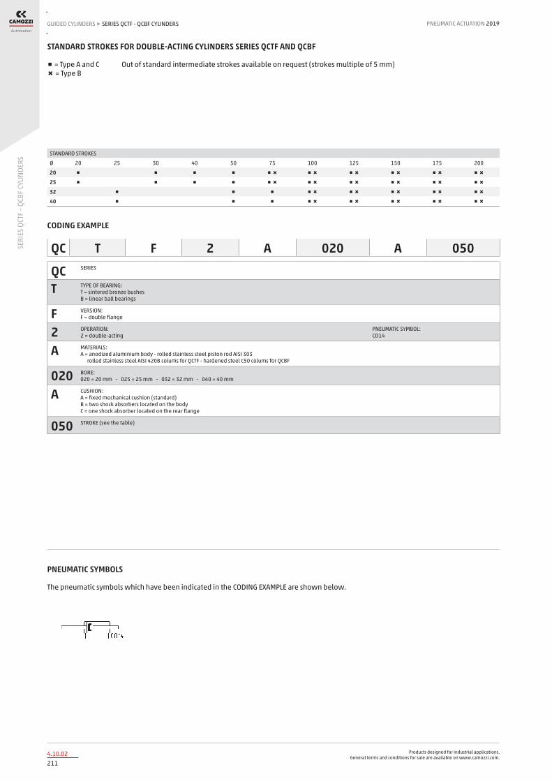
Products designed for industrial applications. General terms and conditions for sale are available on www.camozzi.com.
SERIES QCTF - QCBF CYLINDERSGUIDED CYLINDERS > PNEUMATIC ACTUATION 2019
2114.10.02
SERI
ES Q
CTF
- QCB
F CY
LIND
ERS
STANDARD STROKES FOR DOUBLE-ACTING CYLINDERS SERIES QCTF AND QCBF
■ = Type A and C Out of standard intermediate strokes available on request (strokes multiple of 5 mm) ✖ = Type B
STANDARD STROKES
Ø 20 25 30 40 50 75 100 125 150 175 200
20 ■ ■ ■ ■ ■ ✖ ■ ✖ ■ ✖ ■ ✖ ■ ✖ ■ ✖
25 ■ ■ ■ ■ ■ ✖ ■ ✖ ■ ✖ ■ ✖ ■ ✖ ■ ✖
32 ■ ■ ■ ■ ✖ ■ ✖ ■ ✖ ■ ✖ ■ ✖
40 ■ ■ ■ ■ ✖ ■ ✖ ■ ✖ ■ ✖ ■ ✖
CODING EXAMPLE
QC SERIES
T TYPE OF BEARING: T = sintered bronze bushes B = linear ball bearings
F VERSION: F = double flange
2 OPERATION: 2 = double-acting
PNEUMATIC SYMBOL: CD14
A MATERIALS: A = anodized aluminium body - rolled stainless steel piston rod AISI 303 rolled stainless steel AISI 420B colums for QCTF - hardened steel C50 colums for QCBF
020 BORE: 020 = 20 mm - 025 = 25 mm - 032 = 32 mm - 040 = 40 mm
A CUSHION: A = fixed mechanical cushion (standard) B = two shock absorbers located on the body C = one shock absorber located on the rear flange
050 STROKE (see the table)
QC T F 2 A 020 A 050
PNEUMATIC SYMBOLS
The pneumatic symbols which have been indicated in the CODING EXAMPLE are shown below.
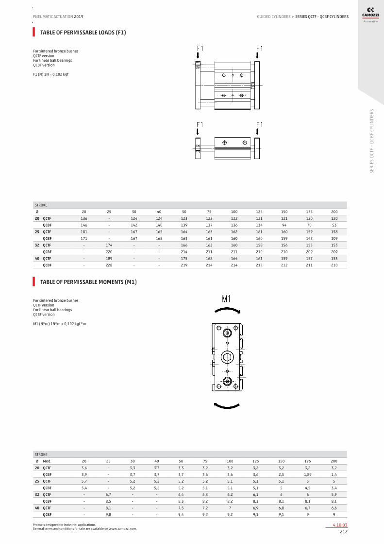
Products designed for industrial applications. General terms and conditions for sale are available on www.camozzi.com.
SERIES QCTF - QCBF CYLINDERSPNEUMATIC ACTUATION
2124.10.03
2019 GUIDED CYLINDERS
SERI
ES Q
CTF
- QCB
F CY
LIND
ERS
>
For sintered bronze bushes QCTF version For linear ball bearings QCBF version F1 (N) 1N = 0.102 kgf
STROKE
Ø 20 25 30 40 50 75 100 125 150 175 200
20 QCTF 136 - 124 124 123 122 122 121 121 120 120
QCBF 146 - 142 140 139 137 136 134 94 70 53
25 QCTF 181 - 167 165 164 163 162 161 160 159 158
QCBF 171 - 167 165 163 161 160 160 159 142 109
32 QCTF - 174 - - 166 162 160 158 156 155 153
QCBF - 220 - - 214 211 211 210 210 209 209
40 QCTF - 189 - - 175 168 164 161 159 157 155
QCBF - 228 - - 219 214 214 212 212 211 210
TABLE OF PERMISSABLE LOADS (F1)
For sintered bronze bushes QCTF version For linear ball bearings QCBF version M1 (N*m) 1N*m = 0,102 kgf *m
STROKE
Ø Mod. 20 25 30 40 50 75 100 125 150 175 200
20 QCTF 3,6 - 3,3 3’3 3,3 3,2 3,2 3,2 3,2 3,2 3,2
QCBF 3,9 - 3,7 3,7 3,7 3,6 3,6 3,6 2,5 1,89 1,4
25 QCTF 5,7 - 5,2 5,2 5,2 5,2 5,1 5,1 5,1 5 5
QCBF 5,4 - 5,2 5,2 5,2 5,1 5,1 5,1 5 4,5 3,4
32 QCTF - 6,7 - - 6,4 6,3 6,2 6,1 6 6 5,9
QCBF - 8,5 - - 8,3 8,2 8,2 8,1 8,1 8,1 8,1
40 QCTF - 8,1 - - 7,5 7,2 7 6,9 6,8 6,7 6,6
QCBF - 9,8 - - 9,4 9,2 9,2 9,1 9,1 9 9
TABLE OF PERMISSABLE MOMENTS (M1)
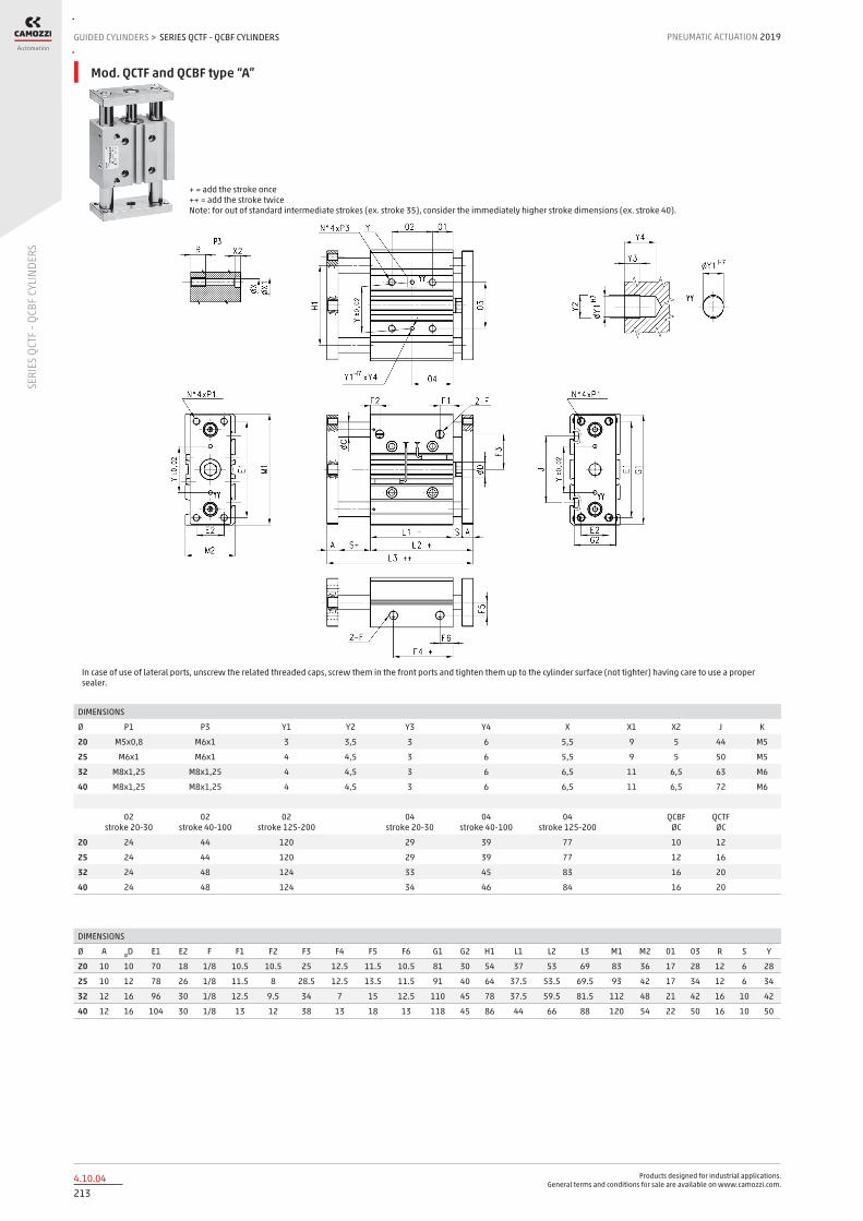
Products designed for industrial applications. General terms and conditions for sale are available on www.camozzi.com.
SERIES QCTF - QCBF CYLINDERSGUIDED CYLINDERS > PNEUMATIC ACTUATION 2019
2134.10.04
SERI
ES Q
CTF
- QCB
F CY
LIND
ERS
DIMENSIONS
Ø A ØD E1 E2 F F1 F2 F3 F4 F5 F6 G1 G2 H1 L1 L2 L3 M1 M2 01 03 R S Y
20 10 10 70 18 1/8 10.5 10.5 25 12.5 11.5 10.5 81 30 54 37 53 69 83 36 17 28 12 6 28
25 10 12 78 26 1/8 11.5 8 28.5 12.5 13.5 11.5 91 40 64 37.5 53.5 69.5 93 42 17 34 12 6 34
32 12 16 96 30 1/8 12.5 9.5 34 7 15 12.5 110 45 78 37.5 59.5 81.5 112 48 21 42 16 10 42
40 12 16 104 30 1/8 13 12 38 13 18 13 118 45 86 44 66 88 120 54 22 50 16 10 50
+ = add the stroke once ++ = add the stroke twice Note: for out of standard intermediate strokes (ex. stroke 35), consider the immediately higher stroke dimensions (ex. stroke 40).
In case of use of lateral ports, unscrew the related threaded caps, screw them in the front ports and tighten them up to the cylinder surface (not tighter) having care to use a proper sealer.
DIMENSIONS
Ø P1 P3 Y1 Y2 Y3 Y4 X X1 X2 J K
20 M5x0,8 M6x1 3 3,5 3 6 5,5 9 5 44 M5
25 M6x1 M6x1 4 4,5 3 6 5,5 9 5 50 M5
32 M8x1,25 M8x1,25 4 4,5 3 6 6,5 11 6,5 63 M6
40 M8x1,25 M8x1,25 4 4,5 3 6 6,5 11 6,5 72 M6
02 stroke 20-30
02 stroke 40-100
02 stroke 125-200
04 stroke 20-30
04 stroke 40-100
04 stroke 125-200
QCBF ØC
QCTF ØC
20 24 44 120 29 39 77 10 12
25 24 44 120 29 39 77 12 16
32 24 48 124 33 45 83 16 20
40 24 48 124 34 46 84 16 20
Mod. QCTF and QCBF type “A”

Products designed for industrial applications. General terms and conditions for sale are available on www.camozzi.com.
SERIES QCTF - QCBF CYLINDERSPNEUMATIC ACTUATION
2144.10.05
2019 GUIDED CYLINDERS
SERI
ES Q
CTF
- QCB
F CY
LIND
ERS
>
DIMENSIONS
Ø A ØD E1 E2 F F1 F2 F3 F4+ F5 F6 G1 G2 G3 H1 L1+ L2+ L3++ M1 M2 01 03 R S
20 10 10 70 18 1/8 10,5 10,5 25 12,5 11,5 10,5 97 30 56,5 54 37 53 69 83 36 17 28 12 6
25 10 12 78 26 1/8 11,5 8 28,5 12,5 13,5 11,5 107 40 61,5 64 37,5 53,5 69 93 42 17 34 12 6
32 12 16 96 30 1/8 12,5 9,5 34 7 15 12,5 134 45 79 78 37,5 59,5 81,5 112 48 21 42 16 10
40 12 16 104 30 1/8 13 12 38 13 18 13 141 45 82 86 44 66 88 120 54 22 50 16 10
+ = add the stroke once ++ = add the stroke twice Note: for out of standard intermediate strokes (ex. stroke 35), consider the immediately higher stroke dimensions (ex. stroke 40).
In case of use of lateral ports, unscrew the related threaded caps, screw them in the front ports and tighten them up to the cylinder surface (not tighter) having care to use a proper sealer.
DIMENSIONS
Ø P1 P3 T U Y Y1 Y2 Y3 Y4 X X1 X2 J K Shock absorber
Δ stroke (mm)
adjustment range cyl. stroke mm
20 M5x0,8 M6x1 57,5 32 28 3 3,5 3 6 5,5 9 5 44 M5 SA-1007 0 ÷ 15 0 ÷ +12
25 M6x1 M6x1 62,5 38 34 4 4,5 3 6 5,5 9 5 50 M5 SA-1007 0 ÷ 15 0 ÷ +8
32 M8x1,25 M8x1,25 81 44 42 4 4,5 3 6 6,5 11 6,5 63 M6 SA-1412 0 ÷ 20 0 ÷ +10
40 M8x1,25 M8x1,25 85 44 50 4 4,5 3 6 6,5 11 6,5 72 M6 SA-1412 0 ÷ 20 0 ÷ +11
02 stroke 75
02 stroke 100
02 stroke 125-200
04 stroke 20-30
04 stroke 40-100
04 stroke 125-200
QCBF ØC
QCTF ØC
20 44 44 120 29 39 77 10 12
25 44 44 120 29 39 77 12 16
32 - 48 124 33 45 83 16 20
40 - 48 124 34 46 84 16 20
Mod. QCTF and QCBF type “B”

Products designed for industrial applications. General terms and conditions for sale are available on www.camozzi.com.
SERIES QCTF - QCBF CYLINDERSGUIDED CYLINDERS > PNEUMATIC ACTUATION 2019
2154.10.06
SERI
ES Q
CTF
- QCB
F CY
LIND
ERS
DIMENSIONS
Ø A ØD E1 E2 F F1 F2 F3 F4+ F5 F6 G1 G2 H1 L1+ L2+ L3++ M1 M2 01 03 R S
20 10 10 70 18 1/8 10,5 10,5 25 12,5 11,5 10,5 81 30 54 37 53 69 83 36 17 28 12 6
25 10 12 78 26 1/8 11,5 8 28,5 12,5 13,5 11,5 91 40 64 37,5 53,5 69,5 93 42 17 34 12 6
32 12 16 96 30 1/8 12,5 9,5 34 7 15 12,5 110 45 78 37,5 59,5 81,5 112 48 21 42 16 10
40 12 16 104 30 1/8 13 12 38 13 18 13 118 45 86 44 66 88 120 54 22 50 16 10
+ = add the stroke once ++ = add the stroke twice Note: for out of standard intermediate strokes (ex. stroke 35), consider the immediately higher stroke dimensions (ex. stroke 40).
In case of use of lateral ports, unscrew the related threaded caps, screw them in the front ports and tighten them up to the cylinder surface (not tighter) having care to use a proper sealer.
DIMENSIONS
Ø P1 P3 TMax Y Y1 Y2 Y3 Y4 X X1 X2 J K Shock absorber
Δ stroke (mm)
adjustment range cyl. stroke (mm)
20 M5x0,8 M6x1 37 28 3 3,5 3 6 5,5 9 5 44 M5 SA-1007 W 0 ÷ 25 -15 ÷ -25
25 M6x1 M6x1 37 34 4 4,5 3 6 5,5 9 5 50 M5 SA-1007 W 0 ÷ 25 -15 ÷ -25
32 M8x1,25 M8x1,25 55 42 4 4,5 3 6 6,5 11 6,5 63 M6 SA-1412 W 0 ÷ 35 -18 ÷ -35
40 M8x1,25 M8x1,25 55 50 4 4,5 3 6 6,5 11 6,5 72 M6 SA-1412 W 0 ÷ 35 -18 ÷ -35
02 stroke 20-30
02 stroke 40-100
02 stroke 125-200
04 stroke 20-30
04 stroke 40-100
04 stroke 125-200
QCBF ØC
QCTF ØC
20 24 44 120 29 39 77 10 12
25 24 44 120 29 39 77 12 16
32 24 48 124 33 45 83 16 20
40 24 48 124 34 46 84 16 20
Mod. QCTF and QCBF type “C”

Products designed for industrial applications. General terms and conditions for sale are available on www.camozzi.com.
SERIES QX TWIN ROD CYLINDERSPNEUMATIC ACTUATION
2164.15.01
2019 GUIDED CYLINDERS
SERI
ES Q
X TW
IN R
OD C
YLIN
DERS
>
Series QX twin cylinders
Double-acting, magnetic, guided ø 10x2, 16x2, 20x2, 25x2, 32x2 mm
Series QX actuators offer a wide range of solutions covering a great number of applications which require a guided linear movement. The design of the double piston, besides assuring a solid and effective guide, offers double force in compact dimensions. Where a high force with precise movement is required, along with a non-rotation function and integrated guide, the QX cylinders are the ideal solution.
The range includes two guide versions with sintered bronze bushes or with linear ball bearings.
» High force
» Precise movement
» Integrated guide
» QXB: linear ball bearings
» QXT: sintered bronze bushes
GENERAL DATAType of construction compact, non magnetic
QXT = sintered bronze bushes - QXB = linear ball bearingsOperation double-actingMaterials body and flange = anodized AL
QXT piston rod = stainless steel AISI 303 - QXB piston rod = hardened steel C50 seals = PU
Mounting method by means of threaded holesStrokes from 10 to 100Operating temperature 0° ÷ 80°C (with dry air - 20°C)Operating speed 50 ÷ 500 mm/sOperating pressure 1 ÷ 10 barFluid clean air, without lubrication. If lubricated air is used, it is recommended to use oil ISOVG32.
Once applied the lubrication should never be interrupted.

Products designed for industrial applications. General terms and conditions for sale are available on www.camozzi.com.
SERIES QX TWIN ROD CYLINDERSGUIDED CYLINDERS > PNEUMATIC ACTUATION 2019
1894.15.02
SERI
ES Q
X TW
IN R
OD C
YLIN
DERS
STANDARD STROKES FOR TWIN CYLINDERS SERIES QX
■ = Double-acting
STANDARD STROKES
Ø 10 20 30 40 50 75 100
10 ■ ■ ■ ■ ■ ■
16 ■ ■ ■ ■ ■ ■ ■
20 ■ ■ ■ ■ ■ ■ ■
25 ■ ■ ■ ■ ■ ■ ■
32 ■ ■ ■ ■ ■ ■ ■
CODING EXAMPLE
QX SERIES
T VERSION T = sintered bronze bushes B = linear ball bearings
2 OPERATION 2 = double-acting (1 flange) radial / axial pressure supply 3 = double-acting through-rod (double-flange), radial pressure supply
PNEUMATIC SYMBOLS CD15 CD16
A MATERIALS A = anodized aluminium body, rolled stainless steel AISI 303 (QXT) or hardened steel C50 (QXB) piston rod
020 BORE 010 = 10 mm - 016 = 16 mm - 020 = 20 mm - 025 = 25 mm - 032 = 32 mm
A TYPE OF DESIGN A = standard
050 STROKE (see the table)
QX T 2 A 020 A 050
PNEUMATIC SYMBOLS
The pneumatic symbols which have been indicated in the CODING EXAMPLE are shown below.

Products designed for industrial applications. General terms and conditions for sale are available on www.camozzi.com.
SERIES QX TWIN ROD CYLINDERSPNEUMATIC ACTUATION
2184.15.03
2019 GUIDED CYLINDERS
SERI
ES Q
X TW
IN R
OD C
YLIN
DERS
>
For diameters from 16 to 32 To mount the sensors of QX cylinders ø 10 in the middle grooves, it is advisable to use M3 screws UNI 9327 and nuts M3 UNI 5589.
Fixing examples with flange in motion
The front and rear regulation screw allows the adjustment of the stroke up to –10mm.
Fixing examples with cylinder body in motion

Products designed for industrial applications. General terms and conditions for sale are available on www.camozzi.com.
SERIES QX TWIN ROD CYLINDERSGUIDED CYLINDERS > PNEUMATIC ACTUATION 2019
2194.15.04
SERI
ES Q
X TW
IN R
OD C
YLIN
DERS
X = cylinder stroke mm. F = load applied on the flange in N.
Load “ F “ should be considered fixed on the flange of the cylinder and with a theorical projection of L = 0 mm.
DIAGRAM OF MAX APPLICABLE LOADS DEPENDING ON THE STROKE ( X )
X = cylinder stroke mm. F = load applied on the flange in N.
Load “ F “ should be considered fixed on the flange of the cylinder and with a theorical projection of L = 0 mm.
DIAGRAM OF MAX APPLICABLE LOADS DEPENDING ON THE STROKE ( X )

Products designed for industrial applications. General terms and conditions for sale are available on www.camozzi.com.
SERIES QX TWIN ROD CYLINDERSPNEUMATIC ACTUATION
2204.15.05
2019 GUIDED CYLINDERS
SERI
ES Q
X TW
IN R
OD C
YLIN
DERS
>
X = cylinder stroke in mm. M = torque moment applied on the flange in Nm.
DIAGRAM OF MAX TORQUE MOMENT DEPENDING ON THE STROKE (X)
X = cylinder stroke in mm. M = torque moment applied on the flange in Nm.
DIAGRAM OF MAX TORQUE MOMENT DEPENDING ON THE STROKE (X)

Products designed for industrial applications. General terms and conditions for sale are available on www.camozzi.com.
SERIES QX TWIN ROD CYLINDERSGUIDED CYLINDERS > PNEUMATIC ACTUATION 2019
2214.15.06
SERI
ES Q
X TW
IN R
OD C
YLIN
DERS
Cylinders Series QX ( single flange )
NOTE: for out of standard intermediate strokes (ex. stroke 37), you have to consider the dimensions referring to the immediately higher stroke (ex. stroke 40) with a maximum permitted reduction of 10 mm.
+ = add the stroke

Products designed for industrial applications. General terms and conditions for sale are available on www.camozzi.com.
SERIES QX TWIN ROD CYLINDERSPNEUMATIC ACTUATION
2224.15.07
2019 GUIDED CYLINDERS
SERI
ES Q
X TW
IN R
OD C
YLIN
DERS
>
DIMENSIONS
Stroke (mm) Ø 10 Ø 16 Ø 20 Ø 25 Ø 32
A 42 58 62 76 94
B 16 21 25 30 37
C 40 56 60 71 92
E 13 19 22 27 35
F 33 42 50 60 75
G 4 5 6 6 8
I 3,5 2,5 4,5 4,5 4
M 8 10 12 12 16
Q 9 11 16 16 16
R 13 13 18 18 18
L1+ 48 57,5 67,5 70,5 80,5
L2+ 59,5 70 84 87 100,5
L3 32,1 34 39,5 44,0 46,5
L4 8,5 8,5 9 8,5 12
L5 16 20 25 30 30
L6 10 18 25 30 30 40
L6 20 28 25 30 30 40
L6 30 38 35 40 40 50
L6 40 48 35 40 40 50
L6 50 58 35 40 40 50
L6 75 83 45 60 60 70
L6 100 - 55 60 60 70
L7 13 13 20 20 20
L8 16 30 30 30 30
L9 10 22 25 30 30 40
L9 20 32 25 30 30 40
L9 30 42 35 40 40 50
L9 40 52 35 40 40 50
L9 50 62 35 40 40 50
L9 75 87 45 60 60 70
L9 100 - 55 60 60 70
L10 20,5 29 31 38 47
L11 31 52 57,2 71,5 47
H2 3,5 4,5 5,5 6,5 6,5
H3 2,5 4,0 4,0 4,0 4,0
H4 4,0 5,0 4,5 5,0 7,5
H5 6,5 6,0 6,0 6,0 7,5
H6 8,0 6,0 8,0 8,0 8,0
H7 3,0 3,0 4,0 4,0 4,0
H8 6,3 - - - -
H10 6,5 10,5 10,5 15 8,5
H11 8 16,5 20,2 21,5 28,5
H12 4 10,5 8,00 8,5 8,5
H13 8 - 9,0 13,0 20,0
H14 8 5,5 12,5 15,0 18,5
D1 M4 M5 M6 M8 M8
D2 6 7,5 9,5 10,5 10,5
D3 2,5 2,5 4 4 4
D4 M3 M3 M4 M5 M5
D5 M3 M4 M4 M5 M5
D6 M3 M3 M4 M4 M4
D7 2,5 2,5 4,0 4,0 4,0
D8 6,0 - - - -
D9 3,5 - - - -
D10 M4 M5 M5 M6 M6
NN 6 8 10 12 16
EE M5 M5 M5 M5 G1/8
J 4,3 - - - -
K 7 7 8 8 10
P 20 25 29 35 45
+ = add the stroke
Dimensions for Series QX with single flange

Products designed for industrial applications. General terms and conditions for sale are available on www.camozzi.com.
SERIES QX TWIN ROD CYLINDERSGUIDED CYLINDERS > PNEUMATIC ACTUATION 2019
2234.15.08
SERI
ES Q
X TW
IN R
OD C
YLIN
DERS
Cylinders Series QX (double flange)
NOTE: for out of standard intermediate strokes (ex. stroke 37), you have to consider the dimensions referring to the immediately higher stroke (ex. stroke 40) with a maximum permitted reduction of 10 mm.
+ = add the stroke

Products designed for industrial applications. General terms and conditions for sale are available on www.camozzi.com.
SERIES QX TWIN ROD CYLINDERSPNEUMATIC ACTUATION
2244.15.09
2019 GUIDED CYLINDERS
SERI
ES Q
X TW
IN R
OD C
YLIN
DERS
>
DIMENSIONS
Stroke (mm) Ø 10 Ø 16 Ø 20 Ø 25 Ø 32
A 42 58 62 76 94
B 16 21 25 30 37
C 40 56 60 71 92
E 13 19 22 27 35
F 33 42 50 60 45
G 4 5 6 6 6
I 3,5 2,5 4,5 4,5 4
M 8 10 12 12 16
Q 9 11 16 16 16
R 13 13 18 18 18
L1+ 72 86,6 98 104,2 115,6
L2++ 95 111,6 131 137,2 155,6
L3 32,1 34 39,5 44 46,5
L5 16 20 25 30 30
L6 10 25 28,3 29,0 27,1 32,8
L6 20 30 33,3 34,0 32,1 37,8
L6 30 35 38,3 39,0 37,1 42,8
L6 40 40 43,3 44,0 42,1 47,8
L6 50 45 48,3 49,0 47,1 52,8
L6 75 57,3 60,8 61,5 59,6 65,3
L6 100 - 73,3 74,0 72,1 77,8
L7 13 13 20 20 20
L8 16 30 30 30 30
L9 10 49,6 36,6 48 54,2 65,6
L9 20 59,6 46,6 58 64,2 75,6
L9 30 69,6 56,6 68 74,2 85,6
L9 40 79,6 66,6 78 84,2 95,6
L9 50 89,6 76,6 88 94,2 105,6
L9 75 114,6 101,6 113 119,2 130,6
L9 100 - 126,6 138 144,2 155,6
L10 10 49,6 56,6 58,0 54,2 65,6
L10 20 59,6 66,6 68,0 64,2 75,6
L10 30 69,6 76,6 78,0 74,2 85,6
L10 40 79,6 86,6 88,0 84,2 95,6
L10 50 89,6 96,6 98,0 94,2 105,6
L10 75 114,6 121,6 123,0 119,2 130,6
L10 100 - 146,6 148,0 144,2 155,6
H2 6,3 4,5 5,50 6,5 6,5
H3 2,5 4,0 4,00 4 4
H4 4 5,0 4,50 5 7,5
H5 6,5 6,0 6,00 6 7,5
H6 8 6,0 8,00 8 8
H7 3 3,0 4,00 4 4
H8 6,3 - - - -
D1 M4 M5 M6 M8 M8
D2 6 7,5 9,5 10,5 10,5
D3 2,5 2,5 4 4 4
D4 M3 M3 M4 M5 M5
D5 M3 M4 M4 M5 M5
D6 M3 M3 M4 M4 M4
D7 2,5 2,5 4 4 4
D8 6 - - - -
D9 3,5 - - - -
D10 M4 M5 M5 M6 M6
NN 6 8 10 12 16
EE M5 M5 M5 M5 G1/8
K 7 7 8 8 10
P 20 25 29 35 40
+ = add the stroke ++ = add the stroke 2 times
Dimensions for Series QX with double flange

Products designed for industrial applications. General terms and conditions for sale are available on www.camozzi.com.
SERIES 14 COMPACT MINI-CYLINDERSNON STANDARD CYLINDERS > PNEUMATIC ACTUATION 2019
2255.05.01
SERI
ES 1
4 CO
MPA
CT M
INI-C
YLIN
DERS
Series 14 compact mini-cylinders
Single-acting Bores ø 6, 10, 16 mm and strokes 5, 10, 15 mm With super-rapid fitting ø 4 and M5 port
Series 14 single-acting compact mini-cylinders have been designed for installation in very small spaces. The design allows the cylinders to be inserted into threaded blocks incorporated in the machine.
All the minicylinders are supplied with a super-rapid fitting incorporated in a tube ø 4 or with a M5 thread. They are available in two versions with either a threaded or a non threaded piston rod.
» Compact design
» With threaded or non threaded piston rod
» Threaded body
GENERAL DATAType of construction compact, non magneticOperation single-actingMaterials body = brass
seals = NBR other = stainless steel
Operating pressure P. min 2,5 bar - P. max 8 barOperating temperature 0°C ÷ 80°C (with dry air - 20°C)Fluid clean air, without lubrication. If lubricated air is used, it is recommended to use oil ISOVG32. Once applied the lubrication should never
be interrupted.Bore ø 6, 10, 16Stroke see tableMounting method by means of threaded body

Products designed for industrial applications. General terms and conditions for sale are available on www.camozzi.com.
SERIES 14 COMPACT MINI-CYLINDERSPNEUMATIC ACTUATION
2265.05.02
2019 NON STANDARD CYLINDERS
SERI
ES 1
4 CO
MPA
CT M
INI-C
YLIN
DERS
>
CODING EXAMPLE
14 SERIES
N VERSION N = non-magnetic
1 OPERATION 1 = single-acting
PNEUMATIC SYMBOL CS01
A TYPE OF CONNECTION A = tube Ø 4 M = thread M5
06 BORE 06 = 6 mm - 10 = 10 mm - 16 = 16 mm
A TYPE OF DESIGN A = non-threaded smooth piston rod B = threaded piston rod
05 STROKE 05 = 5 mm - 10 = 10 mm - 15 = 15 mm
14 N 1 A 06 A 05
PNEUMATIC SYMBOLS
The pneumatic symbols which have been indicated in the CODING EXAMPLE are shown below.

Products designed for industrial applications. General terms and conditions for sale are available on www.camozzi.com.
SERIES 14 COMPACT MINI-CYLINDERSNON STANDARD CYLINDERS > PNEUMATIC ACTUATION 2019
2275.05.03
SERI
ES 1
4 CO
MPA
CT M
INI-C
YLIN
DERS
Compact minicylinders with non threaded piston rod Mod. 14N1A
Super-rapid fitting incorporated
DIMENSIONS
Mod. Ø STROKE A B C D E F SW1 SW2 I
14N1A06A05 6 5 M10x1 3 4\2 34 29 5 9 12 3
14N1A06A10 6 10 M10x1 3 4\2 42 37 5 9 12 3
14N1A06A15 6 15 M10x1 3 4\2 47 42 5 9 12 3
14N1A10A05 10 5 M15x1,5 5 4\2 50 38 12 13 19 4
14N1A10A10 10 10 M15x1,5 5 4\2 57 45 12 13 19 4
14N1A10A15 10 15 M15x1,5 5 4\2 62 50 12 13 19 4
14N1A16A05 16 5 M22x1,5 6 4\2 53,5 39,5 14 20 27 5
14N1A16A10 16 10 M22x1,5 6 4\2 62 48 14 20 27 5
14N1A16A15 16 15 M22x1,5 6 4\2 67 53 14 20 27 5
Compact minicylinders with threaded piston rod Mod. 14N1A
Super-rapid fitting incorporated
DIMENSIONS
Mod. Ø STROKE A B C D E F SW1 SW2 I L M
14N1A06B05 6 5 M10x1 3 4\2 38 29 9 9 12 3 M3x0,5 7
14N1A06B10 6 10 M10x1 3 4\2 46 37 9 9 12 3 M3x0,5 7
14N1A06B15 6 15 M10x1 3 4\2 51 42 9 9 12 3 M3x0,5 7
14N1A10B05 10 5 M15x1,5 5 4\2 50 38 12 13 19 4 M4x0,7 10
14N1A10B10 10 10 M15x1,5 5 4\2 57 45 12 13 19 4 M4x0,7 10
14N1A10B15 10 15 M15x1,5 5 4\2 62 50 12 13 19 4 M4x0,7 10
14N1A16B05 16 5 M22x1,5 6 4\2 53,5 39,5 14 20 27 5 M5x0,8 12
14N1A16B10 16 10 M22x1,5 6 4\2 62 48 14 20 27 5 M5x0,8 12
14N1A16B15 16 15 M22x1,5 6 4\2 67 53 14 20 27 5 M5x0,8 12

Products designed for industrial applications. General terms and conditions for sale are available on www.camozzi.com.
SERIES 14 COMPACT MINI-CYLINDERSPNEUMATIC ACTUATION
2285.05.04
2019 NON STANDARD CYLINDERS
SERI
ES 1
4 CO
MPA
CT M
INI-C
YLIN
DERS
>
Compact minicylinders with non threaded piston rod Mod. 14N1M
Threaded port
DIMENSIONS
Mod. Ø STROKE A B C D E F SW1 SW2 I N O
14N1M06A05 6 5 M10x1 3 M5 28 23 5 9 12 3 5 6
14N1M06A10 6 10 M10x1 3 M5 36 31 5 9 12 3 5 6
14N1M06A15 6 15 M10x1 3 M5 41 36 5 9 12 3 5 6
14N1M10A05 10 5 M15x1,5 5 M5 43 31 12 13 19 4 5 6
14N1M10A10 10 10 M15x1,5 5 M5 50 38 12 13 19 4 5 6
14N1M10A15 10 15 M15x1,5 5 M5 55 43 12 13 19 4 5 6
14N1M16A05 16 5 M22x1,5 6 M5 46,5 32,5 14 20 27 5 5 6
14N1M16A10 16 10 M22x1,5 6 M5 55,5 41,5 14 20 27 5 5 6
14N1M16A15 16 15 M22x1,5 6 M5 60,5 46,5 14 20 27 5 5 6
Compact minicylinders with threaded piston rod Mod. 14N1M
Threaded port
DIMENSIONS
Mod. Ø STROKE A B C D E F SW1 SW2 I L M N O
14N1M06B05 6 5 M10x1 3 M5 32 23 9 9 12 3 M3x0,5 7 5 6
14N1M06B10 6 10 M10x1 3 M5 40 31 9 9 12 3 M3x0,5 7 5 6
14N1M06B15 6 15 M10x1 3 M5 45 36 9 9 12 3 M3x0,5 7 5 6
14N1M10B05 10 5 M15x1,5 5 M5 43 31 12 13 19 4 M4x0,7 10 5 6
14N1M10B10 10 10 M15x1,5 5 M5 50 38 12 13 19 4 M4x0,7 10 5 6
14N1M10B15 10 15 M15x1,5 5 M5 55 43 12 13 19 4 M4x0,7 10 5 6
14N1M16B05 16 5 M22x1,5 6 M5 46,5 32,5 14 20 27 5 M5x0,8 12 5 6
14N1M16B10 16 10 M22x1,5 6 M5 55,5 41,5 14 20 27 5 M5x0,8 12 5 6
14N1M16B15 16 15 M22x1,5 6 M5 60,5 46,5 14 20 27 5 M5x0,8 12 5 6

Products designed for industrial applications. General terms and conditions for sale are available on www.camozzi.com.
SERIES 27 ROUNDLINE CYLINDERSNON STANDARD CYLINDERS > PNEUMATIC ACTUATION 2019
2295.10.01
SERI
ES 2
7 RO
UNDL
INE
CYLI
NDER
S
Series 27 roundline cylinders
Double-acting, magnetic ø 20, 25, 32, 40, 50, 63 mm
Series 27 has been designed to reduce the cylinders sizes as much as possible. These cylinders have been constructed with clean lines using stainless steel for both the tube and the rod and Aluminium for the end-blocks.
The choice of material and other design features have allowed to create a range of versatile and reliable cylinders. The precise method of securing the tube to the end block ensures that all the parts are perfectly aligned. Mechanical cushioning has been fitted on these cylinders in order to reduce noise produced by the piston impact on the end-blocks. Cylinders Series 27 are suitable for assembling with magnetic sensors. Various mounting bracket accessories enable the cylinders to be fitted to suit the requirements of a particular application.
» Reduced dimensions
» Different mounting options
» Perfect alignment, perfect linearity
GENERAL DATAType of construction flangedOperation double actingMaterials rod: Ø20 - 25 stainless steel AISI 303 - Ø32 ÷ 63 stainless steel AISI 420B
tube: INOX AISI 304 piston and rod seals = PU
Mounting feet - trunnion - steel bar - pinsStrokes min-max all diameters 10 - 1000 mmBores ø 20, 25, 32, 40, 50, 63Operating temperature 0°C ÷ 80°C (with dry air - 20°C)Operating pressure 1 ÷ 10 barSpeed 10 ÷ 1000 mm/sec (no load)Fluid filtered air, without lubrication. If lubricated air is used, it is recommended to use oil ISOVG32. Once applied the lubrication should
never be interrupted.

Products designed for industrial applications. General terms and conditions for sale are available on www.camozzi.com.
SERIES 27 ROUNDLINE CYLINDERSPNEUMATIC ACTUATION
2305.10.02
2019 NON STANDARD CYLINDERS
SERI
ES 2
7 RO
UNDL
INE
CYLI
NDER
S
>
STANDARD STROKES FOR DOUBLE-ACTING CYLINDERS SERIES 27
Mod. 27M and 27T (ø 20 ÷ 40) and Mod. 27U (ø 20 ÷ 63)
STANDARD STROKES
Ø 10 25 40 50 80 100 125 160 200 250 300 320 400 500
20 ■ ■ ■ ■ ■ ■ ■ ■ ■ ■ ■ ■ ■ ■
25 ■ ■ ■ ■ ■ ■ ■ ■ ■ ■ ■ ■ ■ ■
32 ■ ■ ■ ■ ■ ■ ■ ■ ■ ■ ■ ■ ■ ■
40 ■ ■ ■ ■ ■ ■ ■ ■ ■ ■ ■ ■ ■ ■
50 ■ ■ ■ ■ ■ ■ ■ ■ ■ ■ ■ ■ ■ ■
63 ■ ■ ■ ■ ■ ■ ■ ■ ■ ■ ■ ■ ■ ■
CODING EXAMPLE
27 SERIES
M VERSION M = rear endblock with trunnion and upper round port for ø 20-25-32-40 T = rear endblock with rear round port for ø 20-25-32-40 U = rear endblock with upper round port for ø 20-25-32-40-50-63
2 OPERATION 2 = double-acting
PNEUMATIC SYMBOL CD08
A MATERIALS A = rolled stainless steel rod - stainless steel tube
20 BORE 20 = 20 mm - 25 = 25 mm - 32 = 32 mm - 40 = 40 mm - 50 = 50 mm - 63 = 63 mm
A TYPE OF DESIGN A = standard
0050 STROKE (see the table)
27 M 2 A 20 A 0050
PNEUMATIC SYMBOLS
The pneumatic symbols which have been indicated in the CODING EXAMPLE are shown below.

Products designed for industrial applications. General terms and conditions for sale are available on www.camozzi.com.
SERIES 27 ROUNDLINE CYLINDERSNON STANDARD CYLINDERS > PNEUMATIC ACTUATION 2019
2315.10.03
SERI
ES 2
7 RO
UNDL
INE
CYLI
NDER
S
ACCESSORIES FOR MAGNETIC CYLINDERS SERIES 27
Coupling piece Mod. GKF
Self aligning rod Mod. GK
Threaded trunnion pin Mod. T
Piston rod socket joint Mod. GY
Swivel ball joint Mod. GA
Foot mount Mod. B Foot mount Mod. B Nose nut Mod. V
All accessories are supplied separately.
Rear trunnion bracket Mod. I
Piston rod lock nut Mod. U
Rear trunnion bracket Mod. I
Rod fork end Mod. G

Products designed for industrial applications. General terms and conditions for sale are available on www.camozzi.com.
SERIES 27 ROUNDLINE CYLINDERSPNEUMATIC ACTUATION
2325.10.04
2019 NON STANDARD CYLINDERS
SERI
ES 2
7 RO
UNDL
INE
CYLI
NDER
S
>
Cylinders Series 27 (Ø 20, 25, 32, 40)
DIMENSIONS
Ø AM ØB BF BE ØCD(H9)ØD EE EW G G1 KK L L6 MM(h9) L5 PL SW VD WF XC+ XC1+ XC2+ SW1
20 14 16 12 M16x1,5 6 21,5 G1\8 12 15,5 8 M8x1,25 7 - 8 13 9 7 3 17 77 62,5 70,8 19
25 16 18 12 M18x1,5 8 26,5 G1\8 14 15,5 8 M10x1,25 9 - 10 17 9 9 3 16,5 78,5 62 69,5 24
32 22 22 15 M22x1,5 8 33,5 G1\8 16 17,5 5,5 M10x1,25 7 20 12 15 9 10 3 23 93 74 86 30
40 23 30 15 M30x1,5 10 41,5 G1\8 20 18 5,5 M12x1,25 5 24 16 15 10 13 3 24 96 78,5 91 38
+ = add the stroke
Cylinders Series 27 (Ø 50, 63)
DIMENSIONS
Ø AM ØB BG BG1 ØD EE FB G KK ØMM(h9) PL RT ØRT1 SW TC TF VD WF XC +
50 23 28 12 8 52,5 G1\4 M6 22 M12x1,25 16 13 M10x1 12 13 49 28,5 2 13 97
63 30 35 12 9,5 65,5 G1\4 M8 22 M16x1,5 20 13 M12x1,5 14 17 62 35,5 2 13 99
+ = add the stroke

Products designed for industrial applications. General terms and conditions for sale are available on www.camozzi.com.
SERIES 27 ROUNDLINE CYLINDERSNON STANDARD CYLINDERS > PNEUMATIC ACTUATION 2019
2335.10.05
SERI
ES 2
7 RO
UNDL
INE
CYLI
NDER
S
Foot mount Mod. B
Material: zinc-plated steel Supplied with: 1x foot 1x front end cap nut mod. V
DIMENSIONS
Mod. Ø ØAB AO AT AU NH SA+ TR US XA+ XS
B-27-20 20 5,5 6 3 13 20 79 32 42 83 27
B-27-25 25 6,6 8 3 12,5 22 78 38 49 82 26
B-27-32 32 6,6 8 4 16 25 95 40 54 102 35
B-27-40 40 7 7 4 16 28 99 52 66 107 36
+ = add the stroke
Foot mount Mod. B
Material: zinc-plated steel Supplied with: 2x feet 4x screws
DIMENSIONS
Mod. Ø ØAB AO AT AU NH SA+ TR US XA+ XS
B-27-50 50 9 10 4 17 40 118 36 52 114 26
B-27-63 63 9 10 5 19 47 124 45 61 118 27
+ = add the stroke
Threaded trunnion pin Mod. T
Material: stainless steel Supplied with: 2x pins
DIMENSIONS
Mod. Ø SWSW ØTDh9 TL UT XG XJ+
T-27-50 50 6 12 9,5 68 26 84
T-27-63 63 6 14 11 84 26 86
+ = add the stroke
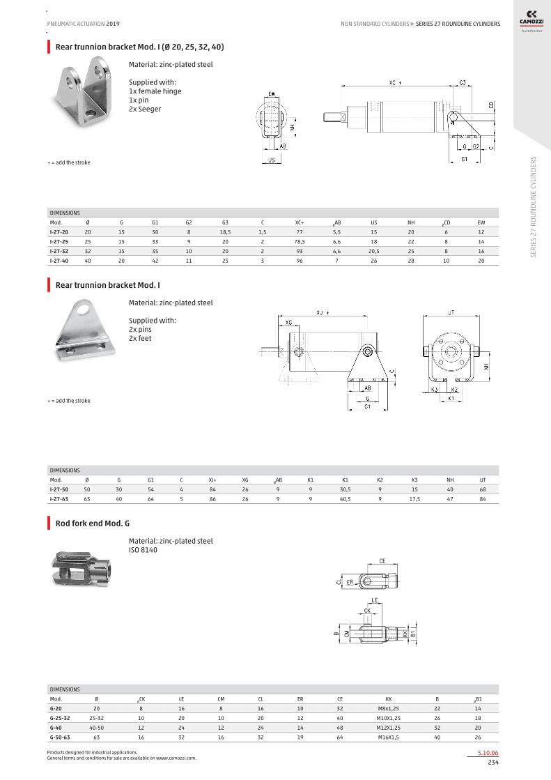
Products designed for industrial applications. General terms and conditions for sale are available on www.camozzi.com.
SERIES 27 ROUNDLINE CYLINDERSPNEUMATIC ACTUATION
2345.10.06
2019 NON STANDARD CYLINDERS
SERI
ES 2
7 RO
UNDL
INE
CYLI
NDER
S
>
Rear trunnion bracket Mod. I (Ø 20, 25, 32, 40)
Material: zinc-plated steel Supplied with: 1x female hinge 1x pin 2x Seeger
DIMENSIONS
Mod. Ø G G1 G2 G3 C XC+ ØAB US NH ØCD EW
I-27-20 20 15 30 8 18,5 1,5 77 5,5 15 20 6 12
I-27-25 25 15 33 9 20 2 78,5 6,6 18 22 8 14
I-27-32 32 15 35 10 20 2 93 6,6 20,5 25 8 16
I-27-40 40 20 42 11 25 3 96 7 26 28 10 20
+ = add the stroke
Rear trunnion bracket Mod. I
Material: zinc-plated steel Supplied with: 2x pins 2x feet
DIMENSIONS
Mod. Ø G G1 C XJ+ XG ØAB K1 K1 K2 K3 NH UT
I-27-50 50 30 54 4 84 26 9 9 30,5 9 15 40 68
I-27-63 63 40 64 5 86 26 9 9 40,5 9 17,5 47 84
+ = add the stroke
Rod fork end Mod. G
Material: zinc-plated steel ISO 8140
DIMENSIONS
Mod. Ø ØCK LE CM CL ER CE KK B ØB1
G-20 20 8 16 8 16 10 32 M8x1,25 22 14
G-25-32 25-32 10 20 10 20 12 40 M10X1,25 26 18
G-40 40-50 12 24 12 24 14 48 M12X1,25 32 20
G-50-63 63 16 32 16 32 19 64 M16X1,5 40 26

Products designed for industrial applications. General terms and conditions for sale are available on www.camozzi.com.
SERIES 27 ROUNDLINE CYLINDERSNON STANDARD CYLINDERS > PNEUMATIC ACTUATION 2019
2355.10.07
SERI
ES 2
7 RO
UNDL
INE
CYLI
NDER
S
Swivel ball joint Mod. GA
Material: zinc-plated steel ISO 8139
DIMENSIONS
Mod. Ø ØCN(H7) U EN ER AX CE KK ØT Z SW
GA-20 20 8 9 12 12 16 36 M8x1,25 12,5 6,5 14
GA-32 25-32 10 10,5 14 14 20 43 M10X1,25 15 6,5 17
GA-40 40-50 12 12 16 16 22 50 M12X1,25 17,5 6,5 19
GA-50-63 63 16 15 21 21 28 64 M16X1,5 22 7,5 22
Piston rod socket joint Mod. GY
Material: zama and zinc-plated steel
DIMENSIONS
Mod. Ø KK L CE L2 AX E ØB ØC T D L1 L3 SW1 SW Z
GY-20 20 M8X1,25 65 32 5 16 8 12 24 12,5 16 16 12 10 14 15
GY-32 25-32 M10X1,25 74 35 6,5 18 10 14 28 15 19 19,5 15 11 17 15
GY-40 40-50 M12X1,25 84 40 6,5 20 12 19 32 17,5 22 21 17 17 19 15
GY-50-63 63 M16X1,5 112 50 8 27 16 22 40 22 27 27,5 23 19 22 11
Piston rod lock nut Mod. U
Material: zinc-plated steel ISO 4035
DIMENSIONS
Mod. Ø D m SW
U-20 20 M8X1,25 5 13
U-25-32 20-32 M10X1,25 6 17
U-40 40-50 M12X1,25 7 19
U-50-63 63 M16X1,5 8 24
Nose nut Mod. V
ISO 4035 V-27-25 / V-42-32 not according standard. Material: zinc-plated steel
DIMENSIONS
Mod. Ø D m SW
V-12-16 20 M16X1,5 8 24
V-27-25 25 M18X1,5 5 24
V-20-25 32 M22X1,5 10 32
V-42-32 40 M30x1,5 8 -

Products designed for industrial applications. General terms and conditions for sale are available on www.camozzi.com.
SERIES 27 ROUNDLINE CYLINDERSPNEUMATIC ACTUATION
2365.10.08
2019 NON STANDARD CYLINDERS
SERI
ES 2
7 RO
UNDL
INE
CYLI
NDER
S
>
Self aligning rod Mod. GK
Material: zinc-plated steel
DIMENSIONS
Mod. Ø KK L L1 L3 L4 Ø A Ø D H I SW SW1 SW2 B1 AX Z E
GK-20 20 M8x1,25 57 26 21 5 8 12,5 19 17 11 7 13 4 16 4 2
GK-25-32 25-32 M10x1,25 71,5 35 20 7,5 14 22 32 30 19 12 17 5 22 4 2
GK-40 40 M12x1,25 75,5 35 24 7,5 14 22 32 30 19 12 19 6 22 4 2
GK-50-63 50-63 M16x1,5 104 53 32 10 22 32 45 41 27 20 24 8 30 3 2
Coupling piece Mod. GKF
Material: zinc-plated steel
DIMENSIONS
Mod. Ø KK A B R TF L L1 I Ø D Ø D1 Ø D2 SW E
GKF-20 20 M8x1,25 30 35 20 25 22,5 10 - 14 5,5 - 13 1,5
GKF-25-32 25-32 M10x1,25 37 60 23 36 22,5 15 6,8 18 11 6,6 15 2
GKF-40 40 M12x1,25 56 60 38 42 22,5 15 9 20 15 9 15 2,5
GKF-50-63 50-63 M16x1,5 80 80 58 58 26,5 15 10,5 25 18 11 22 2,5
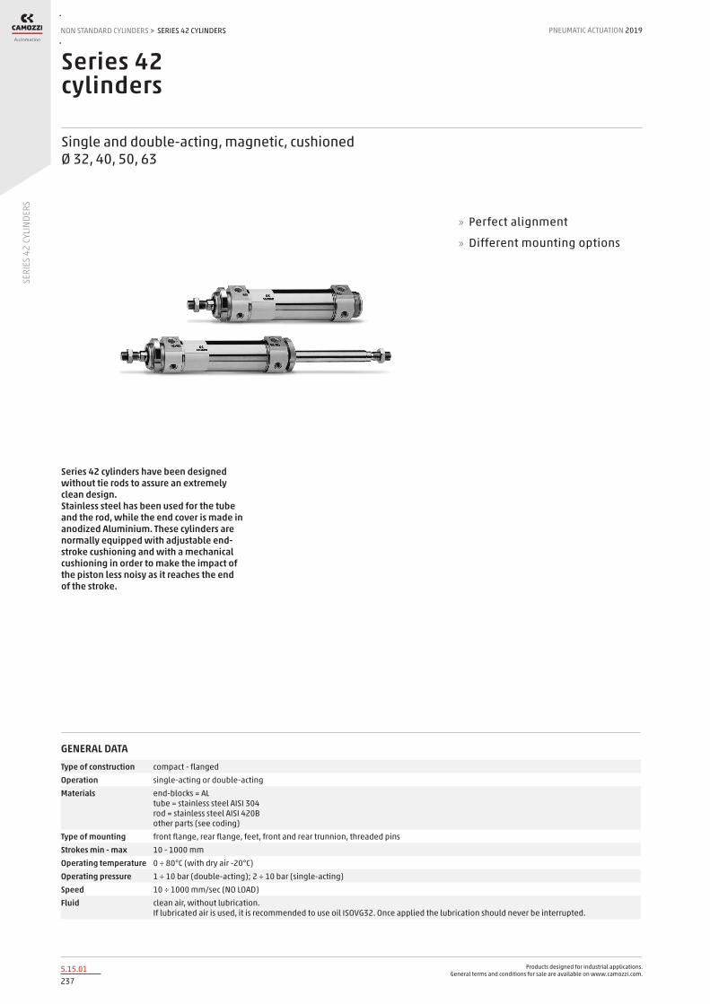
Products designed for industrial applications. General terms and conditions for sale are available on www.camozzi.com.
SERIES 42 CYLINDERSNON STANDARD CYLINDERS > PNEUMATIC ACTUATION 2019
2375.15.01
SERI
ES 4
2 CY
LIND
ERS
Series 42 cylinders
Single and double-acting, magnetic, cushioned Ø 32, 40, 50, 63
Series 42 cylinders have been designed without tie rods to assure an extremely clean design. Stainless steel has been used for the tube and the rod, while the end cover is made in anodized Aluminium. These cylinders are normally equipped with adjustable end-stroke cushioning and with a mechanical cushioning in order to make the impact of the piston less noisy as it reaches the end of the stroke.
» Perfect alignment
» Different mounting options
GENERAL DATAType of construction compact - flangedOperation single-acting or double-actingMaterials end-blocks = AL
tube = stainless steel AISI 304 rod = stainless steel AISI 420B other parts (see coding)
Type of mounting front flange, rear flange, feet, front and rear trunnion, threaded pinsStrokes min - max 10 - 1000 mmOperating temperature 0 ÷ 80°C (with dry air -20°C)Operating pressure 1 ÷ 10 bar (double-acting); 2 ÷ 10 bar (single-acting)Speed 10 ÷ 1000 mm/sec (NO LOAD)Fluid clean air, without lubrication.
If lubricated air is used, it is recommended to use oil ISOVG32. Once applied the lubrication should never be interrupted.

Products designed for industrial applications. General terms and conditions for sale are available on www.camozzi.com.
SERIES 42 CYLINDERSPNEUMATIC ACTUATION
2385.15.02
2019 NON STANDARD CYLINDERS
SERI
ES 4
2 CY
LIND
ERS
>
STANDARD STROKES FOR DOUBLE-ACTING CYLINDERS SERIES 42
✖ = Double acting ■ = Single acting
STANDARD STROKES
Ø 25 50 75 80 100 125 150 160 200 250 300 320 400 500
32 ✖ ■ ✖ ■ ✖ ■ ✖ ✖ ✖ ✖ ✖ ✖ ✖ ✖ ✖ ✖ ✖
40 ✖ ■ ✖ ■ ✖ ■ ✖ ✖ ✖ ✖ ✖ ✖ ✖ ✖ ✖ ✖ ✖
50 ✖ ■ ✖ ■ ✖ ■ ✖ ✖ ✖ ✖ ✖ ✖ ✖ ✖ ✖ ✖ ✖
63 ✖ ■ ✖ ■ ✖ ■ ✖ ✖ ✖ ✖ ✖ ✖ ✖ ✖ ✖ ✖ ✖
CODING EXAMPLE
42 SERIES
M VERSION M= standard magnetic
2 OPERATION 1 = single-acting, cushions (front spring) 2 = double-acting, front and rear cushions 3 = double-acting, no cushion 4 = double-acting, rear cushions 5 = double-acting, front cushion 6 = double-acting, through-rod, front and rear cushions 7 = single-acting, through-rod, cushions
PNEUMATIC SYMBOLS CS12 CD09 CD08 CD10 CD11 CD13 CS13
N MATERIALS N = stainless steel AISI 420B rod - stainless steel AISI 304 tube - NBR seals
050 BORE 032 = 32 mm 040 = 40 mm 050 = 50 mm 063 = 63 mm
A TYPE OF DESIGN A = standard with nose nut Mod. V and piston rod lock nut Mod. U
0200 STROKE (see the table)
42 M 2 N 050 A 0200
PNEUMATIC SYMBOLS
The pneumatic symbols which have been indicated in the CODING EXAMPLE are shown below.

Products designed for industrial applications. General terms and conditions for sale are available on www.camozzi.com.
SERIES 42 CYLINDERSNON STANDARD CYLINDERS > PNEUMATIC ACTUATION 2019
2395.15.03
SERI
ES 4
2 CY
LIND
ERS
ACCESSORIES FOR CYLINDERS SERIES 42
Nose nut Mod. V Coupling piece Mod. GKF
Self aligning rod Mod. GK
Piston rod socket joint Mod. GY
Rod fork end Mod. G
Foot mount Mod. P Trunnion Mod. I Swivel ball joint Mod. GA
All accessories are supplied separately, except for piston rod lock Mod. U and nose nut Mod. V.
Brack threaded pins Mod. T
Piston rod lock nut Mod. U

Products designed for industrial applications. General terms and conditions for sale are available on www.camozzi.com.
SERIES 42 CYLINDERSPNEUMATIC ACTUATION
2405.15.04
2019 NON STANDARD CYLINDERS
SERI
ES 4
2 CY
LIND
ERS
>
Cylinders Series 42
N.B. : sizes L, L1 and L2 in single-acting cylinders are increased by 25 mm.
DIMENSIONS
Ø A KK B B1 B2 B3 B4 C Dd11 D1 D2 D3 E F G SW1 SW2 AM WH L+ L1+ L2+ L3 L4 L5 L6 L7 *
32 12 M10x1.25 M30x1.5 8 41.5 28 36 G1\8 30 38 M8x1 42 23.5 10.5 5 10 17 22 26 156 120 94 48 18 15 11 14 17 / 12
40 16 M12x1.25 M38x1.5 10 50 30 43 G1\4 38 46 M10x1 50 29 15 5 13 19 24 30 175 135 105 54 22 19 13 16 20 / 17
50 20 M16x1.5 M45x1.5 10 58.5 32 54 G1\4 40 57 M12x1.5 60 28.5 14.5 4.5 17 24 32 37 193 143 106 69 25 22 15 18 15 / 14
63 20 M16x1.5 M45x1.5 10 70.5 46.5 66 G3\8 45 70 M14x1.5 60 35 15.5 7 17 24 32 37 208 158 121 69 25 22 15 18 17 / 16
+ = add the stroke * = front/rear cushion stroke
Cylinders Series 42 - through-rod
Note: sizes L, L1 and L2 in single-acting cylinders are increased by 25 mm.
DIMENSIONS
Ø A KK B B1 B2 B3 B4 C D D1 D2 D3 E F G SW1 AM SW2 WH+ L++ L1+ L2+ L3+ L4 L5 *
32 12 M10x1.25 M30x1.5 8 41.5 28 36 G1\8 30 38 M8x1 42 23.5 10.5 5 10 22 17 26 190 120 94 48 18 15 17 / 12
40 16 M12x1.25 M38x1.5 10 50 30 43 G1\4 38 46 M10x1 50 29 15 5 13 24 19 30 213 135 105 54 22 19 20 / 17
50 20 M16x1.5 M45x1.5 10 58.5 32 54 G1\4 45 57 M12x1.5 60 28.5 14.5 4.5 17 32 24 37 244 143 106 69 25 22 15 / 14
63 20 M16x1.5 M45x1.5 10 70.5 46.5 66 G3\8 45 70 M14x1.5 60 35 15.5 7 17 32 24 37 259 158 121 69 25 22 17 / 16
+ = add the stroke once ++ = add the stroke twice * = front/rear cushion stroke

Products designed for industrial applications. General terms and conditions for sale are available on www.camozzi.com.
SERIES 42 CYLINDERSNON STANDARD CYLINDERS > PNEUMATIC ACTUATION 2019
2415.15.05
SERI
ES 4
2 CY
LIND
ERS
Foot mount Mod. P
Material: zinc-plated steel.
DIMENSIONS
Mod. Ø L1 SA + XA + A AB AO AH C G G1 TR TR1 TR2 TR3 H
P-42-32 32 46 142 144 24 7 11 32 4 66 53 52 28 32 52 18
P-42-40 40 53 161 163 28 9 15 36 5 80 61 60 30 36 60 21
P-42-50 50 63 170 175 32 9 15 45 6 90 75 70 40 45 70 25
P-42-63 63 63 185 190 32 9 10 50 6 96 85 76 50 50 76 25
Supplied with: 1x nut 2x single feet + = add the stroke
Trunnion Mod. I
Material: zinc-plated steel.
DIMENSIONS
Mod. Ø L1 + L2 L3 + C C1 C2 C3 D1 D2 E1 F SW1 G G1 G2
I-42-32 32 109,5 36,5 105,5 40 24 46,1 20 7 10 4 35 13 38,1 50,1 58,1
I-42-40 40 120 45 117 50 30 56,1 28 9 12 5 40 17 46,1 60,1 70,1
I-42-50 50 128,5 51,5 124,5 54 34 69,1 36 9 14 6 45 19 57,1 74,1 86,1
I-42-63 63 143 52 142 65 35 82,1 42 9 16 6 50 19 70,1 88,1 100,1
+ = add the stroke

Products designed for industrial applications. General terms and conditions for sale are available on www.camozzi.com.
SERIES 42 CYLINDERSPNEUMATIC ACTUATION
2425.15.06
2019 NON STANDARD CYLINDERS
SERI
ES 4
2 CY
LIND
ERS
>
Bracket with threaded pins Mod. T
Material: stainless steel Supplied with: 2x pins
DIMENSIONS
Mod. Ø XV XV1+ TD TM SW1
T-42-32 32 36,5 109,5 10 51 5
T-42-40 40 45 120 12 61 6
T-42-50 50 51,5 128,5 14 75 6
T-42-63 63 52 143 16 90 8
+ = add the stroke
Nose nut Mod.V-42
Material: zinc-plated steel
DIMENSIONS
Mod. Ø D D1 D2 A B C E
V-42-32 32 M30X1,5 42 36 8 7 37 6,2
V-42-40 40 M38x1,5 50 48 10 9 44 7,2
V-42-50-63 50-63 M45x1,5 60 56 10 9 53 7,2
.
Rod fork end Mod. G
Material: stainless steel ISO 8140
DIMENSIONS
Mod. Ø ØCK LE CM CL ER CE KK B B1
G-25-32 32 10 20 10 20 12 40 M10X1,25 26 18
G-40 40 12 24 12 24 14 48 M12X1,25 32 20
G-50-63 50-63 16 32 16 32 19 64 M16X1,5 40 26

Products designed for industrial applications. General terms and conditions for sale are available on www.camozzi.com.
SERIES 42 CYLINDERSNON STANDARD CYLINDERS > PNEUMATIC ACTUATION 2019
2435.15.07
SERI
ES 4
2 CY
LIND
ERS
Piston rod lock Mod. U
DIMENSIONS
Mod. Ø D m SW
U-25-32 32 M10X1,25 6 17
U-40 40 M12X1,25 7 19
U-50-63 50-63 M16X1,5 8 24
Swivel ball joint Mod. GA
Material: zinc-plated steel ISO 8139
DIMENSIONS
Mod. Ø ØCN U EN ER AX CE KK T Z SW
GA-32 32 10 10,5 14 14 20 43 M10X1,25 15 6,5 17
GA-40 40 12 12 16 16 22 50 M12X1,25 17,5 6,5 19
GA-50-63 50-63 16 15 21 21 28 64 M16X1,5 22 7,5 22
Piston rod socket joint Mod. GY
Material: zama and zinc-plated steel
DIMENSIONS
Mod. Ø KK L CE L2 AX SW SW1 L1 L3 ØT ØD E ØB ØC Z
GY-32 32 M10x1,25 74 35 6,5 18 17 11 19,5 15 15 19 10 14 28 15
GY-40 40 M12x1,25 84 40 6,5 20 19 17 22 17 17,5 22 12 19 32 15
GY-50-63 50-63 M16x1,5 112 50 8 27 22 19 27,5 23 22 27 16 22 40 11

Products designed for industrial applications. General terms and conditions for sale are available on www.camozzi.com.
SERIES 42 CYLINDERSPNEUMATIC ACTUATION
2445.15.08
2019 NON STANDARD CYLINDERS
SERI
ES 4
2 CY
LIND
ERS
>
Self aligning rod Mod. GK
Material: zinc plated steel
DIMENSIONS
Mod. Ø KK L L1 L3 L4 Ø A Ø D H I SW SW1 SW2 B1 AX Z E
GK-25-32 32 M10x1,25 71,5 35 20 7,5 14 22 32 30 19 12 17 5 22 4 2
GK-40 40 M12x1,25 75,5 35 24 7,5 14 22 32 30 19 12 19 6 22 4 2
GK-50-63 50-63 M16x1,5 104 53 32 10 22 32 45 41 27 20 24 8 30 3 2
Coupling piece Mod. GKF
Material: zinc plated steel
DIMENSIONS
Mod. Ø KK A B R TF L L1 I ØD ØD1 ØD2 SW E
GKF-25-32 32 M10x1,25 37 60 23 36 22,5 15 6,8 18 11 6,6 15 2
GKF-40 40 M12x1,25 56 60 38 42 22,5 15 9 20 15 9 15 2,5
GKF-50-63 50-63 M16x1,5 80 80 58 58 26,5 15 10,5 25 18 11 22 2,5
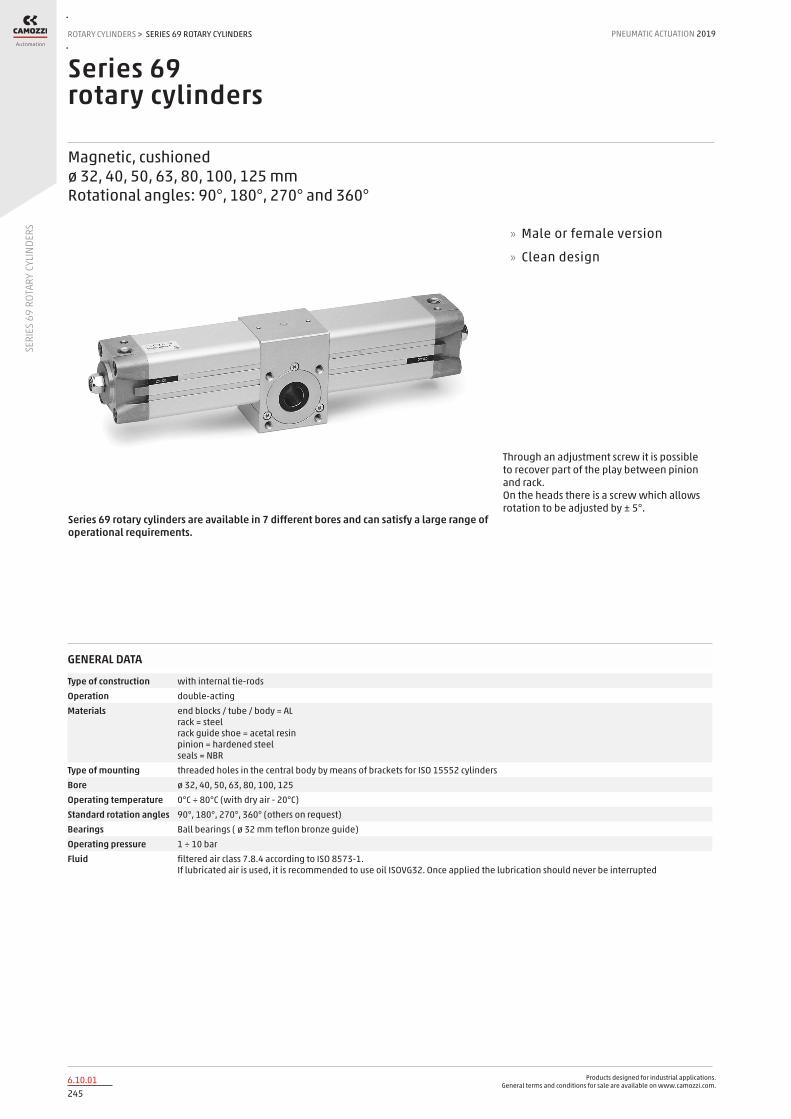
Products designed for industrial applications. General terms and conditions for sale are available on www.camozzi.com.
SERIES 69 ROTARY CYLINDERSROTARY CYLINDERS > PNEUMATIC ACTUATION 2019
2456.10.01
SERI
ES 6
9 RO
TARY
CYL
INDE
RS
Series 69 rotary cylinders
Magnetic, cushioned ø 32, 40, 50, 63, 80, 100, 125 mm Rotational angles: 90°, 180°, 270° and 360°
Series 69 rotary cylinders are available in 7 different bores and can satisfy a large range of operational requirements.
Through an adjustment screw it is possible to recover part of the play between pinion and rack. On the heads there is a screw which allows rotation to be adjusted by ± 5°.
» Male or female version
» Clean design
GENERAL DATA
Type of construction with internal tie-rodsOperation double-actingMaterials end blocks / tube / body = AL
rack = steel rack guide shoe = acetal resin pinion = hardened steel seals = NBR
Type of mounting threaded holes in the central body by means of brackets for ISO 15552 cylindersBore ø 32, 40, 50, 63, 80, 100, 125Operating temperature 0°C ÷ 80°C (with dry air - 20°C)Standard rotation angles 90°, 180°, 270°, 360° (others on request)Bearings Ball bearings ( ø 32 mm teflon bronze guide)Operating pressure 1 ÷ 10 barFluid filtered air class 7.8.4 according to ISO 8573-1.
If lubricated air is used, it is recommended to use oil ISOVG32. Once applied the lubrication should never be interrupted

Products designed for industrial applications. General terms and conditions for sale are available on www.camozzi.com.
SERIES 69 ROTARY CYLINDERSPNEUMATIC ACTUATION
2466.10.02
2019 ROTARY CYLINDERS
SERI
ES 6
9 RO
TARY
CYL
INDE
RS
>
TABLE OF TORQUE FORCE IN Nm (THEORETICAL)
Ø 1 bar 2 bar 3 bar 4 bar 5 bar 6 bar 7 bar 8 bar 9 bar 10 bar
32 1,2 2,4 3,6 4,8 6 7,2 8,4 9,6 10,8 12
40 2,25 4,5 6,75 9 11,25 13,5 15,75 18 20,25 22,5
50 3,9 7,8 11,7 15,6 19,5 23,4 27,3 31,2 35,1 39
63 7,3 14,6 21,9 29,2 36,5 43,8 51,1 58,4 65,7 73
80 15,7 31,4 47,1 62,8 78,5 94,2 109,9 125,6 141,3 157
100 26,35 52,7 79,05 105,4 131,75 158,1 184,45 210,8 237,15 263,5
125 51 102 153 204 255 306 357 408 459 510
CODING EXAMPLE
69 SERIES PNEUMATIC SYMBOL CD18
050 BORE 032 = 32 mm 040 = 40 mm 050 = 50 mm 063 = 63 mm 080 = 80 mm 100 = 100 mm 125 = 125 mm
090 ROTATIONAL ANGLES 090 = 90° 180 = 180° 270 = 270° 360 = 360°
F PINION F = Female M = Male
SEALS MATERIAL: = NBR W = FKM + 130°C
69 - 050 / 090 - F
PNEUMATIC SYMBOLS
The pneumatic symbols which have been indicated in the CODING EXAMPLE are shown below.

Products designed for industrial applications. General terms and conditions for sale are available on www.camozzi.com.
SERIES 69 ROTARY CYLINDERSROTARY CYLINDERS > PNEUMATIC ACTUATION 2019
2476.10.03
SERI
ES 6
9 RO
TARY
CYL
INDE
RS
Ø 32 Ø 40 Ø 50 Ø 63 Ø 80 Ø 100 Ø 125
Maximum axial load F with F1 = 0 100 N 100 N 120 N 120 N 200 N 250 N 300 N
Maximum angular speed ω (rad/s) 66 (rad/s) 55 (rad/s) 49 (rad/s) 42 (rad/s) 31 (rad/s) 29 (rad/s) 23 (rad/s)
Maximum cushionable kinetic energy (J) calculated as E = ½ ∙ J ∙ ω²
0.8 (J) 1.4 (J) 2.1 (J) 4.0 (J) 7.5 (J) 9.0 (J) 15 (J)
MAXIMUM ADMISSIBLE LOADS AND FORCES
M = Center of gravity of the applied theoretical load F = Axial load (N) F1 = Radial load (N)
s = distance between actuator and center of gravity of the applied theoretical load (mm)
CHOICE AND CHECK OF THE ACTUATOR TO BE USED
Max. radial load F1 with F = 0 S = distance between actuator and center of gravity of the applied theoretical load (mm)
Maximum energy that can be cushioned according to the angular speed. J = Moment of inertia (Kg ∙ m²) ω = Angular speed (rad/s)
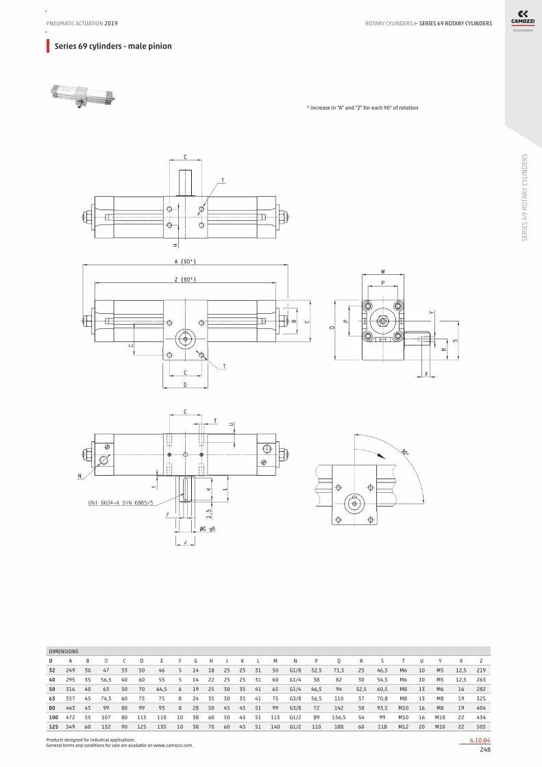
Products designed for industrial applications. General terms and conditions for sale are available on www.camozzi.com.
SERIES 69 ROTARY CYLINDERSPNEUMATIC ACTUATION
2486.10.04
2019 ROTARY CYLINDERS
SERI
ES 6
9 RO
TARY
CYL
INDE
RS
>
Series 69 cylinders - male pinion
DIMENSIONS
Ø A B ٭ C D E F G H J K L M N P Q R S T U Y X Z
32 249 30 47 33 50 46 5 14 18 25 25 31 50 G1/8 32,5 71,5 25 46,5 M6 10 M5 12,5 219
40 295 35 56,5 40 60 55 5 14 22 25 25 31 60 G1/4 38 82 30 54,5 M6 10 M5 12,5 263
50 316 40 63 50 70 64,5 6 19 25 30 35 41 65 G1/4 46,5 94 32,5 60,5 M8 13 M6 16 282
63 357 45 74,5 60 75 75 8 24 35 30 35 41 75 G3/8 56,5 110 37 70,8 M8 13 M8 19 325
80 443 45 99 80 99 93 8 28 50 45 45 51 99 G3/8 72 142 50 93,5 M10 16 M8 19 404
100 472 55 107 80 115 110 10 38 60 50 45 51 115 G1/2 89 156,5 54 99 M10 16 M10 22 434
125 549 60 132 90 125 135 10 38 70 60 45 51 140 G1/2 110 188 60 118 M12 20 M10 22 505
* increase in “A” and “Z” for each 90° of rotation

Products designed for industrial applications. General terms and conditions for sale are available on www.camozzi.com.
SERIES 69 ROTARY CYLINDERSROTARY CYLINDERS > PNEUMATIC ACTUATION 2019
2496.10.05
SERI
ES 6
9 RO
TARY
CYL
INDE
RS
Series 69 cylinders - female pinion
DIMENSIONS
Ø A B ٭ C D E F H J M N P Q R S T U V W Z
32 249 30 47 33 50 46 5 18 25 50 G1/8 32,5 71,5 25 46,5 M6 10 16,3 14 219
40 295 35 56,5 40 60 55 5 22 25 60 G1/4 38 82 30 54,5 M6 10 16,3 14 263
50 316 40 63 50 70 64,5 6 25 30 65 G1/4 46,5 94 32,5 60,5 M8 13 21,8 19 282
63 357 45 74,5 60 75 75 6 35 30 75 G3/8 56,5 110 37 70,8 M8 13 21,8 19 325
80 443 45 99 80 99 93 8 50 45 99 G3/8 72 142 50 93,5 M10 16 27,3 24 404
100 472 55 107 80 115 110 8 60 50 115 G1/2 89 156,5 54 99 M10 16 31,3 28 434
125 549 60 132 90 125 135 8 70 60 140 G1/2 110 188 60 118 M12 16 31,3 28 505
* increase in “A” and “Z” for each 90° of rotation

Products designed for industrial applications. General terms and conditions for sale are available on www.camozzi.com.
SERIES 30 ROTARY CYLINDERSPNEUMATIC ACTUATION
2506.15.01
2019 ROTARY CYLINDERS
SERI
ES 3
0 RO
TARY
CYL
INDE
RS
>
Series 30 rotary cylinders
Non magnetic, cushioned and not cushioned ø 50, 63, 80, 100 mm Rotational angles: 90° and 180°
Series 30 rotary cylinders are made of a special Aluminium profile. Their compact dimensions and clean lines give a good aesthetic appearance. A unique wear resistant guide block gives increased service life to the unit.
Positioning gears are provided for the rotations. On the heads there is a screw which allows rotation to be adjusted by ± 5°.
GENERAL DATAType of construction profileOperation double actingMaterials aluminium profile body & end blocks - NBR seals - other parts - hardened steelMounting by means of holes in bodyBore ø 50 - 63 - 80 - 100Installation in any positionWorking temperature 0°C ÷ 50°C (- 20°C on dry air)Standard rotation 90° - 180°Operating pressure 0.5 ÷ 10 barFluid clean air with or without lubrication

Products designed for industrial applications. General terms and conditions for sale are available on www.camozzi.com.
SERIES 30 ROTARY CYLINDERSROTARY CYLINDERS > PNEUMATIC ACTUATION 2019
2516.15.02
SERI
ES 3
0 RO
TARY
CYL
INDE
RS
TABLE OF TORQUE FORCE IN Nm (THEORETICAL)
Ø 1 bar 2 bar 3 bar 4 bar 5 bar 6 bar 7 bar 8 bar 9 bar 10 bar
50 2,08 4,16 6,24 8,32 10,40 12,48 14,55 16,63 18,71 20,79
63 4,40 8,80 13,20 17,61 22,01 26,41 30,81 35,21 39,61 44,01
80 7,10 14,19 21,29 28,39 35,49 42,58 49,68 56,78 63,87 70,97
100 16,63 33,27 49,90 66,54 83,17 99,80 116,44 133,07 149,07 166,34
CODING EXAMPLE
30 SERIES PNEUMATIC SYMBOL CD17
050 BORE 050 = 50 mm 063 = 63 mm 080 = 80 mm 100 = 100 mm
090 ROTATIONAL ANGLES 090 = 90° 180 = 180°
3 VERSION: = cushioned 3 = not cushioned
30 - 050 / 090 - 3
PNEUMATIC SYMBOLS
The pneumatic symbols which have been indicated in the CODING EXAMPLE are shown below.

Products designed for industrial applications. General terms and conditions for sale are available on www.camozzi.com.
SERIES 30 ROTARY CYLINDERSPNEUMATIC ACTUATION
2526.15.03
2019 ROTARY CYLINDERS
SERI
ES 3
0 RO
TARY
CYL
INDE
RS
>
Series 30 rotary cylinders - cushioned
DIMENSIONS
Mod. A B C D E F h7 G H L M N O P Q R S T
30-050/090 48 62 162 36 2.5 15 25 5 5 25 G1/8 23 M8 x 1.25 46 98 8 8
30-063/090 60 76 186 41 2.5 17 32 6 5 30 G1/8 24 M10 x 1.5 57 117 8 12
30-080/090 72 92 195 50 3 20 35 6 5 35 G1/4 23.5 M12 x 1.75 70 142 9 13
30-100/090 85 112 247 60 4 25 40 8 5 40 G3/8 26 M12 x 1.75 85 172 9 14
30-050/180 48 62 199 36 2.5 15 25 5 5 25 G1/8 26 M8 x 1.25 46 98 8 8
30-063/180 60 76 237 41 2.5 17 30 6 5 30 G1/8 24 M10 x 1.5 57 117 8 12
30-080/180 72 92 245 50 3 20 35 6 5 35 G1/4 23.5 M12 x 1.75 70 142 9 13
30-100/180 85 112 313 60 4 25 40 8 5 40 G3/8 26 M12 x 1.75 85 172 9 14
XX = Screw for stroke regulation
Series 30 rotary cylinders - not cushioned
DIMENSIONS
Mod A B C D E F h7 G H L M N O P Q R S T
30-050/090-3 48 62 150 36 2.5 15 25 5 5 25 G1/8 17 M8 x 1.25 46 98 8 8
30-063/090-3 60 76 172 41 2.5 17 32 6 5 30 G1/8 17 M10 x 1.5 57 117 8 12
30-080/090-3 72 92 191 50 3 20 35 6 5 35 G1/4 21.5 M12 x 1.75 70 142 9 13
30-100/090-3 85 112 245 60 4 25 40 8 5 40 G3/8 25 M12 x 1.75 85 172 9 14
30-050/180-3 48 62 187 36 2.5 15 25 5 5 25 G1/8 17 M8 x 1.25 46 98 8 8
30-063/180-3 60 76 233 41 2.5 17 32 6 5 30 G1/8 17 M10 x 1.5 57 117 8 12
30-080/180-3 72 92 241 50 3 20 35 6 5 35 G1/4 21.5 M12 x 1.75 70 142 9 13
30-100/180-3 85 112 311 60 4 25 40 8 5 40 G3/8 25 M12 x 1.75 85 172 9 14
XX = Screw for stroke regulation

Products designed for industrial applications. General terms and conditions for sale are available on www.camozzi.com.
SERIES ARP ACTUATORSROTARY CYLINDERS > PNEUMATIC ACTUATION 2019
2536.20.01
SERI
ES A
RP A
CTUA
TORS
Series ARP rotary actuators
Model: “Rack & Pinion” Sizes: 1, 3, 5, 10, 12, 20, 35, 55, 70, 100, 150, 250, 400 Rotational angles: 90°
Series ARP rotary actuators have been designed to meet the high demands by the process industry, where they predominantly are used for controlling the opening and closing process valves whereas ball valves and butterfly valves are the most common types.
The actuators exist in thirteen different sizes in order to cover a wide range of applications. Through adjusting screws located on the end caps it is possible to mechanically adjust the opening/closing angle by ±5°. All Series ARP rotary actuators are ATEX certified, the air connections are realized in accordance with Namur VDI/VDE 3845 drilling, while the interface drilling of the process valve is in accordance with ISO 5211 standard.
» ATEX certified product
» Wide range of available sizes
» Air connections in accordance with Namur VDI/VDE 3845 drilling
» Interface drilling of the process valve in accordance with ISO 5211 standard
GENERAL DATAType of construction Rack and pinion typeOperation spring return (single-acting), double-actingMaterials extruded AL-profile body (pressure diecasted anodized AL body for mod. ARP400)
pressure diecasted AL end caps and pistons / racks (end caps in technopolymer for mod. ARP001) zinc-plated steel pinion - POM guide parts - NBR seals
Sizes 001, 003, 005, 010, 012, 020, 035, 055, 070, 100, 150, 250, 400Operating temperature - 30°C ÷ 100°CRotation angle 90°Type of mounting direct to the flange of the valve through screws and bolts, or through mounting kits consisting of bracket and adaptor pin*Operating pressure 2 ÷ 10 barFluid filtered air without lubrication. If lubricated air is used, it is recommended to use oil ISOVG32. Once applied the lubrication should
never be interrupted.Available spare part kits - kits which include sliding parts and seals;
- kits containing springs for transforming an actuator from double-acting to single-acting with spring return.Certification ATEX
* Bracket and adaptor pin is not supplied by Camozzi

Products designed for industrial applications. General terms and conditions for sale are available on www.camozzi.com.
SERIES ARP ACTUATORSPNEUMATIC ACTUATION
2546.20.02
2019 ROTARY CYLINDERS
SERI
ES A
RP A
CTUA
TORS
>
CODING EXAMPLE
ARP - 001 - 1A A - F0300 - A EX
ARP SERIES
001 SIZE 001 = torque force 9 Nm 003 = torque force 24 Nm 005 = torque force 50 Nm 010 = torque force 100 Nm 012 = torque force 120 Nm 020 = torque force 200 Nm 035 = torque force 370 Nm 055 = torque force 597 Nm 070 = torque force 825 Nm 100 = torque force 1122 Nm 150 = torque force 1655 Nm 250 = torque force 2648 Nm 400 = torque force 4800 Nm
1A OPERATION 1A = single-acting, minimum pressure of 4 bar 1B = single-acting, minimum pressure of 5 bar 1C = single-acting, minimum pressure of 5,5 bar 1D = single-acting, minimum pressure of 6 bar 2A = double-acting
PNEUMATIC SYMBOLS: CD19 / CD21 CD19 / CD21 CD19 / CD21 CD19 / CD21 CD17
A ROTATION ANGLE A = 90°
F0300 INTERFACE FOR FLANGE (ISO 5211) F0300 = F03 flange and 9mm square holes F0305 = F03 flange holes + F05 flange and 9mm square holes F0400 = F04 flange and 11mm square holes F0507 = F05 flange holes + F07 flange and 14mm square holes F0705 = F07 flange holes + F05 flange and 17mm square holes F0710 = F07 flange holes + F10 flange and 17mm square holes F1007 = F10 flange holes + F07 flange and 22mm square holes F1210 = F12 flange holes + F10 flange and 27mm square holes F1400 = F14 flange and 36mm square holes F1600 = F16 flange and 46mm square holes F2516 = F25 flange + F16 flange and 55mm square holes
A MATERIALS A = standard anodized C = CNI Kanigen type nickel-plating W = all FKM seals (130°C)
EX ATEX certified product
PNEUMATIC SYMBOLS
The pneumatic symbols which have been indicated in the CODING EXAMPLE are shown below.

Products designed for industrial applications. General terms and conditions for sale are available on www.camozzi.com.
SERIES ARP ACTUATORSROTARY CYLINDERS > PNEUMATIC ACTUATION 2019
2556.20.03
SERI
ES A
RP A
CTUA
TORS
The above graph shows the torque force (in Nm) generated by a double-acting rotary actuator Series ARP during the closing action. The action starts from the 90° position and finishes at 0°. One of the features/advantages with a “rack and pinion” style rotary actuator is that the generated torque force is constant throughout the whole movement. See also the TORQUE FORCE TABLE on the following page.
The above graph shows the torque force (in Nm) generated by a double-acting rotary actuator Series ARP during the opening action. The action starts from the 0° position and finishes at 90°. One of the features/advantages with a “rack and pinion” style rotary actuator is that the generated torque force is constant throughout the whole movement. See also the TORQUE FORCE TABLE on the following page.
TORQUE FORCE DIAGRAM GENERATED BY A DOUBLE-ACTING ACTUATOR
The above graph shows the torque force (in Nm) generated by a single-acting rotary actuator Series ARP during the closing action. The action starts from the 90° position and finishes at 0°. The generated torque force is at the highest at 90°, while it decreases along the stroke due to the fact that the springs get less compressed. In this case it is the springs which generates the driving force. See also the TORQUE FORCE TABLE on the following page.
The above graph shows the torque force (in Nm) generated by a single acting rotary actuator Series ARP during the opening action. The action starts from the 0° position and finishes at 90°. The generated torque force is at the highest at 0°, while it decreases along the stroke due to the fact that the springs get more compressed, (the counter force increases). In this case it is the compressed air which generates the driving force. See also the TORQUE FORCE TABLE on the following page.
TORQUE FORCE DIAGRAM GENERATED BY A SINGLE-ACTING ACTUATOR

Products designed for industrial applications. General terms and conditions for sale are available on www.camozzi.com.
SERIES ARP ACTUATORSPNEUMATIC ACTUATION
2566.20.04
2019 ROTARY CYLINDERS
SERI
ES A
RP A
CTUA
TORS
>
DOUBLE-ACTING models
3 bar 4 bar 5 bar 5,5 bar 6 bar 7 bar
ARP-001-2A 4,4 5,8 7,33 8,0 8,8 10,2
ARP-003-2A 11,8 15,8 19,7 21,7 23,7 27,6
ARP-005-2A 25,3 33,8 42,2 46,4 50,7 59,1
ARP-010-2A 50,7 67,6 84,5 92,9 101,4 118,3
ARP-012-2A 61,2 81,6 102,1 112,2 122,5 142,9
ARP-020-2A 100,9 134,6 168,2 185,08 201,9 235,5
ARP-035-2A 187,0 249,3 311,6 342,8 374,0 436,3
ARP-055-2A 298,5 398,0 497,5 547,2 597,0 696,5
ARP-070-2A 412,5 550,0 687,5 756,2 825,0 962,5
ARP-100-2A 561,0 748,0 935,0 1028,5 1122,0 1309,0
ARP-150-2A 827,5 1103,3 1379,1 1517,0 1655,0 1930,8
ARP-250-2A 1324,0 1765,3 2206,6 2427,3 2648,0 3089,3
ARP-400-2A 2401,5 3202,0 4002,5 4402,7 4803,0 5603,5
SINGLE-ACTING models (for rotation angles of 90°)
Quantity of springs External - Internal
Spring torque (Nm)
0° - 90°
Supply pressure of 4 bar
0° - 90°
Supply pressure of 5 bar
0° - 90°
Supply pressure of 5,5 bar
0° - 90°
Supply pressure of 6 bar
0° - 90°
ARP-003-1AA 8 - / 5,36 - 10,48 10,40 - 5,30 11,80 - 7,90 16,40 - 11,20 18,30 - 13,20
ARP-003-1BA 10 - / 6,70 - 13,10 13,10 - 6,70 15,00 - 8,60 17,00 - 10,60
ARP-003-1CA 11 - / 7,37 - 14,41 14,40 - 7,30 16,30 - 9,30
ARP-003-1DA 12 - / 8,04 - 15,72 13,70 - 6,00 15,70 - 8,00
ARP-005-1AA 8 - / 12,00 - 21,76 21,80 - 12,00 30,30 - 20,50 34,50 - 34,70 38,70 - 28,90
ARP-005-1BA 10 - / 15,00 - 27,20 27,30 - 15,10 31,50 - 19,30 35,70 - 23,50
ARP-005-1CA 11 - / 16,50 - 29,92 30,00 - 16,60 34,20 - 20,80
ARP-005-1DA 12 - / 18,00 - 32,64 28,50 - 13,80 32,70 - 18,10
ARP-010-1AA 8 - / 26,72 - 40,96 40,90 - 26,60 57,80 - 43,50 66,20 - 52,00 74,70 - 60,40
ARP-010-1BA 10 - / 33,40 - 51,20 51,10 - 33,30 59,60 - 41,80 68,00 - 50,20
ARP-010-1CA 11 - / 36,74 - 56,32 56,20 - 36,60 64,70 - 45,10
ARP-010-1DA 12 - / 40,08 - 61,44 52,90 - 31,50 61,30 - 40,00
ARP-012-1AA 4 - 0 28,80 - 52,40 52,90 - 29,30 73,30 - 49,70 83,50 - 59,90 93,70 - 70,10
ARP-012-1BA 4 - 2 36,00 - 65,50 54,70 - 16,20 66,10 - 36,60 76,30 - 46,80 86,50 - 57,00
ARP-012-1CA 4 - 3 39,60 - 72,10 62,50 - 30,00 72,70 - 40,30 82,90 - 50,50
ARP-012-1DA 4 - 4 43,20 - 78,60 58,90 - 23,50 69,10 - 33,70 79,30 - 43,90
ARP-020-1AA 4 - 0 47,70 - 86,80 86,90 - 47,80 120,60 - 81,50 137,40 - 98,30 154,20 - 115,10
ARP-020-1BA 4 - 2 53,70 - 108,50 75,00 - 26,10 108,60 - 59,80 125,40 - 76,60 142,30 - 93,40
ARP-020-1CA 4 - 3 65,50 - 119,40 102,60 - 48,90 119,50 - 65,80 136,30 - 82,60
ARP-020-1DA 4 - 4 71,60 - 130,20 96,70 - 38,10 113,50 - 54,90 130,30 - 71,70
ARP-035-1AA 4 - 0 88,40 - 160,80 161,00 - 88,70 223,40 - 151,00 254,60 - 182,20 285,70 - 213,40
ARP-035-1BA 4 - 2 110,50 - 201,00 138,90 - 48,50 201,30 - 110,80 232,50 - 142,00 263,60 - 173,20
ARP-035-1CA 4 - 3 121,60 - 221,10 190,20 - 90,70 221,40 - 121,90 252,60 - 153,10
ARP-035-1DA 4 - 4 132,60 - 241,20 179,20 - 70,60 210,40 - 101,80 241,50 - 133,00
ARP-055-1AA 4 - 0 141,00 - 256,40 256,80 - 141,40 356,30 - 240,90 406,00 - 290,60 455,70 - 340,30
ARP-055-1BA 4 - 2 176,30 - 320,50 221,60 - 77,30 321,00 - 176,80 370,70 - 226,50 420,50 - 279,20
ARP-055-1CA 4 - 3 193,90 - 352,60 303,40 - 144,70 353,10 - 194,50 402,80 - 244,20
ARP-055-1DA 4 - 4 211,50 - 384,60 285,80 - 112,70 335,50 - 162,40 385,20 - 212,10
ARP-070-1AA 4 - 0 195,0 - 354,0 355,0 - 196,0 493,0 - 333,0 561,0 - 402,0 630,0 - 471,0
ARP-070-1BA 4 - 2 243,0 - 443,0 306,0 - 107,0 444,0 - 245,0 513,0 - 314,0 581,0 - 382,0
ARP-070-1CA 4 - 3 268,0 - 487,0 420,0 - 201,0 488,0 - 269,0 557,0 - 338,0
ARP-070-1DA 4 - 4 292,0 - 531,0 395,0 - 156,0 464,0 - 225,0 533,0 - 294,0
ARP-100-1AA 4 - 0 265,0 - 482,0 483,0 - 266,0 670,0 - 453,0 764,0 - 547,0 857,0 - 640,0
ARP-100-1BA 4 - 2 331,0 - 603,0 417,0 - 146,0 604,0 - 333,0 697,0 - 426,0 791,0 - 520,0
ARP-100-1CA 4 - 3 365,0 - 663,0 571,0 - 272,0 664,0 - 366,0 758,0 - 459,0
ARP-100-1DA 4 - 4 398,0 - 723,0 538,0 - 212,0 631,0 - 306,0 725,0 - 399,0
ARP-150-1AA 4 - 0 391,0 - 711,0 712,0 - 392,0 988,0 - 668,0 1126,0 - 806,0 1264,0 - 944,0
ARP-150-1BA 4 - 2 489,0 - 889,0 615,0 - 215,0 890,0 - 491,0 1028,0 - 629,0 1166,0 - 766,0
ARP-150-1CA 4 - 3 538,0 - 977,0 842,0 - 402,0 979,0 - 540,0 1117,0 - 678,0
ARP-150-1DA 4 - 4 586,0 - 1066,0 793,0 - 313,0 931,0 - 451,0 1069,0 - 589,0
ARP-250-1AA 6 - / 606,0 - 936,0 1159,0 - 829,0 1600,0 - 1270,0 1821,0 - 1491,0 2042,0 - 1712,0
ARP-250-1BA 8 - / 808,0 - 1248,0 957,0 - 517,0 1398,0 - 958,0 1619,0 - 1179,0 1840,0 - 1400,0
ARP-250-1CA 9 - / 909,0 - 1404,0 1297,0 - 802,0 1518,0 - 1023,0 1739,0 - 1244,0
ARP-250-1DA 10 - / 1010,0 - 1560,0 1196,0 - 646,0 1417,0 - 867,0 1638,0 - 1088,0
ARP-400-1AA 10 - / 1180,0 - 1820,0 2022,0 - 1382,0 2823,0 - 2183,0 3223,0 - 2583,0 3623,0 - 2983,0
ARP-400-1BA 12 - / 1416,0 - 2184,0 1786,0 - 1018,0 2587,0 - 1819,0 2987,0 - 2219,0 3387,0 - 2619,0
ARP-400-1CA 15 - / 1770,0 - 2730,0 2233,0 - 1273,0 2633,0 - 1673,0 3033,0 - 2073,0
TORQUE FORCE TABLE (Nm)

Products designed for industrial applications. General terms and conditions for sale are available on www.camozzi.com.
SERIES ARP ACTUATORSROTARY CYLINDERS > PNEUMATIC ACTUATION 2019
2576.20.05
SERI
ES A
RP A
CTUA
TORS
Rotary actuators Series ARP - sizes from 001 to 150
NOTE TO THE TABLE: * ARP-003-... also available with double drilling ISO F03/F05 with ØK of 25 mm and square key M of 9 mm ** DA = weight of double-acting version SA = weight of single-acting version
Mod. ISO A B C D E F G H I J ØK L M N P Q R S T U ØV ØW X Y Z BB CC EE Weight (Kg) DA/SA**
ARP-001-... F03 103 45 51 28,5 - - - - G1/8 10 25 22.5 9 11 - - 8 5 80 2 22.5 16 20 4.5 11.5 - - - 0.6
ARP-003-... F04* 149.5 70 69.5 38 49 10.5 - - G1/8 10 30 32 11 11 - - 8 8 80 1.5 32 20 20 4.5 11.5 - 4 13 1.0 / 1.1
ARP-005-... F05, F07 186.5 87 90.5 49 49 22 - - G1/8 10 35 48 14 15 - - 8 8 80 3 32 20 20 4.5 11.5 - 4 13 1.8 / 1.9
ARP-010-... F05, F07 206 118 113 59 43 8 - - G1/8 10 35 29.5 14 19 - - 8 8 80 3 32 20 20 4.5 11.5 - 6 19 2.8 / 2.9
ARP-012-... F07, F05 194 118.5 121 67 43 8 107 49 G1/4 12 55 29.5 17 20 M6 10 8 5 80 3 45 20 20 6 11.5 - 6 19 4.1 / 4.7
ARP-020-... F07, F10 218 140.5 136.5 72 43 8 107 49 G1/4 12 55 29.5 17 20 M6 10 8 5 80 3 50 32 20 6.5 19 - 8 24 6.3 / 7.0
ARP-035-... F10, F07 266 166.5 156 78 43 8.5 161 73 G1/4 12 70 30 22 24 M6 12 8 5 80 3 61 32 20 7 19 - 8 24 10 / 12
ARP-055-... F12, F10 312 207.5 191 95.5 43 20.5 161 73 G1/4 12 85 42 27 30 M8 15 8 5 130 3 61 40 30 7.5 25.5 10 10 30 18 /21
ARP-070-... F12, F10 358 216 198 99 49 19.5 213 102 G1/4 12 85 46 27 30 M8 12 8 6 130 3 72 40 30 7 25.5 10 10 30 20 / 24
ARP-100-... F14 366 254 227 113.5 43 39.5 213 102 G1/4 12 100 61 36 40 M10 15 8 6 130 3 76 40 30 7 25.5 12 12 36 31 / 35
ARP-150-... F14 394 304 280 140 48.5 51.5 244 117 G1/4 12 100 76 36 40 M12 22 8 6 130 3 78 40 30 7 25.5 12 12 36 44 / 52
BB = end-stroke regulation on the end cap CC = end-stroke regulation on the end cap DD = solenoid mounting/Namur Interface

Products designed for industrial applications. General terms and conditions for sale are available on www.camozzi.com.
SERIES ARP ACTUATORSPNEUMATIC ACTUATION
2586.20.06
2019 ROTARY CYLINDERS
SERI
ES A
RP A
CTUA
TORS
>
Rotary actuators Series ARP - size 250
NOTE TO THE TABLE: ** DA = double-acting - SA = single-acting
Mod. ISO CC EE Weight (Kg) DA / SA **
ARP-250-... F16 14 46 59 / 84
CC = end-stroke regulation on the end cap DD = solenoid mounting/Namur Interface Owing to the end caps sizes, dimensions change from the double-acting model to the single-acting one.

Products designed for industrial applications. General terms and conditions for sale are available on www.camozzi.com.
SERIES ARP ACTUATORSROTARY CYLINDERS > PNEUMATIC ACTUATION 2019
2596.20.07
SERI
ES A
RP A
CTUA
TORS
Rotary actuators Series ARP - size 400
NOTE TO THE TABLE: ** DA = double-acting - SA = single-acting
Mod. ISO CC EE Weight (Kg) DA / SA **
ARP-400-... F25, F16 14 46 107 / 135
CC = end-stroke regulation on the end cap DD = solenoid mounting/Namur Interface Owing to the end caps sizes, dimensions change from the double-acting model to the single-acting one.

Products designed for industrial applications. General terms and conditions for sale are available on www.camozzi.com.
SERIES ARP ACTUATORSPNEUMATIC ACTUATION
2606.20.08
2019 ROTARY CYLINDERS
SERI
ES A
RP A
CTUA
TORS
>
Rotary actuators Series ARP
Reference standard ISO 5211 concerning the dimensions of flanges connecting actuator and valve.
ISO flange d2 f8 d3 d4 h1 max h2 min nr of holes
F03 25 36 M5 3 8 4
F04 30 42 M5 3 8 4
F05 35 50 M6 3 9 4
F07 55 70 M8 3 12 4
F10 70 102 M10 3 15 4
F12 85 125 M12 3 18 4
F14 100 140 M16 4 24 4
F16 130 165 M20 5 30 4
F25 200 254 M16 5 24 8

Products designed for industrial applications. General terms and conditions for sale are available on www.camozzi.com.
SERIES ARP ACTUATORSROTARY CYLINDERS > PNEUMATIC ACTUATION 2019
2616.20.09
SERI
ES A
RP A
CTUA
TORS
Switch box Mod. SBT (standard) e SIP (ATEX version)
Mod. SIP: intrinsic safety Atex version with protection modes Ex II 2 G/D EEx ia IIC T6 for zones classified as 1, 2, 21 e 22.
Mod. Body material Cover material Shaft material Screws Operating temperature Protection class Kind of end stop
SBT-012H0-2H Technopolymer Polycarbonate Technopolymer Stainless steel -15°C + 80°C IP65 2 electromec. end stops SPDT Max 5A 250V AC / 3A 24V DC
SIP702L0-2H Technopolymer Polycarbonate Technopolymer Stainless steel -15°C + 80°C IP65 2 inductive Namur P+F NJ2-V3-N (2 non amplified wires)
Switch box Mod. SBA (standard) e SIM (ATEX version)
Mod. SIP: intrinsic safety Atex version with protection modes Ex II 2 G/D EEx ia IIC T6 for zones classified as 1, 2, 21 e 22.
Mod. Body material Cover material Shaft material Screws Operating temperature Protection class Kind of end stop
SBA-0120N-2H pressure diecasted Aluminium Polycarbonate Technopolymer Stainless steel -15°C + 80°C IP65 2 electromec. end stops SPDT Max 5A 250V AC / 3A 24V DC
SIM7022N-2H pressure diecasted Aluminium Polycarbonate Technopolymer Stainless steel -15°C + 80°C IP65 2 Namur induttivi P+F NJ2-V3-N (2 non amplified wires)

Products designed for industrial applications. General terms and conditions for sale are available on www.camozzi.com.
SERIES 50 CYLINDERSPNEUMATIC ACTUATION
2627.05.01
2019 RODLESS CYLINDERS
SERI
ES 5
0 CY
LIND
ERS
>
Series 50 rodless cylinders
Double-acting, magnetic, cushioned ø 16, 25, 32, 40, 50, 63, 80 mm
Series 50 rodless cylinders are available in 7 different diameters to cover as many applications as possible. A permanent magnet is assembled on the cylinder piston allowing the position to be detected by means of proximity switches positioned on the sliding axis. This series of cylinder is normally supplied with end-stroke cushioning, that can be regulated by means of a screw located on the end-cover.
The Series 50 cylinders are recommended to be used according to the load values and torque forces detailed in the relative tables.
» Four ports on each chamber
» Possibility to supply both chambers from one side (on request)
GENERAL DATAType of construction rodless with integral carriageOperation double-actingMaterials end-covers, piston and barrel = AL
seals = PU and NBROperating temperature 0°C ÷ 50°C(with dry air - 10°C)Operating pressure 1 ÷ 8 barSpeed 10 ÷ 1000 mm/sec (without load)Fluid clean air, without lubrication
If lubricated air is used, it is recommended to use oil ISOVG32. Once applied the lubrication should never be interrupted.Strokes min - max for all bores 100 ÷ 4000 mmStroke tolerance strokes ≤ 1000 mm = 0 / +0,6 mm
strokes > 1000 mm = 0 / +3 mmType of mounting foot mounted

Products designed for industrial applications. General terms and conditions for sale are available on www.camozzi.com.
SERIES 50 CYLINDERSRODLESS CYLINDERS > PNEUMATIC ACTUATION 2019
2637.05.02
SERI
ES 5
0 CY
LIND
ERS
CODING EXAMPLE
50 SERIES
M VERSION M = standard magnetic
2 OPERATION 2 = double-acting cushioned
PNEUMATIC SYMBOL CDSS (see the following pages)
P MATERIALS P = anodized AL profile tube - PU and NBR seals - standard carriage U = anodized AL profile tube - PU and NBR seals - flanged carriage
50 BORE 16 = 16 mm 25 = 25 mm 32 = 32 mm 40 = 40 mm 50 = 50 mm 63 = 63 mm 80 = 80 mm
A TYPE OF MOUNTING A = standard
0500 STROKE (see table)
50 M 2 P 50 A 0500
Ø Max. load permitted (N) F Max. bending torque force permitted (Nm) M Max. bending torque force permitted (Nm) Ms Torsional torque force permitted (Nm) Mv
16 218 3,1 0,5 1
25 660 12,4 1,9 5
32 720 30 4 8
40 1370 39 4 9
50 1600 122 11 16
63 2210 190 19 26
80 3770 305 30 47
M = F x b MS = F x b MV = F x b Note: Loads and bending torque are valid if applied separately.
MAXIMUM PERMITTED LOADS AND TORQUE FORCES

Products designed for industrial applications. General terms and conditions for sale are available on www.camozzi.com.
SERIES 50 CYLINDERSPNEUMATIC ACTUATION
2647.05.03
2019 RODLESS CYLINDERS
SERI
ES 5
0 CY
LIND
ERS
>
Note: This chart has been made according to a max. distance of 0.5 mm Load (N). Once the load and the cylinder diameter have been fixed, the chart gives the K values beyond which it is necessary to put an intermediate feet Mod. BH-50.
LOADS ACCORDING TO SUPPORTS DISTANCE
Note: This chart has been made according to a max. distance of 0.5 mm Load (N). Once the load and the cylinder diameter have been fixed, the chart gives the K values beyond which it is necessary to put an intermediate feet Mod. BH-50.
LOADS ACCORDING TO SUPPORTS DISTANCE

Products designed for industrial applications. General terms and conditions for sale are available on www.camozzi.com.
SERIES 50 CYLINDERSRODLESS CYLINDERS > PNEUMATIC ACTUATION 2019
2657.05.04
SERI
ES 5
0 CY
LIND
ERS
Cylinders with standard carriage Mod. 50M2P
DIMENSIONS
Ø A B C D E F F1 G H I L L1+ L2+ M N P Q R S S1 T U V Z X Y W AA BB TG SW2
16 5 32 48 64 76 M4 8 6 2 M5 5,3 100 130 16 15 M3 8 42,5 28 27 13,5 10 18 24 4,5 24,5 27 29 30 18 4
25 8 50 80 100 120 M5 10 13 2,5 G1/8 9,5 150 200 22 25 M5 13,5 63 40 40 20 15 23 33 5,5 38 40 43 46 27 6
32 12 60 90 120 160 M6 15 14 4 G1/4 10,5 188 250 30 31 M6 15 80 52 52 26 18 27 46 7 48,5 45 54 60 36 6
40 12 55 90 110 150 M6 12 12 4 G1/4 17,5 226 300 35 37 M6 15 88,5 63 63 31,5 18 28 49 7 51 75 57 61 43 6
50 12 70 110 140 180 M6 12 12 4 G1/4 13,5 272 350 40 39 M8 16 103 74,5 76 38 18 28 57 7 59 85 65 69 53 10
63 16 90 140 180 220 M8 15 15 4 G3/8 17,5 342 430 45 44 M8 16 125 92 94 47 19 30 68 9 70 105 78 83 67 10
80 20 120 180 240 280 M10 20 18 4 G1/2 32 408 520 45 56 M10 18,5 153,5 115,5 117 58,5 20 32 83 11 86 120 95 101 83 12

Products designed for industrial applications. General terms and conditions for sale are available on www.camozzi.com.
SERIES 50 CYLINDERSPNEUMATIC ACTUATION
2667.05.05
2019 RODLESS CYLINDERS
SERI
ES 5
0 CY
LIND
ERS
>
Cylinders with flanged carriage Mod. 50M2U
DIMENSIONS
Ø B1 B2 B3 B4 B5 B6 B7
16 36 4 4,5 25 40 76 50
25 51 5 5,5 35 50 120 70
32 66 6 7 40 50 160 90
40 66 6 7 45 60 150 80
50 74 6 7 45 60 180 100
63 89 7 9 60 80 220 130
80 108 8 11 75 100 280 180
Foot mount Mod. B-50
DIMENSIONS
Mod. A1 A2+ A3 A4 A5 A6 A7 A8
B-50-16 3 150 12 3 15 3,6 18 26
B-50-25 6,5 232 18,5 3 22 5,5 27 39
B-50-32 8 286 22 4 30 6,6 36 51
B-50-40 13,5 325 16,5 4 38 9 30 62
B-50-50 13,5 375 16,5 6 48 9 40 75
B-50-63 11 460 19 6 57 11 48 93
B-50-80 18,5 555 21,5 6 72 14 60 116
+ = add the stroke

Products designed for industrial applications. General terms and conditions for sale are available on www.camozzi.com.
SERIES 50 CYLINDERSRODLESS CYLINDERS > PNEUMATIC ACTUATION 2019
2677.05.06
SERI
ES 5
0 CY
LIND
ERS
Brackets Mod. BH-50
DIMENSIONS
Mod. C1 C2 C3 C4 C5 C6 C7 C8 C9 C10 C11 C12
BH-50-16 42 12 25 15 34 20 - 3,4 4,5 12 - 4
BH-50-25 56 21 32,6 22 47 22 - 5,5 10,1 12 - 5
BH-50-32 74 25 47,5 30 62 45 31 6,6 9,7 20 - -
BH-50-40 85 35 56 38 73 60 45 6,6 18,2 20 - -
BH-50-50 98 32 67,5 48 86 60 45 6,6 29,7 20 - -
BH-50-63 126 50 78,5 57 109 74 56 9 11 20 41 -
BH-50-80 155 65 96 72 135 80 60 11 14,5 20 41 -
Self-compensating adaptor Mod. CF-50
DIMENSIONS
Mod. C1 C2 C3 C4 C5 C6 C7 C8 C9 C10 C11 C12 C13
CF-50-25 6 16 40,8 22,9 7,9 31,5 3 15,8 1,2 5,6 38 55,4 4,5
CF-50-32 9,3 50 76,4 27,4 11,9 38,5 4 19 1,7 7,1 48,5 69,4 5,5
CF-50-40 9,3 50 76,4 24,4 11,9 38,5 4 19 1,2 7,1 51 70,9 3,5
CF-50-50 9,3 80 114,6 37,1 11,9 43,9 6 22 1,8 8,6 59 89,2 5,9
CF-50-63 12,7 100 134,6 42,2 15,9 43,9 6 22 0,8 8,6 70 104,7 6,5
CF-50-80 12,7 125 159,5 42,2 19,9 50,3 6 25,1 3 11 86 122,2 5

Products designed for industrial applications. General terms and conditions for sale are available on www.camozzi.com.
SERIES 52 CYLINDERSPNEUMATIC ACTUATION
2687.10.01
2019 RODLESS CYLINDERS
SERI
ES 5
2 CY
LIND
ERS
>
Series 52 rodless cylinders
Double-acting, magnetic, cushioned ø 25, 32, 40, 50, 63 mm
Series 52 rodless cylinders are available in 5 diameters (25, 32, 40, 50 and 63 mm) and comes in three main versions: Basic (M), with Slide bearing (G) and with Roller bearings (R). Furthermore these three main versions are each available with either standard- or short carriage to cover a wider range of applications.
A permanent magnet is assembled on the piston allowing the position to be detected by means of proximity switches positioned in grooves located on 3 sides on the cylinder profile. The cylinder is equipped with an end stroke cushioning which can be regulated by means of a screw located on each end cover of the cylinder. These cylinders are also available in versions with air supply from one side (end cover) only if needed.
» Three main versions, Basic, Slide bearing and Roller bearing
» Extra short carriage as option for all versions
» Possibility of feeding both chambers from one side only
GENERAL DATA
Models Standard, with slide bearings, with roller bearings, air supply from one or both sides, with standard or short carriage. For sizes 50 - 63 roller bearings version is not available.
Materials AL (anodized), plastic, hardened steel, seals: NBR, PUOperating temperature -10°C ÷ +70°COperating pressure 1 ÷ 8 bar
1,5 ÷ 8 bar ( Ø 25 for “R” version )Speed 10 ÷ 1000 mm/sec (without load)Fluid filtered air, without lubrication. If lubricated air is used, it is recommended to use ISO VG32 oil. Once applied the
lubrication should never be interrupted. If speeds exceed 1 m/s lubricated air is recommended.Bore size Ø 25
Ø 32 Ø 40 Ø 50 Ø 63
Cushioning length (mm) 14 mm - Ø 25 20 mm - Ø 32 25 mm - Ø 40 22 mm - Ø 50 32 mm - Ø 63
Strokes with standard carriage (version “P”) Strokes with short carriage (version “C”)
max 6000 mm - Ø25 max 5950 mm - Ø32 max 5900 mm - Ø40, Ø50 max 5880 mm - Ø63 max 6000 mm
Stroke tolerance strokes ≤ 1000 mm = 0 / +0,6 mm strokes > 1000 mm = 0 / +3 mm
Connection G1/8 (Ø 25; 32) G1/4 (Ø 40) G3/8 (Ø 50; 63)

Products designed for industrial applications. General terms and conditions for sale are available on www.camozzi.com.
SERIES 52 CYLINDERSRODLESS CYLINDERS > PNEUMATIC ACTUATION 2019
2697.10.02
SERI
ES 5
2 CY
LIND
ERS
CODING EXAMPLE
52 SERIES
M VERSION M = standard G = with slide bearing R = with roller bearing (only Ø25 - 32 - 40)
2 OPERATION 2 = double-acting, cushioned, with air supply from both sides 8 = double-acting, cushioned, with air supply from one side only
PNEUMATIC SYMBOLS CDSS (see the following pages) CDSS (see the following pages)
P MATERIALS P = anodized AL profile tube, NBR and PU seals, standard carriage C = anodized AL profile, NBR and PU seals, short carriage
40 BORE 25 = 25 mm 32 = 32 mm 40 = 40 mm 50 = 50 mm 63 = 63 mm
A TYPE OF MOUNTING A = standard
0500 STROKE (see table)
52 M 2 P 40 A 0500

Products designed for industrial applications. General terms and conditions for sale are available on www.camozzi.com.
SERIES 52 CYLINDERSPNEUMATIC ACTUATION
2707.10.03
2019 RODLESS CYLINDERS
SERI
ES 5
2 CY
LIND
ERS
>
COMPLEX LOADS If more than one force and torque is applied simultaneously, they have to be calculated according to the following formula: L/L (max)+ Ls/Ls (max)+ M/M (max)+ Ms/Ms (max)+ Mv/Mv (max ) ≤1. For models 52M, the load and torque values refer to the center of the tube. For models 52G/52R the load and torque values refer to the center point of the external guide. It is also necessary for these models to guarantee on the fixing surface a max 0.1 flatness’s value. The load and torque values refer to a velocity of: Models 52M/52G/52M/52G ≤ 0,2 m/s, models 52R ≤ 2 m/s. Load adjustment coefficients can be found on the following page.
Table showing the maximum permitted loads and torque forces
Mod. L Max ( N ) Ls Max ( N ) M Max ( Nm ) Ms Max ( Nm ) Mv Max ( Nm ) Mass at 0 mm stroke (kg) Additional mass per 100 mm (kg)
52M2P25A - 52M8P25A 270 - 13 2,5 11 0,88 0,30
52M2C25A - 52M8C25A 270 - 8 2 7 0,62 0,30
52G2P25A - 52G8P25A 580 580 23 10 23 1,31 0,30
52G2C25A - 52G8C25A 340 340 9 5 9 0,88 0,30
52R2P25A - 52R8P25A 850 1300 65 35 105 1,97 0,42
52R2C25A - 52R8C25A 850 1300 29 35 64 1,33 0,42
52M2P32A - 52M8P32A 300 - 30 3 24 1,40 0,39
52M2C32A - 52M8C32A 300 - 15 3 12 0,96 0,39
52G2P32A - 52G8P32A 850 850 33 15 33 2,09 0,39
52G2C32A - 52G8C32A 460 460 14 6,5 14 1,35 0,39
52R2P32A - 52R8P32A 900 1500 79 40 125 2,96 0,48
52R2C32A - 52R8C32A 900 1500 36 40 76 1,91 0,48
LOADS AND TORQUE FORCES Ø 25 - 32
COMPLEX LOADS If more than one force and torque is applied simultaneously, they have to be calculated according to the following formula: L/L (max)+ Ls/Ls (max)+ M/M (max)+ Ms/Ms (max)+ Mv/Mv (max ) ≤1. For models 52M, the load and torque values refer to the center of the tube. For models 52G/52R the load and torque values refer to the center point of the guide. The load and torque values refer to a velocity of: Models 52M/52G ≤0,2 m/s Models 52R ≤2 m/s If the velocity exceeds 0.2m/s for the models 52M/52G, the load and torque values have to be multiplied by the coefficients according to the table. Load adjustment coefficients can be found on the following page.
Table showing the maximum permitted loads and torque forces
Mod. L Max ( N ) Ls Max ( N ) M Max ( Nm ) Ms Max ( Nm ) Mv Max ( Nm ) Mass at 0 mm stroke (kg) Additional mass per 100 mm (kg)
52M2P40A - 52M8P40A 650 - 60 4 54 2,41 0,52
52M2C40A - 52M8C40A 650 - 30 4 27 1,65 0,52
52G2P40A - 52G8P40A 1120 1120 60 25 60 3,58 0,52
52G2C40A - 52G8C40A 600 600 25 11 25 2,30 0,52
52R2P40A - 52R8P40A 1200 2000 190 67 118 5,89 0,74
52R2C40A - 52R8C40A 1200 2000 85 67 72 3,84 0,74
52M2P50A - 52M8P50A 800 - 80 17 74 5,30 0,96
52M2C50A - 52M8C50A 800 - 38 17 32 3,50 0,96
52G2P50A - 52G8P50A 1550 1500 200 70 200 7,28 0,96
52G2C50A - 52G8C50A 820 800 60 40 60 4,63 0,96
52M2P63A - 52M8P63A 1400 - 110 17 100 8,10 1,32
52M2C63A - 52M8C63A 1400 - 50 17 48 5,40 1,32
52G2P63A - 52G8P63A 2200 2000 300 102 300 11,02 1,32
52G2C63A - 52G8C63A 1100 1100 105 56 105 7,10 1,32
LOADS AND TORQUE FORCES Ø 40 - 50 - 63

Products designed for industrial applications. General terms and conditions for sale are available on www.camozzi.com.
SERIES 52 CYLINDERSRODLESS CYLINDERS > PNEUMATIC ACTUATION 2019
2717.10.04
SERI
ES 5
2 CY
LIND
ERS
The end cushion regulating screw has to be regulated to obtain a smooth movement at the end of stroke. In those applications which have different values than the ones stated in the diagram, external shock-absorbers have to be used. The shock-absorber should be centrally located with respect to the center of the mass. The diagram applies for horizontal operations.
LOAD ADJUSTMENT COEFFICIENTS Speed - Coefficient: 0,2 m/s - 1 0,3 m/s - 0,75 0,4 m/s - 0,5 0,5 m/s - 0,4 0,75 m/s - 0,27 1 m/s - 0,2
END CUSHION DIAGRAM AND LOAD ADJUSTMENT COEFFICIENTS
DEFLECTION 0.5 mm The charts have been made according to a max. deflection of 0.5 mm and 1 mm when a load (N) is applied. The charts give the max distance between two supports in order to stay within the deflection range given.
DEFLECTION 1 mm The charts have been made according to a max. deflection of 0.5 mm and 1 mm when a load (N) is applied. The charts give the max distance between two supports in order to stay within the deflection range given.
LOADS ACCORDING TO SUPPORTS DISTANCE

Products designed for industrial applications. General terms and conditions for sale are available on www.camozzi.com.
SERIES 52 CYLINDERSPNEUMATIC ACTUATION
2727.10.05
2019 RODLESS CYLINDERS
SERI
ES 5
2 CY
LIND
ERS
>
Cylinders with standard carriage Mod. 52M2P
The cylinder has two supply ports “I” for both endcovers. The operator needs to choose which one of the two ports to use on each endcover. The remaining port has to be closed with the supplied tap.
DIMENSIONS
Mod. Ø W E L1 I B G N L ØA ØX S1 T Z C1 C U F F1 H V S R P TG Q Q1
52M2P25A 25 100 149,5 200 G1/8 25 5 19 9,5 6 4,5 49 25 4,5 90 50 15 M5 7 70 22 45 60 M4 36 11 3
52M2P32A 32 120 184,5 240 G1/8 25 5,5 19 9,5 6 5,5 58 32 7,5 130 45 15 M5 7 100 22 54 69 M5 41 11 4
52M2P40A 40 150 222,5 300 G1/4 25 7 23 11,5 7 6,5 68 38 7,5 160 90 15 M5 9 130 22 64 82 M6 49 12 4
52M2P50A 50 175 262 350 G3/8 35 9 30 17 10 8,5 94 59 12,5 150 60 34 M8 16 180 46 90 115 M8 65 17 5
52M2P63A 63 200 300 400 G3/8 50 9,5 30 17 10 8,5 110 68,5 14,0 240 80 34 M8 16 180 46 106 131 M8 78 17 5
+ = add the stroke K = cushion regulation screw
Cylinders with standard carriage Mod. 52M8P
The cylinder has six supply ports (I) , three for one direction (x-h-w) , and the other three (y-z-k) for the opposite direction. With supporting feet (Mod. B-52 / BA-52), ports “h” and “z” have to be closed.
DIMENSIONS
Mod. Ø T1 T2 T3 T4 L2 L3 I
52M8P25A 25 13,5 29,5 13,5 28,5 8 11 G1/8
52M8P32A 32 17,5 34,5 17,5 34,5 9,5 9,5 G1/8
52M8P40A 40 15,5 38 20,5 42,5 11,5 11,5 G1/4
52M8P50A 50 29,5 59 29 59 17 17 G3/8
52M8P63A 63 34 68,5 34 68,5 17 17 G3/8
Where no dimensions are presented, refer to dimensions of cylinder model 52M2P.

Products designed for industrial applications. General terms and conditions for sale are available on www.camozzi.com.
SERIES 52 CYLINDERSRODLESS CYLINDERS > PNEUMATIC ACTUATION 2019
2737.10.06
SERI
ES 5
2 CY
LIND
ERS
Cylinders with short carriage Mod. 52M2C
The cylinder has two supply ports “I” for both endcovers. The operator needs to choose which one of the two ports to use on each end cover.The remaining port has to be closed with the supplied tap.
DIMENSIONS
Mod. Ø W L L1 I B G N E ØA ØX R C F F1 U T V S S1 TG P Z Q Q1
52M2C25A 25 67,5 9,5 135 G1/8 25 5 19 84,5 6 4,5 60 35 M5 7 15 25 22 45 49 36 M4 4,5 11 3
52M2C32A 32 77,5 9,5 155 G1/8 25 5,5 19 99,5 6 5,5 69 45 M5 7 15 32,5 22 54 58 41 M5 7,5 11 4
52M2C40A 40 95 11,5 190 G1/4 25 7 23 112,5 7 6,5 82 50 M5 9 15 38,5 22 64 68 49 M6 7,5 12 4
52M2C50A 50 105 17 210 G3/8 35 9 30 122 10 8,5 115 64 M8 16 34 59 46 90 94 65 M8 12,5 17 5
52M2C63A 63 125 17 250 G3/8 50 9,5 30 150 10 8,5 131 80 M8 16 34 68,5 46 106 110 78 M8 14 17 5
+ = add the stroke K = cushion regulation screw
Cylinders with short carriage Mod. 52M8C
The cylinder has six supply ports (I) , three for one direction (x-h-w) , and the other three (y-z-k) for the opposite direction. With supporting feet (Mod. B-52 / BA-52), ports “h” and “z” have to be closed.
DIMENSIONS
Mod. Ø T1 T2 T3 T4 L2 L3 I
52M8C25A 25 13,5 29,5 13,5 28,5 8 11 G1/8
52M8C32A 32 17,5 34,5 17,5 34,5 9,5 9,5 G1/8
52M8C40A 40 15,5 38 20,5 42,5 11,5 11,5 G1/4
52M8C50A 50 29,5 59 29 59 17 17 G3/8
52M8C63A 63 34 68,5 34 68,5 17 17 G3/8
Where no dimensions are presented, refer to dimensions of cylinder model 52M2C.

Products designed for industrial applications. General terms and conditions for sale are available on www.camozzi.com.
SERIES 52 CYLINDERSPNEUMATIC ACTUATION
2747.10.07
2019 RODLESS CYLINDERS
SERI
ES 5
2 CY
LIND
ERS
>
Cylinders with slide bearing Mod. 52G2P
The cylinder has two supply ports “I” for both endcovers. The operator needs to choose which one of the two ports to use on each end cover. The remaining port has to be closed with the supplied tap.
DIMENSIONS
Mod. Ø W E L1 I L T U N C F F1 D B A H G M J J1 TG Z S R1 P V Q Q1 ØY2 Y ØX Y1 X1 Y3 C1 S1 R
52G2P25A 25 100 159 200 G1/8 9,5 25 30 19 30 M5 8 10,5 50 12,5 8,5 6,5 4,5 - - 36 4,5 45 75 M4 59 11 3 4 4,5 4 4,5 5,5 4 40 49 60
52G2P32A 32 120 191 240 G1/8 9,5 32,5 70 19 35 M5 11 10,5 50 17 8,5 6,5 4,5 M5 9 41 7,5 54 84 M5 69 11 4 4 4,5 4 7 8 4 40 58 69
52G2P40A 40 150 246 300 G1/4 11,5 38 55 23 55 M6 12 10,5 80 10 8,5 6,5 4,5 - - 49 7,5 64 100 M6 79 12 4 6 6,5 6 7 8 6 40 68 82
52G2P50A 50 175 270 350 G3/8 17 59 42 30 50 M8 16 10,5 94 23 8,5 6,5 4,5 - - 65 12,5 90 133 M8 112,5 17 5 - 6,5 6 3 3 6 40 94 115
52G2P63A 63 200 320 400 G3/8 17 68,5 60 30 60 M8 16 10,5 110 24 8,5 6,5 4,5 - - 78 14 106 150 M8 134,5 17 5 - 6,5 6 6,5 6,5 6 40 110 132
jj = these holes are present in cylinder Ø32 only + add the stroke K = cushion regulation screw
Cylinders with slide bearing Mod. 52G8P
The cylinder has six supply ports (I) , three for one direction (x-h-w) , and the other three (y-z-k) for the opposite direction. With supporting feet (Mod. B-52 / BA-52), ports “h” and “z” have to be closed.
DIMENSIONS
Mod. Ø T1 T2 T3 T4 L2 L3 I
52G8P25A 25 13,5 29,5 13,5 28,5 8 11 G1/8
52G8P32A 32 17,5 34,5 17,5 34,5 9,5 9,5 G1/8
52G8P40A 40 15,5 38 20,5 42,5 11,5 11,5 G1/4
52G8P50A 50 29,5 59 29 59 17 17 G3/8
52G8P63A 63 34 68,5 34 68,5 17 17 G3/8
Where no dimensions are presented, refer to dimensions of cyl. mod. 52G2P. The guide can be applied on the right side, if requested.

Products designed for industrial applications. General terms and conditions for sale are available on www.camozzi.com.
SERIES 52 CYLINDERSRODLESS CYLINDERS > PNEUMATIC ACTUATION 2019
2757.10.08
SERI
ES 5
2 CY
LIND
ERS
Cylinders with slide bearing Mod. 52G2C
The cylinder has two supply ports “I” for both endcovers. The operator needs to choose which one of the two ports to use on each end cover. The remaining port has to be closed with the supplied tap.
DIMENSIONS
Mod. Ø W E L1 I L T U N C F F1 D B A H G M J J1 TG Z S R1 P V Q Q1 ØY2 Y ØX Y1 X1 Y3 C1 S1 R
52G2C25A 25 67,5 94 135 G1/8 9,5 25 30 19 30 M5 8 10,5 50 12,5 8,5 6,5 4,5 - - 36 4,5 45 75 M4 59 11 3 4 4,5 4 4,5 5,5 4 40 49 60
52G2C32A 32 77,5 106 155 G1/8 9,5 32,5 70 19 35 M5 11 10,5 50 17 8,5 6,5 4,5 M5 9 41 7,5 54 84 M5 69 11 4 4 4,5 4 7 8 4 40 58 69
52G2C40A 40 95 136 190 G1/4 11,5 38,5 55 23 55 M6 12 10,5 80 10 8,5 6,5 4,5 - - 49 7,5 64 100 M6 79 12 4 6 6,5 6 7 8 6 40 68 82
52G2C50A 50 105 148 210 G3/8 17 59 42 30 50 M8 16 10,5 94 23 8,5 6,5 4,5 - - 65 12,5 90 133 M8 113 17 5 - 6,5 6 3 3 6 40 94 115
52G2C63A 63 125 180 250 G3/8 17 68,5 60 30 60 M8 16 10,5 110 24 8,5 6,5 4,5 - - 78 14 106 150 M8 134,5 17 5 - 6,5 6 6,5 6,5 6 40 110 132
jj = these holes are present in cylinder Ø32 only + add the stroke K = cushion regulation screw
Cylinders with slide bearing Mod. 52G8C
The cylinder has six supply ports (I) , three for one direction (x-h-w),and the other three for the opposite direction (y-z-k). With supporting feet (mod. B-52 / BA-52), ports “h” and “z” have to be closed .
DIMENSIONS
Mod. Ø T1 T2 T3 T4 L2 L3 I
52G8C25A 25 13,5 29,5 13,5 28,5 8 11 G1/8
52G8C32A 32 17,5 34,5 17,5 34,5 9,5 9,5 G1/8
52G8C40A 40 15,5 38 20,5 42,5 11,5 11,5 G1/4
52G8C50A 50 29,5 59 29 59 17 17 G3/8
52G8C63A 63 34 68,5 34 68,5 17 17 G3/8
Where no dimensions are presented, refer to dimensions of cylinder model 52G2C. The guide can be applied on the right side, if requested.

Products designed for industrial applications. General terms and conditions for sale are available on www.camozzi.com.
SERIES 52 CYLINDERSPNEUMATIC ACTUATION
2767.10.09
2019 RODLESS CYLINDERS
SERI
ES 5
2 CY
LIND
ERS
>
Cylinders with roller bearings Mod. 52R2P
The cylinder has two supply ports “I” for both endcovers. The operator needs to choose which one of the two ports to use on each end cover. The remaining port has to be closed with the supplied tap.
DIMENSIONS
Mod. Ø W E L1 I L T U N C F F1 TG Z S R1 P V Q Q1 ØY2 Y ØX Y1 X1 Y3 C1 S1 R2 R
52R2P25A 25 100 160 200 G1/8 9.5 25 40 19 40 M5 7.5 36 4.5 45 97 M4 68 11 3 4 4.5 4 7 8 4 40 49 71 60
52R2P32A 32 120 201 240 G1/8 9.5 32.5 40 19 40 M6 9 41 7.5 54 109 M5 78 11 4 4 4.5 4 7 8 4 40 58 81.5 69
52R2P40A 40 150 252 300 G1/4 11.5 38 55 23 55 M6 12 49 7.5 64 145 M6 90.5 12 4 6 6.5 6 7 8 6 40 68 104.5 82
ff = these holes are not present in cylinder Ø 25 + add the stroke K = cushion regulation screw
Cylinders with roller bearings Mod. 52R8P
The cylinder has six ports, three for one direction (x-h-w), and the other three (y-z-k) for the opposite direction. With supporting feet (Mod. B-52 / BA-52), ports “h” and “z” have to be closed.
DIMENSIONS
Mod. Ø T1 T2 T3 T4 L2 L3 I
52R8P25A 25 13,5 29,5 13,5 28,5 8 11 G1/8
52R8P32A 32 17,5 34,5 17,5 34,5 9,5 9,5 G1/8
52R8P40A 40 15,5 38 20,5 42,5 11,5 11,5 G1/4
Where no dimensions are presented, refer to dimensions of cylinder model 52R2P. The guide can be applied on the right side, if requested.

Products designed for industrial applications. General terms and conditions for sale are available on www.camozzi.com.
SERIES 52 CYLINDERSRODLESS CYLINDERS > PNEUMATIC ACTUATION 2019
2777.10.10
SERI
ES 5
2 CY
LIND
ERS
Cylinders with roller bearings Mod. 52R2C
The cylinder has two supply ports “I” for both endcovers. The operator needs to choose which one of the two ports to use on each end cover. The remaining port has to be closed with the supporting tap.
DIMENSIONS
Mod. Ø W E L1 I L T U N C F F1 TG Z S R1 P V Q Q1 ØY2 Y ØX Y1 X1 Y3 C1 S1 R2 R
52R2C25A 25 67.5 95 135 G1/8 9.5 25 40 19 20 M5 7.5 36 4.5 45 97 M4 68 11 3 4 4.5 4 7 8 4 40 49 71 60
52R2C32A 32 77.5 115 155 G1/8 9.5 32.5 40 19 40 M6 9 41 7.5 54 109 M5 78 11 4 4 4.5 4 7 8 4 40 58 81.5 69
52R2C40A 40 95 143.5 190 G1/4 11.5 38 55 23 55 M6 12 49 7.5 64 145 M6 90.5 12 4 6 6.5 6 7 8 6 40 68 104.5 82
+ = add the stroke K = cushion regulation screw
Cylinders with roller bearings Mod. 52R8C
The cylinder has six supply ports (I) , three for one direction (x-h-w) , and the other three (y-z-k) for the opposite direction. With supporting feet (Mod. B-52 / BA-52), ports “h” and “z” have to be closed.
DIMENSIONS
Mod. Ø T1 T2 T3 T4 L2 L3 I
52R8C25A 25 13,5 29,5 13,5 28,5 8 11 G1/8
52R8C32A 32 17,5 34,5 17,5 34,5 9,5 9,5 G1/8
52R8C40A 40 15,5 38 20,5 42,5 11,5 11,5 G1/4
Where no dimensions are presented, refer to dimensions of cylinder model 52R2C. The guide can be applied on the right side, if requested.

Products designed for industrial applications. General terms and conditions for sale are available on www.camozzi.com.
SERIES 52 CYLINDERSPNEUMATIC ACTUATION
2787.10.11
2019 RODLESS CYLINDERS
SERI
ES 5
2 CY
LIND
ERS
>
Foot mount Mod. B-52
DIMENSIONS
Mod. Ø A1 A2 Series 52...P... A2 Series 52...C... A3 A4 A5 Ø A6 A7 A8 A9
B-52-25 25 5 210 145 5 4,5 5,5 5,5 36 45 22
B-52-32 32 7,5 255 170 7,5 7,5 8,5 7 41 51 25
B-52-40 40 7,5 315 205 7,5 7,5 8,5 9 49 64 25
B-52-50 50 7,5 365 225 7,5 12,5 13,5 8.5 65 89 40
B-52-63 63 7,5 415 265 7,5 14 15 8.5 78 105 50
The following is supplied: 2x feet 4x screws + = add the stroke
Foot mount Mod. BA-52
These are to be used with intermediate bracket (Mod. BH-52... and BL-52...)
DIMENSIONS
Mod. Ø A1 A2 Series 52...P... A2 Series 52...C... A3 A4 A5 Ø A6 A7 A8 A9
BA-52-25 25 7,5 215 150 7,5 5,5 12,5 5,5 36 45 22
BA-52-32 32 7,5 255 170 7,5 16,5 17,5 7 41 51 25
BA-52-40 40 7,5 315 205 7,5 8,5 17,5 9 49 64 25
BA-52-50 50 7,5 365 225 7,5 12,5 27,5 8,5 65 89 40
BA-52-63 63 7,5 415 265 7,5 11 29 8,5 78 105 50
The following is supplied: 2x feet 4x screws + = add the stroke

Products designed for industrial applications. General terms and conditions for sale are available on www.camozzi.com.
SERIES 52 CYLINDERSRODLESS CYLINDERS > PNEUMATIC ACTUATION 2019
2797.10.12
SERI
ES 5
2 CY
LIND
ERS
Intermediate brackets Mod. BH and BL 52-32
Assembling by using two intermediate brackets without using the feet bracket.
DIMENSIONS
Mod. Ø B1 B2 B3 B4 B5 Ø B6
BH-52-25 25 70 8 18.5 35 60 5.5 for cylinders vers. M mounting on sides X, Y, Z - for cylinders vers. G or R mounting on sides X and Y
BH-52-32 32 85 10 23.5 40 73 6.5 for cylinders vers. M mounting on side Z
BL-52-32 32 85 10 23.5 40 73 6.5 for cylinders vers. M, G or R mounting on sides X and Y
BH-52-40 40 105 10 23.5 40 90.5 9 for cylinders vers. M mounting on sides X, Y, Z - for cylinders vers. G or R mounting on sides X and Y
BH-52-50 50 138 15 30 70 120 11 for cylinders vers. M mounting on sides X, Y, Z - for cylinders vers. G or R mounting on sides X and Y
BH-52-63 63 154 15 36 70 136 11 for cylinders vers. M mounting on sides X, Y, Z - for cylinders vers. G or R mounting on sides X and Y
The following is supplied: 1x intermediate bracket 4x screws
Self-compensating adaptor Mod. CF-52
The self-compensating adaptor is used to compensate the difference between the rodless cylinder and the external guide system. Suitable for cylinders mod. 52M2P/52M2C/52M8P/52M8C.
DIMENSIONS
Mod. Ø A X E° B Y D I F G H K Ø L M
CF-52-25-32 25 74 1 ±8 12 0,8 8 54 40 20 80 66 6,5 M6
CF-52-25-32 32 82 0,5 ±6 12 0,8 8 54 40 20 80 66 6,5 M6
CF-52-40 40 94,5 0,5 ±6 12 0,8 8 54 40 20 80 66 6,5 M6
CF-52-50-63 50 130,5 0,5 ±5 24 0,8 11 80 51 23 122 102 9 M8
CF-52-50-63 63 146 0,5 ±4,5 24 0,8 11 80 51 23 122 102 9 M8
The following is supplied: 1x adaptor 1x pin 2x feet 2x seeger

Products designed for industrial applications. General terms and conditions for sale are available on www.camozzi.com.
SERIES CST-CSV-CSH-CSB-CSC-CSD-CSG SENSORSPNEUMATIC ACTUATION
2808.05.01
2019 PROXIMITY SWITCHES
SERI
ES C
ST-C
SV-C
SH-C
SB-C
SC-C
SD-C
SG S
ENSO
RS
>
Series CST-CSV-CSH, CSB-CSC-CSD, CSG magnetic proximity switches
Reed Magnetoresistive - Hall effect (Series CST, CSV, CSH only)
The magnetic proximity switches define the position of the piston in cylinders or grippers. When the internal contact is actuated by a magnetic field, the sensors complete an electrical circuit and provide an output signal to actuate directly a solenoid valve or a PLC. A yellow or red LED diode shows when the internal magnetic contact is closed.
The switches are available in two different versions - Reed with mechanical switching and with electronic switching - and they are subdivided into Hall effect and Magnetoresistive. The electronic versions are suggested for heavy duty with frequent operations and strong vibrations.
» Series CST, CSV, CSH, CSG switches: integrated in the actuator profile, with or without M8 connector
» Series CSB switches: for grippers CGA, CGP
» Series CSC switches: for grippers CGLN
» Series CSD switches: for grippers CGSN, CGPT, CGPS, RPGB
» Series CSG switches: ATEX and UL certified
New models

Products designed for industrial applications. General terms and conditions for sale are available on www.camozzi.com.
SERIES CST-CSV-CSH-CSB-CSC-CSD-CSG SENSORSPROXIMITY SWITCHES > PNEUMATIC ACTUATION 2019
2818.05.02
SERI
ES C
ST-C
SV-C
SH-C
SB-C
SC-C
SD-C
SG S
ENSO
RS
Operation Reed contact Magnetoresistive
Hall effect
Type of output Static or electronic PNP
Type of contact in Reed switches Normally Open (NO) Normally Closed (NC)
Voltage see the characteristics of each model
Max current see the characteristics of each model
Max load 8 W DC and 10 VA AC (Reed)
Protection class IP67
Materials plastic body encapsulating epoxy resin; cable in PVC, connector in PVR, connector body in PU
Mounting directly into the groove or by means of adapters
Signalling by means of a yellow diode Led
Protections see the characteristics of each model
Switching time <1,8 ms (Reed); <1 ms (Magnetoresistive - Hall effect)
Operating temperature -10°C ÷ 80°C
Electrical duration 10.000.000 cycles (Reed); 1.000.000.000 cycles (Magnetoresistive - Hall effect)
Electrical connections with a 2-wire cable, section 2x0.14, 2m (standard), high flexibility; with a 3-wire cable, section 3x0.14, 2m (standard), high flexibility;
with a M8 connector and cable of 0.3 m
SERIES CST, CSV, CSH GENERAL DATA
SERIES CST, CSV, CSH CODING EXAMPLE
CS SERIES
T TYPE OF SLOT: T = T-slot V = V-slot H = H-slot
2 OPERATION: 2 = Reed NO 3 = Magnetoresistive 4 = Reed NC 5 = Hall effect
2 CONNECTIONS: 2 = 2 wires (Reed only) 3 = 3 wires 5 = 2 wires with M8 connector (Reed only) 6 = 3 wires with M8 connector
0 POWER SUPPLY VOLTAGE: 0 = 10 ÷ 110 V DC; 10 ÷ 230 V AC (PNP) 1 = 30 ÷ 110 V DC; 30 ÷ 230 V AC (PNP) 2 = 3 wires cst (PNP) 3 = 10 ÷ 30 V AC/DC (PNP) 4 = 10 ÷ 27 V DC (PNP)
N NOTE (CST/CSV-250N only): N = according to norm
5 LENGTH OF THE CABLE: = 2m (CST and CSV only) 2 = 2m (CSH only) 5 = 5m
CS T - 2 2 0 N - 5

Products designed for industrial applications. General terms and conditions for sale are available on www.camozzi.com.
SERIES CST-CSV-CSH-CSB-CSC-CSD-CSG SENSORSPNEUMATIC ACTUATION
2828.05.03
2019 PROXIMITY SWITCHES
SERI
ES C
ST-C
SV-C
SH-C
SB-C
SC-C
SD-C
SG S
ENSO
RS
>
Operation Reed contact (CSB, CSC only) Magnetoresistive (CSD only)
Type of output -
Type of contact in Reed switches Normally Open (NO)
Voltage see the characteristics of each model
Max current see the characteristics of each model
Max load 8 W DC and 10 VA AC
Protection class IP66
Materials plastic body encapsulating epoxy resin
Mounting directly into the groove
Signalling by means of a red Led
Protections see the characteristics of each model
Switching time <1 ms
Operating temperature -10°C ÷ 60°C
Electrical duration -
Electrical connections with a 2-wire cable, section 2x0.14, 2m (standard), high flexibility (CSB, CSC only); with a 3-wire cable, section 3x0.14, 2m (standard), high flexibility (CSD only);
with a M8 connector and cable of 0.3 m (CSD only)
SERIES CSB, CSC, CSD GENERAL DATA
SERIES CSB, CSC, CSD CODING EXAMPLE
CS SERIES
B TYPE OF SLOT: B = B-slot C = C-slot D = D-slot
D CABLE OUTPUT: D = straight H = 90°
2 OPERATION: 2 = Reed NC (CSB, CSC only) 3 = Magnetoresistive (CSD only)
2 CONNECTIONS: 2 = 2 wires (CSB, CSC only) 3 = 3 wires (CSD only) 6 = 3 wires with M8 connector (CSD only)
0 POWER SUPPLY VOLTAGE: 0 = 10 ÷ 110 V DC/AC (CSB, CSC only) 4 = 10 ÷ 27 V DC PNP (CSD only)
LENGTH OF THE CABLE: = 2m (standard) 5 = 5m
CS B - D - 2 2 0 -

Products designed for industrial applications. General terms and conditions for sale are available on www.camozzi.com.
SERIES CST-CSV-CSH-CSB-CSC-CSD-CSG SENSORSPROXIMITY SWITCHES > PNEUMATIC ACTUATION 2019
2838.05.04
SERI
ES C
ST-C
SV-C
SH-C
SB-C
SC-C
SD-C
SG S
ENSO
RS
Operation Reed contact Magnetoresistive
Type of output Static or electronic PNP and NPN
Type of contact in Reed switches Normally Open (NO)
Voltage vedi caratteristiche singolo modello
Max current see the characteristics of each model
Max load see the code tables
Protection class IP67
Materials plastic body encapsulating epoxy resin; cable in PU
Mounting directly into the groove or by means of adapters directly into the groove
Signalling by means of a LED (colours are indicated in the code tables)
Protections never exceed the maximum voltages and currents
Switching time <5 ms (Reed); <1 ms (Magnetoresistive)
Operating temperature -10°C ÷ 70°C (-10°C ÷ 60°C only for Reed version, 2 wires UL)
Electrical connections with a 2-wire cable, external section 2,8 x 2 wires PU; with a 3-wire cable, external section 2,8 x 3 wires PU
SERIES CSG GENERAL DATA
SERIES CSG CODING EXAMPLE
CS SERIES
G TYPE OF SLOT: G = T-slot
2 OPERATION: 2 = Reed Normally Open 3 = Magnetoresistive PNP 5 = Magnetoresistive NPN 6 = Magnetoresistive PNP Normally Closed 7 = Magnetoresistive NPN Normally Closed
2 CONNECTIONS: 2 = 2 wires 3 = 3 wires
3 POWER SUPPLY VOLTAGE: 3 = 5/10 ÷ 30 V AC/DC (PNP) 4 = 10 ÷ 28 V DC (PNP)
2 LENGTH OF THE CABLE: 2 = 2m 5 = 5m
UL CERTIFICATION: EX = ATEX certification UL = UL certification
CS G - 2 2 3 - 2 - UL

Products designed for industrial applications. General terms and conditions for sale are available on www.camozzi.com.
SERIES CST-CSV-CSH-CSB-CSC-CSD-CSG SENSORSPNEUMATIC ACTUATION
2848.05.05
2019 PROXIMITY SWITCHES
SERI
ES C
ST-C
SV-C
SH-C
SB-C
SC-C
SD-C
SG S
ENSO
RS
>
Reed switches BN = brown BU = blue BK = black
Magnetoresistive and Hall effect switches BN = brown BU = blue BK = black
SWITCHES ELECTRICAL CONNECTIONS
The 3-wire version of the Reed sensors has been designed to allow the connection of several sensors in series, as there is no voltage drop between the supply and the load. See connecting scheme. The voltage drop is 2.8V for the 2-wire Reed sensors and 1.0V for 3-wire Magnetoresistive and Hall effect sensors. 1 BN = Brown 3 BU = Blue 4 BK = Black L = load
Connecting schemes in series

Products designed for industrial applications. General terms and conditions for sale are available on www.camozzi.com.
SERIES CST-CSV-CSH-CSB-CSC-CSD-CSG SENSORSPROXIMITY SWITCHES > PNEUMATIC ACTUATION 2019
2858.05.06
SERI
ES C
ST-C
SV-C
SH-C
SB-C
SC-C
SD-C
SG S
ENSO
RS
Magnetic proximity switches with 2- or 3-wire cable for T-slot
Note for 2-wire switches Mod. CST-220, CST-220-5: in case of polarity reversing the sensor will still be operating, but the LED diode won’t turn on.
Mod. Operation Connections Voltage Output Max. current Max Load Protection L = length cable
CST-220 Reed 2 wires 10 ÷ 110 V AC/DC-230 V AC - 250 mA 10 VA / 8W None 2 m
CST-220-5 Reed 2 wires 10 ÷ 110 V AC/DC-230 V AC - 250 mA 10 VA / 8 W None 5 m
CST-232 Reed 3 wires 5 ÷ 30 V AC/DC PNP 250 mA 10 VA / 8 W Against polarity reversing 2 m
CST-232-5 Reed 3 wires 5 ÷ 30 V AC/DC PNP 250 mA 10 VA / 8 W Against polarity reversing 5 m
CST-332 Magnetoresistive 3 wires 10 ÷ 27 V DC PNP 100 mA 6 W Against polarity reversing and overvoltage 2 m
CST-332-5 Magnetoresistive 3 wires 10 ÷ 27 V DC PNP 100 mA 6 W Against polarity reversing and overvoltage 5 m
CST-532 Hall effect 3 wires 10 ÷ 27 V DC PNP 100 mA 6 W Against polarity reversing and overvoltage 2 m
CST-532-5 Hall effect 3 wires 10 ÷ 27 V DC PNP 100 mA 6 W Against polarity reversing and overvoltage 5 m
Magnetic proximity switches with 2- or 3-wire cable for V-slot
Note for 2-wire switch Mod. CSV-220: In case of polarity reversing the sensor will still be operating, but the LED diode won’t turn on.
Mod. Operation Connections Voltage Output Max. current Max Load Protection L = length cable
CSV-220 Reed 2 wires 10 ÷ 110 V AC/DC-230 V AC - 250 mA 10 VA / 8 W None 2 m
CSV-232 Reed 3 wires 5 ÷ 30 V AC/DC PNP 250 mA 10 VA / 8W Against polarity reversing 2 m
CSV-332 Magnetoresistive 3 wires 10 ÷ 27 V DC PNP 100 mA 6 W Against polarity reversing and overvoltage 2 m

Products designed for industrial applications. General terms and conditions for sale are available on www.camozzi.com.
SERIES CST-CSV-CSH-CSB-CSC-CSD-CSG SENSORSPNEUMATIC ACTUATION
2868.05.07
2019 PROXIMITY SWITCHES
SERI
ES C
ST-C
SV-C
SH-C
SB-C
SC-C
SD-C
SG S
ENSO
RS
>
Magnetic proximity switches with M8 3-pin connector for T-slot
Note for 2-wire switch Mod. CST-250N: in case of polarity reversing the sensor will still be operating, but the LED diode won’t turn on.
Mod. Operation Connection Voltage Output Max. current Max load Protection
CST-250N Reed 2 wires M8 male 3 pin 10 ÷ 110 V AC/DC - 250 mA 10 VA / 8 W None
CST-262 Reed 3 wires M8 male 3 pin 5 ÷ 30 V AC/DC PNP 250 mA 10 VA / 8 W Against polarity reversing
CST-362 Magnetoresistive 3 wires M8 male 3 pin 10 ÷ 27 V DC PNP 100 mA 6 W Against polarity reversing and overvoltage
CST-562 Hall effect 3 wires M8 male 3 pin 10 ÷ 27 V DC PNP 100 mA 6 W Against polarity reversing and overvoltage
Cable length: 0.3 m
Magnetic proximity switches with M8 3-pin connector for V-slot
Note for 2-wire switch Mod. CSV-250N: in case of polarity reversing the sensor will still be operating, but the LED diode won’t turn on.
Mod. Operation Connection Voltage Output Max. current Max load Protection
CSV-250N Reed 2 wires M8 male 3 pin 10 ÷ 110 V AC/DC - 250 mA 10 VA / 8 W None
CSV-262 Reed 3 wires M8 male 3 pin 5 ÷ 30 V AC/DC PNP 250 mA 10 VA / 8 W Against polarity reversing
CSV-362 Magnetoresistive 3 wires M8 male 3 pin 10 ÷ 27 V DC PNP 100 mA 6 W Against polarity reversing and overvoltage
Cable length: 0.3 m
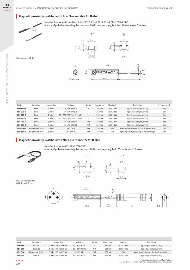
Products designed for industrial applications. General terms and conditions for sale are available on www.camozzi.com.
SERIES CST-CSV-CSH-CSB-CSC-CSD-CSG SENSORSPROXIMITY SWITCHES > PNEUMATIC ACTUATION 2019
2878.05.08
SERI
ES C
ST-C
SV-C
SH-C
SB-C
SC-C
SD-C
SG S
ENSO
RS
Magnetic proximity switches with 2- or 3-wire cable for H-slot
Note for 2-wire switches Mod. CSH-223-2, CSH-223-5, CSH-221-2, CSH-221-5: in case of polarity reversing the sensor will still be operating, but the LED diode won’t turn on.
Mod. Operation Connection Voltage Output Max current Max load Protection L = cable legth
CSH-223-2 Reed 2 wires 10 ÷ 30 V AC/DC - 250 mA 10 VA / 8 W Against polarity reversing 2 m
CSH-223-5 Reed 2 wires 10 ÷ 30 V AC/DC - 250 mA 10 VA / 8 W Against polarity reversing 5 m
CSH-221-2 Reed 2 wires 30 ÷ 230 V AC - 30 ÷ 110 V DC - 250 mA 10 VA / 8 W Against polarity reversing 2 m
CSH-221-5 Reed 2 wires 30 ÷ 230 V AC - 30 ÷ 110 V DC - 250 mA 10 VA / 8 W Against polarity reversing 5 m
CSH-233-2 Reed 3 wires 10 ÷ 30 V AC/DC PNP 250 mA 10 VA / 8 W Against polarity reversing 2 m
CSH-233-5 Reed 3 wires 10 ÷ 30 V AC/DC PNP 250 mA 10 VA / 8 W Against polarity reversing 5 m
CSH-334-2 Magnetoresistive 3 wires 10 ÷ 27 V DC PNP 250 mA 6 W Against polarity reversing and overvoltage 2 m
CSH-334-5 Magnetoresistive 3 wires 10 ÷ 27 V DC PNP 250 mA 6 W Against polarity reversing and overvoltage 5 m
Suitable also for T-slots
Magnetic proximity switches wtih M8 3-pin connector for H-slot
Note for 2-wire switch Mod. CSH-253: in case of polarity reversing the sensor will still be operating, but LED diode won’t turn on.
Mod. Operation Connection Voltage Output Max current Max load Protection
CSH-253 Reed NO 2 wires M8 male 3 pin 10 ÷ 30 V AC/DC - 250 mA 10 VA / 8 W Against polarity reversing
CSH-263 Reed NO 3 wires M8 male 3 pin 10 ÷ 30 V AC/DC PNP 250 mA 10 VA / 8 W Against polarity reversing
CSH-364 Magnetoresistive 3 wires M8 male 3 pin 10 ÷ 27 V DC PNP 250 mA 6 W Against polarity reversing and overvoltage
CSH-463 Reed NC 3 wires M8 male 3 pin 10 ÷ 30 V AC/DC PNP 250 mA 10 VA / 8 W Against polarity reversing
Suitable also for T-slots Cable length: 0.3 m

Products designed for industrial applications. General terms and conditions for sale are available on www.camozzi.com.
SERIES CST-CSV-CSH-CSB-CSC-CSD-CSG SENSORSPNEUMATIC ACTUATION
2888.05.09
2019 PROXIMITY SWITCHES
SERI
ES C
ST-C
SV-C
SH-C
SB-C
SC-C
SD-C
SG S
ENSO
RS
>
Magnetic proximity switch with 2-wire cable for B-slot
In case of polarity reversing the sensor will still be operating, but the LED diode won’t turn on.
Mod. Operation Connections Voltage Output Max. current Max Load Protection L = length cable
CSB-D-220 Reed 2 fili 10÷110 V AC/DC PNP 50 mA 8 W / 10 VA Against polarity reversing and overvoltage 2 m
A = fixing screw B = Led indicator C = ideal position detection
Magnetic proximity switch with 2-wire 90° cable for B-slot
In case of polarity reversing the sensor will still be operating, but the LED diode won’t turn on.
Mod. Operation Connections Voltage Output Max. current Max Load Protection L = length cable
CSB-H-220 Reed 2 fili 10÷110 V AC/DC PNP 50 mA 8 W / 10 VA Against polarity reversing and overvoltage 2 m
A = fixing screw B = Led indicator C = ideal position detection

Products designed for industrial applications. General terms and conditions for sale are available on www.camozzi.com.
SERIES CST-CSV-CSH-CSB-CSC-CSD-CSG SENSORSPROXIMITY SWITCHES > PNEUMATIC ACTUATION 2019
2898.05.10
SERI
ES C
ST-C
SV-C
SH-C
SB-C
SC-C
SD-C
SG S
ENSO
RS
Magnetic proximity switch with 2-wire cable for C-slot
In case of polarity reversing the sensor will still be operating, but the LED diode won’t turn on.
Mod. Operation Connections Voltage Output Max. current Max Load Protection L = length cable
CSC-D-220 Reed 2 fili 10÷110 V AC/DC PNP 50 mA 8 W / 10 VA Against polarity reversing and overvoltage 2 m
A = fixing screw B = Led indicator C = ideal position detection
Magnetic proximity switch with 2-wire 90° cable for C-slot
In case of polarity reversing the sensor will still be operating, but the LED diode won’t turn on.
Mod. Operation Connections Voltage Output Max. current Max Load Protection L = length cable
CSC-H-220 Reed 2 fili 10÷110 V AC/DC PNP 50 mA 8 W / 10 VA Against polarity reversing and overvoltage 2 m
A = fixing screw B = Led indicator C = ideal position detection

Products designed for industrial applications. General terms and conditions for sale are available on www.camozzi.com.
SERIES CST-CSV-CSH-CSB-CSC-CSD-CSG SENSORSPNEUMATIC ACTUATION
2908.05.11
2019 PROXIMITY SWITCHES
SERI
ES C
ST-C
SV-C
SH-C
SB-C
SC-C
SD-C
SG S
ENSO
RS
>
Magnetic proximity switches, 3-wire cable, D-slot
Mod. Operation Connections Voltage Output Max. current Max Load Protection L = length cable
CSD-D-334 Magnetoresistive 3 wires 10 ÷ 27 V DC PNP 200 mA 6W Against polarity reversing and overvoltage 2 m
CSD-D-334-5 Magnetoresistive 3 wires 10 ÷ 27 V DC PNP 200 mA 6W Against polarity reversing and overvoltage 5 m
Magnetic proximity switches, 3-wire cable, D-slot with 90° cable
Mod. Operation Connections Voltage Output Max. current Max Load Protection L = length cable
CSD-H-334 Magnetoresistive 3 wires 10 ÷ 27 V DC PNP 200 mA 6 W Against polarity reversing and overvoltage 2 m
CSD-H-334-5 Magnetoresistive 3 wires 10 ÷ 27 V DC PNP 200 mA 6 W Against polarity reversing and overvoltage 5 m

Products designed for industrial applications. General terms and conditions for sale are available on www.camozzi.com.
SERIES CST-CSV-CSH-CSB-CSC-CSD-CSG SENSORSPROXIMITY SWITCHES > PNEUMATIC ACTUATION 2019
2918.05.12
SERI
ES C
ST-C
SV-C
SH-C
SB-C
SC-C
SD-C
SG S
ENSO
RS
Magnetic proximity switches, male M8 3-pin conn., D-slot, right
Mod. Operation Connection Voltage Output Max current Max load Protection
CSD-D-364 Magnetoresistive 3 wires with M8 connector 10 ÷ 27 V DC PNP 200 mA 6 W Against polarity reversing and overvoltage
Cable length: 0.3 m
Magnetic proximity switches, male M8 3-pin conn., D-slot, 90°
Mod. Operation Connection Voltage Output Max current Max load Protection
CSD-H-364 Magnetoresistive 3 wires with M8 connector 10 ÷ 27 V DC PNP 200 mA 6 W Against polarity reversing and overvoltage
Cable length: 0.3 m

Products designed for industrial applications. General terms and conditions for sale are available on www.camozzi.com.
SERIES CST-CSV-CSH-CSB-CSC-CSD-CSG SENSORSPNEUMATIC ACTUATION
2928.05.13
2019 PROXIMITY SWITCHES
SERI
ES C
ST-C
SV-C
SH-C
SB-C
SC-C
SD-C
SG S
ENSO
RS
>
Magnetic proximity switches, ATEX “II 3 GD” certified, T-slot, right
Note for 2-wire switches Mod. CSG-223-2-EX, CSG-223-5-EX, CSG-324-2-EX, CSG-324-5-EX: in case of polarity reversing the sensor will still be operating, but the LED diode won’t turn on.
Mod. Operation Connection Voltage Output Max current Max load Protection L = cable length (m) LED colour
CSG-223-2-EX Reed NO 2 wires 5 ÷ 30 V AC/DC - 100 mA 3 W IP67 2 Red
CSG-223-5-EX Reed NO 2 wires 5 ÷ 30 V AC/DC - 100 mA 3 W IP67 5 Red
CSG-233-2-EX Reed NO 3 wires 10 ÷ 30 V AC/DC - 500 mA 10 W IP67 2 Yellow
CSG-233-5-EX Reed NO 3 wires 10 ÷ 30 V AC/DC - 500 mA 10 W IP67 5 Yellow
CSG-324-2-EX Magnetoresistive NO 2 wires 10 ÷ 28 V DC - 50 mA 1.5 W IP67 2 Red
CSG-324-5-EX Magnetoresistive NO 2 wires 10 ÷ 28 V DC - 50 mA 1.5 W IP67 5 Red
CSG-334-2-EX Magnetoresistive NO 3 wires 10 ÷ 28 V DC PNP 200 mA 5.5 W IP67 2 Yellow
CSG-334-5-EX Magnetoresistive NO 3 wires 10 ÷ 28 V DC PNP 200 mA 5.5 W IP67 5 Yellow
CSG-534-2-EX Magnetoresistive NO 3 wires 10 ÷ 28 V DC NPN 200 mA 5.5 W IP67 2 Red
CSG-534-5-EX Magnetoresistive NO 3 wires 10 ÷ 28 V DC NPN 200 mA 5.5 W IP67 5 Red
CSG-734-2-EX Magnetoresistive NC 3 wires 10 ÷ 28 V DC NPN 200 mA 5.5 W IP67 2 Red
CSG-734-5-EX Magnetoresistive NC 3 wires 10 ÷ 28 V DC NPN 200 mA 5.5 W IP67 5 Red
CSG-634-2-EX Magnetoresistive NC 3 wires 10 ÷ 28 V DC PNP 200 mA 5.5 W IP67 2 Yellow
CSG-634-5-EX Magnetoresistive NC 3 wires 10 ÷ 28 V DC PNP 200 mA 5.5 W IP67 5 Yellow
Top mounting with the new fixing system
New
Magnetic proximity switches, UL certified, T-slot, right
Note for 2-wire switches Mod. CSG-223-2-UL, CSG-223-5-UL, CSG-324-2-UL, CSG-324-5-UL: in case of polarity reversing the sensor will still be operating, but the LED diode won’t turn on.
Mod. Operation Connection Voltage Output Max current Max load Protection L = cable length (m) LED colour
CSG-223-2-UL Reed 2 wires 5 ÷ 30 V AC/DC - 60 mA 1.8 W IP67 2 Red
CSG-223-5-UL Reed 2 wires 5 ÷ 30 V AC/DC - 60 mA 1.8 W IP67 5 Red
CSG-233-2-UL Reed 3 wires 10 ÷ 30 V AC/DC - 100 mA 3 W IP67 2 Yellow
CSG-233-5-UL Reed 3 wires 10 ÷ 30 V AC/DC - 100 mA 3 W IP67 5 Yellow
CSG-324-2-UL Magnetoresistive 2 wires 10 ÷ 28 V DC - 40 mA 1.2 W IP67 2 Red
CSG-324-5-UL Magnetoresistive 2 wires 10 ÷ 28 V DC - 40 mA 1.2 W IP67 5 Red
CSG-334-2-UL Magnetoresistive 3 wires 10 ÷ 28 V DC PNP 100 mA 3 W IP67 2 Yellow
CSG-334-5-UL Magnetoresistive 3 wires 10 ÷ 28 V DC PNP 100 mA 3 W IP67 5 Yellow
CSG-534-2-UL Magnetoresistive 3 wires 10 ÷ 28 V DC NPN 100 mA 3 W IP67 2 Red
CSG-534-5-UL Magnetoresistive 3 wires 10 ÷ 28 V DC NPN 100 mA 3 W IP67 5 Red
Top mounting with the new fixing system
New

Products designed for industrial applications. General terms and conditions for sale are available on www.camozzi.com.
SERIES CST-CSV-CSH-CSB-CSC-CSD-CSG SENSORSPROXIMITY SWITCHES > PNEUMATIC ACTUATION 2019
2938.05.14
SERI
ES C
ST-C
SV-C
SH-C
SB-C
SC-C
SD-C
SG S
ENSO
RS
Load curves of sensors Mod. CSH, CST, CSV
CSH-223, CSH-253, CSH-233, CSH-263, CSH-463 CSH-334, CSH-364
CST-250N, CSV-250N CST-232, CSV-232, CST-262, CSV-262
CST-332, CSV-332, CST-362, CSV-362, CST-532, CSV-562, CSH-221, CST-220, CSV-220

Products designed for industrial applications. General terms and conditions for sale are available on www.camozzi.com.
SERIES CST-CSV-CSH-CSB-CSC-CSD-CSG SENSORSPNEUMATIC ACTUATION
2948.05.15
2019 PROXIMITY SWITCHES
SERI
ES C
ST-C
SV-C
SH-C
SB-C
SC-C
SD-C
SG S
ENSO
RS
>
Load curves of sensors Mod. CSB, CSC, CSD, CSG
CSB-D-220, CSB-H-220, CSC-D-220, CSC-H-220 CSD-D-334, CSD-H-334, CSD-D-364, CSD-H-364
CSG-223-UL CSG-324-UL
CSG-334-UL, CSG-534-UL CSG-233-UL

Products designed for industrial applications. General terms and conditions for sale are available on www.camozzi.com.
SERIES CST-CSV-CSH-CSB-CSC-CSD-CSG SENSORSPROXIMITY SWITCHES > PNEUMATIC ACTUATION 2019
2958.05.16
SERI
ES C
ST-C
SV-C
SH-C
SB-C
SC-C
SD-C
SG S
ENSO
RS
Load curves of sensors Mod. CSG
CSG-223-EX CSG-324-EX
CSG-334-EX, CSG-534-EX, CSG-634-EX, CSG-734-EX, CSG-233-EX

Products designed for industrial applications. General terms and conditions for sale are available on www.camozzi.com.
SERIES CST-CSV-CSH-CSB-CSC-CSD-CSG SENSORSPNEUMATIC ACTUATION
2968.05.17
2019 PROXIMITY SWITCHES
SERI
ES C
ST-C
SV-C
SH-C
SB-C
SC-C
SD-C
SG S
ENSO
RS
>
DC applications: there is no protection on the Reed sensors on the inductive load, therefore it is advisable to use an electric ciruit with protection against the voltage spikes. See picture above for a typical example. Legend: 1 = Sensor 2 = Load 3 = Protection diode
Electric circuit with protection against voltage spikes
DC and AC applications: there is no protection on the Reed sensors on the inductive load, therefore it is advisable to use an electric ciruit with protection against the voltage spikes. See picture above for a typical example. Legend: 1 = Sensor 2 = Load 3 = Protection varistor
AC applications: there is no protection on the Reed sensors on the inductive load, therefore it is advisable to use an electric circuit with protection against the voltage spikes. See picture above for a typical example. Legend: 1 = Sensor 2 = Load C + R = Series of resistor and protection capacitor
Electric circuit with protection against voltage spikes

Products designed for industrial applications. General terms and conditions for sale are available on www.camozzi.com.
SERIES CST-CSV-CSH-CSB-CSC-CSD-CSG SENSORSPROXIMITY SWITCHES > PNEUMATIC ACTUATION 2019
2978.05.18
SERI
ES C
ST-C
SV-C
SH-C
SB-C
SC-C
SD-C
SG S
ENSO
RS
Mounting of Series CST - CSH - CSG sensors
CST/CSH/CSG sensors can be directly mounted on cylinders: Series 31, 31R, 32, 32R Series 52 Series 61 Series 62, 63 (CSH only) Series 69 Series 6PF Series QC, QCBF, QCTF
Mounting of Series CSV sensors
CSV sensors must be assembled directly into the groove of cylinders: Series 50 ø 16÷25 Series QP - QPR ø 12÷16
3-wire extension with M8 3-pin female connector
With PU sheathing, non shielded cable. Protection class: IP65 1 BN = Brown 4 BK = Black 3 BU = Blue
Mod. L = cable length (m)
CS-2 2
CS-5 5
CS-10 10
In case 2-wire sensors with M8 connector (Mod. CST-250N, CSV-250N, CSH-253) are used, please connect the brown wire to the supply (+) and the black wire to the load.

Products designed for industrial applications. General terms and conditions for sale are available on www.camozzi.com.
SERIES CST-CSV-CSH-CSB-CSC-CSD-CSG SENSORSPNEUMATIC ACTUATION
2988.05.19
2019 PROXIMITY SWITCHES
SERI
ES C
ST-C
SV-C
SH-C
SB-C
SC-C
SD-C
SG S
ENSO
RS
>
3-wire extension with M8 3-pin male / female connector
Non shielded
Mod. cable length “L” (m)
CS-DW03HB-C250 2,5
CS-DW03HB-C500 5
Adapters Mod. S-CST-01 for Series CST-CSH-CSG sensors, V-slot
Mod. Series QP-QPR cylinders Series 50 cylinders
S-CST-01 Ø 20 ÷ 100 Ø 32 ÷ 80
Adapters Mod. S-CST-02..21 for Series CST-CSH-CSG sensors
Mod. Cylinders Series Ø
S-CST-02 24-25-27 16
S-CST-03 24-25-27 20
S-CST-04 24-25-27 25
S-CST-05 94, 95 16-20-25 (94), 16-20 (95)
S-CST-06 90-92-97, 95 32 (90-92-97), 25 (95)
S-CST-07 90-92-97 40
S-CST-08 90-92-97 50
S-CST-09 90-92-97 63
S-CST-10 90 80
S-CST-11 90 100
S-CST-12 90 125
S-CST-18 27-42 32
S-CST-19 27-42 40
S-CST-20 27-42 50
S-CST-21 27-42 63
Materials: - stainless steel and technopolymer (S-CST-05÷12)* - technopolymer (S-CST-02÷04) - technopolymer (S-CST-18÷21) * Not suitable for use with Series CSG sensors

Products designed for industrial applications. General terms and conditions for sale are available on www.camozzi.com.
SERIES CST-CSV-CSH-CSB-CSC-CSD-CSG SENSORSPROXIMITY SWITCHES > PNEUMATIC ACTUATION 2019
2998.05.20
SERI
ES C
ST-C
SV-C
SH-C
SB-C
SC-C
SD-C
SG S
ENSO
RS
Adapters Mod. S-CST-25..28 for Series CST-CSH-CSG sensors
Material: anodized aluminium
Mod. Cylinders Series Ø
S-CST-25 60 - 90 - 63MT 32 ÷ 63
S-CST-26 60 - 90 - 63MT 80 ÷ 100
S-CST-27 60 - 90 - 63MT 125
S-CST-28 40 160 - 200
Adapters for Series CST-CSH-CSG sensors
For Series 60 cylinders mounted with guides 45NHT or 45NHB. S-CST-45N1 is not suitable for use with Series CSG sensors.
Mod. Cylinders Series Ø
S-CST-45N1 60 - 90 - 63MT 32 ÷ 63
S-CST-45N2 60 - 90 - 63MT 80 ÷ 100
Slot cover profile suitable for actuators with T- and H-slot
Supplied with 500 mm tube
Mod. Series of cylinders
S-CST-500 31, 31 Tandem and Multi-position, QCT, QCB, QCBT, QCBF, 61, 62, 63MP, 6E, 5E, 69, 32, 32 Tandem and Multi-position

Products designed for industrial applications. General terms and conditions for sale are available on www.camozzi.com.
SERIES CSN PROXIMITY SWITCHESPNEUMATIC ACTUATION
3008.10.01
2019 PROXIMITY SWITCHES
SERI
ES C
SN P
ROXI
MIT
Y SW
ITCH
ES
>
Series CSN proximity switches
Reed switch
The electrical proximity switch Mod. CSN 2032-0 consists of a Reed switch complete with an electronic protection circuit and a red LED indicator. The resin inside the casing ensures high protection and insulation.
It is designed so that it can be fixed directly on the tie-rod by means of two screws which assure the position longitudinal to the cylinder axle; and with a third screw for the anti-rotation positioning. The three terminals are indicated by the numbers 1, 2 and 3 and enable the following connections to be made (see the scheme).
GENERAL DATA
Mod. CSN 2032-0Voltage from 12 to 220V AC and DCProtection IP54 / IP65 with connector DIN 43650Material glass-reinforced PAMounting bracket for tie rod ø 6 ÷ ø 10Signalling integrated red LEDElectrical connection DIN 43650 connector, Mod. 122-800Max. current 1.5 AMax. load 20 W DC - 30 VA ACActuating time ≤ 2 msActuating tolerance ± 1mmOperating temperature - 25°C ÷ + 75°CType of contact NO (normally open)

Products designed for industrial applications. General terms and conditions for sale are available on www.camozzi.com.
SERIES CSN PROXIMITY SWITCHESPROXIMITY SWITCHES > PNEUMATIC ACTUATION 2019
3018.10.02
SERI
ES C
SN P
ROXI
MIT
Y SW
ITCH
ES
CONNECTION - For inductive loads = solenoid valves, electrical magnets, relay. To connectors = terminals 1 - 2 - For capacitive loads = circuit with remaining tension (see PLC controls) To connectors = 1 - 3 Note: For connections with wires of approximately 10m, the connection shall be made as for a capacitive load. MAXIMUM LOADS For maximum loads see relative diagram, those loads are valid only for inductive loads. For capacitive loads, using clamp 3 (or black wire) load must not exceed 80 mA and load must be given by PLC or, for electrical circuits, by microrelay or micro solenoid valves with 2W maximum consumption. Note: When operating with direct current, clamp 1 must always be connected to the positive outlet (+). In cases where commands are given from the PLC and logic NPN, clamp 1 must be connected to the inlet. In cases where commands are given from the PLC and logic PNP, clamps 2 or 3 must be connected to the inlet. LEGEND: C1 = capacitive load C2 = inductive load
TECHNICAL DATA
The maximum load (W) which the contacts are able to tolerate is that indicated in the section “General data”, i.e. - 20 W for direct current ( DC ) - 30 VA for alternating current ( AC ) The effective load allowed depends on the operating voltage (minimum 12 V, maximum 220 V) as shown in the following graph. Note: this graph was obtained from practical tests performed using a load consisting of our Series A and 6 solenoid valves, at an operating speed of one stroke per second. For higher operating speeds, your are advised to contact our technical department.
Maximum contact load

Products designed for industrial applications. General terms and conditions for sale are available on www.camozzi.com.
SERIES CSN PROXIMITY SWITCHESPNEUMATIC ACTUATION
3028.10.03
2019 PROXIMITY SWITCHES
SERI
ES C
SN P
ROXI
MIT
Y SW
ITCH
ES
>
Switches Series CSN
Mod. for cylinders Series 40 - ø 160 ÷ 200 for cylinders Series 40 - ø 250 ÷ 320 for cylinders Series 41 - ø 160 ÷ 200
CSN 2032-0 mounting band to be ordered separately direct mounting mounting band to be ordered separately
Mounting bracket for sensor
Mod.
S21 for cylinders Series 40 ø 160 and 200
S53 for cylinders Series 41 ø 160 and 200
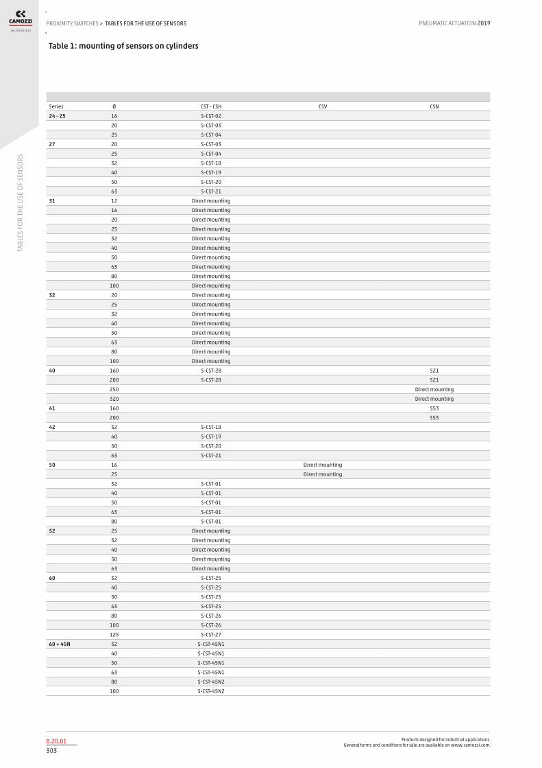
Products designed for industrial applications. General terms and conditions for sale are available on www.camozzi.com.
TABLES FOR THE USE OF SENSORSPROXIMITY SWITCHES > PNEUMATIC ACTUATION 2019
3038.20.01
TABL
ES F
OR TH
E US
E OF
SEN
SORS
Series Ø CST - CSH CSV CSN
24 - 25 16 S-CST-02
20 S-CST-03
25 S-CST-04
27 20 S-CST-03
25 S-CST-04
32 S-CST-18
40 S-CST-19
50 S-CST-20
63 S-CST-21
31 12 Direct mounting
16 Direct mounting
20 Direct mounting
25 Direct mounting
32 Direct mounting
40 Direct mounting
50 Direct mounting
63 Direct mounting
80 Direct mounting
100 Direct mounting
32 20 Direct mounting
25 Direct mounting
32 Direct mounting
40 Direct mounting
50 Direct mounting
63 Direct mounting
80 Direct mounting
100 Direct mounting
40 160 S-CST-28 S21
200 S-CST-28 S21
250 Direct mounting
320 Direct mounting
41 160 S53
200 S53
42 32 S-CST-18
40 S-CST-19
50 S-CST-20
63 S-CST-21
50 16 Direct mounting
25 Direct mounting
32 S-CST-01
40 S-CST-01
50 S-CST-01
63 S-CST-01
80 S-CST-01
52 25 Direct mounting
32 Direct mounting
40 Direct mounting
50 Direct mounting
63 Direct mounting
60 32 S-CST-25
40 S-CST-25
50 S-CST-25
63 S-CST-25
80 S-CST-26
100 S-CST-26
125 S-CST-27
60 + 45N 32 S-CST-45N1
40 S-CST-45N1
50 S-CST-45N1
63 S-CST-45N1
80 S-CST-45N2
100 S-CST-45N2
Table 1: mounting of sensors on cylinders
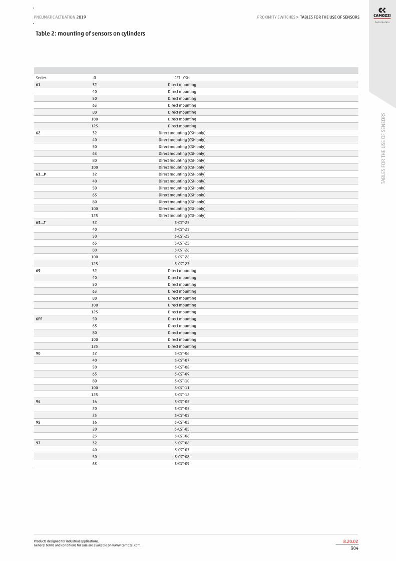
Products designed for industrial applications. General terms and conditions for sale are available on www.camozzi.com.
TABLES FOR THE USE OF SENSORSPNEUMATIC ACTUATION
3048.20.02
2019 PROXIMITY SWITCHES
TABL
ES F
OR TH
E US
E OF
SEN
SORS
>
Series Ø CST - CSH
61 32 Direct mounting
40 Direct mounting
50 Direct mounting
63 Direct mounting
80 Direct mounting
100 Direct mounting
125 Direct mounting
62 32 Direct mounting (CSH only)
40 Direct mounting (CSH only)
50 Direct mounting (CSH only)
63 Direct mounting (CSH only)
80 Direct mounting (CSH only)
100 Direct mounting (CSH only)
63...P 32 Direct mounting (CSH only)
40 Direct mounting (CSH only)
50 Direct mounting (CSH only)
63 Direct mounting (CSH only)
80 Direct mounting (CSH only)
100 Direct mounting (CSH only)
125 Direct mounting (CSH only)
63...T 32 S-CST-25
40 S-CST-25
50 S-CST-25
63 S-CST-25
80 S-CST-26
100 S-CST-26
125 S-CST-27
69 32 Direct mounting
40 Direct mounting
50 Direct mounting
63 Direct mounting
80 Direct mounting
100 Direct mounting
125 Direct mounting
6PF 50 Direct mounting
63 Direct mounting
80 Direct mounting
100 Direct mounting
125 Direct mounting
90 32 S-CST-06
40 S-CST-07
50 S-CST-08
63 S-CST-09
80 S-CST-10
100 S-CST-11
125 S-CST-12
94 16 S-CST-05
20 S-CST-05
25 S-CST-05
95 16 S-CST-05
20 S-CST-05
25 S-CST-06
97 32 S-CST-06
40 S-CST-07
50 S-CST-08
63 S-CST-09
Table 2: mounting of sensors on cylinders

Products designed for industrial applications. General terms and conditions for sale are available on www.camozzi.com.
TABLES FOR THE USE OF SENSORSPROXIMITY SWITCHES > PNEUMATIC ACTUATION 2019
3058.20.03
TABL
ES F
OR TH
E US
E OF
SEN
SORS
Series Ø CST - CSH CSV CSC-D / CSC-H
QC 20 Direct mounting
25 Direct mounting
32 Direct mounting
40 Direct mounting
50 Direct mounting
63 Direct mounting
QCBF 20 Direct mounting
25 Direct mounting
32 Direct mounting
40 Direct mounting
QCTF 20 Direct mounting
25 Direct mounting
32 Direct mounting
40 Direct mounting
QP - QPR 12 Direct mounting
16 Direct mounting
20 S-CST-01
25 S-CST-01
32 S-CST-01
40 S-CST-01
50 S-CST-01
63 S-CST-01
80 S-CST-01
100 S-CST-01
QX 10 Direct mounting
16 Direct mounting
20 Direct mounting
25 Direct mounting
32 Direct mounting
ST 20 Direct mounting
32 Direct mounting
40 Direct mounting
50 Direct mounting
Table 3: mounting of sensors on cylinders

Products designed for industrial applications. General terms and conditions for sale are available on www.camozzi.com.
TABLES FOR THE USE OF SENSORSPNEUMATIC ACTUATION
3068.20.04
2019 PROXIMITY SWITCHES
TABL
ES F
OR TH
E US
E OF
SEN
SORS
>
Series Ø CST - CSH CSB-D / CSB-H CSC-D / CSC-H CSD-D / CSD-H
Grippers
CGA 10 Direct mounting
16 Direct mounting
20 Direct mounting
25 Direct mounting
32 Direct mounting
CGC 50 Direct mounting (CSB-D-220 only)
64 Direct mounting (CSB-D-220 only)
80 Direct mounting (CSB-D-220 only)
100 Direct mounting (CSB-D-220 only)
125 Direct mounting (CSB-D-220 only)
CGLN 10 Direct mounting
16 Direct mounting
20 Direct mounting
25 Direct mounting
32 Direct mounting
CGP 10 Direct mounting
16 Direct mounting
20 Direct mounting
25 Direct mounting
32 Direct mounting
CGPS 10 Direct mounting
16 Direct mounting
20 Direct mounting
25 Direct mounting
32 Direct mounting
CGPT 16 Direct mounting
20 Direct mounting
25 Direct mounting
32 Direct mounting
40 Direct mounting
CGSN 16 Direct mounting Direct mounting
20 Direct mounting Direct mounting
25 Direct mounting Direct mounting
32 Direct mounting Direct mounting
RPGB 8 Direct mounting
12 Direct mounting
Electromechanical axis *
5E 50 Direct mounting (CSH only)
65 Direct mounting (CSH only)
80 Direct mounting (CSH only)
Electromechanical cylinders *
6E 32 Direct mounting
40 Direct mounting
50 Direct mounting
63 Direct mounting
* Further details about Series 5E electromechanical axis and Series 6E electromechanical cylinders can be found in the C_Electrics catalogue which is also available on the Camozzi website www.camozzi.com within the section Products & Solutions › C_Electrics.
Table 4: mounting of sensors on grippers, electromechanical axis/cylinders

Products designed for industrial applications. General terms and conditions for sale are available on www.camozzi.com.
SERIES 43 HYDROCHECKSADDITIONAL CYLINDERS ACCESSORIES > PNEUMATIC ACTUATION 2019
3079.05.01
SERI
ES 4
3 HY
DROC
HECK
S
Series 43 hydrochecks
Bore ø 40mm Regulated thrust or return stroke Skip-Stop function
Series 43 hydrocheck units are available with two different types of control: regulated outward movement and fast return; or fast outward movement and regulated return. These hydrochecks come complete with an oil surge tank which ensures automatic equalisation. Speed variation is obtained by means of an incorporated flow regulator designed to allow comprehensive and constant use.
Upon request, they can be supplied with an incorporated stop valve or an acceleration valve or both. To restore oil when the minimum level in the surge tank is reached, use the following oil and pump Mod. 43N-PMP: hydraulic oil, class H, ISO symbol HG 46, viscosity 4.5 E. at 40°C.
GENERAL DATAType of construction with tie-rodsOperation regulation of the hydrocheck’s rod return (thrust)
regulation of the hydrocheck’s rod thrust (traction)Controllable load max. 600 Kgf without valves, max 500 Kgf with valves (including inertia of moving masses)Operating temperature -10°C ÷ +60°CMedia hydraulic oil, class H, ISO symbol HG 46, viscosity 4.5 E. at 40°CSpeed 70 - 10000 mm/min without valves, 0 - 6000 mm/min with valvesStandard stroke 50, 100, 150, 200 (special stroke available on request)Special designs with STOP or SKIP and SKIP/STOP valve *SKIP/STOP valve operating pressure 4 ÷ 8 barType of mounting feet Mod. B-40 (see B-41-40 for dimensions)
* = minimum stroke 80mm
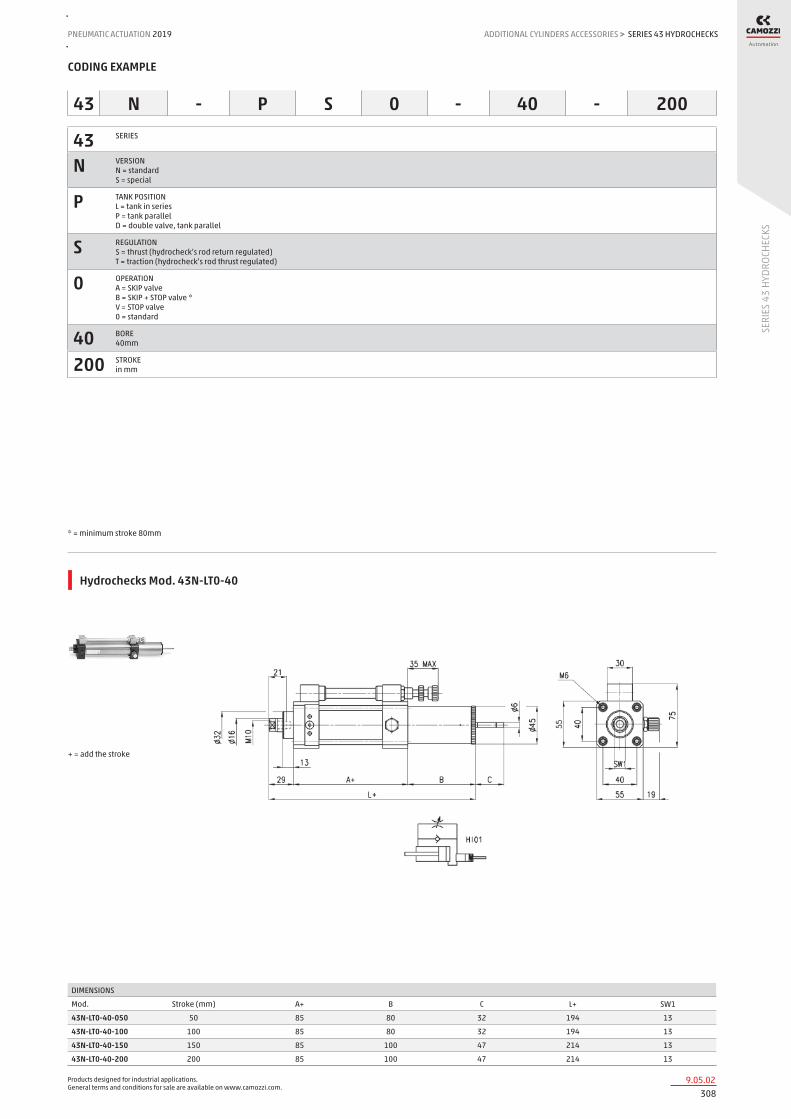
Products designed for industrial applications. General terms and conditions for sale are available on www.camozzi.com.
SERIES 43 HYDROCHECKSPNEUMATIC ACTUATION
3089.05.02
2019 ADDITIONAL CYLINDERS ACCESSORIES
SERI
ES 4
3 HY
DROC
HECK
S
>
CODING EXAMPLE
43 SERIES
N VERSION N = standard S = special
P TANK POSITION L = tank in series P = tank parallel D = double valve, tank parallel
S REGULATION S = thrust (hydrocheck’s rod return regulated) T = traction (hydrocheck’s rod thrust regulated)
0 OPERATION A = SKIP valve B = SKIP + STOP valve * V = STOP valve 0 = standard
40 BORE 40mm
200 STROKE in mm
* = minimum stroke 80mm
43 N - P S 0 - 40 - 200
Hydrochecks Mod. 43N-LT0-40
DIMENSIONS
Mod. Stroke (mm) A+ B C L+ SW1
43N-LT0-40-050 50 85 80 32 194 13
43N-LT0-40-100 100 85 80 32 194 13
43N-LT0-40-150 150 85 100 47 214 13
43N-LT0-40-200 200 85 100 47 214 13
+ = add the stroke

Products designed for industrial applications. General terms and conditions for sale are available on www.camozzi.com.
SERIES 43 HYDROCHECKSADDITIONAL CYLINDERS ACCESSORIES > PNEUMATIC ACTUATION 2019
3099.05.03
SERI
ES 4
3 HY
DROC
HECK
S
Hydrochecks Mod. 43N-LTA-40 and 43N-LTV-40
On request
DIMENSIONS
Mod. Stroke (mm) A+ B C L+ SW1 Pneumatic symbol
43N-LTA-40-050 50 85 80 32 194 13 HI05
43N-LTA-40-100 100 85 80 32 194 13 HI05
43N-LTA-40-150 150 85 100 47 214 13 HI05
43N-LTA-40-200 200 85 100 47 214 13 HI05
43N-LTV-40-050 50 85 80 32 194 13 HI03
43N-LTV-40-100 100 85 80 32 194 13 HI03
43N-LTV-40-150 150 85 100 47 214 13 HI03
43N-LTV-40-200 200 85 100 47 214 13 HI03
+ = add the stroke
Hydrochecks Mod. 43N-LTB-40
On request
DIMENSIONS
Mod. Stroke (mm) A+ B C L+ SW1
43N-LTB-40-050 50 85 80 32 194 13
43N-LTB-40-100 100 85 80 32 194 13
43N-LTB-40-150 150 85 100 47 214 13
43N-LTB-40-200 200 85 100 47 214 13
+ = add the stroke

Products designed for industrial applications. General terms and conditions for sale are available on www.camozzi.com.
SERIES 43 HYDROCHECKSPNEUMATIC ACTUATION
3109.05.04
2019 ADDITIONAL CYLINDERS ACCESSORIES
SERI
ES 4
3 HY
DROC
HECK
S
>
Hydrochecks Mod. 43N-PT0-40
On request
DIMENSIONS
Mod. Stroke (mm) A+ B C L+ SW1
43N-PT0-40-050 50 85 100 32 114 13
43N-PT0-40-100 100 85 105 32 114 13
43N-PT0-40-150 150 85 125 47 114 13
43N-PT0-40-200 200 85 125 47 114 13
+ = add the stroke
Hydrochecks Mod. 43N-PTA-40 and 43N-PTV-40
DIMENSIONS
Mod. Stroke (mm) A+ B C L+ SW1 Pneumatic symbol
43N-PTA-40-050 50 85 100 32 114 13 HI05
43N-PTA-40-100 100 85 105 32 114 13 HI05
43N-PTA-40-150 150 85 125 47 114 13 HI05
43N-PTA-40-200 200 85 125 47 114 13 HI05
43N-PTV-40-050 50 85 100 32 114 13 HI03
43N-PTV-40-100 100 85 105 32 114 13 HI03
43N-PTV-40-150 150 85 125 47 114 13 HI03
43N-PTV-40-200 200 85 125 47 114 13 HI03
+ = add the stroke

Products designed for industrial applications. General terms and conditions for sale are available on www.camozzi.com.
SERIES 43 HYDROCHECKSADDITIONAL CYLINDERS ACCESSORIES > PNEUMATIC ACTUATION 2019
3119.05.05
SERI
ES 4
3 HY
DROC
HECK
S
Hydrochecks Mod. 43N-PTB-40
DIMENSIONS
Mod. Stroke (mm) A+ B C L+ SW1
43N-PTB-40-050 50 85 100 32 114 13
43N-PTB-40-100 100 85 105 32 114 13
43N-PTB-40-150 150 85 125 47 114 13
43N-PTB-40-200 200 85 125 47 114 13
+ = add the stroke
Hydrochecks Mod. 43N-PS0-40
DIMENSIONS
Mod. Stroke (mm) A+ B C L+ SW1
43N-PS0-40-050 50 85 100 32 114 13
43N-PS0-40-100 100 85 105 32 114 13
43N-PS0-40-150 150 85 125 47 114 13
43N-PS0-40-200 200 85 125 47 114 13
+ = add the stroke

Products designed for industrial applications. General terms and conditions for sale are available on www.camozzi.com.
SERIES 43 HYDROCHECKSPNEUMATIC ACTUATION
3129.05.06
2019 ADDITIONAL CYLINDERS ACCESSORIES
SERI
ES 4
3 HY
DROC
HECK
S
>
Hydrochecks Mod. 43N-PSA-40 and 43N-PSV-40
On request
DIMENSIONS
Mod. Stroke (mm) A+ B C L+ SW1 Pneumatic symbol
43N-PSA-40-050 50 85 100 32 114 13 HI06
43N-PSV-40-050 50 85 100 32 114 13 HI04
43N-PSA-40-100 100 85 105 32 114 13 HI06
43N-PSV-40-100 100 85 105 32 114 13 HI04
43N-PSA-40-150 150 85 125 47 114 13 HI06
43N-PSV-40-150 150 85 125 47 114 13 HI04
43N-PSA-40-200 200 85 125 47 114 13 HI06
43N-PSV-40-200 200 85 125 47 114 13 HI04
+ = add the stroke
Hydrochecks Mod. 43N-PSB-40
DIMENSIONS
Mod. Stroke (mm) A+ B C L+ SW1
43N-PSB-40-100 100 85 105 32 114 13
43N-PSB-40-150 150 85 125 47 114 13
43N-PSB-40-200 200 85 125 47 114 13
+ = add the stroke
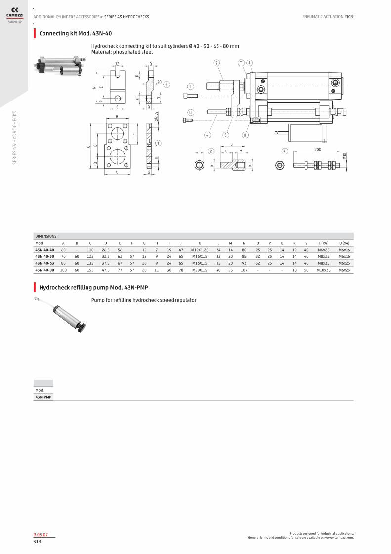
Products designed for industrial applications. General terms and conditions for sale are available on www.camozzi.com.
SERIES 43 HYDROCHECKSADDITIONAL CYLINDERS ACCESSORIES > PNEUMATIC ACTUATION 2019
3139.05.07
SERI
ES 4
3 HY
DROC
HECK
S
Connecting kit Mod. 43N-40
Hydrocheck connecting kit to suit cylinders Ø 40 - 50 - 63 - 80 mm Material: phosphated steel
DIMENSIONS
Mod. A B C D E F G H I J K L M N O P Q R S T (x4) U (x4)
43N-40-40 60 - 110 26.5 56 - 12 7 19 47 M12X1.25 24 14 80 25 25 14 12 40 M6x25 M6x16
43N-40-50 70 60 122 32.5 62 57 12 9 24 65 M16X1.5 32 20 88 32 25 14 14 40 M8x25 M6x16
43N-40-63 80 60 132 37.5 67 57 20 9 24 65 M16X1.5 32 20 93 32 25 14 14 40 M8x35 M6x25
43N-40-80 100 60 152 47.5 77 57 20 11 30 78 M20X1.5 40 25 107 - - - 18 50 M10x35 M6x25
Hydrocheck refilling pump Mod. 43N-PMP
Pump for refilling hydrocheck speed regulator
Mod.
43N-PMP

Products designed for industrial applications. General terms and conditions for sale are available on www.camozzi.com.
SERIES RL ROD LOCKPNEUMATIC ACTUATION
3149.10.01
2019 ADDITIONAL CYLINDERS ACCESSORIES
SERI
ES R
L ROD
LOCK
>
Series RL rod lock
For cylinders ISO 6431/VDMA and ISO 6432 ø 20, 25, 32, 40, 50, 63, 80, 100, 125 mm
Series RL rod locks are available in 9 different sizes (diameters: 20, 25, 32, 40, 50, 63, 80, 100 to 125 mm). The compact dimensions allow units to be fitted on cylinders where space is limited. Rod lock units are often used to hold the load in position during Emergency Stop conditions or when the air supply may be accidently disconnected from the system. The holding forces are measured at 8 bar and apply in both directions.
Caution! The rod lock should not be used to “brake” the piston rod in dynamic conditions and must only be applied when movement has ceased. Note: the cylinder piston rod length must be increased when using a rod lock unit. See the table for the minimum extension lengths for each diameter.
» Compact design
» Functioning in both directions
» Blocks without pressure releases with pressure
GENERAL DATAType of construction compactOperation piston operated clampMaterials housing: anodized AL
clamp: brass seals: NBR
Cylinder diameter ø 20 - 25 - 32 - 40 - 50 - 63 - 80 - 100 - 125Operating temperature 0°C ÷ 80°C (with dry air -20°C)Configuration pressure releaseOperating pressure 3 ÷ 8 barPorts M5 = ø20, 25, 32 - G1/8 = ø40, 50, 63, 80, 100, 125Fluid Filtered air without lubrication. If lubricated air is used, it is recommended to use ISOVG32 oil. Once applied the lubrication should
never be interrupted.

Products designed for industrial applications. General terms and conditions for sale are available on www.camozzi.com.
SERIES RL ROD LOCKADDITIONAL CYLINDERS ACCESSORIES > PNEUMATIC ACTUATION 2019
3159.10.02
SERI
ES R
L ROD
LOCK
CODING EXAMPLE
RLC SERIES RLC = standard, complete with cartridge and housing RLB = cartridge only
41 CYLINDER SERIES 24 = for Series 24 and 25 41 = for Series 60, 61 and 62
PNEUMATIC SYMBOL RDLK
32 CYLINDER DIAMETER (mm) 20 = 20 mm 25 = 25 mm 32 = 32 mm 40 = 40 mm 50 = 50 mm 63 = 63 mm 80 = 80 mm 100 = 100 mm 125 = 125 mm
RLC - 41 - 32
PNEUMATIC SYMBOLS
The pneumatic symbols which have been indicated in the CODING EXAMPLE are shown below.
For a correct use of the rod lock Mod. RLC a pneumatic connection is recommended (as shown in the examples).
CONNECTION EXAMPLES

Products designed for industrial applications. General terms and conditions for sale are available on www.camozzi.com.
SERIES RL ROD LOCKPNEUMATIC ACTUATION
3169.10.03
2019 ADDITIONAL CYLINDERS ACCESSORIES
SERI
ES R
L ROD
LOCK
>
ROD EXTENSION and HOLDING FORCE
Table showing the rod extensions which are necessary for the rod lock mounting.
ø Rod extension [X] (mm) Holding force [static load] (N)
20 +50 300
25 +48 400
32 +40 650
40 +43 1100
50 +57 1600
63 +57 2500
80 +80 4000
100 +80 6300
125 +125 8800

Products designed for industrial applications. General terms and conditions for sale are available on www.camozzi.com.
SERIES RL ROD LOCKADDITIONAL CYLINDERS ACCESSORIES > PNEUMATIC ACTUATION 2019
3179.10.04
SERI
ES R
L ROD
LOCK
Series RL Rod Lock - Ø 20 - 25 mm
DIMENSIONS
Mod. Ø D A D1 H L L1 L2 L3 L4 L5 L6
RLC-24-20 20 8 20 38 21 40 58 35 23 12 24 40
RLC-24-25 25 10 20 38 21 40 58 35 23 12 24 40
Series RL Rod Lock - Ø 32 ÷ 125 mm
Supplied with: - 4x screws
DIMENSIONS
Mod. Ø D D1 D2 D3 G L1 L2 L3 L4 L5 L6 L7 L8 A M H H1 Z
RLC-41-32 32 12 30,5 35 25 M5 58 48 10 8 13 20,5 34 45 32,5 M6 25,5 46,5 M6X20
RLC-41-40 40 16 35 40 28 G1/8 65 55 10 8 13 22,5 38 50 38 M6 30 53 M6X20
RLC-41-50 50 20 40 50 35 G1/8 82 70 12 15 16 29,5 48 60 46,5 M8 36 64 M8X30
RLC-41-63 63 20 45 60 38 G1/8 82 70 12 15 16 29,5 49,5 70 56,5 M8 40 75 M8X30
RLC-41-80 80 25 45 80 48 G1/8 110 90 20 18 20 35 61 90 72 M10 50 95 M10X35
RLC-41-100 100 25 55 100 58 G1/8 115 100 15 18 20 39 69 105 89 M10 58 110,5 M10X35
RLC-41-125 125 32 60 130 65 G1/8 167 122 45 22 30 51 86,5 140 110 M12 80 150 M12X40

Products designed for industrial applications. General terms and conditions for sale are available on www.camozzi.com.
SERIES SA SHOCK ABSORBERSPNEUMATIC ACTUATION
3189.15.01
2019 ADDITIONAL CYLINDERS ACCESSORIES
SERI
ES S
A SH
OCK
ABSO
RBER
S
>
Series SA shock absorbers
7 different sizes Threads: M8x1 - M10x1 - M12x1 - M14x1,5 - M20x1,5 - M25x1,5 - M27x1,5
Series SA shock absorbers exist in 7 different sizes and are used to provide impact and noise absorbtion when stopping objects in motion. Series SA is of a self compensating type which makes it suitable for different applications such as low load/high speed or high load/low speed applications without requiring any additional adjustments on the shock absorber. Series SA is designed so it can be used with or without a stop collar.
By using shock absorber Series SA, following advantages would be provided. - Increased production rate - Reduced maintenance costs - Reduce noise and vibration - Extended life time of the machine.
» Suitable for different applications
» Usable with or without a stop collar
» Self compensating
GENERAL DATA
Model SA-0806 SA-1007 SA-1210 SA-1412 SA-2015 SA-2525 SA-2725
Type of construction Hydraulic shock absorber, self compensatingMaterials Body: steel, black coated
Piston rod: carbon steel chrome plated Piston: carbon steel Sealings: NBR
Threaded body M8x 1 M10x 1 M12 x 1 M14x 1,5 M20x 1,5 M25x 1,5 M27x 1,5Absorption stroke (mm) 6 7 10 12 15 25 25Max. Energy absorption per cycle, Et (Nm) 3 6 12 20 59 80 147Max. Energy absorption per hour, ETc, (Nm) 7000 12400 22500 33000 38000 60000 72000Max. effective mass Me (kg) 6 12 22 40 120 180 270Max N° cycles per minute 80 70 40 70 45 20 10Impact speed, v (m/s) min. - max.
0,3 - 2,5 0,3 - 3,5 0,3 - 4,0 0,3 - 5,0 0,3 - 5,0 0,3 - 5,0 0,3 - 5,0
Weight (g) 15 25 32 65 150 295 360Working temperature (°C) -10°C ÷ +80°C

Products designed for industrial applications. General terms and conditions for sale are available on www.camozzi.com.
SERIES SA SHOCK ABSORBERSADDITIONAL CYLINDERS ACCESSORIES > PNEUMATIC ACTUATION 2019
3199.15.02
SERI
ES S
A SH
OCK
ABSO
RBER
S
CODING EXAMPLE
SA SERIES
0806 SIZE/STROKE 0806 = Size M8 x 1 / Stroke 6 mm 1007 = Size M10 x 1 / Stroke 7 mm 1210 = Size M12 x 1 / Stroke 10 mm 1412 = Size M14 x 1,5 / Stroke 12 mm 2015 = Size M20 x 1,5 / Stroke 15 mm 2525 = Size M25x 1,5 / Stroke 25 mm 2725 = Size M27 x 1,5 / Stroke 25 mm
VERSION = standard, with cap W = Without cap (on request)
SA - 2015
Shock Absorbers Series SA
DIMENSIONS
Mod. A B C D E F G I L SW X Weight (g)
SA-0806W M8X1 40.6 - 2.9 - 33.6 2 3 - 11 6 15
SA-0806 M8X1 40.6 6.6 2.9 8.8 33.6 2 3 55.4 11 6 17
SA-1007W M10X1 47 - 3 - 39 3 3 - 12.7 7 25
SA-1007 M10X1 47 8.6 3 8.6 39 3 3 62.6 12.7 7 28
SA-1210W M12X1 52.5 - 3 - 44 3 4 - 14 10 29
SA-1210 M12X1 52.5 10.3 3 8.8 44 3 4 71.3 14 10 32
SA-1412W M14X1.5 67 - 4 - 58 4 5 - 19 12 65
SA-1412 M14X1.5 67 12 4 10.5 58 4 5 89.5 19 12 70
SA-2015W M20X1.5 73 - 6 - 62 4 7 - 26 15 150
SA-2015 M20X1.5 73 17.8 6 15.8 62 4 7 103.8 26 15 160
SA-2525W M25X1.5 92 - 8 - 82 - 9 - 32 25 280
SA-2525 M25X1.5 92 22 8 19 82 - 9 136 32 25 295
SA-2725W M27X1.5 99 - 8 - 86 5 6.5 - 32 25 360
SA-2725 M27X1.5 99 22 8 19 86 5 6.5 143 32 25 375

Products designed for industrial applications. General terms and conditions for sale are available on www.camozzi.com.
SERIES SA SHOCK ABSORBERSPNEUMATIC ACTUATION
3209.15.03
2019 ADDITIONAL CYLINDERS ACCESSORIES
SERI
ES S
A SH
OCK
ABSO
RBER
S
>
Adjusted stroke nut
A = Initial position B = Final position 1 = Impact object 2 = Adjusted stroke nut 3 = Shock absorber 4 = Fixing screw 5 = Stroke 6 = Stroke length
DIMENSIONS
Mod. Ø A B C D E F
SA-08SC (for SA-0806) 10.5 14 9 M8X1 11 12.7
SA-10SC (for SA-1007) 12 16 10 M10X1 13 14.7
SA-12SC (for SA-1210) 14.5 20 13 M12X1 16 18.5
SA-14SC (for SA-1412) 14.5 27 15 M14X1 19 21.9
SA-20SC (for SA-2015) 27.8 35 20 M20X1.5 26 30
SA-25SC (for SA-2525) 5.8 45 30 M25X1.5 32 37
SA-27SC (for SA-2725) 20.7 65 50 M27X1.5 32 37
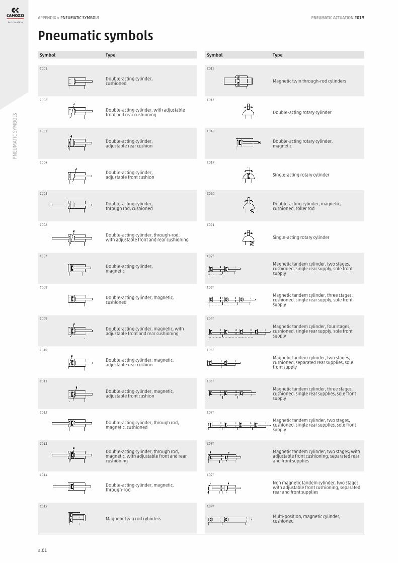
PNEUMATIC ACTUATION 2019
a.01
PNEU
MAT
IC S
YMBO
LS
CD16
Magnetic twin through-rod cylinders
CD17
Double-acting rotary cylinder
CD18
Double-acting rotary cylinder, magnetic
CD19
Single-acting rotary cylinder
CD20
Double-acting cylinder, magnetic, cushioned, roller rod
CD21
Single-acting rotary cylinder
CD2T
Magnetic tandem cylinder, two stages, cushioned, single rear supply, sole front supply
CD3T
Magnetic tandem cylinder, three stages, cushioned, single rear supply, sole front supply
CD4T
Magnetic tandem cylinder, four stages, cushioned, single rear supply, sole front supply
CD5T
Magnetic tandem cylinder, two stages, cushioned, separated rear supplies, sole front supply
CD6T
Magnetic tandem cylinder, three stages, cushioned, single rear supplies, sole front supply
CD7T
Magnetic tandem cylinder, two stages, cushioned, single rear supplies, sole front supply
CD8T
Magnetic tandem cylinder, two stages, with adjustable front cushioning, separated rear and front supplies
CD9T
Non magnetic tandem cylinder, two stages, with adjustable front cushioning, separated rear and front supplies
CDPP
Multi-position, magnetic cylinder,cushioned
CD01
Double-acting cylinder,cushioned
CD02
Double-acting cylinder, with adjustable front and rear cushioning
CD03
Double-acting cylinder, adjustable rear cushion
CD04
Double-acting cylinder, adjustable front cushion
CD05
Double-acting cylinder,through rod, cushioned
CD06
Double-acting cylinder, through-rod, with adjustable front and rear cushioning
CD07
Double-acting cylinder, magnetic
CD08
Double-acting cylinder, magnetic, cushioned
CD09
Double-acting cylinder, magnetic, with adjustable front and rear cushioning
CD10
Double-acting cylinder, magnetic, adjustable rear cushion
CD11
Double-acting cylinder, magnetic, adjustable front cushion
CD12
Double-acting cylinder, through rod, magnetic, cushioned
CD13
Double-acting cylinder, through rod, magnetic, with adjustable front and rear cushioning
CD14
Double-acting cylinder, magnetic, through-rod
CD15
Magnetic twin rod cylinders
Symbol Type Symbol Type
Pneumatic symbolsAPPENDIX > PNEUMATIC SYMBOLS

PNEUMATIC ACTUATION 2019
a.02
PNEU
MAT
IC S
YMBO
LS
Symbol Type Symbol Type
CDSS
Double-acting, rodless cylinder,magnetic
CS01
Single-acting cylinder, front spring
CS02
Single-acting cylinder, front spring, cushioned
CS03
Double-acting cylinder, front spring, cushioned
CS04
Single-acting cylinder, front spring,through rod, cushioned
CS05
Double-acting cylinder, front spring, through rod, with adjustable rear cushioning
CS06
Single-acting cylinder, front spring, magnetic, cushioned
CS07
Double-acting cylinder, front spring, magnetic, with adjustable rear cushioning
CS08
Single-acting cylinder, rear spring, magnetic, cushioned
CS09
Single-acting cylinder, magnetic, front spring
CS10
Single-acting cylinder, through rod, magnetic, cushioned
CS11
Double-acting cylinder, front spring, magnetic, through rod, with adjustablerear cushioning
CS12
Single-acting cylinder, front spring, magnetic, with adjustable rear cushioning
CS13
Single-acting cylinder, front spring, magnetic, through rod, with adjustable rear cushioning
CS14
Double-acting cylinder, rear spring, magnetic, with adjustable front cushioning
CS15
Single-acting cylinder, rear spring, magnetic, roller rod, cushioned
CS16
Double-acting cylinder, rear spring, magnetic, roller rod, cushioned
CS17
Double-acting cylinder, magnetic, rear spring, cushioned
CS18
Double-acting cylinder, magnetic, front spring, cushioned
HI01
Hydrocheck, regulated rod thrust
HI02
Hydrocheck, regulated rod return
HI03
Hydrocheck, regulated rod thrust with stop valve
HI04
Hydrocheck, regulated rod return with stop valve
HI05
Hydrocheck, regulated rod thrust with skip valve
HI06
Hydrocheck, regulated rod return with skip valve
HI07
Hydrocheck, regulated rod thrust with skip and stop valve
HI08
Hydrocheck, regulated rod return with skip and stop valve
RDLK
Rod lock device
APPENDIX > PNEUMATIC SYMBOLS

PNEUMATIC ACTUATION 2019
a.03
SPRI
NG LO
ADS
CYLI
NDER
S
stroke mm
Series 63 - front spring
stroke mm
Series 63 - rear spring
stroke mm
stroke mm
stroke mm
stroke mm
stroke mm
Series 16-24 Series 31-32
Series 31-32 Series 60-61-42-90
stroke mm
Series 14 - stroke 5 mm Series 14 - stroke 10 and 15 mm
Spring loads cylindersAPPENDIX > CARICHI MOLLE CILINDRI

PNEUMATIC ACTUATION 2019
a.04
SPRI
NG LO
ADS
CYLI
NDER
S
stroke mm
stroke mm
Series QN - stroke 10 mm
Series 90-97
* F = spring force
stroke mm
Series QN - stroke 25 mm
stroke mm
Series QN - stroke 4 and 5 mm
stroke mm
Series 94
stroke mm
Series QP
stroke mm
Series QP
APPENDIX > SPRING LOADS CYLINDERS

PNEUMATIC ACTUATION 2019
a.05
FLOW
AND
SPE
ED C
YLIN
DERS
Valves and solenoid valves
Flow regulatorElement being testedPressure regulator
Tap
Flow measurer
Flow survey instruments.
The flow rate indicated in the catalogue is obtained with P1 = 6 bar and P2 = 5 bar.
Air flow required by the valve (6 bar) to obtain the above indicated speeds (NI/min)
Cylinders diameter (mm) Mod. 32 40 50 63 80 100 125 GSCU-1/8”; GSVU-1/8”; GMCU-1/8”; GSCU-1/8” 336 517 517 517 517 517 517 GSCU-1/4”; GSVU-1/4”; GMCU-1/4”; GSCU-1/4” - 525 750 750 750 750 750 RFU 452 M5 69 - - - - - - RFU 482-1/8” 76 76 76 76 76 - - RFU 483-1/8” 175 175 175 175 175 175 - RFU 444-1/4” - 388 388 388 388 388 388 RFU 446-1/4” - - 697 697 697 697 697 SCU M5 - SVU M5 52 - - - - - - SCU-1/4”; SVU-1/4”; MCU-1/4”; MVU-1/4” - 525 543 543 543 543 543 SCU-1/8”; SVU-1/8”; MCU-1/8”; MVU-1/8” 203 203 203 203 203 203 - SCU-3/8”; MCU-3/8” - - - 815 815 815 815 SCU-1/2”; MCU-1/2” - - - - 2100 2846 -
To obtain the above indicated speeds, the connected tubing should have a certain diameter and not exceed, if indicated, the max length (m)
Tube diameter (mm) and max length (m) Mod. 4/2 6/4 8/6 10/8 12/10 GSCU-1/8”; GSVU-1/8”; GMCU-1/8”; GSCU-1/8” - 0,4 8 25 - GSCU-1/4”; GSVU-1/4”; GMCU-1/4”; GSCU-1/4” - - 4,5 18 24 RFU 452 M5 3,5 25 - - - RFU 482-1/8” 3 25 - - - RFU 483-1/8” 0,25 10 - - - RFU 444-1/4” - 2 17 - - RFU 446-1/4” - - 5 20 - SCU M5 - SVU M5 5 - - - - SCU-1/4”; SVU-1/4”; MCU-1/4”; MVU-1/4” - 0,4 8 25 - SCU-1/8”; SVU-1/8”; MCU-1/8”; MVU-1/8” - 7 - - - SCU-3/8”; MCU-3/8” - - 3,5 - - SCU-1/2”; MCU-1/2” - - - 0,25 3,5
Cylinders diameter (mm) Mod. 32 40 50 63 80 100 125 GSCU-1/8”; GSVU-1/8”; GMCU-1/8”; GSCU-1/8” 1000 986 629 395 246 158 100 GSCU-1/4”; GSVU-1/4”; GMCU-1/4”; GSCU-1/4” - 1000 911 573 357 229 145 RFU 452 M5 204 - - - - - - RFU 482-1/8” 227 145 93 58 36 - - RFU 483-1/8” 520 333 212 133 83 53 - RFU 444-1/4” - 739 471 296 185 118 75 RFU 446-1/4” - - 847 532 332 213 135 SCU M5 - SVU M5 154 - - - - - - SCU-1/4”; SVU-1/4”; MCU-1/4”; MVU-1/4” - 1000 660 415 259 166 105 SCU-1/8”; SVU-1/8”; MCU-1/8”; MVU-1/8” 604 387 247 155 97 62 - SCU-3/8”; MCU-3/8” - - - 622 388 249 158 SCU-1/2”; MCU-1/2” - - - - 1000 869 -
Maximum speeds obtainable combining a certain flow regulator (mm/sec) with a cylinder
Flow and speed cylindersAPPENDIX > FLOW AND SPEED CYLINDERS

PNEUMATIC ACTUATION 2019
a.06
OUTP
UT F
ORCE
S DO
UBLE
-ACT
ING
CYLI
NDER
S
Ø Thrust Pressure side MPa (bar) MPa (bar) MPa (bar) MPa (bar) MPa (bar) MPa (bar) MPa (bar) MPa (bar) MPa (bar) MPa (bar) mm cm2 0,10 (1) 0,20 (2) 0,30 (3) 0,40 (4) 0,50 (5) 0,60 (6) 0,70 (7) 0,80 (8) 0,90 (9) 1 (10)
10 1,58 14,22 28,44 42,66 56,88 71,1 85,32 99,54 113,76 127,98 142,2 16 4,02 35,48 71 106,4 142 177,4 213 248,4 283,8 319,4 354,8 20 6,28 55,44 110,8 166,4 221,8 277,2 332,6 388,2 443,6 499 554,4 25 9,82 86,64 173,2 260 346,6 433,2 519,8 606,4 693 779,8 866,4 32 16,08 141,94 283,8 425,8 567,8 709,8 851,6 993,6 1135,6 1277,4 1419,4
SERIES > QX
Ø Thrust Ø Traction Pressure side rod side MPa (bar) MPa (bar) MPa (bar) MPa (bar) MPa (bar) MPa (bar) MPa (bar) MPa (bar) MPa (bar) MPa (bar) mm cm2 mm cm2 0,10 (1) 0,20 (2) 0,30 (3) 0,40 (4) 0,50 (5) 0,60 (6) 0,70 (7) 0,80 (8) 0,90 (9) 1 (10)
10 1,58 6 1,0148 9,1332 18,2664 27,3996 36,5328 45,666 54,7992 63,9324 73,0656 82,1988 91,332 16 4,02 16 3,02 26,62 53,2 79,8 106,4 133 159,6 186,2 213 239,6 266,2 20 6,28 20 4,72 41,58 83,2 124,8 166,4 208 249,6 291 332,6 374,2 415,8 25 9,82 24 7,56 66,68 133,4 200 266,6 333,4 400 466,8 533,4 600 666,8 32 16,08 32 12,06 106,46 213 319,4 425,8 532,2 638,8 745,2 851,6 958,2 1064,6
SERIES > QX
Thrust side Values in Newton
Traction side Values in Newton
SERIES > 16 24 25 27 31 32 QP QN QCT QCB QCBF QCTF 40 41 42 50 52 60 61 62 63 90 92 94 95 97
Ø Thrust Pressure side MPa (bar) MPa (bar) MPa (bar) MPa (bar) MPa (bar) MPa (bar) MPa (bar) MPa (bar) MPa (bar) MPa (bar) mm cm2 0,10 (1) 0,20 (2) 0,30 (3) 0,40 (4) 0,50 (5) 0,60 (6) 0,70 (7) 0,80 (8) 0,90 (9) 1 (10) 8 0,50 4,44 8,9 13,3 17,7 22,2 26,6 31,0 35,5 39,9 44,4 10 0,79 6,93 13,9 20,8 27,7 34,7 41,6 48,5 55,4 62,4 69,3 12 1,13 9,98 20,0 29,9 39,9 49,9 59,9 69,9 79,8 89,8 99,8 16 2,01 17,74 35,5 53,2 71,0 88,7 106,5 124,2 141,9 159,7 177,4 20 3,14 27,72 55,4 83,2 110,9 138,6 166,3 194,1 221,8 249,5 277,2 25 4,91 43,32 86,6 130,0 173,3 216,6 259,9 303,2 346,5 389,9 433,2 32 8,04 70,97 141,9 212,9 283,9 354,9 425,8 496,8 567,8 638,7 709,7 40 12,56 110,89 221,8 332,7 443,6 554,5 665,4 776,2 887,1 998,0 1108,9 50 19,63 173,27 346,5 519,8 693,1 866,3 1039,6 1212,9 1386,2 1559,4 1732,7 63 31,16 275,08 550,2 825,2 1100,3 1375,4 1650,5 1925,6 2200,7 2475,7 2750,8 80 50,24 443,57 887,1 1330,7 1774,3 2217,8 2661,4 3105,0 3548,6 3992,1 4435,7 100 78,50 693,08 1386,2 2079,2 2772,3 3465,4 4158,5 4851,5 5544,6 6237,7 6930,8 125 122,66 1082,93 2165,9 3248,8 4331,7 5414,7 6497,6 7580,5 8663,5 9746,4 10829,3 160 200,96 1774,28 3548,6 5322,8 7097,1 8871,4 10645,7 12419,9 14194,2 15968,5 17742,8 200 314,00 2772,31 5544,6 8316,9 11089,2 13861,5 16633,8 19406,1 22178,4 24950,8 27723,1 250 490,62 4331,73 8663,5 12995,2 17326,9 21658,6 25990,4 30322,1 34653,8 38985,6 43317,3 320 803,84 7097,10 14194,2 21291,3 28388,4 35485,5 42582,6 49679,7 56776,8 63873,9 70971,0
SERIES > 16 24 25 40 41 42 60 61 62 63 90 92 94 95 97
Ø Thrust Ø Traction Pressure side rod side MPa (bar) MPa (bar) MPa (bar) MPa (bar) MPa (bar) MPa (bar) MPa (bar) MPa (bar) MPa (bar) MPa (bar) mm cm2 mm cm2 0,10 (1) 0,20 (2) 0,30 (3) 0,40 (4) 0,50 (5) 0,60 (6) 0,70 (7) 0,80 (8) 0,90 (9) 1 (10) 8 0,50 4 0,38 3,33 6,7 10,0 13,3 16,6 20,0 23,3 26,6 29,9 33,3 10 0,79 4 0,66 5,82 11,6 17,5 23,3 29,1 34,9 40,8 46,6 52,4 58,2 12 1,13 6 0,85 7,49 15,0 22,5 29,9 37,4 44,9 52,4 59,9 67,4 74,9 16 2,01 6 1,73 15,25 30,5 45,7 61,0 76,2 91,5 106,7 122,0 137,2 152,5 20 3,14 8 2,64 23,29 46,6 69,9 93,1 116,4 139,7 163,0 186,3 209,6 232,9 25 4,91 10 4,12 36,39 72,8 109,2 145,5 181,9 218,3 254,7 291,1 327,5 363,9 32 8,04 12 6,91 60,99 122,0 183,0 244,0 305,0 365,9 426,9 487,9 548,9 609,9 40 12,56 16 10,55 93,15 186,3 279,4 372,6 465,7 558,9 652,0 745,2 838,3 931,5 50 19,63 20 16,49 145,55 291,1 436,6 582,2 727,7 873,3 1018,8 1164,4 1309,9 1455,5 63 31,16 20 28,02 247,36 494,7 742,1 989,4 1236,8 1484,2 1731,5 1978,9 2226,2 2473,6 80 50,24 25 45,33 400,25 800,5 1200,8 1601,0 2001,3 2401,5 2801,8 3202,0 3602,3 4002,5 100 78,50 25 73,59 649,76 1299,5 1949,3 2599,0 3248,8 3898,6 4548,3 5198,1 5847,8 6497,6 125 122,66 32 114,62 1011,96 2023,9 3035,9 4047,8 5059,8 6071,8 7083,7 8095,7 9107,6 10119,6 160 200,96 40 188,40 1663,38 3326,8 4990,2 6653,5 8316,9 9980,3 11643,7 13307,1 14970,5 16633,8 200 314,00 40 301,44 2661,41 5322,8 7984,2 10645,7 13307,1 15968,5 18629,9 21291,3 23952,7 26614,1 250 490,62 50 471,00 4158,46 8316,9 12475,4 16633,8 20792,3 24950,8 29109,2 33267,7 37426,1 41584,6 320 803,84 63 772,68 6822,02 13644,0 20466,1 27288,1 34110,1 40932,1 47754,1 54576,2 61398,2 68220,2
Output forces double-acting cylindersAPPENDIX > OUTPUT FORCES DOUBLE-ACTING CYLINDERS

PNEUMATIC ACTUATION 2019
a.07
OUTP
UT F
ORCE
S DO
UBLE
-ACT
ING
CYLI
NDER
S
31SERIES >
Ø Thrust Ø Traction Pressure side rod side MPa (bar) MPa (bar) MPa (bar) MPa (bar) MPa (bar) MPa (bar) MPa (bar) MPa (bar) MPa (bar) MPa (bar) mm cm2 mm cm2 0,10 (1) 0,20 (2) 0,30 (3) 0,40 (4) 0,50 (5) 0,60 (6) 0,70 (7) 0,80 (8) 0,90 (9) 1 (10)
12 1,13 6 0,85 7,49 15,0 22,5 29,9 37,4 44,9 52,4 59,9 67,4 74,9 16 2,01 8 1,51 13,31 26,6 39,9 53,2 66,5 79,8 93,1 106,5 119,8 133,1 20 3,14 10 2,36 20,79 41,6 62,4 83,2 104,0 124,8 145,5 166,3 187,1 207,9 25 4,91 10 4,12 36,39 72,8 109,2 145,5 181,9 218,3 254,7 291,1 327,5 363,9 32 8,04 12 6,91 60,99 122,0 183,0 244,0 305,0 365,9 426,9 487,9 548,9 609,9 40 12,56 16 10,55 93,15 186,3 279,4 372,6 465,7 558,9 652,0 745,2 838,3 931,5 50 19,63 16 17,62 155,53 311,1 466,6 622,1 777,6 933,2 1088,7 1244,2 1399,7 1555,3 63 31,16 20 28,02 247,36 494,7 742,1 989,4 1236,8 1484,2 1731,5 1978,9 2226,2 2473,6 80 50,24 25 45,33 400,25 800,5 1200,8 1601,0 2001,3 2401,5 2801,8 3202,0 3602,3 4002,5 100 78,50 25 73,59 649,76 1299,5 1949,3 2599,0 3248,8 3898,6 4548,3 5198,1 5847,8 6497,6
Ø Thrust Ø Traction Pressure side rod side MPa (bar) MPa (bar) MPa (bar) MPa (bar) MPa (bar) MPa (bar) MPa (bar) MPa (bar) MPa (bar) MPa (bar) mm cm2 mm cm2 0,10 (1) 0,20 (2) 0,30 (3) 0,40 (4) 0,50 (5) 0,60 (6) 0,70 (7) 0,80 (8) 0,90 (9) 1 (10)
12 1,13 6 0,85 7,49 15,0 22,5 29,9 37,4 44,9 52,4 59,9 67,4 74,9 16 2,01 8 1,51 13,31 26,6 39,9 53,2 66,5 79,8 93,1 106,5 119,8 133,1 20 3,14 10 2,36 20,79 41,6 62,4 83,2 104,0 124,8 145,5 166,3 187,1 207,9 25 4,91 10 4,12 36,39 72,8 109,2 145,5 181,9 218,3 254,7 291,1 327,5 363,9 32 8,04 12 6,91 60,99 122,0 183,0 244,0 305,0 365,9 426,9 487,9 548,9 609,9 40 12,56 12 11,43 100,91 201,8 302,7 403,6 504,6 605,5 706,4 807,3 908,2 1009,1 50 19,63 16 17,62 155,53 311,1 466,6 622,1 777,6 933,2 1088,7 1244,2 1399,7 1555,3 63 31,16 16 29,15 257,34 514,7 772,0 1029,4 1286,7 1544,0 1801,4 2058,7 2316,1 2573,4 80 50,24 20 47,10 415,85 831,7 1247,5 1663,4 2079,2 2495,1 2910,9 3326,8 3742,6 4158,5 100 78,50 25 73,59 649,76 1299,5 1949,3 2599,0 3248,8 3898,6 4548,3 5198,1 5847,8 6497,6
QPSERIES >
27SERIES >
Ø Thrust Ø Traction Pressure side rod side MPa (bar) MPa (bar) MPa (bar) MPa (bar) MPa (bar) MPa (bar) MPa (bar) MPa (bar) MPa (bar) MPa (bar) mm cm2 mm cm2 0,10 (1) 0,20 (2) 0,30 (3) 0,40 (4) 0,50 (5) 0,60 (6) 0,70 (7) 0,80 (8) 0,90 (9) 1 (10)
20 3,14 8 2,64 23,29 46,6 69,9 93,1 116,4 139,7 163,0 186,3 209,6 232,9 25 4,91 10 4,12 36,39 72,8 109,2 145,5 181,9 218,3 254,7 291,1 327,5 363,9 32 8,04 12 6,91 60,99 122,0 183,0 244,0 305,0 365,9 426,9 487,9 548,9 609,9 40 12,56 16 10,55 93,15 186,3 279,4 372,6 465,7 558,9 652,0 745,2 838,3 931,5 50 19,63 16 17,62 155,53 311,1 466,6 622,1 777,6 933,2 1088,7 1244,2 1399,7 1555,3 63 31,16 20 28,02 247,36 494,7 742,1 989,4 1236,8 1484,2 1731,5 1978,9 2226,2 2473,6
SERIES >
Ø Thrust Ø Traction Pressure side rod side MPa (bar) MPa (bar) MPa (bar) MPa (bar) MPa (bar) MPa (bar) MPa (bar) MPa (bar) MPa (bar) MPa (bar) mm cm2 mm cm2 0,10 (1) 0,20 (2) 0,30 (3) 0,40 (4) 0,50 (5) 0,60 (6) 0,70 (7) 0,80 (8) 0,90 (9) 1 (10)
20 3,14 10 2,36 20,79 41,6 62,4 83,2 104,0 124,8 145,5 166,3 187,1 207,9 25 4,91 12 3,78 33,34 66,7 100,0 133,3 166,7 200,0 233,4 266,7 300,0 333,4 32 8,04 16 6,03 53,23 106,5 159,7 212,9 266,1 319,4 372,6 425,8 479,1 532,3 40 12,56 16 10,55 93,15 186,3 279,4 372,6 465,7 558,9 652,0 745,2 838,3 931,5 50 19,63 20 16,49 145,55 291,1 436,6 582,2 727,7 873,3 1018,8 1164,4 1309,9 1455,5 63 31,16 20 28,02 247,36 494,7 742,1 989,4 1236,8 1484,2 1731,5 1978,9 2226,2 2473,6
QCT QCB QCTF QCBF
32
Traction side Values in Newton
APPENDIX > OUTPUT FORCES DOUBLE-ACTING CYLINDERS

PNEUMATIC ACTUATION 2019
a.08
TABL
E SH
OWIN
G AI
R CO
NSUM
PTIO
N OF
DOU
BLE-
ACTI
NG C
YLIN
DERS
Thrust side Values in NI for each 10 mm of stroke
Ø Thrust Pressure side MPa (bar) MPa (bar) MPa (bar) MPa (bar) MPa (bar) MPa (bar) MPa (bar) MPa (bar) MPa (bar) MPa (bar) mm cm2 0,10 (1) 0,20 (2) 0,30 (3) 0,40 (4) 0,50 (5) 0,60 (6) 0,70 (7) 0,80 (8) 0,90 (9) 1 (10)
10 1,58 0,003 0,005 0,006 0,008 0,009 0,011 0,013 0,014 0,016 0,017 16 4,02 0,008 0,012 0,016 0,02 0,024 0,028 0,032 0,036 0,04 0,044 20 6,28 0,012 0,018 0,026 0,032 0,038 0,044 0,05 0,056 0,062 0,07 25 9,82 0,02 0,03 0,04 0,05 0,058 0,068 0,078 0,088 0,098 0,108 32 16,08 0,032 0,048 0,064 0,08 0,096 0,112 0,128 0,144 0,16 0,176
SERIES > QX
Traction side Values in NI for each 10 mm of stroke
Ø Thrust Ø Traction Pressure side rod side MPa (bar) MPa (bar) MPa (bar) MPa (bar) MPa (bar) MPa (bar) MPa (bar) MPa (bar) MPa (bar) MPa (bar) mm cm2 mm cm2 0,10 (1) 0,20 (2) 0,30 (3) 0,40 (4) 0,50 (5) 0,60 (6) 0,70 (7) 0,80 (8) 0,90 (9) 1 (10)
10 1,58 6 1,0148 0,002 0,003 0,004 0,005 0,006 0,007 0,008 0,009 0,010 0,011 16 4,02 16 3,02 0,006 0,01 0,012 0,016 0,018 0,022 0,024 0,028 0,03 0,034 20 6,28 20 4,72 0,01 0,014 0,018 0,024 0,028 0,032 0,038 0,042 0,048 0,052 25 9,82 24 7,56 0,016 0,022 0,03 0,038 0,046 0,052 0,06 0,068 0,076 0,084 32 16,08 32 12,06 0,024 0,036 0,048 0,06 0,072 0,084 0,096 0,108 0,12 0,132
SERIES > QX
SERIES >
Ø Thrust Pressure side MPa (bar) MPa (bar) MPa (bar) MPa (bar) MPa (bar) MPa (bar) MPa (bar) MPa (bar) MPa (bar) MPa (bar) mm cm2 0,10 (1) 0,20 (2) 0,30 (3) 0,40 (4) 0,50 (5) 0,60 (6) 0,70 (7) 0,80 (8) 0,90 (9) 1 (10) 8 0,50 0,001 0,002 0,002 0,003 0,003 0,004 0,004 0,005 0,005 0,006 10 0,79 0,002 0,002 0,003 0,004 0,005 0,005 0,006 0,007 0,008 0,009 12 1,13 0,002 0,003 0,005 0,006 0,007 0,008 0,009 0,010 0,011 0,012 16 2,01 0,004 0,006 0,008 0,010 0,012 0,014 0,016 0,018 0,020 0,022 20 3,14 0,006 0,009 0,013 0,016 0,019 0,022 0,025 0,028 0,031 0,035 25 4,91 0,010 0,015 0,020 0,025 0,029 0,034 0,039 0,044 0,049 0,054 32 8,04 0,016 0,024 0,032 0,040 0,048 0,056 0,064 0,072 0,080 0,088 40 12,56 0,025 0,038 0,050 0,063 0,075 0,088 0,100 0,113 0,126 0,138 50 19,63 0,039 0,059 0,079 0,098 0,118 0,137 0,157 0,177 0,196 0,216 63 31,16 0,062 0,093 0,125 0,156 0,187 0,218 0,249 0,280 0,312 0,343 80 50,24 0,100 0,151 0,201 0,251 0,301 0,352 0,402 0,452 0,502 0,553 100 78,50 0,157 0,236 0,314 0,393 0,471 0,550 0,628 0,707 0,785 0,864 125 122,66 0,245 0,368 0,491 0,613 0,736 0,859 0,981 1,104 1,227 1,349 160 200,96 0,402 0,603 0,804 1,005 1,206 1,407 1,608 1,809 2,010 2,211 200 314,00 0,628 0,942 1,256 1,570 1,884 2,198 2,512 2,826 3,140 3,454 250 490,63 0,981 1,472 1,963 2,453 2,944 3,434 3,925 4,416 4,906 5,397 320 803,84 1,608 2,412 3,215 4,019 4,823 5,627 6,431 7,235 8,038 8,842
SERIES > 16 24 25 40 41 42 60 61 62 63 90 92 94 95 97
Ø Thrust Ø Traction Pressure side rod side MPa (bar) MPa (bar) MPa (bar) MPa (bar) MPa (bar) MPa (bar) MPa (bar) MPa (bar) MPa (bar) MPa (bar) mm cm2 mm cm2 0,10 (1) 0,20 (2) 0,30 (3) 0,40 (4) 0,50 (5) 0,60 (6) 0,70 (7) 0,80 (8) 0,90 (9) 1 (10) 8 0,50 4 0,38 0,001 0,001 0,002 0,002 0,002 0,003 0,003 0,003 0,004 0,004 10 0,79 4 0,66 0,001 0,002 0,003 0,003 0,004 0,005 0,005 0,006 0,007 0,007 12 1,13 6 0,85 0,002 0,003 0,003 0,004 0,005 0,006 0,007 0,008 0,008 0,009 16 2,01 6 1,73 0,003 0,005 0,007 0,009 0,010 0,012 0,014 0,016 0,017 0,019 20 3,14 8 2,64 0,005 0,008 0,011 0,013 0,016 0,018 0,021 0,024 0,026 0,029 25 4,91 10 4,12 0,008 0,012 0,016 0,021 0,025 0,029 0,033 0,037 0,041 0,045 32 8,04 12 6,91 0,014 0,021 0,028 0,035 0,041 0,048 0,055 0,062 0,069 0,076 40 12,56 16 10,55 0,021 0,032 0,042 0,053 0,063 0,074 0,084 0,095 0,106 0,116 50 19,63 20 16,49 0,033 0,049 0,066 0,082 0,099 0,115 0,132 0,148 0,165 0,181 63 31,16 20 28,02 0,056 0,084 0,112 0,140 0,168 0,196 0,224 0,252 0,280 0,308 80 50,24 25 45,33 0,091 0,136 0,181 0,227 0,272 0,317 0,363 0,408 0,453 0,499 100 78,50 25 73,59 0,147 0,221 0,294 0,368 0,442 0,515 0,589 0,662 0,736 0,810 125 122,66 32 114,62 0,229 0,344 0,458 0,573 0,688 0,802 0,917 1,032 1,146 1,261 160 200,96 40 188,40 0,377 0,565 0,754 0,942 1,130 1,319 1,507 1,696 1,884 2,072 200 314,00 40 301,44 0,603 0,904 1,206 1,507 1,809 2,110 2,412 2,713 3,014 3,316 250 490,63 50 471,00 0,942 1,413 1,884 2,355 2,826 3,297 3,768 4,239 4,710 5,181 320 803,84 63 772,68 1,545 2,318 3,091 3,863 4,636 5,409 6,181 6,954 7,727 8,500
Table showing air consumption of double-acting cylinders
16 24 25 27 31 32 QP QCT QCB QCBF QCTF 40 41 42 50 52 60 61 62 90 92 94 95 9763
APPENDIX > TABLE SHOWING AIR CONSUMPTION OF DOUBLE-ACTING CYLINDERS

PNEUMATIC ACTUATION 2019
a.09
TABL
E SH
OWIN
G AI
R CO
NSUM
PTIO
N OF
DOU
BLE-
ACTI
NG C
YLIN
DERS
31SERIES >
Ø Thrust Ø Traction Pressure side rod side MPa (bar) MPa (bar) MPa (bar) MPa (bar) MPa (bar) MPa (bar) MPa (bar) MPa (bar) MPa (bar) MPa (bar) mm cm2 mm cm2 0,10 (1) 0,20 (2) 0,30 (3) 0,40 (4) 0,50 (5) 0,60 (6) 0,70 (7) 0,80 (8) 0,90 (9) 1 (10)
12 1,13 6 0,85 0,002 0,003 0,003 0,004 0,005 0,006 0,007 0,008 0,008 0,009 16 2,01 8 1,51 0,003 0,005 0,006 0,008 0,009 0,011 0,012 0,014 0,015 0,017 20 3,14 10 2,36 0,005 0,007 0,009 0,012 0,014 0,016 0,019 0,021 0,024 0,026 25 4,91 10 4,12 0,008 0,012 0,016 0,021 0,025 0,029 0,033 0,037 0,041 0,045 32 8,04 12 6,91 0,014 0,021 0,028 0,035 0,041 0,048 0,055 0,062 0,069 0,076 40 12,56 16 10,55 0,021 0,032 0,042 0,053 0,063 0,074 0,084 0,095 0,106 0,116 50 19,63 16 17,62 0,035 0,053 0,070 0,088 0,106 0,123 0,141 0,159 0,176 0,194 63 31,16 20 28,02 0,056 0,084 0,112 0,140 0,168 0,196 0,224 0,252 0,280 0,308 80 50,24 25 45,33 0,091 0,136 0,181 0,227 0,272 0,317 0,363 0,408 0,453 0,499 100 78,50 25 73,59 0,147 0,221 0,294 0,368 0,442 0,515 0,589 0,662 0,736 0,810
Ø Thrust Ø Traction Pressure side rod side MPa (bar) MPa (bar) MPa (bar) MPa (bar) MPa (bar) MPa (bar) MPa (bar) MPa (bar) MPa (bar) MPa (bar) mm cm2 mm cm2 0,10 (1) 0,20 (2) 0,30 (3) 0,40 (4) 0,50 (5) 0,60 (6) 0,70 (7) 0,80 (8) 0,90 (9) 1 (10)
12 1,13 6 0,85 0,002 0,003 0,003 0,004 0,005 0,006 0,007 0,008 0,008 0,009 16 2,01 8 1,51 0,003 0,005 0,006 0,008 0,009 0,011 0,012 0,014 0,015 0,017 20 3,14 10 2,36 0,005 0,007 0,009 0,012 0,014 0,016 0,019 0,021 0,024 0,026 25 4,91 10 4,12 0,008 0,012 0,016 0,021 0,025 0,029 0,033 0,037 0,041 0,045 32 8,04 12 6,91 0,014 0,021 0,028 0,035 0,041 0,048 0,055 0,062 0,069 0,076 40 12,56 12 11,43 0,023 0,034 0,046 0,057 0,069 0,080 0,091 0,103 0,114 0,126 50 19,63 16 17,62 0,035 0,053 0,070 0,088 0,106 0,123 0,141 0,159 0,176 0,194 63 31,16 16 29,15 0,058 0,087 0,117 0,146 0,175 0,204 0,233 0,262 0,291 0,321 80 50,24 20 47,10 0,094 0,141 0,188 0,236 0,283 0,330 0,377 0,424 0,471 0,518 100 78,50 25 73,59 0,147 0,221 0,294 0,368 0,442 0,515 0,589 0,662 0,736 0,810
QPSERIES >
27SERIES >
Ø Thrust Ø Traction Pressure side rod side MPa (bar) MPa (bar) MPa (bar) MPa (bar) MPa (bar) MPa (bar) MPa (bar) MPa (bar) MPa (bar) MPa (bar) mm cm2 mm cm2 0,10 (1) 0,20 (2) 0,30 (3) 0,40 (4) 0,50 (5) 0,60 (6) 0,70 (7) 0,80 (8) 0,90 (9) 1 (10)
20 3,14 8 2,64 0,005 0,008 0,011 0,013 0,016 0,018 0,021 0,024 0,026 0,029 25 4,91 10 4,12 0,008 0,012 0,016 0,021 0,025 0,029 0,033 0,037 0,041 0,045 32 8,04 12 6,91 0,014 0,021 0,028 0,035 0,041 0,048 0,055 0,062 0,069 0,076 40 12,56 16 10,55 0,021 0,032 0,042 0,053 0,063 0,074 0,084 0,095 0,106 0,116 50 19,63 16 17,62 0,035 0,053 0,070 0,088 0,106 0,123 0,141 0,159 0,176 0,194 63 31,16 20 28,02 0,056 0,084 0,112 0,140 0,168 0,196 0,224 0,252 0,280 0,308
SERIES >
Ø Thrust Ø Traction Pressure side rod side MPa (bar) MPa (bar) MPa (bar) MPa (bar) MPa (bar) MPa (bar) MPa (bar) MPa (bar) MPa (bar) MPa (bar) mm cm2 mm cm2 0,10 (1) 0,20 (2) 0,30 (3) 0,40 (4) 0,50 (5) 0,60 (6) 0,70 (7) 0,80 (8) 0,90 (9) 1 (10)
20 3,14 10 2,36 0,005 0,007 0,009 0,012 0,014 0,016 0,019 0,021 0,024 0,026 25 4,91 12 3,78 0,008 0,011 0,015 0,019 0,023 0,026 0,030 0,034 0,038 0,042 32 8,04 16 6,03 0,012 0,018 0,024 0,030 0,036 0,042 0,048 0,054 0,060 0,066 40 12,56 16 10,55 0,021 0,032 0,042 0,053 0,063 0,074 0,084 0,095 0,106 0,116 50 19,63 20 16,49 0,033 0,049 0,066 0,082 0,099 0,115 0,132 0,148 0,165 0,181 63 31,16 20 28,02 0,056 0,084 0,112 0,140 0,168 0,196 0,224 0,252 0,280 0,308
QCT QCB QCTF QCBF
SERIES >
Pressure (opening/closing) Volume (I) MPa (bar) MPa (bar) MPa (bar) MPa (bar) MPa (bar) MPa (bar) MPa (bar) MPa (bar) MPa (bar) MPa (bar) Mod. open./clos. 0,10 (1) 0,20 (2) 0,30 (3) 0,40 (4) 0,50 (5) 0,60 (6) 0,70 (7) 0,80 (8) 0,90 (9) 1 (10)
ARP 001 0,03 0,03 0,05/0,05 0,08/0,08 0,11/0,11 0,13/0,13 0,16/0,16 0,19/0,19 0,21/0,21 0,24/0,24 0,27/0,27 0,29/0,29 ARP 003 0,10 0,10 0,20/0,20 0,30/0,30 0,40/0,40 0,50/0,50 0,60/0,60 0,70/0,70 0,80/0,80 0,90/0,90 1,00/1,00 1,10/1,10 ARP 005 0,20 0,30 0,40/0,60 0,60/0,90 0,80/1,20 1,00/1,50 1,20/1,80 1,40/2,10 1,60/2,40 1,80/2,70 2,00/3,00 2,20/3,30 ARP 010 0,40 0,50 0,80/1,00 1,20/1,50 1,60/2,00 2,00/2,50 2,40/3,00 2,80/3,50 3,20/4,00 3,60/4,50 4,00/5,00 4,40/5,50 ARP 012 0,49 0,64 0,98/1,28 1,47/1,92 1,96/2,56 2,45/3,20 2,94/3,84 3,43/4,48 3,92/5,12 4,41/5,76 4,90/6,40 5,39/7,04 ARP 020 0,90 1,00 1,80/2,00 2,70/3,00 3,60/4,00 4,50/5,00 5,40/6,00 6,30/7,00 7,20/8,00 8,10/9,00 9,00/10,00 9,90/11,00 ARP 035 1,69 1,90 3,38/3,80 5,07/5,70 6,76/7,60 8,45/9,50 10,14/11,40 11,83/13,30 13,52/15,20 15,21/17,10 16,90/19,00 18,59/20,90 ARP 055 2,80 3,40 5,60/6,80 8,40/10,20 11,20/13,60 14,00/17,00 16,80/20,40 19,60/23,80 22,40/27,20 25,20/30,60 28,00/34,00 30,80/37,40 ARP 055 2,80 3,40 5,60/6,80 8,40/10,20 11,20/13,60 14,00/17,00 16,80/20,40 19,60/23,80 22,40/27,20 25,20/30,60 28,00/34,00 30,80/37,40 ARP 070 3,05 3,70 6,10/7,40 9,15/11,10 12,20/14,80 15,25/18,50 18,30/22,20 21,35/25,90 24,40/29,60 27,45/33,30 30,50/37,00 33,55/40,70 ARP 100 5,52 5,90 11,04/11,80 16,56/17,70 22,08/23,60 27,60/29,50 33,12/35,40 38,64/41,30 44,16/47,20 49,68/53,10 55,20/59,00 60,72/64,90 ARP 150 7,60 9,60 15,20/19,20 22,80/28,80 30,40/38,40 38,00/48,00 45,60/57,60 53,20/67,20 60,80/76,80 68,40/86,40 76,00/96,00 83,60/105,60 ARP 250 8,50 9,80 17,00/19,60 25,50/29,40 34,00/39,20 42,50/49,00 51,00/58,80 59,50/68,60 68,00/78,40 76,50/88,20 85,00/98,00 93,50/107,80 ARP 400 13,60 17,50 27,20/35,00 40,80/52,50 54,40/70,00 68,00/87,50 81,60/105,00 95,20/122,50 108,80/140,00 122,40/157,50 136,00/175,00 149,60/192,50
ARP
32
Traction side Values in NI for each 10 mm of stroke
APPENDIX > TABLE SHOWING AIR CONSUMPTION OF DOUBLE-ACTING CYLINDERS

PNEUMATIC ACTUATION 2019
a.10
DIM
ENSI
ONIN
G GU
IDE
FOR
SHOC
K AB
SORB
ERS
SERI
ES S
A
Symbols description
Dimensioning guide: formulas and examples
Symbol Unit Description m friction coefficient a (rad) angle of incline q (rad) side load angle w (rad/s) angular velocity A (m) width B (m) thickness C (/hr) impact cycles per hour D (cm) cylinder diameter d (cm) piston rod diameter Ed (Nm) drive energy per cycle Ek (Nm) kinetic energy per cycle Et (Nm) total energy per cycle Etc (Nm) total energy per hour F (N) propelling force
Symbol Unit Description Fm (N) maximum shock force g (m/s2) gravity acceleration (9.81 m/s2) h (m) hight m (kg) mass to be decelerated Me (kg) effective mass P (bar) operating pressure R (m) radius Rs (m) shock absorber mounting distance from rotation center S (m) stroke (shock absorber) T (Nm) driving torque t (s) deceleration time v (m/s) velocity of impact mass vs (m/s) impact velocity at shock absorber
In order to select the correct dimensions of Shock absorbers the following parameters are needed:- Weight of the impact object m (kg)- Impact speed v (m/s)- Propelling or thrust force F (N)- No. of impact cycles per hour C (/hr)
Some formulas
5. Cylinder’s traction force F = D2 · π
· P · g/100
4
6. Cylinder’s thrust force F = (D2 - d2 ) · π · P · g/100
4
7. Maximum shock force (approx.) Fm = 1.2 Et /S8. Total energy consumption per hour Etc = Et · C
9. Mass Me = 2Et/v2
Some formulas
1. Kinetic energy Ek = mv2/22. Drive energy Ed = F · S3. Total energy Et = Ek+Ed
4. Free fall speed v = √ (2g*h)
Calculation:
Example 1: Horizontal impact
Application data: v = 1.0 m/sm = 50 kgS = 0.01 mC = 1500 cycles/h
The adequate Shock Absorber to use in this case is Mod. SA 2015 according to the technical data where we find that Et (max) = 59 Nm, Etc (max) = 38000 Nm/h and Me (max) = 120 kg.
Ek =
mv2
= 50 . 12
= 25 Nm
2 2
Et = Ek = 25 Nm Etc = Et . C = 25 . 1500 = 37500 Nm/h
Me = 2Et
= 2 . 25
= 50 kg
v2 12
Example 2: Horizontal impact with propelling force
Application data: m = 40 kgP = 6 barS = 0.01 m first hypothesis SA 1210v = 1.2 m/sD = 50 mmC = 780 cycles/hTo facilitate the calculation, the pressure in the empty cylinder chamber is not considered (safety condition)
Calculation:
The adequate Shock Absorber to use in this case is Mod.SA 2015 according to the technical data where we find that Et (max) = 59 Nm, Etc (max)=38000 Nm/h and Me (max) = 120 kg.
Ek =
mv2 =
40 . 1,22
= 28,8 Nm
2
2Consider the shock absorber with the lowest Et but superior to 28.8 Nm:mod. SA 2015 S=0.015 m
Ed = F . S = D2
.
π . P . g/100 . S =
502 . π
. 6 . 9,81/100 . 0,015 = 17,3 Nm
4
4
Et = Ek + Ed = 28,8 + 17,3 = 46,1 NmEtc = Et . C = 46,1 . 780 = 35958 Nm/h
Me = 2Et
= 2 . 46,1
= 64,0 Kg
v2
1,22
Dimensioning guide for Shock Absorbers Series SAAPPENDIX > DIMENSIONING GUIDE FOR SHOCK ABSORBERS SERIES SA

PNEUMATIC ACTUATION 2019
a.11
DIM
ENSI
ONIN
G GU
IDE
FOR
SHOC
K AB
SORB
ERS
SERI
ES S
A
Calculation:
Example 3: Free fall impact
Application data: h = 0,35 mm = 5 kgS = 0.01 m first hypothesis SA 1210C = 1500 cycles/h
v = √ (2g . h) √ (2 . 9,81 . 0,35) = 2,6 m/s Ek = m . g . h = 5 . 9,81 . 0,35 = 17,2 NmConsider the shock absorber with the lowest l'Et but superior to 17.2 Nm: mod. SA 1412 S = 0.012 mEd = F . S = m . g . s = 5 . 9,81 . 0,012 = 0,6 Nm Et = Ek + Ed = 17,2 + 0,6 = 17,8 NmEtc = Et . C = 17,8 . 1500 = 26700 Nm/h
Me = 2Et
= 2 . 17,5
= 5 Kg
v2
2,62
Calculation:
Example 4: Vertical impact downwards with propelling force
The adequate shock absorber to use in this case is Mod. SA 2725 according to the technical data, where we find that Et (max) = 147 Nm, Etc (max) = 72000 Nm/h and Me (max) = 270 kg.
The adequate shock absorber to use in this case is Mod. SA 1412 according to the technical data, where we find that Et (max) = 20 Nm, Etc (max) = 33000 Nm/h and Me (max) = 40 kg.
Application data:m = 50 kgS = 0.025 mP = 6 barD = 63 mmC = 600 cycles/hv = 1,0 m/s
Calculation:
Example 5: Vertical impact upwards with propelling force
Application data: m = 50 kgh = 0.3 mS = 0.025 m first hypothesis Mod. SA 2525P = 6 bar = 0,6 MPaD = 63 mmC = 600 cycles/hv = 1,0 m/s
Ek =
mv2 =
50 . 12 = 25 Nm
2 2
Consider the shock absorber with the lowest l'Et but superior to 25 Nm: mod. SA 2015 S=0.015 m
Ed = F . S = ( D2 . π
. P . g/100 – m . g) . S = ( 632
. π
6 . 9,81/100 – 50 . 9,81) . 0,015 = 20,1 Nm
4 4
Et = Ek + Ed = 25 + 20,1 = 45,7 NmEtc = Et . C = 45,1 . 600 = 27060 Nm/h
Me = 2Et
= 2 . 45,7
= 91,4 Kg
v2 12
Ek =
mv2
= 50 . 12
= 25 Nm
2 2
Ed = F . S = (m . g + D2
.
π . P . g/100 ) . S = (50 . 9,81 +
63 . π . 6 . 9,81/100) . 0,025 = 58,1 Nm
4 4
Et = Ek + Ed = 25 + 58,1 = 83,1 NmEtc = Et . C = 83,1 . 600 = 49860 Nm/h
Me = 2Et
= 2 . 84
= 168 Kg
v2 12
The adequate shock absorber to use in this case is Mod. SA 2015 according to the technical data, where we find that Et (max) = 59 Nm, Etc (max) = 38000 Nm/h and Me (max )= 120 kg.
Calculation:
Example 6: Inclined impact
Application data: m = 10 kgh = 0,3 mS = 0.015 m∝ = 30°C = 600 cycles/h
v = √ (2g . h) √ (2 . 9,81 . 0,3) = 2,43 m/s Ek = m . g . h 10 . 9,81 . 0,3 = 29,4 Nm Ed = F . S = m . g . sinα . s = 10 . 9,81 . sin30° . 0,015 = 10 . 9,81 . 0,5 . 0,015 = 0,7 Nm Et = Ek + Ed = 29,4 + 0,7 = 30,1 Nm
Etc = Et . C = 30,1 . 600 = 18060 Nm/h Me =
2Et =
2 . 30,1 = 10,2 Kg
v2 2,432a
The adequate shock absorber to use in this case is Mod. SA 2015 according to the technical data, where we find that Et (max) = 59 Nm, Etc (max) = 38000 Nm/h and Me (max) = 120 kg.
∝
APPENDIX > DIMENSIONING GUIDE FOR SHOCK ABSORBERS SERIES SA

PNEUMATIC ACTUATION 2019
a.12
DIM
ENSI
ONIN
G GU
IDE
FOR
SHOC
K AB
SORB
ERS
SERI
ES S
A
ω
ω
Calculation:
Example 7: Horizontal mass on conveyer
The adequate shock absorber to use in this case is Mod. SA 0806 according to the technical data, where we find that Et (max) = 3 Nm, Etc (max) = 7000 Nm/h and Me (max) = 6 kg.
Application data: m = 5 kgv = 0,5 m/sµ = 0,25S = 0.006 mC = 3000 cycles/h
Ek =
mv2 =
5 . 0,52 = 0,63 Nm
2 2
Ed = F . S = m . g . µ . s = 5 . 9,81 . 0,25 . 0,006 = 0,07 Nm Et = Ek + Ed = 0,63 + 0,07 = 0,7 NmEtc = Et . C = 0,7 . 3000 = 2100 Nm/h
Me = 2Et
= 2 . 07
= 5,6 Kg
v2 0,52
Example 8: Horizontal rotating door
Application data: m = 20 kgω = 2,0 rad/sT = 20 NmRs = 0,8 mA = 1,0 mS = 0,015 mC = 600 cycles/h
Calculation: l =
m (4A2
+ B2) =
20(4 . 1,02 + 0,052) = 6,67 Kg . m2
12
12
Ek = lω2
= 6,67 . 2,02
= 13,34 Nm
2 2
θ = S
= 0,015
= 0,019 rad
Rs 0,8
Ed = T . θ = 20 . 0,018 = 0,36 Nm Et = Ek + Ed = 13,34 + 0,36 = 13,7 NmEtc = Et . C = 13,7 . 600 = 8220 Nm/hv = ω . Rs = 2,0 . 0,8 = 1,6 m/s
Me = 2 Et
= 2 . 13,7
= 10,7 Kg
v2
1,62
The adequate shock absorber to use in this case is Mod. SA 1412 according to the technical data, where we find that Et (max) = 20 Nm, Etc (max) = 33000 Nm/h and Me (max) = 40 kg.
Calculation:
Example 9: Horizontal rotating door
Application data: m = 200 kgω = 1,0 rad/sT = 100 NmR = 0,5 mRs = 0,4 mS = 0,015 mC = 100 cycles/h
The adequate shock absorber to use in this case is Mod. SA 2015 according to the technical data, where we find that Et (max) = 59 Nm, Etc (max) = 38000 Nm/h and Me (max) = 720 kg.
To ensure the lifetime of the shock absorber, the movement of the impact body must be perpendicular to the shock absorbers axial centre.
Note: The maximum allowable eccentricity θ ≤ 2,5° (0,044 rad).
Perpendicularity of the load
Load
l =
mR2 =
200 . 0,52
= 25 Kg . m2
2 2
Ek = lω2
= 25 . 1,02
= 12,5 Nm
2 2
θ = S
= 0,015
= 0,0375 rad
Rs 0,4
Ed = T . θ = 100 . 0,0375 = 3,75 Nm Et = Ek + Ed = 12,5 + 3,75 = 16,25 NmEtc = Et . C = 16,25 . 100 = 1625 Nm/hv = ω . Rs = 1,0 . 0,4 = 0,4 m/s
Me = 2 Et
= 2 . 16,25
= 203 Kg
v2 0,42
APPENDIX > DIMENSIONING GUIDE FOR SHOCK ABSORBERS SERIES SA

PNEUMATIC ACTUATION 2019
a.13
QUAL
ITY:
OUR
PRI
ORIT
Y CO
MM
ITM
ENT
APPENDIX > QUALITY: OUR PRIORITY COMMITMENT
Quality: our priority commitment
Our certifications
Research, technological innovation, training, respect for personnel, employee and environmental safety and total customer care are all factors that Camozzi considers strategic in the achievement of quality.
Mandatory directives - Directive 99/34/EC concerning liability for defective products modified by Legislative Decree 02/02/01 n° 25.- Directive 2014/35/EU “Equipment designed for use within certain voltages”.- Directive 2014/30/EU “Electromagnetic Compatibility EMC” and relative additions.- Directive 2014/34/EU “Atex”.- Directive 2006/42/EC “Machinery”. - Directive 2014/68/EU “Pressure Equipment Directive".- Directive 2001/95/EC “General product safety”. - Regulation 1907/2006 concerning the Registration, Evaluation, Authorisation and Restriction of Chemicals (REACH).
Technical standards- ISO 4414 - Pneumatic fluid power - General rules and safety requirements for systems and their components
Environmental notes - Packaging: we respect the environment, so use materials which can be recycled, including recyclable PE and paper.- Green Design Project: in the study of new products, the environmental impact is always taken into consideration (real project, elaboration, etc.).
To Camozzi quality is a system that ensures excellence, not only of the final product but throughout the entire business process.
Camozzi's main goals include quality and safety, the protection of the environment and compatibility of our activities with the territories in which they are performed.
Since 1993 Camozzi has been certified in accordance with the ISO 9001 standard for quality management. In 2003 the company obtained ISO 14001 certification for environmental management.
In the same year, DNV, the global quality assurance and risk management company, certified Camozzi’s Integrated Management System, which includes both ISO 9001 and ISO 14001 standards. Furthermore, in 2013 Camozzi obtained ISO/TS 16949 certification for the Series C-Truck and Series 9000 fuel fittings, then transitioned to the new edition of the IATF 16949 standard in 2018.
From 1 July 2003, all products sold in the European Union and destined to be used in potentially explosive areas, had to be approved according directive 94/9/CE, also known as ATEX.
This directive covered both electrical and non-electrical parts, including for instance pneumatic power and control equipment.

PNEUMATIC ACTUATION 2019
a.14
APPENDIX > INFORMATION FOR THE USE OF CAMOZZI PRODUCTS
INFO
RMAT
ION
FOR
THE
USE
OF C
AMOZ
ZI P
RODU
CTS
Information for the use of Camozzi productsIn order to ensure proper functioning of Camozzi products these general guidelines should be noted.
Air qualityWhile resources such as electricity, water and gas are normally supplied by external companies to guaranteed standards, compressed air is produced from the ambient atmosphere. It is therefore the user that has to guarantee compressed air quality.
High quality air is essential for proper functioning of pneumatic systems. One cubic metre of air at atmospheric pressure typically contains the following: - more than 150 million solid particles with dimensions from 0,01 µm to 100 µm, - fumes due to combustion, - water vapour, with volume depending on temperature; at 30° there are about 30 g/m³ of water - oil, up to about 0,03 mg - micro organisms - plus a variety of chemical contaminants, odours etc …
The further the air is compressed, the higher the air quantity in the same volume and therefore the higher the amount of contaminants.
In order to reduce unwanted contents, compressors are fitted with filters, driers and oil separators at the inlet and outlet.
In spite of these precautions, the air, during its passage along pipes and tubes or while in storage tanks, can collect contaminants such as flakes of rust. Further, water vapour contained in the air can cool down and liquefy, then absorb and retain oil fumes.
For this reason it is advisable to fit compressed air systems and pneumatic machinery with air treatment equipment.
Air treatment: classification according to ISO 8573-1-2010 standard
Different types of air treatment equipment have different functions: isolation valves, pressure regulators, soft-start valves and of course filters.In some applications lubricators are still used, but this is increasingly unusual.Regarding filtering, there are international standards, such as ISO 8573-1-2010, that classify air according to its quality.
ISO 8573-1-2010 classifies compressed air according to the presence of three contaminating categories: solid particles, water or water vapour, and concentration of micro mist or oil vapours. In general, if not specified otherwise in the characteristics of the single component, Camozzi products require an ISO 8573-1-2010 class 7-4-4 air quality.
- class 7 = air has a maximum concentration of SOLID PARTICLES of 5 mg/m³. The filtering elements are designed to separate solid particles with a dimension of more than 25 μm.The air exiting from our filters and therefore the air at the inlet of all other components can contain solid particles with a maximum concentration of 5 mg/m3 and with a maximum dimension of 25 μm.
- class 4 = the compressed AIR temperature has to be ≤ 3°C in order for entrained water vapour to condense and become liquid. Conventional filters have characteristics that separate the humidity in the air only if it is in a liquid or near-liquid state.It is the cooling of the air that enables condensation and removal of water vapour.The air flow entering the bowl of the filter sustains a minimum expansion phase, (according to the Gas Law when gas suddenly expands, its temperature drops) followed by a vortex, this enables the heavier particles and the water vapour (condensing due to the expansion) to adhere to the sides of the bowl and slide down towards the drain.Except for specific versions, users of Camozzi filters have to install driers in their compressed air production systems that, by cooling the air, dehumidify it.
- class 4 = the concentration of OIL PARTICLES must be of maximum 5 mg/m³. It should be noted that compressors use oil for lubrication and that this can be carried into the compressed air system in the form of aerosol, vapour or liquid.This oil, as with all other contaminants, can be transported by the air into the pneumatic circuit. It can then contact the seals of the components and subsequently pass into the environment through the outlets of the solenoid valves. In this case coalescing filters are used to aggregate those micro-molecules of oil suspended in the air and remove them.The use of Camozzi coalescing filters enable to reach classes 2 and 1.It is important to keep in mind that best performance is reached only by means of a multi-phase filtering process with subsequent phases.As illustrated, different filters have different characteristics - a very efficient filter for a certain contaminant may not be so effective for other contaminants.
The filtering elements determine the class of the filters, these elements should be replaced after a specified period or after a specified number of working hours. These parameters vary according to the characteristics of the incoming air.
Camozzi filters are subdivided into different groups:- Filtering element of 25 µm, class 7-8-4- Filtering element of 5 µm, class 6-8-4- Filtering element of 1 µm, class 2-8-2 with pre-filter class 6-8-4- Filtering element of 0,01 µm, class 1-8-1 with pre-filter class 6-8-4 residual oil content of 0,01 mg/m³ - Activated carbon, class 1-7-1 with pre-filter class 1-8-1 residual oil content of 0,003 mg/m³
The components are factory greased with special products and do not need an additional lubrication. In case it should be necessary, use ISO VG 32 oil.The quantity of oil introduced into the circuit depends on the applications. Camozzi suggests a maximum dosage of three drops per minute.
ISO 8573-1-2010
Class
Solid particles Water OilMax. Number of Particles per m³ Max
Concentration mg/m³
Water pressuredew point
°C
Liquid
g/m³
Total content (liquid, aerosol and vapour)
mg/m³0,1 - 0,5
µm0,5 - 1
µm1 - 5 µm
0 More strict than class 1, defined by the device user1 ≤ 20,000 ≤ 400 ≤ 10 - ≤ - 70° - ≤ 0,012 ≤ 400,000 ≤ 6,000 ≤ 100 - ≤ - 40° - ≤ 0,13 - ≤ 90,000 ≤ 1,000 - ≤ - 20° - ≤ 14 - - ≤ 10,000 - ≤ + 3° - ≤ 55 - - ≤ 100,000 - ≤ + 7° - -6 - - - ≤ 5 ≤ + 10° - -7 - - - 5 - 10 - ≤ 0,5 -8 - - - - - 0,5 - 5 -9 - - - - - 5 - 10 -X - - - > 10 - > 10 -
Pneumatic cylinders
The choice of the correct cylinder mounting and also that of the rod attachment to any moving parts, are as important as the control of parameters relating to speed, mass and radial loads.The control of these parameters has to be guaranteed by the user. The location of position sensors (reed switches), and their switching response times to magnetic fields, is dependent upon the type and bore size of the cylinder and the appropriate precautions need to be taken when fixing these items. (see notes on the pages about sensors).
We do not advise the use of a cylinder as a shock absorber or for pneumatic cushioning. If used at the maximum speed, we recommend gradual deceleration to avoid a violent impact between piston and the cylinder end cover.As a general value, we calculate a maximum average speed of 1 m/sec.In this case no lubrication is required as the lubrication introduced during assembly is sufficient to guarantee good operation.If faster speeds are required, we suggest lubrication in the quantities described above.

PNEUMATIC ACTUATION 2019
a.15
DIRE
CTIV
E AT
EX 2
014/
34/E
UAPPENDIX > DIRECTIVE ATEX 2014/34/EU
Directive ATEX 2014/34/EU: Products classified for the use in potentially explosive atmospheres
Group I: Apparatus used in mines
CATEGORY M1 Functioning in explosive atmospheres
CATEGORY M2 Non-supplied equipment in explosive atmospheres
Group II: Apparatus for installations above ground
Product category Gas Dust 1 Zone 0 Zone 20 2 Zone 1 Zone 21 3 Zone 2 Zone 22
Zones, groups and categoriesIn the places and for the types of equipment subject to Directive 99/92/CE, the user should identify the classification of the zones in relation to the danger of the creation of explosive atmospheres because of the presence of gas or dust.Apparatus and equipment for the use in potentially explosive zones are divided in groups:Group I > apparatus used in minesGroup II > apparatus used in installations above ground
Since 19 April 2016 all products which are sold in the European Union and destined to be used in potentially explosive atmospheres have had to be approved according to new Directive 2014/34/EU, also known as ATEX. This Directive applies to both electrical and non-electric items, such as pneumatic drives.
2014/34/EUATEX
Main changes introduced by Directive 2014/34/EU: • Non-electric apparatus and devices, such as pneumatic cylinders, have to comply with the Directive. • Equipment is classified into different categories, which identifies the potentially explosive zones in which they may be used. • The products are identified with the CE mark Ex. • The instructions for use and the declarations of conformity should be supplied with each product that is to be used in potentially explosive zones. • The Directive applies to products intended to be used in zones that are potentially explosive due to the presence of dust as well as to zones where potentially explosive gases may be present. A potentially explosive atmosphere could be composed of gas, mist, steam or dust, which may be present constantly, intermittently or created by processes conducted within the zone. An explosion can occur when there are one or more inflammable substances plus an ignition source present.
An ignition source could be:• Electrical (electric arcs, induced current, heat generated by the Joule effect, i.e. heat created when an electric current flows through a resistance.) • Mechanical (heat between surfaces caused by friction, sparks generated by the collision of metallic bodies, electrostatic discharges, adiabatic compression, i.e. compression of an atmosphere causing a temperature rise) • Chemical (exothermic reactions between materials) • Naked flames. The products which are subject to approval are those which, during their normal use or because of a malfunction, present one or more ignition sources within a potentially explosive atmosphere.
The manufacturer has to guarantee that the product conforms to the declarations and carries the appropriate markings. Moreover, the product should always be accompanied by the appropriate instructions.
The maker and/or user of the equipment should identify the risk zone(s), as defined by Directive 99/92/CE, in which the products are to be used and ensure all instructions are followed.
In the case where a product is made up of two or more components with different markings, the component which is classified in the lowest category defines the class to which the complete product belongs.
Example:solenoid suitable for Category 3 marked ... Ex - II 3 Ex…
and valve suitable for Category 2 ... Ex - II 2 Ex…
The valve unit with solenoid can be used only in Category 3 or Zone 2/22.
Classification of zones according to Directive 99/92/CE
Category 1 Zone 0 - Area in which (permanently, for long periods or often) an explosive atmosphere is present, consisting of a mixture of air and inflammables in the form of gas, vapour or mist. Zone 20 - Area in which (permanently, for long periods or often) an explosive atmosphere is present in the form of a dust/powder cloud which is combustible in air. Category 2 Zone 1 - Area in which, during normal activities, the formation of an explosive atmosphere is probable, consisting of a mixture of air and inflammables in the form of gas, vapours or mist. Zone 21 - Area in which occasionally during normal activities the formation of an explosive atmosphere is probable, in the form of a dust cloud which is combustible in air. Category 3 Zone 2 - Area in which, during normal activities, the formation of an explosive atmosphere, consisting of a mixture of air and inflammables in the form of gas, vapour or mist is not probable and, whenever this should occur, it is only of a short duration. Zone 22 - Area in which, during normal activities, the formation of an explosive atmosphere in the form of a combustible dust cloud is not probable and, whenever this should occur, it is only of a short duration.
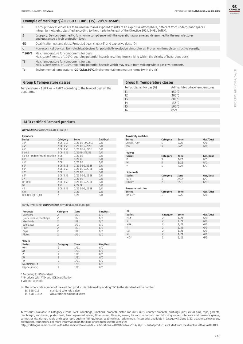
PNEUMATIC ACTUATION 2019
a.16
DIRE
CTIV
E AT
EX 2
014/
34/E
U
APPENDIX > DIRECTIVE ATEX 2014/34/EU
Group I: Temperature classesTemperature = 150°C or = 450°C according to the level of dust on the apparatus.
Group II: Temperature classes Temp. classes for gas (G) Admissible surface temperatures T1 450°C T2 300°C T3 200°C T4 135°C T5 100°C T6 85°C
Example of Marking: II 2 GD c T100°C (T5) -20°C≤Ta≤60°C II II Group: Devices which are to be used in spaces exposed to risks of an explosive atmosphere, different from underground spaces, mines, tunnels, etc., classified according to the criteria in Annex I of the Directive 2014/34/EU (ATEX). 2 Category: Devices designed to function in compliance with the operational parameters determined by the manufacturer and guarantee a high protection level. GD Qualification gas and dusts: Protected against gas (G) and explosive dusts (D). c Non-electrical devices: Non-electrical devices for potentially explosive atmospheres. Protection through constructive security. T 100°C Max. temperature for components for dusts: Max. superf. temp. of 100°C regarding potential hazards resulting from striking within the vicinity of hazardous dusts. T5 Max. temperature for components for gas: Max. superf. temp. of 100°C regarding potential hazards which may result from striking within gas environments. Ta Environmental temperature: -20°C≤Ta≤60°C. Environmental temperature range (with dry air)
ATEX certified Camozzi products
APPARATUS classified as ATEX Group II
Freely installable COMPONENTS classified as ATEX Group II
* According to ISO standard** Products with ATEX and IECEX certification# Without solenoid
» The order code number of the certified products is obtained by adding “EX” to the standard article number Es. 358-015 standard solenoid valve Es. 358-015EX ATEX certified solenoid valve
Accessories available in Category 2 Zone 1/21: couplings, junctions, brackets, piston rod nuts, nuts, counter brackets, bushings, pins, clevis pins, caps, gaskets, diaphragm, sub-bases, plates, feet, hand operated valves, flow valves, flanges, screw, tie rods, automatic and blocking valves, silencers and pressure gauge, connector kits, clamps, rapid and super rapid push-in fittings, hoses, sealing rings, locking nuts. Accessories available in Category 3, Zone 2/22: adaptors, slot covers, extensions, connectors. For more information on this kind of products see the website: http://catalogue.camozzi.com within the section: Downloads > Certifications > ATEX Directive 2014/34/EU > List of products excluded from the directive 2014/34/EU ATEX.
Cylinders Series Category Zone Gas/Dust 16* 2 DE-3 SE 1/21 DE -2/22 SE G/D 24* 2 DE-3 SE 1/21 DE-2/22SE G/D 25* 2 DE-3 SE 1/21 DE-2/22SE G/D 31-32 2 DE-3 SE 1/21DE-2/22SE G/D 31-32 Tandem/multi-position 2 DE 1/21 DE G/D 40* 2 DE 1/21 DE G/D 41* 2 DE 1/21 DE G/D 60* 2 DE-3 SE 1/21 DE-2/22 SE G/D 61* 2 DE-3 SE 1/21 DE-2/22 SE G/D 62* 2 DE 1/21 DE G/D 63* 2 DE-3 SE 1/21 DE-2/22 SE G/D 27 2 DE 1/21 DE G/D QP-QPR 2 DE-3 SE 1/21 DE-2/22 SE G/D QN 3 SE 2/22 SE G/D 42 2 DE-3 SE 1/21 DE-2/22 SE G/D ARP 2 1/21 G/D QCT-QCB-QXT-QXB 2 1/21 G/D
FRL Series Category Zone Gas/Dust MC# 2 1/21 G/D N 2 1/21 G/D MX# 2 1/21 G/D T 2 1/21 G/D CLR 2 1/21 G/D M 2 1/21 G/D MD# 2 1/21 G/D
Proximity switches Series Category Zone Gas/Dust CSH/CST/CSV 3 2/22 G/D CSG 3 2/22 G/D
Pressure switches Series Category Zone Gas/Dust PM 11** 1 0/20 G/D
Valves Series Category Zone Gas/Dust P 3 2/22 G/D W 3 2/22 G/D Y 3 2/22 G/D
Valves Series Category Zone Gas/Dust 9#* 2 1/21 G/D A# 2 1/21 G/D 2 2 1/21 G/D 3# 2 1/21 G/D 4# 2 1/21 G/D NA (NAMUR) # 2 1/21 G/D E (pneumatic) 2 1/21 G/D
Products Category Zone Gas/Dust Silencers 2 1/21 G/D Quick release couplings 2 1/21 G/D Manifolds 2 1/21 G/D Sub-bases 2 1/21 G/D Feet 2 1/21 G/D C aps 2 1/21 G/D Plates 2 1/21 G/D
Solenoids Series Category Zone Gas/Dust U70 3 2/22 G/D H80I** 2 1/21 G/D

a.17
Camozzi around the world
Camozzi Automation S.p.A.Società Unipersonale Via Eritrea, 20/I25126 Brescia ItaliaTel. +39 030/37921 Fax +39 030/[email protected]
Camozzi Neumatica S.A.Polo Industrial Ezeiza,Puente del Inca 2450,B1812IDX, Carlos Spegazzini, EzeizaProvincia de Buenos AiresArgentinaTel. +54 11/[email protected]
Camozzi Automation GmbHLöfflerweg 18A-6060 Hall in TirolAustriaTel. +43 5223/52888-0 Fax +43 5223/[email protected] www.camozzi.at
Camozzi Pneumatic66-1, Perehodnaya str.,220070, MinskBelarusTel. +375 17/3961170 (71)Fax +375 17/3961170 (71)[email protected]
Camozzi do Brasil Ltda.Rod. Adauto Campo Dall’Orto, 2.200Condomínio TechvilleCEP 13178-440 Sumaré S.P.Brazil Tel. +55 19/[email protected]
Shanghai Camozzi AutomationControl Co, Ltd.717 Shuang Dan Road, MaluShanghai - 201801ChinaTel. +86 21/59100999Fax +86 21/[email protected]
Camozzi S.r.o.V Chotejně 700/7Praha - 102 00 Czech RepublicTel. +420 272/690 994Fax +420 272/700 [email protected]
Camozzi Automation ApS Metalvej 7 F4000 RoskildeDenmarkTel. +45 46/[email protected]
Camozzi Automation OÜOsmussaare 8 13811 TallinnEstoniaTel. +372 6119055Fax +372 [email protected] www.camozzi.ee
Camozzi Automation Sarl 5, Rue Louis GattefosséParc de la Bandonniére 69800 Saint-Priest FranceTel. +33 (0)478/213408 Fax +33 (0)472/[email protected]
Camozzi Automation GmbHPorschestraße 1D-73095 AlbershausenGermanyTel. +49 7161/91010-0 Fax +49 7161/[email protected]
Camozzi India Private LimitedD-44, Hosiery Complex,Phase II Extension,Noida - 201 305Uttar Pradesh IndiaTel. +91 120/4055252Fax +91 120/[email protected]
Camozzi Pneumatic Kazakhstan LLPShevchenko/Radostovets, 165b/72g, off. 615050009 AlmatyKazakhstanTel. +7 727/3335334 - 3236250Fax +7 727/2377716 (17)[email protected]
Camozzi Malaysia SDN. BHD.30 & 32, Jalan Industri USJ 1/3Taman Perindustrian USJ 147600 Subang JayaSelangor MalaysiaTel. +60 3/80238400Fax +60 3/[email protected]
Camozzi Neumatica de Mexico S.A. de C.V. Lago Tanganica 707Col. Ocho Cedros 2ª sección50170 TolucaMéxicoTel. +52 722/2707880 - 2126283Fax +52 722/[email protected]
Camozzi Automation ASVerkstedveien 81400 SkiNorwayTel. +47 [email protected]
Camozzi Pneumatic LLCChasnikovo,Solnechnogorskiy DistrictMoscow 141592Russian FederationTel. +7 495/786 65 85Fax +7 495/786 65 [email protected]
Camozzi Iberica SLAvda. Altos Hornos de Vizcaya, 33, L-2 48901 Barakaldo - Vizcaya SpainTel. +34 946 558 958 [email protected]
Camozzi Automation ABBronsyxegatan 7213 75 Malmö SwedenTel. +46 40/[email protected]
Camozzi Automation B.V.De Vijf Boeken 1 A2911 BL Nieuwerkerk a/d IJsselThe NetherlandsTel. +31 180/[email protected]
LLC CamozziKirillovskaya Str, 1-3, section “D” Kiev - 04080UkraineTel. +38 044/5369520 Fax +38 044/[email protected]
Camozzi Automation Ltd.The Fluid Power CentreWatling Street Nuneaton, Warwickshire CV11 6BQ United KingdomTel. +44 (0)24/76374114 Fax +44 (0)24/[email protected]
Camozzi Automation, Inc. Street address:2160 Redbud Boulevard, Suite 101McKinney, TX 75069-8252Remittances:P.O. Box 678518Dallas, TX 75267-8518USATel. +1 972/5488885Fax +1 972/[email protected]
Camozzi Venezuela S.A.Calle 146 con Av. 62N°146-180P.O. Box 529Zona Industrial MaracaiboEdo. ZuliaVenezuelaTel. +58 261/[email protected]
Camozzi R.O. in Hochiminh City6th Floor, Master Building,155 Hai Ba Trung St., Ward 6, District 3Hochiminh CityVietnamTel. +84 8/54477588Fax +84 8/[email protected]

a.18
Camozzi distributors around the world
EuropeZULEX d.o.o.Safeta Zajke 115bSarajevoBosnia-HerzegovinaTel. +387 33/776580Fax +387 33/[email protected] www.zulex.com.ba
L.D. GmbHBlvd AsenYordanov 51592 SofiaBulgariaTel. +359 2/9269011Fax +359 2/[email protected] www.ld-gmbh.com
Bibus Zagreb d.o.o.Anina 91 HR 10000 Zagreb CroatiaTel. +385 1/3818004Fax +385 1/[email protected]
TS Hydropower Ltd.Industrial Area N°64Aglanzia 21-03 Nicosia CyprusTel. +357 22/332085Fax +357 22/[email protected]
AVS-Yhtiöt OyRusthollarinkatu 802270 EspooFinlandTel. +358 10/6137100Fax +358 10/[email protected]
TECHNOMATIC Group IKEEsopou str, Kalochori Industrial Park57009, ThessalonikiGreeceTel. +30 2310/752773Fax +30 2310/[email protected]
Tech-Con Hungária KftVéső u. 9-11 (entrance: Süllő u. 8.)1133 Budapest HungaryTel. +36 1/412 4161Fax +36 1/412 [email protected]
Loft & RaftækiHjallabrekka 1200 KópavogurIceland Tel. +354 564/3000 Fax +354 564/[email protected]
DBF TECHNIC SIABauskas iela 20 - 3021004 RigaLatvia Tel. +371 296 26916 Fax +371 6 [email protected]
Hidroteka Engineering UABChemijos 29E LT-51333 KaunasLithuania Tel. +370 37/452969 Fax +370 37/[email protected]
Rayair Automation Ltd.KW23G - Corradino Ind. EstatePaola, PLA3000 MaltaTel. +356 21/672497Fax +356 21/805181 [email protected]
Bibus Menos Sp. z o.o.ul. Spadochroniarzy 1880-298 GdańskPolandTel. +48 58/6609570 Fax +48 58/[email protected]
Experts d.o.o.Mitropolit Teodosij Gologanov, 149MK-1000 Skopje Rep. of MacedoniaTel. +389 2/3081970 [email protected]
Tech-Con Industry S.r.l.Calea Crângasi N°60Sector 6, 060346 BucharestRomaniaTel. +40 21/2219640Fax +40 21/[email protected]
Tech-Con d.o.o. BeogradCara Dušana 205a 11080 Zemun - Belgrade SerbiaTel. +381 11/4142790Fax +381 11/[email protected]
STAF Automation, s.r.o.Kostiviarska 4944/5974 01 Banská BystricaSlovakiaTel. +421 48/4722777Fax +421 48/[email protected]
KOVIMEX d.o.o.Podskrajnik 60,SI-1380 CerknicaSloveniaTel. +386 1/7096430 Fax +386 1/[email protected]
BIBUS AGAllmendstrasse 26CH-8320 FehraltorfSwitzerlandTel. +41 44/8775011 Fax +41 44/[email protected]
Hidrel Hidrolik Elemanlar San. Ve Tic. A.Ş.Percemli Sok. No:7 Tunel Mevkii 34420 Karakoy IstanbulTurkeyTel. +90 212 251 73 18 - 249 48 81Fax +90 212 292 08 [email protected]
>>

a.19
Camozzi distributors around the world
AmericaLEVCORP S.A.Av. Roma No. 7447Zona ObrajesLa PazBoliviaTel. +591 2 2815658Fax +591 2 [email protected]
NOMADA LtdaPanamericana Norte 2998 unidad 3036Renca - SantiagoChileTel. +56 2 2904 [email protected]
Eurotécnica de Costa Rica AYM, S.A.150 m oeste del cruce de Llorente,hacia Epa TibásCosta RicaTel. +506 2241/4242 - 4230Fax +506 2241/[email protected]
Fluidica Cia. Ltda.Abelardo Moncayo Oe4-08 y Av. AméricaQuito, PichinchaEcuadorTel. +593 2/2440848 - 2/5102004 - 2/2254773Fax +593 2/[email protected]
Aplitec S.A. de C.V.75 Av. Nte, Residencial Escalon Norte IIPje KL #3-CSan SalvadorEl SalvadorTel. +503 2557/2666Fax +503 2557/2652 [email protected]
Isotex de Panamá,S.A.Plaza El Conquistador, Local #45Vía Tocúmen, Panamá CityPanamáTel. +507 217-0050Fax +507 [email protected]
Eicepak S.A.C.Av. Los Cipreses N° 484 Los FicusSanta Anita - LimaPerùTel. +51 1/3628484 - 3627127 - [email protected]
LT Industrial, SRLAve. Charles Summer #53, suite 24BPlaza Charles SummerSanto Domingo, Los PradosRepubblica DominicanaTel. +1809-623-5156Fax [email protected]
Cocles S.A.BVAR Artigas 4543 P.O. Box 11800Montevideo UruguayTelefax +598 22030307/22006428/[email protected]
Middle EastCompressed Air Technology Co.SaaCairo-Alexandria Desert Road Kilo 28Behind Gas Station EmiratesAbu Rawash EgyptTel. +20 35391986/35391987/35391985Fax +20 [email protected]@elhaggarmisr.comwww.elhaggarmisr.com
Automation Yeruham & Co.34, Hahofer st.PO Box 1844 Length 5811702 HolonIsraelTel. +972 73/2606401 Fax +972 3/[email protected]
Raymond Feghali Co. For Trade & Industry SARLRoumieh industrial zone - LebanonP.O. BOX 90-723 Jdeideh LebanonTel. +961 1/893176 - 3/660287 Fax +961 1/[email protected]
Techno-Line Trading & Services WLLWare House 05, Building 2189Road 1529, Block 115HiddKingdom of BahrainTel. +973 17783906Fax +973 [email protected]@technoline.me
AL-Maram National Co. For Buildings General Contracting W.L.L.Shuwaikh Industrial Area Pl. Shop No. 9 ShuwaikhKuwaitTel./Fax +965 24828108Cell. +965 [email protected]
Al-Hawaiya for Industrial Solutions Co. (ALHA)Kilo - 3, Makkah RoadP.O. Box 11429Jeddah 21453 Saudi ArabiaTel. +966 12/6576874Fax +966 12/[email protected]
I.M.O. Industrial Machine Trd. Co. L.L.C.P.O. Box 20376SharjahUnited Arab EmiratesTel. +971 6/5437991 - 6/5437992Fax +971 6/[email protected]
AsiaPT. Golden Archy SaktiKompleks Prima Centre Blok B2 No.2Jl.Pool PPD - Pesing Poglar No.11,Kedaung Kali Angke - Cengkareng,Jakarta Barat 11710IndonesiaTel. +62 21/54377888Fax +62 21/[email protected]
Seika CorporationAqua Dojima East Bldg.16F, 4-4, 1-Chome, Dojimahama,Kita-Ku Osaka JapanTel. +81 6/63453175 Fax +81 6/[email protected]
Polytechnic AutomationSuite 604, 6th Floor, K. S. Trade Tower, New Challi,Shahrah-e-Liaquat,Karachi - 74000,PakistanTel. +9221 32426612Fax +9221 [email protected]
Exceltec Automation Inc.608-G, EL-AL Building, Quezon Avenue, TatalonQuezon City, 1113Philippines Tel. +632/4161143 - 4161141 - 731 9015 Fax +632/[email protected]
Exceltec Enviro Pte LtdBlock 3025 Ubi Road 3# 03-141408653 Singapore Tel. +65/67436083 Fax +65/[email protected]
Taewon-APGeomdanbuk-ro 40-gil, Buk-gu Daegu 41511South KoreaTel. +82 53 384 1058Fax +82 53 384 [email protected]
Korea Flutech Co. LtdNo15-4, 101-gil Palgong-ro, Dong-gu, Daegu, 41005South Korea Tel. +82 53 213 9090 Fax +82 53 353 [email protected]

a.20
Savikma Automation & EngineeringServices (Pvt) Ltd.22, Wattegedara RoadMaharagamaSri Lanka Tel. +94 115642164Hot line +94 777800070 Fax +94 [email protected]
Zenith Automation International Co., Ltd.1F., No.9, Aly. 1, Ln. 5, Sec. 3, Ren’ai Rd.,Da’an Dist., Taipei City 10651 Taiwan (R.O.C.)Tel. +886 2/2781 1267Fax +886 2/3322 [email protected]
Pneumax Co. Ltd.107/1 Chaloem Phrakiat R.9 Rd.,Pravet - Bangkok 10250 ThailandTel. +66 2/7268000 Fax +66 2/[email protected]
AfricaBoudissa Technology Sarl25, Cité 20 Août 1955 Oued Roumane El AchourAlgiers - 16403AlgeriaTel./Fax +213 (0) 23316751Tel./Fax +213 (0) [email protected]
DISMATEC Distribution de Materiels TechniquesN° RCCM-CI-ABJ-2010B1882 16 BP 236 ABIDJAN 16Ivory CoastTel. +225 21267091Fax +225 [email protected]
Hydramatics Control Equipment15 Village Crescent,Linbro Business Park,Sandton Johannesburg 2065South AfricaTel. +2711/6081340 - 1 - 2Fax +2786/[email protected]
A.T.C. AutomatismeAvenue Habib BourguibaCentra Said - BP 25 2033Megrine TunisiaTel. +216 71/297328Fax +216 71/[email protected]
OceaniaGriffiths Components Pty Ltd605 Burwood HwyKnoxfield VictoriaMelbourne 3180AustraliaTel. +61 3/9800 6500 Fax +61 3/9801 [email protected]

A Camozzi Group Company
www.camozzi.com
Contacts
Camozzi Automation S.p.A.Società UnipersonaleVia Eritrea, 20/I25126 BresciaItalyTel. +39 030 [email protected]
93-0
518-
0GB0
02 0
4/20
19