whirl testing of a pneumatic artificial muscle actuation system for a full-scale active rotor
TRANSCRIPT
JOURNAL OF THE AMERICAN HELICOPTER SOCIETY 59, 022006 (2014)
Whirl Testing of a Pneumatic Artificial Muscle Actuation System for aFull-Scale Active Rotor
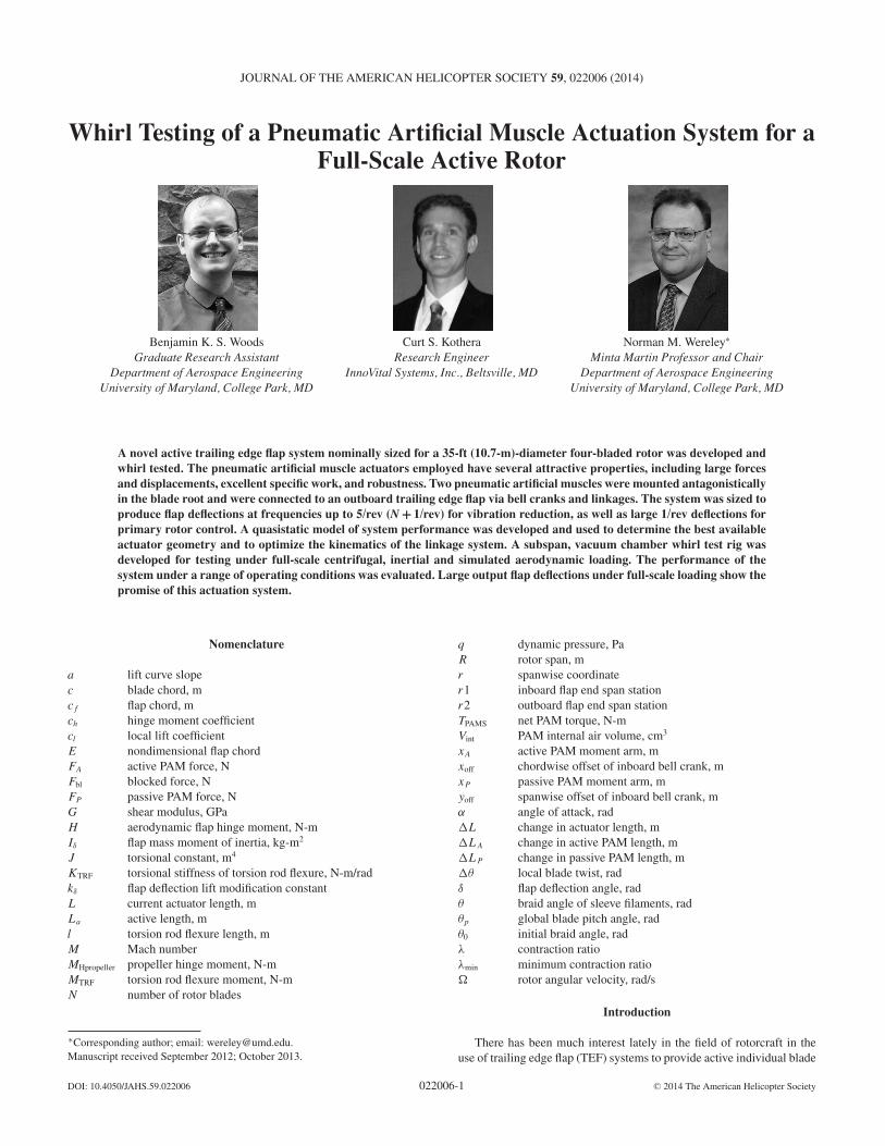
Benjamin K. S. Woods Curt S. Kothera Norman M. Wereley!
Graduate Research Assistant Research Engineer Minta Martin Professor and ChairDepartment of Aerospace Engineering InnoVital Systems, Inc., Beltsville, MD Department of Aerospace Engineering
University of Maryland, College Park, MD University of Maryland, College Park, MD
A novel active trailing edge flap system nominally sized for a 35-ft (10.7-m)-diameter four-bladed rotor was developed andwhirl tested. The pneumatic artificial muscle actuators employed have several attractive properties, including large forcesand displacements, excellent specific work, and robustness. Two pneumatic artificial muscles were mounted antagonisticallyin the blade root and were connected to an outboard trailing edge flap via bell cranks and linkages. The system was sized toproduce flap deflections at frequencies up to 5/rev (N + 1/rev) for vibration reduction, as well as large 1/rev deflections forprimary rotor control. A quasistatic model of system performance was developed and used to determine the best availableactuator geometry and to optimize the kinematics of the linkage system. A subspan, vacuum chamber whirl test rig wasdeveloped for testing under full-scale centrifugal, inertial and simulated aerodynamic loading. The performance of thesystem under a range of operating conditions was evaluated. Large output flap deflections under full-scale loading show thepromise of this actuation system.
Nomenclature
a lift curve slopec blade chord, mcf flap chord, mch hinge moment coefficientcl local lift coefficientE nondimensional flap chordFA active PAM force, NFbl blocked force, NFP passive PAM force, NG shear modulus, GPaH aerodynamic flap hinge moment, N-mI! flap mass moment of inertia, kg-m2
J torsional constant, m4
KTRF torsional stiffness of torsion rod flexure, N-m/radk! flap deflection lift modification constantL current actuator length, mLa active length, ml torsion rod flexure length, mM Mach numberMHpropeller propeller hinge moment, N-mMTRF torsion rod flexure moment, N-mN number of rotor blades
!Corresponding author; email: [email protected] received September 2012; October 2013.
q dynamic pressure, PaR rotor span, mr spanwise coordinater1 inboard flap end span stationr2 outboard flap end span stationTPAMS net PAM torque, N-mVint PAM internal air volume, cm3
xA active PAM moment arm, mxoff chordwise offset of inboard bell crank, mxP passive PAM moment arm, myoff spanwise offset of inboard bell crank, m" angle of attack, rad#L change in actuator length, m#LA change in active PAM length, m#LP change in passive PAM length, m#$ local blade twist, rad! flap deflection angle, rad$ braid angle of sleeve filaments, rad$p global blade pitch angle, rad$0 initial braid angle, rad% contraction ratio%min minimum contraction ratio& rotor angular velocity, rad/s
Introduction
There has been much interest lately in the field of rotorcraft in theuse of trailing edge flap (TEF) systems to provide active individual blade
DOI: 10.4050/JAHS.59.022006 C" 2014 The American Helicopter Society022006-1
B. K. S. WOODS JOURNAL OF THE AMERICAN HELICOPTER SOCIETY
Table 1. Comparison of actuator technologies
Actuation Technology Maximum Strain Actuation Stress (MPa) Specific Work (J/kg) Maximum Frequency (Hz)
Hydraulic 1 70 35,000 100Electomechanical 0.5 1 300 –Solenoid 0.4 0.1 5 80Piezoelectric 0.002 9 1 107
Magnetostrictive 0.002 200 20 107
Shape memory alloy 0.07 700 4,500 7Pneumatic cylinder 1 0.9 1,200 100UMD/TSi PAM 0.4 16 4,000 100
Adapted from Huber, Fleck and Ashby (Ref. 11), with data from Refs. 12 and 13.
control for vibration reduction. Such a system would allow for higherharmonic control of each blade to directly mitigate the vibrations createdby time-varying forces and moments. In addition, if such a system wereto have sufficient control authority, the flaps could also potentially beused for primary control of the aircraft. This could allow for eliminationof the swashplate with its significant drag, complexity, and maintenancepenalties as discussed in Refs. 1–4.
Much of the active rotor work to date has focused on the problemof developing actuator technologies with sufficient control authority,bandwidth, tracking accuracy, and robustness. References 5–10 providean overview of select active rotor research. The actuators consideredhave included hydraulic, piezoelectric, shape memory alloy, and elec-tromechanical technologies, among others, and these have been appliedas drivers of discrete flaps, morphing camber “flaps,” actively twistingblades, and active pitch links. The most successful programs to datehave led to full-scale wind tunnel testing and flight-testing, as in the caseof Refs. 9–12. While the state of the art of active rotors has advancedsignificantly in the past 2 decades, a need still remains for more actu-ation capability. A desired solution is one that is lightweight, reliable,amenable to operation under the high accelerations typical of the rotatingframe, and has sufficient dynamic response. In addition, an ideal solutionwould feature a single actuator technology that has the capability of sat-isfying control authority and bandwidth requirements for both primaryand vibration control simultaneously.
Our approach was to utilize the unique properties of the pneumaticartificial muscle (PAM) actuator. Table 1, adapted from Huber et al.(Ref. 13), with additional data from Refs. 14 and 15, shows that PAMactuators have an attractive set of properties for the active rotor problem.PAMs can generate both high strain and high actuation stress, whichcombined with their low weight, yield a value of specific work that ismore than three orders of magnitude greater than piezoelectric actuators.The specific work for PAM actuators is significantly less than that ofhydraulics, but this is the consequence of operating PAMs at lower pres-sures (<0.7 MPa) than hydraulics (20–30 MPa). It should be noted thatthe mechanical work output of a PAM actuator is greater than a conven-tional hydraulic cylinder when compared on a per unit pressure basis;although the difficulties of using very high pressure air negate some ofthis advantage. There exist significant difficulties with implementing hy-draulic actuators in the rotating frame, particularly with respect to theoperating fluid. While PAMs also require flow of an operating fluid, airhas several advantages over oil in this application. The density of air issubstantially lower than that of oil, meaning less operating fluid mass,and lower pressure changes from the effects of centrifugal acceleration(making it easier to pump air back up to the hub, for instance). Fur-thermore, it is possible to operate the PAMs as an open circuit systemwhere the exhaust fluid is simply dumped to the atmosphere, or eveninjected into the flow for a secondary benefit. While the use of an opencircuit degrades system efficiency, it is a significantly simpler systemmechanically. Finally, while an oil leak from a complicated hydraulic
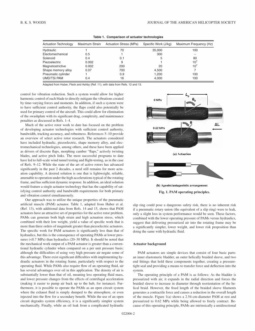
Fig. 1. PAM operating principles.
slip ring could pose a dangerous safety risk, there is no inherent riskif a pneumatic rotary union (the equivalent of a slip ring) were to leak,only a slight loss in system performance would be seen. These factors,combined with the lower operating pressure of PAMs versus hydraulics,suggest that delivering pressurized air into the rotating frame may bea significantly simpler, lower weight, and lower risk proposition thandoing the same with hydraulic fluid.
Actuator background
PAM actuators are simple devices that consist of four basic parts:an inner elastomeric bladder, an outer helically braided sleeve, and twoend fittings that hold these components together, creating a pressure-tight seal and providing a means to transfer force and deflection into thesystem.
The operating principle of a PAM is as follows: As the bladder ispressurized with air, it expands in the radial direction and forces thebraided sleeve to increase in diameter through reorientation of the he-lical braid. However, the fixed length of the braided sleeve filamentsgenerates a contractile force and causes a reduction in the overall lengthof the muscle. Figure 1(a) shows a 2.54-cm-diameter PAM at rest andpressurized to 0.62 MPa while being allowed to freely contract. Be-cause of this operating principle, PAMs are intrinsically a unidirectional
022006-2
WHIRL TESTING OF A PNEUMATIC ARTIFICIAL MUSCLE ACTUATION SYSTEM 2014
actuator. While they are capable of either contraction or extension, de-pending on the initial braid angle !0 (labeled in Fig. 1(a)), the forcescreated by contractile PAMs are much greater than those of an extensilePAM. For this reason, the PAMs studied here are contractile. Further-more, contractile PAMs generate tensile forces and are, therefore, notsusceptible to actuator buckling. In this configuration, PAMs behavesimilarly to natural muscles, as shown in Ref. 16.
If controlled motion in two directions is desired, two PAMs can bearranged as an agonist/antagonist pair to produce bidirectional rotationalmotion about a hinge, as shown in Fig. 1(b). Here the lower PAM is theactive agonist muscle, pulling on the passive antagonist upper PAM andforcing the joint to rotate clockwise. This arrangement is very similarto that of the human musculature system and is well suited for drivingTEFs on helicopter blades.
PAMs have been utilized for many years for prosthetic and roboticapplications (Ref. 17), but only recently have they begun to be consideredfor aerospace applications. References 18–23 cover aerospace applica-tions of PAM technology to date, where they have been considered fordriving rigid TEFs (Refs. 18 and 19), active camber morphing leadingand trailing edges (Refs. 20 and 22), steerable parachutes (Ref. 21), anda morphing wing tip (Ref. 23). Recently, wind tunnel testing of a non-rotating full-scale Bell 407 blade tip with a retrofitted PAM TEF systemshowed the ability of these actuators to generate large flap deflectionsover the required operational frequency range (Ref. 24).
We developed the specific design of the PAM used in this study toaddress the relatively short fatigue lives of PAM actuators that had beenpresent in the literature. Two previous fatigue tests performed on bothcommercially available (Ref. 25) and custom-produced (Ref. 26) PAMactuators had shown a maximum of only 14,000 and 17,600 cycles tofailure. To address these low fatigue lives, a new manufacturing techniquewas developed, as detailed in Ref. 27. Reference 28 describes fatiguetesting of this design under realistic operating conditions for 120 millioncycles with no observed actuator failure. Characterization testing beforeand after cycling showed no degradation in performance.
The objective of the current work is to design a full-scale PAM TEFsystem nominally sized for implementation on a 35-ft (10.7-m)-diameterfour-bladed rotor system similar in scale to the Bell 407 rotor, and tothen test the components of the actuation system on a subspan, vacuumchamber whirl rig under full-scale levels of centrifugal, inertial, andsimulated aerodynamic loading. Of primary interest are the magnitudeof output flap deflection and system-operating bandwidth, and the impactthat increasing levels of centrifugal loading has on these parameters.
PAM TEF System Design
The design and optimization of the PAM-driven TEF system will bediscussed in this section. The performance goals of the system will firstbe established, after which the overall configuration of the design will bediscussed. Details of the various components of the combined analyticaland empirical model used to predict performance will then be discussed.A large number of PAM actuators with different geometries were builtand experimentally characterized. For each PAM configuration tested, anoptimization process was performed to determine the geometric systemparameters that enabled that particular PAM to achieve the design goalswith the minimal volume of pressurized air, which correlates to minimalsystem energy input for that PAM. The PAM configuration that used theleast amount of energy was then selected for further testing.
The actuation system developed in this work was sized with two pri-mary design goals. The first was to produce substantial high-frequencyflap deflections for vibration reduction. Previous work has shown thepotential of a properly sized, servo-type TEF driven at 3–5/rev to pro-vide significant hub vibration reductions for a four-bladed rotor system
(Refs. 4, 6, and 9). To show the promise of PAM technology to surpass thecurrent state of the art, this system was designed to have a level of controlauthority beyond what has typically been achieved. This is reflected inthe design goal of ±7.5! to ±10! of flap deflection at frequencies up to5/rev (nominally 35 Hz for the Bell 407 rotor).
The second design goal was to produce even larger deflections at 1/revto demonstrate the potential that PAMs have as actuators for embeddedprimary control of the rotor. While the exact deflection levels needed forprimary control are dependent on a wide range of factors including flapsizing, blade torsional stiffness, flight condition, and blade index angle,Refs. 29–30 indicate that deflections on the order of ±15! to ±20! maybe suitable.
To meet these design goals, a combined analytical and experimentalapproach was taken. The TEF was chosen to be a 16% span (86.4 cm),15% chord ("3.81 cm) plain flap centered at 0.83R, which is generallyconsistent with other active flap systems, such as those in Refs. 9 and 31.The actuation system was nominally designed for a 35-ft-diameter rotor(based on a Bell 407 blade), and then integrated into a subspan whirl rigfor testing in the University of Maryland vacuum whirl chamber.
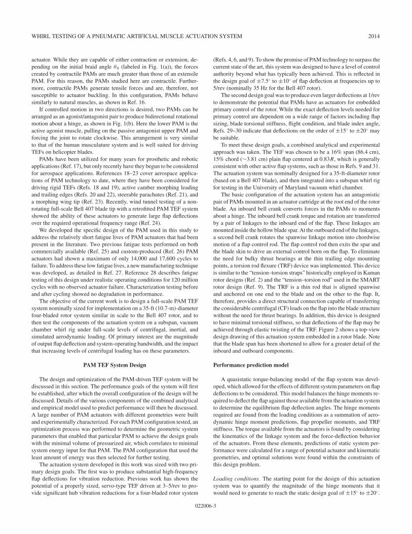
The basic configuration of the actuation system has an antagonisticpair of PAMs mounted in an actuator cartridge at the root end of the rotorblade. An inboard bell crank converts forces in the PAMs to momentsabout a hinge. The inboard bell crank torque and rotation are transferredby a pair of linkages to the inboard end of the flap. These linkages aremounted inside the hollow blade spar. At the outboard end of the linkages,a second bell crank rotates the spanwise linkage motion into chordwisemotion of a flap control rod. The flap control rod then exits the spar andthe blade skin to drive an external control horn on the flap. To eliminatethe need for bulky thrust bearings at the thin trailing edge mountingpoints, a torsion rod flexure (TRF) device was implemented. This deviceis similar to the “tension–torsion straps” historically employed in Kamanrotor designs (Ref. 2) and the “tension–torsion rod” used in the SMARTrotor design (Ref. 9). The TRF is a thin rod that is aligned spanwiseand anchored on one end to the blade and on the other to the flap. It,therefore, provides a direct structural connection capable of transferringthe considerable centrifugal (CF) loads on the flap into the blade structurewithout the need for thrust bearings. In addition, this device is designedto have minimal torsional stiffness, so that deflections of the flap may beachieved through elastic twisting of the TRF. Figure 2 shows a top-viewdesign drawing of this actuation system embedded in a rotor blade. Notethat the blade span has been shortened to allow for a greater detail of theinboard and outboard components.
Performance prediction model
A quasistatic torque-balancing model of the flap system was devel-oped, which allowed for the effects of different system parameters on flapdeflections to be considered. This model balances the hinge moments re-quired to deflect the flap against those available from the actuation systemto determine the equilibrium flap deflection angles. The hinge momentsrequired are found from the loading conditions as a summation of aero-dynamic hinge moment predictions, flap propeller moments, and TRFstiffness. The torque available from the actuators is found by consideringthe kinematics of the linkage system and the force-deflection behaviorof the actuators. From these elements, predictions of static system per-formance were calculated for a range of potential actuator and kinematicgeometries, and optimal solutions were found within the constraints ofthis design problem.
Loading conditions. The starting point for the design of this actuationsystem was to quantify the magnitude of the hinge moments that itwould need to generate to reach the static design goal of ±15! to ±20!.
022006-3
B. K. S. WOODS JOURNAL OF THE AMERICAN HELICOPTER SOCIETY
Fig. 2. PAM TEF actuation system design concept.
This would then guide the selection of the actuators used and other keydesign variables, such as PAM geometry and kinematics. The total hingemoment required to deflect the flap is a combination of aerodynamichinge moment, flap propeller moment, and the stiffness of the TRF.
Aerodynamic hinge moment. The total aerodynamic hinge moment wasdefined as an integral over the flap span (r1 to r2) in terms of a hingemoment coefficient ch, the dynamic pressure q, and the geometric flapchord cf as
H =r2!
r1
(q (r) cf (r)2 ch (r))dr (1)
In an approach adopted from thin airfoil theory, the hinge moment coeffi-cient is defined in Ref. 32 as the summation of two separate effects. Theseinclude moment due to the lift coefficient of the airfoil and moment dueto the flap deflection itself:
ch = cl (r)"
!ch
!cl
#+ "
"!ch
!"
#(2)
The lift curve slope is based on the two-dimensional (2D) airfoil theoryresult with the Glauert compressibility correction added (Ref. 32):
a = 2#!1 " M2
(3)
Jacobs and Pinkerton (Ref. 33) formulated the lift coefficient for a flappedairfoil as
cl (r) = a [$ (r) + k""] (4)
In this instance, the lift coefficient cl varies along the span due to thetwist present in the blade. The local angle of attack at each span stationis a combination of global blade pitch angle %p and local blade twist
&% (r), referenced from the global angle:
$(r) = %p + &% (r) (5)
The lift coefficient also varies due to the impact of flap deflections.This effect is described by Jacobs and Pinkerton and is represented as aproportional increase in lift coefficient with increasing flap deflectionsthrough a proportionality constant k" . Thin airfoil theory is used to derivean expression relating k" to the nondimensional flap chord, E = cf /c,as below (Ref. 33):
k" = cos"1 (1 " 2E) + 2!
E (1 " E)#
(6)
Experimental values of the two terms !ch/!cl and !ch/!" in Eq. (2) werenot available for the proprietary airfoils under consideration. Instead, asymmetric airfoil approximation from incompressible thin airfoil theorywas used. These two quantities are defined in Ref. 33 as a function of thenondimensional chord of the flap E as shown below:
!ch
!cl
= " 1#E2
$ "32
" E
# %E(1 " E)
""
32
" 2E
#"#
2" cos"1(
!E)
#&(7)
!ch
!"= "4 (1 " E)
!E (1 " E)
#E2
$#
2" cos"1(
!E) "
%E(1 " E)
&
(8)
For the 15% chord flap used in this study (E = 0.15), these factorsare equal to "0.068 and "0.698, respectively. These values are for aplain flap with no aerodynamic balance. Many previous active rotor flapsystems, such as those in Refs. 29 and 30, have used aerodynamic balanceto minimize control moments for their actuation systems, at the cost ofan increased drag coefficient during deflection. Given the high outputtorques and deflections of the PAM TEF system, aerodynamic balancewas not employed in the present study, thereby minimizing the drag andincreasing rotor power associated with flap deflections.
The total hinge moment was found by numerically integrating thelocal hinge moments over the 0.86-m flap span to allow for the changesin both blade pitch angle and blade chord along the span. This total aero-dynamic hinge moment is, therefore, dependent on both flap deflectionand global blade pitch angle according to
H = 3.16" + 2.37%p (9)
The aerodynamic analysis used here is fairly straightforward and has allof the assumptions and limitations of the underlying steady 2D airfoiltheory. The analysis, therefore, is not expected to provide a high-fidelityestimation of the exact time-varying loads which would act on a fullyrealized system of this nature, but is intended merely to provide a roughestimation of “full-scale” loading to show the general effectiveness ofthe actuation system.
Propeller moment. The propeller moment is a restoring moment actingon the flap caused by the angular offset between the flap and the planeof rotor rotation. Under CF acceleration, any portion of the flap mass notaligned with the rotation plane will generate a force that is proportional tothe amount of angular offset. The angular offset comes from the combinedeffect of flap deflection " and global blade pitch %p . Equation (10) is usedto find the propeller moment of the full-scale flap design over the flapdeflection range of interest (Ref. 34):
MHpropeller = I"'2(" + %p) (10)
022006-4
WHIRL TESTING OF A PNEUMATIC ARTIFICIAL MUSCLE ACTUATION SYSTEM 2014
Note that while Eq. (10) was derived for untwisted blades, the amount oftwist present over the flap span is only ±1! from the average pitch angle.The rotational inertia of the flap about its rotation axis was calculatedfrom the computer-aided design model to be I! = 8.3"10#5 kg-m2. Thepitch angle "p was set to 6! as a representative case.
TRF stiffness. The use of a TRF to carry the CF load of the flap eliminatedthe need for thrust bearings and greatly simplified the design. The trade-off to these benefits is the presence of torsional stiffness in this componentthat adds to the overall hinge moments. Careful design of the flexureallows for a low torsional stiffness while still providing the axial stiffnessrequired to minimize CF-induced spanwise deflections and sufficientstrength to provide good factors of safety. For the first design iterationand the test results shown here, 17-4 PH stainless steel was chosen forthe flexure due to its good fatigue endurance stress limit and corrosionresistance.
The equation governing torsional stiffness of the flexure KTRF is givenbelow:
KTRF = GJ
l
#
180(11)
The moment about the flap hinge resulting from this stiffness can thenbe determined as
MTRF = KTRF! (12)
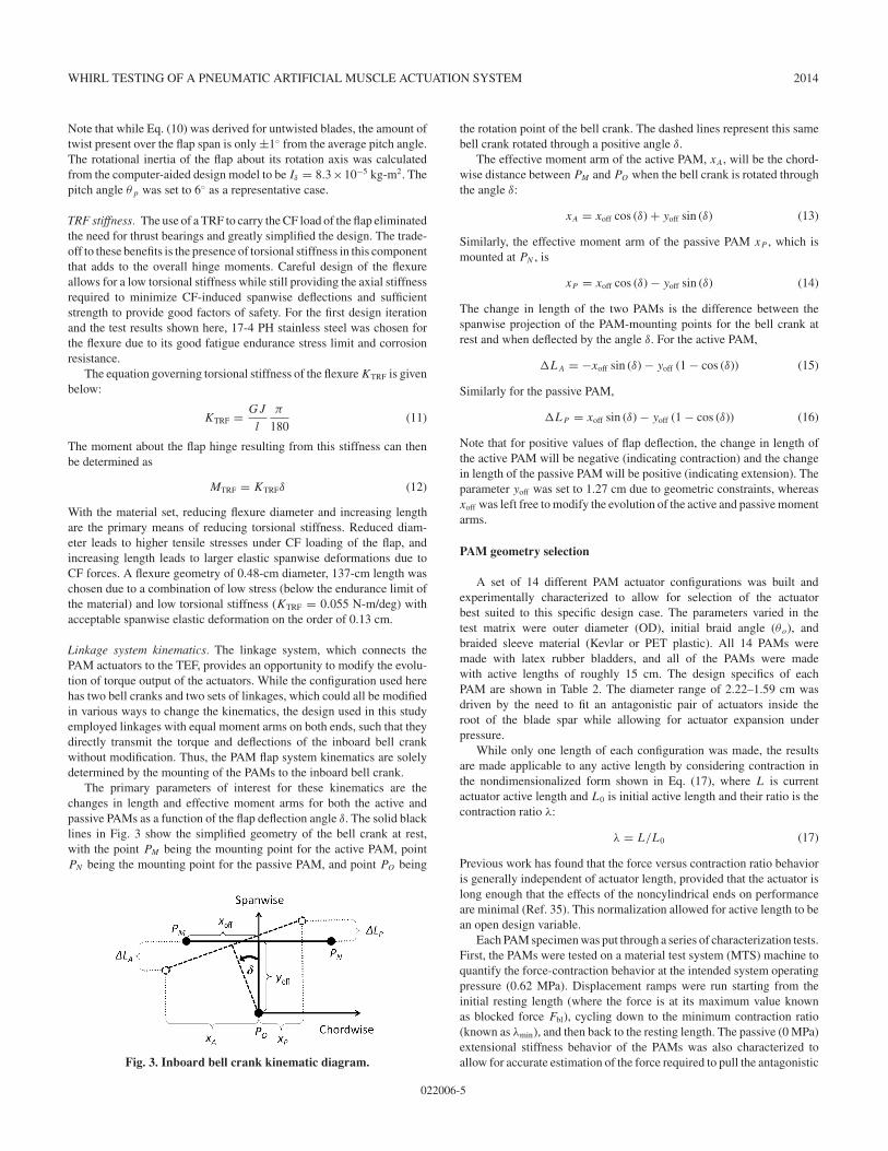
With the material set, reducing flexure diameter and increasing lengthare the primary means of reducing torsional stiffness. Reduced diam-eter leads to higher tensile stresses under CF loading of the flap, andincreasing length leads to larger elastic spanwise deformations due toCF forces. A flexure geometry of 0.48-cm diameter, 137-cm length waschosen due to a combination of low stress (below the endurance limit ofthe material) and low torsional stiffness (KTRF = 0.055 N-m/deg) withacceptable spanwise elastic deformation on the order of 0.13 cm.
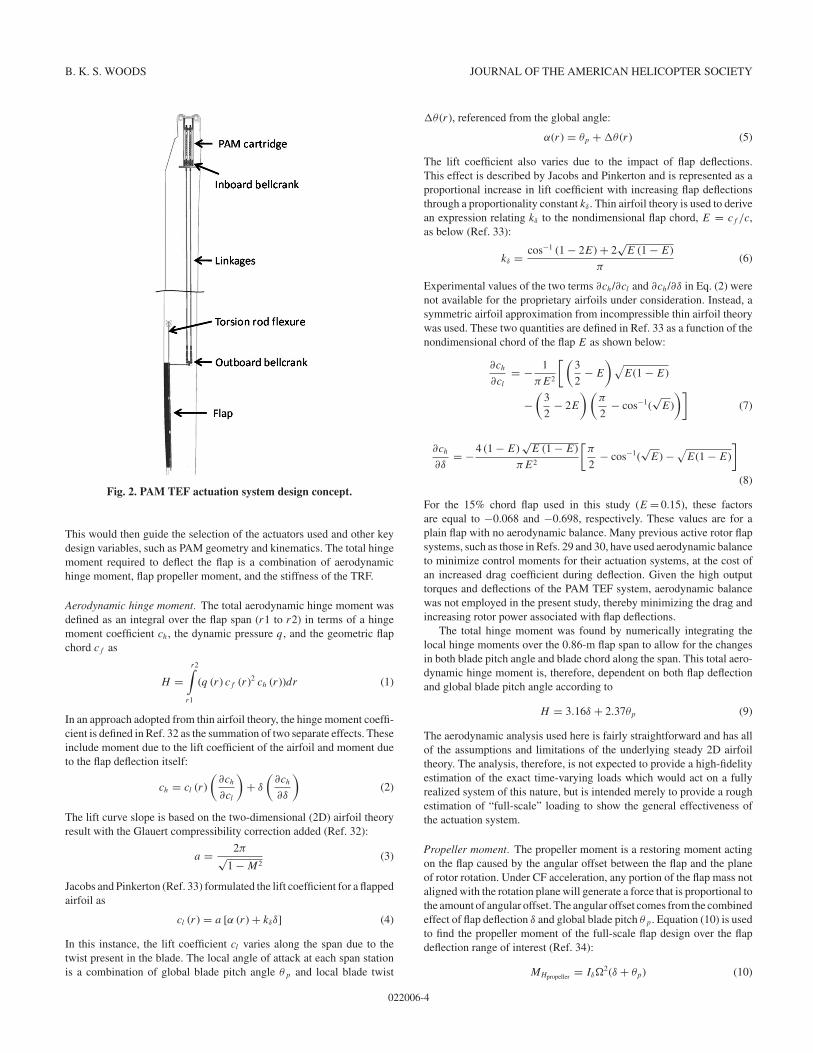
Linkage system kinematics. The linkage system, which connects thePAM actuators to the TEF, provides an opportunity to modify the evolu-tion of torque output of the actuators. While the configuration used herehas two bell cranks and two sets of linkages, which could all be modifiedin various ways to change the kinematics, the design used in this studyemployed linkages with equal moment arms on both ends, such that theydirectly transmit the torque and deflections of the inboard bell crankwithout modification. Thus, the PAM flap system kinematics are solelydetermined by the mounting of the PAMs to the inboard bell crank.
The primary parameters of interest for these kinematics are thechanges in length and effective moment arms for both the active andpassive PAMs as a function of the flap deflection angle !. The solid blacklines in Fig. 3 show the simplified geometry of the bell crank at rest,with the point PM being the mounting point for the active PAM, pointPN being the mounting point for the passive PAM, and point PO being
Fig. 3. Inboard bell crank kinematic diagram.
the rotation point of the bell crank. The dashed lines represent this samebell crank rotated through a positive angle !.
The effective moment arm of the active PAM, xA, will be the chord-wise distance between PM and PO when the bell crank is rotated throughthe angle !:
xA = xoff cos (!) + yoff sin (!) (13)
Similarly, the effective moment arm of the passive PAM xP , which ismounted at PN , is
xP = xoff cos (!) # yoff sin (!) (14)
The change in length of the two PAMs is the difference between thespanwise projection of the PAM-mounting points for the bell crank atrest and when deflected by the angle !. For the active PAM,
$LA = #xoff sin (!) # yoff (1 # cos (!)) (15)
Similarly for the passive PAM,
$LP = xoff sin (!) # yoff (1 # cos (!)) (16)
Note that for positive values of flap deflection, the change in length ofthe active PAM will be negative (indicating contraction) and the changein length of the passive PAM will be positive (indicating extension). Theparameter yoff was set to 1.27 cm due to geometric constraints, whereasxoff was left free to modify the evolution of the active and passive momentarms.
PAM geometry selection
A set of 14 different PAM actuator configurations was built andexperimentally characterized to allow for selection of the actuatorbest suited to this specific design case. The parameters varied in thetest matrix were outer diameter (OD), initial braid angle ("o), andbraided sleeve material (Kevlar or PET plastic). All 14 PAMs weremade with latex rubber bladders, and all of the PAMs were madewith active lengths of roughly 15 cm. The design specifics of eachPAM are shown in Table 2. The diameter range of 2.22–1.59 cm wasdriven by the need to fit an antagonistic pair of actuators inside theroot of the blade spar while allowing for actuator expansion underpressure.
While only one length of each configuration was made, the resultsare made applicable to any active length by considering contraction inthe nondimensionalized form shown in Eq. (17), where L is currentactuator active length and L0 is initial active length and their ratio is thecontraction ratio %:
% = L/L0 (17)
Previous work has found that the force versus contraction ratio behavioris generally independent of actuator length, provided that the actuator islong enough that the effects of the noncylindrical ends on performanceare minimal (Ref. 35). This normalization allowed for active length to bean open design variable.
Each PAM specimen was put through a series of characterization tests.First, the PAMs were tested on a material test system (MTS) machine toquantify the force-contraction behavior at the intended system operatingpressure (0.62 MPa). Displacement ramps were run starting from theinitial resting length (where the force is at its maximum value knownas blocked force Fbl), cycling down to the minimum contraction ratio(known as %min), and then back to the resting length. The passive (0 MPa)extensional stiffness behavior of the PAMs was also characterized toallow for accurate estimation of the force required to pull the antagonistic
022006-5
B. K. S. WOODS JOURNAL OF THE AMERICAN HELICOPTER SOCIETY
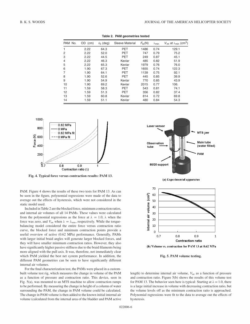
Table 2. PAM geometries tested
PAM No. OD (cm) !0 (deg) Sleeve Material Fbl(N) "min V int at "min (cm3)
1 2.22 64.3 PET 1486 0.74 129.12 2.22 52.0 PET 747 0.79 75.23 2.22 44.5 PET 249 0.87 45.14 2.22 46.3 Kevlar 485 0.82 51.95 2.22 65.3 Kevlar 1979 0.76 76.06 1.90 67.3 PET 1655 0.74 122.37 1.90 64.1 PET 1139 0.75 92.18 1.90 52.6 PET 445 0.85 39.99 1.90 54.9 Kevlar 770 0.85 43.910 1.90 69.2 Kevlar 2015 0.77 106.11 1.59 58.3 PET 543 0.81 74.112 1.59 51.3 PET 356 0.82 37.413 1.59 60.8 Kevlar 814 0.72 69.814 1.59 51.1 Kevlar 480 0.84 54.3
Fig. 4. Typical force versus contraction results: PAM 13.
PAM. Figure 4 shows the results of these two tests for PAM 13. As canbe seen in the figure, polynomial regressions were made of the data toaverage out the effects of hysteresis, which were not considered in thestatic model used.
Included in Table 2 are the blocked force, minimum contraction ratios,and internal air volumes of all 14 PAMs. These values were calculatedfrom the polynomial regressions as the force at " = 1.0, " when theforce was zero, and Vint when " = "min, respectively. While the torque-balancing model considered the entire force versus contraction ratiocurve, the blocked force and minimum contraction points provide auseful overview of active (0.62 MPa) performance. Generally, PAMswith larger initial braid angles will generate larger blocked forces, andthey will have smaller minimum contraction ratios. However, they alsohave significantly higher passive stiffness due to the braid filaments beingmore aligned with the pull axis. It was, therefore, not immediately clearwhich PAM yielded the best net system performance. In addition, thedifferent PAM geometries can be seen to have significantly differentinternal air volumes.
For the final characterization test, the PAMs were placed in a custom-built volume test rig, which measures the change in volume of the PAMas a function of pressure and contraction ratio. This device, seen inFig. 5(a), was mounted to an MTS machine to allow contraction rampsto be performed. By measuring the change in height of a column of watersurrounding the PAM, the change in PAM volume could be calculated.The change in PAM volume is then added to the known initial internal airvolume (calculated from the internal area of the bladder and PAM active
Fig. 5. PAM volume testing.
length) to determine internal air volume, Vint as a function of pressureand contraction ratio. Figure 5(b) shows the results of this volume testfor PAM 13. The behavior seen here is typical: Starting at " = 1.0, thereis a large initial increase in volume with decreasing contraction ratio, butthe volume levels off as the minimum contraction ratio is approached.Polynomial regressions were fit to the data to average out the effects ofhysteresis.
022006-6
WHIRL TESTING OF A PNEUMATIC ARTIFICIAL MUSCLE ACTUATION SYSTEM 2014
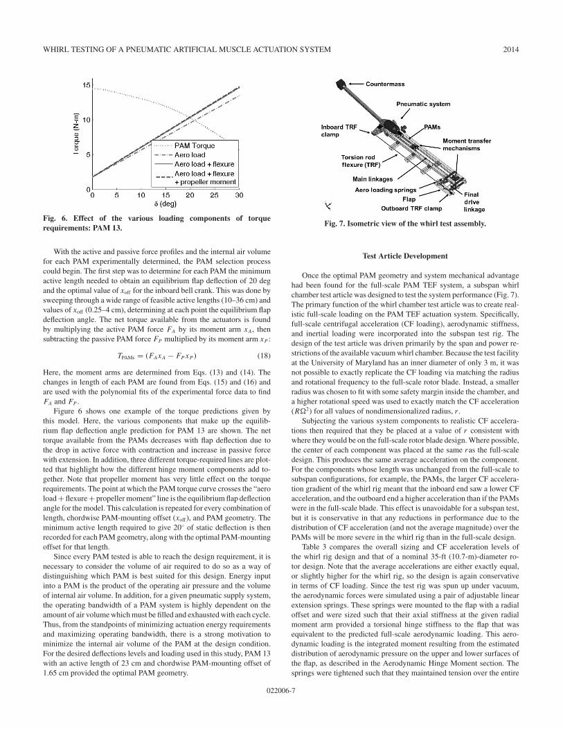
Fig. 6. Effect of the various loading components of torquerequirements: PAM 13.
With the active and passive force profiles and the internal air volumefor each PAM experimentally determined, the PAM selection processcould begin. The first step was to determine for each PAM the minimumactive length needed to obtain an equilibrium flap deflection of 20 degand the optimal value of xoff for the inboard bell crank. This was done bysweeping through a wide range of feasible active lengths (10–36 cm) andvalues of xoff (0.25–4 cm), determining at each point the equilibrium flapdeflection angle. The net torque available from the actuators is foundby multiplying the active PAM force FA by its moment arm xA, thensubtracting the passive PAM force FP multiplied by its moment arm xP :
TPAMs = (FAxA ! FP xP ) (18)
Here, the moment arms are determined from Eqs. (13) and (14). Thechanges in length of each PAM are found from Eqs. (15) and (16) andare used with the polynomial fits of the experimental force data to findFA and FP .
Figure 6 shows one example of the torque predictions given bythis model. Here, the various components that make up the equilib-rium flap deflection angle prediction for PAM 13 are shown. The nettorque available from the PAMs decreases with flap deflection due tothe drop in active force with contraction and increase in passive forcewith extension. In addition, three different torque-required lines are plot-ted that highlight how the different hinge moment components add to-gether. Note that propeller moment has very little effect on the torquerequirements. The point at which the PAM torque curve crosses the “aeroload + flexure + propeller moment” line is the equilibrium flap deflectionangle for the model. This calculation is repeated for every combination oflength, chordwise PAM-mounting offset (xoff ), and PAM geometry. Theminimum active length required to give 20" of static deflection is thenrecorded for each PAM geometry, along with the optimal PAM-mountingoffset for that length.
Since every PAM tested is able to reach the design requirement, it isnecessary to consider the volume of air required to do so as a way ofdistinguishing which PAM is best suited for this design. Energy inputinto a PAM is the product of the operating air pressure and the volumeof internal air volume. In addition, for a given pneumatic supply system,the operating bandwidth of a PAM system is highly dependent on theamount of air volume which must be filled and exhausted with each cycle.Thus, from the standpoints of minimizing actuation energy requirementsand maximizing operating bandwidth, there is a strong motivation tominimize the internal air volume of the PAM at the design condition.For the desired deflections levels and loading used in this study, PAM 13with an active length of 23 cm and chordwise PAM-mounting offset of1.65 cm provided the optimal PAM geometry.
Fig. 7. Isometric view of the whirl test assembly.
Test Article Development
Once the optimal PAM geometry and system mechanical advantagehad been found for the full-scale PAM TEF system, a subspan whirlchamber test article was designed to test the system performance (Fig. 7).The primary function of the whirl chamber test article was to create real-istic full-scale loading on the PAM TEF actuation system. Specifically,full-scale centrifugal acceleration (CF loading), aerodynamic stiffness,and inertial loading were incorporated into the subspan test rig. Thedesign of the test article was driven primarily by the span and power re-strictions of the available vacuum whirl chamber. Because the test facilityat the University of Maryland has an inner diameter of only 3 m, it wasnot possible to exactly replicate the CF loading via matching the radiusand rotational frequency to the full-scale rotor blade. Instead, a smallerradius was chosen to fit with some safety margin inside the chamber, anda higher rotational speed was used to exactly match the CF acceleration(R!2) for all values of nondimensionalized radius, r .
Subjecting the various system components to realistic CF accelera-tions then required that they be placed at a value of r consistent withwhere they would be on the full-scale rotor blade design. Where possible,the center of each component was placed at the same ras the full-scaledesign. This produces the same average acceleration on the component.For the components whose length was unchanged from the full-scale tosubspan configurations, for example, the PAMs, the larger CF accelera-tion gradient of the whirl rig meant that the inboard end saw a lower CFacceleration, and the outboard end a higher acceleration than if the PAMswere in the full-scale blade. This effect is unavoidable for a subspan test,but it is conservative in that any reductions in performance due to thedistribution of CF acceleration (and not the average magnitude) over thePAMs will be more severe in the whirl rig than in the full-scale design.
Table 3 compares the overall sizing and CF acceleration levels ofthe whirl rig design and that of a nominal 35-ft (10.7-m)-diameter ro-tor design. Note that the average accelerations are either exactly equal,or slightly higher for the whirl rig, so the design is again conservativein terms of CF loading. Since the test rig was spun up under vacuum,the aerodynamic forces were simulated using a pair of adjustable linearextension springs. These springs were mounted to the flap with a radialoffset and were sized such that their axial stiffness at the given radialmoment arm provided a torsional hinge stiffness to the flap that wasequivalent to the predicted full-scale aerodynamic loading. This aero-dynamic loading is the integrated moment resulting from the estimateddistribution of aerodynamic pressure on the upper and lower surfaces ofthe flap, as described in the Aerodynamic Hinge Moment section. Thesprings were tightened such that they maintained tension over the entire
022006-7
B. K. S. WOODS JOURNAL OF THE AMERICAN HELICOPTER SOCIETY
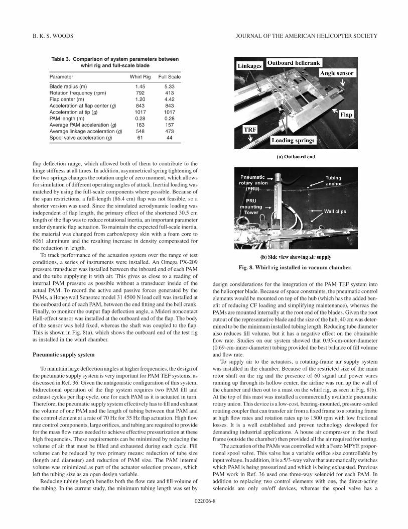
Table 3. Comparison of system parameters betweenwhirl rig and full-scale blade
Parameter Whirl Rig Full Scale
Blade radius (m) 1.45 5.33Rotation frequency (rpm) 792 413Flap center (m) 1.20 4.42Acceleration at flap center (g) 843 843Acceleration at tip (g) 1017 1017PAM length (m) 0.28 0.28Average PAM acceleration (g) 163 157Average linkage acceleration (g) 548 473Spool valve acceleration (g) 61 44
flap deflection range, which allowed both of them to contribute to thehinge stiffness at all times. In addition, asymmetrical spring tightening ofthe two springs changes the rotation angle of zero moment, which allowsfor simulation of different operating angles of attack. Inertial loading wasmatched by using the full-scale components where possible. Because ofthe span restrictions, a full-length (86.4 cm) flap was not feasible, so ashorter version was used. Since the simulated aerodynamic loading wasindependent of flap length, the primary effect of the shortened 30.5 cmlength of the flap was to reduce rotational inertia, an important parameterunder dynamic flap actuation. To maintain the expected full-scale inertia,the material was changed from carbon/epoxy skin with a foam core to6061 aluminum and the resulting increase in density compensated forthe reduction in length.
To track performance of the actuation system over the range of testconditions, a series of instruments were installed. An Omega PX-209pressure transducer was installed between the inboard end of each PAMand the tube supplying it with air. This gives as close to a reading ofinternal PAM pressure as possible without a transducer inside of theactual PAM. To record the active and passive forces generated by thePAMs, a Honeywell Sensotec model 31 4500 N load cell was installed atthe outboard end of each PAM, between the end fitting and the bell crank.Finally, to monitor the output flap deflection angle, a Midori noncontactHall-effect sensor was installed at the outboard end of the flap. The bodyof the sensor was held fixed, whereas the shaft was coupled to the flap.This is shown in Fig. 8(a), which shows the outboard end of the test rigas installed in the whirl chamber.
Pneumatic supply system
To maintain large deflection angles at higher frequencies, the design ofthe pneumatic supply system is very important for PAM TEF systems, asdiscussed in Ref. 36. Given the antagonistic configuration of this system,bidirectional operation of the flap system requires two PAM fill andexhaust cycles per flap cycle, one for each PAM as it is actuated in turn.Therefore, the pneumatic supply system effectively has to fill and exhaustthe volume of one PAM and the length of tubing between that PAM andthe control element at a rate of 70 Hz for 35 Hz flap actuation. High flowrate control components, large orifices, and tubing are required to providefor the mass flow rates needed to achieve effective pressurization at thesehigh frequencies. These requirements can be minimized by reducing thevolume of air that must be filled and exhausted during each cycle. Fillvolume can be reduced by two primary means: reduction of tube size(length and diameter) and reduction of PAM size. The PAM internalvolume was minimized as part of the actuator selection process, whichleft the tubing size as an open design variable.
Reducing tubing length benefits both the flow rate and fill volume ofthe tubing. In the current study, the minimum tubing length was set by
Fig. 8. Whirl rig installed in vacuum chamber.
design considerations for the integration of the PAM TEF system intothe helicopter blade. Because of space constraints, the pneumatic controlelements would be mounted on top of the hub (which has the added ben-efit of reducing CF loading and simplifying maintenance), whereas thePAMs are mounted internally at the root end of the blades. Given the rootcutout of the representative blade and the size of the hub, 40 cm was deter-mined to be the minimum installed tubing length. Reducing tube diameteralso reduces fill volume, but it has a negative effect on the obtainableflow rate. Studies on our system showed that 0.95-cm-outer-diameter(0.69-cm-inner-diameter) tubing provided the best balance of fill volumeand flow rate.
To supply air to the actuators, a rotating-frame air supply systemwas installed in the chamber. Because of the restricted size of the mainrotor shaft on the rig and the presence of 60 signal and power wiresrunning up through its hollow center, the airline was run up the wall ofthe chamber and then out to a mast on the whirl rig, as seen in Fig. 8(b).At the top of this mast was installed a commercially available pneumaticrotary union. This device is a low-cost, bearing-mounted, pressure-sealedrotating coupler that can transfer air from a fixed frame to a rotating frameat high flow rates and rotation rates up to 1500 rpm with low frictionallosses. It is a well established and proven technology developed fordemanding industrial applications. A house air compressor in the fixedframe (outside the chamber) then provided all the air required for testing.
The actuation of the PAMs was controlled with a Festo MPYE propor-tional spool valve. This valve has a variable orifice size controllable byinput voltage. In addition, it is a 5/3-way valve that automatically switcheswhich PAM is being pressurized and which is being exhausted. PreviousPAM work in Ref. 36 used one three-way solenoid for each PAM. Inaddition to replacing two control elements with one, the direct-actingsolenoids are only on/off devices, whereas the spool valve has a
022006-8
WHIRL TESTING OF A PNEUMATIC ARTIFICIAL MUSCLE ACTUATION SYSTEM 2014
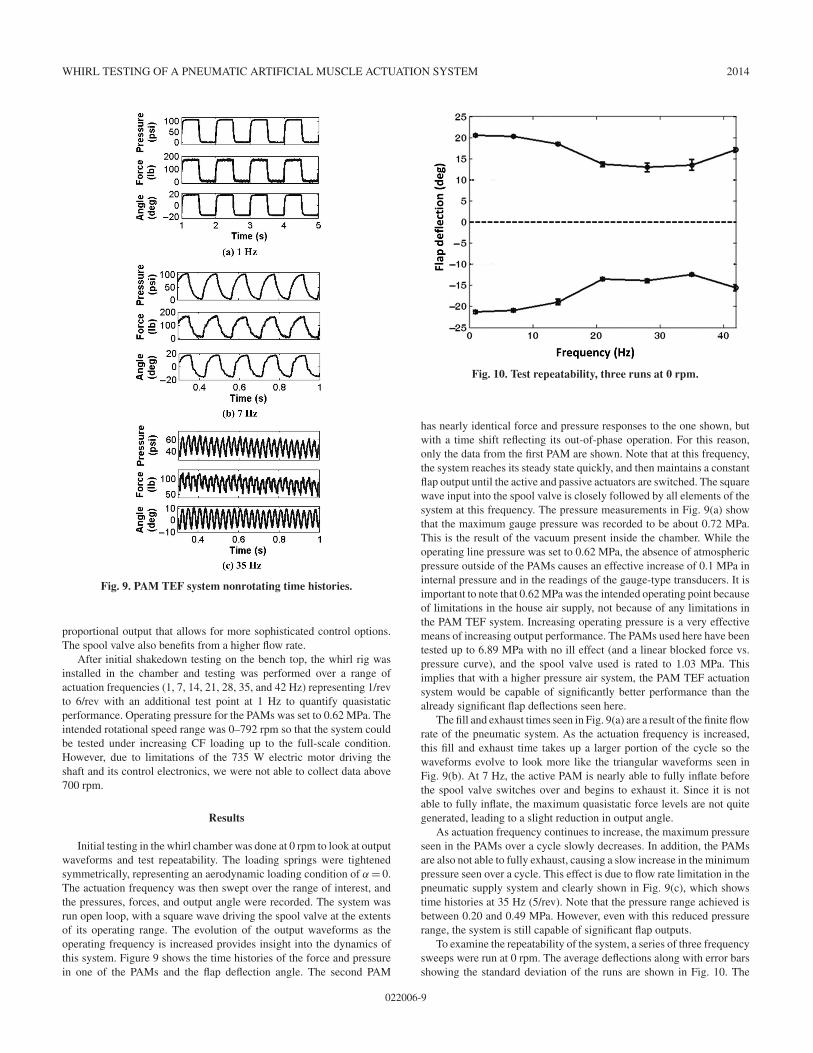
Fig. 9. PAM TEF system nonrotating time histories.
proportional output that allows for more sophisticated control options.The spool valve also benefits from a higher flow rate.
After initial shakedown testing on the bench top, the whirl rig wasinstalled in the chamber and testing was performed over a range ofactuation frequencies (1, 7, 14, 21, 28, 35, and 42 Hz) representing 1/revto 6/rev with an additional test point at 1 Hz to quantify quasistaticperformance. Operating pressure for the PAMs was set to 0.62 MPa. Theintended rotational speed range was 0–792 rpm so that the system couldbe tested under increasing CF loading up to the full-scale condition.However, due to limitations of the 735 W electric motor driving theshaft and its control electronics, we were not able to collect data above700 rpm.
Results
Initial testing in the whirl chamber was done at 0 rpm to look at outputwaveforms and test repeatability. The loading springs were tightenedsymmetrically, representing an aerodynamic loading condition of ! = 0.The actuation frequency was then swept over the range of interest, andthe pressures, forces, and output angle were recorded. The system wasrun open loop, with a square wave driving the spool valve at the extentsof its operating range. The evolution of the output waveforms as theoperating frequency is increased provides insight into the dynamics ofthis system. Figure 9 shows the time histories of the force and pressurein one of the PAMs and the flap deflection angle. The second PAM
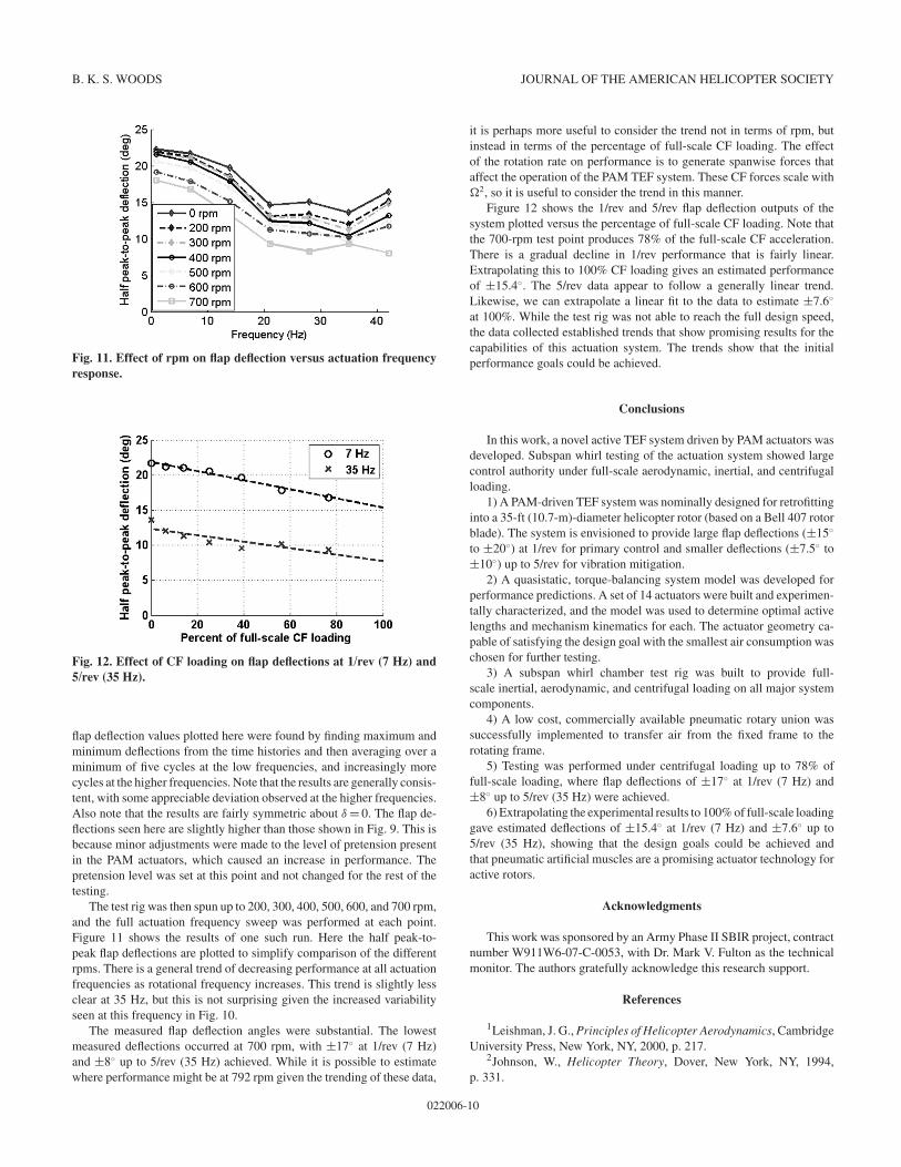
Fig. 10. Test repeatability, three runs at 0 rpm.
has nearly identical force and pressure responses to the one shown, butwith a time shift reflecting its out-of-phase operation. For this reason,only the data from the first PAM are shown. Note that at this frequency,the system reaches its steady state quickly, and then maintains a constantflap output until the active and passive actuators are switched. The squarewave input into the spool valve is closely followed by all elements of thesystem at this frequency. The pressure measurements in Fig. 9(a) showthat the maximum gauge pressure was recorded to be about 0.72 MPa.This is the result of the vacuum present inside the chamber. While theoperating line pressure was set to 0.62 MPa, the absence of atmosphericpressure outside of the PAMs causes an effective increase of 0.1 MPa ininternal pressure and in the readings of the gauge-type transducers. It isimportant to note that 0.62 MPa was the intended operating point becauseof limitations in the house air supply, not because of any limitations inthe PAM TEF system. Increasing operating pressure is a very effectivemeans of increasing output performance. The PAMs used here have beentested up to 6.89 MPa with no ill effect (and a linear blocked force vs.pressure curve), and the spool valve used is rated to 1.03 MPa. Thisimplies that with a higher pressure air system, the PAM TEF actuationsystem would be capable of significantly better performance than thealready significant flap deflections seen here.
The fill and exhaust times seen in Fig. 9(a) are a result of the finite flowrate of the pneumatic system. As the actuation frequency is increased,this fill and exhaust time takes up a larger portion of the cycle so thewaveforms evolve to look more like the triangular waveforms seen inFig. 9(b). At 7 Hz, the active PAM is nearly able to fully inflate beforethe spool valve switches over and begins to exhaust it. Since it is notable to fully inflate, the maximum quasistatic force levels are not quitegenerated, leading to a slight reduction in output angle.
As actuation frequency continues to increase, the maximum pressureseen in the PAMs over a cycle slowly decreases. In addition, the PAMsare also not able to fully exhaust, causing a slow increase in the minimumpressure seen over a cycle. This effect is due to flow rate limitation in thepneumatic supply system and clearly shown in Fig. 9(c), which showstime histories at 35 Hz (5/rev). Note that the pressure range achieved isbetween 0.20 and 0.49 MPa. However, even with this reduced pressurerange, the system is still capable of significant flap outputs.
To examine the repeatability of the system, a series of three frequencysweeps were run at 0 rpm. The average deflections along with error barsshowing the standard deviation of the runs are shown in Fig. 10. The
022006-9
B. K. S. WOODS JOURNAL OF THE AMERICAN HELICOPTER SOCIETY
Fig. 11. Effect of rpm on flap deflection versus actuation frequencyresponse.
Fig. 12. Effect of CF loading on flap deflections at 1/rev (7 Hz) and5/rev (35 Hz).
flap deflection values plotted here were found by finding maximum andminimum deflections from the time histories and then averaging over aminimum of five cycles at the low frequencies, and increasingly morecycles at the higher frequencies. Note that the results are generally consis-tent, with some appreciable deviation observed at the higher frequencies.Also note that the results are fairly symmetric about ! = 0. The flap de-flections seen here are slightly higher than those shown in Fig. 9. This isbecause minor adjustments were made to the level of pretension presentin the PAM actuators, which caused an increase in performance. Thepretension level was set at this point and not changed for the rest of thetesting.
The test rig was then spun up to 200, 300, 400, 500, 600, and 700 rpm,and the full actuation frequency sweep was performed at each point.Figure 11 shows the results of one such run. Here the half peak-to-peak flap deflections are plotted to simplify comparison of the differentrpms. There is a general trend of decreasing performance at all actuationfrequencies as rotational frequency increases. This trend is slightly lessclear at 35 Hz, but this is not surprising given the increased variabilityseen at this frequency in Fig. 10.
The measured flap deflection angles were substantial. The lowestmeasured deflections occurred at 700 rpm, with ±17! at 1/rev (7 Hz)and ±8! up to 5/rev (35 Hz) achieved. While it is possible to estimatewhere performance might be at 792 rpm given the trending of these data,
it is perhaps more useful to consider the trend not in terms of rpm, butinstead in terms of the percentage of full-scale CF loading. The effectof the rotation rate on performance is to generate spanwise forces thataffect the operation of the PAM TEF system. These CF forces scale with"2, so it is useful to consider the trend in this manner.
Figure 12 shows the 1/rev and 5/rev flap deflection outputs of thesystem plotted versus the percentage of full-scale CF loading. Note thatthe 700-rpm test point produces 78% of the full-scale CF acceleration.There is a gradual decline in 1/rev performance that is fairly linear.Extrapolating this to 100% CF loading gives an estimated performanceof ±15.4!. The 5/rev data appear to follow a generally linear trend.Likewise, we can extrapolate a linear fit to the data to estimate ±7.6!
at 100%. While the test rig was not able to reach the full design speed,the data collected established trends that show promising results for thecapabilities of this actuation system. The trends show that the initialperformance goals could be achieved.
Conclusions
In this work, a novel active TEF system driven by PAM actuators wasdeveloped. Subspan whirl testing of the actuation system showed largecontrol authority under full-scale aerodynamic, inertial, and centrifugalloading.
1) A PAM-driven TEF system was nominally designed for retrofittinginto a 35-ft (10.7-m)-diameter helicopter rotor (based on a Bell 407 rotorblade). The system is envisioned to provide large flap deflections (±15!
to ±20!) at 1/rev for primary control and smaller deflections (±7.5! to±10!) up to 5/rev for vibration mitigation.
2) A quasistatic, torque-balancing system model was developed forperformance predictions. A set of 14 actuators were built and experimen-tally characterized, and the model was used to determine optimal activelengths and mechanism kinematics for each. The actuator geometry ca-pable of satisfying the design goal with the smallest air consumption waschosen for further testing.
3) A subspan whirl chamber test rig was built to provide full-scale inertial, aerodynamic, and centrifugal loading on all major systemcomponents.
4) A low cost, commercially available pneumatic rotary union wassuccessfully implemented to transfer air from the fixed frame to therotating frame.
5) Testing was performed under centrifugal loading up to 78% offull-scale loading, where flap deflections of ±17! at 1/rev (7 Hz) and±8! up to 5/rev (35 Hz) were achieved.
6) Extrapolating the experimental results to 100% of full-scale loadinggave estimated deflections of ±15.4! at 1/rev (7 Hz) and ±7.6! up to5/rev (35 Hz), showing that the design goals could be achieved andthat pneumatic artificial muscles are a promising actuator technology foractive rotors.
Acknowledgments
This work was sponsored by an Army Phase II SBIR project, contractnumber W911W6-07-C-0053, with Dr. Mark V. Fulton as the technicalmonitor. The authors gratefully acknowledge this research support.
References
1Leishman, J. G., Principles of Helicopter Aerodynamics, CambridgeUniversity Press, New York, NY, 2000, p. 217.
2Johnson, W., Helicopter Theory, Dover, New York, NY, 1994,p. 331.
022006-10
WHIRL TESTING OF A PNEUMATIC ARTIFICIAL MUSCLE ACTUATION SYSTEM 2014
3Leishman, J., The Helicopter Thinking Forward, Looking Back,College Park Press, College Park, MD, 2007, pp. 101–102.
4Chopra, I., “Review of State of Art of Smart Structures and IntegratedSystems,” AIAA Journal, Vol. 40, (11), November 2002, pp. 2145–2187.
5Loewy, R., “Recent Developments in Smart Structures with Aero-nautical Applications,” Smart Materials and Structures, Vol. 6, (5), 1997,pp. R11–R42.
6Giurgiutiu, V., “Recent Advances in Smart-Material Rotor Con-trol Actuation,” AIAA 2000-1709, AIAA/ASME/ASCE/AHS/ASC 41stStructures, Structural Dynamics, and Materials Conference, Atlanta, GA,April 3–6, 2000.
7Chopra, I., “Status of Application of Smart Structures Technologyto Rotorcraft Systems,” Journal of the American Helicopter Society,Vol. 45, (4), October 2000, pp. 228–252.
8Niezrecki, C., Brei, D., Balakrishnan, S., and Moskalik, A., “Piezo-electric Actuation: State of the Art,” The Shock and Vibration Digest,Vol. 33, (4), 2001, pp. 269–280.
9Straub, F., Kennedy, D., Stemple, A., Anand, V., and Birchette, T.,“Development and Whirl Tower Test of the SMART Active Flap Rotor,”SPIE International Symposium on Smart Structures and Materials, SanDiego, CA, March 14–18, 2004.
10Dieterich, O., Enenkl, B., and Roth, D., “Trailing Edge Flaps for Ac-tive Rotor Control—Aeroelastic Characteristics of the ADASYS RotorSystem,” American Helicopter Society 62nd Annual Forum, Phoenix,AZ, May 9–11, 2006.
11Norman, T. R., Theodore, C., Shinoda, P. M., Fuerst, D., Arnold,U. T. P., Makinen, S., Lorber, P., and O’Neill, J., “Full-Scale Wind Tun-nel Test of a UH-60 Individual Blade Control System for PerformanceImprovement and Vibration, Loads, and Noise Control,” American He-licopter Society 65th Annual Forum Proceedings, Grapevine, TX, May27–29, 2009.
12Arnold, U. T. P., “Recent IBC Flight Test Results from the CH-53G Helicopter,” 29th European Rotorcraft Forum, Friedrichshafen,Germany, September 16–18, 2003.
13Huber, J., Fleck, N., and Ashby, M., “The Selection of MechanicalActuators Based on Performance Indices,” Proceedings of the RoyalSociety A, Vol. 453, (1965) 1997, pp. 2185–2205.
14Moog Actuation Technologies, 2011. “Electromechanical Ac-tuators,” available at http://www.moog.com/products/actuators-servoactuators/multi-purpose/linear-actuators/, accessed February25, 2014.
15Muirhead Aerospace, 2011. “Actuators,” available athttp://www.muirheadaerospace.com/motion-technology/actuators.html#SingleActuator, accessed July 21, 2011.
16Tondu, B., and Lopez, P., “The McKibben Muscle and Its Use in Ac-tuating Robot-Arms Showing Similarities with Human Arm Behaviour,”Industrial Robot, Vol. 24, (6), 1997, p. 432.
17Daerden, F., and Lefeber, D., “Pneumatic Artificial Muscles: Actu-ators for Robotics and Automation,” European Journal of Mechanicaland Environmental Engineering, Vol. 47, (1), 2002, pp. 10–21.
18Kothera, C. S., Woods, B. K. S., Sirohi, J., Wereley, N. M., andChen, P. C., “Fluid-Driven Artificial Muscles as Mechanisms for Con-trolled Actuation,” U.S. Patent 7,837,144, filed: August 11, 2006, issued:November 23, 2010.
19Woods, B., Kothera, C., Sirohi, J., and Wereley, N., “PneumaticArtificial Muscles for Trailing Edge Flap Actuation: A Feasibility Study,”Smart Materials and Structures, 20, 105021 (2011).
20Peel, L., Mejia, J., Narvaez, B., Thompson, K., and Lingala, M.,“Development of a Simple Morphing Wing Using Elastomeric Compos-ites as Skins and Actuators,” Journal of Mechanical Design, 131, 091003(2009).
21Zhang, W., Accorsi, M., and Leonard, W., “Analysis of Geomet-rically Nonlinear Anisotropic Membranes: Application to PneumaticMuscle Actuators,” Finite Elements in Analysis and Design, Vol. 41,(9–10), 2005, pp. 944–962.
22Chou, A., and Philen, M., “High-Performance Flexible Matrix Com-posite Actuators for Trailing Edge Flap Control,” Virginia Space GrantConsortium Student Conference, Norfolk, VA, April 2008.
23Hinshaw, T., “Analysis and Design of a Morphing Wing Tip UsingMulticellular Flexible Matrix Composite Adaptive Skins,” M.S. Thesis,Department of Aerospace Engineering, Virginia Polytechnic Instituteand State University, Blacksburg, VA, 2009.
24Woods, B. K. S., Wereley, N. M., and Kothera, C. S., “Wind TunnelTesting of a Helicopter Rotor Trailing Edge Flap Actuated via Pneu-matic Artificial Muscles,” Journal of Intelligent Material Systems andStructures, Vol. 22, (13), 2011, pp. 1513–1528.
25Klute, G., and Hannaford, B., “Fatigue Characteristics of McKibbenArtificial Muscle Actuators,” IEEE/RSJ International Conference on In-telligent Robots and Systems, Victoria, Canada, October 13–17, 1998.
26Kingsley, D., and Quinn, R., “Fatigue Life and Frequency Responseof Braided Pneumatic Actuators,” Robotics and Automation, Vol. 3, 2002,pp. 2830–2835.
27Woods, B. K. S., Kothera, C. S., and Wereley N. M., “Fluidic Ar-tificial Muscle Actuator and Swaging Process Therefor,” U.S. Patent8,307,753, filed: June 11, 2009, issued: November 13, 2012.
28Woods, B. K. S., Gentry, M., Kothera, C., and Wereley, N., “FatigueLife Testing of Swaged Pneumatic Artificial Muscles as Actuators forAerospace Applications,” Journal of Intelligent Material Systems andStructures, Vol. 23, (3), 2012, pp. 322–338.
29Straub, F., and Merkley, D., “Design of a Servo-Flap Rotor forReduced Control Loads,” Smart Materials and Structures, Vol. 5, (1),1996, pp. 68–75.
30Falls, J., Datta, A., and Chopra, I., “Integrated Trailing-Edge Flapsand Servotabs for Primary Flight Control,” Journal of the AmericanHelicopter Society, 55, 032005 (2010).
31Fulton, M., “Design of the Active Elevon Rotor for Low Vibra-tion,” American Helicopter Society Aeromechanics Specialists’ Meet-ing, Atlanta, GA, November 13–15, 2000.
32Abbott, I., and Von Doenhoff, A., Theory of Wing Sections, Dover,New York, NY, 1958, pp. 190–197.
33Jacobs, E., and Pinkerton, R., “Pressure Distribution Over a Symmet-rical Airfoil Section with Trailing Edge Flap,” NACA Technical Reportno. 360, 1931.
34Copp, P., and Chopra, I., “Continued Development of a Mach ScaleSwashplateless Rotor with Integrated Trailing Edge Flaps,” AmericanHelicopter Society 64th Annual Forum, Montreal, Canada, April 29–May 1, 2008.
35Kothera, C. S., Jangid, M., Sirohi, J., and Wereley, N. M., “Exper-imental Characterization and Static Modeling of McKibben Actuators,”Journal of Mechanical Design, 131, 091010 (2009).
36Woods, B. K. S., Kothera, C., and Wereley, N. M., “Whirl Testingof a Pneumatic Artificial Muscle Driven Helicopter Trailing Edge Flap,”American Helicopter Society 64th Annual Forum, Montreal, Canada,April 29–May 1, 2008.
022006-11