fabrication of pneumatic shearing machine
TRANSCRIPT
© 2016 IJRTI | Volume 1, Issue 2 | ISSN: 2456-3315
IJRTI1611004 International Journal for Research Trends and Innovation (www.ijrti.org) 23
Fabrication of Pneumatic Shearing Machine
1M.Khaja Gulam Hussain,
2T. John babu.
12 Asst.Professors, 1Department of Mechanical Engineering, RGM College of Engineering & Technology, Nandyal-518501, A. P., India. 2Department of Mechanical Engineering, RGM College of Engineering &Technology, Nandyal-518501, A. P., India. .
________________________________________________________________________________________
Abstract: The technology of pneumatics has gained tremendous importance in the field of automation from old fashioned timber
works, machine shops and space robots .Certain characterizes of air have made this medium quite suitable for used in
modern manufacturing and production industries. It is therefore important that technicians and engineers should have
knowledge on pneumatic systems air operated valves accessories. Pneumatic system consists of a compressor plant, pipe
lines, control valves, pneumatic cylinder, connecting links ,control system and drive members. The air is compressed in
an air compressor and from the compressor plant the flow media is transmitted to the pneumatic cylinder through a well
laid pipe line system. So keeping in mind about the importance of pneumatic system , introducing a pneumatic sheet
metal cutting. By the use of pneumatic shearing technique , It can reduce human effort in cutting sheet metal and it is a
time saving process. The design is particularly suited to applications where the working space is constrained. Pneumatic
shearing machines are useful when materials need to be cut in hazardous areas such as oil & gas refineries, chemical
factories or oil rigs as well as dusty and wet environments where electric tools are not effective.
Keywords: Pneumatic cylinder, connecting links Pneumatic shearing machines, time and cost saving. ________________________________________________________________________________________
1. INTRODUCTION:
1.1Sheet Metal: Sheet metal is simply a metal formed into thin and flat pieces. It is one of the fundamental forms used in metal working
and can be cut and bent into a variety of different shapes. Countless everyday objects are constructed of the material.
Thicknesses can vary significantly, although extremely thin thicknesses are considered foil or leaf, and pieces thicker
than 6 mm (0.25 in) are considered plate. The thickness of the sheet metal is called its gauge. Commonly used steel sheet
metal ranges from 30 gauge to about 8 gauge. The larger the gauge number, the thinner the metal. Gauge is measured in
ferrous (iron based) metals while nonferrous metals such as aluminum or copper are designated differently; i.e., Copper
is measured in thickness by Ounce. There are many different metals that can be made into sheet metal, such as aluminum,
brass, copper, steel, tin, nickel and titanium. For decorative uses, important sheet metals include silver, gold and platinum
(platinum sheet metal is also utilized as a catalyst.) Sheet metal also has applications in car bodies, airplane wings,
medical tables, roofs for buildings (Architectural) and many other things.Sheet metal of iron and other materials with high magnetic permeability, also known as laminated steel cores, has applications in transformers and electric machines..
There are three primary procedures in Layout
1. Parallel 2. Radial 3. Triangulation
1.2 Sheet Metal Cutting: Cutting processes are those in which a piece of sheet metal is separated by applying a great
enough force to cause the material to fail. The most common cutting processes are performed by applying a shear force,
and are therefore sometimes referred to as shearing processes. When a great enough shearing force is applied, the shear
stress in the material will exceed the ultimate shear strength and the material will fail and separate at the cut location.
This shearing force is applied by two tools, one above and one below the sheet. Whether these tools are a punch and die
or upper and lower blades, the tool above the sheet delivers a quick downward blow to the sheet metal that rests over the
lower tool. A small clearance is present between the edges of the upper and lower tools, which facilitates the fracture of
the material. The size of this clearance is typically 2-10% of the material thickness and depends upon several factors,
such as the specific shearing process, material, and sheet thickness. The effects of shearing on the material change as the
cut progresses and are visible on the edge of the sheared material. When the punch or blade impacts the sheet, the
clearance between the tools allows the sheet to plastically deform and “rollover” the edge. Finally, the shear stress is too great and the material fractures at an angle with a small burr formed at the edge. The height of these portions of the cut
depends on several factors, including the sharpness of the tools and the clearance between the tools.
1.3 Pneumatic Shearing Machine:
Pneumatics is the branch of technology, which deals with the study and usage of pressurized gas to affect mechanical
motion. Pneumatic sheet metal machine is a cutting machine tool designed to cut metal by applying pneumatic pressure.
© 2016 IJRTI | Volume 1, Issue 2 | ISSN: 2456-3315
IJRTI1611004 International Journal for Research Trends and Innovation (www.ijrti.org) 24
Our project deals with fabrication of light weight pneumatic shearing machine specially designed to quickly and safety
cut through thin and soft metals. This machine can be easily designed using standard cylinders & other components like
release/port/direction control valves, flow regulator, piston and air compressor. Controlling of this machine is as easy as
it is simple ON - OFF type. Because of compressible air, the equipment is less likely to be damaged by shock. There are
numerous types of cutting machines are available in engineering field, but we are interested to introduce pneumatic
system in sheet metal cutting machine. The design is particularly suited to applications where the working space is
constrained, Pneumatic shearing machines are useful when materials need to be cut in hazardous areas such as oil & gas
refineries, chemical factories or oil rigs as well as dusty and wet environments where electric tools are not effective. The
machine is exclusively intended for mass production and they represent the faster and more efficient way to cut a metal..
The operation of the unit is simplified to a few simple operations involving a cylinder block and piston arrangement.
There are numerous types of cutting machines in Engineering field, which are used to fulfill the requirements. We are
interested to introduce pneumatic system in sheet cutting machine. The main function of Pneumatic shearing machine is
to cut thin and soft metals by pneumatic power.
2. LITERATURE SURVEY:
2.1 Pneumatics The word „pneuma‟ comes from Greek and means breather wind. The word pneumatics is the study of air movement and
its phenomena is derived from the word pneuma. Today pneumatics is mainly understood to means the application of air
as a working medium in industry especially to driving and controlling of machines and equipment.
Pneumatics has for some considerable time between used for carrying out the simplest mechanical tasks. In more recent
times it is playing more important role in the development of pneumatic technology for automation.
Pneumatic systems operate on a supply of compressed air which must be made available in sufficient quantity and at a
pressure to suit the capacity of the system. When the pneumatic system is being adopted for the first time, however it
wills indeed the necessary deal with the question of compressed air supply. The key part of any facility for supply of
compressed air is by means using reciprocating compressor. A compressor is a machine that takes in air, gas at a certain
pressure and delivers the air at a high pressure.Compressor capacity is the actual quantity of air compressed and delivered
and the volume expressed is that of the air at intake conditions namely at atmosphere pressure and normal ambient
temperature. The compressibility of the air was first investigated by Robert Boyle in 1962 and he found that the product of pressure
and volume of a particular quantity of gas is inversely proportional.
It is written as
PV = C (or) PıVı = P2V2
In this equation the pressure is the absolute pressured which is about 14.7 Psi and is of courage capable of maintaining a
column of mercury, nearly 30 inches high in an ordinary barometer. Any gas can be used in pneumatic system but air is
the mostly used system now a days.
2.2 Selection Of Pneumatics: Mechanization is broadly defined as the replacement of manual effort by mechanical power. Pneumatic is an attractive
medium for low cost mechanization particularly for sequential (or) repetitive operations. Many factories and plants already have a compressed air system, which is capable of providing the power (or) energy requirements and the control
system (although equally pneumatic control systems may be economic and can be advantageously applied to other forms
of power). The main advantage of an all pneumatic system are usually economic and simplicity the latter reducing
maintenance to a low level. It can also have out standing advantages in terms of safety.
2.3 production Of Compressed Air Pneumatic systems operate on a supply of compressed air, which must be made available in sufficient quantity and at a
pressure to suit the capacity of the system. When pneumatic system is being adopted for the first time, however it wills
indeed the necessary to deal with the question of compressed air supply. The key part of any facility for supply of
compressed air is by means using reciprocating compressor. A compressor is a machine that takes in air, gas at a certain
pressure and delivered the air at a high pressure. Compressor capacity is the actual quantity of air compressed and delivered and the volume expressed is that of the air at
intake conditions namely at atmosphere pressure and normal ambient temperature. Clean condition of the suction air is
one of the factors, which decides the life of a compressor. Warm and moist suction air will result in increased
precipitation of condense from the compressed air. Compressor may be classified in two general types. 1. Positive
displacement compressor. 2. Turbo compressor . Positive displacement compressors are most frequently employed for
compressed air plant and have proved highly successful and supply air for pneumatic control application. The types of
positive compressor are: 1. Reciprocating type compressor 2. Rotary type compressor . Turbo compressors are
employed where large capacity of air required at low discharge pressures. They cannot attain pressure necessary for
pneumatic control application unless built in multistage designs and are seldom encountered in pneumatic service.
© 2016 IJRTI | Volume 1, Issue 2 | ISSN: 2456-3315
IJRTI1611004 International Journal for Research Trends and Innovation (www.ijrti.org) 25
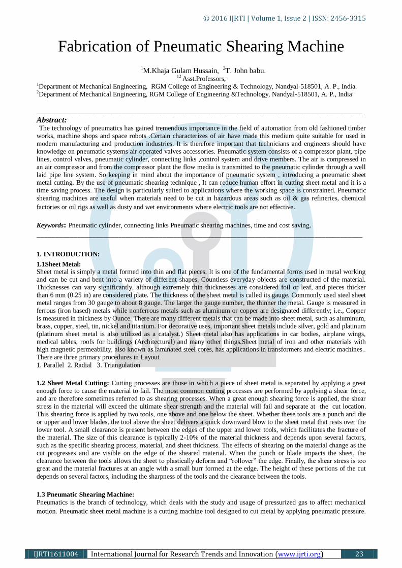
2.4 Reciprocating Compressors:
Fig.1.Working of Reciprocating air compressor
In this type of compressor a cylinder bore encloses a moving piston. As the crankshaft of the compressor rotate, the
piston moves within the cylinder, similar to the piston in a car engine. As the piston is pulled down, the volume
increases, creating a lower atmospheric pressure in the piston chamber. This difference in pressure causes air toenter via
the inlet valve. As the piston is forced upwards the volume of air reduces. The air pressure therefore increases. Eventually the pressure forces the outlet valve to open. To avoid an excessive rise in temperature, Multi-stage
compressors with INTERCOOLERS have been developed. These compressors can generate higher pressures than single
stage compressors. The most common type is the Two-Stage compressor. The following figures show how this
compressor works.
Fig.2.Compressor work of two stage reciprocating compressor
Built for either stationary (or) portable service the reciprocating compressor is by far the most common type.
Reciprocating compressors lap be had is sizes from the smallest capacities to deliver more than 500 m³/min. In single
stage compressor, the air pressure may be of 6 bar machines discharge of pressure is up to 15 bars. Discharge pressure in
the range of 250 bars can be obtained with high pressure reciprocating compressors that of three & four stages. Single
stage and two stage models are particularly suitable for pneumatic applications, with preference going to the two stage design as soon as the discharge pressure exceeds 6 bar , because it in capable of matching the performance of single stage
machine at lower costs per driving powers in the range .
2.5 Selection of Compressor: It is vital for the effective and efficient running of a compressed air plant that the appropriate compressor is selected to
meet the system needs. Large compressor installation can be expensive and complex. However, the following points
should be considered: SYSTEM FLOW RATE DEMAND: This should include both the estimated initial loading and
near term loading. STANDBY CAPACITY FOR EMERGINSIS: This could be a second compressor that is connected to
the main lineFUTURE AIR REQURIMENT: This issue should be considered in the selection of the compressor due to
the cost of replacement of the compressor.
2.5.1 Sizing Of Air Compressor: The sizing of air reservoirs requires taking into account parameters such as system pressure and flow-rate requirements, compressor output capability, and the type of duty of operation. It also serves to dampen pressure pulses either coming
from the compressor or the pneumatic system during valve shifting and component operation. The reservoirs are
equipped with a safety relief valve in order to prevent the explosion of tank. The last equation can be used to determine
the proper size of the reservoir as
Where t= time that reservoir can supply required amount of air (min)
Qr= consumption rate of pneumatic system (SCFM, m3/min),Qc= output flow-rate of compressor (SCFM, m3/min)
Pmax=maximum pressure level in reservoir (psi, kPa), Pmin= minimum pressure level in reservoir (psi, kPa)
Vr= reservoir size (ft3, m3)
2.5.2 Air Capacity Rating Of Compressors :
Air compressors are generally rated in terms of SCFM of free are, defined as air at actual atmospheric conditions. The
equation that allows for this calculation is

© 2016 IJRTI | Volume 1, Issue 2 | ISSN: 2456-3315
IJRTI1611004 International Journal for Research Trends and Innovation (www.ijrti.org) 26
2.5.3Power Required To Drive The Compressor: The following equation can be used to determine the theoretical power required to drive an air compressor.
Theoretical power (in terms of HP) is given by the formula
Theoretical power (in terms of kW) is given by the formula
Pin = inlet atmospheric pressure (psi, kPa )
Pout = outlet atmospheric pressure (psi, kPa ) , Q = flow-rate (standard m3/min)
3. COMPONENTS AND SPECIFICATIONS: The pneumatic sheet metal shearing machine consists of the following components to full fill the requirements of
complete operation of the machine. 1. Pneumatic Control Components 2. Solenoid Valve 3. Connectors 4. Hoses
3.1 Pneumatic Control Components:
3.1.1 Pneumatic Cylinder:
Fig 3. pneumatic cylinders
Pneumatic cylinders (sometimes known as air cylinders) are mechanical devices which use the power of compressed gas
to produce a force in a reciprocating linear motion.
Like hydraulic cylinders, pneumatic cylinders use the stored potential energy of a fluid, in this case compressed air, and
convert it into kinetic energy as the air expands in an attempt to reach atmospheric pressure. This air expansion forces a
piston to move in the desired direction. The piston is a disc or cylinder, and the piston rod transfers the force it develops
to the object to be moved. Engineers prefer to use pneumatics sometime because they are quieter, cleaner, and do not
require large amounts or space for fluid storage. Because the operating fluid is a gas, leakage from a pneumatic cylinder will not drip out and contaminate the
surroundings, making pneumatics more desirable where cleanliness is a requirement. For example, in the mechanical
puppets of the Disney Tiki Room, pneumatics are used to prevent fluid from dripping onto people below the puppet. An
air cylinder is an operative device in which the air is compressed to high pressure. The cylinder converts the energy of
the compressed air into linear motion which extends or retracts the piston rod. The compressed air is nothing but
pneumatic power which is further converted in to mechanical power with the help of actuator. 3.1.2 Single acting cylinder
Fig.4. Single acting cylinder
Single acting cylinder is only capable of performing an operating medium in only one direction. Single acting cylinders
equipped with one inlet for the operating air pressure, can be production in several fundamentally different designs.
Single cylinders develop power in one direction only. Therefore no heavy control equipment should be attached to them.
For return stoke single action cylinder requires only about half the air volume consumed by a double acting for one
operating cycle.
3.1.3 Double Acting Cylinders:
Fig.5.Double acting cylinder
A double acting cylinder is employed in control systems with the full pneumatic cushioning and it is essential when the
cylinder itself is required to retard heavy messes. This can be done by providing two openings at the ends position. In all intermediate position a separate externally mounted cushioning derive most be provided with the damping feature.
The normal escape of air is out off by a cushioning piston before the end of the stock is required. As a result the sit in the
cushioning chamber is again compressed since it cannot escape but slowly according to the setting made on reverses. The
air freely enters the cylinder and the piston stokes in the other direction at full force and velocity.
© 2016 IJRTI | Volume 1, Issue 2 | ISSN: 2456-3315
IJRTI1611004 International Journal for Research Trends and Innovation (www.ijrti.org) 27
3.1.4. Specifications : Stroke length : Cylinder stoker length 200 mm =0.2 m
Piston diameter : 40 mm Piston rod : 15 mm = 15 x 10ˉ³ m
Quantity : 1
Seals : Nitride (Buna-N) Elastomer
End cones : Cast iron
Piston : EN – 8
Media : Air
Temperature : 0-80 º C
Pressure Range : 8 N/m²
3.2 Valves :
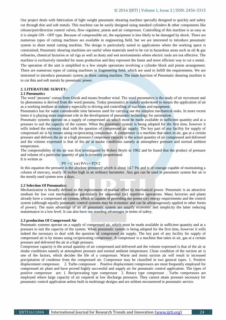
3.2.1. Working of 5/2 Solenoid Valve :
Fig.6. line diagram of Solenoid valve
The solenoid valve has 5 openings. This ensure easy exhausting of 5/2 valve. The spool of the 5/2 valve slide inside the
main bore according to spool position; the ports get connected and disconnected. The working principle is as follows.
Position-1 When the spool is actuated towards outer direction port „P‟ gets connected to „B‟ and „S‟ remains closed while „A‟ gets
connected to „R‟.
Poisition-2 When the spool is pushed in the inner direction port „P‟ and „A‟ gets connected to each other and „B‟ to „S‟ while port
„R‟ remains closed. 3.2.2 Parts of Solenoid Valve:
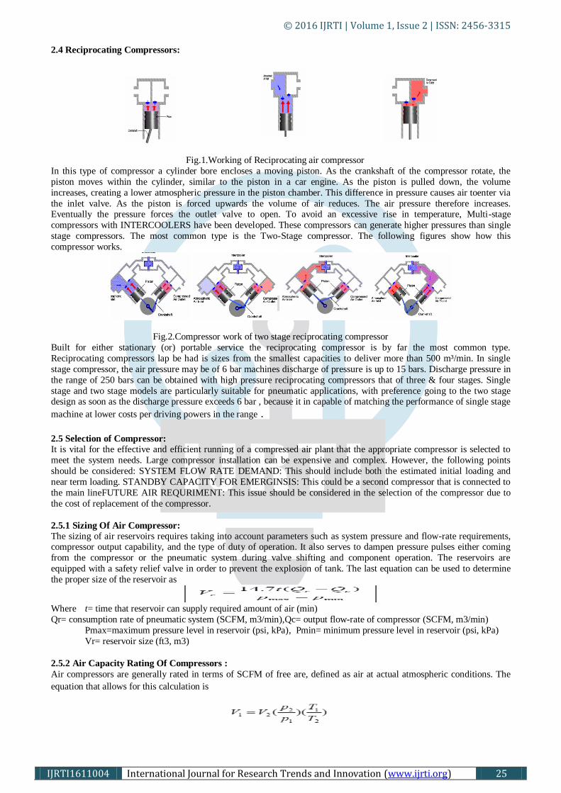
Fig.7.parts identification of solenoid valve
1. Coil (Electro magnetic) :The solenoid coil is made of copper wire. The layers of wire are separated by insulating
layer. The entire solenoid coil is covered with an varnish that is not affected by solvents, moisture, cutting oil or often
fluids. Coils are rated in various voltages such as 115 volts AC, 230 volts AC, 460 volts AC, 575 Volts AC, 6 Volts DC,
12 Volts DC, 24 Volts DC, 115 Volts DC & 230 Volts DC. They are designed for such frequencies as 50 Hz to 60 Hz.
2. Frame The solenoid frame serves several purposes. Since it is made of laminated sheets, it is magnetized when the current
passes through the coil. The magnetized coil attracts the metal plunger to move.The frame has provisions for attaching
the mounting. They are usually bolted or welded to the frame. The frame has provisions for receivers, the plunger. The
wear strips are mounted to the solenoid frame, and are made of materials such as metal or impregnated less fiber cloth
3. Solenoid Plunger The Solenoid plunger is the mover mechanism of the solenoid. The plunger is made of steel laminations which are
riveted together under high pressure, so that there will be no movement of the lamination with respect to one another. At
the top of the plunger a pin hole is placed for making a connection to some device.
Solenoid operated valves are usually provided with cover over either the solenoid or the entire valve. This protects the
solenoid from dirt and other foreign matter, and protects the actuator.
Specifications : Size : 0.635 x 10 ˉ² m, Part size : G 0.635 x 10 ˉ² m, Max pressure range : 0-10 x 10 ⁵ N/m²
4. FABRICATION AND WORKING: 4.1 Components:
4.1.1 Piston: The piston is fitted in the cylinder block and reciprocates inside. When the solenoid valve supplies the air in the front end
of the piston, the piston is pushed forward. This moves the hacksaw and the cutting stroke takes place. Then the solenoid
valve supplies air to the rear end of the piston. The pressure is same but the contact area is less due to the presence of the
© 2016 IJRTI | Volume 1, Issue 2 | ISSN: 2456-3315
IJRTI1611004 International Journal for Research Trends and Innovation (www.ijrti.org) 28
piston rod and pushes the piston at a greater pressure thus resulting in a fast return stroke. The material for the piston is
Aluminum.
4.1.2 Base : All the components of the machine are mounted on the base. It withstands the vibrations encountered during machining.
It is mounted on the bench.
4.1.3 Cutting Blades: A blade is used to cut the sheet metal in a desired dimension. Here we are using high speed steel blades to cut the sheet
metal.
4.1.4 Solenoid Valve: It is a 2x3 positional control valve. It receives the compressed air from the compressor and supplies to the cylinder block
according to the signal, given by the timing device. During one position it supplies air to the frond end of the cylinder
block. During the next position it supplies air to the rear end of the cylinder block.
4.1.5 Flexible Hose: The flexible hoses connect the solenoid valve and the cylinder block. Hoses are made of in layer of elastomer (or) synthetic rubber and braided fabric which takes up the higher pressure. If the hose is subjected to rubbing, it should be
enclosed in a protective sleeve.
4.1.6 Cylinder block: The cylinder block has two opening for admitting air inside the block for achieving the reciprocation motion of the
piston. The material for cylinder block is Aluminum.
4.2 Principle Of Working :
The compressed air from the compressor reaches the solenoid valve. The solenoid valve changes the direction of flow
according to the signals from the timing device. The compressed air pass through the solenoid valve and it is admitted
into the front end of the cylinder block. The air pushes the piston for the cutting stroke. At the end of the cutting stroke
air from the solenoid valve reaches the rear end of the cylinder block. The pressure remains the same but the area is less
due to the presence of piston rod. This exerts greater pressure on the piston, pushing it at a faster rate thus enabling faster return stroke.
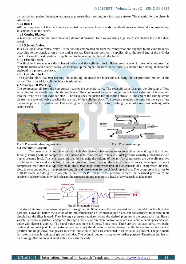
. Fig 8..Pneumatic shearing machine Fig.9.Pneumatic setup
4.3 Pneumatic Circuit: The pneumatic circuit plays a vital role in this device, it is very necessary to explain the working of this circuit.
Initially starting with air compresses, its function is to compress air from a low inlet pressure (usually atmospheric) to a
higher pressure level. This is an accomplished by reducing the volume of the air. Air compressors are generally positive
displacement units and are either of the reciprocating piston type or the rotary screw or rotary vane types. The air
compressor used here is a typically small sized, two-stage compressor unit. It also consists of a compressed air tank,
electric rotor and pulley drive, pressure controls and instruments for quick hook up and use. The compressor is driver by
a 10HP motor and designed to operate in 145 – 175 PSI range. If the pressure exceeds the designed pressure of the
receiver a release value provided releases the excesses air and thus stays a head of any hazards to take place.
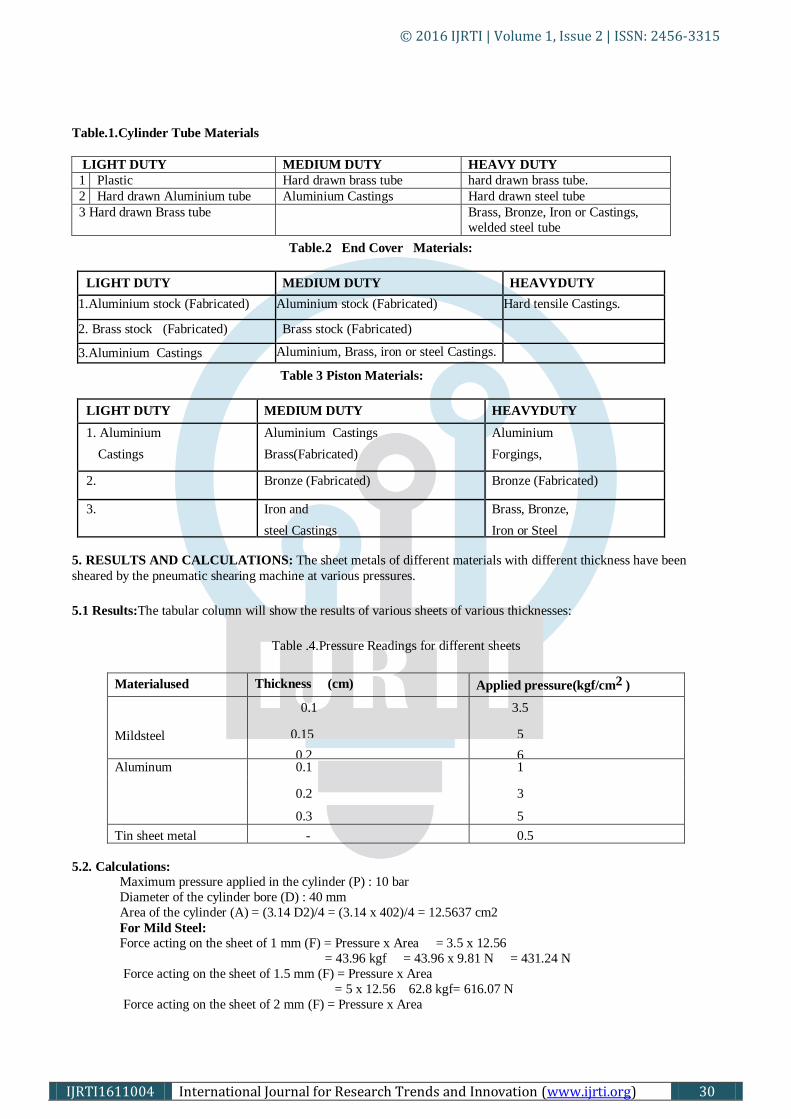
Fig.10. Pneumatic circuit
The stored air from compressor is passed through an air fitter where the compressed air is filtered from the fine dust
particles. However, before the suction of air into compressor a filter process take place, but not sufficient to operate in the
circuit here the filter is used. Then having a pressure regulator where the desired pressure to the operated is set. Here a
variable pressure regulator is adopted. Through a variety of direction control value are available, a hand operated spool
value with detent is applied. The spool value used here is 5 ports, 3 positions. There are two exhaust ports, two outlet ports and one inlet port. In two extreme positions only the directions can be changed while the Centro ore is a neutral
position and no physical changes are incurred. The 2 outlet ports are connected to an actuator (Cylinder). The pneumatic
activates is a double acting, single rod cylinder. The cylinder output is coupled to further purpose. The piston end has an
air horning effect to prevent sudden thrust at extreme ends
© 2016 IJRTI | Volume 1, Issue 2 | ISSN: 2456-3315
IJRTI1611004 International Journal for Research Trends and Innovation (www.ijrti.org) 29
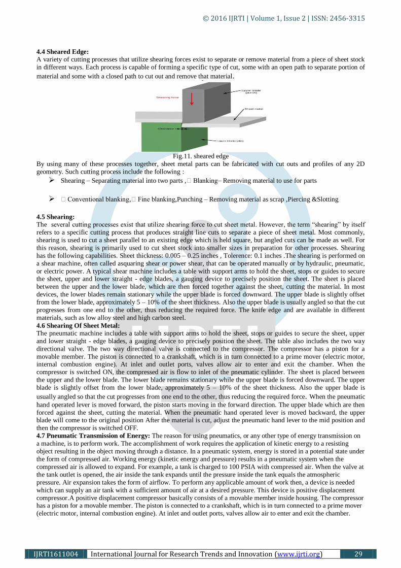
4.4 Sheared Edge: A variety of cutting processes that utilize shearing forces exist to separate or remove material from a piece of sheet stock
in different ways. Each process is capable of forming a specific type of cut, some with an open path to separate portion of
material and some with a closed path to cut out and remove that material.
Fig.11. sheared edge
By using many of these processes together, sheet metal parts can be fabricated with cut outs and profiles of any 2D
geometry. Such cutting process include the following :
Shearing – Separating material into two parts ,Blanking – Removing material to use for parts
Conventional blanking ,Fine blanking ,Punching – Removing material as scrap ,Piercing &Slotting
4.5 Shearing: The several cutting processes exist that utilize shearing force to cut sheet metal. However, the term “shearing” by itself
refers to a specific cutting process that produces straight line cuts to separate a piece of sheet metal. Most commonly,
shearing is used to cut a sheet parallel to an existing edge which is held square, but angled cuts can be made as well. For
this reason, shearing is primarily used to cut sheet stock into smaller sizes in preparation for other processes. Shearing
has the following capabilities. Sheet thickness: 0.005 – 0.25 inches , Tolerence: 0.1 inches .The shearing is performed on
a shear machine, often called asquaring shear or power shear, that can be operated manually or by hydraulic, pneumatic,
or electric power. A typical shear machine includes a table with support arms to hold the sheet, stops or guides to secure the sheet, upper and lower straight - edge blades, a gauging device to precisely position the sheet. The sheet is placed
between the upper and the lower blade, which are then forced together against the sheet, cutting the material. In most
devices, the lower blades remain stationary while the upper blade is forced downward. The upper blade is slightly offset
from the lower blade, approximately 5 – 10% of the sheet thickness. Also the upper blade is usually angled so that the cut
progresses from one end to the other, thus reducing the required force. The knife edge and are available in different
materials, such as low alloy steel and high carbon steel.
4.6 Shearing Of Sheet Metal: The pneumatic machine includes a table with support arms to hold the sheet, stops or guides to secure the sheet, upper
and lower straight - edge blades, a gauging device to precisely position the sheet. The table also includes the two way
directional valve. The two way directional valve is connected to the compressor. The compressor has a piston for a
movable member. The piston is connected to a crankshaft, which is in turn connected to a prime mover (electric motor, internal combustion engine). At inlet and outlet ports, valves allow air to enter and exit the chamber. When the
compressor is switched ON, the compressed air is flow to inlet of the pneumatic cylinder. The sheet is placed between
the upper and the lower blade. The lower blade remains stationary while the upper blade is forced downward. The upper
blade is slightly offset from the lower blade, approximately 5 – 10% of the sheet thickness. Also the upper blade is
usually angled so that the cut progresses from one end to the other, thus reducing the required force. When the pneumatic
hand operated lever is moved forward, the piston starts moving in the forward direction. The upper blade which are then
forced against the sheet, cutting the material. When the pneumatic hand operated lever is moved backward, the upper blade will come to the original position After the material is cut, adjust the pneumatic hand lever to the mid position and
then the compressor is switched OFF.
4.7 Pneumatic Transmission of Energy: The reason for using pneumatics, or any other type of energy transmission on
a machine, is to perform work. The accomplishment of work requires the application of kinetic energy to a resisting
object resulting in the object moving through a distance. In a pneumatic system, energy is stored in a potential state under
the form of compressed air. Working energy (kinetic energy and pressure) results in a pneumatic system when the
compressed air is allowed to expand. For example, a tank is charged to 100 PSIA with compressed air. When the valve at
the tank outlet is opened, the air inside the tank expands until the pressure inside the tank equals the atmospheric
pressure. Air expansion takes the form of airflow. To perform any applicable amount of work then, a device is needed
which can supply an air tank with a sufficient amount of air at a desired pressure. This device is positive displacement
compressor.A positive displacement compressor basically consists of a movable member inside housing. The compressor has a piston for a movable member. The piston is connected to a crankshaft, which is in turn connected to a prime mover
(electric motor, internal combustion engine). At inlet and outlet ports, valves allow air to enter and exit the chamber.
© 2016 IJRTI | Volume 1, Issue 2 | ISSN: 2456-3315
IJRTI1611004 International Journal for Research Trends and Innovation (www.ijrti.org) 30
Table.1.Cylinder Tube Materials
LIGHT DUTY MEDIUM DUTY HEAVY DUTY
1 Plastic Hard drawn brass tube hard drawn brass tube.
2 Hard drawn Aluminium tube Aluminium Castings Hard drawn steel tube
3 Hard drawn Brass tube Brass, Bronze, Iron or Castings,
welded steel tube
Table.2 End Cover Materials:
LIGHT DUTY MEDIUM DUTY HEAVYDUTY
1.Aluminium stock (Fabricated)
Aluminium stock (Fabricated)
Hard tensile Castings.
2. Brass stock (Fabricated) Brass stock (Fabricated)
3.Aluminium Castings
Aluminium, Brass, iron or steel Castings.
Table 3 Piston Materials:
LIGHT DUTY MEDIUM DUTY HEAVYDUTY
1. Aluminium
Castings
Aluminium Castings
Brass(Fabricated)
Aluminium
Forgings,
Aluminium
Castings.
2. Bronze (Fabricated) Bronze (Fabricated)
3. Iron and
steel Castings
Brass, Bronze,
Iron or Steel
Castings.
5. RESULTS AND CALCULATIONS: The sheet metals of different materials with different thickness have been
sheared by the pneumatic shearing machine at various pressures.
5.1 Results:The tabular column will show the results of various sheets of various thicknesses:
Table .4.Pressure Readings for different sheets
Materialused Thickness (cm) Applied pressure(kgf/cm2 )
Mildsteel
0.1 3.5
0.15 5
0.2 6 Aluminum 0.1 1
0.2 3
0.3 5
Tin sheet metal - 0.5
5.2. Calculations: Maximum pressure applied in the cylinder (P) : 10 bar
Diameter of the cylinder bore (D) : 40 mm
Area of the cylinder (A) = (3.14 D2)/4 = (3.14 x 402)/4 = 12.5637 cm2
For Mild Steel: Force acting on the sheet of 1 mm (F) = Pressure x Area = 3.5 x 12.56
= 43.96 kgf = 43.96 x 9.81 N = 431.24 N
Force acting on the sheet of 1.5 mm (F) = Pressure x Area
= 5 x 12.56 62.8 kgf= 616.07 N Force acting on the sheet of 2 mm (F) = Pressure x Area
© 2016 IJRTI | Volume 1, Issue 2 | ISSN: 2456-3315
IJRTI1611004 International Journal for Research Trends and Innovation (www.ijrti.org) 31
= 6 x 12.56= 75.36 kgf= 739.28 N
For Aluminum: Force acting on the sheet of 1 mm (F) = Pressure x Area = 1 x 12.56 = 12.56 kgf = 123 N
Force acting on the sheet of 2 mm (F) = Pressure x Area = 3 x 12.56 = 37.68 kgf = 370 N
Force acting on the sheet of 3 mm (F) = Pressure x Area = 62.8 kgf = 616.068 N
Tin Sheet Metal: Force acting on the sheet (F) = Pressure x Area = 0.5 x 12.56 = 6.28 kgf = 61.54 N
Table..5.Force readings for different sheets
Material used Thickness (cm) Applied pressure (kgf/cm2 ) Force (N)
Mildsteel
0.1 3.5 431.24
0.15 5 616.07
0.2 6 739.28
Aluminum 0.1 1 123
0.2 3 370
0.3 5 616.07
Tinsheetmetal - 0.5 61.54
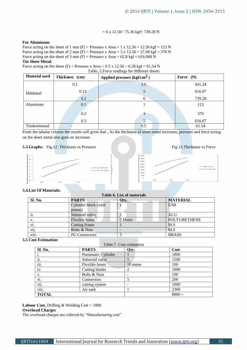
From the tabular column the results will gives that , As the thickness of sheet metal increases, pressure and force acting
on the sheet metal also goes on increases
5.3.Graphs: Fig.12. Thickness vs Pressure Fig 13.Thickness vs Force
5.4.List Of Materials:
Table 6. List of materials
Sl. No. PARTS Qty. MATERIAL
Cylinder block (with
piston)
1 EN8
ii. Solenoid valve 1 ALU.
v. Flexible hoses 5 Meter POLYURETHENE
vi. Cutting frame 1 M.S
vii. Bolts & Nuts - M.S
viii. PU Connectors 5 BRASS
5.5 Cost Estimation:
Table.7. Cost estimation
Sl. No. PARTS Qty. Cost
i. Pneumatic Cylinder 1 1800
ii. Solenoid valve 1 1500
iii. Flexible hoses 10 meter 100
iv. Cutting blades 2 1000
v. Bolts & Nuts - 100
vi. Connectors 5 200
vii. cutting system - 1000
viii. Air tank 1 2300
TOTAL 8000 /-
Labour Cost, Drilling & Welding Cost = 1000
Overhead Charges The overhead charges are referred by “Manufacturing cost”
© 2016 IJRTI | Volume 1, Issue 2 | ISSN: 2456-3315
IJRTI1611004 International Journal for Research Trends and Innovation (www.ijrti.org) 32
Manufacturing Cost = Material Cost + Labor cost= 2000+1000= 3000
Overhead Charges = 30% of the manufacturing cost= 900
Total Cost: Total cost = Material Cost + Labor cost + Overhead Charges
= 2000+1000+900
= 3900
Total cost for this Pneumatic Shearing Machine = 8000+ 3900 = 11900/-
6.CONCLUSION:
In the pneumatic shearing machine variable forces can be obtained by adjusting the pressure of the compressed air. This
equipment can also be used to cut larger thickness sheets with some additional accessories are required. Pneumatic fluids
are considered gases and are compressible. Pneumatic systems are not complete circuits. Air is used to do work and is
then dumped into the atmosphere. Since the mechanism is so simple and versatile it can be handled by any operator,
constriction of the unit is very simple. Handling the machine is easy and smooth operation is achieved. Pneumatics is one
of the technologies now a days widely using in automobile industries (particularly in Flexible manufacturing systems) to
assemble the parts of the automobiles.
7. REFERENCES:
1) Antonio Esposito - Fluid power with application. Prentice hall of India private limited, 1980.
2) Pneumatic and hydraulic systems by Butterworth-Heinemann, Jordan Hill, Oxford, 1997.
3) Catalogue of Jana tic pneumatic product, Jana tic Private Limited Coimbatore.
4) Design data book –compiled by faculty of mechanical engineering
5) P.S.G. College of technology, Coimbatore
6) Festo Didactic KG – Fundamentals of control technology, Esslingen-1998.
7) Festo Pneumatic Catalogue - Festo Pvt Ltd. – Bangalore.
8) Werner Deppert/Kurt Stoll., Cutting Cost With Pneumatics, Vogel Buchverlag Wurzburg, 1998.
9) www.goldman.com/spudgun/history.html
10) Pneumatics by : Steven Dungan and Keith Wiseman 11) Wikipedia.com
12) Brian S. Elliott, Compressed Air Operations Manual, McGraw Hill Book Company, 2006, ISBN 0-07-147526-
5.
13) Heeresh Mistry, Fundamentals of Pneumatic Engineering, Create Space e-Publication, 2013, ISBN 1-49-
372758-3.