a pmma valveless micropump using electromagnetic actuation
TRANSCRIPT
RESEARCH PAPER
C. Yamahata Æ C. Lotto Æ E. Al-Assaf Æ M. A. M. Gijs
A PMMA valveless micropump using electromagnetic actuation
Received: 7 April 2004 / Accepted: 14 June 2004 / Published online: 21 August 2004� Springer-Verlag 2004
Abstract We have fabricated and characterized apolymethylmethacrylate (PMMA) valveless micropump.The pump consists of two diffuser elements and apolydimethylsiloxane (PDMS) membrane with an inte-grated composite magnet made of NdFeB magneticpowder. A large-stroke membrane deflection (�200 lm)is obtained using external actuation by an electromag-net. We present a detailed analysis of the magneticactuation force and the flow rate of the micropump.Water is pumped at flow rates of up to 400 ll/min andbackpressures of up to 12 mbar. We study the fre-quency-dependent flow rate and determine a resonancefrequency of 12 and 200 Hz for pumping of water andair, respectively. Our experiments show that the modelsfor valveless micropumps of A. Olsson et al. (J Micro-mech Microeng 9:34, 1999) and L.S. Pan et al.(J Micromech Microeng 13:390, 2003) correctly predictthe resonance frequency, although additional modelingof losses is necessary.
Keywords Diffuser micropump Æ Lab-on-a-chip ÆPowder blasting
1 Introduction
Since the introduction of the concept of micro totalanalysis systems or lTAS in 1990 (Manz et al. 1990;Manz et al. 1991), multiple fluidic microchip technolo-gies have been developed. A continuous challenge has
been the transport and pumping of small quantities ofbiological fluids, of the order of a few microliters perminute. The first development of a micropump datesfrom the 1980s with the emergence of the field ofmicroelectromechanical systems (MEMS). Van Lintelet al. (1988) and Van de Pol and Van Lintel (1990)presented a silicon micropump based on the piezoelectricor thermopneumatic actuation of a thin membrane.Since then, other integrated silicon-based micropumps,mostly based on piezoelectric actuation, have beenproposed (Nguyen et al. 2002; Tay and Choong 2002).However, for many lTAS applications, microfluidicsystems need to be disposable and low-cost renderingplastic materials more competitive. Plastic micropumpshave already been shown to have great potential (Olssonet al. 1998; Bohm et al. 1999; Santra et al. 2002; Nguyenand Truong 2004). Innovative methods for fluid han-dling were simultaneously developed, such as the use ofmagnetic materials for the micropump actuation. Forexample, magnetic liquids or ferrofluids simultaneouslyprovide the actuation and valving functions in a mi-cropump. A ferrofluidic actuated pipette was presentedby Greivell and Hannaford (1997). Hatch et al. (2001)and Yamahata et al. (2004) reported a micropump basedon the pumping and valving action of a ferrofluidic plugin a microfluidic channel. Alternatively, magnetic actu-ation of a membrane with integrated magnetic parts hasbeen shown to produce large forces (a few hundred lN)and a large membrane deflection (Bohm et al. 1999;Santra et al. 2002; Zhang and Ahn 1996; Liu 1998; Khooand Liu 2000). Such an approach combines the benefitsof the strong magnetic force with the potential ofexternal electromagnetic actuation; moreover, directcontact of the actuating element with the fluidic circuit isavoided. The use of polymer-bonded magnets directlyintegrated with the membrane (Lagorce et al. 1999;Santra et al. 2002; Cho and Ahn 2003) offers additionalminiaturization potential. Valves are also key elementsof a micropump: ball valves (Accoto et al. 2000), nor-mally closed check valves (Nguyen and Truong 2004;Yamahata et al. 2004), valves based on the modification
C. Yamahata (&) Æ C. Lotto Æ E. Al-Assaf Æ M. A. M. GijsInstitute of Microelectronics and Microsystems,Swiss Federal Institute of Technology Lausanne,1015, Lausanne EPFL, SwitzerlandE-mail: [email protected].: +41-21-6936639Fax: +41-21-6935950
Microfluid Nanofluid (2005) 1: 197–207DOI 10.1007/s10404-004-0007-6

of physical properties of liquids (Beebe et al. 2000) aswell as Tesla elements (Forster et al. 1995; Morris andForster 2003) have been proposed. A major advance invalveless pumping was demonstrated by Stemme andStemme (1993) who substituted check valves by nozzle/diffuser elements with fluid-directing effects. Follow-upwork by Olsson et al. (1995) and Olsson (1998) on therealization of in-plane nozzle/diffuser elements triggeredgreat interest in the field of microfluidics (Gerlach et al.1995; Gerlach 1998; Olsson et al. 1999; Nguyen andHuang 2001; Pan et al. 2003). Nozzle/diffuser micro-pumps are of particular interest for disposable lTASapplications because of the simple realization of thediffuser element that significantly lowers fabricationcosts. Additionally, the use of the electromagneticactuation principle, external to the pump, and the use ofplastics appear to be appropriate solutions for therequirements of disposable devices.
In this paper, we describe the fabrication andcharacterization of an electromagnetically actuatedpolymethylmethacrylate (PMMA) valveless micro-pump. It consists of two diffuser elements and a poly-dimethylsiloxane (PDMS) membrane with an integratedcomposite magnet made of NdFeB magnetic powder.Diffuser theory is combined with numerical simulationtools to correctly dimension the micropump. Ourmicropump is a three-dimensional microfluidic structureconsisting of four layers of PMMA, which are micro-structured by powder blasting or by standard mechan-ical micromachining techniques. We also discuss themicrofabrication of the composite magnetic membrane.A large-stroke membrane deflection (�200 lm) isobtained using external electromagnet actuation. Wepresent a detailed analysis of the magnetic actuationforce and the frequency-dependent flow rate of themicropump and analyze our experimental data usingthe theoretical models of Olsson et al. (1999) and Panet al. (2003).
2 Design and theory
The pump is of the so-called ‘‘reciprocating type’’, whichmeans that it uses the oscillatory movement of a mem-brane to displace fluids. The magnetic diaphragm-basedmicropump uses the reciprocating effect of a flexible,magnetic powder containing membrane in combinationwith two diffuser elements (see Fig. 1a). The magneticmembrane is externally actuated by an electromagnet.Diffuser elements are fluidic channel constrictions thatmodify the fluid dynamics such that the fluidic resistanceis higher in one direction than in the other, causing theflow rate to be different in the two directions for thesame applied pressure. A diffuser is characterized by agradual widening of the fluidic cross-section in the senseof the flow and a smaller fluidic resistance. A nozzle ischaracterized by a gradual reduction of the fluidic cross-section in the sense of the flow and a higher fluidicresistance. In a reciprocating micropump, a nozzle/dif-fuser element behaves during half of the membraneactuation cycle as a diffuser, and during the other halveas a nozzle (Stemme and Stemme 1993; Olsson 1998). Inthe concept of the diffuser-based micropump, thisdirectional effect is at the origin of the net pumping in anoscillating cycle because the two nozzle/diffuser elementsare in a reverse orientation relative to the pumpingchamber. During the ‘‘supply mode’’ (chamber volumeincreases), more fluid flows through the inlet elementthan through the outlet element; while during the ‘‘pumpmode’’ (chamber volume decreases), more fluid flowsthrough the outlet element than through the inlet ele-ment. Fig. 1b shows the geometrical parameters of asingle nozzle/diffuser element. When fluidic transport isfrom left to right, the element acts as a diffuser, andwhen transport is from right to left it acts as a nozzle. Inour case, the diffuser entrance has rounded corners(curvature radius r=100 lm) and a width w1=100 lm;the outlet has sharp corners and a width w2=500 lm.The diffuser length is L=2.3 mm, defining the angle2h=9.5�. The height of the nozzle/diffuser element ish=250 lm, as determined by the thickness of thePMMA sheet out of which it is microfabricated. Hence,the cross-sections of the inlet and outlet area of thediffuser are given by A1 = w1· h = 2.5·10�8 m2 andA2=w2 · h=1.25 · 10�7 m2, respectively. The pumping
Fig. 1 a Schematic diagram of the diffuser micropump withexternal electromagnetic actuation of the magnetic membrane.The dashed area illustrates the deflection amplitude of themembrane. b Definition of the geometrical parameters of thediffuser element
198

chamber diameter is 7 mm and its depth D is 0.5 mm.Using a PDMS membrane with high deflection capa-bilities, we obtain a high compression ratio � between thestroke volume (illustrated by the dashed area in Fig. 1a)and the dead volume of the chamber. Typically, for amembrane deflection of 200 lm, the compression ratio is�>0.2. This high � renders our pump self-priming andbubble tolerant (Richter et al. 1998). The large mem-brane deflection amplitude and the self-priming capa-bility of our micropump are a clear advantage offered bythe use of a silicone elastomer and long range magneticactuation forces, when compared to the use of a morerigid silicon membrane with piezoelectric actuation.
An estimate of the flow-directing efficiency of thediffuser elements can be made using pressure loss datafrom internal flow systems. Each part of the diffuser canbe treated separately and the total pressure drop can beevaluated as the sum of the pressure drop across eachpart. It is important to note that in the presented ana-lytical–empirical model, one neglects (i) interferencesbetween the different parts of the nozzle/diffuser and (ii)non-directional channel losses occurring elsewhere in themicrofluidic system. Assumption (i) can be justified bythe relatively large distance L between the entrance ofthe nozzle/diffuser element (more than 20 times thethroat dimension w1), effectively isolating each region.Assumption (ii) is for reasons of simplicity only; anyexperimentally found difference between theory andexperiments can be related to additional channel losses.The pressure drop in an internal flow system is usuallygiven as the loss coefficient K, which is related to thepressure drop DP as:
DP ¼ 1
2K q �u2 ð1Þ
where q is the fluid density and �u is the mean flowvelocity (Stemme and Stemme 1993). The loss coefficientcan be found in the literature for geometries such asdiverging and converging channels and sharp androunded entrances and exits (Blevins 1984; White 1998).Figure 2 shows the dependence of the loss coefficient onthe diffuser expansion angle 2h. This graph, adaptedfrom (Patterson 1938; Cockrell and Markland 1963),gathers from different information sources, among thembeing that of Gibson (1945). For diffusers with smallopening angle, the losses in the diverging-wall directionare small. Gibson had estimated that for rectangularpipes with gradually diverging boundaries, minimumlosses occur for a diffuser angle close to 2h � 11� andare associated with a loss coefficient K � 0.175 (Gibson1945). This is the reason why we have chosen an angleclose to this value for the design of our diffuser element.By considering the pressure difference over the entrance–diffuser–outlet system in terms of a normalized losscoefficient such as nd
DP ¼ nd1
2q �u2
1 ð2Þ
with �u1 the mean velocity at the entrance of the diffuser(see Fig. 3a), one finds that (Olsson et al. 1996)
nd ¼ nd;e þ nd;div þ nd;o ¼ 0:265 ð3Þ
Here, we have summed the normalized loss coefficientof the diffuser (nd,div=K � 0.175) (Gibson 1945), thenormalized loss coefficient of the rounded entrance hole(nd,e = 0.05) (Blevins 1984; White 1998) and the nor-malized loss coefficient of the outlet hole (nd,o=0.04)(Blevins 1984; Olsson et al. 1996; White 1998). When theflow is reversed the diffuser element will behave as anozzle for which losses are completely dominated by theoutlet where the cross-section is smallest. For the nor-malized loss coefficient of the nozzle (see Fig. 3b), onefinds, analogous to Eq. 3, that
nn ¼ nn;e þ nn;conv þ nn;o ¼ 1:0 ð4Þ
Here, we have summed the normalized loss coefficientof the nozzle (nn,conv�0) (Blevins 1984; Olsson et al.1996; White 1998), the normalized loss coefficient of theentrance hole (nn,e�0) (Blevins 1984; White 1998) andthe normalized loss coefficient of the outlet hole(nn,o�1.0) (Blevins 1984; White 1998). The resultingdiffuser element efficiency ratio is defined as
g ¼ nnnd¼ /d
/n
� �2
¼ 3:8 ð5Þ
with /d and /n, the volume flows in the diffuser and inthe nozzle direction, respectively. The higher is g, thehigher the flow-directing efficiency. This efficiency ratiois the theoretically achievable one, but is higher than the
Fig. 2 Dependence of the loss coefficient for a diffuser ductcombination on the diffuser expansion angle 2h. Open squarerectangular diffuser section with ratio of outlet to entrance area A2/A1=9.0; solid circle circular diffuser section with ratio of outlet toentrance area A2/A1=9.0; open circle circular diffuser section withratio of outlet to entrance area A2/A1=4.0; cross circular diffusersection with ratio of outlet to entrance area A2/A1=2.3. Dataadapted from Patterson (1938), and Cockrell and Markland (1963)
199

experimental parameter, as will be shown later. Thismay be due to flow sense independent losses in themicrofluidic circuit.
3 Numerical simulation
The commercial software package Femlab 2.2 (Comsolat http://www.comsol.com/) was used to simulate thenozzle/diffuser element. The program solves the Navier–Stokes equation using a two-equation turbulence modelreferred to as the k�� turbulence model. All simulationswere done in two dimensions using water as the fluid(q=1,000 kg m�3; kinematic viscosity m=1.0 · 10�6
m2 s�1). Defining the Reynolds number Re for a diffuseras
Re ¼ u1w1
mð6Þ
one finds that Re=100 for typical flow velocities�u1=1 m s�1 through the small section of the diffuserwhich is indicative of the development of a laminar flowregime. Singhal et al. (2004) have recently presentednumerical simulations demonstrating that the flow rec-tification effect in nozzle/diffuser elements not only
occurs in the turbulent flow regime, but can also takeplace for laminar flows.
Figure 4 compares the pressure distribution along thecentral symmetry line of a nozzle/diffuser element whenflow is (a) in the diffuser direction and (b) in the nozzledirection, respectively. The simulation clearly shows thata pressure recovery effect occurs in the throat of the
Fig. 3 Evaluation of the loss coefficients a in the diffuser directionand b in the nozzle direction
Fig. 4 Finite element simulation of the pressure distribution alongthe central symmetry line of a a diffuser element, where flow is fromleft to right, clearly showing the pressure recovery between thediffuser entrance and outlet and b a nozzle element, where flow isfrom right to left
200
nozzle/diffuser element when flow is in the diffuserdirection. As was predicted by the empirical results(Patterson 1938; Gibson 1945; Cockrell and Markland1963), this pressure recovery effect is particularly pro-nounced for a diffuser angle 2h�10�.
4 Microfabrication technology
4.1 Magnetic membrane
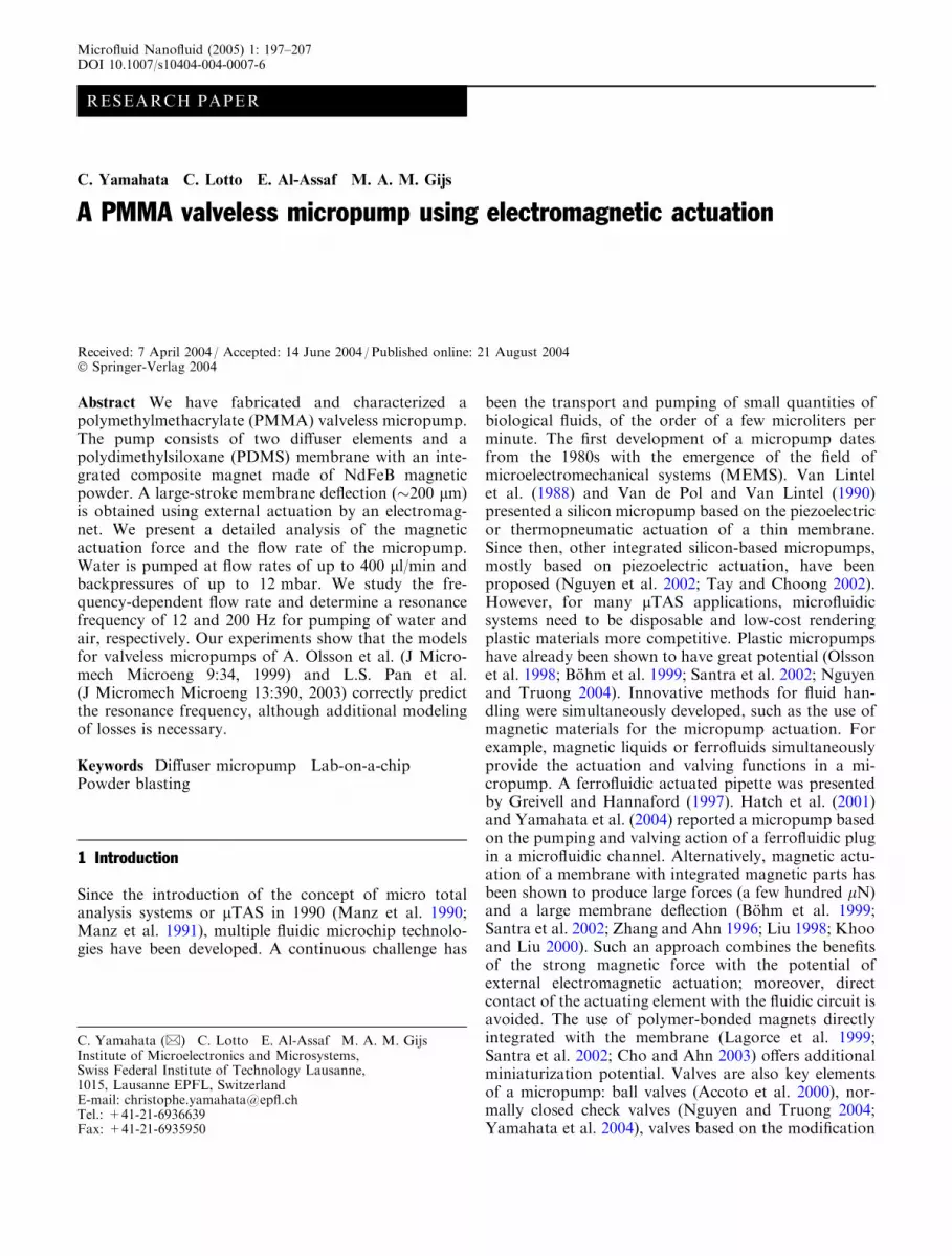
A NdFeB composite membrane was fabricated using atwo-step molding technique. The isotropic magneticpowder MQP-S-11-9 (remanent induction: Br�0.75 T,Magnequench GmbH, Essen, Germany) consisting ofspherical particles with a mean size of 200 lm was firstmixed with commercial PDMS Sylgard 184 (DowCorning Corp., Midland, MI, USA) to synthesize a rare-earth polymer magnet with a powder volume fraction of40%. The membrane weight was Mm=0.15 g. Theeffective Br of the polymer magnet is directly correlatedwith the powder volume fraction, so we expect at most aBr�0.30 T if the magnetization is saturated. A largerPDMS membrane was integrated on top of the rare-earth magnet after degassing of the liquid PDMS invacuum. The polymerization was achieved at 150�Cduring 15 min. This two-step molding procedure wasmade possible by the strong physical bonding betweenthe rough surface of the polymer magnet and the largerPDMS membrane. Finally, the magnetic membrane wasmagnetized in an electromagnet (Magnet Charger 942 A,RFL Industries Inc., Boonton, NJ, USA), before beingintegrated in the PMMA chip. A photograph of afabricated magnetic membrane is shown in Fig. 5.
4.2 Microfluidic chip
PMMA is a widely used polymer in industry and is anattractive material among plastics because of its low costand good chemical resistance to many biochemical
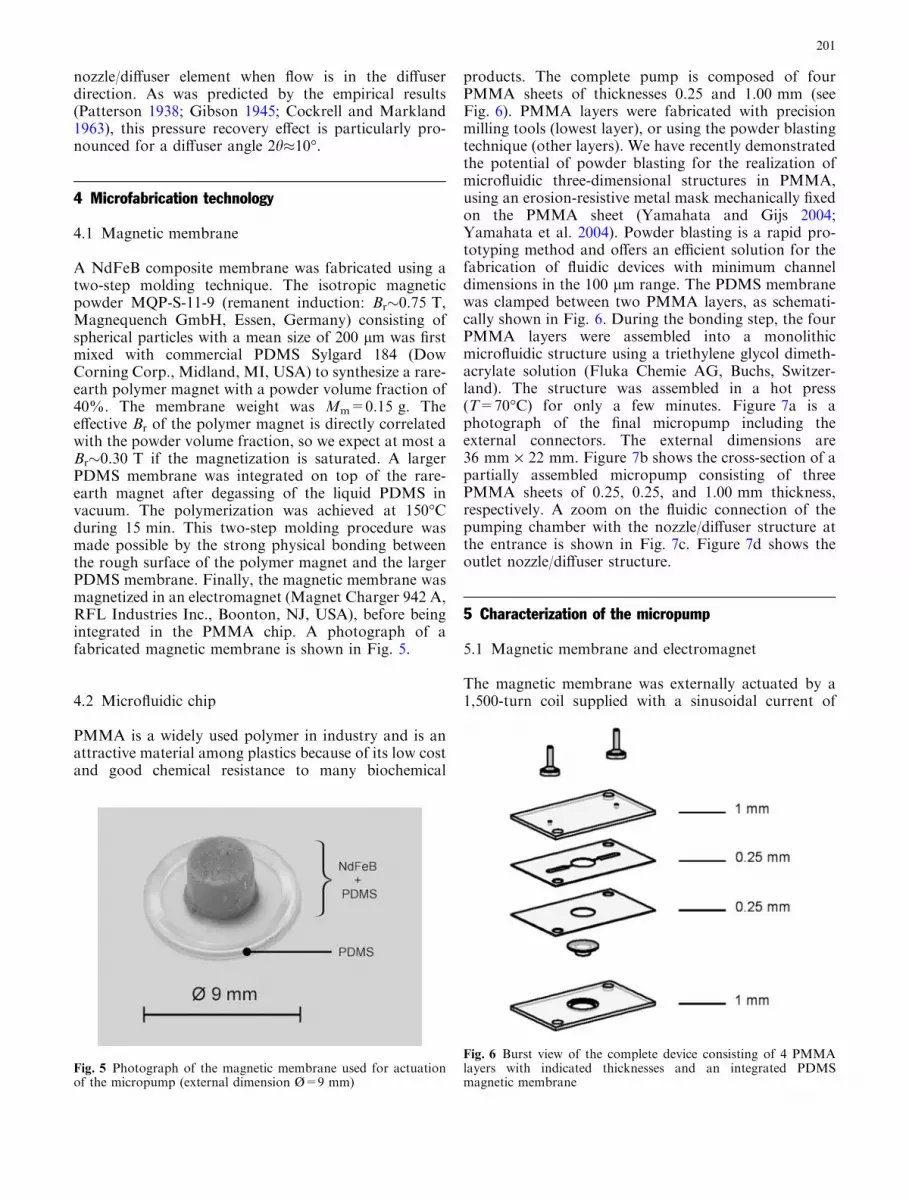
products. The complete pump is composed of fourPMMA sheets of thicknesses 0.25 and 1.00 mm (seeFig. 6). PMMA layers were fabricated with precisionmilling tools (lowest layer), or using the powder blastingtechnique (other layers). We have recently demonstratedthe potential of powder blasting for the realization ofmicrofluidic three-dimensional structures in PMMA,using an erosion-resistive metal mask mechanically fixedon the PMMA sheet (Yamahata and Gijs 2004;Yamahata et al. 2004). Powder blasting is a rapid pro-totyping method and offers an efficient solution for thefabrication of fluidic devices with minimum channeldimensions in the 100 lm range. The PDMS membranewas clamped between two PMMA layers, as schemati-cally shown in Fig. 6. During the bonding step, the fourPMMA layers were assembled into a monolithicmicrofluidic structure using a triethylene glycol dimeth-acrylate solution (Fluka Chemie AG, Buchs, Switzer-land). The structure was assembled in a hot press(T=70�C) for only a few minutes. Figure 7a is aphotograph of the final micropump including theexternal connectors. The external dimensions are36 mm · 22 mm. Figure 7b shows the cross-section of apartially assembled micropump consisting of threePMMA sheets of 0.25, 0.25, and 1.00 mm thickness,respectively. A zoom on the fluidic connection of thepumping chamber with the nozzle/diffuser structure atthe entrance is shown in Fig. 7c. Figure 7d shows theoutlet nozzle/diffuser structure.
5 Characterization of the micropump
5.1 Magnetic membrane and electromagnet
The magnetic membrane was externally actuated by a1,500-turn coil supplied with a sinusoidal current of
Fig. 5 Photograph of the magnetic membrane used for actuationof the micropump (external dimension Ø=9 mm)
Fig. 6 Burst view of the complete device consisting of 4 PMMAlayers with indicated thicknesses and an integrated PDMSmagnetic membrane
201

150 mA amplitude (see schematic diagram in the insertof Fig. 8a). The electromagnet has a soft magnetic ironcore for magnetic field concentration. Figure 8a showsthe magnetic induction along the symmetry line (z axis)of the electromagnet with and without the presence ofthe soft iron core, as measured by a Hall probe (Tesl-ameter model 6010, F.W. Bell, Orlando, FL, USA). Weclearly observe the amplification of the induction by afactor of about eight when using the soft core. Figure 8bshows the vertical gradient of the z component of themagnetic induction d Bz/d z, which is proportional to theactuation force. In an electromagnetic system consistingof a moving permanent magnet and a soft magneticcircuit the resulting force generally is composed of apositive contribution as a result of the magnetization ofthe soft material by the permanent magnet and a con-tribution as a result of the presence of the permanentmagnet in the field of the electromagnet. This secondtype of force in the z direction for a permanent magnetwith magnetization Mz and volume V is given by
Fz ¼ Mz
ZV
dBz
dzdV ð7Þ
We measured the magnetic induction generated bythe permanent magnet membrane using a Hall probeand obtained a value of 0.09 T at the surface of themagnet. From this value we derived a z component ofthe magnetization Mz � 1.44 · 105 A.m–1, taking intoaccount the demagnetization factor of the permanentmagnet (�0.5), the polymer magnet being characterizedby a diameter of 5 mm, a height of 2.2 mm and a volumeof 4.3 · 10�8 m3. We can now evaluate Eq. 7 consider-ing the magnetic field generated by the electromagnet atthe center of the polymer permanent magnet (see Fig. 8).For example, when the polymer magnet is in contactwith the soft iron core of the electromagnet, its centerposition is at z=1 mm providing a force of about100 mN. During normal pumping operation the middleof the polymer magnet is 3 mm away from the soft ironcore and the magnetic membrane deflection is not largerthan 0.25 mm, giving a typical magnetic force of 75 mN.For a PDMS membrane area in contact with the liquidof 3.8 · 10�5 m2 this corresponds to an effective actua-tion pressure of �20 mbar. This value is of the same
Fig. 7 a Photograph of the magnetic membrane actuated diffusermicropump; b cross-section of a partially assembled micropump;c zoom on the inlet diffuser; d zoom on the outlet diffuser
202
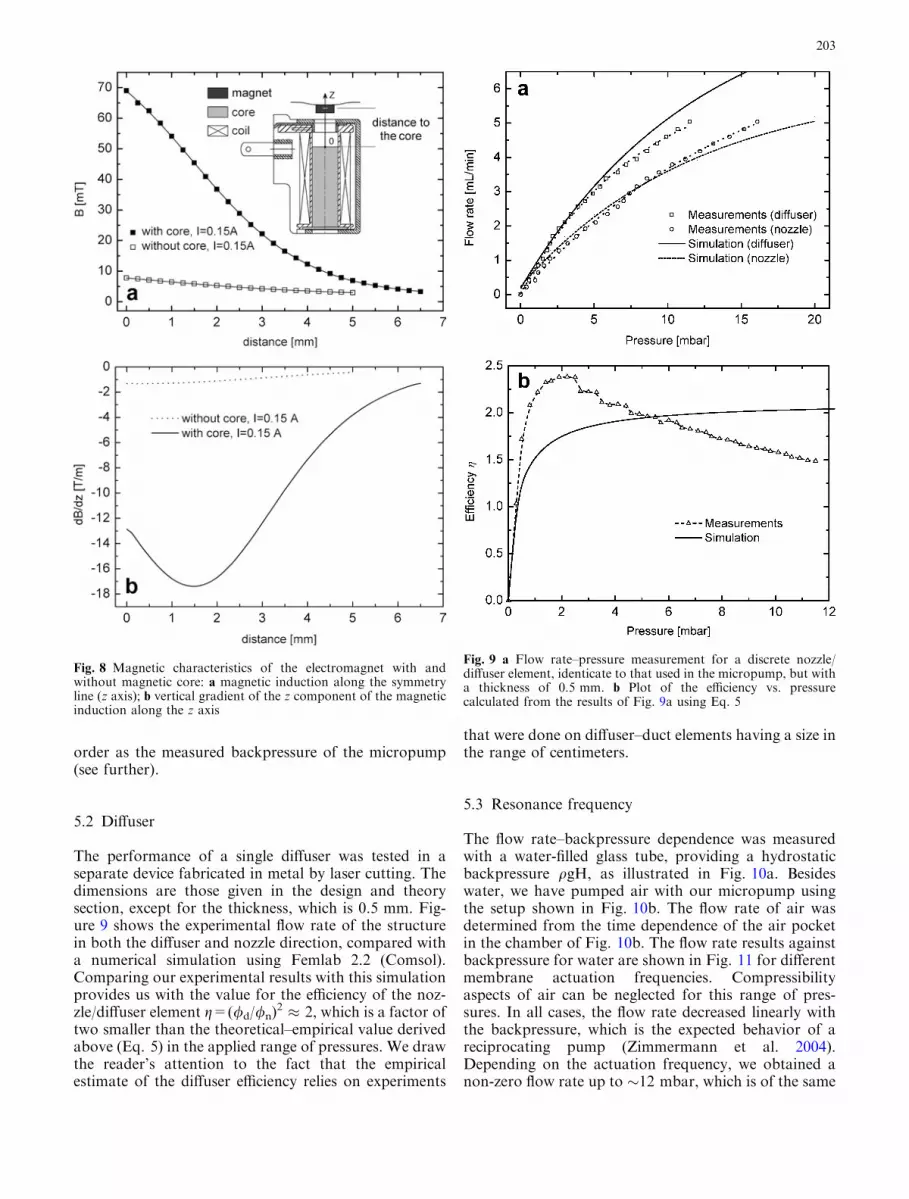
order as the measured backpressure of the micropump(see further).
5.2 Diffuser
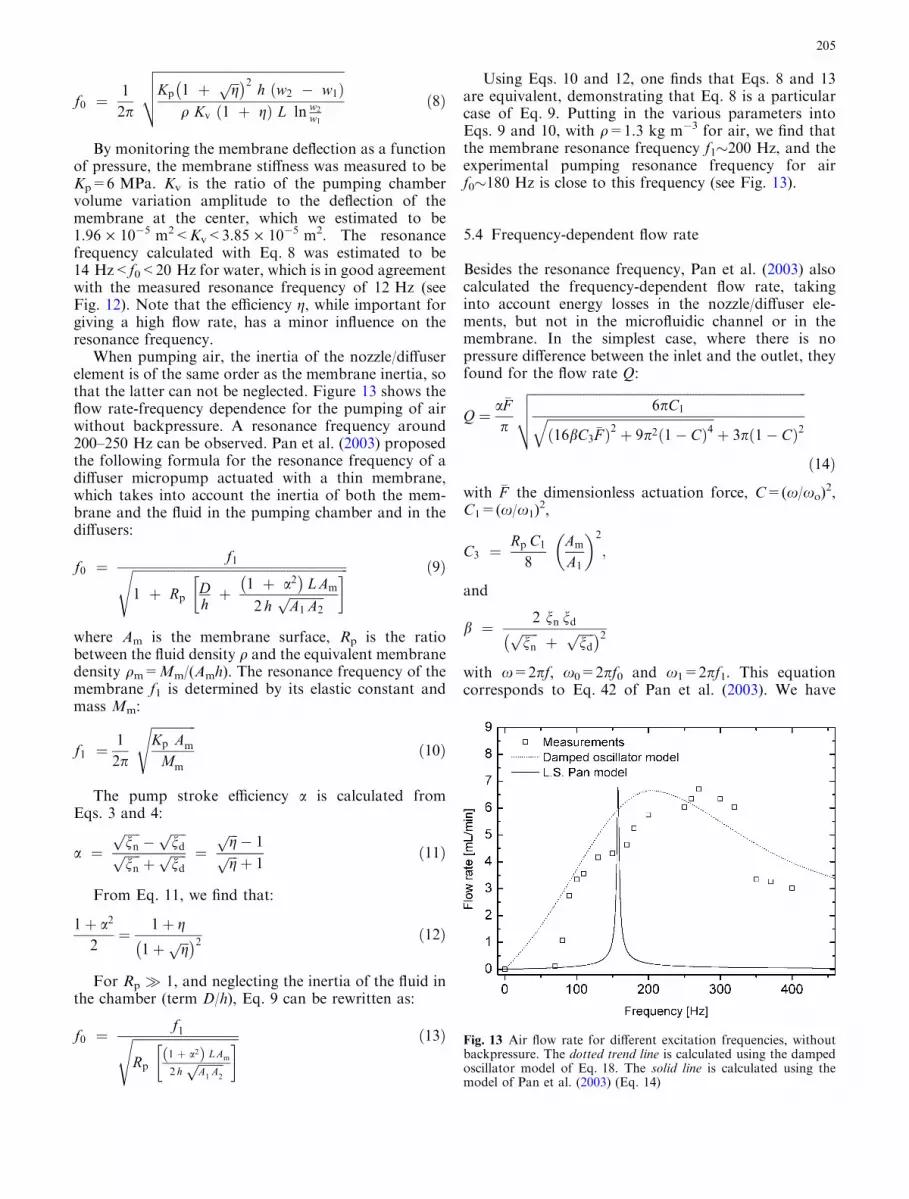
The performance of a single diffuser was tested in aseparate device fabricated in metal by laser cutting. Thedimensions are those given in the design and theorysection, except for the thickness, which is 0.5 mm. Fig-ure 9 shows the experimental flow rate of the structurein both the diffuser and nozzle direction, compared witha numerical simulation using Femlab 2.2 (Comsol).Comparing our experimental results with this simulationprovides us with the value for the efficiency of the noz-zle/diffuser element g=(/d//n)
2 � 2, which is a factor oftwo smaller than the theoretical–empirical value derivedabove (Eq. 5) in the applied range of pressures. We drawthe reader’s attention to the fact that the empiricalestimate of the diffuser efficiency relies on experiments
that were done on diffuser–duct elements having a size inthe range of centimeters.
5.3 Resonance frequency
The flow rate–backpressure dependence was measuredwith a water-filled glass tube, providing a hydrostaticbackpressure qgH, as illustrated in Fig. 10a. Besideswater, we have pumped air with our micropump usingthe setup shown in Fig. 10b. The flow rate of air wasdetermined from the time dependence of the air pocketin the chamber of Fig. 10b. The flow rate results againstbackpressure for water are shown in Fig. 11 for differentmembrane actuation frequencies. Compressibilityaspects of air can be neglected for this range of pres-sures. In all cases, the flow rate decreased linearly withthe backpressure, which is the expected behavior of areciprocating pump (Zimmermann et al. 2004).Depending on the actuation frequency, we obtained anon-zero flow rate up to �12 mbar, which is of the same
Fig. 8 Magnetic characteristics of the electromagnet with andwithout magnetic core: a magnetic induction along the symmetryline (z axis); b vertical gradient of the z component of the magneticinduction along the z axis
Fig. 9 a Flow rate–pressure measurement for a discrete nozzle/diffuser element, identicate to that used in the micropump, but witha thickness of 0.5 mm. b Plot of the efficiency vs. pressurecalculated from the results of Fig. 9a using Eq. 5
203

order as the pressure provided by the magneticmembrane.
For actuation frequencies close to the naturalfrequency of the system, we obtained membrane vibra-tions of larger amplitude that produce a higher flow rateof the pump. A comprehensive explanation of resonancephenomena in fluidic systems can be found in (Nauda-scher and Rockwell 1994). Figure 12 shows the flowrate-frequency dependence for the pumping of waterwithout backpressure. A resonance frequency of �12 Hzcan be observed. For water pumping, the resonancefrequency of a nozzle/diffuser reciprocating pump was
theoretically calculated by Olsson et al. (1999). Theyused an energy analysis technique, where the totalenergy (not taking into account losses) oscillates be-tween the maximum kinetic energy of the fluid in thenozzle/diffuser element and the maximum potential en-ergy of the diaphragm. In their model, the resonancefrequency of the pump is determined by the membranestiffness and the inertia of the fluid in the diffusers:
Fig. 10 Experimental setupused to measure the flow ratedependence a on backpressureand frequency for water; b onfrequency for air
Fig. 12 Water flow rate for different excitation frequencies,without backpressure. The dotted trend line is calculated using thedamped oscillator model of Eq. 18. The solid line is calculated usingthe model of Pan et al. (2003) (Eq. 14)
Fig. 11 Water flow–backpressure characteristics of the micropumpfor different excitation frequencies with dotted trend lines
204
f0 ¼1
2p
ffiffiffiffiffiffiffiffiffiffiffiffiffiffiffiffiffiffiffiffiffiffiffiffiffiffiffiffiffiffiffiffiffiffiffiffiffiffiffiffiffiffiffiffiffiffiffiffiffiffiffiffiffiffiffiffiffiffiKp 1 þ ffiffiffi
gp� �2
h w2 � w1ð Þq Kv 1 þ gð Þ L ln w2
w1
vuut ð8Þ
By monitoring the membrane deflection as a functionof pressure, the membrane stiffness was measured to beKp=6 MPa. Kv is the ratio of the pumping chambervolume variation amplitude to the deflection of themembrane at the center, which we estimated to be1.96 · 10�5 m2<Kv<3.85 · 10�5 m2. The resonancefrequency calculated with Eq. 8 was estimated to be14 Hz<f0<20 Hz for water, which is in good agreementwith the measured resonance frequency of 12 Hz (seeFig. 12). Note that the efficiency g, while important forgiving a high flow rate, has a minor influence on theresonance frequency.
When pumping air, the inertia of the nozzle/diffuserelement is of the same order as the membrane inertia, sothat the latter can not be neglected. Figure 13 shows theflow rate-frequency dependence for the pumping of airwithout backpressure. A resonance frequency around200–250 Hz can be observed. Pan et al. (2003) proposedthe following formula for the resonance frequency of adiffuser micropump actuated with a thin membrane,which takes into account the inertia of both the mem-brane and the fluid in the pumping chamber and in thediffusers:
f0 ¼f1ffiffiffiffiffiffiffiffiffiffiffiffiffiffiffiffiffiffiffiffiffiffiffiffiffiffiffiffiffiffiffiffiffiffiffiffiffiffiffiffiffiffiffiffiffiffiffiffiffiffiffiffiffiffiffiffiffiffiffiffiffiffiffiffiffiffiffi
1 þ RpDhþ 1 þ a2� �
L Am
2 hffiffiffiffiffiffiffiffiffiffiffiA1 A2
p� �s ð9Þ
where Am is the membrane surface, Rp is the ratiobetween the fluid density q and the equivalent membranedensity qm=Mm/(Amh). The resonance frequency of themembrane f1 is determined by its elastic constant andmass Mm:
f1 ¼1
2p
ffiffiffiffiffiffiffiffiffiffiffiffiffiffiKp Am
Mm
sð10Þ
The pump stroke efficiency a is calculated fromEqs. 3 and 4:
a ¼ffiffiffiffiffinnp�
ffiffiffiffiffindp
ffiffiffiffiffinnpþ
ffiffiffiffiffindp ¼
ffiffiffigp � 1ffiffiffi
gp þ 1
ð11Þ
From Eq. 11, we find that:
1þ a2
2¼ 1þ g
1þ ffiffiffigp� �2 ð12Þ
For Rp � 1, and neglecting the inertia of the fluid inthe chamber (term D/h), Eq. 9 can be rewritten as:
f0 ¼f1ffiffiffiffiffiffiffiffiffiffiffiffiffiffiffiffiffiffiffiffiffiffiffiffiffiffiffiffiffiffiffiffiffi
Rp1 þ a2ð Þ L Am
2 hffiffiffiffiffiffiffiffiA1
A2
p� �s ð13Þ
Using Eqs. 10 and 12, one finds that Eqs. 8 and 13are equivalent, demonstrating that Eq. 8 is a particularcase of Eq. 9. Putting in the various parameters intoEqs. 9 and 10, with q=1.3 kg m�3 for air, we find thatthe membrane resonance frequency f1�200 Hz, and theexperimental pumping resonance frequency for airf0�180 Hz is close to this frequency (see Fig. 13).
5.4 Frequency-dependent flow rate
Besides the resonance frequency, Pan et al. (2003) alsocalculated the frequency-dependent flow rate, takinginto account energy losses in the nozzle/diffuser ele-ments, but not in the microfluidic channel or in themembrane. In the simplest case, where there is nopressure difference between the inlet and the outlet, theyfound for the flow rate Q:
Q ¼ a�Fp
ffiffiffiffiffiffiffiffiffiffiffiffiffiffiffiffiffiffiffiffiffiffiffiffiffiffiffiffiffiffiffiffiffiffiffiffiffiffiffiffiffiffiffiffiffiffiffiffiffiffiffiffiffiffiffiffiffiffiffiffiffiffiffiffiffiffiffiffiffiffiffiffiffiffiffiffiffiffiffiffiffiffiffiffiffi6pC1ffiffiffiffiffiffiffiffiffiffiffiffiffiffiffiffiffiffiffiffiffiffiffiffiffiffiffiffiffiffiffiffiffiffiffiffiffiffiffiffiffiffiffiffiffiffiffiffiffiffiffiffi
16bC3�Fð Þ2 þ 9p2 1� Cð Þ4
qþ 3p 1� Cð Þ2
vuut
ð14Þ
with �F the dimensionless actuation force, C=(x/xo)2,
C1=(x/x1)2,
C3 ¼Rp C1
8
Am
A1
� �2
;
and
b ¼ 2 nn ndffiffiffiffiffinnp
þffiffiffiffiffindp� �2
with x=2pf, x0=2pf0 and x1=2pf1. This equationcorresponds to Eq. 42 of Pan et al. (2003). We have
Fig. 13 Air flow rate for different excitation frequencies, withoutbackpressure. The dotted trend line is calculated using the dampedoscillator model of Eq. 18. The solid line is calculated using themodel of Pan et al. (2003) (Eq. 14)
205

fitted our experimental data for both water and airpumping with no adjustable fitting parameters, exceptfor the dimensionless force �F , in such a way that theexperimental and theoretical flow rates coincide at res-onance. The results are presented in Figs. 12 and 13. Forboth cases, the theory of Pan et al. (2003) predicts a verynarrow resonance peak besause of an underestimation ofthe losses in the fluidic circuit. In the case of a forcedoscillating system with damping the dependence of themembrane deflection amplitude X on pulsation x isgiven by Naudascher and Rockwell (1994):
X ¼ dstaticffiffiffiffiffiffiffiffiffiffiffiffiffiffiffiffiffiffiffiffiffiffiffiffiffiffiffiffiffiffiffiffiffiffiffiffiffiffiffiffiffiffiffiffiffiffiffiffiffiffiffiffiffiffiffiffiffiffiffiffiffiffiffiffi2 n x
x0
� 2þ 1 � x
x0
� 2� �2s ð15Þ
with n a dimensionless damping coefficient, and dstaticthe average static deflection of the membrane for theapplied force F, which can be written as:
dstatic ¼F
Kp Amð16Þ
The flow rate of the pump Q can be estimated fromthe average membrane deflection amplitude X times thepulsation x, corrected by the pump stroke efficiency a,giving the following equation:
Q � ap
Am X x ð17Þ
Rewriting Eq. 17 results in:
Q � ap
Am dstatic x1
ffiffiffiffiffiffiffiffiffiffiffiffiffiffiffiffiffiffiffiffiffiffiffiffiffiffiffiffiffiffiffiffiffiffiffiffiffiffiffiffiffiffiffiffiffiffiffiffiffiffiffiffiffiffiffiffiffixx1
� 2
2 n xx0
� 2þ 1� x
x0
� 2� �2
vuuuuut
ð18Þ
For our micropump, losses take place in the diffusers,in the channels, and in the membrane. These multiplesources complicate the estimation of the parameter n.The following values were used for the fitting curve ofFig. 12: a=0.2, dstatic=170 lm, n=35, fo=12 Hz,f1=200 Hz; while for the curve of Fig. 13, we find thata=0.2, dstatic=55 lm, n=0.7, fo=180 Hz, f1=200 Hz,in good agreement with the geometrical parameters ofthe micropump. We note that the damping effect is moreimportant for water than for air, which can berelated to the higher dynamic viscosity of water(lwater=1.0 · 10�3 Ns/m2 at 20�C) compared to air(lair=1.8 · 10�5 Ns/m2 at 20�C). For comparison, if wefit the theoretical curves of Pan et al. (2003) with thedamped forced oscillator model, we find for the dimen-sionless loss coefficient n=0.35 and 0.007 for water andair, respectively. Our experiments are the first ones thatdirectly demonstrate the damped resonance behavior ofa nozzle/diffuser micropump. Although resonance fre-quencies are correctly predicted by the models of Olsson
et al. (1999) and Pan et al. (2003), the damping behavioris strongly underestimated in the theory of Pan. Indeed,to correctly fit our experimental data, the losses in thetheory of Pan need to be overestimated by a factor 100.A possible explanation for the discrepancy between ourexperimental data and the model of Pan et al. (2003)might be the importance of losses in the completemicrofluidic circuit (and not only in the nozzle/diffuserelements), in particular losses caused by squeezed filmdamping in our pumping chamber, which has a verticaldimension of the order of the membrane deflectionamplitude.
6 Conclusion and outlook
We have designed and experimentally realized nozzle/diffuser structures for application in a PMMA micro-pump. The combination of the nozzle/diffuser elementswith an electromagnetically actuated PDMS membrane,characterized by a large deflection amplitude, resulted ina self-priming micropump with which we successfullypumped both water and air. Its flow rate–backpressureperformance has been characterized and the micropumpresonance frequency showed good agreement with thetheoretical models of Olsson et al. (1999) and Pan et al.(2003). The frequency-dependent flow rate can be wellunderstood by a fluidic damped oscillator model. Ourresults indicate that electromagnetic actuation is a sim-ple actuation method that presents a serious alternativeto piezoelectric actuation. In particular, we anticipatethat the technology presented above can be advanta-geously applied for lab-on-a-chip applications where lowcost and/or disposable aspects are of primary impor-tance. Future developments include an enhancement ofthe maximum operation pressure by increasing the vol-ume of the magnet, by using powders with improvedmagnetic characteristics or by creating an electromag-netic actuation circuit with higher effective permeability.
Acknowledgements The authors gratefully acknowledge the SwissCommission for Technology and Innovation for financially sup-porting this project (Project CTI-Medtech 4960.1 MTS) and Dr D.Solignac and Dr A. Donzel for useful discussions.
References
Accoto D, Carrozza MC, Dario P (2000) Modelling of micropumpsusing unimorph piezoelectric actuator and ball valves. J Mi-cromech Microeng 10:277–281
Beebe DJ, Moore JS, Bauer JM, Yu Q, Liu RH, Devadoss C, JoBH (2000) Functional hydrogel structures for autonomous flowcontrol inside microfluidic channels. Nature 404:588–590
Blevins RD (1984) Applied fluid dynamics handbook. VanNostrand-Reinhold, New York
Bohm S, Olthuis W, Bergveld P (1999) A plastic micropump con-structed with conventional techniques and materials. SensActuators A, Phys 77:223–228
Cho HJ, Ahn CH (2003) Microscale resin-bonded permanentmagnets for magnetic micro-electro-mechanical systems appli-cations. J Appl Phys 93:8674–8676
206
Cockrell DJ, Markland E (1963) A review of incompressible dif-fuser flow. Aircraft Eng 35:286–292
Forster F, Bardell R, Afromowitz M, Sharma N (1995) Design,fabrication and testing of fixed-valve micropumps. In: Pro-ceedings of the ASME Fluids Engineering Division, Interna-tional Mechanical Engineering Congress and Exposition, SanFrancisco, USA, pp 39–44
Gerlach T (1998) Microdiffusers as dynamic passive valves formicropump applications. Sens Actuators A, Phys 69:181–191
Gerlach T, Schuenemann M, Wurmus H (1995) A new micropumpprinciple of the reciprocating type using pyramidic microflowchannels as passive valves. J Micromech Microeng 5:199–201
Gibson AH (1945) Hydraulics and its applications. Constable,London, p 93
Greivell N, Hannaford B (1997) The design of a ferrofluid magneticpipette. IEEE Trans Biomed Eng 44:129–135
Hatch A, Kamholz AE, Holman G, Yager P, Bohringer KF (2001)A ferrofluidic magnetic micropump. J Microelectromech Syst10:215–221
Khoo M, Liu C (2000) A novel micromachined magnetic mem-brane microfluid pump. In: International Conference of theIEEE Engineering in Medicine and Biology Society (EMB),Chicago, IL
Lagorce LK, Brand O, Allen MG (1999) Magnetic microactuatorsbased on polymer magnets. J Microelectromech Syst 8:2–9
Liu C (1998) Development of surface micromachined magneticactuators using electroplated permalloy. J Mechatronics 613–633
Manz A, Fettinger JC, Verpoorte E, Ludi H, Widmer HM, Har-rison DJ (1991) Micromachining of monocrystalline silicon andglass for chemical analysis systems—a look into next century’stechnology or just a fashionable craze? Trends Anal Chem10:144–149
Manz A, Graber N, Widmer HM (1990) Miniaturized totalchemical analysis systems: a novel concept for chemical sensing.Sens Actuators B, Chem 1:244–248
Morris CJ, Forster FK (2003) Low-order modeling of resonancefor fixed-valve micropumps based on first principles. J Micro-electromech Syst 12:325–334
Naudascher E, Rockwell D (1994) Flow-induced vibrations: anengineering guide. Balkema, Brookfield, USA
Nguyen N-T, Huang X (2001) Miniature valveless pumps based onprinted circuit board technique. Sens Actuators A, Phys88:104–111
Nguyen N-T, Huang XY, Chuan TK (2002) MEMS-micropumps:a review. J Fluids Eng 124:384–392
Nguyen N-T, Truong T-Q (2004) A fully polymeric micropumpwith piezoelectric actuator. Sens Actuators B, Chem 97:139–145
Olsson A (1998) Valve-less diffuser micropumps. PhD thesis, RoyalInstitute of Technology, Stockholm, Sweden
Olsson A, Enoksson P, Stemme G, Stemme E (1995) A valve-lessplanar pump in silicon. In: Proceeding of the 8th IEEE Inter-national Conference on Transducers, Stockholm, Sweden,vol 2, pp 291–294
Olsson A, Larsson O, Holm J, Lundbladh L, Ohman O, Stemme G(1998) Valve-less diffuser micropumps fabricated using ther-moplastic replication. Sens Actuators A, Phys, 64:63–68
Olsson A, Stemme G, Stemme E (1996) Diffuser-element designinvestigation for valve-less pumps. Sens Actuators A, Phys57:137–143
Olsson A, Stemme G, Stemme E (1999) A numerical design studyof the valveless diffuser pump using a lumped-mass model.J Micromech Microeng 9:34–44
Pan LS, Ng TY, Wu XH, Lee HP (2003) Analysis of valvelessmicropumps with inertial effects. J Micromech Microeng13:390–399
Patterson GN (1938) Modern diffuser design. Aircraft Eng 10:267Richter M, Linnemann R, Woias P (1998) Robust design of gas
and liquid micropumps. Sens Actuators A, Phys 68:480–486Santra S, Holloway P, Batich CD (2002) Fabrication and testing of
a magnetically actuated micropump. Sens Actuators B, Chem87:358–364
Singhal V, Garimella SV, Murthy JY (2004) Low Reynolds numberflow through nozzle-diffuser elements in valveless micropumps.Sens Actuators (in press)
Stemme E, Stemme G (1993) A valveless diffuser/nozzle-based fluidpump. Sens Actuators A, Phys 39:159–167
Tay FEH, Choong WO (2002) Literature review for micropumps.In: Tay FEH (ed) Microfluidics and BioMEMS applications.Kluwer, Boston, MA
Van de Pol FCM, Van Lintel HTG (1990) A thermopneumaticmicropump based on micro-engineering techniques. SensActuators A, Phys 21:198–202
Van Lintel HTG, Van de Pol FCM, Bouwstra S (1988) A piezo-electric micropump based on micromachining of silicon. SensActuators 15:153–167
White FM (1998) Fluid mechanics, 4th edn. McGraw-Hill, NewYork
Yamahata C, Chastellain M, Parashar VK, Petri A, Hofmann H,Gijs MAM (2004) Plastic micropump with ferrofluidic actua-tion. J Microelectromech Syst (in press)
Yamahata C, Gijs MAM (2004) Plastic micropumps using ferro-fluid and magnetic membrane actuation. In: Proceeding of the17th IEEE International Conference on Micro electromechanical systems, Maastricht, The Netherlands, pp 458–461
Zhang W, Ahn CH (1996) A bi-directional magnetic micropumpon a silicon wafer. Paper presented at the ‘‘Solid-state sensorand actuator workshop’’, Hilton Head Island, SC, USA
Zimmermann S, Frank LA, Liepmann D, Pisano AP (2004) Aplanar micropump utilizing thermopneumatic actuation and in-plane flap valves. In: Proceeding of the 17th IEEE InternationalConference on Micro electro mechanical systems, Maastricht,The Netherlands, pp 462–465
207