photonic band gaps in quasiperiodic photonic crystals with negative refractive index
TRANSCRIPT
Photonic band gaps in quasiperiodic photonic crystals with negative refractive index
M. S. Vasconcelos,1 P. W. Mauriz,1 F. F. de Medeiros,2 and E. L. Albuquerque2
1Departamento de Ciências Exatas, Centro Federal de Educação Tecnológica do Maranhão, 65025-001 São Luís, Maranhão, Brazil2Departamento de Física, Universidade Federal do Rio Grande do Norte, 59072-970 Natal, Rio Grande do Norte, Brazil
�Received 4 May 2007; revised manuscript received 6 August 2007; published 16 October 2007�
We investigate the photonic band gaps in quasiperiodic photonic crystals made up of both positive �SiO2�and negative refractive index materials using a theoretical model based on a transfer matrix treatment. Thequasiperiodic structures are characterized by the nature of their Fourier spectrum, which can be dense purepoint �Fibonacci sequences� or singular continuous �Thue-Morse and double-period sequences�. These substi-tutional sequences are described in terms of a series of generations that obey peculiar recursion relations. Wediscussed the photonic band gap spectra for both the ideal cases, where the negative refractive index materialcan be approximated as a constant in the frequency range considered, as well as the more realistic case, takinginto account the frequency-dependent electric permittivity � and magnetic permeability �. We also present aquantitative analysis of the results, pointing out the distribution of the allowed photonic bandwidths for highgenerations, which gives a good insight about their localization and power laws.
DOI: 10.1103/PhysRevB.76.165117 PACS number�s�: 42.70.Qs, 71.36.�c, 71.55.Jv, 78.20.Ci
I. INTRODUCTION
Materials with simultaneously negative permittivity � andnegative permeability �, yielding a negative refractive index� �i.e., the negative square root �=��� had to be chosen�,have recently been extensively studied in several distinct ar-tificial physical settings, inspired by Veselago’s work1 manyyears ago. Veselago coined these peculiar materials as left-handed materials, because they support backward waves�their energy and phase velocity are antiparallel�,2 for which
the electric field E� , the magnetic field H� , and the wave vector
k� form a left-handed set of vectors �the Poynting vector S� isantiparallel to the wave vector; for an up to date review, seeRef. 3�.
Left-handed materials exhibit new electromagnetic re-sponse functions which cannot be found in nature. Actually,this class of material, which we shall refer to as metamate-rials, does not need to be a homogeneous piece of matter. Onthe contrary, it could acquire their electromagnetic propertiesfrom small structures, whose collective behavior is impos-sible to obtain from its constituents. To be more specific, thenon-natural electromagnetic response means that the refrac-tion index in these materials is negative. They can be artifi-cially fabricated with periodic metallic structures,4–6 whoselength of the period is smaller than the wavelength at whichthe unusual properties occur. In the optical domain, thesematerials should have dimensions in the micrometer range orless, and they can be fabricated easily in the microwaveregion.7–9 Besides, the anomalous refraction at the boundarybetween a negative refractive index material and a conven-tional medium, with positive refractive index, can lead toexciting features that can be advantageous in the design ofnovel devices and components. Indeed, these engineeredmetamaterials will offer creative solutions in the develop-ment of new electromagnetic devices, such as multifunc-tional antennas and embedded sensors suitable for variousapplications in wireless and optical systems.10
An alternative approach in attaining negative refractionuses the properties of photonic crystals, structured materials
with a periodic dielectric constant, whose optical band struc-ture is analogous to the electronic band structure in asolid.11–13 Their characteristic band structure and surfacewaves have been extensively studied by using a transfer ma-trix formalism.14,15 Finite periodic system of alternating di-electric layers bounded by air was also investigated,16 inwhich the surface modes of each boundary can interact andbecome coupled in a variable degree depending on both thetruncation of the outer layers and the total thickness of thecrystal slab. More recently, the characteristics of multilayersincorporating left-handed materials have attracted many re-searchers. Of particular interest is the scaling behavior of theband gap around the frequency where the average index ofrefraction of the multilayer structure vanishes, the so-calledzero-�̄ photonic region, which was later associated with om-nireflective properties.17 However, subsequent studies dem-onstrated that this behavior is not universally true,18 givingrise to subsequent research works to explore the possibilityof surface waves on the interface of such multilayer struc-tures �see, for instance, recent results of Namdar et al.19�.Besides, the existence of photonic superlattices of null gapwith band-touching phenomena was demonstrated, indicat-ing the importance of one-dimensional photonic superlatticesfor many important practical applications20 such as a super-lens device which can occur in a simple slab of this material,with an image construction that follows precisely the simplerules of geometric optics.2
When the electromagnetic radiation propagating through apolarizable dielectric or magnetic crystal excites some inter-nal degrees of freedom of the crystal, it gives rise to a hybrid�or mixed� modes called polaritons. Polaritons are quasipar-ticles consisting of a photon coupled to an elementary exci-tation �plasmon, phonon, exciton, etc.� which polarizes thecrystal. The theory of polariton in conventional bulk materi-als is well known �see, e.g., Refs. 21–23�. Specifically, in thecase of an electron plasma, such excitation will have both aphoton and a plasmon component, because the total energy isdistributed over the whole system due to the coupling. Theresultant mode, the plasmon-polariton, may have either a
PHYSICAL REVIEW B 76, 165117 �2007�
1098-0121/2007/76�16�/165117�10� ©2007 The American Physical Society165117-1

very strong photon or a very strong plasmon component, ormay be strongly mixed, depending on the wave vector. Asimilar definition could be used by other types of polaritons.Experimental evidences for these excitations were probedfirst by Henry and Hopfield24 and, nowadays, they have beenturned important in applied solid state physics, especially atnanometer scale. For example, the effect of surface plasmon-polaritons in nanoslit array, where the light is refracted andtransmitted forming “nanolens,” have been proposedrecently25 based on finite-difference time-domain numericalsimulation. In the nanolens, the light incident wave excites asurface plasmon-polariton mode at the slit entrance, whichafterward propagates along the slit region with a complexpropagation constant and decouples into radiation modes atthe slit exit, diffracting into all radial directions with a uni-form power distribution.
Polaritons in quasiperiodic structures exhibit collectiveproperties not shared by their constituents. Therefore, thelong-range correlations induced by the construction of thesesystems are expected to be reflected someway in their spec-tra, defining a novel description of disorder. Indeed, theoret-ical transfer matrix treatments show that these spectra arefractals �for an up to date review of this subject, see Ref. 26�.The study of the fractal spectra generated by these quasiperi-odic structure can help us understand the global order andthe rules that these systems obey at high generation order.
The aim of this work is twofold: first, we want to showthe photonic band gap spectra, which arise from the propa-gation of a plasmon-polariton excitation in quasiperiodicmultilayer structure comprised of alternating layers of bothpositive �SiO2� and negative refractive index materials usinga theoretical model based on a transfer matrix treatment. Thequasiperiodic structures follow the Fibonacci �FB�, Thue-Morse �TM� and double-period �DP� substitutional se-quences and can be generated by the following inflationrules: A→AB, B→A �FB�; A→AB, B→BA �TM�; and A→AB, B→AA �DP�, where A and B are the building blocksmodeling the metamaterial and SiO2, respectively. We makeuse of the transfer matrix approach to analyze them, simpli-fying the algebra which would be otherwise quite involved�for more details, see Ref. 27�. Second, we intend to presenta quantitative analysis of the results, pointing out the distri-bution of the allowed photonic bandwidths for high genera-tions, which gives a good insight about their localization andpower laws.
The plan of this work is as follows. In Sec. II, we presentthe method of calculation employed here, which is based onthe transfer matrix approach. The plasmon-polariton disper-sion relation �bulk and surface modes� is then determined.Section III is devoted to the discussion of this dispersionrelation for the periodic and quasiperiodic structures. Further,we also present their localization profiles and the connectionwith a fractal and/or multifractal behavior through the scal-ing law of their bandwidth spectra, as well as the f��� curvewhich characterizes a multifractal profile. The conclusions ofthis work are presented in Sec. IV.
II. GENERAL THEORY
A schematic illustration of an infinite periodic photonicsuperlattice �the periodic case is nothing but the second gen-
eration of the Fibonacci sequence� consisting of alternatinglayers ¯ABABA¯ is shown in Fig. 1. Here, medium A�metamaterial� has thickness dA, while medium B �SiO2� hasthickness dB. Neglecting any damping term �when losses ofthe metamaterial are considered, the damping factor can bedefined as a fraction of the plasma frequency�, the metama-terial possesses the negative refractive index in the micro-wave region, whose corresponding dielectric permittivity�A��� and magnetic permeability �A��� are, respectively,given by28
�A��� = 1 − �p2/�2, �1�
�A��� = 1 − F�2/��2 − �02� , �2�
where the plasma frequency �p, the resonance frequency �0,and the fraction F are determined only by the geometry ofthe lattice rather than by the charge, effective mass, and den-sity of electrons. The physical parameters used here are�0 /2�=4 GHz, �p /2�=10 GHz, and F=0.56, motivated bythe experimental work of Smith et al.7 It is easy to see thatfor �0���0.6�p, both the dielectric permittivity �A��� andmagnetic permeability �A��� are negative.
The bulk plasmon-polariton dispersion relation of the pe-riodic superlattice is obtained by solving the electromagneticwave equation for p-polarized electromagnetic mode withinthe layers A and B of the nth unit cell of the superlattice. So,we can easily deduce that the components of the electric andmagnetic fields within the layer j=A or B of the nth unit cellhave the form
Exj�z� = A1jn exp�− kzjz� + A2j
n exp�kzjz� , �3�
..
.xxxx
����������������������������������������
n=0n=0n=0n=0
����BBBBBBBB
zzzz
����BBBBBBBB
���
��
���
��
���������������������������������������� ddddAAAA
n=1n=1n=1n=1
ddddBBBB
..
.
FIG. 1. �Color online� The schematic representation of the pho-tonic superlattice, whose unit cell has a size L=dA+dB. �The blue�brown� layer corresponds to material A �B�.�
VASCONCELOS et al. PHYSICAL REVIEW B 76, 165117 �2007�
165117-2

Ezj�z� = �ikx/kzj��A1jn exp�− kzjz� − A2j
n exp�kzjz�� , �4�
Hyj�z� = �− i�� j���/kzj��A1jn exp�− kzjz� − A2j
n exp�kzjz�� ,
�5�
kzj = ��kx2 − � j� j����2/c2�1/2 if kx �� j� j�1/2��/c�
i�� j� j����2/c2 − kx2�1/2 if kx � �� j� j�1/2��/c� .
��6�
Here, kx is the common in-plane wave vector, � is the angu-lar frequency, and c is the velocity of light in vacuum. Theappropriate electromagnetic fields for p-polarized waves aregiven by
E� j�x,z,t� = �Exj,0,Ezj�exp�ikxx − i�t� , �7�
H� j�x,z,t� = �0,Hyj,0�exp�ikxx − i�t� . �8�
Then, employing the standard electromagnetic boundaryconditions at the interfaces of the unit cell, we can find theappropriate �unimodular� transfer matrix for the periodic su-perlattice as
�AAn+1 = T�AA
n, T = NA−1MANB
−1MB, �9�
and
�Ajn = A1j
n
A2jn � . �10�
This transfer matrix T relates the electromagnetic field am-plitudes of a layer in cell n to the equivalent one in cell n±1.Here, Mj and Nj �j=A or B� are given by
Mj = � f j f̄ j
f j/�Zj cos j� − f̄ j/�Zj cos j� , �11�
Nj = � 1 1
1/�Zj cos j� − 1/�Zj cos j� . �12�
Here, Zj =�� j /� j is the impedance of medium j, andsin� j�=� j�� /c� /kx. Also,
f j = exp�− kzjdj�, � j = � j���/kzj, f̄ j = 1/f j , �13�
with dA and dB being the thickness of layers A and B, respec-tively.
Now, using the Floquet-Bloch ansatz, we obtain the dis-persion relation for the bulk plasmon-polariton modes in theform
cos�QL� = �1/2�Tr�T� , �14�
where Tr�T� means the trace of the transfer matrix T. UsingEqs. �9�–�12�, we have
cos�QL� = cos�kzAdA�cos�kzBdB� − f���sin�kzAdA�sin�kzBdB� ,
�15�
where
f��� =1
2ZA cos�kzAdA�
ZB cos�kzBdB�+
ZB cos�kzBdB�ZA cos�kzAdA�� , �16�
with Q being the Floquet-Bloch wave vector.To set up the dispersion relation for the surface plasmon-
polariton modes, we consider a superlattice truncated at z=0 with the region z�0 filled by a transparent medium C,whose frequency-independent dielectric constant is denotedby �C. This semi-infinite superlattice does not possess fulltranslational symmetry in the z direction through multiples ofthe unit cell thickness L, and therefore, Bloch theorem is notanymore valid, as in the bulk case. However, Eq. �14� stillholds provided we replace Q by the complex quantity i�,with � being an attenuation factor,29,30 yielding
cosh��L� = �1/2�Tr�T� . �17�
Since we now have to consider the extra boundary conditionfor the new interface at z=0, this imposes a further constraintwhich enables us eventually to determine the attenuation fac-tor �. The relevant electromagnetic fields in the region z�0 have the form
Ex�z� = C0 exp�kzC� , �18�
Hy�z� = �i��C/kzC�C0 exp�kzC� , �19�
where C0 is a constant and kzC= �kx2−�C�2 /c2�1/2, for kx
�C1/2� /c. Applying the boundary conditions at z=0, we
have
C0 = A1A0 + A2A
0 , �20�
�CC0 = �A�A1A0 − A2A
0 � , �21�
where �C=�C /kzC. Therefore, for the interfaces, we have
T�AA0 = exp�− �L��AA
0 , �22�
where
�AA0 = A1A
0
A2A0 � . �23�
Eliminating the unknown coefficients C, A1A0 , and A2A
0 fromEqs. �20� and �21�, we obtain
T11 + T12 = T22 + T21 −1, �24�
were Tij �i , j=1,2� are the elements of the transfer matrix T,and is a surface dependent parameter given by
= ��A + �C�/��A − �C� , �25�
� j = � j���/kzj . �26�
Here, � j is the dielectric function of the medium under con-sideration �A or C�. Equation �24� represents an implicit dis-persion relation for the surface plasmon-polariton modes.Once it is solved, we can obtain a value for � which mustsatisfy Eq. �17� together with the requirement Re���0 toensure the localization.
This method can now be extended to a more complexquasiperiodic structure by determining the appropriated
PHOTONIC BAND GAPS IN QUASIPERIODIC PHOTONIC… PHYSICAL REVIEW B 76, 165117 �2007�
165117-3

transfer matrices. For instance, it is straightforward to provethat the transfer matrices for any Fibonacci k generation�with k�1� is31
TSk+2= TSk
TSk+1, �27�
with the initial conditions
TS0= NB
−1MB, TS1= NA
−1MA. �28�
Therefore, from the knowledge of the transfer matrices TS0and TS1
, we can determine the transfer matrix of any otherFibonacci generation. In a similar way, we can find the trans-fer matrices for all the other quasiperiodic structures �fordetails, see Ref. 31�.
III. NUMERICAL RESULTS
In this section, we present some numerical results to char-acterize the photonic band gap spectra due to the plasmon-polariton excitation �bulk and surface modes� that can propa-gate in the structures considered here. We consider mediumB as SiO2, with �B=12.3 and �B=1, which are the param-eters appropriated for this material, while for medium A�metamaterial�, we have the frequency-dependent dielectricfunction ���� and magnetic permeability ���� given by Eqs.�1� and �2�, respectively.
The photonic band gap spectrum for the periodic super-lattice is depicted in different scales from Figs. 2�a�–2�c�. Inall these figures, the surface modes are represented bystraight lines, while the bulk bands are characterized by theshadow areas, which are limited by the equations QL=0 andQL=�. The dashed line represents the light line �=ckx inthe vacuum, while the chain-dotted line is the light line �=ckx /�B
1/2 in the positive refractive index material SiO2.As it was already mentioned before, the damping is ne-glected and we assume the external medium C to be vacuum��C=1�, yielding the structure vacuum/metamaterial/SiO2/metamaterial/SiO2¯.
In Fig. 2�a�, the photonic band gap frequency �in units ofthe plasma frequency� is plotted against the dimensionlessin-plane wave vector kxdA for dA /dB=2 with dA=8 mm. Thepolariton spectrum has three well-defined bulk frequencybranches, separated by forbidden frequency gaps where thesurface modes can propagate. For low frequencies, the bulkbranches become narrower when kxdA increases. They tend�together with the lower surface mode� asymptotically to thelimit value � /�p=0.276. The high-frequency branch have aparabolic form such as the plasmon-polariton dispersion re-lation presented in positive refractive index materials. Ob-serve that the middle frequency branch, localized in the fre-quency range 0.276�� /�p�1.0, has a negative slope in thebulk modes, characterizing a negative group velocity forthese modes. On the other hand, there are two surface modesin Fig. 2�a�: the one in the high-frequency region, whoseslope is negative in all intervals, is the so-called backwardmode, starting at the light line �=ckx and tending to � /�p=1/�2 for high value of kxdA. The other one lies at the low-frequency region, whose slope is initially positive �forwardmode�, starting on � /�p=0 and kxdA=0 and tending to
� /�p=0.276 for high values of kxdA, with negative slope�backward mode�.
In order to investigate in more detail the surface modes,we have showed in Fig. 2�b� a zoom in the photonic bandgap spectra depicted in Fig. 2�a� for the region 0.39
FIG. 2. Photonic band gap frequency spectrum, as given by Eq.�14� �bulk modes� and Eq. �24� �surface modes�, for a periodicphotonic superlattice. The shaded areas represent the three bulkmode regions, while the surface modes are represented by full lines.The dashed line represents the light line in the vacuum, while thechain-dotted line is the light line in layer B �SiO2�. In �a�, thefrequency �in units of the plasma frequency� is plotted against thedimensionless in-plane wave vector kxdA, considering the thicknessratio dA /dB=2. In �b�, we have plotted an amplification of �a� forthe region 0.39�� /�p�0.43. In �c�, we show a zoom in the region0.40�� /�p�0.41 of �b�.
VASCONCELOS et al. PHYSICAL REVIEW B 76, 165117 �2007�
165117-4
�� /�p�0.43. Two more surface modes arise; the first one,a degenerate surface mode �with the same value for � andtwo different values for kxdA�, emerges from one bulk bandat � /�p=0.4 and kxdA=0.194 and converges for the samebulk band at kxdA=1.275. Its inflexion point intercepts alower bulk band at kxdA=0.377. In this case, we have a back-ward surface mode which extends from kxdA=0.194 to 0.337and a forward surface mode which extends from kxdA=0.337 to 1.275. The second one emerges from the upperbulk band with negative slope �backward mode� and tendsasymptotically to the limit value � /�p=0.4002 when kxdAincreases. In Fig. 2�c�, the characteristics of this secondmode can be better observed. It divides at kxdA=1.733, withthe upper branch converging to one bulk band and the lowerbranch converging to the other one. In all cases, for the for-ward surface modes, the direction of the total energy flowcoincides with the propagation direction, while for the back-ward modes, the energy flow is backward with respect to thein-plane wave vector kxdA. A similar behavior for the degen-erate surface mode, shown in Fig. 2�b�, was founded byNamdar et al.19 More important, the bifurcation of the sur-face mode shown in Fig. 2�c�, which appears in the fre-quency region where the metamaterials have a negative re-fractive index, is another feature of the photonic band gapspectra. A comparison of the spectrum depicted in Fig. 2�c�with those presented in a previous work,27 for one-dimensional periodic structures with the metamaterial substi-tuted by a corresponding positive index medium �GaAs�,strongly suggests that the bifurcation of the surface mode hasits origin linked to the left-handed properties of one of theconstituent building block layers �the metamaterial mediumA�. Besides, photonic band gaps in Thue-Morse aperiodicsystems with both constituents as positive index media alsodid not show a similar behavior, although for this case, thespectra can be neatly separated into two flavors, the fractalgaps �which are a consequence of the aperiodic geometry�and the traditional gaps presented in the absence of a fractalstructure �as the Thue-Morse one�.32
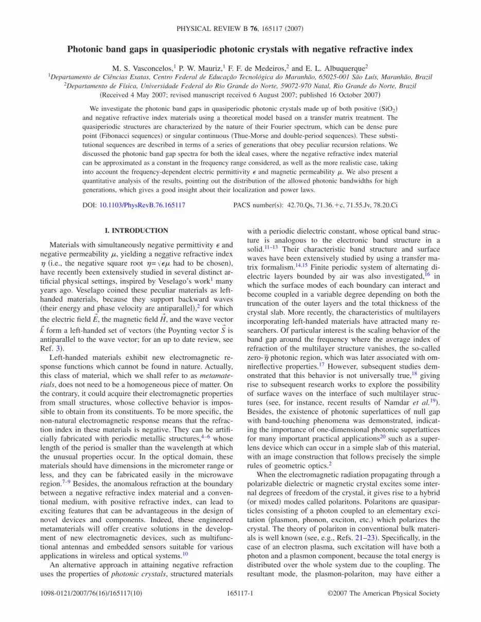
In Fig. 3�a�, we present the photonic band gap spectrumfor the fourth generation of the Fibonacci quasiperiodicstructure. Different of the periodic case, the photonic bandgap spectrum is more fragmented and tends to become nar-rower when kxdA increases. There are several bulk modesseparated by narrow forbidden band gaps, a characteristicdue to the quasiperiodic geometry. Observe that the numberof passbands, considering both regions of high and low fre-quency, is related to the Fibonacci number Fn �Fn=Fn−1+Fn−2, starting with F1=F2=1�. We can observe the exis-tence of five surface modes with a behavior similar to thosefound for the periodic case. The high-frequency surfacemode emerges from the light line �=ckx and then goes to� /�p=1/�2 for high values of kxdA, with negative slope.The second, the third, and the fourth surface modes, seenfrom top to the bottom, alternate negative and positiveslopes, showing the forward and backward propagations. Thesecond surface mode emerges from the light line with nullslope and it tends to � /�p=1/�2 with negative slope �back-ward mode�, together with the bulk bands below and abovethem. The third surface mode emerges from a thin bulk bandat � /�p=0.4, with a null slope, and goes to � /�p=0.276,
with negative slope. The fourth surface mode starts at� /�p=0 and kxdA=0 and then tends together with the bulkbands to � /�p=0.276 for high values of kxdA. The fifth andlast surface mode begins at � /�p=0 and kxdA=0 and tend to� /�p=0.276, with positive slope in all interval shown in thefigure. Therefore, it is a forward wave mode, i.e., in thisregion, we do not have the effect of the negative refraction
FIG. 3. Photonic band gap spectra �in units of the plasma fre-quency� against the dimensionless in-plane wave vector kxdA for thethickness ratio dA /dB=2 considering a quasiperiodic photonic su-perlattice. The shaded areas represent the bulk mode regions, whilethe surface modes are represented by full lines. The dashed linerepresents the light line in the vacuum, while the chain-dotted lineis the light line in layer B �SiO2�. �a� Fibonacci, �b� Thue-Morse,and �c� double period.
PHOTONIC BAND GAPS IN QUASIPERIODIC PHOTONIC… PHYSICAL REVIEW B 76, 165117 �2007�
165117-5

index or, more specifically, we do not have backward modes.As we will see, the behavior of this last surface mode issimilar to those found in other quasiperiodic cases, i.e., atlow frequencies and between the bulk bands localized in therange 0�� /�p�0.276, we have only forward modes.
For completeness, we have also shown the fourth genera-tion for the Thue-Morse and double period quasiperiodicstructures in Figs. 3�b� and 3�c�, respectively. Here, differentfrom the Fibonacci case, we have many passbands that arefragmented and follow a different rule: for both quasiperi-odic structures, the number of fragmented bulk regions Nincreases as �1/3��2n− �−1�n+2�, with n being the Thue-Morse �double-period� generation number. Besides, there aresurface modes �straight lines� above, below, and between thebulk bands with the same properties as those in the Fibonaccicase, i.e., forward and backward propagations. It is easy toobserve that in all these quasiperiodic structures, in the inter-val 0�� /�p�0.4, we have the same qualitative behaviorfor the surface and bulk modes when compared to superlat-tices composed by positive refractive index materials, whilein the range 0.4�� /�p�1.0, we note the effects of thenegative refractive index material. Such fact can be due tothe refraction index ��� being negative in the range 0.4�� /�p�0.6. However, this does not explain all the resultsobserved out of this interval as, for instance, the negativegroup velocity for the two surface modes at high frequency,depicted in Fig. 3�b�. The upper surface mode emerges fromthe light line and, while kxdA increase, it tends asymptoticallyto the convergence limit in � /�p=1/�2 �dotted line�. In therange 0.244�kxdA�2.0, the slope is negative, which meansthat the mode has a negative group velocity. For kxdA2.0,the slope is null so is the group velocity. Observe that onlythis surface mode converges for this limit value.
When the constituents of the superlattice are formed by amaterial with positive refraction index, the passbands in pe-riodic and quasiperiodic structures can be obtained when theabsolute value of the right side of Eq. �14� is less than 1 �cf.Ref. 26 for details�, which means a real z component kz ofthe wave vector. On the other hand, when it is greater than 1,we have a stop band. However, this is not true when thesuperlattice contains materials with both positive and nega-tive refraction indices �which is the case treated here�. Somecomplex value of kz can still make the left-hand side of Eq.�14� smaller than 1, and these complex solutions may havephysical significance. This can be seen considering the dis-persion curves presented in Fig. 4�a�, corresponding to afixed common dimensionless in-plane wave vector kxL /2�=0.1 and a ratio dB /dA=2.69. We have plotted here the re-duced frequency �=�L /2�c against the dimensionlessFloquet-Bloch wave vector QL for the fifth Fibonacci gen-eration. We also have focus our interest to the case where theaverage index of refraction of the superlattice vanishes, theso-called zero-�̄ photonic region, i.e., �̄= ��AdA+�BdB� /L=0, with �A= ��A�A�1/2=−3.53 being the refraction index forthe metamaterial �j=A� and �B= ��B�B�1/2=2.19 being therefraction index for SiO2 �j=B�, respectively �these param-eters correspond to �A=−2.5, �A=−5, �B=4.8, �B=1, dA /L=0.271, and dB /L=0.729�. The reason for that is to distin-guish the usual Floquet-Bloch band gaps, depicted in Figs. 2
and 3, from the zero �̄ band gaps. Besides, there is a possi-bility of a gap widening with respect to the usual superlat-tices constituted only by material with positive refractionindex,33 as well as the possibility of discrete modes and pho-ton tunneling ones34 when �̄=0. Here, we note that the edges
FIG. 4. �a� Photonic band gap spectrum against the dimension-less Floquet-Bloch wave vector QL for the thickness ratio dB /dA
=2.69, considering the fifth generation of the Fibonacci quasiperi-odic photonic superlattice. �b� Projected photonic band structureplotted as a function of the reduced in-plane wave vector Kx
=kxL /2�. The shaded and the white areas correspond to the pass-bands and to the stop bands of the structure, respectively. Thedashed lines mean the light lines �=ckx and �=−ckx in thevacuum.
VASCONCELOS et al. PHYSICAL REVIEW B 76, 165117 �2007�
165117-6

of the bulk bands are not characterized by the Floquet-Blochconditions QL=0 and QL=�. Therefore, we have a reduc-tion of the Brillouin zone.
The �̄=0 band structure can be better seen in the pro-jected band profile �Fig. 4�b�� where the consecutive pass-bands are united to constitute a very large fragmented band,where we can observe discrete and continuous bulk modes.The surface modes are represented by straight lines, and thedashed lines are the light lines corresponding to �=ckx and�=−ckx. As we have mentioned, the surface modes liesabove the light line and between the bulk bands. When itdeparts from kx=0, the passbands become separated by nar-row stop bands, i.e., the discrete modes transform into nar-row bands in which the dimensionless Floquet-Bloch wavevector QL describes a small regions �shadow areas� aroundkx=0, whereas the lowest dispersion curve extends over amore or less spread domain of the reduced Brillouin zone�see Fig. 4�a��. On the other hand, Fig. 4�a� also shows thatfor small values of kxdA, the transmission through the super-lattice is zero, except in certain transmission bands and forsome values of QL��. The discrete frequencies �as in �=� /2�c�1.2 and QL=0, in Fig. 4�a�� are determinedby the Fabry-Pérot resonance condition kzA=m� �m= ±1, ±2, ±3, . . . �, where the waves reflected at consecutiveinterfaces arrive out of phase at the input facet of thesuperlattice.35 The continuous bulk bands are characterizedby the reduced Brillouin zone, 0�QL��, with � being thevalues where the slope goes to negative infinity in Fig. 4�a�.Note that for the nth Fibonacci generation, we can calculatethe dimensionless thicknesses dA /L and dB /L that satisfy theequation �̄n= �Fn−1�AdA+Fn−2�BdB� /L=0, with Fn being thenth generation’s Fibonacci number. In general, for any sub-stitutional sequence, we can calculate these parameterstrough the equation
�̄n = �NA�AdA + NB�BdB�/L = 0, �29�
where NA �NB� is the number of building blocks of layer A�B� for a given generation n.
Now, we examine the confinement effects arising fromcompetition between the long-range aperiodic order, inducedby the quasiperiodic structure, and the short-range disorderby means of a quantitative analysis of the localization andmagnitude of the passband width in the photonic band gapspectra. To do that, we calculate the regions for allowed fre-quencies �passbands�, where ��1/2�Tr�T���1, as a functionof the generation number of the quasiperiodic structure for afixed value of kxdA=0.25, as depicted in Fig. 3�a� �Fibonaccisequence�, Fig. 3�b� �Thue-Morse sequence�, and Fig. 3�c��double-period sequence�. Such a result can be seen in Figs.5–7 together with a log-log plot of the total bandwidth as afunction of the number of building blocks for each quasip-eriodic superlattice, considering three values of kxdA, namely,0.25, 0.35, and 0.5, respectively.
Figure 5�a� shows the distribution of the bandwidths ofthe forbidden and allowed frequencies, as a function of thegeneration number n, up to the 12th generation of the Fi-bonacci sequence, considering kxdA=0.25. This means a unitcell with 89 building blocks A and 144 building blocks B,
totaling 233 building blocks. Note that, as expected, for largen, the allowed band regions get narrower and narrower as anindication of more localized modes. In fact, the total width �of the passband energy regions, which is the Lebesgue mea-sure of the energy spectrum,36 decreases with n as the powerlaw ��Fn
−�. Here, the exponent � �the diffusion constant ofthe spectra� is a function of the common in-plane wave vec-tor kxdA. This exponent can indicate the degree of localiza-tion of the excitation.37 In Fig. 5�b�, we show a log-log plotof these power laws for three different values of kxdA,namely, 0.25, 0.35, and 0.50.
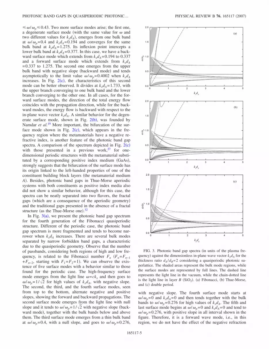
The distribution of the bandwidths for the Thue-Morsestructure, considering kxdA=0.25, is described in Fig. 6�a� upto the eighth generation of the sequence. The total passband
FIG. 5. �Color online� Localization and scaling properties in theFibonacci quasiperiodic structure: �a� the distribution of bandwidthsas a function of the generation number n and �b� log-log plot of thetotal width � of the passband regions against the Fibonacci number�the red, blue, and black lines correspond to the common dimen-sionless in-plane wave vector kxdA equal to 0.25, 0.35, and 0.50,respectively�.
PHOTONIC BAND GAPS IN QUASIPERIODIC PHOTONIC… PHYSICAL REVIEW B 76, 165117 �2007�
165117-7
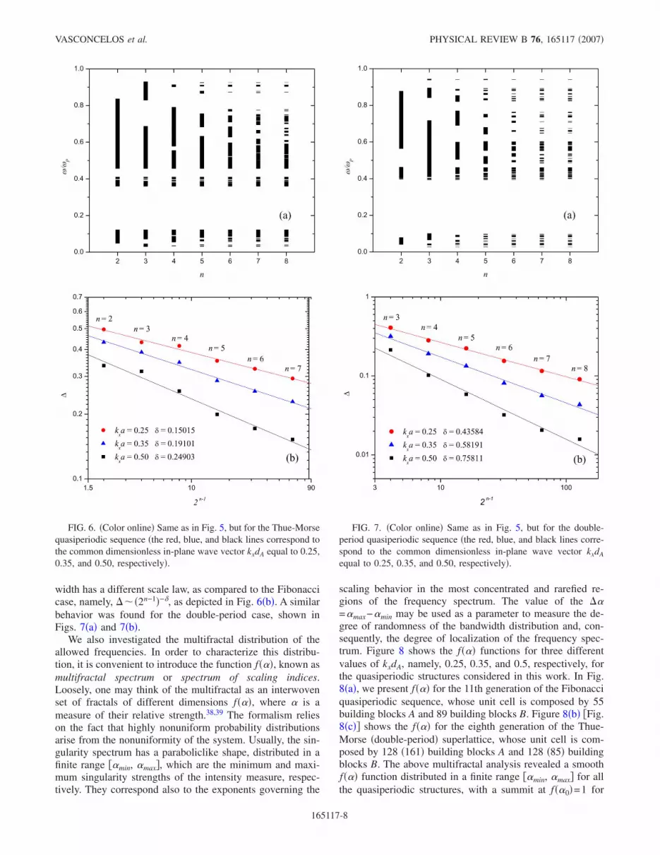
width has a different scale law, as compared to the Fibonaccicase, namely, ���2n−1�−�, as depicted in Fig. 6�b�. A similarbehavior was found for the double-period case, shown inFigs. 7�a� and 7�b�.
We also investigated the multifractal distribution of theallowed frequencies. In order to characterize this distribu-tion, it is convenient to introduce the function f���, known asmultifractal spectrum or spectrum of scaling indices.Loosely, one may think of the multifractal as an interwovenset of fractals of different dimensions f���, where � is ameasure of their relative strength.38,39 The formalism relieson the fact that highly nonuniform probability distributionsarise from the nonuniformity of the system. Usually, the sin-gularity spectrum has a paraboliclike shape, distributed in afinite range ��min, �max�, which are the minimum and maxi-mum singularity strengths of the intensity measure, respec-tively. They correspond also to the exponents governing the
scaling behavior in the most concentrated and rarefied re-gions of the frequency spectrum. The value of the ��=�max−�min may be used as a parameter to measure the de-gree of randomness of the bandwidth distribution and, con-sequently, the degree of localization of the frequency spec-trum. Figure 8 shows the f��� functions for three differentvalues of kxdA, namely, 0.25, 0.35, and 0.5, respectively, forthe quasiperiodic structures considered in this work. In Fig.8�a�, we present f��� for the 11th generation of the Fibonacciquasiperiodic sequence, whose unit cell is composed by 55building blocks A and 89 building blocks B. Figure 8�b� �Fig.8�c�� shows the f��� for the eighth generation of the Thue-Morse �double-period� superlattice, whose unit cell is com-posed by 128 �161� building blocks A and 128 �85� buildingblocks B. The above multifractal analysis revealed a smoothf��� function distributed in a finite range ��min, �max� for allthe quasiperiodic structures, with a summit at f��0�=1 for
FIG. 6. �Color online� Same as in Fig. 5, but for the Thue-Morsequasiperiodic sequence �the red, blue, and black lines correspond tothe common dimensionless in-plane wave vector kxdA equal to 0.25,0.35, and 0.50, respectively�.
FIG. 7. �Color online� Same as in Fig. 5, but for the double-period quasiperiodic sequence �the red, blue, and black lines corre-spond to the common dimensionless in-plane wave vector kxdA
equal to 0.25, 0.35, and 0.50, respectively�.
VASCONCELOS et al. PHYSICAL REVIEW B 76, 165117 �2007�
165117-8

some value �0 of �. These investigations clearly demonstratethat all the spectra correspond to highly nonuniform intensitydistributions, and therefore, they possess the scaling proper-ties of a multifractal.
IV. CONCLUSIONS
In this work, we presented a general theory for the propa-gation of plasmon-polaritons in periodic and quasiperiodicsuperlattices, in which one of the layers has negative refrac-tive index �metamaterial�, with simultaneously negative per-mittivity � and permeability � in the same frequency region.The spectra are illustrated in Figs. 2 �periodic superlattice�and 3 �three types of quasiperiodic structures�. In both cases,we have observed that the effects of the introduction of thenegative refractive index material in the spectra are moreaccentuated in the region 0.276�� /�p�1.0, where manybulk and surfaces modes exist with backward behavior,which is a typical property of metamaterials. On the otherhand, in the interval 0�� /�p�0.276, we have only forwardmodes that are typical of positive refractive index materials.From these results, we can conclude that the photonic bandgap spectrum presents properties for both positive and nega-tive refractive index materials in an interval out of the rangewhere the refractive index of the metamaterial is negative,i.e., 0.4�� /�p�0.6. This is a quite interesting property, notexplored in a recent article,40 where we studied the transmis-sion spectra for the quasiperiodic sequences studied here.
We have also studied some physical properties of thesesubstitutional sequences, mainly those related with their lo-calization, as expressed by the distribution of bandwidthsshown in Figs. 5�a�, 6�a�, and 7�a�. Their self-similarity be-havior was better described through the fractal and/or multi-fractal profiles, whose power laws were depicted in Figs.5�b�, 6�b�, and 7�b�, with no counterpart for the periodiccase.
The most important experimental techniques to probethese spectra are the Raman light scattering and attenuatedtotal reflection �ATR�. In the case of Raman scattering, oneuses a grating spectrometer to detect and analyze the scat-tered light. The typical shift of the frequency of the scatteredlight is in the range 0.6–500 meV, which makes this tech-nique very appropriate for probing the plasmon-polaritonspectra. On the other hand, ATR spectroscopy is much easierto deal with than the Raman one, but typically, it gives lessprecise results. However, it has been employed with successin a number of experiments for ordinary materials �cf. Ref.41�, including an interface between vacuum and a metama-terial slab.42
ACKNOWLEDGMENTS
We would like to thank the Brazilian Research AgenciesCNPq-Rede Nanobioestruturas, FINEP, and FAPEMA forpartial financial support.
FIG. 8. �Color online� The f��� functions of the photonic bandgap bandwidths for the three quasiperiodic structures treated here.The values of kxdA are given in the legend �a� Fibonacci, �b� Thue-Morse, �c� double period. �the red, blue, and black lines correspondto the common dimensionless in-plane wave vector kxdA equal to0.25, 0.35, and 0.50, respectively�.
PHOTONIC BAND GAPS IN QUASIPERIODIC PHOTONIC… PHYSICAL REVIEW B 76, 165117 �2007�
165117-9

1 V. G. Veselago, Sov. Phys. Usp. 10, 509 �1968�.2 S. Foteinopoulou, E. N. Economou, and C. M. Soukoulis, Phys.
Rev. Lett. 90, 107402 �2003�; E. Cubukcu, K. Aydin, E. Ozbay,S. Foteinopoulou, and C. M. Soukoulis, Nature �London� 423,604 �2003�.
3 S. A. Ramakrishna, Rep. Prog. Phys. 68, 449 �2005�.4 J. B. Pendry, A. Holden, D. J. Robbins, and W. J. Stewart, IEEE
Trans. Microwave Theory Tech. 47, 2075 �1999�.5 J. B. Pendry, Phys. Rev. Lett. 85, 3966 �2000�.6 J. B. Pendry, Science 306, 1353 �2004�.7 D. R. Smith, W. J. Padilla, D. C. Vier, S. C. Nemat-Nasser, and S.
Schultz, Phys. Rev. Lett. 84, 4184 �2000�.8 D. R. Smith, J. B. Pendry, and M. C. K. Wiltshire, Science 305,
788 �2004�.9 R. A. Shelby, D. R. Smith, and S. Shultz, Science 292, 77 �2001�.
10 C. G. Parazzoli, R. B. Greegor, K. Li, B. E. C. Koltenbah, and M.Tanielian, Phys. Rev. Lett. 90, 107401 �2003�.
11 E. Yablonovitch, Phys. Rev. Lett. 58, 2059 �1987�.12 S. John, Phys. Rev. Lett. 58, 2486 �1987�.13 S. Johnson and J. D. Joannopoulos, Photonic Crystals: The Road
from Theory to Practice �Kluwer, Boston, 2002�.14 P. Yeh, A. Yariv, and C.-S. Hong, J. Opt. Soc. Am. 67, 423
�1977�.15 P. Yeh, Optical Waves in Layered Media �Wiley, New York,
1988�.16 J. A. Gaspar-Armenta, F. Villa, and T. López-Ríos, Opt. Commun.
216, 379 �2003�.17 H. Jiang, H. Chen, H. Li, and Y. Zhang, Appl. Phys. Lett. 83,
5386 �2003�.18 H. Daninthe, S. Foteinopoulou, and C. M. Soukoulis, Photonics
Nanostruct. Fundam. Appl. 4, 123 �2006�.19 A. Namdar, I. V. Shadrivov, and Y. S. Kivshar, Appl. Phys. Lett.
89, 114104 �2006�.20 S. B. Cavalcanti, M. de Dios–Leyva, E. Reyes-Gómez, and L. E.
Oliveira, Phys. Rev. B 74, 153102 �2006�.21 R. Loudon, Adv. Phys. 13, 423 �1964�.22 Polaritons, edited by E. Burstein and F. de Martini �Pergamon,
Oxford, 1974�.
23 D. L. Mills and E. Burstein, Rep. Prog. Phys. 37, 817 �1974�.24 C. H. Henry and J. J. Hopfield, Phys. Rev. Lett. 15, 964 �1965�.25 Z. Sun and H. K. Kima, Appl. Phys. Lett. 85, 642 �2004�.26 E. L. Albuquerque and M. G. Cottam, Polaritons in Periodic and
Quasiperiodic Structures �Elsevier, Amsterdam, 2004�.27 E. L. Albuquerque and M. G. Cottam, Phys. Rep. 376, 225
�2003�.28 H. V. Shadrivov, A. A. Sukhorukov, and Y. S. Kivshar, Appl.
Phys. Lett. 82, 3820 �2003�.29 B. Djafari-Rouhani, L. Dobrzynski, O. Hardouin Duparc, R. E.
Camley, and A. A. Maradudin, Phys. Rev. B 28, 1711 �1983�; R.E. Camley and D. L. Mills, ibid. 29, 1695 �1984�.
30 G. F. Giuliani and J. J. Quinn, Phys. Rev. Lett. 51, 919 �1983�;W. Liu, G. Eliasson, and J. J. Quinn, Solid State Commun. 55,533 �1985�.
31 M. S. Vasconcelos and E. L. Albuquerque, Phys. Rev. B 57, 2826�1998�.
32 X. Jiang, Y. Zhang, S. Feng, K. C. Huang, Y. Yi, and J. D. Joan-nopoulos, Appl. Phys. Lett. 86, 201110 �2005�.
33 I. S. Nefedov and S. A. Tretyakov, Phys. Rev. E 66, 036611�2002�.
34 L. Wu, S. He, and L. Shen, Phys. Rev. B 67, 235103 �2003�.35 N. C. Panoiu, R. M. Osgood, Jr., S. Zhang, and S. R. J. Brueck, J.
Opt. Soc. Am. B 23, 506 �2006�.36 E. Maciá, Rep. Prog. Phys. 69, 397 �2006�, and references
therein.37 P. Hawrylak and J. J. Quinn, Phys. Rev. Lett. 57, 380 �1986�.38 I. Procaccia, Proceedings of Nobel Symposium on Chaos and
Related Problems �Phys. Scr., T T9, 40 �1985��.39 T. C. Halsey, P. Meakin, and I. Procaccia, Phys. Rev. Lett. 56,
854 �1986�.40 F. F. de Medeiros, E. L. Albuquerque, and M. S. Vasconcelos, J.
Phys.: Condens. Matter 18, 8737 �2006�.41 N. Raj and D. R. Tilley, in The Dielectric Function of Condensed
Systems, edited by L. V. Keldysh, D. A. Kirzhnitz, and A. A.Maradudin �North-Holland, Amsterdam, 1989�.
42 J. N. Gollub, D. R. Smith, D. C. Vier, T. Perram, and J. J. Mock,Phys. Rev. B 71, 195402 �2005�.
VASCONCELOS et al. PHYSICAL REVIEW B 76, 165117 �2007�
165117-10