photonic crystal fiber interfacing
TRANSCRIPT
Photonic crystal Fiber interFacing and Fiber laser comPonents catalogue
In partnership with
2
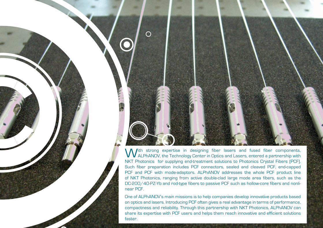
With strong expertise in designing fiber lasers and fused fiber components, ALPhANOV, the Technology Center in Optics and Lasers, entered a partnership with
NKT Photonics for supplying end-treatment solutions to Photonics Crystal Fibers (PCF). Such fiber preparation includes PCF connectors, sealed and cleaved PCF, end-capped PCF and PCF with mode-adaptors. ALPhANOV addresses the whole PCF product line of NKT Photonics, ranging from active double-clad large mode area fibers, such as the DC-200/40-PZ-Yb and rod-type fibers to passive PCF such as hollow-core fibers and nonli-near PCF.
One of ALPhANOV’s main missions is to help companies develop innovative products based on optics and lasers. Introducing PCF often gives a real advantage in terms of performance, compactness and reliability. Through this partnership with NKT Photonics, ALPhANOV can share its expertise with PCF users and helps them reach innovative and efficient solutions faster.
3
Contents
4 Hollow-Core PCF interfacing
Ytterbium DC fibers interfacing
6
8
10
12
PCF connectors14
Fiber splicing20
Special termination
24 Pump and signal combiners for active micro-structured fibers
22
Nonlinear PCF interfacing
Large Mode Area PCF interfacing
End-capping
26 Send us your request
27 Multiboard - Build your own laser
4
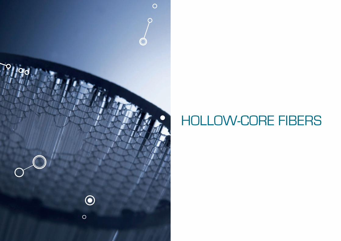
HOLLOW-CORE FIBERS
5
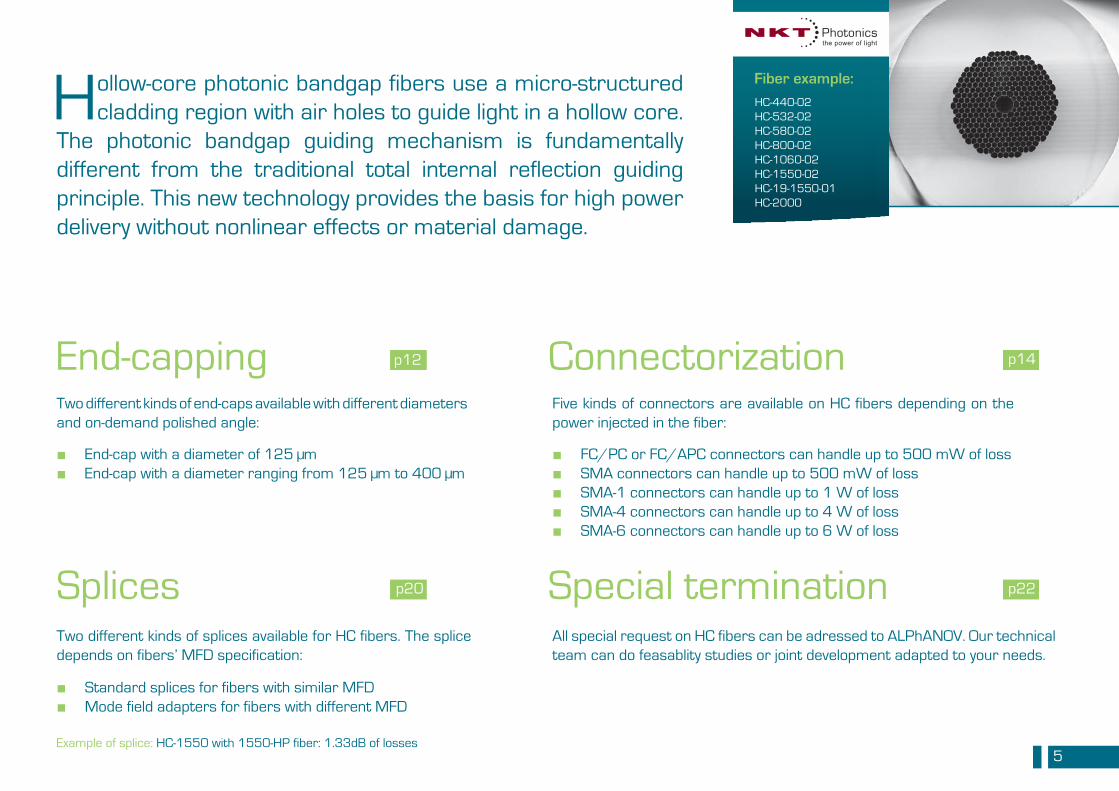
Hollow-core photonic bandgap fibers use a micro-structured cladding region with air holes to guide light in a hollow core.
The photonic bandgap guiding mechanism is fundamentally different from the traditional total internal reflection guiding principle. This new technology provides the basis for high power delivery without nonlinear effects or material damage.
Two different kinds of end-caps available with different diameters and on-demand polished angle:
End-cap with a diameter of 125 µmEnd-cap with a diameter ranging from 125 µm to 400 µm
■ ■
End-cappingFive kinds of connectors are available on HC fibers depending on the power injected in the fiber:
FC/PC or FC/APC connectors can handle up to 500 mW of lossSMA connectors can handle up to 500 mW of lossSMA-1 connectors can handle up to 1 W of lossSMA-4 connectors can handle up to 4 W of lossSMA-6 connectors can handle up to 6 W of loss
■ ■ ■ ■ ■
Connectorization
Two different kinds of splices available for HC fibers. The splice depends on fibers’ MFD specification:
Standard splices for fibers with similar MFDMode field adapters for fibers with different MFD
■ ■
All special request on HC fibers can be adressed to ALPhANOV. Our technical team can do feasablity studies or joint development adapted to your needs.
Splices Special termination
Fiber example:
p12
p20
p14
p22
HC-440-02HC-532-02HC-580-02HC-800-02HC-1060-02HC-1550-02HC-19-1550-01HC-2000
Example of splice: HC-1550 with 1550-HP fiber: 1.33dB of losses
6
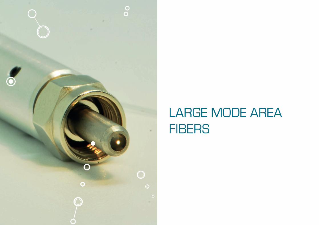
LARGE MODE AREA FIBERS
7
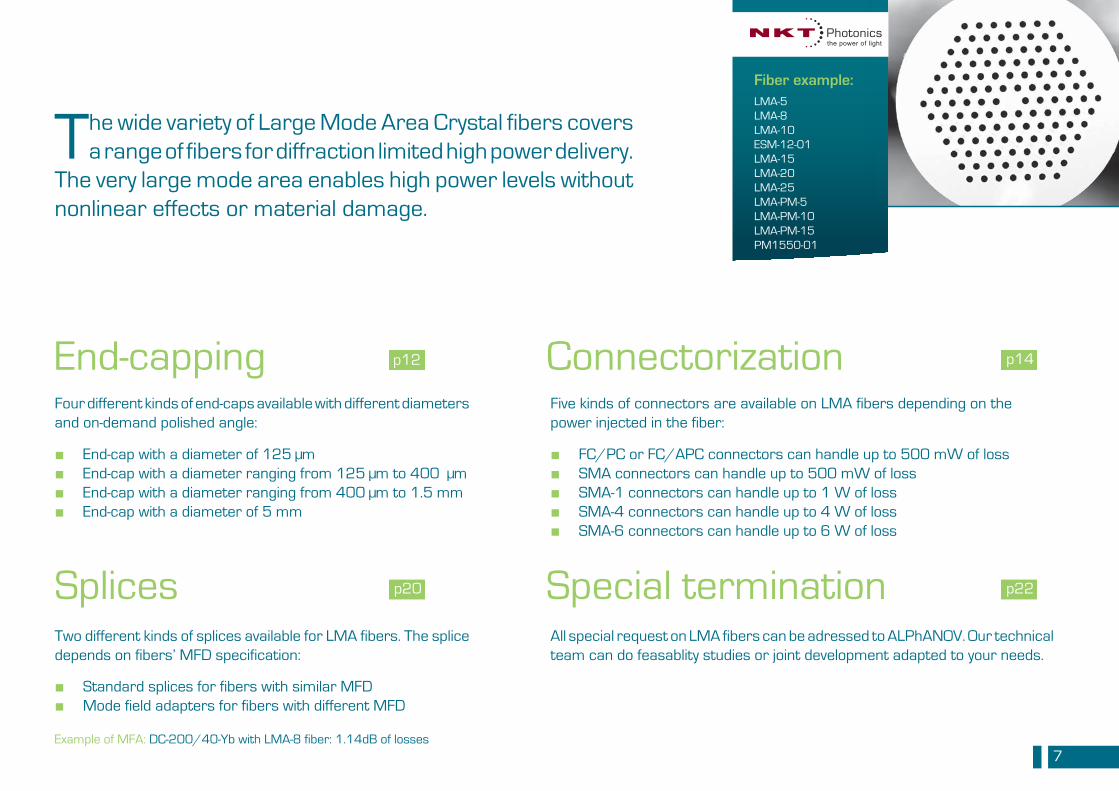
The wide variety of Large Mode Area Crystal fibers covers a range of fibers for diffraction limited high power delivery.
The very large mode area enables high power levels without nonlinear effects or material damage.
Four different kinds of end-caps available with different diameters and on-demand polished angle:
End-cap with a diameter of 125 µmEnd-cap with a diameter ranging from 125 µm to 400 µmEnd-cap with a diameter ranging from 400 µm to 1.5 mmEnd-cap with a diameter of 5 mm
■ ■ ■ ■
End-cappingFive kinds of connectors are available on LMA fibers depending on the power injected in the fiber:
FC/PC or FC/APC connectors can handle up to 500 mW of lossSMA connectors can handle up to 500 mW of lossSMA-1 connectors can handle up to 1 W of lossSMA-4 connectors can handle up to 4 W of lossSMA-6 connectors can handle up to 6 W of loss
■ ■ ■ ■ ■
Connectorization
Two different kinds of splices available for LMA fibers. The splice depends on fibers’ MFD specification:
Standard splices for fibers with similar MFDMode field adapters for fibers with different MFD
■ ■
All special request on LMA fibers can be adressed to ALPhANOV. Our technical team can do feasablity studies or joint development adapted to your needs.
Splices Special termination
p12
p20
p14
p22
Fiber example: LMA-5LMA-8LMA-10ESM-12-01LMA-15LMA-20LMA-25LMA-PM-5LMA-PM-10LMA-PM-15PM1550-01
Example of MFA: DC-200/40-Yb with LMA-8 fiber: 1.14dB of losses
8
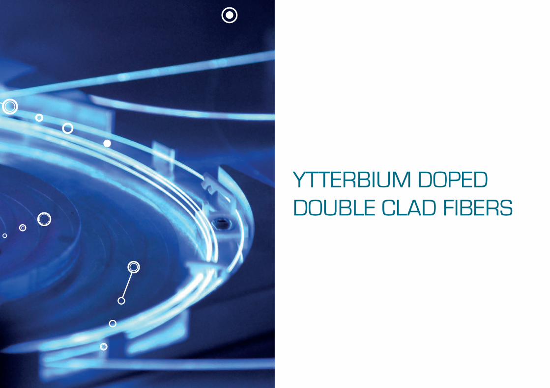
YTTERBIUM DOPED DOUBLE CLAD FIBERS
9
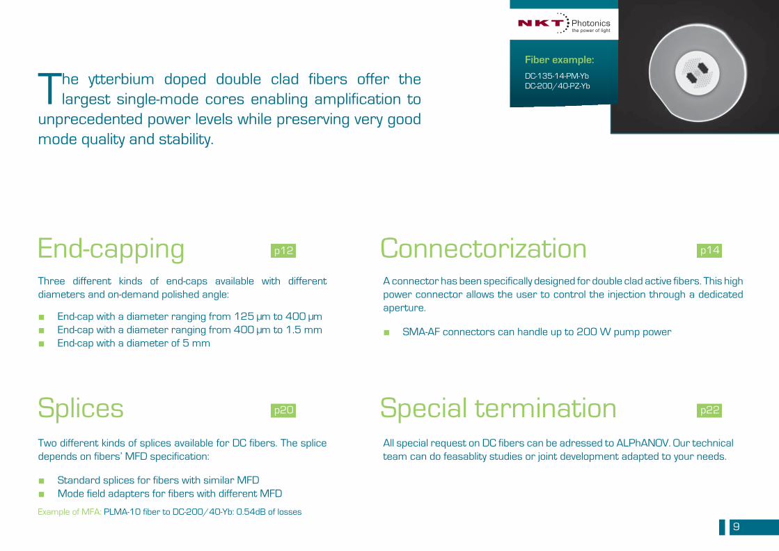
The ytterbium doped double clad fibers offer the largest single-mode cores enabling amplification to
unprecedented power levels while preserving very good mode quality and stability.
Three different kinds of end-caps available with different diameters and on-demand polished angle:
End-cap with a diameter ranging from 125 µm to 400 µmEnd-cap with a diameter ranging from 400 µm to 1.5 mmEnd-cap with a diameter of 5 mm
■ ■ ■
End-cappingA connector has been specifically designed for double clad active fibers. This high power connector allows the user to control the injection through a dedicated aperture.
SMA-AF connectors can handle up to 200 W pump power ■
Connectorization
Two different kinds of splices available for DC fibers. The splice depends on fibers’ MFD specification:
Standard splices for fibers with similar MFDMode field adapters for fibers with different MFD
■ ■
All special request on DC fibers can be adressed to ALPhANOV. Our technical team can do feasablity studies or joint development adapted to your needs.
Splices Special termination
p12
p20
p14
p22
Fiber example: DC-135-14-PM-YbDC-200/40-PZ-Yb
Example of MFA: PLMA-10 fiber to DC-200/40-Yb: 0.54dB of losses
10
NONLINEAR FIBER
11
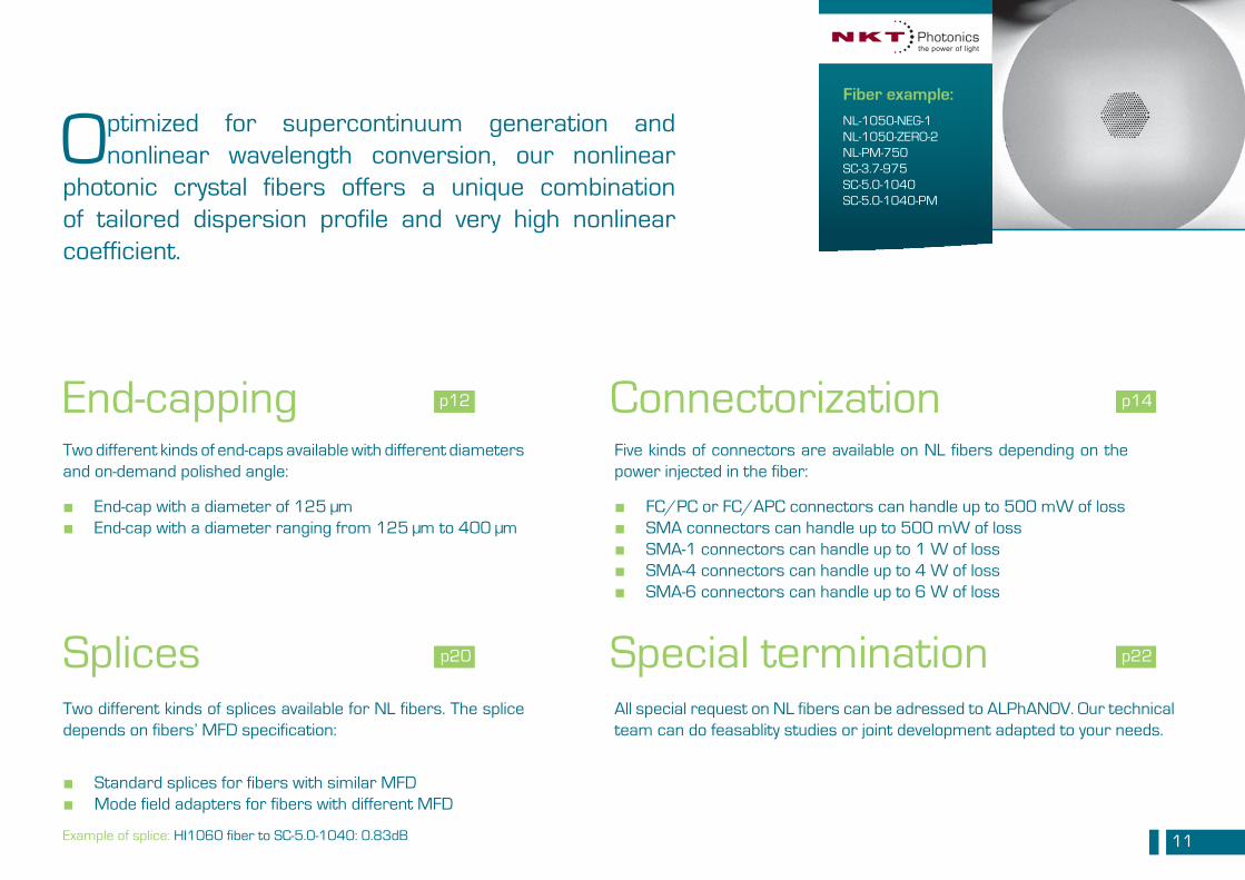
Optimized for supercontinuum generation and nonlinear wavelength conversion, our nonlinear
photonic crystal fibers offers a unique combination of tailored dispersion profile and very high nonlinear coefficient.
Two different kinds of end-caps available with different diameters and on-demand polished angle:
End-cap with a diameter of 125 µmEnd-cap with a diameter ranging from 125 µm to 400 µm
■ ■
End-cappingFive kinds of connectors are available on NL fibers depending on the power injected in the fiber:
FC/PC or FC/APC connectors can handle up to 500 mW of lossSMA connectors can handle up to 500 mW of lossSMA-1 connectors can handle up to 1 W of lossSMA-4 connectors can handle up to 4 W of lossSMA-6 connectors can handle up to 6 W of loss
■ ■ ■ ■ ■
Connectorization
Two different kinds of splices available for NL fibers. The splice depends on fibers’ MFD specification:
Standard splices for fibers with similar MFDMode field adapters for fibers with different MFD
■ ■
All special request on NL fibers can be adressed to ALPhANOV. Our technical team can do feasablity studies or joint development adapted to your needs.
Splices Special termination
p12
p20
p14
p22
Fiber example:
NL-1050-NEG-1NL-1050-ZERO-2NL-PM-750SC-3.7-975SC-5.0-1040SC-5.0-1040-PM
Example of splice: HI1060 fiber to SC-5.0-1040: 0.83dB
12
END-CAPPING
13
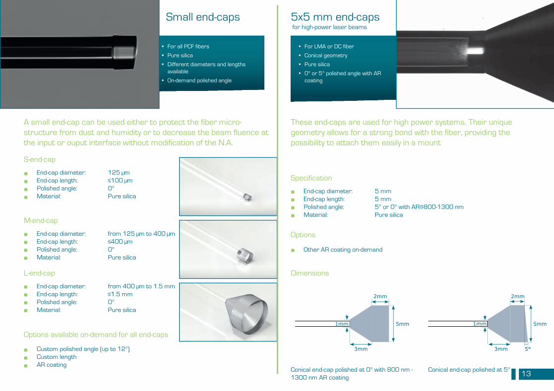
5x5 mm end-caps
Specification
Dimensions
End-cap diameter: 5 mmEnd-cap length: 5 mmPolished angle: 5° or 0° with AR@800-1300 nmMaterial: Pure silica
These end-caps are used for high power systems. Their unique geometry allows for a strong bond with the fiber, providing the possibility to attach them easily in a mount
Options
Other AR coating on-demand
• For LMA or DC fiber
• Conical geometry
• Pure silica
• 0° or 5° polished angle with AR coating
for high-power laser beams
Conical end-cap polished at 0° with 800 nm - 1300 nm AR coating
Conical end-cap polished at 5°
5mm
2mm
3mm
1mm 5mm
2mm
3mm
1mm
5°
Small end-caps
S-end-cap
End-cap diameter: 125 µmEnd-cap length: ≤100 µmPolished angle: 0°Material: Pure silica
A small end-cap can be used either to protect the fiber micro-structure from dust and humidity or to decrease the beam fluence at the input or ouput interface without modification of the N.A.
Options available on-demand for all end-caps
Custom polished angle (up to 12°)Custom length AR coating
• For all PCF fibers
• Pure silica
• Different diameters and lengths available
• On-demand polished angle
M-end-cap
End-cap diameter: from 125 µm to 400 µmEnd-cap length: ≤400 µmPolished angle: 0°Material: Pure silica
L-end-cap
End-cap diameter: from 400 µm to 1.5 mmEnd-cap length: ≤1.5 mmPolished angle: 0°Material: Pure silica
■ ■ ■ ■
■ ■ ■ ■
■ ■ ■ ■
■ ■ ■
■ ■ ■ ■
■
14
PCF CONNECTORS
15
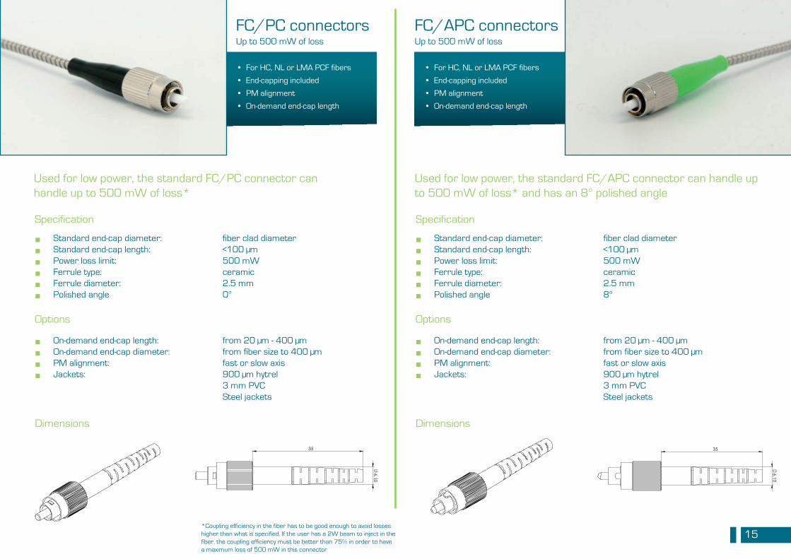
FC/PC connectors
Specification
Dimensions
Standard end-cap diameter: fiber clad diameterStandard end-cap length: <100 µmPower loss limit: 500 mWFerrule type: ceramicFerrule diameter: 2.5 mmPolished angle 0°
Used for low power, the standard FC/PC connector can handle up to 500 mW of loss*
Up to 500 mW of loss
■ ■ ■ ■ ■ ■
Options
On-demand end-cap length: On-demand end-cap diameter: PM alignment: Jackets:
■ ■ ■ ■
from 20 µm - 400 µmfrom fiber size to 400 µmfast or slow axis900 µm hytrel3 mm PVCSteel jackets
• For HC, NL or LMA PCF fibers
• End-capping included
• PM alignment
• On-demand end-cap length
6.10
35
6.10
35
FC/APC connectors
Specification
Dimensions
Standard end-cap diameter: fiber clad diameterStandard end-cap length: <100 µmPower loss limit: 500 mWFerrule type: ceramicFerrule diameter: 2.5 mmPolished angle 8°
Used for low power, the standard FC/APC connector can handle up to 500 mW of loss* and has an 8° polished angle
Up to 500 mW of loss
■ ■ ■ ■ ■ ■
Options
On-demand end-cap length: On-demand end-cap diameter: PM alignment: Jackets:
■ ■ ■ ■
from 20 µm - 400 µmfrom fiber size to 400 µmfast or slow axis900 µm hytrel3 mm PVCSteel jackets
• For HC, NL or LMA PCF fibers
• End-capping included
• PM alignment
• On-demand end-cap length
6.10
35
6.10
35
*Coupling efficiency in the fiber has to be good enough to avoid losses higher than what is specified. If the user has a 2W beam to inject in the fiber, the coupling efficiency must be better than 75% in order to have a maximum loss of 500 mW in this connector
16
60
7.67
60
7.67
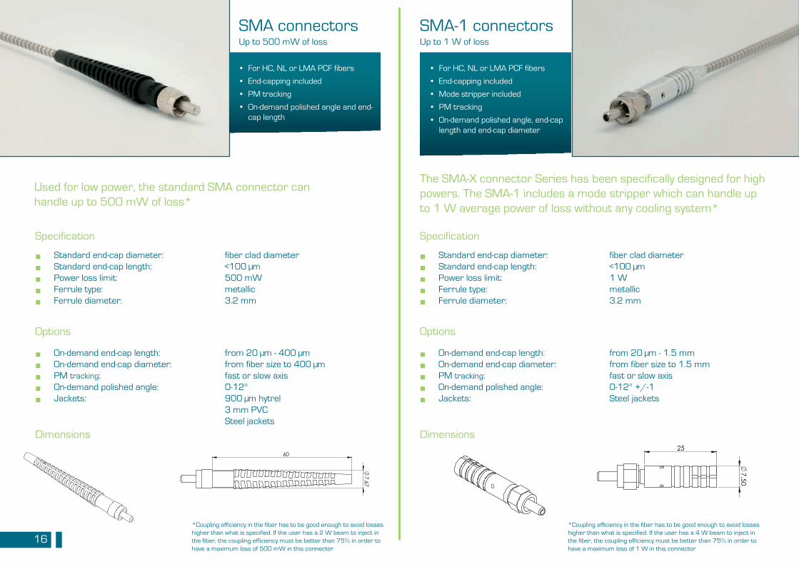
SMA connectors
Specification
Dimensions
Standard end-cap diameter: fiber clad diameterStandard end-cap length: <100 µmPower loss limit: 500 mWFerrule type: metallicFerrule diameter: 3.2 mm
Used for low power, the standard SMA connector can handle up to 500 mW of loss*
Up to 500 mW of loss
Options
On-demand end-cap length: On-demand end-cap diameter: PM tracking: On-demand polished angle: Jackets:
from 20 µm - 400 µmfrom fiber size to 400 µmfast or slow axis0-12°900 µm hytrel3 mm PVCSteel jackets
• For HC, NL or LMA PCF fibers
• End-capping included
• PM tracking
• On-demand polished angle and end-cap length
7.50
25
7.50
25
SMA-1 connectors
Specification
Dimensions
Standard end-cap diameter: fiber clad diameterStandard end-cap length: <100 µmPower loss limit: 1 WFerrule type: metallicFerrule diameter: 3.2 mm
The SMA-X connector Series has been specifically designed for high powers. The SMA-1 includes a mode stripper which can handle up to 1 W average power of loss without any cooling system*
Up to 1 W of loss
Options
On-demand end-cap length: On-demand end-cap diameter: PM tracking: On-demand polished angle: Jackets:
from 20 µm - 1.5 mmfrom fiber size to 1.5 mmfast or slow axis0-12° +/-1Steel jackets
• For HC, NL or LMA PCF fibers
• End-capping included
• Mode stripper included
• PM tracking
• On-demand polished angle, end-cap length and end-cap diameter
■ ■ ■ ■ ■
■ ■ ■ ■ ■
■ ■ ■ ■ ■
■ ■ ■ ■ ■
*Coupling efficiency in the fiber has to be good enough to avoid losses higher than what is specified. If the user has a 4 W beam to inject in the fiber, the coupling efficiency must be better than 75% in order to have a maximum loss of 1 W in this connector
*Coupling efficiency in the fiber has to be good enough to avoid losses higher than what is specified. If the user has a 2 W beam to inject in the fiber, the coupling efficiency must be better than 75% in order to have a maximum loss of 500 mW in this connector
17
50
8.20
50
8.20
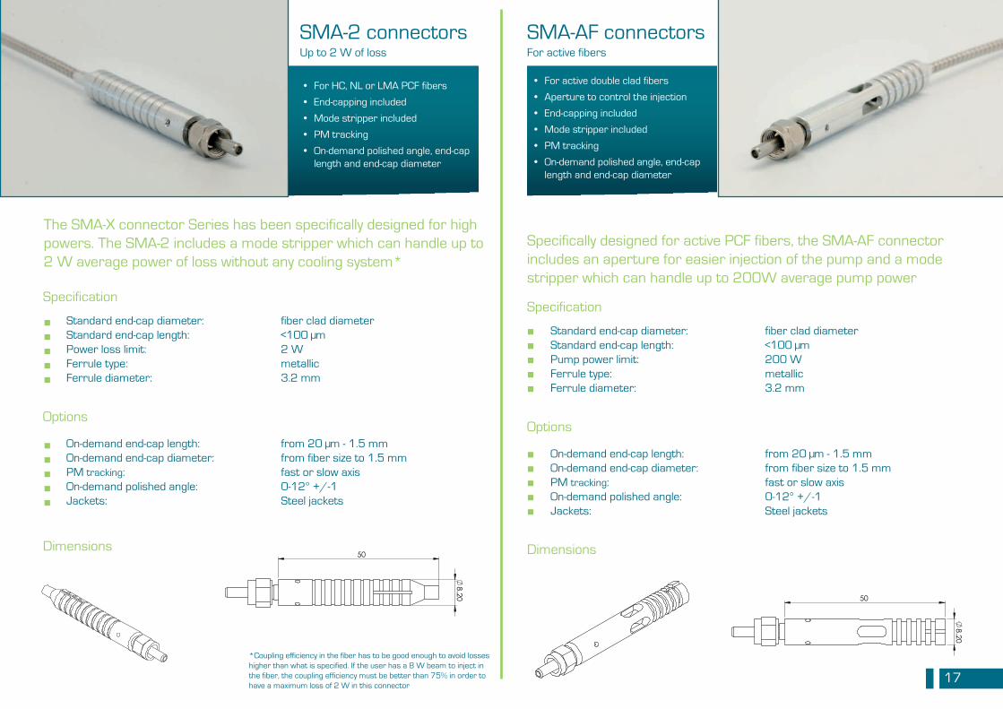
SMA-2 connectors
Specification
Dimensions
Standard end-cap diameter: fiber clad diameterStandard end-cap length: <100 µmPower loss limit: 2 WFerrule type: metallicFerrule diameter: 3.2 mm
Up to 2 W of loss
Options
On-demand end-cap length: On-demand end-cap diameter: PM tracking: On-demand polished angle: Jackets:
from 20 µm - 1.5 mmfrom fiber size to 1.5 mmfast or slow axis0-12° +/-1Steel jackets
8.20
50
8.20
50
SMA-AF connectors
Specification
Dimensions
Standard end-cap diameter: fiber clad diameterStandard end-cap length: <100 µmPump power limit: 200 WFerrule type: metallicFerrule diameter: 3.2 mm
Specifically designed for active PCF fibers, the SMA-AF connector includes an aperture for easier injection of the pump and a mode stripper which can handle up to 200W average pump power
For active fibers
Options
On-demand end-cap length: On-demand end-cap diameter: PM tracking: On-demand polished angle: Jackets:
from 20 µm - 1.5 mmfrom fiber size to 1.5 mmfast or slow axis0-12° +/-1Steel jackets
• For active double clad fibers
• Aperture to control the injection
• End-capping included
• Mode stripper included
• PM tracking
• On-demand polished angle, end-cap length and end-cap diameter
• For HC, NL or LMA PCF fibers
• End-capping included
• Mode stripper included
• PM tracking
• On-demand polished angle, end-cap length and end-cap diameter
The SMA-X connector Series has been specifically designed for high powers. The SMA-2 includes a mode stripper which can handle up to 2 W average power of loss without any cooling system*
■ ■ ■ ■ ■
■ ■ ■ ■ ■
■ ■ ■ ■ ■
■ ■ ■ ■ ■
*Coupling efficiency in the fiber has to be good enough to avoid losses higher than what is specified. If the user has a 8 W beam to inject in the fiber, the coupling efficiency must be better than 75% in order to have a maximum loss of 2 W in this connector
18
89.50
13 89.50
13
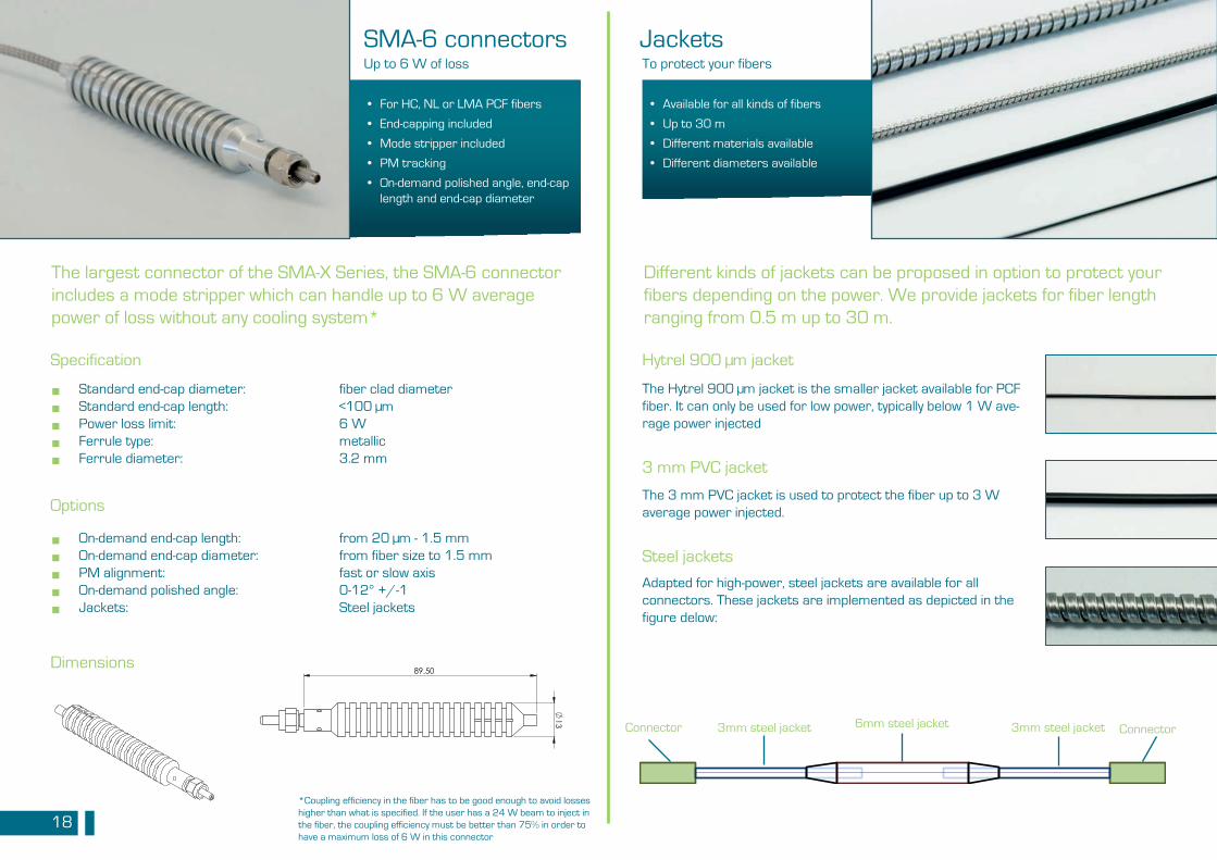
SMA-6 connectors
Specification
Dimensions
Standard end-cap diameter: fiber clad diameterStandard end-cap length: <100 µmPower loss limit: 6 WFerrule type: metallicFerrule diameter: 3.2 mm
Up to 6 W of loss
Options
On-demand end-cap length: On-demand end-cap diameter: PM alignment: On-demand polished angle: Jackets:
from 20 µm - 1.5 mmfrom fiber size to 1.5 mmfast or slow axis0-12° +/-1Steel jackets
• For HC, NL or LMA PCF fibers
• End-capping included
• Mode stripper included
• PM tracking
• On-demand polished angle, end-cap length and end-cap diameter
The largest connector of the SMA-X Series, the SMA-6 connector includes a mode stripper which can handle up to 6 W average power of loss without any cooling system*
Jackets
Hytrel 900 µm jacket
Steel jackets
Different kinds of jackets can be proposed in option to protect your fibers depending on the power. We provide jackets for fiber length ranging from 0.5 m up to 30 m.
3 mm PVC jacket
To protect your fibers
The Hytrel 900 µm jacket is the smaller jacket available for PCF fiber. It can only be used for low power, typically below 1 W ave-rage power injected
Adapted for high-power, steel jackets are available for all connectors. These jackets are implemented as depicted in the figure delow:
The 3 mm PVC jacket is used to protect the fiber up to 3 W average power injected.
Connector Connector3mm steel jacket 3mm steel jacket6mm steel jacket
• Available for all kinds of fibers
• Up to 30 m
• Different materials available
• Different diameters available
■ ■ ■ ■ ■
■ ■ ■ ■ ■
*Coupling efficiency in the fiber has to be good enough to avoid losses higher than what is specified. If the user has a 24 W beam to inject in the fiber, the coupling efficiency must be better than 75% in order to have a maximum loss of 6 W in this connector
19
20
FIBER SPLICING
21
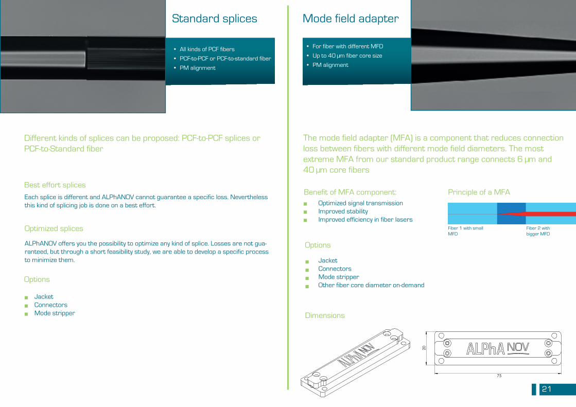
Standard splices
Best effort splices
Options
Optimized splices
Mode field adapter
Dimensions
The mode field adapter (MFA) is a component that reduces connection loss between fibers with different mode field diameters. The most extreme MFA from our standard product range connects 6 µm and 40 µm core fibers
Options
JacketConnectors Mode stripper Other fiber core diameter on-demand
• For fiber with different MFD
• Up to 40 µm fiber core size
• PM alignment
• All kinds of PCF fibers
• PCF-to-PCF or PCF-to-standard fiber
• PM alignment
Different kinds of splices can be proposed: PCF-to-PCF splices or PCF-to-Standard fiber
Each splice is different and ALPhANOV cannot guarantee a specific loss. Nevertheless this kind of splicing job is done on a best effort.
ALPhANOV offers you the possibility to optimize any kind of splice. Losses are not gua-ranteed, but through a short feasibility study, we are able to develop a specific process to minimize them.
JacketConnectors Mode stripper
20
75
Optimized signal transmissionImproved stabilityImproved efficiency in fiber lasers
Benefit of MFA component:
■ ■ ■
■ ■ ■
■ ■ ■ ■
Principle of a MFA
Fiber 1 with small MFD
Fiber 2 with bigger MFD
22
SPECIAL TERMINATION
23
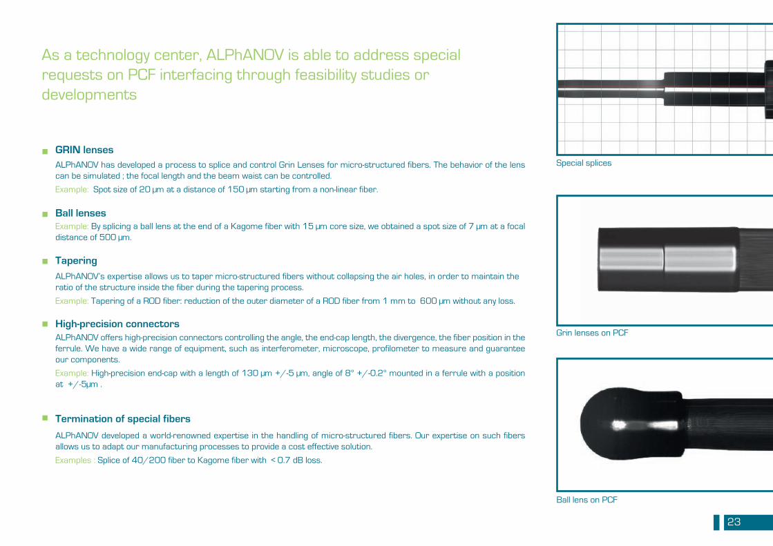
As a technology center, ALPhANOV is able to address special requests on PCF interfacing through feasibility studies or developments
GRIN lenses
Ball lenses
Tapering
High-precision connectors
Termination of special fibers
Grin lenses on PCF
Ball lens on PCF
■
■
■
■
■
Special splices
Example: By splicing a ball lens at the end of a Kagome fiber with 15 µm core size, we obtained a spot size of 7 µm at a focal distance of 500 µm.
ALPhANOV has developed a process to splice and control Grin Lenses for micro-structured fibers. The behavior of the lens can be simulated ; the focal length and the beam waist can be controlled.
Example: Spot size of 20 µm at a distance of 150 µm starting from a non-linear fiber.
ALPhANOV’s expertise allows us to taper micro-structured fibers without collapsing the air holes, in order to maintain the ratio of the structure inside the fiber during the tapering process.
Example: Tapering of a ROD fiber: reduction of the outer diameter of a ROD fiber from 1 mm to 600 µm without any loss.
ALPhANOV offers high-precision connectors controlling the angle, the end-cap length, the divergence, the fiber position in the ferrule. We have a wide range of equipment, such as interferometer, microscope, profilometer to measure and guarantee our components.
Example: High-precision end-cap with a length of 130 µm +/-5 µm, angle of 8° +/-0.2° mounted in a ferrule with a position at +/-5µm .
ALPhANOV developed a world-renowned expertise in the handling of micro-structured fibers. Our expertise on such fibers allows us to adapt our manufacturing processes to provide a cost effective solution.
Examples : Splice of 40/200 fiber to Kagome fiber with < 0.7 dB loss.
24
SPECIAL PUMP AND SIGNAL COMBINER For active microstructured Fibers
25
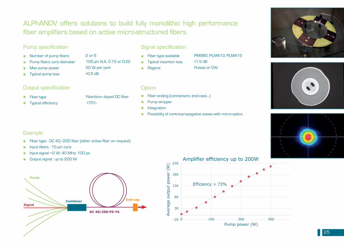
Efficiency > 73%
-20
30
80
130
180
230
0 100 200 300 400
Aver
age
outp
ut p
ower
(W
)
Pump power (W)
DC 40/200-PZ-Yb
Signal
Pump
Combiner End-cap
Amplifier efficiency up to 200W
ALPhANOV offers solutions to build fully monolithic high performance fiber amplifiers based on active micro-structured fibers
Number of pump fibers
Pump fibers core diameter
Max pump power
Typical pump loss
Fiber ending (connectors, end-caps...)
Pump stripper
Integration
Possibility of contra-propagative waves with micro-optics
Option
Pump specification
Fiber type : DC 40/200 fiber (other active fiber on request)
Input fibers : 15 µm core
Input signal ~2 W; 40 MHz; 100 ps
Output signal : up to 200 W
Example
■ ■ ■ ■
■ ■ ■ ■
■ ■ ■ ■
Fiber type available
Typical insertion loss
Regime
Signal specification
■ ■ ■
2 or 6
105 µm N.A. 0.15 or 0.22
50 W per port
<0.5 dB
PM980, PLMA10, PLMA15
<1.5 dB
Pulsed or CW
Fiber type
Typical efficiency
Output specification
■ ■
Ytterbium doped DC fiber
>70%
26
Fiber referenceFiber lengthQuantitiesDo you provide the fiber or not?
Fiber:
What termination would you like to have at each end of the fiber? What are the options that you need?Do you need a jacket around the fiber?
Treatment:
What average power will be injected in the fiber?What are the repetition rate, the wavelength and the pulse duration injected in the fiber?What is your application?
Condition of use:
Contact us and send us your [email protected]
In order to best answer your requests, here are the information we need to know:
27
MULTIBOARDbuild your own laser The ‘MultiBoard’ solution is a set of electronic cards dedicated to control various fiber lasers architectures. Thanks to its modularity, the ‘MultiBoard’ series gives fiber lasers the ability to reach a wide range of features: CW or pulsed, Q–switched or mode-locked operation, multistage MOPA, pulse-on-demand...
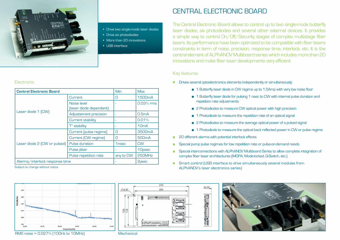
CENTRAL ELECTRONIC BOARD
• Drive two single-mode laser diodes
• Drive six photodiodes
• More than 20 innovations
• USB interface
The Central Electronic Board allows to control up to two single-mode butterfly laser diodes, six photodiodes and several other external devices. It provides a simple way to control On/Off/Security stages of complex multistage fiber lasers. Its performance have been optimized to be compatible with fiber lasers constraints in term of noise, precision, response time, interlock, etc. It is the central element of ALPhANOV Multiboard series which includes more than 20 innovations and make fiber laser developments very efficient
Key features
Drives several optoelectronics elements independently or simultaneously:
■ 1 Butterfly laser diode in CW regime up to 1.5Amp with very low noise floor
■ 1 Butterfly laser diode for pulsing 1 nsec to CW with internal pulse duration and repetition rate adjustments
■ 2 Photodiodes to measure CW optical power with high precision
■ 1 Photodiode to measure the repetition rate of an optical signal
■ 2 Photodiodes to measure the average optical power of a pulsed signal
■ 1 Photodiode to measure the optical back reflected power in CW or pulse regime
20 different alarms with potential interlock effects
Special pump pulse regimes for low repetition rate or pulse-on-demand needs
Special interconnections with ALPhANOV Multiboard Series to allow complete integration of complex fiber laser architectures (MOPA, Mode-locked, Q-Switch, etc.)
Smart control (USB interface to drive simultaneously several modules from ALPhANOV’s laser electronics series)
Electronic
RMS noise = 0.027% (100Hz to 10MHz)
Central Electronic Board Min Max
Laser diode 1 (CW)
Current 0 1500mA
Noise level(laser diode dependant)
- 0.03% rms
Adjustement precision - 0.5mA
Current stability - 0.01%
T° stability - 10mK
Laser diode 2 (CW or pulsed)
Current (pulse regime) 0 3500mA
Current (CW regime) 0 500mA
Pulse duration 1nsec CW
Pulse jitter - 10psec
Pulse repetition rate any to CW 250MHz
Alarms/interlock response time - 2µsecSubject to change without notice
■
■
■
■
■
Mechanical
29
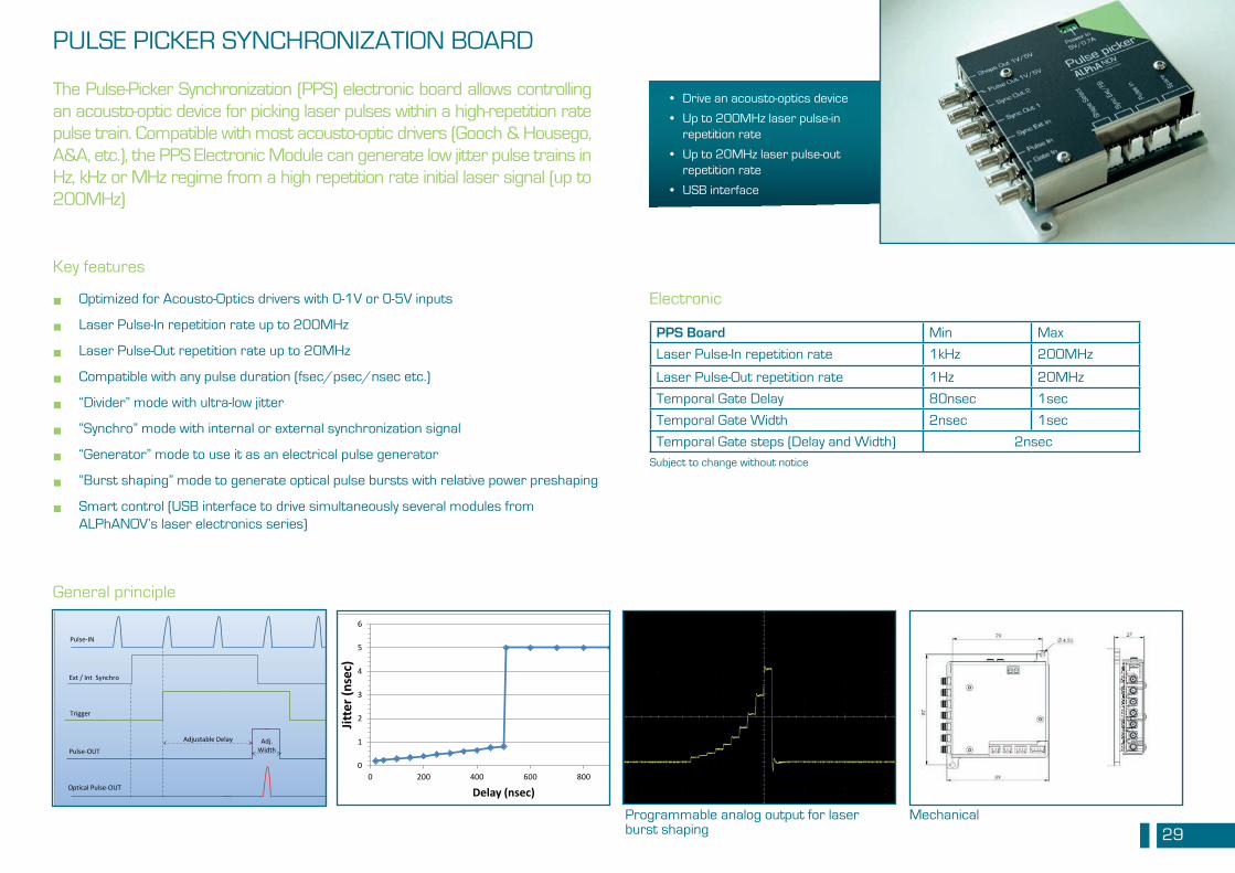
PULSE PICKER SYNCHRONIZATION BOARD
• Drive an acousto-optics device
• Up to 200MHz laser pulse-in repetition rate
• Up to 20MHz laser pulse-out repetition rate
• USB interface
The Pulse-Picker Synchronization (PPS) electronic board allows controlling an acousto-optic device for picking laser pulses within a high-repetition rate pulse train. Compatible with most acousto-optic drivers (Gooch & Housego, A&A, etc.), the PPS Electronic Module can generate low jitter pulse trains in Hz, kHz or MHz regime from a high repetition rate initial laser signal (up to 200MHz)
Key features
Optimized for Acousto-Optics drivers with 0-1V or 0-5V inputs
Laser Pulse-In repetition rate up to 200MHz
Laser Pulse-Out repetition rate up to 20MHz
Compatible with any pulse duration (fsec/psec/nsec etc.)
“Divider” mode with ultra-low jitter
“Synchro” mode with internal or external synchronization signal
“Generator” mode to use it as an electrical pulse generator
“Burst shaping” mode to generate optical pulse bursts with relative power preshaping
Smart control (USB interface to drive simultaneously several modules from ALPhANOV’s laser electronics series)
■
■
■
■
■
■
■
■
■
Electronic
PPS Board Min Max
Laser Pulse-In repetition rate 1kHz 200MHz
Laser Pulse-Out repetition rate 1Hz 20MHz
Temporal Gate Delay 80nsec 1sec
Temporal Gate Width 2nsec 1sec
Temporal Gate steps (Delay and Width) 2nsecSubject to change without notice
Programmable analog output for laser burst shaping
Trigger
Ext / Int Synchro
Adj. Width
Adjustable Delay
Pulse-IN
Pulse-OUT
Optical Pulse-OUT
General principle
0
1
2
3
4
5
6
0 200 400 600 800 1 000
Jitte
r (ns
ec)
Delay (nsec)
Mechanical
30
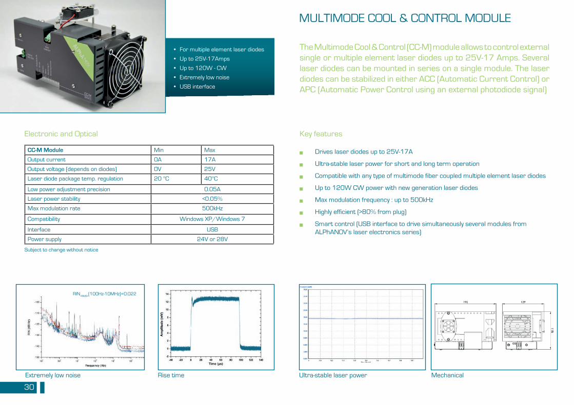
MULTIMODE COOL & CONTROL MODULE
• For multiple element laser diodes
• Up to 25V-17Amps
• Up to 120W - CW
• Extremely low noise
• USB interface
The Multimode Cool & Control (CC-M) module allows to control external single or multiple element laser diodes up to 25V-17 Amps. Several laser diodes can be mounted in series on a single module. The laser diodes can be stabilized in either ACC (Automatic Current Control) or APC (Automatic Power Control using an external photodiode signal)
Key features
Drives laser diodes up to 25V-17A
Ultra-stable laser power for short and long term operation
Compatible with any type of multimode fiber coupled multiple element laser diodes
Up to 120W CW power with new generation laser diodes
Max modulation frequency : up to 500kHz
Highly efficient (>80% from plug)
Smart control (USB interface to drive simultaneously several modules from ALPhANOV’s laser electronics series)
■
■
■
■
■
■
■
CC-M Module Min Max
Output current 0A 17A
Output voltage (depends on diodes) 0V 25V
Laser diode package temp. regulation 20 °C 40°C
Low power adjustment precision 0.05A
Laser power stability <0.05%
Max modulation rate 500kHz
Compatibility Windows XP/Windows 7
Interface USB
Power supply 24V or 28V
Subject to change without notice
Electronic and Optical
Ultra-stable laser powerRise timeExtremely low noise
RIN<RMS>
(100Hz-10MHz)=0.022
Mechanical
31
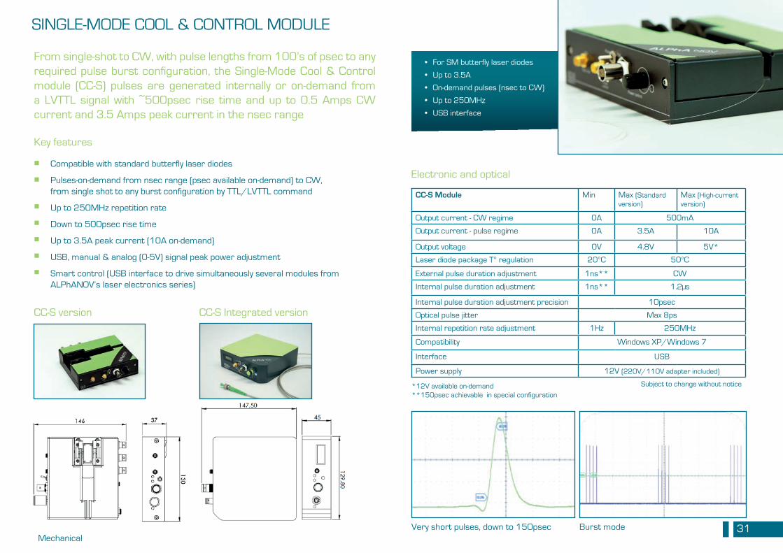
SINGLE-MODE COOL & CONTROL MODULE
• For SM butterfly laser diodes
• Up to 3.5A
• On-demand pulses (nsec to CW)
• Up to 250MHz
• USB interface
From single-shot to CW, with pulse lengths from 100’s of psec to any required pulse burst configuration, the Single-Mode Cool & Control module (CC-S) pulses are generated internally or on-demand from a LVTTL signal with ~500psec rise time and up to 0.5 Amps CW current and 3.5 Amps peak current in the nsec range
Key features
Compatible with standard butterfly laser diodes
Pulses-on-demand from nsec range (psec available on-demand) to CW, from single shot to any burst configuration by TTL/LVTTL command
Up to 250MHz repetition rate
Down to 500psec rise time
Up to 3.5A peak current (10A on-demand)
USB, manual & analog (0-5V) signal peak power adjustment
Smart control (USB interface to drive simultaneously several modules from ALPhANOV’s laser electronics series)
■
■
■
■
■
■
■
Electronic and optical
CC-S Module Min Max (Standard version)
Max (High-current version)
Output current - CW regime 0A 500mA
Output current - pulse regime 0A 3.5A 10A
Output voltage 0V 4.8V 5V*
Laser diode package T° regulation 20°C 50°C
External pulse duration adjustment 1ns** CW
Internal pulse duration adjustment 1ns** 1.2µs
Internal pulse duration adjustment precision 10psec
Optical pulse jitter Max 8ps
Internal repetition rate adjustment 1Hz 250MHz
Compatibility Windows XP/Windows 7
Interface USB
Power supply 12V (220V/110V adapter included)
*12V available on-demand**150psec achievable in special configuration
Subject to change without notice
Burst modeVery short pulses, down to 150psec
CC-S version CC-S Integrated version
Mechanical
ALPhANOVInstitut d’optique d’AquitaineRue François Mitterrand 33400 Talence - France
Tél. : +33 (0)5 24 54 52 [email protected]
www.alphanov.com
Photos : ALPhANOV, NKT photonics
In partnership with