pedestrian bridges
TRANSCRIPT

Sudan University of Science and Technology
Collage of Engineering
Department of Civil Engineering
A Research Submitted in Partial Fulfillment for the Requirement of
the Degree of B.Sc. in Civil Engineering
(Structures)
Prepared by:
Azzam Mohamed Ibrahim
Ibrahim Ahmed Adam
Mohamed Subhi Hussain
Supervised by:
T. Tahani Mohamed El-Amen
September 2016

i
الايه بسم هللا الرمحن الرحمي
احتمل درها ف
بق
ودية
ت أ
سال
ماء ماء ف نزل من الس
﴿أ
اء الار ابتغ يه في الن
ا يوقدون عل ابيا ومم يل زبدا ر س
حق ه ال
لك يضرب الل
ذ
ه ك
لث و متاع زبد م
ية أ
حل
اس ع النا ما ينف م
اء وأ
هب جف
يذ
بد ف ا الز م
أباطل ف
وال
ف
ثيمك
ال﴾ف
مث
ه ال
لك يضرب الل
ذ
رض ك
ي ال
صدق اهلل العظيم رعـــــــــدورة الـــس
17الآية

ii
هداءإال إلى رمز الحب وبلسم الشفاء ... إلى من أرضعتني الحب والحنان
إلى الروح التي سكنت روحي
والدتي الحبيبة الناصع بالبياضإلى القلب
إلى الوالده الحاضره الغائبه امال دفع هللا
إلى من كلت أنامله ليقدم لنا لحظة ... إلى من جرع الكأس فارغا ليسقيني قطرة حب
سعادة
إلى من حصد األشواك عن دربي ليمهد لي طريق العلم
والدي العزيز إلى القلب الكبير
أخواني وإخوتي الطاهرة الرقيقة والنفوس البريئة إلى رياحين حياتيإلى القلوب
اآلن تفتح األشرعة وترفع المرساة لتنطلق السفينة في عرض بحر واسع مظلم هو بحر الحياة
وفي هذه الظلمة ال يضيء إال قنديل الذكريات ذكريات األخوة البعيدة إلى الذين أحببتهم
أصدقائي وأحبوني
دروبنا بالعلم والمعرفة " اساتذتي" الى من اناروا
. ن نبيل, وامين. ,, في هذا الوطن الى من يتجدد معهم العطاء واالمل ..لكل إنسا

iii
We dedicate this project to our parents for the
love and support they have provided
throughout our entire life, they have been there
for every decision we have made and help our
dreams become reality, to our friends and
families for their help and encourage.

iv
الشكر والعرف ان
لى أعوام قضيناها في رحاب الجامعة مع أساتذتنا البد لنا ونحن نخطو خطواتنا األخيرة في الحياة الجامعية من وقفة نعود إ ... الكرام الذين قدموا لنا الكثير باذلين بذلك جهودا كبيرة في بناء جيل الغد لتبعث األمة من جديد
... وقبل أن نمضي قدما نقدم أسمى آيات الشكر واالمتنان والتقدير والمحبة إلى الذين حملوا أقدس رسالة في الحياة ... الذين مهدوا لنا طريق العلم والمعرفةإلى
...إلى جميع أساتذتنا األف اضل
ونخص بالتقدير والشكر لمشرفنا أ. تهاني محمد االمين
، ، إلى من وقف إلى جانبنا لمساندته لنا مهندس. منتصر بوزارة الطرق والجسور الإلى توجه بخاص الشكر نكما أننا
...احتجنا اليهم عندما

v
In the first of all with sincere thankful and confesses of
credited to ALLAH for healthy and wellness.
Any project doesn’t end without active or passive support
from person’s surrounding or closed to you. We would like
to gratitude T. Tahani Mohamed El-Amen for his advices,
guidance, and ample time to help us to finish this project.
With practical gratefulness to Mohammed El-Hassan for
great supporting and assistances.
With deep Thanks to our parents for encouragement and
moral impulse. My prayers for all of them.
The thanks extended to the staff of structure department for
practical help.
We would also like to thank our friends, for stand and feel
integral with us.

vi
Abstract
This work aims to analysis and design for a pedestrian bridge for people
and bicycles in Khartoum state on Africa street near institute of evidently
relationships, and that is with using manual methods for analysis and
design and using sap 2000 and robot 2015 programs then make a
comparative between them.
التجريد
يهدف إفريقياعلى شارع بمدينة الخرطوم محلية الخرطوم جات وذلك إلى تحليل وتصميم جسر للمشاه وللدرا العمل هذا
استخدام طرقببالقرب من العالقات البينيه و 2000طريق استخدام برنامجي ساب يدويه ثم عن والتصميم ال التحليل
ومقارنة النتائج 2015روبوت .بينهم

vii
Table of Contents
i الايه
ii الإهداء
iii
والعرف ان الشكر iv
v
Abstract vi
vi التجريد
List of tables ix
List of figures x
List of Symbols xi
1 Chapter One: Introduction .......................................... 1
1.1Overview 1
1.2 Aim and Objectives 2
1.3 Problem Statement 2
1.4 Proposed Solution 3
1.5 Motivation 3
1.6 The Methodology 3
1.7 Outlines 4
2 Chapter Two: Literature Review
2.1 Introduction 5
2.1.1 Bridges 5
2.1.2 Types of Bridge by Traffic: 5
2.1.3 Types of Bridge by Traffic Position: 5
2.1.4 Types of bridges by Material & Fabrications 6
2.1.5 Types of Bridge by Structure: 7
2.2 Pedestrian Bridges: 10
2.2.1 previous studies: 10
2.2.2 Materials of pedestrian bridges: 11

viii
2.2.3 Loads of pedestrian bridges: 12
3 Chapter three: analysis & design using the programs
3.1 SAP2000 15

ix
List of tables
Table 2-1 Base Pressure according to AASHTO LRFD ............................. 14

x
List of figures
Figure 1-1 Location of the pedestrian bridge .................................................. 2
Figure 1-2 Real view of the location ................................................................ 3
Figure 2-1 Deck Type bridge ............................................................................. 6
Figure 2-2 Half-through type bridge ................................................................. 6
Figure 2-3 Arch bridge ........................................................................................ 7
Figure 2-4 A beam simply supported on each side by a pier ....................... 8
Figure 2-5 Cable-Stayed Bridge ........................................................................ 9
Figure 2-6 A footbridge at Firepool, UK ....................................................... 10

xi
List of Symbols
Alphabetic Symbols
P B: base wind pressure
RC: Reinforced Concrete
PC: Pre-Stressed Concrete
Greek Letters
Shear Stress (Pa)
: Density (Kg/𝐦𝟑)
Viscosity (Pa.s)
: Boundary layer thickness
Abbreviations
SUST: Sudan University of Science and Technology
LFRD: Load & Resistance Factor Design
UK: United Kingdom

1
1 Chapter One: Introduction
1.1 Overview
Pedestrian Bridges all over the world offer an aesthetically creative and
technically innovative array of structures for student study. Such bridges
(especially in cities) are highly visible to the tourist and the citizen alike.
Bridges reveal and to show their structural form much more clearly than
most buildings do, and this makes them ideal teaching tools. Furthermore,
the AASHTO Guide Specifications for Design of Pedestrian Bridges
represent a manageable introduction to formal engineering design for a
semester long project. Students undertook conceptual design of pedestrian
bridges. After a class wide study of innovative precedents, they worked in
small groups and were required to choose and analyze a site, and propose
an initial structural plane. A minimum clear span was required to push
more ambitious spanning strategies. They then performed a Finite Element
Analysis and sized all the primary structural members of the bridge.

2
1.2 Aim and Objectives
Aim: Help in solving problems of accidents due to crossing the main
roads in Sudan, and encourage continued undergraduate and postgraduate
projects of Analysis & Design of pedestrian Bridge at the Sudan University
of Science & Technology.
Objectives: The researchers specified the project objectives as:
Identification of the types of bridges.
Analysis of pedestrian bridge.
Manual design for a pedestrian bridge according to AASHTO LRFD
2010.
Analysis a pedestrian bridge using SAP2000 program.
Analysis and design by robot structural analysis professional 2015.
Compare between the manual design and the programs design.
1.3 Problem Statement
There was a big problem in highways due to crossing, which causing
crowding and at the same time causing seriousness for people whom try to
crossing.
Figure 1-1 Location of the pedestrian bridge

3
Figure 1-2 Real view of the location
1.4 Proposed Solution
Provide Pedestrian Bridges at the highways.
1.5 Motivation
Pedestrian Bridges are one of the advanced structures in the world and
it makes many solutions in the issue of crowding.
1.6 The Methodology
Viewing the published literatures about pedestrian bridges, types of
pedestrian bridges and methods of analysis and design of pedestrian
bridges.
Apply analysis and design operation using the American standards
(ACI318-11) & AASHTO LRFD 2010.
Using Sap 2000 program for analysis and Robot 2015 program for
analysis and design.
Comparison of results and then get recommendations.
4
1.7 Outlines
Chapter one include: Introduction, aim of the Project, objectives,
motivation, contribution, problem statement, proposed solution, and
methodology.
Chapter two include: Literature review.
Chapter three include: analysis & design using the programs.
Chapter four include: The manual design.
Chapter five include: Results and discussion.
Chapter six include: Conclusion & recommendations
References& appendix.

5
2 Chapter Two: Literature Review
2.1 Introduction
2.1.1 Bridges
A bridge may be defined as a structure used to carry loads over an opening,
which may take the form of a valley or stream, a road or railway. One way
to cross a valley is to build an embankment which effectively closes the
opening. Such a structure is not a bridge, and it is important to recognize
that the opening crossed by the bridge generally performs a function in
itself, which must be maintained.
•A bridge is a structure that is used to cross some form of barrier, making
it easier get to one place from another.
•Other barriers, such as rivers, have always confronted travelers and traders
who wanted to take the shortest t, quickest and safes t route to complete
their journeys.
2.1.2 Types of Bridge by Traffic:
1- Highway bridge (trucks, cars)
2- Pedestrian bridge (pedestrians, bicycles)
3- Railway bridge(trains)
4-Transit guideway (city trains, monorail)
Other types (pipelines utilities industrial aqueduct airport structure)
investigations is important in aircraft industry; since the Aircraft
invention at nineteenth century, there are many experiments were done
without investigations, but it was not successful, to resolve this two
method of investigations are used.
2.1.3 Types of Bridge by Traffic Position:
2.1.3.1 Deck type bridges:
1- Structural components under the deck
2- Preferred by drivers (can clearly see the view)

6
3- Requires space under the bridge
Figure 2-1 Deck Type bridge
2.1.3.2 Through type bridges:
1- Structural components above the deck.
2- Obstructed view (not a problem for railway bridges).
3- No structure under the bridge.
Figure 2-2 Half-through type bridge
2.1.4 Types of bridges by Material & Fabrications:
2.1.4.1 Materials:
Masonry (brick, rock) bridges -
Timber bridges -
Reinforced Concrete (RC) bridges -
Pre-stressed Concrete (PC) bridges -
Iron bridges -
Steel bridges -
Aluminum bridges -
Composites bridges -

7
Plastics bridges -
-Etc...
2.1.4.2 Fabrications:
Precast (RC/PC) bridges -
Cast-in-place (RC/PC) bridges -
Pretension (PC) bridges -
Posttensioned (PC) bridges -
Prefabricated(steel) bridges -
Rivet (steel) bridges -
Bolted (steel/ timber) bridges -
Welded (steel) bridges -
-Etc…
2.1.5 Types of Bridge by Structure:
2.1.5.1 Arch bridge:
a bridge having a curved structure. The arch design provides strength by
exerting force downwards and sideways against the abutment as shown in
figure (2.3).
Figure 2-3 Arch bridge
Advantages:
a) Aesthetically pleasing.
b) Design has yet to be done on the IPFW campus.
c) Can easily be covered.
d) Construction can be formed to minimize the impact to traffic on
Coliseum Boulevard – many of the pieces can be prefabricated.
e) Due to span, cost effective given the bridges requirements.
f) If designed as a parabolic arch, all forces in the arch axial.
8
Disadvantages:
a) Large horizontal forces applied to the foundations from the arch
b) Uses large amounts of steel.
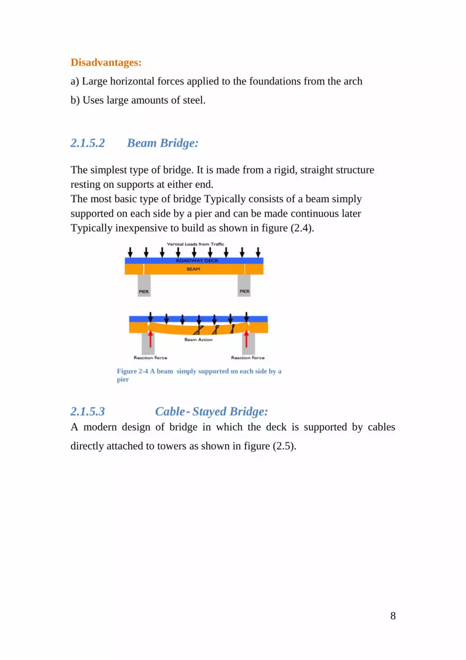
2.1.5.2 Beam Bridge:
The simplest type of bridge. It is made from a rigid, straight structure
resting on supports at either end.
The most basic type of bridge Typically consists of a beam simply
supported on each side by a pier and can be made continuous later
Typically inexpensive to build as shown in figure (2.4).
2.1.5.3 Cable‐ Stayed Bridge:
A modern design of bridge in which the deck is supported by cables
directly attached to towers as shown in figure (2.5).
Figure 2-4 A beam simply supported on each side by a
pier

9
Figure 2-5 Cable-Stayed Bridge
Advantages:
a) Aesthetically pleasing.
b) Ability for long clear spans.
c) Modern style of bridge construction.
Disadvantages:
a) Need adequate spacing on either side of columns to reduce eccentric
loading.
b) Covering takes away from the appeal of the design.
c) More cost effective for long spans/not for this short of a span.
d) Difficult to construct
e) Already one on the IPFW campus (crossing the St. Joseph River).
2.1.5.4 Cantilever Bridge:
Similar to the beam bridge, this design gets its support from
counterbalanced beams meeting in the middle of the bridge rather than
from supports at either end. The two arms of the beam are called
cantilevers.
In a cantilever bridge, the roadway is constructed out from the pier in two
directions at the same time so that the weight on both sides counterbalance
each other.

10
Notice the larger section at the support to resist negative moments
2.1.5.5 Suspension Bridge:
A type of bridge in which the deck hangs from wires attached to thick
cables. The cables themselves Pass over towers and are securely anchored
in concrete anchorages.
Suspension bridge needs to have very strong main cables.
Cables are anchored at the abutment -abutment has to be massive.
2.2 Pedestrian Bridges:
A footbridge (also called a pedestrian bridge, pedestrian overpass, or
pedestrian overcrossing) is a bridge designed for pedestrians and in some
cases cyclists.
2.2.1 previous studies:
- A footbridge is located at Firepool, Taunton, Somerset, UK. It is located
between the Rive Tone and Taunton/Bridgewater Canal at 2010 they used
a cable stayed pedestrian bridges over 60m span with a single and a
carriageway of width 3.5m.
The preliminary design aimed to achieve maximum ratio between the main
span and the back span whist ensuring minimum or no uplift in the backstay
anchorage and satisfying the aerodynamic stability requirements of BD.
The static, dynamic and non-linear analysis of the structure was carried out
using LUSAS 14.1 software. The structural model is shown in Figure
(2-6).
Figure 2-6 A footbridge at Firepool, UK

11
- Research (Group Members: Renan Constantino Chris Ripke and James
Welch;2009), showed that with pedestrian travel over Coliseum Boulevard
being as dangerous as it is, the group feels that the best possible way in
ensuring safe travel over this roadway is by constructing a pedestrian
bridge. In addition to helping pedestrians safely cross over Coliseum
Boulevard, the structure should be of an innovative design the most
suitable type of bridge to meet the needs of this structure is of an arch style
design. With an overall span of 210’ and a height off of the footer of 40.5’,
Utilizing steel and concrete for the major design members, erection of the
structure would proceed quickly due to the ability of most of the main
components being prefabricated off of the job site.
- A footing bridge is located in Al-mataar street in front of main gate of the
airport the bridge is over a span of 31.5 m, and it’s not design to carry
lateral loads which caused a vibrations an instability of the bridge which
make it unfit to use.
2.2.2 Materials of pedestrian bridges:
According to AASHTO LRFD Bridge Construction Specifications, all
materials and tests must conform to the appropriate standards included in
the AASHTO Standard Specifications for Transportation Materials and
Methods of Sampling and Testing and/or the standards of the American
Society for Testing and Materials.
- Masonry (brick, rock) bridges
- Timber bridges:
Nominal resistance for wood products shall be based on specified size and
conditions of use with respect to moisture content and time effect.
- Reinforced Concrete (RC) bridges:
Designs should be based on the material properties cited herein and on the
use of materials that conform to the standards for the grades of construction

12
materials as specified in AASHTO LRFD Bridge Construction
Specifications.
- Pre-Stressed Concrete (PC) bridges
- Iron bridges
- Steel bridges:
Structural steels shall conform to the requirements and the design shall be
based on the minimum properties indicated.
- Aluminum bridges
- Composites bridges
- Plastics bridges
2.2.3 Loads of pedestrian bridges:
It is usual to treat cycle loads and pedestrians together. The pedestrian
loading dominates due to its more mobile and compact nature; Pedestrian
loading encompasses a number of forms. The static loading due to a
particular density of pedestrians is well known. The loads placed on
handrails, less obvious loads are due to a single person. A vandal, or groups
of vandals, could apply unusual loads to the structure, which could damage
it. Due to the flexibility of footbridges, vibration of the bridge due to a
single person walking over it or due to deliberate activity by some people
must also be considered. Vibration may occur in either the vertical or
horizontal directions; it can cause discomfort for some sections of the
community and this must be guarded against. by groups of people or by a
crush of people require consideration.
Consideration must be given to the likely usage of a footbridge and its
maintenance. If a footbridge is in a remote site, e.g. a park, it is unlikely to
suffer loading from a crowd of people. However, it may be used by a
vehicle maintaining a park, to access all areas of the park.

13
Either this must be considered in the design or special steps must be taken
to prevent use of the footbridge by vehicles. In the case of a major, large
span footbridge, crossing a river in a central city area, higher usage of the
bridge should be expected. The bridge may be used for special events such
as viewing fireworks or regattas on a river. Maintenance of this type of
bridge is also likely to be a major consideration as it is unlikely that the
bridge can be maintained by any means other than from the bridge itself.
Pedestrian bridges shall be designed in accordance with the requirements
of the AASHTO LFRD Guide Specifications for the Design of Pedestrian
Bridges, dated Seismic design of pedestrian bridges shall be performed in
accordance with the requirements of the AASHTO Guide Specifications
for LRFD Seismic Bridge Design.
A. Dead Load: Dead loads are those loads that are permanently applied to
the structure. For the pedestrian bridge that is being designed, there are
three sources for the dead load: the weigh and the weight of notice boards.
B. Live Load: The live loads applied to the bridge are variable loads
applied to the bridge that are in addition to the dead loads on the structure.
There are three live loads applied to the bridge: the live load for peoples
C. Service Vehicle Load: In addition to the uniform live and dead loads
applied to the bridge, the bridge must also be designed to carry the loading
of a moving service vehicle. A designated service vehicle is needed in the
design of the bridge in case there is an emergency vehicle needs to cross
over the structure, or if a maintenance vehicle needs to access the walkway
(i.e. removal of snow on the concrete deck). As detailed in AASHTO
LRFD Bridge Design Specifications, with the walkway on the bridge being
only 10 ft wide, the code recommends using an H5 design service vehicle,
as shown in Figure 1 6. Further, the AASHTO code states that the service
vehicle load is not applied in combination to the pedestrian live load.
Figure 2.5 standard service or maintenance vehicle.

14
D. Wind Loads: For the usual girder and slab bridges with less than 30′
height above ground, the following simplified wind pressure on structure
(WS), could be used in lieu of the general method described in AASHTO
LRFD Article 3.8.1.2.
If justified by local conditions, a different base design wind velocity may
be selected for load combinations not involving wind on live load. The
direction of the design wind shall be assumed to be horizontal, unless
otherwise specified in AASHTO LRFD Article 3.8.3. In the absence of
more precise data, design wind pressure, in ksf, may be determined as:
PD=PB*(𝑉𝐷𝑍
𝑉𝑩)
2=
𝑃𝐵𝑉𝐷𝑍2
10000… … … … … … … … … … … … … … … … … … … . . (2‐1 )
Table 2-1 Base Pressure according to AASHTO LRFD
Super structure
component
Windward load, ksf Leeward load, ksf
Trusses, Columns and
Arches
0.05 0.025
Beams 0.05 NA
Large Flat Surfaces 0.05 NA
PB corresponding to VB=100 mph

15
3 Chapter three: analysis & design using the
programs
3.1 SAP2000
Founded in 1975 by now company President Ashraf Habibullah,
Computers & Structures, Inc. (CSI) is a worldwide leader in the
development of software used in the design and analysis of civil
engineering structures. Instead of producing software that can be used for
a generalized range of structures, CSI tailors their programs to be tailored
to specific classes of structures. SAP2000, the software used in the analysis
of the pedestrian bridge, is intended for use on structures such as bridges,
dams, stadiums, industrial structures, and buildings. Other titles produced
by CSI include: ETABS, software used mainly for building, and the SAFE
System, a powerful program used to design and analyze concrete slabs and

16
foundations. SAP2000’s power comes in its amazing flexibility. From the
simplest design of a two dimensional frame, to a complicated bridge in
three dimensions, to the “Bird’s Nest” (Chinese National) Stadium from
the Games of the XXIX Olympiad, it can be seen that vast power that lies
within this software package. Its true strength is in its various analysis
options: linear, nonlinear, static and dynamic analysis of two and three
dimensional structures. The advanced features of SAP2000 allow for a
structure to be analyzed even when a material no longer falls in the linear
range where Hooke’s Law is valid (stress is no longer proportional to
strain). Students in the civil engineering program at IPFW are first
introduced to SAP2000 in CE 375: Structural Analysis and then further
explore the depths of the software in two more courses: CE 376: Design of
Concrete Structures, and CE 475 Design of Steel Structures. In addition to
these three courses, the software was used extensively in the entire Senior
Design Project. Throughout these courses, the basic steps in designing a
structure are taught while learning the interface of the SAP2000 software.
Any structural design which can be completed in SAP2000 may be broken
into four steps:
a) Modeling
Upon creating a new file, the software prompts the user with a screen
asking for the user to define a new model. The user can either define a new
model and grid system themselves, or they can choose a predefined
template such as a beam, 2-d or 3-d truss, 3-d frame, etc. If creating a new
model with a user defined 3-d grid, it is advised to carefully define a grid
that allows for the model to be correctly defined. By taking a few extra
minutes setting up the initial grid, the user can save a tremendous amount
of time later on in the modeling of the structure. After the grid is set, it is
now time for the user to start the actual design of the structure. Prior to
placing members in the model, the materials the user wishes to use in the

17
structure must be defined. Defining materials is easily done through the
software which has built into the system a database that has numerous
shapes and sizes of steel and aluminum members that are used by different
agencies throughout the world. Once the materials are defined, a member’s
shape or material can simply be changed by a dialog box which will then
modify the mechanical properties of the member. In addition to frame
members, cables, and tendons, the user can also define shells and planes
that may be used in a structure. The materials that are defined for use in the
shell or plane are also easily defined through the built in database.
Once all members and materials are defined (they can be revised at any
time), the structure can then be drawn on the grid system. After the
correctly dimensioned structure is on the grid, pre-analysis activities are
completed to accurately model the structure. These steps include: meshing
any objects together so that they act like one continuous member, correctly
setting any constraints, and/or restraints to joints to precisely model the
joint if it may be a pinned or fixed connection for example, and applying
any releases to the member’s in order to apply internal force releases at a
given point. The last step in modeling the structure is to determine the loads
that will be applied to it. SAP2000 allows for live, dead (which includes
the structures self-weight), moving, earthquake, wind, etc. loads that can
be analyzed both separately as well as concurrently according to AASHTO
LRFD specifications. With these loads in place, the user can then proceed
to the analysis of the structure.
b) Analysis
If the user has taken the time to meticulously set up an accurate model of
the structure, analysis of the structure becomes streamlined. With the
loading conditions already applied to the model, all the user must do is
determine which load cases they would like to run (any or all of them), and
then they simply press the “Run Now” button. While SAP2000 is analyzing
18
the structure, a dialog box is displayed on the computer screen showing the
status of the analysis. It is on this screen that the program will inform the
user whether the structure was successfully analyzed, or if there was an
error. If the user is just performing a linear, static analysis, the program
may only take a few seconds before the analysis output may be displayed;
however, if a nonlinear or dynamic analysis is performed, the user may
wait much longer for the structural analysis to be completed. In some cases,
numerous iterations may be needed in order for an acceptable convergence
value to be established.
c) Display
Following the completed analysis of the structure, the user is then able to
view the mechanical behavior of the structure. For every different display
options that can be selected, the user is given the option to view the results
per the selected loading condition. Once the analysis finishes the default
view of the structure is its deformed shape. This display can be extremely
convenient to visualize the effects of the applied loads on the structure, and
if the deformation agrees with the anticipated results of the loading. If there
is an error in how the model is designed, it may be obvious by erratic results
of the deformed shape of the structure. The other option for the display is
to show the resultant forces for the joints, frames/cables, and shells. If the
“Joint” display is chosen, the forces acting on that joint for the given
loading condition is displayed on the screen. These results can then be used
for the design of the supporting structure, whether it be a foundation, or
any other type of support required. For the frames/cables force option, the
user is given various options to view different forces acting on the member
which include: axial force, torsion, shear 2-2, shear 3-3, moment 2-2, and
moment 3- 3. An additional option for the forces is to either show the actual
values on the structure itself, or to just display a filled diagram representing
the corresponding force acting on the member. Much like the deformed

19
shape display, this view allows the user to visually determine if the
structure is acting accordingly to the design load cases acting on it. If the
designed structure has any shell objects, the final display option is to view
the forces acting on these shell elements. Options for the shell force
diagram includes: the component types may it be resultant forces, shell
stresses, or concrete design; output type for visible, top, or bottom face as
well as whether they are the maximum or minimum values; and, the forces
in the components, whether they be the various layers of concrete, or the
reinforcement steel in the concrete.
d) Design
If the mechanical behavior of the structure is deemed to be accurate, the
final step in SAP2000 is the actual design of the structure. An extremely
useful feature of the software is that the user can define a list of member
shapes and sizes that the program can choose between to safely support the
forces per the given loading combinations. This feature eliminates the need
for the user to manually go back and forth choosing different sized
members by a trial and error approach. Instead, the user can allow the
program to optimize the steel design members. This can save the designer
hours of their time. All the user has to do when they feel that they are ready
to start the design of the structure is to select the correct design option (steel
frame, concrete frame, or aluminum frame), and the software will go
through and design the structure. After all members are analyzed, the
resulting screen will show the corresponding size of the member as well
as, judging by the member’s color, whether or not the member passed the
design standards. When the design is complete, it is highly advised to run
the option, “Verify Analysis vs. Design Section” to determine if the
analyzed members are the same as the design sizes which will affect the
dead load of the structure. If the members are found to differ, all the user

20
needs to do is rerun the analysis as well as the design of the structure,
repeating these two steps until the analysis and design members converge.