short–span bridges – leading australian innovations
TRANSCRIPT
Creating and Renewing Urban Structures 1
Short–Span Bridges – Leading Australian Innovations
Frank Rapattoni Technical Executive - Bridges Parsons Brinckerhoff Melbourne, Australia [email protected]
Frank Rapattoni, born 1950, received his Bachelor of Civil Engineering from Swinburne Institute of Technology. He joined Parsons Brinckerhoff after extensive experience in the design, construction and development of bridges in VicRoads, BHP Steel and Cardno.
Summary Australia has one of the most extensive road networks in the world with some 37,000 bridges. The bridges have relatively short spans by comparison with other continents. Bridge engineering has undergone a significant evolution in the past decade. New developments have led to reduction in costs, improvements in safety and lower environmental impact. The development of the prestressed concrete Super T-beam system has made the greatest impact capturing a large market share in a short time. Advances in the design and construction of steel bridges have also made these more competitive. Perhaps the most significant innovation is the “pier-redundant” bridge, a concept with unmatched safety in the event of pier collapse. These developments have potential application in the USA and around the world. Keywords: Precast beams, prestressing, standardisation, safety, pier redundancy, surface coating, deck formwork, composite steel bridges.
1. Introduction Australia is a vast country with a largely flat topography. It is known as the driest continent on Earth with few large rivers and many small ephemeral streams. It has one of the most extensive road networks in the world comprising more than 800,000 km of public roads – from tracks to local roads, arterials, highways and major freeways and the total number of road, rail and pedestrian bridges is little more than 37,000 [15] or one every 22km approximately. Developments of short-span bridges in the last decade have led to reduction in costs, improvements in safety and lower environmental impact. Some of these are considered to be at the leading edge of short-span bridge engineering. The development of the prestressed concrete Super T-beam system has made the greatest impact and advances in the design and construction of steel bridges also made these more competitive. One of the most significant innovations is the “pier-redundant” bridge concept which provides an unmatched level of safety by avoiding total bridge collapse in the event of pier failure. In this paper I will discuss the background to the developments and key benefits of these systems, their use both in Australasia and their potential application in the USA and world-wide.
2. Overview of Australian Bridges The number of road bridges on National Highways and Arterial Roads is around 14,000. Based on deck area, 77% have superstructures in concrete, 18% in steel and 5% in timber [15]. For the overall road network, the respective percentages are 55% in concrete, 15% in steel and 30% in timber. Most timber bridges were constructed in the early 1900’s and are now found mostly on local roads. Australian bridges have relatively short spans with 95% of all bridges having spans less than 40m and more than 80% less than 20m. The longer spans are used mainly in grade separations on freeways and some of the larger rivers.
2 17TH CONGRESS OF IABSE, CHICAGO, 2008
2
The bridge industry is relatively small by comparison with other continents. State Road Authorities played a leading role in some of the developments aiming to achieve a high level of standardisation. The steel industry played a significant role in the recent advancement of steel bridge engineering through the development of design aids, research and promotion of best practices.
3. Leading Innovations
3.1 Prestressed Concrete Super T-Beams
3.1.1 Background Prestressed concrete Super T-beams are by far the most popular bridge beams used in Australia for spans ranging from 10 to 38m. Their development began with the inception of T-slabs, similar beams developed for spans up to 19m [1]. A brief history of developments is given below:
• A number of different standard precast reinforced and prestressed beams were developed since the 1950’s to suit a range of spans from 6 to 19 metres. The type of beams varied in each State and required a large investment in steel moulds resulting in high costs.
• The main drivers for the development of a better beam were o Standardisation to reduce the cost of precast beams o Increasing focus on safety during construction. o Reduction of costly specialist site labour. o Desirability to reduce construction time.
• Research and development by VicRoads, the Road Authority in the State of Victoria, led to the development of T-Slabs [1]. The key features and benefits of this beam type are:
o A single fixed steel mould is used to cater for spans from 6 to 19 metres. The different beam depths are produced by using infill moulds or plinths. Beams can be simply lifted off the fixed mould after stressing.
o Straight strands are used. These are de-bonded as required to limit stresses along the beam. This simplifies and speeds up stressing when compared to draped strands with hold-downs although more strands are usually required.
o Flanges may vary in width enabling adjustments to suit bridges of varying widths and curvature.
o Deck formwork is not required. The beams create a safe working platform allowing deck construction to be done entirely from above the beams.
In brief the system is designed to minimise the overall cost of the bridge rather than optimising any particular part for structural efficiency.
• Testing to prove the performance of T-slabs was undertaken in co-operation with Melbourne University [2]. This testing confirmed the adequacy of the 140mm deck overlay under high level concentrated wheel loading. The tests results also indicated that end diaphragms may be desirable in order to mobilise the considerable torsional stiffness of the T-slabs to increase the lateral load distribution. These also minimise high local shear and delaminating stresses in the in-situ deck directly above the joints between the precast beams.
• VicRoads proceeded to standardise details and prepare a complete set of standard drawings to cut the cost of design and drafting allowing economical and speedy preparation of plans and specifications. It was decided that end diaphragms would not be incorporated as they required formwork on site and added significant costs and construction time in addition to increased risk to site workers working at height. The beams were designed for the resulting lower distribution of live loading and local effects.
• This system became popular very quickly with owners (State Road Authorities and Councils), precasters and bridge construction contractors leading to the demise of most other beam types in Victoria. The system was adopted across Australia within a few years.
Creating and Renewing Urban Structures 3
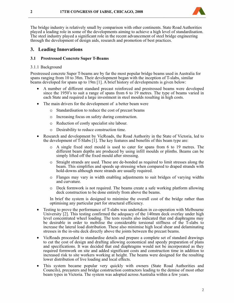
3.1.2 Development of the Super T-beam
Fig. 1: Super T-beam Mould and Dimensions Fig. 2: Super T-beam being installed
• The success of the T-slab concept was the catalyst for the development of the Super T-beams, shown in Fig. 1 and 2, to extend the span range up to 38m [3].
o In addition to similar benefits offered by T-slabs, the key objective of this development was to reduce the high cost of Trough Beams, Bulb T-Beams, AASHTO Type 3 & 4 Girders and Bulb T-Beams for spans in excess of 19m. This required up to 7 different moulds and the capital costs were beyond the reach of smaller precasters due to the large investment required to supply this low-volume market segment. The resulting lack of competition led to very high prices.
o In view of the potential impact on the established local industry, VicRoads worked in close consultation with key stakeholders to ensure that their needs were considered and benefits were maximised. Precasters with established moulds for the longer span standard beams resisted the development initially, however the economic benefits could not be ignored and the development proceeded. Ultimately, close consultation at all stages of the development allowed a smooth transition for all stakeholders.
o In order to speed up the development, VicRoads decided to standardise only the outer dimensions of the beam to facilitate fast uptake and fabrication of standard moulds across the industry. Internal dimensions were suggested but these can be varied as required without impacting the benefits of the standardisation.
o Precasters co-operated nationally with State Road Authorities to standardise reinforcing and prestressing details [9] to maximise efficiency.
• Based on the T-slab concept, Super T-beams beams can span up to 32m as a simply supported span or 38m when continuous over three spans or more with SM1600 live loading [12]. It should be noted that this design load is among the highest in the world [12].
o The original concept was a closed box with cantilevers utilising polystyrene to form the void, similarly to the T-slabs. This concept was implemented with mixed success as some precasters were unable to effectively restrain the large void against buoyancy during casting with the undesirable result that dimensional accuracy could not be guaranteed and was difficult to verify. Incorrect location of the void affects the section properties of the beam and the concrete cover with obvious consequences for strength and durability.
o The drawbacks of the original concept were overcome by the development of the “open-top” Super T-beam or “Teeroff” [10] by using removable internal forms and internal diaphragms along the beam.
4 17TH CONGRESS OF IABSE, CHICAGO, 2008
4
o Further optimisation of the design led to the use of slightly wider beams which allow the placement of more prestressing strands and enable slightly longer spans. This has now been standardised across Australia [12].
o Some State Road Authorities require the use of external end diaphragms although these are considered to be optional by modifying the design.
• Super T-beams have now effectively replaced T-slabs and most of the other beam types used across Australia and New Zealand. A single fixed steel form can be used to manufacture beams for spans ranging from 6 to 38metres.
In summary, • Super T-beams are now the choice bridging system used across Australasia for bridge spans
up to 38m. They have effectively replaced T-slabs and most of the other beam types. • The cost of bridge design and construction dropped significantly due to increased
competition and ease of construction as the use of this system accelerated. • The safety of site construction workers is improved compared with other beam systems as
the Super T-beams provide an immediate working platform after erection. Formwork for deck construction is largely eliminated and speed of construction is increased significantly. In addition, relatively unskilled labour can be employed for deck construction, further reducing costs.
• The aesthetics of this system is considered to be superior to I-girder bridges and is comparable to the favoured appearance of box girder bridges.
• This development found immediate acceptance by owners, designers, precasters and bridge contractors across Australasia. Close consultation and co-operation with industry in the development of the beam was instrumental to its success.
3.1.3 Recent use of Super T-beams The most recent project in Australia, which demonstrates the use of this system in a variety of bridge types, is the East Link Project. This project is a $AUD 2.5 Billion toll freeway funded and constructed using a Build, Own, Operate and Transfer (BOOT) delivery model and comprises 92 bridges, in addition to tunnels and culverts, over a length of 39 km. Construction contractors were Thiess and John Holland. Parsons Brinckerhoff (PB) with Hyder and Connel Wagner were the design consultants. Super T-beams were used to build most of the road bridges and some pedestrian bridges. The bridges varied in width, skew, curvature and articulation. The Super T-beams were adapted to the suit the geometry by varying the width of the flanges. General features of the designs are as follows:
• Simply supported spans were used as much as possible to enable easy and fast construction. Super T-beams with a depth of 1800mm can span up to 32m as simply supported spans for the standard SM1600 live loading [12]
• For adjacent spans the reinforced concrete deck was made continuous over the piers with the deck de-bonded from the beam over a length of 1500mm using bituminous impregnated fibre board.
• Spans in excess of 32 m and up to 38m were made fully continuous. • Super T-beam depths varied from 750 to 1800mm. The widths varied from 1120 to 2500mm
for road bridges and up to 3000mm for pedestrian bridges. • Reinforced concrete deck thickness varied from 180 to 200mm • Elastomeric bearings pads were used throughout. • For curved bridges the flange widths were varied to suit the curvature, keeping the trough of
the beam straight. • For varying width bridges the flange widths were varied symmetrically along the beam.
Creating and Renewing Urban Structures 5
• Beam mass ranged from 15 to 75 tonnes. A single 500 tonne crane was used to handle and place the beams on site.
• Substructures comprised reinforced concrete abutments and piers founded on reinforced concrete driven piles and bored piles.
• Integral abutments were used where possible. Other abutments comprised reinforced earth walls, soil-nailed walls, concrete retaining walls and some spill-through embankments.
• Barriers comprise precast concrete parapets of varying containment capacity. A precast yard was established to manufacture the beams as well as other precast elements such as noise walls, bridge barriers, pier columns and retaining walls. A total of 1650 Super T-beams were manufactured in a two-year period. Construction of this project started in 2005 and was completed by April 2008. The use of the Super T-beams contributed significantly to the speed of construction and proved to be very safe and economical.
3.2 Developments in Steel Bridges
3.2.1 Background Steel bridges steadily lost market share from the 1950’s to 1990’s as concrete bridges provided cheaper alternatives. A number of developments contributed to the decreasing popularity of steel bridges in Australia as follows:
• Failures of steel girders on the King Street bridge in 1962 and the Westgate Bridge in 1970, both in Melbourne, led to stricter, if not unreasonable, standards of workmanship which increased the cost of steel fabrication and affected their economic viability. A number of fabricators ceased operation thus reducing the capacity and the competitiveness of the steel industry.
• High cost of repainting steel girders. This is due mainly to the legacy from the use of poorly performing paints with red lead primers. Repainting requires stripping back to bare metal by sand blasting in air tight and leak-proof enclosures under strict Environmental and Occupation Health and Safety (OH&S) requirements.
• Some Authorities imposed a cost penalty on steel bridges when comparing with competing concrete bridge solutions in the selection process. This is despite research indicating that there is no significant difference in the life-cycle cost of existing steel and concrete bridges [13], [14]. Unfortunately this practice still persists despite the expected difference in maintenance costs being extremely difficult to estimate for modern bridges.
• Universities have focused more on concrete research and education since the 1960’s to produce generations of new engineers more familiar with concrete technology than steel. This has influenced their choice towards concrete.
• Perhaps the lowest point for steel bridges was in 1992 when a new AUSTROADS Limit States Bridge Design Code was released without a steel section.
The overall impact of the above favoured the choice of concrete and, as that industry became larger and more competitive, concrete bridges became increasingly more economical.
3.2.2 New developments for steel bridges The following developments in the last decade have increased the attractiveness of steel bridges and led to resurgence of their use:
• TransfloorTM precast decking system • Design aids • Coatings guide for new steel bridges • Pier-redundant bridges
6 17TH CONGRESS OF IABSE, CHICAGO, 2008
6
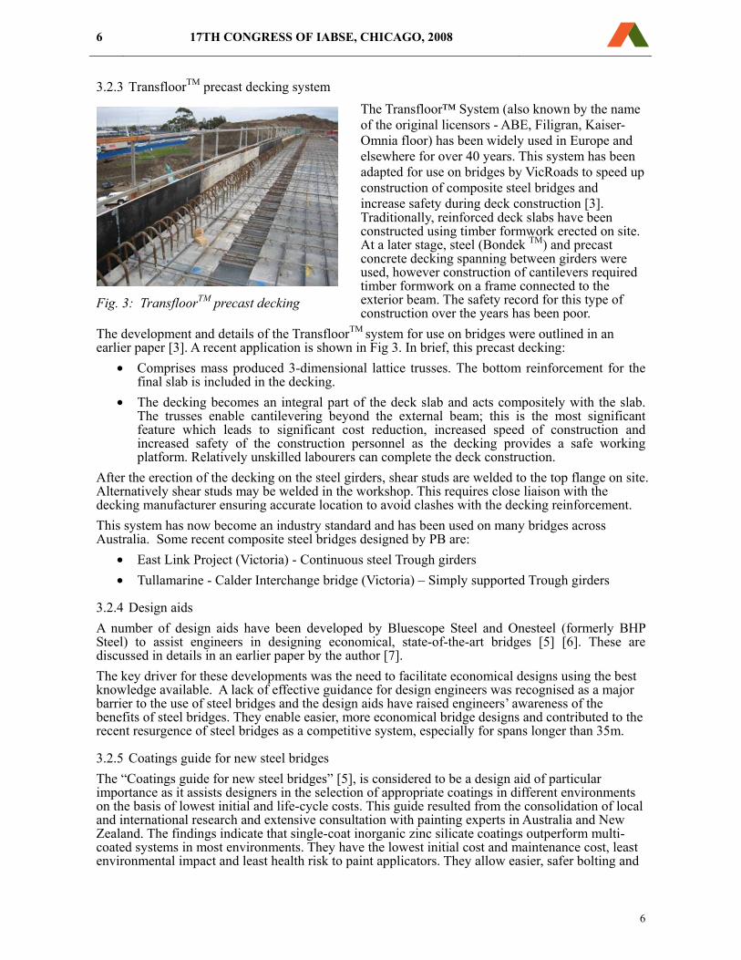
3.2.3 TransfloorTM precast decking system The Transfloor™ System (also known by the name of the original licensors - ABE, Filigran, Kaiser-Omnia floor) has been widely used in Europe and elsewhere for over 40 years. This system has been adapted for use on bridges by VicRoads to speed up construction of composite steel bridges and increase safety during deck construction [3]. Traditionally, reinforced deck slabs have been constructed using timber formwork erected on site. At a later stage, steel (Bondek TM) and precast concrete decking spanning between girders were used, however construction of cantilevers required timber formwork on a frame connected to the exterior beam. The safety record for this type of construction over the years has been poor.
The development and details of the TransfloorTM system for use on bridges were outlined in an earlier paper [3]. A recent application is shown in Fig 3. In brief, this precast decking:
• Comprises mass produced 3-dimensional lattice trusses. The bottom reinforcement for the final slab is included in the decking.
• The decking becomes an integral part of the deck slab and acts compositely with the slab. The trusses enable cantilevering beyond the external beam; this is the most significant feature which leads to significant cost reduction, increased speed of construction and increased safety of the construction personnel as the decking provides a safe working platform. Relatively unskilled labourers can complete the deck construction.
After the erection of the decking on the steel girders, shear studs are welded to the top flange on site. Alternatively shear studs may be welded in the workshop. This requires close liaison with the decking manufacturer ensuring accurate location to avoid clashes with the decking reinforcement. This system has now become an industry standard and has been used on many bridges across Australia. Some recent composite steel bridges designed by PB are:
• East Link Project (Victoria) - Continuous steel Trough girders • Tullamarine - Calder Interchange bridge (Victoria) – Simply supported Trough girders
3.2.4 Design aids A number of design aids have been developed by Bluescope Steel and Onesteel (formerly BHP Steel) to assist engineers in designing economical, state-of-the-art bridges [5] [6]. These are discussed in details in an earlier paper by the author [7]. The key driver for these developments was the need to facilitate economical designs using the best knowledge available. A lack of effective guidance for design engineers was recognised as a major barrier to the use of steel bridges and the design aids have raised engineers’ awareness of the benefits of steel bridges. They enable easier, more economical bridge designs and contributed to the recent resurgence of steel bridges as a competitive system, especially for spans longer than 35m.
3.2.5 Coatings guide for new steel bridges The “Coatings guide for new steel bridges” [5], is considered to be a design aid of particular importance as it assists designers in the selection of appropriate coatings in different environments on the basis of lowest initial and life-cycle costs. This guide resulted from the consolidation of local and international research and extensive consultation with painting experts in Australia and New Zealand. The findings indicate that single-coat inorganic zinc silicate coatings outperform multi-coated systems in most environments. They have the lowest initial cost and maintenance cost, least environmental impact and least health risk to paint applicators. They allow easier, safer bolting and
Fig. 3: TransfloorTM precast decking
Creating and Renewing Urban Structures 7
splicing on site, use less material and are hence more sustainable. An earlier paper [11] discusses some of the research in detail and leads to the conclusion that this is the best coating for steel bridges in most environments. Its use will make steel bridges more competitive, safer to construct and maintain, more environmentally friendly and a better investment overall.
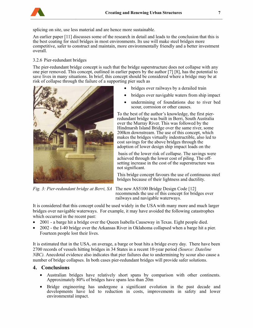
3.2.6 Pier-redundant bridges The pier-redundant bridge concept is such that the bridge superstructure does not collapse with any one pier removed. This concept, outlined in earlier papers by the author [7] [8], has the potential to save lives in many situations. In brief, this concept should be considered where a bridge may be at risk of collapse through the failure of a supporting pier such as
• bridges over railways by a derailed train • bridges over navigable waters from ship impact • undermining of foundations due to river bed
scour, corrosion or other causes. To the best of the author’s knowledge, the first pier-redundant bridge was built in Berri, South Australia over the Murray River. This was followed by the Hindmarsh Island Bridge over the same river, some 200km downstream. The use of this concept, which makes the bridges virtually indestructible, also led to cost savings for the above bridges through the adoption of lower design ship impact loads on the basis of the lower risk of collapse. The savings were achieved through the lower cost of piling. The off-setting increase in the cost of the superstructure was not significant. This bridge concept favours the use of continuous steel bridges because of their lightness and ductility.
Fig. 3: Pier-redundant bridge at Berri, SA The new AS5100 Bridge Design Code [12] recommends the use of this concept for bridges over railways and navigable waterways.
It is considered that this concept could be used widely in the USA with many more and much larger bridges over navigable waterways. For example, it may have avoided the following catastrophes which occurred in the recent past: • 2001 - a barge hit a bridge over the Queen Isabella Causeway in Texas. Eight people died. • 2002 - the I-40 bridge over the Arkansas River in Oklahoma collapsed when a barge hit a pier.
Fourteen people lost their lives. It is estimated that in the USA, on average, a barge or boat hits a bridge every day. There have been 2700 records of vessels hitting bridges in 34 States in a recent 10-year period (Source: Dateline NBC). Anecdotal evidence also indicates that pier failures due to undermining by scour also cause a number of bridge collapses. In both cases pier-redundant bridges will provide safer solutions.
4. Conclusions • Australian bridges have relatively short spans by comparison with other continents.
Approximately 80% of bridges have spans less than 20m • Bridge engineering has undergone a significant evolution in the past decade and
developments have led to reduction in costs, improvements in safety and lower environmental impact.
8 17TH CONGRESS OF IABSE, CHICAGO, 2008
8
• The development of the prestressed concrete Super T-beam system reshaped the industry. It is estimated that some 85% of all road and rail bridges constructed in Australia use this system which is extremely competitive for spans up to 38m.
• Advances in the design and construction of steel bridges have also made these more competitive, especially for spans in excess of 38m.
o Deck construction has been made fast, safe and economical using a precast decking system incorporating a lattice truss which eliminates any formwork.
o The development of design aids has facilitated design and improved the standard of steel bridge designs.
o The use of single-coat inorganic zinc coatings, which have been shown to outperform multi-coat systems and reduce both initial and maintenance costs, also reduces risks to workers and facilitates fabrication and site works.
o Perhaps the most significant innovation is the “pier-redundant” bridge – a virtually indestructible bridge concept with unmatched safety in the event of pier collapse.
o It is considered that the above developments are at the leading edge of short-span bridge engineering and have the potential to be adopted in the USA and around the world.
5. References [1] RAPATTONI F. & WELLS J.B. “Bridge superstructure using PSC T-slabs”, Proceedings
of the AUSTROADS Bridges Conference, Brisbane, Feb 1991, pp. 743-758. [2] VAN DER MOLEN J.L., RAPATTONI F., HARITOS N., WELLS J. “The performance
of a T-slab bridge deck under high levels of concentrated loading” Proceedings of the AUSTROADS Bridges Conference, Brisbane, Feb 1991, pp. 477-488.
[3] RAPATTONI F., WELLS J.B. & P. GRAN “New developments in bridge superstructures”, Proceedings of the AUSTROADS 1994 Bridges Conference, Melbourne, Feb 1994, pp.39 to 39-13.
[5] SZOKOLIK A. & RAPATTONI F. “Coatings Guide for New Steel Bridges”, Published by BHP Steel, 1998.
[6] RAPATTONI F., EASTWOOD D., BENNETT M. & CHEUNG H. “Composite Steel Bridges - Concepts and Design charts”, Published by BHP Steel, 1998.
[7] RAPATTONI F.A. "Steel Bridges - Solutions for the 21st Century" IABSE Symposium, Melbourne, September 2002.
[8] RAPATTONI F.A. "Safety First for bridges – by design" Proceedings of AUSTROADS 2004 Bridges Conference, Hobart, 2004.
[9] MERRETZ W. “Towards national standardisation of Super T girders” Proceedings of the AUSTROADS 1997 Bridges Conference, Sydney, 1997, pp.108-124.
[10] CONNAL J. “Bridge beam developments – the Teeroff” Proceedings of the AUSTROADS 1997 Bridges Conference, Sydney, 1997, pp.125-139.
[11] SZOKOLIK A. & RAPATTONI F. “Single-coat inorganic zinc silicates – is this the definitive answer for the surface protection of steel bridges?” Proceedings of the AUSTROADS 1997 Bridges Conference, Sydney, 1997, pp.285-295.
[12] AS5100 – Bridge Design, Standards Australia, 2006. [13] VAN REYK, F. “A National Model for Life-Cycle Costing of Bridges” Proceedings of
the 1997 AUSTROADS Bridge Conference, Sydney, Australia, pp. 139-149. [14] VESHOSKY, D. and BEIDELMEN C.R. “Life-Cycle Cost Analysis Doesn’t Work for
Bridges” Civil Engineering, July 1992, p. 6. [15] Road Facts 2005, AUSTROADS, 2005.