cable-supported bridges (hänge-, spannband - concrete
TRANSCRIPT
12.05.2021 1
Cable-supported bridges
(Hänge-, Spannband- und Schrägseilbrücken)
ETH Zürich | Chair of Concrete Structures and Bridge Design | Bridge Design Lectures
12.05.2021 2
Common aspects
Cable-stayed bridges
ETH Zürich | Chair of Concrete Structures and Bridge Design | Bridge Design Lectures
Suspension bridges
Typologies
Historical Perspective Static analysis of cables
Dynamic effects
Cable types
Cable-supported bridges
12.05.2021 3ETH Zürich | Chair of Concrete Structures and Bridge Design | Bridge Design Lectures
Common aspects – Typologies
Cable-supported bridges – Common aspects: Typologies
12.05.2021 4
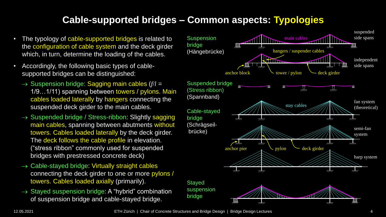
• The typology of cable-supported bridges is related to
the configuration of cable system and the deck girder
which, in turn, determine the loading of the cables.
• Accordingly, the following basic types of cable-
supported bridges can be distinguished:
Suspension bridge: Sagging main cables (f/l =
1/9…1/11) spanning between towers / pylons. Main
cables loaded laterally by hangers connecting the
suspended deck girder to the main cables.
Suspended bridge / Stress-ribbon: Slightly sagging
main cables, spanning between abutments without
towers. Cables loaded laterally by the deck girder.
The deck follows the cable profile in elevation.
(“stress ribbon” commonly used for suspended
bridges with prestressed concrete deck)
Cable-stayed bridge: Virtually straight cables
connecting the deck girder to one or more pylons /
towers. Cables loaded axially (primarily).
Stayed suspension bridge: A “hybrid” combination
of suspension bridge and cable-stayed bridge.
Suspension
bridge
(Hängebrücke)
ETH Zürich | Chair of Concrete Structures and Bridge Design | Bridge Design Lectures
Cable-stayed
bridge
(Schrägseil-
brücke)
Suspended bridge
(Stress ribbon)
(Spannband)
Stayed
suspension
bridge
fan system
(theoretical)
semi-fan
system
harp system
independent
side spans
main cables
tower / pylon
stay cables
hangers / suspender cables
deck girder
suspended
side spans
pylon deck girder
anchor block
anchor pier

Cable-supported bridges
12.05.2021 5ETH Zürich | Chair of Concrete Structures and Bridge Design | Bridge Design Lectures
Common aspects – Historical perspective

Cable-supported bridges – Common aspects: Historical perspective
12.05.2021 6
Similar to arches, suspension bridges have been built for centuries
(some sources see notes):
• More than 2 millennia ago (ca. 65 n.Chr.), the first iron chain
footbridge is said to have been built in Yunnan, China.
• The Incas are said to have built grass rope suspension
footbridges since the 12th century, with a network of ca. 200
bridges around 1600. These bridges required regular
maintenance and replacement of the ropes every 1-3 years
(top photo).
• A Twärrenbrücke (“Querbrücke” = footpath along a canyon wall,
suspended by means of chains) is known to have been part of
the Gotthard route around 1218.
• In 1616, Faustus Verantius in a publication included a project –
or rather, a vision – for a chain-supported bridge (bottom
illustration).
ETH Zürich | Chair of Concrete Structures and Bridge Design | Bridge Design Lectures

Cable-supported bridges – Common aspects: Historical perspective
12.05.2021 7
(continued, some sources see notes)
• Thangtong Gyalpo, a Buddhist yogi known as
Chakzampa (the Bridge Builder), built 58 iron chain
suspension bridges throughout the Himalayan region,
with spans up to 100 m, in the 15th century
(top illustrations).
• James Finley built suspension bridges in the U.S., using
similar chains as T. Gyalpo, already in 1796
(bottom illustrations).
• While stone arches are virtually imperishable unless
their foundations are destroyed (e.g. by floods),
suspension elements are much less durable and hence,
hardly any of these early cable-supported bridges have
survived.
• In the following, merely some milestones in the
development of suspension bridges are highlighted. For
a more complete overview, refer to literature.
ETH Zürich | Chair of Concrete Structures and Bridge Design | Bridge Design Lectures
Cable-supported bridges – Common aspects: Historical perspective
12.05.2021 8ETH Zürich | Chair of Concrete Structures and Bridge Design | Bridge Design Lectures
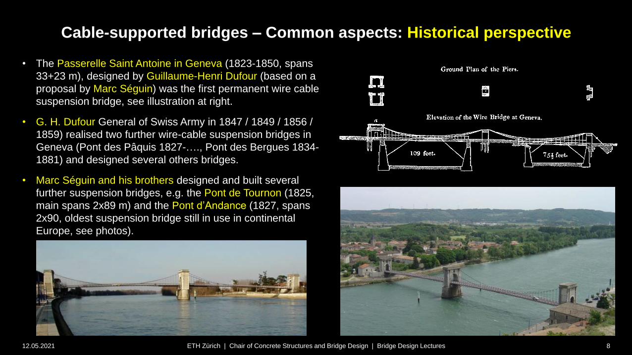
• The Passerelle Saint Antoine in Geneva (1823-1850, spans
33+23 m), designed by Guillaume-Henri Dufour (based on a
proposal by Marc Séguin) was the first permanent wire cable
suspension bridge, see illustration at right.
• G. H. Dufour General of Swiss Army in 1847 / 1849 / 1856 /
1859) realised two further wire-cable suspension bridges in
Geneva (Pont des Pâquis 1827-…., Pont des Bergues 1834-
1881) and designed several others bridges.
• Marc Séguin and his brothers designed and built several
further suspension bridges, e.g. the Pont de Tournon (1825,
main spans 2x89 m) and the Pont d’Andance (1827, spans
2x90, oldest suspension bridge still in use in continental
Europe, see photos).

Cable-supported bridges – Common aspects: Historical perspective
12.05.2021 9ETH Zürich | Chair of Concrete Structures and Bridge Design | Bridge Design Lectures
• The chain-stayed Saalebrücke in Nienburg (l =
80 m, Christian Gottfried Heinrich Bandhauer,
1825, top figure) was a precursor of cable-
stayed bridges, though not very successful.
• The bridge collapsed on the 6.12.1825, only
four months after inauguration, due to
overload, faulty chains and / or oscillations
caused by singing public during the celebration
of St. Nikolaus. 55 people died.
• Bandhauer’s design was very innovative,
despite that he probably knew Claude Louis
Marie Henri Navier’s “Mémoire sur les ponts
suspendus” (published 1823), where similar
schemes were depicted (bottom figure;
Navier’s project for a suspension bridge over
the Seine in Paris, the Pont des Invalides with
170 m span, also part of this publication, was
never finished).
• A further highlight was the bascule opening at
midspan, allowing large ship masts to pass.
Cable-supported bridges – Common aspects: Historical perspective
12.05.2021 10ETH Zürich | Chair of Concrete Structures and Bridge Design | Bridge Design Lectures
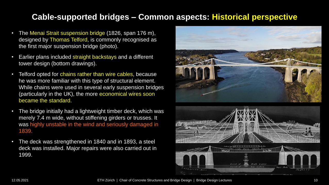
• The Menai Strait suspension bridge (1826, span 176 m),
designed by Thomas Telford, is commonly recognised as
the first major suspension bridge (photo).
• Earlier plans included straight backstays and a different
tower design (bottom drawings).
• Telford opted for chains rather than wire cables, because
he was more familiar with this type of structural element.
While chains were used in several early suspension bridges
(particularly in the UK), the more economical wires soon
became the standard.
• The bridge initially had a lightweight timber deck, which was
merely 7.4 m wide, without stiffening girders or trusses. It
was highly unstable in the wind and seriously damaged in
1839.
• The deck was strengthened in 1840 and in 1893, a steel
deck was installed. Major repairs were also carried out in
1999.

Cable-supported bridges – Common aspects: Historical perspective
12.05.2021 11ETH Zürich | Chair of Concrete Structures and Bridge Design | Bridge Design Lectures
• Suspension bridge chains were commonly eyebar chains,
usually with direct connection by pins.
• The Menai suspension bridge originally had cast iron chains
with indirect connection (bottom left photo). These were
replaced by steel chains with direct connection in 1939.

Cable-supported bridges – Common aspects: Historical perspective
12.05.2021 12ETH Zürich | Chair of Concrete Structures and Bridge Design | Bridge Design Lectures
• The Clifton suspension bridge (1863, span 214 m), designed
by Isambard Kingdom Brunel, also used eyebar chains.
• Other relevant bridges were built before (see next slide). The
Clifton bridge is mentioned here, right after the Menai straits
bridge, because of the chains, and also because it should
have been finished much before its opening in 1864 (see
notes).
• Other than the Menai straits bridge, there are no hangers in
the side spans in the Clifton bridge.
Cable-supported bridges – Common aspects: Historical perspective
12.05.2021 13ETH Zürich | Chair of Concrete Structures and Bridge Design | Bridge Design Lectures
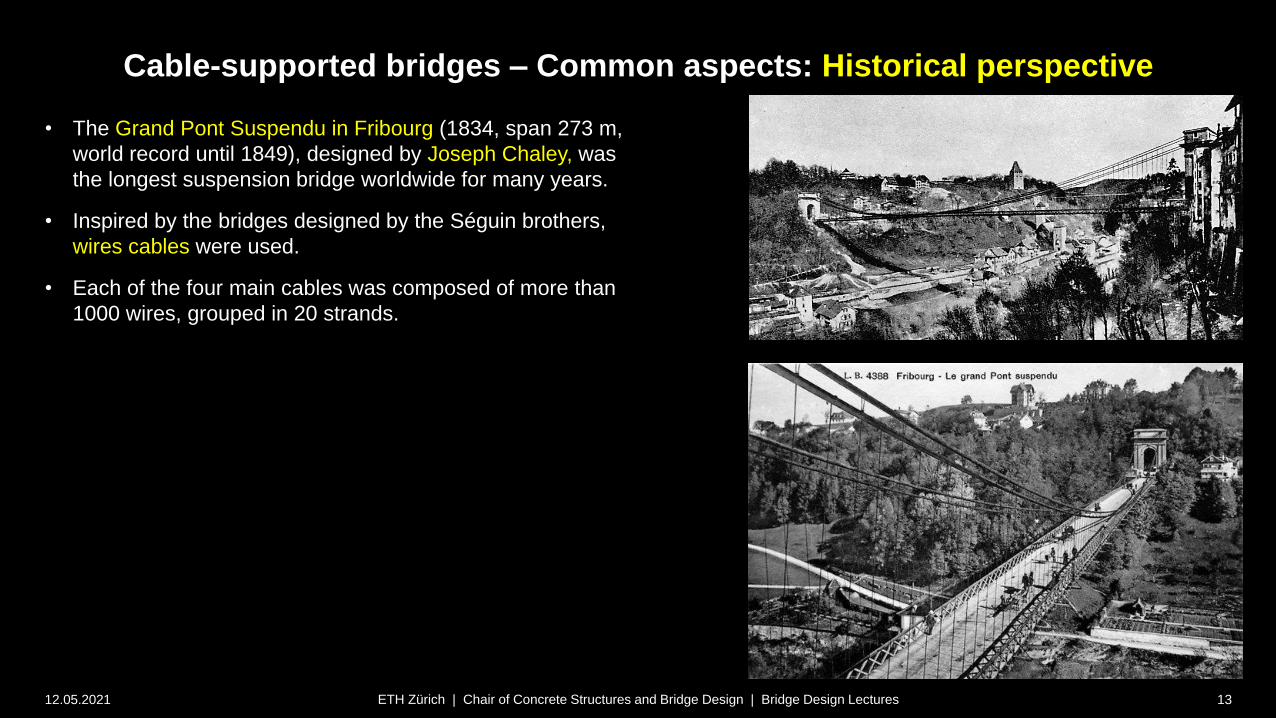
• The Grand Pont Suspendu in Fribourg (1834, span 273 m,
world record until 1849), designed by Joseph Chaley, was
the longest suspension bridge worldwide for many years.
• Inspired by the bridges designed by the Séguin brothers,
wires cables were used.
• Each of the four main cables was composed of more than
1000 wires, grouped in 20 strands.

Cable-supported bridges – Common aspects: Historical perspective
12.05.2021 14ETH Zürich | Chair of Concrete Structures and Bridge Design | Bridge Design Lectures
• The Grand Pont Suspendu in Fribourg (1834, span 273 m,
world record until 1849), designed by Joseph Chaley, was
the longest suspension bridge worldwide for many years.
• Inspired by the bridges designed by the Séguin brothers,
wires cables were used.
• Each of the four main cables was composed of more than
1000 wires, grouped in 20 strands.
Cable-supported bridges – Common aspects: Historical perspective
12.05.2021 15ETH Zürich | Chair of Concrete Structures and Bridge Design | Bridge Design Lectures
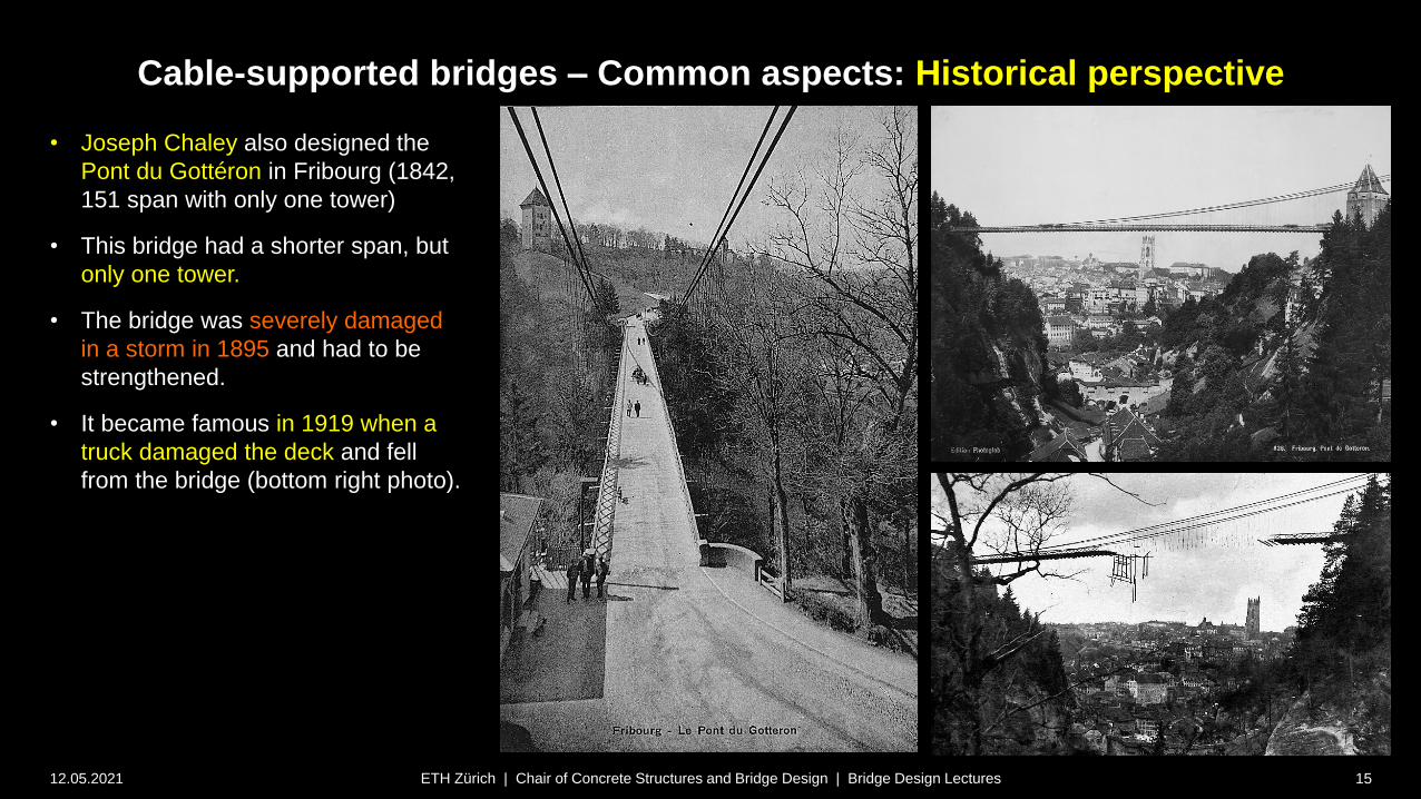
• Joseph Chaley also designed the
Pont du Gottéron in Fribourg (1842,
151 span with only one tower)
• This bridge had a shorter span, but
only one tower.
• The bridge was severely damaged
in a storm in 1895 and had to be
strengthened.
• It became famous in 1919 when a
truck damaged the deck and fell
from the bridge (bottom right photo).

Cable-supported bridges – Common aspects: Historical perspective
12.05.2021 16ETH Zürich | Chair of Concrete Structures and Bridge Design | Bridge Design Lectures
• The Wheeling suspension bridge (1849, span 308 m, record
until 1866), designed by Charles Ellet Jr., is the oldest
suspension bridge still serving vehicle traffic.
• However, it had to be reconstructed after collapsing in 1854
due to wind-induced oscillations apparently similar to the
Tacoma Narrows Bridge (see behind).
• In 1886, under guidance of J. Roebling, stays similar to the
Brooklyn Bridge (see behind) were installed. Further
strengthening was provided in 1922 and 1930.
Cable-supported bridges – Common aspects: Historical perspective
12.05.2021 17ETH Zürich | Chair of Concrete Structures and Bridge Design | Bridge Design Lectures
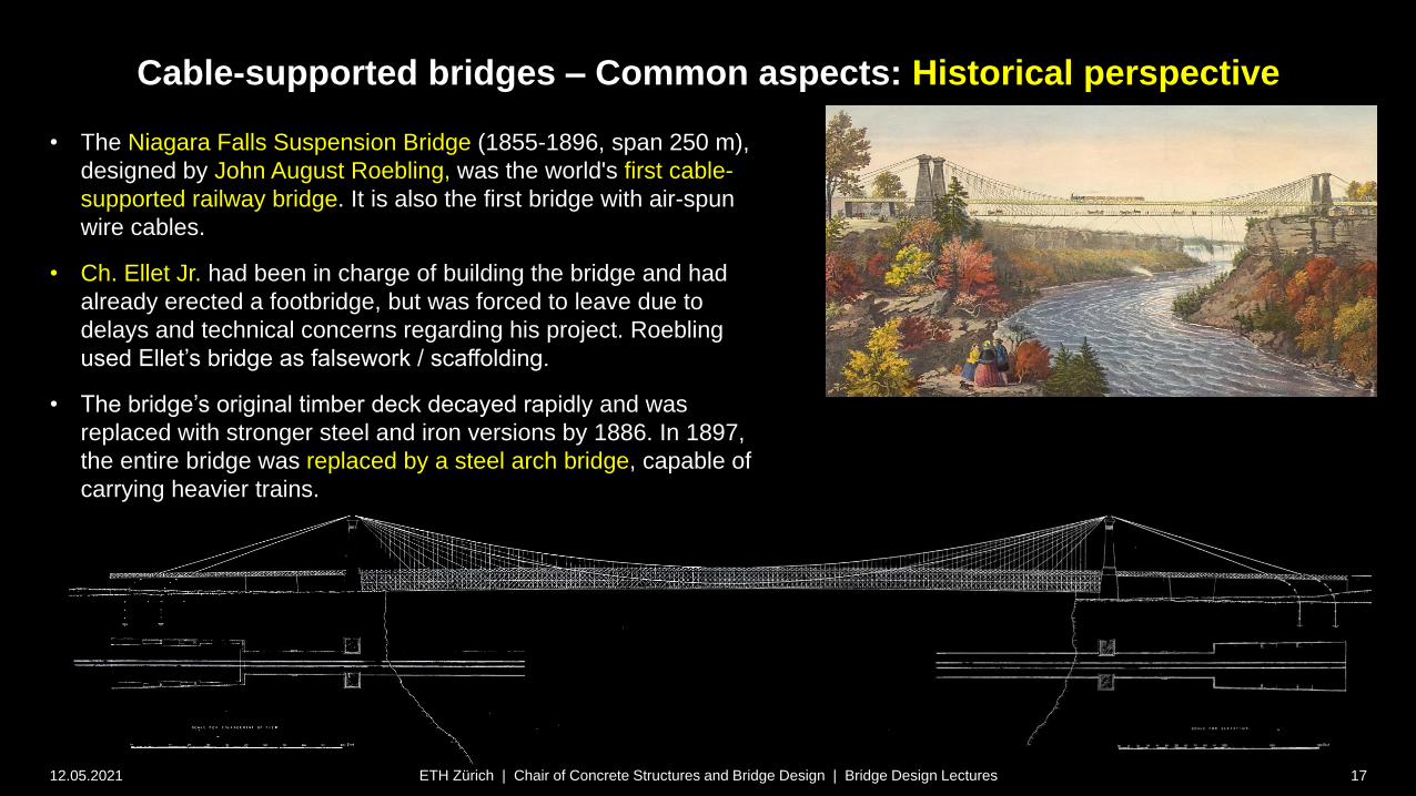
• The Niagara Falls Suspension Bridge (1855-1896, span 250 m),
designed by John August Roebling, was the world's first cable-
supported railway bridge. It is also the first bridge with air-spun
wire cables.
• Ch. Ellet Jr. had been in charge of building the bridge and had
already erected a footbridge, but was forced to leave due to
delays and technical concerns regarding his project. Roebling
used Ellet’s bridge as falsework / scaffolding.
• The bridge’s original timber deck decayed rapidly and was
replaced with stronger steel and iron versions by 1886. In 1897,
the entire bridge was replaced by a steel arch bridge, capable of
carrying heavier trains.
Cable-supported bridges – Common aspects: Historical perspective
12.05.2021 18ETH Zürich | Chair of Concrete Structures and Bridge Design | Bridge Design Lectures
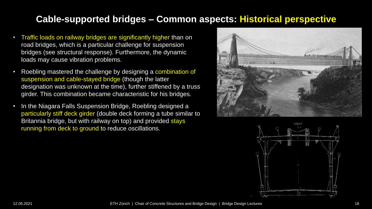
• Traffic loads on railway bridges are significantly higher than on
road bridges, which is a particular challenge for suspension
bridges (see structural response). Furthermore, the dynamic
loads may cause vibration problems.
• Roebling mastered the challenge by designing a combination of
suspension and cable-stayed bridge (though the latter
designation was unknown at the time), further stiffened by a truss
girder. This combination became characteristic for his bridges.
• In the Niagara Falls Suspension Bridge, Roebling designed a
particularly stiff deck girder (double deck forming a tube similar to
Britannia bridge, but with railway on top) and provided stays
running from deck to ground to reduce oscillations.

Cable-supported bridges – Common aspects: Historical perspective
12.05.2021 19ETH Zürich | Chair of Concrete Structures and Bridge Design | Bridge Design Lectures
• Almost at the same time, Robert Stephenson designed the
Britannia Bridge, carrying railway traffic across the Menai Strait
(1850, spans 70+140+140+70 m).
• In order to control deformations and oscillations, Stephenson
provided a “monster tube” cross section, consisting of riveted
wrought iron plates (following contemporary shipbuilding
practices), inside which the trains were running.
• Originally, Stephenson’s intention was to use the steel girder
primarily for stiffness, and provide suspension cables or stays to
carry a large portion of the self-weight.
• However, experiments by William Fairbairn to verify the buckling
stability of the top chords indicated that they needed to be
strengthened. Further experiments on stiffened plates (see cross-
section photo) then led to a design that was stiff and strong
enough to carry the entire load without any need for cables.
• While the bridge was seen as a “triumph of science” at the time,
hardly any tubular bridges were built later (Conwy Railway bridge
and Pont Victoria in Montreal, both designed by Stephenson).
• Unfortunately, the bridge had to be replaced after a fire in 1970,
and the new design only maintained the piers.

Cable-supported bridges – Common aspects: Historical perspective
12.05.2021 20ETH Zürich | Chair of Concrete Structures and Bridge Design | Bridge Design Lectures
• In the John A. Roebling Suspension Bridge
(1866, until 1983 Covington and Cincinnati
Suspension Bridge, span 322 m) over the
Ohio River, Roebling used the same concept
as in the Niagara Falls suspension bridge,
albeit with
a less stiff truss girder since the bridge had
to carry only carriages and pedestrians
suspended side spans
• The Covington-Cincinnati bridge held the
span record until 1868, when the Niagara-
Clifton bridge was built (Samuel Keefer,
stayed suspension bridge, span 384 m).
However, that bridge collapsed in a hurricane
in 1889.
• In 1896, the Covington-Cincinnati bridge was
widened and provided with a second set of
cables. Currently, it is still used, with a weight
limit of 11 t.

Cable-supported bridges – Common aspects: Historical perspective
12.05.2021 21ETH Zürich | Chair of Concrete Structures and Bridge Design | Bridge Design Lectures
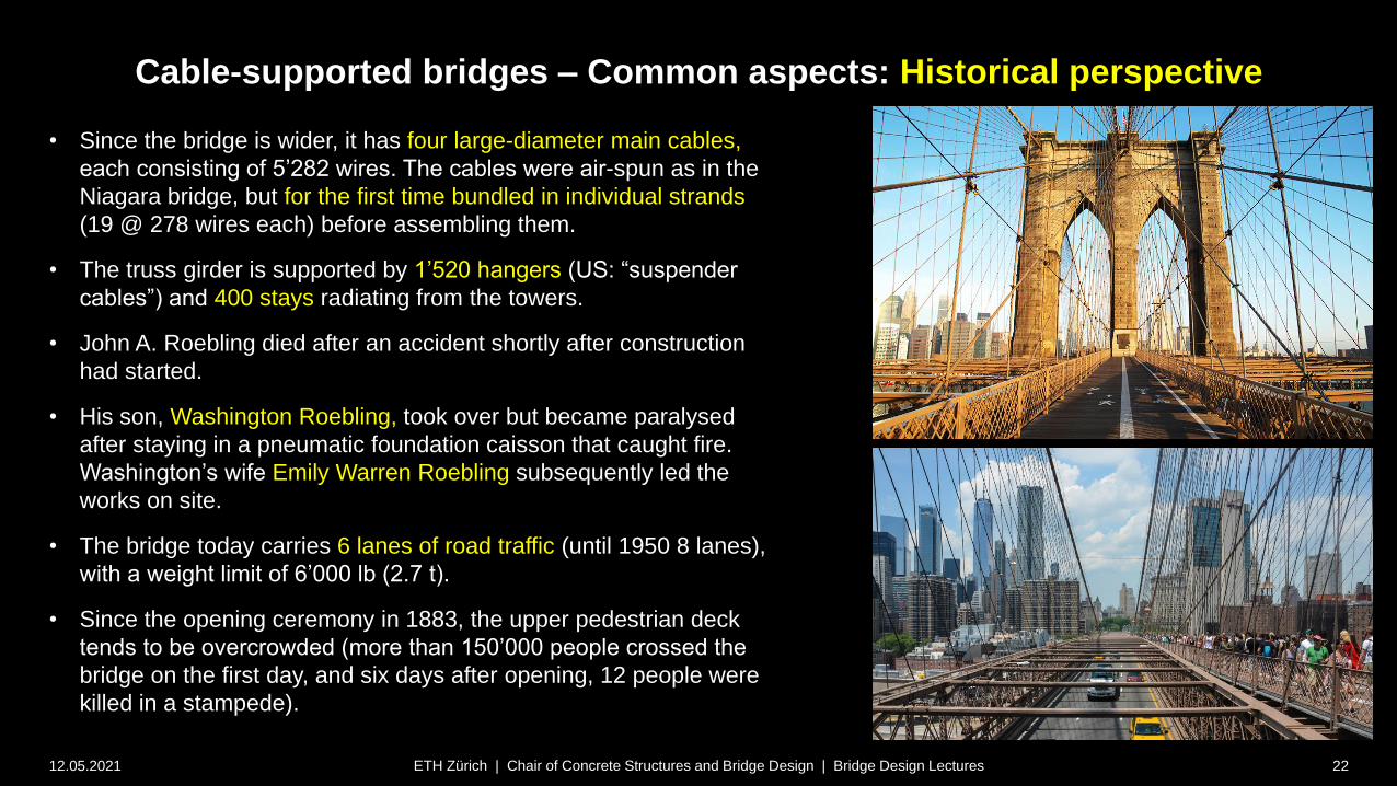
• The Brooklyn Bridge (1883, until 1915 “New York and
Brooklyn Bridge” or “East River Bridge”, span 486 m,
record suspension span until 1903) is certainly the most
prominent bridge designed by John A. Roebling.
• Roebling again used the same concept as in the
Covington-Cincinnati and Niagara bridges, combining
suspension cables, stay cables and a stiffening truss.
Cable-supported bridges – Common aspects: Historical perspective
12.05.2021 22ETH Zürich | Chair of Concrete Structures and Bridge Design | Bridge Design Lectures
• Since the bridge is wider, it has four large-diameter main cables,
each consisting of 5’282 wires. The cables were air-spun as in the
Niagara bridge, but for the first time bundled in individual strands
(19 @ 278 wires each) before assembling them.
• The truss girder is supported by 1’520 hangers (US: “suspender
cables”) and 400 stays radiating from the towers.
• John A. Roebling died after an accident shortly after construction
had started.
• His son, Washington Roebling, took over but became paralysed
after staying in a pneumatic foundation caisson that caught fire.
Washington’s wife Emily Warren Roebling subsequently led the
works on site.
• The bridge today carries 6 lanes of road traffic (until 1950 8 lanes),
with a weight limit of 6’000 lb (2.7 t).
• Since the opening ceremony in 1883, the upper pedestrian deck
tends to be overcrowded (more than 150’000 people crossed the
bridge on the first day, and six days after opening, 12 people were
killed in a stampede).

Cable-supported bridges – Common aspects: Historical perspective
12.05.2021 23ETH Zürich | Chair of Concrete Structures and Bridge Design | Bridge Design Lectures
• As mentioned, the Brooklyn Bridge was the longest span
suspension bridge until 1903. However, the Forth Bridge,
a cantilever steel truss bridge, designed by John Fowler
and Benjamin Baker, was the world’s longest span bridge
after opening in 1890, with a main span of 520 m, followed
by the similar Québec Bridge (1918, rebuilt after having
collapsed in construction 1907) with a span of 549 m.
• Suspension bridges only returned to be the longest span
typology with the Ambassador Bridge (1929, span 564 m),
whose span was soon almost doubled by the George
Washington Bridge (1931, 1067 m). George Washington
Akashi-Kaikyo
Golden Gate
Humber
Verrazzano Narrows
Brooklyn
AmbassadorForth
Québec
Russky
Tatara
Sutong
Normandie
New
River
Gorge
BayonneLupu
Chaotianmen
Eads
Hell GateFribourg
mai
n s
pan
[m
]year ( inauguration)
Storebælt
Longest span bridges (all typologies)
Cable-supported bridges – Common aspects: Historical perspective
12.05.2021 24ETH Zürich | Chair of Concrete Structures and Bridge Design | Bridge Design Lectures
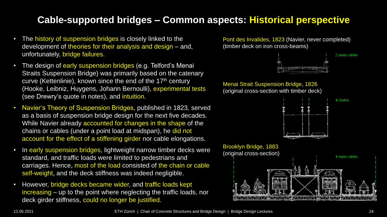
• The history of suspension bridges is closely linked to the
development of theories for their analysis and design – and,
unfortunately, bridge failures.
• The design of early suspension bridges (e.g. Telford’s Menai
Straits Suspension Bridge) was primarily based on the catenary
curve (Kettenlinie), known since the end of the 17th century
(Hooke, Leibniz, Huygens, Johann Bernoulli), experimental tests
(see Drewry’s quote in notes), and intuition.
• Navier’s Theory of Suspension Bridges, published in 1823, served
as a basis of suspension bridge design for the next five decades.
While Navier already accounted for changes in the shape of the
chains or cables (under a point load at midspan), he did not
account for the effect of a stiffening girder nor cable elongations.
• In early suspension bridges, lightweight narrow timber decks were
standard, and traffic loads were limited to pedestrians and
carriages. Hence, most of the load consisted of the chain or cable
self-weight, and the deck stiffness was indeed negligible.
• However, bridge decks became wider, and traffic loads kept
increasing – up to the point where neglecting the traffic loads, nor
deck girder stiffness, could no longer be justified.
Pont des Invalides, 1823 (Navier, never completed)
(timber deck on iron cross-beams)
Brooklyn Bridge, 1883
(original cross-section)
Menai Strait Suspension Bridge, 1826
(original cross-section with timber deck)
2 main cables
4 chains
4 main cables
Cable-supported bridges – Common aspects: Historical perspective
12.05.2021 25ETH Zürich | Chair of Concrete Structures and Bridge Design | Bridge Design Lectures
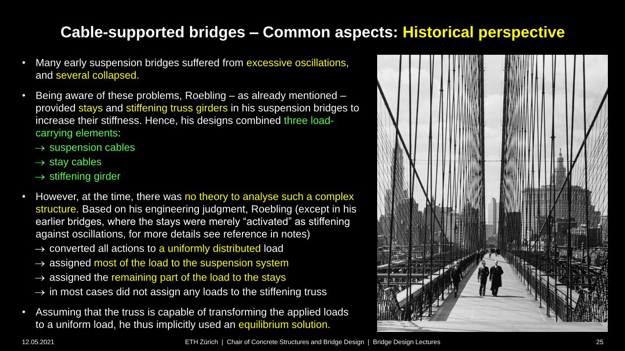
• Many early suspension bridges suffered from excessive oscillations,
and several collapsed.
• Being aware of these problems, Roebling – as already mentioned –
provided stays and stiffening truss girders in his suspension bridges to
increase their stiffness. Hence, his designs combined three load-
carrying elements:
suspension cables
stay cables
stiffening girder
• However, at the time, there was no theory to analyse such a complex
structure. Based on his engineering judgment, Roebling (except in his
earlier bridges, where the stays were merely “activated” as stiffening
against oscillations, for more details see reference in notes)
converted all actions to a uniformly distributed load
assigned most of the load to the suspension system
assigned the remaining part of the load to the stays
in most cases did not assign any loads to the stiffening truss
• Assuming that the truss is capable of transforming the applied loads
to a uniform load, he thus implicitly used an equilibrium solution.
Cable-supported bridges – Common aspects: Historical perspective
12.05.2021 26ETH Zürich | Chair of Concrete Structures and Bridge Design | Bridge Design Lectures
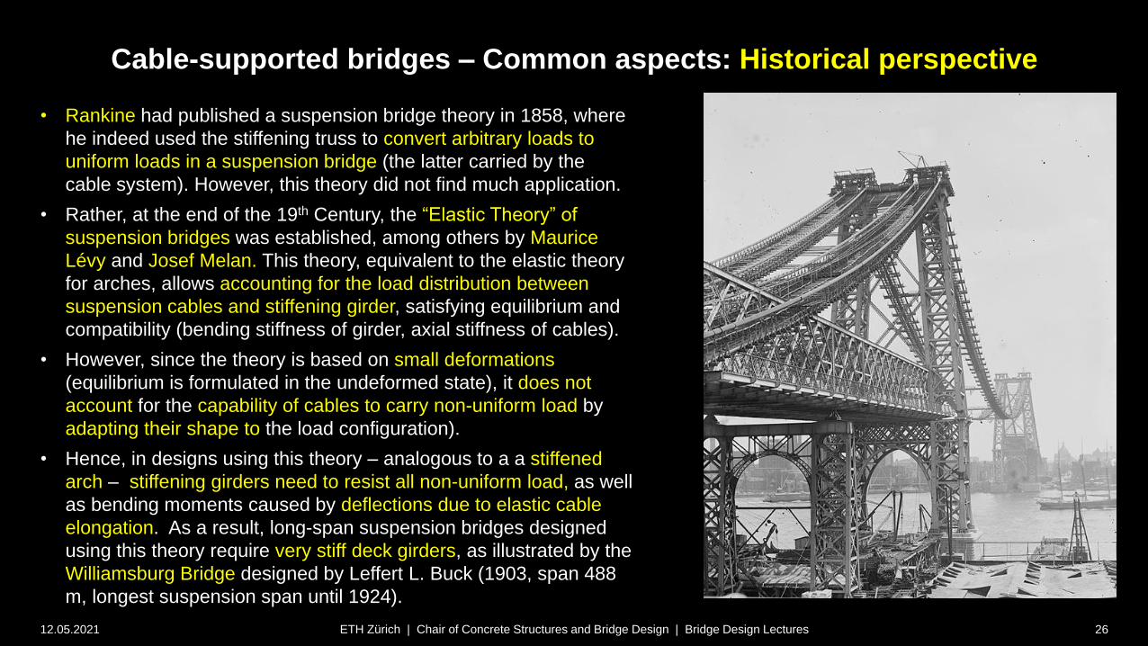
• Rankine had published a suspension bridge theory in 1858, where
he indeed used the stiffening truss to convert arbitrary loads to
uniform loads in a suspension bridge (the latter carried by the
cable system). However, this theory did not find much application.
• Rather, at the end of the 19th Century, the “Elastic Theory” of
suspension bridges was established, among others by Maurice
Lévy and Josef Melan. This theory, equivalent to the elastic theory
for arches, allows accounting for the load distribution between
suspension cables and stiffening girder, satisfying equilibrium and
compatibility (bending stiffness of girder, axial stiffness of cables).
• However, since the theory is based on small deformations
(equilibrium is formulated in the undeformed state), it does not
account for the capability of cables to carry non-uniform load by
adapting their shape to the load configuration).
• Hence, in designs using this theory – analogous to a a stiffened
arch – stiffening girders need to resist all non-uniform load, as well
as bending moments caused by deflections due to elastic cable
elongation. As a result, long-span suspension bridges designed
using this theory require very stiff deck girders, as illustrated by the
Williamsburg Bridge designed by Leffert L. Buck (1903, span 488
m, longest suspension span until 1924).

Cable-supported bridges – Common aspects: Historical perspective
12.05.2021 27ETH Zürich | Chair of Concrete Structures and Bridge Design | Bridge Design Lectures
• In 1888 (refined version 1906), Josef Melan published
the “Deflection Theory” of suspension bridges
(Formänderungstheorie der Hängebrücken).
• This theory accounts for the beneficial effect of large
cable deformations (second order deformations) in the
load distribution among suspension cables and
stiffening girder.
• As a result, much more slender stiffening girders could
be used in bridges designed using this theory.
• Leon Moisseiff first applied the Deflection Theory in the
design of the Manhattan Bridge (1909, span 448 m).
• The difference between the Manhattan bridge and the
Williamsburg bridge, built only 6 years earlier and
carrying even less traffic load with a similar span, is
striking both visually (compare photos) as well as
numerically (Slenderness h/l = 1/37.5 vs 1/56).

Cable-supported bridges – Common aspects: Historical perspective
12.05.2021 28ETH Zürich | Chair of Concrete Structures and Bridge Design | Bridge Design Lectures
• When applying the Deflection Theory,
structural safety can be guaranteed without
stiffening girder. The required girder
stiffness is thus essentially governed by the
limits on deflections under traffic loads –
which become smaller as the self-weight of
the bridge increases.
• Consequently, very slender deck girders
are sufficient in large span suspension
bridges with a relatively large self weight
(cables + deck girder).
• Othmar H. Ammann made use of this in his
incredibly slender design (h/l = 1/351, more
than six times higher slenderness than in
the Manhattan bridge) of the George
Washington Bridge (1931, span 1067 m,
record span until 1937).
• The George Washington Bridge was
disruptive regarding span, but also
slenderness (see notes).

Cable-supported bridges – Common aspects: Historical perspective
12.05.2021 29ETH Zürich | Chair of Concrete Structures and Bridge Design | Bridge Design Lectures
• In 1962, a second deck was added to the
George Washington Bridge, increasing its
capacity from 8 to 8+6 = 14 lanes of traffic.
• The slenderness was reduced to h/l =
1/120, yet the bridge still is and looks very
slender.
Cable-supported bridges – Common aspects: Historical perspective
12.05.2021 30ETH Zürich | Chair of Concrete Structures and Bridge Design | Bridge Design Lectures
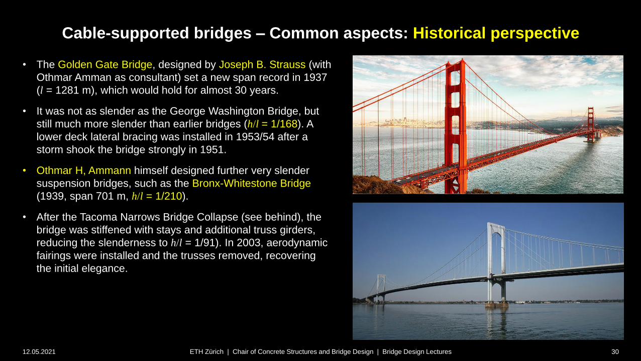
• The Golden Gate Bridge, designed by Joseph B. Strauss (with
Othmar Amman as consultant) set a new span record in 1937
(l = 1281 m), which would hold for almost 30 years.
• It was not as slender as the George Washington Bridge, but
still much more slender than earlier bridges (h/l = 1/168). A
lower deck lateral bracing was installed in 1953/54 after a
storm shook the bridge strongly in 1951.
• Othmar H, Ammann himself designed further very slender
suspension bridges, such as the Bronx-Whitestone Bridge
(1939, span 701 m, h/l = 1/210).
• After the Tacoma Narrows Bridge Collapse (see behind), the
bridge was stiffened with stays and additional truss girders,
reducing the slenderness to h/l = 1/91). In 2003, aerodynamic
fairings were installed and the trusses removed, recovering
the initial elegance.

Cable-supported bridges – Common aspects: Historical perspective
12.05.2021 31ETH Zürich | Chair of Concrete Structures and Bridge Design | Bridge Design Lectures
• While neither the George Washington Bridge nor the Bronx-Whitestone
bridge experienced excessive oscillations (and the Golden Gate Bridge
only in a severe storm 1951), several other suspension bridges with
slender decks had to be stiffened for this reason.
• Documented examples include the Thousand Islands Bridge (1937, span
240 m) and the Deer Isle Bridge (1939, span 329 m), both designed by
the renowned engineer David B. Steinman.
• The Thousand Islands Bridge was stiffened with “truss” stays shortly
after the opening, due to excessive oscillations in wind. The Deer Isle
Bridge was retrofitted with “truss” stays even before opening, since
similar oscillations as in the Thousand Islands Bridge had been observed
during construction.
• Despite these obvious problems,
and the knowledge about
wind-induced collapses
of several early suspension
bridges without stiffening girder,
ultra-slender suspension bridges
kept being built.
Cable-supported bridges – Common aspects: Historical perspective
12.05.2021 32ETH Zürich | Chair of Concrete Structures and Bridge Design | Bridge Design Lectures
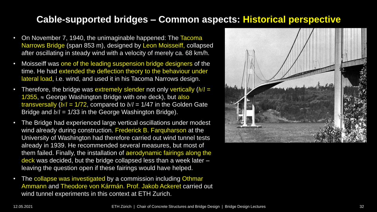
• On November 7, 1940, the unimaginable happened: The Tacoma
Narrows Bridge (span 853 m), designed by Leon Moisseiff, collapsed
after oscillating in steady wind with a velocity of merely ca. 68 km/h.
• Moisseiff was one of the leading suspension bridge designers of the
time. He had extended the deflection theory to the behaviour under
lateral load, i.e. wind, and used it in his Tacoma Narrows design.
• Therefore, the bridge was extremely slender not only vertically (h/l =
1/355, George Washington Bridge with one deck), but also
transversally (b/l = 1/72, compared to b/l = 1/47 in the Golden Gate
Bridge and b/l = 1/33 in the George Washington Bridge).
• The Bridge had experienced large vertical oscillations under modest
wind already during construction. Frederick B. Farquharson at the
University of Washington had therefore carried out wind tunnel tests
already in 1939. He recommended several measures, but most of
them failed. Finally, the installation of aerodynamic fairings along the
deck was decided, but the bridge collapsed less than a week later –
leaving the question open if these fairings would have helped.
• The collapse was investigated by a commission including Othmar
Ammann and Theodore von Kármán. Prof. Jakob Ackeret carried out
wind tunnel experiments in this context at ETH Zurich.
Cable-supported bridges – Common aspects: Historical perspective
12.05.2021 33ETH Zürich | Chair of Concrete Structures and Bridge Design | Bridge Design Lectures
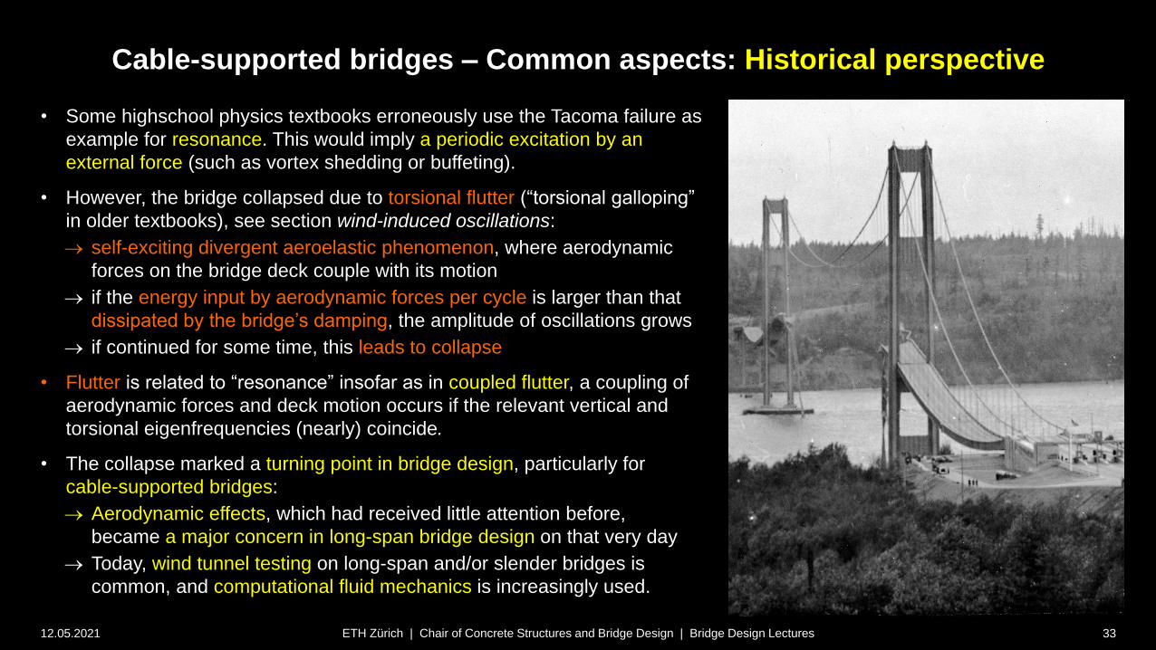
• Some highschool physics textbooks erroneously use the Tacoma failure as
example for resonance. This would imply a periodic excitation by an
external force (such as vortex shedding or buffeting).
• However, the bridge collapsed due to torsional flutter (“torsional galloping”
in older textbooks), see section wind-induced oscillations:
self-exciting divergent aeroelastic phenomenon, where aerodynamic
forces on the bridge deck couple with its motion
if the energy input by aerodynamic forces per cycle is larger than that
dissipated by the bridge’s damping, the amplitude of oscillations grows
if continued for some time, this leads to collapse
• Flutter is related to “resonance” insofar as in coupled flutter, a coupling of
aerodynamic forces and deck motion occurs if the relevant vertical and
torsional eigenfrequencies (nearly) coincide.
• The collapse marked a turning point in bridge design, particularly for
cable-supported bridges:
Aerodynamic effects, which had received little attention before,
became a major concern in long-span bridge design on that very day
Today, wind tunnel testing on long-span and/or slender bridges is
common, and computational fluid mechanics is increasingly used.

Cable-supported bridges – Common aspects: Historical perspective
12.05.2021 34ETH Zürich | Chair of Concrete Structures and Bridge Design | Bridge Design Lectures
• The Tacoma Narrows bridge was rebuilt in 1950, with a much deeper
and wider stiffening girder, (h/l = 1/87 vs. 1/355, b/l = 1/46 vs. 1/72,
truss box girder with high torsional stiffness vs. open cross-section).
• The towers had suffered severe damage, being deflected almost 4 m
towards the shore after collapse of the main span. Only the cable
anchorages, tower pedestals and foundations could be re-used. The
steel (cables, deck, towers) was sold as scrap.
• In 2007, a second bridge was added, with equal span.
Cross-section of
collapsed bridge (1940)
Cross-section of
rebuilt bridge (1950)
Cable-supported bridges – Common aspects: Historical perspective
12.05.2021 35ETH Zürich | Chair of Concrete Structures and Bridge Design | Bridge Design Lectures
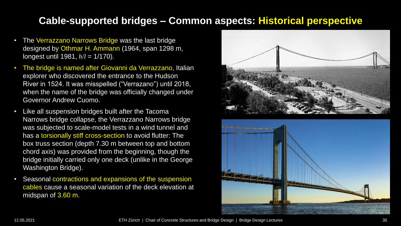
• The Verrazzano Narrows Bridge was the last bridge
designed by Othmar H. Ammann (1964, span 1298 m,
longest until 1981, h/l = 1/170).
• The bridge is named after Giovanni da Verrazzano, Italian
explorer who discovered the entrance to the Hudson
River in 1524. It was misspelled (“Verrazano”) until 2018,
when the name of the bridge was officially changed under
Governor Andrew Cuomo.
• Like all suspension bridges built after the Tacoma
Narrows bridge collapse, the Verrazzano Narrows bridge
was subjected to scale-model tests in a wind tunnel and
has a torsionally stiff cross-section to avoid flutter: The
box truss section (depth 7.30 m between top and bottom
chord axis) was provided from the beginning, though the
bridge initially carried only one deck (unlike in the George
Washington Bridge).
• Seasonal contractions and expansions of the suspension
cables cause a seasonal variation of the deck elevation at
midspan of 3.60 m.
Cable-supported bridges – Common aspects: Historical perspective
12.05.2021 36ETH Zürich | Chair of Concrete Structures and Bridge Design | Bridge Design Lectures
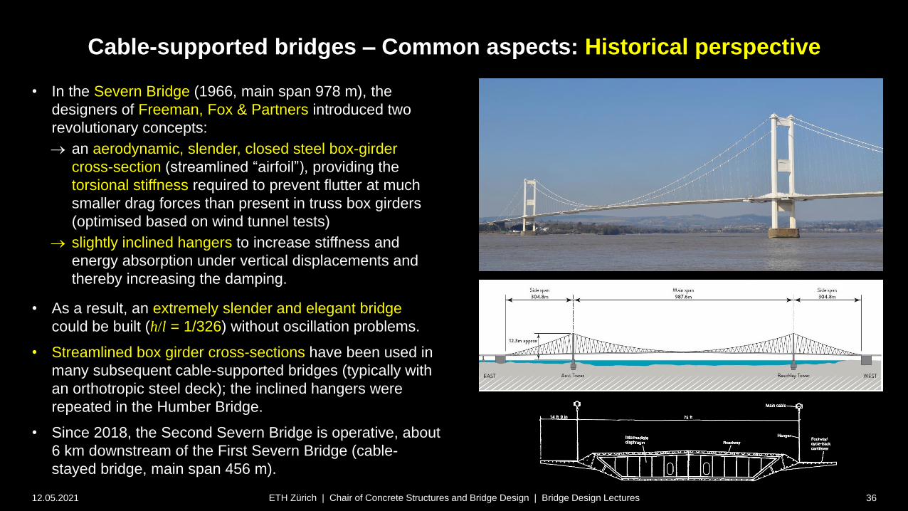
• In the Severn Bridge (1966, main span 978 m), the
designers of Freeman, Fox & Partners introduced two
revolutionary concepts:
an aerodynamic, slender, closed steel box-girder
cross-section (streamlined “airfoil”), providing the
torsional stiffness required to prevent flutter at much
smaller drag forces than present in truss box girders
(optimised based on wind tunnel tests)
slightly inclined hangers to increase stiffness and
energy absorption under vertical displacements and
thereby increasing the damping.
• As a result, an extremely slender and elegant bridge
could be built (h/l = 1/326) without oscillation problems.
• Streamlined box girder cross-sections have been used in
many subsequent cable-supported bridges (typically with
an orthotropic steel deck); the inclined hangers were
repeated in the Humber Bridge.
• Since 2018, the Second Severn Bridge is operative, about
6 km downstream of the First Severn Bridge (cable-
stayed bridge, main span 456 m).

Cable-supported bridges – Common aspects: Historical perspective
12.05.2021 37ETH Zürich | Chair of Concrete Structures and Bridge Design | Bridge Design Lectures
• In the Humber Bridge (1991, main span 1410 m, record
until 1998, h/l = 1/313), Freeman, Fox & Partners again
used a streamlined steel box girder with orthotropic steel
deck, as well as the slightly inclined hangers.
Cable-supported bridges – Common aspects: Historical perspective
12.05.2021 38ETH Zürich | Chair of Concrete Structures and Bridge Design | Bridge Design Lectures
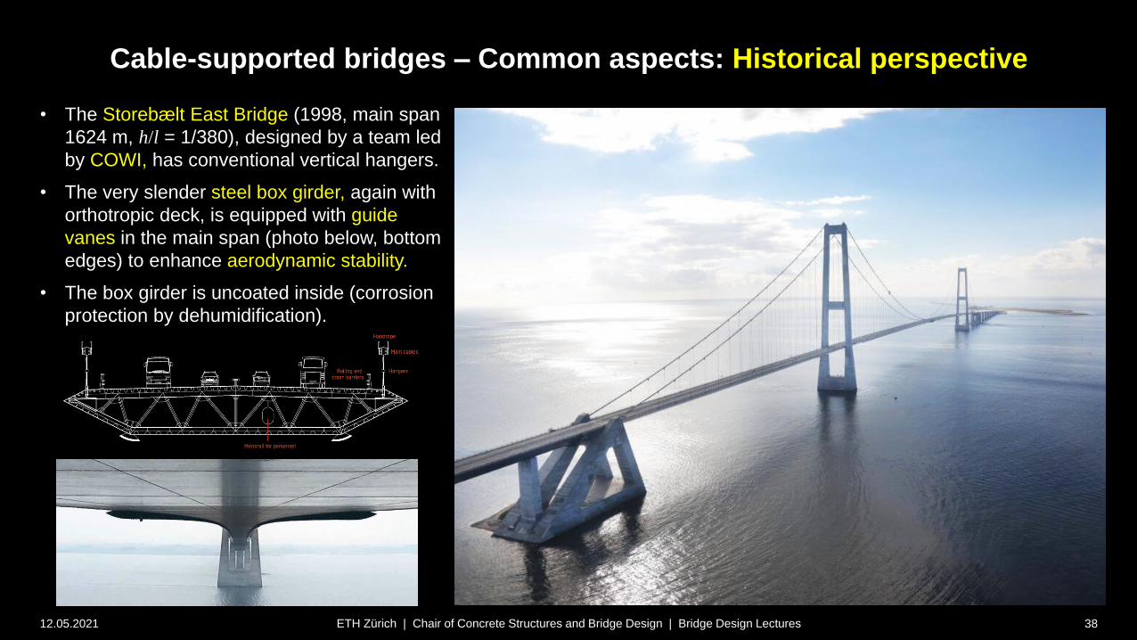
• The Storebælt East Bridge (1998, main span
1624 m, h/l = 1/380), designed by a team led
by COWI, has conventional vertical hangers.
• The very slender steel box girder, again with
orthotropic deck, is equipped with guide
vanes in the main span (photo below, bottom
edges) to enhance aerodynamic stability.
• The box girder is uncoated inside (corrosion
protection by dehumidification).
Cable-supported bridges – Common aspects: Historical perspective
12.05.2021 39ETH Zürich | Chair of Concrete Structures and Bridge Design | Bridge Design Lectures
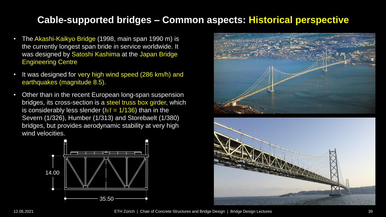
• The Akashi-Kaikyo Bridge (1998, main span 1990 m) is
the currently longest span bride in service worldwide. It
was designed by Satoshi Kashima at the Japan Bridge
Engineering Centre
• It was designed for very high wind speed (286 km/h) and
earthquakes (magnitude 8.5).
• Other than in the recent European long-span suspension
bridges, its cross-section is a steel truss box girder, which
is considerably less slender (h/l = 1/136) than in the
Severn (1/326), Humber (1/313) and Storebaelt (1/380)
bridges, but provides aerodynamic stability at very high
wind velocities.
35.50
14.00

Cable-supported bridges – Common aspects: Historical perspective
12.05.2021 40ETH Zürich | Chair of Concrete Structures and Bridge Design | Bridge Design Lectures
• The two main cables, with a diameter of 1.12 m,
were fabricated using prefabricated parallel wire
strands (PPWS)
• Each main cable consists of 290 PPWS with 127
wires Ø5.23 mm, totalling 36’830 wires per cable
(see Cable Types section).
Cable-supported bridges – Common aspects: Historical perspective
12.05.2021 41ETH Zürich | Chair of Concrete Structures and Bridge Design | Bridge Design Lectures
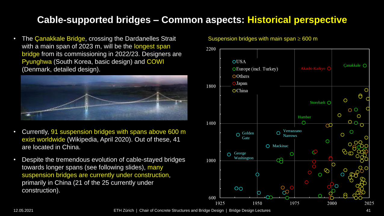
• The Çanakkale Bridge, crossing the Dardanelles Strait
with a main span of 2023 m, will be the longest span
bridge from its commissioning in 2022/23. Designers are
Pyunghwa (South Korea, basic design) and COWI
(Denmark, detailed design).
• Currently, 91 suspension bridges with spans above 600 m
exist worldwide (Wikipedia, April 2020). Out of these, 41
are located in China.
• Despite the tremendous evolution of cable-stayed bridges
towards longer spans (see following slides), many
suspension bridges are currently under construction,
primarily in China (21 of the 25 currently under
construction).
Suspension bridges with main span 600 m
George
Washington
Akashi-Kaikyo
Golden
Gate
Humber
Verrazzano
Narrows
Storebælt
Çanakkale
Mackinac
Cable-supported bridges – Common aspects: Historical perspective
12.05.2021 42ETH Zürich | Chair of Concrete Structures and Bridge Design | Bridge Design Lectures
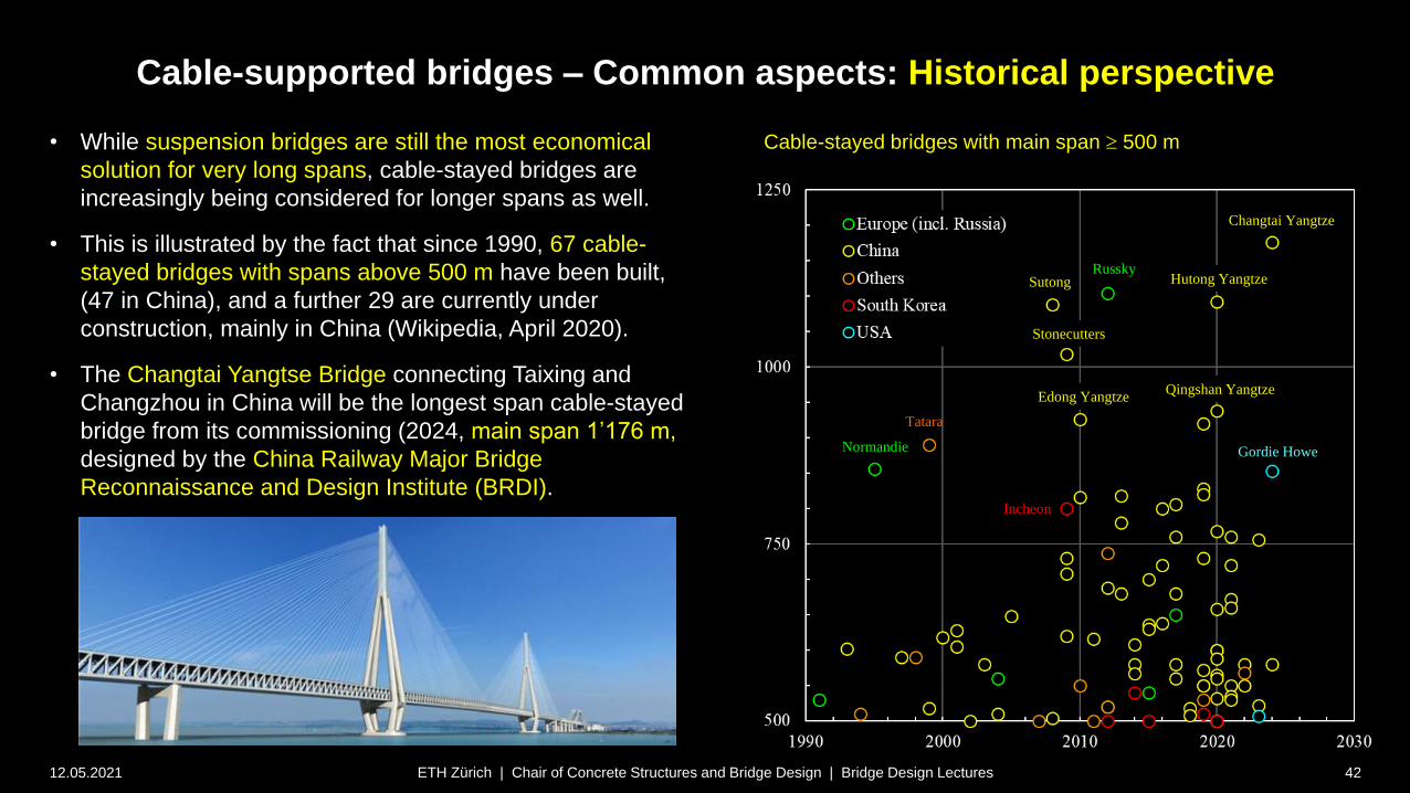
• While suspension bridges are still the most economical
solution for very long spans, cable-stayed bridges are
increasingly being considered for longer spans as well.
• This is illustrated by the fact that since 1990, 67 cable-
stayed bridges with spans above 500 m have been built,
(47 in China), and a further 29 are currently under
construction, mainly in China (Wikipedia, April 2020).
• The Changtai Yangtse Bridge connecting Taixing and
Changzhou in China will be the longest span cable-stayed
bridge from its commissioning (2024, main span 1’176 m,
designed by the China Railway Major Bridge
Reconnaissance and Design Institute (BRDI).
Cable-stayed bridges with main span 500 m
Russky
Tatara
Sutong
Normandie
Changtai Yangtze
Hutong Yangtze
Stonecutters
Edong Yangtze Qingshan Yangtze
Gordie Howe
Incheon
Cable-supported bridges – Common aspects: Historical perspective
12.05.2021 43ETH Zürich | Chair of Concrete Structures and Bridge Design | Bridge Design Lectures
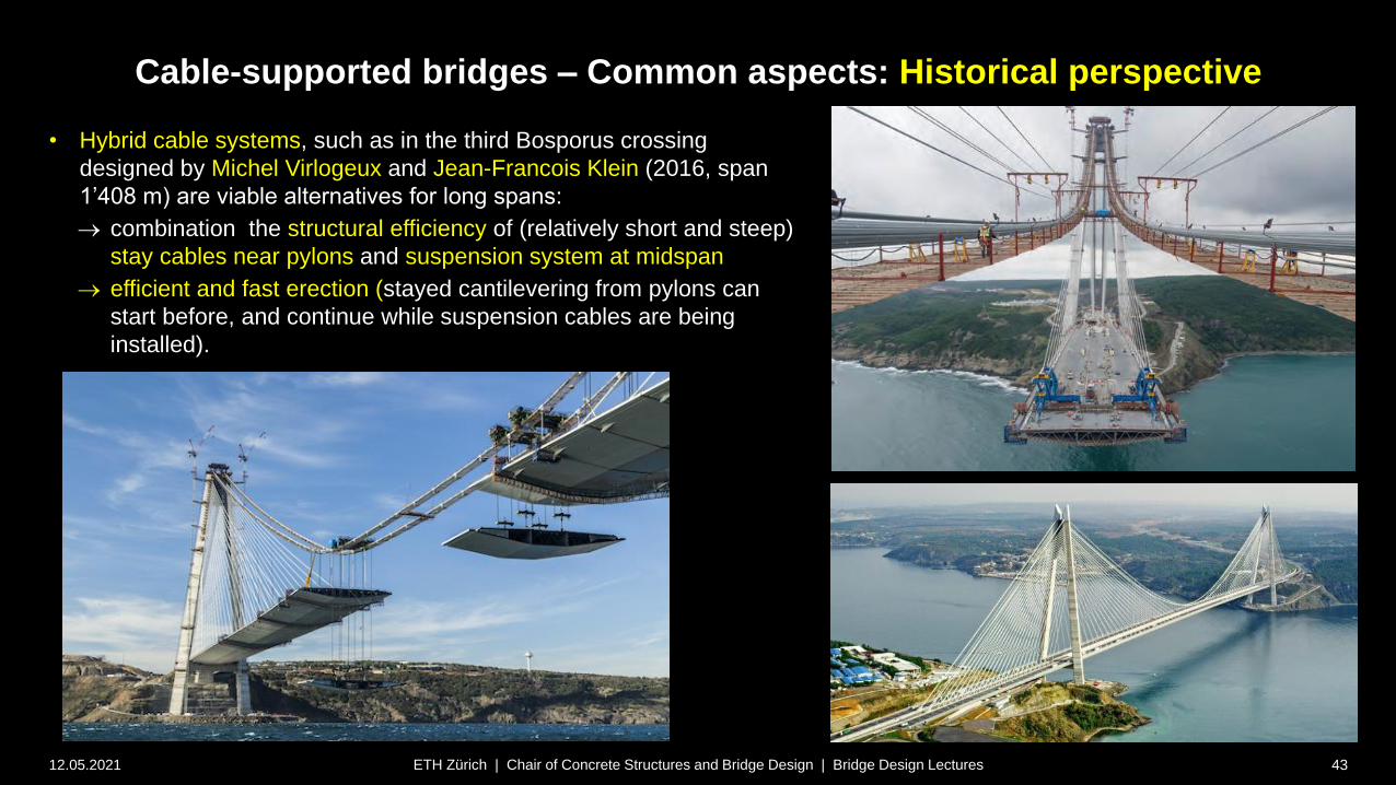
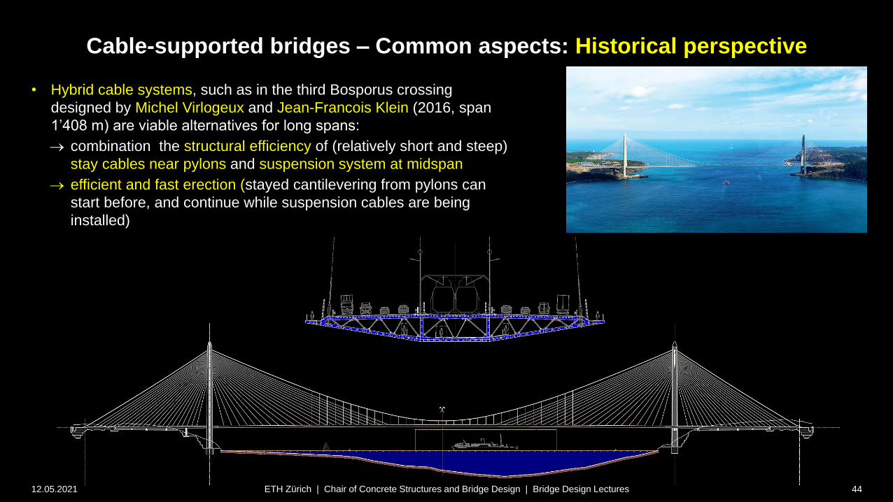
• Hybrid cable systems, such as in the third Bosporus crossing
designed by Michel Virlogeux and Jean-Francois Klein (2016, span
1’408 m) are viable alternatives for long spans:
combination the structural efficiency of (relatively short and steep)
stay cables near pylons and suspension system at midspan
efficient and fast erection (stayed cantilevering from pylons can
start before, and continue while suspension cables are being
installed).
Cable-supported bridges – Common aspects: Historical perspective
12.05.2021 44ETH Zürich | Chair of Concrete Structures and Bridge Design | Bridge Design Lectures
• Hybrid cable systems, such as in the third Bosporus crossing
designed by Michel Virlogeux and Jean-Francois Klein (2016, span
1’408 m) are viable alternatives for long spans:
combination the structural efficiency of (relatively short and steep)
stay cables near pylons and suspension system at midspan
efficient and fast erection (stayed cantilevering from pylons can
start before, and continue while suspension cables are being
installed)
Cable-supported bridges – Common aspects: Historical perspective
12.05.2021 45ETH Zürich | Chair of Concrete Structures and Bridge Design | Bridge Design Lectures
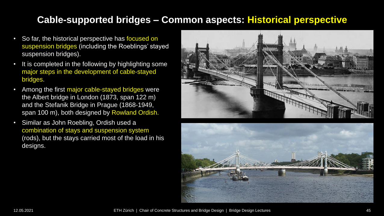
• So far, the historical perspective has focused on
suspension bridges (including the Roeblings’ stayed
suspension bridges).
• It is completed in the following by highlighting some
major steps in the development of cable-stayed
bridges.
• Among the first major cable-stayed bridges were
the Albert bridge in London (1873, span 122 m)
and the Stefanik Bridge in Prague (1868-1949,
span 100 m), both designed by Rowland Ordish.
• Similar as John Roebling, Ordish used a
combination of stays and suspension system
(rods), but the stays carried most of the load in his
designs.
Cable-supported bridges – Common aspects: Historical perspective
12.05.2021 46ETH Zürich | Chair of Concrete Structures and Bridge Design | Bridge Design Lectures
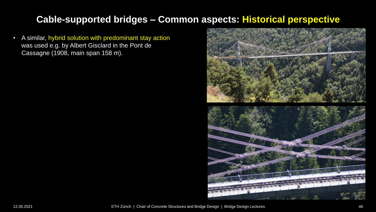
• A similar, hybrid solution with predominant stay action
was used e.g. by Albert Gisclard in the Pont de
Cassagne (1908, main span 158 m).
Cable-supported bridges – Common aspects: Historical perspective
12.05.2021 47ETH Zürich | Chair of Concrete Structures and Bridge Design | Bridge Design Lectures
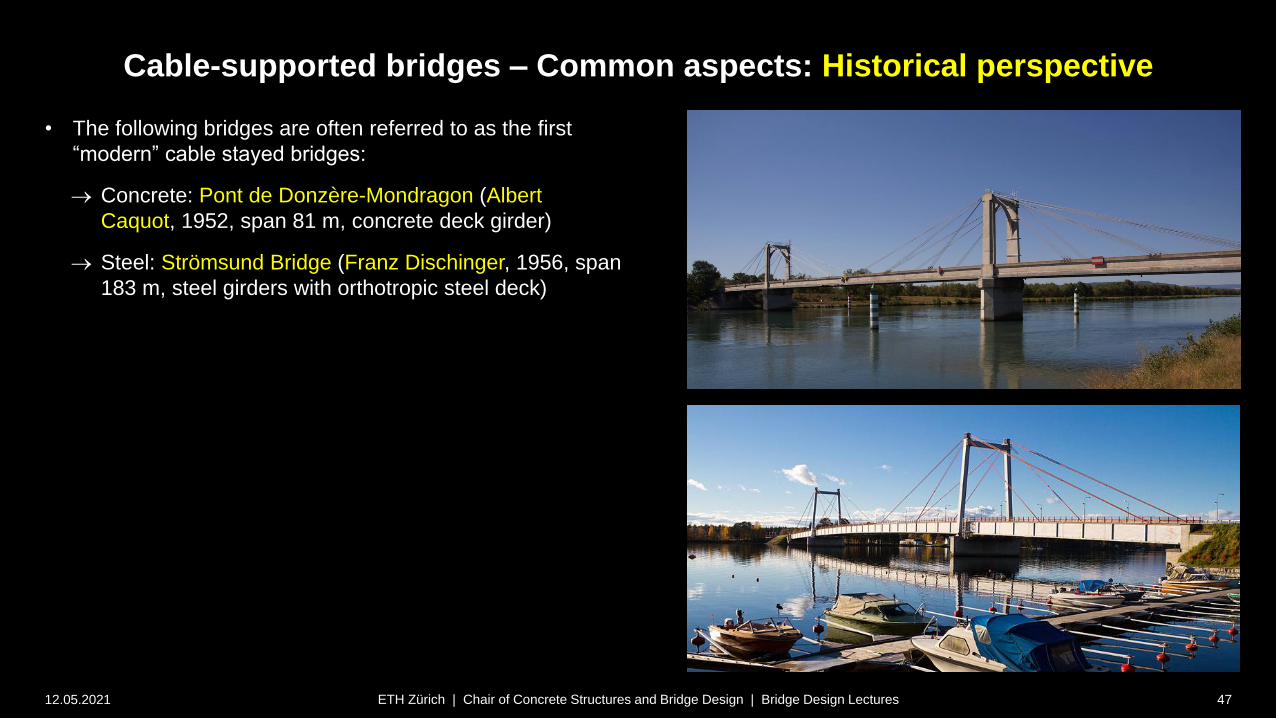
• The following bridges are often referred to as the first
“modern” cable stayed bridges:
Concrete: Pont de Donzère-Mondragon (Albert
Caquot, 1952, span 81 m, concrete deck girder)
Steel: Strömsund Bridge (Franz Dischinger, 1956, span
183 m, steel girders with orthotropic steel deck)

Cable-supported bridges – Common aspects: Historical perspective
12.05.2021 48ETH Zürich | Chair of Concrete Structures and Bridge Design | Bridge Design Lectures
• In the first cable-stayed bridges, few massive stays (in many
cases even only one stay per span) were used. In German,
such bridges are commonly referred to as “Zügelgurtbrücken”.
• Using single stays facilitated analysis and design, as the stays
could be treated as “flexible supports” (replacing a pier)
• A pioneer of this typology was Riccardo Morandi, who designed
several similar bridges like the Lake Maracaibo Bridge (1962, 5
main spans @ 235 m, total length 8.7 km. built in record time,
stays exchanged due to corrosion in 1982).
• To increase the stiffness of the stays, Morandi later replaced the
bare cables by prestressed concrete ties.
• Morandi’s concept of prestressed concrete ties was adopted by
many other designers due to its high efficiency, see bottom
example (Donaubrücke Metten, 1981, span 145 m).
Cable-supported bridges – Common aspects: Historical perspective
12.05.2021 49ETH Zürich | Chair of Concrete Structures and Bridge Design | Bridge Design Lectures
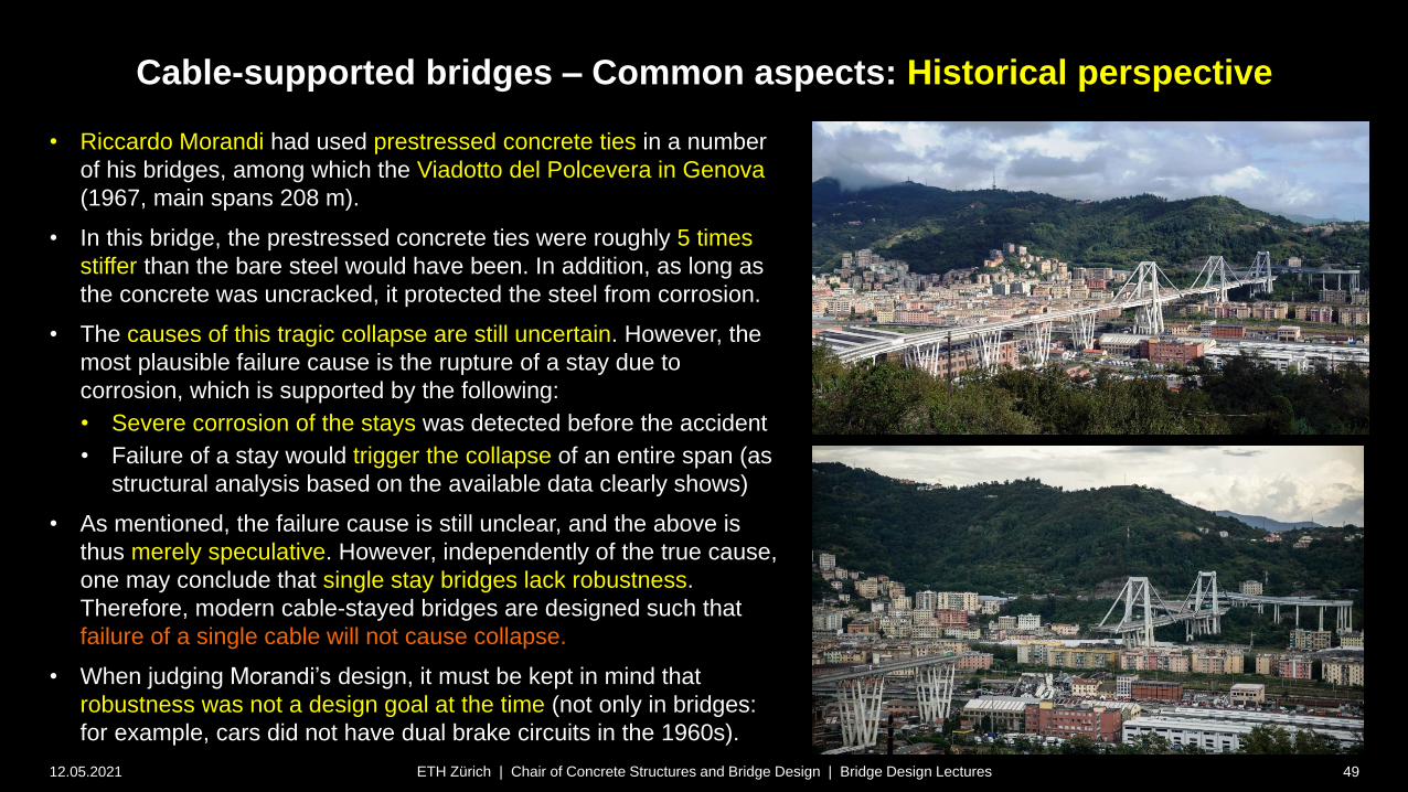
• Riccardo Morandi had used prestressed concrete ties in a number
of his bridges, among which the Viadotto del Polcevera in Genova
(1967, main spans 208 m).
• In this bridge, the prestressed concrete ties were roughly 5 times
stiffer than the bare steel would have been. In addition, as long as
the concrete was uncracked, it protected the steel from corrosion.
• The causes of this tragic collapse are still uncertain. However, the
most plausible failure cause is the rupture of a stay due to
corrosion, which is supported by the following:
• Severe corrosion of the stays was detected before the accident
• Failure of a stay would trigger the collapse of an entire span (as
structural analysis based on the available data clearly shows)
• As mentioned, the failure cause is still unclear, and the above is
thus merely speculative. However, independently of the true cause,
one may conclude that single stay bridges lack robustness.
Therefore, modern cable-stayed bridges are designed such that
failure of a single cable will not cause collapse.
• When judging Morandi’s design, it must be kept in mind that
robustness was not a design goal at the time (not only in bridges:
for example, cars did not have dual brake circuits in the 1960s).

Cable-supported bridges – Common aspects: Historical perspective
12.05.2021 50ETH Zürich | Chair of Concrete Structures and Bridge Design | Bridge Design Lectures
• The Theodor Heuss Brücke (1958, span: 260 m)
and the (Rhein-)Kniebrücke (1969, span 319 m),
both located in Düsseldorf and designed by Fritz
Leonhardt, underline the leading role of German
engineers in the development of cable-stayed
bridges.
• Both bridges share a harp arrangement of the
stays, in the case of the Kniebrücke combined with
anchor piers at all back stays, enabling a very
slender deck girder in the main span.

Cable-supported bridges – Common aspects: Historical perspective
12.05.2021 51ETH Zürich | Chair of Concrete Structures and Bridge Design | Bridge Design Lectures
• One of the first cable-stayed bridges with multiple
number of stays was the Rheinbrücke Bonn Nord
(1967, span 280 m), designed by Hellmut
Homberg.
• This was also among the few early cable-stayed
bridges with only one suspension plane, requiring a
high torsional stiffness of the deck girder.

Cable-supported bridges – Common aspects: Historical perspective
12.05.2021 52ETH Zürich | Chair of Concrete Structures and Bridge Design | Bridge Design Lectures
• The Puente de Rande, designed by Fabrizio de Miranda and
Florencio del Pozo (1978, widened in 2011, span 401 m,
second longest span at time of erection) was another early
multi-stay cable-stayed bridge.
• The Barrios de Luna bridge (1983, span 440 m) is an early
example of a bridge with closely spaced cables, enabling a
very slender deck girder.
• The designers Carlos Fernández Casado and Javier
Manterola took advantage of computing power to analyse
the highly statically indeterminate system.

Cable-supported bridges – Common aspects: Historical perspective
12.05.2021 53ETH Zürich | Chair of Concrete Structures and Bridge Design | Bridge Design Lectures
• With the Pont de Normandie (1994, span 856 m), designed
by Michel Virlogeux, the span range of cable-stayed bridges
was greatly increased.
• The Stonecutters Bridge (2009, span 1018 m), designed by
Arup, COWI and Buckland & Taylor, was the first cable-
stayed bridge with a span exceeding a kilometre.
• Clearly, with such long spans, aerodynamic effects are as
important in cable-stayed bridges as in suspension bridges.
• The progress of cable-stayed bridges towards longer spans
and more slender decks clearly benefitted from the
experiences with aerodynamic effects in long-span
suspension bridges. For example, the twin deck of the
Stonecutter’s bridge was chosen primarily for aerodynamic
reasons.
Cable-supported bridges
12.05.2021 54ETH Zürich | Chair of Concrete Structures and Bridge Design | Bridge Design Lectures
Common aspects – Cable types
Cable-supported bridges – Common aspects: Cable types
12.05.2021 55
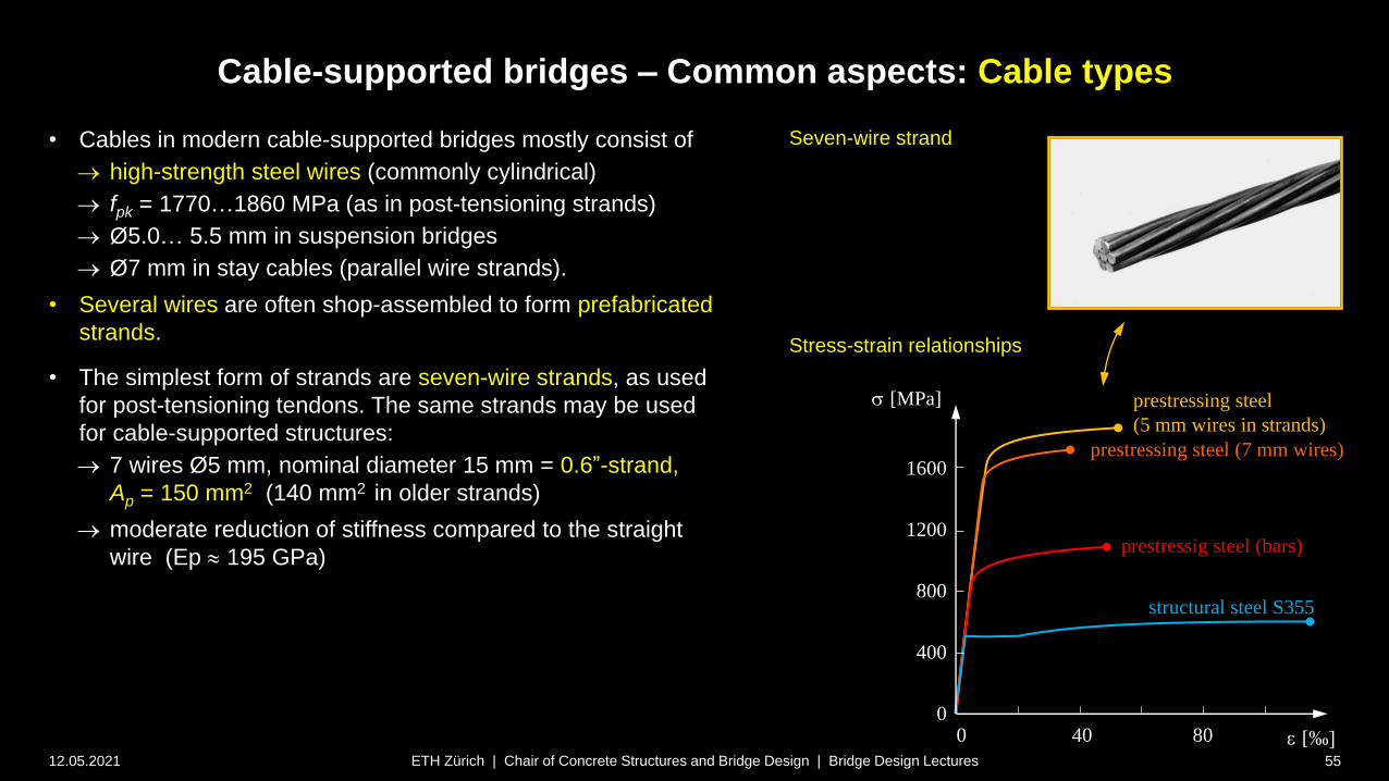
• Cables in modern cable-supported bridges mostly consist of
high-strength steel wires (commonly cylindrical)
fpk = 1770…1860 MPa (as in post-tensioning strands)
Ø5.0… 5.5 mm in suspension bridges
Ø7 mm in stay cables (parallel wire strands).
• Several wires are often shop-assembled to form prefabricated
strands.
• The simplest form of strands are seven-wire strands, as used
for post-tensioning tendons. The same strands may be used
for cable-supported structures:
7 wires Ø5 mm, nominal diameter 15 mm = 0.6”-strand,
Ap = 150 mm2 (140 mm2 in older strands)
moderate reduction of stiffness compared to the straight
wire (Ep 195 GPa)
ETH Zürich | Chair of Concrete Structures and Bridge Design | Bridge Design Lectures
e [‰]
s [MPa]
1600
1200
800
400
40 80
prestressing steel
(5 mm wires in strands)
prestressing steel (7 mm wires)
prestressig steel (bars)
structural steel S355
00
Seven-wire strand
Stress-strain relationships
Cable-supported bridges – Common aspects: Cable types
12.05.2021 56
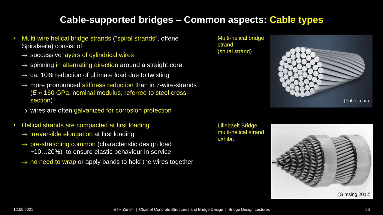
• Multi-wire helical bridge strands (“spiral strands”, offene
Spiralseile) consist of
successive layers of cylindrical wires
spinning in alternating direction around a straight core
ca. 10% reduction of ultimate load due to twisting
more pronounced stiffness reduction than in 7-wire-strands
(E 160 GPa, nominal modulus, referred to steel cross-
section)
wires are often galvanized for corrosion protection
• Helical strands are compacted at first loading
irreversible elongation at first loading
pre-stretching common (characteristic design load
+10…20%) to ensure elastic behaviour in service
no need to wrap or apply bands to hold the wires together
ETH Zürich | Chair of Concrete Structures and Bridge Design | Bridge Design Lectures
Multi-helical bridge
strand
(spiral strand)
Lillebaelt Bridge
multi-helical strand
exhibit
[Gimsing 2012]
[Fatzer.com]
Cable-supported bridges – Common aspects: Cable types
12.05.2021 57
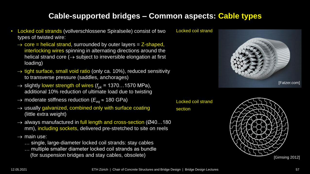
• Locked coil strands (vollverschlossene Spiralseile) consist of two
types of twisted wire:
core = helical strand, surrounded by outer layers = Z-shaped,
interlocking wires spinning in alternating directions around the
helical strand core ( subject to irreversible elongation at first
loading)
tight surface, small void ratio (only ca. 10%), reduced sensitivity
to transverse pressure (saddles, anchorages)
slightly lower strength of wires (fpk = 1370…1570 MPa),
additional 10% reduction of ultimate load due to twisting
moderate stiffness reduction (Eeq 180 GPa)
usually galvanized, combined only with surface coating
(little extra weight)
always manufactured in full length and cross-section (Ø40…180
mm), including sockets, delivered pre-stretched to site on reels
main use:
… single, large-diameter locked coil strands: stay cables
… multiple smaller diameter locked coil strands as bundle
(for suspension bridges and stay cables, obsolete)
ETH Zürich | Chair of Concrete Structures and Bridge Design | Bridge Design Lectures
[Gimsing 2012]
Locked coil strand
Locked coil strand
section
[Fatzer.com]
Cable-supported bridges – Common aspects: Cable types
12.05.2021 58
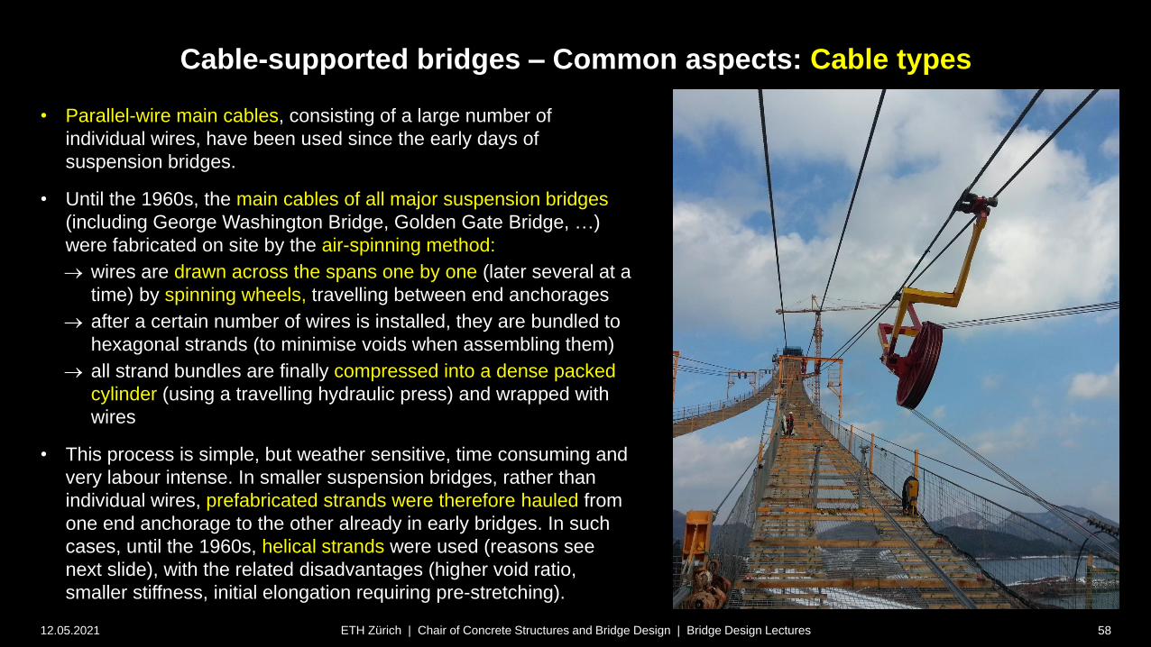
• Parallel-wire main cables, consisting of a large number of
individual wires, have been used since the early days of
suspension bridges.
• Until the 1960s, the main cables of all major suspension bridges
(including George Washington Bridge, Golden Gate Bridge, …)
were fabricated on site by the air-spinning method:
wires are drawn across the spans one by one (later several at a
time) by spinning wheels, travelling between end anchorages
after a certain number of wires is installed, they are bundled to
hexagonal strands (to minimise voids when assembling them)
all strand bundles are finally compressed into a dense packed
cylinder (using a travelling hydraulic press) and wrapped with
wires
• This process is simple, but weather sensitive, time consuming and
very labour intense. In smaller suspension bridges, rather than
individual wires, prefabricated strands were therefore hauled from
one end anchorage to the other already in early bridges. In such
cases, until the 1960s, helical strands were used (reasons see
next slide), with the related disadvantages (higher void ratio,
smaller stiffness, initial elongation requiring pre-stretching).
ETH Zürich | Chair of Concrete Structures and Bridge Design | Bridge Design Lectures

Cable-supported bridges – Common aspects: Cable types
12.05.2021 59
• Pre-fabricated parallel-wire strands PPWS (Paralleldrahtkabel)
require neither reducing strength nor stiffness compared to the
individual wires, which is clearly an advantage over helical
strands, but they
were not used until the 1960s due to concerns about reeling
(curving the undistorted section of a large parallel wire strand
causes high stresses in the inner- and outermost wires)
• However, tests in the 1960s showed that parallel wire strands
rotate when reeled (thus avoiding the excessive stresses).
• Since then, PPWS cables have largely replaced helical and
locked-coil cables in short and medium span, as well as air-spun
parallel wire cables in large span suspension bridges.
• Since long cables are required, the number of wires per strand is
limited by transport and erection capacities. In recent suspension
bridges, PPWS with up to 127 wires Ø5 mm were used,
assembling the main cables from a large number of PPWS (figure:
Strand reel Akashi-Kaikyo bridge, weight 85 t for a 4 km long 127-
wire strand; 290 strands form each of the two main cables).
• The PPWS are hexagonal as the air-spun strands.
ETH Zürich | Chair of Concrete Structures and Bridge Design | Bridge Design Lectures
Prefabricated
parallel wire
strands
(parts of a
main cable)
Strand reel
[Gimsing 2012]
[Gimsing 2012]
Cable-supported bridges – Common aspects: Cable types
12.05.2021 60ETH Zürich | Chair of Concrete Structures and Bridge Design | Bridge Design Lectures
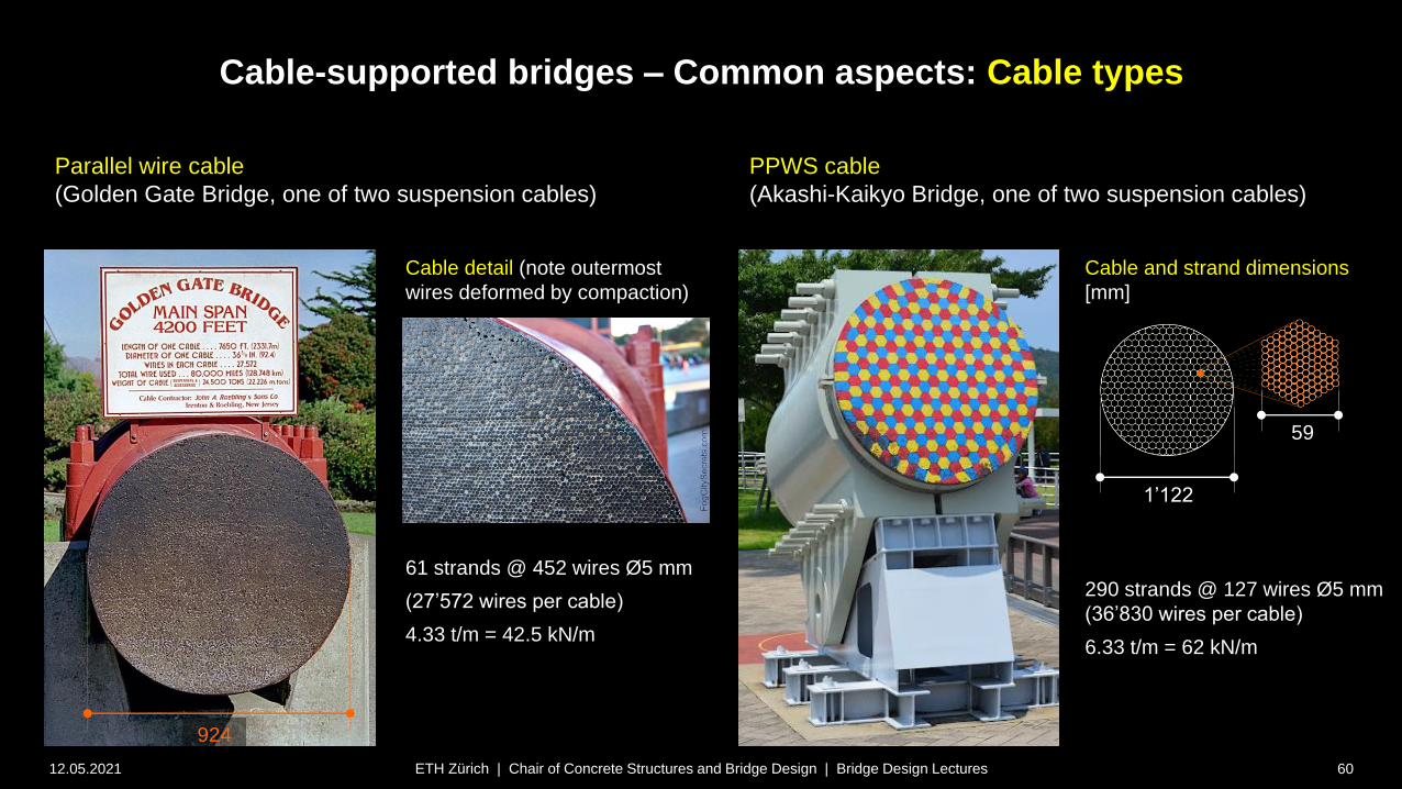
Cable detail (note outermost
wires deformed by compaction)
Cable and strand dimensions
[mm]
Parallel wire cable
(Golden Gate Bridge, one of two suspension cables)
PPWS cable
(Akashi-Kaikyo Bridge, one of two suspension cables)
61 strands @ 452 wires Ø5 mm
(27’572 wires per cable)
4.33 t/m = 42.5 kN/m
290 strands @ 127 wires Ø5 mm
(36’830 wires per cable)
6.33 t/m = 62 kN/m
1’122
59
924

Cable-supported bridges – Common aspects: Cable types
12.05.2021 61
• Larger parallel wire strands (up to 499 wires Ø7mm could be
produced according to suppliers) are used for stay cables (top
figure: largest stay cable of Zarate-Brazo Largo Bridges in
Argentina (337 Ø7 mm wires)
• Perfectly parallel wire strands need to be held together
wrapping by a spiral cable was usual in early cable-stayed
bridges using parallel wire strands
additional PE tube with corrosion inhibitor in void
disadvantage: large diameter (wind loads) and higher dead
load
• Since the 1990s, “New parallel wire strands”, developed in
Japan, are being used (bottom figure). In these, the wire
bundle is slightly twisted
self-consolidating under tension (no need for wrapping)
easier (un)reeling
improved corrosion protection (cover extruded directly on
wire bundle)
ETH Zürich | Chair of Concrete Structures and Bridge Design | Bridge Design Lectures
Prefabricated
parallel wire
strands
(stay cable)
[Gimsing 2012]
[Gimsing 2012]
HDPE cover
filament tape
wires Ø7 mm
Cable-supported bridges – Common aspects: Cable types
12.05.2021 62
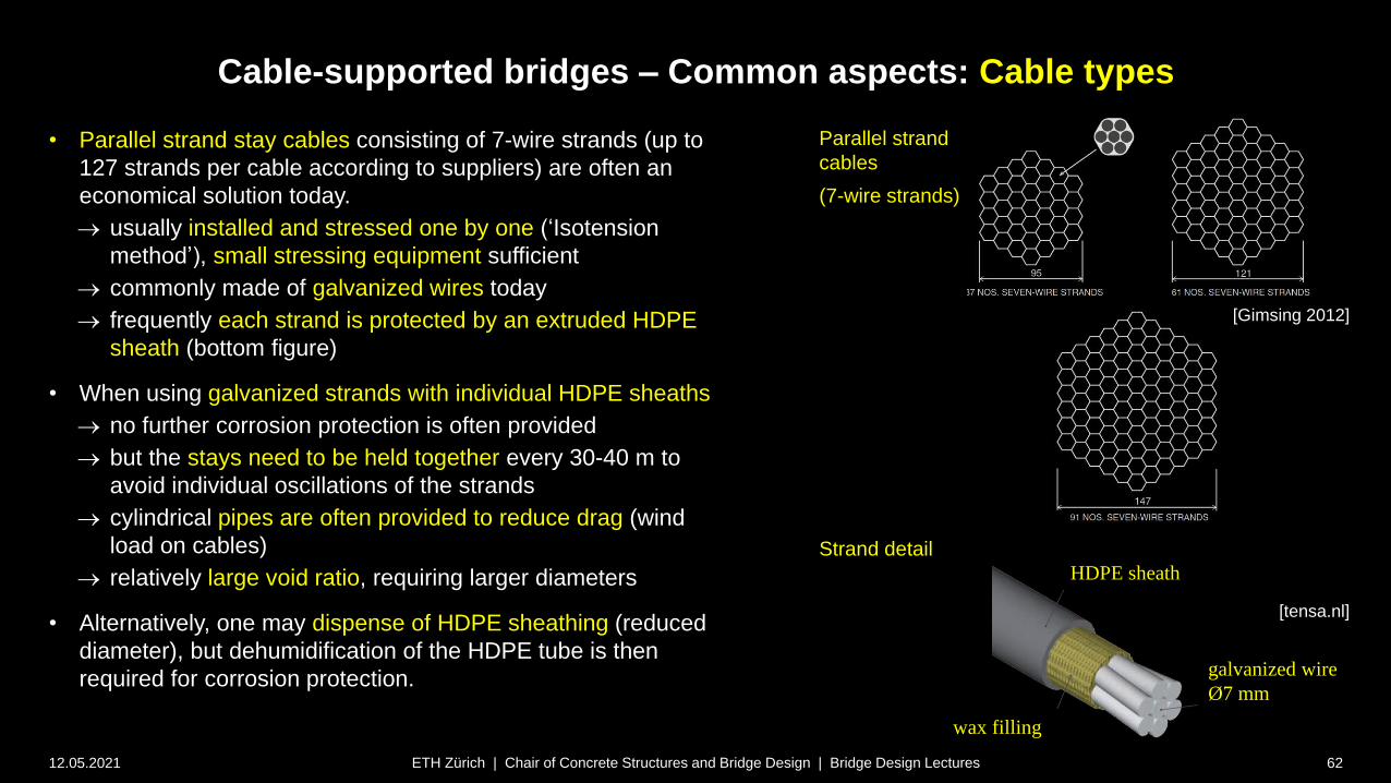
• Parallel strand stay cables consisting of 7-wire strands (up to
127 strands per cable according to suppliers) are often an
economical solution today.
usually installed and stressed one by one (‘Isotension
method’), small stressing equipment sufficient
commonly made of galvanized wires today
frequently each strand is protected by an extruded HDPE
sheath (bottom figure)
• When using galvanized strands with individual HDPE sheaths
no further corrosion protection is often provided
but the stays need to be held together every 30-40 m to
avoid individual oscillations of the strands
cylindrical pipes are often provided to reduce drag (wind
load on cables)
relatively large void ratio, requiring larger diameters
• Alternatively, one may dispense of HDPE sheathing (reduced
diameter), but dehumidification of the HDPE tube is then
required for corrosion protection.
ETH Zürich | Chair of Concrete Structures and Bridge Design | Bridge Design Lectures
Parallel strand
cables
(7-wire strands)
[Gimsing 2012]
[tensa.nl]
Strand detail
galvanized wire
Ø7 mm
wax filling
HDPE sheath
Cable-supported bridges – Common aspects: Cable types
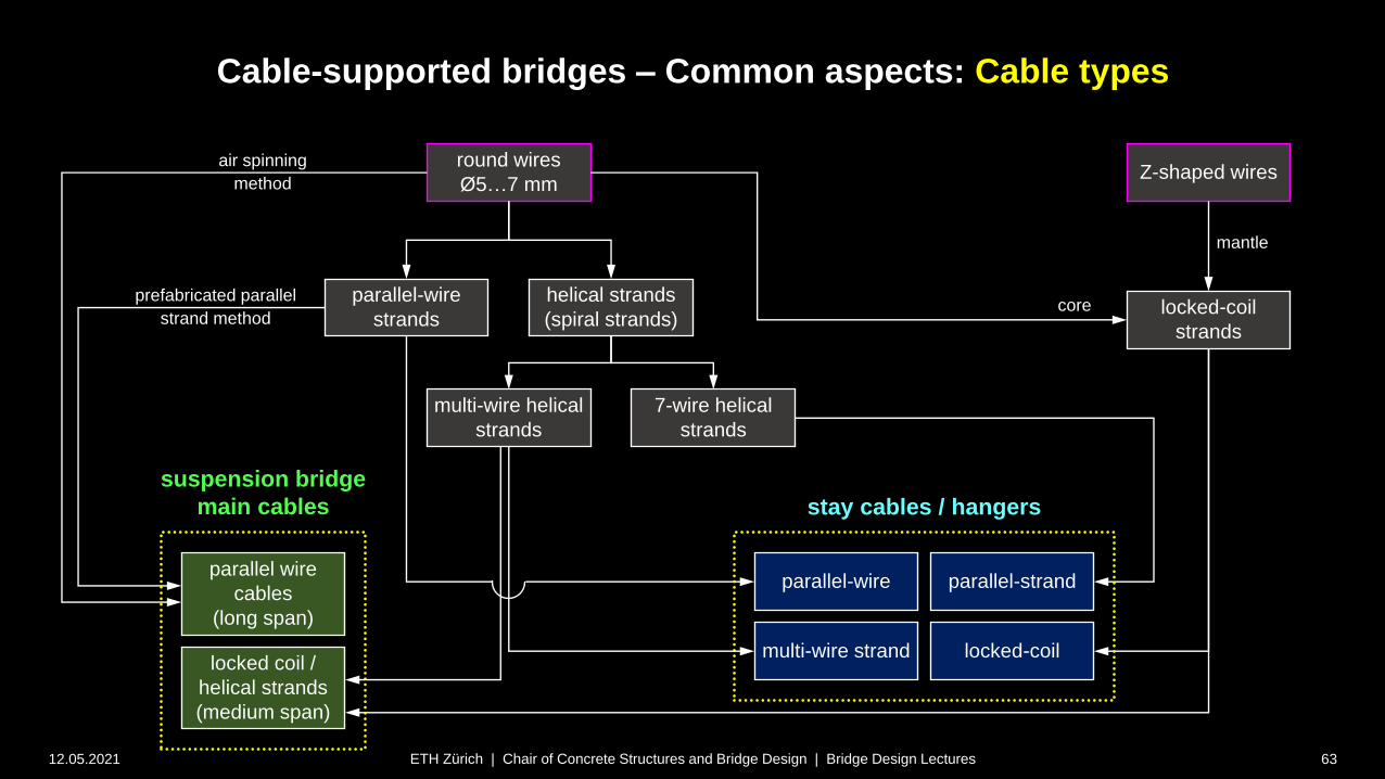
12.05.2021 63ETH Zürich | Chair of Concrete Structures and Bridge Design | Bridge Design Lectures
round wires
Ø5…7 mm
helical strands
(spiral strands)
multi-wire helical
strands
parallel-wire
strands
7-wire helical
strands
parallel-strand
locked-coillocked coil /
helical strands
(medium span)
Z-shaped wires
locked-coil
strands
parallel-wire
multi-wire strand
parallel wire
cables
(long span)
stay cables / hangers
suspension bridge
main cables
air spinning
method
prefabricated parallel
strand methodcore
mantle

Cable-supported bridges – Common aspects: Cable types
12.05.2021 64ETH Zürich | Chair of Concrete Structures and Bridge Design | Bridge Design Lectures
round wires
Ø5…7 mm
helical strands
(spiral strands)
multi-wire helical
strands
parallel-wire
strands
7-wire helical
strands
parallel-strand
(stay cables)
locked coil /
helical strands
(medium span)
Z-shaped wires
locked-coil
strands
parallel-wire
(stay cables)
multi-wire strand
parallel wire
cables
(long span)
stay cables / hangers
suspension bridge
main cables
air spinning
method
prefabricated parallel
strand methodcore
mantle
locked-coil
(susp./stay cables)
Cable-supported bridges – Common aspects: Cable types
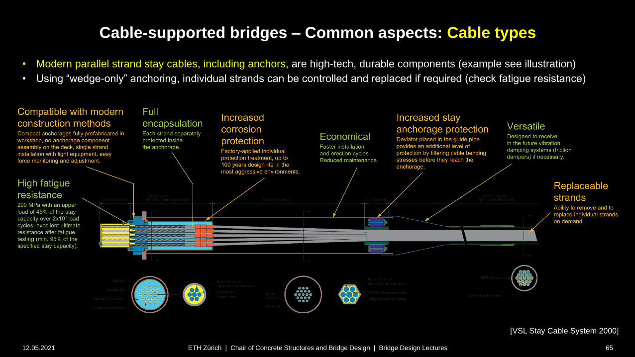
12.05.2021 ETH Zürich | Chair of Concrete Structures and Bridge Design | Bridge Design Lectures 65
• Modern parallel strand stay cables, including anchors, are high-tech, durable components (example see illustration)
• Using “wedge-only” anchoring, individual strands can be controlled and replaced if required (check fatigue resistance)
[VSL Stay Cable System 2000]
Cable-supported bridges
12.05.2021 66ETH Zürich | Chair of Concrete Structures and Bridge Design | Bridge Design Lectures
Common aspects – Static analysis of cables
General cable behaviour
Cable-supported bridges – Common aspects: Laterally loaded cables
12.05.2021 67
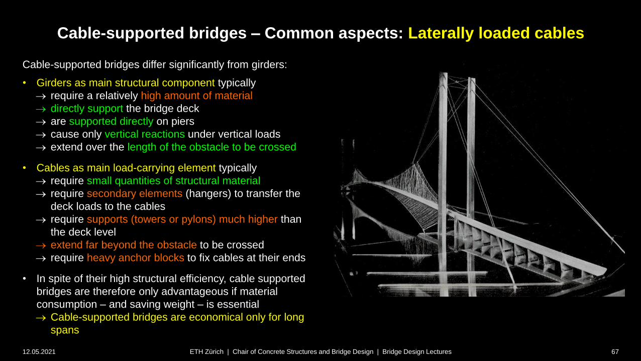
Cable-supported bridges differ significantly from girders:
• Girders as main structural component typically
require a relatively high amount of material
directly support the bridge deck
are supported directly on piers
cause only vertical reactions under vertical loads
extend over the length of the obstacle to be crossed
• Cables as main load-carrying element typically
require small quantities of structural material
require secondary elements (hangers) to transfer the
deck loads to the cables
require supports (towers or pylons) much higher than
the deck level
extend far beyond the obstacle to be crossed
require heavy anchor blocks to fix cables at their ends
• In spite of their high structural efficiency, cable supported
bridges are therefore only advantageous if material
consumption – and saving weight – is essential
Cable-supported bridges are economical only for long
spans
ETH Zürich | Chair of Concrete Structures and Bridge Design | Bridge Design Lectures

Cable-supported bridges – Common aspects: General cable behaviour
12.05.2021
• While cables are very stiff under funicular loads (loads for
which the cable’s initial geometry is funicular, commonly
dead load), they are considerably more flexible than girders
under non-funicular load configurations.
• Hence, in the design of cable-supported structures,
deformations are more of a concern than strength.
• In the detailed analysis and design of cable-supported
bridges, numerical methods are used today, accounting for
nonlinearities caused by large displacements, for the final
layout as well as erection stages.
• If common cable configurations are used (reasonably two-
dimensional cable planes), the initial geometry of the cable
system may be determined using the same numerical
methods, or the approximations for preliminary design
outlined on the following slides.
• For complex, three-dimensional cable configurations,
specialised form-finding tools may be used.
ETH Zürich | Chair of Concrete Structures and Bridge Design | Bridge Design Lectures
z
x
Cable profiles under non-symmetric load
dead load cable
profile = funicular
curve for g
cable profile under
g+q
funicular curve for g+q
(cable profile under
g+q witout stiffening
girder)
q
g
68
deflection of deck
under g+q (assuming
horizontal alignment
under g as shown in
white)

Cable-supported bridges – Common aspects: General cable behaviour
12.05.2021 69
• The cable geometry under a given load can
be determined iteratively, using the cable
equation. This is outlined here following the
lines of Marti, Theory of Structures (2012).
• Since large deformations occur, the
equilibrium conditions must be formulated for
the deformed system (using linear statics, a
cable with EI 0 can only resist loads for
which its initial geometry is funicular).
• Consider a flexible cable with constant axial
stiffness but EI = 0 spanning between points
O and A (left figure). The cable has an initial
length L, and carries a vertical line load q(x)
(including its self-weight).
• The cable equation is obtained formulating
equilibrium of the deformed system (right
figure and equations).
• The additional terms LaTDT and Ls0/E
account for possible thermal strain and cable
prestress, constant along the cable length.
ETH Zürich | Chair of Concrete Structures and Bridge Design | Bridge Design Lectures
q
S dS
z
xS
H dH
H
V dV
V
qdx
ds
dxl
aO
Aconst
0
EA
EI
2 2 2geometry: (a) 1 with
(b) 0 const directly from (b)
equilibrium: (c) 0 rewrite (d), with
(d) 0 differentiate (d), insert (c)
cab
x
z
y
ds dx dz dx z z dz dx
F dH H
F qdx dV V Hz z dz dx
M Hdz Vdx Hz q
2
2
2
2 0
2
1
le force: (e) 1 since , see above
deformed cable length:
initial length changes due to ,
1 1 "cabl
a
e eq
t
uat
l
io
n
t
"
e as ic str ins hermal strains T
l l
T
o o
S zz dx L T dx
S H V H z V Hz
L S EA
E EA
s a D
a
0 and prestress TD s
dz
Static system of cable and cable element
(adapted from Marti, 2012; a = secant inclination due to anchorage height difference)
Cable-supported bridges – Common aspects: General cable behaviour
12.05.2021 70
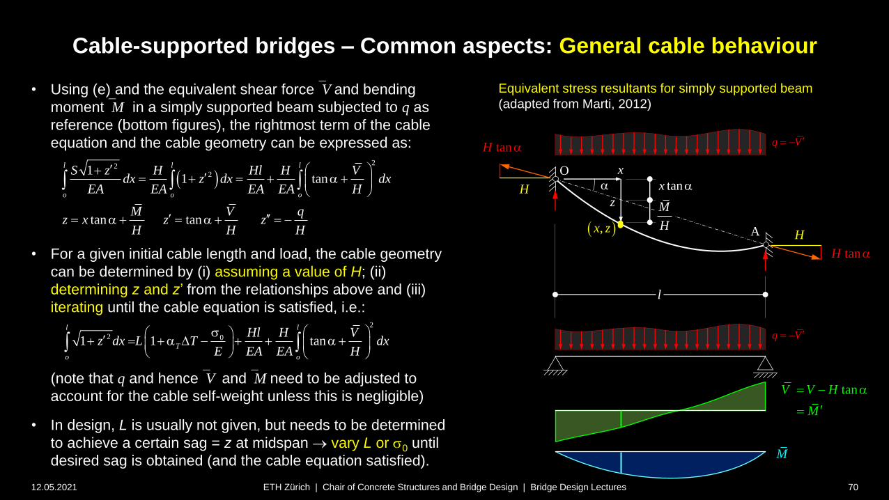
• Using (e) and the equivalent shear forceV and bending
momentM in a simply supported beam subjected to q as
reference (bottom figures), the rightmost term of the cable
equation and the cable geometry can be expressed as:
• For a given initial cable length and load, the cable geometry
can be determined by (i) assuming a value of H; (ii)
determining z and z’ from the relationships above and (iii)
iterating until the cable equation is satisfied, i.e.:
(note that q and henceV andM need to be adjusted to
account for the cable self-weight unless this is negligible)
• In design, L is usually not given, but needs to be determined
to achieve a certain sag = z at midspan vary L or s0 until
desired sag is obtained (and the cable equation satisfied).
ETH Zürich | Chair of Concrete Structures and Bridge Design | Bridge Design Lectures
tanV V H
M
a
z
x
H
tanH a
l
aO
A
H
tanH a
tanx a
M
H ,x z
M
22
211 tan
tan tan
l l l
o o o
S z H Hl H Vdx z dx dx
EA EA EA EA H
M V qz x z z
H H H
a
a a
q V
2
2 01 1 tan
l l
T
o o
Hl H Vz dx L T dx
E EA EA H
s a D a
Equivalent stress resultants for simply supported beam
(adapted from Marti, 2012)
q V
Cable-supported bridges – Common aspects: General cable behaviour
12.05.2021
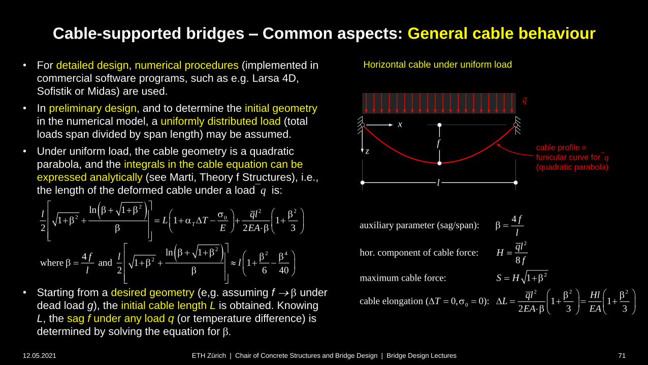
• For detailed design, numerical procedures (implemented in
commercial software programs, such as e.g. Larsa 4D,
Sofistik or Midas) are used.
• In preliminary design, and to determine the initial geometry
in the numerical model, a uniformly distributed load (total
loads span divided by span length) may be assumed.
• Under uniform load, the cable geometry is a quadratic
parabola, and the integrals in the cable equation can be
expressed analytically (see Marti, Theory f Structures), i.e.,
the length of the deformed cable under a loadq is:
• Starting from a desired geometry (e,g. assuming f b under
dead load g), the initial cable length L is obtained. Knowing
L, the sag f under any load q (or temperature difference) is
determined by solving the equation for b.
ETH Zürich | Chair of Concrete Structures and Bridge Design | Bridge Design Lectures
Horizontal cable under uniform load
z
x
cable profile =
funicular curve forq
(quadratic parabola)
q
2
2
2 2 2
0
4auxiliary parameter (sag/span):
hor. component of cable force:8
maximum cable force: 1
cable elongation ( 0, 0): 1 12 3 3
f
l
qlH
f
S H
ql HlT L
EA EA
b
b
b bD s D
b
22 2
2 0
22 4
2
ln 11 1 1
2 2 3
ln 14where and 1 1
2 6 40
T
l qlL T
E EA
f ll
l
b b s b b a D b b
b b b b b b b
f
l
71
Cable-supported bridges
12.05.2021 72ETH Zürich | Chair of Concrete Structures and Bridge Design | Bridge Design Lectures
Common aspects – Static analysis of Cables
Laterally (usually vertically) loaded cables

Cable-supported bridges – Common aspects: Laterally loaded cables
12.05.2021 73
• On this and the following slides, the behaviour of suspension
bridges (resp. their main cables) is investigated following the
example used by Gimsing (see notes for source).
• The example is based on the following basic parameters:
• span l = 1’000 m, fg /l = 0.1 (100 m sag under g )
• dead load g = 220 kN/m, traffic load q = 80 kN/m
• cable cross-section A = 0.56 m2 (14’551 wires Ø7 mm)
(cable weight = 44.0 kN/m 20% of g, not negligible!)
• Solving the cable equation for bg= 0.4 (dead load geometry,
no thermal strain nor prestress), the initial cable length L is:
• The full load geometry is obtained by solving for bg+q :
ETH Zürich | Chair of Concrete Structures and Bridge Design | Bridge Design Lectures
Deflection under traffic load acting over varying width b
(adapted from Gimsing 2012)
z
x
1000 ml
80 kN/mq
220 kN/mg
gf
( )w q
dead load cable profile =
funicular curve for g
cable profile under g+q
w(q) = deflection due to q)
2
2
2
Dead load ( 220 kN/m, chosen 100 m):
40.4000 275 MN
8
1 296 MN 491 MPa
Full load ( 300 kN/m, cable equation 101.726 m):
40.4069 368 M
8
g
g
g g
g
g
g g g g
c
g q
g q
g q g q
g q
g f
f glH
l f
SS H
A
g q f
f g q lH
l f
b
b s
b
2
N
1 398 MN 711 MPag q
g q g q g q g q
c
SS H
A
b s
222
2ln 1
1 1 1023.474 m2 2 3
g gg
g
g g
l glL L
EA
b b b b b b
2
22
2ln 1
1 12 2 3
0.4069, 101.726 m, ( ) 101.726 100 1.726 m4
g q g qg q
g q
g q g q
g q
g q g q
g q llL
EA
lf w q
b b b b b b b
b

Cable-supported bridges – Common aspects: Laterally loaded cables
12.05.2021 74
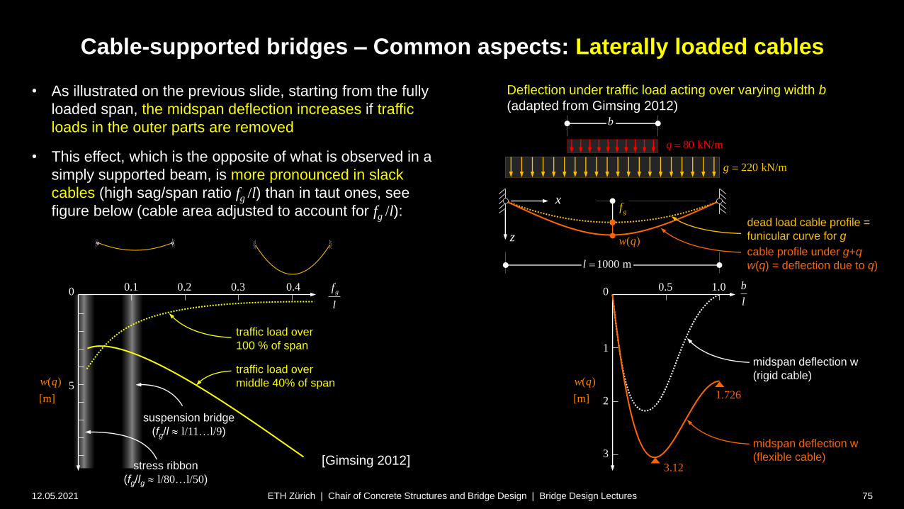
• This slide compares the midspan deflection due to traffic
load over the central part of the main span, over a varying
portion b of the span l:
the midspan deflection under traffic load over the full
span is 1.726 m, fully due to cable elongation.
the same deflection is obtained for only ca. 10% loaded
length
under partial length loading, the cable deflects more,
with a maximum deflection of 3.12 m for a loaded
length of about 40% of the span
only about 1/3 of the maximum deflection is due to
cable elongation for 40% loaded length. The remaining
deflection is due to the change of cable geometry.
note that under uniform load (traffic load over the full
span), deflections of a rigid cable are zero.
ETH Zürich | Chair of Concrete Structures and Bridge Design | Bridge Design Lectures
Deflection under traffic load acting over varying width b
(adapted from Gimsing 2012)
z
x
1000 ml
b
80 kN/mq
220 kN/mg
gf
( )w q
b
l
( )
[m]
w q
0
1
2
3
0.5 1.0
midspan deflection w
(flexible cable)
midspan deflection w
(rigid cable)
3.12
1.726
dead load cable profile =
funicular curve for g
cable profile under g+q
w(q) = deflection due to q)
Cable-supported bridges – Common aspects: Laterally loaded cables
12.05.2021 75
• As illustrated on the previous slide, starting from the fully
loaded span, the midspan deflection increases if traffic
loads in the outer parts are removed
• This effect, which is the opposite of what is observed in a
simply supported beam, is more pronounced in slack
cables (high sag/span ratio fg /l) than in taut ones, see
figure below (cable area adjusted to account for fg /l):
ETH Zürich | Chair of Concrete Structures and Bridge Design | Bridge Design Lectures
Deflection under traffic load acting over varying width b
(adapted from Gimsing 2012)
z
x
1000 ml
b
80 kN/mq
220 kN/mg
gf
( )w q
b
l
( )
[m]
w q
0
1
2
3
0.5 1.0
midspan deflection w
(flexible cable)
midspan deflection w
(rigid cable)
3.12
1.726
gf
l
( )
[m]
w q
0
5
0.1 0.2
traffic load over
middle 40% of span
traffic load over
100 % of span
0.3 0.4
suspension bridge
(fg/l l/11…l/9)
[Gimsing 2012]stress ribbon
(fg/lg l/80…l/50)
dead load cable profile =
funicular curve for g
cable profile under g+q
w(q) = deflection due to q)
Cable-supported bridges – Common aspects: Laterally loaded cables
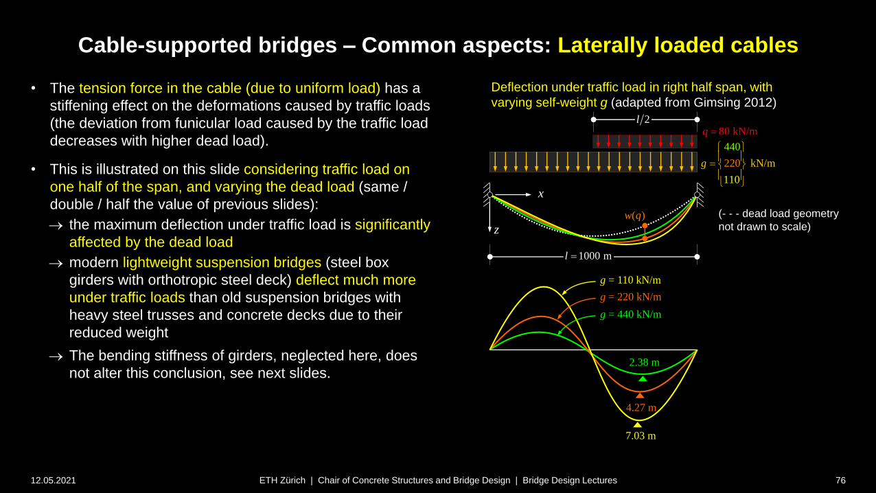
12.05.2021 76
• The tension force in the cable (due to uniform load) has a
stiffening effect on the deformations caused by traffic loads
(the deviation from funicular load caused by the traffic load
decreases with higher dead load).
• This is illustrated on this slide considering traffic load on
one half of the span, and varying the dead load (same /
double / half the value of previous slides):
the maximum deflection under traffic load is significantly
affected by the dead load
modern lightweight suspension bridges (steel box
girders with orthotropic steel deck) deflect much more
under traffic loads than old suspension bridges with
heavy steel trusses and concrete decks due to their
reduced weight
The bending stiffness of girders, neglected here, does
not alter this conclusion, see next slides.
ETH Zürich | Chair of Concrete Structures and Bridge Design | Bridge Design Lectures
Deflection under traffic load in right half span, with
varying self-weight g (adapted from Gimsing 2012)
z
x
1000 ml
2l80 kN/mq
220 m
11
/
44
0
kN
0
g
(- - - dead load geometry
not drawn to scale)( )w q
g = 110 kN/m
g = 220 kN/m
g = 440 kN/m
7.03 m
4.27 m
2.38 m
Cable-supported bridges – Common aspects: Laterally loaded cables
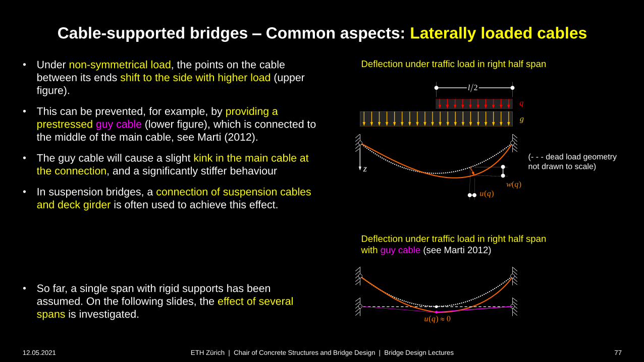
12.05.2021 77
• Under non-symmetrical load, the points on the cable
between its ends shift to the side with higher load (upper
figure).
• This can be prevented, for example, by providing a
prestressed guy cable (lower figure), which is connected to
the middle of the main cable, see Marti (2012).
• The guy cable will cause a slight kink in the main cable at
the connection, and a significantly stiffer behaviour
• In suspension bridges, a connection of suspension cables
and deck girder is often used to achieve this effect.
• So far, a single span with rigid supports has been
assumed. On the following slides, the effect of several
spans is investigated.
ETH Zürich | Chair of Concrete Structures and Bridge Design | Bridge Design Lectures
Deflection under traffic load in right half span
z
2l
q
g
(- - - dead load geometry
not drawn to scale)
( )w q
( )u q
Deflection under traffic load in right half span
with guy cable (see Marti 2012)
( ) 0u q

Cable-supported bridges – Common aspects: Laterally loaded cables
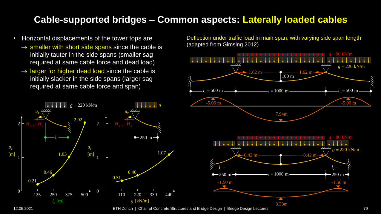
12.05.2021 78
• The deformations of suspension bridges are
significantly affected by the span layout. This is
illustrated following (once again) an example given by
Gimsing [Gimsing 2012].
• The figure compares the deflections of two three-span
cables with spans of 500+1000+500 m and
250+1000+250 m, respectively, due to traffic load in
the main span (other parameters as previous slides).
midspan deflection in bridge with short side span is
only ca. 40% of that with long side span
(in a continuous beam, the midspan deflection
would only decrease by ca. 20% if the side span is
halved)
strong influence of side span length primarily
caused by horizontal displacements uT of the tower
tops (almost four times larger for long side span)
horizontal displacements of the tower tops are
primarily caused by sag reduction of the cables in
the end spans (and not the elongation of the
cable), see following slide.
ETH Zürich | Chair of Concrete Structures and Bridge Design | Bridge Design Lectures
10 m
1000 ml 500 msl 500 m
1000 ml 250 m
sl
80 kN/mq
220 kN/mg
80 kN/mq
220 kN/mg
-1.50 m
3.23m
500 msl
-5.06 m
7.94m
0.42 m
-5.06 m
-1.50 m
0.42 m
1.62 m 1.62 m
Deflection under traffic load in main span, with varying side span length
(adapted from Gimsing 2012)
250 m
sl
Cable-supported bridges – Common aspects: Laterally loaded cables
12.05.2021 79
• Horizontal displacements of the tower tops are
smaller with short side spans since the cable is
initially tauter in the side spans (smaller sag
required at same cable force and dead load)
larger for higher dead load since the cable is
initially slacker in the side spans (larger sag
required at same cable force and span)
ETH Zürich | Chair of Concrete Structures and Bridge Design | Bridge Design Lectures
2
1
0250 500125 375
0.21
0.46
1.03
2.022
1
0
0.31
0.46
1.07
220 440110 330
[m]
Tu
[m]sl [kN/m]g
[m]
Tu
sl 250 m
g q gH H
220 kN/mg g
TuTu
g q gH H
100 m
1000 ml 500 msl 500 m
1000 ml 250 m
sl
80 kN/mq
220 kN/mg
80 kN/mq
220 kN/mg
-1.50 m
3.23m
500 msl
-5.06 m
7.94m
0.42 m
-5.06 m
-1.50 m
0.42 m
1.62 m 1.62 m
Deflection under traffic load in main span, with varying side span length
(adapted from Gimsing 2012)
250 m
sl
Cable-supported bridges – Common aspects: Laterally loaded cables
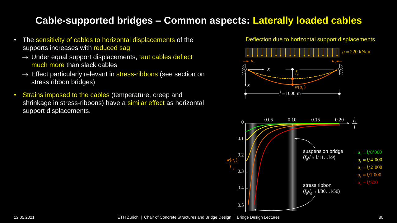
12.05.2021 80
• The sensitivity of cables to horizontal displacements of the
supports increases with reduced sag:
Under equal support displacements, taut cables deflect
much more than slack cables
Effect particularly relevant in stress-ribbons (see section on
stress ribbon bridges)
• Strains imposed to the cables (temperature, creep and
shrinkage in stress-ribbons) have a similar effect as horizontal
support displacements.
ETH Zürich | Chair of Concrete Structures and Bridge Design | Bridge Design Lectures
Deflection due to horizontal support displacements
z
x
1000 ml
220 kN/mg
gf
( )sw u
susu
gf
l
( )s
g
w u
f
0
0.1
0.05 0.10 0.15 0.20
suspension bridge
(fg/l l/11…l/9)
stress ribbon
(fg/lg l/80…l/50)
0.2
0.3
0.4
0.5
1
4 '0
0
00
8'00
'000
2 ' 0
0
50
00
s
s
s
s
s
u l
u
u
l
u
u
l
l
l

Cable-supported bridges – Common aspects: Laterally loaded cables
12.05.2021 81
• So far, it has not only been assumed that the cable acts as a
rope without bending stiffness, but the stiffening effect of the
deck girder has been neglected.
• This is justified in preliminary design, as illustrated by this slide
comparing the deflections for the cable alone with those of
suspension bridges with two different stiffening girder layouts:
differences negligible for traffic load over entire main span
differences small for traffic load over half the main span
ETH Zürich | Chair of Concrete Structures and Bridge Design | Bridge Design Lectures
1000 ml 240 m
q
g
240 m
q
g
500 m240 m 500 m 240 m
Comparison of deflections under traffic load
(adapted from Gimsing 2012)
cable alone
suspension bridge, stiffening girder simply supported (*)
suspension bridge, stiffening girder continuous (*)
(*) inertia of a modern 3 m deep steel box girder
4.71
4.87
5.19
3.34
3.36
3.40
-1.90
-1.84
-1.74
-1.47
-1.25
-1.24
-2.80
-2.27
-2.09
-0.84
-0.64
-0.45
Cable-supported bridges
12.05.2021 82ETH Zürich | Chair of Concrete Structures and Bridge Design | Bridge Design Lectures
Common aspects – Static analysis of Cables
Axial stiffness of laterally loaded cables
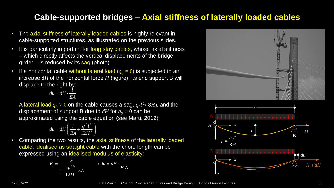
Cable-supported bridges – Axial stiffness of laterally loaded cables
12.05.2021 83
• The axial stiffness of laterally loaded cables is highly relevant in
cable-supported structures, as illustrated on the previous slides.
• It is particularly important for long stay cables, whose axial stiffness
– which directly affects the vertical displacements of the bridge
girder – is reduced by its sag (photo).
• If a horizontal cable without lateral load (q0 = 0) is subjected to an
increase dH of the horizontal force H (figure), its end support B will
displace to the right by:
A lateral load q0 > 0 on the cable causes a sag, q0l2/(8H), and the
displacement of support B due to dH for q0 > 0 can be
approximated using the cable equation (see Marti, 2012):
• Comparing the two results, the axial stiffness of the laterally loaded
cable, idealised as straight cable with the chord length can be
expressed using an idealised modulus of elasticity:
ETH Zürich | Chair of Concrete Structures and Bridge Design | Bridge Design Lectures
H
A x
0q
f
l
H dH
z
x
0q
du
2 3
0
312
q lldu dH
EA H
ldu dH
EA
B2
0
8
q lf
H
2 2
0
31
12
i
i
E lE du dH
q l E AEA
H
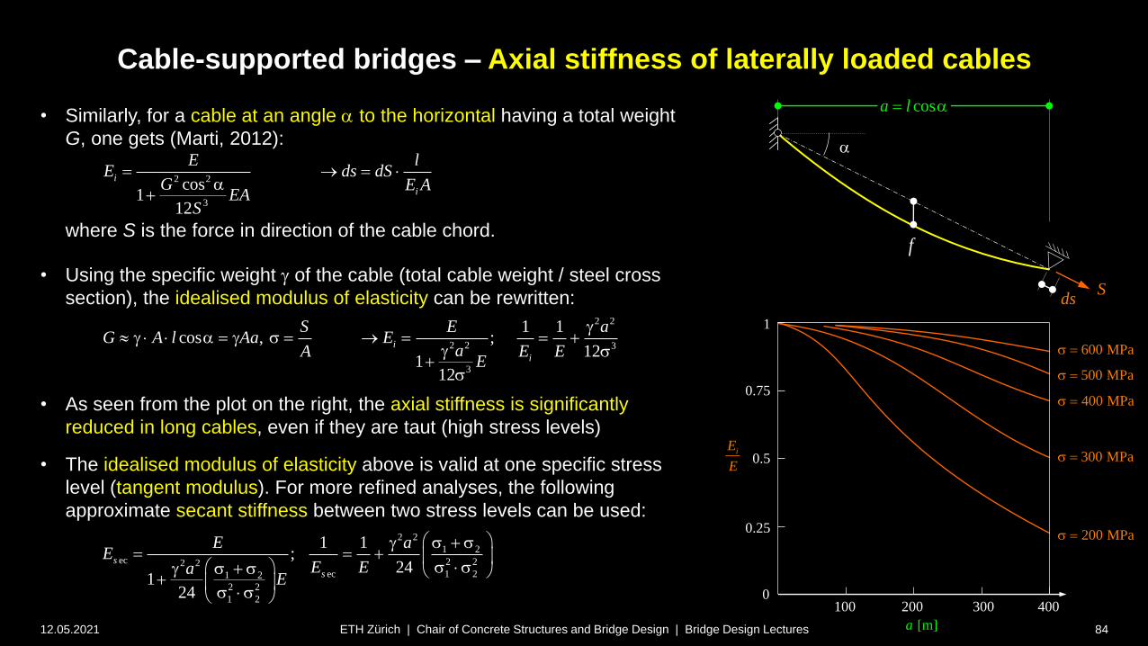
Cable-supported bridges – Axial stiffness of laterally loaded cables
12.05.2021 84
• Similarly, for a cable at an angle a to the horizontal having a total weight
G, one gets (Marti, 2012):
where S is the force in direction of the cable chord.
• Using the specific weight g of the cable (total cable weight / steel cross
section), the idealised modulus of elasticity can be rewritten:
• As seen from the plot on the right, the axial stiffness is significantly
reduced in long cables, even if they are taut (high stress levels)
• The idealised modulus of elasticity above is valid at one specific stress
level (tangent modulus). For more refined analyses, the following
approximate secant stiffness between two stress levels can be used:
ETH Zürich | Chair of Concrete Structures and Bridge Design | Bridge Design Lectures
2 2
3
cos1
12
i
i
E lE ds dS
G E AEA
S
a
Sds
a
2 2
2 2 3
3
1 1cos , ;
121
12
i
i
S E aG A l Aa E
aA E EE
g g a g s
g s
s
0100
iE
E
[m]a
0.25
200 300 400
1
0.75
0.5
200 MPas
300 MPas
400 MPas
500 MPas
600 MPas
2 2
1 2ec 2 22 2
ec 1 21 2
2 2
1 2
1 1;
241
24
s
s
E aE
E EaE
g s s
s s g s s s s
cosa l a
f

Cable-supported bridges – Axial stiffness of laterally loaded cables
12.05.2021 85
• As seen from the plot on the previous slide, the reduction of the idealised
modulus of elasticity is pronounced for long cables working at a low stress.
• In cable-styed bridges, the vertical stiffness of the stays is of primary
interest (rather than their axial stiffness). Considering a single stay cable
inclined at an angle a, the cable force due to a load Q and the resulting
cable elongation are
and assuming that the deck girder is axially rigid, the vertical displacement
(using e.g. the Williot diagram) corresponds to
• Hence, the vertical stiffness of the stay is
• In a fan-type stay layout (same h for all stays), the vertical stiffness of the
long stays is thus not only reduced by the effect of sag (Ei), but even more
pronouncedly by the geometrical effects caused by their flatter inclination.
ETH Zürich | Chair of Concrete Structures and Bridge Design | Bridge Design Lectures
S
w
ds
a
cosa l a
a
cosa l a
iE A
deck cableEA EA
22
3sin sini
z i
E AQ h hk E A
w l ll
a a
Q
sin sin i
Q Q lS ds
E A
a a
2sin sin i
ds Q lw
E A
a a
f
h
Cable-supported bridges
12.05.2021 86ETH Zürich | Chair of Concrete Structures and Bridge Design | Bridge Design Lectures
Common aspects – Static analysis of Cables
Combined cable-type and bending response

Cable-supported bridges – Common aspects: Bending of cables
12.05.2021 87
• When analysing the global structural behaviour of cable-supported
bridges, it is usually sufficient to neglect the bending stiffness of the
cables – even in the case of stress-ribbons with a relatively stiff cross-
section (see section on stress-ribbons).
• However, local bending of the cables (resp. stress ribbons) needs to
be considered to verify
fatigue stresses, particularly for stay cables
serviceability of stress ribbons (crack widths, durability)
• The behaviour of stress-ribbons can be analysed by accounting for
the combined cable-type and bending response. As outlined by Marti
(Theory of Structures, 2013, Chapter 18.9), the differential equation
with the solution
covers the entire spectrum from a pure bending response only (l 0),
to a pure cable-type response (l ). Note that it has been
assumed in the derivation of the differential equation that the dead
load g is carried by cable tension alone.
ETH Zürich | Chair of Concrete Structures and Bridge Design | Bridge Design Lectures
Stress-ribbon geometry used for illustrations on
next slides (typical stress-ribbon footbridge)
( ), ( )H
EIw H H w q g H H g H H qH
D D D D
1 2 3 4cosh( ) sinh( ) part
H Hw c c x c x c x w
EI
D l l l
z
x
100 ml
20 kN/mg
1.50 mgf
10 kN/mq
gf
4 gf
l
Elevation
Cross-section
2.50 m
0.28 m
2
2
21 GN
137 MN
4 GN
1 MN
m
m
I
c
I
p
p
c
EA
EA
EI
EI

Cable-supported bridges – Common aspects: Bending of cables
12.05.2021 88
• In cables – particularly stay cables and stress-ribbons – bending
moments are caused by sag variations (due to load, imposed
strains or dynamic effects), since the end anchorages are
commonly fixed, rather than hinged.
• Solving the differential equation given on the previous slide, one
gets the following expression for the bending moments (Marti
2012, 19.9.2.2):
where b = horizontal span and j0 imposed end rotation of cable.
The first term on the right side can usually be neglected.
• As illustrated in the figure for j0 0, the bending moments
range from 5…20% of those in a clamped girder for j0 0
are localised near the end anchorages (particularly for low
bending stiffness, as is the case in stay cables)
• If the end rotation j0 is set to that of a hinged cable under dead
load, as usual, variable loads and end rotations still cause bending
moments.
ETH Zürich | Chair of Concrete Structures and Bridge Design | Bridge Design Lectures
Bending moments due to dead load
(cable end rotation j0 0)
02
cosh2
( )2
sinh( )2
c c
bx
g g b NM x N EI
bN EI
l j l l l
2
12
M
gb
0 0.1 0.2 0.3 0.4
0
0.1
0.2
M0 xx200
b,
gc b2
12
M0 xx100
b,
gc b2
12
M0 xx33.3
b,
gc b2
12
0
xx
bH 1.667 10
4 kN
-0.05
0
0.05
0.10
0.15
0.20
0 0.1 0.2 0.3 0.4 0.5x
b
stress ribbon
(1/l b/35)
stay cables
(1/l b/100 … b/200)
j0 0
0(0)2
cg bM N EI j
l

40 20 0 20 400.06
0.03999999999999999
0.02
0
0.02
M xx1 c3, c4,
Q l
4
M xx2 c3, c4,
Q l
4
xx1 xx2,
40 20 0 20 400.04
0.02
0
0.02
M1 xx1 c3, c4,
q l2
64
M2 xx2 c7, c8,
q l2
64
xx1 xx2, xx,
Cable-supported bridges – Common aspects: Bending of cables
12.05.2021 89
• In stress-ribbons, relevant bending moments are also caused
by traffic loads. Analytical solutions are available e.g. for the
cases shown on the right:
asymmetric traffic load on half a span (Marti 2012, 18.9.3.2)
concentrated load at midspan (Marti 2012, 18.9.3.3)
• The figures illustrate the bending moments for a typical stress-
ribbon (cross-section see previous slides). It can be seen that
the bending moments are 1-2 orders of magnitude smaller than
in a beam of equal span, and also significantly smaller than in a
two-hinged arch (where they would amount to ql2/64 and
7Ql/128, respectively). Due to the high slenderness of the
stress ribbon, they are, however, still not negligible.
• The bending moments that would occur if only the cables were
active (concrete as weight), whose values are indicated in
brackets, are another order of magnitude smaller.
• For general loading, geometrically nonlinear analyses
accounting for large deformations are required. Specialised
software is recommended for such cases.
ETH Zürich | Chair of Concrete Structures and Bridge Design | Bridge Design Lectures
Bending moments under selected load configurations
(normalised with M in a two-hinged arch under same load)
100 ml
20 kN/mg
1.50 mgf
10 kN/mq
20 kN/mg
30 kNQ
1.50 mgf
0.04
0.02
0
-0.02
0.20
0.10
0
-0.10
7
128
M
Ql
2
64
M
ql
0.247 (0.021)
-0.013 (-(-3.310-5 )
-0.0131 (-3.5710-5 )
0.0330 (0.00029)
Cable-supported bridges
12.05.2021 90ETH Zürich | Chair of Concrete Structures and Bridge Design | Bridge Design Lectures
Common aspects – Dynamic effects
Cable-supported bridges
12.05.2021 91ETH Zürich | Chair of Concrete Structures and Bridge Design | Bridge Design Lectures
Common aspects – Dynamic effects
Pedestrian-induced oscillations

Cable-supported bridges – Dynamic effects: Pedestrian-induced oscillations
12.05.2021 92ETH Zürich | Chair of Concrete Structures and Bridge Design | Bridge Design Lectures
• Many early suspension bridges suffered from excessive
oscillations due to traffic or wind, and several unfortunately
collapsed.
• For example, the following bridges collapsed due to oscillations
caused by pedestrians:
• According to some sources (Stiftung Deutsches
Technikmuseum Berlin Historisches Archiv), the Saalebrücke
in Nienburg (chain-stayed bridge, l = 80 m, Christian Gottfried
Heinrich Bandhauer, 1825) collapsed due to rhythmic
movements of the singing crowd on the bridge.
• The Broughton chain suspension bridge (l = 44 m, S. Brown,
1826), collapsed in 1831 by a detachment of 74 soldiers
marching in step. 20 soldiers were injured, six severely.
• The Angers wire-cable suspension bridge (Pont de la Basse-
Chaîne, l = 102 m, J. Chaley, 1838), presumably collapsed in
1850 by a combination of corrosion in anchor cables and
resonance caused by a battalion of almost 800 soldiers
crossing the bridge during a thunderstorm with strong wind
(not walking in step, but involuntarily moving in tune, known as
“lateral lock-in” today). 226 soldiers died.
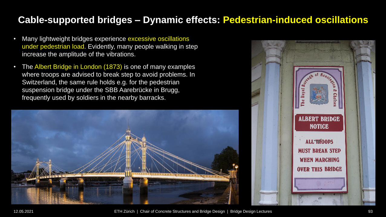
Cable-supported bridges – Dynamic effects: Pedestrian-induced oscillations
12.05.2021 93ETH Zürich | Chair of Concrete Structures and Bridge Design | Bridge Design Lectures
• Many lightweight bridges experience excessive oscillations
under pedestrian load. Evidently, many people walking in step
increase the amplitude of the vibrations.
• The Albert Bridge in London (1873) is one of many examples
where troops are advised to break step to avoid problems. In
Switzerland, the same rule holds e.g. for the pedestrian
suspension bridge under the SBB Aarebrücke in Brugg,
frequently used by soldiers in the nearby barracks.
• Code provisions for frequencies?
• No slender footbridge without being in the critical range …?

Cable-supported bridges – Dynamic effects: Pedestrian-induced oscillations
12.05.2021 94ETH Zürich | Chair of Concrete Structures and Bridge Design | Bridge Design Lectures
• Pedestrian-induced oscillations are not unique to cable-supported bridges,
but may occur in any lightweight structure.
• Such oscillations, including lateral oscillations, were studied intensely by
Prof. Hugo Bachmann at ETH Zurich in the 1980s. In a book published by
IABSE 1987 (see notes), he had recommended to avoid the following
frequency ranges in footbridges (or carry out detailed vibration analyses):
vertical oscillations: 1.6…2.4 Hz and 3.5…4.5 Hz
lateral oscillations: 0.8…1.2 Hz and 1.6 …2.4 Hz
• Bachmann had also already investigated the effect of the number of
people simultaneously crossing a bridge (excitation, added mass), and
their potential synchronisation with movements.
• Despite this knowledge, the Millennium Bridge in London (Arup / Foster
Partners / A. Caro) was built in 2000 with the first two lateral
eigenfrequencies in the critical range around 1 Hz (sources see notes).
• The bridge had to be evacuated at the opening due to severe lateral
oscillations. The “wobbly bridge” was then retrofitted with 37 viscous
dampers and 52 tuned mass dampers (cost: ca. 5 million pounds).
• The designers launched a research programme to study this problem, that
“had not yet been incorporated into the relevant bridge design codes” (see
notes).
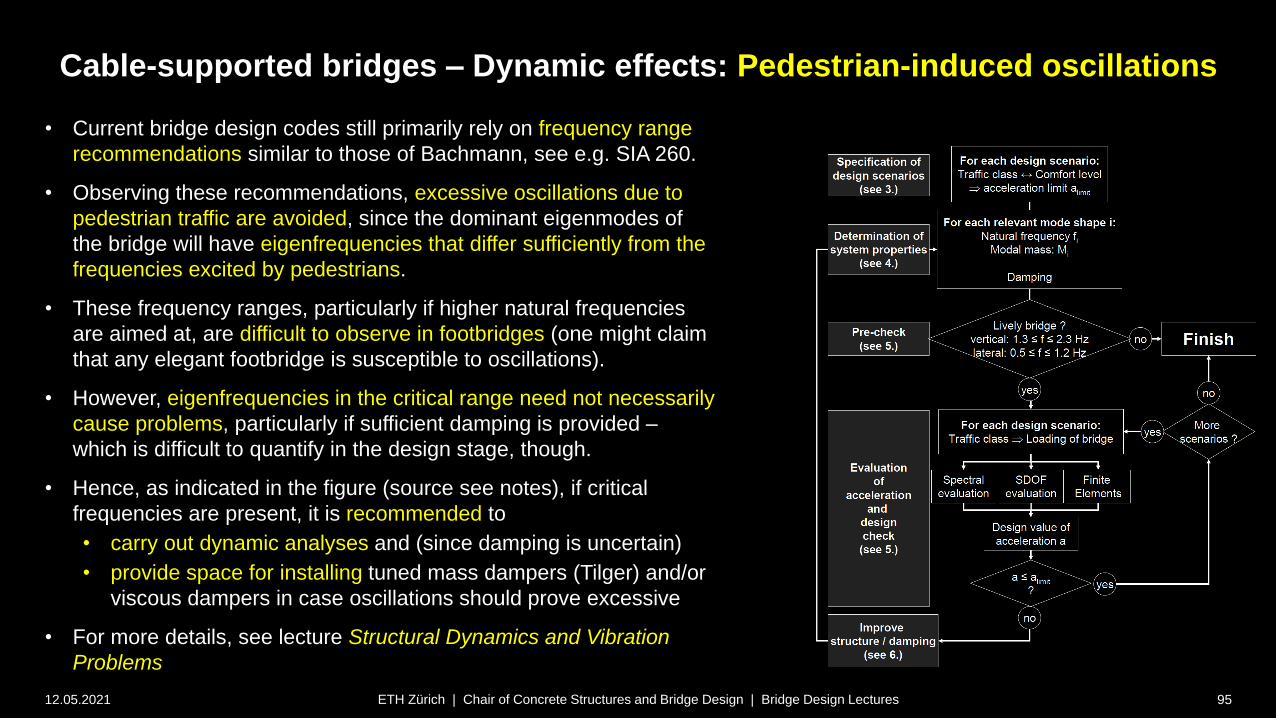
Cable-supported bridges – Dynamic effects: Pedestrian-induced oscillations
12.05.2021 95ETH Zürich | Chair of Concrete Structures and Bridge Design | Bridge Design Lectures
• Current bridge design codes still primarily rely on frequency range
recommendations similar to those of Bachmann, see e.g. SIA 260.
• Observing these recommendations, excessive oscillations due to
pedestrian traffic are avoided, since the dominant eigenmodes of
the bridge will have eigenfrequencies that differ sufficiently from the
frequencies excited by pedestrians.
• These frequency ranges, particularly if higher natural frequencies
are aimed at, are difficult to observe in footbridges (one might claim
that any elegant footbridge is susceptible to oscillations).
• However, eigenfrequencies in the critical range need not necessarily
cause problems, particularly if sufficient damping is provided –
which is difficult to quantify in the design stage, though.
• Hence, as indicated in the figure (source see notes), if critical
frequencies are present, it is recommended to
• carry out dynamic analyses and (since damping is uncertain)
• provide space for installing tuned mass dampers (Tilger) and/or
viscous dampers in case oscillations should prove excessive
• For more details, see lecture Structural Dynamics and Vibration
Problems

Cable-supported bridges – Dynamic effects: Pedestrian-induced oscillations
12.05.2021 96ETH Zürich | Chair of Concrete Structures and Bridge Design | Bridge Design Lectures
• Current bridge design codes still primarily rely on frequency range
recommendations similar to those of Bachmann, see e.g. SIA 260.
• Observing these recommendations, excessive oscillations due to
pedestrian traffic are avoided, since the dominant eigenmodes of
the bridge will have eigenfrequencies that differ sufficiently from the
frequencies excited by pedestrians.
• These frequency ranges, particularly if higher natural frequencies
are aimed at, are difficult to observe in footbridges (one might claim
that any elegant footbridge is susceptible to oscillations).
• However, eigenfrequencies in the critical range need not necessarily
cause problems, particularly if sufficient damping is provided –
which is difficult to quantify in the design stage, though.
• Hence, as indicated in the figure (source see notes), if critical
frequencies are present, it is recommended to
• carry out dynamic analyses and (since damping is uncertain)
• provide space for installing tuned mass dampers (Tilger) and/or
viscous dampers in case oscillations should prove excessive
• For more details, see lecture Structural Dynamics and Vibration
Problems
Birskopfsteg Basel (zpf Ingenieure, oscillations already
anticipated in design 2 tuned mass dampers provided)
Very slender and elegant footbridge
(h/l = 1/73)
Vertical Eigenfrequencies critical
(0.9/2.9/3.9 Hz )
tuned mass dampers planned
from beginning (located inside the
steel box girder):
Cable-supported bridges
12.05.2021 97ETH Zürich | Chair of Concrete Structures and Bridge Design | Bridge Design Lectures
Common aspects – Dynamic effects
Wind-induced oscillations
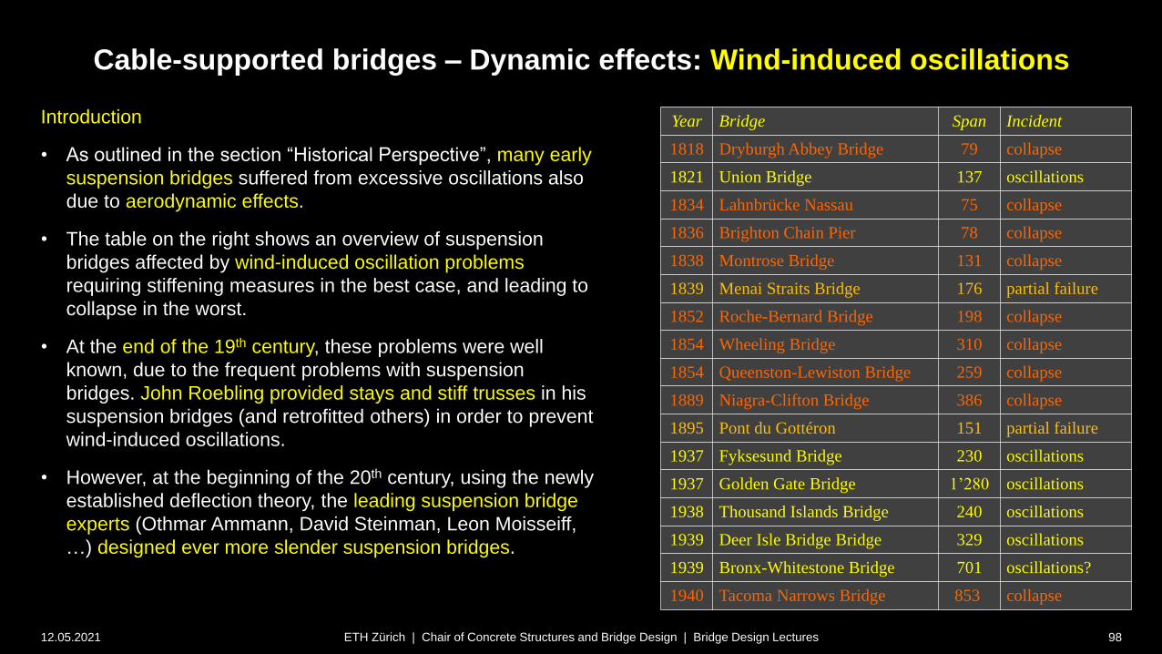
Cable-supported bridges – Dynamic effects: Wind-induced oscillations
12.05.2021 98ETH Zürich | Chair of Concrete Structures and Bridge Design | Bridge Design Lectures
Introduction
• As outlined in the section “Historical Perspective”, many early
suspension bridges suffered from excessive oscillations also
due to aerodynamic effects.
• The table on the right shows an overview of suspension
bridges affected by wind-induced oscillation problems
requiring stiffening measures in the best case, and leading to
collapse in the worst.
• At the end of the 19th century, these problems were well
known, due to the frequent problems with suspension
bridges. John Roebling provided stays and stiff trusses in his
suspension bridges (and retrofitted others) in order to prevent
wind-induced oscillations.
• However, at the beginning of the 20th century, using the newly
established deflection theory, the leading suspension bridge
experts (Othmar Ammann, David Steinman, Leon Moisseiff,
…) designed ever more slender suspension bridges.
Year Bridge Span Incident
1818 Dryburgh Abbey Bridge 79 collapse
1821 Union Bridge 137 oscillations
1834 Lahnbrücke Nassau 75 collapse
1836 Brighton Chain Pier 78 collapse
1838 Montrose Bridge 131 collapse
1839 Menai Straits Bridge 176 partial failure
1852 Roche-Bernard Bridge 198 collapse
1854 Wheeling Bridge 310 collapse
1854 Queenston-Lewiston Bridge 259 collapse
1889 Niagra-Clifton Bridge 386 collapse
1895 Pont du Gottéron 151 partial failure
1937 Fyksesund Bridge 230 oscillations
1937 Golden Gate Bridge 1’280 oscillations
1938 Thousand Islands Bridge 240 oscillations
1939 Deer Isle Bridge Bridge 329 oscillations
1939 Bronx-Whitestone Bridge 701 oscillations?
1940 Tacoma Narrows Bridge 853 collapse

Cable-supported bridges – Dynamic effects: Wind-induced oscillations
12.05.2021 99ETH Zürich | Chair of Concrete Structures and Bridge Design | Bridge Design Lectures
Introduction
• Even before the Tacoma Narrows Bridge collapsed, severe
wind-induced oscillations had been observed in several
recently built, slender suspension bridges.
• Nonetheless, aerodynamic effects on bridges were only
recognised and investigated in detail after the Tacoma
Narrows Bridge collapse.
• Even if from today’s perspective (see notes *), the mechanics
of the failure were not fully understood at the time –
aeroelasticity was a relatively new field of research even in
aeronautics – the collapse marked a turning point in bridge
design, particularly for cable-supported bridges:
Aerodynamic effects, which had received little attention
before, became a major concern in long-span bridge
design on that very day.
Today, wind tunnel testing for aerodynamic effects on long-
span and/or slender bridges is common.
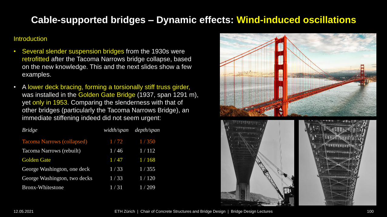
Cable-supported bridges – Dynamic effects: Wind-induced oscillations
12.05.2021 100ETH Zürich | Chair of Concrete Structures and Bridge Design | Bridge Design Lectures
Introduction
• Several slender suspension bridges from the 1930s were
retrofitted after the Tacoma Narrows bridge collapse, based
on the new knowledge. This and the next slides show a few
examples.
• A lower deck bracing, forming a torsionally stiff truss girder,
was installed in the Golden Gate Bridge (1937, span 1291 m),
yet only in 1953. Comparing the slenderness with that of
other bridges (particularly the Tacoma Narrows Bridge), an
immediate stiffening indeed did not seem urgent:
Bridge width/span depth/span
Tacoma Narrows (collapsed) 1 / 72 1 / 350
Tacoma Narrows (rebuilt) 1 / 46 1 / 112
Golden Gate 1 / 47 1 / 168
George Washington, one deck 1 / 33 1 / 355
George Washington, two decks 1 / 33 1 / 120
Bronx-Whitestone 1 / 31 1 / 209
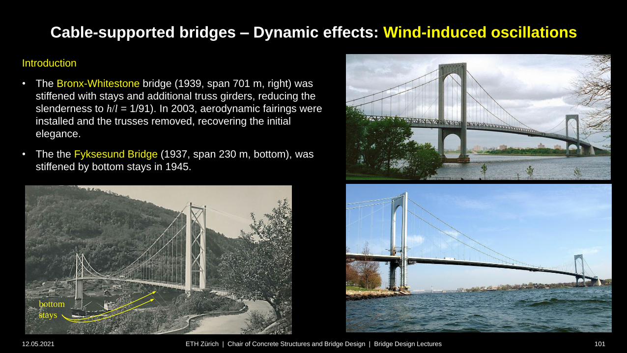
Cable-supported bridges – Dynamic effects: Wind-induced oscillations
12.05.2021 101ETH Zürich | Chair of Concrete Structures and Bridge Design | Bridge Design Lectures
Introduction
• The Bronx-Whitestone bridge (1939, span 701 m, right) was
stiffened with stays and additional truss girders, reducing the
slenderness to h/l = 1/91). In 2003, aerodynamic fairings were
installed and the trusses removed, recovering the initial
elegance.
• The the Fyksesund Bridge (1937, span 230 m, bottom), was
stiffened by bottom stays in 1945.
bottom
stays
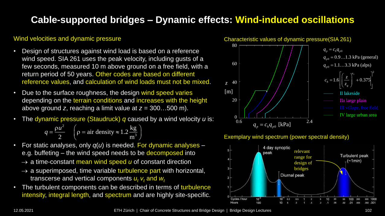
Cable-supported bridges – Dynamic effects: Wind-induced oscillations
12.05.2021 102ETH Zürich | Chair of Concrete Structures and Bridge Design | Bridge Design Lectures
Wind velocities and dynamic pressure
• Design of structures against wind load is based on a reference
wind speed. SIA 261 uses the peak velocity, including gusts of a
few seconds, measured 10 m above ground on a free field, with a
return period of 50 years. Other codes are based on different
reference values, and calculation of wind loads must not be mixed.
• Due to the surface roughness, the design wind speed varies
depending on the terrain conditions and increases with the height
above ground z, reaching a limit value at z = 300…500 m).
• The dynamic pressure (Staudruck) q caused by a wind velocity u is:
• For static analyses, only q(u) is needed. For dynamic analyses –
e.g. buffeting – the wind speed needs to be decomposed into
a time-constant mean wind speed u of constant direction
a superimposed, time variable turbulence part with horizontal,
transcerse and vertical components ut vt and wt
• The turbulent components can be described in terms of turbulence
intensity, integral length, and spectrum and are highly site-specific.
Characteristic values of dynamic pressure(SIA 261)
0
0
0
2
r
–––
–––– III village, f ee fiel
a
d
– IV large urban a
0.9 1.3 kPa (general)
1.1 3.
l
3 kPa (alp
–––– IIa
1
larg
7
e
s
pl
e
a
I
i
–
n
–
s)
.6 0.3
e
re
–
5
– I ak id
r
p h p
p
p
h
g
q c q
q
q
zc
z
a
2
3
kgair density 1.2
2 m
uq
2.40.6
20
0
40
60
80
0 [kPa]p h pq c q
[m]
z
Exemplary wind spectrum (power spectral density)
relevant
range for
design of
bridges

Cable-supported bridges – Dynamic effects: Wind-induced oscillations
12.05.2021 103ETH Zürich | Chair of Concrete Structures and Bridge Design | Bridge Design Lectures
Aeroelasticity – Basic aspects
• Aerodynamic effects are relevant to tall, slender buildings and flexible
long-span bridges.
• When studying these effects, the interaction of aerodynamic forces
( fluid dynamics) with the static and dynamic response
( structural mechanics) of the structure needs to be accounted for.
• This interaction is studied by aeroelasticity (Aeroelastik), a
fundamental topic in aeronautical engineering.
• An in-depth treatment of aeroelasticity is beyond the scope of this
lecture. In fact, even the most experienced designers of long-span
bridges rely on specialised experts when designing for wind loads.
• However, some basic aspects are treated here to
facilitate a basic understanding and awareness of potential
problems caused by aerodynamic effects
provide the common vocabulary required for communication with
aerodynamic experts
provide a basis for further study of this subject
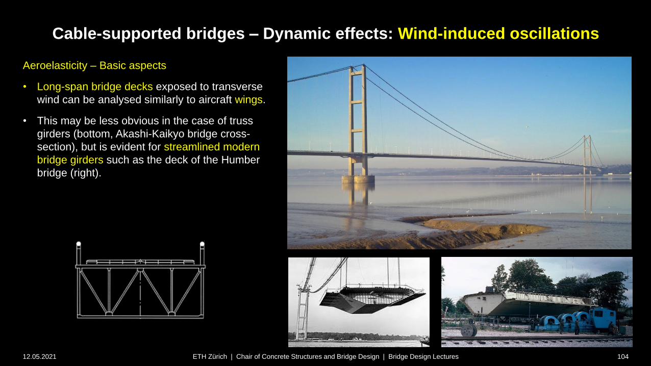
12.05.2021 104ETH Zürich | Chair of Concrete Structures and Bridge Design | Bridge Design Lectures
Aeroelasticity – Basic aspects
• Long-span bridge decks exposed to transverse
wind can be analysed similarly to aircraft wings.
• This may be less obvious in the case of truss
girders (bottom, Akashi-Kaikyo bridge cross-
section), but is evident for streamlined modern
bridge girders such as the deck of the Humber
bridge (right).
Cable-supported bridges – Dynamic effects: Wind-induced oscillations

12.05.2021 105ETH Zürich | Chair of Concrete Structures and Bridge Design | Bridge Design Lectures
Aeroelasticity – Basic aspects
• Such streamlined girders (right: Third Bosporus
Crossing) of modern long-span bridges indeed
resemble airfoils (Tragflächen).
• Like the wings of an aircraft, bridge girders – as
airfoils – may be damaged by torsional
divergence and flutter, which are examined on
the following slides.
• Further aerodynamic phenomena relevant to
bridges, such as buffeting, vortex shedding and
galloping are briefly outlined behind.
• Galloping is typical for bluff bodies (stumpfe
Körper). Here, it has to be kept in mind that
even streamlined bridge decks may become
bluff by traffic on the bridge.
• Furthermore, other than in aircraft wings (where
except in gliders, the air velocity is dominated by
the cruise speed), wind on bridges is commonly
turbulent and non-uniform in time and space.
Cable-supported bridges – Dynamic effects: Wind-induced oscillations
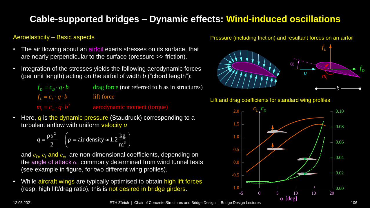
Cable-supported bridges – Dynamic effects: Wind-induced oscillations
12.05.2021 106ETH Zürich | Chair of Concrete Structures and Bridge Design | Bridge Design Lectures
Aeroelasticity – Basic aspects
• The air flowing about an airfoil exerts stresses on its surface, that
are nearly perpendicular to the surface (pressure >> friction).
• Integration of the stresses yields the following aerodynamic forces
(per unit length) acting on the airfoil of width b (“chord length”):
• Here, q is the dynamic pressure (Staudruck) corresponding to a
turbulent airflow with uniform velocity u
and cD, cL and cm are non-dimensional coefficients, depending on
the angle of attack a, commonly determined from wind tunnel tests
(see example in figure, for two different wing profiles).
• While aircraft wings are typically optimised to obtain high lift forces
(resp. high lift/drag ratio), this is not desired in bridge girders.
2
3
kgair density 1.2
2 m
uq
Pressure (including friction) and resultant forces on an airfoil
u
a
b
Lf
Df
tm
2
(not referred t
n
o h as in stdrag force
)
aerody amic moment (to
il ft force
r e
rqu
uctur s)
e
L
D
m
D
t
Lf
f
m c q b
c
c
b
q
q
b
-5 5 10 10 200
DLc c
-1.0
2.0
0.5
0.10
0.08
0.06
0.04
0.02
0.00
1.5
1.0
0.0
-0.5
[deg]a
Lift and drag coefficients for standard wing profiles
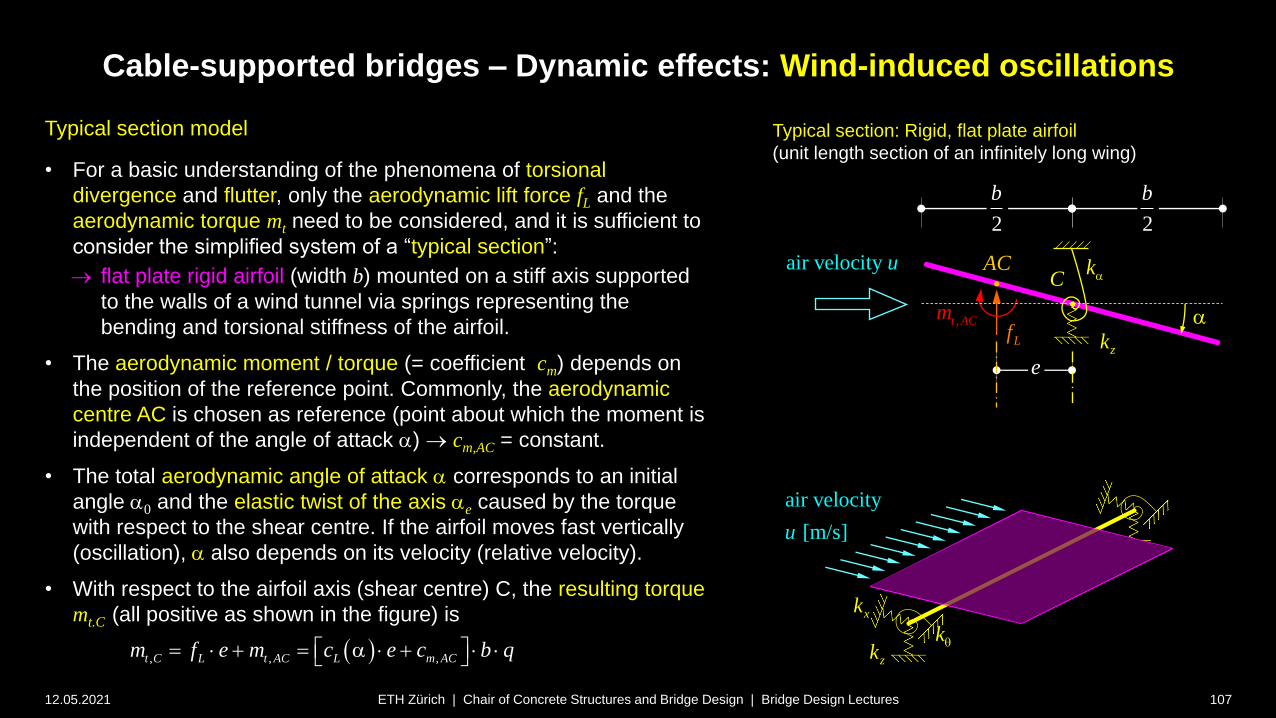
Cable-supported bridges – Dynamic effects: Wind-induced oscillations
12.05.2021 107ETH Zürich | Chair of Concrete Structures and Bridge Design | Bridge Design Lectures
Typical section model
• For a basic understanding of the phenomena of torsional
divergence and flutter, only the aerodynamic lift force fL and the
aerodynamic torque mt need to be considered, and it is sufficient to
consider the simplified system of a “typical section”:
flat plate rigid airfoil (width b) mounted on a stiff axis supported
to the walls of a wind tunnel via springs representing the
bending and torsional stiffness of the airfoil.
• The aerodynamic moment / torque (= coefficient cm) depends on
the position of the reference point. Commonly, the aerodynamic
centre AC is chosen as reference (point about which the moment is
independent of the angle of attack a) cm,AC = constant.
• The total aerodynamic angle of attack a corresponds to an initial
angle a0 and the elastic twist of the axis ae caused by the torque
with respect to the shear centre. If the airfoil moves fast vertically
(oscillation), a also depends on its velocity (relative velocity).
• With respect to the airfoil axis (shear centre) C, the resulting torque
mt.C (all positive as shown in the figure) is
zk
xk
k
air velocity
[m/s]u
Typical section: Rigid, flat plate airfoil
(unit length section of an infinitely long wing)
Lf
air velocity u
,t ACm
2
b
2
b
e
a
AC kaC
zk
, , ,t C L t AC L m ACm f e m c e c b q a
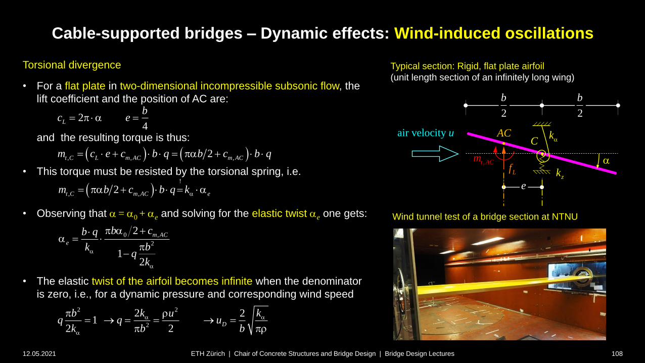
Cable-supported bridges – Dynamic effects: Wind-induced oscillations
12.05.2021 108ETH Zürich | Chair of Concrete Structures and Bridge Design | Bridge Design Lectures
Torsional divergence
• For a flat plate in two-dimensional incompressible subsonic flow, the
lift coefficient and the position of AC are:
and the resulting torque is thus:
• This torque must be resisted by the torsional spring, i.e.
• Observing that a = a0 + ae and solving for the elastic twist ae one gets:
• The elastic twist of the airfoil becomes infinite when the denominator
is zero, i.e., for a dynamic pressure and corresponding wind speed
24
L
bc e a
, , ,2t C L m AC m ACm c e c b q b c b q a
!
, ,2t C m AC em b c b q ka a a
0 ,
2
2
12
m AC
e
b cb q
bkq
ka
a
a a
2 2
2
2 21
2 2D
k kb uq q u
k b b
a a
a
Typical section: Rigid, flat plate airfoil
(unit length section of an infinitely long wing)
Lf
air velocity u
,t ACm
2
b
2
b
e
a
AC kaC
zk
Wind tunnel test of a bridge section at NTNU
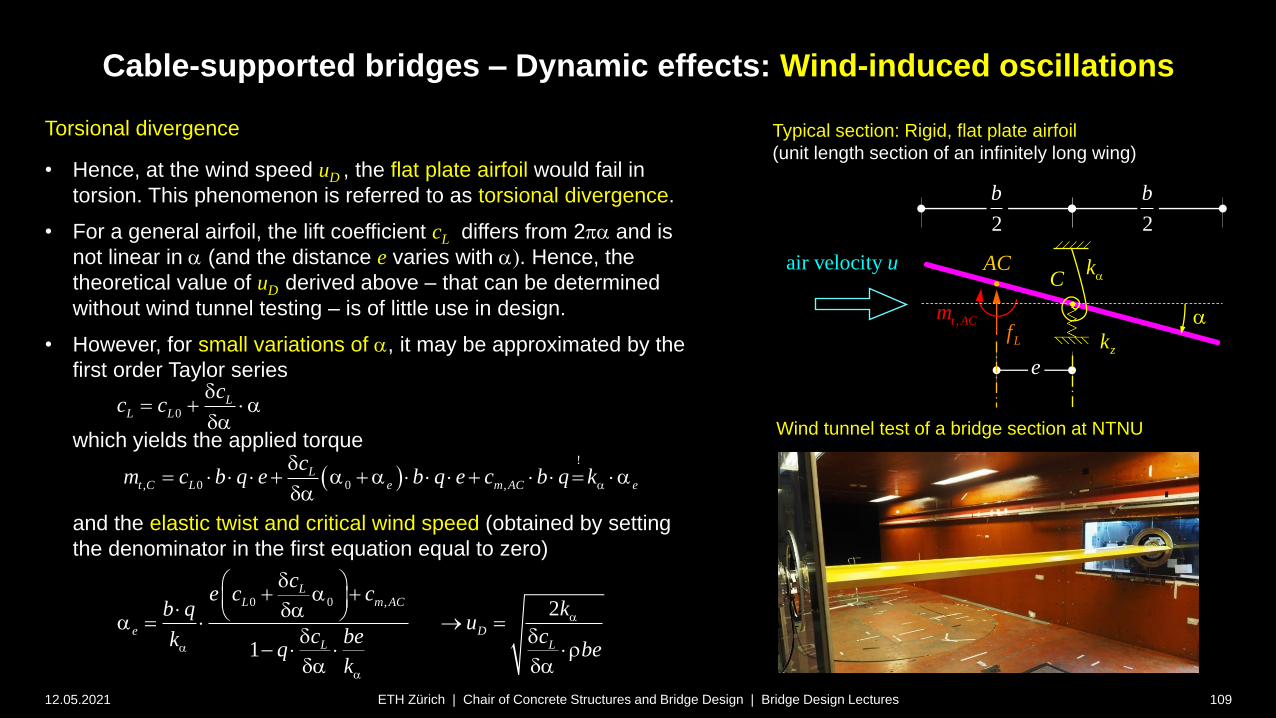
Cable-supported bridges – Dynamic effects: Wind-induced oscillations
12.05.2021 109ETH Zürich | Chair of Concrete Structures and Bridge Design | Bridge Design Lectures
Torsional divergence
• Hence, at the wind speed uD , the flat plate airfoil would fail in
torsion. This phenomenon is referred to as torsional divergence.
• For a general airfoil, the lift coefficient cL differs from 2a and is
not linear in a (and the distance e varies with a. Hence, the
theoretical value of uD derived above – that can be determined
without wind tunnel testing – is of little use in design.
• However, for small variations of a, it may be approximated by the
first order Taylor series
which yields the applied torque
and the elastic twist and critical wind speed (obtained by setting
the denominator in the first equation equal to zero)
0L
L L
cc c
a
a
!
, 0 0 ,L
t C L e m AC e
cm c b q e b q e c b q ka
a a a
a
0 0 , 2
1
LL m AC
e DL L
ce c c
kb qu
c cbekq be
k
a
a
a
a a a
a a
Typical section: Rigid, flat plate airfoil
(unit length section of an infinitely long wing)
Lf
air velocity u
,t ACm
2
b
2
b
e
a
AC kaC
zk
Wind tunnel test of a bridge section at NTNU

Cable-supported bridges – Dynamic effects: Wind-induced oscillations
12.05.2021 110ETH Zürich | Chair of Concrete Structures and Bridge Design | Bridge Design Lectures
Torsional divergence
• The distance e cannot directly be obtained from wind tunnel tests,
since the coefficient cm,AC is unknown.
• In bridge aeroelasticity, the total aerodynamic moment coefficient ct
referred to the bridge axis (combining the above values and
determined from wind tunnel tests) is thus commonly used
• Using again the first-order Taylor series, and setting the denominator
of the resulting equation for the elastic twist equal to zero, one gets the
critical wind speed ud for torsional divergence
• Using plots of the coefficient ct (and its derivative) determined from
wind tunnel tests, the critical wind speed uD can be determined.
Exemplary aerodynamic moment coefficient and derivative
(including traffic effect [Pospisil et al., see notes])
2
2 2
,2
t C t t
um qb c b c
a a
22
, 0
2 2 0 0
2 22
2
2
21
2
tt C t e
tt
e Dtt
cum b c k
cc
ku bu
ccu bkb
k
a
a
a
a
a a
a
a
a a
aa
tc
a
tc

Cable-supported bridges – Dynamic effects: Wind-induced oscillations
12.05.2021 111ETH Zürich | Chair of Concrete Structures and Bridge Design | Bridge Design Lectures
Coupled flutter
• Torsional divergence is usually not critical in
bridges. However, the critical wind speed for
torsional divergence uD is useful for the
analysis of coupled flutter as well.
• Coupled flutter, a divergent aeroelastic
instability phenomenon occurring at the flutter
velocity uf < uD, has the following
characteristics:
• simultaneous vertical and torsional
harmonic oscillation
• coupling of vertical and torsional
oscillations due to nearly coinciding
eigenfrequencies fv and ft
• energy accumulation and, eventually,
collapse
• The phenomenon of flutter is known in bridge
engineering since the prominent Tacoma
Narrows Bridge collapse by torsional flutter in
1940 (see section historical perspective).
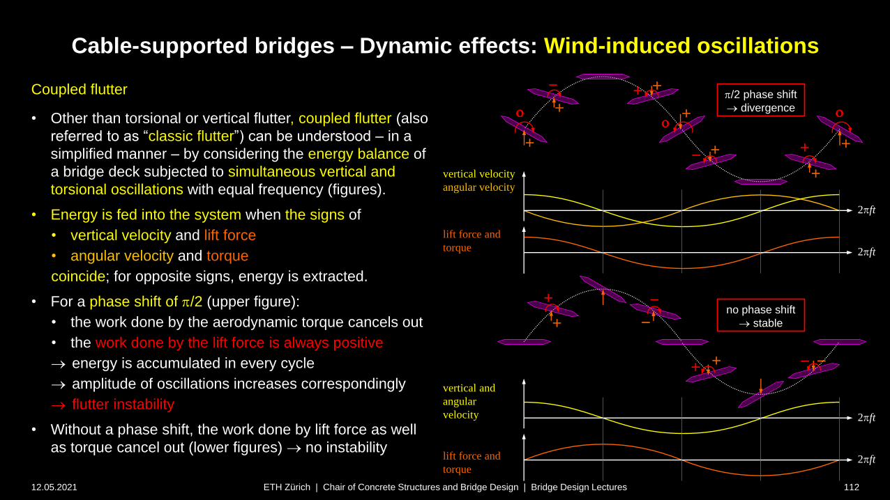
Cable-supported bridges – Dynamic effects: Wind-induced oscillations
12.05.2021 112ETH Zürich | Chair of Concrete Structures and Bridge Design | Bridge Design Lectures
lift force and
torque
vertical velocity
angular velocity
/2 phase shift
divergence
vertical and
angular
velocity
lift force and
torque
2 ft
Coupled flutter
• Other than torsional or vertical flutter, coupled flutter (also
referred to as “classic flutter”) can be understood – in a
simplified manner – by considering the energy balance of
a bridge deck subjected to simultaneous vertical and
torsional oscillations with equal frequency (figures).
• Energy is fed into the system when the signs of
• vertical velocity and lift force
• angular velocity and torque
coincide; for opposite signs, energy is extracted.
• For a phase shift of /2 (upper figure):
• the work done by the aerodynamic torque cancels out
• the work done by the lift force is always positive
energy is accumulated in every cycle
amplitude of oscillations increases correspondingly
flutter instability
• Without a phase shift, the work done by lift force as well
as torque cancel out (lower figures) no instability
no phase shift
stable
2 ft
2 ft
2 ft
o
o
o

Cable-supported bridges – Dynamic effects: Wind-induced oscillations
12.05.2021 113ETH Zürich | Chair of Concrete Structures and Bridge Design | Bridge Design Lectures
Coupled flutter
• The torsional eigenfrequency ft of cable-supported bridges with two
cable planes is commonly larger than their vertical eigenfrequency fv
(see figure; for A-shaped pylons with inclined cable planes, the
torsional frequency is even higher).
• However, the equivalent torsional stiffness, and hence ft , is reduced
by the aerostatic pressure, which increases with air velocity.
• For a flat plate airfoil, this leads to the flutter velocity
where ud = is critical wind speed for torsional divergence.
• The above equation is strongly simplified and neglects the dynamic
nature of wind loads. A better approximation is given by Selberg’s
semi-empirical equation:
where m is the mass of the girder per unit length and Im is the
corresponding mass moment of inertia (see figure).
2
21 v
f D D
t
fu u u
f
2
20.52 1 v
f D D
t m
f mu u b u
f I
b
m zkzk
cable planes
zkzk
2
m
1 2 13
1 6,
2 2 2
z t zv t
m
t
z
k k kf
m ff
I
f
G
2
4m
mbI
2
12m
mbI
2
2
zt
k bk
2
2
zt
k bk
1 2 11
1 2,
2 2 2
z t zv t
m
t
z
k k kf
m ff
I
f
m
Ratios of vertical and torsional eigenfrequencies for
Bridges with two cable planes at their edges
2
m
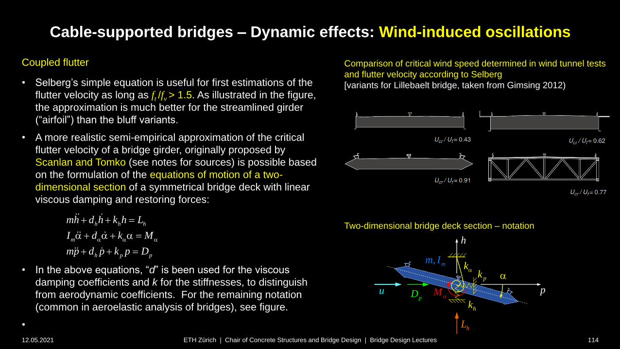
Cable-supported bridges – Dynamic effects: Wind-induced oscillations
12.05.2021 114ETH Zürich | Chair of Concrete Structures and Bridge Design | Bridge Design Lectures
Coupled flutter
• Selberg’s simple equation is useful for first estimations of the
flutter velocity as long as ft /fv > 1.5. As illustrated in the figure,
the approximation is much better for the streamlined girder
(“airfoil”) than the bluff variants.
• A more realistic semi-empirical approximation of the critical
flutter velocity of a bridge girder, originally proposed by
Scanlan and Tomko (see notes for sources) is possible based
on the formulation of the equations of motion of a two-
dimensional section of a symmetrical bridge deck with linear
viscous damping and restoring forces:
• In the above equations, “d” is been used for the viscous
damping coefficients and k for the stiffnesses, to distinguish
from aerodynamic coefficients. For the remaining notation
(common in aeroelastic analysis of bridges), see figure.
•
Comparison of critical wind speed determined in wind tunnel tests
and flutter velocity according to Selberg
[variants for Lillebaelt bridge, taken from Gimsing 2012)
h h h
m
h p p
mh d h k h L
I d k M
mp d p k p D
a a a
a a a
Ma
a
hL
pD p
ka
hk
pk
h
Two-dimensional bridge deck section – notation
, mm I
u
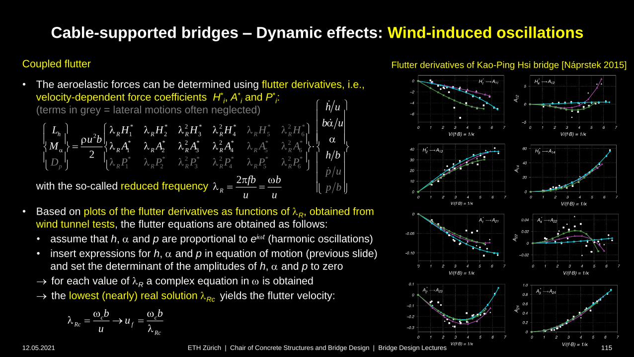
Cable-supported bridges – Dynamic effects: Wind-induced oscillations
12.05.2021 115ETH Zürich | Chair of Concrete Structures and Bridge Design | Bridge Design Lectures
Coupled flutter
• The aeroelastic forces can be determined using flutter derivatives, i.e.,
velocity-dependent force coefficients H*i, A
*i and P*
i:
(terms in grey = lateral motions often neglected)
with the so-called reduced frequency
• Based on plots of the flutter derivatives as functions of lR, obtained from
wind tunnel tests, the flutter equations are obtained as follows:
• assume that h, a and p are proportional to eiwt (harmonic oscillations)
• insert expressions for h, a and p in equation of motion (previous slide)
and set the determinant of the amplitudes of h, a and p to zero
for each value of lR a complex equation in w is obtained
the lowest (nearly) real solution lRc yields the flutter velocity:
Flutter derivatives of Kao-Ping Hsi bridge [Náprstek 2015]
3
* 2 *
5 6
* 2 *
5 6
* * 2 * 2 * * 2 *
1 2 3
2
4 5 6
* * 2 * *
1 2 42* * 2 * 2 *
1 2 3 42
h R R R R
R R R R
R R
R R
p R R R R R R
h u
b uL
b
H H H Hu b
h
H H
A
P
Mb
A
p
A A A A
D P P P P Pu
p
a
a l l l l a
l l l l
l l
l l
l l l
l
l l
2
R
fb b
u u
wl
c cRc f
Rc
b bu
u
w wl
l
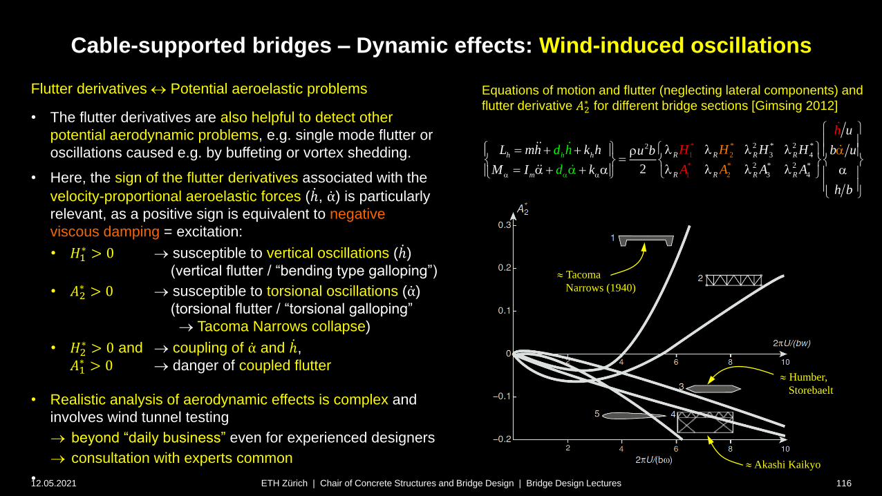
Cable-supported bridges – Dynamic effects: Wind-induced oscillations
12.05.2021 116ETH Zürich | Chair of Concrete Structures and Bridge Design | Bridge Design Lectures
Flutter derivatives Potential aeroelastic problems
• The flutter derivatives are also helpful to detect other
potential aerodynamic problems, e.g. single mode flutter or
oscillations caused e.g. by buffeting or vortex shedding.
• Here, the sign of the flutter derivatives associated with the
velocity-proportional aeroelastic forces ( ሶℎ, ሶα) is particularly
relevant, as a positive sign is equivalent to negative
viscous damping = excitation:
• 𝐻1∗ > 0 susceptible to vertical oscillations ( ሶℎ)
(vertical flutter / “bending type galloping”)
• 𝐴2∗ > 0 susceptible to torsional oscillations ( ሶα)
(torsional flutter / “torsional galloping”
Tacoma Narrows collapse)
• 𝐻2∗ > 0 and coupling of ሶα and ሶℎ,
𝐴1∗ > 0 danger of coupled flutter
• Realistic analysis of aerodynamic effects is complex and
involves wind tunnel testing
beyond “daily business” even for experienced designers
consultation with experts common
•
Equations of motion and flutter (neglecting lateral components) and
flutter derivative 𝐴2∗ for different bridge sections [Gimsing 2012]
2 * 2 *23 4
2 * 2 *
3 4
* *
2
*
2
1
*
12
R R R Rh h
R R R
h
Rm
u
H HL mh
A
k h b uu b
A AM I k
b
h
A
d h
d
H
h
H
aa a
l l l l
l l l l a a a
a
a
Tacoma
Narrows (1940)
Akashi Kaikyo
Humber,
Storebaelt

Cable-supported bridges – Dynamic effects: Wind-induced oscillations
12.05.2021 117ETH Zürich | Chair of Concrete Structures and Bridge Design | Bridge Design Lectures
Use of flutter derivatives for aeroelastic phenomena
• Even if aerodynamic stability is satisfied – i.e., the critical
velocities for flutter and torsional divergence are higher than
the design wind speed – large wind-induced oscillations may
not be excluded.
• The most relevant phenomena potentially causing large,
albeit self-limiting oscillations are
• buffeting
• vortex-shedding
• galloping
• While galloping mainly affects cables, buffeting and vortex
shedding also cause oscillations of the bridge girder. As seen
in the upper figure, these mechanisms occur at lower wind
velocities than coupled flutter.
• All these phenomena are fairly complex and can only be
approximated analytically or numerically (computational fluid
dynamics), requiring wind tunnel tests in general. They will
only be briefly outlined in the following. As with flutter,
consulting with wind experts is recommended.
Schematic response of a slender structure under wind
(adapted from [Gimsing 2012])
wind velocity u
response
vortex shedding buffeting flutter
Vortex-induced oscillations on the Storebælt bridge
before mounting of guide vanes [Gimsing 2012]
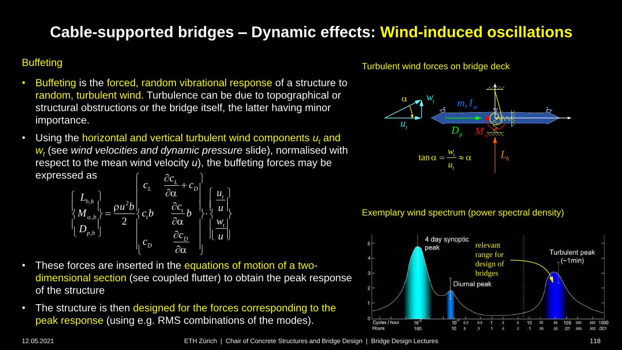
Cable-supported bridges – Dynamic effects: Wind-induced oscillations
12.05.2021 118ETH Zürich | Chair of Concrete Structures and Bridge Design | Bridge Design Lectures
Buffeting
• Buffeting is the forced, random vibrational response of a structure to
random, turbulent wind. Turbulence can be due to topographical or
structural obstructions or the bridge itself, the latter having minor
importance.
• Using the horizontal and vertical turbulent wind components ut and
wt (see wind velocities and dynamic pressure slide), normalised with
respect to the mean wind velocity u), the buffeting forces may be
expressed as
• These forces are inserted in the equations of motion of a two-
dimensional section (see coupled flutter) to obtain the peak response
of the structure
• The structure is then designed for the forces corresponding to the
peak response (using e.g. RMS combinations of the modes).
, 2
,
,
2
LL D
th b
tb t
t
p bD
D
cc c
uLcu b u
M c b bw
Dc u
c
a
a
a
a
Ma
hL
pD
, mm I
tu
a
tan t
t
w
ua a
tw
Exemplary wind spectrum (power spectral density)
relevant
range for
design of
bridges
Turbulent wind forces on bridge deck
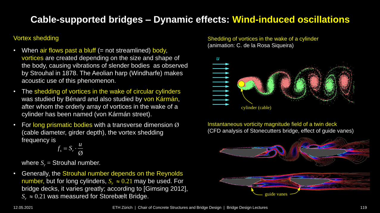
Cable-supported bridges – Dynamic effects: Wind-induced oscillations
12.05.2021 119ETH Zürich | Chair of Concrete Structures and Bridge Design | Bridge Design Lectures
Vortex shedding
• When air flows past a bluff (= not streamlined) body,
vortices are created depending on the size and shape of
the body, causing vibrations of slender bodies as observed
by Strouhal in 1878. The Aeolian harp (Windharfe) makes
acoustic use of this phenomenon.
• The shedding of vortices in the wake of circular cylinders
was studied by Bénard and also studied by von Kármán,
after whom the orderly array of vortices in the wake of a
cylinder has been named (von Kármán street).
• For long prismatic bodies with a transverse dimension Ø
(cable diameter, girder depth), the vortex shedding
frequency is
where Sr = Strouhal number.
• Generally, the Strouhal number depends on the Reynolds
number, but for long cylinders, Sr 0.21 may be used. For
bridge decks, it varies greatly; according to [Gimsing 2012],
Sr 0.21 was measured for Storebælt Bridge.
u
cylinder (cable)
Shedding of vortices in the wake of a cylinder
(animation: C. de la Rosa Siqueira)
Øs r
uf S
Instantaneous vorticity magnitude field of a twin deck
(CFD analysis of Stonecutters bridge, effect of guide vanes)
guide vanes

Cable-supported bridges – Dynamic effects: Wind-induced oscillations
12.05.2021 120ETH Zürich | Chair of Concrete Structures and Bridge Design | Bridge Design Lectures
Vortex shedding
• Large oscillations may occur in case of resonance, i.e., if the vortex
shedding frequency coincides with a the frequency of a dominant
eigenmode of the bridge cylinder fi . Hence, the critical velocity is
• Even if the critical vortex-shedding velocity ucr is reached, large
oscillations only occur if all following conditions are met:
• low structural damping
• laminar wind flow with low turbulence intensity, nearly
perpendicular to the girder axis (ca. 20°)
• ucr high enough to excite bridge, but not too high such that
narrowing of the wake disrupts the creation of vortices.
• Hence, only few cable supported bridges have exhibited excessive
vortex-shedding oscillations though ucr is often exceeded.
• The Storebælt Bridge experienced significant vortex-induced
oscillations (photo on previous slide) before guide vanes were
installed. As potential problems had been detected in the wind
tunnel tests, provisions had been made in design to fit these
elements to the bottom corners of the deck (figure and photo).
Guide vanes preventing vortex-induced oscillations on the
Storebælt bridge [Gimsing 2012]
Ø
S
icr
fu
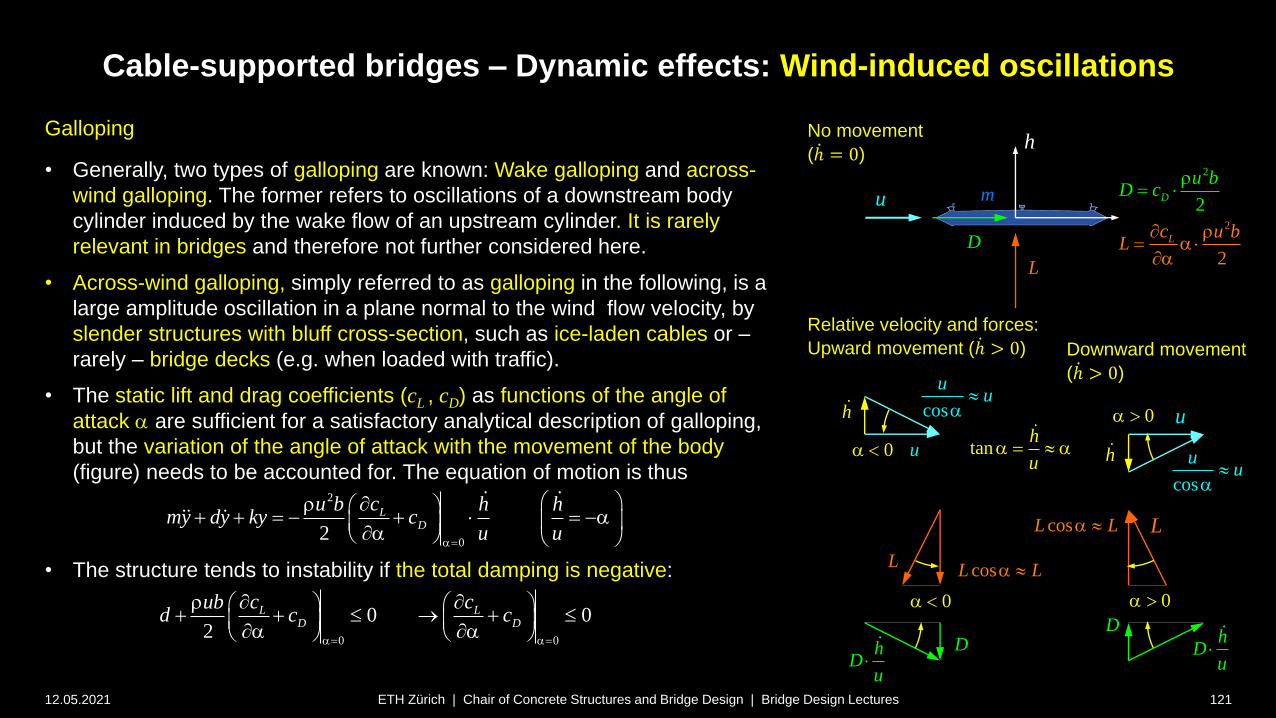
Cable-supported bridges – Dynamic effects: Wind-induced oscillations
12.05.2021 121ETH Zürich | Chair of Concrete Structures and Bridge Design | Bridge Design Lectures
Galloping
• Generally, two types of galloping are known: Wake galloping and across-
wind galloping. The former refers to oscillations of a downstream body
cylinder induced by the wake flow of an upstream cylinder. It is rarely
relevant in bridges and therefore not further considered here.
• Across-wind galloping, simply referred to as galloping in the following, is a
large amplitude oscillation in a plane normal to the wind flow velocity, by
slender structures with bluff cross-section, such as ice-laden cables or –
rarely – bridge decks (e.g. when loaded with traffic).
• The static lift and drag coefficients (cL , cD) as functions of the angle of
attack a are sufficient for a satisfactory analytical description of galloping,
but the variation of the angle of attack with the movement of the body
(figure) needs to be accounted for. The equation of motion is thus
• The structure tends to instability if the total damping is negative:
2
02
LD
cu b h hmy dy ky c
u ua
a
a
0 0
0 02
L LD D
c cubd c c
a a
a a
tanh
ua a
L
D
u0a
mu
h u
h
cos
uu
a
cos
uu
a
0a
hD
u
hD
u
D
2
2
2
2
L
D
u bD
uL
c
c b a
a
0a
cosL La
0a
L
h
D
L
cosL La
No movement
( ሶℎ = 0)
Relative velocity and forces:
Upward movement ( ሶℎ > 0) Downward movement
( ሶℎ > 0)
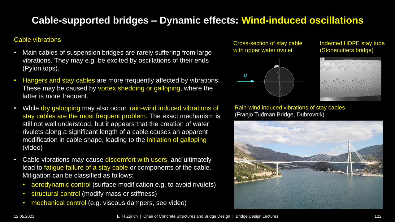
Cable-supported bridges – Dynamic effects: Wind-induced oscillations
12.05.2021 122ETH Zürich | Chair of Concrete Structures and Bridge Design | Bridge Design Lectures
Cable vibrations
• Main cables of suspension bridges are rarely suffering from large
vibrations. They may e.g. be excited by oscillations of their ends
(Pylon tops).
• Hangers and stay cables are more frequently affected by vibrations.
These may be caused by vortex shedding or galloping, where the
latter is more frequent.
• While dry galopping may also occur, rain-wind induced vibrations of
stay cables are the most frequent problem. The exact mechanism is
still not well understood, but it appears that the creation of water
rivulets along a significant length of a cable causes an apparent
modification in cable shape, leading to the initiation of galloping
(video)
• Cable vibrations may cause discomfort with users, and ultimately
lead to fatigue failure of a stay cable or components of the cable.
Mitigation can be classified as follows:
• aerodynamic control (surface modification e.g. to avoid rivulets)
• structural control (modify mass or stiffness)
• mechanical control (e.g. viscous dampers, see video)
Rain-wind induced vibrations of stay cables
(Franjo Tuđman Bridge, Dubrovnik)
Indented HDPE stay tube
(Stonecutters bridge)
Cross-section of stay cable
with upper water rivulet
u