path following control of unmanned quadrotor helicopter with
TRANSCRIPT
HAL Id: hal-01537732https://hal.archives-ouvertes.fr/hal-01537732
Submitted on 6 Jul 2017
HAL is a multi-disciplinary open accessarchive for the deposit and dissemination of sci-entific research documents, whether they are pub-lished or not. The documents may come fromteaching and research institutions in France orabroad, or from public or private research centers.
L’archive ouverte pluridisciplinaire HAL, estdestinée au dépôt et à la diffusion de documentsscientifiques de niveau recherche, publiés ou non,émanant des établissements d’enseignement et derecherche français ou étrangers, des laboratoirespublics ou privés.
Path following control of unmanned quadrotorhelicopter with obstacle avoidance capability
Zhixiang Liu, Laurent Ciarletta, Chi yuan, youmin Zhang, Didier Theilliol
To cite this version:Zhixiang Liu, Laurent Ciarletta, Chi yuan, youmin Zhang, Didier Theilliol. Path following controlof unmanned quadrotor helicopter with obstacle avoidance capability. International Conference onUnmanned Aircraft Systems, ICUAS’17, Jun 2017, Miami, Florida, United States. �hal-01537732�
Path Following Control of Unmanned Quadrotor Helicopter withObstacle Avoidance Capability
Zhixiang Liu1, Laurent Ciarletta1, Chi Yuan2, Youmin Zhang2, and Didier Theilliol3
Abstract— This paper proposes a new path following method-ology combining with a obstacle avoidance scheme for un-manned quadrotor helicopter (UQH) capable of working inthe cluttered and hazardous environments. A new cross-trackerror prediction based mechanism, where the cross-track erroris estimated by utilizing the extend Kalman filter (EKF), is firstdeveloped for the path following scheme. Then, the UQH isequipped with obstacle avoidance capability employing a light-computational approach, the visibility graph algorithm. Thepriority of UQH is to switch to obstacles avoidance maneuveringin the presence of obstacles, and continue to execute theassigned mission after avoiding all hazardous objects blockingthe desired path. The control system developed for attitude andposition control of UQH is also introduced. Finally, extensivesimulation studies on a nonlinear model of UQH with aseries of dangerous scenarios are conducted to demonstratethe effectiveness of the proposed methodology.
I. INTRODUCTION
The last decades have seen a tremendous progress in thedevelopment of unmanned aerial vehicles (UAVs). A growingnumber of research institutes, universities, governments, andcommercial entities across the world are developing andemploying UAVs for a diverse range of applications, such asscientific research [1], environmental monitoring and surveil-lance [2], [3], natural resources exploration [4], post-disastersearch and rescue [5], and military missions [6]. Unmannedquadrotor helicopters (UQHs), as an important group ofUAV, possess tremendous advantages comparing with othermanned/unmanned aerial vehicles including affordable costof development [7], decreased mechanical structure com-plicacy [8], easy-to-fly [9], enhanced maneuverability andoutstretched deployability [10], [11], as well as experimentalplatform for newly developed techniques [12].
As the complexities of application grow, UQHs are ac-cordingly required to deploy in more cluttered, sophisticated,and hazardous environments, this situation strongly demandsUQHs to be equipped with enhanced reliable and safeinstruments as well as more robust guidance and controlalgorithms for guaranteeing satisfactory performance of tasksexecution and preventing collision with buildings, mountains,trees, other manned/unmanned vehicles, etc.. However, semi-autonomy up to date is still favored over full autonomy due to
1Zhixiang Liu and Laurent Ciarletta are with the Lorraine Re-search Laboratory in Computer Science and its Applications (LORIA),University of Lorraine, Nancy, France, [email protected], [email protected]
2Chi Yuan, and Youmin Zhang are with the Department of Mechan-ical and Industrial Engineering, Concordia University, Montreal, Canada,chi [email protected], [email protected]
3Didier Theilliol with CRAN, University of Lorraine, Nancy, France,[email protected]
the diverse nature of missions and limited obstacle avoidancecapabilities of UQHs. Therefore, this work is intended toestablish the study of methodology with satisfactory andsafe performance to improve the autonomy of current UQHsincluding increasing application diversity and minimizing theamount of human supervision.
The existing mission execution can be generally parti-tioned into three predominant sorts: set-point stabilization,trajectory tracking, and path following [13]. This studyfalls into the path following problem of UQH. From theliterature, there exist two categories of design methods: 1)individual design of guidance and control systems, whichseparates the system into an inner control loop and anouter guidance loop; 2) integrated design of guidance andcontrol systems. In order to simplify the design procedureand separately manage the guidance-related disturbancesand uncertainties problems in the guidance system withoutintroducing them to control system and complicating thedesign and debugging procedures, this study chooses toseparately design guidance and control systems. Numerousexisting research works have been dedicated to the field withindividual design philosophy. In [14], the robust nonlinearcontrol theory is used for maneuvering a UQH to follow aclass of smooth Jordan curves. [15] presents a modified pure-pursuit path following method which uses inertial velocityin the calculation of commanded lateral acceleration. Withthis method, both straight and curved line paths can bewell followed. A nonlinear output-feedback control method,which employs the global exponential observer, Lyapunov’sdirect method and backstepping technique, is developed in[16] for path following application. In [17], a vector-fieldbased path following scheme is devised to generate desiredcourse references to attitude control in the inner-loop system.[18] introduces a path following control law which relies ona nonlinear control strategy derived at the kinematic level.
Regarding obstacle avoidance methods, a large number ofheuristic obstacle avoidance methods have been developedfor UAVs, such as particle swarm optimization (PSO) [19],genetic algorithm (GA) [20], artificial potential field (APF)[21], [22], and probabilistic roadmap-based method [23].Considering the low computational capability of the onboardprocessor of UQH as well as high maneuverability of UQH,this study selects a light-computational obstacle avoidancemethod, the visibility graph [24], as the obstacle avoidancedesign.
Following the concept of hierarchical structure design, ahybrid system, which consists of three functionality modulesincluding the path following, obstacle avoidance, and motion
zB
yB
xB
oB
u3
u4
u2
Left
Rear
Front
Right
L
Roll Pitch
Yaw
u1
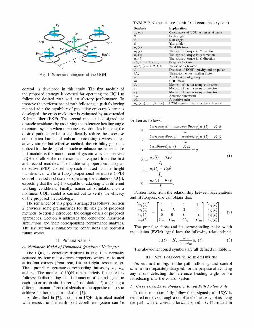
Fig. 1: Schematic diagram of the UQH.
control, is developed in this study. The first module ofthe proposed strategy is devised for operating the UQH tofollow the desired path with satisfactory performance. Toimprove the performance of path following, a path followingmethod with the capability of predicting cross-track error isdeveloped; the cross-track error is estimated by an extendedKalman filter (EKF). The second module is designed forobstacle avoidance by modifying the reference heading angleto control system when there are any obstacles blocking thedesired path. In order to significantly reduce the excessivecomputation burden of onboard processing devices, a rel-atively simple but effective method, the visibility graph, isutilized for the design of obstacle avoidance mechanism. Thelast module is the motion control system which maneuversUQH to follow the reference path assigned from the firstand second modules. The traditional proportional-integral-derivative (PID) control approach is used for the heightmaintenance, while a fuzzy proportional-derivative (FPD)control method is chosen for operating the attitude of UQH,expecting that the UQH is capable of adapting with differentworking conditions. Finally, numerical simulations on anonlinear UQH model is carried out to verify the efficacyof the proposed methodology.
The remainder of this paper is arranged as follows: Section2 provides some preliminaries for the design of proposedmethods. Section 3 introduces the design details of proposedapproaches. Section 4 addresses the conducted numericalsimulations and their corresponding performance analyses.The last section summarizes the conclusions and potentialfuture works.
II. PRELIMINARIES
A. Nonlinear Model of Unmanned Quadrotor Helicopter
The UQH, as concisely depicted in Fig. 1, is normallyactuated by four motor-driven propellers which are locatedat its four corners (front, rear, left, and right, respectively).These propellers generate corresponding thrusts u1, u2, u3,and u4. The motion of UQH can be briefly illustrated asfollows: 1) distributing identical amount of control signal toeach motor to obtain the vertical translation; 2) assigning adifferent amount of control signals to the opposite motors toachieve the horizontal translation [7].
As described in [7], a common UQH dynamical modelwith respect to the earth-fixed coordinate system can be
TABLE I: Nomenclature (earth-fixed coordinate system)Symbols Explanationx, y, z Coordinates of UQH at center of massθ Pitch angleφ Roll angleψ Yaw angleuz(t) Total lift forceuθ(t) The applied torque in θ directionuφ(t) The applied torque in φ directionuψ(t) The applied torque in ψ directionKn (n = 1, 2, ..., 6) Drag coefficientsui(t) (i = 1, 2, 3, 4) Thrust of each rotorL Distance of UQH’s gravity and propellerCm Thrust-to-moment scaling factorg Acceleration of gravitym UQH massIx Moment of inertia along x directionIy Moment of inertia along y directionIz Moment of inertia along z directionωm Actuator bandwidthKm A positive gainuci(t) (i = 1, 2, 3, 4) PWM signals distributed to each rotor
written as follows:
x =(sinψsinφ+ cosψsinθcosφ)uz(t)−K1x
m
y =(sinψsinθcosφ− cosψsinφ)uz(t)−K2y
m
z =(cosθcosφ)uz(t)−K3z
m− g
φ =uφ(t)−K4φ
Ix
θ =uθ(t)−K5θ
Iy
ψ =uψ(t)−K6ψ
Iz.
(1)
Furthermore, from the relationship between accelerationsand lift/torques, one can obtain that:
uz(t)uθ(t)uφ(t)uψ(t)
=
1 1 1 1L −L 0 00 0 L −LCm Cm −Cm −Cm
u1(t)u2(t)u3(t)u4(t)
. (2)
The propeller force and its corresponding pulse widthmodulation (PWM) signal have the following relationships:
ui(t) = Kmωm
s+ ωmuci(t). (3)
The above-mentioned symbols are all defined in Table I.
III. PATH FOLLOWING SCHEME DESIGN
As outlined in Fig. 2, the path following and controlschemes are separately designed, for the purpose of avoidingany errors defecting the reference heading angle beforeintroducing it to the control system.
A. Cross-Track Error Prediction Based Path Follow Rule
In order to successfully follow the assigned path, UQV isrequired to move through a set of predefined waypoints alongthe path with a constant forward speed. As illustrated in
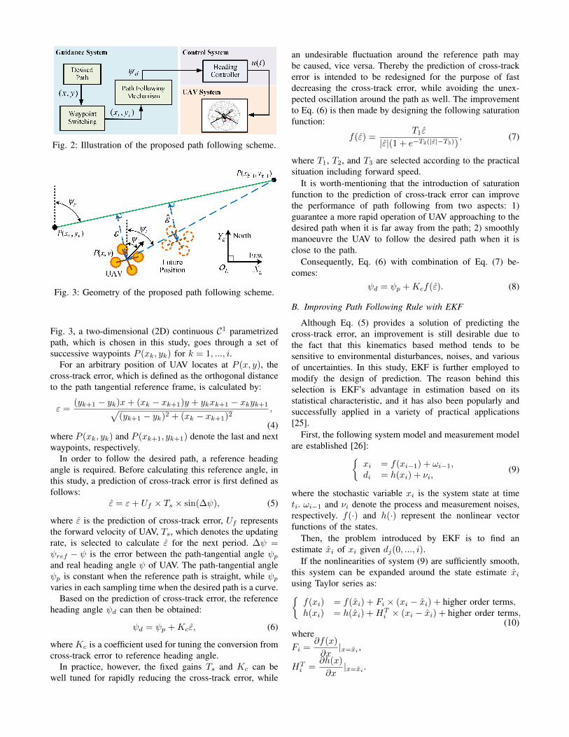
Fig. 2: Illustration of the proposed path following scheme.
Fig. 3: Geometry of the proposed path following scheme.
Fig. 3, a two-dimensional (2D) continuous C1 parametrizedpath, which is chosen in this study, goes through a set ofsuccessive waypoints P (xk, yk) for k = 1, ..., i.
For an arbitrary position of UAV locates at P (x, y), thecross-track error, which is defined as the orthogonal distanceto the path tangential reference frame, is calculated by:
ε =(yk+1 − yk)x+ (xk − xk+1)y + ykxk+1 − xkyk+1√
(yk+1 − yk)2 + (xk − xk+1)2,
(4)where P (xk, yk) and P (xk+1, yk+1) denote the last and nextwaypoints, respectively.
In order to follow the desired path, a reference headingangle is required. Before calculating this reference angle, inthis study, a prediction of cross-track error is first defined asfollows:
ε = ε+ Uf × Ts × sin(∆ψ), (5)
where ε is the prediction of cross-track error, Uf representsthe forward velocity of UAV, Ts, which denotes the updatingrate, is selected to calculate ε for the next period. ∆ψ =ψref − ψ is the error between the path-tangential angle ψpand real heading angle ψ of UAV. The path-tangential angleψp is constant when the reference path is straight, while ψpvaries in each sampling time when the desired path is a curve.
Based on the prediction of cross-track error, the referenceheading angle ψd can then be obtained:
ψd = ψp +Kcε, (6)
where Kc is a coefficient used for tuning the conversion fromcross-track error to reference heading angle.
In practice, however, the fixed gains Ts and Kc can bewell tuned for rapidly reducing the cross-track error, while
an undesirable fluctuation around the reference path maybe caused, vice versa. Thereby the prediction of cross-trackerror is intended to be redesigned for the purpose of fastdecreasing the cross-track error, while avoiding the unex-pected oscillation around the path as well. The improvementto Eq. (6) is then made by designing the following saturationfunction:
f(ε) =T1ε
|ε|(1 + e−T2(|ε|−T3)), (7)
where T1, T2, and T3 are selected according to the practicalsituation including forward speed.
It is worth-mentioning that the introduction of saturationfunction to the prediction of cross-track error can improvethe performance of path following from two aspects: 1)guarantee a more rapid operation of UAV approaching to thedesired path when it is far away from the path; 2) smoothlymanoeuvre the UAV to follow the desired path when it isclose to the path.
Consequently, Eq. (6) with combination of Eq. (7) be-comes:
ψd = ψp +Kcf(ε). (8)
B. Improving Path Following Rule with EKF
Although Eq. (5) provides a solution of predicting thecross-track error, an improvement is still desirable due tothe fact that this kinematics based method tends to besensitive to environmental disturbances, noises, and variousof uncertainties. In this study, EKF is further employed tomodify the design of prediction. The reason behind thisselection is EKF’s advantage in estimation based on itsstatistical characteristic, and it has also been popularly andsuccessfully applied in a variety of practical applications[25].
First, the following system model and measurement modelare established [26]:{
xi = f(xi−1) + ωi−1,di = h(xi) + νi,
(9)
where the stochastic variable xi is the system state at timeti. ωi−1 and νi denote the process and measurement noises,respectively. f(·) and h(·) represent the nonlinear vectorfunctions of the states.
Then, the problem introduced by EKF is to find anestimate xi of xi given dj(0, ..., i).
If the nonlinearities of system (9) are sufficiently smooth,this system can be expanded around the state estimate xiusing Taylor series as:{f(xi) = f(xi) + Fi × (xi − xi) + higher order terms,h(xi) = h(xi) +HT
i × (xi − xi) + higher order terms,(10)
whereFi =
∂f(x)
∂x|x=xi
,
HTi =
∂h(x)
∂x|x=xi .

Neglecting the higher order terms in Eq. (10), Eq. (9) canthen be approximated by:{
xi = Fi−1xi−1 + ωi−1 + φi−1,di = HT
i xi + νi + ϕi−1,(11)
whereφi−1 = f(xi−1)− Fi−1xi−1,ϕi−1 = h(xi−1)−HT
i−1xi−1.Therefore, the desired estimate xi can be obtained by the
following EKF recursive equations [26]:
Fi−1 = ∂f(x)∂x
∣∣∣x=xi−1|i−1
,
Hi = ∂h(x)∂x
∣∣∣x=xi|i−1
,
Ki = Pi|i−1HTi (Ri +HiPi|i−1H
Ti )−1,
xi|i = f(xi−1|i−1) +Ki[di − h(xi|i−1)],Pi|i = Fi−1(Pi−1|i−1 −KiHiPi−1|i−1)FTi−1 +Qi−1,
(12)where di represents the observation vector, Ki is theKalman gain, Pi denotes the covariance matrix of stateestimation error, and the estimated state xi|i is the opti-mal solution which approaches the conditional mean valueE[xi|(d0, d1, . . . , di)].
Ultimately, choosing the state of EKF as x = [Uf ,∆ψ]T ,and applying the Kalman recursion (12), the prediction ofcross-track error ε can be obtained for the computation ofreference heading angle.
Fig. 4: Geometry of the adopted obstacle avoidance method.
IV. OBSTACLE AVOIDANCE SCHEME DESIGN
Maintaining the safety of UQHs is generally a priorityover mission execution including trajectory tracking and pathfollowing. Therefore, in the event of encountering obstacles,the current objective is first to avoid any potential collisions,then return to the assigned mission. Considering the compu-tational capability of the processor onboard UQH and highmaneuverability requirement in practice, this study utilizesa relatively simple but effective roadmap-based obstacleavoidance method, the visibility graph, to avoid any obstaclesapproaching to the UAV.
The general concept of visibility graph method is toconnect UAV and the next objective waypoint, two possibilitycan occur: 1) the next objective waypoint is visible whenthere is no obstacles between UAV and the waypoint, andthe path is approachable; 2) otherwise, the path to objectivewaypoint is blocked by obstacles, then an optimal path (the
Fig. 5: Composition of controllers to follow the desired path.
shortest path) of avoiding the obstacle and moving towardsto objective waypoint is achievable by comparing all of theavailable connections from UAV, through one of the detectedvertex of obstacle, to objective waypoint.
As illustrated in Fig. 4, in the absence of obstacles, UAVfollows the desired path by tracking the reference headingangle ψd generated according to the desired path; but in thepresence of obstacles, UAV stops following the desired pathand changes to follow the obstacle avoidance heading angleto avoid the approaching obstacles.
In order to calculate the corresponding heading angleto keep the UAV away from colliding with obstacles, thefollowing rule is established:
ψd =
{ψl if δl ≤ δr,ψr if δl > δr,
(13)
where δl = |ψl−ψ| and δr = |ψr−ψ|. ψl and ψr denote theleftmost and rightmost vertex of obstacle combining with asafety distance with respect to UAV, respectively. This safetydistance is chosen by inflating the obstacle with a specificradius according to the forward velocity of UAV, minimumturning radius of UAV, and the practical safety requirement.
V. CONTROL SYSTEM DESIGN
As shown in Fig. 5, the tasks of control system design inthis study include:
1) To maintain a desired height and follow the referenceyaw angle.
2) To keep a constant forward motion by achieving anacceptable performance of pitch angle control.
3) To guarantee the stability of UAV with small deviationsfrom the hovering flight.
A PID controller is chosen for height control, controllergains can be determined by:
uz = KhP (zd − z) +Kh
I
∫(zd − z)dt+Kh
D(−z), (14)
where zd is the desired height, and KhP , Kh
I and KhD are the
gains of PID controller.
A PD controller is designed for the attitude operation (yawand pitch angle control), controller gains is calculated as:
uθ = KθP (θd − θ) +Kθ
D(pd − p),uψ = Kψ
P (ψd − ψ) +KψD(rd − r),
(15)
where KψP and Kψ
D are the gains of PD controller for yawangle, while Kθ
P and KθD are the gains for pitch angle. p
and r denote the angular velocities of pitch and yaw.In order to improve the robustness of attitude controller
against structural changes and uncertainties in system pa-rameters as well as environmental disturbances, the attitudecontroller is further tuned by the fuzzy logic control (FLC)rule. The following simple linear transformation is used forcalculating controller gains:
KP = (KmaxP −Kmin
P )∆KP +KminP ,
KD = (KmaxD −Kmin
D )∆KD +KminD ,
(16)
where [KminP ,Kmax
P ], [KminD ,Kmax
D ] represent the prede-fined ranges of KP and KD, respectively. ∆KP and ∆KD
are determined by the following linguistic rules of FLC:
If ek is Ai and ∆ek is Bi, then ∆KP is Ci and ∆KD is Di,(17)
where Ai, Bi, Ci, and Di represent the fuzzy sets corre-sponding to ek, ∆ek, ∆KP , and ∆KD.
Due to the space limit, further details of the design pro-cedure is omitted here. Readers can refer to other literaturefor the similar design method [27].
VI. SIMULATIONS
To demonstrate the effectiveness of the proposed method,numerical simulations on a nonlinear UQH model are con-ducted. Two scenarios are selected in the simulation:
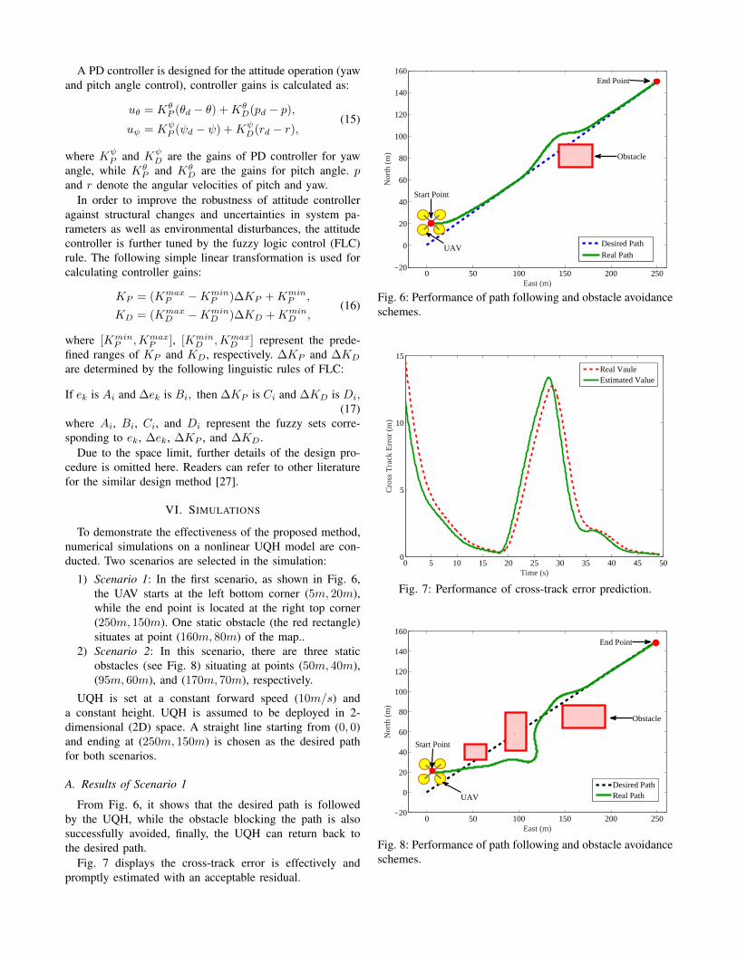
1) Scenario 1: In the first scenario, as shown in Fig. 6,the UAV starts at the left bottom corner (5m, 20m),while the end point is located at the right top corner(250m, 150m). One static obstacle (the red rectangle)situates at point (160m, 80m) of the map..
2) Scenario 2: In this scenario, there are three staticobstacles (see Fig. 8) situating at points (50m, 40m),(95m, 60m), and (170m, 70m), respectively.
UQH is set at a constant forward speed (10m/s) anda constant height. UQH is assumed to be deployed in 2-dimensional (2D) space. A straight line starting from (0, 0)and ending at (250m, 150m) is chosen as the desired pathfor both scenarios.
A. Results of Scenario 1
From Fig. 6, it shows that the desired path is followedby the UQH, while the obstacle blocking the path is alsosuccessfully avoided, finally, the UQH can return back tothe desired path.
Fig. 7 displays the cross-track error is effectively andpromptly estimated with an acceptable residual.
0 50 100 150 200 250−20
0
20
40
60
80
100
120
140
160
East (m)
Nor
th (
m)
Desired Path
Real Path
Obstacle
UAV
Start Point
End Point
Fig. 6: Performance of path following and obstacle avoidanceschemes.
0 5 10 15 20 25 30 35 40 45 500
5
10
15
Time (s)
Cro
ss T
rack
Err
or (
m)
Real VauleEstimated Value
Fig. 7: Performance of cross-track error prediction.
0 50 100 150 200 250−20
0
20
40
60
80
100
120
140
160
East (m)
Nor
th (
m)
Desired PathReal PathUAV
Start Point
End Point
Obstacle
Fig. 8: Performance of path following and obstacle avoidanceschemes.
0 5 10 15 20 25 30 35 40 45 50−35
−30
−25
−20
−15
−10
−5
0
5
10
15
Time (s)
Cro
ss T
rack
Err
or (
m)
Real VauleEstimated Value
Fig. 9: Performance of cross-track error prediction.
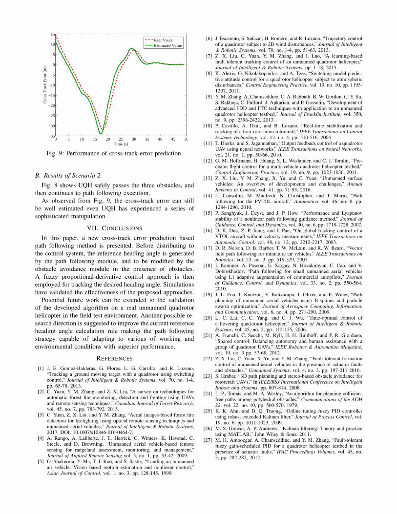
B. Results of Scenario 2
Fig. 8 shows UQH safely passes the three obstacles, andthen continues to path following execution.
As observed from Fig. 9, the cross-track error can stillbe well estimated even UQH has experienced a series ofsophisticated manipulation.
VII. CONCLUSIONS
In this paper, a new cross-track error prediction basedpath following method is presented. Before distributing tothe control system, the reference heading angle is generatedby the path following module, and to be modified by theobstacle avoidance module in the presence of obstacles.A fuzzy proportional-derivative control approach is thenemployed for tracking the desired heading angle. Simulationshave validated the effectiveness of the proposed approaches.
Potential future work can be extended to the validationof the developed algorithm on a real unmanned quadrotorhelicopter in the field test environment. Another possible re-search direction is suggested to improve the current referenceheading angle calculation rule making the path followingstrategy capable of adapting to various of working andenvironmental conditions with superior performance.
REFERENCES
[1] J. E. Gomez-Balderas, G. Flores, L. G. Carrillo, and R. Lozano,“Tracking a ground moving target with a quadrotor using switchingcontrol,” Journal of Intelligent & Robotic Systems, vol. 70, no. 1-4,pp. 65-78, 2013.
[2] C. Yuan, Y. M. Zhang, and Z. X. Liu, “A survey on technologies forautomatic forest fire monitoring, detection and fighting using UAVsand remote sensing techniques,” Canadian Journal of Forest Research,vol. 45, no. 7, pp. 783-792, 2015.
[3] C. Yuan, Z. X. Liu, and Y. M. Zhang, “Aerial images-based forest firedetection for firefighting using optical remote sensing techniques andunmanned aerial vehicles,” Journal of Intelligent & Robotic Systems,2017, DOI: 10.1007/s10846-016-0464-7.
[4] A. Rango, A. Laliberte, J. E. Herrick, C. Winters, K. Havstad, C.Steele, and D. Browning, “Unmanned aerial vehicle-based remotesensing for rangeland assessment, monitoring, and management,”Journal of Applied Remote Sensing vol. 3, no. 1, pp. 33-42, 2009.
[5] O. Shakernia, Y. Ma, T. J. Koo, and S. Sastry, “Landing an unmannedair vehicle: Vision based motion estimation and nonlinear control,”Asian Journal of Control, vol. 1, no. 3, pp. 128-145, 1999.
[6] J. Escareno, S. Salazar, H. Romero, and R. Lozano, “Trajectory controlof a quadrotor subject to 2D wind disturbances,” Journal of Intelligent& Robotic Systems, vol. 70, no. 1-4, pp. 51-63, 2013.
[7] Z. X. Liu, C. Yuan, Y. M. Zhang, and J. Luo, “A learning-basedfault tolerant tracking control of an unmanned quadrotor helicopter,”Journal of Intelligent & Robotic Systems, pp. 1-18, 2015.
[8] K. Alexis, G. Nikolakopoulos, and A. Tzes, “Switching model predic-tive attitude control for a quadrotor helicopter subject to atmosphericdisturbances,” Control Engineering Practice, vol. 19, no. 10, pp. 1195-1207, 2011.
[9] Y. M. Zhang, A, Chamseddine, C. A. Rabbath, B. W. Gordon, C. Y. Su,S. Rakheja, C. Fulford, J. Apkarian, and P. Gosselin, “Development ofadvanced FDD and FTC techniques with application to an unmannedquadrotor helicopter testbed,” Journal of Franklin Institute, vol. 350,no. 9, pp. 2396-2422, 2013.
[10] P. Castillo, A. Dzul, and R. Lozano, “Real-time stabilization andtracking of a four-rotor mini rotorcraft,” IEEE Transactions on ControlSystems Technology, vol. 12, no. 4, pp. 510-516, 2004.
[11] T. Dierks, and S. Jagannathan, “Output feedback control of a quadrotorUAV using neural networks,” IEEE Transactions on Neural Networks,vol. 21, no. 1, pp. 50-66, 2010.
[12] G. M. Hoffmann, H. Huang, S. L. Waslander, and C. J. Tomlin, “Pre-cision flight control for a multi-vehicle quadrotor helicopter testbed,”Control Engineering Practice, vol. 19, no. 9, pp. 1023-1036, 2011.
[13] Z. X. Liu, Y. M. Zhang, X. Yu, and C. Yuan, “Unmanned surfacevehicles: An overview of developments and challenges,” AnnualReviews in Control, vol. 41, pp. 71-93, 2016.
[14] L. Consolini, M. Manfredi, N. Christopher, and T. Mario, “Pathfollowing for the PVTOL aircraft,” Automatica, vol. 46, no. 8, pp.1284-1296, 2010.
[15] P. Sanghyuk, J. Deyst, and J. P. How, “Performance and Lyapunovstability of a nonlinear path following guidance method,” Journal ofGuidance, Control, and Dynamics, vol. 30, no. 6, pp. 1718-1728, 2007.
[16] D. K. Duc, Z. P. Jiang, and J. Pan, “On global tracking control of aVTOL aircraft without velocity measurements,” IEEE Transactions onAutomatic Control, vol. 48, no. 12, pp. 2212-2217, 2003.
[17] D. R. Nelson, D. B. Barber, T. W. McLain, and R. W. Beard, “Vectorfield path following for miniature air vehicles,” IEEE Transactions onRobotics, vol. 23, no. 3, pp. 519-529, 2007.
[18] I. Kaminer, A. Pascoal, E. Xargay, N. Hovakimyan, C. Cao, and V.Dobrokhodov, “Path following for small unmanned aerial vehiclesusing L1 adaptive augmentation of commercial autopilots,” Journalof Guidance, Control, and Dynamics, vol. 33, no. 2, pp. 550-564,2010.
[19] J. L. Foo, J. Knutzon, V. Kalivarapu, J. Oliver, and E. Winer, “Pathplanning of unmanned aerial vehicles using B-splines and particleswarm optimization,” Journal of Aerospace Computing, Information,and Communication, vol. 6, no. 4, pp. 271-290, 2009.
[20] L. C. Lai, C. C. Yang, and C. J. Wu, “Time-optimal control ofa hovering quad-rotor helicopter,” Journal of Intelligent & RoboticSystems, vol. 45, no. 2, pp. 115-135, 2006.
[21] A. Franchi, C. Secchi, M. Ryll, H. H. Bulthoff, and P. R. Giordano,“Shared control: Balancing autonomy and human assistance with agroup of quadrotor UAVs,” IEEE Robotics & Automation Magazine,vol. 19, no. 3 pp. 57-68, 2012.
[22] Z. X. Liu, C. Yuan, X. Yu, and Y. M. Zhang, “Fault-tolerant formationcontrol of unmanned aerial vehicles in the presence of actuator faultsand obstacles,” Unmanned Systems, vol. 4, no. 3, pp. 197-211 2016.
[23] S. Hrabar, “3D path planning and stereo-based obstacle avoidance forrotorcraft UAVs,” In IEEE/RSJ International Conference on IntelligentRobots and Systems, pp. 807-814, 2008.
[24] L. P., Tomas, and M. A. Wesley, “An algorithm for planning collision-free paths among polyhedral obstacles,” Communications of the ACM22, vol. 22, no. 10, pp. 560-570, 1979.
[25] K. K. Ahn, and D. Q. Truong, “Online tuning fuzzy PID controllerusing robust extended Kalman filter,” Journal of Process Control, vol.19, no. 6, pp. 1011-1023, 2009.
[26] M. S. Grewal, A. P. Andrews, “Kalman filtering: Theory and practiceusing MATLAB,” John Wiley & Sons, 2011.
[27] M. H. Amoozgar, A. Chamseddine, and Y. M. Zhang, “Fault-tolerantfuzzy gain-scheduled PID for a quadrotor helicopter testbed in thepresence of actuator faults,” IFAC Proceedings Volumes, vol. 45, no.3, pp. 282-287, 2012.