a review of quadrotor unmanned aerial vehicles
TRANSCRIPT

SURVEY PAPER
A Review of Quadrotor Unmanned Aerial Vehicles: Applications,Architectural Design and Control Algorithms
Moad Idrissi1 & Mohammad Salami1 & Fawaz Annaz1
Received: 7 March 2021 /Accepted: 3 November 2021# Crown 2022
AbstractOver the past decade, unmanned aerial vehicles (UAVs) have received a significant attention due to their diverse capabilities fornon-combatant and military applications. The primary aim of this study is to unveil a clear categorization overview for more thana decade worth of substantial progress in UAVs. The paper will begin with a general overview of the advancements, followed byan up-to-date explanation of the different mechanical structures and technical elements that have been included. The paper willthen explore and examine various vertical take-off and landing (VTOL) configurations, followed by expressing the dynamics,applicable simulation tools and control strategies for a Quadrotor. In conclusion to this review, the dynamic system presented willalways face limitations such as internal and/or external disturbances. Hence, this can be minimised by the choice of introducingappropriate control techniques or mechanical enhancements.
Keywords UAV . Quadrotor . Review . Control Laws . Dynamic modelling
1 Introduction
The twenty-first century has seen a rapid spread of UnmannedAerial Vehicles (UAVs) that are telemetrymonitored and con-trolled by pilots on the ground, who can either be nearby or faraway (depending on the application). Initially, developmentswere limited to large military drones, however, advances inmotors technology, drive electronics, microcontrollers and ac-cess to GPS navigation, encouraged manufacturers to developsmaller and cheaper drones [1].
UAVs may be classified as either being fixed or rotarywinged aircrafts. Fixed-winged (FW) aircrafts generally havesimpler structures than rotary wing (RW) crafts, hence theyrequire less complicated maintenance and repair processes,allowing for a cheap, longer operational time and high-speed
flight durations. They also have natural gliding capabilitieswith no power requirement, and are capable of carrying largerpayloads over longer distances while consuming less power.However, FW crafts requires a runway or a launcher for take-off and landing, unlike RW crafts which are capable of verti-cally taking-off/landing (VTOL); therefore, short take off/landing (STOL) solutions are very popular to help eradicatethis issue.
Moreover, fixed-wing crafts require continuous airflowover their wings to generate lift, thus, they must maintainforward motion (i.e. can’t stay stationary), which makes themunsuitable for stationary (hovering) applications such as in-spection. It is because of these advantages, rotary-wingedcrafts have globally received the interest of researchers anddevelopers in the commercial, industrial, military and rescueservices sectors; and therefore they are found in applicationswithin the media industry, fire services, power production,agricultural industry, express delivery services, search andrescue tasks, inspection, surveillance, aerial photography andmany more [2].
With regard to VTOL and Horizontal take-off/landing(HTOL) UAVs, research has been greatly undertaken to im-prove the flight performance by modifying the mechanicalstructure of these systems, some of which are extremely smallUAVs that could perhaps be the size of ‘small particles’weighing around 0.1Kg while others could be as large as a
* Moad [email protected]
Mohammad [email protected]
Fawaz [email protected]
1 Faculty of Computing, Engineering and the Built Environment,Birmingham City University, Birmingham, UK
https://doi.org/10.1007/s10846-021-01527-7
/ Published online: 22 January 2022
Journal of Intelligent & Robotic Systems (2022) 104: 22
conventional piloted aircraft weighing over 150Kg [1, 3]. Thevast majority of these changes and modifications has resultedin the implementation of these drones on wider applicationsworldwide. While the mechanical architecture is rapidly en-hancing, control techniques is considered as a major topic forresearchers to carry out and achieve successful drone opera-tions. Doing so meant that the dynamic model for the UAVmust be taken into great consideration without neglecting anyparameters as that will characterize the performance of thecontrol law. As for the control algorithms studied in this field,the literature review is rich with various techniques some ofwhich are PID [4–7], LQR [8–11], Sliding Mode [7, 12–15]Backstepping [16–19] and more.
Since drones are now becoming the centre of attention inrobotics and autonomous engineering, the aim of this researchis to provide the reader with an insight of various UAVmechanical architectures such that a comparative studywill be undertaken to illustrate the advantages and draw-backs of each design. In particular, Quadrotors have beenspecifically selected due to their efficient performance andease of manoeuvrability, which will be studied in relation toexplaining the dynamic behaviour and system parametersbased on a realistic model [20]. Additionally, various controltechniques will be explored essentially discussing other au-thors’ output performance of each method and their draw-backs. Common control laws such as PID and SM will beinvestigated further in terms of elaborating on the control al-gorithms and depicting the output solutions from the literaturereviewed.
The paper is structured as follows. Section 2. will begin byoutlining the technological features of UAVs generally ex-ploring some of the common features that these systems hold.Section 3. expresses various UAV mechanical architecturesdescribing the performance of each method based on the ben-efits and drawbacks attained from other researchers. InSection 4, a comparative study between the performances ofvarious VTOL drones is carried out with a discussion of thecommon Quadrotor configurations. Section 5 elaborates onthe aerodynamic effects of the Quadrotor and how they per-form without the inclusion of a controller, while section 6shows the widely implemented simulation tools for physicaland mathematical modelling. Section 7 provides a thoroughreview of the common control laws with a discussion of themost appropriate method according to the mission criteria.Lastly, section 8 concludes the reviewed studies.
2 Enabling Technologies and Applications
The functionality of UAVs has always been dependant on thetechnological features that are included within the electronicsystem of the aircraft. The development of these features thatcan be directly added to the system architecture is becoming
more advanced due to the increased demand for certain dronecharacteristics. Although these features are all advantageousin their own ways, the implementation process is only consid-ered viable when the drone is expected to function within acertain application. For instance, [21] and his team have fo-cused on UAVs and ground unmanned vehicles to collabora-tively work for search and rescuemissions. The significant useof motion planning equipment provides a real-time feedbackdata to the wilderness rescue team, allowing them to accurate-ly focus and pinpoint the target on the ground.
Another technological feature that has emerged for UAVshas been increasingly implemented and researched. [22] tookthe opportunity to review and provide a summary of some ofthe current commercial, open source and research autopilotsystems. The authors mentioned that these systems can purelyguide the UAV into following a referenced trajectory withoutany assistance from the human operator. With the implemen-tation of the selected controller and careful parameter tuning,the operator is able to achieve an improved performance de-pending on the set application.
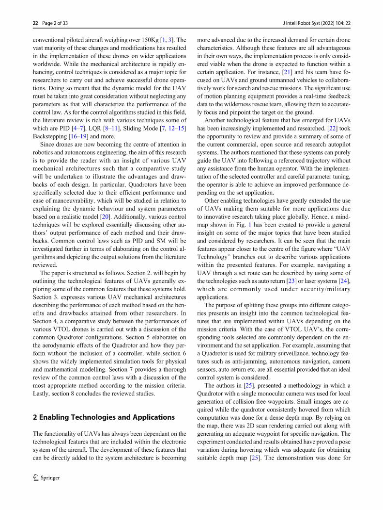
Other enabling technologies have greatly extended the useof UAVs making them suitable for more applications dueto innovative research taking place globally. Hence, a mind-map shown in Fig. 1 has been created to provide a generalinsight on some of the major topics that have been studiedand considered by researchers. It can be seen that the mainfeatures appear closer to the centre of the figure where “UAVTechnology” branches out to describe various applicationswithin the presented features. For example, navigating aUAV through a set route can be described by using some ofthe technologies such as auto return [23] or laser systems [24],which are commonly used under security/militaryapplications.
The purpose of splitting these groups into different catego-ries presents an insight into the common technological fea-tures that are implemented within UAVs depending on themission criteria. With the case of VTOL UAV’s, the corre-sponding tools selected are commonly dependent on the en-vironment and the set application. For example, assuming thata Quadrotor is used for military surveillance, technology fea-tures such as anti-jamming, autonomous navigation, camerasensors, auto-return etc. are all essential provided that an idealcontrol system is considered.
The authors in [25], presented a methodology in which aQuadrotor with a single monocular camera was used for localgeneration of collision-free waypoints. Small images are ac-quired while the quadrotor consistently hovered from whichcomputation was done for a dense depth map. By relying onthe map, there was 2D scan rendering carried out along withgenerating an adequate waypoint for specific navigation. Theexperiment conducted and results obtained have proved a posevariation during hovering which was adequate for obtainingsuitable depth map [25]. The demonstration was done for
22 Page 2 of 33 J Intell Robot Syst (2022) 104: 22
validating the proposed method in a challenging environmentwhere navigating a Quadrotor was successfully done fromnarrow passages including people, boxes, and doors [25].
Additional UAV technologies specifically equipped withvision and intelligence methods include object detection, pathplanning and object tracking [26]. With regard to these intel-ligent features, a methodology is followed to allow the UAVto locally generate waypoints that are collision-free whichproved clear visibility and tracking [27]. In [28], a techniqueis proposed for collision avoidance systems depending onvisual detection. The system hardware consisted of a hum-mingbird Quadrotor which was equipped with a higher redmarker along with two built-in-fish-eye cameras. The mea-surements fusion were done from two cameras utilizing aGaussian-mixture probability hypothesis density filter, whichproved successful tracking [28]. The proposed collisionavoidance algorithm relied on navigation functions. Theseare designed specifically for coping with cameras particularlycharacterized by limiting the field of view. There is recordingconducted of the trajectory data with an external motion cap-ture system which led towards demonstration of decent ro-bustness against internal noise [28, 29].
Although the features presented in Fig. 1 can easily overlapwith other categories depending on the set application, clari-fying this further is presented in Table 1 which highlights
some of the applications that are suitable for the various fea-tures mentioned in Fig. 1. It is evident that the applicationsselected for each feature somehow overlaps with otherfeatures. Hence, a combination of these features can be-come greatly effective when combined for certain flightmissions.
3 UAV Mechanical Architectures
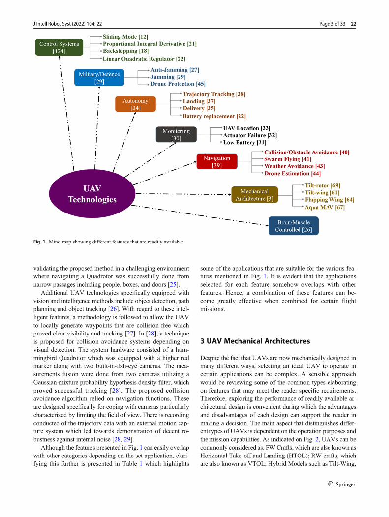
Despite the fact that UAVs are now mechanically designed inmany different ways, selecting an ideal UAV to operate incertain applications can be complex. A sensible approachwould be reviewing some of the common types elaboratingon features that may meet the reader specific requirements.Therefore, exploring the performance of readily available ar-chitectural design is convenient during which the advantagesand disadvantages of each design can support the reader inmaking a decision. The main aspect that distinguishes differ-ent types of UAVs is dependent on the operation purposes andthe mission capabilities. As indicated on Fig. 2, UAVs can becommonly considered as: FWCrafts, which are also known asHorizontal Take-off and Landing (HTOL); RW crafts, whichare also known as VTOL; Hybrid Models such as Tilt-Wing,
Fig. 1 Mind map showing different features that are readily available
Page 3 of 33 22J Intell Robot Syst (2022) 104: 22
Tilt-Rotor etc. and Exclusive models that consist of uniquedesigns such as the Bird UAV [3].
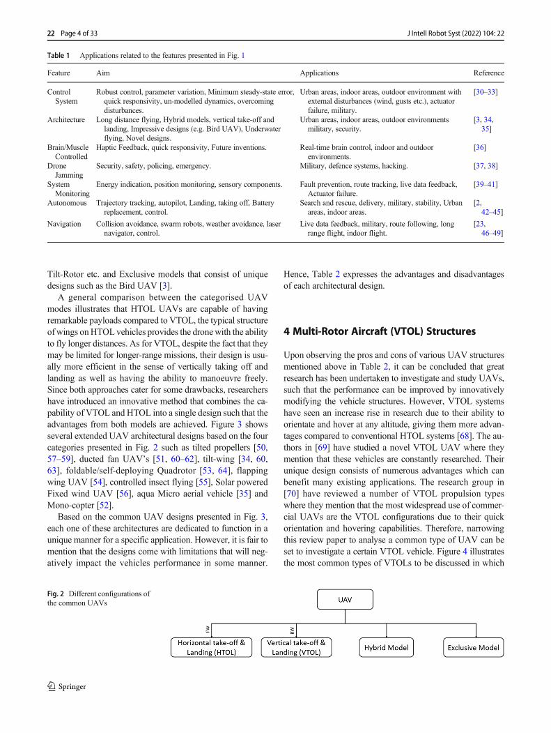
A general comparison between the categorised UAVmodes illustrates that HTOL UAVs are capable of havingremarkable payloads compared to VTOL, the typical structureof wings onHTOL vehicles provides the drone with the abilityto fly longer distances. As for VTOL, despite the fact that theymay be limited for longer-range missions, their design is usu-ally more efficient in the sense of vertically taking off andlanding as well as having the ability to manoeuvre freely.Since both approaches cater for some drawbacks, researchershave introduced an innovative method that combines the ca-pability of VTOL and HTOL into a single design such that theadvantages from both models are achieved. Figure 3 showsseveral extended UAV architectural designs based on the fourcategories presented in Fig. 2 such as tilted propellers [50,57–59], ducted fan UAV’s [51, 60–62], tilt-wing [34, 60,63], foldable/self-deploying Quadrotor [53, 64], flappingwing UAV [54], controlled insect flying [55], Solar poweredFixed wind UAV [56], aqua Micro aerial vehicle [35] andMono-copter [52].
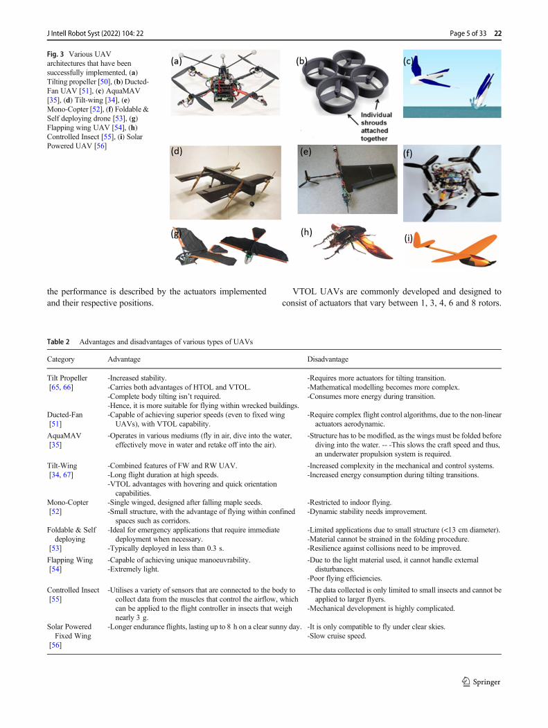
Based on the common UAV designs presented in Fig. 3,each one of these architectures are dedicated to function in aunique manner for a specific application. However, it is fair tomention that the designs come with limitations that will neg-atively impact the vehicles performance in some manner.
Hence, Table 2 expresses the advantages and disadvantagesof each architectural design.
4 Multi-Rotor Aircraft (VTOL) Structures
Upon observing the pros and cons of various UAV structuresmentioned above in Table 2, it can be concluded that greatresearch has been undertaken to investigate and study UAVs,such that the performance can be improved by innovativelymodifying the vehicle structures. However, VTOL systemshave seen an increase rise in research due to their ability toorientate and hover at any altitude, giving them more advan-tages compared to conventional HTOL systems [68]. The au-thors in [69] have studied a novel VTOL UAV where theymention that these vehicles are constantly researched. Theirunique design consists of numerous advantages which canbenefit many existing applications. The research group in[70] have reviewed a number of VTOL propulsion typeswhere they mention that the most widespread use of commer-cial UAVs are the VTOL configurations due to their quickorientation and hovering capabilities. Therefore, narrowingthis review paper to analyse a common type of UAV can beset to investigate a certain VTOL vehicle. Figure 4 illustratesthe most common types of VTOLs to be discussed in which
Table 1 Applications related to the features presented in Fig. 1
Feature Aim Applications Reference
ControlSystem
Robust control, parameter variation, Minimum steady-state error,quick responsivity, un-modelled dynamics, overcomingdisturbances.
Urban areas, indoor areas, outdoor environment withexternal disturbances (wind, gusts etc.), actuatorfailure, military.
[30–33]
Architecture Long distance flying, Hybrid models, vertical take-off andlanding, Impressive designs (e.g. Bird UAV), Underwaterflying, Novel designs.
Urban areas, indoor areas, outdoor environmentsmilitary, security.
[3, 34,35]
Brain/MuscleControlled
Haptic Feedback, quick responsivity, Future inventions. Real-time brain control, indoor and outdoorenvironments.
[36]
DroneJamming
Security, safety, policing, emergency. Military, defence systems, hacking. [37, 38]
SystemMonitoring
Energy indication, position monitoring, sensory components. Fault prevention, route tracking, live data feedback,Actuator failure.
[39–41]
Autonomous Trajectory tracking, autopilot, Landing, taking off, Batteryreplacement, control.
Search and rescue, delivery, military, stability, Urbanareas, indoor areas.
[2,42–45]
Navigation Collision avoidance, swarm robots, weather avoidance, lasernavigator, control.
Live data feedback, military, route following, longrange flight, indoor flight.
[23,46–49]
Fig. 2 Different configurations ofthe common UAVs
22 Page 4 of 33 J Intell Robot Syst (2022) 104: 22
the performance is described by the actuators implementedand their respective positions.
VTOL UAVs are commonly developed and designed toconsist of actuators that vary between 1, 3, 4, 6 and 8 rotors.
Fig. 3 Various UAVarchitectures that have beensuccessfully implemented, (a)Tilting propeller [50], (b) Ducted-Fan UAV [51], (c) AquaMAV[35], (d) Tilt-wing [34], (e)Mono-Copter [52], (f) Foldable &Self deploying drone [53], (g)Flapping wing UAV [54], (h)Controlled Insect [55], (i) SolarPowered UAV [56]
Table 2 Advantages and disadvantages of various types of UAVs
Category Advantage Disadvantage
Tilt Propeller[65, 66]
-Increased stability.-Carries both advantages of HTOL and VTOL.-Complete body tilting isn’t required.-Hence, it is more suitable for flying within wrecked buildings.
-Requires more actuators for tilting transition.-Mathematical modelling becomes more complex.-Consumes more energy during transition.
Ducted-Fan[51]
-Capable of achieving superior speeds (even to fixed wingUAVs), with VTOL capability.
-Require complex flight control algorithms, due to the non-linearactuators aerodynamic.
AquaMAV[35]
-Operates in various mediums (fly in air, dive into the water,effectively move in water and retake off into the air).
-Structure has to be modified, as the wings must be folded beforediving into the water. -- -This slows the craft speed and thus,an underwater propulsion system is required.
Tilt-Wing[34, 67]
-Combined features of FW and RW UAV.-Long flight duration at high speeds.-VTOL advantages with hovering and quick orientation
capabilities.
-Increased complexity in the mechanical and control systems.-Increased energy consumption during tilting transitions.
Mono-Copter[52]
-Single winged, designed after falling maple seeds.-Small structure, with the advantage of flying within confined
spaces such as corridors.
-Restricted to indoor flying.-Dynamic stability needs improvement.
Foldable & Selfdeploying
[53]
-Ideal for emergency applications that require immediatedeployment when necessary.
-Typically deployed in less than 0.3 s.
-Limited applications due to small structure (<13 cm diameter).-Material cannot be strained in the folding procedure.-Resilience against collisions need to be improved.
Flapping Wing[54]
-Capable of achieving unique manoeuvrability.-Extremely light.
-Due to the light material used, it cannot handle externaldisturbances.
-Poor flying efficiencies.
Controlled Insect[55]
-Utilises a variety of sensors that are connected to the body tocollect data from the muscles that control the airflow, whichcan be applied to the flight controller in insects that weighnearly 3 g.
-The data collected is only limited to small insects and cannot beapplied to larger flyers.
-Mechanical development is highly complicated.
Solar PoweredFixed Wing
[56]
-Longer endurance flights, lasting up to 8 h on a clear sunny day. -It is only compatible to fly under clear skies.-Slow cruise speed.
Page 5 of 33 22J Intell Robot Syst (2022) 104: 22
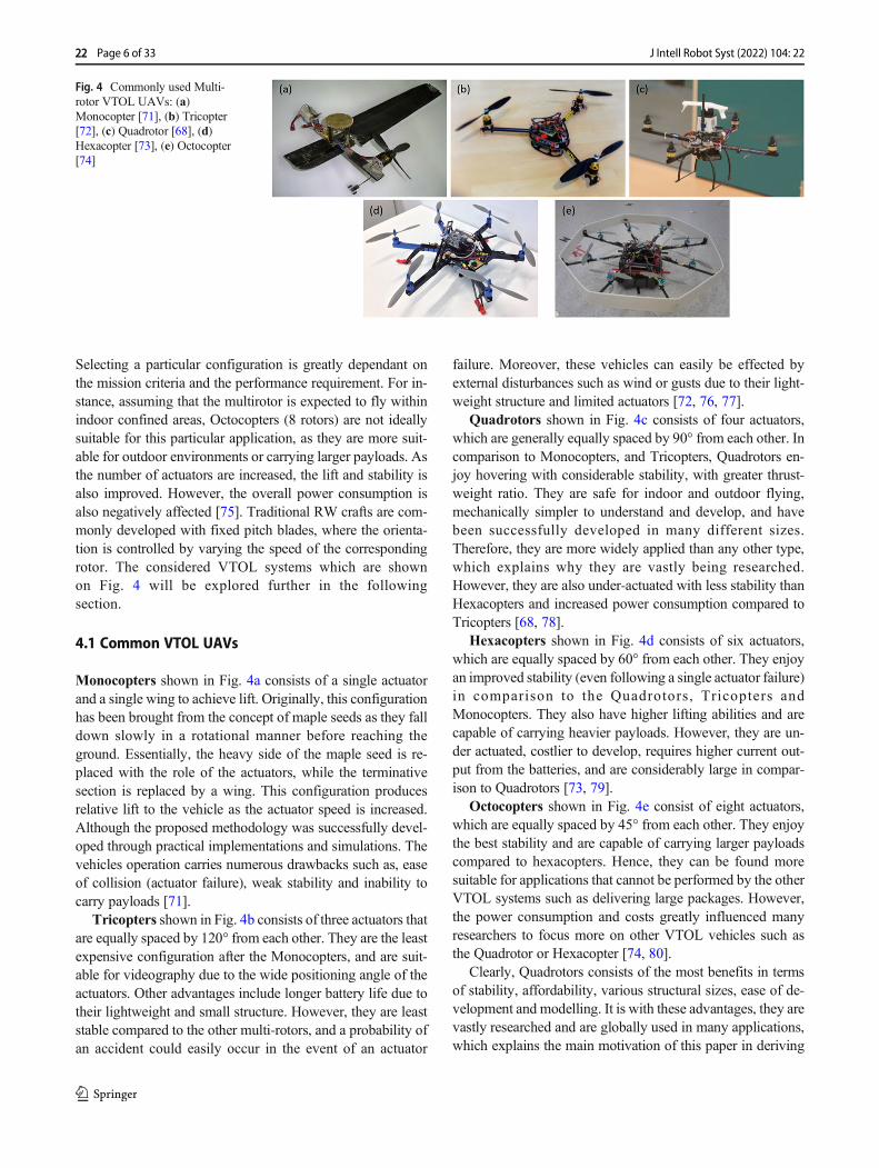
Selecting a particular configuration is greatly dependant onthe mission criteria and the performance requirement. For in-stance, assuming that the multirotor is expected to fly withinindoor confined areas, Octocopters (8 rotors) are not ideallysuitable for this particular application, as they are more suit-able for outdoor environments or carrying larger payloads. Asthe number of actuators are increased, the lift and stability isalso improved. However, the overall power consumption isalso negatively affected [75]. Traditional RW crafts are com-monly developed with fixed pitch blades, where the orienta-tion is controlled by varying the speed of the correspondingrotor. The considered VTOL systems which are shownon Fig. 4 will be explored further in the followingsection.
4.1 Common VTOL UAVs
Monocopters shown in Fig. 4a consists of a single actuatorand a single wing to achieve lift. Originally, this configurationhas been brought from the concept of maple seeds as they falldown slowly in a rotational manner before reaching theground. Essentially, the heavy side of the maple seed is re-placed with the role of the actuators, while the terminativesection is replaced by a wing. This configuration producesrelative lift to the vehicle as the actuator speed is increased.Although the proposed methodology was successfully devel-oped through practical implementations and simulations. Thevehicles operation carries numerous drawbacks such as, easeof collision (actuator failure), weak stability and inability tocarry payloads [71].
Tricopters shown in Fig. 4b consists of three actuators thatare equally spaced by 120° from each other. They are the leastexpensive configuration after the Monocopters, and are suit-able for videography due to the wide positioning angle of theactuators. Other advantages include longer battery life due totheir lightweight and small structure. However, they are leaststable compared to the other multi-rotors, and a probability ofan accident could easily occur in the event of an actuator
failure. Moreover, these vehicles can easily be effected byexternal disturbances such as wind or gusts due to their light-weight structure and limited actuators [72, 76, 77].
Quadrotors shown in Fig. 4c consists of four actuators,which are generally equally spaced by 90° from each other. Incomparison to Monocopters, and Tricopters, Quadrotors en-joy hovering with considerable stability, with greater thrust-weight ratio. They are safe for indoor and outdoor flying,mechanically simpler to understand and develop, and havebeen successfully developed in many different sizes.Therefore, they are more widely applied than any other type,which explains why they are vastly being researched.However, they are also under-actuated with less stability thanHexacopters and increased power consumption compared toTricopters [68, 78].
Hexacopters shown in Fig. 4d consists of six actuators,which are equally spaced by 60° from each other. They enjoyan improved stability (even following a single actuator failure)in comparison to the Quadrotors, Tricopters andMonocopters. They also have higher lifting abilities and arecapable of carrying heavier payloads. However, they are un-der actuated, costlier to develop, requires higher current out-put from the batteries, and are considerably large in compar-ison to Quadrotors [73, 79].
Octocopters shown in Fig. 4e consist of eight actuators,which are equally spaced by 45° from each other. They enjoythe best stability and are capable of carrying larger payloadscompared to hexacopters. Hence, they can be found moresuitable for applications that cannot be performed by the otherVTOL systems such as delivering large packages. However,the power consumption and costs greatly influenced manyresearchers to focus more on other VTOL vehicles such asthe Quadrotor or Hexacopter [74, 80].
Clearly, Quadrotors consists of the most benefits in termsof stability, affordability, various structural sizes, ease of de-velopment and modelling. It is with these advantages, they arevastly researched and are globally used in many applications,which explains the main motivation of this paper in deriving
Fig. 4 Commonly used Multi-rotor VTOL UAVs: (a)Monocopter [71], (b) Tricopter[72], (c) Quadrotor [68], (d)Hexacopter [73], (e) Octocopter[74]
22 Page 6 of 33 J Intell Robot Syst (2022) 104: 22
their dynamic models, exploring popular control techniques,highlight common simulation tools, and discussing theachievements attained from previous researchers.
4.2 Quadrotor Configurations
Quadrotors consists of four actuators that are individually con-trolled to produce a relative thrust. In order to achieve lift, twoof its motors have to rotate in opposite directions, otherwise,the net moment about the centre of mass will become non zeroresulting in unwanted motions. In helicopters, the tail rotor ortail aerofoil is required to cancel out the net moment createdabout the centre, and in Quadrotors, the net moment needs tobe cancelled out by making any two pairs arranged to rotateclockwise (CW) while the adjacent pairs rotate counter clock-wise (CCW). Hence, it has become customary for the oppositemotors in a crossed configured Quadrotor to rotate in oppositedirections.
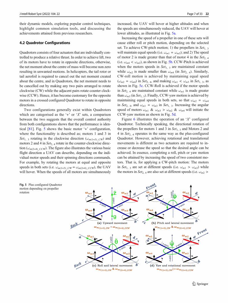
Two configurations generally exist within Quadrotorswhich are categorised as the ‘+’ or ‘X’ sets, a comparisonbetween the two suggests that the overall control authorityfrom both configurations shows that the performance is iden-tical [81]. Fig. 5 shows the basic motor ‘+’ configuration,where the functionality is described as; motors 1 and 3 inSet1, 3 rotating in the clockwise direction (ωm(1=3)_CW) andmotors 2 and 4 in Set2, 4 rotate in the counter-clockwise direc-tion (ωm(2=4)_CCW). The figure also illustrates the various basicflight direction a UAV can describe, depending on the indi-vidual motor speeds and their spinning directions commands.For example, by rotating the motors at equal and oppositespeeds in both sets (i.e. ωm(1=3)_CW = ωm(2=4)_CCW), the UAVwill hover. When the speeds of all motors are simultaneously
increased, the UAV will hover at higher altitudes and whenthe speeds are simultaneously reduced, the UAV will hover atlower altitudes, as illustrated in Fig. 5a.
Increasing the speed of a propeller in one of these sets willcause either roll or pitch motion, depending on the selectedset. To achieve CW-pitch motion; 1) the propellers in Set1, 3will maintain equal speeds (i.e. ωm1 = ωm3); and 2) The speedof motor 2 is made greater than that of motor 4 in the Set2, 4(i.e. ωm4 < ωm2), as shown in Fig. 5b. CCW-Pitch is achievedwhen the motors speeds in Set1, 3 are maintained constantwhile ωm2 is made smaller than ωm4 (in Set2, 4). Similarly,CW-roll motion is achieved by maintaining equal speed(ωm2 = ωm4) in Set2, 4, and making ωm1 < ωm3 in Set1, 3, asshown in Fig. 5c. CCW-Roll is achieved if the motor speedsin Set2, 4 are maintained constant while ωm1 is made greaterthanωm3 (in Set1, 3). Finally, CCW-yawmotion is achieved bymaintaining equal speeds in both sets, so that ωm2 = ωm4
in Set2, 4, and ωm1 = ωm3 in Set1, 3. Increasing the angularspeed of motors ωm1 & ωm3 > ωm2 & ωm4 will initiate theCCW-yaw motion as shown in Fig. 5d.
Figure 6 illustrates the operation of an ‘X’ configuredQuadrotor. Technically speaking, the directional rotation ofthe propellers for motors 1 and 3 in Set1, 3 and Motors 2 and4 in Set2, 4 operates in the same way as the plus-configuredQuadrotor. However, achieving rotational and translationalmovements is different as two actuators are required to in-crease or decrease the speed so that the desired angle can beachieved. In essence, completing a roll, pitch or yaw motioncan be attained by increasing the speed of two consistent mo-tors. That is, for applying a CW-pitch motion: The motorsin Set1, 3 are set at different speeds (i.e. ωm1 > ωm3) whilethe motors in Set2, 4 are also set at different speeds (i.e. ωm2 >
Fig. 5 Plus configured Quadrotormotion depending on propellerrotation
Page 7 of 33 22J Intell Robot Syst (2022) 104: 22

ωm4) as shown in Fig. 6b. Similarly, to achieve a CCW-pitchmotion: The actuators in Set1, 3 are set at the opposite speeds(i.e. ωm1 < ωm3) while the speed of the motors in Set2, 4 arealso set at opposite speeds to the CW-pitch rotation (i.e.ωm2 <ωm4). When applying a CW-roll motion: Set1, 3 are set to beone higher than the other (i.e. ωm1 < ωm3) while Set2, 4 hassimilar configurations (i.e. ωm2 > ωm4) as shown in Fig. 6c. ACCW-Roll angle is achieved by setting ωm1 > ωm3 in Set1, 3while setting the speeds of Set2, 4 to ωm2 < ωm4. Finally, aCW-Yaw rotation around the z-axis is accomplished by up-holding an equivalent speed of Set1, 3 while reducing speedin Set2, 4. Likewise, a CCW-Yaw motion is attained by main-taining the speed of Set2, 4 and reducing the speed in Set1, 3 asshown in Fig. 6d.
By presenting the functionality of both Quadrotor config-urations, the thrust mixing algorithm for the ‘+’ and ‘X’ UAVis described in Table 3 which explains that changing the speedof a propeller in one of these sets will cause either a rolling orpitching motion, depending on the selected set.
5 Quadrotor Dynamics
In this section, the mathematical model will be developed andverified against those studied by different authors in [82–86].It is assumed that the drone is rigid and has a symmetricstructure; thrust is produced by propellers of equal size whilethe rotors are facing upward in the z-direction; and that all
Fig. 6 Cross ‘X’ configuredQuadrotor motion
Table 3 Described motion for aQuadrotor based on the speedcommands
Plus Configuration Cross Configuration
Command Set1, 3 Set2, 4 Speed Status Set1, 3 Set2, 4 Speed Status
Hover (H) ωm1=ωm3 ωm2=ωm4 Set1, 3 = Set2, 4 ωm1=ωm3 ωm2=ωm4 Set1, 3 = Set2, 4CW_Pitch ωm1=ωm3 ωm4<ωm2 N/A ωm1>ωm3 ωm2>ωm4 N/A
CW_Roll ωm1>ωm3 ωm2=ωm4 N/A ωm1<ωm3 ωm2>ωm4 N/A
CW_Yaw ωm1=ωm3 ωm2=ωm4 Set1, 3 < Set2, 4 ωm1=ωm3 ωm2=ωm4 Set1, 3 < Set2, 4CCW_Pitch ωm1=ωm3 ωm4>ωm2 N/A ωm1<ωm3 ωm2<ωm4 N/A
CCW_Roll ωm1<ωm3 ωm2=ωm4 N/A ωm1>ωm3 ωm2<ωm4 N/A
CCW_Yaw ωm1=ωm3 ωm2=ωm4 Set1, 3> Set2, 4 ωm1=ωm3 ωm2=ωm4 Set1, 3 > Set2, 4
22 Page 8 of 33 J Intell Robot Syst (2022) 104: 22
rotors have the same distances to the centre of mass.Regardless of the Quadrotor configuration, the centre of massis assumed to be at the centre of the body inertial frame.Mathematically, the motions are presented by the twelve states
in xT as shown in Eq. (1). {x, y, z} and {x; y; z } denote theposition and respective speeds with reference to the inertial
fixed frame. Similarly, {ϕ, θ, ψ} and {ϕ:θ; ψ } correspond tothe angular displacements (roll, pitch and yaw) and their rateof change as denoted in [1, 84, 87].
xT ¼ x; x; y; y; z; z;ϕ; ϕ; θ; θ;ψ; ψn �
ð1Þ
Rolling, Pitching and Yawing with respect to the fixedinertial frame may be described through the transformationmatrix as shown in Eq. (2) where the Euler angles must bebounded to −π=2≤ϕ≤π=2, −π=2≤θ≤π=2 and −π ≤ ψ ≤ π inorder to prevent singularities and excessive rotations wheregreater control efforts are required [83].
ℝ10 ϕ; θ;ψð Þ ¼
cθcψ cθsψ −sθsϕsθcψ−cϕsψ sϕsθsψ þ cϕcψ sϕcθcϕsθcψ þ sϕsψ cϕsθsψ−sϕcψ cϕcθ
0@
1A
ð2Þ
Where s and c denote sin and cos respectively. The posi-tions coordinates and the moments of inertia for the Quadrotorbody frame can be expressed as rbf in eq. (3) and Jbf in eq. (4)[83].
rbf ¼ x; y; z½ � ð3Þ
Jbf ¼m y2 þ z2� �
mxy mxzmxy m x2 þ z2
� �myz
mxz myz m x2 þ y2� �
0B@
1CA ð4Þ
Jbf Contains scalar moments of inertia and the product ofinertia. An example is depicted below:
Moment of inertia about z−axis ¼ I z ¼ m x2 þ y2� �
Product of inertia I xz ¼ mxyð5Þ
Therefore,
Jbf ¼J x −J xy −J xz
−J xy J y −J yz−J xz −J yz J z
0@
1A ð6Þ
5.1 Aerodynamics Effects of the Propeller
Quadrotors are made up of propellers that consist of two ormore blades and a central hub that fits directly into the motorrod. As a result of the way they are constructed, a thrust isproduced by increasing the speed of the motor enforcing the
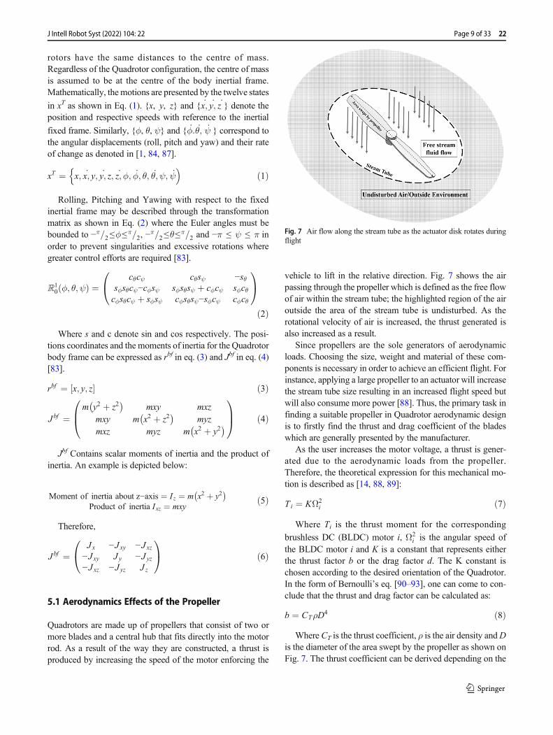
vehicle to lift in the relative direction. Fig. 7 shows the airpassing through the propeller which is defined as the free flowof air within the stream tube; the highlighted region of the airoutside the area of the stream tube is undisturbed. As therotational velocity of air is increased, the thrust generated isalso increased as a result.
Since propellers are the sole generators of aerodynamicloads. Choosing the size, weight and material of these com-ponents is necessary in order to achieve an efficient flight. Forinstance, applying a large propeller to an actuator will increasethe stream tube size resulting in an increased flight speed butwill also consume more power [88]. Thus, the primary task infinding a suitable propeller in Quadrotor aerodynamic designis to firstly find the thrust and drag coefficient of the bladeswhich are generally presented by the manufacturer.
As the user increases the motor voltage, a thrust is gener-ated due to the aerodynamic loads from the propeller.Therefore, the theoretical expression for this mechanical mo-tion is described as [14, 88, 89]:
Ti ¼ KΩ2i ð7Þ
Where Ti is the thrust moment for the corresponding
brushless DC (BLDC) motor i, Ω2i is the angular speed of
the BLDC motor i and K is a constant that represents eitherthe thrust factor b or the drag factor d. The K constant ischosen according to the desired orientation of the Quadrotor.In the form of Bernoulli’s eq. [90–93], one can come to con-clude that the thrust and drag factor can be calculated as:
b ¼ CTρD4 ð8Þ
Where CT is the thrust coefficient, ρ is the air density andDis the diameter of the area swept by the propeller as shown onFig. 7. The thrust coefficient can be derived depending on the
Fig. 7 Air flow along the stream tube as the actuator disk rotates duringflight
Page 9 of 33 22J Intell Robot Syst (2022) 104: 22
propeller geometry and the aerodynamic characteristics usingthe blade element theory [3]. Therefore, transposing eq. (8)into (7) becomes:
Ti ¼ bΩ2i ¼ CTρD4Ω2
i ð9Þ
Assuming that a Quadrotor is rotating about the z-axis inhovering mode, the propeller will generate a drag momentumacting in the opposite direction of which it is turning [6].Hence, the drag factor that determines the power required tospin the propeller is expressed as:
d ¼ CPρD5 ð10Þ
WhereCP is the power coefficient of the propeller. Transposingeq. (10) into eq. (7) will provide the following expression:
Ti ¼ dΩ2i ¼ CPρD5Ω2
i ð11Þ
By assuming that a plus configured Quadrotor is to bestudied, achieving the desired control action can be deter-mined through the systems input signals which are describedby the addition and subtraction of the four independent actu-ators, as shown in the following equations:
U 1 ¼ b Ω21 þ Ω2
2 þ Ω23 þ Ω2
4
� �U 2 ¼ b −Ω2
2 þ Ω24
� �U 3 ¼ b −Ω2
1 þ Ω23
� �U 4 ¼ d −Ω2
1 þ Ω22−Ω
23 þ Ω2
4
� � ð12Þ
The control action is dependent on the angular velocities offour independent rotors noted as Ω1, Ω2, Ω3 and Ω4. Ωr is theoverall residual propeller angular speed which is considered inthe gyroscopic torque as the Quadrotor rolls or pitches.
Ωr ¼ −Ω1 þ Ω2−Ω3 þ Ω4 ð13Þ
The matrix form for the theoretical control action presentedin eq. (12) is described as:
U1
U2
U3
U4
2664
3775 ¼
b b b b0 −b 0 b−b 0 b 0−d d −d d
2664
3775*
Ω12
Ω22
Ω32
Ω42
2664
3775 ð14Þ
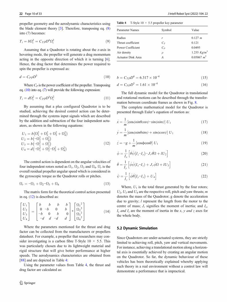
Where the parameters mentioned for the thrust and dragfactor can be collected from the manufacturers or propellersdatasheet. For example, a propeller that researchers may con-sider investigating is a carbon fibre T-Style 10 × 5.5. Thiswas particularly chosen due to its lightweight material andrigid structure that will give better performance at higherspeeds. The aerodynamics characteristics are obtained from[88] and are depicted in Table 4:
Using the parameter values from Table 4, the thrust anddrag factor are calculated as:
b ¼ CTρD4 ¼ 6:317� 10−4 ð15Þd ¼ CPρD5 ¼ 1:61� 10−4 ð16Þ
The full dynamic model for the Quadrotor in translationaland rotational motions can be described through the transfor-mation between coordinate frames as shown in Fig. 8.
The complete mathematical model for the Quadrotor ispresented through Euler’s equation of motion as:
::x ¼ 1
mcosϕsinθcosψ−sinϕsinψ½ � U 1 ð17Þ
::y ¼ 1
mcosϕsinθsinψþ sinϕcosψ½ � U 1 ð18Þ
::z ¼ −g þ 1
mcosϕcosθ½ � U1 ð19Þ
::ϕ ¼ 1
Ixθψ I z−Iy
� �−J r θΩþ lU2
h ið20Þ
::θ ¼ 1
Iyϕψ Ix−I zð Þ þ J r ϕΩþ lU3
h ið21Þ
::ψ ¼ 1
I zϕθ Iy−Ix
� �þ U 4
h ið22Þ
Where, U1 is the total thrust generated by the four rotors;U2,U3 andU4 are the respective roll, pitch and yaw thrusts;mdenotes the mass of the Quadrotor; g denote the accelerationdue to gravity; l represent the length from the motor to thecentre of mass; Jr signifies the moment of inertia; and Ix,Iy and Iz are the moment of inertia in the x, y and z axes forthe whole body.
5.2 Dynamic Simulation
Since Quadrotors are under-actuated systems, they are strictlylimited to achieving roll, pitch, yaw and vertical movements.For instance, achieving a translational motion along a horizon-tal axis is essentially achieved by creating an angular motionon the Quadrotor. So far, the dynamic behaviour of thesevehicles has been theoretically explained whereby applyingsuch theory in a real environment without a control law willdemonstrate a performance that is impractical.
Table 4 T-Style 10 × 5.5 propeller key parameter
Parameter Names Symbol Value
Radius r 0.127 m
Thrust coefficient CT 0.121
Power Coefficient CP 0.0495
Air density ρ 1.255 Kg/m3
Actuator Disk Area A 0.05067 m2
22 Page 10 of 33 J Intell Robot Syst (2022) 104: 22
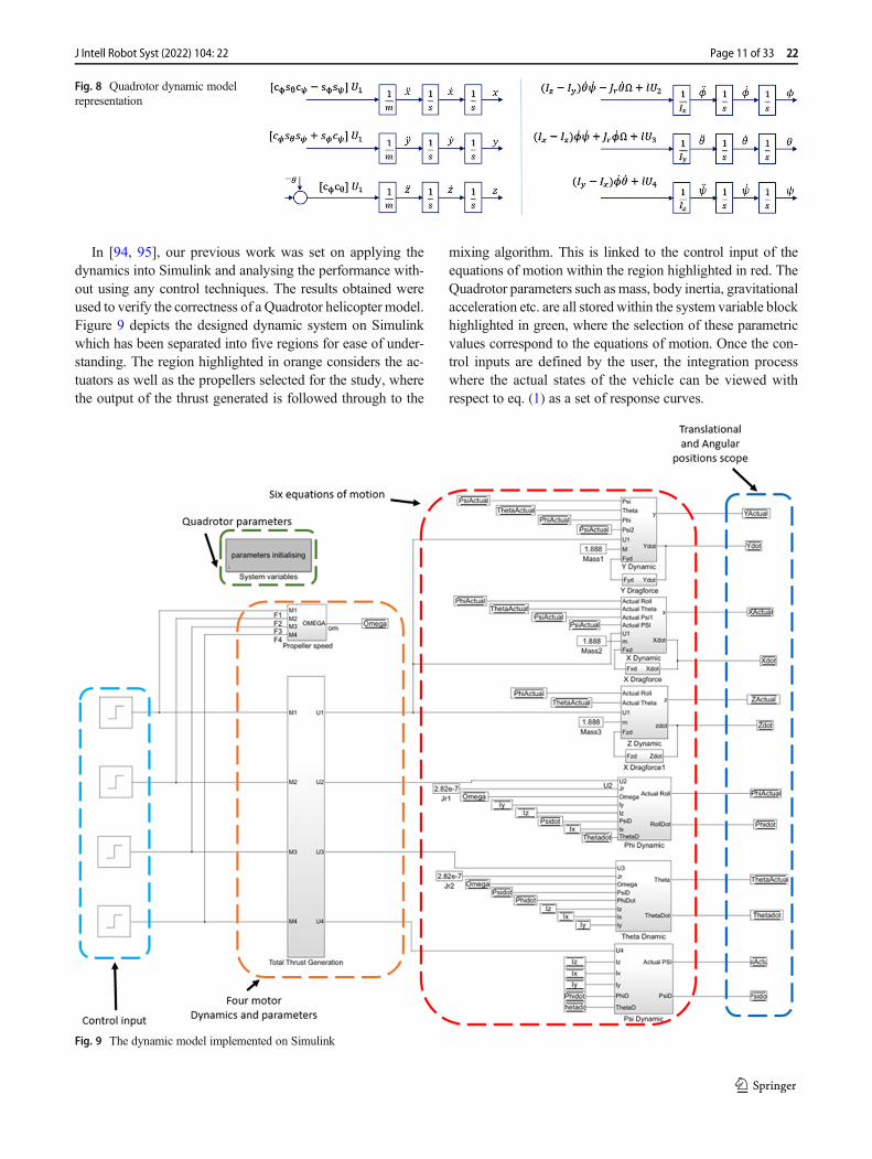
In [94, 95], our previous work was set on applying thedynamics into Simulink and analysing the performance with-out using any control techniques. The results obtained wereused to verify the correctness of a Quadrotor helicopter model.Figure 9 depicts the designed dynamic system on Simulinkwhich has been separated into five regions for ease of under-standing. The region highlighted in orange considers the ac-tuators as well as the propellers selected for the study, wherethe output of the thrust generated is followed through to the
mixing algorithm. This is linked to the control input of theequations of motion within the region highlighted in red. TheQuadrotor parameters such as mass, body inertia, gravitationalacceleration etc. are all stored within the system variable blockhighlighted in green, where the selection of these parametricvalues correspond to the equations of motion. Once the con-trol inputs are defined by the user, the integration processwhere the actual states of the vehicle can be viewed withrespect to eq. (1) as a set of response curves.
Fig. 8 Quadrotor dynamic modelrepresentation
Fig. 9 The dynamic model implemented on Simulink
Page 11 of 33 22J Intell Robot Syst (2022) 104: 22
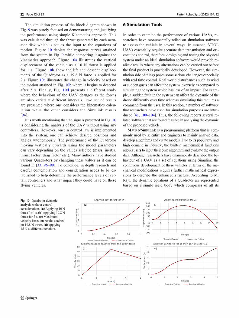
The simulation process of the block diagram shown inFig. 9 was purely focused on demonstrating and justifyingthe performance using simple Kinematics approach. Thiswas calculated through the thrust generated by each actu-ator disk which is set as the input to the equations ofmotion. Figure 10 depicts the response curves attainedfrom the system in Fig. 9 while comparing it against thekinematics approach. Figure 10a illustrates the verticaldisplacement of the vehicle as a 10 N thrust is appliedfor 1 s. Figure 10b show the lift and descent displace-ments of the Quadrotor as a 19.8 N force is applied for2 s. Figure 10c illustrates the change in velocity based onthe motion attained in Fig. 10b where it begins to descendafter 2 s. Finally, Fig. 10d presents a different studywhere the behaviour of the UAV changes as the forcesare also varied at different intervals. Two set of resultsare presented where one considers the kinematics calcu-lation while the other considers the Simulink results[94].
It is worth mentioning that the signals presented in Fig. 10is considering the analysis of the UAV without using anycontrollers. However, once a control law is implementedinto the system, one can achieve desired positions andangles autonomously. The performance of the Quadrotormoving vertically upwards using the model parameterscan vary depending on the values selected (mass, inertia,thrust factor, drag factor etc.). Many authors have studiedvarious Quadrotors by changing these values as it can befound in [33, 96–99]. To conclude, in depth research andcareful contemplation and consideration needs to be es-tablished to help determine the performance levels of cer-tain controllers and what impact they could have on theseflying vehicles.
6 Simulation Tools
In order to examine the performance of various UAVs, re-searchers have monumentally relied on simulation softwareto assess the vehicle in several ways. In essence, VTOLUAVs essentially require accurate data transmission and ori-entations control, therefore, designing and testing the physicalsystem under an ideal simulation software would provide re-alistic results where any alternations can be carried out beforethe final product is practically developed. However, the sim-ulation side of things poses some serious challenges especiallywith real time control. Real world disturbances such as windor sudden gusts can affect the system inversely as compared tosimulating the system which has less of an impact. For exam-ple, a sudden fault in the system can affect the dynamic of thedrone differently over time whereas simulating this requires acommand from the user. In this section, a number of softwarethat researchers have used for simulation purposes are intro-duced [41, 100–104]. Thus, the following reports several re-lated software that are found feasible in analysing the dynamicof the proposed vehicle.
Matlab/Simulink is a programming platform that is com-monly used by scientist and engineers to mainly analyse data,develop algorithms and create models. Due to its popularity andhigh demand in industry, the built-in mathematical functionsallows users to input their own algorithm and evaluate the outputdata. Although researchers have unanimously described the be-haviour of a UAV as a set of equations using Simulink, thecontinuous development of these vehicles in terms of the me-chanical modifications requires further mathematical expres-sions to describe the enhanced structure. According to M.Raju, the dynamic equations of a Quadrotor are representedbased on a single rigid body which comprises of all its
Fig. 10 Quadrotor dynamicanalysis without controlconsiderations: (a) Applying 10Nthrust for 1 s, (b) Applying 19.8 Nthrust for 2 s, (c) Maximumvelocity based on results attainedon 19.8 N thrust, (d) applying15 N at different iterations
22 Page 12 of 33 J Intell Robot Syst (2022) 104: 22
components, however the effects of multi-body interactions thatoccur in real time is not considered. This is due to the fact that asthe number of bodies increase within the system, the detaileddynamic interaction between these components becomes morecomplex to express mathematically [105].
Martínez also mentions that researchers are referring back tothe helicopter theory to seek for clues on how to produce bettermodels that represent the UAV dynamics. Additionally, the ap-plication of helicopter theory compared to Quadrotor theory isnot straight forward [106]. Therefore, physical modelling soft-ware are introduced which can be utilised to predict thevehicle performance in a more detailed manner.
GazeBo is a multi-body interaction software developed in2002 with a concept of simulating robots in outdoor environ-ments. The popularity of the software immensely grew overthe years due to its ease of implementation and the ability toconsider external disturbances. Since the software becameknown worldwide for its great features, users began to use itonmulti robots and indoor environments testing various math-ematical models, designing robots to meet user requirements,and more importantly, being able to test Artificial intelligence(AI) systems within realistic situations. Moreover, the opensource software also allows users to program their robots andview the reaction through graphical user interfaces (GUI) plat-form [41, 101, 107].
ARGos is another type of software that is commonly usedto simulate a flock of robots working simultaneously. Each ofthese robots are characterized with a number of componentssuch as actuators, sensors, control module etc. that can bestudied. So far, there has been numerous simulators developedto test and evaluate single robots only. However, ARGos hasthe ability to test multiple machines working simultaneouslywhile providing results, but, a drawback of increased compu-tational power and degraded performance is encountered asthe number of robots are increased [41, 102].
Msc ADAMS is an abbreviation for Automatic DynamicAnalysis Mechanical Systems, which is a powerful softwarethat can build and model almost any multi-body interactivesystem [108]. Initially, users are required to construct geome-tries or import CAD designs into the software where the per-formance can be viewed in a 3D environment. Accurate mo-tions can be viewed once the constraints, forces and momentsare applied to the relative components without the need ofconsidering any mathematical expressions to the vehicle dy-namics [109].
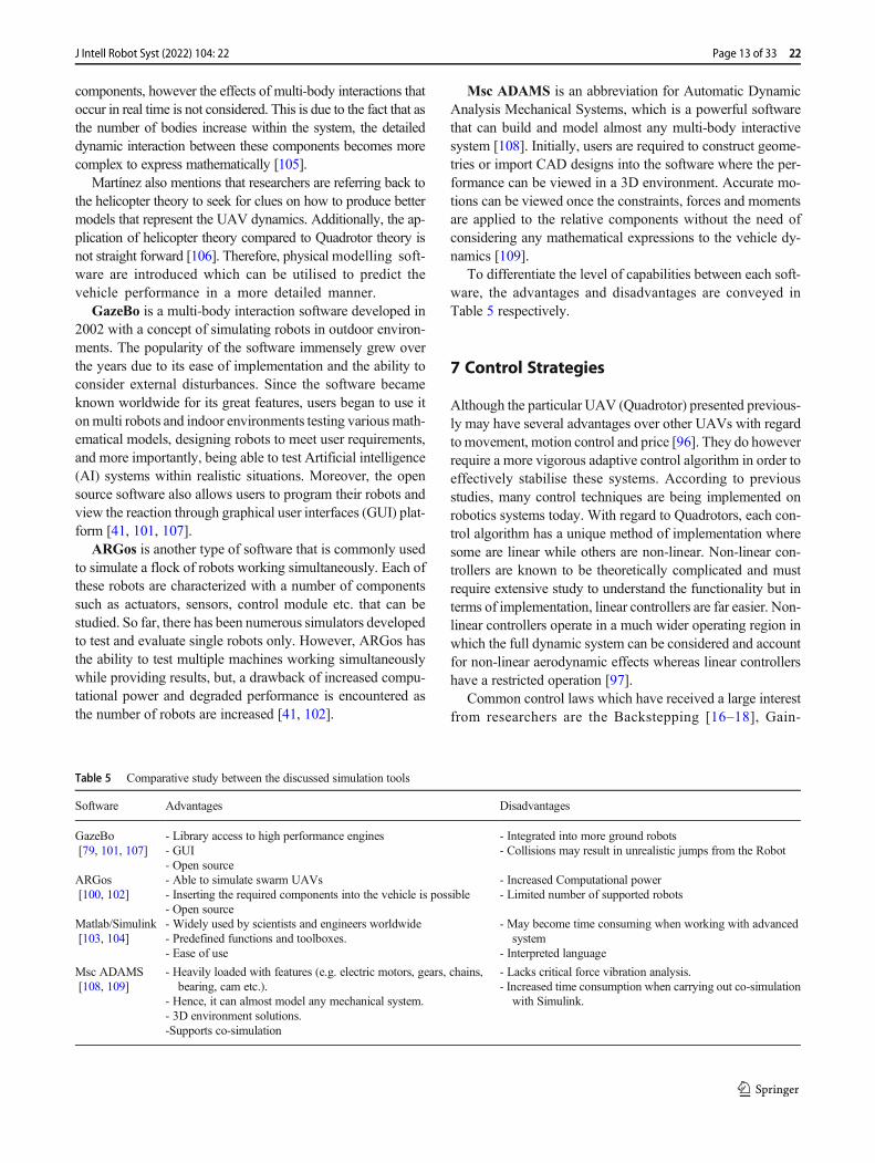
To differentiate the level of capabilities between each soft-ware, the advantages and disadvantages are conveyed inTable 5 respectively.
7 Control Strategies
Although the particular UAV (Quadrotor) presented previous-ly may have several advantages over other UAVs with regardto movement, motion control and price [96]. They do howeverrequire a more vigorous adaptive control algorithm in order toeffectively stabilise these systems. According to previousstudies, many control techniques are being implemented onrobotics systems today. With regard to Quadrotors, each con-trol algorithm has a unique method of implementation wheresome are linear while others are non-linear. Non-linear con-trollers are known to be theoretically complicated and mustrequire extensive study to understand the functionality but interms of implementation, linear controllers are far easier. Non-linear controllers operate in a much wider operating region inwhich the full dynamic system can be considered and accountfor non-linear aerodynamic effects whereas linear controllershave a restricted operation [97].
Common control laws which have received a large interestfrom researchers are the Backstepping [16–18], Gain-
Table 5 Comparative study between the discussed simulation tools
Software Advantages Disadvantages
GazeBo[79, 101, 107]
- Library access to high performance engines- GUI- Open source
- Integrated into more ground robots- Collisions may result in unrealistic jumps from the Robot
ARGos[100, 102]
- Able to simulate swarm UAVs- Inserting the required components into the vehicle is possible- Open source
- Increased Computational power- Limited number of supported robots
Matlab/Simulink[103, 104]
- Widely used by scientists and engineers worldwide- Predefined functions and toolboxes.- Ease of use
- May become time consuming when working with advancedsystem
- Interpreted language
Msc ADAMS[108, 109]
- Heavily loaded with features (e.g. electric motors, gears, chains,bearing, cam etc.).
- Hence, it can almost model any mechanical system.- 3D environment solutions.-Supports co-simulation
- Lacks critical force vibration analysis.- Increased time consumption when carrying out co-simulation
with Simulink.
Page 13 of 33 22J Intell Robot Syst (2022) 104: 22

scheduling [110–112], adaptive control [92, 113–115], H∞
Control [116, 117], Fuzzy Logic [118–120], LinearQuadratic Regulators (LQR) [8–11], Proportional IntegralDerivative (PID) [5–7, 98] and Sliding mode controllers(SMC) [7, 12, 13]. Since these are found to be the popularcontrol techniques for attitude stabilisation and position con-trol, this review will focus on providing the reader with anoverview of the controller functionality as well as other re-searchers’ comments on the performance.
On the other hand, two of these controllers will be reviewedand studied further in terms of exploring the functionality andunderstanding the performance capability of each technique.The selection of the first controller must meet the criteria ofsimple implementation and suitable control while ignoring theaspect of robustness against external disturbances. As for thesecond controller, robustness is a priority where the Quadrotormust have great stability regardless of various disturbances.
7.1 Backstepping
The basic functionality of a Backstepping technique consistsof breaking down the systems control architecture into sub-sections. The name “Backstepping” refers to the recursivenature of the design procedure, where initially, the physicalcontrol input is considered within a small subsystem by whicha virtual control law is created. Following that, the design isfurther constructed into a number of sub steps until a fullcontrollability of the system is achieved. The developmentprocess is also based on the Lyapunov theorem that involvesthe stability of solutions through ordinary differential eqs.[121, 122].
The author in [123] has presented a Backstepping controlstrategy to control the load position of two mass systems withunknown backlash. Controlling the two mass systemwill con-sist of either controlling the speed or position, in which onemass represents the motor while the other one represents aload (e.g. propeller aerodynamic load) that are connected to-gether via a shaft. Assuming that all the feedback signals fromthe motor, shaft and load are available. Designing the controlalgorithm consists of a pre-control block as shown on Fig. 11,where the input to this particular block considers the actualfeedback states of the systemwhich drives the required signalsfor executing the nonlinear Backstepping control law. The
authors have mentioned that the availability of all the systemstates have provided asymptotic stability and that future im-provements will focus on the consideration of designing moresteps for the controller.
The authors in [18] have also studied Backstepping com-bined with PID for controlling the attitude of a QuadrotorUAV. The results obtained are compared with the convention-al PID controller, where motor dynamics are also consideredin the system. Figure 12 depicts the performance outcome of aBackstepping based PID (BS-PID) compared with a typicalPID controller. It is evident that the BS-PID showed higherrobustness and an improved transient response. While chang-ing the attitude, the BS-PID controller has also showed a bet-ter performance in overshooting and settling time.
7.2 Gain Scheduling
The use of gain scheduling encompasses the ability to extendthe region of stability to a Quadrotor. This is achieved byautonomously selecting appropriate gains of the controller asthe UAV advances in flight. To express this further, the line-arization about a certain point of a nonlinear system is onlyvalid around that point where only local asymptotic stability isguaranteed. Therefore, the use of gain scheduling can improvethe linearization capability of further extension to a range ofoperating points, which is achieved by enforcing the controllerparameters to vary as the system dynamically changes [110].The authors in [111] have mentioned that if the change ofdynamics in a system can be determined, then the parameterscan be viewed and changed by monitoring operatingconditions.
In papers [110, 124], the authors followed a common de-sign procedure for gain scheduling to control a Quadrotor. Alinear parameter varying model of the UAV was constructedusing Jacobian linearization method in which multiple equi-librium points were set, typically known for this controller asscheduling variables (variables whose values are monitored todetermine when and how will the controller switch). Typicallinearization control techniques are used to develop control-lers for the linear parameter varying model of the plant.Finally, determining how the controller switches around theseequilibrium points will be dependent on how the schedulingvariable changes. Figure 13 depicts the parameter varying
Fig. 11 Block diagram of four-step Backstepping controlalgorithm [123]
22 Page 14 of 33 J Intell Robot Syst (2022) 104: 22
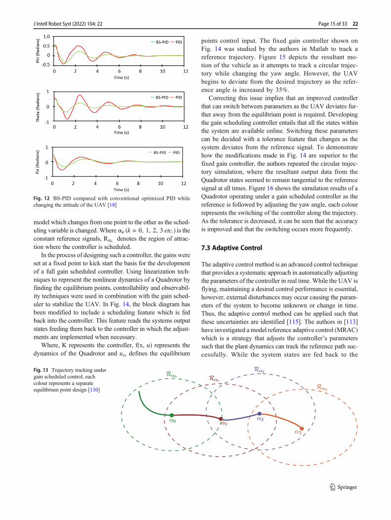
model which changes from one point to the other as the sched-uling variable is changed.Where αk (k = 0, 1, 2, 3 etc.) is theconstant reference signals, Rαk denotes the region of attrac-tion where the controller is scheduled.
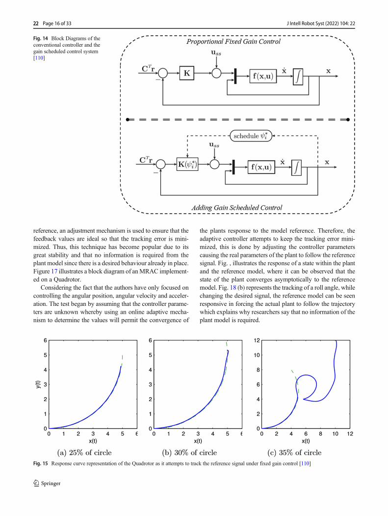
In the process of designing such a controller, the gains wereset at a fixed point to kick start the basis for the developmentof a full gain scheduled controller. Using linearization tech-niques to represent the nonlinear dynamics of a Quadrotor byfinding the equilibrium points, controllability and observabil-ity techniques were used in combination with the gain sched-uler to stabilize the UAV. In Fig. 14, the block diagram hasbeen modified to include a scheduling feature which is fedback into the controller. This feature reads the systems outputstates feeding them back to the controller in which the adjust-ments are implemented when necessary.
Where, K represents the controller, f(x, u) represents thedynamics of the Quadrotor and uss defines the equilibrium
points control input. The fixed gain controller shown onFig. 14 was studied by the authors in Matlab to track areference trajectory. Figure 15 depicts the resultant mo-tion of the vehicle as it attempts to track a circular trajec-tory while changing the yaw angle. However, the UAVbegins to deviate from the desired trajectory as the refer-ence angle is increased by 35%.
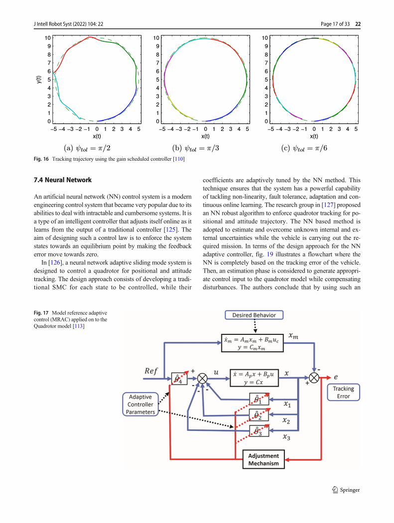
Correcting this issue implies that an improved controllerthat can switch between parameters as the UAV deviates fur-ther away from the equilibrium point is required. Developingthe gain scheduling controller entails that all the states withinthe system are available online. Switching these parameterscan be decided with a tolerance feature that changes as thesystem deviates from the reference signal. To demonstratehow the modifications made in Fig. 14 are superior to thefixed gain controller, the authors repeated the circular trajec-tory simulation, where the resultant output data from theQuadrotor states seemed to remain tangential to the referencesignal at all times. Figure 16 shows the simulation results of aQuadrotor operating under a gain scheduled controller as thereference is followed by adjusting the yaw angle, each colourrepresents the switching of the controller along the trajectory.As the tolerance is decreased, it can be seen that the accuracyis improved and that the switching occurs more frequently.
7.3 Adaptive Control
The adaptive control method is an advanced control techniquethat provides a systematic approach in automatically adjustingthe parameters of the controller in real time.While the UAV isflying, maintaining a desired control performance is essential,however, external disturbances may occur causing the param-eters of the system to become unknown or change in time.Thus, the adaptive control method can be applied such thatthese uncertainties are identified [115]. The authors in [113]have investigated a model reference adaptive control (MRAC)which is a strategy that adjusts the controller’s parameterssuch that the plant dynamics can track the reference path suc-cessfully. While the system states are fed back to the
Fig. 13 Trajectory tracking undergain scheduled control, eachcolour represents a separateequilibrium point design [110]
Fig. 12 BS-PID compared with conventional optimized PID whilechanging the attitude of the UAV [18]
Page 15 of 33 22J Intell Robot Syst (2022) 104: 22
reference, an adjustment mechanism is used to ensure that thefeedback values are ideal so that the tracking error is mini-mized. Thus, this technique has become popular due to itsgreat stability and that no information is required from theplant model since there is a desired behaviour already in place.Figure 17 illustrates a block diagram of anMRAC implement-ed on a Quadrotor.
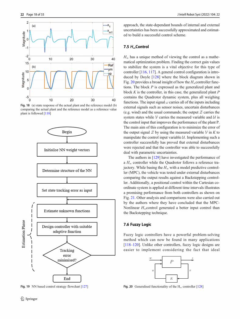
Considering the fact that the authors have only focused oncontrolling the angular position, angular velocity and acceler-ation. The test began by assuming that the controller parame-ters are unknown whereby using an online adaptive mecha-nism to determine the values will permit the convergence of
the plants response to the model reference. Therefore, theadaptive controller attempts to keep the tracking error mini-mized, this is done by adjusting the controller parameterscausing the real parameters of the plant to follow the referencesignal. Fig. , illustrates the response of a state within the plantand the reference model, where it can be observed that thestate of the plant converges asymptotically to the referencemodel. Fig. 18 (b) represents the tracking of a roll angle, whilechanging the desired signal, the reference model can be seenresponsive in forcing the actual plant to follow the trajectorywhich explains why researchers say that no information of theplant model is required.
Fig. 14 Block Diagrams of theconventional controller and thegain scheduled control system[110]
Fig. 15 Response curve representation of the Quadrotor as it attempts to track the reference signal under fixed gain control [110]
22 Page 16 of 33 J Intell Robot Syst (2022) 104: 22
7.4 Neural Network
An artificial neural network (NN) control system is a modernengineering control system that became very popular due to itsabilities to deal with intractable and cumbersome systems. It isa type of an intelligent controller that adjusts itself online as itlearns from the output of a traditional controller [125]. Theaim of designing such a control law is to enforce the systemstates towards an equilibrium point by making the feedbackerror move towards zero.
In [126], a neural network adaptive sliding mode system isdesigned to control a quadrotor for positional and attitudetracking. The design approach consists of developing a tradi-tional SMC for each state to be controlled, while their
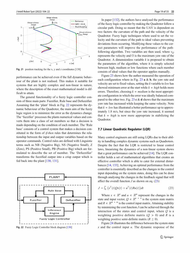
coefficients are adaptively tuned by the NN method. Thistechnique ensures that the system has a powerful capabilityof tackling non-linearity, fault tolerance, adaptation and con-tinuous online learning. The research group in [127] proposedan NN robust algorithm to enforce quadrotor tracking for po-sitional and attitude trajectory. The NN based method isadopted to estimate and overcome unknown internal and ex-ternal uncertainties while the vehicle is carrying out the re-quired mission. In terms of the design approach for the NNadaptive controller, fig. 19 illustrates a flowchart where theNN is completely based on the tracking error of the vehicle.Then, an estimation phase is considered to generate appropri-ate control input to the quadrotor model while compensatingdisturbances. The authors conclude that by using such an
Fig. 16 Tracking trajectory using the gain scheduled controller [110]
Fig. 17 Model reference adaptivecontrol (MRAC) applied on to theQuadrotor model [113]
Page 17 of 33 22J Intell Robot Syst (2022) 104: 22
approach, the state-dependant bounds of internal and externaluncertainties has been successfully approximated and estimat-ed to build a successful control scheme.
7.5 H∞Control
H∞ has a unique method of viewing the control as a mathe-matical optimization problem. Finding the correct gain valuesto stabilize the system is a vital objective for this type ofcontroller [116, 117]. A general control configuration is intro-duced by Doyle [128] where the block diagram shown inFig. 20 provides a broad insight of how theH∞controller func-tions. The block P is expressed as the generalized plant andblock K is the controller, in this case, the generalized plant Pcontains the Quadrotor dynamic system, plus all weighingfunctions. The input signal ω carries all of the inputs includingexternal signals such as sensor noises, uncertain disturbances(e.g. wind) and the usual commands; the output Z carries thesystem states while V carries the measured variable and U isthe control input that improves the performance of the plant P.The main aim of this configuration is to minimize the error ofthe output signal Z by using the measured variable V in K tomanipulate the control input variable U. Implementing such acontroller successfully has proved that external disturbanceswere rejected and that the controller was able to successfullydeal with parametric uncertainties.
The authors in [129] have investigated the performance ofa H∞ controller while the Quadrotor follows a reference tra-jectory. While basing the H∞ with a model predictive control-ler (MPC), the vehicle was tested under external disturbancescomparing the output results against a Backstepping control-ler. Additionally, a positional control within the Cartesian co-ordinate system is applied at different time intervals illustratesa promising performance from both controllers as shown onFig. 21. Other analysis and comparisons were also carried outby the authors where they have concluded that the MPC-Nonlinear H∞control generated a better input control thanthe Backstepping technique.
7.6 Fuzzy Logic
Fuzzy logic controllers have a powerful problem-solvingmethod which can now be found in many applications[118–120]. Unlike other controllers, fuzzy logic designs areeasier to implement considering the fact that ideal
Fig. 18 (a) state response of the actual plant and the reference model (b)comparing the actual plant and the reference model as a reference valueplant is followed [118]
Fig. 19 NN based control strategy flowchart [127] Fig. 20 Generalised functionality of the H∞ controller [128]
22 Page 18 of 33 J Intell Robot Syst (2022) 104: 22
performance can be achieved even if the full dynamic behav-iour of the plant is not realised. This makes it suitable forsystems that are highly complex and non-linear in nature,where the description of the exact mathematical model is dif-ficult to attain.
The general functionality of a fuzzy logic controller con-sists of three main parts: Fuzzifier, Rule base and Defuzzifier.Assuming that the ‘plant’ block in Fig. 22 represents the dy-namic behaviour of the Quadrotor, the main aim of the fuzzylogic region is to minimize the error as the dynamics change.The ‘fuzzifier’ processes the plants numerical values and con-verts them into a class of set members so that a decision ismade depending on the condition of each member. The ‘Rulebase’ consists of a control system that makes a decision con-stituted in the form of if-then rules that determines the rela-tionship between the input and output variables based on theoperator commands. Control rules are defined with Linguisticterms such as NB (Negative Big), NS (Negative Small), Z(Zero), PS (Positive Small), PB (Positive Big) which are for-mulated to describe the set of member. The ‘Defuzzifier’transforms the fuzzified output into a crisp output which isfed back into the plant [130, 131].
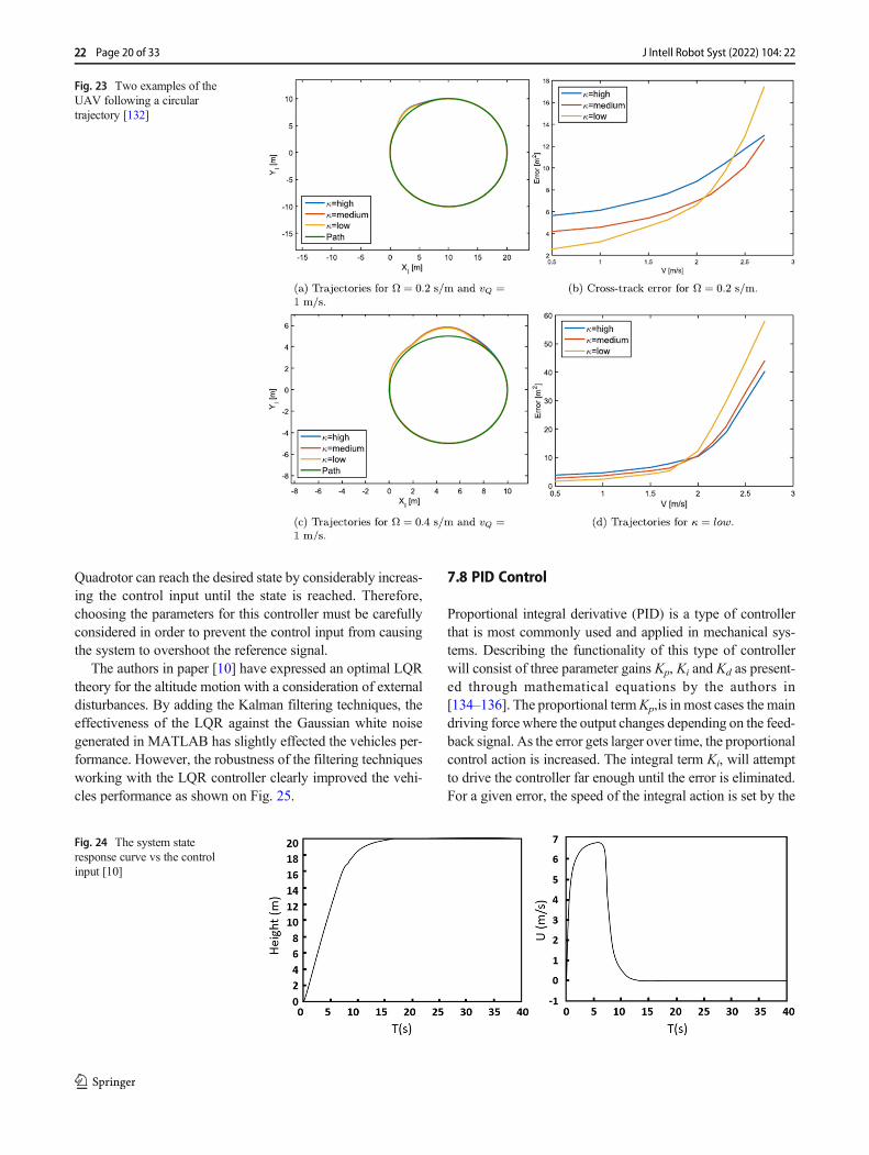
In paper [132], the authors have analysed the performanceof the fuzzy logic controller bymaking the Quadrotor follow acircular path. Doing so meant that the UAV is dependent ontwo factors: the curvature of the path and the velocity of theQuadrotor. Fuzzy logic techniques where used to set the ve-locity and the curvature of the path to ideal values preventingdeviations from occurring. Modifying these values to the cor-rect parameters will improve the performance of the path-following algorithm. Two variables are then used, where vQrepresents the velocity and Ω is the maximum yaw rate of theQuadrotor. A dimensionless variable k is proposed to obtainthe parameters of the algorithm, where it is simply selectedbetween high, medium or low functions where each memberconsists of ideal values that the operator applies manually.
Figure 23 shows how the author measured the operation ofeach configuration where in Fig. 23 a & b, the yaw rate andvelocity are set to fixed values, setting the k variable to low hasshowed minimum error at the start while k = high holds moreerrors. Therefore, choosing k = medium is the most appropri-ate configuration in which the error was ideally balanced com-pared to the other two. Fig. 23 c& d shows that the maximumyaw rate has increased while keeping the same velocity. Notethat k = low has illustrated a better performance up to approx-imately 1.8 m/s, but since the yaw rate increased, it seemedthat k = high is now more appropriate in stabilizing theQuadrotor.
7.7 Linear Quadratic Regulator (LQR)
Many control engineers are still using LQRs due to their abil-ity in handling complex dynamic systems such as Quadrotors.Despite the fact that the LQR is restricted to linear controllaws, linearizing the dynamics of a non-linear system showsthat a great performance can be achieved [14]. The LQR con-troller holds a set of mathematical algorithms that creates aneffective controller which is able to cater for external distur-bances [14, 133]. Achieving an optimal performance from thecontroller is essentially described as the changes in the controlinput depending on the system states, doing this can be donethrough analysing the changes in the feedback signal that willaffect the overall function J as shown on eq. (23):
J ¼ ∫∝0 xT tð ÞQx tð Þ þ uT tð ÞRu tð Þ� �dt ð23Þ
Where x ∈ ℝn and u ∈ ℝm represent the changes in thestate and input vector, Q ∈ ℝn ∗ n is the system state matrixand R ∈ ℝm ∗ m is the control input matrix. Attaining stabilityby minimizing the cost function J can be achieved through theinteraction of the states and control input, where Q is aweighting positive definite matrix (Q > 0) and R is aweighting positive semi-definite matrix (R ≥ 0).
Figure 24 illustrates the difference between the system statex and the control input u. The dynamic response of the
Fig. 21 position tracking for the x, y and z coordinates [138]
Fig. 22 Fuzzy Logic Controller block diagram [130]
Page 19 of 33 22J Intell Robot Syst (2022) 104: 22
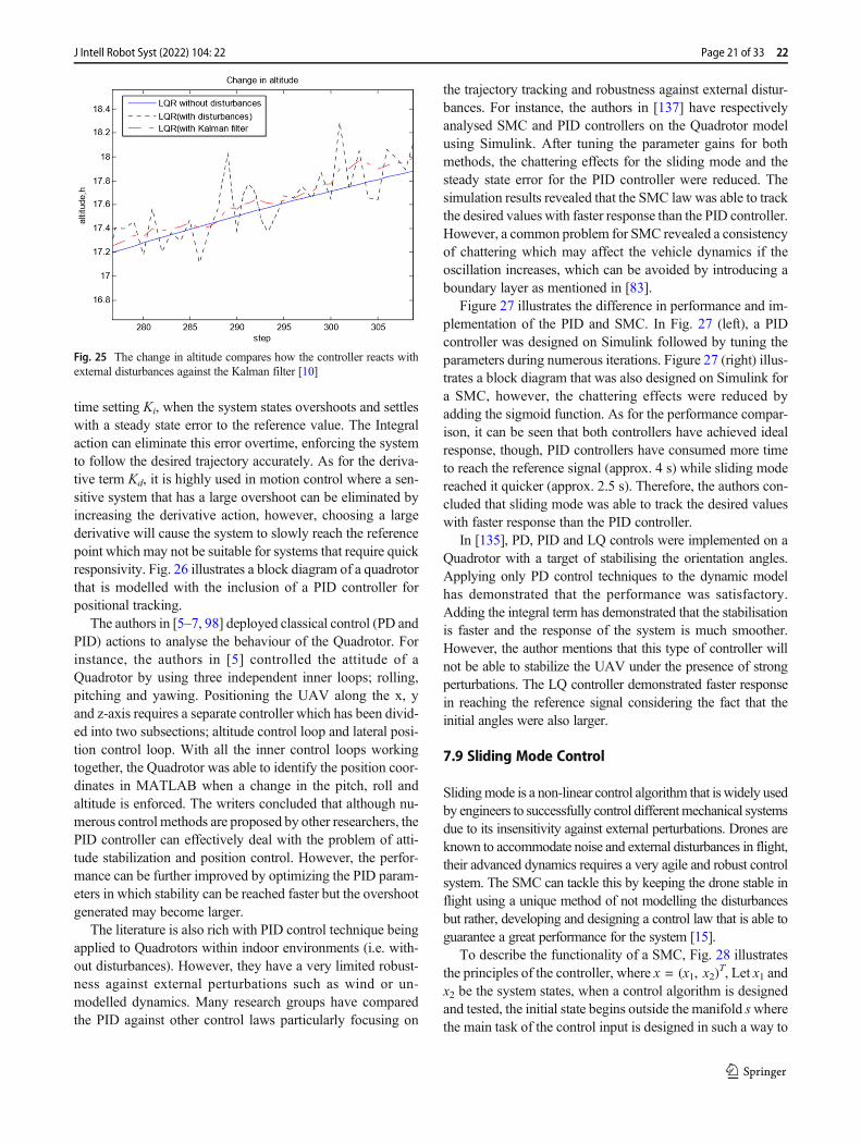
Quadrotor can reach the desired state by considerably increas-ing the control input until the state is reached. Therefore,choosing the parameters for this controller must be carefullyconsidered in order to prevent the control input from causingthe system to overshoot the reference signal.
The authors in paper [10] have expressed an optimal LQRtheory for the altitude motion with a consideration of externaldisturbances. By adding the Kalman filtering techniques, theeffectiveness of the LQR against the Gaussian white noisegenerated in MATLAB has slightly effected the vehicles per-formance. However, the robustness of the filtering techniquesworking with the LQR controller clearly improved the vehi-cles performance as shown on Fig. 25.
7.8 PID Control
Proportional integral derivative (PID) is a type of controllerthat is most commonly used and applied in mechanical sys-tems. Describing the functionality of this type of controllerwill consist of three parameter gains Kp, Ki and Kd as present-ed through mathematical equations by the authors in[134–136]. The proportional termKp,is in most cases the maindriving force where the output changes depending on the feed-back signal. As the error gets larger over time, the proportionalcontrol action is increased. The integral term Ki, will attemptto drive the controller far enough until the error is eliminated.For a given error, the speed of the integral action is set by the
Fig. 23 Two examples of theUAV following a circulartrajectory [132]
Fig. 24 The system stateresponse curve vs the controlinput [10]
22 Page 20 of 33 J Intell Robot Syst (2022) 104: 22
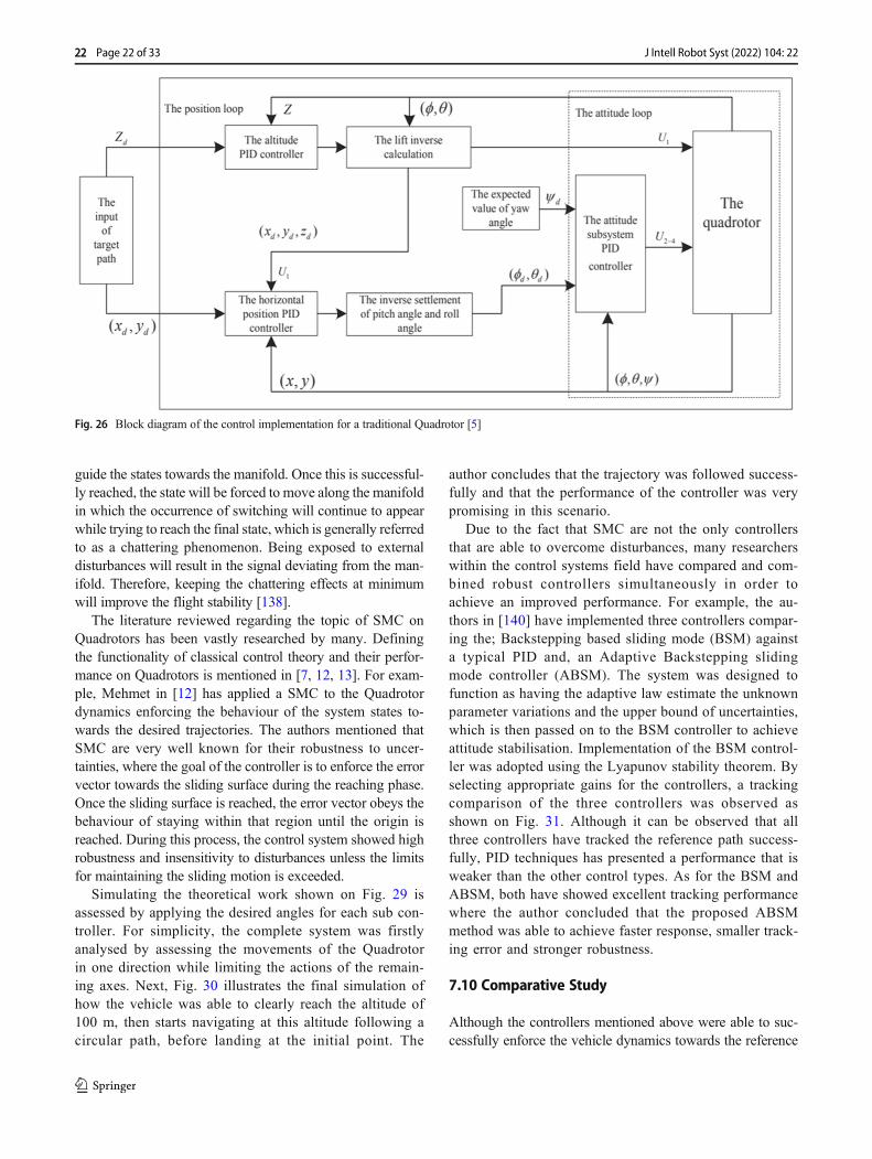
time setting Ki, when the system states overshoots and settleswith a steady state error to the reference value. The Integralaction can eliminate this error overtime, enforcing the systemto follow the desired trajectory accurately. As for the deriva-tive term Kd, it is highly used in motion control where a sen-sitive system that has a large overshoot can be eliminated byincreasing the derivative action, however, choosing a largederivative will cause the system to slowly reach the referencepoint which may not be suitable for systems that require quickresponsivity. Fig. 26 illustrates a block diagram of a quadrotorthat is modelled with the inclusion of a PID controller forpositional tracking.
The authors in [5–7, 98] deployed classical control (PD andPID) actions to analyse the behaviour of the Quadrotor. Forinstance, the authors in [5] controlled the attitude of aQuadrotor by using three independent inner loops; rolling,pitching and yawing. Positioning the UAV along the x, yand z-axis requires a separate controller which has been divid-ed into two subsections; altitude control loop and lateral posi-tion control loop. With all the inner control loops workingtogether, the Quadrotor was able to identify the position coor-dinates in MATLAB when a change in the pitch, roll andaltitude is enforced. The writers concluded that although nu-merous control methods are proposed by other researchers, thePID controller can effectively deal with the problem of atti-tude stabilization and position control. However, the perfor-mance can be further improved by optimizing the PID param-eters in which stability can be reached faster but the overshootgenerated may become larger.
The literature is also rich with PID control technique beingapplied to Quadrotors within indoor environments (i.e. with-out disturbances). However, they have a very limited robust-ness against external perturbations such as wind or un-modelled dynamics. Many research groups have comparedthe PID against other control laws particularly focusing on
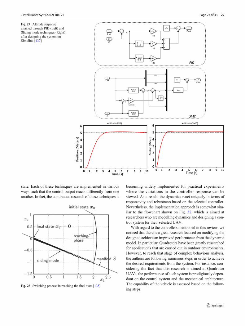
the trajectory tracking and robustness against external distur-bances. For instance, the authors in [137] have respectivelyanalysed SMC and PID controllers on the Quadrotor modelusing Simulink. After tuning the parameter gains for bothmethods, the chattering effects for the sliding mode and thesteady state error for the PID controller were reduced. Thesimulation results revealed that the SMC law was able to trackthe desired values with faster response than the PID controller.However, a common problem for SMC revealed a consistencyof chattering which may affect the vehicle dynamics if theoscillation increases, which can be avoided by introducing aboundary layer as mentioned in [83].
Figure 27 illustrates the difference in performance and im-plementation of the PID and SMC. In Fig. 27 (left), a PIDcontroller was designed on Simulink followed by tuning theparameters during numerous iterations. Figure 27 (right) illus-trates a block diagram that was also designed on Simulink fora SMC, however, the chattering effects were reduced byadding the sigmoid function. As for the performance compar-ison, it can be seen that both controllers have achieved idealresponse, though, PID controllers have consumed more timeto reach the reference signal (approx. 4 s) while sliding modereached it quicker (approx. 2.5 s). Therefore, the authors con-cluded that sliding mode was able to track the desired valueswith faster response than the PID controller.
In [135], PD, PID and LQ controls were implemented on aQuadrotor with a target of stabilising the orientation angles.Applying only PD control techniques to the dynamic modelhas demonstrated that the performance was satisfactory.Adding the integral term has demonstrated that the stabilisationis faster and the response of the system is much smoother.However, the author mentions that this type of controller willnot be able to stabilize the UAV under the presence of strongperturbations. The LQ controller demonstrated faster responsein reaching the reference signal considering the fact that theinitial angles were also larger.
7.9 Sliding Mode Control
Slidingmode is a non-linear control algorithm that is widely usedby engineers to successfully control differentmechanical systemsdue to its insensitivity against external perturbations. Drones areknown to accommodate noise and external disturbances in flight,their advanced dynamics requires a very agile and robust controlsystem. The SMC can tackle this by keeping the drone stable inflight using a unique method of not modelling the disturbancesbut rather, developing and designing a control law that is able toguarantee a great performance for the system [15].
To describe the functionality of a SMC, Fig. 28 illustratesthe principles of the controller, where x = (x1, x2)
T, Let x1 andx2 be the system states, when a control algorithm is designedand tested, the initial state begins outside the manifold swherethe main task of the control input is designed in such a way to
Fig. 25 The change in altitude compares how the controller reacts withexternal disturbances against the Kalman filter [10]
Page 21 of 33 22J Intell Robot Syst (2022) 104: 22
guide the states towards the manifold. Once this is successful-ly reached, the state will be forced to move along the manifoldin which the occurrence of switching will continue to appearwhile trying to reach the final state, which is generally referredto as a chattering phenomenon. Being exposed to externaldisturbances will result in the signal deviating from the man-ifold. Therefore, keeping the chattering effects at minimumwill improve the flight stability [138].
The literature reviewed regarding the topic of SMC onQuadrotors has been vastly researched by many. Definingthe functionality of classical control theory and their perfor-mance on Quadrotors is mentioned in [7, 12, 13]. For exam-ple, Mehmet in [12] has applied a SMC to the Quadrotordynamics enforcing the behaviour of the system states to-wards the desired trajectories. The authors mentioned thatSMC are very well known for their robustness to uncer-tainties, where the goal of the controller is to enforce the errorvector towards the sliding surface during the reaching phase.Once the sliding surface is reached, the error vector obeys thebehaviour of staying within that region until the origin isreached. During this process, the control system showed highrobustness and insensitivity to disturbances unless the limitsfor maintaining the sliding motion is exceeded.
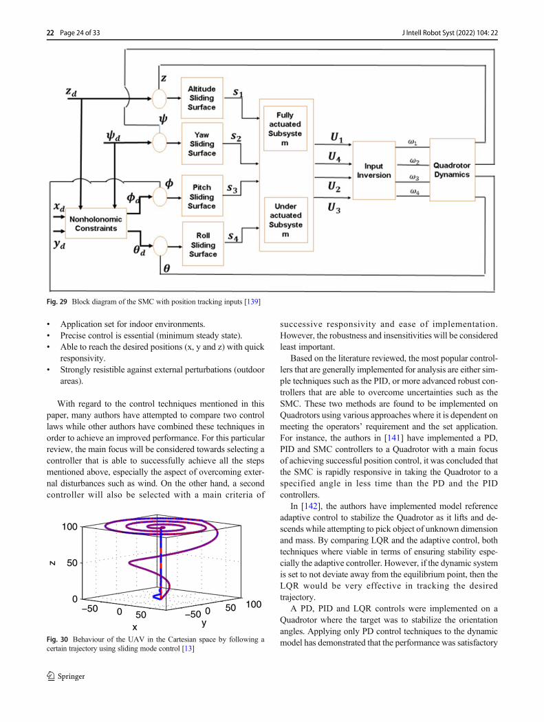
Simulating the theoretical work shown on Fig. 29 isassessed by applying the desired angles for each sub con-troller. For simplicity, the complete system was firstlyanalysed by assessing the movements of the Quadrotorin one direction while limiting the actions of the remain-ing axes. Next, Fig. 30 illustrates the final simulation ofhow the vehicle was able to clearly reach the altitude of100 m, then starts navigating at this altitude following acircular path, before landing at the initial point. The
author concludes that the trajectory was followed success-fully and that the performance of the controller was verypromising in this scenario.
Due to the fact that SMC are not the only controllersthat are able to overcome disturbances, many researcherswithin the control systems field have compared and com-bined robust controllers simultaneously in order toachieve an improved performance. For example, the au-thors in [140] have implemented three controllers compar-ing the; Backstepping based sliding mode (BSM) againsta typical PID and, an Adaptive Backstepping slidingmode controller (ABSM). The system was designed tofunction as having the adaptive law estimate the unknownparameter variations and the upper bound of uncertainties,which is then passed on to the BSM controller to achieveattitude stabilisation. Implementation of the BSM control-ler was adopted using the Lyapunov stability theorem. Byselecting appropriate gains for the controllers, a trackingcomparison of the three controllers was observed asshown on Fig. 31. Although it can be observed that allthree controllers have tracked the reference path success-fully, PID techniques has presented a performance that isweaker than the other control types. As for the BSM andABSM, both have showed excellent tracking performancewhere the author concluded that the proposed ABSMmethod was able to achieve faster response, smaller track-ing error and stronger robustness.
7.10 Comparative Study
Although the controllers mentioned above were able to suc-cessfully enforce the vehicle dynamics towards the reference
Fig. 26 Block diagram of the control implementation for a traditional Quadrotor [5]
22 Page 22 of 33 J Intell Robot Syst (2022) 104: 22
state. Each of these techniques are implemented in variousways such that the control output reacts differently from oneanother. In fact, the continuous research of these techniques is
becoming widely implemented for practical experimentswhere the variations in the controller response can beviewed. As a result, the dynamics react uniquely in terms ofresponsivity and robustness based on the selected controller.Nevertheless, the implementation approach is somewhat sim-ilar to the flowchart shown on Fig. 32, which is aimed atresearchers who are modelling dynamics and designing a con-trol system for their selected UAV.
With regard to the controllers mentioned in this review, wenoticed that there is a great research focused on modifying thedesign to achieve an improved performance from the dynamicmodel. In particular, Quadrotors have been greatly researchedfor applications that are carried out in outdoor environments.However, to reach that stage of complex behaviour analysis,the authors are following numerous steps in order to achievethe desired requirements from the system. For instance, con-sidering the fact that this research is aimed at QuadrotorUAVs, the performance of such system is prodigiously depen-dant on the control system and the mechanical architecture.The capability of the vehicle is assessed based on the follow-ing steps:
Fig. 27 Altitude responseattained through PID (Left) andSliding mode techniques (Right)after designing the system onSimulink [137]
Fig. 28 Switching process in reaching the final state [138]
Page 23 of 33 22J Intell Robot Syst (2022) 104: 22
& Application set for indoor environments.& Precise control is essential (minimum steady state).& Able to reach the desired positions (x, y and z) with quick
responsivity.& Strongly resistible against external perturbations (outdoor
areas).
With regard to the control techniques mentioned in thispaper, many authors have attempted to compare two controllaws while other authors have combined these techniques inorder to achieve an improved performance. For this particularreview, the main focus will be considered towards selecting acontroller that is able to successfully achieve all the stepsmentioned above, especially the aspect of overcoming exter-nal disturbances such as wind. On the other hand, a secondcontroller will also be selected with a main criteria of
successive responsivity and ease of implementation.However, the robustness and insensitivities will be consideredleast important.
Based on the literature reviewed, the most popular control-lers that are generally implemented for analysis are either sim-ple techniques such as the PID, or more advanced robust con-trollers that are able to overcome uncertainties such as theSMC. These two methods are found to be implemented onQuadrotors using various approaches where it is dependent onmeeting the operators’ requirement and the set application.For instance, the authors in [141] have implemented a PD,PID and SMC controllers to a Quadrotor with a main focusof achieving successful position control, it was concluded thatthe SMC is rapidly responsive in taking the Quadrotor to aspecified angle in less time than the PD and the PIDcontrollers.
In [142], the authors have implemented model referenceadaptive control to stabilize the Quadrotor as it lifts and de-scends while attempting to pick object of unknown dimensionand mass. By comparing LQR and the adaptive control, bothtechniques where viable in terms of ensuring stability espe-cially the adaptive controller. However, if the dynamic systemis set to not deviate away from the equilibrium point, then theLQR would be very effective in tracking the desiredtrajectory.
A PD, PID and LQR controls were implemented on aQuadrotor where the target was to stabilize the orientationangles. Applying only PD control techniques to the dynamicmodel has demonstrated that the performance was satisfactory
Fig. 29 Block diagram of the SMC with position tracking inputs [139]
Fig. 30 Behaviour of the UAV in the Cartesian space by following acertain trajectory using sliding mode control [13]
22 Page 24 of 33 J Intell Robot Syst (2022) 104: 22
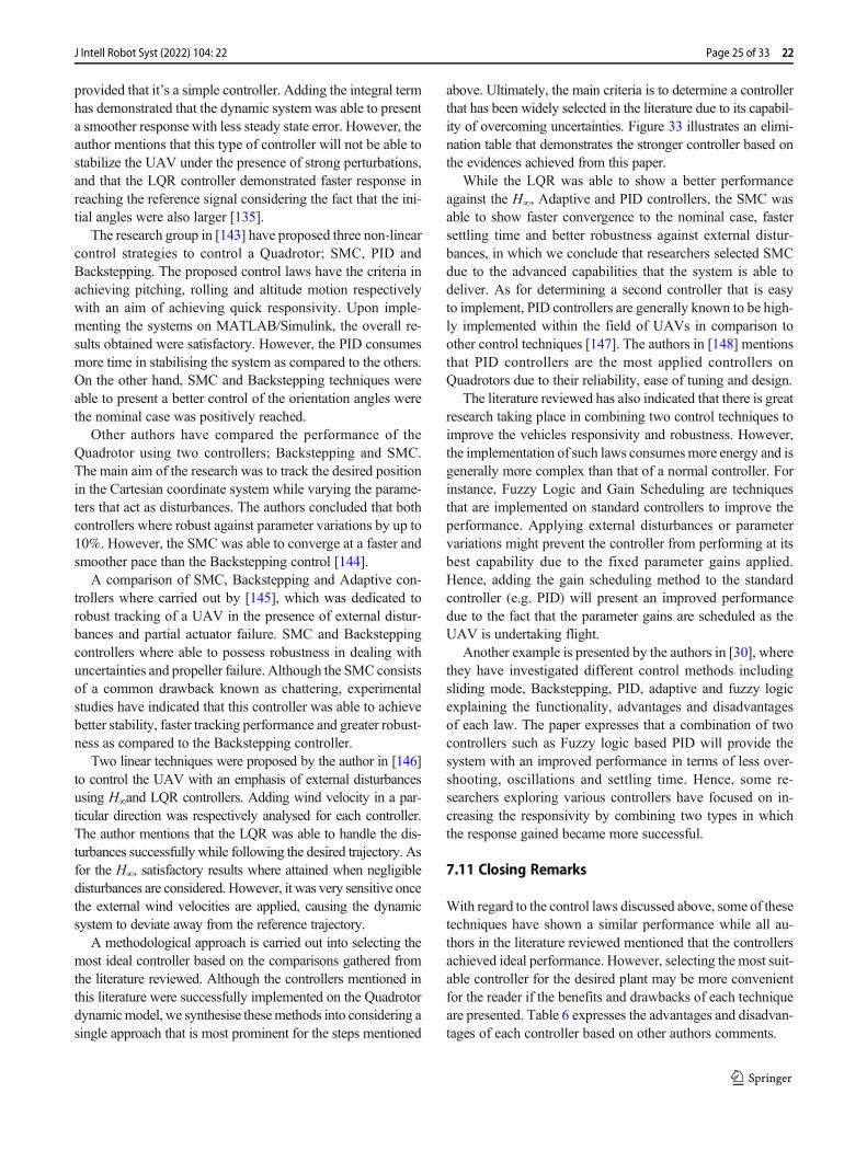
provided that it’s a simple controller. Adding the integral termhas demonstrated that the dynamic system was able to presenta smoother response with less steady state error. However, theauthor mentions that this type of controller will not be able tostabilize the UAV under the presence of strong perturbations,and that the LQR controller demonstrated faster response inreaching the reference signal considering the fact that the ini-tial angles were also larger [135].
The research group in [143] have proposed three non-linearcontrol strategies to control a Quadrotor; SMC, PID andBackstepping. The proposed control laws have the criteria inachieving pitching, rolling and altitude motion respectivelywith an aim of achieving quick responsivity. Upon imple-menting the systems on MATLAB/Simulink, the overall re-sults obtained were satisfactory. However, the PID consumesmore time in stabilising the system as compared to the others.On the other hand, SMC and Backstepping techniques wereable to present a better control of the orientation angles werethe nominal case was positively reached.
Other authors have compared the performance of theQuadrotor using two controllers; Backstepping and SMC.The main aim of the research was to track the desired positionin the Cartesian coordinate system while varying the parame-ters that act as disturbances. The authors concluded that bothcontrollers where robust against parameter variations by up to10%. However, the SMC was able to converge at a faster andsmoother pace than the Backstepping control [144].
A comparison of SMC, Backstepping and Adaptive con-trollers where carried out by [145], which was dedicated torobust tracking of a UAV in the presence of external distur-bances and partial actuator failure. SMC and Backsteppingcontrollers where able to possess robustness in dealing withuncertainties and propeller failure. Although the SMC consistsof a common drawback known as chattering, experimentalstudies have indicated that this controller was able to achievebetter stability, faster tracking performance and greater robust-ness as compared to the Backstepping controller.
Two linear techniques were proposed by the author in [146]to control the UAV with an emphasis of external disturbancesusing H∞and LQR controllers. Adding wind velocity in a par-ticular direction was respectively analysed for each controller.The author mentions that the LQR was able to handle the dis-turbances successfully while following the desired trajectory. Asfor the H∞, satisfactory results where attained when negligibledisturbances are considered. However, it was very sensitive oncethe external wind velocities are applied, causing the dynamicsystem to deviate away from the reference trajectory.
A methodological approach is carried out into selecting themost ideal controller based on the comparisons gathered fromthe literature reviewed. Although the controllers mentioned inthis literature were successfully implemented on the Quadrotordynamicmodel, we synthesise thesemethods into considering asingle approach that is most prominent for the steps mentioned
above. Ultimately, the main criteria is to determine a controllerthat has been widely selected in the literature due to its capabil-ity of overcoming uncertainties. Figure 33 illustrates an elimi-nation table that demonstrates the stronger controller based onthe evidences achieved from this paper.
While the LQR was able to show a better performanceagainst the H∞, Adaptive and PID controllers, the SMC wasable to show faster convergence to the nominal case, fastersettling time and better robustness against external distur-bances, in which we conclude that researchers selected SMCdue to the advanced capabilities that the system is able todeliver. As for determining a second controller that is easyto implement, PID controllers are generally known to be high-ly implemented within the field of UAVs in comparison toother control techniques [147]. The authors in [148] mentionsthat PID controllers are the most applied controllers onQuadrotors due to their reliability, ease of tuning and design.
The literature reviewed has also indicated that there is greatresearch taking place in combining two control techniques toimprove the vehicles responsivity and robustness. However,the implementation of such laws consumesmore energy and isgenerally more complex than that of a normal controller. Forinstance, Fuzzy Logic and Gain Scheduling are techniquesthat are implemented on standard controllers to improve theperformance. Applying external disturbances or parametervariations might prevent the controller from performing at itsbest capability due to the fixed parameter gains applied.Hence, adding the gain scheduling method to the standardcontroller (e.g. PID) will present an improved performancedue to the fact that the parameter gains are scheduled as theUAV is undertaking flight.
Another example is presented by the authors in [30], wherethey have investigated different control methods includingsliding mode, Backstepping, PID, adaptive and fuzzy logicexplaining the functionality, advantages and disadvantagesof each law. The paper expresses that a combination of twocontrollers such as Fuzzy logic based PID will provide thesystem with an improved performance in terms of less over-shooting, oscillations and settling time. Hence, some re-searchers exploring various controllers have focused on in-creasing the responsivity by combining two types in whichthe response gained became more successful.
7.11 Closing Remarks
With regard to the control laws discussed above, some of thesetechniques have shown a similar performance while all au-thors in the literature reviewed mentioned that the controllersachieved ideal performance. However, selecting the most suit-able controller for the desired plant may be more convenientfor the reader if the benefits and drawbacks of each techniqueare presented. Table 6 expresses the advantages and disadvan-tages of each controller based on other authors comments.
Page 25 of 33 22J Intell Robot Syst (2022) 104: 22
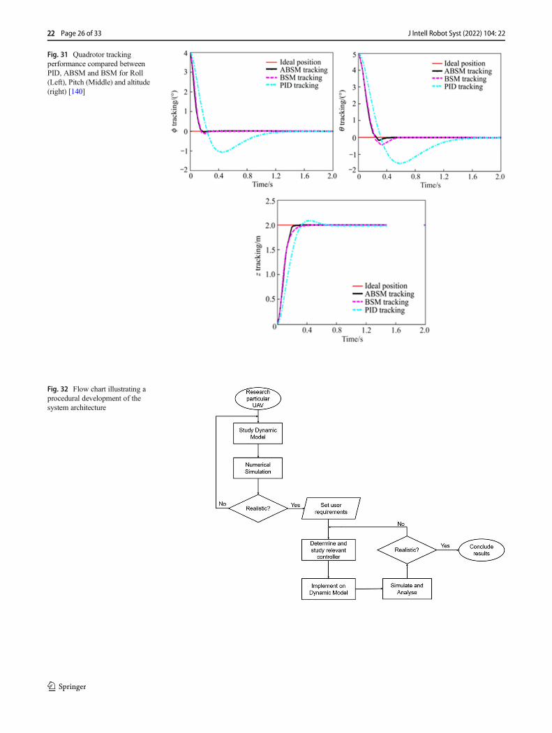
Fig. 31 Quadrotor trackingperformance compared betweenPID, ABSM and BSM for Roll(Left), Pitch (Middle) and altitude(right) [140]
Fig. 32 Flow chart illustrating aprocedural development of thesystem architecture
22 Page 26 of 33 J Intell Robot Syst (2022) 104: 22
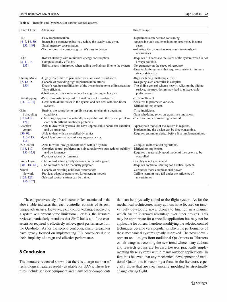
The comparative study of various controllersmentioned in theabove table indicates that each controller consists of its ownunique advantages. However, each control technique applied toa system will present some limitations. For this, the literaturereviewed particularly mentions that SMC holds all of the char-acteristics required to effectively achieve great performance fromthe Quadrotor. As for the second controller, many researchershave greatly focused on implementing PID controllers due totheir simplicity of design and effective performance.
8 Conclusion
The literature reviewed shows that there is a large number oftechnological features readily available for UAVs. These fea-tures include sensory equipment and many other components
that can be physically added to the flight system. As for themechanical architecture, many authors have focused on inno-vatively developing novel drones to function in a mannerwhich has an increased advantage over other designs. Thismay be appropriate for a specific application but may not beapplicable for others, therefore, modifying the selected controltechniques became very popular in which the performance ofthese mechanical systems greatly improved. The novel devel-opment and designs from traditional Quadrotors to Tiltrotorsor Tilt-wings is becoming the new trend where many authorsand research groups are focused towards practically imple-menting these systems within many outdoor applications. Infact, it is believed that any mechanical development of tradi-tional Quadrotors is becoming a focus in the literature, espe-cially those that are mechanically modified to structurallychange during flight.
Table 6 Benefits and Drawbacks of various control systems
Control Law Advantage Disadvantage
PID[4–7, 14, 30,133, 149]
-Easy Implementation.-Increasing parameter gains may reduce the steady state error.-Small memory consumption.-Well responsive considering that it’s easy to design.
-Experiments can be time consuming.-Aggressive gain and overshooting occurrence in some
cases.-Adjusting the parameters may result in overshoot
occurrences.
LQR[8–11, 14,133]
-Robust stability with minimized energy consumption.-Computationally efficient.-Effectiveness is improved when adding the Kalman filter to the system.
-Requires full access to the states of the system which is notalways possible.
-No guarantee on the speed of response.-Unsuitable for systems that require consistent minimum
steady state error.
Sliding Mode[7, 12–15,150]
-Highly insensitive to parameter variations and disturbances.-Capable of providing high implementation efforts.-Doesn’t require simplification of the dynamics in terms of linearization.-Time efficient.-Chattering effects can be reduced using filtering techniques.
-High switching chattering effects.-Designing such controller is complex.-The sliding control scheme heavily relies on the sliding
surface, incorrect design may lead to unacceptableperformance.
Backstepping[16–19, 30]
-Present robustness against external constant disturbances.-Deals with all the states in the system and can deal with non-linear
systems.
-Time inefficient.-Sensitive to parameter variation.-Difficult to implement.
GainScheduling
[110–112,124]
-Enables the controller to rapidly respond to changing operatingconditions.
-The design approach is naturally compatible with the overall problemeven with difficult nonlinear problems.
-Time inefficient.-Gain scheduling relies on extensive simulations.-There are no performance guaranteed.
Adaptivecontrol
[30, 92,113–115,151]
-Able to deal with systems that have unpredictable parameter variationand disturbances.
-Able to deal with un-modelled dynamics.-Quickly responsive against varying parameters.
-Appropriate model of the system is required.-Implementing the design can be time consuming.-Requires enormous design before final implementations.
H∞ Control[116, 117,152–155]
-Able to work through uncertainties within a system.-Complex control problems are solved under two subsections; stability
and performance.-Provides robust performance.
-Complex mathematical algorithms.-Difficult to implement.-Requires a reasonably good model of the system to be
controlled.
Fuzzy Logic[30, 118–120]
-The control action greatly depends on the rules given.-The controller can be manually prepared.
-Stability is not guaranteed.-Requires continuous tuning for a critical system.
NeuralNetwork
[125–127,156, 157]
-Capable of resisting unknown disturbances-Provides adaptive parameters for uncertain models-Selected control system can be trained
-Consumes more computational power-Offline learning may fail under the influence of
uncertainties
Page 27 of 33 22J Intell Robot Syst (2022) 104: 22
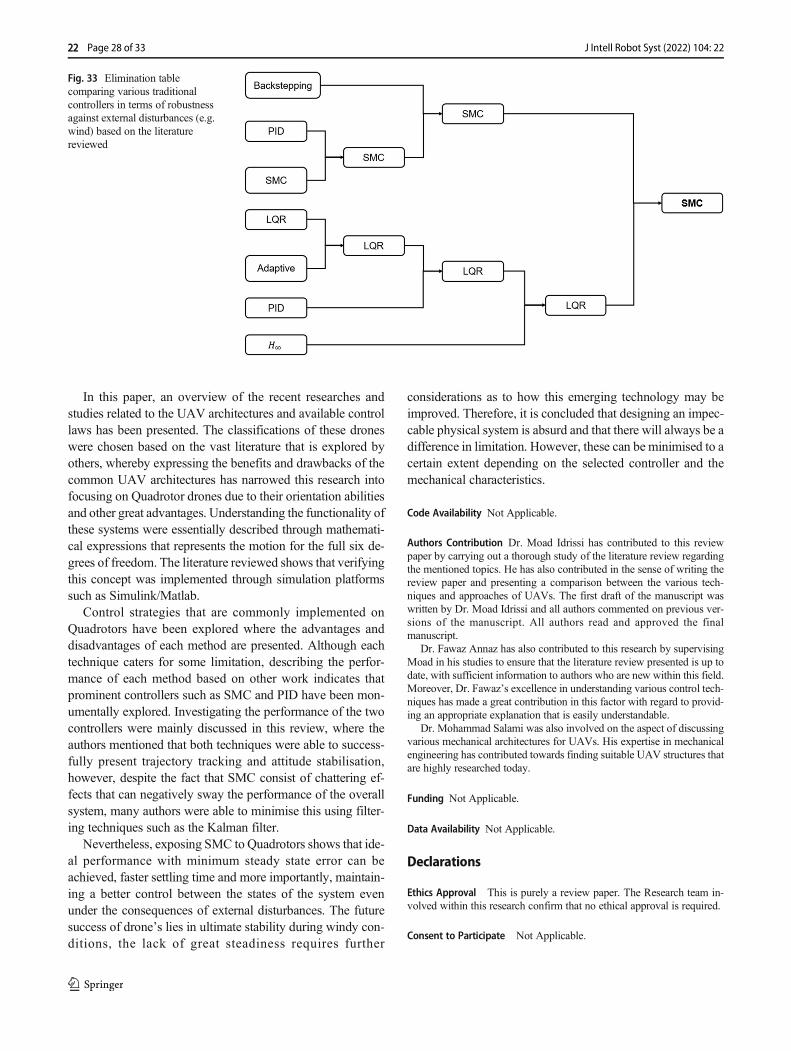
In this paper, an overview of the recent researches andstudies related to the UAV architectures and available controllaws has been presented. The classifications of these droneswere chosen based on the vast literature that is explored byothers, whereby expressing the benefits and drawbacks of thecommon UAV architectures has narrowed this research intofocusing on Quadrotor drones due to their orientation abilitiesand other great advantages. Understanding the functionality ofthese systems were essentially described through mathemati-cal expressions that represents the motion for the full six de-grees of freedom. The literature reviewed shows that verifyingthis concept was implemented through simulation platformssuch as Simulink/Matlab.
Control strategies that are commonly implemented onQuadrotors have been explored where the advantages anddisadvantages of each method are presented. Although eachtechnique caters for some limitation, describing the perfor-mance of each method based on other work indicates thatprominent controllers such as SMC and PID have been mon-umentally explored. Investigating the performance of the twocontrollers were mainly discussed in this review, where theauthors mentioned that both techniques were able to success-fully present trajectory tracking and attitude stabilisation,however, despite the fact that SMC consist of chattering ef-fects that can negatively sway the performance of the overallsystem, many authors were able to minimise this using filter-ing techniques such as the Kalman filter.
Nevertheless, exposing SMC to Quadrotors shows that ide-al performance with minimum steady state error can beachieved, faster settling time and more importantly, maintain-ing a better control between the states of the system evenunder the consequences of external disturbances. The futuresuccess of drone’s lies in ultimate stability during windy con-ditions, the lack of great steadiness requires further
considerations as to how this emerging technology may beimproved. Therefore, it is concluded that designing an impec-cable physical system is absurd and that there will always be adifference in limitation. However, these can be minimised to acertain extent depending on the selected controller and themechanical characteristics.
Code Availability Not Applicable.
Authors Contribution Dr. Moad Idrissi has contributed to this reviewpaper by carrying out a thorough study of the literature review regardingthe mentioned topics. He has also contributed in the sense of writing thereview paper and presenting a comparison between the various tech-niques and approaches of UAVs. The first draft of the manuscript waswritten by Dr. Moad Idrissi and all authors commented on previous ver-sions of the manuscript. All authors read and approved the finalmanuscript.
Dr. Fawaz Annaz has also contributed to this research by supervisingMoad in his studies to ensure that the literature review presented is up todate, with sufficient information to authors who are new within this field.Moreover, Dr. Fawaz’s excellence in understanding various control tech-niques has made a great contribution in this factor with regard to provid-ing an appropriate explanation that is easily understandable.
Dr. Mohammad Salami was also involved on the aspect of discussingvarious mechanical architectures for UAVs. His expertise in mechanicalengineering has contributed towards finding suitable UAV structures thatare highly researched today.
Funding Not Applicable.
Data Availability Not Applicable.
Declarations
Ethics Approval This is purely a review paper. The Research team in-volved within this research confirm that no ethical approval is required.
Consent to Participate Not Applicable.
Fig. 33 Elimination tablecomparing various traditionalcontrollers in terms of robustnessagainst external disturbances (e.g.wind) based on the literaturereviewed
22 Page 28 of 33 J Intell Robot Syst (2022) 104: 22
Consent for Publication Not Applicable.
Conflict of Interest Not Applicable.
Open Access This article is licensed under a Creative CommonsAttribution 4.0 International License, which permits use, sharing, adap-tation, distribution and reproduction in any medium or format, as long asyou give appropriate credit to the original author(s) and the source, pro-vide a link to the Creative Commons licence, and indicate if changes weremade. The images or other third party material in this article are includedin the article's Creative Commons licence, unless indicated otherwise in acredit line to the material. If material is not included in the article'sCreative Commons licence and your intended use is not permitted bystatutory regulation or exceeds the permitted use, you will need to obtainpermission directly from the copyright holder. To view a copy of thislicence, visit http://creativecommons.org/licenses/by/4.0/.
References
1. Clarke, R.: Understanding the drone epidemic. Comp Law SecurRev. 30(3), 230–246 (2014)
2. dos Santos, S., Barros R., Nascimento C.L., Givigi S.N.: Designof attitude and path tracking controllers for quad-rotor robotsusing reinforcement learning. In 2012 IEEE AerospaceConference, pp. 1–16. IEEE, (2012). https://ieeexplore.ieee.org/a b s t r a c t / d o c u m e n t / 6 1 8 7 3 1 4 ? c a s a _ t o k e n =B Z b X M v G 2 F H Y A A A A A : J R H m R H - i L _2Kqv9VjEp0wwroX7pELsA3wX_P9mUSRIDLp3pgaRArqe0_sFfZTq-qPeYzp7_cAGj1
3. Hassanalian, M., Abdelkefi, A.: Classifications, applications, anddesign challenges of drones. A review. Prog Aerospace Sci. 91,99–131 (2017)
4. Asal, F. and Coşgun, M.: “Pi pd pid controllers,” Middle EastTechnical University Electrical & Electronics Engineering,(2013).
5. Jiao, Q., Liu J., Zhang, Y. and Lian W.: “Analysis and design thecontroller for quadrotors based on PID control method”, in 33rdYouth Academic Annual Conference of Chinese Association ofAutomation (YAC) IEEE, (2018, May).
6. Salih, A., Moghavvemi, M., Mohamed, H., Gaeid, K.: Flight PIDcontroller design for a UAV quadrotor. Sci. Res. Essays. 5(23),3660–3667 (2010)
7. Bouadi, H.B., Cunha, S., Drouin, A. and Mora-Camino, F:Adaptive sliding mode control for quadrotor attitude stabilizationand altitude tracking. In: 2011 IEEE 12th InternationalSymposium on Computational Intelligence and Informatics(CINTI), pp. 449–455. IEEE, (2011). https://ieeexplore.ieee.org/abstract/document/6108547
8. Shulong, Z., Honglei, A., Daibing, Z. and Lincheng, S.: A newfeedback linearization LQR control for attitude of quadrotor. In:2014 13th International Conference on Control AutomationRobotics & Vision (ICARCV), pp. 1593–1597. IEEE, (2014).https://ieeexplore.ieee.org/abstract/document/7064553?casa_token=6PpjWGl_E3kAAAAA:6N-sybD7C3YGz5yS_J V a 8 2 L 2 4 w m F U Y U I Y - x G p 6 Y D E u D Q I e x X r -CSqqaoLodN7wNxv7vfd78bssz6
9. Khatoon, S., Gupta, D., Das, L.K.: PID & LQR control for aquadrotor: Modeling and simulation. Int. Conf. Adv. Comput.Commun. Inform, ICACCI. 796–780 (2014)
10. Hajiyev, C., Vural, S.Y.: LQR Controller with Kalman EstimatorApplied to UAV Longitudinal Dynamics. Positioning. 4, 36–41(2013)
11. Everett, M.F.: LQRwith Integral Feedback on a ParrotMinidrone.Massachusetts Instit Technol. 4, 6, 2 (2015)
12. Efe, M.: “Robust low altitude behavior control of a quadrotorrotorcraft through sliding modes. In”, in Control & Automation,MED’07. Mediterranean Conference on (pp. 1–6). IEEE., (2007).
13. Zheng, E., Xiong, J., Luo, J.: Second order sliding mode controlfor a quadrotor UAV. ISA Trans. 53(4), 1350–1356 (2014)
14. Zulu, A., John, S.: A Review of Control Algorithms forAutonomous Quadrotors. Open J. Appl. Sci. 04(14), 547–556(2014)
15. Hoffmann, G., Jang, J.S., Tomlin, C.J.: Multi-Agent X4-FlyerTestbed Control Design: Integral Sliding Mode vs.Reinforcement Learning. in Int. Conf. Intell. Robot. Syst. 468–473 (2005)
16. Madani, T. and Benallegue, A.: “Backstepping control for aquadrotor helicopter”, In: IEEE/RSJ International Conference onIntelligent Robots and Systems (pp. 3255–3260). IEEE., (2006).
17. Madani, T. and Benallegue, A.: Control of a quadrotor mini-heli-copter via full state backstepping technique. In: Proceedings of the45th IEEE Conference on Decision and Control, pp. 1515–1520.IEEE, (2006). https://ieeexplore.ieee.org/abstract/document/4177802?casa_token=BeTekbOD-pwAAAAA:HuCNeT-r s o c 7 2 y r Q g 8 n H w % 2 D %2 D I M A T R E x z 3 R E G S J 7 i 9 X 6 D 2 u r 9 D N 3 q H _5bPGz8FMrKwvsLYUSXnJ9rg
18. Mian, A., Daobo, W.: Modeling and backstepping-based nonlin-ear control strategy for a 6 DOF quadrotor helicopter. Chin. J.Aeronaut. 21(3), 261–268 (2008)
19. Karabacak, M., Eskikurt, H.: Design, modelling and simulation ofa new nonlinear and full adaptive backstepping speed trackingcontroller for uncertain PMSM. Appl. Math. Model. 36(11),5199–5213 (2012)
20. Hoffmann, G., Huang, H., Waslander, S., Tomlin, C.: Precisionflight control for a multi-vehicle quadrotor helicopter testbed.Control. Eng. Pract. 19(9), 1023–1036 (2011)
21. Kashino, Z., Nejat, G., Benhabib, B.: Aerial Wilderness Searchand Rescue with Ground Support. J. Intell. Robot. Syst. 1–17(2019)
22. Chao, H., Cao, Y., Chen, Y.: Autopilots for small unmanned aerialvehicles: A survey. Int. J. Control. Autom. Syst. 8(1), 36–44(2010)
23. Lu, Z., Nagata, F., Watanabe, K., Habib, M.: iOS application forquadrotor remote control. Artificial Life Robot. 22(3), 374–379(2017)
24. Nugent Jr., T.a.K.J.: Laser power beaming for defense and secu-rity applications. Intern Soc Opt Photon. 8045, 804514 (2011)
25. Alvarez, H., Paz, L., Sturm J. and Cremers, D.: “Collision avoid-ance for quadrotors with a monocular camera”, ExperimentalRobotics, Springer, pp. 195–209, (2016).
26. Vaddi, S.: “Efficient object detection model for real-time UAVapplications”, Doctoral dissertation, Iowa State University,(2019).
27. Al Hassan, L.: Knowledge Transfer for Business Continuity &Disaster Recovery. Intern J New Technol Res. 4, 2 (2012)
28. Roelofsen S., Gillet, D. and Martinoli, A.: “Reciprocal collisionavoidance for quadrotors using on-board visual detection,” in In2015 IEEE/RSJ International Conference on Intelligent Robotsand Systems (IROS) (pp. 4810–4817). IEEE, (2015).
29. Roelofsen S., Martinoli, A. and Gillet, D.: “Distributeddeconfliction algorithm for unmanned aerial vehicles with limitedrange and field of view sensors,” in In 2015 American ControlConference (ACC) (pp. 4356–4361). IEEE, (2015).
30. Behrooz, F., Mariun, N., Marhaban, M., Mohd Radzi, M., Ramli,A.: Review of control techniques for HVAC systems—nonlinearity approaches based on Fuzzy cognitive maps.Energies. 11(3), 495 (2018)
Page 29 of 33 22J Intell Robot Syst (2022) 104: 22
31. Efe M.O.: Robust low altitude behavior control of a quadrotorrotorcraft through sliding modes. In: 2007 MediterraneanConference on Control & Automation, pp. 1–6. IEEE, (2007).https://ieeexplore.ieee.org/abstract/document/4433755
32. Goodarzi F., Lee D. and Lee T.: Geometric nonlinear PID controlof a quadrotor UAV on SE (3). In: 2013 European control confer-ence (ECC), pp. 3845–3850. IEEE (2013). https://ieeexplore.ieee.org/abstract/document/6669644?casa_token=fsKhdwCMukUAAAAA:cyiueipMeTRMHsubeGW42YXtKbTo7DXVBFEntITxxYvxd1_Ei-Xmpc93zd6lmWvD3LwcUFSkC_KX
33. Reyes-Valeria, E., Enriquez-Caldera, R., Camacho-Lara, S. andGuichard J.: “LQR control for a quadrotor using unit quaternions:Modeling and simulation”, in In CONIELECOMP 2013, 23rdInternational Conference on Electronics, Communications andComputers, (2013).
34. Cetinsoy, E., Dikyar, S., Hançer, C., Oner, K., Sirimoglu, E.,Unel, M., Aksit, M.: Design and construction of a novel quadtilt-wing UAV. Mechatronics. 22(6), 723–745 (2012)
35. Siddall, R., Kovač, M.: Launching the AquaMAV: Bioinspireddesign for aerial–aquatic robotic platforms. Bioinspir biomimet.9(3), 031001 (2014)
36. Menda, J., Hing, J., Ayaz, H., Shewokis, P., Izzetoglu, K., Onaral,B., Oh, P.: Optical brain imaging to enhance UAV operator train-ing, evaluation, and interface development. J. Intell. Robot. Syst.61(1–4), 423–443 (2011)
37. Mead, J., Bobda, C. and Whitaker, T.: “Defeating drone jammingwith hardware sandboxing”, in In 2016 IEEE Asian Hardware-Oriented Security and Trust (AsianHOST) (pp. 1–6). IEEE.,(2016).
38. Multerer, T., Ganis, A., Prechtel, U., Miralles, E., Meusling, A.,Mietzner, J., Vossiek, M., Loghi, M. and Ziegler, V.: “Low-costjamming system against small drones using a 3D MIMO radarbased tracking”, In: In 2017 European Radar Conference, (2017).
39. Ozdemir, U., Aktas, Y., Vuruskan, A., Dereli, Y., Tarhan, A.,Demirbag, K., Erdem, A., Kalaycioglu, G., Ozkol, I., Inalhan,G.: Design of a commercial hybrid VTOL UAV system. J.Intell. Robot. Syst. 74(1–2), 371–393 (2014)
40. Fujii K., Higuchi, K. and Rekimoto, J.: “Endless flyer: A contin-uous flying drone with automatic battery replacement”, In: In2013 IEEE 10th International Conference on UbiquitousIntelligence and Computing and 2013 IEEE 10th InternationalConference, (2013).
41. Alkhoori, F., Zweiri, Y., Younes, A., Taha, T. and Seneviratne L.:“Fault tolerance control for quad-rotor UAV using gain-scheduling in Matlab/Gazebo”, In: In 2017 4th InternationalConference on Systems and Informatics (ICSAI) (pp. 104–109),(2017).
42. Hanford, S., Long L. and Horn J.: “A small semi-autonomousrotary-wing unmanned air vehicle (UAV)”, In Infotech@Aerospace, p. 7077, (2005).
43. Phillips B., Hrishikeshavan V., Yeo, D., Chopra, I. and Rand, O.:Flight performance of a package delivery Quadrotor biplane. In:7th AHS Technical Meeting on VTOL Unmanned AircraftSystems, Phoenix, AZ (2017). https://vtol.org/store/product/flight-performance-of-a-package-delivery-quadrotor-biplane-11884.cfm; https://www.researchgate.net/publication/313556193_Flight_Performance_of_a_Package_Delivery_Quadrotor_Biplane
44. Goel, R., Shah, S., Gupta N. and Ananthkrishnan N.: “Modeling,simulation and flight testing of an autonomous quadrotor”, InProceedings of ICEAE, pp.1–7., (2009).
45. Xiao-Hong, W., Gui-Li, X., Yu-Peng, T., Biao, W. and Jing-Dong, W.; “UAV’s automatic landing in all weather based onthe cooperative object and computer vision”, In: In 2012 SecondInternational Conference on Instrumentation, Measurement,Computer, (2012).
46. Bristeau, P., Callou, F., Vissiere, D., Petit, N.: The navigation andcontrol technology inside the ar. drone micro uav. IFAC Proc Vol.44(1), 1477–1484 (2011)
47. Lin, Y., Saripalli, S.: Sampling-based path planning for UAVcollision avoidance. IEEE Trans. Intell. Transp. Syst. 18(11),3179–3192 (2017)
48. Kushleyev, A., Mellinger, D., Powers, C., Kumar, V.: Towards aswarm of agile micro quadrotors. Auton. Robot. 35(4), 287–300(2013)
49. Chang X., Yang C., Wu J, S, X. and Shi Z: “A surveillance systemfor drone localization and tracking using acoustic arrays”, In: In2018 IEEE 10th Sensor Array andMultichannel Signal ProcessingWorkshop (SAM) (pp. 573–577). IEEE., (2018).
50. Ryll, M., Bülthoff, H., Giordano, P.: A novel overactuatedquadrotor unmanned aerial vehicle: Modeling, control, and exper-imental validation. IEEE Trans. Control Syst. Technol. 23(2),540–556 (2014)
51. Ohanian O.: “Ducted fan aerodynamics and modeling, with appli-cations of steady and synthetic jet flow control”, Doctoral disser-tation, Virginia Tech, (2011).
52. Houghton, J. and Hoburg, W.: “Fly-by-wire Control of aMonocopter”, In Experimental Projects II Tech. Rep.Massachusetts Institute of Technology., (2008).
53. Falanga, D., Kleber, K., Mintchev, S., Floreano, D., Scaramuzza,D.: The Foldable Drone: A Morphing Quadrotor That CanSqueeze and Fly. IEEE Robot Auto Lett. 4(2), 209–216 (2019)
54. Hassanalian, M., Abdelkefi, A., Wei, M., Ziaei-Rad, S.: A novelmethodology for wing sizing of bio-inspired flapping wing microair vehicles: theory and prototype. ActaMech. 228(3), 1097–1113(2017)
55. Sato, H., Maharbiz, M.: Recent developments in the remote radiocontrol of insect flight. Front. Neurosci. 4, 199 (2010)
56. Bronz, M., Hattenberger, G., Moschetta, J.: Development of along endurance mini-uav: Eternity. Intern J Micro Air Vehicl.5(4), 261–272 (2013)
57. Ryll, H.M., Bülthoff, H., Giordano, P.R.: Modeling andControl ofa Quadrotor UAV with Tilting Propellers. IEEE Int. Conf. Robot.Autom. 4606–4613 (2012)
58. Saif, A., Aliyu, A., Al Dhaifallah, M., Elshafei, M.: DecentralizedBackstepping Control of a Quadrotor with Tilted-rotor underWind Gusts. Int. J. Control. Autom. Syst. 16(5), 2458–2472(2018)
59. Odelga, M., Stegagno, P. and Bülthoff H.: “A fully actuatedquadrotor UAV with a propeller tilting mechanism: Modelingand control”, In: In 2016 IEEE International Conference onAdvanced Intelligent Mechatronics (AIM) (pp. 306–311).IEEE., (2016).
60. Hrishikeshavan, V., Black J. and Chopra, I.: “Development of aQuad Shrouded Rotor Micro Air Vehical and PerformanceEvaluation in Edgewise Flow”, In: In Proceedings of theAmerican Helicopter Society Forum., (2012).
61. Xu J., Tian, G. and Hu, Z.: “Attitude control of ducted fan UAVwith three auxiliary rotor”, In: In 2016 35th Chinese ControlConference (CCC) (pp. 10938–10,943). IEEE., (2016).
62. Aktas, Y., Ozdemir, U., Dereli, Y., Tarhan, A., Cetin A.,Vuruskan A., Yuksek B., Cengiz H., Basdemir S., Ucar M. andGenctavM.: “A low cost prototyping approach for design analysisand flight testing of the turac vtol uav”, in Internation conferenceof Unmanned aircraft systems ICUAS, (2014).
63. Hancer C., Oner K., Sirimoglu E., Cetinsoy E. and Unel M.:“Robust position control of a tilt-wing quadrotor”, In: In 49thIEEE Conference on Decision and Control (CDC) (pp. 4908–4913). IEEE., (2010).
64. S. Mintchev, L. Daler, G. L’Eplattenier, L. Saint-Raymond and D.Floreano: “Foldable and self-deployable pocket sized quadrotor”,
22 Page 30 of 33 J Intell Robot Syst (2022) 104: 22
In: IEEE Int. Conf. Robot. Autom., vol. 2015–June, no. June, pp.2190–2195, 2015.
65. Nemati, A. and Kumar, M.: “Modeling and control of a single axistilting quadcopter”, In: In 2014American Control Conference (pp.3077–3082). IEEE., (2014).
66. Liu, Z., He, Y., Yang, L., Han, J.: Control techniques of tilt rotorunmanned aerial vehicle systems: A review. Chin. J. Aeronaut.30(1), 135–148 (2017)
67. Muraoka, K., Okada, N. and Kubo, D.: “Quad tilt wing vtol uav:Aerodynamic characteristics and prototype flight”, In: In AIAAInfotech@ Aerospace Conference and AIAA Unmanned...Unlimited Conference, (2009).
68. Ireland, M., “Investigations in multi-resolution modelling of thequadrotor micro air vehicle (”, Doctoral dissertation, University ofGlasgow, (2014).
69. Lyu, X., Gu, H.,Wang, Y., Li, Z., Shen, S. and Zhang, F.: “Designand implementation of a quadrotor tail-sitter vtol uav,” In: In 2017IEEE international conference on robotics and automation (ICRA)(pp. 3924–3930). IEEE., (2017).
70. Jo, D., Kwon, Y.: Analysis of VTOL UAV PropellantTechnology. J Comp Commu. 5(7), 76–82 (2017)
71. Safaee, A., Moussavi, S., Menhaj, M.: Design and Construction ofMonocopter and its Nonlinear Control Using Photo Diode Array.U. Porto J Engin. 4(2), 34–41 (2018)
72. Agrawal, K., Shrivastav, P.: Multi-rotors: A revolution in un-manned aerial vehicle. Intern J Sci Re. 4(11), 1800–1804 (2015)
73. Fogelberg J.: “Navigation and Autonomous Control of aHexacopter in Indoor Environments”, Doctoral Dissertation,(2013).
74. Er, M., Yuan, S. and Wang, N.: “Development control and navi-gation of Octocopter”, In: In 2013 10th IEEE InternationalConference on Control and Automation (ICCA) (pp. 1639–1643). IEEE., (2013).
75. Gjertsen, S. and Salem, D.: “Tilt rotor tricopter: control system forthe holonomic multirotor platform”, Master’s thesis, Universiteteti Agder/University of Agder, 2013.
76. Źrebiec, J.: Modelling of Unmanned Aerial Vehicle–Tricopter.Automatyka/Automatics. 20(1), 7 (2016)
77. Jannasch, I. and Sabatta, D.: “Design and construction of a self-levelling tricopter using gain scheduling and PID controllers”, In:In 2019 Southern African Universities Power EngineeringConference/Robotics and Mechatronics/Pattern Recognition asso-ciation of south africa, (2019).
78. Honglei, A., Jie, L., Jian, W., Jianwen, W., Hongxu, M.:Backstepping-based inverse optimal attitude control of quadrotor.Int. J. Adv. Robot. Syst. 10(5), 223 (2013)
79. Alaimo, A., Artale, V., Milazzo,C., Ricciardello, A. and Trefiletti,L.: “Mathematical modeling and control of a hexacopter”, In: In2013 International Conference on Unmanned Aircraft Systems(ICUAS) (pp. 1043–1050). IEEE., (2013).
80. Suprapto, B., Heryanto, M., Suprijono, H., Muliadi, J. andKusumoputro, B.: “Design and development of heavy-lifthexacopter for heavy payload”, In: In 2017 InternationalSeminar on Application for Technology of Information andCommunication, (2017).
81. Niemiec, R. and Gandhi, F.: “A comparison between quadrotorflight configurations.,” dspace, (2016).
82. Beard, R.: Quadcopter Dynamics, Simulation, and Control,Brigham Young University (2008)
83. Stevens, B., Lewis, F., Johnson, E.: Aircraft control and simula-tion: Dynamics, controls design, and autonomous systems. JohnWiley & Sons (2015)
84. Herrera M., Chamorro W., Gómez A. and Camacho O.: “Slidingmode control: An approach to control a quadrotor,” In: In 2015Asia-Pacific Conference on Computer Aided System Engineering(APCASE) (pp. 314–319). IEEE., (2015).
85. Salazar S., Gonzalez-Hernandez I., Lopez R. and R. Lozano:“Simulation and robust trajectory-tracking for a QuadrotorUAV”, In: In Unmanned Aircraft Systems (ICUAS), 2014International Conference on (pp. 1167–1174). IEEE., (2014).
86. Bouabdallah, S. and Siegwart, R.: Backstepping and sliding-modetechniques applied to an indoor micro quadrotor. In: Proceedingsof the 2005 IEEE International Conference on Robotics andAutomation, pp. 2247–2252. IEEE, (2005). https://ieeexplore.ieee.org/abstract/document/1570447?casa_token=VoUMXABKfPkAAAAA:yoVpzg3ZbI2KASxPWdJ4oWXKFrVQ JOKdAU9 q Iw 2 z l 3 e ZW I d y n 7 p P - hC r 0WS8 4 p9XWKf4gE7H9dqZ
87. Gettinger, D. and Holland Michel, A.: Drone Sightings and CloseEncounters: an Analysis. Center for the Study of the Drone, BardCollege, Annandale-on-Hudson, NY, USA (2015). https://dronecenter.bard.edu/projects/other-projects/drone-sightings-and-close-encounters/
88. Lee, K., Choi, Y., Park, J.: Backstepping Based FormationControl of Quadrotors with the State Transformation Technique.Appl. Sci. 7, 11 (2017)
89. Cunha, R., Cabecinhas, D. and Silvestre, C.: Nonlinear trajectorytracking control of a quadrotor vehicle. In: 2009 European ControlConference (ECC), pp. 2763–2768. IEEE (2009). https://ieeexplore.ieee.org/abstract/document/7074825?casa_token=jOvPgog9o6AAAAAA:2WMC5MTtIzV8oUlMp16MTQzBhZhhcFbJZk-pX09JS4-vUmmXQWnzQcccCcSkxOCUWfvOJ24dQT_S
90. Zhu, Y., Krstic, M. and Su, H.: “Lyapunov-based BacksteppingCon t r o l o f a C l a s s o f L i n e a r S y s t em s w i t h o u tOverparametrization, Tuning Functions or Nonlinear Damping*,”,” in IEEE pp. 3614–3621,, (2015).
91. Ahmadi, Amir Ali.: Non-monotonic lyapunov functions for sta-bility of nonlinear and switched systems: theory and computation.PhD diss., Massachusetts Institute of Technology, (2008). https://dspace.mit.edu/handle/1721.1/44206
92. Dydek, Z.T., Annaswamy, A.M., Lavretsky, E.: Adaptive controlof quadrotor UAVs: A design trade study with flight evaluations.IEEE Trans. Control Syst. Technol. 21(4), 1400–1406 (2013)
93. Wang T., Wang L., Liang J. and Chen Y.: “Autonomous controland trajectory tracking of quadrotor helicopter”, In: In 2012 IEEEInternational Conference on Computer Science and AutomationEngineering (CSAE) (Vol. 3, pp. 251–255). IEEE., (2012).
94. Idrissi, M., Annaz, F.: Dynamic Modelling and Analysis of aQuadrotor Based on Selected Physical Parameters. Internl JMech Engin Robot Res. 9(6), (2020)
95. Idrissi M., Annaz F. and Salami M.: “Mathematical & PhysicalModelling of a Quadrotor UAV”, In: In 2021 7th InternationalConference on Control, Automation and Robotics (ICCAR) (pp.206–212). IEEE, (2021).
96. Mohammadi M. and Shahri A.: “Modelling and decentralizedadaptive tracking control of a quadrotor UAV”, in In 2013 FirstRSI/ISM International Conference on Robotics and Mechatronics(ICRoM) (pp. 293–300). IEEE., (2013).
97. Partovi, A., Zong Yao Kevin, A., Lin, H., Chen, B. and Cai, G.:“Development of a cross style quadrotor”, In: In AIAA Guidance,Navigation, and Control Conference (p. 4780)., (2012).
98. Erginer, B. and Altug, E.: Modeling and PD control of a quadrotorVTOL vehicle. In: 2007 IEEE Intelligent Vehicles Symposium,pp. 894–899. IEEE (2007). https://ieeexplore.ieee.org/abstract/document/4290230?casa_token=NmbTaCgGGaAAAAAA:_X6hVcDtrqYq97c-4nQhc9ARI0HJ6Lm7SOi8gADycOsK67J5BhtgyTjWaLkQTvuu-Tldj-YVKXuO
99. Shaik, M. and Whidborne, J.: “Robust sliding mode control of aquadrotor”, In: In 2016 UKACC 11th International Conference onControl (CONTROL) (pp. 1–6). IEEE., (2016).
Page 31 of 33 22J Intell Robot Syst (2022) 104: 22
100. Ivaldi, S., Padois, V., Nori, F.: Tools for dynamics simulation ofrobots: a survey based on user feedback. Cornell University(2014)
101. Howard, A., Koenig, N.: Gazebo robot simulation made easy.(2022). http://gazebosim.org/
102. Pinciroli C.: The ARGoS website. (2022). https://www.argos-sim.info/concepts.php. [Online]. Accessed 1 January 2022.
103. Achtelik, M. C., Stumpf, J., Gurdan, D. and Doth, K.: Design of aflexible high performance quadcopter platform breaking theMAVendurance record with laser power beaming. In: 2011 IEEE/RSJInternational Conference on Intelligent Robots and Systems, pp.5166–5172. IEEE, (2011). https://ieeexplore.ieee.org/abstract/document/6094731?casa_token=xQa3FSy48T4AAAAA:_gpoc0KJFeyIS2HLQQb5pib9Okq2fBaOT3HIBtHdeJMR0Fp7mYDfYLRLfmG93w-o3Jzmi_94zRum
104. Mathworks: MATLAB and Simulink for Robotics andAutonomous Systems. https://uk.mathworks.com/solutions/robotics.html?s_tid=ML_mod_pers_eng, (2018). [Online].Accessed 01 January 2022
105. Hossain, M. and Krouglicof, N.: “Multi-body dynamics modeling& control of quadrotor helicopter using bond graph”, In: InProceedings of the International Conference on Bond GraphModeling and Simulation (pp. 102–114), (2016).
106. Martínez, V.: Modelling of the flight dynamics of a quadrotorhelicopter. (2007). https://www.scribd.com/doc/285929857/Modelling-of-the-Flight-Dynamics-of-a-Quadrotor-Helicopter
107. Ivaldi S., Padois V. and Nori F.: Tools for dynamics simulation ofrobots: a survey based on user feedback. arXiv preprint arXiv:1402.7050 (2014). https://arxiv.org/abs/1402.7050
108. Xue, X.: Investigation into the Utility of the MSC ADAMSDynamic Software for Simulating Robots and Mechanisms.Ohio University, PhD diss (2013). https://etd.ohiolink.edu/apexprod/rws_olink/r/1501/10?clear=10&p10_accession_num=ohiou1366108948
109. Stefánsson, T.: “A UAV mechanism for autonomous landingandtransportation of cargo”, Master thesis, (2014).
110. Sawyer, S., “Gain-scheduled control of a quadcopter UAV”,Master’s thesis, University of Waterloo, (2015).
111. Milhim, A., Zhang, Y. and Rabbath, C.: “Gain scheduling basedpid controller for fault tolerant control of quad-rotor uav”, AIAAinfotech@ aerospace, p. 3530, (2010).
112. Qiao, J., Liu, Z. and Zhang, Y.: “Gain scheduling PID control ofthe quad-rotor helicopter”, In: In 2017 IEEE InternationalConference on Unmanned Systems (ICUS) (pp. 1594–1601).IEEE., (2017).
113. Pérez R., Galvan G., Vázquez A., Melo S. and Alabazares D.:“Attitude Control of a Quadcopter Using Adaptive ControlTechnique”, Adaptive Robust Control Systems., (2017).
114. Schreier, M.: “Modeling and adaptive control of a quadrotor”, In:In 2012 IEEE International Conference on Mechatronics andAutomation (pp. 383–390). IEEE., (2012).
115. Cezayirli, A.: “Adaptive Control of Nonlinear Systems UsingMultiple Identification Models”, Doctoral dissertation, BogaziçiUniversity, (2007).
116. Jafar, A., Fasih-UR-Rehman, S., Fazal-UR-Rehman, S., Ahmed,N. and Shehzad, M.: “A robust H∞ control for unmanned aerialvehicle against atmospheric turbulence”, In: In 2016 2ndInternational Conference on Robotics and Artificial Intelligence,(2016).
117. Babar, M., Ali, S., Shah, M., Samar, R., Bhatti, A. and Afzal, W.:“Robust control of uavs using h∞ control paradigm”, In: In 2013IEEE 9th International Conference on Emerging Technologies(ICET) (pp. 1–5). IEEE., (2013).
118. Bandara, R. and Gaspe, S.; “Fuzzy logic controller design for anUnmanned Aerial Vehicle”, In: In 2016 IEEE International
Conference on Information and Automation for Sustainability(ICIAfS) (pp. 1–5). IEEE., (2016).
119. Doitsidis, L., Valavanis, K., Tsourveloudis, N. and Kontitsis, M.:“A framework for fuzzy logic based UAV navigation and con-trol”, In: In IEEE International Conference on Robotics andAutomation, Proceedings. ICRA’04. 2004 (Vol. 4, pp. 40, 2004.(2004)
120. Fedor, P. and Perduková, D.: “Use of Fuzzy Logic for Design andControl of Nonlinear MIMO Systems. ,” Modern Fuzzy ControlSystems and Its Applications, p. 377., (2017).
121. Härkegård O.: “Backstepping and control allocation with applica-tions to flight control”, Doctoral dissertation, Linköpingsuniversitet, 2003.
122. Lecointe, M., Ponzoni Carvalho Chanel, C and Defaÿ, F.:“Backstepping control law application to path tracking with anindoor quadrotor”. In: International conference proceedings,(2015).
123. Mola, M., Khayatian, A. and Dehghani, M.: “Backstepping posi-tion control of two-mass systems with unknown backlash”, In: In2013 9th Asian Control Conference (ASCC)., (2013).
124. Rugh, W., Shamma, J.: Research on gain scheduling. Automatica.36(10), 1401–1425 (2000)
125. Leondes, C.: Neural network systems techniques and applications:Advances in theory and applications. Academic Press (1998)
126. Razmi, H., Afshinfar, S.: Neural network-based adaptive slidingmode control design for position and attitude control of aquadrotor UAV. Aerospace Science and Technology. Aerosp.Sci. Technol. 91, 12–27 (2019)
127. Jin, X., He, T., Wu, X., Wang, H., Chi, J.: Robust adaptive neuralnetwork-based compensation control of a class of quadrotor air-crafts. J Franklin Institute. 357(17), 12241–12,263 (2020)
128. Doyle, J., Glover, K., Khargonekar, P., Francis, B.: State-spacesolutions to standard H/sub 2/and H/sub infinity/control problems.IEEE Trans. Autom. Control. 34(8), 831–847 (1989)
129. Raffo, G., Ortega, M., Rubio, F.: An integral predictive/nonlinearH∞ control structure for a quadrotor helicopter. Automatica.46(1), 29–39 (2010)
130. Babawuro, A.: “Development of a Fuzzy Controller for TubersPost-harvest Storage System,” Doctoral dissertation, Kulliyyahof Engineering, International Islamic University Malaysia, (2015).
131. Zakariah, A., Faramarzi, M., Jamian, J., Yunus, M.: Medium sizedual-axis solar tracking system with sunlight intensity comparisonmethod and fuzzy logic implementation. Jurnal Teknologi. 77(17),(2015)
132. Garcia-Aunon, P., Peñas, M., de la Cruz García, J.: Parameterselection based on fuzzy logic to improve UAV path-followingalgorithms. J. Appl. Log. 24, 62–75 (2017)
133. Saeed, A. S., Younes, A. B., Islam, S., Dias, J., Seneviratne, L. andCai, G.: “A Review on the Platform Design , Dynamic Modelingand Control of Hybrid UAVs,” In: IEEE, (2015).
134. Sticksel, J.: Autonomous Quadcopter Navigation. MastersDissertation (2014)
135. Bouabdallah, S., Noth, A. and Siegwart, R.: “PID vs LQ controltechniques applied to an indoor micro quadrotor”, In: In 2004IEEE/RSJ International Conference on Intelligent Robots andSystems (IROS)(IEEE Cat. No. 04CH37566) (Vol. 3, pp. 2451–2), (2004).
136. Park, S., Won, D.H., Kang, M.S., Kim, T.J., Lee, H.G., Kwon,S.J.: RIC(Robust Internal-loop Compensator) based flight controlof a quad-rotor typeUAV. IEEE/RSJ Int. Conf. Intell. Robot. Syst.IROS. 2005, 1015–1020 (2005)
137. Cömert, C., Kasnakoğlu, C.: Comparing and developing PID andsliding mode controllers for quadrotor. Internl J Mech EnginRobot Res. 6(3), 194–199 (2017)
22 Page 32 of 33 J Intell Robot Syst (2022) 104: 22
138. Brandtstädter H., “Sliding mode control of electromechanical sys-tems”, Doctoral dissertation, Technische Universität München,(2009).
139. Elhennawy, A.: “Dynamic modeling and robust nonlinear controlof unmanned quadrotor vehicle”, Doctoral Thesis, (2018).
140. Jiang, X., Su, C., Xu, Y., Liu, K., Shi, H., Li, P.: An adaptivebackstepping sliding mode method for flight attitude of quadrotorUAVs. J. Cent. South Univ. 25(3), 616–631 (2018)
141. Castillo-Zamora, J., Camarillo-Gomez, K., Perez-Soto, G.,Rodriguez-Resendiz, J.: Comparison of PD, PID and sliding-mode position controllers for V–tail quadcopter stability. IeeeAccess. 6, 38086–38,096 (2018)
142. Ghaffar, A., Richardson, T.: Model reference adaptive control andLQR control for quadrotor with parametric uncertainties. Intern JMechan Mechatron Engin. 9(2), 244–250 (2015)
143. Tripathi, V., Behera, L. and Verma, N., “Design of sliding modeand backstepping controllers for a quadcopter”, In: In 2015 39thNational Systems Conference (NSC) (pp. 1–6). IEEE., (2015).
144. Swarup A., “Comparison of quadrotor performance usingbackstepping and sliding mode control.,” In: In Proceedings ofthe 2014 Interna-tional Conference on Circuits, Systems andControl., (2014).
145. Wang, H., Zhang, Y., Yi, Y., Xin, J. and Liu, D.: “Nonlineartracking control methods applied to qball-x4 quadrotor uav againstactuator faults”, In: In 2016 Chinese Control and DecisionConference (CCDC) (pp. 3478–3483). IEEE., (2016).
146. Araar, O. and Aouf, N.: “Full linear control of a quadrotor UAV,LQ vs H∞”. In: In 2014 UKACC International Conference onControl (CONTROL) (pp. 133–138). IEEE., (2014).
147. Connor, J., Seyedmahmoudian, M. and Horan, B.: “Using particleswarm optimization for PID optimization for altitude control on aquadrotor”. In: In 2017 Australasian Universities PowerEngineering Conference (AUPEC) (pp. 1–6). IEEE., (2017).
148. Sadeghzadeh, I., Mehta, A. and Zhang, Y.: “Fault/damage tolerantcontrol of a quadrotor helicopter UAV using model referenceadaptive control and gain-scheduled PID”, In: In AIAAGuidance, Navigation, and Control Conference (p. 6716)., (2011).
149. Idrissi, M., Salami, M., Annaz, F.: Modelling, simulation andcontrol of a novel structure varying quadrotor. Aerosp. Sci.Technol. 107093 (2021)
150. Brandtstadter, H.: “Slidingmode control of electromechanical sys-tems”, Ph.D. dissertation, TU Munchen, (2009).
151. Lavretsky, E.: Adaptive control: introduction, overview, and ap-plications. In: Lecture Notes from IEEE Robust and AdaptiveControl Workshop (2008). https://d1wqtxts1xzle7.cloudfront.net/34066064/IEEE_WorkShop_Slides_Lavretsky_Adaptive_C o n t r o l - w i t h - c o v e r - p a g e - v 2 . p d f ? E x p i r e s = 1 6 41083409&Signature=We9CiCaZt~8r-pawFcl-Zx8ma-1nLddUuSfTJ6kkSEfpVjf j0FUhJPab4vobRdQgak7C~lYVegJ2tbNkMMHM8ep9YtWeU-WURUZLm5JB8bWXyRhVq-2 0 R n c U e T c n I 7 H R q P Z n L I E Z P 0 e Z N 6 2 y D p sRvEWWEp l34 t h lUFQFW6BiyAcc cU9ZXVkbnA7m O h F ~ b S K ~ g C t 0 C o j h 6 p w m R r d j V 9 o T P d Z q yUcT0cHLAJ8iroVCCvqdRqj5MRih9gizXfAnV6ByR-k-4nNI4-f B X I u S H E C Y U Q W d J Z M - y F K L s W 8 e 0 4
o k O I t 1 T e V 4 U S V Y N y j P o 8 j i ~ w H o PwiZ4wjXOg75UWbog1CPBA__&Key-Pair-Id=APKAJLOHF5GGSLRBV4ZA
152. Méndez Cubillos, X. D. S. L: “Using of H-infinity control methodin attitude control system of rigid-flexible satellite”, MathematicalProblems in Engineering, (2009).
153. de Souza, L. and de Souza, A.: “Comparison of LQR, LQG andH-infinity Methods to Design Controllers for a Satellite consideringFluid-Structure Interaction”, In The 6th International Conferenceon Computational Methods, (2015).
154. Bansal, A., Sharma, V.: Design and analysis of robust H-infinitycontroller. Control theory Inform. 3(2), 7–14 (2013)
155. Méndez Cubillos, X. and de Souza, L.: “Using of H-infinity con-trol method in attitude control system of rigid-flexible satellite,”Mathematical Problems in Engineering, (2009).
156. Roy, R., Islam, M., Sadman, N., Mahmud, M., Gupta, K., Ahsan,M.: A Review on Comparative Remarks, Performance Evaluationand Improvement Strategies of Quadrotor Controllers.Technologies. 9(2), 37 (2021)
157. Han, B., Zhou, Y., Deveerasetty, K. and Hu, C.: “A review ofcontrol algorithms for quadrotor,” in In 2018 IEEE InternationalConference on Information and Automation (ICIA) (pp. 951–956). IEEE, (2018).
Publisher’s Note Springer Nature remains neutral with regard to jurisdic-tional claims in published maps and institutional affiliations.
Dr Moad Idrissi has achieved a First class Honours degree in ElectronicEngineering in 2016. He then moved on to study an MSc in EmbeddedSystems at the University of Birmingham, which was successfully com-pleted in 2017. In May 2021, Dr Moad successfully completed his PhDentitled “Computer Aided Design and Analysis of a Novel QuadrotorUAV with an Interchangeable Structure”. Currently, Dr Moad’s primaryresearch interests are now focused on vision-based robotics using artifi-cial intelligence and human-robot interaction.
DrMohammad Salami graduated fromArak Azad University, Iran, witha BSc in Civil Engineering in 2007. He undertook a Master’s programme(Geotechnical Engineering) and obtained his MSc in Civil Engineering in2010. After one year in industry, working in structural design, he decidedto continue his education and started his PhD research at the University ofBristol in 2011. His PhD was based on the seismic performance of dif-ferent structures such as wood-frame and reinforced concrete (RC) build-ings, considering mainshock and aftershock sequences.
Dr Fawaz Annaz had a long international career in MechatronicsEngineering, where he has taught and conducted research in many coun-tries including the UK, Singapore, Japan, Malaysia and Brunei. In 1996,he received a PhD in Avionics that addressed ‘ArchitecturesConsolidation and Monitoring Methods in High Integrity Multi-LaneSmart Electric Actuators’. The research addressed the development ofactuation architectures that were designed to move control surfaces sim-ilar to that of an aileron on the Sea-Harrier.
Page 33 of 33 22J Intell Robot Syst (2022) 104: 22