palladian graphs: using a graph grammar to automate the palladian grammar
TRANSCRIPT
eCAADe 28 275-Generative and Parametric Design
Palladian GraphsUsing a graph grammar to automate the Palladian grammar
Thomas Grasl1, Athanassios Economou21Vienna University of Technology, Austria, 2Georgia Institute of Technology, USA 1(http://thomas.grasl.com), 2(http://www.coa.gatech.edu/~economou)[email protected], [email protected]
Abstract. An implementation of the Palladian grammar using a graph grammar and a graph to shape mapping is presented. The application is embedded in a parametric CAD environment and allows the exploration of Palladian villas by hand or by using a random generator.Keywords. Grammar; graph; shape; implementation; automation.
Introduction
Graphs and graph grammars are well known as tools to explore abstract systems of objects and their rela-tions. In architecture these are often interpreted to be programmatic functions and their interrelations or, more concrete, spaces and their adjacencies (Steadman, 1976). This project attempts to show that shape bound considerations can also be addressed using graphs if they are modelled appropriately and a graph to shape mapping can be established.
Palladian Villas have consistently been used to introduce new ideas for shape grammars; here too they serve as proof of concept. The rules taken from Stiny and Mitchell (1978) are transcribed into their graph equivalent. The graph grammar is executed and the result is transformed into a plan by an inter-preter module.
The implementation was to create a prototypi-cal workflow to be used for numerous grammar implementations. Furthermore the logic was to be embedded into an existing CAD environment in or-der to reduce the necessary work of designing and interface and enabling the user to modify the results in a familiar environment.
Implementation
The graph grammar was modelled in GrGen.NET, this graph rewriting system allows the graph model and the rules to be described in tailor-made modelling languages and to compile the grammar into more efficient .NET assemblies. These assemblies can then be included in any programming project that sup-included in any programming project that sup- in any programming project that sup-project that sup- that sup-ports .NET. There are numerous CAD packages which support plug-ins developed in this manner; this project is implemented as Add-In for Autodesk Revit.
Grammar
There are several approaches to graph grammars, depending on what kind of object is being rewritten and how elements are mapped from the left hand side of a rule to the right hand side. The single push-out approach (SPO), which enables unrestricted grammars, is used for this implementation (Rozen-berg, 1997).
Graph grammars have been used extensively in numerous fields from pattern recognition to devel-opmental biology; hence the methodological toolset is comprehensive. Four our purpose it is important

276 eCAADe 28 - Generative and Parametric Design
to grasp the concepts of preservation morphism and negative application conditions (NACs). The preser-vation morphism describes the method of mapping nodes and edges from the left side of the rule to the right. Shape grammars use a coordinate cross and Euclidean relations to achieve the same but Euclide-an relations do not apply to graphs, hence another method for describing how the changes take effect had to be devised. NACs allow the definition of fea-tures which may not be part of the graph in order to achieve a match.
The grammar is based on the Palladian gram-mar by Stiny and Mitchell (1978). That is, each shape grammar rule was taken and the graph grammar equivalent was implemented. Sometimes the nature of graph grammars enabled several shape rules to be represented as one, other times additional rules are required.
The basic sequence is to construct an adjacency graph for the (2m + 1) x n grid underlying the de-sign. Collapse nodes to achieve the different layouts, thereby keeping all the edges except if they turn into loops. This has twofold implications. First, we are
features such as realignments, doors and windows.In practice it has proven helpful to add some ad-
ditional nodes to the procedure described above. The entire structure is bound by orientation nodes representing north, east, south and west, much as described by Steadman (1976). A state node is used to help guide the grammar through the vari-ous phases of creation. This corresponds to the label on the central axis in the Palladian grammar. Finally a star formation sub-graph was introduced to hold parameters such as the dimensions of the underly-ing grid.
It must also be noted that the nodes and edges of the graph can be of different types and each can hold several attributes. In visual representations this is shown with various decorations and labels respectively (Figure 1). The hierarchy of node types is shown in Figure 1a. During the sub-graph match-1a. During the sub-graph match-a. During the sub-graph match-ing process a node can be mapped to any node of its own type or of a descendant type. The status, pa-rameter and orientation types hold attributes for the grammars status, a name-value pair and a direction respectively.
Figure 1 Vocabulary and conventions: (a) Hierarchy of nodes (b) Hierarchy of edges and their attributes. (c) Labels used to depict graph grammar rules.
dealing with a multi-graph, since two nodes may be connected by several edges. Second, an edge rep-resents an actual wall segment and not merely the fact that two spaces are adjacent, this knowledge can be but to use during the transformation process. Subsequently exterior spaces such as the porticos are added and the edges are modified to represent
The edges, which are all undirected, are either of the North-South type or of the East-West type (Figure 1b). All edges hold the same attributes: an integer value holding an axis identification number, boolean values for features such as doors or win-dows and some floating point values used for wall realignment.

eCAADe 28 277-Generative and Parametric Design
The conventions used to depict the graph gram-mar rules are shown in Figure 1c. The most impor-1c. The most impor-c. The most impor-tant concept for understanding the rules is the mark-ing of nodes. If a node is shown as marked within a rule, this does not mean that the node is also marked in the graph. This is contradictory to what one would expect from the labels of a shape grammar. Markings are used only to map nodes from the left hand side of the rule to the right hand side. In this sense they are more like the coordinate cross in shape gram-mars than labels. This convention is the visual rep-resentation of the preservation morphism explained above.
If nodes are concatenated, their marks are also concatenated. Edges attached to only one of the source nodes are transferred to the newly created combined node, edges attached to both are deleted.Labelled nodes are used to depict specific orientation
nodes. The letters {N, E, S, W} are not mere markings, they represent specific direction attributes.Edge attributes are written next to the respective edge symbol as a name-value pair. If there is no name, a lowercase string from the set {wa, c, d, wi, o, e}, indicating which attribute is being referred to ( Figure 1b), the axis identification number is used by default.
The rules are number, for easier reference the numbers of the respective rules in the Palladian grammar are given in square brackets.The initial graph is simply a status node set to Initial (Figure 2). The first rule which marks the beginning of the grid generation, adds the parameter root and a rudimentary adjacency graph consisting of one centre room node and the four orientation nodes. Note that for convenience the two edges connecting each pair of orientation nodes are shown as one with
Figure 2 The initial graph and the first rule.
Figure 3 The rules to generate a (2m+1) x n grid. Rule 2 replaces rules [3, 5] from the Palladian grammar, since nodes ● and ●● may be homomorphic and of any room type.

278 eCAADe 28 - Generative and Parametric Design
two symbols throughout the following depictions.While the whole grammar cannot be shown
here due to space restrictions, the initial graph and the first rule are shown in Figure 2, the rule set for the generation of the grid is shown in Figure 3 and the rule set for the concatenation of spaces is shown in Figure 4.
Villa MalcontentaFigure 5 shows an example derivation of the graph for the Villa Malcontenta. The attributes of state and orientation nodes are shown throughout the sequence in order to facilitate understanding. Edge attributes are shown only if they have been modified by the preceding step.
Figure 4 Concatenating spaces to gen-erate the final layout.
Transformation
Although the generated graph does not hold a whole lot of information, due to additional knowl-edge about Palladio’s Villa designs it is possible to generate the floor plans. The orthogonal nature of the designs, the reduced formal vocabulary, the dominance of the underlying grid and the uniform placement of doors and window along an axis all provide information to transform the graph into a plan.
Essentially each edge is transformed into a wall segment including optional features such as win-dows and doors, part of a colonnade or a void. First the transformation must determine orientation and position of the segment. The object type for replace-ment is then determined by looking at the nodes connected by the edge.

eCAADe 28 279-Generative and Parametric Design
The orientation of the wall is determined by the edge type. The position of the wall segment can be determined by looking at the axis identification number of the edge and its neighbouring edges. Es-sentially each node covers a certain range of axes in each direction. Information about the actual form of the space is not carried directly in the graph and must be derived by looking at each edge in detail.
Thus the three cases shown in Figure 10 have to be taken into consideration and can be resolved based on the fact that there can be only one non-rectangu-lar space, which must contain the central axis.
The base case (Figure 6a) shows two adjacent spaces, it is clear that the wall’s position must be in between the two.
Should the ranges of the spaces overlap, they
Figure 5 Derivation of the graph for the Villa Malcontenta.

280 eCAADe 28 - Generative and Parametric Design
must also bypass each other to some extent. If one space encloses the other as shown in Figure 6b, it is clear that it cannot be rectangular, thus the other one must be and the wall can be placed at its boundary.
Alternatively, the spaces might overlap on a cor-ner (Figure 6c). In order to resolve this case it must be determined which space contains the central axis and thus is the non-rectangular space. Again the wall can then be placed along the other spaces boundary.
This determines between which axes the wall is, its position within the coordinate system is then cal- within the coordinate system is then cal- is then cal-culated using the parameters and optional offsets.
Once the position is determined the objects can be generated according to the edges attributes (Figure 7) and its nodes. Thereby it is important to notice that replacement rules are ordered from the
specific to the general and edges must be replaced by applying the first matching rule. Door sizes are for example chosen according to the kind of spaces they connect. Doors leading from the interior to the exte-rior are larger (3) than internal doors (4) and doors leading from a portico to the exterior (5, 6) are in-terpreted to be arches. The exact position the open-ing within the wall segment can be determined by a parameter, if nothing is set a default value is used.
This step is greatly facilitated by modern object-orientated CAD environments. Objects such as walls, windows and doors can be modelled in advance to any chosen level of detail; the transformation pro-cess must then simply generate instances from the given libraries and compose them appropriately.
Figure 6 Possible cases the transfor-mations must consider. The arrow marks the position where the wall segment will be placed.
Figure 7 The attribute sieve determin-ing the edge transformation. Edges are replaced by the first match.

eCAADe 28 281-Generative and Parametric Design
Shape grammar
Once the wall segments have been positioned and sized on the plan, the wall joins need to resolved in order to receive a clean plan. The rules in Figure 8 show the possible configurations and their resolu-tion. The rules must be applied in the shown order; every rule must be applied as often as possible be-fore stepping to the next rule.
Since we are dealing with orthogonal joins of monolithic walls this step shows little complexity. The shape grammar part could be more powerful, but it was not deemed necessary here.
Figure 8 Cleaning up the plan.
Derivations
Some results of the Palladian transformations are shown in Figure 9. The Villa Foscari and the Villa �a-9. The Villa Foscari and the Villa �a-. The Villa Foscari and the Villa �a-doero from Palladios body of work and the Villa Hol-lywood generated by Stiny and Mitchell.
Interface
The rules are implemented as buttons in the user interface, after each application of a rule the model is updated to reflect the changes. Additionally the
Figure 9 Some generated plans: (a) the Villa Malcontenta, (b) the Villa Badoero and (c) the Villa Hollywood.
282 eCAADe 28 - Generative and Parametric Design
environments allows for two features beneficial to usability. First each rule can be assigned a detailed tooltip description; this is used to explain what ef-fect the rule will have and to compare the respec-tive shape grammar rule to the graph grammar rule. Second the activity state of each button can be set individually; this means if a rule cannot be applied because the derivation is currently in the wrong state or the current configuration simply does not al-low its application the respective button can be set inactive. This is implemented by a group of test rules, which can be applied to the graph and which return a boolean value, indicating if a set of conditions is met or not.
Random Generation
Apart from being able to apply the rules manually
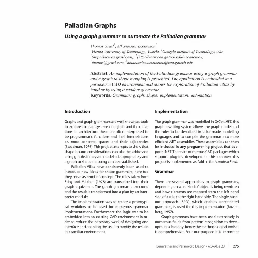
Figure 10 A montage showing the rib-bon of the Autodesk Revit Add-In and several steps of a derivation.
one-by-one, a random generator was implemented to generate derivations at the push of a button. The application of rules is guided by weighted random numbers in order to increase the probability of an appealing result.
Conclusion
Overall it is an interesting exercise to translate a shape grammar into its graph equivalent. Of course it would be sensible to model rules that are more ac-cessible to a graph approach if this methodology is used for new grammars. This would mean concen-trating on functional considerations and adjacen-cies rather than on purely formal arrangements of spaces. These Palladian piano nobiles do not lend themselves well to this approach and hence can be seen as an extreme example, well suited for testing.
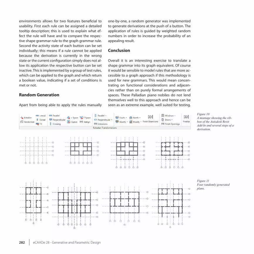
Figure 11 Four randomly generated plans.

eCAADe 28 283-Generative and Parametric Design
However, future projects will inspect this line of thought.
It was shown that the information contained and transformed by a shape grammar can be abstracted into a graph grammar to enable easier computation. The final graph can then be transformed back into a visual representation. Intelligent transformation mechanisms can conceal implementation details from the end user if desired. This will most likely require transformations after each rule application either by updating the changes or simply by recalcu-lating the entire structure.
Acknowledgement
The graph grammar was implemented with GrGen.NET (Geiß et al., 2006). The resulting libraries were embedded into an Autodesk Revit Add-In, which is also used for the topomorphical transformation; the final cleaning up of the plan was actually left to the wall join functions built into Revit. The shape gram-mar equivalent is included here for the sake of com-pleteness. The Add-In is available from the authors.
References
Geiß, R and �atz, G and Grund, D and Hack, S and Sza-lkowski, A 2006, ‘GrGen: A Fast SPO-�ased Graph Rewriting Tool’ Graph Transformations, Springer-Verlag, �erlin, pp. 383-397.
Rozenberg, G (ed.) 1997, Handbook of Graph Grammars and Computing by Graph Transformation: Founda-tions Vol. 1, World Scientific Publishing Co Pte Ltd.
Steadman, P 1976, ‘Graph-theoretic representation of architectural arrangement’ in L. March (ed.), The Architecture of Form, Cambridge University Press, Cambridge, UK, pp. 94-115.
Stiny, G and Mitchell, WJ 1978, ‘The Palladian grammar’, Environment and Planning B, 5(1), pp. 5-18.
