methods to automate assessing outage risk and technical
TRANSCRIPT

INL-EXT-19-55308 Revision 0
Light Water Reactor Sustainability Program
Methods to Automate Assessing Outage Risk and Technical
Specification Compliance for Planned Work and Current Plant
Conditions
August 2019
U.S. Department of Energy
Office of Nuclear Energy

DISCLAIMER This information was prepared as an account of work sponsored by an
agency of the U.S. Government. Neither the U.S. Government nor any agency thereof, nor any of their employees, makes any warranty, expressed or implied, or assumes any legal liability or responsibility for the accuracy, completeness, or usefulness, of any information, apparatus, product, or process disclosed, or represents that its use would not infringe privately owned rights. References herein to any specific commercial product, process, or service by trade name, trade mark, manufacturer, or otherwise, does not necessarily constitute or imply its endorsement, recommendation, or favoring by the U.S. Government or any agency thereof. The views and opinions of authors expressed herein do not necessarily state or reflect those of the U.S. Government or any agency thereof.

ii
INL-EXT-19-55308 Revision 0
Methods to Automate Assessing Outage Risk and Technical Specification Compliance for Planned Work
and Current Plant Conditions
Shawn St Germain Idaho National Laboratory
James Masterlark, Robert Priddy, and Scott Beck AMMI Risk Solutions
August 2019
http://www.inl.gov
Prepared for the U.S. Department of Energy Office of Nuclear Energy
Under DOE Idaho Operations Office Contract DE-AC07-05ID14517

iii
EXECUTIVE SUMMARY This research effort is a part of the Light Water Reactor Sustainability
(LWRS) program, a research and development (R&D) program sponsored by the Department of Energy that is performed in close collaboration with industry R&D programs. It provides the technical foundations for licensing and managing the long term, safe, and economical operation of current nuclear power plants (NPPs). The LWRS program serves to help the United States (U.S.) nuclear industry adopt new technologies and engineering solutions that facilitate the continued safe operation of these NPPs and the extension of their current operating licenses.
The Outage Risk Management Improvement Pilot Project seeks to improve the management of NPP outages. This is done through the development of tools to assist in evaluating pending activities against requirements so as to detect undesired interactions. Significant efforts are expended to manage the nuclear risk of an outage. Utilities conduct pre-outage-risk assessments, based on a detailed review of the outage schedule, to identify where combinations of outage work and out-of-service equipment would result in degradation of nuclear-safety or regulatory compliance. Probabilistic risk-assessment studies are conducted to monitor the risk of the outage activities and system unavailability. These studies are usually presented to site and fleet management and the site plant operational review committee for concurrence that the outage is planned safely and that reasonable measures have been taken to minimize the risk of outage activities.
During the outage, the plant configuration is monitored continuously to ensure that it conforms to the approved safety plan. Deviations must be assessed and approved by management committees. In virtually all outage meetings and job briefings, the current nuclear-safety status of the plant, including information on the specific equipment necessary to meet the requirements of the nuclear-safety plan, is communicated. In addition, the operations and outage organizations implement several layers of physical and administrative barriers to prevent unintended interaction with the systems and equipment credited for nuclear safety.
In spite of all these efforts, nuclear-safety challenges still occur too frequently during outages. While some of these are due to failures of equipment credited for safety, the majority occur because of human error. These typically involve some form of interaction between work activities and plant-configuration changes. Some of them are very subtle and are extremely challenging to detect in advance. Nevertheless, they are not acceptable and represent clear opportunities to improve nuclear safety during outages. This report provides a demonstration of capabilities in the development of a predictive software platform for improving configuration control and accessing the plant risks associated with outage work protocols. It illustrates how the software assists in strategies to minimize these interactions.
In addition to maintaining nuclear safety, numerous administrative requirements must be complied with during an outage. This report discusses the use of logic modeling to monitor planned work against technical-specification requirements for given plant conditions and to integrate these requirements with shutdown-risk models, clearance-order requirements, and other plant-condition requirements.

iv
ACKNOWLEDGMENTS
This report was made possible through funding by the United States Department of Energy’s Light Water Reactor Sustainability Program. We thank Jodi L. Vollmer and Barney C. Hadden at Idaho National Laboratory for technical editing and formatting of this report.

v
CONTENTS
EXECUTIVE SUMMARY ......................................................................................................................... iii
ACKNOWLEDGMENTS ........................................................................................................................... iv
ACRONYMS .............................................................................................................................................. vii
1. INTRODUCTION .............................................................................................................................. 1
2. REVIEW OF PREVIOUS SOFTWARE AND METHODS DEVELOPMENT ............................... 1 2.1 Overview of the OSSREM Application ................................................................................... 2
3. AN OVERVIEW OF OUTAGE REQUIREMENTS ......................................................................... 3 3.1 Technical Specifications .......................................................................................................... 3 3.2 Shutdown-risk Assessment ...................................................................................................... 4 3.3 Mode-change Checklist ............................................................................................................ 4 3.4 Clearance Orders ...................................................................................................................... 4 3.5 Plant-condition Constraints ...................................................................................................... 4
4. PROPOSED METHODOLOGIES..................................................................................................... 5 4.1 Automated Technical Specification Monitoring ...................................................................... 5 4.2 Integration with Clearance-order System ............................................................................... 12 4.3 Integration with Outage-risk Monitors ................................................................................... 12 4.4 Natural-language Processing .................................................................................................. 13
5. CONCLUSIONS .............................................................................................................................. 13
6. REFERENCES ................................................................................................................................. 13
FIGURES
Figure 1. OSSREM user interface. ................................................................................................................ 3
Figure 2. PRISM overview plant-status interface. ........................................................................................ 7
Figure 3. Safety injection system diagram display. ...................................................................................... 9
Figure 4. AC-power system diagram display. ............................................................................................... 9
Figure 5. Schedule display. ......................................................................................................................... 10
Figure 6. System Availability Requirements display. ................................................................................. 11
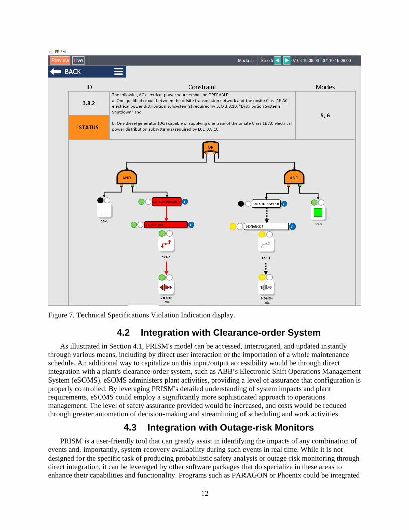
Figure 7. Technical Specifications Violation Indication display. ............................................................... 12

vi

vii
ACRONYMS AC alternating current
CFR Code of Federal Regulations
CSS containment-spray system
DOE Department of Energy
eSOMS Electronic Shift Operations Management System
GUI graphical user interface
HPSI high-head safety injection
LCO limiting conditions for operation
LER licensee event report
LOTO lockout/tagout
LPSI low-pressure safety injection
LWRS Light Water Reactor Sustainability
NPP nuclear power plant
NRC (U.S.) Nuclear Regulatory Commission
OCC outage control center
OOS out of service
OSSREM outage system-status and requirements monitor
PRISM Predictive Intelligent Solution Modules
R&D research and development
SDC shutdown cooling
SI safety injection
SRO senior reactor operator
SSC system, structure, and component
TS technical specification
U.S. United States

viii

1
1. INTRODUCTION This research effort is a part of the LWRS program, an R&D program sponsored by the Department
of Energy and performed in close collaboration with industry R&D programs that provide the technical foundation for licensing and managing the long-term, safe, and economical operation of current NPPs. The LWRS program helps the United States (U.S.) nuclear industry adopt new technologies and engineering solutions that facilitate the continued safe operation of these NPPs and extension of their current operating licenses.
One major area selected for capability-enabling research is outage safety and efficiency. A pilot project in the LWRS program, Outage Risk Management Improvement, is a multiyear effort targeted at NPP outage improvement. The primary purpose of this pilot project is to improve real-time plant risk-management and configuration control during outage as a function of work activities and plant-system alignments. It will develop a means for combining actual plant-status information with intended component manipulations embedded in procedures and work packages that are underway or scheduled.
Control-room and outage-control-center (OCC) staff must be continually informed about the actual state of the operational and maintained systems. Frequent OCC meetings certainly help to promote information flow, but an effective system-configuration and risk-monitoring system would be a useful tool to support the decision-making process [1]. There is an opportunity to leverage several technologies to assist control-room and OCC personnel in monitoring and verifying that current requirements will allow planned work. Making outage key-performance parameters and requirements and the relationships among them visible in real time would enable all personnel to anticipate and prepare for configuration changes and requirements during plant evolutions. It would support frequent reevaluation of the existing outage configuration and help to estimate the effects of planned interventions and corrective actions. In addition, easy access to system-configuration information would support preparation of a daily risk report which, in turn, would support decision-making processes and the handling of unexpected deviations from the outage plan.
This report describes research into additional methods for automating the monitoring of key outage requirements. The work continues research proposed in a previous report by St. Germain et al. (2018) [2]. That report determined that a combination of information visualization, natural-language processing (NLP), and logic modeling would likely be an effective tool for preventing unintended system interactions during NPP outages. It was determined that logic-based graphical user interface (GUI) software was needed to support the evaluation and further development of concepts that improve outage-risk management. The GUI software concept, which is under development, is called the Outage System Status and Requirements Monitor (OSSREM). The OSSREM application established the key display concepts and user interface, but did not incorporate logic modeling or methods to automatically evaluate compliance with technical specifications (TSs). Current research expanded upon the OSSREM application concepts, but now uses a new software platform, Predictive Intelligent Solution Modules (PRISM), to handle the complex logic modeling required and to provide enhanced user information related to system status. PRISM is a commercial software application available from AMMI Risk Solutions. AMMI Risk Solutions was contracted to provide a demonstration application in PRISM.
The discussion in this report focuses on implementing a software module, PRISM. PRISM is designed easily to navigate and interpret large volumes of complex data, activities, and events such as those experienced during an outage, to associate them with the facility’s regulations, requirements, standards, and procedures, and to notify staff and provide solutions to non-compliant situations.
2. REVIEW OF PREVIOUS SOFTWARE AND METHODS DEVELOPMENT
Previous research in the area of outage-risk management determined that, while current risk-management methods have so far prevented serious outage incidents, there is still room for improvement.

2
It also included a review of licensee event reports (LERs) submitted between 2010 and 2015 for events that occurred during shutdown conditions [3]. This review identified 248 LERs written for outage execution-related issues. Of these events, 113 were identified as being reasonably preventable. The main high-level causes identified included issues related to configuration control, procedure use, and control and mode-change issues. The researchers concluded that a combination of data visualization, NLP, and logic models could be employed to develop an advanced requirements monitor to support operations staff in ensuring that scheduled work complies with TS and shutdown-risk profiles for given plant conditions.
2.1 Overview of the OSSREM Application To support further research into potential outage-risk-management strategies, LWRS researchers
developed a software application. OSSREM is an information collection, processing, and visualization tool that is intended to support operations staff during outage conditions in maintaining awareness of plant conditions and requirements in very dynamic work environments.
It is well established that the world’s most significant and publicized accidents involving an NPP have occurred during a time when the plant was operating at or near full-power electrical generation. For most NPP designs, this is called commonly called “Mode 1” of plant operation. However, NPP designs have other plant operating modes where power generation is reduced and enters various shutdown stages of a planned plant refueling outage at which the plant generates zero power. The risks that are present during an outage are not negligible and contribute a significant portion to overall plant risk. In addition, refueling outages pose additional problems and challenges that are not present during full-power operations. Outage work requires a substantial increase in the work force, including contractors and contract personnel not familiar with the plant environment and protocols working 20–30 days and performing thousands of activities in that short time span. These activities, many of them complex and hazardous (e.g., hot work, work at heights, high-voltage electrical work), require an increase in work coordination and scheduling in order to ensure a safe working environment for all staff.
Work authorization during an outage typically takes place outside the main control room to minimize distracting the main control-room staff. The work-control senior reactor operator (SRO) is required to maintain awareness of ever-changing plant conditions, but without the benefit of the indications provided by the main control-room displays. The OSSREM application is designed to provide critical information on current plant status, operating mode, required systems, and the availability for work of key systems and components. Key concepts for the GUI are presented in in Figure 1.

3
Figure 1. OSSREM user interface.
3. AN OVERVIEW OF OUTAGE REQUIREMENTS Outage managers are responsible for ensuring that work orders are ready for approval prior to
authorization. Previous research identified key functions performed by the outage-management team [4]. Significant time and effort are applied to outage-schedule planning prior to the start of a refueling outage, but after the start of the outage, the schedule shifts continuously without the benefit of weeks of planning. Because of this, the work-control SRO is relied upon to verify that the authorization of a work order will not create a conflict with TSs, shutdown-risk assessment, mode-change checklists, existing and scheduled clearance orders, and other ongoing work, nor will it interfere with required plant conditions. Each of these requirements has its own tracking method and is not easily verified individually, must less concurrent with the other requirements. Given the large volume of work that must be evaluated each day, no human can keep track of all the various changing requirements. This section will describe the nature of these requirements and how they are typically verified under current outage conditions. Failures to verify compliance with all requirements can cause increased regulatory and corrective-action tracking burdens, schedule delays, and reactor- or industrial-safety issues.
3.1 Technical Specifications TSs prescribe various operating requirements for NPPs. TSs are part of an NPP’s license to operate,
granted by the U.S. Nuclear Regulatory Commission (NRC). The licensee is not allowed to revise its TSs without prior NRC approval. The TSs outline limiting conditions for operation (LCOs) for various systems important to plant safety. These LCOs describe applicability requirements for various modes of operation and completion time limits if the LCO is not met. There are specific actions and reporting requirement the licensee must follow if the LCO is not met. Failure of the licensee to comply with its TSs requires reporting to NRC per 10 Code of Federal Regulations (CFR) 50.73 as an LER. Ensuring compliance with TSs is one of the basic responsibilities of operations staff in authorizing work. Because

4
of the highly fluid nature of outage work and continually changing plant conditions, it is not always easy to keep track of the various applicability requirements in the TSs.
3.2 Shutdown-risk Assessment NPPs continually evaluate the nuclear-safety risk of their ongoing operations. To perform this
assessment, various probabilistic-risk-assessment techniques have been developed and employed. During refueling outages, reactor-safety risk is also monitored and controlled. Various software applications have been developed to support outage-risk assessment and monitoring. Each of these applications requires precise knowledge of plant conditions and configuration. The work-control SRO must understand risk impacts of each work package prior to authorizing the work. The risk assessment is evaluated continuously and is only valid if the conditions assumed in the assessment are maintained. To ensure the plant is operating under the planned risk assessment, requirements for equipment operability and configuration must be monitored and controlled. The plant configuration that was analyzed and approved by the shutdown-risk assessment becomes an additional requirement for the work-control SRO to consider prior to authorizing work.
3.3 Mode-change Checklist Mode-change checklists are used as part of the plant startup procedure to ensure key systems are
available prior to placing the plant into conditions that require designating a new operating mode per the TSs. The most challenging and error-prone mode change is moving from Mode 5 to Mode 4 when coming out of an outage. Mode 4 includes many more required systems to be operable to support continued plant startup. Equipment on which work was performed during the outage may not be declared operable prior to various surveillance checks, and plant conditions may not support these checks at the time the work is completed. Due to a large amount of work that may still be ongoing, it is sometimes difficult to verify that all required systems are operable and remain operable during the startup. Plants typically rely on paper checklists to ensure that all requirements are met and required systems are available prior to mode change, but this system can fail if not carefully managed.
3.4 Clearance Orders Clearance orders are used by operations personnel to remove equipment from service, allowing safe
performance of work. The placement of clearance orders is sometimes also referred to as “lockout/tagout” (LOTO) and is part of an NPP’s occupational-safety program. Clearance orders place danger tags on system boundaries for both personnel and plant protection. Effectively managing the schedule of clearance-order hangs and lifts becomes critical during a refueling outage. Many schedule delays are caused by unanticipated conflicts between scheduled work and clearance-order tagged components in place for other scheduled work. Plants sometimes use electronic databases to manage clearance orders, and the clearance orders are inserted into the outage schedule as part of work-package scheduling.
The usage of LOTO is significantly more prominent during an outage due to the increase in maintenance activities. In addition, the added restrictions of LOTO may incorporate an extended work area to ensure proper equipment or system equipment isolation. To avoid TS violations or placing workers or other plant operations in a potentially dangerous situations, it is important to track and monitor clearance orders during the outage. Using data from the clearance-order database is an essential tool for effective configuration management and automated requirements monitoring.
3.5 Plant-condition Constraints During a refueling outage, the plant conditions must be carefully controlled, and work must be
scheduled during the proper work window. As outage durations are reduced, work windows become increasingly short, and effective understanding of the constraints imposed by plant conditions on the desired work activities becomes even more important. An effective requirements monitor should consider

5
required plant conditions among the requirements. Plant-condition constraints could include status of equipment and personnel hatches in containment, reactor water level, shutdown cooling trains, service water trains, or status of fuel movement. A mechanism should exist for the requirements monitor to display and track each of these important parameters.
4. PROPOSED METHODOLOGIES Early design concepts for the OSSREM software have been described in previous reports INL/EXT-
17-43234 [2] and INL/EXT-18-51474 [3]. Most of the design features from these reports were integrated into the current OSSREM software prototype. This section discusses the integration of existing concepts of the OSSREM with the PRISM application that will easily navigate and interpret large volumes of complex data. Previous research identified key aspects to consider in developing an information display [5 and 6]. These concepts have been carried forward into the latest demonstration platform. PRISM will consolidate, display, and evaluate data related to plant configurations and upcoming work activities to detect and prevent potential conflicts, activities, and events with TSs and other plant-protocol information from existing risk-monitoring software or shutdown-risk-assessment procedures.
The PRISM module for this report’s demonstrative purpose does not have all proposed OSSREM design features incorporated. Features such as reactor coolant-system inventory indication, tank- and reactor-vessel-level indication, containment-hatch status, etc., will be added later.
For this methodology demonstration, the generic safety injection (SI) system was modeled in PRISM software. The SI system included the following systems:
• High-pressure safety injection (HPSI), including both injection and recirculation mode of operation and the safety-injection tanks (SITs)
• Low-pressure safety injection (LPSI), including both injection and recirculation mode of operation and shutdown cooling mode
• Containment-spray system (CSS), including containment-spray mode (including recirculation) and shutdown cooling (SDC) modes of operation
• Alternating current (AC)-power electrical-distribution system, including emergency power (i.e., diesel generators).
Also, TSs concerning the SI and AC-power system, pertinent information from a typical shutdown-risk assessment, plausible scheduling information regarding the SI system and administrative procedures were entered into PRISM.
4.1 Automated Technical Specification Monitoring
PRISM’s initial GUI displays a simplified plant status and main-system and equipment layout. Figure 2 shows the plant-overview display screen. The GUI of this screen contains the following information:
1. An overview plant-status screen (referred to as the plant dashboard) displays the main systems and equipment in the plant and their respected operating status. The plant-dashboard screen shows the following systems and equipment:
- The reactor vessel, its pressurizer, the steam generator, its pressurizer, and the reactor coolant pumps
- Refueling water-storage tanks and the reactor sump - Key systems and equipment and their operating status, indicated using color-coded indicators - The spray pond (i.e., the ultimate heat sink)

6
- Main electrical-distribution equipment. 2. A legend located on the right side of the screen shows the meaning of the color-coded status in the
PRISM software. The legend can be hidden or expanded at user discretion.
3. Key plant component-status information. This illustrates the status of major components in key plant systems. This visually indicates status of a component, such as if the component is in standby, running, failed, failed by dependency, protected, or out of service (OSS) due to test and maintenance or, possibly, a combination, such as protected and in standby. As an example, Figure 2 indicates the following for the SI and AC-power systems:
- HPSI Pump A is failed by an override by clicking the availability indicators located above the component in the GUI. This automatically places HPSI Pump B in a protective status.
- LPSI Pump A is energized through an operational override by clicking on the component itself in the GUI.
- The remaining pumps in the SI system are all available, but de-energized. - The offsite electrical power system main busses are functional and energized, with both
emergency diesel generators available and in standby. 4. The status of key plant safety systems typically used during an outage. Figure 2 illustrates that both
Trains A and B of the CSS are available for containment-spray alignment. In addition, Figure 2 illustrates the following for cold- or hot-leg injection:
- Train A of HPSI is unavailable for both injection and recirculation modes - Train B of HPSI is available for both injection and recirculation - Both trains of LPSI are available for injection, recirculation and SDC - Both trains of CSS are available for SI recirculation and SDC.
5. Modified configuration notice. Located at the top portion of the GUI is a darkened configuration-selector ribbon. In the upper-right corner of the selector ribbon is a notification message, “Modify Configuration,” in bold, orange text. This indicates to the user that the scheduled plant status has been modified through the GUI in some manner (i.e., by manually failing a component or performing an operational override). The Reset button to the right of this notice will reset any changes to plant configuration back to the original scheduled status.
6. Preview and live plant-configuration indication. On the far left of the selector ribbon is an indicator of the time mode the user views in terms of plant configuration and status. If “Preview” is highlighted, it indicates that the user is analyzing a time frame during an outage that is advanced in time. If Live is highlighted, the user is looking at the current time in the schedule during which PRISM is accessing preloaded data on the latest and current daily operating status and configuration.

7
Figure 2. PRISM overview plant-status interface.
The PRISM plant-dashboard screen includes, in the center of the configuration-selector ribbon, the indication of the plant mode of operation and the time frame in the outage schedule that is being observed. Figure 2 illustrates that the user is currently looking at a time frame when the plant is in Mode 3 of operation, and the time frame of the outage schedule is Slice 1, with the date and time shown of this slice of time. The user can easily change the slice of time in the schedule by clicking on the “previous” or “next” arrow buttons in the selector ribbon.
In addition, the PRISM Plant Dashboard screen includes a Back selector and the drop-down Main Menu, as indicated in Figure 2. By selecting the Back arrow, the GUI toggles the user back to the previous screen view. The drop-down Main Menu currently displays the following options:
• Incident log
• Schedule
• Plant dashboard
• Systems.
The Systems option in the Main Menu selector is expandable and will display all systems modeled in PRISM. For this demonstration, only the AC-power system and the SI system are modeled. When the SI system is selected, PRISM will display the Safety Injection System screen, as shown in Figure 3. The system display shows much greater component detail than the Plant Dashboard and, in addition to pumps, includes motor-operated valves, manual valves, heat exchangers, and all flow paths. The SI-system display includes HPSI, LPSI, and CSS systems that constitute the entire SI system. The ability to zoom into a specific section of the diagram is available; the systems screens represent a detailed drawing of equipment configuration, either for a Live (that is, current) view or a Preview of schedule slice displayed in the selector ribbon located at the top of the display.
All changes that were made by the user in the Plant Dashboard screen are transferred over to the system display screen and to any other system screens where there is a dependency or a shared component. Therefore, as Figure 3 illustrates, because the HPSI Train A pump was failed by an

8
operational override and LPSI Pump A was started (energized), these changes were transferred to the system diagram.
The GUI of the system display in Figure 3 contains the following features:
1. System Status Summary Panel. This panel is located on the far-right side of the screen and displays the availability status of the systems and their respective mode of function. In Figure 3, the system status shows that HPSI Train A is failed for both injection and recirculation functions. All trains for LPSI and CSS are available for all their modes of operation, including injection, recirculation, and SDC.
2. System Alignment Panel. This panel, also located on the far-right side of the screen, displays the system-alignment status. For the SI system, the HPSI, LPSI and the CSS subsystems are selectable to be in standby, injection (or spray, for the CSS subsystem), recirculation, or SDC mode of operation. In addition, for each slice in the outage schedule that the user selects, the OSSREM will adjust the System Alignment panel to represent the appropriate alignment status for the respected schedule slice.
3. Flow Path Availability. The system display shows flow-path availability of all possible flow paths in the system. The GUI indicates when a flow path is available and flowing, available and not flowing, or not available due to an unavailable component.
4. Protected Equipment Notification. Protected-equipment rules are loaded into the OSSREM, and the software checks these rules against each slice configuration in the schedule and alignment and equipment out-of-service (OOS) modifications. Protected equipment is displayed in the system display (and the Plant Dashboard display), highlighted in purple. As illustrated in Figure 3, Train A HPSI pumps were failed by an operational override (possibly to be placed in test and maintenance, for example). When this occurred, PRISM checked the protective-equipment logic rules and related those to the modified alignment. From the logic check, it placed HPSI Train B components into a protected-equipment status.
5. If protected equipment is placed in a failed mode (i.e., placed as OOS), the logic in the software will determine a violation in the protected-equipment rules and outline the purple-highlighted equipment in orange to notify the user of a potential violation. In addition, if the user selects a different slice in time in the schedule, the software logic compares the protective-equipment rules with the alignment, the OSS equipment in the slice, and any operational overrides and notifies the user of a protected-equipment violation in the GUI.
6. Suggested and Recovered Components. The system display will show, with a light-blue indicator above a component, a component that was previously failed or unavailable, but was eventually recovered (i.e., made operational again). The GUI will also indicate whether a component or components could be used for a suggested flow path for operational success.
7. Support System Dependencies. PRISM will carry over failures in one system to other systems. Figure 4 shows a simplified AC electrical power system, including offsite and emergency power. If an electrical bus in this system is taken out for maintenance or if it failed, all components connected to that bus will also be failed. The GUI will also indicate possible cross-tie connects for those components to get power from another bus.

9
Figure 3. Safety injection system diagram display.
Figure 4. AC-power system diagram display.
The PRISM Main Menu includes a Schedule option that allows the user to examine specific schedule periods, or slices, and checks those slices and any modifications to the work orders or system

10
configurations to plant-specific TSs, administrative procedures, and risk-assessment results. Figure 5 show the Schedule screen of PRISM.
For this demonstration, PRISM was loaded with a simplified plant-outage schedule. The time slices of the schedule are in chronological order from left to right at the top of the screen, with start and end dates and times for each slice. The user can switch among the slices by clicking a specific slice number or using the arrow selectors to jump between the slices located in the selector ribbon at the top of the GUI. The Reset button, located below the selector ribbon, resets any modifications to the schedule back to their original configurations.
The GUI for the schedule displayed in Figure 5 contains the following features:
1. Plant Conditions. This displays the status of specific plant conditions for the slice of schedule selected. Plant conditions include spent-fuel-pool water level, time to boil, reactor coolant-system inventory, and containment integrity. These conditions and any others can be added to PRISM at the plant’s discretion.
2. System Availability Requirements. This feature displays the relevant TSs, administrative procedures, prerequisites, and mode-change checklists for a specific schedule slice.
3. Alignments. This feature displays the systems alignment for each specified schedule slice. For this demonstration, the SI system is in SDC alignment for all slices.
4. Risk Management Action Level (RMAL). For this feature, PRISM will notify the user if an RMAL has been violated for a specified slice in outage schedule. The RMAL is calculated for both situations in which the pressurizer manway is on or off.
Figure 5. Schedule display.
For this demonstration, Slice 5 in the schedule was selected. By expanding the Technical Specifications options under System Availability Requirements, the GUI will display the TS specific to

11
the SI system, as shown in Figure 6. Under each slice, the GUI indicates whether the slice meets the technical requirements (shown in green) or does not meet the technical requirements.
As indicated in Figure 6, Slice 5 does not satisfy the technical requirements for 3.8.2 AC Sources—Shutdown shown as the Slice 5 panel marked in orange. When the orange panel is clicked, PRISM will display the reason the technical specification was not met, as shown in Figure 7. In this case, it shows how the slice did not meet the requirements because one electrical train had an offsite breaker OOS, and another electrical train had the emergency diesel generator OOS.
Figure 6. System Availability Requirements display.
12
Figure 7. Technical Specifications Violation Indication display.
4.2 Integration with Clearance-order System As illustrated in Section 4.1, PRISM's model can be accessed, interrogated, and updated instantly
through various means, including by direct user interaction or the importation of a whole maintenance schedule. An additional way to capitalize on this input/output accessibility would be through direct integration with a plant's clearance-order system, such as ABB’s Electronic Shift Operations Management System (eSOMS). eSOMS administers plant activities, providing a level of assurance that configuration is properly controlled. By leveraging PRISM's detailed understanding of system impacts and plant requirements, eSOMS could employ a significantly more sophisticated approach to operations management. The level of safety assurance provided would be increased, and costs would be reduced through greater automation of decision-making and streamlining of scheduling and work activities.
4.3 Integration with Outage-risk Monitors PRISM is a user-friendly tool that can greatly assist in identifying the impacts of any combination of
events and, importantly, system-recovery availability during such events in real time. While it is not designed for the specific task of producing probabilistic safety analysis or outage-risk monitoring through direct integration, it can be leveraged by other software packages that do specialize in these areas to enhance their capabilities and functionality. Programs such as PARAGON or Phoenix could be integrated

13
with PRISM through data sharing or by more-fundamental means, resulting in a user experience that provides the strength and capabilities of both platforms.
4.4 Natural-language Processing A key capability of the PRISM software system is the ease with which it can read, interpret and
evaluate large amounts of complicated data. The PRISM application contains Microsoft Excel-based data tables of plant-outage information that include operating and administrative procedures, work orders, shutdown-risk-assessment protocols, and TSs. Logic rules based on this information are evaluated for the specific mode of operation of the plant and outage-schedule time period to determine the required plant configuration and necessary system, structure, and component (SSC) manipulations. PRISM continually compares both current outage-schedule status and user configuration overrides and then looks for violations in protocols, procedures, and TSs. PRISM notifies the user of any violations through its GUI. A separate application will be developed to extract the plant-outage data from plant documentation using a technique known as NLP. Researchers at Vanderbilt University are currently developing a tool to extract the expected plant-outage information from the plant procedures in a data form that could be incorporated into PRISM data table and logic format.
5. CONCLUSIONS Previous work completed on the OSSREM program determined that the cognitive load placed on
plant staff to ensure that scheduled outage work will comply with plant conditions and requirements is very challenging. To complete an entire plant outage, an enormous amount of information must be analyzed and interpreted to ensure that scheduled work activities, plant conditions, and SSC manipulations are achieved safely and in compliance with plant-outage protocol, licensee procedures, and all regulatory requirements.
Current research expands upon the OSSREM application concepts, and these are incorporated in a new software platform, PRISM, to handle the complex logic modeling required and to provide enhanced user information related to system status. The PRISM application easily navigates and interprets large volumes of complex plant and configuration-logic data. PRISM consolidates, displays, and evaluates data related to present plant configurations and upcoming work activities to detect and prevent potential conflicts, activities, and events with TSs and other plant work-protocol information from any existing risk-monitoring software or shutdown-risk-assessment procedures.
Future additions and improvements to the PRISM outage platform of the OSSREM capabilities are anticipated, and the GUI can easily be modified to meet plant requirements. Enhancements to be added to PRISM include operating-mode change checklists, LOTO protocols, procedure prerequisites, safe-shutdown protocols, and detailed safe-shutdown risk-assessment analysis and checklists.
6. REFERENCES 1. International Atomic Energy Agency (2016). Nuclear Plant Outage Optimization Strategy. (IAEA-
TECDOC-1806). International Atomic Energy Agency.
2. S. St. Germain, J. Hugo, G. Gobbel, and R. Reeves, (2018). Prototype System for Detecting Interactions between Current Plant Configurations States and Component Manipulations Directed by In-Use Procedures. INL/EXT-18-51474. Idaho National Laboratory: Idaho Falls, ID.
3. S. St. Germain, J. Hugo, M. Manic, and K. Amarsinghe, (2017). Technologies for Detecting Interactions between Current Plant Configuration States and Component Manipulations Directed by In-Use Procedures. (INL/EXT-17-43234). Idaho National Laboratory, Idaho Falls, ID.
4. S. St. Germain, R.K. Farris, A.M. Whaley, H.D. Medema, and D.I. Gertman, (2014). Guidelines for Implementation of an Advanced Outage Control Center to Improve Outage Coordination, Problem

14
Resolution, and Outage Risk Management. INL/EXT-14-33182. Idaho National Laboratory: Idaho Falls, ID.
5. S. St. Germain, R. Farris, and K. Thomas, (2015). Development of Improved Graphical Displays for an Advanced Outage Control Center, Employing Human Factors Principles for Outage Schedule Management. INL/EXT-15-36489. Idaho National Laboratory: Idaho Falls, ID.
6. S. St. Germain and J. Hugo, (2016). Development of an Overview Display to allow Advanced Outage Control Center Management to quickly evaluate Outage Status. INL/EXT-16-39622. Idaho National Laboratory: Idaho Falls, ID.