2019 outage handbook - combined cycle journal
TRANSCRIPT
Number 57 2Q/2018
www.ccj-online.com
$15
INDEPENDENT VOICE OF THE GAS-TURBINE-BASED GENERATION SECTOR
2019 OUTAGE HANDBOOKFeaturesSharing HRSG technology
globally benefits users. ......42NDT innovations showcased at
HRSG Forum ....................44Streamlining I&C
learning. ..............................46Outage management improves
with delegation of job leads. ....................................48
Proper greasing of equipment ...........................48
Standardizing data on fire extinguishers benefits recordkeeping, compliance ...........................50
Oil labeling. .............................50The importance of
cleanliness ...........................52 Brian Hulse
Building the better mouse trap ........... 54
Brian Hulse
How to excavate safely in high-risk areas ..........68
Tight project control, capable craft personnel spell success for triple major ......70
Backwash plate-and-frame heat exchanger to boost performance ........................78
The future is nothing without the past. ...............................80
Dave Lucier
AIG upgrades slash ammonia consumption, tube fouling. .................................84
ISO 16890, a new global test standard, facilitates comparison of alternative air filters ..............................88
User Group Reports7EA annual meetings focus on O&M solutions to improve profit-ability, safety .................................. 4 The oldest gas turbines in the GE 7E fleet of nearly 1200 engines served by the 7EA Users Group are approaching a half-century of service. Highlights of the 2017 conference presented here speak to the level of detail shared by the user and vendor participants at this forum, encouraging owner/operators to register today for the upcoming meeting (October 8 – 11, Hyatt Regency Orange County, Garden Grove, Calif).
The report is divided into five sections: Inspection, focusing on the TILs consid-ered by experts to be of greatest impor-tance to the fleet (p 6); user presentations, featuring a bucket-rock coating solution, rotor exchange program, compressor R1 ice damage, and clashing update (p 10); roundtable discussions on bus-duct issues and rotor lifetime evaluation (p 14); GE Day (p 20); and summaries of vendor pre-sentations on a variety of topics (p 24). Australasian HRSG users discuss risk-based inspection, corrosion under insulation, water chemistry . 32 Highlights: Recommissioning of Swanbank E after three years of layup (p 34); fail-ure rates in ageing HRSGs (p 36); cycle chemistry (pp 36, 38); thermal-transient issues (p 36); ultrasonic condensate detection (p 38); film-forming substances (p 40); materials issues (p 41). European Turbine Network (ETN Global) expands its services for end users .................................................... 74Launch of a Best Practices program in the areas of workforce development/knowl-edge management and EHS (environ-ment, health, safety) helps guide improve-ment programs at production facilities owned and operated by power-generation and oil-and-gas companies.Business Partners ............................. 89Departure of industry leaders accelerates.Buyers Guide ...................................... 95
Register today
2018 7EA Confer-ence and Vendor FairOctober 8 – 11Hyatt Regency Orange County, Garden Grove, Calif [email protected]
Effingham County Power. .......46Foam inserts prevent air flow through offline gas turbinesRiver Road Generating Plant ..58Retrofit air-inlet filter house for emer-gency egressHermiston Generating Plant ...60Self-perform combustion inspectionsMinnesota River Station ..........62Upgrades to non-segregated bus duct help prevent faultsOntelaunee Energy Facility ....65Water-wash program gives year-round benefitGreen Country Energy ............66Design hazardous-spill response plan for worst-case scenarioCCC Tuxpan II and V ...............77Outage safety benefits from commu-nity outreach program

Film-forming substances —an international forum ...................... 6Neutralizing amines and filming products are viewed by some of the industry’s thought lead-ers as the next frontier in cycle chemistry. They offer the potential for reducing corrosion in heat-recovery steam generators, condens-ers, and steam turbines in plants not having the luxury of operating baseload and/or tight control of water/steam chemistry. Report brings you up to speed on a technology that promotes high plant availability and reduces mainte-nance costs.
Materials issues, drones, cycle chemistry, attemperators, automation, life manage-ment among meeting’s highlights ........ 63This year’s event in Houston, like the HRSG Forum’s inaugural meeting in Charlotte, addressed topics of immediate interest to HRSG experts and combined-cycle system owner/operators. There were spirited discus-sions before, during, and after the formal tech-nical agenda. Participants networked freely within this consolidation of equipment details, operating trials and errors, and forward-looking ideas. Another year, another great program ....52The world’s largest conference supporting gas-turbine users attracted to Palm Springs in March more than 1000 attendees from 24 countries and 42 states. CCJ’s coverage of this event begins with the best practices shared by in the following plants:n Equus Power I, p 75 n J-Power Long Island Fleet, p 78 n Terry Bundy, p 76 n EVM I (Mexi-co), p 78 n Lawrence, p 80 n West Valley, p 82 n Pinelawn, p 84 n Shoreham, p 85 n REO Town Cogen, p 86 n Orange Grove, p 88 n Worthington, p 90 n Orange Cogen, p 92.ELECTRIC GENERATORS, 2018 Annual Review ........... follows p 38Compiled by Editor Clyde Maughan, a gen-erator consultant of renown, and the steering committee of the Generator Users Group, this seminal work summarizing the presentations and discussions from the 2017 GUG confer-ence was sponsored by Mechanical Dynamics & Analysis.
LEFT COL OVER RUN
WWW.RENTECHBOILERS.COM
At RENTECH, every boiler is custom built. The conditions, demands and specs of
your application are unique – and mission critical to success. Our expert engineers
will analyze your needs and design an integrated, cost-effective solution. Then
we’ll construct, install and service a boiler that is durable, energy efficient and
clean running. Always the best – and never off the shelf.
TEXAS INGENUITY.RENTECH BOILERS. AS TOUGH AS TEXAS.
WATERWALL HRSG DESIGNS AVAILABLE TO SUPPORT HIGH LEVELS
OF DUCT FIRING.
HIGH DEGREE OF SHOP FABRICATION TO MINIMIZE FIELD ERECTION TIME.
COMPLETE SYSTEMS CUSTOM DESIGNED FOR THE MOST STRINGENT CUSTOMER SPECIFICATIONS.
COMBINED CYCLE JOURNAL, Number 57, Second Quarter 2018 3
Business Staff*Susie CarahaliosAdvertising Sales [email protected] CYCLE Journal is published by PSI Media Inc, a Pearl Street company. Editorial offices are at 7628 Belmondo Lane, Las Vegas, Nev 89128. Office manager: Robert G Schwieger Jr.*Carahalios Media is the exclusive worldwide advertising sales organization for the COMBINED CYCLE Journal. Business offices are at Carahalios Media, 5921 Crestbrook Dr, Morrison, Co 80465. To cancel or change your subscription, write [email protected]
Editorial Advisory BoardRobert W AndersonCompetitive Power Resources
Robert D ThrelkeldPlant Manager, Tenaska Lindsay Hill and Central Alabama PlantsTenaska Operations Inc
J Edward BarndtSenior VP, Rockland Capital
Gabriel FleckManager, Gas Plant OperationsAssociated Electric Cooperative Inc
Dr Barry DooleyStructural Integrity Associates Inc
Editorial StaffScott G SchwiegerGeneral ManagerPrint and Electronic Products702-612-9406, [email protected] KomodaCreative DirectorSteven C StultzConsulting EditorClark G SchwiegerSpecial Projects ManagerRobert G Schwieger SrEditor Emeritus702-869-4739, [email protected]
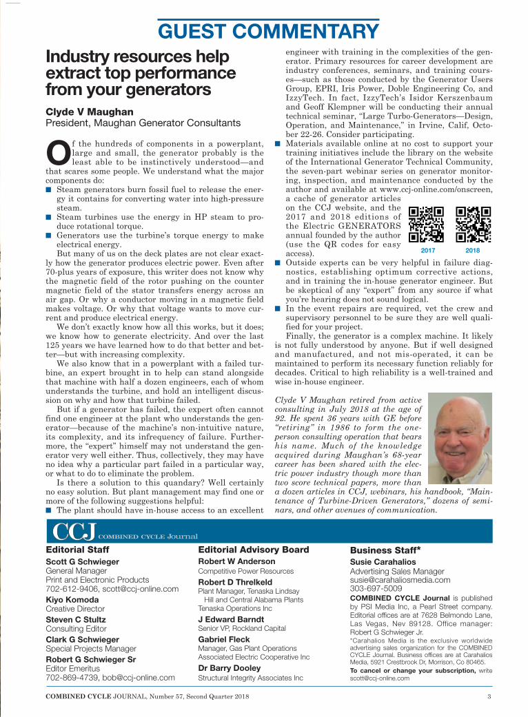
Industry resources help extract top performance from your generatorsClyde V Maughan President, Maughan Generator Consultants
Of the hundreds of components in a powerplant, large and small, the generator probably is the least able to be instinctively understood—and
that scares some people. We understand what the major components do:n Steam generators burn fossil fuel to release the ener-
gy it contains for converting water into high-pressure steam.
n Steam turbines use the energy in HP steam to pro-duce rotational torque.
n Generators use the turbine’s torque energy to make electrical energy.But many of us on the deck plates are not clear exact-
ly how the generator produces electric power. Even after 70-plus years of exposure, this writer does not know why the magnetic field of the rotor pushing on the counter magnetic field of the stator transfers energy across an air gap. Or why a conductor moving in a magnetic field makes voltage. Or why that voltage wants to move cur-rent and produce electrical energy.
We don’t exactly know how all this works, but it does; we know how to generate electricity. And over the last 125 years we have learned how to do that better and bet-ter—but with increasing complexity.
We also know that in a powerplant with a failed tur-bine, an expert brought in to help can stand alongside that machine with half a dozen engineers, each of whom understands the turbine, and hold an intelligent discus-sion on why and how that turbine failed.
But if a generator has failed, the expert often cannot find one engineer at the plant who understands the gen-erator—because of the machine’s non-intuitive nature, its complexity, and its infrequency of failure. Further-more, the “expert” himself may not understand the gen-erator very well either. Thus, collectively, they may have no idea why a particular part failed in a particular way, or what to do to eliminate the problem.
Is there a solution to this quandary? Well certainly no easy solution. But plant management may find one or more of the following suggestions helpful:n The plant should have in-house access to an excellent
engineer with training in the complexities of the gen-erator. Primary resources for career development are industry conferences, seminars, and training cours-es—such as those conducted by the Generator Users Group, EPRI, Iris Power, Doble Engineering Co, and IzzyTech. In fact, IzzyTech’s Isidor Kerszenbaum and Geoff Klempner will be conducting their annual technical seminar, “Large Turbo-Generators—Design, Operation, and Maintenance,” in Irvine, Calif, Octo-ber 22-26. Consider participating.
n Materials available online at no cost to support your training initiatives include the library on the website of the International Generator Technical Community, the seven-part webinar series on generator monitor-ing, inspection, and maintenance conducted by the author and available at www.ccj-online.com/onscreen, a cache of generator articles on the CCJ website, and the 2017 and 2018 editions of the Electric GENERATORS annual founded by the author (use the QR codes for easy access).
n Outside experts can be very helpful in failure diag-nostics, establishing optimum corrective actions, and in training the in-house generator engineer. But be skeptical of any “expert” from any source if what you’re hearing does not sound logical.
n In the event repairs are required, vet the crew and supervisory personnel to be sure they are well quali-fied for your project.Finally, the generator is a complex machine. It likely
is not fully understood by anyone. But if well designed and manufactured, and not mis-operated, it can be maintained to perform its necessary function reliably for decades. Critical to high reliability is a well-trained and wise in-house engineer.
Clyde V Maughan retired from active consulting in July 2018 at the age of 92. He spent 36 years with GE before “retiring” in 1986 to form the one-person consulting operation that bears his name. Much of the knowledge acquired during Maughan’s 68-year career has been shared with the elec-tric power industry though more than two score technical papers, more than a dozen articles in CCJ, webinars, his handbook, “Main-tenance of Turbine-Driven Generators,” dozens of semi-nars, and other avenues of communication.
GUEST COMMENTARY
WWW.RENTECHBOILERS.COM
At RENTECH, every boiler is custom built. The conditions, demands and specs of
your application are unique – and mission critical to success. Our expert engineers
will analyze your needs and design an integrated, cost-effective solution. Then
we’ll construct, install and service a boiler that is durable, energy efficient and
clean running. Always the best – and never off the shelf.
TEXAS INGENUITY.RENTECH BOILERS. AS TOUGH AS TEXAS.
WATERWALL HRSG DESIGNS AVAILABLE TO SUPPORT HIGH LEVELS
OF DUCT FIRING.
HIGH DEGREE OF SHOP FABRICATION TO MINIMIZE FIELD ERECTION TIME.
COMPLETE SYSTEMS CUSTOM DESIGNED FOR THE MOST STRINGENT CUSTOMER SPECIFICATIONS.
2017 2018
4 COMBINED CYCLE JOURNAL, Number 57, Second Quarter 2018
7EA USERS GROUP
The oldest gas turbines in the GE 7E fleet served by the 7EA Users Group are approaching a half-century of service. This
fleet incorporates gas-turbine models MS7001A, B, C, E, and EA, numbering 1168 units at 216 plants worldwide in mid-2017. The first unit, a 52.9-MW, oil-fired MS70001A, commissioned by Long Island Lighting Co in 1971 at its Shoreham Plant, is still in service, now owned and operated by National Grid Generation LLC.
What all the stats suggest is that given today’s topsy turvy generation world, the 2018 7EA Users Group meeting at the Hyatt Regency Orange County, Garden Grove, Calif, October 8-11, is the best place for owner/opera-tors to find out what their colleagues are doing to meet demanding grid requirements and still turn a profit.
Presentations and discussion ses-sions will be replete with ideas and experience on strategies to accom-modate must-take renewables, what upgrades others have found worth-while for maximizing availability and starting reliability, when you should replace—not repair—parts, etc. You probably could sit down now and write dozens of questions you’d like answers to for helping to guide O&M strategies at your plant.
Do that! Then use the list to justify your
participation in the conference. Even if you get only a fraction of your ques-tions answered, the financial benefit associated with making informed deci-sions could be enormous. Think of the meeting as free consulting.
The admission fee for users is only $250. Even after adding in transporta-tion and hotel, the total cost is only a few dollars north of a thousand. Meals? Most of those are covered. No budget? That’s no excuse for an opportunity like this; put off buying something budgeted until next year.
This is the 7EA Users’ first meet-ing on the West Coast since Monterey in 2013 and travel is convenient. LAX
is 35 miles from the Hyatt Regency, and the Orange County/John Wayne Airport only 13 miles away.
If you have never attended a 7EA
Users Group meeting and have to do more “research” before you hop off the proverbial bubble, consider that last year’s meeting in St. Augustine, Fla, attracted 100 users, in round numbers (about 40% by show of hands were first-timers), from six countries; 109 companies were represented at the vendor fair.
The 2018 conference agenda is available on the group’s website at http://ge7ea.users-groups.com but it doesn’t speak to the level of detail shared by both the user and vendor participants. You can get this by read-ing the report below.
Finally, consider perusing the user group’s e-mail forum, moderated by Greg Carvalho of Simplified Technol-ogy Co, and easily accessible via the website. It contains hundreds of solu-tions of value. The first post by a user was July 28, 2003; same time last year the number of postings available to users topped 17,000.
Those who have participated in pre-vious meetings sponsored by the 7EA Users Group might want to review the agenda: The conference format has changed. This year, GE Day is Monday and the widely valued annual presenta-tion, “What We Are Seeing in the Fleet from Our Borescope Inspections,” by Mike Hoogsteden, director of field ser-vices for Advanced Turbine Support LLC, moves to the first hour on Tuesday.
The editors believe this presenta-tion alone is worth the registration fee—particularly for first timers. It brings you up to speed quickly regard-ing what’s going on in plants like yours and what to look for during inspec-tion and maintenance outages, and includes a review of the most relevant Technical Information Letters (TILs) issued by the OEM.
Consider that most users are “land-locked” at their plants and with the significant turnover in personnel these days a knowledge vacuum may exist at your facility. This and the other presentations will help you break that vacuum.
Annual meetings focus on O&M solutions to improve profitability, safety
2018 Conference and Exhibition
October 8 - 11Hyatt Regency Orange County
Garden Grove, CalifSteering committeeSyed Mehdi Ali, GM operations,
K-Electric Ltd (Pakistan)Dale Anderson, CT technician
foreman, East Kentucky Power Co-op Inc
Tracy Dreymala, facility manager, San Jacinto Peakers, EthosEnergy Group
Ronald Eldred, plant manager, Rosemary Power Station, Dominion
Guy LeBlanc, supervisor, Con-solidated CT Plants, First Energy Corp
Tony Ostlund, combustion turbine technician, Puget Sound Energy
Doug Reves, outage coordinator, Arkansas Electric Co-op Corp
Randall Rieder, mechanical engi-neer, ATCO Power (Canada)
Mike Vonallmen, maintenance supervisor, Clarksdale Public Utilities
Lane Watson, account engineer, FM Global
Josh Wille, maintenance super-intendent, Westlake Chemical Corp
Stay connected with colleagues via the user forum at http://ge7ea.users-groups.com.
RID VARNISH FOREVERFACT...NOT FICTION
Contact Us to Learn More!
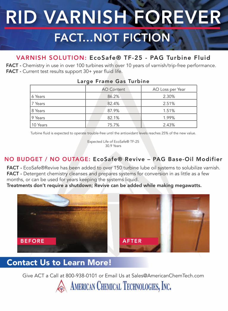
VARNISH SOLUTION: EcoSafe® TF-25 - PAG Turbine FluidFACT - Chemistry in use in over 100 turbines with over 10 years of varnish/trip-free performance.FACT - Current test results support 30+ year fluid life.
NO BUDGET / NO OUTAGE: EcoSafe® Revive – PAG Base-Oil ModifierFACT - EcoSafe®Revive has been added to over 150 turbine lube oil systems to solubilize varnish.FACT - Detergent chemistry cleanses and prepares systems for conversion in as little as a few months, or can be used for years keeping the systems liquid.Treatments don’t require a shutdown; Revive can be added while making megawatts.
BEFORE AFTER
Give ACT a Call at 800-938-0101 or Email Us at [email protected]
AO Content AO Loss per Year
6 Years 86.2% 2.30%
7 Years 82.4% 2.51%
8 Years 87.9% 1.51%
9 Years 82.1% 1.99%
10 Years 75.7% 2.43%
Large Frame Gas Turbine
Turbine fluid is expected to operate trouble-free until the antioxidant levels reaches 25% of the new value.
Expected Life of EcoSafe® TF-2530.9 Years
6 COMBINED CYCLE JOURNAL, Number 57, Second Quarter 2018
7EA USERS GROUP
InspectionA goal of every engine inspection is not to miss something that could contrib-ute to a forced outage. Success requires qualified technicians equipped with the most sophisticated tools available and well connected to company experts with deep and applicable experience ready to help diagnose findings that may be unfamiliar to those at the plant site.
Mike Hoogsteden, director of field services, Advanced Turbine Support LLC, which inspects scores of GE E-class gas turbines annually, tradi-tionally opens the 7EA Users Group meeting with the highly informative presentation, “What We Are Seeing in the 7EA Fleet during Our Inspec-tions.” This is of particular value to first-timers requiring an engine ori-entation lesson as well as a primer on what to look for and where during inspections to assure reliable service from the generating asset. The photos Hoogsteden presents are invaluable.
Pat Myers, the de facto leader of the 7EA Users Group steering com-mittee before his retirement as plant manager of AEP’s Ceredo Generating Station a couple of years ago, repre-sented CCJ at the 2017 meeting and sat in on Hoogsteden’s presentation. Now a consultant, Myers shares with clients his extensive knowledge on plant construction, maintenance, and operation gained over four decades in management positions at both gas and electric companies.
Hoogsteden opened his presenta-tion by suggesting that owner/opera-tors review Technical Information Letters (TILs) issued by the OEM for their engines, take notes, and bring their questions to the next user-group meeting. Colleagues and participating equipment/services providers, he said, are the best source of advice on what’s important and what’s not.
The five TILs at the top of Hoog-steden’s list for 7EA users are the following:n 1884, “7EA R1/S1 Inspection Rec-
ommendations,” which addresses the need to inspect R1 and S1 air-foils for possible damage caused by clashing—the unwanted contact between the leading edges of S1 stator-vane tips and the trailing edges of rotor blades in the platform area.
n 1980, “7EA S1 Suction Side Inspec-tion Recommendations,” which advises users to inspect for crack indications on S1 vanes made of Type-403 stainless-steel, regardless of whether clashing damage is in evidence on S1 and R1 airfoils.
n 1854, “Compressor Rotor Stages 2 and 3 Tip Loss,” which suggests blending and tipping to mitigate the impact on availability and reliability of R2 and/or R3 tip loss. This TIL supplements information provided by the OEM in the O&M manual provided with the engine.
n 1562-R1, “Heavy-Duty Gas Tur-bine Shim Migration and Loss,” which informs users on the need to monitor the condition of compres-sor shims and corrective actions available to mitigate the risks of migrating shims.
n 1744, “S17, EGV1, and EGV2 Stator-Ring Rail and CDC Hook Fit Wear Inspection,” provides guidance on the repair of dovetail wear and suggests hardware and software enhancements available to mitigate the potential risk caused by operating conditions that pro-mote such wear. TIL 1884. It took years for the OEM
to address clashing in a TIL (Fig 1). Hoogsteden believes Advanced Tur-bine Support was the first company to alert the industry to this phenom-enon—back in 2006. TIL 1884 was issued in spring 2013.
During the intervening years, Advanced Turbine Support worked closely with the user group, Myers on point, to share inspection data impor-tant to problem definition and solution. Developments in inspection technology
contributed to a better understanding of first-stage findings and provided information of greater value for the resolution of issues.
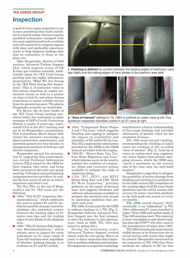
TIL 1884 went beyond clashing, recommending the checking of stator vanes for cracking in the co-called “area of interest” (Fig 2). Lock-up of vanes in carbon-steel ring segments can cause higher-than-normal oper-ating stresses, which the OEM says “reach a maximum on the suction side of the vane near the mid-chord location.”
Hoogsteden’s suggestion to mitigate the possibility of serious damage from clashing and cracking is to perform an in-situ eddy-current (EC) inspection on the trailing edges of all R1 rotor-blade platforms and the entire suction side of every S1 stator vane from platform to tip each peak-run season or every six months.
TIL 1980, issued January 2016, essentially is an “addendum” to TIL 1884, addressing S1 vanes installed in legacy 7EAs (1996 and earlier) made of Type 403 stainless steel. This material is more susceptible to mid-chord crack-ing than the GTD™ 450 alloy used in the manufacture of vanes since 1997.
TIL1980 recommends inspection by visible means or by fluorescent dye to reveal suction-side cracks that might be present. Hoogsteden mentioned in his comments on TIL 1884 that these methods are inferior to EC for this
1. Clashing is defined as contact between the leading edges of stationary vane tips (right) and the trailing edges of rotor blades in the platform area (left)
2. “Area of interest” defined in TIL 1884 is outlined on stator vane at left. Dye penetrant inspection identifies cracks in an S1 vane at right

Follow Us! /MD&A @mdaturbines MD&A Turbines
MD&A now offers Gas Turbine Capital Parts, Upgrades and Component Repairs through the integration of the PW Power Systems IGT Division.
The MD&A San Antonio Service Center, our gas turbine parts service facility in Texas, has cutting edge equipment and repair techniques with proven expertise on multiple frame gas components. Our enhanced gas turbine new parts use proprietary advanced technology.
MD&A is a full-service, global gas turbine provider for parts, services, and repairs. Our experts are committed to delivering consistent quality and value with quick response, exceptional communications, and innovative solutions.
PARTS | SERVICES | REPAIRS
MD&A's Gas Turbine Services 19 British American Blvd. | Latham, NY 12110 ph. +1 518-399-3616 | www.MDAturbines.com
Full Service Provider
8 COMBINED CYCLE JOURNAL, Number 57, Second Quarter 2018
7EA USERS GROUP
purpose. He added that if the vanes are coated, visible or fluorescent dye penetrant inspections may not be dependable, nor have an acceptable probability of detection.
Regarding the effectiveness of ultrasonic (UT) inspection for this purpose, if coating degradation—such as disbonding—occurs, the value of UT could be compromised.
TIL 1854, released in August 2012, informs owner/operators of E-class compressors about the blending and tipping of second- and third-stage rotor blades it recommends to mitigate the negative impact on availability and reliability caused by tip loss from heavy rubs and/or corrosion pitting.
The OEM says fleet experience and engineering analysis have concluded that compressor rubs can be caused by casing distortion that progresses over time, and by hot restarts initi-ated between one and eight hours after shutdown. The latter causes critical clearances to decrease. Corrosion pit-ting, by contrast, can create a local stress concentration that may result in tip loss via high-cycle fatigue.
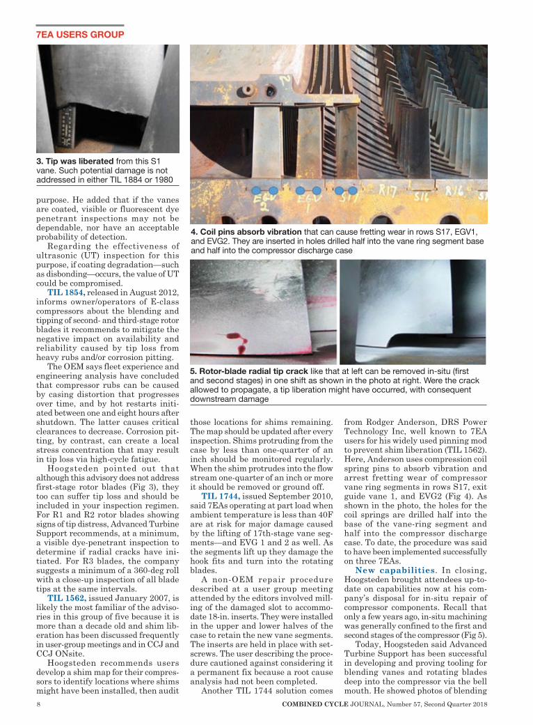
Hoogsteden pointed out that although this advisory does not address first-stage rotor blades (Fig 3), they too can suffer tip loss and should be included in your inspection regimen. For R1 and R2 rotor blades showing signs of tip distress, Advanced Turbine Support recommends, at a minimum, a visible dye-penetrant inspection to determine if radial cracks have ini-tiated. For R3 blades, the company suggests a minimum of a 360-deg roll with a close-up inspection of all blade tips at the same intervals.
TIL 1562, issued January 2007, is likely the most familiar of the adviso-ries in this group of five because it is more than a decade old and shim lib-eration has been discussed frequently in user-group meetings and in CCJ and CCJ ONsite.
Hoogsteden recommends users develop a shim map for their compres-sors to identify locations where shims might have been installed, then audit
those locations for shims remaining. The map should be updated after every inspection. Shims protruding from the case by less than one-quarter of an inch should be monitored regularly. When the shim protrudes into the flow stream one-quarter of an inch or more it should be removed or ground off.
TIL 1744, issued September 2010, said 7EAs operating at part load when ambient temperature is less than 40F are at risk for major damage caused by the lifting of 17th-stage vane seg-ments—and EVG 1 and 2 as well. As the segments lift up they damage the hook fits and turn into the rotating blades.
A non-OEM repair procedure described at a user group meeting attended by the editors involved mill-ing of the damaged slot to accommo-date 18-in. inserts. They were installed in the upper and lower halves of the case to retain the new vane segments. The inserts are held in place with set-screws. The user describing the proce-dure cautioned against considering it a permanent fix because a root cause analysis had not been completed.
Another TIL 1744 solution comes
from Rodger Anderson, DRS Power Technology Inc, well known to 7EA users for his widely used pinning mod to prevent shim liberation (TIL 1562). Here, Anderson uses compression coil spring pins to absorb vibration and arrest fretting wear of compressor vane ring segments in rows S17, exit guide vane 1, and EVG2 (Fig 4). As shown in the photo, the holes for the coil springs are drilled half into the base of the vane-ring segment and half into the compressor discharge case. To date, the procedure was said to have been implemented successfully on three 7EAs.
New capabilities. In closing, Hoogsteden brought attendees up-to-date on capabilities now at his com-pany’s disposal for in-situ repair of compressor components. Recall that only a few years ago, in-situ machining was generally confined to the first and second stages of the compressor (Fig 5).
Today, Hoogsteden said Advanced Turbine Support has been successful in developing and proving tooling for blending vanes and rotating blades deep into the compressor via the bell mouth. He showed photos of blending
3. Tip was liberated from this S1 vane. Such potential damage is not addressed in either TIL 1884 or 1980
4. Coil pins absorb vibration that can cause fretting wear in rows S17, EGV1, and EVG2. They are inserted in holes drilled half into the vane ring segment base and half into the compressor discharge case
5. Rotor-blade radial tip crack like that at left can be removed in-situ (first and second stages) in one shift as shown in the photo at right. Were the crack allowed to propagate, a tip liberation might have occurred, with consequent downstream damage

10 COMBINED CYCLE JOURNAL, Number 57, Second Quarter 2018
7EA USERS GROUP
on S11 vanes and R12 blades. The latter blend was about 1 in. along the length of the blade and about 300 mils deep.
Hoogsteden also mentioned that the company could cut off protruding shims deep into the machine by com-ing in through the back end of the compressor.
The learning never stops at user-group meetings. One of the discus-sions at Advanced Turbine Support’s stand during the vendor fair focused on the presentation by a user earlier in the day who had discovered cracks in the 17th-stage vane slot during the replacement of blades on two units having between 550 and 700 starts (round numbers) and fewer than 3000 hours of service.
The cracks were found near where the flat-bottom slot transitions to a radius on the inlet end and were blend-ed out. Typically, they were about 1 in. long and up to 30 mils deep; several cracks ran over the edge of the wheel by about 0.100 in. One of the units had crack indications on more than 90% of its slots; the other machine just had “many” cracked slots. Another user in on the discussion said he had observed similar cracks when replacing 17th-stage blades on his 7EA.
Hoogsteden said such cracks on the 7EAs appeared similar to those addressed by TILs 1971 and 1972 which covered cracking in F-class units designed with flat-slot-bottom dovetails in compressor wheels for
stages 12 to 17. He commented that company technicians would add this to their list of things to look for when performing 7EA inspections.
User presentationsPresentations by owner/operators are the lifeblood of every user-group meeting. There is value in presenta-tions by vendors, of course, but when a user colleague shares experiences, best practices, and lessons learned everyone listens—you can tell by the questions asked and the follow-on discussion generated.
There were five user presentations at the 2017 meeting of the 7EA Users Group. The editors were present for four as reflected by the summary notes that follow. The fifth was an overview by a utility engineer on his company’s experience in converting its gas turbines to MkVIe control systems. To dig deeper, you can access the pre-sentations on the organization’s web-site at http://ge7ea.users-groups.com. You’ll have to register if not already a member.
Dovetail coating in-situ Dovetail wear and tear caused by excessive time on turning gear and operation at a TG speed conducive to damage is an annual agenda topic given the 7B-EA fleet’s high percent-age of simple-cycle engines required
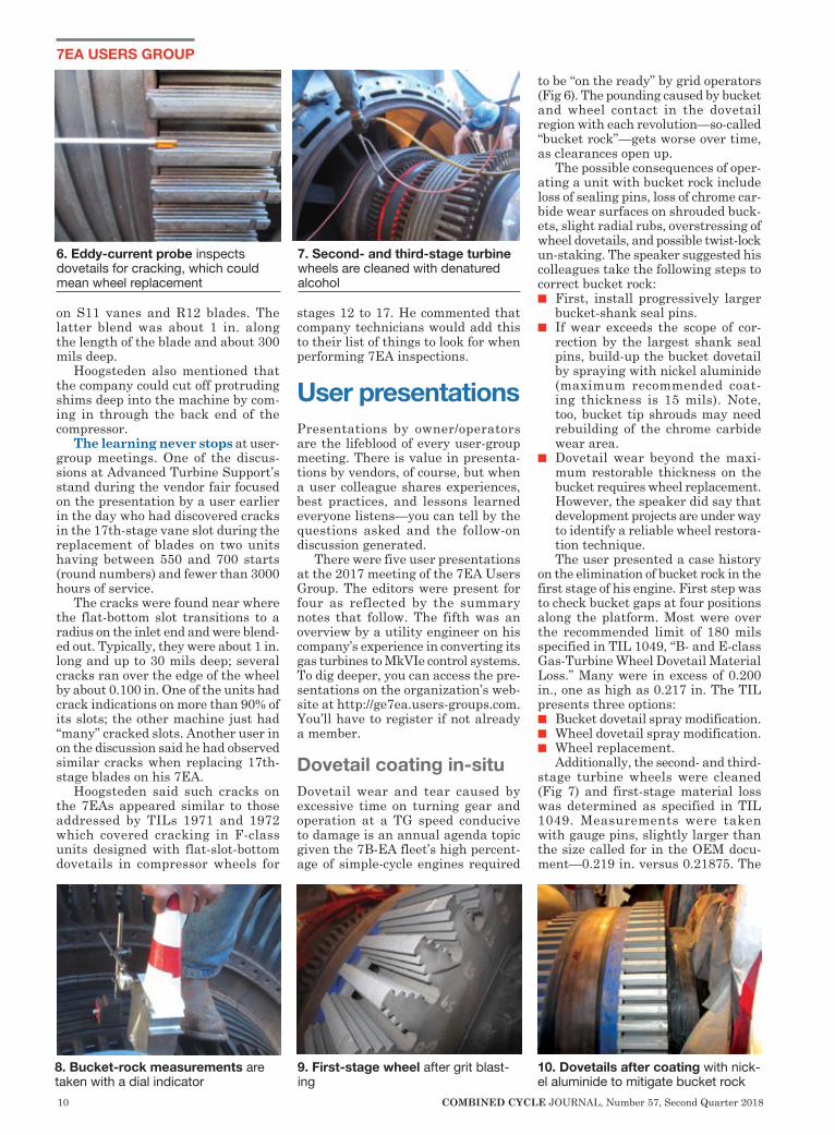
to be “on the ready” by grid operators (Fig 6). The pounding caused by bucket and wheel contact in the dovetail region with each revolution—so-called “bucket rock”—gets worse over time, as clearances open up.
The possible consequences of oper-ating a unit with bucket rock include loss of sealing pins, loss of chrome car-bide wear surfaces on shrouded buck-ets, slight radial rubs, overstressing of wheel dovetails, and possible twist-lock un-staking. The speaker suggested his colleagues take the following steps to correct bucket rock: n First, install progressively larger
bucket-shank seal pins.n If wear exceeds the scope of cor-
rection by the largest shank seal pins, build-up the bucket dovetail by spraying with nickel aluminide (maximum recommended coat-ing thickness is 15 mils). Note, too, bucket tip shrouds may need rebuilding of the chrome carbide wear area.
n Dovetail wear beyond the maxi-mum restorable thickness on the bucket requires wheel replacement. However, the speaker did say that development projects are under way to identify a reliable wheel restora-tion technique. The user presented a case history
on the elimination of bucket rock in the first stage of his engine. First step was to check bucket gaps at four positions along the platform. Most were over the recommended limit of 180 mils specified in TIL 1049, “B- and E-class Gas-Turbine Wheel Dovetail Material Loss.” Many were in excess of 0.200 in., one as high as 0.217 in. The TIL presents three options: n Bucket dovetail spray modification.n Wheel dovetail spray modification.n Wheel replacement.
Additionally, the second- and third-stage turbine wheels were cleaned (Fig 7) and first-stage material loss was determined as specified in TIL 1049. Measurements were taken with gauge pins, slightly larger than the size called for in the OEM docu-ment—0.219 in. versus 0.21875. The
6. Eddy-current probe inspects dovetails for cracking, which could mean wheel replacement
7. Second- and third-stage turbine wheels are cleaned with denatured alcohol
8. Bucket-rock measurements are taken with a dial indicator
9. First-stage wheel after grit blast-ing
10. Dovetails after coating with nick-el aluminide to mitigate bucket rock

12 COMBINED CYCLE JOURNAL, Number 57, Second Quarter 2018
7EA USERS GROUP
results all were within TIL limits, indicating the wheel had not reached end of life.
Bucket-rock measurements also were taken, using a dial indicator at the side of the platform while manu-ally rocking the bucket to its limit and recording the total indicator travel (Fig 8). Rock recorded at 12 positions on the wheel ranged from 0.138 to 0.160 in. with the average 0.150. The speaker said he was told by a shop person with deep knowledge of rotors that 0.085-in. rock is the targeted value when spray coating a wheel.
The user’s plant opted to spray-coat the first-stage wheel given the engine’s current mode of operation with long periods on turning gear. Fig 9 shows the wheel after grit blasting, Fig 10 after coating with nickel aluminide to mitigate rock. Note that the spray repair took five shifts after buckets were removed; work was done with the rotor in place. New replacement buckets were installed after comple-tion of the spray repair. Plant rates the project a success.
Rotor exchange program Five of the six 7EAs at a 6 × 3 com-bined-cycle cogeneration plant serv-ing an industrial facility were rap-idly approaching the OEM’s stated 200,000-hr maximum rotor life for its baseload frame engines. The machines, all manufactured in 1992, were steam-injected and had averaged 182,741 actual fired hours. The high-hours engine had 188,460 service hours.
The owner evaluated the three rotor-exchange options listed below, considering several vendors in the process. n Purchase both turbine and compres-
sor rotors as new.n Purchase seed rotors (compressor
and turbine) and refurbish based on fired hours of each unit.
n Basic seed-rotor (compressor and turbine) replacement.GE was selected to provide the
seed-rotor exchange program based on rotor availability, cost, refurbishment time, and technological expertise. Key points in the OEM’s program were the following:n Extend 7EA rotor fired hours from
200,000 to 300,000 and starts by 1500 to 5000.
n The OEM would provide two seed rotors, refurbish three of the plant’s rotors, and provide a spare rotor with a storage container. Compres-sor seed rotors would be bladed, turbine rotors would have buckets supplied by the plant and installed at the GE shop.
n A 60-day schedule was planned for
rotor refurbishment.Work scope and other important
details included these:n Full teardown inspection using
ultrasonic, eddy-current, mag-particle, fluorescent penetrant, and visual procedures, plus hardness testing.
n Replace compressor rotor blades in stages 14 to 17.
n Replace compressor turbine, and unit rotor assembly bolting.
n Inspect and repair dovetails in com-pressor wheels 14 to 17, stage-16 rabbet fillets, and stage-17 impeller blades.Note that replacement of compres-
sor stator blades and turbine buckets and nozzles were not included in the rotor exchange project. Any other deficiencies identified in the existing turbine and compressor rotors would be categorized as “extra work.”
Project completion was planned for year-end 2017. At the time of the user-group meeting in October, the extra work—certainly of importance to anyone considering a rotor exchange—included the following: n Field service charges for reaming of
dowel holes and alignment of four units.
n The compressor for one unit was in bad shape and required this addi-tional effort:
● De-blading and re-blading of rows 1 to 13.
● Patch-ring repairs on four rows. ● Turbine rotor rabbet crack
repair. ● New turbine-rotor forward and
aft stub shafts. ● New second-stage compressor
wheel. ● New turbine wheels.n An additional seed rotor made nec-
essary by an unfit-for-duty compres-sor found in one unit.One of the lessons learned: Don’t
expect things to go the way you planned on a project of this magnitude, even having experienced manpower and putting forth maximum effort. You likely will identify issues no one thought possible. Perhaps the biggest surprise here was the finding of exces-sive bucket rock on one of the turbines.
The GE shop reported this for the first stage and the turbine rotor was returned to the plant without buck-ets, the owner believing a new set of first-stage buckets would correct the problem. It didn’t. Plan B was to have the new buckets coated to reduce the dovetail gap. But on further inspection, excessive rock also was found in the second and third stages. In the end, all three turbine wheels were replaced at significant extra cost.
A table presented by the speaker
showed that the outage time projected for the unit with the wrecked compres-sor (last bullet point above), budgeted at 720 hours, would actually be about 4000 hours (unit overhaul had not been completed before the meeting). For the other engines, the actual outages wound up taking an average of 40% more hours than planned, in round numbers.
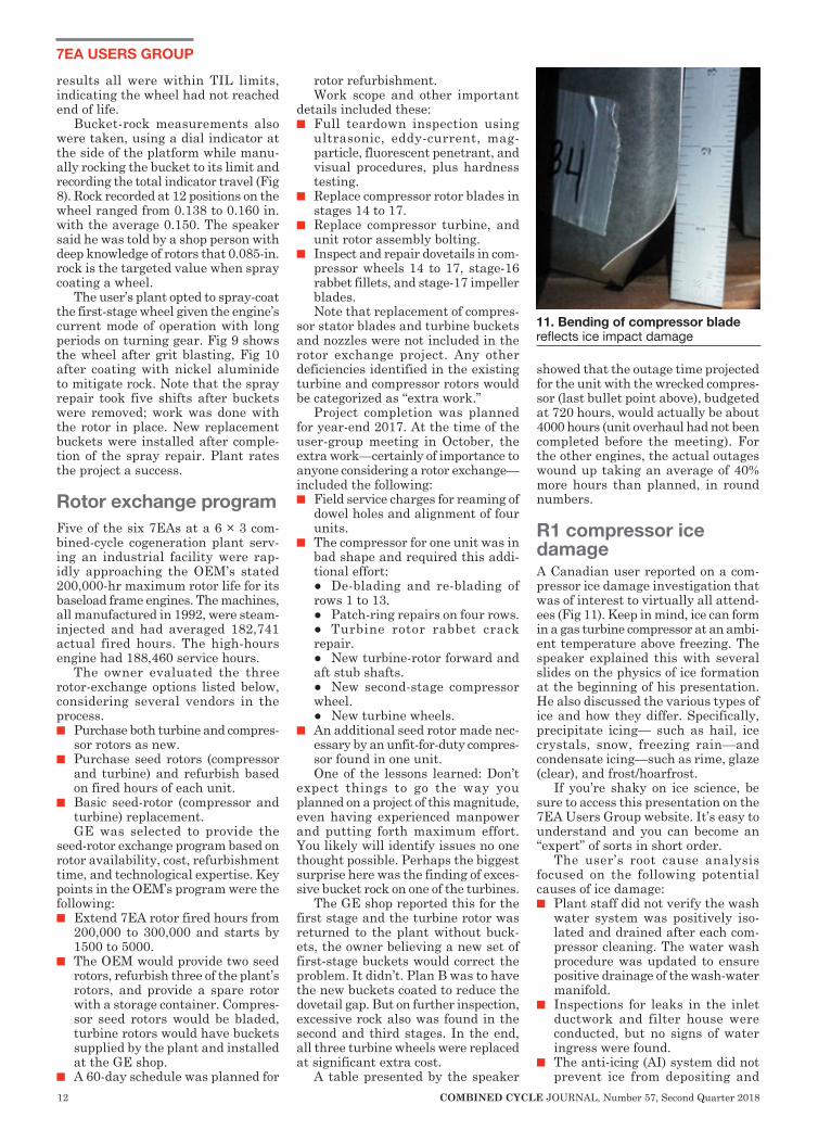
R1 compressor ice damage A Canadian user reported on a com-pressor ice damage investigation that was of interest to virtually all attend-ees (Fig 11). Keep in mind, ice can form in a gas turbine compressor at an ambi-ent temperature above freezing. The speaker explained this with several slides on the physics of ice formation at the beginning of his presentation. He also discussed the various types of ice and how they differ. Specifically, precipitate icing— such as hail, ice crystals, snow, freezing rain—and condensate icing—such as rime, glaze (clear), and frost/hoarfrost.
If you’re shaky on ice science, be sure to access this presentation on the 7EA Users Group website. It’s easy to understand and you can become an “expert” of sorts in short order.
The user’s root cause analysis focused on the following potential causes of ice damage:n Plant staff did not verify the wash
water system was positively iso-lated and drained after each com-pressor cleaning. The water wash procedure was updated to ensure positive drainage of the wash-water manifold.
n Inspections for leaks in the inlet ductwork and filter house were conducted, but no signs of water ingress were found.
n The anti-icing (AI) system did not prevent ice from depositing and
11. Bending of compressor blade reflects ice impact damage

AdvancedTurbineSupport.com Follow Us on Linkedin
Scheduling & Technical Information Michael Hoogsteden, Director Of Field [email protected]
Business Administration & EstimatesChris McGinley, Operations Manager352.231.5284352.231.5284cmcginley@advancedturbinesupport.com
Report Reviews & RecommendationsBrett Fuller, Field Service [email protected]
Owner Contact InformationRod Shidler, President/Owner352.302.2364352.302.2364rshidler@advancedturbinesupport.comRick Ginder, CEO/ [email protected]
Advanced Turbine Support has strong alliances with multiple, respected turbine and generator repair service providers. This, coupled with the knowledge and experience gained by performing thousands of inspections annually, ensures we deliver critical information to optimize your turbine’s reliability and efficiency.
Discover the Power of Experience, Technology & Proactive Onsite Assessments.
24-Hour World-Wide
Support
Your TRUSTED One-Source Inspection Provider.The Industry Leader in Experienced & Accurate Combustion & Steam Turbine, Generator Borescope & In-Situ NDE Inspections.
Now Offering:• High-Temperature Borescope Inspections• In-Situ Aft Compressor Blending• Part Retrieval• Turbine Disk & Compressor Steam Cleaning
14 COMBINED CYCLE JOURNAL, Number 57, Second Quarter 2018
7EA USERS GROUP
growing on air-intake surfaces. The details in the slides specific to the GE system are recommended view-ing for anyone with a similar system and issues, and anyone planning on protecting his or her plant’s gas turbines in this manner. The AI portion of the presentation
began with a description of the inputs to the control system (inlet tempera-ture and humidity) used by GE de-icing logic to control the inlet bleed heat (IBH) charged with preventing ice formation. Problems identified included the following:n Thermocouple noise, which was an
easy fix by enabling a low-pass filter in the software (this is defaulted in normal control when the system is set up).
n Poor IBH valve control because of the installed position feedback on the positioner. An upgraded valve positioner solved this problem.
n Dew-point sensors were supplied by the OEM with the wrong range software. The instrument manufac-turer corrected this by increasing the dwell time through the auto-purge sequence of the humidity sensor. During the ensuing discussion it
became apparent that the de-icing control provided by GE did not shut off until the ambient temperature rose above the set point—about 40F. The ambient temperature falling below the ice-formation temperature (too cold to carry moisture that would form ice) did not shut off the IBH (running at about 10%), regardless of how much colder it got. This results in a signifi-cant reduction in efficiency and output when operating at cold temperatures outside of the ice-formation physics.
Best practice: A user commented during the discussion that he and his colleagues had found a significant water entry point in the inlet duct-work. The bolting supplied during unit installation for clamping flange gaskets on the inlet “key” slot was bottoming out and not properly sealing the joint when the flange bolts were torqued. This permitted water entry into the inlet duct which could cause icing at low ambient temperatures.
Clashing update, rotor cracking A user with perhaps more experience on clashing in 7EA compressors than anyone else in attendance reported
that one of his affected units was ret-rofitted with GE’s new-design S1 and S2 blades and showed no evidence of clashing after 42 fired starts in the last year. Photos revealed pristine airfoils.
He also reported R17 flat-bottom slot cracks on two 2001-vintage units. One had 2877 fired hours, 675 starts, and 24 trips, the other 2490 fired hours and 557 starts. The latter had indica-tions of similar length in 51 of the 56 slots. Very little blending was needed to remove them.
RoundtablesIn 7EA Users lingo, “roundtable” is essentially a panel discussion. This differs from CTOTF™, where the term essentially means “session.” Semantics aside, the 2017 meeting of the 7EA Users Group featured two two-hour roundtables, one on bus duct, the other on rotor life management.
The way these sessions are arranged, participating vendors are seated at the front of the meeting room, owner/operators in the audience. To begin, each of the vendors reviews its capabilities on the topic at hand and after introductory comments are completed the moderator, a member of the group’s steering committee, ignites discussion and steers user questions to one or more of the panelists.
Bus ductThe Bus Duct Roundtable, chaired by Guy LeBlanc of First Energy Corp, fea-tured these four vendor participants:n Bruce Hack, Crown Electric Engi-
neering & Manufacturing LLC.n Jesus Davila, RMS Energy Co.n Jeffrey Andle, Emerson IntelliSAW.n Gary Whitehead, Electrical Build-
ers Inc.Snippets of information gleaned
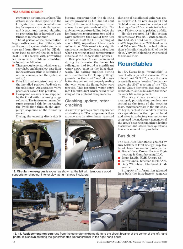
from both the introductory remarks 12. Circular non-seg bus is robust as shown at the left with temporary wood supports for shipping. Interior view at right shows insulators
13, 14. Replacement non-seg runs from the generator (extreme right) to the circuit breaker at the center of the left-hand photo; it is shown entering the generator step-up transformer in the right-hand photo
Cutsforth.com/Contact800.290.6458 [email protected]
For more information, contact us:
GOODBYE MANUAL MEASUREMENTS.
HELLO ASSURANCE
MONITORING.Cutsforth is grounded in real-world solutions. Cutsforth Shaft Grounding and Assurance Monitoring provides real-time voltage, current and ground rope status sent to your control room, or you can collect the readings at the Display Panel safely located near the generator. It’s the quick, easy, and safe way to know — really know — the generator is properly grounded.
And it’s only from Cutsforth.
Learn more atCutsforth.com/ShaftGrounding
Shaft Grounding AssemblyDual Shaft Grounding Ropes
CFI-GEN-00007_v3.indd 1 1/22/18 9:33 AM
16 COMBINED CYCLE JOURNAL, Number 57, Second Quarter 2018
7EA USERS GROUP
made by each of the panelists and the open discussion are summarized in the bullet points below. For the most part, they reflect best practices and lessons learned.
n Traditional non-segregated-phase bus duct (a/k/a non-seg) failure events are far too frequent and often can become catastrophic. Recall that non-seg has all three phases in a common enclosure (Fig 12). In Fig 13, non-seg runs from the generator at the extreme right to the generator circuit breaker in the center of the picture and then to an auxiliary transformer (not shown). Fig 14 shows non-seg entering the generator step-up transformer.Traditional non-seg bus is made up
of bolted rectangular sections—each section is a repetition of weak con-nections conducive to failure (Fig 15). Every bolted-section joint and bolted-conductor joint is a point where loos-ening can occur because of vibration and/or thermal cycling.
In his opening remarks, Crown Electric’s Bruce Hack noted that Westinghouse Electric Corp, which made both gas turbines and bus duct, understood the failure-prone problems of traditional non-seg when applied to gas-turbine applications and specifi-cally developed circular non-seg bus
duct (CNSB) to address these issues. Crown Electric is the direct successor to the Westinghouse CNSB design.
Hack said CNSB is built just like isolated-phase (iso-phase) bus, except it is non-seg. Its welded aluminum housing has no sectional joints to fail, thereby protecting against all environmental conditions. Plus, it surrounds and supports Crown’s extruded aluminum conductors, which are air-insulated, eliminating the need for sleeve insulation prone to rubbing, cracking, tracking, and in the extreme, failure.
The conductors are supported by porcelain stand-off insulators, which may be optionally specified with a dew-point rating. Thus, potential heating issues related to moisture control are avoided.
In bus-duct replacement projects, the circular non-seg often can mount right on the existing steel structural supports. To illustrate: The circular non-seg shown in Figs 13 and 14 was installed on the same steel that sup-ported the Fig 15 rectangular bus that it replaced.
Crown Electric’s non-seg retrofits were given two-thumbs-up by multiple owner/operators, and they noted the more flexible inspection requirements for Crown non-seg compared to at least some alternatives.
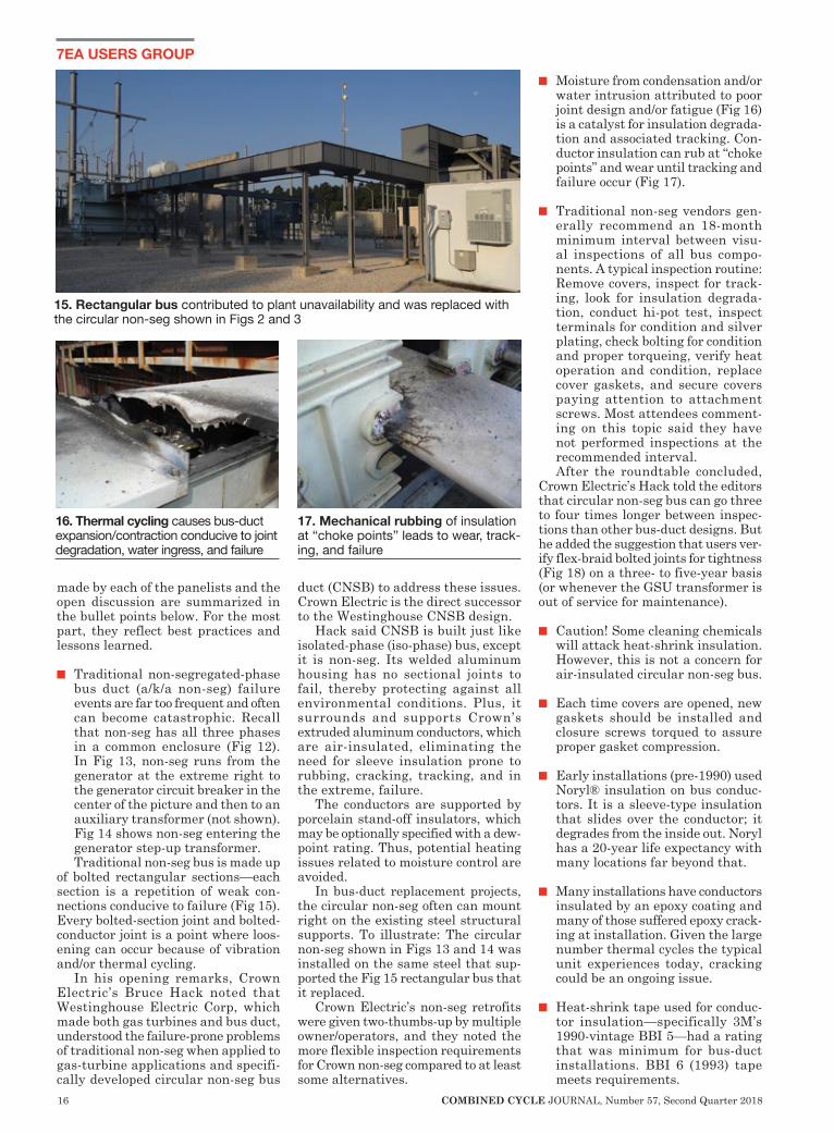
n Moisture from condensation and/or water intrusion attributed to poor joint design and/or fatigue (Fig 16) is a catalyst for insulation degrada-tion and associated tracking. Con-ductor insulation can rub at “choke points” and wear until tracking and failure occur (Fig 17).
n Traditional non-seg vendors gen-erally recommend an 18-month minimum interval between visu-al inspections of all bus compo-nents. A typical inspection routine: Remove covers, inspect for track-ing, look for insulation degrada-tion, conduct hi-pot test, inspect terminals for condition and silver plating, check bolting for condition and proper torqueing, verify heat operation and condition, replace cover gaskets, and secure covers paying attention to attachment screws. Most attendees comment-ing on this topic said they have not performed inspections at the recommended interval. After the roundtable concluded,
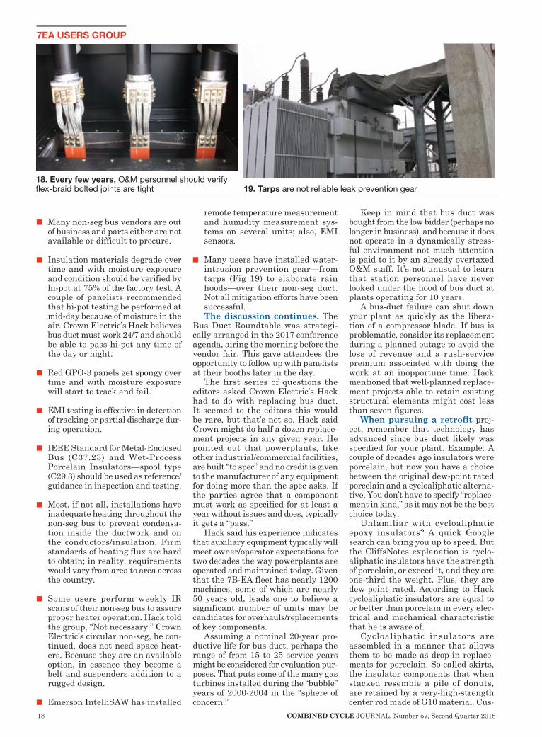
Crown Electric’s Hack told the editors that circular non-seg bus can go three to four times longer between inspec-tions than other bus-duct designs. But he added the suggestion that users ver-ify flex-braid bolted joints for tightness (Fig 18) on a three- to five-year basis (or whenever the GSU transformer is out of service for maintenance).
n Caution! Some cleaning chemicals will attack heat-shrink insulation. However, this is not a concern for air-insulated circular non-seg bus.
n Each time covers are opened, new gaskets should be installed and closure screws torqued to assure proper gasket compression.
n Early installations (pre-1990) used Noryl® insulation on bus conduc-tors. It is a sleeve-type insulation that slides over the conductor; it degrades from the inside out. Noryl has a 20-year life expectancy with many locations far beyond that.
n Many installations have conductors insulated by an epoxy coating and many of those suffered epoxy crack-ing at installation. Given the large number thermal cycles the typical unit experiences today, cracking could be an ongoing issue.
n Heat-shrink tape used for conduc-tor insulation—specifically 3M’s 1990-vintage BBI 5—had a rating that was minimum for bus-duct installations. BBI 6 (1993) tape meets requirements.
16. Thermal cycling causes bus-duct expansion/contraction conducive to joint degradation, water ingress, and failure
17. Mechanical rubbing of insulation at “choke points” leads to wear, track-ing, and failure
15. Rectangular bus contributed to plant unavailability and was replaced with the circular non-seg shown in Figs 2 and 3
18 COMBINED CYCLE JOURNAL, Number 57, Second Quarter 2018
7EA USERS GROUP
n Many non-seg bus vendors are out of business and parts either are not available or difficult to procure.
n Insulation materials degrade over time and with moisture exposure and condition should be verified by hi-pot at 75% of the factory test. A couple of panelists recommended that hi-pot testing be performed at mid-day because of moisture in the air. Crown Electric’s Hack believes bus duct must work 24/7 and should be able to pass hi-pot any time of the day or night.
n Red GPO-3 panels get spongy over time and with moisture exposure will start to track and fail.
n EMI testing is effective in detection of tracking or partial discharge dur-ing operation.
n IEEE Standard for Metal-Enclosed Bus (C37.23) and Wet-Process Porcelain Insulators—spool type (C29.3) should be used as reference/guidance in inspection and testing.
n Most, if not all, installations have inadequate heating throughout the non-seg bus to prevent condensa-tion inside the ductwork and on the conductors/insulation. Firm standards of heating flux are hard to obtain; in reality, requirements would vary from area to area across the country.
n Some users perform weekly IR scans of their non-seg bus to assure proper heater operation. Hack told the group, “Not necessary.” Crown Electric’s circular non-seg, he con-tinued, does not need space heat-ers. Because they are an available option, in essence they become a belt and suspenders addition to a rugged design.
n Emerson IntelliSAW has installed
remote temperature measurement and humidity measurement sys-tems on several units; also, EMI sensors.
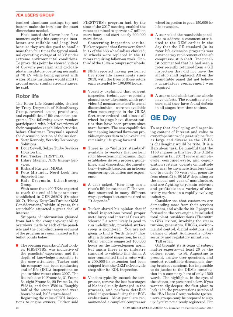
n Many users have installed water-intrusion prevention gear—from tarps (Fig 19) to elaborate rain hoods—over their non-seg duct. Not all mitigation efforts have been successful. The discussion continues. The
Bus Duct Roundtable was strategi-cally arranged in the 2017 conference agenda, airing the morning before the vendor fair. This gave attendees the opportunity to follow up with panelists at their booths later in the day.
The first series of questions the editors asked Crown Electric’s Hack had to do with replacing bus duct. It seemed to the editors this would be rare, but that’s not so. Hack said Crown might do half a dozen replace-ment projects in any given year. He pointed out that powerplants, like other industrial/commercial facilities, are built “to spec” and no credit is given to the manufacturer of any equipment for doing more than the spec asks. If the parties agree that a component must work as specified for at least a year without issues and does, typically it gets a “pass.”
Hack said his experience indicates that auxiliary equipment typically will meet owner/operator expectations for two decades the way powerplants are operated and maintained today. Given that the 7B-EA fleet has nearly 1200 machines, some of which are nearly 50 years old, leads one to believe a significant number of units may be candidates for overhauls/replacements of key components.
Assuming a nominal 20-year pro-ductive life for bus duct, perhaps the range of from 15 to 25 service years might be considered for evaluation pur-poses. That puts some of the many gas turbines installed during the “bubble” years of 2000-2004 in the “sphere of concern.”
Keep in mind that bus duct was bought from the low bidder (perhaps no longer in business), and because it does not operate in a dynamically stress-ful environment not much attention is paid to it by an already overtaxed O&M staff. It’s not unusual to learn that station personnel have never looked under the hood of bus duct at plants operating for 10 years.
A bus-duct failure can shut down your plant as quickly as the libera-tion of a compressor blade. If bus is problematic, consider its replacement during a planned outage to avoid the loss of revenue and a rush-service premium associated with doing the work at an inopportune time. Hack mentioned that well-planned replace-ment projects able to retain existing structural elements might cost less than seven figures.
When pursuing a retrofit proj-ect, remember that technology has advanced since bus duct likely was specified for your plant. Example: A couple of decades ago insulators were porcelain, but now you have a choice between the original dew-point rated porcelain and a cycloaliphatic alterna-tive. You don’t have to specify “replace-ment in kind,” as it may not be the best choice today.
Unfamiliar with cycloaliphatic epoxy insulators? A quick Google search can bring you up to speed. But the CliffsNotes explanation is cyclo-aliphatic insulators have the strength of porcelain, or exceed it, and they are one-third the weight. Plus, they are dew-point rated. According to Hack cycloaliphatic insulators are equal to or better than porcelain in every elec-trical and mechanical characteristic that he is aware of.
Cycloaliphatic insulators are assembled in a manner that allows them to be made as drop-in replace-ments for porcelain. So-called skirts, the insulator components that when stacked resemble a pile of donuts, are retained by a very-high-strength center rod made of G10 material. Cus-
18. Every few years, O&M personnel should verify flex-braid bolted joints are tight 19. Tarps are not reliable leak prevention gear

Expert Analysis, Filtration, and Flushing
Treat your turbine like
it was your ownCCJ Reader access:
www.cleanoil.com/likeitwasyourown
20 COMBINED CYCLE JOURNAL, Number 57, Second Quarter 2018
7EA USERS GROUP
tomized aluminum castings top and bottom make the insulator the exact dimensions needed.
Hack tooted the Crown horn for a moment saying his company’s insu-lators are reliable and long-lived because they are designed to handle more than four times the typical nomi-nal operating voltage of 15 kV under extreme environmental conditions. To prove this point he showed videos of Crown’s porcelain and cycloali-phatic insulators operating normally at 70 kV while being sprayed with water. Many insulators would short to ground under similar circumstances, he said.
Rotor lifeThe Rotor Life Roundtable, chaired by Tracy Dreymala of EthosEnergy Group, covered issues, procedures, and capabilities of life-extension pro-grams. The following seven vendors participated with brief overviews of their companies’ capabilities/activities, before Chairman Dreymala opened the discussion portion of the session:n Scott Kennedy, Veracity Technology
Solutions.n Doug Sewell, Sulzer Turbo Services
Houston Inc.n Paul Tucker, FIRST/TBS.n Hilary Magner, NRG Energy Ser-
vices.n Richard Rucigay, MD&A.n Pete Miranda, Nord-Lock Inc/
Superbolt Inc.n Kale Dreymala, EthosEnergy
Group.With more than 400 7EAs expected
to reach the end-of-life parameters established in GER-3620N (October 2017), “Heavy-Duty Gas Turbine O&M Considerations,” within 10 years, this roundtable attracted a great deal of interest.
Snippets of information gleaned from both the company-capability overviews made by each of the panel-ists and the open-discussion segment of the program are summarized in the bullet points below.
n The opening remarks of Paul Tuck-er, FIRST/TBS, was indicative of the panelists’ experience and the depth of knowledge accessible to the user attendees. Tucker said his company has been conducting end-of-life (EOL) inspections on gas-turbine rotors since 2007. The list includes: 10 Frame 3s, 31 Frame 5s, eight Frame 6s, 20 Frame 7s, six W251s, and four W501s. Roughly half of the rotors inspected were hours-based, half starts-based.Regarding the value of EOL inspec-
tions to engine owners, Tucker said
FIRST/TBS’s program had, by the time of the 2017 meeting, enabled the rotors examined to operate 4.7-million more hours and start nearly 200,000 more times.
Concerning inspection results, Tucker reported that flaws were found in 17 of the 563 wheels/discs checked; 13 wheels were replaced in the 11 rotors requiring follow-on work. One-third of the 13 were compressor wheels.
n NRG reported having performed five rotor life assessments since 2013, with the lives of those rotors each extended by 100,000 hours.
n Veracity explained that current inspection techniques—especially phased-array ultrasonic, which pro-vides 3D measurements of internal discontinuities—were not available when most engines in the 7B-EA fleet were ordered and almost all wheel forgings have discontinui-ties that have been present since manufacture. The new capabilities for mapping internal flaws can pro-vide engineers data to help calculate remaining life going forward.
n There is no “industry standard” available to vendors that perform rotor life-extension programs. Each establishes its own process, guide-lines, and disposition documenta-tion—typically based on an in-house engineering evaluation and experi-ence.
n A user asked, “How long can a rotor’s life be extended?” The ven-dors answered in many different ways, perhaps best summarized as “It depends.”
n Tucker shared his opinion that if wheel inspections reveal proper metallurgy and internal flaws are “cleared,” a rotor likely is good to run indefinitely, provided surface creep is monitored. You are not going to find a “birth defect” flaw after a detailed inspection, he said. Other vendors suggested 100,000 hours as the life-extension norm, but again there is no industry standard to validate this claim. A user commented that a rotor with a 200,000-hr extension had been shipped from the OEM’s Greenville shop after its EOL inspection.
n Vendors typically unstack the com-pressor, remove the last four stages of blades (usually damaged in the process), and perform detailed wheel inspections during their EOL evaluations. Most panelists rec-ommended a complete compressor
wheel inspection to get a 150,000-hr life extension.
n A user asked the roundtable panel-ists to address a comment attrib-uted to the OEM earlier in the day that the GE standard (in its rotor life-extension program) was a mandatory replacement of the aft compressor stub shaft. One panel-ist commented that he had seen a rotor recently returned from a GE inspection that did not have the aft stub shaft replaced. All on the roundtable panel did not believe a mandatory replacement was required.
n A user asked which turbine wheels have defects. The roundtable ven-dors said they have found defects in all stages from time to time.
GE DayTo say that developing and organiz-ing content of interest and value to owner/operators of a gas-turbine fleet as large and diverse as the 7B-EA is challenging would be trite. It is a Herculean task. Be mindful that the 1168 engines in this fleet (the OEM’s number in fall 2017) serve in simple-cycle, combined-cycle, and cogen-eration systems, operate on multiple fuels, may be anywhere from less than one to nearly 50 years old, generate from about 52 to 90 MW depending on the model and year of manufacture, and are fighting to remain relevant and profitable in a variety of elec-tricity markets in a rapidly evolving industry.
Consider too that customers are demanding more from their services partners, and while the 2017 program focused on the core engine, it included total plant considerations (Fleet360* in GE’s lexicon) involving the steam turbine, generators, HRSGs, environ-mental control, digital solutions, and balance of plant. Additionally, cyber-security and regulatory initiatives.
Tall order. GE brought its A-team of subject
matter experts—at least 20 by the editors’ count—to St. Augustine to present, answer user questions, and conduct roundtable discussions dur-ing breakout sessions. It’s impossible to do justice to the OEM’s contribu-tion in a summary here of only 1500 words. The highlights, in the eyes of the editors, are presented below. If you want to dig deeper, the first place to look is in the presentations section of the 7EA Users Group website (ge7ea.users-groups.com); be prepared to sign up if you’re not already registered. For
WWW.JASC-CONTROLS.COMTel: +1 602.438.4400 Fax: +1 602.438.4420
Maximum ReliabilityMaximum ReliabilityWater Cooling Technology Provides Increased Operating
Intervals Between Liquid Fuel Runs
WWW.JASC-CONTROLS.COMTel: +1 602.438.4400 Fax: +1 602.438.4420
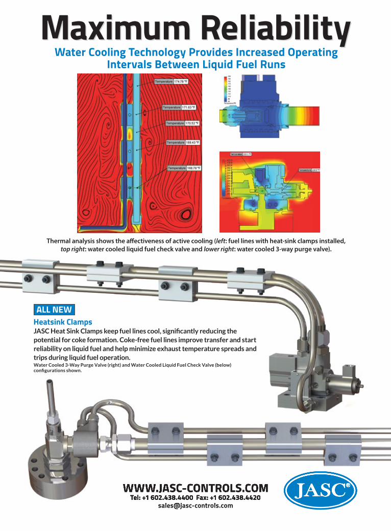
JASC Heat Sink Clamps keep fuel lines cool, significantly reducing the potential for coke formation. Coke-free fuel lines improve transfer and start reliability on liquid fuel and help minimize exhaust temperature spreads and trips during liquid fuel operation.Water Cooled 3-Way Purge Valve (right) and Water Cooled Liquid Fuel Check Valve (below) configurations shown.
Heatsink ClampsALL NEW
Thermal analysis shows the a�ectiveness of active cooling (left: fuel lines with heat-sink clamps installed, top right: water cooled liquid fuel check valve and lower right: water cooled 3-way purge valve).
22 COMBINED CYCLE JOURNAL, Number 57, Second Quarter 2018
7EA USERS GROUP
more information, reach out to your plant’s customer service rep.
Perhaps the two most significant announcements made during GE Day, which began after morning coffee Tuesday and ran until OEM’s “Open House” (dinner and exhibition) at 5 pm, concerned GE’s revamped field-service operation and a change in the rotor maintenance-factor cal-culation.
Field services. Regarding the first point, the OEM essentially sev-ered its field-service employees from GE employment in August 2017 and allowed most of them to interview for positions in its wholly owned subsid-iary, FieldCore, which aggregated the field-service resources from GE Power Services and Granite Services International Inc—at least that’s the way the editors understand the organizational changes. Note that Atlantic Plant Maintenance, a wholly owned affiliate business of GE Power Services that provides craft labor in the US and Canada, was not rolled into FieldCore.
The users were told during the GE-sponsored evening reception that they should continue to contact their regu-lar GE rep to arrange for field-service support. Billing will continue to be directly through GE to the customer. The FieldCore regional GM address-ing the group said his organization would continue to provide quality field-service support to/for GE while driving down costs.
There was significant chatter among users during coffee breaks regarding the shift to FieldCore. As you might expect, most of the discus-sions were negative: Change is difficult for most people to accept without at least some grumbling. Attend the 2018 meeting of the 7EA Users Group in California, October 7-11, to learn more about the transition of field services to FieldCore and how its processes are changing to better suit the customer.
Forced cooling. Shortly before the 2017 meeting, GE published Revision N to its “Heavy-Duty Gas Turbine Operation and Maintenance Con-siderations (GER 3620),” introduced nearly three decades ago. It generally is recognized as the company’s “bible,” providing frame owner/operators guidance on O&M tradeoffs for the company’s engines.
It’s important for users to obtain a copy of this document (access via Google) and to keep up with future revisions—you never know what surprises it may have. In Revision N, the change creating the most concern among owner/operators is believed to be the one related to the impact of forced cooling on the rotor mainte-
nance factor. It states that should an operator
force-cool a unit after operation, there will be a 4× impact on the maintenance factor for that start. An OEM represen-tative said this applies to E-class units and defined forced cooling as cranking a gas turbine (after a start/run) for an extended period of time at more than 60 rpm. “Extended” was not defined in terms of hours.
Also said was that the maintenance-factor calculation for forced cooling had to be “back calculated” in determining “factored starts” for rotor maintenance actions.
Owner/operators of legacy E and EA models with cranking turning gears (versus ratchet-type turning gears) and cranking speeds above 60 rpm to avoid bucket-rock damage should take a deep breath: A significant addition to the number of factored starts will occur.
Until now it has been “routine” for many plants to force-cool their gas turbines to reduce the time required for maintenance outages and offline compressor washing. This new calcu-lation suggests operators might want to rethink their cooldown procedures. Also, staff at affected plants should review operating logs to determine how the new calculation impacts their rotor-inspection schedule. Presenta-tions at various user-group meetings indicate a two- to three-year planning phase may be required and it’s possible you’re now late getting started.
More bad news: The unit trip fac-tor is now 2×.
NERC requirements. “Respond-ing to NERC MOD and PRC Stan-dards” was another presentation containing information you might not want to be reminded of, but necessary. It covered the required testing and model validation required to comply with standards that would be July 2018 enforceable. Obviously, that date has already passed. So if some of what follows comes as a surprise to you, it’s a good idea to learn quickly and bring your plant up to current requirements.
The first part of the presentation focused on testing that should be con-ducted to understand the capability of your equipment and to get the most from it. This is an important step to assure full compliance with NERC standards. The speaker reminded that manufacturer “design” may have a wide range of “normal” and retun-ing of controller settings or retrofit of late-model digital controllers may result in significant deviation from “book ratings.”
Additional benefits of testing include the following:
n Recognition of deviations, enabling a refinement in tuning.
n Better coordination with protection systems.
n More effective training of staff because of testing at the bounds of control—that is, non-normal oper-ating modes. NERC model validation standards
reviewed were these:n MOD-025-2, “Verification of Gen-
erator/Plant Real and Reactive Capability.” Requirements include verification of the maximum con-tinuous real power output and lagging and leading reactive power outputs; calculation of transformer losses; analysis of test results and manufacturer’s stated limits; sub-mission of data reporting forms; documentation of auxiliary load consumption.
n MOD-026-1, “Verification of Dynamic Models and Data for Generator Excitation Control and Plant Volt-VAr Control Functions.” Requirements include submission of an excitation control system description, and of an approved model for the generator, exciter, power system stabilizer, and plant volt/VAr controls. Plus, verification that the model simulation matches the response from a disturbance.
n MOD-027-1, “Verification of Dynamic Models and Data for Turbine/Governor and Load Control or Active Power/Frequency Control Functions.” Requirements include submission of a description of the governor and load control system, and of an approved model for the governor and plant active power controls. Plus, verification that the model simulation matches the response from either a significant disturbance or an online speed gov-ernor step test. So much for the details. To learn
more about applicability and timing of the model validation standards, access the presentation on the 7EA Users Group website. Keep in mind that the generation owner is responsible for model validity; also that one size does not fit all: applicability differs in the East, WECC, and Ercot, as does the timing of compliance.
Typical tests were profiled by the presenter and test-equipment require-ments were defined, followed by analy-sis and reporting requirements. If you feel overwhelmed after reviewing all the things you’re responsible for beyond safety, top availability, high starting reliability, low heat rate, etc, you can turn to GE Energy Consult-ing for help. The short promotional section of the presentation mentioned this group has tested more than 1500

24 COMBINED CYCLE JOURNAL, Number 57, Second Quarter 2018
7EA USERS GROUP
units and has experience with all major OEM equipment.
Technical Information Letters. A review of the latest TILs is always of value. It’s easy to miss communi-cations on these important missives during busy periods. The four TILs highlighted at the 2017 meeting were these:n TIL 2046 describes DLN1 purge-
valve operating issues (potential gas backflow into the wrapper) and actions to mitigate them.
n TIL 2028 provides control settings for Reuter Stokes flame sensors. Be aware that false flame detection is possible if the threshold is set too low, resulting in unburned fuel delivery.
n TIL 2025 addresses dry GE Reuter Stokes Model FTD325 flame-scan-ner false indication on shutdown.
n TIL 2044 addresses dry GE Reuter Stokes Model FTD325 flame-scan-ner false indication while offline. A session on typical B- and E-class
rotors revealed the following findings:n R-17 compressor vane migration
has been attributed to staking vari-ability. A new standardized method of staking has been implemented. It notches the R17 vane near the center of the wheel and wheel mate-rial is moved into the notch on the vane.
n TIL 1049 regarding history and recommended checks for wear on turbine-wheel dovetails was discussed. Repair personnel were reminded to check platform gaps, and if they are “out of band” then perform a “pin check.”
Vendor presentations Presentations by suppliers expose users to new technologies and solutions for improving unit performance and personnel safety, providing valuable perspective on topics of importance. At the 2017 7EA Users Group meeting, 27 companies interfaced with owner/operators from the podium. There was GE Day (p 20), the Bus Duct Roundta-ble (p 14), the Rotor Life Roundtable (p 20), and more than a dozen individual presentations. Plus, the vendor fair brought users face-to-face with more than a hundred product/services pro-viders on Wednesday evening.
Steering-committee members know how sensitive their colleagues are to sales pitches, so presentations are invited, then vetted to eliminate more than expected horn-tooting. Inviting experts to address specific topics mini-mizes duplication of subject matter
and expands the learning experience. Subjects covered in last year’s
vendor presentations included the following: gas-turbine inspection (p 6), DLN-1 troubleshooting, controls issues, fuel systems, training, genera-tor circuit breakers (p 28), rewinding of generators, coupling best practices, exhaust-plenum improvements, con-trol-system tuning, generator diagnos-tic, air filters, and actuator overhaul.
Quite a lineup for sure and what you can expect at the 2018 meeting. Register today at http://ge7ea.users-groups.com. Short summaries of sev-eral 2017 presentations selected by the editors for coverage are below. To dig deeper, and to access other Power-Points, visit the user group’s website. You’ll have to register if not already a member.
“Troubleshooting DLN-1 Primary Re-Ignitions,” Mitchell Cohen, Tur-bine Technology Services Corp.
Mitch Cohen, one of the industry’s leading experts on the DLN-1 combus-tion system, always has been ready to share his considerable knowledge with 7EA owner/operators. CCJ has been covering Cohen’s presentations since he spoke on DLN-1 basics at the 2007 meeting of the 7EA Users Group in San Francisco. To access, visit www.ccj-online.com and use the search fea-ture provided. If you are new to the industry and the DLN-1 you might want to begin there; it’s a valuable backgrounder.
At the 2017 meeting in St. Augus-tine, Cohen spoke to the causes of primary re-ignition (PRI) and how to mitigate this operational anomaly. Operators should be concerned about primary re-ignition, he told the group, because it can move the engine out of emissions compliance; plus, extended lean-lean operation causes excessive heating of the venturi in the combus-tion liner and incurs a 10× mainte-nance factor (TIL-1443 R2).
Cohen listed the following as pos-sible causes of primary re-ignition:n Spontaneous, unexpected ignition
source in the primary zone—such as lube oil, hydrocarbon liquids in fuel gas, distillate in dual-fuel machines, and combustible matter in air (dry grass, for example). The speaker identified several common materials that might be drawn into the inlet duct through breaches in inlet filters or ductwork, or acci-dently left inside the machine dur-ing an outage, with auto-ignition temperatures below the compressor discharge temperature.
n System instability—fuel, air, com-bustion dynamics; or an instability induced by faulty or mis-calibrated
instrumentation. Cohen said PRIs after transfer from liquid fuel are relatively common. A possible rem-edy: Implement a temporary, high-er-pressure purge in primary and lean-lean mode after fuel transfer.
He also mentioned that wiring problems in the Mark V cabinet (so-called wire whiskers) are known to have spuriously energized the igni-tion transformer, thereby causing re-ignition. Plus, don’t overlook the possibility of a faulty P-2 transmit-ter: It can cause a hiccup in speed-ratio-valve control.The most common cause of PRI
during fuel transfer was said to be improper timing of purge valves. The specified opening time is 35 ± 5 sec-onds. Slow opening minimizes load and temperature spikes, while rapid opening (8.5 seconds) expels residual transfer fuel unevenly and in a slug-like manner causing a large load spike and high exhaust spread. The latter triggers the spark plug to fire, trans-ferring to lean-lean extended mode. n Powering up of spark plugs, initi-
ated by control-logic response to an alarm/fault condition such as high exhaust spread, thereby igniting a combustion source in the primary zone. Bear in mind that DLN-1 spark plugs cannot be retracted and that insertion depth is criti-cal. Check the depth after a main-tenance outage. Inserting a plug too far will burn up the tip and the spark plug will act as a glow plug to re-ignite primary fuel during the fuel transfer process.
n Sub-optimal tuning.
“Considerations for the Rewind of Highly Cycled 7A6 Generator Rotors,” W Howard Moudy, National Electric Coil.
Howard Moudy is a frequent pre-senter at user-group meetings and gen-erally held in high esteem by owner/operators both for his knowledge of things generator and his willingness to share what he knows. Over the last several years, Moudy’s 7EA User Group presentations have focused on a variety of concerns with the 7A6 gen-erators typically married to the 7EA, including the following:n Stator failures traced to housing
leaks.n Stator-winding partial discharge.n Rotor main lead failure.n Stator endwinding looseness (dust-
ing and greasing).n Rotor-turn insulation migration.n Rotor copper elongation and fore-
shortening. The speaker moved quickly through
his review to allow maximum time for coverage of the requested topic:
26 COMBINED CYCLE JOURNAL, Number 57, Second Quarter 2018
7EA USERS GROUP
rewinding of highly cycled 7A6 gen-erator rotors. You can come up to speed on the subjects listed above with simple keyword searches in the online archives of CCJ and the International Generator Technical Community Forum (www.generatortechnicalfo-rum.org).
Moudy set the stage for his pre-sentation with this brief introduction:n The rotor is the primary generator
component most affected by cycling.n Many generators, the 7A6 in par-
ticular, were not designed for cyclic operation.
n Rotational forces, or cyclic loading, can fatigue rotor components—especially those not designed for cycling.
n Rotor endwindings not designed for cyclic operation can be modified and rewound to better withstand this demanding service environment and provide long-term reliable operation.
The last bullet point was the segue to Moudy’s 2017 presentation. Key points he made:n 7A6 rotors are experiencing issues
in the rotor main lead, and crack-ing of the 90-deg right-angle-turn joint assembly of the coils, because of fatigue attributed to cycling. First step in avoiding a forced out-age: Have a qualified technician borescope the main leads of your generators—regularly.
n NEC reported having a coil-forming process to avoid the 90-deg right-angle turns on coils by forming a bend in the copper to eliminate the right-angle joint. The speaker also mentioned migra-
tion of rotor-winding turn insulation because of insufficient bonding, noting the potential value of borescoping for identifying possible issues. Plus, he said poor design of the end-turn block-ing contributed to copper elongation and foreshortening issues.
Finally, Moudy suggested that users read IEEE C50.13 to learn more about the terminology used in lifecycle investigations and better understand what their machines are capable of in terms of start/stop cycles, in baseload and peaking service, etc.
“7EA Marriage Flange Load Cou-pling Hardware Solution,” Pat McCormack, Riverhawk Company.
Pat McCormack spoke to hardware issues associated with the 7EA mar-riage flange (turbine to compressor) and load coupling, and proven solu-tions. For example, marriage-flange bolting often is difficult to remove because of galling. Galled threads cause the hardware to seize, requiring that the bolts be cut off, which can add to outage time. Turnaround costs are increased as well because new hard-ware is required.
Recommended solution: Use hydraulically stretched bolting for the
DCS data can pinpoint avoidable, damaging thermal transients in HRSGsHeat-recovery steam generators (HRSGs) are sometimes ignored by personnel at plants powered by GE Frame 7 E-class gas turbines—pri-marily 7Bs, 7Es, and 7EAs. The 7EA Users Group, with which you are most familiar, focuses on “things engine,” leaving solutions for other major equipment—including HRSGs and steam turbines—up to others.
There are more boilers and steam turbines serving in plants with Frame 7 E-class GTs than you might imag-ine. At the 2017 7EA Users Group meeting, GE said the fleet totaled 1168 engines, with about two-thirds of those in simple-cycle service. About half of the remaining machines are in cogen systems. Another 140 units are integrated into combined cycles, the remainder mostly drive compressors in LNG plants. Given this information, the editors put the number of HRSGs supporting the 7B-EA fleet at about 325; two-thirds of those are in the US.
Perhaps the best open source of practical O&M problem-solving information on boilers is the HRSG Forum with Bob Anderson, which meets next at the Hilton Orlando, July 22-24, 2019. This meeting will bring you up to date on HRSG issues and solutions worldwide given the Forum’s affiliation with user groups in Australia/New Zealand, Canada, Europe, and Russia. Plus, Anderson, a respected and active industry con-sultant specializing in boiler work, brings first-hand insights to Forum discussions based on the scores of
HRSG surveys he has conducted around the globe.
Anderson told the editors that HRSG owners and operators, in par-ticular those affiliated with plants built prior to and during the gas-turbine “bubble” (2000-2004), often traced pressure-part failures—superheater/reheater tubes and steam-pipe girth welds, for example—to attemperator overspray. A common root cause: Controls configured as a simple feed-back loop instead of the cascade control scheme typically required, and operator intervention by lowering the attemperator setpoint.
Anderson recalled that a few years ago, after many operators had improved their control logic, he noticed leaking spray water when an attemperator was supposed to be out of service and believed that was causing most of the trouble. Ander-son found many attemperators with chronic and/or severe leaking prob-lems used valve-protective logic that opened and closed the block valve each time after and before, respec-tively, the control valve opened and closed.
The intention of this “master control valve/martyr block valve” logic was to protect the seat in the expensive control valve from dam-age caused by opening and closing against the high differential pressure across the valve. In other words, let the block valve take the damage in an attempt to protect the control-valve seat.
Anderson has for years been tell-
ing anyone who would listen (includ-ing attendees at the 2018 HRSG Forum) that use of such logic in a unit where the attemperator comes into and out of service frequently ensures the block valve’s seat will be damaged quickly, allowing leak-by. Damage to the control valve’s seat then occurs because the block valve can no longer isolate it from high dif-ferential pressure. The large number of leaking attemperators Anderson has found doing the HRSG surveys mentioned earlier supports this hypothesis.
He suggests that owners use the following “master block valve/martyr control valve” logic to avoid wear and tear on valves serving in cycling units: Open the block valve once dur-ing unit startup when the gas-turbine exit gas temperature increases to about 950F and leave the valve open until EGT decreases to 950F during shutdown.
The improved logic assures the block-valve seat will remain sound, protecting superheater/reheater tubes, headers, and piping from damage far more costly to repair than control-valve seats. Anderson believes owners will not see signifi-cantly higher maintenance costs on their control valves because their tight shutoff is not critical provided the block-valve seats are protected.
At the recent HRSG Forum, Anderson urged users to periodically review DCS data to see when their valves are opening and closing and to see if there is any leakage.
Eaton.indd 2 10/17/17 1:52 PM
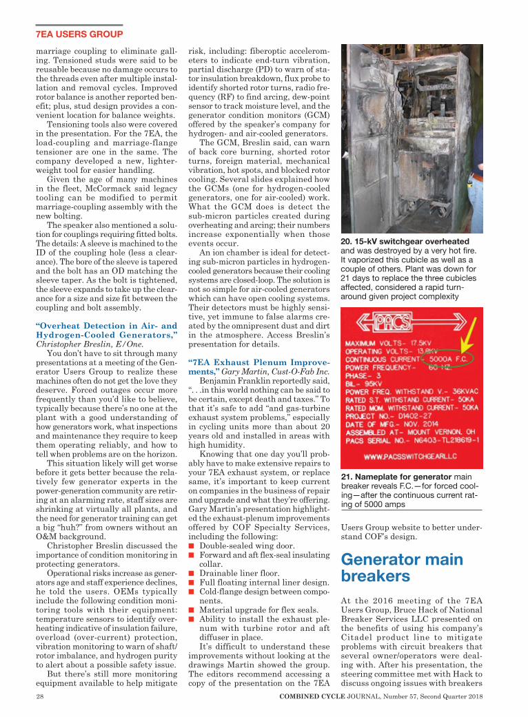
28 COMBINED CYCLE JOURNAL, Number 57, Second Quarter 2018
7EA USERS GROUP
marriage coupling to eliminate gall-ing. Tensioned studs were said to be reusable because no damage occurs to the threads even after multiple instal-lation and removal cycles. Improved rotor balance is another reported ben-efit; plus, stud design provides a con-venient location for balance weights.
Tensioning tools also were covered in the presentation. For the 7EA, the load-coupling and marriage-flange tensioner are one in the same. The company developed a new, lighter-weight tool for easier handling.
Given the age of many machines in the fleet, McCormack said legacy tooling can be modified to permit marriage-coupling assembly with the new bolting.
The speaker also mentioned a solu-tion for couplings requiring fitted bolts. The details: A sleeve is machined to the ID of the coupling hole (less a clear-ance). The bore of the sleeve is tapered and the bolt has an OD matching the sleeve taper. As the bolt is tightened, the sleeve expands to take up the clear-ance for a size and size fit between the coupling and bolt assembly.
“Overheat Detection in Air- and Hydrogen-Cooled Generators,” Christopher Breslin, E/One.
You don’t have to sit through many presentations at a meeting of the Gen-erator Users Group to realize these machines often do not get the love they deserve. Forced outages occur more frequently than you’d like to believe, typically because there’s no one at the plant with a good understanding of how generators work, what inspections and maintenance they require to keep them operating reliably, and how to tell when problems are on the horizon.
This situation likely will get worse before it gets better because the rela-tively few generator experts in the power-generation community are retir-ing at an alarming rate, staff sizes are shrinking at virtually all plants, and the need for generator training can get a big “huh?” from owners without an O&M background.
Christopher Breslin discussed the importance of condition monitoring in protecting generators.
Operational risks increase as gener-ators age and staff experience declines, he told the users. OEMs typically include the following condition moni-toring tools with their equipment: temperature sensors to identify over-heating indicative of insulation failure, overload (over-current) protection, vibration monitoring to warn of shaft/rotor imbalance, and hydrogen purity to alert about a possible safety issue.
But there’s still more monitoring equipment available to help mitigate
risk, including: fiberoptic accelerom-eters to indicate end-turn vibration, partial discharge (PD) to warn of sta-tor insulation breakdown, flux probe to identify shorted rotor turns, radio fre-quency (RF) to find arcing, dew-point sensor to track moisture level, and the generator condition monitors (GCM) offered by the speaker’s company for hydrogen- and air-cooled generators.
The GCM, Breslin said, can warn of back core burning, shorted rotor turns, foreign material, mechanical vibration, hot spots, and blocked rotor cooling. Several slides explained how the GCMs (one for hydrogen-cooled generators, one for air-cooled) work. What the GCM does is detect the sub-micron particles created during overheating and arcing; their numbers increase exponentially when those events occur.
An ion chamber is ideal for detect-ing sub-micron particles in hydrogen-cooled generators because their cooling systems are closed-loop. The solution is not so simple for air-cooled generators which can have open cooling systems. Their detectors must be highly sensi-tive, yet immune to false alarms cre-ated by the omnipresent dust and dirt in the atmosphere. Access Breslin’s presentation for details.
“7EA Exhaust Plenum Improve-ments,” Gary Martin, Cust-O-Fab Inc.
Benjamin Franklin reportedly said, “. . .in this world nothing can be said to be certain, except death and taxes.” To that it’s safe to add “and gas-turbine exhaust system problems,” especially in cycling units more than about 20 years old and installed in areas with high humidity.
Knowing that one day you’ll prob-ably have to make extensive repairs to your 7EA exhaust system, or replace same, it’s important to keep current on companies in the business of repair and upgrade and what they’re offering. Gary Martin’s presentation highlight-ed the exhaust-plenum improvements offered by COF Specialty Services, including the following:n Double-sealed wing door.n Forward and aft flex-seal insulating
collar.n Drainable liner floor.n Full floating internal liner design.n Cold-flange design between compo-
nents.n Material upgrade for flex seals.n Ability to install the exhaust ple-
num with turbine rotor and aft diffuser in place.It’s difficult to understand these
improvements without looking at the drawings Martin showed the group. The editors recommend accessing a copy of the presentation on the 7EA
Users Group website to better under-stand COF’s design.
Generator main breakersAt the 2016 meeting of the 7EA Users Group, Bruce Hack of National Breaker Services LLC presented on the benefits of using his company’s Citadel product line to mitigate problems with circuit breakers that several owner/operators were deal-ing with. After his presentation, the steering committee met with Hack to discuss ongoing issues with breakers
20. 15-kV switchgear overheated and was destroyed by a very hot fire. It vaporized this cubicle as well as a couple of others. Plant was down for 21 days to replace the three cubicles affected, considered a rapid turn-around given project complexity
21. Nameplate for generator main breaker reveals F.C.—for forced cool-ing—after the continuous current rat-ing of 5000 amps

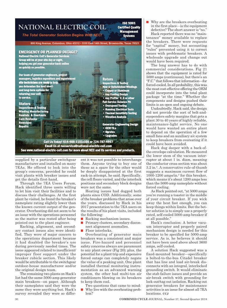
30 COMBINED CYCLE JOURNAL, Number 57, Second Quarter 2018
supplied by a particular switchgear manufacturer and installed on many 7EAs. He offered to look into the group’s concerns, provided he could visit plants with breaker issues and get the details first-hand.
Through the 7EA Users Forum, Hack identified three users willing to let him visit their facilities and to discuss their challenges. At the first plant he visited, he found the breaker’s nameplate rating slightly lower than the known current output of the gen-erator. Overheating did not seem to be an issue with the operations personnel so the matter was rested after being pointed out to the plant engineer.
Racking, alignment, and second-ary contact issues also were identi-fied. They were of major concern to the operations department because it had disabled the breaker’s use during previously needed times. The issue appeared related to insufficient/improper floor support under the breaker cubicle section. This likely would be attributable to the switchgear outdoor-house manufacturer and/or the original design team.
The remaining two plants on Hack’s list had the same 5000-amp generator main breakers—on paper. Although their nameplates said they were the same they were anything but. Hack’s survey revealed they were so differ-
ent it was not possible to interchange them. Anyone trying to buy one of these as a spare for the other would be deeply disappointed at the first rack-in attempt, he said. Specifically, the cell floors varied, and the interlock positions and secondary block designs were not the same.
Heating issues had dogged both plants since COD. Additionally, some of the breaker problems that arose over the years, discussed by Hack in his 2017 presentation to the 7EA users on the results of his plant visits, included the following:n Racking mechanism issues.n Primary clusters, secondary discon-
nect alignment anomalies.n Floor interlocks.
Overheating of generator main breakers was a consistent and major issue. Fire-hazard and personnel safety concerns always are paramount to any plant owner (Fig 20); plus, the potential for a plant trip and expensive forced outage can completely negate the value of a peaking unit. One plant installed thermal monitoring instru-mentation as an advanced warning system, the other had multi-ton air conditioners blowing on its breakers to keep them cool.
Two questions that came to mind:n Why live with the overheating prob-
lem?
n Why are the breakers overheating in the first place—is the equipment defective? The short answer is “no.” Hack reported there was no “main-
tenance” money available to replace the breakers. There were requests for “capital” money, but accounting “rules” prevented using it to correct issues with problematic breakers. A wholesale upgrade and change out would have been required.
The long answer has to do with commercial considerations. Fig 21 shows that the equipment is rated for 5000 amps (continuous), but there’s an “F.C.” that follows that information—for forced-cooled. In all probability, this was the most cost-effective offering the OEM could incorporate into the total plant package “at the time.” Whether the components and designs pushed their limits is an open and ongoing debate.
Undoubtedly, Hack said, the design did not provide the sort of belt-and-suspenders safety margins that gets a plant 30 to 40 years of highly reliable, maintenance-light service. No one would have wanted an entire plant to depend on the operation of a few small fans and an auxiliary a/c system to keep breakers from overeating if it could have been avoided.
Hack dug deeper with a back-of-the-envelope calculation. He measured the lower stem of the vacuum inter-rupter at about 1 in. diam, meaning the conductor cross section was about 3.2 in.². A conservative rule-of-thumb suggests a maximum current flow of 1000-1200 amps/in.² for this breaker, which means it’s about 1200 amps less than the 5000-amp nameplate without forced cooling.
As Hack pointed out, “at 5000 amps you’re running a toaster in the middle of your circuit breaker. If you wick away the heat fast enough, you can keep things within limits. But the bet-ter solution is to simply use a properly rated, self-cooled 5000-amp breaker if at all possible.”
Hack’s conclusion: A better vacu-um interrupter and properly paired mechanism design is needed for this breaker to be specified for 5000-amp service. As is, he believes it should not have been used above about 3600 amps, self-cooled.
A solution Hack suggested was a fixed-mounted breaker—specifically a bolted-to-the-bus Citadel breaker that has line and load air-break dis-connects with an integral, interlocked grounding switch. It would eliminate the stab failure issues and provide an air-break switch with grounding for lock-out/tag-out isolation. Racking out generator breakers for maintenance activities is an issue for almost all 7EA locations. ccj
Call Us Today! 614-488-1151x105 or 724-787-4967Email Us at [email protected]
See www.national-electric-coil.com for more about NEC and its services and products.
RotorsInspections & TestingNew or Refurbished Windings• Copper or Aluminum• Any Cooling Design• Any Profile: C, E or otherFFull-Service Balance Pit• Overspeed Testing• Running Electrical Tests• Thermal Sensitivity Testing• Vibration Analysis
Generator Engineering Design• OEM TILs• Up• Uprates• Upgrades
StatorsInspections & TestingWinding ManufacturingRewinds & OverhaulsCore RestacksRewedgesRRepairs
National Electric Coil’s Generator ServicesGroup will be at your site day or night,helping you get your generator back onlineas quickly as possible.
Our team of generator engineers, projectmanagers, logistics expeditors and experiencedsite technicians are ready site technicians are ready to helpyou determine the best short-and long-term options forreturning your unitto service.
ISO 9001Certified Quality
ManagementSystems
EMERGENCY OR PLANNED OUTAGE?
800.223.7867 l hydroinc.com
ATLANTA l BEAUMONT l CHICAGO l DEER PARK l DENVER l HOUSTON l LOS ANGELES l PHILADELPHIA
AUSTRALIA l CANADA l ENGLAND l FRANCE l INDIA l KOREA l UNITED ARAB EMIRATES l VIETNAM
Total SupportTotal ReliabilityEngineering expertise and years of experience in the field make us a valuable part of your day to day operations.
Hydro provides independent, unbiased engineering expertise and
support to pump users around the world.
Multistage pumps are manufactured by a number of companies for high pressure medium flow applications and are critical to combined cycle plant operations.
These machines are critical but on occasion present challenges.
Hydro’s study of this type of equipment and the issues encountered, has resulted in the development of engineering solutions and processes to ensure successful repairand installation of multistage pumps. Our engineers and technical staff have extensive experience with a broad range of pump equipment. This diverse engineering expertise,and use of the latest manufacturing and design technologies are why so many combinedcycle plants rely on Hydro. We invite you to rely on us too.
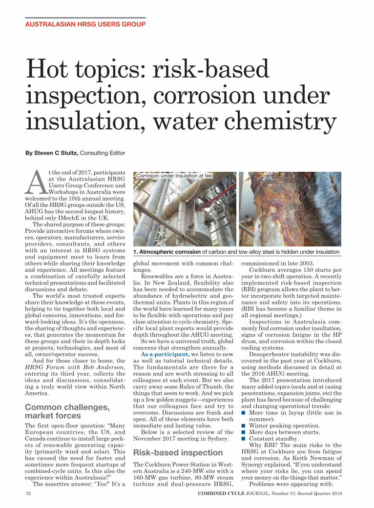
32 COMBINED CYCLE JOURNAL, Number 57, Second Quarter 2018
AUSTRALASIAN HRSG USERS GROUP
At the end of 2017, participants at the Australasian HRSG Users Group Conference and Workshops in Australia were
welcomed to the 10th annual meeting. Of all the HRSG groups outside the US, AHUG has the second longest history, behind only IMechE in the UK.
The shared purpose of these groups: Provide interactive forums where own-ers, operators, manufacturers, service providers, consultants, and others with an interest in HRSG systems and equipment meet to learn from others while sharing their knowledge and experience. All meetings feature a combination of carefully selected technical presentations and facilitated discussions and debate.
The world’s most trusted experts share their knowledge at these events, helping to tie together both local and global concerns, innovations, and for-ward-looking ideas. It’s the openness, the sharing of thoughts and experienc-es, that generates the momentum for these groups and their in-depth looks at projects, technologies, and most of all, owner/operator success.
And for those closer to home, the HRSG Forum with Bob Anderson, entering its third year, collects the ideas and discussions, consolidat-ing a truly world view within North America.
Common challenges, market forces The first open-floor question: “Many European countries, the US, and Canada continue to install large pock-ets of renewable generating capac-ity (primarily wind and solar). This has caused the need for faster and sometimes more frequent startups of combined-cycle units. Is this also the experience within Australasia?”
The assertive answer: “Yes!” It’s a
global movement with common chal-lenges.
Renewables are a force in Austra-lia. In New Zealand, flexibility also has been needed to accommodate the abundance of hydroelectric and geo-thermal units. Plants in this region of the world have learned for many years to be flexible with operations and pay close attention to cycle chemistry. Spe-cific local plant reports would provide depth throughout the AHUG meeting.
So we have a universal truth, global concerns that strengthen annually.
As a participant, we listen to new as well as tutorial technical details. The fundamentals are there for a reason and are worth stressing to all colleagues at each event. But we also carry away some Rules of Thumb, the things that seem to work. And we pick up a few golden nuggets—experiences that our colleagues face and try to overcome. Discussions are frank and open. All of these elements have both immediate and lasting value.
Below is a selected review of the November 2017 meeting in Sydney.
Risk-based inspectionThe Cockburn Power Station in West-ern Australia is a 240-MW site with a 160-MW gas turbine, 80-MW steam turbine and dual-pressure HRSG,
commissioned in late 2003. Cockburn averages 150 starts per
year in two-shift operation. A recently implemented risk-based inspection (RBI) program allows the plant to bet-ter incorporate both targeted mainte-nance and safety into its operations. (RBI has become a familiar theme in all regional meetings.)
Inspections in Australasia com-monly find corrosion under insultation, signs of corrosion fatigue in the HP drum, and corrosion within the closed cooling systems.
Desuperheater instability was dis-covered in the past year at Cockburn, using methods discussed in detail at the 2016 AHUG meeting.
The 2017 presentation introduced many added topics (seals and at casing penetrations, expansion joints, etc) the plant has faced because of challenging and changing operational trends:n More time in layup (little use in
summer).n Winter peaking operation.n More days between starts.n Constant standby.
Why RBI? The main risks to the HRSG at Cockburn are from fatigue and corrosion. As Keith Newman of Synergy explained, “If you understand where your risks lie, you can spend your money on the things that matter.”
Problems were appearing with:
Hot topics: risk-based inspection, corrosion under insulation, water chemistry By Steven C Stultz, Consulting Editor
Corrosion under insulation at tee
1. Atmospheric corrosion of carbon and low-alloy steel is hidden under insulation

HRSG MAINTENANCE SERVICES
• SCR Catalyst Cleaning & Repacking
• CO Catalyst Cleaning & Repacking
• Ammonia Injection Grid Cleaning
• Ammonia Vaporizer Cleaning
• SCR & CO Catalyst Replacement
• HRSG Tube Cleaning
• Inlet Filter House & Duct Refurbishment
GROOME INDUSTRIAL
SERVICE GROUP
Corporate Headquarters 155 Franklin Turnpike Waldwick, NJ 07463(800) 505-6100www.groomeindustrial.com

34 COMBINED CYCLE JOURNAL, Number 57, Second Quarter 2018
AUSTRALASIAN HRSG USERS GROUP
n Feedwater piping—HP pipe, LP pipe, and HP drain pipe.
n HP drum—cracking on attachment welds and on internal surfaces of both downcomers.
n Galvanic corrosion in the condenser (seawater cooled).
n Desuperheater overspray.This status presentation triggered
active discussions and thoughts on solutions. Desuperheater liner replacement is being considered, but repair is a near-term option if the crack does not enter the pressure parts. Penetration seals and corrosion of carbon-steel rings were discussed, along with repair/replacement issues. Fabric penetration-seal retrofits and isolation valves were covered also and would be explained in later pre-sentations.
The RBI concept was openly exam-ined including the ability to incor-porate major events into the RBI calculation. Cockburn currently uses Microsoft Excel. Maintenance plan-ning is with SAP, guided by the RBI analysis.
This presentation served as a real-world introduction to both RBI and much of the meeting agenda.
Hidden dangersCorrosion under insulation (CUI) was a topic in several case studies. CUI is
atmospheric corrosion—a/k/a rusting of carbon and low-alloy steels (Fig 1). For stainless steels this leads to stress corrosion cracking above 140F (Fig 2). The main problem remains this: there is not yet a method of inspecting with the insulation in place. And this is not unique to the power industry. It is a significant concern within the global refining industry as well.
Five case studies were reviewed by Charles Thomas of Quest Integrity.
With insulation removed, inspec-tion of carbon steel can be visual. Inspection of stainless is both visual and with dye penetrant. At highest risk are the small-bore lines, most with thin walls, and dead legs that cool down away from the main ves-sel. But a plant cannot remove all insulation, and therefore, “Inspection techniques to identify CUI (without removing the insulation) are the current holy grail of the inspection industry.”
Case studies were presented on LP drum-level transmission pipe (Fig 3), HP vent line, pipe bend low points
where water pools, and the discovery of stress corrosion cracking under sup-port plates.
The underlying message: look carefully.
Lengthy discussions followed on inspection techniques and method-ologies including guided wave, radi-ography, eddy current and thermal imaging. The general agreement was the need for a risk-based approach: “Manage by targeted inspection of at-risk areas.”
An interesting thought was gener-ated during the discussions: If insula-tion is not required, don’t replace it.
Perhaps consider also installing rain covers on the pipe bridge for plants with horizontal, exposed runs.
Swanbank E For the past three years, participants have reviewed the status and details of Stanwell Corp’s 375-MW Swanbank E Power Station in Queensland (Fig 4). The plant was withdrawn from service on Dec 1, 2014, and placed in dry storage after operating with an average 97.5% reliability.
Site labor was reduced to a care-taker team, and comprehensive cold storage and preservation of all systems was implemented.
Major storage risks, typically, are corrosion of water/steam components and corrosion under insulation. Acid dew point corrosion on the HRSG gas side was a concern, as were gas and steam turbine corrosion. Stanwell’s full storage with dehumidified air has ensured few issues other than rain-water ingress (some corrosion under insulation).
Leaks
2. Stress corrosion cracking of austenitic stainless steel (Types 304 and 316) is easy to identify
3. LP drum level transmission pipe corrosion (above)4. Swanbank E Power Station in Queensland was returned to service from dry storage (right)
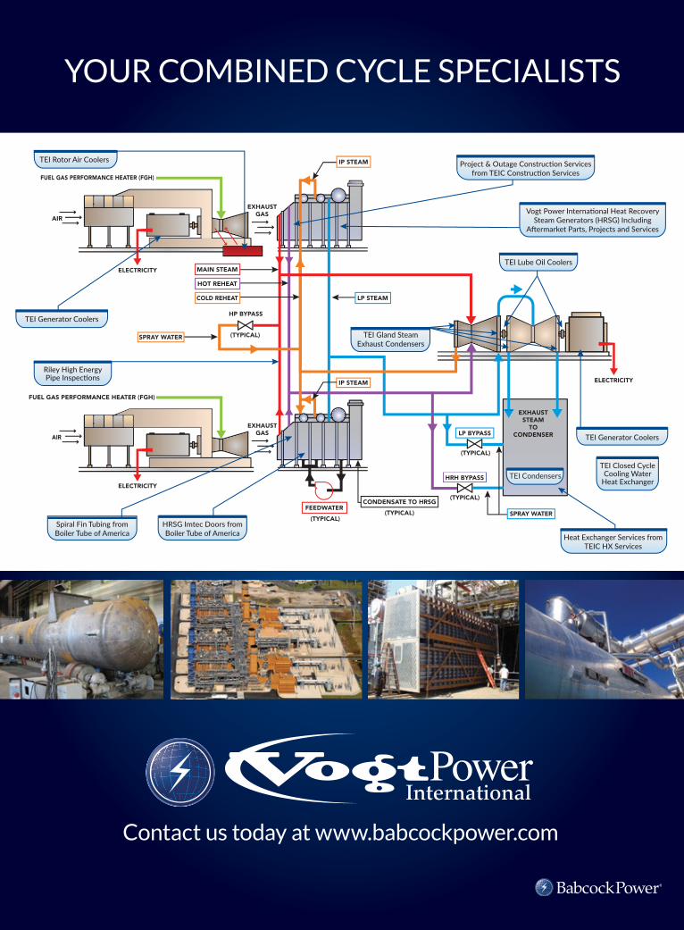
AIR
FUEL GAS PERFORMANCE HEATER (FGH)
FUEL GAS PERFORMANCE HEATER (FGH)
ELECTRICITY
ELECTRICITY
ELECTRICITY
EXHAUSTSTEAM
TOCONDENSER
(TYPICAL)
EXHAUSTGAS
AIR
EXHAUSTGAS
(TYPICAL)
(TYPICAL)
(TYPICAL)(TYPICAL)
IP STEAM
MAIN STEAM
FEEDWATER
HOT REHEAT
COLD REHEAT
HP BYPASS
LP STEAM
LP BYPASS
HRH BYPASS
SPRAY WATER
CONDENSATE TO HRSG
SPRAY WATER
TEI Generator Coolers
TEI Lube Oil Coolers
TEI Rotor Air Coolers
TEI Condensers
Riley High Energy Pipe Inspec�ons
Spiral Fin Tubing from Boiler Tube of America Heat Exchanger Services from
TEIC HX Services
HRSG Imtec Doors from Boiler Tube of America
TEI Closed Cycle Cooling Water
Heat Exchanger
TEI Generator Coolers
TEI Gland Steam Exhaust Condensers
Project & Outage Construc�on Services from TEIC Construc�on Services
Vogt Power Interna�onal Heat Recovery Steam Generators (HRSG) Including
A�ermarket Parts, Projects and Services
IP STEAM
YOUR COMBINED CYCLE SPECIALISTS
Contact us today at www.babcockpower.com
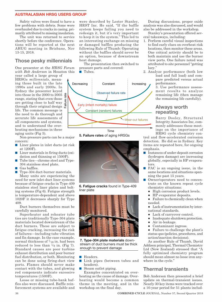
36 COMBINED CYCLE JOURNAL, Number 57, Second Quarter 2018
AUSTRALASIAN HRSG USERS GROUP
Safety valves were found to have a few problems with debris. Some were overhauled due to cracks in casing, pri-marily attributed to missing insulation.
The unit was returned to service shortly before the conference. Opera-tions will be reported at the next AHUG meeting in Brisbane, Nov 13-15, 2018.
Those pesky millennialsOne presenter at the HRSG Forum with Bob Anderson in Houston this year called a large group of HRSGs millennials, mean-ing those built in the late 1990s and early 2000s. In Sydney the presenter keyed into those in the 2000 to 2005 range, stating that even those are getting close to half way through their original design life. The common message is the need to do thorough and accurate life assessments of all components and systems, and to understand the over-heating mechanisms in these aging units (Fig 5).
Non-pressure parts can be a major concern: n Liner plates in inlet ducts (at risk
at 1200F).n Liner materials in firing ducts (oxi-
dation and thinning at 1500F).n Tube ties—chrome steel and Type-
304 stainless steel plate.n Gas baffles.n Type-304 duct-burner materials.
Many units are experiencing the need for new inlet-duct liner systems because of fatigue cracks in Type-409 stainless steel liner plates and bolt-ing systems (Fig 6). Fatigue strength is temperature-dependent and above 1020F it decreases sharply for Type 409.
Duct burners themselves must be carefully monitored.
Superheater and reheater tube ties are traditionally Type-304 plate materials located downstream of the duct burners. These are subject to fatigue cracking, increasing the risk of failures—including tube vibration and fin damage. In the case example, normal thickness of 7∕16 in. had been reduced to less than 1∕8 in. (Fig 7). Standard causes are poor turbine exhaust distribution and poor burner fuel distribution, or both. Monitoring can be done using firing-duct view ports. Flames should never make contact with the tubes, and glowing red components indicate excessive temperatures (1500F).
Loose or missing tube-bank baf-fles also were discussed. Baffle rein-forcement systems are available and
were described by Lester Stanley, HRST Inc. He said, “If the baffle system keeps failing you need to redesign it, but it’s very important to keep it in the system.” This led to an interesting exchange on missing or damaged baffles producing the following Rule of Thumb: Operating without the baffles should never be an option, because of downstream heat damage.
The presentation then switched to pressure parts and covered:n Tubes.
n Headers.n Link pipes (between tubes and
headers).n Steam outlet piping.
Examples concentrated on over-heating as the cause of damage. Over-heating would become a common theme in the meeting, and in the workshop on the final day.
During discussions, proper oxide analysis was also discussed, and would also be addressed in the workshop.
Stanley’s presentation offered sev-eral takeaways, including: 1. Perform careful visual inspections
to find early clues on overheat risk locations, then monitor these areas. One critical activity should be to both maintain and use the burner view ports. One failure noted was attributed to site personnel “getting lazy.”
2. Analyze performance (both low load and full load) and com-pare predicted versus actual performance.3. Use performance assess-ment results to analyze remaining life (then manage the remaining life carefully).
Always worth repeating Barry Dooley, Structural Integrity Associates Inc, com-monly addresses these meet-ings on the importance of HRSG cycle chemistry con-
trol and flow-accelerated corrosion detection. He did so in Sydney. Key items are repeated here, for ongoing emphasis.n Instances of under-deposit corrosion
(hydrogen damage) are increasing globally, especially in HP evapora-tors.
n FAC is an ongoing issue, in the same locations and situations span-ning the past 15 years.
n Owner/operators need to concen-trate on the known repeat cycle chemistry situations:
● High corrosion product levels. ● HP evaporator deposits. ● Failure to chemically clean when
needed. ● Lack of instrumentation by inter-
national standards. ● Lack of carryover control. ● Inadequate shutdown protection. ● Air in-leakage. ● Contaminant ingress. ● Failure to challenge the plant’s
status quo (policies, procedures, and action/inaction decisions).As another Rule of Thumb, David
Addison principal, Thermal Chemistry Ltd (New Zealand) stressed that “A fully optimized chemistry program should mean almost no loose iron any-where in the cycle.”
Thermal transients Bob Anderson then presented a brief update on thermal-transient issues. Nearly 30 key items were tracked over a 10-year period for 51 plants includ-
Failu
re ra
te
Decreasing Constant Increasing
Time
Observed failure rate
Early (infant mortality) failure
Constant (random) failures
Wear-out failures
5. Failure rates of aging HRSGs
t < 1/8 in.
6. Fatigue cracks found in Type-409 liner plate
7. Type-304 plate materials down-stream of duct burners must be thick enough to prevent damage
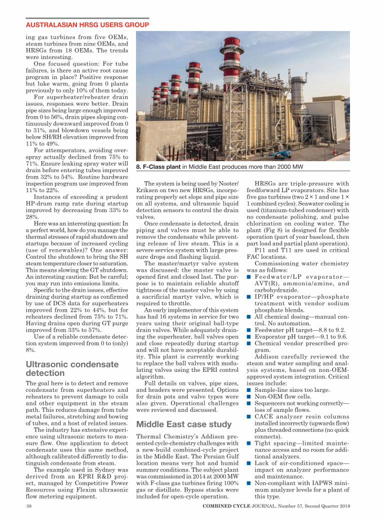
38 COMBINED CYCLE JOURNAL, Number 57, Second Quarter 2018
AUSTRALASIAN HRSG USERS GROUP
ing gas turbines from five OEMs, steam turbines from nine OEMs, and HRSGs from 18 OEMs. The trends were interesting.
One focused question: For tube failures, is there an active root cause program in place? Positive response but luke warm, going from 0 plants previously to only 10% of them today.
For superheater/reheater drain issues, responses were better. Drain pipe sizes being large enough improved from 0 to 56%, drain pipes sloping con-tinuously downward improved from 0 to 31%, and blowdown vessels being below SH/RH elevation improved from 11% to 49%.
For attemperators, avoiding over-spray actually declined from 75% to 71%. Ensure leaking spray water will drain before entering tubes improved from 32% to 54%. Routine hardware inspection program use improved from 11% to 22%.
Instances of exceeding a prudent HP-drum ramp rate during startup improved by decreasing from 33% to 28%.
Here was an interesting question: In a perfect world, how do you manage the thermal stresses of rapid shutdown and startups because of increased cycling (use of renewables)? One answer: Control the shutdown to bring the SH steam temperature closer to saturation. This means slowing the GT shutdown. An interesting caution: But be careful; you may run into emissions limits.
Specific to the drain issues, effective draining during startup as confirmed by use of DCS data for superheaters improved from 22% to 44%, but for reheaters declined from 75% to 71%. Having drains open during GT purge improved from 33% to 57%.
Use of a reliable condensate detec-tion system improved from 0 to (only) 8%.
Ultrasonic condensate detectionThe goal here is to detect and remove condensate from superheaters and reheaters to prevent damage to coils and other equipment in the steam path. This reduces damage from tube metal failures, stretching and bowing of tubes, and a host of related issues.
The industry has extensive experi-ence using ultrasonic meters to mea-sure flow. One application to detect condensate uses this same method, although calibrated differently to dis-tinguish condensate from steam.
The example used in Sydney was derived from an EPRI R&D proj-ect, managed by Competitive Power Resources using Flexim ultrasonic flow metering equipment.
The system is being used by Nooter/Eriksen on two new HRSGs, incorpo-rating properly set slope and pipe size on all systems, and ultrasonic liquid detection sensors to control the drain valves.
Once condensate is detected, drain piping and valves must be able to remove the condensate while prevent-ing release of live steam. This is a severe service system with large pres-sure drops and flashing liquid.
The master/martyr valve system was discussed: the master valve is opened first and closed last. The pur-pose is to maintain reliable shutoff tightness of the master valve by using a sacrificial martyr valve, which is required to throttle.
An early implementer of this system has had 16 systems in service for two years using their original ball-type drain valves. While adequately drain-ing the superheater, ball valves open and close repeatedly during startup and will not have acceptable durabil-ity. This plant is currently working to replace the ball valves with modu-lating valves using the EPRI control algorithm.
Full details on valves, pipe sizes, and headers were presented. Options for drain pots and valve types were also given. Operational challenges were reviewed and discussed.
Middle East case studyThermal Chemistry’s Addison pre-sented cycle-chemistry challenges with a new-build combined-cycle project in the Middle East. The Persian Gulf location means very hot and humid summer conditions. The subject plant was commissioned in 2014 at 2000 MW with F-class gas turbines firing 100% gas or distillate. Bypass stacks were included for open-cycle operation.
HRSGs are triple-pressure with feedforward LP evaporators. Site has five gas turbines (two 2 × 1 and one 1 × 1 combined cycles). Seawater cooling is used (titanium-tubed condenser) with no condensate polishing, and pulse chlorination on cooling water. The plant (Fig 8) is designed for flexible operation (part of year baseload, then part load and partial plant operation).
P11 and T11 are used in critical FAC locations.
Commissioning water chemistry was as follows:n Feedwater /LP evaporator—
AVT(R), ammonia/amine, and carbohydrazide.
n IP/HP evaporator—phosphate treatment with vendor sodium phosphate blends.
n All chemical dosing—manual con-trol. No automation.
n Feedwater pH target—8.8 to 9.2.n Evaporator pH target—9.1 to 9.6.n Chemical vendor prescribed pro-
gram.Addison carefully reviewed the
steam and water sampling and anal-ysis systems, based on non-OEM-approved system integration. Critical issues include:n Sample-line sizes too large.n Non-OEM flow cells. n Sequencers not working correctly—
loss of sample flows.n CACE analyzer resin columns
installed incorrectly (upwards flow) plus threaded connections (no quick connects).
n Tight spacing—limited mainte-nance access and no room for addi-tional analyzers.
n Lack of air-conditioned space—impact on analyzer performance and maintenance.
n Non-compliant with IAPWS mini-mum analyzer levels for a plant of this type.
8. F-Class plant in Middle East produces more than 2000 MW

http://secc.umicore.com
Smarter catalysts: two in one
Better emissions compliance
http://secc.umicore.com
Clean air is our business. The GTC-802 (NOx/CO-VOC) “Dual Function” catalyst will
help your plant meet stricter emission standards while improving performance and
profitability. GTC-802 combines two catalysts in one, delivering both superior
NOx reduction and outstanding CO and VOC oxidation. Lowest pressure drop,
near zero SO2 oxidation and reduced ammonia slip add up to improved heat
rate, increased power output and fewer cold-end maintenance issues. GTC-802 is
positioned downstream of the ammonia injection grid in the same location as the
current SCR catalyst. As an added benefit, the catalyst allows direct injection of
liquid ammonia or urea in place of the traditional vaporized ammonia.
40 COMBINED CYCLE JOURNAL, Number 57, Second Quarter 2018
The plant meets only 80% of the IAPWS minimum instrumentation levels. If the O/S analyzers are taken into account, this drops to 60%.
There is no automation for the dosing systems (manual once per day testing). The plant is constantly over/under dosing and chemists are not dedicated to the area.
The chemistry laboratory onsite is set up primarily for fuel and environ-mental water analysis and is physi-cally separated from operations and engineering. Experience is low, and documentation levels are poor and, at least in part, technically incorrect.
Layup and storage procedures are poor. HRSGs are left wet without nitrogen capping, partially drained down, for weeks at a time. Steam turbines are left with no protection. DHA equipment at site has never been commissioned. Outside of key summer (high demand) months, the plant is in flexible operating mode. Multiple GTs/HRSGs are out of service, recallable on short notice.
Commissioning was poorly man-aged with major delays. Commission-ing documentation and procedures were poor.
HRSG makeup rates are extremely high. The water treatment plant has operated in overload to ensure makeup demand is met (42% over
design). Startups and flexible opera-tion increase the water demand even more.
FAC is a problem, as shown in Fig 9. Even with P11 in the LP evaporator, FAC was detected (also in IP evapo-rator and HP economizers). FAC was attributed to the plant’s initial AVT(R) program with reducing agent, low feed-water and LP evaporator pH, and low IP evaporator pH.
Condenser tube-leak risk is high (no leak detection analyzers) and con-denser spill return is directly back to the site demin tank—a major risk of contaminating all units if one leaks.
Improvement activities include the following:1. High makeup demand. Focus on
identification and fixing/replacing leaking HRSG valves, and improve treatment plant maintenance prac-tices.
2. Low feedwater/evaporator pH. Undertaking correct dosing; run-ning pumps/chemicals at correct levels.
3. FAC in HRSGs. Halt reducing-agent dosing, increase feedwater pH to 9.8 with ammonia, increase HRSG evaporators (IP/HP) pH with tri-sodium phosphate (TSP); implement condensate polishing program.
4. Analyzers O/S. OEM training of
technicians, increase priority on defects and repairs, correct setup issues, and begin additional ana-lyzer project (sodium in condensate, etc).
5. Condenser. Future change to spill/return setup (to raw water tank), and increase in risk awareness
6. Chemistry management. Rewrite chemistry manual and procedures to align with IAPWS Technical Guidance Documents, phosphate dosing with TSP only, improve chemistry management, ongoing development of chemists.
7. Layup and storage. Develop pro-cedures; push to commission DHA equipment.
Film-forming substancesDay Two ended with an update on film-forming substances—specifically GE application experience in HRSGs—by Justin West. Various updates have been covered recently by CCJ.
This presentation highlighted developments by summarizing signifi-cant differences between modern FFAs and older filming-amine technology:n Higher volatility over wide steam-
cycle pressure/temperature range versus ODA.
n Strongly absorbed and highly per-sistent surface film.
TURBınE ınSULATıOn AT ıTS FınEST
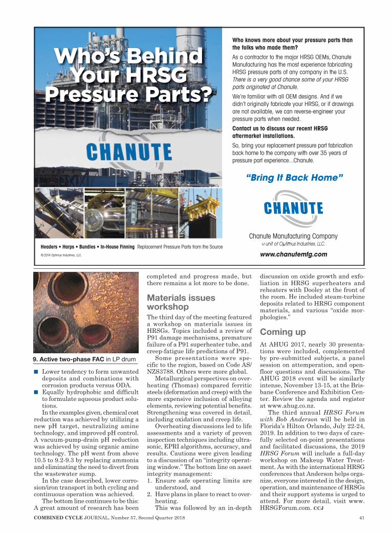
COMBINED CYCLE JOURNAL, Number 57, Second Quarter 2018 41
n Lower tendency to form unwanted deposits and combinations with corrosion products versus ODA.
n Equally hydrophobic and difficult to formulate aqueous product solu-tions.In the examples given, chemical cost
reduction was achieved by utilizing a new pH target, neutralizing amine technology, and improved pH control. A vacuum-pump-drain pH reduction was achieved by using organic amine technology. The pH went from above 10.5 to 9.2-9.3 by replacing ammonia and eliminating the need to divert from the wastewater sump.
In the case described, lower corro-sion/iron transport in both cycling and continuous operation was achieved.
The bottom line continues to be this: A great amount of research has been
completed and progress made, but there remains a lot more to be done.
Materials issues workshop The third day of the meeting featured a workshop on materials issues in HRSGs. Topics included a review of P91 damage mechanisms, premature failure of a P91 superheater tube, and creep-fatigue life predictions of P91.
Some presentations were spe-cific to the region, based on Code AS/NZS3788. Others were more global.
Metallurgical perspectives on over-heating (Thomas) compared ferritic steels (deformation and creep) with the more expensive inclusion of alloying elements, reviewing potential benefits. Strengthening was covered in detail, including oxidation and creep life.
Overheating discussions led to life assessments and a variety of proven inspection techniques including ultra-sonic, EPRI algorithms, accuracy, and results. Cautions were given leading to a discussion of an “integrity operat-ing window.” The bottom line on asset integrity management:1. Ensure safe operating limits are
understood, and2. Have plans in place to react to over-
heating. This was followed by an in-depth
discussion on oxide growth and exfo-liation in HRSG superheaters and reheaters with Dooley at the front of the room. He included steam-turbine deposits related to HRSG component materials, and various “oxide mor-phologies.”
Coming upAt AHUG 2017, nearly 30 presenta-tions were included, complemented by pre-submitted subjects, a panel session on attemperation, and open-floor questions and discussions. The AHUG 2018 event will be similarly intense, November 13-15, at the Bris-bane Conference and Exhibition Cen-ter. Review the agenda and register at www.ahug.co.nz.
The third annual HRSG Forum with Bob Anderson will be held in Florida’s Hilton Orlando, July 22-24, 2019. In addition to two days of care-fully selected on-point presentations and facilitated discussions, the 2019 HRSG Forum will include a full-day workshop on Makeup Water Treat-ment. As with the international HRSG conferences that Anderson helps orga-nize, everyone interested in the design, operation, and maintenance of HRSGs and their support systems is urged to attend. For more detail, visit www.HRSGForum.com. ccj
9. Active two-phase FAC in LP drum
© 2014 Optimus Industries, LLC.
Who’s Behind Your HRSG
Pressure Parts?
Headers • Harps • Bundles • In-House Finning Replacement Pressure Parts from the Source
Who knows more about your pressure parts than the folks who made them?
As a contractor to the major HRSG OEMs, Chanute Manufacturing has the most experience fabricating HRSG pressure parts of any company in the U.S. There is a very good chance some of your HRSG parts originated at Chanute.
We’re familiar with all OEM designs. And if we didn’t originally fabricate your HRSG, or if drawings are not available, we can reverse-engineer your pressure parts when needed.
Contact us to discuss our recent HRSG aftermarket installations.
So, bring your replacement pressure part fabrication back home to the company with over 35 years of pressure part experience...Chanute.
Chanute Manufacturing Company a unit of Optimus Industries, LLC.
www.chanutemfg.com
“Bring It Back Home”
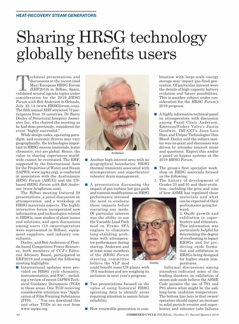
42 COMBINED CYCLE JOURNAL, Number 57, Second Quarter 2018
HEAT-RECOVERY STEAM GENERATORS
Technical presentations and discussions at the recent (mid May) European HRSG Forum (EHF2018) in Bilbao, Spain,
validated several agenda topics under consideration for the 2019 HRSG Forum with Bob Anderson in Orlando, July 22-14 (www.HRSGforum.com). The fifth annual EHF attracted 72 par-ticipants from 16 countries. Dr Barry Dooley of Structural Integrity Associ-ates Inc, who chaired the meeting as he had done previously, considered the event “highly successful.”
While design codes, operating para-digm, and economic drivers may vary geographically, the technologies impor-tant to HRSG success (materials, water chemistry, etc) are global. Hence, the value in sharing experiences world-wide cannot be overstated. The EHF, supported by the International Assn for the Properties of Water and Steam (IAPWS, www.iapws.org), is conducted in association with the Australasian HRSG Forum (AHUG) and the US-based HRSG Forum with Bob Ander-son (www.hrsgforum.com).
The Bilbao meeting featured 28 presentations, a panel discussion on attemperation, and a workshop on HRSG materials aspects. The highly interactive forum incorporated new information and technologies related to HRSGs, case studies of plant issues and solutions, and open discussions among users (18 owner/operators were represented in Bilbao), equip-ment suppliers, and industry con-sultants.
Dooley, and Bob Anderson of Flori-da-based Competitive Power Resourc-es, both members of CCJ’s Edito-rial Advisory Board, participated in EHF2018 and compiled the following meeting highlights:n International updates were pro-
vided on HRSG cycle chemistry, instrumentation, and FAC—includ-ing a review of recent IAPWS Tech-nical Guidance Documents (TGD) in these areas. One TGD receiving considerable attention was “Appli-cation of Film Forming Substances (FFS). . . .” You can download this and other TGDs at no cost from www.iapws.org.
n Another high-interest area with no geographical boundaries: HRSG thermal transients associated with attemperators and superheater/reheater drain management.
n A presentation discussing the impact of gas-turbine hot-gas-path and controls modifications on HRSG performance stressed the need to evaluate these impacts before executing any mods. Of particular interest was the ability to use the Variable Load Path mod on Frame 9FA engines to eliminate long-standing prob-lems with attempera-tor performance during startup. Anderson and at least some members of the HRSG Forum steering committee believe the VLP mod could benefit some US plants with 7FA machines and are weighing its inclusion in next year’s program.
n Two presentations focused on the value of using historical HRSG operating data to identify areas requiring attention to assure future reliability.
n How renewable generation in com-
bination with large-scale energy storage may impact gas-fired gen-eration. Of particular interest were the details of high-capacity battery evolution and future possibilities. This is another subject under con-sideration for the HRSG Forum’s 2019 program.
n A highly informative technical panel on attemperators with discussion among Panel Chair Anderson, Emerson/Fisher Valve’s Justin Goodwin, IMI-CCI’s Juan-Luis Dias, and Uniper Technologies’ Dan Blood. Dooley said the subject mat-ter was on-point and discussion was driven by attendee interest areas and questions. Expect this and/or a panel on bypass systems at the 2019 HRSG Forum.
n The group’s first specialist work-shop on HRSG materials focused on the following:
1. The history of development of Grades 23 and 91 and their evolu-tion—including the pros and cons of how ASME has regulated these
materials and what can be expected of their performance going for-ward.2. Oxide growth and exfoliation in super-heaters and reheaters. This information was particularly helpful for determining the degree of overheating in legacy HRSGs and for pre-dicting oxide forma-tion and exfoliation in HRSGs being designed for higher steam tem-peratures.
Informal discussions among attendees indicated some of the leading thinkers on exfoliation of steam-side oxide believe the ASME Code permits the use of T91 and P91 above what might be the safe long-term oxidation temperature. The bottom line here is that owner/operators should expect an increase in solid particle erosion and super-heater and reheater tube failures
Sharing HRSG technology globally benefits users
Dooley
Anderson
COMBINED CYCLE JOURNAL, Number 57, Second Quarter 2018 43
in legacy units. Attend the 2019 HRSG Forum to learn more on this critical subject.
3. Metallurgical examination should be the first stage in a root cause analysis of HRSG tube failures.
n The importance of cycle chemistry in combined-cycle plants was cov-ered several presentations, includ-ing these:
1. The latest guidance from IAPWS.2. The use of so-called Repeat Cycle
Chemistry Situations for identify-ing future damage/failure.
3. Examples of good plant-chemistry control practices.
4. The importance of managing, vet-ting, and validating cycle-chemistry alarms to assure that the most important alarms are not missed. Anderson considers this an impor-tant topic with practical informa-tion not generally thought about by O&M personnel. It’s penciled in on the preliminary program for the 2019 HRSG Forum.
5. The application of film forming sub-stances for combined-cycle plants and how to identify hydrophobicity.
n Repowering with gas-turbines was discussed by two presenters. One offered experience with dry cooling systems.
n Case studies reviewed performance of dry-ice blasting and pressure-wave technology in removing exter-nal tube deposits.
n Latest experience with gas tight-ness and movement of penetration seals.
n Anderson presented case studies on how to identify and remedy the root cause of premature erosion in HP turbine-bypass pressure control valves. Severe erosion is caused by opening the bypass valve prematurely during startup. Such erosion also may be caused by wet steam ingested by the valve when depressurizing the HP sys-tem via the bypasses during pres-surized layup. Discussed too were damaging thermal transients in high-energy steam piping when operating the bypasses during pressurized layup.
n Extensive discussion and informa-tion on the optimal approach for HP-drum-to-downcomer cracking.
n New technologies, including the latest HRSG designs for the Chi-nese market and the use of UV for treating boiler makeup. ccj
Power Plant Maintenance Tools
Tube Expansion
Fin Removal
Tube Beveling
Panel Cutting
Fast, Accurate, Easy OperationAvailable for Sale or Rental
World Leader in Boiler Maintenance Tools
800-343-6926 | 508-429-4441www.escotool.com
A Unit of ESCO Technologies, Inc.
412.798.8990www.TesTex-NDT.com
Claw Tool for Tube to Header Weld Cracking
Internal Crawler for Visual and Tube Thickness from
the Tube ID
OD Scanning for TubeWall Thickness
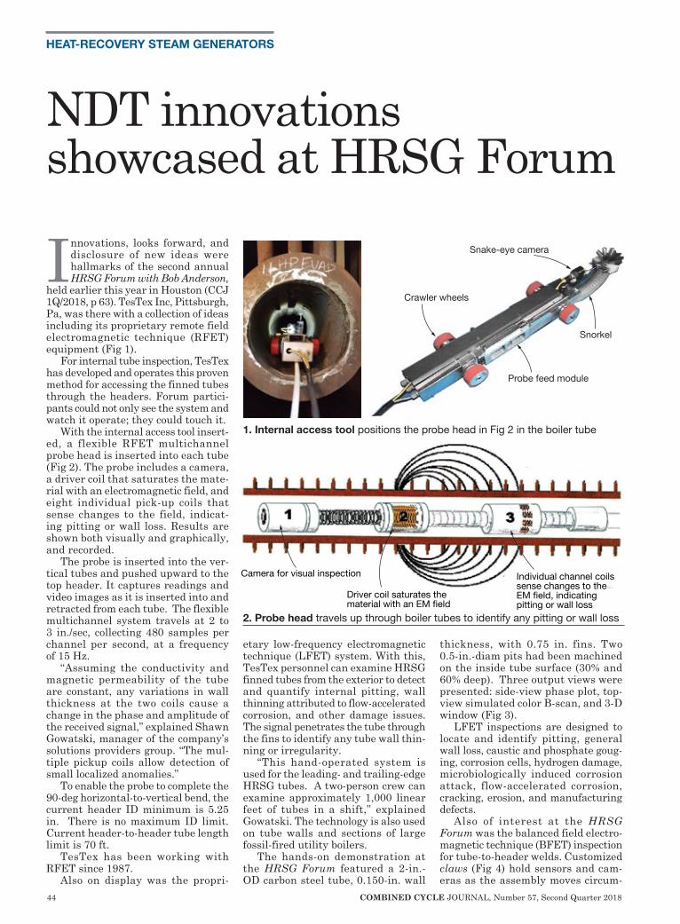
44 COMBINED CYCLE JOURNAL, Number 57, Second Quarter 2018
HEAT-RECOVERY STEAM GENERATORS
Innovations, looks forward, and disclosure of new ideas were hallmarks of the second annual HRSG Forum with Bob Anderson,
held earlier this year in Houston (CCJ 1Q/2018, p 63). TesTex Inc, Pittsburgh, Pa, was there with a collection of ideas including its proprietary remote field electromagnetic technique (RFET) equipment (Fig 1).
For internal tube inspection, TesTex has developed and operates this proven method for accessing the finned tubes through the headers. Forum partici-pants could not only see the system and watch it operate; they could touch it.
With the internal access tool insert-ed, a flexible RFET multichannel probe head is inserted into each tube (Fig 2). The probe includes a camera, a driver coil that saturates the mate-rial with an electromagnetic field, and eight individual pick-up coils that sense changes to the field, indicat-ing pitting or wall loss. Results are shown both visually and graphically, and recorded.
The probe is inserted into the ver-tical tubes and pushed upward to the top header. It captures readings and video images as it is inserted into and retracted from each tube. The flexible multichannel system travels at 2 to 3 in./sec, collecting 480 samples per channel per second, at a frequency of 15 Hz.
“Assuming the conductivity and magnetic permeability of the tube are constant, any variations in wall thickness at the two coils cause a change in the phase and amplitude of the received signal,” explained Shawn Gowatski, manager of the company’s solutions providers group. “The mul-tiple pickup coils allow detection of small localized anomalies.”
To enable the probe to complete the 90-deg horizontal-to-vertical bend, the current header ID minimum is 5.25 in. There is no maximum ID limit. Current header-to-header tube length limit is 70 ft.
TesTex has been working with RFET since 1987.
Also on display was the propri-
etary low-frequency electromagnetic technique (LFET) system. With this, TesTex personnel can examine HRSG finned tubes from the exterior to detect and quantify internal pitting, wall thinning attributed to flow-accelerated corrosion, and other damage issues. The signal penetrates the tube through the fins to identify any tube wall thin-ning or irregularity.
“This hand-operated system is used for the leading- and trailing-edge HRSG tubes. A two-person crew can examine approximately 1,000 linear feet of tubes in a shift,” explained Gowatski. The technology is also used on tube walls and sections of large fossil-fired utility boilers.
The hands-on demonstration at the HRSG Forum featured a 2-in.-OD carbon steel tube, 0.150-in. wall
thickness, with 0.75 in. fins. Two 0.5-in.-diam pits had been machined on the inside tube surface (30% and 60% deep). Three output views were presented: side-view phase plot, top-view simulated color B-scan, and 3-D window (Fig 3).
LFET inspections are designed to locate and identify pitting, general wall loss, caustic and phosphate goug-ing, corrosion cells, hydrogen damage, microbiologically induced corrosion attack, flow-accelerated corrosion, cracking, erosion, and manufacturing defects.
Also of interest at the HRSG Forum was the balanced field electro-magnetic technique (BFET) inspection for tube-to-header welds. Customized claws (Fig 4) hold sensors and cam-eras as the assembly moves circum-
NDT innovations showcased at HRSG Forum
Crawler wheels
Snake-eye camera
Snorkel
Probe feed module
Camera for visual inspection
Driver coil saturates the material with an EM field
Individual channel coils sense changes to the EM field, indicating pitting or wall loss
1. Internal access tool positions the probe head in Fig 2 in the boiler tube
2. Probe head travels up through boiler tubes to identify any pitting or wall loss
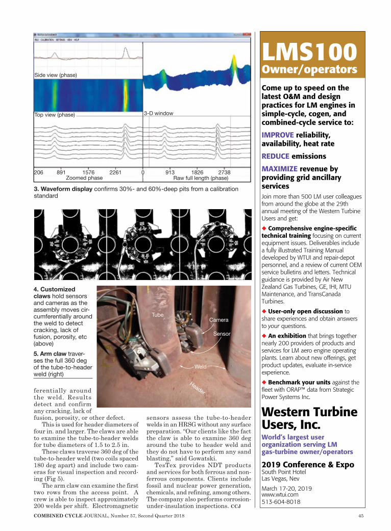
COMBINED CYCLE JOURNAL, Number 57, Second Quarter 2018 45
ferentially around the weld. Results detect and confirm any cracking, lack of fusion, porosity, or other defect.
This is used for header diameters of four in. and larger. The claws are able to examine the tube-to-header welds for tube diameters of 1.5 to 2.5 in.
These claws traverse 360 deg of the tube-to-header weld (two coils spaced 180 deg apart) and include two cam-eras for visual inspection and record-ing (Fig 5).
The arm claw can examine the first two rows from the access point. A crew is able to inspect approximately 200 welds per shift. Electromagnetic
sensors assess the tube-to-header welds in an HRSG without any surface preparation. “Our clients like the fact the claw is able to examine 360 deg around the tube to header weld and they do not have to perform any sand blasting,” said Gowatski.
TesTex provides NDT products and services for both ferrous and non-ferrous components. Clients include fossil and nuclear power generation, chemicals, and refining, among others. The company also performs corrosion-under-insulation inspections. ccj
Side view (phase)
Zoomed phase 206 891 1576 2261 0 913 1826 2738
Raw full length (phase)
3-D windowTop view (phase)
Tube
Sensor
Camera
Weld
Header
4. Customized claws hold sensors and cameras as the assembly moves cir-cumferentially around the weld to detect cracking, lack of fusion, porosity, etc (above)5. Arm claw traver- ses the full 360 deg of the tube-to-header weld (right)
3. Waveform display confirms 30%- and 60%-deep pits from a calibration standard
LMS100Owner/operatorsCome up to speed on the latest O&M and design practices for LM engines in simple-cycle, cogen, and combined-cycle service to:
IMPROVE reliability, availability, heat rate
REDUCE emissions
MAXIMIZE revenue by providing grid ancillary servicesJoin more than 500 LM user colleagues from around the globe at the 29th annual meeting of the Western Turbine Users and get:
◆ Comprehensive engine-specific technical training focusing on current equipment issues. Deliverables include a fully illustrated Training Manual developed by WTUI and repair-depot personnel, and a review of current OEM service bulletins and letters. Technical guidance is provided by Air New Zealand Gas Turbines, GE, IHI, MTU Maintenance, and TransCanada Turbines.
◆ User-only open discussion to share experiences and obtain answers to your questions.
◆ An exhibition that brings together nearly 200 providers of products and services for LM aero engine operating plants. Learn about new offerings, get product updates, evaluate in-service experience.
◆ Benchmark your units against the fleet with ORAP™ data from Strategic Power Systems Inc.
Western Turbine Users, Inc.World’s largest user organization serving LM gas-turbine owner/operators
2019 Conference & ExpoSouth Point HotelLas Vegas, Nev
March 17-20, 2019www.wtui.com513-604-8018
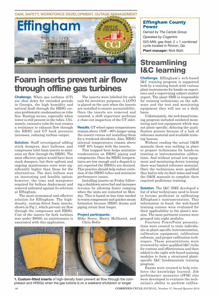
46 COMBINED CYCLE JOURNAL, Number 57, Second Quarter 2018
O&M, SAFETY, WORKFORCE DEVELOPMENT, OUTAGE MANAGEMENT
Challenge. When gas turbines (GT) are shut down for extended periods in Georgia, the high humidity and natural draft through the HRSG cre-ates problematic condensation on tube fins. Rusting occurs, especially when water is still present in the tubes. Ulti-mately, excessive tube fin rust creates a resistance to exhaust flow through the HRSG and GT back pressure increases, reducing turbine output.
Solution. Staff investigated adding stack dampers, duct balloons, and compressor inlet foam inserts to mini-mize air flow through the HRSG. The most effective option would have been stack dampers, but their upfront and ongoing maintenance costs were sig-nificantly higher than those for the alternatives. The duct balloon was an interesting and feasible option; however, the time and manpower required for balloon deployment and removal militated against its selection at Effingham.
The most economical and effective solution for Effingham: The high-density, custom-fitted foam inserts, shown in Fig 1, which prevent air flow through the compressor and HRSG. Cost of the inserts for both turbines was under $9000; no maintenance is associated with this application.
The inserts were labelled for each unit for inventory purposes. A LOTO is placed on the unit when the inserts are installed to ensure accountability. Once the inserts are removed and counted, a shift supervisor performs a close-out inspection of the GT inlet.
Results. GT wheel-space temperatures remain above 150F—90% longer using the inserts versus not installing them for a weekend shutdown. Also, HRSG internal temperatures remain above 100F 40% longer with the inserts.
This trapped heat helps minimize condensation on HRSG piping and components. Once the HRSG tempera-tures are low enough and a dispatch is not expected the HRSGs are drained. This practice should help reduce corro-sion of the HRSG tubes and minimize performance issues.
Installing inserts on Friday follow-ing a shutdown saves fuel and increases revenue by allowing faster ramping when the units are restarted on Mon-day. This is based on less time needed to warm components and quicker steam formation because HRSG drums and piping retain heat longer.
Project participants:Mike Sears, Marty McDaniel, and
Chris Hofer
Streamlining I&C learningChallenge. Effingham’s web-based I&C training program is supported both by a training bench with various plant instruments for hands-on experi-ence and a supervising subject-matter expert. The plant SME is responsible for training technicians on the soft-ware and the test and monitoring equipment they will use on a daily basis.
Unfortunately, the web-based train-ing program included outdated moni-toring and test equipment which was not plant-specific, delaying the quali-fication process because of a lack of reference material and available train-ing lessons.
Without reading the actual O&M manuals there was nothing in place to prepare technicians for hands-on training or instrumentation calibra-tions. And without actual test equip-ment and monitoring-device training there was limited reference material. Once the technicians were qualified they had to rely on their notes and read the O&M manuals to complete their required proficiency training.
Solution. The I&C SME developed a list of what technicians need to know to become proficient in calibrating Effingham’s instrumentation. This information in hand, the web-based training courses were evaluated for their applicability to the plant’s mis-sion. The most pertinent courses were grouped into eight modules.
Fourteen PowerPoint presenta-tions were created to train individu-als on plant-specific instrumentation, calibration equipment, calibration software, and proper calibration tech-niques. These presentations were reviewed by other qualified I&C techs for content and effectiveness and then added to the eight web-based training modules to form a structured plant-specific I&C fundamentals training program.
Exams were created to help rein-force the knowledge learned. Job performance measures (JPM) also were developed to evaluate the tech-nician’s ability to perform calibra-
Effingham
Foam inserts prevent air flow through offline gas turbines
Effingham County PowerOwned by The Carlyle GroupOperated by Cogentrix525-MW, gas-fired, 2 × 1 combined cycle located in Rincon, Ga Plant manager: Nick Bohl
1. Custom-fitted inserts of high-density foam prevent air flow through the com-pressor and HRSGs when the gas turbine is on a weekend shutdown or longer

Increase effectivenessand efficiency
your operations Optimize
Improve the reliability of your assets
Providing total plant innovative solutionsSiemens offers an array of solutions that breathe new life into your energy infrastructure enabling you to deliver reliable power safely to your customers.
Get empowered, call your local Siemens representative or visit siemens.com/power-generation-services
siemens.com
CCJ AD-August-2018.indd 1 7/31/18 3:42 PM
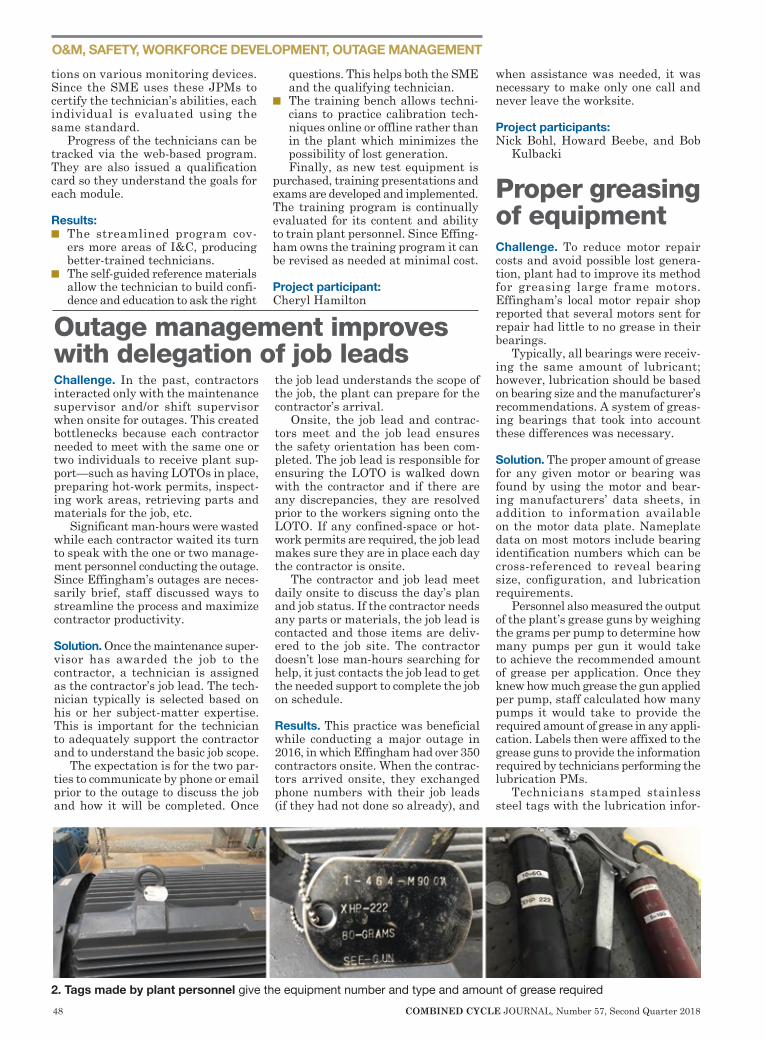
48 COMBINED CYCLE JOURNAL, Number 57, Second Quarter 2018
O&M, SAFETY, WORKFORCE DEVELOPMENT, OUTAGE MANAGEMENT
Challenge. In the past, contractors interacted only with the maintenance supervisor and/or shift supervisor when onsite for outages. This created bottlenecks because each contractor needed to meet with the same one or two individuals to receive plant sup-port—such as having LOTOs in place, preparing hot-work permits, inspect-ing work areas, retrieving parts and materials for the job, etc.
Significant man-hours were wasted while each contractor waited its turn to speak with the one or two manage-ment personnel conducting the outage. Since Effingham’s outages are neces-sarily brief, staff discussed ways to streamline the process and maximize contractor productivity.
Solution. Once the maintenance super-visor has awarded the job to the contractor, a technician is assigned as the contractor’s job lead. The tech-nician typically is selected based on his or her subject-matter expertise. This is important for the technician to adequately support the contractor and to understand the basic job scope.
The expectation is for the two par-ties to communicate by phone or email prior to the outage to discuss the job and how it will be completed. Once
the job lead understands the scope of the job, the plant can prepare for the contractor’s arrival.
Onsite, the job lead and contrac-tors meet and the job lead ensures the safety orientation has been com-pleted. The job lead is responsible for ensuring the LOTO is walked down with the contractor and if there are any discrepancies, they are resolved prior to the workers signing onto the LOTO. If any confined-space or hot-work permits are required, the job lead makes sure they are in place each day the contractor is onsite.
The contractor and job lead meet daily onsite to discuss the day’s plan and job status. If the contractor needs any parts or materials, the job lead is contacted and those items are deliv-ered to the job site. The contractor doesn’t lose man-hours searching for help, it just contacts the job lead to get the needed support to complete the job on schedule.
Results. This practice was beneficial while conducting a major outage in 2016, in which Effingham had over 350 contractors onsite. When the contrac-tors arrived onsite, they exchanged phone numbers with their job leads (if they had not done so already), and
when assistance was needed, it was necessary to make only one call and never leave the worksite.
Project participants:Nick Bohl, Howard Beebe, and Bob
Kulbacki
Proper greasing of equipmentChallenge. To reduce motor repair costs and avoid possible lost genera-tion, plant had to improve its method for greasing large frame motors. Effingham’s local motor repair shop reported that several motors sent for repair had little to no grease in their bearings.
Typically, all bearings were receiv-ing the same amount of lubricant; however, lubrication should be based on bearing size and the manufacturer’s recommendations. A system of greas-ing bearings that took into account these differences was necessary.
Solution. The proper amount of grease for any given motor or bearing was found by using the motor and bear-ing manufacturers’ data sheets, in addition to information available on the motor data plate. Nameplate data on most motors include bearing identification numbers which can be cross-referenced to reveal bearing size, configuration, and lubrication requirements.
Personnel also measured the output of the plant’s grease guns by weighing the grams per pump to determine how many pumps per gun it would take to achieve the recommended amount of grease per application. Once they knew how much grease the gun applied per pump, staff calculated how many pumps it would take to provide the required amount of grease in any appli-cation. Labels then were affixed to the grease guns to provide the information required by technicians performing the lubrication PMs.
Technicians stamped stainless steel tags with the lubrication infor-
tions on various monitoring devices. Since the SME uses these JPMs to certify the technician’s abilities, each individual is evaluated using the same standard.
Progress of the technicians can be tracked via the web-based program. They are also issued a qualification card so they understand the goals for each module.
Results: n The streamlined program cov-
ers more areas of I&C, producing better-trained technicians.
n The self-guided reference materials allow the technician to build confi-dence and education to ask the right
questions. This helps both the SME and the qualifying technician.
n The training bench allows techni-cians to practice calibration tech-niques online or offline rather than in the plant which minimizes the possibility of lost generation.Finally, as new test equipment is
purchased, training presentations and exams are developed and implemented. The training program is continually evaluated for its content and ability to train plant personnel. Since Effing-ham owns the training program it can be revised as needed at minimal cost.
Project participant: Cheryl Hamilton
Outage management improves with delegation of job leads
2. Tags made by plant personnel give the equipment number and type and amount of grease required
What’s with Air Cooled Condensers?
The AT-ACC™ with nuCore™ provides a variety of benefits, including:
• Reduced Noise• Less mechanical equipment• A lower height profile• A reduced visual impact• Less susceptibility to wind effects• Lower levels of vibrations• Reduced total installed costs• A reduced risk of recirculation
Learn about our unique advantage to optimize the ACC design with unprecedented precision utilizing the inherent benefits of the nuCore heat exchanger manufactured exclusively by EVAPCO-BLCT.
Visit EVAPCO-BLCT.com
F E A T U R I N G T H E
M A N U FA C T U R E D BY
Designed to reduce an air cooled condenser’s total installed cost, the Advanced Technology™ ACC features a nuCore™ Heat Exchanger for more efficient heat transfer.
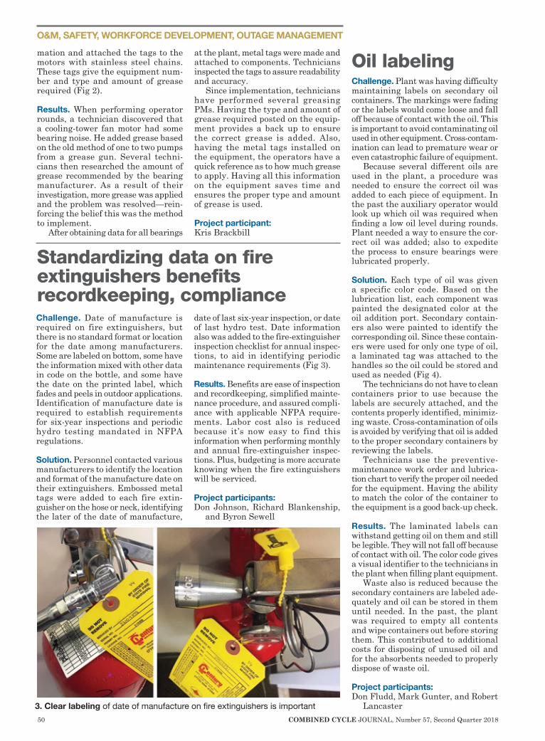
50 COMBINED CYCLE JOURNAL, Number 57, Second Quarter 2018
O&M, SAFETY, WORKFORCE DEVELOPMENT, OUTAGE MANAGEMENT
Challenge. Date of manufacture is required on fire extinguishers, but there is no standard format or location for the date among manufacturers. Some are labeled on bottom, some have the information mixed with other data in code on the bottle, and some have the date on the printed label, which fades and peels in outdoor applications. Identification of manufacture date is required to establish requirements for six-year inspections and periodic hydro testing mandated in NFPA regulations.
Solution. Personnel contacted various manufacturers to identify the location and format of the manufacture date on their extinguishers. Embossed metal tags were added to each fire extin-guisher on the hose or neck, identifying the later of the date of manufacture,
date of last six-year inspection, or date of last hydro test. Date information also was added to the fire-extinguisher inspection checklist for annual inspec-tions, to aid in identifying periodic maintenance requirements (Fig 3).
Results. Benefits are ease of inspection and recordkeeping, simplified mainte-nance procedure, and assured compli-ance with applicable NFPA require-ments. Labor cost also is reduced because it’s now easy to find this information when performing monthly and annual fire-extinguisher inspec-tions. Plus, budgeting is more accurate knowing when the fire extinguishers will be serviced.
Project participants:Don Johnson, Richard Blankenship,
and Byron Sewell
Oil labelingChallenge. Plant was having difficulty maintaining labels on secondary oil containers. The markings were fading or the labels would come loose and fall off because of contact with the oil. This is important to avoid contaminating oil used in other equipment. Cross-contam-ination can lead to premature wear or even catastrophic failure of equipment.
Because several different oils are used in the plant, a procedure was needed to ensure the correct oil was added to each piece of equipment. In the past the auxiliary operator would look up which oil was required when finding a low oil level during rounds. Plant needed a way to ensure the cor-rect oil was added; also to expedite the process to ensure bearings were lubricated properly.
Solution. Each type of oil was given a specific color code. Based on the lubrication list, each component was painted the designated color at the oil addition port. Secondary contain-ers also were painted to identify the corresponding oil. Since these contain-ers were used for only one type of oil, a laminated tag was attached to the handles so the oil could be stored and used as needed (Fig 4).
The technicians do not have to clean containers prior to use because the labels are securely attached, and the contents properly identified, minimiz-ing waste. Cross-contamination of oils is avoided by verifying that oil is added to the proper secondary containers by reviewing the labels.
Technicians use the preventive-maintenance work order and lubrica-tion chart to verify the proper oil needed for the equipment. Having the ability to match the color of the container to the equipment is a good back-up check.
Results. The laminated labels can withstand getting oil on them and still be legible. They will not fall off because of contact with oil. The color code gives a visual identifier to the technicians in the plant when filling plant equipment.
Waste also is reduced because the secondary containers are labeled ade-quately and oil can be stored in them until needed. In the past, the plant was required to empty all contents and wipe containers out before storing them. This contributed to additional costs for disposing of unused oil and for the absorbents needed to properly dispose of waste oil.
Project participants:Don Fludd, Mark Gunter, and Robert
Lancaster
mation and attached the tags to the motors with stainless steel chains. These tags give the equipment num-ber and type and amount of grease required (Fig 2).
Results. When performing operator rounds, a technician discovered that a cooling-tower fan motor had some bearing noise. He added grease based on the old method of one to two pumps from a grease gun. Several techni-cians then researched the amount of grease recommended by the bearing manufacturer. As a result of their investigation, more grease was applied and the problem was resolved—rein-forcing the belief this was the method to implement.
After obtaining data for all bearings
at the plant, metal tags were made and attached to components. Technicians inspected the tags to assure readability and accuracy.
Since implementation, technicians have performed several greasing PMs. Having the type and amount of grease required posted on the equip-ment provides a back up to ensure the correct grease is added. Also, having the metal tags installed on the equipment, the operators have a quick reference as to how much grease to apply. Having all this information on the equipment saves time and ensures the proper type and amount of grease is used.
Project participant:Kris Brackbill
Standardizing data on fire extinguishers benefits recordkeeping, compliance
3. Clear labeling of date of manufacture on fire extinguishers is important
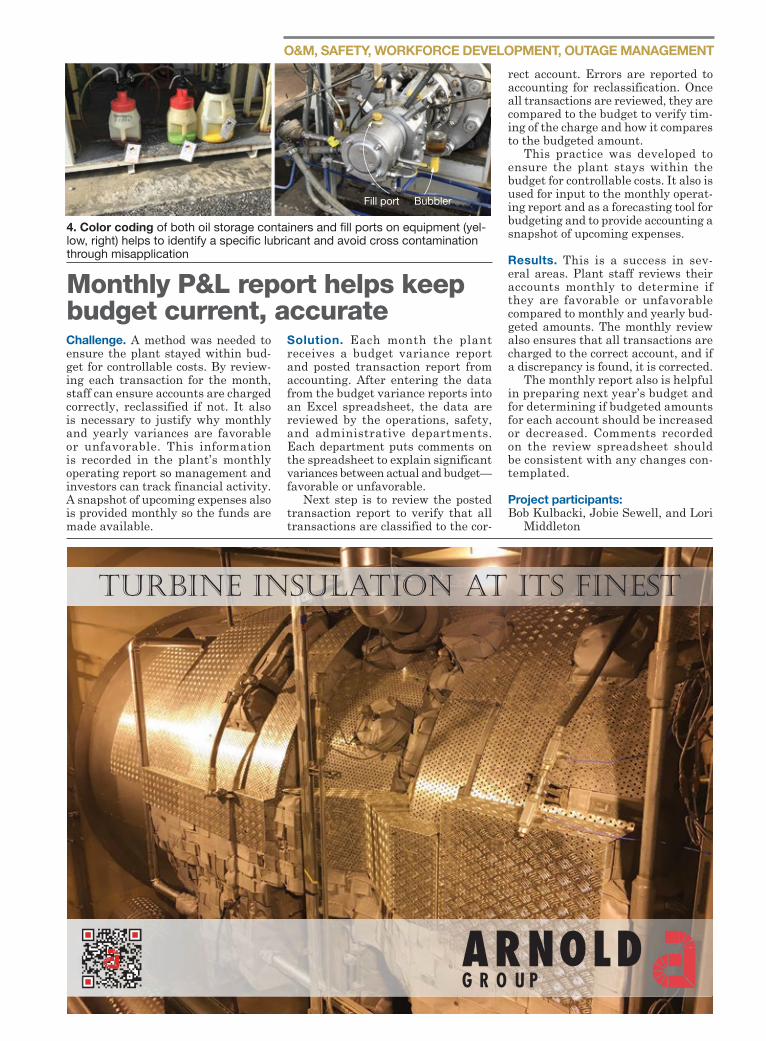
O&M, SAFETY, WORKFORCE DEVELOPMENT, OUTAGE MANAGEMENT
Challenge. A method was needed to ensure the plant stayed within bud-get for controllable costs. By review-ing each transaction for the month, staff can ensure accounts are charged correctly, reclassified if not. It also is necessary to justify why monthly and yearly variances are favorable or unfavorable. This information is recorded in the plant’s monthly operating report so management and investors can track financial activity. A snapshot of upcoming expenses also is provided monthly so the funds are made available.
Solution. Each month the plant receives a budget variance report and posted transaction report from accounting. After entering the data from the budget variance reports into an Excel spreadsheet, the data are reviewed by the operations, safety, and administrative departments. Each department puts comments on the spreadsheet to explain significant variances between actual and budget—favorable or unfavorable.
Next step is to review the posted transaction report to verify that all transactions are classified to the cor-
rect account. Errors are reported to accounting for reclassification. Once all transactions are reviewed, they are compared to the budget to verify tim-ing of the charge and how it compares to the budgeted amount.
This practice was developed to ensure the plant stays within the budget for controllable costs. It also is used for input to the monthly operat-ing report and as a forecasting tool for budgeting and to provide accounting a snapshot of upcoming expenses.
Results. This is a success in sev-eral areas. Plant staff reviews their accounts monthly to determine if they are favorable or unfavorable compared to monthly and yearly bud-geted amounts. The monthly review also ensures that all transactions are charged to the correct account, and if a discrepancy is found, it is corrected.
The monthly report also is helpful in preparing next year’s budget and for determining if budgeted amounts for each account should be increased or decreased. Comments recorded on the review spreadsheet should be consistent with any changes con-templated.
Project participants:Bob Kulbacki, Jobie Sewell, and Lori
Middleton
Fill port Bubbler
4. Color coding of both oil storage containers and fill ports on equipment (yel-low, right) helps to identify a specific lubricant and avoid cross contamination through misapplication
Monthly P&L report helps keep budget current, accurate
TURBınE ınSULATıOn AT ıTS FınEST
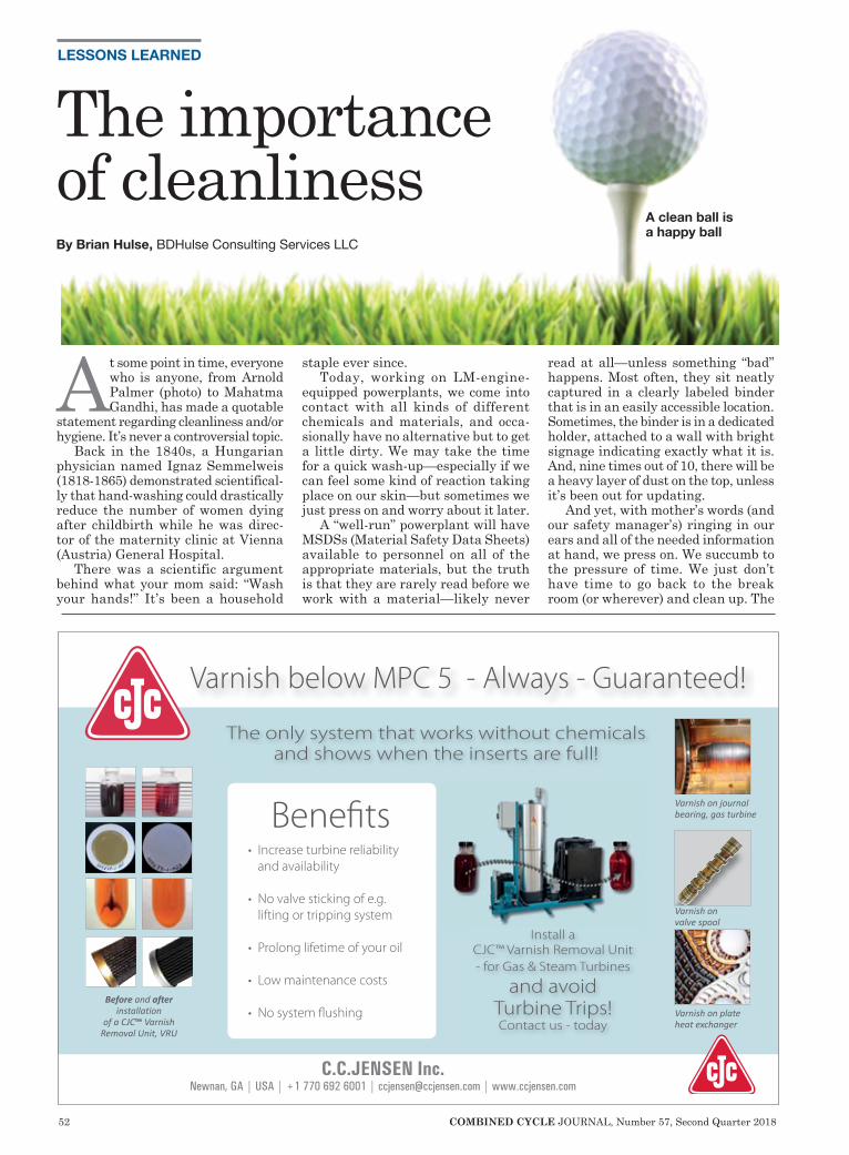
52 COMBINED CYCLE JOURNAL, Number 57, Second Quarter 2018
LESSONS LEARNED
At some point in time, everyone who is anyone, from Arnold Palmer (photo) to Mahatma Gandhi, has made a quotable
statement regarding cleanliness and/or hygiene. It’s never a controversial topic.
Back in the 1840s, a Hungarian physician named Ignaz Semmelweis (1818-1865) demonstrated scientifical-ly that hand-washing could drastically reduce the number of women dying after childbirth while he was direc-tor of the maternity clinic at Vienna (Austria) General Hospital.
There was a scientific argument behind what your mom said: “Wash your hands!” It’s been a household
staple ever since. Today, working on LM-engine-
equipped powerplants, we come into contact with all kinds of different chemicals and materials, and occa-sionally have no alternative but to get a little dirty. We may take the time for a quick wash-up—especially if we can feel some kind of reaction taking place on our skin—but sometimes we just press on and worry about it later.
A “well-run” powerplant will have MSDSs (Material Safety Data Sheets) available to personnel on all of the appropriate materials, but the truth is that they are rarely read before we work with a material—likely never
read at all—unless something “bad” happens. Most often, they sit neatly captured in a clearly labeled binder that is in an easily accessible location. Sometimes, the binder is in a dedicated holder, attached to a wall with bright signage indicating exactly what it is. And, nine times out of 10, there will be a heavy layer of dust on the top, unless it’s been out for updating.
And yet, with mother’s words (and our safety manager’s) ringing in our ears and all of the needed information at hand, we press on. We succumb to the pressure of time. We just don’t have time to go back to the break room (or wherever) and clean up. The
The importance of cleanlinessBy Brian Hulse, BDHulse Consulting Services LLC
A clean ball is a happy ball
C.C.JENSEN Inc.Newnan, GA | USA | +1 770 692 6001 | [email protected] | www.ccjensen.com
Before and after installation
of a CJC™ Varnish Removal Unit, VRU
Varnish below MPC 5 - Always - Guaranteed!
The only system that works without chemicals and shows when the inserts are full!
• Increase turbine reliability and availability
• No valve sticking of e.g. lifting or tripping system
• Prolong lifetime of your oil
• Low maintenance costs
• No system �ushing
Bene�ts Varnish on journal bearing, gas turbine
Varnish on plate heat exchanger
Varnish on valve spool
Install a CJC™ Varnish Removal Unit - for Gas & Steam Turbines
and avoid Turbine Trips!Contact us - today
COMBINED CYCLE JOURNAL, Number 57, Second Quarter 2018 53
LESSONS LEARNEDjob has to be finished, readings taken, boiler blown down, RO back-flushed, etc. There’s always something more important than washing your hands.
When I was in the US Navy, work-ing for the first time with LM (and Allison) gas turbines on a Spruance-class destroyer, I got one of those “life lessons” that one does not forget quickly. I had been aboard ship for about three and a half years when I came down a ladder in the engine room and there at the bottom was one of my shipmates. . .on the deck plates. . .experiencing some kind of seizure.
I called for help and, while it was en route, I tried to keep him from hurting himself as he jerked spasmodically. I didn’t know what was happening or what else to do. He had never (to my knowledge) had this happen before. Finally, the corpsmen showed up and, since we were in our home port, he was taken to the base hospital.
It turned out that he had “synthetic oil poisoning.” There are several chemi-cals contained in the oil that can cause harm. Some of them are trans-dermal (they can go through your skin) and the body doesn’t metabolize them, so, they build up in your system over time. My shipmate’s hygiene practices were particularly poor when it came to work-ing with the oil (he didn’t wash after
contact, he didn’t immediately change clothes when they became soaked, etc). Because of that, and his system’s specific sensitivity to the chemicals, he had a nervous system reaction that resulted in the seizure. Since the build-up in his system couldn’t be removed, he lost his MOS (Military Occupational Specialty) code and could no longer be in the machinery spaces of the ship.
Although the MSDS would lead you to believe that synthetic oil (as well as many other chemical compounds) is relatively safe, there are hygiene warnings/recommendations sprinkled throughout the text. It’s also important to know that everyone is different. Some folks can eat jalapeno peppers and some can’t. Some can tolerate more of a certain chemical and some can’t tolerate hardly any of it at all.
As plant managers and supervi-sors, it’s critical for us to always have our teams’ best interests at heart. We have to make time for personnel to take care of themselves—wash up, change clothes, and whatever else is needed to keep them healthy. It’s always best to err on the side of conservativism. It won’t hurt to be overly cautious, but it may hurt to be in a hurry.
We all have safety meetings, and we all are always on the hunt for new—and applicable— topics to dis-
cuss. Reading an MSDS or two at each safety meeting is not a bad thing to incorporate. You won’t get through the whole binder anytime soon, but you may spark enough interest to get folks looking at it proactively a little more often.
Take a tour through your bath-rooms, break rooms, whatever facilities you have for personal hygiene. Take stock of what’s available for everyone to use. Make sure it’s up to your stan-dards—what you would want to use if you had to clean up after a shift or a spill or working on the gas turbine. If you don’t see something you’d like, chances are it’s not going to be that expensive or difficult to correct the deficiency. Do it, and let everyone know you’ve done it. Not only may they use it, but they will appreciate your efforts in looking out for their health and safety.
Be aware and observant. If you see one of your folks coming in from a job or in the process of doing one and they have signs of some exposure that concerns you, say something. Let them know you’re concerned and that you’d like them to get cleaned up as soon as practical. Yes, it’s inconvenient, and yes, it might hold things up a bit, but again it sends the message that you’re serious about their safety.
■
MORE POWER TO YOUMORE POWER MORE POWER
Replacement Filters and Components■ Cartridge, panel and compact filters■ Pulse system valves, solenoids and controllers■ Inlet hood components
Certified Field Service Crews■ Filter/pre-filter changeouts■ System inspections and check-ups■ Coatings, corrections and component replacements
With over a century of filtration expertise and the first to manufacture air intake and pulse system components for gas turbines, Donaldson® is well-equipped to put more power in your hands.
CONTACT US FORFILTERS, PARTS, OR SERVICE
866.569.7256© 2018 Donaldson Company, Inc.
Donaldson.com [email protected]
54 COMBINED CYCLE JOURNAL, Number 57, Second Quarter 2018
LESSONS LEARNED
It’s an age-old quest—building the better mouse trap. The US Patent Office has issued over 4400 patents for mouse traps
although, paradoxically, only about 20 of them have ever seen any com-mercial success.
This would lead one to think that better is a term that needs more specific definition. Smaller? Easier to operate? More mice out of service per minute of trap service? Cheaper? Limited contact with the eradicated mouse? What is better?
When it comes to the air that LM-series gas turbines ingest, better focuses on three critical areas: n Cleanliness. n Temperature (45F to 65F usually
is optimal). n Direction (gas turbines don’t like
directional disturbances of the air at their inlets). When it comes to plant owners,
they’re usually looking to keep expen-ditures down, but they budget for maintenance and are willing to look at reasonable improvements to their existing equipment. With that in mind, let’s agree that the third area, “direc-tion” is off the table. Design of the inlet-duct structure is what it is. The engine has run with it to date and is none the worse off for it. It could likely be redesigned and improved, but the effort and costs would be unaccept-ably high.
CleanlinessSo what about cleanliness? How can cleanliness be improved without bust-ing the maintenance budget or incur-ring significant capital costs?
Gaskets. Man-doors, hatches, structural flanges all have gaskets that deteriorate over time. Once the gasket fails, untreated air can enter the duct.
Filtration and/or temperature control may be adversely affected. Inspect gas-kets regularly and fix them promptly when discrepancies are found.
Filters. There are times when the critical drivers of operational excel-lence (cost, vendor alliances, logistics, quality, product performance, product availability, etc) get out of whack. We may have sacrificed too much product performance for some other driver. If the product isn’t performing, it doesn’t matter how easy it is to get or how cheap it is. It’s not doing the job, and that is unacceptable. Make sure your product priorities are right.
Theory of operation. Without get-ting into redesigns or rebuilding, take stock of your current theory of opera-tion versus your actual operating envi-ronment. Things change. Certain site elements may have not been taken into consideration that have now become apparent. Your EPC contractor may have bought the generic duct offering with no site-specific options to save money, or out of ignorance.
Example: You may benefit from adding a pre-filter element to your high-efficiency filters. This may not only improve cleanliness, but may extend the life of your high-efficiency filter elements. If you’re in a marine environment, you may benefit from
Building the better mouse trap
From rebabbitting to reverse engineering, custom designs to precision manufacturing, diagnosing problems to optimizing performance, Bearings Plus provides the bearing and seal solutions for your critical turbomachinery.
713.948.6000www.bearingsplus.com/CCJ
Bearings Plus provides the bearing and seal solutions for your critical turbomachinery.
Before After
The Aftermarket Arm of
CCO Bearings Plus - Bearing Repair Ad - CCJ - 030118.indd 1 3/6/18 9:29 AM
COMBINED CYCLE JOURNAL, Number 57, Second Quarter 2018 55
LESSONS LEARNED
Cust-O-Fab Specialty Services offers
a convenient single source contact
for construction and fabrication. We
provide cost-effective retrofit solutions
for your power generation project.
Safety, Quality, Schedule & Value.
» Exhaust Plenum Upgrades
» Exhaust Ductwork & Silencers
» Inlet Filterhouse & Cooling Systems
» Inlet Ductwork & Silencers
» Speciality Welding Services
» Boiler Upgrades and Repair
918.245.6685 • www.custofab.com
Look to Cust-O-Fab for the experience, expertise and
dedication to provide a safe, well planned and efficient
project… every time.
the addition of demister pads at the front of the duct.
Conversely, you may benefit from the removal of a feature. In one case, the O&M team I was on dropped the overall differential pressure of the duct 0.5 in. H2O by removing a set of inertial separator panels that we found to be ineffective in our environment.
Preservation. Maintaining the integrity of structural surfaces—espe-cially downstream of the high-efficien-cy filter elements—is critical. Rust and failing coatings are your (and your engine’s) enemy. Doing spot repairs is perfectly acceptable, but you have to ensure you’re doing it right.
Engines are sensitive to a lot of materials. For instance, they don’t like zinc, a common element in many prim-ers used to protect steel surfaces from corrosion. Unlike regular paints or epoxies which resist corrosion by form-ing an impermeable barrier between the metal and atmospheric moisture, zinc-rich primers provide corrosion protection by electrical means: The zinc and the steel form a tiny electri-cal cathodic cell that protects the steel at the expense of the zinc. Of course, the zinc primer also provides a little “barrier” protection as well.
However, these same properties react poorly with the engine’s gas-path
surfaces, so zinc-rich primers should be avoided. The best advice is to con-tact the duct manufacturer and get a primer/paint spec from them.
Instrumentation. Keeping instru-ments calibrated seems like a no-brainer, but in this case it is a special challenge. Pressure and differential-pressure instruments typically mea-sure very small quantities. The struc-ture has a habit of vibrating because of air buffeting around inside. Instru-ments are mounted to the structure. Vibration can wreak havoc on them, sometimes actually shaking apart the instruments. Check them regularly.
Temperature instruments may be affected by what side of the duct structure they’re located on (catching morning or late afternoon sun).
Don’t be afraid to suggest addi-tional or more accurate instru-ments to refine your understand-ing of what’s occur-ring in each step of the process inside the duct. Build credibility and a database with them. Being able to examine the process at a more
granular level may help justify work orders or even capital expenditures.
Temperature Controlling inlet air temperature has a direct effect on the horsepower output of your engine. Keeping the air going into the machine in that “Goldilocks” range of 45F to 65F will help the engine perform at its best. If we have a mechanical means to do this installed (chiller, evap cooler, fog-ging, etc) in the duct, all the better, but there are a couple of tricks we can use to our advantage when we don’t have the mechanical means at our disposal.
Coatings. Several high-tech coat-ings are commercially available (such as coated polymer stacks, ceram-ic beaded polymers, LO-MIT high-reflective coatings, etc) that reduce structural heat absorption. Much like your car sitting in the direct sunlight,
duct structures often are quite a bit hotter than the ambient air
temperature. Theoretically, a metal surface
in still, dry 77F air can reach 248F. Because of the variables in wind, humidity, sun angle, etc,
it usually maxes out somewhere between 95F and 122F. Still, that’s a lot of heat available in

SAVE THE DATE! July 22-24, 20193 days of practical knowledge
you can take back to your company
Learn from experts all over the world and participate in Q&A after each session. Take back ideas that will SAVE your company money. Here’s what others say about HRSG FORUM:
3RD
ANNU
AL
CONF
EREN
CE
W I T H B O B A N D E R S O NFORUM
“ There’s a big range of speakers and a wide range of technical topics.”
“Amazing, robust Q&A after each presentation.”
“These are passionate speakers, experts who know what they are talking about.”
“A tremendous learning experience.”
July 22–24, 2019Hilton Orlando
6001 Destination Parkway, Orlando, FL
SAVE THE DATE:

COMBINED CYCLE JOURNAL, Number 57, Second Quarter 2018 57
the structure to bring the temperature of the air inside up. The next time you’re getting ready to paint the exte-rior of the duct, investigate the use of one of these coatings on the sides and top of the duct.
Lagging. An old friend from the steam world, the concept of lagging—or insulation—of the duct has proven successful. However, depending on the site environment, the cost of ongoing maintenance may be prohibitive. Coat-ings may be a better solution in all but the driest of climates. If your duct does have a mechanical means of tem-perature control installed, enclosed, or shielded insulation should be consid-ered on the external structural sur-faces between the introduction point (chiller coils, evap-cooler panels, etc) and the front of the gas turbine. It’s a low-cost way of ensuring you get all of the “goodness” out of the system.
Gaskets, preservation, instru-mentation. Everything that was said above in these three areas can be equally applied to temperature control. Thus, their importance is not just doubled, but is raised by a magni-tude. Keeping up in these three areas is nothing but pure goodness as far as your gas turbine is concerned.
Thus, by taking advantage of the maintenance budget you’ve been allo-cated, leveraging some new technolo-gies, and applying modest amounts of capital judiciously, you can take the mediocre mouse trap you already have in your back yard and turn it into a lean, mean mouse killin’ machine. In other words, a much “better” mouse trap. ccj
About the authorBrian Hulse has spent his 40+ post-college years dealing with gas turbines from many per-spectives. These include the US Navy, EPC, O&M (owner and third party), asset man-agement, compo-nent repair/reverse engineering/man-ufacture, mobile powerplant pack-aging, and depot MRO management.
Today, the former Western Turbine Users Inc board member is an indepen-dent consultant, sharing his expertise on safety, O&M, quality control, finan-cial accountability, and team-building with leading owner/operators. Hulse’s deep technical experience underpins his work in the development of depot-level work scopes, conduct of root-cause failure analyses, guidance on plant audits and best practices, and as an expert witness.
Users Group
Air Cooled Condenser Users Group
October 8 - 11, 2018
Cheyenne Mountain Resort, Colorado Springs, ColoAgenda at www.acc-usersgroup.org
Tenth AnnualConference
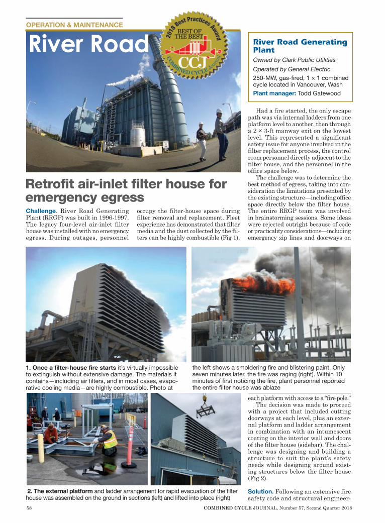
58 COMBINED CYCLE JOURNAL, Number 57, Second Quarter 2018
OPERATION & MAINTENANCE
Challenge. River Road Generating Plant (RRGP) was built in 1996-1997. The legacy four-level air-inlet filter house was installed with no emergency egress. During outages, personnel
occupy the filter-house space during filter removal and replacement. Fleet experience has demonstrated that filter media and the dust collected by the fil-ters can be highly combustible (Fig 1).
Had a fire started, the only escape path was via internal ladders from one platform level to another, then through a 2 × 3-ft manway exit on the lowest level. This represented a significant safety issue for anyone involved in the filter replacement process, the control room personnel directly adjacent to the filter house, and the personnel in the office space below.
The challenge was to determine the best method of egress, taking into con-sideration the limitations presented by the existing structure—including office space directly below the filter house. The entire RRGP team was involved in brainstorming sessions. Some ideas were rejected outright because of code or practicality considerations—including emergency zip lines and doorways on
each platform with access to a “fire pole.”The decision was made to proceed
with a project that included cutting doorways at each level, plus an exter-nal platform and ladder arrangement in combination with an intumescent coating on the interior wall and doors of the filter house (sidebar). The chal-lenge was designing and building a structure to suit the plant’s safety needs while designing around exist-ing structures below the filter house (Fig 2).
Solution. Following an extensive fire safety code and structural engineer-
River Road Generating PlantOwned by Clark Public UtilitiesOperated by General Electric250-MW, gas-fired, 1 × 1 combined cycle located in Vancouver, WashPlant manager: Todd Gatewood
River Road
Retrofit air-inlet filter house for emergency egress
1. Once a filter-house fire starts it’s virtually impossible to extinguish without extensive damage. The materials it contains—including air filters, and in most cases, evapo-rative cooling media—are highly combustible. Photo at
the left shows a smoldering fire and blistering paint. Only seven minutes later, the fire was raging (right). Within 10 minutes of first noticing the fire, plant personnel reported the entire filter house was ablaze
2. The external platform and ladder arrangement for rapid evacuation of the filter house was assembled on the ground in sections (left) and lifted into place (right)

COMBINED CYCLE JOURNAL, Number 57, Second Quarter 2018 59
ing analysis, a custom emergency egress was designed, pre-fabricated, assembled, and installed (Fig 3). This reduced the personnel concern regarding rapid egress. The retrofit external platform and ladder assem-bly eliminated the safety hazard of the internal “trap door and ladder” access system supplied with the original filter house.
Results. A process failure-modes effects analysis (FMEA) was com-pleted. Prior to the retrofit, the total risk priority number (RPN) was 784. Following completion of the retrofit, the RPN was reduced to 150—a reduc-tion in RPN of 81%.
Project participants:Todd Gatewood, plant managerKen Roach, maintenance managerSteve Ellsworth, shift supervisorTerry Toland, energy resources man-
ager
How intumescent coatings workIntumescent coatings, often referred to as intumescent paint, are a passive method of fire resis-tance. They consist of a series of chemicals suspended in a binder. When the binder is exposed to heat it begins to soften, which allows the suspended chemicals to react and release a vapor that creates a foam. Carbonization occurs and the foam solidifies into a black insulating material that helps keep doors and the escape structure, such as that shown in Fig 3, relatively cool.
3. Emergency escape tower has landings on each floor of the filter house, making it easily accessible through the doorways installed
Oklahoma’s Only University of APPLIED Technology
Empowering the Next Generation of Power Plant Operators
OSUIT students engage in a two-year degree plan that includes a paid internship & significant progress towards an initial Plant Operator qualification.
Visit osuit.edu/powerplant for the top ten reasons to pursue your degree at OSUIT.
NEBRASKA
Energy
Generation
OperationswA.A.S. degree in 18 months.wFace-to-face at SCC’s Milford, NE campus. Somecourses online.wGraduates are trained to operate Combined Cycle, coal, nuclear, and other electrical and fluid fuel generating plants.wFocus areas: Fossil/Biofuels, Nuclear and Military.wTransfer agreements with Bismarck (N.D.) State College and Thomas Edison (N.J.) State College allow SCC graduates to pursue a bachelor’s degree.Call 800-933-7223 ext. 8394
“LES appreciates the foresight at SCC that drove investing the time and resources to bring this program online. Having a local program that Nebraska utilities can help mold to fit their specific needs is a valuable resource that LES is proud to be a part of. The desire to source locally-educated and skilled operations staff for our generation facilities has been met by SCC.”
Brian McReynolds,Generation Operations, Lincoln Electric System
www.southeast.edu/
EnergyAtSCC
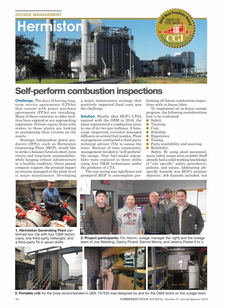
60 COMBINED CYCLE JOURNAL, Number 57, Second Quarter 2018
OUTAGE MANAGEMENT
Challenge. The days of having long-term service agreements (LTSAs) that coexist with power purchase agreements (PPAs) are vanishing. Many of these contracts in older facil-ities have expired or are approaching expiration. Private-equity firms with stakes in these plants are looking at maximizing their returns on the assets.
Strategic independent power pro-ducers (IPPs), such as Hermiston Generating Plant (HGP), would like to strike a balance between short-term return and long-term sustainability, while keeping critical infrastructure in a healthy condition. Given parent company support, the greatest impact on returns managed at the plant level is major maintenance. Developing
a major maintenance strategy that positively impacted fixed costs was the challenge.
Solution. Shortly after HGP’s LTSA expired with the OEM in 2016, the plant experienced a combustion issue in one of its two gas turbines. A bore-scope inspection revealed damaged diffusers on several fuel nozzles. Plant management contracted a third-party technical advisor (TA) to assess the issue. Because of time constraints, management decided to “self-perform” the outage. Nine fuel-nozzle assem-blies were replaced in three shifts using four O&M technicians under the guidance of a TA.
The cost saving was significant and prompted HGP to contemplate per-
forming all future combustion inspec-tions with in-house labor.
To implement an in-house outage program, the following considerations had to be evaluated:n Safety.n Training.n Cost.n Schedule.n Experience.n Tooling.n Parts availability and sourcing.n Reliability.
Safety. By using plant personnel, many safety issues were avoided. Staff already had a solid working knowledge of “site specific” safety procedures, policies, and issues. Addressing job-specific hazards was HGP’s primary objective. Job hazards included, but
2. Project participants: Tim Hevrin, outage manager (far right) and the outage team of Joe Wedding, Danny Picard, Dennis Morris, and Jeremy Parker (l to r)
1. Hermiston Generating Plant per-formed two CIs with four O&M techni-cians, one third-party millwright, and a third-party TA in seven shifts
3. Portable crib for the tools recommended in GEK 107535 was designed by and for the O&M techs on the outage team
Self-perform combustion inspections
Hermiston
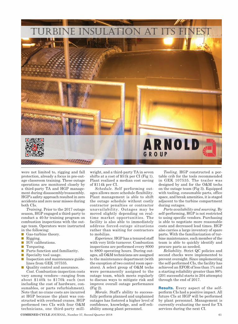
COMBINED CYCLE JOURNAL, Number 57, Second Quarter 2018 61
were not limited to, rigging and fall protection, already a focus in pre-out-age classroom training. These outage operations are monitored closely by a third-party TA and HGP manage-ment during disassembly/reassembly. HGP’s safety approach resulted in zero accidents and zero near misses during both CIs.
Training. Prior to the 2017 outage season, HGP engaged a third-party to conduct a 40-hr training program on combustion inspections with the out-age team. Operators were instructed in the following:n Gas-turbine theory.n Rigging.n IGV calibrations.n Torqueing.n Parts function and familiarity.n Specialty tool usage.n Inspection and maintenance guide-
lines from GEK 107535.n Quality control and assurance.
Cost. Combustion-inspection costs vary among vendors—ranging from about $140k to $170k each (not including the cost of hardware, con-sumables, or parts refurbishment). Note that no crane costs are incurred at HGP because the plant was con-structed with overhead cranes. HGP performed two CIs with four O&M technicians, one third-party mill-
wright, and a third-party TA in seven shifts at a cost of $51k per CI (Fig 1). Plant realized a median cost saving of $114k per CI.
Schedule. Self performing out-ages allows more schedule flexibility. Plant management is able to shift the outage schedule without costly contractor penalties or contractor unavailability. Outages may be moved slightly depending on real-time market opportunities. The facility is also able to immediately address forced-outage situations rather than waiting for contractors to mobilize.
Experience. HGP has a tenured staff with very little turnover. Combustion inspections are performed every 8000 to 8800 operating hours. During out-ages, all O&M technicians are assigned to the maintenance department (with the exception of two control room oper-ators). A select group of O&M techs were permanently assigned to the outage team, which meets regularly to discuss ways to mitigate risk and improve overall outage performance (Fig 2).
Morale. Staff’s ability to success-fully perform planned and unplanned outages has fostered a higher level of confidence, knowledge, and self-reli-ability among plant personnel.
Tooling. HGP constructed a por-table crib for the tools recommended in GEK 107535. The trailer was designed by and for the O&M techs on the outage team (Fig 3). Equipped with tooling, consumable parts, office space, and break amenities, it is staged adjacent to the turbine compartment during outages.
Parts availability and sourcing. By self-performing, HGP is not restricted to using specific vendors. Purchasing is able to negotiate more reasonable costs and decreased lead times. HGP also carries a large inventory of spare parts. With the familiarization of tur-bine maintenance, each member of the team is able to quickly identify and procure parts as needed.
Reliability. Strict QC policies and second checks were implemented to prevent oversight. Since implementing the self-performed CIs, the facility has achieved an EFOR of less than 1% and a starting reliability greater than 98% (201 successful starts in 204 attempts) through the end of 2017.
Results. Every aspect of the self-perform CIs had a positive impact. All future CIs at HGP will be performed by plant personnel. Management is currently evaluating the need for TA services during the next CI.
TURBınE ınSULATıOn AT ıTS FınEST
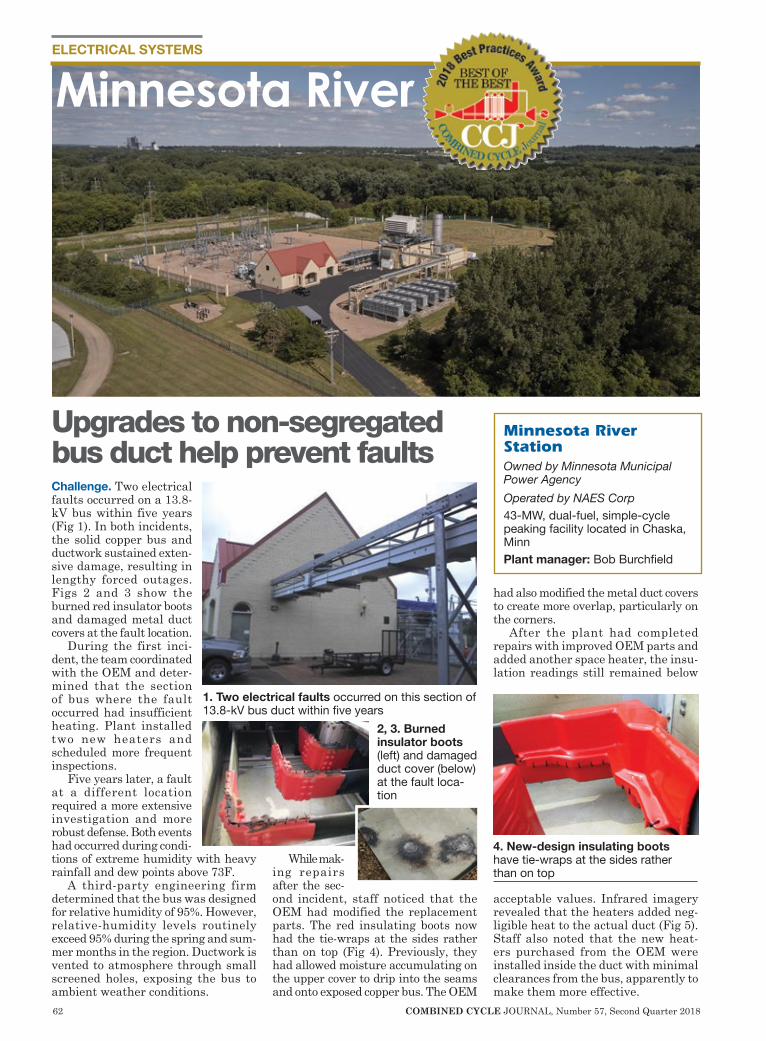
62 COMBINED CYCLE JOURNAL, Number 57, Second Quarter 2018
ELECTRICAL SYSTEMS
Challenge. Two electrical faults occurred on a 13.8-kV bus within five years (Fig 1). In both incidents, the solid copper bus and ductwork sustained exten-sive damage, resulting in lengthy forced outages. Figs 2 and 3 show the burned red insulator boots and damaged metal duct covers at the fault location.
During the first inci-dent, the team coordinated with the OEM and deter-mined that the section of bus where the fault occurred had insufficient heating. Plant installed two new heaters and scheduled more frequent inspections.
Five years later, a fault at a different location required a more extensive investigation and more robust defense. Both events had occurred during condi-tions of extreme humidity with heavy rainfall and dew points above 73F.
A third-party engineering firm determined that the bus was designed for relative humidity of 95%. However, relative-humidity levels routinely exceed 95% during the spring and sum-mer months in the region. Ductwork is vented to atmosphere through small screened holes, exposing the bus to ambient weather conditions.
While mak-ing repairs after the sec-ond incident, staff noticed that the OEM had modified the replacement parts. The red insulating boots now had the tie-wraps at the sides rather than on top (Fig 4). Previously, they had allowed moisture accumulating on the upper cover to drip into the seams and onto exposed copper bus. The OEM
had also modified the metal duct covers to create more overlap, particularly on the corners.
After the plant had completed repairs with improved OEM parts and added another space heater, the insu-lation readings still remained below
acceptable values. Infrared imagery revealed that the heaters added neg-ligible heat to the actual duct (Fig 5). Staff also noted that the new heat-ers purchased from the OEM were installed inside the duct with minimal clearances from the bus, apparently to make them more effective.
Minnesota River
Upgrades to non-segregated bus duct help prevent faults
Minnesota River StationOwned by Minnesota Municipal Power AgencyOperated by NAES Corp43-MW, dual-fuel, simple-cycle peaking facility located in Chaska, MinnPlant manager: Bob Burchfield
1. Two electrical faults occurred on this section of 13.8-kV bus duct within five years
2, 3. Burned insulator boots (left) and damaged duct cover (below) at the fault loca-tion
4. New-design insulating boots have tie-wraps at the sides rather than on top
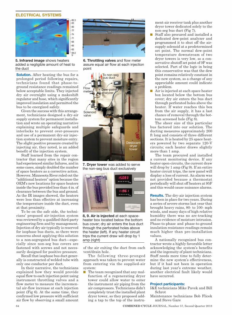
64 COMBINED CYCLE JOURNAL, Number 57, Second Quarter 2018
ELECTRICAL SYSTEMS
Solution. After heating the bus for a prolonged period following repairs, technicians found that phase-to-ground resistance readings remained below acceptable limits. They injected dry air overnight using a makeshift regulator and hose, which significantly improved insulation and permitted the bus to be energized safely.
Given the success with this arrange-ment, technicians designed a dry-air supply system for permanent installa-tion and wrote an operating narrative explaining multiple safeguards and interlocks to prevent over-pressure and use of a permanent dry-air injec-tion system to prevent moisture entry. The slight positive pressure created by injecting air, they noted, is an added benefit of the injection system.
Staff learned from the repair con-tractor that many sites in the region had experienced similar failures, and in some cases, simply doubled the number of space heaters as a corrective action. However, Minnesota River ruled out the “additional heaters” option because the OEM’s new locations for space heaters inside the bus provided less than 4 in. of clearance between the bus and ground. As the IR images showed, the heaters were less than effective at increasing the temperature inside the duct, even at that proximity.
To be on the safe side, the techni-cians’ proposed air-injection system was reviewed by a qualified third-party engineering firm and by management. Injection of dry air typically is reserved for isophase bus ducts, so there were concerns about applying this solution to a non-segregated bus duct—espe-cially since non-seg bus covers are fastened with screws and not neces-sarily designed for positive pressure.
Recall that isophase bus duct gener-ally is constructed of welded tube with only one conductor per duct.
In their narrative, the technicians explained how they would provide equal flow to each injection point using instrument throttling valves and a flow meter to measure the incremen-tal air-flow increase at each injection point (Fig 6). At the same time, they confirmed low pressure with sufficient air flow by observing a small amount
of the air exiting the duct from each vent/drain hole.
The following three-pronged approach was taken to prevent water from entering via the supplied-air system:n The team recognized that any mal-
function of a regenerating dryer tower could allow water to enter the instrument air piping from the air compressors. Technicians didn’t completely trust the installed plant dryer tower, so they proposed add-ing a tap to the top of the instru-
ment-air receiver tank plus another dryer tower dedicated solely to the non-seg bus duct (Fig 7).
n Staff also procured and installed a dedicated dew-point analyzer and programmed it to shut off the air-supply solenoid at a predetermined set point. The normal dew-point temperature downstream of two dryer towers is very low, so a con-servative shutoff set point of 0F was selected. Part of the logic in being this conservative was that the dew point remains relatively constant in the new system, so a change of any appreciable amount could indicate a problem.
n Air is injected at each space heater box located below the bottom bus cover; dry air enters the bus duct through perforated holes above the heater. If water reaches this box from the air supply, it has a last chance of removal through the bot-tom screened hole (Fig 8).The sheer size of this particular
bus factored into our solution. The ducting measures approximately 200 ft long and consists of three different sections. It is heated by 25 space heat-ers powered by two separate 120-V circuits; each heater draws slightly more than 1 amp.
The team procured and installed a current monitoring device. If any heater open-circuits, the current draw will drop by 1 amp (Fig 9). If an entire heater circuit trips, the new panel will display a loss of current. An alarm was not provided because a thermostat periodically will shut off heaters at 95F and this would cause nuisance alarms.
Results. The dry-air injection system has been in place for two years. During a series of severe storms last year that brought heavy rains, 80- to 100- mph winds, and many days of high relative humidity there was no arc-tracking and no evidence of moisture intrusion. Phase-to-phase and phase-to-ground insulation resistance readings remain much higher than pre-installation values.
A nationally recognized bus con-tractor wrote a highly favorable letter acknowledging the system’s benefits and the ingenuity of plant technicians. Staff needs more time to fully deter-mine the new system’s effectiveness, but if it had not been in operation during last year’s extreme weather, another electrical fault likely would have occurred.
Project participants: I&E technicians Mike Pavek and Bill
SchrotMaintenance technicians Bob Flicek
and Steve Gare
5. Infrared image shows heaters added a negligible amount of heat to the duct
6. Throttling valves and flow meter assure equal air flow at each injection point
Desiccantdryertower
To non-segbus duct
Solenoid valve
Dew-point analyzer
Flow meters
7. Dryer tower was added to serve the non-seg bus duct exclusively
8, 9. Air is injected at each space-heater box located below the bottom bus cover; dry air enters the bus duct through the perforated holes above the heater (left). If any heater circuit trips the current draw will drop by 1 amp (right)
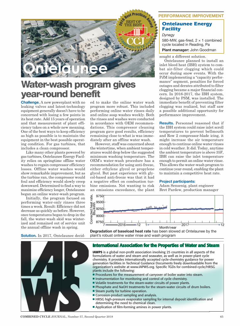
COMBINED CYCLE JOURNAL, Number 57, Second Quarter 2018 65
PERFORMANCE IMPROVEMENT
Challenge. A new powerplant with no leaking valves and latest-technology equipment generally doesn’t have to be concerned with losing a few points in its heat rate. Add 15 years of operation and that measurement of plant effi-ciency takes on a whole new meaning. One of the best ways to keep efficiency as high as possible is to maintain the equipment in the best possible operat-ing condition. For gas turbines, that includes a clean compressor.
Like many other plants powered by gas turbines, Ontelaunee Energy Facil-ity relies on springtime offline water washes to regain compressor efficiency losses. Offline water washes would show remarkable improvement, but as the turbine ran, the compressor would foul and efficiency would slowly creep downward. Determined to find a way to maximize efficiency longer, Ontelaunee began an online water-wash program.
Initially, the program focused on performing water-only rinses three times a week. Result: Efficiency did not decrease as quickly as before. However, once temperatures began to drop in the fall, the water-wash skid was winter-ized and remained out of service unit the annual offline wash in spring.
Solution. In 2017, Ontelaunee decid-
ed to make the online water wash program more robust. This included performing online water rinses daily and online soap washes weekly. Both the rinses and washes were conducted in accordance with OEM recommen-dations. This compressor cleaning program gave good results, efficiency remaining close to what is was imme-diately after an offline water wash.
However, staff was concerned about the wintertime, when ambient temper-atures would drop below the suggested minimum washing temperature. The OEM’s water-wash procedure has a recommendation for using anti-freeze, either ethylene glycol or propylene glycol. But past experience with gly-col-based anti-freeze was that it had a negative effect on combustion tur-bine emissions. Not wanting to risk an emissions exceedance, the plant
sought a different solution.Ontelaunee planned to install an
inlet bleed heat (IBH) system to com-bat air-filter clogging which could occur during snow events. With the PJM implementing a “capacity perfor-mance” segment, penalties for forced outages and derates attributed to filter clogging became a major financial con-cern. In 2016-2017, the IBH system, designed by PSM, was installed. The immediate benefit of preventing filter clogging was realized, but staff saw a possible additional opportunity for performance improvement.
Results. Personnel reasoned that if the IBH system could raise inlet scroll temperatures to prevent bellmouth and Row 2 compressor-blade icing, it might increase the air temperature enough to continue online water rinses in cold weather. It did. Today, anytime the ambient temperature is above 35F, IBH can raise the inlet temperature enough to permit an online water rinse. This allows the water-wash program to continue year-round, enabling the plant to maintain a competitive heat rate.
Project participants: Adam Sensenig, plant engineerBret Pardew, production manager
OntelauneeWater-wash program gives year-round benefit
Ontelaunee Energy FacilityDynegy580-MW, gas-fired, 2 × 1 combined cycle located in Reading, PaPlant manager: John Goodman
8750Cor
rect
ed h
eat r
ate,
Btu
/kW
h
9000
9250
9500
9750
Month/year7 12 1 122016 2017
Degradation of baseload heat rate has been slowed at Ontelaunee by the plant’s robust online water rinse and wash program
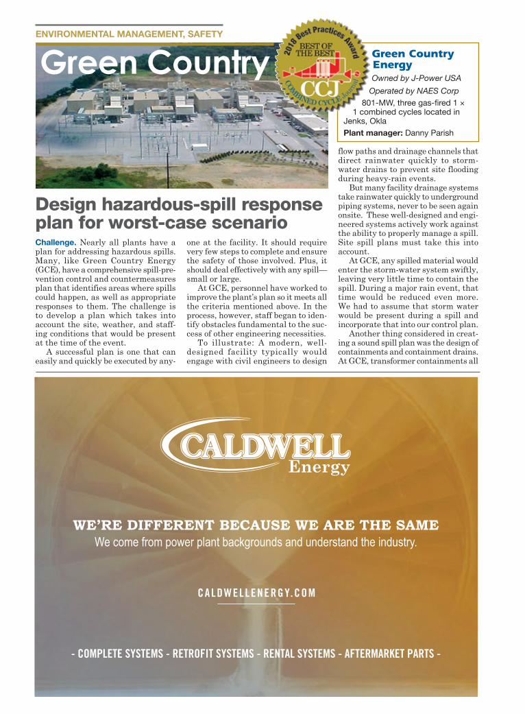
ENVIRONMENTAL MANAGEMENT, SAFETY
Challenge. Nearly all plants have a plan for addressing hazardous spills. Many, like Green Country Energy (GCE), have a comprehensive spill-pre-vention control and countermeasures plan that identifies areas where spills could happen, as well as appropriate responses to them. The challenge is to develop a plan which takes into account the site, weather, and staff-ing conditions that would be present at the time of the event.
A successful plan is one that can easily and quickly be executed by any-
one at the facility. It should require very few steps to complete and ensure the safety of those involved. Plus, it should deal effectively with any spill—small or large.
At GCE, personnel have worked to improve the plant’s plan so it meets all the criteria mentioned above. In the process, however, staff began to iden-tify obstacles fundamental to the suc-cess of other engineering necessities.
To illustrate: A modern, well-designed facility typically would engage with civil engineers to design
flow paths and drainage channels that direct rainwater quickly to storm-water drains to prevent site flooding during heavy-rain events.
But many facility drainage systems take rainwater quickly to underground piping systems, never to be seen again onsite. These well-designed and engi-neered systems actively work against the ability to properly manage a spill. Site spill plans must take this into account.
At GCE, any spilled material would enter the storm-water system swiftly, leaving very little time to contain the spill. During a major rain event, that time would be reduced even more. We had to assume that storm water would be present during a spill and incorporate that into our control plan.
Another thing considered in creat-ing a sound spill plan was the design of containments and containment drains. At GCE, transformer containments all
Green Country Energy Owned by J-Power USA
Operated by NAES Corp801-MW, three gas-fired 1 ×
1 combined cycles located in Jenks, OklaPlant manager: Danny Parish
Design hazardous-spill response plan for worst-case scenario
Green Country
WE’RE DIFFERENT BECAUSE WE ARE THE SAMEWe come from power plant backgrounds and understand the industry.
CALDWELLENERGY.COM
- COMPLETE SYSTEMS - RETROFIT SYSTEMS - RENTAL SYSTEMS - AFTERMARKET PARTS -
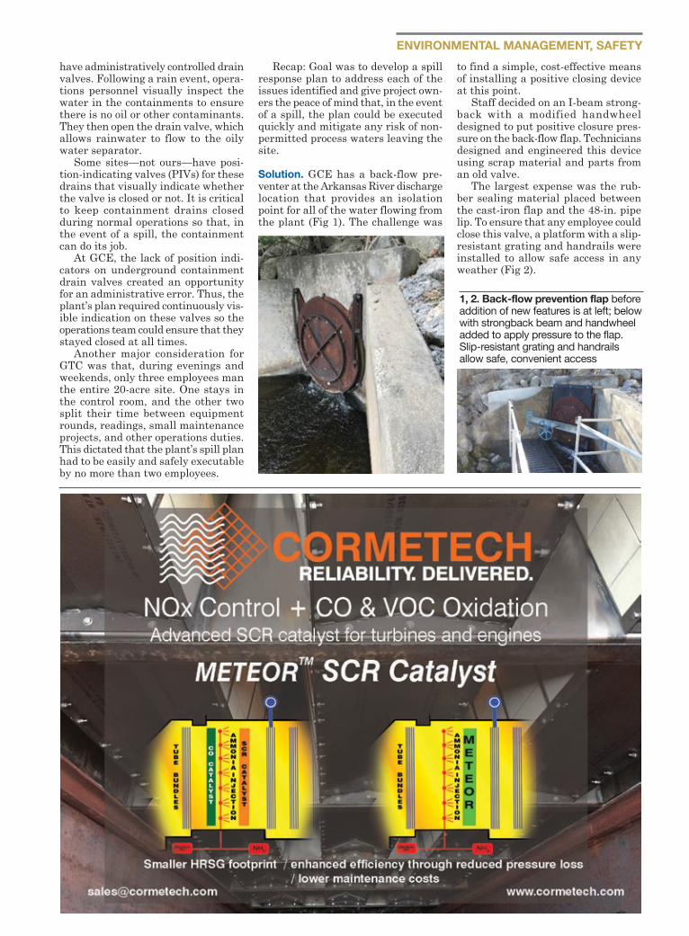
ENVIRONMENTAL MANAGEMENT, SAFETYhave administratively controlled drain valves. Following a rain event, opera-tions personnel visually inspect the water in the containments to ensure there is no oil or other contaminants. They then open the drain valve, which allows rainwater to flow to the oily water separator.
Some sites—not ours—have posi-tion-indicating valves (PIVs) for these drains that visually indicate whether the valve is closed or not. It is critical to keep containment drains closed during normal operations so that, in the event of a spill, the containment can do its job.
At GCE, the lack of position indi-cators on underground containment drain valves created an opportunity for an administrative error. Thus, the plant’s plan required continuously vis-ible indication on these valves so the operations team could ensure that they stayed closed at all times.
Another major consideration for GTC was that, during evenings and weekends, only three employees man the entire 20-acre site. One stays in the control room, and the other two split their time between equipment rounds, readings, small maintenance projects, and other operations duties. This dictated that the plant’s spill plan had to be easily and safely executable by no more than two employees.
Recap: Goal was to develop a spill response plan to address each of the issues identified and give project own-ers the peace of mind that, in the event of a spill, the plan could be executed quickly and mitigate any risk of non-permitted process waters leaving the site.
Solution. GCE has a back-flow pre-venter at the Arkansas River discharge location that provides an isolation point for all of the water flowing from the plant (Fig 1). The challenge was
to find a simple, cost-effective means of installing a positive closing device at this point.
Staff decided on an I-beam strong-back with a modified handwheel designed to put positive closure pres-sure on the back-flow flap. Technicians designed and engineered this device using scrap material and parts from an old valve.
The largest expense was the rub-ber sealing material placed between the cast-iron flap and the 48-in. pipe lip. To ensure that any employee could close this valve, a platform with a slip-resistant grating and handrails were installed to allow safe access in any weather (Fig 2).
1, 2. Back-flow prevention flap before addition of new features is at left; below with strongback beam and handwheel added to apply pressure to the flap. Slip-resistant grating and handrails allow safe, convenient access
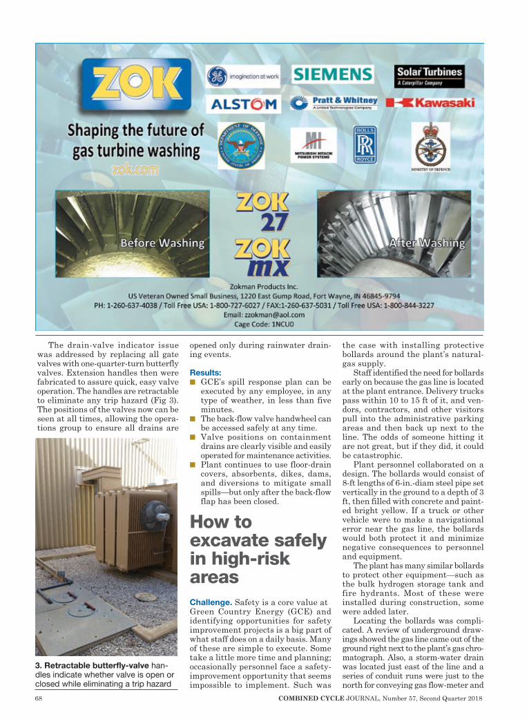
68 COMBINED CYCLE JOURNAL, Number 57, Second Quarter 2018
The drain-valve indicator issue was addressed by replacing all gate valves with one-quarter-turn butterfly valves. Extension handles then were fabricated to assure quick, easy valve operation. The handles are retractable to eliminate any trip hazard (Fig 3). The positions of the valves now can be seen at all times, allowing the opera-tions group to ensure all drains are
opened only during rainwater drain-ing events.
Results: n GCE’s spill response plan can be
executed by any employee, in any type of weather, in less than five minutes.
n The back-flow valve handwheel can be accessed safely at any time.
n Valve positions on containment drains are clearly visible and easily operated for maintenance activities.
n Plant continues to use floor-drain covers, absorbents, dikes, dams, and diversions to mitigate small spills—but only after the back-flow flap has been closed.
How to excavate safely in high-risk areasChallenge. Safety is a core value at Green Country Energy (GCE) and identifying opportunities for safety improvement projects is a big part of what staff does on a daily basis. Many of these are simple to execute. Some take a little more time and planning; occasionally personnel face a safety-improvement opportunity that seems impossible to implement. Such was
the case with installing protective bollards around the plant’s natural-gas supply.
Staff identified the need for bollards early on because the gas line is located at the plant entrance. Delivery trucks pass within 10 to 15 ft of it, and ven-dors, contractors, and other visitors pull into the administrative parking areas and then back up next to the line. The odds of someone hitting it are not great, but if they did, it could be catastrophic.
Plant personnel collaborated on a design. The bollards would consist of 8-ft lengths of 6-in.-diam steel pipe set vertically in the ground to a depth of 3 ft, then filled with concrete and paint-ed bright yellow. If a truck or other vehicle were to make a navigational error near the gas line, the bollards would both protect it and minimize negative consequences to personnel and equipment.
The plant has many similar bollards to protect other equipment—such as the bulk hydrogen storage tank and fire hydrants. Most of these were installed during construction, some were added later.
Locating the bollards was compli-cated. A review of underground draw-ings showed the gas line came out of the ground right next to the plant’s gas chro-matograph. Also, a storm-water drain was located just east of the line and a series of conduit runs were just to the north for conveying gas flow-meter and
3. Retractable butterfly-valve han-dles indicate whether valve is open or closed while eliminating a trip hazard
COMBINED CYCLE JOURNAL, Number 57, Second Quarter 2018 69
chromatograph data to the control room. In addition, the bulk hydrogen line
to the generators was routed through that area. Then there was the plant ring road alongside the gas line. If the bollards were moved far enough away from the gas line to clear all of these obstacles, they could pose more of a hazard to plant mobile equipment and personnel than the gas line itself.
The risks associated with any sort of conventional excavation appeared to outweigh the safety value of the bollards. Hand-digging in this area looked all but impossible because of the hard clay and rock. Result: The project was considered too risky to undertake and was put on hold for
several years.
Solution. In 2017, plant manage-ment recommitted to installing the safety bollards around the gas line. After researching possible work-arounds, Badger Hydrovac Services was engaged to excavate the founda-tion holes.
Badger relies on high-pressure water to loosen the soil, rock, and clay while simultaneously using a vacuum pipe to pull the loosened material out of the hole. This approach was effective and did not damage any underground cable, conduit, concrete, piping, or other critical equipment (Fig 4).
Results. Badger’s excavation was
fast, safe, and cost-effective. GCE now has a fully protected gas line (Fig 5).
But unexpected things have a way of turning up when excavating in an industrial setting. This project was no exception. When digging the final bollard hole in a location that had no known obstacles, a buried pipe was found. It turned out to be the control-room sewage lift station line and was not on any of the drawings. Hydrovac spared the plant a messy and expensive outcome, reinforcing staff awareness that all excavations involve risk.
Project participants: The entire GCE staff.
4. Hydrovac system makes holes for bollards with minimal impact to existing infrastructure (left)5. Bollards protect gas line at plant entrance (below)
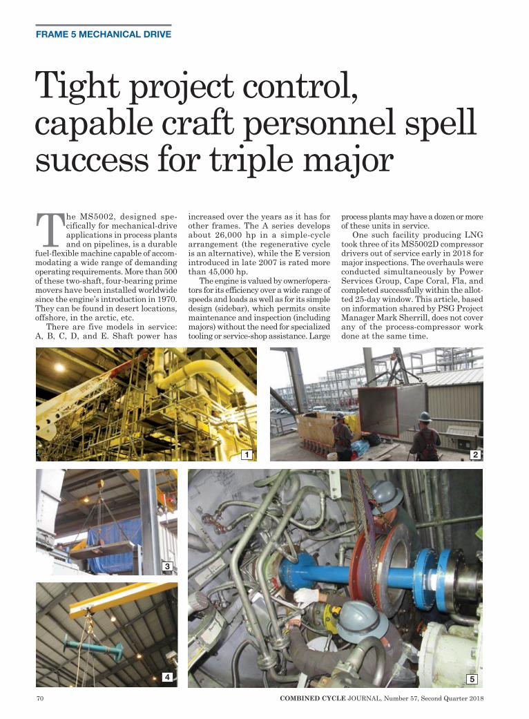
70 COMBINED CYCLE JOURNAL, Number 57, Second Quarter 2018
FRAME 5 MECHANICAL DRIVE
The MS5002, designed spe-cifically for mechanical-drive applications in process plants and on pipelines, is a durable
fuel-flexible machine capable of accom-modating a wide range of demanding operating requirements. More than 500 of these two-shaft, four-bearing prime movers have been installed worldwide since the engine’s introduction in 1970. They can be found in desert locations, offshore, in the arctic, etc.
There are five models in service: A, B, C, D, and E. Shaft power has
increased over the years as it has for other frames. The A series develops about 26,000 hp in a simple-cycle arrangement (the regenerative cycle is an alternative), while the E version introduced in late 2007 is rated more than 45,000 hp.
The engine is valued by owner/opera-tors for its efficiency over a wide range of speeds and loads as well as for its simple design (sidebar), which permits onsite maintenance and inspection (including majors) without the need for specialized tooling or service-shop assistance. Large
process plants may have a dozen or more of these units in service.
One such facility producing LNG took three of its MS5002D compressor drivers out of service early in 2018 for major inspections. The overhauls were conducted simultaneously by Power Services Group, Cape Coral, Fla, and completed successfully within the allot-ted 25-day window. This article, based on information shared by PSG Project Manager Mark Sherrill, does not cover any of the process-compressor work done at the same time.
1 2
4
3
5
Tight project control, capable craft personnel spell success for triple major
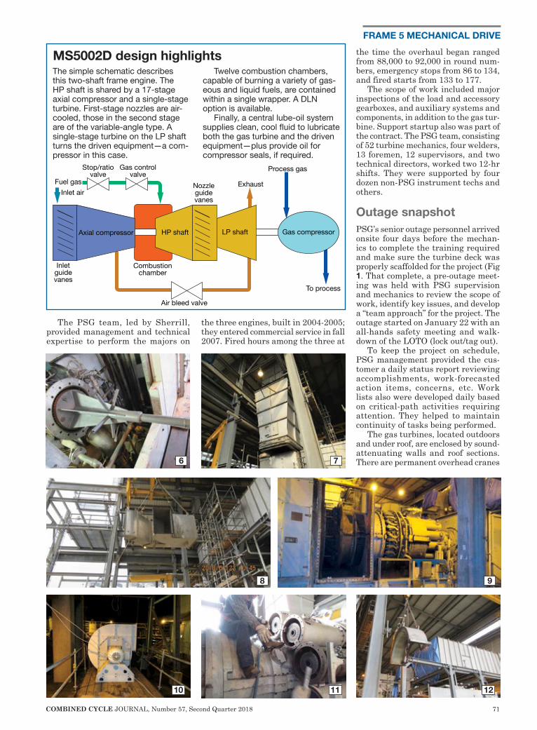
COMBINED CYCLE JOURNAL, Number 57, Second Quarter 2018 71
FRAME 5 MECHANICAL DRIVE
The PSG team, led by Sherrill, provided management and technical expertise to perform the majors on
the three engines, built in 2004-2005; they entered commercial service in fall 2007. Fired hours among the three at
the time the overhaul began ranged from 88,000 to 92,000 in round num-bers, emergency stops from 86 to 134, and fired starts from 133 to 177.
The scope of work included major inspections of the load and accessory gearboxes, and auxiliary systems and components, in addition to the gas tur-bine. Support startup also was part of the contract. The PSG team, consisting of 52 turbine mechanics, four welders, 13 foremen, 12 supervisors, and two technical directors, worked two 12-hr shifts. They were supported by four dozen non-PSG instrument techs and others.
Outage snapshotPSG’s senior outage personnel arrived onsite four days before the mechan-ics to complete the training required and make sure the turbine deck was properly scaffolded for the project (Fig 1. That complete, a pre-outage meet-ing was held with PSG supervision and mechanics to review the scope of work, identify key issues, and develop a “team approach” for the project. The outage started on January 22 with an all-hands safety meeting and walk-down of the LOTO (lock out/tag out).
To keep the project on schedule, PSG management provided the cus-tomer a daily status report reviewing accomplishments, work-forecasted action items, concerns, etc. Work lists also were developed daily based on critical-path activities requiring attention. They helped to maintain continuity of tasks being performed.
The gas turbines, located outdoors and under roof, are enclosed by sound-attenuating walls and roof sections. There are permanent overhead cranes
8 9
6 7
10 11 12
Gas controlvalve
Stop/ratiovalve
Fuel gasInlet air
Inletguidevanes
Axial compressor
Combustionchamber
Air bleed valve
HP shaft
Nozzleguidevanes
LP shaft Gas compressor
To process
Process gas
Exhaust
MS5002D design highlightsThe simple schematic describes this two-shaft frame engine. The HP shaft is shared by a 17-stage axial compressor and a single-stage turbine. First-stage nozzles are air-cooled, those in the second stage are of the variable-angle type. A single-stage turbine on the LP shaft turns the driven equipment—a com-pressor in this case.
Twelve combustion chambers, capable of burning a variety of gas-eous and liquid fuels, are contained within a single wrapper. A DLN option is available.
Finally, a central lube-oil system supplies clean, cool fluid to lubricate both the gas turbine and the driven equipment—plus provide oil for compressor seals, if required.

72 COMBINED CYCLE JOURNAL, Number 57, Second Quarter 2018
FRAME 5 MECHANICAL DRIVE
21
22 2423
1816
17
19 20
13 14 15
onsite. Work began on all three engines in parallel with disassembly of roof-mounted ductwork 2 and removal of the roof panels 3. Inlet and exhaust expansion joints were unbolted and collapsed to facilitate removal of the inlet 90-deg elbow and exhaust-duct transition section.
While this work was underway, the load 4 and accessory 5 couplings were disassembled and alignment fixtures 6 were installed to take the necessary readings. After the exhaust section 7 and inlet-ductwork 8 and cooling-air
piping were removed, the package enclosures were disassembled to gain access to the turbines 9. Cooling-air fans were removed 10 and their motor bearings were replaced.
Next, combustion-system hardware 11 and the wrappers 12 were removed. Components replaced: fuel stop valve 13, fuel nozzles, can covers, crossfire tubes, and liners. All cases from the inlet bellmouth to the exhaust dif-fuser 14 were rigged and picked (upper halves of the compressor 15 and tur-bine 16 cases, and exhaust frame 17
and diffuser) allowing removal of the HP 18 and LP 19 rotors.
NDE inspections of the exhaust case and diffuser were performed; no indica-tions were found. After the rotors were lifted off their bearings and transferred to storage coffins 20 for shipment to the owner’s repair facility, compres-sor stator vanes 21 were replaced. Refurbished rotors were installed for the next interval 22.
IGV gears 23 and vanes, and the first- and second-stage shroud blocks, were replaced. Severe damage was
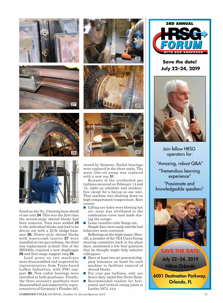
COMBINED CYCLE JOURNAL, Number 57, Second Quarter 2018 73
found on the No. 2 bearing heat shield of one unit 24. This was the first time the second-stage shroud blocks had been removed. Nuts were welded 25 to the individual blocks and had to be driven out with a 20-lb sledge ham-mer 26. Newer-style shroud blocks with honeycomb inserts 27 were installed on two gas turbines, the third was replacement in-kind. One of the MS5002s required a new diaphragm 28 and first-stage support ring 29.
Load gears on two machines were disassembled and inspected by representatives from Texas-based Lufkin Industries, with PSG sup-port 30. New radial bearings were installed in both gearboxes. Finally, the three accessory gearboxes were disassembled and inspected by repre-sentatives of Germany’s Flender AG,
owned by Siemens. Radial bearings were replaced in the three units. The main lube-oil pump was replaced with a new one 31.
Restarts of the overhauled gas turbines occurred on February 14 and 15, right on schedule and incident-free except for a hiccup on one unit. That machine was shutting down on high compartment temperature. Root causes:n Lifting eye holes were blowing hot
air; issue was attributed to the combustion–cover mod made dur-ing the outage.
n Loose crossfire-tube flange set. Simple fixes were made and the bad
behaviors were corrected. Reflecting on the triple major, Sher-
rill, a member of the 7EA Users Group steering committee back in his plant days, mentioned a few best practices that he thought might help industry colleagues:n Have at least two air-powered chip-
ping hammers on hand for each machine to facilitate removal of shroud blocks.
n For your gas turbines, only use heavy-duty, metal-free Never Seize.
n Recommended sealant for hori-zontal and vertical casing joints is Loctite 5972. ccj
27
30
25
28
31
26
29
July 22–24, 2019Hilton Orlando
6001 Destination Parkway, Orlando, FL
SAVE THE DATE:
Save the date! July 22–24, 2019
Join fellow HRSG operators for:
“Amazing, robust Q&A”
“Tremendous learning experience”
“Passionate and knowledgeable speakers”
3RD ANNUAL
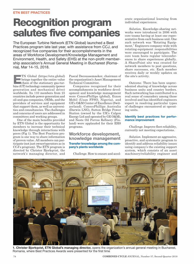
74 COMBINED CYCLE JOURNAL, Number 57, Second Quarter 2018
ETN BEST PRACTICES
ETN Global (https://etn.global) brings together the entire value chain of the stationary gas-tur-
bine (GT) technology community (power generation and mechanical drive) worldwide. Its 110 members from 23 countries include power-generation and oil-and-gas companies, OEMs, and the providers of services and equipment that support them, as well as universi-ties and consultancies. The challenges and concerns of users are addressed in committees and working groups.
One of the main benefits provided by ETN Global is the opportunity for members to increase their technical knowledge through interactions with peers (Fig 1). The Best Practices pro-gram is one way to share information of proven value. All members can par-ticipate (not just owner/operators as in CCJ’s program). The ETN program is directed by Christer Bjorkqvist, the network’s managing director, and
Pascal Decoussemaeker, chairman of the organization’s Asset Management Technical Committee.
Companies recognized for their accomplishments in workforce devel-opment and knowledge management were ConocoPhillips (global), Exxon Mobil (Usan FPSO, Nigeria), and GE’s O&M Center of Excellence (Swit-zerland). ConocoPhillips Australia (Darwin LNG), Sutton Bridge Power Station (owned by the UK’s Calgon Energy Ltd and operated by GE O&M), and Neste Oil Porvoo Refinery (Fin-land) were applauded for their EHS programs.
Workforce development, knowledge managementTransfer knowledge among the com-pany’s plants worldwide
Challenge. How to ensure and accel-
erate organizational learning from individual experiences.
Solution. Knowledge-sharing net-works were introduced in 2006 with core teams having at least one repre-sentative from each business unit. One such network was “Rotating Equip-ment.” Engineers company-wide with rotating-equipment responsibilities were encouraged to participate. The core team hosts regular teleconfer-ences to share experiences globally. A SharePoint site was created for network members to post questions, share successes, etc. Each member receives daily or weekly updates on the site’s activity.
Outcome. There has been unprec-edented sharing of knowledge across business units and country borders. Such networking has contributed to a real sense of comradery among those involved and has identified engineers expert in resolving particular types of challenges encountered at operat-ing units.
Identify best practices for perfor-mance improvement
Challenge. Improve fleet reliability, currently not meeting expectations.
Solution. Implement an aggressive, proactive, and systematic program to identify and address reliability issues using company’s the existing support system, which consists of an asset machinery/reliability engineer and
Recognition program salutes five companiesThe European Turbine Network (ETN Global) launched a Best Practices program late last year, with assistance from CCJ, and recognized five companies for their accomplishments in the areas of Workforce Development/Knowledge Management and Environment, Health, and Safety (EHS) at the non-profit member-ship association’s Annual General Meeting in Bucharest (Roma-nia), Mar 14-15, 2018.
1. Christer Bjorkqvist, ETN Global’s managing director, opens the organization’s annual general meeting in Bucharest, Romania, where Best Practices Awards were presented for the first time
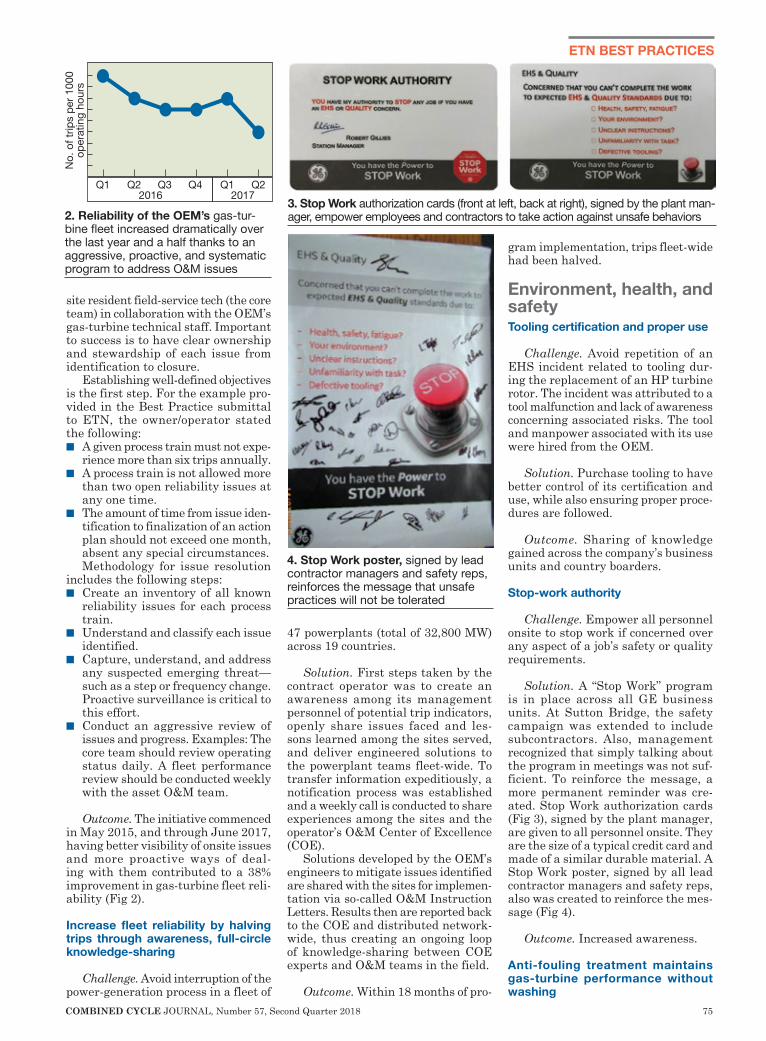
COMBINED CYCLE JOURNAL, Number 57, Second Quarter 2018 75
ETN BEST PRACTICES
site resident field-service tech (the core team) in collaboration with the OEM’s gas-turbine technical staff. Important to success is to have clear ownership and stewardship of each issue from identification to closure.
Establishing well-defined objectives is the first step. For the example pro-vided in the Best Practice submittal to ETN, the owner/operator stated the following:n A given process train must not expe-
rience more than six trips annually.n A process train is not allowed more
than two open reliability issues at any one time.
n The amount of time from issue iden-tification to finalization of an action plan should not exceed one month, absent any special circumstances. Methodology for issue resolution
includes the following steps:n Create an inventory of all known
reliability issues for each process train.
n Understand and classify each issue identified.
n Capture, understand, and address any suspected emerging threat—such as a step or frequency change. Proactive surveillance is critical to this effort.
n Conduct an aggressive review of issues and progress. Examples: The core team should review operating status daily. A fleet performance review should be conducted weekly with the asset O&M team.
Outcome. The initiative commenced in May 2015, and through June 2017, having better visibility of onsite issues and more proactive ways of deal-ing with them contributed to a 38% improvement in gas-turbine fleet reli-ability (Fig 2).
Increase fleet reliability by halving trips through awareness, full-circle knowledge-sharing
Challenge. Avoid interruption of the power-generation process in a fleet of
47 powerplants (total of 32,800 MW) across 19 countries.
Solution. First steps taken by the contract operator was to create an awareness among its management personnel of potential trip indicators, openly share issues faced and les-sons learned among the sites served, and deliver engineered solutions to the powerplant teams fleet-wide. To transfer information expeditiously, a notification process was established and a weekly call is conducted to share experiences among the sites and the operator’s O&M Center of Excellence (COE).
Solutions developed by the OEM’s engineers to mitigate issues identified are shared with the sites for implemen-tation via so-called O&M Instruction Letters. Results then are reported back to the COE and distributed network-wide, thus creating an ongoing loop of knowledge-sharing between COE experts and O&M teams in the field.
Outcome. Within 18 months of pro-
gram implementation, trips fleet-wide had been halved.
Environment, health, and safetyTooling certification and proper use
Challenge. Avoid repetition of an EHS incident related to tooling dur-ing the replacement of an HP turbine rotor. The incident was attributed to a tool malfunction and lack of awareness concerning associated risks. The tool and manpower associated with its use were hired from the OEM.
Solution. Purchase tooling to have better control of its certification and use, while also ensuring proper proce-dures are followed.
Outcome. Sharing of knowledge gained across the company’s business units and country boarders.
Stop-work authority
Challenge. Empower all personnel onsite to stop work if concerned over any aspect of a job’s safety or quality requirements.
Solution. A “Stop Work” program is in place across all GE business units. At Sutton Bridge, the safety campaign was extended to include subcontractors. Also, management recognized that simply talking about the program in meetings was not suf-ficient. To reinforce the message, a more permanent reminder was cre-ated. Stop Work authorization cards (Fig 3), signed by the plant manager, are given to all personnel onsite. They are the size of a typical credit card and made of a similar durable material. A Stop Work poster, signed by all lead contractor managers and safety reps, also was created to reinforce the mes-sage (Fig 4).
Outcome. Increased awareness.
Anti-fouling treatment maintains gas-turbine performance without washing
Q1 Q2 Q3 Q4 Q1 Q2
No.
of t
rips
per 1
000
oper
atin
g ho
urs
2016 2017
2. Reliability of the OEM’s gas-tur-bine fleet increased dramatically over the last year and a half thanks to an aggressive, proactive, and systematic program to address O&M issues
3. Stop Work authorization cards (front at left, back at right), signed by the plant man-ager, empower employees and contractors to take action against unsafe behaviors
4. Stop Work poster, signed by lead contractor managers and safety reps, reinforces the message that unsafe practices will not be tolerated
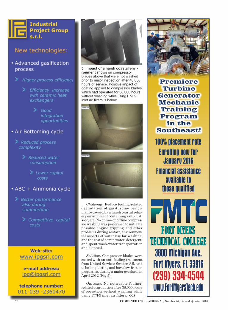
76 COMBINED CYCLE JOURNAL, Number 57, Second Quarter 2018
Challenge. Reduce fouling-related degradation of gas-turbine perfor-mance caused by a harsh coastal refin-ery environment containing salt, dust, soot, etc. No online or offline compres-sor washing was performed to mitigate possible engine tripping and other problems during restart, environmen-tal aspects of water use for washing, and the cost of demin water, detergent, and spent wash-water transportation and disposal.
Solution. Compressor blades were coated with an anti-fouling treatment from United Services Sweden AB, said to be long-lasting and have low-friction properties, during a major overhaul in April 2012 (Fig 5).
Outcome. No noticeable fouling-related degradation after 38,000 hours of operation without washing while using F7/F9 inlet air filters. ccj
5. Impact of a harsh coastal envi-ronment shows on compressor blades above that were not washed prior to major inspection after 40,000 hours of service. Positive impact of coating applied to compressor blades which had operated for 38,000 hours without washing while using F7/F9 inlet air filters is below
3800 Michigan Ave.Fort Myers, FL 33916(239) 334-4544www.FortMyersTech.edu
PremiereTurbine
Generator Mechanic TrainingProgram
in theSoutheast!
100% placement rateEnrolling now for
January 2016Financial assistance
available to those qualified
Fort Myerstechnical college
Fort Myerstechnical college

COMBINED CYCLE JOURNAL, Number 57, Second Quarter 2018 77
SAFETY, OPERATION & MAINTENANCE
Challenge. The people who live in the communities around the Tuxpan plants are a critical resource for the company. Management is concerned that citizens know what to do in an emergency and how to deal with safety-related issues encountered in their daily lives.
Solution: Develop safety training programs for people living near the company’s facilities and for “safety watchers” to assist plant personnel during outages. NAES implemented the core safety training program for 80 residents. It was conducted by personnel with extensive experience in industrial safety; participants completing the program received a certificate.
Lessons were presented on how to use a safety harness, what to do in an emergency, firefighting, CPR, types of fires and fire extinguishers, hazard and risk identification, differences between hazardous and urban wastes, PPE, crane and forklift inspection, etc.
Four groups of about 20 partici-
pants each were trained in one month (Fig 1). Goal was to increase knowl-edge of safety issues and to ensure a good relationship with stakeholders. The top performers in the community training program were invited to be part of a group of safety observers who would participate in the Tuxpan II fall outage by supporting NAES manage-ment in the supervision of contractor personnel.
Prior to the outage, the safety observers were trained to monitor spe-cific issues. When the outage began, the safety watchers, supervised by the NAES HSSE team and training per-sonnel, were divided into groups—first in day and night shifts, then in key areas (Fig 2).
Watchers had the task of giving safety recommendations for each act or unsafe condition detected, first addressing the worker to correct it, then the contractor’s safety supervisor to prevent it from happening again, and finally the NAES supervisor to integrate the incident into the safety statistics to improve or control it.
Results. Excellent results were obtained with the safety watchers; they helped the HSSE team avoid a lost-time incident during the 35-day outage. Here are the stats:n Good practices cited, 115.n Drug and alcohol tests, 6796. There
were 10 positive results for alcohol, three for drugs.
n Unsafe acts and conditions report-ed, 233.
n Near misses, 6.n Safety inspections conducted, 192.n Minor first aid (health issues, head-
aches, flu, etc), 139.n First aid (safety issues), 2.n Medical treatments, 1.n Lost-time incidents, 0.n Incidents closed, 232.n Average number of persons onsite
during the daytime, about 360.n Average number of persons onsite
during at night, about 100.
Project participants:Jorge Gamel Esparza Cárdenas, PE,
plant manager Leonel Rosas Maitret, PE, production
directorJonathan Carballo Alonso, PE, techni-
cal assistantOdilón Cruz Salomón, PE, HSSE
supervisor
CCC Tuxpan II and V Owned by Electricidad Águila de Tuxpan and
Electricidad Sol de Tuxpan Operated by NAES Corp
Tuxpan II: 500-MW, dual-fuel, 2 × 1 combined cycle located in Tuxpan, Veracruz, MexTuxpan V: 500-MW, gas-fired, 2 × 1 combined cycle located in Tuxpan, Veracruz, MexPlant manager: Jorge Gamel Espar-za Cárdenas, PE
Tuxpan II and V
Outage safety benefits from community outreach program
1. Each of the four training classes had about 20 participants from commu-nities in the vicinity of Tuxpan plants
2. Safety watcher monitoring proper crane use
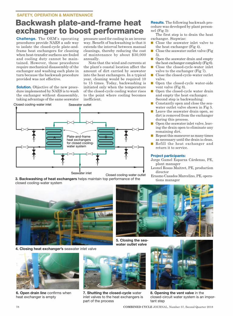
78 COMBINED CYCLE JOURNAL, Number 57, Second Quarter 2018
SAFETY, OPERATION & MAINTENANCE
Challenge. The OEM’s operating procedures provide NAES a safe way to isolate the closed-cycle plate-and-frame heat exchangers for cleaning when heat-transfer surfaces are fouled and cooling duty cannot be main-tained. However, these procedures require mechanical disassembly of the exchanger and washing each plate in turn because the backwash procedure provided was not effective.
Solution. Objective of the new proce-dure implemented by NAES is to wash the exchanger without disassembly, taking advantage of the same seawater
pressure used for cooling in an inverse way. Benefit of backwashing is that it extends the interval between manual cleanings, thereby reducing the cost of maintenance by about $30,000 annually.
Note that the wind and currents at the plant’s coastal location affect the amount of dirt carried by seawater into the heat exchangers. In a typical year, cleaning would be required 10 to 15 times. Today, backwashing is initiated only when the temperature of the closed-cycle cooling water rises to the point where cooling becomes inefficient.
Results. The following backwash pro-cedure was developed by plant person-nel (Fig 3):
The first step is to drain the heat exchanger. Stepwise:n Close the seawater inlet valve to
the heat exchanger (Fig 4).n Close the seawater outlet valve (Fig
5). n Open the seawater drain and empty
the heat exchanger completely (Fig 6).n Close the closed-cycle-water inlet
valve to the exchanger (Fig 7). n Close the closed-cycle-water outlet
valve.n Open the closed-cycle water-side
vent valve (Fig 8).n Open the closed-cycle water drain
and empty the heat exchanger.Second step is backwashing:
n Constantly open and close the sea-water outlet valve shown in Fig 5.
n Leave the seawater drain open, so dirt is removed from the exchanger during this process.
n Open the seawater inlet valve, leav-ing the drain open to eliminate any remaining dirt.
n Repeat this maneuver as many times as necessary until the drain is clean.
n Refill the heat exchanger and return it to service.
Project participants:Jorge Gamel Esparza Cárdenas, PE,
plant manager Leonel Rosas Maitret, PE, production
directorErasmo Casados Marcelino, PE, opera-
tions manager
Backwash plate-and-frame heat exchanger to boost performance
Closed cooling-water inlet Seawater outlet
Seawater inlet
Plate-and-frame heat exchangers for closed cooling-water system
Closed cooling-water outlet
A B
3. Backwashing of heat exchangers helps maintain top performance of the closed cooling-water system
4. Closing heat exchanger’s seawater inlet valve
5. Closing the sea-water outlet valve
6. Open drain line confirms when heat exchanger is empty
7. Shutting the closed-cycle water inlet valves to the heat exchangers is part of the process
8. Opening the vent valve in the closed-circuit water system is an impor-tant step

COMBINED CYCLE JOURNAL, Number 57, Second Quarter 2018 79
Challenge. The “Tests of Safe Start with Gas Fuel in the Gas Turbines” have as an objective to assure reliable starting and to avoid delays in the com-missioning of the turbines, verifying the correct physi-cal operation as well as the logical response of the main valves involved in starting and operating the engines.
Solution. The safe-start tests are conducted on the following valves: n Fuel gas system. n Pressure control.n Main flow control. n Pilot pressure control.n Fuel gas vent.n Turbine fuel-gas shutoff
for protection against gas-turbine overspeed; plus confirmation of overspeed trip reset.
n High-pressure bleed.n Low-pressure bleed.
Results. Conducting these tests has allowed the detection and correction of abnormal variations in response of the valves to control logic, physical abnormalities of move-ment, and other situa-tions in a timely manner for correction before tur-bine start. Deadtimes have been reduced, failed starts avoided, and turbine dam-age prevented.
Project participants:Jorge Gamel Esparza
Cárdenas, PE, plant manager
Leonel Rosas Maitret, PE, production director
Erasmo Casados Mar-celino, PE, operations manager
Tests of safe start with gas fuel in the GT
+ Cycle Chemistry Audits+ New Project Specifications
+ FAC Management+ Chemistry Investigations+ Cycle Chemistry Training
+64 21 843 [email protected]
NEW ZEALAND
CCGT / HRSG Chemistry Experts
www.thermalchemistry.com
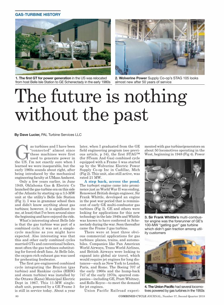
80 COMBINED CYCLE JOURNAL, Number 57, Second Quarter 2018
GAS-TURBINE HISTORY
Gas turbines and I have been “connected” almost since these machines were first used to generate power in
the US. I’m not exactly sure when I learned we were inseparable, but the early 1960s sounds about right, after being introduced by the mechanical engineering faculty at UMass Amherst.
Only a few years earlier, in June 1949, Oklahoma Gas & Electric Co launched the gas-turbine era on this side of the Atlantic by starting up a 3.5-MW unit at the utility’s Belle Isle Station (Fig 1). I was in grammar school then and didn’t know anything about gas turbines; however, it is significant (to me, at least) that I’ve been around since the beginning and have enjoyed the ride.
What’s interesting about Belle Isle is that the gas turbine was part of a combined cycle; it was not a simple-cycle machine as you might have expected. Also interesting was that this and other early combined cycles married GTs and conventional boilers, most often the gas turbines substitut-ing for forced-draft fans. At Belle Isle, the oxygen-rich exhaust gas was used for preheating feedwater.
The first pre-engineered combined cycle integrating the Brayton (gas turbine) and Rankine cycles (HRSG and steam turbine) was installed by the Ottawa (Kans) Municipal Electric Dept in 1967. This 11-MW single-shaft unit, powered by a GE Frame 3 is still in service today. About a year
later, when I graduated from the GE field engineering program (see previ-ous article, p 34), the first STAG™ (for STeam And Gas) combined cycle equipped with a Frame 5 was started up by the Wolverine Electric Power Supply Co-op Inc in Cadillac, Mich (Fig 2). This unit, also still active, was rated 21 MW.
A step back, across the pond. The turbojet engine came into promi-nence just as World War II was ending. Renowned British design engineer, Sir Frank Whittle, developed an engine in the post war period that is reminis-cent of early GE multi-combustor gas turbines (Fig 3). GE and others were looking for applications for this new technology in the late 1940s and Whittle was known to have conferred in Sche-nectady during the war. Soon thereafter came the Frame 3 gas turbine.
There were at least three obvi-ous commercial applications for gas turbines: planes, trains, and automo-biles. Companies like Pan American World Airways, Trans World Airlines, and British Airways were looking to expand into global air travel, which would require jet engines for long dis-tances—such as New York to London, Paris, and Rome. The Boeing 707 of the early 1960s and the hump-back 747 of the early 1970s, spurred com-panies—including GE, Pratt Whitney, and Rolls Royce—to meet the demand for jet engines.
Union Pacific Railroad experi-
mented with gas turbine/generators on about 50 locomotives operating in the West, beginning in 1948 (Fig 4). Power
3. Sir Frank Whittle’s multi-combus-tor engine was the forerunner of GE’s 100-MW “gatling gun” gas turbine which didn’t gain traction among util-ity customers
4. The Union Pacific had several locomo-tives powered by gas turbines in the 1950s
The future is nothing without the pastBy Dave Lucier, PAL Turbine Services LLC
1. The first GT for power generation in the US was relocated from host Belle Isle Station to GE Schenectady in the early 1980s
2. Wolverine Power Supply Co-op’s STAG 105 looks almost new after 50 years of service
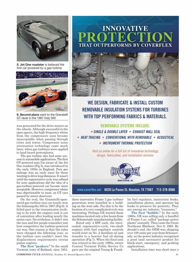
COMBINED CYCLE JOURNAL, Number 57, Second Quarter 2018 81
was generated for the drive motors on the wheels. Although successful in the open spaces, the high-frequency whine from the compressors soon became unacceptable when passing through cities and towns. Compressor noise attenuation technology came much later, when gas turbines were applied to land-based powerplants.
The gas turbine also had some suc-cess in automobile applications. The first GT-powered auto I’m aware of, the Jet One roadster (Fig 5), was introduced in the early 1950s in England. Poor gas mileage was an early issue for those wanting to drive long distances. It wasn’t until the regenerative cycle was refined for auto applications did the idea of a gas-turbine-powered car become more acceptable. However, compressor whine was objectionable to most, as GT cars passed by street observers.
On the oval, the Granatelli-spon-sored gas-turbine race car nearly won the Indianapolis 500 in 1967 (Fig 6). A failed part in the transmission (noth-ing to do with the engine) took it out of contention after leading nearly the entire race. Nevertheless, it didn’t win the race and few people remember just how competitive the turbine-powered car was. One reason is that the rules were changed the following year, so the turbine cars couldn’t meet the displacement requirements versus piston engines.
The first “peakers.” In the small Vermont town of Rutland, circa 1951,
three innovative Frame 3 gas turbine/generators were installed in a build-ing on the west side. For this to be the location of a very complicated cycle was interesting. Perhaps GE wanted these machines located only a few hours from the Schenectady manufacturing facility.
Rated only 4 MW each, the inter-cooled, regenerative-cycle, two-shaft engines with fuel regulator controls would start on No. 2 distillate oil and transfer to a heavier fuel oil during operation (Fig 7). When the final unit was retired in the early 1990s, owner Central Vermont Public Service Co gave me the original Young & Frank-
lin fuel regulator, instruction books, installation photos, and operator log books to preserve for posterity. They are among my industry “treasures.”
The first “bubble.” In the early 1960s, GE was selling only a handful of Frame 5 so- called “package power plants” annually. Then came the Great Northeast Blackout, Nov 9, 1965. By decade’s end, the OEM was shipping over 100 units per year from Schenect-ady, as the power industry recognized a good (and necessary) product for black-start, emergency, and peaking applications.
Installation time was short once a
6. Second place went to the Granatelli GT racer in the 1967 Indy 500
5. Jet One roadster is believed the first car powered by a gas turbine
www.coverflex.net 6828 La Paseo St. Houston, TX 77087 713-378-0966
INNOVATIVEPROTECTIONTHAT OUTPERFORMS BY COVERFLEX
WE DESIGN, FABRICATE & INSTALL CUSTOM REMOVABLE INSULATION SYSTEMS FOR TURBINES WITH TOP PERFORMING FABRICS & MATERIALS.
REMOVABLE SYSTEMS INCLUDE:• SINGLE & DOUBLE LAYER • EXHAUST WALL SEAL
• HEAT TRACING • CONVENTIONAL WITH REMOVABLE • ACOUSTICAL • INSTRUMENT THERMAL PROTECTION
Visit us online for a full list of innovative technology,design, fabrication, and installation services.
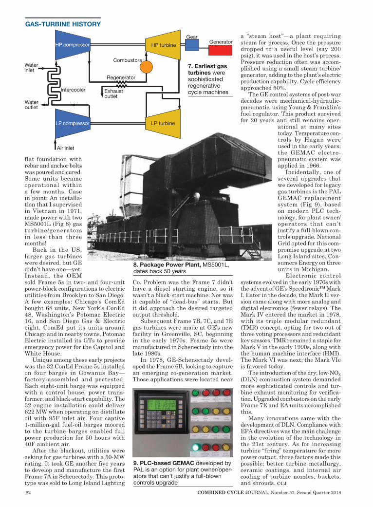
82 COMBINED CYCLE JOURNAL, Number 57, Second Quarter 2018
GAS-TURBINE HISTORY
flat foundation with rebar and anchor bolts was poured and cured. Some units became operational within a few months. Case in point: An installa-tion that I supervised in Vietnam in 1971, made power with two MS5001L (Fig 8) gas turbine/generators in less than three months!
Back in the US, larger gas turbines were desired, but GE didn’t have one—yet. Instead, the OEM sold Frame 5s in two- and four-unit power-block configurations to electric utilities from Brooklyn to San Diego. A few examples: Chicago’s ComEd bought 68 units, New York’s ConEd 48, Washington’s Potomac Electric 16, and San Diego Gas & Electric eight. ComEd put its units around Chicago and in nearby towns, Potomac Electric installed its GTs to provide emergency power for the Capitol and White House.
Unique among these early projects was the 32 ConEd Frame 5s installed on four barges in Gowanus Bay—factory-assembled and pretested. Each eight-unit barge was equipped with a control house, power trans-former, and black-start capability. The 32-engine installation could deliver 622 MW when operating on distillate oil with 95F inlet air. Four captive 1-million-gal fuel-oil barges moored to the turbine barges enabled full power production for 50 hours with 40F ambient air.
After the blackout, utilities were asking for gas turbines with a 50-MW rating. It took GE another five years to develop and manufacture the first Frame 7A in Schenectady. This proto-type was sold to Long Island Lighting
Co. Problem was the Frame 7 didn’t have a diesel starting engine, so it wasn’t a black-start machine. Nor was it capable of “dead-bus” starts. But it did approach the desired targeted output threshold.
Subsequent Frame 7B, 7C, and 7E gas turbines were made at GE’s new facility in Greenville, SC, beginning in the early 1970s. Frame 5s were manufactured in Schenectady into the late 1980s.
In 1978, GE-Schenectady devel-oped the Frame 6B, looking to capture an emerging co-generation market. Those applications were located near
a “steam host”—a plant requiring steam for process. Once the pressure dropped to a useful level (say 200 psig), it was used in the host’s process. Pressure reduction often was accom-plished using a small steam turbine/generator, adding to the plant’s electric production capability. Cycle efficiency approached 50%.
The GE control systems of post-war decades were mechanical-hydraulic-pneumatic, using Young & Franklin’s fuel regulator. This product survived for 20 years and still remains oper-
ational at many sites today. Temperature con-trols by Hagan were used in the early years; the GEMAC electro-pneumatic system was applied in 1966.
Incidentally, one of several upgrades that we developed for legacy gas turbines is the PAL GEMAC replacement system (Fig 9), based on modern PLC tech-nology, for plant owner/operators that can’t justify a full-blown con-trols upgrade. National Grid opted for this com-promise upgrade at two Long Island sites, Con-sumers Energy on three units in Michigan.
Electronic control systems evolved in the early 1970s with the advent of GE’s Speedtronic™ Mark I. Later in the decade, the Mark II ver-sion came along with more analog and digital electronics (fewer relays). The Mark IV entered the market in 1978, with its triple modular redundant (TMR) concept, opting for two out of three voting processors and redundant key sensors. TMR remained a staple for Mark V in the early 1990s, along with the human machine interface (HMI). The Mark VI was next; the Mark VIe is favored today.
The introduction of the dry, low-NOx (DLN) combustion system demanded more sophisticated controls and tur-bine exhaust monitoring for verifica-tion. Upgraded combustors on the early Frame 7E and EA units accomplished this.
Many innovations came with the development of DLN. Compliance with EPA directives was the main challenge in the evolution of the technology in the 21st century. As for increasing turbine “firing” temperature for more power output, three factors made this possible: better turbine metallurgy, ceramic coatings, and internal air cooling of turbine nozzles, buckets, and shrouds. ccj
9. PLC-based GEMAC developed by PAL is an option for plant owner/oper-ators that can’t justify a full-blown controls upgrade
8. Package Power Plant, MS5001L, dates back 50 years
HP turbineGear
Generator
Combustors
Regenerator
Exhaust outlet
Air inlet
Water inlet
Water outlet
Intercooler
HP compressor
LP compressor LP turbine
7. Earliest gas turbines were sophisticated regenerative-cycle machines

COMBINED CYCLE JOURNAL, Number 57, Second Quarter 2018 83
Aeroderivative Gas Turbine Support, Inc.phone: (561) 994-0000fax: (561) 994-3600email: [email protected]
1141 S. Rogers Circle, Suite 11 Boca Raton, FL 33487
LM2500LM5000LM6000LMS100GG4/FT4
Visit our newly redesigned website www.agtsi.com
Generating Timely Repair Solutions•Generator Testing Services
•Generator Repair Services • Stator – Rewinds, Rewedges, Core Repairs, etc..
• Rotor – Rewinds, Retaining Ring Removal/Replacement, etc…
• High Voltage Bushing Manufacturing & Refurbishment
518.843.1112
www.agtservices.com
AGT Services specializes in providing generator test, inspection, and repair
solutions, coupled with expert restorations and expedited delivery of components to
repair or rewind any Steam, Gas, or Nuclear turbine generator.
PROFESSIONAL SERVICES Plus new/used equipment, tools, parts
Contact Susie Carahalios today at: [email protected] • Voice: 303-697-5009 • Fax: 303-697-5709
2019 ConferenceFebruary 17 - 22 • DoubleTree Resort by Hilton, Paradise Valley, Ariz
Exhibitor contact:Tammy Faust, meeting coordinator, [email protected]
User contact:Russ Snyder, chairman, 501F Users Group, [email protected]
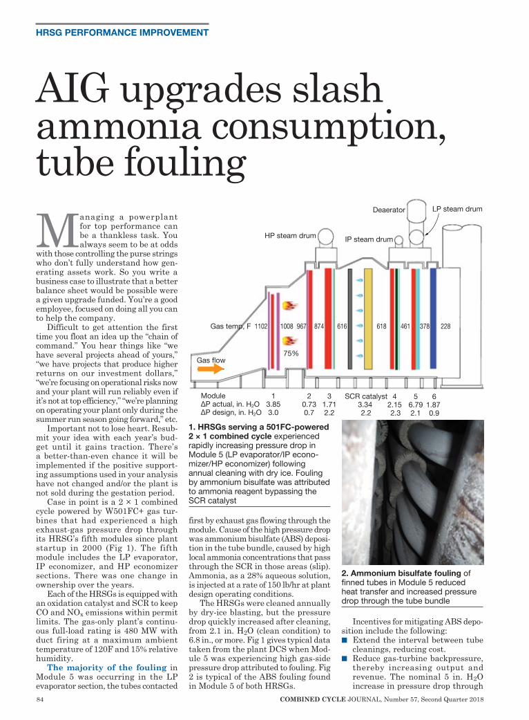
84 COMBINED CYCLE JOURNAL, Number 57, Second Quarter 2018
HRSG PERFORMANCE IMPROVEMENT
Managing a powerplant for top performance can be a thankless task. You always seem to be at odds
with those controlling the purse strings who don’t fully understand how gen-erating assets work. So you write a business case to illustrate that a better balance sheet would be possible were a given upgrade funded. You’re a good employee, focused on doing all you can to help the company.
Difficult to get attention the first time you float an idea up the “chain of command.” You hear things like “we have several projects ahead of yours,” “we have projects that produce higher returns on our investment dollars,” “we’re focusing on operational risks now and your plant will run reliably even if it’s not at top efficiency,” “we’re planning on operating your plant only during the summer run season going forward,” etc.
Important not to lose heart. Resub-mit your idea with each year’s bud-get until it gains traction. There’s a better-than-even chance it will be implemented if the positive support-ing assumptions used in your analysis have not changed and/or the plant is not sold during the gestation period.
Case in point is a 2 × 1 combined cycle powered by W501FC+ gas tur-bines that had experienced a high exhaust-gas pressure drop through its HRSG’s fifth modules since plant startup in 2000 (Fig 1). The fifth module includes the LP evaporator, IP economizer, and HP economizer sections. There was one change in ownership over the years.
Each of the HRSGs is equipped with an oxidation catalyst and SCR to keep CO and NOx emissions within permit limits. The gas-only plant’s continu-ous full-load rating is 480 MW with duct firing at a maximum ambient temperature of 120F and 15% relative humidity.
The majority of the fouling in Module 5 was occurring in the LP evaporator section, the tubes contacted
first by exhaust gas flowing through the module. Cause of the high pressure drop was ammonium bisulfate (ABS) deposi-tion in the tube bundle, caused by high local ammonia concentrations that pass through the SCR in those areas (slip). Ammonia, as a 28% aqueous solution, is injected at a rate of 150 lb/hr at plant design operating conditions.
The HRSGs were cleaned annually by dry-ice blasting, but the pressure drop quickly increased after cleaning, from 2.1 in. H2O (clean condition) to 6.8 in., or more. Fig 1 gives typical data taken from the plant DCS when Mod-ule 5 was experiencing high gas-side pressure drop attributed to fouling. Fig 2 is typical of the ABS fouling found in Module 5 of both HRSGs.
Incentives for mitigating ABS depo-sition include the following:n Extend the interval between tube
cleanings, reducing cost.n Reduce gas-turbine backpressure,
thereby increasing output and revenue. The nominal 5 in. H2O increase in pressure drop through
HP steam drum IP steam drum
Deaerator LP steam drum
Gas flow
Gas temp, F 1102 1008 967 874 616 618 461 378 228
75%
Module 1 2 3 SCR catalyst 4 5 6ΔP actual, in. H2O 3.85 0.73 1.71 3.34 2.15 6.79 1.87ΔP design, in. H2O 3.0 0.7 2.2 2.2 2.3 2.1 0.9
1. HRSGs serving a 501FC-powered 2 × 1 combined cycle experienced rapidly increasing pressure drop in Module 5 (LP evaporator/IP econo-mizer/HP economizer) following annual cleaning with dry ice. Fouling by ammonium bisulfate was attributed to ammonia reagent bypassing the SCR catalyst
2. Ammonium bisulfate fouling of finned tubes in Module 5 reduced heat transfer and increased pressure drop through the tube bundle
AIG upgrades slash ammonia consumption, tube fouling
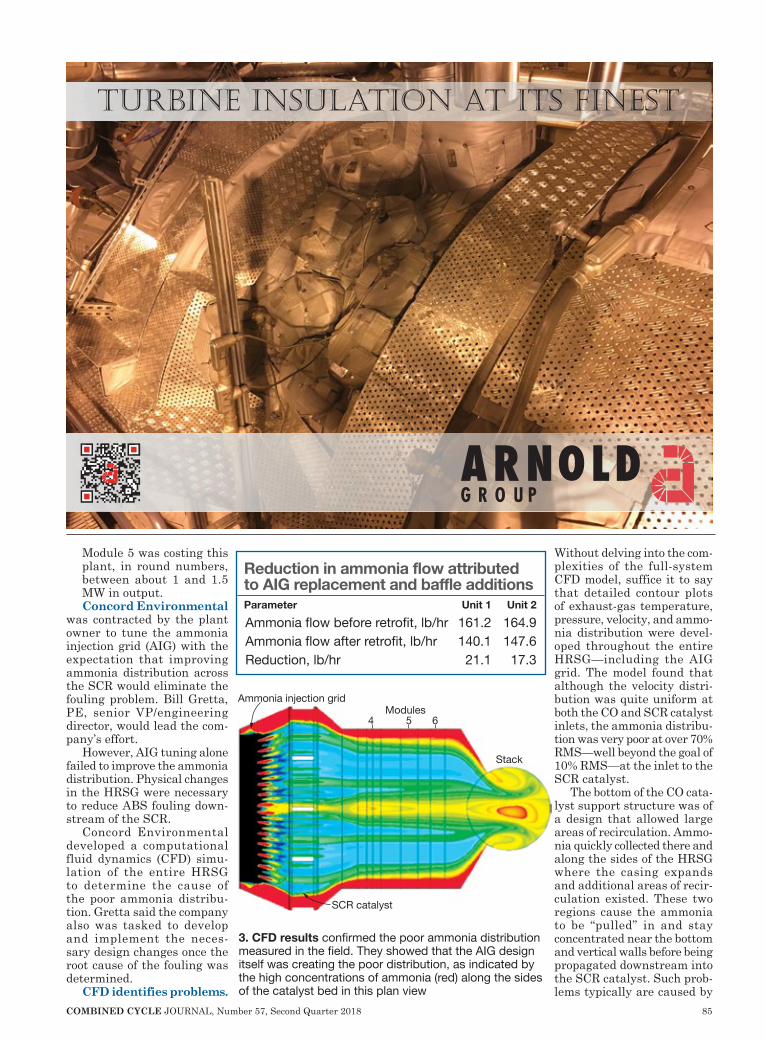
COMBINED CYCLE JOURNAL, Number 57, Second Quarter 2018 85
Module 5 was costing this plant, in round numbers, between about 1 and 1.5 MW in output. Concord Environmental
was contracted by the plant owner to tune the ammonia injection grid (AIG) with the expectation that improving ammonia distribution across the SCR would eliminate the fouling problem. Bill Gretta, PE, senior VP/engineering director, would lead the com-pany’s effort.
However, AIG tuning alone failed to improve the ammonia distribution. Physical changes in the HRSG were necessary to reduce ABS fouling down-stream of the SCR.
Concord Environmental developed a computational fluid dynamics (CFD) simu-lation of the entire HRSG to determine the cause of the poor ammonia distribu-tion. Gretta said the company also was tasked to develop and implement the neces-sary design changes once the root cause of the fouling was determined.
CFD identifies problems.
Without delving into the com-plexities of the full-system CFD model, suffice it to say that detailed contour plots of exhaust-gas temperature, pressure, velocity, and ammo-nia distribution were devel-oped throughout the entire HRSG—including the AIG grid. The model found that although the velocity distri-bution was quite uniform at both the CO and SCR catalyst inlets, the ammonia distribu-tion was very poor at over 70% RMS—well beyond the goal of 10% RMS—at the inlet to the SCR catalyst.
The bottom of the CO cata-lyst support structure was of a design that allowed large areas of recirculation. Ammo-nia quickly collected there and along the sides of the HRSG where the casing expands and additional areas of recir-culation existed. These two regions cause the ammonia to be “pulled” in and stay concentrated near the bottom and vertical walls before being propagated downstream into the SCR catalyst. Such prob-lems typically are caused by
TURBınE ınSULATıOn AT ıTS FınEST
Ammonia injection grid
SCR catalyst
Stack
4 5 6 Modules
3. CFD results confirmed the poor ammonia distribution measured in the field. They showed that the AIG design itself was creating the poor distribution, as indicated by the high concentrations of ammonia (red) along the sides of the catalyst bed in this plan view
Reduction in ammonia flow attributed to AIG replacement and baffle additionsParameter Unit 1 Unit 2
Ammonia flow before retrofit, lb/hr 161.2 164.9Ammonia flow after retrofit, lb/hr 140.1 147.6Reduction, lb/hr 21.1 17.3

86 COMBINED CYCLE JOURNAL, Number 57, Second Quarter 2018
too few injection holes in the AIG and the lack of mixing of the ammonia and the flue gas (Fig 3).
Concord Environmental’s CFD modeling confirmed that ammonia was concentrating heavily along the side walls as well as in the top and bottom corners of the catalyst bed. However, the CFD model revealed that the AIG design itself was creating the poor distribution with high concentrations along the sides of the catalyst. The AIG supplied with the HRSG was located 4 ft downstream of CO catalyst, in a section of the HRSG casing expanding towards the SCR catalyst.
The solution was to move the new AIG 3 ft upstream so the revised
AIG centerline was 1 ft down-stream of the CO cata lys t (the gray mod-ule immediate-ly upstream of the AIG in Fig 1) in a uniformly spaced arrangement. CFD modeling also showed that add-ing mixing baffles to the upstream side of the newly located AIG greatly improved local mixing. The lance penetrations through the HRSG cas-ing remain unchanged thus causing a jog in the AIG lances in the upstream direction. This eliminated the need to modify any external piping (Fig 4).
Mixing of ammonia downstream of an AIG is highly dependent on the local turbulence level in the gas; thus the holes in the new grid are spaced over its entire 33-ft length. Plus, all holes point directly downstream, unlike those in the original design. The turbulence level downstream of the fine-pitch CO catalyst is very low; the new baffles greatly improve
323.832.8316 www.ADVfiltra�on.com info@advfiltra�on.comCommi�ed to Customer Sa�sfac�on Over 30 Years of GT Inlet Air Filtra�on ExperienceGAS TURBINE INLET AIR FILTERS, SERVICE & INSTALLATION
ADVANCED FILTRATION CONCEPTS
Normalized ammonia concentration0.5 0.7 0.9 1.1 1.3 1.5
Baseline, RMS=70.2% Final design, RMS=5.8%
4. New AIG lances and baffles as installed. Note that the original structural penetrations were unchanged although the AIG was moved 3 ft upstream
5. Ammonia distribution across the vertical face of the SCR catalysts compared for both the baseline case and final design. Red shows sections with ammonia bypass, the darker color regions with poor ammonia mixing. Figure at left is the vertical cross section of the flue shown in Fig 3
COMBINED CYCLE JOURNAL, Number 57, Second Quarter 2018 87
ammonia mixing. In addition, there was a large wall
at the base of the CO catalyst bed which created a large recirculation zone along the floor. The CFD model was used to design plates that were added around the perimeter of the CO catalyst to direct exhaust flow directly into the AIG and avoid sneakage along the sides, top, and bottom into those recirculation zones.
With the addition of AIG mixing baffles and CO catalyst ducting baffles, gas flow from the CO catalyst now flows uniformly into the AIG injection area. When compared to the baseline AIG pressure drop, the new design added only 0.2 in. H2O. More impor-tantly, the final CFD design reduced the ammonia velocity distribution to 5.8% RMS, well below the design goal of no more than 10% RMS (Fig 5).
Accelerated construction. Con-cord Environmental was awarded the design, supply, and installation contract for removing the old AIG and installing the upgrades after the CFD modeling report was completed and the results presented to the plant owner in early October 2017. However, the owner had earlier scheduled a plant outage for Nov 1-14, 2017, so there was less than a month available to design and fabricate the new AIG and baffles, select, and mobilize the contractor at the job site, and complete installation.
Concord selected a non-union con-tractor based on its experience and ability to meet the project’s compressed schedule. The new AIG tubes and baf-fles were quickly fabricated by one of company’s preferred fabrication shops, arriving onsite October 30.
By that time, the contractor had mobilized onsite and had completed the demolition and removal of the old AIG. Construction crews worked two 12-hr shifts to complete the AIG upgrades on both HRSGs on schedule. Installation of the new AIG and baffles was completed November 13, one day ahead of schedule.
Operating data after startup. After the outage was completed, initial startup data showed significant reduc-tion in ammonia flow, which translates into reduced localized ammonia con-centrations (table).
Ammonia usage has decreased by 15% to 25% depending on load, and pressure drop in Module 5 has held steady for the past six months based on station instrument readings. The result has been a reduction in plant operating cost through the reduction of ammonia usage, avoiding the oper-ating efficiency loss experienced with ABS fouling of Module 5, and will greatly reduce the future cost to clean the ABS from Module 5 tubes. ccj
LM2500Owner/operators
Come up to speed on the latest O&M and design practices for LM engines in simple-cycle, cogen, and combined-cycle service to:
IMPROVE reliability, availability, heat rate
REDUCE emissions
MAXIMIZE revenue by providing grid ancillary servicesJoin more than 500 LM user colleagues from around the globe at the 29th annual meeting of the Western Turbine Users and get:
◆ Comprehensive engine-specific technical training focusing on current equipment issues. Deliverables include a fully illustrated Training Manual developed by WTUI and repair-depot personnel, and a review of current OEM service bulletins and letters. Technical guidance is provided by Air New Zealand Gas Turbines, GE, IHI, MTU Maintenance, and TransCanada Turbines.
◆ User-only open discussion to share experiences and obtain answers to your questions.
◆ An exhibition that brings together nearly 200 providers of products and services for LM aero engine operating plants. Learn about new offerings, get product updates, evaluate in-service experience.
◆ Benchmark your units against the fleet with ORAP™ data from Strategic Power Systems Inc.
Western Turbine Users, Inc.World’s largest user organization serving LM gas-turbine owner/operators
2019 Conference & ExpoSouth Point HotelLas Vegas, Nev
March 17-20, 2019www.wtui.com513-604-8018
LM6000Owner/operators
Come up to speed on the latest O&M and design practices for LM engines in simple-cycle, cogen, and combined-cycle service to:IMPROVE reliability, availability, heat rateREDUCE emissionsMAXIMIZE revenue by providing grid ancillary servicesJoin more than 500 LM user colleagues from around the globe at the 29th annual meeting of the Western Turbine Users and get:
◆ Comprehensive engine-specific technical training focusing on current equipment issues. Deliverables include a fully illustrated Training Manual developed by WTUI and repair-depot personnel, and a review of current OEM service bulletins and letters. Technical guidance is provided by Air New Zealand Gas Turbines, GE, IHI, MTU Maintenance, and TransCanada Turbines.
◆ User-only open discussion to share experiences and obtain answers to your questions.
◆ An exhibition that brings together nearly 200 providers of products and services for LM aero engine operating plants. Learn about new offerings, get product updates, evaluate in-service experience.
◆ Benchmark your units against the fleet with ORAP™ data from Strategic Power Systems Inc.
Western Turbine Users, Inc.World’s largest user organization serving LM gas-turbine owner/operators
2019 Conference & ExpoSouth Point HotelLas Vegas, Nev
March 17-20, 2019www.wtui.com513-604-8018
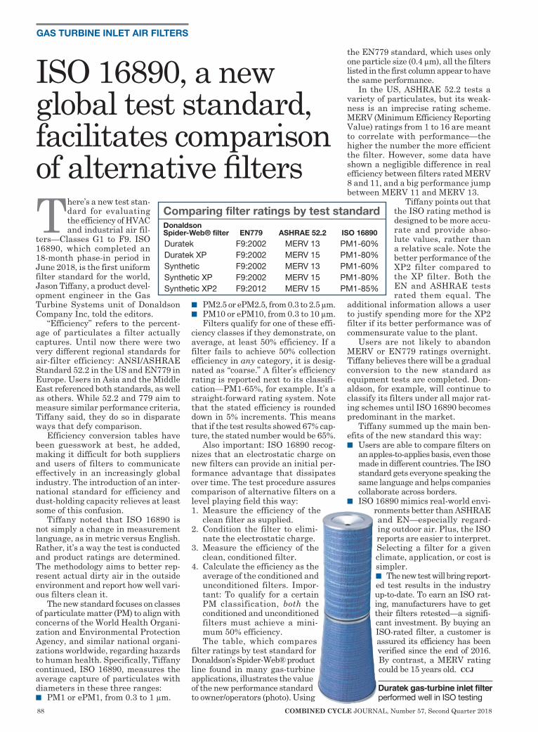
88 COMBINED CYCLE JOURNAL, Number 57, Second Quarter 2018
GAS TURBINE INLET AIR FILTERS
There’s a new test stan-dard for evaluating the efficiency of HVAC and industrial air fil-
ters—Classes G1 to F9. ISO 16890, which completed an 18-month phase-in period in June 2018, is the first uniform filter standard for the world, Jason Tiffany, a product devel-opment engineer in the Gas Turbine Systems unit of Donaldson Company Inc, told the editors.
“Efficiency” refers to the percent-age of particulates a filter actually captures. Until now there were two very different regional standards for air-filter efficiency: ANSI/ASHRAE Standard 52.2 in the US and EN779 in Europe. Users in Asia and the Middle East referenced both standards, as well as others. While 52.2 and 779 aim to measure similar performance criteria, Tiffany said, they do so in disparate ways that defy comparison.
Efficiency conversion tables have been guesswork at best, he added, making it difficult for both suppliers and users of filters to communicate effectively in an increasingly global industry. The introduction of an inter-national standard for efficiency and dust-holding capacity relieves at least some of this confusion.
Tiffany noted that ISO 16890 is not simply a change in measurement language, as in metric versus English. Rather, it’s a way the test is conducted and product ratings are determined. The methodology aims to better rep-resent actual dirty air in the outside environment and report how well vari-ous filters clean it.
The new standard focuses on classes of particulate matter (PM) to align with concerns of the World Health Organi-zation and Environmental Protection Agency, and similar national organi-zations worldwide, regarding hazards to human health. Specifically, Tiffany continued, ISO 16890, measures the average capture of particulates with diameters in these three ranges:n PM1 or ePM1, from 0.3 to 1 µm.
n PM2.5 or ePM2.5, from 0.3 to 2.5 µm.n PM10 or ePM10, from 0.3 to 10 µm.
Filters qualify for one of these effi-ciency classes if they demonstrate, on average, at least 50% efficiency. If a filter fails to achieve 50% collection efficiency in any category, it is desig-nated as “coarse.” A filter’s efficiency rating is reported next to its classifi-cation—PM1-65%, for example. It’s a straight-forward rating system. Note that the stated efficiency is rounded down in 5% increments. This means that if the test results showed 67% cap-ture, the stated number would be 65%.
Also important: ISO 16890 recog-nizes that an electrostatic charge on new filters can provide an initial per-formance advantage that dissipates over time. The test procedure assures comparison of alternative filters on a level playing field this way:1. Measure the efficiency of the
clean filter as supplied.2. Condition the filter to elimi-
nate the electrostatic charge.3. Measure the efficiency of the
clean, conditioned filter.4. Calculate the efficiency as the
average of the conditioned and unconditioned filters. Impor-tant: To qualify for a certain PM classification, both the conditioned and unconditioned filters must achieve a mini-mum 50% efficiency.The table, which compares
filter ratings by test standard for Donaldson’s Spider-Web® product line found in many gas-turbine applications, illustrates the value of the new performance standard to owner/operators (photo). Using
the EN779 standard, which uses only one particle size (0.4 µm), all the filters listed in the first column appear to have the same performance.
In the US, ASHRAE 52.2 tests a variety of particulates, but its weak-ness is an imprecise rating scheme. MERV (Minimum Efficiency Reporting Value) ratings from 1 to 16 are meant to correlate with performance—the higher the number the more efficient the filter. However, some data have shown a negligible difference in real efficiency between filters rated MERV 8 and 11, and a big performance jump between MERV 11 and MERV 13.
Tiffany points out that the ISO rating method is designed to be more accu-rate and provide abso-lute values, rather than a relative scale. Note the better performance of the XP2 filter compared to the XP filter. Both the EN and ASHRAE tests rated them equal. The
additional information allows a user to justify spending more for the XP2 filter if its better performance was of commensurate value to the plant.
Users are not likely to abandon MERV or EN779 ratings overnight. Tiffany believes there will be a gradual conversion to the new standard as equipment tests are completed. Don-aldson, for example, will continue to classify its filters under all major rat-ing schemes until ISO 16890 becomes predominant in the market.
Tiffany summed up the main ben-efits of the new standard this way:n Users are able to compare filters on
an apples-to-applies basis, even those made in different countries. The ISO standard gets everyone speaking the same language and helps companies collaborate across borders.
n ISO 16890 mimics real-world envi-ronments better than ASHRAE and EN—especially regard-ing outdoor air. Plus, the ISO reports are easier to interpret. Selecting a filter for a given climate, application, or cost is simpler.n The new test will bring report-ed test results in the industry up-to-date. To earn an ISO rat-ing, manufacturers have to get their filters retested—a signifi-cant investment. By buying an ISO-rated filter, a customer is assured its efficiency has been verified since the end of 2016. By contrast, a MERV rating could be 15 years old. ccj
ISO 16890, a new global test standard, facilitates comparison of alternative filters
Comparing filter ratings by test standardDonaldson Spider-Web® filter EN779 ASHRAE 52.2 ISO 16890
Duratek F9:2002 MERV 13 PM1-60%Duratek XP F9:2002 MERV 15 PM1-80%Synthetic F9:2002 MERV 13 PM1-60%Synthetic XP F9:2002 MERV 15 PM1-80%Synthetic XP2 F9:2012 MERV 15 PM1-85%
Duratek gas-turbine inlet filter performed well in ISO testing
COMBINED CYCLE JOURNAL, Number 57, Second Quarter 2018 89
Departure of industry leaders acceleratesFor several years, a topic of discussion at virtually every user-group meeting attended by the editors was that the industry is ageing rapidly and retire-ments are near at hand. The question, “Who was going to fill the shoes of the talented managers, supervisors, and O&M personnel heading for the exit?” was asked over and over again.
There were answers, of course, but few in a position to do something about the coming exodus of the industry’s most experienced were really listening and fewer still seemed willing to act on what they heard and knew in hearts should be done.
The obvious answer to some who manage the financial services firms that are a dominant force in the elec-tric generation sector today was to reduce staff in lock step with depar-tures. Nothing wrong in managing with a sharp pencil, but there comes a point when you’re cutting muscle and bone, not fat. It takes significant commitment and effort to steer clear of that reef.
The first guid-ance on how to pre-pare for the com-ing sea change the editors remember was offered about a decade ago by a pair of industry leaders, Rich Evans and Dr Robert Mayfield. They weren’t the only ones, to be sure, but both were plant managers who clearly saw the handwriting on the wall, were sensitive to the need for con-tinuing personnel development, and were active par-ticipants in two of the industry’s most vocal users groups.
Both Evans and Mayfield began by reaching out to colleagues via CCJ’s Best Practices Awards program. In 2005, Evans was plant manager of Wolf Hills Energy, a six-unit aero peaking facility, and among the first award recipients. In the first 10 years of the recognition program, Mayfield’s 3 × 1 F-class Tenaska Virginia Generating Station, earned more awards than any other plant in the nation.
Their unrelenting commitment to the industry and its people is without question. A decade ago, Evans was on the CTOTF™ executive committee as the vice chair for power systems. He was the driving force behind the user group’s initiative to identify and attract promising technicians and engi-neers to the gas-turbine sector of the industry and to make sure there were career rewards in place to retain them.
To get the proverbial ball rolling, he developed and chaired an interactive forum with a panel of true experts in generation-plant management to help guide those wanting to listen.
Mayfield, by contrast, has been a passionate speaker at 7F, CTOTF, and Combined Cycle user groups meetings on workforce development through Career and Technical Education pro-grams. Plus, a frequent lecturer and author on knowledge management initiatives to guide plants on how to retain what their employees have learned on the job.
Mayfield’s contributions to the industry were recognized by the Com-bined Cycle Users Group during its annual meeting at the end of August in Louisville where he received the orga-nization’s 2018 Individual Achieve-ment Award.
The user groups provided the forums for discussion and helped the industry plan for the transition, but little that is visible has been done to develop new talent in a meaningful way—except possibly at a few compa-nies managed by power professionals. Given that retirements to this point have occurred at what might be con-sidered a relatively manageable rate, what about the next couple of years?
In July 2018 alone at least three key industry contributors said good-bye: Paul Tegen of Cogentrix Energy Power Management LLC, Joe Schnei-der of NRG Energy, and John Demcko of Arizona Public Service Co. Others have told the editors they’ll be gone by year-end or a couple of weeks thereaf-ter—including Evans.
As you read though the biographical snapshots saluting the July departures ask yourself how the industry can absorb such losses—particularly in a time when the OEMs are laying off thousands, small shops are closing up, and leadership is in short supply. To minimize the chaos, what incen-tives should be offered to talented personnel to cope with the pain?
Paul Tegen was chief combustion
turbine/I&C engineer at Cogentrix. He served as the Westinghouse roundtable chair at CTOTF in the early 1980s, then teamed up with Bill Wimperis, Bill Barras, and a few others to launch the 501F Users Group. Tegen was elected the group’s first chairman and served in that capacity for about 10 years. He was required to resign when Cogentrix sold its 501F plants, then returned as vice chairman a few years later when his employer bought other 501F assets.
Tegen also was the de facto floor leader at V Users Group meetings in the mid-2000s when Cogentrix owned a pair of V machines in the Caribbean. That user meeting was, and still is, organized by Siemens. The 2018 con-ference was being conducted in Denver, September 10-13, when this issue of CCJ went to press.
Tegen joined Northern States Power Co in 1976, after graduating from the Milwaukee School of Engineering with a degree in electrical engineering. First job was as a results engineer. Siemens Power Corp (the Siemens entity serv-ing the US market before the company bought Westing-house) was his next stop where he spe-cialized in controls work. Then it was back to NSP for a year or so before joining LS Power in the mid-1990s as project manager for the 501FC-powered LSP Whitewater Cogen LP. He was then appointed plant manager.
Joe Schneider was manager of gas-turbine maintenance in NRG’s engi-neering and technical services group. He had an interesting career and, in his words, “Went out on top.” Schnei-der shared his expertise with the industry as a member of the steering committees for both CTOTF (Siemens roundtable and program chair) and the Combustion Turbine and Combined Cycle Users Organization (CTC2).
Reflecting, Schneider said mentor-ing industry newcomers was the part of his job he enjoyed most. He tipped his hat in admiration to plant person-nel—especially those responsible for units in their twilight years. There’s nothing harder to do, in his opinion, than to keep those engines running in a manner that meets management expectations with little tangible sup-port.
After a few years in the aircraft industry, Schneider migrated to Alaska in the early 1980s to work as a consulting engineer for AVEC, the Alaska Village Electric Co-op, which has more than
BUSINESS PARTNERS
Evans
Mayfield
Tegen
Schneider
90 COMBINED CYCLE JOURNAL, Number 57, Second Quarter 2018
53 member villages—most fairly remote and depen-dent on diesel power. He was involved in the design and installation of village elec-trification projects. Next gig was with Coffman Engineers doing engineering, installa-tion, and commissioning of village cogeneration proj-ects involving electric power, fresh water production, and sewage treatment.
From 1986 to 1999, Schneider was at Chugach Electric Assn Inc where he gained experience in hydro-turbine and Frame 5 maintenance and overhauls before moving to the Beluga plant as a maintenance supervisor for work on 11Ds and 7B to E conversions. During his last six years at Chugach, he was involved in outage planning and main-tenance of all the utility’s generating units, plus their integration with the so-called railbelt utilities.
Moving to Houston in 1999, Schneider’s career snaked through the deregulation era with assets changing ownership frequently over the years—Houston Lighting & Power to Reliant to RRI to GenOn (which merged with Mirant) to NRG. He had engineering positions at a couple of plants and in central engi-neering offices before being appointed
NRG’s manager of gas-tur-bine maintenance.
John Demcko, PE, was a senior consulting engineer for Arizona Public Service Co. He has been a member of the Gener-ator Users Group steering com-mittee since the organization’s founding. Demcko has 45 years of professional experience with GE, New York Power Pool (now NYISO), and APS. He plans to
migrate into active consulting in 2019 (visit www.eumacinc.com).
APS responsibilities included the implementation of digital-fault-recorder (DFR) technology for mon-
itoring all of the company’s major generating units; development of techniques and instrumentation to enhance the utility’s ability to perform predictive maintenance; troubleshooting and upgrading of excitation systems; and the intro-duction of new test and measure-ment technologies to alert and inform on power-quality problems.
Demcko has authored more than 70 technical publications on generator monitoring, control and protection, and power-system instrumentation and measurements. He received his BS and MS degrees in electrical engineering from Clarkson University.
Intended for end-users of Ovation control systems.
ANNUAL OVATIONUSERS’ GROUP CONFERENCE
July 28 – August 1, 2019 WESTIN CONVENTION CENTER HOTELPITTSBURGH, PAWWW.OVATIONUSERS.COM
CELEBRATING YEARS OF COLLABORATION32
HP superheater and reheater drain-system designs and operating practices that do not remove all condensate prior to initiation of steam flow during cold, warm, and hot startups are unable to protect tube-to-header connections, header bores, and nozzle-to-header con-nections from severe thermal fatigue damage. Such damage has resulted in many premature tube failures and can be expected to cause header bore cracking and/or nozzle-to-header weld failure.
Damage mitigation demands reli-able, leak-tight operation of both tube-panel drain valves and attemperator block valves (to help prevent water entry into tube panels). Conval Inc (www.conval.com), which recently ded-icated a 72,000-ft2 advanced manufac-turing center (photo right) in Enfield, Ct, 13 miles down I-91 from Bradley International Airport, has been an industry leader in the supply of US-made forged severe-service valves for half a century.
Conval’s advanced manufacturingcenter focuses on HRSG user needs
Demcko
COMBINED CYCLE JOURNAL, Number 57, Second Quarter 2018 91
The company previously made its globe, gate, and ball valves for high-temperature/high-pressure service at a three-building campus in Somers, Ct.
Conval VP Mike Hendrick, who participated in the HRSG Forum with Bob Anderson (www.hrsgforum.com) last March (2018), told the editors he prefers ball valves for meeting the on/off (never throttling) demanding service needs of isolation, vent, and drain valves.
For the temperatures and pressures experienced in today’s advanced com-bined cycles, Conval offers ball valves up to 4 in. This size range satisfies most HRSG applications, including
attemperator block valves. Note that final superheater harp in a typical F-class HRSG requires the equivalent of three 2-in.-diam drain lines to effec-tively remove the condensate collected.
Hendrick urged users to select their drain and block valves carefully, making sure metal seats are available when service temperatures are 400F and above, stems are blowout-proof, seat leakage meets the tightest specs after installation, coatings assure long life, and internals can be accessed in-line for inspection and maintenance.
Periodic review of best practices and lessons learned concerning drain and attemperation systems is particularly
important today, HRSG Forum Chair-man Bob Anderson told the editors, especially given the recent and pend-ing retirements of the industry’s most knowledgeable boiler personnel (see previous article). The steering com-mittee is considering a presentation or discussion session on this topic at the 2019 meeting. Learn more at www.hrsgforum.com.
Industry newsAllied Power Group acquires Eta Tech-nologies LLC; its principals, Richard Curtis and John Kearney, join Allied in leadership positions. APG President David Theis said “Eta’s V-Series exper-tise fits seamlessly with APG’s strat-egy of providing full-service solutions to the power generation industry—including turbine component repair, rotor repair, new parts manufacturing, and field service. . . .”
Mitsubishi Hitachi Power Systems announces the successful first fire of its three M501J gas turbines at Domin-ion Energy’s 1558-MW Greensville County Power Station. MHPS claims global leadership in the development and delivery of 60-Hz advanced gas turbines rated above 250 MW with 158 units ordered since their first delivery in 2001.
SSS® Clutch builds the widest range of high power, automatic, overrunning, gear-type clutches
SSS Clutch Company, Inc. www.sssclutch.com
SSS Gears Limited www.sssgears.co.uk
Capabilities: 500 ft-lb to 3,000,000 ft-lb Torque
100 kW to 400,000 kW
Speeds up to 17,000 rpm
Encased and Shaft Mounted Designs

92 COMBINED CYCLE JOURNAL, Number 57, Second Quarter 2018
In related announcements, the manufacturer signs an agreement with Gaz Energie to develop a 515-MW gas-fired project that will have the lowest cost of electricity and the lowest emis-sions of any generating station in Peru when it goes into service in 2021.
MHPS also announces the integra-tion of its Pratt & Whitney Power Sys-tems industrial gas turbine business into Mechanical Dynamics & Analysis. The unified team at MD&A offers a full suite of services, parts, repairs, and upgrades for the 7EA, 7FA, and V94.3AX gas turbines in simple- and combined-cycle configurations.
FIRST/TBS announces Level I Basic and Level II Advanced machine-shop training. The three-day programs consist of a one-day classroom compo-nent and two days of hands-on train-ing on lathes, milling machines, etc. In hands-on training, every student manufactures a finished product using drawings and step-by-step instruction.
Indeck Power promotes Ken Altman to service manager. He brings over 30 years of boiler experience to his new role, 17 with Indeck, which stocks boilers rated up to 250,000-lb/hr for immediate shipment on a lease/rental or sale basis.
Vistra Energy Corp, the parent of TXU Energy and Luminant, completes its previously announced merger with Dynegy Inc. Vistra Energy now employs about 6000 people across 12 states and owns about 40,000 MW of generating capacity—more than 60% powered by natural gas and all but 16% located with the Ercot, PJM, and ISO New England markets.
Doble Engineering Co creates new division dedicated to NERC compli-ance initiatives and hires James Hol-ler, well known in this sector of the industry, as its director of regulatory compliance.
Babcock Power Environmental Inc purchases substantially all the assets of Geo-Synthetics LLC, which offers a full range of erosion and sediment controls and fabricates geotextile tubes for dewatering and materials handling solutions.
Babcock Power Inc appoints Chris-topher Turner president/CEO of Vogt Power International Inc; he was VP engineering. Before joining Vogt, Turner worked at GE and AAF Inter-national.
Ansaldo Energia appoints Giuseppe
Zampini managing director, replacing Filippo Abba, who resigned.
Emerson and AspenTech form an alli-ance to deliver digital technologies. Initial focus will be on engineering software, supply chain software, and asset performance management. In related news, Emerson acquired Pro-Sys Inc, a global supplier of software and services that increase production and safety at companies in the chemi-cal, oil and gas, pulp and paper, and refining industries.
Swift Filters Inc announces a new line of desiccant breathers for industrial equipment. The Swift-Dri™ breath-ers block moisture and particulates contained in ambient air from enter-ing hydraulic-system reservoirs, gear-boxes, diesel fuel-oil storage tanks, and pumps.
Siemens announces the following:n SGT-800 upgrade is designed to
provide owner/operators significant fuel savings and CO2 emissions reduction. For 2 × 1 combined-cycle applications, the enhancement could boost output by more than 20 MW while improving heat rate by 3.5%. Upgrade includes improved compressor-blade design for bet-
COMBINED CYCLE JOURNAL, Number 57, Second Quarter 2018 93
ter aerodynamic performance, optimized gas-path mass flow, and component cooling in the turbine section.
n UAE orders three SGT5-4000F gas turbines for the Al Aweer power-plant complex located about 25 miles from downtown Dubai. The additional 815 MW produced by the new equipment will raise Al Aweer’s output to 2800 MW.
n Panama orders six SGT-800 gas turbine/generators for a new plant to be located by the seaport of Colon on the Caribbean coast. Siemens also is providing the steam turbine/generator for the 6 × 1 combined cycle. Fuel is LNG, first generation is expected in fall 2020.
n Inter Pipeline Ltd orders two SGT-800s for the company’s Heartland Petrochemical Complex under con-struction near Fort Saskatchewan in Canada’s Alberta province.
n Huadian Fuxin Energy Corp Ltd, one of China’s five state-owned power producers, orders the coun-try’s first H-class gas turbines from Siemens for a combined cool-ing, heat, and power project in the Zengcheng District of Guangzhou City. Siemens is helping the district replace small coal-fired boilers with clean natural-gas-fired systems.
The OEM also plans to digitally upgrade and network gas, steam, and wind turbines and PV for opti-mal dispatch.
Output of the 50-Hz units is more than 670 MW at ISO conditions; net generating efficiency reportedly is greater than 62%. Siemens had sold 88 H-class gas turbines worldwide as of April 2018; 65 units were in operation.
n Five compressor trains, each con-sisting of an SGT-400 gas turbine and a single-shaft pipeline com-pressor, were supplied to Fermaca Enterprises for two pipeline sta-tions in Mexico.
n Siemens has rebranded and renamed its full subsidiary NEM Energy into Siemens Heat Transfer Technology BV.
n ASME recognizes Siemens with its Emerging Technology Award for the company’s first successfully 3D-printed and fully tested gas-turbine blades.
n Siemens and Chromalloy are rec-ognized by Florida Governor Rick Scott for selecting Hillsborough County as the headquarters loca-tion for their new joint venture, Advanced Airfoil Components. The company will be located in a 210,000-ft2 facility in the Tampa
Regional Industrial Park; scheduled opening is late 2018.
n Siemens is now offering its SGT-800 industrial gas turbine with a power output of 57 MW and an electrical efficiency of more than 40% in a simple-cycle configuration. When this engine is incorporated into a 2 × 1 combined cycle, output is 163 MW and net efficiency 58.5%. The turbine, originally known under the product name GTX100, was launched in 1997.
Generator Users Group recognizes Consultant Jane Hutt with its 2018 Maughan Award, named in honor of Clyde V Maughan (see page 3), during the organization’s annual meeting in Louisville at the end of August. GUG Chairman Ryan Harrison of ATCO Power read the following inscription to the assembled group: “For her out-standing leadership in the pursuit of open communication between genera-tor users and the design/maintenance community. Through her direction and dedication, the International Gen-erator Technical Community (IGTC) online forum has grown to 4200+ pres-ent members worldwide.”
Combined Cycle Users Group rec-ognizes Dr Robert Mayfield, plant
MAY 20-24, 2019
SAVE THE DATE
2019 ANNUAL CONFERENCE
POWERUSERS.ORG
RENAISSANCE SCHAUMBURG1551 THOREAU DR N
SCHAUMBURG, IL 60173
94 COMBINED CYCLE JOURNAL, Number 57, Second Quarter 2018
manager of Tenaska Westmoreland Generating Station, and Robert Krowech, PE, founder of HRST Inc, today perhaps the nation’s leading independent HRSG aftermarket products and services firm, with the organization’s 2018 Individual Achievement Award.
Mayfield, a former naval officer, spent 27 years on active duty, achiev-ing the rank of submarine commander. Career highlights include service on four nuclear submarines and as aca-demics director of the Naval Nuclear Power School.
After retiring from the Navy, he spent 15 years as plant manager of the 3 × 1, 7FA-powered Tenaska Virginia combined cycle where May-field and his team gained recognition as one of the nation’s model OSHA VPP Star sites. Plus, they received the Virginia Governor Volunteer and Community Service Award for their hands-on work in promoting science, technology, engineering, and math at elementary and higher schools in the area.
In his spare time, Mayfield has served as an adjunct professor at the graduate-school level and has written two books and numerous publications. He is a tireless advocate for STEM and CTE (Career and Technical Edu-cation).
Watch www.Frame6UsersGroup.org for registration information
2019 Annual ConferenceJune 10-13
Hilton Orange CountyCosta Mesa, Calif
Index to advertisers501F Users Group ........................... 837F Users Group ............................... 933M ................................................... 37ACC Users Group ............................ 57Advanced Filtration Concepts Inc ... 86Advanced Turbine Support LLC ...... 13Aeroderivative Gas Turbine Support Inc ................................................ 27AGTServices Inc .............................. 83American Chemical Technologies ... 5Arnold Group ................ 40, 51, 61, 85Babcock Power ............................... 35BPI—BearingsPlus .......................... 54C C Jensen ..................................... 52Caldwell Energy ............................... 66Chanute Manufacturing ................... 41Coverflex Manufacturing Inc ........... 81Cormetech Inc ................................. 67Cust-O-Fab Specialty Services LLC ............................... 55 Cutsforth Inc .................................... 15
Donaldson Company Inc ................. 53Doosan Turbomachinery Services ... 17Duct Balloon .................................... 91EPT .................................................. 19Esco Tool ......................................... 43EthosEnergy .................................. 100Evap Tech Inc .................................. 49Fort Myers Technical College .......... 76Frame 6 Users Group ...................... 94Gas Turbine Controls ....................... 11Generator Technical Forum (IGTC) .. 92Groome Industrial Services Group .......................................... 33Hilliard Corp, Hilco Filtration Systems ....................................... 9HRSG Forum with Bob Anderson ....................... 56, 73HRST Inc ......................................... 83Hydro Inc ......................................... 31IAPWS ............................................. 65IPG Srl ............................................. 76JASC ............................................... 21Kobelco Compressors America ...... 29
Liburdi .............................................. 69Maximum Turbine Support .............. 23MD&A ............................................. 7NAES Corp ...................................... 79National Electric Coil ....................... 30Natole Turbine Enterprises Inc ........ 83Ovation Users Group ....................... 90OSU Institute of Technology ............ 59Pearl Street YouTility® .................... 57Power Users .................................... 63Rentech Boiler Systems Inc .............. 2Siemens ........................................... 47Southeast Community College........ 59SSS Clutch Company Inc ................ 91Sulzer Turbo Services Houston Inc . 99TesTex .............................................. 43Thermal Chemistry Ltd .................... 79Umicore Catalyst USA Inc ............... 39Western Turbine Users Inc ........ 45, 87Young & Franklin Inc ........................ 25Zokman Products Inc ...................... 68
COMBINED CYCLE Journal 2Q/2018

FIND A VENDOR, FIX A PLANT
COMBINED CYCLE JOURNAL, Number 57, Second Quarter 2018 95
Advanced Filtration Concepts Offers new and innovative filtration products for the GT/ CC power industry. Invest to save with inlet air filters that are high efficiency, low back-
pressure, and long lasting. As the largest stocking distributor of industrial air filters in the West, AFC is equipped to meet your most urgent GT inlet filtration needs. Turnkey installation available.Advanced Indoor Air Quality Care
Specializes in cleaning heavy-duty equipment, power generation facilities, and electric utility plants. Options of cleaning include dry-ice
blasting, soda blasting, and media blast-ing depending upon the project.Advanced Turbine Support
Has delivered unbiased fleet experience and superior cus-tomer service for more than a decade. Company provides users high-resolution bore-
scope inspections, cutting edge ultrasonic and eddy-current inspections, and magnet-ic-particle and liquid dye-penetrant inspec-tions in accordance with OEM Technical Information Letters and Service Bulletins.AECOM
Power Business Unit special-izes in single-point manage-ment for grassroots, retrofit, and expansion projects for power industry clients, having
engineered and/or constructed more than
280,000 MW of electricity worldwide. Aeroderivative Gas Turbine Support
AGTSI offers a full range of aeroderivative gas-turbine, off-engine, and package parts from the most basic to the most critical. An expansive
inventory of spares and replacement parts is maintained at our warehouse for all models of GE LM2500, LM5000, LM6000, and LMS100, as well as P&W GG4/FT4. AGTServices
Over 200 years of combined, proven OEM engineering, design, and hands-on experi-ence; known in the industry for its schedule-conscious,
cost-effective solutions with respect to generator testing and repairs.American Chemical Technologies
Provides state-of-the-art syn-thetic lubricants to the power generation industry. Founded more than 30 years ago in the US, ACT has grown to
become an international supplier of value-added lubricants that provide superior benefits to equipment, the environment, and are worker-friendly. ARNOLD Group
With more than 550 installed insulation systems on heavy-duty gas and steam turbines, company is the global leader in designing, manufacturing,
and installing the most efficient and reliable single-layer turbine insulation systems.Associated Fire Protection
Specializes in the design, installation, commissioning, and 24/7/365 service and aftermarket support of all types of fire protection and
life safety systems for the power gen-eration and petrochemical industry. ISO 9001:2015 certified company.BBM-CPG Technology
Leader in industrial noise control with a proven engi-neering team and high-quality manufacturing, specializing in design and manufacturing of
enclosures, exhaust plenums and ducts, shrouds, flue-gas and steam silencers, and air filtration systems.Bearings Plus Inc
Provider of repairs and cus-tom technology upgrades for turbomachinery. Designs and manufactures an integrated solution to meet specific
requirements for every operating environ-ment, applying the latest fluid film bearing and high-performing seal technology to legacy equipment to optimize performance.Bremco
Full-service industrial main-tenance contractor since 1976. Company experience in combined-cycle projects includes header, tube, and
Your direct connection to CCJ’s Online Buyers Guide
at www.ccj-online.com/bg
Products and services from over 100 companies support new unit construction, retrofit and maintenance activities at existing facilities, and plant operations. Solutions span gas and steam turbines, HRSGs, pumps, valves,
piping, cooling towers, condensers, etc
ABOUT QR CODESA wealth of data in the palm of your hand. Visit your App Store and download one of our suggested QR readers for your smartphone or tablet to access enhanced digital content and information.
Recommended, free, and easy-to-use apps:■ AT&T Code Scanner■ QR Reader for iPhone■ QR Reader for Android
FIND A VENDOR, FIX A PLANT
96 COMBINED CYCLE JOURNAL, Number 57, Second Quarter 2018
complete panel/harp replacements. We also have significant experience in liner repairs/upgrades, duct-burner repairs, penetration seals, and stack-damper installations.C C Jensen Oil Maintenance
Manufactures CJC™ kidney-loop fine filters and filter separators for the conditioning of lube oil, hydraulic oil, and control fluids. Our extensive
know-how ensures optimal maintenance of oil systems and equipment reliability.Caldwell Energy
Power augmentation, including inlet fogging and wet compres-sion solutions, boosts the output and efficiency of gas turbines. With more than 400k hours of
operating experience in power generation, these systems offer proven performance and are backed by a three-year warranty.Camfil Farr Power Systems
A world leader in the devel-opment, manufacture, and supply of clean air and noise reducing systems for gas turbines. A correctly designed
system minimizes engine degradation, leading to lower operating costs, optimum efficiency, and less environmental impact. Cemtek KVB-Enertec
Leading supplier of custom-engineered extractive, dilution, and mercury CEMS from sin-gle units to multiple complex units in cabinets and shelters;
and provider of support for compliance and non-compliance applications.Chanute Manufacturing
Contract fabricator of HRSG products—including finned tubes, pressure-part modules, headers, ducting, casing, and steam drums.
CormetechThe world’s leading devel-oper, manufacturer, and sup-plier of catalysts for selective catalytic reduction (SCR) sys-tems to control emissions of
nitrogen oxides from stationary sources. Cormetech SCR catalysts are highly effi-cient and cost-effective where systems must be capable of reducing NOx by more than 90%.COVERFLEX Manufacturing
Offers superior removable insulation systems for an array of gas and steam tur-bines. Based on OEM turbine designs and feedback from
plant managers, insulation systems are custom-designed to provide comprehen-sive thermal protection. Creative Power Solutions
CPS is a group of engineer-ing companies in the power generation and energy utiliza-tion sector. Its mission is to provide advanced, efficient, and
customized technology solutions to clients ranging from OEMs to plant operators and energy consumers.Crown Electric Engineering & Manufacturing
Engineers, designs, fabri-cates, and installs isolated phase bus, large bus duct systems, and outdoor switchgear. Specializes in
rapid response needs such as IPB for GSU change-outs, quick-ship fabrica-tion, and emergency on-site service needs.Cust-O-Fab Specialty Services
Provides the latest technology in exhaust plenums, exhaust ductwork, and exhaust inte-rior liner upgrades that will drastically reduce external
heat transfer, making the unit safer and more efficient and easier to operate and maintain.Cutsforth
Our experience and innovative designs have brought best-in-class brush holders, collector rings, shaft grounding, and onsite field services for gen-
erators and exciters to some of the world’s largest power companies.DEKOMTE de Temple
Manufactures fabric and metal expansion joints which compensate for changes in length caused by changes in ductwork temperature. Axial,
lateral, or angular movements can be compensated for. Company has gained a global reputation for ingenuity of design and quality of products.Donaldson Company
Leading worldwide pro-vider of filtration systems that improve people’s lives, enhance equipment per-formance, and protect the
environment. Donaldson is committed to satisfying customer needs for filtration solutions through innovative research and development, application expertise, and global presence.ECT-Engine Cleaning Technologies
Offers R-MC and PowerBack gas turbine and compressor cleaners to eliminate com-pressor fouling. Additionally, ECT designs specialty nozzle
assemblies and custom pump skids for the proper injection of chemicals and water for cleaning, power augmentation, and fogging.Environex Inc
Engineering and consulting experts in post-combustion NOx and CO control tech-nologies. Primary focus is SCR and oxidation catalyst
testing and system maintenance, catalyst management and selection, troubleshoot-ing, and design.
Emerson Automation SolutionsOvation™ control system offers fully coordinated boiler and turbine control, inte-grated generator exciter con-trol, automated startup and
shutdown sequencing, fault tolerance for failsafe operation, extensive cyber secu-rity features, and embedded advanced control applications that can dramatically improve plant reliability and efficiency.EthosEnergy
This JV between Wood Group and Siemens is a leading inde-pendent service provider of rotating equipment services and solutions. Globally, these
services include EPC; facility O&M; design, manufacture, and application of engineered components, upgrades, and re-rates; repair, overhaul, and optimization of gas and steam turbines, generators, pumps, compressors, and other high-speed rotating equipment.Evapco-BLCT Dry Cooling Inc
Specializes in the design and supply of air-cooled condens-ers (ACCs) and air-cooled heat exchangers (ACHEs) for the power industry with over
5000 MW of operating references in the USA and considered a premier ACC sup-plier for the global power market.EvapTech Inc
Full service provider of new towers and aftermarket ser-vices for field erected cooling towers. World leader in evapo-rative and hybrid cooling tech-
nologies specializing in design, component manufacturing, construction services, parts, upgrades, and consultation.Falcon Crest Aviation
Distributor of ZOK27 and ZOKmx gas-turbine com-pressor cleaning detergents. ZOK27 is a single cleaner and inhibitor in one that cleans and
protects the engine—and also inhibits cor-rosion. ZOKmx is a power cleaner formulat-ed to replace solvents providing exceptional cleaning without the health and environ-mental risks associated with solvents.Federal Steel Supply Inc
Distributor of seamless HRSG high-energy pipe and power piping. Scheduled and heavier than scheduled walls in stock for headers, steam lines, etc.
SA106 B/C and SA335 P11/P22/P91. Fittings to complement all pipe. Offering cut-to-length, custom fittings, specialty end preparation, supplemental testing, and emergency same-day shipments. Frenzelit North America
Specializes in providing long-term expansion-joint solu-tions for gas-turbine exhaust applications. In addition to manufacturing superior qual-
ity expansion joints, Frenzelit also makes HRSG penetration seals, insulating mate-rials, and acoustic pillows for silencers.
FIND A VENDOR, FIX A PLANT
COMBINED CYCLE JOURNAL, Number 57, Second Quarter 2018 97
Gas Turbine ControlsWorld’s largest stock of GE Speedtronic circuit boards and components for the OEM’s gas and steam tur-bines. GTC stocks thousands
of genuine GE-manufactured cards for the MKI, MKII, MKIII, MKIV, MKV, MKVI, and LCI controls, as well as EX2000, Alterrex and Generrex excitation.Groome Industrial Service Group
Offers a variety of SCR and CO catalyst cleaning and maintenance services nationwide and has formed strategic alliances with indus-
try experts and catalyst manufacturers to ensure that Groome offers the most widely supported, comprehensive, turn-key service available.GTC Services
Field engineering company offers gas-turbine owners and operators worldwide “Total Speedtronic Support.” Engi-neers have decades of experi-
ence servicing and troubleshooting all GE Speedtronic systems.Haldor Topsoe
Our air pollution technology includes a series of unique catalysts for Selective Catalytic Reduction (SCR) systems for the control of nitrogen oxides
(NOx), and the reduction of carbon monox-ide (CO) and volatile organic compounds (VOCs), from stationary and mobile sources.Hilliard
The HILCO® Division cost-effectively brings fluid-contam-ination problems under control and engineers a full-range of filters, cartridges, vessels, vent
mist eliminators, transfer valves, reclaimers, coolant recyclers and systems, and mem-brane filtration systems.HRST
Specializes in technical ser-vices and product designs for HRSGs, waste heat boilers, and smaller gas or oil fired power boilers globally. Experience on
over 200 boilers annually and able to provide quality inspections, analysis work, design upgrades, professional training, and more.Hydro
Engineered solutions enable combined-cycle plants to achieve pump reliability and reduced O&M costs. As the largest independent pump
rebuilder, Hydro works hand-in-hand with pump users to optimize the performance and reliability of their pumping systems.Hy-Pro Filtration
Provides innovative products, support, and solutions to solve hydraulic, lubrication, and diesel contamination problems. Company’s global
distribution and technical-support net-works enable customers to get the most
out of their diesel, hydraulic, and lube-oil assets. ISO 9001 certified.JASC
Engineers and manufactures actuators and fluid-control components for power genera-tion, aerospace, defense, and research applications to improve
operational capability and performance.KnechtionRepair Tools
Manufactures tools designed to make thread repairs to both the female and male ends of cross-threaded compression fittings. In most
cases, the repair will be accomplished without removing the tube from the sys-tem. This saves the O&M tech time and avoids additional downtime. Kobelco Compressors America
Provides robust, high-effi-ciency fuel-gas compressors for use with all major types of gas turbines—including GE, Mitsubishi, Alstom, Siemens,
Rolls-Royce, and Solar. Over 300 of the company’s screw-type compressors have been supplied for gas turbines.Liburdi Turbine Services
Advanced repairs employ the latest technologies and are proven to extend the life of components for all engine types. Company specializes
in high-reliability component repairs and upgrades for blades, vanes, nozzles, shrouds, combustors, and transitions.M & M Engineering
Provides failure analyses and related services to indus-trial and insurance-company clients. M&M’s expertise includes corrosion in boilers,
steam turbines, generators, combustion turbines, deaerators, feedwater heaters, and water and steam piping.Mechanical Dynamics & Analysis
One of the largest turbine/generator engineering and outage-services companies in the US. MD&A provides com-plete project management,
overhaul, and reconditioning of heavy rotating equipment worldwide.Membrana, a 3M company
Market-leading producer of microporous membranes and membrane devices used in healthcare and industrial degassing appli-
cations. The Industrial & Specialty Fil-tration Group manufactures Liqui-Flux® ultrafiltration and microfiltration mod-ules as well as Liqui-Cel® membrane contactors.Mitten Manufacturing
Leading fluid system pack-ager for numerous OEMs, EPC firms, utilities, and plant operators all over the world offering a number of value-
added designs, spare parts management, and field services.Multifab Inc (MFI)
Over 40 years of experience in design and manufacturing of products used for high-temp equipment along with air and flue gas applications.
Offers a wide variety of services for all types of expansion joints, dampers, and high-temp products including installation, removal, repair, and splicing.NAES
One of the world’s largest independent providers of operations, construction, and maintenance services, provided through a tightly
integrated family of subsidiaries and oper-ating divisions. NAES services include O&M; construction, retrofit, and mainte-nance under dedicated long-term mainte-nance or individual project contracts; and customized services designed to improve plant and personnel effectiveness.National Breaker Services
Industry leader in switchgear life optimization, life exten-sion, and system upgrades. Manufactures new, highly customized low- and medi-
um-voltage switchgear and provides on-site troubleshooting, maintenance, and testing of existing systems.National Electric Coil
Leading independent manu-facturer of high-voltage generator stator windings with expertise in design and manufacturing of stator wind-
ings for any size, make, or type of genera-tor. This includes diamond coils, Roebel bars—including direct cooled, inner-gas, and inner-liquid cooled bars—and wave windings.Parker Balston
Develops and manufactures nitrogen generators for all your power generation needs including boiler layup, gas seals, purging gas lines prior
to service, blanketing demin water tanks, and LNG terminals.Parker Hannifin
Reduce costs and optimize performance with the world’s leading diversified OEM of motion, flow, process control, filtration, and sealing tech-
nologies, providing precision engineered solutions for the power generation mar-ket. Parker Hannifin Gas Turbine Filtration
With over 50 years of experi-ence delivering innovative solutions for GT inlet filtration and monitoring fleet-wide performance data, our indus-
try and applications experts will select the appropriate filter for your site designed to meet specific operating goals.
FIND A VENDOR, FIX A PLANT
98 COMBINED CYCLE JOURNAL, Number 57, Second Quarter 2018
Power Service ConsultantsBoutique consulting group focusing on LTSA contract negotiation support for owner/operators of gas turbines, steam turbines, and genera-
tors. With over 30 years of experience in power systems service, our focus is to drive down avoidable maintenance costs.Praxair Surface Technologies
Leading global supplier of sur-face-enhancing processes and materials, as well as an innova-tor in thermal spray, composite electroplating, diffusion, and
high-performance slurry coatings processes. Company produces and applies metallic and ceramic coatings that protect critical metal components such as in gas turbines.Precision Iceblast
World leader in HRSG tube cleaning. PIC cleans more HRSGs than any other ice blasting company in the world. It ensures that HRSGs
operate efficiently by providing the clean-est boiler tubes possible.PSM
Full-service provider to gas-turbine equipped generating plants, offering technologically advanced aftermarket turbine components and performance
upgrades, parts reconditioning, field services, and flexible Long Term Agreements (LTAs) to the worldwide power generation industry. PW Power Systems
Provides competitive, efficient, and flexible gas-turbine pack-ages rated from 25 to 120 MW. PWPS offers a full range of maintenance, overhaul, repair
and spare parts for other manufacturers’ GTs with specific concentration on the high-temperature F-class industrial machines.Rentech Boiler Systems
International provider of high-quality, engineered indus-trial boiler systems. Rentech is a market leader in providing HRSGs for cogeneration and
CHP plants. It is in its second decade of designing and manufacturing high-quality custom boilers—including HRSGs, waste-heat boilers, fired packaged boilers, specialty boilers, and emissions control systems.Sargent & Lundy
Provides complete engineering and design, project services, and energy business consulting for power projects and system-wide planning. The firm has
been dedicated exclusively to serving elec-tric power and energy-intensive clients for more than 120 years.Siemens Energy
A leading global supplier for the generation, transmission, and distribution of power and for the extraction, conversion, and transport of oil and gas.
Leadership in the increasingly complex energy business makes it a first-choice supplier for global customers. Known for innovation, excellence and responsibility, company has the answers to the sustain-ability, flexibility, reliability, and cost chal-lenges facing customers today. SNC Lavalin
Global engineering, construc-tion, and project management company, and a major player in the ownership of infrastruc-ture. Our passion for solving
complex problems has allowed us to excel across many industrial sectors. We are a market leader in thermal power, having designed and constructed more than 50 GW of power capacity in over 200 locations.SSS Clutch Company
Clutches enable operators to disconnect generators from simple-cycle turbines for synchronous-condenser ser-vice. Clutches also find appli-
cation in CHP plants and in single-shaft combined-cycle facilities where operating flexibility is beneficial. Strategic Power Systems
Provides products and ser-vices focused on capturing powerplant operational and maintenance data to develop reliability metrics and bench-
marks for end users—including some of the most recognized organizations in the global energy market.Sulzer
Provides cutting-edge main-tenance and service solutions for rotating equipment dedi-cated to improving custom-ers’ processes and business
performances. When pumps, turbines, compressors, generators, and motors are essential to operations, Sulzer offers tech-nically advanced and innovative solutions.TEC-The Energy Corp
Our skills and experience assist GT owners with front-end engineering, procurement of major equipment, and management of engineering,
construction, and commissioning of new facilities. From due diligence to detailed design, TEC covers all phases of complex power projects.TEi Services
Offers a full range of heat-transfer products and services and fully trained, certified main-tenance personnel. Provides world-class emergency repair
services, underpinned by a 75-yr history in the design and manufacture of condensers, feedwater heaters, and heat exchangers.TesTex Inc
World leader in electromag-netic non-destructive testing (NDT). We continually define the state-of-the-art for the testing of ferrous and non-
ferrous materials and structures through
applied research and development.
Trinity Turbine Technology LP Provides innovative, cost-effective and reliable gas and steam turbine maintenance solutions to industrial opera-tors worldwide. We provide
high quality and reliable turn-key outage support and component repairs with unmatched responsiveness and depend-ability.
ValvTechnologies Global leader in the design and manufacturing of zero-leakage metal-seated ball valve solutions for severe ser-vice applications. Committed, dependable partner providing
the best isolation solutions to ensure cus-tomer satisfaction, safety and reliability, and improved process and performance.
Vogt Power InternationalSupplies custom-designed HRSGs for GTs from 25 to 375 MW and has extensive experi-ence in supplementary-fired units. Scope of supply
includes SCR and CO systems, stack dampers, silencers, shrouds, and exhaust bypass systems.
World of Controls
Worldwide, low-cost pro-vider of DCS circuit boards offering an array of ancillary services which include test-ing/repair of circuit boards,
parts, DCS troubleshooting, Dos support, HMI upgrades/backup and field-based mechanical and controls training.
Young & FranklinPremier fuel control supplier for combustion turbines for both long-term hydraulic solutions and, more recently, innovative all-electric controls
solutions. Product scope supports natural gas, liquid, syngas, and alternative fuels as well as providing air controls to provide proper fuel to air mixtures.
Zokman ProductsDistributor of ZOK27 and ZOKmx gas-turbine com-pressor cleaning detergents. ZOK27 is a single cleaner and inhibitor in one that cleans
and protects the engine—and also inhibits corrosion. ZOKmx is a power cleaner formulated to replace solvents providing exceptional cleaning without the health and environmental risks associated with solvents.
Mitigating your risk through reliable services
Your rotating equipment needs to have the highest level of reliability.
Our customized solutions help make your equipment more reliable to improve your operational efficiency and to reduce maintenance time and cost. Our priority is mitigating your risk through reliable services.
Contact us to find your best service solution.
Sulzer Turbo Services Houston Inc., 11518 Old La Porte Road, La Porte, TX 77571, USAPhone +1 713 567 2700, [email protected]

EthosEnergy provides tailored solutions designed to deliver value, increase efficiency and enhance performance.
Visit www.ethosenergygroup.comOr email [email protected]
Technically sound for all yourrotating equipment needs