organic materials for nonlinear optics
TRANSCRIPT
qb"s'c\R
Organic Materials For
Nonlinear Optics
A thesis submitted for the degree of
Doctor of PhilosoPhY
by
Peter D. Turner B.Sc. (Hons)
The Department of Chemistry
The University of Adelaide
June 1999
I
Contents
Abstract
Statement
Acknowledgments
List of Abbreviations
Introduction
1.1. The Basic Principles of Nonlinear Optics
1. l. 1. Second-Order Materials
1.1.2. Third-Order Materials -
1.1.3. Measuring 1''' Values
1.2. The Project
L.2.L Cyclophane Systems
I.2.2. Cyclophane Nomenclature
I.2.3. Cyclophanes for Nonlinear Optics
1.2.4. Cyclophane Formation Methodology
I.2.5. Structural Isomers of Cyclophanes
I.2.6. Templates In Cyclophane Synthesis
1.2.7. The Project TemPlates
1.3. Summary
The Monomers
2.I. Introducing Functionality to Phenol Derivatives
2.I.1. The Mannich Reaction
2.I.2. Ortho Selectivity with the Mannich Reaction
2.I.3. Derivatives of the Mannich Bases
2.1.4. Triflation Studies
2.2. Isophthalate Derivatives
Page
iv
V
vi
vii
I
2
2
3
6
7
8
9
1t
1l
I4
15
t7
t7
18
18
18
2I
23
26
29
2
J
2.3. One-arm Monomers
2.3.1. The Salicylate Monomers
2.3.2. The 3-Iodobenzoic Acid Derivatives
2.4. Protecting the Monomers
2.5. Summary
Template Synthesis
3.1. The Standard Template
3.2. More Soluble Templates
3.3. Summary
Monomer-Template Coupling Chemistry
4.I. Palladium Catalysed Coupling Reactions
4.2. Coupling to the TemPlates
4.2.1. Coupling of the Silyl-Protected Monomers
4.2.2. Coupling of Non-Protected Monomers
4.2.3. Regioselective Coupling Reactions
4.3. Coupling to the OMe-Substituted Template
4.3.I. The Formation and Coupling of a Two-Unit Oligomer
4.4. Summary
New Coupling Chemistry
5.1. The Initial Discovery
5.2. Optimising the Conditions
5.3. Non-ActivatedSubstrates
5.4. Forming the Monomer-Template Coupled Systems
5.5. Subsequent Results from the Crisp Group
5.6. Summary
Functional Group Manipulations
6.1. Conversion of the Mannich Bases
6.2. Conversion of the Acetoxymethyl Groups
6.3. Reduction of the Esters
6.4. Conversion of the Hydroxymethyl Groups
6.5. Summary
35
35
36
36
38
39
39
40
44
45
45
47
52
55
58
59
60
64
65
61
69
74
76
78
19
81
81
84
85
87
96
4.
5
6
ll
7 Cyclophane Formation
11. TransesterificationReactions
7.2. Formation of the Thiacyclophanes
L3. Formation of the Azacyclophanes
7.4. Molecular Modelling of the Cyclophanes
7.5. X-ray Structure of an One-Arm Cyclophane
7.6. Summary
UV-Visible and Fluorescence Spectroscopy
8.1. UV-VisibleSpectroscopy
8.1.1. UV-Vis Spectra
8.2. FluorescenceSpectroscopy
S.2.L Fluorescence Spectra
8.3. Summary
Conclusions and Future Work
Experimental
Bibliography
Appendix: Published Articles
97
98
99
r02
103
r0l
109
110
110
t12
t22
r24
134
135
1,39
190
205
8.
9.
10.
11.
lll
A ct
The preparation of a series of conjugated cyclophanes is described. The
cyclophanes were constructed by the coupling of various monomeric or dimeric systems
to a series of anthracene templates to produce a range of 'bis-coupled' systems which
were then manipulated to effect cyclophane formation. The monomers and dimers were
derivatives of benzene and phenylethynylene respectively, and contained 'linker-arm'
precursor groups along with groups amenable to palladium catalysed coupling reactions.
The anthracene template systems were functionalised in the 1,8-positions for palladium
catalysed coupling reactions, and several possessed functionality in the 1O-position to
aid in solubility. The monomeric and dimeric systems were coupled to the templates
using palladium catalysis to produce a series of bis-coupled systems. Subsequent
functional group manipulations of the linker-arm precursors afforded a number of bis-,
tetrakis- and tetra-bromomethyl bis-coupled derivatives. Nucleophilic displacement
reactions with these systems led to the formation of the cyclophanes.
Molecular modelling studies were performed on the bis-coupled systems and the
cyclophanes to investigate steric interactions between the unconstrained and constrained
aromatic systems.
Ultraviolet-visible and fluorescence spectra were recorded for many of the bis-
coupled and cyclophane systems, and an x-ray crystal structure was obtained for one of
the cyclophanes.
A new catalytic protocol was discovered and developed for the palladium
catalysed coupling of terminal alkynes to aryl-halides using zinc co-catalysts.
lv
Acknowledsments
Many people must be acknowledged in the preparation of this thesis. First
and foremost I would like to thank my supervisor Dr Geoff Crisp for providing me with
an interesting and challenging project, and for all the guidance he has given me over
many years.
I would like to rhank all the Staff of the Department of Chemistry for their
help, especially: Tom Blumenthal (Mass Spec.), Jeff Borkent (Computing), John
Cameron (Store), Phil Clements (NMR), Barry Hyde-Parker (Workshop) and Dr
Edward Tiekink (X-Ray). Acknowledgment must also go to the Australian Research
Council for providing me with an Australian Postgraduate Award.
Many thanks to all my friends and colleagues in the Department, whose
names are too numerous to list here, I thank you all for your help, encouragement and
for sharing a beer or two with me. Thanks also to the past and present members of lab 1,
you were all great people to work alongside.
Finally, I would like to thank my family for all their support over the years.
vl
Ac
BTMA.ICI2
conc
DBU
DIBAL-H
DMAP
DMF
DMSO
EI
eq
FAB
IR
LSIMS
mp
NBS
NLO
NMR
ppm
pv
TBDMS
/-Bu
TDS
THF
tlc
TsOH
UV-Vis
List of Abbrevi tions
Acetyl
Benzyltrimethylammonium dichloroiodate
Concentration
1,8-Diazabicyclo[5.4.0]undec-7-ene
Diisobutylaluminium hydride
Dimethylaminopyridine
Dimethylformamide
Dimethylsulphoxide
Electron Impact
Equivalents
Fast Atom Bombardment
Infrared Spectrum
Liquid Secondary Ionisation Mass Spectrometry
Melting Point
N-Bromosuccinimide
Nonlinear Optics
Nuclear Magnetic Resonance
Parts Per Million
Pyridine
t e rt -B utyldimethy I s ily I
tert-ButyI
Thexyldimethylsilyl
Tetrahydrofuran
Thin Layer Chromatography
p-Toluenesulphonic acid
Ultraviolet-Visible
vll
Chapter I
L. Introduction
Nonlinear optics (NLO) is a relatively new field of research providing many
opportunities for advances in Physics, Chemistry and Engineering. New compounds are
constantly being sought as researchers the world over look to understand more about the
processes involved in NLO. This thesis aims to present new methodologies towards the
design and synthesis of new materials for possible nonlinear optical applications. The
very novelty of these new materials infers that they should possess interesting physical
and chemical properties, and they may find applications in areas other than NLO, such
as in the field of conducting polymers.l
Since the mid-1980's a significant research effort has been directed towards the
study of NLO. This is reflected in the wealth of articles being published on nonlinear
optics each year.2'3'o The reason for this is the potential for nonlinear optical materials to
have applications in the technology of optical processing of information. For all optical
processing, which involves the control of light by light, 'third-order' materials provide
the necessary functions of optical logic, optical switching and optical memory storage
for ultrafast light operated computers.s'u't Other properties arising from these materials
include optical phase conjugation, new frequency generation and eyelsensor
protection.8'e
Initially, NLO studies were focused on inorganic materials, such as GaAs and
InSb crystals. Both materials possessed reasonable nonlinear optical properties, but they
had drawbacks with their response times, magnitude of nonlinearity, processibility and
production costs. The inorganics also absorb strongly in the visible region of the
electromagnetic spectrum and can have poor optical quality, limiting their potential
applications.e
Organic systems, on the other hand, tend to be of low cost, have fast response
times (<10-e s), large nonlinear properties, are active over a broad frequency range, are
inherently synthetically flexible and often have high damage thresholds (especially for
solutions).2
Chapter I Introduction
1.1. The Basic Principles of Nonlinear Optics
Nonlinear optics is the study of the interaction of an electromagnetic field of a
high intensity laser beam with a nonlinear optical material. The applied electromagnetic
field interacts with the molecules within the material, causing changes to the original
laser beam's phase, frequency, amplitude and polarisation, thereby producing new
electromagnetic fields.e''o From a theoretical and mathematical viewpoint, nonlinear
optical properties arise from the nonlinear induced polarisability of the material' This
can be described by Equation (l¡.tt'rz'¡'
P = /t,E + fz)E.E + lt)E.E.E +... (1)
Where P is the induced polarisation and the susceptibilities I(n) are tensor quantities.
The linear susceptibility of the material, l" , is usually adequate for describing optical
responses with a weak optical field. The linear susceptibility relates to the dielectric
constant and refractive index of a material. If a material is subjected to a laser beam,
which has a correspondingly high intensity electric field E, the induced polarisation can
be driven beyond the linear region. This gives rise to second- and third-order nonlinear
optical susceptibilities, XØ and f3), with f3) values being studied more intensely at
the moment. Higher orders of susceptibility are possible, however, these phenomena
have yet to be pursued experimentally in any depth.
1. 1. I Second-Order Materials
Briefly, second-order organic materials had been studied much more than their
third-order counterparts and there are several rules that are generally accepted for
designing second-order materials. The basic rules are that the materials should be
dipolar, highly polarisable, extensively n-conjugated and show charge transfers between
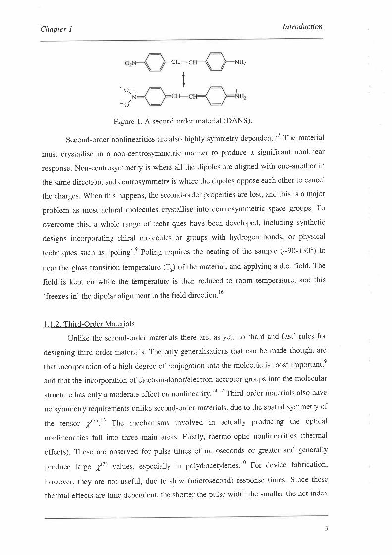
electron-donor (e.g. NH2) and electron-acceptor groups (e.g. NO2).e An example of this
type of material is shown below in Figure 1 for the compound known as DANS (N,N-
dimethylamino-nitrostilbene). I a
2
Chapter I Introduction
CH_C
- O..+N-t
Figure 1. A second-order material (DANS).
Second-order nonlinearities are also highly symmetry dependent.ls The material
must crystallise in a non-centrosymmetric manner to produce a significant nonlinear
response. Non-centrosymmetry is where all the dipoles are aligned with one-another in
the same direction, and centrosymmetry is where the dipoles oppose each other to cancel
the charges. When this happens, the second-order properties are lost, and this is a major
problem as most achiral molecules crystallise into centrosymmetric space groups. To
overcome this, a whole range of techniques have been developed, including synthetic
designs incorporating chiral molecules or groups with hydrogen bonds, or physical
techniques such as 'poling'.e Poling requires the heating of the sample (-90-130') to
near the glass transition temperature (Tr) of the material, and applying a d'c. field. The
field is kept on while the temperature is then reduced to room temperature, and this
'freezes in' the dipolar alignment in the field direction'16
1. 1.2. Third-Order Materials
Unlike the second-order materials there are, as yet, no 'hard and fast' rules for
designing third-order materials. The only generalisations that can be made though, are
that incorporation of a high degree of conjugation into the molecule is most important,e
and that the incorporation of electron-donor/electron-acceptor groups into the molecular
structure has only a moderate effect on nonlinearity.14'17 Third-order materials also have
no symmetry requirements unlike second-order materials, due to the spatial symmetry of
the tensor /'3).t3 The mechanisms involved in actually producing the optical
nonlinearities fall into three main areas. Firstly, thermo-optic nonlinearities (thermal
effects). These are observed for pulse times of nanoseconds or greater and generally
produce Iarge /3) values, especially in polydiacetylenes.l0 For device fabrication,
however, they are not useful, due to slow (microsecond) response times. Since these
thermal effects are time dependent, the shorter the pulse width the smaller the net index
NHz
+
3
Chapter I Introduction
change and so thermal effects can be separated from the more important nuclear and
electronic nonlinearities by reducing the pulse width of the laser to the sub-nanosecond
. 18.19reglon.
Nuclear and electronic contributions to nonlinearities are the most significant
processes in terms of response times and magnitude. Nuclear contributions arise from
optical field induced changes in the motions of the nuclei. After the sudden impression
of the field, this contribution can only be observed after a time of approximately 10-12 s.
This is because the nucleus has to undergo a vibrational or rotational decay cycle.20
Electronic contributions are those arising from the nonlinear distortion of the electronic
orbits around the average positions of the nuclei (e.g. exciton formation). These
processes occur on a very short timescale (-10-lós¡, and are considered to be virtually
instantaneous.20 Both of these contributions can be resolved from one another by Raman
Scattering techniques.20
Electronic contributions can be enhanced by designing molecules and polymers
with high degrees of conjugation. It is the ru-electron delocalisation which promotes
induced polarisation within the material when subjected to high intensity laser beams' In
general, for small molecules the trend is that the higher the degree of conjugation, the
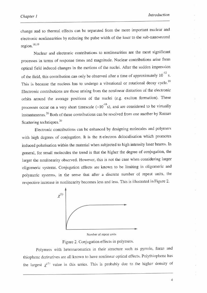
larger the nonlinearity observed. However, this is not the case when considering larger
oligomeric systems. Conjugation effects are known to be limiting in oligomeric and
polymeric systems, in the sense that after a discrete number of repeat units, the
respective increase in nonlinearity becomes less and less. This is illustrated in Figure 2'
/t)
Number of repeat units
Figure 2. Conjugation effects in polymers'
Polymers with heteroaromatics in their structure such as pyrrole, furan and
thiophene derivatives are all known to have nonlinear optical effects. Polythiophene has
the largest /3) value in this series. This is probably due to the higher density of
4
Chapter I Introduction
electrons near to the sulphur atom.2l In mathematical terms, the effects of the
heteroatom in the ring can be explained using Frontier Molecular Orbital Theory to
determine the charge transfer mechanisms between orbitals.22
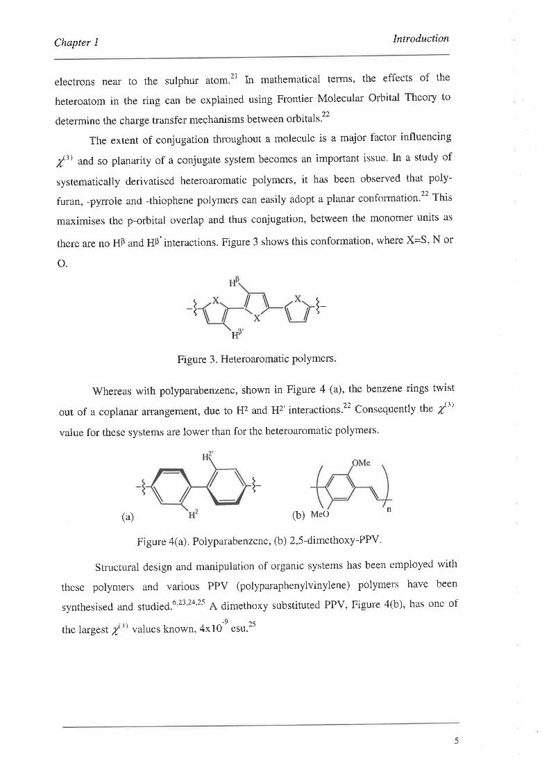
The extent of conjugation throughout a molecule is a major factor influencing
/3) and so planarity of a conjugate system becomes an important issue' In a study of
systematically derivatised heteroaromatic polymers, it has been observed that poly-
furan, -pyrrole and -thiophene polymers can easily adopt a planar conformation.2' This
maximises the p-orbital overlap and thus conjugation, between the monomer units as
there are no HÞ and HÞ'interactions. Figure 3 shows this conformation, where X=S, N or
o.
l-Hp
Figure 3. Heteroaromatic polymers'
Whereas with polyparabenzene, shown in Figure 4 (a), the benzene rings twist
out of a coplanar arrangement, due to H2 and H2'interactions.22 Consequently the /3)
value for these systems are lower than for the heteroaromatic polymers.
(a) (b) Meo
Figure 4(a). Polyparabenzene, (b) 2,5-dimethoxy-PPV'
Structural design and manipulation of organic systems has been employed with
these polymers and various PPV (polyparaphenylvinylene) polymers have been
synthesised and studied.6'23'24'2s A dimethoxy substituted PPV, Figure 4(b), has one of
the largest f ') values known, 4x10-e "su.25
l-n
5
Chapter I Inftoduction
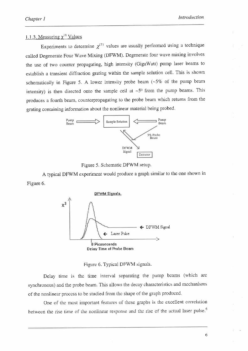
1. 1.3. Measuring X(3) Values
Experiments to determine lt) values are usually performed using a technique
called Degenerate Four Wave Mixing (DFWM). Degenerate four wave mixing involves
the use of two counter propagating, high intensity (GigaWatt) pump laser beams to
establish a transient diffraction grating within the sample solution cell. This is shown
schematically in Figure 5. A lower intensity probe beam (-57o of the pump beam
intensity) is then directed onto the sample cell at -50 from the pump beams. This
produces a fourth beam, counterpropagating to the probe beam which returns from the
grating containing information about the nonlinear material being probed.
Sample Solution
51o ProbeBeam
SignalDetector
Figure 5. Schematic DFWM setuP.
A typical DFWM experiment would produce a graph similar to the one shown in
Figure 6.
DFWM Signals.
€ DFSIM Srgral
C Laser Pulse
PicosecondsDelay Time of Probe Beam
Figure 6. Typical DFWM signals.
Delay time is the time interval separating the pump beams (which are
synchronous) and the probe beam. This allows the decay characteristics and mechanisms
of the nonlinear process to be studied from the shape of the graph produced.
One of the most important features of these graphs is the excellent correlation
between the rise time of the nonlinear response and the rise of the actual laser pulse.6
Pump Pump
Beam Beam
DFWM
x3
6
Chapter I Introduction
This implies that some nonlinear responses are virtually instantaneous. Decay of the
DFWM signal is determined by various quantum electronic processes, such as exciton
and bipolaron decay.26 The main goal at the moment in this field is to minimise the
decay of the signal after impression of the laser pulse and to extend the life of the
transient grating (extend the tail-end of the signal).
Other common methods of measuri ng /') include the optical Kerr gate,26 third
harmonic generatione and the Z-scantechnique.2T
1.2. The Project
We have seen earlier that enhancement of conjugation throughout a molecular
structure increases the magnitude of the nonlinearity and minimises the fall off in the
nonlinearity as the number of repeat units increases. From work done previously in our
group it was found that the extent of conjugation throughout several tolane oligomers
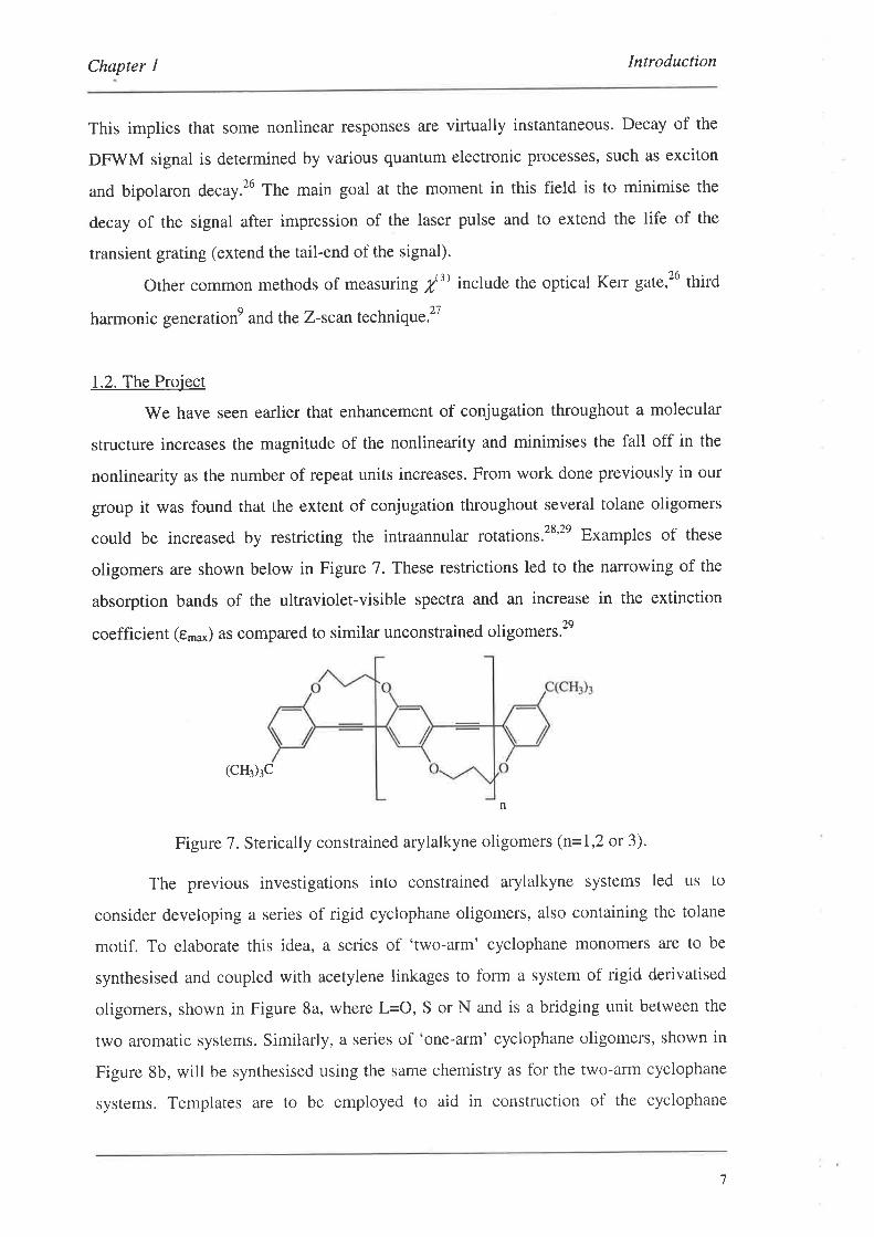
could be increased by restricting the intraannular rotations.2s'2e Examples of these
oligomers are shown below in Figure 7. These restrictions led to the narrowing of the
absorption bands of the ultraviolet-visible spectra and an increase in the extinction
coefficient (t*u*) as compared to similar unconstrained oligomers.2e
(cH3)3c
Figure 7. Sterically constrained arylalkyne oligomers (n=1,2 or 3).
The previous investigations into constrained arylalkyne systems led us to
consider developing a series of rigid cyclophane oligomers, also containing the tolane
motif. To elaborate this idea, a series of 'two-arm' cyclophane monomers are to be
synthesised and coupled with acetylene linkages to form a system of rigid derivatised
oligomers, shown in Figure 8a, where L=O, S or N and is a bridging unit between the
two aromatic systems. Similarly, a series of 'one-arm' cyclophane oligomers, shown in
Figure 8b, will be synthesised using the same chemistry as for the two-arm cyclophane
systems. Templates are to be employed to aid in construction of the cyclophane
n
7
Chapter I Introduction
structures. Coupling of the monomers to the templates will be achieved using palladium
catalysed coupling reactions.3o
'(b) tì1(a)
Figure 8. The target systems: (a) the 'two-arm' cyclophane oligomers, (b) the 'one-arm'
cyclophane oligomers.
1.2. l. Cyclophane Systems
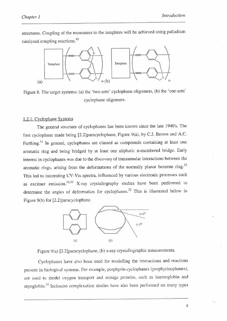
The general structure of cyclophanes has been known since the late 1940's' The
first cyclophane made being l2.2lparacyclophane, Figure 9(a), by C.J. Brown and A.C.
Farthing.3l In general, cyclophanes are classed as compounds containing at least one
aromatic ring and being bridged by at least one aliphatic n-membered bridge. Early
interest in cyclophanes was due to the discovery of transannular interactions between the
aromatic rings, arising from the deformations of the normally planar benzene ring.32
This led to interesting UV-Vis spectra, influenced by various electronic processes such
as excimer emission.32'33 X-ray crystallography studies have been performed to
determine the angles of deformation for cyclophanes.'2 This is illustrated below in
Figure 9(b) for 12.2)paracyclophane.
tz.óo
t t'zo
(a) (b)
Figure 9 (a) 12.zlparacyclophane, (b) x-ray crystallographic measurements
Cyclophanes have also been used for modelling the interactions and reactions
present in biological systems. For erample, porphyrin-cyclophanes (porphyrinophanes),
are used to model oxygen transport and storage proteins, such as haemoglobin and
myoglobin.3a Inclusion complexation studies have also been performed on many types
8
Template Template
Chapter I Introduction
of cyclophanes, since various molecules can form stable complexes if the cyclophane
cavity is sufficiently large.35 An interesting aspect of these complexes is the inclusion of
an apolar substrate within a cyclophane host in both aqueous solutions and solid state.35
The most recent research at the moment is with regards to chiral molecular recognition,
using cyclophanes containing one or more chiral centres. This allows enantioselectivity
of substrates to form inclusion complexes.36
1,2.2. Cyclophane Nomenclature
The nomenclature for cyclophanes has only recently been published'37
Previously there were no 'hard and fast' rules, and only partial I.U.P.A'C. guidelines3s
along with various naming methodologies by authors of cyclophane-related papers were
available.33''n No* a new form of nomenclature called 'Phane Nomenclature' has been
developed for naming cyclophanes and other complex structures. It is based on the idea
of simplifying a complex structure to a 'simplified skeleton' consisting of a 'simplified
phane parent graph' with 'superatoms' and 'skeletal locants'. An example of a
'simplified skeleton' is given below in Figure 10. The 'simplified phane parent graph' is
generally a ring structure for cyclophanes, but can be an acyclic chain as in Figure 11. tn
the example below (Figure 10), the simplified phane parent graph is a cycloheptane
structure, and consequently the simplified skeletal name is cycloheptaphane. The
superatoms represent ring structures and skeletal locants refer to the substitution
positions on the rings, with respect to the simplified skeleton. In the example below, the
superatom at position one (1) of the simplified skeleton is a naphthalene ring and is
connected to the simplified skeleton in the two and seven positions. Similarly, the
superatom in position four (4) of the simplified skeleton is a benzene ring which is
connected to the simplified skeleton in the one and three positions. There are various
rules governing the priority and location of the superatoms in the simplified skeleton,
and with the numbering of the locants.3T After the complex structure has been reduced
down to the various simplified components, the cyclophane name is built-up in a
process called amplification. The first part of the name refers to the superatom number,
followed by the skeletal locants in parentheses and then the ring name' This is repeated
till all the superatoms have been incorporated. Finally, the simplified skeletal name is
9
Chapter I Introduction
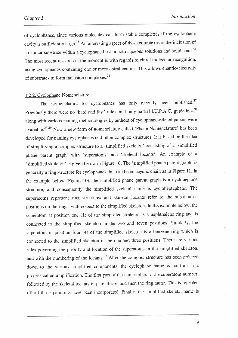
added on the end. For example, the structure in Figure 10 has the full name l(2,7)-
naphthalena-4( 1,3)-benzenacycloheptaphane.
Simplification
Amplihcation4
Original structure
Simplified skeleton
O = SuPeratom
Figure 10. An example of phane nomenclature.
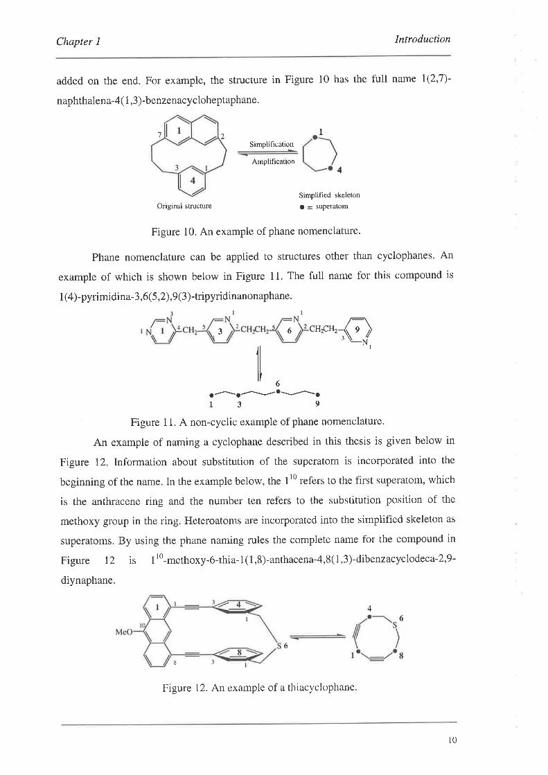
Phane nomenclature can be applied to structures other than cyclophanes. An
example of which is shown below in Figure 11. The full name for this compound is
I (4)-pyrimidina-3,6(5,2),9(3)-tripyridinanonaphane.
3 6 cH.pH2
i^'.l-'-;Figure I 1. A non-cyclic example of phane nomenclature'
An example of naming a cyclophane described in this thesis is given below in
Figure 12. Information about substitution of the superatom is incorporated into the
beginning of the name. In the example below, the 110 refers to the first superatom, which
is the anthracene ring and the number ten refers to the substitution position of the
methoxy group in the ring. Heteroatoms are inco¡porated into the simplified skeleton as
superatoms. By using the phane naming rules the complete name for the compound in
Figure 12 is I rO-methoxy-6-thia-
1( 1,8)-anthacena-4,8( 1,3)-dibenzacyclodeca-2,9-
diynaphane.
I2'1
24 q6
4
6
8
Figure 12. An example of a thiacyclophane
10

Chapter I Introduction
1.2.3. Cyclophanes for Nonlinear Optics
In terms of using the cyclophanes for nonlinear optics, we propose that their
structure will serve to restrict the rotations between the aromatic rings and the acetylenic
linkages, effectively locking the n-conjugated systems into two discrete parallel planes'
This clamping effect wilt serve to maximise conjugation throughout the molecular
backbone of the oligomer and hence maximise any nonlinear response' These
restrictions should produce a lowering of the band gap (Eg), as compared to unrestricted
poly-paraphenylacetylene and a narrowing of the UV-visible absorption spectrum with a
red-shifting of l,-u*. These ideas are consistent with restricted rotations of n-
conjugated systems.ao'al'a2 There also exists the possibility that any transannular
interactions involving charge transfer mechanisms may promote photorefractive
properties in these materials.a3
Briefly, photorefractive materials are at the 'crossroads' between second-order
and third-order materials.a3 They have contributions from both types of nonlinearities'
These materials generally have slow response times (-100 ms) due to second-order
processes. Nevertheless, these materials have many applications in optical computing,
real-time holography and the optical storage of information'aa'as
1.2.4. Cyclophane Formation Methodology
The formation of both the two-arm cyclophanes and the one-arm cyclophanes is
to be developed using a new methodology. The main aspects of which are outlined
schematically in Figure l3 for the two-arm cyclophanes. Exactly the same methodology
will be used for the one-arm cyclophanes'
1l
IntroductionChapter I
L
TPd coupling
of substrates
Cyclisation
/
Repeat Cycle
Cyclisation
Where = templûte, pre = precursor and L = linker-arm.T
R
(L
L
Pd coupling
PreL
L L
(a) x
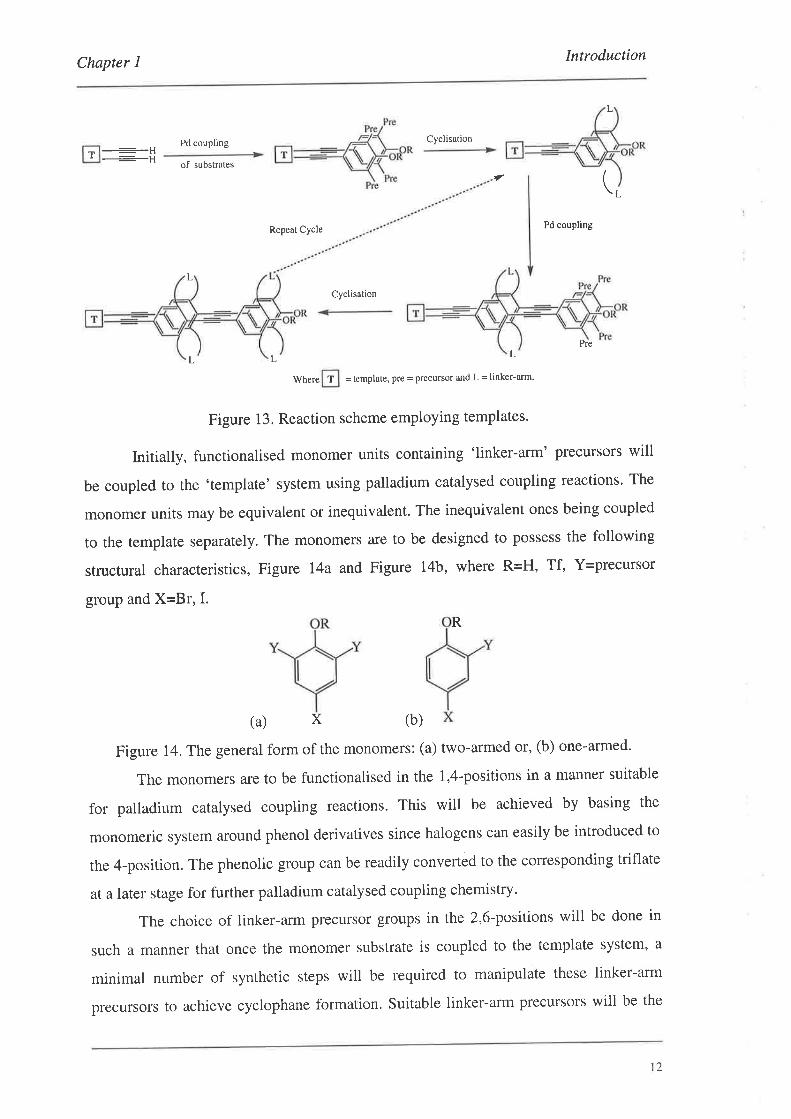
Figure 13. Reaction scheme employing templates'
Initially, functionalised monomer units containing 'linker-arm' precursors will
be coupled to the 'template' system using palladium catalysed coupling reactions. The
monomer units may be equivalent or inequivalent. The inequivalent ones being coupled
to the template separately. The monomers are to be designed to possess the following
structural characteristics, Figure I4a and Figure 14b, where R=H, 1¡, {=precursor
group and X=Br, I.
(b)
Figure 14. The general form of the monomers: (a) two-armed or, (b) one-armed'
The monomers are to be functionalised in the 1,4-positions in a manner suitable
for palladium catalysed coupling reactions. This will be achieved by basing the
monomeric system around phenol derivatives since halogens can easily be introduced to
the 4-position. The phenolic group can be readily converted to the corresponding triflate
at a later stage for further palladium catalysed coupling chemistry.
The choice of linker-arm precursor groups in the 2,6-positions will be done in
such a manner that once the monomer substrate is coupled to the template system, a
minimal number of synthetic steps will be required to manipulate these linker-arm
precursors to achieve cyclophane formation. Suitable linker-arm precursors will be the
l2
Chapter I Intoduction
esters, acetoxymethyl and hydroxymethyl groups which will ultimately lead to [3'3]-
cyclophanes. The linker-arms in these [3.3]-cyclophanes will contain one of a range of
different heteroatoms, namely O, N and S. In doing so, a determination of the influence
of heteroatoms on nonlinearity can be performed through a comparative study'
Thc function of the template is to dramatically aid the cyclisation step, by
holding the linker-ann precursors in close proximity thereby pre-organising the system'
previous methods of cyclophane formation involved the use of high dilution techniques
which are in general tedious and can produce low yields due to entropy factors.aó Even
though these entropy factors have been reduced in some cases through the use of the
caesium effect,a6 the utilisation of these template systems should give cyclophanes in
much higher yields. Apart from the clamping and rigidifying nature of the cyclophanes
on the molecular structure the templates themselves will serve to add a degree of rigidity
to the oligomeric system. The introduction of a high degree of rigidity to the oligomers
may have adverse effects on solubility.2e It may become necessary to incorporate alkyl
groups into the template structures to increase solubility'
After cyclophane formation, further monomeric groups will be coupled to the
oligomer where each aromatic ring is separated by an acetylene unit. This is followed by
linker-arm manipulation and cyclisation to form the second repeat unit. The oligomer
length is then built up by simple repetition of this cycle'
Another route to forming the cyclophanes is to firstly build up the basic oligomer
length using the monomer substrates, off the template, as shown schematically for the
two-arm cyclophanes in Figure 15. Once the correct functional groups have been
introduced to form the functionalised oligomer, they will be then coupled to the
template. Finally, with a minimum number of steps, the linker-arm precursors will then
be manipulated to effect cyclophane formation'
t3

Chapter I Introduction
MOnomers --t>
Basic oligomer
Functional groupman ipulations
Cyclisation
+
-
Functionalised oligomer
Template
Pre
n
L Ln
Figure 15. The alternative route to the cyclophanes
1.2.5. Structural Isomers of Cyclophanes
The reason for investigating the two-arm cyclophanes possessing a meta
relationship between the linker-arms, 'metacyclophanes,' rather than the isomeric two-
affn 'paracyclophanes,' lies in the problem of structural isomers. For example, forming
the paracyclophanes with two repeats units and higher, inequivalent rotamers will arise
from rotations of the un-linked precursor substrates, before the linker-arms are formed.
This is illustrated for the two unit case schematically in Figure 16. The number of
possible isomers increases dramatically as the number of repeat units increases.
LL
L L
Pre
CyclisationCyclisation
L LL
LL
Figure i6. The structural isomers possible'
By using metacyclophanes we effectively remove the problem of regiospecificity
completely. The use of monomers with linker-arm precursors in the 2,6-positions will
I4
Chapter I Introduction
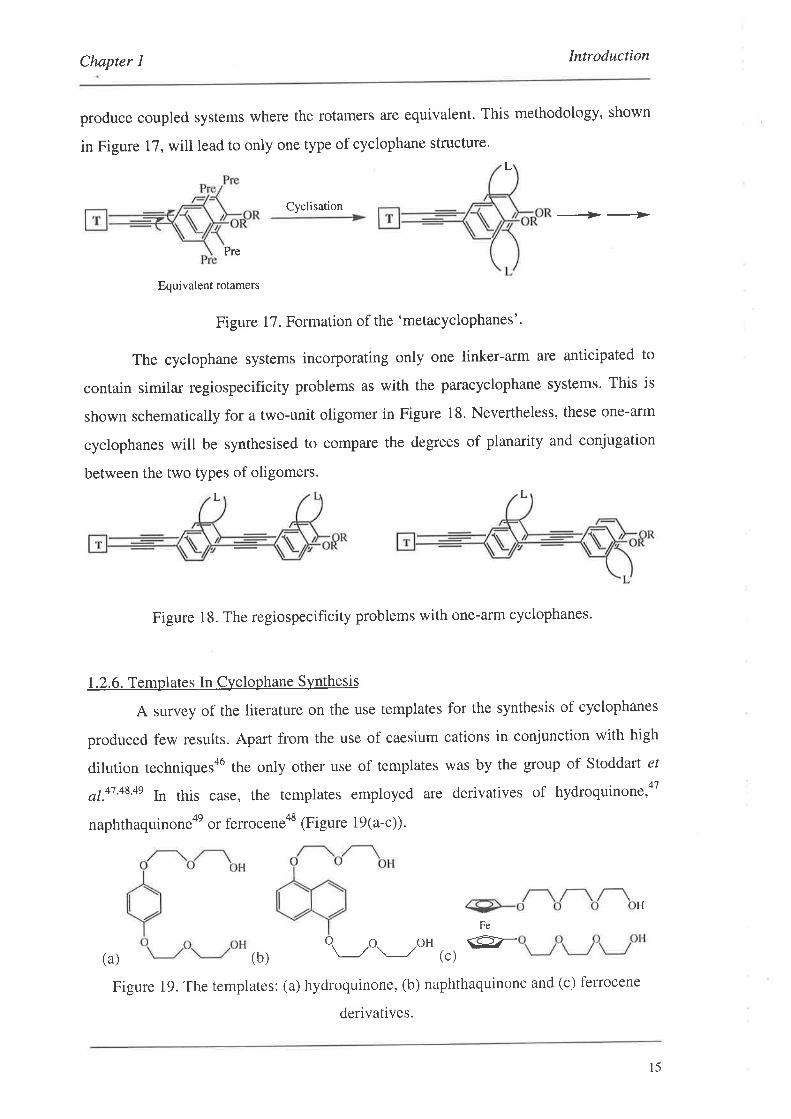
produce coupled systems where the rotamers are equivalent. This methodology, shown
in Figure 17, will lead to only one type of cyclophane structure.
Cyclisation +-_¿>
(a) (b)
Figure 19. The templates: (a) hydroquinone, (b) naphthaquinone and (c) ferrocene
derivatives.
L
Pre
Equivalent rotamers
Figure 17. Formation of the 'metacyclophanes'.
The cyclophane systems incorporating only one linker-arm are anticipated to
contain similar regiospecificity problems as with the paracyclophane systems. This is
shown schematically for a two-unit oligomer in Figure 18. Nevertheless, these one-arm
cyclophanes will be synthesised to compare the degrees of planarity and conjugation
between the two types of oligomers.
L
Figure 18. The regiospecificity problems with one-affn cyclophanes.
1.2.6. Templates In Cyclophane Synthesis
A survey of the literature on the use templates for the synthesis of cyclophanes
produced few results. Apart from the use of caesium cations in conjunction with high
dilution techniquesa6 the only other use of templates was by the group of Stoddart e/
a1.47,48,4s In this case, the templates employed are derivatives of hydroquinone,aT
naphthaquinone4e or ferroceneos iFigure 19(a-c)).
o\-,roa----ron (.)
g-
L
H
Fe
l5
Chapter I Introduction
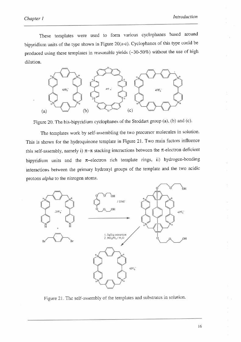
These templates were used to form various cyclophanes based around
bipyridium units of the type shown in Figure 20(a-c). Cyclophanes of this type could be
produced using these templates in reasonable yields (-30-5OVo) without the use of high
dilution.
4PF6 4PF6-
(b) (c)
/ DMF
4PFó
I liq/liq extraction2. NH4PF6 / H2O
4PF6
.IPF
(a)
Figure 20. The bis-bipyridium cyclophanes of the Stoddart group (a), (b) and (c).
The templates work by self-assembling the two precursor molecules in solution'
This is shown for the hydroquinone template in Figure 21. Two main factors influence
this self-assembly, namely i) n-n stacking interactions between the n-electron deficient
bipyridium units and the ru-electron rich template rings, ii) hydrogen-bonding
interactions between the primary hydroxyl groups of the template and the two acidic
protons alpha to the nitrogen atoms.
2PF6
+
Figure 2I.The self-assembly of the templates and substrates in solution.
l6
Chapter 1 Introduction
1.2.7. The Project Templates
The synthesis of the cyclophanes in the previous section relied on non-covalent
interactions between the substrates and the templates in solution. Our aim, however, is
to employ templates which are covalently bonded to the substrates' This method should
produced high yields in the cyclisation step since it doesn't rely on weak dispersive
forces or hydrogen bonding.
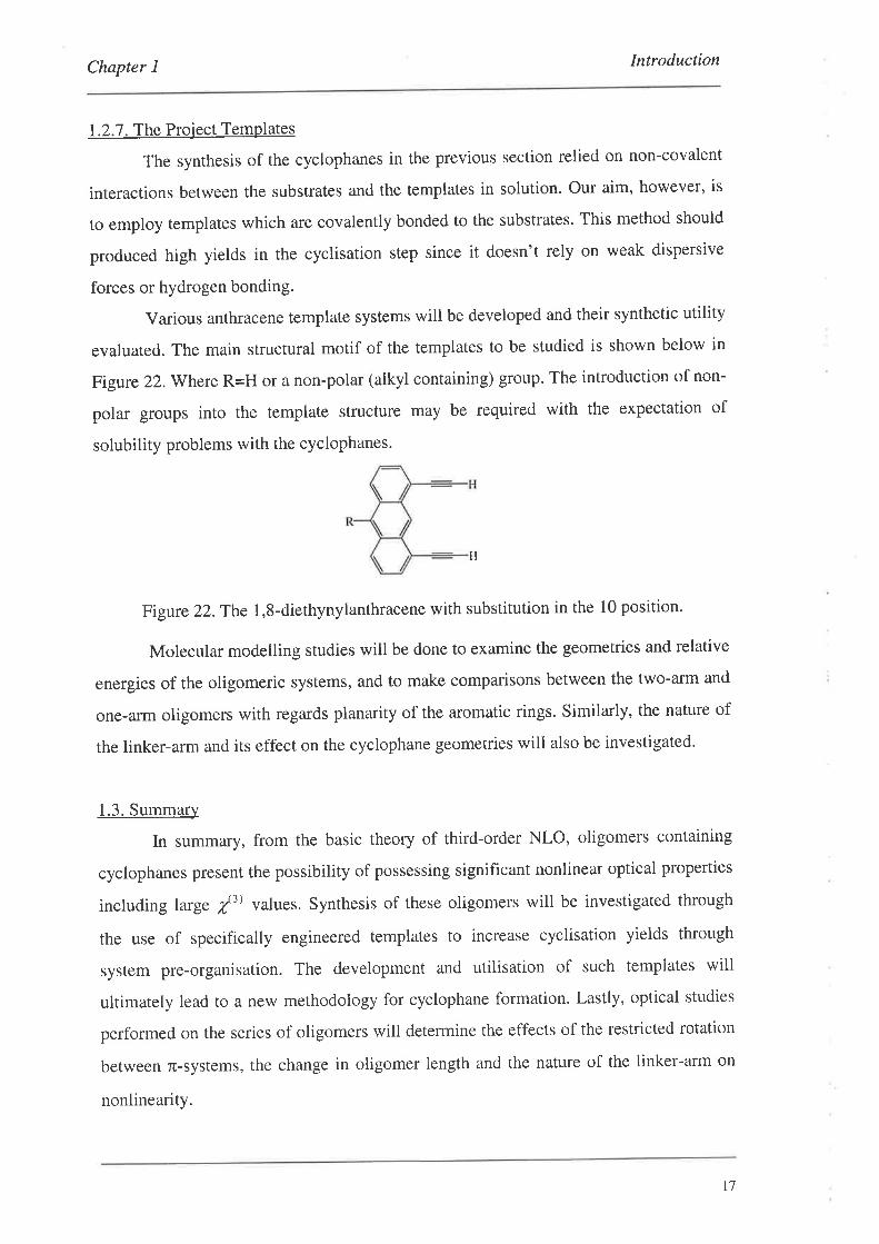
Various anthracene template systems will be developed and their synthetic utility
evaluated. The main structural motif of the templates to be studied is shown below in
Figure 22.Where R=H or a non-polar (alkyl containing) group. The introduction of non-
polar groups into the template structure may be required with the expectation of
solubility problems with the cyclophanes.
Figure 22.The 1,8-diethynylanthracene with substitution in the 10 position.
Molecular modelling studies will be done to examine the geometries and relative
energies of the oligomeric systems, and to make comparisons between the two-arm and
one-arm oligomers with regards planarity of the aromatic rings. Similarly, the nature of
the linker-arm and its effect on the cyclophane geometries will also be investigated.
1.3. Summary
ln summary, from the basic theory of third-order NLO, oligomers containing
cyclophanes present the possibility of possessing significant nonlinear optical properties
including 1arge f3) values. Synthesis of these oligomers will be investigated through
the use of specifically engineered templates to increase cyclisation yields through
system pre-organisation. The development and utilisation of such templates wili
ultimately lead to a new methodology for cyclophane formation. Lastly, optical studies
performed on the series of oligomers will determine the effects of the restricted rotation
between fr-systems, the change in oligomer length and the nature of the linker-arm on
nonlinearity.
H
r7
Chapter 2 The Monomers
2. The Monomers-_
The organic chemist is often faced with a multitude of possible pathways for any
synthetic goal. The choice of the 'right' pathway is often difficult and can only be made
after much experimentation. This reasoning lead to the development of a wide range of
monomeric synthons which could, potentially, be used to prepare the desired cyclophane
oligomers.
2.1. Introducing Functionality to Phenol Derivatives
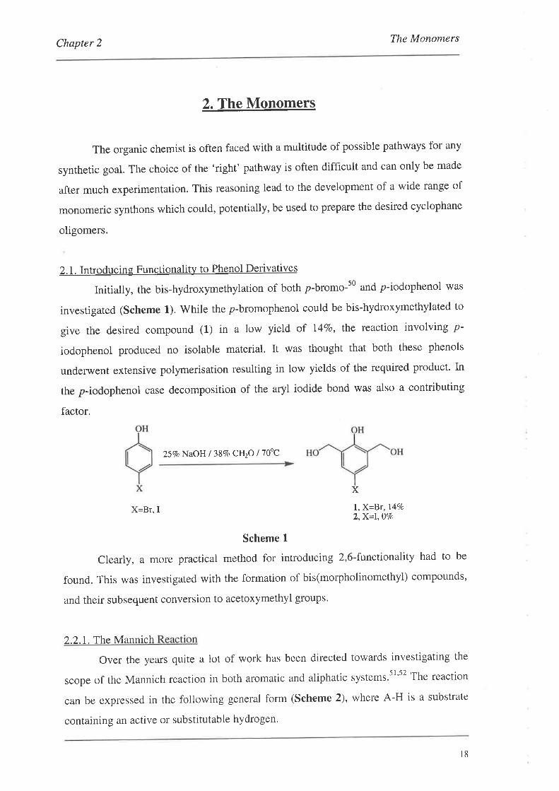
Initially, the bis-hydroxymethylation of both p-bromo-s0 and p-iodophenol was
investigated (Scheme 1). While the p-bromophenol could be bis-hydroxymethylated to
give the desired compound (L) in a low yield of I4Vo, the reaction involving p-
iodophenol produced no isolable material. It was thought that both these phenols
underwent extensive polymerisation resulting in low yields of the required product. In
the p-iodophenol case decomposition of the aryl iodide bond was also a contributing
factor.
257o NaOH I 38Vo CLI2O /70'C
X
X=Br, I l,X=Br,l4Vo2,X=\jVo
Scheme 1
Clearly, a more practical method for introducing 2,6-functionality had to be
found. This was investigated with the formation of bis(morpholinomethyl) compounds,
and their subsequent conversion to acetoxymethyl groups.
2.2.L The Mannich
Over the years quite a lot of work has been directed towards investigating the
scope of the Mannich reaction in both aromatic and aliphatic systems.5l's2 The reaction
can be expressed in the following general form (Scheme 2), where A-H is a substrate
containing an active or substitutable hydrogen.
l8
Chapter 2 The Monomers
Acid or Base RII,R'N_C_AI
H+ R2R3NH + A-H R
Scheme 2
Examples of this type of reaction are shown below in Figure 23 with the active
hydrogens underlined.s2 The products of these reactions are known as Mannich bases.
Rt-c-Hilo
H
-oR
R---H HCN ROH RSH
Figure 23.Examples of Substrates for the Mannich Reaction.
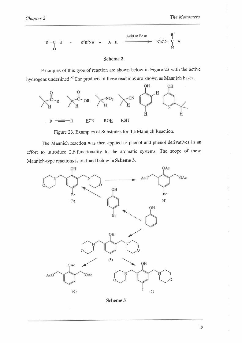
The Mannich reaction was then applied to phenol and phenol derivatives in an
effort to introdu ce 2,6-functionality to the aromatic systems. The scope of these
Mannich-type reactions is outlined below in Scheme 3.
Br
(3)
Br
(4)
\
N
H
\.
,/
rl\./,ol-toJ
,/(s)
OAc
aû
Í (t)(6)
Scheme 3
19

Chapter 2 The Monomers
The first route to be investigated was that of p-bromophenol (Scheme 4).
Initially, reaction conditions that had been previously described in the literature were
trialed but met with little ,uccess.t3 This involved adding morpholine and 38Vo
formaldehyde to an ethanolic solution of p-bromophenol. After being allowed to stir
overnight, the reaction mixture was heated at reflux with a small amount of
concentrated sulphuric acid in an attempt to catalyse the reaction. After five days only
starting materials were present by tlc.
Morpholine 1387o CH2O
AcoH / 80oC
3,82Vo
Scheme 4
A successful reaction took place when acetic acid was used as both solvent and
activator. In this case the desired material (3) was isolated in 82Vo yield in only 6 hours.
Unfortunately, application of this procedure to p-iodophenol met with little success' The
bis-substituted compound (7) could only be isolated in 2Vo yield with the majority of the
isolable reaction product being the mono-morpholinomethyl compound (8) (Scheme 5).
The mono-morpholinomethyl compound was isolated in a low ISVo yield' This was
thought to be due to the decomposition of the starting material since apart from the
appearance of baseline material by tlc, the reaction mixture turned from colourless to
dark red which may have indicated the formation of iodine. This colour was discharged
during the extractive workup when the reaction mixture was washed with a 57o sodium
thiosulphate solution. The formation of (7) was achieved via a different approach, as
discussed later.
Br
Morpholine l38Vo CH2O
AcoH / 80"C
r^N¿.-, +
7,2Vo
Scheme 5
8, l5Vo
20
Chapter 2 The Monomers
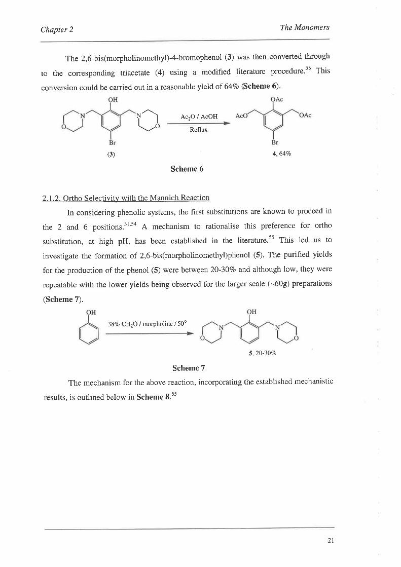
The 2,6-bis(morpholinomethyl)-4-bromophenol (3) was then converted through
to the corresponding triacetate (4) using a modified literature procedure.t3 Thit
conversion could be carried out in a reasonable yield of 64Vo (Scheme 6).
Ac2O / AcOH
Reflux
4,6470
Scheme 6
2.1.2. Ortho Selectivit)¡ with the Mannich Reaction
In considering phenolic systems, the first substitutions are known to proceed in
the 2 and 6 positions.sl's4 A mechanism to rationalise this preference for ortho
substitution, at high pH, has been established in the literature.s5 This led us to
investigate the formation of 2,6-bis(morpholinomethyl)phenol (5). The purified yields
for the production of the phenol (5) were between 20-30Vo and although low, they were
repeatable with the lower yields being observed for the larger scale (-609) preparations
(Scheme 7).
38Vo CH2O / morpholine / 50o
5,20-30Vo
Scheme 7
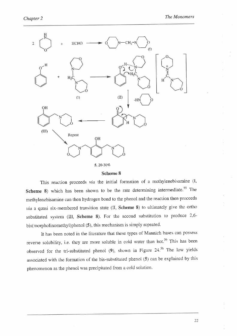
The mechanism for the above reaction, incorporating the established mechanistic
results, is outlined below in Scheme 8.ss
rl!,o
(3)
2l
Chapter 2 The Monomers
2 +n_
HCHO + d. N-CH2-N. P\_/ - \J11¡
H H (o' +
)+
(r) (r)
NA\
Uå H
(m)Repeat
5,20-3070
Scheme 8
This reaction procee ds via the initial formation of a methylenebisamine (I,
Scheme 8) which has been shown to be the rate determining intermediate.ss The
methylenebisamine can then hydrogen bond to the phenol and the reaction then proceeds
via a quasi six-membered transition state (II, Scheme 8) to ultimately give the ortho
substituted system (Itr, Scheme 8). For the second substitution to produce 2,6-
bis(morpholinomethyl)phenol (5), this mechanism is simply repeated.
It has been noted in the literature that these types of Mannich bases can possess
reverse solubility, i.e. they are more soluble in cold water than hot.s6 This has been
observed for the tri-substituted phenol (9), shown in Figure 24.56 The low yields
associated with the formation of the bis-substituted phenol (5) can be explained by this
phenomenon as the phenol was precipitated from a cold solution.
22
Chapter 2 The Monomers
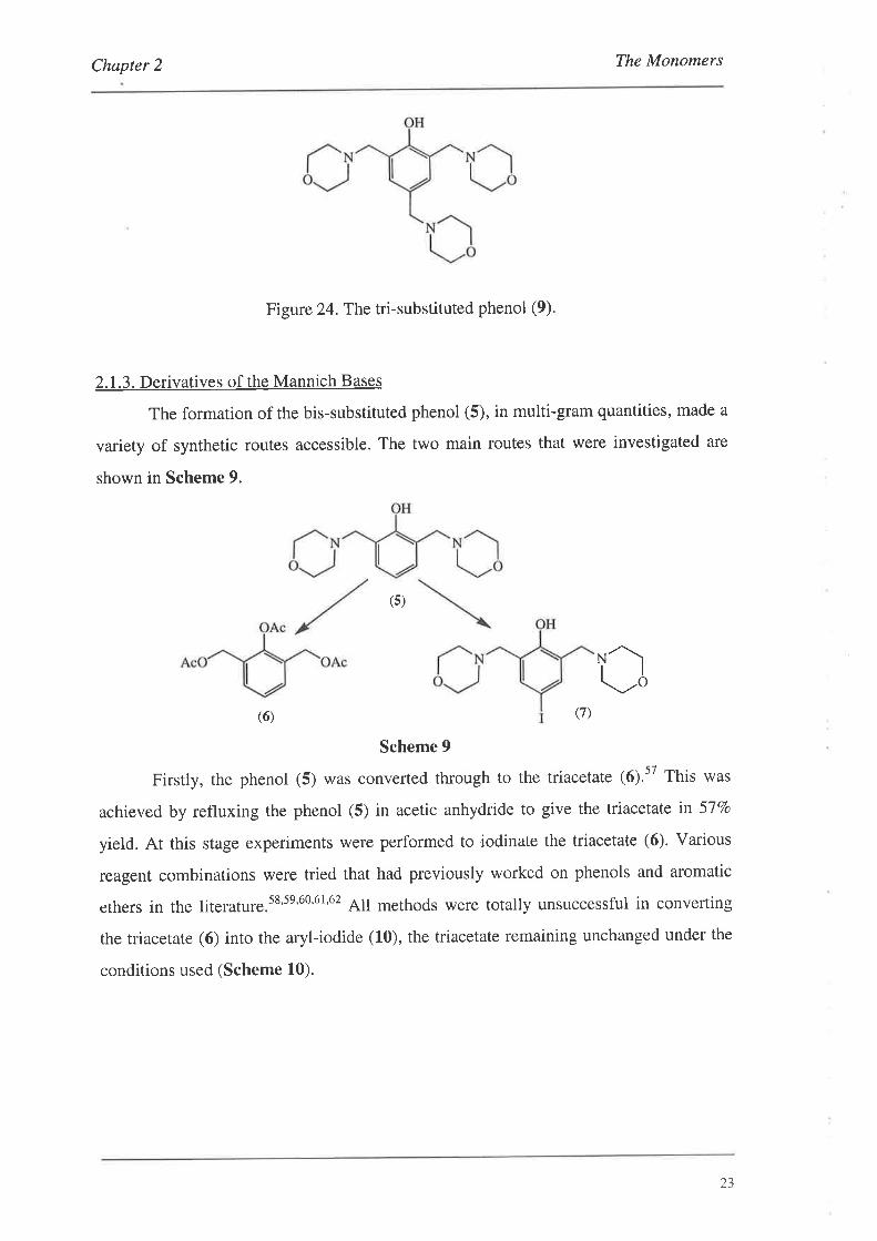
Figure 24.The tri-substituted phenol (9).
2.1.3. Derivatives of the Mannich Bases
The formation of the bis-substituted phenol (5), in multi-gram quantities, made a
variety of synthetic routes accessible. The two main routes that were investigated are
shown in Scheme 9.
(s)
rl!,o(6) (7)
Scheme 9
Firstly, the phenol (5) was converted through to the triacetate 16),57 This was
achieved by refluxing the phenol (5) in acetic anhydride to give the triacetate in 5l%o
yield. At this stage experiments were performed to iodinate the triacetate (6). Various
reagent combinations were tried that had previously worked on phenols and aromatic
ethers in the literature.ss'se'60'6t'62 All methods were totally unsuccessful in converting
the triacetate (6) into the aryl-iodide (10), the triacetate remaining unchanged under the
conditions used (Scheme 10).
23
The MonomersChapter 2
Ac2O / reflux
Merhods: I (ro)a) morpholine / 12
b) HgO / 12
c) ICI / CH2CI2d) BTMA.ICI I CIl2Clz/ MeOHe) CuCl2 / I2l A,c2O
Ð Cu(OAch /l2l AIOH
6,57Vo
II
(r1)Methods:
a) 0.5M guanidine / MeOH
b) lM NaOH / EIOH
c) K2CO3 / MeOH
d¡zn* tMeoH
(s)
Scheme 10
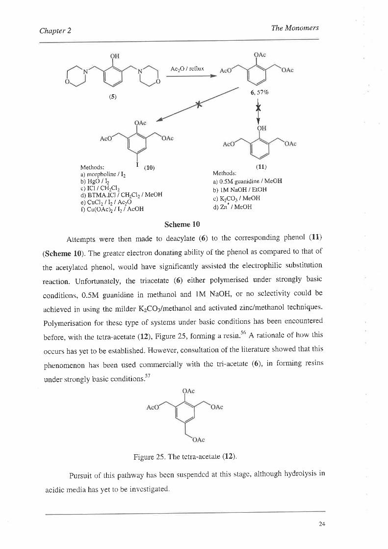
Attempts were then made to deacylate (6) to the corresponding phenol (11)
(Scheme 10). The greater electron donating ability of the phenol as compared to that of
the acetylated phenol, would have significantly assisted the electrophilic substitution
reaction. Unfortunately, the triacetate (6) either polymerised under strongly basic
conditions, 0.5M guanidine in methanol and lM NaOH, or no selectivity could be
achieved in using the milder KzCO¡/methanol and activated zinclmethanol techniques.
polymerisation for these type of systems under basic conditions has been encountered
before, with the tetra-acetate (12), Figure 25, forming a resin.s6 A rationale of how this
occurs has yet to be established. However, consultation of the literature showed that this
phenomenon has been used commercially with the tri-acetate (6), in forming resins
under strongly basic conditions'57
Figure 25. The tetra-acetate (12).
pursuit of this pathway has been suspended at this stage, although hydrolysis in
acidic media has yet to be investigated.
24
Chapter 2 The Monomers
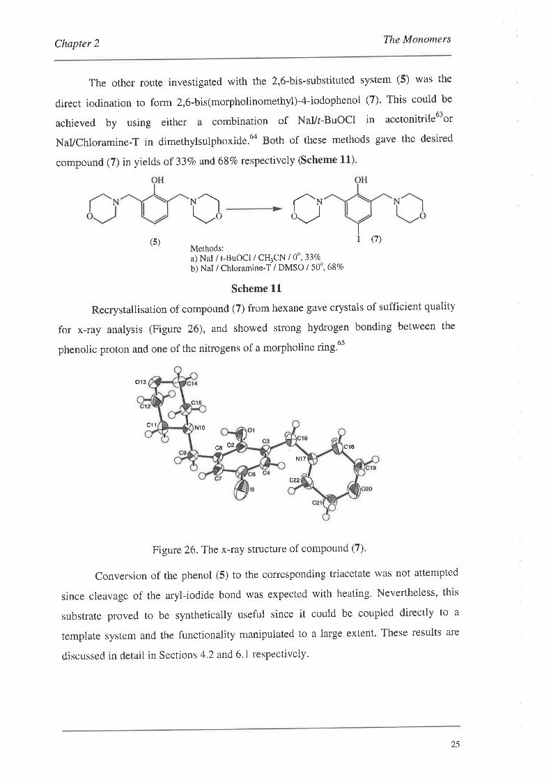
The other route investigated with the 2,6-bis-substituted system (5) was the
direct iodination to form 2,6-bis(morpholinomethyl)-4-iodophenol (7). This could be
achieved by using either a combination of NaVr-BuOCl in acetonitrile63or
NaVChloramine-T in dimethylsulphoxide.6o Both of these methods gave the desired
compound (7) in yields of 337o and 68Vo respectively (scheme 11).
Ìì!,oâNå-..,
(7)Methods:a) NaI / r-BuOCl / CH3CN I 0o,33Eo
b) NaI / Chloramine-T / DMSO / 5Oo , 68Eo
Scheme lL
Recrystallisation of compound (7) from hexane gave crystals of sufficient quality
for x-ray analysis (Figure 26), and showed strong hydrogen bonding between the
phenolic proton and one of the nitrogens of a morpholine ring.6s
(s)
013
c1t N10
c8 c2 cl8
Nl7
cul6
Figure 26.The x-ray structure of compound (7).
Conversion of the phenol (5) to the corresponding triacetate was not attempted
since cleavage of the aryl-iodide bond was expected with heating. Nevertheless' this
substrate proved to be synthetically useful since it could be coupled directly to a
template system and the functionality manipulated to a large extent. These results are
discussed in detail in Sections 4.2 and 6.1 respectively'
25
Chapter 2 The Monomers
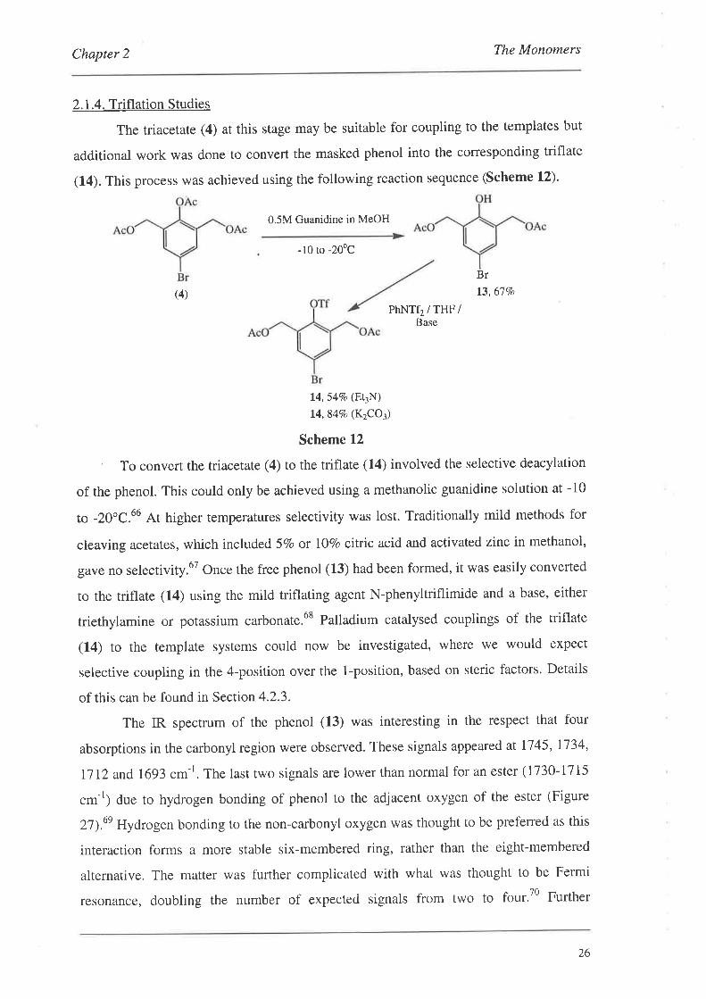
2. 1.4. Triflation Studies
The triacetate (4) at this stage may be suitable for coupling to the templates but
additional work was done to convert the masked phenol into the corresponding triflate
(14). This process was achieved using the following reaction sequence (Scheme L2)'
0.5M Guanidine in MeOH
-10 ro -20oC
(4)
Br
t3,67Vo
PhNTf2 / THF /Base
14,547o (E\N)14,84Vo (K2CO3)
Scheme 12
' To convert the triacetate (4) to the triflate (14) involved the selective deacylation
of the phenol. This could only be achieved using a methanolic guanidine solution at -10
to -20oC.ó6 At higher temperatures selectivity was lost. Traditionally mild methods for
cleaving acetates, which included 57o or IOVo citric acid and activated zinc in methanol,
gave no selectivity.6T Once the free phenol (13) had been formed, it was easily converted
to rhe triflate (1.4) using the mild triflating agent N-phenyltriflimide and a base, either
triethylamine or potassium carbonate.6s Palladium catalysed couplings of the triflate
(14) to the template systems could now be investigated, where we would expect
selective coupling in the 4-position over the 1-position, based on steric factors. Details
of this can be found in Section 4.2.3.
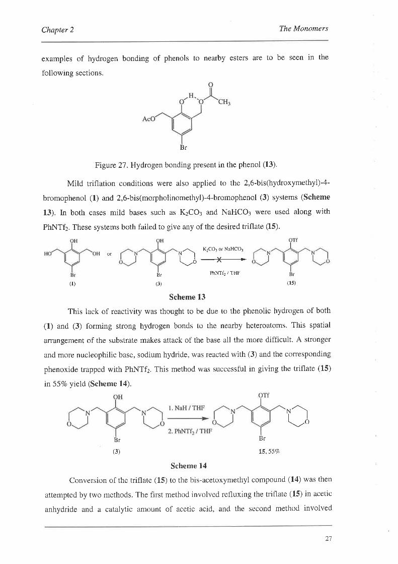
The IR spectrum of the phenol (13) was interesting in the respect that four
absorptions in the carbonyl region were observed. These signals appeared at 1745, L'734'
Il12 and 1693 cm-r. The last two signals are lower than normal for an ester (1730-I715
cm-'; due to hydrogen bonding of phenol to the adjacent oxygen of the ester (Figure
2l).un Hydrogen bonding to the non-carbonyl oxygen was thought to be preferred as this
interaction forms a more stable six-membered ring, rather than the eight-membered
alternative. The matter was further complicated with what was thought to be Fermi
resonance, doubling the number of expected signals from two to four.70 Further
26
Chapter 2 The Monomers
examples of hydrogen bonding of phenols to nearby esters are to be seen in the
following sections.
Br
Figure 2T.Hydrogen bonding present in the phenol (13).
Mild triflation conditions were also applied to the 2,6-bis(hydroxymethyl)-4-
bromophenol (L) and 2,6-bis(morpholinomethyl)-4-bromophenol (3) systems (Scheme
13). In both cases mild bases such as KzCO: and NaHCO¡ were used along with
PhNTf2. These systems both failed to give any of the desired triflate (15).
K2CO1 or NaHCO3
+-*PhNTf2 / THF
or îl\'v'o
(1)
Br
(3) (rs)
Scheme 13
This lack of reactivity was thought to be due to the phenolic hydrogen of both
(1) and (3) forming strong hydrogen bonds to the nearby heteroatoms. This spatial
arrangement of the substrate makes attack of the base all the more difficult. A stronger
and more nucleophilic base, sodium hydride, was reacted with (3) and the corresponding
phenoxide trapped with PhNTfz. This method was successful in giving the triflate (15)
in 557o yield (Scheme 14).
û
Br
(3)
Scheme 14
Conversion of the triflate (1.5) to the bis-acetoxymethyl compound (14) was then
attempted by two methods. The first method involved refluxing the triflate (15) in acetic
anhydride and a catalytic amount of acetic acid, and the second method involved
Br
15,557o
21
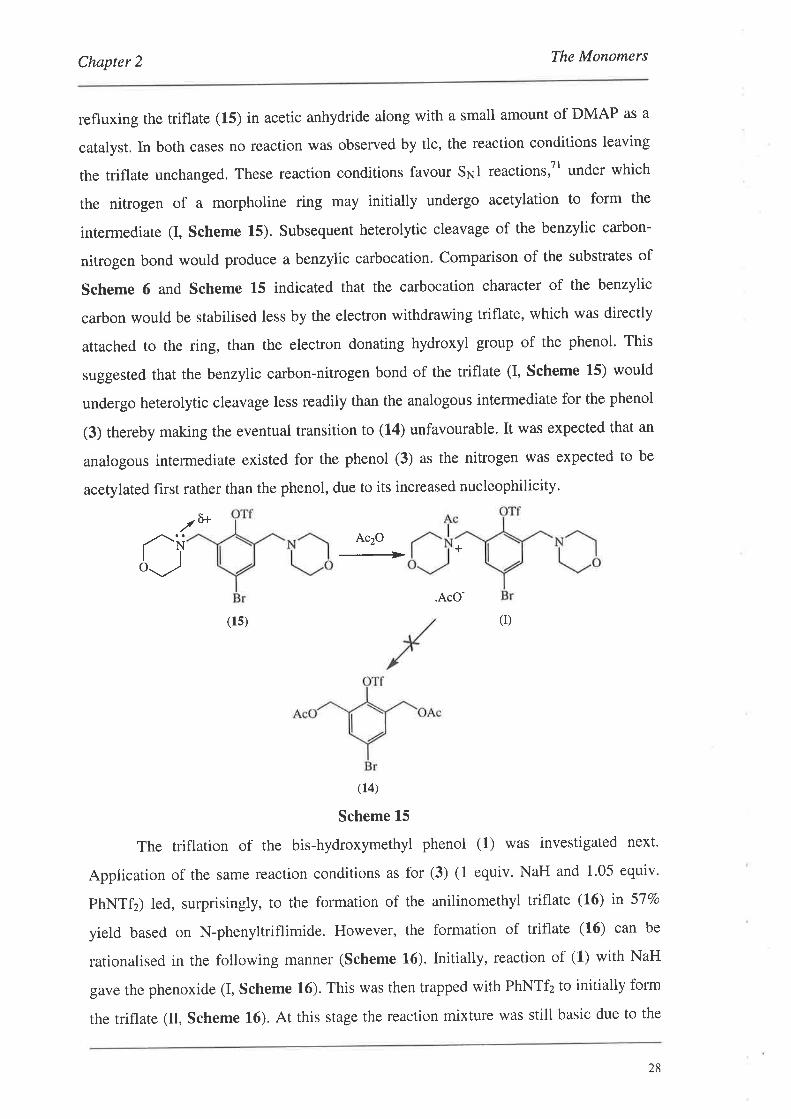
Chapter 2 The Monorners
refluxing the triflate (15) in acetic anhydride along with a small amount of DMAP as a
catalyst. In both cases no reaction was observed by tlc, the reaction conditions leaving
the triflate unchanged. These reaction conditions favour Sr.¡1 reactions,Tl under which
the nitrogen of a morpholine ring may initially undergo acetylation to form the
intermediate (I, Scheme 15). Subsequent heterolytic cleavage of the benzylic carbon-
nitrogen bond would produce a benzylic carbocation. Comparison of the substrates of
Scheme 6 and Scheme 15 indicated that the carbocation character of the benzylic
carbon would be stabilised less by the electron withdrawing triflate, which was directly
attached to the ring, than the electron donating hydroxyl group of the phenol. This
suggested that the benzylic carbon-nitrogen bond of the triflate (I, Scheme L5) would
undergo heterolytic cleavage less readily than the analogous intermediate for the phenol
(3) thereby making the eventual transition to (14) unfavourable. It was expected that an
analogous intermediate existed for the phenol (3) as the nitrogen was expected to be
acetylated first rather than the phenol, due to its increased nucleophilicity.
./ ô+
Ac2O
+
.AcO-
(14)
Scheme 15
The triflation of the bis-hydroxymethyl phenol (1) was investigated next.
Application of the same reaction conditions as for (3) (1 equiv. NaH and 1.05 equiv.
phNTfz) led, surprisingly, to the formation of the anilinomethyl triflate (L6) in 57Vo
yield based on N-phenyltriflimide. However, the formation of triflate (L6) can be
rationalised in the following manner (Scheme 16). Initially, reaction of (1) with NaH
gave the phenoxide (I, Scheme 16). This was then trapped with PhNTfz to initially form
the triflate (tr, Scheme L6). At this stage the reaction mixture was still basic due to the
aio.,¿2
+
(I)(1s)
28
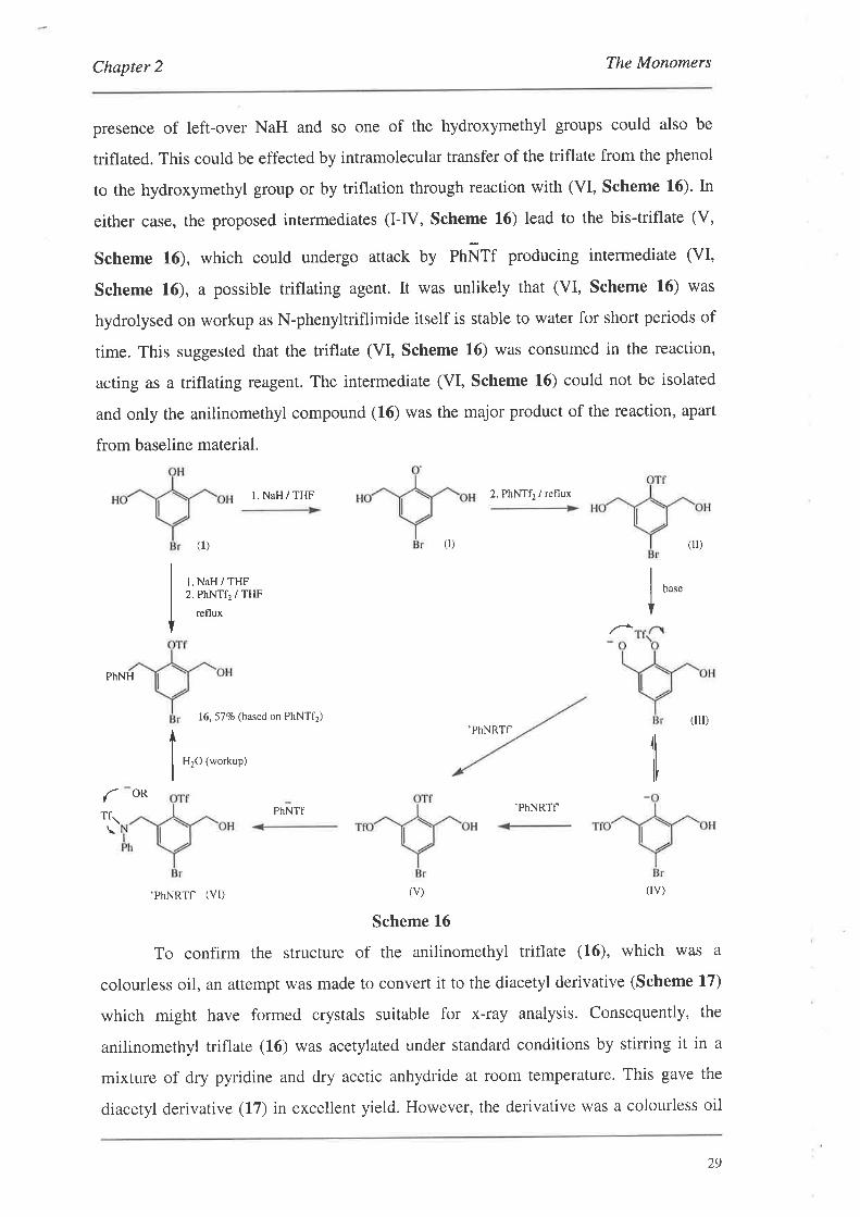
Chapter 2 The Monomers
presence of left-over NaH and so one of the hydroxymethyl groups could also be
triflated. This could be effected by intramolecular transfer of the triflate from the phenol
to the hydroxymethyl group or by triflation through reaction with (VI, Scheme 16). In
either case, the proposed intermediates (I-IV, Scheme 16) lead to the bis-triflate (V,
Scheme 16), which could undergo attack by pnÑff producing intermediate (VI,
Scheme 16), a possible triflating agent. It was unlikely that (VI, Scheme 16) was
hydrolysed on workup as N-phenyltriflimide itself is stable to water for short periods of
time. This suggested that the triflate (VI, Scheme 16) was consumed in the reaction,
acting as a triflating reagent. The intermediate (VI, Scheme L6) could not be isolated
and only the anilinomethyl compound (16) was the major product of the reaction, apart
from baseline material.
l. NaH / THF 2. PhNTf2 / reflux
(ll)0)(l)
l. NaH / THF2. PhNTf2 / THF
reflux
base
PhNH
16,57Vo (bæed on PhNTf2)
H2O (workup)
PhNTf
(Ill)'PhNRTT
ITf:,
OR'PhNRTf
'PhNRTfl (VI) (V) (IV)
Scheme 16
To confirm the structure of the anilinomethyl triflate (16), which was a
colourless oil, an attempt was made to convert it to the diacetyl derivative (Scheme 17)
which might have formed crystals suitable for x-ray analysis. Consequently, the
anilinomethyl triflate (16) was acetylated under standard conditions by stirring it in a
mixture of dry pyridine and dry acetic anhydride at room temperature. This gave the
diacetyl derivative (17) in excellent yield. However, the derivative was a colourless oil
29
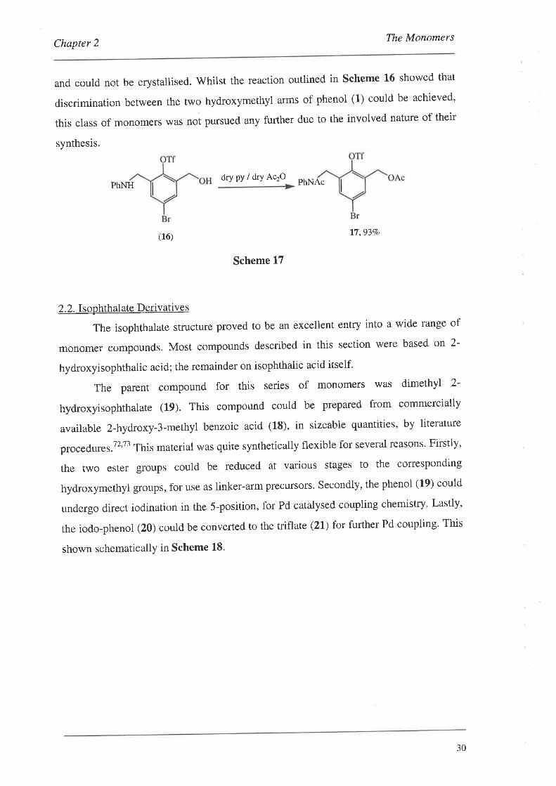
Chapter 2 The Monomers
and could not be crystallised. Whilst the reaction outlined in Scheme 16 showed that
discrimination between the two hydroxymethyt arms of phenol (1) could be achieved'
this class of monomers was not pursued any further due to the involved nature of their
synthesis.
dry py / dry AqOPhNAcPhNH
I7,93Vo
Scheme 17
2.2. Isophthalate Derivatives
The isophthalate structure proved to be an excellent entry into a wide range of
monomer compounds. Most compounds described in this section were based on 2-
hydroxyisophthalic acid; the remainder on isophthalic acid itself'
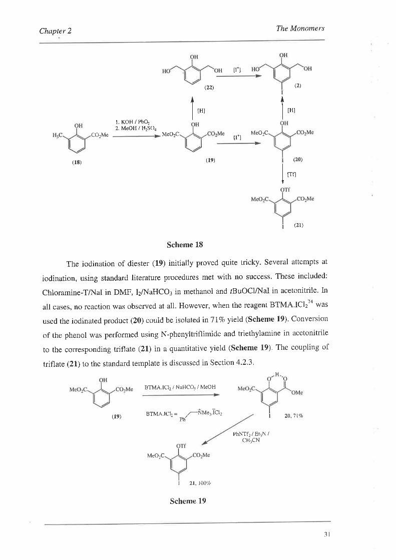
The parent compound for this series of monomers was dimethyl 2-
hydroxyisophthalate (19). This compound could be prepared from commercially
available 2-hydroxy-3-methyl benzoic acid (18), in sizeable quantities, by literature
procedures.T2't3 This material was quite synthetically flexible for several reasons. Firstly,
the t,wo ester groups could be reduced at various stages to the corresponding
hydroxymethyl groups, for use as linker-arm precursors' Secondly, the phenol (19) could
undergo direct iodination in the 5-position, for Pd catalysed coupling chemistry' Lastly,
the iodo-phenol (20) could be converted to the triflate (21) for further Pd coupling. This
shown schematicallY in Scheme 18.
(16)
30
Chapter 2 The Monomers
r. KoH / Pbq2. MeOH / H2SO4
MeO2C
(le) BTMA.lCl2 =
MeO2C
(22)
u*l
lrl
(2)
tHl
(20)
trfl
20,'7lVo
tHl
CO,Me
(18) (le)
(2r)
Scheme 18
The iodination of diesrer (19) initially proved quite tricky. Several attempts at
iodination, using standard literature procedures met with no success. These included:
Chloramine-TÆ.{al in DMF, IzA{aHCO¡ in methanol and rBuOClÆ'{aI in acetonitrile. In
all cases, no reaction was observed at all. However, when the reagent BTMA.ICI T'o was
used the iodinated product (20) could be isolated in'lI7o yield (Scheme 19). Conversion
of the phenol was performed using N-phenyltriflimide and triethylamine in acetonitrile
to the corresponding triflate (21) in a quantitative yield (Scheme 19). The coupling of
triflate (21) to the standard template is discussed in Section 4.2.3,
H
BTMA.ICI2 / NaHCO3 / MeOH
7-ÑMe',.lCl,p(
PhNTf2 / EtlN /CH¡CN
I 21, t0070
MeO.C
Scheme 19
3l
Chapter 2 The Monomers
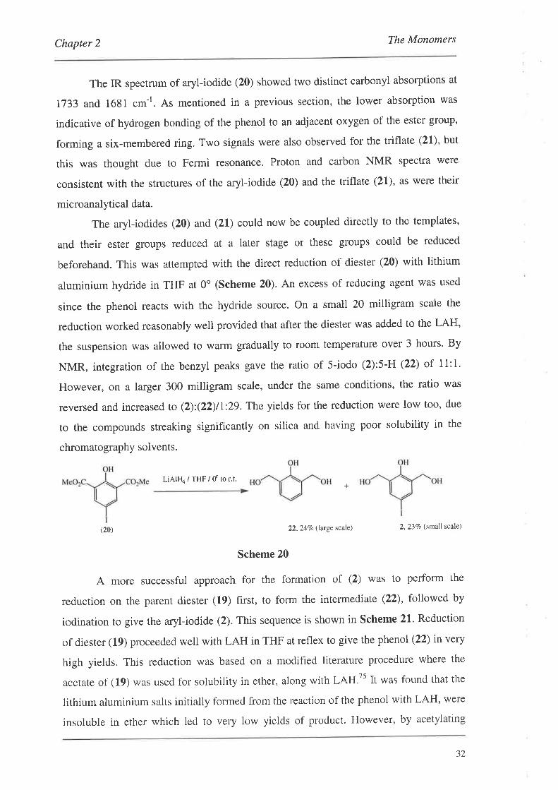
The IR spectrum of aryl-iodide (20) showed two distinct carbonyl absorptions at
1733 and 1681 cm-I. As mentioned in a previous section, the lower absorption was
indicative of hydrogen bonding of the phenol to an adjacent oxygen of the ester group'
forming a six-membered ring. Two signals were also observed for the triflate (21), but
this was thought due to Fermi resonance. Proton and carbon NMR Spectra were
consistent with the structures of the aryl-iodide (20) and the triflate (21), as were their
microanalytical data.
The aryl-iodides (20) and (21) could now be coupled directly to the templates,
and their ester groups reduced at a later stage or these groups could be reduced
beforehand. This was attempted with the direct reduction of diester (20) with lithium
aluminium hydride in THF at 0o (Scheme 20). An excess of reducing agent was used
since the phenol reacts with the hydride source. On a small 20 milligram scale the
reduction worked reasonably well provided that after the diester was added to the LAH,
the suspension was allowed to warm gradually to room temperature over 3 hours. By
NMR, integration of the benzyl peaks gave the ratio of 5-iodo (2):5-H (22) of II:I.
However, on a larger 300 milligram scale, under the same conditions, the ratio was
reversed and increased to (2):(22)11,:29. The yields for the reduction were low too, due
to the compounds streaking significantly on silica and having poor solubility in the
chromatography solvents.
LiAtFI4irHF/dtor.t.
(20) 22,247a (large scale) 2, 237o (small scale)
Scheme 20
A more successful approach for the formation of (2) was to perform the
reduction on the parent diester (19) first, to form the intermediate (22), followed by
iodination ro give the aryl-iodide (2). This sequence is shown in Scheme 21" Reduction
of diester (19) proceeded well with LAH in THF at reflex to give the phenol (22) in very
high yields. This reduction was based on a modified literature procedure where the
acetate of (19) was used for solubility in ether, along with LAH.tt It *us found that the
lithium aluminium salts initially formed from the reaction of the phenol with LAH, were
insoluble in ether which led to very low yields of product. However, by acetylating
+
32

Chapter 2 The Monomers
phenol (19) ether solubility during the course of the reaction was maintained, enabling
smooth reduction to the phenol (22). Our use of THF instead of ether eliminated these
solubility problems, and so acetylation of (19) was not required. Iodination of the phenol
was straightforward using the same conditions as for the diester (20) to give the aryl-
iodide (2) in 89Vo yield (Scheme 21).
Of interest with the phenol (22) was enantiotropic polymorphism was observed
with its melting point.75 This is where there exists two (or more) crystalline forms which
interchange reversibly on changing the temperature, and each form has its own stability
range of temperature.T6 On heating, two distinct melting points were observed. The
sample initially melted at94.5-95.5o, and if the sample was removed from the hot-stage
at this point, it crystallised immediately and melted at 98.0-99.0o. If this second form
was removed at or above 99.0o, the sample crystallised slowly over 20 mins and melted
at 94.0-95.0", consistent with the first form. The published melting points were 94,J-
95.2" for the first form and 98.2-98.4" for the second. The cycle could also be repeated
on the same sample several times, and either form could be obtained at will.75 This
phenomenon was not observed for the phenols (1) and (2).
LiAll-(a/THF/ reflux.BTMA.lC12 /
NaHCO3 / MeOH
(19) 2,8970
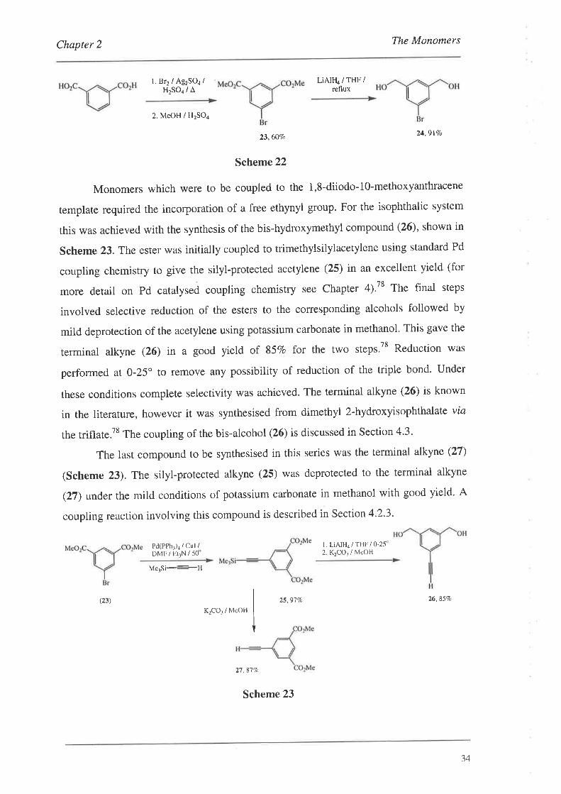
A series of simpler monomers based on isophthalic acid were prepared to be
used as trial systems throughout this work. Monomers based on the parent isophthalic
acid underwent slightly different chemistry (Scheme 22).Irritially, isophthalic acid was
converted to dimethyl 5-bromoisophthalate (23) using a standard literature procedure'77
This monomer could be directly coupled to the templates (Section 4.2.2) or the ester
groups could be reduced beforehand. The reduction was performed to give the aryl-
bromide (24) againusing a standard literary procedure'77
22,94Vo
Scheme 21
J-t
Chapter 2 The Monomers
l. Br2 / Ag2SOa /H2SO4 /
^
Pd(PPh1)a / Cul /DMFiEIIN/50o
LiAIF{4 / THF /reflux
2. MeOH / H2SO4
23,60Vo24.9l%o
Scheme 22
Monomers which were to be coupled to the 1,8-diiodo-10-methoxyanthracene
template required the incorporation of a free ethynyl group. For the isophthalic system
this was achieved with the synthesis of the bis-hydroxymethyl compound (26), shown in
Scheme 23. The ester was initially coupled to trimethylsilylacetylene using standard Pd
coupling chemisrry ro give the silyl-protected acetylene (25) in an excellent yield (for
more detail on Pd catalysed coupling chemistry see Chapter 4).78 The final steps
involved selective reduction of the esters to the corresponding alcohols followed by
mild deprotection of the acetylene using potassium carbonate in methanol. This gave the
terminal alkyne (26) in a good yield of 85Vo for the two steps.78 Reduction was
performed at O-25" to remove any possibility of reduction of the triple bond. Under
these conditions complete selectivity was achieved. The terminal alkyne (26) is known
in the literature, however it was synthesised from dimethyl 2-hydroxyisophthalate via
the triflate.78 The coupling of the bis-alcohol (26) is discussed in Section 4'3'
The last compound to be synthesised in this series was the terminal alkyne (27)
(Scheme 23). The silyl-protected alkyne (25) was deprotected to the terminal alkyne
(27) under the mild conditions of potassium carbonate in methanol with good yield. A
coupling reaction involving this compound is described in Section 4.2'3,
l. LiAlH4/THF/o-25o2. K2CO¡ / MeOH
MelSi-----fl
(23) 25,977a 26,85Vo
KzCO¡ / MeOH
27 .87Vc
Scheme 23
34
Chapter 2 The Monomers
2.3. One-arm Monomers
The synthesis of the one-arm monomers was based around two key
commercially available compounds, namely methyl salicylate and 3-iodobenzoic acid'
The methyl salicylate derivatives had ethynyl groups introduced into the 4-position vlø
the iodide since these one-arïn compounds were mainly being coupled to the 1,8-diiodo-
lg-methoxyanthracene template. The 3-iodobenzoic acid derivatives were used as
simple test compounds for the more complex salicylate monomers, and also for 'end-
capping' some of the oligomer systems (Section 4'3'I)'
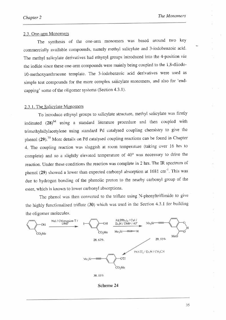
2.3.1. The Salicylate Monomers
To introduce ethynyl groups to salicylate structure, methyl salicylate was firstly
iodinated (28)uo using a standard literature procedure and then coupled with
trimethylsilylacetylene using standard Pd catalysed coupling chemistry to give the
phenol (2Ð.7e More details on Pd catalysed coupling reactions can be found in Chapter
4. The coupling reaction was sluggish at room temperature (taking over 16 hrs to
complete) and so a slightly elevated temperature of 40o was necessary to drive the
reaction. Under these conditions the reaction was complete in 2 hrs' The IR spectrum of
phenol (29) showed a lower than expected carbonyl absorption at 1681 cm-r. This was
due to hydrogen bonding of the phenolic proton to the nearby carbonyl group of the
ester, which is known to lower carbonyl absorptions.
The phenol was then converted to the triflate using N-phenyltriflimide to give
the highly funcrionalised triflate (30) which was used in the Section 4.3.1 for building
the oligomer molecules.
Pd(PPhì)4 / cul /OH Er¡N / DMF / 40'
Nal / Chloramine-T iOH DMF o
Me3Si--f{
Me
29,93Vo
PhNTf2/EtrN/CH3CN
28,62Vo.
30.88c/o
oTfMe-¡Si
Scheme 24
35
Chapter 2 The Monomers
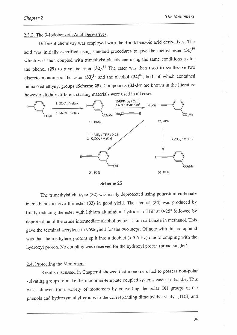
2.3.2. The 3-Iodobenzoic Acid Derivatives
Different chemistry was employed with the 3-iodobenzoic acid derivatives. The
acid was initially esterified using standard procedures to give the methyl ester (31)80
which was then coupled with trimethylsilylacetylene using the same conditions as for
the phenol (29) to give the ester (32).81 The ester was then used to synthesise two
discrete monomers: the ester (33)" and the alcohol (34)t', both of which contained
unmasked ethynyl groups (Scheme 25). Compounds (32-34) are known in the literature
however slightly different starting materials were used in all cases'
l. SOCL / refluxPd(PPh3)a / CuI /Er3N/DMF/4d Me3S
2. MeOH i reflux Me3Si---tl
3r, l00vo 32,98Vo
l. LiAlFI4 trør I o-zf2.K1CO3 / MeOH K2CO3 / MeOH
34,96Vo 33,82Vo
Scheme 25
The trimethylsilylalkyne (32) was easily deprotected using potassium carbonate
in methanol to give the ester (33) in good yield. The alcohol (34) was produced by
firstly reducing the ester with lithium aluminium hydride in THF at 0-25o followed by
deprotection of the crude intermediate alcohol by potassium carbonate in methanol. This
gave the terminal acetylene in 96Vo yield for the two steps. Of note with this compound
was that the methylene protons split into a doublet (J 5.6 Hz) due to coupling with the
hydroxyl proton. No coupling was observed for the hydroxyl proton (broad singlet).
2.4. Prorectins the Monomers
Results discussed in Chapter 4 showed that monomers had to possess non-polar
solvating groups to make the monomer-template coupled systems easier to handle. This
was achieved for a variety of monomers by convefiing the polar OH groups of the
phenols and hydroxymethyl groups to the corresponding dimethylthexylsilyl (TDS) and
36
Chapter 2 The Monomers
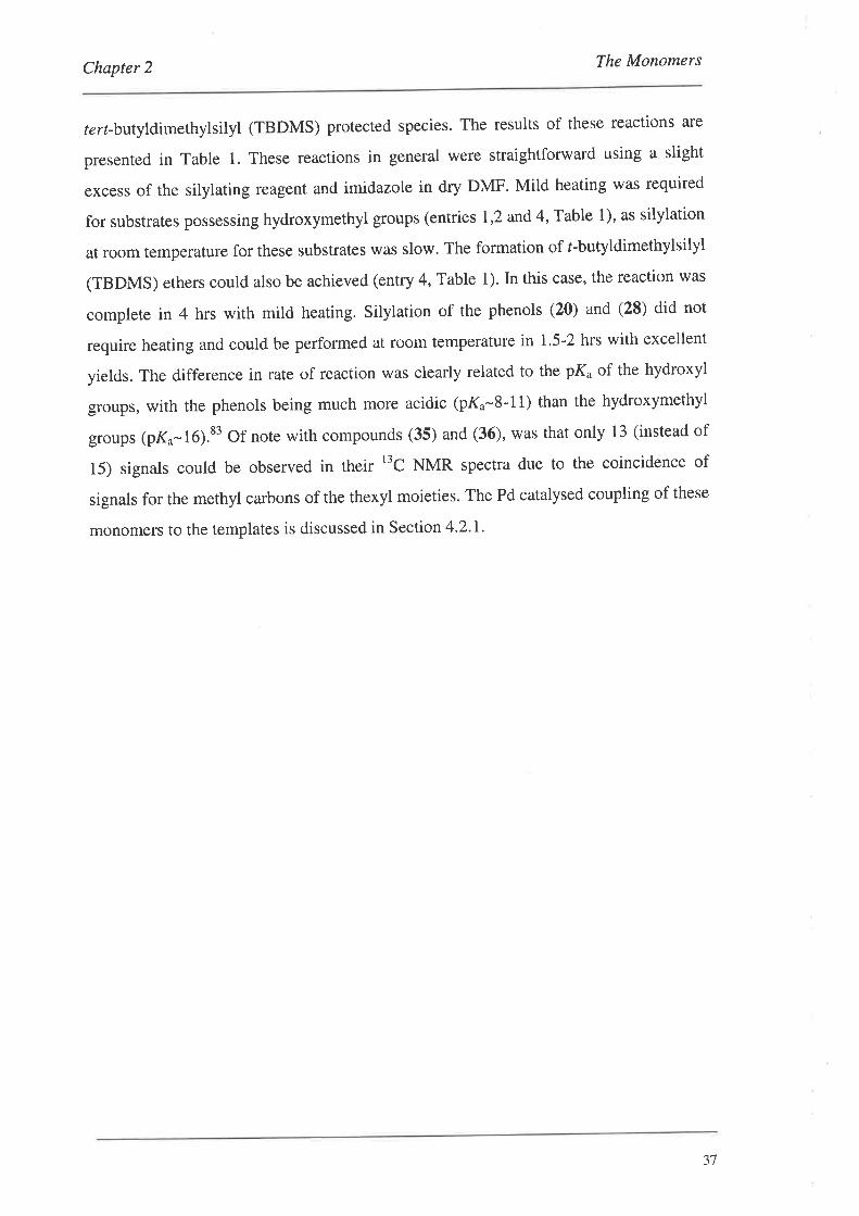
tert-butyldimethylsilyl (TBDMS) protected species. The results of these reactions are
presented in Table 1. These reactions in general were straightforward using a slight
excess of the silylating reagent and imidazole in dry DMF. Mild heating was required
for substrates possessing hydroxymethyl groups (entries 1,2 and4, Table 1), as silylation
at room temperature for these substrates was slow. The formation of r-butyldimethylsilyl
(TBDMS) ethers could also be achieved (entry 4, Table 1). In this case, the reaction was
complete in 4 hrs wirh mild heating. Silylation of the phenols (20) and (28) did not
require heating and could be performed at room temperature in 1.5-2 hrs with excellent
yields. The difference in rate of reaction was clearly related to the PK" of the hydroxyl
groups, with the phenols being much more acidic (pK"-8-11) than the hydroxymethyl
groups (pK.-16).83 Of note with compounds (35) and (36), was that only 13 (instead of
15) signals could be observed in their t'C NMR spectra due to the coincidence of
signals for the methyl carbons of the thexyl moieties. The Pd catalysed coupling of these
monomers to the templates is discussed in Section 4.2.I.
JI
Chapter 2 The Monomers
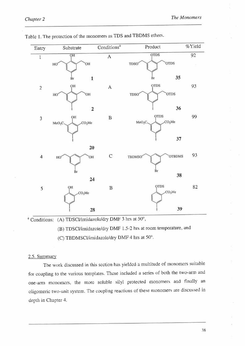
Table 1. The protection of the monomers as TDS and TBDMS ethers.
Entry Substrate Conditionsu Product VoYield
1 A
35
36
92
93
99
93
82
L
A2
2
B3
20
C4
24
B5
37
38
Me
28 39
o Conditions: (A) TDscl/imidazole/dry DMF 3 hrs at 50o,
(B) TDscl/imidazole/dry DMF 1.5-2 hrs at room temperature, and
(C) TBDMSCUimidazole/dry DMF 4 hrs at 50'.
2.5. Summary
The work discussed in this section has yielded a multitude of monomers suitable
for coupling to the various templates. These included a series of both the two-arm and
one-arm monomers, the more soluble silyl protected monomers and finally an
oligomeric two-unit system. The coupling reactions of these monomers are discussed in
depth in Chapter 4.
38
Chapter 3 Template Synthesis
3. Template Svnthesis
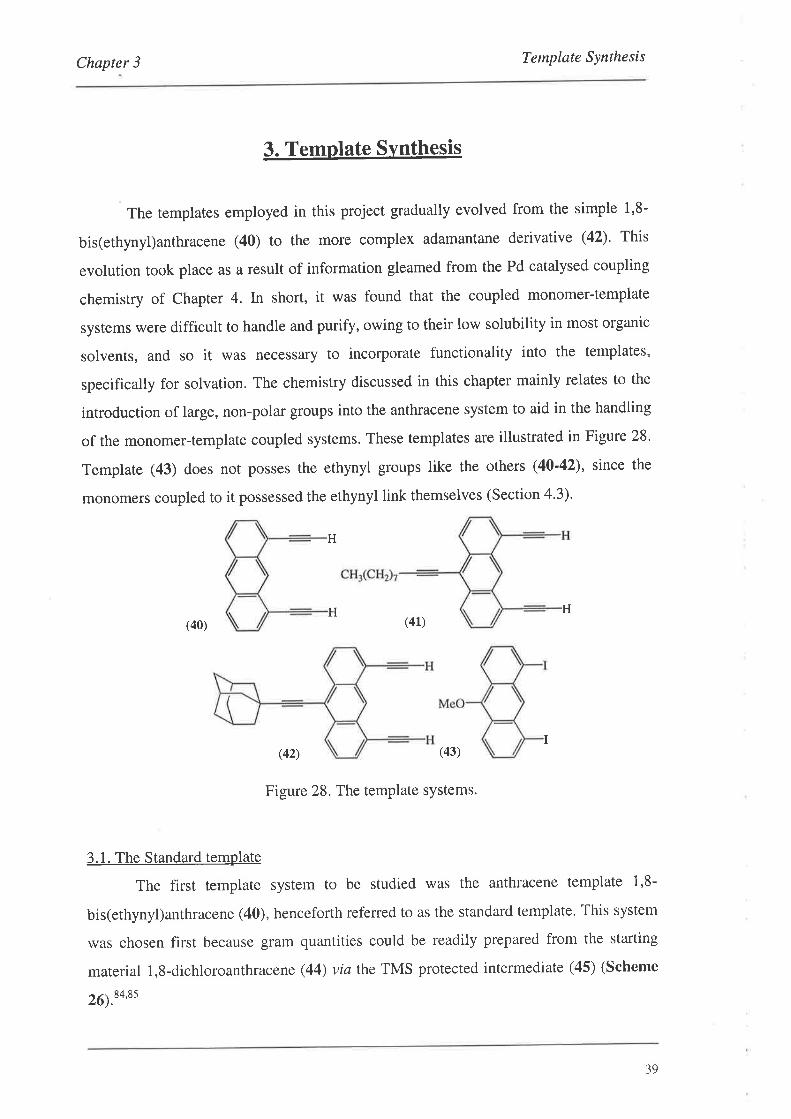
The templates employed in this project gradually evolved from the simple 1,8-
bis(ethynyl)anthracene (40) to the more complex adamantane derivative (42)' This
evolution took place as a result of information gleamed from the Pd catalysed coupling
chemistry of Chapter 4. ln short, it was found that the coupled monomer-template
systems were difficult to handle and purify, owing to their low solubility in most organic
solvents, and so it was necessary to incorporate functionality into the templates,
specifically for solvation. The chemistry discussed in this chapter mainly relates to the
introduction of large, non-polar groups into the anthracene system to aid in the handling
of the monomer-template coupled systems. These templates are illustrated in Figure 28.
Template (43) does not posses the ethynyl groups like the others (40'42), since the
monomers coupled to it possessed the ethynyl link themselves (Section 4'3).
H(40) (41)
(42) (43)
Figure 28. The template systems.
3.1. The Standard template
The first template system to be studied was the anthracene template i,8-
bis(ethynyl)anthracene (40), henceforth referred to as the standard template. This system
was chosen first because gram quantities could be readily prepared from the starting
material 1,8-dichloroanthracene (44) viafhe TMS protected intermediate (45) (Scheme
26¡.t+'as
H
H
I
39
Chapter 3 Template Synthesis
Ni(acac)2/PPh3/THF
Me3Si---MgBr K2CO3 / MeOH
SiMe3
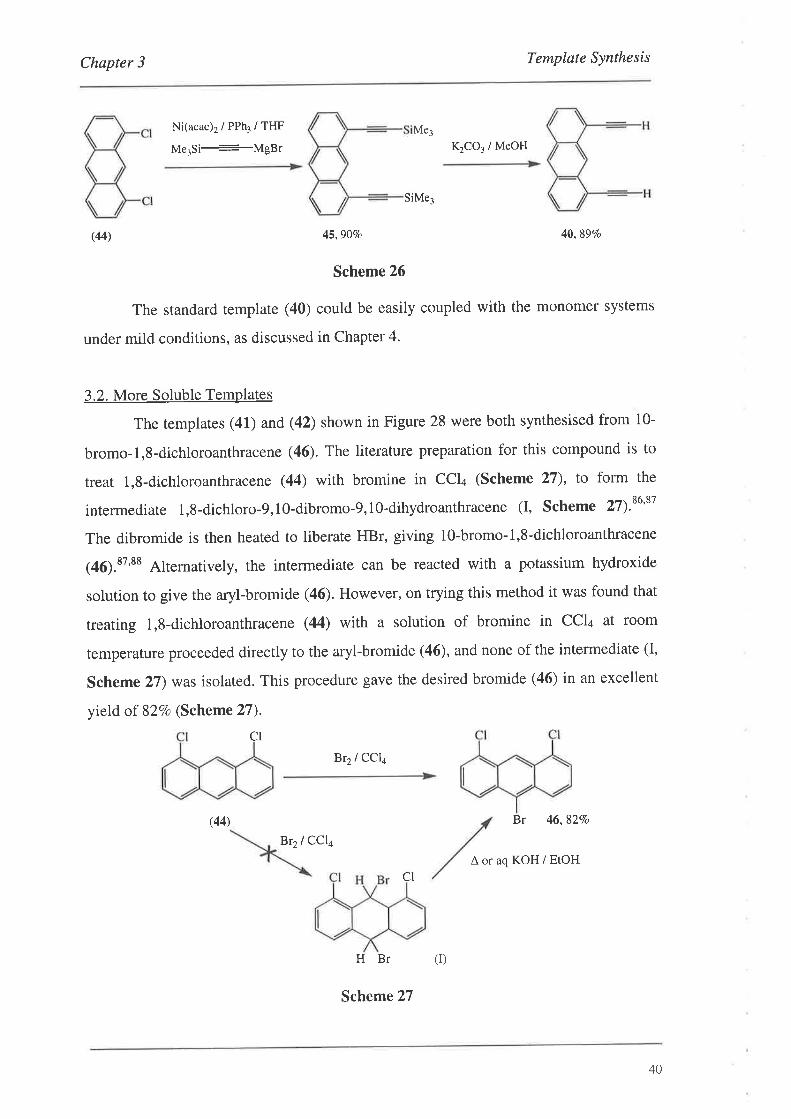
(44) 45,90Vo 40,89Vo
Scheme 26
The standard template (40) could be easily coupled with the monomer systems
under mild conditions, as discussed in Chapter 4.
3.2. More Soluble Templates
The templates (41) and (42) shown in Figure 28 were both synthesised from l0-
bromo-1,8-dichloroanthracene (46). The literature preparation for this compound is to
treat l,8-dichloroanthracene (44) with bromine in CCI¿ (Scheme 27), to form the
intermediate 1,8-dichloro-9,10-dibromo-9,1O-dihydroanthracene (I, Scheme 27).ru'r'
The dibromide is then heated to liberate HBr, giving l0-bromo-1,8-dichloroanthracene
(46)."'tt Alternatively, the intermediate can be reacted with a potassium hydroxide
solution to give the aryl-bromide (46). However, on trying this method it was found that
treating l,8-dichloroanthracene (44) with a solution of bromine in CCI¿ at room
temperature proceeded directly to the aryl-bromide (46), and none of the intermediate (I,
Scheme 27) was isolated. This procedure gave the desired bromide (46) in an excellent
yield of 82Vo (Scheme?7).
CI
Br2lCCla
(44) Br 46,827o
Br2lCCla
 or aq KOH / EtOHCI
HBr
Me¡
Scheme 27
(r)
40
Chapter 3 Template Synthesis
Of note with this compound was the manner in which it melted. The
experimental melting point of 200.0-201.5o was in good agreement with the literature
melting point of 202".88 However, it was observed that the initial fine golden needles,
obtained from recrystallisation from chloroform or acetic acid, fused together between
170-180" to form prisms. These prisms in turn melted sharply at 200.0-201.5o. These
observations are consistent with monotropic polymorphism,T6 although there was no
mention of this being observed in the literature.ss This is where the prismatic form is
stable at all temperatures below its melting point and never changes back to the needle
form, and the needle form has a lower melting point, and is stable below that.
Whilst the melting point agreed with the published value, the issue of
regiochemistry still had to be addressed since the experimental details of the aryl-
bromide (46) were published before the advent of NMR. More recently, a carbon NMR
study was performed on a series of naphthalene and anthracene compounds which
included the aryl-bromide (46).rn The lO-substituted anthracenes were assigned their
regiochemistry based on the magnitude and multiplicity of the three bond 13"1¡ C-H
coupling constants. Although no synthetic experimental details were presented in the
paper, the ôc, l"Icn and 3./cs values were consistent with our experimental values.8e
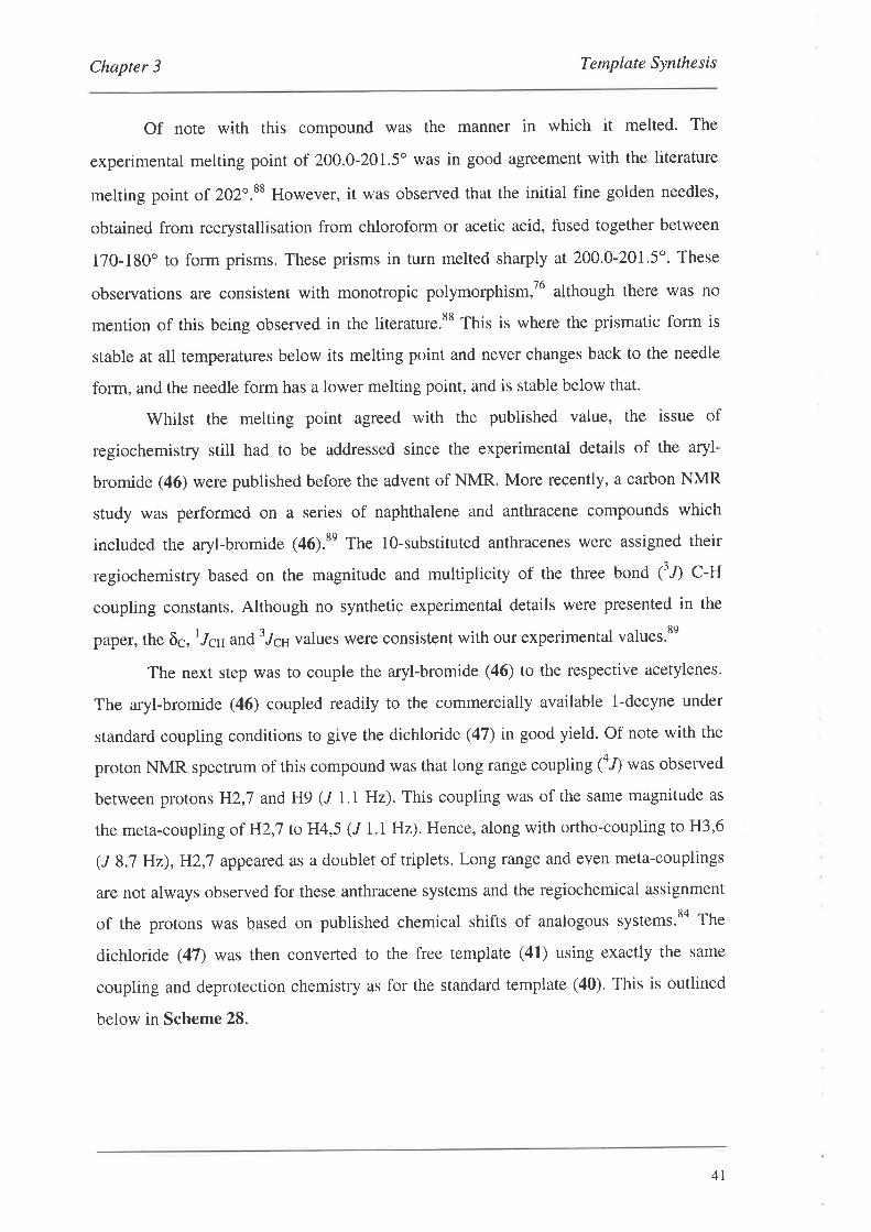
The next step was to couple the aryl-bromide (46) to the respective acetylenes'
The aryl-bromide (46) coupled readily to the commercially available l-decyne under
standard coupling conditions to give the dichloride (47) in good yield. Of note with the
proton NMR spectrum of this compound was that long range coupling (a,f was observed
between protons H2,7 and H9 (/ 1.1 Hz). This coupling was of the same magnitude as
the meta-coupling of HZ,l to H4,5 (J 1.1 Hz). Hence, along with ortho-coupling to H3,6
(J 83 Hz),H2,7 appeared as a doublet of triplets. Long range and even meta-couplings
are not always observed for these anthracene systems and the regiochemical assignment
of the protons was based on published chemical shifts of analogous systems.sa The
dichloride (47) was then converted to the free template (41) using exactly the same
coupling and deprotection chemistry as for the standard template (40). This is outlined
below in Scheme 28.
4I
Chapter 3 Template Synthesis
(dd) H (dr)
2
4(dd)
Pd(PPh3)a / CuI /cH3cN /
piperidine500
CH3(CHzh H9
l-decyne5
CIó 't
(46) 47,82Vo
L Ni(acac)2 / PPh3 / THF
Me3Si_-MgBr
2.K1CO3/ MeOH
41,487o (2 steps)
Scheme 28
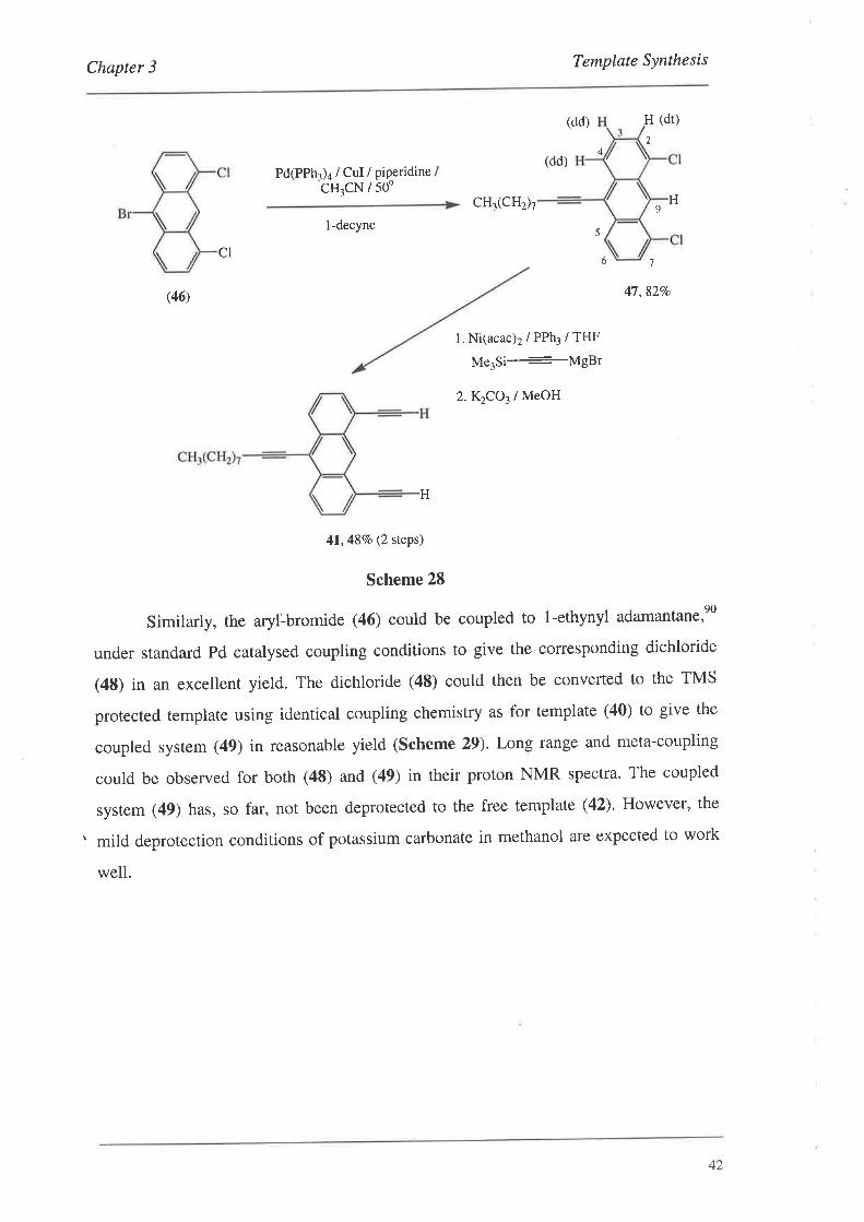
Similarly, the aryl-bromide (46) could be coupled to l-ethynyl adamantane,eO
under standard Pd catalysed coupling conditions to give the coruesponding dichloride
(48) in an excellent yield. The dichloride (48) could then be converted to the TMS
protected template using identical coupling chemistry as for template (40) to give the
coupled system (49) in reasonable yield (Scheme 29). Long range and meta-coupling
could be observed for both (48) and (49) in their proton NMR spectra. The coupled
system (49) has, so far, not been deprotected to the free template (42). However, the
. mild deprotection conditions of potassium carbonate in methanol are expected to work
well.
H
42
Chapter 3 Template Synthesis
(dd)
(dd)
Ni(acac)2/PPh3/THF
Me3Si-MgBr
32
4Pd(PPh3)a / CuI /
piperidine / 50o
H 5
H
cl
9
CI
(dd) H
6 7
(46) 48,9470
24
(dd)
H9
5 SiMe3
49,69Vo
Scheme 29
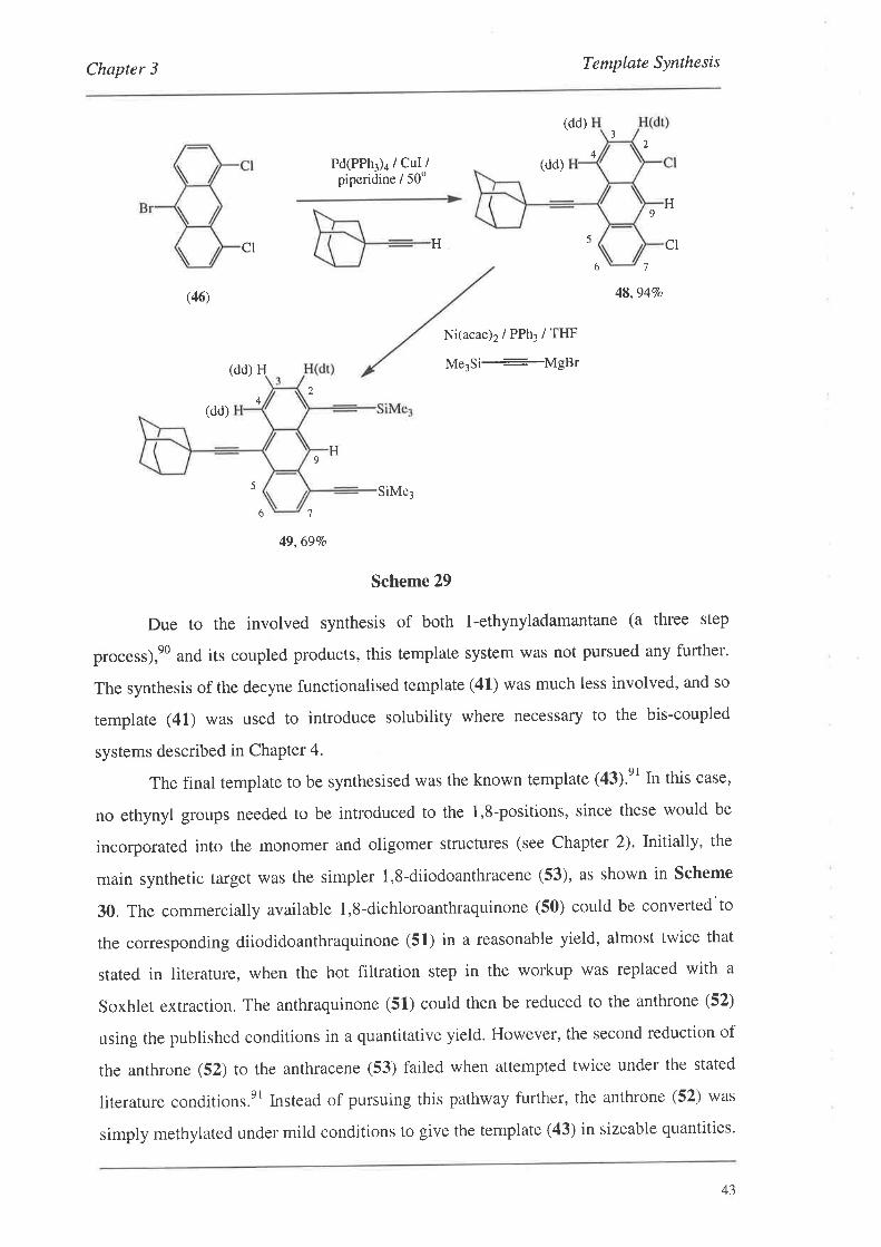
Due to the involved synthesis of both l-ethynyladamantane (a three step
process),e0 and its coupled products, this template system was not pursued any further.
The synthesis of the decyne functionalised template (41) was much less involved, and so
template (41) was used to introduce solubility where necessary to the bis-coupled
systems described in ChaPter 4.
The final template to be synthesised was the known template (43).'t In this case,
no ethynyl groups needed to be introduced to the 1,8-positions, since these would be
incorporated into the monomer and oligomer structures (see Chapter 2). lnitially, the
main synthetic target was the simpler 1,8-diiodoanthracene (53), as shown in Scheme
30. The commercially available 1,8-dichloroanthraquinone (50) could be converted'to
the corresponding diiodidoanthraquinone (51) in a reasonable yield, almost twice that
stated in literature, when the hot filtration step in the workup was replaced with a
Soxhlet extraction. The anthraquinone (51) could then be reduced to the anthrone (52)
using the published conditions in a quantitative yield. However, the second reduction of
the anthron e (52) to the anthracene (53) failed when attempted twice under the stated
literature conditions.er Instead of pursuing this pathway further, the anthrone (52) was
simply methylated under mild conditions to give the template (43) in sizeable quantities.
76
43
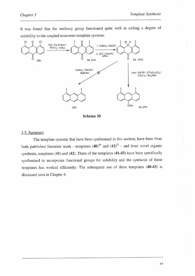
Chapter 3 Template Synthesis
It was found that the methoxy group functioned quite well in adding a degree of
solubility to the coupled monomer-template systems.
HHNaI / Cu bronze /
PhNOr / refluxl. NaBFIa / MeOH
2.HCl IMeOH /reflux
(s0) 51,637o
NaBH4 / MeOH /diglyme
52, l00%o
conc. NaOH / (CH3O)2SO2 /CH2CI2 / BuaNBr
43,6570
Scheme 30
3.3. Summary
The template systems that have been synthesised in this section, have been from
both pubtished literature work - templates (40)to and (43)et - and from novel organic
synthesis, templates (41) and (42). Three of the templates (41-43) have been specifically
synthesised to incorporate functional groups for solubility and the synthesis of these
templates has worked efficiently. The subsequent use of these templates (40'43) is
discussed next in Chapter 4.
(s3)
44
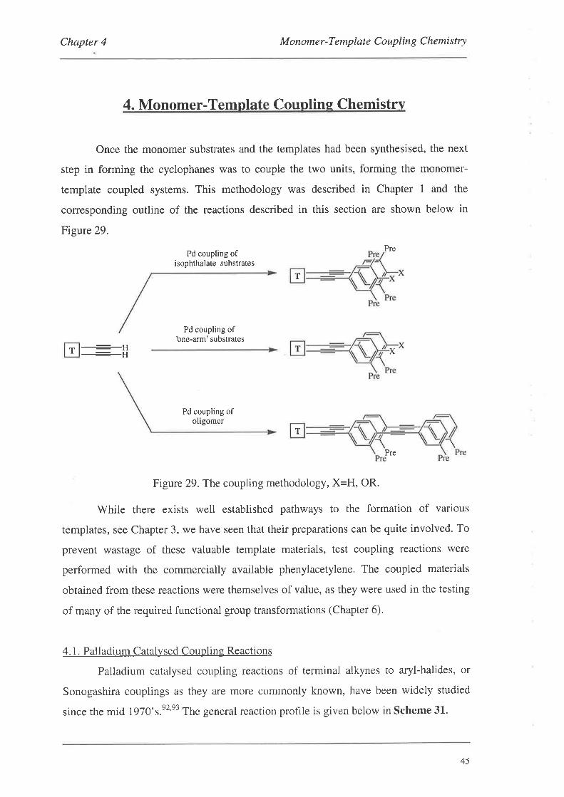
Chapter 4 Monomer-Template Coupling Chemistry
4. Monomer-Templa Counlins Chemistrv
Once the monomer substrates and the templates had been synthesised, the next
step in forming the cyclophanes was to couple the two units, forming the monomer-
template coupled systems. This methodology was described in Chapter 1 and the
corresponding outline of the reactions described in this section are shown below in
Figure 29.
Pd coupling ofisophthalate substrates
Pre
Pd coupling ofbne-arm' substrates
T lttl X
Pd coupling ofoligomer
Pre
Figure 29.The coupling methodology, X=H, OR.
While there exists well established pathways to the formation of various
templates, see Chapter 3, we have seen that their preparations can be quite involved. To
prevent wastage of these valuable template materials, test coupling reactions were
performed with the commercially available phenylacetylene. The coupled materials
obtained from these reactions were themselves of value, as they were used in the testing
of many of the required functional group transformations (Chapter 6).
4.1. Palladium Catalysed Coupling Reactions
Palladium catalysed coupling reactions of terminal alkynes to aryl-halides, or
Sonogashira couplings as they are more commonly known, have been widely studied
since the mid 1970's.e2'e3 The general reaction profile is given below in Scheme 31.
T
T
45
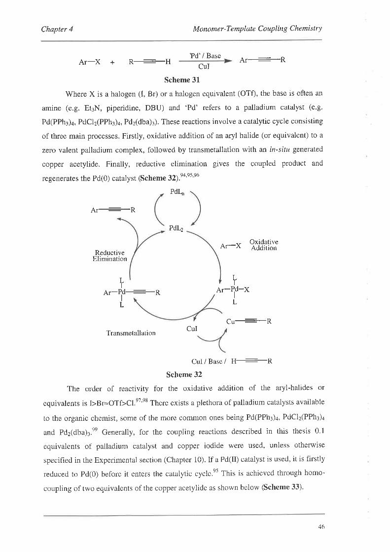
Chapter 4 M onome r -Te mp lat e C o up lin g C hemi stry
?d'/ BaseAl l\Ar-X + R-H
CuI
Scheme 31
Where X is a halogen (I, Br) or a halogen equivalent (OTÐ, the base is often an
amine (e.g. Et3N, piperidine, DBU) and 'Pd' refers to a palladium catalyst (e.g.
Pd(PPh3)a, PdCl2GPh¡)+, Pdz(dba):). These reactions involve a catalytic cycle consisting
of three main processes. Firstly, oxidative addition of an aryl halide (or equivalent) to a
zero valent palladium complex, followed by transmetallation with an in-situ generated
copper acetylide. Finally, reductive elimination gives the coupled product and
regenerates the Pd(O) catalyst (Scheme 32¡.e+'ss'sa
PdI-
Ar:R
Ar-X OxidativeAddition
ReductiveElimination
Pdr4
LI
L
LI
Ar- R ar-ld-xL
cu+RTransmetallation
CuI/ Base/ H+RScheme 32
The order of reactivity for the oxidative addition of the aryl-halides or
equivalents is ÞBr=OTf>Cl.e7'e8 There exists a plethora of palladium catalysts available
to the organic chemist, some of the more common ones being Pd(PPh¡)¿, PdCl2(PPh3)4
and Pd2(dbu)r.nn Generally, for the coupling reactions described in this thesis 0.1
equivalents of palladium catalyst and copper iodide were used, unless otherwise
specified in the Experimental section (Chapter 10). If a Pd(tr) catalyst is used, it is firstly
reduced to Pd(0) before it enters the catalytic cycle.es This is achieved through homo-
coupling of two equivalents of the copper acetylide as shown below (Scheme 33).
CuI
46
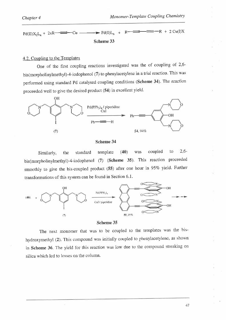
Chapter 4 M onomer-Template C ouplin g Chemistry
Pd(II)X2L.+ 2xR+Cu +Pd(O)I-n + ft-R + 2Cu(I)X
Scheme 33
4.2. Coupling to the Templates
One of the first coupling reactions investigated was the of coupling of 2,6-
bis(morpholinylmethyl)-4-iodophenol (7) to phenylacetylene in a trial reaction. This was
performed using standard Pd catalysed coupling conditions (Scheme 34)' The reaction
proceeded well to give the desired product (54) in excellent yield.
rì!,oPd(PPh3)4 / piperidine
CUI
I Ph--H
(7) 54,94Vo
Scheme 34
Similarly, the standard template (40) was coupled to 2'6-
bis(morpholinylmethyl)-4-iodophenol (7) (Scheme 35). This reaction proceeded
smoothly to give the bis-coupled product (55) after one hour in 95Vo yield. Further
transformations of this system can be found in Section 6' 1'
oGN
Pd(PPH3)a o:N(40) + ----Þ-Þ
Cul / piperidine
(7) 55,9570
Scheme 35
The next monomer that was to be coupled to the templates was the bis-
hydroxymethyl (2). This compound was initially coupled to phenylacetylene, as shown
in Scheme 36, The yield for this reaction was low due to the compound streaking on
silica which led to losses on the column.
47
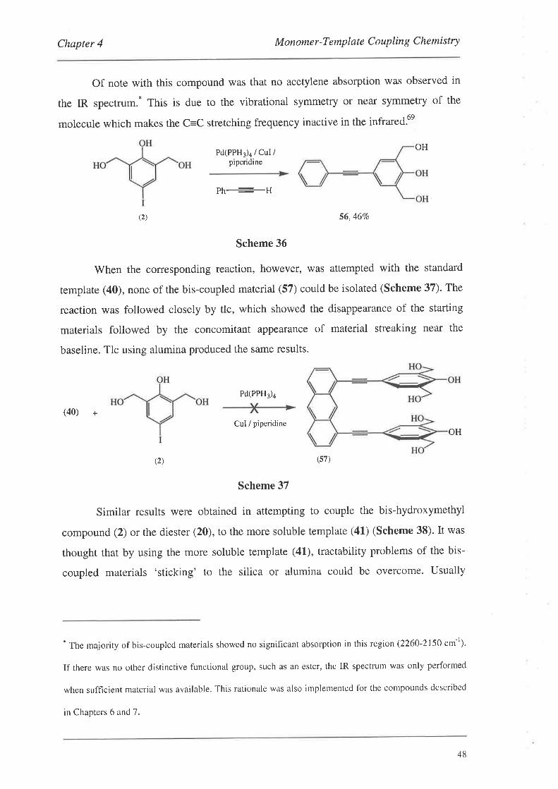
Chapter 4 M onome r -T emplat e C o up lin g C hemi stry
Of note with this compound was that no acetylene absorption was observed in
the IR spectrum.* This is due to the vibrational symmetry or near symmetry of the
molecule which makes the C=C stretching frequency inactive in the infrared.6e
Pd(PPH3)a / CuI /piperidine
OH
r ll
\2) 56,46Vo
Scheme 36
'When the corresponding reaction, however, was attempted with the standard
template (40), none of the bis-coupled material (57) could be isolated (Scheme 37). The
reaction was followed closely by tlc, which showed the disappearance of the starting
materials followed by the concomitant appearance of material streaking near the
baseline. Tlc using alumina produced the same results.
Pd(PPH3)a
(40) +
CuI / piperidineOH
(2)
Scheme 37
Similar results were obtained in attempting to couple the bis-hydroxymethyl
compound (2) or the diester (20), to the more soluble template (41) (Scheme 38). It was
thought that by using the more soluble template (41), tractability problems of the bis-
coupled materials 'sticking' to the silica or alumina could be overcome. Usually
* The majority of bis-coupled materials showed no significant absorption in this region (2260-2150 cm-t).
If there was no other distinctive functional group, such as an ester, the IR spectrum was only performed
when sufhcient material was available. This rationale was also implemented for the compounds described
in Chapters 6 and 7.
(s7)
48
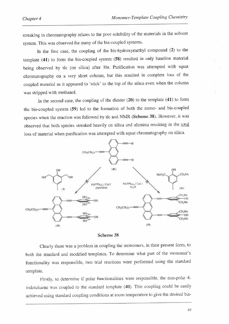
Chapter 4 Monomer-Template Coupling Chemistry
streaking in chromatography relates to the poor solubility of the materials in the solvent
system. This was observed for many of the bis-coupled systems.
In the first case, the coupling of the bis-hydroxymethyl compound (2) to the
template (41) to form the bis-coupled system (58) resulted in only baseline material
being observed by tlc (on silica) after thr. Purification was attempted with squat
chromatography on a very short column, but this resulted in complete loss of the
coupled material as it appeared to 'stick' to the top of the silica even when the column
was stripped with methanol.
In the second case, the coupling of the diester (20) to the template (41) to form
the bis-coupled system (59) led to the formation of both the mono- and bis-coupled
species when the reaction was followed by tlc and NMR (Scheme 38). However, it was
observed that both species streaked heavily on silica and alumina resulting in the total
loss of material when purification was attempted with squat chromatography on silica.
CH3(CHz)r
(41)
Me
(2)
Pd(PPh¡)¡ / Cul /piperidine
Pd(PPh1)a / Cul /ErlN (20)
CO2MeOH
(s8) (s9)
Scheme 38
Clearly there was a problem in coupling the monomers, in their present form, to
both the standard and modified templates. To determine what part of the monomer's
functionality was responsible, two trial reactions were performed using the standard
template.
Firstly, to determine if polar functionalities were responsible, the non-polar 4-
iodotoluene was coupled to the standard template (40). This coupling could be easily
achieved using standard coupling conditions at room temperature to give the desired bis-
49
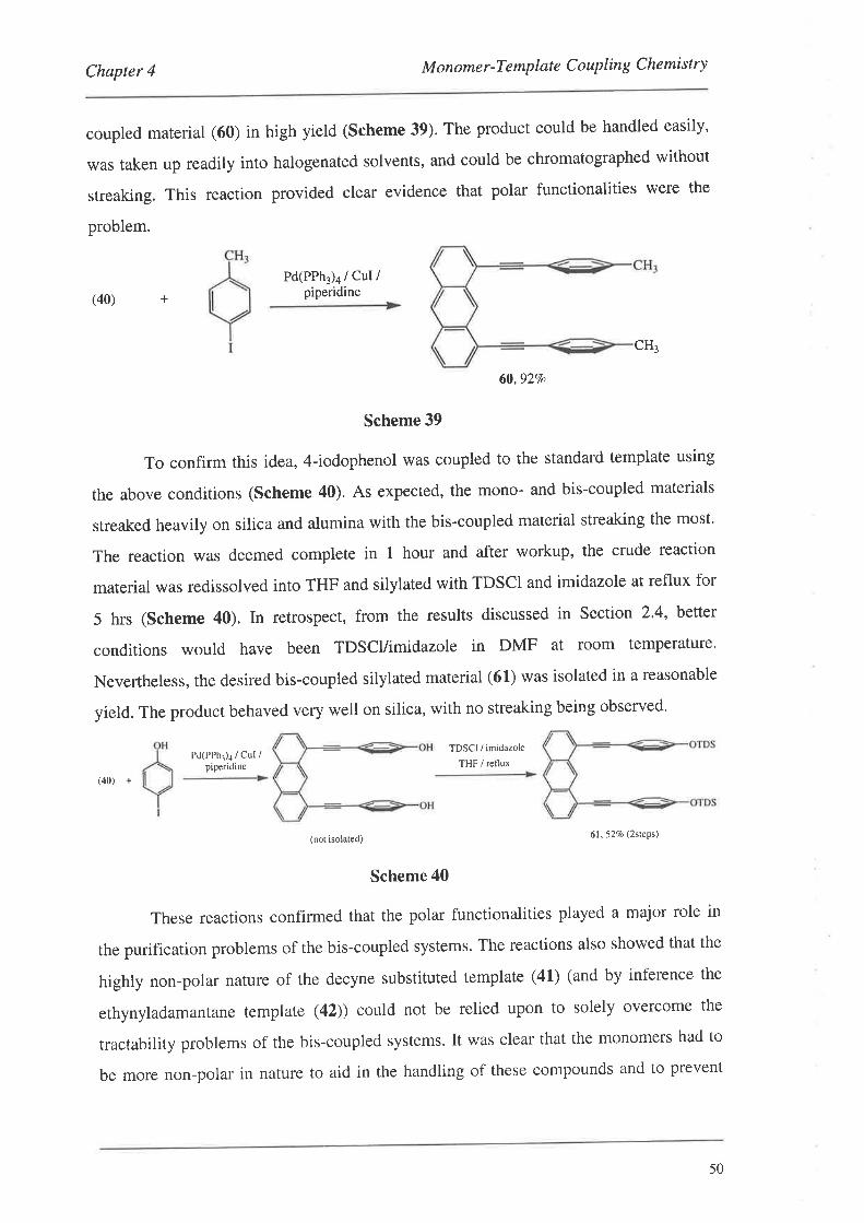
Chapter 4 M onome r -T emplat e C o uplin g Che mi st ry
coupled marerial (60) in high yield (scheme 39). The product could be handled easily,
was taken up readily into halogenated solvents, and could be chromatographed without
streaking. This reaction provided clear evidence that polar functionalities were the
problem.
+
Pd(PPh3)a / CuI /piperidine(40)
CH¡
60,92Vo
Scheme 39
To confirm this idea, 4-iodophenol was coupled to the standard template using
the above conditions (Scheme 40). As expected, the mono- and bis-coupled materials
streaked heavily on silica and alumina with the bis-coupled material streaking the most.
The reaction was deemed complete in I hour and after workup, the crude reaction
material was redissolved into THF and silylated with TDSCI and imidazole at reflux for
5 hrs (Scheme 40). In retrospect, from the results discussed in Section 2.4, bettet
conditions would have been TDSCl/imidazole in DMF at room temperature.
Nevertheless, the desired bis-coupled silylated material (61) was isolated in a reasonable
yield. The product behaved very well on silica, with no streaking being observed'
Pd(PPhr)¡ / Cut /piperidine
(40) +
(not isolated) 61,527o (2steps\
Scheme 40
These reactions confirmed that the polar functionalities played a major role in
the purification problems of the bis-coupled systems. The reactions also showed that the
highly non-polar nature of the decyne substituted template (41) (and by inference the
ethynyladamantane template (42)) could not be relied upon to solely overcome the
tractability problems of the bis-coupled systems. It was clear that the monomers had to
be more non-polar in nature to aid in the handling of these compounds and to prevent
TDSCI / imidazole
THF / reflux
50
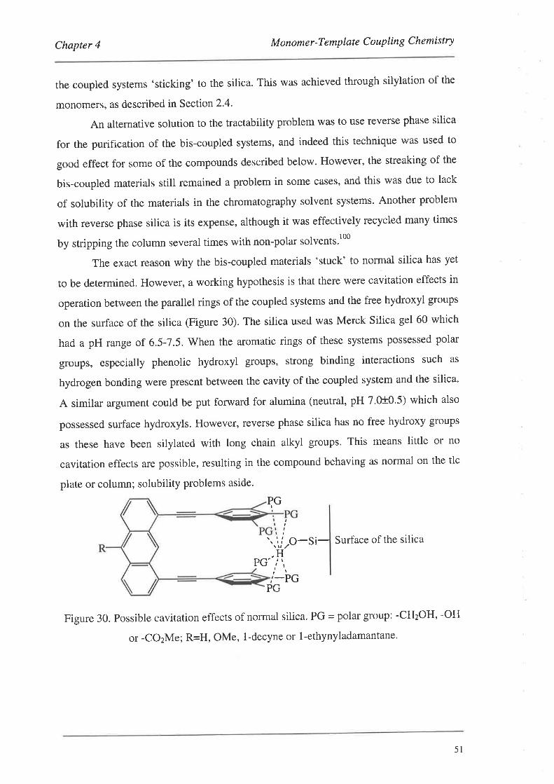
Chapter 4 M onome r -Template C ouplin g Chemistry
the coupled systems 'sticking' to the silica. This was achieved through silylation of the
monomers, as described in SectionZ. .
An alternative solution to the tractability problem was to use reverse phase silica
for the purification of the bis-coupled systems, and indeed this technique was used to
good effect for some of the compounds described below. However, the streaking of the
bis-coupled materials still remained a problem in some cases, and this was due to lack
of solubility of the materials in the chromatography solvent systems. Another problem
with reverse phase silica is its expense, although it was effectively recycled many times
by stripping the column several times with non-polar solvents'100
The exact reason why the bis-coupled materials 'stuck' to normal silica has yet
to be determined. However, a working hypothesis is that there were cavitation effects in
operation between the parallel rings of the coupled systems and the free hydroxyl groups
on the surface of the silica (Figure 30). The silica used was Merck Silica gel 60 which
had a pH range of 6.5-7.5. When the aromatic rings of these systems possessed polar
groups, especially phenolic hydroxyl groups, strong binding interactions such as
hydrogen bonding were present between the cavity of the coupled system and the silica.
A similar argument could be put forward for alumina (neutral, pH 7.0t0.5) which also
possessed surface hydroxyls. However, reverse phase silica has no free hydroxy groups
as these have been silylated with long chain alkyl groups. This means little or no
cavitation effects are possible, resulting in the compound behaving as normal on the tlc
plate or column; solubility problems aside.
si- Surface of the silica
Figure 30. Possible cavitation effects of normal silica' PG - polar group: -CH2OH' -OH
or -COzMe; R=H, OMe, l-decyne or l-ethynyladamantane'
PG'
PGI
_PG
II
\,iro-H
t¡
PG
5l
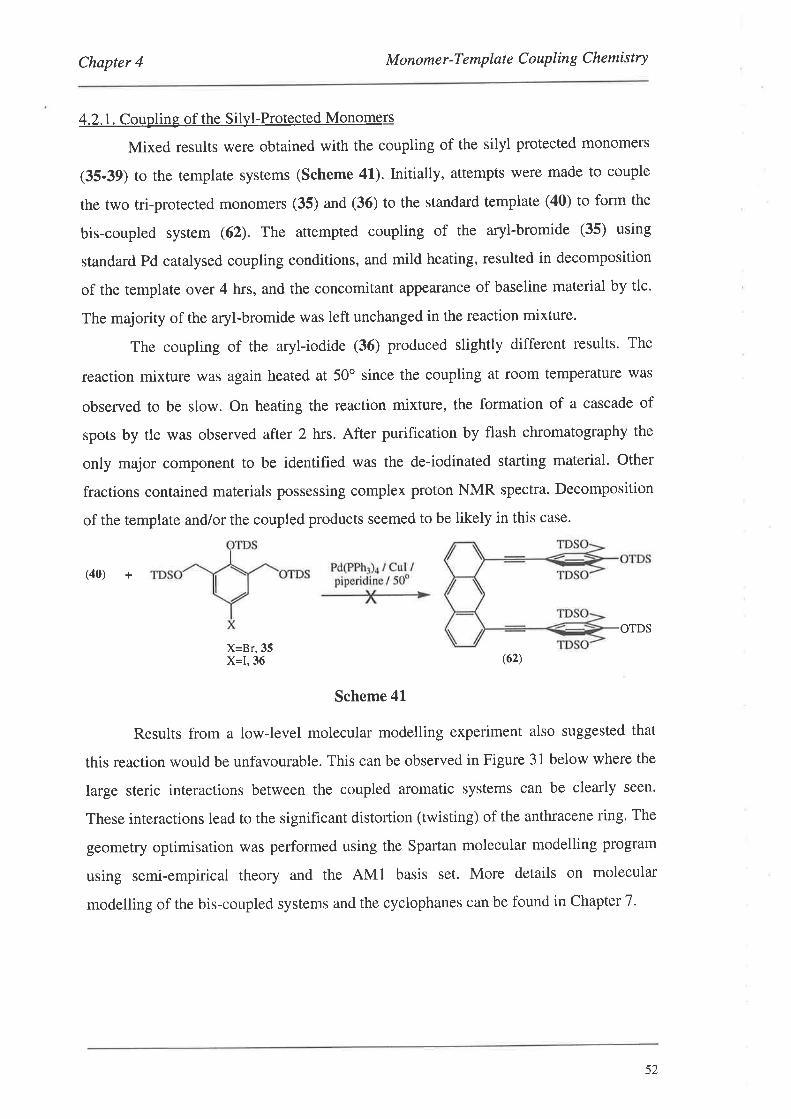
Chapter 4 M onome r -T e mp lat e C o up lin g Che mist ry
4.2.1. Coupling of the Silyl-Protected Monomers
Mixed results were obtained with the coupling of the silyl protected monomers
(35-39) to the template systems (Scheme 41). Initially, attempts were made to couple
the two tri-prorected monomers (35) and (36) to the standard template (40) to form the
bis-coupled system (62). The attempted coupling of the aryl-bromide (35) using
standard Pd catalysed coupling conditions, and mild heating, resulted in decomposition
of the template over 4 hrs, and the concomitant appearance of baseline material by tlc.
The majority of the aryl-bromide was left unchanged in the reaction mixture.
The coupling of the aryl-iodide (36) produced slightly different results. The
reaction mixture was again heated at 50" since the coupling at room temperature was
observed to be slow. On heating the reaction mixture, the formation of a cascade of
spots by tlc was observed after 2 hrs. After purification by flash chromatography the
only major component to be identified was the de-iodinated starting material. Other
fractions contained materials possessing complex proton NMR spectra. Decomposition
of the template and/or the coupled products seemed to be likely in this case.
(40) +
OTDS
X=Br, 35X=1,36
Scheme 41
Results from a low-level molecular modelling experiment also suggested that
this reaction would be unfavourable. This can be observed in Figure 31 below where the
large steric interactions between the coupled aromatic systems can be clearly seen.
These interactions lead to the significant distortion (twisting) of the anthracene ring. The
geometry optimisation was performed using the Spartan molecular modelling program
using semi-empirical theory and the AMl basis set. More details on molecular
modelling of the bis-coupled systems and the cyclophanes can be found in Chapter 7.
(62)
52
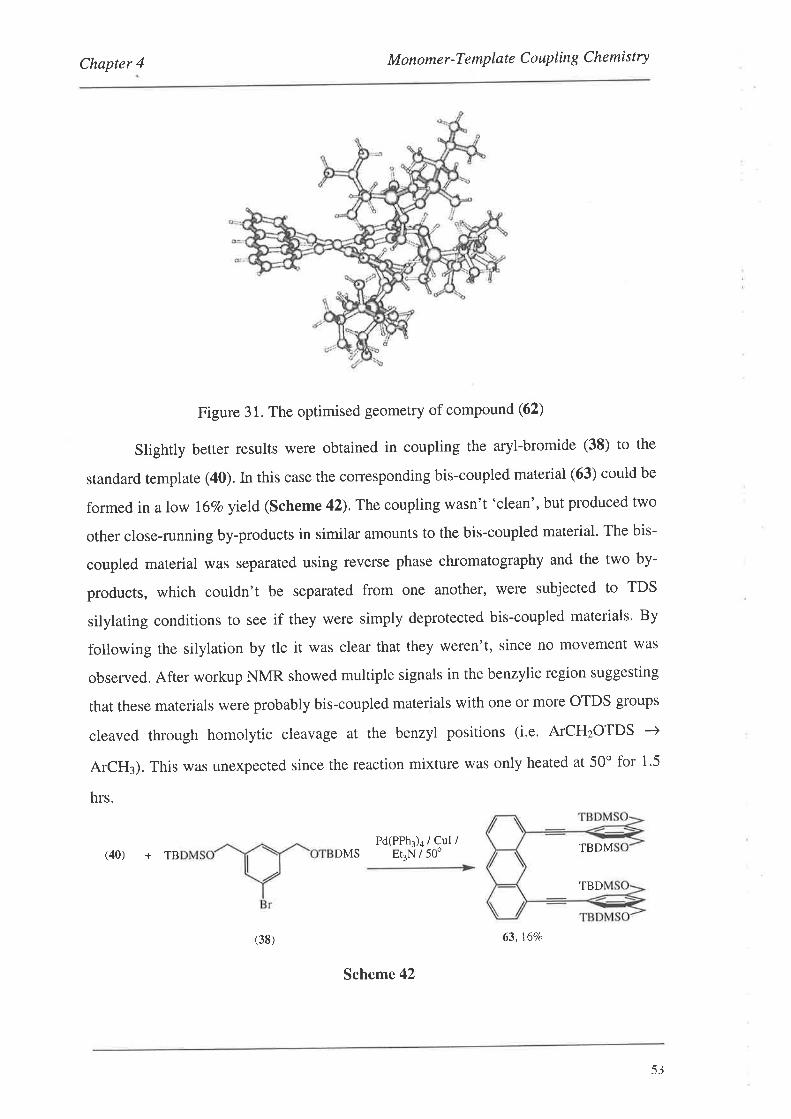
Chapter 4 M onome r -T emp late C o uplin g Chemi st ry
Figure 31. The optimised geometry of compound (62)
Slightly better results were obtained in coupling the aryl-bromide (38) to the
standard remplate (40). In rhis case the corresponding bis-coupled material (63) could be
formed in a low l6Vo yield (Scheme 42).The coupling wasn't 'clean', but produced two
other close-running by-products in similar amounts to the bis-coupled material. The bis-
coupled material was separated using reverse phase chromatography and the two by-
products, which couldn't be separated from one another, were subjected to TDS
silylating conditions to see if they were simply deprotected bis-coupled materials. By
following the silylation by tlc it was clear that they weren't, since no movement was
observed. After workup NMR showed multiple signals in the benzylic region suggesting
that these materials were probably bis-coupled materials with one or more OTDS groups
cleaved through homolytic cleavage at the benzyl positions (i.e. ATCHzOTDS -->
ArCH¡). This was unexpected since the reaction mixture was only heated at 50o for 1'5
hrs.
PdlPPh3)a / Cul /Et.N / 50'(40) + TB DMS TBDM
TBD
(38)
Scheme 42
63, l6Va
53
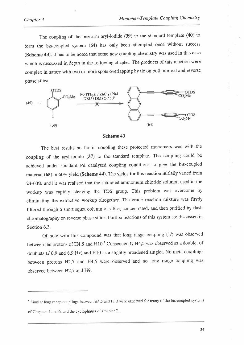
Chapter 4 M onome r -Te mp late C oup lin g C hemi stry
The coupling of the one-arm aryl-iodide (39) to the standard template (40) to
form the bis-coupled system (64) has only been attempted once without success
(Scheme 43). It has to be noted that some new coupling chemistry was used in this case
which is discussed in depth in the following chapter. The products of this reaction were
complex in nature with two or more spots overlapping by tlc on both normal and reverse
phase silica.
Pd(PPh3)4 lZnCl2lNaIDBU/DMSO/50"
(40) +
OTDSCO2Me
(3e) (64)
Scheme 43
The best results so far in coupling these protected monomers was with the
coupling of the aryl-iodide (37) to the standard template. The coupling could be
achieved under standard Pd catalysed coupling conditions to give the bis-coupled
material (65) in 60Vo yield(Scheme 44). The yields for this reaction initially varied from
24-607o until it was realised that the saturated ammonium chloride solution used in the
workup was rapidly cleaving the TDS group. This problem was overcome by
eliminating the extractive workup altogether. The crude reaction mixture was firstly
filtered through a short squat column of silica, concentrated, and then purified by flash
chromatography on reverse phase silica. Further reactions of this system are discussed in
Section 6.3.
Of note with this compound was that long range coupling 1a.f was observed
between the protons of H4,5 and H10.T Consequently H4,5 was observed as a doublet of
doublers (/ 0.9 and 6.9 Hz) and H10 as a slightly broadened singlet. No meta-couplings
between protons H2,J and H4,5 were observed and no long range coupling was
observed between H2,'7 andH9.
'Similar long range couplings between H4,5 and H10 were observed for many of the bis-coupled systems
of Chapters 4 and 6, and the cyclophanes of Chapter 7'
54
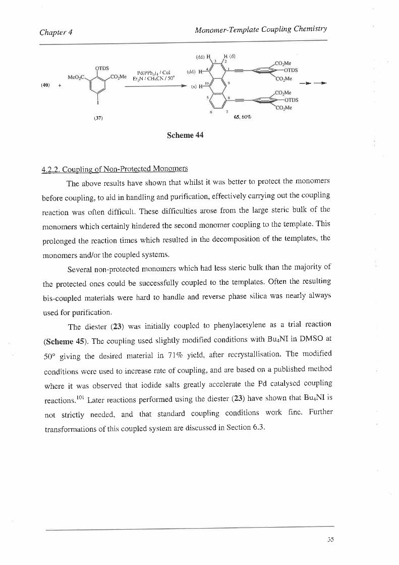
Chapter 4 M onome r -T emplat e C o uplin g Che mi stry
(dd) H (d)
Pd(PPhl)a / CulEr-rN/CHTCN/50'
(dd)
(40) + -ì> -+
65,60lo
Scheme 44
4.2.2. Coupling of Non-Protected Monomers
The above results have shown that whilst it was better to protect the monomers
before coupling, to aid in handling and purification, effectively carrying out the coupling
reaction was often difficult. These difficulties arose from the large steric bulk of the
monomers which certainly hindered the second monomer coupling to the template' This
prolonged the reaction times which resulted in the decomposition of the templates, the
monomers and/or the coupled systems.
Several non-protected monomers which had less steric bulk than the majority of
the protected ones could be successfully coupled to the templates. Often the resulting
bis-coupled materials were hard to handle and reverse phase silica was nearly always
used for purification.
The diester (23) was initially coupled to phenylacetylene as a trial reaction
(Scheme 45). The coupling used slightly modified conditions with Bu¿NI in DMSO at
50" giving the desired material in T IVo yield, after recrystallisation. The modified
conditions were used to increase rate of coupling, and are based on a published method
where it was observed that iodide salts greatly accelerate the Pd catalysed coupling
reactions.'0t Later reactions performed using the diester (23) have shown that Bu4NI is
not strictly needed, and that standard coupling conditions work fine. Further
transformations of this coupled system are discussed in Section 6.3.
(s)
(37)
i5
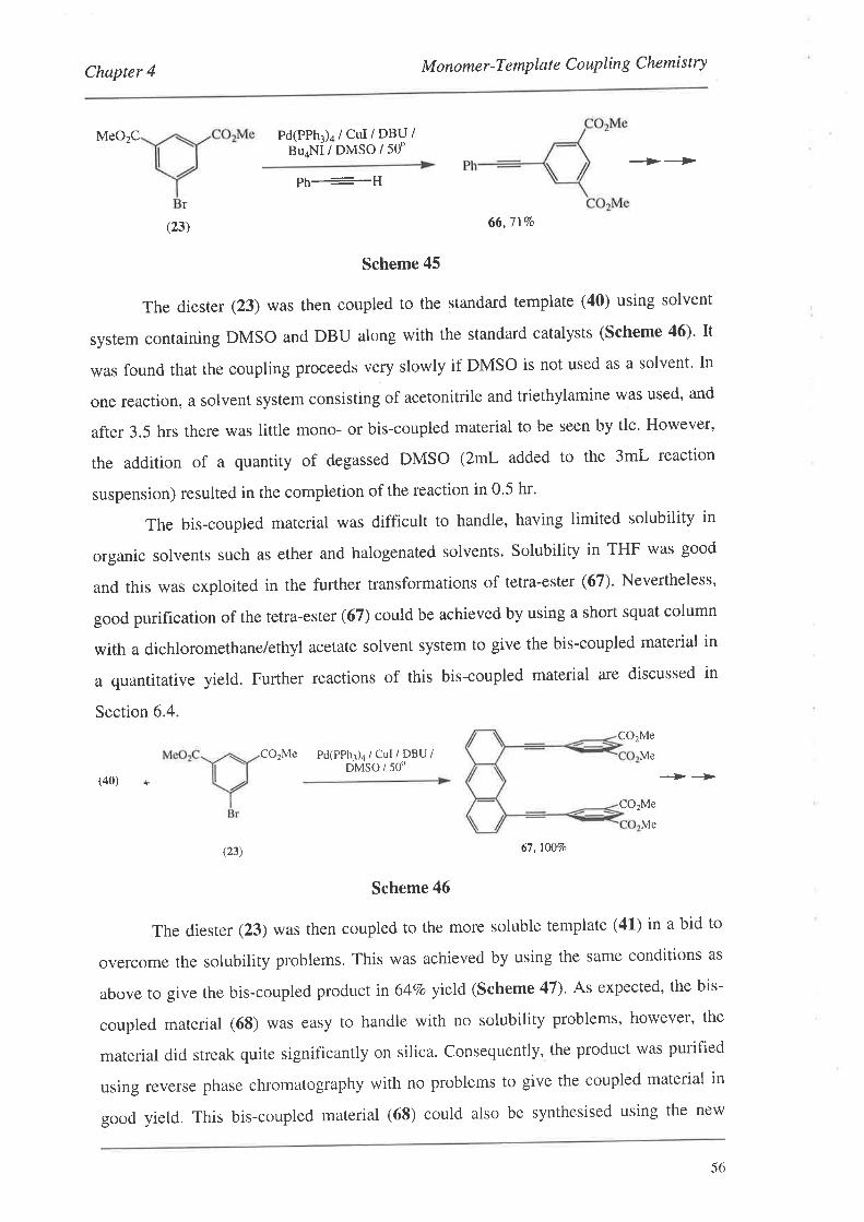
Chapter 4 M onome r -T emplate C o uplin g Che mi st ry
MeO2C Pd(PPhl)4 / CuI / DBU /BuaNI/DMSO/50"
-:>-r>Ph----H
r
(23) 66,7 t%o
Scheme 45
The dieste r (23) was then coupled to the standard template (40) using solvent
system containing DMSO and DBU along with the standard catalysts (Scheme 46). It
was found that the coupling proceeds very slowly if DMSO is not used as a solvent' In
one reaction, a solvent system consisting of acetonitrile and triethylamine was used, and
after 3.5 hrs there was little mono- or bis-coupled material to be seen by tlc. However,
the addition of a quantity of degassed DMSO (zmL added to the 3mL reaction
suspension) resulted in the completion of the reaction in 0.5 hr.
The bis-coupled material was difficult to handle, having limited solubility in
organic solvents such as ether and halogenated solvents. Solubility in THF was good
and this was exploited in the further transformations of tetra-ester (67). Nevertheless,
good purification of the tetra-ester (67) could be achieved by using a short squat column
with a dichloromethane/ethyl acetate solvent system to give the bis-coupled material in
a quantitative yield. Further reactions of this bis-coupled material are discussed in
Section 6.4.
CO2Me
CO2Me Pd(PPhr)4 / Cul / DBU /DMSO / 5on
Me
(40) + --->--->
CO2Me
(23) 67, t00vo
Scheme 46
The dieste r (23) was then coupled to the more soluble template (41) in a bid to
overcome the solubility problems. This was achieved by using the same conditions as
above to give the bis-coupled productin 64To yield (scheme 47)' As expected, the bis-
coupled material (68) was easy to handle with no solubility problems, however, the
material did streak quite significantly on silica. Consequently, the product was purified
using reverse phase chromatography with no problems to give the coupled material in
good yield. This bis-coupled material (68) could also be synthesised using the new
Me
56
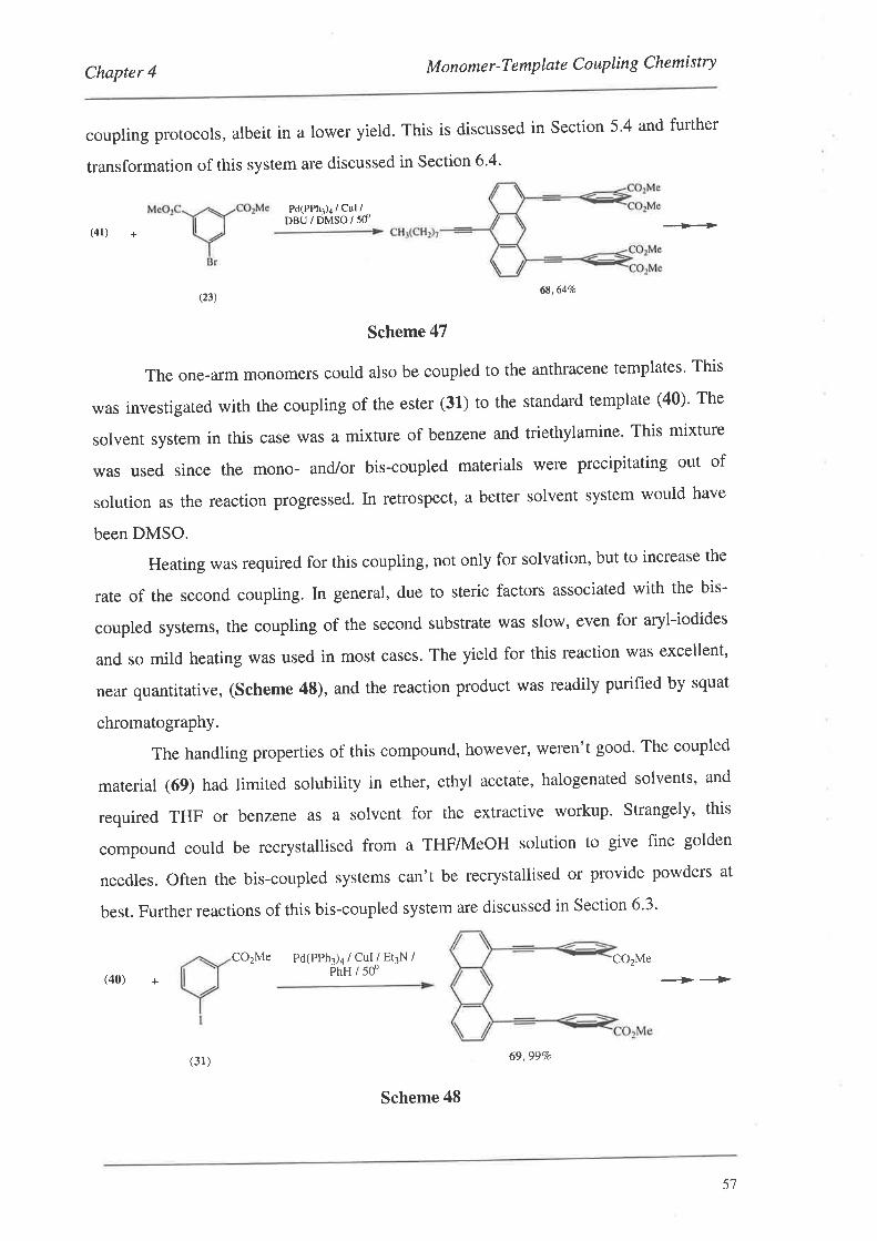
Chapter 4 M onome r -T emplat e C o uplin g Che mi st ry
coupling protocols, albeit in a lower yield. This is discussed in Section 5'4 and further
transformation of this system are discussed in section6.4.
PdtPPhr)¿ / Cul /neu¡dN,rsolsd
(41) +
CO2Me
--Ð
-+-->
(23)6E,64Vo
Scheme 47
The one-arm monomers could also be coupled to the anthracene templates' This
was investigated with the coupling of the ester (31) to the standard template (40)' The
solvent system in this case was a mixture of benzene and triethylamine' This mixture
was used since the mono- and/or bis-coupled materials were precipitating out of
solution as the reaction progressed. In retrospect, a better solvent system would have
been DMSO.
Heating was required for this coupling, not only for solvation, but to increase the
rate of the second coupling. In general, due to steric factors associated with the bis-
coupled systems, the coupling of the second substrate was slow, even for aryl-iodides
and so mild heating was used in most cases. The yield for this reaction was excellent,
near quantitative, (Scheme 48), and the reaction product was readily purified by squat
chromatography.
The handling properties of this compound, however, weren't good' The coupled
material (69) had limited solubility in ether, ethyl acetate, halogenated solvents, and
required THF or benzene as a solvent for the extractive workup' Strangely' this
compound could be recrystallised from a THF/I\4eOH solution to give fine golden
needles. Often the bis-coupled systems can't be recrystallised or provide powders at
best. Further reactions of this bis-coupled system are discussed in Section 6.3'
co2Me Pd(PPhl)4 / cul / EtlN /PhH / 500(40) +
(31)
Scheme 48
69.99Va
57
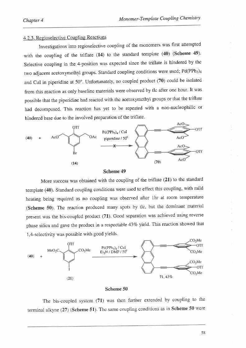
(40) +
Chapter 4 M onomer-Template C oupling Chemistry
4.2.3. Regioselective Coupling Reactions
Investigations into regioselective coupling of the monomers was first attempted
with the coupling of the triflate (14) to the standard template (40) (Scheme 49)'
Selective coupling in the 4-position was expected since the triflate is hindered by the
two adjacent acetoxymethyl groups. Standard coupling conditions were used; Pd(PPh3)4
and CuI in piperidine at 50o. Unfortunately, no coupled product (70) could be isolated
from this reaction as only baseline materials were observed by tlc after one hour' It was
possible that the piperidine had reacted with the acetoxymethyl groups or that the triflate
had decomposed. This reaction has yet to be repeated with a non-nucleophilic or
hindered base due to the involved preparation of the triflate.
Pd(PPh)a / CuI
piperidine / 50o
orf
(14) (70)
Scheme 49
More success was obtained with the coupling of the triflate (21) to the standard
template (40). Standard coupling conditions were used to effect this coupling, with mild
heating being required as no coupling was observed after thr at room temperature
(Scheme 50). The reaction produced many spots by tlc, but the dominant material
present was the bis-coupled product (71.). Good separation was achieved using reverse
phase silica and gave the product in a respectable 437o yield. This reaction showed that
1,4-selectivity was possible with good yields.
Pd(PPh3)a / CulEt3N/DMF/50o
(40) +
(2r) 7t,43Vo
Scheme 50
The bis-coupled system (71) was then further extended by coupling to the
terminal alkyne (27) (Scheme 51). The same coupling conditions as in Scheme 50 were
58
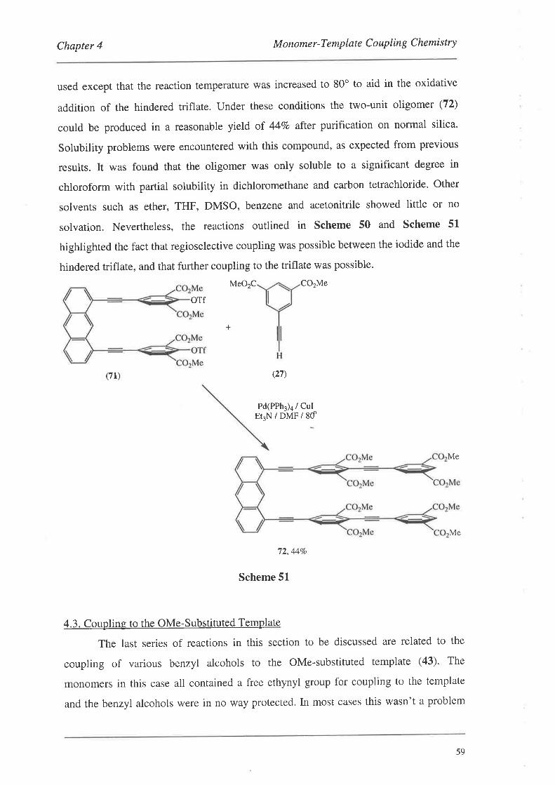
Chapter 4 M onome r -Templat e C o uplin g C he mi stry
used except that the reaction temperature was increased to 80o to aid in the oxidative
addition of the hindered triflate. Under these conditions the two-unit oligomer (72)
could be produced in a reasonable yield of 447o after purification on normal silica.
Solubility problems were encountered with this compound, as expected from previous
results. It was found that the oligomer was only soluble to a significant degree in
chloroform with partiat solubility in dichloromethane and carbon tetrachloride' Other
solvents such as ether, THF, DMSO, benzene and acetonitrile showed little or no
solvation. Nevertheless, the reactions outlined in Scheme 50 and Scheme 51
highlighted the fact that regioselective coupling was possible between the iodide and the
hindered triflate, and that further coupling to the triflate was possible.
MeO2C CO2Me
+
(71)
oTf
(27)
Pd(PPh¡)¿ / CuIEr3N/DMF/8d
Me
Me
72,44Vo
Scheme 51
4.3. Coupling to the OMe-Substituted Template
The last series of reactions in this section to be discussed are related to the
coupling of various benzyl alcohols to the OMe-substituted template (43). The
monomers in this case all contained a free ethynyl group for coupling to the template
and the benzyl alcohols were in no way protected. [n most cases this wasn't a problem
59
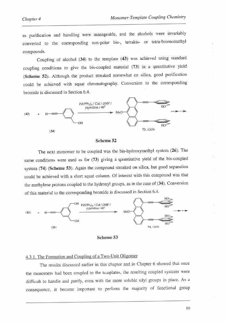
Chapter 4 M onome r -T e mpl at e C o uplin g Che mi stry
as purification and handling were manageable, and the alcohols rvere invariably
converted to the corresponding non-polar bis-, tetrakis- or tetra-bromomethyl
compounds.
Coupling of alcohol (34) to the template (43) was achieved using standard
coupling conditions to give the bis-coupled material (73) in a quantitative yield
(Scheme 52). Although the product streaked somewhat on silica, good purification
could be achieved with squat chromatography. Conversion to the corresponding
bromide is discussed in Section 6.4.
Pd(PPhr)¿ / cul / DMF /pipêridine / 40o
MeO -->-+
--->-->
(43) +
(43) +
(34¡ 73, lÙ07o
Scheme 52
The next monomer to be coupled was the bis-hydroxymethyl system (26). The
same conditions were used as for (73) giving a quantitative yield of the bis-coupled
system (74) (Scheme 53). Again the compound streaked on silica, but good separation
could be achieved with a short squat column. Of interest with this compound was that
the methylene protons coupled to the hydroxyl gloups, as in the case of (34)' Conversion
of this material to the corresponding bromide is discussed in Section 6'4'
Pd(PPhr)¡ / Cul / DMF /piperidine / 40u
OH
14, 1007o
Scheme 53
The results discussed earlier in this chapter and in Chapter 6 showed that once
the monomers had been coupled to the ternplates, the resulting coupled systems were
difficult to handle and purify, even with the more soluble silyl groups in place' As a
consequence, it became important to perform the majority of functional group
(26)
F
60
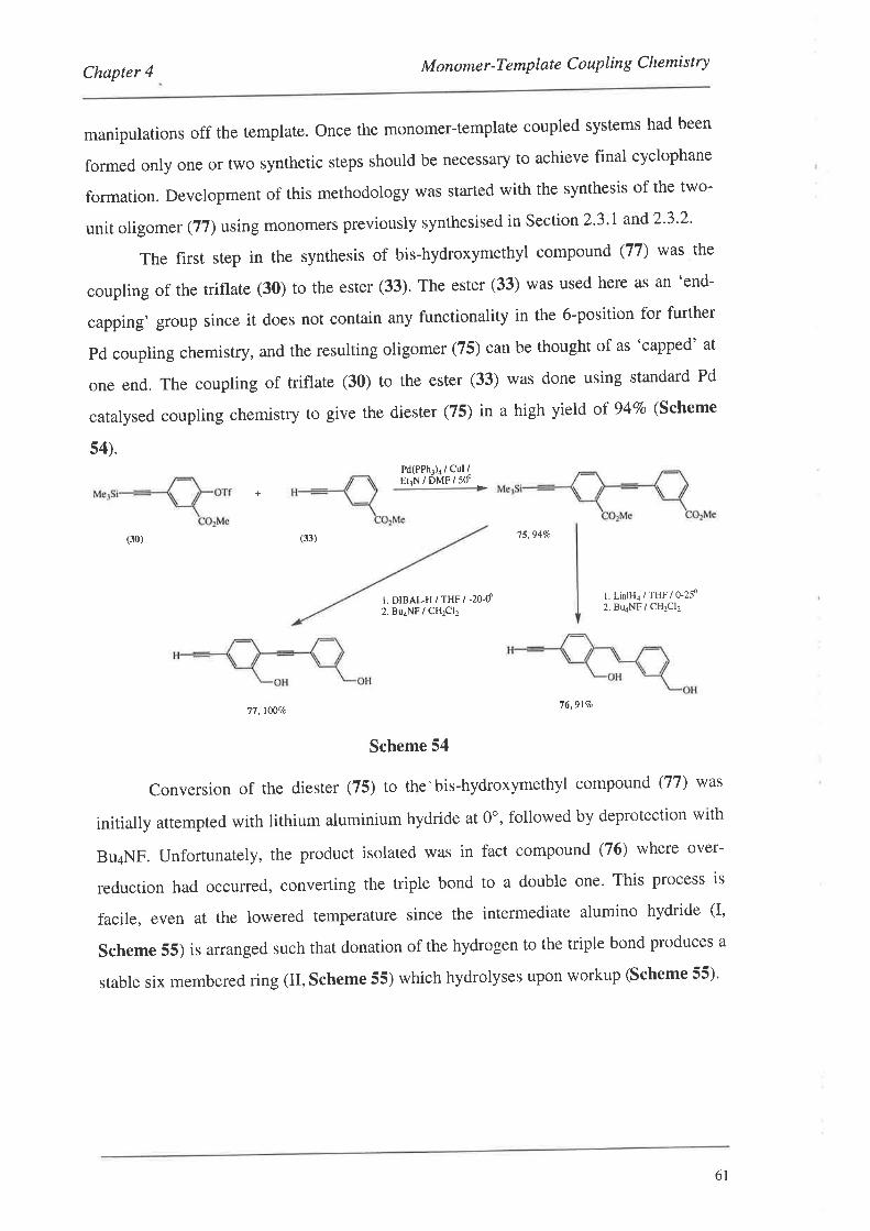
Chapter 4 M onome r -T emplat e C o uplin g Che mi st ry
manipulations off the template. Once the monomer-template coupled systems had been
formed only one or two synthetic steps should be necessary to achieve final cyclophane
formation. Development of this methodology was started with the synthesis of the two-
unit oligom er (ll)using monomers previously synthesised in Section 2'3'I and2'3'2'
The first step in the synthesis of bis-hydroxymethyl compound (77) was the
coupling of the triflate (30) to the ester (33). The ester (33) was used here as an 'end-
capping' group since it does not contain any functionality in the 6-position for further
Pd coupling chemistry, and the resulting oligomer (75) can be thought of as 'capped' at
one end. The coupling of triflate (30) to the ester (33) was done using standard Pd
catalysed coupling chemistry to give the diester (75) in a high yield of 947o (Scheme
s4).Pd(PPhr)4 / Cul iEr3N / DMF / 50" -+
(33) 75,94%(30)
r. DIBALH / THF / -20-d2. BuaNF / CHzCl2
l. LialHa / THF / 0-2f2. BU4NF / CH2CI2
76,917o77,1007a
Scheme 54
Conversion of the diester (75) to the'bis-hydroxymethyl compound (77) was
initially attempted with lithium aluminium hydride at 0o, followed by deprotection with
Bu¿NF. Unfortunately, the product isolated was in fact compound (76) where over-
reduction had occurred, converting the triple bond to a double one' This process is
facile, even at the lowered temperature since the intermediate alumino hydride (I,
Scheme 55) is arranged such that donation of the hydrogen to the triple bond produces a
stable six membered ring (II, Scheme 55) which hydrolyses upon workup (Scheme 55)'
61
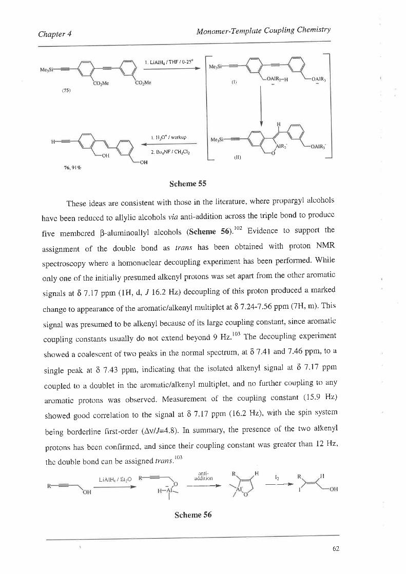
Chapter 4 M onome r -T em plat e C o uplin g Chemi st ry
t. LiAlH4 / THF / o-25o
oAlR-ì
(7s)
t. H,o* / workup
2. BuaNF / CH2CI2(ll)
OH76,9170
Scheme 55
These ideas are consistent with those in the literature, where propargyl alcohols
have been reduced to allylic alcohols via antl-addition across the triple bond to produce
five membered B-aluminoallyl alcohols (Scheme 56).to' Evidence to support the
assignment of the double bond as frøns has been obtained with proton NMR
spectroscopy where a homonuclear decoupling experiment has been performed' While
only one of the initially presumed alkenyl protons was set apart from the other aromatic
signals at ô 7.17 ppm (1H, d, J 16.2 Hz) decoupling of this proton produced a marked
change to appearance of the aromatic/alkenyl multiplet at õ 7 .24-'7 .56 ppm (7H, m)' This
signal was presumed to be alkenyl because of its large coupling constant, since aromatic
coupling constants usually do not extend beyond 9 Hz.t03 The decoupling experiment
showed a coalescent of two peaks in the normal spectrum, at õ 7'41 andT '46 ppm' to a
single peak ar õ 7.43 ppm, indicating that the isolated alkenyl signal at õ 7'17 ppm
coupled to a doublet in the aromatic/alkenyl multiplet, and no further coupling to any
aromatic protons was observed. Measurement of the coupling constant (15'9 Hz)
showed good correlation to the signal at õ 7.17 ppm (16.2Hz), with the spin system
being borderline first-order (Av//=4.8). ln summary, the presence of the two alkenyl
protons has been confirmed, and since their coupling constant was greater than 12 Hz'
the double bond can be assigned trans.t03
(t)
R2
OH
antl-addition l2 H
-______>LiAIru / Et2O
Scheme 56
H
62
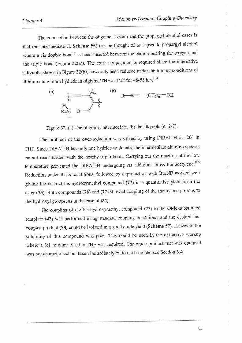
Chapter 4 M onome r -T e mplat e C o uplin g C hemi st ry
The connection between the oligomer system and the propargyl alcohol cases is
that the intermediate (I, Scheme 55) can be thought of as a pseudo-propargyl alcohol
where a cis double bond has been inserted between the carbon bearing the oxygen and
the triple bond (Figure 32(a)). The extra conjugation is required since the alternative
alkynols, shown in Figure 32(b),have only been reduced under the forcing conditions of
lithium aluminium hydride in diglymeÆHF at 140" for 48-55 hrs.rOa
(b)(a) R--(cHrn-oH
R2Al-
Figure 32. (a)The oligomer intermediate, (b) the alkynols (n=2-7).
The problem of the over-reduction was solved by using DIBAL-H at -20o in
THF. Since DIBAL-H has only one hydride to donate, the intermediate alumino species
cannot react further with the nearby triple bond' Carrying out the reaction at the low
temperature prevented the DIBAL-H undergoing cis addition across the acetylene.'05
Reduction under these conditions, followed by deprotection with Bu¿NF worked well
giving the desired bis-hydroxymethyl compound (77) in a quantitative yield from the
esrer (75). Borh compounds (76) and (77) showed coupling of the methylene protons to
the hydroxyl groups, as in the case of (34)'
The coupling of the bis-hydroxymethyl compound (77) to the oMe-substituted
template (43) was performed using standard coupling conditions, and the desired bis-
coupled product (78) could be isolated in a good crude yield (Scheme 57)' However' the
solubility of this compound was poor. This could be seen in the extractive workup
where a 3:1 mixture of ether:THF was required. The crude product that was obtained
was not characterised but taken immediately on to the bromide, see Section 6'4'
H
6.i
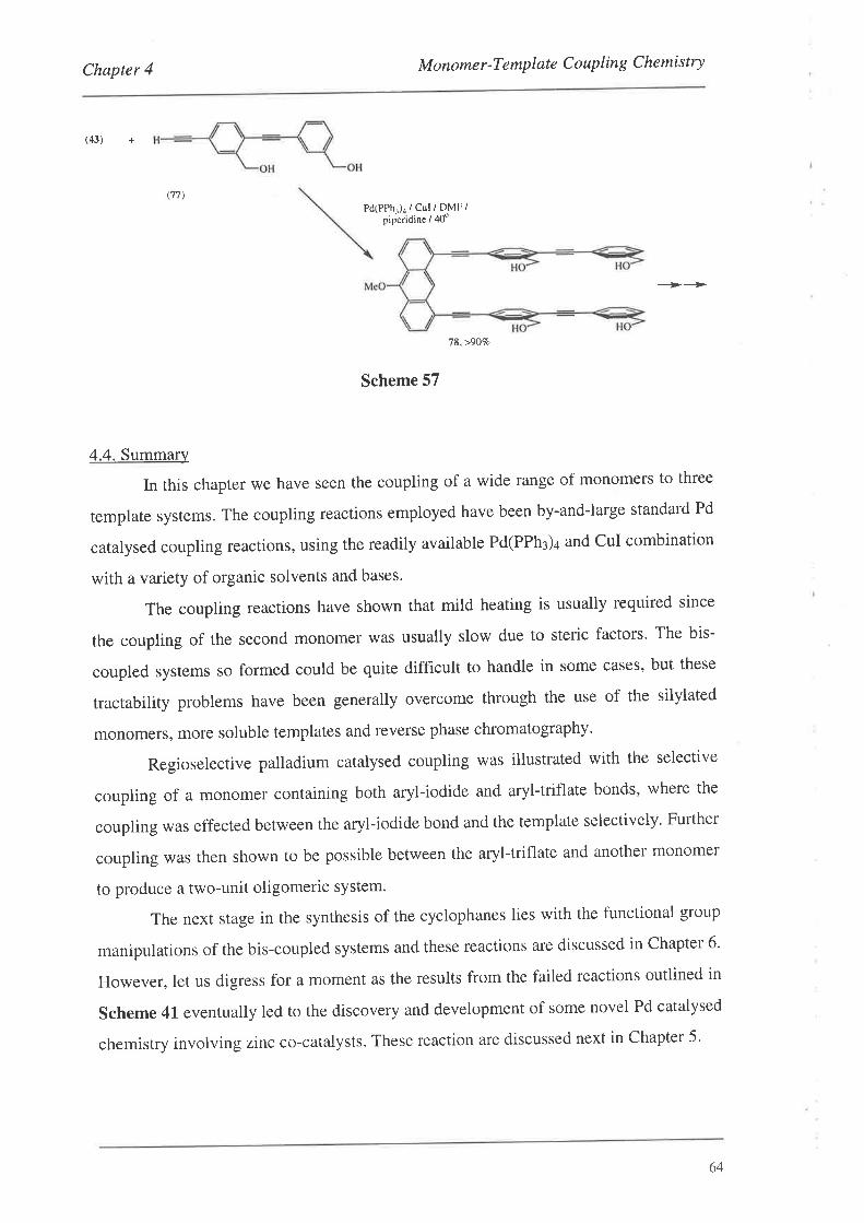
Chapter 4 Monomer-Template Coupling Chemistry
(43) +
(77)Pd(PPhr)d / Cul / DMF /
piperidine / 40"
---->---->
78,>9070
Scheme 57
4.4. Summary
In this chapter we have seen the coupling of a wide range of monomers to three
template systems. The coupling reactions employed have been by-and-large standard Pd
catalysed coupling reactions, using the readily available Pd(PPhl)+ and CuI combination
with a variety of organic solvents and bases.
The coupling reactions have shown that mild heating is usually required since
the coupling of the second monomer was usually slow due to steric factors. The bis-
coupled systems so formed could be quite difficult to handle in some cases, but these
tractability problems have been generally overcome through the use of the silylated
monomers, more soluble templates and reverse phase chromatography.
Regioselective palladium catalysed coupling was illustrated with the selective
coupling of a monomer containing both aryl-iodide and aryl-triflate bonds, where the
coupling was effected between the aryl-iodide bond and the template selectively. Further
coupling was then shown to be possible between the aryl-triflate and another monomer
to produce a two-unit oligomeric system.
The next stage in the synthesis of the cyclophanes lies with the functional group
manipulations of the bis-coupled systems and these reactions are discussed in Chapter 6'
However, let us digress for a moment as the results from the failed reactions outlined in
Scheme 4l eventually led to the discovery and development of some novel Pd catalysed
chemistry involving zinc co-catalysts. These reaction are discussed next in Chapter 5.
64
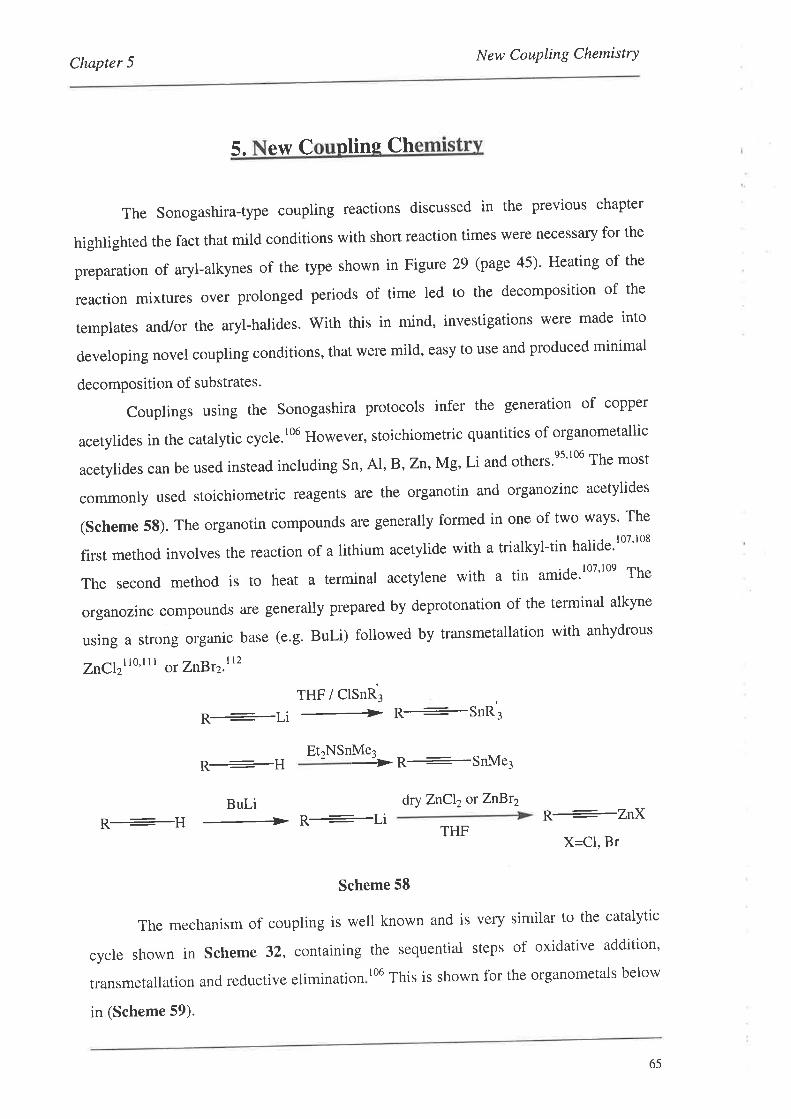
New Coupling ChemistryChapter 5
5. e\ü c nlins Ch
The Sonogashira-type coupling reactions discussed in the previous chapter
highlighted the fact that mild conditions with short reaction times were necessary for the
preparation of aryl-alkynes of the type shown in Figure 29 (page 45)' Heating of the
reaction mixtures over prolonged periods of time led to the decomposition of the
templates and./or the aryl-halides' With this in mind, investigations were made into
developing novel coupling conditions, that were mild, easy to use and produced minimal
decomposition of substrates.
Couplings using the Sonogashira protocols infer the generation of copper
acetylides in the catalytic cycle.r06 However, stoichiometric quantities of organometallic
acetylides can be used instead including Sn, Al, B'Zî,Mg' Li and others'es'106 The most
commonly used stoichiometric reagents are the organotin and organozinc acetylides
(Scheme 58). The organotin compounds afe generally formed in one of two ways' The
first method involves the reaction of a lithium acetylide with a trialkyl-tin halide.r0T'108
The second method is to heat a terminar acetylene with a ti' amide.l.7'l.e The
organozinc compounds are generally prepared by deprotonation of the terminal alkyne
using a strong organic base (e.g. BuLi) followed by transmetallation with anhydrous
ZnCIzrro'l t I or ZîBï2.1r2
THF / ClSnR3
R+Li 4 ft+$nft,
R+H Et2NSnMe'- ft+SnMe3
dry ZnCl2orZnBt2Bul-iR+H + R+Li
THF
Scheme 58
The mechanism of coupling is well known and is very similar to the catalytic
cycle shown in Sche me 32, containing the sequential steps of oxidative addition'
transmetallation and reductive elimination
in (Scheme 59).
106 This is shown for the organometals below
R+ZnXX=Cl, Br
65
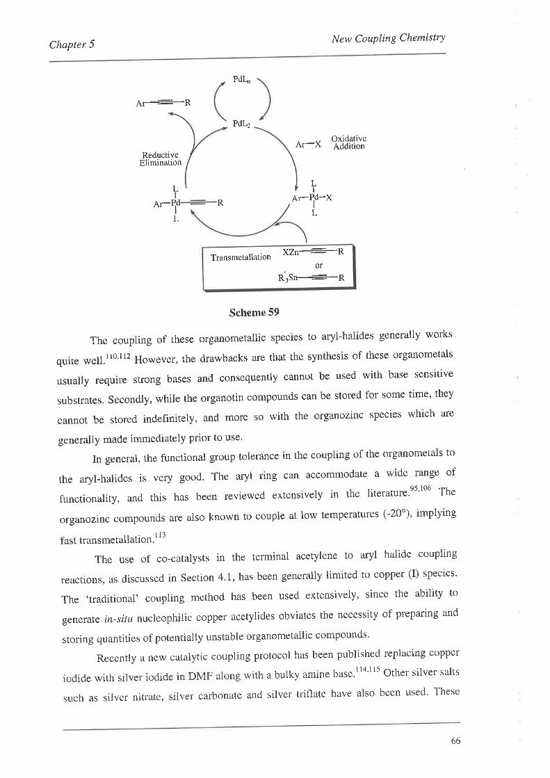
Chapter 5New Coupling ChemistrY
OxidativeAddition
d¡---ft
ReductiveElimination
Ar-L
Pdl.,
PdL2
Ar-X
LI
Ar- XPd-I
L
Scheme 59
The coupling of these organometallic species to aryl-halides generally works
quite well.ll0'l12 However, the drawbacks are that the synthesis of these organometals
usually require strong bases and consequently cannot be used with base sensitive
substrates. Secondly, while the organotin compounds can be stored for some time' they
cannot be stored indefinitely, and more so with the organozinc species which are
generally made immediately prior to use'
ln general, the functional group tolerance in the coupling of the organometals to
the aryl-halides is very good. The aryl ring can accommodate a wide range of
functionarity, and this has been reviewed extensivery in the literature.es'106 The
organozinc compounds are also known to couple at low temperatures (-20')' implying
fast transmetallation. I l3
The use of co-catalysts in the terminal acetylene to aryl halide coupling
reactions, as discussed in Section4.l, has been generally limited to copper (I) species'
The ,traditional' coupling method has been used extensively, since the ability to
generate in-situ nucleophilic copper acetylides obviates the necessity of preparing and
storing quantities of potentially unstable organometallic compounds'
Recently a new catalytic coupling protocol has been published replacing copper
iodide with silver iodide in DMF along with a bulky amine base.l'o''tt Othet silver salts
such as silver nitrate, silver carbonate and silver triflate have also been used' These
\/n+-PTransmetallation
R3Sn+Pot
66
Chapter 5New Coupling Chemistry
conditions were used to couple vinyl triflates with terminal acetylenes,lls and in the
synthesis of epoxyenynes.t'o'tts The use of the silver salts was required in the latter case'
since the use of copper iodide led to the decomposition of the epoxyacetylenic starting
materials. Mechanistically, silver acetylides are thought to be generated in-situ' and that
these behave as other metal acetyrides in the transmetalation step of the catalytic
cycle.ll5
The lack of many alternatives to copper led us to look for novel coupling
protocols using different metallic species. By using previously untried metallic salts as
alternatives to copper iodide, it may be possible to effect a faster transmetallation step'
Previous studies have shown transmetallation to be the rate determining step in many of
the catalytic cycles.l16'l17 By increasing the rate of transmetallation, coupling may be
possible under milder conditions (e.g. lower temperature), leading to minimal
decomposition of the template acetylenes during the coupling reactions' It was known
from the literature that zinc acetylides readily couple to aryl-halides with a palladium
catalyst,lt0,l12 and so the generation of these organozinc species (or their equivalents) in-
sifø would be an important step towafds finding an alternative to the Sonogashira
method. our initial investigations have met with some success, the results of which
were published recently and are presented below'l l8
5.1. The Initial Discovery
The first reaction investigated was the coupling of iodobenzene with
phenylacetylene. These substrates were chosen due to their activated nature towards Pd
catalysed coupling, since the iodobenzene readily undergoes oxidative addition at room
temperature, and the terminal acetylenic proton of phenylacetylene could be abstracted
by bases commonly used for Pd catalysed couplings. The catalysts initially used were
57o Pd(PPh3)a and I07o ZnClz in degassed piperidine as both the solvent and base
(Scheme 60). However, after the above reagents were added together, no reaction was
observed after 4 hrs at room temperature. A crystal of iodine was then added and an
immediate precipitation of a solid (piperidine hydroiodide) was observed with the
reaction going to completion in I hr. An extractive workup followed by recrystallisation
gave the expected product (79) (tolan) in807o yield'
67
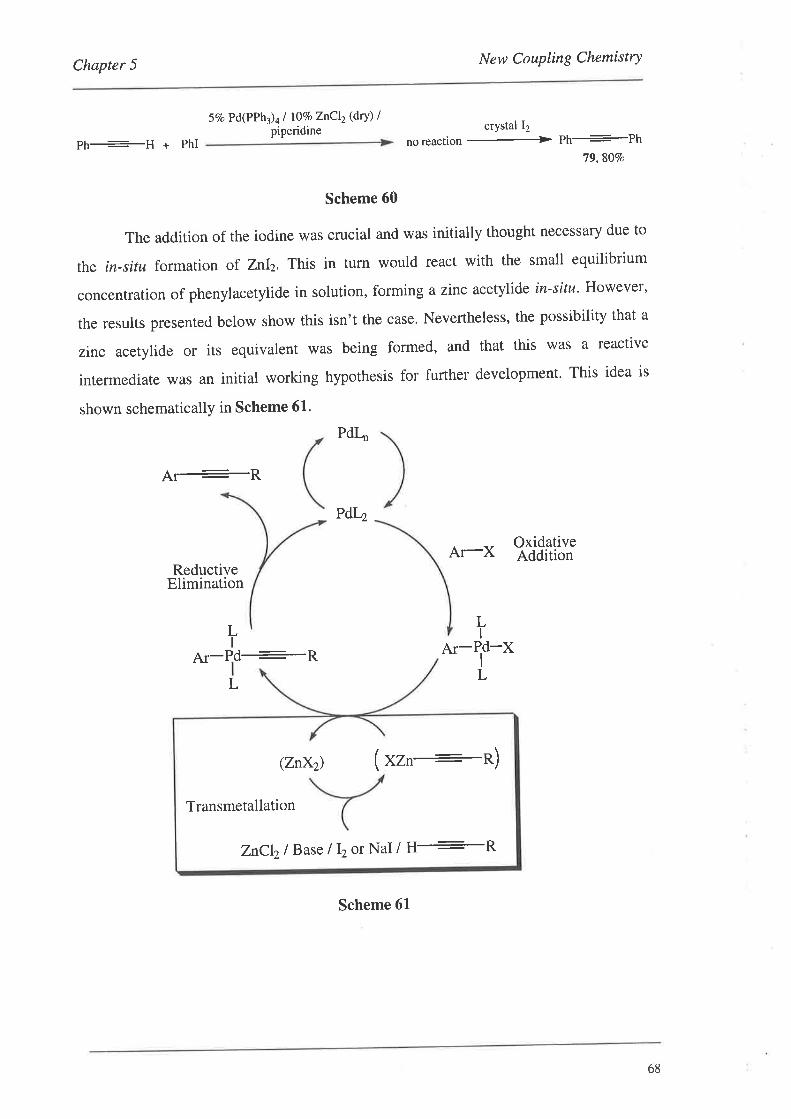
Chapter 5 New Coupling Chemistry
57o Pd(PPh¡)¿ I l\VoZnCl2(dry) Ipiperidine
Ph+H + PhI
Scheme 60
The addition of the iodine was crucial and was initially thought necessary due to
the in-situ formation of znIz. This in turn would react with the small equilibrium
concentration of phenylacetylide in solution, forming a zinc acetylide in-situ' However'
the results presented below show this isn't the case. Nevertheless, the possibility that a
zinc acetylide or its equivalent was being formed, and that this was a reactive
intermediate was an initial working hypothesis for further development' This idea is
shown schematicallY in Scheme 61.
PdI-
tr¡+ftPdI4
Ar-X OxidativeAddition
ReductiveElimination
crystal 12
noreaction ---+ Ph+Ph79,80Vo
LIL
I
Ar-Pd-RL
tu-ld-xL
(znxz) (xzn+n)
ZnCl2l Base lþot NaI/ H+R
Transmetallation
Scheme 6L
68
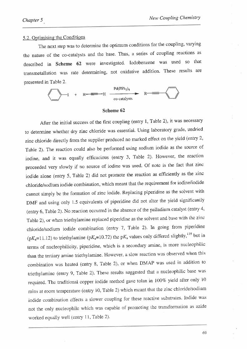
Chapter 5 _
New Coupling Chemistry
5.2. Optimising the Conditions
The next step was to determine the optimum conditions for the coupling' varying
the nature of the co-catalysts and the base. Thus, a series of coupling reactions as
described in Scheme 62 were investigated. Iodobenzene was used so that
transmetallation was rate determining, not oxidative addition' These results are
presented in Table 2.
Pd(PPh3)4
R----H-co-catalYsts
+
Scheme 62
After the initial success of the first coupling (entry 1, Table 2), it was necessary
to determine whether dry zinc chloride was essential. Using laboratory grade, undried
zinc chloride directly from the supplier produced no marked effect on the yield (entry 2'
Table 2). The reaction could also be performed using sodium iodide as the source of
iodine, and it was equally efficacious (entry 3, Table 2). However, the reaction
proceeded very slowly if no source of iodine was used' Of note is the fact that zinc
iodide alone (entry 5, Table 2) did not promote the reaction as efficiently as the zinc
chloride/sodium iodide combination, which meant that the requirement for iodineiiodide
cannot simply be the formation of zinc iodide. Replacing piperidine as the solvent with
DMF and using only 1.5 equivalents of piperidine did not alter the yield significantly
(entry 6, Table 2). No reaction occurred in the absence of the palladium catalyst (entry 4'
Table 2), or when triethylamine replaced piperidine as the solvent and base with the zinc
chlorideisodium iodide combination (entry 7, Table 2). In going from piperidine
(pK.=11.12) to trierhylamine (pKu=10 .12) rhepKo values only differed slightly,rre but in
terms of nucleophilicity, piperidine, which is a secondary amine, is more nucleophilic
than the tertiary amine triethylamine. However, a slow reaction was observed when this
combination was heated (entry 8, Table 2), ot when DMAP was used in addition to
triethylamine (entry 9, Table 2). These results suggested that a nucleophilic base was
required. The traditional copper iodide method gave tolan ln IO}Vo yield after only l0
mins at room temperature (entry 10, Table 2) which meant that the zinc chloride/sodium
iodide combination effects a slower coupling for these reactive substrates. Iodide was
not the only nucleophile which was capable of promoting the transformation as azide
worked equally well (entry 11, Table 2)'
69
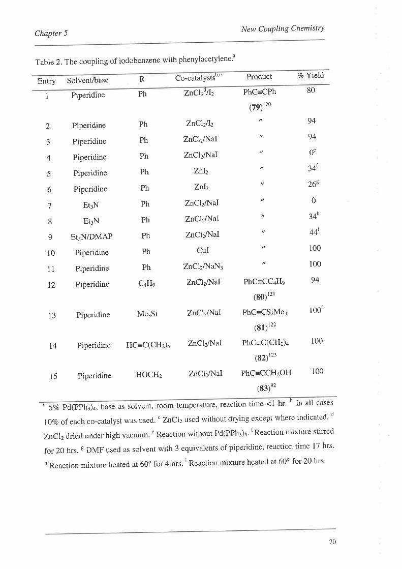
New CouPling ChemistryChapter 5
Table 2. The coupling of iodobenzene with phenylacetylene.o
Entry Solvent/base R Co-catalystsb'' Product Vo Y\eld
1 Piperidine ZnClzollz PhC=CPh
(79)''o
80Ph
Piperidine
Piperidine
Piperidine
Piperidine
Piperidine
EtrN
Et¡N
Et¡N/DMAP
Piperidine
Piperidine
Piperidine
ZnClzllz
ZnClzlf{aI
ZnClzlNaI
znh
ZnI2
ZnClzA{aI
ZnClzl}{aI
ZnClzÆ'laI
CUI
ZnClzlNlaN¡
ZnClzA{aI
94
94
0'
341
26s
0
34h
44'
100
100
94
2
3
4
5
6
7
8
9
10
11
12
Ph
Ph
Ph
Ph
Ph
Ph
Ph
Ph
Ph
Ph
C¿Hs
13 Piperidine Me¡Si ZnClzll{aI
14 Piperidine HC=C(CHz)¿ ZnClzA{aI
15 Piperidine HOCHz ZnClzA{aI
PhC=CC+Hs
(g0)t''
PhC=CSiMe¡
(g1)'tt
PhC=C(CHz)¿
(82)"'
PhC=CCHzOH
(83)e2
100f
100
100
u 5Vo Pd(PPh¡)¿, base as solvent, room temperature' reaction time <1 hr. b tn all cases
l¡Vo ofeach co-catalyst was used. " Znclzused without drying except where indicated' d
ZnClzdried under high vacuum.'Reaction without Pd(PPh3)4. f Reaction mixture stirred
for 20 hrs. s DMF used as solvent with 3 equivalents of piperidine, reaction time 17 hrs'
h Reaction mixture heated at 60o for 4 hrs. ' Reaction mixture heated at 60o for 20 hrs'
10
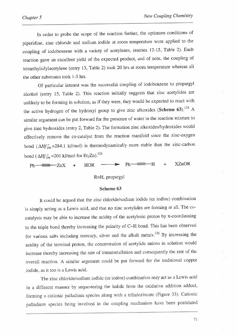
Chøpter 5 New Coupling Chemistry
In order to probe the scope of the reaction further, the optimum conditions of
piperidine, zinc chloride and sodium iodide at room temperature were applied to the
coupling of iodobenzene with a variety of acetylenes, (entries I2-L5, Table 2)' Each
reaction gave an excellent yield of the expected product, and of note, the coupling of
trimethylsilylacetylene (entry 13, Table 2) took 20 hrs at room temperature whereas all
the other substrates took 1-3 hrs.
Of particular interest was the successful coupling of iodobenzene to propargyl
alcohol (entry 15, Table 2). This reaction initially suggests that zinc acetylides are
unlikely to be forming in solution, as if they were, they would be expected to react with
the active hydrogen of the hydroxyl group to give zinc alkoxides (Scheme 63¡.124 A
similar argument can be put forward for the presence of water in the reaction mixture to
give zinc hydroxides (entry 2,Table 2). The formation zinc alkoxides/hydroxides would
effectively remove the co-catalyst from the reaction manifold since the zinc-oxygen
bond ( Nlfinr=284.1 kJ/mol) is thermodynamically more stable than the zinc-carbon
bond ( NIfírr=ZOl kJ/mol for Et2zn¡'t2s
Ph+ZnX+HOR+PhH+XZnOR
R=H, propargyl
Scheme 63
It could be argued that the zinc chloride/sodium iodide (or iodine) combination
is simply acting as a Lewis acid, and that no zinc acetylides are forming at all. The co-
catalysts may be able to increase the acidity of the acetylenic proton by rc-coordinating
to the triple bond thereby increasing the polarity of c-H bond. This has been observed
for various salts including mercury, silver and the alkali metals.l26 By increasing the
acidity of the terminal proton, the concentration of acetylide anions in solution would
increase thereby increasing the rate of transmetallation and consequently the rate of the
overall reaction. A similar argument could be put forward for the traditional copper
iodide, as it too is a Lewis acid.
The zinc chloride/sodium iodide (or iodine) combination may act as a Lewis acid
in a different manner by sequestering the halide from the oxidative addition adduct,
forming a cationic palladium species along with a trihalozincate (Figure 33). Cationic
palladium species being involved in the coupling mechanism have been postulated
1l
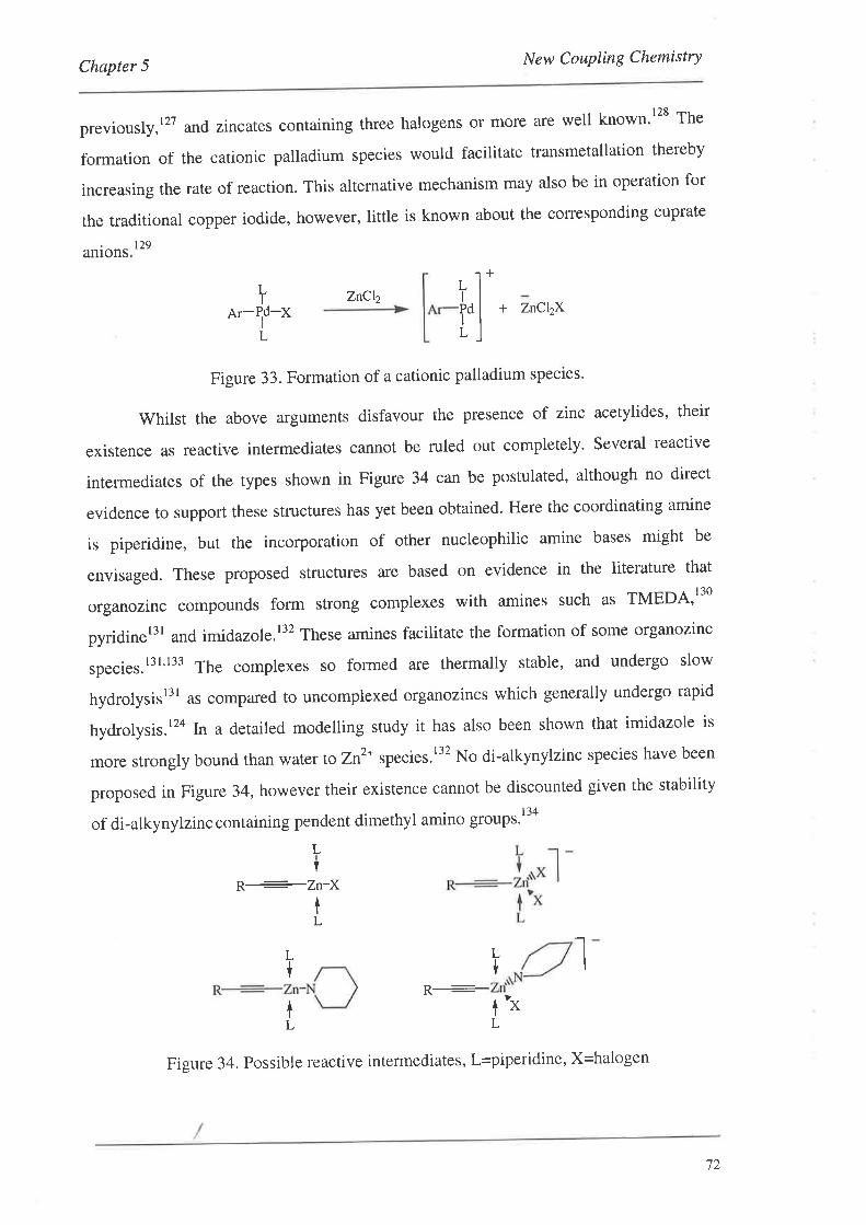
Chapter 5 New Coupling Chemistry
previously,l2T and zincates containing three halogens or more are well known't28 The
formation of the cationic palladium species would facilitate transmetallation thereby
increasing the rate of reaction. This alternative mechanism may also be in operation for
the traditional copper iodide, however, little is known about the corresponding cuprate
t29aruons
+LI
Pd-I
L
LI
PdI
L
ZnCþ+ ZnCl2XAr- X
Figure33.Formationofacationicpalladiumspecies.
Whilst the above arguments disfavour the presence of zinc acetylides, their
existence as reactive intermediates cannot be ruled out completely. Several reactive
intermediates of the types shown in Figure 34 can be postulated, although no direct
evidence to support these structures has yet been obtained. Here the coordinating amine
is piperidine, but the incorporation of other nucleophilic amine bases might be
envisaged. These proposed structures are based on evidence in the literature that
organozinc compounds form strong complexes with amines such as TMEDA'130
pyridinet3l and imidazole.l32 These amines facilitate the formation of some organozinc
species.l3l't33 The complexes so formed are thermally stable, and undergo slow
hydrolysisl" a. co*pared to uncomplexed organozincs which generally undergo rapid
hydrolysis. t24 kt a detailed modelling study it has also been shown that imidazole is
more strongly bound than water to zn2* species.l32 No di-alkynylzinc species have been
proposed in Figure 34, however their existence cannot be discounted given the stability
of di-alkynylzinc containing pendent dimethyl amino group''t'o
R:¿n-2ttI
L
L*
LI
L{ I
tL
1'*L
Figure 34. Possible reactive intermedia¡s5, l=piperidine, X=halogen
72
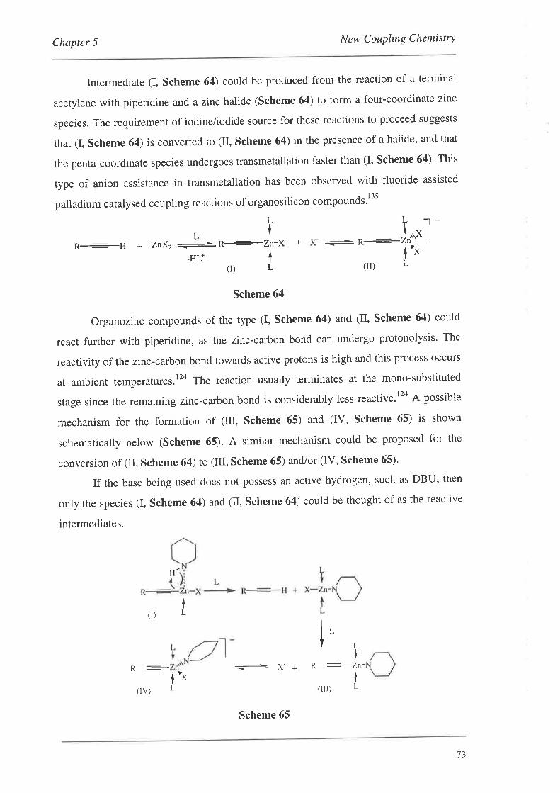
Chapter 5 New Coupling Chemistry
Intermediate (I, scheme 64) could be produced from the reaction of a terminal
acetylene with piperidine and a zinc halide (Scheme 64) to form a four-coordinate zinc
species. The requirement of iodine/iodide source for these reactions to proceed suggests
that (I, Scheme 64) is converted to (II, Scheme 64) in the presence of a halide, and that
the penta-coordinate species undergoes transmetallation faster than (I, Scheme 64). This
type of anion assistance in transmetallation has been observed with fluoride assisted
palladium catalysed coupling reactions of organosilicon compounds.l 35
L
LÍR-----H a ZnX2
-R--Zn-X
-HL+ T(DL
L -r-
i"* I
t'"L(D
Scheme 64
Organozinc compounds of the type (I, Scheme 64) and (tr, Scheme 64) could
react further with piperidine, as the zinc-carbon bond can undergo protonolysis' The
reactivity of the zinc-carbon bond towards active protons is high and this process occurs
at ambient temperatures.l2o The reaction usually terminates at the mono-substituted
stage since the remaining zinc-carbon bond is considerably less reactive.l2a A possible
mechanism for the formation of (Itr, Scheme 65) and (IV, Scheme 65) is shown
schematically below (Scheme 65). A similar mechanism could be proposed for the
conversion of (II, Scheme 64) to (III, Scheme 65) and/or (IV, Scheme 65)'
If the base being used does not possess an active hydrogen, such as DBU, then
only the species (I, scheme 64) and (tr, scheme 64) could be thought of as the reactive
intermediates.
t(I) L
i' Lt
-
X- + R-----Zn-tL
t(rrr) L(lv)'X
Scheme 65
13
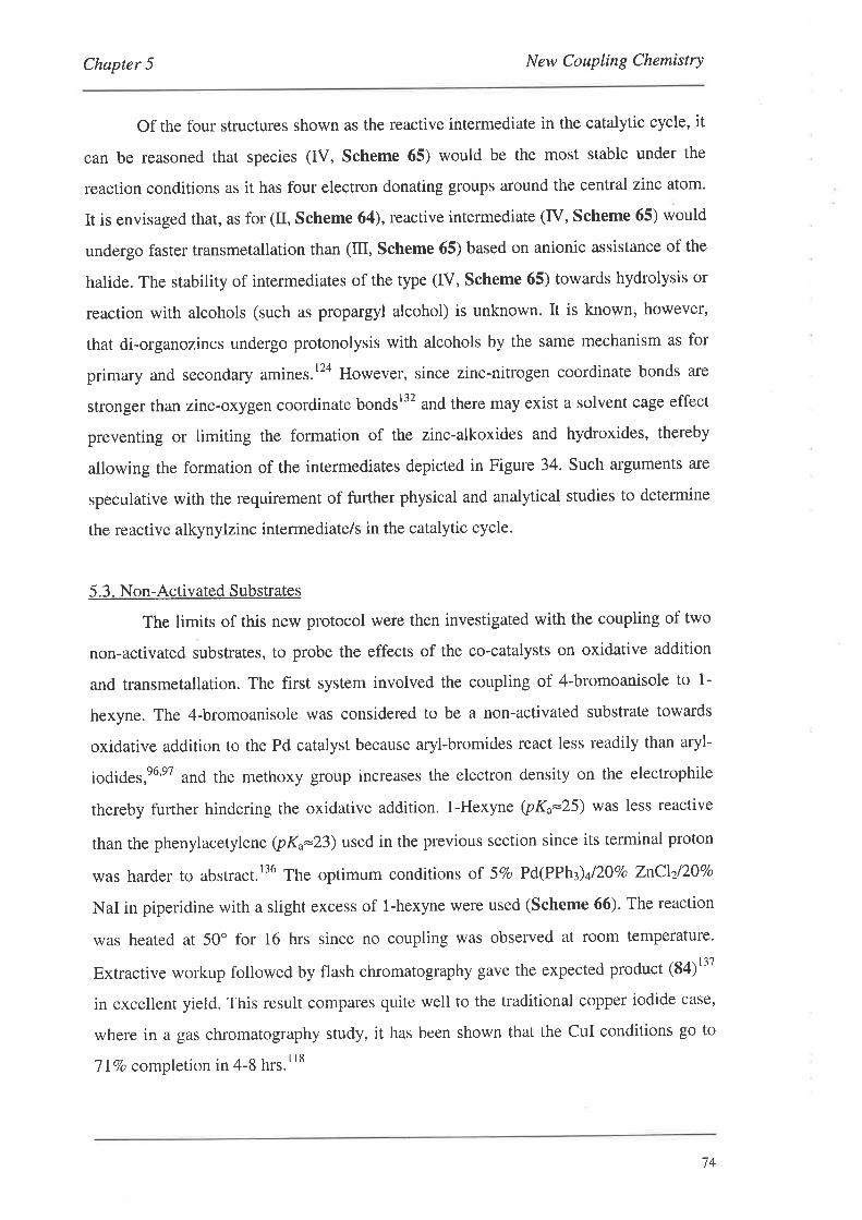
Chapter 5 New Coupling Chemistry
Of the four structures shown as the reactive intermediate in the catalytic cycle, it
can be reasoned that species (fV, Scheme 65) would be the most stable under the
reaction conditions as it has four electron donating groups around the central zinc atom.
It is envisaged that, as for (tr, Scheme 64), reactive intermediate (fV, Scheme 65) would
undergo faster transmetallation than (Itr, Scheme 65) based on anionic assistance of the
halide. The stability of intermediates of the type (IV, Scheme 65) towards hydrolysis or
reaction with alcohols (such as propargyl alcohol) is unknown. It is known, however,
that di-organozincs undergo protonolysis with alcohols by the same mechanism as for
primary and secondary amines.t24 However, since zinc-nitrogen coordinate bonds are
stronger than zinc-oxygen coordinate bondsl32 and there may exist a solvent cage effect
preventing or limiting the formation of the zinc-alkoxides and hydroxides, thereby
allowing the formation of the intermediates depicted in Figure 34. Such arguments are
speculative with the requirement of further physical and analytical studies to determine
the reactive alkynylzinc intermediate/s in the catalytic cycle.
5.3. Non-Activated Substrates
The limits of this new protocol were then investigated with the coupling of two
non-activated substrates, to probe the effects of the co-catalysts on oxidative addition
and transmetallation. The first system involved the coupling of 4-bromoanisole to 1-
hexyne. The 4-bromoanisole was considered to be a non-activated substrate towards
oxidative addition to the Pd catalyst because aryl-bromides react less readily than aryl-
iodides,e6'e7 and the methoxy group increases the electron density on the electrophile
thereby further hindering the oxidative addition. l-Hexyne (pKo=25) was less reactive
than the phenylacetylene (pKu=23) used in the previous section since its terminal proton
was harder to abstract.t36 The optimum conditions of 57o Pd(PPh3)y'2ÙVo ZnCLzlZÙVo
NaI in piperidine with a slight excess of 1-hexyne were used (Scheme 66). The reaction
was heated at 50o for 16 hrs since no coupling was observed at room temperature.
Extractive workup followed by flash chromatography gave the expected product (84)t"
in excellent yield. This result compares quite well to the traditional copper iodide case,
where in a gas chromatography study, it has been shown that the CuI conditions go to
TIVo completion in 4-8 hrs.tls
74
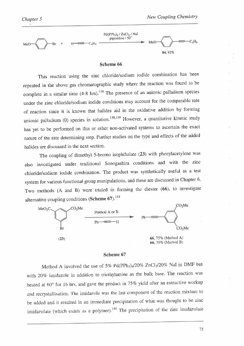
Chapter 5 New Coupling Chemistry
Pd(PPh3)4/ZnCl2lNatpiperidine / 50'
+ H--Qol{n
84,927o
Scheme 66
This reaction using the zinc chloride/sodium iodide combination has been
repeated in the above gas chromatographic study where the reaction was found to be
complete in a similar time (4-8 hrs).rt8 The presence of an anionic palladium species
under the zinc chloride/sodium iodide conditions may account for the comparable rate
of reaction since it is known that halides aid in the oxidative addition by forming
anionic palladium (0) species in solution.l3s'l3e However, a quantitative kinetic study
has yet to be performed on this or other non-activated systems to ascertain the exact
nature of the rate determining step. Further studies on the type and effects of the added
halides are discussed in the next section.
The coupling of dimethyl 5-bromo isophthalate (23) with phenylacetylene was
also investigated under traditional Sonogashira conditions and with the zinc
chloride/sodium iodide combination. The product was synthetically useful as a test
system for various functional group manipulations, and these are discussed in Chapter 6'
Two methods (A and B) were trialed in forming the diester (66), to investigate
alternative coupling conditions (Scheme 67)'"t
MeO2CMethod A or B
PhPh----H
(23) 66,75Vo (Method A)66,70Vo (Method B)
Scheme 67
Method A involved the use of 5vo Pd(PPh3)y'2ovo znclzl^\vo NaI in DMF but
with 20Vo imidazole in addition to triethylamine as the bulk base. The reaction was
heated at 60o for 16 hrs, and gave the product inl5Vo yield after an extractive workup
and recrystallisation. The imidazole was the last component of the reaction mixture to
be added and it resulted in an immediate precipitation of what was thought to be zinc
imidazolate (which exists as a polymer).t40 The precipitation of the zinc imidazolate
15

Chapter 5 New Coupling Chemistry
reduced the availability of the zinc catalyst, explaining why a long reaction trme was
necessary. lt was thought that the use of imidazole could be substituted for the
nucleophilic piperidine, which has the potential to react with the ester groups'
comparison to the cul method was promising, with the traditional method giving the
product inTlTo yield in t hr to our method giving a yield of 75Vo in 16 hrs' The next
method went part way to improve this issue'
Merhod B involved the use of 5vo Pd(PPh3)y'2\vo znclzl2\To NaI in DMF with
excess DBU as the base. In this case, DBU was our nucleophilic base, and it was chosen
as it would not form amide products with our diester (23) as piperidine might. By using
DBU instead of triethylamine, a higher concentration of acetylide anions in solution
could be formed as DBU was considerably more basic (pK;-23.9 in CH¡CN¡rar than
triethylamine (pKu=l$ .46 in cH¡cN)ra2. Using these conditions gave a faster reaction
than with merhod A, giving the product (66) in l\vo yield after 3 hrs' clearly these
conditions were now comparable to that of the cul method.
To summarise the results so far, the optimum conditions used are Pd(PPh¡)¿'
laboratory reagent grade znCl2 and NaI in piperidine as the solvent and base' If the
substrates were sensitive to piperidine, the use of DBU as the base in DMF worked well'
Further studies by the Crisp group in this area have found that Pd(PPh¡)¿ was the most
appropriate palladium source to use.l18 The use of a nucleophilic base for this reaction
was essential, and either NaI or iodine could be used in conjunction with ZnCll Finally,
as with the cul method, heating was required for non-activated aryl-bromides.
5.4. Forming the Monomer-Template Coupled Systems
Taking this new coupling chemistry and applying it to coupling monomers with
template has met with mixed success. The results of the reaction described in Scheme
68 are presented below in Table 3.
n
H
+
(40) R=H(41) R=l-decyne
Pd(PPhr)4 / additives
Scheme 68
76
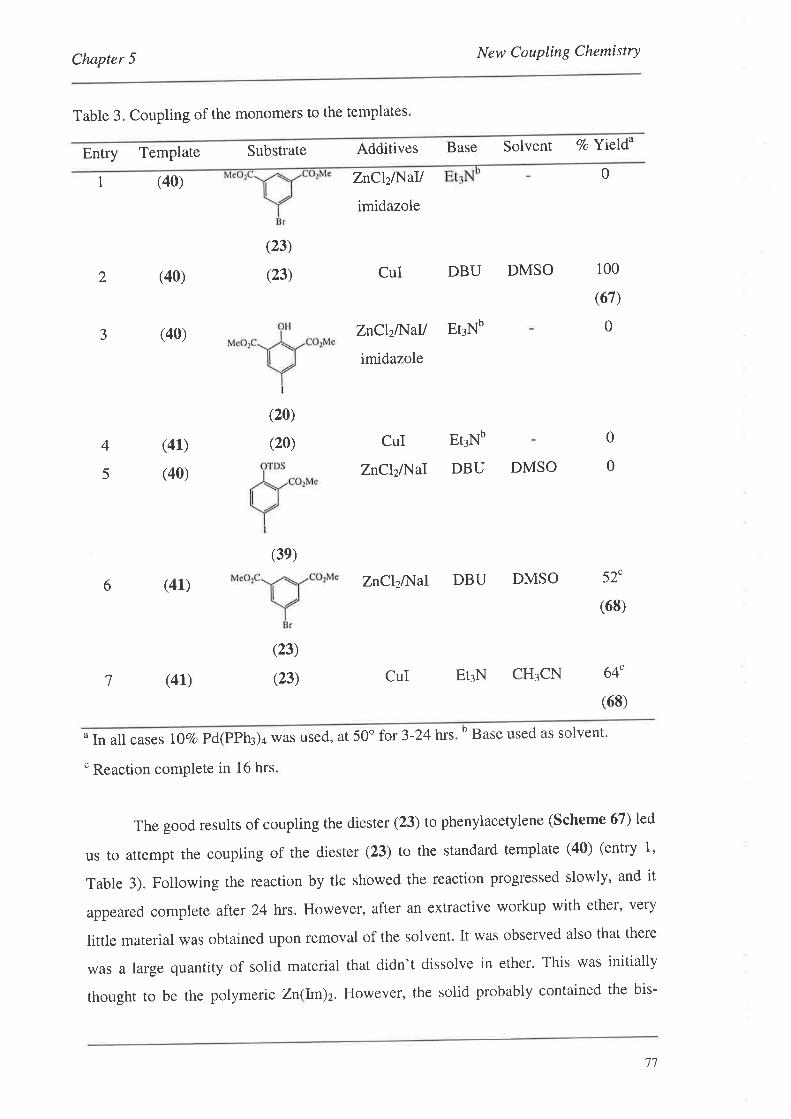
New Coupling ChemistryChapter 5
Table 3. Coupling of the monomers to the templates
Entry TemPlate Substrate
(40)
(40)
(23)
(23)
Additives Base Solvent 7o Y\eId"
ZnClzll{aV
imidazole
ZnClzlNall Et3Nb
imidazole
CuI
ZnClzA{aI
CuI DBU DMSO
0I
2
3
100
(67)
0(40)
Et¡Nb
(20)
(20) 0
0
4
5
(41)
(40) DBU DMSO
6 (4L)
7 (41)
(3e)
ZnClzlÌ.{al DBU DMSO 52"
(68)
(23)
(23) CuI EtrN CH¡CN 64"
(68)
o In all cases 107o Pd(PPh3)4 was used, at 50o for 3- 24hrs.b Base used as solvent.
" Reaction complete in 16 hrs
The good results of coupling the diester (23) to phenylacetylene (Scheme 67) led
us ro attempt the coupling of the diester (23) to the standard template (40) (entry 1'
Table 3). Following the reaction by tlc showed the reaction progressed slowly, and it
appeared complete afrcr 24 hrs. However, after an extractive workup with ether, very
little material was obtained upon removal of the solvent. It was observed also that there
was a large quantity of solid material that didn't dissolve in ether' This was initially
thought to be the polymeric Zn(Im)2' However, the solid probably contained the bis-
77
Chapter 5 New Coupling Chemistry
coupled product (67) as it had been shown earlier (entry 2, Table 3) (Section 4'2'2) that
such compounds are difficult to handle with low solubility in most organic solvents' A
better extractive solvent would have been chloroform or THF.
Similar results were obtained in côupling the diester (20) to the standard
template (40) (entry 3, Table 3). However, upon workup the coupled material could be
extracted using ether, but was lost on a Squat column, the material streaking a great deal
on silica. This result was reminiscent of the problems encountered in Section 4'2 where
the tradition CuI coupling conditions were used (entry 4, Table 3) with the more soluble
template (41.).
Somewhat more promising results came out of the coupling of the protected
monomer (39) with the standard template (40) (entry 5, Table 3)' The coupling was
observed to be very slow and the reaction was worked up after 16 hrs' Tlc showed that
several compounds were overlapping on both normal and reverse phase silica' and
consequently the bis-coupled material could not be purified to any significant extent'
This coupling reaction has yet to be performed with the standard CuI catalyst for
comparison.
The best results using this new chemistry were obtained with the coupling of the
diester (23) to the more soluble decyne functionalised template (41) (entry 6, Table 3)'
In this case the desired coupled product (68) could be obtained in 52Vo yield' By using
the more soluble template the bis-coupled material could be handled easily and it did not
streak to any significant extent on silica. This reaction also compared well to the
tradition CuI method, where under standard conditions the yield of the product was 64Vo
(entry 7, Table 3).
5.5. Subsequent Results from the Crisp Group
The precise mechanism of the zinc chloride/sodium iodide reaction remains
unknown. To discern more information about the reaction, a Series of qualitative
experiments were performed using gas chromatography to determine the extent of the
reaction.lts Bri"fly, the coupling reaction shown in Scheme 66 was investigated in
deprh and it was found rhat the palladium catalysts Pd(PPh3)4 and ClzPd(PPh¡)¿ were
equally efficacious. Also, the use of DMSO was favoured over DMF and gave fewer
side products. However, the most interesting result to come out of this study' was the
78
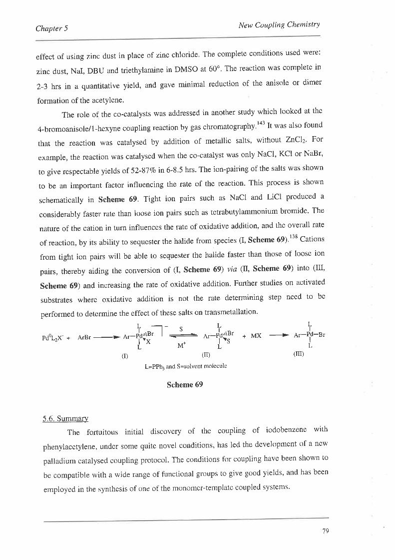
Chapter 5 New Coupling Chemistry
effect of using zinc dust in place of zinc chloride. The complete conditions used were:
zinc dust, NaI, DBU and triethylamine in DMSO at 60o' The reaction was complete in
2-3 hrs in a quantitative yield, and gave minimal reduction of the anisole or dimer
formation of the acetylene.
The role of the co-catalysts was addressed in another study which looked at the
4-bromoanisole/1-hexyne coupling reaction by gas chromatography'la3 It was also found
that the reaction was catalysed by addition of metallic salts, without ZnClz' For
example, the reaction was catalysed when the co-catalyst was only NaCl' KCI or NaBr'
to give respectable yields or 52-87Vo in 6-8.5 hrs. The ion-pairing of the salts was shown
to be an important factor influencing the rate of the reaction. This process is shown
schematically in Scheme 69. Tight ion pairs such as NaCl and LiCl produced a
considerably faster rate than loose ion pairs such as tetrabutylammonium bromide' The
nature of the cation in turn influences the rate of oxidative addition, and the overall rate
of reaction, by its ability to sequester the halide from,species (I, Scheme 69)'r38 Cations
from tight ion pairs will be able to sequester the halide faster than those of loose ion
pairs, thereby aiding the conversion of (I, Scheme 69) via (tr, Scheme 69) into (III'
Scheme 69) and increasing the rate of oxidative addition. Further studies on activated
substrates where oxidative addition is not the rate determining step need to be
performed to determine the effect of these salts on transmetallation'
LI! -t- s
pdohx- + A¡Br --> er-eþ'Jf' I
-LM*
L
o.-Jf$r"'L
+MX -+ ar-Pf-BrL
5.6. Summary
The fortuitous initial
(D
L=PPh: and S=solvent molecule
Scheme 69
discovery of the coupling of iodobenzene with
(n)(r)
phenylacetylene, under some quite novel conditions, has led the development of a new
palladium catalysed coupling protocol. The conditions for coupling have been shown to
be compatible with a wide range of functional groups to give good yields, and has been
employed in the synthesis of one of the monomer-template coupled systems'
79
Chapter 5 New Coupling Chemistry
Studies within the Crisp group have shown that the nucleophilicity of the base is
important and this would imply a coordination of the base to the zinc intermediate
which either stabilises or activates the organozinc intermediate. The zinc salts may
simply be acting as Lewis acids to increase the acidity of the terminal alkyne thereby
facilitating coupling, or a more complex organozinc intermediate or intermediates may
be involved. Other Lewis acids apart from those containing zinc have been shown to be
effective, and in some cases the coupling proceeds in the absence of zinc,
80
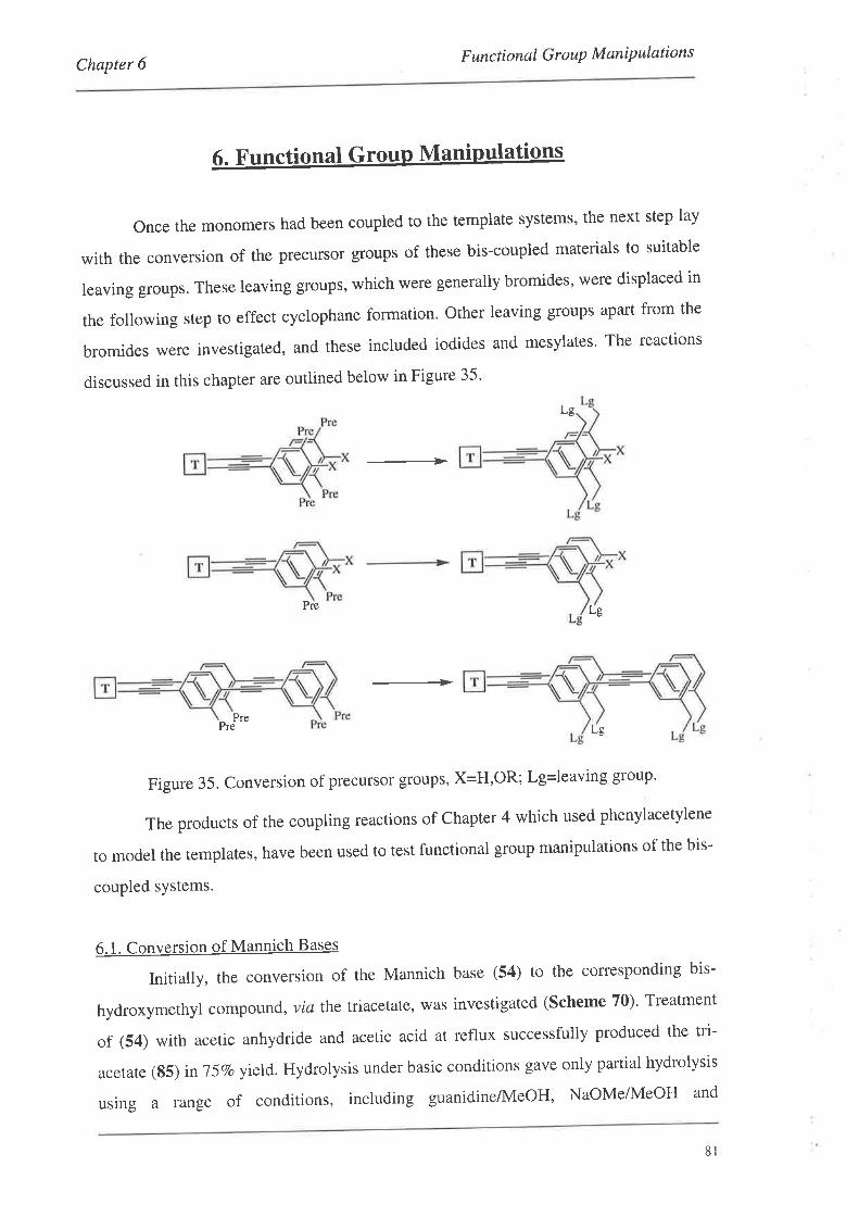
Chapter 6 F unct ional G ro uP M ani P ulation s
6. Functional Group Manipulations
Once the monomers had been coupled to the template systems' the next step lay
with the conversion of the precursor groups of these bis-coupled materials to suitable
leaving groups. These leaving groups, which were generally bromides, were displaced in
the following step to effect cyclophane formation' Other leaving groups apart from the
bromides were investigated, and these included iodides and mesylates' The reactions
discussed in this chapter are outlined below in Figure 35'
Lg
-1>
Pre Lg
-+Pre
Pre Lg
Figure35.Conversionofprecursorgroups'X=H'OR;Lg=leavinggroup'
The products of the coupling reactions of Chapter 4 which used phenylacetylene
to model the templates, have been used to test functional group manipulations of the bis-
coupled sYstems.
6.1. Conversion of Mannich Bases
Initially, the conversion of the Mannich base (54) to the corresponding bis-
hydroxymethyl compo lrrrd, via the triacetate, was investigated (Scheme 70)' Treatment
of (54) with acetic anhydride and acetic acid at reflux successfully produced the tri-
acetate (85) in 75Vo y\eld.Hydrolysis under basic conditions gave only partial hydrolysis
using a range of conditions, including guanidine/MeOH, NaOMe/MeOH and
81
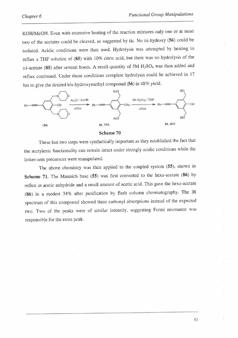
Chapter 6 F uncti onal G r o uP M aniP ulation s
KOFVMeOH. Even with extensive heating of the reaction mixtures only one or at most
two of the acetates could be cleaved, as suggested by tlc. No tri-hydroxy (56) could be
isolated. Acidic conditions were then used. Hydrolysis was attempted by heating to
reflux a THF solution of (85) with 107o citric acid, but there was no hydrolysis of the
tri-acetate (85) after several hours. A small quantity of 5M HzSO+ was then added and
reflux continued. Under these conditions complete hydrolysis could be achieved in 17
hrs to give the desired bis-hydroxymethyl compound (56) in 48Vo yield'
Ac2O / AcOH 5M H2SO1 / THF
PhOH
refluxreflux
(54) 85,757o 56'487o
Scheme 70
These last two steps were synthetically important as they established the fact that
the acetylenic functionality can remain intact under strongly acidic conditions while the
linker-arm precursors were manipulated.
The above chemistry was then applied to the coupled system (55), shown in
Scheme 71. The Mannich base (55) was first converted to the hexa-acetate (86) by
reflux in acetic anhydride and a small amount of acetic acid. This gave the hexa-acetate
(86) in a modest 347o aftet purification by flash column chromatography' The IR
spectrum of this compound showed three carbonyl absorptions instead of the expected
two. Two of the peaks were of similar intensity, suggesting Fermi resonance was
responsible for the extra Peak.
82
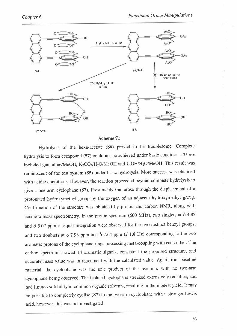
Chapter 6 F unctional Group M aniP ulations
OH
O:N Ac2o/ACOH/reflux
(ss) 86,347o
Basic or acidicconditions
2M H2SO4 / THF/reflux
OH
87,567o (57)
Scheme 71
Hydrolysis of the hexa-acetate (86) proved to be troublesome. Complete
hydrolysis to form compound (57) could not be achieved under basic conditions. These
included guanidine/IVIeOH, KzCO¡/HzOilvteOH and LiOH/H2O/MeOH. This result was
reminiscent of the test system (85) under basic hydrolysis. More success was obtained
with acidic conditions. However, the reaction proceeded beyond complete hydrolysis to
give a one-arm cyclophane (87). Presumably this arose through the displacement of a
protonated hydroxymethyl group by the oxygen of an adjacent hydroxymethyl group'
Confirmation of the structure was obtained by proton and carbon NMR, along with
accurate mass spectrometry. In the proton spectrum (600 MHz), two singlets at õ 4'82
and õ 5.07 ppm of equal integration were observed for the two distinct benzyl groups,
and two doublets at ô 7.93 ppm and õ7.64 ppm (J 1.8 Hz) corresponding to the two
aromatic protons of the cyclophane rings possessing meta-coupling with each other. The
carbon spectrum showed 14 aromatic signals, consistent the proposed structure, and
accurate mass value was in agreement with the calculated value. Apart from baseline
material, the cyclophane was the sole product of the reaction, with no two-arm
cyclophane being observed. The isolated cyclophane streaked extensively on silica, and
had limited solubility in common organic solvents, resulting in the modest yield. It may
be possible to completely cyclise (87) to the two-arm cyclophane with a stronger Lewis
acid, however, this was not investigated'
OH
83
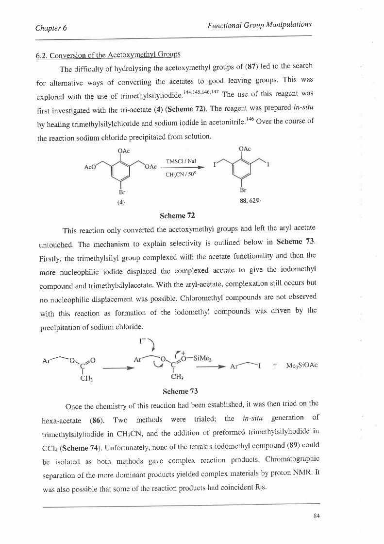
Chapter 6 F unc t i onal G r o uP M aniP ulation s
6.2. Conversion of the Acetoxymethyl Groups
The difficulty of hydrolysing the acetoxymethyl groups of (87) led to the search
for alternative ways of converting the acetates to good leaving groups' This was
explored with the use of trimethylsilyliodide.ta4't4s't46't47 The use of this reagent was
first investigated with the tri-acetate (4) (Scheme72)' The reagent was prepared in-situ
by heating trimethylsilylchloride and sodium iodide in acetonitrile.ra6 Over the course of
the reaction sodium chloride precipitated from solution'
TMSCI / Nat
cHjcN / 50o
Br
(4) 88,627o
Scheme 72
This reaction only converted the acetoxymethyl groups and left the aryl acetate
untouched. The mechanism to explain selectivity is outlined below in Scheme 73'
Firstly, the trimethylsilyl group complexed with the acetate functionality and then the
more nucleophilic iodide displaced the complexed acetate to give the iodomethyl
compound and trimethylsilylacetate. With the aryl-acetate, complexation still occurs but
no nucleophilic displacement was possible. Chloromethyl compounds are not observed
with this reaction as formation of the iodomethyl compounds was driven by the
precipitation of sodium chloride.
I
Ar^o\CH¡
Scheme 73
+ Me3SiOAc
CH¡
Once the chemistry of this reaction had been established, it was then tried on the
hexa-acetate (S6). Two methods were trialed; the in-situ generation of
trimethylsilyliodide in CH¡CN, and the addition of preformed trimethylsilyliodide in
ccl¿ (sche me74). unforrunately, none of the tetrakis-iodomethyl compound (89) could
be isolated as both methods gave complex reaction products' Chromatographic
separation of the more dominant products yielded complex materials by proton NMR' It
was also possible that some of the reaction products had coincident Rrs'
84
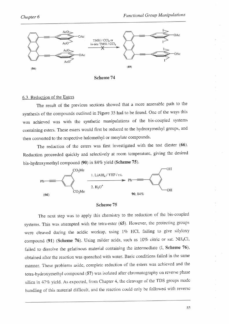
Chapter 6 F unctional G ro uP M aniP ulations
OAcTMSI / CCla or
in-situ TMSI / CCla
(8ó)
Scheme 74
6.3. Reduction of the Esters
The result of the previous sections showed that a more amenable path to the
synthesis of the compounds outlined in Figure 35 had to be found. One of the ways this
was achieved was with the synthetic manipulations of the bis-coupled systems
containing esters. These esters would first be reduced to the hydroxymethyl groups, and
then converted to the respective halomethyl or mesylate compounds'
The reduction of the esters was first investigated with the test diester (66)'
Reduction proceeded quickly and selectively at room temperature, giving the desired
bis-hydroxymethyl compound (90) in 84Vo yield (Scheme 75)'
OH
1. LiAlH4 / THF / r.t.
2. H3O+
(66) 9l,84Vo
Scheme 75
The next step was to apply this chemistry to the reduction of the bis-coupled
systems. This was attempted with the tetra-ester (65). However, the protecting groups
were cleaved during the acidic workup, using LVo HCl, failing to give silyloxy
compound (91) (Scheme 76). Using milder acids, such as l}Vo cittic or sat. NH¿CI,
failed to dissolve the gelatinous material containing the intermediate (I, Scheme 76),
obtained after the reaction was quenched with water. Basic conditions failed in the same
manner. These problems aside, complete reduction of the esters was achieved and the
tetra-hydroxymethyl compound (57) was isolated after chromatography on reverse phase
silica in 47Vo yield. As expected, from Chapter 4, fhrc cleavage of the TDS groups made
handling of this material difficult, and the reaction could only be followed with reverse
(E9)
Ph
85
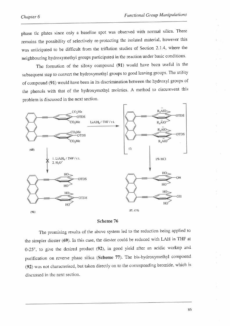
Chapter 6 F unc ti onal G r o uP M ani P ulation s
phase tlc plates since only a baseline spot was observed with normal silica' There
remains the possibility of selectively re-protecting the isolated material, however this
was anticipated to be difficult from the triflation studies of Section 2'l'4, where the
neighbouring hydroxymethyl groups participated in the reaction under basic conditions'
The formation of the siloxy compound (91) would have been useful in the
subsequent step to convert the hydroxymethyl groups to good leaving groups' The utility
of compound (91) would have been in its discrimination between the hydroxyl groups of
the phenols with that of the hydroxymethyl moieties. A method to circumvent this
problem is discussed in the next section.
CO2Me
LiAlll4/THFir.t.
OTDS
(6s) (r)
l. LiAIFI4 / THF / r.t.2. HrO*
l%o HCI
OH
OTDS
(el) 57,477o
Scheme 76
The promising results of the above system led to the reduction being applied to
the simpler diester (69). In this case, the diester could be reduced with LAH in THF at
O-25", to give the desired product (92), in good yield after an acidic workup and
purification on reverse phase silica (Scheme 77). The bis-hydroxymethyl compound
(92) was not characterised, but taken directly on to the corresponding bromide, which is
discussed in the next section.
OH
86
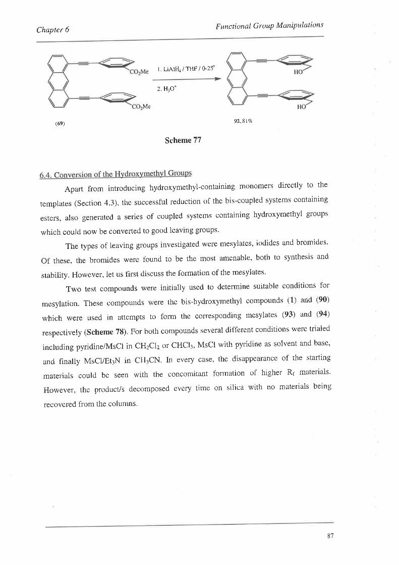
Chapter 6 Functional GrouP MoniP ulations
l. LiAIFI4 / THF / o-2f
2. HjO+
Me
(6e) 92,817o
Scheme 77
Apart from introducing hydroxymethyl-containing monomers directly to the
templates (Section 4.3), the successful reduction of the bis-coupled systems containing
esters, also generated a series of coupled systems containing hydroxymethyl groups
which could now be converted to good leaving groups'
The types of leaving groups investigated were mesylates, iodides and bromides'
Of these, the bromides were found to be the most amenable, both to synthesis and
stability. However, let us first discuss the formation of the mesylates'
Two test compounds were initially used to determine suitable conditions for
mesylation. These compounds were the bis-hydroxymethyl compounds (1) and (90)
which were used in attempts to form the corresponding mesylates (93) and (94)
respectively (Scheme 78). For both compounds several different conditions were trialed
including pyridine/Mscl in cHzclz or cHCl3, Mscl with pyridine as solvent and base,
and finally MsClÆt¡N in CH¡CN. ln every case, the disappearance of the starting
materials could be seen with the concomitant formation of higher R¡ materials'
However, the product/s decomposed every time on silica with no materials being
recovered from the columns.
8',7
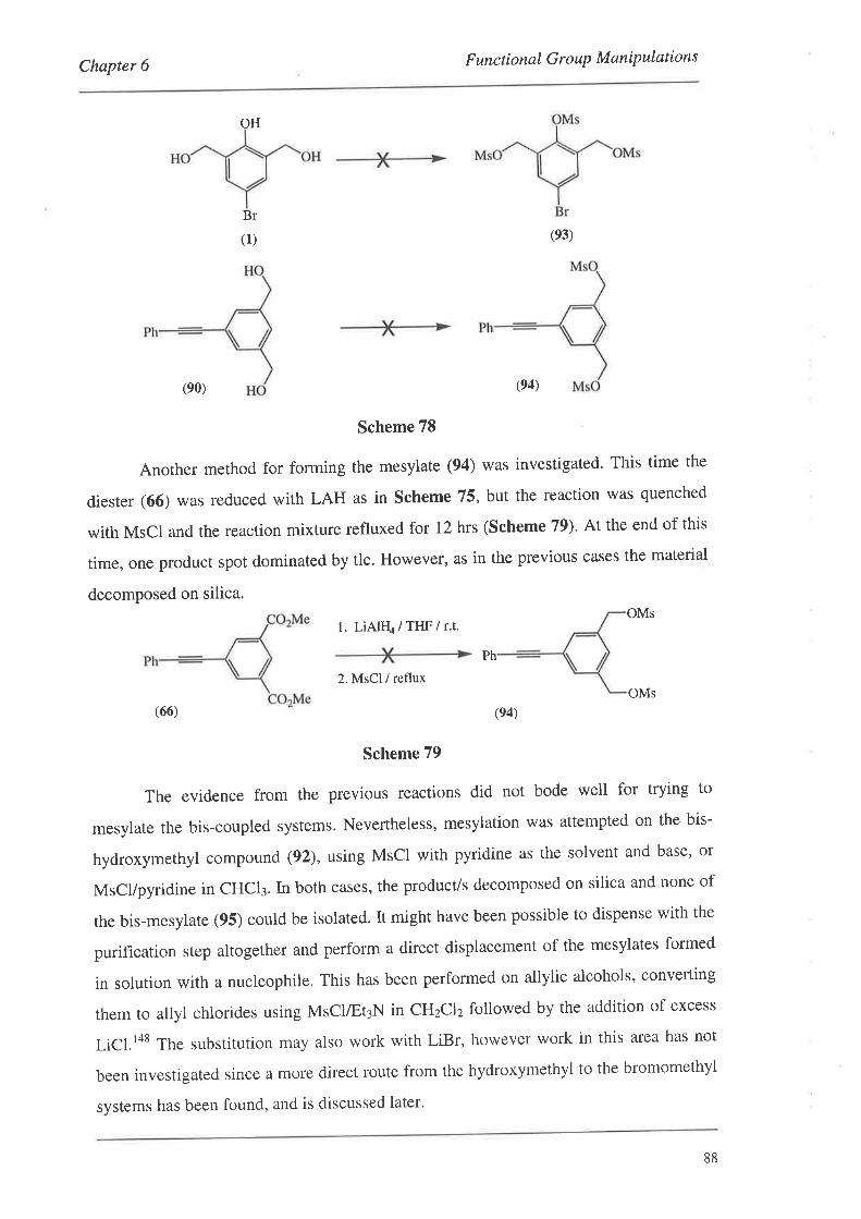
Chapter 6 F unctional G r o uP M ani P ulation s
OH
Br
(1) (e3)
(e0) (e4)
Scheme 78
Another method for forming the mesylate (94) was investigated' This time the
diester (66) was reduced with LAH as in scheme 75, but the reaction was quenched
with MsCl and the reaction mixture refluxed for 12 hrs (Scheme 79). At the end of this
time, one product spot dominated by tlc. However, as in the previous cases the material
decomposed on silica.
l. LiAlH4/THF/r.t.
Ph
2. MsCl / reflux
(66)
Scheme 79
The evidence from the previous reactions did not bode well for trying to
mesylate the bis-coupled systems. Nevertheless, mesylation was attempted on the bis-
hydroxymethyl compound (92), using MsCl with pyridine as the solvent and base' or
MsCl/pyridine in CHCI3. In both cases, the product/s decomposed on silica and none of
the bis-mesylate (95) could be isolated. It might have been possible to dispense with the
purification step altogether and perform a direct displacement of the mesylates formed
in solution with a nucleophile. This has been performed on allylic alcohols, converting
them to allyl chlorides using MsclÆtrN in cHzclz followed by the addition of excess
LiCl.l4s The substitution may also work with LiBr, however work in this area has not
been investigated since a more direct route from the hydroxymethyl to the bromomethyl
systems has been found, and is discussed later'
OMs
OMs
(e4)
88
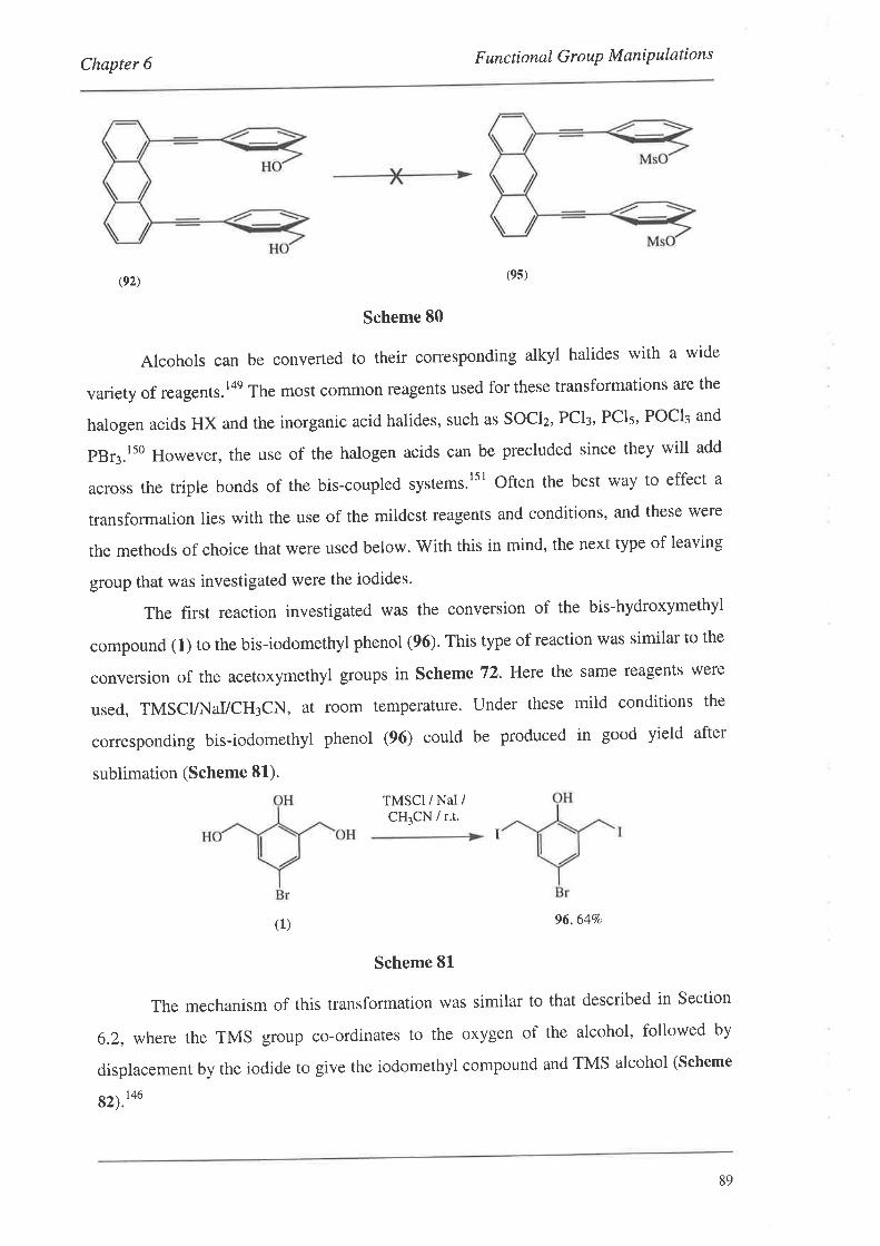
Chapter 6 F unc ti onal G r o uP M aniP ulation s
(e2) (9s)
Scheme 80
Alcohols can be converted to their corresponding alkyl halides with a wide
variety of reagents.'on Th" most common reagents used for these transformations are the
halogen acids HX and the inorganic acid halides, such as Socl2, Pcl¡, PCls, POCI3 and
pBr3.ls0 However, the use of the halogen acids can be precluded since they will add
across the triple bonds of the bis-coupled systems.lsl Often the best way to effect a
transformation lies with the use of the mildest reagents and conditions, and these were
the methods of choice that were used below. With this in mind, the next type of leaving
group that was investigated were the iodides.
The first reaction investigated was the conversion of the bis-hydroxymethyl
compound (1) to the bis-iodomethyl phenol (96). This type of reaction was similar to the
conversion of the acetoxymethyl groups in scheme 72. Hete the same reagents were
used, TMSCI/Ir{aVCH3CN, at room temperature. Under these mild conditions the
corresponding bis-iodomethyl phenol (96) could be produced in good yield after
sublimation (Scheme 81).
TMSCI / NaI /CH,CN / r.t.
(1) 96,64Vo
Scheme 81
The mechanism of this transformation was similar to that described in Section
6.2, where the TMS group co-ordinates to the oxygen of the alcohol, followed by
displacement by the iodide to give the iodomethyl compound and TMS alcohol (Scheme
82).'ou
I
89
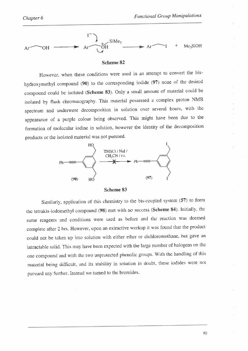
Chapter 6 F un c t ional G r o uP M aniP ulat ion s
SiMej
Ar^oH + Ar^I + Me3sioH
Scheme 82
However, when these conditions were used in an attempt to convert the bis-
hydroxymethyl compound (90) to the corresponding iodide (97) none of the desired
compound could be isolated (Scheme 83)' Only a small amount of material could be
isolated by flash chromatography. This material possessed a complex proton NMR
spectrum and underwent decomposition in solution over several hours, with the
appearance of a purple colour being observed. This might have been due to the
formation of molecular iodine in solution, however the identity of the decomposition
products or the isolated material was not pursued.
TMSCI / NaI /CH3CN / r.t.
_)Þ ph
(e0) (e7)
Scheme 83
Similarly, application of this chemistry to the bis-coupled system (57) to form
the tetrakis-iodomethyl compound (9S) met with no success (Scheme 84)' Initially' the
same reagents and conditions were used as before and the reaction was deemed
complete after 2 hrs. However, upon an extractive workup it was found that the product
could not be taken up into solution with either ether or dichloromethane, but gave an
intractable solid. This may have been expected with the large number of halogens on the
one compound and with the two unprotected phenolic groups. V/ith the handling of this
material being difficult, and its stability in solution in doubt, these iodides were not
pursued any further. Instead we turned to the bromides'
90
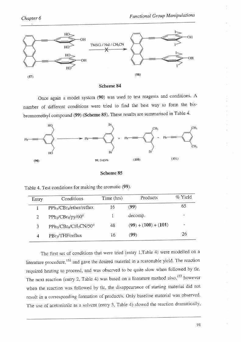
Chapter 6 F unc tional Gr o uP M aniP ulation s
TMSCIiNal/CH3CN
OH
(sz)
Scheme 84
Once again a model system (90) was used to test reagents and conditions' A
number of diff'erent conditions were tried to find the best way to form the bis-
bromomethyl compound (99) (Scheme 85). These results are summarised in Table 4'
Br
OH
(e8)
++
(e0) 99,0-65To
Scheme 85
Table 4. Test conditions for making the aromatic (99)'
B
(100) (r01)
Conditions Time (hrs) Products Vo YieldEntry
1 PPh¡ lCBr¿,lether/reflux
2 PPh¡/CBry'py160"
3 PPh¡lCBrqlCHtCN/sO'
4 PBr3/THF/reflux
(ee)
decomp.
(9e)+(100)+(101)
(ee)
T6
1
48
16
65
26
The first set of conditions that were tried (entry l,Table 4) were modelled on a
literature procedure,l52 and gave the desired material in a reasonable yield' The reaction
required heating to proceed, and was observed to be quite slow when followed by tlc'
The next reaction (entry 2, Table 4) was based on a literature method also,l53 however
when the reaction was followed by tlc, the disappearance of starting material did not
result in a corresponding formation of product/s. Only baseline material was observed'
The use of acetonitrile as a solvent (entry 3, Table 4) slowed the reaction dramatically,
9I
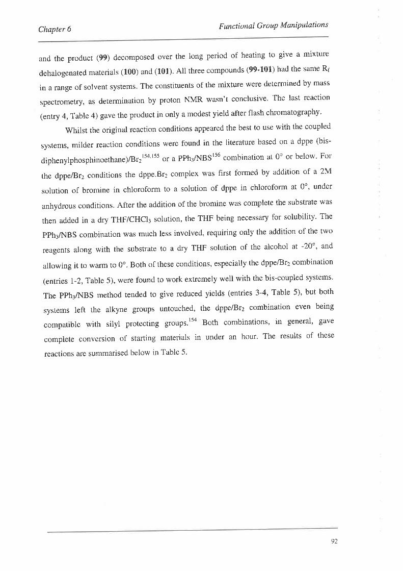
Chapter 6 F unctional G r o uP M ani P ulations
and the product (99) decomposed over the long period of heating to give a mixture
dehalogenated materials (100) and (101)' All three compounds (99'101) had the same R¡
in a range of solvent systems. The constituents of the mixture were determined by mass
spectrometfy, as determination by proton NMR wasn't conclusive' The last reaction
(entry 4, Table 4) gave the product in only a modest yield after flash chromatography'
V/hilst the original reaction conditions appeared the best to use with the coupled
systems, milder reaction conditions were found in the literature based on a dppe (bis-
diphenylphosphinoethane)/Br2rs4'rss or a PPh¡/NBSr56 combination at 0o or below' For
the dppe/Br2 conditions the dppe.Br2 cornplex was first formed by addition of a 2M
solution of bromine in chloroform to a solution of dppe in chloroform at 0o' under
anhydrous conditions. After the addition of the bromine was complete the substrate was
then added in a dry THF/CHCI¡ solution, the THF being necessary for solubility' The
PPh3/NBS combination was much less involved, requiring only the addition of the two
reagents along with the substrate to a dry THF solution of the alcohol at -20o, and
allowing it to warm to 0". Both of these conditions, especially the dppelBrz combination
(entries I-2,Table 5), were found to work extremely well with the bis-coupled systems'
The PPh¡A{BS method tended to give reduced yields (entries 3-4, Table 5), but both
systems left the alkyne groups untouched, the dppe/Brz combination even being
compatible with silyl protecting groups.tto Both combinations, in general' gave
complete conversion of starting materials in under an hour' The results of these
reactions are summarised below in Table 5'
92
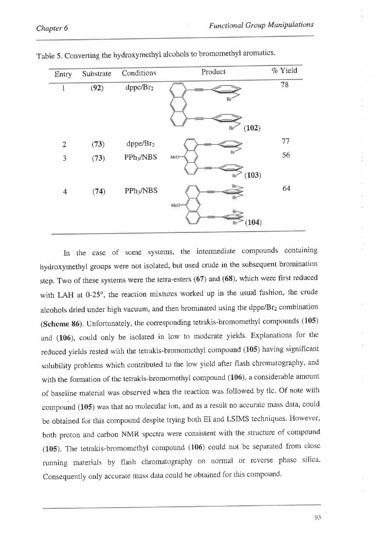
Chapter 6 F unctional Gro uP M aniPulations
Table 5. Converting the hydroxymethyl alcohols to bromomethyl aromatics'
Entry Substrate Conditions Product
(92) dpPe/Br2
Vo Yield
18I
2
5
(73)
(73)
dppelB12
PPh3/NBS
(102)
(103)
77
56
644 (74) PPh¡A{BS
In the case of some systems, the intermediate compounds containing
hydroxymethyl groups were not isolated, but used crude in the subsequent bromination
step. Two of these systems were the tetra-esters (67) and (68), which were first reduced
with LAH at 0-25", the reaction mixtures worked up in the usual fashion, the crude
alcohols dried under high vacuum, and then brominated using the dppe/Brz combination
(Scheme 86). Unfortunately, the corresponding tetrakis-bromomethyl compounds (105)
and (106), could only be isolated in low to moderate yields. Explanations for the
reduced yields rested with the tetrakis-bromomethyl compound (105) having significant
solubility problems which contributed to the low yield after flash chromatography, and
with the formation of the tetrakis-bromomethyl compound (106), a considerable amount
of baseline material was observed when the reaction was followed by tlc. Of note with
.o-pound (105) was that no molecular ion, and as a result no accurate mass data, could
be obtained for this compound despite trying both EI and LSIMS techniques. However,
both proton and carbon NMR spectra were consistent with the structure of compound
(105). The tetrakis-bromomethyl compound (106) could not be separated from close
running materials by flash chromatography on normal or feverse phase silica'
Consequently only accurate mass data could be obtained for this compound'
(104)
93
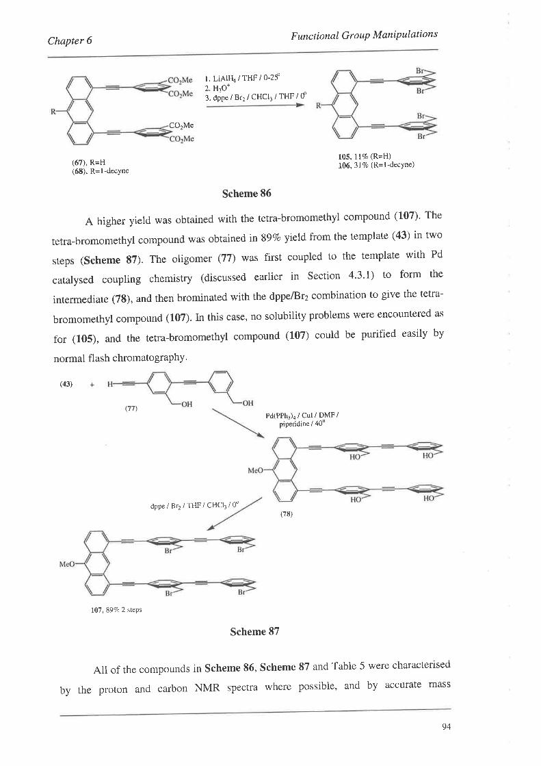
F uncti onal G ro uP M ani P ulati onsChapter 6
l. LiAlru/THF/0-2f2. H3O+
3. dipe / Br2 / CHCI3 / THF / d
CO2Me
(67), R=H(68), R=l-decyne
105, llTo (R=H)106, 3l%o (R= I -decYne)
Scheme 86
A higher yield was obtained with the tetra-bromomethyl compound (107)' The
tetra-bromomethyl compound was obtainedinSgVo yield from the template (43) in two
sreps (Scheme 87). The oligomer (77) was first coupled to the template with Pd
catalysed coupling chemistry (discussed earlier in Section 4'3'l) to form the
intermediate (78), and then brominated with the dppe/Br2 combination to give the tetra-
bromomethyl compound (107). In this case, no solubility problems were encountered as
for (105), and the tetra-bromomethyl compound (107) could be purified easily by
normal flash chromatography'
(43) +
(77)Pd(PPh1)4 / Cul / DJ\'[F /
piperidine i 40"
dppe / Br2 / TIIF / CHCI3 / 0'
107, 897c 2 steps
Scheme 87
All of the compounds in scheme 86, Scheme 87 and Table 5 were characterised
by the proton and carbon NMR spectra where possible, and by accurate mass
(78)
94

Chapter 6 F unctional G r o up M aniP ulat i on s
spectrometry (except for compound (105)). The accurate mass data generally gave good
correlations between the observed and predicted mass values. Similarly, good
correlations were observed between the observed and predicted isotope pattern of the
molecular ions. These distinctive patterns are due to the two isotopes of bromine, TeBr
and srBr, which have natural abundances of 49.5 and 50.57o respectively' Examples of
the isotope distribution patterns are shown below for (107) in Graph I and for (102) in
Graph 2. On occasion the formation of molecular ions could not be observed using
electron-impact or electrospray techniques with the bis-coupled systems. However, this
problem was generally overcome using liquid secondary ionisation mass spectrometry
(LS1¡4S). The issue of producing sufficient quantities of molecular ions relative to
background noise, may explain why there are slight deviations between the observed
and predicted values in Graphs 1 and 2. The isotope patterns were generated using the
program "Isotope Pattern Calculator Version I.6.4".
, Predicted
I Experimental
Graph L The predicted and experimental isotope patterns for C51H32Br+O (107)
. Predicted
I Experirnental
Glaph 2. The predicted and experimental isotope patterns for C:zHzoBrz Q02)
100
80
60
40
20
0
o0)tr
@o,
mlz
Âl(r)çlr)(oó@co@@o)o)oo)o)(OF-@O)ON l'.- l'.- t'- @ó¡o)O)O)o)
C\j (fj t rO (O l.-(o(o@(o@(()rf)tr)lf)t.r)roro
mlz
10080604020
0
U'L(¡)
=
95
Chapter 6 F unctional G r o uP M aniP ulation s
6.5. Summary
The results discussed in this chapter have shown that the conversion of the
precursor groups of the bis-coupled systems to 'good' leaving groups was possible in
the form of bromides. Other leaving groups such as mesylates and iodides were found to
have limited stability in solution. Nevertheless, a series of bis-coupled systems were
transformed into systems suitable for cyclophane formation by displacement of the alkyl
bromides with a variety of nucleophiles. These reactions are discussed next in Chapter
7
96
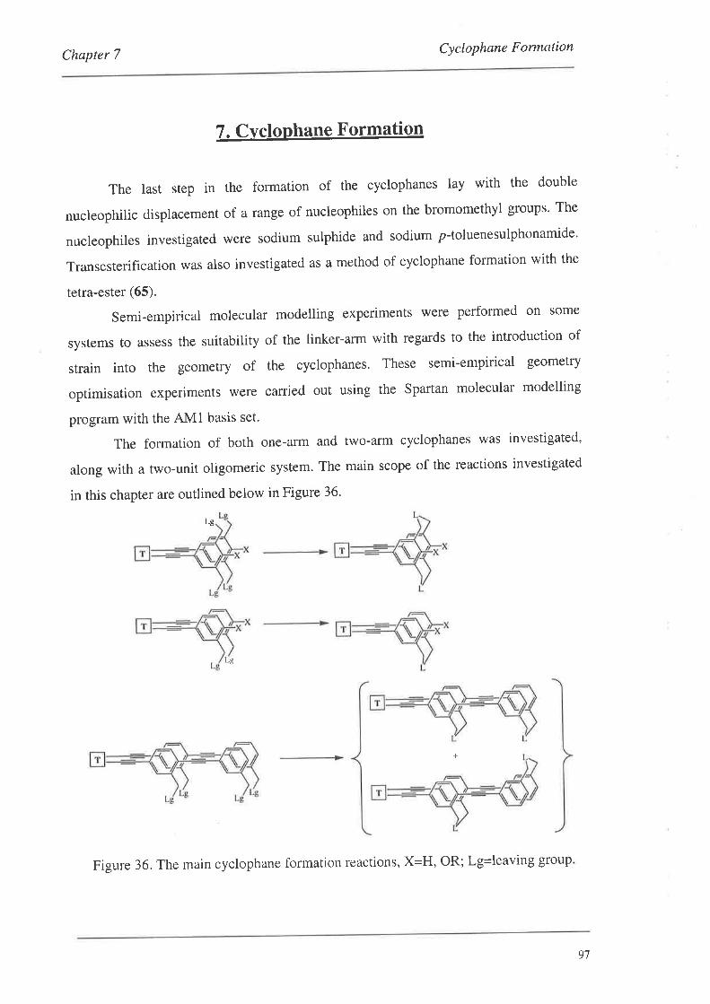
Chapter 7 Cyclophane Formation
7. Cvclophane Formation
The last step in the formation of the cyclophanes lay with the double
nucleophilic displacement of a range of nucleophiles on the bromomethyl groups' The
nucleophiles investigated were sodium sulphide and sodium p-toluenesulphonamide'
Transesterification was also investigated as a method of cyclophane formation with the
tetra-ester (65).
Semi-empirical molecular modelling experiments were performed on some
systems to assess the suitability of the linker-arm with regards to the introduction of
strain into the geometry of the cyclophanes. These semi-empirical geometry
optimisation experiments were carried out using the Spartan molecular modelling
program with the AMl basis set.
The formation of both one-arm and two-arm cyclophanes was investigated'
along with a two-unit oligomeric system. The main scope of the reactions investigated
in this chapter are outlined below in Figure 36'
Lg
Lg
+
Figure 36. The main cyclophane formation reactions, X=H, OR; Lg-leaving group
97
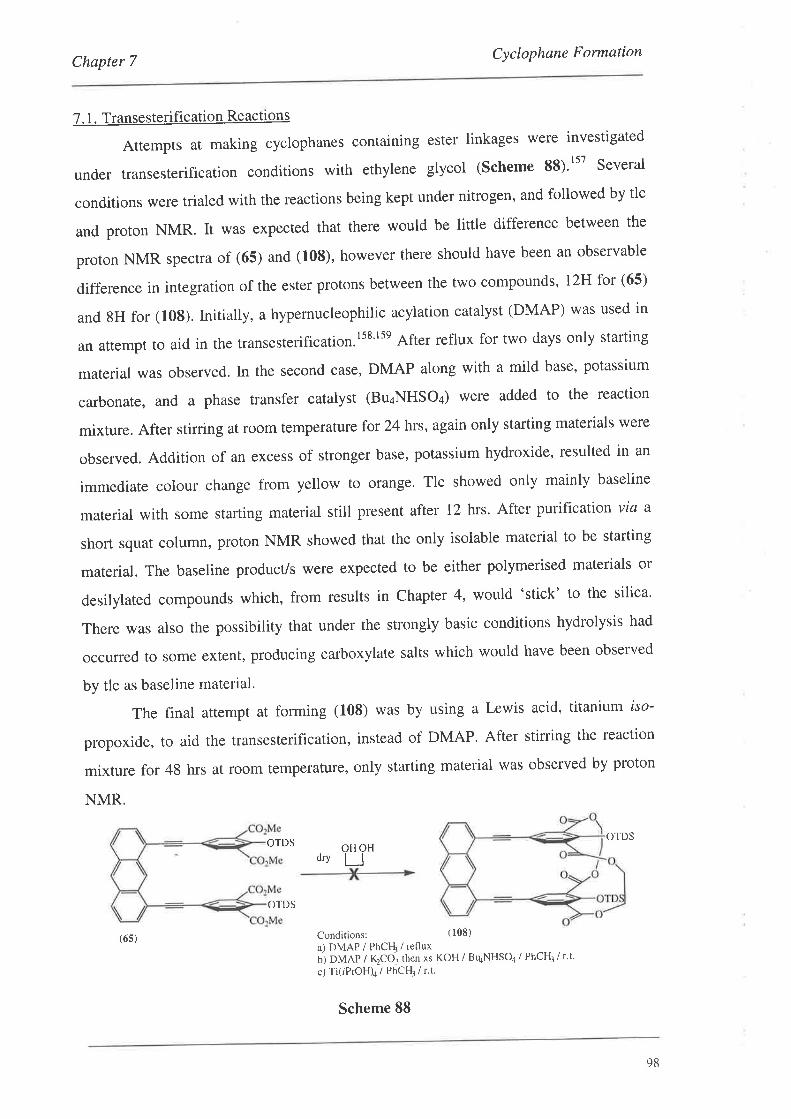
Chapter 7 Cyclophane Formation
7. 1. Transesterification Reactions
Attempts at making cyclophanes containing ester linkages were investigated
under transesterification conditions with ethylene glycol (Scheme 88)'ttt Several
conditions were trialed with the reactions being kept under nitrogen, and followed by tlc
and proton NMR. It was expected that there would be little difference between the
proton NMR spectra of (65) and (108), however there should have been an observable
difference in integration of the ester protons between the two compounds , Iz}J for (65)
and 8H for (108). lnitially, a hypernucleophilic acylation catalyst (DMAP) was used in
an attempt to aid in the transesterification.lss'lse Aftet reflux for two days only starting
material was observed. tn the second case, DMAP along with a mild base, potassium
carbonate, and a phase transfer catalyst (Bg4NHSOa) were added to the reaction
mixture. After stirring at room temperature for 24 hrs, again only starting materials were
observed. Addition of an excess of stronger base, potassium hydroxide, resulted in an
immediate colour change from yellow to orange. Tlc showed only mainly baseline
material with some starting material still present after 12 hrs. After purificaiion via a
short squat column, proton NMR showed that the only isolable material to be starting
material. The baseline producls were expected to be either polymerised materials or
desilylated compounds which, from results in Chaptet 4, would 'stick' to the silica'
There was also the possibility that under the strongly basic conditions hydrolysis had
occurred to some extent, producing carboxylate salts which would have been observed
by tlc as baseline material.
The final attempt at forming (108) was by using a Lewis acid, titanium iso-
propoxide, to aid the transesterification, instead of DMAP. After stirring the reaction
mixture for 48 hrs at room temperatufe, only starting material was observed by proton
NMR.
OTDSOTDS
d.yOHOHLI
Con¿itions: (108)
a) DMAP / PhCFI / refluxul oltnp / K2co3 then xs KoH / BqNHSoa / PhCH¡ / r't'
c) Ti(iPrOH)¿ / PhCH¡ / r.t.
(6s)
OTDS
Scheme 88
98
Chapter 7Cyclophane Formation
7.2. Formation of the Thiacyclophanes
The next method investigated for forming cyclophanes was the double
nucleophilic displacement of the sulphide anion on the bromomethyl compounds
described in Chapter 6 to form thiacyclophanes' The results of these reactions are
presented below in Table 6.
The first reaction investigated was with the formation of cyclophane (109)'
Initially, a solution of sodium sulphide was added to a solution of the bis-bromomethyl
compound (102) in DMF (entry 1, Table 6)' After stirring at room temperature for 3 hrs
the reaction underwent an extractive workup and purification by reverse phase
chromarography to afford the thiacyclophane (109) in 267o yield' A higher yield was
obtained when sodium sulphide adsorbed on alumina (2.5 mmol/g)160 was used (entry 2'
Table 6), although an additional2 equivalents of sulphide were added after 3 hrs since
starting material was still present by tlc. using the adsorbed sulphide reagent in
conjunction with a dichloromethane/ethanol (5:1) solvent system eliminated the
extractive workup, as on completion, the reaction mixture was simply filtered'
concentrated and purified by chromatography (entries 2-8, Table 6)' Purification was
best attained by using reverse phase silica for thiacyclophane (109)' however'
chromatography on normal silica was adequate for the purification of thia- and dithia-
cyclophanes (L10) and (111), with some streaking observed due to limited solubility in
the solvent systems. Only a modest increase in yield was observed by using high
dilution techniques with the formation of thiacyclophane (110) (entries 3 and 4, Table
6). It was necessary to add an extra 3 equivalents of sulphide with the high dilution case,
as starting material was still present by tlc an hour after addition of the bis-bromomethyl
compound was complete. without high dilution (entry 4, Table 6), the 3 equivalents
were sufficient and the reaction was complete in t hour. This suggests, along with entry
2, thatthe adsorbed reagent starts to decompose after approximately an hour in solution'
99
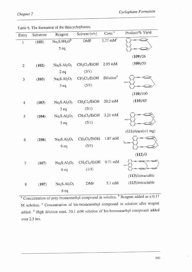
Chapter 7
Table 6. The formation of the thiacyclophanes
Solvent (v/v) Conc.o
Cyclophane Formation
Prcductl%o YieldEntry Substrate Reagent
1 (102) NazS gHzob DMF 1.77 mM'
2 (102)
3 (103)
4 (103)
5 (104)
6 (106)
7 (107)
8 (107)
5eq
NazS.AlzO¡
2eq
NazS.AlzO¡
3eq
CHzClzÆtOH
(5/1)
CHzClzÆtOH
(s/1)
2.95 mM
Dilutiond
2O.2mM.
3.21 mM
(I0e)t26
(10eys0
(110)/1oo
(110y8s
(111)/trace(<l mg)
(112)/0
(113)/intractable
(113)/intractable
NazS.AlzOs
3eq
NazS.AlzOl
5eq
CHzClzÆtOH
(s/1)
CHzClzÆtOH
(s/1)
NazS.AlzO¡
6eq
CHzClzÆtOH 1.87 mM
(si 1)
NazS.AlzOr
6eq
CHzClzÆtOH 0.71mM
(1/1)
NazS.AlzO¡
6eq
DMF 5.1mM
o Concentration of poly-bromomethyl compound in solution. b Reagent added as a 0.17
M solution. ' concentration of bis-bromomethyl compound in solution after reagent
added. d High dilution used, 10.1 mM solution of bis-bromomethyl compound added
over 2.5 hrs
r00
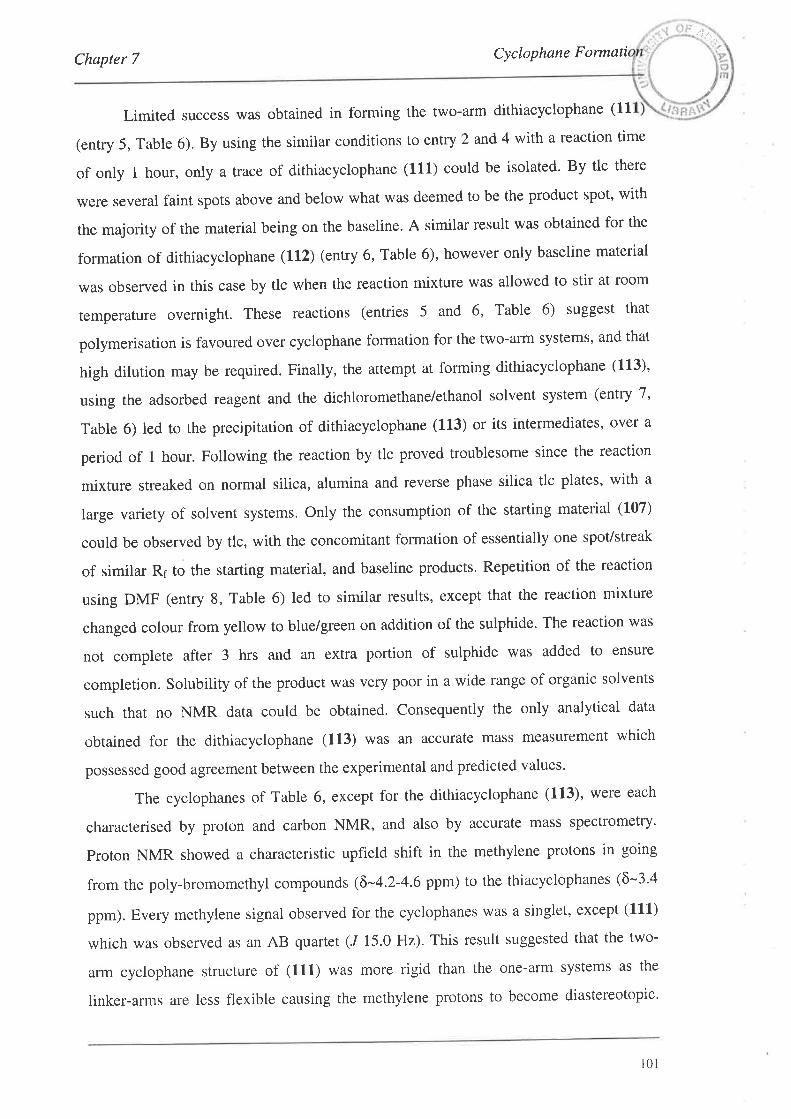
/\þ
Chapter 7 Cyclophane Formati
Limited success was obtained in forming the two-arm dithiacyclophane (11
(entry 5, Table 6). By using the similar conditions to entry 2 and 4 with a reaction time
of only t hour, only a rrace of dithiacyclophane (111) coutd be isolated. By tlc there
were several faint spots above and below what was deemed to be the product spot' with
the majority of the material being on the baseline. A similar result was obtained for the
formation of dithiacyclophane (112) (entry 6, Table 6), however only baseline material
was observed in this case by tlc when the reaction mixture was allowed to stir at room
temperature overnight. These reactions (entries 5 and 6, Table 6) suggest that
polymerisation is favoured over cyclophane formation for the two-arm systems, and that
high dilurion may be required. Finally, the attempt at forming dithiacyclophane (1'13)'
using the adsorbed reagent and the dichloromethane/ethanol solvent system (entry 7,
Table 6) led to the precipitation of dithiacyclophane (113) or its intermediates, over a
period of t hour. Following the reaction by tlc proved troublesome since the reaction
mixture streaked on normal silica, alumina and reverse phase silica tlc plates, with a
large variety of solvent systems. Only the consumption of the starting material (107)
could be observed by tlc, with the concomitant formation of essentially one spot/streak
of similar Rr to the starting material, and baseline products. Repetition of the reaction
using DMF (entry 8, Table 6) led to similar results, except that the reaction mixture
changed colour from yellow to blue/green on addition of the sulphide. The reaction was
not complete after 3 hrs and an extra portion of sulphide was added to ensure
completion. Solubility of the product was very poor in a wide range of organic solvents
such that no NMR data could be obtained. Consequently the only analytical data
obtained for the dithiacyclophane (113) was an accurate mass measurement which
possessed good agreement between the experimental and predicted values'
The cyclophanes of Table 6, except for the dithiacyclophane (113), were each
characterised by proton and carbon NMR, and also by accurate mass spectrometry'
proton NMR showed a characteristic upfield shift in the methylene protons in going
from the poly-bromomethyl compounds (õ-4.2-4.6 ppm) to the thiacyclophanes (ô-3.4
ppm). Every methylene signal observed for the cyclophanes was a singlet, except (111)
which was observed as an AB quartet (/ 15.0 Hz). This result suggested that the two-
arm cyclophane structure of (111) was more rigid than the one-arm systems as the
linker-arms are less flexible causing the methylene protons to become diastereotopic'
101
Chapter 7 Cyclophane Formation
The one-arm thia- and aza-cyclophanes (of Section 7'3), both undergo fast rotations on
the NMR timescale about the aryl-alkyne bonds leading to a time-average signal (a
singlet) being observed for the methylene protons. At low temperature one would expect
a slowing of these rotations, and consequently an appearance of an AB quartet' as the
each of the protons become trapped in a distinct chemical environment'
(ut)
-
H
Fast
Figure 37. The rigid two-arm cyclophane (1,11), and the more flexible one-arm
cYcloPhanes.
A variable temperature proton NMR experiment was performed in which the
proton spectrum of (110) was obtained at 5o intervals between 25o and -55o in CDCI¡
(mp -64"). The results of this experiment showed no splitting or even broadening of the
benzylic protons as the temperature was lowered to -55o. The benzylic protons were
observed as a sharp singlet at ô 3.43 ppm. The experiment could have been repeated
with a solvent possessing a lower melting point than CDCI3' For example, d¿-MeOH
and ds-THF have melting points of -98' and -108o respectively' However, since no
broadening was observed at -55' in CDCI3, very little difference, if any, would be
expected in the proton spectrum by reducing the temperature a further 30o'
Consequently, the experiment was not repeated using a different solvent'
7.3. Formation of the Azacyclophanes
Formation of cyclophanes other than thiacyclophanes was investigated with the
formation of azacyclophane (114) (Scheme 89). A modified literatule procedure was
used in which 1.5 equivalents of TosNHNa and the bis-bromomethyl compound (103)
were stirred together in DMF under nitrogen with heating.'61 The reaction was complete
in I hour. An extractive workup followed by chromatography on normal silica yielded
t02
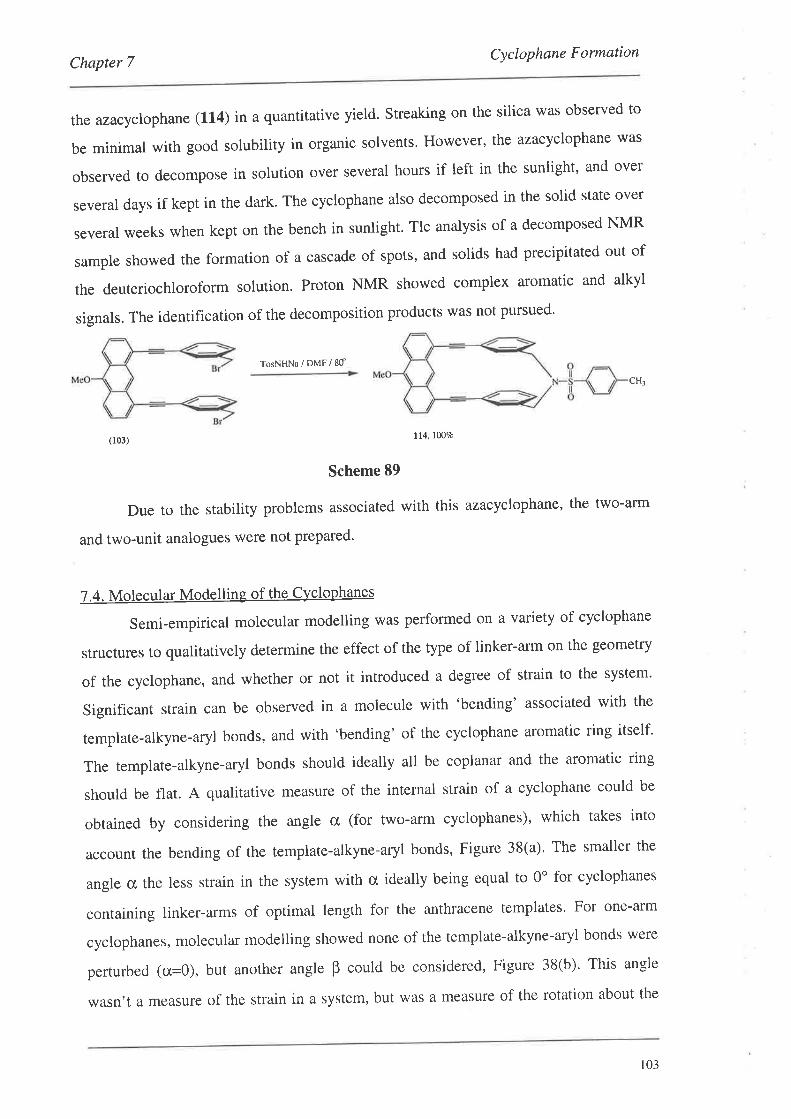
Chapter 7Cyclophane Formation
the azacyclophane (114) in a quantitative yield. Streaking on the silica was observed to
be minimal with good solubility in organic solvents' However' the azacyclophane was
observed to decompose in solution over several hours if left in the sunlight, and over
several days if kept in the dark. The cyclophane also decomposed in the solid state over
several weeks when kept on the bench in sunlight' Tlc analysis of a decomposed NMR
sample showed the formation of a cascade of spots, and solids had precipitated out of
the deuteriochloroform solution. Proton NMR showed complex aromatic and alkyl
signals. The identification of the decomposition products was not pursued'
TosNHNa/DMF/8d
CH¡
(103) ll4. l0O7o
Scheme 89
Due to the stability problems associated with this azacyclophane, the two-arm
and two-unit analogues were not prepared'
7.4. Molecular Modelling of the Cyclophanes
Semi-empirical molecular modelling was performed on a variety of cyclophane
structures to qualitatively determine the effect of the type of linker-arm on the geometry
of the cyclophane, and whether or not it introduced a degree of strain to the system'
Significant strain can be observed in a molecule with 'bending' associated with the
template-alkyne-aryl bonds, and with 'bending' of the cyclophane aromatic ring itself'
The template-alkyne-aryl bonds should ideally all be coplanar and the aromatic ring
should be flat. A qualitative measure of the internal strain of a cyclophane could be
obtained by considering the angle cr (for two-arm cyclophanes), which takes into
account the bending of the template-alkyne-aryl bonds, Figure 3S(a)' The smaller the
angle cx, the less strain in the system with cr ideally being equal to 0" for cyclophanes
containing linker-arms of optimal length for the anthracene templates' For one-arm
cyclophanes, molecular modelling showed none of the template-alkyne-aryl bonds were
perturbed (ü=0), but another angle B could be considered, Figure 38(b)' This angle
wasn't a measure of the strain in a system, but was a measure of the rotation about the
103
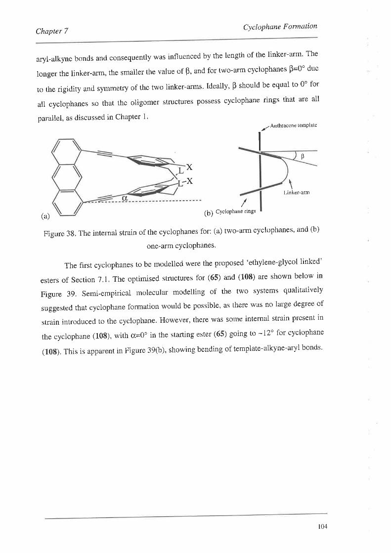
Chapter 7Cyclophane Formation
aryl-alkyne bonds and consequently was influenced by the length of the linker-arm' The
longer the linker-arm, the smaller the value of B, and for two-arm cyclophanes Þ=0" due
to the rigidity and symmetry of the two linker-arms. Ideally' B should be equal to 0" for
all cyclophanes so that the oligomer structures possess cyclophane rings that are all
parallel, as discussed in Chapter 1'
VAnrhracene temPlate
B
L X
-XLinker-arm
(a)
/(þ) CYcloPhane rings
Figure 38. The internal strain of the cyclophanes for: (a) two-arm cyclophanes' and (b)
one-arm cYcloPhanes.
The first cyclophanes to be modelled were the proposed 'ethylene-glycol linked'
esters of Section 7.1. The optimised structures for (65) and (108) are shown below in
Figure 39. Semi-empirical molecular modelling of the two systems qualitatively
suggested that cyclophane formation would be possible, as there was no large degree of
strain introduced to the cyclophane. However, there was some internal strain present in
the cyclophane (|08), with ct=Qo in the starting ester (65) going to -12" for cyclophane
(10S). This is apparent in Figure 39(b), showing bending of template-alkyne-aryl bonds'
r04
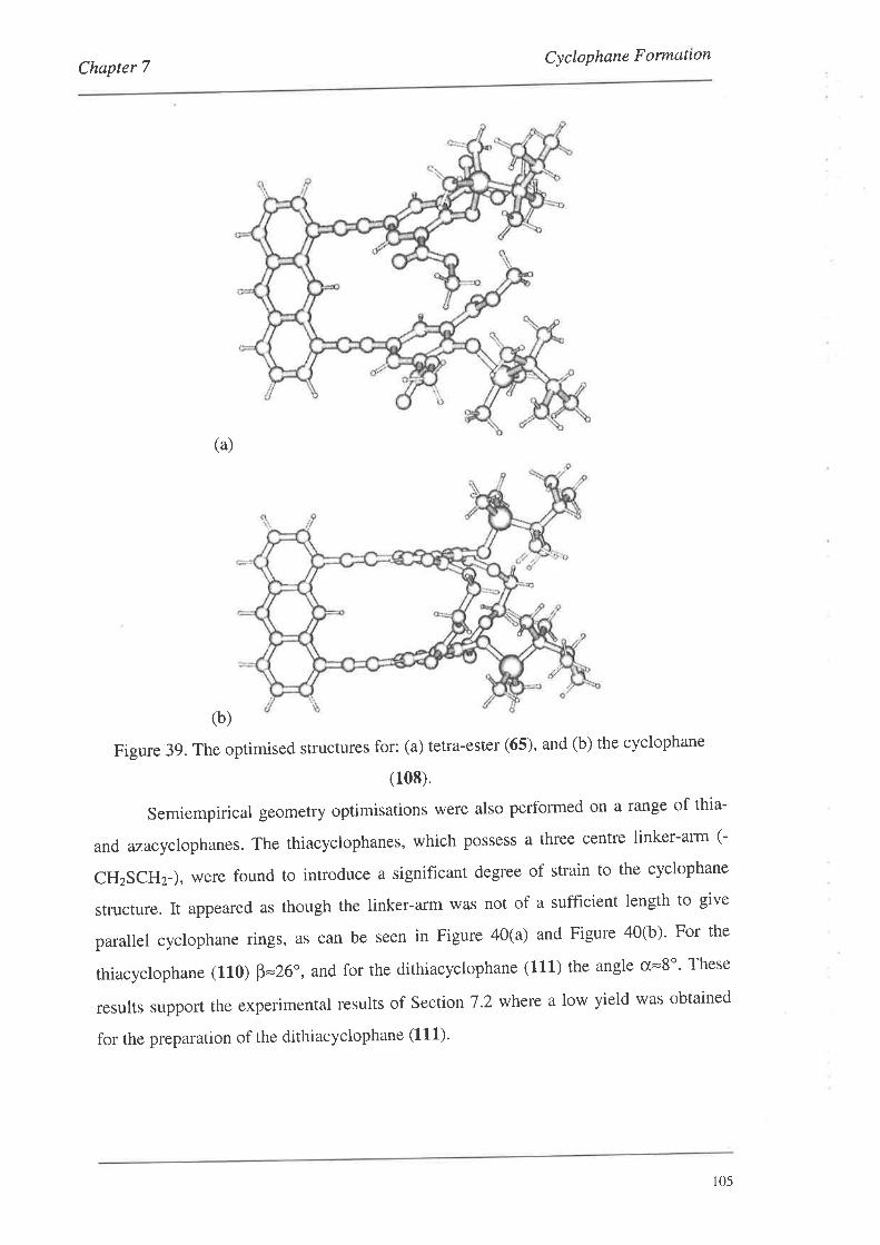
Cyclophane FormationChapter 7
(a)
(b)
Figure 39. The optimised structures for: (a) tetra-ester (65), and (b) the cyclophane
(108).
Semiempirical geometry optimisations were also performed on a range of thia-
and azacyclophanes. The thiacyclophanes, which possess a three centre linker-arm (-
CHzSCHz-), were found to introduce a significant degree of strain to the cyclophane
structure. It appeared as though the linker-arm was not of a sufficient length to give
parallel cyclophane rings, as can be seen in Figure 40(a) and Figure 40(b)' For the
thiacyclophane (110) þ=26", and for the dithiacyclophane (111) the angle cr=8o' These
results support the experimental results of Sectio n 7 .2 where a low yield was obtained
for the preparation of the dithiacyclophane (111)'
r05
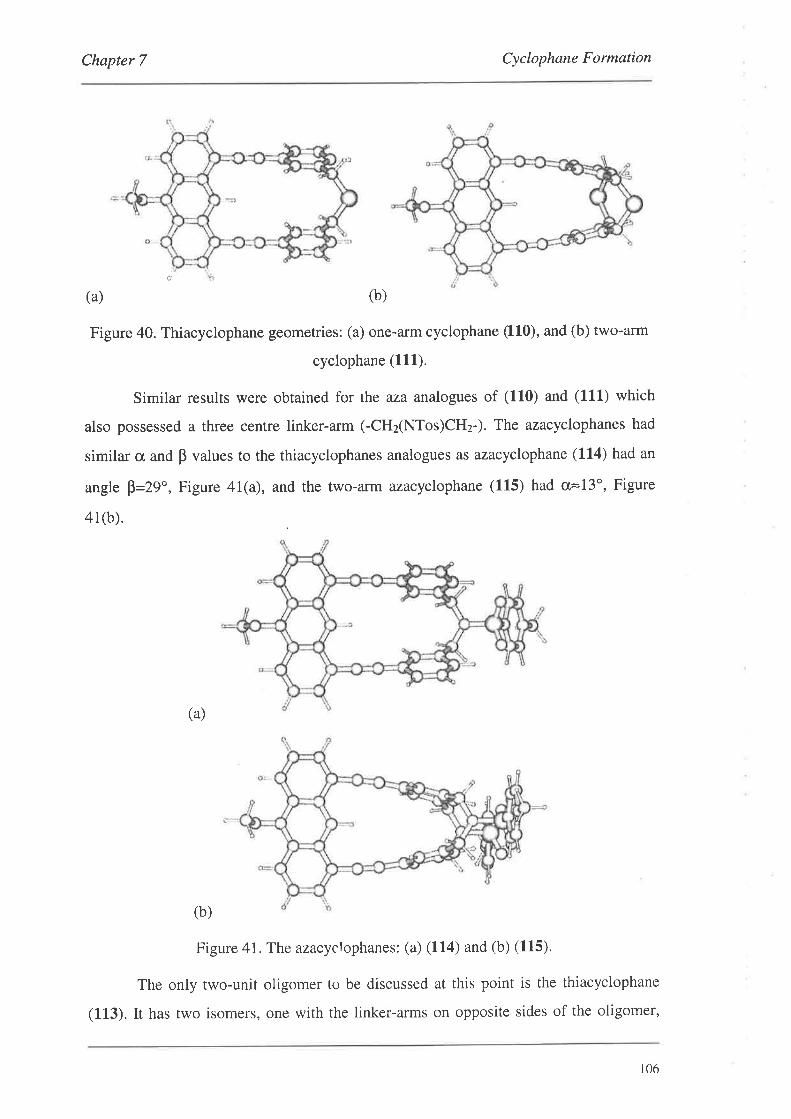
Chapter 7 Cyclophane Formation
t'
(a) (b)
Figure 40. Thiacyclophane geometries: (a) one-arm cyclophane (110), and (b) two-arm
cyclophane (111).
Similar results were obtained for rhe aza analogues of (110) and (111) which
also possessed a three centre linker-arm (-CHzNTos)CHz-). The azacyclophanes had
similar cr and B values to the thiacyclophanes analogues as azacyclophane (114) had an
angle þ=29", Figure 41(a), and the two-arm azacyclophane (115) had cr=13o, Figure
41(b).
(a)
(b)
Figure 41. The azacyclophanes: (a) (114) and (b) (115).
The only two-unit oligomer to be discussed at this point is the thiacyclophane
(113). It has two isomers, one with the linker-arms on opposite sides of the oligomer,
106
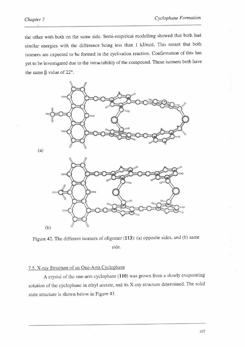
Chapter 7 Cyclophane Formation
the other with both on the same side. Semi-empirical modelling showed that both had
similar energies with the difference being less than I kJ/mol. This meant that both
isomers are expected to be formed in the cyclisation reaction. Confirmation of this has
yet to be investigated due to the intractability of the compound. These isomers both have
the same p value of 22".
(a)
(b)
Figure 42.The different isomers of oligomer (113): (a) opposite sides, and (b) same
side.
7.5. X-rav S tructure of an One-Arm Cvcloohane
A crystal of the one-arm cyclophane (110) was grown from a slowly evaporating
solution of the cyclophane in ethyl acetate, and its X-ray stt'ucture determined. The solid
state structure is shown below in Figure 43'
101
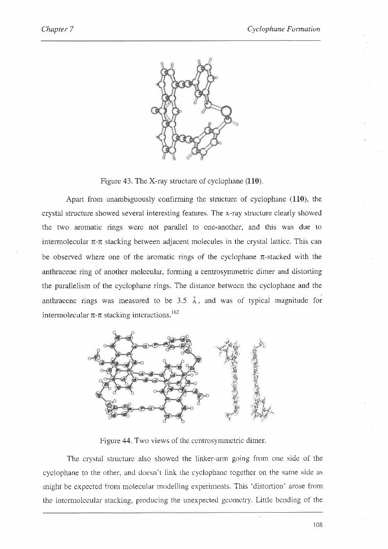
Chapter 7 Cyclophane Formation
Figure 43. The X-ray structure of cyclophane (110).
Apart from unambiguously confirming the structure of cyclophane (110), the
crystal structure showed several interesting features. The x-ray structure clearly showed
the two aromatic rings were not parallel to one-another, and this was due to
intermolecular rc-r¡ stacking between adjacent molecules in the crystal lattice. This can
be observed where one of the aromatic rings of the cyclophane fi-stacked with the
anthracene ring of another molecular, forming a centrosymmetric dimer and distorting
the parallelism of the cyclophane rings. The distance between the cyclophane and the
anthracene rings was measured to be 3.5 Å, and was of typical magnitude for
intermolecular r-ru stacking interactions.l62
Figure 44. Two views of the centrosymmetric dimer.
The crystal structure also showed the linker-arm going from one side of the
cyclophane to the other, and doesn't link the cyclophane together on the same side as
might be expected from molecular modelling experiments. This 'distortion' arose from
the intermolecular stacking, producing the unexpected geometry. Little bending of the
108
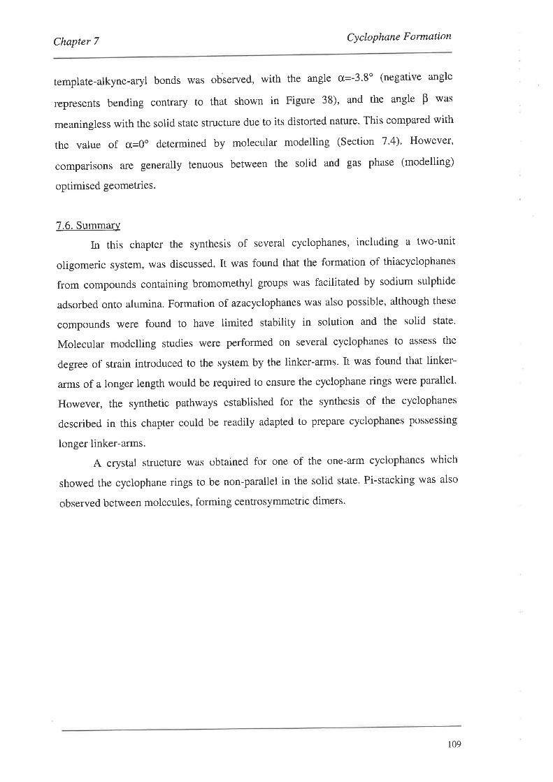
Chapter 7 Cyclophane Formation
template-alkyne-aryl bonds was obierved, with the angle cr=-3'8o (negative angle
represents bending contrary to that shown in Figure 38), and the angle B was
meaningless with the solid state structure due to its distorted nature. This compared with
the value of cr,=Oo determined by molecular modelling (Section 7.4). However,
comparisons ale generally tenuous between the solid and gas phase (modelling)
optimised geometries.
7.6. Summary
In this chapter the synthesis of several cyclophanes, including a two-unit
oligomeric system, was discussed. It was found that the formation of thiacyclophanes
from compounds containing bromomethyl groups was facilitated by sodium sulphide
adsorbed onto alumina. Formation of azacyclophanes was also possible, although these
compounds were found to have limited stability in solution and the solid state.
Molecular modelling studies were performed on several cyclophanes to assess the
degree of strain introduced to the system by the linker-arms. It was found that linker-
arms of a longer length would be required to ensure the cyclophane rings were parallel.
However, the synthetic pathways established for the synthesis of the cyclophanes
described in this chapter could be readily adapted to prepare cyclophanes possessing
longer linker-arms.
A crystal structure was obtained for one of the one-arm cyclophanes which
showed the cyclophane rings to be non-parallel in the solid state. Pi-stacking was also
observed between molecules, forming centrosymmetric dimers.
109
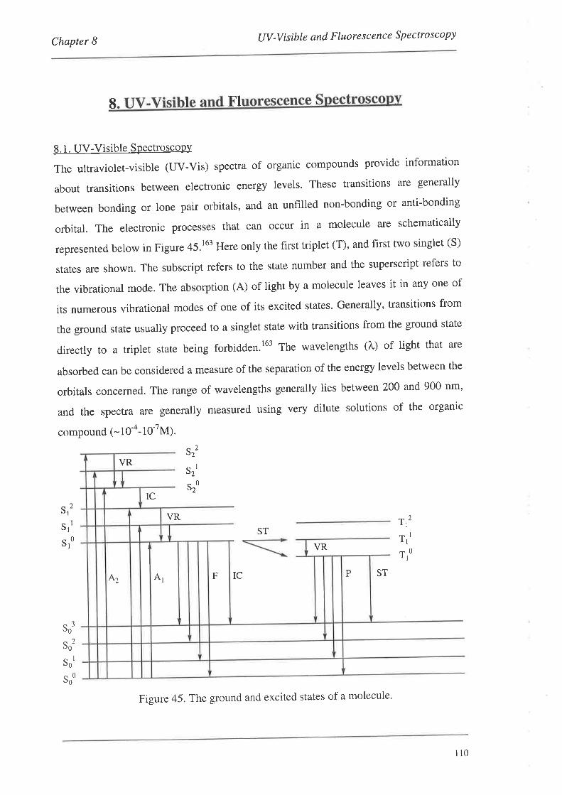
tlV -Visibte and F luo re sc enc e S pe cto s co pyChapter I
I I FI
8. 1. UV-Visible SPectroscopy
The ultraviolet-visible (UV-Vis) spectra of organic compounds provide information
about transitions between electronic energy levels. These transitions are generally
between bonding or lone pair orbitals, and an unfilled non-bonding or anti-bonding
orbital. The electronic processes that can occuf in a molecule are schematically
represented below in Figure 45.t63 Here only the first triplet (T), and first two singlet (S)
states are shown. The subscript refers to the state number and the superscript refers to
the vibrational mode. The absorption (A) of light by a molecule leaves it in any one of
its numerous vibrational modes of one of its excited states. Generally, transitions from
the ground state usually proceed to a singlet state with transitions from the ground state
directly to a triplet state being forbidden.r63 The wavelengths (À,) of light that are
absorbed can be considered a measure of the separation of the energy levels between the
orbitals concerned. The range of wavelengths generally lies between 200 and 900 nm'
and the spectra are generally measured using very dilute solutions of the organic
compound (- l0-4- 1o-7M).
Srt
s2
s2
VR
ST
VRS
S
S
I
0
2I
II
0I
IC
VR
IC ST
T,,
Tr'
T,o
So'
Sot
So'
Soo
PFAtA2
Figure 45. The ground and excited states of a molecule'
110
Chapter I UV-Visible and Fluorescence Spectroscopy
The absorbance (A) of a compound at a particular wavelength can be expressed
using the Beer-Lambert law (Equation 2)' Absorbance has no units' The remaining
variables .Is and 1 are the intensities of the incident and transmitted light respectively'
The quantity e is the molar absorption coefficient (1000 cm2mol-r;, I is the length of the
solution cell (cm), and c is the concentration of the solution (moll-l)''6a't6s Generally'
values of e are quoted without units.
A = log,o 1= r.r.,(2)
The absorption of light leads to the excitation of electrons in a molecule which is
accompanied by changes in the rotational and vibrational states' This means that the
UV-Vis spectrum is observed as a series of broad peaks and not a line spectrum'
However, due to solvent interactions, fine Structure information is usually 'blurred' out
to a smooth curve, but in the vapour phase or in non-polar solvents it can sometimes be
observed. The observance of fine structure in aromatic systems can be increased by
rigidifying the molecular framework.oo' t6t
Generally, the longer the chromophore (the groups containing electrons
responsible for absorption) the more intense the absorption with e values of -100 000
and the larger the value of Àn,o*. This is because with an increase in the number of
electrons in the chromophore the energy difference between rC and fi* becomes less and
less. Generally, allowed transitions will have e>10 000 whereas forbidden transitions
have e values below 1000.
The introduction of substituents directly onto an aromatic system can have
varied effects.l6s lntroduction of unsaturated groups such as alkenyl or alkynyl'
generally result in a large bathochromic shift (a shift to longer L), a decrease in fine
structure and an increase in intensity. Methoxy or hydroxyl groups don't significantly
alter the UV-Vis spectrum, although the hydroxyl groups can introduce some intense
bands at long wavelengths.
The uv-vis and fluorescence spectra of cyclophanes have been studied in detail
as these compounds can poSSeSS interesting transannular interactions between the
cyclophane rings.32'33 These interactions arise when the linker-arms are short' typically
two or three methylene units long, thereby introducing deformations to the aromatic
rings. Deformation of the aromatic rings results in little fine structure being observed'
1ll

Chapter I UV -V i sible and Fluore s c enc e Sp e c tro sc opy
However, when the linker-arms are lengthened fine structure returns.32t various charge-
transfer complexes of cyclophanes have been prepared, usually with the electron
deficient tetracyanoethylene (TNCE) molecule.32o''66 These complexes generally show
an absorption at lower wavelength than the uncomplexed cyclophane due to the charge
transfer absorptions. Charge-transfer mechanisms can also exist between the cyclophane
molecules themselves, without the addition of r¡-acids or 7¡-bases' These intermolecular
excited complexes are called excimers (excited homodimers). These complexes (C)
form at high concentrations (-10-2 M), and are stabilised by both exciton resonance
(*CCe+CC*¡ and charge-transfer configurations (C+C-<+C-C+¡.32a't61 If two different
solute molecules are involved in the complex then the excited complex is called an
exciplex.16T Excimers are cha¡acterised by their emission (fluorescence) spectra where
there is generally a broad emission at a lower wavelength ihan the monomer emission'
The emission is dependent on both temperatureló7 and concentration'168
8.1.1. UV-Vis Spectra
The UV-Vis spectra of several bis-coupled systems and cyclophanes are
presented below. The spectra were recorded as dilute solutions (-10-s M) in HPLC
grade THF. The first group of compounds to be studied were the template systems'
shown below in Figure 46. These spectra showed two distinct regions of absorption,
both of which were related to the ru electrons. The first region was a broad series of
peaks centred about 390 nm resulting from r-rx transitions to low excited states
(primary band), and the second was a quite sharp peak centred about 265 nm resulting
from higher energy r¡-rux transitions (secondary band).16e'170 In general, the primary band
contained more vibrational fine structure than the secondary, and this was observed for
all the compounds described in this chapter. It was also noted that all the UV-Vis
spectra possessed very similar absorptions to the parent compound anthracene with the
differences being the wavelengths of the primary and secondary bands and the reduced
amount of fine structure in the primary band'I70
The templates shown below, whilst having similar primary and secondary band
structures, differed substantially when considering the position of À.u^' The methoxy
template (43), as expected, had the lowest À'o* at 408 nm (e 10 000) due to the absence
of the alkynyl groups which increase the length of the chromophore in other systems'
tt2
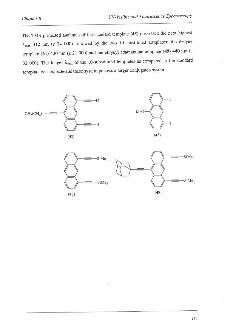
Chapter I UV -Visible and F luore sc enc e S p ectro sc opy
The TMS protected analogue of the standard template (45) possessed the next highest
),"^o* 4I2 nm (e 24 000) followed by the two l0-substituted templates: the decyne
remplare (41) 430 nm (e 21 000) and the ethynyl adamantane template (49) 440 nm (e
32 000). The longer f,,nu* of the lQ-substituted templates as compared to the standard
template was expected as these system possess a larger conjugated system.
cH3(cHr7
(41)
(4s)
H
SiMe3
(43)
(4e)
H
SiMe3
SiMe3
113
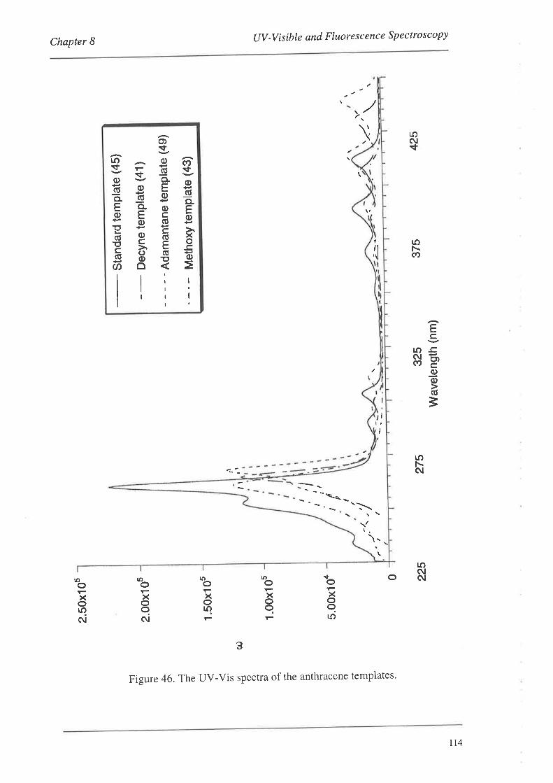
(¡)
Í oc |a CD Þ I .l (D I ct) Ø rd o () ts-t o H)
CD
ÊD rl Þ Õ (D o (D ts Ê0
CD (t)
2.50
x105
2.00
x10s
1 .5
0x10
s
1.00
x10s
5.00
x104
¡ tt
z
425
0 225
275
375
325
Wav
elen
gûh
(nm
)
è
Sta
ndar
d te
mP
late
(45
)
Dec
Yne
tem
Pla
te (
41)
- A
dam
anta
ne t
emP
late
(49
)
Met
hoxY
tem
Pla
te (
43)
II
,l
I ¡tI t, I
;-r
¡
tî''.'
/
\ (\ ì oo <a (\ s- \ o ì (\ ø o (\ o G c/
)I (\ o I 4 a o v
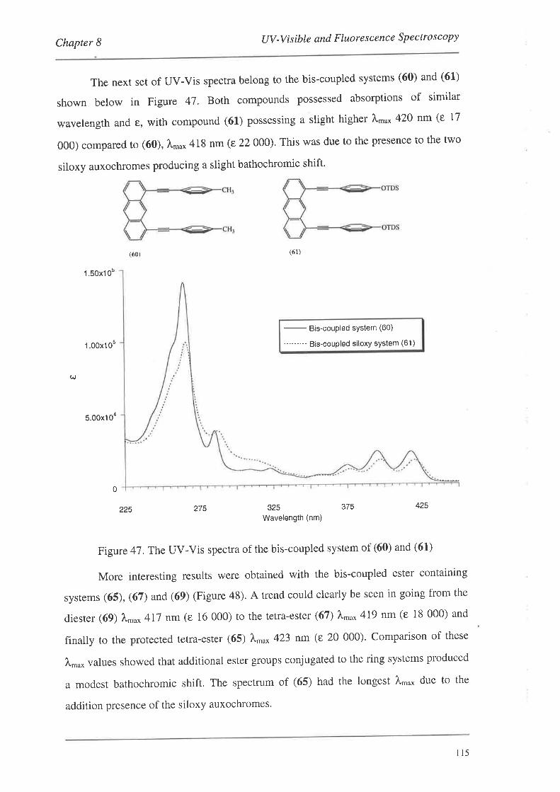
Chapter I UV -V is ible and F luore sc enc e Sp e ctro s c opy
The nexr set of UV-Vis specrra belong to the bis-coupled systems (60) and (61)
shown below in Figure 47. Both compounds possessed absorptions of similar
wavelength and €, with compound (61) possessing a slight higher À,nu* 420 nm (e 17
000) compared to (60), À,n* 418 nm (e 22 000). This was due to the presence to the two
siloxy auxochromes producing a slight bathochromic shift.
(ó1)
1 .50x1Os
1.00x10⁵ -
Bis-couPled sYstem (60)
'---"'-- Bis-coupled siloxy system (61 )
UJ
5.00x10⁴
0
425
(60)
225 275 325Wavelength (nm)
375
Figure 47 .The UV-Vis spectra of the bis-coupled system of (60) and (61)
More interesting results were obtained with the bis-coupled ester containing
systems (65), (67) and (69) (Figure 48). A trend could clearly be seen in going from the
diester (69) À,oo* 4I7 nm (e 16 000) to the tetra-ester (67) À,no* 419 nm (e 18 000) and
finatly to the protected tetra-ester (65) l,'u* 423 nm (e 20 000)' Comparison of these
À,,nu* values showed that additional ester groups conjugated to the ring systems produced
a modest bathochromic shift. The spectrum of (65) had the longest I.o* due to the
addition presence of the siloxy auxochromes.
l15
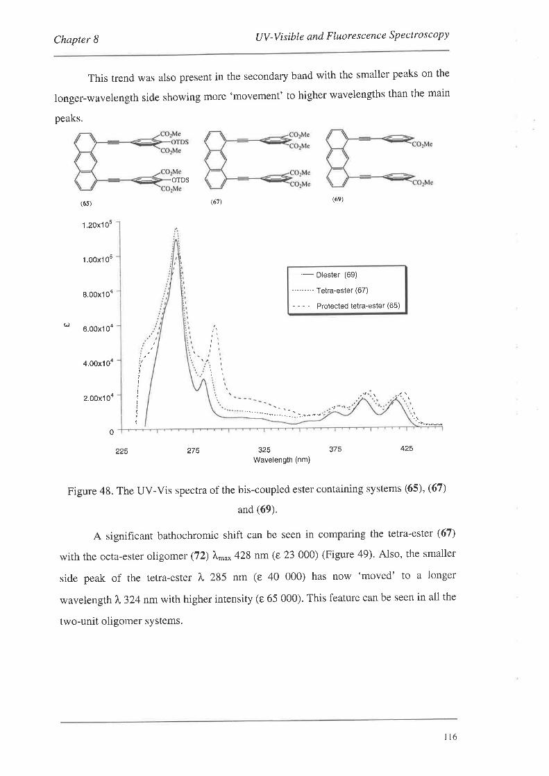
Chapter 8 UV -V is ible and F luore sc enc e S pe c to s c opy
This trend was also present in the secondary band with the smaller peaks on the
longer-wavelength side showing more 'movement' to higher wavelengths than the main
peaks.
OTDS
(6s)
1.20x10⁵
1.00x10s
8.00x10⁴
g)6.00x10⁴
4.00x10⁴
2.00x10⁴
(67\ (6e)
- Diester (69)
--"-'-" Tetra-ester (67)
- - - - - Protected tetra-ester (65)
:.
¡t
¡tII
IIII(Iî
0
225 275 325Wavelength (nm)
375 425
Figure 48. The UV-Vis spectra of the bis-coupled ester containing systems (65), (67)
and (69).
A significant bathochromic shift can be seen in comparing the tetra-ester (67)
with the octa-ester oligomer (72) Ì,"^o* 428 nm (e 23 000) (Figure 49). Also, the smaller
side peak of the tetra-ester ?," 285 nm (e 40 000) has now 'moved' to a longer
wavelength 7,"324 nm wirh higher intensity (e 65 000). This feature can be seen in all the
two-unit oligomer systems.
tt6
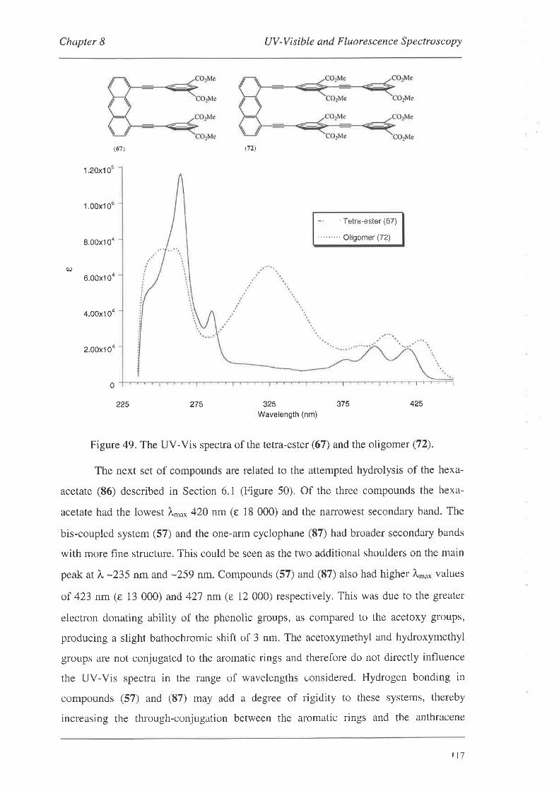
Chapter 8 UV-Visible and Fluorescence Spectroscopy
(ó7)
225
\72)
1.20x1 05
1.00x1 05
8.00x10⁴
6.00x1 Oa
4.00x10⁴
2.00x10⁴
-
Tetra-ester (67)
'"'-'-" Oligomer (72)
q)
0
275 325Wavelength (nm)
375 425
Figure 49. The UV-Vis spectra of the tetra-ester (67) and the oligomer (72).
The next set of compounds are related to the attempted hydrolysis of the hexa-
acetate (86) described in Section 6.1 (Figure 50). Of the three compounds the hexa-
acetate had the lowest 7,"^o* 420 nm (e 18 000) and the narrowest secondary band. The
bis-coupled system (57) and the one-arm cyclophane (87) had broader secondary bands
with more fine structure. This could be seen as the two additional shoulders on the main
peak at ì," -235 nm and -259 nm. Compounds (57) and (87) also had higher À,,no* values
of 423 nm (e 13 000) and 421 nm (e 12 000) respectively. This was due to the greater
electron donating ability of the phenolic groups, as compared to the acetoxy groups,
producing a slight bathochromic shift of 3 nm. The acetoxymethyl and hydroxymethyl
groups are not conjugated to the aromatic rings and therefore do not directly influence
the UV-Vis spectra in the range of wavelengths considered. Hydrogen bonding in
compounds (57) and (87) may add a degree of rigidity to these systems, thereby
increasing the through-conjugation between the aromatic rings and the anthracene
tt7
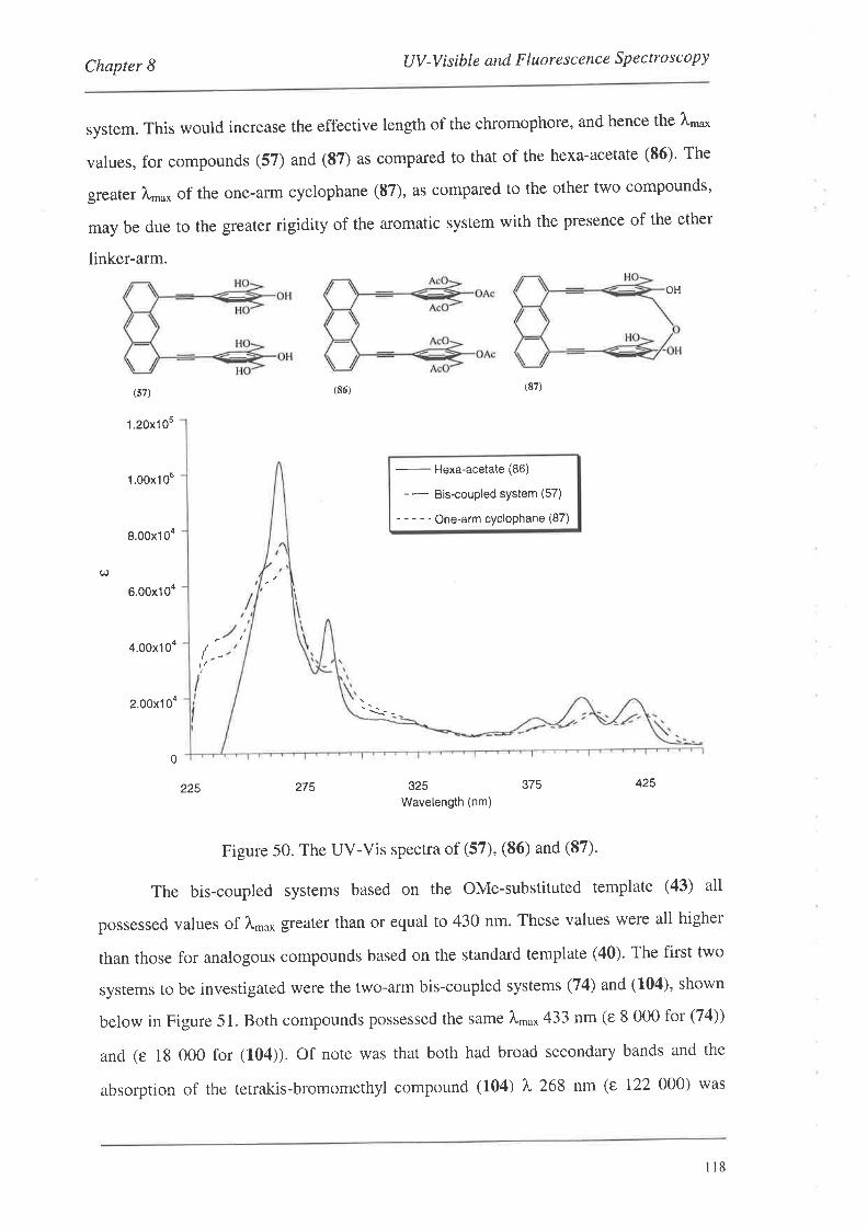
Chapter I UV -V is ibte and F luo re sc enc e S p e c tro s c o py
system. This would increase the effective length of the chromophore, and hence the À,nu*
values, for compounds (57) and (87) as compared to that of the hexa-acetate (86)' The
greater À,,,u* of the one-arm cyclophane (87), as compared to the other two compounds'
may be due to the greater rigidity of the aromatic system with the presence of the ether
linker-arm.
OH
(87)(86)(s7)
1.20x'105
1.00x10⁵
8.00x10⁴
6.00x10⁴
4.00x10⁴
2.00x10⁴
-
Hexa-acetate (86)
- - Bis-coupled sYstem (57)
- - - - - One-arm cycloPhane (87)
(¡.)
t/
'\r-
0
275 325Wavelength (nm)
375 425225
Figure 50. The UV-Vis spectra of (57), (86) and (87)'
The bis-coupled systems based on the OMe-substituted template (43) all
possessed values of ¡,ma* greater than or equal to 430 nm. These values were all higher
than those for analogous compounds based on the standard template (40). The first two
systems to be investigated were the two-arm bis-coupled systems (74) and (104), shown
below in Figure 51. Both compounds possessed the same 1.*o* 433 nm (e 8 000 for (74))
and (e l8 000 for (104)). Of note was that both had broad secondary bands and the
absorption of the tetrakis-bromomethyl compound (104) ¡" 268 nm (e 122 000) was
ll8
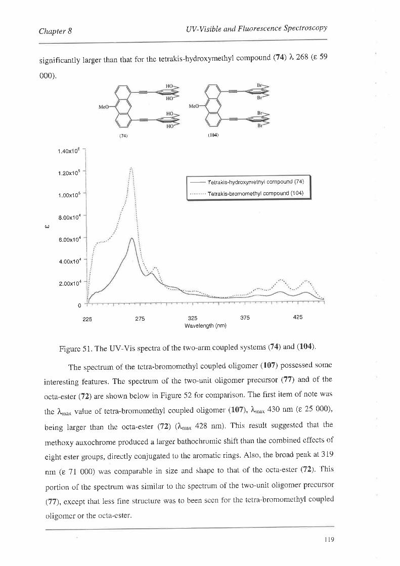
Chapter 8 UV -V i sible and F luore s c enc e Sp e ctro sco py
significantly larger than that for the tetrakis-hydroxymethyl compound (74) ), 268 (e 59
000).
(74) (104)
1 .40x10s
1 .20x105
1.00x10⁵ -
Tetrakis-hydroxymethyl compound (74)
-"'-'-" Tetrakis-bromomethyl compound (104)
8.00x10⁴
6.00x10⁴
4.00x10⁴
2.00x10⁴
0
425
C^)
225 275 325
Wavelength (nm)
375
Figure 51. The UV-Vis spectra of the two-arm coupled systems (74) and (104).
The spectrum of the tetra-bromomethyl coupled oligomer (107) possessed some
interesting features. The spectrum of the two-unit oligomer precursor (77) and of the
octa-ester (72) are shown below in Figure 52 for comparison. The first item of note was
the l.,nu* value of tetra-bromomethyl coupled oligomer (1'07), l.n'o* 430 nm (e 25 000)'
being larger than the octa-ester (72) (1,."^ 428 nm). This result suggested that the
methoxy auxochrome produced a larger bathochromic shift than the combined effects of
eight ester groups, directly conjugated to the aromatic rings. Also, the broad peak at 319
nm (e 71 000) was comparable in size and shape to that of the octa-ester (72). This
portion of the spectrum was similar to the spectrum of the two-unit oligomer precursor
(77), except that less fine structure was to been seen for the tetra-bromomethyl coupled
oligomer or the octa-ester.
il9
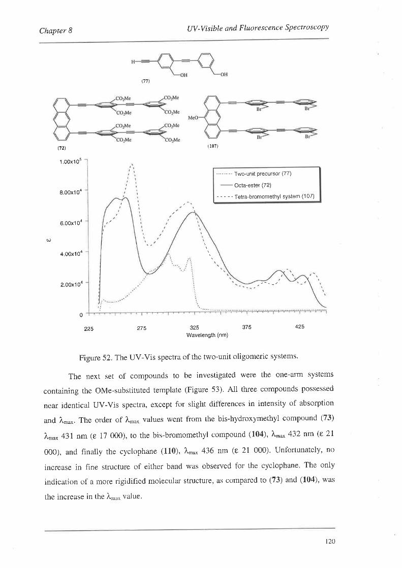
Chapter 8 UV -V isible and F luore s c enc e Spe ctro s copy
(72)
1 .00x105
8.00x10⁴
6.00x10⁴
4.00x10⁴
2.00x10⁴
0
(77)
275
(107)
325Wavelength (nm)
"" --" Two-unit precursor (77)
-
octa-esÌer (72\
- - - - - Tetra-bromomethyl system (107)
C¡.)
225 375 425
Figure 52. The UV-Vis spectra of the two-unit oligomeric systems.
The next set of compounds to be investigated were the one-arm systems
containing the OMe-substituted template (Figure 53). All three compounds possessed
near identicat UV-Vis spectra, except for slight differences in intensity of absorption
and Àn.o*. The order of Àma* values went from the bis-hydroxymethyl compound (73)
À,no* 431 nm (e 17 000), to the bis-bromomethyl compound (104), À*u* 432nm(e2I
000), and finally the cyclophane (110), I'u* 436 nm (e 21 000)' Unfortunately, no
increase in fine structure of either band was observed for the cyclophane. The only
indication of a more rigidified molecular structure, as compared to (73) and (104), was
the increase in the À,n,0* value.
120
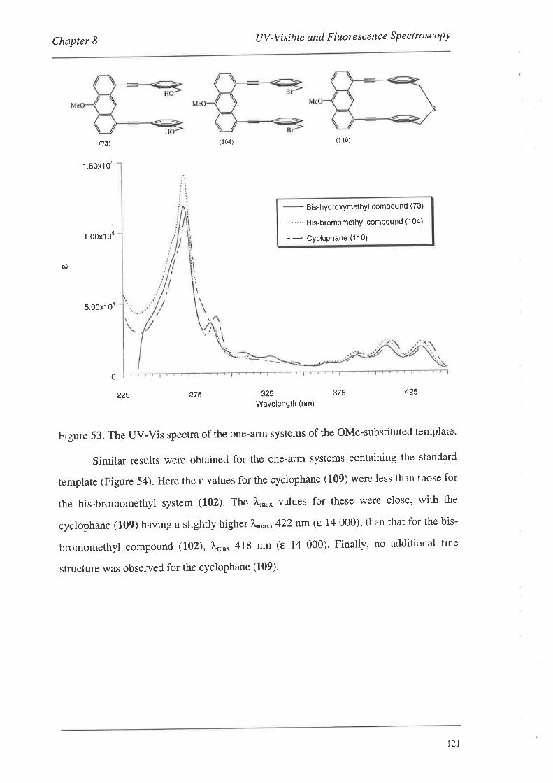
Chapter I UV-Visible and F luore scence Spectroscopy
(73)
1 .50x10s
1.00x'l 05
5.00x1 0a
0
(104) (r r0)
-
Bis-hydroxymethyl compound (73)
----"'-' Bis-bromomethyl compound ('l 04)
- - CycloPhane (1 10)
q)
\
275 325Wavelength (nm)
375 425225
Figure 53. The UV-Vis spectra of the one-arïn systems of the OMe-substituted template'
Similar results were obtained for the one-arm systems containing the standard
template (Figure 54). Here the e values for the cyclophane (109) were less than those for
the bis-bromomethyl system (102). The À'u* values for these were close, with the
cyclophane (109) having a slightly higher 7\^o*,422 nm (e 14 000), than that for the bis-
bromomethyl compound (102), À,nu* 418 nm (e 14 000). Finally, no additional fine
structure was observed for the cyclophane (109).
t2t
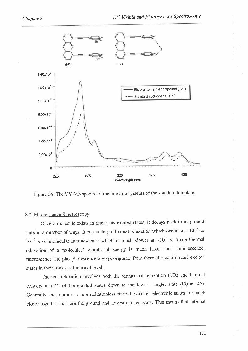
Chapter I tlV-Visibte and Fluorescence Spectroscopy
(102) (109)
1.40x10⁵
1 .20x105
1 .00x105
8.00x10⁴
6.00x10⁴
4.00x10⁴
2.00x10⁴
0
-
B¡s-Þrornomethyl compound (102)
-- Standard cYcloPhane (109)
o \I\
225 275 325
Wavelength (nm)375 425
Figure 54. The UV-Vis spectra of the one-arm systems of the standard template.
8.2. Fluorescence Spectroscopy
Once a molecule exists in one of its excited states, it decays back to its ground
state in a number of ways. It can undergo thermal relaxation which occurs at -10-ta to
10-12 s or molecular luminescence which is much slower at -10-8 s. Since thermal
relaxation of a molecules' vibrational energy is much faster than luminescence,
fluorescence and phosphorescence always originate from thermally equilibrated excited
states in their lowest vibrational level.
Thermal relaxation involves both the vibrational relaxation (VR) and internal
conversion (IC) of the excited states down to the lowest singlet state (Figure 45)'
Generally, these processes are radiationless since the excited electronic states are much
closer together than are the ground and lowest excited state. This means that internal
t22
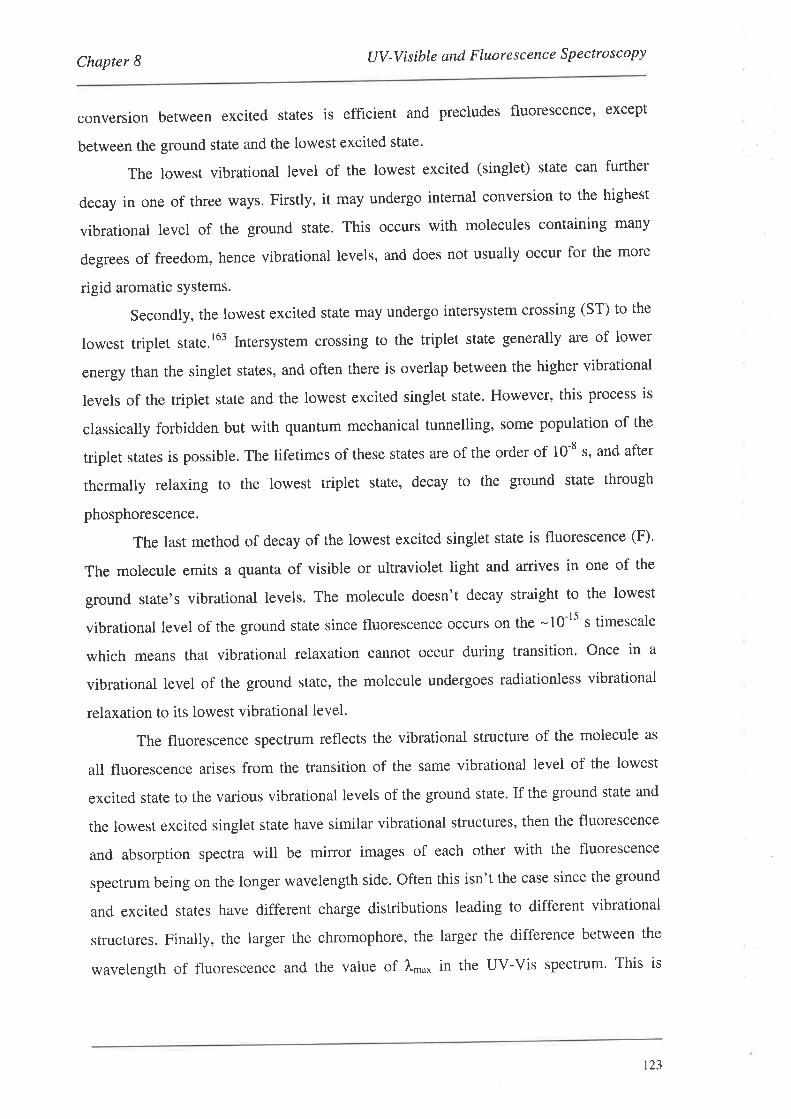
Chapter 8 tlV -V isible and F luore sc enc e S p e cto sc opy
conversion between excited states is efficient and precludes fluorescence' except
between the ground state and the lowest excited state'
The lowest vibrational level of the lowest excited (singlet) state can further
decay in one of three ways. Firstly, it may undergo internal conversion to the highest
vibrational level of the ground state. This occurs with molecules containing many
degrees of freedom, hence vibrational levels, and does not usually occur for the more
rigid aromatic sYstems.
Secondly, the lowest excited state may undergo intersystem crossing (ST) to the
lowest triplet state.l63 lntersystem crossing to the triplet state generally are of lower
energy than the singlet states, and often there is overlap between the higher vibrational
levels of the triplet state and the lowest excited singlet state. However, this process is
classically forbidden but with quantum mechanical tunnelling, some population of the
triplet states is possible. The lifetimes of these states are of the order of 10-8 s, and after
thermally relaxing to the lowest triplet state, decay to the ground state through
phosphorescence.
The last method of decay of the lowest excited singlet state is fluorescence (F).
The molecule emits a quanta of visible or ultraviolet light and arrives in one of the
ground state's vibrational levels. The molecule doesn't decay straight to the lowest
vibrational level of the ground state since fluorescence occurs on the -10-ls s ûmescale
which means that vibrational relaxation cannot occur during transition. Once in a
vibrational level of the ground state, the molecule undergoes radiationless vibrational
relaxation to its lowest vibrational level.
The fluorescence spectrum reflects the vibrational structure of the molecule as
all fluorescence arises from the transition of the same vibrational level of the lowest
excited state to the various vibrational levels of the ground state. If the ground state and
the lowest excited singlet state have similar vibrational structures, then the fluorescence
and absorption spectra will be mirror images of each other with the fluorescence
spectrum being on the longer wavelength side. Often this isn't the case since the ground
and excited states have different charge distributions leading to different vibrational
structures. Finally, the larger the chromophore, the larger the difference between the
wavelength of fluorescence and the value of Àn'o* in the UV-Vis spectrum' This is
t23
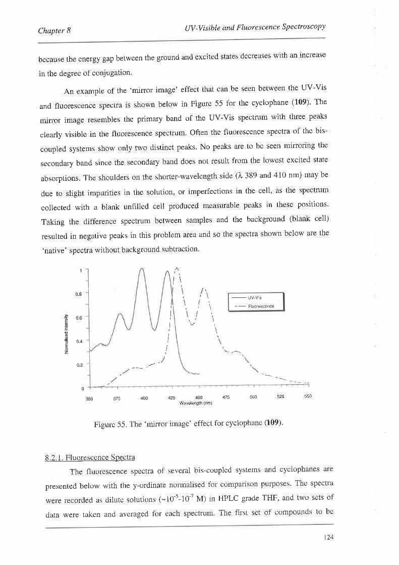
Chapter 8 UV -V isible and F luore s c e nc e Spe ctro s c opy
because the energy gap between the ground and excited States decreases with an increase
in the degree of conjugation'
An example of the 'mirror image' effect that can be seen between the UV-Vis
and fluorescence spectra is shown below in Figure 55 for the cyclophane (109)' The
mirror image resembles the primary band of the UV-Vis spectrum with three peaks
clearly visible in the fluorescence spectrum. Often the fluorescence spectra of the bis-
coupled systems show only two distinct peaks. No peaks are to be seen mirroring the
secondary band since the secondary band does not result from the lowest excited state
absorptions. The shoulders on the shorter-wavelength side (À 389 and 410 nm) may be
due to slight impurities in the solution, or imperfections in the cell, as the spectrum
collected with a blank unfilled cell produced measurable peaks in these positions'
Taking the difference spectrum between samples and the background (blank cell)
resulted in negative peaks in this problem area and so the spectra shown below are the
'native' spectra without background subtraction.
/\
!II
I
I
I
0.8
0.6
0.4
0.2
-
uv_vis
- -
Fluorêscence
Êo-co.9EE
z
r'
U
350 375 400 425 450 475 500 525 550
Wavelength (nm)
Figure 55. The 'mirror image' effect for cyclophane (109)
8.2. 1. Fluorescence Spectra
The fluorescence spectra of several bis-coupled systems and cyclophanes are
presented below with the y-ordinate normalised for comparison purposes. The spectra
were recorded as dilute solutions (-10-s-10-7 M) in HPLC grade THF, and two sets of
data were taken and averaged for each spectrum. The first set of compounds to be
t24
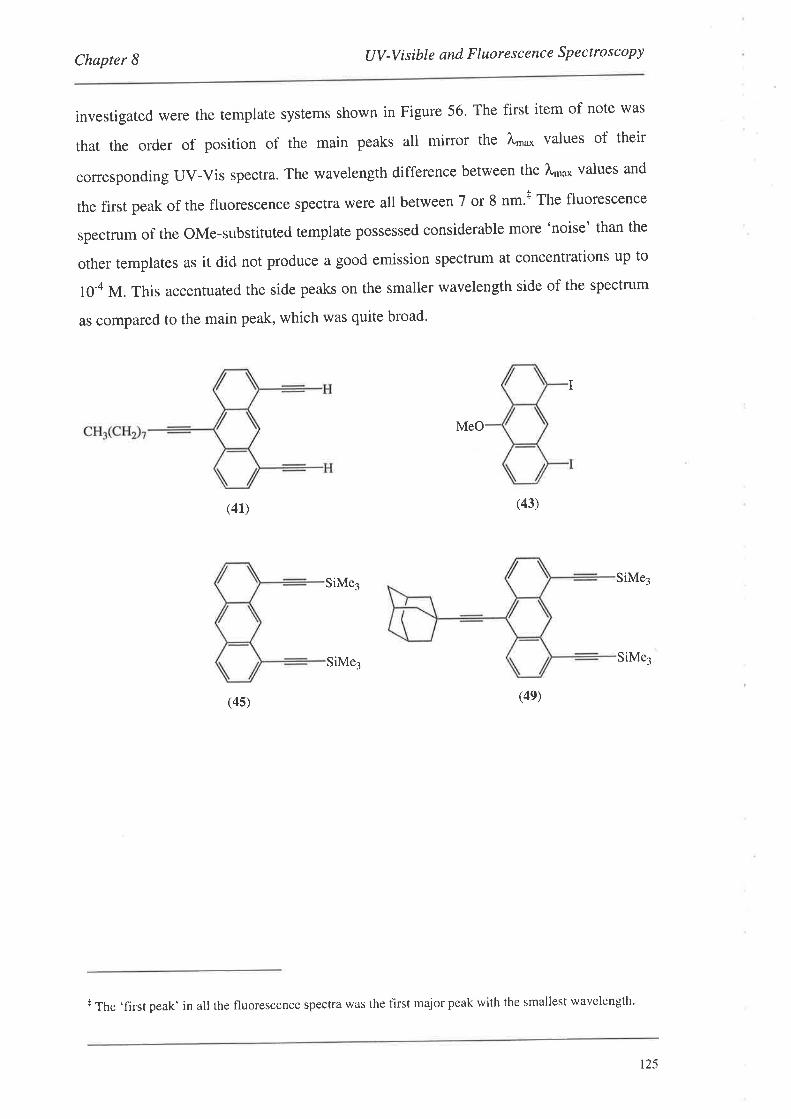
Chapter I UV-Visibte and Fluorescence Spectroscopy
investigated were the template systems shown in Figure 56' The first item of note was
that the order of position of the main peaks all mirror the l"'o* values of their
corresponding UV-ViS spectra. The wavelength difference between the l'."* values and
the first peak of the fluorescence spectra were all between 7 or 8 nm't The fluorescence
spectrum of the OMe-substituted template possessed considerable more 'noise' than the
other templates as it did not produce a good emission spectrum at concentrations up to
l0-4 M. This accentuated the side peaks on the smaller wavelength side of the spectrum
as compared to the main peak, which was quite broad'
MeO
(41) (43)
SiMe3 SiMe3
SiMej SiMej
(4s) (4e)
I
+ The ,first peak' in all the fluorescence spectra was the first major peak with the smallest wavelength'
r25
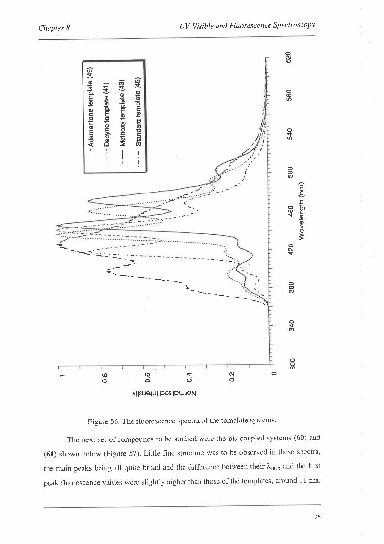
Chapter I UV-Visible and Fluorescence Spectroscopy
-'çvË 1gE.HfiËåE r'HE(!oú_ËË ÈË
E åË E
lilrli'|r
(
(
..ã:2' t
o(\¡(o
ooll)
o!trn
ooto
EcE,
8Þsõõo
=oC\I\t
Ì
?._ __ _
L o@í)
oÉ(o
oo(Ð
oc'{oao
qo
qo
Á+lsue+ul pesllow,toN
Figure 56, The fluorescence spectra of the template systems.
The next set of compounds to be studied were the bis-coupled systems (60) and
(61) shown below (Figure 57). Little fine structure was to be observed in these spectra,
the main peaks being all quite broad and the difference between their À*o^ and the first
peak fluorescence values were slightly higher than those of the templates, around 11 nm.
t26
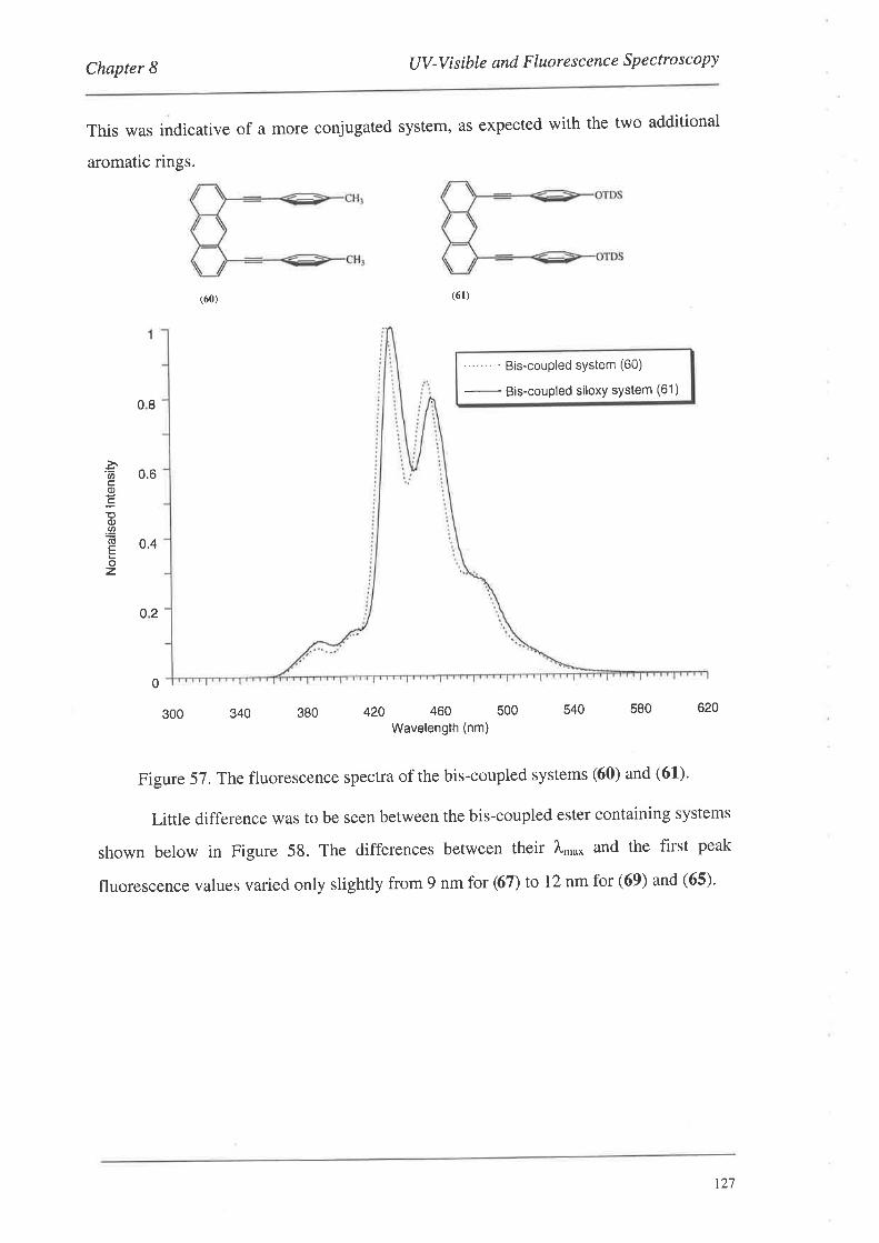
Chapter 8 UV-Visible and Fluore sc ence Spectroscopy
This was indicative of a more conjugated system, as expected with the two additional
aromatic rings.
"-""'- Bis-coupled system (60)
-
Bis-coupled siloxy system (61)
0
340 380 420 460 500
Wavelength (nm)540 580 620
Figure 57. The fluorescence spectra of the bis-coupled systems (60) and (61)'
Little difference was to be seen between the bis-coupled ester containing systems
shown below in Figure 58. The differences between their À,.u* and the first peak
fluorescence values varied only slightly from 9 nm for (67) to 12 nm for (69) and (65).
(61)(ó0)
08
E 0,6o
;(I).U'
E 0.4Èoz
02
300
r27
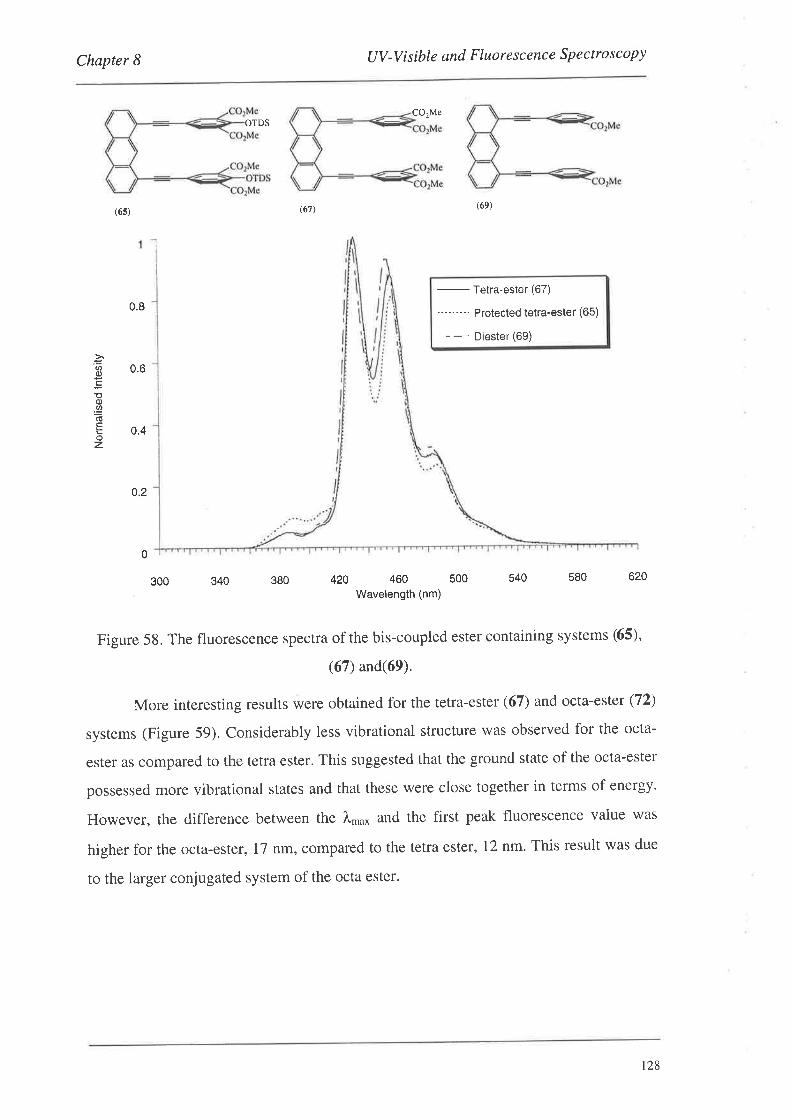
Chapter I UV-Visible and Fluorescence Specffoscopy
=U)0)
;o.9õEoz
CO2MeOTDS
(6s) (67) (69)
-
Tetra-ester (67)
-"""-- Protected tetra-ester (65)
- - Diester (69)
340 380 540 580 620
Figure 58. The fluorescence spectra of the bis-coupled ester containing systems (65),
(67) and(69).
More interesting results were obtained for the tetra-ester (67) and octa-estet (72)
systems (Figure 59). Considerably less vibrational structure was observed for the octa-
ester as compared to the tetra ester. This suggested that the ground state of the octa-ester
possessed more vibrational states and that these were close together in terms of energy.
However, the difference between the },n'o* and the first peak fluorescence value was
higher for the octa-ester, 17 nm, compared to the tetra ester, 12 nm. This result was due
to the larger conjugated system of the octa ester.
0.8
0.6
0.4
0.2
0
300 420 460 500
Wavelength (nm)
t28
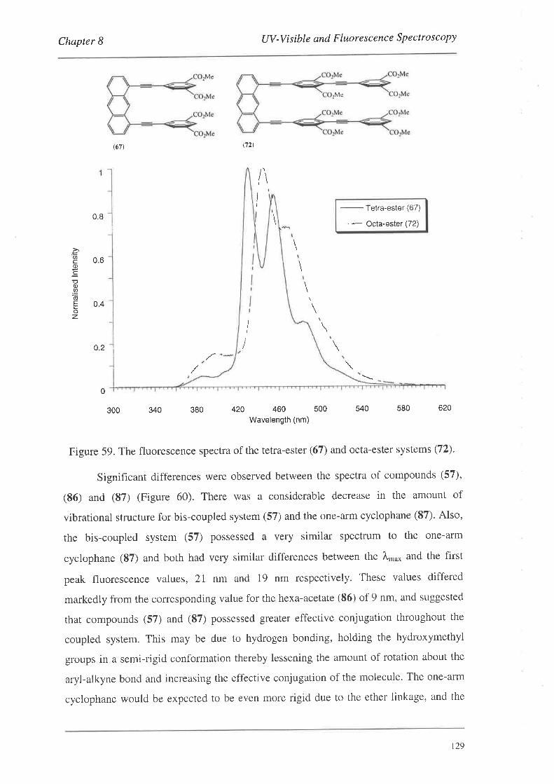
Chapter I UV-Visible and Fluorescence Spectroscopy
¡Me
(67) (72t
¡Me
-
Tetra-ester (67)
- - Octa-esler (72)
Ii
\
0.8
0.4
06EU'
o
;o),q)õEoz
\
02
380
0
300 340 580 620
Figure 59. The fluorescence spectra of the tetra-ester (67) and octa-ester systems (72).
Significant differences were observed between the spectra of compounds (57),
(86) and (S7) (Figure 60). There was a considerable decrease in the amount of
vibrational structure for bis-coupled system (57) and the one-arm cyclophane (87). Also,
the bis-coupled system (57) possessed a very similar spectrum to the one-arm
cyclophane (87) and both had very similar differences between the À,,,o* and the first
peak fluorescence values, 21 nm and 19 nm respectively. These values differed
markedly from the corresponding value for the hexa-acetate (86) of 9 nm, and suggested
rhat compounds (57) and (87) possessed greater effective conjugation throughout the
coupled system. This may be due to hydrogen bonding, holding the hydroxymethyl
groups in a semi-rigid conformation thereby lessening the amount of rotation about the
aryl-alkyne bond and increasing the effective conjugation of the molecule. The one-arm
cyclophane would be expected to be even more rigid due to the ether linkage, and the
540420 460 500
Wavelength (nm)
\
I
t29
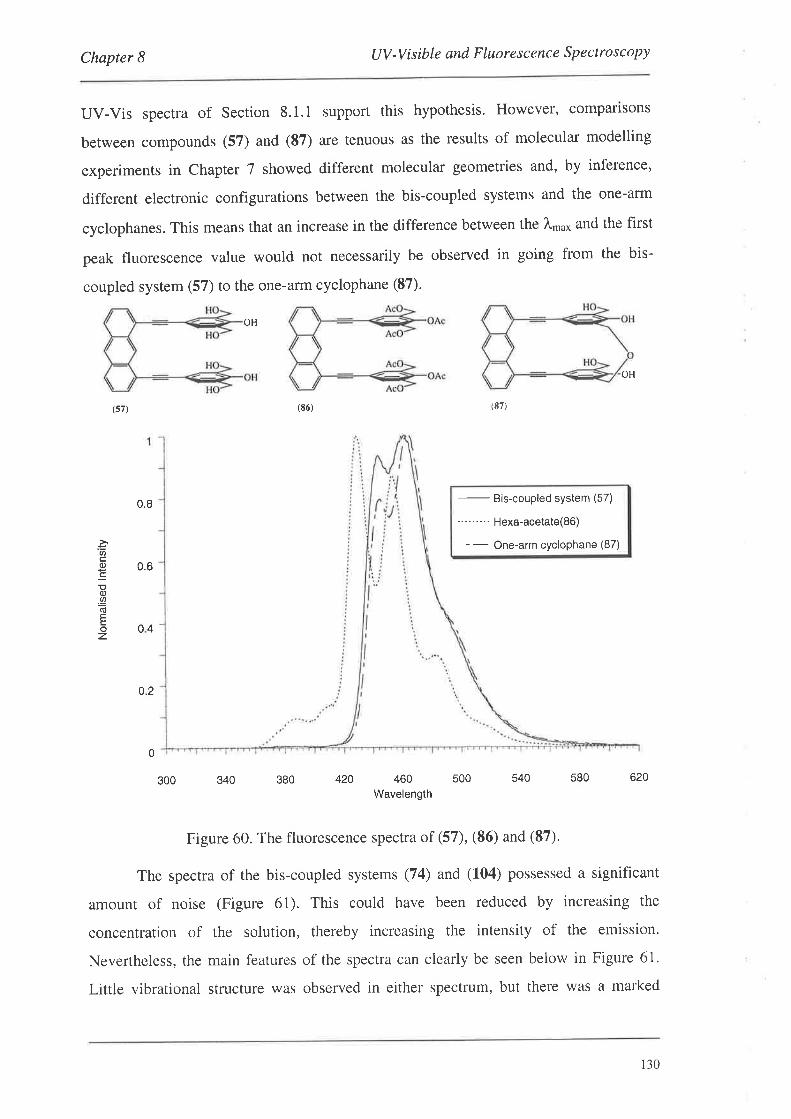
Chapter 8 UV -V isible and F luo re s c enc e S p e ctro s c o py
UV-Vis spectra of Section 8.1.1 support this hypothesis. However, comparlsons
between compounds (57) and (87) are tenuous as the results of molecular modelling
experiments in Chapter 7 showed different molecular geometries and, by inference,
different electronic configurations between the bis-coupled systems and the one-arm
cyclophanes. This means that an increase in the difference between the À*o* and the first
peak fluorescence value would not necessarily be observed in going from the bis-
coupled system (57) to the one-arm cyclophane (87).
OH
OH
(s7) (E7)
0.8
-
Bis-couPled sYstem (57)
-'- "" -- Hexa-acetate(86)
- - One-arm cyclophane (87)
0.6
0.2
(E6)
o4
'õc.(¡)
=;(¡).9,rEoz
0
300 340 380 420 460Wavelength
500 540 580 620
Figure 60. The fluorescence spectra of (57), (86) and (87)'
The spectra of the bis-coupled systems (74) and (104) possessed a significant
amount of noise (Figure 61). This could have been reduced by increasing the
concentration of the solution, thereby increasing the intensity of the emission.
Nevertheless, the main features of the spectra can clearly be seen below in Figure 61.
Little vibrational structure was observed in either spectrum, but there was a marked
130
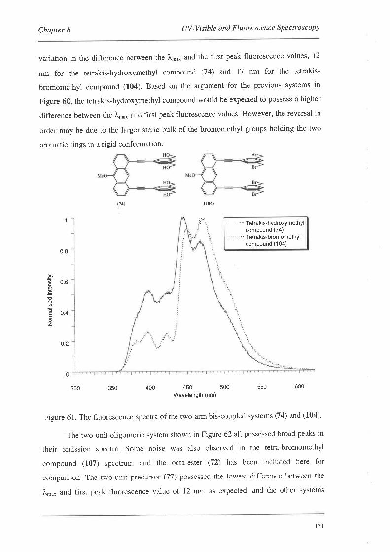
Chapter I UV-Visible and Fluorescence Spectroscopy
variation in the difference between the l,ro* and the first peak fluorescence values, 12
nm for the terrakis-hydroxymethyl compound (74) and I7 nm for the tetrakis-
bromomethyl compound (f04). Based on the argument for the previous systems in
Figure 60, the tetrakis-hydroxymethyl compound would be expected to possess a higher
difference between the Àn'o* and first peak fluorescence values. However, the reversal in
order may be due to the larger steric bulk of the bromomethyl groups holding the two
aromatic rings in a rigid conformation.B
(74) (104)
i,t'.1
-
Tetrakis-hydroxYmethYlcompound (74)
-" " - "' Tetrakis-bromomethYlcompound (104)
0.8
àE 0.6EC
o(¡)
.9
E 0.4oz
o2
0
350 400 550 600
Figure 61. The fluorescence spectra of the two-arm bis-coupled systems Q4) and (104).
The two-unit oligomeric system shown in Figure 62 all possessed broad peaks in
their emission spectra. Some noise was also observed in the tetra-bromomethyl
compound (107) spectrum and the octa-ester (72) has been included here for
comparison. The two-unit precursor (77) possessed the lowest difference between the
À.o^ and first peak fluorescence value of 12 nm, as expected, and the other systems
300 450 500
Wavelength (nm)
t3l
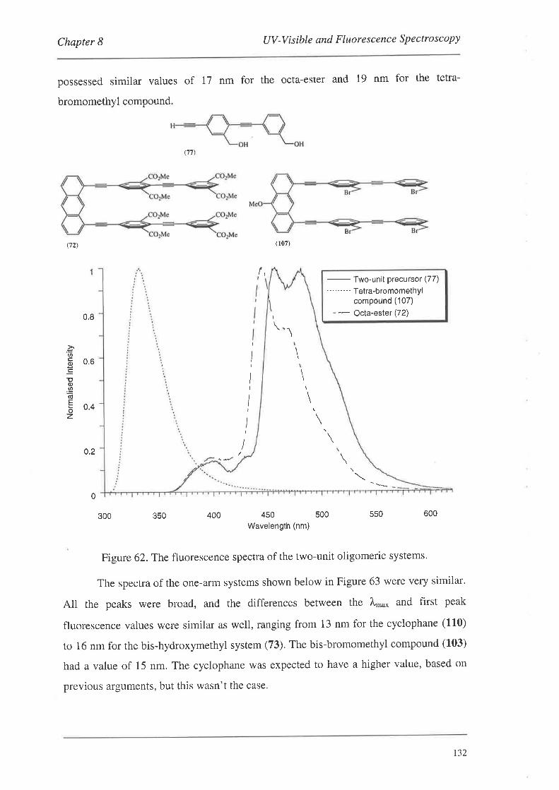
Chapter I UV-VisibIe and Fluorescence Spectroscopy
possessed similar values of 17 nm for the octa-ester and 19 nm for the tetra-
bromomethyl compound
(77)
(72) (107)
B
/,
-
Two-unit Precursor (77)
' - " " "- Tetra-bromomethYlcompound (107)
- - octa-ester (72)
0.8
.=(t6 0.6C
Eo).2õcE 0.4z
i
I
!
I
I0.2
0
350 400 550 600
Figure 62.The fluorescence spectra of the two-unit oligomeric systems'
The spectra of the one-arm systems shown below in Figure 63 were very similar'
All the peaks were broad, and the differences between the l,'u* and first peak
fluorescence values were similar as well, ranging from 13 nm for the cyclophane (110)
to 16 nm for the bis-hydroxymethyl system (73). The bis-bromomethyl compound (103)
had a value of 15 nm. The cyclophane was expected to have a higher value, based on
previous arguments, but this wasn't the case.
300 450 500
Wavelength (nm)
\
\
I
\
132
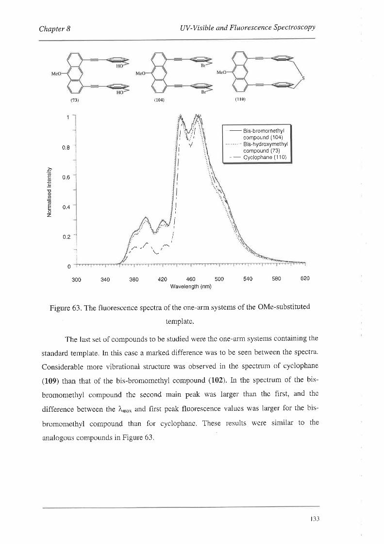
Chapter 8 UV -V isible and Fluores c enc e S p e ctro s co py
.=tJ)
(l)
;o.9.õcboz
(73)
0.8 -
0.2 -
0
0.6
0.4
300 340 380
(104)
420 460 s00Wavelength (nm)
(1 l0)
-
Bis-bromomethYlcompound (104)
--'-" "' Bis-hydroxymethYlcompound (73)
- -
Cyclophane (1 10)
540 580 620
Figure 63. The fluorescence spectra of the one-arm systems of the OMe-substituted
template.
The last set of compounds to be studied were the one-arm systems containing the
standard template. In this case a marked difference was to be seen between the spectra.
Considerable more vibrational structure was observed in the spectrum of cyclophane
(109) than that of the bis-bromomethyl compound (1.02). In the spectrum of the bis-
bromomethyl compound the second main peak was larger than the first, and the
difference between the Àn.o* and first peak fluorescence values was larger for the bis-
bromomethyl compound than for cyclophane. These results were similar to the
analogous compounds in Figure 63.
t,
I
l
I
I
I
r33
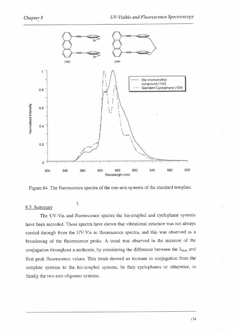
Chapter 8 UV -V is ible and F luore s c enc e Sp e ctro sc o py
(r02) (109)
-
Bis-bromomethYlcompound (102)
-- Standard Cyclophane (109)
300 340 380 540 s80 620
Figure 64. The fluorescence spectra of the one-arm systems of the standard template.
\8.3. Summary
The UV-Vis and fluorescence spectra the bis-coupled and cyclophane systems
have been recorded. These spectra have shown that vibrational structure was not always
carried through from the UV-Vis to fluorescence spectra, and this was observed as a
broadening of the fluorescence peaks. A trend was observed in the measure of the
conjugation throughout a molecule, by considering the difference between the À,n o* and
first peak fluorescence values. This trend showed an increase in conjugation from the
template systems to the bis-coupled systems, be they cyclophanes or otherwise, to
finally the two-unit oligomer systems.
\I
\
'õ(l,
EEq).9,(úEoz
0.8
0.6
0.4
0.2
0
420 460 500Wavelength (nm)
\I
\
\
\
\
\I
\
!
/
!
134
Chapter 9 Conclusions and Future Work
9. Conclusions and Future Work
A series of one-arm and two-arm monomers has been prepared (Chapter 2).
These compounds have incorporated within them various linker-arrn precursors (-
COzMe or -CHzOH); groups amenable to palladium catalysed coupling reactions (Br, I
or ethynyl); and, in some cases, groups to aid in solubility (silyloxy groups).
Various anthracene template systems were synthesised (Chapter 3). Two of these
templates were literature compounds, (40) and (43), and two others were novel 10-
substituted systems, (41) and (42). Synthesis of the 1O-substituted systems was achieved
via the key steps of regioselective bromination of l,8-dichloroanthracene in the 10
position and the subsequent regioselective palladium catalysed coupling of terminal
alkynes to this functionalised position.
The one- and two-arm monomers were coupled to the template systems to form
a series of bis-coupled systems (Chapter 4). The couplings were performed using
Sonogashira coupling conditions. Solubility and purification problems were encountered
for a number of the bis-coupled systems, however these were overcome by the
introduction of silyloxy groups and by using reverse phase silica for purification.
A one-arm, two-unit oligomer was synthesised by the palladium catalysed
coupling of two monomer units, the triflate (30) and alkyne (33) (Chapter 4).
Subsequent reduction of the methyl esters to the corresponding hydroxymethyl groups
could be achieved using DIBAL-H. The use of lithium aluminium hydride was found to
reduce the esters as well as regiospecifically reducing the internal alkyne to a trans
double bond. The oligomer was then successfully coupled to a template system (43).
The coupling of the triflate (21) to the template (40) showed that regioselective
coupling was possible between an aryl-iodine bond versus a hindered aryl-triflate, and
that the reaction proceeded in good yield (Chapter 4). Extension of this bis-coupled
system (71) to the octa-ester (72) using a palladium catalysed coupling reaction with the
monomer (27), showed that further coupling was possible to the hindered bis-triflate.
A new catalytic protocol was discovered and developed for the palladium
catalysed coupling of aryl-halides to terminal alkynes (Chapter 5). The new protocol
employed zinc salts and iodine/iodide co-catalysts in place of the traditional copper (I)
135
Chapter 9 Conclusions and Future Work
iodide. It was established that nucleophilic amine bases were required for these
reactions. The new coupling conditions were successfully used for the preparation of
various test and bis-coupled systems.
The linker-affn precursors of the bis-coupled systems were manipulated to form
a series of compounds containing bromomethyl groups (Chapter 6). It was found that
the conesponding iodomethyl and mesylate compounds were unstable and, in some
cases, could not be isolated.
The bromomethyl compounds were then converted into a series of thia-, dithia-
and aza-cyclophanes viø double nucleophilic displacement reactions (Chapter 7). The
formation of the thiacyclophanes (109) and (110) was best achieved using alumina
absorbed Na2S giving the cyclophanes in high yields. Conditions employing high
dilution had little effect on the yield of the cyclophanes, and the addition of extra
absorbed reagent was necessary to complete the reaction due to it decomposing over
time in solution. The poor yields of the two-arm cyclophane (111) suggested that the
three-unit linker-arms \ryere too short for the anthracene template systems. Molecular
modelling results supported this idea with significant 'bending' of the alkyne groups and
the aromatic rings being observed for the two-arm dithia- and diaza-cyclophanes.
An x-ray crystal structure was obtained for the thiacyclophane (110) (Chapter 7).
The structure showed the cyclophane rings to be non-parallel in the solid state, and that
[-stacking was present between the molecules. This produced centrosymmetric dimers
of the cyclophane in the solid state.
The corresponding one-arm azacyclophane (114) could be prepared in good
yield from the bis-bromomethyl compound (103) (Chapter 7). However, this cyclophane
was found to be unstable, and so the corresponding two-arm analogues or two-unit
oligomeric systems were not prepared.
The UV-Vis and fluorescence spectra were obtained for many of the bis-coupled
systems and cyclophanes. An increase in fine structure was not observed in the UV-Vis
spectra of the cyclophanes, as compared to the unconstrained systems. However, an
increase in conjugation was observed in going from the templates to the bis-coupled
systems, and from the bis-coupled systems to the two-unit oligomeric systems. This was
determined by considering the difference between the value of À,n0* in the UV-Vis
spectra and the À value of the first main peak in the fluorescence spectra.
t36
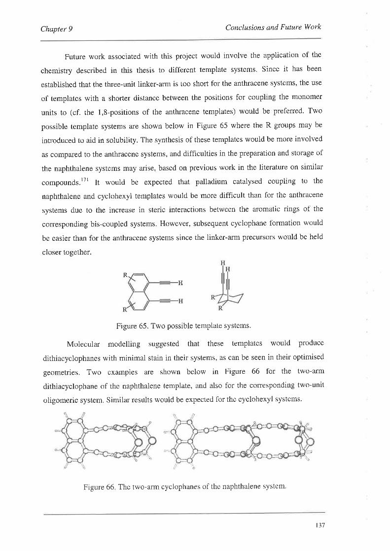
Chapter 9 Conclusions and Future Work
Future work associated with this project would involve the application of the
chemistry described in this thesis to different template systems. Since it has been
established that the three-unit linker-arm is too short for the anthracene systems, the use
of templates with a shorter distance between the positions for coupling the monomer
units to (cf. the l,8-positions of the anthracene templates) would be preferred. Two
possible template systems are shown below in Figure 65 where the R groups may be
introduced to aid in solubility. The synthesis of these templates would be more involved
as compared to the anthracene systems, and difficulties in the preparation and storage of
the naphthalene systems may arise, based on previous work in the literature on similar
compounds.lTl It would be expected that palladium catalysed coupling to the
naphthalene and cyclohexyl templates would be more difficult than for the anthracene
systems due to the increase in steric interactions between the aromatic rings of the
corresponding bis-coupled systems. However, subsequent cyclophane formation would
be easier than for the anthracene systems since the linker-arm precursors would be held
closer together.
H
Figure 65. Two possible template systems.
Molecular modelling suggested that these templates would produce
dithiacyclophanes with minimal stain in their systems, as can be seen in their optimised
geometries. Two exampies are shown below in Figure 66 for the two-arm
dithiacyclophane of the naphthalene template, and also for the corresponding two-unit
oligomeric system. Similar results would be expected for the cyclohexyl systems.
R
:)
Figure 66. The two-arm cyclophanes of the naphthalene system'
137
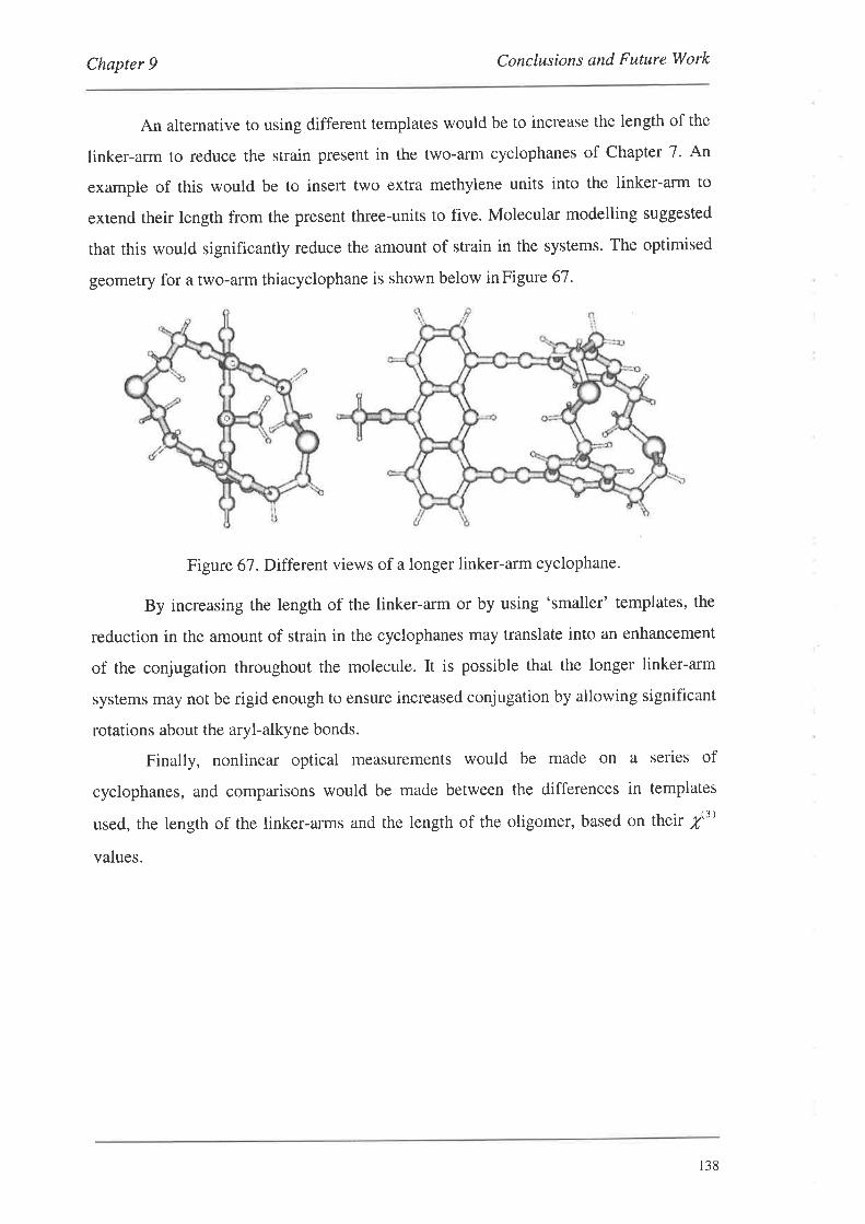
Chapter 9 Conclusions and Future Work
An alternative to using different templates would be to increase the length of the
linker-arm to reduce the strain present in the two-arm cyclophanes of Chapter 7. An
example of this would be to insert two extra methylene units into the linker-arm to
extend their length from the present three-units to five. Molecular modelling suggested
that this would significantly reduce the amount of strain in the systems. The optimised
geometry for a two-arm thiacyclophane is shown below inFigure 67.
Figure 67. Different views of a longer linker-arm cyclophane.
By increasing the length of the linker-arm or by using 'smaller' templates, the
reduction in the amount of strain in the cyclophanes may translate into an enhancement
of the conjugation throughout the molecule. It is possible that the longer linker-arm
systems may not be rigid enough to ensure increased conjugation by allowing significant
rotations about the aryl-alkyne bonds.
Finally, nonlinear optical measurements would be made on a series of
cyclophanes, and comparisons would be made between the differences in templates
used, the length of the linker-arms and the length of the oligomer, based on their /3)
values.
138
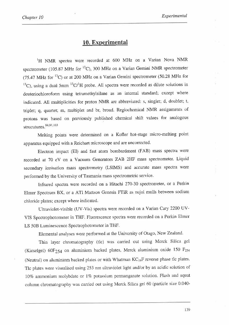
Chapter l0 Experimental
L0. Experimental
tH NMR spectra were recorded at 600 MHz on a Varian Nova NMR
spectrometer (105.87 MHz for t'C), 300 MHz on a Varian Gemini NMR spectrometer
(75.47 MHz for r3C¡ or at2OO MHz on a Varian Gemini spectrometer (50.28 MHz for
13C¡, using a dual 5mm l3C/lH probe. All spectra were recorded as dilute solutions in
deuteriochloroform using tetramethylsilane as an internal standard; except where
indicated. All multiplicities for proton NMR are abbreviated: s, singlet; d, doublet; t,
triplet; q, quartet; m, multiplet and br, broad. Regiochemical NMR assignments of
protons was based on previously published chemical shift values for analogous
strucutures.S4'9 I' I 03
Melting points were determined on a Kofler hot-stage micro-melting point
apparatus equipped with a Reichart microscope and are uncorrected.
Electron impact (EI) and fast atom bombardment (FAB) mass spectra were
recorded at 70 eV on a Vacuum Generators ZAB zHF mass spectrometer. Liquid
secondary ionisation mass spectrometry (LSIMS) and accurate mass spectra were
performed by the University of Tasmania mass spectrometric service.
Infrared spectra were recorded on a Hitachi 270-30 spectrometer, or a Perkin
Elmer Spectrum BX, or a ATI Mattson Genesis FTIR as nujol mulls between sodium
chloride plates; except where indicated.
Ultraviolet-visible (UV-Vis) spectra were recorded on a Varian Cary 2200 UY-
VIS Spectrophotometer in THF. Fluorescence spectra were recorded on a Perkin Elmer
LS 508 Luminescence Spectrophotometer in THF.
Elemental analyses were performed at the University of Otago, New Zealand.
Thin layer chromatography (tlc) was carried out using Merck Silica gel
(Kieselgel) 60F254 on aluminium backed plates, Merck aluminium oxide 150 Fzs¿
(Neutral) on aluminium backed plates or with Whatman KCraF reverse phase tlc plates.
Tlc plates were visualised using 253 nm ultraviolet light and/or by an acidic solution of
I07o ammonium molybdate or IVo potassium permanganate solution. Flash and squat
column chromatography was carried out using Merck Silica gel 60 (particle size 0.040-
139
Chapter 10 Experimentøl
0.063 mm) pH 6.5-1.5, Fluka aluminium oxide for chromatography 507 C neutral (100-
125 mesh) pH 7.0t0.5 or with Waters preparative C18 (55-105 pm) reverse phase silica.
Solvents were purified and dried using standard laboratory procedures.'t' All
organic extracts were dried over anhydrous magnesium sulphate. All solvents for
palladium catalysed coupling reactions were degassed by the freeze-pump-thaw method
and kept under an atmosphere of nitrogen.lT2 All reactions involving anhydrous solvents
were also kept under an atmosphere of nitrogen. ''Wet' ether refers to a water saturated
solution of ether.
A typical extractive workup for the palladium catalysed coupling reactions
involved addition of the reaction mixture to sat. NH¿CI and extraction with two portions
of organic solvent. The organic layers were then combined and washed once with water.
Finally, the solvent was dried and removed.
The following compounds were prepared according to published procedures:
methyl 5-iodosalic yìate,6a dimethyl 2-hydroxyisophthalate,T2'73 benzyltrimethyl-
ammonium dichloroiodate,Ta dimethyl 5-bromoisophthalafe,TT I,3-bis(hydroxymethyl)-
5-bromobe Írzerre,l' 1,8-dichloroanthracene,8s 1,8-diethynylanthracene,sa
ethynyladamantaneeO, 1,8-diiodo-1O-methoxyanthracene,el and sodium sulphide
adsorbed on alumina (2.5 mmol/g).1ó0
2,6-Bis(hydroxymethyl) -4-bromophenol (1)
To an aqueous solution of 25Vo NaOH (25 mL) containingp-bromophenol (8.65
g, 50 mmot) and methanol (12.5 mL) was added 38Vo formaldehyde solution (45 mL).
The resulting mixture was heated at7}" for 1.5 hrs and then allowed to stir at room
remperature for a further 36 hrs. A solution of acetic acid (12.5 mL) in water (25 mL)
was then added and stiring was continued for 6 hrs at room temperature after which a
white precipitate had formed. This was collected and recrystallised from ethyl acetate to
give fine off-white needles (1.61 E, I4Vo); mp 150.0-151.0" (lit.2 163.0-164.0',
purification by sublimation); ôH (300 MHz, d6-acetone) 4.13 (4H, s, ATCHzOH),I '28
(2H, s, ArH); õc Q5.47 MHz, d6-acetone) 61.4 (ATCHzOH), 111.7 (ArBr)' 129.3,
130.6, 153.5 (AroH); nlz (Er) 2341M*, 8rBr, 39vo),232 (M* ,'eBr, 4ovo¡,216 (84),2r4
(87).
t40
Chapter l0 Experimental
2,6-Bis(hydroxymethyl)-4-iodophenol (2)
To a solution of 2,6-bis(hydroxymethyl)phenol (22) (1.22 g, 7.92 mmol) in
merhanol (40 mL) was added NaHCO¡ (3.32 g, 39.61 mmol) and
benzyltrimethylammonium dichloroiodate (2.90 8, 8.32 mmol)' The resulting
suspension was stirred at room temperature for 2hrs. The reaction mixture was
concentrated in vacuo and then purified by squat column chromatography
ldichloromethane/ethyl acetate 1/1 (viv), Rr 0.50] to give the title compound as a fawn
solid (1.98 g,89Vo). A small sample was recrystallised from a methanol/water mixture
as orange needles; mp 155.0-156.5"; Exact Mass Calcd for CsHqIO* 279.9598, Found
279.9608; ôH (200 MHz, d6-acetone) 4]2 (4H, s, ATCHzOH), 7.46 (2H, s, ArH); ðc
(50.23 MHz) 6L2,81.5 (ArI), 131.0, 135.4,154.4 (ArOH); mlz (EÐ 280 (M*,37Eo),
262 (r00).
2,6-Bis(morpholinomethyl) -4-bromophenol (3)
To a solution of p-bromophenol (8.65 g,50 mmol) in acetic acid (10 mL) was
added morpholine (9.60 mL, 110 mmol) and 38Vo formaldehyde solution (11 mL, 110
mmol). The resulting solution was then heated at 80o for 6 hrs. The reaction mixture
was then taken up into dichloromethane (200 mL) and washed with water (100 mL), sat.
NaHCO¡ (100 mL) and finally water (100 mL). The solution was dried and passed
through a short squat column. The solvent was removed in vacuo, to yield a yellow solid
(16.45 g,82Vo); mp 115.0-115.5"; Anal. Calcd for CroHz:NzO¡Br: C,5I.16; H, 6.24; N,
7.54, Found C,52.03:H,6.23;N,1.42; õH (300 MHz) 2.53 (8H, t, J 4.6H2),3.59 (4H,
s, ATCHzR),3.74 (8H, t, J 4.6H2),7.20 (2H, s, ArH); õcQ5.47 MHz) 52.7,58.2,66'3'
110.1 (ArBr), 124.0, 130.8, 154.7 (ArOH): mlz (EI) 3721M*, 8rBr, 40Vo),370 (M*,
7eBr,4rvo¡, 285 (1oo), 283 (84).
1-Acetoxy-2,6-bis(acetoxymethyl)'4'bromobenzene (4)
A solution of 2,6-bis(morpholinomethyl)-4-bromophenol (3) (5.00 g, 13.5
mmol) in acetic anhydride (30 mL) and acetic acid (2 mL) was refluxed fot 24 hrs. The
reaction mixture was concentrated by rotary evaporation and the resulting red/brown oil
taken up into dichloromethane (150 mL), washed with sat. NaHCO¡ (3x75 mL) and
water (75 mL). The solvent was dried and removed in vacuo to give a red oil. This oil
t4l
Chapter I0 Experimental
was then shaken with a solution of 3Vo methanol in hexane (10 mL) for 5 mins before
being placed in the fridge to crystallise overnight. The crude product was collected and
recrystallised from hexane to give colourless needles (3.08 g, 647o); mp 81.0-82.0';
Anal. Calcd for Cr¿HrsOd; C,46'82;H,4.2I, Found: C,46.73;H,4.02; ôH (300 MHz)
2.lO (6H, s, ATCH2OCOCH¡), 2.35 (3H, s, ATOCOCH3), 5.00 (4H, s, ATCHzR), 7'57
(2H, s, tuH); õc Q5.47 MHz) 20.4,20j,60.5, 119.4 (ArBr), 131.1 (ArCHzOAc),
I3Z.B, 146.3 (ArOAc), 168.7 (C=O), 170.3 (C=O); mlz (FAB) 361 ((M+H)*, t'Bt,
60vo),359 ((M+H)*, t'Br, 617o),301 (13), 20g (r3),25g (16),257 (17); v'u* (cm-r)
1734,1768 (C=O).
2,6-Bis(morpholinomethyl)phenol (5)
To a38Vo formaldehyde solution (35.2 mL,450 mmol) was added phenol (20.00
g,2I0 mmol) followed by morpholine (38.6 mL, 440 mmol). The resulting suspension
was stirred vigorously and heated at 50o for 15 hrs. Water (100 mL) and ethyl acetate
(20 mL) was then added with cooling to 0". Over 0.5 hr a white precipitate formed
which was collected by vacuum filtration and washed with a solution of water/ethyl
acerate (10:1) (100 mL). The solid was recrystallised from hexane to give the title
compound as colourless plates (12.00 g, 20Vo); mp 123.5-124.5"; Anal' Calcd for
CroHz¿NzO3: C,65.73;H,8.27, Found: C,66'02; H; 8.07; õn (300 MHz) 2'51 (8H, t, 'I
4.6 }Jz), 3.61 (4H, s, ATCHzR),3.1| (8H, t, J 4.6 Hz), 6.74 (IH, t, J 7 .5 Hz, ArH),7 .04
(2H, d, J 7.5 Hz, ArH); õc Q5.41 MHz) 53.1, 59.2, 66.7 (ArCHzR), 118'5, 122'0
(ArCHzR), I2g .O, 1 5 5.9 (ArOH); ml z (EI) 292 (l\/f , I sEo), 205 ( 1 00).
1 -Acetoxy-2,6-bis (acetoxymethyl)benzene (6)
A solution of 2,6-bis(morpholinomethyl)phenol (5) (4.69 g, 16 mmol) in acetic
anhydride (20 mL,196 mmol) was refluxed for 20 hrs. The reaction mixture was added
to water (200 mL) and extracted with dichloromethane (3x100 mL). The organic
extracts were combined and washed with sat. Na2CO3 (3x100 mL) followed by water
(100 mL). The solvent was dried and remove in vacuo to give a colourless oil57 (2.54 g,
57Vo); õH (300 MHz) Lgz (6H, s, ATCHzOCOCH3), 2.20 (3H, s, ATOCOCHù, 4'92
(4H, s, ATCHzOAc),7.12 (lH, t, JJ.6Hz,4-H),7.30(2H,d,JJ.6Hz, ArH); õcQ5'47
142
Chapter 10 Experimental
MHz) 19.8,20.1,60.7 (ArCHzOAc), 125.8, 128j7,130.1, 147.3 (ArOAc), 168'5 (C=O),
169.g (C=O); m/z (EI) 361 (M*, ItBr,60Vo¡, 359 (M*, 'nBr,6OVo¡, 301 (8rBr, l87o),299
(t'8., rSvo),257 ç8tBr, Lgvo),259 ç1e8r,207o);v'u* (cmr) 1768, 1734 (c=o)'
2,6-Bis(morpholinomethyl)'4'iodophenol (7)
Method A:
To a solution consisting of acetonitrile (16 mL) and water (5 mL) was added 2,6-
bis(morpholinomethyl)phenol (5) (2.00 g, 6.85 mmol) and NaI (1.23 g,8.22 mmol)' The
resulting solution was cooled to 0" and r-BuOCl (1 mL, 8.35 mmol) added dropwise vla
syringe. The reaction mixture was allowed to stir for a further 15 mins at 0o before being
taken up into dichloromethane (50 mL) and washed with water (50 mL). The aqueous
layer was re-extracted with dichloromethane (50 mL), the organic layers combined,
washed with sat. NazSzO¡ (2x50 mL) and finally water (50 mL). The solvent was dried
and remov ed in vacuo to give a yellow oil. The product was purified by flash
chromatography on silica gel [ethyl acetate, Rf 0.36] to give a colourless oil which
crystallised upon addition of hexane to give an off-white solid (0.94 g' 33Vo).
Method B:
To a solution of 2,6-bis(morpholinomethyl)phenol (5) (2.00 g, 6.85 mmol) in
dimerhylsulphoxide (10 mL) was added NaI (1.23 g, 8.22 mmol) and chloramine-T
trihydrate (2.32 g,8.22 mmol) with stirring. The resulting suspension was heated at 50o
for 45 mins after which time the reaction mixture was taken up into dichloromethane
(50 mL) and washed with water (50 mL). The aqueous layer was re-extracted with
dichloromethane (50 mL), the organic layers combined and washed with sat. NazSzO¡
(2x50 mL) and water (50 mL). The solvent was dried and removed in vacuo to give a
yellow oil. The product was purified by flash chromatography on silica gel [ethyl
acetate, Rr 0.361 to give a colourless oil which was taken up into hot hexane and upon
cooling gave off-white prisms (1.95 g, 68Vo); mp 108.0-109.0o; Exact Mass Calcd for
CroHz¡INzO¡: 418.0755. Found: 418.0163; ôH (300 MHz) 2.52 (8H, t, J 4.6 Hz),3.59
(4H, s, ATCH2R), 3.74 (8H,t, J 4'6Hz),7.34 (2H, s, ArH); õcQ5'41 MHz) 53'1, 58'5,
66J,113.1 (ArI), 125.0,131.3,156.1(ArOH);mlz(EI)41S (lvf ,44Eo),331(98).
r43
Chapter 10 Experimental
2-(Morpholinomethyl)-4-iodophenol (8)
The procedure was analogous to that for (3) except that the solution was heated
for 23 hrs at 50". Purification by flash chromatography [dichloromethaneiethyl acetate
III (v/v), Rr 0.41l gave the title compound as a colourless oil (157o); Exact Mass Calcd
for crrHr¿INOz: 319.0071, Found: 319.0066; ôH (300 MHz) 2.56 (4H, br s), 3.65 (2H, s,
ATCH2R), 3.76 (4[,br s), 6.60 (1H, d, J 8'4l1rz),7 .28 (1H, d, J 2.1Hz),1 .44 (IH, dd, J
2.1 and8.4Hz);õcQ5.47 MHz) 52'7,60'9,66.6,80.6 (ArI), 118.5, 123'2, l3l'1,
137 .6, 157 .4 (ArOH); mlz (EI) 3 19 (Nf , I00Vo), 233 (28) .
2,6-Bis(acetoxymethyl) -4-bromophenol (l'3)
A stock solution of 0.5M guanidine in methanol was prepared. Sodium (1.78 g,
17.4 mmol) was added to dry methanol (S00 mL) under a nitrogen atmosphere. Once
effervescence had ceased, guanidine hydrogencarbonate (14.20 g, 79 mmol) was added
with stirring. After t hr the resulting white suspension was filtered and the 0.5M
guanidine solution stored under nitrogen.
A solution of 1-acetoxy-2,6-bis(acetoxymethyl)-4-bromobenzene (4) (600 mg,
1.67 mmol) in methanol (S mL) and dichloromethane (8 mL) was cooled to -25" before
0.5 M guanidine in methanol (3.34 mI-, L67 mmol) was added over 0.5 hr. During this
time the reaction temperature was kept between -20 and -25". The reaction mixture was
then allowed to stir for a further 3 hrs. Acetic acid (0.2 mL) was then added to quench
the reaction. The reaction mixture was taken up into dichloromethane (75 mL) and
washed with 5Vo NH¿C1 (40 mL) and water (40 mL). The solvent was dried and
removed in vqcuo to yield an off-white solid which was recrystallised from hexane to
give the title compound as a colourless powder (353 mg, 677o); mp 82'0-83.0o; Exact
Mass Cald for crzHr¡osBr 315.9947, Found: 315.9948; ôH (300 MHz) 2.13 (6H, s,
ATCHzOCOCH:), 5.10 (4H, s, ATCHzOÃc),7'41 (2H, s, ArH); õc Q5.47 MHz) 20'8
(cH3co2cH2Ar), 61.8 (ArCH2OAc), 119.9 (ArBr), 125.4, 134.1,152.9 (ArOH)' 172.5
(C=o) ; ml z (¡ir) 3 I 8 (M*, 8' Br, 8vo¡, 3 I 6 (M*, 7 eBr, yvo¡, 216 (30), 21 4 (32): v,nu* (cm- I
)
1745, 1734, 1712,1693 (C=O).
t44
Chapter l0 Experimental
Phenyl-2,6-bis(acetoxymethyl) -4-bromo'trifl uoromethylsulphonate (14)
Method A:
2,6-Bis(acetoxymethyl)-4-bromophenol (13) (100 mg,3.16x10-a mol), potassium
carbonate (52 mg,3.78x10-a mol) and N-phenyltriflimide (136 mg, 3.78x10-a mol) in
THF (6 mL) were stined together at room temperature for 16 hrs. The reaction mixture
was taken up into dichloromethane (40 mL) and washed with 5Vo NH+CI (2x25 mL) and
water (25 mL). The solvent was dried and removed in vacuo to give a colourless oil.
The crude product was purified by flash chromatography [dichloromethane, Rr 0.49] to
give the title compound as colourless oil which crystallised upon addition of pentane as
colourless prisms (118 mg, 84Vo)'
Method B:
2,6-Bis(acetoxymethyl)-4-bromophenol (13) (100 ñ8, 3.16x1O-amol),
trierhylamine (0.02 mL, 3.16x10-amol) and N-phenyltriflimide (123 mg,3.47x10-a mol)
in THF (6 mL) were stirred together at room temperature for 16 hrs. The reaction
mixture was taken up into dichloromethane (40 mL) and washed with 5Vo NH4CI (2x20
mL) and water (20 mL). The solvent was dried and removed in vacuo to give a
colourless oil which was taken up into boiling pentane to give colourless prisms on
cooling (76 mg, 54Vo); mp 59.5o; Anal. Calcd for Cr¡HrzBrF¡OzS: C, 34'16; H, 2'69,
Found: C, 34.67; H,2.46; ðH (300 MHz) 2.I5 (6H, s, ATCHzOCOCH¡), 5.20 (4H, s,
ATCHzOAc), 1.63 (2H, s, ArH); õc Q5.41 MHz) 20'6 (CH3CO2CH2Ar), 60'0
(ArCHzOAc), 118.4 (q, J 319 Hz, CF¡SOzAr), 122.6 (ArBr), 132'6, 133'3, 142'3
(ArOTf), 170.2 (C=O); m/z (FAB) 451 ((M+H)*, *'Br, 4Vo),449 ((M+H)*,7eBr,4Vo),
391 (18), 289 (18), 301 (20), 299 (20);v,o* (cm-r) 1746 (C=O).
Phenyl-2,6-bis(morpholinomethyt)-4-bromo-trifluoromethylsulphonate (15)
2,6-Bis(morpholinomethyl)-4-bromophenol (5) (500 mg, 1.35 mmol) in dry THF
(5 mL) was added dropwise via syringe to a suspension of NaH (50 mg, 2.08 mmol) in
dry THF (10 mL) at 0" under a nitrogen atmosphere. With the addition of (5) complete,
N-phenyltriflimide (530 mg, 1.48 mmol) in dry THF (5 mL) was added via syringe and
the suspension refluxed for 3 hrs. The reaction mixture was quenched by dropwise
addition of water before being taken up into dichloromethane (50 mL) and washed with
water (50 mL). The aqueous layer was re-extracted with dichloromethane (50 mL), the
r45

Chapter l0 Experimental
organic layers combined and dried. The solvent was removed in vacuo and the resulting
golden oil purified by flash chromatography on silica gel [dichloromethane/ethyl acetate
4/I (v/v), Rr 0.501 to give the title compound as a colourless oil (374 mg,55Vo); Exact
Mass Calcd for CrzHzzBrF¡NzOsS: 505.0444, Found: 505.0464; õH (300 MHz) 2'45
(4H, t, J 4.3H2),3.58 (4H, s, ATCH2R),3.71(8H, t, J 4.6H2),7.12(2H, s, ArH); õc
(75.47 MHz) 53.2, 56.4, 66.5, 118.3 (q, J 321 Hz, CF3SO2R), 122'l (ArBr), 132.6,
134.1, 144.4 (ArOTÐ; mlz 505 ((M+H)+, 8'Br,65Vo¡, 503 ((M+H¡* ¡7eBr1 and (M-H)*
[ttBr], Bgvo),so1 ((M-H)*, tnBr, 25vo).
2- (Anilinomethyl)-4-bromo-6-(hydroxymethyl)phenyl'
trifluoromethanesulphonate (16)
2,6-Bis(hydroxymethyl)-4-bromophenol (l) (220 mg, 0.77 mmol) in dry THF
(10 mL) was added dropwise uia syringe to a suspension of NaH (17 mg,O.77 mmol) in
dry THF (5 mL) at 0o under a nitrogen atmosphere. Upon completion of addition of (3)
the reaction mixture was allowed to warm to room temperature and was stirred for a
further hour. N-phenyltriflimide (2S5 ñg, 0.80 mmol) was then added and the
suspension refluxed for 3 hrs. The reaction mixture was quenched by dropwise addition
of 'wet' ether until no further effervescence was observed. The solvent was removed in
vacuo and the resulting oil purified by flash chromatography on silica gel
[dichloromethane, Rr 0.22] to give the title compound as a colourless oil which slowly
solidified on standing (100 mg, 57Vo based on N-phenyltriflimide); mp 85.0-88'0';
Exact Mass Calcd for CrsHr¡BrF¡NO¿S: 438.9718, Found: 438.9718; õn (200 MHz):
4.69 (2H, s, ATCH2R), 4.96 (2H, s, ATCH2R), 7'01 (lH, d, J 2.4 Hz, ArH), 1.20-1.33
(6H, m, ArH); õcQ5.47 MHz) 50.8,63.9, 111.5, 120.5 (q, J324.4 Hz, ATOSOzCF:),
123.6, 126.l,I2g.l, 129.2, 129.3,130.6, 132.6, 136.4, 153.6; m/z (EI) 441 (M*,8rBr,
49vo),439 (M*, 'eBr, 6ovo¡, 424 (8IBr,3lvo), 422 (7eBr,25vo),290 18rBr, 40vo),288
(tnB., 4rvo).
t46
Chapter 10 Experimental
2-(Acetylanilinomethyl)'4'bromo'6' (acetoxymethyl)phenyl'
trifl uoromethanesulphonate (17)
A solution containing the triflate (16) (45 mg, 1.02x10-a mol) in dry pyridine (2
mL) and dry acetic anhydride (0.5 mL) was stined at room temperature for 16 hrs. The
reaction mixture was concentrated in vacuo and purification by flash chromatography
[dichloromethane, Rr 0.50] gave the title compound as a colourless oil (50 mg,93Vo); En
(200 MHz) 2.06 (3H, s, ROCOCHù, 2.32 (3H, s, ROCOCH,), 4.81 (2H, br s,
ATCHzR), 4.93 (2H, s, ATCH2R),1.09 (1H, d, J 2.4H2, ArH), 7.13-7.20 (2H, m, ArH),
7.33-7.36 (3H, m, tuH), 7.48 (1H, d, J 2.4 Hz, ArH); õc Q5.47 MHz) 20'5
(ROCOCH),20.7 (ROCOCH3), 51.8, 60.5, 118.3, 120.5 (q, J 324'5 Hz, ROSOzCF¡),
r2g.o, r29.2, 129.5, r29.6, 131.5, 133.5, 134.3, 135,9, r47.0, 168.9 (C=O)' n0.2
(C=o); mlz (¡ir) 525 (M+, 8'Br, 28vo¡, 523 (M*,"8r, 27vo¡. 483 l8rBr , r2vo),481 (7eBr,
L2Vo);v,u* (cm-r) (film) 1766,1747 (C=O).
Dimethyl 2-hydroxy-5-iodoisophthalate (20)
To a solution of dimethyl 2-hydroxyisophalate (1.00 g, 4.76 mmol) in methanol
(50 mL) was added NaHCO¡ (2.00 g, 10.48 mmol) and benzyltrimethylammonium
dichloroiodate (1.74 g, 5.00 mmol). The resulting suspension was stired at room
temperature for 3 hrs, and then filtered and the solvent removed. The crude product was
then taken up into chloroform (150 mL), washed with sat. NazSzO¡ (100 mL) and brine
(100 mL). The solvent was dried and removed to give the title compound as an off-
white solid (1.13 g,7IVo). A small sample was purified for analysis by sublimation at
85"/0.03 mmHg; mp 135.0-138.0" with rapid heating; Anal. Calcd for CroHqOsI: C,
35.74:H,2.70,Found: C,35.98; H,2.44; ðH (300 MHz) 3.96 (6H, s, ATCOzCH¡),8'32
(6H, s, tuIt); õc Q5.47 MHz) 52.7 (ÃrCOzCH¡), 78.9 (ArI), 118.6, 114.6, 161.2, 166.8
(c=o); mlz (EI) 336 (M*, lO¡Vo),304 (62),273 (41),2a6 66); v,'o* (cm-r) 1733, 168l
(C=O).
Dimethyl 5-iodo-2-{ [(trifluoromethyl)sulphonyl]oxy ]isophthalat e (21)
Dimethyl 2-hydroxy-5-iodoisophthalate (20) (200 ffig, 5.95x10-a mol),
triethylamine (0. l0 mL, 1 .39x l0-3 mol) and N-phenyltriflimide (27 6 mg, 7 .7 4xIO a mol)
in dry CH:CN (5 mL) were stirred together for 16 hrs at room temperature under
r47
Chapter 10 Experimental
nitrogen. The reaction mixture was then concentrated in vacuo and then purified by
flash chromatography [hexane/ethyl acetate 6lI (v/v), Rr 0.36] to give the title
compound as a colourless oil which crystallised upon addition of pentane as colourless
needles (278 mg, I007o); mp 96.0-98.0'; Anal. calcd for c11H3F¡ISOz: C,28.22; H,
1.72, Found: C,28.43;H, 1.72; õH (300 MHz) 3.96 (6H, s, ATCOzCH¡), 8'46 (2H, s,
AtH); õc Q5.41 MHz) 53.2 (ATCOzCH¡), 92'1 (ArI), 118.5 (q, J 321 Hz, CF3SO2AT),
127.5, 144.7, 146.2, 162.9 (C=O): mlz (EÐ 468 (M*, 1007o), 437 (36), 404 (r4), 313
(49); v*u* (.m-') 1739, 1726 (C=O).
2,6-Bis(hydroxymethyl)phenol (22)
To a suspension of lithium aluminium hydride (1.50 g, 39.47 mmol) in dry THF
(50 mL) under nitrogen was added a solution of dimethyl 2-hydroxyisophthalateT2'73 in
dry THF (50 mL) dropwise with stirring at room temperature. After addition was
complete, the suspension was reflux for t hr. The reaction mixture was quenched with
'wet' ether and then added to 5Vo HCI (100 mL), followed by extraction with ether
(2x5O mL). The organic layers combined, dried and the solvent removed.
Recrystallisation from chloroform gave the title compound as colourless prisms (3.28 g,
94Vo); Enantiotropic polymorphism was observed, mp 94.5-95.5" (1ft.7s 94.1-95.2'); ôH
(300 MHz, d6-acetone/CDCl3) 4.72 (4H, 2, ATCHzOH), 6.12 (1H, t, J '7 '5 Hz, ArH),
7.03 (2H, d, J 7.5 Hz, ArH); õc Q5.47 MHz, d6-acetone) 62.2 (ÃrCHzOH), 119.9,
l2l .3, 127 .8,154.8 (ArOH); mJz (EI) 154 (Nf ,69Eo), 136 (91), 135 (93)' 107 (100).
Dimethyl 5-(trimethylsilylethynyl)isophthalate (25)
A solution of dimethyl 5-bromoisophthalate (23) (0.50 g, 1.83 mmol), Pd(PPh3)4
(0.10 g,0.09 mmol), trimethylsilylacetylene (0.39 mL,2.74 mmol) and CuI (I7 mg,
0.09 mmol) in a degassed solvent system of triethylamine (1 mL)/DMF (4 mL) was
stirred at 50" for 16 hrs. An extractive workup with ether (40 mL) gave a tan solid.
Purification by sublimation at 80'/0.02 mmHg yielded the title compound as a
colourless solid (0.52 g,9TTo);mp 102,0-104.0'(no lit. mp)78; õH (300 MHz) 0.26 (9H,
s, RSi(CH:)¡), 3.96 (6H, s, ATCOzCH:,,8.29 (2H, d, J 1.2 Hz, ArH), 8.61 (lH, t, J I'2
Hz, ArH); õc Q5.47 MHz) -0.3 (RSi(CH¡)¡), 52.4 (ATCOzCH¡), 96'7 (C=C), 102'l
t48
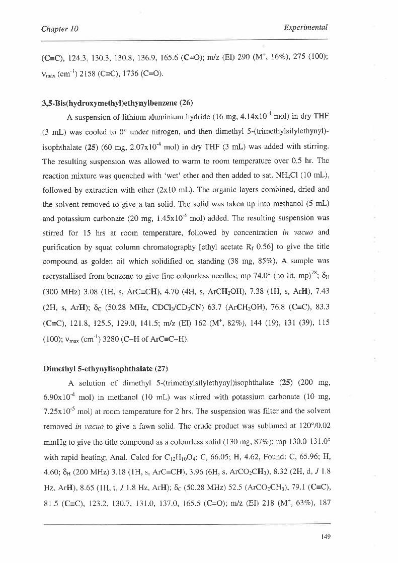
Chapter l0 Experimental
(C=C), 124.3,130.3, 130.8, 136.9,165.6 (C=O); mlz (EÐ 290 (M+,l6Eo), 275 (100);
v,u* (cm-r) 2158 (C=C),1736 (C=O).
3,5-Bis(hydroxymethyl)ethynylbenzene (26)
A suspension of lithium aluminium hydride (16 mg, 4.I4xl0-a mol) in dry THF
(3 mL) was cooled to 0" under nitrogen, and then dimethyl 5-(trimethylsilylethynyl)-
isophthalate (25) (60 mg, 2.07xIO-a mol) in dry THF (3 mL) was added with stining.
The resulting suspension was allowed to warm to room temperature over 0,5 hr. The
reaction mixture was quenched with 'wet' ether and then added to sat. NH4CI (10 mL),
followed by extraction with ether (2x10 mL). The organic layers combined, dried and
the solvent removed to give a tan solid. The solid was taken up into methanol (5 mL)
and potassium carbonate (20 mg, 1.45x10-a mol) added. The resulting suspension was
stirred for 15 hrs at room temperature, followed by concentration in vacuo and
purification by squat column chromatography [ethyl acetate Rr 0.56] to give the title
compound as golden oil which solidified on standing (38 mg, 85Vo). A sample was
recrystallised from benzene to give fine colourless needles; mp 74.0' (no lit. mp)78; õH
(300MHz) 3.08 (1H, s, ArC=CH),4.70(4H, s, ATCH2OH),7.38 (1H, s, AtH),7.43
(2H, s, ArH); ôc (50.28 MHz, CDCI¡/CD3CN) 63.7 (ATCHzOH),76.8 (C=C), 83.3
(c=c), 12r.8, 125.5, 129.0, 14r.5; mlz (EI) 162 (M+, 82Vo), r44 (19), 131 (39), 115
(100);vn'u* (cm-r) 32s0 (C-H of ArC=C-H).
Dimethyl 5 -ethynylisophthalat e (27 )
A solution of dimethyl 5-(trimethylsilylethynyl)isophthalate (25) (200 n8,
6.90x10-a mol) in methanol (10 mL) was stirred with potassium carbonate (10 mg,
7.25xl}-5 mol) at room temperature for 2 hrs. The suspension was filter and the solvent
removed in vacuo to give a fawn solid. The crude product was sublimed at 120"/0.02
mmHg to give the title compound as a colourless solid (130 mg, 87Vo); mp 130.0-131.0"
with rapid heating; Anal. Calcd for CrzHroO¿: C, 66.05; H, 4.62, Found: C, 65.96; H,
4.60; ôu (200 MHz) 3.18 (1H, s, ArC=CH),3.96 (6H, s, ATCOzCH¡),8.32 (2H, d, J 1.8
Hz, ArH), 8.65 (lH, r,,r 1.8 Hz, ArH); ôc (50.28 MHz) 52.5 (ATCOzCH¡), 79.1 (C=C),
81.5 (C=C), 123.2, 130.7,131.0, 131.0, 165.5 (C=O); niz (F,I) 218 (M+, 63Vo), 187
t49
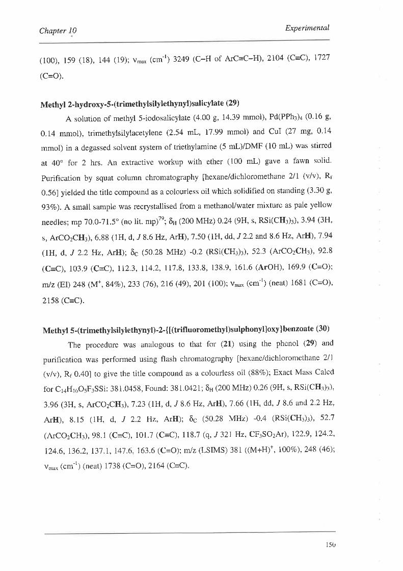
Chapter l0 Experimental
(100), 159 (18), 144 (19); v,u* (cm-r) 3249 (C-H of A¡C=C-H),2104 (C=C), 1727
(C=O).
Methyl 2-hydroxy-S -(trimethylsilylethynyl)salicyl ate (29)
A solution of methyl 5-iodosalicylate (4.00 g, 14.39 mmol), Pd(PPh3)4 (0.16 g,
0.14 mmol), trimethylsilylacety\ene (2.54 mL, 17.99 mmol) and CuI (27 mg,0.I4
mmol) in a degassed solvent system of triethylamine (5 mL)/DMF (10 mL) was stirred
at 40o for 2 hrs. An extractive workup with ether (100 mL) gave a fawn solid'
Purification by squat column chromatography [hexane/dichloromethane 2lI (v/v), R¡
0.561 yielded the title compound as a colourless oil which solidified on standing (3.30 g'
93Vo). A small sample was recrystallised from a methanoUwater mixture as pale yellow
needles; mp 70.0-71.5. (no lit. mp)7e; ôH (200 MHz) 0.24 (9H, s, RSi(CH¡)¡), 3.94 (3H,
s, ATCOzCH3), 6.88 (lH, d, J 8.6H2, ArH), 7.50 (lH, dd, J 2'2 and 8'6 Hz, ArH),7 '94
(1H, d, J 2.2 Hz, ArH); õc (50.28 MHz) -0.2 (RSi(cH¡)r), 52.3 (ATCOzCHù, 92.8
(C=C), 103.9 (C=C), 112.3, 114.2, 117.8, 133'8, 138.9, 161'6 (ArOH), 169.9 (C=O);
mlz (EI) 248 (M*,84Vo),233 (76),2t6 (4g),201 (100); v*u* (cm-r) (neat) 1681 (C=O),
2158 (C=C).
Methyl 5-(trimethylsilylethynyl)-2-{t(trifluoromethyl)sulphonylloxy}benzoate (30)
The procedure was analogous to that for (21) using the phenol (29) and
purification was performed using flash chromatography fhexane/dichloromethane 2ll
(v/v), Rr 0.401 to give the title compound as a colourless oil (88Vo); Exact Mass Calcd
for Cr¿HroOsF¡SSi: 381.0458, Found: 38L0421; õn (200 MHz) 0.26 (9H, s, RSi(CH:)¡),
3.96 (3H, s, ATCO2CHù,7 .23 (lH, d, J 8.6 Hz, ArH), 7.66 (lH, dd, J 8.6 and 2'2 Hz,
ArH), 8.15 (1H, d, J 2.2 Hz, ArH); õc (50.28 MHz) -0'4 (RSi(CH¡)¡)' 52'7
(ATCOzCH:),98.1 (C=C), 101.7 (C=C), 118.7 (q, J 321Hz, CF3SO2Ãr), 122'9, 124'2,
124.6, 136.2, t3't .1, t4l .6, 163.6 (C=O); mlz (LSIMS) 381 ((M+H¡*, 1007o¡,2a8 Ø6);
v,no* (cm-r) (neat) 1738 (C=O),2164 (C=C)
r5u
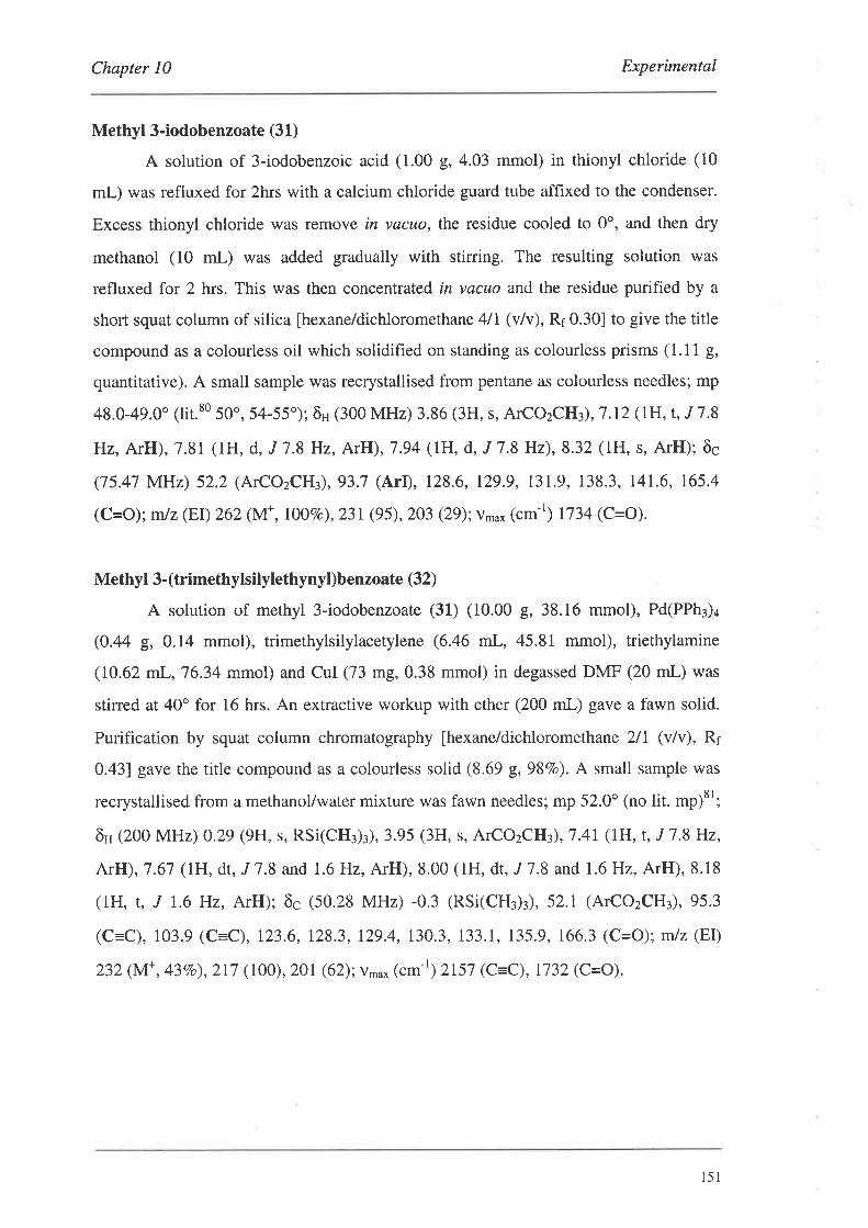
Chapter 10 Experimental
Methyl 3-iodobenzoate (31)
A solution of 3-iodobenzoic acid (1.00 g,4.03 mmol) in thionyl chloride (10
mL) was refluxed for 2hrs with a calcium chloride guard tube affixed to the condenser.
Excess thionyl chloride was remove in vacuo, the residue cooled to 0o, and then dry
methanol (10 mL) was added gradually with stining. The resulting solution was
refluxed for 2 hrs. This was then concentrated in vacuo and the residue purified by a
short squat column of silica [hexane/dichloromethane 4lI (v/v), Rr 0.30] to give the title
compound as a colourless oil which solidified on standing as colourless prisms (1.11 g,
quantitative). A small sample was recrystallised from pentane as colourless needles; mp
48.0-49.0' 1lit.80 50o, 54-55'); ôH (300 MHz) 3.86 (3H, s, ATCOzCHù,7.12 (lH, t, J 7.8
Hz, ArH), 7.81 (lH, d, J 7.8 Hz, ArH), 7.94 (IH, d, J 7.8 Hz), 8.32 (1H, s, ArH); ôc
(75.47 MHz) 52.2 (ATCOzCH¡), 93.7 (ArI), 128.6, 129.9, 131.9, 138.3, 14L6, 165.4
(c=o); mlz (EI) 262 (lvf ,1007o),231 (95),203 (29):v,u* (cm-r) 1734 (C=O).
Methyl 3- (trimethylsilylethynyl)benzoate (32)
A solution of methyl 3-iodobenzoate (31) (10.00 g, 38.16 mmol), Pd(PPh3)4
(O.44 g, 0.14 mmol), trimethylsilylacetylene (6.46 mL, 45.81 mmol), triethylamine
(10.62 mL,76.34 mmol) and CUI (73 m9,0.38 mmol) in degassed DMF (20 mL) was
stined at 40" for 16 hrs. An extractive workup with ether (200 mL) gave a fawn solid.
Purification by squat column chromatography [hexane/dichloromethane 2/l (v/v), Rr
0.431 gave the title compound as a colourless solid (8.69 g, 98Vo). A small sample was
recrystallised from a methanol/water mixture was fawn needles; mp 52.0o (no lit. mp)81;
ôH (200 MHz) 0.29 (9H, s, RSi(CH¡)¡), 3.95 (3H, s, ATCOzCH¡),7 .41 (1H, t, J 7 .8 Hz,
ArH), 7.67 (IH, dt, J 7.8 and 1.6 Hz, ArH), 8.00 (1H, dt, J 7.8 and 1.6 Hz, ArH), 8.18
(lH, t, J 1.6 Hz, ArH); ôc (50.28 MHz) -0,3 (RSi(CH¡)¡), 52.1 (ATCOzCH¡), 95.3
(C=C), 103.9 (C=C), 123.6, 128.3, 129.4, 130.3, 133.1, 135.9, 166.3 (C=O): mlz (EI)
232 (M+, 43Vo),217 (IOO),201 (62); v.o* (cm-r) 2157 (C=C), 1732 (C=O).
l5l
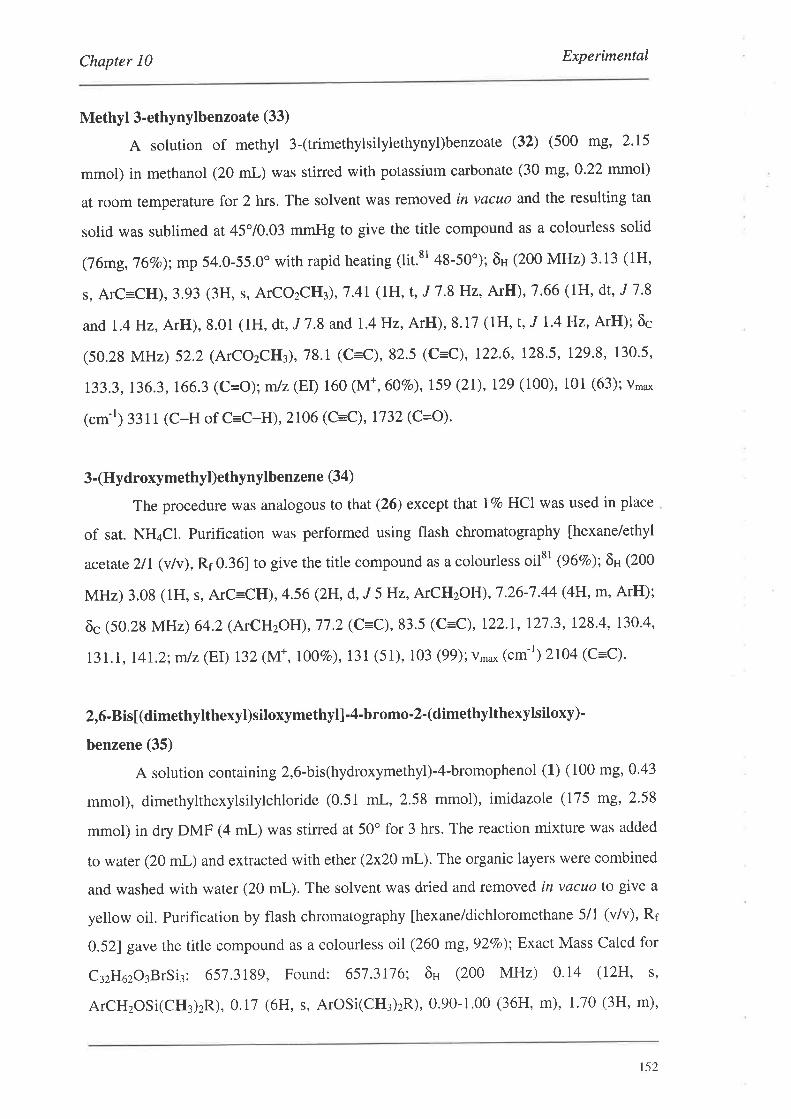
Chapter l0 Experimental
Methyl 3-ethynylbenzoate (33)
A solution of methyl 3-(trimethylsilylethynyl)benzoate (32) (500 mg, 2.15
mmol) in methanol (20 mL) was stirred with potassium carbonate (30 mg, O.22 mmol)
at room temperature for 2 hrs. The solvent was removed in vacuo and the resulting tan
solid was sublimed at 45"/0.03 mmHg to give the title compound as a colourless solid
(76mg,76Vo);mp 54.0-55.0" with rapid heating (lit.8r 48-50"); õH (200 MHz) 3.13 (1H,
s, ArC=CH), 3.93 (3H, s, ATCOzCHù,7.4I (1H, t, J 7.8 Hz, ArH), 7.66 (IH, dt, J 7 '8
and 1.4 Hz, ArH), 8.01 (lH, dt, J 7.8 and 1'4 Hz, ArH), 8'17 (1H, t, J 1.4 Hz, ArH); ôc
(50.28 MHz) 52.2 (ATCOzCH¡), 78.1 (C=C), 82.5 (C=C), 122.6, 128.5, 129.8, 130.5,
133.3,136.3,166.3 (C=O);mlz(ED 160 (M*,60E0),159(21),129(100), 101 (63);v'u*
("m-t) 331 1 (c-H of c=c-H),2106 (c=c), 1732 (c=o).
3-(Hydroxymethyl)ethynylbenzene (34)
The procedure was analogous to that (26) except that lVo HCI was used in place
of sat. NH¿CI. Purification was performed using flash chromatography [hexane/ethyl
acetate 2/L (vlv),Rr 0.361 to give the title compound as a colourless oilsr (96Vo); ôH (200
MHz) 3.08 (1H, s, ArC:CH),4.56 (2H, d, J 5 Hz, ATCHzOH),1 '26-7 .44 (4H, m, ArH);
õc (50.28 MHz) 64.2 (ÃrCHzOH), 77.2 (C=C), 83.5 (C=C), 122.1, l2'7.3, 128.4, 130.4,
131.1, I4L2;mtz(EI) 132(M*,I}OVo),131 (51), 103 (99);vtno* (c*-') 2104 (C=C).
2,6-Bis[(dimethylthexyl)siloxymethyl]-4-bromo-2-(dimethylthexylsiloxy)-
benzene (35)
A solution containing 2,6-bis(hydroxymethyl)-4-bromophenol (1) (100 mg,0'43
mmol), dimethytthexylsilylchloride (0.51 mL, 2.58 mmol), imidazole (175 mg, 2.58
mmol) in dry DMF (4 mL) was stirred at 50o for 3 hrs. The reaction mixture was added
to water (20 mL) and extracted with ether (2x20 mL). The organic layers were combined
and washed with water (20 mL). The solvent was dried and removed in vacuo to give a
yellow oil. Purification by flash chromatography [hexane/dichloromethane 5/1 (v/v), Rr
0.521 gave the title compound as a colourless oil (260 mg,92Vo); Exact Mass Calcd for
C:zHozO¡BrSi¡: 651.3189, Found: 657.3176; ôu (200 MHz) 0'14 (12H, s'
ATCHzOSi(CH¡)zR), 0.i7 (6H, s, ArOSi(CH:)zR), 0.90-1.00 (36H, m), 1.70 (3H, m),
152
Chapter l0 Experimental
4.67 (4H,s, ATCHzOR),7.49 (2H, s, ArH); õc (50.28 MHz) (only 13 signals observed) -
3.5, -1.6, 18.5, 20.3,25.3,25,7,33.9,34.I, 60.2 (ATCHzOR), 114.8 (ArBr), 128.8,
134.2, I4i.O; mtz (Et) 660 (M*, 8rBr, 1 IVo),6581M*, 7eBr, lOVo),575 18rBr, 25Vo),573
(tnBr, 23vo),487 (8rBr, 88vo),485 (7eBr, 79vo).
2,6-Bis[(dimethylthexyl)siloxymethyl]-4-iodo-2-(dimethylthexylsiloxy)benzene (36)
The procedure was analogous to that for (35) using 2,6-bis(hydroxymethyl)-4-
iodophenol (2) and purification by flash chromatography [hexane/dichloromethane 5/1
(v/v), Rr 0.481 gave rhe title compound as a colourless oil (93Vo); Anal. Calcd for
C:zH6¡O¡ISit: C,54.36; H, 8.98, Found: C,54.63:H,9'25; ôH (300 MHz) 0'11 (12H' s'
ATCHzOSi(CH3)2R),0.16 (6H, s, ArOSi(CH¡)zR),0.89-0.99 (36H' m)' 1.70 (3H, m),
4.63 (4H, s, ATCHzOR), 7.66 (2H, s, ArH); õcQ5.47 MHz) (only 13 signals observed) -
3.6, -1.5, 18.5 (br), 20.4 (br),25.3,25.8,34.0,34.2,60.1 (ATCHzOR), 85.2 (ArI), 134.5,
135.1, 148.0; mtz(EI) 707 (M*, 5Vo),621(18), 533 (34).
Dimethyl 5-iodo-2-[(dimethylthexyl)siloxy]isophthalate (37)
The procedure was analogous to that for (35) using the phenol (20) and 1.5
equivalents of both TDSCI and imidazole. The reaction mixture was stirred at room
temperature for 2 hrs, and purification by flash chromatography ldichloromethane, Rr
0.361 gave the title compound as a colourless oil (99Vo); Anal. Calcd for ClsHzrOsISi:
C, 45.19: H, 5.69, Found: C, 45.49; H, 5.49; ôr¡ (300 MHz) 0'00 (6H' s,
ArOSi(CH¡)zR), O.g4 (6H, d, J 6.9 Hz, (CH3)2CHR), l'02 (6H' s'
(CH¡)zCHC(CH¡)zSiR), 1.73 (1H, septet, J 6.9 Hz, (CH¡)zCHR), 3'85 (6H, s'
ATCOzCH¡), 8.1 I (2H, s, ArfI); õc Q5'47 MHz) -2.8, 18.4,20.0,25'2,33'6, 52'3,82'6
(ArI), Izi .8, t43.1, 153.5, 165.4 (C=O); mlz (FAB) 479 ((M+H¡*, 8Vo¡, 463 (10), 393
(100); v,u* (cm-r) 1145,1122 (C=o).
3,5-Bisl(t-butyldimethyl)siloxymethyl] bromobenzene (38)
The procedure was analogous to that for (35) using the 1,3-bis(hydroxymethyl)-
5-bromobenzene (24) and 2.2 equivalents of both TBDMSCI and imidazole. The
reaction mixture was stirred for at 50o for 4 hrs, and purification by flash
chromarography [hexane/dichloromethane 5/1 (v/v), R¡ 0.33] gave the title compound as
153
Chapter 10 Experimental
a colourless oil (937o); Anal. Calcd for CuoH¡zO2BrSi2: C, 53'91; H, 8.37, Found: C,
54.28: H, 8.52; õH (300 MHz) 0.07 (12H, s, ATCHzOSi(CH¡)ztBu), 0'92 (18H'
ATCHzOSi(CH3)2C(CH¡)¡), 4.61 (4H, s, ATCHzOR), 7.18 (1H' br s' ArH)' 7.31 (2H,br
s, ArH); õc Q5.47 MHz) -5.4, 18.3, 25.8,64.2 (ATCH2OR), 122.1, 122.3, 127.5, 143.7;
mlz (Er) 446 (l\/f ,8'Br, r4vo¡,444 (Nf ,7eBr, r27o¡. 389 (8), 387(8).
Methyl 5-iodo-2-l(dimethylthexyl)siloxy]benzoate (39)
The procedure was analogous to that for (35) using the phenol (28) and 1.5
equivalents of both TDSCI and imidazole. The reaction mixture was stirred at room
temperature for 1.5 hrs, and purification by flash chromatography
[hexane/dichloromethane 3lI (v/v), Rr 0.38] gave the title compound as a colourless oil
(82Vo); Exact Mass Calcd for CroHzoIO¡Si: 42L0699, Found: 421.0689; ôH (300 MHz)
0.22 (6H, s, ArOSi(CH¡)zR), 0.91 (6H, d, J 6'9 Hz, (CH3)zCHR), 0'96 (6H, s'
(CH3)2CHC(CH¡)zSiR), 1.74 (lH, septet, J 6'9 Hz, (CH3)2CHR), 3'85 (3H, s,
ATCOzCHù, 6.62 (lH, d, J 8.7 Hz, ArH), 7.60 (lH, dd, J 2.4 and 8.7 Hz, ArH), 8'01
(lH, d, J 2.4 Hz, fuH); õc Q5.47 MHz) -2.4, I8'4, 19.9,25.1,33.7, 51.9, 82'5 (ArI)'
122.9, 125.3, 139.8, 141.4, 154.7, 165.6 (C=O): mlz (EÐ 420 (M+, 7Vo),405 (5), 335
(100); v",u* (cm-r) 1725 (C=o).
l0-Decynyl- l,8-diethynylanthracene (41)
To a solution of 1,8-dichloro-l0-decynylanthracene (47) (400 mg, 1.04 mmol),
Ni(acac)2 (27 mg,0.10 mmol) and PPh3 (27 mg,0.10 mmol) in dry THF (15 mL) was
added a solution of (trimethylsilylethynyl)magnesium bromide (20 mL, 0.42ll{ in THF).
The Grignard was prepared by the addition of a solution of ethylmagnesium bromide
(10 mL,0.84 M in THF) to trimethylsilylacetylene (1.30 mL,9.19 mmol) in dry THF
(10 mL) at 0". The Grignard was waffned to room temperature over 2 hrs with vigorous
gas evolution. After addition of the Grignard to (47), the resulting solution was refluxed
for 17 hrs. The reaction mixture was quenched by cautious addition to sat NH4CI (100
mL). The organic layer was separated and the aqueous layer re-extracted with ether
(2x50 mL). The organic layers were combined and washed with water (100 mL). The
solvent was dried and removed to give a brown solid (400 mg) which was redissolved in
a 1:1 THF:MeOH (20 mL) solvent system. Potassium carbonate was added (110 mg,
r54
Chapter l0 Experimental
0.78 mmol) and the reaction mixture was stirred for 16 hrs at room temperature' The
solvent was then removed, and purification by flash chromatography
[hexane/dichloromethane 8/1 (v/v), Rr 0.36] gave the title compound as a yellow solid
(188 hg, 48Vo). A small quantity was recrystallised from methanol as small
orange/yellow prisms; mp 94.0-95.5o; Anal. calcd for czaHzo: C,92.77;H,7.23, Found:
C,92.52;H,7.12; ôH (300 MHz) 0.89 (3H, t, J 6.6H2),1.32-L 8l (12H, m),2'75 (2H,t,
J 7.2H2),3.62 (2H, s, AIC=CH),7.51(2H, dd, .,I6.9 and 8.7 Hz, AnthrylH), 7.80 (2H'
d, J 8.7 Hz, AnthrylH), 8.57 (2H, d, J 6.9 Hz, AnthrylH), 9.42 (IIH, s, AnthrylH); õç
(75.47 MHz) 14.1, 20.1,22.6, 28.9,29.1,29.2 (br,2 overlapping signals), 31.8, 76.8
(c=c), 81.6 (C=C), 82.8 (C=C), 103.3 (C=C), 120.0, 120.1, 123.8, t25.7, 128.4, 131.2,
131.8, 132.3;m/z (FAB) 363 ((M+H¡*, ITVo¡,362 (M+ , 30Vo); v*o* (cm-r) 329t (C-H of
ArC=C-H),2214 (C=C); UV-Vis (nm)257 (49 000), 265 (117 000), 287 (lO 000),299
(10 000), 369 (5 000), 384 (10 000), 406 (19 000), 430 (21 000); Fluorescence (nm)
390, 393, 417, 438, 462, 494.
1O-bromo- L,8-dichloroanthracene (46)
To a solution of 1,8-dichloroanthracene (3.45 g, t3.96 mmol) in CCI¿ (200 mL)
was added a solution of bromine (3.60 mL, 69.83 mmol) in CCI¿ (15 mL) dropwise with
stirring. A yellow precipitate formed during the addition of the bromine, and once
addition was complete, the reaction mixture was stirred for a further 16 hrs at room
temperature. The solvent and excess bromine was removed in vacuo and the residue
recrystallised from acetic acid to give the title compound as fine golden needles (3.7I g,
82Vo); mp 200.0-ZOI.5" (lit.88 202'); ôn (300 MHz) 7.54 (2H, dd, "/ 1.2 and9.OHz,
AnthrylH), 7.68 (2H, d, J 7.2 Hz, AnthrylH), 8.48 (2H, d, J 9.0H2, AnthrylH); ôc
(75.41 MHz) 121.4, 123.5, 126.3, 121'0, 127.1, 129.6, 131.4, 132.7; õc Q5'47 MHz,
proton coupled) 121.5 (d, J 166.4Hz), 125.5 (m), 126.4 (dd, J 166.7 and9'l Hz), 127.0
(dd, J 165.4 andT .4 Hz), 127 .l (d, ,f 164.2 Hz), 129'6 (t, J 5'9 Hz), I3l'4 (t, J 8'2 Hz),
132.6 (m); mlz (EI) 330 (M*,2x37C18'Br, 8Vo), 328 (M*, 2x37cl7eBr and "Cl"ClttBr,
47Vo),326 (M*, 2x3sclsrBr and 3sCI37Cl7eBr, I00Vo),324 (M*,zx3scl1eBr,607o),249
(3),247 (5),245 (8),212 (13),210 (50), 175 (30).
155
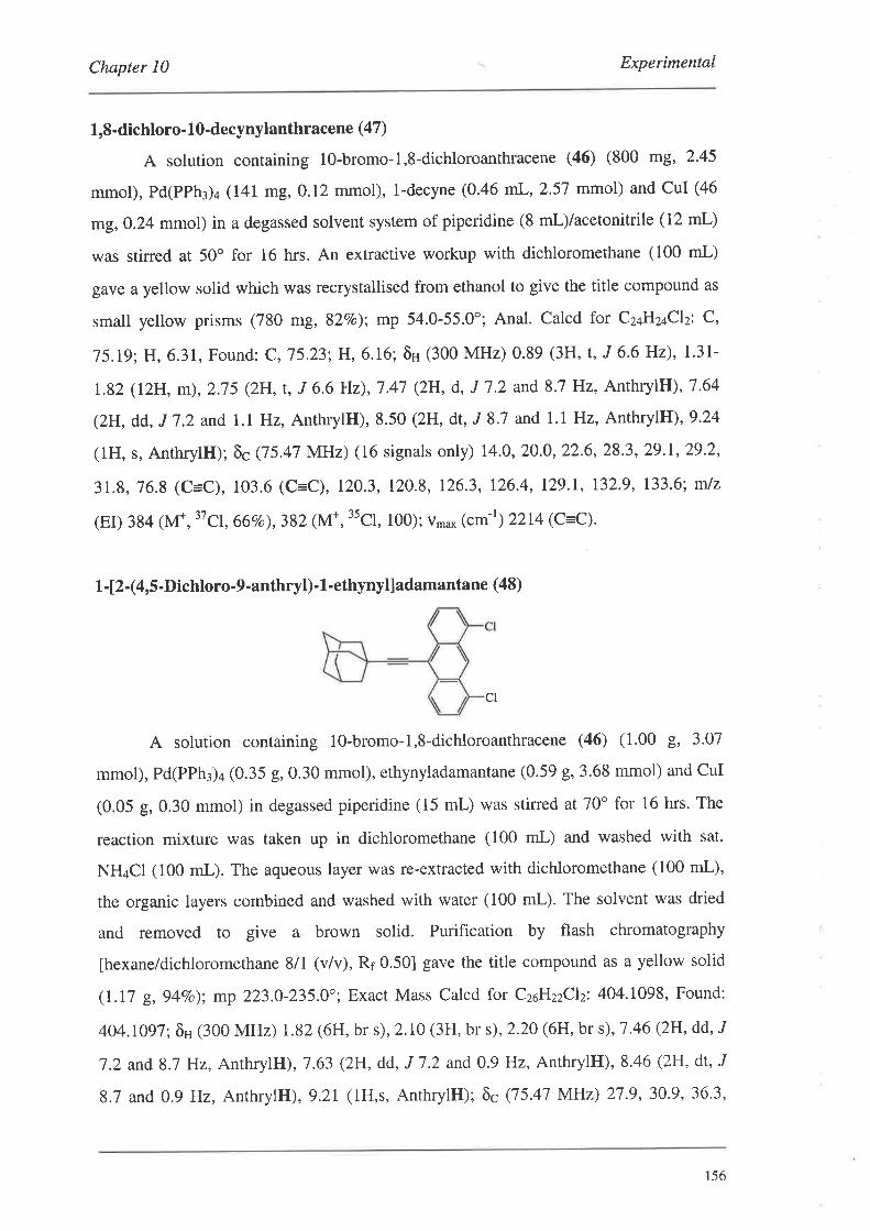
Chapter l0 Experimental
1,8-dichloro- 10-decynylanthracene (47)
A solution containing 10-bromo-1,8-dichloroanthracene (46) (800 mg, 2.45
mmol), Pd(PPh¡)+ (141 mg, 0.12 mmol), l-decyne (0.46 mL, 2.57 mmol) and CuI (46
mg, O.24 mmol) in a degassed solvent system of piperidine (8 ml)/acetonitrile (12 mL)
was stined at 50" for 16 hrs. An extractive workup with dichloromethane (100 mL)
gave a yellow solid which was recrystallised from ethanol to give the title compound as
small yellow prisms (780 mg, 82Vo); mp 54.0-55.0"; Anal. Calcd for C2aH2aClz: C,
15.19; H,6.31, Found: C,75.23; H,6.16; ôH (300 MHz) 0.89 (3H, t, J 6'6 Hz), 1.31-
L82 (12H, m),2.75 (2H, t, J 6.6 Hz),1.47 (2H, d, J 7 '2 and 8.7 Hz, AnthrylE),7.64
(2H, dd, J 7.2 and, l.I Hz, AnthrylH), 8.50 (2H, dt, J 8.7 and 1.1 Hz, AnthrylH),9.24
(1H, s, AnthrylH); õc Q5.47 MHz) (16 signals only) 14.0, 20.0,22.6,28.3,29.1,29.2,
31.8,76.8 (C=C), 103.6 (C=C), 120.3, 120.8, 126.3, 126.4, 129.1, 132.9, 133.6; rnlz
(EI) 384 llv{*, 37c1, 667o),382 (M*, 35C1, 100); v*u* (cm-r) 2214 (C=C).
L-12-(4,5-Dichloro-9-anthryl)-1-ethynylladamantane (48)
cl
A solution containing 10-bromo-1,8-dichloroanthracene (46) (1.00 g, 3.01
mmol), Pd(PPh¡)¿ (0.35 g,0.30 mmol), ethynyladamantane (0.59 g, 3.68 mmol) and CuI
(0.05 g, 0.30 mmol) in degassed piperidine (15 mL) was stirred at 70o for 16 hrs. The
reaction mixture was taken up in dichloromethane (100 mL) and washed with sat.
NH¿CI (100 mL). The aqueous layer was re-extracted with dichloromethane (100 mL),
the organic layers combined and washed with water (100 mL). The solvent was dried
and removed to give a brown solid. Purification by flash chromatography
[hexane/dichloromethane 8/1 (v/v), Ri 0.50] gave the title compound as a yellow solid
(LI/ g,94Vo); mp 223.0-235.0"; Exact Mass Calcd for CzoHzzClzi 404.1098, Found:
404j097; ôH (300 MHz) 1.82 (6H, br s), 2.10 (3H, bt s),2'20 (6H, br s),7.46 (2H, dd, J
7.2 and8.7 Hz, AnthrylH), L63 (2H, dd, J 1.2 and 0.9 Hz, AnthrylH), 8.46 (2H, dt, J
8.7 and 0.9 Hz, AnthrylH), 9.21 (lH,s, AnthrylH); ôc (75.47 MHz) 2J'9,30.9' 36.3,
156

Chapter l0 Experimental
42.g,15.6 (C=C), 111.5 (C=C), 120.3, 120.7,126.3,126.4, 121.4, 129.1, t32.9, 133.4;
m/z (EI) 408 (M*, 37cf7cl, r3vo),406 (M*, 37cl3scl, 687o),404 (M*, "cl"cl, r007o);
v,nu^ 1cm-r¡ 2209 (c=c).
l-{2-Í4,5-Bis(trimethylsilytethynyl)-9-anthryll-1-ethynyl}adamantane (49)
SiMe3
The procedure was analogous to that for (41) except that the intermediate solid
was purified by flash chromatography [hexane/dichloromethane 8/1 (v/v), Rr 0.44] to
give the title compound as a yellow solid (697o). A small quantity was recrystallised
from i-PrOH as small yellow prisms; mp230.0-232.0o; Anal. Calcd for C¡oH¿oSiz: C,
8L76;H,7.62,Found: C,81.58; H,1.77; õH (300 MHz) 0.37 (18H, s, ArC=CSi(CH¡)¡),
1.81 (6H, br s), 2.09 (3H, br s), 2.19 (6H, br s), 7.48 (2H, dd, J 6.9 and9 Hz, AnthrylH),
7.19 (2H,dd,J 6.9 and0.9 Hz, AnthrylH),8.53 (2H,dt,J9 and0.9Hz, AnthrylH),9.29
(lH,s); õc Q5.47 MHz) 0.4,28.1, 31'1,36.4, 43'1,75.8 (C=C), 100.0 (C=C), 103'6
(C=C), 111.1 (C=C), 119.8, 121.6, 123.8, 125.6, 128.1, 130'8, 132.1, 132'5; mlz (El)
528 (M*, l37o); v,"u* (cm-r) 2148 (C=C); UV-Vis (nm) 240 (20 000), 261 (15 000), 269
(13 000), 297 (11 000), 3ll (14 000),371 (7 000),391 (15 000),414 (28 000), 440 (32
000); Fluorescence (nm) 382, 400,425,447,473, 504.
2,6-Bis(morpholinomethyl)'4-(2-phenyl' L'ethynyl)phenol (54)
A solution of 2,6-bis(morpholinomethyl)-4-iodophenol (7) (1.00 g,2.03 mmol),
Pd(PPh3)4 (0.23 9,0.20 mmol), phenyl acetylene (0.45 mL,4.06 mmol) and CuI (38 mg,
0.20 mmol) in degassed piperidine (15 mL) was stined at room temperature for I hr. An
extractive workup with dichloromethane (60 mL) gave an orange/red oil. Purification by
flash chromatography on silica gel fethyl acetate, Rr 0.40] gave the title compound as a
golden oil (0.83 g, 94Vo); Exact Mass Calcd for Cz+HzsNzO¡: 392'2100, Found:
392.2103; õH (300 MHz) 2.12 (8H, t, J 4.4 Hz), 3'80 (4H s, ATCH2R), 3.92 (8H, t, J 4'4
Hz), 1.51 (5H, m, ArH), 1.69 (2H, m, ArH); õc (50'28 MHz) 53'1, 58'6, 66'6
iMel
r57
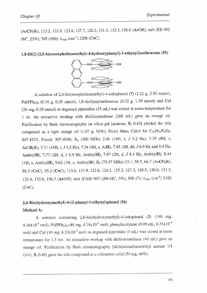
Chapter I0 Experimental
(ArcHzR), !13.2,122.5,123.6,!27.7,128.2,131.3, !32.3,156.6(ArOH);mlz(EÐ392
çM,.*,23vo¡,305 (100)i Vma* ("tn-') 2208 (c=c).
1,8-Di{2-[3,5-bis(morpholinomethyl)-4-hydroxyphenyl]-l-ethynyl]anthracene (55)
o:NOH
N
oCt¡A solution of 2,6-bis(morpholinomethyl)-4-iodophenol (7) (1.22 9,292 mmol),
Pd(PPh¡)¿ (0.16 g, 0.29 mmol), l,8-diethynylanthracene (0.32 g, 139 mmol) and CuI
(26 mg,0.29 mmol) in degassed piperidine (15 mL) was stirred at room temperature for
t hr. An extractive workup with dichloromethane (200 mL) gave an orange oil.
Purification by flash chromatography on silica gel [acetone, Rr 0.43] yielded the title
compound as a light orange oil (1.07 g, 95Vo); Exact Mass Calcd for CsoHssN¿Oo:
807.4123, Found: 807.4246; ôH (300 MHz) 2.46 (16H, t, J 4.2 Hz), 3'39 (8H, s,
ATCHzR),3.71 (16H, t,J 4.2H2),7.34 (4H, s, ArH),7.45 (2H,dd,J 6'9}Jzand8'4H2,
AnthrylH), 7.17 (2H, d, J 6.9 Hz, AnthrylH.), 7.97 (2H, d, J 8.4 Hz, AnthrylH), 8'44
(1H, s, AnthrylH), 9.62 (IH, s, AnthrylH); õc Q5.47 MHz) 53.1, 58.7, 66'7 (ArCHzR)'
86.3 (C=C),95.2 (C=C), 113.6, 121.9, 122.6, 124.2, 125.2, 127 '3, 128.5, 130'0, 131'3,
131.6, 132.6,156.7 (ArOH); mlz (FAB) 807 ((M+H)*,5%o¡' 306 (7); vma* (cm-r) 2192
(C=C).
2,6-Bis(hydroxymethyl)-4-(2'phenyl' l'ethynyl)phenol (56)
Method A:
A solution containing 2,6-bis(hydroxymethyl)-4-iodophenol (2) (140 ñ8,
4.16x10-a mol), Pd(PPh3)4 (48 mg,4.16x10-s mol), phenylacetylene (0.09 mL,8.33x10-a
mol) and CuI (16 mg, 8.33x10⁴ mol) in degassed piperidine (3 mL) was stirred at room
temperature for 1.5 hrs, An extractive workup with dichloromethane (40 mL) gave an
orange oil. Purification by flash chromatography [dichloromethane/ethyl acetate 1/1
(v/v), Rr 0.481 gave the title compound as a colourless solid (59 mg, 46Vo).
r58
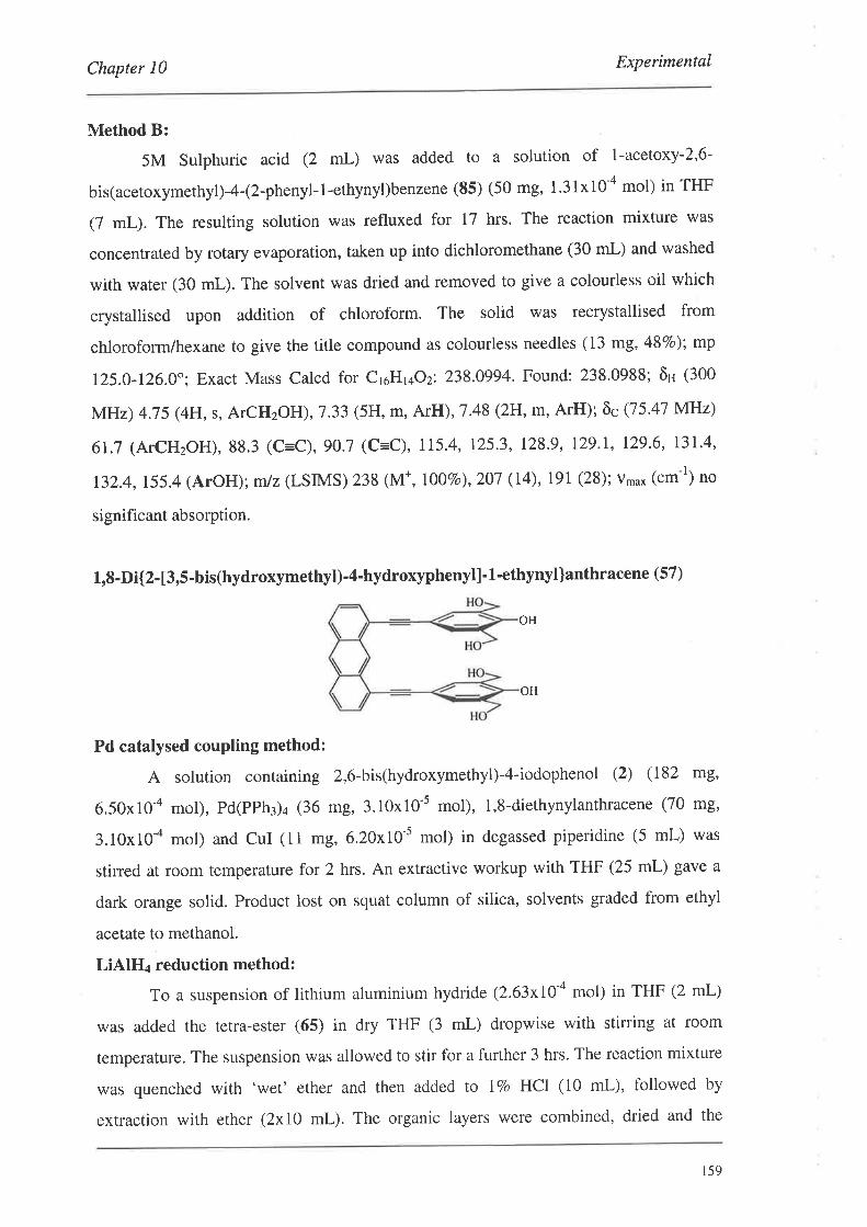
Chapter l0 Experimental
Method B:
5M Sulphuric acid (2 mL) was added to a solution of 1-acetoxy-2'6-
bis(acetoxymerhyl)-4-(2-phenyl-l-ethynyl)benzene (85) (50 mg, 1.31x10-a mol) in THF
(7 mL). The resulting solution was refluxed for 17 hrs. The reaction mixture was
concentrated by rotary evaporation, taken up into dichloromethane (30 mL) and washed
with water (30 mL). The solvent was dried and removed to give a colourless oil which
crystallised upon addition of chloroform. The solid was recrystallised from
chloroform/hexane to give the title compound as colourless needles (13 mg, 48Vo); mp
125.0-126.0"; Exact Mass Calcd for CroH vOz: 238'0994' Found: 238.0988; ôH (300
MHz) 4.75 (4H, s, ATCHzOH),7.33 (5H, m, ArH), 7.48 (2H, m, ArH); õcQ5'47 MHz)
61.7 (ATCH2OH), 88.3 (C=C), gO.1 (c=C), 115.4, 125.3' 128.9' 129.1' 129.6' 131.4,
132.4,155.4(ArOH); m/z (LSIMS) 238 (M+, 10070),207 (14), 191 (28); v'u* 1cm-r) no
significant absorption.
1,8-Di{2- [3,5 -bis(hydroxymethyt)-4-hydroxyphenyl]' 1 -ethynyl]anthracene (57)
Pd catalysed coupling method:
A solution containing 2,6-bis(hydroxymethyl)-4-iodophenol (2) (182 ñ9,
6.50x10-a mol), Pd(PPh¡)¿ (36 mg, 3.10x10⁻⁵ mol), 1,8-diethynylanthracene (70 mg,
3.10x10-a mol) and CuI (11 mg,6.20x10-s mol) in degassed piperidine (5 mL) was
stirred at room temperaturefor2 hrs. An extractive workup with THF (25 mL) gave a
dark orange solid. Product lost on squat column of silica, solvents graded from ethyl
acetate to methanol.
LiAlH4 reduction method:
To a suspension of lithium aluminium hydride (2.63xI0-a mol) in THF (2 mL)
was added the tetra-ester (65) in dry THF (3 mL) dropwise with stirring at room
temperature. The suspension was allowed to stir for a further 3 hrs. The reaction mixture
was quenched with 'wet' ether and then added to lVo HCI (10 mL), followed by
extraction with ether (2x10 mL). The organic layers were combined, dried and the
OH
OH
r59
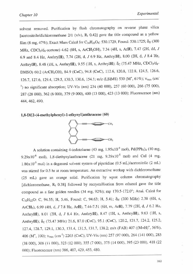
Chapter 10 Experimental
solvent removed. Purification by flash chromatography on reverse phase silica
[acetonitrile/dichloromethane 2lI (vlv), Rf 0.42] gave the title compound as a yellow
film (8 mg, 47 Vo); Exact Mass Calcd for C3aH26Oo: 530' 1729, Found: 530' 1725', õH (300
MHz, CDCl¡/do-acetone) 4.62 (8H, s, ATCH2OH),7.34 (4H, s, ArH), 7'41 (2H' dd' J
6.9 and 8.4 Hz, AnrhrylH), 7.74 (2H, d, J 6.9 Hz, AnthrylH), 8.00 (2H, d, J 8.4 Hz,
AnrhrylH), 8.48 (1H, s, AnthrylH), 9.55 (1H, s, AnthrylH); õc Q5.47 MHz, CDCI¡/do-
DMSO) 60.2 (ATCHzOH), 84.9 (C=C), 94.8 (C=C), 112.6,120.8, 122.8, 124.5, 126.6,
126.7,12i.6,129.4,12g.5,130.3, 130.6, 154.1; m/z (LSIMS) 530 (M*,6lEo); vmax (cm-
r) no significant absorption; UV-Vis (nm) 234 (40 000), 257 (60 000), 266 (75 000)'
287 (28000),362 (6 000), 379 (9 000),400 (13 000), 423 (13 000); Fluorescence (nm)
444,462,490.
1,8-Di[2-(4-methylphenyl)'1'ethynyl]anthracene (60)
A solution containing 4-iodotoluene (43 mg, 1.95x10-a mol), Pd(PPh3)4 (10 mg,
9.29x10-ó mol), l,8-diethynylanrhracene (21 mg, 9.29x10-s mol) and CuI (4 mE,
l.86xl0-5 mol) in a degassed solvent system of piperidine (0.5 ml)/acetonitrile (2 mL)
was stirred for 0.5 hr at room temperature. An extractive workup with dichloromethane
(25 mL) gave an orange solid. Purification by squat column chromatography
[dichloromethane, Rr 0.38] followed by recrystallisation from ethanol gave the title
compound as a fine golden needles (34 mg, 92Vo); mp 170.5-172'0"; Anal. Calcd for
CyHzzO: C, 94.55; H, 5.46, Found: C, 94'63; H, 5.41; õn (200 MHz) 2'38 (6H, s,
ArCH¡), 6.99 (4H, d, J 1.8 Hz, ArH), 1.44-7 '51 (6H, m, ArH), 7.19 (2H, d, J 6'2 Hz,
AnthrylH), 8.01 (2H, d, J 8.4 Hz, AnthrylH), 8'47 (1H, s, AnthrylH), 9'63 (1H, s,
AnthrylH); õc Q5.47 MHz) 21.6,87.0 (C=C), 95.1 (C=C), 120.2, l2l.l, 124.2, 125,2,
127 .4, 128,1 , 12g.1,130.3, 131.4, 131.5, l3l.l , 138.2; m/z (FAB) 407 ((M+H)*, 567o¡,
406 (M*, 100); v,"o* (.¡¡ ') 2203 (C=C); UV-Vis (nm) 251 (97 000), 264 (I4l000), 285
(38 000),308 (i1000), 323 (12000),355 (7 000),375 (14 000),395 (23 000), 4r8(22
000); Fluorescence (nm) 386, 407, 429, 453, 480'
CH¡
160
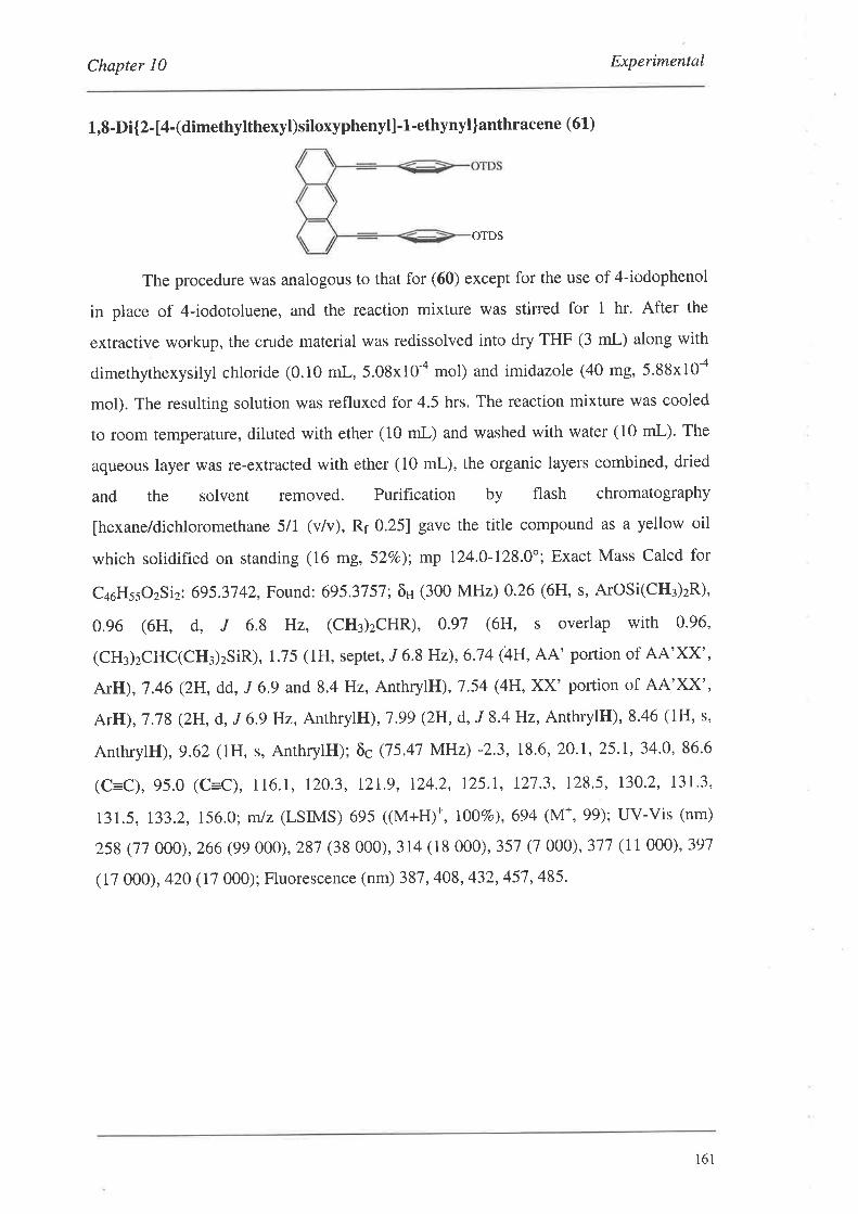
Chapter 10 Experimental
1,8-Di{2- [4-(dimethytthexyl)siloxyphenyt] - 1 -ethynyl ]anthracene (61)
OTDS
The procedure was analogous to that for (60) except for the use of 4-iodophenol
in place of 4-iodotoluene, and the reaction mixture was stirred for I hr. After the
extractive workup, the crude material was redissolved into dry THF (3 mL) along with
dimethythexysilyl chloride (0.10 mL, 5.08x10-a mol) and imidazole (40 mg, 5.88x10-a
mol). The resulting solution was refluxed for 4.5 hrs. The reaction mixture was cooled
to room temperature, diluted with ether (10 mL) and washed with water (10 mL). The
aqueous layer was re-extracted with ether (10 mL), the organic layers combined, dried
and the solvent removed. Purification by flash chromatography
[hexane/dichloromethane 5/1 (v/v), Rr 0.25] gave the title compound as a yellow oil
which solidified on standing (16 mg, 52Vo); mp 124.0-128.0'; Exact Mass Calcd for
c¿oHssozS iz: 695.37 42, Found: 695.37 57; ôH (300 MHz) 0.26 (6}l, s, ArOSi(CH¡)zR),
0.96 (6H, d, J 6.8 Hz, (CH¡)zCHR), 0'91 (6H, s overlap with 0'96,
(CH¡)zCHC(CH3)2SiR), 1.75 (1H, septet , J 6.8 Hz), 6.74 (4H, AA' portion of AA'XX',
ArH), 7.46 (2H, dd, .I 6.9 and 8.4 Hz, AnthryllJ),1.54 (4H, XX' portion of AA'XX',
ArH), 7 .78 (2H, d, J 6.9 Hz, Anthryllt),1 .99 (2H, d, J 8.4 Hz, AnthrylH)' 8.46 (lH, s,
AnthrylH), 9.62 (IH, s, AnthrylH); õc (75.47 MHz) -2'3, 18.6,20.1,25.1, 34'0, 86.6
(C=C),95.0 (C=C), 116.1, 120.3, 12L9, 124.2, 125.I, L21.3, 128.5, 130.2, 131'3,
131.5, 133.2, 156.0; m/z (LSIMS) 695 ((M+H)+, r\OVo),694 (M*,99); UV-Vis (nm)
258 (11 000),266 (99 000), 287 (38 000),314 (18 000), 357 (7 000), 377 (11 000), 397
(17 000), 420 (17 000); Fluorescence (nm) 387, 408,432,45'7,485.
161
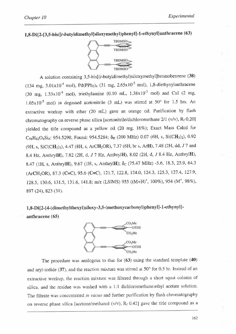
Chapter 10 Experimental
1,8-Di{2-[3,5-bis([r-áutyldimethyl]siloxymethyl)phenyll-1-ethynyl]anthracene (63)
A solution containing 3,5-bisl(r-butyldimethyl)siloxymethyl]bromobenzene (38)
(134 mg, 3.01x10-a mol), Pd(PPh¡)¿ (31 mg, 2.65x10-s mol), 1,8-diethynylanthracene
(30 mg, 1.33x10-a mol), rriethylamine (0.10 mL, 1.38x10⁻³ mol) and cul (2 mg,
1.05x10⁻⁵ mol) in degassed acetonitrile (3 mL) was stirred at 50" for 1.5 hrs. An
extractive workup with ether (20 mL) gave an orange oil. Purification by flash
chromatography on reverse phase silica [acetonitrileidichloromethane 2/I (v/v), Rr 0.20]
yielded the title compound as a yellow oil (20 mg, 167o): Exact Mass Calcd for
cssHszo¿Siq:954.5290, Found: 954.5284; õH (200 MHz) 0.07 (6H, s, Si(CH3)ù,092
(9H, s, SiC(CH3)3),4.47 (8H, s, ATCHzOR),1.37 (6H, br s, ArH), 7 '48 (2H, dd, 'I7 and
8.4H2, AnthrylH), 7.82 (2H, d, J 7 Hz, AnthrylH), 8.02 (2H, d, J 8.4H2, AnthrylH),
8.47 (lH, s, AnthrylH),9.67 (lH, s, AnthrylH); õc Q5.47 MHz) -5.6, 18.3, 25.9, 64'3
(ATCHzOR), 87.3 (C=C), 95.6 (C=C), 12L7, 122.8, 124.0, 124'3, 125'3, 127 '4, 127 '9,
12g.5,130.6, 131.5, 131.6,141.8; m/z (LSIMS) 955 ((M+H)*, 1007o),954 (M+, 98Vo),
897 (24),823 (31).
1,8-Di{2-[4-(dimethylthexyt)siloxy-3,5-(methoxycarbonyl)phenyl]-1-ethynyl]-
anthracene (65)
The procedure was analogous to that for (63) using the standard template (40)
and aryl-iodide (37), and the reaction mixture was stirred at 50o for 0.5 hr. Instead of an
extractive workup, the reaction mixture was filtered through a short squat column of
silica, and the residue was washed with a 1:1 dichloromethane:ethyl acetate solution'
The filtrate was concentrated in vacuo and further purification by flash chromatography
on reverse phase silica [acetone/methanol (v/v), Rr 0.42] gave the title compound as a
t62
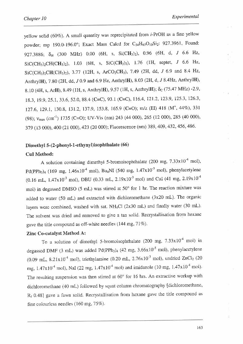
Chapter l0 Experimental
yellow solid (602o). A small quantity was reprecipitated from i-PrOH as a fine yellow
powder; mp 190.0-196.0o; Exact Mass Calcd for Cs¿Ho¡OroSiz: 927.3961, Found:
927.3886; õH (300 MHz) 0.00 (6H, s, Si(CH3)2), 0'96 (6H' d' J 6'6 Hz'
SiC(CH¡)zCH(CH3)2), 1.03 (6H, s' SiC(CH¡)z), I'76 (1H, septet' J 6'6 Hz'
Sic(cH¡)zcII(CH3)2) , 3.77 (12H, s, ATCOzCHù, 7.49 (2H' dd' J 6,9 and 8.4 Hz,
AnthrylH),7.80 (2H, dd,,r0.9 and 6.9 Hz, AnthrylH),8.03 (2H, d, J 8.4H2, AnthrylH),
8.10 (4H, s, ArH),8.49 (1H, s, AnthrylH),9.57 (lH, s, AnthrylH); õcQ5'41 }/{Hz) -2'9'
18.3, 19.9, 25,1,33.6,52.0, 88.4 (C=C),93.1 (C=C),116.4,121.2,123.9,125.3,126.3,
t27 .6, I2g.I, 130.8, 131.2, I3l .g, 153.8, 165.9 (C=O); mlz (EI) 418 (M+, 44Eo), 331
(98); v,u* ("m-') 1735 (C=o); UV-Vis (nm) 243 (44 000), 265 (12 000), 285 (40 000)'
37g (13000),400 (21 000), 423 (20 000); Fluorescence (nm) 389, 409,432,456,486.
Dimethyl 5-(2-phenyl-1'ethynyl)isophthalate (66)
CuI Method:
A solution containing dimethyl S-bromoisophthalate (200 mg, 7.33x10-a mol),
pd(pph¡)¿ (169 mg, 1.46x10-a mol), BuaNI (540 mg, l.47xl0-3 mol), phenylacetylene
(0.16 mL, l.47xì0-3 mol), DBU (0,33 mL, 2.I9xl0-r mol) and CuI (41 mg,2.I9xI0-a
mol) in degassed DMSO (5 mL)'was stirred at 50o for t hr. The reaction mixture was
added to water (50 mL) and extracted with dichloromethane (3x20 mL)' The organic
layers were combined, washed with sat. NH¿CI (2x30 mL) and finally water (30 mL).
The solvent was dried and removed to give a tan solid. Recrystallisation from hexane
gave the title compound as off-white needles (I44 mg,T IVo).
Zinc Co-catalyst Method A:
To a solution of dimethyl 5-bromoisophthalate (200 mg, 7.33xI0-a mol) in
degassed DMF (3 mL) was added Pd(PPh3)4 (42 mg,3.66x10-s mol), phenylacetylene
(0.09 mL, 8.21x10-a mol), triethylamine (0.20 mL, 2.76xI0-1 mol), undrted ZnClz (20
mg,I.47xI0-a mol), NaI (22 mg,I.47xI0-a mol) and imidazole (10 mg, !.47x10-a mol)'
The resulting suspension was then stined at 60" for 16 hrs. An extractive workup with
dichloromethane (40 mL) followed by squat column chromatography [dichloromethane,
Rr 0.481 gave a fawn solid. Recrystallisation from hexane gave the title compound as
fine colourless needles (160 mg,75Vo).
r63
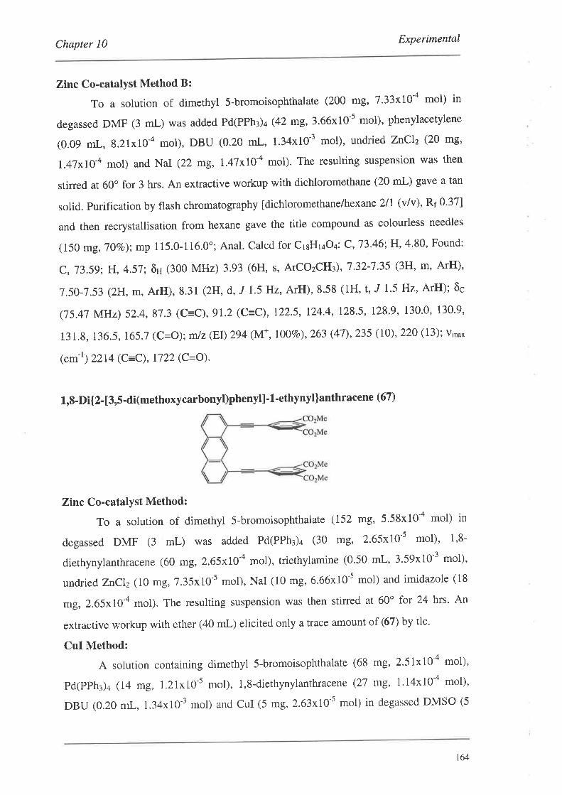
Chapter 10 Experimental
Zinc Co-catalyst Method B:
To a solution of dimethyl S-bromoisophthalate (200 mg, 7.33xLO'a mol) in
degassed DMF (3 mL) was added Pd(PPh¡)+ (42 mg,3.66x10-5 mol), phenylacetylene
(0.09 mL, 8.21x10-a mol), DBU (0.20 mL, 1.34x10⁻³ mol), undried ZnClz (20 mg'
I.47xl0-a mol) and NaI (22 mg, l.47xl04 mol). The resulting suspension was then
stired at 60o for 3 hrs. An extractive workup with dichloromethane (20 mL) gave a tan
solid. purification by flash chromatography [dichloromethane/hexane 2ll (v/v), Rr 0.37]
and then recrystallisation from hexane gave the title compound as colourless needles
(150 mg, 10vo); mp 115.0-116.0o; Anal. calcd for cr¡Hr¿o¿,: c,'73.46; H,4.80, Found:
C,73.59;H,4.57; ôH (300 MHz) 3.93 (6H, s, ATCOzCI|Iù,7'32-7'35 (3H' m' ArH)'
7.50-7.53 (2H,m,ArH),8'31 (2H, d, J 1'5 Hz, ArH),8'58 (1H, t, J l'5 Hz' ArH); ôc
(75.47 MHz) 52.4, 87.3 (C=C), 91.2 (C=C), 122.5, 124.4, 128.5, 128.9, 130.0, 130.9,
131.8, 136.5, 165.7 (C=O);mlz(EI)294 (M*,IOOE,),263 (47),235 (10),220 (13); v'oo*
(c--') 2214 (c=C), 1722 (c=o).
L,8-Di{2- l3,5-di(methoxycarbonyl)phenyl] - 1 -ethynyl]anthracen e (67 )
Zinc Co-catalyst Method:
To a solution of dimethyl 5-bromoisophthalate (152 mg, 5'58x10-a mol) in
degassed DMF (3 mL) was added Pd(PPh¡)¿ (30 DB, 2.65x10-s mol), 1,8-
diethynylanthracene (60 mg, 2.65x\0'a mol), triethylamine (0.50 mL, 3'59x10-3 mol),
undried ZnClz(10 mg, 7.35x10-s mol), NaI (10 mg, 6.66x10-s mol) and imidazole (18
mg, 2.65x10-a mol). The resulting suspension was then stined at 60" for 24 hrs. An
extractive workup with ether (40 mL) elicited only a trace amount of (67) by tlc'
CuI Method:
A solution containing dimethyl 5-bromoisophthalate (68 mg, 2.51x10⁴ mol),
pd(pph3)4 (14 mg, l.2lxl0-5 mol), 1,8-diethynylanthracene (27 mg, 1'14x10-a mol),
DBU (0.20 mL, 1.34x10⁻³ mol) and CuI (5 mg,2.63x10-5 mol) in degassed DMSO (5
164
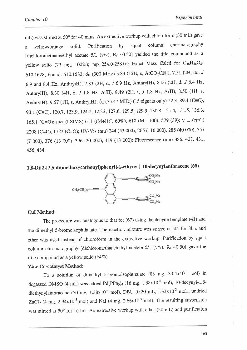
Chapter 10 Experimental
mL) was stirred at 50" for 40 mins. An extractive workup with chloroforin (30 mL) gave
a yellow/orange solid. Purification by squat column chromatography
[dichloromethane/ethyl acetate 5/1 (v/v), Rr -0'50] yielded the title compound as a
yellow solid (73 mg, 1007o); mp 254.0-258.0"; Exact Mass Calcd for C¡sHzoOs:
6r0.1628, Found: 610.1583; õH (300 MHz) 3.83 (12H, s, ArCozóH¡), 7'51 (2H, dd, J
6.9 and 8.4 ]Hz, AnthrylH), 7 '83 (2H, d, J 6.9 Hz, AnthrylH), 8'06 (2H' d' J 8'4 Hz'
AnthrylH), 8,30 (4H, d, ,f 1.8 Hz, ArH), 8.49 (2H, t, 'f 1'8 Hz, ArH)' 8'50 (1H' s'
AnthrylH),9.57 (lH, s, AnthrylH); õc (75.47 MHz) (15 signals only) 52.3, 89.4 (C=C),
93.1 (C=C),120.7,123.g,124.2,125.2,127.6,129.5,129.9,130.8, 131.4,131.5, 136'3,
165.1 (C=O); 61z(LSIMS) 611 ((M+H)*,69Eo),610 (M*, 100), 579 (39); v'u* ("m-')
2208 (C=C),1723 (C=O); UV-Vis (nm) 244 (53 000), 265 (116 000), 285 (40 000)' 357
(7 000), 376 (13 000), 396 (20 000),419 (18 000); Fluorescence (nm) 386, 407' 431,
456,484
1,8-Di{2-[3,5-di(methoxycarbonyl)phenyl]-1-ethynyl]-10-decynylanthracene (68)
CO.Me
CuI Method:
The procedure was analogous to that for (67) using the decyne template (41) and
the dimethyl 5-bromoisophthalate. The reaction mixture was stirred at 50o for 3hrs and
ether was used instead of chloroform in the extractive workup. Purification by squat
column chlomatography ldichloromethane/ethyl acetate 5lI (vlv), Rf -0'50] gave the
title compound as a yellow solid (64Vo).
Zinc Co-catalyst Method:
To a solution of dimethyl 5-bromoisophthalate (83 mg, 3'04x10-a mol) in
degassed DMSO (4 mL) was added Pd(PPh3)4 (16 mg, 1.38x10⁻⁵ mol), 1g-decynyl-1,8-
diethynylanthracene (50 mg, 1.38x10-a mol), DBU (0.20 mL, 1'33x10-3 mol)' undried
ZnClz (4 mg,2.94x10-s mol) and NaI (4 mg,2.66x10 s mol). The resulting suspension
was stirred at 50o for 16 hrs. An extractive workup with ether (30 mL) and purification
165
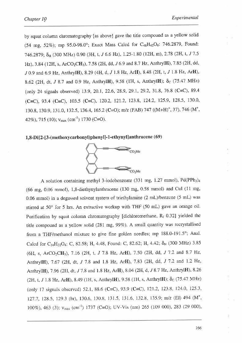
Chapter I0 Experimental
by squat column chromatography [as above] gave the title compound as a yellow solid
(54 mg, 52Vo); mp 95.0-98.0o; Exact Mass Calcd for C¿sH¿zOl. 746.2879, Found:
746.2879; õH (300 MHz) 0.90 (3H, t, J 6.6 Hz), I'25-L 80 (12H, m),2.78 (2H, t, J 7 '5
Hz),3.84 (IzH, s, ATCOzCHT), 7.58 (2H, dd, ,I6.9 and 8.7 Hz, AnthrylH), 7'85 (2H, dd,
J0.9 and 6.9H2, AnthrylH), 8.29 (4H, d, "f 1.8 Hz, ArH), 8.48 (2H, t, 'f 1.8 Hz, ArH),
8.62 (2H, dt, J 8.7 and 0.9 Hz, AnthrylH), 9.58 (1H, s, AnthrylH); õc Q5.47 MHz)
(on\y 24 signals observed) 13.9, 20.1, 22.6, 28.9, 29.I, 29'2,31.8, 76.8 (C=C), 89'4
(C=C), 93.4 (C=C), 103.5 (C=C), 120.2, 121.2, 123'8, 124.2, 125.9, 128.5, 130'0,
130.8, 130.9, 131.0, 132.5,136.4,165.2(C=O);rnJz(FAB) 147 ((M+H)*,37),746(M+,
427o),715 (10); v*u* (cm-r) 1730 (C=O).
1,8-Di{2- [3-(methoxycarbonyl)phenyl]' L'ethynyl ]anthracene (69)
A solution containing methyl 3-iodobenzoate (331 mg, 1.21 mmol), Pd(PPh¡)+
(66 mg,0.06 mmol), l,8-diethynylanthracene (130 mg,0.58 mmol) and CuI (11 mg,
0.06 mmol) in a degassed solvent system of triethylamine (2 nL)lbenzene (5 mL) was
stirred at 50o for 5 hrs. An extractive workup with THF (50 mL) gave an orange oil.
Purification by squat column chromatography fdichloromethane, Rr 0.32] yielded the
title compound as a yellow solid (281 mg, 99Vo). A small quantity was recrystallised
from a THF/methanol mixture to give fine golden needles; mp 188.0-191.5'; Anal.
Calcd for C3aH22O¿: C, 82.58; H, 4.48, Found: C,82.62; H, 4.42; õH (300 MHz) 3'85
(6H, s, ATCOzCHù,7.16 (2H,f, J l.8Hz, ArH),7.50 (2H, dd, J l'2 andS'7 Hz,
AnthrylH), 7.61 (2H, dt, J 7.8 and 1.8 Hz, ArH),7.83 (2H, dd, J 1.2 and l'2H2,
AnthrylH), '7.96 (2lH, dt., J 7.8 and 1.8 Hz, ArH), 8.04 (2H, d, J 8.7 Hz, AnthrylH), 8.26
(2H, t, J 1.8 Hz, ArH), 8.49 (lH, s, AnthrylH), 9.58 (1H, s, AnthrylH); õc Q5.47 MHz)
(only 17 signals observed) 52.1,88.6 (C=C),93.9 (C=C), I2L2, I23.8, 124.0, I25.3,
121.7,128.5, 129.3 (br), 130.6, 130.8, 131.5, 131.6, 132'8, 135.9; mlz (EI) 494 (M*,
lOTVo), a$ e); vn,u* (cm-r) t737 (C=O); UV-Vis (nm) 265 (109 000), 283 (29 000),
t66

Chapter l0 Experimental
356 (4 000), 375 (9 000), 395 (16 000), 417 (16 000); Fluorescence (nm) 385,407,429,
453,481
1,8-Di{2-[3,5-di(methoxycarbonyl)-4-{t(trifluoromethyl)sulphonyl]oxy}phenyll'L-
ethynyllanthracene (71)
Me
A solution containing dimethyl 5-iodo-2-{[(trifluoromethyl)sulphonyl]oxy]-
isophrhalate (2L) (128 mg, Z.l2xl}'a mol), Pd(PPh¡)¿ (16 mg, 1.38x10⁻⁵ mol), 1,8-
diethynylanthracene (30 mg, L.32xI0-a mol), triethylamine (0.40 mL, 2.86x10⁻³ mol)
and CuI (2m8,1.00x10-5 mol) in degassed DMF (2 mL) was stined at 50o for t hrs. An
extractive workup with ether (40 mL) gave a yellow oil. Purification by flash
chromatography on reverse phase silica [acetonitrile, Rr 0.38] yielded the title
compound as a yellow solid (81 mg, 687o); mp 87.0-89.0o; Exact Mass Calcd for
c¿oHz¿or¿SzFo: 906.0545, Found: 906.0539; õH (300 MHz) 3.90 (12H, s, ATCO2CH3),
7 .53 (2H, dd, J 7 .2 and 8.4 Hz, AnthrylH), 7.86 (2H, dd, J 7 .2 and 0,9 Hz, AnthrylH),
8.09 (2H, d, J 8.4 Hz, AnthrylH), 8.32 (4H, s, ArH), 8.52 (1H, s, AnthrylH),9'42 (IH,
s, AnthrylH); õc (75.47 MHz) 53.0 (ATCOzCH¡), 91.3 (C=C),9L7 (c=C), 118.6 (q, ,I
324.5 Hz, ATOSOzCF¡), 120.0, 123.2, I25.0, 125.2, 126.4, 128.0, 130'1, 131'1, I3l'4,
131.9, 13g.4, 145.3,163.3 (C=O); mtz (LSIMS) 906 (M*, I00Vo),875 (19); v*o* (cm-r)
1734 (C=O).
t67
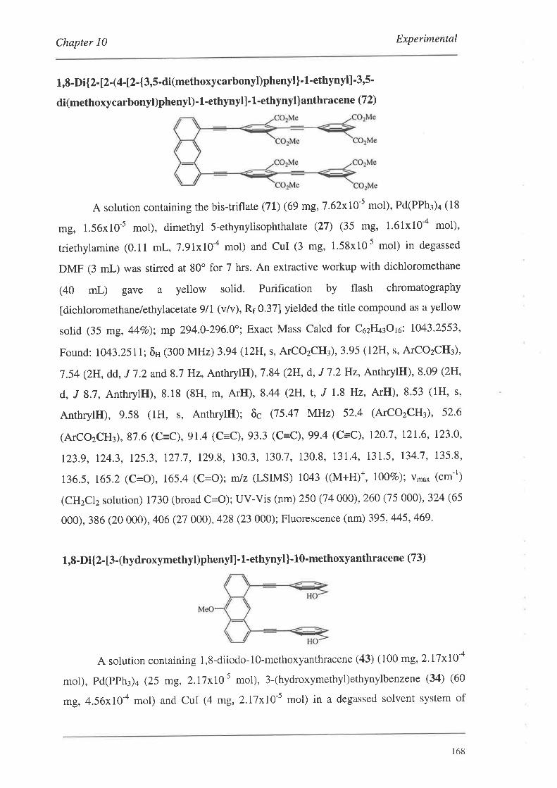
Chapter l0 Experimental
1,8-Di{2- [2 -(4-12-{3,í-di(methoxycarbonyl)phenyl}-1'ethynyl] -3'5'
di(methoxycarbonyl)phenyl)- l-ethynyll - l-ethynyllanthracene (72)
A solurion containing the bis-triflate (71) (69 mg, 7.62x10⁻⁵ mol), Pd(PPh3)4 (18
ü8, 1.56x10-s mol), dimerhyl 5-ethynylisophthalate (27) (35 mg, 1.61x10-a mol),
triethylamine (0.11 mL, 7.9lxI0-a mol) and CuI (3 mg, 1.58x10⁻⁵ mol) in degassed
DMF (3 mL) was stirred at 80" for 7 hrs. An extractive workup with dichloromethane
(40 mL) gave a yellow solid. Purification by flash chromatography
[dichloromethane/ethylacetate 9/I (vlv), Rr 0.37] yielded the title compound as a yellow
solid (35 mg, 44Vo); mp 294.0-296.0"; Exact Mass Calcd for C62H¿rOto: 1043.2553'
Found: 1043.2511; ôs (300 MHz) 3.94 (12H, s, ATCO2CH3), 3.95 (12H, s, ATCO2CH3),
7.54 (2H, dd, J 7.2 and 8.7 Hz, AnthrylH), 7.84 (2H, d, J 7.2H2, AnthrylH), 8.09 (2H'
d, J 8.7, AnthrylH),8.18 (8H, m, ArH), 8.44 (2H, t,,f 1.8 Hz, ArH),8.53 (1H, s,
AnthrylH), 9.58 (1H, s, AnthrylH); õc Q5.47 MHz) 52.4 (ATCOzCH¡)' 52'6
(ATCOzCH),87.6 (C=C), 91.4 (C=C),93.3 (C=C), 99.4 (C=C), 120.1, 121.6, 123.0,
123.9, 124.3, r25.3, r27.7, r29.8, 130.3, 130J,130.8, r3r.4, 131.5, 134.7, 135.8,
136.5, 165.2 (C=O), 165.4 (C=O); m/z (LSIMS) 1043 ((M+H)+, ß1Vo); v'o* (cm-r)
(CHzClz solution) 1730 (broad C=O); UV-Vis (nm) 250 (74 000), 260 (15 000),324 (65
000), 386 (20 000), 406 (21 000), 428 (23 000); Fluorescence (nm) 395,445,469.
1,8-Di{2-[3-(hydroxymethyl)phenyt].l-ethynyl]-lO-methoxyanthracene (73)
A solution containing 1,8-diiodo-1O-methoxyanthracene (43) (100 mg,2.17x10-a
mol), pd(pph3)4 (25 mg, 2.17x10 s mol), 3-(hydroxymethyl)ethynylbenzene (34) (60
mg, 4.56x10-a mol) and CuI (4 mg,2.I7xI0-s mol) in a degassed solvent system of
168
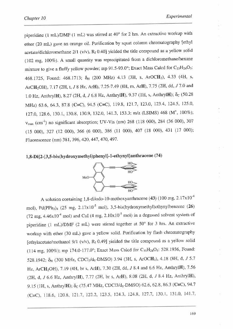
Chapter I0 Experimental
piperidine (l mL)/DMF (1 mL) was stirred at 40" for 2 hrs. An extractive workup with
ether (20 mL) gave an orange oil. Purification by squat column chromatography [ethyl
acetate/dichlorometha ne 2lI (v/v), Rr 0.401 yielded the title compound as a yellow solid
(102 mg, lO1Vo). A small quantity was reprecipitated from a dichloromethane/hexane
mixture to give a fluffy yellow powder; mp 91.5-93.0o; Exact Mass Calcd for C¡¡Hz¿O¡:
468.1725, Found: 468,\713; ôs (200 MHz) 4.13 (3H, s, ArOCH¡), 4'33 (4H' s'
ATCHzOH),7.I7 (2H,t,J 8Hz, ArH), 7.25-7.49 (8H, m, ArH),7'75 (2H, dd, 'I7'0 and
!.oHz,AnrhrylH), 8.27 (2H, d, J 6.8 Hz, AnthrylH), 9.37 (1H, s, AnthrylH); õc (50.28
MHz) 63.6, 64.3,87.8 (C=C),94.5 (C=C), 119.8, 121.7, 123.0, 123.4, 124.5, 125.0,
127.0, 128.6,130.1, 130.8, 130.9, 132.0, 141.3,153.3; m/z (LSIMS) 468 (M*, 1007o);
v,u* (cm-r) no significant absorption; uv-vis (nm) 26s (118 000), 284 (36 000)' 307
(15 000), 321 (12 000),366 (6 000),386 (11 000),407 (18 000),431 (17 000);
Fluorescence (nm) 38 l, 396, 420, 447, 470, 497 .
1,8-Di{2- [3,5-bis(hydroxymethyl)phenyl]-1-ethynyl]anthracene (74)
A solurion containing 1,8-diiodo-10-methoxyanthracene (43) (100 mg,2'17x10-a
mol), Pd(PPh3)4 (25 mg, 2.l7xI0-s mol), 3,5-bis(hydroxymethyl)ethynylbenzene (26)
(72 mg, 4.46xIO-a mol) and CuI (4 mg,2.10x10-5 mol) in a degassed solvent system of
piperidine (1 mL)/DMF (2 mL) were stirred together at 50o for 3 hrs. An extractive
workup with ether (30 mL) gave a yellow solid. Purification by flash chromatography
[ethylacetare/methanol glI (vlv), Rr 0.49] yielded the title compound as a yellow solid
(114 mg, IOOVo); mp 174.0- 117.0"; Exact Mass Calcd for c¡sHzaos: 528'1936, Found:
528.1942; ôH (300 MHz, CDCI¡/d6-DMSO) 3.94 (3H' s' ATOCH3)' 4,18 (8H, d, "r 5'7
Hz, ATCHzOH), l.lg (4H, br s, ArH) ,7.30 (2H, dd, ,I 8.4 and 6.6 Hz, AnthrylH), 7.56
(2H, d, J 6.6 ]Hz, AnthrylH), 7.17 (2H, br s, ArH), 8.08 (2H, d, J 8'4 Hz, AnthrylH)'
9.15 (lH, s, AnrhrylH):õcQ5.4l MHz,CDCI3/d6-DMSO) 62.6,62.8,86.3 (C=C)'94'7
(c=c), 118.6, 120.8, l2L'7,122.2, 123.5, 124.3, 124.8, 121.7,130.1, 131.0, I4I.7,
r69
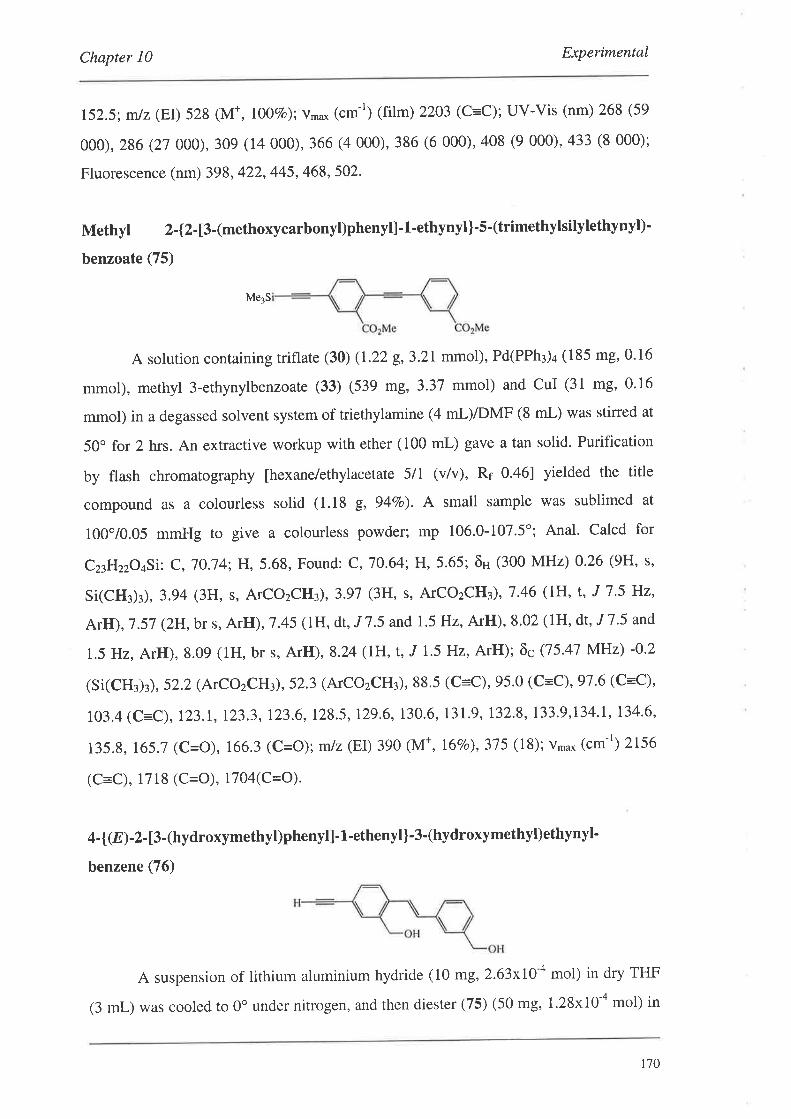
Chapter l0 Experimental
t52.5; mlz (EI) 528 (M+, IO07o); v*o* (cm-r) (film) 2203 (C=C); UV-Vis (nm) 268 (59
000),286 (27 000), 309 (14 000),366 (4 000), 386 (6 000),408 (9 000), a33 (8 000);
Fluorescence (nm) 398, 422, 445, 468, 502'
Methyl 2-{2-13-(methoxycarbonyl)phenyll-1-ethynyl}-5-(trimethylsilylethynyl)'
benzoate (75)
Me3S
A solution containing triflate (30) (L22 g,3.21mmol), Pd(PPh3)4 (185 mg,0.16
mmol), methyl 3-ethynylbeûzoate (33) (539 mg,3.37 mmol) and CuI (31 mg,0.16
mmol) in a degassed solvent system of triethylamine (4 mLyDMF (8 mL) was stirred at
50o for 2 hrs. An extractive workup with ether (100 mL) gave a tan solid. Purification
by flash chromatography [hexane/ethylacetate 5/1 (v/v), Rr 0.46] yielded the title
compound as a colourless solid (1.18 g, 94Vo). A small sample was sublimed at
100"/0.05 mmHg to give a colourless powder; mp 106.0-107.5'; Anal. Calcd for
Cz¡HzzO¿Si: C,7O.74: H,5.68, Found: C,70.64; H,5.65; ôH (300 MHz) 0'26 (9H, s'
Si(CH3)3), 3.94 (3H, s, ATCOzCrIù,3.97 (3H, s, ATCOzCHù,1'46 (1H, t, J 1'5 Hz,
ArH), 7.57 (z[,br s, ArH), 7 '45 (lH, dt, J 7 '5 and 1.5 Hz, ArH), 8.02 (1H, dt, J 7'5 and
1.5 Hz, ArH), 8.09 (1H, br s, ArH),8'24 (lH, t, J L5 Hz, ArH); õc Q5'47 MHz) -0'2
(Si(CH3)3) ,52.2 (ATCOzCHù,52.3 (ArCOzCH3), 88.5 (C=C), 95'0 (C=C),91'6 (C=C),
t03.4 (c=c), 123.1,123.3, 123.6,128.5, !29.6,130.6, 131.9, 132.8,133.9,134.1,134.6,
135.8, 165.7 (C=O), 166.3 (C=O); mlz (EI) 390 (M+, I6Eo), 375 (18); vmax (cm-r) 2156
(C=C), 1718 (C=O), 1704(C=O).
4-t(E)-2-13-(hydroxymethyl)phenytl-1-ethenylÌ-3-(hydroxymethyl)ethynyl-
benzene (76)
A suspension of lithium aluminium hydride (10 mg, 2.63xI0-a mol) in dry THF
(3 mL) was cooled to 0o under nitrogen, and then diester (75) (50 mg, 1.28x10 a mol) in
170
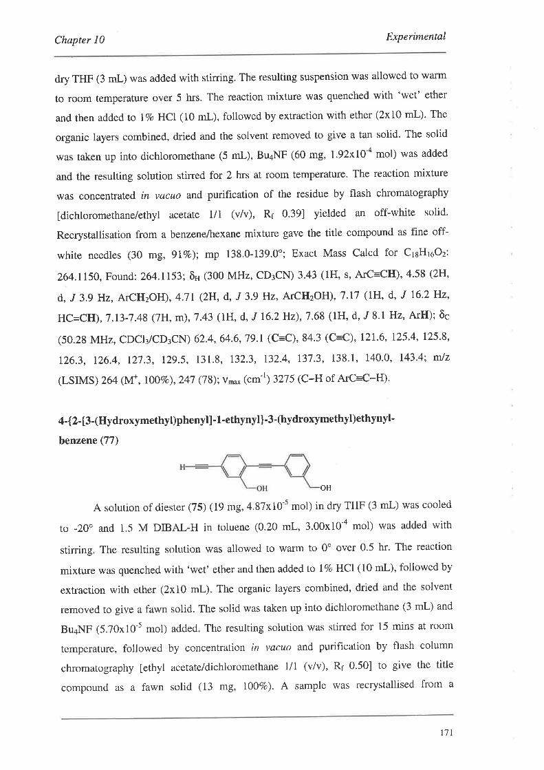
Chapter 10 Experimental
dry THF (3 mL) was added with stining. The resulting suspension was allowed to warm
to room temperature over 5 hrs. The reaction mixture was quenched with 'wet' ether
and then added to l7o HCI (10 mL), followed by extraction with ether (2x10 mL). The
organic layers combined, dried and the solvent removed to give a tan solid. The solid
was taken up into dichloromethane (5 mL), Bu¿NF (60 mg, I.92xI0-a mol) was added
and the resulting solution stirred for 2 hrs at room temperature. The reaction mixture
was concentrated in vacuo and purification of the residue by flash chromatography
[dichloromethane/ethyl acetate III (v/v), Rr 0.39] yielded an off-white solid.
Recrystallisation from a benzene/hexane mixture gave the title compound as fine off-
white needles (30 mg, gIVo); mp 138.0-139.0"; Exact Mass Calcd for CrsHroOz:
264.1150, Found:264.1153; ôH (300 MHz, GD¡CN) 3.43 (1H, s, ArC=CH)' 4.58 (2H'
d, J 3,g Hz, ATCHzOH), 4.7t (2H, d, J 3'9 Hz, ATCIIzOH), 7 '17 (IH, d, J 16'2 Hz,
HC=CH), 7 .13-7 .48 (7H, m), 7 .43 (IH, d, J 16.2 Hz), 7 .68 (1H, d, J 8'I Hz, ArH); ôc
(50.28 MHz, CDCI3/CD:CN) 62.4, 64.6,79.1 (C=C), 84.3 (C=C)' 121.6' 125.4' 125'8'
126.3, 126.4, r27.3, L29.5, 131.8, 132.3, 132.4, r37.3, 138.1, 140.0, 143.4; mJz
(LSIMS ) 264 (Nf , rOOTo), 247 (7 S);v,u* (cm- I ) 327 5 (C-H of ArC=C-H).
4-{2- t3-(Hydroxymethyl)phenyll' 1-ethynyl}-3-(hydroxymethyl)ethynyl'
benzene (77)
OH
A solution of diester (75) (19 mg, 4.87x10⁻⁵ mol) in dry THF (3 mL) was cooled
to -20" and 1.5 M DIBAL-H in toluene (0.20 mL, 3.00x10-a mol) was added with
stirring. The resulting solution was allowed to warm to 0o over 0.5 hr. The reaction
mixture was quenched with 'wet' ether and then added to IVo HCI (10 mL), followed by
extraction with ether (2x10 mL). The organic layers combined, dried and the solvent
removed to give a fawn solid. The solid was taken up into dichloromethane (3 mL) and
Bu¿NF (5.70x10⁻⁵ mol) added. The resulting solution was stirred for 15 mins at room
temperature, followed by concentration in vacuo and purification by flash column
chromatography [ethyl acetate/dichloromethane III (v/v), Rr 0.50] to give the title
compound as a fawn solid (13 mg, l\ovo). A sample was recrystallised from a
111
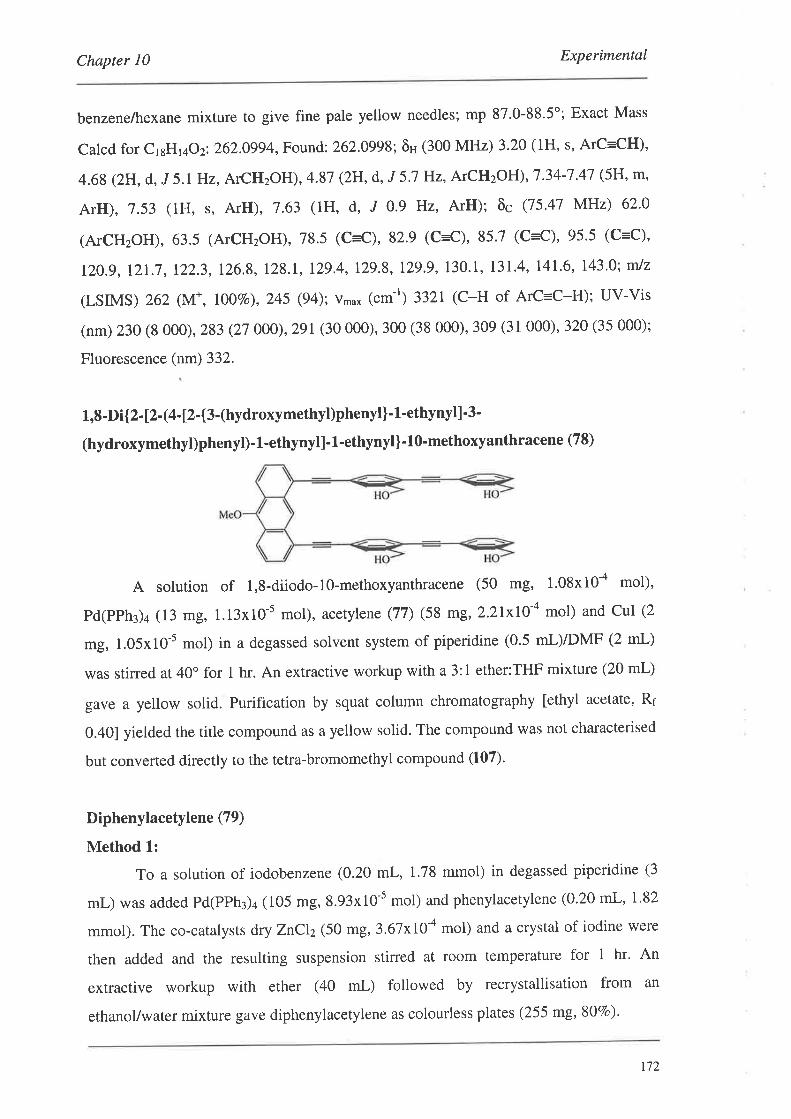
Chapter l0 Experimental
benzene/hexane mixture to give fine pale yellow needles; mp 87.0-88.5"; Exact Mass
calcd for crsHr¿o z:262.0994, Found: 262.0998; ôH (300 MHz) 3.20 (1H, s, ArC=CH),
4.68 (2H, d, J 5.1 Hz, ATCHzOH), 4.87 (2H, d, J 5.7 Hz, ATCHzOH), 7.34-7.47 (5H, m,
fuH), 7.53 (1H, s, ArH), 7.63 (1H, d, J 0'9 Hz, ArH); õc Q5'47 MHz) 62'0
(ATCH2OH), 63.5 (ATCHzOH), 78.5 (C=C), 82.9 (C=C)' 85.7 (C=C), 95.5 (C=C)'
r2o.g, !21.7, 122,3, 126.8, 128.1, r29.4, 129.8, 129.9,130.1, r3r.4, r4r.6, 143'0; mJz
(LSIMS) 262 (M*, I}OVo),2a5 Q4); v** (cm-r) 3321 (C-H of ArC=C-H); UV-Vis
(nm) 230 (8 000), 283 (2t 000), 291 (30 000), 300 (38 000), 309 (31 000), 320 (35 000);
Fluorescence (nm) 332.
1,8-Di{2- [2- (4-t2-{3-(hydroxymethyl)phenyl }' 1'ethvnyl]'3-
(hydroxymethyl)phenyl)-1-ethynyll-L-ethynyl)-l0-methoxyanthracene (78)
A solution of 1,8-diiodo-lo-methoxyanthracene (50 flg, 1.08x10-a mol),
Pd(PPh¡)¿ (13 mg, 1.13x10-s mol), acetylene (77) (58 mg, 2.2IxI0-a mol) and CuI (2
mg, 1.05x10⁻⁵ mol) in a degassed solvent system of piperidine (0.5 mL)/DMF (2 mL)
was stirred at 40o for t hr. An extractive workup with a 3:1 ether:THF mixture (20 mL)
gave a yellow solid. Purification by squat column chromatography [ethyl acetate, R¡
0.401 yielded the title compound as a yellow solid. The compound was not characterised
but converted directly to the tetra-bromomethyl compound (107)'
Diphenylacetylene (79)
Method 1:
To a solution of iodobenzene (0.20 mL, 1.78 mmol) in degassed piperidine (3
mL) was added Pd(PPh3)4 (105 mg, 8.93x10⁻⁵ mol) and phenylacetylene (0.20 mL, 1'82
mmol). The co-catalysts dry ZnCI2 (50 mg, 3.6lxI}-a mol) and a crystal of iodine were
then added and the resulting suspension stined at room temperature for t hr' An
extractive workup with ether (40 mL) followed by recrystallisation from an
ethanol/water mixture gave diphenylacetylene as colourless plates (255 mg,80Vo).
r72
Chapter l0 Experimental
Method 2:
The procedure was analogous to Method 1 except that undried zinc chloride (57
mg,4.19x10-a mol) was used (94Vo).
Method 3:
The procedure was analogous to Method I except that a co-catalyst combination
of undried zinc chloride (57 mg,4.19x10-a mol) and sodium iodide (27 mg,1.78x10-a
mol) was used (94Vo).
Method 4:
The procedure was analogous to Method I except that no palladium catalyst was
added and the co-catalyst combination of undried zinc chloride (57 mg,4.19x10-a mol)
and sodium iodide (27 mg,1.78x10-a mol) was used. No reaction was observed by tlc'
Method 5:
The procedure was analogous to Method I except that zinc iodide (57 mg,
1.78x10-a mol) as co-catalyst was used and the reaction mixture was stirred at room
temperature for 20 hrs (34Vo).
Method 6:
The procedure was analogous to Method I except that piperidine (0.53 mL, 5.34
mmot) and zinc iodide (57 mg, 1.78x10-a mol) as co-catalyst in DMF (3 mL) were used
and the reaction mixture was stirred at room temperature for 17 hrs (26Vo)'
IVlethod 7:
The procedure lvas analogous to Method I except that triethylamine (3 mL) was
used as the solvent and base, with the co-catalyst combination of undried zinc chloride
(57 mg, 419xI0a mol) and sodium iodide (27 mg,1.78x10-a mol). The reaction mixture
was stirred at room temperature for 20 mins. No reaction was observed by tlc.
Method 8:
The procedure was analogous to Method 1 except that triethylamine (3 mL) was
used as the solvent and base, with the co-catalyst combination of undried zinc chloride
(57 mg, 4.l9xI04 mol) and sodium iodide (27 mg,1.78x10-a mol). The reaction mixture
was stirred at 60o for 4 hrs (34Vo).
Method 9:
The procedure was analogous to Method 1 except that triethylamine (3 mL) was
used as the solvent and base, with the co-catalyst combination of undried zinc chloride
173
Chapter l0 Experimental
(57 mg, 4.19x10-a mol), sodium iodide (27 mg, 1.78x10-a mol) and DMAP (217 mg,
1.78 mmol). The reaction mixture was stirred at 60o for 20 hrs (44Vo).
Method 10:
The procedure was analogous to Method 1 except that the co-catalyst CUI (34
mg, 1.78x10-a mol) was used (1007o).
Method 11:
The procedure was analogous to Method 1 except that the co-catalyst
combination of undrie d zinc chloride (57 mg, 4.19x10-a mol) and sodium azide (I2 mg,
1.78x10-a mol) was used (1007o); mp 59.0-60.0' (lit. 62.5")''o; ô" (300 MHz) 7.33 (6Pr,
m, ArH), 7.54 (4H, m, ArH); õc Q5.47 MHz) 89.4 (C=C), 123.4, 128.2, 128'3, 131'6;
mlz (EI) 178 (Vf, 1007o), 152 (7), 126 Ø);v*u* (cm-t) no significant absorption.
1-(1-Hexynyl)benzene (80)
The procedure was analogous to that for (79, Method 1) using iodobenzene and
l-hexyne, and the reaction mixture was stined at room temperature for 2 hrs. An
extractive workup with dichloromethane (40 mL) and purification by squat column
chromatography [hexane/dichloromethane 3/1 (v/v), Rr 0.47] gave the title compound as
a golden oilt2t ç94Vo); õn (300 MHz) ): 0.87 (2H, t, J 7 .2 Hz), 1.51 (4H, m), 2.40 (2H, t,
J 7 .2 Hz), 7 .26 (3H, m, ArH), 7 .39 (2H, m, ArH); õc Q5-47 MHz) l3'4, l9'0, 2I'9,
30.8, 80.6 (C=C), 90.4 (C=C), 124.2, I2l .4, 128'2,131.6; m/z (EI) 158 (M*, l%o), 143
(65), l2g (69), 115 (100); v,"u* (cm-r) 2231 (C=C).
Trimethyl (2-phenyl- 1 -ethynyl)silane (8 1)
The procedure was analogous to that for (79, Method 3) using iodobenzene and
trimethylsilylacetylene, and the reaction mixture was stirred at room temperature for 20
hrs. An extractive workup with dichtoromethane (40 mL) and purification by squat
column chromatography' lhexane/dichloromethane 5/1 (v/v), Rr 0.52] gave the title
compound as a colourless oilr22 O00Vo); ôH (300 MHz) 0.25 (9H, s), 7.30 (3H, m, ArH),
7.47 (2H, m, ArH); õc (50.28 MHz): -0'1,93.9 (C=C), 105.2 (C=C), 123'2, 128'2,
128.5,13I.9; v'o* (cm-r) (neat) 2160 (C=C).
174
Chapter l0 Experimental
1,8-Diphenyl-1,7-octadiYne (82)
To a solution of iodobenzene (0.40 mL, 3.57 mmol) in degassed piperidine (3
mL) was added Pd(PPh¡)¿ (210 mg, 1.82x10-a mol), l,7-octadiyne (0'26 mI-, 1.96
mmol), undried ZnClz (100 mg, 7.l2xt1-a mol) and NaI (54 mg, 3'56x10-a mol)' The
resulting suspension was then stirred at room temperature for 3hrs. An extractive
workup with dichloromethane (40 mL) gave a golden oil. The crude product was
purified by flash chromatography [hexane/dichloromethane 3lI (v/v), Rr 0.43] to give
the title compound as a colourless oil (459mg, I0O7o). The spectroscopic data was
consistent with published values. 123
3-Phenyl-2-propyn-1'ol (83)
The procedure was analogous to that f.or (79, Method 3) using iodobenzene and
propargyl alcohol, and the reaction mixture was stined at room temperature for 45 mins.
An extractive workup with dichloromethane (40 mL) and purification by flash
chromatography [dichloromethane/ethyl acetate 10/1 (v/v), Rr 0.57] gave the title
compound as a golden oi|ez çlOO7o). õH (300 MHz) 4.49 (zlJ,br s),7 .26 (3H, m, ArH),
7.43 (2H, m, ArH); õc Q5.47 MHz) 51.0, 85.3 (C=C), 87.3 (C=C),122.5, 128.2, 128.3,
131.6; mtz (EI) 132 (M+, 67o), 131 (9), 1 15 (a); v,n* (cm-r) 2238 (C=C).
1 - (l-Hexynyl) -4-methoxybenzene (84)
The procedure was analogous to that for (79, Method 3) using 4-bromoanisole
and l-hexyne, and the reaction mixture was stined at 50o for 16 hrs. An extractive
workup with dichloromethane (40 mL) and purification by flash chromatography
[hexane/dichloromethane 5/1 (v/v), Rr 0.40] gave the title compound as a colourless
orlt37 ç92Vo). õH (200MHz): O.94 (2H, t, J 6.8 Hz), 1.50 (4H, m),2.39 (2H, t, J 6.8 Hz),
3.7g (3H, s), 6.80 (2H, AA' portion of AA'XX" ArH), 1.30 (2H, XX' portion of
AA'XX', ArH); õc Q5.47 MHz) 13'5, l9'0, 21.9,30.9' 55'0, 80'2 (C=C), 88'6 (C=C)'
I 13.8, 132.2, 132.8,159.0; mlz (EI) 188 (M+, 84Vo), ll3 (41), 159 (29), 145 (100), 1 15
(27); v ^u*(c--') (neat) 2535 (C=C).
t75
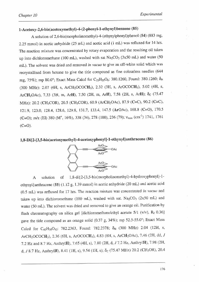
Chapter l0 Experimental
1-Acetoxy-2,6-bis(acetoxymethyl)-4-(2.phenyl- L -ethynyl)benzene (85)
A solution of 2,6-bis(morpholinomethyl)-4-(ethynylphenyl)phenol (54) (883 mg,
2.25 mmol) in acetic anhydride (25 mL) and acetic acid (1 mL) was refluxed for 14 hrs.
The reaction mixture was concentrated by rotary evaporation and the resulting oil taken
up into dichloromethane (100 mL), washed with sat NazCO¡ (3x50 mL) and water (50
mL). The solvent was dried and removed in vacuo to give an off-white solid which was
recrystallised from hexane to give the title compound as fîne colourless needles (644
mg,75Vo); mp 80.0o; Exact Mass Calcd for czzHzooo: 380.1260, Found: 380.1260; ôH
(300 MHz): 2.07 (6H, s, ATCHzOCOCH¡), 2.32 (3H, s, ATOCOCH¡), 5'02 (4H, s'
ATCHzOA)),7.33 (3H, m, ArH), 7.50 (2H, m, ArH), 7.58 (2H, s, ArH); õc Q5'47
MHz): 20.2 (CH{OR), 20.5 (CH3COR), 60.9 (ArCHzOAc),87.9 (C=C), 90.2 (c=c),
IzL.g, !23.0, 128.4, 128.6, I29.8, 13L7,133.4, 147.5 (ArOAc), 168.8 (C=O), 170.5
(c=o); mlz (EI) 380 (M*, I6Vo),338 (34), 278 (100), 236 (79); v,'u* (cm-t) 1741, 176I
(C=O).
1,8-Di{2- [3,5-bis(acetoxymethyl)-4-acetoxyphenyl]' 1'ethynyl]anthracene (86)
A solution of 1,8-di{2-[3,5-bis(morpholinomethyl)-4-hydroxyphenyl]-1-
ethynyllanrhracene (55) (1.12 g,1.39 mmol) in acetic anhydride (20 mL) and acetic acid
(0.5 mL) was refluxed for 17 hrs. The reaction mixture \ryas concentrated in vacuo and
taken up into dichloromethane (100 mL), washed with sat. NazCO¡ (2x50 mL) and
water (50 mL). The solvent was dried and removed to give an orange oil. Purification by
flash chromatography on silica gel [dichloromethane/ethyl acetate 5/1 (v/v), Rr 0.36]
gave the title compound as an orange solid (0.37 g,34Vo); mp 52.5-55.0"; Exact Mass
calcd for c¿oH¡sorz: 782.2363, Found: 782.2378: õH (300 MHz) 2.04 (12H, s,
ATCHzOCOCH:), 2.36 (6H, s, ATOCOCH3), 4.83 (8H, s, ATCHzOA1),7 '46 (2H, dd' J
L2Hz and 8.7 Hz, AnrhrylH), 7.65 (4H, s), 7.80 (2H, d, J 7.2 Hz, AnthryllJ),l.98 (2H,
d, J 8.7 Hz, AnthrylH), 8.41 (lH, s), 9.54 (lH, s); ôc Q5.47 MHz) 20.2 (CHtOR), 20.4
176
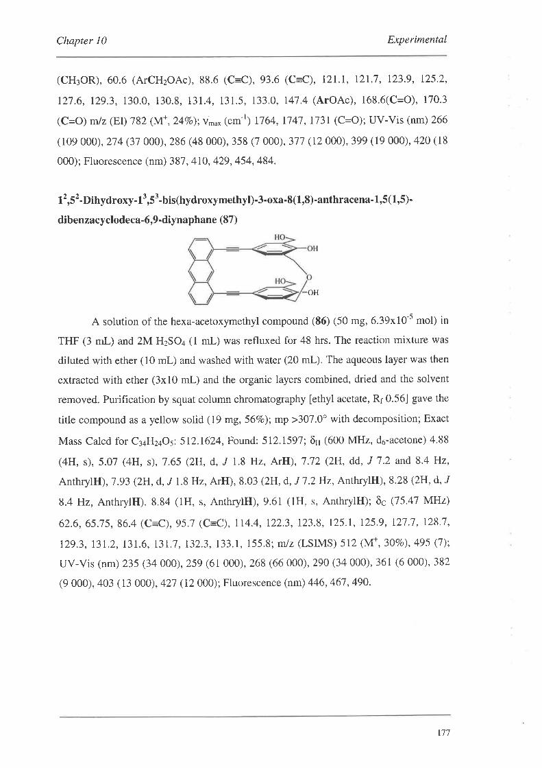
Chapter l0 Experimental
(CH¡OR), 60.6 (ArCH2OAc), 88.6 (C=C),93.6 (C=C), I2l.I, 121.7, 123.9, 125.2,
127.6, 129.3, 130.0, 130.8, 131.4, 131.5, 133.0, 147.4 (ArOAc), 168.6(C=O), 170.3
(C=o) mlz (EI) 782 (M+, 247o); v*u* (cm-r) 1764, 1747, Il3I (C=O); UV-Vis (nm) 266
(109 000), 214 (31 000),286 (48 000),35S (7 000),377 (12 000),399 (19 000),420 (18
000); Fluorescence (nm) 387, 4I0, 429, 454, 484.
12,52-Dihydroxy- 13,5'-bislhydroxymethyl)-3-oxa-8(1,8)-anthracena- 1,5(1,5)-
dibenzacyclodeca-6,9-diynaphane (87)
OH
A solution of the hexa-acetoxymethyl compound (S6) (50 mg, 6.39x10-s mol) in
THF (3 mL) and 2M HzSO+ (1 mL) was refluxed for 48 hrs. The reaction mixture was
diluted with ether (10 mL) and washed with water (20 mL). The aqueous layer was then
extracted with ether (3x10 mL) and the organic layers combined, dried and the solvent
removed. Purification by squat column chromatography [ethyl acetate, Rr 0.56] gave the
title compound as a yellow solid (19 mg,56Vo); mp >307.0o with decomposition; Exact
Mass Calcd for C¡¿HzqOs: 512.1624, Found: 512.1591; ôH (600 MHz, d6-acetone) 4,88
(4H, s), 5.O7 (4H, s), 7.65 (2H, d, J L8 }lz, ArH), 7.72 (2H, dd, J 7.2 and 8.4 Hz,
AnthrylH), 7.93 (2H, d, "/ 1.8 Hz, ArH), 8.03 (2H, d, J 1.2 Hz, AnthrylH), 8.28 (2H, d, J
8.4 Hz, AnthrylH). 8.84 (lH, s, AnthrylH), 9.61 (lH, s, AnthrylH); õc Q5.47 MHz)
62.6, 65.15, 86.4 (C=C), 95.1 (C:-C), 114.4, 122.3, 123,8, 125.1, 125.9, 127 '7, 128'7,
129.3, 131.2,131.6, l3l.'7,132.3,133.1, 155.8; m/z (LSIMS) 512 (M*,30Eo),495 (1);
uv-vis (nm) 235 (34 000), 259 (61000),268 (66 000), 290 (34 000),361 (6 000), 382
(9 000), 403 ( 13 000), 421 (12 000); Fluorescence (nm) 446, 461 , 490.
r77
Chapter I0 Experimental
L -Acetoxy-2,6-bis(iodomethyl)-4-bromobenzene (88)
To a solution of l-acetoxy-2,6-bis(acetoxymethyl)-4-bromobenzene (4) (1.00 g,
2.78 mmol) in acetonitrile (20 mL) was added trimethylsilylchloride (2.5 mL, 19.63
mmol) and NaI (2.51 g,16.71 mmol). The resulting suspension was heated at 50o for 20
hrs. Reaction mixture was quenched by addition to sat. NazCO¡ (50 mL) and extracted
with dichloromethane (2x50 mL). The organic layers were combined and washed with
57o NazSzO¡ (50 rnl-) and finally water (50 mL). The solvent was dried and removed to
give a tan solid which was recrystallised from methanol/water to give off-white needles
(0.85 g, 62Vo); mp 190.5-192.0"; Anal. Calcd for CroHqBrIzOz: C, 24.27; H, 1.83,
Found: C, 24,42; H, 1.90; ôH (300 MHz) 2.48 (3H, s, ATOCOCH¡), 4.2I (4H, s,
ATCHzOAc), 7.46 (2H, s, ArH); õc Q5.41 MHz) -3.9 (ArCHzI), 20.6 (ATOCOCH¡),
llg.4 (ArBr), 133.4, 134.8, 146.2, 167.7 (C=O); mJz (EI) 496 1M*, 8rBr, ITVo), 494
qM*, 7eBr, rTvo),454 q8rBr, 65vo), 452 (7eBr,65vo),369 18rBr, Bgvo),367 (7eBr,9ovo),
321 ç9tBr,79vo),325 (7eBr,8lvo), 199 (8lBr, 56vo), L97 ç7eBr,54vo); v*o*(cm-r) 1749
(C=O).
1,3-Bis(hydroxymethyl) -5 - (2-phenyl- 1 -ethynyl)benzene (90)
To a suspension of lithium aluminium hydride (69 mg, 2.04 mmol) in dry THF
(15 mL) was added the diester (66) (300 mg, 1.02 mmol) in dry THF (15 mL) dropwise
with stirring at room temperature. The suspension was allowed to stir for a further I hr.
The reaction mixture was quenched with 'wet' ether and then added to 57o HCI (30
mL). The organic layer was separated, and the aqueous layer extracted with ether (2x30
mL). The organic layers combined, dried and the solvent removed to give a tan solid.
Recrystallisation from a chloroform/hexane mixture gave the title compound as
colourless needles (204 m& 84Vo); mp 100.0-102.0o; Exact Mass Calcd for CroHr¿Oz:
238.0994, Found: 238.0988; ôH (300 MHz) 4.10 (4H, s, ATCH2OH),7.33-1.36 (4H, m,
ArH), 7.45-7.46 (2H, m, ArH), l.5l-7.54 (2H, m, ArH); õc Q5.41 MHz) 63.9
(ATCHzOH), 88.9 (C=C), 89.1 (C=C), 122.9,123.0, 125,0, 128.1, 128.2, 128.5, 131.3,
141.1; mlz (El) 238 (M+, I\OVo),201 (14); vn,.* (cm-r) no significant absorption.
178
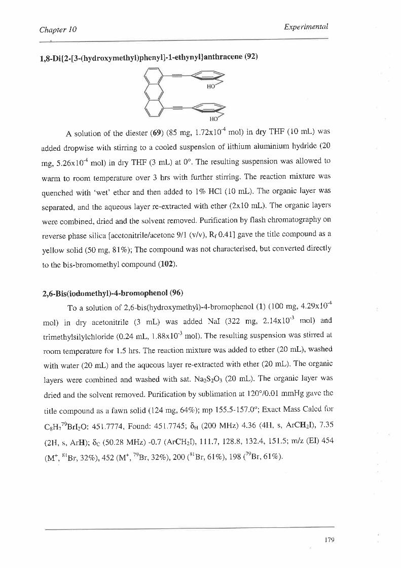
Chapter 10 Experimental
1,8-Dit2- [3-(hydroxymethyt)phenyl]' 1'ethynyl]anthracene (92)
A solurion of the diester (69) (85 mg, lJ2xI04 mol) in dry THF (10 mL) was
added dropwise with stining to a cooled suspension of lithium aluminium hydride (20
mg,5.26x10-a mol) in dry THF (3 mL) at 0'. The resulting suspension was allowed to
warm to room temperature over 3 hrs with further stirring. The reaction mixture was
quenched with 'wet' ether and then added to lVo HCI (10 mL). The organic layer was
separated, and the aqueous layer re-extracted with ether (2xI0 mL). The organic layers
were combined, dried and the solvent removed. Purification by flash chromatography on
reverse phase silica [acetonitrile/acetone 9/1 (v/v), R¡0.41] gave the title compound as a
yellow solid (50 mg, SlVo); The compound was not characterised, but converted directly
to the bis-bromomethyl compound (102).
2,6-Bis(iodomethyl)-4-bromophenol (96)
To a solution of 2,6-bis(hydroxymethyl)-4-bromophenol (1) (100 mg,4'29x10-a
mol) in dry acetonitrile (3 mL) was added NaI (322 ffig, 2.I4xIO-3 mol) and
trimethylsilylchloride (0.24 mL,1.88x10-3 mol). The resulting suspension was stirred at
room temperature for 1.5 hrs. The reaction mixture was added to ether (20 mL), washed
with water (20 mL) and the aqueous layer re-extracted with ether (20 mL). The organic
Iayers were combined and washed with sat. NazSzO¡ (20 mL). The organic layer was
dried and the solvent removed. Purification by sublimation at 120"/0.01 mmHg gave the
title compound as a fawn solid (124 mg,64Vo); mp 155.5-157.0'; Exact Mass Calcd for
CsHzTeBrIzO: 45l.ill4, Found: 451.7745; ôH (200 MHz) 4.36 (4H, s, ATCH2I),1.35
(2H, s, ArH); õc (50.28 MHz) -0.7 (ArCHzI), 111.7, 128.8, 132'4, 151'5; mlz (EI) 454
qM*, srBr, 32vo), 452 (l\/f ,7nBr,32vo¡ 200 18rBr, 6lvo),198 (7eBr, 617o).
r'79
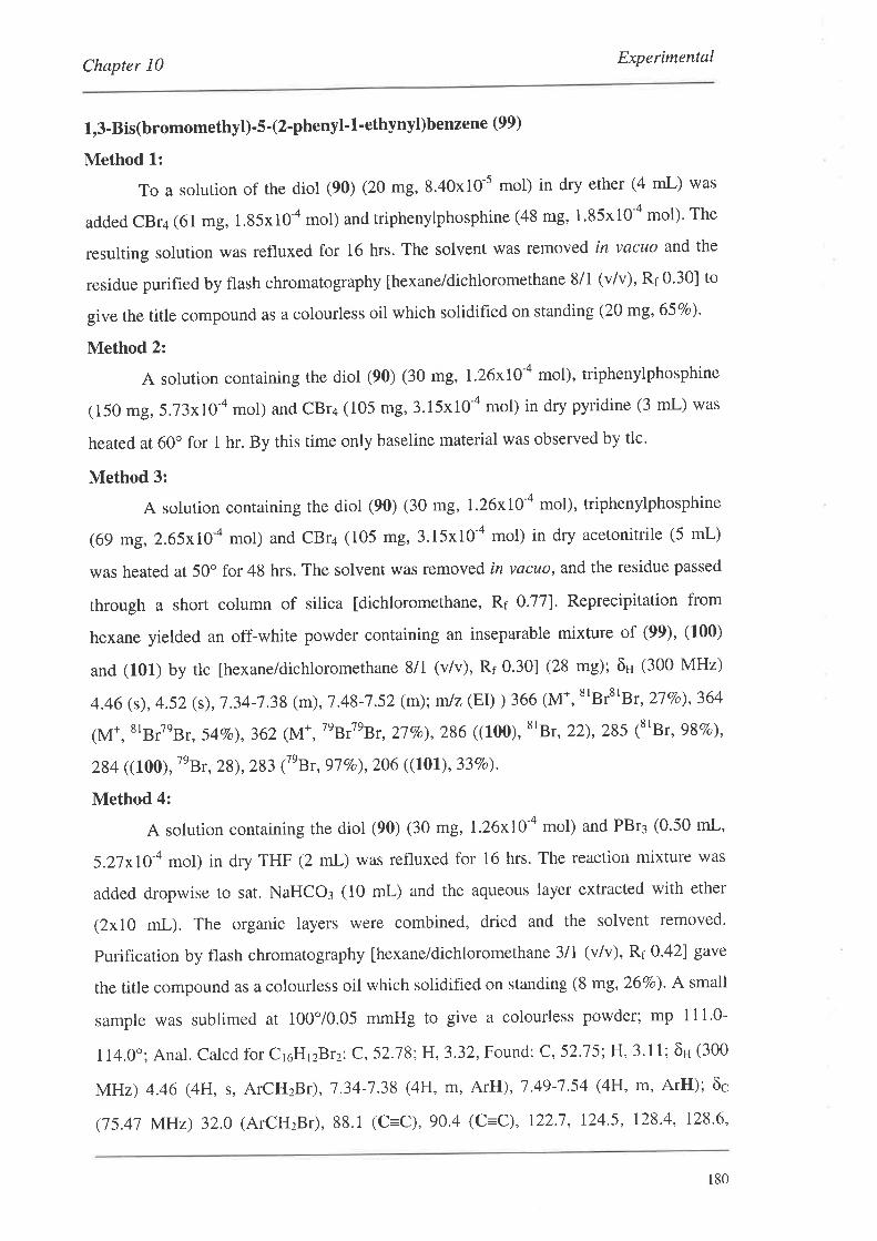
Chapter l0 Experimental
1,3-Bis(bromomethyl)'5'(2'phenyl' 1'ethynyl)benzene (99)
Method 1:
To a solurion of the diol (90) (20 mg, 8.40x10-s mol) in dry ether (4 mL) was
added CBr4 (61 mg, 1.85x10 a mol) and triphenylphosphine (48 mg, 1.85x10-a mol). The
resulting solution was refluxed for 16 hrs. The solvent was removed in vacuo and the
residue purified by flash chromatography [hexane/dichloromethane 8/1 (v/v), Ri 0.30] to
give the title compound as a colourless oil which solidified on standing (20 mg, 65Vo).
Method 2:
A solution containing rhe diol (90) (30 mg, !.26x10-a mol), triphenylphosphine
(150 mg, 5.l3xI0-a mol) and cBr+ (105 mg,3.15x10-a mol) in dry pyridine (3 mL) was
heated at 60" for I hr. By this time only baseline material was observed by tlc.
Method 3:
A solution conraining the diol (90) (30 mg, 1.26x10-a mol), triphenylphosphine
(69 mg, 2.65xIO-a mol) and CBr4 (105 mg, 3.15x10-a mol) in dry acetonitrile (5 mL)
was heated at 50" for 48 hrs. The solvent was removed in vacuo, and the residue passed
through a short column of silica [dichloromethane, Rr 0.77]. Reprecipitation from
hexane yielded an off-white powder containing an inseparable mixture of (99)' (100)
and (101) by tlc [hexane/dichloromethane 8/1 (v/v), Rr 0.30] (28 mg); ôu (300 MHz)
4.46 (s), 4.52 (s), '7 .34-7 .38 (m),7 .48-7.52 (m); m/z (EI) ) 366 (M*, 8rBr8rBr, 27Vo),364
(M*, 8tBr7eBr, 54vo),362 (M*,|ny{nBr,27vo),286 ((100), t'Br, 22),285 (t'Bt, 98vo),
284 ((100), t'Br, 28),283 (tnBr, 97vo),206 ((101), 33vo).
Method 4:
A solution containing the diol (90) (30 mg, L26x10-a mol) and PBr3 (0.50 mL,
5.2lxl1-a mol) in dry THF (2 mL) was refluxed for 16 hrs. The reaction mixture was
added dropwise to sat. NaHCO¡ (10 mL) and the aqueous layer extracted with ether
(2x10 mL). The organic layers were combined, dried and the solvent removed.
purification by flash chromatography fhexane/dichloromethane 3lI (v/v), R¡ 0.42] gave
the title compound as a colourless oil which solidified on standing (8 mg, 267o)' A small
sample was sublimed at 100'/0.05 mmHg to give a colourless powder; mp 111'0-
1 14.0.; Anal. calcd for c16H12B rz: C, 52.J8:H,3.32, Found: C, 52.75 H' 3,11; ôH (300
MHz) 4.46 (4H, s, ATCHzB r), 7.34-7.38 (4H, m, ArH), 1.49-7 '54 (4H, m, ArH); ôc
(15.41 MHz) 32.0 (ArcHzBr), 88.1 (c=C),90.4 (C=C), 122.1, 124.5, 128.4, 128.6,
180
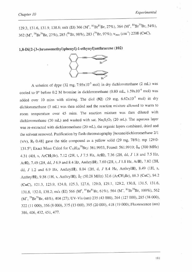
Chapter l0 Experimental
12g.3,131.6, 131.9, 138.6; m/z (EI) 366 (M*, ttBrs'Br, 27Vo),364 (M*, 8'BrteBr, 54Vo),
362 (M+, tnB.7nBr, 27vo),285 18lBr, 98vo),283 17eBr, 97vo);vn'o* (cm-l) 2208 (c=c)'
1,8-Di{2- [3-(bromomethyl)phenyl]. 1-ethynyl]anthracene (102)
A solution of dppe (32 mg,7.95x10-5 mol) in dry dichloromethane (2 mL) was
cooled to 0o befbre 0.2 M bromine in dichloromethane (0.80 mL, 1.59x10-a mol) was
added over 10 mins with stirring. The diol (92) (29 mg, 6.62x10'5 mol) in dry
dichloromethane (3 mL) was then added and the reaction mixture allowed to warm to
room temperature over 45 mins. The reaction mixture was then diluted with
dichloromethane (20 mL) and washed with sat' Na2S2O3 (20 mL)' The aqueous layer
was re-extracted with dichloromethane (20 mL), the organic layers combined, dried and
the solvent removed. Purification by flash chromatography lhexane/dichloromethane2ll
(v/v), Rf 0.481 gave the title compound as a yellow solid (29 mg,787o); mp 129'0-
131.5"; Exacr Mass Calcd for C¡zHro'nBrr'.561.9933, Found: 561.9910; õH (300 MHz)
4.3I (4H, s, ArCHzBr),7.12 (2H,t, J 7.5 Hz, ArH), 1'36 (2H, dd' "I 1'8 and J'5 Hz'
ArH), 1.4g (2H, dd, J 6.9 and 8.4 Hz, AnthrylH), 7.60 (2H,t, J l.8Hz, ArH), 7.82 (2H'
dd, ,r !.2 and 6.9 Hz, AnthrylH), 8.04 (2H, d, J 8.4 Hz, AnthrylH), 8'49 (lH, s,
AnthrylH),9.58 (lH, s, AnthrylH); õc (50.28 MHz) 32.6 (ArCHzBr), 88.3 (C:-C),94.2
(c=c), 121.3, 123.9, 124.0, 125.3, 121.6, 129.0, I2g.l, 129.2, 130.8, 131.5, 131.6,
131.8, l3Z.O, 138.2; mlz (EI) 566 (M*, 8'Br8'Br, 6lVo),564 (M*, 8tBt7nBt, I0O7o),562
(M*, 7eBr7eBr,48Vo),404 (27);UV-Vis (nm) 235 (43 000), 264 (121 000), 285 (38 000)'
322 (11 000), 356 (8 000), 375 (13 000), 395 (20 000), 418 (19 000); Fluorescence (nm)
386, 406, 432, 45r, 471 .
181

ExperimentalChapter l0
1,8-Di{2-[3-(bromomethyl)phenyl]-l-ethynyt]-l0'methoxyanthracene (1'03)
Method L:
The procedure was analogous to that for (102) using the diol (73) and dty
chloroform was used in place of dichloromethane. Purification by flash chromatography
[hexane/dichloromethane llI (v/v), Rr0.47] gave the title compound as a yellow solid
(198 mg,'777o).
Method 2:
A solurion of the diol (73) (50 mg, 1.07x10-a mol) in dry THF (5 mL) was
cooled to -200 before triphenylphosphine (59 mg, 2.I4xIO-a mol) and NBS (40 mg,
2.24x10-a mol) were added. The reaction mixture was then allowed to warm to room
temperature over 2 hrs with stirring. The reaction was quenched by addition to sat'
NaHCO¡ (20 mL), followed by extraction with ether (2x20 mL)' The organic layers
were combined, dried and the solvent removed. Purification by flash chromatography
[hexane/dichloromethane 2/I (v/v), Rf 0.30] gave the title compound as a yellow solid
(35 mg, 56zo);mp 135.0-1 37.0";Exact Mass Calcd for c¡¡Hzzo'eBtr:592'0038, Found:
5g2.0016; ôH (200 MHz) 4.18 (3H, s, ATOCH3)' 4'31(4H, s, ArCHzBr), 7 '14 (2H, t, J
7.6Hz,ArH), 7.34-1.38 (2H, m, ArH),7'45-1'59 (4H, m, ArH)' 1'8I (2H' dd' "/ 1 and
6.8 Hz,AnthrylH), 8.34 (2H, dt, ,r I and 7.8 Hz, AnthrylH), 9.40 (1H, s, AnthrylH); õc
(50.28 MHz) 32.6,63.7,88.3 (C=C),g4.4 (C=C), 119.8, 12I'6, 123'4, 123.9, 124'6'
125.1, I2g.O, I29.1,130.9, 131.8, 132.0, 132.I, I38.2,153.5; m/z (LSIMS) 596 (M+'
8'BrstBr, 5BVo),594 (M+, ttBrtnBr, !007o),5g2 (M+, tnBrtnBr, 44Vo); UV-Vis (nm) 268
(141000), 28'7 (32000),312 (I2OO0),321(12 000), 366 (1000),386 (14 000), 408 (22
OOO), 432 (21 000); Fluorescence (nm) 381, 396, 420, 441 , 410' 491 '
r82
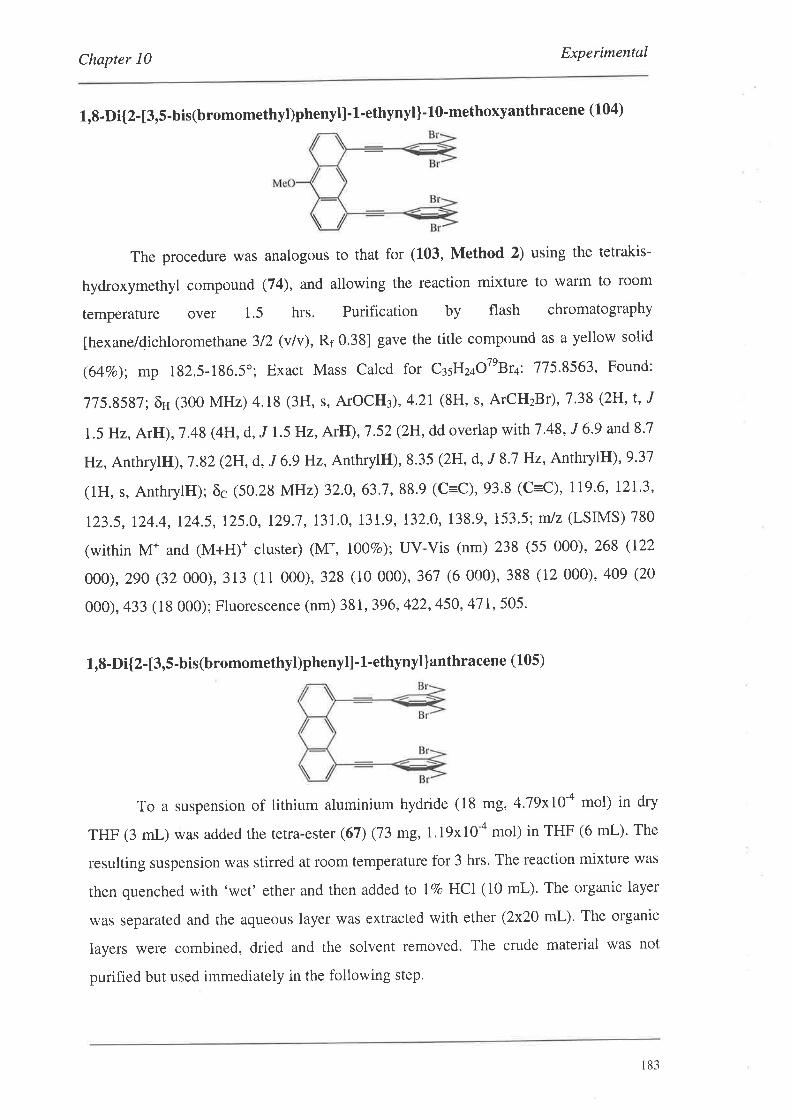
Chapter 10 Experimental
1,8-Di{2-[3,5-bis(bromomethyl)phenyl] -1-ethynyl]-lO-methoxyanthracene (104)
The procedure was analogous to that for (103, Method 2) using the tetrakis-
hydroxymethyl compound (74), and allowing the reaction mixture to warm to room
temperature over 1.5 hrs. Purification by flash chromatography
[hexane/dichloromethane 3/2 (v/v), Rr 0.38] gave the title compound as a yellow solid
(64Vo); mp 182.5-186.5o; Exacr Mass Calcd for ctsEz¿o7eBr+: 715.8563, Found:
715.8587; ôH (300 MHz) 4.18 (3H, s, ATOCH3), 4.21 (8H' s' ArCH2Br)' 7 .38 (2H' t' J
1.5 Hz, ArH), 7.48 (4H,d, J 1.5 Hz, ArH), 7.52 (2H, dd overlap with 7.48, J 6.9 and8,7
Hz, AnrhrylliI),1.82 (2H, d, J 6.9lH2, AnthrylH), 8.35 (2H, d, J 8.7 Hz, AnthrylH), 9.37
(lH, s, AnthrylH); ðc (50.28 MHz) 32.0,63.7,88'9 (C=C),93.8 (C=C), 119'6, 12L3,
123.5, 124.4, 124.5, 125.0, 129.7,131.0, 131.9, 132.0, 138.9, 153.5; m/z (LSIMS) 780
(within M* and (M+H)+ cluster) (M*, I00Eo); uv-vis (nm) 238 (55 000), 268 (122
000),290 (32 000),313 (11 000),328 (10 000),367 (6 000),388 (12 000),409 (20
000), 433 (1S 000); Fluorescence (nm) 381, 396, 422, 450, 47 I, 505'
1,8-Di{2-[3,5-bis(bromomethyl)phenyl]- 1'ethynyl ]anthracene (105)
To a suspension of lithium aluminium hydride (18 mg, 4'79xl}-a mol) in dry
THF (3 mL) was added the tetra-ester (67) (73 mg,l.l9x10-a mol) in THF (6 mL). The
resulting suspension was stirred at room temperature for 3 hrs. The reaction mixture was
then quenched with 'wet' ether and then added fo l7o HCI (10 mL). The organic layer
was separated and the aqueous layer was extracted with ether (2x20 mL). The organic
layers were combined, dried and the solvent removed. The crude material was not
purified but used immediately in the following step.
r83
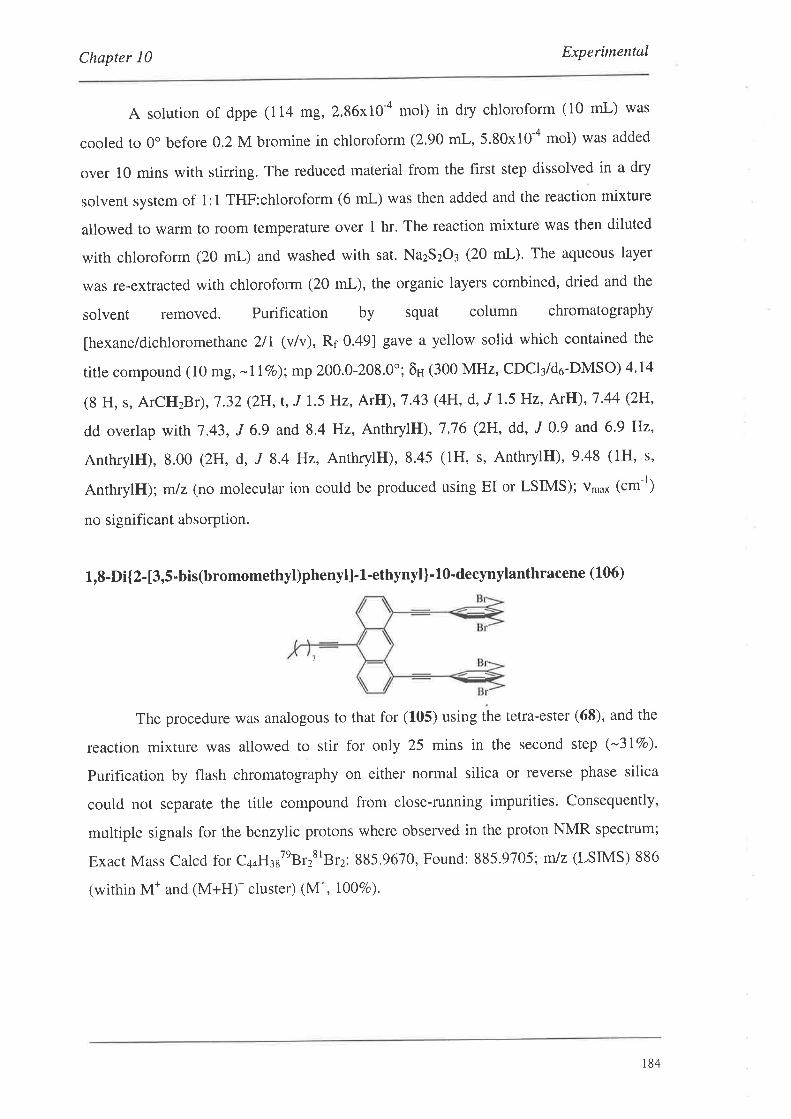
Chapter 10 Experimental
A solution of dppe (114 mg, 2.86x10-a mol) in dry chloroform (10 mL) was
cooled to 0o before 0.2 M bromine in chloroform (2.90 mL, 5.80x10-a mol) was added
over 10 mins with stirring. The reduced material from the first step dissolved in a dry
solvent system of 1:1 THF:chloroform (6 mL) was then added and the reaction mixture
allowed to warm to room temperature over I hr. The reaction mixture was then diluted
with chloroform (20 mL) and washed with sat. NazSzO3 (20 mL). The aqueous layer
was re-extracted with chloroform (20 mL), the organic layers combined, dried and the
solvent removed. Purification by squat column chromatography
[hexane/dichloromethane 2/I (v/v), R¡ 0.49] gave a yellow solid which contained the
title compound (10 mg, -l IVo);mp 200.0-208.0'; õH (300 MHz, CDCI¡/d6-DMSO) 4.14
(8 H, s, ArCH2Br), L32 (2H,¡., J I'5 Hz, ArH), 7.43 (4H' d,,f 1.5 Hz, ArH), 1'44 (2H,
dd overlap with 7.43, J 6.9 and 8.4 Hz, AnthrylH), 7.16 (2H, dd, ,f 0.9 and 6.9 Hz,
AnthrylH), 8.00 (2H, d, J 8.4 Hz, AnthrylH), 8.45 (1H, s, AnthrylH), 9'48 (1H, s,
AnthrylH); mlz (no molecular ion could be produced using EI or LSIMS); Vn'o* (.-')
no significant absorption.
1,8-Di{2-[3,5-bis(bromomethyl)phenyl]-1.-ethynyl]-10-decynylanthracene (106)
The procedure was analogous to that for (105) using the tetra-ester (68), and the
reaction mixture was allowed to stir for only 25 mins in the second step (-3lVo).
Purification by flash chromatography on either normal silica or reverse phase silica
could not separate the title compound from close-running impurities. Consequently,
multiple signals for the benzylic protons where observed in the proton NMR spectrum;
Exact Mass Calcd for C¿¿HrrteB.rttBrz: 885,9670, Found: 885.9705; m/z (LSIMS) 886
(within M* and (M+H)* cluster) (M+, 10070).
1
184
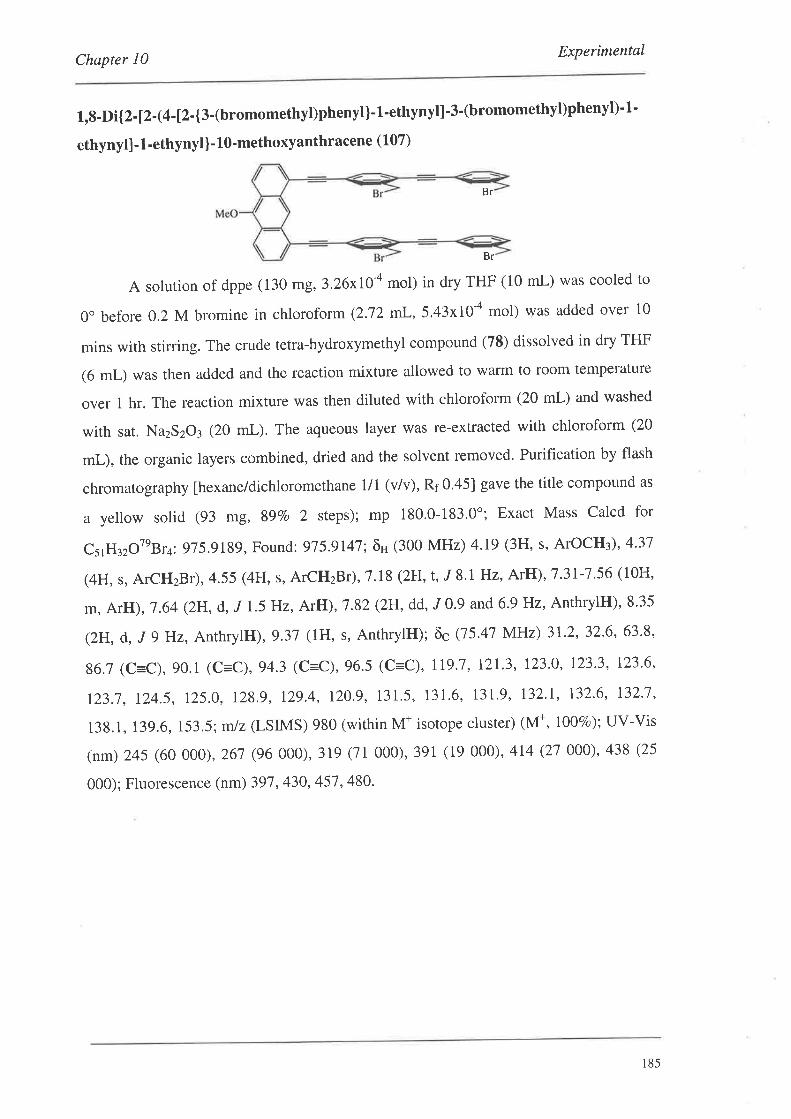
Chapter 10 Experimental
1,8-Di{2-[2-(4-t2-{3-(bromomethyl)phenyl}-1-ethynyl]'3'(bromomethyl)phenyl)-1'
ethynyll-1-ethynyl)-lO-methoxyanthracene (107)
A solurion of dppe (130 mg, 3,26x10+ mol) in dry THF (10 mL) was cooled to
0o before 0.2 M bromine in chloroform(2.12 mL,5.43x10-a mol) was added over l0
mins with srirring. The crude tetra-hydroxymethyl compound (78) dissolved in dry THF
(6 mL) was then added and the reaction mixture allowed to warm to room temperature
over t hr. The reaction mixture was then diluted with chloroform (20 mL) and washed
with sat. NazSzO¡ (20 mL). The aqueous layer was re-extracted with chloroform (20
mL), the organic layers combined, dried and the solvent removed. Purification by flash
chromatography [hexane/dichloromethane 1/1 (v/v), R¡ 0.45] gave the title compound as
a yellow solid (93 mg, 89Vo 2 steps); mp 180'0-183'0"; Exact Mass Calcd for
CsrH¡zOTeBr+:975.9189, Found: 975.9147; ôH (300 MHz) 4.19 (3H, s, ATOCH3),4.31
(4H, s, ArCH2Br), 4.55 (4H, s, ArCH2Br), 7.18 (2H' t' J 8,I Hz' ArH), 7.3I-7.56 (10H,
m, ArH), 1.64 (2H, d, ,f 1.5 Hz, ArH), 7.82 (2H, dd, ,f 0'9 and 6'9 Hz, AnthrylH)' 8'35
(2H, d, J 9 Hz, AnthrylH), 9.37 (IIH, s, AnthrylH); õc (75.47 MHz) 31.2,32.6,63.8,
86.7 (C=C),90.1 (c=c), 94.3 (C=C),96.5 (C=C), 119.7, !2L3, 123.0, 123.3, 123'6,
123.1, 124.5, 125.0, 128.9, 129.4, 120.9, 131.5, 131.6, 131.9, 132.I, 132.6, L32.1,
138.1, 13g.6,153.5; m/z (LSIMS) 9S0 (within M+ isotope cluster) (M*, 10070); uv-vis
(nm) 245 (60 000), 261 (96 000),319 (11000),391 (19 000), 414 (21 000)' 438 (25
000); Fluorescence (nm) 397, 430,457,480.
Br
Br
185
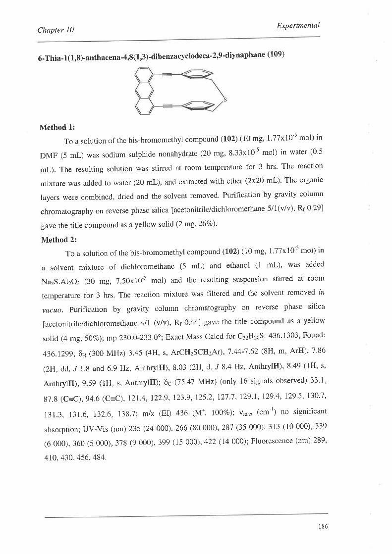
ExperimentalChapter l0
6-Thia-1(1,8)-anthacena-4,8(1,3)-dibenzacyclodeca-2,9'diynaphane (109)
Method 1:
To a solution of the bis-bromomethyl compound (102) (10 mg,l.77xl0-s mol) in
DMF (5 mL) was sodium sulphide nonahydrate (20 mg, 8'33x10 5 mol) in water (0'5
mL). The resulting solution was stirred at room temperature for 3 hrs. The reaction
mixture was added to water (20 mL), and extracted with ether (2x20 mL)' The organic
layers were combined, dried and the solvent removed. Purification by gravity column
chromatography on reverse phase silica [acetonitrile/dichloromethane 5i 1(v/v), Rr 0'29]
gave the title compound as a yellow solid (2 mg,26Vo)'
Method 2:
To a solurion of the bis-bromomethyl compound (102) (10 mg, L77x!0-s mol) in
a solvent mixture of dichloromethane (5 mL) and ethanol (1 mL), was added
NazS.AlzO¡ (30 mg, 7.50x10⁻⁵ mol) and the resulting suspension stirred at room
temperature for 3 hrs. The reaction mixture was filtered and the solvent removed in
vacuo. Purification by gravity column chromatography on reverse phase silica
[acetonitrile/dichloromethane 4ll (vlv), Rr 0.44] gave the title compound as a yellow
solid (4 mg, SOVo); mp 230.0-233.0'; Exact Mass Calcd for C¡zHzoS: 436'1303' Found:
436.1299; ôu (300 MHz) 3.45 (4H, s, ATCHzSCH2AT), 7.44-1.62 (8H, m, ArH), 7'86
(2H, dd, J 1.8 and 6.9 Hz, AnthrylH), 8.03 (2H, d, J 8.4 Hz, AnthrylH), 8'49 ( lH, s,
AnrhrylH),9.59 (1H, s, AnthrylH); ôc (75.47 MHz) (only 16 signals observed) 33'1,
87.8 (C=C), 94.6 (C=C), 12L4, 122.9, !23.9, 125.2, 127.7, 129.1, 129.4, 129.5, 130.1,
131.3, 131.6, 132.6, I3g.l; m/z (EI) 436 (M*, I00vo); v,no* (cm-r) no significant
absorption; uv-vis (nm) 235 (24 000),266 (s0 000),287 (35 000), 313 (10 000), 339
(6 000),360 (5 000),378 (9 000),399 (15 000),422 (14 000); Fluorescence (nm) 289,
410, 430, 456, 484.
186
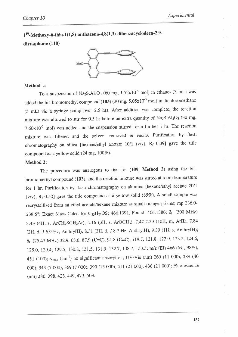
ExperimentalChapter I0
1 r0-Methoxy-6-thia- 1(1.,8)-anthacena-4,8(1,3)'dibenzacyclodeca'2,9'
diynaphane (110)
Method 1:
To a suspension of NazS.AI2O3 (60 mg, 1 .52xlO-a mol) in ethanol (3 mL) was
added the bis-bromomethyl compound (103) (30 mg, 5.05x10-s mol) in dichloromethane
(5 mL) via a syringe pump ovet 2.5 hrs. After addition was complete, the reaction
mixture was allowed to stir for 0.5 hr before an extra quantity of NazS'Al2O3 (30 mg'
7.60x10⁻⁵ mol) was added and the suspension stirred for a further t hr. The reaction
mixture was filtered and the solvent removed in vacuo. Purification by flash
chromatography on silica [hexane/ethyl acetate 10/1 (v/v), Rr 0.39] gave the title
compound as a yellow solid (24 mg,I00Vo).
Method 2:
The procedure was analogous to that for (L09, Method 2) using the bis-
bromomethyl compound (103), and the reaction mixture was stirred at room temperature
for t hr. Purification by flash chromatography on alumina [hexane/ethy| acetate 20ll
(v/v), Rf 0.501 gave the title compound as a yellow solid (857o). A small sample was
recrystallised from an ethyl acetate/hexane mixture as small orange prisms; mp 236'0-
23g.5": Exact Mass Calcd for c33Hzzos: 466.1391, Found: 466.1386; õH (300 MHz)
3.43 (4H, s, ATCHzSCH2AT), 4.16 (3H, s, ArOCH¡),7.42-7.59 (10H, m, ArH),7.84
(2H, d, J 6,9 Hz, AnthrylH), 8.31 (2H, d, J 8'.7 Hz, AnthrylH), 9.39 (lH, s, AnthrylH);
õc Q5.47 MHz) 32.g,63.6,87.9 (C=C), 94.8 (C=C), IIg.7, 121.8, 122'9, 123.2, 124'6'
125.0, 12g.4, ),2g.5,130.8, 131.5, 131.9, 132.1,138.7, 153.5; mlz (EI) 466 (M*, 987o),
a51 (100); v,oo* lcm-r) no significant absorption; uv-vis (nm) 269 (11 000), 289 (40
000),343 (7 000), 369 (7 000),390 (13 000), 4lI (21000),436 (21 000); Fluorescence
(nm) 380, 398, 423, 449, 473, 503.
t87
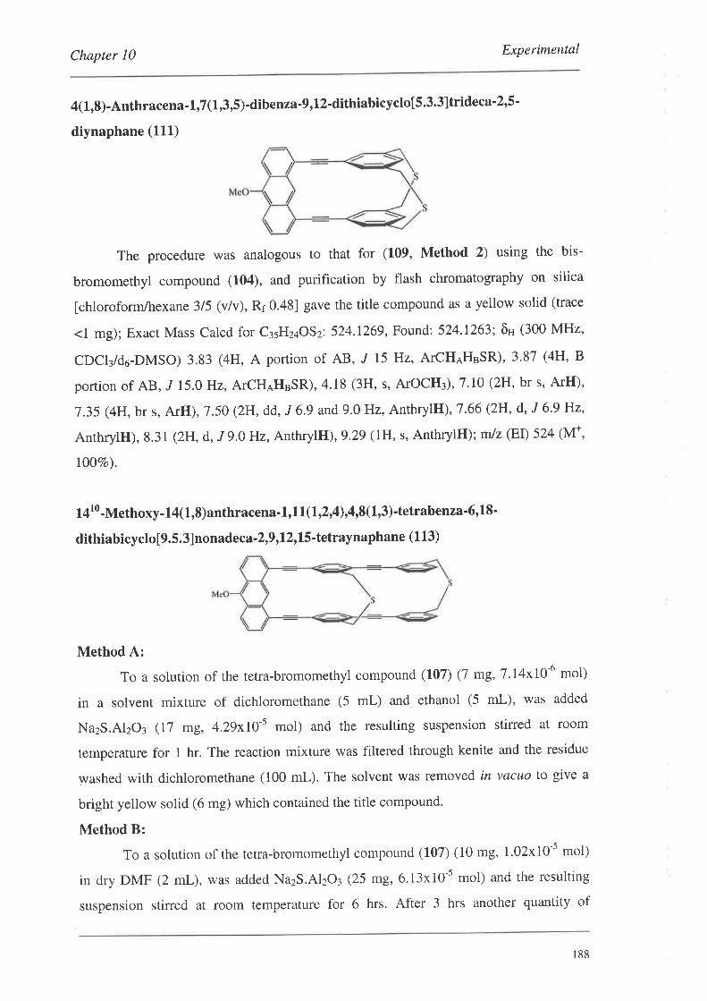
Chapter l0 Experimental
4(1,8)-Anthracena-1,,7(1,3,5)-dibenza-9,12-dithiabicyclo[5.3.3]trideca'2,5-
diynaphane (111)
The procedure was analogous to that for (109, Method 2) using the bis-
bromomethyl compound (104), and purification by flash chromatography on silica
fchloroform/hexane 315 (vlv), Rr 0.48] gave the title compound as a yellow solid (trace
.l *g); Exact Mass Calcd for C¡sHz¿OSz: 524.1269, Found: 524.1263: õH (300 MHz,
CDCI¡/d6-DMSO) 3.83 (4H, A portion of AB, J 15 Hz, ATCHAHBSR), 3.87 (4H, B
portion of AB, J 15.0 Hz, ArCH¡H3SR), 4.18 (3H, s, ArOCH¡), 7'10 (2H,bt s, ArH),
7.35 (4H, br s, ArH),7.50 (2H, dd, J 6'9 and9.0Hz, AnthrylH), 7.66 (2H, d, J 6'9 Hz,
AnthrylH),8.31 (2H, d,,f 9.0 Hz, AnthrylH|),g.2g (1H, s, AnthrylH); m/z (EI) 524 (M+,
I0OVo).
14r0-Methoxy-14(1,8)anthracena'l,l1.(1,2,4),4,8(1,3)-tetrabenza'6'18'
dithiabicyclo[9.5.3]nonadeca-2,9,12,15'tetraynaphane (1 13)
Method A:
To a solution of the tetra-bromomethyl compound (107) (1 mg,7'14x10-6 mol)
in a solvent mixture of dichloromethane (5 mL) and ethanol (5 mL), was added
NazS.AlzOt e1 mg,4.29x10-5 mol) and the resulting suspension stirred at room
temperature for t hr. The reaction mixture was filtered through kenite and the residue
washed with dichloromethane (100 mL). The solvent was removed in vacuo to give a
bright yellow solid (6 mg) which contained the title compound.
Method B:
To a solution of the tetra-bromomethyl compound (107) (10 mg, l.02xl0-s mol)
in dry DMF (2 mL), was added NazS.AlzO3 (25 mg,6.13x10-5 mol) and the resulting
suspension stirred at room temperature for 6 hrs. After 3 hrs another quantity of
188
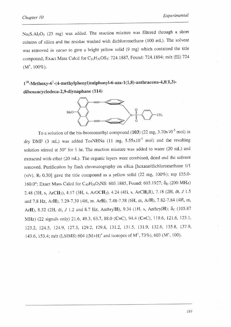
Chapter I0 Experimental
NazS.AlzO3 (25 mg) was added. The reaction mixture was filtered through a short
column of silica and the residue washed with dichloromethane (100 mL)' The solvent
was remov ed in vacuo to give a bright yellow solid (9 mg) which contained the title
compound; Exact Mass Calcd for CsrH¡zOSz: 124.1887, Found: 124.1894; mlz (EI) 124
(M*, 10070).
1 r0-Methoxy-6r
- 14-methylphenyl)sulphon yl-6 -aza-I(I,8)-anthracena'4,8 (L,3)'
dibenzacyclodeca-2,9'diynaphane (114)
CH¡
o
To a solution of the bis-bromomethyl compound (103) (22 mg, 3.70x10-s mol) in
dry DMF (3 mL) was added TosNHNa (11 mg,5.55x10-s mol) and the resulting
solution stirred at 50o for I hr. The reaction mixture was added to water (20 mL) and
extracted with ether (20 mL). The organic layers were combined, dried and the solvent
removed. Purification by flash chromatography on silica [hexane/dichloromethane 1/1
(v/v), R¡ 0.301 gave the title compound as a yellow solid (22 mg, l00%o); mp 155.0-
160.0"; Exact Mass Calcd for C¿oH2eO3NS: 603.1885, Found: 603.1927; õH (200 MHz)
2.48 (3H, s, ArCH3), 4.17 (3H, s, ATOCH3),4'24 (4H, s, ATCHzR), l 'I8 (2H, dt, 'f 1'5
and 7.8 Hz, ArH), 1.29-1.39 (4H, m, ArH), 7 '48-1.58 (6H, m, ArH), 7.82-7 '84 (4H, m,
ArH), 8.32 (2H,dt, J 1.2 and 8.7 Hz, AnthrylH),9.34 (1H, s, AnthrylH); õc (105'87
MHz) (22 signals only) 21.6, 49.3,63'1,88'0 (C=C),94.4 (C=C), 119,6, l2l'6, 123'1,
123.2, 124.5, 124.9, r27.3, 129.2, 129.8, 13r.2, 131.5, 13r.9, 132'6, 135.8, r31.9,
143.6,153.4;m/z (LSIMS) 604 ((M+H)+ and isotopes of M*, 73Vo),603 (M+, 100).
189
Bibliography
I
2
3
4
5
Biblioeraphy
Handbook of conducting polymers 2"d Edition, (Eds.: Skotheim, T.4.,
Elsenbaumer, R.L. and Reynolds, J.R., Marcel Dekker, New York, 1998.
Organic Materials for Nonlinear Optics, @ds.: Hann, R.A. and Bloor, D.),
Royal Society of Chemistry, London, 1989.
Organic Materials for Nonlinear Optics 1| (Eds.: Hann, R.A. and Bloor, D.),
Royal Society of Chemistry, Cambridge, 1991.
Organic Materials for Nonlinear Optics 11l, (Eds.: Ashwell, G.J. and Bloor, D.),
Royal Society of Chemistry, London,1993.
Ulrich, D.R., in Materials for Nonlinear Optics, Chemical Perspectives, (Eds.:
Marder, S.R., John, J.E. and Stucky G.D.), American Chemical Society,
Washington DC, 1991, pp. 24I-263.
6 Singh, 8.P., Prasad, P.N. and Karasz, F.E., Polymer,1988,29,1940
7 Reinisch, R. and Vitrant, G., Prog. Quant. Elect.,1994, L8, 1.
a) Tutt, L.W. and Boggess, T.F., Prog. Quant. Elect., 1993,17,299; b) Shirk,
J.S., Pong, R.G.S., Bartoli, F.J. and Snow, 4.W., Appl. Phys. Lett., 1993,63,
1880.
9 Long, N.J., Angew. Chem. Int. Ed. 8ng1.,1995,34,2I
8
190
Bibliography
10 a) Stucky, G.D., Marder, S.R. and Sohn, J.8., in Materials for Nonlinear Optics,
Chemical Perspectives, (Eds.: Marder, S.R., John, J.E. and Stucky G.D.),
American Chemical Society, Washington DC, L991, pp 2-30; b) Prasad, P.N.,
ibid, pp.50-66.
11 Mills, D.L., Nonlinear Optics: Basic Concepts, Springer-Verlag, Heidelberg,
t99t.
12 Boyd, R.W., Nonlinear Optics, Academic Press, London, 1992.
13 Butcher, P.N. and Cotter, D., The Elements of Nonlinear Optics, Cambridge
University Press, Avon, 1990.
t4 Spangler, C.S., Kelleher, T.4., Liu, P.-K., Cheng, L.-T., Tang, N. and Hellwarth,
R., in Organic Materials for Nonlinear Optics 111, @ds.: Ashwell, G.J. and
Bloor, D.), Royal Society of Chemistry, London, 1993, pp. 19-24.
15 DeMartino, R.N., in Fine Chemicals for the Electronics Industry II, (F,ds.: Ando,
D.J. and Pellatt, M.G.), Royal Society of Chemistry, Cambridge, 1991, pp.223-
236.
16 Karakus, Y., Cross, G.H., Bloor, D., Douglas, W.E., Corrin, R.J.P. andYang,Z.-
X., in Organic Materials for Nonlinear Optics 111, (Eds.: Ashwell, G.J. and
Bloor, D.), Royal Society of Chemistry, London, 1993, pp. 156-162.
t7 Spangler, C.W., in Handbook of Conducting Polymers 2nd Edition, (Eds,:
Skotheim, T.4., Elsenbaumer, R.L. and Reynolds, J.R., Marcel Dekker, New
York, 1998, pp. 7 43-7 63.
Stegeman, G.E., in Organic Materials for Nonlinear Optics 11, (Eds.: Hann, R.A.
and Bloor, D.), Royal Society of Chemistry, Cambridge,l99L, pp. 31I-323.
18
191

Bibliography
22
19 Hoffman, H.J., Opt. Soc. Am.8., 1986, 3,253
20 Hellwarth, R., Cherlow, J. and Yang, T.T.,Phys. Rev., 1975,1I,964
2l Maloney, C. and Blau, W., J. Opt. Soc. Am. 8., 1987,4, 1035.
Zhao, M.T., Samoc, M., Singh, B.P. and Prasad, P.N., /. Phys. Chem., 1989, 93,
7916.
Pang, Y., Samoc, M. and Prasad, P.N., "f. Chem. Phys., L99I,94,5282.
Swiatkiewicz,J., Prasad, P.N. and Karasz, F.E., ,f. AppI. Phys., L993,74,525
Swiatkiewicz, J., Prasad, P.N., Karasz, F.E., Druy, M.A. and Glatowski, P.,
Appl. Phys. Lett., 1990, 56,892.
26 Kobayashi, T., Yoshizawa, M., Stamm, U., Taiji, M. and Hasegawa, M., J. Opt.
Soc. Am.,1990, 7, 1558.
27 Bredas, J.L., Adant, C., Tackx, P. and Persoons, A.., Chem. Rev., 1994,94,243.
Crisp, G.T. and Bubner, T .P., Tetrahedron, 1997 ,53, I 1881
Crisp, G.T. and Bubner, T .P ., Tetrahedron, 1997 , 53, 1 I 899
Guther, R., Rissanen, K. and Vogtle, F., Chem. Ûer.,1994,127,743.
23
24
25
28
29
30
31 Brown, C.J. and Farthing, A.C., Nature, 1949, 164, 9L5.
t92
Bibliography
32 (a) Diederich, F., Cyclophan¿s, The Royal Society Of Chemistry, Cambridge,
1991, pp. 7-15; (b) Sheehan, M. and Cram D.J., "f. Am. Chem. Soc., 1969,91,
3553; (c) Otsubo, T., Kohda, T. and Misumi, 5., Bull. Chem. Soc. Jpn.,1980, 53,
512; (d) Shinmyozu, T.,Inazu, T. and Yoshino, T., Chem. I¿tt., 1977,1347.
33 Otsubo, T., Kohda, T. and Misumi, 5., BulI. Chem. Soc. Jpn., 1980, 53,5I2
34 Diederich, F., Cyclophanes, The Royal Society Of Chemistry, Cambridge, 1991,
pp. 18-43.
35 Odashima, K., Itai, 4., Iitaka and Y., Koga, K., ,f. Am. Chem. Soc., 1980, L02,
2504.
36 Diederich, F., Cyclophanes, The Royal Society Of Chemistry, Cambridge, 1991,
pp.222-245.
37 Powel, Vy'.H., Pure & AppI. Chem., 1998, 70, 1513.
A Guide to IUPAC Nomenclature of Organic Compounds: Recommendations
1993, (Eds.: Panico, R., Richer, J.-C. and Powell, W.H.), Blackwell Scientific
Publications, Oxford, 1993.
Rossa, L. and Vogtle, F.,inTopics in Current Chemistry, Vol. ll3: Cyclophanes
1, (Eds.: Dewar, M.J.S., Dunitz, J.D., Hafner, K., Heilbronner, E., Ito, S., Iæhn,
J.M., Niedenzu, K., Raymond, K.N., Rees, C.W., Schafer, K., Vogtle, F. and
Wittig, G.), Springer-Verlag, Berlin, 1983, pp. 1-86.
38
39
Roncali, J., Thobie-Gautier, C., Elandaloussi, E.H. and Frere, P., J. Chem. Soc.,
Chem. Comm., L994, 2249.
40
t93
Bibliography
4L Distefano, G., Dal Colle, M., Jones, D., Zambianchi, M., Favaretto, L. and
Modelli, A.,J. Phys. Chem., 1993,97,3504.
42 Keane, M.P., Svenson, S., Naves de Brito, 4., Correia, N., Lunell, S., Sjorgren,
B.,Inganas, O. and Salaneck, W.R., J. Phys. Chem., 1990, 93, 6357.
43 Scandalphon, Kippelefl, B., Meerholz, K. and Peyghambarian, N., Appl. Opt,
1996,35,2346.
44 McMichael, I., Christian, W., Pletcher, D., Chang, T.Y. and Hong, J.H., Appl.
Opt., 1996,35,2375.
45 Photorefractive Materials and their Applications, VoIs. I and II, (Eds.: Gunter,
P. and Huignard, J.-P.), Springer-Verlag, Berlin, 1988.
46 Kruizinga, W.H. and Kellogg, M., J. Am. Chem. Soc., 1989,103, 5183
47 Langford, S.J. and Stoddart, F.J., Pure & Appl. Chem., L996,68, 1255.
Asakawa, M., Ashton, P.R., Menzer, S., Raymo, F.M., Stoddart, F.J., 'White,
A.J.P. and Williams, D.J., Chem. Eur. J.,1996,2,877.
Asakawa, M., Ashton, Brown, C.L., Fyte, M.C.T., Menzer, Pasini, D., Scheuer,
C., Stoddart, F.J., White, A.J.P. and Williams, D.J., Chem. Eur. J., 1997,3,
1t36.
Moshfegh, 4.4., Mazandarani, 8., Nahid, A. and Hakimelahi, G.H., HeIv. Chim.
Acta., L982,65,1229.
Heaney, H., in Comprehensive Organic Synthesis, (Eds.: Trost, B.M. and
Fleming, I), Pergamon Press, Oxford, I99I,4,pp.953-973.
48
49
50
51
t94
53
54
55
56
57
52
58
Bibliography
(a) March, J., Advanced Organic Chemistry: Reactions, Mechanisms and
Structure 4th Ed., Wiley, New York, 1992, p.550; (b) ibid, p.900.
Albrecht, M., Synthesis, 1996, 230.
Bruckhalter, J.H. and Leib, R.I., J. Org. Chem., 196I,26,4078.
Burckhalter, J.H., 'Wells, J.N. and Mayer, W.J.,Tetrahedron l¿tt., 1964, 1353.
Bruson, H.A. and MacMullen, C.W., J. Am. Chem. Soc., 1941,63,270.
(a) [.emon, P.H.R.B., King, J.G., Murray, G., [,eoni, H. and Gerber, 4.H., Chem.
Abstr., ll3: P2I3239y; (b) L€mon, P.H.R.B., King, J.G., Murray, G., [æoni, H.
and Gerber, 4.H., Chem. Abstr., lI4:P67342d.
Chabrier, P., Seyden-Pennne, J. and Fouace, A.-M., C. R. Acad. Sci., 1957,245,
174.
Orito, K., Hatakeyama, T., Takeo, M. and Suginome, H., Synthesis,1995,1273.
McCleland, C.W., Synthetic Reagents,1980, 5, pp. 85-165.
Kajigeshi, S., Kakinami, T., Yamasaki, H., Fujisaki, S, Kondo, M. and Okamoto,
T., Chem. Lett., 1987, 2109.
Baird, W.C. and Surridge, J.H., J. Org. Chem., 1970,35,3436.
Kometani, T., Watt, D.S., Ji, T. and Fitz, T., J. Org. Chem.,1985, 50, 5384.
59
60
6T
62
63
64 Kometani, T., Watt, D.S. and Ji, T., Tetrahedron Lett., 1985, 26,2043
195
Bibliography
65
66
67
Crisp, G.T., Turner, P.D. and Tiekink, E.R.T., Zeit. Fur Krist.,1998, 213, 385
Kunesh, N., Miet, C. and Poisson, J., Tetrahedron I'ett.,1987,28,3569.
Gonzalez,4.G., Jorge, Z.D. andLopez Dorta, H'L', Tetrahedron Lett., 1981,22,
Hendrickson, J.B., Bair, K.W., Bergeron, R., Giga, A', Skipper, P.L., Sternbach,
D.D. and Wareing, 1.A,., Org. Prep. Proced. Int., L977,9,I73'
Williams, D.H. and Fleming, 1., Spectroscopic Methods in Organic Chemistry 4tt'
Editíon, McGraw-Hill, London, 1 9 89, pp. 29 -62.
Rao, C.N.R., Chemical Applications of Infrared Spectroscopy, Academic Press,
New York,1963, pp. 17-18.
March, J., Advanced Organic Chemistry: Reactions, Mechanisms and Structure
4th Ed., Wiley, New York,1992,pp.557-562.
Todd, D. and Martell, A.8., Org. Synth., Collect. Vol., 5,617
Moshfegh, A., Fallab, S. and Erlenmeyer,H., HeIv. Chim. Acta., L957 ,40, lI57 .
Kajigaeshi, S., Kakinami, T., Fujisaki, S., Kondo, M. and Okamoto, T', Chem.
Lett., 1987,2109.
75 Freeman, J.H., J. Am. Chem. Soc., 1952,74,6257
Jelley, E.E., in Techniques of Crganic Chemistry 2nd Ed, (Ed: Weissberger, A.),
Interscience Publ., New York,1949,1, pp. 886-889.
335
68
69
t0
7I
72
73
74
76
t96
77
78
79
Bibliography
Sherrod, S.4., da Costa, R.L., Barnes, R.4., and Boekelheide, V., J. Am. Chem.
Soc., L974,96, L565.
Bhagwat, S.S., Roland, D.M., Main,4.J., Gude, C., Goldstein, R., Cohen, D.S.,
Dotson, R., Mathis, J. and Lee, W., Bioorg. & Med. Chem. I¿tt., L992,2,1623.
Agback, K.H., Ahrgren, L., Berglingh, T., Heraldsson, M., Olsson, L.I. and
Smedegaard, G., Chem. Abstr., lL9: P24969Lc.
Dictionary of Organic Compounds 5't' Edition. (Eds.: Cadogan, J.I.G., Raphael,
R.A. and Rees, C.W.), Chapman and Hall, Pennsylvania, 1982, I-00395 Me
ester, p. 3325.
Austin, W.B., Bilow, N., Kelleghan, W.J. and Lau, K.S.Y., J. Org. Chem., I98I,
46,2280.
Perez, J., Burillo, G., Roa, M., Vazquez, C. and Ogawa,T., Polymer BulI., L992,
27,527.
March, 1., Advanced Organic Chemistry: Reactions, Mechanisms and Structure
4th Ed., Wiley, New York, L992,p.25I.
(a) Vogtle, F., Koch, H. and Rissanen, K., Chem. Ber., 1992, 125,2129; (b)
Katz, H.E., J. Org. Chem., 1989,54,2119.
(a) House, H,O., Koepsell, D. and Jaeger, W.J., ,f. Org. Chem., 1973,38, 1167;
(b) House, H.O., Ghali, N.L, Haack, J.L. and VanDerveer, D., J. Org. Chem.,
1980,45, 1807.
80
81
82
83
84
85
86 Barnett, E.B. and Matthews, M.4., Rec. Trav. Chim., L924,43, 530
197
87
88
95
89
90
91
92
93
94
Bibliography
Elsevier's Encyclopaedia of Organic Chemistry, Series 3 : Carboisocyclic
Condensed Compounds, (Eds.: Josephy, E. and Radt, F., Elsevier, New York,
1949,13, pp. 234-259.
Barnett, E.D., Cook, J.W. and Matthews, M.4., Recl. Trav. Chim. Pays-Bas,
1926,45,68,
Schuster, I.I., "/. Org. Chem., 1981, 46, 5110
Archibald, T.G., Malik, A.A. and Baum, K., Macromolecules, 199L,24,5261.
Lovell, J.M. and Joule, J.4., Syn. Comm., l99l ,27, 1209
Cassar, L., J. Organomet. Chem.,1975,93,253.
Dieck, H.A. and Heck, R.F., J. Organomet. Chem.,1975,93,259
Catalysis of Organic Reactions, (Eds.: Rylander, P.N', Greenfield, H. and
Augustine, R.L.), Marcel Dekker Inc., New York, 1988, pp. 381-407.
Tsuji, J., Palldium Reagents and Catalysfs, John Wiley and Sons, Surrey, 1995,
p. 168.
96 Negishi, 8., Acc. Chem. Res., 1982,1,5, 340.
Stille, J.K. and Lan, K.S.Y., Acc. Chem. Res., 1977 ,I0,434.
Parshall, G.W., J. Am. Chem. Soc., I9J4,96,2360
Heck, R.F., Palladium Reagents in Organic Synthesis, Academic Pfess, London,
1985, pp. 1-18.
97
98
99
198
Bibliography
100 Farina, Y., J. Org. Chem., 1991, 56, 4985
101 Powell, N.A. and Rychnovsky, S.D., Tetrahedron I'ett., 1996,37,7901
t02 Preparation of Alkenes : A Practical Approach, (Ed.: V/illiams, J. M' J), Oxford
University Press, New York, 1996, pp. 145-146.
103 Williams, D.H. and Fleming, 1., Spectroscopic Methods in Organic Chemistry 4tt'
Edition, McGraw-Hill, London, 1 989, pp. 63 -149'
104 Rossi, R. and Carpita, A., Synthesis, 1977,56I
105 Zweifel, G. and Miller, J.A., Org. React., 1984,32,375.
106 Sonogashirâ, K., ín Comprehensive Organic Synthesis, (Eds.: Trost, B.M. and
Fleming,I), Pergamon Press, Oxford, I99I,3, pp. 52I-549.
101 Stille, J.K.,,r. Am. Chem. \oc.,1987, 109, 2L38.
108 Rudisill, D.E., Castonguay, L.A. and Stille, LK., Tetrahedron Lett., 1988,29,
1509.
109 Stille, J.K., Angew. Chem. Int. Ed. 8ng1.,1986, 25, 508.
110 King, A.O. and Negishi, 8., J. Org. Chem., 1918,43, 358'
111 King, 4.O., Okukado, N. and Negishi, 8., Chem. Comm., 1977 ,683.
Llz Negishi, E., Kotora, M. and Xu, C., J. Org. Chem., 1991,62,8957
113 Andreini,8.P., Carpita, A. andRossi, R.,TetrahedronLett.,1988,29,2239
199
Bibliography
lL4 Bertus, P. and Pale, P., Tetrahedron I'ett., L996,37 , 20L9
115 Bertus, P. and Pale, P., J. Organomet. Chem., 1998, 567, I73
I 16 Farina, V. and Krishnan, B., J. Am. Chem. Soc., 199I,113, 9585
lL7 Casado, A.L. andEspinet, P., J. Am. Chem. Soc., 1998, 120,8978
118 Crisp, G.T., Turner, P.D., Stephens, K.4., J. Organomet. Chem., 1998,570,219
119 Lange's Handbook of Chemistry 13"' Edition, (Ed.: Dean, J.A.), McGraw-Hill,
New York, 1985, pp. 5.18-5.60.
120 Dictionary of Organic Compounds 5't' Edition, @ds.: Cadogan, J'I.G., Raphael,
R.A. and Rees, C.W.), Chapman and Hall, Pennsylvania, L982, D-07760, p.
2297.
IzL Dieck, H.A. and Heck, F.R.,,f. Organomet. Chem.,1975,93,259
122 Chen, Q.Y. and Yang, Z.Y.,Tetrahedron I'ett.,1986,27,I17I.
I23 Pearson, 4.J., Shively, R.J. and Dubbert, R.4., Organometallics, 1992, LL,4096.
Comprehensive Organometallic Chemistry, @ds.: Wilkinson, Sir G., Stone,
F.G.A. and Abel, E.W., Pergamon Press, Oxford, 1982,pp.823-862.
L25 Lange's Handbook of Chemistry l4'h Edition, (Ed.: Dean, J.A.), McGraw-Hill,
New York, 1992, pp. 4.23-4.35.
r24
126 Dessy, R.8., Okuzumi, Y. and Chen, A., J. Am. Chem. \oc.,1962,84,2899
200
Bibliography
127 Osakada, K., Sakata, R. and Yamamoto ,T., Organometallics, 1997 ,16, 5354.
t28 (a) Waters, D.N., Short, E.L., Tharwat, M. and Morris, D.F.C., J. MoI. Struc.,
1973, I7 ,389; (b) Yudovich, 8.8., Zabolotskii, V.I., Iævin, E.D. and Tikhonov,
K.I., Zh. Obshch. Khim.(English), 1976, 46,2576.
L29 Hartl, H., Brudgam, I. and Mahdjour-Hassan-Abadi, F., Z. Naturþrsch., 1983,
388,57.
130 Yasuda, H., Ohnumâ, Y., Nakamura, 4., Kai, Y., Yasuoka, N. and Kasai, N.,
BwII. Chem. Soc. Jpn.,1980,53, 1101.
131 Liu, E.K.S .,Inorg. Chem., 1980, 19,266.
132 Cini, R., Musaev, D.G., Marzilli, L.G. and Morokuma, K., /. MoI. Struct.,1997,
392,55.
I33 Jiang, B. and Xu, Y., J. Org. Chem., I99I,56,7336.
L34 De Konig, 4.J., Van Rijn, P.E. and Van Der Kerk, G.J.M., J. Organomet
Chem., 1979,174,129.
135 Hatanka, Y. andHiyama, T.,Synlett., 1991,845
136 Streitwieser, A. and Ruben, D.M.E., J. Am. Chem. Soc., 1971,93,1794.
137 Al-Hassan, M.I., J. Organomet. Chem.,1990,395,227
138 Amatore, C., Jutand, A. and Suarez, A., J. Am. Chem. \oc.,1993,115,9531.
20t
Bibliography
r39 Amatore, C., Carre, E., Jutand, A
Organometallic s, L995, 14, 5605.
M'Barki, M.A. and Meyer, G.,
140 Bauman, J.E. and Wang, J.C.,Inorg. Chem., 1964,3,368.
I4T Iæfek, K.T., Pruszynski, P. and Thanapaalasingham, K., Can. J. Chem., 1989,
67,590.
I42 Schlemper,H., Ph.D. Thesis (University Of Bad Marienberg), 1990, p. 85.
143 Coles, S, Honours Thesis (University Of Adelaide), 1998.
L44 Schmidt, 4.H., Aldrichima Acta, 198I, L4,31
145 Jung, M.E. and Lyster, M.4., J. Am. Chem. \oc.,1977,99,968.
146 Olah, G.4., Narang, S.C., Balaram Gupta, B.G. and Malhotra, R., J. Org. Chem.,
1979,44, 1247.
I47 Morita, T., Okamoto, Y. and Sakurai,H.,Tetrahedron Len.,1978,2523
148 Corey, E.J. and Kania, RS.,Tetrahedron I'ett., 1998,39,J41
149 Larock, R.C., Comprehensive Organic Transþrmations, VCH, New York, 1989,
pp.353-360.
150 March, J., Advanced Organic Chemistry: Reactions, Mechanisms and Structure
4th Ed., Wiley, New York, 1992, pp. 43I-433.
151 Jones, R. and Pattison, J.8., ,f. Chem. Soc. C, 1969,1046.
202
Bibliography
L52 Lan, A.J.Y., Heuckeroth, R.O. and Mariano, P.S., J' Am. Chem. Soc., 1987, 109,
2738.
153 Kashem, 4., Anisuzzaman, M. and Whistler, R.L., Carbohydr. Res., 1978,6L,
51 1.
I54 Schmidt, S.P. and Brooks, D.W., Tetrahedron Lett., 1987,28,767
155 Wiley, G.4., Rein, B.M. and Hershkowitz, R.L.,Tetrahedron I¿tt., 1964,2509
156 Nicolaou, K.C., Veale, C.4., Webber, S.E. and Katerinopoulos, H., J. Am.
Chem. Soc., 1985, 107,1515.
L57 Larock, R.C., Comprehensive Organic Transþrmations, VCH, New York, 1989,
pp.985-987.
158 Steglich, W. and Hofle, G., Angew. Chem. Int. Ed. ÛngL,1969, 8, 981
159 Taber, D.F., Amedio, J.C. and Patel, Y.K., J. Org. Chem., 1985, 50, 3618
160 Bodwell, G.J., Houghton, T.J., Koury, H.E. and Yarlagadda,B', Synlett', 1995,
751
L6L Breidenbach, S., Harren, J., Neumann, S., Nieger, M., Rissanen, K' and Vogtle,
F., J. Chem. Soc., PerkinTrans. l, 1996,2061'
L62 Hunter, C.A. and Sanders, J.K.M., J. Am. Chem. Soc., 1990,ll2, 5525'
Schulman, S.G., Fluorescence and Phosphorescence Spectroscopy:
P hy s i c o c h e mi c aI P rinc ip I e s and P r ac ti c e, P er gamon Pres s, Exeter, L9J J .
r63
203
Bibliography
r64 Williams, D.H. and Fleming, L, Spectroscopic Methods in Organic Chemistry 4tt'
Edition, McGraw-Hill, London, 1989, pp. 1-28
Friedel, R.A. and Orchin, M., (Jltraviolet Spectra of Aromatic Compounds,
Wiley, New York, 1951.
165
166 Diederich, F., Cyclophanes, The Royal Society Of Chemistry, Cambridge, 1991,
pp.44-46.
167 Mattes, S.L. and Farid, 5., Science,1984,226,917
168 Crooks, J.E., The Spectrum in Chemistry, Academic PreSS, London, 1978, pp'
135-136
169 Rao, C.N.R., Ultra-Violet and Visible Spectroscopy, Butterworths, L¡ndon,
t96l
I70 Jaffe, H.H. and Orchin, M., Theory and Applications of Ultraviolet
Spectroscopy, John Wiley and Sons, New York, 1962'
L7l Badrieh, Y., Blum, J. and Schumann, H., J. MoL Cat., 1994,90,231'
I72 Perrin, D.D., Aramarego, W.L.F. and Perrin, D.R., Purification of Laboratory
Chemicals 4't' Edition, Butterworth Heineman, Bath, 1996'
204
Appendix: Published Articles
Published Articles
1. Crisp, G.T., Turner, P.D. and Tiekink, E.R.T., Zeit. Fur Krist., 1998, 213, 385.
2. Crisp, G.T., Turner, P.D., Stephens, K.4., J. Organomet. Chem., Igg8,570,2I9.
205
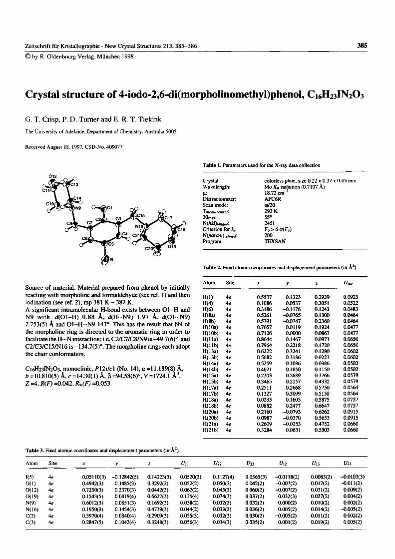
Zeitschrift für Kristallographie - New Crystal Structures 213, 385-386 385 © by R. Oldenbourg Verlag, München 1998
Crystal structure of 4-iodo-2,6-dì(morpholinomethyl)phenol, C16H23IN2O3
G. T. Crisp, P. D. Turner and E. R. T. Tiekink
The University of Adelaide, Department of Chemistry, Australia 5005
Received August 18. 1997. CSD-No. 409077
Table 1. Parameters used for the X-ray data collection
012 Crystal: colorless plate, size 0.22 χ 0.37 χ 0.45 mm Wavelength: Mo Ka radiation (0.7107 λ) μ: 18.72 cm"' Diffractometer: AFC6R Scan mode: (оПв Τ measurement' 293 К
55° 2451
Criterion for/о: Fo > 6 a(Fo) Л(рагат),фка: 200 Program: TEXSAN
Table 2. Final atomic coordinates and displacement parameters (in  )̂
Atom Site X y ζ l/iso Source of material: Material prepared from phenol by initially Source of material: Material prepared from phenol by initially reacting with тофЬоЦпе and formaldehyde (see ref. 1) and then H(l) 4« 0.5537 0.1323 0.2939 0.0923 iodination (see ref. 2); mp 381 К - 382 К. H(4) 4e 0.1086 0.0537 0.3051 0.0522 A significant intramolecular H-bond exists between Ol-H and H(6) 4e 0.3186 -0.1176 0.1243 0.0483 N9 with d(01-H) 0.88 Â, d(H - N9) 1.97 Â, d(01-N9) 2.753(5) Â and 01-H - N9 147°. This has the result that N9 of
H(8a) H(8b) H(lOa)
4e 4e 4e
0.5261 0.5791 0.7657
-0.0765 -0.0747
0.0119
0.1300 0.2360 0.1924
0.0464 0.0464 0.0477
the тофЬоНпе ring is directed to the aromatic ring in order to H(lOb) 4e 0.7126 0.0000 0.0867 0.0477 facilitate the Η···Ν interaction; i.e. C2/C7/C8/N9 is ̂ 9.7(6)° and H(lla) 4e 0.8644 0.1467 0.0973 0.0656 C2/C3/C15/N16 is -134.7(5)°. The morpholine rings each adopt the chair conformation.
H(llb) H(13a) H(13b)
4e 4e 4e
0.7964 0.6222 0.5682
0.2218 0.3241 0.3186
0.1720 0.1280 0.0223
0.0656 0.0602 0.0602
C 1 6 H 2 3 I N 2 O 3 , monoclinic, Pì2i/cl (No. 14), a =11.189(8) Â, H(14a) 4e 0.5259 0.1086 0.0386 0.0502
C 1 6 H 2 3 I N 2 O 3 , monoclinic, Pì2i/cl (No. 14), a =11.189(8) Â, H(14b) 4e 0.4621 0.1850 0.1150 0.0502 b =10.810(5) Â, с =14.30(1) Â, β =94.58(6)°, V=1724.1 Â^ H(15a) 4e 0.2303 0.2689 0.3766 0.0579 Ζ =4, R(F) =0.042, R^F) =0.053. H(15b)
H(17a) 4e 4e
0.3465 0.2511
0.2157 0.2668
0.4332 0.5750
0.0579 0.0564
H(17b) 4e 0.1327 0.3099 0.5158 0.0564 H(18a) 4e 0.0235 0.1603 0.5875 0.0737 H(18b) 4e 0.0882 0.2477 0.6647 0.0737 H(20a) 4e 0.2160 -0.0793 0.6262 0.0915 H(20b) 4e 0.0987 -0.0370 0.5653 0.0915 H(21a) 4e 0.2609 -0.0253 0.4752 0.0660 H(21b) 4e 0.3284 0.0631 0.5503 0.0660
Table 3. Final atomic coordinates and displacement parameters (in Â^)
Atom Site χ y ζ Un Un t/33 Un t/l3 t/23
1(5) Ae 0.05110(3) -0.12842(5) 0.14223(3) 0.0520(2] 1 0.1127(4) 0.0565(3) -0.0118(2) 0.0083(2) -0.0103(3) 0(1) Ae 0.4942(3) 0.1485(3) 0.3292(2) 0.052(2) 0.050(2) 0.042(2) -0.007(2) 0.017(2) -0.011(2) 0(12) 4e 0.7250(3) 0.2370(3) 0.0442(3) 0.062(2) 0.045(2) 0.060(2) -0.007(2) 0.031(2) 0.009(2) 0(19) 4e 0.1543(5) 0.0819(4) 0.6627(3) 0.135(4) 0.074(3) 0.037(2) 0.032(3) 0.027(2) 0.004(2) N(9) 4e 0.6012(3) 0.0851(3) 0.1692(3) 0.038(2) 0.032(2) 0.032(2) 0.000(2) 0.010(2) 0.002(2) N(16) 4e 0.1950(3) 0.1454(3) 0.4739(3) 0.044(2) 0.033(2) 0.036(2) 0.005(2) 0.014<2) -0.005(2) C(2) 4e 0.3970(4) 0.0840(4) 0.2909(3) 0.055(3) 0.032(3) 0.030(2) -0.005(2) 0.011(2) 0.002(2) C(3) 4e 0.2847(5) 0.1042(4) 0.3248(3) 0.056(3) 0.034(3) 0.035(2) 0.001(2) 0.019(2) 0.005(2)
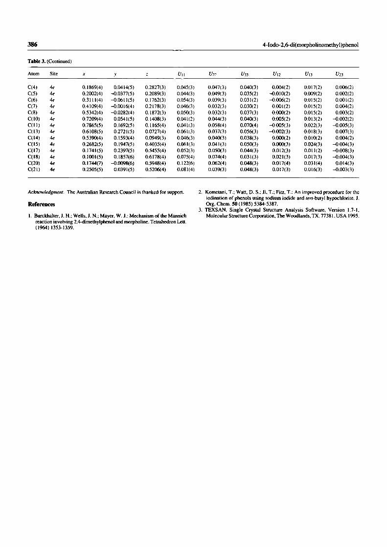
386 4-1о0о-2,6-Ш(тофЬоНпо111ей1у1)рЬепо1
Table 3. (Continued)
Atom Site ДГ V Ζ Un Uli f/зз ί/12 Un ί/23
C(4) 4e 0.1869(4) 0.0414(5) 0.2827(3) 0.045(3) 0.047(3) 0,040(3) 0.004(2) 0.017(2) 0.006(2) C(5) 4e 0.2002(4) -0.0377(5) 0.2089(3) 0.044(3) 0.049(3) 0.035(2) -0.010(2) 0.009(2) 0.002(2) C(6) 4e 0.3111(4) -0.0611(5) 0.1762(3) 0.054(3) 0.039(3) 0,031(2) -0.006(2) 0.015(2) 0.001(2) C(7) 4e 04109(4) -0.0016(4) 0.2178(3) 0.046(3) 0.032(3) 0.030(2) 0.001(2) 0.015(2) 0.004(2) C(8) 4e 0.5342(4) -0.0282(4) 0.1872(3) 0.050(3) 0.032(3) 0.037(3) 0.000(2) 0.015(2) 0.003(2) C(10) 4e 0.7209(4) 0.0541(5) 0.1408(3) 0.041(2) 0.044(3) 0.040(3) 0.005(2) 0.013(2) -0.002(2) C( l l ) 4e 0.7865(5) 0.1692(5) 0.1165(4) 0.041(3) 0.058(4) 0.070(4) -0.005(3) 0.022(3) -0.005(3) C(13) 4e 0.6108(5) 0.2721(5) 0.0727(4) 0.061(3) 0.037(3) 0.056(3) -0.002(3) 0.018(3) 0.007(3) C(14) 4e 0.5390(4) 0.1593(4) 0.0949(3) 0.046(3) 0.040(3) 0.038(3) 0.000(2) 0.010(2) 0.004(2) C(I5) 4e 0.2682(5) 0.1947(5) 0.4035(4) 0.061(3) 0.041(3) 0.050(3) 0.000(3) 0.024(3) -0.004(3) C(I7) 4e 0.1741(5) 0.2397(5) 0.5455(4) 0.052(3) 0.050(3) 0.044(3) 0.012(3) 0.011(2) -0.008(3) C(I8) 4e 0.1001(5) 0.1857(6) 0.6178(4) 0.075(4) 0.074(4) 0.031(3) 0.021(3) 0.017(3) -0.004(3) C(20) 4e 0.1744(7) -0.0098(6) 0.5948(4) 0.122(6) 0.062(4) 0.048(3) 0.017(4) 0.031(4) 0.014(3) C(21) 4e 0.2505(5) 0.0391(5) 0.5206(4) 0.081(4) 0.039(3) 0.048(3) 0.017(3) 0.016(3) -0.003(3)
Acknowledgment. The Australian Research Council is thanked for support.
References
I. Burckhalter, J. H.; Wells, J. N.; Mayer, W. J.: Mechanism of the Mannich reaction involving 2,4-dimethylphenol and тофЬоИпе. Tetrahedron Lett. (1964) 1353-1359.
2. Kometani, T.; Watt, D. S.; Ji, T.; Fitz, T.: An improved procedure for the iodination of phenols using sodium iodide and rm-butyl hypochlorite. J. Org. Chem. 50 (1985) 5384-5387.
3. TEXSAN. Single Crystal Structure Analysis Software, Version 1.7-1, Molecular Structure Corporation, The Woodlands, TX. 77381. USA 1995.

Crisp, G.T., Turner, P.D. and Stephens, K.A. (1998) Palladium-catalysed coupling of terminal alkynes with aryl halides aided by catalytic zinc. Journal of Organometallic Chemistry, v. 570 (2), pp. 219-224, November 1998
NOTE: This publication is included in the print copy of the thesis
held in the University of Adelaide Library.
It is also available online to authorised users at:
http://dx.doi.org/10.1016/S0022-328X(98)00765-7