geometric optics - wustl physics
TRANSCRIPT
1
Geometric Optics Pre-‐Lab: Learning About Lenses
A Bit of History
Information about the world’s first lenses is a little fuzzy. (Probably not unlike the images they formed.) Archaeologists have found shaped rock-‐crystal in Crete and Asia Minor that are approximately 4000 years old. It is unclear, however, whether these lenses were used to aid vision or if they were used as jewelry. What is certain is that by the year 400 B.C., the Greeks were using glass globes filled with water to focus sunlight and start fires. These so-‐called burning-‐glasses were also used by doctors to cauterize wounds.1, 2
Glass lenses began to be used to improve vision in thirteenth century Italy. It was then that the first spectacles were produced. The first pair of glasses is most commonly attributed to a pair of Italians: Alexandro della Spina and Salvino d’Armati. Interestingly, one of the sources used to support d’Armati’s role in the development of eyeglasses is his epitaph! His tombstone reads1:
Here lies Salvino degli Armato of the Armati of Florence. Inventor of Spectacles. God pardon his sins. A.D. 1317.
I guess that’s pretty clear proof that not all research is done in a library!
These early Italian lens makers were adept at making convex lenses (also called converging lenses -‐ these are the ones that are thickest in the middle). Such lenses are used in glasses to correct far-‐sightedness, a condition technically known as hyperopia, as well as the condition known as presbyopia, which is essentially far-‐sightedness that tends to develop as people age. But the introduction of the printing press in the fifteenth century caused the number of myopic (aka, near-‐sighted) individuals to skyrocket, creating demand for spectacles with concave lenses2 (also called diverging lenses -‐ these are the ones that are thickest at the edges). Seeing money to be made, lens makers perfected the more difficult art of producing concave lenses.
By the early 1600’s, humanity was ready to put multiple lenses together and make the first telescope. There is great disagreement over who invented the telescope. (One thing is for sure: it was not Galileo.) Credit is most often given to a Dutch spectacle-‐maker named Hans Lippershey (or sometimes Lipperhey), who made his first telescope in 1608. There are many stories about his first telescope. The best of these says that he stole the idea from two children who were playing in his store.1, 3 Though we may never know exactly who, where, when, or how the first telescope was made, it’s clear what scientists and amateurs alike have used telescopes to accomplish.
Though you may think the story of lenses is pretty much complete, there is still cutting-‐edge research going on using the biggest lenses the universe has to offer: gravitational lenses. It turns out that gravity can steer light much like a glass lens. Very rarely, the result is that a relatively nearby galaxy magnifies a
2
relatively distant galaxy. If you want to learn more and participate in real research, check out the Spacewarps project at zooniverse.org. You could actually discover one of these rare treats!
[Most of this history came from the three books listed in the References portion of this lab. There’s more good stuff in there!]
Thin Lens Equation and Ray Tracing
The key equation when dealing with lenses is the thin lens equation. Lenses form an image of an object. The thin lens equation allows us to relate the object distance (s), the image distance (s’), and the focal length of the lens (f). The thin lens equation states:
1𝑠+1𝑠′=1𝑓
There is also a graphical method for relating these three lengths that we will call ray tracing. Ray tracing gives very reliable results identical to those given by the thin lens equation, as long as care is taken when making the drawings. It is vital that you use a ruler, and it is very helpful to use graph paper.
There tend to be four characteristics of an image with which we are concerned. They are: the location, type, orientation, and lateral magnification. In the definition below, we will always assume that the viewer is on the right side of the lens. The light rays with which we are concerned are traveling from the left to the right. Let’s go through these one-‐by-‐one.
1) Image Location or Image Distance: The location of the image is basically where the image will form relative to the center of the lens. It can be positive or negative. A positive location indicates the image forms on the viewer’s side of the lens (the right side of the lens). A negative location indicates that the image forms on the left side of the lens.
2) Type: An image can be real or virtual. A real image is formed when a lens causes rays from the object to intersect at the point where the image forms. A real image can be projected on a screen. A virtual image is produced in situations where the lens does not cause rays to intersect. A viewer is in a sense tricked into thinking that light is coming from a point in space. A virtual image cannot be projected on a screen. The sign of the location actually indicates the type of image that is formed by a lens. A real image will have a positive image distance. A virtual image will have a negative image distance.
3) Lateral Magnification: This relates the height of the image to the height of the object. The definition of lateral magnification is:
𝑚 =ℎ!"#$%ℎ!"#$%&
This should jibe with your notion of magnification. A little geometry shows that we can re-‐write this expression using s and s’ such that
𝑚 = −𝑠′𝑠
3
4) Orientation: An image can be upright or inverted (inverted just means flipped over). We can determine the orientation from the lateral magnification. A positive 𝑚 corresponds to an upright image. A negative 𝑚 tells us that the image is inverted.
An object can also be real or virtual. If a single lens is used to form an image of matter (like an apple or a hammer), then the object is real. Virtual objects can occur in systems with multiple lenses when the image formed by one lens is the object for a second lens. If the first lens forms a real image on the viewer’s side (the right side) of the second lens, this real image is treated as the virtual object for the second lens. A real object has a positive object distance while a virtual object has a negative object distance. The following reading and exercises will help clarify all of this new information.
Reading About Thin Lenses
Read Section 34.4 in Young & Freedman which covers the thin lens equation and ray-‐tracing techniques. (You may skip the part of Section 34.4 with the heading The Lensmaker’s Equation. You may also skip Example 34.8. We will not investigate the lensmaker’s equation in this lab.) After reading the text and the corresponding examples, complete the following exercises using the thin lens equation and ray tracing.
Some Exercises
For each of the scenarios below (PL1 – PL5), use the thin lens equation and ray tracing to determine:
a) the location of the image (or the image distance), s’ b) the type of image (real or virtual) c) the lateral magnification, m d) the orientation of the image (upright or inverted)
You may think that using both methods to find the image is unnecessary. However, if you solve the problem both ways and compare the results carefully, you are essentially guaranteed to find any mistakes you have made, allowing you to make the necessary corrections.
PL1. A real object is placed 12 cm from a converging lens whose focal length is 6 cm.
PL2. A real object is placed 8 cm from a converging lens whose focal length is 12 cm.
PL3. A real object is placed 20 cm from a diverging lens whose focal length is -‐15 cm.
PL4. A real object is placed 6 cm from a diverging lens whose focal length is -‐18 cm.
PL5. A converging lens has been used to form a real image. This image is then used as the virtual object for a diverging lens. This virtual object is located 4 cm from the diverging lens. (Recall that a virtual object must be to the right of the lens.) The focal length of the diverging lens is -‐8 cm. (Note: We do not need any information about the converging lens. All that matters in this problem is that we know where it forms its image.)
4
Lateral Magnification vs. Angular Magnification
As you have seen, one of the things that we can predict using the thin lens equation is the lateral magnification of the image. The lateral magnification is the ratio of the height of the image to the height of the object. (A plus or minus sign on the magnification indicates whether the image is upright or inverted.) A lateral magnification whose absolute value is between zero and one indicates that the image is shorter than the object. A lateral magnification whose absolute value is greater than one indicates that the image is taller than the object.
However, one must be very careful when trying to relate the lateral magnification to the perceived size of the object. If a viewer is far from the lens (several times the focal length), then the lateral magnification does a good job describing how large an image will appear. But in practice, a viewer is usually fairly close to the lens (less than a focal length). When the viewer is close to the lens, the lateral magnification gives us absolutely no information about how large the viewer will perceive the image to be.
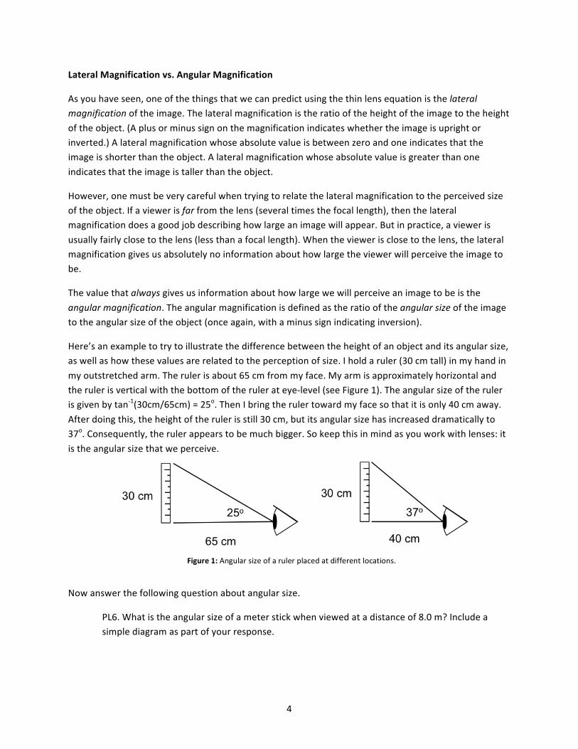
The value that always gives us information about how large we will perceive an image to be is the angular magnification. The angular magnification is defined as the ratio of the angular size of the image to the angular size of the object (once again, with a minus sign indicating inversion).
Here’s an example to try to illustrate the difference between the height of an object and its angular size, as well as how these values are related to the perception of size. I hold a ruler (30 cm tall) in my hand in my outstretched arm. The ruler is about 65 cm from my face. My arm is approximately horizontal and the ruler is vertical with the bottom of the ruler at eye-‐level (see Figure 1). The angular size of the ruler is given by tan-‐1(30cm/65cm) = 25o. Then I bring the ruler toward my face so that it is only 40 cm away. After doing this, the height of the ruler is still 30 cm, but its angular size has increased dramatically to 37o. Consequently, the ruler appears to be much bigger. So keep this in mind as you work with lenses: it is the angular size that we perceive.
Now answer the following question about angular size.
PL6. What is the angular size of a meter stick when viewed at a distance of 8.0 m? Include a simple diagram as part of your response.
Figure 1: Angular size of a ruler placed at different locations.
5
Telescope Appendix
As the final component to this Pre-‐Lab, read Appendix A. Then answer the following questions.
You want to make a simple telescope using two converging lenses as shown in Appendix A. One lens has a focal length of 5 cm. The other lens has a focal length of 20 cm.
PL7. Which lens should be the eyepiece? Which lens should be the objective? Explain briefly.
PL8. About how long will the telescope be?
6
Part I: The Spectacular Spectacle Mystery
The Story
England, 1892: After a demanding week of intrigue and passion during his pursuit of the thief who stole the telescope from the Royal Observatory, Sherlock Holmes has finally narrowed down the number of suspects to just two. Was it the dastardly, near-‐sighted Professor Moriarty or the manipulative, far-‐sighted Irene Adler? As it turns out, the ever perceptive Holmes found a crooked pair of glasses left at the scene of the crime. This should be the final evidence needed to pinpoint the thief! Unfortunately, our hero doesn’t have a good understanding of vision or geometric optics. This is where you, the always reliable Dr. Watson must step in. You know there must be a simple solution…
Equipment
• Lenses B, D, E (converging lenses) • Lens F (diverging lens) • Screen (S) • Piece of paper with text • Glasses (the evidence)
1. Detective Work
You begin your hands-‐on experience with lenses with an experiment whose procedure is very simple. However, you will be able to use the result to help you distinguish between converging and diverging lenses during the remainder of the lab. (And you’ll be able to help Holmes, of course.)
Do This: Take lens B and place it over some text on a piece of paper such, that you can see the text through the lens. Stand so that you’re looking down through the lens, keeping your head as far from the lens as possible. (That is, your head should not be close to the piece of paper.) Slowly move the lens upward toward your face, keeping your head still. Pay attention to the appearance of the text as you move the lens toward your face. Repeat this procedure with lens D and lens E.
1.1. Describe your observations. What happens with every lens? What are the differences?
1.2. As part of your response to Step 1.1, you hopefully mentioned that the text gets very blurry and distorted when the lens is a few centimeters above the text. (If not, you might want to revisit that Step.) This blurring happens when the lens is about one focal length from the text. Draw a ray-‐tracing diagram that shows why a very poor image will be formed when the text is at the focal point of a converging lens.
1.3. Relate the observations you recorded in Step 1.1 to exercises that you did in the Pre-‐Lab.
Do This: Repeat the previous Do This using the diverging lens, lens F.
7
1.4. Describe what you observe as you view the text through lens F.
1.5. Relate the observations you recorded in Step 1.4 to exercises that you did in the Pre-‐Lab.
Read This: Now let’s cover just a little bit of physiology so that we can nab the right wrongdoer.
1.6. A far-‐sighted person can easily see objects that are far away. However, the far-‐sighted eye cannot focus on objects that are close by. In a far-‐sighted eye, close-‐up objects are actually focused behind the retina, making them appear blurry. What kind of lenses should a far-‐sighted person wear to see nearby objects? Explain briefly.
1.7. A near-‐sighted person can easily see objects that are nearby. However, the near-‐sighted eye cannot focus on objects that are far away. In a near-‐sighted eye, far-‐away objects are actually focused in front of the retina, making them appear blurry. What kind of glasses should a near-‐sighted person wear to see far-‐away objects? Explain briefly.
Do This: Take the evidence out of the plastic bag.
1.8. Record the exhibit number that is attached to your pair of glasses.
1.9. Whodunit? Remember, Sherlock Holmes (and your TA) expects a clear, logical, and complete response.
Part II: Finding the Focal Length of a Converging Lens
2. Experiment
Besides knowing what kind of lens you’re working with, it is often important to know the focal length of the lens. This experiment takes you through one method for determining the focal length of a converging lens. Knowing these focal lengths will serve you well in Part IV of today’s experiment.
2.1. Use the thin lens equation to predict the location and the type of the image formed by a converging lens when the object is placed very far from the lens (much, much farther than the focal length). Show your work.
Read This: You should have found that the lens will form a real image with an image distance that approaches the focal length. A real image can be projected on a screen, while a virtual image cannot. Since a real image can be projected on a screen, this gives us a simple procedure for determining the focal length of a converging lens.
2.2. Place lens B and the screen (S) in the optical bench. Aim the optical bench at some far-‐away (at least a couple of meters) object, like your light bulb or something out the window. (The lens should be between the screen and the far-‐away object.) Adjust the screen until you see a crisp

8
projection of the far-‐away object. Record the distance between the lens and the screen -‐ it is the focal length of lens B.
2.3. Repeat Step 2.2 for lens D.
2.4. Repeat Step 2.2 for lens E.
2.5. Repeat Step 2.2 for lens F. Does this procedure work with lens F? If not, briefly describe the problem.
Read This: Let’s try to figure out why this procedure doesn’t work for the diverging lens, lens F.
2.6. Use the thin lens equation to predict the location and type of image formed by a diverging lens when the object is placed far away. Show your work.
2.7. How does your answer to 2.6 show that we won’t get an image on the screen when we use lens F?
Part III: Finding the Focal Length of a Diverging Lens
As you just discovered, it’s a little tricky to find the focal length of a diverging lens. The problem is that a single diverging lens will never form a real image of a real object, so projecting an image on a screen is out of the question. However, a diverging lens can form a real image of a virtual object. So then the question becomes, “How do we form a virtual object?” Well, with a second lens, of course! In this experiment, the real image formed by a converging lens becomes the virtual object for a diverging lens. It might be helpful to refer to the diagram you drew and the math you did in PL5.
3. The Experiment
Do This: Place the screen (S) and Lens B on the optical bench. Point the bench at some far away object. Adjust the screen until a crisp image of the far away object is formed.
3.1. Record the position of the converging lens.
3.2. Record the position of the screen.
Do This: Place lens F between the screen and the converging lens. You should see that this destroys the image on the screen. This is good.
3.3. Record the position of lens F.
Do This: Being careful not to disturb the lenses, adjust the position of the screen until a crisp image of the far away object is re-‐formed on the screen.
3.4. Record the new position of the screen.

9
3.5. Using the thin lens equation and three of the four positions you recorded, determine the focal length of the diverging lens. [Hint: Be very careful about which distances are positive and negative in the thin lens equation.] Show your work.
Read This: That is a good, precise way to determine the focal length of a diverging lens, but it may have been hard to follow. Here’s a kind of rough way to check if your answer to 3.5 is plausible.
3.6. Draw a ray-‐tracing diagram to show that when a real object is placed at the focal point of a diverging lens, an upright, virtual image is formed with a lateral magnification of ½. That means when the viewer is far from the lens, the image would look half as tall as the object.
Do This: On this page, there are two rectangles, one twice as tall and wide as the other (Figure 2). Place lens F over the larger rectangle and stand above it such that you are as far from the lens as possible. (That is, your head should not be close to the page.) Slowly pull the lens toward your face. The tall rectangle should start looking smaller and smaller. When the image of the large rectangle is approximately the same size as the small rectangle, stop moving the lens. Have your partner measure the distance between the lens and the page. Putting a negative sign in front of this distance should give you a good estimate of the focal length of the diverging lens.
3.7. Do these two methods for determining the focal length of the diverging lens give you consistent results?
Figure 2: Rectangles needed to answer Step 3.7
Part IV: The Refracting Telescope
We can start doing some really cool things if we get multiple lenses working together in the correct way. Hopefully, you’ve had the opportunity to examine the night sky with a telescope. (If not, there is an observatory on the roof of Crow that you might want to check out.) Refer to Appendix A if you need to remind yourself about the basics of telescopes.
It will be stated without proof that the angular magnification M produced by our simple refracting telescope is given by
𝑀 = −𝑓!𝑓!
10
where fo and fe are the focal lengths of the objective lens and the eyepiece, respectively. A negative angular magnification indicates that the image will be inverted. Further, recall that the separation of the objective lens and the eyepiece will be approximately equal to the sum of the focal lengths.
The Story
The 1700’s were the golden age of pirating in the Americas. In addition to an impressive beard and a boat, a successful pirate needed a tool to aid in seeing long distances. Since you thoroughly read the Bit of History, you know that telescopes became available in the early 1600’s. It’s time for you to play pirate (or walk the plank!). After learning about telescopes in the following exercises, you will describe the telescope that would suit you best for roaming the high seas in search of treasure.
4. Experiment
4.1. Begin by picking your pirate name. Record it here.
4.2. Design a telescope using lens D and lens E, but don’t build it quite yet. Which one should be the objective lens? Which one should be the eyepiece? What should be the approximate distance between the lenses?
Do This: Test your design.
4.3. Did your design work? Explain any flaws that were in your initial design and how you fixed them.
4.4. Imagine replacing lens E with lens B. Would you have to put lens B closer to lens D or farther from lens D. Explain. (Do not actually do this yet.)
4.5. Predict how this replacement would affect the angular magnification produced by the telescope. Support your prediction with a sentence or two.
Do This: Replace lens E with lens B and make adjustments as necessary until the new telescope gives you a crisp image.
4.6. Were your responses to Steps 4.4 and 4.5 correct? If not, explain where your reasoning failed.
4.7. Predict what will happen if you switch the positions of lens B and lens D. That is, how will the operation of your telescope change if lens D is the eyepiece and lens B is the objective?
Do This: Test the prediction you made in Step 4.7.
4.8. Was your prediction correct? If not, explain where your reasoning failed.
4.9. Does the equation for the angular magnification of a telescope work if a diverging lens is used as the eyepiece? Explain, being sure to cite observations that you make.
11
4.10. What lenses would you use to make your telescope for pirating? (You can use lenses that we don’t have in lab. Remember, you’d have some gold coins available to purchase new lenses.) Explain why you make your choices. Arrrrrr!
Head-‐Scratchers
Don’t forget to complete the following problems. They should be at the end of your lab report. If you want to work on them during lab, start a new page in your lab notebook.
• 1.2 • 4.10
References
[1] King, Henry C. (1995). History of the Telescope. Charles Griffen & Co., Ltd., High Wycombe, Bucks, England.
[2] Dunn, Richard. (2009). The Telescope: A Short History. National Maritime Museum, London, England.
[3] Filkin, David. (1997). Stephen Hawking’s Universe: The Cosmos Explained. Harper Collins Publishers, Inc., New York, NY.

12
Appendix A: Telescopes
Telescope Crash Course
When you use a telescope to look at Saturn, the magnificent planet certainly looks a lot bigger. It turns out, though, that the image produced by the telescope is actually smaller than the object (Saturn). So then why does Saturn look bigger through the telescope? It’s because the image formed by the telescope is much closer to your eye. Remember that angular size is the important quantity when working with perceived size.
The simple telescope examined in lab uses one objective lens and one eyepiece. The objective lens is the lens that is closer to the object. It has a relatively long focal length and forms a real image of a far-‐away object very close to its focal point. The second lens, the eyepiece, is very close to the viewer’s eye. The viewer uses the eyepiece as a magnifying glass to look at the image formed by the objective lens. The telescope gives a crisp image when the object is far away and when the separation between the lenses is approximately equal to the sum of their focal lengths.
The ray tracing for a telescope is actually kind of tricky because the object is ideally many, many focal lengths from the objective lens. (Our page just isn’t big enough.) The objective lens would then form an extremely small image very close to the focal point. (This would be hard to show.) With these problems in mind, the rest of this Appendix shows some ray tracings that will give you a good idea about how the telescope works.
Telescope Ray Tracing
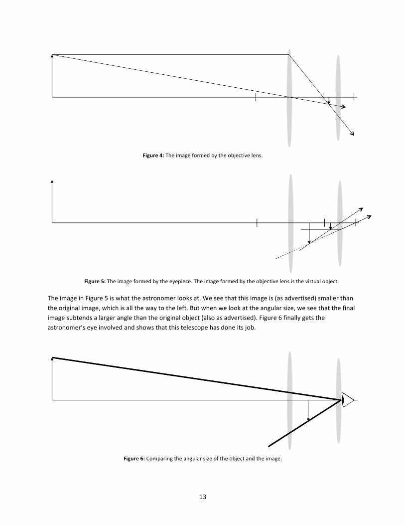
First, we have an object (somewhat) far from a converging objective lens with a relatively long focal length and a converging eyepiece with a relatively short focal length. The interior focal point is shared by the two lenses.
We would like to have the object even farther away, but this will have to do. Let’s find where the objective lens would form an image of the object. (We ignore the eyepiece for now.) As expected, the image in Figure 4 is small, inverted, and very close to the focal point. (If the object were farther away, the image would be smaller and closer to the focus.) Now we consider the eyepiece. The astronomer uses the eyepiece as a magnifying glass to view the little image that we just found. That is, the image formed by the objective lens is the object for the eyepiece. Figure 5 shows the image formed by the eyepiece.
Figure 3: An object far away from a telescope.
13
The image in Figure 5 is what the astronomer looks at. We see that this image is (as advertised) smaller than the original image, which is all the way to the left. But when we look at the angular size, we see that the final image subtends a larger angle than the original object (also as advertised). Figure 6 finally gets the astronomer’s eye involved and shows that this telescope has done its job.
Figure 4: The image formed by the objective lens.
Figure 5: The image formed by the eyepiece. The image formed by the objective lens is the virtual object.
Figure 6: Comparing the angular size of the object and the image.