geometrical optics - selfstudys
TRANSCRIPT
GEOMETRICAL OPTICS
———————————————————————————————————
INTRODUCTION :
Blue lakes, ochre deserts, green forest, and multicolored rainbows can be enjoyed by anyone who has eyes with which to see them. But by studying the branch of physics called optics, which deals with the behaviour of light and other electromagnetic waves, we can reach a deeper appreciation of the visible world. A knowledge of the properties of light allows us to understand the blue color of the sky and the design of optical devices such as telescopes, microscopes, cameras, eyeglasses, and the human eyes. The same basic principles of optics also lie at the heart of modern developments such as the laser, optical fibers, holograms, optical computers, and new techniques in medical imaging.
1. CONDITION FOR RECTILINEAR PROPAGATION OF LIGHT (Only for information not in IIT-JEE syllabus)
Some part of the optics can be understood if we assume that light travels in a straight line and it bends abruptly when it suffers reflection or refraction.
The assumption that the light travels in a straight line is correct if (i) the medium is isotropic, i.e. its behaviour is same in all directions and (ii) the obstacle past which the
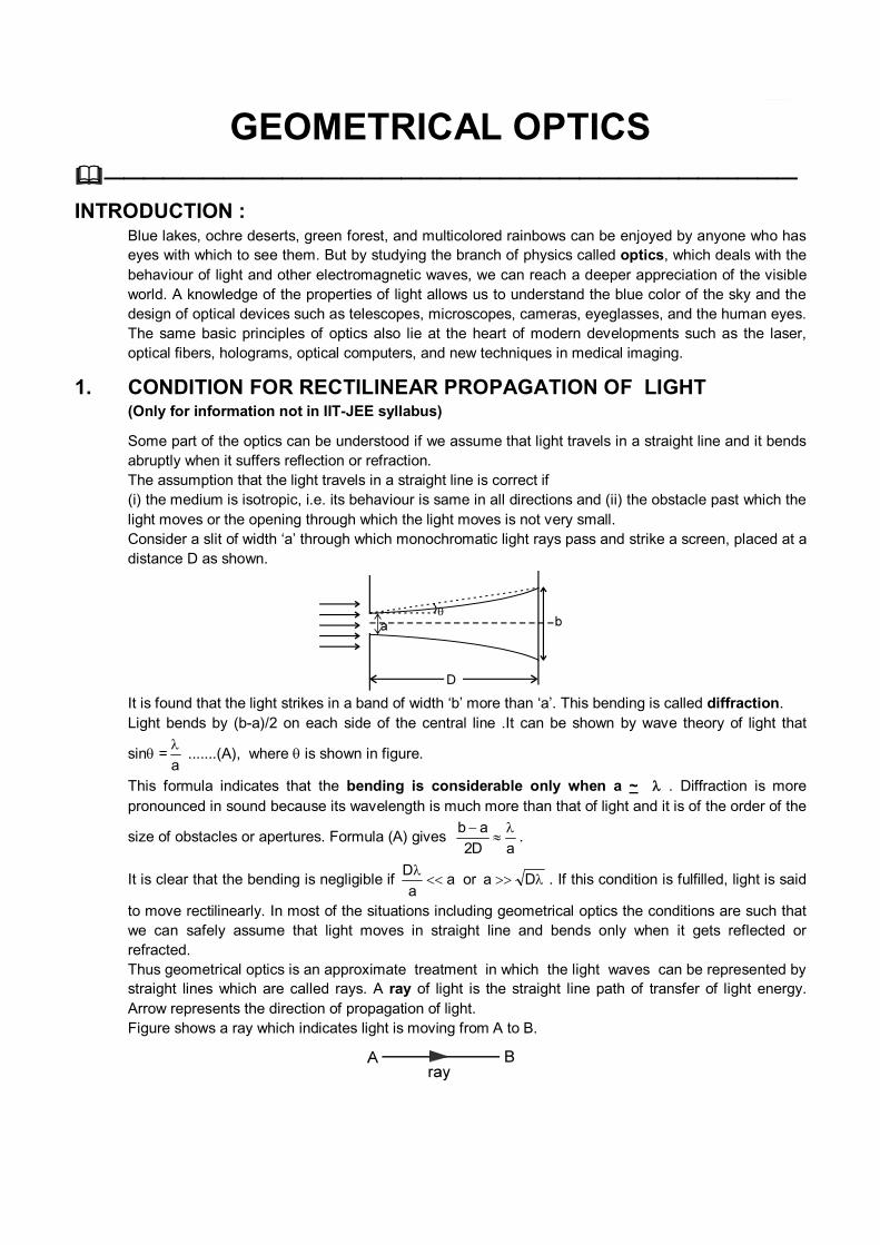
light moves or the opening through which the light moves is not very small. Consider a slit of width ‘a’ through which monochromatic light rays pass and strike a screen, placed at a
distance D as shown.
It is found that the light strikes in a band of width ‘b’ more than ‘a’. This bending is called diffraction. Light bends by (b-a)/2 on each side of the central line .It can be shown by wave theory of light that
sin =a
.......(A), where is shown in figure.
This formula indicates that the bending is considerable only when a ~ . Diffraction is more pronounced in sound because its wavelength is much more than that of light and it is of the order of the
size of obstacles or apertures. Formula (A) gives b a
2D a
.
It is clear that the bending is negligible if aa
D
or Da . If this condition is fulfilled, light is said
to move rectilinearly. In most of the situations including geometrical optics the conditions are such that we can safely assume that light moves in straight line and bends only when it gets reflected or refracted.
Thus geometrical optics is an approximate treatment in which the light waves can be represented by straight lines which are called rays. A ray of light is the straight line path of transfer of light energy. Arrow represents the direction of propagation of light.
Figure shows a ray which indicates light is moving from A to B.
2. PROPERTIES OF LIGHT (i) Speed of light in vacuum, denoted by c, is equal to 3 × 10⁸ m/s approximately. (ii) Light is electromagnetic wave (proposed by Maxwell). It consists of varying electric field and
magnetic field.
(iii) Light carries energy and momentum. (iv) The formula v = f is applicable to light.
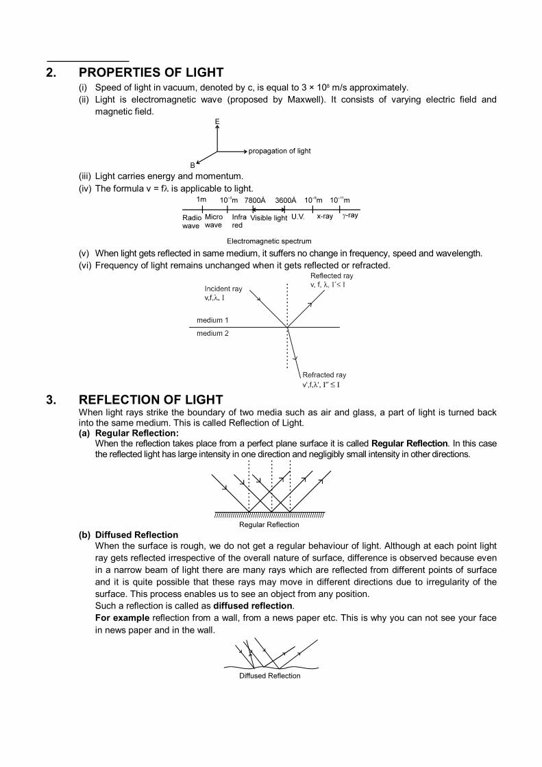
(v) When light gets reflected in same medium, it suffers no change in frequency, speed and wavelength. (vi) Frequency of light remains unchanged when it gets reflected or refracted.
3. REFLECTION OF LIGHT When light rays strike the boundary of two media such as air and glass, a part of light is turned back
into the same medium. This is called Reflection of Light. (a) Regular Reflection: When the reflection takes place from a perfect plane surface it is called Regular Reflection. In this case
the reflected light has large intensity in one direction and negligibly small intensity in other directions.
(b) Diffused Reflection When the surface is rough, we do not get a regular behaviour of light. Although at each point light
ray gets reflected irrespective of the overall nature of surface, difference is observed because even in a narrow beam of light there are many rays which are reflected from different points of surface and it is quite possible that these rays may move in different directions due to irregularity of the surface. This process enables us to see an object from any position.
Such a reflection is called as diffused reflection. For example reflection from a wall, from a news paper etc. This is why you can not see your face
in news paper and in the wall.
3.1 Laws of Reflection (a) The incident ray, the reflected ray and the normal at the point of incidence lie in the same plane. This
plane is called the plane of incidence (or plane of reflection). This condition can be expressed
mathematically as R
. (
×N
) = N
. (
× R
)=
.(N
× R
) = 0 where
, N
and R
are vectors of any magnitude along incident ray, the normal and the reflected ray respectively.
(b) The angle of incidence (the angle between normal and the incident ray) and the angle of reflection (the angle between the reflected ray and the normal) are equal, i.e.,
i = r Special Cases : Normal Incidence : In case light is incident normally,
i = r = 0 = 180º Note : We say that the ray has retraced its path. Grazing Incidence : In case light strikes the reflecting surface tangentially,
i = r = 90 ; deviation, = 0º or 360º Note : In case of reflection speed (magnitude of velocity) of light remains unchanged but in grazing
incidence velocity remains unchanged.
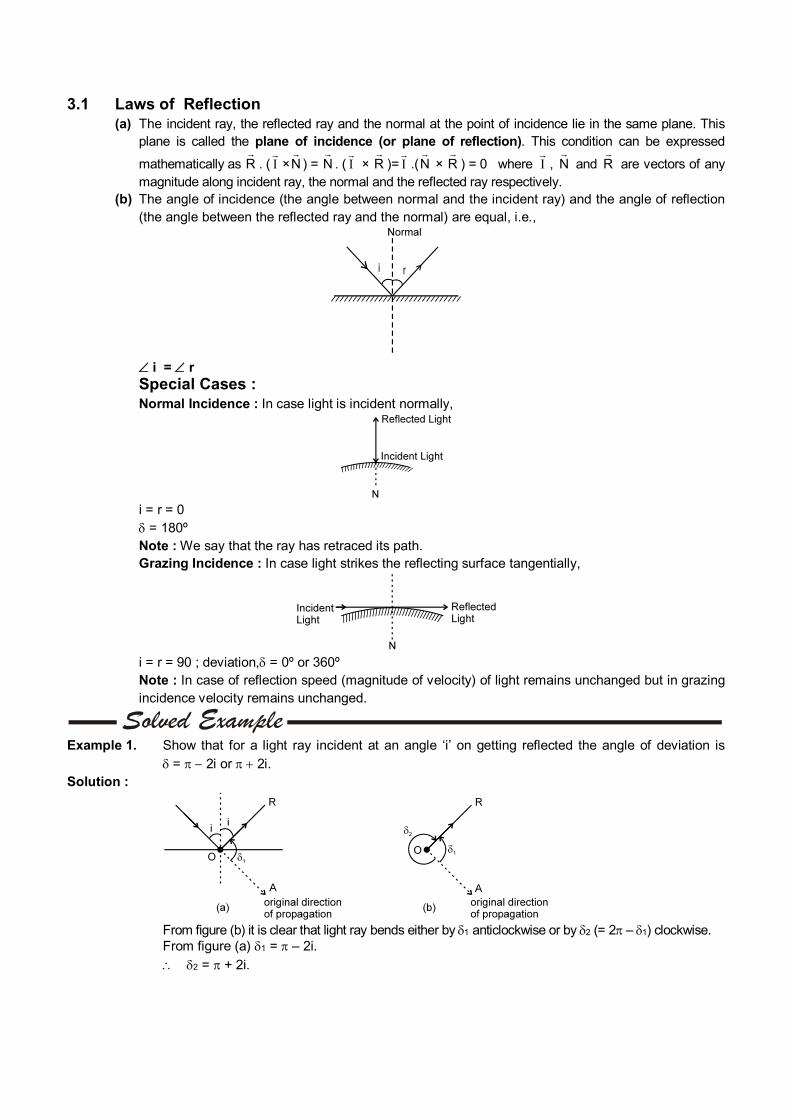
Example 1. Show that for a light ray incident at an angle ‘i’ on getting reflected the angle of deviation is
= 2i or 2i. Solution :
From figure (b) it is clear that light ray bends either by 1 anticlockwise or by 2 (= 2 – 1) clockwise. From figure (a) 1 = – 2i.
2 = + 2i.
———————————————————————————————————
3.2 Object and Image (a) Object (O) : Object is defined as point of intersection of incident rays.
O
O
Let us call the side in which incident rays are present as incident side and the side in which
reflected (refracted) rays are present, as reflected (refracted) side. Note : An object is called real if it lies on incident side otherwise it is called virtual. (In case of
plane mirror only) (b) Image () : Image is defined as point of intersection of reflected rays (in case of reflection) or
refracted rays (in case of refraction).
Note : An image is called real if it lies on reflected or refracted side otherwise it is called virtual.
4. PLANE MIRROR Plane mirror is formed by polishing one surface of a plane thin glass plate .It is also said to be silvered
on one side.
A beam of parallel rays of light, incident on a plane mirror will get reflected as a beam of parallel reflected rays.
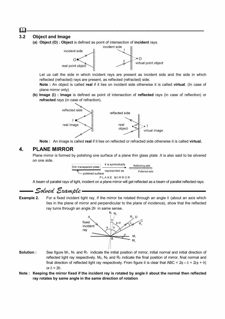
Example 2. For a fixed incident light ray, if the mirror be rotated through an angle (about an axis which
lies in the plane of mirror and perpendicular to the plane of incidence), show that the reflected ray turns through an angle 2in same sense.
Solution : See figure M1, N1 and R1 indicate the initial position of mirror, initial normal and initial direction of
reflected light ray respectively. M2, N2 and R2 indicate the final position of mirror, final normal and final direction of reflected light ray respectively. From figure it is clear that ABC = 2 = 2 + )
or = 2. Note : Keeping the mirror fixed if the incident ray is rotated by angle about the normal then reflected
ray rotates by same angle in the same direction of rotation
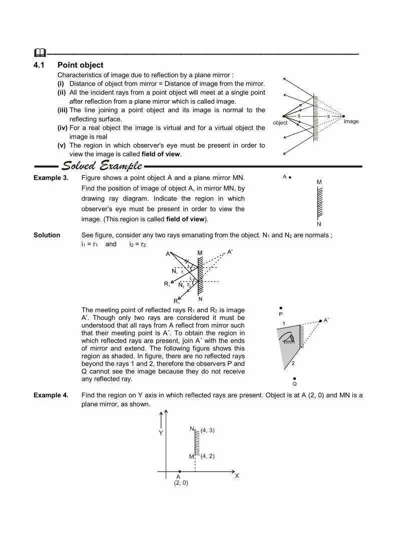
——————————————————————————————————— 4.1 Point object Characteristics of image due to reflection by a plane mirror : (i) Distance of object from mirror = Distance of image from the mirror. (ii) All the incident rays from a point object will meet at a single point
after reflection from a plane mirror which is called image. (iii) The line joining a point object and its image is normal to the
reflecting surface. (iv) For a real object the image is virtual and for a virtual object the
image is real (v) The region in which observer's eye must be present in order to
view the image is called field of view.
Example 3. Figure shows a point object A and a plane mirror MN.
Find the position of image of object A, in mirror MN, by
drawing ray diagram. Indicate the region in which
observer’s eye must be present in order to view the
image. (This region is called field of view).
Solution See figure, consider any two rays emanating from the object. N1 and N2 are normals ; i1 = r1 and i2 = r2
The meeting point of reflected rays R1 and R2 is image
A’. Though only two rays are considered it must be understood that all rays from A reflect from mirror such that their meeting point is A´. To obtain the region in which reflected rays are present, join A´ with the ends of mirror and extend. The following figure shows this region as shaded. In figure, there are no reflected rays beyond the rays 1 and 2, therefore the observers P and Q cannot see the image because they do not receive any reflected ray.
Example 4. Find the region on Y axis in which reflected rays are present. Object is at A (2, 0) and MN is a plane mirror, as shown.
Solution : The image of point A, in the mirror is at A’ (6, 0). Join A’ M and extend to cut Y axis at M’ ( Ray originating
from A which strikes the mirror at M gets reflected as the ray MM’ which appears to come from A’). Join A’N and extend to cut Y axis at N’ (Ray originating from A which strikes the mirror at N gets reflected as the ray NN’ which appears to come from A’).
From geometry. M’ (0, 6) N’ (0, 9). M’N’ is the region on Y axis in which reflected
rays are present.
———————————————————————————————————
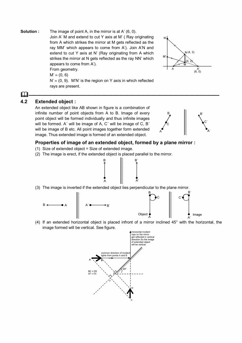
4.2 Extended object : An extended object like AB shown in figure is a combination of
infinite number of point objects from A to B. Image of every point object will be formed individually and thus infinite images will be formed. A´ will be image of A, C´ will be image of C, B´ will be image of B etc. All point images together form extended image. Thus extended image is formed of an extended object.
Properties of image of an extended object, formed by a plane mirror : (1) Size of extended object = Size of extended image. (2) The image is erect, if the extended object is placed parallel to the mirror.
(3) The image is inverted if the extended object lies perpendicular to the plane mirror.
(4) If an extended horizontal object is placed infront of a mirror inclined 45° with the horizontal, the
image formed will be vertical. See figure.
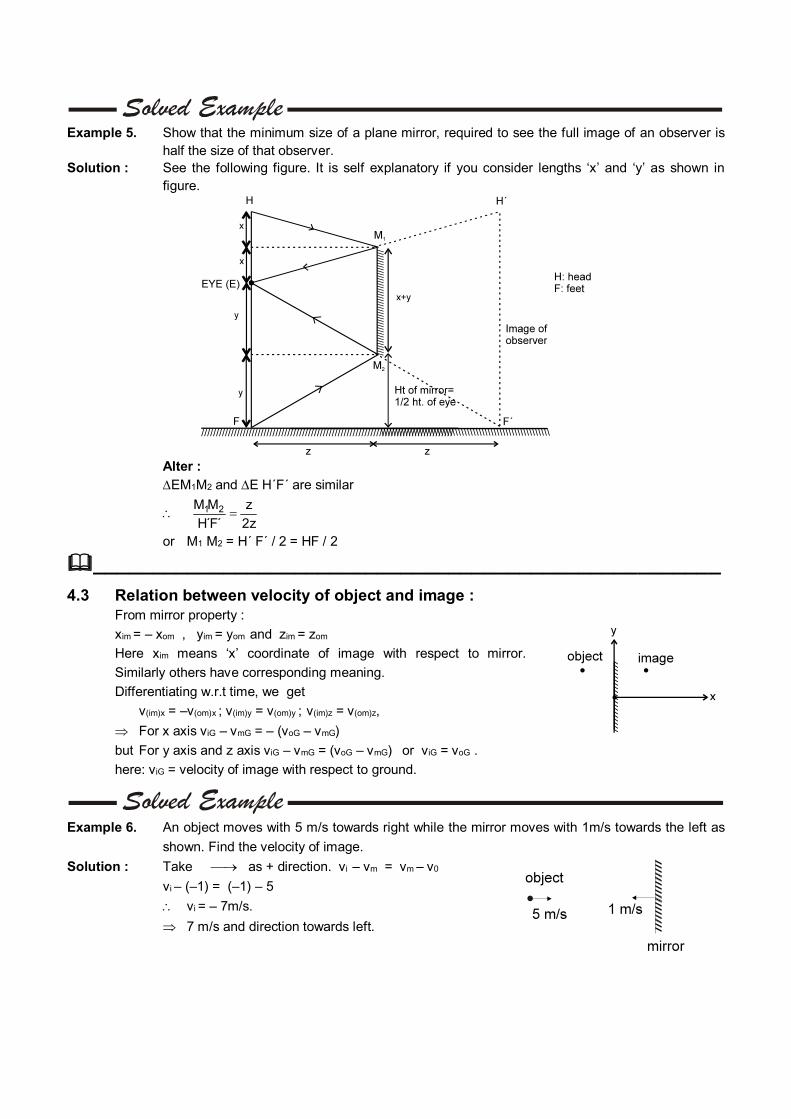
Example 5. Show that the minimum size of a plane mirror, required to see the full image of an observer is
half the size of that observer. Solution : See the following figure. It is self explanatory if you consider lengths ‘x’ and ‘y’ as shown in
figure.
Alter : EM1M2 and E H´F´ are similar
1 2M M z
H´F´ 2z
or M1 M2 = H´ F´ / 2 = HF / 2
_____________________________________________________
4.3 Relation between velocity of object and image : From mirror property :
xim = – xom , yim = yom and zim = zom
Here xim means ‘x’ coordinate of image with respect to mirror.
Similarly others have corresponding meaning.
Differentiating w.r.t time, we get
v(im)x = –v(om)x ; v(im)y = v(om)y ; v(im)z = v(om)z,
For x axis viG – vmG = – (voG – vmG)
but For y axis and z axis viG – vmG = (voG – vmG) or viG = voG .
here: viG = velocity of image with respect to ground.
Example 6. An object moves with 5 m/s towards right while the mirror moves with 1m/s towards the left as
shown. Find the velocity of image.
Solution : Take as + direction. vi – vm = vm – v0
vi – (–1) = (–1) – 5
vi = – 7m/s. 7 m/s and direction towards left.
Example 7. There is a point object and a plane mirror. If the mirror is moved by 10 cm away from the object
find the distance which the image will move.
Solution : We know that xim = – xom or xi – xm = xm – xo
or xi – xm = xm – xo.
In this question xo = 0 ; xm = 10 cm.
Therefore xi = 2xm – xo = 20 cm.
Alter :
2(x + 10) = 2 x + d
d = 20 cm
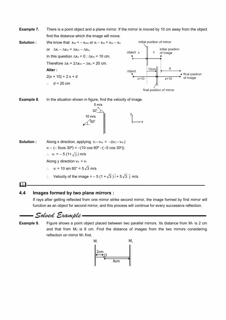
Example 8. In the situation shown in figure, find the velocity of image.
Solution : Along x direction, applying vi – vm = –(v0 – vm )
vi – (– 5cos 30º) = –(10 cos 60º –( –5 cos 300))
vi = – 5 (1+ 3 ) m/s
Along y direction v0 = vi
vi = 10 sin 60° = 5 3 m/s
Velocity of the image = – 5 (1 + 3 ) i + 5 3 j m/s.
——————————————————————————————————— 4.4 Images formed by two plane mirrors :
If rays after getting reflected from one mirror strike second mirror, the image formed by first mirror will
function as an object for second mirror, and this process will continue for every successive reflection.
Example 9. Figure shows a point object placed between two parallel mirrors. Its distance from M1 is 2 cm
and that from M2 is 8 cm. Find the distance of images from the two mirrors considering
reflection on mirror M1 first.
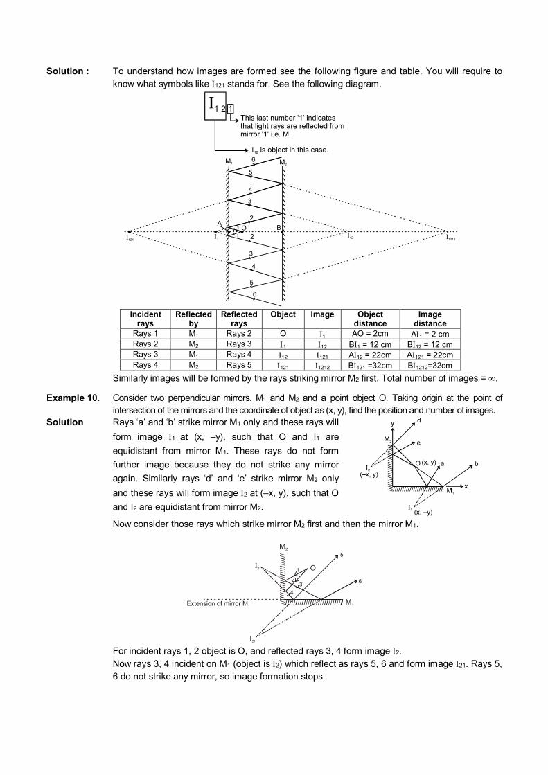
Solution : To understand how images are formed see the following figure and table. You will require to know what symbols like 121 stands for. See the following diagram.
Incident rays
Reflected by
Reflected rays
Object Image Object distance
Image distance
Rays 1 M1 Rays 2 O 1 AO = 2cm A1 = 2 cm Rays 2 M2 Rays 3 1 12 B1 = 12 cm B12 = 12 cm Rays 3 M1 Rays 4 12 121 A12 = 22cm A121 = 22cm Rays 4 M2 Rays 5 121 1212 B121 =32cm B1212=32cm
Similarly images will be formed by the rays striking mirror M2 first. Total number of images = .
Example 10. Consider two perpendicular mirrors. M1 and M2 and a point object O. Taking origin at the point of intersection of the mirrors and the coordinate of object as (x, y), find the position and number of images.
Solution Rays ‘a’ and ‘b’ strike mirror M1 only and these rays will
form image 1 at (x, –y), such that O and I1 are
equidistant from mirror M1. These rays do not form
further image because they do not strike any mirror
again. Similarly rays ‘d’ and ‘e’ strike mirror M2 only
and these rays will form image 2 at (–x, y), such that O
and I2 are equidistant from mirror M2.
Now consider those rays which strike mirror M2 first and then the mirror M1.
For incident rays 1, 2 object is O, and reflected rays 3, 4 form image 2. Now rays 3, 4 incident on M1 (object is 2) which reflect as rays 5, 6 and form image 21. Rays 5,
6 do not strike any mirror, so image formation stops.
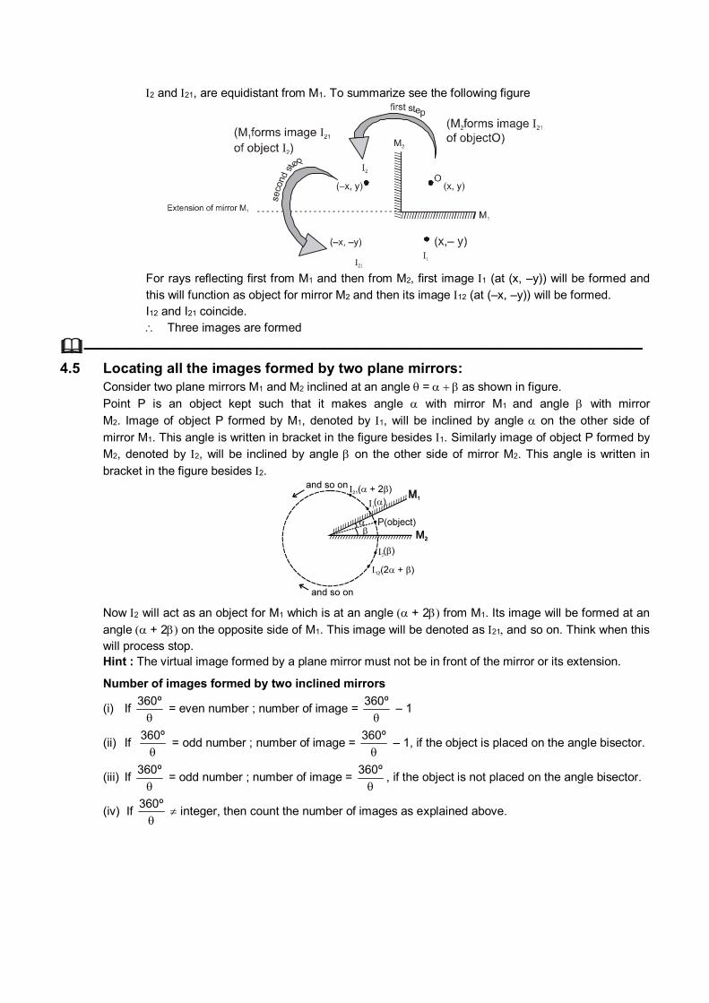
2 and 21, are equidistant from M1. To summarize see the following figure
For rays reflecting first from M1 and then from M2, first image 1 (at (x, –y)) will be formed and
this will function as object for mirror M2 and then its image 12 (at (–x, –y)) will be formed. I12 and I21 coincide. Three images are formed
——————————————————————————————————— 4.5 Locating all the images formed by two plane mirrors: Consider two plane mirrors M1 and M2 inclined at an angle =as shown in figure. Point P is an object kept such that it makes angle with mirror M1 and angle with mirror
M2. Image of object P formed by M1, denoted by 1, will be inclined by angle on the other side of
mirror M1. This angle is written in bracket in the figure besides 1. Similarly image of object P formed by M2, denoted by 2, will be inclined by angle on the other side of mirror M2. This angle is written in
bracket in the figure besides 2.
Now 2 will act as an object for M1 which is at an angle + 2 from M1. Its image will be formed at an
angle + 2 on the opposite side of M1. This image will be denoted as 21and so on. Think when this will process stop.
Hint : The virtual image formed by a plane mirror must not be in front of the mirror or its extension.
Number of images formed by two inclined mirrors
(i) If 360º
= even number ; number of image =
360º
– 1
(ii) If 360º
= odd number ; number of image =
360º
– 1, if the object is placed on the angle bisector.
(iii) If 360º
= odd number ; number of image =
360º
, if the object is not placed on the angle bisector.
(iv) If 360º
integer, then count the number of images as explained above.

Example 11. Two mirrors are inclined by an angle 30°. An object is placed making 10° with the mirror M1.
Find the positions of first two images formed by each mirror. Find the total number of images using (i) direct formula and (ii) counting the images.
Solution : Figure is self explanatory. Number of images
(i) Using direct formula : 360º
30º = 12 (even number)
number of images = 12 – 1 = 11
(ii) By counting. See the following table
_____________________________________________________
5. SPHERICAL MIRRORS Spherical Mirror is formed by polishing one surface of a part of sphere. Depending upon which part is
shining the spherical mirror is classified as (a) Concave mirror, if the side towards center of curvature is shining and (b) Convex mirror if the side away from the center of curvature is shining.

5.1 Important terms related with spherical mirrors :
R
CP
A
B
A spherical shell with the center of curvature, pole aperture and radius of curvature identified
(a) Center of Curvature (C) : The center of the sphere from which the spherical mirror is formed is called the center of curvature
of the mirror. It is represented by C and is indicated in figure. (b) Pole (P) : The center of the mirror is called as the Pole. It is represented by the point P on the mirror APB in
figure. (c) Principal Axis : The Principal Axis is a line which is perpendicular to the plane of the mirror and passes through the
pole. The Principal Axis can also be defined as the line which joins the Pole to the Center of Curvature of the mirror.
(d) Aperture (A) : The aperture is the segment or area of the mirror which is available for reflecting light. In figure.
APB is the aperture of the mirror. (e) Principle focus (F) : It is the point of intersection of all the reflected rays for which the incident rays strike the mirror (with
small aperture) parallel to the principal axis. In concave mirror it is real and in the convex mirror it is virtual. The distance from pole to focus is called focal length.
Concave mirror
Convex mirror
Example 12. Find the angle of incidence of ray for which it passes through the pole, given that M || CP.
Solution : MIC = CP =
M || CP M = CP = C = CP
CP = CP =
In CP all angle are equal
3 = 180º = 60º
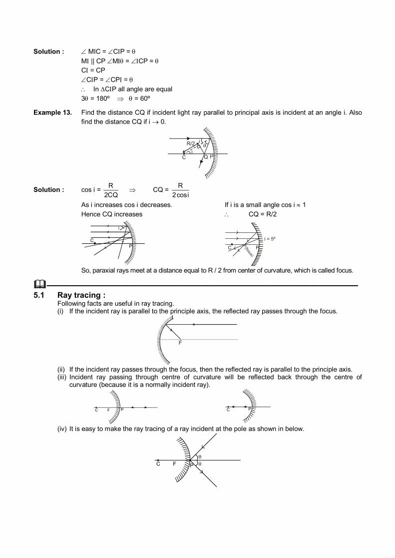
Example 13. Find the distance CQ if incident light ray parallel to principal axis is incident at an angle i. Also find the distance CQ if i 0.
Solution : cos i = R
2CQ CQ =
R
2cosi
As i increases cos i decreases. If i is a small angle cos i 1
Hence CQ increases CQ = R/2
So, paraxial rays meet at a distance equal to R / 2 from center of curvature, which is called focus.
——————————————————————————————————— 5.1 Ray tracing : Following facts are useful in ray tracing. (i) If the incident ray is parallel to the principle axis, the reflected ray passes through the focus.
F
(ii) If the incident ray passes through the focus, then the reflected ray is parallel to the principle axis. (iii) Incident ray passing through centre of curvature will be reflected back through the centre of
curvature (because it is a normally incident ray).
(iv) It is easy to make the ray tracing of a ray incident at the pole as shown in below.
5.2 Sign Convention We are using co–ordinate sign convention. (i) Take origin at pole (in case of mirror) or at optical centre (in case of lens). Take X axis along the
Principal Axis, taking positive direction along the incident light. u, v, R and f indicate the x coordinate of object, image, centre of curvature and focus respectively. (ii) y-coordinates are taken positive above Principle Axis and negative below Principle Axis’ h1 and h2
denote the y coordinates of object and image respectively.
Note : This sign convention is used for reflection from mirror, reflection through flat or curved surfaces or
lens.
5.3 Formula for Reflection from spherical mirrors :
(a) Mirror formula : f
1
R
2
u
1
v
1
X-coordinate of centre of curvature and focus of concave mirror are negative and those for convex mirror are positive. In case of mirrors since light rays reflect back in X-direction, therefore -ve sign of v indicates real image and +ve sign of v indicates virtual image.
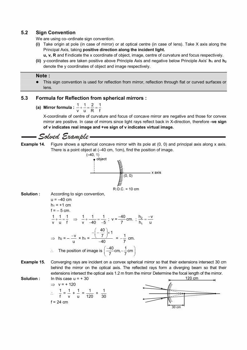
Example 14. Figure shows a spherical concave mirror with its pole at (0, 0) and principal axis along x axis.
There is a point object at (–40 cm, 1cm), find the position of image.
Solution : According to sign convention, u = –40 cm h1 = +1 cm f = – 5 cm.
1 1 1
v u f
1 1 1
v 40 5
; v =40
7
cm. ; 2
1
h v
h u
h2 = – v
u
× h1 =
401
7
40
= 1
7 cm.
The position of image is 40 1
cm, cm7 7
Example 15. Converging rays are incident on a convex spherical mirror so that their extensions intersect 30 cm behind the mirror on the optical axis. The reflected rays form a diverging beam so that their extensions intersect the optical axis 1.2 m from the mirror. Determine the focal length of the mirror.
Solution : In this case u = + 30 v = + 120
1
f =
1
v +
1
u =
1
120 +
1
30
f = 24 cm
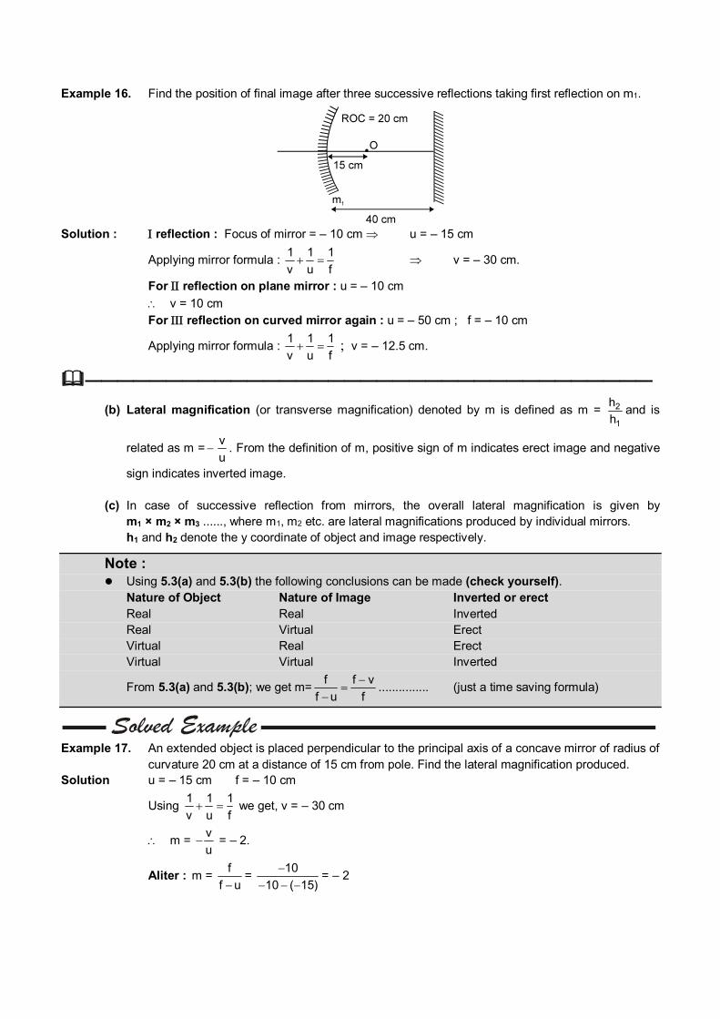
Example 16. Find the position of final image after three successive reflections taking first reflection on m1.
Solution : reflection : Focus of mirror = – 10 cm u = – 15 cm
Applying mirror formula : 1 1 1
v u f v = – 30 cm.
For reflection on plane mirror : u = – 10 cm v = 10 cm For reflection on curved mirror again : u = – 50 cm ; f = – 10 cm
Applying mirror formula : 1 1 1
v u f ; v = – 12.5 cm.
———————————————————————————————————
(b) Lateral magnification (or transverse magnification) denoted by m is defined as m = 2
1
h
hand is
related as m =v
u . From the definition of m, positive sign of m indicates erect image and negative
sign indicates inverted image. (c) In case of successive reflection from mirrors, the overall lateral magnification is given by
m1 × m2 × m3 ......, where m1, m2 etc. are lateral magnifications produced by individual mirrors. h1 and h2 denote the y coordinate of object and image respectively.
Note : Using 5.3(a) and 5.3(b) the following conclusions can be made (check yourself). Nature of Object Nature of Image Inverted or erect Real Real Inverted Real Virtual Erect Virtual Real Erect Virtual Virtual Inverted
From 5.3(a) and 5.3(b); we get m=f f v
f u f
............... (just a time saving formula)
Example 17. An extended object is placed perpendicular to the principal axis of a concave mirror of radius of
curvature 20 cm at a distance of 15 cm from pole. Find the lateral magnification produced. Solution u = – 15 cm f = – 10 cm
Using 1 1 1
v u f we get, v = – 30 cm
m = v
u = – 2.
Aliter : m = f
f u=
10
10 ( 15)
= – 2
Example 18. A person looks into a spherical mirror. The size of image of his face is twice the actual size of his face. If the face is at a distance 20 cm then find the nature and radius of curvature of the mirror.
Solution : Person will see his face only when the image is virtual. Virtual image of real object is erect. Hence m = 2
v
u
= 2 v = 40 cm
Applying 1 1 1
v u f ; f = – 40 cm or R = –80 cm (concave)
R.O.C. = 80 cm
Alter : m = f
f u 2 =
f
f ( 20)
f = – 40 cm or R = –80cm (concave) R.O.C. = 80 cm
Example 19. An image of a candle on a screen is found to be double its size. When the candle is shifted by a distance 5 cm then the image become triple its size. Find the nature and ROC of the mirror.
Solution : Since the images formed on screen it is real. Real object and real image implies concave mirror.
Applying m = f
f u or – 2 =
f
f (u) .....(1)
After shifting – 3 = f
f (u 5) .....(2)
[Why u + 5 ?, why not u – 5 : In a concave mirror, the size of real image will increase, only when the real object is brought closer to the mirror. In doing so, its x coordinate will increase]
From (1) & (2) we get, f = – 30 cm or R = –60 cm (concave) and R.O.C. = 60cm
——————————————————————————————————— (d) Velocity of image (i) Object moving perpendicular to principal axis : From the relation in 5.3.(b) we have
2
1
h v
h u or h2 =
v
u . h1
If a point object moves perpendicular to the principal axis, x coordinate of both the object & the image become constant. On differentiating the above relation w.r.t. time, we get,
2dh
dt= 1v dh
u dt
Here, 1dh
dt denotes velocity of object perpendicular to the principal axis and 2dh
dt denotes
velocity of image perpendicular to the principal axis.
(ii) Object moving along principal axis : On differentiating the mirror formula with respect to time
we get 2
2
dv v du
dt dtu , where
dt
dv is the velocity of image along principal axis and
dt
du is the
velocity of object along principal axis. Negative sign implies that the image, in case of mirror, always moves in the direction opposite to that of object. This discussion is for velocity with respect to mirror and along the x axis.
(iii) Object moving at an angle with the principal axis : Resolve the velocity of object along and
perpendicular to the principal axis and find the velocities of image in these directions separately and then find the resultant.
(e) Optical power of a mirror (in Dioptre) = –1
f
f = focal length with sign and in meters. (f) If object lying along the principal axis is not of very small size, the longitudinal magnification
= 2 1
2 1
v v
u u
(it will always be inverted)
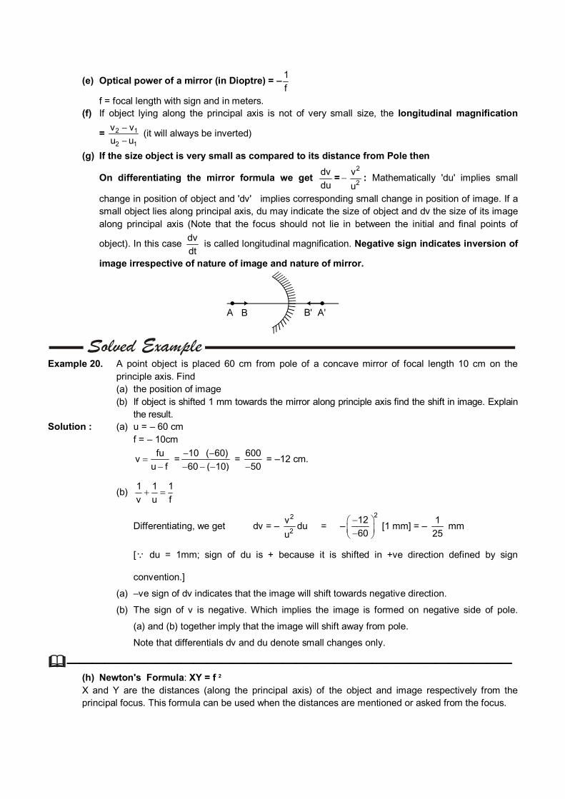
(g) If the size object is very small as compared to its distance from Pole then
On differentiating the mirror formula we get dv
du=
2
2
v
u : Mathematically 'du' implies small
change in position of object and 'dv' implies corresponding small change in position of image. If a small object lies along principal axis, du may indicate the size of object and dv the size of its image along principal axis (Note that the focus should not lie in between the initial and final points of
object). In this case dt
dv is called longitudinal magnification. Negative sign indicates inversion of
image irrespective of nature of image and nature of mirror.
Example 20. A point object is placed 60 cm from pole of a concave mirror of focal length 10 cm on the
principle axis. Find (a) the position of image (b) If object is shifted 1 mm towards the mirror along principle axis find the shift in image. Explain
the result. Solution : (a) u = – 60 cm f = – 10cm
fu
vu f
=10 ( 60)
60 ( 10)
= 600
50 = –12 cm.
(b) 1 1 1
v u f
Differentiating, we get dv = – 2
2
v
udu = –
212
60
[1 mm] = – 1
25 mm
[ du = 1mm; sign of du is + because it is shifted in +ve direction defined by sign
convention.]
(a) –ve sign of dv indicates that the image will shift towards negative direction.
(b) The sign of v is negative. Which implies the image is formed on negative side of pole.
(a) and (b) together imply that the image will shift away from pole.
Note that differentials dv and du denote small changes only.
——————————————————————————————————— (h) Newton's Formula: XY = f 2 X and Y are the distances (along the principal axis) of the object and image respectively from the
principal focus. This formula can be used when the distances are mentioned or asked from the focus.
6. REFRACTION OF LIGHT When the light changes its medium, some changes occurs in its properties, the phenomenon is known
as refraction. If the light is incident at an angle (0º < i < 90º) then it deviates from its actual path. It is due to
change in speed of light as light passes from one medium to another medium. If the light is incident normally then it goes to the second medium without bending, but still it is
called refraction. Refractive index of a medium is defined as the factor by which speed of light reduces as compared
to the speed of light in vacuumc
v =
speed of light in vacuum
speed of light in medium.
More (less) refractive index implies less (more) speed of light in that medium, which therefore is called optical denser (rarer) medium.
6.1 Laws of Refraction (a) The incident ray, the normal to any refracting surface at the point of incidence and the refracted ray
all lie in the same plane called the plane of incidence or plane of refraction.
(b) Sin i
Sin r = Constant for any pair of media and for light of a
given wave length. This is known as Snell's Law.
Also, Sin i
Sin r = 2
1
n
n = 1
2
v
v = 1
2
For applying in problems remember n1sini = n2sinr
2
1
n
n= 1n2 = Refractive Index of the second medium with
respect to the first medium. c = speed of light in air (or vacuum) = 3 x 10⁸ m/s.
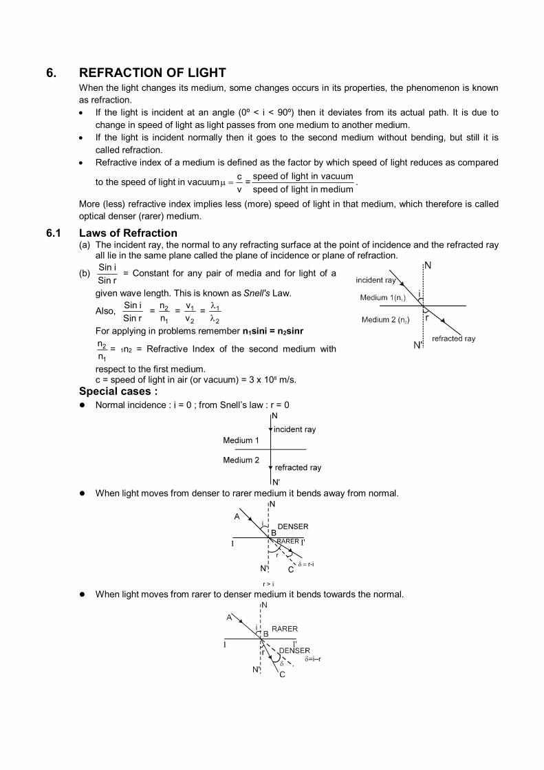
Special cases : Normal incidence : i = 0 ; from Snell’s law : r = 0
When light moves from denser to rarer medium it bends away from normal.
When light moves from rarer to denser medium it bends towards the normal.
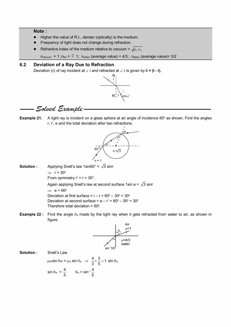
Note : Higher the value of R.., denser (optically) is the medium. Frequency of light does not change during refraction.
Refractive index of the medium relative to vacuum = r r
nvacuum = 1 ; nair = ~ 1; nwater (average value) = 4/3 ; nglass (average value)= 3/2
6.2 Deviation of a Ray Due to Refraction Deviation () of ray incident at i and refracted at r is given by = |i r|.
Example 21. A light ray is incident on a glass sphere at an angle of incidence 600 as shown. Find the angles r, r’, e and the total deviation after two refractions.
Solution : Applying Snell’s law 1sin60° = 3 sinr
r = 300 From symmetry r’ = r = 30°.
Again applying Snell’s law at second surface 1sin e = 3 sinr
e = 600 Deviation at first surface = i – r = 600 – 300 = 300 Deviation at second surface = e – r’ = 600 – 300 = 300 Therefore total deviation = 600.
Example 22 : Find the angle a made by the light ray when it gets refracted from water to air, as shown in figure.
Solution : Snell’s Law
Wsin W = a sin a 4 3
13 5 sin a
sin a = 4
5 a = sin–1
4
5
Example 23. Find the speed of light in medium ‘a’ if speed of light in medium ‘b’ is c
3 where c = speed of
light in vacuum and light refracts from medium ‘a’ to medium ‘b’ making 45º and 60º respectively with the normal.
Solution : Snell’s Law a sin a = b sin b
a
c
v sin a =
b
c
v sin b.
a
c
v sin 45º =
c
c / 3 sin 60º.
va = 2c
3 3
——————————————————————————————————— 6.3 Principle of Reversibility of Light Rays (a) A ray travelling along the path of the reflected ray is reflected along the path of the incident ray. (b) A refracted ray reversed to travel back along its path will get refracted along the path of the incident
ray. Thus the incident and refracted rays are mutually reversible.
7. REFRACTION THROUGH A PARALLEL SLAB When light passes through a parallel slab, having same medium on both sides, then (a) Emergent ray is parallel to the incident ray.
Note : Emergent ray will not be parallel to the incident ray if the medium on both the sides of slab are
different.
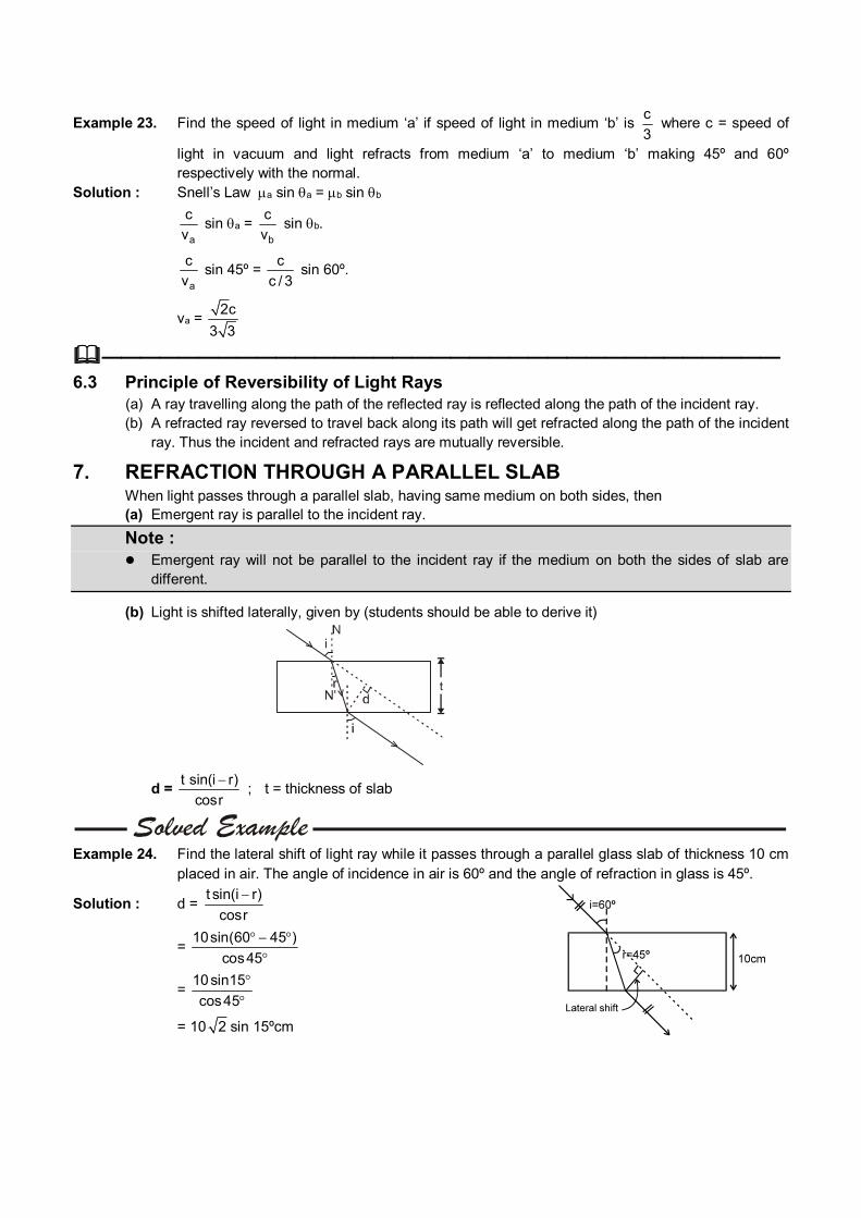
(b) Light is shifted laterally, given by (students should be able to derive it)
d = t sin(i r)
cosr
; t = thickness of slab
Example 24. Find the lateral shift of light ray while it passes through a parallel glass slab of thickness 10 cm
placed in air. The angle of incidence in air is 60º and the angle of refraction in glass is 45º.
Solution : d = t sin(i r)
cosr
= 10sin(60 45 )
cos45
= 10sin15
cos45
= 10 2 sin 15ºcm
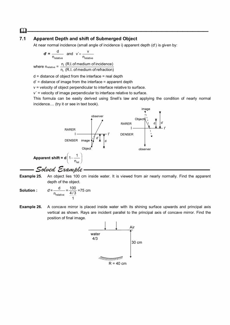
——————————————————————————————————— 7.1 Apparent Depth and shift of Submerged Object At near normal incidence (small angle of incidence i) apparent depth (d) is given by:
d= relative
d
n and
relative
vv´
n
where nrelative = i
r
n (R. .of medium of incidence)
n (R. . of medium of refraction)
d = distance of object from the interface = real depth
d’ = distance of image from the interface = apparent depth
v = velocity of object perpendicular to interface relative to surface.
v´ = velocity of image perpendicular to interface relative to surface.
This formula can be easily derived using Snell’s law and applying the condition of nearly normal
incidence.... (try it or see in text book).
Apparent shift = drel
11
n
Example 25. An object lies 100 cm inside water. It is viewed from air nearly normally. Find the apparent
depth of the object.
Solution : d=relative
d
n=
1004 / 3
1
=75 cm
Example 26. A concave mirror is placed inside water with its shining surface upwards and principal axis
vertical as shown. Rays are incident parallel to the principal axis of concave mirror. Find the
position of final image.

Solution: The incident rays will pass undeviated through the water surface and strike the mirror parallel to
its principal axis. Therefore for the mirror, object is at . Its image A (in figure) will be formed at
focus which is 20 cm from the mirror.
Now for the interface between water and air, d = 10 cm.
d’ = w
a
d
nn
=10
4 / 31
= 7.5 cm.
Example 27. See the figure (i) Find apparent height of the bird. (ii) Find apparent depth of fish. (iii) At what distance will the bird appear to the fish? (iv) At what distance will the fish appear to the bird? (v) If the velocity of bird is 12 cm/sec downward and
the fish is 12 cm/sec in upward direction, then find out their relative velocities with respect to each other.
Solution (i) d´B = 36 361 3 / 443
= 48 cm (ii) d´F = 36
4 / 3 = 27 cm
(iii) For fish : dB = 36 + 48 = 84 cm ; dB = 36 + 48 = 84 cm (iv) For bird : dF = 27 + 36 = 63 cm. ; dF = 27 + 36 = 63 cm.
(v) Velocity of fish with respect to bird = 12
124 / 3
1/1
= 21 cm/sec.
Velocity of bird with respect to fish = 12
123 / 4
1/1
= 28 cm/sec.
Example - 28 See the figure. Find the distance of final image formed by mirror
Solution : Shift = 1
3 13 / 2
For mirror object is at a distance
= 21 – 1
3 13 / 2
= 20 cm
Object is at the centre of curvature of mirror. Hence the light rays will retrace and image will be formed on the object itself.
——————————————————————————————————— 7.2 Refraction through a composite slab (or refraction through a number of parallel
media, as seen from a medium of R. I. n0)
Apparent depth (distance of final image from final surface)
= 1
1rel
t
n + 2
2 rel
t
n + 3
3 rel
t
n +......... + n
n rel
t
n
Apparent shift
= t1 1rel
11
n
+ t2
2 rel
11
n
+........+
reln
n1
n
tn
Where ' t ' represents thickness and ' n ' represents the R.I. of the respective media, relative to the medium of observer. (i.e. n1rel = n1/n0, n2 rel = n2/n0 etc.)
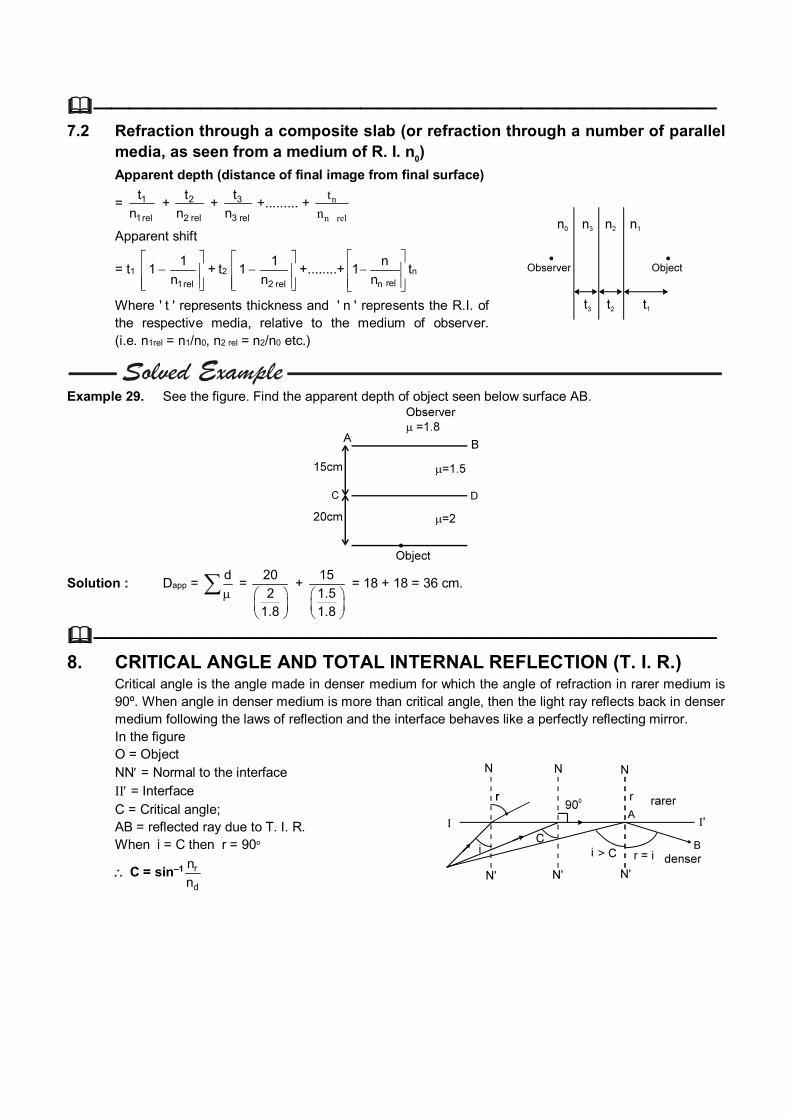
Example 29. See the figure. Find the apparent depth of object seen below surface AB.
Solution : Dapp = d
= 20
21.8
+ 15
1.51.8
= 18 + 18 = 36 cm.
——————————————————————————————————— 8. CRITICAL ANGLE AND TOTAL INTERNAL REFLECTION (T. I. R.) Critical angle is the angle made in denser medium for which the angle of refraction in rarer medium is
90º. When angle in denser medium is more than critical angle, then the light ray reflects back in denser medium following the laws of reflection and the interface behaves like a perfectly reflecting mirror.
In the figure O = Object NN = Normal to the interface II = Interface C = Critical angle; AB = reflected ray due to T. I. R. When i = C then r = 90o
C = sin–1 r
d
n
n
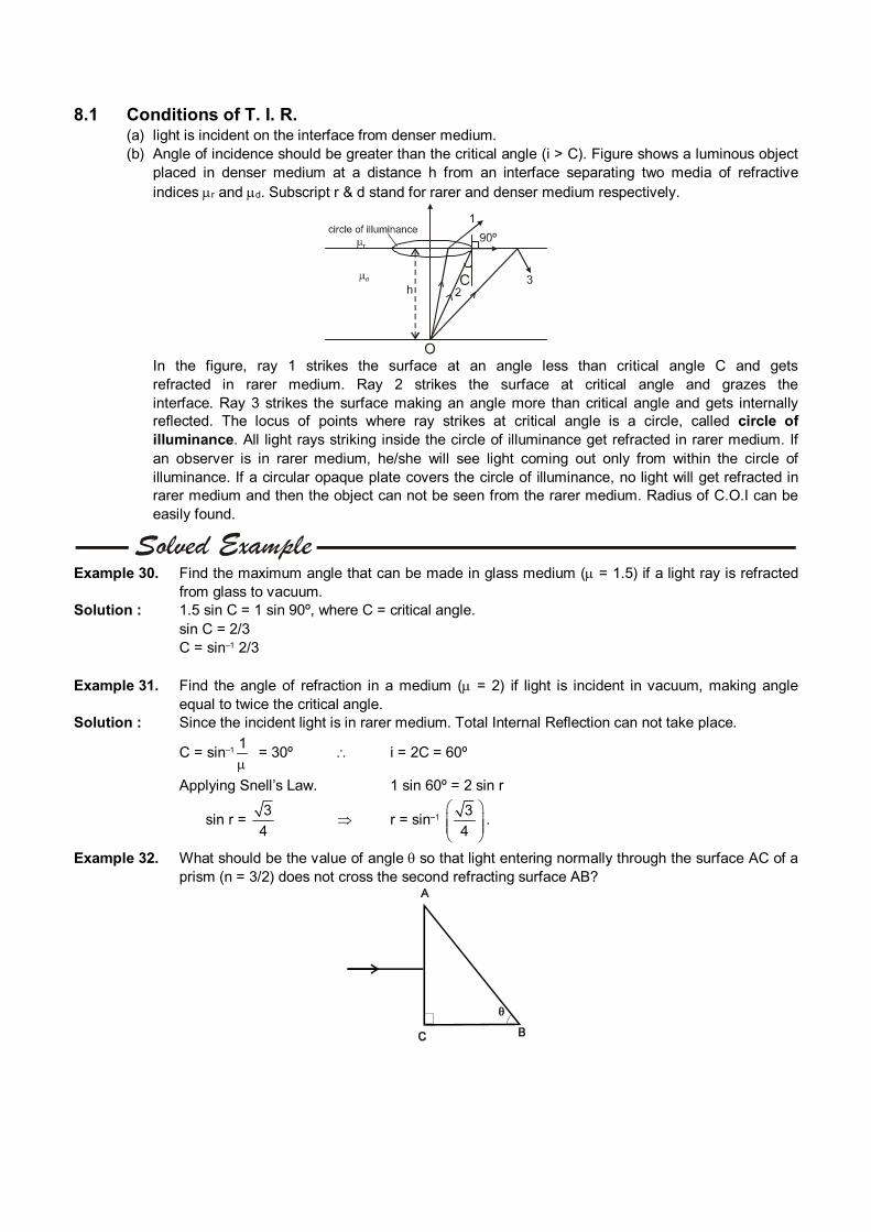
8.1 Conditions of T. I. R. (a) light is incident on the interface from denser medium.
(b) Angle of incidence should be greater than the critical angle (i > C). Figure shows a luminous object placed in denser medium at a distance h from an interface separating two media of refractive indices r and d. Subscript r & d stand for rarer and denser medium respectively.
In the figure, ray 1 strikes the surface at an angle less than critical angle C and gets
refracted in rarer medium. Ray 2 strikes the surface at critical angle and grazes the interface. Ray 3 strikes the surface making an angle more than critical angle and gets internally reflected. The locus of points where ray strikes at critical angle is a circle, called circle of illuminance. All light rays striking inside the circle of illuminance get refracted in rarer medium. If an observer is in rarer medium, he/she will see light coming out only from within the circle of illuminance. If a circular opaque plate covers the circle of illuminance, no light will get refracted in rarer medium and then the object can not be seen from the rarer medium. Radius of C.O.I can be easily found.
Example 30. Find the maximum angle that can be made in glass medium ( = 1.5) if a light ray is refracted
from glass to vacuum. Solution : 1.5 sin C = 1 sin 90º, where C = critical angle. sin C = 2/3 C = sin–1 2/3 Example 31. Find the angle of refraction in a medium ( = 2) if light is incident in vacuum, making angle
equal to twice the critical angle. Solution : Since the incident light is in rarer medium. Total Internal Reflection can not take place.
C = sin–11
= 30º i = 2C = 60º
Applying Snell’s Law. 1 sin 60º = 2 sin r
sin r = 3
4 r = sin–1
3
4
.
Example 32. What should be the value of angle so that light entering normally through the surface AC of a prism (n = 3/2) does not cross the second refracting surface AB?
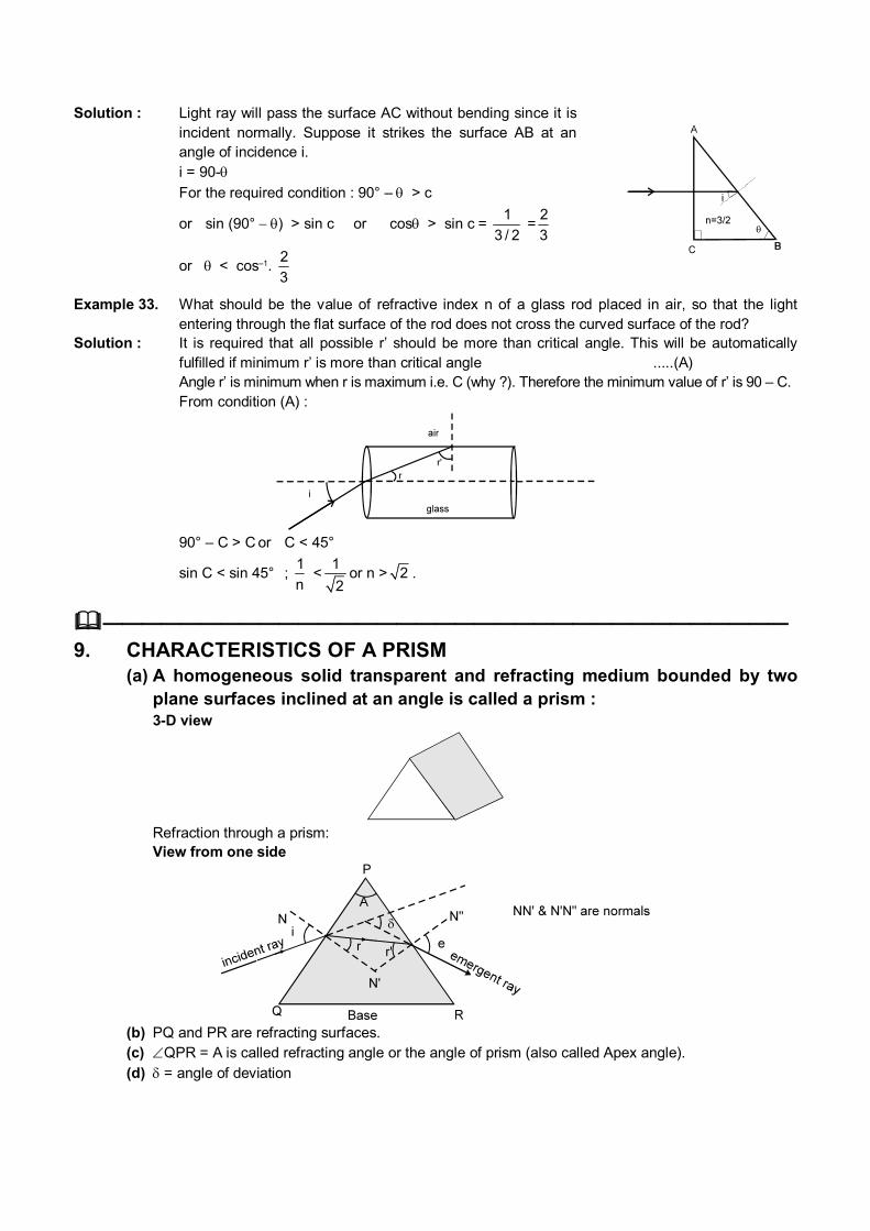
Solution : Light ray will pass the surface AC without bending since it is incident normally. Suppose it strikes the surface AB at an angle of incidence i.
i = 90-
For the required condition : 90° – > c
or sin (90°) > sin c or cos> sin c = 1
3 / 2 =
2
3
or < cos–1. 2
3
Example 33. What should be the value of refractive index n of a glass rod placed in air, so that the light entering through the flat surface of the rod does not cross the curved surface of the rod?
Solution : It is required that all possible r’ should be more than critical angle. This will be automatically fulfilled if minimum r’ is more than critical angle .....(A)
Angle r’ is minimum when r is maximum i.e. C (why ?). Therefore the minimum value of r’ is 90 – C. From condition (A) :
90° – C > C or C < 45°
sin C < sin 45° ; 1
n < 1
2or n > 2 .
——————————————————————————————————— 9. CHARACTERISTICS OF A PRISM (a) A homogeneous solid transparent and refracting medium bounded by two
plane surfaces inclined at an angle is called a prism : 3-D view
Refraction through a prism: View from one side
(b) PQ and PR are refracting surfaces. (c) QPR = A is called refracting angle or the angle of prism (also called Apex angle). (d) = angle of deviation
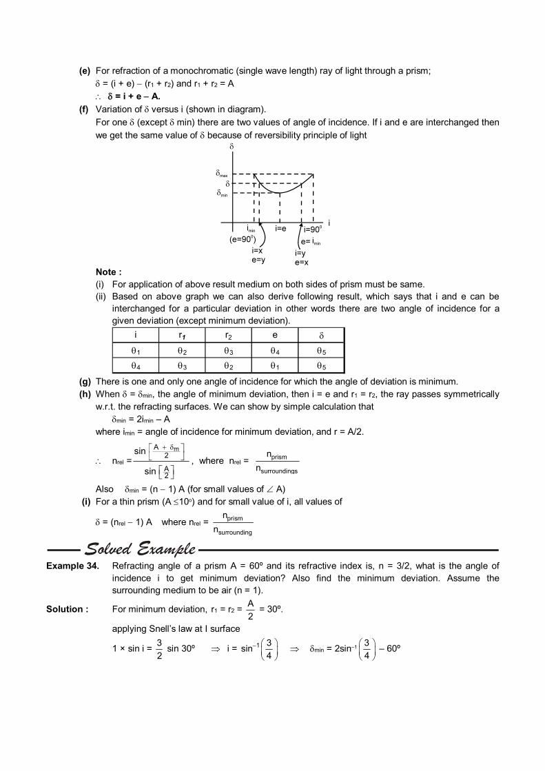
(e) For refraction of a monochromatic (single wave length) ray of light through a prism; = (i + e) (r1 + r2) and r1 + r2 = A = i + e A.
(f) Variation of versus i (shown in diagram).
For one (except min) there are two values of angle of incidence. If i and e are interchanged then
we get the same value of because of reversibility principle of light
Note : (i) For application of above result medium on both sides of prism must be same. (ii) Based on above graph we can also derive following result, which says that i and e can be
interchanged for a particular deviation in other words there are two angle of incidence for a given deviation (except minimum deviation).
i r1 r2 e
1 2 3 4 5
4 3 2 1 5 (g) There is one and only one angle of incidence for which the angle of deviation is minimum. (h) When = min, the angle of minimum deviation, then i = e and r1 = r2, the ray passes symmetrically
w.r.t. the refracting surfaces. We can show by simple calculation that min = 2imin – A where imin = angle of incidence for minimum deviation, and r = A/2.
nrel =mA
2
A2
sin
sin
, where nrel = prism
surroundings
n
n
Alsomin = (n 1) A (for small values of A) (i) For a thin prism (A 10o) and for small value of i, all values of
= (nrel 1) A where nrel = prism
surrounding
n
n
Example 34. Refracting angle of a prism A = 60º and its refractive index is, n = 3/2, what is the angle of
incidence i to get minimum deviation? Also find the minimum deviation. Assume the surrounding medium to be air (n = 1).
Solution : For minimum deviation, r1 = r2 = A
2 = 30º.
applying Snell’s law at I surface
1 × sin i = 3
2 sin 30º i = 1 3
sin4
min = 2sin–13
4
– 60º
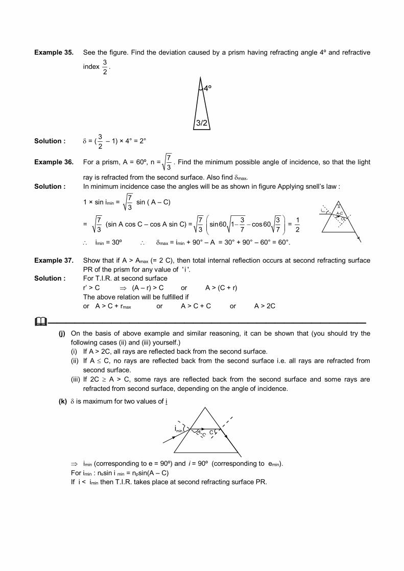
Example 35. See the figure. Find the deviation caused by a prism having refracting angle 4º and refractive
index 3
2.
Solution : = (3
2 – 1) × 4° = 2°
Example 36. For a prism, A = 60º, n =7
3. Find the minimum possible angle of incidence, so that the light
ray is refracted from the second surface. Also find max. Solution : In minimum incidence case the angles will be as shown in figure Applying snell’s law :
1 × sin imin = 7
3 sin ( A – C)
= 7
3 (sin A cos C – cos A sin C) =
7
3
3 3sin60 1 cos60
7 7
=
1
2
imin = 30º max = imin + 90° – A = 30° + 90° – 60° = 60°.
Example 37. Show that if A > Amax (= 2 C), then total internal reflection occurs at second refracting surface
PR of the prism for any value of ' i '. Solution : For T.I.R. at second surface r’ > C (A – r) > C or A > (C + r) The above relation will be fulfilled if or A > C + rmax or A > C + C or A > 2C
——————————————————————————————————— (j) On the basis of above example and similar reasoning, it can be shown that (you should try the
following cases (ii) and (iii) yourself.) (i) If A > 2C, all rays are reflected back from the second surface. (ii) If A C, no rays are reflected back from the second surface i.e. all rays are refracted from
second surface. (iii) If 2C A > C, some rays are reflected back from the second surface and some rays are
refracted from second surface, depending on the angle of incidence.
(k) is maximum for two values of i
imin (corresponding to e = 90º) and i = 90º (corresponding to emin). For imin : nssin i min = npsin(A – C) If i < imin then T.I.R. takes place at second refracting surface PR.
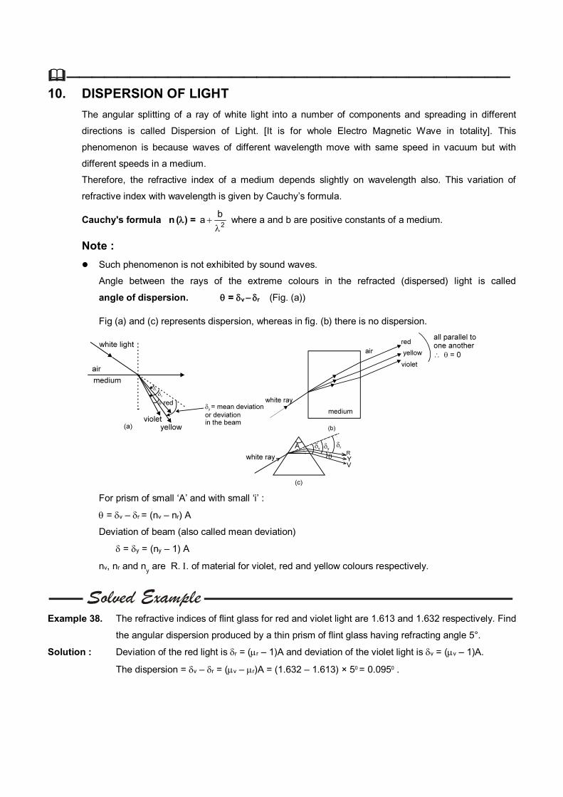
——————————————————————————————————— 10. DISPERSION OF LIGHT
The angular splitting of a ray of white light into a number of components and spreading in different
directions is called Dispersion of Light. [It is for whole Electro Magnetic Wave in totality]. This
phenomenon is because waves of different wavelength move with same speed in vacuum but with
different speeds in a medium.
Therefore, the refractive index of a medium depends slightly on wavelength also. This variation of
refractive index with wavelength is given by Cauchy’s formula.
Cauchy's formula n () = 2
ba
where a and b are positive constants of a medium.
Note :
Such phenomenon is not exhibited by sound waves.
Angle between the rays of the extreme colours in the refracted (dispersed) light is called
angle of dispersion. = v r (Fig. (a))
Fig (a) and (c) represents dispersion, whereas in fig. (b) there is no dispersion.
For prism of small ‘A’ and with small ‘i’ :
= v – r = (nv – nr) A
Deviation of beam (also called mean deviation)
= y = (ny – 1) A
nv, nr and ny are R. . of material for violet, red and yellow colours respectively.
Example 38. The refractive indices of flint glass for red and violet light are 1.613 and 1.632 respectively. Find
the angular dispersion produced by a thin prism of flint glass having refracting angle 5°.
Solution : Deviation of the red light is r = (r – 1)A and deviation of the violet light is v = (v – 1)A.
The dispersion = v – r = (v – r)A = (1.632 – 1.613) × 50 = 0.0950 .
Note : Numerical data reveals that if the average value of is small v – r is also small and if the average
value of is large v – r is also large. Thus, larger the mean deviation, larger will be the angular dispersion.
Dispersive power () of the medium of the material of prism is given by : = v r
y
n n
n 1
is the property of a medium. For small angled prism (A 10o) with light incident at small angle i :
v r
y
n n
n 1
= v r
y
=y
= angular dispersion
deviation of mean ray (yellow)
[ ny = v rn n
2
if ny is not given in the problem ]
n 1 = refractivity of the medium for the corresponding colour.
Example 39. Refractive index of glass for red and violet colours are 1.50 and 1.60 respectively. Find (a) the refractive index for yellow colour, approximately (b) Dispersive power of the medium.
Solution : (a) y ~ v R
2
=
1.50 1.60
2
= 1.55 (b) = v R
y
–
– 1
= 1.60 1.50
1.55 1
= 0.18.
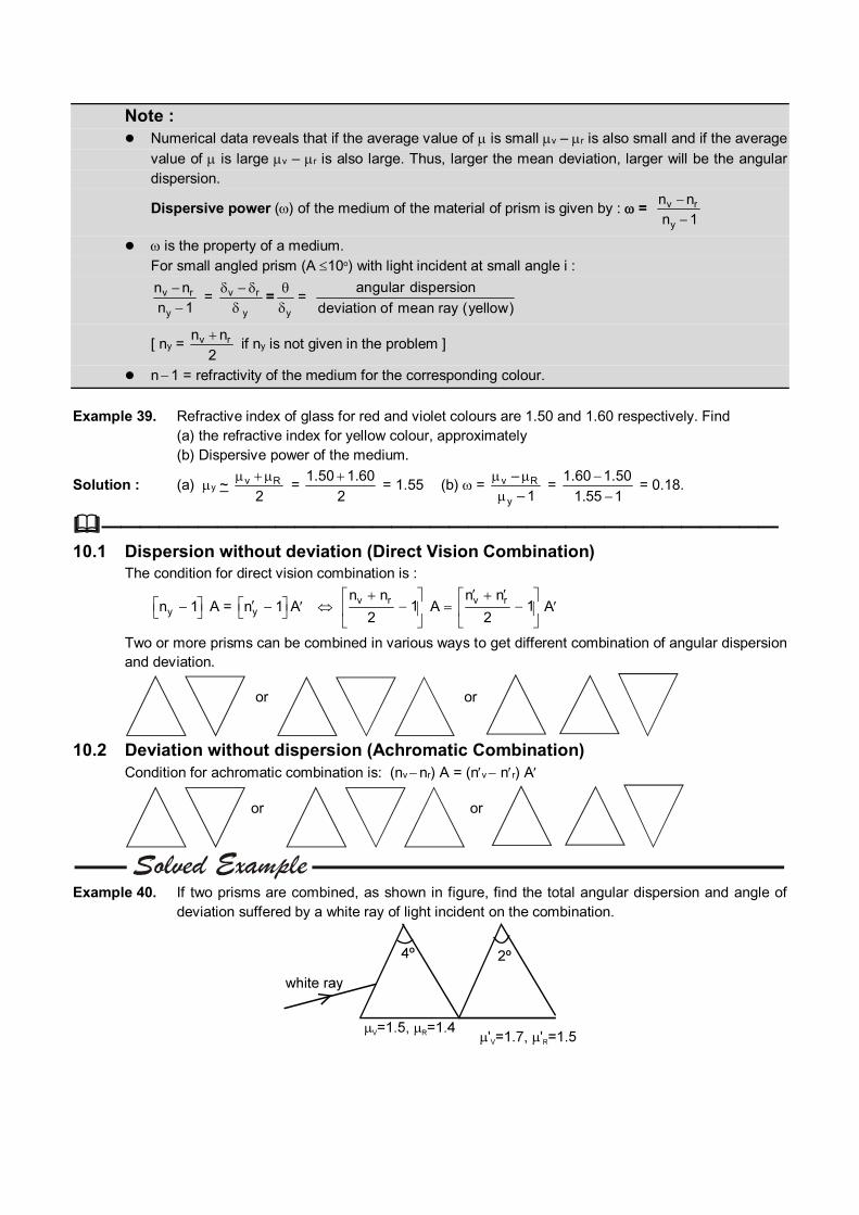
——————————————————————————————————— 10.1 Dispersion without deviation (Direct Vision Combination) The condition for direct vision combination is :
yn 1 A = yn 1 A v rn n1
2
A v rn n
12
A
Two or more prisms can be combined in various ways to get different combination of angular dispersion and deviation.
or or
10.2 Deviation without dispersion (Achromatic Combination) Condition for achromatic combination is: (nv
nr) A = (nv nr) A
or or
Example 40. If two prisms are combined, as shown in figure, find the total angular dispersion and angle of
deviation suffered by a white ray of light incident on the combination.
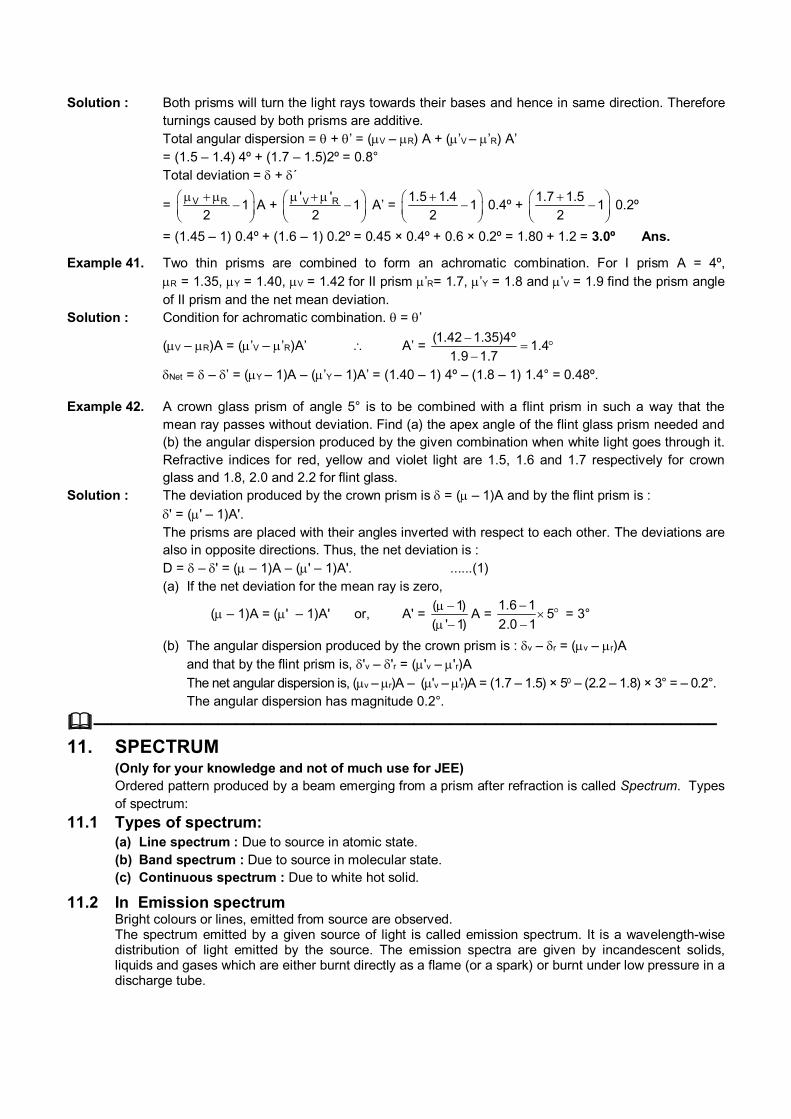
Solution : Both prisms will turn the light rays towards their bases and hence in same direction. Therefore turnings caused by both prisms are additive.
Total angular dispersion = + ’ = (V – R) A + (’V – ’R) A’ = (1.5 – 1.4) 4º + (1.7 – 1.5)2º = 0.8° Total deviation = + ´
= V R 12
A + V R' '1
2
A’ = 1.5 1.4
12
0.4º + 1.7 1.5
12
0.2º
= (1.45 – 1) 0.4º + (1.6 – 1) 0.2º = 0.45 × 0.4º + 0.6 × 0.2º = 1.80 + 1.2 = 3.0º Ans.
Example 41. Two thin prisms are combined to form an achromatic combination. For I prism A = 4º, R = 1.35, Y = 1.40, V = 1.42 for II prism ’R= 1.7, ’Y = 1.8 and ’V = 1.9 find the prism angle of II prism and the net mean deviation.
Solution : Condition for achromatic combination. = ’
(V – R)A = (’V – ’R)A’ A’ = (1.42 1.35)4º
1.41.9 1.7
Net = – ’ = (Y – 1)A – (’Y – 1)A’ = (1.40 – 1) 4º – (1.8 – 1) 1.4° = 0.48º.
Example 42. A crown glass prism of angle 5° is to be combined with a flint prism in such a way that the mean ray passes without deviation. Find (a) the apex angle of the flint glass prism needed and (b) the angular dispersion produced by the given combination when white light goes through it. Refractive indices for red, yellow and violet light are 1.5, 1.6 and 1.7 respectively for crown glass and 1.8, 2.0 and 2.2 for flint glass.
Solution : The deviation produced by the crown prism is = ( – 1)A and by the flint prism is :
' = (' – 1)A'. The prisms are placed with their angles inverted with respect to each other. The deviations are
also in opposite directions. Thus, the net deviation is : D = – ' = ( – 1)A – (' – 1)A'. ......(1) (a) If the net deviation for the mean ray is zero,
( – 1)A = (' – 1)A' or, A' = ( 1)
( ' 1)
A = 1.6 1
52.0 1
= 3°
(b) The angular dispersion produced by the crown prism is : v – r = (v – r)A and that by the flint prism is, 'v – 'r = ('v – 'r)A
The net angular dispersion is, (v – r)A – ('v – 'r)A = (1.7 – 1.5) × 50 – (2.2 – 1.8) × 3° = – 0.2°. The angular dispersion has magnitude 0.2°.
———————————————————————————————————
11. SPECTRUM (Only for your knowledge and not of much use for JEE) Ordered pattern produced by a beam emerging from a prism after refraction is called Spectrum. Types
of spectrum:
11.1 Types of spectrum: (a) Line spectrum : Due to source in atomic state. (b) Band spectrum : Due to source in molecular state. (c) Continuous spectrum : Due to white hot solid.
11.2 In Emission spectrum Bright colours or lines, emitted from source are observed. The spectrum emitted by a given source of light is called emission spectrum. It is a wavelength-wise
distribution of light emitted by the source. The emission spectra are given by incandescent solids, liquids and gases which are either burnt directly as a flame (or a spark) or burnt under low pressure in a discharge tube.
11.3 In Absorption spectrum Dark lines indicates frequencies absorbed.
When a beam of light from a hot source is passed through a substance (at a lower temperature), a part
of the light is transmitted but rest of it is absorbed. With the help of a spectrometer, we can know the
fraction of light absorbed corresponding to each wavelength. The distribution of the wavelength
absorption of light by a substance is called an absorption spectrum. Every substance has its own
characteristic absorption spectrum.
11.4 Spectrometer Consists of a collimator (to collimate light beam), prism and telescope. It is used to observe the
spectrum and also measure deviation.
———————————————————————————————————
12. REFRACTION AT SPHERICAL SURFACES For paraxial rays incident on a spherical surface separating two media:
2n
v 1n
u = 2 1n n
R
.................... (A)
where light moves from the medium of refractive index n1 to the medium of refractive index n2.
Transverse magnification (m) (of dimension perpendicular to principal axis) due to refraction at
spherical surface is given by m =v R
u R
= 2
1
v /n
u/n
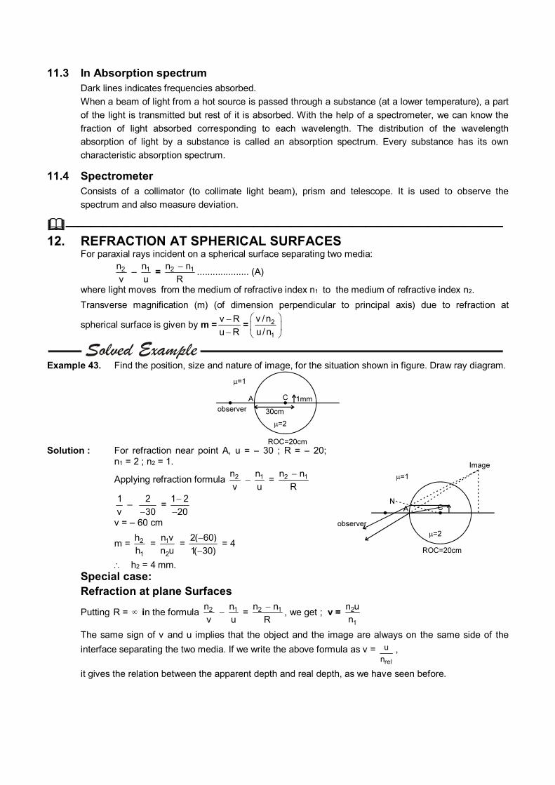
Example 43. Find the position, size and nature of image, for the situation shown in figure. Draw ray diagram.
Solution : For refraction near point A, u = – 30 ; R = – 20;
n1 = 2 ; n2 = 1.
Applying refraction formula 2n
v 1n
u = 2 1n n
R
1
v –
2
30 =
1 2
20
v = – 60 cm
m = 2
1
h
h = 1
2
n v
n u =
2( 60)
1( 30)
= 4
h2 = 4 mm.
Special case: Refraction at plane Surfaces
Putting R = in the formula 2n
v 1n
u = 2 1n n
R
, we get ; v = 2
1
n u
n
The same sign of v and u implies that the object and the image are always on the same side of the
interface separating the two media. If we write the above formula as v = u
nrel
,
it gives the relation between the apparent depth and real depth, as we have seen before.
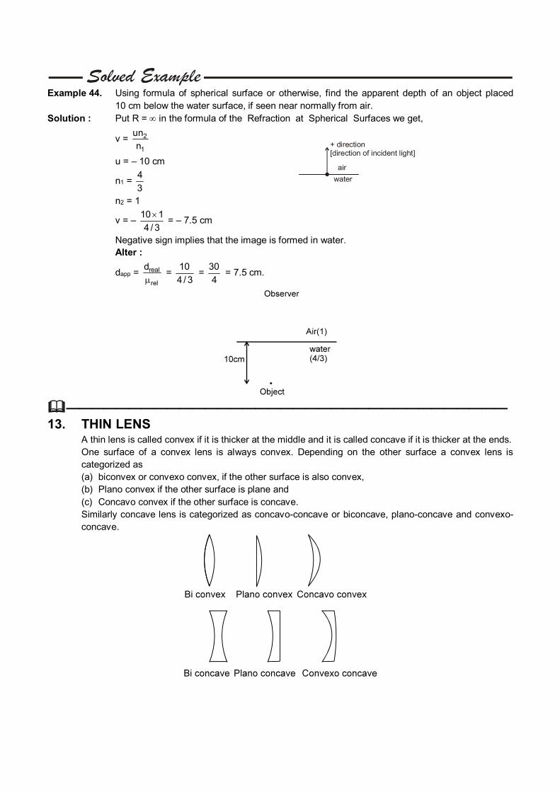
Example 44. Using formula of spherical surface or otherwise, find the apparent depth of an object placed 10 cm below the water surface, if seen near normally from air.
Solution : Put R = in the formula of the Refraction at Spherical Surfaces we get,
v = 2
1
un
n
u = – 10 cm
n1 = 4
3
n2 = 1
+ direction [ of incident light]direction
air
water
v = – 10 1
4 / 3
= – 7.5 cm
Negative sign implies that the image is formed in water. Alter :
dapp = real
rel
d
=
10
4 / 3 =
30
4 = 7.5 cm.
———————————————————————————————————
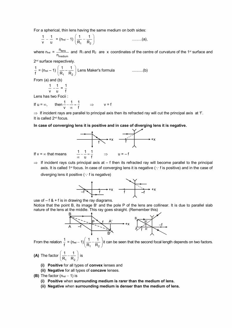
13. THIN LENS A thin lens is called convex if it is thicker at the middle and it is called concave if it is thicker at the ends. One surface of a convex lens is always convex. Depending on the other surface a convex lens is
categorized as (a) biconvex or convexo convex, if the other surface is also convex, (b) Plano convex if the other surface is plane and (c) Concavo convex if the other surface is concave. Similarly concave lens is categorized as concavo-concave or biconcave, plano-concave and convexo-
concave.
For a spherical, thin lens having the same medium on both sides:
1
v
1
u = (nrel 1)
1 2
1 1
R R
.........(a),
where nrel = lens
medium
n
n and R1 and R2 are x coordinates of the centre of curvature of the 1st surface and
2nd surface respectively.
1
f = (nrel – 1)
1 2
1 1–
R R
Lens Maker's formula ..........(b)
From (a) and (b)
1
v
1
u =
1
f
Lens has two Focii :
If u = , then1 1 1
v f
v = f
If incident rays are parallel to principal axis then its refracted ray will cut the principal axis at ‘f’. It is called 2nd focus.
In case of converging lens it is positive and in case of diverging lens it is negative.
If v = that means 1 1 1
u f
u = – f
If incident rays cuts principal axis at – f then its refracted ray will become parallel to the principal axis. It is called 1st focus. In case of converging lens it is negative ( f is positive) and in the case of
diverging lens it positive ( f is negative)
use of – f & + f is in drawing the ray diagrams. Notice that the point B, its image B and the pole P of the lens are collinear. It is due to parallel slab
nature of the lens at the middle. This ray goes straight. (Remember this)
From the relation f
1 = (nrel 1)
1 2
1 1
R R
it can be seen that the second focal length depends on two factors.
(A) The factor 1 2
1 1
R R
is
(i) Positive for all types of convex lenses and (ii) Negative for all types of concave lenses. (B) The factor (nrel 1) is (i) Positive when surrounding medium is rarer than the medium of lens. (ii) Negative when surrounding medium is denser than the medium of lens.
(C) So a lens is converging if f is positive which happens when both the factors (A) and (B) are of same sign.
(D) And a lens is diverging if f is negative which happens when the factors (A) and (B) are of opposite signs.
(E) Focal length of the lens depends on medium of lens as well as surrounding. (F) It also depends on wavelength of incident light. Incapability of lens to focus light rays of various
wavelengths at single point is known as chromatic aberration.
Example 45. Find the behaviour of a concave lens placed in a rarer medium. Solution : Factor (A) is negative, because the lens is concave. Factor (B) is positive, because the lens is placed in a rarer medium. Therefore the focal length of the lens, which depends on the product of these factors, is
negative and hence the lens will behave as diverging lens.
Example 46. Show that the factor 1 2
1 1
R R
(and therefore focal length) does not depend on which surface
of the lens light strike first. Solution : Consider a convex lens of radii of curvature p and q as shown.
CASE 1 : Suppose light is incident from left side and strikes the surface with radius of
curvature p, first. Then R1 = +p ; R2 = -q and 1 2
1 1
R R
=
1 1
p q
CASE 2 : Suppose light is incident from right side and strikes the surface with radius of
curvature q, first. Then R1 = +q ; R2 = -p and 1 2
1 1
R R
=
1 1
q p
Though we have shown the result for biconvex lens, it is true for every lens.
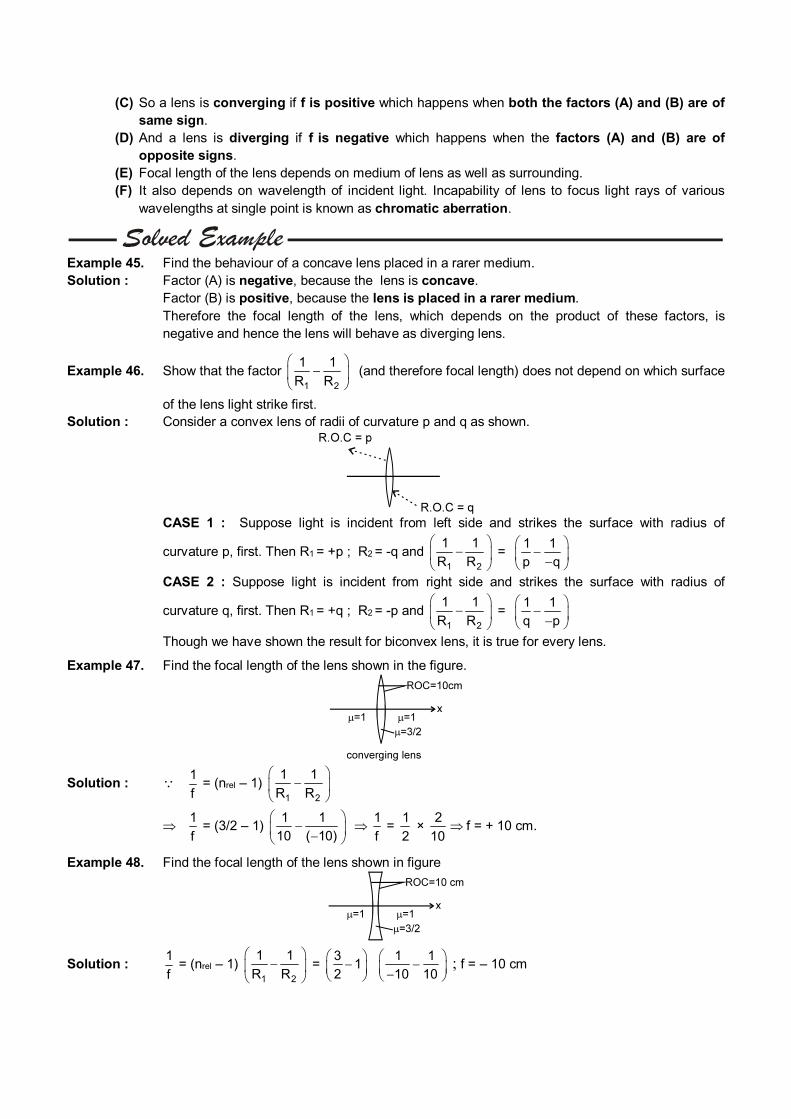
Example 47. Find the focal length of the lens shown in the figure.
Solution : 1
f = (nrel – 1)
1 2
1 1
R R
1
f = (3/2 – 1)
1 1
10 ( 10)
1
f =
1
2 ×
2
10 f = + 10 cm.
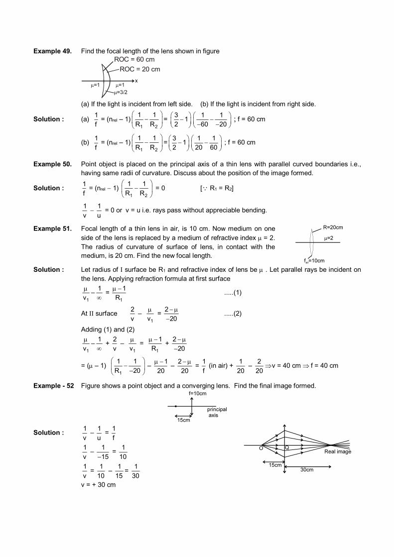
Example 48. Find the focal length of the lens shown in figure
Solution : 1
f = (nrel – 1)
1 2
1 1
R R
=
31
2
1 1
10 10
; f = – 10 cm
Example 49. Find the focal length of the lens shown in figure
ROC = 60 cm
ROC = 20 cm
(a) If the light is incident from left side. (b) If the light is incident from right side.
Solution : (a) 1
f = (nrel – 1)
1 2
1 1
R R
=
31
2
1 1
60 20
; f = 60 cm
(b) 1
f = (nrel – 1)
1 2
1 1
R R
=
31
2
1 1
20 60
; f = 60 cm
Example 50. Point object is placed on the principal axis of a thin lens with parallel curved boundaries i.e., having same radii of curvature. Discuss about the position of the image formed.
Solution : f
1 = (nrel 1)
1 2
1 1
R R
= 0 [ R1 = R2]
1
v
1
u = 0 or v = u i.e. rays pass without appreciable bending.
Example 51. Focal length of a thin lens in air, is 10 cm. Now medium on one side of the lens is replaced by a medium of refractive index = 2. The radius of curvature of surface of lens, in contact with the medium, is 20 cm. Find the new focal length.
Solution : Let radius of surface be R1 and refractive index of lens be . Let parallel rays be incident on
the lens. Applying refraction formula at first surface
1
1–
v
= 1
1
R
.....(1)
At surface 2
v –
1v
= 2
20
.....(2)
Adding (1) and (2)
1
1–
v
+ 2
v –
1v
= 1
1
R
+ 2
20
= ( – 1) 1
1 1
R 20
– 1
20
–
2
20
=
1
f (in air) +
1
20 –
2
20 v = 40 cm f = 40 cm
Example - 52 Figure shows a point object and a converging lens. Find the final image formed.
Solution : 1
v –
1
u =
1
f
1
v –
1
15 =
1
10
1
v =
1
10 –
1
15=
1
30
v = + 30 cm
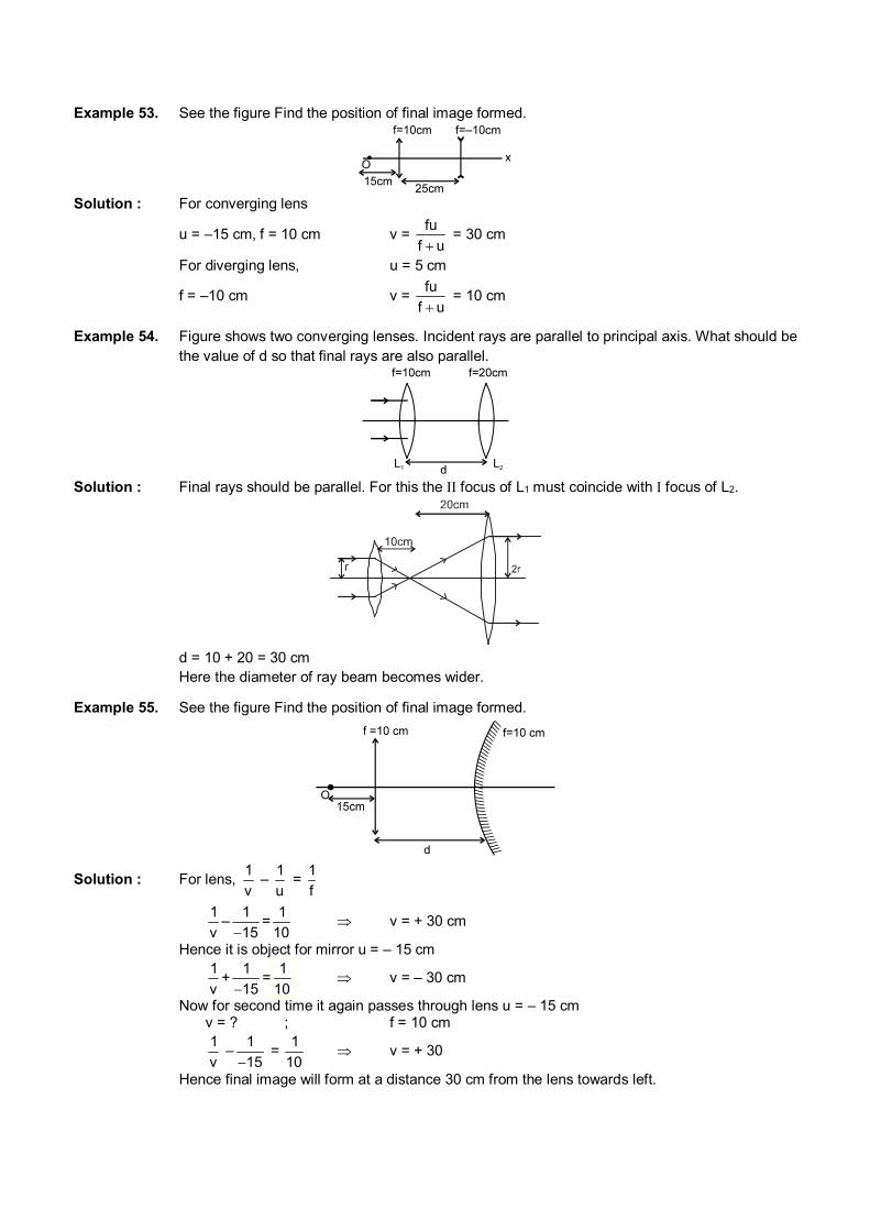
Example 53. See the figure Find the position of final image formed.
Solution : For converging lens
u = –15 cm, f = 10 cm v = fu
f u = 30 cm
For diverging lens, u = 5 cm
f = –10 cm v = fu
f u = 10 cm
Example 54. Figure shows two converging lenses. Incident rays are parallel to principal axis. What should be the value of d so that final rays are also parallel.
Solution : Final rays should be parallel. For this the focus of L1 must coincide with focus of L2.
d = 10 + 20 = 30 cm Here the diameter of ray beam becomes wider.
Example 55. See the figure Find the position of final image formed.
Solution : For lens, 1
v –
1
u =
1
f
1
v–
1
15=
1
10 v = + 30 cm
Hence it is object for mirror u = – 15 cm
1
v+
1
15=
10
1 v = – 30 cm
Now for second time it again passes through lens u = – 15 cm v = ? ; f = 10 cm
1
v –
1
15 =
1
10 v = + 30
Hence final image will form at a distance 30 cm from the lens towards left.
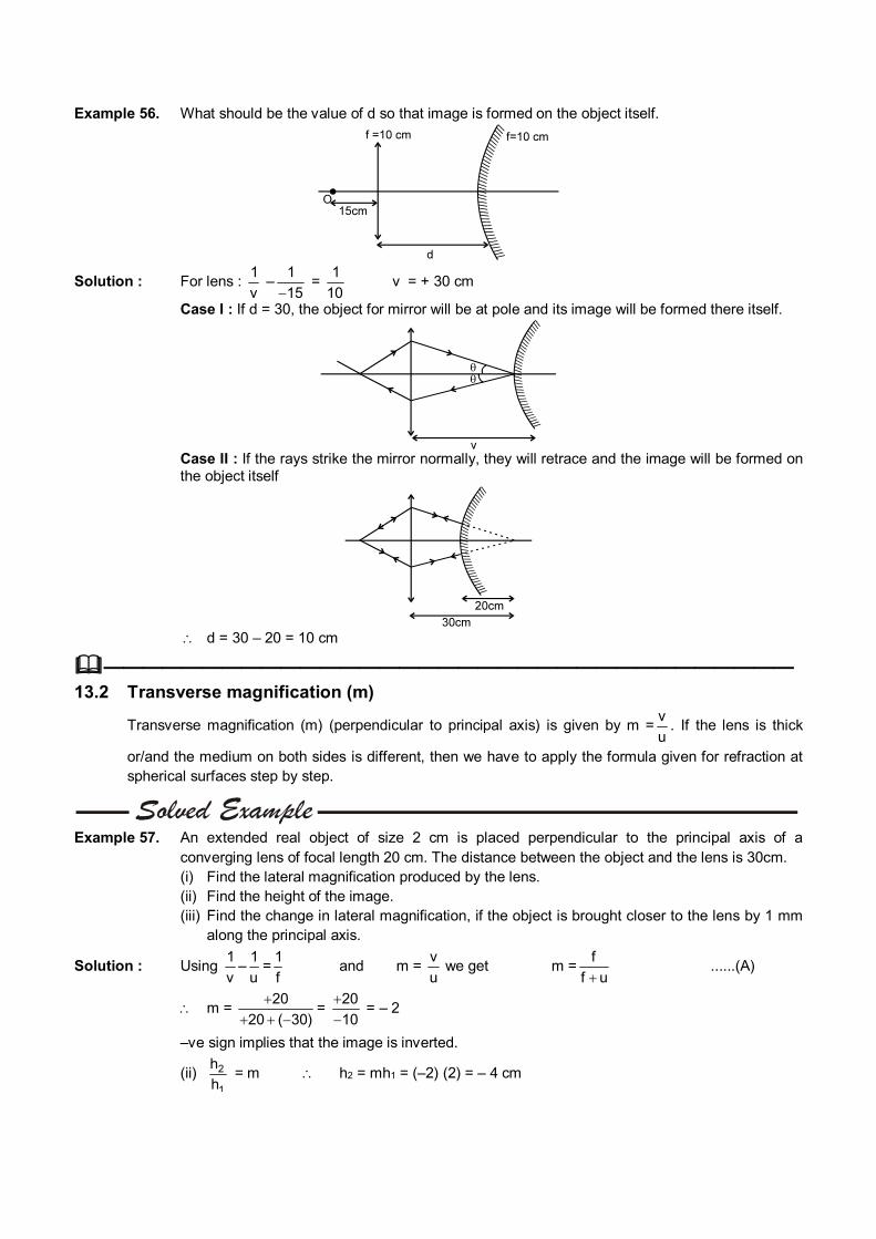
Example 56. What should be the value of d so that image is formed on the object itself.
Solution : For lens : 1
v –
1
15 =
1
10 v = + 30 cm
Case I : If d = 30, the object for mirror will be at pole and its image will be formed there itself.
Case II : If the rays strike the mirror normally, they will retrace and the image will be formed on
the object itself
d = 30 – 20 = 10 cm
——————————————————————————————————— 13.2 Transverse magnification (m)
Transverse magnification (m) (perpendicular to principal axis) is given by m =v
u. If the lens is thick
or/and the medium on both sides is different, then we have to apply the formula given for refraction at spherical surfaces step by step.
Example 57. An extended real object of size 2 cm is placed perpendicular to the principal axis of a
converging lens of focal length 20 cm. The distance between the object and the lens is 30cm. (i) Find the lateral magnification produced by the lens. (ii) Find the height of the image. (iii) Find the change in lateral magnification, if the object is brought closer to the lens by 1 mm
along the principal axis.
Solution : Using 1
v–
1
u=
1
f and m =
v
u we get m =
f
f u ......(A)
m = 20
20 ( 30)
= 20
10
= – 2
–ve sign implies that the image is inverted.
(ii) 2
1
h
h = m h2 = mh1 = (–2) (2) = – 4 cm
(iii) Differentiating (A) we get
dm = 2
f
(f u)
du = 2
(20)
( 10)
(0.1) =2
100
= –.02
Note that the method of differential is valid only when changes are small.
Alternate method : u (after displacing the object) = –(30 + 0.1) = – 29.9 cm
Applying the formula m = f
f u
m = 20
20 ( 29.9) = – 2.02
change in ‘m’ = – 0.02. Since in this method differential is not used, this method can be used for any changes, small or large.
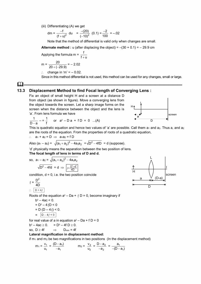
——————————————————————————————————— 13.3 Displacement Method to find Focal length of Converging Lens : Fix an object of small height H and a screen at a distance D
from object (as shown in figure). Move a converging lens from the object towards the screen. Let a sharp image forms on the screen when the distance between the object and the lens is ‘a’. From lens formula we have
1
D a – =
1
f or a2 – D a + f D = 0 ...(A)
This is quadratic equation and hence two values of ‘a’ are possible. Call them a1 and a2. Thus a, and a2 are the roots of the equation. From the properties of roots of a quadratic equation,
a1 + a2 = D a1a2 = f D
Also (a1 – a2) = 21 2 1 2(a a ) 4a a = 2D 4fD = d (suppose).
‘d’ physically means the separation between the two position of lens. The focal length of lens in terms of D and d.
so, a1 – a2 = 21 2 1 2(a a ) 4a a
2D 4fd = d
condition, d = 0, i.e. the two position coincide
= 2D
4D
a
D
L
H
(D-a)screen
Roots of the equation a2 – Da + D = 0, become imaginary if b2 – 4ac < 0. = D2 – 4D < 0 = D (D – 4) < 0.
= for real value of a in equation a2 – Da + f D = 0 b2 – 4ac 0. = D2 – 4f D 0.
so, D 4f Dmin = 4f Lateral magnification in displacement method: if m1 and m2 be two magnifications in two positions (In the displacement method)
m1 = 1
1
v
u = 1
1
(D a )
a
m2 = 2
2
v
u = 2
2
D a
a
= 1
1
a
(D a )
So m1 m2 = 1
1
D a
a
× 1
1
a
(D a ) = 1.
If image length are h1 and h2 in the two cases,
then m1 = – 1h
H m2 = – 2h
H m1 m2 = 1
1 22
h h
H = 1 h1h2 = H2 H = 1 2h h
———————————————————————————————————
14. COMBINATION OF LENSES
The equivalent focal length of thin lenses in contact is given by 321 f
1
f
1
f
1
F
1 ...., where f1, f2, f3 are
focal lengths of individual lenses. If two lenses are separated by a distance d and the incident light rays are parallel to the common principal axis, then the combination behaves like a single lens of focal
length given by the relation 2121 ff
d
f
1
f
1
F
1 and the position of equivalent lens is
1
dF
f
with respect to
2nd lens.
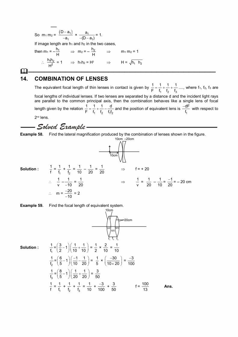
Example 58. Find the lateral magnification produced by the combination of lenses shown in the figure.
Solution : 1
f =
1
1
f +
2
1
f =
1
10 –
1
20 =
1
20 f = + 20
1
v –
1
10 =
1
20
1
v =
1
20 –
1
10=
1
20
= – 20 cm
m = 20
10
= 2
Example 59. Find the focal length of equivalent system.
Solution : 1
1
f=
31
2
1 1
10 10
= 1
2 ×
2
10 =
1
10
2
1
f=
61
5
1 1
10 20
= 1
5 ×
30
10 20
= 3
100
3
1
f=
81
5
1 1
20 20
= 3
50
1
f =
1
1
f +
2
1
f +
3
1
f =
1
10 +
3
100
+
3
50 f =
100
13 Ans.
———————————————————————————————————
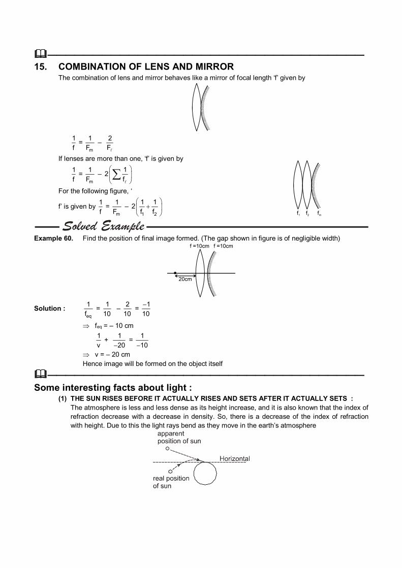
15. COMBINATION OF LENS AND MIRROR The combination of lens and mirror behaves like a mirror of focal length ‘f’ given by
1
f =
m
1
F –
2
F
If lenses are more than one, ‘f’ is given by
1
f =
m
1
F –
12
f
For the following figure, ‘
f’ is given by 1
f =
m
1
F –
1 2
1 12
f f
Example 60. Find the position of final image formed. (The gap shown in figure is of negligible width)
Solution : eq
1
f =
1
10 –
2
10 =
1
10
feq = – 10 cm
1
v +
1
20 =
1
10
v = – 20 cm Hence image will be formed on the object itself
——————————————————————————————————— Some interesting facts about light : (1) THE SUN RISES BEFORE IT ACTUALLY RISES AND SETS AFTER IT ACTUALLY SETS : The atmosphere is less and less dense as its height increase, and it is also known that the index of
refraction decrease with a decrease in density. So, there is a decrease of the index of refraction with height. Due to this the light rays bend as they move in the earth’s atmosphere
(2) THE SUN IS OVAL SHAPED AT THE TIME OF ITS RISE AND SET : The rays diverging from the lower edge of the sun have to cover a greater thickness of air than the
rays from the upper edge. Hence the former are refracted more than the latter, and so the vertical diameter of the sun appears to be a little shorter than the horizontal diameter which remains unchanged.
(3) THE STARS TWINKLE BUT NOT THE PLANETS : The refractive index of atmosphere fluctuates by a small amount due to various reasons. This
causes slight variation in bending of light due to which the apparent position of star also changes, producing the effect of twinkling.
(4) GLASS IS TRANSPARENT, BUT ITS POWDER IS WHITE : When powdered, light is reflected from the surface of innumerable small pieces of glass and so the
powder appears white. Glass transmits most of the incident light and reflects very little hence it appears transparent.
(5) GREASED OR OILED PAPER IS TRANSPARENT, BUT PAPER IS WHITE : The rough surface of paper diffusely reflects incident light and so it appears white. When oiled or
greased, very little reflection takes place and most of the light is allowed to pass and hence it appears transparent.
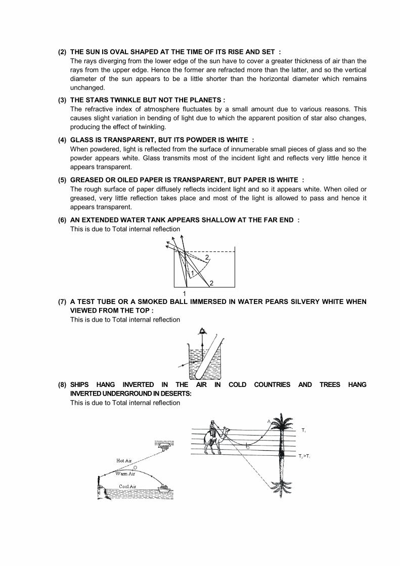
(6) AN EXTENDED WATER TANK APPEARS SHALLOW AT THE FAR END : This is due to Total internal reflection
(7) A TEST TUBE OR A SMOKED BALL IMMERSED IN WATER PEARS SILVERY WHITE WHEN
VIEWED FROM THE TOP : This is due to Total internal reflection
(8) SHIPS HANG INVERTED IN THE AIR IN COLD COUNTRIES AND TREES HANG
INVERTED UNDERGROUND IN DESERTS: This is due to Total internal reflection
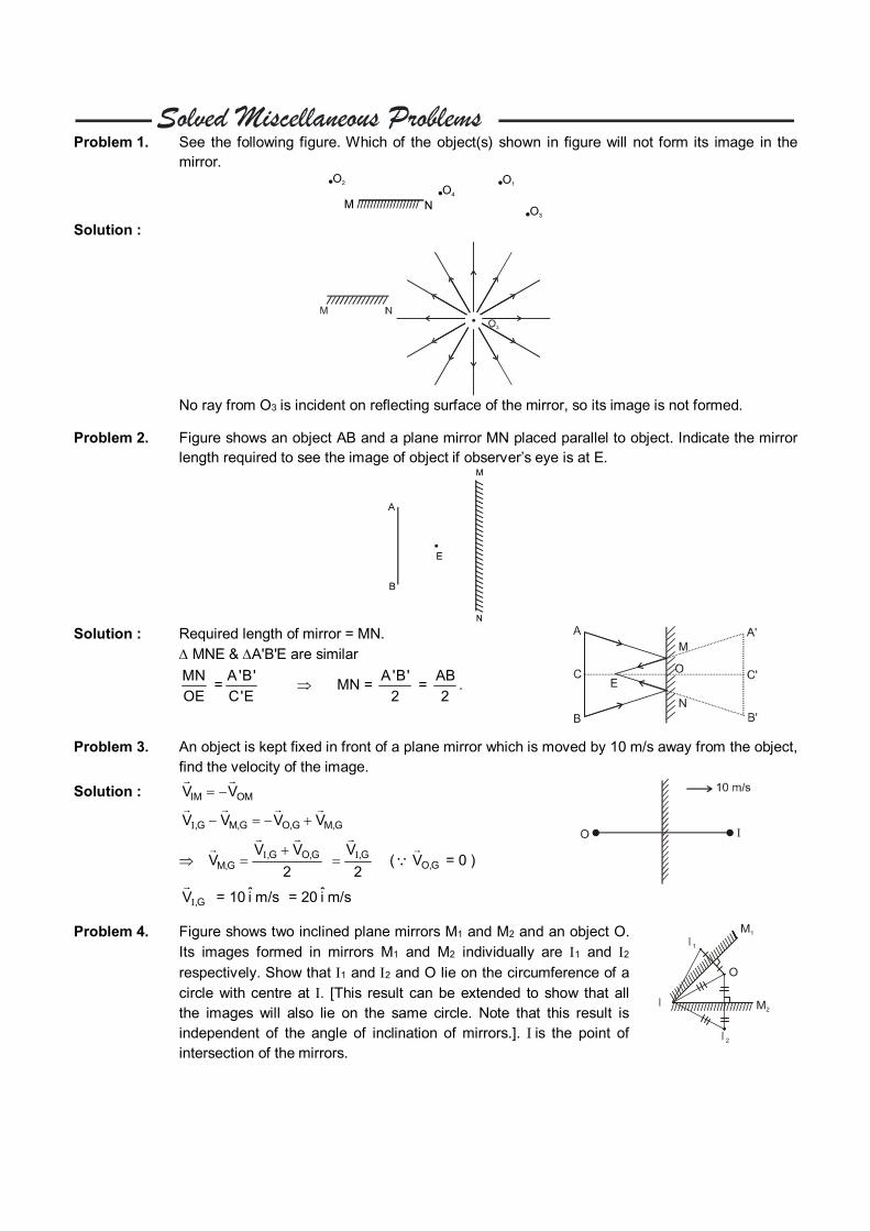
Problem 1. See the following figure. Which of the object(s) shown in figure will not form its image in the
mirror.
Solution :
No ray from O3 is incident on reflecting surface of the mirror, so its image is not formed.
Problem 2. Figure shows an object AB and a plane mirror MN placed parallel to object. Indicate the mirror length required to see the image of object if observer’s eye is at E.
Solution : Required length of mirror = MN. MNE & A'B'E are similar
MN
OE =
A'B'
C'E MN =
A'B'
2 =
AB
2.
Problem 3. An object is kept fixed in front of a plane mirror which is moved by 10 m/s away from the object, find the velocity of the image.
Solution : IM OMV V
,G M,G O,G M,GV V V V
,G O,GM,G
V VV
2
,GV
2
( O,GV
= 0 )
,GV
= 10 i m/s = 20 i m/s
Problem 4. Figure shows two inclined plane mirrors M1 and M2 and an object O. Its images formed in mirrors M1 and M2 individually are 1 and 2 respectively. Show that 1 and 2 and O lie on the circumference of a circle with centre at . [This result can be extended to show that all the images will also lie on the same circle. Note that this result is independent of the angle of inclination of mirrors.]. is the point of intersection of the mirrors.
///////////////////////////////
//////
//////
//////
/////////
O
I 1
I 2
I
M1
M2
Solution : Clearly, OQ and 2Q are congruent and OP and 1P are congruent
So, 1 = O and O = 2
Hence, 1 = O = 2 So, 1 and 2 and O lie on the circumference of a circle with centre .
///////////////////////////////
//////
//////
//////
/////////
O
I 1
I 2
I
M
P
Q
1
M2
Problem 5. Find the position of final image after three successive reflections taking first reflection on m1
Solution : 1st reflection at m1 u = – 15cm f = –10 cm
1 1 1
v u f =
3 2 1
30 30
v = – 30 cm
2nd reflection at plane mirror : u = 5 cm v = – 5 cm For III reflection on curved mirror again : u = – 20 cm
v = uf
u f =
( 20) ( 10)
20 10
= 200
10 = – 20 cm
Image is 20 cm right of m1
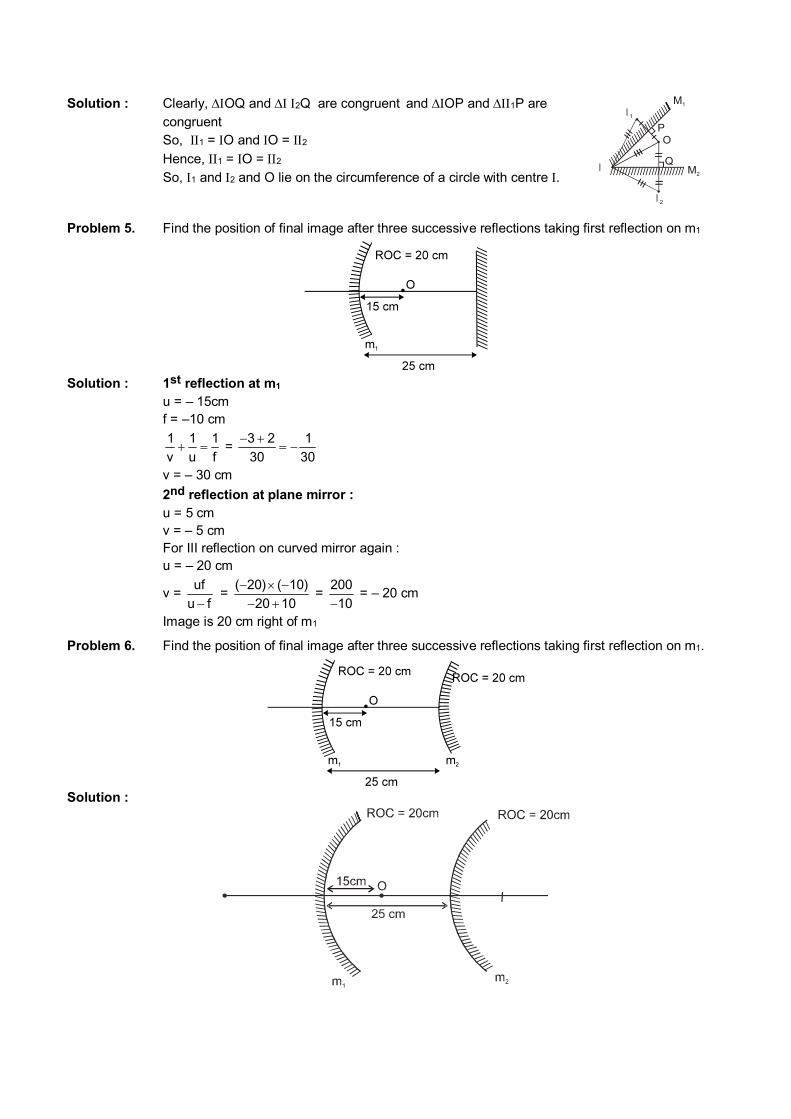
Problem 6. Find the position of final image after three successive reflections taking first reflection on m1.
Solution :
1st reflection at mirror m1 : u = –15 cm, f = – 10cm
1
v =
1
f –
1
u
v = uf
u f=
( 15) ( 10)
( 15) 10
= 150
5cm = –30 cm.
Thus, image is formed at a point 5 cm right of m2 which will act as an object for the reflection at m2
For 2nd reflection at m2 u = 5 cm, f = 10 cm
v = uf
u f =
5 10
5 10
= 50
5 = – 10 cm.
3rd reflection at m1 again. u = –15 cm f = – 10 cm
v = uf
u f =
15 ( 10)
( 15) 10
= –30 cm. Ans.
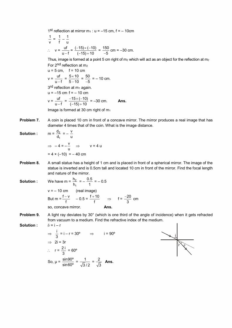
Image is formed at 30 cm right of m1 Problem 7. A coin is placed 10 cm in front of a concave mirror. The mirror produces a real image that has
diameter 4 times that of the coin. What is the image distance.
Solution : m = 2
1
d
d = –
v
u
– 4 = –v
u v = 4 u
= 4 × (–10) = – 40 cm
Problem 8. A small statue has a height of 1 cm and is placed in front of a spherical mirror. The image of the statue is inverted and is 0.5cm tall and located 10 cm in front of the mirror. Find the focal length and nature of the mirror.
Solution : We have m = 2
1
h
h = –
0.5
1 = – 0.5
v = – 10 cm (real image)
But m =f v
f
– 0.5 =
f 10
f
f =
20
3
cm
so, concave mirror. Ans.
Problem 9. A light ray deviates by 30° (which is one third of the angle of incidence) when it gets refracted from vacuum to a medium. Find the refractive index of the medium.
Solution : = i – r
i
3 = i – r = 30º i = 90º
2i = 3r
r = 2 i
3 = 60º
So, µ = sin90º
sin60º =
1
3 / 2 =
2
3 Ans.
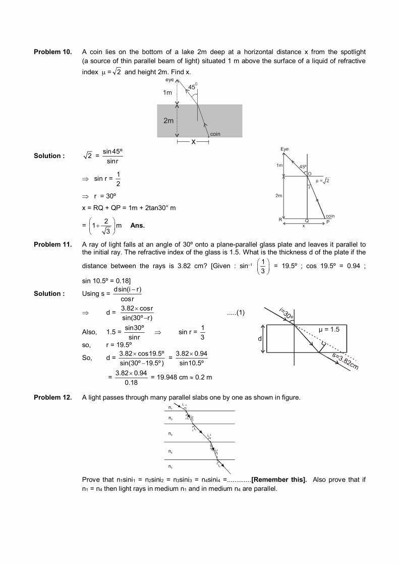
Problem 10. A coin lies on the bottom of a lake 2m deep at a horizontal distance x from the spotlight (a source of thin parallel beam of light) situated 1 m above the surface of a liquid of refractive
index = 2 and height 2m. Find x.
1m
2m
450
xcoin
eye
Solution : 2 = sin45º
sinr
sin r = 1
2
r = 30º
x = RQ + QP = 1m + 2tan30° m
= 2
13
m Ans.
Problem 11. A ray of light falls at an angle of 30º onto a plane-parallel glass plate and leaves it parallel to the initial ray. The refractive index of the glass is 1.5. What is the thickness d of the plate if the
distance between the rays is 3.82 cm? [Given : sin–1 1
3
= 19.5º ; cos 19.5º = 0.94 ;
sin 10.5º = 0.18]
Solution : Using s = dsin(i r)
cosr
d = 3.82 cosr
sin(30º r)
.....(1)
Also, 1.5 = sin30º
sinr sin r =
1
3
so, r = 19.5º
So, d = 3.82 cos19.5º
sin(30º 19.5º )
= 3.82 0.94
sin10.5º
= 3.82 0.94
0.18
= 19.948 cm 0.2 m
µ = 1.5
Problem 12. A light passes through many parallel slabs one by one as shown in figure.
Prove that n1sini1 = n2sini2 = n3sini3 = n4sini4 =.............[Remember this]. Also prove that if
n1 = n4 then light rays in medium n1 and in medium n4 are parallel.
Solution : We have, 1
2
sini
sini = 2
1
n
n
n1 sin i1 = n2 sin i2 ....(i) Similarly n2 sin i2 = n3 sin i3 so on so, n1 sin i1 = n2 sin i2 = n3 sin i3 = .............. n1 sin i1 = n4 sin i4 sin i1 = sin i4 ( n1 = n2) so, i1 = i4
Hence, light rays in medium n1 and in medium n4 are parallel.
Problem 13. An object lies 90 cm in air above water surface .It is viewed from water nearly normally. Find the apparent height of the object.
Solution : d´ = rel
d
n =
i r
d
n /n =
90 cm1
4 /3
= 90 4
3
cm = 120 cm Ans.
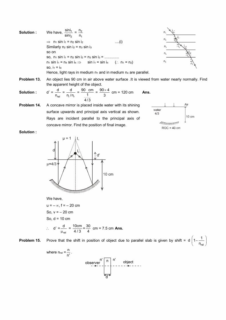
Problem 14. A concave mirror is placed inside water with its shining
surface upwards and principal axis vertical as shown.
Rays are incident parallel to the principal axis of
concave mirror. Find the position of final image.
Solution :
1
2
d'
µ = 1
We have,
u = – , f = – 20 cm
So, v = – 20 cm
So, d = 10 cm
d´ =rel
d
=
10cm
4 / 3=
30
4 cm = 7.5 cm Ans.
Problem 15. Prove that the shift in position of object due to parallel slab is given by shift = rel
1d 1
n
where nrel =n
n'.
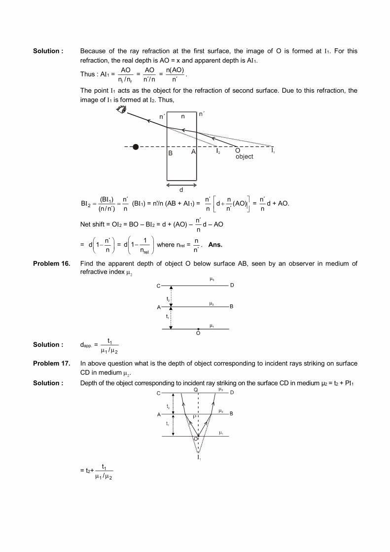
Solution : Because of the ray refraction at the first surface, the image of O is formed at 1. For this
refraction, the real depth is AO = x and apparent depth is A1.
Thus : A1 = i r
AO
n /n =
AO
n´/n =
n(AO)
n´.
The point 1 acts as the object for the refraction of second surface. Due to this refraction, the
image of 1 is formed at 2. Thus,
12
(B ) n´B
(n/ n ) n
(B1) = n'/n (AB + A1) =
n´
n
nd (AO)
n
= n´
nd + AO.
Net shift = O2 = BO – B2 = d + (AO) – n´
nd – AO
= n´
d 1n
= rel
1d 1
n
where nrel =
n
n´. Ans.
Problem 16. Find the apparent depth of object O below surface AB, seen by an observer in medium of refractive index
Solution : dapp. = 1
1 2
t
/
Problem 17. In above question what is the depth of object corresponding to incident rays striking on surface CD in medium .
Solution : Depth of the object corresponding to incident ray striking on the surface CD in medium µ2 = t2 + P1
= t2+ 1
1 2
t
/
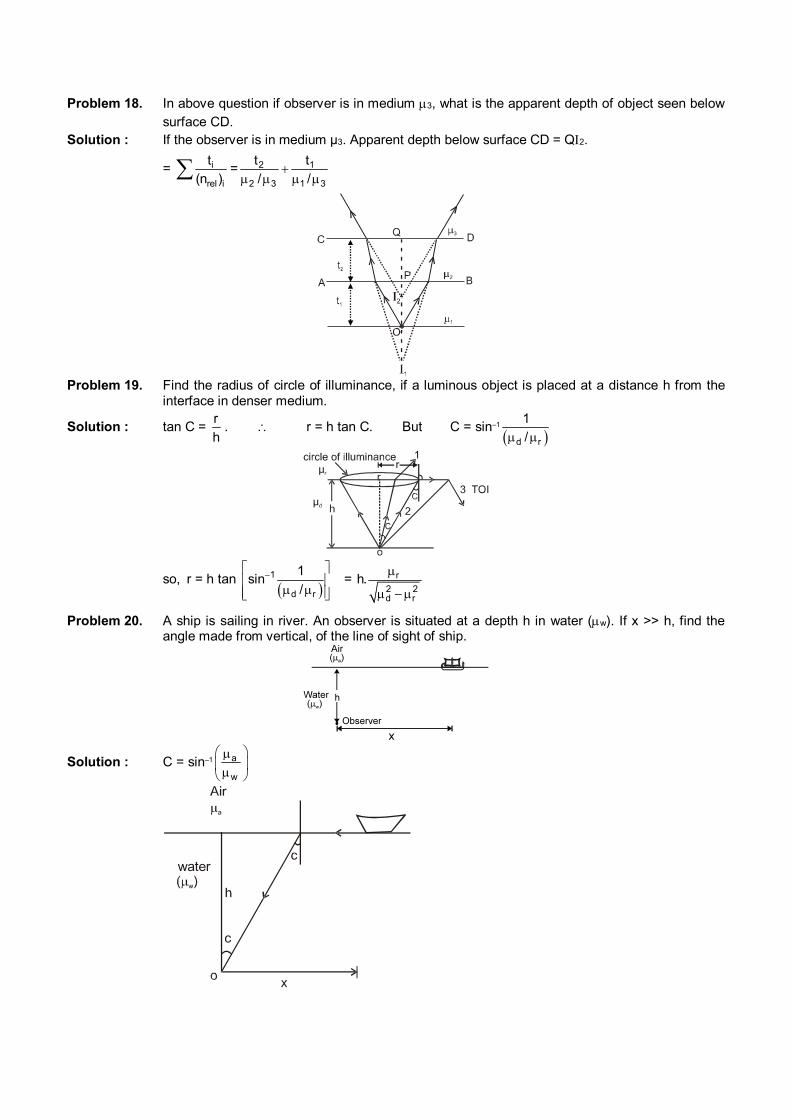
Problem 18. In above question if observer is in medium 3, what is the apparent depth of object seen below surface CD.
Solution : If the observer is in medium µ3. Apparent depth below surface CD = Q2.
= i
rel i
t
(n ) = 2 1
2 3 1 3
t t
/ /
Problem 19. Find the radius of circle of illuminance, if a luminous object is placed at a distance h from the
interface in denser medium.
Solution : tan C = r
h. r = h tan C. But C = sin–1
d r
1
/
so, r = h tan
1
d r
1sin
/
= r
2 2d r
h.
Problem 20. A ship is sailing in river. An observer is situated at a depth h in water (w). If x >> h, find the angle made from vertical, of the line of sight of ship.
Solution : C = sin–1 a
w
c
water
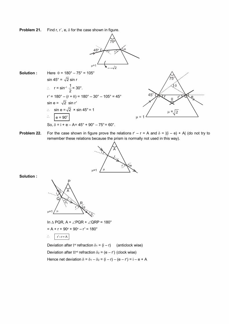
Problem 21. Find r, r´, e, for the case shown in figure.
– – Solution : Here = 180° – 75° = 105°
sin 45° = 2 sin r
r = sin–1 1
2= 30°.
r ' = 180° – (r + ) = 180° – 30° – 105° = 45°
sin e = 2 sin r '
sin e = 2 × sin 45° = 1
e = 90o
So, = i + e – A = 45° + 90° – 75° = 60°.
r'
Problem 22. For the case shown in figure prove the relations r – r = A and = |(i – e) + A| (do not try to remember these relations because the prism is normally not used in this way).
Solution :
In PQR, A + PQR + QRP = 180°
= A + r + 90o + 90o – r ' = 180°
Deviation after st refraction 1 = (i – r) (anticlock wise)
Deviation after nd refraction 2 = (e – r) (clock wise)
Hence net deviation = 1 – 2 = (i – r) – (e – r) = i – e + A
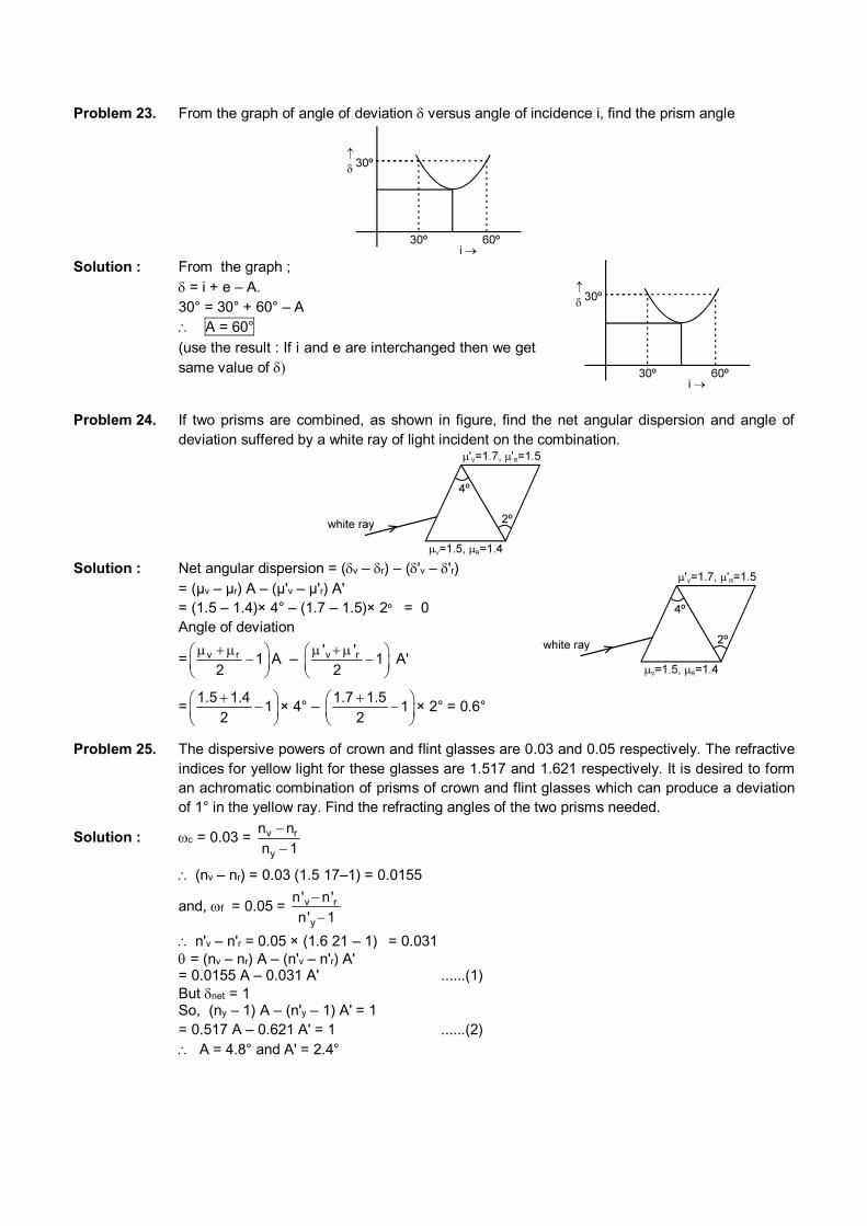
Problem 23. From the graph of angle of deviation versus angle of incidence i, find the prism angle
Solution : From the graph ; = i + e – A. 30° = 30° + 60° – A A = 60°
(use the result : If i and e are interchanged then we get same value of
Problem 24. If two prisms are combined, as shown in figure, find the net angular dispersion and angle of
deviation suffered by a white ray of light incident on the combination.
Solution : Net angular dispersion = (v – r) – ('v – 'r) = (µv – µr) A – (µ'v – µ'r) A' = (1.5 – 1.4)× 4° – (1.7 – 1.5)× 2o = 0 Angle of deviation
= v r 12
A – v r' '1
2
A'
=1.5 1.4
12
× 4° – 1.7 1.5
12
× 2° = 0.6°
Problem 25. The dispersive powers of crown and flint glasses are 0.03 and 0.05 respectively. The refractive indices for yellow light for these glasses are 1.517 and 1.621 respectively. It is desired to form an achromatic combination of prisms of crown and flint glasses which can produce a deviation of 1° in the yellow ray. Find the refracting angles of the two prisms needed.
Solution : c = 0.03 = v r
y
n n
n 1
(nv – nr) = 0.03 (1.5 17–1) = 0.0155
and, f = 0.05 = v r
y
n' n'
n' 1
n'v – n'r = 0.05 × (1.6 21 – 1) = 0.031 = (nv – nr) A – (n'v – n'r) A' = 0.0155 A – 0.031 A' ......(1) But net = 1 So, (ny – 1) A – (n'y – 1) A' = 1 = 0.517 A – 0.621 A' = 1 ......(2)
A = 4.8° and A' = 2.4°
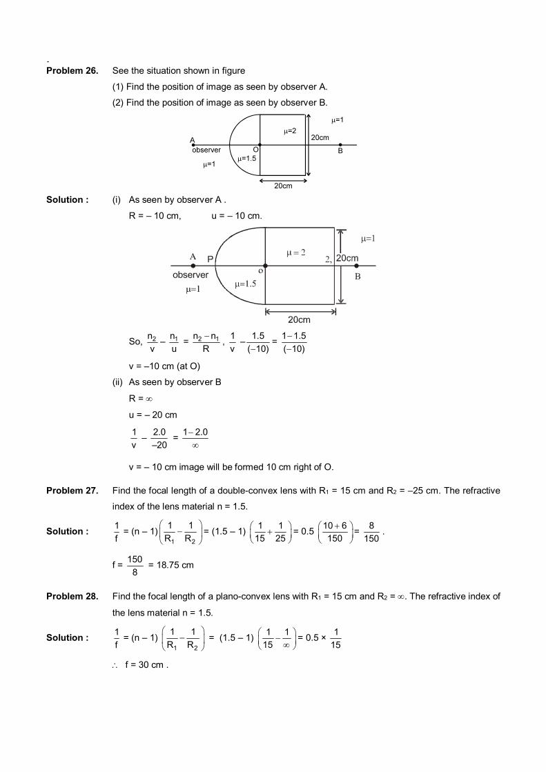
Problem 26. See the situation shown in figure
(1) Find the position of image as seen by observer A.
(2) Find the position of image as seen by observer B.
Solution : (i) As seen by observer A .
R = – 10 cm, u = – 10 cm.
observer
So, 2n
v– 1n
u = 2 1n n
R
,
1
v –
1.5
( 10)=
1 1.5
( 10)
v = –10 cm (at O)
(ii) As seen by observer B
R =
u = – 20 cm
1
v –
2.0
–20 =
1 2.0
v = – 10 cm image will be formed 10 cm right of O.
Problem 27. Find the focal length of a double-convex lens with R1 = 15 cm and R2 = –25 cm. The refractive
index of the lens material n = 1.5.
Solution : 1
f = (n – 1)
1 2
1 1
R R
= (1.5 – 1)
1 1
15 25
= 0.5 10 6
150
= 8
150.
f = 150
8 = 18.75 cm
Problem 28. Find the focal length of a plano-convex lens with R1 = 15 cm and R2 = . The refractive index of
the lens material n = 1.5.
Solution : 1
f = (n – 1)
1 2
1 1
R R
= (1.5 – 1) 1 1
15
= 0.5 × 1
15
f = 30 cm .
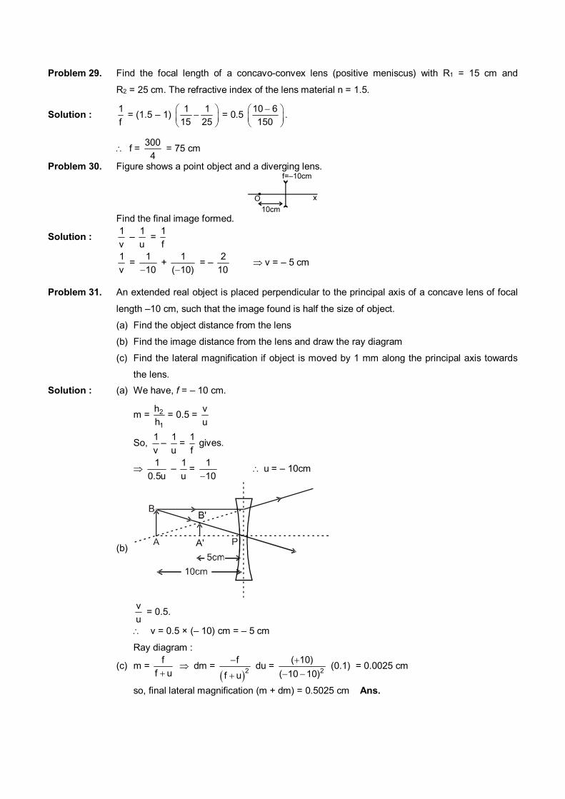
Problem 29. Find the focal length of a concavo-convex lens (positive meniscus) with R1 = 15 cm and
R2 = 25 cm. The refractive index of the lens material n = 1.5.
Solution : 1
f = (1.5 – 1)
1 1
15 25
= 0.5 10 6
150
.
f= 300
4 = 75 cm
Problem 30. Figure shows a point object and a diverging lens.
Find the final image formed.
Solution : 1
v –
1
u =
1
f
1
v =
1
10 +
1
( 10) = –
2
10 v = – 5 cm
Problem 31. An extended real object is placed perpendicular to the principal axis of a concave lens of focal
length –10 cm, such that the image found is half the size of object.
(a) Find the object distance from the lens
(b) Find the image distance from the lens and draw the ray diagram
(c) Find the lateral magnification if object is moved by 1 mm along the principal axis towards
the lens.
Solution : (a) We have, f = – 10 cm.
m = 2
1
h
h = 0.5 =
v
u
So, 1
v–
1
u=
1
f gives.
1
0.5u –
1
u=
1
10 u= – 10cm
(b)
v
u = 0.5.
v = 0.5 × (– 10) cm = – 5 cm
Ray diagram :
(c) m = f
f u dm =
2f
f u
du =
2
( 10)
( 10 10)
(0.1) = 0.0025 cm
so, final lateral magnification (m + dm) = 0.5025 cm Ans.
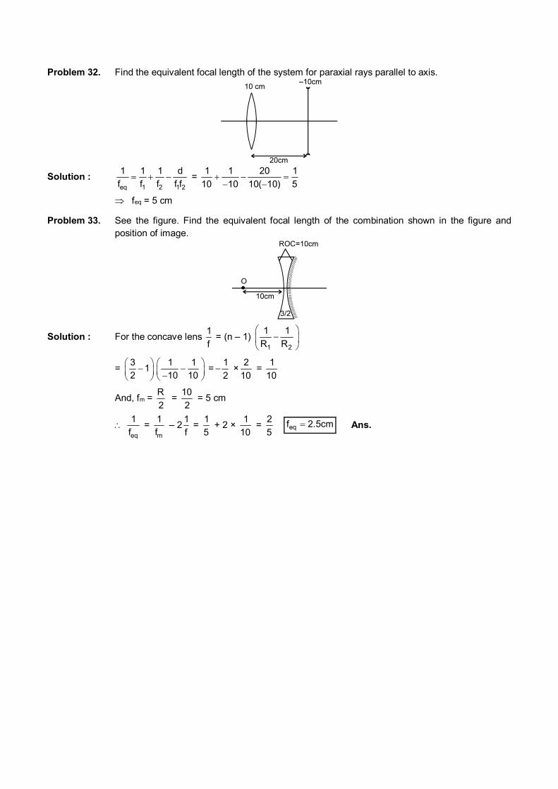
Problem 32. Find the equivalent focal length of the system for paraxial rays parallel to axis.
Solution : eq 1 2 1 2
1 1 1 d
f f f f f =
1 1 20 1
10 10 10( 10) 5
feq = 5 cm
Problem 33. See the figure. Find the equivalent focal length of the combination shown in the figure and position of image.
Solution : For the concave lens 1
f = (n – 1)
1 2
1 1
R R
= 3
12
1 1
10 10
=1
2 ×
2
10 =
1
10
And, fm = R
2 =
10
2 = 5 cm
eq
1
f =
m
1
f – 2
1
f =
1
5 + 2 ×
1
10 =
2
5 cm5.2feq Ans.
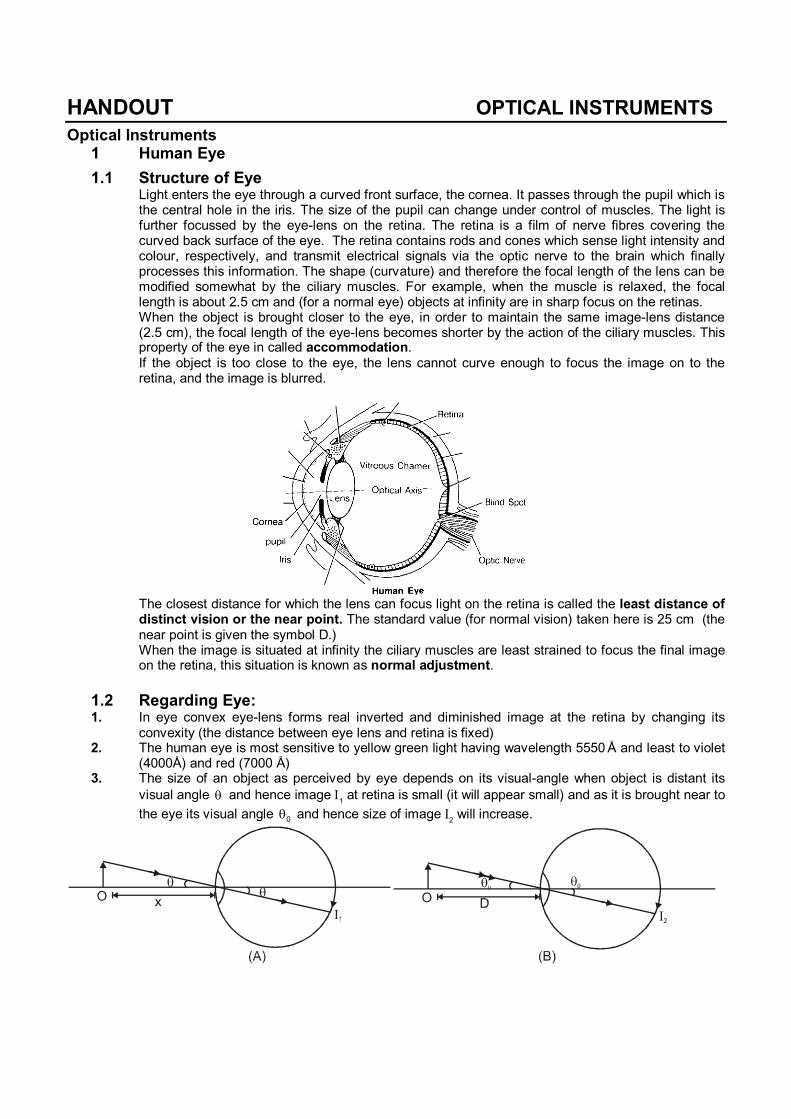
HANDOUT OPTICAL INSTRUMENTS
Optical Instruments 1 Human Eye
1.1 Structure of Eye Light enters the eye through a curved front surface, the cornea. It passes through the pupil which is
the central hole in the iris. The size of the pupil can change under control of muscles. The light is further focussed by the eye-lens on the retina. The retina is a film of nerve fibres covering the curved back surface of the eye. The retina contains rods and cones which sense light intensity and colour, respectively, and transmit electrical signals via the optic nerve to the brain which finally processes this information. The shape (curvature) and therefore the focal length of the lens can be modified somewhat by the ciliary muscles. For example, when the muscle is relaxed, the focal length is about 2.5 cm and (for a normal eye) objects at infinity are in sharp focus on the retinas.
When the object is brought closer to the eye, in order to maintain the same image-lens distance (2.5 cm), the focal length of the eye-lens becomes shorter by the action of the ciliary muscles. This property of the eye in called accommodation.
If the object is too close to the eye, the lens cannot curve enough to focus the image on to the retina, and the image is blurred.
The closest distance for which the lens can focus light on the retina is called the least distance of
distinct vision or the near point. The standard value (for normal vision) taken here is 25 cm (the near point is given the symbol D.)
When the image is situated at infinity the ciliary muscles are least strained to focus the final image on the retina, this situation is known as normal adjustment.
1.2 Regarding Eye: 1. In eye convex eye-lens forms real inverted and diminished image at the retina by changing its
convexity (the distance between eye lens and retina is fixed) 2. The human eye is most sensitive to yellow green light having wavelength 5550 Å and least to violet
(4000Å) and red (7000 Å) 3. The size of an object as perceived by eye depends on its visual-angle when object is distant its
visual angle and hence image 1 at retina is small (it will appear small) and as it is brought near to
the eye its visual angle 0 and hence size of image 2 will increase.
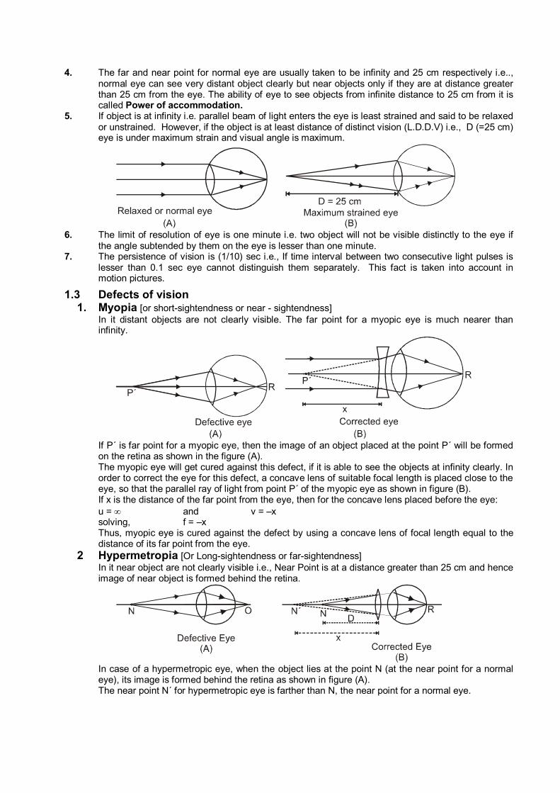
4. The far and near point for normal eye are usually taken to be infinity and 25 cm respectively i.e.., normal eye can see very distant object clearly but near objects only if they are at distance greater than 25 cm from the eye. The ability of eye to see objects from infinite distance to 25 cm from it is called Power of accommodation.
5. If object is at infinity i.e. parallel beam of light enters the eye is least strained and said to be relaxed or unstrained. However, if the object is at least distance of distinct vision (L.D.D.V) i.e., D (=25 cm) eye is under maximum strain and visual angle is maximum.
6. The limit of resolution of eye is one minute i.e. two object will not be visible distinctly to the eye if
the angle subtended by them on the eye is lesser than one minute. 7. The persistence of vision is (1/10) sec i.e., If time interval between two consecutive light pulses is
lesser than 0.1 sec eye cannot distinguish them separately. This fact is taken into account in motion pictures.
1.3 Defects of vision 1. Myopia [or short-sightendness or near - sightendness] In it distant objects are not clearly visible. The far point for a myopic eye is much nearer than
infinity.
If P´ is far point for a myopic eye, then the image of an object placed at the point P´ will be formed
on the retina as shown in the figure (A). The myopic eye will get cured against this defect, if it is able to see the objects at infinity clearly. In
order to correct the eye for this defect, a concave lens of suitable focal length is placed close to the eye, so that the parallel ray of light from point P´ of the myopic eye as shown in figure (B).
If x is the distance of the far point from the eye, then for the concave lens placed before the eye: u = and v = –x solving, f = –x Thus, myopic eye is cured against the defect by using a concave lens of focal length equal to the
distance of its far point from the eye. 2 Hypermetropia [Or Long-sightendness or far-sightendness] In it near object are not clearly visible i.e., Near Point is at a distance greater than 25 cm and hence
image of near object is formed behind the retina.
In case of a hypermetropic eye, when the object lies at the point N (at the near point for a normal
eye), its image is formed behind the retina as shown in figure (A). The near point N´ for hypermetropic eye is farther than N, the near point for a normal eye.
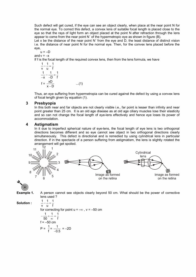
Such defect will get cured, if the eye can see an object clearly, when place at the near point N for the normal eye. To correct this defect, a convex lens of suitable focal length is placed close to the eye so that the rays of light form an object placed at the point N after refraction through the lens appear to come from the near point N´ of the hypermetropic eye as shown in figure (B).
Let x be the distance of the near point N´ from the eye and D, the least distance of distinct vision i.e. the distance of near point N for the normal eye. Then, for the convex lens placed before the eye,
u = –D and v = –x If f is the focal length of the required convex lens, then from the lens formula, we have
1 1 1
v u f
1 1 1
x D f
f = xD
x D ...(1)
Thus, an eye suffering from hypermetropia can be cured against the defect by using a convex lens
of focal length given by equation (1).
3 Presbyopia In this both near and far objects are not clearly visible i.e., far point is lesser than infinity and near
point greater than 25 cm. It is an old age disease as at old age ciliary muscles lose their elasticity and so can not change the focal length of eye-lens effectively and hence eye loses its power of accommodation.
4 Astigmatism In it due to imperfect spherical nature of eye-lens, the focal length of eye lens is two orthogonal
directions becomes different and so eye cannot see object in two orthogonal directions clearly simultaneously. This defect is directional and is remedied by using cylindrical lens in particular direction. If in the spectacle of a person suffering from astigmatism, the lens is slightly rotated the arrangement will get spoiled.
Example 1. A person cannot see objects clearly beyond 50 cm. What should be the power of corrective
lens used ?
Solution : 1 1 1
v u f
for correcting for point u = – , v = –50 cm
1 1 1
50 f
f = –50 cm
P = 1
f=
1
0.5 = –2D
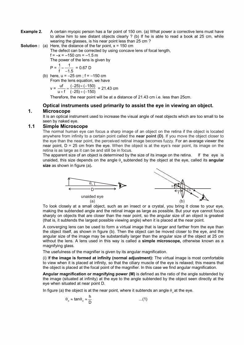
Example 2. A certain myopic person has a far point of 150 cm. (a) What power a corrective lens must have to allow him to see distant objects clearly ? (b) If he is able to read a book at 25 cm, while wearing the glasses, is his near point less than 25 cm ?
Solution : (a) Here, the distance of the far point, x = 150 cm The defect can be corrected by using concave lens of focal length, f = –x = –150 cm = –1.5 m The power of the lens is given by
P = 1 1
f 1.5
= 0.67 D
(b) here, u = –25 cm ; f = –150 cm From the lens equation, we have
v = uf ( 25) ( 150)
u f ( 25) ( 150)
= 21.43 cm
Therefore, the near point will be at a distance of 21.43 cm i.e. less than 25cm.
Optical instruments used primarily to assist the eye in viewing an object. 1. Microscope It is an optical instrument used to increase the visual angle of neat objects which are too small to be
seen by naked eye. 1.1 Simple Microscope The normal human eye can focus a sharp image of an object on the retina if the object is located
anywhere from infinity to a certain point called the near point (D). If you move the object closer to the eye than the near point, the perceived retinal image becomes fuzzy. For an average viewer the near point, D = 25 cm from the eye. When the object is at the eye’s near point, its image on the retina is as large as it can be and still be in focus.
The apparent size of an object is determined by the size of its image on the retina. If the eye is unaided, this size depends on the angle
o subtended by the object at the eye, called its angular
size as shown in figure (a).
To look closely at a small object, such as an insect or a crystal, you bring it close to your eye,
making the subtended angle and the retinal image as large as possible. But your eye cannot focus sharply on objects that are closer than the near point, so the angular size of an object is greatest (that is, it subtends the largest possible viewing angle) when it is placed at the near point.
A converging lens can be used to form a virtual image that is larger and farther from the eye than the object itself, as shown in figure (b). Then the object can be moved closer to the eye, and the angular size of the image may be substantially larger than the angular size of the object at 25 cm without the lens. A lens used in this way is called a simple microscope, otherwise known as a magnifying glass.
The usefulness of the magnifier is given by its angular magnification.
(i) If the image is formed at infinity (normal adjustment): The virtual image is most comfortable to view when it is placed at infinity, so that the ciliary muscle of the eye is relaxed; this means that the object is placed at the focal point of the magnifier. In this case we find angular magnification.
Angular magnification or magnifying power (M) is defined as the ratio of the angle subtended by the image (situated at infinity) at the eye to the angle subtended by the object seen directly at the eye when situated at near point D.
In figure (a) the object is at the near point, where it subtends an angle o at the eye.
o o
htan
D ...(1)
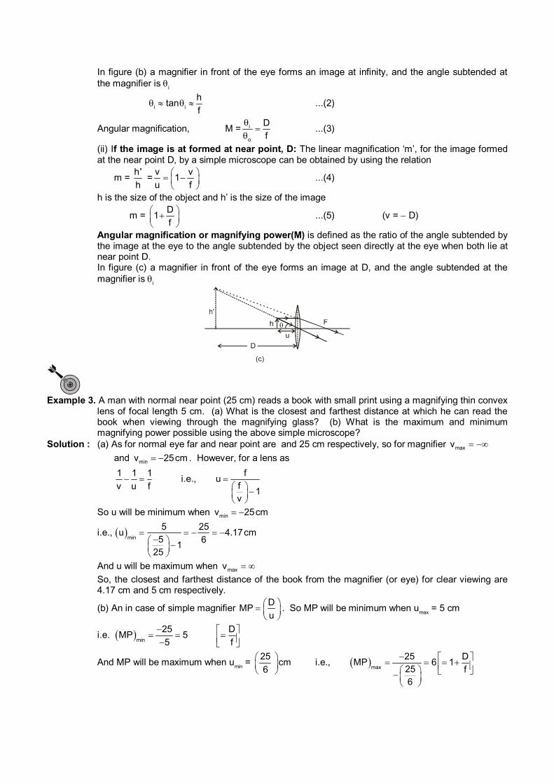
In figure (b) a magnifier in front of the eye forms an image at infinity, and the angle subtended at the magnifier is
i
i i
htan
f ...(2)
Angular magnification, M = i
o
D
f
...(3)
(ii) If the image is at formed at near point, D: The linear magnification ‘m’, for the image formed at the near point D, by a simple microscope can be obtained by using the relation
m = h'
h =
v v1
u f
...(4)
h is the size of the object and h’ is the size of the image
m = D
1f
...(5) (v = D)
Angular magnification or magnifying power(M) is defined as the ratio of the angle subtended by the image at the eye to the angle subtended by the object seen directly at the eye when both lie at near point D.
In figure (c) a magnifier in front of the eye forms an image at D, and the angle subtended at the magnifier is
i
Example 3. A man with normal near point (25 cm) reads a book with small print using a magnifying thin convex
lens of focal length 5 cm. (a) What is the closest and farthest distance at which he can read the book when viewing through the magnifying glass? (b) What is the maximum and minimum magnifying power possible using the above simple microscope?
Solution : (a) As for normal eye far and near point are and 25 cm respectively, so for magnifier maxv and minv 25cm . However, for a lens as
1 1 1
v u f i.e.,
fu
f1
v
So u will be minimum when minv 25cm
i.e., min
5 25u 4.17cm
5 61
25
And u will be maximum when maxv
So, the closest and farthest distance of the book from the magnifier (or eye) for clear viewing are 4.17 cm and 5 cm respectively.
(b) An in case of simple magnifier D
MPu
. So MP will be minimum when umax
= 5 cm
i.e. min
25MP 5
5
D
f
And MP will be maximum when umin
= 25
cm6
i.e., max
25 DMP 6 1
25 f6
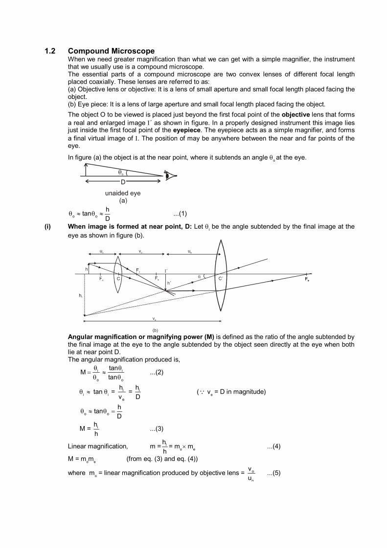
1.2 Compound Microscope When we need greater magnification than what we can get with a simple magnifier, the instrument
that we usually use is a compound microscope. The essential parts of a compound microscope are two convex lenses of different focal length
placed coaxially. These lenses are referred to as: (a) Objective lens or objective: It is a lens of small aperture and small focal length placed facing the
object. (b) Eye piece: It is a lens of large aperture and small focal length placed facing the object.
The object O to be viewed is placed just beyond the first focal point of the objective lens that forms a real and enlarged image ´ as shown in figure. In a properly designed instrument this image lies just inside the first focal point of the eyepiece. The eyepiece acts as a simple magnifier, and forms a final virtual image of . The position of may be anywhere between the near and far points of the eye.
In figure (a) the object is at the near point, where it subtends an angle o at the eye.
o o
htan
D ...(1)
(i) When image is formed at near point, D: Let i be the angle subtended by the final image at the
eye as shown in figure (b).
Angular magnification or magnifying power (M) is defined as the ratio of the angle subtended by
the final image at the eye to the angle subtended by the object seen directly at the eye when both lie at near point D.
The angular magnification produced is,
i
o
M
i
o
tan
tan
...(2)
i tan
i = i
e
h
v = ih
D ( v
e = D in magnitude)
o o
htan
D
M = ih
h ...(3)
Linear magnification, m = ih
h= m
o m
e ...(4)
M = mom
e (from eq. (3) and eq. (4))
where mo = linear magnification produced by objective lens = o
o
v
u ...(5)
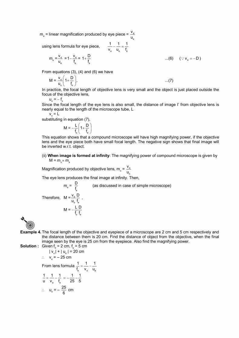
me = linear magnification produced by eye piece = e
e
v
u
using lens formula for eye piece, e e e
1 1 1
v u f
me = e
e
v
u = e
e
v1
f =
e
D1
f ...(6) ( ev D )
From equations (3), (4) and (6) we have
M = o
o e
v D1
u f
, ...(7)
In practice, the focal length of objective lens is very small and the object is just placed outside the focus of the objective lens,
uo = f
o
Since the focal length of the eye lens is also small, the distance of image I’ from objective lens is nearly equal to the length of the microscope tube, L
vo = L
substituting in equation (7),
M = o e
L D1
f f
This equation shows that a compound microscope will have high magnifying power, if the objective lens and the eye piece both have small focal length. The negative sign shows that final image will be inverted w.r.t. object.
(ii) When image is formed at infinity: The magnifying power of compound microscope is given by M = m
o m
e
Magnification produced by objective lens, m
o = o
o
v
u
The eye lens produces the final image at infinity. Then,
me =
e
D
f (as discussed in case of simple microscope)
Therefore, M = o
o e
v D
u f ,
M = o e
L D
f f
Example 4. The focal length of the objective and eyepiece of a microscope are 2 cm and 5 cm respectively and
the distance between them is 20 cm. Find the distance of object from the objective, when the final image seen by the eye is 25 cm from the eyepiece. Also find the magnifying power.
Solution : Given f0 = 2 cm, f
e = 5 cm
| vo | + | u
e | = 20 cm
ve = – 25 cm
From lens formula e o e
1 1 1
f v u
e e
1 1 1 1 1
u v f 25 5
ue = –
25
6 cm
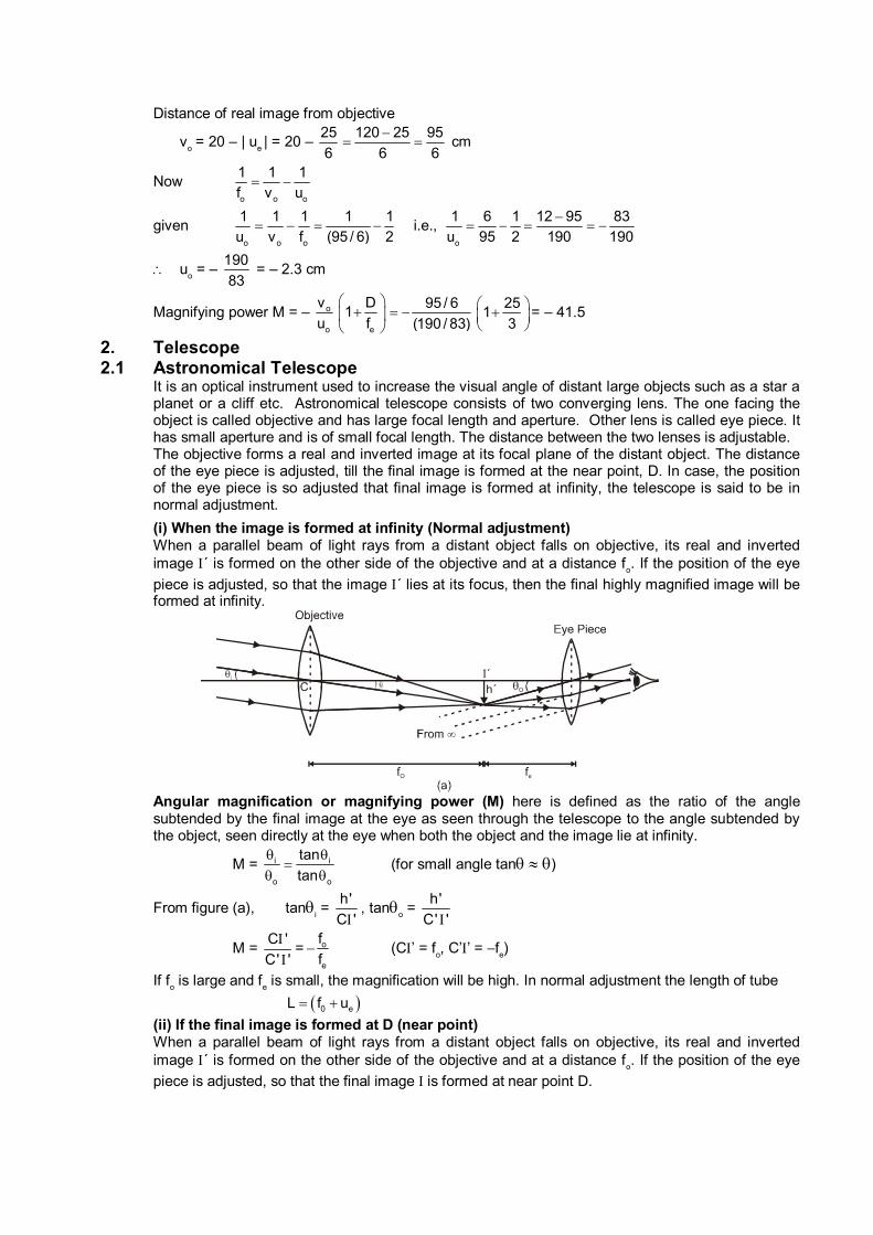
Distance of real image from objective
vo = 20 – | u
e | = 20 –
25
6
120 25 95
6 6
cm
Now o o o
1 1 1
f v u
given o o o
1 1 1 1 1
u v f (95 / 6) 2 i.e.,
o
1 6 1 12 95 83
u 95 2 190 190
uo = –
190
83 = – 2.3 cm
Magnifying power M = – o
o
v
u e
D1
f
95 / 6
(190 / 83)
251
3
= – 41.5
2. Telescope 2.1 Astronomical Telescope It is an optical instrument used to increase the visual angle of distant large objects such as a star a
planet or a cliff etc. Astronomical telescope consists of two converging lens. The one facing the object is called objective and has large focal length and aperture. Other lens is called eye piece. It has small aperture and is of small focal length. The distance between the two lenses is adjustable.
The objective forms a real and inverted image at its focal plane of the distant object. The distance of the eye piece is adjusted, till the final image is formed at the near point, D. In case, the position of the eye piece is so adjusted that final image is formed at infinity, the telescope is said to be in normal adjustment.
(i) When the image is formed at infinity (Normal adjustment) When a parallel beam of light rays from a distant object falls on objective, its real and inverted
image ´ is formed on the other side of the objective and at a distance fo. If the position of the eye
piece is adjusted, so that the image ´ lies at its focus, then the final highly magnified image will be formed at infinity.
Angular magnification or magnifying power (M) here is defined as the ratio of the angle
subtended by the final image at the eye as seen through the telescope to the angle subtended by the object, seen directly at the eye when both the object and the image lie at infinity.
M = i i
o o
tan
tan
(for small angle tan )
From figure (a), tani =
h'
C ', tan
o =
h'
C' '
M = C '
C' '
= o
e
f
f (C’ = f
o, C’’ = f
e)
If fo is large and f
e is small, the magnification will be high. In normal adjustment the length of tube
0 eL f u
(ii) If the final image is formed at D (near point) When a parallel beam of light rays from a distant object falls on objective, its real and inverted
image ´ is formed on the other side of the objective and at a distance fo. If the position of the eye
piece is adjusted, so that the final image is formed at near point D.
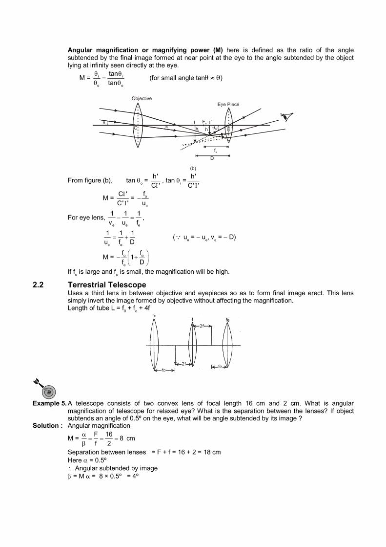
Angular magnification or magnifying power (M) here is defined as the ratio of the angle subtended by the final image formed at near point at the eye to the angle subtended by the object lying at infinity seen directly at the eye.
M = i i
o o
tan
tan
(for small angle tan )
From figure (b), tan o =
h'
C ', tan
i =
h'
C' '
M = C '
C' '
= o
e
f
u
For eye lens, e e e
1 1 1
v u f ,
e e
1 1 1
u f D ( u
e = u
e, v
e = D)
M = o e
e
f f1
f D
If fo is large and f
e is small, the magnification will be high.
2.2 Terrestrial Telescope Uses a third lens in between objective and eyepieces so as to form final image erect. This lens
simply invert the image formed by objective without affecting the magnification. Length of tube L = f
0 + f
e + 4f
Example 5. A telescope consists of two convex lens of focal length 16 cm and 2 cm. What is angular
magnification of telescope for relaxed eye? What is the separation between the lenses? If object subtends an angle of 0.5º on the eye, what will be angle subtended by its image ?
Solution : Angular magnification
M = F 16
8f 2
cm
Separation between lenses = F + f = 16 + 2 = 18 cm Here = 0.5º Angular subtended by image = M = 8 × 0.5º = 4º
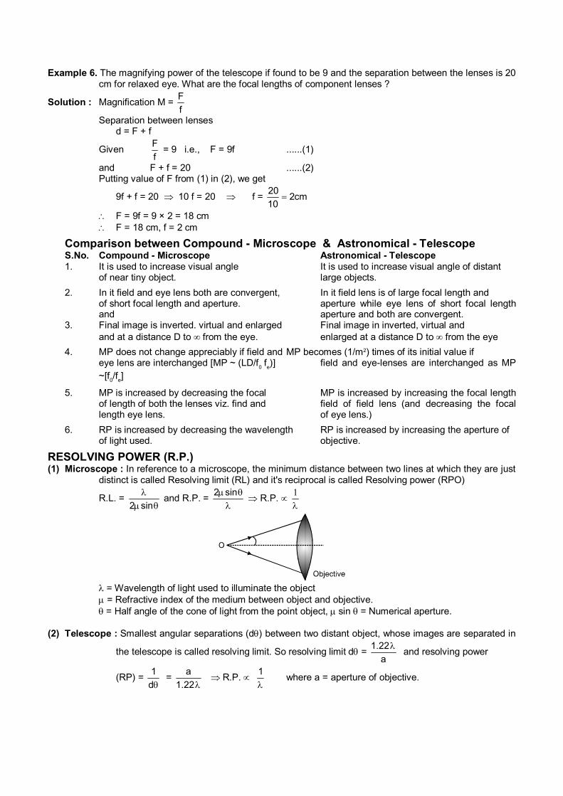
Example 6. The magnifying power of the telescope if found to be 9 and the separation between the lenses is 20 cm for relaxed eye. What are the focal lengths of component lenses ?
Solution : Magnification M = F
f
Separation between lenses d = F + f
Given F
f = 9 i.e., F = 9f ......(1)
and F + f = 20 ......(2) Putting value of F from (1) in (2), we get
9f + f = 20 10 f = 20 f = 20
2cm10
F = 9f = 9 × 2 = 18 cm F = 18 cm, f = 2 cm
Comparison between Compound - Microscope & Astronomical - Telescope S.No. Compound - Microscope Astronomical - Telescope 1. It is used to increase visual angle It is used to increase visual angle of distant of near tiny object. large objects.
2. In it field and eye lens both are convergent, In it field lens is of large focal length and of short focal length and aperture. aperture while eye lens of short focal length
and aperture and both are convergent. 3. Final image is inverted. virtual and enlarged Final image in inverted, virtual and and at a distance D to from the eye. enlarged at a distance D to from the eye
4. MP does not change appreciably if field and MP becomes (1/m2) times of its initial value if eye lens are interchanged [MP ~ (LD/f
0 f
e)] field and eye-lenses are interchanged as MP
~[f0/f
e]
5. MP is increased by decreasing the focal MP is increased by increasing the focal length of length of both the lenses viz. find and field of field lens (and decreasing the focal length eye lens. of eye lens.)
6. RP is increased by decreasing the wavelength RP is increased by increasing the aperture of of light used. objective.
RESOLVING POWER (R.P.) (1) Microscope : In reference to a microscope, the minimum distance between two lines at which they are just
distinct is called Resolving limit (RL) and it's reciprocal is called Resolving power (RPO)
R.L. = 2 sin
and R.P. = 2 sin
R.P.
1
= Wavelength of light used to illuminate the object = Refractive index of the medium between object and objective. = Half angle of the cone of light from the point object, sin = Numerical aperture.
(2) Telescope : Smallest angular separations (d) between two distant object, whose images are separated in
the telescope is called resolving limit. So resolving limit d = 1.22
a
and resolving power
(RP) = 1
d=
a
1.22R.P.
1
where a = aperture of objective.
Example 7 Find the half angular width of the central bright maximum in the Fraunhofer diffraction pattern of a slit of width 12 × 10–5 cm when the slit is illuminated by monochromatic light of wavelength 6000Å.
Solution. Here sina
Where is half angular width of the central maximum. A = 12 × 10–5 cm, = 6000Å = 6 × 10⁻⁵cm.
5
5
6 10sin 0.50
a 12 10
or = 30°
Example 8 In Fraunhofer diffraction due to a narrow slit a screen is placed 2 m away from the lens to obtain the pattern. If the slit width is 0.2 mm and the first minima lie 5 mm on either side of the central maximum, find the wavelength of light.
Solution. In the case of Fraunhofer diffraction at a narrow rectangular aperature, a sin = n
n = 1 a sin =
sin = x
D
ax
D
ax
D
Here a = 0.2 mm = 00.2cm x = 5 mm = 0.5 cm D = 2m = 200 cm
0.02 0.5
200
= 5 × 10⁻⁵ cm L = 5000Å Example 9. Light of wavelength 6000Å is incident on a slit of width 0.30 nm. The screen is placed 2m from
the slit. Find : (a) the position of the first dark fringe and (b) the width of the central bright fringe.
Solution. The first dark fringe is on either side of the central bright fringe. Here, n = ±1, D = 2m = 6000Å = 6 × 10⁻⁷m
sin = x
D
a = 0.30 mm = 3 × 10⁻⁴ m a sin = n
(a) x = n D
a
x = ± 7
4
1 6 10 2
3 10
x = ±4 × 10⁻³m The positive and negative signs correspond to the dark fringes on either side of the central
bright fringe. (b) The width of the central bright fringe, y = 2x = 2 × 4 × 10–3 = 8 × 10⁻³ m = 8 mm
Example 10. A signal slit of width 0.14 mm is illuminated normally by monochromatic light and diffraction bands are observed on a screen 2m away. If the centre of the second dark band is 1.6 cm from the middle of the central bright band, deduce the wavelength of light used.
Solution. In the case of Fraunhofer diffraction at a narrow rectangular slit, a sin = n Here gives the directions of the minimum n = 2 , = ? a = 0.14 mm = 0.14 × 10⁻³ m D = 2 m x = 1.6 cm = 1.6 × 10⁻² m
sin = x n
D a
=
xa
nD
= 2 31.6 10 0.14 10
2.2
= 5.6 × 10⁻⁷ m = 5600Å
Example 11. A screen is placed 2m away from a narrow slit which is illuminated with light of wavelength
6000Å. If the first minimum lies 50 mm on either side of the central maximum, calculate the slit width.
Solution. In the case of Fraunhofer diffraction at a narrow slit, a sin = n
sin = x
D
ax
D = n
Here width of the slit = a = ? x = 5 mm = 5 × 10⁻³ m D = 2m = 6000Å = 6 × 10⁻⁷m n = 1
a = n D
x
a = 7
3
1 6 10 2
5 10
a = 2.4 × 10⁻⁴ m a = 0.24 mm Example 12. Find the angular width of the central bright maximum in the Fraunhofer diffraction pattern of a
slit of width 12 × 10–5 cm when the slit is illuminated by monochromatic light of wavelength 6000Å.
Solution. Here sin = a
where is the half angular width of the central maximum
a = 12 × 10–5 cm = 12 × 10–7 m
= 6000Å = 6 × 10⁻⁷ m
sin = 7
7
6 10
12 10
= 0.5
= 30°
Angular width of the central maximum.
2 = 60°
Example 13. Diffraction pattern of a signal slit of width 0.5 cm is formed by a lens of focal length 40 cm. Calculate the distance between the first dark and the next bright fringe from the axis. Wave length = 4890Å.
Solution. For minimum intensity a sin
n = n
sin n = 1x
f ' n = 1
1x
f a
Here = 4890Å = 4890 × 10–10 m a = 0.5 cm = 5 × 10⁻³ m f = 40 cm = 0.4 m
x1 =
f
a
x1 =
x1 = 3.912 × 10⁻⁵ m
For secondary maximum
a sin n =
10
3
0.4 4890 10
5 10
For the first secondary maximum n = 1
sin n =
(2n 1)
2
2x 3
f 2a
x2 =
3 f
2a
x2 =
10
5
3 4890 10 0.4
2 5 10
x2 = 5.868 × 10⁻⁵ m
Difference, x
2 – x
1 = 5.868 × 10⁻⁵ – 3.912 × 10–5
= 1.956 × 10⁻⁵ m = 1.596 × 10⁻² mm Example 14. Find the separation of two points on the moon that can be resolved by a 500 cm telescope. The
distance of the moon is 3.8 × 10⁵ km. The eye is most sensitive to light of wavelength 5500 Å.
Solution. The limit of resolution of a telescope is given by
d = 1.22
a
Here = 5500 × 10–8cm, a = 500 cm
d = 81.22 5500 10
500
d = 13.42 × 10⁻⁸ radian
Let the distance between the two point be x
d = x
R
Here R = 3.8 × 1010 cm
x = R.d
= 3.8 × 1010 × 13.42 × 10–8
= 50.996 × 102 cm = 50.996 meters
Example 15. Calculate the aperture of the objective of a telescope which may by used to resolve stars
separated by 4.88 × 10⁻⁶ radian for light of wavelength 6000Å
Solution. Here = 6000Å = 6 × 10⁻⁵ cm, = 4.88 × 10⁻⁶ radian
D = ?
= 1.22
or D = 5
8
1.22 1.22 6 1015cm
4.88 10
Example 16. Two pin holes 1.5 mm apart are placed in front of a source of light of wavelength 5.5 × 10⁻⁵ cm
and seen through a telescope with its objectives stopped down to a diameter of 0.4 cm. Find
the maximum distance from the telescope at which the pin holes can be resolved.
Solution. Here, = 5.5 × 10⁻⁵ cm
a = 0.4 cm
d = 1.22
a
Also d = x
d
x = 1.5 mm = 0.15 cm
x 1.22
d a
d = xa
1.22
d = 5
0.15 0.4cm
1.22 5.5 10
d = 894.2 cm = 8.942 m
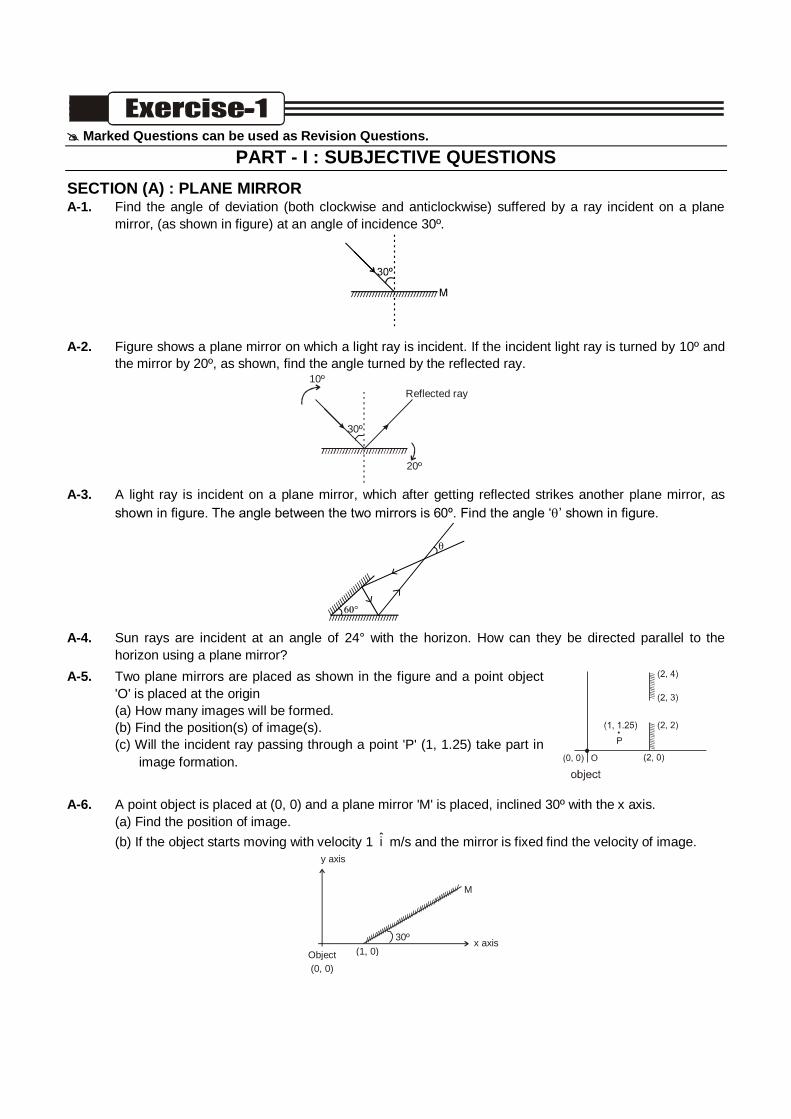
Marked Questions can be used as Revision Questions.
PART - I : SUBJECTIVE QUESTIONS
SECTION (A) : PLANE MIRROR A-1. Find the angle of deviation (both clockwise and anticlockwise) suffered by a ray incident on a plane
mirror, (as shown in figure) at an angle of incidence 30º.
A-2. Figure shows a plane mirror on which a light ray is incident. If the incident light ray is turned by 10º and
the mirror by 20º, as shown, find the angle turned by the reflected ray.
30º
20º
Reflected ray 10º
A-3. A light ray is incident on a plane mirror, which after getting reflected strikes another plane mirror, as
shown in figure. The angle between the two mirrors is 60º. Find the angle ‘’ shown in figure.
A-4. Sun rays are incident at an angle of 24° with the horizon. How can they be directed parallel to the
horizon using a plane mirror?
A-5. Two plane mirrors are placed as shown in the figure and a point object
'O' is placed at the origin
(a) How many images will be formed.
(b) Find the position(s) of image(s).
(c) Will the incident ray passing through a point 'P' (1, 1.25) take part in
image formation.
A-6. A point object is placed at (0, 0) and a plane mirror 'M' is placed, inclined 30º with the x axis.
(a) Find the position of image.
(b) If the object starts moving with velocity 1 i m/s and the mirror is fixed find the velocity of image.
(1, 0) Object (0, 0)
·
/ / / / / / / / / / / / / / / / / / / / / / / / / / / / / / / / / / / / / / / / / / / /
M
30º x axis
y axis
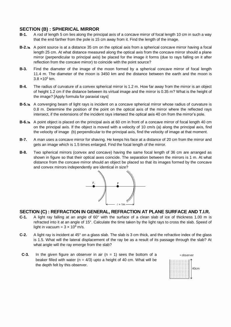
SECTION (B) : SPHERICAL MIRROR
B-1. A rod of length 5 cm lies along the principal axis of a concave mirror of focal length 10 cm in such a way
that the end farther from the pole is 15 cm away from it. Find the length of the image.
B-2. A point source is at a distance 35 cm on the optical axis from a spherical concave mirror having a focal
length 25 cm. At what distance measured along the optical axis from the concave mirror should a plane
mirror (perpendicular to principal axis) be placed for the image it forms (due to rays falling on it after
reflection from the concave mirror) to coincide with the point source?
B-3. Find the diameter of the image of the moon formed by a spherical concave mirror of focal length
11.4 m. The diameter of the moon is 3450 km and the distance between the earth and the moon is
3.8 ×10⁵ km.
B-4. The radius of curvature of a convex spherical mirror is 1.2 m. How far away from the mirror is an object
of height 1.2 cm if the distance between its virtual image and the mirror is 0.35 m? What is the height of
the image? [Apply formula for paraxial rays]
B-5. A converging beam of light rays is incident on a concave spherical mirror whose radius of curvature is
0.8 m. Determine the position of the point on the optical axis of the mirror where the reflected rays
intersect, if the extensions of the incident rays intersect the optical axis 40 cm from the mirror’s pole.
B-6. A point object is placed on the principal axis at 60 cm in front of a concave mirror of focal length 40 cm
on the principal axis. If the object is moved with a velocity of 10 cm/s (a) along the principal axis, find
the velocity of image (b) perpendicular to the principal axis, find the velocity of image at that moment.
B-7. A man uses a concave mirror for shaving. He keeps his face at a distance of 20 cm from the mirror and
gets an image which is 1.5 times enlarged. Find the focal length of the mirror.
B-8. Two spherical mirrors (convex and concave) having the same focal length of 36 cm are arranged as
shown in figure so that their optical axes coincide. The separation between the mirrors is 1 m. At what
distance from the concave mirror should an object be placed so that its images formed by the concave
and convex mirrors independently are identical in size?
SECTION (C) : REFRACTION IN GENERAL, REFRACTION AT PLANE SURFACE AND T.I.R. C-1. A light ray falling at an angle of 60° with the surface of a clean slab of ice of thickness 1.00 m is
refracted into it at an angle of 15°. Calculate the time taken by the light rays to cross the slab. Speed of
light in vacuum = 3 × 10⁸ m/s.
C-2. A light ray is incident at 45° on a glass slab. The slab is 3 cm thick, and the refractive index of the glass
is 1.5. What will the lateral displacement of the ray be as a result of its passage through the slab? At
what angle will the ray emerge from the slab?
C-3. In the given figure an observer in air (n = 1) sees the bottom of a
beaker filled with water (n = 4/3) upto a height of 40 cm. What will be
the depth felt by this observer.
40cm
observer
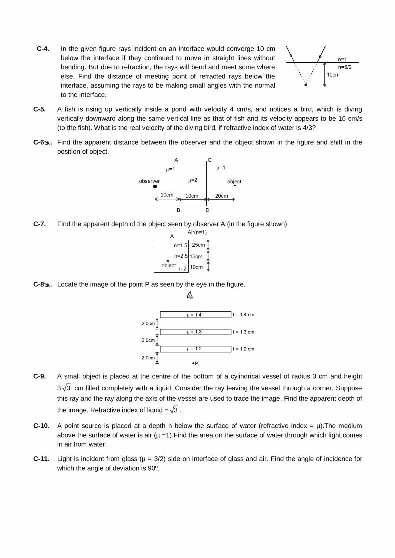
C-4. In the given figure rays incident on an interface would converge 10 cm
below the interface if they continued to move in straight lines without
bending. But due to refraction, the rays will bend and meet some where
else. Find the distance of meeting point of refracted rays below the
interface, assuming the rays to be making small angles with the normal
to the interface.
C-5. A fish is rising up vertically inside a pond with velocity 4 cm/s, and notices a bird, which is diving
vertically downward along the same vertical line as that of fish and its velocity appears to be 16 cm/s
(to the fish). What is the real velocity of the diving bird, if refractive index of water is 4/3?
C-6. Find the apparent distance between the observer and the object shown in the figure and shift in the
position of object.
10cm 20cm 10cm
object
C
D
A
B
observer
C-7. Find the apparent depth of the object seen by observer A (in the figure shown)
C-8. Locate the image of the point P as seen by the eye in the figure.
C-9. A small object is placed at the centre of the bottom of a cylindrical vessel of radius 3 cm and height
3 3 cm filled completely with a liquid. Consider the ray leaving the vessel through a corner. Suppose
this ray and the ray along the axis of the vessel are used to trace the image. Find the apparent depth of
the image. Refractive index of liquid = 3 .
C-10. A point source is placed at a depth h below the surface of water (refractive index = µ).The medium
above the surface of water is air (µ =1).Find the area on the surface of water through which light comes
in air from water.
C-11. Light is incident from glass (µ = 3/2) side on interface of glass and air. Find the angle of incidence for
which the angle of deviation is 90º.
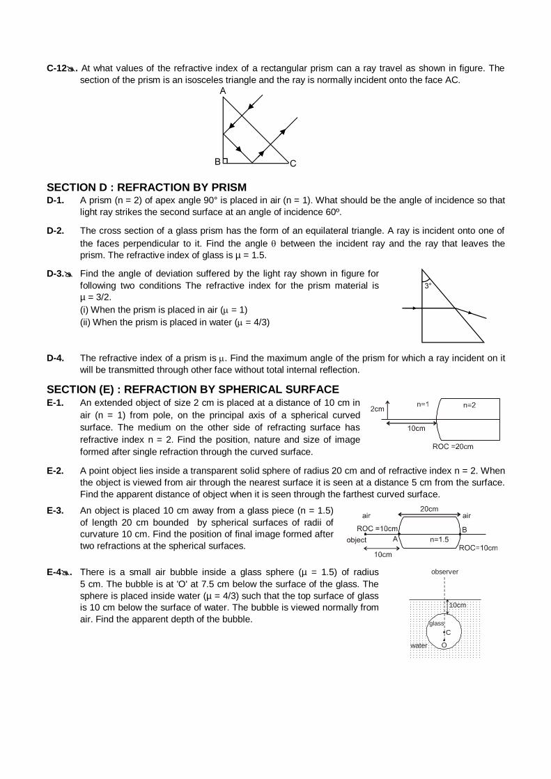
C-12. At what values of the refractive index of a rectangular prism can a ray travel as shown in figure. The
section of the prism is an isosceles triangle and the ray is normally incident onto the face AC.
SECTION D : REFRACTION BY PRISM
D-1. A prism (n = 2) of apex angle 90° is placed in air (n = 1). What should be the angle of incidence so that
light ray strikes the second surface at an angle of incidence 60º.
D-2. The cross section of a glass prism has the form of an equilateral triangle. A ray is incident onto one of
the faces perpendicular to it. Find the angle between the incident ray and the ray that leaves the
prism. The refractive index of glass is µ = 1.5.
D-3. Find the angle of deviation suffered by the light ray shown in figure for
following two conditions The refractive index for the prism material is
µ = 3/2.
(i) When the prism is placed in air ( = 1)
(ii) When the prism is placed in water ( = 4/3)
D-4. The refractive index of a prism is . Find the maximum angle of the prism for which a ray incident on it
will be transmitted through other face without total internal reflection.
SECTION (E) : REFRACTION BY SPHERICAL SURFACE E-1. An extended object of size 2 cm is placed at a distance of 10 cm in
air (n = 1) from pole, on the principal axis of a spherical curved
surface. The medium on the other side of refracting surface has
refractive index n = 2. Find the position, nature and size of image
formed after single refraction through the curved surface.
E-2. A point object lies inside a transparent solid sphere of radius 20 cm and of refractive index n = 2. When
the object is viewed from air through the nearest surface it is seen at a distance 5 cm from the surface.
Find the apparent distance of object when it is seen through the farthest curved surface.
E-3. An object is placed 10 cm away from a glass piece (n = 1.5)
of length 20 cm bounded by spherical surfaces of radii of
curvature 10 cm. Find the position of final image formed after
two refractions at the spherical surfaces.
E-4. There is a small air bubble inside a glass sphere (µ = 1.5) of radius
5 cm. The bubble is at 'O' at 7.5 cm below the surface of the glass. The
sphere is placed inside water (µ = 4/3) such that the top surface of glass
is 10 cm below the surface of water. The bubble is viewed normally from
air. Find the apparent depth of the bubble.
water
observer
10cm
C
glass
O
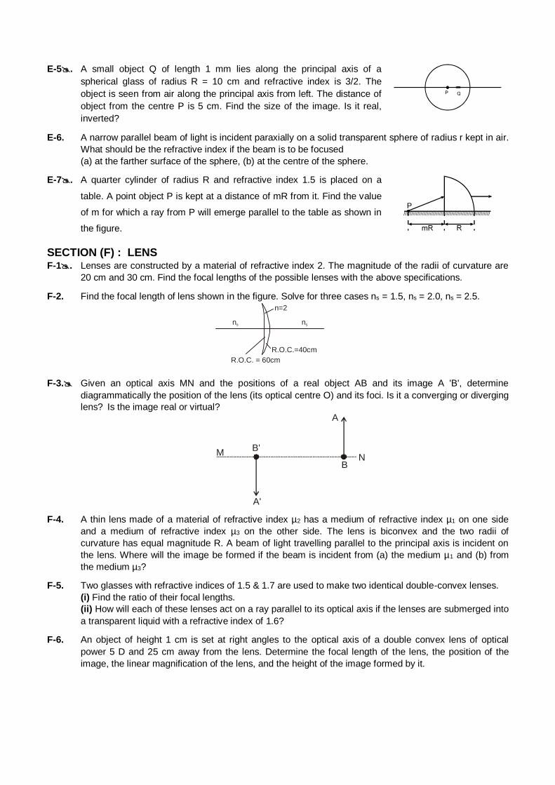
E-5. A small object Q of length 1 mm lies along the principal axis of a
spherical glass of radius R = 10 cm and refractive index is 3/2. The
object is seen from air along the principal axis from left. The distance of
object from the centre P is 5 cm. Find the size of the image. Is it real,
inverted?
E-6. A narrow parallel beam of light is incident paraxially on a solid transparent sphere of radius r kept in air.
What should be the refractive index if the beam is to be focused
(a) at the farther surface of the sphere, (b) at the centre of the sphere.
E-7. A quarter cylinder of radius R and refractive index 1.5 is placed on a
table. A point object P is kept at a distance of mR from it. Find the value
of m for which a ray from P will emerge parallel to the table as shown in
the figure.
SECTION (F) : LENS
F-1. Lenses are constructed by a material of refractive index 2. The magnitude of the radii of curvature are
20 cm and 30 cm. Find the focal lengths of the possible lenses with the above specifications.
F-2. Find the focal length of lens shown in the figure. Solve for three cases ns = 1.5, ns = 2.0, ns = 2.5.
n s n s
n=2
R.O.C.=40cm R.O.C. = 60cm
F-3. Given an optical axis MN and the positions of a real object AB and its image A 'B', determine
diagrammatically the position of the lens (its optical centre O) and its foci. Is it a converging or diverging
lens? Is the image real or virtual?
A'
NB'
B
A
M
F-4. A thin lens made of a material of refractive index µ2 has a medium of refractive index µ1 on one side
and a medium of refractive index µ3 on the other side. The lens is biconvex and the two radii of
curvature has equal magnitude R. A beam of light travelling parallel to the principal axis is incident on
the lens. Where will the image be formed if the beam is incident from (a) the medium µ1 and (b) from
the medium µ3?
F-5. Two glasses with refractive indices of 1.5 & 1.7 are used to make two identical double-convex lenses.
(i) Find the ratio of their focal lengths.
(ii) How will each of these lenses act on a ray parallel to its optical axis if the lenses are submerged into
a transparent liquid with a refractive index of 1.6?
F-6. An object of height 1 cm is set at right angles to the optical axis of a double convex lens of optical
power 5 D and 25 cm away from the lens. Determine the focal length of the lens, the position of the
image, the linear magnification of the lens, and the height of the image formed by it.

F-7. A lens placed between a candle and a fixed screen forms a real triply magnified image of the candle on
the screen. When the lens is moved away from the candle by 0.8 m without changing the position of the
candle, a real image one-third the size of the candle is formed on the screen. Determine the focal
length of the lens.
F-8. A pin of length 1 cm lies along the principal axis of a converging lens, the centre being at a distance of
5.5 cm from the lens. The focal length of the lens is 3 cm. Find the size of the image.
F-9. The radius of the sun is 0.75 × 10⁹ m and its distance from the earth is 1.5 × 10¹¹ m. Find the diameter
of the image of the sun formed by a lens of focal length 40 cm.
F-10. A 2.5 dioptre lens forms a virtual image which is 4 times the object placed perpendicularly on the
principal axis of the lens. Find the required distance of the object from the lens.
F-11. A diverging lens of focal length 20 cm is placed coaxially 5 cm towards left of a converging mirror of
focal length 10 cm. Where should an object be placed towards left of the lens so that a real image is
formed at the object itself ?
F-12. A convex lens and a convex mirror are placed at a separation of 15 cm. The focal length of the lens is
25 cm and radius of curvature of the mirror is 80 cm. Where should a point source be placed between
the lens and the mirror so that the light, after getting reflected by the mirror and then getting refracted
by the lens, comes out parallel to the principal axis?
F-13. A point object is placed on the principal axis of a converging lens of focal length 15 cm at a distance of
30 cm from it. A glass plate (µ = 1.50) of thickness 3 cm is placed on the other side of the lens
perpendicular to the axis. Find the position of the image of the point object.
F-14. A converging lens of focal length 10 cm and a diverging lens of focal length 5 cm are placed 5 cm apart
with their principal axes coinciding. A beam of light travelling parallel to the principal axis and having a
beam diameter 5.0 mm, is incident on the combination. Show that the emergent beam is parallel to the
incident one. Find the beam diameter of the emergent beam. Also find out the ratio of emergent and
incident intensities.
SECTION (G) : COMBINATION OF LENSES/LENS AND MIRRORS. G-1. Two identical thin converging lenses brought in contact so that their axes coincide are placed 12.5 cm
from an object. What is the optical power of the system and each lens, if the real image formed by the
system of lenses is four times as large as the object?
G-2. A point object is placed at a distance of 15 cm from a convex lens. The image is formed on the other
side at a distance of 30 cm from the lens. When a concave lens is placed in contact with the convex
lens, the image shifts away further by 30 cm. Calculate the focal lengths of the two lenses.
G-3. The convex surface of a thin concavo-convex lens of glass of refractive
index 1.5 has a radius of curvature 20 cm. the concave surface has a
radius of curvature 60 cm. The convex side is silvered and placed on a
horizontal surface as shown in figure. (a) Where should a pin be placed
on the axis so that its image is formed at the same place? (b) If the
concave part is filled with water (µ = 4/3), find the distance through which
the pin should be moved so that the image of the pin again coincides
with the pin.
SECTION (H) : DISPERSION OF LIGHT
H-1. A certain material has refractive indices 1.53, 1.60 and 1.68 for red, yellow and violet light respectively.
(a) Calculate the dispersive power. (b) Find the angular dispersion produced by a thin prism of angle 6°
made of this material.
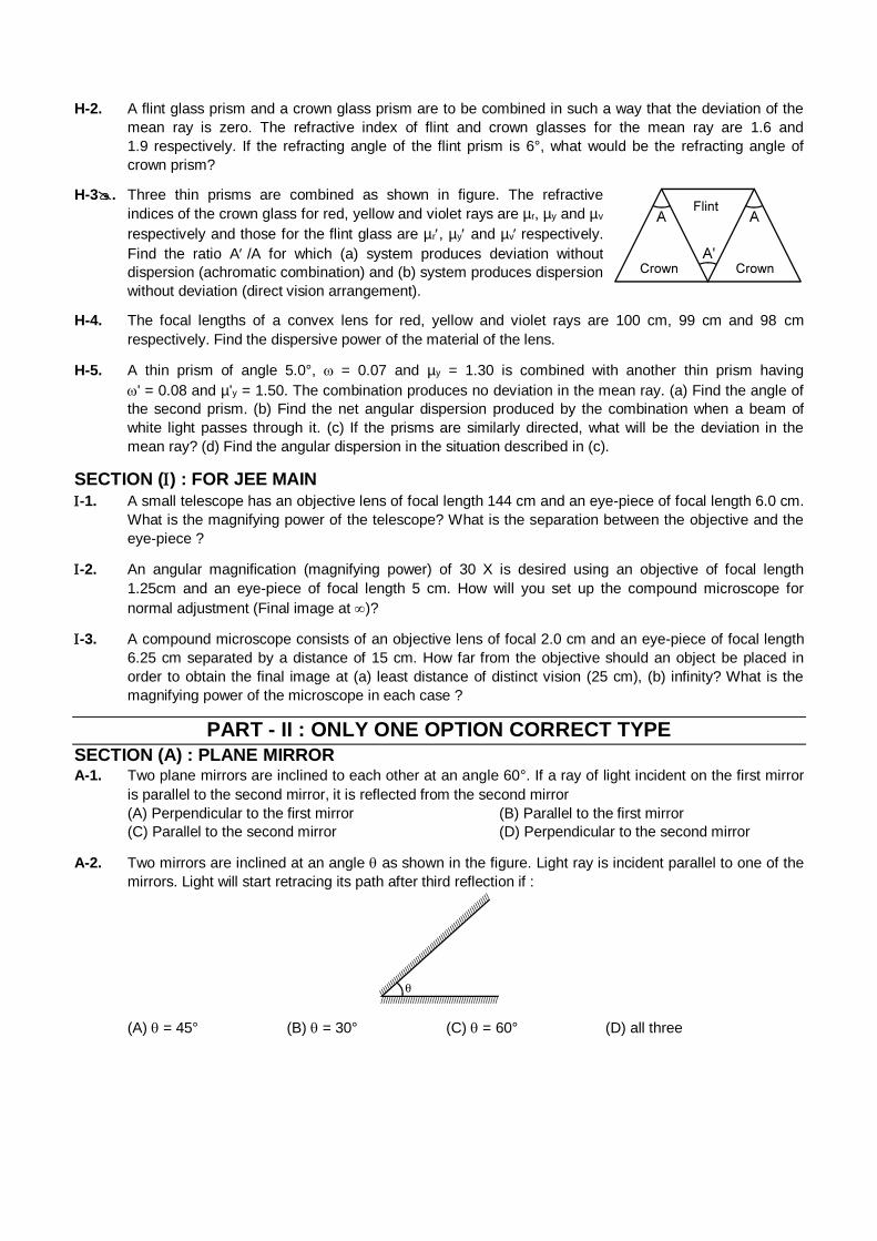
H-2. A flint glass prism and a crown glass prism are to be combined in such a way that the deviation of the
mean ray is zero. The refractive index of flint and crown glasses for the mean ray are 1.6 and
1.9 respectively. If the refracting angle of the flint prism is 6°, what would be the refracting angle of
crown prism?
H-3. Three thin prisms are combined as shown in figure. The refractive
indices of the crown glass for red, yellow and violet rays are µr, µy and µv
respectively and those for the flint glass are µr, µy and µvrespectively.
Find the ratio A/A for which (a) system produces deviation without
dispersion (achromatic combination) and (b) system produces dispersion
without deviation (direct vision arrangement).
H-4. The focal lengths of a convex lens for red, yellow and violet rays are 100 cm, 99 cm and 98 cm
respectively. Find the dispersive power of the material of the lens.
H-5. A thin prism of angle 5.0°, = 0.07 and µy = 1.30 is combined with another thin prism having
' = 0.08 and µ'y = 1.50. The combination produces no deviation in the mean ray. (a) Find the angle of
the second prism. (b) Find the net angular dispersion produced by the combination when a beam of
white light passes through it. (c) If the prisms are similarly directed, what will be the deviation in the
mean ray? (d) Find the angular dispersion in the situation described in (c).
SECTION () : FOR JEE MAIN
-1. A small telescope has an objective lens of focal length 144 cm and an eye-piece of focal length 6.0 cm.
What is the magnifying power of the telescope? What is the separation between the objective and the
eye-piece ?
-2. An angular magnification (magnifying power) of 30 X is desired using an objective of focal length
1.25cm and an eye-piece of focal length 5 cm. How will you set up the compound microscope for
normal adjustment (Final image at )?
-3. A compound microscope consists of an objective lens of focal 2.0 cm and an eye-piece of focal length
6.25 cm separated by a distance of 15 cm. How far from the objective should an object be placed in
order to obtain the final image at (a) least distance of distinct vision (25 cm), (b) infinity? What is the
magnifying power of the microscope in each case ?
PART - II : ONLY ONE OPTION CORRECT TYPE
SECTION (A) : PLANE MIRROR
A-1. Two plane mirrors are inclined to each other at an angle 60°. If a ray of light incident on the first mirror
is parallel to the second mirror, it is reflected from the second mirror
(A) Perpendicular to the first mirror (B) Parallel to the first mirror
(C) Parallel to the second mirror (D) Perpendicular to the second mirror
A-2. Two mirrors are inclined at an angle as shown in the figure. Light ray is incident parallel to one of the
mirrors. Light will start retracing its path after third reflection if :
(A) = 45° (B) = 30° (C) = 60° (D) all three
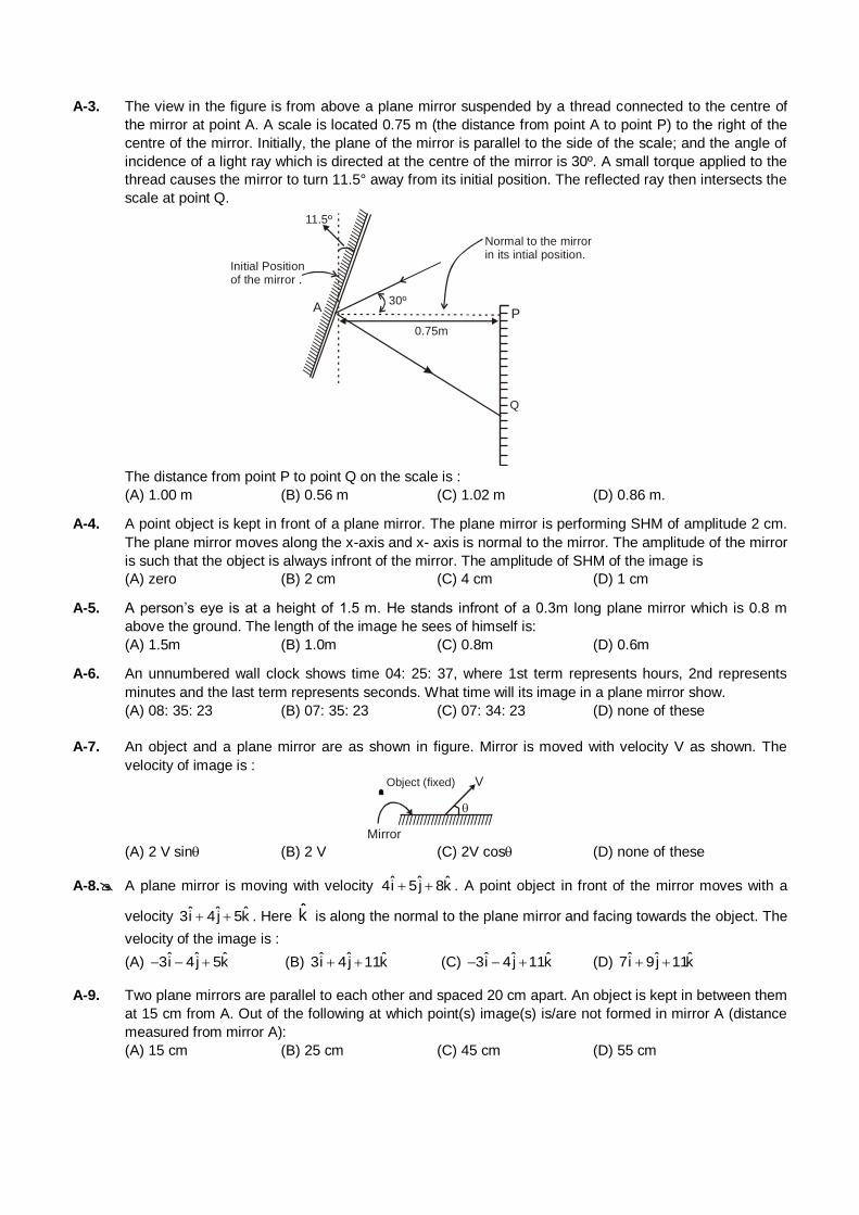
A-3. The view in the figure is from above a plane mirror suspended by a thread connected to the centre of
the mirror at point A. A scale is located 0.75 m (the distance from point A to point P) to the right of the
centre of the mirror. Initially, the plane of the mirror is parallel to the side of the scale; and the angle of
incidence of a light ray which is directed at the centre of the mirror is 30º. A small torque applied to the
thread causes the mirror to turn 11.5° away from its initial position. The reflected ray then intersects the
scale at point Q.
Q
////////////////////////////////////////////////////
P
11.5º
30º
0.75m
Normal to the mirror in its intial position.
Initial Position of the mirror .
A
The distance from point P to point Q on the scale is :
(A) 1.00 m (B) 0.56 m (C) 1.02 m (D) 0.86 m.
A-4. A point object is kept in front of a plane mirror. The plane mirror is performing SHM of amplitude 2 cm.
The plane mirror moves along the x-axis and x- axis is normal to the mirror. The amplitude of the mirror
is such that the object is always infront of the mirror. The amplitude of SHM of the image is
(A) zero (B) 2 cm (C) 4 cm (D) 1 cm
A-5. A person’s eye is at a height of 1.5 m. He stands infront of a 0.3m long plane mirror which is 0.8 m
above the ground. The length of the image he sees of himself is:
(A) 1.5m (B) 1.0m (C) 0.8m (D) 0.6m
A-6. An unnumbered wall clock shows time 04: 25: 37, where 1st term represents hours, 2nd represents
minutes and the last term represents seconds. What time will its image in a plane mirror show.
(A) 08: 35: 23 (B) 07: 35: 23 (C) 07: 34: 23 (D) none of these
A-7. An object and a plane mirror are as shown in figure. Mirror is moved with velocity V as shown. The
velocity of image is :
//////////////////////////
V
Mirror
Object (fixed)
(A) 2 V sin (B) 2 V (C) 2V cos (D) none of these
A-8. A plane mirror is moving with velocity ˆ ˆ ˆ4i 5j 8k . A point object in front of the mirror moves with a
velocity ˆ ˆ ˆ3i 4j 5k . Here k is along the normal to the plane mirror and facing towards the object. The
velocity of the image is :
(A) ˆ ˆ ˆ3i 4j 5k (B) ˆ ˆ ˆ3i 4j 11k (C) ˆ ˆ ˆ3i 4j 11k (D) ˆ ˆ ˆ7i 9j 11k
A-9. Two plane mirrors are parallel to each other and spaced 20 cm apart. An object is kept in between them
at 15 cm from A. Out of the following at which point(s) image(s) is/are not formed in mirror A (distance
measured from mirror A):
(A) 15 cm (B) 25 cm (C) 45 cm (D) 55 cm
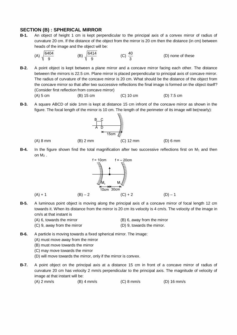
SECTION (B) : SPHERICAL MIRROR
B-1. An object of height 1 cm is kept perpendicular to the principal axis of a convex mirror of radius of
curvature 20 cm. If the distance of the object from the mirror is 20 cm then the distance (in cm) between
heads of the image and the object will be:
(A) 6404
9 (B)
6414
9 (C)
40
3 (D) none of these
B-2. A point object is kept between a plane mirror and a concave mirror facing each other. The distance
between the mirrors is 22.5 cm. Plane mirror is placed perpendicular to principal axis of concave mirror.
The radius of curvature of the concave mirror is 20 cm. What should be the distance of the object from
the concave mirror so that after two successive reflections the final image is formed on the object itself?
(Consider first reflection from concave mirror)
(A) 5 cm (B) 15 cm (C) 10 cm (D) 7.5 cm
B-3. A square ABCD of side 1mm is kept at distance 15 cm infront of the concave mirror as shown in the
figure. The focal length of the mirror is 10 cm. The length of the perimeter of its image will be(nearly):
(A) 8 mm (B) 2 mm (C) 12 mm (D) 6 mm
B-4. In the figure shown find the total magnification after two successive reflections first on M1 and then
on M2 .
(A) + 1 (B) – 2 (C) + 2 (D) – 1
B-5. A luminous point object is moving along the principal axis of a concave mirror of focal length 12 cm
towards it. When its distance from the mirror is 20 cm its velocity is 4 cm/s. The velocity of the image in
cm/s at that instant is
(A) 6, towards the mirror (B) 6, away from the mirror
(C) 9, away from the mirror (D) 9, towards the mirror.
B-6. A particle is moving towards a fixed spherical mirror. The image:
(A) must move away from the mirror
(B) must move towards the mirror
(C) may move towards the mirror
(D) will move towards the mirror, only if the mirror is convex.
B-7. A point object on the principal axis at a distance 15 cm in front of a concave mirror of radius of
curvature 20 cm has velocity 2 mm/s perpendicular to the principal axis. The magnitude of velocity of
image at that instant will be:
(A) 2 mm/s (B) 4 mm/s (C) 8 mm/s (D) 16 mm/s
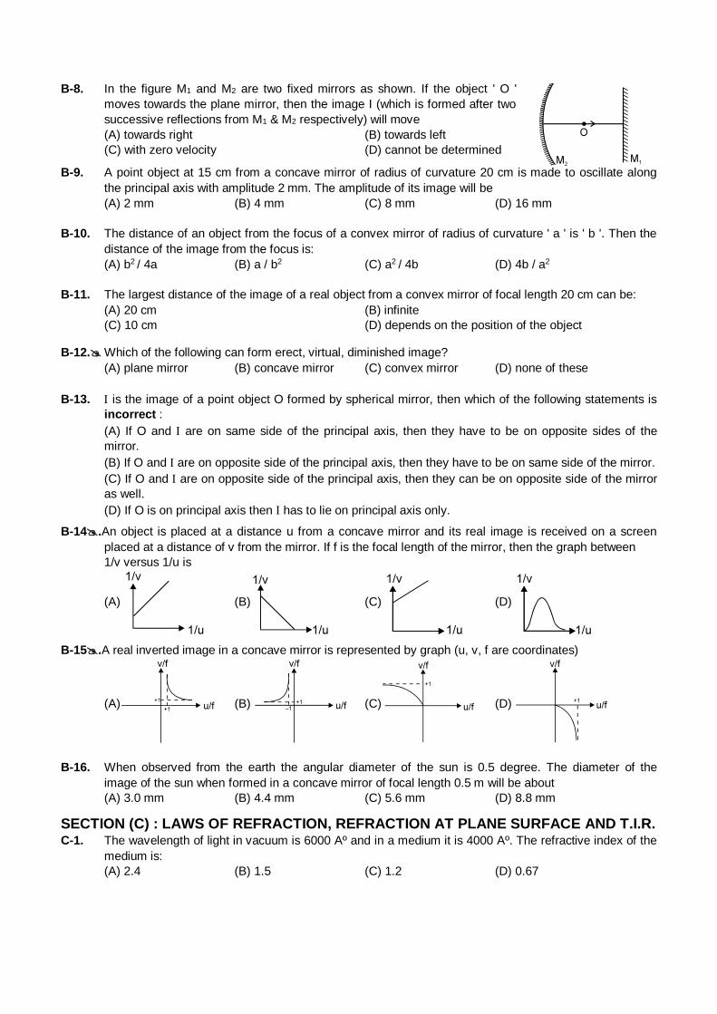
B-8. In the figure M1 and M2 are two fixed mirrors as shown. If the object ' O '
moves towards the plane mirror, then the image I (which is formed after two
successive reflections from M1 & M2 respectively) will move
(A) towards right (B) towards left
(C) with zero velocity (D) cannot be determined
B-9. A point object at 15 cm from a concave mirror of radius of curvature 20 cm is made to oscillate along
the principal axis with amplitude 2 mm. The amplitude of its image will be
(A) 2 mm (B) 4 mm (C) 8 mm (D) 16 mm
B-10. The distance of an object from the focus of a convex mirror of radius of curvature ' a ' is ' b '. Then the
distance of the image from the focus is:
(A) b2 / 4a (B) a / b2 (C) a2 / 4b (D) 4b / a2
B-11. The largest distance of the image of a real object from a convex mirror of focal length 20 cm can be:
(A) 20 cm (B) infinite
(C) 10 cm (D) depends on the position of the object
B-12. Which of the following can form erect, virtual, diminished image?
(A) plane mirror (B) concave mirror (C) convex mirror (D) none of these
B-13. is the image of a point object O formed by spherical mirror, then which of the following statements is
incorrect :
(A) If O and are on same side of the principal axis, then they have to be on opposite sides of the
mirror.
(B) If O and are on opposite side of the principal axis, then they have to be on same side of the mirror.
(C) If O and are on opposite side of the principal axis, then they can be on opposite side of the mirror
as well.
(D) If O is on principal axis then has to lie on principal axis only.
B-14.An object is placed at a distance u from a concave mirror and its real image is received on a screen
placed at a distance of v from the mirror. If f is the focal length of the mirror, then the graph between
1/v versus 1/u is
(A) (B) (C) (D)
B-15.A real inverted image in a concave mirror is represented by graph (u, v, f are coordinates)
(A)
(B)
(C) (D)
B-16. When observed from the earth the angular diameter of the sun is 0.5 degree. The diameter of the
image of the sun when formed in a concave mirror of focal length 0.5 m will be about
(A) 3.0 mm (B) 4.4 mm (C) 5.6 mm (D) 8.8 mm
SECTION (C) : LAWS OF REFRACTION, REFRACTION AT PLANE SURFACE AND T.I.R. C-1. The wavelength of light in vacuum is 6000 Aº and in a medium it is 4000 Aº. The refractive index of the
medium is:
(A) 2.4 (B) 1.5 (C) 1.2 (D) 0.67
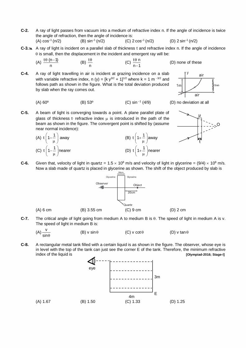
C-2. A ray of light passes from vacuum into a medium of refractive index n. If the angle of incidence is twice
the angle of refraction, then the angle of incidence is:
(A) cos–1 (n/2) (B) sin–1
(n/2) (C) 2 cos–1 (n/2) (D) 2 sin–1
(n/2)
C-3. A ray of light is incident on a parallel slab of thickness t and refractive index n. If the angle of incidence
is small, then the displacement in the incident and emergent ray will be:
(A) t (n 1)
n
(B)
t
n
(C)
t n
n 1
(D) none of these
C-4. A ray of light travelling in air is incident at grazing incidence on a slab
with variable refractive index, n (y) = [k y3/2 + 1]1/2 where k = 1 m 3/2 and
follows path as shown in the figure. What is the total deviation produced
by slab when the ray comes out.
(A) 60º (B) 53º (C) sin 1 (4/9) (D) no deviation at all
C-5. A beam of light is converging towards a point. A plane parallel plate of
glass of thickness t, refractive index is introduced in the path of the
beam as shown in the figure. The convergent point is shifted by (assume
near normal incidence):
(A) 1
t 1
away (B) 1
t 1
away
(C) 1
t 1
nearer (D) 1
t 1
nearer
C-6. Given that, velocity of light in quartz = 1.5 108 m/s and velocity of light in glycerine = (9/4) 108 m/s.
Now a slab made of quartz is placed in glycerine as shown. The shift of the object produced by slab is
(A) 6 cm (B) 3.55 cm (C) 9 cm (D) 2 cm
C-7. The critical angle of light going from medium A to medium B is . The speed of light in medium A is v.
The speed of light in medium B is:
(A)v
sin (B) v sin (C) v cot (D) v tan
C-8. A rectangular metal tank filled with a certain liquid is as shown in the figure. The observer, whose eye is in level with the top of the tank can just see the corner E of the tank. Therefore, the minimum refractive index of the liquid is [Olympiad-2016; Stage-I]
4m
3m
E
eye
(A) 1.67 (B) 1.50 (C) 1.33 (D) 1.25
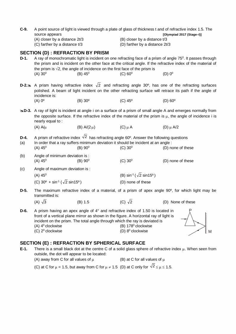
C-9. A point source of light is viewed through a plate of glass of thickness t and of refractive index 1.5. The
source appears [Olympiad 2017 (Stage–I)]
(A) closer by a distance 2t/3 (B) closer by a distance t/3
(C) farther by a distance t/3 (D) farther by a distance 2t/3
SECTION (D) : REFRACTION BY PRISM D-1. A ray of monochromatic light is incident on one refracting face of a prism of angle 750. It passes through
the prism and is incident on the other face at the critical angle. If the refractive index of the material of
the prism is 2, the angle of incidence on the first face of the prism is
(A) 300 (B) 450 (C) 600 (D) 00
D-2. A prism having refractive index 2 and refracting angle 30º, has one of the refracting surfaces
polished. A beam of light incident on the other refracting surface will retrace its path if the angle of
incidence is:
(A) 0º (B) 30º (C) 45º (D) 60º
D-3. A ray of light is incident at angle i on a surface of a prism of small angle A and emerges normally from
the opposite surface. If the refractive index of the material of the prism is , the angle of incidence i is
nearly equal to :
(A) A/ (B) A/(2 ) (C) A (D) A/2
D-4. A prism of refractive index 2 has refracting angle 60º. Answer the following questions
(a) In order that a ray suffers minimum deviation it should be incident at an angle :
(A) 450 (B) 900 (C) 300 (D) none of these
(b) Angle of minimum deviation is :
(A) 450 (B) 900 (C) 300 (D) none of these
(c) Angle of maximum deviation is :
(A) 450 (B) sin-1 ( 2 sin15º )
(C) 30º + sin-1 ( 2 sin15º ) (D) none of these
D-5. The maximum refractive index of a material, of a prism of apex angle 90º, for which light may be
transmitted is:
(A) 3 (B) 1.5 (C) 2 (D) None of these
D-6. A prism having an apex angle of 4° and refractive index of 1.50 is located in
front of a vertical plane mirror as shown in the figure. A horizontal ray of light is
incident on the prism. The total angle through which the ray is deviated is
(A) 40 clockwise (B) 1780 clockwise
(C) 20 clockwise (D) 80 clockwise M
P
SECTION (E) : REFRACTION BY SPHERICAL SURFACE
E-1. There is a small black dot at the centre C of a solid glass sphere of refractive index . When seen from
outside, the dot will appear to be located:
(A) away from C for all values of (B) at C for all values of
(C) at C for = 1.5, but away from C for 1.5 (D) at C only for 2 1.5.
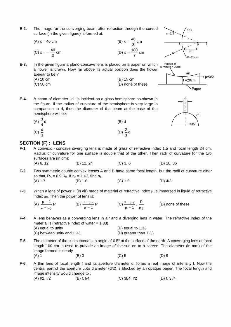
E-2. The image for the converging beam after refraction through the curved
surface (in the given figure) is formed at:
(A) x = 40 cm (B) x = 40
3cm
(C) x = 40
3cm (D) x =
180
7cm
n=3/2
n=1
P
30
O x
R=20cm
E-3. In the given figure a plano-concave lens is placed on a paper on which
a flower is drawn. How far above its actual position does the flower
appear to be ?
(A) 10 cm (B) 15 cm
(C) 50 cm (D) none of these
E-4. A beam of diameter ‘ d ‘ is incident on a glass hemisphere as shown in
the figure. If the radius of curvature of the hemisphere is very large in
comparison to d, then the diameter of the beam at the base of the
hemisphere will be:
(A) 3
4d (B) d
(C) d
3 (D)
2
3d
SECTION (F) : LENS
F-1. A convexo - concave diverging lens is made of glass of refractive index 1.5 and focal length 24 cm.
Radius of curvature for one surface is double that of the other. Then radii of curvature for the two
surfaces are (in cm):
(A) 6, 12 (B) 12, 24 (C) 3, 6 (D) 18, 36
F-2. Two symmetric double convex lenses A and B have same focal length, but the radii of curvature differ
so that, RA = 0.9 RB. If nA = 1.63, find nB.
(A) 1.7 (B) 1.6 (C) 1.5 (D) 4/3
F-3. When a lens of power P (in air) made of material of refractive index is immersed in liquid of refractive
index 0. Then the power of lens is:
(A) 0
1
P (B) 0
1
P (C) 0
1
.
0
P
(D) none of these
F-4. A lens behaves as a converging lens in air and a diverging lens in water. The refractive index of the
material is (refractive index of water = 1.33)
(A) equal to unity (B) equal to 1.33
(C) between unity and 1.33 (D) greater than 1.33
F-5. The diameter of the sun subtends an angle of 0.50 at the surface of the earth. A converging lens of focal
length 100 cm is used to provide an image of the sun on to a screen. The diameter (in mm) of the
image formed is nearly
(A) 1 (B) 3 (C) 5 (D) 9
F-6. A thin lens of focal length f and its aperture diameter d, forms a real image of intensity I. Now the
central part of the aperture upto diameter (d/2) is blocked by an opaque paper. The focal length and
image intensity would change to :
(A) f/2, I/2 (B) f, I/4 (C) 3f/4, I/2 (D) f, 3I/4
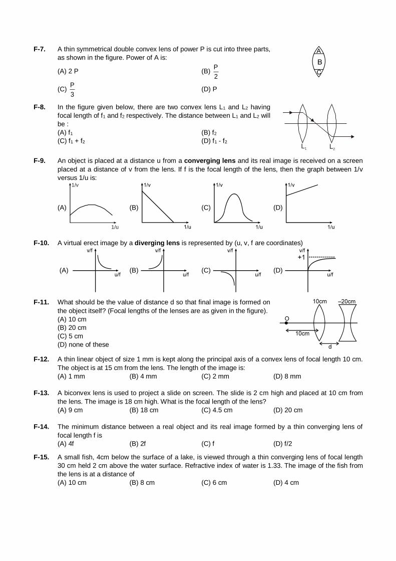
F-7. A thin symmetrical double convex lens of power P is cut into three parts,
as shown in the figure. Power of A is:
(A) 2 P (B) P
2
(C) P
3 (D) P
F-8. In the figure given below, there are two convex lens L1 and L2 having
focal length of f1 and f2 respectively. The distance between L1 and L2 will
be :
(A) f1 (B) f2
(C) f1 + f2 (D) f1 - f2 L1 L2
F-9. An object is placed at a distance u from a converging lens and its real image is received on a screen
placed at a distance of v from the lens. If f is the focal length of the lens, then the graph between 1/v
versus 1/u is:
(A)
1/v
1/u
(B) (C) (D)
F-10. A virtual erect image by a diverging lens is represented by (u, v, f are coordinates)
(A) (B) (C) (D)
F-11. What should be the value of distance d so that final image is formed on
the object itself? (Focal lengths of the lenses are as given in the figure).
(A) 10 cm
(B) 20 cm
(C) 5 cm
(D) none of these
F-12. A thin linear object of size 1 mm is kept along the principal axis of a convex lens of focal length 10 cm.
The object is at 15 cm from the lens. The length of the image is:
(A) 1 mm (B) 4 mm (C) 2 mm (D) 8 mm
F-13. A biconvex lens is used to project a slide on screen. The slide is 2 cm high and placed at 10 cm from
the lens. The image is 18 cm high. What is the focal length of the lens?
(A) 9 cm (B) 18 cm (C) 4.5 cm (D) 20 cm
F-14. The minimum distance between a real object and its real image formed by a thin converging lens of
focal length f is
(A) 4f (B) 2f (C) f (D) f/2
F-15. A small fish, 4cm below the surface of a lake, is viewed through a thin converging lens of focal length
30 cm held 2 cm above the water surface. Refractive index of water is 1.33. The image of the fish from
the lens is at a distance of
(A) 10 cm (B) 8 cm (C) 6 cm (D) 4 cm
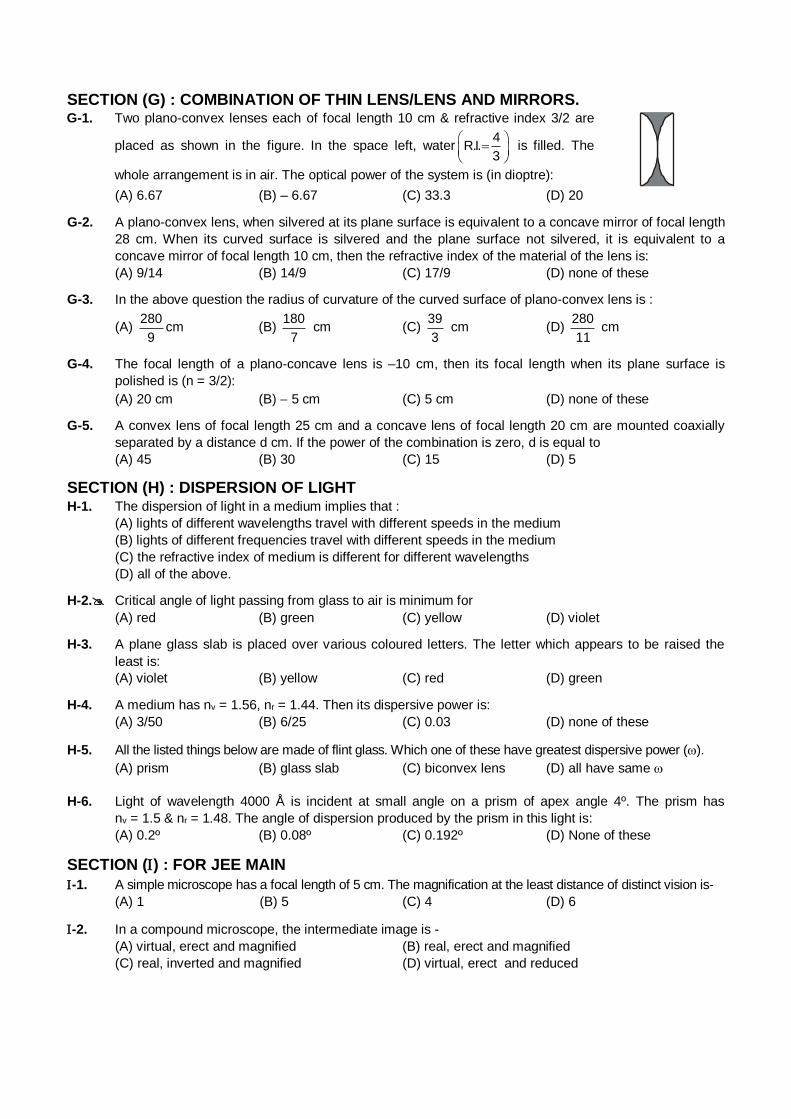
SECTION (G) : COMBINATION OF THIN LENS/LENS AND MIRRORS. G-1. Two plano-convex lenses each of focal length 10 cm & refractive index 3/2 are
placed as shown in the figure. In the space left, water4
R.I.3
is filled. The
whole arrangement is in air. The optical power of the system is (in dioptre):
(A) 6.67 (B) – 6.67 (C) 33.3 (D) 20
G-2. A plano-convex lens, when silvered at its plane surface is equivalent to a concave mirror of focal length
28 cm. When its curved surface is silvered and the plane surface not silvered, it is equivalent to a
concave mirror of focal length 10 cm, then the refractive index of the material of the lens is:
(A) 9/14 (B) 14/9 (C) 17/9 (D) none of these
G-3. In the above question the radius of curvature of the curved surface of plano-convex lens is :
(A) 280
9cm (B)
180
7 cm (C)
39
3 cm (D)
280
11 cm
G-4. The focal length of a plano-concave lens is –10 cm, then its focal length when its plane surface is
polished is (n = 3/2):
(A) 20 cm (B) 5 cm (C) 5 cm (D) none of these
G-5. A convex lens of focal length 25 cm and a concave lens of focal length 20 cm are mounted coaxially
separated by a distance d cm. If the power of the combination is zero, d is equal to
(A) 45 (B) 30 (C) 15 (D) 5
SECTION (H) : DISPERSION OF LIGHT
H-1. The dispersion of light in a medium implies that :
(A) lights of different wavelengths travel with different speeds in the medium
(B) lights of different frequencies travel with different speeds in the medium
(C) the refractive index of medium is different for different wavelengths
(D) all of the above.
H-2. Critical angle of light passing from glass to air is minimum for
(A) red (B) green (C) yellow (D) violet
H-3. A plane glass slab is placed over various coloured letters. The letter which appears to be raised the
least is:
(A) violet (B) yellow (C) red (D) green
H-4. A medium has nv = 1.56, nr = 1.44. Then its dispersive power is:
(A) 3/50 (B) 6/25 (C) 0.03 (D) none of these
H-5. All the listed things below are made of flint glass. Which one of these have greatest dispersive power ().
(A) prism (B) glass slab (C) biconvex lens (D) all have same
H-6. Light of wavelength 4000 Å is incident at small angle on a prism of apex angle 4º. The prism has
nv = 1.5 & nr = 1.48. The angle of dispersion produced by the prism in this light is:
(A) 0.2º (B) 0.08º (C) 0.192º (D) None of these
SECTION () : FOR JEE MAIN
-1. A simple microscope has a focal length of 5 cm. The magnification at the least distance of distinct vision is-
(A) 1 (B) 5 (C) 4 (D) 6
-2. In a compound microscope, the intermediate image is -
(A) virtual, erect and magnified (B) real, erect and magnified
(C) real, inverted and magnified (D) virtual, erect and reduced
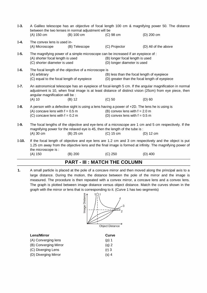
-3. A Galileo telescope has an objective of focal length 100 cm & magnifying power 50. The distance
between the two lenses in normal adjustment will be
(A) 150 cm (B) 100 cm (C) 98 cm (D) 200 cm
-4. The convex lens is used in-
(A) Microscope (B) Telescope (C) Projector (D) All of the above
-5. The magnifying power of a simple microscope can be increased if an eyepiece of :
(A) shorter focal length is used (B) longer focal length is used
(C) shorter diameter is used (D) longer diameter is used
-6. The focal length of the objective of a microscope is
(A) arbitrary (B) less than the focal length of eyepiece
(C) equal to the focal length of eyepiece (D) greater than the focal length of eyepiece
-7. An astronomical telescope has an eyepiece of focal-length 5 cm. If the angular magnification in normal
adjustment is 10, when final image is at least distance of distinct vision (25cm) from eye piece, then
angular magnification will be :
(A) 10 (B) 12 (C) 50 (D) 60
-8. A person with a defective sight is using a lens having a power of +2D. The lens he is using is
(A) concave lens with f = 0.5 m (B) convex lens with f = 2.0 m
(C) concave lens with f = 0.2 m (D) convex lens with f = 0.5 m
-9. The focal lengths of the objective and eye-lens of a microscope are 1 cm and 5 cm respectively. If the
magnifying power for the relaxed eye is 45, then the length of the tube is :
(A) 30 cm (B) 25 cm (C) 15 cm (D) 12 cm
-10. If the focal length of objective and eye lens are 1.2 cm and 3 cm respectively and the object is put
1.25 cm away from the objective lens and the final image is formed at infinity. The magnifying power of
the microscope is :
(A) 150 (B) 200 (C) 250 (D) 400
PART - III : MATCH THE COLUMN
1. A small particle is placed at the pole of a concave mirror and then moved along the principal axis to a
large distance. During the motion, the distance between the pole of the mirror and the image is
measured. The procedure is then repeated with a convex mirror, a concave lens and a convex lens.
The graph is plotted between image distance versus object distance. Match the curves shown in the
graph with the mirror or lens that is corresponding to it. (Curve 1 has two segments)
Lens/Mirror Curve
(A) Converging lens (p) 1
(B) Converging Mirror (q) 2
(C) Diverging Lens (r) 3
(D) Diverging Mirror (s) 4
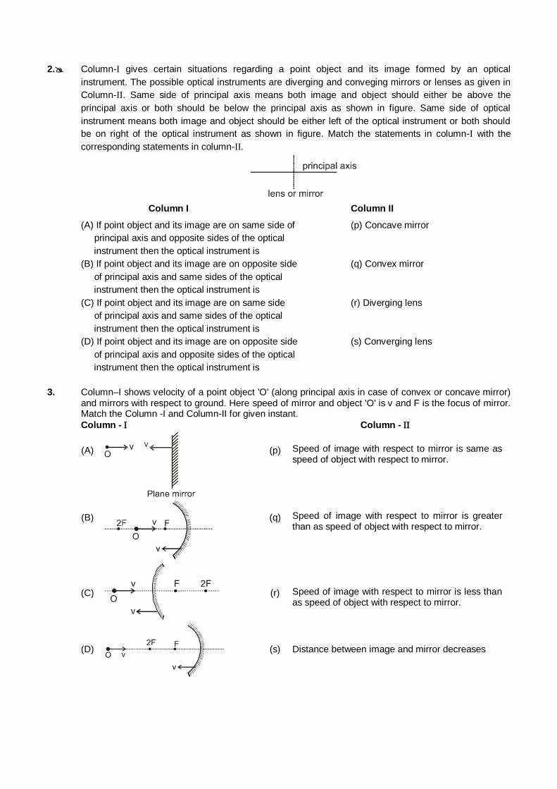
2. Column-I gives certain situations regarding a point object and its image formed by an optical
instrument. The possible optical instruments are diverging and conveging mirrors or lenses as given in
Column-II. Same side of principal axis means both image and object should either be above the
principal axis or both should be below the principal axis as shown in figure. Same side of optical
instrument means both image and object should be either left of the optical instrument or both should
be on right of the optical instrument as shown in figure. Match the statements in column-I with the
corresponding statements in column-II.
Column I Column II
(A) If point object and its image are on same side of (p) Concave mirror
principal axis and opposite sides of the optical
instrument then the optical instrument is
(B) If point object and its image are on opposite side (q) Convex mirror
of principal axis and same sides of the optical
instrument then the optical instrument is
(C) If point object and its image are on same side (r) Diverging lens
of principal axis and same sides of the optical
instrument then the optical instrument is
(D) If point object and its image are on opposite side (s) Converging lens
of principal axis and opposite sides of the optical
instrument then the optical instrument is
3. Column–I shows velocity of a point object 'O' (along principal axis in case of convex or concave mirror) and mirrors with respect to ground. Here speed of mirror and object 'O' is v and F is the focus of mirror. Match the Column -I and Column-II for given instant.
Column - Column -
(A)
(p)
Speed of image with respect to mirror is same as speed of object with respect to mirror.
(B)
(q)
Speed of image with respect to mirror is greater than as speed of object with respect to mirror.
(C)
(r)
Speed of image with respect to mirror is less than as speed of object with respect to mirror.
(D)
(s)
Distance between image and mirror decreases
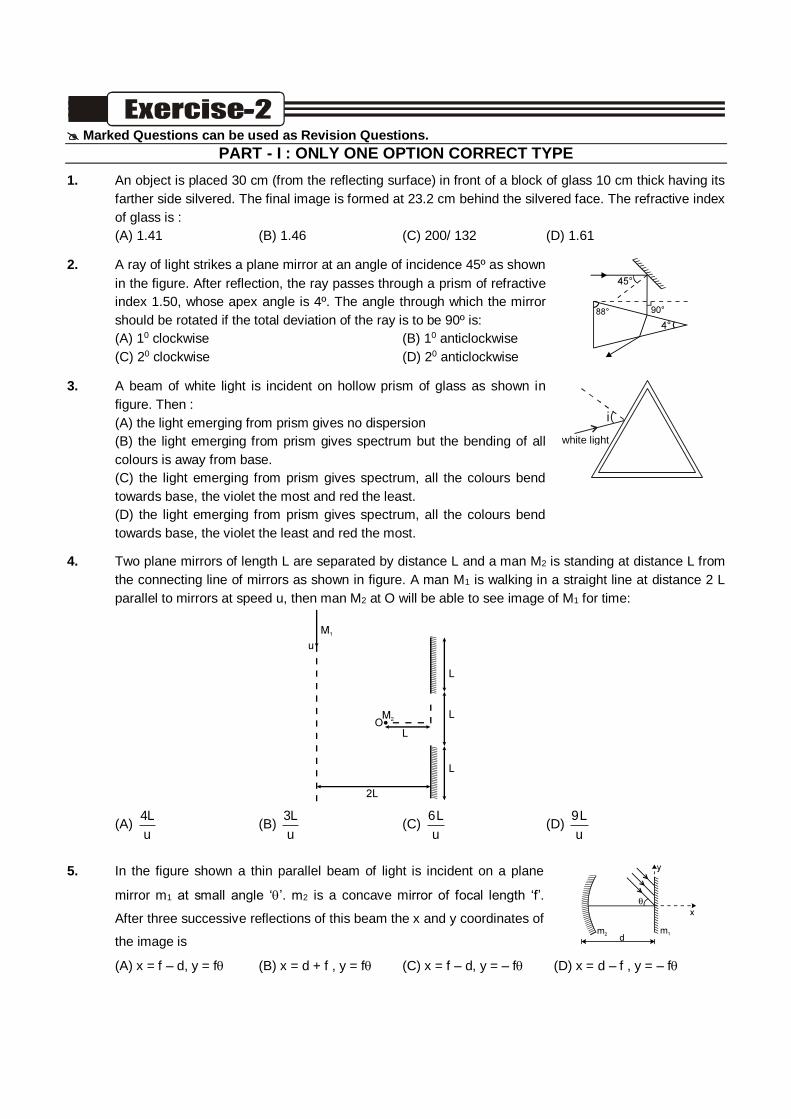
Marked Questions can be used as Revision Questions.
PART - I : ONLY ONE OPTION CORRECT TYPE
1. An object is placed 30 cm (from the reflecting surface) in front of a block of glass 10 cm thick having its
farther side silvered. The final image is formed at 23.2 cm behind the silvered face. The refractive index
of glass is :
(A) 1.41 (B) 1.46 (C) 200/ 132 (D) 1.61
2. A ray of light strikes a plane mirror at an angle of incidence 45º as shown
in the figure. After reflection, the ray passes through a prism of refractive
index 1.50, whose apex angle is 4º. The angle through which the mirror
should be rotated if the total deviation of the ray is to be 90º is:
(A) 10 clockwise (B) 10 anticlockwise
(C) 20 clockwise (D) 20 anticlockwise
3. A beam of white light is incident on hollow prism of glass as shown in
figure. Then :
(A) the light emerging from prism gives no dispersion
(B) the light emerging from prism gives spectrum but the bending of all
colours is away from base.
(C) the light emerging from prism gives spectrum, all the colours bend
towards base, the violet the most and red the least.
(D) the light emerging from prism gives spectrum, all the colours bend
towards base, the violet the least and red the most.
( i
white light
4. Two plane mirrors of length L are separated by distance L and a man M2 is standing at distance L from
the connecting line of mirrors as shown in figure. A man M1 is walking in a straight line at distance 2 L
parallel to mirrors at speed u, then man M2 at O will be able to see image of M1 for time:
(A) 4L
u (B)
3L
u (C)
6L
u (D)
9L
u
5. In the figure shown a thin parallel beam of light is incident on a plane
mirror m1 at small angle ‘’. m2 is a concave mirror of focal length ‘f’.
After three successive reflections of this beam the x and y coordinates of
the image is
(A) x = f – d, y = f (B) x = d + f , y = f (C) x = f – d, y = – f (D) x = d – f , y = – f
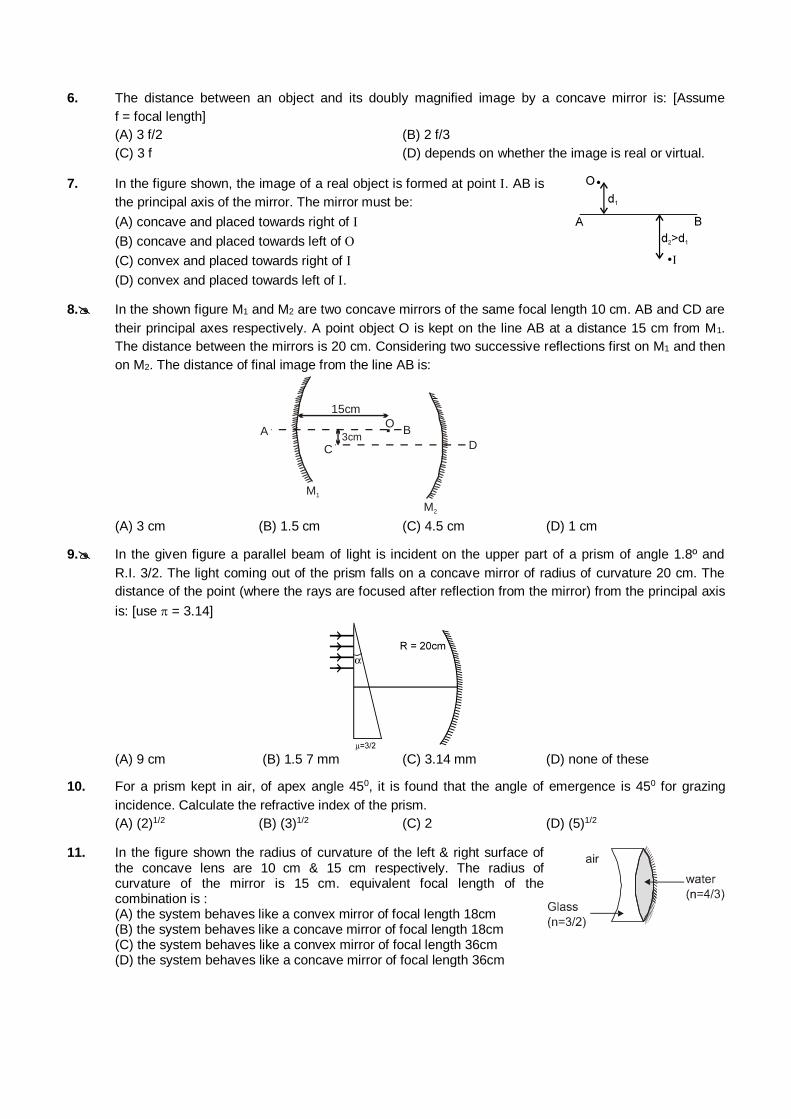
6. The distance between an object and its doubly magnified image by a concave mirror is: [Assume
f = focal length]
(A) 3 f/2 (B) 2 f/3
(C) 3 f (D) depends on whether the image is real or virtual.
7. In the figure shown, the image of a real object is formed at point . AB is
the principal axis of the mirror. The mirror must be:
(A) concave and placed towards right of
(B) concave and placed towards left of
(C) convex and placed towards right of
(D) convex and placed towards left of .
8. In the shown figure M1 and M2 are two concave mirrors of the same focal length 10 cm. AB and CD are
their principal axes respectively. A point object O is kept on the line AB at a distance 15 cm from M1.
The distance between the mirrors is 20 cm. Considering two successive reflections first on M1 and then
on M2. The distance of final image from the line AB is:
3cm.
15cm
A
D
B
C
M1
M2
O
(A) 3 cm (B) 1.5 cm (C) 4.5 cm (D) 1 cm
9. In the given figure a parallel beam of light is incident on the upper part of a prism of angle 1.8º and
R.I. 3/2. The light coming out of the prism falls on a concave mirror of radius of curvature 20 cm. The
distance of the point (where the rays are focused after reflection from the mirror) from the principal axis
is: [use = 3.14]
(A) 9 cm (B) 1.5 7 mm (C) 3.14 mm (D) none of these
10. For a prism kept in air, of apex angle 450, it is found that the angle of emergence is 450 for grazing
incidence. Calculate the refractive index of the prism.
(A) (2)1/2 (B) (3)1/2 (C) 2 (D) (5)1/2
11. In the figure shown the radius of curvature of the left & right surface of the concave lens are 10 cm & 15 cm respectively. The radius of curvature of the mirror is 15 cm. equivalent focal length of the combination is :
(A) the system behaves like a convex mirror of focal length 18cm (B) the system behaves like a concave mirror of focal length 18cm (C) the system behaves like a convex mirror of focal length 36cm (D) the system behaves like a concave mirror of focal length 36cm
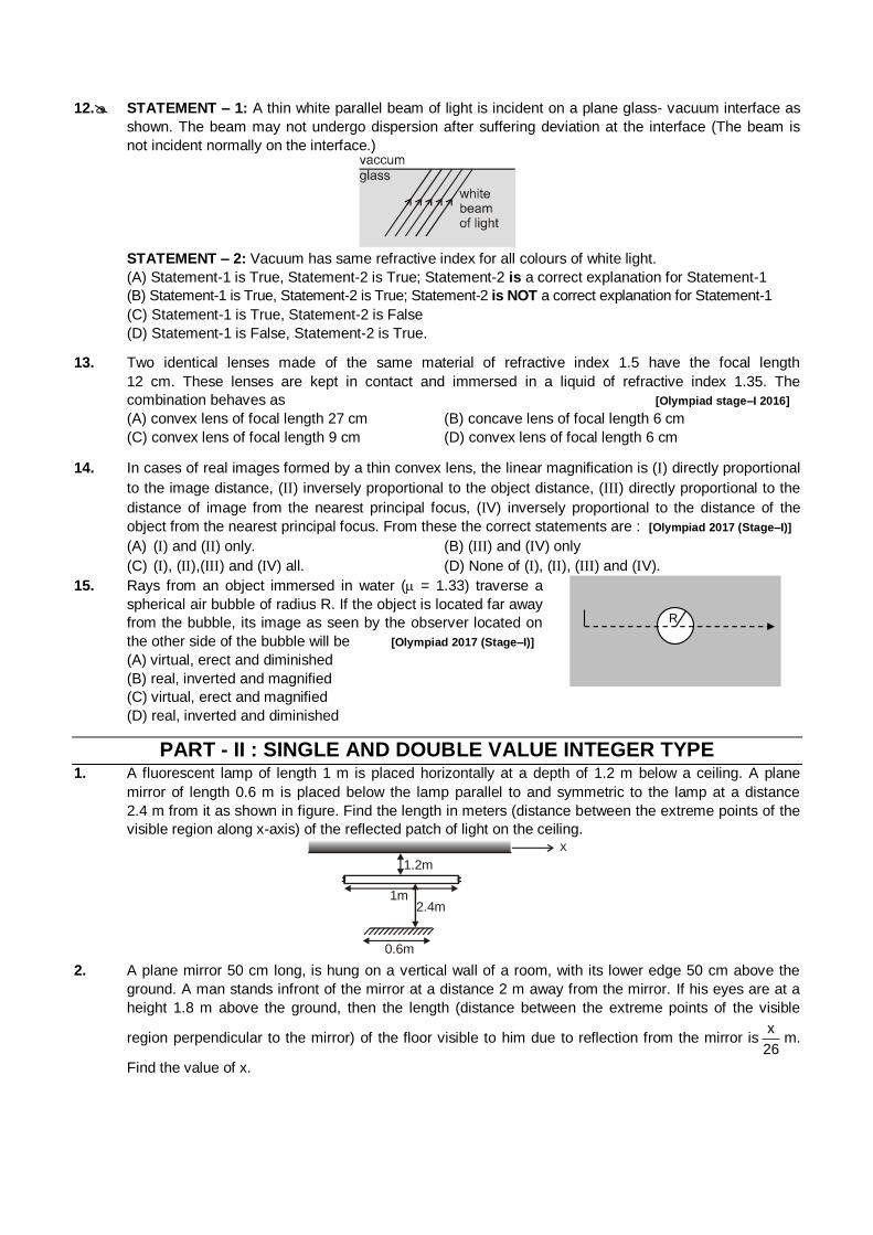
12. STATEMENT – 1: A thin white parallel beam of light is incident on a plane glass- vacuum interface as
shown. The beam may not undergo dispersion after suffering deviation at the interface (The beam is
not incident normally on the interface.)
STATEMENT – 2: Vacuum has same refractive index for all colours of white light.
(A) Statement-1 is True, Statement-2 is True; Statement-2 is a correct explanation for Statement-1
(B) Statement-1 is True, Statement-2 is True; Statement-2 is NOT a correct explanation for Statement-1
(C) Statement-1 is True, Statement-2 is False
(D) Statement-1 is False, Statement-2 is True.
13. Two identical lenses made of the same material of refractive index 1.5 have the focal length
12 cm. These lenses are kept in contact and immersed in a liquid of refractive index 1.35. The
combination behaves as [Olympiad stage–I 2016]
(A) convex lens of focal length 27 cm (B) concave lens of focal length 6 cm
(C) convex lens of focal length 9 cm (D) convex lens of focal length 6 cm
14. In cases of real images formed by a thin convex lens, the linear magnification is () directly proportional
to the image distance, () inversely proportional to the object distance, () directly proportional to the
distance of image from the nearest principal focus, (V) inversely proportional to the distance of the
object from the nearest principal focus. From these the correct statements are : [Olympiad 2017 (Stage–I)]
(A) () and () only. (B) () and (V) only
(C) (), (),() and (V) all. (D) None of (), (), () and (V).
15. Rays from an object immersed in water ( = 1.33) traverse a
spherical air bubble of radius R. If the object is located far away
from the bubble, its image as seen by the observer located on
the other side of the bubble will be [Olympiad 2017 (Stage–I)]
(A) virtual, erect and diminished
(B) real, inverted and magnified
(C) virtual, erect and magnified
(D) real, inverted and diminished
R
PART - II : SINGLE AND DOUBLE VALUE INTEGER TYPE 1. A fluorescent lamp of length 1 m is placed horizontally at a depth of 1.2 m below a ceiling. A plane
mirror of length 0.6 m is placed below the lamp parallel to and symmetric to the lamp at a distance
2.4 m from it as shown in figure. Find the length in meters (distance between the extreme points of the
visible region along x-axis) of the reflected patch of light on the ceiling.
1m
1.2m
2.4m
0.6m
x
2. A plane mirror 50 cm long, is hung on a vertical wall of a room, with its lower edge 50 cm above the
ground. A man stands infront of the mirror at a distance 2 m away from the mirror. If his eyes are at a
height 1.8 m above the ground, then the length (distance between the extreme points of the visible
region perpendicular to the mirror) of the floor visible to him due to reflection from the mirror isx
26m.
Find the value of x.
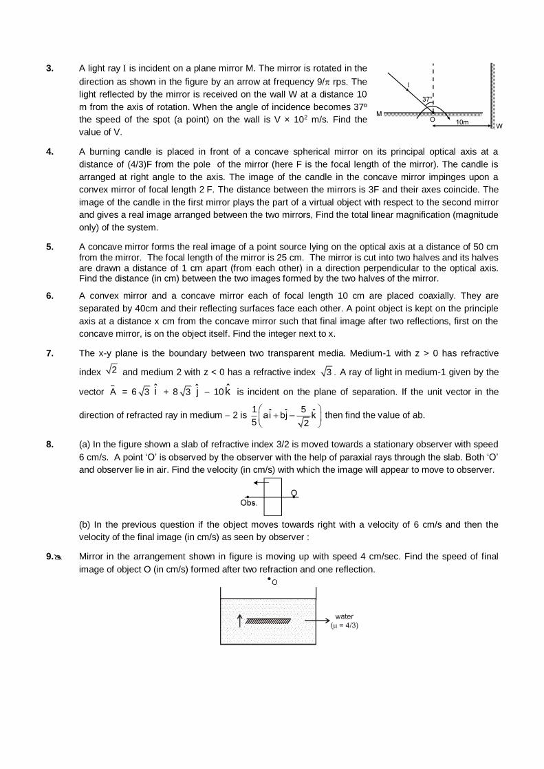
3. A light ray is incident on a plane mirror M. The mirror is rotated in the
direction as shown in the figure by an arrow at frequency 9/ rps. The
light reflected by the mirror is received on the wall W at a distance 10
m from the axis of rotation. When the angle of incidence becomes 37º
the speed of the spot (a point) on the wall is V × 102 m/s. Find the
value of V.
4. A burning candle is placed in front of a concave spherical mirror on its principal optical axis at a
distance of (4/3)F from the pole of the mirror (here F is the focal length of the mirror). The candle is
arranged at right angle to the axis. The image of the candle in the concave mirror impinges upon a
convex mirror of focal length 2 F. The distance between the mirrors is 3F and their axes coincide. The
image of the candle in the first mirror plays the part of a virtual object with respect to the second mirror
and gives a real image arranged between the two mirrors, Find the total linear magnification (magnitude
only) of the system.
5. A concave mirror forms the real image of a point source lying on the optical axis at a distance of 50 cm from the mirror. The focal length of the mirror is 25 cm. The mirror is cut into two halves and its halves are drawn a distance of 1 cm apart (from each other) in a direction perpendicular to the optical axis. Find the distance (in cm) between the two images formed by the two halves of the mirror.
6. A convex mirror and a concave mirror each of focal length 10 cm are placed coaxially. They are
separated by 40cm and their reflecting surfaces face each other. A point object is kept on the principle
axis at a distance x cm from the concave mirror such that final image after two reflections, first on the
concave mirror, is on the object itself. Find the integer next to x.
7. The x-y plane is the boundary between two transparent media. Medium-1 with z > 0 has refractive
index 2 and medium 2 with z < 0 has a refractive index 3 A ray of light in medium-1 given by the
vector A = 6 3 i + 8 3 j 10 k is incident on the plane of separation. If the unit vector in the
direction of refracted ray in medium 2 is 1 5ˆ ˆ ˆai bj – k5 2
then find the value of ab.
8. (a) In the figure shown a slab of refractive index 3/2 is moved towards a stationary observer with speed
6 cm/s. A point ‘O’ is observed by the observer with the help of paraxial rays through the slab. Both ‘O’
and observer lie in air. Find the velocity (in cm/s) with which the image will appear to move to observer.
(b) In the previous question if the object moves towards right with a velocity of 6 cm/s and then the
velocity of the final image (in cm/s) as seen by observer :
9. Mirror in the arrangement shown in figure is moving up with speed 4 cm/sec. Find the speed of final
image of object O (in cm/s) formed after two refraction and one reflection.
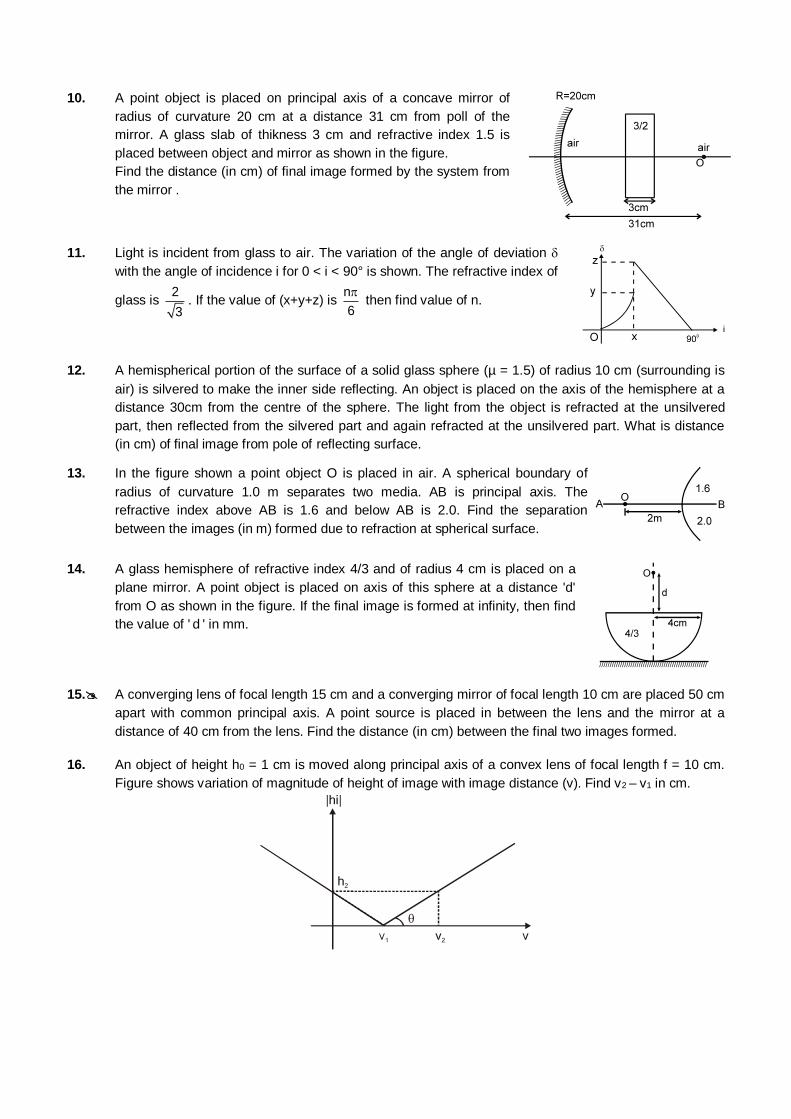
10. A point object is placed on principal axis of a concave mirror of
radius of curvature 20 cm at a distance 31 cm from poll of the
mirror. A glass slab of thikness 3 cm and refractive index 1.5 is
placed between object and mirror as shown in the figure.
Find the distance (in cm) of final image formed by the system from
the mirror .
11. Light is incident from glass to air. The variation of the angle of deviation
with the angle of incidence i for 0 < i < 90° is shown. The refractive index of
glass is 2
3. If the value of (x+y+z) is
n
6
then find value of n.
12. A hemispherical portion of the surface of a solid glass sphere (µ = 1.5) of radius 10 cm (surrounding is
air) is silvered to make the inner side reflecting. An object is placed on the axis of the hemisphere at a
distance 30cm from the centre of the sphere. The light from the object is refracted at the unsilvered
part, then reflected from the silvered part and again refracted at the unsilvered part. What is distance
(in cm) of final image from pole of reflecting surface.
13. In the figure shown a point object O is placed in air. A spherical boundary of
radius of curvature 1.0 m separates two media. AB is principal axis. The
refractive index above AB is 1.6 and below AB is 2.0. Find the separation
between the images (in m) formed due to refraction at spherical surface.
14. A glass hemisphere of refractive index 4/3 and of radius 4 cm is placed on a
plane mirror. A point object is placed on axis of this sphere at a distance 'd'
from O as shown in the figure. If the final image is formed at infinity, then find
the value of ' d ' in mm.
15. A converging lens of focal length 15 cm and a converging mirror of focal length 10 cm are placed 50 cm
apart with common principal axis. A point source is placed in between the lens and the mirror at a
distance of 40 cm from the lens. Find the distance (in cm) between the final two images formed.
16. An object of height h0 = 1 cm is moved along principal axis of a convex lens of focal length f = 10 cm.
Figure shows variation of magnitude of height of image with image distance (v). Find v2 – v1 in cm.
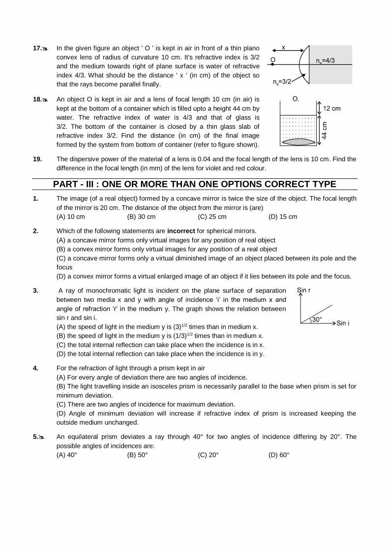
17. In the given figure an object ' O ' is kept in air in front of a thin plano
convex lens of radius of curvature 10 cm. It's refractive index is 3/2
and the medium towards right of plane surface is water of refractive
index 4/3. What should be the distance ' x ' (in cm) of the object so
that the rays become parallel finally.
18. An object O is kept in air and a lens of focal length 10 cm (in air) is
kept at the bottom of a container which is filled upto a height 44 cm by
water. The refractive index of water is 4/3 and that of glass is
3/2. The bottom of the container is closed by a thin glass slab of
refractive index 3/2. Find the distance (in cm) of the final image
formed by the system from bottom of container (refer to figure shown).
19. The dispersive power of the material of a lens is 0.04 and the focal length of the lens is 10 cm. Find the
difference in the focal length (in mm) of the lens for violet and red colour.
PART - III : ONE OR MORE THAN ONE OPTIONS CORRECT TYPE
1. The image (of a real object) formed by a concave mirror is twice the size of the object. The focal length
of the mirror is 20 cm. The distance of the object from the mirror is (are)
(A) 10 cm (B) 30 cm (C) 25 cm (D) 15 cm
2. Which of the following statements are incorrect for spherical mirrors.
(A) a concave mirror forms only virtual images for any position of real object
(B) a convex mirror forms only virtual images for any position of a real object
(C) a concave mirror forms only a virtual diminished image of an object placed between its pole and the
focus
(D) a convex mirror forms a virtual enlarged image of an object if it lies between its pole and the focus.
3. A ray of monochromatic light is incident on the plane surface of separation
between two media x and y with angle of incidence ‘i’ in the medium x and
angle of refraction ‘r’ in the medium y. The graph shows the relation between
sin r and sin i.
(A) the speed of light in the medium y is (3)1/2 times than in medium x.
(B) the speed of light in the medium y is (1/3)1/2 times than in medium x.
(C) the total internal reflection can take place when the incidence is in x.
(D) the total internal reflection can take place when the incidence is in y.
4. For the refraction of light through a prism kept in air
(A) For every angle of deviation there are two angles of incidence.
(B) The light travelling inside an isosceles prism is necessarily parallel to the base when prism is set for
minimum deviation.
(C) There are two angles of incidence for maximum deviation.
(D) Angle of minimum deviation will increase if refractive index of prism is increased keeping the
outside medium unchanged.
5. An equilateral prism deviates a ray through 40° for two angles of incidence differing by 20°. The
possible angles of incidences are:
(A) 40° (B) 50° (C) 20° (D) 60°
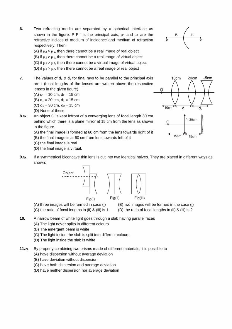
6. Two refracting media are separated by a spherical interface as
shown in the figure. P P is the principal axis, 1 and 2 are the
refractive indices of medium of incidence and medium of refraction
respectively. Then:
(A) if 2 > 1, then there cannot be a real image of real object
(B) if 2 > 1, then there cannot be a real image of virtual object
(C) if 1 > 2, then there cannot be a virtual image of virtual object
(D) if 1 > 2, then there cannot be a real image of real object
7. The values of d1 & d2 for final rays to be parallel to the principal axis
are : (focal lengths of the lenses are written above the respective
lenses in the given figure)
(A) d1 = 10 cm, d2 = 15 cm
(B) d1 = 20 cm, d2 = 15 cm
(C) d1 = 30 cm, d2 = 15 cm
(D) None of these
8. An object O is kept infront of a converging lens of focal length 30 cm
behind which there is a plane mirror at 15 cm from the lens as shown
in the figure.
(A) the final image is formed at 60 cm from the lens towards right of it
(B) the final image is at 60 cm from lens towards left of it
(C) the final image is real
(D) the final image is virtual.
9. If a symmetrical biconcave thin lens is cut into two identical halves. They are placed in different ways as
shown:
(A) three images will be formed in case (i) (B) two images will be formed in the case (i)
(C) the ratio of focal lengths in (ii) & (iii) is 1 (D) the ratio of focal lengths in (ii) & (iii) is 2
10. A narrow beam of white light goes through a slab having parallel faces
(A) The light never splits in different colours
(B) The emergent beam is white
(C) The light inside the slab is split into different colours
(D) The light inside the slab is white
11. By properly combining two prisms made of different materials, it is possible to
(A) have dispersion without average deviation
(B) have deviation without dispersion
(C) have both dispersion and average deviation
(D) have neither dispersion nor average deviation
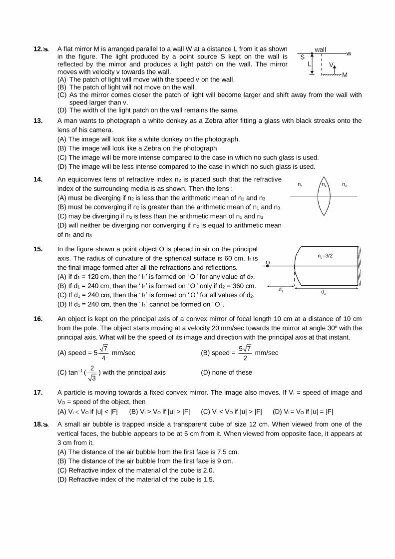
12. A flat mirror M is arranged parallel to a wall W at a distance L from it as shown in the figure. The light produced by a point source S kept on the wall is reflected by the mirror and produces a light patch on the wall. The mirror moves with velocity v towards the wall.
(A) The patch of light will move with the speed v on the wall. (B) The patch of light will not move on the wall.
L S
wall w
V
M
(C) As the mirror comes closer the patch of light will become larger and shift away from the wall with speed larger than v.
(D) The width of the light patch on the wall remains the same.
13. A man wants to photograph a white donkey as a Zebra after fitting a glass with black streaks onto the
lens of his camera.
(A) The image will look like a white donkey on the photograph.
(B) The image will look like a Zebra on the photograph
(C) The image will be more intense compared to the case in which no such glass is used.
(D) The image will be less intense compared to the case in which no such glass is used.
14. An equiconvex lens of refractive index n2 is placed such that the refractive
index of the surrounding media is as shown. Then the lens :
(A) must be diverging if n2 is less than the arithmetic mean of n1 and n3
(B) must be converging if n2 is greater than the arithmetic mean of n1 and n3
(C) may be diverging if n2 is less than the arithmetic mean of n1 and n3
(D) will neither be diverging nor converging if n2 is equal to arithmetic mean
of n1 and n3
15. In the figure shown a point object O is placed in air on the principal
axis. The radius of curvature of the spherical surface is 60 cm. If is
the final image formed after all the refractions and reflections.
(A) If d1 = 120 cm, then the ‘ If ’ is formed on ‘ O ’ for any value of d2.
(B) If d1 = 240 cm, then the ‘ If ’ is formed on ‘ O ’ only if d2 = 360 cm.
(C) If d1 = 240 cm, then the ‘ If ’ is formed on ‘ O ’ for all values of d2.
(D) If d1 = 240 cm, then the ‘ If ’ cannot be formed on ‘ O ‘.
16. An object is kept on the principal axis of a convex mirror of focal length 10 cm at a distance of 10 cm
from the pole. The object starts moving at a velocity 20 mm/sec towards the mirror at angle 30º with the
principal axis. What will be the speed of its image and direction with the principal axis at that instant.
(A) speed = 57
4 mm/sec (B) speed =
5 7
2 mm/sec
(C) tan–1 (2
3) with the principal axis (D) none of these
17. A particle is moving towards a fixed convex mirror. The image also moves. If Vi = speed of image and
VO = speed of the object, then
(A) Vi VO if |u| < |F| (B) Vi > VO if |u| > |F| (C) Vi < VO if |u| > |F| (D) Vi = VO if |u| = |F|
18. A small air bubble is trapped inside a transparent cube of size 12 cm. When viewed from one of the
vertical faces, the bubble appears to be at 5 cm from it. When viewed from opposite face, it appears at
3 cm from it.
(A) The distance of the air bubble from the first face is 7.5 cm.
(B) The distance of the air bubble from the first face is 9 cm.
(C) Refractive index of the material of the cube is 2.0.
(D) Refractive index of the material of the cube is 1.5.
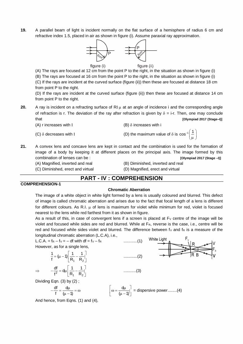
19. A parallel beam of light is incident normally on the flat surface of a hemisphere of radius 6 cm and
refractive index 1.5, placed in air as shown in figure (i). Assume paraxial ray approximation.
(A) The rays are focused at 12 cm from the point P to the right, in the situation as shown in figure (i)
(B) The rays are focused at 16 cm from the point P to the right, in the situation as shown in figure (i)
(C) If the rays are incident at the curved surface (figure (ii)) then these are focused at distance 18 cm
from point P to the right.
(D) If the rays are incident at the curved surface (figure (ii)) then these are focused at distance 14 cm
from point P to the right.
20. A ray is incident on a refracting surface of R at an angle of incidence i and the corresponding angle
of refraction is r. The deviation of the ray after refraction is given by = i-r. Then, one may conclude
that [Olympiad 2017 (Stage–I)]
(A) r increases with (B) increases with i
(C) decreases with (D) the maximum value of is 1 1cos
21. A convex lens and concave lens are kept in contact and the combination is used for the formation of
image of a body by keeping it at different places on the principal axis. The image formed by this
combination of lenses can be : [Olympiad 2017 (Stage –I)]
(A) Magnified, inverted and real (B) Diminished, inverted and real
(C) Diminished, erect and virtual (D) Magnified, erect and virtual
PART - IV : COMPREHENSION COMPREHENSION-1
Chromatic Aberration
The image of a white object in white light formed by a lens is usually coloured and blurred. This defect
of image is called chromatic aberration and arises due to the fact that focal length of a lens is different
for different colours. As R.I. of lens is maximum for violet while minimum for red, violet is focused
nearest to the lens while red farthest from it as shown in figure.
As a result of this, in case of convergent lens if a screen is placed at FV centre of the image will be
violet and focused while sides are red and blurred. While at FR, reverse is the case, i.e., centre will be
red and focused while sides violet and blurred. The difference between fV and fR is a measure of the
longitudinal chromatic aberration (L.C.A), i.e.,
L.C.A. = fR – fV = – df with df = fV – fR ............(1)
However, as for a single lens,
1 2
1 1 1( 1)
f R R
............(2)
2
1 2
df 1 1d
R Rf
...........(3)
Dividing Eqn. (3) by (2) ;
df d
f ( 1)
d
( 1)
= dispersive power ........(4)
And hence, from Eqns. (1) and (4),
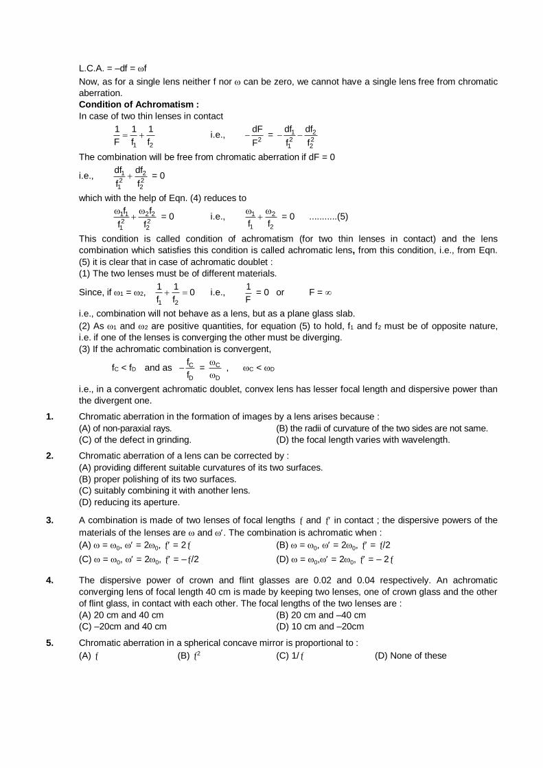
L.C.A. = –df = f
Now, as for a single lens neither f nor can be zero, we cannot have a single lens free from chromatic
aberration.
Condition of Achromatism :
In case of two thin lenses in contact
1 2
1 1 1
F f f i.e.,
2
dF
F = 1 2
2 21 2
df df
f f
The combination will be free from chromatic aberration if dF = 0
i.e., 1 22 21 2
df df
f f = 0
which with the help of Eqn. (4) reduces to
1 1 2 22 21 2
f f
f f
= 0 i.e., 1 2
1 2f f
= 0 ...........(5)
This condition is called condition of achromatism (for two thin lenses in contact) and the lens
combination which satisfies this condition is called achromatic lens, from this condition, i.e., from Eqn.
(5) it is clear that in case of achromatic doublet :
(1) The two lenses must be of different materials.
Since, if 1 = 2, 1 2
1 10
f f i.e.,
1
F = 0 or F =
i.e., combination will not behave as a lens, but as a plane glass slab.
(2) As 1 and 2 are positive quantities, for equation (5) to hold, f1 and f2 must be of opposite nature,
i.e. if one of the lenses is converging the other must be diverging.
(3) If the achromatic combination is convergent,
fC < fD and as C
D
f
f = C
D
, C < D
i.e., in a convergent achromatic doublet, convex lens has lesser focal length and dispersive power than
the divergent one.
1. Chromatic aberration in the formation of images by a lens arises because :
(A) of non-paraxial rays. (B) the radii of curvature of the two sides are not same.
(C) of the defect in grinding. (D) the focal length varies with wavelength.
2. Chromatic aberration of a lens can be corrected by :
(A) providing different suitable curvatures of its two surfaces.
(B) proper polishing of its two surfaces.
(C) suitably combining it with another lens.
(D) reducing its aperture.
3. A combination is made of two lenses of focal lengths and in contact ; the dispersive powers of the
materials of the lenses are and . The combination is achromatic when :
(A) = 0, = 20, = 2 (B) = 0, = 20, = /2
(C) = 0, = 20, = –/2 (D) = 0, = 20, = – 2
4. The dispersive power of crown and flint glasses are 0.02 and 0.04 respectively. An achromatic
converging lens of focal length 40 cm is made by keeping two lenses, one of crown glass and the other
of flint glass, in contact with each other. The focal lengths of the two lenses are :
(A) 20 cm and 40 cm (B) 20 cm and –40 cm
(C) –20cm and 40 cm (D) 10 cm and –20cm
5. Chromatic aberration in a spherical concave mirror is proportional to :
(A) (B) 2 (C) 1/ (D) None of these
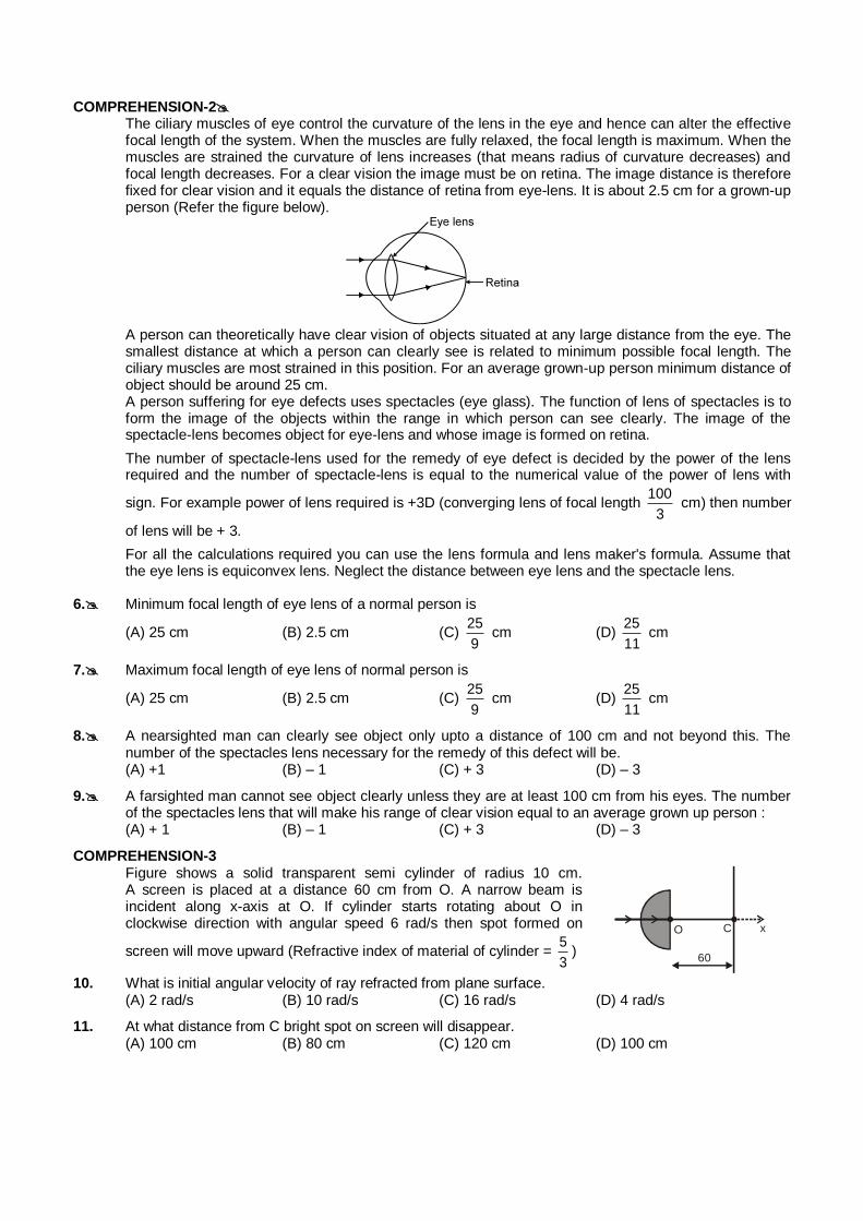
COMPREHENSION-2 The ciliary muscles of eye control the curvature of the lens in the eye and hence can alter the effective
focal length of the system. When the muscles are fully relaxed, the focal length is maximum. When the muscles are strained the curvature of lens increases (that means radius of curvature decreases) and focal length decreases. For a clear vision the image must be on retina. The image distance is therefore fixed for clear vision and it equals the distance of retina from eye-lens. It is about 2.5 cm for a grown-up person (Refer the figure below).
A person can theoretically have clear vision of objects situated at any large distance from the eye. The
smallest distance at which a person can clearly see is related to minimum possible focal length. The ciliary muscles are most strained in this position. For an average grown-up person minimum distance of object should be around 25 cm.
A person suffering for eye defects uses spectacles (eye glass). The function of lens of spectacles is to form the image of the objects within the range in which person can see clearly. The image of the spectacle-lens becomes object for eye-lens and whose image is formed on retina.
The number of spectacle-lens used for the remedy of eye defect is decided by the power of the lens required and the number of spectacle-lens is equal to the numerical value of the power of lens with
sign. For example power of lens required is +3D (converging lens of focal length 100
3 cm) then number
of lens will be + 3.
For all the calculations required you can use the lens formula and lens maker's formula. Assume that the eye lens is equiconvex lens. Neglect the distance between eye lens and the spectacle lens.
6. Minimum focal length of eye lens of a normal person is
(A) 25 cm (B) 2.5 cm (C) 25
9 cm (D)
25
11 cm
7. Maximum focal length of eye lens of normal person is
(A) 25 cm (B) 2.5 cm (C) 25
9 cm (D)
25
11 cm
8. A nearsighted man can clearly see object only upto a distance of 100 cm and not beyond this. The number of the spectacles lens necessary for the remedy of this defect will be.
(A) +1 (B) – 1 (C) + 3 (D) – 3
9. A farsighted man cannot see object clearly unless they are at least 100 cm from his eyes. The number of the spectacles lens that will make his range of clear vision equal to an average grown up person :
(A) + 1 (B) – 1 (C) + 3 (D) – 3
COMPREHENSION-3 Figure shows a solid transparent semi cylinder of radius 10 cm.
A screen is placed at a distance 60 cm from O. A narrow beam is incident along x-axis at O. If cylinder starts rotating about O in clockwise direction with angular speed 6 rad/s then spot formed on
screen will move upward (Refractive index of material of cylinder = 5
3)
O C x
60
10. What is initial angular velocity of ray refracted from plane surface. (A) 2 rad/s (B) 10 rad/s (C) 16 rad/s (D) 4 rad/s
11. At what distance from C bright spot on screen will disappear. (A) 100 cm (B) 80 cm (C) 120 cm (D) 100 cm
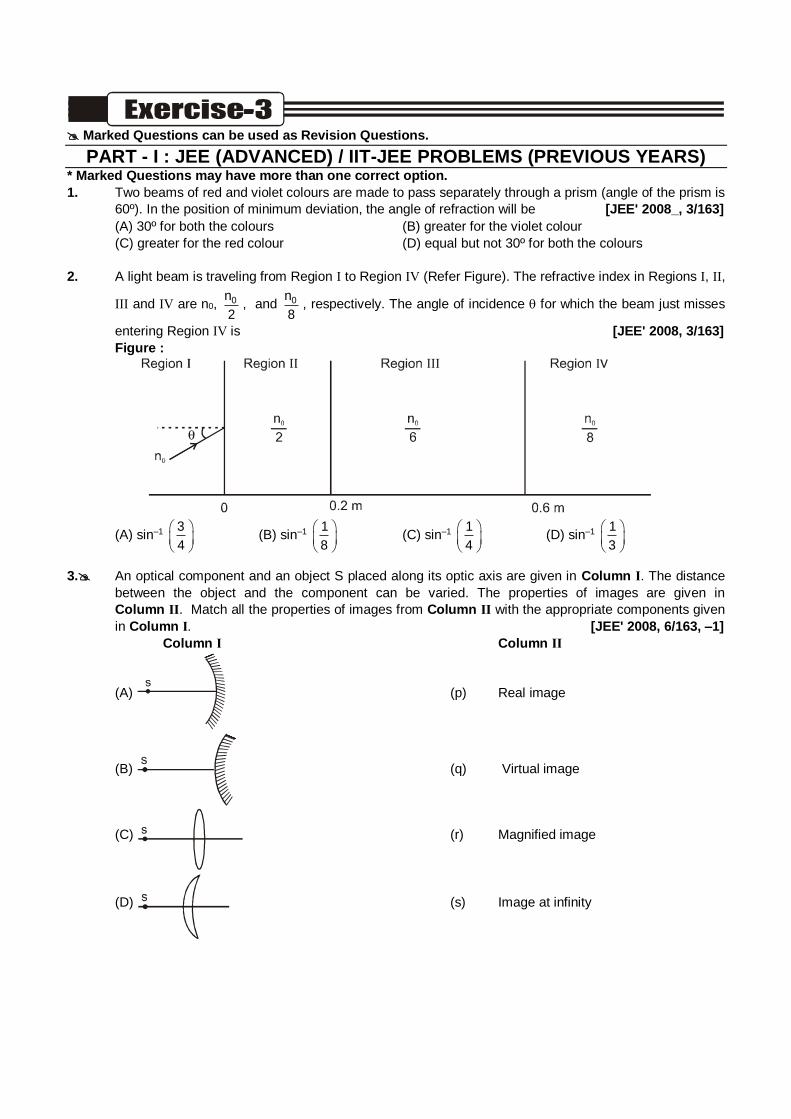
Marked Questions can be used as Revision Questions.
PART - I : JEE (ADVANCED) / IIT-JEE PROBLEMS (PREVIOUS YEARS) * Marked Questions may have more than one correct option.
1. Two beams of red and violet colours are made to pass separately through a prism (angle of the prism is
60º). In the position of minimum deviation, the angle of refraction will be [JEE' 2008_, 3/163]
(A) 30º for both the colours (B) greater for the violet colour
(C) greater for the red colour (D) equal but not 30º for both the colours
2. A light beam is traveling from Region I to Region IV (Refer Figure). The refractive index in Regions I, II,
III and IV are n0, 0n
2, and 0n
8, respectively. The angle of incidence for which the beam just misses
entering Region IV is [JEE' 2008, 3/163]
Figure :
(A) sin–1 3
4
(B) sin–1 1
8
(C) sin–1 1
4
(D) sin–1 1
3
3. An optical component and an object S placed along its optic axis are given in Column I. The distance
between the object and the component can be varied. The properties of images are given in
Column II. Match all the properties of images from Column II with the appropriate components given
in Column I. [JEE' 2008, 6/163, –1]
Column I Column II
(A) (p) Real image
(B) (q) Virtual image
(C) (r) Magnified image
(D) (s) Image at infinity
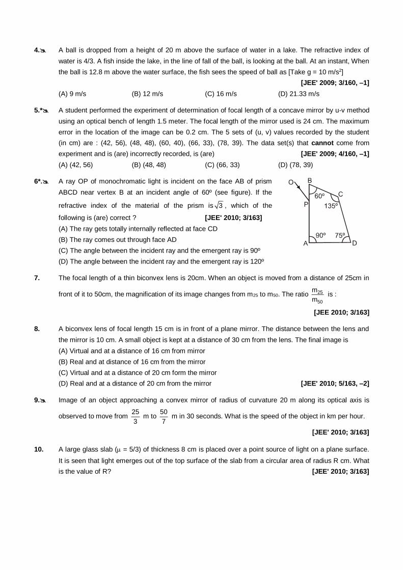
4. A ball is dropped from a height of 20 m above the surface of water in a lake. The refractive index of
water is 4/3. A fish inside the lake, in the line of fall of the ball, is looking at the ball. At an instant, When
the ball is 12.8 m above the water surface, the fish sees the speed of ball as [Take g = 10 m/s2]
[JEE' 2009; 3/160, –1]
(A) 9 m/s (B) 12 m/s (C) 16 m/s (D) 21.33 m/s
5.* A student performed the experiment of determination of focal length of a concave mirror by u-v method
using an optical bench of length 1.5 meter. The focal length of the mirror used is 24 cm. The maximum
error in the location of the image can be 0.2 cm. The 5 sets of (u, v) values recorded by the student
(in cm) are : (42, 56), (48, 48), (60, 40), (66, 33), (78, 39). The data set(s) that cannot come from
experiment and is (are) incorrectly recorded, is (are) [JEE' 2009; 4/160, –1]
(A) (42, 56) (B) (48, 48) (C) (66, 33) (D) (78, 39)
6*. A ray OP of monochromatic light is incident on the face AB of prism
ABCD near vertex B at an incident angle of 60º (see figure). If the
refractive index of the material of the prism is 3 , which of the
following is (are) correct ? [JEE' 2010; 3/163]
(A) The ray gets totally internally reflected at face CD
(B) The ray comes out through face AD
(C) The angle between the incident ray and the emergent ray is 90º
(D) The angle between the incident ray and the emergent ray is 120º
7. The focal length of a thin biconvex lens is 20cm. When an object is moved from a distance of 25cm in
front of it to 50cm, the magnification of its image changes from m25 to m50. The ratio 25
50
m
m is :
[JEE 2010; 3/163]
8. A biconvex lens of focal length 15 cm is in front of a plane mirror. The distance between the lens and
the mirror is 10 cm. A small object is kept at a distance of 30 cm from the lens. The final image is
(A) Virtual and at a distance of 16 cm from mirror
(B) Real and at distance of 16 cm from the mirror
(C) Virtual and at a distance of 20 cm form the mirror
(D) Real and at a distance of 20 cm from the mirror [JEE' 2010; 5/163, –2]
9. Image of an object approaching a convex mirror of radius of curvature 20 m along its optical axis is
observed to move from 25
3 m to
50
7 m in 30 seconds. What is the speed of the object in km per hour.
[JEE' 2010; 3/163]
10. A large glass slab ( = 5/3) of thickness 8 cm is placed over a point source of light on a plane surface.
It is seen that light emerges out of the top surface of the slab from a circular area of radius R cm. What
is the value of R? [JEE' 2010; 3/163]
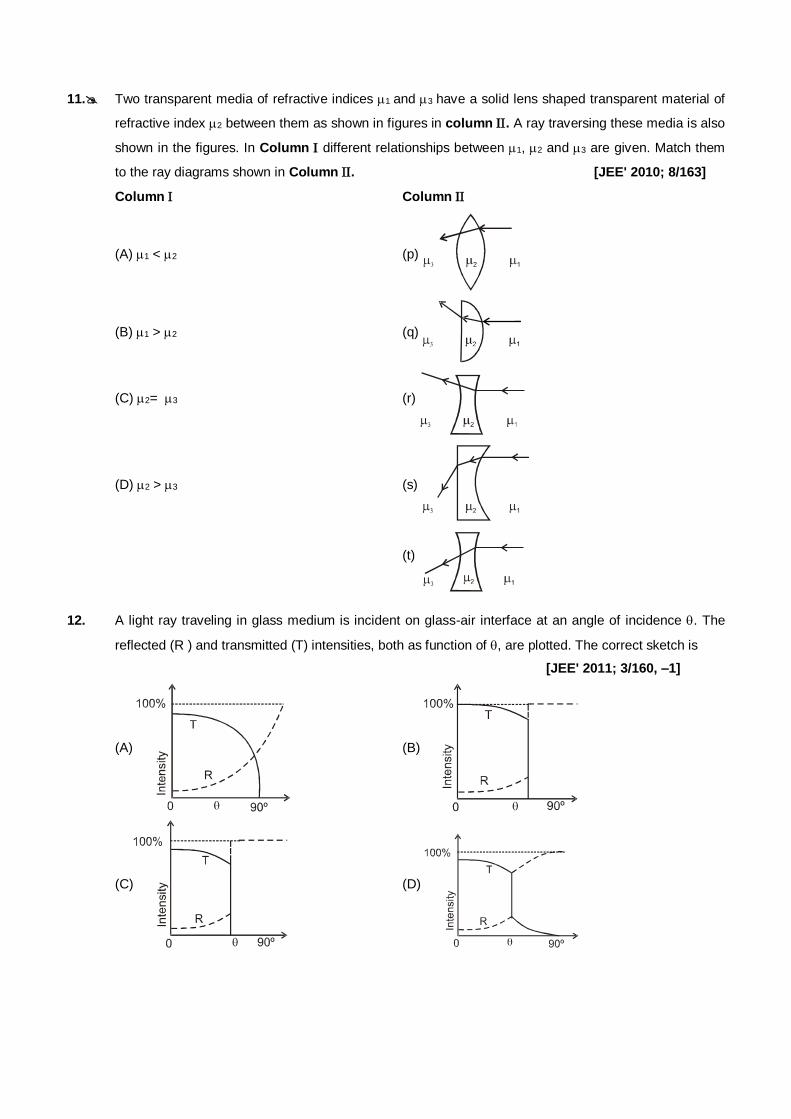
11. Two transparent media of refractive indices 1 and 3 have a solid lens shaped transparent material of
refractive index 2 between them as shown in figures in column . A ray traversing these media is also
shown in the figures. In Column different relationships between 1, 2 and 3 are given. Match them
to the ray diagrams shown in Column . [JEE' 2010; 8/163]
Column Column
(A) 1 < 2 (p)
(B) 1 > 2 (q)
(C) 2= 3 (r)
(D) 2 > 3 (s)
(t)
12. A light ray traveling in glass medium is incident on glass-air interface at an angle of incidence . The
reflected (R ) and transmitted (T) intensities, both as function of , are plotted. The correct sketch is
[JEE' 2011; 3/160, –1]
(A)
(B)
(C)
(D)
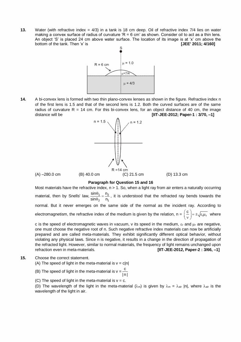
13. Water (with refractive index = 4/3) in a tank is 18 cm deep. Oil of refractive index 7/4 lies on water making a convex surface of radius of curvature ‘R = 6 cm’ as shown. Consider oil to act as a thin lens. An object ‘S’ is placed 24 cm above water surface. The location of its image is at ‘x’ cm above the bottom of the tank. Then ‘x’ is [JEE' 2011; 4/160]
14. A bi-convex lens is formed with two thin plano-convex lenses as shown in the figure. Refractive index n
of the first lens is 1.5 and that of the second lens is 1.2. Both the curved surfaces are of the same
radius of curvature R = 14 cm. For this bi-convex lens, for an object distance of 40 cm, the image
distance will be [IIT-JEE-2012; Paper-1 : 3/70, –1]
(A) –280.0 cm (B) 40.0 cm (C) 21.5 cm (D) 13.3 cm
Paragraph for Question 15 and 16
Most materials have the refractive index, n > 1. So, when a light ray from air enters a naturally occurring
material, then by Snells' law, 1 2
2 1
sin n
sin n
, it is understood that the refracted ray bends towards the
normal. But it never emerges on the same side of the normal as the incident ray. According to
electromagnetism, the refractive index of the medium is given by the relation, n = r r
c
where
c is the speed of electromagnetic waves in vacuum, v its speed in the medium, r and r are negative,
one must choose the negative root of n. Such negative refractive index materials can now be artificially
prepared and are called meta-materials. They exhibit significantly different optical behavior, without
violating any physical laws. Since n is negative, it results in a change in the direction of propagation of
the refracted light. However, similar to normal materials, the frequency of light remains unchanged upon
refraction even in meta-materials. [IIT-JEE-2012, Paper-2 : 3/66, –1]
15. Choose the correct statement.
(A) The speed of light in the meta-material is v = c|n|
(B) The speed of light in the meta-material is v =c
| n |
(C) The speed of light in the meta-material is v = c.
(D) The wavelength of the light in the meta-material (m) is given by m = air |n|, where air is the
wavelength of the light in air.
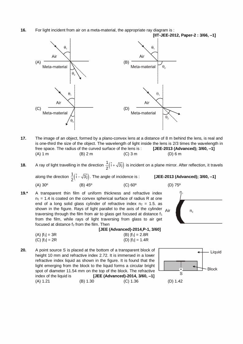
16. For light incident from air on a meta-material, the appropriate ray diagram is :
[IIT-JEE-2012, Paper-2 : 3/66, –1]
(A) (B)
(C) (D)
17. The image of an object, formed by a plano-convex lens at a distance of 8 m behind the lens, is real and
is one-third the size of the object. The wavelength of light inside the lens is 2/3 times the wavelength in
free space. The radius of the curved surface of the lens is : [JEE-2013 (Advanced); 3/60, –1]
(A) 1 m (B) 2 m (C) 3 m (D) 6 m
18. A ray of light travelling in the direction 1 ˆ ˆi 3 j2
is incident on a plane mirror. After reflection, it travels
along the direction 1 ˆ ˆi 3 j2
. The angle of incidence is : [JEE-2013 (Advanced); 3/60, –1]
(A) 30º (B) 45º (C) 60º (D) 75º
19.* A transparent thin film of uniform thickness and refractive index
n1 = 1.4 is coated on the convex spherical surface of radius R at one
end of a long solid glass cylinder of refractive index n2 = 1.5. as
shown in the figure. Rays of light parallel to the axis of the cylinder
traversing through the film from air to glass get focused at distance f1
from the film, while rays of light traversing from glass to air get
focused at distance f2 from the film. Then
[JEE (Advanced)-2014,P-1, 3/60]
(A) |f1| = 3R (B) |f1| = 2.8R
(C) |f2| = 2R (D) |f2| = 1.4R
20. A point source S is placed at the bottom of a transparent block of
height 10 mm and refractive index 2.72. It is immersed in a lower
refractive index liquid as shown in the figure. It is found that the
light emerging from the block to the liquid forms a circular bright
spot of diameter 11.54 mm on the top of the block. The refractive
index of the liquid is [JEE (Advanced)-2014, 3/60, –1]
(A) 1.21 (B) 1.30 (C) 1.36 (D) 1.42
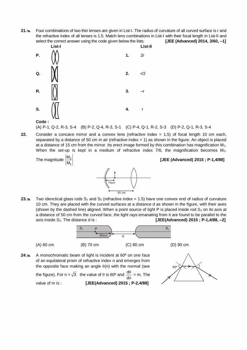
21. Four combinations of two thin lenses are given in List-I. The radius of curvature of all curved surface is r and
the refractive index of all lenses is 1.5. Match lens combinations in List-I with their focal length in List-II and
select the correct answer using the code given below the lists. [JEE (Advanced) 2014, 3/60, –1]
List-I List-II
P. 1. 2r
Q. 2. r/2
R. 3. –r
S. 4. r
Code :
(A) P-1, Q-2, R-3, S-4 (B) P-2, Q-4, R-3, S-1 (C) P-4, Q-1, R-2, S-3 (D) P-2, Q-1, R-3, S-4
22. Consider a concave mirror and a convex lens (refractive index = 1.5) of focal length 10 cm each,
separated by a distance of 50 cm in air (refractive index = 1) as shown in the figure. An object is placed
at a distance of 15 cm from the mirror. Its erect image formed by this combination has magnification M1.
When the set-up is kept in a medium of refractive index 7/6, the magnification becomes M2.
The magnitude 2
1
M
M [JEE (Advanced) 2015 ; P-1,4/88]
23. Two idenctical glass rods S1 and S2 (refractive index = 1.5) have one convex end of radius of curvature
10 cm. They are placed with the curved surfaces at a distance d as shown in the figure, with their axes
(shown by the dashed line) aligned. When a point source of light P is placed inside rod S1 on its axis at
a distance of 50 cm from the curved face, the light rays emanating from it are found to be parallel to the
axis inside S2. The distance d is : [JEE(Advanced) 2015 ; P-1,4/88, –2]
(A) 60 cm (B) 70 cm (C) 80 cm (D) 90 cm
24. A monochromatic beam of light is incident at 60º on one face
of an equilateral prism of refractive index n and emerges from
the opposite face making an angle (n) with the normal (see
the figure). For n = 3 the value of is 60º and d
dn
= m. The
value of m is : [JEE(Advanced) 2015 ; P-2,4/88]
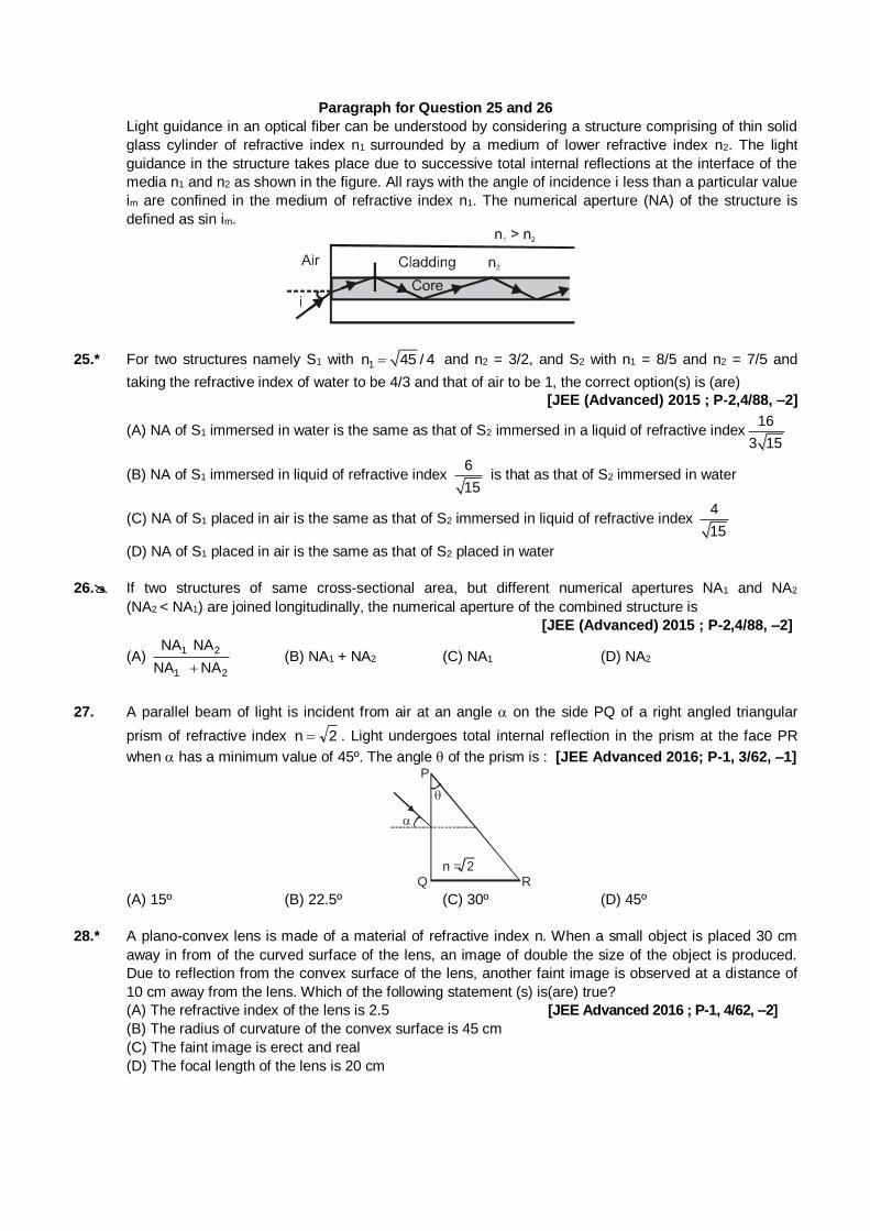
Paragraph for Question 25 and 26 Light guidance in an optical fiber can be understood by considering a structure comprising of thin solid
glass cylinder of refractive index n1 surrounded by a medium of lower refractive index n2. The light
guidance in the structure takes place due to successive total internal reflections at the interface of the
media n1 and n2 as shown in the figure. All rays with the angle of incidence i less than a particular value
im are confined in the medium of refractive index n1. The numerical aperture (NA) of the structure is
defined as sin im.
25.* For two structures namely S1 with 1n 45 / 4 and n2 = 3/2, and S2 with n1 = 8/5 and n2 = 7/5 and
taking the refractive index of water to be 4/3 and that of air to be 1, the correct option(s) is (are)
[JEE (Advanced) 2015 ; P-2,4/88, –2]
(A) NA of S1 immersed in water is the same as that of S2 immersed in a liquid of refractive index16
3 15
(B) NA of S1 immersed in liquid of refractive index 6
15 is that as that of S2 immersed in water
(C) NA of S1 placed in air is the same as that of S2 immersed in liquid of refractive index 4
15
(D) NA of S1 placed in air is the same as that of S2 placed in water
26. If two structures of same cross-sectional area, but different numerical apertures NA1 and NA2
(NA2 < NA1) are joined longitudinally, the numerical aperture of the combined structure is
[JEE (Advanced) 2015 ; P-2,4/88, –2]
(A) 1 2
1 2
NA NA
NA NA (B) NA1 + NA2 (C) NA1 (D) NA2
27. A parallel beam of light is incident from air at an angle on the side PQ of a right angled triangular
prism of refractive index 2n . Light undergoes total internal reflection in the prism at the face PR
when has a minimum value of 45º. The angle of the prism is : [JEE Advanced 2016; P-1, 3/62, –1]
n = 2
P
Q R (A) 15º (B) 22.5º (C) 30º (D) 45º
28.* A plano-convex lens is made of a material of refractive index n. When a small object is placed 30 cm
away in from of the curved surface of the lens, an image of double the size of the object is produced.
Due to reflection from the convex surface of the lens, another faint image is observed at a distance of
10 cm away from the lens. Which of the following statement (s) is(are) true?
(A) The refractive index of the lens is 2.5 [JEE Advanced 2016 ; P-1, 4/62, –2]
(B) The radius of curvature of the convex surface is 45 cm
(C) The faint image is erect and real
(D) The focal length of the lens is 20 cm
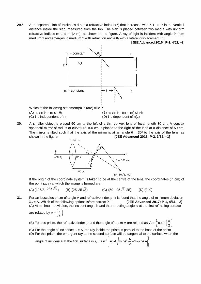
29.* A transparent slab of thickness d has a refractive index n(z) that increases with z. Here z is the vertical
distance inside the slab, measured from the top. The slab is placed between two media with uniform
refractive indices n1 and n2 (> n1), as shown in the figure. A ray of light is incident with angle i from
medium 1 and emerges in medium 2 with refraction angle f with a lateral displacement l :
[JEE Advanced 2016 ; P-1, 4/62, –2]
n1 = constant
n2 = constant
z
i 1
d
2 l f
n(z)
Which of the following statement(s) is (are) true ?
(A) n1 sini = n2 sin f (B) n1 sini =(n2 – n1) sin f
(C) l is independent of n2 (D) l is dependent of n(z)
30. A smaller object is placed 50 cm to the left of a thin convex lens of focal length 30 cm. A convex
spherical mirror of radius of curvature 100 cm is placed to the right of the lens at a distance of 50 cm.
The mirror is tilted such that the axis of the mirror is at an angle = 30º to the axis of the lens, as
shown in the figure. [JEE Advanced 2016; P-2, 3/62, –1]
(0, 0)
50 cm
R = 100 cm
(–50, 0)
f = 30 cm
x
(50 50 3, 50)
If the origin of the coordinate system is taken to be at the centre of the lens, the coordinates (in cm) of
the point (x, y) at which the image is formed are :
(A) (125/3, 25/ 3 ) (B) (25, 25 3) (C) (50 25 3, 25) (D) (0, 0)
31. For an isosceles prism of angle A and refractive index , it is found that the angle of minimum deviation
m = A. Which of the following options is/are correct ? [JEE Advanced 2017; P-1, 4/61, –2]
(A) At minimum deviation, the incident angle i1 and the refracting angle r1 at the first refracting surface
are related by r1 = 1i
2
(B) For this prism, the refractive index and the angle of prism A are related as 11A cos
2 2
(C) For the angle of incidence i1 = A, the ray inside the prism is parallel to the base of the prism (D) For this prism, the emergent ray at the second surface will be tangential to the surface when the
angle of incidence at the first surface is 1 2
1
Ai sin sinA 4cos 1 cosA
2
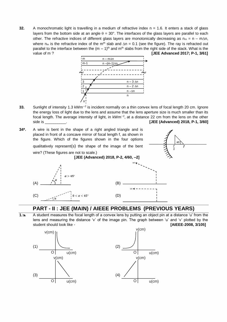
32. A monochromatic light is travelling in a medium of refractive index n = 1.6. It enters a stack of glass
layers from the bottom side at an angle = 30°. The interfaces of the glass layers are parallel to each
other. The refractive indices of different glass layers are monotonically decreasing as nm = n – mn,
where nm is the refractive index of the mth slab and n = 0.1 (see the figure). The ray is refracted out
parallel to the interface between the (m – 1)th and mth slabs from the right side of the stack. What is the
value of m ? [JEE Advanced 2017; P-1, 3/61] m n – mn
m-1 n –(m-1)n
3
2
1
n – 3 n
n – 2 n
n –n
n
33. Sunlight of intensity 1.3 kWm−2 is incident normally on a thin convex lens of focal length 20 cm. Ignore
the energy loss of light due to the lens and assume that the lens aperture size is much smaller than its
focal length. The average intensity of light, in kWm−2, at a distance 22 cm from the lens on the other
side is __________. [JEE (Advanced) 2018, P-1, 3/60]
34*. A wire is bent in the shape of a right angled triangle and is
placed in front of a concave mirror of focal length f, as shown in
the figure. Which of the figures shown in the four options
qualitatively represent(s) the shape of the image of the bent
wire? (These figures are not to scale.)
[JEE (Advanced) 2018, P-2, 4/60, –2]
(A) (B)
(C) (D)
PART - II : JEE (MAIN) / AIEEE PROBLEMS (PREVIOUS YEARS) 1. A student measures the focal length of a convex lens by putting an object pin at a distance ‘u’ from the
lens and measuring the distance ‘v’ of the image pin. The graph between ‘u’ and ‘v’ plotted by the
student should look like - [AIEEE-2008, 3/105]
(1)
v(cm)
O u(cm)
(2)
v(cm)
O u(cm)
(3)
v(cm)
O u(cm)
(4)
v(cm)
O u(cm)
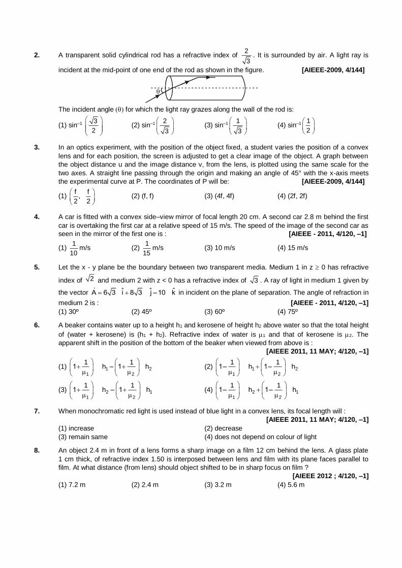
2. A transparent solid cylindrical rod has a refractive index of 2
3. It is surrounded by air. A light ray is
incident at the mid-point of one end of the rod as shown in the figure. [AIEEE-2009, 4/144]
The incident angle for which the light ray grazes along the wall of the rod is:
(1) sin–1 3
2
(2) sin–1 2
3
(3) sin–1 1
3
(4) sin–1 1
2
3. In an optics experiment, with the position of the object fixed, a student varies the position of a convex
lens and for each position, the screen is adjusted to get a clear image of the object. A graph between
the object distance u and the image distance v, from the lens, is plotted using the same scale for the
two axes. A straight line passing through the origin and making an angle of 45° with the x-axis meets
the experimental curve at P. The coordinates of P will be: [AIEEE-2009, 4/144]
(1) f f
,2 2
(2) (f, f) (3) (4f, 4f) (4) (2f, 2f)
4. A car is fitted with a convex side–view mirror of focal length 20 cm. A second car 2.8 m behind the first
car is overtaking the first car at a relative speed of 15 m/s. The speed of the image of the second car as
seen in the mirror of the first one is : [AIEEE - 2011, 4/120, –1]
(1) 1
10m/s (2)
1
15m/s (3) 10 m/s (4) 15 m/s
5. Let the x - y plane be the boundary between two transparent media. Medium 1 in z 0 has refractive
index of 2 and medium 2 with z < 0 has a refractive index of 3 . A ray of light in medium 1 given by
the vector ˆ ˆ ˆA 6 3 i 8 3 j –10 k in incident on the plane of separation. The angle of refraction in
medium 2 is : [AIEEE - 2011, 4/120, –1]
(1) 30º (2) 45º (3) 60º (4) 75º
6. A beaker contains water up to a height h1 and kerosene of height h2 above water so that the total height
of (water + kerosene) is (h1 + h2). Refractive index of water is 1 and that of kerosene is 2. The
apparent shift in the position of the bottom of the beaker when viewed from above is :
[AIEEE 2011, 11 MAY; 4/120, –1]
(1) 1 21 2
1 11 h – 1 h
(2) 1 21 2
1 11– h 1– h
(3) 2 11 2
1 11 h – 1 h
(4) 2 11 2
1 11– h 1– h
7. When monochromatic red light is used instead of blue light in a convex lens, its focal length will :
[AIEEE 2011, 11 MAY; 4/120, –1]
(1) increase (2) decrease
(3) remain same (4) does not depend on colour of light
8. An object 2.4 m in front of a lens forms a sharp image on a film 12 cm behind the lens. A glass plate
1 cm thick, of refractive index 1.50 is interposed between lens and film with its plane faces parallel to
film. At what distance (from lens) should object shifted to be in sharp focus on film ?
[AIEEE 2012 ; 4/120, –1]
(1) 7.2 m (2) 2.4 m (3) 3.2 m (4) 5.6 m
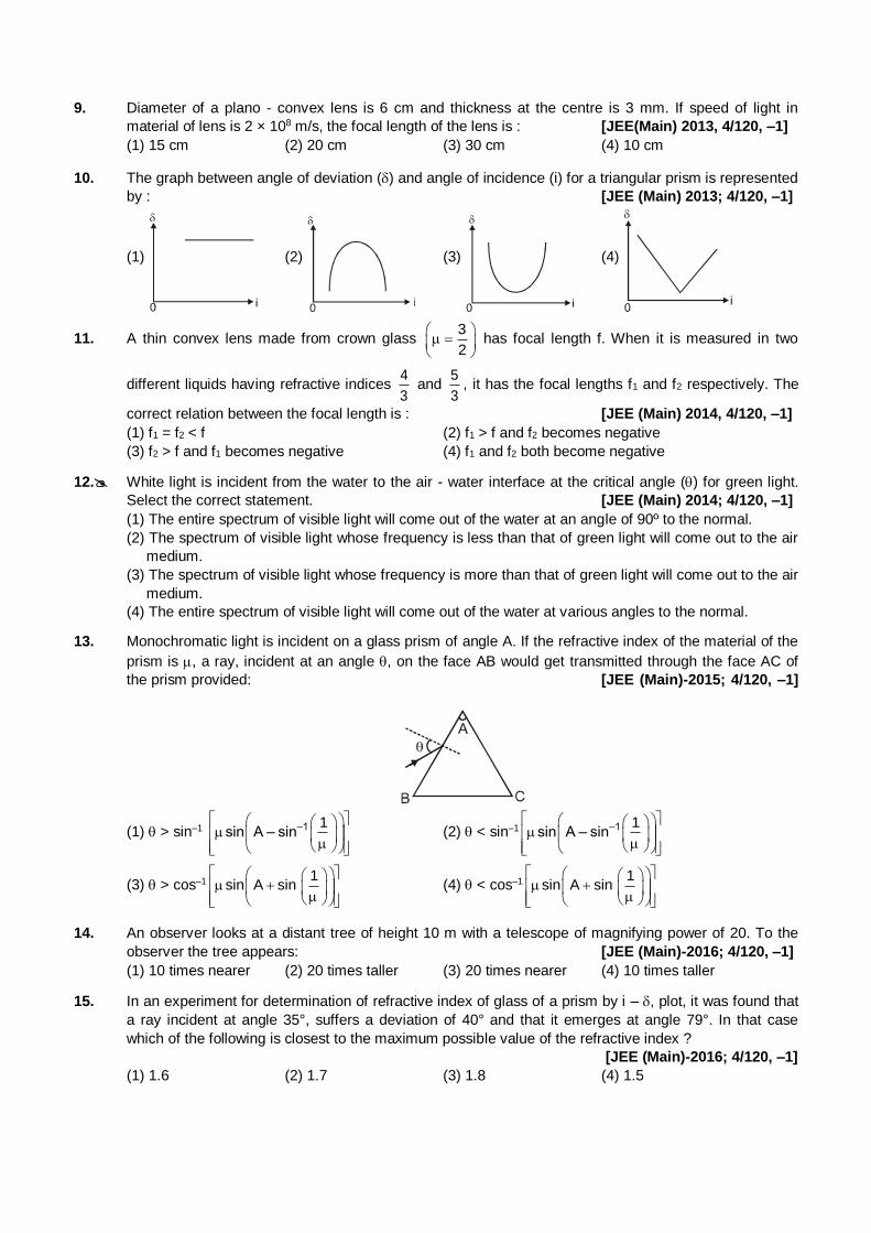
9. Diameter of a plano - convex lens is 6 cm and thickness at the centre is 3 mm. If speed of light in
material of lens is 2 × 10⁸ m/s, the focal length of the lens is : [JEE(Main) 2013, 4/120, –1]
(1) 15 cm (2) 20 cm (3) 30 cm (4) 10 cm
10. The graph between angle of deviation () and angle of incidence (i) for a triangular prism is represented
by : [JEE (Main) 2013; 4/120, –1]
(1) (2) (3) (4)
11. A thin convex lens made from crown glass 3
2
has focal length f. When it is measured in two
different liquids having refractive indices 4
3 and
5
3, it has the focal lengths f1 and f2 respectively. The
correct relation between the focal length is : [JEE (Main) 2014, 4/120, –1]
(1) f1 = f2 < f (2) f1 > f and f2 becomes negative
(3) f2 > f and f1 becomes negative (4) f1 and f2 both become negative
12. White light is incident from the water to the air - water interface at the critical angle () for green light.
Select the correct statement. [JEE (Main) 2014; 4/120, –1]
(1) The entire spectrum of visible light will come out of the water at an angle of 90º to the normal.
(2) The spectrum of visible light whose frequency is less than that of green light will come out to the air
medium.
(3) The spectrum of visible light whose frequency is more than that of green light will come out to the air
medium.
(4) The entire spectrum of visible light will come out of the water at various angles to the normal.
13. Monochromatic light is incident on a glass prism of angle A. If the refractive index of the material of the
prism is , a ray, incident at an angle , on the face AB would get transmitted through the face AC of
the prism provided: [JEE (Main)-2015; 4/120, –1]
(1) > sin–1 –1 1sin A – sin
(2) < sin–1 –1 1sin A – sin
(3) > cos–1 –1
1sin A sin
(4) < cos–1 –1
1sin A sin
14. An observer looks at a distant tree of height 10 m with a telescope of magnifying power of 20. To the
observer the tree appears: [JEE (Main)-2016; 4/120, –1]
(1) 10 times nearer (2) 20 times taller (3) 20 times nearer (4) 10 times taller
15. In an experiment for determination of refractive index of glass of a prism by i – , plot, it was found that
a ray incident at angle 35°, suffers a deviation of 40° and that it emerges at angle 79°. In that case
which of the following is closest to the maximum possible value of the refractive index ?
[JEE (Main)-2016; 4/120, –1]
(1) 1.6 (2) 1.7 (3) 1.8 (4) 1.5
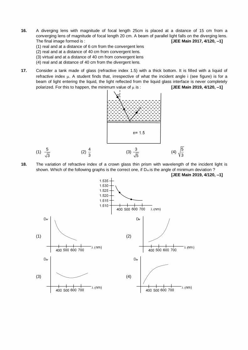
16. A diverging lens with magnitude of focal length 25cm is placed at a distance of 15 cm from a
converging lens of magnitude of focal length 20 cm. A beam of parallel light falls on the diverging lens.
The final image formed is : [JEE Main 2017, 4/120, –1]
(1) real and at a distance of 6 cm from the convergent lens
(2) real and at a distance of 40 cm from convergent lens.
(3) virtual and at a distance of 40 cm from convergent lens
(4) real and at distance of 40 cm from the divergent lens.
17. Consider a tank made of glass (refractive index 1.5) with a thick bottom. It is filled with a liquid of
refractive index . A student finds that, irrespective of what the incident angle i (see figure) is for a
beam of light entering the liquid, the light reflected from the liquid glass interface is never completely
polarized. For this to happen, the minimum value of is : [JEE Main 2019, 4/120, –1]
(1) 5
3 (2)
4
3 (3)
3
5 (4)
5
3
18. The variation of refractive index of a crown glass thin prism with wavelength of the incident light is
shown. Which of the following graphs is the correct one, if Dm is the angle of minimum deviation ?
[JEE Main 2019, 4/120, –1]
(1)
(2)
(3)
(4)
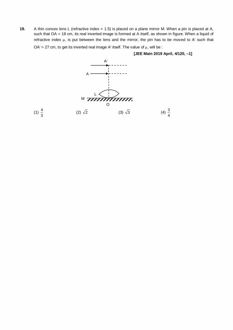
19. A thin convex lens L (refractive index = 1.5) is placed on a plane mirror M. When a pin is placed at A,
such that OA = 18 cm, its real inverted image is formed at A itself, as shown in figure. When a liquid of
refractive index is put between the lens and the mirror, the pin has to be moved to A' such that
OA' = 27 cm, to get its inverted real image A' itself. The value of will be :
[JEE Main 2019 April, 4/120, –1]
L
O
MN
A
A'
(1) 3
4 (2) 2 (3) 3 (4)
4
3
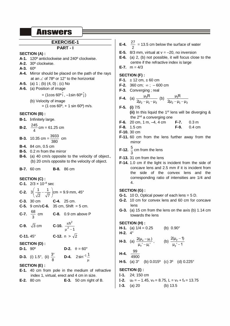
EXERCISE-1
PART - I
SECTION (A) :
A-1. 120º anticlockwise and 240º clockwise.
A-2. 30º clockwise.
A-3. 60º
A-4. Mirror should be placed on the path of the rays
at an of 78º or 12° to the horizontal
A-5. (a) 1 ; (b) (4, 0) ; (c) No
A-6. (a) Position of image
= (1cos 60º i , –1sin 60º j )
(b) Velocity of image
= (1 cos 60º, + 1 sin 60º) m/s.
SECTION (B) :
B-1. nfinitely large.
B-2. 245
4cm = 61.25 cm
B-3. 10.35 cm =3933
380 cm
B-4. 84 cm, 0.5 cm
B-5. 0.2 m from the mirror
B-6. (a) 40 cm/s opposite to the velocity of object.,
(b) 20 cm/s opposite to the velocity of object.
B-7. 60 cm B-8. 86 cm
SECTION (C) :
C-1. 2/3 × 10–8 sec
C-2. 1 1
3 cm2 7
= 9.9 mm, 45°
C-3. 30 cm C-4. 25 cm.
C-5. 9 cm/s C-6. 35 cm, Shift = 5 cm.
C-7. 68
3 cm C-8. 0.9 cm above P
C-9. 3 cm C-10. 2
2
h
1
C-11. 45° C-12. n > 2
SECTION (D) :
D-1. 90º D-2. = 60°
D-3. (i) 1.5°, (ii) 3
8
D-4.
1sin2 1
SECTION (E) :
E-1. 40 cm from pole in the medium of refractive
index 1, virtual, erect and 4 cm in size.
E-2. 80 cm E-3. 50 cm right of B.
E-4. 27
2 = 13.5 cm below the surface of water
E-5. 8/3 mm, virtual at v = –20, no inversion
E-6. (a) 2, (b) not possible, it will focus close to the
centre if the refractive index is large
E-7. m = 4/3
SECTION (F) :
F-1. ± 12 cm, ± 60 cm
F-2. 360 cm; ; – 600 cm
F-3. Converging ; real
F-4. (a) 3
2 1 3
µ R
2µ µ µ (b) 1
2 1 3
µ R
2µ µ µ
F-5. (i) 7/5
(ii) In this liquid the 1st lens will be diverging &
the 2nd a converging one
F-6. 20 cm, 1 m, –4, 4 cm F-7. 0.3 m
F-8. 1.5 cm F-9. 0.4 cm
F-10. 30 cm
F-11. 60 cm from the lens further away from the
mirror
F-12. 5
3cm from the lens
F-13. 31 cm from the lens
F-14. 1.0 cm if the light is incident from the side of
concave lens and 2.5 mm if it is incident from
the side of the convex lens and the
corresponding ratio of intensities are 1/4 and
4.
SECTION (G) :
G-1. 10 D, Optical power of each lens = 5 D.
G-2. 10 cm for convex lens and 60 cm for concave
lens
G-3. (a) 15 cm from the lens on the axis (b) 1.14 cm
towards the lens
SECTION (H) :
H-1. (a) 1/4 = 0.25 (b) 0.90°
H-2. 4°
H-3. (a) v r
v r
2(µ µ )
µ µ
, (b)
y
y
2(µ 1)
µ 1
H-4. 99
4900
H-5. (a) 3° (b) 0.015º (c) 3º (d) 0.225°
SECTION () : -1. 24; 150 cm
-2. u0 = – 1.45, v0 = 8.75, L = v0 + fe = 13.75
-3. (a) 20 (b) 13.5
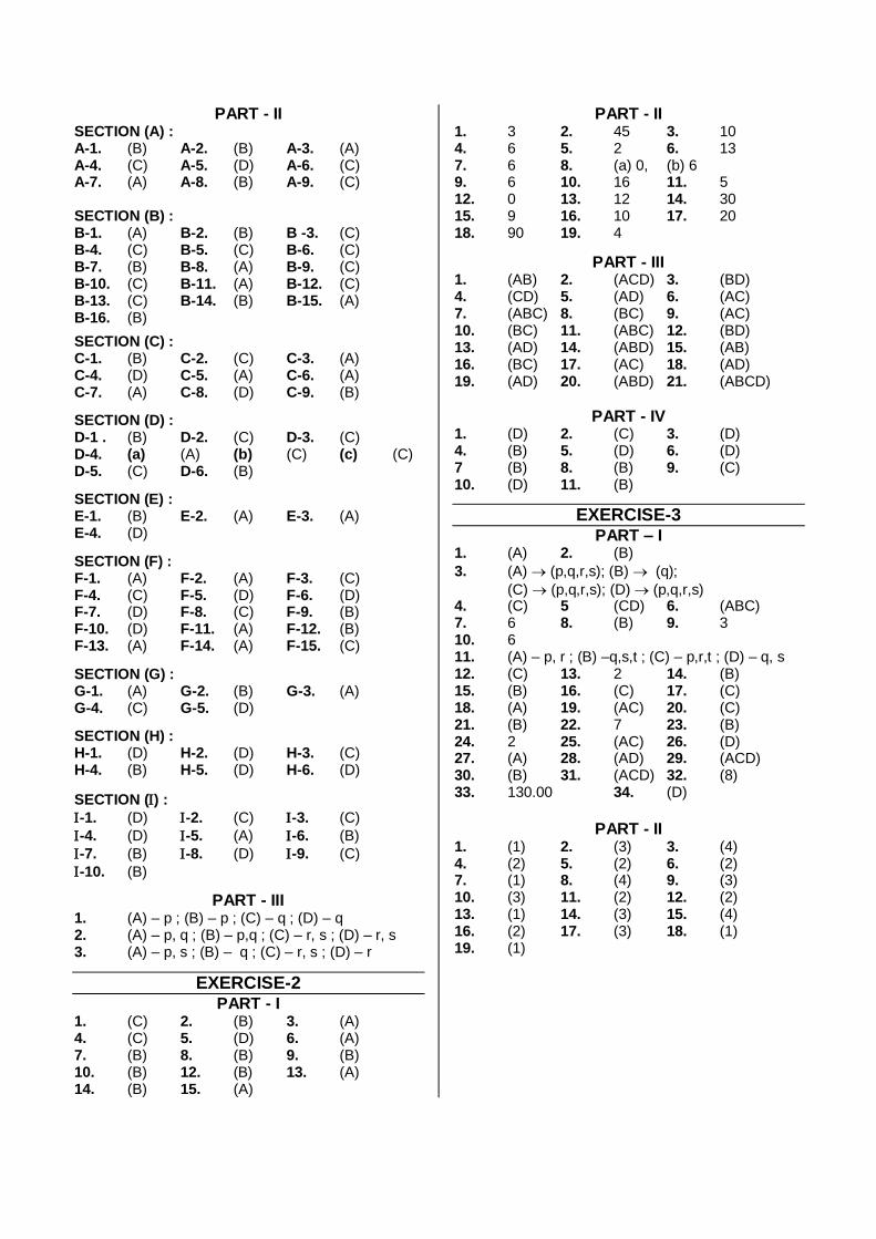
PART - II SECTION (A) : A-1. (B) A-2. (B) A-3. (A) A-4. (C) A-5. (D) A-6. (C) A-7. (A) A-8. (B) A-9. (C) SECTION (B) :
B-1. (A) B-2. (B) B -3. (C) B-4. (C) B-5. (C) B-6. (C) B-7. (B) B-8. (A) B-9. (C) B-10. (C) B-11. (A) B-12. (C) B-13. (C) B-14. (B) B-15. (A) B-16. (B)
SECTION (C) :
C-1. (B) C-2. (C) C-3. (A) C-4. (D) C-5. (A) C-6. (A) C-7. (A) C-8. (D) C-9. (B)
SECTION (D) : D-1 . (B) D-2. (C) D-3. (C) D-4. (a) (A) (b) (C) (c) (C) D-5. (C) D-6. (B)
SECTION (E) : E-1. (B) E-2. (A) E-3. (A) E-4. (D)
SECTION (F) : F-1. (A) F-2. (A) F-3. (C) F-4. (C) F-5. (D) F-6. (D) F-7. (D) F-8. (C) F-9. (B) F-10. (D) F-11. (A) F-12. (B) F-13. (A) F-14. (A) F-15. (C)
SECTION (G) : G-1. (A) G-2. (B) G-3. (A) G-4. (C) G-5. (D)
SECTION (H) : H-1. (D) H-2. (D) H-3. (C) H-4. (B) H-5. (D) H-6. (D)
SECTION () :
-1. (D) -2. (C) -3. (C)
-4. (D) -5. (A) -6. (B)
-7. (B) -8. (D) -9. (C)
-10. (B)
PART - III 1. (A) – p ; (B) – p ; (C) – q ; (D) – q 2. (A) – p, q ; (B) – p,q ; (C) – r, s ; (D) – r, s 3. (A) – p, s ; (B) – q ; (C) – r, s ; (D) – r
EXERCISE-2 PART - I
1. (C) 2. (B) 3. (A) 4. (C) 5. (D) 6. (A) 7. (B) 8. (B) 9. (B) 10. (B) 12. (B) 13. (A) 14. (B) 15. (A)
PART - II 1. 3 2. 45 3. 10 4. 6 5. 2 6. 13 7. 6 8. (a) 0, (b) 6 9. 6 10. 16 11. 5 12. 0 13. 12 14. 30 15. 9 16. 10 17. 20 18. 90 19. 4
PART - III 1. (AB) 2. (ACD) 3. (BD) 4. (CD) 5. (AD) 6. (AC) 7. (ABC) 8. (BC) 9. (AC) 10. (BC) 11. (ABC) 12. (BD) 13. (AD) 14. (ABD) 15. (AB) 16. (BC) 17. (AC) 18. (AD) 19. (AD) 20. (ABD) 21. (ABCD)
PART - IV 1. (D) 2. (C) 3. (D) 4. (B) 5. (D) 6. (D) 7 (B) 8. (B) 9. (C) 10. (D) 11. (B)
EXERCISE-3 PART – I
1. (A) 2. (B)
3. (A) (p,q,r,s); (B) (q);
(C) (p,q,r,s); (D) (p,q,r,s) 4. (C) 5 (CD) 6. (ABC) 7. 6 8. (B) 9. 3 10. 6 11. (A) – p, r ; (B) –q,s,t ; (C) – p,r,t ; (D) – q, s 12. (C) 13. 2 14. (B) 15. (B) 16. (C) 17. (C) 18. (A) 19. (AC) 20. (C) 21. (B) 22. 7 23. (B) 24. 2 25. (AC) 26. (D) 27. (A) 28. (AD) 29. (ACD) 30. (B) 31. (ACD) 32. (8) 33. 130.00 34. (D)
PART - II
1. (1) 2. (3) 3. (4) 4. (2) 5. (2) 6. (2) 7. (1) 8. (4) 9. (3) 10. (3) 11. (2) 12. (2) 13. (1) 14. (3) 15. (4) 16. (2) 17. (3) 18. (1) 19. (1)
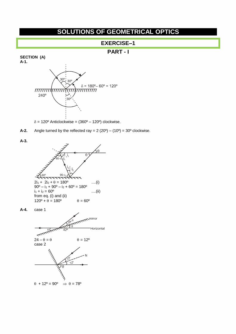
SOLUTIONS OF GEOMETRICAL OPTICS
EXERCISE–1
PART - I SECTION (A) A-1.
= 120º Anticlockwise = (360º – 120º) clockwise. A-2. Angle turned by the reflected ray = 2 (20º) – (10º) = 30º clockwise.
A-3.
2i1 + 2i2 + = 180º ....(i) 90º – i1 + 90º – i2 + 60º = 180º i1 + i2 = 60º ....(ii) from eq. (i) and (ii)
120º + = 180º = 60º A-4. case 1
mirror
Horizontal42º
24 – = = 12º case 2
+ 12º = 90º = 78º
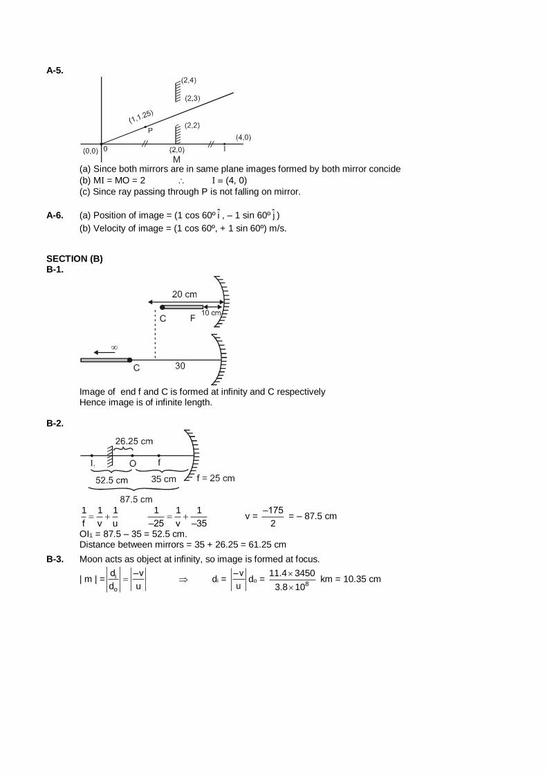
A-5.
M
(a) Since both mirrors are in same plane images formed by both mirror concide
(b) MI = MO = 2 I (4, 0)
(c) Since ray passing through P is not falling on mirror.
A-6. (a) Position of image = (1 cos 60º i , – 1 sin 60º j )
(b) Velocity of image = (1 cos 60º, + 1 sin 60º) m/s.
SECTION (B) B-1.
Image of end f and C is formed at infinity and C respectively Hence image is of infinite length. B-2.
35 cm
1 1 1
f v u
1 1 1
–25 v –35 v =
–175
2 = – 87.5 cm
OI1 = 87.5 – 35 = 52.5 cm. Distance between mirrors = 35 + 26.25 = 61.25 cm
B-3. Moon acts as object at infinity, so image is formed at focus.
| m | = i
o
d –v
d u di =
–v
udo =
8
11.4 3450
3.8 10
km = 10.35 cm
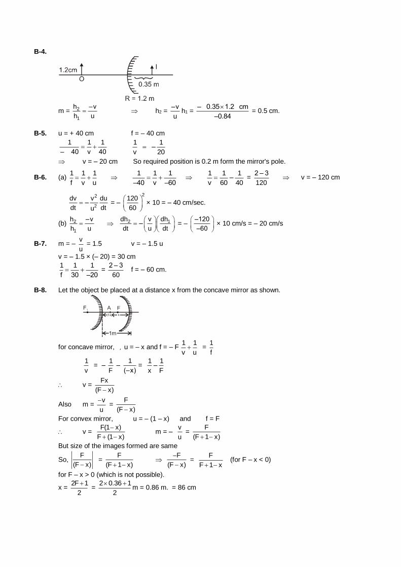
B-4.
m = 2
1
h –v
h u h2 =
–v
uh1 =
– 0.35 1.2 cm
–0.84
= 0.5 cm.
B-5. u = + 40 cm f = – 40 cm
1 1 1
– 40 v 40
1 1–
v 20
v = – 20 cm So required position is 0.2 m form the mirror's pole.
B-6. (a) 1 1 1
f v u
1 1 1
–40 v –60
1 1 1–
v 60 40 =
2 – 3
120 v = – 120 cm
2
2
dv v du–
dt dtu = –
2120
60
× 10 = – 40 cm/sec.
(b) 2
1
h –v
h u 2 1dh v dh
–dt u dt
= –
–120
–60
× 10 cm/s = – 20 cm/s
B-7. m = – v
u = 1.5 v = – 1.5 u
v = – 1.5 × (– 20) = 30 cm
1 1 1
f 30 –20 =
2 – 3
60 f = – 60 cm.
B-8. Let the object be placed at a distance x from the concave mirror as shown.
for concave mirror, ] u = – x and f = – F 1 1
v u =
1
f
1
v = –
1
F –
1
(–x)=
1 1–
x F
v = Fx
(F x)
Also m = v
u
=
F
(F x)
For convex mirror, u = – (1 – x) and f = F
v = F(1 x)
F (1 x)
m = –
v
u =
F
(F 1 x)
But size of the images formed are same
So, F
(F x) =
F
(F 1 x)
F
(F x)
=
F
F 1 x (for F – x < 0)
for F – x > 0 (which is not possible).
x = 2F 1
2
=
2 0.36 1
2
m = 0.86 m. = 86 cm
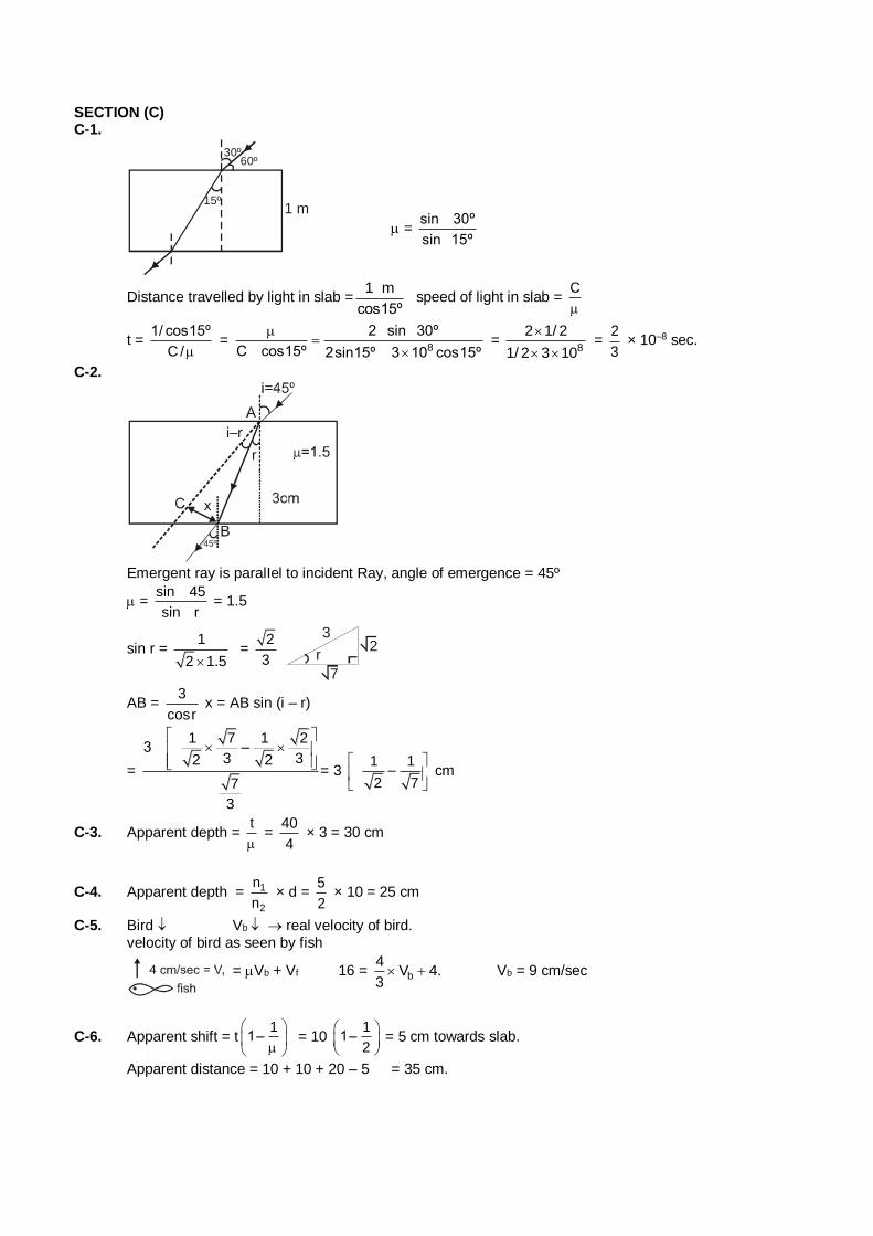
SECTION (C) C-1.
15º1 m
60º30º
= sin 30º
sin 15º
Distance travelled by light in slab =1 m
cos15º speed of light in slab =
C
t = 1/ cos15º
C/ =
8
2 sin 30º
C cos15º 2sin15º 3 10 cos15º
=
8
2 1/ 2
1/ 2 3 10
=
2
3 × 10⁻⁸ sec.
C-2.
r
i–r
45º
Emergent ray is paralIel to incident Ray, angle of emergence = 45º
= sin 45
sin r = 1.5
sin r = 1
2 1.5 =
2
3
32
7
r
AB = 3
cosr x = AB sin (i – r)
=
1 7 1 23 –
3 32 2
7
3
= 3 1 1
–2 7
cm
C-3. Apparent depth = t
=
40
4 × 3 = 30 cm
C-4. Apparent depth = 1
2
n
n × d =
5
2 × 10 = 25 cm
C-5. Bird Vb real velocity of bird. velocity of bird as seen by fish
= Vb + Vf 16 = b
4V 4.
3 Vb = 9 cm/sec
C-6. Apparent shift = t1
1–
= 10
11–
2
= 5 cm towards slab.
Apparent distance = 10 + 10 + 20 – 5 = 35 cm.
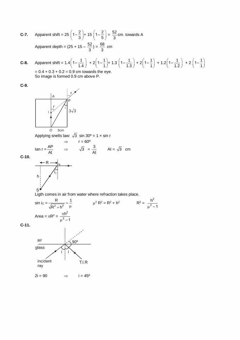
C-7. Apparent shift = 25 2
1–3
+ 15 2
1–5
= 52
3cm. towards A
Apparent depth = (25 + 15 – 52
3) =
68
3 cm
C-8. Apparent shift = 1.41
1–1.4
+ 21
1–1
+ 1.3 1
1–1.3
+ 21
1–1
+ 1.21
1–1.2
+ 2 1
1–1
= 0.4 + 0.3 + 0.2 = 0.9 cm towards the eye. So image is formed 0.9 cm above P. C-9.
Applying snells law: 3 sin 30º = 1 × sin r
r = 60º
tan r =AP
A 3 =
3
A AI = 3 cm
C-10.
Ligth comes in air from water where refraction takes place.
sin iC =2 2
R 1
R h
2 R2 = R2 + h2 R2 = 2
2
h
–1
Area = R2 = 2
2
h
–1
C-11.
2i = 90 i = 45º
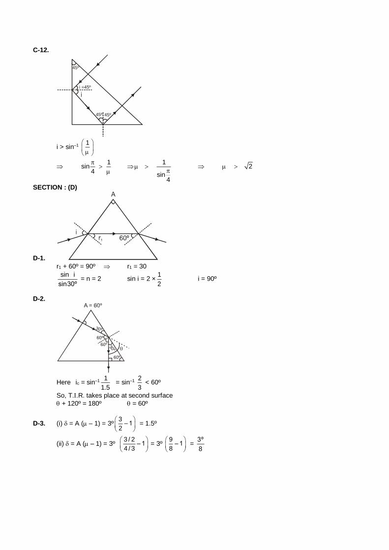
C-12.
45º
i =45º
45º45º
i > sin–1 1
1
sin4
1
sin4
2
SECTION : (D)
D-1.
r1 + 60º = 90º r1 = 30
sin i
sin30º = n = 2 sin i = 2 ×
1
2 i = 90º
D-2.
Here ic = sin–1 1
1.5 = sin–1
2
3 < 60º
So, T..R. takes place at second surface
+ 120º = 180º = 60º
D-3. (i) = A ( – 1) = 3º3
– 12
= 1.5º
(ii) = A ( – 1) = 3º 3 / 2
– 14 / 3
= 3º 9
– 18
= 3º
8
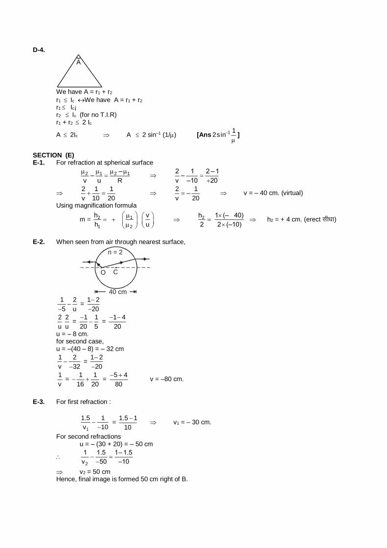
D-4.
We have A = r1 + r2
r1 Ic We have A = r1 + r2 r1 Ic¡ r2 Ic (for no T.I.R) r1 + r2 2 Ic
A 2Ic A 2 sin–1 (1/) [Ans
1sin2 1 ]
SECTION (E) E-1. For refraction at spherical surface
2 1 2 1––
v u R
2 1 2 –1–
v –10 20
2 1 1
v 10 20
2 1–
v 20 v = – 40 cm. (virtual)
Using magnification formula
m = 2 1
1 2
h v
h u
2h 1 (– 40)
2 2 (–10)
h2 = + 4 cm. (erect lh/kk)
E-2. When seen from air through nearest surface,
O C
n = 2
40 cm
1 2
5 u
=
1 2
20
2
u
2
u =
1 1
20 5
=
1 4
20
u = – 8 cm. for second case, u = –(40 – 8) = – 32 cm
1 2
v 32
= 1 2
20
1
v =
1 1
16 20 =
5 4
80
v = –80 cm.
E-3. For first refraction :
1
1.5 1
v 10
= 1.5 1
10
v1 = – 30 cm.
For second refractions u = – (30 + 20) = – 50 cm
2
1 1.5 1– 1.5
v 50 –10
v2 = 50 cm Hence, final image is formed 50 cm right of B.
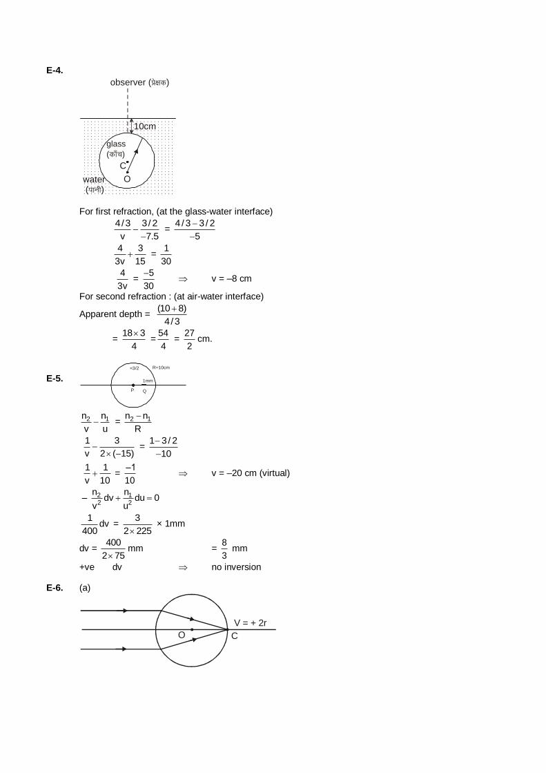
E-4.
observer (çs{kd)
10cm
C
O water
glass (dk¡p)
(ikuh)
For first refraction, (at the glass-water interface)
4/3 3/ 2
v 7.5
= 4 / 3 3 / 2
5
4 3
3v 15 =
1
30
4
3v =
5
30
v = –8 cm
For second refraction : (at air-water interface)
Apparent depth = (10 8)
4/3
= 18 3
4
=
54
4 =
27
2cm.
E-5. P Q
1mm
R=10cm =3/2
2 1n n
v u = 2 1n n
R
1 3
v 2 ( 15)
=
1 3/ 2
10
1 1
v 10 =
–1
10 v = –20 cm (virtual)
– 2 12 2
n ndv du 0
v u
1
dv400
= 3
2 225 × 1mm
dv = 400
2 75mm =
8
3 mm
+ve dv no inversion E-6. (a)
C
V = + 2r
O
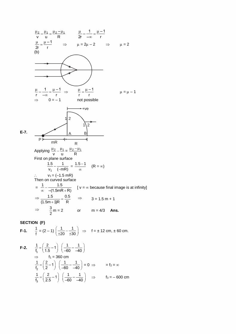
2 1 2 1––
v u R
1 –1–
2r – r
–1
2r r
= 2 – 2 = 2
(b)
1 –1
–r – r
– 1
r r
= – 1
0 = – 1 not possible
E-7.
+ve
1 2
1 2
A B
PRmR
Applying 2 1
v u
= 2 1
R
First on plane surface
1
1.5 1
v ( mR)
=
1.5 1
(R = )
v1 = (–1.5 mR) Then on curved surface
= 1 1.5
–(1.5mR R)
[ v = because final image is at infinity]
1.5 0.5
(1.5m 1)R R
3 = 1.5 m + 1
3
2m = 2 or m = 4/3 Ans.
SECTION (F)
F-1. 1
f = (2 – 1)
1 1
20 30
f = ± 12 cm, ± 60 cm.
F-2. 1
1 2 1 1– 1 –
f 1.5 –60 –40
f1 = 360 cm
2
1 2 1 1– 1 –
f 2 –60 –40
= 0 = f2 =
3
1 2 1 1– 1 –
f 2.5 –60 –40
f3 = – 600 cm
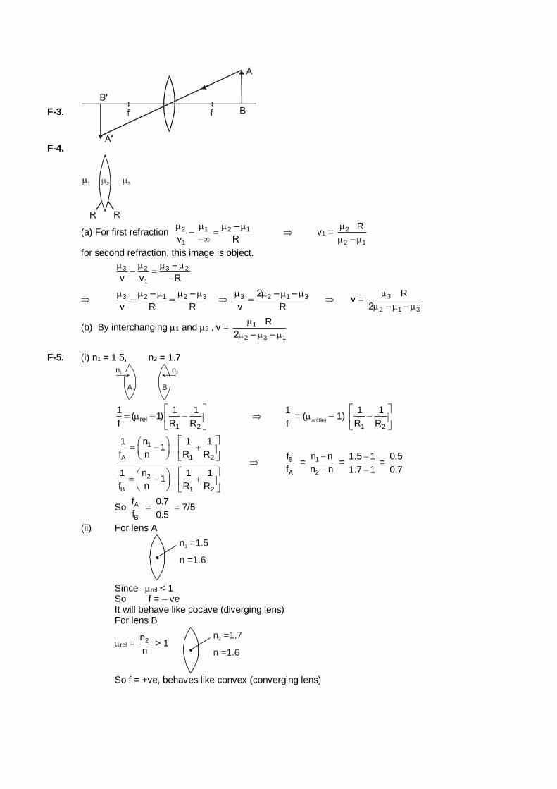
F-3.
F-4.
(a) For first refraction 2 1 2 1
1
––
v – R
v1 = 2
2 1
R
–
for second refraction, this image is object.
3 2 3 2
1
––
v v –R
3 2 1 2 3– ––
v R R
3 2 1 32 – –
v R
v = 3
2 1 3
R
2 – –
(b) By interchanging 1 and 3 , v = 1
2 3 1
R
2 – –
F-5. (i) n1 = 1.5, n2 = 1.7
n1
A
n2
B
rel1 2
1 1 1( 1)
f R R
1
f = (
vkisf{kr – 1)
1 2
1 1
R R
1
A 1 2
2
B 1 2
1 n 1 11
f n R R
1 n 1 11
f n R R
B
A
f
f = 1
2
n n
n n
=
1.5 1
1.7 1
=
0.5
0.7
So A
B
f
f =
0.7
0.5 = 7/5
(ii) For lens A
n =1.51
n =1.6
Since rel < 1 So f = – ve It will behave like cocave (diverging lens) For lens B
rel = 2n
n > 1
n =1.72
n =1.6
So f = +ve, behaves like convex (converging lens)
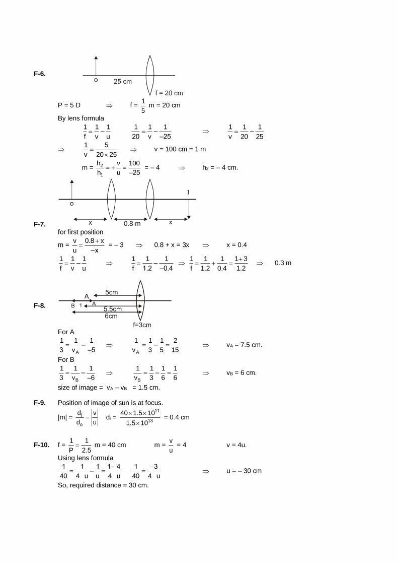
F-6.
P = 5 D f = 1
5 m = 20 cm
By lens formula
1 1 1
–f v u
1 1 1–
20 v –25
1 1 1–
v 20 25
1 5
v 20 25
v = 100 cm = 1 m
m = 2
1
h v 100
h u –25 = – 4 h2 = – 4 cm.
F-7. 0.8 m for first position
m = v 0.8 x
u –x
= – 3 0.8 + x = 3x x = 0.4
1 1 1–
f v u
1 1 1–
f 1.2 –0.4
1 1 1 1 3
f 1.2 0.4 1.2
0.3 m
F-8.
For A
A
1 1 1–
3 v –5
A
1 1 1 2–
v 3 5 15 vA = 7.5 cm.
For B
B
1 1 1–
3 v –6
B
1 1 1 1–
v 3 6 6 vB = 6 cm.
size of image = vA – vB = 1.5 cm. F-9. Position of image of sun is at focus.
|m| = i
o
d v
d u di =
11
13
40 1.5 10
1.5 10
= 0.4 cm
F-10. f = 1 1
P 2.5 m = 40 cm m =
v
u = 4 v = 4u.
Using lens formula
1 1 1 1– 4
–40 4 u u 4 u
1 –3
40 4 u u = – 30 cm
So, required distance = 30 cm.
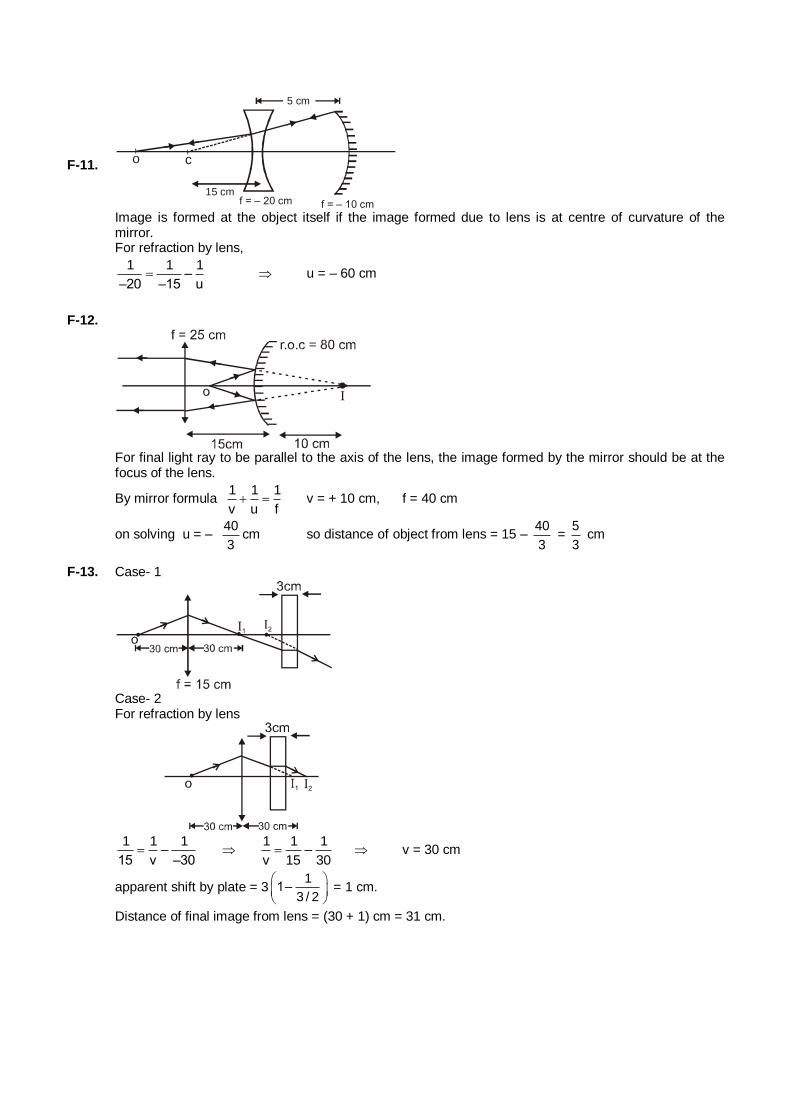
F-11. o c
15 cmf = – 20 cm f = – 10 cm
5 cm
Image is formed at the object itself if the image formed due to lens is at centre of curvature of the mirror.
For refraction by lens,
1 1 1
––20 –15 u
u = – 60 cm
F-12.
For final light ray to be parallel to the axis of the lens, the image formed by the mirror should be at the focus of the lens.
By mirror formula 1 1 1
v u f v = + 10 cm, f = 40 cm
on solving u = – 40
3cm so distance of object from lens = 15 –
40
3 =
5
3 cm
F-13. Case- 1
Case- 2 For refraction by lens
1 1 1
–15 v –30
1 1 1
–v 15 30 v = 30 cm
apparent shift by plate = 31
1–3 / 2
= 1 cm.
Distance of final image from lens = (30 + 1) cm = 31 cm.
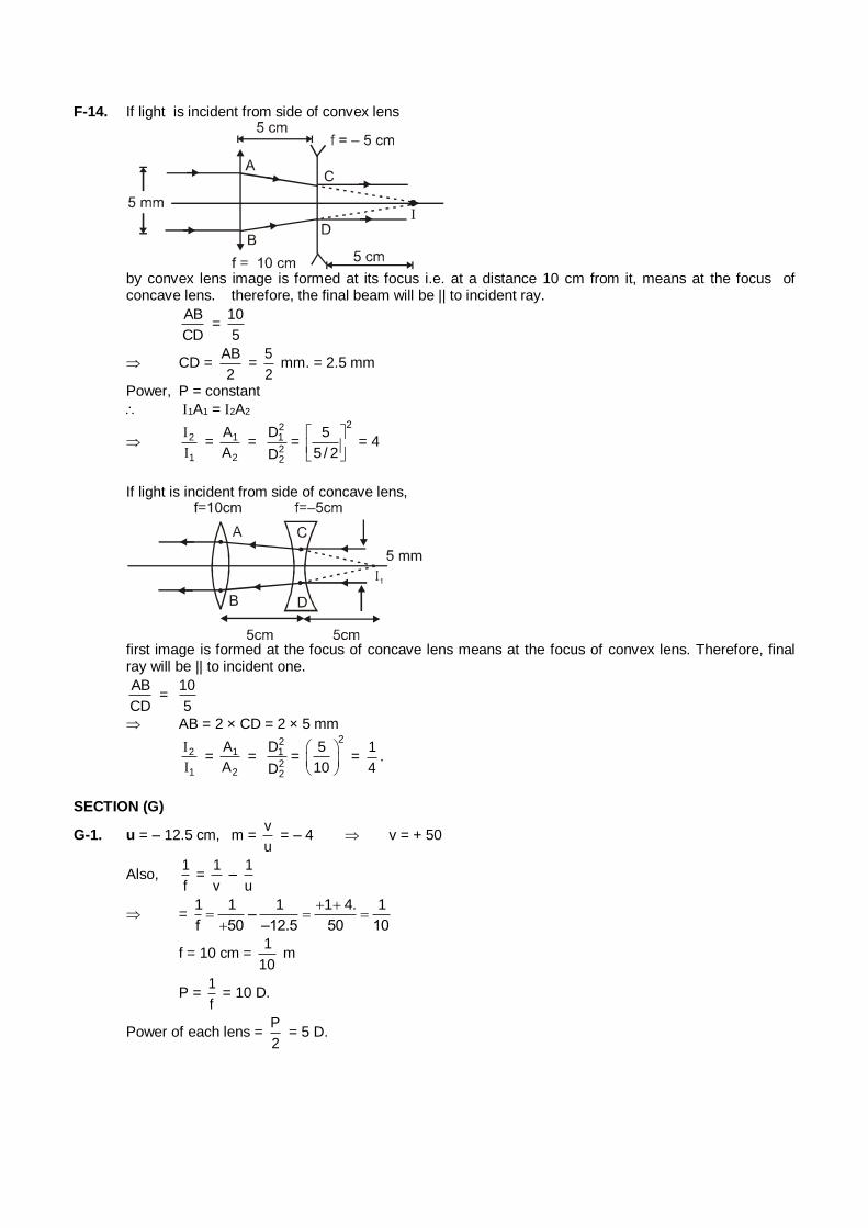
F-14. If light is incident from side of convex lens
by convex lens image is formed at its focus i.e. at a distance 10 cm from it, means at the focus of
concave lens. therefore, the final beam will be || to incident ray.
AB
CD =
10
5
CD = AB
2 =
5
2 mm. = 2.5 mm
Power, P = constant
1A1 = 2A2
2
1
I
I = 1
2
A
A =
2122
D
D=
25
5 / 2
= 4
If light is incident from side of concave lens,
first image is formed at the focus of concave lens means at the focus of convex lens. Therefore, final
ray will be || to incident one.
AB
CD =
10
5
AB = 2 × CD = 2 × 5 mm
2
1
I
I = 1
2
A
A =
2122
D
D=
25
10
= 1
4.
SECTION (G)
G-1. u = – 12.5 cm, m = v
u = – 4 v = + 50
Also, 1
f =
1
v –
1
u
= 1 1 1 1 4. 1
–f 50 –12.5 50 10
f = 10 cm = 1
10 m
P = 1
f = 10 D.
Power of each lens = P
2 = 5 D.
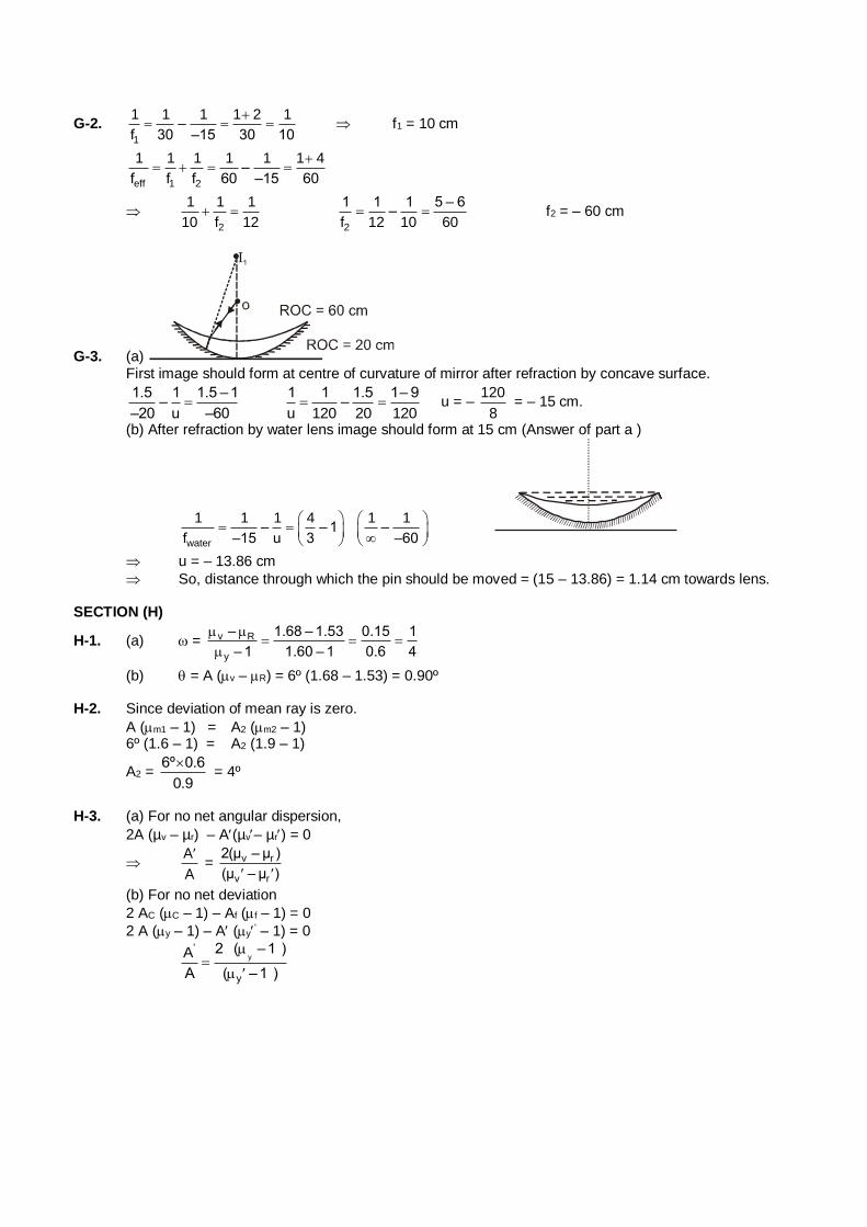
G-2. 1
1 1 1 1 2 1–
f 30 –15 30 10
f1 = 10 cm
eff 1 2
1 1 1 1 1 1 4–
f f f 60 –15 60
2
1 1 1
10 f 12
2
1 1 1 5 – 6–
f 12 10 60 f2 = – 60 cm
G-3. (a) First image should form at centre of curvature of mirror after refraction by concave surface.
1.5 1 1.5 –1
––20 u –60
1 1 1.5 1– 9
–u 120 20 120 u = –
120
8 = – 15 cm.
(b) After refraction by water lens image should form at 15 cm (Answer of part a )
water
1 1 1 4 1 1– – 1 –
f –15 u 3 –60
u = – 13.86 cm
So, distance through which the pin should be moved = (15 – 13.86) = 1.14 cm towards lens. SECTION (H)
H-1. (a) = v R
y
– 1.68 – 1.53 0.15 1
– 1 1.60 – 1 0.6 4
(b) = A (v – R) = 6º (1.68 – 1.53) = 0.90º H-2. Since deviation of mean ray is zero.
A (m1 – 1) = A2 (m2 – 1) 6º (1.6 – 1) = A2 (1.9 – 1)
A2 = 6º 0.6
0.9
= 4º
H-3. (a) For no net angular dispersion,
2A (µv – µr) – A(µv– µr) = 0
A
A
= v r
v r
2(µ – µ )
(µ – µ )
(b) For no net deviation
2 AC (C – 1) – Af (f – 1) = 0
2 A (y – 1) – A (y' – 1) = 0
y
'
y
2 ( –1 )A
A ( –1 )
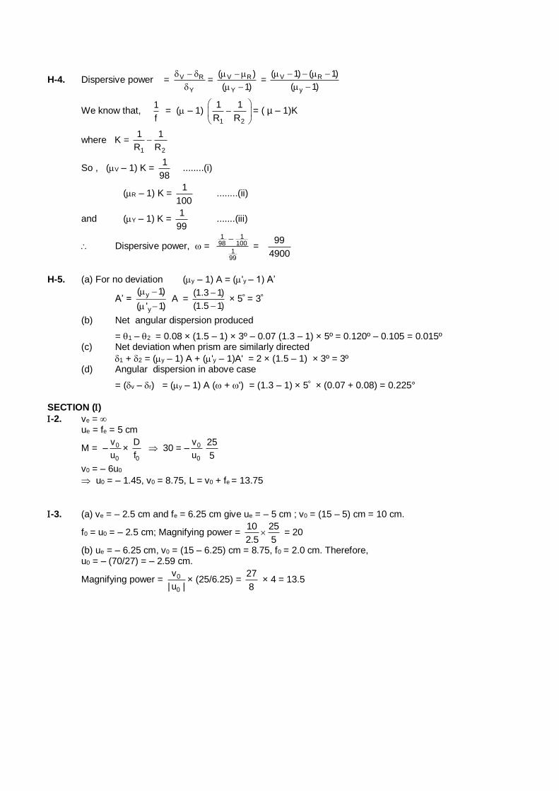
H-4. Dispersive power = V R
Y
= V R
Y
( )
( 1)
= V R
y
( 1) ( 1)
( 1)
We know that, 1
f = ( – 1)
1 2
1 1
R R
= ( µ – 1)K
where K = 1 2
1 1
R R
So , (V – 1) K = 1
98 ........(i)
(R – 1) K = 1
100 ........(ii)
and (Y – 1) K = 1
99 .......(iii)
Dispersive power, = 1 1
98 100
199
=
99
4900
H-5. (a) For no deviation (y – 1) A = ('y – 1) A’
A’ = y
y
( 1)
( ' 1)
A =
(1.3 1)
(1.5 1)
× 5º = 3º
(b) Net angular dispersion produced
= 1 – 2 = 0.08 × (1.5 – 1) × 3º – 0.07 (1.3 – 1) × 5º = 0.120º – 0.105 = 0.015º (c) Net deviation when prism are similarly directed
1 + 2 = (y – 1) A + ('y – 1)A' = 2 × (1.5 – 1) × 3º = 3º (d) Angular dispersion in above case
= (v – r) = (y – 1) A ( + ') = (1.3 – 1) × 5º × (0.07 + 0.08) = 0.225°
SECTION () -2. ve = ue = fe = 5 cm
M = – 0
0
v
u×
0
D
f 30 = – 0
0
v
u
25
5
v0 = – 6u0
u0 = – 1.45, v0 = 8.75, L = v0 + fe = 13.75
-3. (a) ve = – 2.5 cm and fe = 6.25 cm give ue = – 5 cm ; v0 = (15 – 5) cm = 10 cm.
f0 = u0 = – 2.5 cm; Magnifying power = 10 25
2.5 5 = 20
(b) ue = – 6.25 cm, v0 = (15 – 6.25) cm = 8.75, f0 = 2.0 cm. Therefore, u0 = – (70/27) = – 2.59 cm.
Magnifying power = 0
0
v
| u |× (25/6.25) =
27
8 × 4 = 13.5
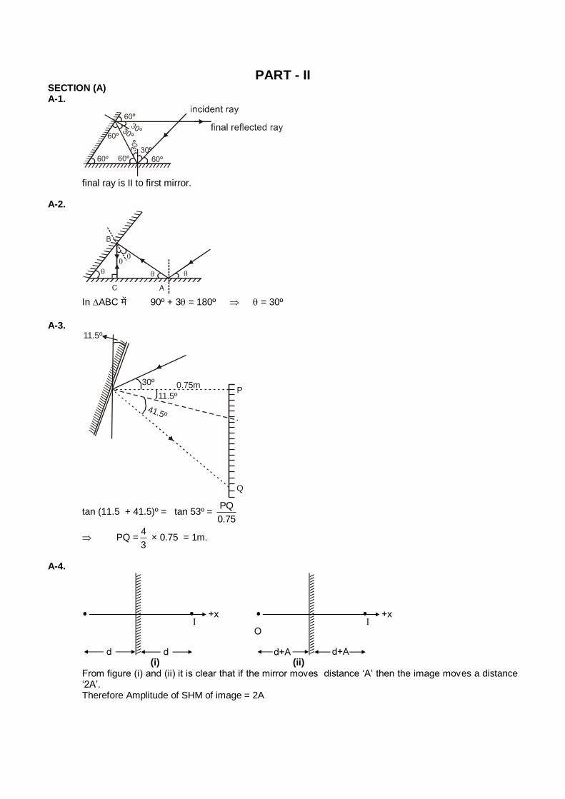
PART - II SECTION (A) A-1.
final ray is II to first mirror.
A-2.
In ABC esa 90º + 3 = 180º = 30º
A-3.
Q
/////////////////////////////////////////
0.75m30º
11.5º
41.5º
P
11.5º
tan (11.5 + 41.5)º = tan 53º = PQ
0.75
PQ =4
3 × 0.75 = 1m.
A-4.
(i) (ii) From figure (i) and (ii) it is clear that if the mirror moves distance ‘A’ then the image moves a distance
‘2A’. Therefore Amplitude of SHM of image = 2A
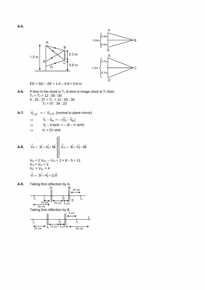
A-5.
ED = AD – AE = 1.4 – 0.8 = 0.6 m A-6. If time in the clock is T1 & time in image clock is T2 then. T1 + T2 = 12 : 00 : 00 4 : 25 : 37 + T2 = 12 : 00 : 00 T2 = 07 : 34 : 23
A-7. , MV = – O, MV (normal to plane mirror)
MV V = – 0 M(V V )
V Vsin = – (0 – V sin)
V = 2V sin.
A-8. 0ˆ ˆ ˆV 3i 4j 5k
mˆ ˆ ˆV 8i 5 j 8k
VIZ = 2 Vmz – Voz = 2 × 8 – 5 = 11 VIx = Vox = 3 VIy = Voy = 4
Iˆ ˆ ˆV 3i 4j 11k
A-9. Taking first reflection by A.
Taking first reflection by B
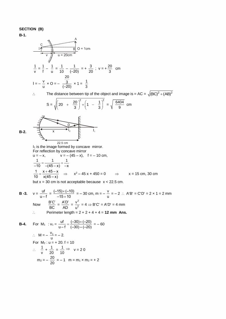
SECTION (B)
B-1.
1
v =
1
f –
1
u =
1
10 –
1
(–20) = +
3
20 ; v = +
20
3 cm
I = – v
u × O = –
20
3(–20)
× 1 = 1
3
The distance between tip of the object and image is = AC = 2 2(BC) (AB)
S =
2 220 1
20 13 3
=
6404
9 cm
B-2.
I1 is the image formed by concave mirror. For reflection by concave mirror u = – x, v = – (45 – x), f = – 10 cm,
1 1 1
–10 –(45 – x) –x
1 x 45 – x
10 x(45 – x)
x2 – 45 x + 450 = 0 x = 15 cm, 30 cm
but x = 30 cm is not acceptable because x < 22.5 cm.
B -3. v = uf
u – f =
(–15) (–10)
–15 10
= – 30 cm, m = –
v
u = – 2 AB = CD = 2 × 1 = 2 mm
Now B C
BC
=
A D
AD
=
2
2
v
u = 4 BC = AD = 4 mm
Perimeter length = 2 + 2 + 4 + 4 = 12 mm Ans.
B-4. For M1 : v1 = uf (–30) (–20)
u – f (–30) – (–20)
= – 60
M = – 1v
u= – 2.
For M2 : u = + 20. f = 10
1
v +
1
20 =
1
10 v = 2 0
m2 = – 20
20 = – 1 m = m1 × m2 = + 2
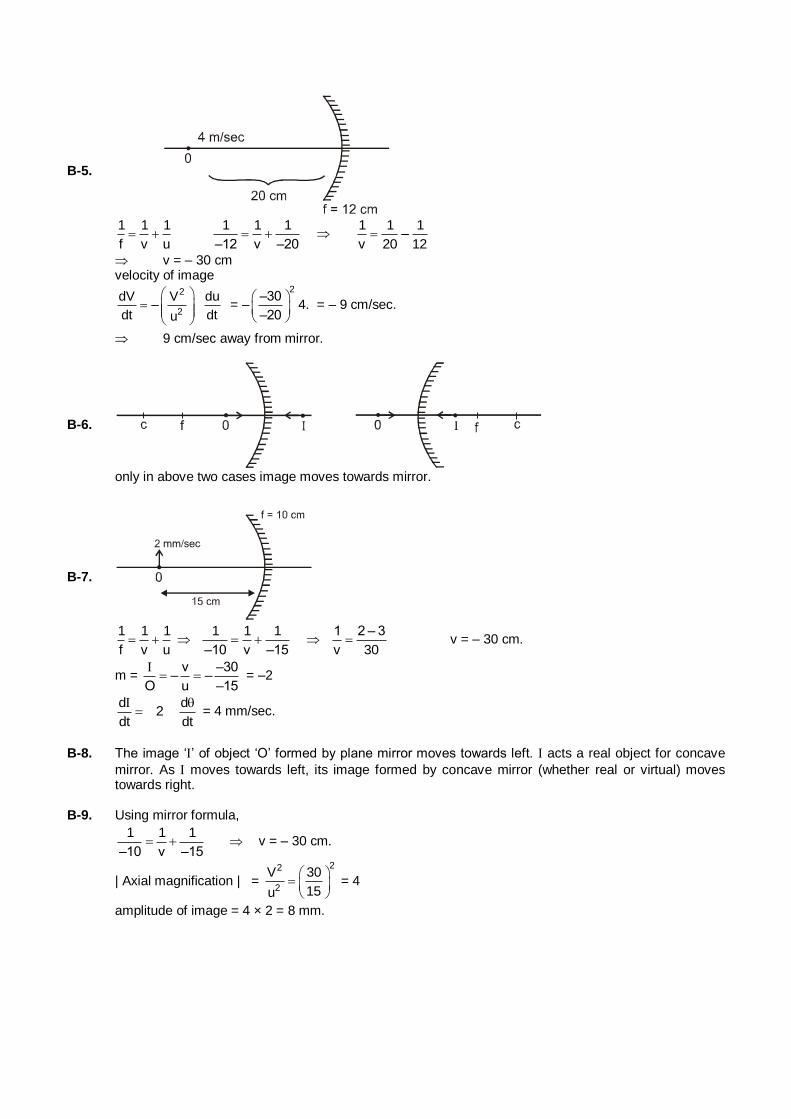
B-5.
1 1 1
f v u
1 1 1
–12 v –20
1 1 1–
v 20 12
v = – 30 cm velocity of image
2
2
dV V du–
dt dtu
= –
2–30
–20
4. = – 9 cm/sec.
9 cm/sec away from mirror.
B-6.
only in above two cases image moves towards mirror.
B-7.
1 1 1
f v u
1 1 1
–10 v –15
1 2 – 3
v 30 v = – 30 cm.
m = v –30
– –O u –15
= –2
d d
2dt dt
= 4 mm/sec.
B-8. The image ‘’ of object ‘O’ formed by plane mirror moves towards left. acts a real object for concave
mirror. As moves towards left, its image formed by concave mirror (whether real or virtual) moves towards right.
B-9. Using mirror formula,
1 1 1
–10 v –15 v = – 30 cm.
| Axial magnification | =
22
2
V 30
15u
= 4
amplitude of image = 4 × 2 = 8 mm.
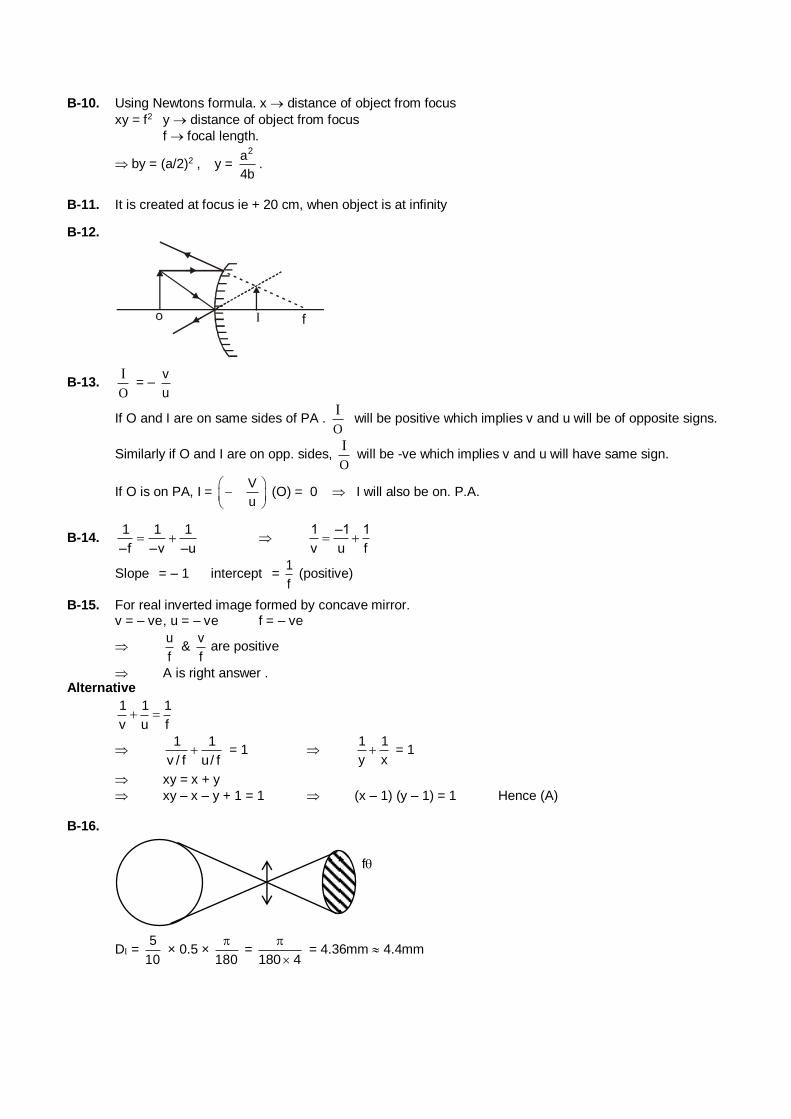
B-10. Using Newtons formula. x distance of object from focus
xy = f2 y distance of object from focus
f focal length.
by = (a/2)2 , y = 2a
4b.
B-11. It is created at focus ie + 20 cm, when object is at infinity
B-12.
B-13. O
I = –
v
u
If O and I are on same sides of PA . O
I will be positive which implies v and u will be of opposite signs.
Similarly if O and I are on opp. sides, O
I will be -ve which implies v and u will have same sign.
If O is on PA, I = V
u
(O) = 0 I will also be on. P.A.
B-14. 1 1 1
–f –v –u
1 –1 1
v u f
Slope = – 1 intercept = 1
f (positive)
B-15. For real inverted image formed by concave mirror. v = – ve , u = – ve f = – ve
u
f &
v
f are positive
A is right answer . Alternative
1 1 1
v u f
1 1
v / f u/ f = 1
1 1
y x = 1
xy = x + y
xy – x – y + 1 = 1 (x – 1) (y – 1) = 1 Hence (A) B-16.
f
D = 5
10 × 0.5 ×
180
=
180 4
= 4.36mm 4.4mm

SECTION (C)
C-1. = V
m
6000
4000
= 1.5
C-2. i = 2r 1 sin i = n sin r
2 sin i/2 cos i/2 = n sin i/2
cos i/2 = (n/2)
i = 2 cos–1 (n/2)
C-3. Displacement = t sin(i – r)
cosr and 1sin i = n × sinr
Since i and r are small angles. and i = nr Displacement = t ( i – r )
Displacement = t i r
1–i
= t 1
1–n
= t (n –1)
n
C-4. As n varies ‘y’, parallel slabs can be taken, and we know in parallel slabs nr sin ir = constant. as n1sini1 = 1 × sin90° = 1 = constant nfinal = nair = 1
1 = 1 × sin rfinal rfinal = 90°
Deviation is zero. C-5.
oo' = t 1
1–
C-6. nquartz = 2 ; nglycerine = 4
3
quartz
glycerine
n
n
DokVZt
fXyljhu
=2
4 / 3 =
3
2= µrel
shift = t rel
11
= 18 1
13 / 2
= 6 cm
C-7. sin = A
B
1 C
C
CB =
V
sin
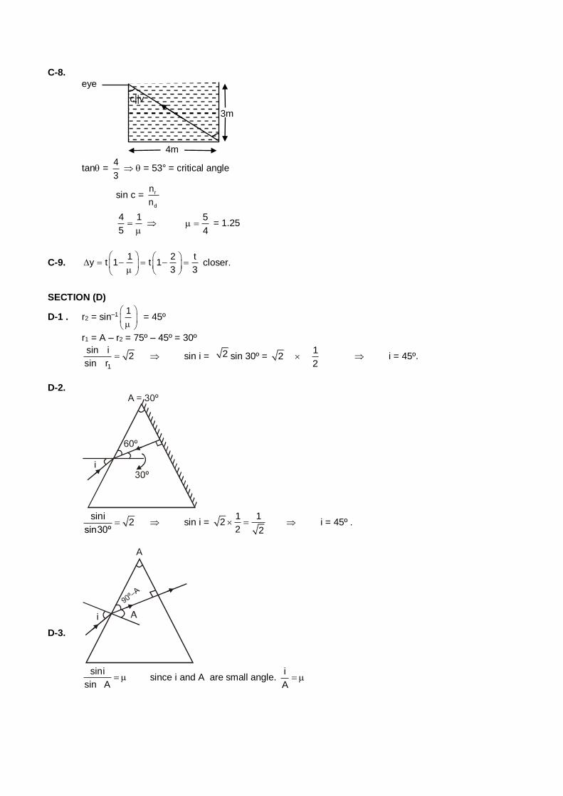
C-8.
3m
c||v
4m
eye
tan = 4
3 = 53° = critical angle
sin c = r
d
n
n
4 1
5
5
4 = 1.25
C-9. 1 2 t
y t 1 t 13 3
closer.
SECTION (D)
D-1 . r2 = sin–1 1
= 45º
r1 = A – r2 = 75º – 45º = 30º
1
sin i2
sin r sin i = 2 sin 30º =
12
2 i = 45º.
D-2.
sini
2sin30º
sin i = 1 1
22 2
i = 45º .
D-3.
sini
sin A since i and A are small angle.
i
A
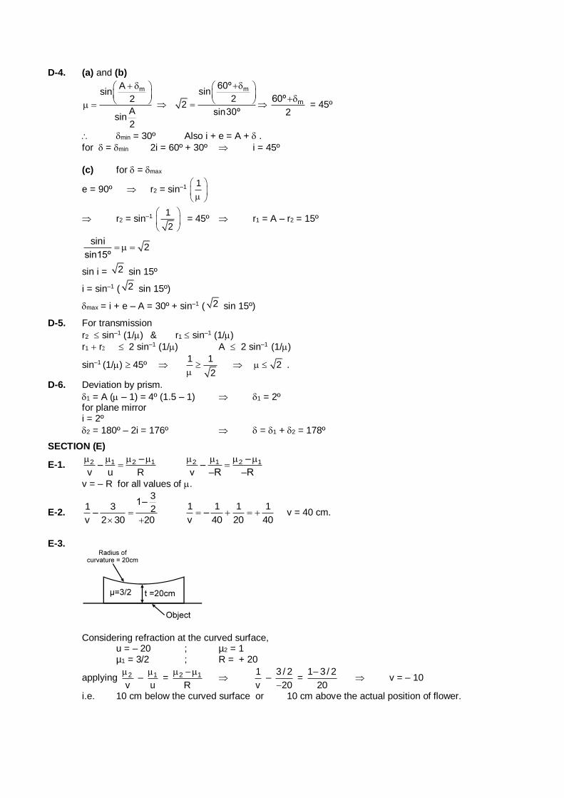
D-4. (a) and (b)
mAsin
2
Asin
2
m60ºsin
22
sin30º
m60º
2
= 45º
min = 30º Also i + e = A + .
for = min 2i = 60º + 30º i = 45º
(c) for = max
e = 90º r2 = sin–1 1
r2 = sin–1 1
2
= 45º r1 = A – r2 = 15º
sini
2sin15º
sin i = 2 sin 15º
i = sin–1 ( 2 sin 15º)
max = i + e – A = 30º + sin–1 ( 2 sin 15º)
D-5. For transmission
r2 sin–1 (1/) & r1 sin–1 (1/)
r1 r 2 sin–1 (1/) A 2 sin–1 (1/)
sin–1 (1/) 45º 1 1
2
2 .
D-6. Deviation by prism.
1 = A ( – 1) = 4º (1.5 – 1) 1 = 2º for plane mirror i = 2º
2 = 180º – 2i = 176º = 1 + 2 = 178º
SECTION (E)
E-1. 2 1 2 1––
v u R
2 1 2 1–
–v –R –R
v = – R for all values of .
E-2.
31–
1 3 2–v 2 30 20
1 1 1 1
–v 40 20 40 v = 40 cm.
E-3.
Considering refraction at the curved surface, u = – 20 ; µ2 = 1 µ1 = 3/2 ; R = + 20
applying 2
v
– 1
u
= 2 1
R
1
v –
3 / 2
20 =
1 3/ 2
20
v = – 10
i.e. 10 cm below the curved surface or 10 cm above the actual position of flower.
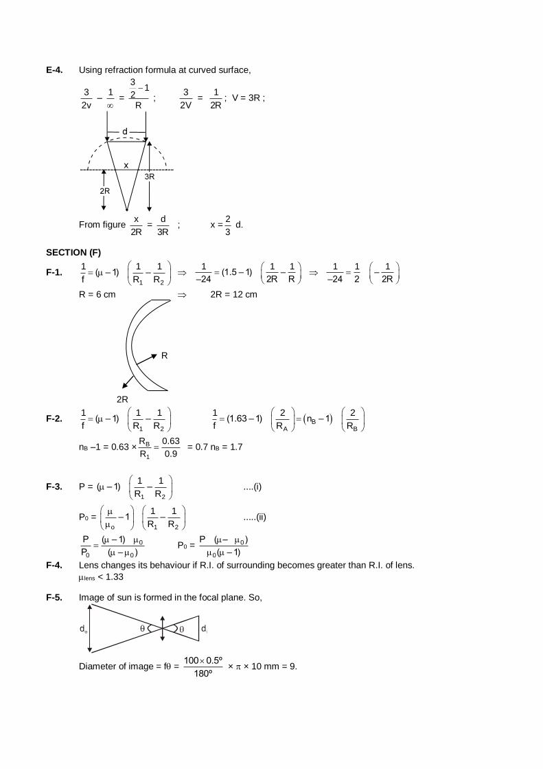
E-4. Using refraction formula at curved surface,
3
2v –
1
=
31
2R
;
3
2V =
1
2R; V = 3R ;
From figure x
2R =
d
3R ; x =
2
3 d.
SECTION (F)
F-1. 1 2
1 1 1( –1) –
f R R
1 1 1(1.5 – 1) –
–24 2R R
1 1 1–
–24 2 2R
R = 6 cm 2R = 12 cm
R
2R
F-2. 1 2
1 1 1( –1) –
f R R
B
A B
1 2 2(1.63 –1) n –1
f R R
nB –1 = 0.63 × B
1
R 0.63
R 0.9 = 0.7 nB = 1.7
F-3. P = 1 2
1 1( – 1) –
R R
....(i)
P0 = o 1 2
1 1– 1 –
R R
.....(ii)
0
0 0
P ( – 1)
P ( – )
P0 = 0
0
P ( – )
( – 1)
F-4. Lens changes its behaviour if R.I. of surrounding becomes greater than R.I. of lens.
lens < 1.33 F-5. Image of sun is formed in the focal plane. So,
Diameter of image = f = 100 0.5º
180º
× × 10 mm = 9.
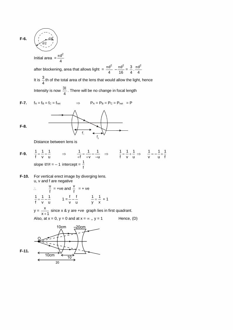
F-6.
Initial area =2d
4
after blockening, area that allows light = 2d
4
–
2d
16
=
3
4.
2d
4
It is 3
4th of the total area of the lens that would allow the light, hence
Intensity is now 3
4
. There will be no change in focal length
F-7. fA = fB = fC = fnet PA = PB = PC = Pnet = P
F-8.
Distance between lens is
F-9. 1 1 1
–f v u
1 1 1–
f v –u
1 1 1
f v u
1 1 1–
v u f
slope <ky = – 1 intercept = 1
f
F-10. For vertical erect image by diverging lens. u, v and f are negative
u
f = +ve and
v
f = + ve
1 1 1
–f v u 1 =
f f–
v u
1 1
y x + 1
y = x
x 1 since x & y are +ve graph lies in first quadrant.
Also, at x = 0, y = 0 and at x = ,, y = 1 Hence, (D)
F-11.
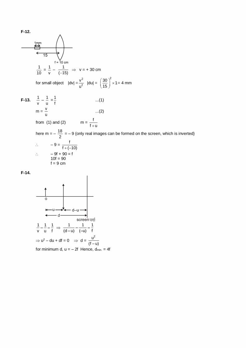
F-12.
1
10 =
1
v –
1
( 15) v = + 30 cm
for small object |dv| =2
2
v
u |du| =
230
115
= 4 mm
F-13. 1
v –
1
u =
1
f ...(1)
m = v
u ...(2)
from (1) and (2) m = f
f u
here m = – 18
2 = – 9 {only real images can be formed on the screen, which is inverted}
– 9 = f
f ( 10)
– 9f + 90 = f 10f = 90 f = 9 cm F-14.
1 1 1
–v u f
1 1 1
–(d – u) (–u) f
u2 – du + df = 0 d = 2u
(f – u)
for minimum d, u = – 2f Hence, dmin. = 4f
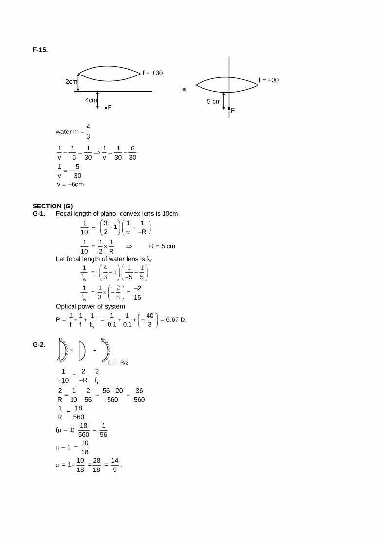
F-15.
2cm
4cm F
f = +30
water m =4
3
5 cm
f = +30
F
1 1 1 1 1 6
v 5 30 v 30 30
1 5
v 30
v 6cm
SECTION (G) G-1. Focal length of plano–convex lens is 10cm.
1
10 =
31
2
1 1
R
1
10 =
1 1
2 R R = 5 cm
Let focal length of water lens is fw
w
1
f =
41
3
1 1
5 5
w
1
f =
1 2
3 5
= 2
15
Optical power of system
P = w
1 1 1
f f f =
1 1 40
0.1 0.1 3
= 6.67 D.
G-2.
1
10 =
2 2
R f
2 1 2
R 10 56 =
56 20
560
=
36
560
1
R =
18
560
( – 1) 18
560 =
1
56
– 1 = 10
18
= 10
118
=28
18 =
14
9.
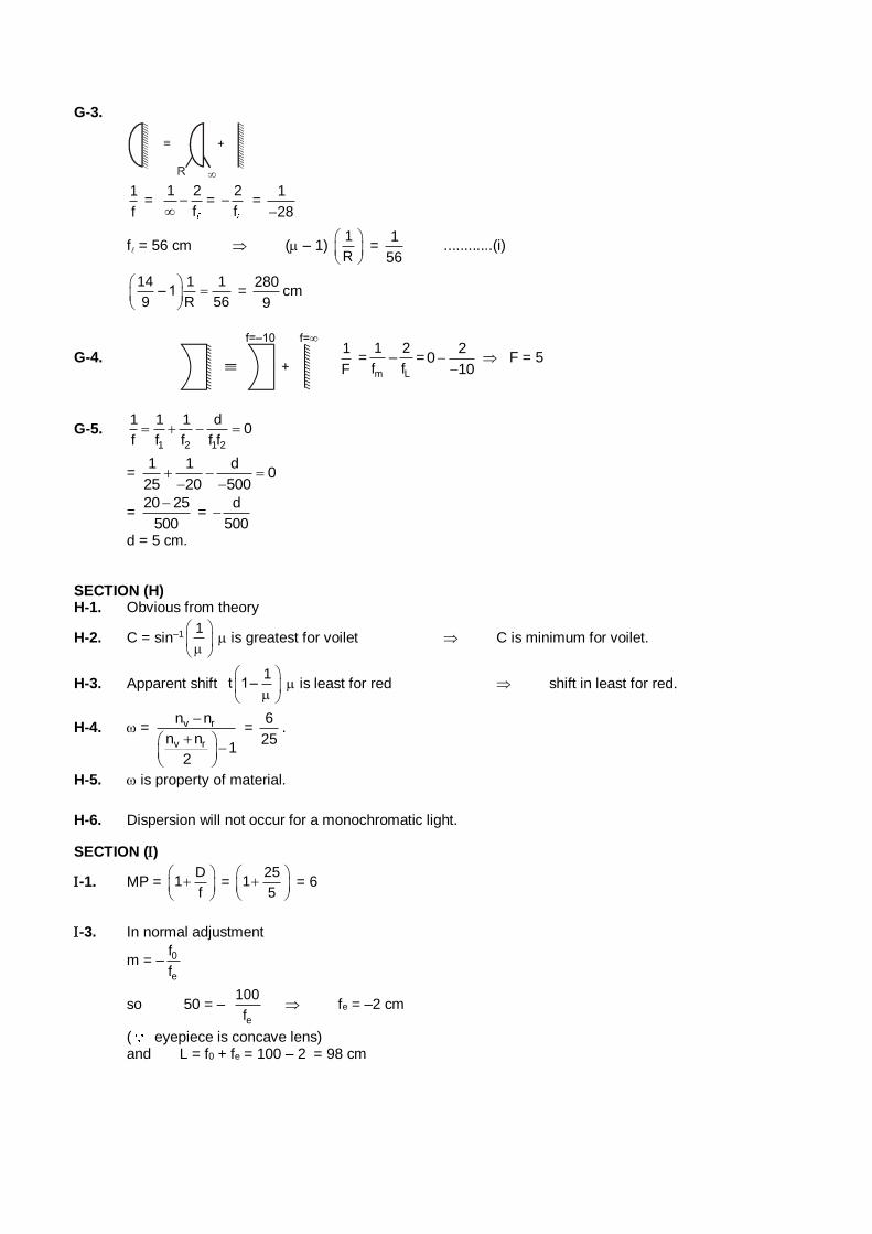
G-3.
1
f =
1 2
f
=
2
f =
1
28
f = 56 cm ( – 1) 1
R
= 1
56 ............(i)
14 1 1
– 19 R 56
=
280
9cm
G-4. 1
F =
m
1
f–
L
2
f=
20
10
F = 5
G-5. 1 2 1 2
1 1 1 d0
f f f f f
= 1 1 d
025 20 500
= 20 25
500
=
d
500
d = 5 cm. SECTION (H) H-1. Obvious from theory
H-2. C = sin–1 1
is greatest for voilet C is minimum for voilet.
H-3. Apparent shift 1
t 1–
is least for red shift in least for red.
H-4. = v r
v r
n n
n n1
2
= 6
25.
H-5. is property of material.
H-6. Dispersion will not occur for a monochromatic light.
SECTION ()
-1. MP = D
1f
=
251
5
= 6
-3. In normal adjustment
m = – 0
e
f
f
so 50 = – e
100
f fe = –2 cm
( eyepiece is concave lens) and L = f0 + fe = 100 – 2 = 98 cm
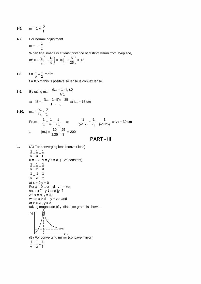
-5. m = 1 + D
f
-7. For normal adjustment
m = – 0
e
f
f
When final image is at least distance of distinct vision from eyepiece,
m' = – 0 e
e
f f1
f d
=
510 1
25
= 12
-8. f = 1 1
p 2 metre
f = 0.5 m this is positive so lense is convex lense.
-9. By using m = 0 e
0 e
(L f f ).D
f f
45 = (L 1 5) 25
1 5
L = 15 cm
-10. m = 0
0 e
v D
u f
From 0 0 0
1 1 1
f v u
0
1 1 1
( 1.2) v ( 1.25)
v0 = 30 cm
m30 25
1.25 3 = 200
PART - III
1. (A) For converging lens (convex lens)
1 1 1
–v u f
u = – x, v = y, f = d (+ ve constant)
1 1 1
v x d
1 1 1
–y d x
at x = 0 y = 0 For x = 0 to x = d, y = – ve
so, if x y and |y|
At x = d, y = when x > d , y + ve, and
at x = , y = d taking magnitude of y, distance graph is shown.
x
|y|
(B) For converging mirror (concave mirror )
1 1 1
v u f
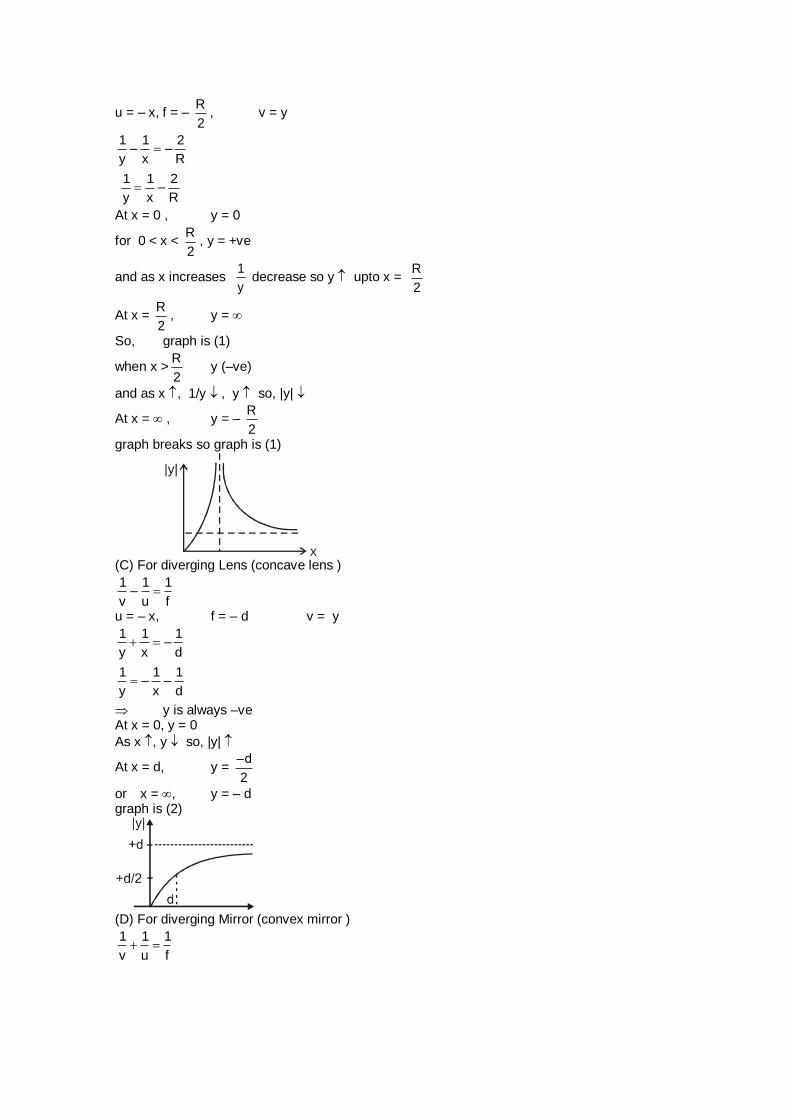
u = – x, f = – R
2, v = y
1 1 2
– –y x R
1 1 2
–y x R
At x = 0 , y = 0
for 0 < x < R
2, y = +ve
and as x increases 1
y decrease so y upto x =
R
2
At x = R
2, y =
So, graph is (1)
when x >R
2 y (–ve)
and as x , 1/y , y so, |y|
At x = , y = – R
2
graph breaks so graph is (1)
x
|y|
(C) For diverging Lens (concave lens )
1 1 1
–v u f
u = – x, f = – d v = y
1 1 1
–y x d
1 1 1
– –y x d
y is always –ve At x = 0, y = 0
As x , y so, |y|
At x = d, y = –d
2
or x = , y = – d graph is (2)
(D) For diverging Mirror (convex mirror )
1 1 1
v u f
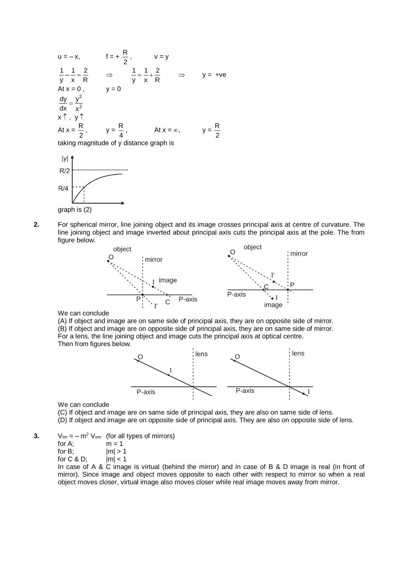
u = – x, f = + R
2, v = y
1 1 2
–y x R
1 1 2
y x R y = +ve
At x = 0 , y = 0
2
2
dy y
dx x
x , y
At x = R
2, y =
R
4, At x = , y =
R
2
taking magnitude of y distance graph is
graph is (2)
2. For spherical mirror, line joining object and its image crosses principal axis at centre of curvature. The line joining object and image inverted about principal axis cuts the principal axis at the pole. The from figure below.
O
object
mirror
I image
C P-axisPI'
Oobject
mirror
Iimage
CP-axis
P
I'
We can conclude (A) If object and image are on same side of principal axis, they are on opposite side of mirror. (B) If object and image are on opposite side of principal axis, they are on same side of mirror. For a lens, the line joining object and image cuts the principal axis at optical centre. Then from figures below.
O lens
I
P-axis
Olens
P-axis I
We can conclude (C) If object and image are on same side of principal axis, they are also on same side of lens. (D) If object and image are on opposite side of principal axis. They are also on opposite side of lens.
3. Vm = – m2 Vom (for all types of mirrors) for A; m = 1 for B; |m| > 1 for C & D; |m| < 1 In case of A & C image is virtual (behind the mirror) and in case of B & D image is real (in front of
mirror). Since image and object moves opposite to each other with respect to mirror so when a real object moves closer, virtual image also moves closer while real image moves away from mirror.
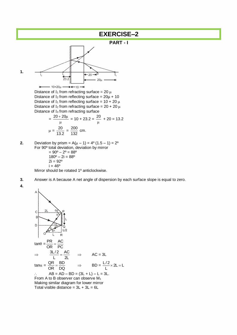
EXERCISE–2
PART - I
1.
Distance of 1 from refracting surface = 20
Distance of 2 from reflecting surface = 20µ + 10
Distance of 1 from reflecting surface = 10 + 20
Distance of 2 from refracting surface = 20 + 20
Distance of 3 from refracting surface
= 20 20
= 10 + 23.2 =
20
+ 20 = 13.2
= 20
13.2 =
200
132 cm.
2. Deviation by prism = A( – 1) = 4º (1.5 – 1) = 2º For 90º total deviation, deviation by mirror = 90º – 2º = 88º 180º – 2i = 88º 2i = 92º i = 46º Mirror should be rotated 1º anticlockwise. 3. Answer is A because A net angle of dispersion by each surface slope is equal to zero.
4.
tan =PR AC
OR PC
3L / 2 AC
L 2L AC = 3L
tan = QR BD
OR DQ BD =
L / 22L L
L
AB = AD – BD = (3L + L) – L = 3L. From A to B observer can observe M1 Making similar diagram for lower mirror Total visible distance = 3L + 3L = 6L
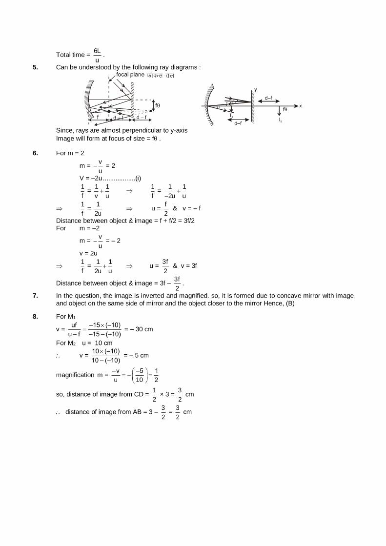
Total time = 6L
u.
5. Can be understood by the following ray diagrams :
Since, rays are almost perpendicular to y-axis
Image will form at focus of size = f. 6. For m = 2
m = v
u = 2
V = –2u ..................(i)
1
f =
1 1
v u
1
f =
1 1
2u u
1
f =
1
2u u =
f
2 & v = – f
Distance between object & image = f + f/2 = 3f/2 For m = –2
m = v
u = – 2
v = 2u
1
f =
1 1
2u u u =
3f
2 & v = 3f
Distance between object & image = 3f – 3f
2.
7. In the question, the image is inverted and magnified. so, it is formed due to concave mirror with image and object on the same side of mirror and the object closer to the mirror Hence, (B)
8. For M1
v = uf –15 (–10)
u – f –15 – (–10)
= – 30 cm
For M2 u = 10 cm
v = 10 (–10)
10 – (–10)
= – 5 cm
magnification m = –v –5 1
–u 10 2
so, distance of image from CD = 1
2 × 3 =
3
2 cm
distance of image from AB = 3 – 3
2 =
3
2 cm
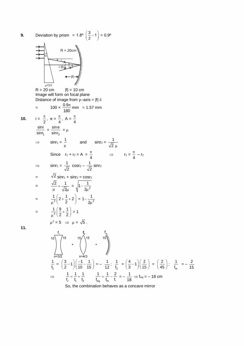
9. Deviation by prism = 3
1.8º 12
= 0.9º
R = 20 cm |f| = 10 cm Image will form on focal plane
Distance of image from y–axis = |f|
= 100 × 0.9
180
mm = 1.57 mm
10. i = 2
, e =
4
, A =
4
1
sini
sinr =
2
sine
sinr =
sinr1 = 1
and sinr2 =
1
2
Since r1 + r2 = A = 4
r1 =
4
– r2
sinr1 = 1
2 cosr2 –
1
2sinr2
= 2 sinr1 + sinr2 = cosr2
= 2 1
2
=
2
11
2
= 2
1 12 2
2
=
2
11
2
= 2
1 9 1
2 2
= 1
2 = 5 = 5 .
11.
1
1
f =
31
2
1 1
10 15
= –
1
12;
2
1
f =
41
3
2
15
= 2
45
; m
1
f = –
2
15
1 2
1 1 1
f f f
eq m
1 1 2
f f f = –
1
18 feq = – 18 cm
So, the combination behaves as a concave mirror
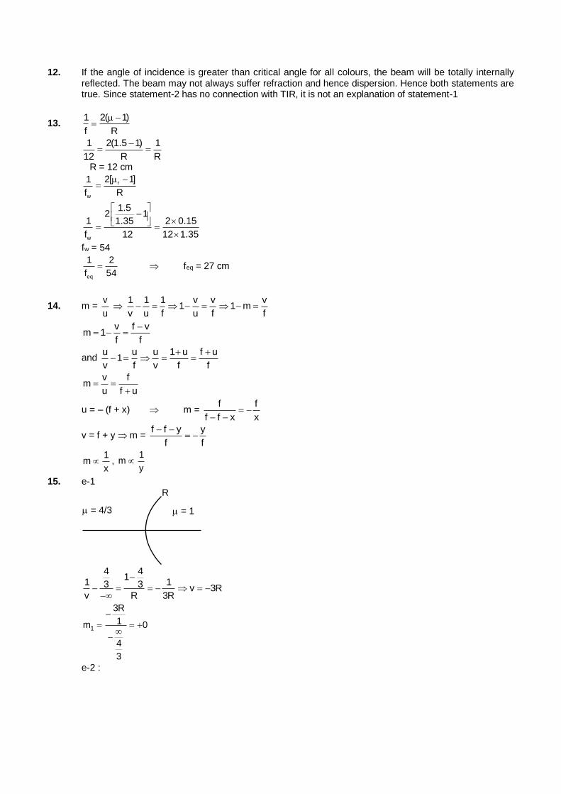
12. If the angle of incidence is greater than critical angle for all colours, the beam will be totally internally reflected. The beam may not always suffer refraction and hence dispersion. Hence both statements are true. Since statement-2 has no connection with TIR, it is not an explanation of statement-1
13. 1 2( 1)
f R
1 2(1.5 1) 1
12 R R
R = 12 cm
r
w
2[ 1]1
f R
w
1.52 1
1 2 0.151.35
f 12 12 1.35
fw = 54
eq
1 2
f 54 feq = 27 cm
14. m = v
u
1 1 1 v v v1 1 m
v u f u f f
v f v
m 1f f
and u u u 1 u f u
1v f v f f
v f
mu f u
u = – (f + x) m = f f
f f x x
v = f + y m = f f y y
f f
1
mx
, 1
my
15. e-1
R
= 1 = 4/3
4 41
1 13 3 v 3Rv R 3R
1
3R
1m 0
4
3
e-2 :
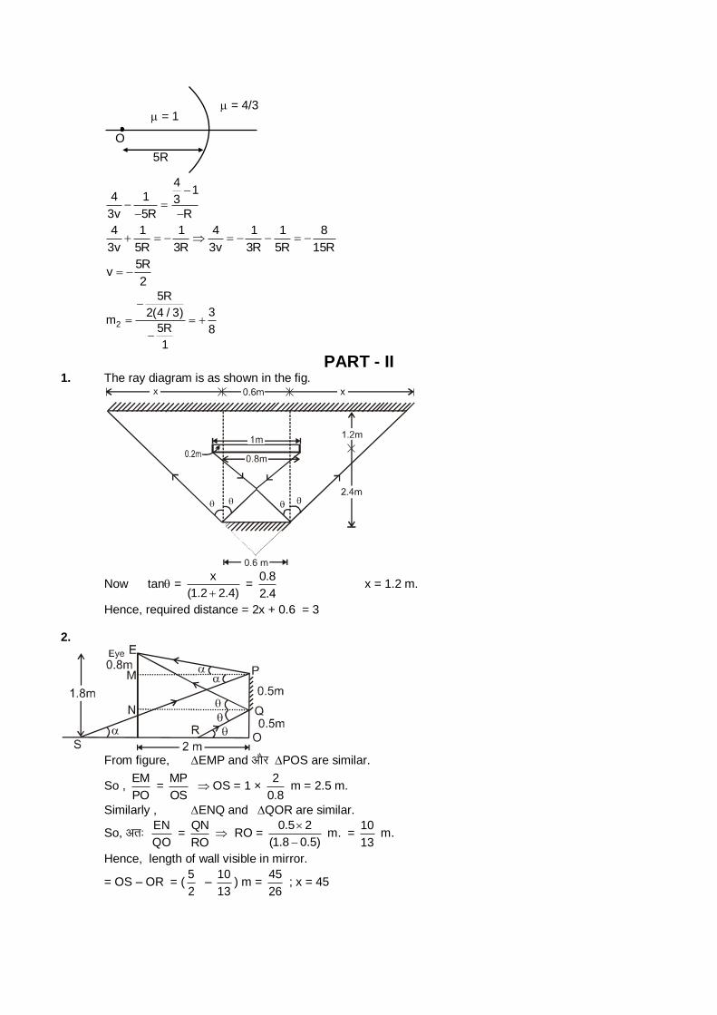
= 4/3
5R
O
= 1
41
4 1 3
3v 5R R
4 1 1 4 1 1 8
3v 5R 3R 3v 3R 5R 15R
5R
v2
2
5R
32(4 / 3)m
5R 8
1
PART - II 1. The ray diagram is as shown in the fig.
Now tan = x
(1.2 2.4) =
0.8
2.4 x = 1.2 m.
Hence, required distance = 2x + 0.6 = 3 2.
From figure, EMP and vkSj POS are similar.
So , EM
PO =
MP
OS OS = 1 ×
2
0.8 m = 2.5 m.
Similarly , ENQ and QOR are similar.
So, vr% EN
QO =
QN
RO RO =
0.5 2
(1.8 0.5)
m. =
10
13 m.
Hence, length of wall visible in mirror.
= OS – OR = (5
2 –
10
13) m =
45
26 ; x = 45
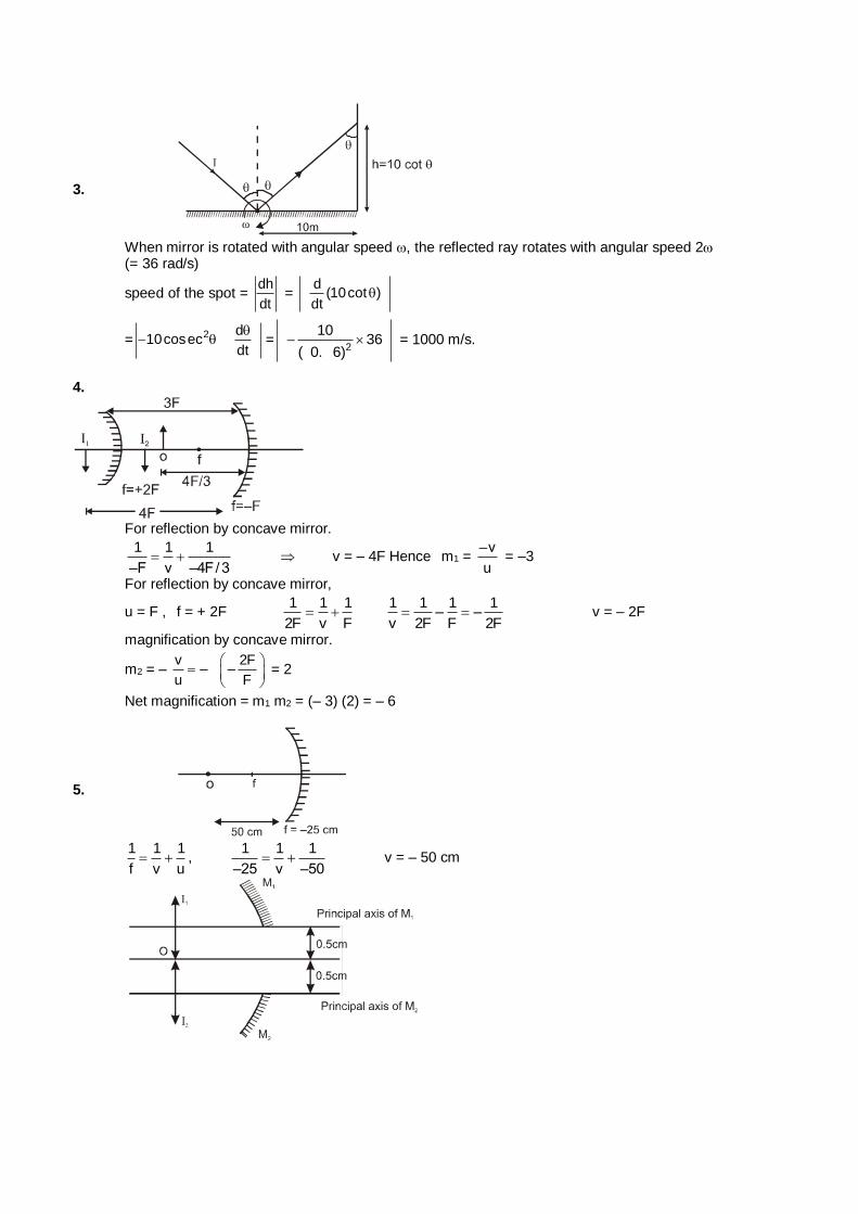
3.
When mirror is rotated with angular speed , the reflected ray rotates with angular speed 2 (= 36 rad/s)
speed of the spot = dh
dt =
d(10cot )
dt
= 2 d10cosec
dt
=
2
1036
( 0. 6) = 1000 m/s.
4.
For reflection by concave mirror.
1 1 1
–F v –4F/3 v = – 4F Hence m1 =
–v
u = –3
For reflection by concave mirror,
u = F , f = + 2F 1 1 1
2F v F
1 1 1 1– –
v 2F F 2F v = – 2F
magnification by concave mirror.
m2 = – v 2F
– –u F
= 2
Net magnification = m1 m2 = (– 3) (2) = – 6
5.
1 1 1
f v u ,
1 1 1
–25 v –50 v = – 50 cm
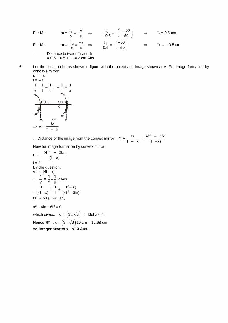
For M1 m = 1 v–
o u
1 – 50
––0.5 –50
1 = 0.5 cm
For M2 m = 2 –v
o u
2 –50
–0.5 –50
2 = – 0.5 cm
Distance between 1 and 2 = 0.5 + 0.5 + 1 = 2 cm.Ans 6. Let the situation be as shown in figure with the object and image shown at A. For image formation by
concave mirror, u = – x f = – f
1
v =
1
f –
1
u = –
1
f +
1
x
v = fx
f – x
Distance of the image from the convex mirror = 4f + fx
f – x =
24f – 3fx
(f x)
Now for image formation by convex mirror,
u = – 2(4f – 3fx)
(f x)
f = f By the question, v = – (4f – x)
1
v =
1 1
f u gives ,
1
(4f x) =
1
f +
2
(f – x)
(4f 3fx)
on solving, we get, x2 – 6fx + 6f2 = 0
which gives,] x = 3 3 f But x < 4f
Hence vr% , x = 3 – 3 10 cm = 12.68 cm
so integer next to x is 13 Ans.
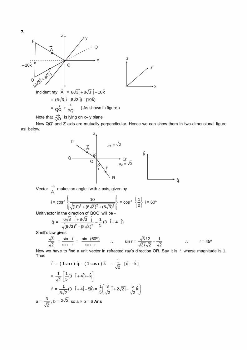
7.
p
A
zy
Q
x
O
Q
k10
10
^
^
3 i + 8
3 j
z
y
x
Incident ray A = ˆ ˆ ˆ6 3i 8 3 j 10k
= ˆ ˆ ˆ(6 3 i 8 3 j) (10k)
= QO
+ PQ
( As shown in figure )
Note that QO
is lying on x– y plane
Now QQ’ and Z axis are mutually perpendicular. Hence we can show them in two-dimensional figure
ask below.
k
q
Vector A
makes an angle i with z-axis, given by
i = cos-1 2 2 2
10
(10) (6 3) (8 3)
= cos-1 1
2
i = 60º
Unit vector in the direction of QOQ’ will be -
q = 2 2
ˆ ˆ6 3 i 8 3 j 1
5(6 3) (8 3)
ˆ ˆ(3 i 4 j)
Snell’s law gives
3
2 =
sin i
sin r =
sin (60º)
sin r sin r =
3 / 2 1
3 / 2 2 r = 45º
Now we have to find a unit vector in refracted ray’s direction OR. Say it is r whose magnitude is 1. Thus
r = ( 1sin r ) q – ( 1 cos r ) k = 1
2 [ q – k ]
= 1
2
1 ˆ ˆ ˆ(3 i 4 j) k5
r = 1 ˆ ˆ ˆ(3 i 4 j 5k)
5 2 =
1 3 5ˆ ˆ ˆi 2 2 j k5 2 2
a = 3
2, b = 2 2 so a × b = 6 Ans
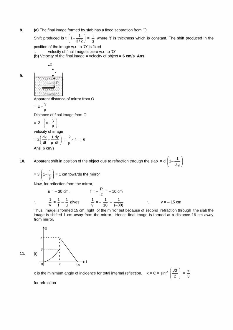
8. (a) The final image formed by slab has a fixed separation from ’O’.
Shift produced is t 1
13 / 2
=
t
3 where ‘t’ is thickness which is constant. The shift produced in the
position of the image w.r. to ‘O’ is fixed
velocity of final image is zero w.r. to ‘O’ (b) Velocity of the final image = velocity of object = 6 cm/s Ans.
9. x
y
O
Apparent distance of mirror from O
= y
x
Distance of final image from O
= y
2 x
velocity of image
= 2dx 1 dy
dt dt
= 2
4
= 6
Ans 6 cm/s
10. Apparent shift in position of the object due to refraction through the slab = d rel
11
µ
= 3 32
11
= 1 cm towards the mirror
Now, for reflection from the mirror,
u = – 30 cm. f = – R
2 = – 10 cm
1
v =
1
f –
1
u gives
1
v = –
1
10 –
1
( 30) v = – 15 cm
Thus, image is formed 15 cm, right of the mirror but because of second refraction through the slab the image is shifted 1 cm away from the mirror. Hence final image is formed at a distance 16 cm away from mirror.
11. (i)
i
x is the minimum angle of incidence for total internal reflection. x = C = sin–1 3
2
= 3
for refraction
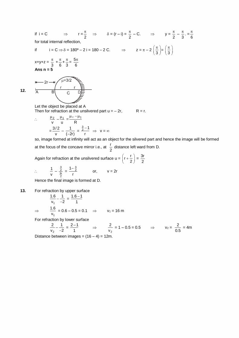
if i = C r =2
= (r – i) =
2
– C. y =
2
–
3
. =
6
for total internal reflection,
if i = C = 180º – 2 i = 180 – 2 C. z = – 2 3
= 3
x+y+z = 3
+
6
+
3
=
5
6
Ans n = 5
12.
Let the object be placed at A Then for refraction at the unsilvered part u = – 2r, R = r.
2
v
– 1
u
=
2 1
R
=3 / 2
v –
1
( 2r) =
32
1
r
v =
so, image formed at infinity will act as an object for the silvered part and hence the image will be formed
at the focus of the concave mirror i.e., at r
2 distance left ward from D.
Again for refraction at the unsilvered surface u = r
r2
=
3r
2
1
v –
323r2
= 32
1
r
or, v = 2r
Hence the final image is formed at D.
13. For refraction by upper surface
1
1.6 1
v 2
= 1.6 1
1
1
1.6
v = 0.6 – 0.5 = 0.1 v1 = 16 m
For refraction by lower surface
2
2 1
v 2
= 2 1
1
2
2
v = 1 – 0.5 = 0.5 v2 =
2
0.5 = 4m
Distance between images = (16 – 4) = 12m.
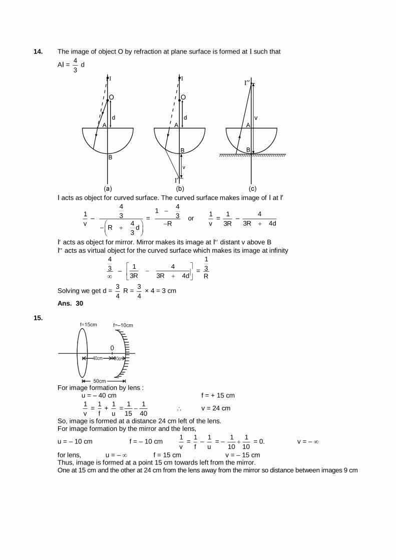
14. The image of object O by refraction at plane surface is formed at I such that
AI = 4
3 d
I acts as object for curved surface. The curved surface makes image of I at I
1
v –
4
34
R d3
=
41
3R
or
1
v =
1
3R –
4
3R 4d
I acts as object for mirror. Mirror makes its image at I distant v above B
I acts as virtual object for the curved surface which makes its image at infinity
4
3
– 1 4
3R 3R 4d
=
1
3R
Solving we get d = 3
4 R =
3
4 × 4 = 3 cm
Ans. 30
15.
For image formation by lens : u = – 40 cm f = + 15 cm
1
v =
1
f +
1
u =
1 1
15 40 v = 24 cm
So, image is formed at a distance 24 cm left of the lens. For image formation by the mirror and the lens,
u = – 10 cm f = – 10 cm 1
v =
1
f –
1
u = –
1 1
10 10 = 0. v = –
for lens, u = – f = 15 cm v = – 15 cm Thus, image is formed at a point 15 cm towards left from the mirror. One at 15 cm and the other at 24 cm from the lens away from the mirror so distance between images 9 cm
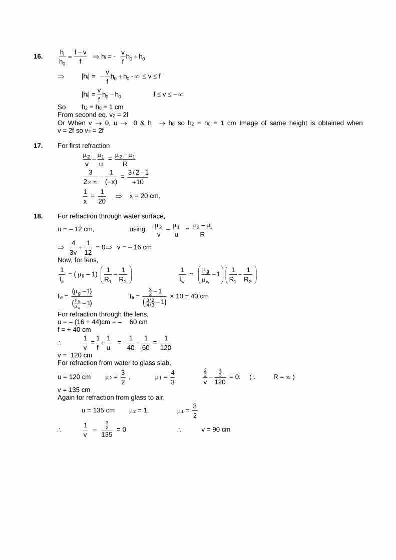
16. i
0
h f v
h f
hi = - 0 0
vh h
f
|hi| = 0 0
vh h
f - v f
|hi| = 0 0
vh h
f f v –
So h2 = h0 = 1 cm From second eq. v2 = 2f
Or When v 0, u 0 & hi h0 so h2 = h0 = 1 cm Image of same height is obtained when v = 2f so v2 = 2f
17. For first refraction
2 1
v u
= 2 1
R
3 1
2 ( x)
=
3/ 2 1
10
1
x =
1
20 x = 20 cm.
18. For refraction through water surface,
u = – 12 cm, using 2
v
– 1
u
= 2 1– µ
R
4 1
3v 12 = 0 v = – 16 cm
Now, for lens,
a
1
f = ( g – 1)
1 2
1 1
R R
w
1
f =
g
w
1
1 2
1 1
R R
fw = g
w
g( 1)
( 1)
fa =
32
3 / 24 /3
1
1
× 10 = 40 cm
For refraction through the lens, u = – (16 + 44)cm = – 60 cm f = + 40 cm
1
v =
1 1
f u =
1 1
40 60 =
1
120
v = 120 cm For refraction from water to glass slab,
u = 120 cm 2 = 3
2 , 1 =
4
3
3 432
v 120 = 0. ( R = )
v = 135 cm Again for refraction from glass to air,
u = 135 cm 2 = 1, 1 = 3
2
1
v –
32
135 = 0 v = 90 cm
19. 1
f = (n 1)
1 2
1 1
R R
2
d f
f =
1 2
1 1
R R
dn
differentiating both sides
df
f (n 1)
1 2
1 1
R R
=
1 2
1 1
R R
dn df = f
dn
n 1
but dn = nv nR d f = v Rn n
n 1
f df = f fv fR = f
= 0.04 10 = –0.4 cm
Ans.: fR fv = 4 mm
PART - III
1. f = – 20 m & m = – v
u= 2
using v = 2u.
1 1 1
–20 2u u
3 1
2u –20 u = – 30 cm
using v = – 2u
1 1 1
–20 –2u u
1 1
2u –20 u = – 10 cm
2. (A) No, when object is between infinite and focus ,image is real. (C) when object is between pole and focus, image is magnified. (D) when object is between pole and focus image formed by convex mirror is real.
3. y
x
C sinr
C sin i = tan 30º =
1
3
Cy = 1
3 Cx.
since y is denser, total internal reflection can take place when ray is incident from y.
4. (A) is not true for minimum deviation. (B) is true only if refracting side are equal. (C) Two angles for maximum deviation are 90º and imin.
(D) min. = ( – 1) A.
5. A = 60º
= 40º
i + e = A +
i + e = 100º and i – e = 20º
i = 60º or ;k 40º
6. 1 2 1 2––
v u R
1 2–v u
< 0
1 2
v u
1
2
v
u
v
u > 0
v and u must have same sign.
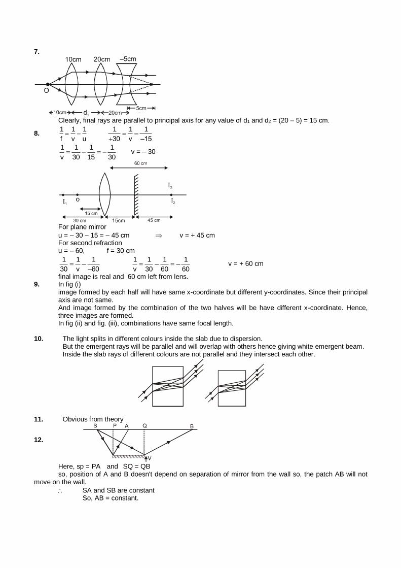
7.
Clearly, final rays are parallel to principal axis for any value of d1 and d2 = (20 – 5) = 15 cm.
8. 1 1 1
f v u
1 1 1–
30 v –15
1 1 1 1
– –v 30 15 30 v = – 30
For plane mirror
u = – 30 – 15 = – 45 cm v = + 45 cm For second refraction u = – 60, f = 30 cm
1 1 1
–30 v –60
1 1 1 1
– –v 30 60 60 v = + 60 cm
final image is real and 60 cm left from lens. 9. In fig (i) image formed by each half will have same x-coordinate but different y-coordinates. Since their principal
axis are not same. And image formed by the combination of the two halves will be have different x-coordinate. Hence,
three images are formed. In fig (ii) and fig. (iii), combinations have same focal length. 10. The light splits in different colours inside the slab due to dispersion. But the emergent rays will be parallel and will overlap with others hence giving white emergent beam. Inside the slab rays of different colours are not parallel and they intersect each other.
11. Obvious from theory
12.
Here, sp = PA and SQ = QB so, position of A and B doesn't depend on separation of mirror from the wall so, the patch AB will not move on the wall.
SA and SB are constant So, AB = constant.
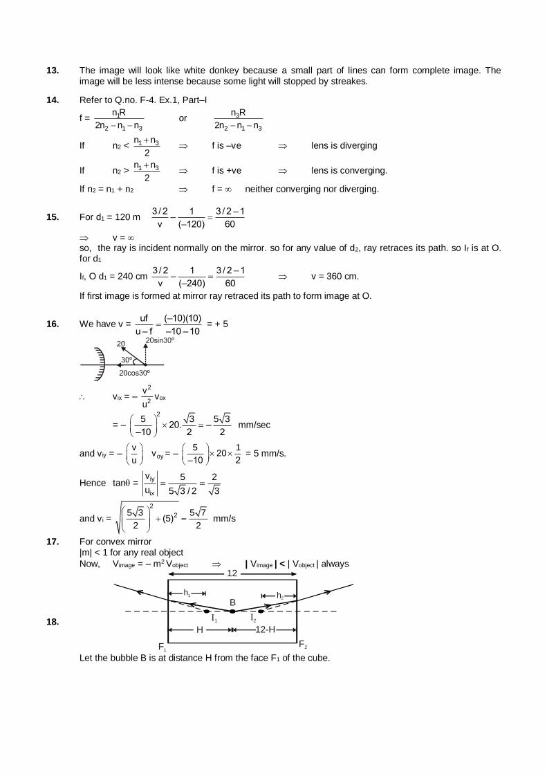
13. The image will look like white donkey because a small part of lines can form complete image. The image will be less intense because some light will stopped by streakes.
14. Refer to Q.no. F-4. Ex.1, Part–I
f = 1
2 1 3
n R
2n n n or 3
2 1 3
n R
2n n n
If n2 < 1 3n n
2
f is –ve lens is diverging
If n2 > 1 3n n
2
f is +ve lens is converging.
If n2 = n1 + n2 f = neither converging nor diverging.
15. For d1 = 120 m 3 / 2 1 3 / 2 – 1
–v (–120) 60
v = so, the ray is incident normally on the mirror. so for any value of d2, ray retraces its path. so If is at O.
for d1
If, O d1 = 240 cm 3 / 2 1 3 / 2 – 1
–v (–240) 60
v = 360 cm.
If first image is formed at mirror ray retraced its path to form image at O.
16. We have v = uf (–10)(10)
u – f –10 –10 = + 5
vix = – 2
2
v
uvox
= –
25 3 5 3
20. ––10 2 2
mm/sec
and v iy = – oy
vv
u
= – 5 1
20–10 2
= 5 mm/s.
Hence tan = iy
ix
v 5 2
u 5 3 / 2 3
and v i =
2
25 3 5 7(5)
2 2
mm/s
17. For convex mirror |m| < 1 for any real object
Now, Vimage = – m2 Vobject | Vimage | < | Vobject | always
18.
h1 h2
1
B
12
F1F2
H
212-H
Let the bubble B is at distance H from the face F1 of the cube.
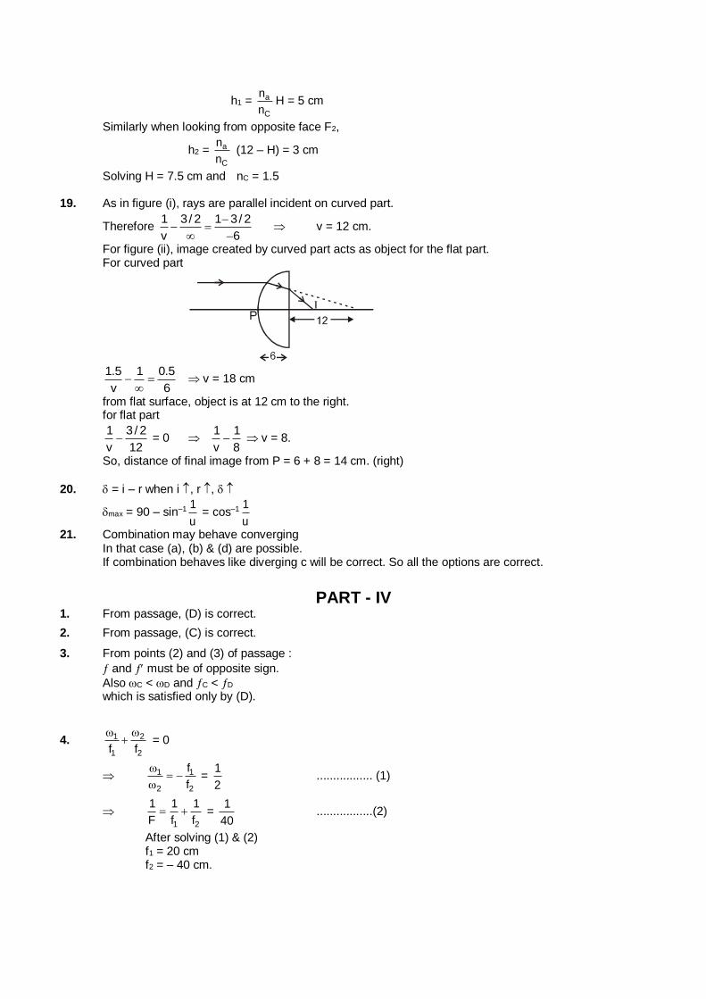
h1 = a
C
n
nH = 5 cm
Similarly when looking from opposite face F2,
h2 = a
C
n
n (12 – H) = 3 cm
Solving H = 7.5 cm and nC = 1.5 19. As in figure (i), rays are parallel incident on curved part.
Therefore 1 3/ 2 1 3/ 2
v 6
v = 12 cm.
For figure (ii), image created by curved part acts as object for the flat part. For curved part
1.5 1 0.5
v 6
v = 18 cm
from flat surface, object is at 12 cm to the right. for flat part
1 3 / 2
v 12 = 0
1 1
v 8 v = 8.
So, distance of final image from P = 6 + 8 = 14 cm. (right)
20. = i – r when i , r ,
max = 90 – sin–1 1
u = cos–1 1
u
21. Combination may behave converging In that case (a), (b) & (d) are possible. If combination behaves like diverging c will be correct. So all the options are correct.
PART - IV
1. From passage, (D) is correct.
2. From passage, (C) is correct.
3. From points (2) and (3) of passage :
and must be of opposite sign.
Also C < D and C < D which is satisfied only by (D).
4. 1 2
1 2f f
= 0
1 1
2 2
f
f
=
1
2 ................. (1)
1 2
1 1 1
F f f =
1
40 .................(2)
After solving (1) & (2) f1 = 20 cm f2 = – 40 cm.
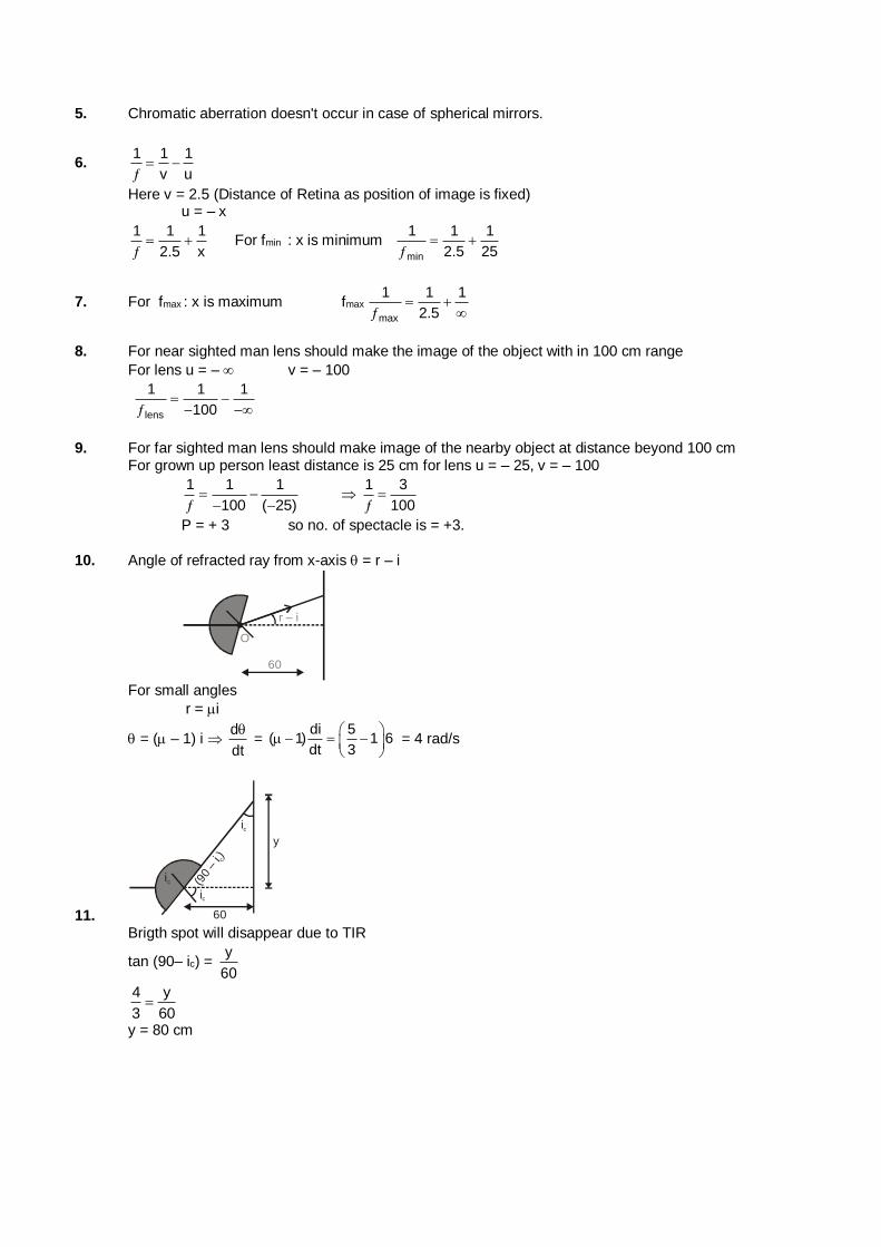
5. Chromatic aberration doesn't occur in case of spherical mirrors.
6. 1 1 1
v u
Here v = 2.5 (Distance of Retina as position of image is fixed) u = – x
1 1 1
2.5 x
For fmin : x is minimum
min
1 1 1
2.5 25
7. For fmax : x is maximum fmax
max
1 1 1
2.5
8. For near sighted man lens should make the image of the object with in 100 cm range
For lens u = – v = – 100
lens
1 1 1
100
9. For far sighted man lens should make image of the nearby object at distance beyond 100 cm For grown up person least distance is 25 cm for lens u = – 25, v = – 100
1 1 1
100 ( 25)
1 3
100
P = + 3 so no. of spectacle is = +3.
10. Angle of refracted ray from x-axis = r – i
O
r – i
60
r
For small angles
r = i
= ( – 1) i d
dt
=
di 5( 1) 1 6
dt 3
= 4 rad/s
11.
(90
– i )c
ic
ic
ic
y
60 Brigth spot will disappear due to TIR
tan (90– ic) = y
60
4 y
3 60
y = 80 cm
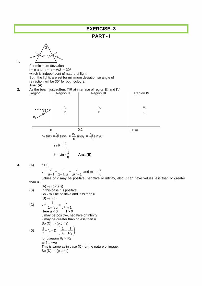
EXERCISE–3
PART - I
1. For minimum deviation
i = e and r1 = r2 = A/2 = 30º which is independent of nature of light. Both the lights are set for minimum deviation so angle of refraction will be 30° for both colours. Ans. (A)
2. As the beam just suffers TIR at interface of region and IV.
n0 sin = 01
nsin
2 = 0
2
nsin
6 = 0n
sin908
sin = 1
8
= sin–1 1
8 Ans. (B)
3. (A) f < 0,
v = uf f u
u f 1 f /u u/ f 1
and m = –
v
u
values of v may be positive, negative or infinity, also it can have values less than or greater than u.
(A) (p,q,r,s) (B) In this case f is positive. So v will be positive and less than u.
(B) (q)
(C) v = f u
1 f /u u/ f 1
Here u < 0 f > 0 v may be positive, negative or infinity v may be greater than or less than u
So (C) (p,q,r,s)
(D) 1 2
1 1 1( 1)
f R R
for diagram R2 > R1
f is +ve This is same as in case (C) for the nature of image.
So (D) (p,q,r,s)
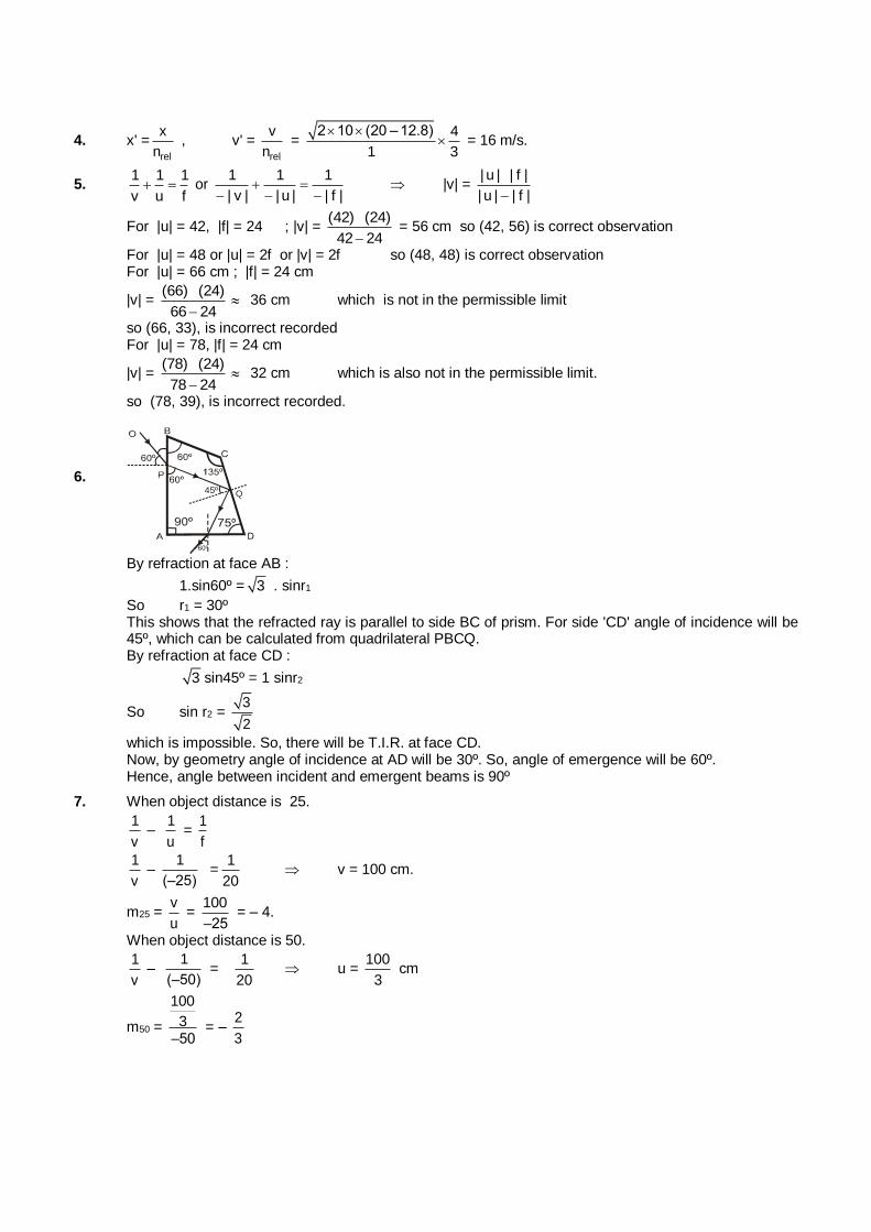
4. x' =rel
x
n , v' =
rel
v
n =
2 10 (20 – 12.8) 4
1 3
= 16 m/s.
5. 1 1 1
v u f or
1 1 1
| v | | u | | f |
|v| =
| u | | f |
| u | | f |
For |u| = 42, |f| = 24 ; |v| = (42) (24)
42 24 = 56 cm so (42, 56) is correct observation
For |u| = 48 or |u| = 2f or |v| = 2f so (48, 48) is correct observation For |u| = 66 cm ; |f| = 24 cm
|v| = (66) (24)
66 24 36 cm which is not in the permissible limit
so (66, 33), is incorrect recorded For |u| = 78, |f| = 24 cm
|v| = (78) (24)
78 24 32 cm which is also not in the permissible limit.
so (78, 39), is incorrect recorded.
6. 45º
60º
Q
By refraction at face AB :
1.sin60º = 3 . sinr1
So r1 = 30º This shows that the refracted ray is parallel to side BC of prism. For side 'CD' angle of incidence will be
45º, which can be calculated from quadrilateral PBCQ. By refraction at face CD :
3 sin45º = 1 sinr2
So sin r2 = 3
2
which is impossible. So, there will be T.I.R. at face CD. Now, by geometry angle of incidence at AD will be 30º. So, angle of emergence will be 60º. Hence, angle between incident and emergent beams is 90º
7. When object distance is 25.
1
v –
1
u =
1
f
1
v –
1
(–25) =
1
20 v = 100 cm.
m25 = v
u =
100
–25 = – 4.
When object distance is 50.
1
v –
1
(–50) =
1
20 u =
100
3 cm
m50 =
100
3–50
= – 2
3
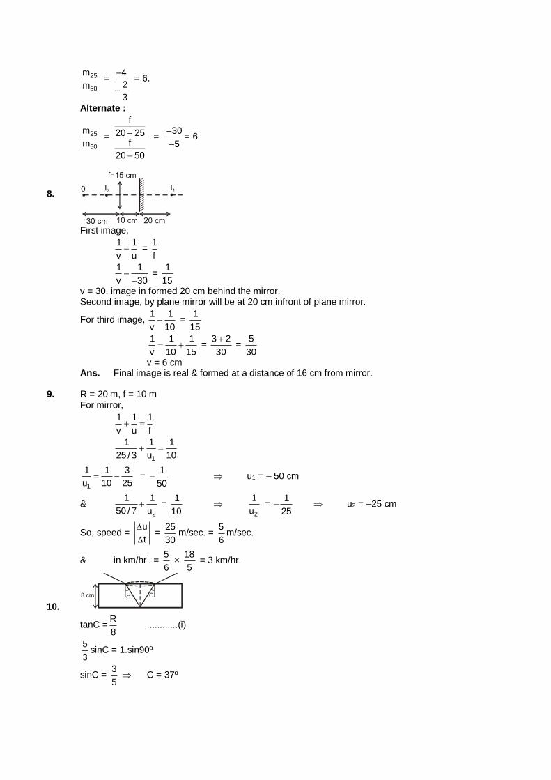
25
50
m
m =
–4
2–
3
= 6.
Alternate :
25
50
m
m =
f
20 25f
20 50
= 30
5
= 6
8.
First image,
1 1
v u =
1
f
1 1
v 30
= 1
15
v = 30, image in formed 20 cm behind the mirror. Second image, by plane mirror will be at 20 cm infront of plane mirror.
For third image, 1 1
v 10 =
1
15
1 1 1
v 10 15 =
3 2
30
=
5
30
v = 6 cm Ans. Final image is real & formed at a distance of 16 cm from mirror. 9. R = 20 m, f = 10 m For mirror,
1 1 1
v u f
1
1 1 1
25 / 3 u 10
1
1 1 3
u 10 25 =
1
50 u1 = – 50 cm
& 2
1 1
50 / 7 u =
1
10
2
1
u =
1
25 u2 = –25 cm
So, speed = u
t
=
25
30m/sec. =
5
6m/sec.
& in km/hr a = 5
6 ×
18
5 = 3 km/hr.
10.
8 cm CC
tanC =R
8 ............(i)
5
3sinC = 1.sin90º
sinC = 3
5 C = 37º
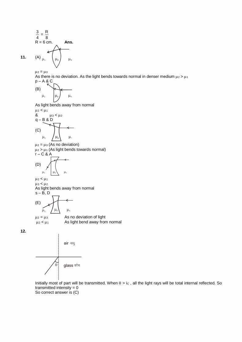
3
4 =
R
8
R = 6 cm. Ans.
11. (A)
2 = 3
As there is no deviation. As the light bends towards normal in denser medium 2 > 1
p – A & C
(B)
As light bends away from normal
2 < 1
& 3 < 2 q – B & D
(C)
2 = 3 (As no deviation)
2 > 1 (As light bends towards normal) r – C & A
(D)
2 < 1
3 < 2 As light bends away from normal s – B, D
(E)
2 = 3 As no deviation of light
2 < 1 As light bend away from normal 12.
Initially most of part will be transmitted. When > iC , all the light rays will be total internal reflected. So
transmitted intensity = 0 So correct answer is (C)
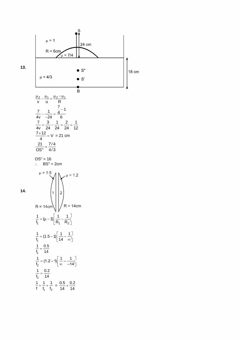
13.
2 1 2 1
v u R
71
7 1 44v 24 6
7 3 1 2 1
4v 24 24 24 12
7 12
V4
= 21 cm
21 7/ 4
OS" 4/3
OS" = 16
BS" = 2cm
14.
1 1 2
1 1 1( 1)
f R R
1
1 1 1(1.5 1)
f 14
1
1 0.5
f 14
2
1 1 1(1.2 – 1) –
f –14
2
1 0.2
f 14
1 2
1 1 1
f f f =
0.5 0.2
14 14
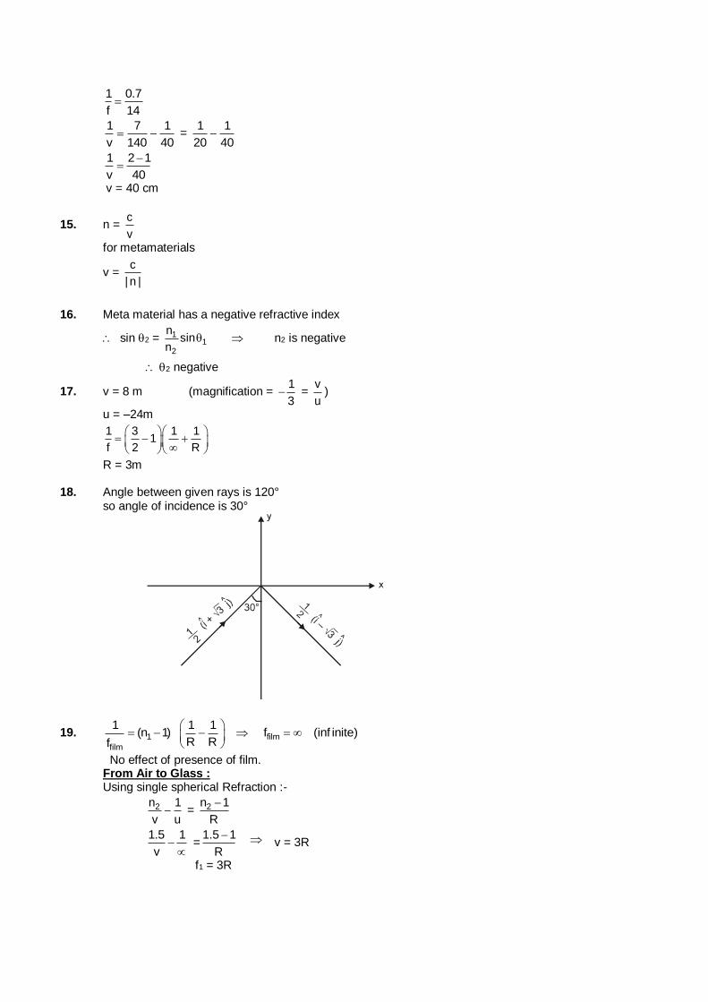
1 0.7
f 14
1 7 1
v 140 40 =
1 1
20 40
1 2 1
v 40
v = 40 cm
15. n = c
v
for metamaterials
v = c
| n |
16. Meta material has a negative refractive index
sin 2 = 11
2
nsin
n n2 is negative
2 negative
17. v = 8 m (magnification = 1
3 =
v
u)
u = –24m
1 3 1 1
1f 2 R
R = 3m 18. Angle between given rays is 120° so angle of incidence is 30°
19. 1
film
1 1 1(n 1) f (inf inite)
R Rf
film
No effect of presence of film. From Air to Glass : Using single spherical Refraction :-
2n 1
v u = 2n 1
R
1.5 1
v
=1.5 1
R
v = 3R
f1 = 3R
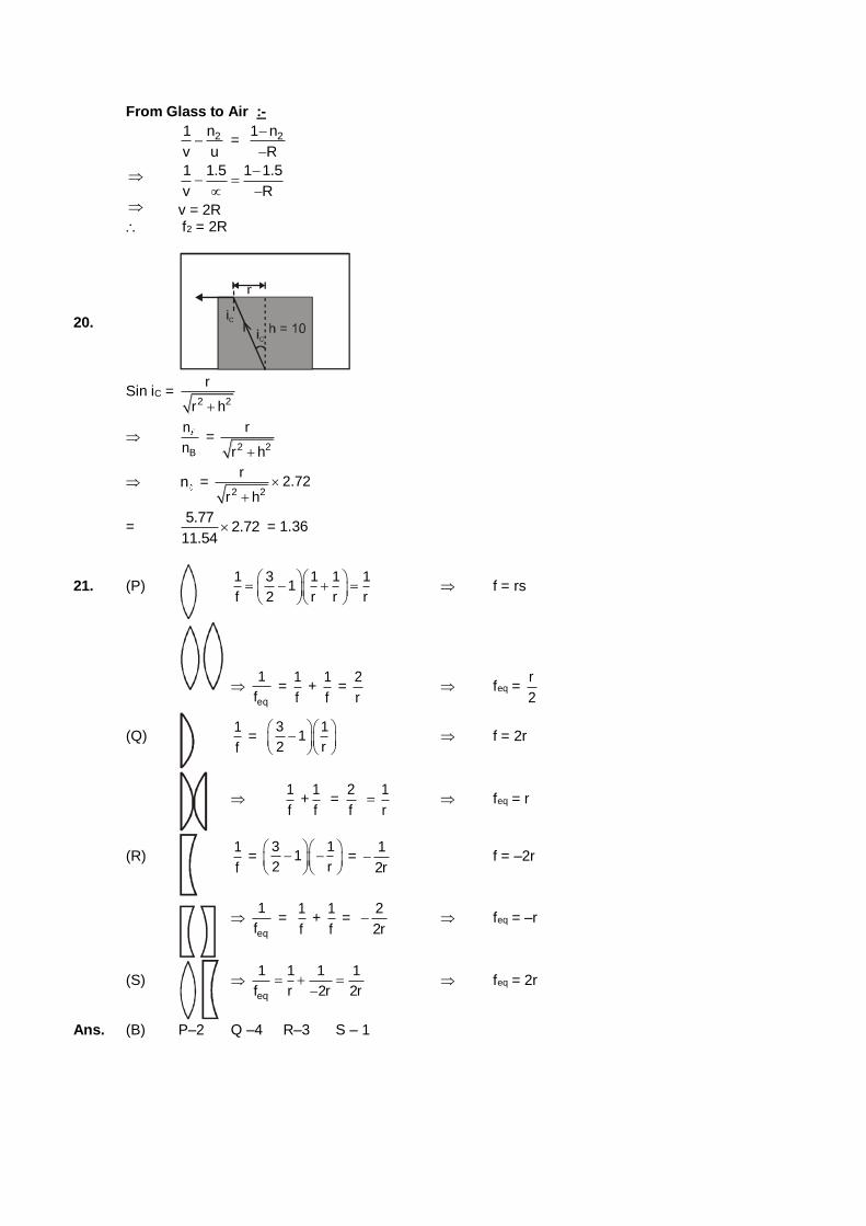
From Glass to Air :-
21 n
v u = 21 n
R
1 1.5 1 1.5
v R
v = 2R f2 = 2R
20.
Sin iC = 2 2
r
r h
B
n
n =
2 2
r
r h
n = 2 2
r2.72
r h
= 5.77
2.7211.54
= 1.36
21. (P) 1 3 1 1 1
1f 2 r r r
f = rs
eq
1
f =
1
f +
1
f =
2
r feq =
r
2
(Q) 1
f =
3 11
2 r
f = 2r
1
f +
1
f =
2
f
1
r feq = r
(R) 1
f =
3 11
2 r
=
1
2r f = –2r
eq
1
f =
1
f +
1
f =
2
2r feq = –r
(S) eq
1 1 1 1
f r 2r 2r
feq = 2r
Ans. (B) P–2 Q –4 R–3 S – 1
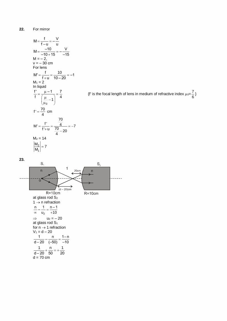
22. For mirror
f V
M –f – u u
–10 V
M ––10 15 –15
M = – 2, v = – 30 cm For lens
f 10
M' –1f u 10 – 20
M1 = 2 In liquid
0
f ' – 1 7
f 41
{f' is the focal length of lens in medium of refractive index 0=7
6}
70
f '4
cm
70f ' 4M' 7
70f ' u20
4
M2 = 14
2
1
M7
M
23.
at glass rod S2
1 n refraction
2
n 1 n – 1–
u 10
u2 = – 20 at glass rod S1
for n 1 refraction V1 = d – 20
1 n 1– n
–d – 20 (–50) –10
1 n 1
d – 20 50 20
d = 70 cm
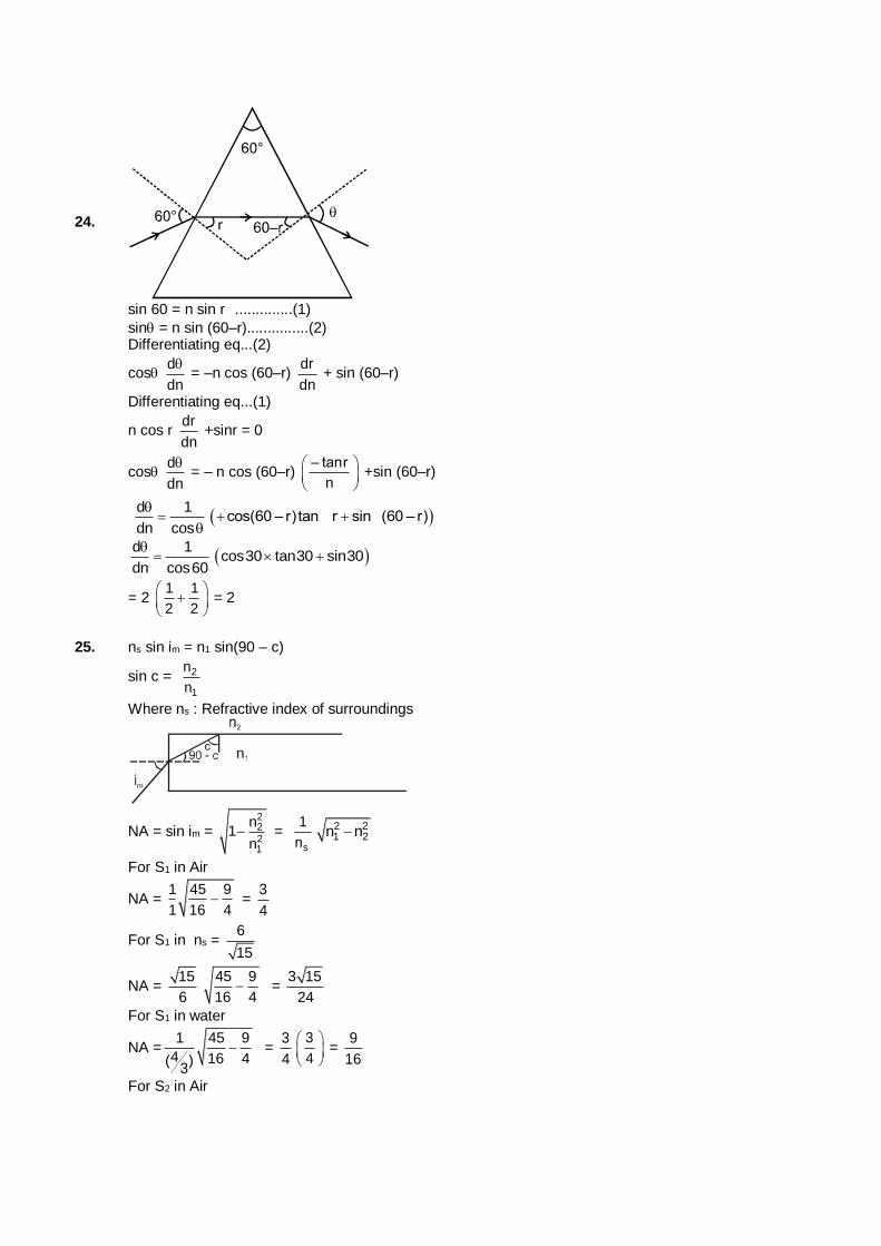
24.
sin 60 = n sin r ..............(1)
sin = n sin (60–r)...............(2) Differentiating eq...(2)
cos d
dn
= –n cos (60–r)
dr
dn + sin (60–r)
Differentiating eq...(1)
n cos r dr
dn +sinr = 0
cos d
dn
= – n cos (60–r)
– tanr
n
+sin (60–r)
d 1
dn cos
cos(60 – r)tan r sin (60 – r)
d 1
dn cos60
cos30 tan30 sin30
= 2 1 1
2 2
= 2
25. ns sin im = n1 sin(90 – c)
sin c = 2
1
n
n
Where ns : Refractive index of surroundings
NA = sin im = 2221
n1
n =
s
1
n
2 21 2n n
For S1 in Air
NA = 1 45 9
1 16 4 =
3
4
For S1 in ns = 6
15
NA = 15
6
45 9
16 4 =
3 15
24
For S1 in water
NA =1 45 9
4 16 4( )3
= 3
4
3
4
= 9
16
For S2 in Air
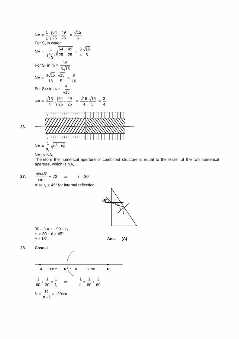
NA = 1
1
64 49
25 25 =
15
5
For S2 in water
NA = 1 64 49
4 25 25( )3
= 3 15
4 5
For S2 in ns = 16
3 15
NA = 3 15
16
15
5 =
9
16
For S2 sin ns = 4
15
NA = 15
4
64 49
25 25 =
15 15
4 5 =
3
4
26.
NA = 2 21 2
s
1n n
n
NA2 < NA1 Therefore the numerical aperture of combined structure is equal to the lesser of the two numerical
aperture, which is NA2
27. sin45
2sinr
r = 30°
Also r1 45° for internal reflection.
r1
r 45°
90 – = r + 90 – r1
r1 > 30 + 45°
15° Ans. (A) 28. Case–I
30cm 60cm n
1
1 1 1
60 30 f
1
1 1 2
f 60 60
f1 = R
20cmn 1
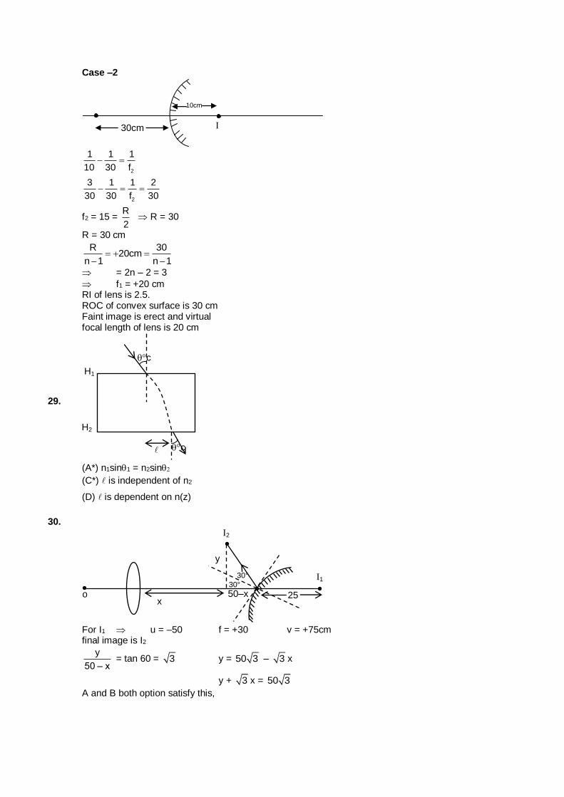
Case –2
30cm
10cm
2
1 1 1
10 30 f
2
3 1 1 2
30 30 f 30
f2 = 15 = R
2 R = 30
R = 30 cm
R 30
20cmn 1 n 1
= 2n – 2 = 3
f1 = +20 cm RI of lens is 2.5. ROC of convex surface is 30 cm Faint image is erect and virtual focal length of lens is 20 cm
29.
H1
H2
c
c
(A*) n1sin1 = n2sin
(C*) is independent of n2
(D) is dependent on n(z)
30.
o x
50–x 25
I1
I2
30°
30°
y
For I1 u = –50 f = +30 v = +75cm final image is I2
y
50 – x = tan 60 = 3 y = 50 3 – 3 x
y + 3 x = 50 3
A and B both option satisfy this,
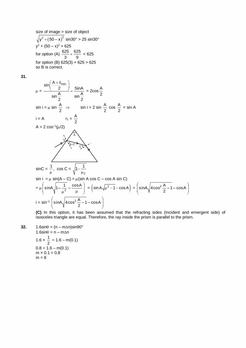
size of image > size of object
22y 50 – x sin30° > 25 sin30°
y2 + (50 – x)2 > 625
for option (A) 625 625
3 9 < 625
for option (B) 625(3) + 625 > 625 so B is correct. 31.
=
minAsin
2 SinA
A Asin sin
2 2
= 2cos2
A
sin i = sin 2
A sin i = 2 sin
2
A cos
2
A = sin A
i = A r1 = 2
A
A = 2 cos–1(/2)
i
A
A–C C
sinC = 1
, cos C =
2
11
sin i = sin(A – C) = (sin A cos C – cos A sin C)
=
Acos–
1–1Asin
2 = 2sinA 1 cosA =
Acos–1–
2
Acos4Asin 2
i = sin–1
Acos–1–
2
Acos4Asin 2
(C) In this option, it has been assumed that the refracting sides (Incident and emergent side) of isosceles triangle are equal. Therefore, the ray inside the prism is parallel to the prism.
32. 1.6sin = (n – mn)sin90°
1.6sin = n – mn
1.6 × 2
1 = 1.6 – m(0.1)
0.8 = 1.6 – m(0.1) m × 0.1 = 0.8 m = 8
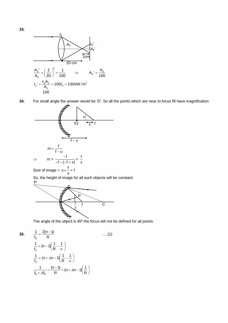
33.
20 cm
0
A0
2cm
0
A0
2
0
0
A 2 1
A 20 100
00
AA
100
20 00 0
0
A100 130kW /m
A
100
34. For small angle the answer would be 'D'. So all the points which are near to focus fill have magnification
f/2 f x
x
f – x f
mf u
m = f
f ( f x)
=
f
x
Size of image = f
xx
= f
So, the height of image for all such objects will be constant.
f
2 f C
P
P
The angle of the object is 45º the focus will not be defined for all points.
35. R
)1n(2
f
1
0
.....(1)
1
R
1)1n(
f
1
1
1
R
1)1nn(
f
1
2
R
1)1nn(
R
)1n(
ff
1
00
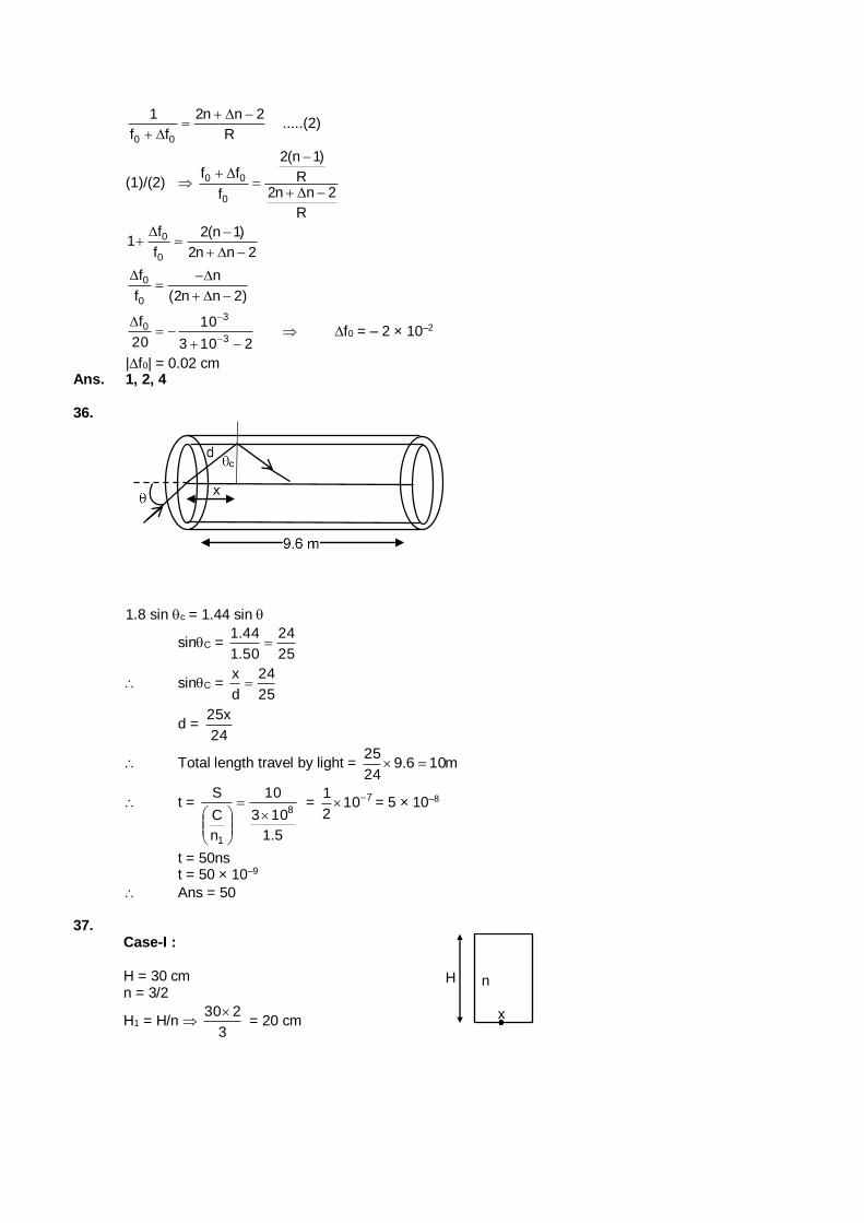
R
2nn2
ff
1
00
.....(2)
(1)/(2)
R
2nn2R
)1n(2
f
ff
0
00
2nn2
)1n(2
f
f1
0
0
)2nn2(
n
f
f
0
0
2103
10
20
f3
30
f0 = – 2 × 10⁻²
|f0| = 0.02 cm Ans. 1, 2, 4 36.
1.8 sin c = 1.44 sin
sinC = 25
24
50.1
44.1
sinC = 25
24
d
x
d = 24
x25
Total length travel by light = m106.924
25
t =
5.1
103
10
n
C
S8
1
= 710
2
1 = 5 × 10⁻⁸
t = 50ns t = 50 × 10–9
Ans = 50 37.
Case-I :
H = 30 cm n = 3/2
H1 = H/n 3
230 = 20 cm
x
n H
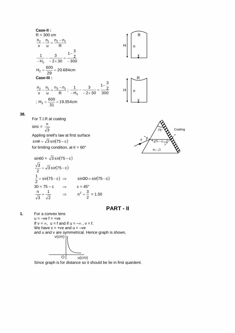
Case-II : R = 300 cm
R
nn
u
n
v
n 1212
300
2
31
302
3
H
1
2
cm684.2029
600H2
x
n H
R
Case-III :
R
nn
u
n
v
n 1212 ;
300
2
31
302
3
H
1
3
; cm354.1931
600H3
x
n H
R
38.
For T.I.R at coating
sinc = 3
n
Appling snell's law at first surface
c–75sin3sin
for limiting condition, at = 60°
75°
Coating
3RI
c
(75 – c)
sin60 = c–75sin3
c75sin32
3
c75sin2
1 c75sin30sin
30 = 75 – c c = 45°
2
1
3
n
2
3n2 = 1.50
PART - II 1. For a convex lens u = –ve f = +ve
If v = , u = f and if u = – , v = f. We have v = +ve and u = –ve and u and v are symmetrical. Hence graph is shown,
v(cm)
O u(cm) Since graph is for distance so it should be lie in first quardent.
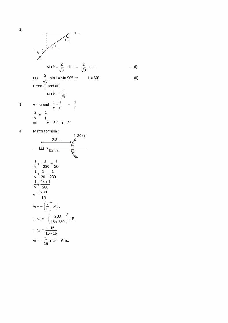
2.
sin =2
3 sin r =
2
3cos i ....(i)
and 2
3 sin i = sin 90º i = 60º ....(ii)
From (i) and (ii)
sin = 1
3
3. v = u and 1 1 1
v u f
2
v =
1
f
v = 2 f, u = 2f 4. Mirror formula :
1 1 1
v 280 20
1 1 1
v 20 280
1 14 1
v 280
v = 280
15
v = –
2
om
v.v
u
v = –
2280
.1515 280
v = 15
15 15
v = 1
15 m/s Ans.
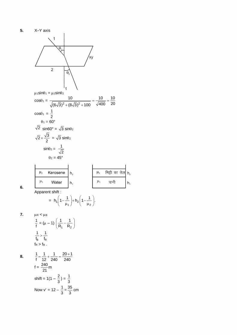
5. X–Y axis
1sin1 = 2sin2
cos1 = 2 2
10 10 10
20400(6 3) (8 3) 100
cos1 = 1
2
1 = 60°
2 sin60° = 3 sin2
3
22
= 3 sin2
sin2 = 1
2
2 = 45°
6. Apparent shift :
= 1 21 2
1 1h 1 h 1
.
7. R < B
1
f = ( – 1)
1 2
1 1
R R
B R
1 1
f f
fR > fB .
8. 1 1 1 20 1
f 12 240 240
f = 240
m21
shift = 1(1 – 2
3) =
1
3
Now v = 12 – 1
3=
35
3cm
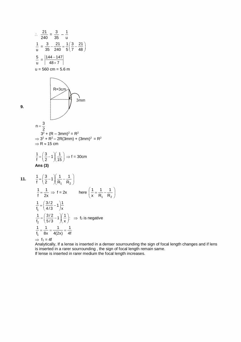
21
240 =
3
35 –
1
u
1
u =
3 21 1 3 21
35 240 5 7 48
5
u =
144 147
48 7
u = 560 cm = 5.6 m
9.
3n
2
32 + (R – 3mm)2 = R2
32 + R2 – 2R(3mm) + (3mm)2 = R2
R 15 cm
1 3 1
1f 2 15
f = 30cm
Ans (3)
11. 1 2
1 3 1 11
f 2 R R
1 1
f 2x f = 2x here
1 2
1 1 1
x R R
1
1 3 / 2 11
f 4 / 3 x
2
1 3 / 2 11
f 5 / 3 x
: f2 is negative
1
1 1 1 1
f 8x 4(2x) 4f
f1 = 4f Analytically, If a lense is inserted in a denser sourrounding the sign of focal length changes and if lens is inserted in a rarer sourrounding , the sign of focal length remain same.
If lense is inserted in rarer medium the focal length increases.
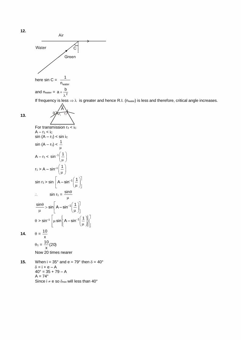
12.
here sin C = water
1
n
and nwater = 2
ba
If frequency is less is greater and hence R.I. (nwater) is lessand therefore, critical angle increases.
13.
For transmission r2 < iC
A – r1 < iC sin (A – r1) < sin iC
sin (A – r1) < 1
A – r1 < 1 1sin
r1 > A – sin–1 1
sin r1 > sin 1 1A – sin
sin r1 = sin
1sin 1sin A – sin
> sin–1 1 1sin A – sin
14. = x
10
1 = )20(x
10
Now 20 times nearer
15. When i = 35° and e = 79° then = 40°
= i + e – A 40° = 35 + 79 – A A = 74°
Since i e so min will less than 40°
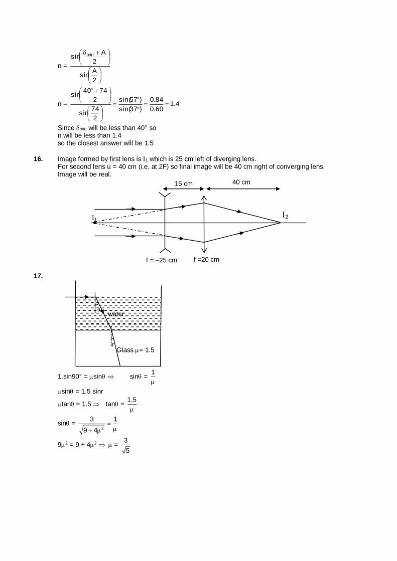
n =
2
Asin
2
Asin min
n = 4.160.0
84.0
)37sin(
)57sin(
2
74sin
2
7440sin
Since min will be less than 40° so n will be less than 1.4 so the closest answer will be 1.5
16. Image formed by first lens is 1 which is 25 cm left of diverging lens. For second lens u = 40 cm (i.e. at 2F) so final image will be 40 cm right of converging lens. Image will be real.
15 cm
f =20 cm
2
40 cm
f = –25 cm
1
17.
Glass = 1.5
water
r
1.sin90° = sin sin = 1
sin = 1.5 sinr
tan= 1.5 tan = 1.5
sin = 2
3 1
9 4
92 = 9 + 42 = 3
5
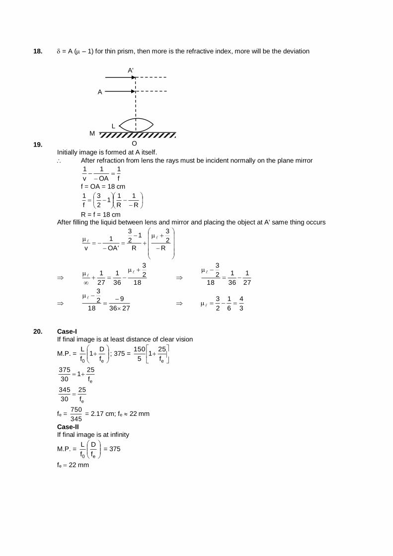
18. = A ( – 1) for thin prism, then more is the refractive index, more will be the deviation
19.
L
O
MN
A
A'
Initially image is formed at A itself.
After refraction from lens the rays must be incident normally on the plane mirror
f
1
OA
1
v
1
f = OA = 18 cm
R
1
R
11
2
3
f
1
R = f = 18 cm After filling the liquid between lens and mirror and placing the object at A' same thing occurs
R
2
3
R
12
3
'OA
1
v
18
2
3
36
1
27
1
27
1
36
1
18
2
3
2736
9
18
2
3
3
4
6
1
2
3
20. Case-I
If final image is at least distance of clear vision
M.P. =
e0 f
D1
f
L; 375 =
ef
251
5
150
ef
251
30
375
ef
25
30
345
fe = 345
750 = 2.17 cm; fe 22 mm
Case-II If final image is at infinity
M.P. =
e0 f
D
f
L = 375
fe 22 mm
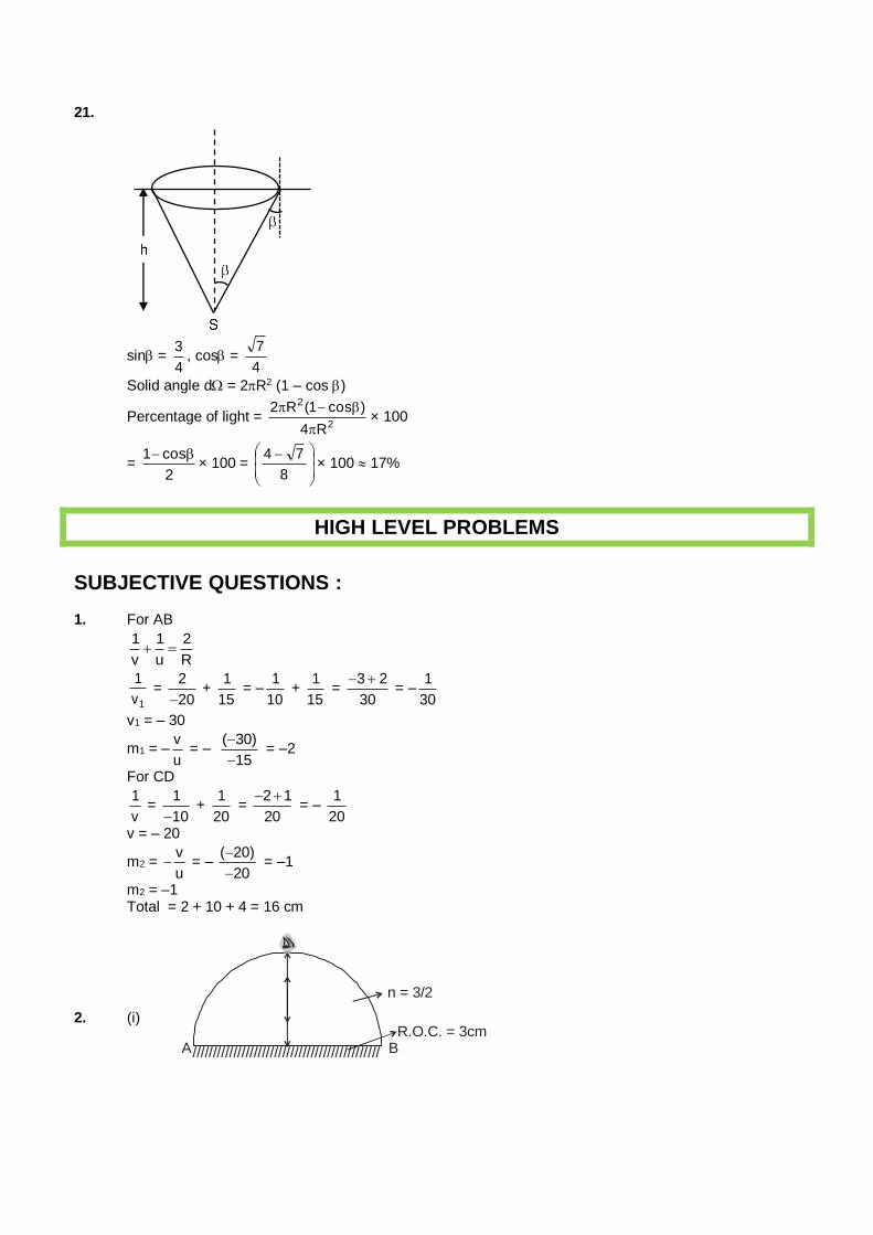
21.
sin = 4
3, cos =
4
7
Solid angle d = 2R2 (1 – cos )
Percentage of light = 2
2
R4
)cos1(R2
× 100
= 2
cos1 × 100 =
8
74× 100 17%
HIGH LEVEL PROBLEMS
SUBJECTIVE QUESTIONS : 1. For AB
1 1 2
v u R
1
1
v =
2
20 +
1
15 = –
1
10 +
1
15 =
3 2
30
= –
1
30
v1 = – 30
m1 = –v
u = –
( 30)
15
= –2
For CD
1
v =
1
10 +
1
20 =
2 1
20
= –
1
20
v = – 20
m2 = v
u = –
( 20)
20
= –1
m2 = –1 Total = 2 + 10 + 4 = 16 cm
2. (i)
//////////////////////////////////////////////A BR.O.C. = 3cm
n = 3/2
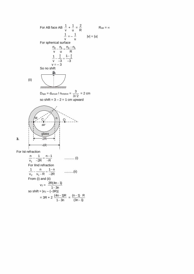
For AB face AB 1
v +
1
u =
2
R RAB =
1
v = –
1
u |v| = |u|
For spherical surface
2 1 2 1n n n n
v u R
3 32 2
11
v 3 3
v = – 3 So no shift
(ii)
////////////////////////////////////////
Dapp = dactual / nrelative = 3
3 / 2 = 2 cm
so shift = 3 – 2 = 1 cm upward
3.
For Ist refraction
1
n 1 n 1
v 2R R
........... (i)
For IInd refraction
2 1
1 n 1 n
v v R 2R
..........(ii)
From (i) and (ii)
v2 = 2R(4n 1)
1 3n
so shift = |v2 – (–3R)|
= 3R + 2 (4n 1)R
1 3n
=
(n 1) R
(3n 1)
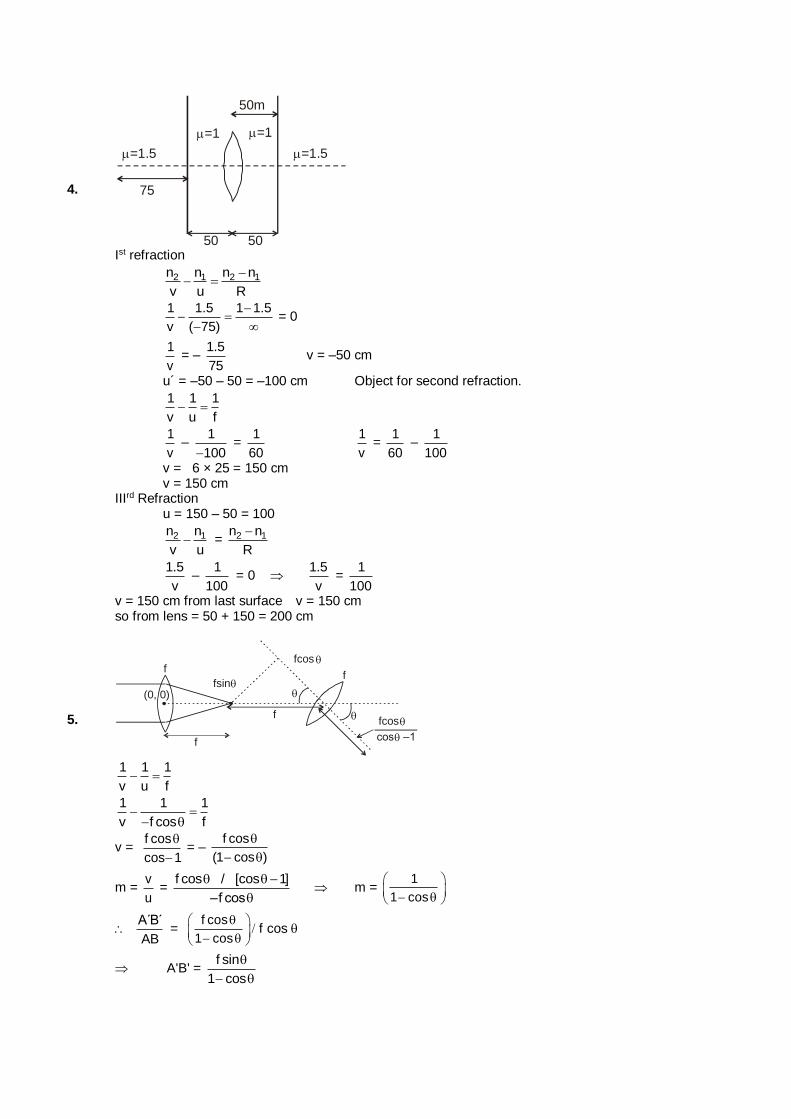
4.
=1 =1
50m
75
=1.5 =1.5
50 50
Ist refraction
2 1 2 1n n n n
v u R
1 1.5 1 1.5
v ( 75)
= 0
1
v = –
1.5
75 v = –50 cm
u´ = –50 – 50 = –100 cm Object for second refraction.
1 1 1
v u f
1
v –
1
100 =
1
60
1
v =
1
60 –
1
100
v = 6 × 25 = 150 cm v = 150 cm IIIrd Refraction u = 150 – 50 = 100
2 1n n
v u = 2 1n n
R
1.5
v –
1
100 = 0
1.5
v =
1
100
v = 150 cm from last surface v = 150 cm so from lens = 50 + 150 = 200 cm
5.
fcos
f
f
f
f
fcos
cos –1
fsin
(0, 0)
1 1 1
v u f
1 1 1
v f cos f
v = f cos
cos 1
= –
f cos
(1 cos )
m = v
u =
f cos / [cos 1]
–f cos
m =
1
1 cos
A´B´
AB =
f cos
1 cos
f cos
A'B' = f sin
1 cos
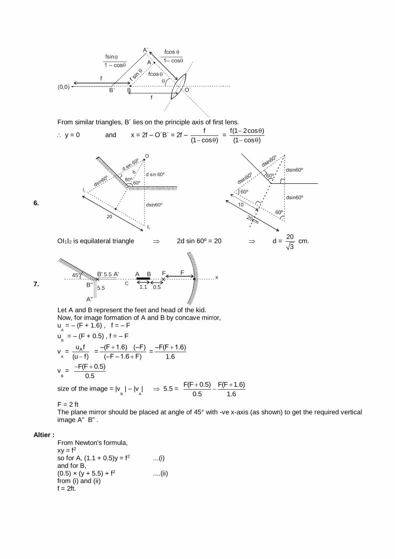
From similar triangles, B´ lies on the principle axis of first lens.
y = 0 and x = 2f – O´B´ = 2f – f
(1 cos ) =
f(1 2cos )
(1 cos )
6.
OI1I2 is equilateral triangle 2d sin 60º = 20 d = 20
3 cm.
7.
//////////////////
/ ///
//////
//////////////
××C
////////
////////
////////
///////
FFA BB'
B''
A''
A'
1.1 0.5
x5.5
5.5
45°
Let A and B represent the feet and head of the kid. Now, for image formation of A and B by concave mirror, u
A = – (F + 1.6) , f = – F
uB = – (F + 0.5) , f = – F
vA
= Au f
(u f) =
–(F 1.6) (–F)
(–F – 1.6 F)
=
–F(F 1.6)
1.6
vB
= F(F 0.5)
0.5
size of the image = |vB
| – |vA
| 5.5 = F(F 0.5) F(F 1.6)
0.5 1.6
F = 2 ft The plane mirror should be placed at angle of 45° with -ve x-axis (as shown) to get the required vertical
image A" B" . Altier : From Newton's formula, xy = f2 so for A, (1.1 + 0.5)y = f2 ...(i) and for B, (0.5) × (y + 5.5) + f2 ....(ii) from (i) and (ii) f = 2ft.
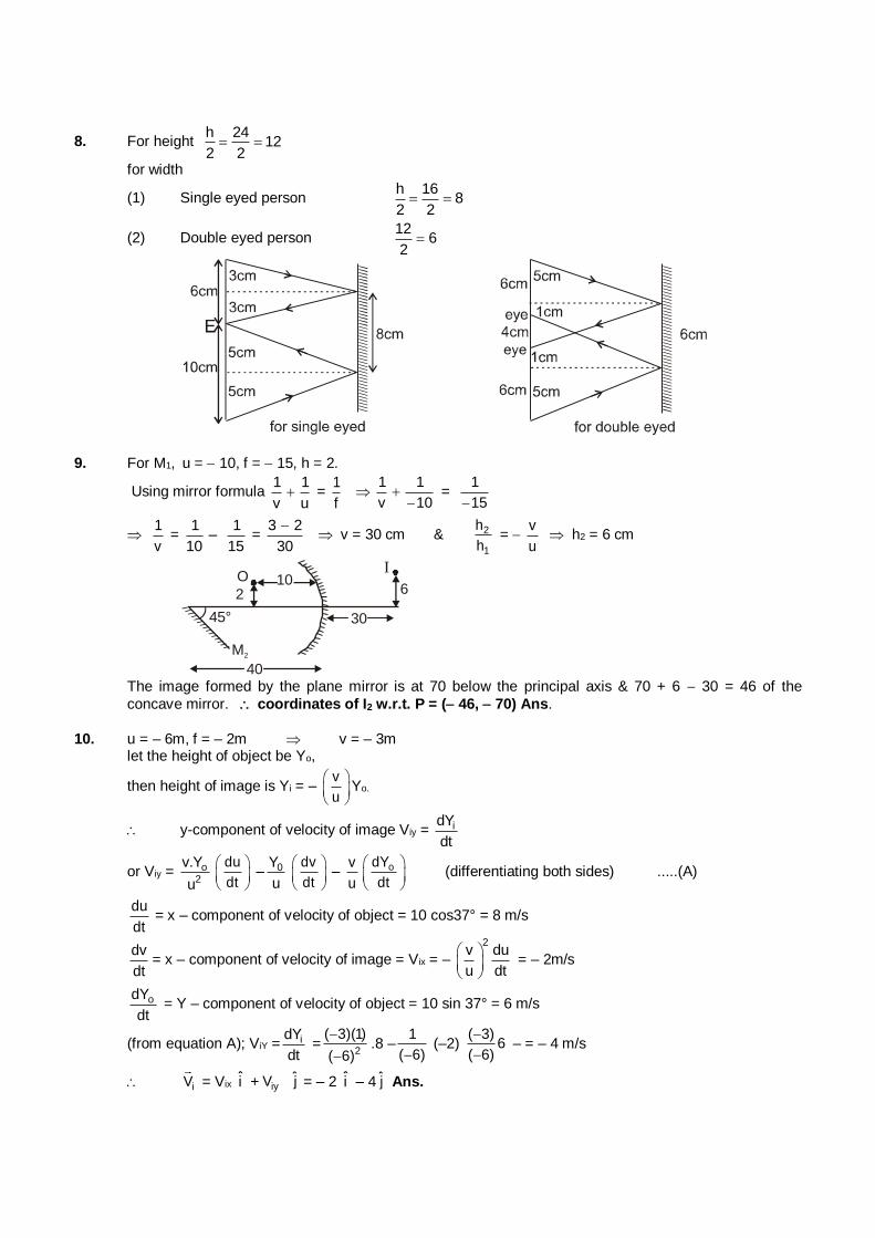
8. For height h 24
122 2
for width
(1) Single eyed person h 16
82 2
(2) Double eyed person 12
62
9. For M1, u = 10, f = 15, h = 2.
Using mirror formula 1 1
v u =
1
f
1 1
v 10
= 1
15
1
v =
1 1–
10 15 =
3 2
30
v = 30 cm & 2
1
h
h =
v
u h2 = 6 cm
) 45°
O
M2
40
30
1062
I
The image formed by the plane mirror is at 70 below the principal axis & 70 + 6 30 = 46 of the
concave mirror. coordinates of I2 w.r.t. P = ( 46, 70) Ans.
10. u = – 6m, f = – 2m v = – 3m let the height of object be Yo,
then height of image is Yi = – v
u
Yo.
y-component of velocity of image Viy = idY
dt
or Viy = o2
v.Y
u
du
dt
– 0Y
u
dv
dt
– v
u
odY
dt
(differentiating both sides) .....(A)
du
dt = x – component of velocity of object = 10 cos37° = 8 m/s
dv
dt= x – component of velocity of image = Vix = –
2v du
u dt
= – 2m/s
odY
dt = Y – component of velocity of object = 10 sin 37° = 6 m/s
(from equation A); ViY = idY
dt =
2
( 3)(1)
( 6)
.8 –
1
( 6) (–2)
( 3)6
( 6)
– = – 4 m/s
iV = Vix i + iyˆV j = – 2 i – 4 j Ans.
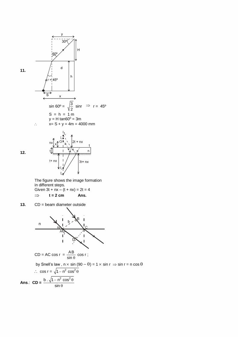
11.
sin 60º = 3
2 sinr r = 45º
S = h = 1 m y = H tan600 = 3m
x= S + y = 4m = 4000 mm
12.
The figure shows the image formation in different steps. Given 3t + nx – (t + nx) = 2t = 4
t = 2 cm Ans. 13. CD = beam diameter outside
CD = AC cos r = AB
sin cos r ;
by Snell’s law , n sin (90 ) = 1 sin r sin r = n cos
cos r = 2 21 n cos
Ans.: CD = 2 2b . 1 n cos
sin
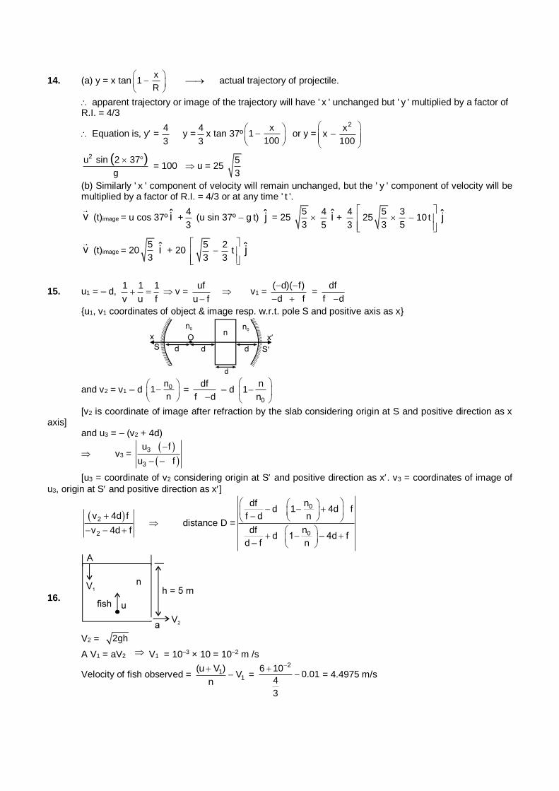
14. (a) y = x tanx
1R
actual trajectory of projectile.
apparent trajectory or image of the trajectory will have ' x ' unchanged but ' y ' multiplied by a factor of R.I. = 4/3
Equation is, y = 4
3 y =
4
3x tan 37º
x1
100
or y =
2xx
100
2u sin 2 37
g
( ) = 100 u = 25
5
3
(b) Similarly ' x ' component of velocity will remain unchanged, but the ' y ' component of velocity will be multiplied by a factor of R.I. = 4/3 or at any time ' t '.
v (t)image = u cos 37º i +4
3 (u sin 37º g t) j = 25
5
3
4
5i +
4
3
5 325 10 t
3 5
j
v (t)image = 205
3i + 20
5 2t
3 3
j
15. u1 = – d, 1 1 1
v u f v =
uf
u f v1 =
( d)( f)
d f
=
df
f d
{u1, v1 coordinates of object & image resp. w.r.t. pole S and positive axis as x}
and v2 = v1 – d 0n1
n
=
df
f d – d
0
n1
n
[v2 is coordinate of image after refraction by the slab considering origin at S and positive direction as x axis] and u3 = – (v2 + 4d)
v3 =
3
3
u f
u f
[u3 = coordinate of v2 considering origin at S and positive direction as x. v3 = coordinates of image of
u3, origin at S and positive direction as x]
2
2
v 4d f
v 4d f
distance D =
0
0
df nd 1 4d f
f d n
df nd 1 – 4d f
d – f n
16.
V2 = 2gh
A V1 = aV2 V1 = 10–3 × 10 = 10–2 m /s
Velocity of fish observed = 11
(u V )V
n
=
26 100.01
4
3
= 4.4975 m/s
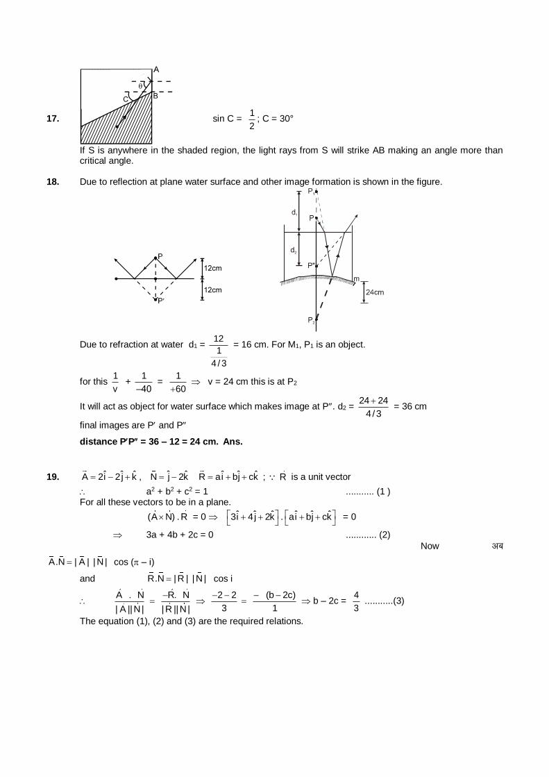
17. sin C = 1
2; C = 30°
If S is anywhere in the shaded region, the light rays from S will strike AB making an angle more than critical angle.
18. Due to reflection at plane water surface and other image formation is shown in the figure.
Due to refraction at water d1 = 12
1
4 / 3
= 16 cm. For M1, P1 is an object.
for this 1
v +
1
–40 =
1
60 v = 24 cm this is at P2
It will act as object for water surface which makes image at P. d2 = 24 24
4/3
= 36 cm
final images are P and P
distance PP= 36 – 12 = 24 cm. Ans.
19. ˆ ˆ ˆA 2i 2j k , ˆ ˆN j 2k ˆ ˆ ˆR ai bj ck ; R is a unit vector
a2 + b2 + c2 = 1 ........... (1 ) For all these vectors to be in a plane.
(A N) .R = 0 ˆ ˆ ˆ3i 4j 2k
. ˆ ˆ ˆai bj ck
= 0
3a + 4b + 2c = 0 ............ (2)
Now vc
A.N | A | |N | cos ( – i)
and R.N |R | |N | cos i
A . N
| A ||N|
R. N
|R ||N |
2 2
3
(b 2c)
1
b – 2c =
4
3 ...........(3)
The equation (1), (2) and (3) are the required relations.
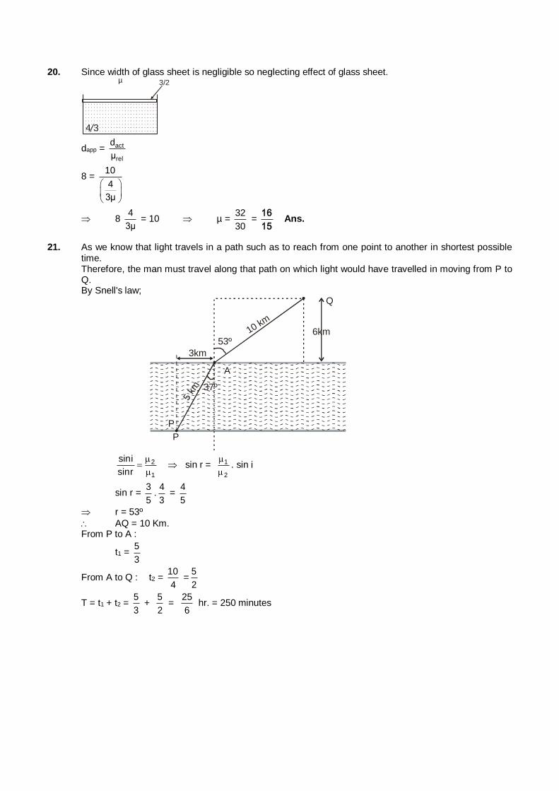
20. Since width of glass sheet is negligible so neglecting effect of glass sheet.
4 3
3/2µ
dapp = act
rel
d
µ
8 = 10
4
3µ
8 4
3µ = 10 µ =
32
30 =
16
15 Ans.
21. As we know that light travels in a path such as to reach from one point to another in shortest possible time.
Therefore, the man must travel along that path on which light would have travelled in moving from P to Q. By Snell's law;
3km
Q
P
6km53º
10 km
5 km
P
37º
A
2
1
sini
sinr
sin r = 1
2
. sin i
sin r = 3
5.
4
3 =
4
5
r = 53º
AQ = 10 Km. From P to A :
t1 = 5
3
From A to Q : t2 = 10
4 =
5
2
T = t1 + t2 = 5
3 +
5
2 =
25
6 hr. = 250 minutes
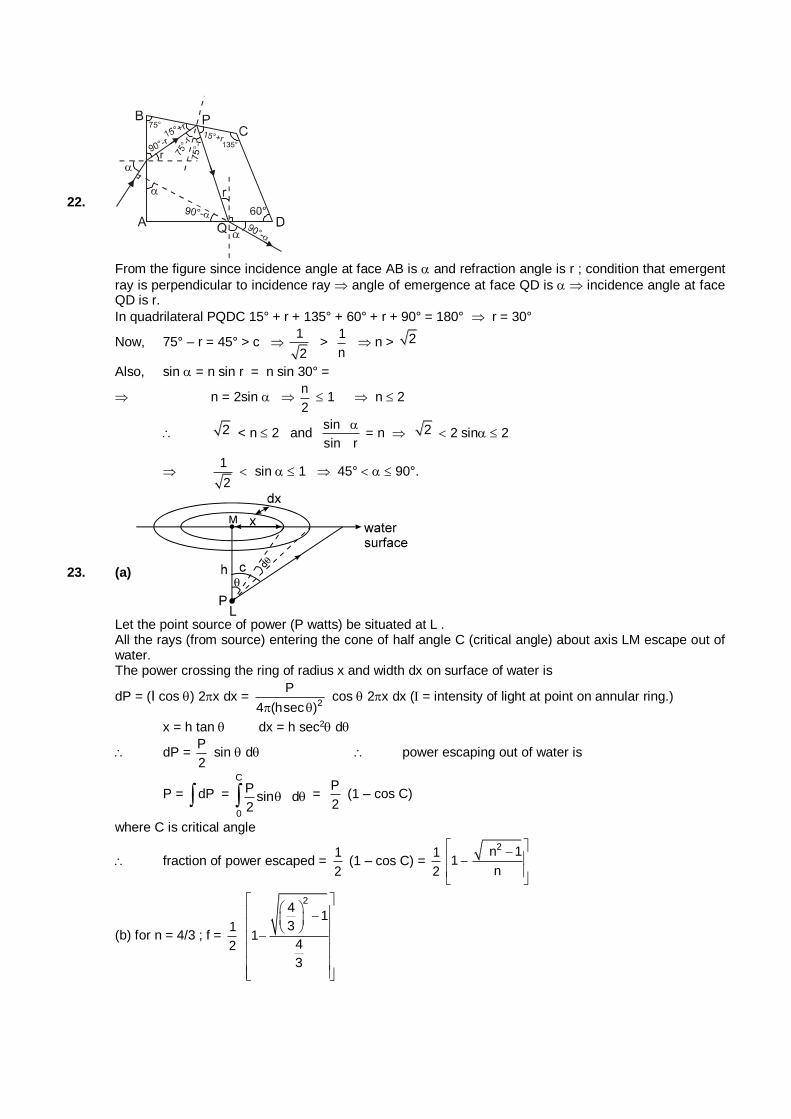
22.
From the figure since incidence angle at face AB is and refraction angle is r ; condition that emergent
ray is perpendicular to incidence ray angle of emergence at face QD is incidence angle at face QD is r.
In quadrilateral PQDC 15° + r + 135° + 60° + r + 90° = 180° r = 30°
Now, 75° – r = 45° > c 1
2 >
1
n n > 2
Also, sin = n sin r = n sin 30° =
n = 2sin n
2 1 n 2
2 < n 2 and sin
sin r
= n 2 2 sin 2
1
2 sin 1 45° 90°.
23. (a)
Let the point source of power (P watts) be situated at L . All the rays (from source) entering the cone of half angle C (critical angle) about axis LM escape out of
water. The power crossing the ring of radius x and width dx on surface of water is
dP = (I cos ) 2x dx = 2
P
4 (hsec ) cos 2x dx ( = intensity of light at point on annular ring.)
x = h tan dx = h sec2 d
dP = P
2 sin d power escaping out of water is
P = dP =
C
0
Psin d
2 =
P
2 (1 – cos C)
where C is critical angle
fraction of power escaped = 1
2 (1 – cos C) =
1
2
2n 11
n
(b) for n = 4/3 ; f = 1
2
24
13
14
3
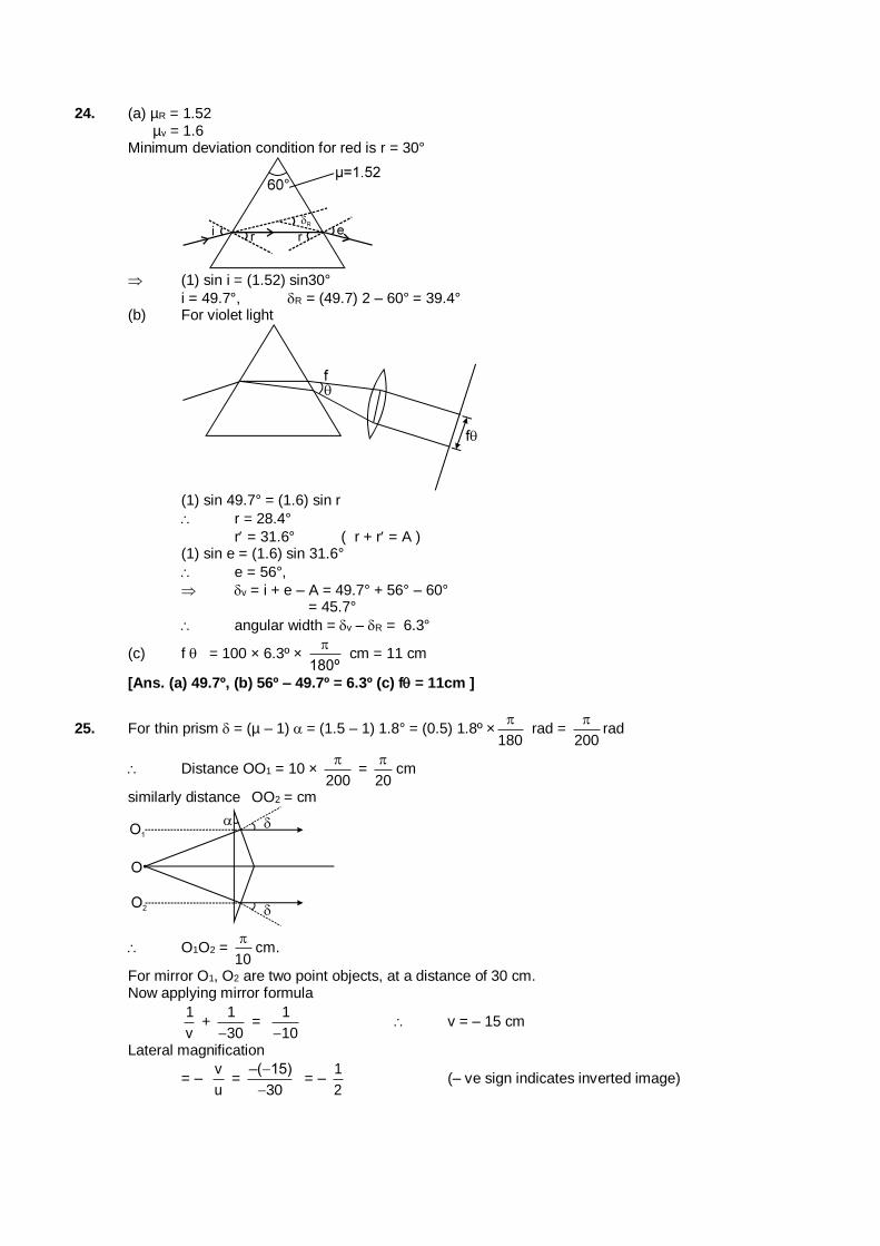
24. (a) µR = 1.52 µv = 1.6 Minimum deviation condition for red is r = 30°
(1) sin i = (1.52) sin30°
i = 49.7°, R = (49.7) 2 – 60° = 39.4° (b) For violet light
(1) sin 49.7° = (1.6) sin r
r = 28.4°
r = 31.6° ( r + r = A ) (1) sin e = (1.6) sin 31.6°
e = 56°,
v = i + e – A = 49.7° + 56° – 60° = 45.7°
angular width = v – R = 6.3°
(c) f = 100 × 6.3º × 180º
cm = 11 cm
[Ans. (a) 49.7º, (b) 56º – 49.7º = 6.3º (c) f= 11cm ]
25. For thin prism = (µ – 1) = (1.5 – 1) 1.8° = (0.5) 1.8º ×180
rad =
200
rad
Distance OO1 = 10 × 200
=
20
cm
similarly distance OO2 = cm
O1O2 = 10
cm.
For mirror O1, O2 are two point objects, at a distance of 30 cm. Now applying mirror formula
1
v +
1
30 =
1
10 v = – 15 cm
Lateral magnification
= – v
u =
–( 15)
30
= –
1
2 (– ve sign indicates inverted image)
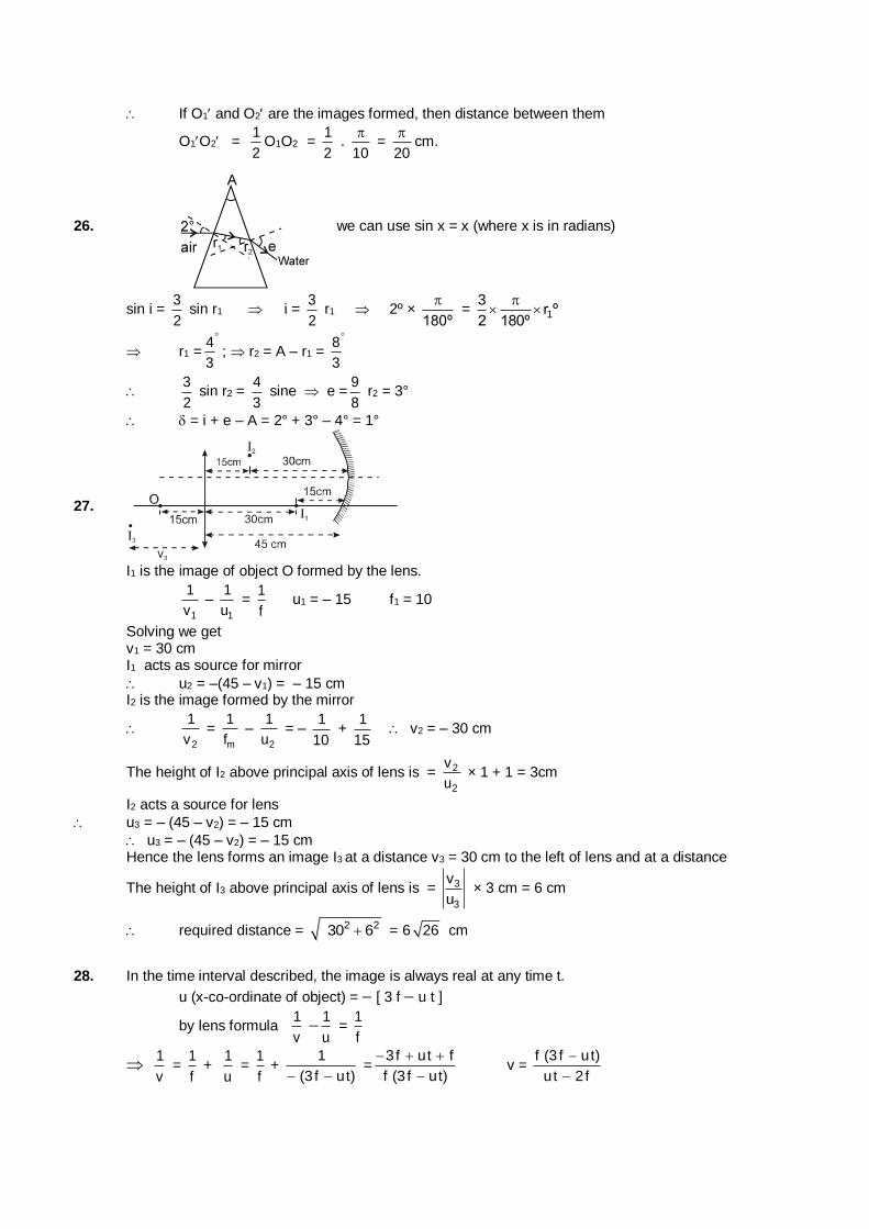
If O1and O2 are the images formed, then distance between them
O1O2 = 1
2O1O2 =
1
2 .
10
=
20
cm.
26. we can use sin x = x (where x is in radians)
sin i = 3
2 sin r1 i =
3
2 r1 2º ×
180º
= 1
3r º
2 180º
r1 =4
3
; r2 = A – r1 = 8
3
3
2 sin r2 =
4
3 sine e =
9
8 r2 = 3°
= i + e – A = 2° + 3° – 4° = 1°
27.
I1 is the image of object O formed by the lens.
1
1
v –
1
1
u =
1
f u1 = – 15 f1 = 10
Solving we get v1 = 30 cm I1 acts as source for mirror
u2 = –(45 – v1) = – 15 cm I2 is the image formed by the mirror
2
1
v =
m
1
f –
2
1
u = –
1
10 +
1
15 v2 = – 30 cm
The height of I2 above principal axis of lens is = 2
2
v
u × 1 + 1 = 3cm
I2 acts a source for lens
u3 = – (45 – v2) = – 15 cm
u3 = – (45 – v2) = – 15 cm Hence the lens forms an image I3 at a distance v3 = 30 cm to the left of lens and at a distance
The height of I3 above principal axis of lens is = 3
3
v
u × 3 cm = 6 cm
required distance = 2 230 6 = 6 26 cm
28. In the time interval described, the image is always real at any time t.
u (x-co-ordinate of object) = [ 3 f u t ]
by lens formula 1
v
1
u =
1
f
1
v =
1
f +
1
u =
1
f +
1
(3 f ut) =
3f ut f
f (3 f ut)
v =
f (3 f ut)
ut 2 f
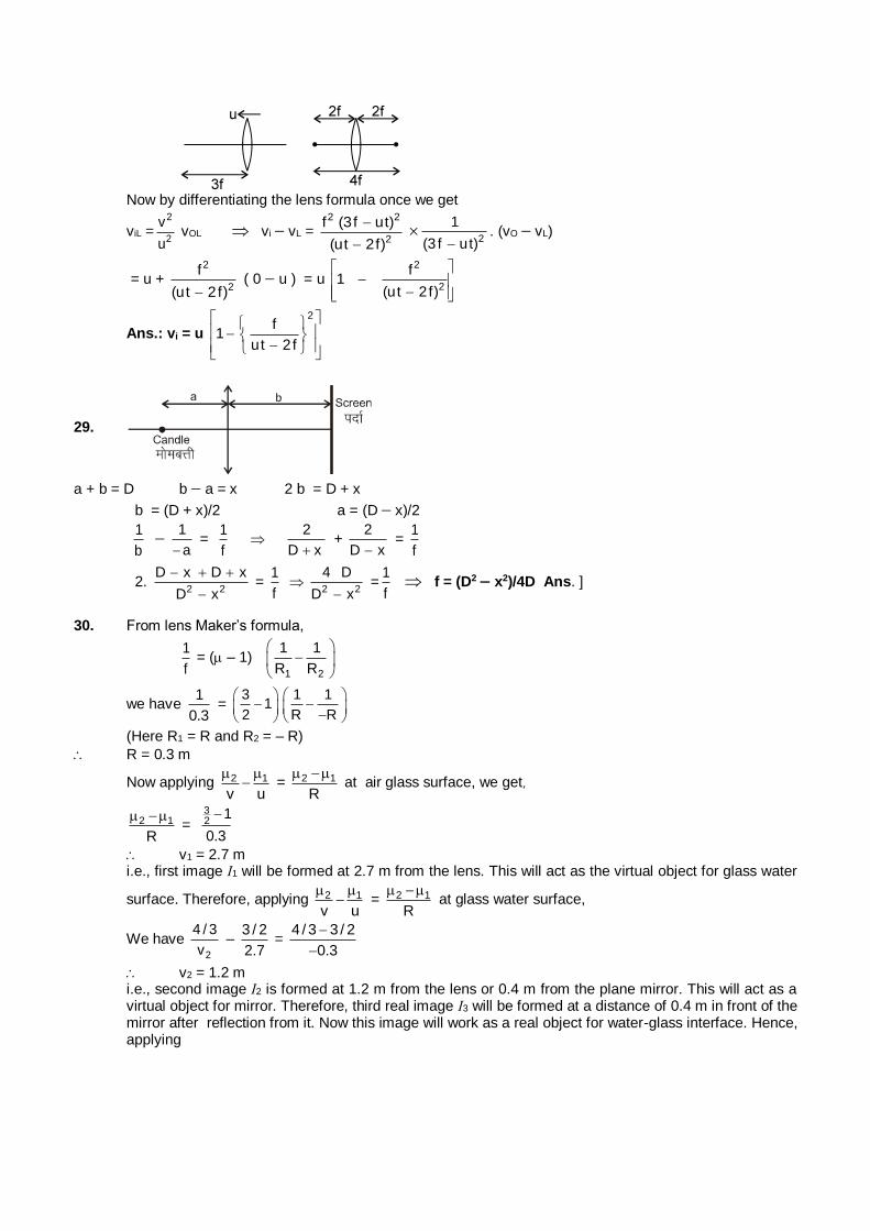
Now by differentiating the lens formula once we get
viL =2
2
v
u vOL vi vL =
2 2
2
f (3f ut)
(ut 2f)
2
1
(3 f ut). (vO vL)
= u + 2
2
f
(ut 2 f) ( 0 u ) = u
2
2
f1
(ut 2f)
Ans.: vi = u
2f
1ut 2f
29.
a + b = D b a = x 2 b = D + x
b = (D + x)/2 a = (D x)/2
1
b
1
a =
1
f
2
D x +
2
D x =
1
f
2. 2 2
D x D x
D x
=
1
f
2 2
4 D
D x =
1
f f = (D2 x2)/4D Ans. ]
30. From lens Maker’s formula,
1
f = ( – 1)
1 2
1 1
R R
we have 1
0.3 =
31
2
1 1
R R
(Here R1 = R and R2 = – R)
R = 0.3 m
Now applying 2 1
v u
= 2 1
R
at air glass surface, we get]
2 1
R
=
32
1
0.3
v1 = 2.7 m i.e., first image I1 will be formed at 2.7 m from the lens. This will act as the virtual object for glass water
surface. Therefore, applying 2 1
v u
= 2 1
R
at glass water surface,
We have 2
4 / 3
v –
3 / 2
2.7 =
4 / 3 3 / 2
0.3
v2 = 1.2 m i.e., second image I2 is formed at 1.2 m from the lens or 0.4 m from the plane mirror. This will act as a
virtual object for mirror. Therefore, third real image I3 will be formed at a distance of 0.4 m in front of the mirror after reflection from it. Now this image will work as a real object for water-glass interface. Hence, applying
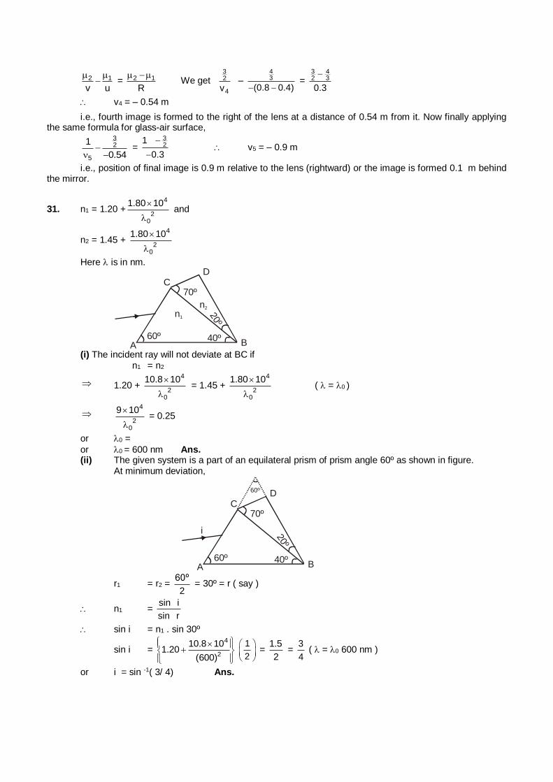
2 1
v u
= 2 1
R
We get
32
4v –
43
(0.8 0.4) =
3 42 3
0.3
v4 = – 0.54 m
i.e., fourth image is formed to the right of the lens at a distance of 0.54 m from it. Now finally applying the same formula for glass-air surface,
32
5
1
0.54
=
32
1
0.3
v5 = – 0.9 m
i.e., position of final image is 0.9 m relative to the lens (rightward) or the image is formed 0.1 m behind the mirror.
31. n1 = 1.20 +4
20
1.80 10
and
n2 = 1.45 + 4
20
1.80 10
Here is in nm.
60º 40º
70º
20º
A B
CD
n1
n2
(i) The incident ray will not deviate at BC if n1 = n2
1.20 + 4
20
10.8 10
= 1.45 +
4
20
1.80 10
( = 0 )
4
20
9 10
= 0.25
or 0 =
or 0 = 600 nm Ans. (ii) The given system is a part of an equilateral prism of prism angle 60º as shown in figure. At minimum deviation,
60º
60º
40º
70º
20º
A B
CD
i
r1 = r2 = 60º
2 = 30º = r ( say )
n1 = sin i
sin r
sin i = n1 . sin 30º
sin i = 4
2
10.8 101.20
(600)
1
2
= 1.5
2 =
3
4 ( = 0 600 nm )
or i = sin -1( 3/ 4) Ans.
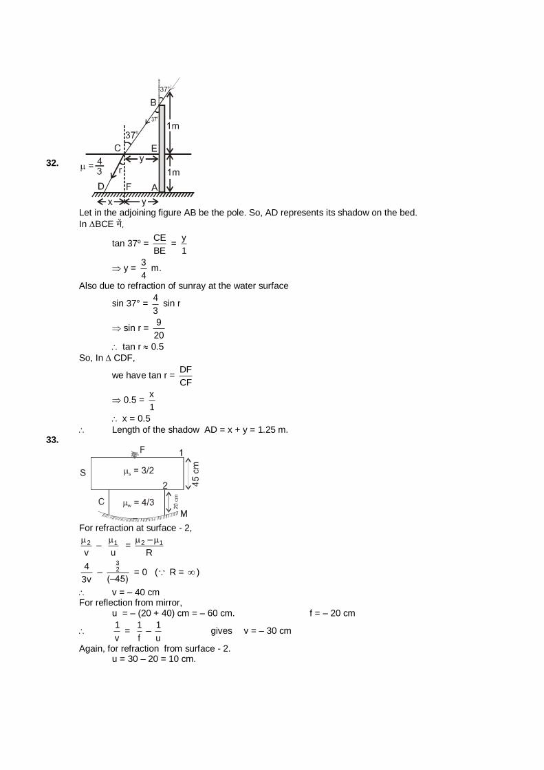
32.
Let in the adjoining figure AB be the pole. So, AD represents its shadow on the bed.
In BCE esa]
tan 37o = CE
BE =
y
1
y = 3
4 m.
Also due to refraction of sunray at the water surface
sin 37° = 4
3 sin r
sin r = 9
20
tan r 0.5
So, In CDF,
we have tan r = DF
CF
0.5 = x
1
x = 0.5
Length of the shadow AD = x + y = 1.25 m. 33.
For refraction at surface - 2,
2
v
– 1
u
= 2 1–
R
4
3v –
32
(–45) = 0 ( R = )
v = – 40 cm For reflection from mirror, u = – (20 + 40) cm = – 60 cm. f = – 20 cm
1
v =
1
f –
1
u gives v = – 30 cm
Again, for refraction from surface - 2. u = 30 – 20 = 10 cm.
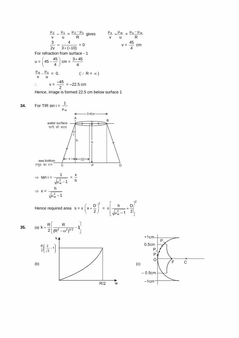
2
v
– 1
u
= 2 1
R
gives s
v
– w
u
= s w
R
3
2v –
4
3 ( 10) = 0 v =
45
4 cm
For refraction from surface - 1
u = 45
454
cm =
3 45
4
a s
v u
= 0. ( R = )
v = –45
2 = –22.5 cm
Hence, image is formed 22.5 cm below surface 1
34. For TIR sin i = w
1
tan i = 2w
1
1 =
x
h
x = 2w
h
1
Hence required area s =
2D
x2
=
2
2w
h D
2– 1
35. (a) 2 2 1/ 2
R Rk 1
2 (R )
(b) (c)
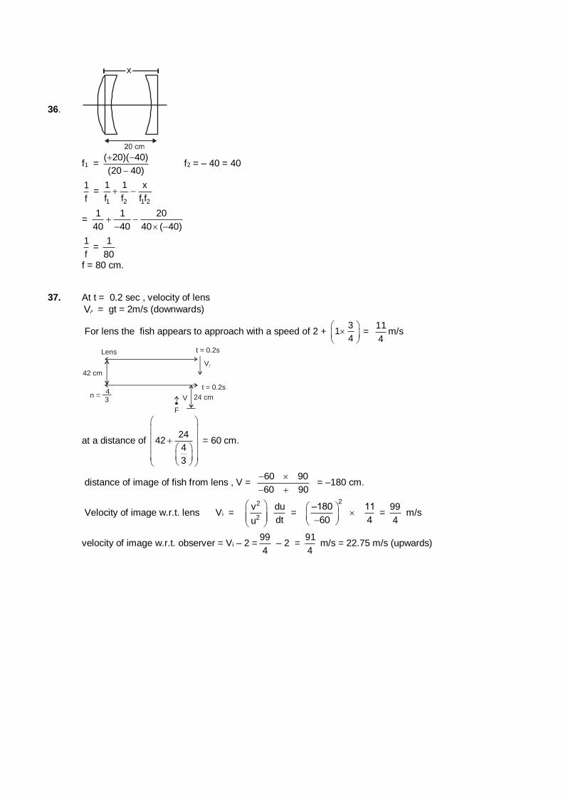
36.
f1 = ( 20)( 40)
(20 40)
f2 = – 40 = 40
1
f =
1 2 1 2
1 1 x
f f f f
= 1 1 20
40 40 40 ( 40)
1
f =
1
80
f = 80 cm. 37. At t = 0.2 sec , velocity of lens
V = gt = 2m/s (downwards)
For lens the fish appears to approach with a speed of 2 + 3
14
=
11
4m/s
42 cm
Lens t = 0.2s
t = 0.2s
V
V
F
43
n = 24 cm
at a distance of 24
424
3
= 60 cm.
distance of image of fish from lens , V = 60 90
60 90
= –180 cm.
Velocity of image w.r.t. lens Vi = 2
2
v du
dtu
=
2–180 11
60 4
=
99
4 m/s
velocity of image w.r.t. observer = Vi – 2 =99
4 – 2 =
91
4 m/s = 22.75 m/s (upwards)
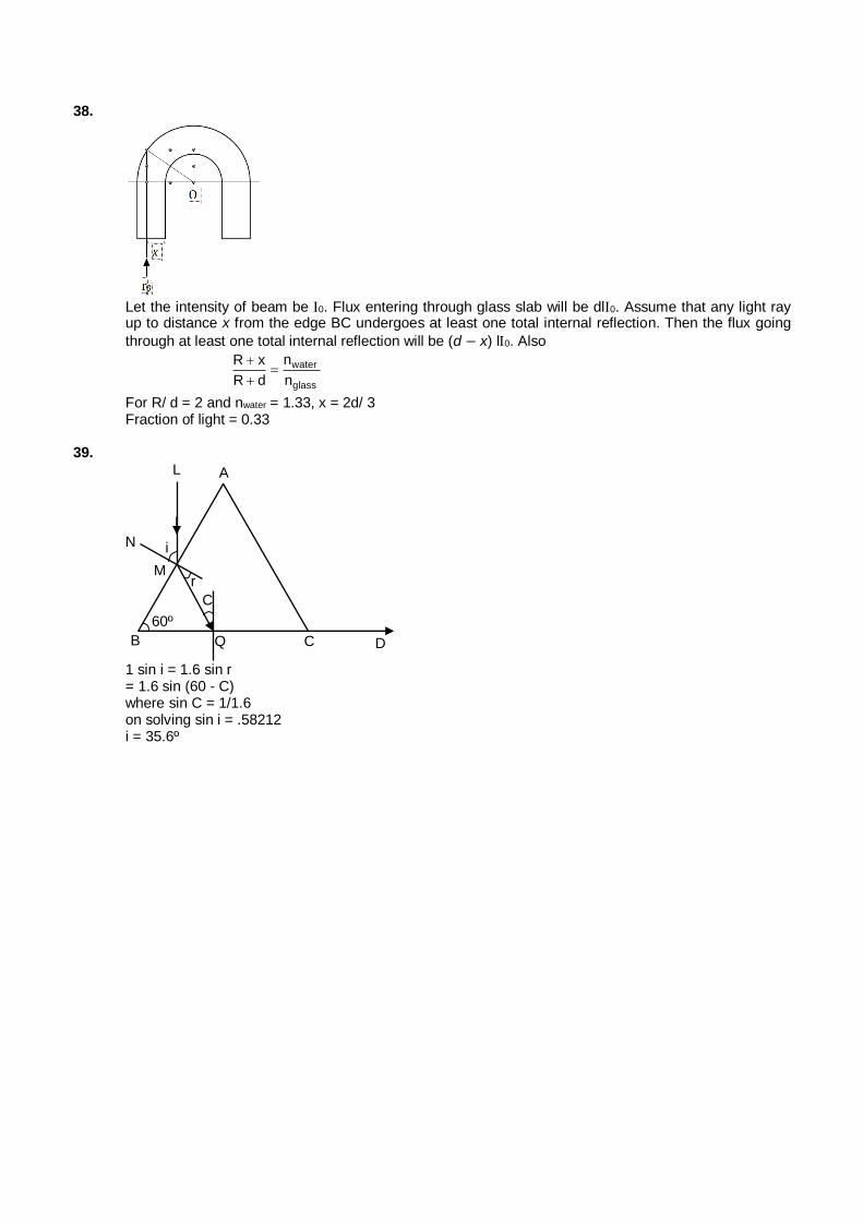
38.
Let the intensity of beam be 0. Flux entering through glass slab will be dl0. Assume that any light ray up to distance x from the edge BC undergoes at least one total internal reflection. Then the flux going
through at least one total internal reflection will be (d − x) l0. Also
water
glass
nR x
R d n
For R/ d = 2 and nwater = 1.33, x = 2d/ 3 Fraction of light = 0.33
39.
Q C D
N
L A
M
B
C
60º
r
i
1 sin i = 1.6 sin r = 1.6 sin (60 - C) where sin C = 1/1.6 on solving sin i = .58212 i = 35.6º