study guide “wave optics”
TRANSCRIPT

NATIONAL TECHNICAL UNIVERSITY
“KHARKOV POLYTECHICAL INSTITUTE”
Department of Physics
LYUBCHENKO E.A.
STUDY GUIDE
“WAVE OPTICS”
Kharkov 2018
2
OPTICS
Optics is the part of physics that deals with the propagation of light through
transparent media and its interaction with substance. Optical effects can be divided
into three broad classes: those which can be explained without reference to the fact
that light is fundamentally a wave or particle phenomenon, those which can be
explained only on the basis that light is a wave phenomenon, and those which can
be only explained on the basis that light is the flux of particles (photons). So, there
are three main parts of optics: geometric optics; wave (physical) optics; and
quantum optics.
Chapter 1. GEOMETRIC OPTICS
Geometric optics does not make any explicit assumption about the nature of
light; it tends to suggest that light consists of a stream of massless particles. This is
certainly what scientists, including, most notably, Isaac Newton, generally
assumed up until about the year 1800. In geometric optics, light is treated as a set
of rays, emanating from a source, which propagate through transparent media
according to a set of four simple laws.
1. The law of rectilinear propagation, which states that light rays propagating
through a homogeneous transparent medium, propagate in straight lines.
2. The law of independent propagation of light rays, which states that light
rays at the point of intersection do not disturb each other
(superposition principle);
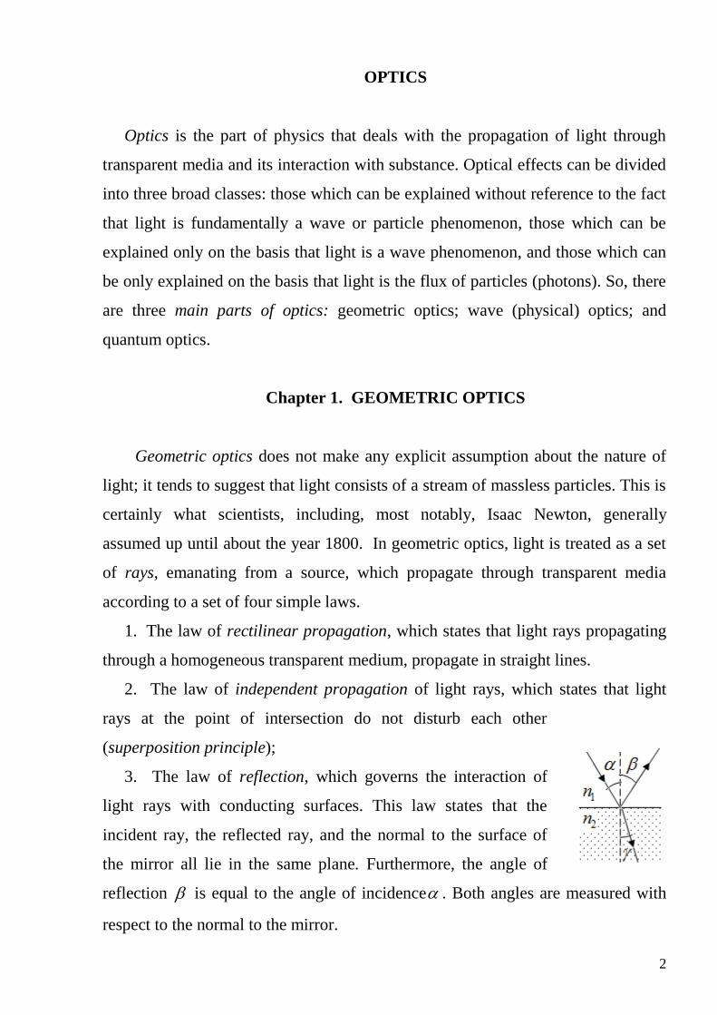
3. The law of reflection, which governs the interaction of
light rays with conducting surfaces. This law states that the
incident ray, the reflected ray, and the normal to the surface of
the mirror all lie in the same plane. Furthermore, the angle of
reflection is equal to the angle of incidence . Both angles are measured with
respect to the normal to the mirror.
3
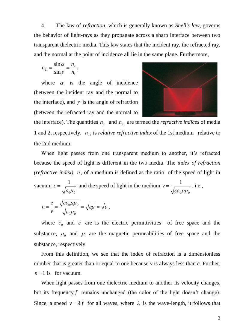
4. The law of refraction, which is generally known as Snell's law, governs
the behavior of light-rays as they propagate across a sharp interface between two
transparent dielectric media. This law states that the incident ray, the refracted ray,
and the normal at the point of incidence all lie in the same plane. Furthermore,
221
1
sin
sin
nn
n
,
where is the angle of incidence
(between the incident ray and the normal to
the interface), and is the angle of refraction
(between the refracted ray and the normal to
the interface). The quantities 1n and 2n are termed the refractive indices of media
1 and 2, respectively, 21n is relative refractive index of the 1st medium relative to
the 2nd medium.
When light passes from one transparent medium to another, it’s refracted
because the speed of light is different in the two media. The index of refraction
(refractive index), n , of a medium is defined as the ratio of the speed of light in
vacuum 0 0
1c
and the speed of light in the medium
0 0
1v
, i.e.,
0 0
0 0
cn
v
,
where 0 and are is the electric permittivities of free space and the
substance, 0 and are the magnetic permeabilities of free space and the
substance, respectively.
From this definition, we see that the index of refraction is a dimensionless
number that is greater than or equal to one because v is always less than c. Further,
1n is for vacuum.
When light passes from one dielectric medium to another its velocity changes,
but its frequency f remains unchanged (the color of the light doesn’t change).
Since, a speed v f for all waves, where is the wave-length, it follows that
4
the wavelength of light must also change as it crosses an interface between two
different media. When light propagates from medium with refractive index 1n to
medium with refractive index 2n , the ratio of the wavelengths in the two media is
given by
1 1 1 221
2 2 2 1
v f v nn
v f v n
.
If the first medium is vacuum, 1 0 (in vacuum) and 2 (in substance),
0n
.
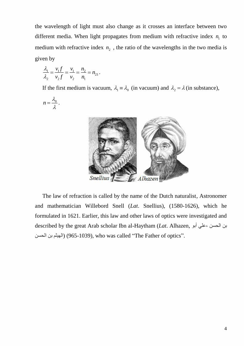
The law of refraction is called by the name of the Dutch naturalist, Astronomer
and mathematician Willebord Snell (Lat. Snellius), (1580-1626), which he
formulated in 1621. Earlier, this law and other laws of optics were investigated and
described by the great Arab scholar Ibn al-Haytham (Lat. Alhazen, بن الحسن ،علي أبو
.”who was called “The Father of optics ,(1039-965) (الهيثم بن الحسن
5
Chapter 2. WAVE OPTICS
In wave (physical) optics, light is considered to propagate as electromagnetic
(EM) wave. It is the form of radiant energy.
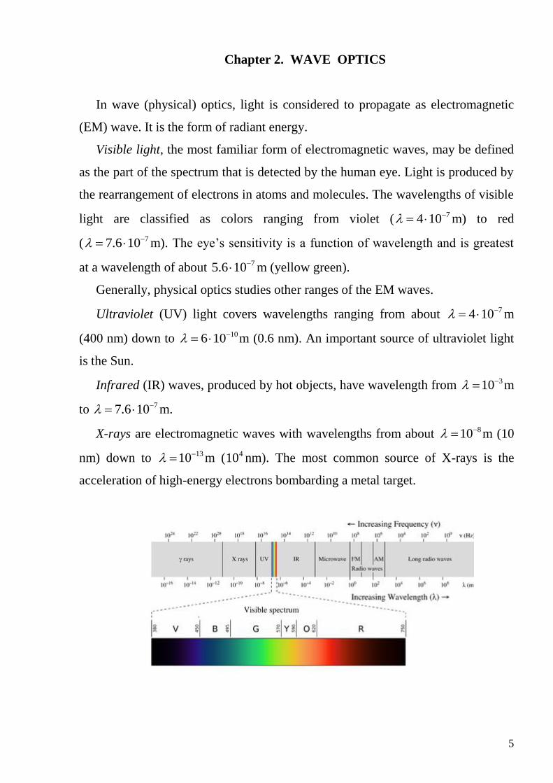
Visible light, the most familiar form of electromagnetic waves, may be defined
as the part of the spectrum that is detected by the human eye. Light is produced by
the rearrangement of electrons in atoms and molecules. The wavelengths of visible
light are classified as colors ranging from violet ( 74 10 m) to red
( 77.6 10 m). The eye’s sensitivity is a function of wavelength and is greatest
at a wavelength of about 75.6 10 m (yellow green).
Generally, physical optics studies other ranges of the EM waves.
Ultraviolet (UV) light covers wavelengths ranging from about 74 10 m
(400 nm) down to 106 10 m (0.6 nm). An important source of ultraviolet light
is the Sun.
Infrared (IR) waves, produced by hot objects, have wavelength from 310 m
to 77.6 10 m.
X-rays are electromagnetic waves with wavelengths from about 810 m (10
nm) down to 1310 m ( 410 nm). The most common source of X-rays is the
acceleration of high-energy electrons bombarding a metal target.

6
1. INTERFERENCE
1.1. Coherence
The distance that the wave covered in vacuum is
geometrical path length s . The optical path length (or
optical distance) L is the product of the geometric
length of the path light follows through the system,
and the index of refraction of the medium through
which it propagates.
L n s .
s L =m.
If two rays are propagating in the media with refractive indexes 1n and 2n , and
covered the optical distances 1L and 2L , respectively, the optical path difference is
1 2 1 1 2 2L L n s n s .
The phase difference of two waves that, after having been in phase
initially, have traversed optical path lengths 1L and 2L , respectively, is
2
.
Coherence is the matched progress of several oscillating or wave processes.
Coherent waves are monochromatic (having the equal frequencies) waves
which are correlated to each other in phase. These phase relationships are
maintained over long time. Coherent sources emit light waves of the same
wavelengths or frequencies, which are always in phase with each other or have a
constant phase difference, i.e., coherent waves. Two coherent waves can produce
the phenomenon of interference.
Ordinary light is incoherent because it comes from independent atoms which
emit on time scales of about 10-8 seconds.

7
1.2. Interference. Constructive and destructive interference
If two light waves passing through some common point P where each of them
causes a displacement, according to the principle of superposition the resultant
displacement is given by a vector sum of two displacements produced by each of
the waves. If both displacements are along the same direction we can use the
expression for calculation the amplitude of resultant
oscillation 2 2 2
1 2 1 22 cosA A A A A . Since intensity I of waves is proportional
to 2A , 1 2 1 22 cosI I I I I . And finally, assuming 1 2 0I I I , we obtain
0 02 2 cosI I I .
In dependence on the phase difference there are different cases are possible:
1. Constructive interference (maximum intensity)
cos 1 2 , 0,1,2,...
22 2 ,
2
k k
k k k
04I I
2. Destructive interference (minimum intensity)
cos 1 2 1 , 0,1,2,...
22 1 2 1
2
k k
k k
0I
At the points of maximum intensity the light waves emanating from each source
are in phase. So the constructive interference occurs, resulting in a light patch on
the screen. The general condition for constructive interference is that the path-
length difference between the two waves be an integer number of wave-length, or
even number of half-wave-lengths:
22
k k
,
where 0,1, 2,...k
At the points of minimum intensity waves are out of phase, so the destructive
interference occurs, resulting in a dark patch on the screen. The general condition
for destructive interference on the screen is that the difference in path-length

8
between the two waves be a half-integer number of wavelengths, or odd number of
half-wave-lengths:
1
2 12 2
k k
,
where 0,1, 2,...k
Therefore, interference is a phenomenon of redistribution of light on account
the superposition of the coherent waves.
1.3. Coherent and incoherent sources of light. Huygens’s Principle
The sources of light emitting waves having constant initial phase difference are
called coherent sources.
The sources of light emitting waves with random phase difference are called
incoherent sources. For interference phenomenon, the sources must be coherent.
So it is necessary to “prepare” light from readily available incoherent light sources
- which typically emit individual, uncoordinated, short wave trains of fixed phase
of no longer than 10−8 seconds - so that the light from such sources remains
coherent over periods of time long enough to overlap and produce visible
interference patterns. There are generally two ways to do this.
Methods of producing coherent sources:
- by division of the wave front: in this method the wave front which is the locus
of points of same phase is divided into two (or the large amount) parts. The
example is Young’ double slit method;
- by division of amplitude: in this method the amplitude of a wave is divided
into two parts by successive reflections.
Interference and further, diffraction, are explained by wave theory first
proposed by a Dutch physicist and mathematician Christian Huygens (1629-1695).
The assumptions of Huygens theory are: a source sends waves in all possible
directions. The locus of points of medium oscillating in same phase is called a

9
wave front. From the point source, the wave front is spherical: while for a line
source the wave front is cylindrical. The distant wave front is plane.
Huygens’s Principle: Each point of a wave front acts as a source of secondary
waves (spherical wavelets). These wavelets travel with the velocity of light in the
medium. A surface tangent to the wavelets at given instant constitutes the new
position of the wave front is called the envelope of the wavelets.
Each point on the wave front acts as a point source that emits secondary.
1.4. Double-slit interference. Young’s experiment
In 1801 English scientist and physician Thomas Young
(1773 – 1829) conducted an experiment to understand to
the nature of light. Young thought that light acted like a
wave and with his double slit experiment, he could see how
light waves would interact if they intersected. The
monochromatic point source S is a source of light whose
spherical wave front (circular in the drawing) falls on two
slits to create secondary sources 1S and 2S according to Huygens’s Principle. They
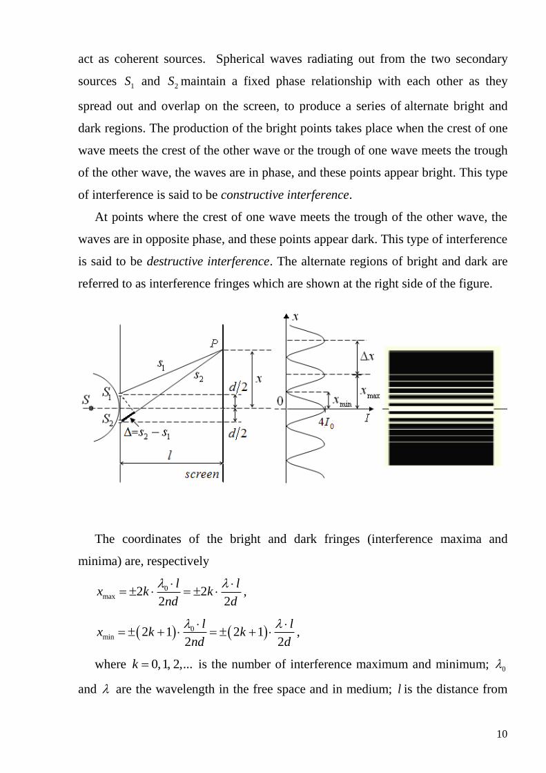
10
act as coherent sources. Spherical waves radiating out from the two secondary
sources 1S and 2S maintain a fixed phase relationship with each other as they
spread out and overlap on the screen, to produce a series of alternate bright and
dark regions. The production of the bright points takes place when the crest of one
wave meets the crest of the other wave or the trough of one wave meets the trough
of the other wave, the waves are in phase, and these points appear bright. This type
of interference is said to be constructive interference.
At points where the crest of one wave meets the trough of the other wave, the
waves are in opposite phase, and these points appear dark. This type of interference
is said to be destructive interference. The alternate regions of bright and dark are
referred to as interference fringes which are shown at the right side of the figure.
The coordinates of the bright and dark fringes (interference maxima and
minima) are, respectively
0max 2 2
2 2
l lx k k
nd d
,
0min 2 1 2 1
2 2
l lx k k
nd d
,
where 0,1, 2,...k is the number of interference maximum and minimum; 0
and are the wavelength in the free space and in medium; l is the distance from

11
the slits to the screen; n is the refractive index, and d is the separation between the
slits.
The distance between two bright (dark) fringes is
0max1 max 0
l lx x x
n d d
.
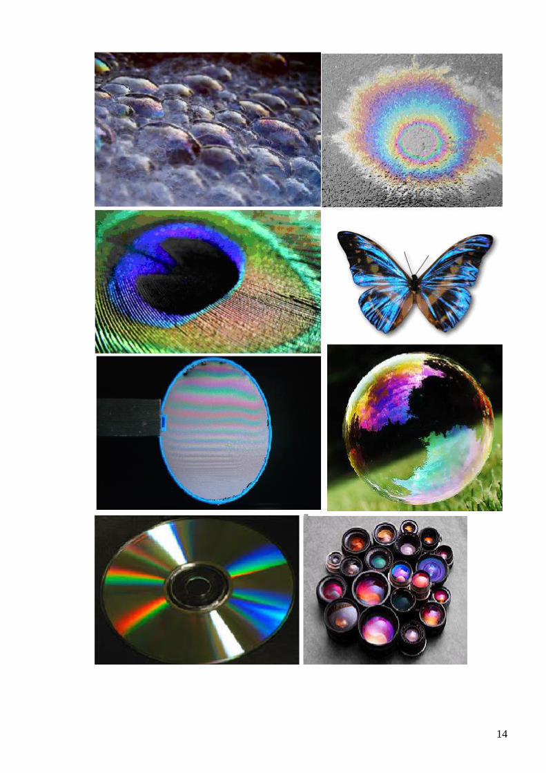
1.5. Thin film interference
Double slit interference, described in the previous paragraph, is rarely observed
in nature. And there is another type of interference that is quite frequently
observed, namely thin film interference. Swirling colors on an oil slick, colors on a
soap bubble, the purple tinge on an expensive camera lens, coloration of the wings
of certain moths and butterflies are all examples of thin film interference.
Light wave interference results when two waves are traveling through a
medium and meet up at the same location. When a light wave reaches the boundary
between two media, a portion of the wave reflects off the boundary and a portion is
transmitted across the boundary. The reflected
portion of the wave remains in the original
medium. The transmitted portion of the wave
enters the new medium and continues traveling
through it until it reaches a subsequent
boundary. If the new medium is a thin film,
then the transmitted wave does not travel far before it reaches a new boundary and
undergoes the usual reflection and transmission behavior. Thus, there are two
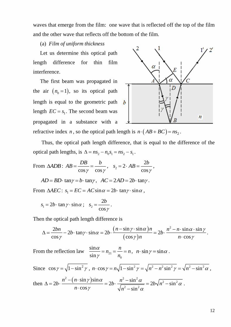
12
waves that emerge from the film: one wave that is reflected off the top of the film
and the other wave that reflects off the bottom of the film.
(a) Film of uniform thickness
Let us determine this optical path
length difference for thin film
interference.
The first beam was propagated in
the air 0 1n , so its optical path
length is equal to the geometric path
length 1EC s . The second beam was
propagated in a substance with a
refractive index n , so the optical path length is 2n AB BC ns .
Thus, the optical path length difference, that is equal to the difference of the
optical path lengths, is 2 0 1 2 1ns n s ns s .
From ADB : cos cos
DB bAB
,
2
22
cos
bs AB
,
tan tanAD BD b , 2 2 tanAC AD b .
From AEC : 1 sin 2 tan sins EC AC b ,
1 2 tan sins b ; 2
2
cos
bs
.
Then the optical path length difference is
2sin sin2 sin sin2 tan sin 2 2
cos cos cos
n nbn n nb b b
n n
.
From the reflection law 21
0
sin
sin
nn n
n
, sin sinn .
Since 2cos 1 sin , 2 2 2 2 2 2cos 1 sin sin sinn n n n n ,
then 2 2 2
2 2
2 2
sin sin sin2 2 2 sin
cos sin
n n nb b b n
n n
.

13
When light incident from a less dense medium (smaller n) reflects off the
boundary with a denser (larger n) medium a 180° phase change on reflection
occurs. Substitution of this phase shift in the relationship between the optical phase
difference and the optical path length difference 2
gives the additional
path length difference
2 2 2
.
Incorporating this phase change leads to the expression for optical path length
difference
2 22 sin2
b n
,
where b is the thickness of the film, n is the refractive index of the thin film
substance, is the angle of incidence, is the wavelength of the incident light.
The theory of the interference due to a parallel film can now enable us to
understand as to why films appear colored. The incident light is white and falls on
a parallel-sided film. The incident light will split up by reflection at the top and
bottom of the film. The split rays are in a position to interfere and interference of
these rays is responsible for the colors. The bright or dark appearance of the
reflected light depends upon the refractive index, the thickness of the film and the
incidence angle. At a particular point of the film and for a particular position of the
eye, the interfering rays of only certain wavelengths will have a path difference
satisfying the conditions of bright fringe. Hence only such wavelengths (colors)
will be present there. Other wavelengths will be present with diminished intensity.
The colors for which the condition of minima is satisfied are absent. We know that
the condition for maxima and minima in transmitted light are opposite to that of
reflected light. Hence, the colors that are absent in reflected light would be present
in transmitted light. The colors observed in transmitted and reflected light are
complimentary.
14
15
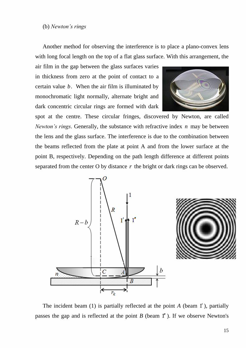
(b) Newton’s rings
Another method for observing the interference is to place a plano-convex lens
with long focal length on the top of a flat glass surface. With this arrangement, the
air film in the gap between the glass surfaces varies
in thickness from zero at the point of contact to a
certain value b . When the air film is illuminated by
monochromatic light normally, alternate bright and
dark concentric circular rings are formed with dark
spot at the centre. These circular fringes, discovered by Newton, are called
Newton’s rings. Generally, the substance with refractive index n may be between
the lens and the glass surface. The interference is due to the combination between
the beams reflected from the plate at point A and from the lower surface at the
point B, respectively. Depending on the path length difference at different points
separated from the center O by distance r the bright or dark rings can be observed.
The incident beam (1) is partially reflected at the point A (beam 1 ), partially
passes the gap and is reflected at the point B (beam 1 ). If we observe Newton's
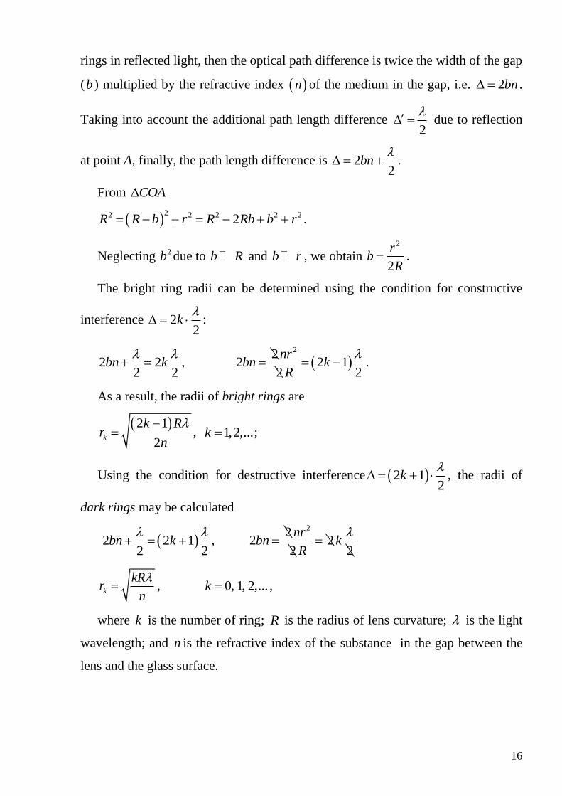
16
rings in reflected light, then the optical path difference is twice the width of the gap
(b ) multiplied by the refractive index n of the medium in the gap, i.e. 2bn .
Taking into account the additional path length difference 2
due to reflection
at point A, finally, the path length difference is 22
bn
.
From COA
22 2 2 2 22R R b r R Rb b r .
Neglecting 2b due to b R and b r , we obtain 2
2
rb
R .
The bright ring radii can be determined using the condition for constructive
interference 22
k
:
2 22 2
bn k
, 22
2 2 12 2
nrbn k
R
.
As a result, the radii of bright rings are
2 1
2k
k Rr
n
, 1,2,...k ;
Using the condition for destructive interference 2 12
k
, the radii of
dark rings may be calculated
2 2 12 2
bn k
, 22
2 22 2
nrbn k
R
k
kRr
n
, 0, 1, 2,...k ,
where k is the number of ring; R is the radius of lens curvature; is the light
wavelength; and n is the refractive index of the substance in the gap between the
lens and the glass surface.
17
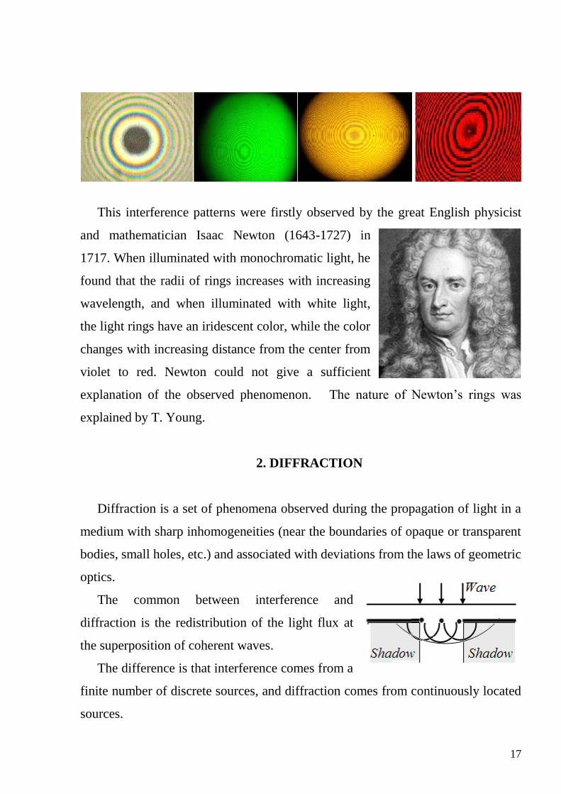
This interference patterns were firstly observed by the great English physicist
and mathematician Isaac Newton (1643-1727) in
1717. When illuminated with monochromatic light, he
found that the radii of rings increases with increasing
wavelength, and when illuminated with white light,
the light rings have an iridescent color, while the color
changes with increasing distance from the center from
violet to red. Newton could not give a sufficient
explanation of the observed phenomenon. The nature of Newton’s rings was
explained by T. Young.
2. DIFFRACTION
Diffraction is a set of phenomena observed during the propagation of light in a
medium with sharp inhomogeneities (near the boundaries of opaque or transparent
bodies, small holes, etc.) and associated with deviations from the laws of geometric
optics.
The common between interference and
diffraction is the redistribution of the light flux at
the superposition of coherent waves.
The difference is that interference comes from a
finite number of discrete sources, and diffraction comes from continuously located
sources.
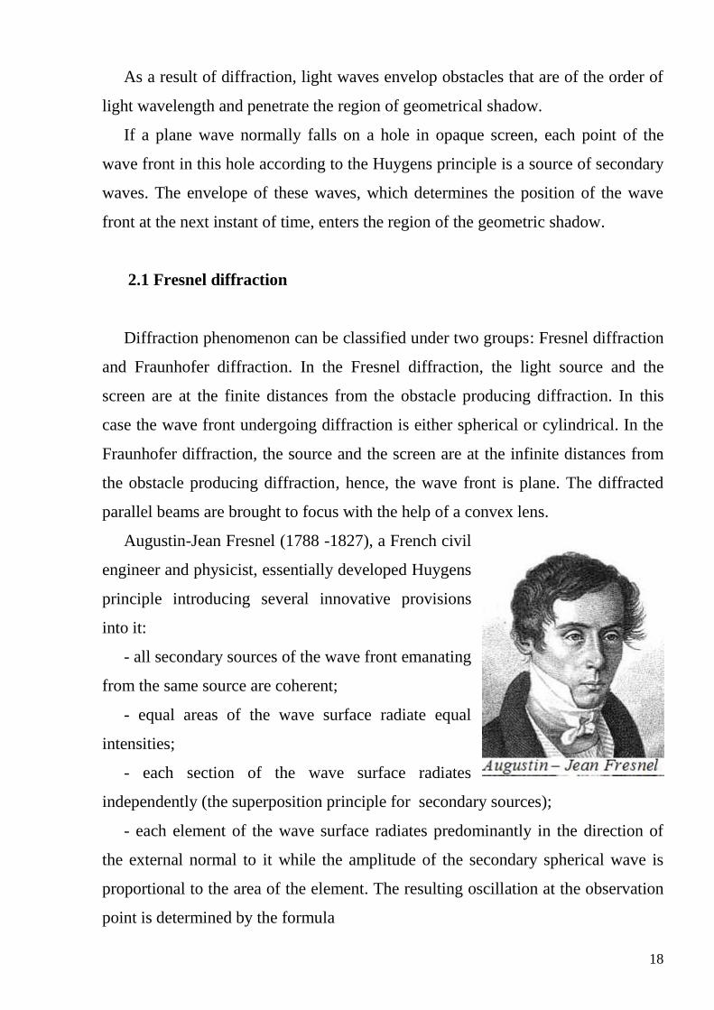
18
As a result of diffraction, light waves envelop obstacles that are of the order of
light wavelength and penetrate the region of geometrical shadow.
If a plane wave normally falls on a hole in opaque screen, each point of the
wave front in this hole according to the Huygens principle is a source of secondary
waves. The envelope of these waves, which determines the position of the wave
front at the next instant of time, enters the region of the geometric shadow.
2.1 Fresnel diffraction
Diffraction phenomenon can be classified under two groups: Fresnel diffraction
and Fraunhofer diffraction. In the Fresnel diffraction, the light source and the
screen are at the finite distances from the obstacle producing diffraction. In this
case the wave front undergoing diffraction is either spherical or cylindrical. In the
Fraunhofer diffraction, the source and the screen are at the infinite distances from
the obstacle producing diffraction, hence, the wave front is plane. The diffracted
parallel beams are brought to focus with the help of a convex lens.
Augustin-Jean Fresnel (1788 -1827), a French civil
engineer and physicist, essentially developed Huygens
principle introducing several innovative provisions
into it:
- all secondary sources of the wave front emanating
from the same source are coherent;
- equal areas of the wave surface radiate equal
intensities;
- each section of the wave surface radiates
independently (the superposition principle for secondary sources);
- each element of the wave surface radiates predominantly in the direction of
the external normal to it while the amplitude of the secondary spherical wave is
proportional to the area of the element. The resulting oscillation at the observation
point is determined by the formula

19
cosS
AE K t kr dS
r ,
where E is the light vector magnitude, A is the amplitude of the light
oscillation, r is the distance from the element to the observation point, k is the
wave number, K is the coefficient depending on the angle between the
normal to dS and the direction from dS to the observation point.
Calculation using the above formula is quite complex hence Fresnel proposed a
method of quantitative calculations of the diffraction pattern for cases
characterized by a certain symmetry. This simple method is known as Fresnel half-
period zone method.
Fresnel assumed that a wave front that started from a source P can be divided into
large number of strips which are known as Fresnel’s half period zones (HPZ). If
the distance between the points O and P is b then the distances to the edges of
these zones from the point P have to be 2
b
, 22
b
, …, 2
b k
. The resultant
effect at any point on the screen is due to the combined effect of all the secondary
waves from various zones. Since the path difference between the wavelets
originating from two consecutive HPZ's and reaching the point P is 2
the phase
difference is .
Therefore, waves that arrive at P from two contiguous zones damp one
another, whereas the action of zones separated by one zone is added.
20
1 1 3 3 51 2 3 4 2 4... ...
2 2 2 2 2
A A A A AA A A A A A A
If the areas of zones are approximately equal 1 2 3S S S , the amplitudes are
approximately too: 1 2 3 ...A A A As a result, if
1. the first HPZ is open, 1A A .
2. two HPZ are open, 0A .
3. three HPZ are open, 1A A .
4. for large number of HPZ, the amplitude of light at point P due to whole wave
front is half the amplitude due to the 1st HPZ.: 1
2
AA .
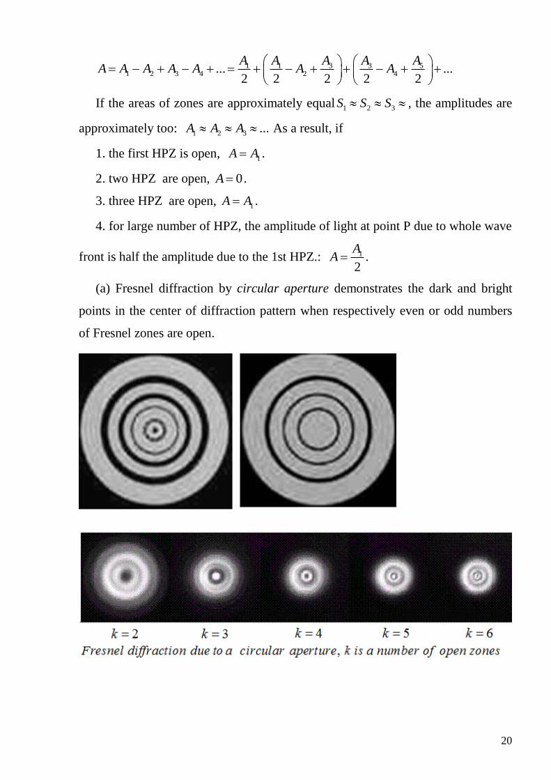
(a) Fresnel diffraction by circular aperture demonstrates the dark and bright
points in the center of diffraction pattern when respectively even or odd numbers
of Fresnel zones are open.

21
(b) Fresnel diffraction due to the knife-edge and the opaque disc
2.2. Fraunhofer diffraction
Fraunhofer diffraction of light waves takes
place when the diffraction pattern is viewed at a long
distance from the diffracting object, and also when it
is viewed at the focal plane of an imaging lens. This
technique names after Joseph von Fraunhofer (1787
22
– 1826), German physicist who first studied the dark lines of the Sun’s spectrum
and used extensively the diffraction grating, a device that disperses light more
effectively than a prism does.
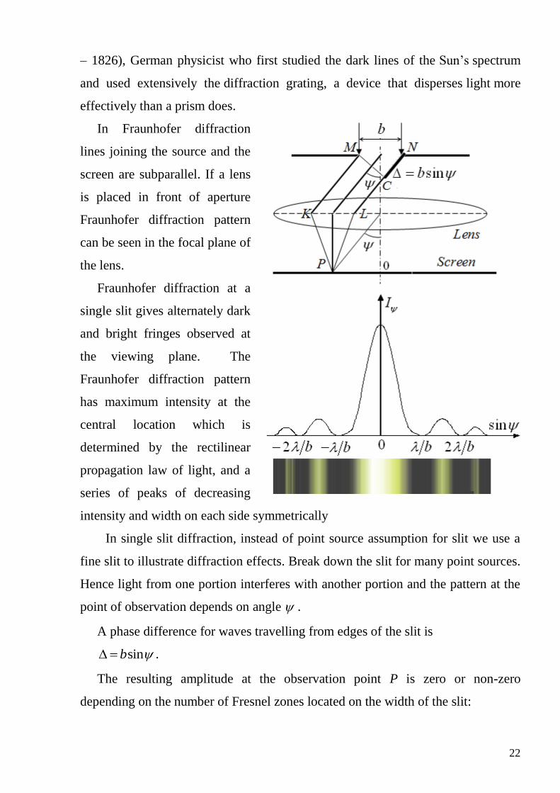
In Fraunhofer diffraction
lines joining the source and the
screen are subparallel. If a lens
is placed in front of aperture
Fraunhofer diffraction pattern
can be seen in the focal plane of
the lens.
Fraunhofer diffraction at a
single slit gives alternately dark
and bright fringes observed at
the viewing plane. The
Fraunhofer diffraction pattern
has maximum intensity at the
central location which is
determined by the rectilinear
propagation law of light, and a
series of peaks of decreasing
intensity and width on each side symmetrically
In single slit diffraction, instead of point source assumption for slit we use a
fine slit to illustrate diffraction effects. Break down the slit for many point sources.
Hence light from one portion interferes with another portion and the pattern at the
point of observation depends on angle .
A phase difference for waves travelling from edges of the slit is
sinb .
The resulting amplitude at the observation point P is zero or non-zero
depending on the number of Fresnel zones located on the width of the slit:
23
sin 22
b k
, 1,2,...k - diffraction minimum
sin 2 12
b k
, 0,1,2,...k - diffraction maximum
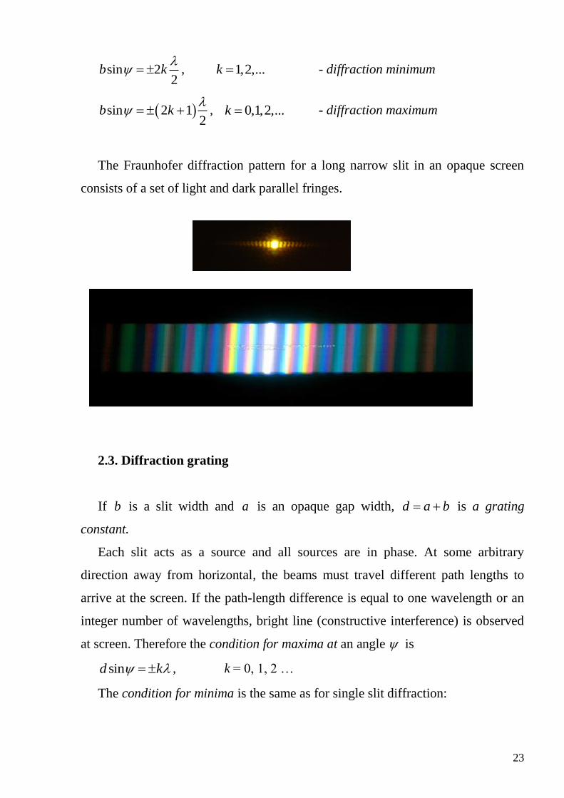
The Fraunhofer diffraction pattern for a long narrow slit in an opaque screen
consists of a set of light and dark parallel fringes.
2.3. Diffraction grating
If b is a slit width and a is an opaque gap width, d a b is a grating
constant.
Each slit acts as a source and all sources are in phase. At some arbitrary
direction away from horizontal, the beams must travel different path lengths to
arrive at the screen. If the path-length difference is equal to one wavelength or an
integer number of wavelengths, bright line (constructive interference) is observed
at screen. Therefore the condition for maxima at an angle is
sind k , k = 0, 1, 2 …
The condition for minima is the same as for single slit diffraction:
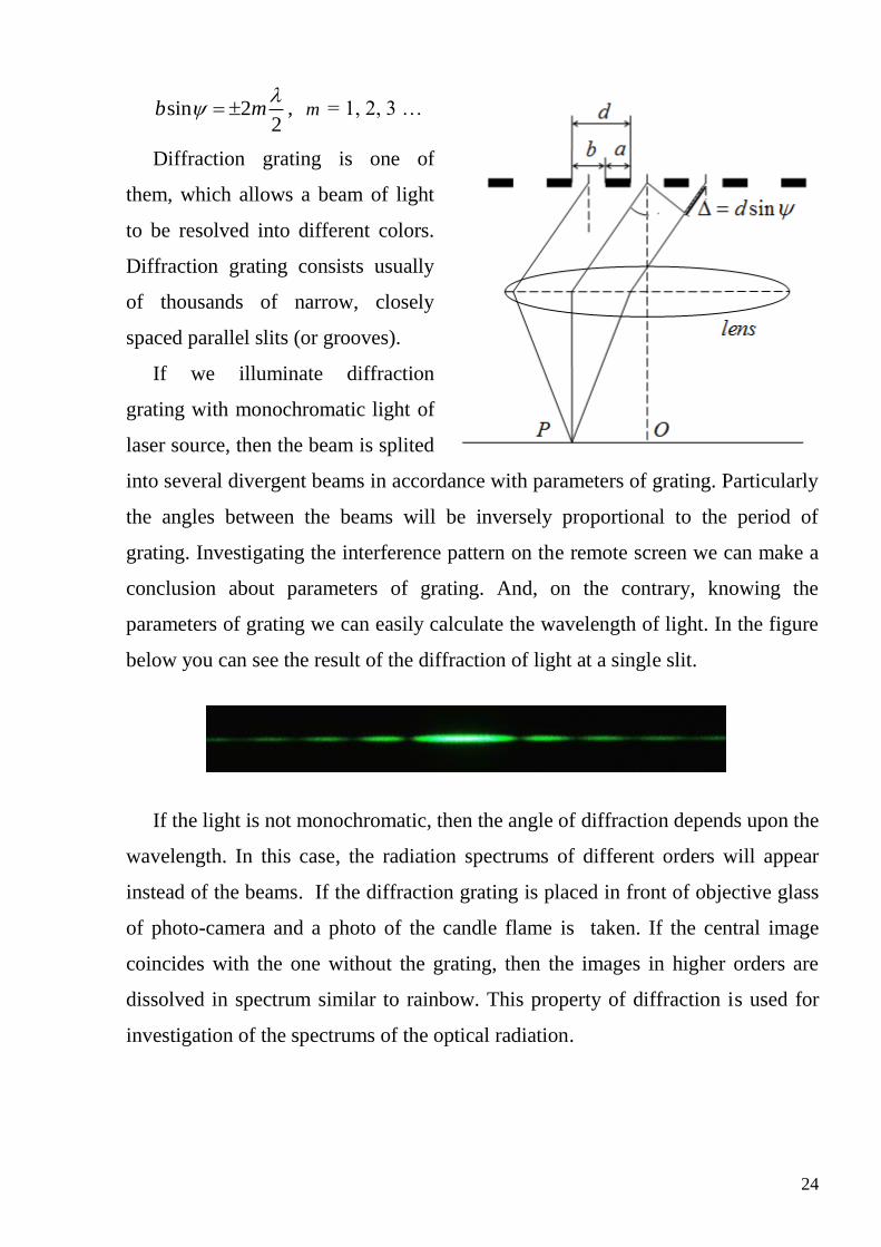
24
sin 22
b m
, m = 1, 2, 3 …
Diffraction grating is one of
them, which allows a beam of light
to be resolved into different colors.
Diffraction grating consists usually
of thousands of narrow, closely
spaced parallel slits (or grooves).
If we illuminate diffraction
grating with monochromatic light of
laser source, then the beam is splited
into several divergent beams in accordance with parameters of grating. Particularly
the angles between the beams will be inversely proportional to the period of
grating. Investigating the interference pattern on the remote screen we can make a
conclusion about parameters of grating. And, on the contrary, knowing the
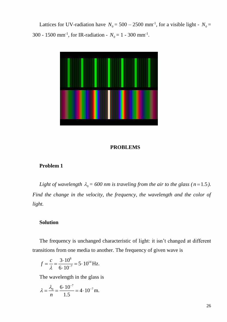
parameters of grating we can easily calculate the wavelength of light. In the figure
below you can see the result of the diffraction of light at a single slit.
If the light is not monochromatic, then the angle of diffraction depends upon the
wavelength. In this case, the radiation spectrums of different orders will appear
instead of the beams. If the diffraction grating is placed in front of objective glass
of photo-camera and a photo of the candle flame is taken. If the central image
coincides with the one without the grating, then the images in higher orders are
dissolved in spectrum similar to rainbow. This property of diffraction is used for
investigation of the spectrums of the optical radiation.

25
Diffraction gratings can be used to split light into its constituent wavelengths
(colors). In general, it gives better wavelength separation than does a prism,
although the output light intensity is usually much smaller.
By shining a light beam into a grating whose spacing d is known, and
measuring the angle where the light is imaged, one can measure the
wavelength . This is the manner in which the atomic spectra of various elements
were first measured.
If 1 and 2 are two nearly equal
wavelengths between which the
spectrometer can hardly distinguish,
the resolving power (resolvance) of
the grating R is defined to be
2 1
R
,
where 1 2
2
.
Resolvance is the measure of
ability to resolve the different
wavelength components. If N lines are illuminated on the grating it can be shown
that the resolvance is
0
lR kN kN l k
d ,
where k is an order of a grating spectrum (maxima); l is the length of a
diffraction grating; 0N is a number of lines per unit length.
26
Lattices for UV-radiation have 0N = 500 – 2500 mm-1, for a visible light - 0N =
300 - 1500 mm-1, for IR-radiation - 0N = 1 - 300 mm-1.
PROBLEMS
Problem 1
Light of wavelength 0 = 600 nm is traveling from the air to the glass ( 1.5n ).
Find the change in the velocity, the frequency, the wavelength and the color of
light.
Solution
The frequency is unchanged characteristic of light: it isn’t changed at different
transitions from one media to another. The frequency of given wave is
814
7
3 105 10
6 10
cf
Hz.
The wavelength in the glass is
770 6 10
4 101.5n
m.
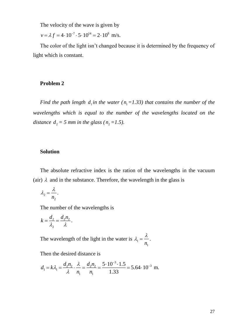
27
The velocity of the wave is given by
7 14 84 10 5 10 2 10v f m/s.
The color of the light isn’t changed because it is determined by the frequency of
light which is constant.
Problem 2
Find the path length 1d in the water ( 1n =1.33) that contains the number of the
wavelengths which is equal to the number of the wavelengths located on the
distance 2d = 5 mm in the glass ( 2n =1.5).
Solution
The absolute refractive index is the ration of the wavelengths in the vacuum
(air) and in the substance. Therefore, the wavelength in the glass is
2
2n
.
The number of the wavelengths is
2 2 2
2
d d nk
.
The wavelength of the light in the water is 1
1n
.
Then the desired distance is
332 2 2 2
1 1
1 1
5 10 1.55.64 10
1.33
d n d nd k
n n
m.
28
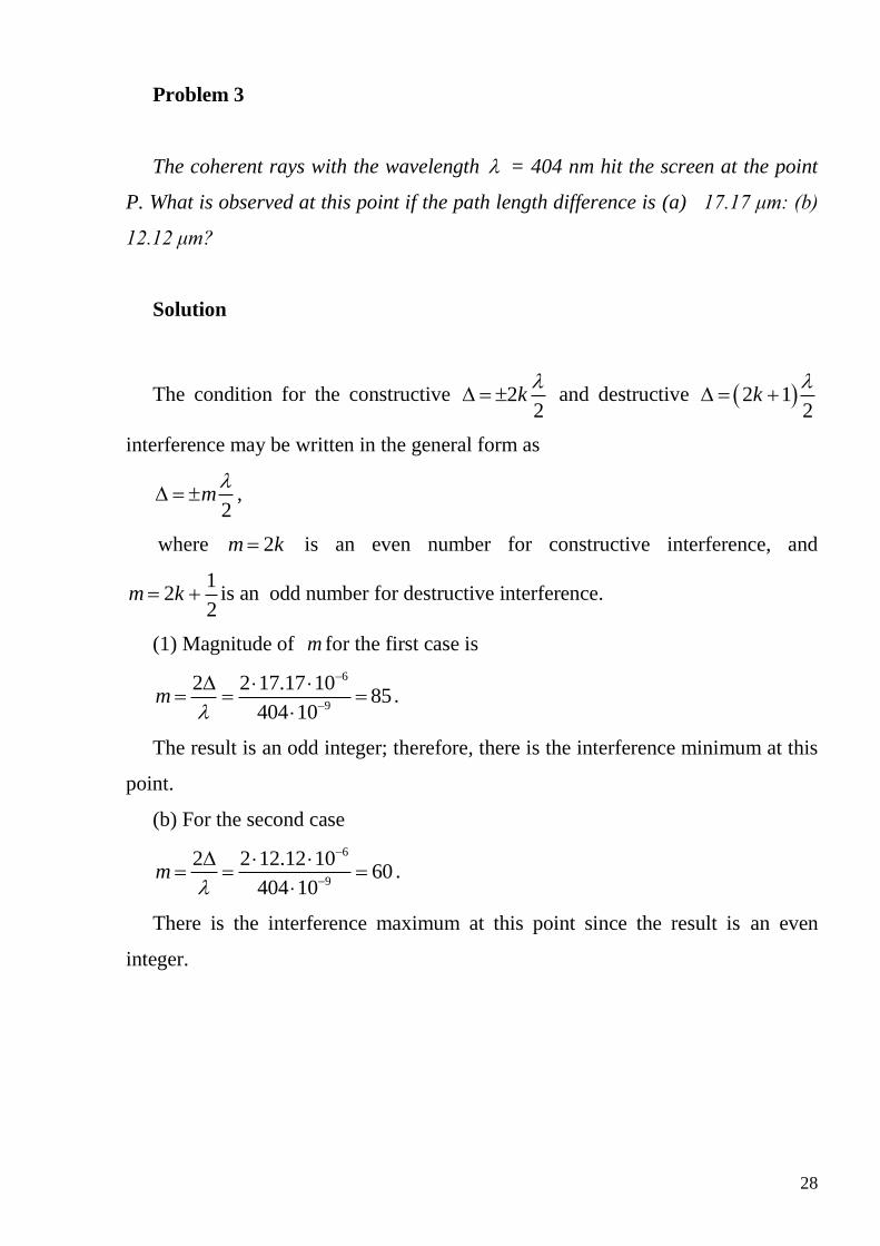
Problem 3
The coherent rays with the wavelength = 404 nm hit the screen at the point
P. What is observed at this point if the path length difference is (a) 17.17 μm: (b)
12.12 μm?
Solution
The condition for the constructive 22
k
and destructive 2 12
k
interference may be written in the general form as
2m
,
where 2m k is an even number for constructive interference, and
12
2m k is an odd number for destructive interference.
(1) Magnitude of m for the first case is
6
9
2 2 17.17 1085
404 10m
.
The result is an odd integer; therefore, there is the interference minimum at this
point.
(b) For the second case
6
9
2 2 12.12 1060
404 10m
.
There is the interference maximum at this point since the result is an even
integer.
29
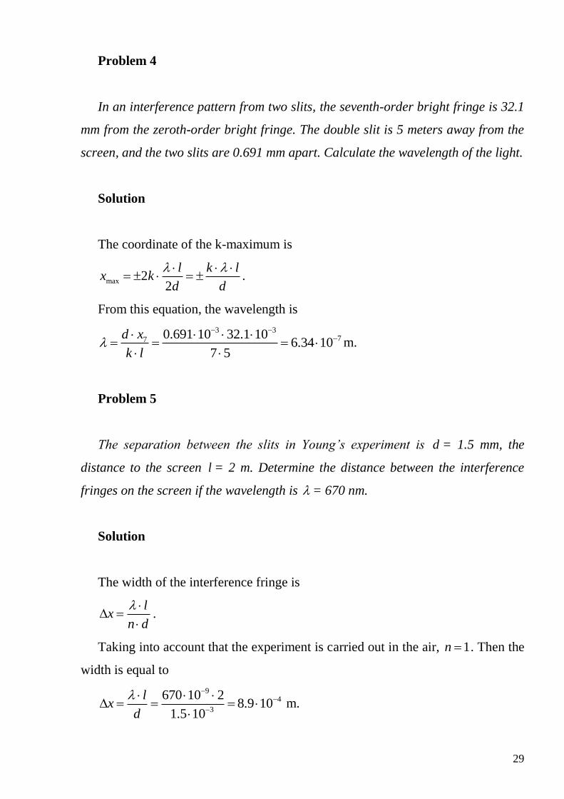
Problem 4
In an interference pattern from two slits, the seventh-order bright fringe is 32.1
mm from the zeroth-order bright fringe. The double slit is 5 meters away from the
screen, and the two slits are 0.691 mm apart. Calculate the wavelength of the light.
Solution
The coordinate of the k-maximum is
max 22
l k lx k
d d
.
From this equation, the wavelength is
3 377 0.691 10 32.1 10
6.34 107 5
d x
k l
m.
Problem 5
The separation between the slits in Young’s experiment is d = 1.5 mm, the
distance to the screen l = 2 m. Determine the distance between the interference
fringes on the screen if the wavelength is = 670 nm.
Solution
The width of the interference fringe is
lx
n d
.
Taking into account that the experiment is carried out in the air, 1n . Then the
width is equal to
94
3
670 10 28.9 10
1.5 10
lx
d
m.
30
774.074 10
1.019 104 4
filmd
m.
Problem 6
In the double-slit experiment, the distance between the slits is 0.15d mm,
‘slit-screen’ separation is 120l cm, the wavelength is 600 nm, and position of
the point P is 1.44x cm. What is the path length difference for the rays from
two slits arriving at point P? Does point P correspond to a maximum, a minimum,
or an intermediate condition?
Solution
The path length difference is given by sind . When l x , the angle is
small and we can make the approximation sin tanx
l . Thus,
3 260.15 10 1.44 10
sin tan 1.8 101.2
d xd d
l
m.
The ratio of the path difference and the wavelength is
6
9
1.8 103
600 10
.
31
Since the path difference is an integer multiple of the wavelength 3 or , in
other words, it is equal to the even number of half-wavelengths 22
k
, the
intensity at the point P is the maximum.
Problem 7
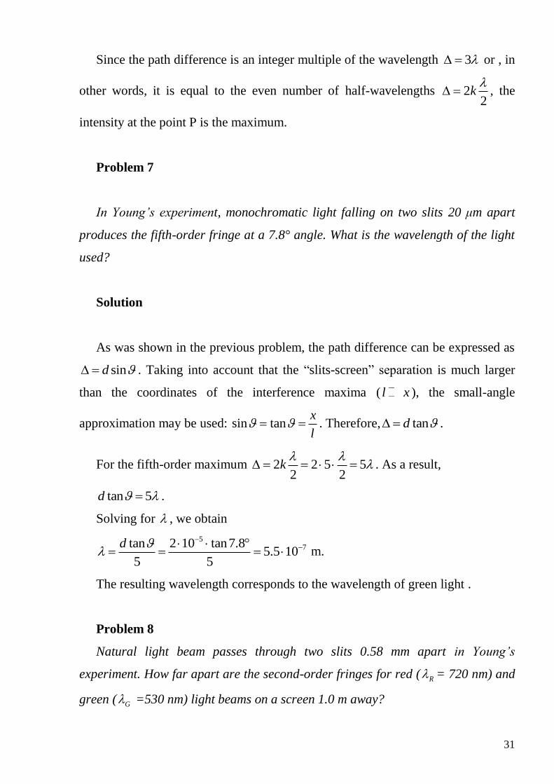
In Young’s experiment, monochromatic light falling on two slits 20 μm apart
produces the fifth-order fringe at a 7.8° angle. What is the wavelength of the light
used?
Solution
As was shown in the previous problem, the path difference can be expressed as
sind . Taking into account that the “slits-screen” separation is much larger
than the coordinates of the interference maxima ( l x ), the small-angle
approximation may be used: sin tanx
l . Therefore, tand .
For the fifth-order maximum 2 2 5 52 2
k
. As a result,
tan 5d .
Solving for , we obtain
57tan 2 10 tan7.8
5.5 105 5
d
m.
The resulting wavelength corresponds to the wavelength of green light .
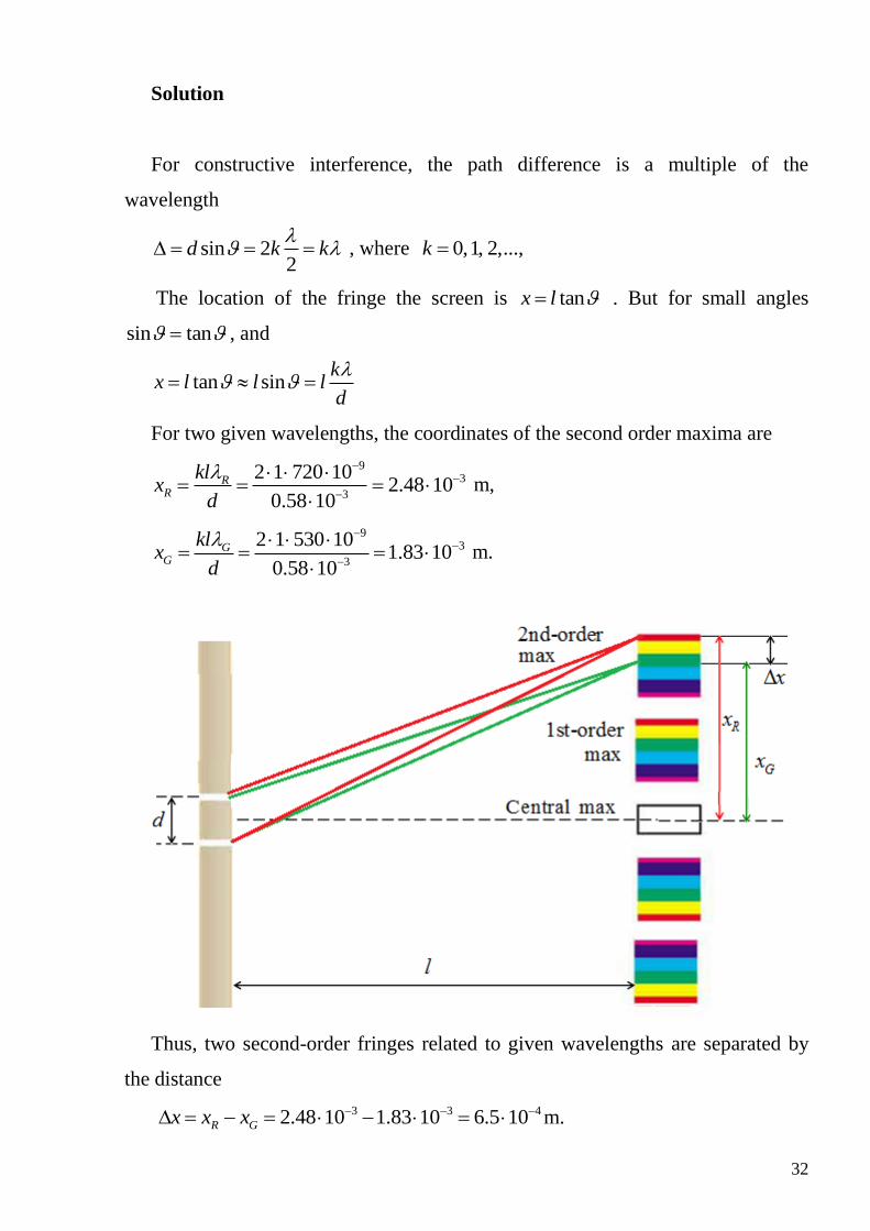
Problem 8
Natural light beam passes through two slits 0.58 mm apart in Young’s
experiment. How far apart are the second-order fringes for red ( R = 720 nm) and
green ( G =530 nm) light beams on a screen 1.0 m away?
32
Solution
For constructive interference, the path difference is a multiple of the
wavelength
sin 22
d k k
, where 0,1, 2,...,k
The location of the fringe the screen is tanx l . But for small angles
sin tan , and
tan sink
x l l ld
For two given wavelengths, the coordinates of the second order maxima are
93
3
2 1 720 102.48 10
0.58 10
RR
klx
d
m,
93
3
2 1 530 101.83 10
0.58 10
GG
klx
d
m.
Thus, two second-order fringes related to given wavelengths are separated by
the distance
3 3 42.48 10 1.83 10 6.5 10R Gx x x m.
33
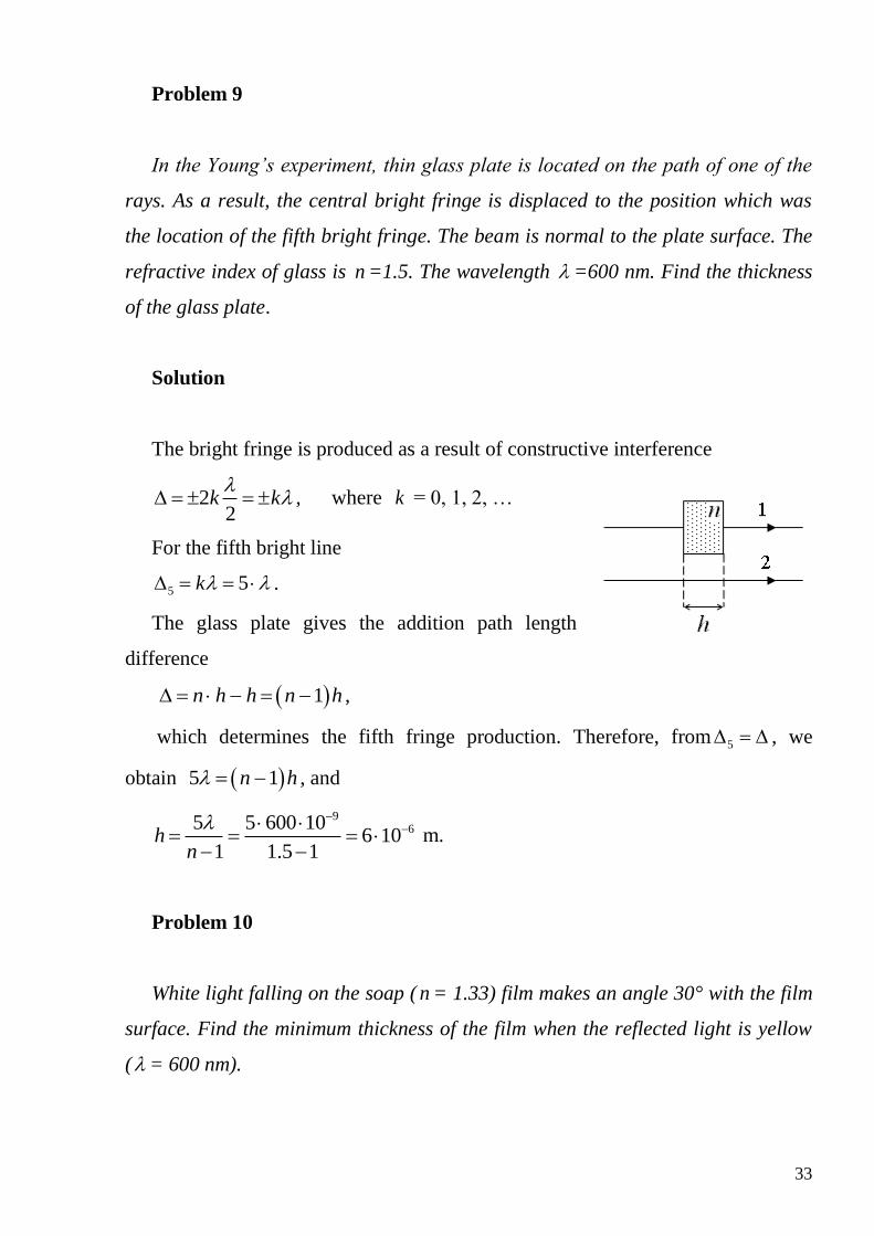
Problem 9
In the Young’s experiment, thin glass plate is located on the path of one of the
rays. As a result, the central bright fringe is displaced to the position which was
the location of the fifth bright fringe. The beam is normal to the plate surface. The
refractive index of glass is n =1.5. The wavelength =600 nm. Find the thickness
of the glass plate.
Solution
The bright fringe is produced as a result of constructive interference
22
k k
, where k = 0, 1, 2, …
For the fifth bright line
5 5k .
The glass plate gives the addition path length
difference
1n h h n h ,
which determines the fifth fringe production. Therefore, from 5 , we
obtain 5 1n h , and
965 5 600 10
6 101 1.5 1
hn
m.
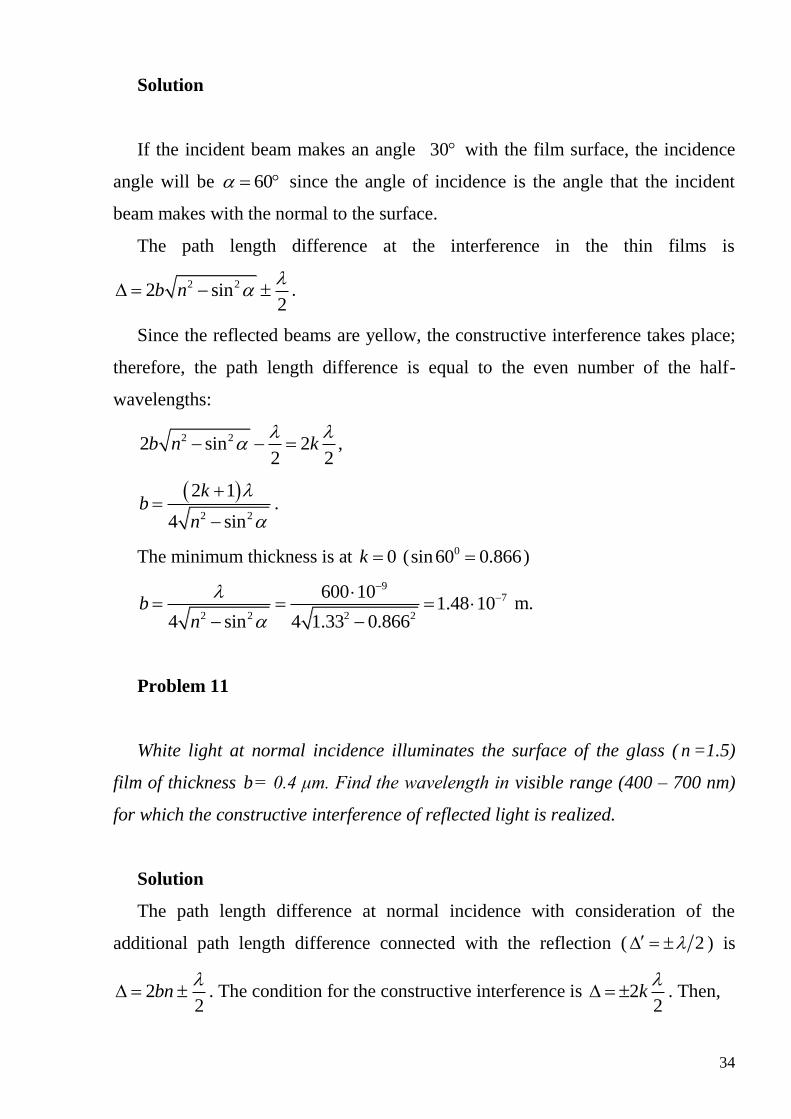
Problem 10
White light falling on the soap ( n = 1.33) film makes an angle 30° with the film
surface. Find the minimum thickness of the film when the reflected light is yellow
( = 600 nm).
34
Solution
If the incident beam makes an angle 30 with the film surface, the incidence
angle will be 60 since the angle of incidence is the angle that the incident
beam makes with the normal to the surface.
The path length difference at the interference in the thin films is
2 22 sin2
b n
.
Since the reflected beams are yellow, the constructive interference takes place;
therefore, the path length difference is equal to the even number of the half-
wavelengths:
2 22 sin 22 2
b n k
,
2 2
2 1
4 sin
kb
n
.
The minimum thickness is at 0k ( 0sin60 0.866 )
97
2 2 2 2
600 101.48 10
4 sin 4 1.33 0.866b
n
m.
Problem 11
White light at normal incidence illuminates the surface of the glass ( n =1.5)
film of thickness b= 0.4 μm. Find the wavelength in visible range (400 – 700 nm)
for which the constructive interference of reflected light is realized.
Solution
The path length difference at normal incidence with consideration of the
additional path length difference connected with the reflection ( 2 ) is
22
bn
. The condition for the constructive interference is 22
k
. Then,
35
2 22 2
bn k
,
2 2 12
bn k
,
4
2 1
bn
k
, where 0, 1, 2,...k
Calculation gives:
0k 6 64 4 0,4 10 1.5 2.4 10bn м,
1k 6
64 2.4 100.8 10
3 3
bn
м,
2k 6
64 2.4 100.48 10
5 5
bn
м,
3k 6
64 2.4 100.34 10
7 7
bn
м.
It is obvious that only 60.48 10 m meets the requirements of the problem.
Problem 12
Monochromatic light with a frequency of 7.5·1014 Hz is traveling through the
air when it reaches a thin film ( 1.45n ). The incidence angle is 400. Determine
the minimum thickness of the film that will result in de constructive interference of
the reflected light.
Solution
The wavelength of the incident light is 8
7
14
3 104 10
7.5 10
c
f
m.
The path length difference at the interference in thin films is
2 22 sin2
b n
.
The condition for destructive interference is 2 12
k
. Therefore
36
2 22 sin 2 12 2
b n k
,
2 22 sinb n k ,
2 2sin
kb
n
The minimum thickness is at 1k ,
77
min 2 2 2 2 0
4 103.08 10
sin 1.45 sin 40b
n
m.
Problem 13
White light is incident on a soap film ( n = 1.3) in air. The reflected light looks
bluish because the red light ( = 670 nm) is absent in the reflection. What is the
minimum thickness of the soap film?
Solution
At the normal incidence of the light on the thin soap film the path length
difference is 22
bn
. This path length difference has to be multiple of the odd
number of the half-wavelength:
2 2 12 2
bn k
.
It gives 2bn k and 2
kb
n
.
The minimum thickness for destructive interference realization foe the red light
is at 1k :
99
min
670 10258 10
2 2 1.3b
n
m.
37
Problem 14
A picture frame manufacturer wishes to design picture frames that provide
minimal glare from the glass cover. In order to achieve this, a thin plastic film
( n = 1.35) is placed on the glass surface ( 1n = 1.52). If light reflected in the middle
of the visible spectrum with a wavelength of 550 nm is to be minimized, what film
thickness is required?
Solution
The reflection from the “air-film” interface will be 180° out of phase with the
incident light. The reflection from the “film-glass” interface will also be 180° out
of phase with the incident light. (Both reflections occur at a less dense to more
dense boundary.) Therefore, two reflected rays would be in phase if the path
difference were zero. To produce destructive interference between these two rays,
and hence minimize the glare, the path difference must be 2 . To achieve this,
the film thickness must be 2 , where is the wavelength of the light in the
film. According to the definition, the refractive index of the plastic film is
air
film
n
. The wavelength in the film is
97550 10
4.074 101.35
airfilm
n
m.
The thickness of the film has to be 7
74.074 101.0185 10
4 4d
m.
Problem 15
In Newton’s rings apparatus, the radii of the k-th and (k + 20)-th dark rings are
found to be 0.162 and 0.368 cm, respectively, when light of wavelength 546 nm is
used. Calculate the radius of curvature, R, of the lower surface of the lens.
38
Solution
The radius of the k -th dark ring is given by
kr kR .
The radius of (k + 20)-th dark ring is
20 20kr k R .
Squaring above equations, subtracting and solving for R , the radius of curvature
of the lower lens is
2 2
2 22 2
20
9
0.368 10 0.162 101
20 20 546 10
k kr rR
m.
Problem 16
The radius of the 10th dark ring in Newton’s rings apparatus changes from 60
to 50 mm when a liquid is introduced between the lens and the plate. Calculate the
refraction index of the liquid.
Solution
The radius of the dark ring when the air is in gaping is given by
kr kR .
When the gap is filled by liquid, the radius is
k
kRr
n
.
k
k
r kR nn
r kR
.
The refractive index is equal to
2 260
1.4450
k
k
rn
r
.
39
Problem 17
The Newton’s rings apparatus is illuminated by the monochromatic light which
is normal to the upper surface of the plane-convex lens. The radii of the adjacent
dark rings are 4 mm and 4.38 mm. The radius of curvature of the lens is R =6.4 m.
Find the numbers of the rings and the wavelength of the light.
Solution
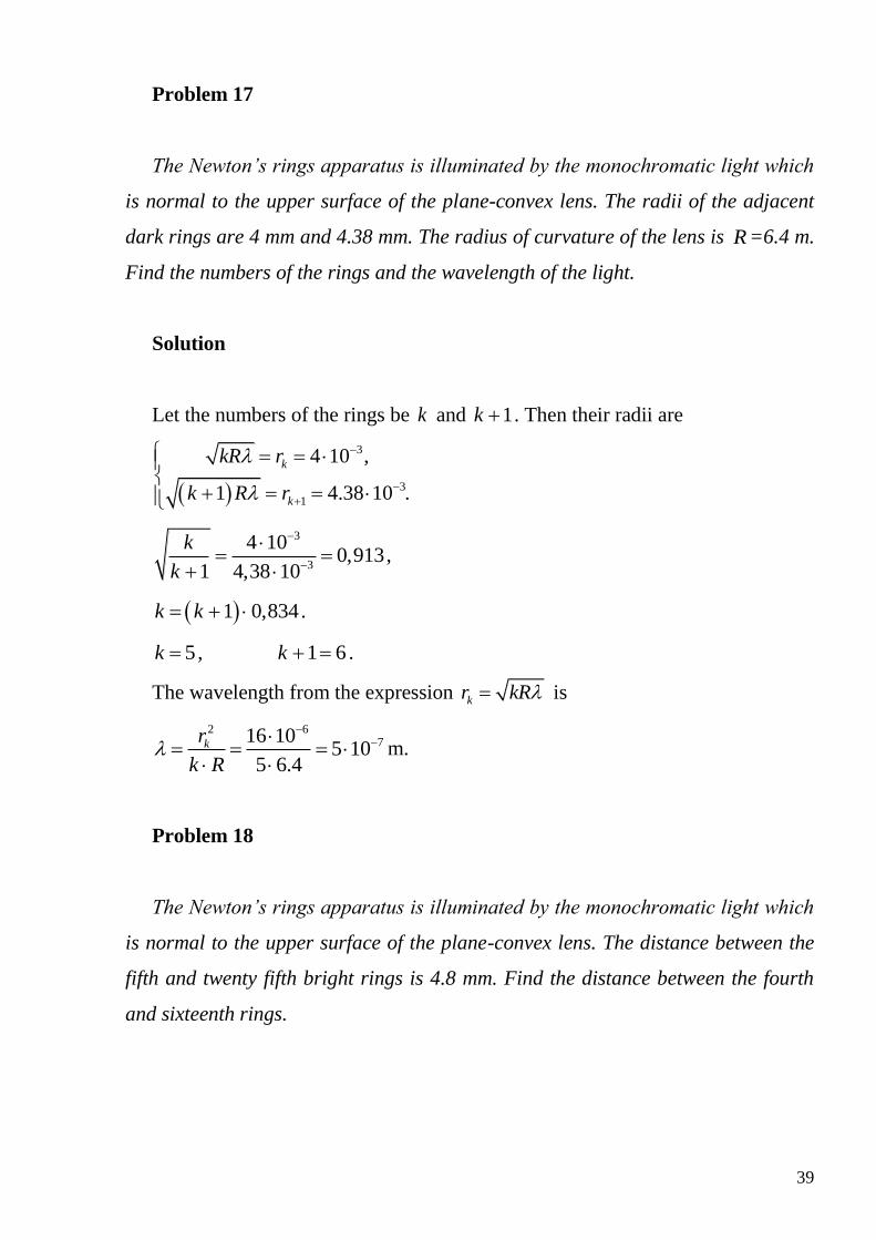
Let the numbers of the rings be k and 1k . Then their radii are
3
3
1
4 10 ,
1 4.38 10 .
k
k
kR r
k R r
3
3
4 100,913
1 4,38 10
k
k
,
1 0,834k k .
5k , 1 6k .
The wavelength from the expression kr kR is
2 6716 10
5 105 6.4
kr
k R
m.
Problem 18
The Newton’s rings apparatus is illuminated by the monochromatic light which
is normal to the upper surface of the plane-convex lens. The distance between the
fifth and twenty fifth bright rings is 4.8 mm. Find the distance between the fourth
and sixteenth rings.
40
Solution
Using the formulas for the radii of the bright 2 1
2k
k Rr
and dark
kr kR rings, the given distance is expressed as
25 5
49 9 7 32.83
2 2 2
R Rr r R R
.
The sought distance is
16 4 16 4 2r r R R R .
The ration of these two expressions is
25 5
16 4
2.83
2
r r R
r r R
.
Then the distance between the fourth and sixteenth rings is
3 3
16 4 25 5 0.707 4.8 10 0.707 3.4 10r r r r m.
Problem 19
The Newton’s ring apparatus is illuminated by the monochromatic light ( =
500nm). The gaping between the lens and the glass plate is filled with water. Find
the thickness of the water layer at the locus of the forth bright ring.
Solution
From the drawing of the Newton’s ring apparatus,
22 2
kR R b r ,
2 2 2 22 kR R Rb b r .
Since b R , we neglect 2b , and obtain 2
2
krbR
.
The radius of k -th bright ring is
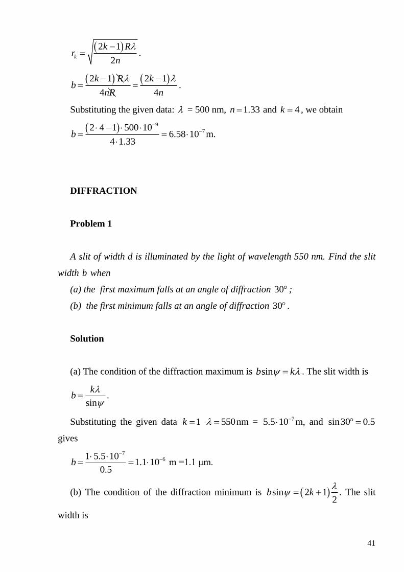
41
2 1
2k
k Rr
n
.
2 1 2 1
4 4
k R kb
nR n
.
Substituting the given data: = 500 nm, 1.33n and 4k , we obtain
9
72 4 1 500 106.58 10
4 1.33b
m.
DIFFRACTION
Problem 1
A slit of width d is illuminated by the light of wavelength 550 nm. Find the slit
width b when
(a) the first maximum falls at an angle of diffraction 30 ;
(b) the first minimum falls at an angle of diffraction 30 .
Solution
(a) The condition of the diffraction maximum is sinb k . The slit width is
sin
kb
.
Substituting the given data 1k 550 nm = 75.5 10 m, and sin30 0.5
gives
761 5.5 10
1.1 100.5
b
m =1.1 μm.
(b) The condition of the diffraction minimum is sin 2 12
b k
. The slit
width is

42
2 1
2 sin
kb
.
After substituting the given data 0k 550 nm = 75.5 10 m, and
sin30 0.5 we obtain
771 5.5 10
5.5 102 0.5
b
m = 0.55 μm.
Problem 2
Light of the wavelength = 589 nm falls on the slit of width b = 2.25 μm. Find
the angular deviations for the diffraction minimum. Determine the number of
minima that this slit gives. How many minima does this slit give?
Solution
The condition for diffraction minimum is sin 22
b k
, so the number of
maximum is
sinbk
.
Since sin 1 ,
6
max 9
2.25 103.83
589 10
bk
.
As k is the number of the diffraction minimum, it has to be integer, therefore,
maxk = 3. Note! We didn’t round the obtained result 3.83 according to the
mathematical rules. If we round it to 4, we would obtain sin greater than 1. But
it is nonsense. Therefore, we omitted the fractional part of 3.83 and obtained the
result k = 3.
The angles that are related to the diffraction minima may be found according to
sink
b
.

43
1k 9
1 6
1 589 10sin 0.295
2 10
, 1 17.1 ;
2k 9
2 6
2 589 10sin 0.59
2 10
, 2 36.2 ;
3k 9
3 6
3 589 10sin 0.885
2 10
, 3 62.3 .
This slit gives six diffraction minima; three minima on the each side of the
central maximum, i.e., max2 2 3 6K k .
Problem 3
The monochromatic light of wavelength 600 nm illuminates the slit of width b=
30 μm. There is the convex lens behind the slit and the observation screen in its
focal plane. What is observed on the screen at the diffraction angles that are (a)
4.59º and (b) 6.32º?
Solution
The conditions for diffraction maximum sin 2 12
b k
and minimum
sin 22
b k
may be written in the general form as
sin2
b m
,
where m is an odd number for maximum and an even number for minimum,
relatively.
Then,
2 sinbm
.
(a) For the first given diffraction angle,
6
11 9
2 sin 2 30 10 sin4.598
600 10
bm
.
44
The result is an even integer, therefore, 1 2 8m k , 4k . Thus, there is the
4th diffraction minimum.
(b) For the second diffraction angle,
6
22 9
2 sin 2 30 10 sin6.3211
600 10
bm
.
The result is an odd integer, therefore, 2 2 1 11m k , 5k . This is the 5th
diffraction maximum.
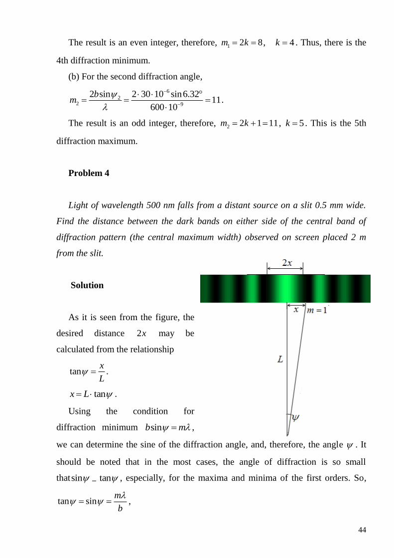
Problem 4
Light of wavelength 500 nm falls from a distant source on a slit 0.5 mm wide.
Find the distance between the dark bands on either side of the central band of
diffraction pattern (the central maximum width) observed on screen placed 2 m
from the slit.
Solution
As it is seen from the figure, the
desired distance 2x may be
calculated from the relationship
tanx
L .
tanx L .
Using the condition for
diffraction minimum sinb m ,
we can determine the sine of the diffraction angle, and, therefore, the angle . It
should be noted that in the most cases, the angle of diffraction is so small
thatsin tan , especially, for the maxima and minima of the first orders. So,
tan sinm
b
,
45
93
3
2 2 1 500 102 2 tan 2 4 10
0.5 10
mx L L
b
m = 4 mm.
Problem 5
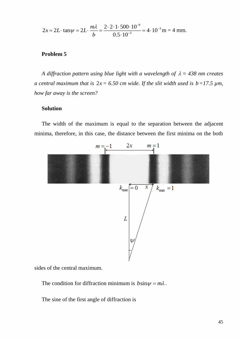
A diffraction pattern using blue light with a wavelength of = 438 nm creates
a central maximum that is 2x = 6.50 cm wide. If the slit width used is b=17.5 µm,
how far away is the screen?
Solution
The width of the maximum is equal to the separation between the adjacent
minima, therefore, in this case, the distance between the first minima on the both
sides of the central maximum.
The condition for diffraction minimum is sinb m .
The sine of the first angle of diffraction is

46
9
6
438 10sin 0.025
17.5 10
m
b b
.
arcsin0.025 1.43 .
On the other side, the tangent of the diffraction angle can be expressed using
the “slit-screen” separation L and the distance from the center of the diffraction
pattern to the first order minimum x. As a result, the required distance is
0.0651.3
tan 2 tan1.43
xL
m.
Problem 6
A coherent beam of light from a hydrogen discharge tube falls normally on a
diffraction grating of 8000 lines per centimeter. Calculate the angular deviation of
each line in the first-order spectrum. Do any lines of the second-order spectrum
overlap the first-order spectrum? (For the hydrogen discharge tube, red = 656.3
nm; blue green = 486.1 nm, blue = 434.0 nm, violet = 410.1 nm.)
Solution
Since the grating has 0N 8000 lines per centimeter, the grating spacing is
given by:
0
1 1
8000d
N cm= 61.25 10 m.
We can calculate the deviation of each component in turn by using the
diffraction grating equation for bright fringes:
sind k , where 0,1, 2,...k

47
It is necessary to calculate the angles of the first order fringes and the second
order fringes for the given lights and to compare them to determine whether they
have overlap. The general idea is to compare the biggest angle max1 of the first-
order fringes and the smallest angle min 2 of second-order fringes. If
max1 min 2 , the overlap happens. Otherwise, no overlap occurs.
(1) The first-order maximum:
Violet line: 9
1 6
1 410 10sin 0.328
1.25 10V
k
d
1 arcsin 0.328 19.14V .
Blue line: 9
1 6
1 434 10sin 0.347
1.25 10B
k
d
,
1 arcsin0.347 20.31B
Blue-green line: 9
1 6
1 486.1 10sin 0.389
1.25 10BG
k
d
,
1 arcsin0.389 22.88BG
48
Red line: 9
1 6
1 656.3 10sin 0.525
1.25 10R
k
d
1 arcsin0.525 31.67R
(b) The second-order maximum
Violet line: 9
2 6
2 410 10sin 0.656
1.25 10V
k
d
2 arcsin 0.656 41V .
Blue line: 9
2 6
2 434 10sin 0.694
1.25 10B
k
d
,
2 arcsin0.694 87.9B .
Blue-green line: 9
1 6
2 486.1 10sin 0.778
1.25 10BG
k
d
,
2 arcsin0.778 51.1BG .
Red line gives 9
1 6
2 656.3 10sin 1
1.25 10
k
d
. This is the impossible result. So
the red line is absent in the second-order spectrum produced by this diffraction
grating.
To determine whether the second-order spectrum for violet line overlaps the
first-order spectrum, we need to compare the angles corresponding to red line in
the 1st order spectrum and the violet line in the 2nd order spectrum, namely,
2 41V and 1 31.67R . Since 31.67 41 , overlapping of the spectra is not
observed.
Problem 7
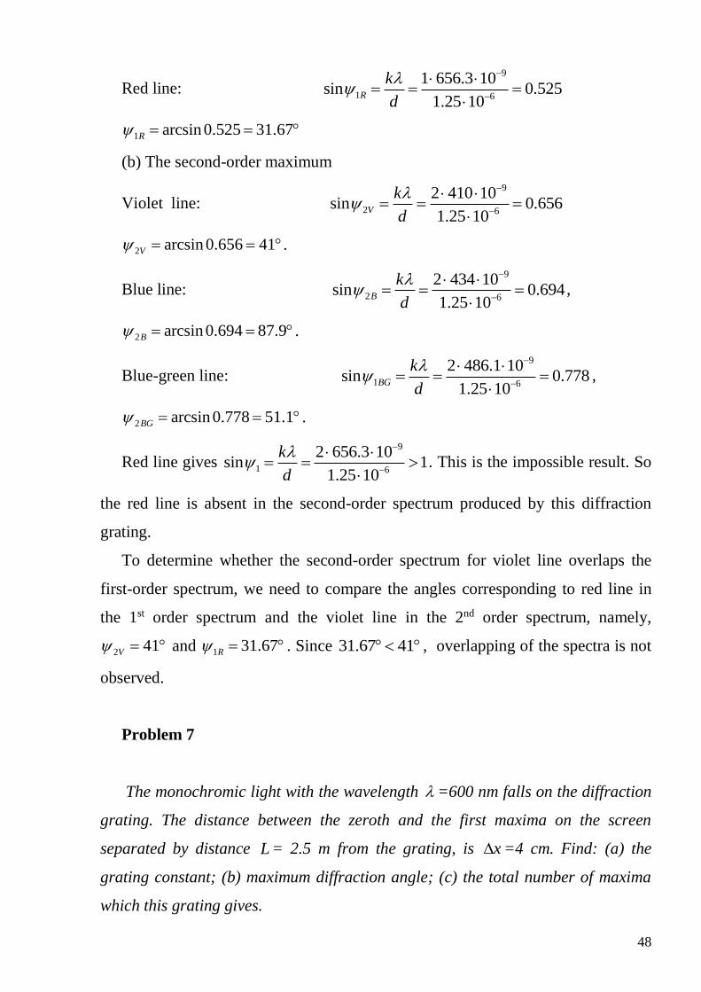
The monochromic light with the wavelength =600 nm falls on the diffraction
grating. The distance between the zeroth and the first maxima on the screen
separated by distance L= 2.5 m from the grating, is x =4 cm. Find: (a) the
grating constant; (b) maximum diffraction angle; (c) the total number of maxima
which this grating gives.
49
Solution
The condition for diffraction maximum is sind k , k = 0, 1, 2,…. For the
first ( 1k ) maximum:
1sind .
On other hand, 11tan
x
L ,
-2
11
4 10arctan arctan arctan0.016
2.5
x
L
.
1 0.9 .
The grating constant is
5
1
3.75 10sin
d
m.
The highest order of diffraction spectrum can
be calculated, assuming that the maximum magnitude of sin 1 , Then,
5
maxmax 9
sin 3.75 1062.5
600 10
d dk
.
The resulting value has to be rounded to an integer, since k is the number of the
diffraction spectrum. It should be remembered that the value of the sine should not
be greater than 1, therefore, we remove the fractional portion. As a result, the
highest number of diffraction spectrum is max 62k .The diffraction angle for this
spectrum can be calculated as
9
maxmax 5
62 600 10sin 0.992
3.75 10
k
d
,
max arcsin 0.992 82.75
The total number of diffraction maxima is 62 at each side and one central
maximum:
max2 1 2 62 1 125K k .
50
Problem 8
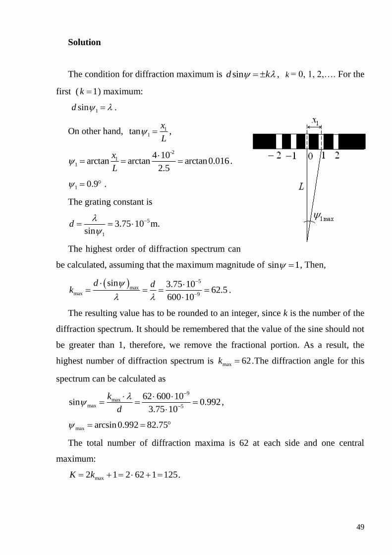
A parallel beam of white light is shines normally on a diffraction grating with
6500 lines per 1 cm. Assuming the wavelengths of yellow and blue light in air are
1 = 600 nm and 2 = 400 nm, respectively, show that there is overlapping
between yellow and blue spectra. Find the orders of the overlapping spectra.
Solution
The conditions for diffraction maxima for the yellow and blue lights in the case
of their overlapping are
1 1
2 2
sin ,
sin .
d k
d k
Since the left sides of the expressions
are the same, 1 1 2 2k k . The resulting
equation contains two unknown
quantities and can not be solved from a
formal point of view. But, if we recall
that the 1k and 2k are the numbers of the
diffraction spectra, and hence the integers, then we obtain
1 2
2 1
400 2
600 3
k
k
.
The obtained result indicates that the yellow line in the 2nd-order diffraction
spectrum is overlapped by the blue line of the 3rd-order spectrum
Problem 9
Diffraction grating with 100 lines per 1 mm is at the distance 2 m from the
screen. It is illuminated by white light that strikes normally to the grating. Find the
51
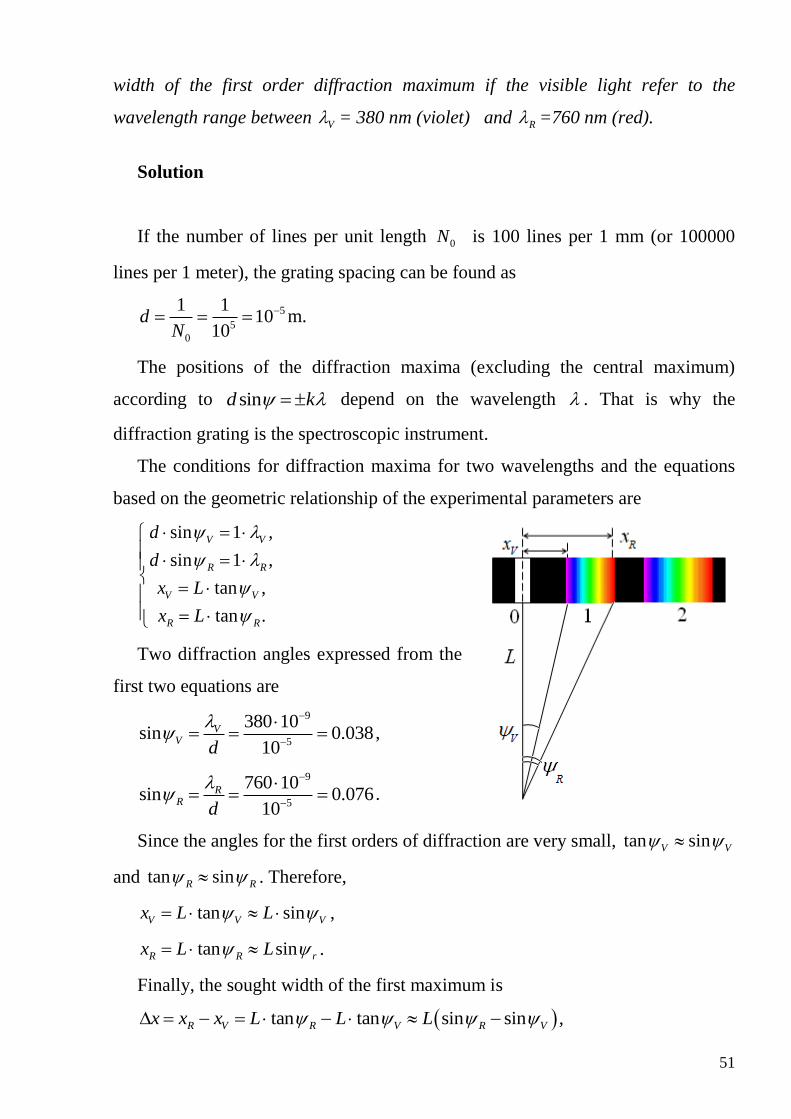
width of the first order diffraction maximum if the visible light refer to the
wavelength range between V = 380 nm (violet) and R =760 nm (red).
Solution
If the number of lines per unit length 0N is 100 lines per 1 mm (or 100000
lines per 1 meter), the grating spacing can be found as
5
5
0
1 110
10d
N
m.
The positions of the diffraction maxima (excluding the central maximum)
according to sind k depend on the wavelength . That is why the
diffraction grating is the spectroscopic instrument.
The conditions for diffraction maxima for two wavelengths and the equations
based on the geometric relationship of the experimental parameters are
sin 1 ,
sin 1 ,
tan ,
tan .
V V
R R
V V
R R
d
d
x L
x L
Two diffraction angles expressed from the
first two equations are
9
5
380 10sin 0.038
10
VV
d
,
9
5
760 10sin 0.076
10
RR
d
.
Since the angles for the first orders of diffraction are very small, tan sinV V
and tan sinR R . Therefore,
tan sinV V Vx L L ,
tan sinR R rx L L .
Finally, the sought width of the first maximum is
tan tan sin sinR V R V R Vx x x L L L ,
52
0.076 0.036 0.076x m.
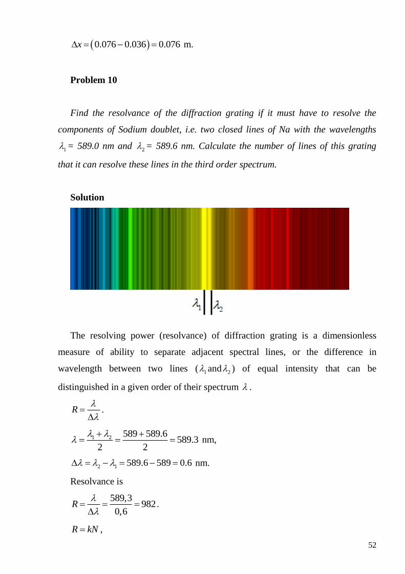
Problem 10
Find the resolvance of the diffraction grating if it must have to resolve the
components of Sodium doublet, i.e. two closed lines of Na with the wavelengths
1 = 589.0 nm and 2 = 589.6 nm. Calculate the number of lines of this grating
that it can resolve these lines in the third order spectrum.
Solution
The resolving power (resolvance) of diffraction grating is a dimensionless
measure of ability to separate adjacent spectral lines, or the difference in
wavelength between two lines ( 1 and 2 ) of equal intensity that can be
distinguished in a given order of their spectrum .
R
.
1 2 589 589.6589.3
2 2
nm,
2 1 589.6 589 0.6 nm.
Resolvance is
589,3982
0,6R
.
R kN ,
53
where k is the number of the diffraction spectrum in which the lines are
observed separately, and N is the total number of lines of the grating.
Substituting 3k and 982R gives the sought number of lines
982328
3
RN
k lines.
Problem 11
Diffraction pattern is obtained by means of the diffraction grating of the length
l = 0.5 cm with 0N =100 mm-1. Find the order of the spectrum in which two lines
with the wavelengths 1 = 578nm and 2 = 580 nm can be clearly resolved.
Solution
The resolvance of the diffraction grating is
0R kN l
.
The average wavelength is equal to
1 2 578 580579
2 2
nm.
The wavelength difference is
2 1 580 578 0.2 nm.
The order of the spectrum is determined as
9
9 5
0
579 105.8 6
0.2 10 10 0.005k
N l
.
Note! We obtained the result as a broken number. The number of spectrum has
to be integer; therefore, it is necessary to round the obtained result. Remember that
we have to round it to the greater integer regardless the mathematical rule: 5.2 and
5.8 are to round to 6, because the lines couldn’t be resolved in the 5th order
54
spectrum. It is possible in the spectra of 6k as the width of the spectrum
increases with its number.
Now it is necessary to check if this grating allows obtaining the 6th spectrum.
Sincesind
k
, the largest spectrum number can be calculated assuming
max
sin 1 and substituting 2 1 .
max
max 5 9
2 0 2
sin 1 117.24 17
10 580 10
dk
N
.
The maximum spectrum number is max 17k , therefore, it is possible to observe
the given lines in the spectra of 6k .
Problem 12
A diffraction grating 4 cm wide produces a deviation of 30 degrees in the
second order spectrum with light of wavelength 660 nm. What is the total number
of lines on the grating?
Solution
The total number of lines depends on the number of lines per unit length 0N
and the width of the diffraction grating as 0N N l .
In turn, the grating spacing is 0
1d
N .
From the condition for diffraction maximum sind k , the grating spacing
is
962 2 660 10
2.64 10sin sin30
d
m.
The total number of lines is
2
0 6
4 1015152
2.64 10
lN N l
d
lines.