numerical and experimental study of water/oil emulsified fuel combustion in a diesel engine
TRANSCRIPT

Numerical and experimental study of water/oil emulsified fuel combustion
in a diesel engineq
Niko Sameca,*, Breda Kegla, Robert W. Dibbleb
aFaculty of Mechanical Engineering, University of Maribor, Smetanova 17, SI-2000 Maribor, SloveniabDepartment of Mechanical Engineering, University of California at Berkeley, Berkeley, CA 94720-1740, USA
Received 1 February 2002; revised 30 April 2002; accepted 6 May 2002; available online 3 July 2002
Abstract
Numerical and experimental studies were made on some of the chemical and physical properties of water/oil emulsified fuel (W/OEF)
combustion characteristics. Numerical investigations of W/OEF combustion’s chemical kinetic aspects have been performed by simulation
of water/n-heptane mixture combustion, assuming a model of a homogenous reactor’s concentric shells. The injection and fuel spray
characteristics are analyzed numerically also in order to study indirectly the physical effects of water present in diesel fuel during the
combustion process. The experimental results of W/OEF combustion in the DI diesel engine are also presented and discussed. The results of
engine testing in a broad field of engine loads and speeds have shown a significant pollutant emission reduction with no worsening of specific
fuel consumption. q 2002 Elsevier Science Ltd. All rights reserved.
Keywords: Combustion; Emission; Numerical modelling
1. Introduction
The development of internal combustion (IC) engines
has followed a dual strategy over the years:
† Improvement of engine performance and
† Reduction of pollutant emissions.
The incrassation of the fuel’s and lubricant’s quality is of
great importance in order to achieve the mentioned strategy.
Some of the chemical improvements in the fuels and
lubricants used in heavy-duty diesel engines consist of
numerous technologies in order to meet the demanded levels
of environmental compatibility (economy, emissions, noise)
and market requirements (reliability, lifetime, price, etc.).
Several conventional and unconventional techniques
have proved to be powerful tools when improving diesel
engine characteristics, especially NOx and soot emissions.
Among these approaches, the addition of water to diesel fuel
and its addition to gasoline as a modified fuel for spark-
ignited engines have a long history [1]. Several systems
have been invented and experimentally investigated. The
main physical effects of water on combustion processes
have also been studied theoretically [2–4]. Moreover, the
addition of water is considered to be one of the effective
approaches to the in-cylinder reduction of pollutant
formation whilst at the same time an economic way of
reducing NOx and particulate materials (PM).
In general, it has been concluded that the presence of
water vapor in reactants influences the physics and chemical
kinetics of combustion and has a beneficial effect on the
rate-of-heat release history and reduction of pollutants
emissions. During combustion vaporized water reduces the
flame temperature, changes the chemical composition of the
reactants, resulting in higher OH radical concentration
controlling the NO formation rate and soot oxidation, and
dilutes the reach zones in the combustion chamber.
Water may be added to the fuel in several ways:
† continuously into the air stream via a single point system
or periodically through intake valves via a multi-point
system [5,6],
† water is injected directly into the cylinder through a
separate nozzle, or is introduced to fuel within the injection
nozzle when fuel injection does not take place [7],
† by stratified fuel–water injection [10], or
† through the preparation of stabilized water/fuel
emulsion (W/OEF).
0016-2361/02/$ - see front matter q 2002 Elsevier Science Ltd. All rights reserved.
PII: S0 01 6 -2 36 1 (0 2) 00 1 35 -7
Fuel 81 (2002) 2035–2044
www.fuelfirst.com
q Published first on the web via Fuelfirst.com—http://www.fuelfirst.com
* Corresponding author.
E-mail address: [email protected] (N. Samec).

A short features review of some different methods of
water addition and introduction is given in Ref. [8].
The effects of single and multi-points water addition
systems on the NOx and soot emissions of a vehicular
heavy-duty diesel engine have been investigated [5,9] and
studied previously in our laboratory. It may be concluded
based on these results, that both systems showed practically
the same beneficial influence on NO emission reduction, but
rather a poor effect on soot emission. Considering our
previous results and the results of several other investi-
gations performed recently [11,12] we have concluded that
more promising effects on NOx and soot reduction may be
expected when we turn our attention to W/OEF using the
same engine in our experiments.
Firstly, the chemical–physical effects on NO and soot
formation have been numerically investigated and presented
in this paper by simulating W/OEF combustion with the
application of an engine combustion model with detailed
chemical kinetics and simplified mixing. Furthermore, both
the injection and W/OEF spray characteristics are analyzed
using numerical simulation. The effects of injection and
spray characteristics on emissions and other engine
characteristics at several operating regimes are discussed
for different fuel/water ratios on the basis of this analysis.
The overall effect of different amount of the water presence
(0, 10, and 15%) in a diesel fuel on NO, HC soot emissions
reduction has been experimentally performed by using a
four-cylinder air-cooled DI truck diesel engine.
2. Numerical investigations
Many experimental investigations of W/OEF combus-
tion in diesel engines have been made to show some of the
benefits of water addition to the diesel fuel on the reduction
of pollutant emission, specific fuel consumption, thermal
loading, and maximum combustion pressure [13–16]. They
could not offer, however, a more detailed explanation of
some of the specific physical and chemical effects of W/
OEF combustion processes. In this case, the corresponding
numerical investigations seem to be very helpful. Two
major groups of numerical investigations have been
performed: numerical simulation of W/OEF combustion
from the chemical kinetics point of view, and numerical
simulation of the injection processes for a better under-
standing of W/OEF atomization processes influenced by
vaporized water droplets.
2.1. Numerical simulation of W/OEF combustion
The numerical model of complete chemistry and
turbulent mixing is too vast. Usual simplifications are
moderately detailed fluid mechanics with simplified chemi-
cal kinetics. We here simplify the turbulent mixing and
retain detailed chemical kinetics. The model divides the
flow and reaction field inside the combustion chamber into a
series of concentric deformable shells that can be arbitrarily
convoluted by convection and turbulence; each shell is
modeled as a well-mixed reactor (WMR) [17,18]. The
thermo chemical data and detailed chemical kinetics for
each WMR are computed using the CHEMKIN package of
numerical codes.
Basic differential equations for a single WMR shown in
Fig. 1, can be derived from the conservation of mass,
species, and energy, respectively, [18]
dm
dt¼
XNi
i¼1
_mi 2 _me ð1Þ
djs
dt¼
1
m
XNi
i¼1
_miðjis 2 jsÞ þ_vsMs
rð2Þ
dT
dt¼
1
�cpm
XNi
i¼1
_mi
XNs
s¼1
ðhis 2 hsÞjis
" #2
XNs
s¼1
_vshsMs
r�cp
21
r�cp
dp
dtð3Þ
where m is the mass inside of reactor, _mi is the mass flow
rate into reactor at inlet i, _me is the total mass flow rate out of
the reactor, Ni is the number of inlets, js is the mass fraction
of species, jis is the mass fraction of species s at inlet i, Ns is
the number of chemical species, _vs is the production rate of
species s (calculated using CHEMKIN), Ms is the molecular
mass of species s, r is the mass density in the reactor, T is the
temperature, �cp is the mean specific heat at constant pressure
in the reactor, and p is the pressure.
In the multiple reactor case, as shown in Fig. 2, the
outlets of one reactor become the inlets of the adjacent
reactors. If the first reactor were ignited, hot gas would flow
into the second reactor, which would soon reach the ignition
temperature and ignite. This ignition process repeats itself
as the hot gas in the second reactor goes into the third
reactor and so forth. Since the fluid properties are the same
at all exits, the flow at all exits may be lumped together into
a single exit flow, even though there may be more than one
exit. When applying a series of various WMRs numbers of
different sizes, the typical combustion chamber under auto
Fig. 1. A WMR with multiple inlets and a single outlet.
Fig. 2. A series of WMRs.
N. Samec et al. / Fuel 81 (2002) 2035–20442036

ignition conditions can be modeled to show a conceptual
picture of a 12-reactor system in Fig. 3 considered in our
case.
The dp=dt term in Eq. (3) is modeled by assuming that all
reactors have the same pressure and noting that:
p ¼Rm
V
XNr
r¼1
mrTr
Mr
; ð4Þ
where Rm is the universal gas constant, V is the total volume
of all reactors, and Mr is the mean molecular weight of the
gas in the reactor.
Differentiating Eq. (4) with respect to time, and
considering that combustion occurs at the constant volume
of each reactor gives an expression for dp=dt which can be
rearranged to give:
V
Rm
dp
dt¼
XNr
r¼1
mrTr
XNs
s¼1
1
Msr
djsr
dtþ
XNr
r¼1
mr
dTr
dt
XNs
s¼1
jsr
Msr
þXNr
r¼1
Tr
dmr
dt
XNs
s¼1
jsr
Msr
: ð5Þ
In the case of Nr reactors there is an energy Eq. (3) for
dTr=dt; which contains dp=dt: Eq. (5), which is the formula
for dp=dt also contains the dTr=dt of each of the reactors.
This forms a set of Nr of Eq. (3) in Nr unknowns that must
be solved simultaneously to give the dTr=dt terms.
2.2. Numerical simulation of W/OEF injection processes
To investigate some of the physical effects of water
present in fuel during combustion in a diesel engine, it is
important to consider major injection parameters, which
have a strong effect on the primary spray droplets size and
distribution over the combustion chamber. In the combus-
tion of W/OEF, however, the primary spray fuel droplets are
further divided as a result of explosive vaporization caused
by the rapid heating of water dispersed within the individual
fuel droplets. The internal water droplets undergo
spontaneous nucleation of steam bubbles at a temperature
well above the vaporization temperature depending on in-
cylinder pressure, causing a violent conversion of the water
droplet into steam. The vaporization, in turn, produces a
rapid expansion of the surrounding oil droplets, fragmenting
the oil into a vast number of smaller fuel droplets
representing very intensive micro explosions. The name
for this process is secondary atomization. The efficiency of
this secondary atomization can be indirectly investigated by
numerical simulation of the W/OEF injection processes by
calculating both the mean injection characteristics, and
primary spray droplets size. The droplets size of W/OEF is
one of the most important factors determining the
subsequent combustion characteristics.
The most important injection and spray characteristics
are calculated using our own mathematical model for the
numerical simulation of injection processes in an in-line
diesel fuel injection system [22,23,26]. In this mathematical
model, the flow of the fuel through the high-pressure (HP)
system is modeled as a one-dimensional flow. The HP
system consists of five parts: the in-barrel chamber, the
delivery valve chamber, the snubber valve chamber, the HP
tube, and the injector chamber. The response of this system
is governed by a system of 15 first-order ordinary
differential equations (equations of continuity and equations
of motion for the movable parts). In each HP part, the
instantaneous fuel properties and pressures are assumed to
be constant with the exception of the pressures in the HP
tube. The relationship between the response variables on
both sides of the HP tube is established by the equations of
pressure wave transport. The equation of pressure wave
transport is derived from equations of momentum and
continuity
›p
›xþ r
›w
›tþ rkw ¼ 0;
›w
›xþ
1
a2r
›p
›t¼ 0; ð6Þ
where w is the fluid velocity, r is the fluid density, k is the
flow resistance factor, p is the pressure, a is the velocity of
sound, and x is the coordinate along the high-pressure tube.
Only the injection rate history ð_qÞ and the needle lift ðhnÞ
from the set of all response variables are discussed in the
following. Additionally, the Sauter mean diameter ðd32Þ and
heat release ðQÞ histories are considered.
The injection rate can be expressed as
_q ¼ minAin
ffiffiffiffiffiffiffiffiffiffiffiffiffiffiffi2
rlpin 2 pal
sð7Þ
where the symbol ðminAinÞ denotes the effective nozzle flow
area, pin denotes the injection pressure and pa is the ambient
pressure.
The needle lift is calculated from the equation of motion
dhn
dt¼
0; Fn $ 0 and hn ¼ hmaxn
0; Fn # 0 and hn ¼ 0
vn; otherwise
8>><>>: ð8Þ
Fig. 3. Conceptual picture of typical locations of the reactors.
N. Samec et al. / Fuel 81 (2002) 2035–2044 2037

dvn
dt¼
0; Fn $ 0 and hn ¼ hmaxn
0; Fn # 0 and hn ¼ 0
Fn=min; otherwise
8>><>>: ð9Þ
where Fn ¼ ðAstn 2 Ase
n Þpin þ Asen psac 2 Fn
0 2 Cnhn; psac ¼
ðK2=ð1 þ K2ÞÞðpin 2 paÞ þ pa; K ¼ minAin=ðminAinÞmax;hmax
n is the maximal needle lift, Asen is the needle seat
cross-section area, Astn is the needle steam cross-section area,
Fn0 is the spring preloading force and Cn is the spring
stiffness.
The Sauter mean diameter was calculated from the well-
known Hiroyasu formula
d32 ðmmÞ ¼ 2:39 £ 103ðpinj 2 paÞ20:135r0:121
a q0:131 ð10Þ
where pinj; pa are the injection and ambient pressure,
respectively (Pa), ra is the air density (kg m23), and q is the
fuelling (m3 st21).
Furthermore, the heat release was calculated from the
equation of energy conservation
dQ 2 dQc þ hf dmf ¼ dðmcvTÞ þ p dV ð11Þ
where Q is the heat release or combustion energy, Qc is the
cooling loss, hf dmf is the apparent sensible enthalpy
derived from the injected fuel, mcvT is the sensible internal
energy of the gas in the cylinder and p dV is the expansion
work.
2.3. Numerical results and discussion
It is possible to make different calculations to find out
some chemical aspects of the water present in the fuel using
the presented simplified numerical model of W/OEF
combustion. A stoichiometric mixture of n-heptane (instead
of diesel fuel) has been applied for these calculations
considering a detailed n-heptane kinetic mechanism [19]
also including Zeldovich NOx formation reactions and the
corresponding soot model as follows:
C3H3 þ C3H3 ¼ A1
A1 ! 6CðSÞ þ 3H2
C4H2 ! 4CðSÞ þ H2
CðSÞ þ C2H2 ! 3CðSÞ þ H2
C2H2 ! 2CðSÞ þ H2
The first reactor (Fig. 3) involves the mixture of a given
amount of water and n-heptane, while other reactors involve
the corresponding amount of air with a temperature of
950 K assuring auto ignition.
When adding different amounts of water (0, 10, and 30%
by volume) to the fuel, the corresponding amount of fuel is
replaced by water resulting in lower combustion tempera-
ture as shown in Fig. 4. In a real system, the combustion
temperature is reduced additionally during the water
vaporization processes, but it is not considered in the
chemical mechanism used here. Lower combustion tem-
perature, however, directly influences thermal NO for-
mation during the reduction in chemical reaction rates for
Zeldovich mechanism reactions [24]:
O þ N2 !k1
NO þ N
k1 ¼ 1:8 £ 1012 expð2319 kJ mol21=RTÞ
ð12Þ
N þ O2 !k2
NO þ O
k2 ¼ 6:4 £ 109 expð226 kJ mol21=RTÞ
ð13Þ
N þ OH!k3
NO þ H k3 ¼ 3:0 £ 1013 ð14Þ
Only minor contribution to the NO formation may also be
expected by considering the following reactions
O þ N2 þ M Y N2O þ M; ð15Þ
N2O þ O Y 2NO; ð16Þ
which may become important at lower temperatures
because of their lower activation energy, especially for
reaction (16) with Ea ¼ 97 kJ mol21 [24]. Additionally, the
NO concentration may be reduced by reducing the O atoms
concentration (reactions (12), (15), and (16)) due to its
consumption at the OH radicals formation by the following
overall reactions
H2O þ O ! OH þ OH ð17Þ
H2O þ H ! OH þ H2 ð18Þ
as a consequence of the water present in the fuel. However,
Fig. 4. Temperature profile at the combustion of n-heptane/water emulsion
with 0, 10, and 20% of water.
Fig. 5. NO concentration during the combustion of n-heptane/water
emulsion of 0, 10, and 20% of water content.
N. Samec et al. / Fuel 81 (2002) 2035–20442038
assuming from the theoretical point of view that the N atoms
are in a quasi-steady state (fast reactions (13) and (14))
d½NO�=dt ¼ 0; the following NO formation expression is
obtained
d½NO�
dt¼ 2k1½O�½N2�; ð19Þ
indicating very high dependence on NO formation from the
O atoms concentration. Fig. 5 shows the calculated overall
time history of NO formation during the water/n-heptane
emulsion combustion.
The fuel’s chemical composition has been changed by
water addition to the fuel, resulting in higher OH radicals
production during combustion, reactions (17) and (18). At
the same time higher OH concentration drop is expected
because of their consumption during soot oxidation due to
the possible reaction
Cn þ OH ! CO þ Cn21 þ H
as shown in Fig. 6. It finally means less soot emission in the
combustion products. The OH radicals play an important
role in soot oxidation especially at higher temperatures,
because they become the leading oxidators of soot, whereas
oxygen in its molecular form is consumed by the flame [20].
It is also possible to produce higher OH concentration
resulting in higher soot emission abatement [21] by adding
some other additives to the fuel instead of water (i.e. H2O2).
Lower OH concentration seems to also have an additional
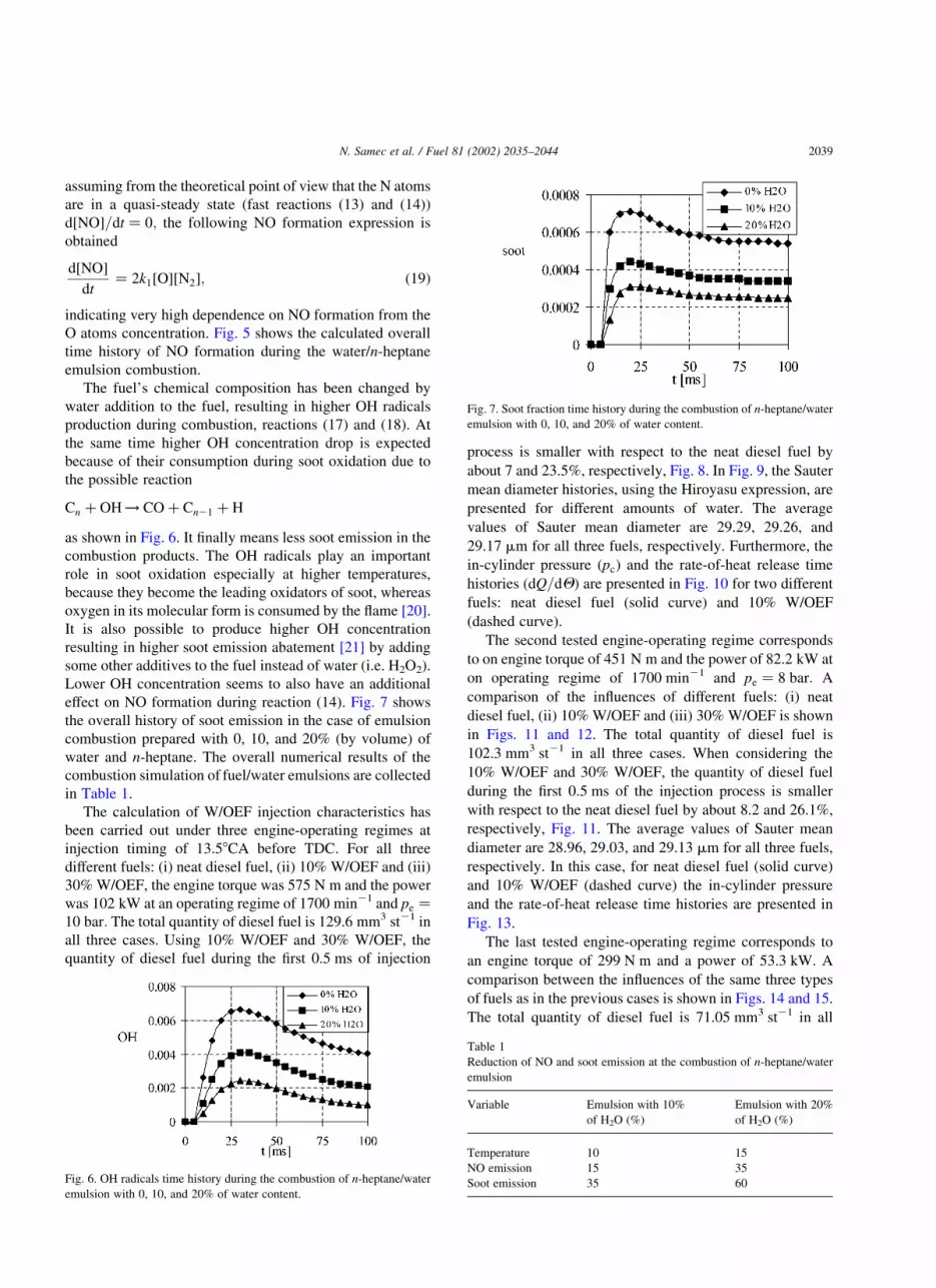
effect on NO formation during reaction (14). Fig. 7 shows
the overall history of soot emission in the case of emulsion
combustion prepared with 0, 10, and 20% (by volume) of
water and n-heptane. The overall numerical results of the
combustion simulation of fuel/water emulsions are collected
in Table 1.
The calculation of W/OEF injection characteristics has
been carried out under three engine-operating regimes at
injection timing of 13.58CA before TDC. For all three
different fuels: (i) neat diesel fuel, (ii) 10% W/OEF and (iii)
30% W/OEF, the engine torque was 575 N m and the power
was 102 kW at an operating regime of 1700 min21 and pe ¼
10 bar: The total quantity of diesel fuel is 129.6 mm3 st21 in
all three cases. Using 10% W/OEF and 30% W/OEF, the
quantity of diesel fuel during the first 0.5 ms of injection
process is smaller with respect to the neat diesel fuel by
about 7 and 23.5%, respectively, Fig. 8. In Fig. 9, the Sauter
mean diameter histories, using the Hiroyasu expression, are
presented for different amounts of water. The average
values of Sauter mean diameter are 29.29, 29.26, and
29.17 mm for all three fuels, respectively. Furthermore, the
in-cylinder pressure ðpcÞ and the rate-of-heat release time
histories ðdQ=dQÞ are presented in Fig. 10 for two different
fuels: neat diesel fuel (solid curve) and 10% W/OEF
(dashed curve).
The second tested engine-operating regime corresponds
to on engine torque of 451 N m and the power of 82.2 kW at
on operating regime of 1700 min21 and pe ¼ 8 bar: A
comparison of the influences of different fuels: (i) neat
diesel fuel, (ii) 10% W/OEF and (iii) 30% W/OEF is shown
in Figs. 11 and 12. The total quantity of diesel fuel is
102.3 mm3 st21 in all three cases. When considering the
10% W/OEF and 30% W/OEF, the quantity of diesel fuel
during the first 0.5 ms of the injection process is smaller
with respect to the neat diesel fuel by about 8.2 and 26.1%,
respectively, Fig. 11. The average values of Sauter mean
diameter are 28.96, 29.03, and 29.13 mm for all three fuels,
respectively. In this case, for neat diesel fuel (solid curve)
and 10% W/OEF (dashed curve) the in-cylinder pressure
and the rate-of-heat release time histories are presented in
Fig. 13.
The last tested engine-operating regime corresponds to
an engine torque of 299 N m and a power of 53.3 kW. A
comparison between the influences of the same three types
of fuels as in the previous cases is shown in Figs. 14 and 15.
The total quantity of diesel fuel is 71.05 mm3 st21 in all
Fig. 6. OH radicals time history during the combustion of n-heptane/water
emulsion with 0, 10, and 20% of water content.
Fig. 7. Soot fraction time history during the combustion of n-heptane/water
emulsion with 0, 10, and 20% of water content.
Table 1
Reduction of NO and soot emission at the combustion of n-heptane/water
emulsion
Variable Emulsion with 10%
of H2O (%)
Emulsion with 20%
of H2O (%)
Temperature 10 15
NO emission 15 35
Soot emission 35 60
N. Samec et al. / Fuel 81 (2002) 2035–2044 2039

three cases. Taking into account the 10% W/OEF and 30%
W/OEF, the quantity of diesel fuel during the first 0.5 ms of
the injection process is smaller with respect to the neat
diesel fuel by about 5.4 and 25.2%, respectively. The
average values of the Sauter mean diameter are 28.28,
28.45, and 28.57 mm for all three fuels, respectively.
Finally, Fig. 16 shows the in-cylinder pressure and the
rate of the heat-release histories for two different fuels: neat
diesel fuel (solid curve) and 10% W/OEF (dashed curve).
The presented results correspond to the regime of n ¼
1700 min21 and pe ¼ 5 bar:
The gradient of heat release ðdQ=dQÞ during the
premixing phase of the diesel combustion is increased by
using W/OEF, Figs. 10, 13, and 16. The reason for this
seems to be in the fact, that the mixture is better prepared
due to prolonged ignition delay. In this way, a larger amount
of the mixture burns down in the kinetic phase of the
combustion process. It also has to be pointed out, that the
ignition locations of the emulsion fuels are different from
those of a pure diesel fuel [2]. Ignition occurs in the middle
of the combustion chamber with the diesel fuel, while it
occurs in the bottom region or at multiple points in the
middle simultaneously with W/OEF. The flame propagates
slowly from the ignition locations, so that it takes twice as
long or longer for the luminous flame to propagate over the
whole chamber using W/OEF. Some experimental investi-
gations [2] show that strong micro explosions of a group of
droplets can occur in the specific region of the luminous
flames near the spray tip. They affect the local shape and
brightness of the flames as small, dark, round regions due to
the explosion of superheated water in the droplets. The sizes
of the micro explosions range from barely identifiable small
ones to those with a diameter of a few millimeters. Micro
explosions of the emulsion fuels seem to enhance the
mixing of the fuel with the surrounding air for faster and
more efficient combustion also resulting in a higher heat
release gradient ðdQ=dQÞ at the beginning of the combus-
tion process.
When employing numerical simulation, it can observed
Fig. 8. Injection rate and needle lift histories. Engine-operating regime:
n ¼ 1700 min21; pe ¼ 10 bar:
Fig. 9. Sauter mean diameter histories. Engine-operating regime: n ¼
1700 min21; pe ¼ 10 bar:
Fig. 10. In-cylinder pressure and rate-of-heat release time histories. Engine-
operating regime: n ¼ 1700 min21; pe ¼ 10 bar:
Fig. 11. Injection rate and needle lift histories. Engine-operating regime:
n ¼ 1700 min21; pe ¼ 8 bar:
N. Samec et al. / Fuel 81 (2002) 2035–20442040

that the diesel fuel quantity during the first 0.5 ms of the
injection process decreases with higher water/diesel rates,
Figs. 8, 11, and 14, reducing the combustion temperature
and consequently NOx emission. It has also been verified by
previous numerical simulation of water/n-heptane emulsion
combustion and later experimental work.
W/OEF gives somewhat larger Sauter mean diameters,
Figs. 9, 12, and 15. In spite of this, the previously simulated
and measured soot emission values are lower at all engine-
operating regimes. This can be explained again by the
phenomenon of micro explosions, which probably leads to
better atomization, although, at the beginning of the
injection the emulsion droplets are rather large, which
seems to be normal, whilst the emulsion droplet involves a
given amount of smaller water droplets. Very small droplets
with a well-controlled size distribution are necessary in
order for secondary atomization to be more effective in a
combustion process. Insufficient energy will be produced if
the number of water droplets is to small, causing secondary
atomization. On the other hand, larger droplets reduce the
number of droplets for explosion and tend to produce less
violent explosions within the oil droplets because of
nucleation taking place at lower temperatures.
3. Experimental approach and set-up
A four-cylinder air-cooled DI truck diesel engine has
been employed for the experimental investigations of the
overall effects of water present in diesel fuel. This engine
with a displacement volume of 7118 cm3 offers a maximal
power of 150 kW and a maximal torque of 315 N m.
Practical W/OEF preparation by adding a very small amount
of special emulsifier (Span 85), requires a very precise
mixing methodology in order to obtain a stable emulsion
with no separation of constituents during a long time period,
which is acceptable for the practical application of W/OEF
in all fields of land and marine use.
The load-speed test map is presented in Fig. 17 and all
the data have been taken at each point during the stabilized
engine-operating regime. Three series of experiments have
been carried out in each series using either pure diesel fuel,
10% W/OEF or 15% W/OEF at the same engine-operating
regime as in the case of the numerical simulation of the W/
OEF injection processes. The engine test was carried out on
a completely computer controlled Zollner B-350AC test
bench, where all important data (temperatures, pressures,
fuel, and air consumption) determining engine-operating
regime were measured and stored for further processing and
computing engine performance data (volumetric efficiency,
air–fuel equivalence ratio, etc.). The concentrations of
some combustion products in the engine exhaust gases were
measured with indicated standard instrumentation: NO,
NO2 (Chem.-lum. Analyzer), CO(NDIR), THC(FID),
Fig. 12. Sauter mean diameter histories. Engine-operating regime: n ¼
1700 min21; pe ¼ 8 bar:
Fig. 13. In-cylinder pressure and rate-of-heat release time histories. Engine-
operating regime: n ¼ 1700 min21; pe ¼ 8 bar:
Fig. 14. Injection rate and needle lift histories. Engine-operating regime:
n ¼ 1400 min21; pe ¼ 5 bar:
Fig. 15. Sauter mean diameter histories. Engine-operating regime: n ¼
1400 min21; pe ¼ 5 bar:
N. Samec et al. / Fuel 81 (2002) 2035–2044 2041

O2(ZrO hard electrolyte) and soot (AVL soot analyzer,
Bosch unit). The indicative pressure (KISTLER) time
history was in-line monitored, stored and processed at
each regime representing the base for heat release history
computation, already presented in the section of numerical
investigations.
3.1. Experimental results and discussion
A comparison of the exhaust emission data (NOx, HC,
soot) and specific fuel consumption (be) for three different
fuels (i) neat diesel fuel (D2), (ii) 10% W/OEF, and (iii)
15% W/OEF and three different engine-operating regimes
are presented in Figs. 18–20, considering the D2 pollutant
emission as 100%. The relative emission reduction of
component ‘i’ in the exhaust gases, at the same engine-
operating conditions, is expressed as follows:
DEirel½%� ¼
½E�i;D2 2 ½E�i;W=OEF
½E�i;D2
£ 100 ð20Þ
Comparing the results of this W/OEF investigation with the
results of our previous experiments, when water was added
to the fuel separately via single and multi-point injection [5,
25], or with the results of other authors when other modes of
water addition were applied [7,8,10], it may be concluded
that water addition via W/OEF is the most appropriate
approach to decreasing NOx, soot and THC emissions in a
diesel engine exhaust, with no worsening of fuel consump-
tion as can also be seen from Figs. 18–20. It is also the
cheapest way; no changes are needed in the engine or its
ancillaries.
The effect of W/F ratio was so unclearly expressed in our
experimental results, probably because of smaller differ-
ences of water fraction in the emulsion. If the W/F ratio is
increased, however, the trend of pollutant emissions
reduction (reported elsewhere, i.e. [8,11]) has a positive
gradient of reduction as it can also be estimated by results
from our numerical experiment.
Summarizing our experimental emission data by aver-
aging them over the whole field of engine-operating regimes
(Fig. 17), the reduction of pollutant emissions is given in
Table 2 and offers general information of pollutant
abatement by using W/OEF in diesel engine. It has to be
emphasized again that the overall emission abatement
results are the consequence of the mutual chemical and
physical effects treated separately in our numerical
investigations. Comparing the experimental and numerical
results of the NOx and soot emission reduction (Tables 1 and
2), one can find out that the chemical effect seems to be
more important at NOx emission reduction and physical
effects seem to be dominant at soot emission reduction.
Moreover, on the base of our experimental results and
results obtained by simulation of W/OEF injection pro-
cesses, it may be concluded that higher soot emission
reduction is achieved at higher engine loadings (Figs.
18–20) when the fuel droplet size is bigger containing more
of the smaller water droplets assuring, effective micro
explosions. In the case of lower loadings, the injected rate of
W/OEF is lower and, consequently, the fuel droplet size is
smaller which now contain less water droplets. Higher
injection pressures, however, assure better fuel atomization
resulting in smaller fuel droplets. Therefore, a negligible
effect of secondary atomization at the modern high-pressure
diesel injection may be expected, especially in the case of
common rail injection systems because of its constant high
level injection pressure.
Fig. 16. In-cylinder pressure and rate-of-heat release time histories. Engine-
operating regime: n ¼ 1700 min21; pe ¼ 5 bar:
Fig. 17. The load speed test map.
Fig. 18. The relative reductions of exhaust emissions and specific fuel
consumption be. Engine-operating regime pe ¼ 10 bar; n ¼ 1700 rpm:
Fig. 19. The relative reductions of exhaust emissions and specific fuel
consumption be. Engine-operating regime pe ¼ 8 bar; n ¼ 1700 rpm:
N. Samec et al. / Fuel 81 (2002) 2035–20442042

4. Conclusions
The following conclusions can be made based on the
results of the numerical and experimental investigations.
† The strong influence of chemical kinetics on ignition
reactions and on the rate of pollutant formation is
discussed, emphasizing the role of O and OH radicals,
taking into account our results obtained by numerical
simulation of water/n-heptane mixture combustion,
employing an engine combustion model with detailed
chemical kinetics and simplified mixing.
† With numerical analysis of the injection and fuel spray
characteristics, as well as the processes in the cylinder, it
is possible to investigate some of the physical effects of
water present in diesel fuel during combustion processes
and their benefits to the harmful emissions reduction. The
physical impact of water in fuel on the external diesel
combustion characteristic has been evaluated by analyz-
ing in-cylinder pressure, and the rate-of-heat release time
histories. In relation to the net diesel fuel combustion, the
ignition delay became longer by about 10% and the
gradient of rate-of-heat release during premixed burning
increased up to 26%, when W/OEF was used as fuel
under the same engine-operating conditions.
† Testing the vehicular DI diesel engine under several
loads and speeds, using 10% and 15% W/OEF, NOx
concentration in exhaust gas was reduced by nearly 20%
and concentration of soot (Bosch unit) by up to 50%,
with practically no worsening of specific fuel consump-
tion. When comparing the numerical and experimental
results, it becomes clear that chemical kinetics play an
important role, especially in the NOx formation whilst
some physical effects (secondary atomization due to
micro explosions) seem to be more important at soot
emission reduction. At a higher injection pressure,
however, the effect of secondary atomization is expected
to be reduced because of too small fuel droplets
containing insufficient amounts of smaller water
droplets.
† W/OEF can be successfully used to reduce heavy-duty
diesel engine exhaust pollutant emissions, especially
NOx and soot. It is supposed, that this unconventional
technique to reduce NOx and soot emissions in diesel
exhaust is a quite suitable technique to be employed on
vehicular diesel engines for special purposes working
primarily in urban area or on stationary engines, when
they have to satisfy ultra low emission standards.
References
[1] Tsao TC, Wang CL, Miller EM. Performance of gasoline–water fuel
in a modified SI engine. SAE Paper, 841399 1984;.
[2] Park JW, Huh KY, Park KH. Experimental study on the combustion
characteristics of emulsified diesel in rapid compression and
expansion machine. Proc Instn Engrs 2000;214. Part D, ImechE.
[3] Sheng HZ, Chen L, Wu CK. The droplet group micro-explosions in
W/O diesel fuel emulsion spray. SAE Paper, 950855 1995;.
[4] Isihada M, Chen ZL. An analysis of the added water effect on NO
formation in DI diesel engines. SAE Paper, 941691 1994;.
[5] Samec N, Dibble RW, Chen JY, Pagon A. Reduction of NOx and soot
emission by water injection during combustion in a diesel engine.
FISITA 2000, Seoul, Korea; 2000.
[6] Samec N, Dibble RW. The strategies for reducing emission from
heavy duty diesel vehicles. Urban Transport 2000, Cambridge, UK;
2000.
[7] Takasaki T. Verbesserung der Verbremung in Diselmotoren durch
geschicchtete Wasser-einspritzung. MTZ 1998;59(4):276–84.
[8] Velji A, Eichel E, Remmels W, Haug F. Diselmotoren erfuellen mit
wassereinspritzung zukuennftige NOx und russgrenzwerte. MTZ
1996;57:7/8.
[9] Cernej A, Dobovisek Z, Bhattacharya S, Kegl B. Experimental study
on the effect of the multipoint timed port water injection in a vehicular
diesel engine. KONES 93, International Science Conference on IC
Engines, Gdansk, Conference, Proceedings; pp. 81–9. 1993.
[10] Miyamo H, Yasueda S, Tayama K, Tabeishi M, Tosa Y, Nagoe Y.
Development of stratified fuel–water injection system for low-NOx
diesel combustion. SAE D24.
[11] Pitterman R, Hinz M, Kauert L. Einfluss von Abgasrueckfuehrung
und Kraftotoff Wasser-Emulsion auf Verbrennungsablauf und Schad-
stoffbildung um Dieselmotor. MTZ 1999;60:12.
[12] Mello JP, Mello AM. NOx emission from direct injection diesel
engines with water/steam dilution. SAE Inc., 01-0836, pp. 15–30.
1999.
[13] Tsukahara M, Yoshimoto Y. W/O emulsion realizes low smoke and
efficient operation of DI engines without high pressure injection. SAE
Paper, 890449 1989;.
[14] Gunnerman RW, Russell R. Emission and efficiency benefits of
emulsified fuels to internal combustion engines. SAE Paper, 972009
1997;.
[15] Tsukahara M, Yoshimoto Y. Reduction of NOx, smoke BSFC, and
maximum combustion pressure by low compression ratios in a diesel
engine fuelled by diesel fuel. SAE Paper, 920464 1992;.
[16] Yoshimoto Y, Tsukahara M, Kuramoto T. Improvement of BSFC by
reducing diesel engine cooling losses with emulsified fuel. SAE
Paper, 962022 1996;.
[17] Andreatta DA. The use of reformed natural gas as a fuel for
reciprocating engines. A Doctor Dissertation, University of California
at Berkeley, Mechanical Engineering Department, 1995.
[18] Chen JY, Dibble RW. A perfectly-stirred-reaction description of
Fig. 20. The relative reductions of exhaust emissions and specific fuel
consumption. Engine-operating regime pe ¼ 5 bar; n ¼ 1700 rpm:
Table 2
Average reduction of pollutants emissions in % related to D2 exhaust
emissions
W/OEF (%) NOx THC Soot
10 20 52 68
15 18 33 75
N. Samec et al. / Fuel 81 (2002) 2035–2044 2043

chemistry in turbulent nonpremixed combustion of methane in air.
Combustion Sci Technol 1992;84:45–50.
[19] Curran HJ, Gaffuri P, Pitz WJ, Westbrook CK. A comprehensive
modeling study of n-heptane oxidation. Combustion Flame 1998;
114(1–2):149–77.
[20] Roth P, Brandt O. High temperature oxidation of suspended soot
particles verified by CO and CO2 measurements. 23rd International
Symposium on Combustion, The Combustion Institute; 1990. pp.
1485–91.
[21] Born C, Peters N. Reduction of soot emission at a DI diesel engine by
additional injection of hydrogen peroxide during combustion. SAE
Paper, 982676 1998;.
[22] Kegl B. Successive optimal design procedure applied on conventional
fuel injection equipment. ASME J Mech Des 1996;118:490–3.
[23] Kegl B. Optimal design of conventional in-line fuel injection
equipment. Proc Instn Mech Engrs, Part D: J Auto Engng 1995;209:
135–41.
[24] Warnatz J, Mass U, Dibble RW. Combustion: physical and chemical
fundamentals, modelling and simulation, experiments, pollutant
formation. Berlin: Springer; 1996.
[25] Kegl B, Pehan S. Reduction of diesel engine emissions by water
injection. Automotive and Transportation Technology Congress and
Exhibition, Powertrain and Heat Transfer/Exchange, Barcelona,
Spain, ATTCE 2001 Proceedings: [SAE], Powertrain and Heat
Transfer/exchange, vol. 2. Warrendale: SAE International; 2001. p.
368.
[26] Kegl, B. An improved mathematical model of conventional FIE
processes. SAE Technical Paper Ser, 950079 1995;17–25.
N. Samec et al. / Fuel 81 (2002) 2035–20442044