numerical and experimental investigation of high-efficiency axial-flow pump
TRANSCRIPT

Accepted Manuscript
Hygroscopic strain measurement by fibre Bragg gratings sensors in organic ma-
trix composites – application to monitoring of a composite structure
H. Ramezani-Dana, P. Casari, A. Perronnet, S. Fréour, F. Jacquemin, C. Lupi
PII: S1359-8368(13)00589-1
DOI: http://dx.doi.org/10.1016/j.compositesb.2013.10.014
Reference: JCOMB 2691
To appear in: Composites: Part B
Received Date: 25 February 2013
Revised Date: 30 August 2013
Accepted Date: 16 October 2013
Please cite this article as: Ramezani-Dana, H., Casari, P., Perronnet, A., Fréour, S., Jacquemin, F., Lupi, C.,
Hygroscopic strain measurement by fibre Bragg gratings sensors in organic matrix composites – application to
monitoring of a composite structure, Composites: Part B (2013), doi: http://dx.doi.org/10.1016/j.compositesb.
2013.10.014
This is a PDF file of an unedited manuscript that has been accepted for publication. As a service to our customers
we are providing this early version of the manuscript. The manuscript will undergo copyediting, typesetting, and
review of the resulting proof before it is published in its final form. Please note that during the production process
errors may be discovered which could affect the content, and all legal disclaimers that apply to the journal pertain.

1
Hygroscopic strain measurement by fibre Bragg gratings
sensors in organic matrix composites – application to
monitoring of a composite structure
*H. Ramezani-Dana, P. Casari, A. Perronnet, S. Fréour, F. Jacquemin, C. Lupi
LUNAM Université - Université de Nantes - Centrale Nantes, Institut de Recherche en Génie
Civil et Mécanique (UMR CNRS 6183), 58, rue Michel Ange - BP 420, 44606 Saint-Nazaire,
France
E-mail : [email protected],
Abstract
This study is devoted to the identification of the moisture expansion coefficients of
composite materials by means of a novel measurement technique. This method is based
on the insertion of Fiber Bragg Grating (FBG) sensors between composite layers. The
sensor enables to measure the hygroscopic strain induced by moisture diffusion in the
plane of the laminated composite. Experimental results from immersed samples, varying
both the direction of measurement and the fibre volume fraction are given according to
the water uptake, and leading to the characterization of moisture expansion coefficient.
Keywords: A. Polymer-matrix composites (PMCs); B. Fiber Bragg grating sensors;
C. Environmental degradation
* Corresponding author: [email protected], [email protected] (Tel No: +33612808764)

2
1. Introduction
Organic matrix composites are extensively used in several engineering applications due
to their exceptional stiffness to weight ratio. However, when such materials are exposed
to humid environments, they absorb moisture which can severely affect their hygro-
mechanical properties [1-3] as well as the multi-scale internal mechanical states
experienced by the constituents of polymer matrix composites [4,5]. Consequently,
durability and reliability of structural parts made of such materials can be impaired in
humid environments. In the glass/polyester composites used in this study, the matrix
absorbs a significant amount of water whereas absorption by fibres is almost null. One
key issue is to predict the stress state of the material submitted to such environment by
means of moisture expansion coefficients. The purpose of this work is exactly to
provide such materials parameters and a technique has been developed for it. Numerous
authors have used Fibre Bragg Grating (FBG) sensors [6-11] in order to achieve local
strain measurements, temperatures and other quantities of engineering interest. An FBG
clearly provides many advantages compared to other strain measurement techniques,
since it enables to investigate internal mechanical states in the depth of the specimen
without suffering from an ageing of the sensor itself.
Then, an experimental study of both the time-dependent moisture uptake and strain field
in composite containing FBG sensors has been achieved. Fibre Bragg Grating (FBG)
sensors were used to characterize the evolution of hygroscopic strain field in
unidirectional fibre-reinforced composite specimens immersed in de-ionized water,
during both the transient and the permanent stages of the moisture diffusion process.
Besides, the time-dependent average moisture uptake over the volume of the samples
was followed through the classical gravimetric method until the permanent regime has
been reached. Both longitudinal and transversal moisture expansion coefficients (CME)

3
of these composite samples were determined by using the data collected through the
optical sensors oriented either in a direction parallel or perpendicular to the reinforcing
fibres.
2. Materials and testing methods
2.1 Materials and specimens
The tested unidirectional composite samples were made of E-glass fibres embedded in
an ortho-phtalic polyester resin (POLYLITE 420-731 from REICHOLD) polymerizing
at room temperature. The specimens were manufactured through the vacuum assisted
resin infusion (VARI) method.
Several composites, as well as neat resin square plates 1.3 mm thick were fabricated.
After cutting and polishing, the samples surfaces were cleaned with ethanol in order to
remove any residual oil and dirt resulting from machining. The initial weights and
dimensions of the specimens were recorded. The FBGs employed in this study were
printed on standard SMF-28e single mode optical fibres with a 250 µm diameter. Bragg
gratings (10 mm long) were uniform, and centered on a 1555 ± 0.2 nm wavelength.
The use of FBG in composite samples is limited by the ability to insert this sensor in the
composite material in order to retrieve the optical signal without (or the less as possible)
modifying the mechanical behaviour of the composite structure considered.
In order to address this issue, the optical fibre containing Bragg grating was inserted
between two plates, bonded by polyester resin. The FBG were either aligned with the
reinforcing fibres or set perpendicularly to them.
In the area of the grating, the FBGs acrylate coating was removed in order to get the
most direct strain provided by the surrounding material towards the sensor.
This type of specimen architecture enabled us to obtain instrumented samples, the final
size of which is 90x90x3 mm3. In addition, this kind of architecture allows us to limit
the stresses experienced by optical fibre during the fabrication process.

4
The main parameters controlling moisture diffusion kinetics, namely the diffusion
coefficients and the maximum moisture absorption capacity, do strongly depend on the
volume fraction of the constituents (i.e., those of the reinforcing fibres and the
polymeric matrix). Therefore, the reinforcing fibres content of the composite affects the
magnitude of the multi-scale mechanical states to be monitored during the present work.
As a consequence, the accurate characterization of the volume fraction occupied by
glass fibres in each investigated sample was mandatory in the context of the present
work. Several techniques have historically been employed in order to determine the
fibre volume fraction (vf) of organic matrix composites [12-14]. In the present work, the
identification of the glass-fibre volume fraction in the manufactured samples will be
handled according to a dimension and weight analysis method.
Optical microscopy and Scanning Electron Microscopy were used for investigating the
microstructure of the manufactured samples (see figure 1). According to both
characterization methods, specimens are void-free.
Figure 1 . SEM micrograph showing an optical fibre embedded perpendicularly to the
reinforcing fibres (white dashed line circle illustrates the optic fibre coating).

5
As a result, the total volume of the composite (Vt) is equal to the sum of the volume
occupied by the glass fibres (Vf), on the one hand and by the resin (Vr), on the other
hand:
rft VVV += (1)
A similar relation is also valid for the corresponding masses:
ttrrffrft Vρ VρVρmmm =+=+= (2)
whereρ denotes the mass density. The total density respects the following classical
mixture law:
( )fv1 ρf vρr vρf vρρ rfrtt −+=+= (3)
The reinforcing fibres volume fraction corresponds to the following ratio:
rρfρrρtρ
rρV
m
rρfρ
1
V
Vfv
t
t
t
f
−
−=⎥
⎦
⎤⎢⎣
⎡−
−== (4)
Dimensions and mass of the specimens were measured in order to determine their total
volume (Vt) and their total mass (mt), from which the total mass density calculation is
straightforward. The same method was applied to the neat resin samples, so that the
numerical
value of rρ could be deduced. Glass fibres mass density is a well known parameter that
is widely available in the literature [15]. The results obtained through this calculation
method, for the glass fibres volume fraction, are displayed in table 1.
Specimen group N° 1 2 3vf (%) 17 21 22
Table 1. Fibre volume content of the manufactured samples.
2.2 Experimental set up and hygroscopic ageing process
Two series of specimens were manufactured. The first subset of samples was
instrumented by FBGs sensors. FBGs were oriented perpendicular or parallel to the

6
reinforcing fibres. This group of samples was intended to provide the time-dependent
evolution of the internal strains states throughout the moisture diffusion process. The
second subset of specimens, which did not contain any optical fibre, was devoted to
moisture uptake characterization by means of periodic mass measurements. The
samples were also immersed in de-ionized water.
The optical measurement system used is constituted as follows: The optical source is a
broadband optical source in C-Band (1530-1560 nm) based on erbium doped Amplified
Spontaneous Emission. This light source is connected to a 2-1 optical coupler. The
optical output coupler is connected to a FBGs realized in a standard SMF-28e single
mode optical fiber. The Bragg grating length is 10 mm. The reflected signal is received
through the optical coupler by an Optical Spectrum Analyzer (Anritsu MS9710B) with
70 pm wavelength resolution. The spectral signature of the Bragg grating is numerically
analyzed in order to determine the measured strain during the hygroscopic ageing test
imposed to the samples.
2.3 Technique of measurement
Mechanical strains measurements through FBG have been presented in various papers
[16, 17]. A FBG consists in a series of grating slices formed along the fibre axis. If the
Bragg condition is fulfilled, a light signal propagating into the device can interfere
constructively to the waves reflected by each of the slices. As a result, a back reflected
signal with a center wavelength commonly known as the Bragg wavelength bλ is formed.
Bragg-wavelength bλ depends on the effective index of refraction (neff) and on the Bragg
period (Λ) of the grating according to the well known Bragg equation (eq. 5).

7
By inscribing several FBGs with different grating periods in the same optical fiber, an
array of grating is manufactured. This allows the user to monitor different positions in
the structure with only one sensor line [18].
Λ2nλ effb = (5)
In the case when the FBG is submitted to a homogeneous axial strain zε and uniform
temperature changeΔT , the Bragg wavelength experiences a deviation bλΔ from the
reference value 0bλ corresponding to the unloaded state ( 0ε z = ; 0ΔT = ):
ΔT baελ
λλ
λ
Δλ
zb
b0b
b
b +=−
= (6)
Coefficients a and b depend on the nature of the optical fibre and the FBG printing
parameters. According to relation (6), under isothermal conditions, the Bragg
wavelength shift bλΔ is proportional to the axial strain ( zε ).
According to expression (6), one obvious major limitation of FBG sensors in
composites is the sensitivity to both the deformation and the temperature. As a result to
measure moisture absorption through the deformation variation, the temperature must
be simultaneously measured to determined thermo-optic effect and thermo-mechanical
deformations to determine deformations only due do moisture absorption.
In the present study, the strong hygroscopic strain experienced by organic matrix
composites exposed to moisture diffusion is expected to induce an axial elongation of
the optic fibre containing the Bragg grating [19], resulting in a significant Bragg
wavelength shift according to equation (6).
3. Results and discussion
3.1 Hygroscopic aging tests

8
The curves of weight gain versus the square root of time obtained for the neat resin as
well as those corresponding to the composite samples are shown on figure 2a and 2b,
respectively.
Figure 2. The weight gain versus the square root of time ( t ) curves for resin specimen (a) and
composite specimens with different fibre content (b).
The neat resin (figure 2a) exhibits a time-dependent moisture uptake typical from
Fickian kinetics. According to figure 2b, the three composite samples exhibit an almost
linear evolution of their moisture uptake for several months until a pseudo-plateau
indicating that the saturation of the diffusion process is reached. Thus, it is realistic to
also consider a fickian diffusion behavior for the investigated composite samples.
The identification method of the diffusion parameters used in this study was explained
in [20]. This method was consisting in identifying the unknowns of the problem by
minimizing the standard deviation between the calculated and measured quantities using
a Gauss-Newton algorithm.
The moisture diffusion parameters of both composite and neat resin specimen are then
presented in table 2:
(a) (b)
resin
Moisture uptake (%)

9
Dapparent (mm2/s) D2 (mm2/s) Ms (%) Composite (vf = 17 %) 2.2*10-7 2.07*10-7 0.85 Composite (vf = 21 %) 2.1*10-7 1.74*10-7 0.78 Composite (vf = 22 %) 1.83*10-7 1.97*10-7 0.79
Bulk resin 2.31*10-7 2.31*10-7 1.5 Table 2. Moisture diffusion parameters of composite and neat resin.
3.2 Internal strain measurement
The measured Bragg’s wavelength shift enables to determine strain experienced in the
center of the instrumented samples, from relation 6, assuming that the thermal
contribution, namely, the product ΔT b is negligible by comparison to the quantity of
interest: za. ε .
Figure 3 shows the evolution as a function of the square root of time of the hygroscopic
strain, obtained for the three composite specimens instrumented by FBG positioned
perpendiculary to the reinforcing fibres. Room temperature change of the ambient fluid
monitored during the ageing test is also displayed on the same figures. One can observe
three steps on this figure. We can note a very light induced strain during first day for the
samples containing 17 % and 22 % of glass fibres in opposite to the sample with 21 %
of glass fibres. Indeed this sample (vf =21%) was released in order to characterize the
Bragg grating properties before water ageing effects. This specimen sinks in again after
some days. This last, led to the ageing period shifting for this specimen. In the second
step, we can note a quasi linear behavior of deformation during several months. Finally,
the last step corresponds to the permanent regime of the diffusion process. A significant
scattering of the hygroscopic strains can be noticed during last step. This scattering
almost follows the temperature change of the ambient fluid, which ranges from 25°C to
31°C throughout the ageing test.

10
Such a temperature change strongly affects the Bragg wavelength and consequently the
measured strain.
As an example, we found the hygroscopic strain close to 4600*10-6 at 31°C for the
sample containing 17 % of fibres. This value decreased to 3800*10-6 at 25°C. This
variation of the strain in the saturation state could be explained by a temperature
change. Figure 3b shows the evolution of the strain as a function of square root of time
for the three composite specimens instrumented by FBG positioned in a direction
parallel to the reinforcing fibres. The measured strain in this direction is smaller in
comparison to the first case (a). In fact, in the direction parallel to the reinforcements
(b), the moisture expansion coefficient of unidirectional composite is usually lower than
in the direction perpendicular to the reinforcements (a), which induces smaller
hygroscopic strain during the moisture diffusion process.
The effect of temperature variations on the measured strain is also significant; therefore,
the determination of purely hygroscopic strain value is not easy, particularly in a
direction parallel to the reinforcing fibres.
Figure 3. Evolutions of the strain as a function of square root of time for the composite
specimens instrumented perpendicularly (a) and parallely (b) to the reinforcing fibres.
(a) (b)
Square root of time (s1/2)
ε (10-6) Temperature (°C)
Square root of time (s1/2)
Temperature (°C)
11
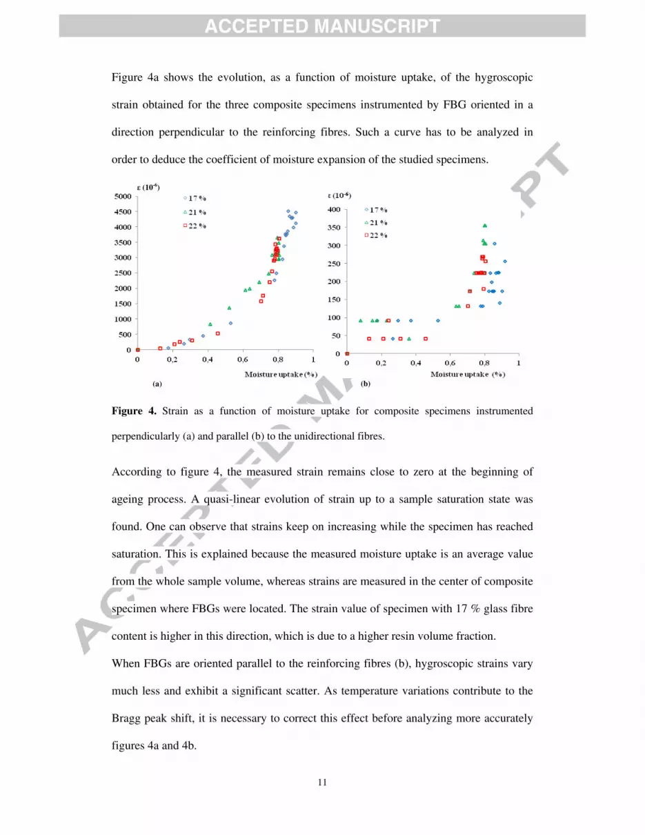
Figure 4a shows the evolution, as a function of moisture uptake, of the hygroscopic
strain obtained for the three composite specimens instrumented by FBG oriented in a
direction perpendicular to the reinforcing fibres. Such a curve has to be analyzed in
order to deduce the coefficient of moisture expansion of the studied specimens.
Figure 4. Strain as a function of moisture uptake for composite specimens instrumented
perpendicularly (a) and parallel (b) to the unidirectional fibres.
According to figure 4, the measured strain remains close to zero at the beginning of
ageing process. A quasi-linear evolution of strain up to a sample saturation state was
found. One can observe that strains keep on increasing while the specimen has reached
saturation. This is explained because the measured moisture uptake is an average value
from the whole sample volume, whereas strains are measured in the center of composite
specimen where FBGs were located. The strain value of specimen with 17 % glass fibre
content is higher in this direction, which is due to a higher resin volume fraction.
When FBGs are oriented parallel to the reinforcing fibres (b), hygroscopic strains vary
much less and exhibit a significant scatter. As temperature variations contribute to the
Bragg peak shift, it is necessary to correct this effect before analyzing more accurately
figures 4a and 4b.
(a) (b)
ε (10-6)

12
The Bragg wavelengths from before and after ageing and the corresponding strains were
gathered in table 3.
vf (%) Angle (°)
bλ (nm) Before
immersion
bλ (nm) After
immersion
bλΔ
(nm) ε (10-6)
17 0 1554.68 1554.95 0.27 255 17 90 1550.98 1556.01 5.03 4157 21 0 1554.68 1555.14 0.46 379 21 90 1551.48 1555.93 4.45 3677 22 0 1554.68 1554.97 0.29 239 22 90 1550.81 1555.18 4.37 3611
Table 3. Hygroscopic strain for all instrumented specimens 3.3 Correction from thermal expansion
A part of the strain scatter in the Bragg peak shifts is the effect of temperature leading to
both a variation of the optical index associated to a global thermal expansion of both the
composite laminate and the optical fibre. In order to determine a better estimate of
hygroscopic strains, temperature effects are corrected.
Several methods have been proposed in the literature to achieve this task, as an example
by combining multiple sensors or by using a specific sensor [21-28]. In this study, we
propose a quick but reliable method. Actually, additional information is necessary. For
this purpose, a thermal loading has been conducted once the laminates reached a
saturated state. The result on strain is plotted in figure 5 for the three composite
specimens instrumented by FBG positioned perpendicularly (figure 5a) or parallel
(figure 5b) to the reinforcing fibres, respectively.

13
Figure 5. Bragg wavelength as a function of temperature for the composite specimens
instrumented perpendicularly (a) and parallel (b) to the reinforcing fibres.
From the slope of the curves presented on figures 5a and 5b, one can separate the effects
induced by the temperature change from that of the hygroscopic strain on the measured
Bragg wavelength shifting bλ. A linear change of the Bragg wavelength occurs as a
function of temperature from 23°C to 35°C in the studied directions. The composites
specimens, in which FBG sensors were positioned in a direction perpendicular to the
reinforcing fibres (figure 5a) show greater slope of Bragg shifting in comparison to the
specimens, in which FBG sensors were oriented parallel to the reinforcing fibres (figure
5b). These results are used to correct the measured strain from a known temperature
shift. Indeed by using the graph trend slope of these curves ( f(T)λ = ), sensitivity of
Bragg wavelength to the temperature was deduced. Accordingly, the contribution due to
the temperature on the Bragg peak shifts could be determined and separated from the
total strain, so that the neat hygroscopic strain was eventually estimated through (7).
thertothyg εεε −= (7)
Bragg wavelength (nm)
(a) (b)

14
According to the measurements, the sensitivity is higher in the direction perpendicular
to the reinforcing fibres.
Figure 6a represents strains before and after correction as a function of the square root
of time for the composites specimen with 17 % fibre contents instrumented by FBG
oriented in a direction perpendicular to the reinforcing fibres. The saturation pattern of
strains curve for this sample is better defined in comparison to the uncorrected
measurements. In contrary, the deformation of the composite specimen with 17 % fibre
content instrumented by FBG positioned parallel to the reinforcing fibres (figure 6b)
remains scattered after correction of the effect of temperature. This last could be
explained by local heterogeneities of the lamination. Globally, measured strains
decrease by removing the effect of temperature from the strain response to moisture.
Figure 6. Strains evolution as a function of square root of time for the composite specimens
instrumented perpendicularly (a) and parallel (b) to the reinforcing fibres.
Figure 7 shows the corrected strains as a function of moisture content for the three
composite specimens instrumented by FBG positioned either in a direction
perpendicular (figure 7a) or parallel (figure 7b) to the reinforcing fibres, respectively.
(a) (b) Square root of time (s1/2)
ε (10-6) Temperature ( °C) Temperature (° C) ε (10-6)

15
Figure 7. Evolutions of the strain as a function of moisture content for the composite specimens
instrumented perpendicularly (a) and parallel (b) to the reinforcing fibres.
According to figure 7a, the evolution of hygroscopic strain and the saturation pattern of
the three samples are better defined in comparison to non corrected state. Unfortunately,
at this step, we can see also a bit of disturbance on the saturation pattern for the
specimen with 17 % fibre content. Knowing that this disturbance appears in a saturated
state, consecutive evolution of the deformation is probably associated to a defect of the
microstructure, such as a cracking. Hygroscopic strain in the direction parallel to the
reinforcements (figure 7b) is hard to explain, due to the very small strains experienced
by the three composite specimens in that direction.
From the curves of the hygroscopic strain as a function of the water uptake, one can also
determine the coefficients of moisture expansion of the studied samples. The moisture
expansion coefficients are determined by considering the strains and moisture contents
in the steady state:
Moisture uptake (%)(a) (b)

16
S
1111 M
εβ = (8)
S
2222 M
εβ = (9)
The values of these coefficients are given in table 4:
vf (%) Ms (%) 11ε (10-6) 22ε (10-6) 11β 22β
17 0.85 180 4000 0.021 0.471 21 0.79 330 3140 0.042 0.397 22 0.78 200 3100 0.026 0.397
Table 4. Mechanical and hygroscopical properties of elaborated samples.
4. Conclusions
In this work, the hygroscopic strains experienced by composite samples immersed in
de-ionized water were followed from the transient to the permanent stage of the
diffusion process. The measurements were carried out owing to Fibre Bragg Grating
(FBG) sensors. The results obtained by this method confirm the pertinence of FBG
sensors to measure the local strain.
In this study, the thermal strains due to the temperature change during the experimental
investigation have been determined in order to identify a more realistic estimation of the
hygroscopic strains.
The hygroscopic strain has been identified in a direction parallely and perpendicularly
to the reinforcing fibres. The combination of the obtained results to the knowledge of
the moisture uptake enables the identification of the macroscopic coefficients of
moisture expansion of the studied samples, also.
References
[1] Shen CH, Springer GS. Moisture absorption and desorption of composite materials. Journal of Composite Materials 1976; 10:2-20.

17
[2] Weitsman YJ. Fatigue of composite materials. New York: Elsevier, 1991. [3] Selzer R, Friedrich K. Mechanical properties and failure behavior of carbon fibers-reinforced polymer composites under the influence of moisture. Composite Part A 1976; 28:595-604. [4] Youssef G, Fréour S, Jacquemin F. Stress-dependent Moisture Diffusion in Composite Materials. Journal of Composite Materials 2011; 43:1621-1637. [5] Sar BE, Fréour S, Davies P, Jacquemin F. Coupling Moisture Diffusion and Internal Mechanical States in Polymers - A Thermodynamical Approach. European Journal of Mechanics 2012; 36:38-43. [6] Karalekas D, Cugnoni J, Botsis J. Monitoring of hygrothermal ageing effects in an epoxy resin using FBG sensor: A methodological study. Composites Science and Technology 2009; 69:507-514 [7] Pereira G, Frias C, Faria H, Frazão O, Marques AT. On the improvement of strain measurements with FBG sensors embedded in unidirectional composites. Polymer Testing 2013; 32:99–105. [8] Mihailov SJ. Fiber Bragg Grating Sensors for Harsh Environments. Sensors 2012; 12(2): 1898-1918. [9] Frieden J, Cugnoni J, Botsis J, Gmür T, Ćorić D. High-speed internal strain measurements in composite structures under dynamic load using embedded FBG sensors. Composite Structures 2010; 92:1905–1912.
[10] Mulle M, Collombet F, Olivier P, Zitoune R, Huchette C, Laurin F, Grunevald YH. Assessment of cure-residual strains through the thickness of carbon–epoxy laminates using FBGs Part II: Technological specimen. Composites Part A: Applied science and Manufacturing 2009; 40(10):1534–1544.
[11] Yeo TL, Sun T, Grattan KTV. Fibre-optic sensor technologies for humidity and moisture measurement, Sensors and Actuators A 2008; 144:280-295 [12] Ye BS, Svenson AL, Bank LC. Mass and volume fraction properties of pultruded glass fibre-reinforced composites. Composites 1995; 26(10):725-731. [13] Green P, Fibre volume fraction determination of carbon-epoxy composites using an acid digestion bomb. Journal of Materials Science Letters 1991; 10(19):1162-1164. [14] Ye BS, Svenson AL, Bank LC. Mass and volume fraction properties of pultruded glass fibre-reinforced composites. Composites 1995; 26(10):725-731. [15] Herakovitch CT. Mechanics of Fibrous Composites. New York: John Wiley and Sons Inc., 1998. [16] Helan R, Urban F. Principle of Fiber Bragg Gratings Measurement. In Proceeding of 30th International Spring Seminar on Electronics technology (ISSE/30). Cluj Napoca, Romania, 2007.

18
[17] Giaccari P, Dunkel GR, Humbert L, Botsis J, Limberger HG, Salathé RP. On a direct determination of non-uniform internal strain fields using fibre Bragg grating. Smart Materials and structures 2005; 14(1):127-136. [18] Luyckx G, Voet E, Lammens N, and Degrieck Y. Strain Measurements of Composite Laminates with embedded Fibre Bragg Gratings: Criticism and Opportunities for Research. Sensors 2011; 11(1):384-408. [19] Frieden J, Cugnoni J, Botsis J, Gmür T. High-speed internal strain measurements in composite structures under dynamic load using embedded FBG sensors. Composite Structures 2010; 92:1905–1912. [20] Ramezani dana H, Perronnet A, Freour S, Casari P and Jacquemin F. Identification of moisture diffusion parameters in organic matrix composites. Journal of Composite Materials 2013; 47(9):1081-1092. [21] Li T, Dong X, Chan CC, Hu L, Qianà W. Simultaneous strain and temperature measurement based on a photonic crystal fiber modal-interference interacting with a long period fiber grating. Optics Communications 2012; 285:4874-4877. [22] Xia L, Shuai B, Li W, Liu D. Simultaneous measurement of temperature and infinitesimal displacement using the high cladding mode coupling loss in fiber Bragg grating. Sensors and Actuators A 2012; 176:53-56. [23] Valdivielso F, Matı�as IR, Arregui FJ. Simultaneous measurement of strain and temperature using a fiber Bragg grating and a thermochromic material. Sensors and Actuators A 2002; 101:107-116. [24] Cavaleiro PM, Araújo FM, Ferreira LA, Santos JL, Farahi F. Simultaneous measurement of strain and temperature using Bragg gratings written in germanosilicate and boron-codoped germanosilicate fibers. IEEE Photonics Technology Letters 1999; 11(12):1635-1637. [25] Enríquez DA, Cruz ARD, Thereza M, Giraldi MR. Hybrid FBG–LPG sensor for surrounding refractive index and temperature simultaneous discrimination. Optics & Laser Technology 2012; 44(4):981-986. [26] Kang HK, Ryu CY, Hong CS, Kim CG. Simultaneous Measurement of Strain and Temperature of Structures Using Fiber Optic Sensor. Journal of Intelligent Material Systems and Structures 2001; 12(4):277-281. [27] Rao YJ, Yuan SF, Zeng XK, Lian DK, Zhu Y, Wang YP, Huang SL, Liu TY, Fernando GF, Zhang L, Bennion I. Simultaneous strain and temperature measurement of advanced 3-D Braided composite materials using an improved EFPI/FBG system. Optics and lasers in Engineering 2002; 38(6):557-566. [28] Lopez-Higuera JM, Echevarria J, Quintela A, Jauregui C, Cobo A, Strain and temperature transducer on one fiber Bragg grating. In proceedings of 8th Annual International Symposium on Smart Structures and materials (SPIE/8), Newport Beach, California, USA, March, 2001.p.192-198.