vertebral axial rotation measurement method
TRANSCRIPT

c o m p u t e r m e t h o d s a n d p r o g r a m s i n b i o m e d i c i n e 8 1 ( 2 0 0 6 ) 8–17
journa l homepage: www. int l .e lsev ierhea l th .com/ journa ls /cmpb
Vertebral axial rotation measurement method
Wei-Min Chia, Ching-Wei Chenga, Wei-Cheng Yehb,c, Shih-Chang Chuanga,Ti-Sheng Changd, Jian-Horng Chene,∗
a Department of Bio-industrial Mechatroics Engineering, National Chung Hsing University, Taiwan, ROCb Department of Radiology, Department of Health, Executive Yuan Chia-I Hospital, Taiwan, ROCc Department of Radiological Technology, Central Taiwan University of Science and Technology, Taiwan, ROCd Department of Surgery, Armed Forces Taichung General Hospital, Taiwan, ROCe Department of Physical Therapy, Chung Shan Medical University, 110 Sec. 1, Chien-Kuo N. Rd., Taichung 402, Taiwan, ROC
a r t i c l e i n f o a b s t r a c t
Article history:
Received 25 August 2005
Received in revised form 30
September 2005
Accepted 4 October 2005
Keywords:
Scoliosis
Axial rotation
Radiograph
Pedicle shadow
Iteration
This study presents a new method for measuring axial rotation of vertebra. Anatomical
landmarks of the vertebral body were first recognized in X-ray film. By employing appropri-
ate geometrical relationships, vertebral body shape parameters and a computer iteration
method, the rotation angle of vertebra on the transverse plane can rapidly be obtained. A
cadaver lumbar spine axial rotation–fixation device was designed to confirm the accuracy
of the proposed methodology. Rotation angles on CT images were adopted as the golden
standard and compared with analytical results based on X-ray films. Analytical results
demonstrated that the proposed method obtained more accurate and reliable results than
previous methods.
© 2005 Elsevier Ireland Ltd. All rights reserved.
1. Introduction
Scoliosis is a three-dimensional deformity of spinal column,generally meaning displacement and/or rotation of spinalsegments from normal positions. Measuring the degree ofdeformity is important to observing the progress of scoliosis,operative planning and correcting these spinal columns[1–3]. To determine the degree of scoliosis, deformation istypically using anteroposterior view (AP-view) and lateralview X-rays. However, assessing the extent of rotation of aspinal segment on the transverse plane is difficult. Althoughcomputed tomography (CT) technology is currently widelyapplied to measure spinal deformity, and can obtain accuratemeasurements [4,5], the subject must have a supine position.However, this position reduces mechanical effects as the
∗ Corresponding author. Tel.: +886 4 24730022x11764.E-mail address: [email protected] (J.-H. Chen).
gravitational force and asymmetry of both lower limbs, suchas leg length inequality.
Another significant disadvantage of CT, apart from its highcost, is patient exposure to radiation. Therefore, a methodol-ogy is required that utilizes one X-ray film obtained in a stand-ing position for estimating the rotation angle of the spinalcolumn on the transverse plane.
2. Background
In 1948, Cobb [6] first proposed a method for assessing therotation angle of a vertebra based on the linear offset of thespinous process in relation to position of the vertebral body onX-ray film. The degree of rotation from normal to the maximal
0169-2607/$ – see front matter © 2005 Elsevier Ireland Ltd. All rights reserved.doi:10.1016/j.cmpb.2005.10.004

c o m p u t e r m e t h o d s a n d p r o g r a m s i n b i o m e d i c i n e 8 1 ( 2 0 0 6 ) 8–17 9
position was expressed by ‘0’ to ‘++++’; however, the relation-ship between the number of ‘+’ and actual degree of rotationwas not reported.
Nash and Moe [7] proposed that the relative position ofthe pedicle in relation to the vertebral body on X-ray filmshould represent the degree of rotation of a spinal segment.Fait and Janovec [8] estimated a segment’s rotation angle basedon trigonometric relationships. In this method, the distancebetween the pedicle at the convex side and the edge of thevertebral body is a, and the full width of the vertebral body isb. An approximate rotation angle was then obtained based onthe ratio of a/b. However, Benson [9] explained why calculatingrotation angle based on the pedicle position in X-ray imageslikely resulted in errors: (1) significant changes in the shape ofall vertebrae; (2) differences between actual pedicle and pedi-cle images; (3) inclination of vertebra on the sagittal plane.With an increasing vertebral rotation angle, the projected con-tour of the vertebral body results in some offset of the borders.Neither of these methods is completely satisfactory; however,they effectively describe the relationship between vertebralrotation and displacement of the pedicle or spinous process.
Coetsier et al. [10] utilized the position of the two pedi-cles and width of the vertebral body to calculate the rotationangle. However, Gunzburg et al. questioned the accuracy ofthis method [1]. Perdriolle and Vidal [11] created a ‘torsion-meter’ that can read vertebral rotation angles using the lateraledge of a vertebral body and the position of pedicle shadow onti
rXras
catsl
AAstp
3
Atrt
mvss
Fig. 1 – Spinal segment rotates on the transverse plane(Upper). On the X-ray film, the projection of vertebral bodyand pedicle can be recognized (Below). (a) Before rotationand (b) after rotation.
the vertebral body (lower part of Fig. 1). Each pedicle is roughlyrepresented by an oval shadow. The oval’s border close to thevertebral body center is considered as the inner side, and theborder close to the lateral side edge of the vertebral body isconsidered as the outer side.
The two images (Fig. 1(a and b)) are then combined, andthe center points, O, of vertebral body are superimposed.The projected relationship is illustrated in Fig. 2. The pedicleposition is the midpoint of the connection between thecranial and caudal parts of the oval shadow [1]. Letters A andB indicate the positions of the left and right pedicles before
he convex side. However, this method produced errors thatncreased with the rotation angle [12].
In 1986, Stokes et al. [13] developed a procedure that sepa-ately marked six landmarks on both an AP-view and oblique-ray to calculate vertebral rotation angles. Russell et al. [14]
eported that the method proposed by Stokes was the leastccurate of all methods and had a very complex analyticalystem.
In analyzing various techniques, Gunzburg et al. [1] indi-ated that the methods developed by Perdriolle and Vidal [11]nd Coetsier et al. [10] had the best results. Furthermore, thesewo methods have other beneficial features, namely pediclehadows and the narrowest parts of the vertebral body on bothateral sides are considered to be anatomical landmarks.
This study utilized a lumbar spine from a human cadaver.natomical landmarks were located on various vertebrae onP-view X-rays. Employing appropriate geometrical relation-hips, vertebral body shape parameters and a computer itera-ion method, the rotation angles of vertebrae on the transverselane are easily obtained.
. Design considerations
s inclination angles of a spinal segment on coronal and sagit-al planes are easily obtained using AP and lateral radiographs,espectively; they are not within the scope of this study. Fur-hermore, only AP radiographs are utilized.
The upper part of Fig. 1 presents images of a spinal seg-ent before and after rotation. Point H at the middle of the
ertebral foramen near the vertebral body was previously con-idered by some as the rotation center [8,15,16]. When a spinalegment rotates, the pedicle position is displaced relative to
Fig. 2 – Schematic drawing of vertebral rotation.
10 c o m p u t e r m e t h o d s a n d p r o g r a m s i n b i o m e d i c i n e 8 1 ( 2 0 0 6 ) 8–17
vertebral rotation, respectively (Fig. 2). The positions of thesepedicles after rotation are marked as A′ and B′. The rotationangle � can be recognized as � = ∠AOA′.
Furthermore, let the projections of two pedicles (before andafter rotation) and center of the vertebral body on the film bedenoted by a, b, a′, b′ and o, respectively. Additionally, D is set atthe midpoint of AB, a straight line, A′F, is drawn perpendicularto Oo with point F located at the intersection of the two lines.
Based on trigonometric relationships, the following equa-tions are obtained:
� = ∠AOD − ∠A′OF (1)
∠A′OF = sin−1 A′F
OA′ (2)
Moreover, the distance between the vertebral body centerand the pedicle at the convex side is
OA′ = OA = ADsin ∠AOD
(3)
Since AD = 12 AB, let the actual distance between the two
pedicles be AB = ab = w, then Eq. (3) can be rewritten as
OA′ = OA = AB2 sin ∠AOD
= w
2 sin ∠AOD(4)
Table 1 – Shape parameter of the vertebral body andcorresponding ∠AOD
Vertebra
L1 L2 L3 L4 L5
Shape parameter �
of vertebral body(statistical value[13])
0.97 0.92 1.04 1.25 –
∠AOD (◦) 44.1 42.6 46.1 51.3 –
In Eq. (4), ∠AOD is correlated with the vertebral body shape,
which is determined by AD and OD. Additionally, ADOD
= � isthe shape parameter of the vertebral body. Notably, an APradiograph taken in a standing position only obtains a coro-nal plane image (lower part of Fig. 2). Consequently, withoutother clues in a film, the shape parameter � for every ver-tebral body should be obtained from statistical data. Stokeset al. [13] obtained average width-to-depth values for verte-bral bodies L1–L4 (Table 1); half of the width-to-depth value isthe shape parameter � in this study. Thus, ∠AOD = tan−1 � isderived.
Fig. 3 – Iteration flowchart for ca
lculating the rotation angle.
c o m p u t e r m e t h o d s a n d p r o g r a m s i n b i o m e d i c i n e 8 1 ( 2 0 0 6 ) 8–17 11
4. System description
4.1. Measurement and computational flowchart
Fig. 3 presents the flowchart of the iteration process. Both a′oand a′b′ are measured on X-ray film (Fig. 2). Actual distancew between the two pedicles is first assumed as the projectedlength a′b′ = w′ (that is, in initial state, the � is assumed tobe 0◦), which is substituted into Eq. (4) to derive an approxi-mate OA′. Then this approximate OA′ and measured a′o = A′Fis substituted into Eq. (2) to generate an approximate ∠A′OF.Using Eq. (1), the approximate rotation angle � is derived. As
A′B′ cos � = a′b′ (5)
and
AB = A′B′ = w (6)
the assumed value w can be modified. This modified w is theninput into Eq. (4) repeating the above process until � converges.The criterion for terminating the iteration process is when thepercentage change of � between two iterations is less than athreshold value, such as 0.1%.
4.2. Theoretical validation
4Fw2a
tfiplc
4Ba
Fig. 5 – Vertebral rotation angle on CT image. Angle �1
measured in this work is identical to that used by Aaro etal. [4], i.e., �2.
lumbar spine gradually from 0◦ to 30◦ at an increment of 5◦,to achieve a total of seven rotational states. At each state,take one X-ray and CT image. The spinal rotation–fixationdevice was placed on a wooden board, which supported thedevice and avoided any change in rotation state when trans-ferring between X-rays and CT scans. For X-rays, standard APradiographs were taken. The source film distance was set to100 cm, as in actual clinical work. The object film distancewas roughly 10 cm; this distance only changed the magnifi-
.2.1. Human spine rotation–fixation deviceig. 4 shows the cadaver spine rotation–fixation device,hich has a rectangular polyethylene (PE) base sized
8.5 cm × 6 cm × 20 cm on each side. The base has an open holend a protractor attached to its center.
A PE rod was inserted through the vertebral foramen, suchhat the lumbar spine was strung in series. Vertebrae werexed to the rod with adhesive to permit coaxial rotation. Aointer was placed at the end of the rod. Therefore, when the
umbar segments rotate simultaneously, the pointer can indi-ate the protractor scale.
.2.2. Image acquiring procedureefore taking an image, set the spinous process facing upward,nd align the pointer with 0 on the protractor. Rotate the
Fig. 4 – Human spine rotation–fixation device.
Fig. 6 – Converging process of rotation angle. The rotationangle appears on CT image is 15◦, while the convergingvalue is 15.7◦ by the current method using an APradiograph.

12 c o m p u t e r m e t h o d s a n d p r o g r a m s i n b i o m e d i c i n e 8 1 ( 2 0 0 6 ) 8–17
cation and did not affect the resulting rotation measurement[17].
4.2.3. Identification of rotation angle of lumbar segmentsThe protractor angle was only a reference for simulating thelumbar segments in various axial rotation states. Additionally,when segments were fixed on the PE axle, spinous processesmay not be completely aligned. Consequently, actual initialangles of the segments were only very close to 0◦ when thepointer was aligned with 0 on the protractor. Thus, actualsegment rotation angle was confirmed on CT scans. Therotation angle of segments on CT images was taken as agolden standard to validate the accuracy of the proposedcomputational method.
Fig. 5 presents the method used to measure actual rotationangles with CT images. Based on CT image of the vertebrawaist cutting through the pedicles, this work connected pointH (Fig. 1(b)) and the vertebral body center, the angle �1 is iden-tical to that used by Aaro et al. [4], i.e., �2.
5. Status report
Based on partial damage of L5, the vertebral contour on theX-ray image was unidentifiable, and, therefore, the rotationangle was not obtained. Consequently, only four lumbar seg-ments (L1–L4) were assessed.
After marking the necessary anatomical landmarks on theX-rays of four lumbar segments, a computer program basedon the proposed equations was developed to determine therotation angle. When the rotation angle of L2 measured ona CT scan is 15◦, the angle, by the current method, rapidlyconverges to 15.7◦ after 10 iterations (Fig. 6).
Fig. 7 shows the relationship between actual rotation angle�CT, measured from CT images, and the rotation angle �X, esti-mated based on X-ray films of the four vertebrae (L1–L4). Forevery vertebra, the calculated value �X and standard value �CT
are strongly correlated, with R2 of 0.988, 0.991, 0.961 and 0.970.Regression equations are provided.
Fig. 7 – Regression analysis of the calculated value �X and the sta(b) L2, (c) L3 and (d) L4.
ndard value �CT for four lumbar vertebrae rotations: (a) L1,
c o m p u t e r m e t h o d s a n d p r o g r a m s i n b i o m e d i c i n e 8 1 ( 2 0 0 6 ) 8–17 13
The current methodology and four previous methods(Table 2) were used to assess vertebral rotation angles. Thehorizontal axis in Fig. 8 indicated the observed rotation angle�CT on CT images. The vertical axis represents angle �X, esti-mated using various methods, and a 45◦ straight line is areference line produced when calculated and actual values arethe same.
Fig. 8 demonstrates actual rotation angle is overestimatedby these methods, for lumbar L1, and underestimated, forL4, whereas the actual rotation angle was estimated moreaccurately for L2 and L3. However, the proposed methodologyobtains rotational angles closest to actual angles. This study
uses root-mean-square (RMS) error (Erms) (Table 3) to judgeaccuracy
Erms =
√√√√17
7∑i=1
(�X − �CT)2 (7)
The RMS error did not exceed 3◦ for all the four vertebraeusing the proposed method (Table 3). The proposed methodis more accurate than the other four methods. A significantlylarge RMS error (6.2◦) for L4 was obtained by the methoddeveloped by Stokes et al. [13]. Conversely, it is worth to
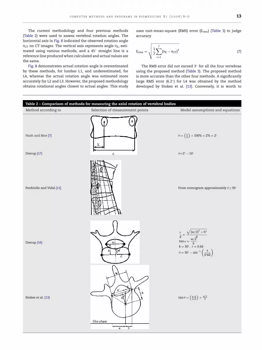
Table 2 – Comparison of methods for measuring the axial rotation of vertebral bodies
Method according to Selection of measurement points Model assumptions and equations
Nash and Moe [7] � =(
xd
)× 100% = Z% = Z◦
Drerup [17] � = Z◦ − 10◦
Perdriolle and Vidal [11]
Drerup [16]
Stokes et al. [13]
From nomogram approximately � ≤ 30◦
r
d=
√(w/2)2 + h2
d
tan � = w/2h
k = 30◦, r = 0.6d
� = 30◦ − sin−1(
s
0.6d
)
tan � =(
a−ba+b
)× w/2
h

14 c o m p u t e r m e t h o d s a n d p r o g r a m s i n b i o m e d i c i n e 8 1 ( 2 0 0 6 ) 8–17
Fig. 8 – Comparisons of rotation angles of L1–L4 analyzed by five methods. The straight line with slope to be equal to 1provides a reference of �X = �CT.
note the accuracy of the conventional torsionmeter with itsease-of-operation.
6. Lessons learned
All known methods of measuring length and angles onradiographs have marking and measuring error. Causes ofmarking errors include landmark labeling and the precisionof rules. Some factors contributing to measurement errorinclude the method employed, radiographic quality, inter-observer error and intra-observer error. A method’s accuracyis mainly determined by its strategy. This study comparedfive measurement methods. The proposed methodologyutilized the same marking and measuring tools as othermethods, i.e., pen and ruler, but achieves better accuracy,and proved more reliable and reasonable than the otherfour methods. Image processing techniques, digitizers andprecision instruments can be utilized to improve accuracy;
however, such an investigation is not the principle aim ofthis study.
Although the affects of translations on the projected imageand the resulting rotation measurement perhaps may needto be addressed, Drerup [17] demonstrated that effects dueto irradiation of the vertebra by divergent rays are ignoredbecause of their small size.
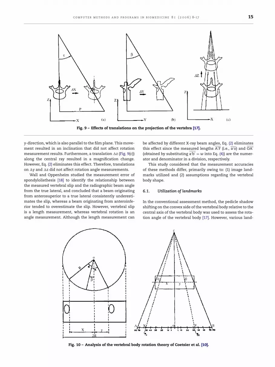
Drerup [17] decomposed translations into three compo-nents: �x, �y and �z. Fig. 9(a) presents a translation, in whichthe vertebra is moved perpendicularly to both the central rayand vertebral axis, causing an apparent rotation � that canthen be calculated. By the equation tan � = p/l, where p denotesthe distance along the x-axis of the projected vertebra fromthe principal point H and l denotes the film–focus distance.Therefore, if a spinal segment clearly deviates from the plumbline of the normal spinal column in clinical cases, deviationdistance can be measured and, thus, rotation angle can becorrected. Fig. 9(b) presents the effect of a translation in the
c o m p u t e r m e t h o d s a n d p r o g r a m s i n b i o m e d i c i n e 8 1 ( 2 0 0 6 ) 8–17 15
Fig. 9 – Effects of translations on the projection of the vertebra [17].
y-direction, which is also parallel to the film plane. This move-ment resulted in an inclination that did not affect rotationmeasurement results. Furthermore, a translation �z (Fig. 9(c))along the central ray resulted in a magnification change.However, Eq. (2) eliminates this effect. Therefore, translationson �y and �z did not affect rotation angle measurements.
Wall and Oppenheim studied the measurement error ofspondylolisthesis [18] to identify the relationship betweenthe measured vertebral slip and the radiographic beam anglefrom the true lateral, and concluded that a beam originatingfrom anterosuperior to a true lateral consistently underesti-mates the slip, whereas a beam originating from anteroinfe-rior tended to overestimate the slip. However, vertebral slipis a length measurement, whereas vertebral rotation is anangle measurement. Although the length measurement can
be affected by different X-ray beam angles, Eq. (2) eliminatesthis effect since the measured lengths A′F (i.e., a′o) and OA′
(obtained by substituting a′b′ = w into Eq. (4)) are the numer-ator and denominator in a division, respectively.
This study considered that the measurement accuraciesof these methods differ, primarily owing to: (1) image land-marks utilized and (2) assumptions regarding the vertebralbody shape.
6.1. Utilization of landmarks
In the conventional assessment method, the pedicle shadowshifting on the convex side of the vertebral body relative to thecentral axis of the vertebral body was used to assess the rota-tion angle of the vertebral body [17]. However, various land-
dy r
Fig. 10 – Analysis of the vertebral bo otation theory of Coetsier et al. [10].
16 c o m p u t e r m e t h o d s a n d p r o g r a m s i n b i o m e d i c i n e 8 1 ( 2 0 0 6 ) 8–17
Table 3 – Root-mean-square errors of rotation anglemeasured by five methods
Method Erms (◦)
L1 L2 L3 L4
Nash and Moe-10◦ 3.0 1.9 3.3 9.7Perdriolle 6.7 5.4 2.4 5.8Drerup 3.6 3.3 3.5 3.9Stokes 2.2 2.1 1.8 6.2This work 2.9 1.0 1.9 2.8
marks, for example, the inner or outer border of the pedicleshadow, or center point, result in different assessment meth-ods. Coetsier et al. [10] derived the following formulas fromthe relationship between the geometry of the vertebral bodyand pedicles and trigonometric functions (Fig. 10):
X
R= sin(˛ + ˇ) = OX
OA(8)
Y
R= sin(˛ − ˇ) = OY
OA(9)
where ˇ is the rotation angle. Conversely, the angle ˛, asdefined by Coetsier, is the half of the opening angle betweenthe ‘INNER sides’ of the two pedicles; however, ∠AOD definedin this study is an angle from the center of the vertebral bodyto the ‘MIDPOINT’ between the cranial and caudal edges of thepedicle shadow on the convex side. Coetsier et al. [10] derivedthe following equations based on trigonometric relations:
˛ + ˇ = ϕ1 (10)
˛ − ˇ = ϕ2 (11)
Furthermore,
Fig. 11 – Change of points at the inner/outer boundary ofpedicle observed from different locations [16].
6.2. Assumption of vertebral body shape
Drerup [16] examined the symmetrical characteristics of ver-tebrae with CT images, finding that although the vertebralshape causes small differences in the ratio of the length (i.e.,rd
; Table 2), the shape parameters of the convex and concavesides were not significantly different (p ≤ 0.01) after transla-tion into an angle. An asymmetrical configuration resultingfrom slight deformation of the body rarely affects estimatedrotational angle. However, if the body has a large deformationforming serious asymmetry, then any analytical method basedon radiographs can only obtain an approximate estimate ofvertebral axial rotation.
Some scholars [10,19] assumed the vertebral body as acylinder, took the width of vertebral body in AP-view as thediameter, and then input this value into Eq. (8) or (9). How-ever, this study considered that measurement error was dueto the oval rather than cylindrical shape of the vertebral body.After the oval rotates at angle �, the projected length of thelong axle becomes d cos � (Fig. 12). Richards [12] assessed mea-surement error of the torsionmeter, which, at a rotation anglesbetween 0◦ and 10◦ is substantial and within 5◦. However, theerror range increases to 10◦ at a rotation angles between 15◦
ˇ = ϕ1 − ϕ2
2(12)
or
ˇ = ˛ − ϕ2 (13)
After measuring ϕ1 and ϕ2, Coetsier et al. [10] obtained therotation angle using Eq. (12). Conversely, Drerup [16] and thiswork utilized Eq. (13). However, Drerup [16] adopted the sameanatomic landmarks as used by Coetsier et al. [10], namelythe ‘INNER side’ of the oval shadow. Pedicle shadows yieldedchanges in the inner and outer edges in projections relativeto different observational directions (Fig. 11). The projectionpoint at the inner edge of the pedicle shifts from Ti to Ti′,whereas that at the outer edge of the pedicle shifts from Tato Ta′. Gunzburg et al. [1] demonstrated that the midpointbetween the cranial and caudal edges of the pedicle shadowis not influenced by the vertebral rotation. Thus, this work setthe mid point between the cranial and caudal edges of thepedicle shadows as the position of a single pedicle.
Fig. 12 – Projection offset of oval long axle.
c o m p u t e r m e t h o d s a n d p r o g r a m s i n b i o m e d i c i n e 8 1 ( 2 0 0 6 ) 8–17 17
and 30◦, and reaches 15◦ at a 35◦ rotation angle.Compared to the torsionmeter developed by Perdriolle
and Vidal, the method proposed here obtains more accurateresults. Although the landmark used in this work has a widthw of two pedicles, it likely yields a projection offset. To correctthis error, this work utilized an iteration procedure to obtainactual length (w). Analytical results demonstrated that theiteration method effectively corrects the rotation offset in aprojection, obtaining a more accurate axial rotation angle forthe vertebral body than that obtained using other methods.
Limitations of this proposed measurement method are asfollows: the concave pedicle shadow on X-ray film should beclearly identifiable, and the concave pedicle must not haveshifted beyond the projection range of the vertebral body. Themost appropriate measurement range of the angle obtainedfrom lumbar AP radiograph is approximately 0–30◦. Barsantiet al. [20] also estimated the rotation of a single vertebral bodyusing Perdriolle’s torsionmeter. Their study found that largeerrors exist when the vertebral rotation angle exceeds 35◦. Itwas considered to be the fact that the difficulty of finding anaccurate reference point on the vertebral body. When the rota-tion angle exceeds 35◦, the analytical method based on the twopedicle shadows cannot achieve accurate axial rotation of thevertebral body.
7. Conclusion and future plans
Tatawstoctnc
A
Tot
r
[2] F. Lopez-Sosa, J.T. Guille, J.R. Bowen, Rotation of the spinein congenital scoliosis, J. Pediatr. Orthop. 15 (1995) 528–534.
[3] R. Perdriolle, J. Vidal, Thoracic idiopathic scoliosis curveevolution and prognosis, Spine 10 (1985) 785–791.
[4] S. Aaro, M. Dahlborn, L. Svensson, Estimation of vertebralrotation in structural scoliosis by computer tomography,Acta Radiol. Diagn. 19 (1978) 990–992.
[5] M. Yazici, E.R. Acaroglu, A. Alanay, V. Deviren, A. Cila, A.Surat, Measurement of vertebral rotation in standingversus supine position in adolescent idiopathic scoliosis, J.Pediatr. Orthop. 21 (2001) 252–256.
[6] J.R. Cobb, Outline for the study of scoliosis, in: J.W.Edwards (Ed.), Instructional Course Lectures, vol. 5,American Academy of Orthopaedic Surgeons, Ann Arbor,1948, pp. 261–275.
[7] C.L. Nash, J.H. Moe, A study of vertebral rotation, J. BoneJoint Surg. Am. 51 (2) (1969) 223–229.
[8] M. Fait, M. Janovec, Establishing the rotation angle in thevertebrae, Scripta Med. 43 (1970) 207–215.
[9] D.R. Benson, Roentgenographic evaluation of vertebralrotation, J. Bone Joint Surg. Am. 58 (1976) 1125–1129.
[10] M. Coetsier, M. Vercauteren, P. Moerman, A newradiographic method for measuring vertebral rotation inscoliosis, Acta Orthop. Belg. 43 (1977) 598–605.
[11] R. Perdriolle, J. Vidal, Etude de la courbure scoliotique.Importance de l’extension et de la rotation vert’ebrale,Rev. Chir. Orthop. 67 (1981) 25–34.
[12] B.S. Richards, Measurement error in assessment ofvertebral rotation using the Perdriolle torsionmeter, Spine17 (5) (1992) 513–517.
he proposed method for measuring vertebral rotation anglechieved more accurate results than previous methods. Forhe analyzed spinal segments, this method was also reliablend accurate. Under 30◦, measurement error did not increaseith the rotation angle. In clinical applications, when patients
tand with their shoulders parallel to the radiograph film, andhe central ray is aimed at the level of the main target vertebran the interlinked line of the cervical and sacral spinal pro-esses, accurate measurement results can be obtained. Whenhe spinal segment clearly deviates from the plumb line of aormal spinal column in clinical cases, the deviation distancean be measured, and the rotation angle can then be corrected.
cknowledgment
he authors would like to thank the National Science Councilf the Republic of China, Taiwan, for financially supportinghis research under Contract No. NSC93-2213-E-040-004.
e f e r e n c e s
[1] R. Gunzburg, J. Gunzburg, J. Wagner, R.D. Fraser, Radiologicinterpretation of lumbar vertebral rotation, Spine 16 (6)(1991) 660–664.
[13] I.A.F. Stokes, L.C. Bigalow, M.S. Moreland, Measurement ofaxial rotation of vertebrae in scoliosis, Spine 11 (1986)213–218.
[14] G.G. Russell, V.J. Raso, D. Hill, J. McIvor, A comparison offour computerized methods for measuring vertebralrotation, Spine 15 (1990) 24–27.
[15] R.R. Coleman, D.E. Harrison, B.B. Bernard, The effects ofcombined x-axis translations and y-axis rotations onprojected lamina junction offset, J. Manipulative Physiol.Ther. 27 (6) (2004) 403–407.
[16] B. Drerup, Improvements in measuring vertebral rotationfrom the projections of the pedicles, J. Biomech. 18 (5)(1985) 369–378.
[17] B. Drerup, Principles of measurement of vertebral rotationfrom frontal projections of the pedicles, J. Biomech. 17 (12)(1984) 923–935.
[18] M.S. Wall, W.L. Oppenheim, Measurement error ofspondylolisthesis as a function of radiographic beamangle, J. Pediatr. Orthop. 15 (1995) 193–198.
[19] R. Perdriolle, in: S.A. Maloine (Ed.), La Scoliose: Son EtudeTridimensionelle, Paris, 1979.
[20] C.M. Barsanti, A. deBari, B.M. Covino, The torsion meter: acritical review, J. Pediatr. Orthop. 10 (1990) 527–531.