numerical analysis and synthesis of 2d quasi-optical reflectors and beam waveguides based on an...
TRANSCRIPT
1Dtttirrdmqflg[tcra
wt[arofiqpi
Nosich et al. Vol. 24, No. 9 /September 2007 /J. Opt. Soc. Am. A 2831
Numerical analysis and synthesis of 2Dquasi-optical reflectors and beam waveguides
based on an integral-equation approachwith Nystrom’s discretization
Andrey A. Nosich,1,* Yuriy V. Gandel,1 Thore Magath,2 and Ayhan Altintas3
1School of Mathematics, Kharkiv National University, Kharkiv 61077, Ukraine2EuTC Research Communication, Panasonic Electronic Devices (Europe) GmbH, Zeppelinstrasse 19,
21337 Lueneburg, Germany3Department of Electrical and Electronics Engineering, Bilkent University, Ankara 06800, Turkey
*Corresponding author: [email protected]
Received December 8, 2006; revised April 26, 2007; accepted May 3, 2007;posted May 9, 2007 (Doc. ID 77895); published August 10, 2007
Considered is the beam wave guidance and scattering by 2D quasi-optical reflectors modeling the componentsof beam waveguides. The incident field is taken as the complex-source-point field to simulate a finite-widthbeam generated by a small-aperture source. A numerical solution is obtained from the coupled singular inte-gral equations (SIEs) for the surface currents on reflectors, discretized by using the recently introducedNystrom-type quadrature formulas. This analysis is applied to study what effect the edge illumination has onthe performance of a chain of confocal elliptic reflectors. We also develop a semianalytical approach for shapedreflector synthesis after a prescribed near-field pattern. Here a new point is the use of auxiliary SIEs of thesame type as in the scattering analysis problem, however, for the gradient of the objective function. Sampleresults are presented for the synthesis of a reflector-type beam splitter. © 2007 Optical Society of America
OCIS codes: 140.0140, 140.3290, 140.3410, 140.5960, 230.5750, 140.4780.
ai
wwrevcr
crdac
ccecelfstntv
. INTRODUCTIONiffractive metallic mirrors or reflectors are key elements
hat provide the phase correction necessary for manipula-ion of beams across a wide range of frequencies from op-ical to millimeter (mm) waves. Despite noticeable lossesn the visible range, applications of diffractive optical mir-ors are numerous and include laser beam focusing, redi-ection, coupling, feedback, spectral filtering, wavelength-ivision multiplexing, and optical disk readout [1–3]. Asaterial losses of good metals sharply decrease with fre-
uency, beam waveguides formed by chains of metallic re-ectors have become even more attractive for low-lossuidance of the terahertz and mm waves since the 1960s4–10]. Today reflector beam waveguides are used, e.g., inhe heating of plasma in controlled nuclear fusion ma-hines with the mm waves generated by high-power gy-otrons and as feed lines for mm-wave radio astronomyntennas [11–13].Electromagnetic modeling of reflectors is usually done
ith geometrical and physical optics [14–16] includinghe recently developed powerful auxiliary-plane approach17]. However, these methods are based on ray tracingnd fail to fully characterize fine interaction effects andesonances. For more accurate modeling, rigorous meth-ds are necessary. Note also that the currently popularnite-difference time-domain commercial field solvers re-uire prohibitively large computer resources when ap-lied even to a single reflector larger than 10 wavelengthsn size, in open domain. Therefore their use in parametric
1084-7529/07/092831-6/$15.00 © 2
nalysis is painful, and in numerical optimization so far its virtually impossible.
These facts suggest that economic and accurate full-ave analysis and synthesis of reflectors and beamaveguides is still in demand. A general way to build cor-
esponding numerical algorithms is to use an integral-quation (IE) approach. Here, the crucial point is the de-elopment of an efficient discrete model, i.e., a fast andonvergent numerical algorithm having controlled accu-acy.
In optics, where metals are lossy and beams are wellollimated, reflectors are usually simulated with surface-elief structures and dielectric boundary conditions (i.e., aemand for continuity of the tangential field componentscross the surface) [18–20]. Therefore IEs are actuallyoupled pairs of equations along infinite contours.
In contrast to optics, mm-wave and terahertz reflectorsan be considered perfect electric conductors (PECs) be-ause of very high electron conductivity in this range. Aslectromagnetic wave beams are less collimated in thisase, the edges of reflectors have to be accounted for prop-rly. Therefore quasi-optical reflectors are normally simu-ated with zero-thickness PEC screens that lead to SIEsor the electric currents induced on finite surfaces withharp edges. Such IEs always have singular kernels andherefore must be discretized carefully, especially if theeeded accuracy is finer than the first couple of digits. Inhe 1990s, the method of analytical regularization was de-eloped to convert IEs into Fredholm second-kind matrix
007 Optical Society of America
ep
tpsdtp[Nqrird
bqswasuM
2TFTtttfiz
w=Ftlpt�ollt
UthbepIt
ws
kTwda
Niec(tqbaeTcTr1prc
3FACsitaUesa
itamt
2832 J. Opt. Soc. Am. A/Vol. 24, No. 9 /September 2007 Nosich et al.
quations because of the explicit inversion of the staticarts [21].An alternative approach uses Nystrom-type discretiza-
ion of SIEs and specific quadrature formulas for the com-utation of the matrix elements. In [22], we presented ba-ic ideas of such a discrete model based on the method ofiscrete singularities (MDS) and gave some examples ofhe accurate 2D analysis of curved reflector antennas. Inarallel, a similar approach was developed recently in23] for flat 2D strips and slots in a layered environment.ote that these works use different edge-correcteduadrature formulas, although both consider the wholeeflector as an entire domain and improve the accuracy byncreasing the order of interpolation polynomials, i.e., theeflector is not meshed with a finer and finer set of sub-omains.In the sections that follow, we consider the E-polarized
eam wave guidance and scattering by a chain of 2Duasi-optical reflectors used as a waveguide, and wetudy the role of the reflector edge illumination in theaveguide performance. We also develop a semianalyticalpproach for a shaped reflector synthesis after a pre-cribed near field pattern. Both analysis and synthesisse SIEs of the same type discretized with the aid of theDS.
. ANALYSIS AND MDS DISCRETIZATIONhe geometry of a generic 2D reflector system, shown inig. 1, is an example of a finite-length beam waveguide.he reflectors are assumed to be PEC and have zerohickness. The feed is a z-directed line current placed athe complex-valued source point (see also [21,22]) and hasime dependence exp�−i�t�, omitted in the analysis. Theeld generated by such a feed can be characterized by thecomponent of the electric field, which is given by
U0�r�� = H0�1��k�r� − r�c��, �1�
here H0�1��·� is the Hankel function of the first kind, k
� /c, r�c=r�0+ ib� , r�0= �x0 ,y0�, and b� = �b cos � ,b sin ��. Theunction (1) is a rigorous solution to the Helmholtz equa-
ion and, because of the complex-valued argument, simu-ates a directive beam looking within �=�. In thearaxial domain, this is simply a Gaussian beam. Notehat Eq. (1) has two branch points atx0±b cos � ,y0�b sin ��, and to single out a unique valuef U0�x ,y� one has to join them with a branch cut B ofength 2b. This cut can be considered a model of the real-ife aperture of a small horn; the greater kb, the narrowerhe beam.
Fig. 1. Geometry of confocal three-reflector beam waveguide.
The total field is considered a sum, U=Usc+U0, wheresc is the secondary field scattered by reflectors and U0
he incident one. The function Usc has to solve the Helm-oltz equation off Sq, q=1, . . .Q, and satisfy (a) the PECoundary condition on Sq, (b) the edge conditions at thendpoints, and (c) the radiation condition. In the case of Eolarization, this problem is reduced to a set of Q coupledEs of the first kind for the surface currents induced onhe strips, jp�sq�,
i
4�q=1
Q �Sq
H0�1��k�r�q�sq� − r�p�sp0���jq�sq�dsq = − U0�r�p�sp0��,
�2�
here r�p�sp0��Sp and sp ,sp0 are the arc lengths along C2
mooth open curves Sp, p=1, . . .Q.Note that set (2) has logarithmic singularities in the
ernels when the source and observation points coincide.herefore its direct moment-method-like discretizationsith the local basis–testing functions, although possible,o not lead to efficient and always convergent numericallgorithms.We handle Eq. (2) by using the recently developed
ystrom-type numerical method of solving the SIEs metn the scattering of waves by open PEC screens withdges—the method of discrete singularities: applying aontour parameterization x�t� ,y�t�, one can transform IE2) to another, Cauchy-singular IE set with supplemen-ary conditions and further discretize it by using theuadrature formulas of interpolation type with the nodeseing the roots of the Chebyshev polynomials of the firstnd second kinds. As a result, we obtain a set of linearquations and solve it with a simple Gaussian scheme.he method’s details and extensive numerical validationsan be found in [22]; paper [23] is also a relevant source.his method enables one to study the effects of the waveadiation, guidance, and scattering for reflectors up to00� and more in size, with high accuracy and small com-uter resources. Near- and far-field patterns, surface cur-ents, and also focusability and directivity can be readilyomputed for various reflector shapes, feed locations, etc.
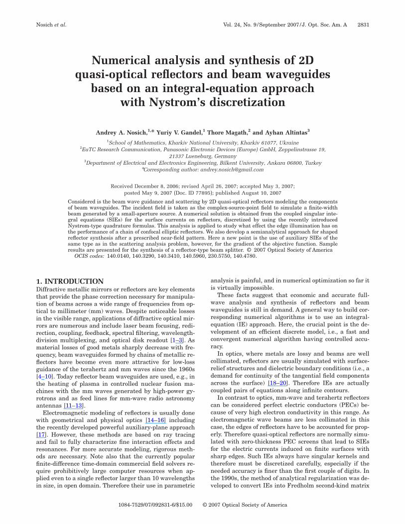
. NUMERICAL RESULTS FOR REFLECTORIELD ANALYSIS. Elliptic Single-Reflector Focusersonsider first a single elliptic reflector fed by a complex-ource-point (CSP) source whose aperture center is placedn the geometrical focus F1 (Fig. 2). This geometry is in-eresting for the near-field focusing in such applicationss plasma heating and laser pumping with microwaves.nlike parabolic antennas, performance of elliptic focus-
rs should be characterized by the maximum field inten-ity near the second geometrical focus and the shape andrea of the focal spot domain.We have studied numerically how the field amplitude
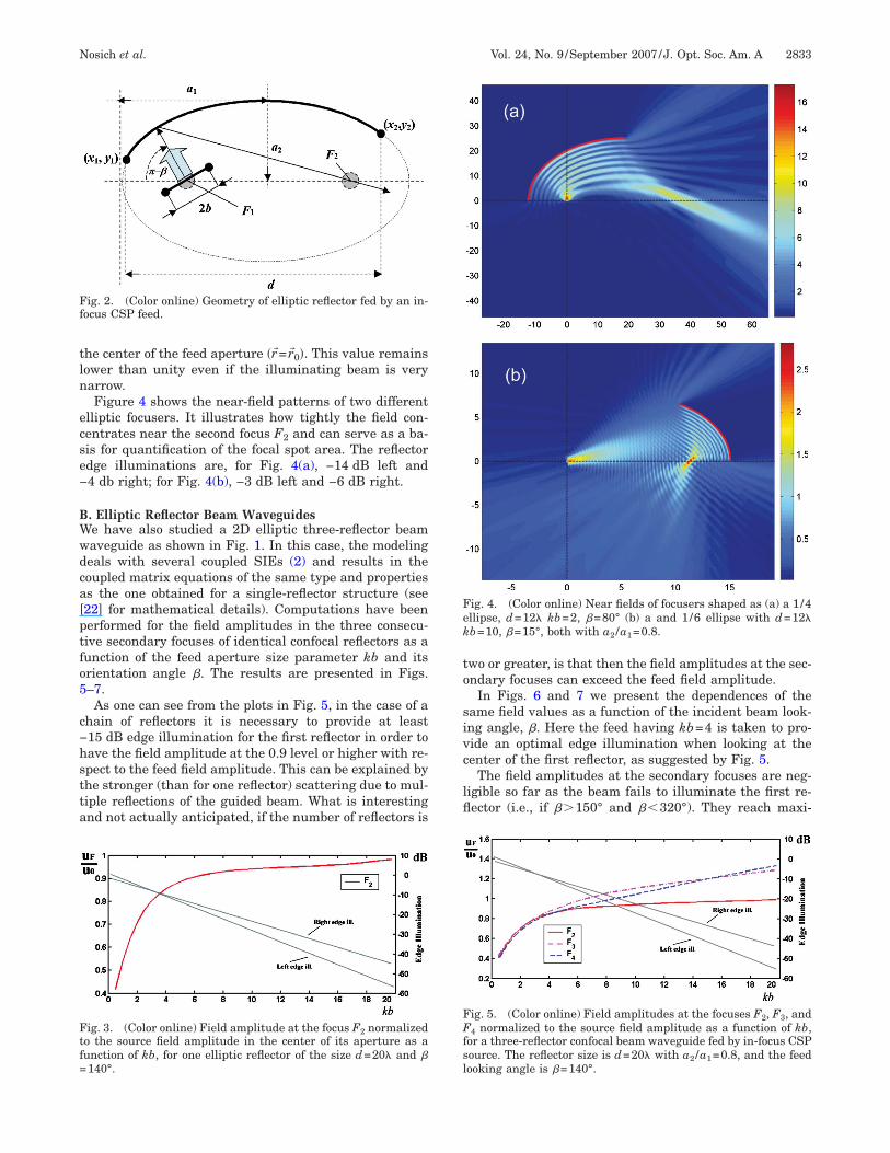
n the second focus depends on the edge illumination con-rolled by the feeding beam width and orientation. Suchnalysis (see Fig. 3) shows that at least −10 dB edge illu-ination is necessary to provide the second-focus ampli-
ude at the level 0.8 of the source field amplitude taken at
tln
ecse−
BWwdca[ptfo5
c−hstta
to
sivc
lfl
Ff
Ftf=
Fek
FFfsl
Nosich et al. Vol. 24, No. 9 /September 2007 /J. Opt. Soc. Am. A 2833
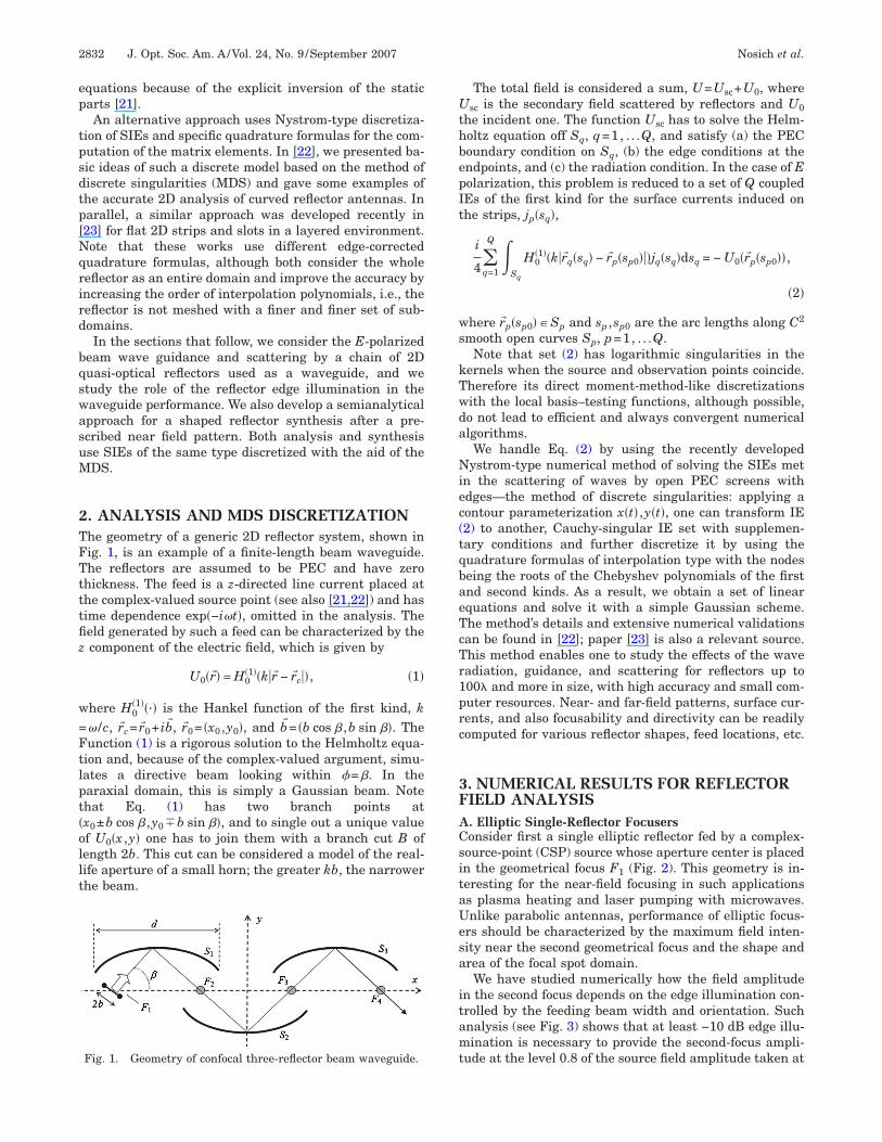
he center of the feed aperture �r� =r�0�. This value remainsower than unity even if the illuminating beam is veryarrow.Figure 4 shows the near-field patterns of two different
lliptic focusers. It illustrates how tightly the field con-entrates near the second focus F2 and can serve as a ba-is for quantification of the focal spot area. The reflectordge illuminations are, for Fig. 4(a), −14 dB left and4 db right; for Fig. 4(b), −3 dB left and −6 dB right.
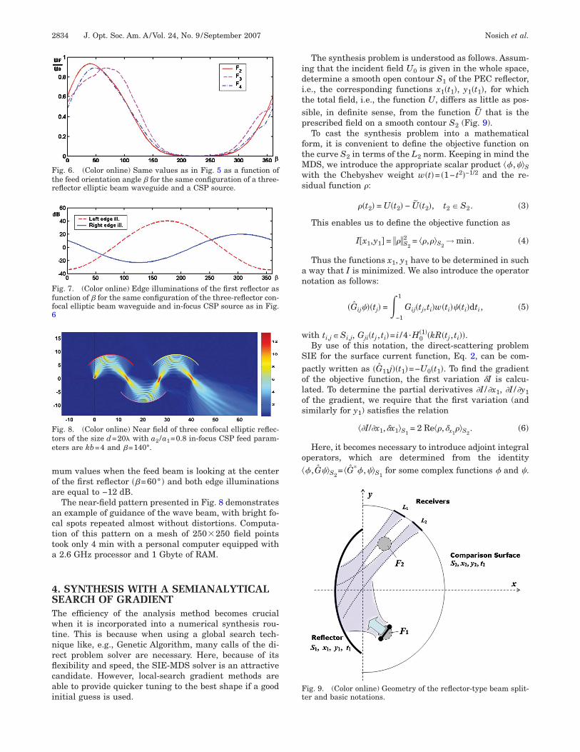
. Elliptic Reflector Beam Waveguidese have also studied a 2D elliptic three-reflector beamaveguide as shown in Fig. 1. In this case, the modelingeals with several coupled SIEs (2) and results in theoupled matrix equations of the same type and propertiess the one obtained for a single-reflector structure (see22] for mathematical details). Computations have beenerformed for the field amplitudes in the three consecu-ive secondary focuses of identical confocal reflectors as aunction of the feed aperture size parameter kb and itsrientation angle �. The results are presented in Figs.–7.As one can see from the plots in Fig. 5, in the case of a
hain of reflectors it is necessary to provide at least15 dB edge illumination for the first reflector in order toave the field amplitude at the 0.9 level or higher with re-pect to the feed field amplitude. This can be explained byhe stronger (than for one reflector) scattering due to mul-iple reflections of the guided beam. What is interestingnd not actually anticipated, if the number of reflectors is
ig. 2. (Color online) Geometry of elliptic reflector fed by an in-ocus CSP feed.
ig. 3. (Color online) Field amplitude at the focus F2 normalizedo the source field amplitude in the center of its aperture as aunction of kb, for one elliptic reflector of the size d=20� and �140°.
wo or greater, is that then the field amplitudes at the sec-ndary focuses can exceed the feed field amplitude.
In Figs. 6 and 7 we present the dependences of theame field values as a function of the incident beam look-ng angle, �. Here the feed having kb=4 is taken to pro-ide an optimal edge illumination when looking at theenter of the first reflector, as suggested by Fig. 5.
The field amplitudes at the secondary focuses are neg-igible so far as the beam fails to illuminate the first re-ector (i.e., if ��150° and ��320°). They reach maxi-
ig. 4. (Color online) Near fields of focusers shaped as (a) a 1/4llipse, d=12� kb=2, �=80° (b) a and 1/6 ellipse with d=12�b=10, �=15°, both with a2 /a1=0.8.
ig. 5. (Color online) Field amplitudes at the focuses F2, F3, and4 normalized to the source field amplitude as a function of kb,
or a three-reflector confocal beam waveguide fed by in-focus CSPource. The reflector size is d=20� with a2 /a1=0.8, and the feedooking angle is �=140°.
moa
actta
4STwtnrflcai
iditsp
ftMws
an
w
Spolos
o�
Fff6
Fte
Ftr
Ft
2834 J. Opt. Soc. Am. A/Vol. 24, No. 9 /September 2007 Nosich et al.
um values when the feed beam is looking at the centerf the first reflector ��=60° � and both edge illuminationsre equal to −12 dB.The near-field pattern presented in Fig. 8 demonstrates
n example of guidance of the wave beam, with bright fo-al spots repeated almost without distortions. Computa-ion of this pattern on a mesh of 250�250 field pointsook only 4 min with a personal computer equipped with2.6 GHz processor and 1 Gbyte of RAM.
. SYNTHESIS WITH A SEMIANALYTICALEARCH OF GRADIENThe efficiency of the analysis method becomes crucialhen it is incorporated into a numerical synthesis rou-
ine. This is because when using a global search tech-ique like, e.g., Genetic Algorithm, many calls of the di-ect problem solver are necessary. Here, because of itsexibility and speed, the SIE-MDS solver is an attractiveandidate. However, local-search gradient methods areble to provide quicker tuning to the best shape if a goodnitial guess is used.
ig. 7. (Color online) Edge illuminations of the first reflector asunction of � for the same configuration of the three-reflector con-ocal elliptic beam waveguide and in-focus CSP source as in Fig.
ig. 8. (Color online) Near field of three confocal elliptic reflec-ors of the size d=20� with a2 /a1=0.8 in-focus CSP feed param-ters are kb=4 and �=140°.
ig. 6. (Color online) Same values as in Fig. 5 as a function ofhe feed orientation angle � for the same configuration of a three-eflector elliptic beam waveguide and a CSP source.
The synthesis problem is understood as follows. Assum-ng that the incident field U0 is given in the whole space,etermine a smooth open contour S1 of the PEC reflector,.e., the corresponding functions x1�t1�, y1�t1�, for whichhe total field, i.e., the function U, differs as little as pos-ible, in definite sense, from the function U that is therescribed field on a smooth contour S2 (Fig. 9).To cast the synthesis problem into a mathematical
orm, it is convenient to define the objective function onhe curve S2 in terms of the L2 norm. Keeping in mind theDS, we introduce the appropriate scalar product �� ,�Sith the Chebyshev weight w�t�= �1− t2�−1/2 and the re-
idual function :
�t2� = U�t2� − U�t2�, t2 � S2. �3�
This enables us to define the objective function as
I�x1,y1 = S2
2 = �,�S2→ min. �4�
Thus the functions x1, y1 have to be determined in suchway that I is minimized. We also introduce the operatorotation as follows:
�Gij��tj� =�−1
1
Gij�tj,ti�w�ti��ti�dti, �5�
ith ti,j�Si,j, Gji�tj , ti�= i /4 ·H0�1��kR�tj , ti��.
By use of this notation, the direct-scattering problemIE for the surface current function, Eq. 2, can be com-actly written as �G11j��t1�=−U0�t1�. To find the gradientf the objective function, the first variation �I is calcu-ated. To determine the partial derivatives �I /�x1, �I /�y1f the gradient, we require that the first variation (andimilarly for y1) satisfies the relation
��I/�x1,�x1�S1= 2 Re�,�x1
�S2. �6�
Here, it becomes necessary to introduce adjoint integralperators, which are determined from the identity� ,G�S2
= �G*� ,�S1for some complex functions � and .
ig. 9. (Color online) Geometry of the reflector-type beam split-er and basic notations.
Og
w
fjfw(
hTMos
5STbdotvflfit
tit
tpeaa
cocis1sa
o
Fas
Fb
Ffl
Nosich et al. Vol. 24, No. 9 /September 2007 /J. Opt. Soc. Am. A 2835
n performing certain derivations and using adjoint inte-ral operators, we finally obtain
�I
�x1= 2 Re�− �Ux10
0 + Gx10,11 j�� − j�Gx1,11* � − Gx10,21
* ��,
�7�
here auxiliary function � satisfies an adjoint SIE:
G11* � = G21
* . �8�
Thus the x1 component of the gradient of our objectiveunction satisfies a SIE whose operator is a complex con-ugate to that of the analysis SIE (2). The right-hand-partunction of adjoint SIE is determined after solving Eq. (2)ith a first-guess contour S1, obtaining residual function
3), and integrating it along contour S2.Note that the operators involved in Eqs. (7) and (8)
ave either smooth or logarithmic-singular kernels.herefore all of them can be efficiently computed with theDS discretization of Section 3. The total gradient of the
bjective function is given by Eq. (7) and a similar expres-ion for �I /�y1.
. NUMERICAL RESULTS FOR BEAMPLITTER SYNTHESISo test the idea of the semianalytical gradient synthesisased on the SIE-MDS technique, consider the problem ofesigning a single-reflector beam splitter, S1 (see Fig. 9),f the field radiated by a CSP feed. The comparison con-our S2 is taken as a half-circle with two isolated inter-als, L1 and L2, on which the field of the synthesized re-ector is to be focused. Therefore the prescribed fieldunction on this contour is taken as a superposition of twodentical Gaussian functions having maxima at the cen-ral points of L1 and L2.
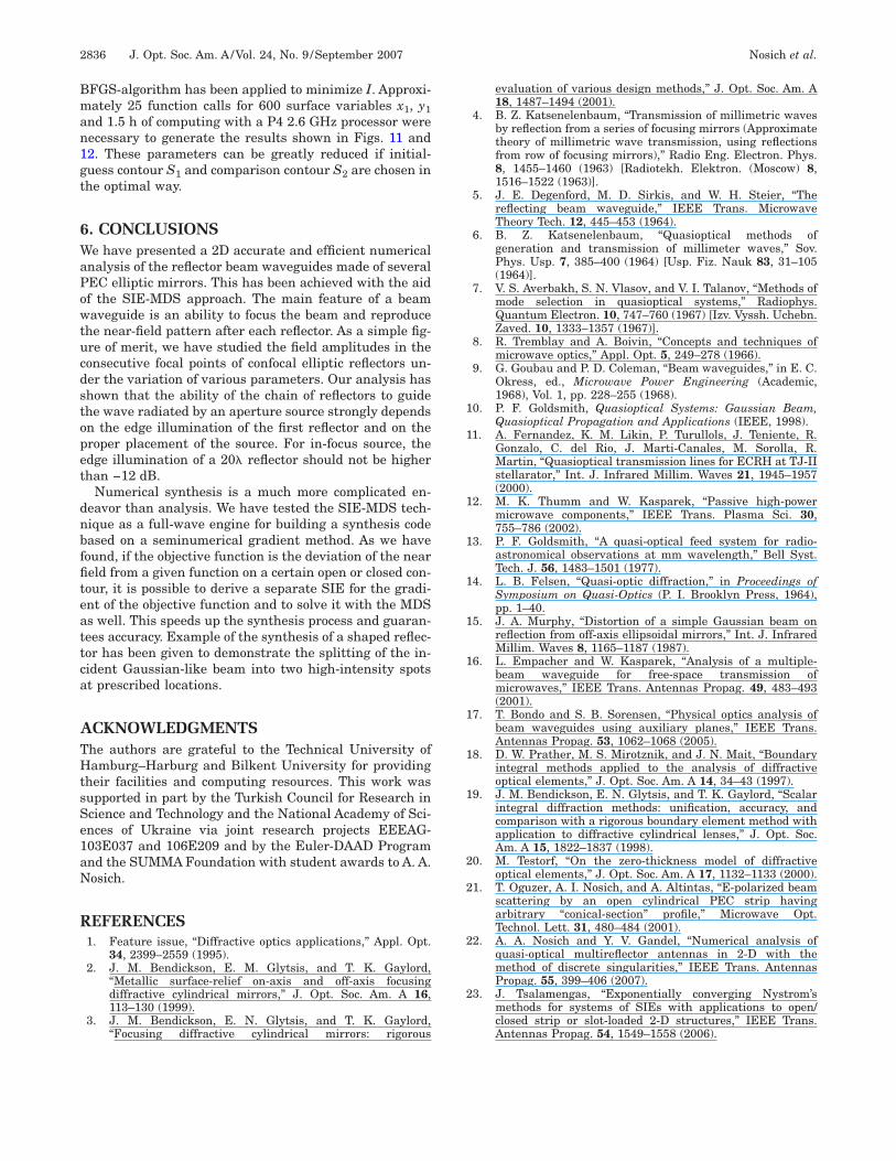
As the initial guess, we took an elliptic contour S1 ofhe fixed aperture size d=35�, having the feed placed atts first focus F1 (Fig. 10). The feed field is fixed, havinghe aperture parameter kb=8 (b is the imaginary part of
ig. 10. (Color online) Near field of the initial d=35� elliptic re-ector with a /a =0.8 fed by an in-focus CSP source.
2 1he source coordinate). Such a feed, if placed at the focaloint F1 and aimed at the center of S1, provides a −10 dBdge illumination of the reflector. The intervals L1 and L2re located behind the other geometrical focal point F2,nd the comparison contour S2 diameter is 48�.After performing the synthesis as explained above, we
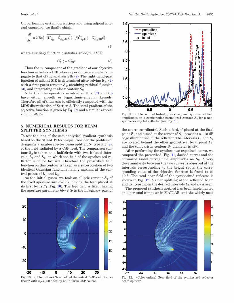
ompared the prescribed (Fig. 11, dashed curve) and theptimized (solid curve) field amplitudes on S2. A verylose similarity between the two curves is observed at thentervals corresponding to the bright spots; the corre-ponding value of the objective function is found to be0−2. The total near field of the synthesized reflector ishown in Fig. 12. A clear splitting of the reflected beamnd its focusing on the desired intervals L1 and L2 is seen.The proposed synthesis method has been implemented
n a personal computer in MATLAB, and the widely used
ig. 11. (Color online) Initial, prescribed, and synthesized fieldmplitudes on a semicircular normalized contour S2 for a non-ymmetrically fed reflector (see Fig. 10).
ig. 12. (Color online) Near field of the synthesized reflectoream splitter.
Bman1gt
6WaPowtucdstopet
dnbffiteattca
ATHtsSe1aN
R
1
1
1
1
1
1
1
1
1
1
2
2
2
2
2836 J. Opt. Soc. Am. A/Vol. 24, No. 9 /September 2007 Nosich et al.
FGS-algorithm has been applied to minimize I. Approxi-ately 25 function calls for 600 surface variables x1, y1
nd 1.5 h of computing with a P4 2.6 GHz processor wereecessary to generate the results shown in Figs. 11 and2. These parameters can be greatly reduced if initial-uess contour S1 and comparison contour S2 are chosen inhe optimal way.
. CONCLUSIONSe have presented a 2D accurate and efficient numerical
nalysis of the reflector beam waveguides made of severalEC elliptic mirrors. This has been achieved with the aidf the SIE-MDS approach. The main feature of a beamaveguide is an ability to focus the beam and reproduce
he near-field pattern after each reflector. As a simple fig-re of merit, we have studied the field amplitudes in theonsecutive focal points of confocal elliptic reflectors un-er the variation of various parameters. Our analysis hashown that the ability of the chain of reflectors to guidehe wave radiated by an aperture source strongly dependsn the edge illumination of the first reflector and on theroper placement of the source. For in-focus source, thedge illumination of a 20� reflector should not be higherhan −12 dB.
Numerical synthesis is a much more complicated en-eavor than analysis. We have tested the SIE-MDS tech-ique as a full-wave engine for building a synthesis codeased on a seminumerical gradient method. As we haveound, if the objective function is the deviation of the neareld from a given function on a certain open or closed con-our, it is possible to derive a separate SIE for the gradi-nt of the objective function and to solve it with the MDSs well. This speeds up the synthesis process and guaran-ees accuracy. Example of the synthesis of a shaped reflec-or has been given to demonstrate the splitting of the in-ident Gaussian-like beam into two high-intensity spotst prescribed locations.
CKNOWLEDGMENTShe authors are grateful to the Technical University ofamburg–Harburg and Bilkent University for providing
heir facilities and computing resources. This work wasupported in part by the Turkish Council for Research incience and Technology and the National Academy of Sci-nces of Ukraine via joint research projects EEEAG-03E037 and 106E209 and by the Euler-DAAD Programnd the SUMMA Foundation with student awards to A. A.osich.
EFERENCES1. Feature issue, “Diffractive optics applications,” Appl. Opt.
34, 2399–2559 (1995).2. J. M. Bendickson, E. M. Glytsis, and T. K. Gaylord,
“Metallic surface-relief on-axis and off-axis focusingdiffractive cylindrical mirrors,” J. Opt. Soc. Am. A 16,113–130 (1999).
3. J. M. Bendickson, E. N. Glytsis, and T. K. Gaylord,“Focusing diffractive cylindrical mirrors: rigorous
evaluation of various design methods,” J. Opt. Soc. Am. A18, 1487–1494 (2001).
4. B. Z. Katsenelenbaum, “Transmission of millimetric wavesby reflection from a series of focusing mirrors (Approximatetheory of millimetric wave transmission, using reflectionsfrom row of focusing mirrors),” Radio Eng. Electron. Phys.8, 1455–1460 (1963) [Radiotekh. Elektron. (Moscow) 8,1516–1522 (1963)].
5. J. E. Degenford, M. D. Sirkis, and W. H. Steier, “Thereflecting beam waveguide,” IEEE Trans. MicrowaveTheory Tech. 12, 445–453 (1964).
6. B. Z. Katsenelenbaum, “Quasioptical methods ofgeneration and transmission of millimeter waves,” Sov.Phys. Usp. 7, 385–400 (1964) [Usp. Fiz. Nauk 83, 31–105(1964)].
7. V. S. Averbakh, S. N. Vlasov, and V. I. Talanov, “Methods ofmode selection in quasioptical systems,” Radiophys.Quantum Electron. 10, 747–760 (1967) [Izv. Vyssh. Uchebn.Zaved. 10, 1333–1357 (1967)].
8. R. Tremblay and A. Boivin, “Concepts and techniques ofmicrowave optics,” Appl. Opt. 5, 249–278 (1966).
9. G. Goubau and P. D. Coleman, “Beam waveguides,” in E. C.Okress, ed., Microwave Power Engineering (Academic,1968), Vol. 1, pp. 228–255 (1968).
0. P. F. Goldsmith, Quasioptical Systems: Gaussian Beam,Quasioptical Propagation and Applications (IEEE, 1998).
1. A. Fernandez, K. M. Likin, P. Turullols, J. Teniente, R.Gonzalo, C. del Rio, J. Marti-Canales, M. Sorolla, R.Martin, “Quasioptical transmission lines for ECRH at TJ-IIstellarator,” Int. J. Infrared Millim. Waves 21, 1945–1957(2000).
2. M. K. Thumm and W. Kasparek, “Passive high-powermicrowave components,” IEEE Trans. Plasma Sci. 30,755–786 (2002).
3. P. F. Goldsmith, “A quasi-optical feed system for radio-astronomical observations at mm wavelength,” Bell Syst.Tech. J. 56, 1483–1501 (1977).
4. L. B. Felsen, “Quasi-optic diffraction,” in Proceedings ofSymposium on Quasi-Optics (P. I. Brooklyn Press, 1964),pp. 1–40.
5. J. A. Murphy, “Distortion of a simple Gaussian beam onreflection from off-axis ellipsoidal mirrors,” Int. J. InfraredMillim. Waves 8, 1165–1187 (1987).
6. L. Empacher and W. Kasparek, “Analysis of a multiple-beam waveguide for free-space transmission ofmicrowaves,” IEEE Trans. Antennas Propag. 49, 483–493(2001).
7. T. Bondo and S. B. Sorensen, “Physical optics analysis ofbeam waveguides using auxiliary planes,” IEEE Trans.Antennas Propag. 53, 1062–1068 (2005).
8. D. W. Prather, M. S. Mirotznik, and J. N. Mait, “Boundaryintegral methods applied to the analysis of diffractiveoptical elements,” J. Opt. Soc. Am. A 14, 34–43 (1997).
9. J. M. Bendickson, E. N. Glytsis, and T. K. Gaylord, “Scalarintegral diffraction methods: unification, accuracy, andcomparison with a rigorous boundary element method withapplication to diffractive cylindrical lenses,” J. Opt. Soc.Am. A 15, 1822–1837 (1998).
0. M. Testorf, “On the zero-thickness model of diffractiveoptical elements,” J. Opt. Soc. Am. A 17, 1132–1133 (2000).
1. T. Oguzer, A. I. Nosich, and A. Altintas, “E-polarized beamscattering by an open cylindrical PEC strip havingarbitrary “conical-section” profile,” Microwave Opt.Technol. Lett. 31, 480–484 (2001).
2. A. A. Nosich and Y. V. Gandel, “Numerical analysis ofquasi-optical multireflector antennas in 2-D with themethod of discrete singularities,” IEEE Trans. AntennasPropag. 55, 399–406 (2007).
3. J. Tsalamengas, “Exponentially converging Nystrom’smethods for systems of SIEs with applications to open/closed strip or slot-loaded 2-D structures,” IEEE Trans.Antennas Propag. 54, 1549–1558 (2006).