characteristics of waveguides for long-distance transmission
TRANSCRIPT
JOURNAL OF RESEARCH of the National Bureau of Standards-D. Radio Propagation Vol. 65D, No.1, January- February 1961
Characteristics of Waveguides for Long-Distance Transmission 1
A . E. Karbowiak and 1. Solymar (May 23,1960)
Discussion of a "'aveguide communication system is given and t he syste m is co mpared with existing communication media. The principal properties of waveguide- the mcdium of communication- are discussed in some detail. The particular sig nificance of heli cal a nd coated waveguides is pointed out and the design formulas in cludcd. The p lwnomenon of mode conversion-reconversion , which is pec uliar to a waveguide communicat io n systcm, is discussed in general and the basic theory as app li cab le to design is also discussed . D esig n feat ures of components such as bends, transduce rs, tapers, etc., a re analyzed . The effect of waveguide disco nt inui t ies is a nalyzed in so me detail and \'ariou ~ aspects of signa l d istort ion are a lso considered .
1. Introduction
:Man , in his constant efforts towards progres , finds it necessury to establish better, quicker , and more numerous communica tion systems. It is even said that complexity of communic~1tion systems grows in proportion to the development of civilizRtion. As th e conventional means of communication beeome gn.duaUy used to capacity and the traffiC continues to increase, one, naturally, turns tow~ll"ds more exotic means of communication. vVaveguide is a possible winner [1, 2, 3] 2 and in this co nn ection specit11 acknowledgment should be made of the vrr)" important pion eer and continuing work of the Bell Laboratories in this field . Although the fin,.l assessment can only be made against the background of economy, a detailed performance assessmenL must be the first step. Bor a number of reasons, as we shall see subsequenLly, such a waveguide is essentially a circular tube about 1 to 3 in. in diameter and the Wtwes involvcd arc in the millimetric band. S uch a pipe- the medium of communications- would be laid. in the ground or at the bottom of oceans for hundreds and thousands of miles.
In order to bring out any advantages tlmt a waveguide communication system may have over the existing sys tems, the principal features arc shown tabulatcd in table 1. From this it is evident that the main advantage of a waveguide communication system is its large communication capacity. Provided that very short millimetric waves are used then, in principle, several hundreds of television channels, or the equivalen t in speech channels, can be accommodated in a single pipe. The waveguide is also eharacterized by small attenuation, and in contrast to microwave links it is a screened system. Whether such enormous communication capacities will ever be require::l is another matter ; but, if present statistics are anything to go by, then these capacities will be required in less than 20 years time,
1 Contribution from Standard Telecommunication Laboratories, Ltd ., Londou Road, Harlow, Essex, England .
, Figures in brackets indicate the literature references at the end of this paper
75
if not for telephone communication then for purposes such as data trRnsmission, color and cinema television as well as f01" purposes not yet conceived.
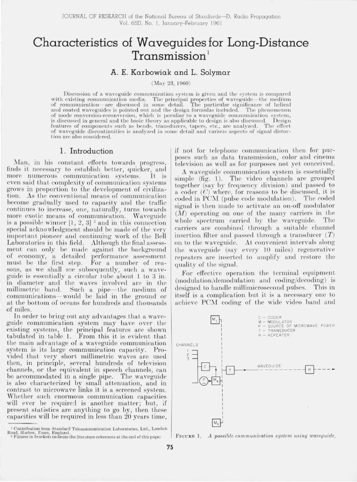
A waveguide communication system is essentially simplc (fig . 1) . The video channels are grouped together (say by ("reC[ uency division) and passed to a coder (0) whcre, for retLSons Lo be discussed , it is coded in PC~/I (pulse code modulHt,ion) . The coded signal is then made to acLivaLe an on-off modulator (M) operating on one of the many carriers in the whole spectrum carried by the waveguidc. The carriers are combined through a suitable channel inserLionfilter and pnssecl Lhroug h a tran ducer (T) on to the waveguide. At co nvenient intervals along Lhe waveguide (say every 10 miles) rege nerative repeaters are inserted to amplify Rnd restore th e qualit)" of the signal.
Bor effective operation Lhe tcrminal equipment (modulation/demodulation and co ding/decocl ing) is designed to handle millimicrosecond pulses. This in itself is a complication but it is a necessary one to achieve PC::\1 coding of the wiel e video band and
CHANNELS
I 2 3
@ I I I I I I I I I
C - CODER M - MODULATOR P - SOURCE OF MI CROWAVE POWER T - TRANSDUCER R - REPEATER
I WAVEGUIDE ~ ~f--~-----------~ --- ..
I
I I I I I I I I
bY FIG U RE 1. A possible communication syslem 1lsing waveguide.
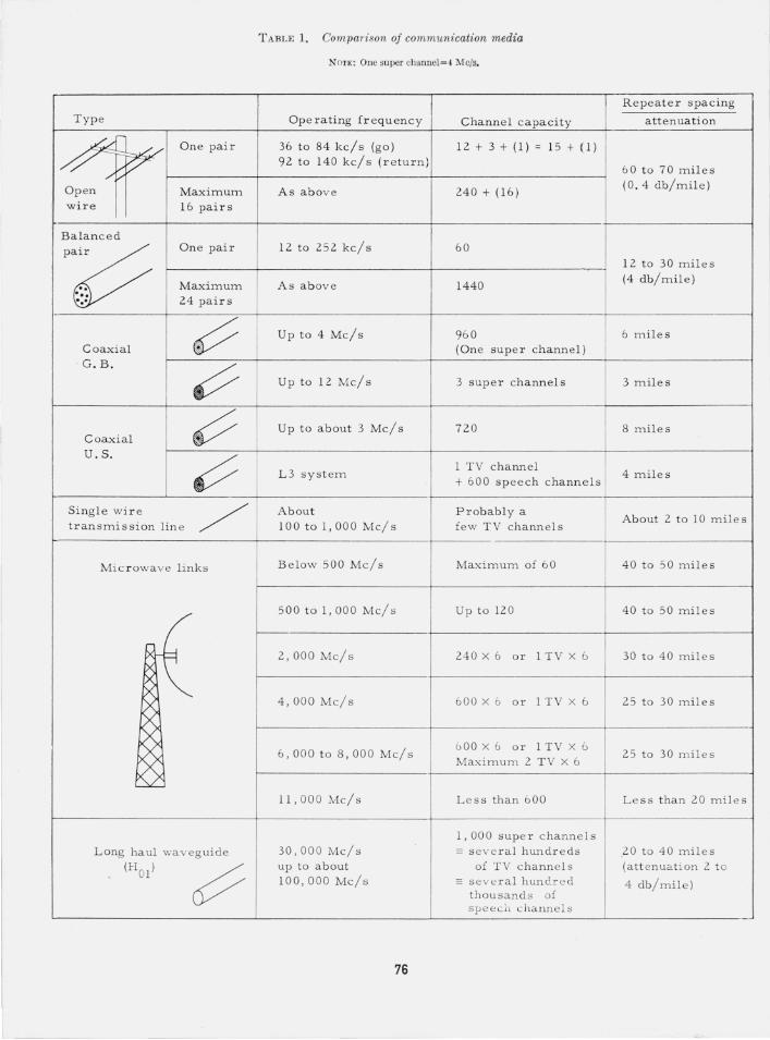
TABLE 1. Comparison of communication media
NOTE: Dne super channel=4 Me/s.
Rep eater spacing
Type Operating frequenc y Channel capacity attenuation
~~~ One pair 36 to 84 kc/s (go) 12 + 3 + (1 ) = 15 + (1)
92 to 140 kc/ s (return) 60 t o 70 miles
Open Maximum As above 240 + ( 16) (0.4 db/mile)
wire 16 pairs
Balance d
p~ One pair 12 to 252 kc/s 60
, 1 2 to 30 m il es
Maximum As above 1440 (4 db/ m i le)
" '., 24 pair s ' ..
~ Up to 4 M c/s 960 6 mil es C oaxial (One super channe l )
- G .B.
~ Up to 1 2 MC/s 3 super channels 3 mile s
~ Up to about 3 MC/s 720 8 mile s Coaxial U . S.
~ L 3 sys t em 1 TV c hanne l
4 miles + 60 0 speech channels
Singl e w ir e / About Probably a About 2 t o 10 m i les
transmission lin e 100 to 1, 000 Mc/s few TV channels
Mic r owave links Below 50 0 Mc/s Maximum of 60 40 to 50 miles
500 to 1, 000 MC/s Up to 120 40 to 50 miles
( 2 ,000 Mc/s 240 X 6 or 1 TV X 6 30 t o 40 mile s
~ 4, 000 Mc/s 600 X 6 o r 1 TV X 6 25 t o 30 m il es
6 , 000 t o 8 , 000 MC/s 6 00 X 6 or 1 TV X 6
25 to 30 miles Maximum 2 T V X 6
11,000 Mc/s Less than 600 Less than 20 miles
1,000 super channels
Long haul waveguide 30, 000 MC/s - several hundreds 20 to 40 miles
(HOI)
~ up to about of TV channels (attenuation 2 t o 100,000 MC/s - se v e ral hundr e d 4 db/mile)
thousands of speech channel s
76
derive the advantage of r egenera tion, Regener~tion is a necessary requirement because of the large sIgnal distortion cven 'with waveguides of modera te length (say 10 m'ilcs), It has ,been established,be;y:ond any doubt that for long-chstance commumcatIOn purposes only modula tion systems capable of regene~ation can be used, and of these PCM has defimte technological advantages.
This paper is not an attempt ~t a balanced. summary of the subject matter, but IS a presentatIOn of the opinions of the authors.
2 . Summary of Properties of Waveguides
There are four principal factors influencing the performance of a waveguide: (1) Its geometry both in shape and size (in terms of the wavelength), (2) its mode of operation, (3) the value of the surface impedance of its walls, and (4) the natu~'e and magnitude of the tolerances o~ t~e cross sect~on,
For 10nO'-distance commUl11CatIOn wavegmdes of circular cr~ss section opera ting in the H OI mode have been chosen. The choice is chiefly a matter of technological preference bas~d on a number ,of considerations. Such wavegUIdes have relatively low dispersion and low attenuation and can be constructed '0 discrimina te against unwanted modes, and the requirements on the tolerances on the c~'oss section are less exacting than for other wavegmdes and modes.
The exact waveguide properties and construction is a matter of compromise between a .number ,of conflicting factors such as. co.st of. termm::l eq1.llpment and repeaters, permISsIble sIgnal dIs tor tlOn , service rcliability etc. And, since thesp factors can be traded for ea~h other it is impossible to give a speci6cation for. a wave,guide under any given cor:-ditions except m the lIgh t of accumulated e~penmental experience. But, to fix orders of magmtudc a wavcO'uide operating in the 4- to 8-mm band would be abo~t 2 to 3 in, in diameter,
'With waveO'uides there are two principal sources of sio'nal distortion: (1) Delay distortion [6], and (2) ~ode conversion-reconversion phenomena [1,,4], D elay distortion arises (like wi~b m?st commumcat ion media) because of the nonlmeanty of the phase
~ characteris tic, (3(w). This leads to the undesu'able feature that the higb frequ ency components of tbe siO'nal travel faster than tbe low frequency comp~nents, a ph enomenon known as disper~io? , .A corresponding distortion ~u,e t o th: va~'IatlOn m th e at tenuation charactenstIC a(w) IS, WIth waveguides, negligible [6] .
The actual bandwidth limitation due to delay distortion depends to a large extent on the modu~ation method and is particularly troublesome wIth FM. P C:\1, on the other h and, is rather immune. but even bere 10- mtLsec modulation pulses would be unrecognizable after . a journey down a .typi~al
I waveO'uide, say, 30 mIles long ; regen?ratlOn IS, t herefore called .for. In addition, certam amount of equalization of the (3(w) characteristic may be a necessity.
77
Mode conversion-reconversion is a new phenomenon, peculiar to wave&uide transn,tission. systems. It arises b ecause a tYPICal wavegUIde SUItable for long distance transmission can su:pport a large number of modes apart from the d eSIred one (H OI)' and because of the irregularities in the waveguide (small dents , changes in ~iameter and cross sectional shape, small bends and kmks, etc.). In consequence, at each minute irregularity the preferred tr.ansmission mode (HOI) becomes scattered and partIally transformed into the parasite modes. The process is lmown as mode conversion and leads to a gradual diffusion of energy into the parasite modes and, th erefore increased attenuation. With some exceptions thi~ process of mode conversion is actua~ly not particularly harmful: It .can~ot,. however, e>:Ist on its own but, by reCIprOCIty, It IS accompamed by the complementary process of ':reconver~ion:" In this process, the energy now partIally carned m the unwanted modes becomes r econverted (by being scattered by subsequent irregularities) ,back to the H OI mode. But since the group velocltJ es of the parasite modes differ from tbat of the H OI mode, the reconversion is not in phase with the signal carried in the IIol mode. Further , sin ce the degree of the distortion is phase dependent and tbe phase of the reconverted signal is related Lo the distan ce b etween the conversion and r econversion points in terms of the wavelength , the whole process of mode conversion-reconversion is frequen cy sensitive. The overall frequency attenuation curve is, therefore, very irregular, leading to considerable sign al ,distortion. Because of the nature of mode eon verSlOnreconversion phenomena it is inconceivable that sui table terminal equipment could be constru cted to coun teract its effects. Mode conversion-reconversion effects are conveniently minimized by suitable waveguide design. .
There i on e particular aspect of mode converSlOnreconversion that calls for special attention: this arises through bending of the waveguide. The circular waveguide carryin g- the IIol ~nod.e ca? support simultaneously th.e Ell mode, ~laVll1g. Icl : ntIcal velocity.3 In a straIg ~lt wavegLllde. tlll~ lS of no direct consequence, but If t.he wavegUIde 1S bent in an arc of a circle then the two modes become coupled with subsequent exchange of energy between the modes. This leads to large attenuation and signal distortion. Once again the effect is counteracted by judicious waveguide design.
It is possible to design a whole series of components [1, 5] such as specially tailored bends and corners, tapers, mode transducers, :lte. But tbe design is not as straigh tforward as with components for conventional single mode rectangular waveguide. The waveguide can support a laTge number of modes and therefore, any changes of the waveguide geometry ~ust be made with great care bearing in mind mode conversion-reconversion phenomena. This requires a detailed study of wave transmission
3 Such modes are termed degeuerate.
in multimode waveguides and the coupling effects due to irregularities ; a field relatively unexploited in its analytical and experimental aspects.
D espite all the planning difficulties, a waveguide when properly designed will give satisfactory service and will handle successfully a bandwidth well in excess of 20 kMc/s , which is equivalent to an intelligence bandwidth of about 1,000 Mc/s, a capacity not offered by any other existing communication medium.
3. Delay Distortion in Uniform Waveguides
As is well known, with waveguides both a(w) and /3(w ) are functions of frequency. It can be shown [6], however, that the effect of a(w) on signal dist.ortion is negligible in comparison with /3(w ) . H ere, therefore, only the effect of the /3(w ) characteristic will be examined.
The phase propagation coefficient /3(w ) is given by
(1)
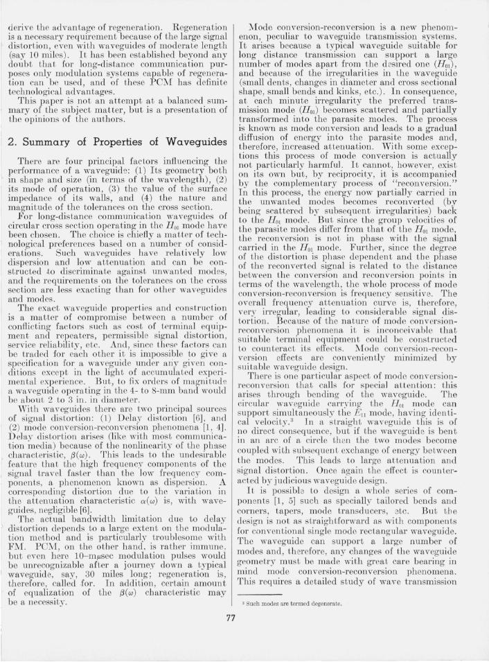
where c is the velocity of light, and W e the cutoff frequency of the waveguide, which is a geometrical parameter. These relations are illustrated in figure 2.
The phase (Vph) and group velocities (vg) are defined by
Vph Wo = £.. c -J(w~-w~) Vg
(2)
These quantities are frequency dependent. If the signal is composed of several frequencies
then, naturally, the signal will be distorted because the high frequency components will travel faster \ han the low frequency ones. The differential phase delay between the extreme components 01 the modulating envelope is a measure of signal distortion: it is the delay distortion term. For a waveguide operated at a frequency substantially above
f3
o w
FIGURE 2. (3-w characteristic of a perfect waveguide.
78
cutoff the bandwid th (in Mc/s) can be expressed as follows [6]:
f= (l9 jF) Cfo/l) 1/2 (ocp ) 1/2 (3)
where F = cutoff frequency/carrier frequency l = length of waveguide in kilometers
j~ = carrier frequency in kilomegacycles per secona ocp = permissible phase delay between the carrier and
the sideband in radians. It has been assumed that j is a small proportion of carrier frequency.
For example, for a typical rectangular waveguide F = 0.6, and therefore at the carrier frequency of 10 kMc/s (and length 30 km) we get
]=9.4 (1 rad)1/2Mc/s. The permissible amount of delay distortion (ocp ) ;
is a function of modulation method. Clearly, with I AM if (acp) = 7r/2 then inversion of sidebands takes ' place: a condition of severe distor tion. For AM, FM, and many other modulation methods the maximum possible value of acp is only a small fraction of 1 rad. For PCM, however, (acp) can take quite substantial values; once again, therefore, PCM is superior to the more common modulation methods.
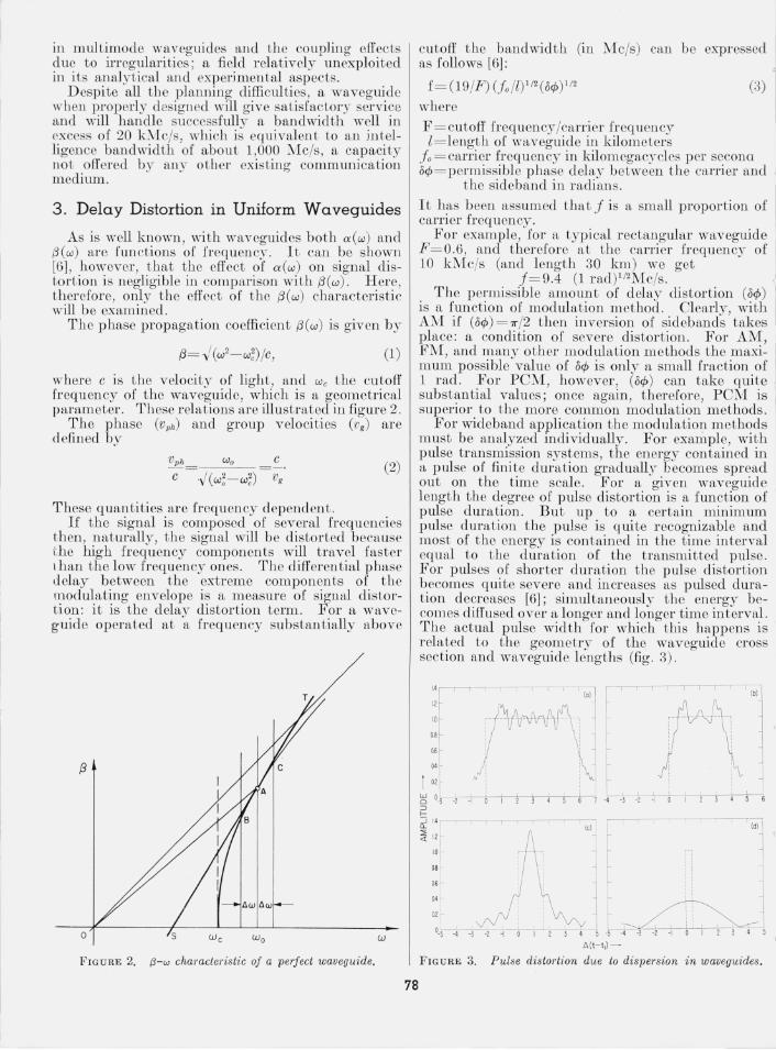
For wideband application the modulation methods must be analyzed individually. For example, with pulse transmission systems, the energy contained in a pulse of finite duration gradually becomes spread out on the time scale. For a given waveguide length the degree of pulse distortion is a function of pulse duration. But up to a certain minimum pulse duration the pulse is quite recognizable and most of the energy is contained in the t ime interval equal to t he duration of the transmitted pulse. For pulses of shorter duration the pulse distortion becomes quite severe and increases as pulsed duration decreases [6]; simultaneously the energy becomes diffused over a longer and longer time interval. The actual pulse width for which this happens is related to the geometry of the waveguide cross section and waveguide lengths (fig . 3).
Q4
1 01
w J o -J -1 -I Q 1
::J f--~ 1.4 r--,-------------r
-,----,----,-, ~ --,-1 --.----,- -,------ 'l;'j - --I' 1 ~ 1\--- ----;
, l r I :
~ ~ , J : J
2 3 4 5 6 ~ "-Ic---t----?-----.---t-' +-i 7 -4 -J ·1 --:r- 1 J 4
~ 1,2 f.-
<l ~: r oJ
.---,----- - IcI' ~ , i Idll
:f 11: \ 1 ' i~~
0_>-5 --4'-'-J~ ---'-+--'1 ~1 J 4 5 -5 -4 -J -1 ·1 0 1 1 J 4 5
A( t- t,i-
FIGURE 3. Pulse distortion due to dispersion in waveguides.
T.\'p ic<ll 'nlveguides fo r lo ng-distance transmission h ave F = 0. 15, then at a frequency of 35 kMc/s p ulses HS shor t as 10 m Msec can b c tr ansmitted wi t hou t signific::m t distor tion over a dis t ftn ce of som e 30 k m . Su ch perform ance is sufflcien t for man)- a pplicfttions, but if i t wer e required to transm it ev('n shor ter pulses some equalization of waveguid e characteristic "~ould then b e n ecessary. Such eq ualiz,l t iol1 is b est carried out at t be t ermin al equipm ent.
4. Properties of Uniform Waveguides and Their Uses
4 .1. Simple Waveguides
The reasons for choosing for long-distance transmission the circular waveguide op erated in the circular electric m ode (H oI) have b een explain ed in section 2. Such waveguides can support, apart from t he desired (H oI) mode a mul ti tude of other m ode all of which a rc und esirable. The total number of modes t hat can possibly propagate in a waveguide with diam et er D is kno wn as t he m odulus of overmoding, )J!{. T h is is approximately given by
(4)
The larger t he m odulus of overmoding, the larger t he num ber of possible modes and, consequently, the gr eater t he eng ineering difficul ties in preven ting m ode conversion-reconversion phenomena. Y et, a large ratio DIAD is necessary to have low attenua tion and dis persion . Of necessity, th erefore, th e proport ions of a waveguide are a compromi e. Ty picftlly, D/Ao is of t he order of 10 or more a nd the m odulus of overmoding is, ther efore, at least about 200 to 400 .
E ach of t he m odes prop agates wi th a characteristic group v eloci ty given by
(5)
The COlnmon est type of waveguide is a plain metallic pipe. With such waveguides the wall of the waveguid e presen ts a surface r esis tance R , given by [7]
(6)
wh ere <Tis th e conductivi ty of t he m etal, M i ts p ermi tt ivity, and ..J(Molf. o)=377 ohms, is th e free space imp edan ce. This surface r esis tance gives rise to a ttenuation which for Emn mod es is given by [7]
(7)
79
and for Hmn modes by
These attenu fttion s are given in decibels per meter if D, t he diameter of the waveguide, is measured in meters .
The a t tenuation of th e H OI mode (the wan ted mode) is given by [7]
(9)
Thus for a copper waveguid e at t he free sp ace waveleng th of 8.7 m m, i t is l.2 db/mile.
Most of the un wan ted modes have ftttenua tion a nd group veloci ties differing subs tan tially from the H OI mode. Tbus attenua tions of 10 to 50 tim es that of t h e H OI m ode is common and group velocities of most m ode difl'er from the H OI mode by as much as 10 p ercen t or more. A few of the mod es, h owever, h ave properties similar to those of t he H OI m od e. For example, the Ell mode h as gr oup velocity almost equal to tha t of the H OI m ode and a few of the modes, notably t he Ilo2 ' 1103 , Il1 2, Il13, Il22, and !-I23 , have a t tenuation only 3 to 10 tim es as mu ch a the H OI
mode. These m odes, therefore, tend to b e p ar ticuLnly troublesom e an d the only wn,y to deal with them satisfac torily i tlu'o Ll gh judicious use of special waveguide.
4.2 . Special WavEguides
W aveguides of special co nstru cti on ar c ll ecessary, as explained in tbe earli er sec tio ll s, prin cipally to co mbat or at leas t to millimize th e m ode cO ll versionr econversion efl'ec ts. For s uch applications, disk waveguides were firs t to be sugges ted Hnd various ellip tic, COlTug,L ted , a ll d more complex structures wer e tried for nego tia ting bCllds . AILer m fmy years of r esearch it is now clear tha t only JlClical , and dielec tric coated wfweg uici cs a re likely to be of any extensive use. Such waveg uid es bcJlcw e as if their surface impedan ce were a nisotropic.
The th eory of propagcLtion in IlIlisotropi c waveguides can be qui te involved , but sill cr II <w eguides for long distan ce tr ansmiss ion h ave, ill general, sm all surface impedance an approxiu l<Lte trcal1n en t is adequate, a nd this will be gi vc n here [8, 9] .
The propagcLtion co effi cien t ill snch IVa vcguides is given by
wher e t he qu an ti ty ol' (= ex+jo(3) is composed of t be a t tenua tion coefficient (ex) a nd a quantity 0(3 modifying the phase change coeffi cient ((3 0) of t he waveguide with zero surface impedan ce. The coeffi cien t ex is proportional to surface r esistance (R s) ftnd 0(3 to surface r eactan ce (X,), t hese being r espectively t he r eal and imaginary parts of surface impedance, Z ,.
With anisotropic waveguides the quantity Zs may be described in terms of the matrix of its components; most simply in terms of its two principal components Z~ and Zr which are surface impedance components along the two principal axes. The sum of the projection of these components along the cf> and z directions defin e the circumferential (Z",) and axial (Z z) components of the surface impedance; and it is these components that are used in the subsequen t formulas. Z", can be regarded as the surface impedance presented to the currents flowing in the waveguide wall in t he circumferential direction and Z z a corresponding quantity for currents flowing in the axial direction.
In such waveguides the attenuation of E-waves is given by [9]
nepers (11)
and for H-waves by
[ em A )2J-1 X 1- -; D nepers (12)
where the meaning of symbols is as before. In the above formulas if X" ~ X ", are substituted
for Hz and H"" respectively, t hen o{3 will be obtained.
4 .3. Dielectric Coated Waveguides
A metallic surface exhibits a surface impedance given by [8]
(13)
where Rm is given by (6). The surface of a copper tube ((j= 5.8 X I07 mho/m), therefore, presents at Ao= 8.7 mm a surface impedance of (1 + j )X 1.28 X 10⁻⁴, relative to free space (abou t 0.048 ohms) .
If, now, the metallic tube is coated with a thin layer of dielectric then its surface impedance 'will be enhanced as given in table 2, where t is the thickness of the dielectric layer, ko= 27r/ Ao, ~ r relative permittivity, and 0 the loss angle of the dielectric. Olearly, by choosing suitable materials and the thickness of t he dielectric layer, it is possible to obtain within wide limits any required surface impedance compo-
T A B LE 2. The surface impedance of a dielectric coated metal surface
T hese value must he augmen ted hy Z ",= R m+jX .. (R m=Xm= ";"jl'/"";, ,/I'O,) the surface impedance of the metal.
Surface im pedance
2 .=R .+jX . 7.= R .+jX .
Re part
R,=tk,(tan ~/,,) R.= ~ (tko)3( " tan ~)
3
1m part
X .=tk,(l - l / ,,) X.= ~(tk,)3(,,- 1)
3
80
nents and, consequently, the attenuation and phase velocity of the E and H modes can be varied relative to the H on modes. By way of illustration, at the free space wavelength of 8.7 mm, for ~T = 2 , tan 0= 0.15, and t= 0.046 mm, the surface impedance components become Zz= 2.5 X lO- 3 + j 1.7 X I0- 2 and Z",=3.7 X I0- 6+ j 3.3 X I0- 4 over and above the value of Zm. If we substitute these values in eqs (11) and (12) we find that for a waveguide of 7-cm diam, there is a 20-fold increase in attenuation of E and H modes (other than H on) relative to the H OI at t he expense of only a 3 percent increase in attenuation of the 1£01 mode. The surface reactance X z is, at the same time, increased by a factor of 140 leading to a substantial change in phase velocity of most modes.
The increase in relative attenuation is necessary I
to cope with mode conversion-reconversion, due to irregularities in the waveguide, while the increase in the surface reactance, X" ~ is necessary so that the waveguide can cope with bends.
4 .4. Ring or Disk Structures
Any periodic array of coaxial disks or rings of different surface impedances falls into this class. If the pitch of such a structure is small in comparison with the wavelength then a simple approximate treatment is possible, as follows:
Let Zl and Z2 be the surface impedance of the individual elements, thickness tl and t3, respectively, then the anisotropic components of the effective surface impedance are given by
Zlt1+ Z2t2 "\
Zz t1 + tz
}-Z",= Z IZ2(t1 + t2) (14)
Z2tl+ Z1t2
Since in most applications IZ21>IZtI and t2< <tl these expressions can be further simplified to
(15)
Thus given Zl, Z2, t l , and t2 t he surface impedance components Z z and Z", can be calculated. In turn, the attenuation and phase propagation coeffi cients can be obtained from (11 ) and (12).
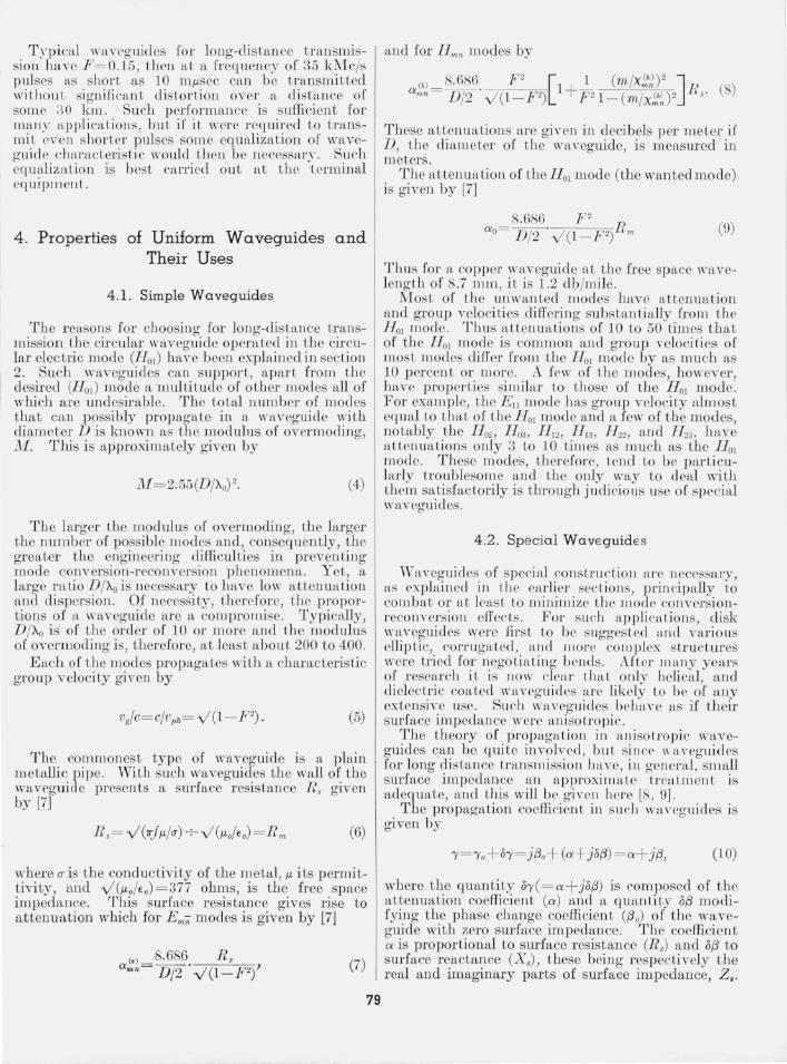
The quantities Zl and Z2 are determined from the ' knowledge of the actual physical structure. This can be a lengthy calculation, but since in practical applications only an estimate of the value of the surface impedance is needed, it is permissible to make a number of rather drastic approximations. For example, for a corrugated waveguide (fig. 4) , Zl is the copper in trinsic impedance and Z2 is the input impedance to a parallel plane transmission line,
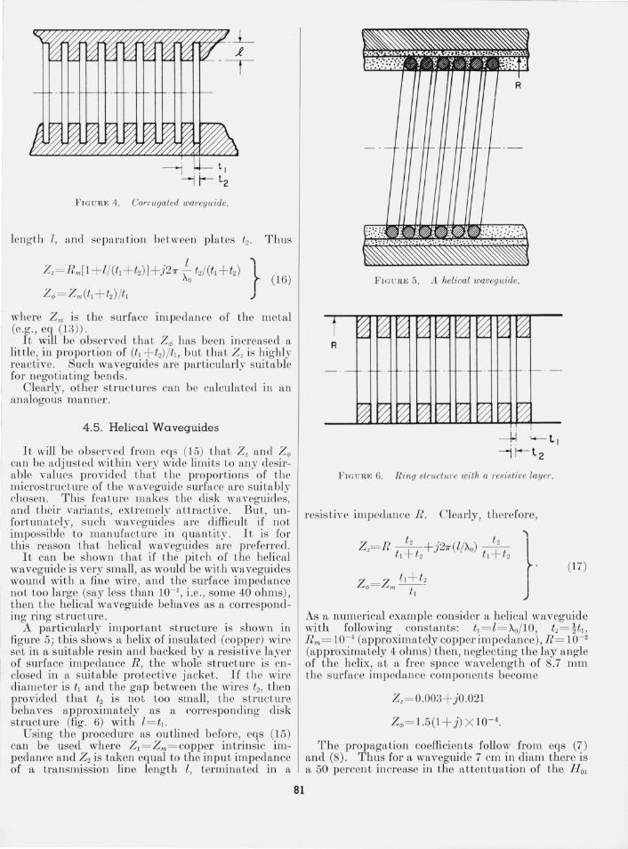
FIG U RE 4. Corrugated waveguide.
lellgth I, and separation between plates t2. Thus
where Zm is tbe surface impedance of the metal (eg; ., eq (13)) .
it will be observed that Z'" ha been increased a little, in proportion of (tl + t2)/t1, but that Z z is highly reactive. Such waveguides arc particularly suitable for nego tiating bends.
Clearly, other structures can be calculated in an analogous manner.
4.5. Helical Waveguides
It will be observed from cqs (15) that Z z and Z~ can be adjusted within very wide limits to any desirable values provided that the proportions of the microstructure of the waveguide surface are suitably chosen. This feature makes the disk waveguid es, and their variants, extremely attractive. But, UJl
fortuna tely , such waveguid es are difficult if not impossible to nmnufacture in quantity. It is for this reason that helical waveguides are preferred.
It can be shown that if the piteh of the helical waveguide is very small, as would be with waveguides wound with a fine wire, and the surface impedance not too large (say less than 10- 1, i .e., some 40 ohms), then the helical waveguide behaves as a corresponding ring structure.
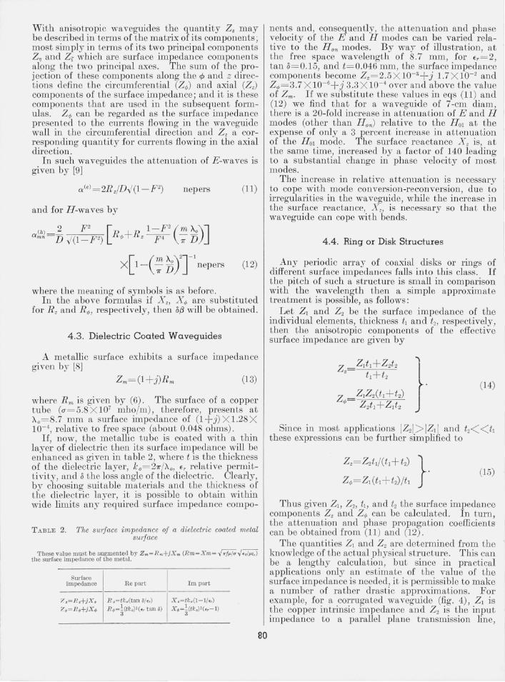
A particularly important structure is shown in figure 5; this shows a helix of insulated (copper) wire set in a suitable resin and backed by a resistive layer of surface impedance R, the whole structure is enclosed in a suitable protective jacket. If the wire diameter is tl and the gap between the wires t2 , then
I provided that t2 is not too small, the struct ure behaves approximately as a corresponding disk structure (fig . 6) with l= t1•
Using the procedure as outlined before, eqs (15) can be used where ZI = Z,,,= copper intrinsic impedance and Z2 is taken equal to the input impedance of a transmission line length I , terminated in a
81
FIG U RE 5. A helical waveguide.
R
FIGU RE 6. Ring slrt.eluTe wilh a j'esis tive layer .
resistive impedance R . Clearly, therefore,
(17)
As a numerical example consider a helical waveguide with following co nstants: tJ= I= t..o/l0 , t2=itJ, R m= 10- 4 (approximately copper impedance), R = 10- 2
(approximately 4 ohms) then, neglec ting the lay angle of the helix, at a free space wavelength of 8.7 mm the surface impedance components become
Z z= 0.003+ jO.021
Z",= 1.5(1+ j) X 10- 4 .
The propagation coefficients follow from eqs (7) and (8). Thus for a waveguide 7 cm in diam there is a 50 percent increase in the attentuation of the HOI
mode, and a 30-fold increase in the attenuation of most E -modes. The attenuation of the lower order H -modes has also been increased by a factor of 30, while the surface reactance is increased 200 times.
5. Basic Theory of Nonuniform Waveguides
Theory of nonuniform waveguides is fundamental for thorough understanding of transmission aspects as well as design of many waveguide components peculiar to long distance transmission by waveguide. ~hus, cOI~'llnonlJ:' waves are conveyed from an osCIllator ma a sIngle mode rectangular waveguide through a transducer to a circular waveguide then through a taper to the main waveguide run.
We shall see that a mode transducer a bent waveguide, as well as a taper are particular' embodiments of nonuniform transmission lines. The main waveguide run is also a nonuniform transmission line in the sense that it can carry a large number of modes and all minute. irregularities act as coupling elements between the hnes ; each line representing one particular mode.
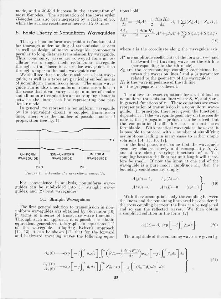
Il~ genera.l, we rep~'ese~lt a nonuniform waveguide by ItS eqUIvalent CIrcUlt: n coupled transmission lines, where n is the number of possible modes of propagation (see Jig. 7).
--------~-----'-----------~~
----------r-----------------~~----------.z
UNIFORM WAVEGUIDE
- .......
z=O t: L
UNIFORM
WAVEGUIDE
FIGURE 7. Schematic of a nommiform waveguide.
For convenience in analysis, nonuniform wavegu~des can be subdivided into (1) straight wavegUldes, and (2) bent waveguides.
5.1. Straight Waveguides
The first general solution to transmission in non~niform waveguid~s was obtained by Stevenson [10) m terms of a senes of transverse wave functions. Through such an approach it is possible to obtain equivalent generalized telegraphist's equations [11 ) of the ~vaveguide. Adopting Reiter's approach [12 , 13), It can be shown [17) that for the forward and backward traveling waves the following equa-
tions hold
where z is the coordinate along the waveguide axis.
A t are amplitude coefficients of the forward (+) and backward (-) traveling waves on the ith line (corresponding to the ith mode).
S~ are the corresponding coupling coefficients between the waves on lines i and p (a parameter related to the geometry of the waveguide) . I
K i is the wave impedance of the ith line. f3 i the propagation coefficient.
The above are exact equations for a set of lossles;.; nonuniform transmission lines where S, K , and f3 are, in general , functions of z . These equations are exact representation of transmission in a nonuniform waveguide. In principle, therefore, given the functional dependence of the waveguide geometry on the cOOl'dinate z, the propagation problem can be solved , but the computational difficulties are in most cases formidable. I'Vith practical waveguides, however, it is possible to proceed with a number of simplifying assumptions leading in many cases to rather simple solutions [14, 15, 16, 17) .
In the first place, we assum e that the waveguide geometry changes slowly and consequently S, K, and f3 are slowly varying functions of z. The coupling between the lines per unit length will therefore be small. If now the input at one end of the waveguide is a pure mode, amplitude A o, then the boundary conditions are simply
A t,(O) = A o
A t (O)=O
A ;;,(L) = 0
A i(L )=O
'\
(i~m) J · (19)
With these assumptions only the coupling between the line m and the remaining lines need be considered; the cross coupling between the lines can be neglected and so can the reflected waves. We then obtain a simplified solu tion in the form [17)
A;t;(z)=A o exp [ -j.f f3mclzJ (20)
The amplitudc of the remaining waves arc given by
- [ 'lL J 1L ( - 1 cUlnK » [ . 1Z J '\ A.(O)~-cxp -J "Pmd, " 8" -2 d,' exp -J2 0 Pmd, d, I
A t(L )_ [ 'lL J1L ± [ 'l z J r
(21)
A i (0) - ± exp - J 0 f3i cl z 0 Sim exp - J 0 (f3m =t= f3i ) cl z cl z I .J
82
In the derivation of these expressions it has been assumed that none of the modes are at the cutoff. When dealing with components, such as tapers for example, some modes are of necessity at the cutoff at some cross section along the taper, and it would appear that (20) and (21) are not a sound basis for design. Nevertheless, i t appears that the use of (20) and (21) is usually justified [18].
It is to be observed that usually it is only the lower order modes that need to be at all considered (typically H 02 , H 03 , H 12, H 13, H 22 , H 23 ; cf., section 4.1.).
The (3 coefficients of these modes differ but very little from that of the HOI and consequently (eq (2 1)) only the coefficients of the forward traveling waves (A +) need be considered; the coefficients A - are very much smaller and can, therefore, be neglected.
Using eqs (21) an interesting proposition can be proven . In general, a pure mode at the input to a waveguide will produce at the output a combination of modes. For a good transducer the output consists of an almost pure mode of the desired kind. The purity of this mode can now b e made as high as desir ed merely by increasing the length of the transducer: the longer and more gradual the transducer the purer is the mode at the outpuL.
5.2. Propagation in Bent Waveguides
The general coupled transmission line equations for a b ent waveguide of arbitrary cross secLion were given by Shimizu [19] from which the relations for a circular waveguide follow. 'rhe particular case of a bent circular waveguide wa analyzed earlier by Jouguet [20], who analyzed the field in a curved waveguide by means of perLurbaLio n caleulus and obtained the field in Lerms of a n expansion in powers of I /R, where R is the radius of curvature of the waveguide.
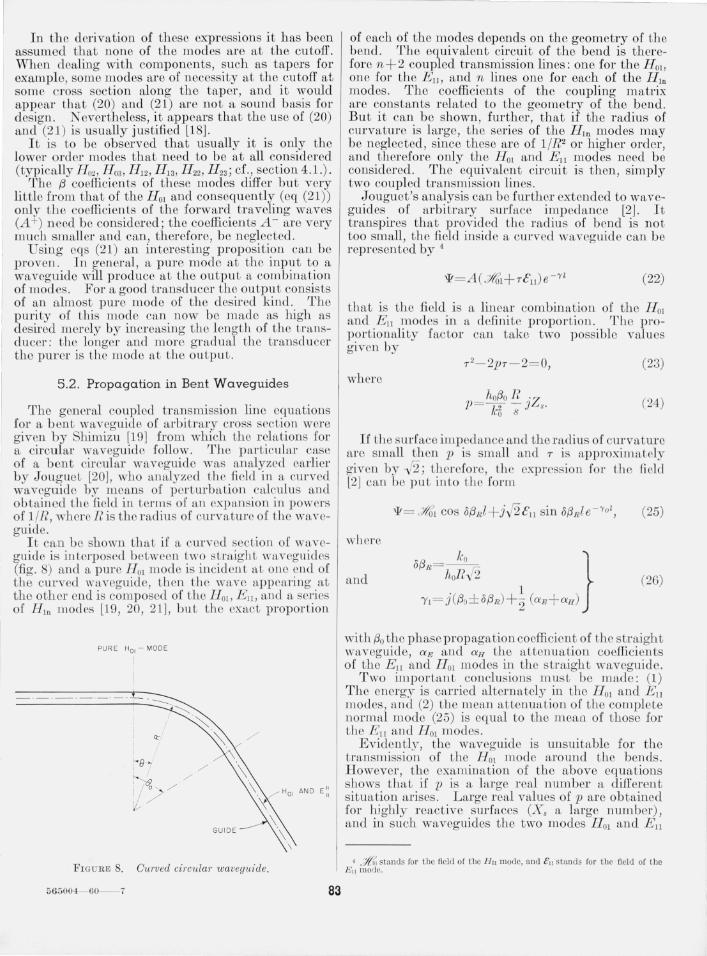
It can be shown that if a curved seeLion of waveguide is interposed between two sLraight waveguides (fig. 8) and a pure lIOl mode is incident aL one eud of the curved waveguide, then t he wave appearing at the other end is composed of the H OI, Ell , and a series of HID modes [19, 20, 21], but the exact proportion
PURE HOI - MODE
I
~8 ,
~6' 1/ 0 ,-, /
't /
FIG URE 8. C1trved circular waveguide.
565004- 60--7 83
------ --.-- ----- -_ .. -- -----
of each of the modes depends on the geometry of the bend. The equivalent circuit of the bend is therefore n+ 2 coupled transmission lines: one for the H OI, one for the Ell, and n lines one for each of the HID modes. The coefficients of the coupling matrix are constants related to the geometry of the bend. But it can be shown, further, that if the radius of curvature is large, the series of the HID modes may be neglected, since these are of 1/R2 or higher order, and therefore only the HOI and Ell modes need be considered. The equivalen t circuit is then, simply two coupled transmission lines.
Jouguet's analysis can be further extended to waveguides of arbitrary surface impedance [2]. It transpires that provided the radius of bend is not too small , the field inside a curved waveguide can b e represented by 4
(22)
that is the field is a linear co mbination of the H OI and Ell modes in a definite proportion. rrhe proportionality factor can take two possible values given by
(23) where
_ hof3o 1l. ·Z p - k2 J "' s' o 8
(24)
If the surface impedance and the radius of curvature are small then p is small and r is approximately given by -f2; Lherefore, the expression for the field l2] can be put into Lhe form
where
and (26)
with f30 the phase propagation coefficient of Lhe straight waveguide, aE and aH the attenuation coefficients of the Ell and H OI modes in the sLraight waveguide.
Two important conclusions must be made: (1) The energy is carried alternately in tbe HOI and Ell modes , a nd (2) the rnean attenuation of Lhe complete normal mode (25) is equal to the mean of those for the E!1 and H OI modes.
Evidently, the waveguide is unsuitable for the transmission of the HOi mode around the bends. However, the examination of the above equation s shows that if z) is a large real number a different situation arises. Large real values of p are obtained for higbly reactive surfaces eX. a large number), and in such waveguides the two modes Fl01 and E!1
• ,;fa stands for the field of t1w H " mode, and ell stands for the field of the Ell mode.
propagate almost independently of each other, but the attenuation of H OI mode is slightly increased. In such a waveguide, the attenuation of the H OI
mode is given by [2] (27)
where ao is the attenuation in the straight waveguide and is given by (eq (12»
2 F 2 aO=D '1/(1-F2) R q,. (28)
TLe additional attenuation due to the bend is given by
D Rs/\Z.\2 aR= 4R2 F\/(1- F2) · (29)
Clearly, by choosing a sufficiently large surface reactance it is possible to bring this increase in attenuation below any predetermined level. Such values of surface reactance can be conveniently obtained either by coating the waveguide surface with a layer of dielectric or by corrugating the waveguide surface in a suitable manner.
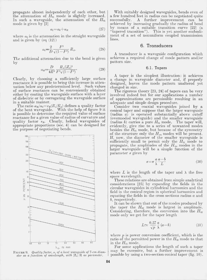
The ratio aR/aO= vR(Rz/R q,) defines a quality factor of the bent waveguide. With the help of figure 9 it is possible to determine the required value of surface reactance for a given value of radius of curvature and quality factor VR . Clearly, helical waveguides of appropriate proportions (sec. 4) can be designed for the purpose of negotiating bends.
1000 ~-~-'--'---'-------'-------'------T--::J
100
500
IS.O S.5 1.0 7.5 8.0 8.5 9.0 9.5
Ao• IN mm
FIGURE 9. Quality factor, v, of a bent waveruide of 7-cm diameter as a function of wavelength, with IZ, R as parameter.
With suitably designed waveguides, bends even of a few hundred feet in radius can be negotiated quite successfully. A further improvement can be achieved by increasing gradually the radius of bend by means of a suitable transition curve [22] (a " tapered transition") . This is yet another embodiment of a set of nonuniform coupled transmission lines.
6. Transducers
A transducer is a waveguide configuration which achieves a required change of mode pattern and/or pattern size.
6 .1. Tapers
A taper is the simplest illustration: it achieves a change in waveguide diameter and, if properly designed, leaves the mode pattern unaltered yet changed in size.
The rigorous theory [23, 24] of tapers can be very involved indeed but for our applications a number of approximations are permissible resulting in an adequate and simple design procedure.
Consider two coaxial waveguides joined by a conical taper and suppose that the larger waveguide (radius a) is operated substantially above cutoff (overmoded waveguide) and the smaller waveguide (radius b) carries a pure H OI mode. The taper will, evidently, give rise to a series of unwanted modes besides the H OI mode, but because of the symmetry of the structure only the Hon modes will be present. If, now, the diameter of the smaller waveguide is sufliciently small to permit only the H OI mode to propagate, the amplitudes of the H on modes in the larger waveguide will be a simple function of the parameter () given by
84
aa- b (}=7r~L (30)
where L is the length of the taper and A the free space wavelength.
These relations are obtained from simple analytical considerations [25] by expanding the fields in the circular waveguides in cylindrical harmonics and the field in the conical region in spherical harmonics and equating the fields in the cross sections radius a and b, respectively.
It can be shown that out of the m odes produced by the taper the H 02 mode is largest in amplitude. Considering, therefore, the conversion into the H 02
mode only we get for the taper length
0.57 a L':::::!. ·- - (a- b) 'lIp A
(31)
where p is power conversion coefficient, which is the ratio of the permitted power in the H 02 mode to that in the HOI mode.
For some applications the length of such a taper may be excessive, but a further improvement is possible by using a two-section conical taper (fig. 10).
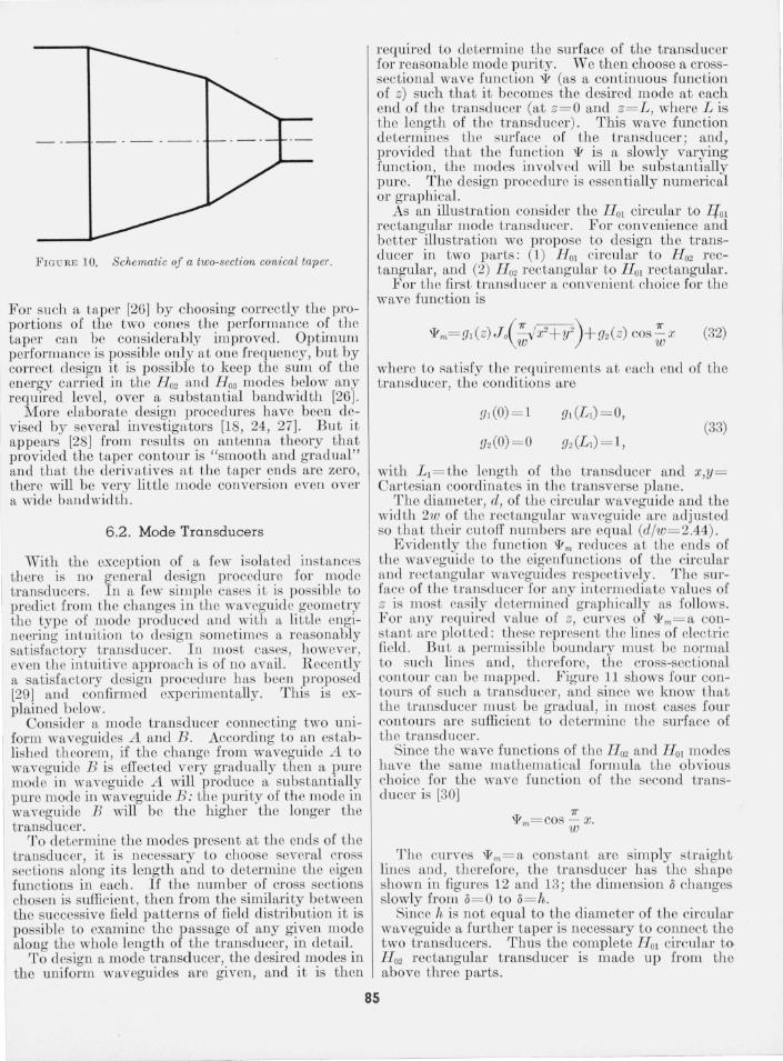
FIGUltE 10. Schematic of a two-section conical taper.
For such a taper [26] by choosing correctly the proportions of the two cones the performance of the taper can be considerably improved. Optimum performan ce is possible only at one frequency, but by correct design it is possible to keep the sum of the energy carried in the H 02 and H 03 modes below any required level, over a substantial bandwidth [26].
More elaborate design procedures have been devised by several investigators [1 , 24, 27]. But it appears [28] from results on antenna theory that provided the taper contour is "smooth and gradual" and that the derivatives a t the taper ends are zero, there will be very little mode conversion even over a wide bandwidth .
6.2. Mode Transducers
With the exception of a few isolated instances there is no general design procedure for mode transducers. In a few simple cases it is possible to predict from the changes in Lhe waveguide geometry the type of mode l)roduced and with a little engineering intuition to design sometimes a reasonably satisfactory transducer. In most cases, however,
I even the intuitive approach is of no avail . R ecently a satisfactory design procedure has been proposed [29] and confu'med experimentally. This is ex-plained below.
Consider a mode transducer connecting two uni-I form waveguides A and B . According to an estab
lished theorem, if the change from waveguide A to waveguide B is effected very gradually then a pure mode in waveguide A will produce a substantially pure mode in waveguide B: the purity of the mode in waveguide B will be the higher the longer the transducer.
To determine the modes present at the ends of the transducer, it is necessary to choose several cross sections along its length and to determine the eigen functions in each. If the number of cross sections chosen is sufficient, then from the similarity between the successive field patterns of field distribution it is possible to examine the passage of any given mode along the whole length of the transducer, in detail .
To design a mode transducer, the desired modes in the uniform waveguides are given, and it is then
required to determine the surface of the transducer for reasonable mode purity. We then choose a crosssectional wave function \IF (as a continuous function of z) such that it becomes the desired mode at each end of the transducer (at z= O and z= L , where Lis the length of the transducer). This wave function determines the surface of the transducer ; and, provided that the function \IF is a slowly varying function, the modes involved will be substantially pure. The design procedure is essentially numerical or graphical.
As an illustration consider the H o! circular to lio! rectangular mode transducer. For convenience and better illustration we propose to design the transducer in two parts: (1) H o! circular to H 02 rectangular, and (2) H 02 rectangular to H OI r ectangular.
For the fu'st transducer a convenient choice for the wave function is
(32)
where to satisfy the requirements at each end of the transducer, the conditions are
91(0) = 1
[/2(0) = 0 (33)
with LI= the length of the transducer and x,Y= Cartesian coordinates in the transverse plane.
The diameter, d, of the ciJ.'cular waveguide and the width 2w of the rectangular waveguide arc adju ted so that their cutoff numbers are equal (d/w= 2.44).
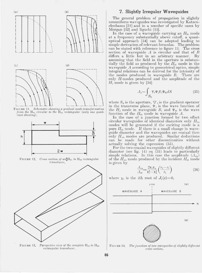
Evidently the function \IF", reduces at the ends of the waveguide to the eigenfunctions of the circular and rectangular waveguides respectively. The surface of the transducer for any intermediate values of z is most easily determined graphically as follows. For any required value of z, curves of \IF",= a constan t arc plotted: these represent the lines of electric field. But a permissible boundary must be normal to such lines and, therefore, t he cross-sectional contour can be mapped. Figure 11 shows four contours of such a transducer, and since we know that the transducer must be gradual, in most cases four contours arc sufficicnt to determine the surface of the transducer.
Since the wave functions of the H 02 and H OI modes have the same mathematical formula the obvious choice for the wave function of the second transducer is [3 0]
85
The CUTves \lFm= a constan t are simply straight lines and, therefore, the transducer has the shape shown in figures 12 and 13 ; the dimension 0 changes slowly from 0= 0 to 0= 71, .
Since 71, is not equal to the diameter of the circular waveguide a further taper is necessary to connect tho two transducers. Thus the complete H Ol circulal' to H 02 rectangular transducer is made up from the above three parts.
(0 )
, \
L. _ __ __ . _ ___ "
(c )
i
~.
\ \
\ \ \ \ \ \
.--1
(b)
(d)
------- - - , \ \
I I
\ \ \ \ \ I I
. ...1
FIGU RE 11. S chematic showing a gradual mode transformation fr om the H OI circular to the H 02 rectangu lar (only one quadrant showin g) .
w
1 8
h t 2w
FIGU R E 12. Cross section of anlHol to H 02 rectangular tTansducer.
FIGU RE 13. Perspective view of the com plete H OI to H02 rectangular transd1lcer.
86 I
7 . Slightly Irregular Waveguides
The general problem of propagation in slightly nonuniform waveguides was investigated by Katzenelenbaum [31] and in a number of specific cases by Morgan [32] and Iiguchi [33].
In the case of a waveguide carrying an Ho! mode at a frequency substantially above cutoff, a quasioptical approach [34] can be adopted leading to simple derivation ofrelevant formulas . The problem can be stated with reference to figure 13. The cross section of waveguide A is circular and that of B differs a little but in an arbitrary manner. By assuming that the field in the aperture is substantially the field as produced by the Ho! mode in the waveguide A according to geometrical optics, simple integral relations can be derived for the intensity of the modes produced in waveguide B. There are only H-modes produced and the amplitude of the H j mode is given by [34]
A J = J 'V/I!/VI'¥OldS So
(35)
where So is the aperture, V t is the gradient operator in the transverse plane, '¥ j is the wave function of the H j mode in waveguide B , and '¥OI is the wave function of the HOI mode in waveguide A.
In the case of a junction formed by two offset circular waveguides of identical diameters only H! n modes will be generated if the exciting mode is a pure HOI mode. If there is a small change in waveguide diameter and the waveguides are coaixal then only H on modes are produced. Similar deduction s can be made for other discontinuities without actually solving the expression (35).
For the two coaxial waveguides of slightly different diameter (see fig. 14) eq (35) leads to particularly simple relations. In thi.s case the amplitude (A on) of the H on mode produced by the incident Ho! mode is given by
where Xi IS the ith root of J! (x) = o. Z :;::0
I
(36)
(a)
WAVEGUIDE A I WA VEGUIDE B
~I--"N (b)
• FIGURE 14. The j uncti on of two waveguides of slightly different cross section .
Consider now two such steps in tandem. Clearly the contributions from the conversions must be combined taking the correct phases into account. It C1:Ln then be shown that if the inserted length of the waveguide is one-half beat wavelength (of HO I
and H o2) long and its diameter the mean of the t wo extreme waveguides, th en the mod e conversion is minimized [35] . The same procedure can b e applied
I to other H on modes and a suitable transition between two ·waveguides of different diameters designed .
8 . Mode Conversion-Reconversion
As mentioned in section 2 mode conversionreconversion is a phenomenon existing in any over moded waveguide, such as would be used for longdistance transmission. The level of mode conversion or reconversion on th eir own is a function of waveguide tolerances , but the combined effect of mode conversion-recon version, whicb determines the signal distor tion is also a function of waveguide design or more precisely i t is related to the surface impedance of the waveguide.
For technological reasons one cannot redu ce tbe mod e conversion process beyond a certain limit, related to tbe waveguide tolerances. For given tolerances, however, the mode conversion-reconversion process can be reduced , in principle, below any predetermined level by choosing suitable surface impedan ce. 5 The remaining problem then is a technological one, of r ealizing such surface imped ance . The actual design is a compromise between what is desirable from the mode conversio n-reconversion point of view and what is practicable or at all possible to achieve using existing methods.
Briefly, for good performance on bends, wa veguides must have high surface reactance in the axial direction eXz co mponents) while t he circumferential component (X ,,) remains small . For good discrimination against unwanted modes produced by typical small inegularities, large attenuaLion for unwanted modes and small attenuation for the H OI mode is called r or : that is large Rz an d sm all R q,.
Due to waveguide irregularities a large number of modes become coupled together. If the coupling coefficients representing the aggregate effect of wavegU.i.de irregularities .contn:in a periodic con~ponc.nt , conSIderable slgnal distortlOn takes place [4]: m effect the /3 (w) characteristic becomes broken up by regularly spaced ab sorption bands. But if the irregulariti es are spaced in a random manner no such extreme signal distortion will take place; but on the other hand, the 0: and {3 characteristics become irregular in a random manner with a root m ean square value proportional to (C / 1::.(3) 2 (c is tbe rms value of the coupling coefficient c, and 1::./3 the differ ence between th e pbase propagation coeffi cients of the H OI mode and the parasitic mode) leading to effective crosstalk between the components of the coded signal. III general, the signal distortion due
Ii 'rho conversion to 1-1011 modes has been neglected, since t hi s is not usually troublesome.
87
to mode conversion-reconversion is a function of the quantity (c/ 6/3)2/ 1::.0: where 1::.0: is the difference between the attenuations of the parasitic mode and the H OI mode. For this reason the more the group velocities of the parasitic modes differ from that of the H OI mode and the greater the attenuation of the parasitic modes, the smaller the signal distortion due to mode conversion-reconversion . As discussed in section 4, special waveguides can hring about such changes and h ence their significance.
9. Conclusions
Waveguides for long distttllce communications already form a wide specialized subj ect, too wide to be discussed adequately in an article of t ills size. But we have discussed the main constituents of a waveguide communication system pointing out the necessity of regenerative modulation m ethod, such as P OM.
Special waveguides have been discussed in some detail because, in t he ligh t of presen t knowledge, such waveguides- either of the helical type or dielectric coated- are the only types lik:ely to succeed.
Mode conversion phenomena t11"e intimately connected with overmoded waveguides, of the type used for long distance transmission . D eep understanding of mode conversion processes is essential for successful designs and accordingly a theory has been outlined. The design of su ch components as tapers, mode transducers, and bends rest on nlOde conversion theory.
Various sources of signal distortion have been analyzed in some detail, but it has been stressed t hat if PCM modulation is used and regenerative repeaters, as well as special waveguides, a most advanced system of unequaJled capacity will resul t.
Most of the work described in tills paper was carried out as p int of a research program. of St::mdal'd T elecommunicat ion J..Jaboratories Ltd. The authors have benefi ted from discussions with a number of their colleagues: such discussions helped to crystalize many of the more involved idCt1s.
Acknowledgment is also made to St,1lldard T elecommunication Laboratories L td ., for permission to publish the paper.
10. References
[1] S. E. Miller , Waveguide as a communication m edium , Bell System Tec h. J . 33, 1209 (1954). .
[2] A. E. Karbowia k, Microwave aspccts of wavegUIdes for long di stance t ransmi ssion , Proe . Inst. Elec. E ngrs. (London), Monograph No. 287R (Feb. 1958).
[3] H. M. Barlow, The explorat ion of waveguid e for t runk waveguide multiple channel communications, J . Brit. Inst . Radio Engrs. 7,251 (Oct. 1947).
[4] A. E. ICarbowiak, Distortion of information in nonuniform multimode waveguides, Conv. on Long Distance Transmission by Waveguide, Lo ndon (J an. 1959) .
/

[5] A. E . Karbowiak and H . Enight, An experimental investigation of waveguides for long distance transmission, Conv. on Long Distance Transmission by Waveguide, London (Jan . 1959).
[6] A. E. Karbowiak, Propagation of transients in wavegu ides, Proc. Inst. Elec . Engrs. (London), Monograph No. 224R 105C (Feb. 1957) .
[7] A. E. Karbowiak, Waveguide characteristics, E lectron. a nd Radio Engl'. 34,379 (Oct. 1957) .
[8] A. E . Karbowiak, Theory of imperfect guides- The effect of wall impedance, Proc . Inst. Elec. Engrs. (London) 102B, 698 (Sept . 1955).
[9] A. E. Karbowiak, Microwave propagation in anisotropic wavegu ides, Proc. Inst. Elec. Engrs. (London), Monograph No. 147R 103C, 139 (Aug. 1955).
[10] A. F. Stevenson, General t heory of electromagnetic horns, J . Appl. Phys. 22, 1447 (Dec . 1951).
[11] S . A. Schelkunoff, Con version of Maxwell 's equations into generalised telegraphist 's equations, Bell System Tech. J. 34, 995 (Sept. 1955).
[12] G. Reiter, Connection of two waveguides by a waveguide of variable cross-section (in Hungarian), Thesis from Appl. Math. , Univ. Eotvos Lorand, Budapest (June 1955).
[13] G. Reiter, Generalised telegraphist's equation for waveguides of varying cross-section, Proc. Inst . Elec. Engrs. (London), pt. B Supp!. No. 13, p . 54 (Jan. 1959).
[14] B . Z. Katzenelenbaum , Non-uniform waveguides with slowly changing parameters (in Russian), Doklady Akad. N auk. S.S.R. 12, 711 (1955).
[15] B . Z. Katzenelenbaum, On t he general theory of nonuniform waveguides (in Russian), Dokl. Akad . N auk. S.S.R. 116, 203 (1957).
[16] B . Z. Katzenelenbaum, On the theory of non-uniform waveguides with slowly changing parameters, Intern . Conf. Ultrahigh Frequency Circuits and Antennas, Paris (Oct . 1957).
[17] L . Solymar, Spurious mode generation in non-uniform waveguide, IRE Trans. MTT- 7, 379 (July 1959) .
[18] H . G. Unger, Circular waveguide taper of improved design, Bell Syst em Tech. J . 37, 899 (July 1958).
[19] Y. Shimizu, Theory of transmitting circular electric wave around bends, presented at Intern . Conf. Ultrahigh Frequency Circuits and Antennas, Paris (Oct. 1957) .
[20] M. Jouguet, Effect of curvature on the propagation of electromagnetic waves in guides of circula r crosssection , Cables et Transmission 1, 133 (1947).
88
[21] W. J. Albersheim, Propagation of TEO! waves in curved waveguides, Bell System Tech. J . 28, 1 (1949).
[22] H. G. U nger, Normal mode bends for circular electric waves, Bell System Tech. J . 36, 1292 (1957).
[23] K . T anaka, Mode conversion through the tapered section of circular waveguide system , Intern . Conf. Ultrahigh Frequency Circuits and Antennas, Paris (Oct. 1957) .
[24] B . Z. Katzenelenbaull1 , Long symmetrical waveguide taper for H OI wave (ill Russian), Radiotekh. Elektron . 21, 531 (1957) .
[25] L. Solymar , Design of a conical taper in circular waveguide system supporting H OI mode, Proc . IRE 46, 618 (1958).
[26] L. Solymar, Design of a two-section conical taper in circular waveguid e system supporting t he HOI mode, Proc. Inst. Elec. Engrs . (London), pt. B . Supp!. No . 13, p . 119 (Jan . 1959).
[27] L. Solymar, Monotonic multi-section tapers for overmoded circular waveguides, Proc. Inst . Elec. Engrs. (London), pt. B. Suppl. No. 13, p . 121 (Jan . 1959).
[28] L. Solymar, Discussion on " Special microwave equipment, " Proc. Inst. Elec. Engrs. (London), pt. B. Supp!. No. 13, p . 147 (J an. 1959) .
[29] L. Solymar and C. C. Eaglesfield, Design of mode transducers, IRE Trans. MTT- 8, 61 (Jan . 1960).
[30] C. C. Eaglesfield , Y. Klinger , and L. Solymar, A new H JO to H 2o mode transdu cer (to be published in Proc . Inst. Elec. Engrs. (London) .
[31] B. Z. Katzenelenbaum, Imperfect waveguide in boundary a nd geometry, I zvest. Akad. Nauk. , p. 9 (1955).
[32] S. P . Morgan, Mode conversion losses in transmission of circular electric waves through slightly non-circular guides, J. Appl. Phys. 21, 329 (1950) .
[33] S. !iguchi , Mode conversion in the transmission of TEol wave through a slight tilt and a slight off-set of waveguide, Intern. ConL Ultrahigh Frequency Circui ts and Antennas, Paris (Oct. 1957).
[34] L. Solymar, Overmoded waveguides, optical approach to mode conversion, Electron. and Radio Engr. 36, 426 (Nov. 1959).
[35] L. Solymar, Step transducer between overmoded circular waveguides, Proc. Inst . Elec. Engrs. (London), pt. B. Suppl. No. 13, p. 129 (Jan. 1959) .
(Paper 65DI- I05)