matrix analysis of microring coupled-resonator optical waveguides
TRANSCRIPT
Matrix analysis of microring coupled-resonatoroptical waveguides
Joyce K. S. Poon, Jacob Scheuer, Shayan Mookherjea, George T.Paloczi, Yanyi Huang, and Amnon Yariv
Department of Electrical Engineering and Department of Applied Physics, California Instituteof Technology, MS 136-93, Pasadena, CA 91125
www.its.caltech.edu/∼poon
Abstract: We use the coupling matrix formalism to investigate continuous-wave and pulse propagation through microring coupled-resonator opticalwaveguides (CROWs). The dispersion relation agrees with that derivedusing the tight-binding model in the limit of weak inter-resonator cou-pling. We obtain an analytical expression for pulse propagation througha semi-infinite CROW in the case of weak coupling which fully accountsfor the nonlinear dispersive characteristics. We also show that intensityof a pulse in a CROW is enhanced by a factor inversely proportional tothe inter-resonator coupling. In finite CROWs, anomalous dispersionsallows for a pulse to propagate with a negative group velocity such thatthe output pulse appears to emerge before the input as in “superluminal”propagation. The matrix formalism is a powerful approach for microringCROWs since it can be applied to structures and geometries for whichanalyses with the commonly used tight-binding approach are not applicable.
© 2004 Optical Society of America
OCIS codes: (230.5750) Resonators; (230.7370) Waveguides; (230.3120) Integrated opticsdevices
References and links1. A. Yariv, Y. Xu, R. K. Lee, and A. Scherer, “Coupled-resonator optical waveguide: a proposal and analysis,” Opt.
Lett. 24, 711–713 (1999).2. Y. Xu, R. K. Lee, and A. Yariv, “Propagation and second-harmonic generation of electromagnetic waves in a
coupled-resonator optical waveguide,” J. Opt. Soc. Am. B77, 387–400 (2000).3. N. Stefanou and A. Modinos, “Impurity bands in photonic insulators,” Phys. Rev. B57, 12 127–12 133 (1998).4. D. N. Christodoulides and N. K. Efremidis, “Discrete temporal solitons along a chain of nonlinear coupled
microcavities embedded in photonic crystals,” Opt. Lett.27, 568–570 (2002).5. S. Mookherjea and A. Yariv, “Kerr-stabilized super-resonant modes in coupled-resonator optical waveguides,”
Phys. Rev. E66, 046 610 (2002).6. J. E. Heebner and R. W. Boyd, “‘Slow’ and ‘fast’ light in resonator-coupled waveguides,” J. Mod. Opt.49,
2629–2636 (2002).7. C. K. Madsen, “General IIR optical filter design for WDM applications using all-pass filters,” IEEE J. Lightwave
Technol.18, 860–868 (2000).8. G. Lenz, B. J. Eggleton, C. K. Madsen, and R. E. Slusher, “Optical delay lines based on optical filters,” IEEE J.
Quantum Electron.37, 525–532 (2001).9. B. E. Little, S. T. Chu, W. Pan, D. Ripin, T. Kaneko, Y. Kokubun, and E. Ippen, “Vertically coupled glass
microring resonator channel dropping filters,” IEEE Photon. Technol. Lett.11, 215–217 (1999).10. M. Bayindir, B. Temelkuran, and E. Ozbay, “Tight-binding description of the coupled defect modes in three-
dimensional photonic crystals,” Phys. Rev. Lett.84, 2140–2143 (2000).11. A. Yariv and P. Yeh,Optical waves in crystals: Propagation and control of laser radiation (Wiley, New York,
1984).
(C) 2004 OSA 12 January 2004 / Vol. 12, No. 1 / OPTICS EXPRESS 90#3181 - $15.00 US Received 14 October 2003; revised 19 December 2003; accepted 22 December 2003
12. K. Oda, N. Takato, and H. Toba, “A wide-FSR waveguide double-ring resonator for optical FDM transmissionsystems,” IEEE J. of Lightwave Technol.9, 728–736 (1991).
13. R. Orta, P. Savi, R. Tascone, and D. Trinchero, “Synthesis of multiple-ring resonator filters for optical systems,”IEEE Photon. Technol. Lett.7, 1447–1449 (1995).
14. J. V. Hryniewicz, P. P. Absil, B. E. Little, R. A. Wilson, and P.-T. Ho, “Higher order filter response in coupledmicroring resonators,” IEEE Photon. Technol. Lett.12, 320–322 (2000).
15. A. Melloni, R. Costa, P. Monguzzi, and M. Martinelli, “Ring-resonator filters in silicon oxynitride technologyfor dense wavelength-division multiplexing systems,” Opt. Lett.28, 1567–1569 (2003).
16. A. Yariv, “Universal relations for coupling of optical power between microresonators and dielectric waveguides,”Electron. Lett.36, 321–322 (2000).
17. B. E. Little, S. T. Chu, H. A. Haus, J. Foresi, and J.-P. Laine, “Microring resonator channel dropping filter,” IEEEJ. Lightwave Technol.15, 998–1005 (1997).
18. A. Melloni and F. Morichetti, “Linear and nonlinear pulse propagation in coupled resonator slow-wave opticalstructures,” Opt. Quantum Electron.35, 365–379 (2003).
19. J. E. Heeber, R. W. Boyd, and Q.-H. Park, “SCISSOR solitons and other novel propagation effects inmicroresonator-modified waveguides,” J. Opt. Soc. Am. B19, 722–731 (2002).
20. S. Mookherjea and A. Yariv, “Pulse propagation in a coupled-resonator optical waveguide to all orders of disper-sion,” Phys. Rev. E65, 056 601 (2002).
21. A. D. Poularikas,The handbook af formulas and tables for signal processing (IEEE Press, New York, 1998).22. G. T. Paloczi, Y. Huang, A. Yariv, and S. Mookherjea, “Polymeric Mach-Zehnder interferometer using serially
coupled microresonators,” Opt. Express11, 2666–2671 (2003).23. S. Longhi, M. Marano, M. Belmonte, and P. Laporta, “Superluminal pulse propagation in linear and nonlinear
photonic grating structures,” IEEE. J. Sel. Top. Quantum Electron.9, 4–16 (2003).24. M. Bayindir, S. Tanriseven, and E. Ozbay, “Propagation of light through localized coupled-cavity modes in one-
dimensional photonic band-gap structures,” Appl. Phys. A72, 117–119 (2001).25. W. Chen and D. L. Mills, “Gap solitons and the nonlinear optical-response of superlattices,” Phys. Rev. Lett.58,
160–163 (1987).26. C. M. de Sterke and J. E. Sipe, “Envelope-function approach for the electrodynamics of nonlinear periodic
structures,” Phys. Rev. A38, 5149–5165 (1988).27. C. M. de Sterke, D. G. Salinas, and J. E. Sipe, “Coupled-mode theory for light propagation through deep nonlinear
gratings,” Phys. Rev. E54, 1969–1989 (1996).28. B. J. Eggleton, R. E. Slusher, C. M. de Sterke, P. A. Krug, and J. E. Sipe, “Bragg grating solitons,” Phys. Rev.
Lett. 76, 1627–1630 (1996).29. D. N. Christodoulides and R. I. Joseph, “Slow Bragg solitons in nonlinear periodic structures,” Phys. Rev. Lett.
62, 1746–1749 (1989).30. Little Optics press release, “Higher order optical filters using microring resonators” (Little Optics, 2003),
http://www.littleoptics.com/hofilter.pdf.
1. Introduction
Coupled optical resonators are becoming important in nonlinear optics research as well as intelecommunication applications [1, 2, 3, 4, 5, 6]. Systems consisting of a few coupled res-onators, say 1< N < 5, have been proposed for optical filtering and modulation [7, 8, 9]. Onthe other extreme, “large” systems, sayN > 10, can be regarded as a new type of waveguidetermed Coupled-Resonator Optical Waveguide (CROW) with unique and controllable disper-sion properties [3, 1, 2, 10].
The “large” chains (CROWs) have been previously analyzed using a tight-binding formalism[1]. In the tight-binding method, we approximate the electric field of an eigenmodeEK of theCROW as a Bloch wave superposition of the individual resonator modesEΩ [1],
EK(r, t) = E0exp(iωKt)∑n
exp(−inKΛ)EΩ(r−nΛz), (1)
where thenth resonator in the chain is centered atz = nΛ. Under the assumption of symmetricnearest neighbor coupling, the dispersion relation of the CROW is [1]
ωK = Ω[1− ∆α
2+κ1cos(KΛ)
], (2)
(C) 2004 OSA 12 January 2004 / Vol. 12, No. 1 / OPTICS EXPRESS 91#3181 - $15.00 US Received 14 October 2003; revised 19 December 2003; accepted 22 December 2003
whereΩ is the resonant frequency of an individual resonator and∆α andκ1 are defined as
∆α =∫
d3r[ε(r)− ε0(r)]EΩ(r) ·EΩ(r) (3a)
κ1 =∫
d3r[ε0(r−Λz)− ε(r−Λz)]×EΩ(r) ·EΩ(r−Λz). (3b)
ε(r) is the dielectric coefficient of the CROW andε0(r) is the dielectric coefficient of an indi-vidual resonator. Therefore, the coupling parameterκ1 represents the overlap of the modes oftwo neighboring resonators and∆α/2 gives the fractional self frequency shift ofωK .
Even though much of the theoretical work on CROWs is based on the tight-binding method[2, 5], the formalism is not convenient for practical, physical systems. For example, it doesnot account for input/output coupling, loss, different resonator sizes, or variations in couplingstrengths. With the aim of rigorously analyzing realistic CROW structures, we use a matrixapproach [11, 12, 13] to study a system consisting ofN coupled ring resonators with input andoutput waveguides. Since the modal properties of ring resonators can be easily tailored andtheir fabrication technology is mature [14, 15], they may enable practical implementations ofCROWs.
2. Transfer matrix formalism
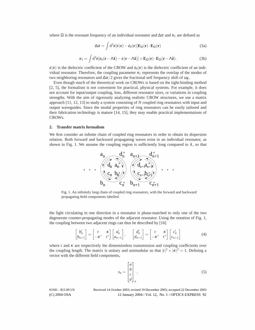
We first consider an infinite chain of coupled ring resonators in order to obtain its dispersionrelation. Both forward and backward propagating waves exist in an individual resonator, asshown in Fig. 1. We assume the coupling region is sufficiently long compared toλ , so that
b’. . .. . .
an
bn
n
cn
cn n
’ a
b
c
’
n+1 n+1
n+1n+1
n+1 n+1’ ’
nd n’ dn+1 n+1’
d
a
b
d
a
c
’
Fig. 1. An infinitely long chain of coupled ring resonators, with the forward and backwardpropagating field components labelled.
the light circulating in one direction in a resonator is phase-matched to only one of the twodegenerate counter-propagating modes of the adjacent resonator. Using the notation of Fig. 1,the coupling between two adjacent rings can thus be described by [16]
[b′n
bn+1
]=
[t κ
−κ ∗ t∗
][a′n
an+1
],
[d′
ndn+1
]=
[t κ
−κ ∗ t∗
][c′n
cn+1
](4)
wheret andκ are respectively the dimensionless transmission and coupling coefficients overthe coupling length. The matrix is unitary and unimodular so that|t|2 + |κ |2 = 1. Defining avector with the different field components,
xn =
abcd
n
, (5)
(C) 2004 OSA 12 January 2004 / Vol. 12, No. 1 / OPTICS EXPRESS 92#3181 - $15.00 US Received 14 October 2003; revised 19 December 2003; accepted 22 December 2003
Equation (4) can be rewritten as
xn+1 =[
P 00 P
]x′n ≡ Px′n (6a)
P =1κ
[−t 1−1 t∗
](6b)
As the field propagates around the ring, it accumulates a phase shift and may be attenuated,so
x′n =[
0 QQ 0
]xn ≡ Qxn (7a)
Q =[
0 e−iβRπ
eiβRπ 0
](7b)
In the above definition,R is the ring radius andβ = n(ω)ω/c+ iα , wheren(ω) is the frequencydependent effective index andα is the loss (or gain) per unit length in the ring. Combining (6)and (7), we have
xn+1 = PQxn (8)
Equation (8) is completely general. The matricesP andQ can be specified at each frequencyto account for any frequency dependence of the effective index, loss, and transmission andcoupling coefficients.
3. CROW dispersion relation
From a theoretical point of view, it is important to understand how the tight-binding and matrixapproaches are related to each other. We shall show the matrix method embodied in Eq. (8)converges to the tight-binding result in Eq. (2) under certain approximations. The approach weadopt is similar to the transfer matrix analysis of a Bragg stack [11].
The field in one resonator of the CROW as specified byxn is
E (ρ,φ) = E(ρ)×
an exp[iβR(π−φ)]+dn exp[−iβR(π−φ)] 0 < φ < πbn exp[−iβR(π+φ)]+ cn exp[iβR(π+φ)] −π < φ < 0
(9)
whereφ is the azimuthal angle relative to the propagation direction in the counter-clockwisesense, andρ is the radial co-ordinate. For a mode of an infinite chain of ring resonators, thefields are periodic at the lattice constant,Λ. So applying Bloch’s theorem,
xn+1 = exp(−iKΛ)xn, (10)
whereK is the CROW propagation constant. Combining this requirement with (8) leads to
Det|PQ−exp(−iKΛ)U | = Det|(PQ)2−exp(−i2KΛ)U | = 0, (11)
whereU is the identity matrix.We assume lossless propagation and Im(κ ) Re(κ ) for phase-matched coupling. We recall
that at the resonant frequency of an individual resonator,Ω, Ωn(Ω)R/c = m, wherem is aninteger, andn(Ω) is the effective index atΩ. Therefore, approximatingn(Ω) ≈ n(ωK), wesolve Eq. (11) to obtain
sin(ωK
Ωmπ) = ±Im(κ )cos(KΛ), (12)
which is the desired dispersion relation for a ring CROW. This relation is exact in the sense thatit involves no assumption about the coupling strength.
(C) 2004 OSA 12 January 2004 / Vol. 12, No. 1 / OPTICS EXPRESS 93#3181 - $15.00 US Received 14 October 2003; revised 19 December 2003; accepted 22 December 2003
If we expand Eq. (12) in the parameter∆ωmπ/Ω, ∆ω ≡ ωK −Ω, we obtain to first order
ωK
Ω= 1±κ2cos(KΛ), (13)
whereκ2 ≡ Im(κ )/(mπ). The two dispersion relations corresponding to the ‘±’ coexist foran infinite structure to allow for both forward and backward wave propagation (i.e. positiveand negative group velocities). Physically, for a finite structure without reflection and a uni-directional input as in Fig. 3, only the dispersion relation with the matching group and phasevelocities as the input wave will be of significance.
Equation (13) is of a form identical to the tight-binding result in Eq. (2). The correction∆α/2term does not explicitly appear in Eq. (13) since it is accounted for by Re(κ ). From Eq. (13),it follows that for∆ωmπ/Ω 1, it is necessary that|κ | 1. This condition and the absenceof all but the nearest neighbor coupling are thus the validity conditions for the tight-bindingapproximate result (13).
0 0.2 0.4 0.6 0.8 10.997
0.998
0.999
1
1.001
1.002
1.003
kΛ/π
ω/Ω
Exact SolutionApproximate Solution
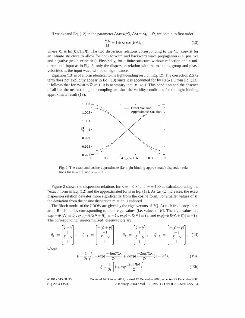
Fig. 2. The exact and cosine-approximate (i.e. tight-binding-approximate) dispersion rela-tions form = 100 andκ = −0.8i.
Figure 2 shows the dispersion relations forκ = −0.8i andm = 100 as calculated using the“exact” form in Eq. (12) and the approximated form in Eq. (13). AsωK/Ω increases, the exactdispersion relation deviates more significantly from the cosine form. For smaller values ofκ ,the deviation from the cosine dispersion relation is reduced.
The Bloch modes of the CROW are given by the eigenvectors ofPQ. At each frequency, thereare 4 Bloch modes corresponding to the 4 eigenvalues (i.e. values ofK). The eigenvalues areexp(−iK1Λ)≡ ξ1, exp[−i(K1Λ+π)]≡−ξ1, exp(−iK2Λ)≡ ξ2, and exp[−i(K2Λ+π)]≡−ξ2.The corresponding (un-normalized) eigenvectors are
qξ1=
ζ +γ1
ζ +γ1
, q−ξ1
=
−(ζ +γ)
−1ζ +γ
1
, qξ2
=
ζ −γ1
ζ −γ1
, q−ξ2
=
−(ζ −γ)
−1ζ −γ
1
, (14)
where
γ =12t
√1+exp(
−4imπωΩ
)+2exp(−2imπω
Ω)(1−2t2), (15a)
ζ =12t
[1+exp(
2imπωΩ
)]. (15b)
(C) 2004 OSA 12 January 2004 / Vol. 12, No. 1 / OPTICS EXPRESS 94#3181 - $15.00 US Received 14 October 2003; revised 19 December 2003; accepted 22 December 2003
The 4 eigenvectors are orthogonal to each other and they represent standing waves in eachresonator. In the limit of weak coupling|κ | 1 andω ≈ Ω, such thatγ ≈ |κ | ≈ 0, ζ ≈ 1, andξ1 = ξ2, the 4 eigenvectors reduce to 2 degenerate eigenvectors, representing the two differentsuperpositions of the clockwise and counter-clockwise propagating waves in a single resonator:
qξ1= qξ2
=
1111
, q−ξ1
= q−ξ2=
−1−111
. (16)
In the limit of strong coupling andω≈Ω, t 1,γ+ζ ≈√
1+|κ |1−|κ | ≈ 2
t , andζ −γ≈√
1−|κ |1+|κ | ≈ 0.
The eigenvectors become
qξ1=
2t12t1
, q−ξ1
=
−2
t−12t1
, qξ2
=
0101
, q−ξ2
=
0−101
. (17)
We observe that 2 field components are significantly stronger than the other. This correspondsto a wave that “zig-zags” through the resonators without making complete round-trips in eachresonator. The asymptotic behavior of the eigenvectors confirms the physical picture that as|κ | → 0, the modes of the CROW are essentially the modes of the independent resonators, andas |κ | → 1, the microrings no longer act as resonators and the CROW modes are essentiallyconventional waveguide modes.
4. Finite CROWs and a travelling wave picture
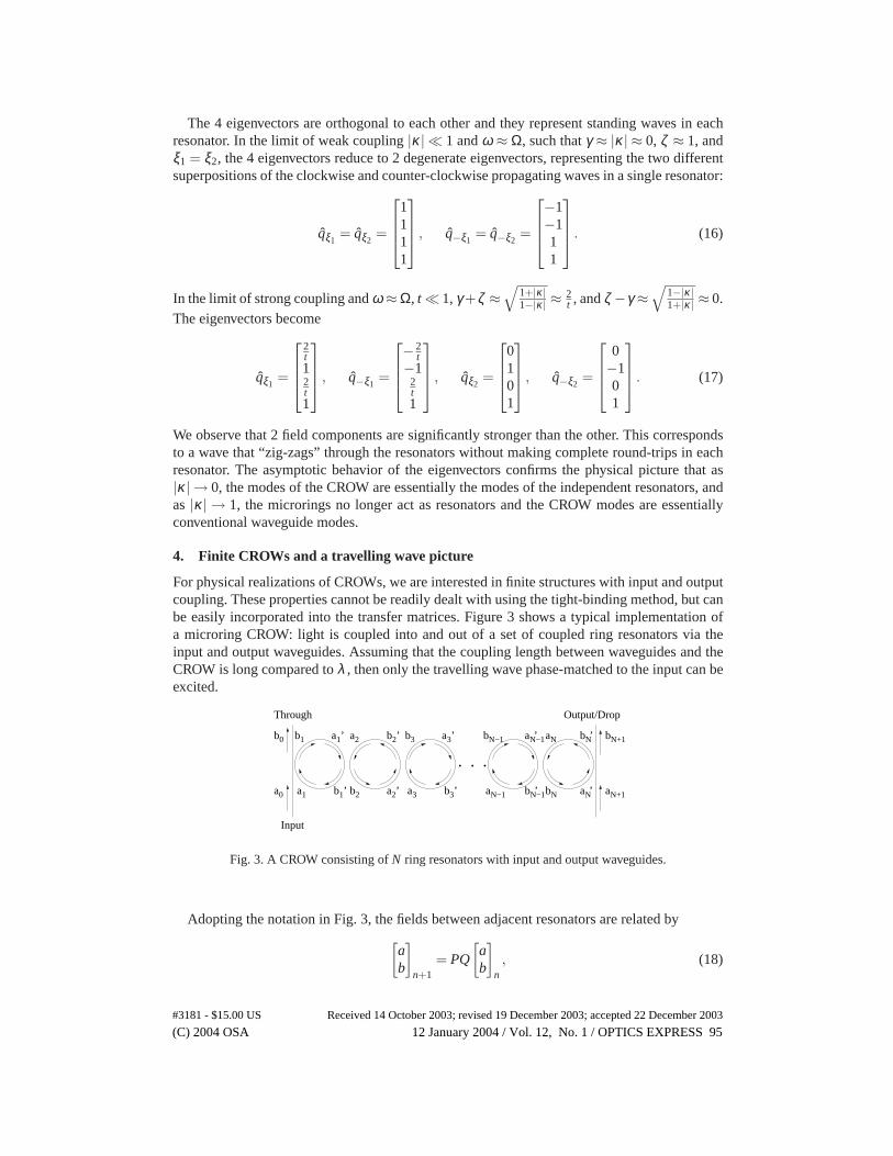
For physical realizations of CROWs, we are interested in finite structures with input and outputcoupling. These properties cannot be readily dealt with using the tight-binding method, but canbe easily incorporated into the transfer matrices. Figure 3 shows a typical implementation ofa microring CROW: light is coupled into and out of a set of coupled ring resonators via theinput and output waveguides. Assuming that the coupling length between waveguides and theCROW is long compared toλ , then only the travelling wave phase-matched to the input can beexcited.
a10a
b0
b1’ ’
’a3
3b ’
’a1 ’
’
bN+1
N+1a
N−1b
Input
Through Output/Drop
a2
b a
b
2
3
3
b ’2
’a2 bN−1’
aN−1aN
Nb aN
bN’
. . .
1b
N−1a
Fig. 3. A CROW consisting ofN ring resonators with input and output waveguides.
Adopting the notation in Fig. 3, the fields between adjacent resonators are related by[
ab
]n+1
= PQ
[ab
]n, (18)
(C) 2004 OSA 12 January 2004 / Vol. 12, No. 1 / OPTICS EXPRESS 95#3181 - $15.00 US Received 14 October 2003; revised 19 December 2003; accepted 22 December 2003
whereP andQ are defined in Eq. (6) and Eq. (7).By cascading the transfer matrices,PQ, we obtain an expression for the field components at
the output of the CROW afterN identical rings:[
aN+1
bN+1
]= PoutQ(PQ)N−1Pin
[a0
b0
]≡
[A BC D
][a0
b0
], (19)
wherePin andPout describe the coupling between the CROW and the input/output waveguides.For a single input to the waveguide, we setaN+1 = 0. Therefore, the transfer functions at the“through” and “output” ports as shown in Fig. 3 are
b0
a0= −A
B≡ Tthr(ω), (20a)
bN+1
a0= C− AD
B≡ Tout(ω). (20b)
As in microring filter design [17], the coupling between the waveguides and the CROW can beselected to maximize the flatness of the transmission response. Therefore, a finite CROW canbe designed to mimic an infinite CROW over a bandwidth with a sufficiently flat transmissionresponse.
An advantage of the matrix formalism is that it is valid for chains of any lengthN, whichis essential in analyzing any physical realization of a CROW. From the phase response of thetransmission function given by Eq. (20), we can deduce the dispersion relation of the structure.However, we note that the travelling wave is not an eigenmode of the CROW, since the Blochmodes as given by the eigenvectors ofPQ are standing waves as in Eq. (14). A travelling wavesolution is formed by a superposition, either the sum or difference, of the two Bloch modeswith equal group velocities (i.e. ˆqξ1
andq−ξ1, or qξ2
andq−ξ2). The travelling wave is an eigen-
vector of(PQ)2, and it is verified that the sense of propagation in the rings alternates betweenclockwise and counter-clockwise with each operation ofPQ, as depicted in Fig. 3. Therefore,taking the phase difference accumulated over two rings to be−2KΛ, whereK is the Blochwave vector, such that the phase difference between the output and the input is approximately−(N −1)KΛ, we can determine the CROW dispersion from the finite structure.
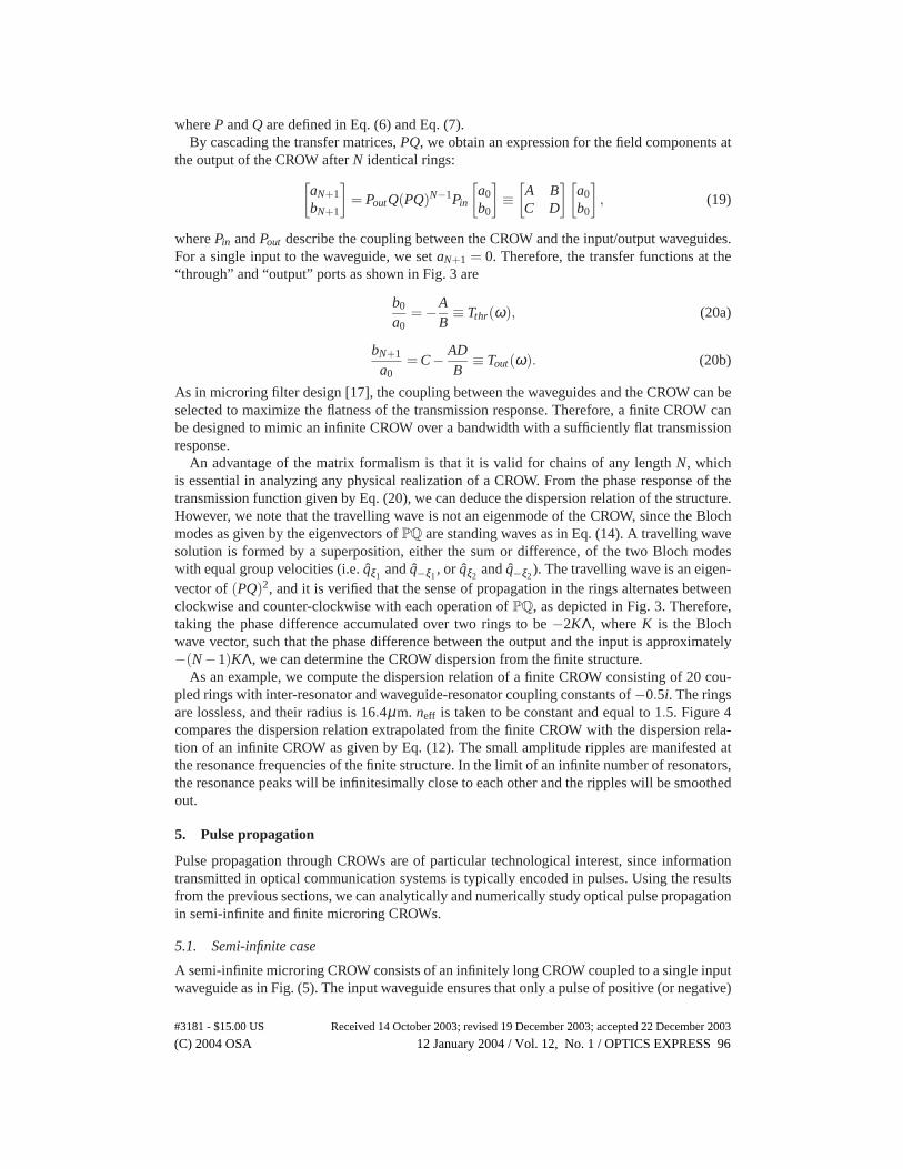
As an example, we compute the dispersion relation of a finite CROW consisting of 20 cou-pled rings with inter-resonator and waveguide-resonator coupling constants of−0.5i. The ringsare lossless, and their radius is 16.4µm. neff is taken to be constant and equal to 1.5. Figure 4compares the dispersion relation extrapolated from the finite CROW with the dispersion rela-tion of an infinite CROW as given by Eq. (12). The small amplitude ripples are manifested atthe resonance frequencies of the finite structure. In the limit of an infinite number of resonators,the resonance peaks will be infinitesimally close to each other and the ripples will be smoothedout.
5. Pulse propagation
Pulse propagation through CROWs are of particular technological interest, since informationtransmitted in optical communication systems is typically encoded in pulses. Using the resultsfrom the previous sections, we can analytically and numerically study optical pulse propagationin semi-infinite and finite microring CROWs.
5.1. Semi-infinite case
A semi-infinite microring CROW consists of an infinitely long CROW coupled to a single inputwaveguide as in Fig. (5). The input waveguide ensures that only a pulse of positive (or negative)
(C) 2004 OSA 12 January 2004 / Vol. 12, No. 1 / OPTICS EXPRESS 96#3181 - $15.00 US Received 14 October 2003; revised 19 December 2003; accepted 22 December 2003
0 0.2 0.4 0.6 0.8 10.998
0.999
1
1.001
1.002
1.003
KΛ/π
ω/Ω
20 resonatorsInfinite chain
Fig. 4. The exact dispersion relation for an infinite CROW and the dispersion relation asextracted from 20 coupled resonators. The rings have a radius of 16.4µm and the inter-resonator coupling is−0.5i.
group velocity propagates through the structure. Assuming that the bandwidth of the input pulseis within the bandwidth of the CROW band such that all of the input light is coupled into thewaveguide, the field amplitudeb1 in the first resonator isb1(ω) = −1/κina0(ω), whereκin isthe coupling coefficient between the input waveguide and the first resonator. Since|κin| < 1,the intensity of the field inside the CROW is higher than that of the input pulse by 1/|κin|2.This does not violate energy conservation, as the increased intensity is a consequence of thereduced group velocity and hence the spatial compression of the pulse inside the CROW. Usingthe dispersion relation in Eq. (13), the maximum group velocity in the CROW is
vg,max =|κ |ΛΩ
mπ. (21)
Defining the “slowing” factor as in Ref. [18] to be
S =c
neffvg,max, (22)
and approximatingΛ 2R, S can be expressed as
S =π
2|κ | . (23)
Therefore, forκin = κ , the intensity inside the rings is roughly enhanced by(23S)2. This result
makes intuitive sense since the only loss mechanism for the otherwise lossless resonators isthe inter-resonator coupling. Interestingly, even though the energy velocity of the Bloch modesat Ω corresponds to the group velocityvg,max[11], the energy velocity of a wave that is fullycoupled into the semi-infinite CROW is proportional to|κ |2. Hence, the intensity enhancementis proportional to the energy velocity reduction rather than the group velocity reduction.
Also, in contrast to CROWs, for other coupled resonator structures where there is no feed-back between the resonators, such as the SCISSOR [19], the slowing factor is approximatelyproportional to 1/|κ |2 in the case of weak coupling. However, a CROW has the advantage that,even in the presence of loss, it is most transmitting for the frequencies of the CROW band,while a side-coupled resonator is most attenuating near the resonant frequency of the resonator.
To analyze the temporal dynamics a pulse launched into the semi-infinite CROW, we adopta method of analysis that is analogous to pulse propagation in conventional waveguides such
(C) 2004 OSA 12 January 2004 / Vol. 12, No. 1 / OPTICS EXPRESS 97#3181 - $15.00 US Received 14 October 2003; revised 19 December 2003; accepted 22 December 2003
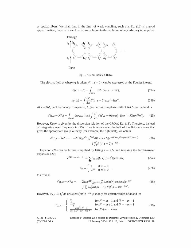
as optical fibers. We shall find in the limit of weak coupling, such that Eq. (13) is a goodapproximation, there exists a closed-form solution to the evolution of any arbitrary input pulse.
b
a10a
b0
b1’ ’
’a3
3b ’
’a1
Input
Through
a2
b a
b
2
3
3
b ’2
’a2
. . .
1
Fig. 5. A semi-infinite CROW.
The electric field at whereb1 is taken,E (t,z = 0), can be expressed as the Fourier integral
E (t,z = 0) =∫
banddωb1(ω)exp(iωt), (24a)
b1(ω) =∫
dt ′
2πE (t ′,z = 0)exp(−iωt ′). (24b)
At z = NΛ, each frequency component,b1(ω), acquires a phase shift ofNKΛ, so the field is
E (t,z = NΛ) =∫
banddωexp(iωt)
∫dt ′
2πE (t ′,z = 0)exp[−i(ωt ′ +K(ω)NΛ)]. (25)
However,K(ω) is given by the dispersion relation of the CROW, Eq. (13). Therefore, insteadof integrating over frequency in (25), if we integrate over the half of the Brillouin zone thatgives the appropriate group velocity (for example, the right half), we obtain
E (t,z = NΛ) = −ΛΩκ2eiΩt ∫ π/Λ0 dK sin(KΛ)e−iKNΛeiΩκ2 cos(KΛ)(t−t ′) (26)∫ dt ′
2πE (t ′,z = 0)e−iΩt ′ .
Equation (26) can be further simplified by lettingx = KΛ, and invoking the Jacobi-Angerexpansion [20],
eiΩκ cos(x)(t−t ′) = ∑m
cmJm[Ωκ2(t − t ′)]cos(mx) (27a)
cm =
1 if m = 02im if m > 0
, (27b)
to arrive at
E (t,z = NΛ) = −Ωκ2eiΩt ∑m cm∫ π
0 dxsin(x)cos(mx)e−ixN (28)∫ dt ′2πJm[Ωκ2(t − t ′)]E (t ′,z = 0)e−iΩt ′ .
However,αm,N =∫ π
0 dxsin(x)cos(mx)e−ixN = 0 only for certain values ofm andN:
αm,N =
iπ4 for N = m−1 andN = −m−1− iπ
4 for N = m+1 andN = −m+1−2(m2+N2−1)
(m2+N2−1)2−4m2N2 for N +m = even(29)
(C) 2004 OSA 12 January 2004 / Vol. 12, No. 1 / OPTICS EXPRESS 98#3181 - $15.00 US Received 14 October 2003; revised 19 December 2003; accepted 22 December 2003
So the equation for the pulse envelopeE(t,z), such thatE (t,z) = E(t,z)eiΩt , is given by theconvolution integral
E(t,z = NΛ) = −κ2Ω2π ∑
mcmαm,N
∫dt ′Jm[Ωκ2(t − t ′)]E(t ′,z = 0). (30)
The Fourier transform of a Bessel functionJn(t) is only defined within|2π f | ≤ 1 [21], whichaccounts for the finite bandwidth of the CROW,Ω(1−|κ2|) ≤ ω ≤ Ω(1+ |κ2|).
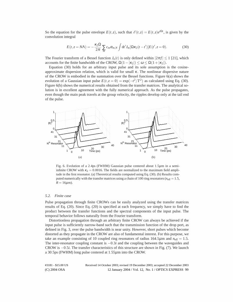
Equation (30) holds for an arbitrary input pulse and its sole assumption is the cosine-approximate dispersion relation, which is valid for smallκ . The nonlinear dispersive natureof the CROW is embodied in the summation over the Bessel functions. Figure 6(a) shows theevolution of a Gaussian input pulseE(t,z = 0) = exp(−t2/T 2) as calculated using Eq. (30).Figure 6(b) shows the numerical results obtained from the transfer matrices. The analytical so-lution is in excellent agreement with the fully numerical approach. As the pulse propagates,even though the main peak travels at the group velocity, the ripples develop only at the tail endof the pulse.
010
2030
40
1
11
21
31
410
0.5
1
Time (ps)
Nth Resonator
|E|2
(a)
010
2030
40
1
11
21
31
410
0.5
1
Time (ps)
Nth Resonator
|E|2
(b)
Fig. 6. Evolution of a 2.4ps (FWHM) Gaussian pulse centered about 1.5µm in a semi-infinite CROW withκ2 = 0.0016. The fields are normalized to the maximum field ampli-tude in the first resonator. (a) Theoretical results computed using Eq. (30). (b) Results com-puted numerically with the transfer matrices using a chain of 100 ring resonators (neff = 1.5,R = 16µm).
5.2. Finite case
Pulse propagation through finite CROWs can be easily analyzed using the transfer matricesresults of Eq. (20). Since Eq. (20) is specified at each frequency, we simply have to find theproduct between the transfer functions and the spectral components of the input pulse. Thetemporal behavior follows naturally from the Fourier transform.
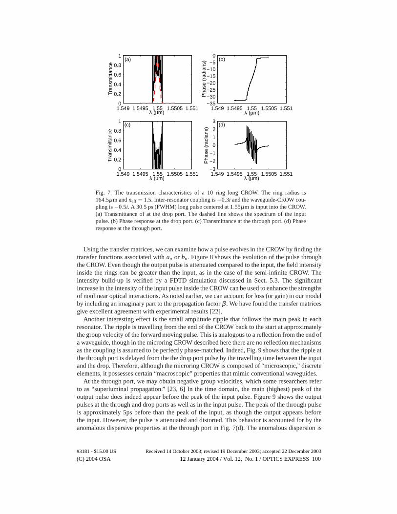
Distortionless propagation through an arbitrary finite CROW can always be achieved if theinput pulse is sufficiently narrow-band such that the transmission function of the drop port, asdefined in Fig. 3, over the pulse bandwidth is near unity. However, short pulses which becomedistorted as they propagate in the CROW are also of fundamental interest. For this purpose, wetake an example consisting of 10 coupled ring resonators of radius 164.5µm andneff = 1.5.The inter-resonator coupling constant is−0.3i and the coupling between the waveguides andCROW is−0.5i. The transfer characteristics of this structure are shown in Fig. (7). We launcha 30.5ps (FWHM) long pulse centered at 1.55µm into the CROW.
(C) 2004 OSA 12 January 2004 / Vol. 12, No. 1 / OPTICS EXPRESS 99#3181 - $15.00 US Received 14 October 2003; revised 19 December 2003; accepted 22 December 2003
1.549 1.5495 1.55 1.5505 1.5510
0.2
0.4
0.6
0.8
1
Tra
nsm
ittan
ceλ (µm)
1.549 1.5495 1.55 1.5505 1.551−35−30−25−20−15−10−5
0
Pha
se (
radi
ans)
λ (µm)
1.549 1.5495 1.55 1.5505 1.5510
0.2
0.4
0.6
0.8
1
Tra
nsm
ittan
ce
λ (µm)1.549 1.5495 1.55 1.5505 1.551−3
−2
−1
0
1
2
3
Pha
se (
radi
ans)
λ (µm)
(a) (b)
(c) (d)
Fig. 7. The transmission characteristics of a 10 ring long CROW. The ring radius is164.5µm andneff = 1.5. Inter-resonator coupling is−0.3i and the waveguide-CROW cou-pling is−0.5i. A 30.5 ps (FWHM) long pulse centered at 1.55µm is input into the CROW.(a) Transmittance of at the drop port. The dashed line shows the spectrum of the inputpulse. (b) Phase response at the drop port. (c) Transmittance at the through port. (d) Phaseresponse at the through port.
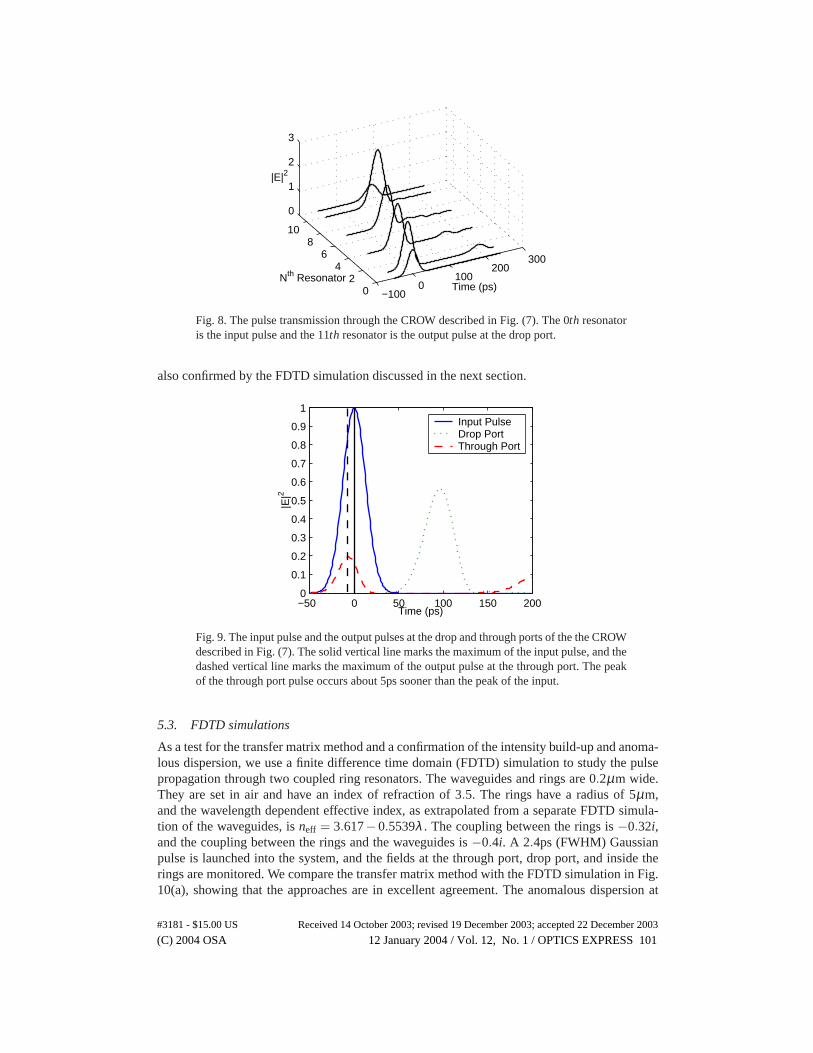
Using the transfer matrices, we can examine how a pulse evolves in the CROW by finding thetransfer functions associated withan or bn. Figure 8 shows the evolution of the pulse throughthe CROW. Even though the output pulse is attenuated compared to the input, the field intensityinside the rings can be greater than the input, as in the case of the semi-infinite CROW. Theintensity build-up is verified by a FDTD simulation discussed in Sect. 5.3. The significantincrease in the intensity of the input pulse inside the CROW can be used to enhance the strengthsof nonlinear optical interactions. As noted earlier, we can account for loss (or gain) in our modelby including an imaginary part to the propagation factorβ . We have found the transfer matricesgive excellent agreement with experimental results [22].
Another interesting effect is the small amplitude ripple that follows the main peak in eachresonator. The ripple is travelling from the end of the CROW back to the start at approximatelythe group velocity of the forward moving pulse. This is analogous to a reflection from the end ofa waveguide, though in the microring CROW described here there are no reflection mechanismsas the coupling is assumed to be perfectly phase-matched. Indeed, Fig. 9 shows that the ripple atthe through port is delayed from the the drop port pulse by the travelling time between the inputand the drop. Therefore, although the microring CROW is composed of “microscopic,” discreteelements, it possesses certain “macroscopic” properties that mimic conventional waveguides.
At the through port, we may obtain negative group velocities, which some researchers referto as “superluminal propagation.” [23, 6] In the time domain, the main (highest) peak of theoutput pulse does indeed appear before the peak of the input pulse. Figure 9 shows the outputpulses at the through and drop ports as well as in the input pulse. The peak of the through pulseis approximately 5ps before than the peak of the input, as though the output appears beforethe input. However, the pulse is attenuated and distorted. This behavior is accounted for by theanomalous dispersive properties at the through port in Fig. 7(d). The anomalous dispersion is
(C) 2004 OSA 12 January 2004 / Vol. 12, No. 1 / OPTICS EXPRESS 100#3181 - $15.00 US Received 14 October 2003; revised 19 December 2003; accepted 22 December 2003
−1000
100200
300
02
46
810
0
1
2
3
Time (ps)Nth Resonator
|E|2
Fig. 8. The pulse transmission through the CROW described in Fig. (7). The 0th resonatoris the input pulse and the 11th resonator is the output pulse at the drop port.
also confirmed by the FDTD simulation discussed in the next section.
−50 0 50 100 150 2000
0.1
0.2
0.3
0.4
0.5
0.6
0.7
0.8
0.9
1
Time (ps)
|E|2
Input PulseDrop PortThrough Port
Fig. 9. The input pulse and the output pulses at the drop and through ports of the the CROWdescribed in Fig. (7). The solid vertical line marks the maximum of the input pulse, and thedashed vertical line marks the maximum of the output pulse at the through port. The peakof the through port pulse occurs about 5ps sooner than the peak of the input.
5.3. FDTD simulations
As a test for the transfer matrix method and a confirmation of the intensity build-up and anoma-lous dispersion, we use a finite difference time domain (FDTD) simulation to study the pulsepropagation through two coupled ring resonators. The waveguides and rings are 0.2µm wide.They are set in air and have an index of refraction of 3.5. The rings have a radius of 5µm,and the wavelength dependent effective index, as extrapolated from a separate FDTD simula-tion of the waveguides, isneff = 3.617−0.5539λ . The coupling between the rings is−0.32i,and the coupling between the rings and the waveguides is−0.4i. A 2.4ps (FWHM) Gaussianpulse is launched into the system, and the fields at the through port, drop port, and inside therings are monitored. We compare the transfer matrix method with the FDTD simulation in Fig.10(a), showing that the approaches are in excellent agreement. The anomalous dispersion at
(C) 2004 OSA 12 January 2004 / Vol. 12, No. 1 / OPTICS EXPRESS 101#3181 - $15.00 US Received 14 October 2003; revised 19 December 2003; accepted 22 December 2003
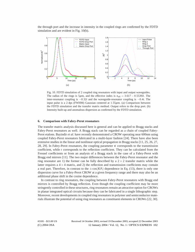
the through port and the increase in intensity in the coupled rings are confirmed by the FDTDsimulation and are evident in Fig. 10(b).
0 5 10 15 20 250
0.2
0.4
0.6
0.8
1
Time (ps)
Nor
mal
ized
|E|2
FDTD InputFDTD Drop PortMatrix InputMatrix Drop Port
(a)
0 2 4 6 8 10 12 140
0.2
0.4
0.6
0.8
1
1.2
1.4
1.6
1.8
Time (ps)
|E|2
Input PulseRing 1Ring 2Drop PortThrough Port
(b)
Fig. 10. FDTD simulation of 2 coupled ring resonators with input and output waveguides.The radius of the rings is 5µm, and the effective index isneff = 3.617− 0.5539λ . Theinter-resonator coupling is−0.32i and the waveguide-resonator coupling is−0.4i. Theinput pulse is a 2.4ps (FWHM) Gaussian centered at 1.55µm. (a) Comparison betweenthe FDTD simulation and the transfer matrix method. Output refers to the drop port. (b)Intensity built-up and anomalous dispersion as confirmed by the FDTD simulation.
6. Comparison with Fabry-Perot resonators
The transfer matrix analysis discussed here is general and can be applied to Bragg stacks andFabry-Perot resonators as well. A Bragg stack can be regarded as a chain of coupled Fabry-Perot etalons. Bayindiret al. have recently demonstrated a CROW operating near 600nm usingcoupled Fabry-Perot resonators fabricated in a multi-layer fashion [24]. There have also beenextensive studies in the linear and nonlinear optical propagation in Bragg stacks [11, 25, 26, 27,28, 29]. In Fabry-Perot resonators, the coupling parameterκ corresponds to the transmissioncoefficient, whilet corresponds to the reflection coefficient. They can be calculated from theFresnel coefficients or from an analysis of a Bragg stack in the case of a Fabry-Perot withBragg end mirrors [11]. The two major differences between the Fabry-Perot resonator and thering resonator are 1) the former can be fully described by a 2× 2 transfer matrix while thelatter requires a 4×4 matrix, and 2) the reflection and transmission coefficients may containa real part. Therefore, in contrast to the±cos(KΛ) dependence in Eq. (13), there is only onedispersion curve for a Fabry-Perot CROW at a given frequency range and there may also be anadditional phase shift in the cosine dependence.
In contrast to ring resonators, the coupling between Fabry-Perot resonators with Bragg endmirrors is controlled by Bragg reflection. Even though the coupling coefficient may be morestringently controlled in these structures, ring resonators remain an attractive option for CROWsin planar integrated optical circuits because they can be fabricated in a single lithographic step.Moreover, recent developments in coupled ring resonators in polymer and semiconductor mate-rials illustrate the potential of using ring resonators as constituent elements in CROWs [22, 30].
(C) 2004 OSA 12 January 2004 / Vol. 12, No. 1 / OPTICS EXPRESS 102#3181 - $15.00 US Received 14 October 2003; revised 19 December 2003; accepted 22 December 2003
7. Conclusion
In summary, the transfer matrix method is used to analyze microring coupled resonators. Thetransfer matrix and tight-binding approaches yield equivalent dispersion relations in the limitof weak coupling. We also study pulse propagation through semi-infinite and finite CROWs tofind intensity enhancement as well as anomalous dispersion. The matrix method can accountfor finite chains, holds for any coupling strength, applies to travelling waves, and can treatheterogeneous chains consisting of an arbitrary mix of resonators and coupling constants. Thesefeatures make the transfer matrices versatile for device design and for analyzing experimentalresults of microring CROWs [22].
Acknowledgments
The authors thank Dr. Y. Xu, J. Choi, W. Green, and W. Liang for helpful discussions. J. Poonacknowledges support from the Natural Sciences and Research Council of Canada. The supportof DARPA, the Office of Naval Research, and the Air Force Office of Scientific Research aregratefully acknowledged.
(C) 2004 OSA 12 January 2004 / Vol. 12, No. 1 / OPTICS EXPRESS 103#3181 - $15.00 US Received 14 October 2003; revised 19 December 2003; accepted 22 December 2003