nasa tm x-2759
TRANSCRIPT
N A S A TECHNICAL
M E M O R A N D U M
CS
><
NASA TM X-2759
DOTOTGIUDEDBY AUTHORITY OCHAJSTGE NOTICES NO.IESII N0.
CONFIDENTIAL
BY
SUBJECT TO GEXECUTIVE ORDERAT TWO YEAR INTI
CLASSIFIED
USSIFICATION SCHEDULE OFAUTOMATICALLY DOWNGRADED
DECLASSIFIED ON DEC 31
1979
s :I..
A WIND-TUNNEL INVESTIGATIONOF THE APPLICATION OF THENASA SUPERCRITICAL AIRFOIL TOA VARIABLE-WING-SWEEP FIGHTER AIRPLANE
by Theodore G. Ayers
Langley Research Center
Hampton, Va. 23365
NATIONAL AERONAUTICS AND SPACE ADMINISTRATION • WASHINGTON, D. C. • JULY 1973
https://ntrs.nasa.gov/search.jsp?R=19830002758 2018-09-15T17:09:05+00:00Z
1. Report No.
NASA TM X-27592. Government Accession No. 3. Recipient's Catalog No.
4. Title and SubtitleA WIND-TUNNEL INVESTIGATION OF THE APPLICATION OFTHE NASA SUPERCRITICAL AIRFOIL TO A VARIABLE-WING -SWEEP FIGHTER AIRPLANE (U)
5. Report Date
July 19736. Performing Organization Code
7. Author(s)
Theodore G. Ayers8. Performing Organization Report No.
L-8689
9. Performing Organization Name and Address
NASA Langley Research CenterHampton, Va. 23665
10. Work Unit No.
760-64-01-0511. Contract or Grant No.
12. Sponsoring Agency Name and Address
National Aeronautics and Space AdministrationWashington, D.C. 20546
13.'Type of Report and Period Covered
Technical Memorandum14. Sponsoring Agency Code
15. Supplementary Notes
16. Abstract
An investigation was conducted in the Langley 8-foot transonic pressure tunnel and theLangley Unitary Plan wind tunnel to evaluate the effectiveness of three variations of the NASAsupercritical airfoil as applied to a model of a variable-wing-sweep fighter airplane. Wingpanels incorporating conventional NACA 64A-series airfoil with 0.20 and 0.40 camber wereused as bases of reference for this evaluation. Static force and moment measurements wereObtained for wing leading-edge sweep angles of 26°, 33°, 39°, and 72.5°. Fluctuating wing-root-bending-moment data were obtained at subsonic speeds to determine buffet characteristics.Subsonic data were also obtained for determining the effects of wing transition location andSpoiler deflection. Limited lateral directional data are included for the conventional 0.20 cam-bered wing and the supercritical wing.
CLASSIFICATION CHANGE
_ UNCLASSIFIEDToBy authority jaf.Changed by .X- • -»•/// /<-v «cn.o_»*— =—• —•Classified Document Master Control Station, NASAScientific and Technical Information F&cillty
Date ft-/? -
17. Key Words (Suggested by Author(s))
Transonic aerodynamicsSupercritical wingVariable sweep fighter aircraft
19. Security Classif. (of this report) 20. Security Classif
Unclassif
"NATION
Unauthorized Dis<
SECURI
:'RMATION"
Criminal Sanctions.
A WIND-TUNNEL INVESTIGATION OF THE
APPLICATION OF THE NASA SUPERCRITICAL AIRFOIL TO A
VARIABLE-WING-SWEEP FIGHTER AIRPLANE*
By Theodore G. AyersLangley Research Center
SUMMARY
An investigation has been conducted in the Langley 8-foot transonic pressure tunneland the Langley Unitary Plan wind tunnel to evaluate the effectiveness of three variationsof the NASA supercritical airfoil as applied to a model of a variable-wing-sweep fighterairplane. Wing panels incorporating conventional NACA 64A-series airfoils with 0.20 and0.40 camber were used as bases of reference for this evaluation. Static force and momentmeasurements were obtained for wing leading-edge sweep angles of 26°, 33°, and 39° atsubsonic speeds and for a wing leading-edge sweep angle of 72.5° at transonic and super-sonic speeds. In addition, fluctuating wing-root-bending-moment data were obtained atsubsonic speeds to determine buffet characteristics.
The results of this evaluation indicate that increasing the conventional camber hadlittle effect on the cruise Mach number but did reduce the trimmed drag characteristicsin the moderate- to high-lift range and did increase the buffet onset lift coefficient at sub-sonic speeds. An increase in the cruise Mach number capability of about 0.10 was notedfor the model with the supercritical wing as compared with the wings incorporating con-ventional NACA 64A-series airfoils. Substantial reductions in the moderate- to high-lifttrimmed drag characteristics were achieved with the supercritical wing at the higher sub-sonic speeds. The lift coefficient for buffet onset was increased significantly with thesupercritical wing for a leading-edge sweep angle of 26° at Mach numbers of 0.75 andabove. The low-speed (Mach number = 0.60) drag characteristics were somewhat higherand the buffet-onset lift coefficient somewhat lower for the supercritical wing as comparedwith the conventional 0.40 cambered wing although these characteristics were improved bythe use of trailing-edge flaps. At supersonic speeds, the trimmed drag characteristicsfor the supercritical wing were slightly higher than those for the wings incorporating con-ventional camber. No adverse yaw characteristics were noted for the supercritical wingat the test conditions for which data were obtained.
* Title, Unclassified.
INTRODUCTION
The current emphasis on fighter aircraft capable of achieving high maneuver loadfactors for air-to-air combat at high subsonic speeds has created a need for basicresearch in the areas of buffet and high-lift drag at transonic speeds. The stringentrequirements placed on these aircraft also are such that methods must be found to reducethe drag and airplane buffeting associated with shock-induced boundary-layer separationof the wing flow at high maneuvering lift coefficients. Although twist, camber, and sweephave a favorable effect on the wing flow characteristics, the use of these methods alonedoes not fully solve the basic supercritical flow problem. Two-dimensional results forrecently developed integral supercritical airfoils (ref. 1) have indicated that substantialimprovements in aircraft performance at high subsonic speeds might be achieved byspecial shaping of the airfoil to improve the supercritical flow above the upper surface.Three-dimensional wind-tunnel and flight-test results are included in references 2 to 5for airplane configurations intended to demonstrate the potential of the supercritical air-foil for improving wing structural efficiency and airplane cruise speed.
As is well known, at supercritical Mach numbers a broad region of supersonic flowextends vertically from an airfoil. This region of supersonic flow is usually terminated
.by a shock wave causing an energy loss and therefore a drag increase. In addition, theshock wave produces a positive pressure gradient at the airfoil surface which may causeseparation of the boundary layer with an associated large increase in drag. This shock-induced separation occurs initially on an airfoil because the low-momentum air of theboundary layer cannot traverse the pressure rise through the shock wave superimposedon the subcritical pressure recovery. The special shaping of the supercritical airfoilupper surface reduces both the extent and strength of the shock wave and also reducesthe adverse pressure gradient behind the shock wave with corresponding reductions in thedrag. To compensate for the reduced lift on the upper surface of the supercritical airfoilresulting from the reduced curvature, the airfoil has increased camber near the trailingedge. Unpublished two-dimensional results have indicated a delay in the drag-rise Machnumber of about 0.10 as compared with a conventional 6-series airfoil. In addition, asignificant delay in the Mach number for buffet onset at a given lift coefficient was notedas well as an increase in the maximum lift coefficient for buffet onset.
On the basis of the two-dimensional results, a program was initiated by the NASAto investigate the three-dimensional characteristics of a variable-wing-sweep fighter air-plane model incorporating the supercritical airfoil. A variable-wing-sweep model waschosen because of the large leading-edge radius of the supercritical airfoil which must beswept behind the Mach line for operation at supersonic speeds. The purpose of this paperis to present the results of this three-dimensional investigation. Data are also includedfor a NACA 64A-series airfoil with 0.20 and 0.40 camber to indicate the improvements in
/J
high-lift characteristics which might be expected from an increase in conventional cam-ber. Data are included herein for the effects of wing section geometry, wing incidenceangle, trailing-edge flap deflection, and wing leading-edge sweep angle. Limited dataare included for the effects of horizontal-tail deflection and transition location.
SYMBOLS
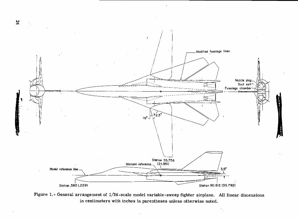
The results as presented herein are referred to the body-axis system with theexception of the lift and drag coefficients which are referred to the stability-axis system.The moment center was located at a point 55.174 cm (21.722 in.) rearward of the nose(0.45c, A = 16°) along the model reference line. (See fig. 1.) All coefficients are basedon the geometry of the model having a wing-leading-edge sweep of 16°. Data wereobtained in U.S. Customary Units and are presented herein in both SI and U.S. CustomaryUnits. The coefficients and symbols used herein are defined as follows:
b wing span, 80.010 cm (31.500 in.)
CD drag coefficient, —^qb
CL lift coefficient, 2J|t
~ „. , ,,. . , Rolling momentCj rolling-moment coefficient, s__qbu
AC;GI lateral stability parameter, -£±, per deg
Cm pitching-moment coefficient, Pitching momentqSc
Cn yawing-moment coefficient, Yawinp moment
A f1
Cnfi directional stability parameter, -dr, Per deS
CY side-force coefficient, Side force
ACVside-force parameter, * per deg
local chord, cm (in.)
wing mean aerodynamic chord, 11.483 cm (4.521 in.)
iw incidence of wing reference plane at pivot relative to model reference line(positive when trailing edge is down), deg
L/D lift-drag ratio
M free-stream Mach number •
Mjrj root-mean-square output of wing bending gage, N-m (Ib-in.)
p. stagnation pressure, kN/m2 (lb/ft2)
q free-stream dynamic pressure, N/m2 (lb/ft2)
R Reynolds number based on c
S wing area including fuselage intercept, 846.319 cm2 (0.911 ft2)
Tf. stagnation temperature, K (°F)
t/c thickness-chord ratio
x,y,z distances along the X-, Y-, and Z-axes, respectively, cm (in.)
a angle of attack referred to model reference line, deg
/3 angle of sideslip referred to model plane of symmetry (positive when noseis left), deg
6f trailing-edge flap deflection (positive when trailing edge is down), deg
6^ horizontal-tail deflection angle referred to respective wing reference plane(positive when trailing edge is down), deg
6S spoiler deflection (positive when trailing edge is up), deg
A leading-edge sweep angle of outboard wing panel, deg
Subscripts:
1 lower
4
trim trimmed condition
u upper
MODEL DESCRIPTION
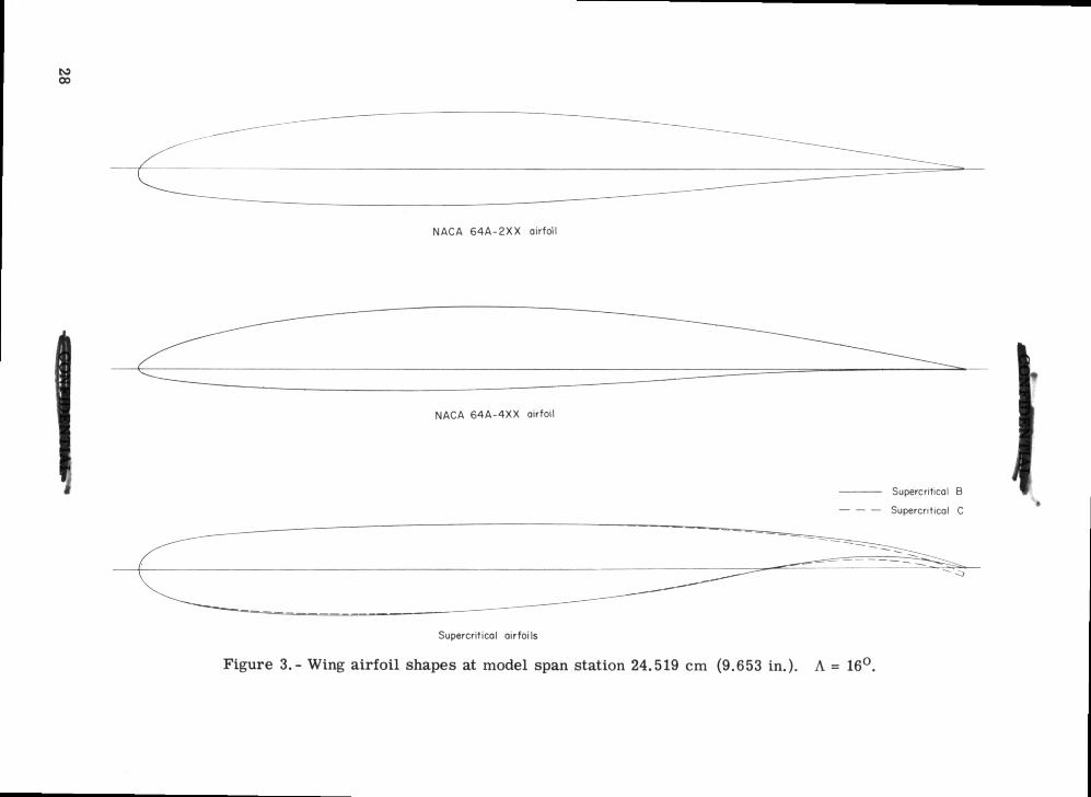
The general arrangement of the 1/24-scale model utilized for this investigation isshown in figure 1 and photographs are presented as figure 2. The model has an inboardwing pivot located longitudinally at model station 55.756 cm (21.951 in.) and laterally at7.440 cm (2.929 in.) outboard of the model plane of symmetry. Provisions were madefor manually varying the leading-edge sweep of the outboard wing panels from 16° to 72.5°and for varying the wing incidence angle, at the wing pivot, from 1° to -3° with respectto the model reference plane. Data were obtained during this investigation for leading -edge sweep angles of 26°, 33°, and 39° with various wing incidence angles at subsonicspeeds and for a leading-edge sweep angle of 72.5° and a wing incidence angle of 1° attransonic and supersonic speeds. Five wings identical in planform and thickness(t/c « 0.11 at pivot and t/c ~ 0.10 at tip; parallel to free stream A = 16°) were testedduring the present investigation. Sketches of the airfoil shapes at approximately the mid-span of the panels for four of these wings are shown in figure 3. This series of wingscomprised of two conventional wings, one incorporating NACA 64A2XX airfoils; the otherincorporating NACA 64A4XX airfoils, and three wings incorporating variations of thesupercritical airfoil.
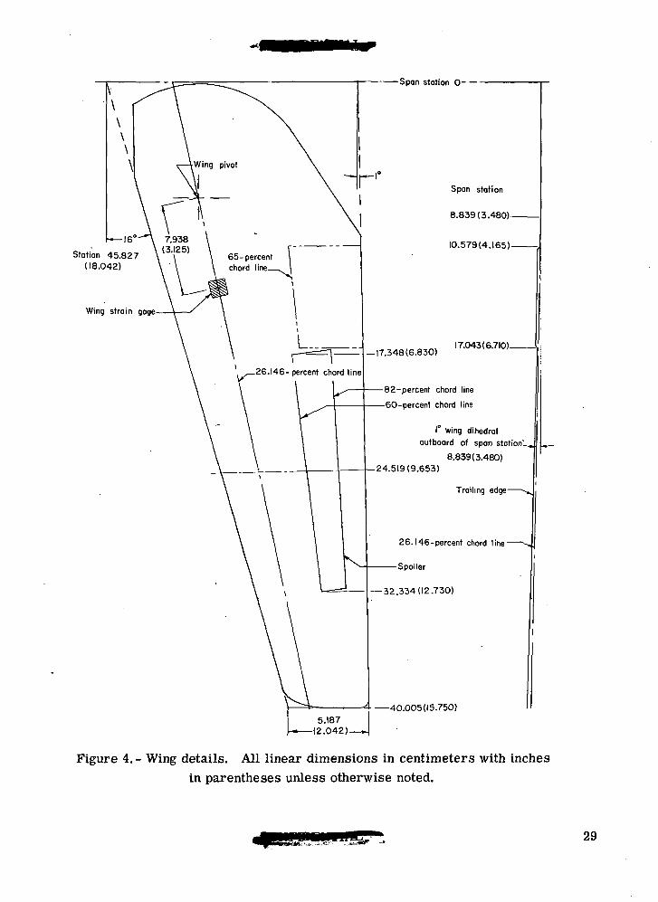
The first wing consisted of a modified NACA 64A-series airfoil with 0.2 camber(NACA 64A2XX) outboard of the wing pivot and parallel to the free stream (A = 16°).(See table I for coordinates.) This wing was uniformly twisted about the 26.146-percentchord line; the twist varying from 0° at the pivot to -4° at the tip. The area of the trail-ing edge of the wing, bounded by span stations 10.579 cm (4.165 in.) and 17.043 cm(6.710 in.) and the 65-percent chord line, was modified as shown in figure 4 to allow thewing to clear the engine ducts when the leading-edge sweep was 72.5°. This basic wingwas tested with 1° of wing incidence only.
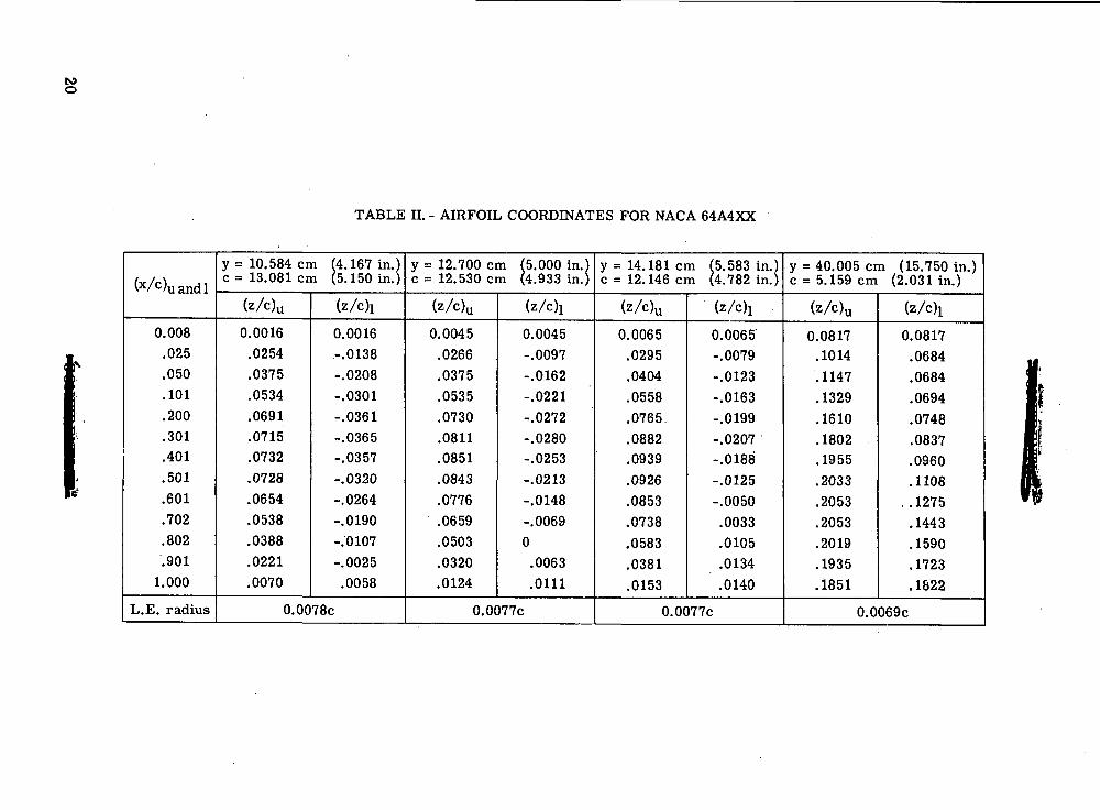
The second wing consisted of conventional NACA 64A-series airfoil sections with0.40 camber (NACA 64A4XX) outboard of span station 12.700 cm (5.00 in.) and parallelto the free stream (A = 16°). The airfoils inboard of this span station were modifiedNACA 64A-series with 0.20 camber; this change was incorporated into the wing to allowtesting without altering the model geometry in the area of the wing glove juncture. Thiswing did not have the trailing-edge modification which was incorporated into the NACA64A2XX wing. In addition, this wing was twisted in a manner similar to the 0.20 cam-bered wing; however, the twist was increased to -6° at the tip to improve the spanwiseload distribution for the high-lift maneuver cases at the higher subsonic Mach numbers.
The airfoil coordinates for this wing are given in table II. Data were obtained for thiswing with incidence angles of ±1° with A = 26° and for -1° with A = 33° and 39°.
Supercritical wing A consisted of constant spanwise section geometry outboard ofspan station 12.700 cm (5.00 in.). (See table HE for coordinates.) The twist distributionfor this wing was the same as that for the 0.40 cambered wing, that is, 6° of uniformtwist from the pivot to the tip. All data presented herein for supercritical wing A wereobtained with 1° of wing incidence.
Supercritical wing B, as well as wing C to be described below, was developedthrough a series of exploratory tests and only the data for the final shapes are presentedherein. These exploratory tests were conducted with 26° of leading-edge sweep on theoutboard panels, the design criteria being reduced high-lift (CL = 0.90) drag at M = 0.85and M = 0.91 without adversely affecting the M = 0.85 cruise drag. The airfoil geom-etry for supercritical wing B (table IV) differed from supercritical wing A primarily inthat the lower surface of supercritical wing B was modified to eliminate boundary-layerseparation on that surface at the higher Mach numbers and the upper surface was modifiednear the wing-glove juncture to improve the shock-wave pattern. In addition, the wingtrailing-edge angle was increased somewhat to improve the lift effectiveness. Data wereobtained for ±1° of incidence with this wing.
Supercritical wing C consisted of further modifications which essentially resultedin a variation in the spanwise airfoil geometry. The trailing-edge angle was decreasedinboard and increased outboard in an attempt to improve the upper surface pressure dis-tributions, particularly for the higher wing-sweep angles of 33° and 39°. The lower sur-face was modified near the tip to eliminate a local shock formation on this surface andthe trailing-edge thickness was increased to alleviate the structural problems associatedwith a very thin trailing edge. Coordinates for supercritical wing C are given in table V.Data were obtained for this wing with -3° of incidence only.
Provisions were made for testing the supercritical wing with various full-spantrailing-edge flap deflections. The desired flap deflections were obtained by machininggrooves into the upper and lower surface of the wing panels at the 80-percent chord lineand rotating the last 20-percent chord of the wing panels about the mean line of the airfoilat 0.80c. Data were obtained for supercritical wing B with 5° and 10° of flap rotation atsubsonic speeds and with -5° of flap rotation at the higher supersonic speeds.
The horizontal tails were mounted in the wing chord plane and consisted of biconvexairfoil sections, parallel to the free stream. The vertical tail consisted of 3.2-percent-thick modified biconvex airfoils parallel to the free stream. Twin ventral fins weremounted on the lower aft fuselage and canted outward 30° from the model plane ofsymmetry.
APPARATUS AND PROCEDURES
Facilities
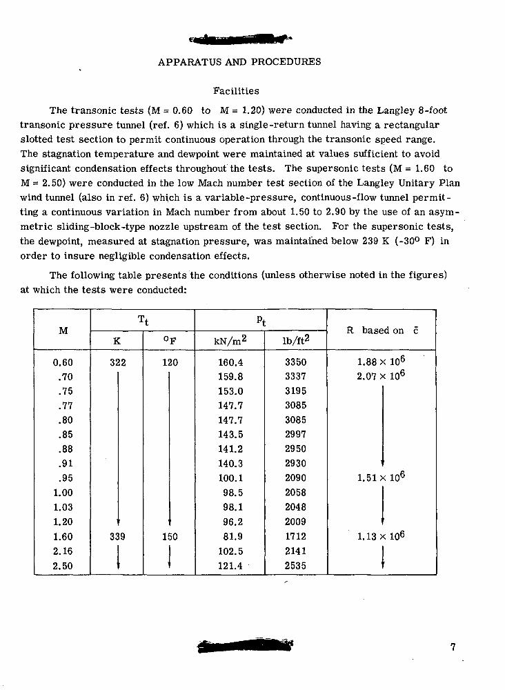
The transonic tests (M = 0.60 to M = 1.20) were conducted in the Langley 8-foottransonic pressure tunnel (ref. 6) which is a single-return tunnel having a rectangularslotted test section to permit continuous operation through the transonic speed range.The stagnation temperature and dewpoint were maintained at values sufficient to avoidsignificant condensation effects throughout the tests. The supersonic tests (M = 1.60 toM = 2.50) were conducted in the low Mach number test section of the Langley Unitary Planwind tunnel (also in ref. 6) which is a variable-pressure, continuous-flow tunnel permit-ting a continuous variation in Mach number from about 1.50 to 2.90 by the use of an asym-metric sliding-block-type nozzle upstream of the test section. For the supersonic tests,the dewpoint, measured at stagnation pressure, was maintained below 239 K (-30° F) inorder to insure negligible condensation effects.
The following table presents the conditions (unless otherwise noted in the figures)at which the tests were conducted:
M
0.60.70.75.77.80.85.88.91.95
1.001.031.201.602.162.50
Tt
K
322
33911t
oF
120
15011!
pt
kN/m2
160.4159.8153.0147.7147.7143.5141.2140.3100.198.598.196.281.9
102.5121.4
lb/ft2
335033373195308530852997295029302090205820482009171221412535
R based on c
1.88 x 10⁶
2.07 x 10⁶
1.51 x 10⁶
1.13X 10⁶
11f
Boundary-Layer Transition
Transition was fixed on the upper and lower surfaces of the outboard wing panelsfor most of the subsonic and transonic tests by using the techniques discussed in refer-ence 7 to simulate the full-scale Reynolds number boundary-layer separation character-istics. To maintain laminar flow ahead of the trip, as required by this technique, themodel surface was maintained in an exceptionally smooth condition throughout the tests.For the data presented herein with the transition rearward, the upper surface trip locationvaried from 35- to 40-percent chord at the mean aerodynamic chord and the tip, respec-tively, and the lower surface trip location varied from 30- to 35-percent chord at the meanaerodynamic chord and the tip, respectively. By using the fluorescent oil film technique(ref. 8) to observe boundary-layer flow patterns, laminar separation was observed aheadof the upper surface trip outboard of the wing-glove juncture for wing-sweep angles of 26°,33°, and 39°. The trips for this inboard region were located at about 5-percent chord atthe wing-glove juncture and were angled rearward to intersect the aft trip at a point7.62 cm (3.0 in.), 11.43 cm (4.5 in.), and 15.24 cm (6.0 in.) outboard of the wing-glovejuncture and along the span for leading-edge sweep angles of 26°, 33°, and 39°, respec-tively. In addition, laminar separation was observed across the span where a strongadverse pressure gradient occurred ahead of the trip. In most of these cases the uppersurface transition was moved forward to about the 5-percent chord to insure that a tur-bulent boundary layer existed forward of this adverse pressure gradient.
Measurements
Six-component static aerodynamic force and moment measurements were obtainedby means of an electrical strain-gage balance located within the fuselage cavity. Themeasurements were taken over an angle-of-attack range from about 0° to 12° for wing-leading-edge sweep angles of 26°, 33°, and 39° at Mach numbers from 0.60 to 0.91 andfor a wing-leading-edge sweep angle of 72.5° at Mach numbers from 0.95 to 2.50. Lim-ited measurements were obtained at sideslip angles of ±5° for a wing-leading-edge sweepof 33° at Mach numbers of 0.85 and 0.91. Total and static pressures were measured atthe duct exits to determine internal duct drag. Additional pressures were measured atthe balance chamber and nozzle exit plug bases.
The buffet information included herein was obtained by the wing-root-bending gagetechnique described in references 9 and 10. The wing gages located in the position shownin figure 3 consisted of four active strain gages forming a complete bending-momentbridge. The results, as presented in this paper, represent the average root-mean-squarevalues of the fluctuating wing-root-bending moments integrated over a 45-second samplingtime.
Corrections
The drag coefficient Cj) has been corrected for internal flow through the ducts.The drag data have also been adjusted to the condition of free-stream static pressureacting over the fuselage cavity and nozzle-exit plug bases.
Because of the high loads imposed on the model in the transonic speed range andthe necessity for obtaining data at angles of attack where severe model buffeting occurred,a model sting arrangement was chosen in which the sting diameter was increased, by atapered section, immediately aft of the model base. The proximity of the sting taper tothe model base produced a positive pressure field, at subsonic and transonic speeds,which affected the axial-force and pitching-moment measurements. In order to determinecorrectly the pitch requirements for trim, the pitching-moment coefficients have beenadjusted by incremental values determined from unpublished data obtained from previoustests of the basic configuration using a model sting which did not adversely affect thestrain-gage data. The drag data have not been adjusted for this adverse pressure fieldand are therefore invalid insofar as absolute values are concerned. However, the buoy-ancy effect would be the same for all configurations and the incremental drag values aretherefore accurate. No buoyancy corrections were required for the data obtained at Machnumbers from 1.60 to 2.50.
The measured angles of attack and sideslip have been corrected for model supportsting and balance deflections occurring upstream of the angle-measurement device as aresult of aerodynamic loads on the model. The angles of attack, sideslip, and controldeflections are estimated to be accurate to within ±0.1°; the Mach numbers, within ±0.002at transonic speeds and ±0.015 at supersonic speeds.
PRESENTATION OF RESULTS
The results of this investigation are presented in the following figures:Figure
Longitudinal aerodynamic characteristics (|3 = 0°) of configuration for -A = 26° for -
Comparison of NACA 64A2XX and supercritical airfoils 5Comparison of NACA 64A2XX and NACA 64A4XX airfoils 6
A = 33° for -Comparison of NACA 64A2XX and supercritical airfoils 7Comparison of NACA 64A2XX and NACA 64A4XX airfoils 8
A = 39° for -Comparison of NACA 64A2XX, supercritical, and NACA 64A4XX airfoils ... 9
FigureLongitudinal aerodynamic characteristics (/3 = 0°) for -
A = 26° for -Effect of trailing-edge flaps on configuration with supercritical airfoil B . . . 10Effect of fuselage fairing on configuration with NACA 64A2XX airfoil 11Effect of transition location on configuration with NACA 64A2XX airfoil ... 12Effect of transition location on configuration with supercritical airfoil B . . . 13Effect of transition location on configuration with supercritical airfoil C . . . 14
A = 39° for -Effect of transition location on configuration with supercritical airfoil B . . . 15
Effect of horizontal-tail deflection on longitudinal aerodynamiccharacteristics for —A = 26° for -
Configuration with NACA 64A2XX airfoil. iw = 1° 16Configuration with supercritical airfoil B. iw = -1° 17Configuration with NACA 64A4XX airfoil. iw = 1° 18Configuration with NACA 64A4XX airfoil. iw = -1° 19
A = 33° for -Configuration with supercritical airfoil B. iw = 1° 20Configuration with supercritical airfoil C. iw = -3° 21Configuration with NACA 64A4XX airfoil. iw = 1° 22
A = 39° for -Configuration with supercritical airfoil B. iw = -1° 23Configuration with NACA 64A4XX airfoil. iw =-1° 24
Buffet characteristics of configuration with —A = 26° for -
Comparison of NACA 64A2XX and supercritical airfoils . 25Comparison of NACA 64A2XX and NACA 64A4XX airfoils , 26
A = 33° for -Comparison of NACA 64A2XX and supercritical airfoils 27Comparison of NACA 64A2XX and NACA 64A4XX airfoils 28
A = 39° for -Comparison of NACA, 64A2XX, supercritical, and NACA 64A4XX airfoils ... 29
Buffet characteristics for -A = 26° for -
Effect of trailing-edge flaps on configuration with supercritical airfoil B . . . 30Effect of transition location on configuration with NACA 64A2XX airfoil ... 31Effect of transition location on supercritical airfoil B 32Effect of transition location on configuration with supercritical airfoil C ... 33
10
FigureA = 39° for -
Effect of transition location on configuration with supercritical airfoil B . . . 34
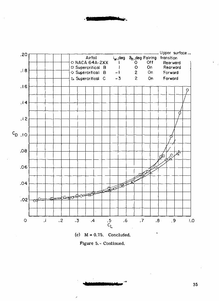
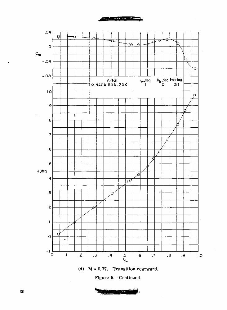
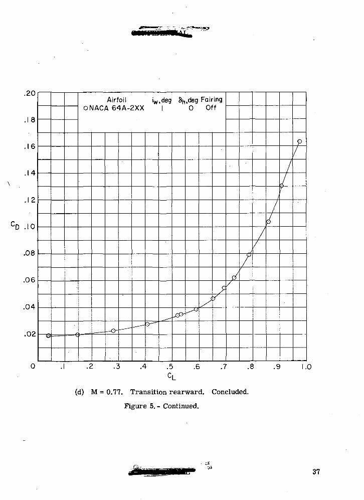
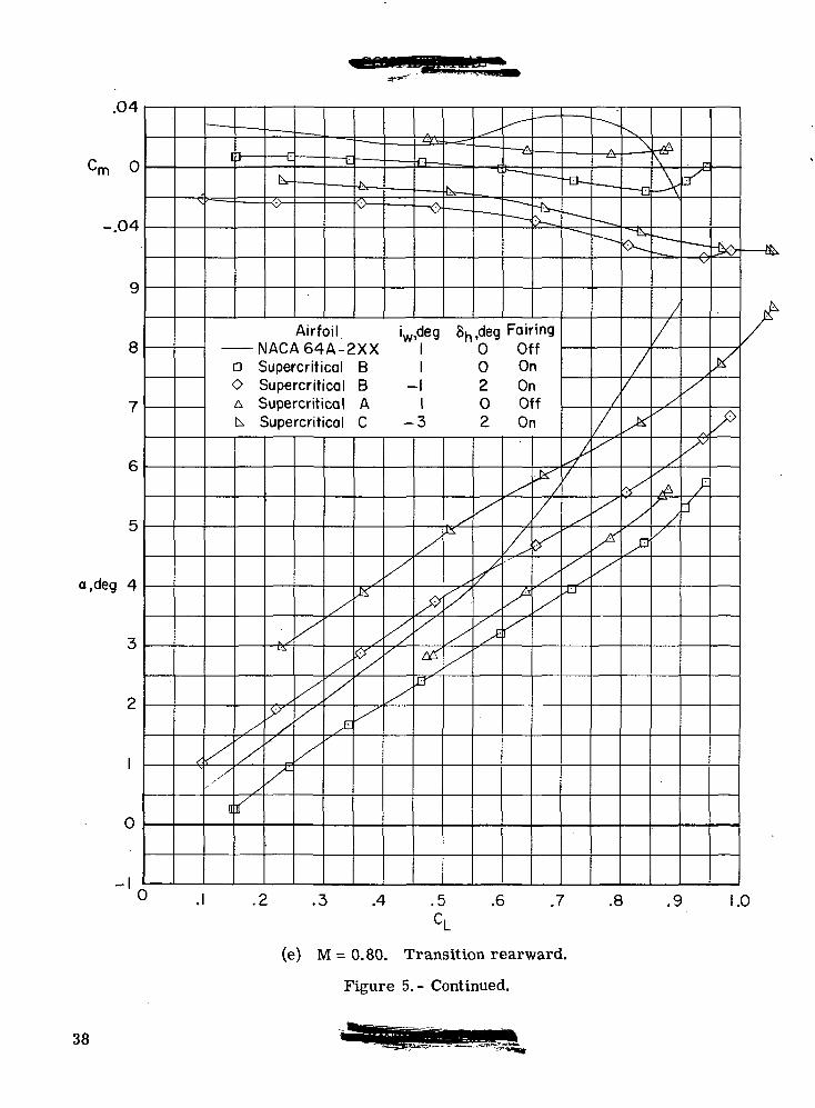
Comparison of longitudinal aerodynamic characteristics of configuration withNACA 64A2XX, supercritical B, and NACA 64A4XX airfoils with -A = 72.5° for -
6h = Off, transition rearward, fuselage fairing on 355h = °°> transition rearward, fuselage fairing on 366h = Off, transition forward, fuselage fairing off 376h = °°> transition forward, fuselage fairing off 386^ = -10°, transition forward, fuselage fairing off 39
Lateral-directional aerodynamic characteristics for -A = 33° for -
Configuration with NACA 64A2XX airfoil. iw = 1° i 40Configuration with supercritical airfoil B. iw = 1° 41Configuration with supercritical airfoil B. iw = -1° 42
Effect of spoiler deflection on configuration with supercritical airfoil B.A = 26° 43
Summary of aerodynamic characteristics -Variation of trimmed CD with M for -
CL = 0.50 , 44CL = 0.90 45
Variation of Cm with M for -CL = 0.50 46CL = 0.90 47,
Variation of a with M for -CL = 0.50 48CL = 0.90 49
Variation of sideslip derivatives with CL 50Trimmed lift-drag polars. A = 39°, M = 0.90 51
DISCUSSION OF RESULTS
Early in the test program a fairing was added to the fuselage sides as shown in fig-ure 1 to improve the wing lower surface flow near the wing-body juncture. For the moreimportant comparisons presented herein, this fairing was on the model; however, somedata are presented for the model without the fairing. To provide the reader with incre-mental values, data are presented in figure 11 for the basic configuration with and without
11
this fairing. Unless otherwise noted all data presented herein are for the configurationswithout the fuselage fairing.
Because of the scope of this investigation, it became prohibitive to obtain horizontal-tail deflection data for all the configurations at all test conditions. For those configura-tions where no trim data were obtained, the trimmed drag characteristics, presented infigures 44, 45, and 51, were obtained by using incremental values from configurations andtest conditions which most nearly represented the configuration to be trimmed.
Although an attempt was made to obtain all the basic comparison data, for a givenwing-sweep angle, at the same horizontal-tail deflection angle, some data were inadver-tently obtained with inconsistent horizontal-tail settings. The reader is therefore cau-tioned to note the horizontal-tail deflection angle listed in the figure key when using thebasic comparison data presented herein. The reader is also cautioned to note that thehorizontal-tail deflection angles were all referenced to the respective wing chord planein an attempt to provide data with consistent wing-tail relationships and to providepitching-moment levels approximately the same for all configurations.
The reader will also note that the wing incidence angle was varied during the inves-tigation. This variation was made in an attempt to have the fuselage angles of attack forthe various supercritical wing configurations match those for the configuration with theNACA 64A4XX airfoil at the cruise condition. However, the final incidence angle for thesupercritical wing was determined from a compromise of the cruise and maneuver dragcharacteristics.
For the data presented in the analysis figures (figs. 44 to 51), no attempt has beenmade to adjust the results for transition location. However, the data presented in fig-ures 12 to 15 indicate that the general conclusions would not be affected if these adjust-ments were made. The reader can therefore refer back to the basic data included in fig-ures 5 to 9 for the transition locations for the various wings.
Cruise Mach Number
The trimmed drag characteristics for four of the wings utilized in the present inves-tigation are summarized in figure 44 for a cruise lift coefficient of 0.50. The resultsobtained for the 0.40 cambered wing with iw = -1°, which has better high-speed maneuvercharacteristics than the same wing with iw = 1°, show little or no improvement in aero-dynamic range factor M(L/D) over the 0.20 cambered wing throughout the Mach numberand wing-sweep ranges for which data were obtained.
The results obtained for supercritical wing C, iw = -3°, indicate an increase in thecruise Mach number of about 0.10 as compared with the conventional wings. It will benoted that there is a slight drag penalty associated with the supercritical wing at the cruise
12
Mach number. However, in spite of this penalty, the supercritical wing C provides anincrease in the aerodynamic range factor of somewhat more than 10 percent. It shouldalso be pointed out that in every instance the results for supercritical wing C showimprovements over supercritical wing B. The pitching-moment characteristics sum-marized in figure 46 show more negative values of Cm for the supercritical wings;however, the trim drag penalties are generally very small at the subsonic cruise liftconditions.
High-Lift Drag at High Subsonic Mach Numbers
The trimmed drag characteristics presented in figure 45 for a lift coefficient of 0.90indicate that the 0.40 cambered NACA 64A-series wing effectively reduced the drag ascompared with the 0.20 cambered wing throughout the Mach number and wing-sweepranges of the investigation. 'Analysis of the data presented in figures 6, 8, and 9 indicatesthat the drag improvements obtained with the 0.40 cambered wing are considerably lessat moderate lift coefficients and in the low-lift range the increased camber results indrag penalties.
The results presented in figure 45(a) for the 0.40 cambered NACA 64A-series wingat a leading-edge sweep angle of 26° indicate that the use of iw = -1° provides lowerdrag at high lift in the Mach number range from 0.75 to 0.90 than iw = 1°. In essence,the more negative wing incidence increases the effective twist and thereby unloads thewing tips and reduces the tendency toward tip stall, particularly at the higher wing-sweepangles. Only the negative incidence (iw = -1°) was used for tests of the wing with 0.40camber at the higher leading-edge sweep angles of 33° and 39°.
The results obtained for supercritical wings B and C are also presented in figure 45and indicate substantial drag reductions at Mach numbers above 0.76 as compared withthose for the 0.40 cambered wing. Again, as was noted for the cruise condition, super-critical wing C indicates lower drag levels than supercritical wing B throughout the Machnumber and wing-sweep ranges of the investigation.
Data presented in figures 5 and 7 indicate that reducing the incidence of supercrit-ical wing B from 1° to -1° provides substantially lower drag at high lift coefficientsthroughout the Mach number range. For supercritical wing C, the incidence angle wasfurther reduced to -3° to provide more nearly the same fuselage angle of attack for agiven lift coefficient as for the 0.40 cambered wing (fig. 49).
Again, as at cruise lift coefficients, the pitching moments for the configurationswith the supercritical wings are more negative than for the conventional wings. (Seefig. 47.) However, for the higher Mach numbers where the drag penalties associated withproviding trim are greatest, the differences in pitching moment for the supercritical andconventional wings are generally relatively small.
13
To provide an indication of the general effectiveness of the supercritical airfoil inreducing drag at M = 0.90, a condition of primary interest to the military services,trimmed drag polars for the condition obtained from cross plots of the measured dataare presented in figure 51. The comparison is made for a leading-edge sweep angleof 39° which results in the lowest drag for the NACA 64A-series and supercritical C wingsat this Mach number. Although the reductions in drag indicated are substantial, signifi-cantly greater improvements were obtained with the supercritical wing at Mach numbersof 0.80 and 0.85 for the most satisfactory sweep angles for these conditions (figs. 44and 45).
High-Lift Drag at Moderate Subsonic Mach Numbers
The results of figure 45 indicate that for a sweep angle of 26°, the drag at high liftfor the supercritical wings is greater than for the 0.40 camber NACA 64A-series wing atMach numbers less than 0.76. The results presented in figure 10 indicate that simpletrailing-edge flap deflections can substantially improve the high-lift characteristics of thesupercritical wing at the lower speeds. Also, the results of several other investigationsof leading-edge flap deflections on uncambered conventional sections suggest that the low-speed characteristics for the supercritical wing could probably be significantly improvedby such a device.
Drag at Supersonic Mach Numbers
The aerodynamic characteristics obtained at supersonic Mach numbers are pre-sented in figures 35 to 39 for a wing leading-edge sweep angle of 72.5°. Because of theproximity of the horizontal tail to the wing chord plane, it was believed that a wing-tailinterference might exist for the 72.5° sweep condition. For this reason the supersonictests were conducted with the horizontal tail on and off. Additional data were also•obtained for a horizontal-tail deflection angle of -10° at the higher supersonic speeds.
The drag characteristics obtained at a Mach number of 1.20 for the configurationswithout the horizontal tail are presented in figure 35. These data show nearly identicaldrag levels for the conventional 0.20 cambered wing and the supercritical wing. Some-what better drag characteristics are noted for the 0.40 cambered wing as compared withthe 0.20 cambered wing.
The results obtained at the higher supersonic Mach numbers (figs. 37, 38, and 39)in general indicate higher drag levels for supercritical wing B as compared with the0.20 cambered wing. It will be noted, however, that the pitching moments for supercrit-ical wing B are somewhat more positive than those for the NACA 64A-series wings andthis wing would therefore have a lower trim drag penalty. It should'also be pointed outthat the data presented in figures 37, 38, and 39 for the supercritical wing B were obtained
14
with -5° of flap rotation. This negative flap rotation was used to decrease the aft camberof the wing and thus reduce any drag penalties which might be incurred at the highersupersonic speeds where the Mach angle approaches the trailing-edge sweep angle.
Lift Coefficient for Buffet Onset
A qualitative analysis of the data of figures 25 to 34 indicates that, in general,throughout the Mach number and wing-sweep ranges of the tests, the 0.40 cambered wingexhibits higher buffet onset lift coefficients than does the 0.20 cambered wing (figs. 26,28, and 29). It should be pointed out that the higher lift coefficients for buffet onset indi-cated for the 0.40 cambered wing, particularly at the higher Mach numbers, are primarilythe result of the increased twist of this wing and are not a camber effect. Reducing thewing incidence angle of the NACA 64A-series wing with 0.40 camber further delays buffetonset to higher C^ values as shown in figure 26. In addition, increasing the wingleading-edge sweep appears to increase the lift coefficient for buffet onset for the NACA64A-series wings at the higher subsonic Mach numbers (figs. 26, 28, and 29).
An analysis of the data obtained for the supercritical wings indicates that supercrit-ical wing B with 26° of leading-edge sweep (fig. 25) effectively delays buffet onset to sub-stantially higher lift coefficients than does the 0.40 cambered wing at Mach numbersabove 0.75. As was noted for the 0.40 cambered wing, reducing the incidence of super-critical wing B from 1° to -1° provides further increases in the lift coefficient for buffetonset (figs. 26 and 28). At a Mach number of 0.75 and below, the results obtained forsupercritical wing B indicate lower CL values for buffet onset than were obtained forthe 0.40 cambered wing. However, results obtained for supercritical wing B with 5° and10° of simple flap rotation (fig. 30) indicate improvement in the buffet onset lift coefficientat these lower Mach numbers, and as was discussed in the section dealing with high-liftdrag, it is quite possible that additional improvements in the buffet characteristics, at thelower Mach numbers, could be realized by the use of leading-edge devices. Similarimprovements in the buffet characteristics might be noted for the conventional airfoilswith flap deflections.
Supercritical wing C, which was investigated with iw = -3°, exhibited higher buffetonset lift coefficients throughout the Mach number and wing-sweep ranges of the tests thandid supercritical wing B. Again, as was the case for supercritical wing B, the low Machnumber buffet characteristics could probably be improved by the use of leading-edgedevices.
An analysis of all the data for the supercritical wings indicates that the buffet onsetlift coefficients are reduced with an increase in wing-sweep angle with resulting reduc-tions in the improvements in buffet onset provided by the supercritical wing as comparedwith the 0.40 cambered NACA 64A-series wing.
15
In many instances, high values of the fluctuating wing-root-bending moments werenoted for all the wings at relatively low lift coefficients, particularly at the higher Machnumbers. It is believed that these high bending-moment values are the result of lowersurface separation and that in the case of the supercritical wings, this separation couldprobably be eliminated by negative flap deflections or higher sweep angles.
Lateral Characteristics
The very limited data obtained at sideslip angles and summarized in figure 50 indi-cate no adverse effects for supercritical wing B as compared with the NACA 64A-serieswing with 0.20 camber.
Limited data were obtained at low Mach numbers to determine the effect of spoilerdeflection, for lateral control, on supercritical wing B (fig. 43). In general, the resultsindicate that the spoiler deflection is very effective in providing lateral control for thesupercritical wing.
Transition Location Effects
The effects of wing upper surface transition location on the longitudinal aerodynamiccharacteristics of the configuration with the 0.20 cambered wing are presented in fig-ure 12. These data indicate increased drag and substantially altered pitching-momentcharacteristics at supercritical Mach numbers when the transition trip is moved forward.This forward location of the transition trip increases the relative boundary-layer thick-ness as compared with full-scale conditions and results in more severe shock-inducedseparation. For the supercritical wings at some Mach numbers, the shock wave movesfrom near the leading edge to a well aft position as the angle of attack is increased andfor these test conditions the correct transition trip location is in doubt. In most cases,data were obtained with both forward and rearward trip locations. Some of the resultsare presented in figures 13, 14, and 15.
The effect of wing upper surface transition location on the buffet characteristics ofthe configuration with the 0.20 cambered wing with a leading-edge sweep angle of 26° ispresented in figure 31. These data are of interest in that moving the transition forwardresults in higher buffet onset lift coefficients at the Mach numbers where supercriticalflow exists over the wing. It appears that the thicker boundary layer associated with thegreater chordwise extent of turbulent flow for the forward transition may attenuate thefluctuations associated with shock—boundary-layer interaction and thus provide resultswhich may be more favorable than those which would be obtained in flight. For this rea-son, extreme caution should be used in obtaining and interpreting wind-tunnel results usingthe wing-root-bending-moment technique.
16
CONCLUSIONS
An investigation has been conducted in the Langley 8-foot transonic pressure tun-nel and the Langley Unitary Plan wind tunnel to evaluate the effectiveness of three varia-tions of the NASA supercritical airfoil as applied to a model of a variable-wing-sweepfighter airplane. Wing panels incorporating conventional NACA 64A-series airfoils with0.20 and 0.40 camber were used as bases of reference for this evaluation. Static forceand moment measurements were obtained for wing leading-edge sweep angles of 26°, 33°,and 39° at subsonic speeds and for a wing leading-edge sweep of 72.5° at transonic andsupersonic speeds. In addition, fluctuating wing-root-bending-moment data were obtainedat subsonic speeds to determine buffet characteristics. The following conclusions areindicated:
1. Increasing the conventional camber had little effect on the cruise Mach numberbut did reduce the trimmed drag characteristics in the moderate- to high-lift range andincreased the buffet onset lift coefficient at subsonic speeds.
2. An increase in the cruise Mach number capability of about 0.10 was noted for themodel with the supercritical wing as compared with the wings incorporating conventionalNACA 64A-series airfoils.
3. Substantial reductions in the moderate- to high-lift trimmed drag characteristics! j
were achieved with the supercritical wing at the higher, subsonic speeds.
4. The lift coefficient for buffet onset was increased significantly with the super-critical wing for a leading-edge sweep angle of 26° at Mach numbers of 0.75 and above.
5. The low-speed (Mach number = 0.60) drag characteristics were somewhat higherand the buffet onset lift coefficient somewhat lower for the supercritical wing as com-pared with the conventional 0.40 cambered wing although these characteristics wereimproved by the use of trailing-edge flaps.
6. At supersonic speeds, the trimmed drag characteristics for the supercriticalwing were slightly higher than those for the wings incorporating conventional camber.
7. No adverse yaw characteristics were noted for the supercritical wing at the testconditions for which the data were obtained.
Langley Research Center,National Aeronautics and Space Administration,
Hampton, Va., March 16, 1973.
17
REFERENCES
1. Harris, Charles D.: Aerodynamic Characteristics of Two NASA Supercritical Air-foils With Different Maximum Thicknesses. NASA TM X-2532, 1972.
2. Ferris, James C.: Static Aerodynamic Characteristics of a Model With a 17-Percent -Thick Supercritical Wing. NASA TM X-2551, 1972.
3. Bartlett, Dennis W.; and Re, Richard J.: Wind-Tunnel Investigation of Basic Aero-dynamic Characteristics of a Super critical-Wing Research Airplane Configuration.NASA TM X-2470, 1972.
4. Anon.: Supercritical Wing Technology - A Progress Report on Flight Evaluations.NASA SP-301, 1972.
5. Palmer, W. E.; Elliott, D. W.; and White, J. E.: Flight and Wind Tunnel Evaluationof a 17% Thick Supercritical Airfoil on a T-2C Airplane. NR71H-150 (Con-tract N00019-70-C-0474), North American Rockwell Corp., July 31, 1971.Vol. I - Basic Report. (Available from DDC as AD 517 436L.)Vol. II — Flight Measured Wing Wake Profiles and Surface Pressures.
(Available from DDC as AD 517 437L.)
6. Pirrello, C. J.; Hardin, R. D.; Heckart, M. V.; and Brown, K. R.: An Inventory ofAeronautical Ground Research Facilities. Vol. I - Wind Tunnels. NASACR-1874, 1971.
7. Loving, Donald L.: Wind-Tunnel—Flight Correlation of Shock-Induced SeparatedFlow. NASA TND-3580, 1966.
8. Loving, Donald L.; and Katzoff, S.: The Fluorescent-Oil Film Method and OtherTechniques for Boundary-Layer Flow Visualization. NASA MEMO 3-17-59L,1959.
9. Davis, Don D., Jr.; and Huston, Wilber B.: The Use of Wind Tunnels To PredictFlight Buffet Loads. NACA RM L57D25, 1957.
10. Ray, Edward J.: Techniques for Determining Buffet Onset. NASA TM X-2103, 1970.
18
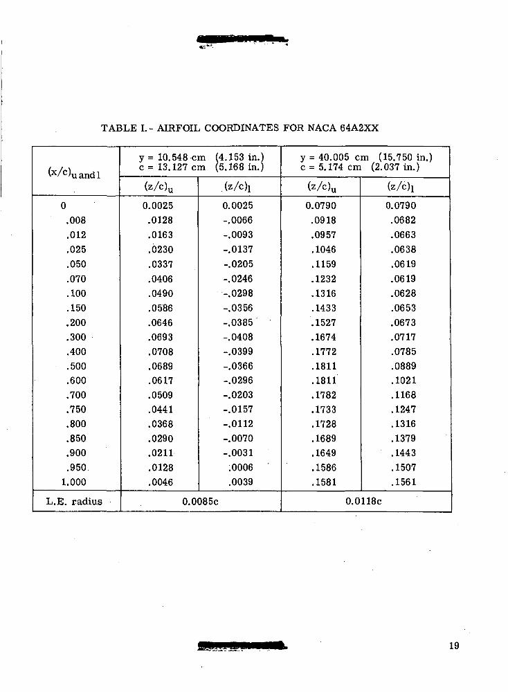
TABLE I. - AIRFOIL COORDINATES FOR NACA 64A2XX
(x/c)uandl
0.008.012.025.050.070.100.150.200.300.400.500.600.700.750.800.850.900.9501.000
L.E. radius
y = 10.548 cm (4.153 in.)c = 13.127 cm (5.168 in.)
(z/c)u
0.0025.0128.0163.0230.0337.0406.0490.0586.0646.0693.0708.0689.0617.0509.0441.0368.0290.0211.0128.0046
.(z/c)i
0.0025-.0066-.0093-.0137-.0205-.0246-.0298-.0356-.0385-.0408-.0399-.0366-.0296-.0203-.0157-.0112-.0070-.0031.0006.0039
0.0085c
y = 40.005 cm (15.750 in.)c = 5. 174 cm (2.037 in.)
(z/c)u
0.0790.0918.0957.1046.1159.1232.1316.1433.1527.1674.1772.1811.1811.1782.1733.1728.1689.1649.1586.1581
(z/c)i
0.0790.0682.0663.0638.0619.0619.0628.0653.0673.0717.0785.0889.1021.1168.1247.1316.1379.1443.1507.1561
O.OllSc
19
CO
<;oOT
wIOIa
c^
i-sC-i-l•C
Om
0
*— 'CM
aSS
U5
U
O0
5O
ind"!
II II
>> 0
c e
•1-1 -i-ioo C
NC
O 00
in ir-
is's-
s su u
t— t C
DC
OT
fi-f i-<
T)< CN1—
1 TH
II II
>>
o
c c
•r-l >p-l
O 0
0
O C
O
OO
5
m
S SW
O
O O
O C
Oc- inCQ ej1—
1 iH
II II
>>
0
c c
•i-< •**t-
OCD in1—
1 TH
TJ« in
SCG
0 0
T^T
-I
coco
in o
O C
Oi-H
i-H
M II
>>
o
»-H
T3§S
<^
^H
?NS
<
i-H
oN^3
'o"N»— i
5N3
-v.
ONi— i
ONSN
c-
>*
'S<
Tt
<a
ot
-o
oo
mc
oo
co
tN
i-
HO
OO
OC
3>
Tt
<C
Oc
oO
C-
T»
<O
5e
MC
Mo
oc
oc
Dc
DC
-o
oo
>'-
ies
iT»
<in
c-
oo
ot-
^c
-o
ot
Min
co
co
co
os
in
t-
ci-H
i-H
^c
Qi-io
in
co
min
i-io
om
oo
oi-
Hc
oc
oo
oo
so
oo
oc
nc
o
oin
oc
oo
oc
jit-
'o
oin
oe
oin
^C
)C
DC
-C
MC
DC
nO
OO
CM
in
cO
OC
O^
oo
oo
oo
oo
oo
oo
oO
1
1
I I
1
1
I 1
in
in
^o
om
ojo
co
co
oo
co
'-
ic
oc
Dc
no
in
co
oo
co
cM
mc
oo
oo
om
oe
si^
j<
mc
-o
oo
io
io
oe
-in
co
i-
<o
oo
oo
oo
oo
oo
oo
oin
c-
cq
i-
ie
MO
co
co
co
oj
CO
»-HT
ro
sc
oe
siD
-o
oin
T-
i^c
D
CO
«-Ho
oiH
ca
ca
-e
>a
eQ
e>
ji-io
o
^-i
oo
oo
oo
oo
oo
oo
O
I 1
1
1
1
1
1
1
1
O
in
co
min
o>
-i!-
io
oc
oc
j>
oo
o^
T^
cD
C-
eo
co
TH
in
^f
t-
mo
cN
ie
ii
oe
sic
oin
^o
oa
3O
3c
-c
Din
co
»-
io
oo
oo
oo
oo
oo
oo
oto
co
co
TH
i-
iin
c-
o^
oc
-in
oo
"-
lo
oo
oc
DC
Din
eq
cD
OJ
OC
Min
O'H
cM
co
co
co
co
co
es
i'-
ii-
io
oO
OO
OO
OO
OO
OO
OO
O
1. 1
1 1
1 1
1 1
1 1
1
cO
Tt
tm
^i-
rm
ea
ao
^a
oc
oi-
io
T-
iint
-c
oc
35
i-ic
oe
Mm
co
oo
cN
ic-
oe
Mc
oin
cD
t-
c-
c-
cD
in
co
cN
io
oo
oo
oo
oo
oo
oo
ooo
om
O'-
iO'-
i^H
i-H
i-ie
sic
xi'-
ioo
ca
in
oo
oo
oo
oo
oo
oo
o'-
ic
jc
o-
^io
co
t-
oo
cn
oo'
,-H
uO5
CO
Ooo'yc-c-oo'uc-c-oo'u0
0c-ooo'radius
WHJ
20
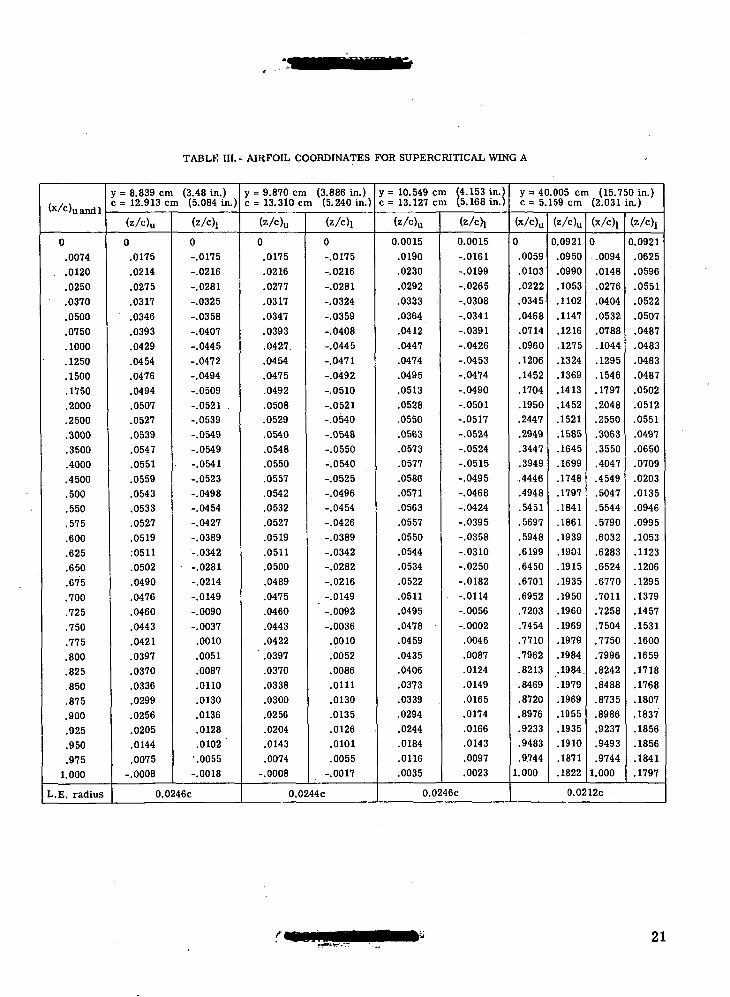
TABLE HI. - AIRFOIL COORDINATES FOR SUPERCRITICAL WING A
(x/c)uandl
0.0074
. .0120.0250.0370.0500.0750.1000.1250.1500.1750.2000.2500.3000.3500.4000.4500.500.550.575.600.625.650.675.700.725.750.775.800.825.850.875.900.925.950.975
1.000
L.E. radius
y = 8.839 cm (3.48 in.)c= 12.913 cm (5.084 In.)
(z/c)u
0.0175.0214.0275.0317.0346.0393.0429.0454.0476.0494.0507.0527.0539.0547.0551.0559.0543.0533.0527.0519:0511.0502.0490.0476.0460.0443.0421.0397.0370.0336.0299.0256.0205.0144.0075
-.0008
(z/ch
0-.0175-.0216-.0281-.0325-.0358-.0407-.0445-.0472-.0494-.0509-.0521 .-.0539-.0549-.0549-.0541-.0523-.0498-.0454-.0427-.0389-.0342-.0281-.0214-.0149-.0090-.0037.0010.0051.0087.0110.0130.0136.0128.0102
'.0055-.0018
0.0246C
y = 9.870 cm (3.886 in.)c = 13.310cm (5.240 in.)
(z/c)u
0.0175.0216.0277.0317.0347.0393.0427.0454.0475.0492.0508.0529.0540.0548.0550.0557.0542.0532.0527.0519.0511.0500.0489.0475.0460.0443.0422
' .0397.0370.0338.0300.0256.0204.0143.0074
-.0008
(z/c)i
0-.0175-.0216-.0281-.0324-.0359-.0408-.0445-.0471-.0492-.0510-.0521-.0540-.0548-.0550-.0540-.0525-.0496-.0454-.0426-.0389-.0342-.0282-.0216-.0149-.0092-.0036.0010.0052.0086.0111.0130.0135.0126.0101.0055
-.0017
0.0244c
y = 10.549 cm (4.153 in.)c = 13.127 cm (5.168 in.)
(z/c)u
0.0015.0190.0230.0292.0333.0364.0412.0447.0474.0495.0513.0528.0550.0563.0573.0577.0586.0571.0563.0557.0550.0544.0534.0522.0511.0495.0478.0459.0435.0406.0373.0339.0294.0244.0184.0116.0035
(z/ch
0.0015-.0161-.0199-.0265-.0308-.0341-.0391-.0426-.0453-.0474-.0490-.0501-.0517-.0524-.0524-.0515-.0495-.0468-.0424-.0395-.0358-.0310-.0250-.0182-.0114-.0056-.0002.0046.0087.0124.0149.0165.0174.0166.0143.0097.0023
0.0246C
y = 40.005 cm (15.750 in.)c = 5.159 cm (2.031 in.)
(x/c)u
0
.0059
.0103
.0222
.0345
.0468
.0714
.0960
.1206
.1452
.1704
.1950
.2447
.2949
.3447
.3949
.4446
.4948
.5451
.5697
.5948
.6199
.6450
.6701
.6952
.7203
.7454
.7710
.7962
.8213
.8469
.8720
.8976
.9233
.9483
.97441.000
(z/c)u
0.0921.0950.0990.1053.1102.1147.1216.1275.1324.1369.1413.1452.1521.1585.1645.1699.1748.1797.1841.1861.1939.1901.1915.1935.1950.1960.1969.1979.1984.1984..1979.1969.1955.1935.1910.1871.1822
(x/c)!
0.0094.0148.0276.0404.0532.0788.1044.1295.1546.1797.2048.2550.3063.3550.4047.4549.5047.5544.5790.6032.6283.6524.6770.7011.7258.7504.7750.7996.8242.8488.8735.8986.9237.9493.9744
1.000
(z/c)j
0.0921.0625.0596.0551.0522.0507.0487.0483.0483.0487.0502.0512.0551.0497.0650.0709.0203.0135.0946.0995.1053.1123.1206.1295.1379.1457.1531.1600.1659.1718.1768.1807.1837.1856.1856.1841.1797
0.0212c
21
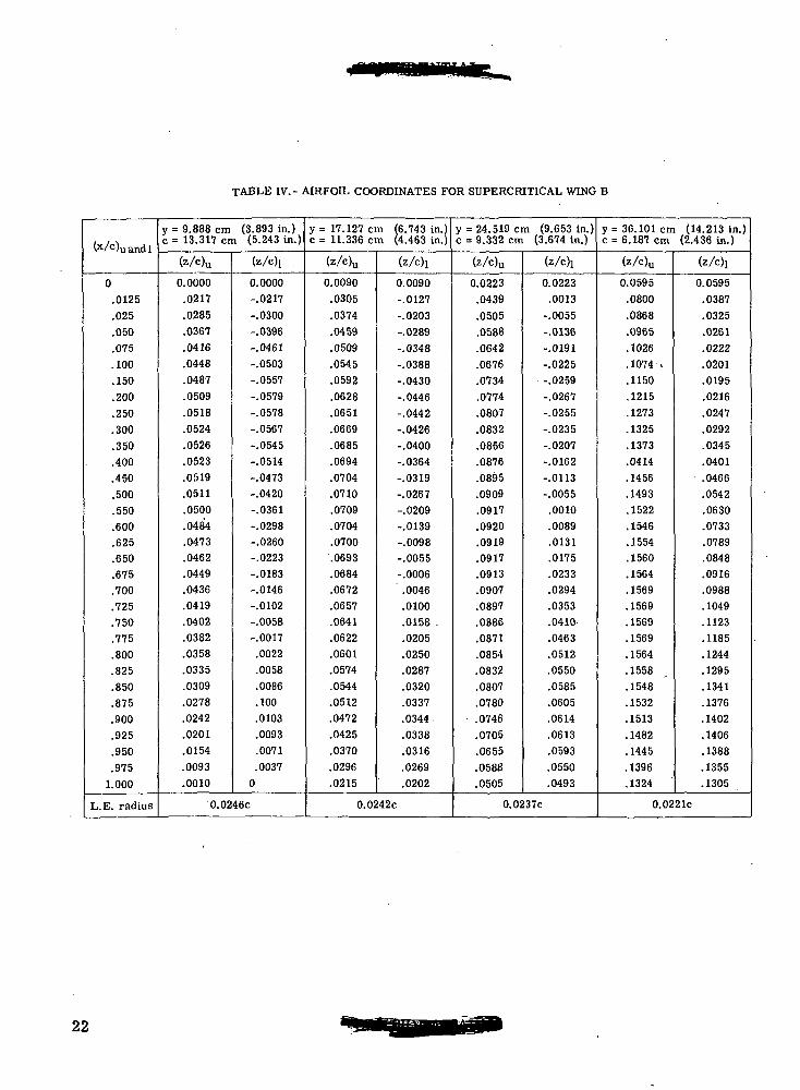
TABLE IV.- AIRFOIL COORDINATES FOR SUPERCRITICAL WING B
(x/0uandl
0.0125.025.050.075.100.150.200.250.300.350.400.450.500.550.600.625.650.675.700.725.750.775.800.825.850.875.900.925.950.9751.000
L.E. radius
y = 9.888 cm (3.893 in.)c = 13.317 cm (5.243 in.)
(z/c)u
0.0000.0217.0285.0367.0416.0448.0487.0509.0518.0524.0526.0523.0519.0511.0500.0484.0473.0462.0449.0436.0419.0402.0382.0358.0335.0309.0278.0242.0201.0154.0093.0010
(z/c)i .
0.0000-.0217
-.0300-.0396-.0461-.0503-.0557-.0579-.0578-.0567-.0545-.0514-.0473-.0420-.0361-.0298-.0260-.0223-.0183-.0146-.0102-.0058-.0017.0022.0058.0086.100.0103.0093.0071.00370
0.0246C
y= 17. 127 cm (6.743 in.)c = 11.336 cm (4.463 in.)
(z/c)u
0.0090.0305.0374.0459.0509.0545.0592.0628.0651.0669.0685.0694.0704.0710.0709.0704.0700.0693.0684.0672.0657.0641.0622.0601.0574.0544.0512.0472.0425.0370.0296.0215
(z/c)i
0.0090-.0127
-.0203-.0289-.0348-.0388-.0430-.0446-.0442-.0426-.0400-.0364-.0319-.0267-.0209-.0139-.0098-.0055-.0006.0046.0100.0158 ..0205.0250.0287.0320.0337.0344.0338.0316.0269.0202
0.0242c
y = 24.519 cm (9.653 in.)c = 9.332 cm (3.674 in.)
(z/c)u
0.0223.0439.0505.0588.0642.0676.0734.0774.0807
.0832
.0856
.0876
.0895
.0909
.0917
.0920
.0919
.0917
.0913
.0907
.0897
.0886
.0871
.0854
.0832
.0807
.0780• .0746.0705.0655.0588.0505
(z/c)i
0.0223.0013-.0055-.0136-.0191-.0225-.0259-.0267-.0255-.0235-.0207-.0162-.0113-.0055.0010.0089.0131.0175.0233.0294.0353.0410.0463.0512.0550.0585.0605.0614.0613.0593.0550.0493
0.0237c
y= 36.101 cm (14.213 in.)c = 6. 187 cm (2.436 in.)
(z/c)u
0.0595.0800.0868.0965.1026.1074 *.1150.1215.1273.1325.1373.0414.1456.1493.1522.1546.1554.1560.1564.1569.1569.1569.1569.1564.1558.1548.1532.1513.1482.1445.1396.1324
(z/e)i
0.0595.0387.0325.0261.0222.0201.0195.0216.0247.0292.0345.0401.0466.0542.0630.0733.0789.0848.0916.0988.1049.1123.1185.1244.1295.1341.1376.1402.1406.1388.1355.1305
0.0221C
22
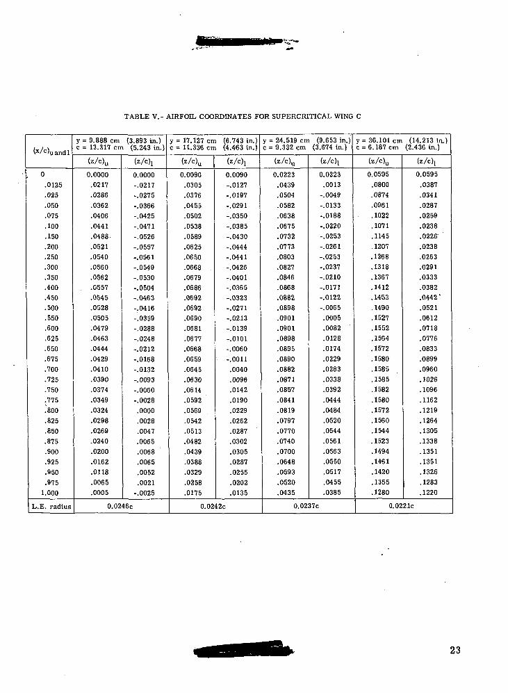
TABLE V. - AIRFOIL COORDINATES FOR SUPERCRITICAL WING C
<x/c)uandl
0.0125.025.050.075.100.150.200.250.300.350.400.450.500.550.600.625.650.675.700.725.750.775.800.825.850.875.900.925.950.9751.000
L.E. radius
y = 9.888 cm (3.893 in.)c = 13.317 cm (5.243 in.)
(z/c)u
0.0000
.0217
.0286
.0362
.0406
.0441
.0488.
.0521
.0540
.0560
.0562
.0557
.0545
.0528
.0505
.0479
.0463
.0444
.0429
.0410
.0390
.0374
.0349
.0324
.0298
.0269
.0240
.0200
.0162
.0118
.0065
.0005
(z/c)j
0.0000-.0217-.0275-.0366-.0425-.0471-.0526-.0557-.0561-.0549-.0530-.0504-.0463-.0416-.0359-.0288-.0248-.0212-.0168-.0132-.0093-.0060-.0028.0000.0028.0047.0065.0068.0065.0052.0021-.0025
0.0246c
y = 17.127 cm (6.743 in.)c = 11.336 cm (4.463 in.)
(z/0u
0.0090.0305.0376.0455.0502.0538.0589.0625.0650.0668 ..0679.0686.0692.0692.0690.0681.0677.0668.0659.0645.0630.0614.0592.0569.0542.0513.0482.0439.0388.0329.0258.0175
(z/c)!
0.0090-.0127-.0197-.0291-.0350-.0385-.0430-.0444-.0441-.0426-.0401-.0365-.0323-.0271-.0213-.0139-.0101-.0060-.0011.0040.0096.0142.0190.0229.0262.0287.0302.0305.0287.0255.0202.0135
0.0242C
y = 24. 519 cm (9.653 in.)c = 9. 332 cm (3.674 in.)
(z/c)u
0.0223.0439.0504.0582.0638.0675.0732.0773.0803.0827.0846.0868.0882.0898.0901.0901.0898.0895.0890.0882.0871.0857.0841.0819.0797.0770.0740.0700.0648.0593.0520.0435
(z/c)i
0.0223.0013-.0049-.0133-.0188-.0220-.0253-.0261-.0253-.0237-.0210-.0171-.0122-.0065.0005.0082.0128.0174.0229.0283.0338,0392.0444.0484.0520.0544.0561.0563.0550.0517.0455.0385
0.0237c
y = 36.101 cm (14.213 in.)c = 6. 187 cm (2.436 in.)
(zA%
0.0595.0800.0874.0961.1022.1071.1145.1207.1268.1318.1367.1412.1453.1490.1527.1552.1564.1572.1580.1585.1585.1582.1580.1572.1560.1544.1523.1494.1461.1420.1355.1280
(z/c)j
0.0595.0387.0341.0287.0259.0238.0226'.0238.0263.0291.0333.0382.0442 '.0521.0612.0718.0776.0833.0899.0960.1026.1096.1162.1219.1264.1305.1338.1351.1351.1326.1283.1220
0.0221c
23
CQC_O'wao>sa a,
^ co
Z* "->
«
>
S0)
ocos-s0)
CO
fi• fH«4Ha<Dcuco0)i-H
1SI—I
cuT3OSCOIo
a>-M
•££
sS
Scu
C
24
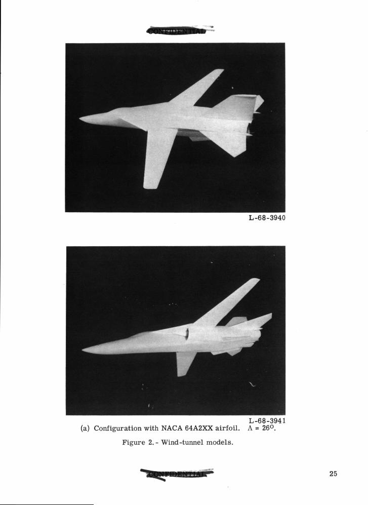
L-68-3940
L-68-3941(a) Configuration with NACA 64A2XX airfoil. A = 26°.
Figure 2.- Wind-tunnel models.
25
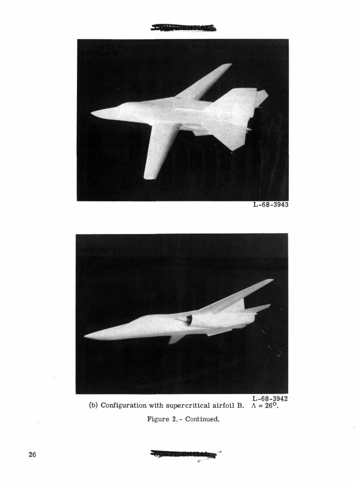
L-68-3943
L-68-3942(b) Configuration with supercritical airfoil B. A = 26°.
Figure 2. - Continued.
26
L-68-3134
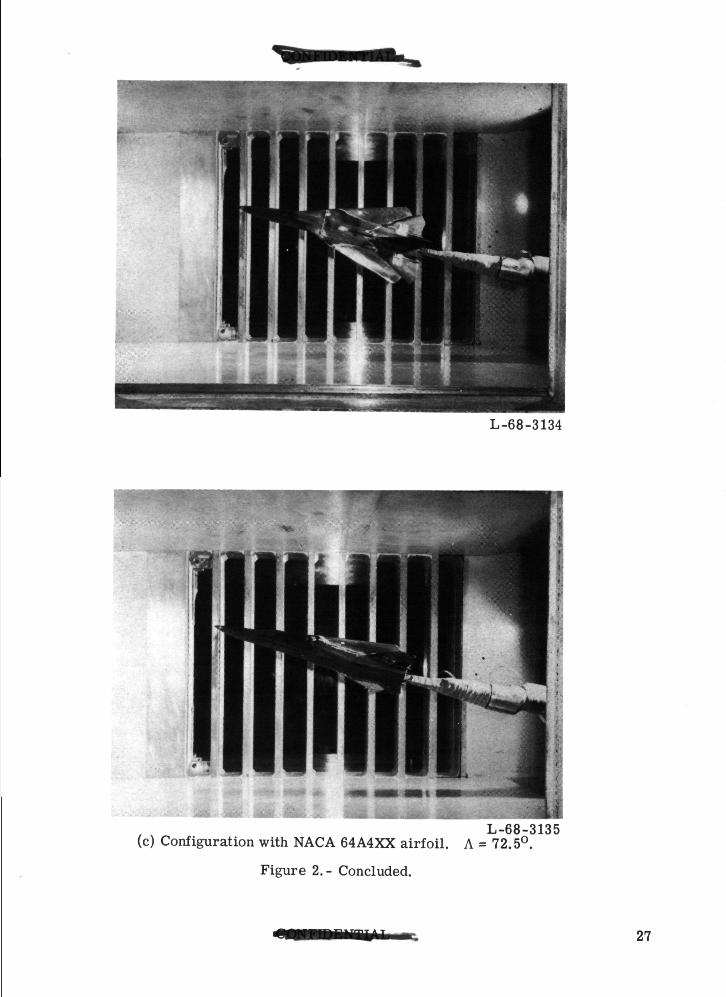
L-68-3135(c) Configuration with NACA 64A4XX airfoil. A = 72.5°.
Figure 2.- Concluded.
27
CD O8.
CO
XXXX<J-<s<O<
OCDCCO
inCO•
2-SO03CM
I13ts03cdCO
91
COOJ
i
28
Station 45.827(18.042)
Wing strain gage
Span station 0
Span station
8.839(3.480)-
10.579(4.165)-
— 17.348(6.830)17.043(6.710)-
82-percent chord line
60-percent chord line
1° wing dihedraloutboard of span stotion'_
8.839(3.480)24.519(9.653)
Trailing edge"
26.146-percent chord line-
Spoiler
32.334(12.730)
40.005(15.750)
Figure 4. - Wing details. All linear dimensions in centimeters with inchesin parentheses unless otherwise noted.
29
.08
.04
^m
10
a.deg
0
Airfoil0 NACA 64A-2XXO Supercritical B
k Supercritical C
iw ,deg Sh,deg Fairing Upper surface transitionI 0 O.ff Rearward
-1 2 On Forward
-3 On Forward
ff<
X
fi
0 .1 .2 .3 .4 .5 .6 .7 .8 .9 1.0CL
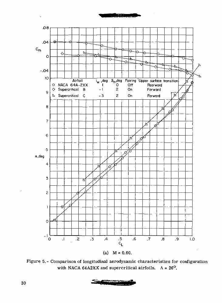
(a) M = 0.60.
Figure 5. - Comparison of longitudinal aerodynamic characteristics for configurationwith NACA 64A2XX and supercritical airfoils. A = 26°.
30
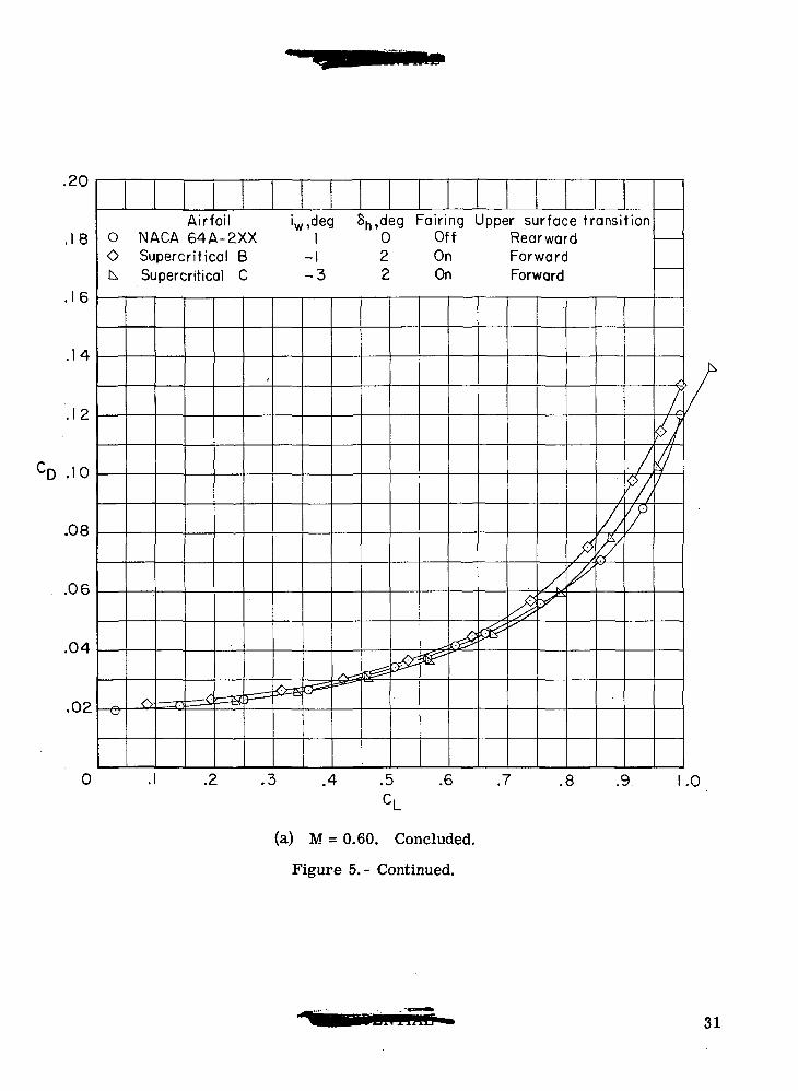
.20
.18
,16
.12
CD .10
.08
.06
.04
.02
Airfoil iw»deg &h»de9 Fairing Upper surface fransi0 NACA 64A-2XX 1 0 Off RearwardO Supercritical B -1 2 On Forwardk Supercritical C -3 2 On Forward
G~=S
(
F=l
/V-;
^
-
3 -<&
&^S'
^
^<^X
/{X
/
^
tion
/%'/
/
/ r-
tl41
.4 .5 .6 .7 .8 .9 .0
(a) M = 0.60. Concluded,
Figure 5.- Continued.
31
.08
Cm .04
0
8
a.deg
0
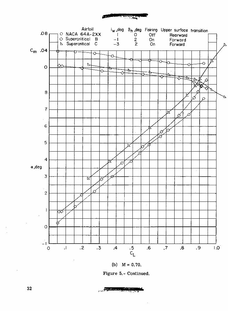
AirfoilO NACA 64A-2XXO Supercritical Bk Supercritical C
iw ,deg 8n ,deg Fairing Upper surface transitionI 0 Off Rearward
-1 2 On Forward-3 2 On Forward
0
T
.4 .5 .6 .7 .8 .9 1.0
(b) M = 0.70.
Figure 5.- Continued.
32
.20
8
,16
.14
.12
D -1
.08
.06
.04
.02
0 .4 .5C,
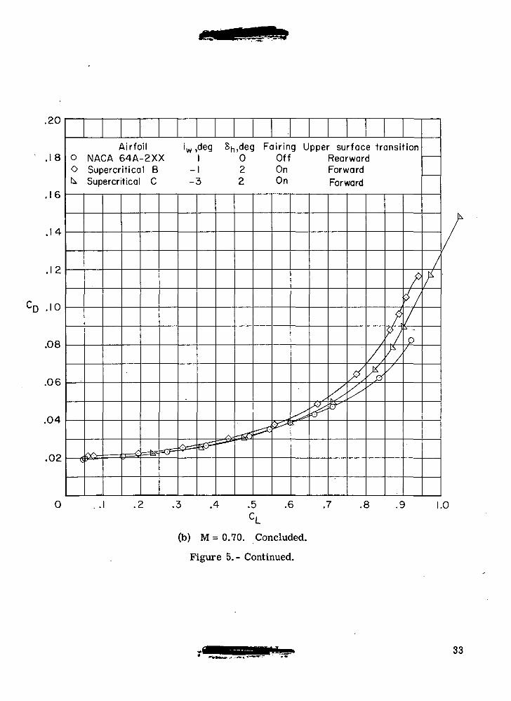
(b) M= 0.70. Concluded.
Figure 5.- Continued.
Airfoil iw ,deg Sh,deg Fairing Upper surface transitiono NACA 64A-2XX 1 0 Off RearwardO Supercritical B - 2 On Forwardk Supercritical C -3 2 On Forward
<! < r-Q&*. 'T=£-^
s\-• *~
• ^K~
. s&£•r/,
/
/,^/
k*>//
?i//•*
p/
/
f
.6 .7 .8 .9 1.0
33
•rn
0
1
-.04
-.08
10
9
8
7
6
5
leg
4
3
2
1
0
1
tf
rf
IB
- — .• — • .
—
b
I
• .
— i
~CJ
1 —• .
— t r ~TJ^-.=-4r •==-^ — ,
—• —
^- .•—-^
\
~^Q,
1-V
\\-&•
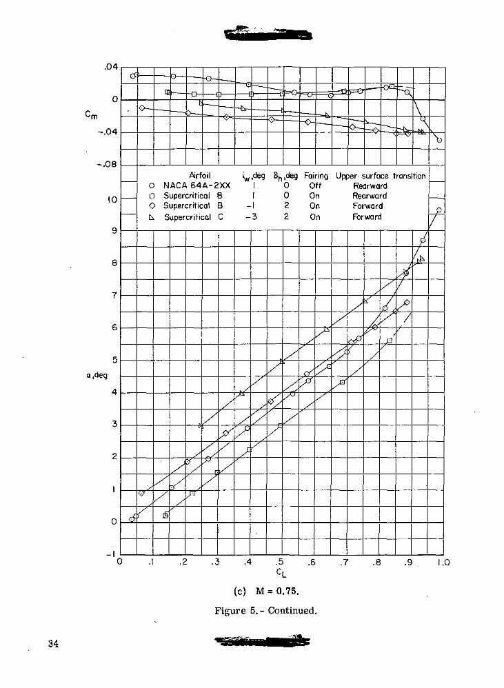
Airfoil iw,deg S^.deg Fairing Upper surface transition0 NACA 64A-2XX 1 0 Off Rearwarda Supercritical B 1 0 On RearwardO Supercritical B -1 2 On Forwardk. Supercritical C -3 2 On Forward
'/O
/
/
X/
15
X
X
Xp/
^
/
/./^r
X
X
Xx^x
XX
XX/
/
// ,
/I/
x<^X
X
/
<X
X
X/
XXX
X
x
x
<^X
x
<*?/
/
/
*
/«f".
//
/
^X
p/
V^>/
fk
\>
p/
0 .2 .3 .4 .5 .6 .7 .8 .9 1 .(
CL
(c) M = 0.75.
Figure 5.- Continued.
34
.20
8
.14
.12
-D .10
.08
.06
.04
,02
0
=ffl 1 ^^
Airfoil 'w^eg 8^,deg Fairing0 NACA 64A-2XX 1 0 Offa Supercritical B 1 0 OnO Supercritical B -1 2 Onk, Supercritical C -3 2 On
. — - -^^
'• r ^
FT
X^^
^'/y
Upper surface-,transition
RearwardRearwardForwardForward
103
/
f ,
f/
&/
/t1
'
^
?
1
.4 .5CL
.6 .7 .8 .9 1.0
(c) M = 0.75. Concluded.
Figure 5.- Continued.
35
.UH
0
Cm
-.04
Oft
10
9
8
7
6
5
a.deg
4
3
2
1
0
-1C
0
//
o
V.
/-
i
X
—
/
r==^ ™
°~~- — -— .— <
^w \J X
^\
Airfoil iw,deg Sh,deg FairingO N A C A 6 4 A - 2 X X 1 0 Off
(Y/"
X/
X•T
/
IX ^
x°/
/
/y
/
e//
//
/
^
k\
/
/
N7)
P/
> -I .2 .3 .4 .5 .6 .7 .8 .9 1CL
.0
(d) M = 0.77. Transition rearward.
Figure 5.- Continued.
36
8
.16
.14
.12
D .10
.08
.06
.04
.02
0
AirfoiloNACA 64A-2XX
Sh,deg Fairing1 0 Off
£-
.1 .2 .3 .4 .5 .6 .7 .8 .9 1.0
(d) M = 0.77. Transition rearward. Concluded.
Figure 5.- Continued.
37
.04
0
-.04
8
a,deg 4
0
0
AirfoilNACA64A-2XX
a Supercritical BO Supercritical BA Supercritical Ak Supercritical C
iw,deg 8h,deg Fairing
-3
00202
OffOnOnOffOn
T
.3 .4 .5C,
.6 .7 .8 .9
(e) M = 0.80. Transition rearward.
Figure 5.- Continued.
1.0
38
.20
.18
.16
.14
.12
CD .10
.08
.06
.04
.02 < . — 11
D S
0 SA S
k S
a=-
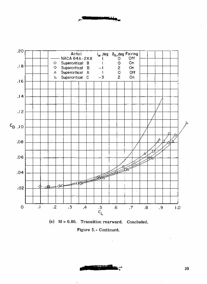
Airfoil iw,deg 8k, deg FairingACA64A-2XX 1 0 Offupercriticql B 1 0 Onupercritical B - 1 2 Onupercritical A 1 0 Offupercritical C -3 2 On
•
TfeSiyy^ ^
^
^
^J^
/
g|
//
^
/
/
^^
//
^^
//
/$
//
/y.//
F.
/„<?
yv
$
• \ .2 .3 .4 .5 .6 .7 .8 .9 1.0CL
(e) M = 0.80. Transition rearward. Concluded.
Figure 5.- Continued.
39
.12
.08
.04
0
-.04
a.deg
0
-io
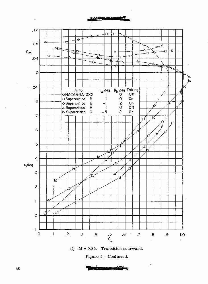
AirfoilONACA64A-2XXa Supercritical BOSupercritical BA Supercritical Ak Supercritical C
i deg Sh,deg Fairing
-3
OffOnOnOffOn
.3 .4 .5 .6 .7 .8 .9 1.0
(f) M = 0.85. Transition rearward.
Figure 5.- Continued.
40
.zu
.18
.16
.14
.12
CD .10
.08
.06
.04
.02
-
(5
v -
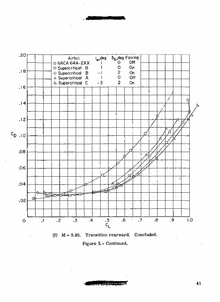
Airfoil iw,deg Sn,deg FairingONACA64A-2XX 1 0 Offo Supercritical B 1 0 OnO Supercritical B -1 2 OnA Supercritical A 1 0 Offk, Supercritical C -3 2 On
-or-
./cS
^
/
(S
>
fr<
^
0
/
A
^
//
/ // s
//
/^//'/
(
/
//
y
/D
///y/y
//
7.7/
,//
•
1
**/
0 .2 .3 .4 .5 .6 ' .7 .8 .9CL
(f) M = 0.85. Transition rearward. Concluded.
Figure 5.- Continued.
1.0
41
.16
.12
.08
.04
0
a.deg 3
0
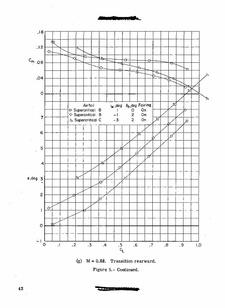
Airfoila Supercritical BO Supercritical Bk Supercritical C
iw,deg 8h,deg Fairing1 0 On
- 1 2 On-3 2 On
0 .3 .4 .5 .6 .7 .8 .9 1.0
(g) M = 0.88. Transition rearward.
Figure 5.- Continued.
42

.18
.16
.14
.12
.10
.08
.06
.04
.02
te .— — —
Airfoil iw,deg Sn,deg Fairinga Supercritical B 1 0 OnO Supercritical B -1 2 Onk, Supercritical C -3 2 On
**& ^
X
/
X^*s
fyf
//
^
X/ J
Y
/
%7
/
y
P /
0 .2 .3 .4 .5 .6 .7 .8 .9CL
(g) M = 0.88. Transition rearward. Concluded.
Figure 5.- Continued.
1.0
43
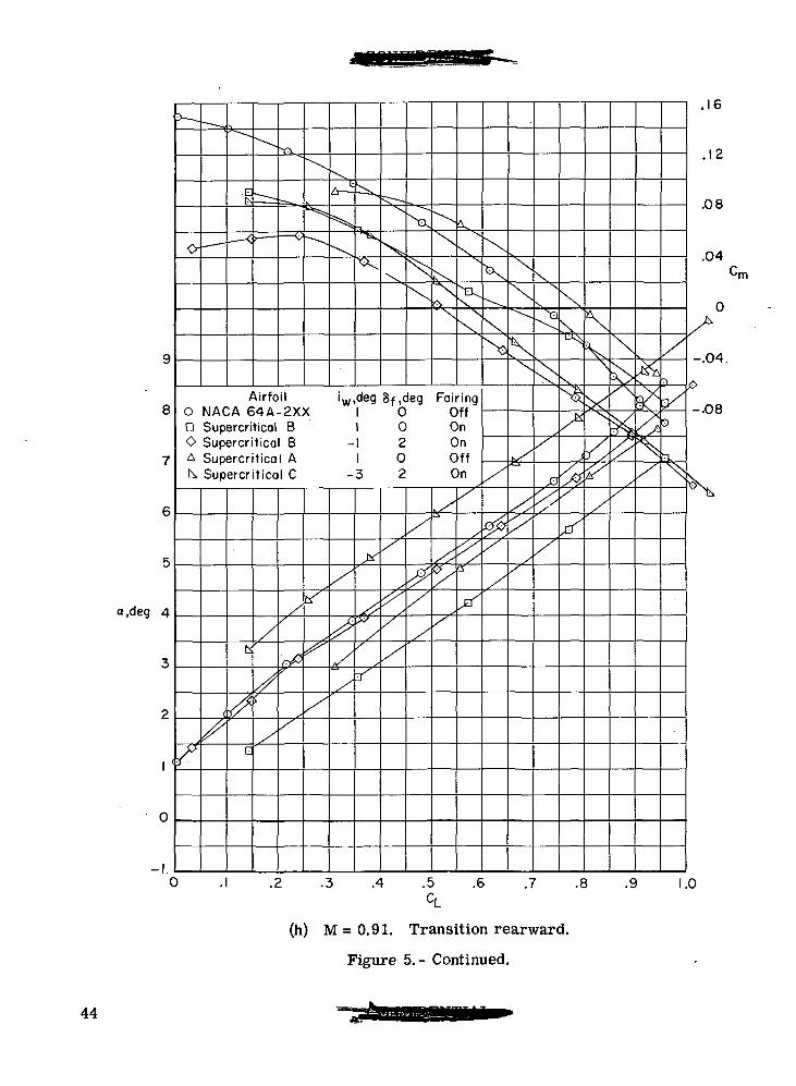
a.deg 4
1 '
ik.
^NJN
Airfoil0 NACA 64A-2XXa Supercritical BO Supercritical BA Supercritical Ak Supercritical C
iw,deg Sf.deg Fairing0 Off
1 0 O n-1 2 On
1 0 Off-3 2 On
X
\,
.2 .3 .4 .5 .6 .7 .8
.16
.12
.08
.04
•rn
-.04
-.08
.9 1.0
(h) M = 0.91. Transition rearward.
Figure 5. - Continued.
44
.<L\J
.18
.16
.14
.12
CD -10
.08
.06
.04
.02
0
W ^r^
Airfco NACA 64,D SupercritiO SupercritiA Supercritik Supercriti
----•F^
-^f^ tez?
>ilA OI+.-C-,
cal:alcalcal
^
^
-
iw,deg S^,'0^ Fa'r'n9XX 1 0 OffB 1 0 OnB -1 2 OnA 1 0 OffC -3 2 On
x
_^P^?^^
&^
^
</
&^
</
^
/
'
^
p/
/S''
i
//
&&2*
#
/ 4
/
/
^
A
//////#
V
V/V
.1 .2 .3 .4 .5 .6 .7 .8 .9 1 .(CL
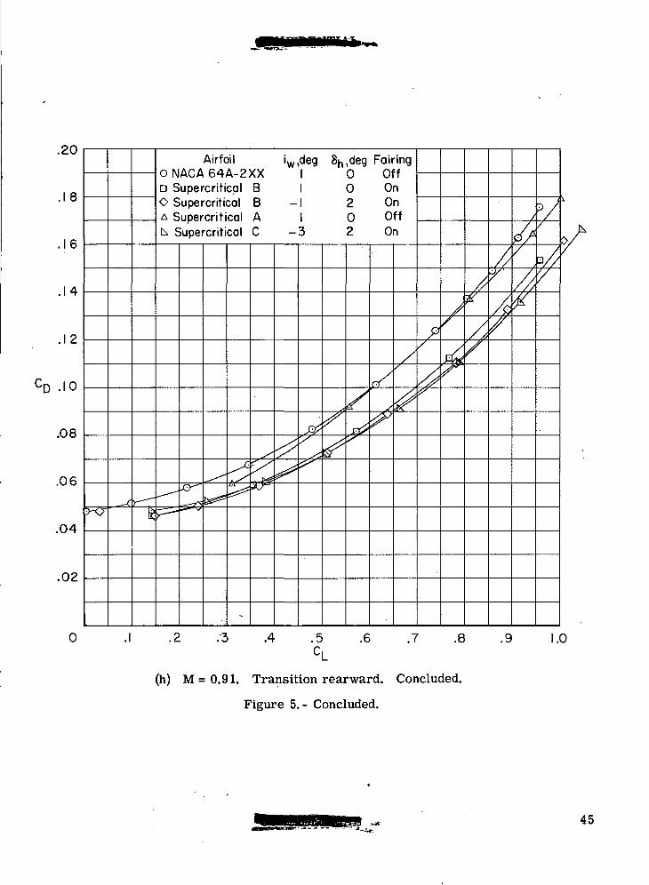
(h) M=0.91. Transition rearward. Concluded.
Figure 5.- Concluded.
45
8
a,deg 5
o
= 3—6-
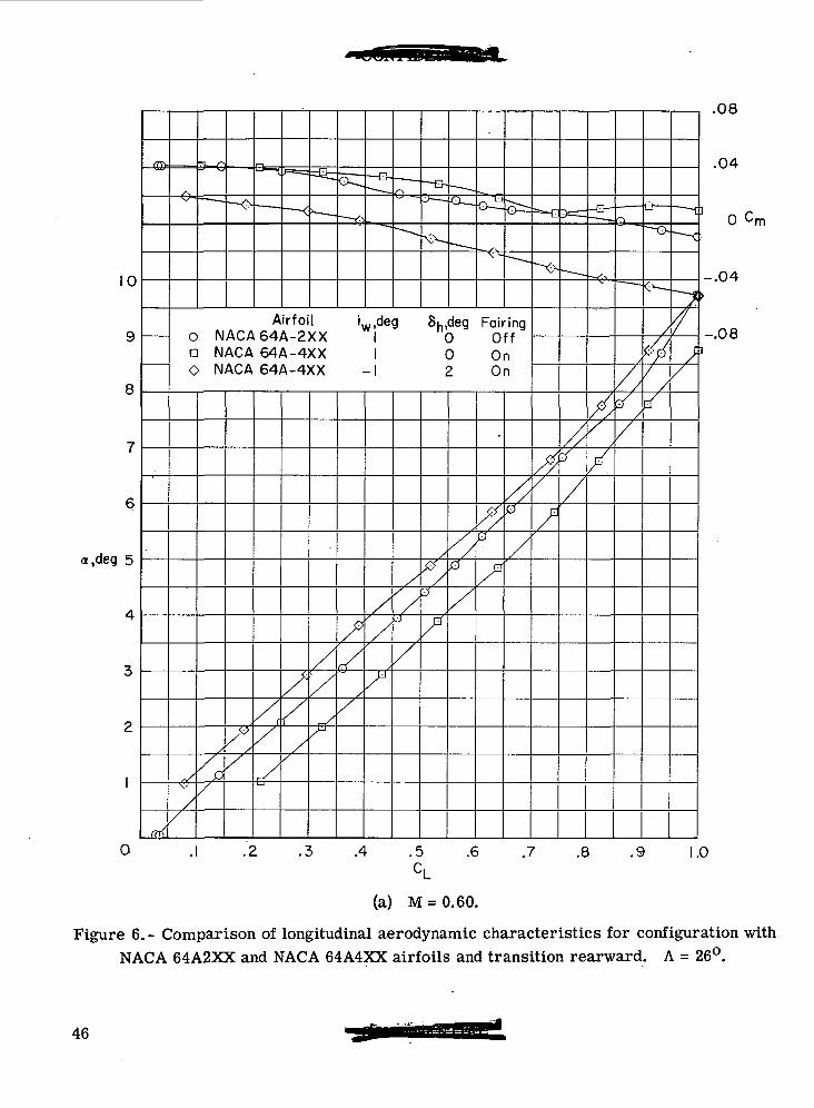
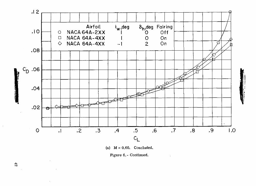
AirfoilO NACA64A-2XXa NACA 64A-4XXO NACA 64A-4XX
iw,deg Sh,deg Fairing0 Off0 On2 On
.2 .3 .4 .5 .6 .7 .8 .9
.08
.04
•rn
-.04
-.08
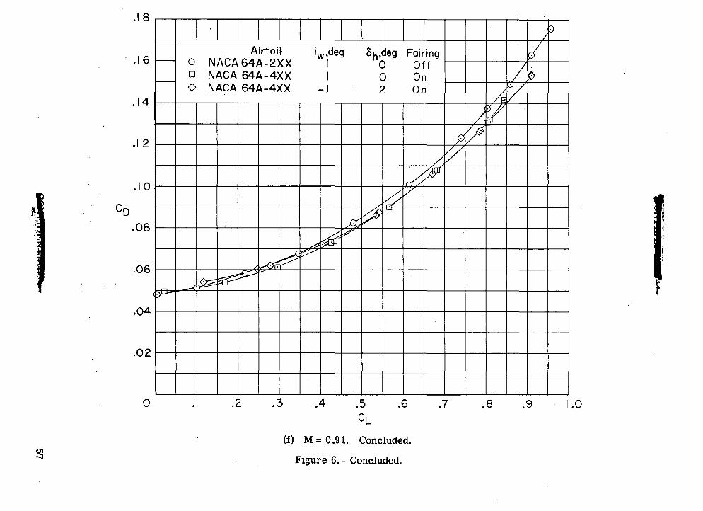
1.0
(a) M = 0.60.
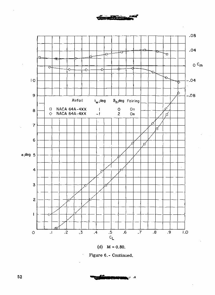
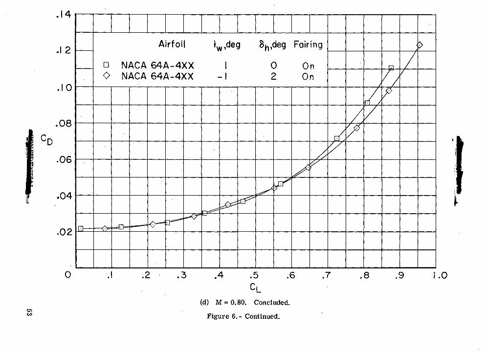
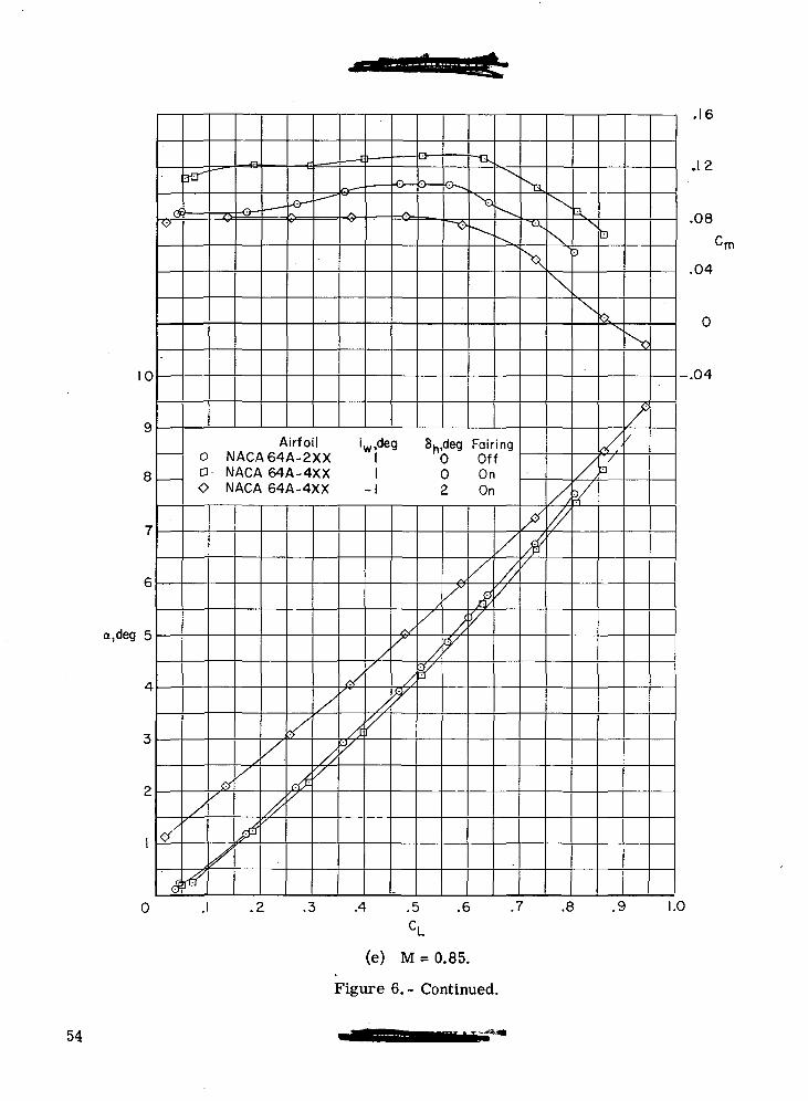
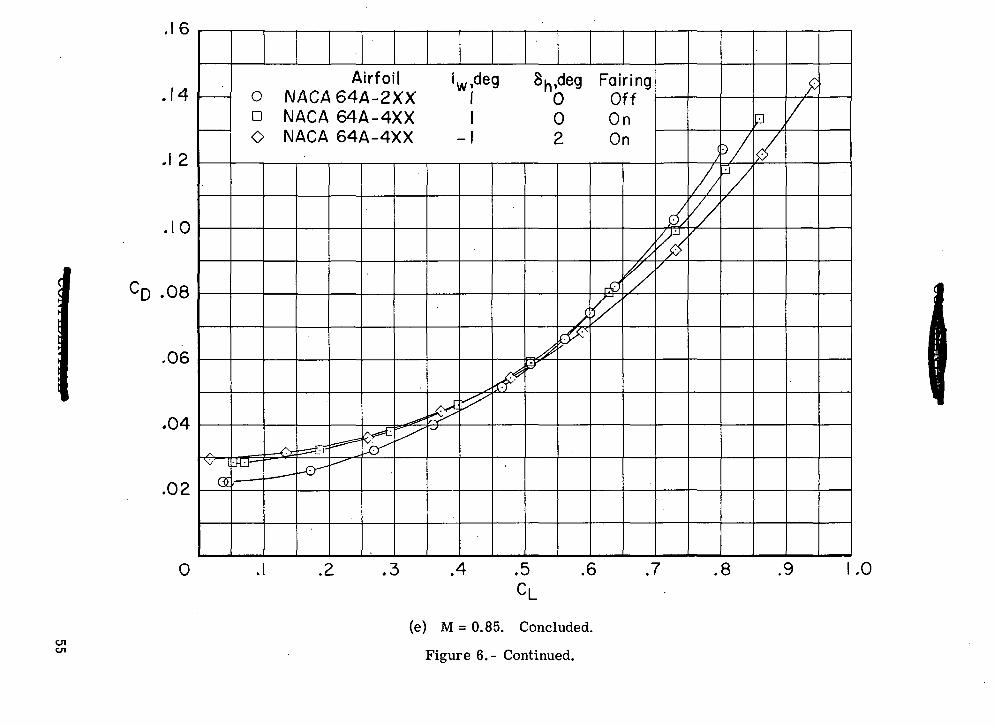
Figure 6.- Comparison of longitudinal aerodynamic characteristics for configuration withNACA 64A2XX and NACA 64A4XX airfoils and transition rearward. A = 26°.
46
C\J
V
"d S
- C
C
•5
00
0U_3
.O O
OJ
<5O<u
XX
X—
— ^^
^^
^^^
'5
CM
t <
fr
•- < <
<
tCD<o
O D
O
COo
I
CDo•Q
O
CV1o
00(DtorOOJ
O
11§ -s
OoCD
OII
oUI
CD0
47
8
a,deg
0
AirfoilO NACA64A-2XXa NACA 64A-4XXO NACA 64A-4XX
Su-.deg Fairing0 Off0 On2 On
.04
0 Cm
-.04
-.08
.1 .2 .3 .4 .5 .6 .7 .8 .9 1.0
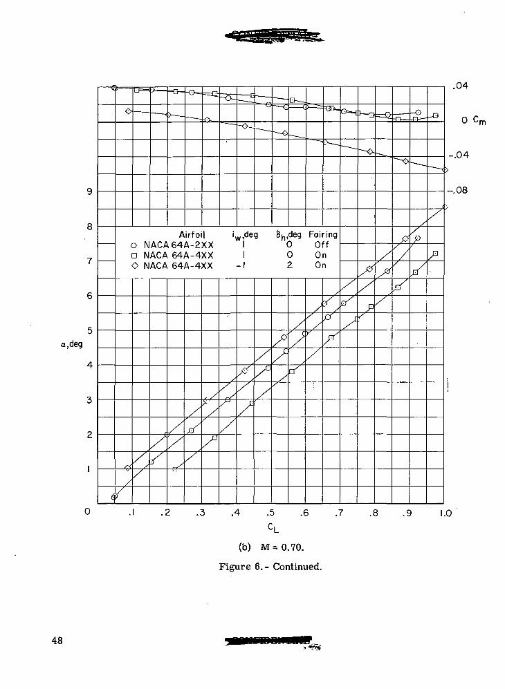
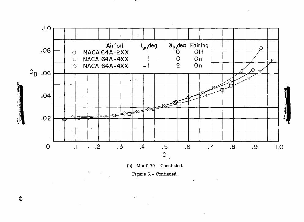
(b) M=0.70.
Figure 6.- Continued.
48
T30)OOUOII
g1uI
CD
QO
49
10
8
a,deg 5
o
AirfoilO NACA64A-2XXa NACA 64A-4XXO NACA 64A-4XX
w ,deg Su,deg Fairing0 Off0 On2 On
A
.04
0 Cm
-.04
-.08
1Z
A .5 .6 .7 . .8 .9 1.0
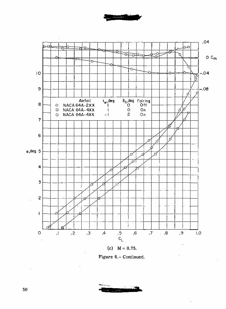
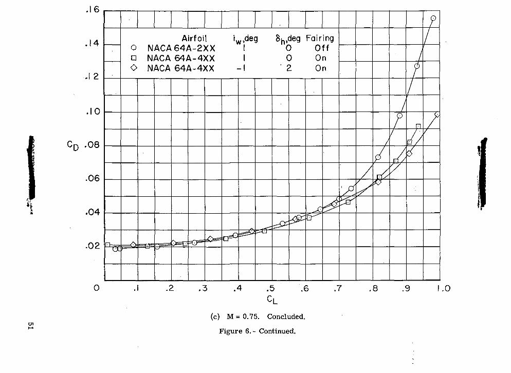
(c) M=0.75.
Figure 6.- Continued.
50
. C
J
CvJ
Ii-HO
IDt- I•«-rf
•g.60)^be
Q0
51
10
8
a,deg 5
0
Airfoil iw,deg 8h,deg Fairing
a NACA 64A-4XXO NACA 64A-4XX
0 On2 On
.4 .5
CL.6
(d) M = 0.80.
Figure 6.- Continued.
.7 .8
.08
.04
'm
-.04
-.08
.9 1.0
52
encC
C
.
00
CD0)T
3.
O C
M
0>•o
.5 I
X X
—
XX
o 'sf CD
o o
2 Z
D O
GO
T30)
"3i-HO§Oooo
tJI•l-t•sOO0)
% 3>
roCM
COo
CDOCDO
CVJO
QO
53
10
9
8
7
6
a,deg 5
4
3
2
1
0
rf
<#'
— B-
•
— -
,- — J
[
Cr~ — — —
-o
~~~Q^
^
\
\^^
Airfoil iw,deg 8h,deg Fairing0 NACA64A-2XX 1 0 Offa NACA 64A-4XX 1 0 OnO NACA 64A-4XX -1 2 On
/
ffQ
<?
'
/
/
$
/
/>
^
t£/
/
/,
'/
</
/ly
/
'
^Y
,/•
/t
¥
/
/,w
/
/,¥
/
$y
/
//l/
^^s
X
/
\N
X
/ y
/
\3
X
/
tl
^
/<•V
N>
f/
.2 .3 .4 .5 .6 .7 .8 .9 1.Ci
.1 0
.12
.08
Cm
.04
0
O4
0
(e) M = 0.85.
Figure 6.- Continued.
54
'5 O
O O
CD"R
-O O
C\J
o»5~XX
XX
XX
OJ
- rl"
O
O D
O
COO
CDOCDO
CVJO
CD10
T3CO
-2
1o
3o
£Oinco
OOCOcufaD
QO
55
Page intentionally left blank
-GL
00
r*
"»Z M- c
c
"o O O
OU
-
"^O
.c<x>C
T<D
XX
X-^
>
^^
XX
X
-X.—
X
X
XV
?V
o o
j ^r
tiii
~ «
<^"
t ^"ID
CDCD
•«
O
o n
O
CVJC
Oo
^roCVJo
QO
00
IDro
oooOJ
oII
T3II-HOCco
57
.08
.04
Cm 0
-.04
-.08
8
a.deg
0
ft
0
Airfoilo NACA64A-2XXD Supercritical BO Supercritical BA Supercritical A
Supercritical C
iw,deg FairingI OffI On
OnOff
- 11
-3 On(upper surface transition forward
for supercritical )
V*
CK
p
.2 .3 .4 .5 .6 .7 .8 .9 1.0
(a) M = 0.80.
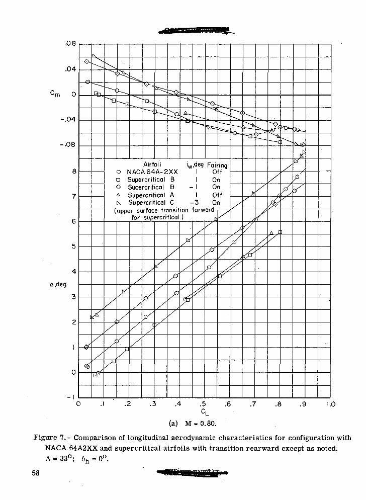
Figure 7. - Comparison of longitudinal aerodynamic characteristics for configuration withNACA 64A2XX and supercritical airfoils with transition rearward except as noted.A = 33°; 6h = 0°.
58
.20
.18
.16
.14
.12
CD .10
.08
.06
.04
.02 /\_&• >da_*H=»"
_—nv— M;Sj — ^/-l
'
ss^*
Airfoil iw ,deg Fairing0 NACA64A-2XX 1 Offn Supercritical B OnO Supercritical B - OnA Supercritical A 1 Offk Supercritical C -3 On
(upper surface transition forwardfor supercritical C )
if &** ZZ&•tt^
"
(
^33
^
/
//,V
•
Jr. r%.
1i/
$y
1
1
r/
f
//
*
/
/
A .5 .6 .7 .8 .9 .0
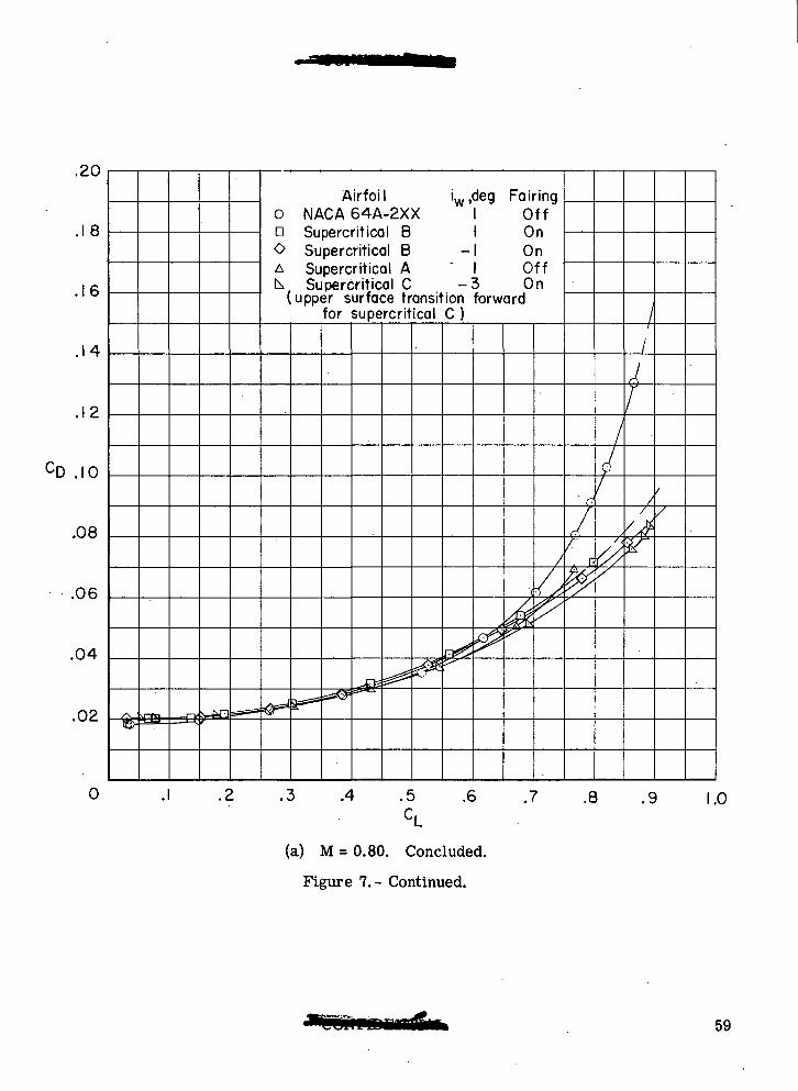
(a.) M = 0.80. Concluded.
Figure 7.- Continued.
59
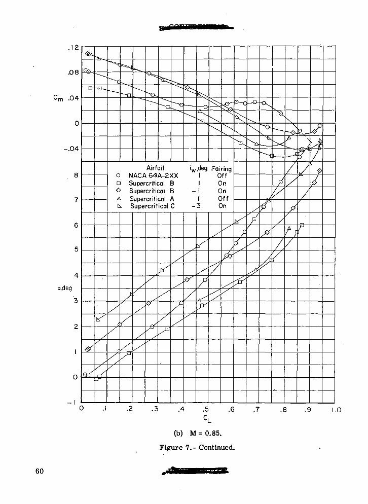
.12
.08
Cm .04
0
-.04
8
a,deg
0
Q--Q-.
Airfoil0 NACA64A-2XXa Supercritical BO Supercritical BA Supercritical Ak Supercritical C
iw,deg Fairing1
-3
OffOnOnOffOn
.4 .5 .6 .7
J1?-
.8 .9 1.0
(b) M=0.85.
Figure 7.- Continued.
60
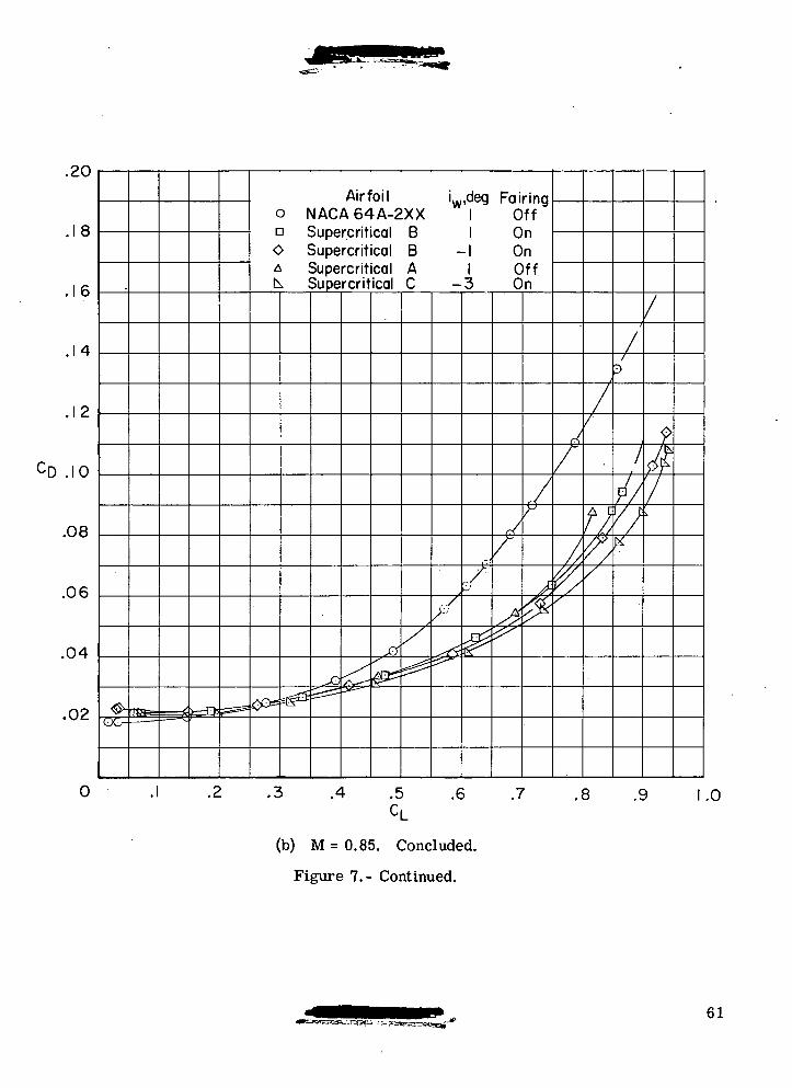
.C.\J
.18
.16
.14
.12
CD .10
.08
.06
.04
.02
0
<^ flSfe—^
r^
Airfoil i deg Fairingo NACA64A-2XX 1 Offa Supercritical B 1 OnO Supercritical B -1 OnA Supercritical A 1 Offk Supercritical C -3 On
=(5^5
JO===^
fi/
^
/
^
/
&
/
A
^
/
^
^
,
/
//,
r/
/
*'
n/
/p
/
V}^
/
f$i.
.1 .2 .3 .4 .5 .6 .7 .8 .9 1CL
.0
(b) M=0.85 . Concluded.
Figure 7.- Continued.
61
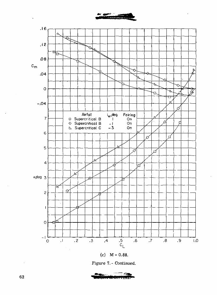
.16
.12
.08
.04
N,
a-
-.04
XAirfoil iw,deg Fairing
D Supercritical B 1 OnO Supercritical B -1 Onk Supercritical C -3 On
0 -e
-I0 -I 3 .4 .5 .6 .7 .8 .9
CL
(c) M = 0.88.
Figure 1. - Continued.
1.0
62
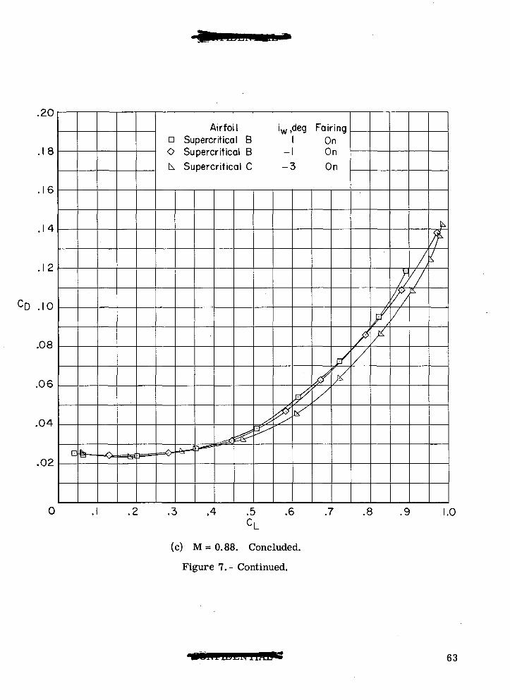
.£U
.18
.16
.14
.12
CD .10
.08
.06
.04
.02Dfe—
— fes£]===
Airfoil iw,deg Fairinga Supercritical B OnO Supercritical B -1 On
k Supercritical C -3 On
A-J 3— *• ^£^0^^
y/X
X
x
//
//V/
/ /y
,/f
^
.3 .4 .5 .6 .7 .8 .9
(c) M = 0.88. Concluded.
Figure 7.- Continued.
1.0
63
-^X
a,deg
0
0
\
(3
XX
N
Airfoilo NACA64A-2XXn Supercritical BO Supercritical BA Supercritical Ak Supercritical C
iw,deg Fairing
-3-
OffOnOnOffOn
/
//
^
.4 .5 .6 .7 .8 .9
-.12
.08
.04
0
-.04 cm
-.08
1.0
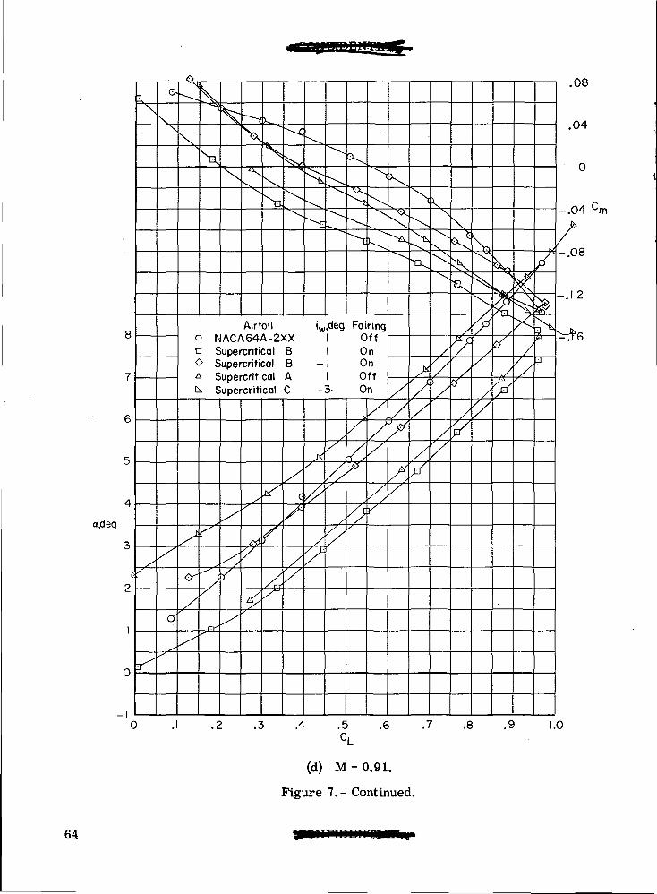
(d) M = 0.91.
Figure 7.- Continued.
64
,C-\J
.18
.16
.14
.12
CD .10
.08
.06
.04
.02
0
•y
- —
Airfoil iw,deg Fairing0 NACA64A-2XX 1 Offa Supercritical B 1 OnO Supercritical B -1 OnA Supercritical A 1 Offk Supercritical C -3 On
^.££
S
/>
^
/
/£
/
^/
•/
l>/
/
//
y
/
/fr
'/
/f
^
/J
///f/7
c
/
///fy
d/
//,'//
i
/fy
y
////'/X
p
p /
I/
.1 .2 .3 .4 .5 .6 .7 .8 .9 1
. CL
1.0
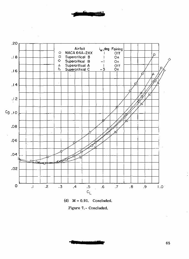
(d) M=0.91. Concluded.
Figure 7.- Concluded.
65
1 1
10
9
8
7
6
a,deg
5
4
3
2
1
^
^
^^
^^
^
\
"^
^
—
"
^_
^n
<J^
^
^~-
^^
-o.
Airfoil iw,deg Fairing0 NACA 64A-2XX 1 Offa NACA 64A-4XX -1 On
/
/
'
/
/
'
/
/
n'
•s/
/
'
/
/
?/
/
/\
f
r//*
/
/x
/CY/
-oj
/
&
/
^^^
//"
B^
•-A
^
x0
. ^
r
/
/
/
?
•~ , — ,
/X
1
t4
.uo
.04
C
0
-.04
-.08
.2 .3 .4 .5 .6 .7 .8 .9 1.0
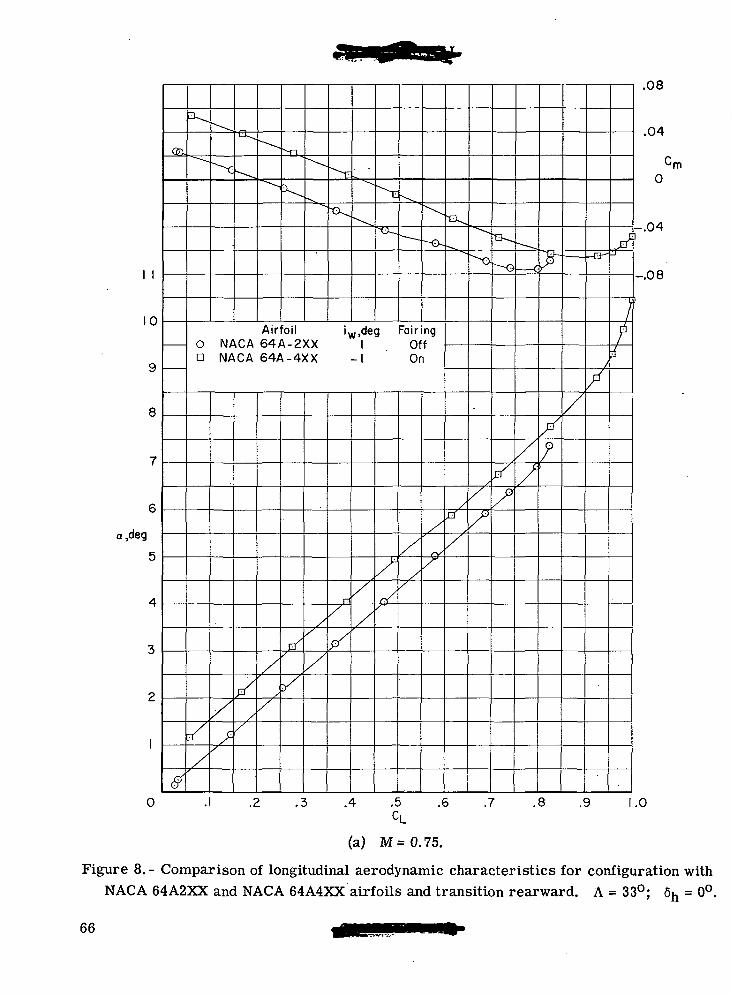
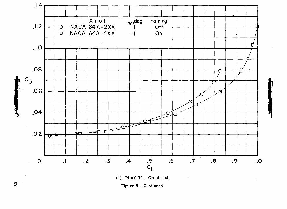
(a) M=0.75.
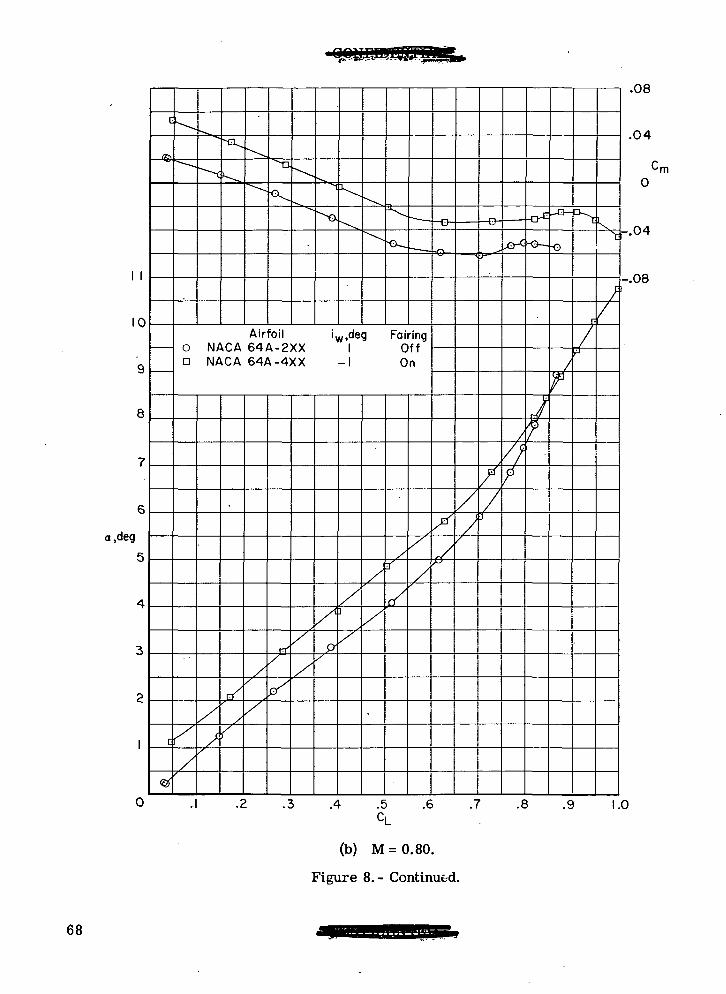
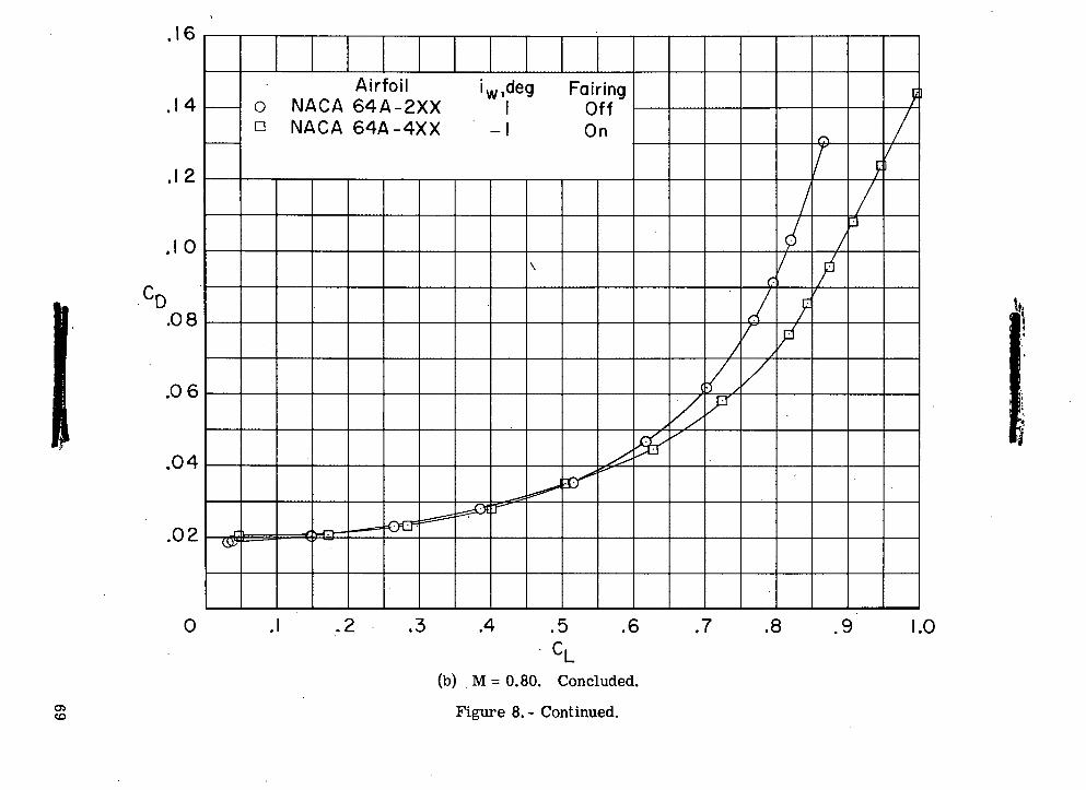
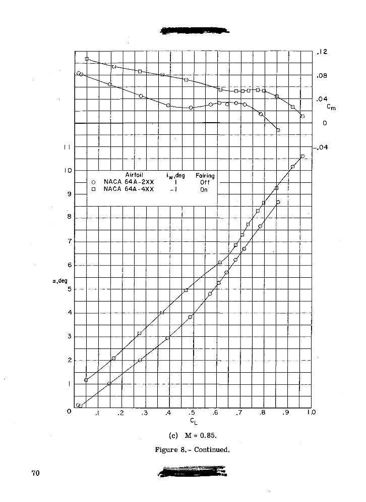
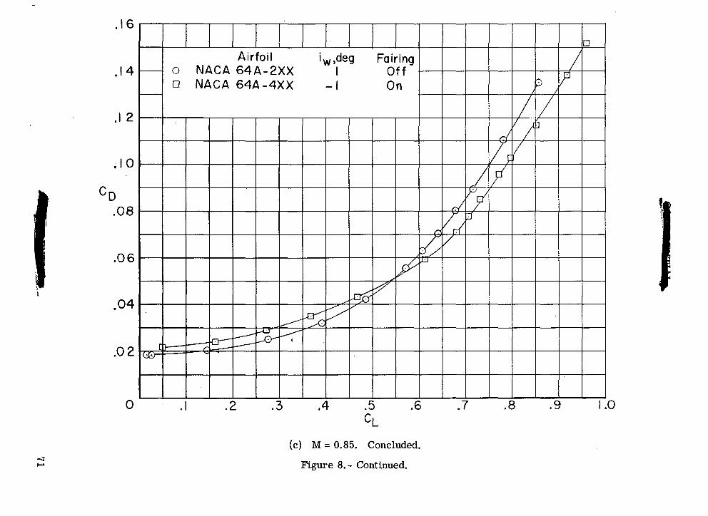
Figure 8. - Comparison of longitudinal aerodynamic characteristics for configuration withNACA 64A2XX and NACA 64A4XX airfoils and transition rearward. A = 33°; 6h = 0°.
66
o
cO
en(U•a _X
XX X
_ OJ >
•^ I
I
< CD CD
O O
O D
CM
k
CDCD
QOOCDO
CMOQO
ouint-
T30)OUco0)bQ
67
I I
10
a,deg
c
©J
c
<&
"\
-~-~.
-^
^c
~°
^
^-^
^~>.
"0.\
"**v
-
^C
>0i
^
^^
^^^•o .
_
— • —
Airfoil iw.deg Fairing0 NACA 64A-2XX 1 Offa NACA 64A-4XX -1 On
</
/
/
//
r/
/
^
//
/
FT/
^
//
/*p-
/
X]
X
/
/
Xif
/
/
/
•0
Xy
///
//D
/
/;?
n*
J
7
— Q —
/
f
=S
r
/
t
/
/
.uo
.04
0
-.04
-.08
.2 .3 .4 .5 .6 .7 .8 .9 1.0CL
•rn
(b) M=0.80.
Figure 8.- Continued.
68
•- c
» *^
- w
go
o
0)T
J --
X X
X X
OJ S
J-
<
CD
C
D
< <
0 0
< <
z z
'o
n
CDCVl
COO(DO
CMO
00
o
T50)O§ooo
Iico*o>
ro
0O
69
I I
10
a,deg
Airfoil0 NACA 64A-2XXa NACA 64A-4XX
iw,deg Fairing1 Off
-1 On
^
7
.08
.04
•rn
-.04
.4 .5 .6 .7 .8 .9 1.0
(c) M=0.85.
Figure 8.- Continued.
70
a
o
• *-
c
li-ena>TJ
X X
X X
_
OJ M
-"5 ^
'
t <
<•- sh 'vT<
C
O C
O
< <
0 0
o n
Tl
V
CDCOrOC\J
COOJ
OaoO
co0<d~0
CNJ0
0
•oI"ooOincx>o
ioo
71
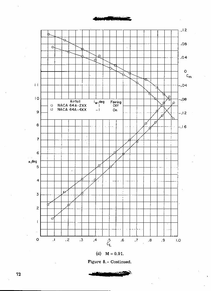
10
a.deg
0-
Airfoil0 NACA 64A-2XXa NACA 64A-4XX
iw,deg Fairing1 Off
-1 On
&
.4 .5 .6 .7 .8 .9
. .12
.08
.04
'm
-.08
-.12
--.16
1.0
(d) M = 0.91.
Figure 8.- Continued.
72
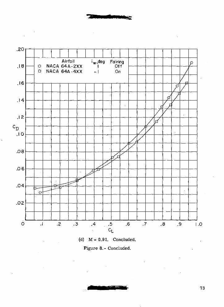
.£U
.18
.16
.14
.12
CD.1 0
.08
.06
.04
.02
0
Airfoil iWide9 Fairing0 NACA 64A-2XX 1 OffD NACA 64A-4XX -1 On
o-_ — - —
r-i —^~y
^
^
K ^
<6's&
s
//d/ //
//
/./
//
p
/,y
^///
/r
/
//
f
.2 .3 .4 .5 .6 .7 .8 .9 1CL
.0
(d) M=0.91. Concluded.
Figure 8.- Concluded.
73
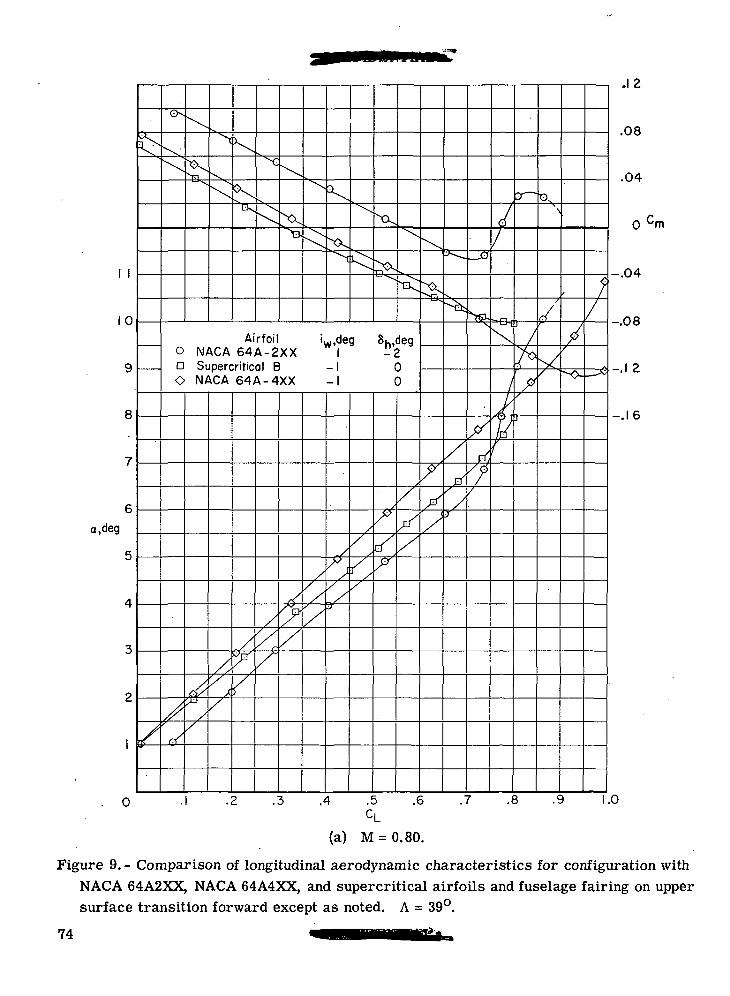
10
a,deg
Ox
Airfoil0 NACA 64A-2XXD Supercritical BO NACA 64A-4XX
iw,deg-2
00
•Sir
X
.12
.08
.04
0
-.04
-.08
-.1 2
-.16
.2 .3 .4 .6 .7 .8 .9 1.0.5CL
(a) M = 0.80.
Figure 9. - Comparison of longitudinal aerodynamic characteristics for configuration withNACA 64A2XX, NACA 64A4XX, and supercritical airfoils and fuselage fairing on uppersurface transition forward except as noted. A = 39°.
74
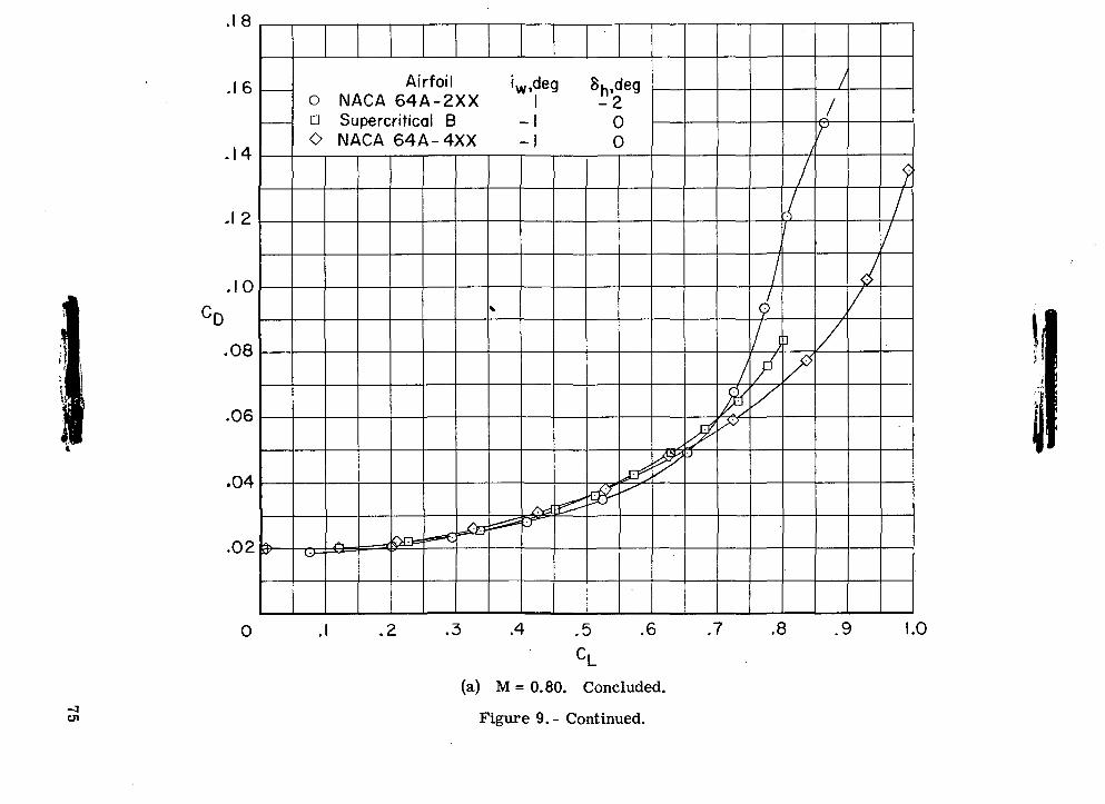
)
\
D01.
tfC0)•q••—'6H—<U
~~^(
n_OJ C
= 1
XXcvj ai^ c
3i
S*
< S2 °
*5 :
2 C
/
O
C
3
^j O
|
XxJ^r. i3
--<1 "
:^t
: to3
<
^ 3 <
> z
] O
^ ^-v
i-
~-
cv ^^
J
>>— —
-.c \^0-t
3
\
0LJvac \X^))
\^
u k>
>>
o.Xc
\\?
r-5
h\1
\1«<CNC |>J)
(T>
Qj
r^in
'OtU
0"Su
in —
1 O
. O
o00O
J" II
• .'c?
10
"•
rvi
o
-oCT
)
QO
75
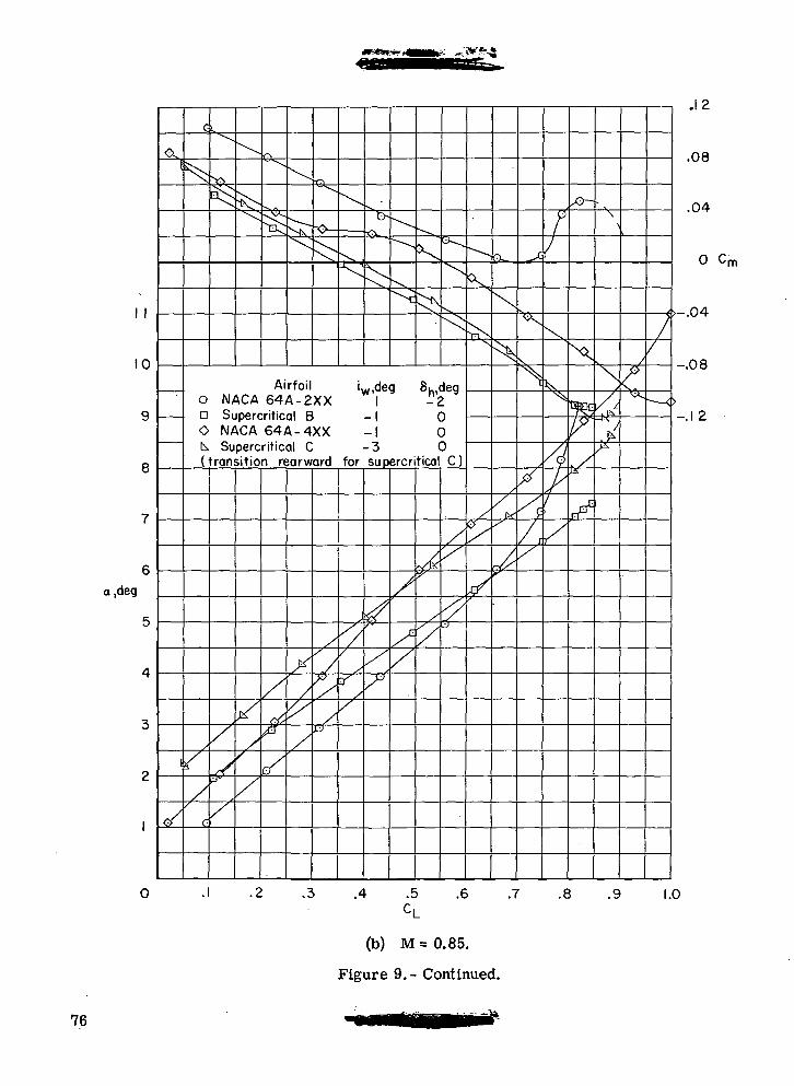
10
a,deg
^^
o-
X
Airfoil iw,deg Su.degO NACA 64A-2XX I -2n Supercritical B -1 0O NACA 64A-4XX -I 0b. Supercritical C -3 0(transition rearward for supercritical C)
X
X
.4 .5CL
(b) M=0.85.
Figure 9.- Continued.
\s
.6 .7 .8 .9
.12
.08
.04
0 Cm
>-.04
-.08
-.12
1.0
76
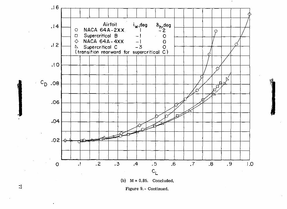
CD
0
0)
<\J O O
O
o
•o» '
x—
O
J CD
£
' _
*- < o
< 3o
^<
3
2 C
O
o0_
ro v' ' 1
x^- 0
o>
-5
<
o j-
5 £
8
«<
3
<
/>Z
C
/) c
o
O
D O
C\JO
00OCDO
\5\i
CMO
oCT»
COroCVJ
O)
"o g
5OO
0
g
QO
77
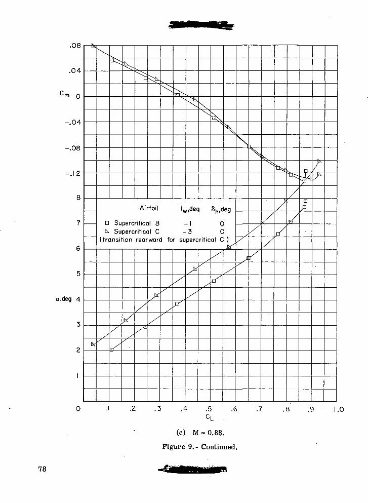
.uo
.04
Cm o
-.04
-.08
-.12
8
7
6
5
a,deg 4
3
2
1
0
ts
k
\
^^^E
^\^1\v
Airfoil iw
a Supercritical Bk Supercritical C
(transition rearward for su
x
^
X
n/
y^x•
/
x11
J*
/
x
xX"
X
X
<^
,,dec
I
3perc
X*
x
x
^N
\
8h,deg
00
ritical C )
'
/
/
Xx
\
S
/
^'
i
N
X
/
^
/
i/p/
L^
/
I/
^;
*>
.1 -2 .3 .4 .5 .6 .7 .8 .91
CL.0
(c) M = 0.88.
Figure 9.- Continued.
78
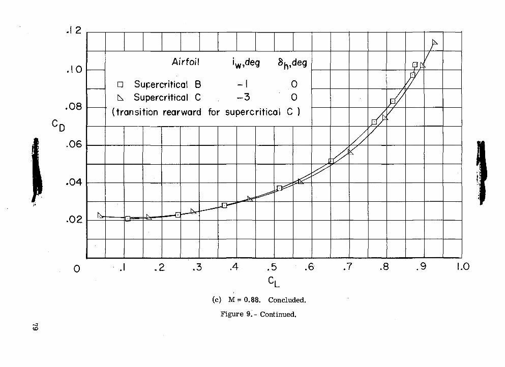
A,
\,
o>O
O
^x»
•8
ooo
7 •?
»I
I Q
.3cn
OQ O
po
o
o
5£ S oo
o
c:
I I
£
CO CO
'wJcon
zi i:
\
00
T3
II—I
OaoOaoCOo
IOOos
rO
CMO
00Ocoo
C\Jo
o
79
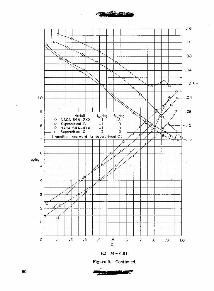
10
a,deg
c>-^
"0
X
Airfoil0 NACA 64A-2XXa Supercritical BO NACA 64A-4XXk Supercritical C
iw,deg Su.deg
-3
-2000
(transition rearward for supercritical C )
^
X
0
J-y
.16
.12
.08
.04
o cm
-.04
^-.08
\-.12
'-.16
.4 .5 .6 J .8 .9 1.0
(d) M=0.91.
Figure 9. - Continued.
80
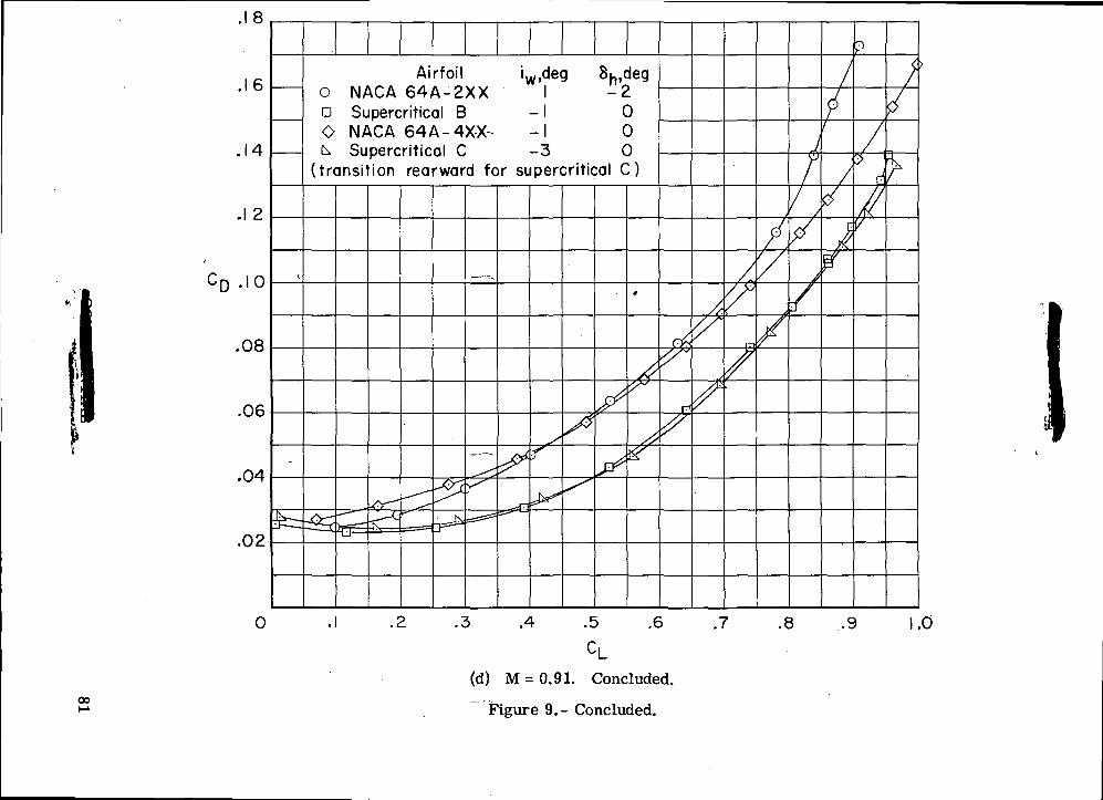
e
ia6>
CT
O O
O O
CO
0O.-o
--- ro «!>
- —
»- <
o <
o
»_
< g
<
S c
8 IS IS
Z (f) 2
C
O «
O D
O i:
XX
X'V
QO
COO
X\
CDOCOo
COrOC\J
T3<u'O
T3
3
Vr—
I T
jO
5
c
^o
o
° o
g
O5
Ios
81
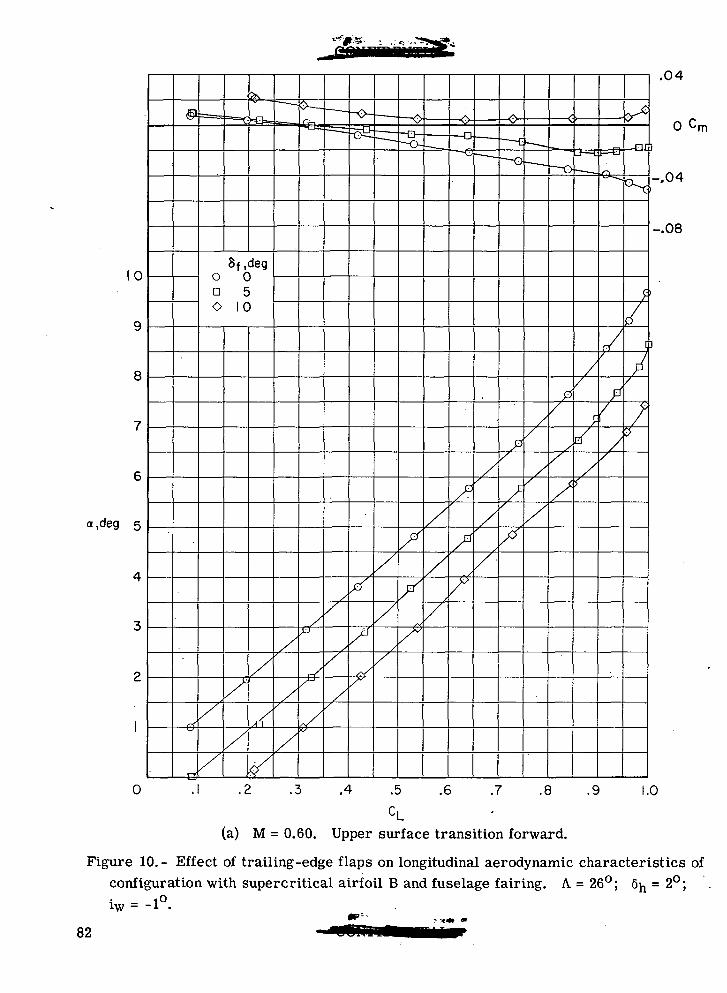
0
8
a,deg 5
0
.04
o cm
-.04
-.08
.2 .3 .4 .5 .6 .7 .8 .9 1.0
(a) M = 0.60. Upper surface transition forward.
Figure 10.- Effect of trailing-edge flaps on longitudinal aerodynamic characteristics ofconfiguration with supercritical airfoil B and fuselage fairing. A = 26°; 6n = 2°;iw = -1°.
82
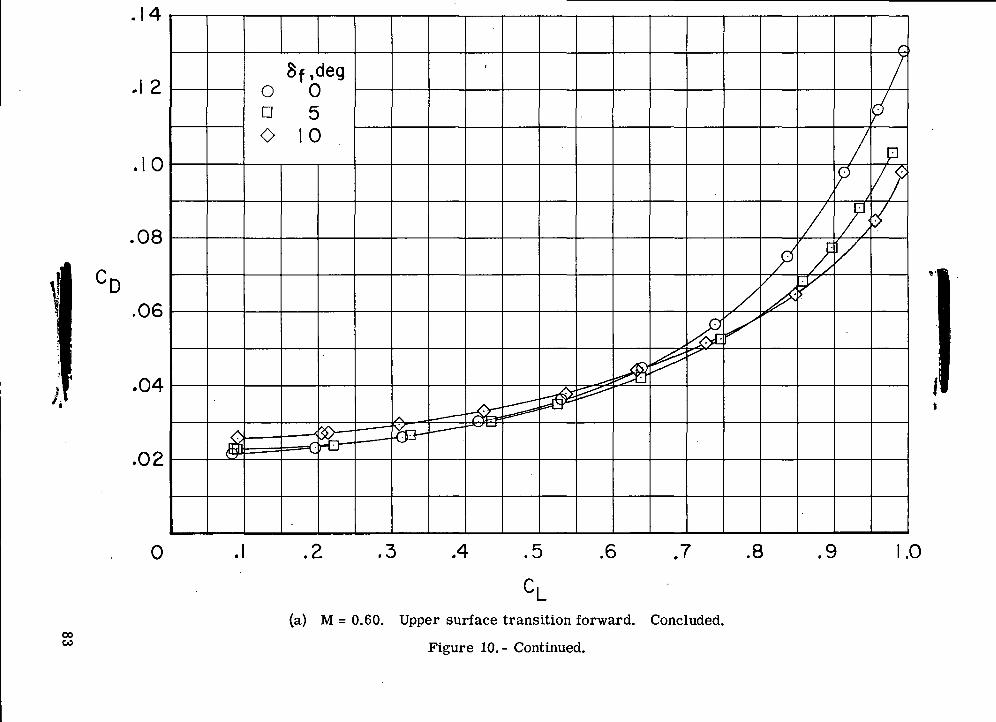
10 O<50
O D
O
00if)
00oCDO
CVJo
O
O
T30)UOOSHO"c i.2
§*5
ZJw
c
0)ort<D
IoCDrt
QC
J
83
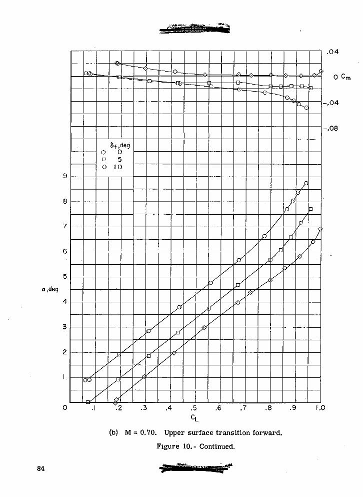
8
a,cleg
0
oo
X
-i .04
0 Cm
-.04
-.08
7
.1 .2 .3 .4 .5 .6 .7 .8 .9 1.0
CL
(b) M = 0.70. Upper surface transition forward.
Figure 10.- Continued.
84
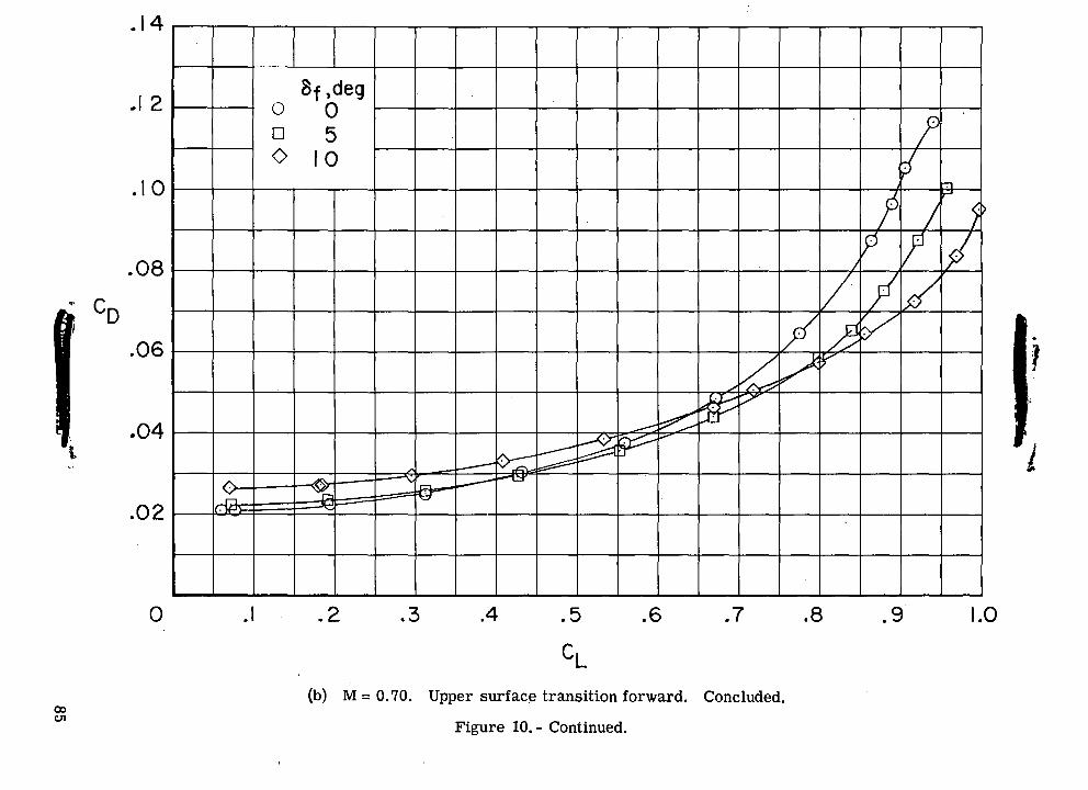
<D
ID O
O D
O
00O(DO
o
(\JO
CDCO(Dro(M
"8ooO.2 S
£
C.1-1
-r-C
CQ
-H
11-M(U. '.
^ <u
3 t-<
M 3
, bO
H
-i-l3?
fe
oe-
QO
85
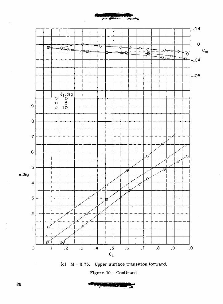
8
a.deg
X
.04
0
-.04
-.08
0 .2 .3 .4 .5 .6 .7 .8 .9 1.0
(c) M = 0.75. Upper surface transition forward.
Figure 10.- Continued.
86
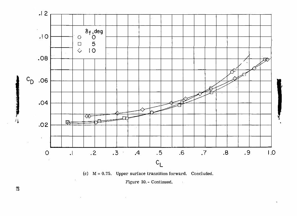
\
O)• O
ID
O
o n O
\
CVJ00o
CDoQO
<\JO
o00
O
rOO
Ii-H
-SourtCQ0)aOII
§U
87
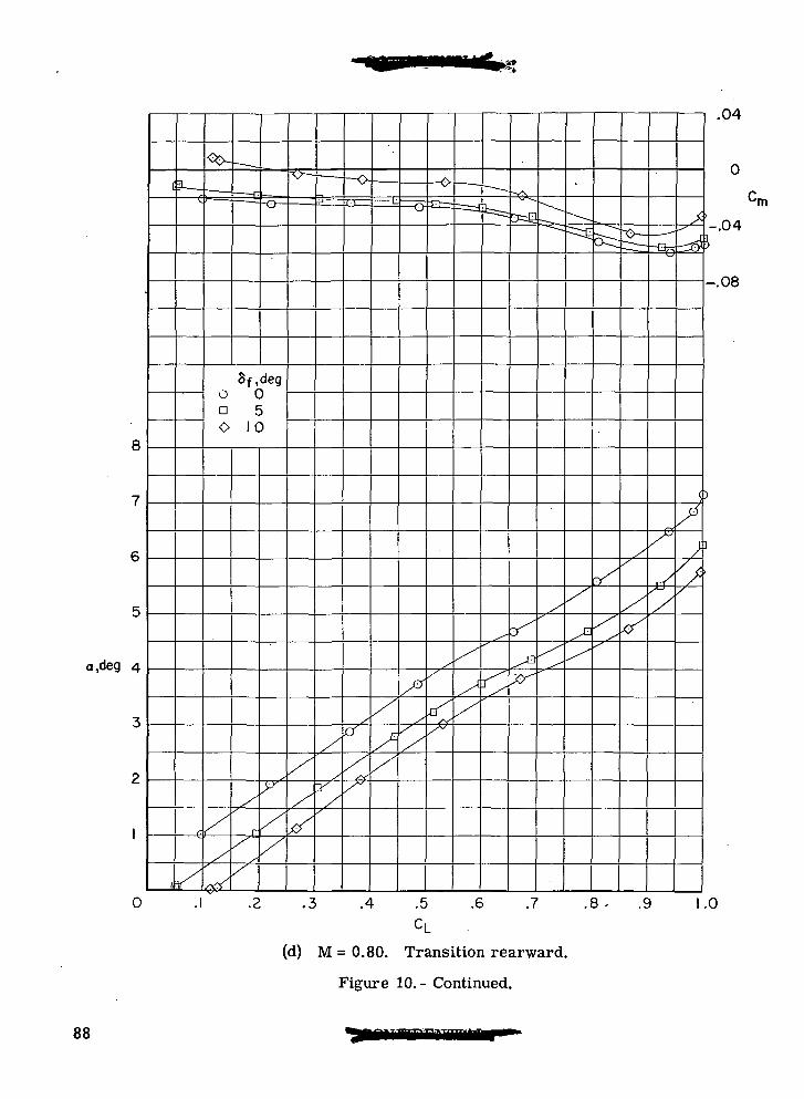
8
a,deg 4
0 .3 .4 .5
CL
.6 .7
(d) M = 0.80. Transition rearward.
Figure 10.- Continued.
-.08
o
.9 1.0
88
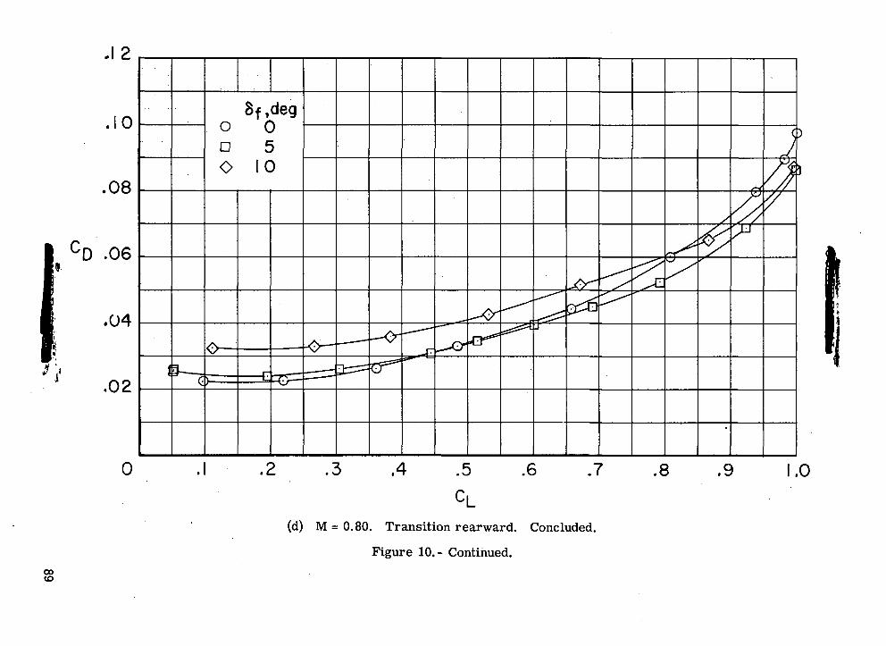
rOC\J
730>oo
7316<U
I '.
±4
O
w
'-iS
o
™
{-<
E-" §j
Ocooii
o
Qo
89
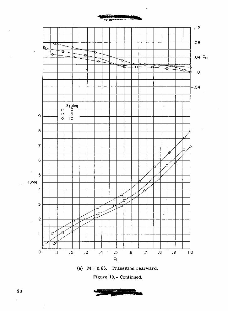
a,deg
Sf.dego 0a 5O 10
0
.12
.08
.04 Cm
-.04
.3 .4 .5 .6 .7 .8 .9 1.0
(e) M=0.85. Transition rearward.
Figure 10.- Continued.
90
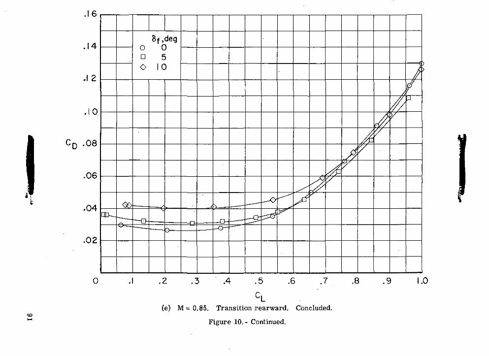
-©
"°-O
in O
0 D
O
\\
toCM
000CD0
«d-0
CVJ
9876532
Concluded
CLon rearward.Trans85e) M=
Continued
it
10.cu£faD£
Oo
91
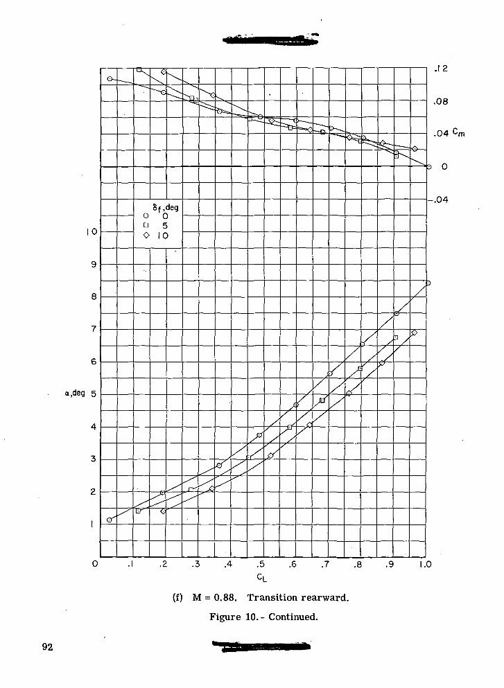
a,deg 5
0
Sf.dego 0n 5O 10
.12
.08
.04C m
3 0
-.04
3
.3 .4 .5 .6 .7 .8 .9 1.0
(f) M = 0.88. Transition rearward.
Figure 10.- Continued.
92
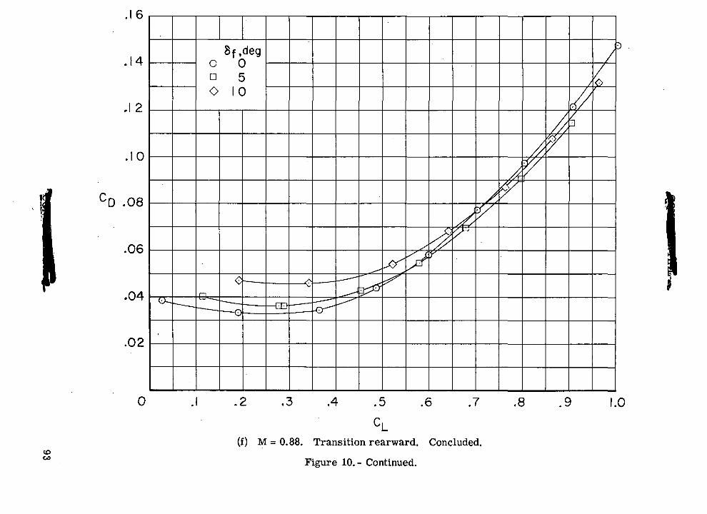
o>0>•O in
o
o n
O
V
C£>O
CDO*
QO
CDO'si-CD
CVJo
oCOroO
§O•o -o
M
Q)
rt ^
£
5
£
o*
O
o
'.•43
o•55
"<c
oj
S
Zti
3
cCOons-93
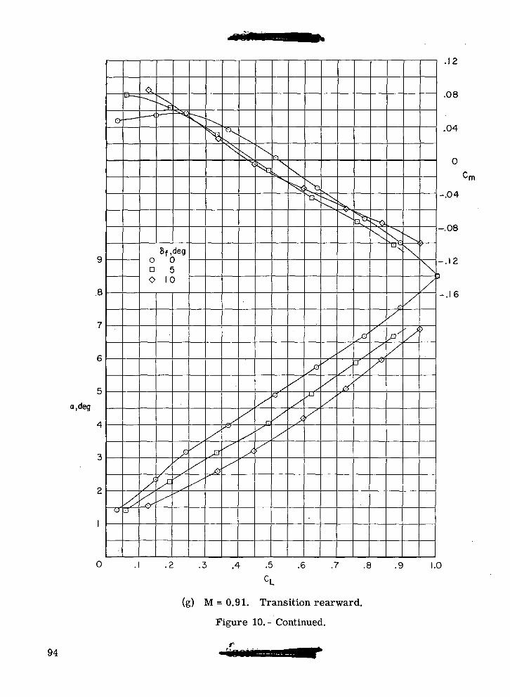
a.deg
Sf,dego 0n 5O 10
-£.-
.12
.08
.04
•rn
-.04
-.08
-.12
-.16
0 .1 .2 .3 .4 .5 .6 .7 .8 .9 1.0
(g) M = 0.91. Transition rearward.
Figure 10.- Continued.
94
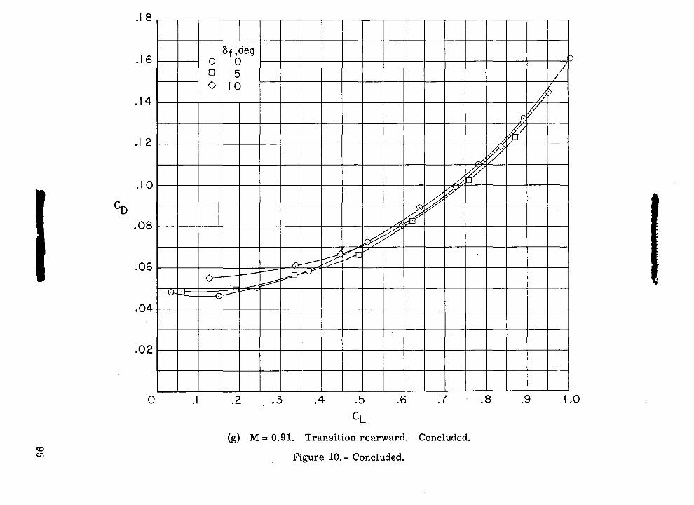
-£t
in o(O
0 D
O
N
00
o
ro
CO
QO
OI73f-irtrt<DSi
COrton
1oobDs95
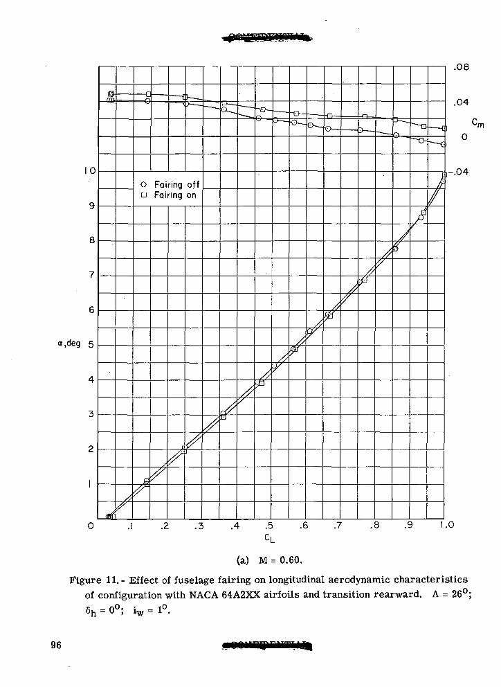
10
a.deg 5
0
_/,
O Fairing offa Fairing on
A
/•
.3 .4 .5
CL
7
.08
.04
0
-.04
.6 .7 .8 .9 1.0
(a) M = 0.60.
Figure 11.- Effect of fuselage fairing on longitudinal aerodynamic characteristicsof configuration with NACA 64A2XX airfoils and transition rearward. A = 26°;
96
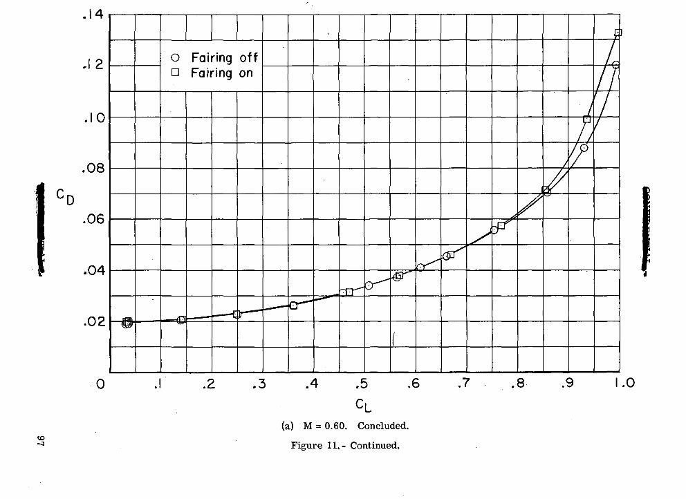
M-
Co
o
O^
O"*
c. c
.0 .0
O
D
-
00
\
OJ
OCOO
CDOo
CVJo
rO
1I-HOOOoCDe
•8oO0)^3>
QO
97
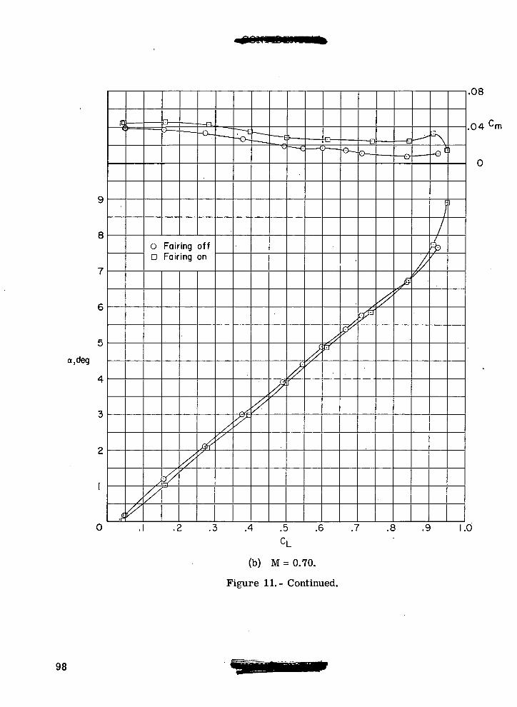
8
a,deg
0
O Fairing offa Fairing on
.4 .5
CL
(b) M = 0.70.
Figure 11.- Continued.
.08
.04
0
.6 .7 .8 .9 1.0
98
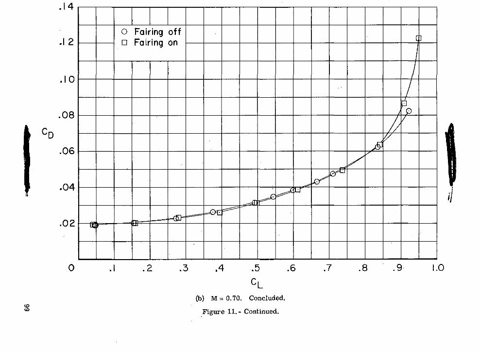
-B
M-
Co o
C
C"^
"^
,° i°U_ U_
O D
,Q
CVJ00o
COOO
Jo
QCJ
oo(DlOo
CJ
"81oGOOoc-
0)
•l-t
•goO0)3bO
99
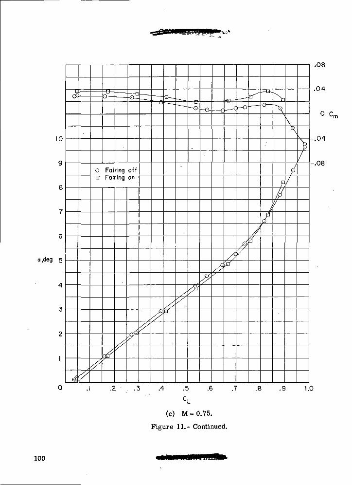
10
8
a.deg 5
0
o Fairing offa Fairing on
.4 .5
c,
(c) M = 0.75.
Figure 11.- Continued.
.6 .7 .8 .9
-.04
.08
.04
cm
1.0
100
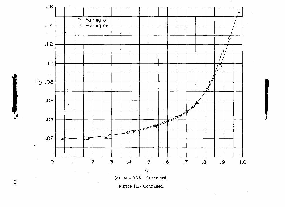
o o
o> o>c c
o o
u_ u_
O D
o00o
•
QO
CDOCMO
CD00roCVJ
•8 -o
3
2i—c
3o
c
oOU
•OOo>3be
101
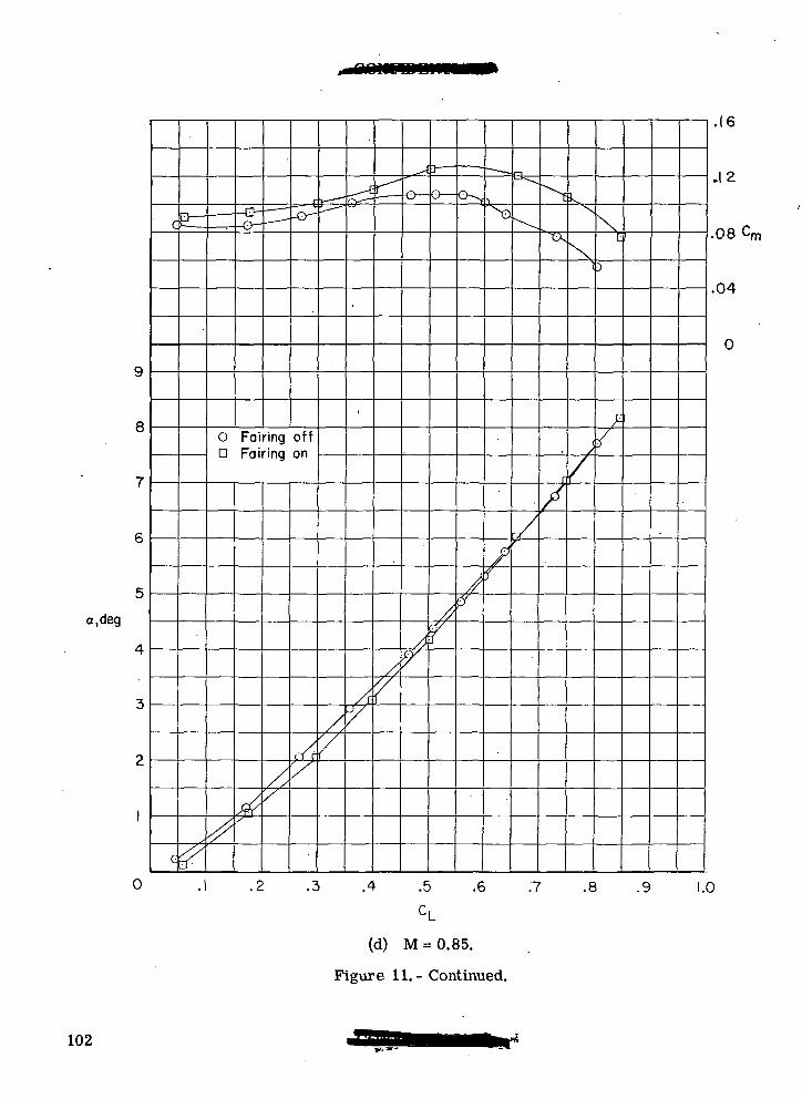
8
a.deg
0
O Fairing offD Fairing on
.4 .5 .6 .7 .8 .9
.16
.12
.08 Cr
.04
0
1.0
(d) M = 0.85.
Figure 11. - Continued.
102
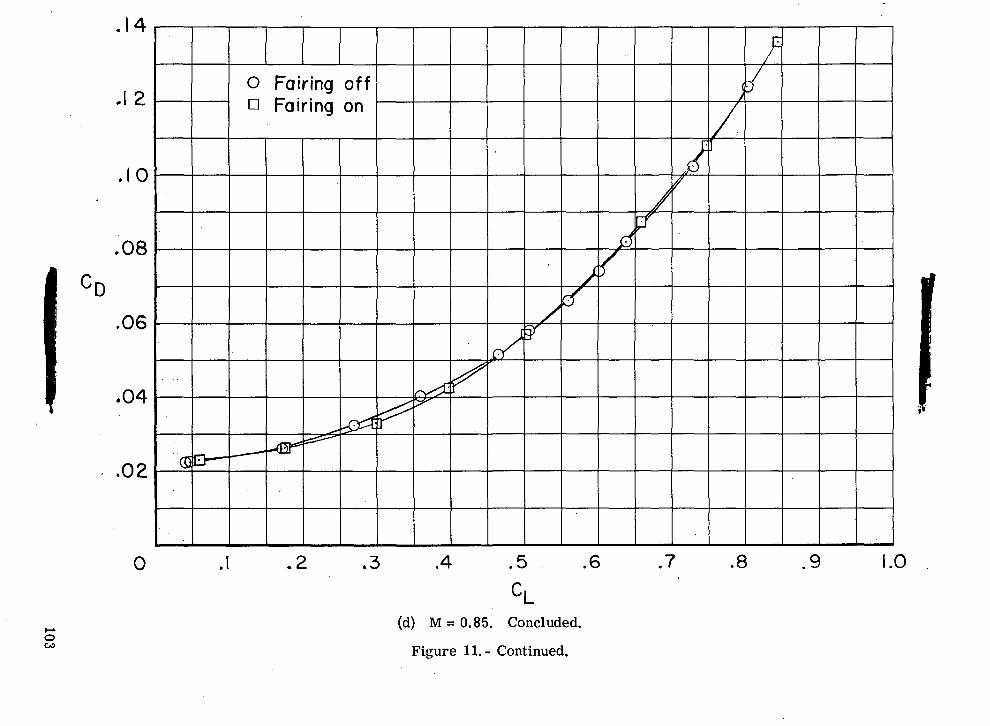
M-
CO
O
o> enc c
o o
O D
enCOtoo
rO
O00o
(OoO
Jo
o
O>ooUIf5O
O
OII
IIU0)
QO
103
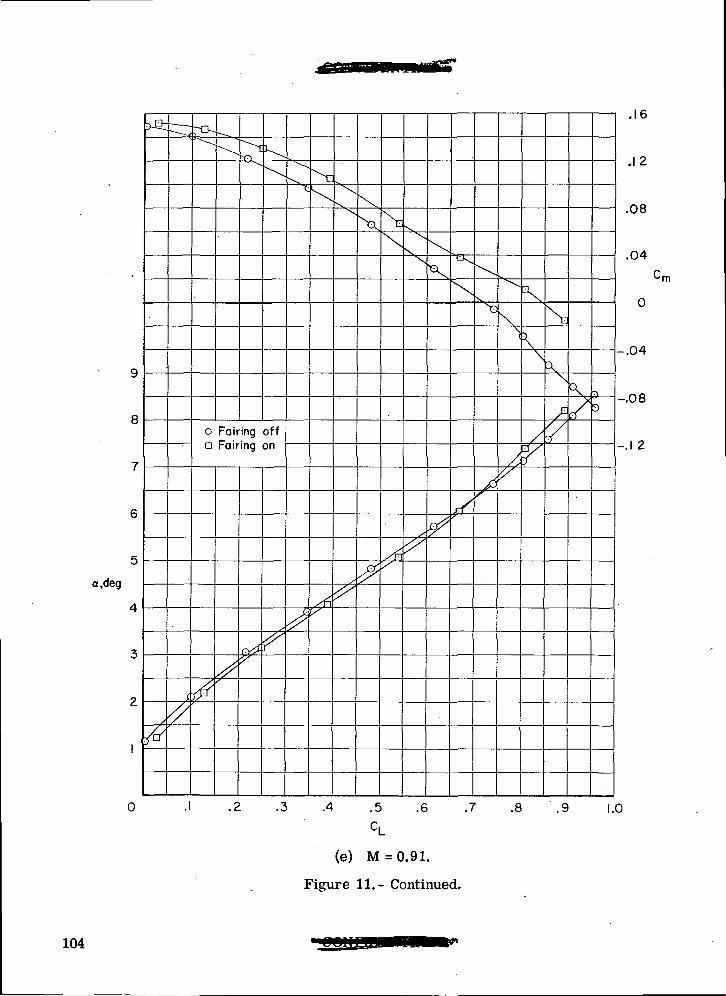
8
a,deg
0
o Fairing offa Fairing on
\
.4 .5 .6 .7 .8 .9
.16
.12
.08
.04
•rn
-.04
-.08
-.1 2
1.0
(e) M = 0.91.
Figure 11.- Continued.
104
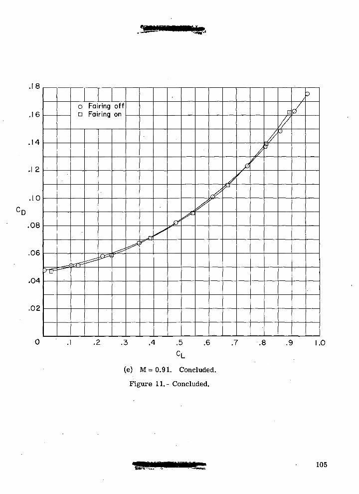
.18
.1 2
.10
'D
.08
.06
,04
.02
o Fairing offa Fairing on EJ
.4 .5
CL.6 .7 .8 .9 .0
(e) M = 0.91. Concluded.
Figure 11.- Concluded.
105
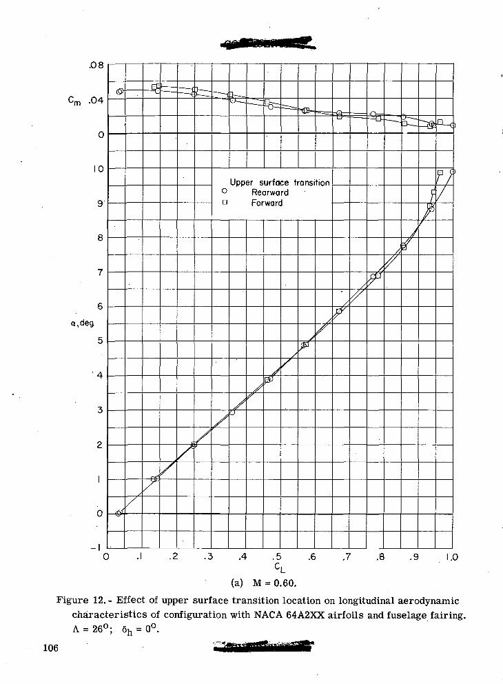
.08
-04
10
a, (teg
4
0
0
Upper surface transition° Rearwardo Forward
.2 .3 .4 .5 .6 .7 .8 .9 1.0
(a) M = 0.60.
Figure 12. - Effect of upper surface transition location on longitudinal aerodynamiccharacteristics of configuration with NACA 64A2XX airfoils and fuselage fairing.A = 26°; 6h = 0°.
106
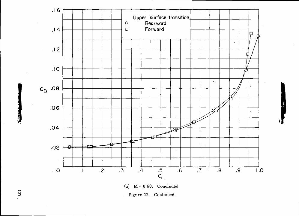
o
cg"55co0) T
3O
»-
38
?.0)Q
.O
.ID
O
D
00
oUo«0oII
I4->OObD
CVJ
OJGOO
CDO
CVJo
QO
107
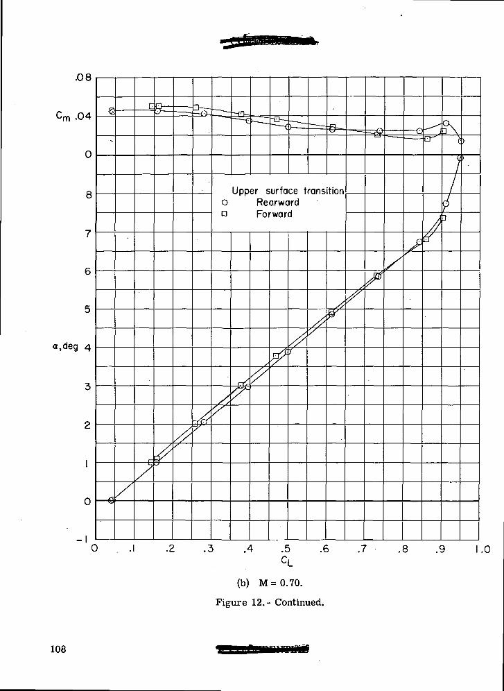
.08
.04
8
a,deg 4
-I
r
Upper surface transitiono Rearwardn Forward
X
.4 .5 .6 .7 .8 .9 1.0
(b) M=0.70.
Figure 12.- Continued.
108
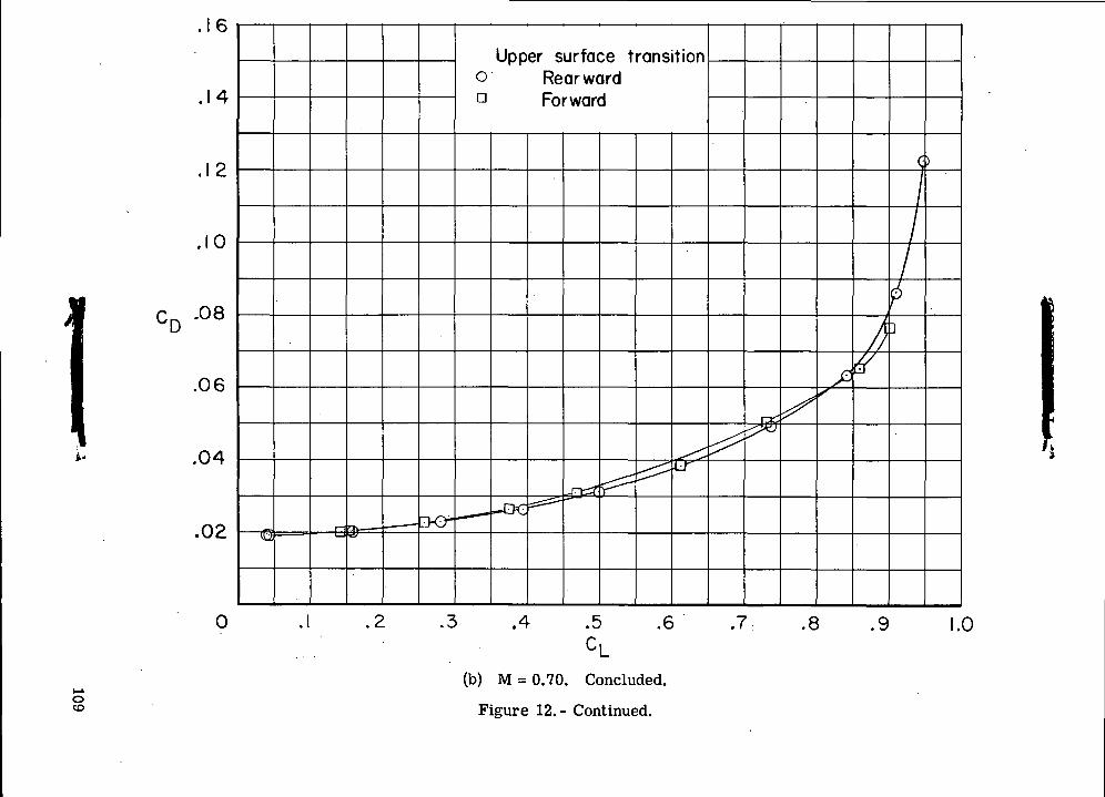
c.oOO
P
"2i£
<5Q.
CL
O D
o00
T3O>OOOoC--oIIs
g•so(U
ro
OJ
O00O
(DOCOo
QO
109
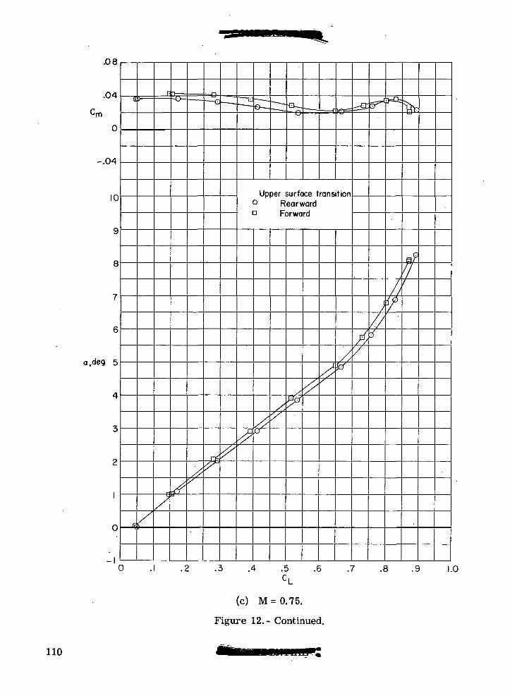
.08
.04 &F
m
-.04
10
a,deg 5
-1
Upper surface transition° RearwardD Forward
0
X
A
.3 .4 .5 .6 .7 .8 .9 1.0
(c) M=0.75 .
Figure 12.- Continued.
110
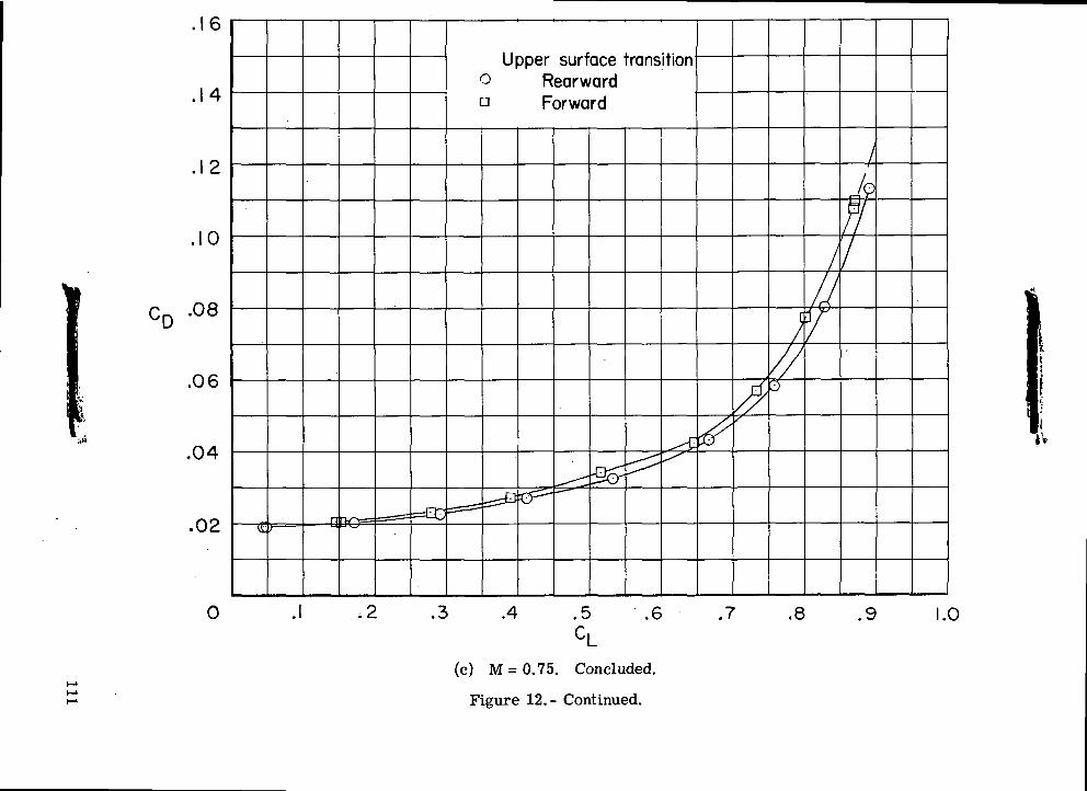
oIQ)
"OO
£=
TJ
III
0)
Q.
CL
=)
O
D
CO
CD"3coinc-
73CD3OUesiCDbO
rOc\J
OJ
00OCDO
<Mo
QO
111
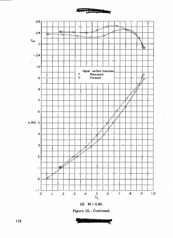
.08
.04
0
-.04
10
a.deg 5
(8>—
10
P
Upper surface transition° RearwardD Forward
.3 .4 .5 .6 .7 .8 .9 1.0
(d) M = 0.80.
Figure 12. - Continued.
112
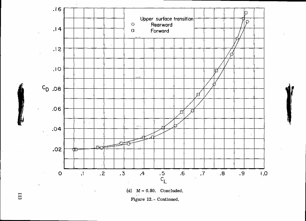
QJ
"D
111
Q.
CLo n
00(Dm
"8TJ1OG6ocooII
O<u
«
, be
^ 5373
rO
00OCDO
OCMO
OO
113
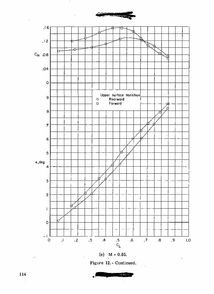
.16
.12
Cm .08
.04
a.deg
0
Upper surface transitiono RearwardD Forward
.4 .5C,
(e) M = 0.85.
Figure 12. - Continued.
.6 .7 .8 .9 1.0
114
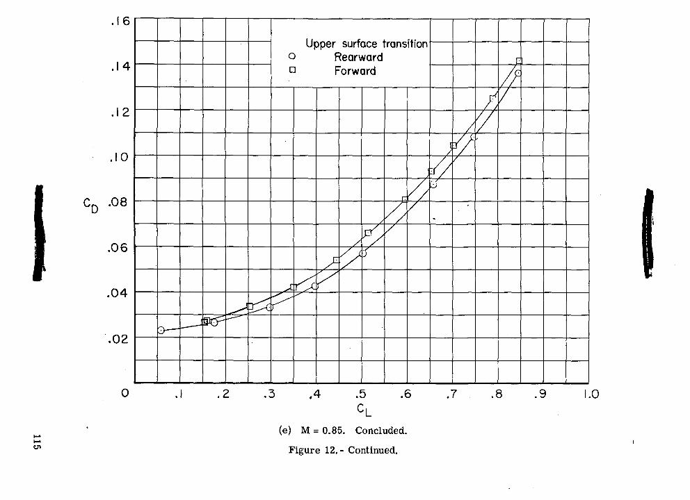
.0'55cod> »-
-no o
j:
II!en
o>
onr
iiw
. ••"
CDQ.
Q.o a
OJ
O00O
<£>O
C\J
O
oCD00inrOCVJ
a>oinooon
•oCDgOOOJ;-,
.§>
QO
115
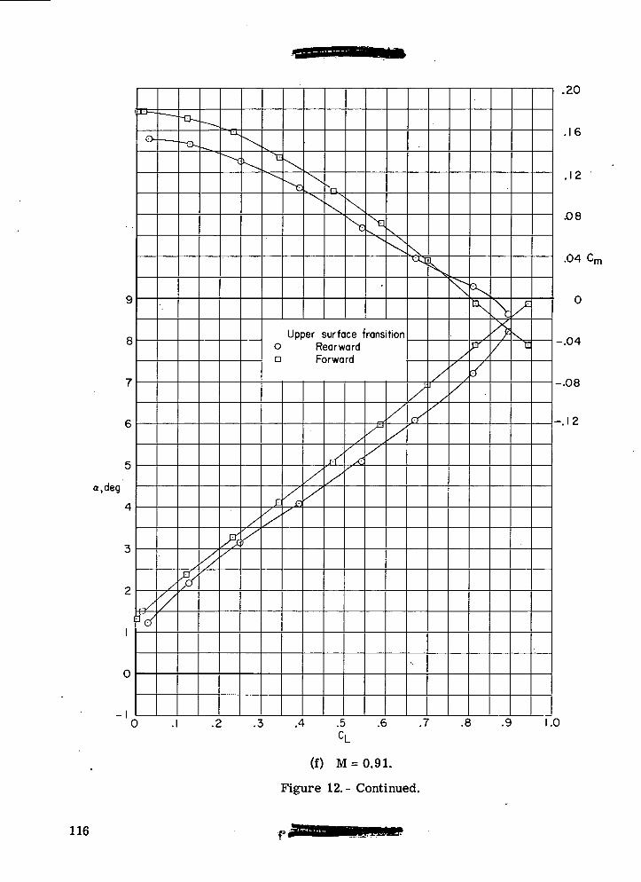
8
a.deg
-I0 .1
Upper surface fransitiono Rearwarda Forward
.4 .5CL
(f) M = 0.91.
Figure 12.- Continued.
.16
.12
.08
.04 C n
-.04
-.08
-.12
.6 .7 .8 .9 1.0
116
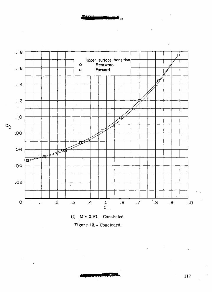
'D
.1 8
.16
.14
.12
.1.0
.08
.06
.04
.02
0
s^ssi^a -fTff*^^r
Upper surface transitiono Rearwardn Forward
^
^^
^
xx^^
,//
r
'
^y^
/
//
P/
.1 .2 .3 .4 .5 .6 .7 .8 .9 1
CL
(f) M = 0.91. Concluded.
Figure 12. - Concluded.
117
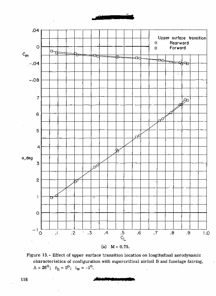
0
-.04
-.08
a.deg
0
y
Upper surface transitiono Rearwarda Forward
rf
0 .1 .2 .3 .4 .5 .6 .7 .8 .9 1.0
(a) M=0.75.
Figure 13.- Effect of upper surface transition location on longitudinal aerodynamiccharacteristics of configuration with supercritical airfoil B and fuselage fairing.A = 26°; 6h = 0°; iw = -1°.
118
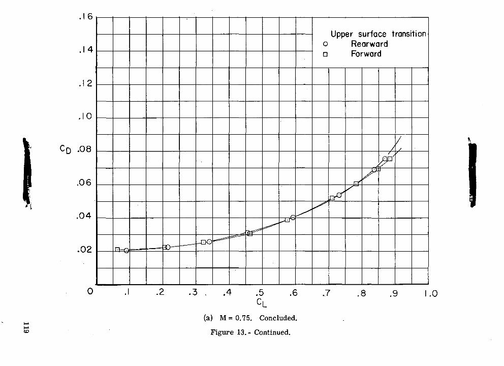
O
onransUpper surfaceo Rearwarda Forward
c>
?
CDCO
to^C
J
730)
IOOOinc-oII
roCO
<£>
QO
119
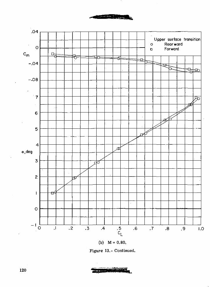
.04
-.08
a,deg
-'
9= Q
X
Upper surface transitiono Rearwarda Forward
.4 .5 .6 .7 .8 9 1.0
(b) M = 0.80.
Figure 13.- Continued.
120
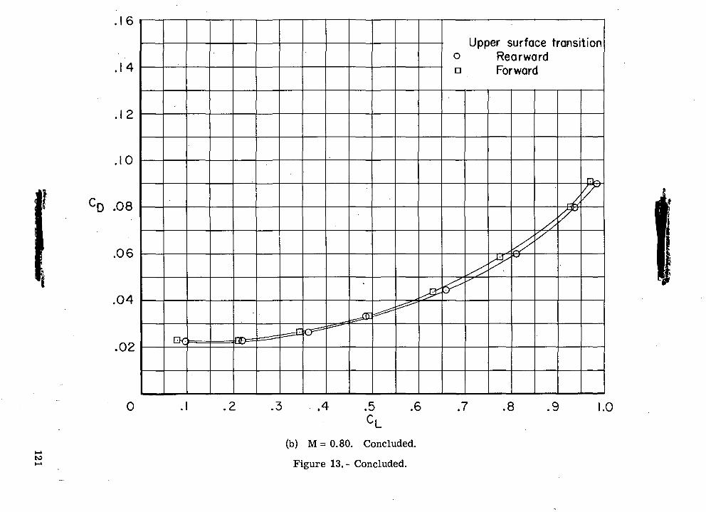
Upper surface transitiono Rearwardn Forward
CO10
1
X
T3
O
3
O
"«o
S
OII
roCM
toC\J
COCO
CVJ
121
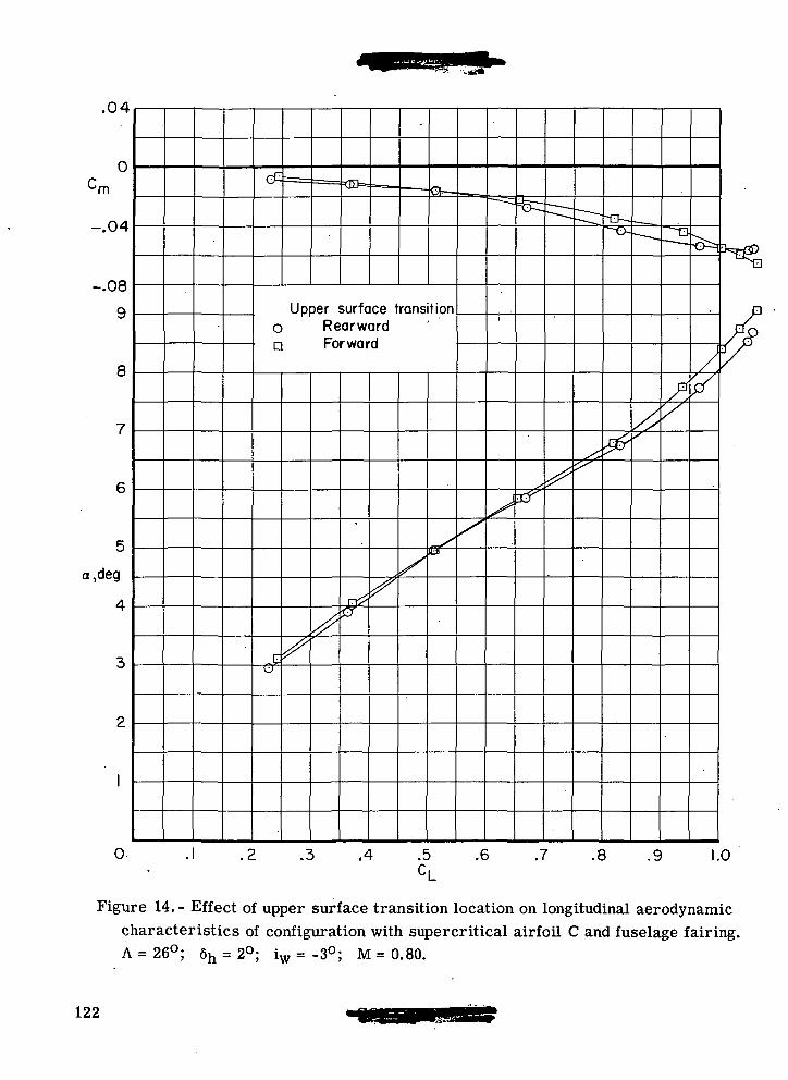
.04
0
Cm
-.04
-.08
9
8
a,deg
Upper surface transitiono Rearwarda Forward
0 .3 .4 .5 .6 .7 .8 .9 1.0
Figure 14.- Effect of upper surface transition location on longitudinal aerodynamiccharacteristics of configuration with supercritical airfoil C and fuselage fairing.A = 26°; 6h = 2°; iw = -3°; M = 0.80.
122
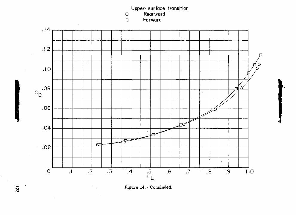
o
otoco0)
a.a.o a
00
CD
•3i-HuaouE
ro
<M00O
COoO
CVJO
QO
123
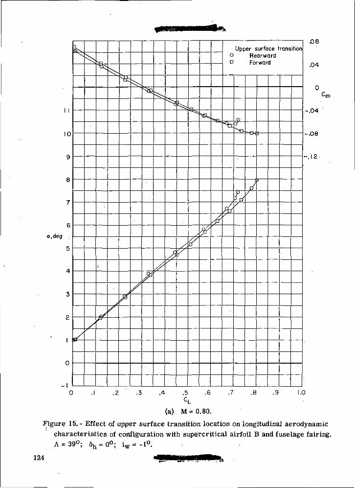
1 1
10
a.deg
^
Upper surface transition° RearwardD Forward
p
=&fj
.08
.04
•rn
-.04
-.08
-.12
0 .1 .2 .3 .4 .5 .6 .7 .8 .9 1.0CL
(a) M=0.80.
Figure 15.- Effect of upper surface transition location on longitudinal aerodynamicI
characteristics of configuration with supercritical airfoil B and fuselage fairing.A = 39°; 6h = 0°; iw = -1°.
124
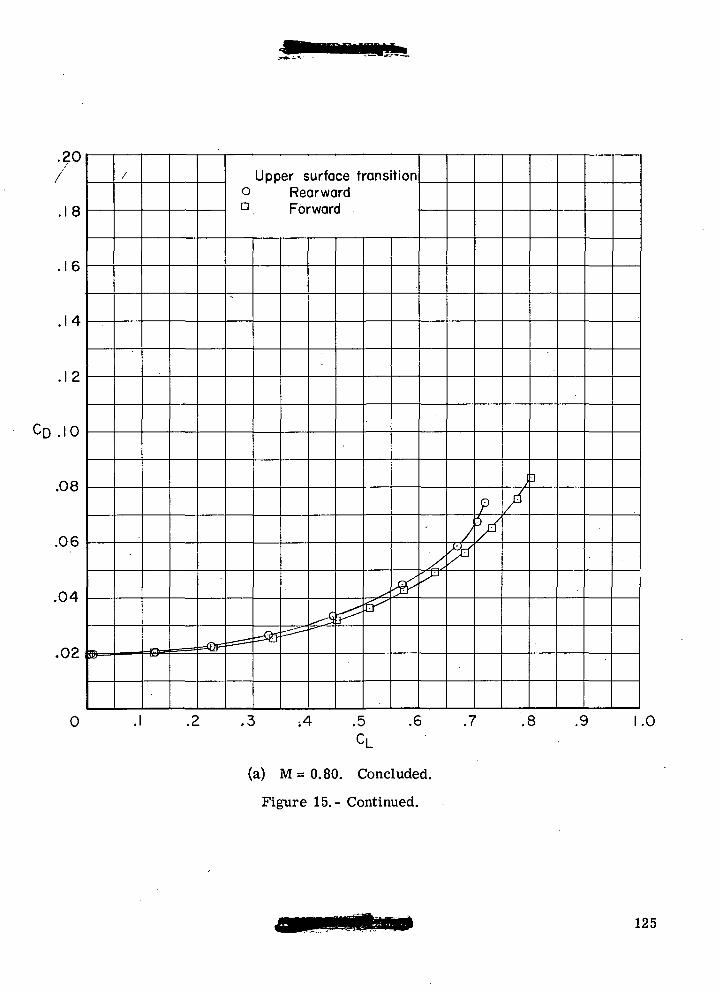
.18
.16
.14
.12
CD .10
.08
.06
.04
.02
0
®=
/
• ^^B =©= ===== =@F
Upper surface transitiono RearwardD Forward
^=^ ^^^$^
x
^
jT-Y ->^Vf
-
>°
/
7*
?y}
/]
.1 .2 .3 ;4 .5 .6 .7 .8 .9 1CL
(a) M = 0.80. Concluded.
Figure 15.- Continued.
125
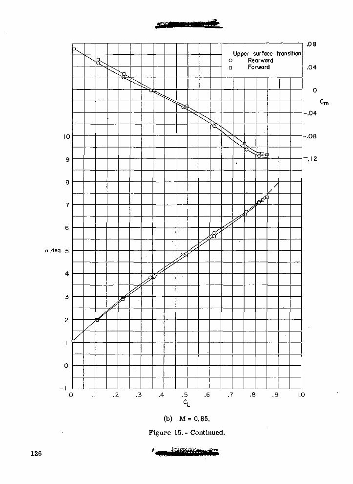
10
a.deg 5
0
V
Upper surface transitiono Rearwarda Forward
.4 .5 .6 .7 .8 .9
.08
.04
0
-.04
-.08
-.12
-n\
1.0
(b) M=0.85.
Figure 15.- Continued.
126
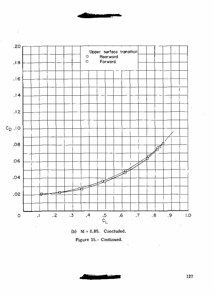
.zu
.18
.16
.14
.12
CD .10
.08
.06
.04
.02
0
o=- —w •_ ^S*
Upper surface transitiono RearwardQ Forward
g>^, ;^
•/&
^
X^X
/*
rrT
fi0'
/1
/
.1 .2 .3 .4 .5 .6 .7 .8 .9 1.
CL
(b) M = 0.85. Concluded.
Figure 15.- Continued.
127
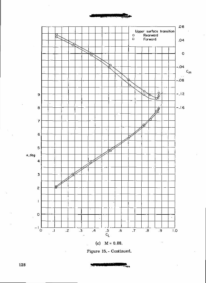
a.deg
-I0
\
Upper surface transitiono Rearwarda Forward
.4 .5CL
(c) M=0.88.
Figure 15.- Continued.
.6 .7 .8 .9
.08
.04
0
-.04
-.08
-.12
-.16
•rn
1.0
128
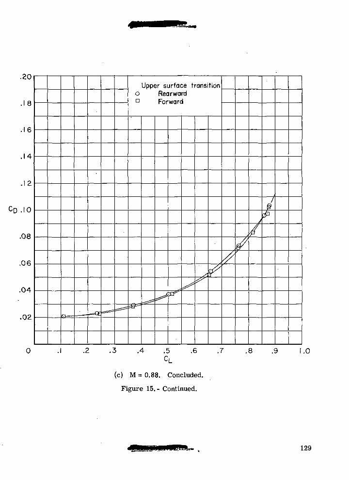
.£U
.18
.16
.14
.12
CD .10
.08
.06
.04
.02
0 •
— — — •
===^
Upper surface transitiono RearwardD Forward
&-^2^
^
X^
/^^
j
/
1
£
.2 .3 .4 .5 .6 .7 .8 .9 1
CL.0
(c) M = 0.88. Concluded.
Figure 15.- Continued.
129
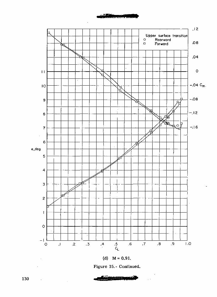
10
a.deg
N
Upper surface transitiono RearwardD Forward
A
.3 .4 .5
CL
(d) M=0.91.
Figure 15.- Continued.
A?
.12
.08
.04
-.04 C,m
-.08
-.12
-.16
.6 .7 .8 .9 1.0
130
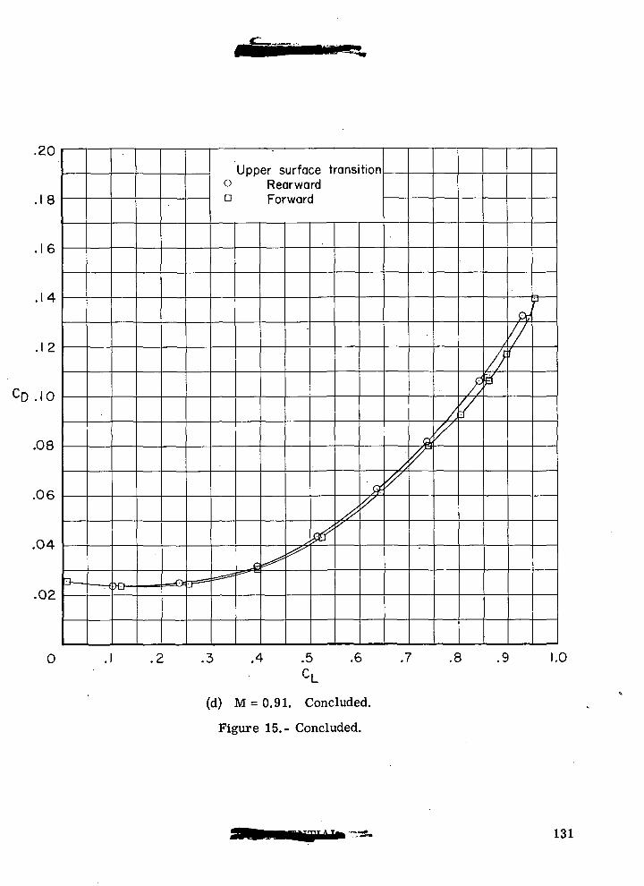
.<iU
.18
.16
.14
.12
.10
.08
.06
.04
.02r< •
Upper surface transition° Rearwardo Forward
*<== ^
'
^stf ^
f
J
r'/
/ /'/
//]7i
p
.1 .2 .3 .4 .5 .6 .7 .8 .9 1.0
(d) M = 0.91. Concluded.
Figure 15.- Concluded.
131
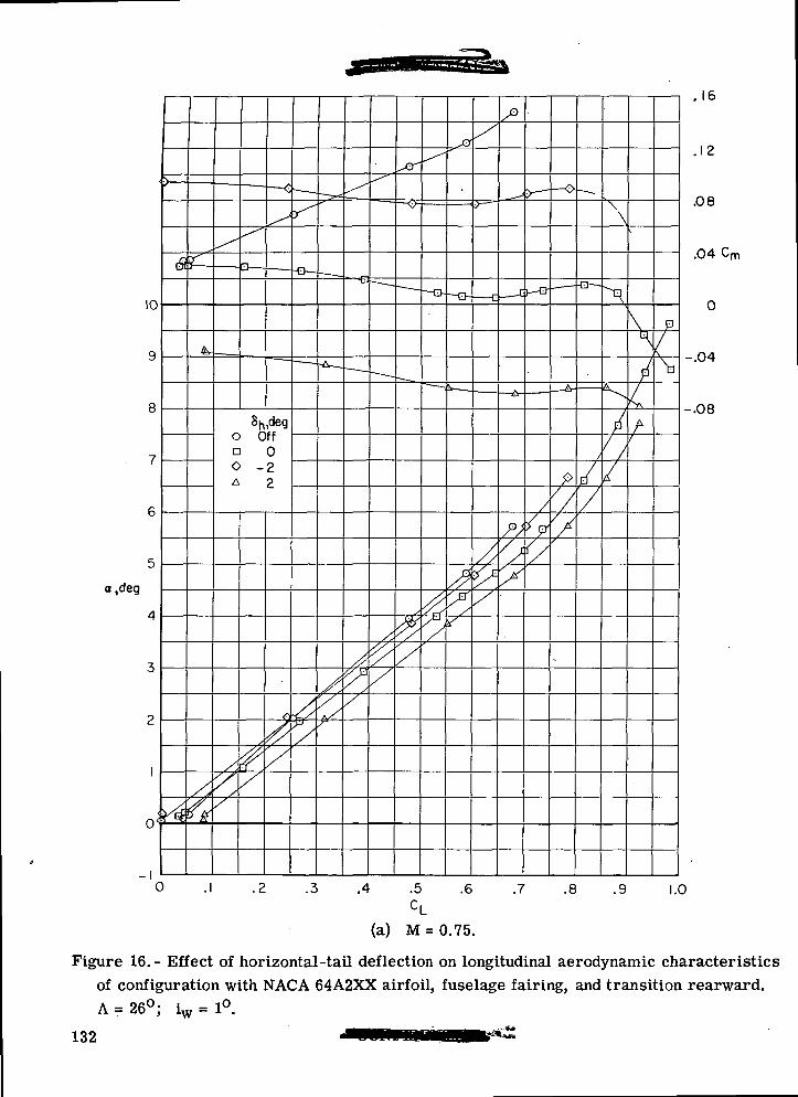
10
a ,deg
0<
0
o Offa 0O -2A 2 77
A
.2 .3 .4 .5 .6 .7 .8 .9
.16
.12
.08
.04 Cm
-.04
-.08
1.0
(a) M = 0.75.
Figure 16.- Effect of horizontal-tail deflection on longitudinal aerodynamic characteristicsof configuration with NACA 64A2XX airfoil, fuselage fairing, and transition rearward.A = 26°; iw = 1°.
132
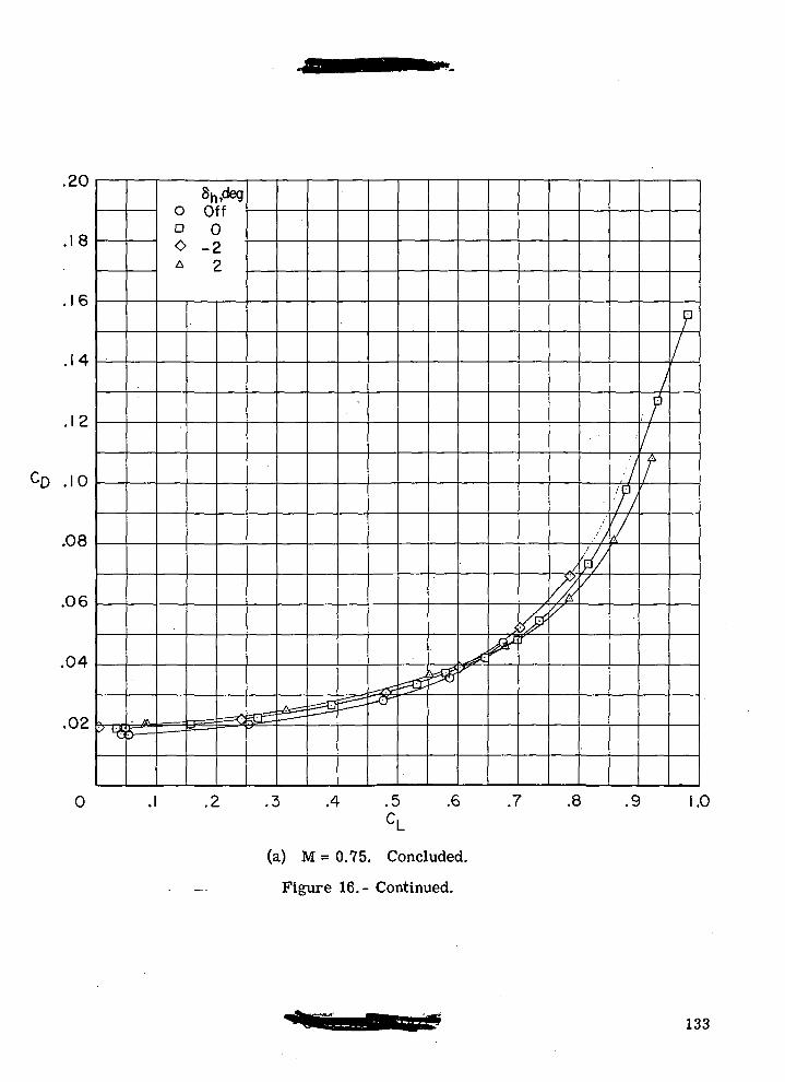
.18
16
.12
CD .10
.08
.06
.04
.02
0
Sh,dego Offo 00 -2A 2
.3 .4 .5c,
.6 .7
(a) M = 0.75. Concluded.
Figure 16.- Continued.
F
-tMT:h
W
.8 .9 .0
133
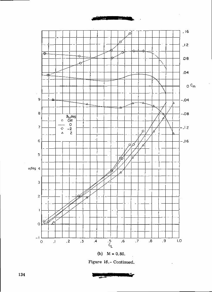
a,deg 4
8h,dego Off
— 0O -2A 2
0
-I
\
.16
.12
.08
.04
0 cm
-.04
-.08
-.1 2
-.16
0 .4 .5 .6 .7 .8 .9 1.0
(b) M = 0.80.
Figure 16.- Continued.
134
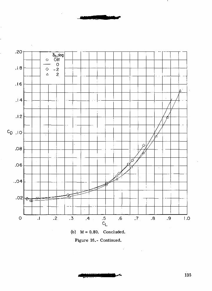
.20
.18
16
, 1 2
CD .10
.08
.06
-.04
.02
Sh,dego Off
— 0O -2A 2
A .5CL
.6 .7
(b) M = 0.80. Concluded.
Figure 16.- Continued.
.8 .9 1.0
135
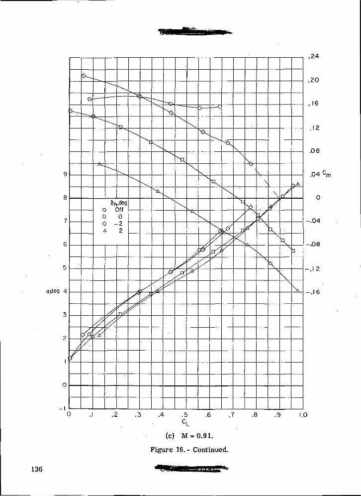
a,deg 4
0
ifc
AYs
o Offn 00 -2A 2
X
"a
.24
.20
. 16
.12
.08
.04 cm
0
-.04
-.08
-.12
-.16
0 .1 .4 .5C,
.6 .7 .8 .9 1.0
(c) M = 0.91.
Figure 16.- Continued.
136
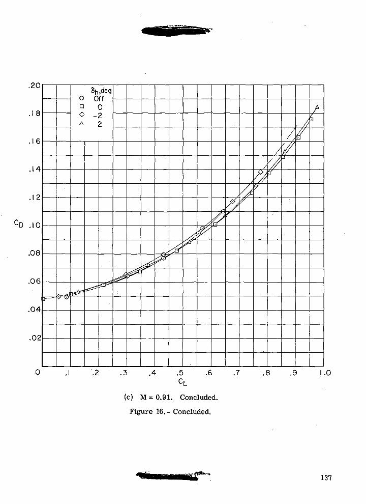
.20
8
.16
.14
CD .10
.08
.06
.04
.02
8h,dego OffQ 00 -2A 2
.4 .5CL
.6 .7 .8 .9 1.0
(c) M = 0.91. Concluded.
Figure 16.- Concluded.
137
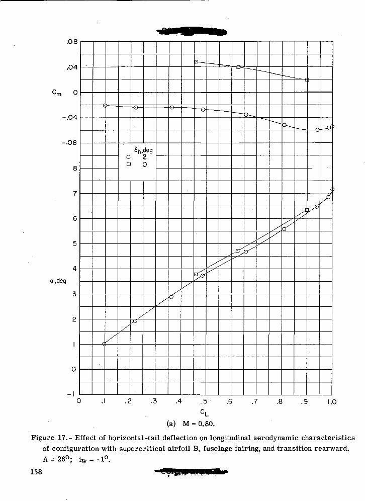
.08
.04
-.04
-.08
8
a.deg
0
Sh,dego 2a 0
0 .1 .2 .3 .4 .5 .6 .7 .8 .9 1.0CL
(a) M = 0.80.
Figure 17.- Effect of horizontal-tail deflection on longitudinal aerodynamic characteristicsof configuration with supercritical airfoil B, fuselage fairing, and transition rearward.A = 26°; iw = -1°.
138
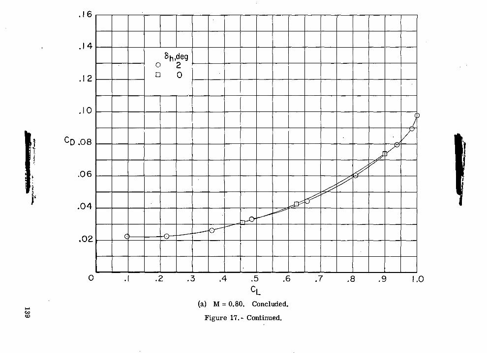
o>o n
\
00qoo
CDoCOO
CDCDrOOJ
1I—<OIoC
O
a)gIO<U
139
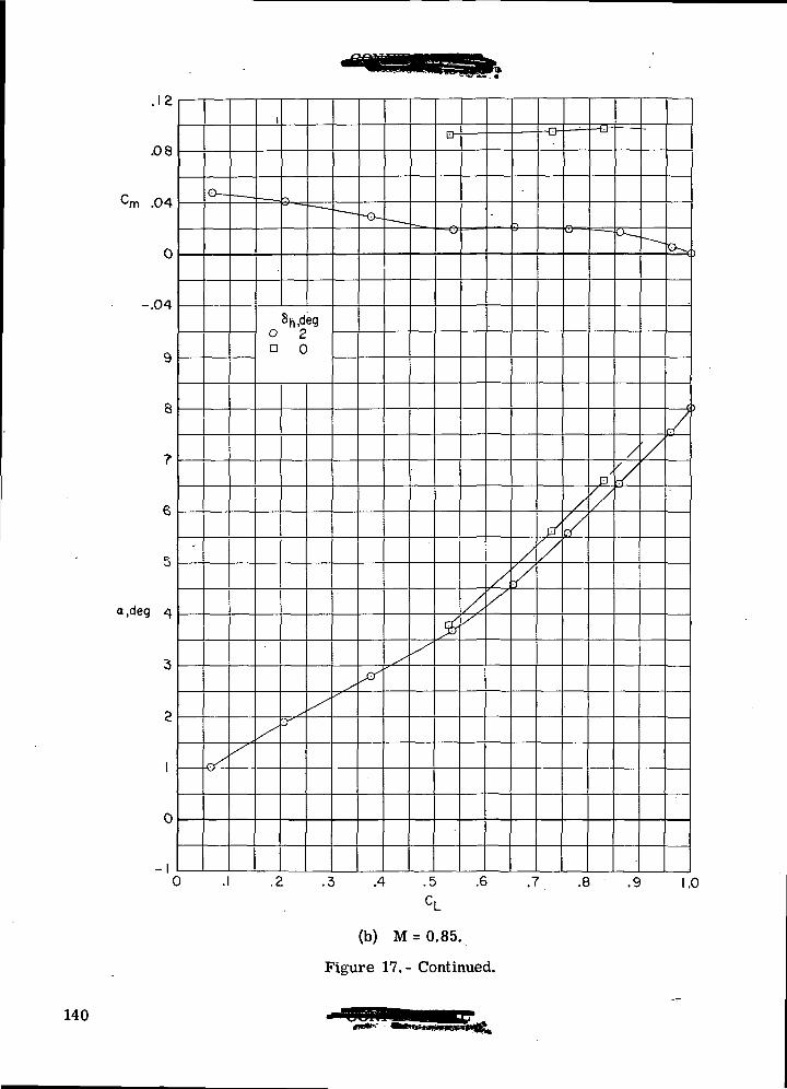
, 1 2
.08
cm .04
0
-.04
a.deg
0
-I0
8h,dego 2a 0
A .5 .6 .7 .8 .9 1.0
(b) M = 0.85.
Figure 17. - Continued.
140
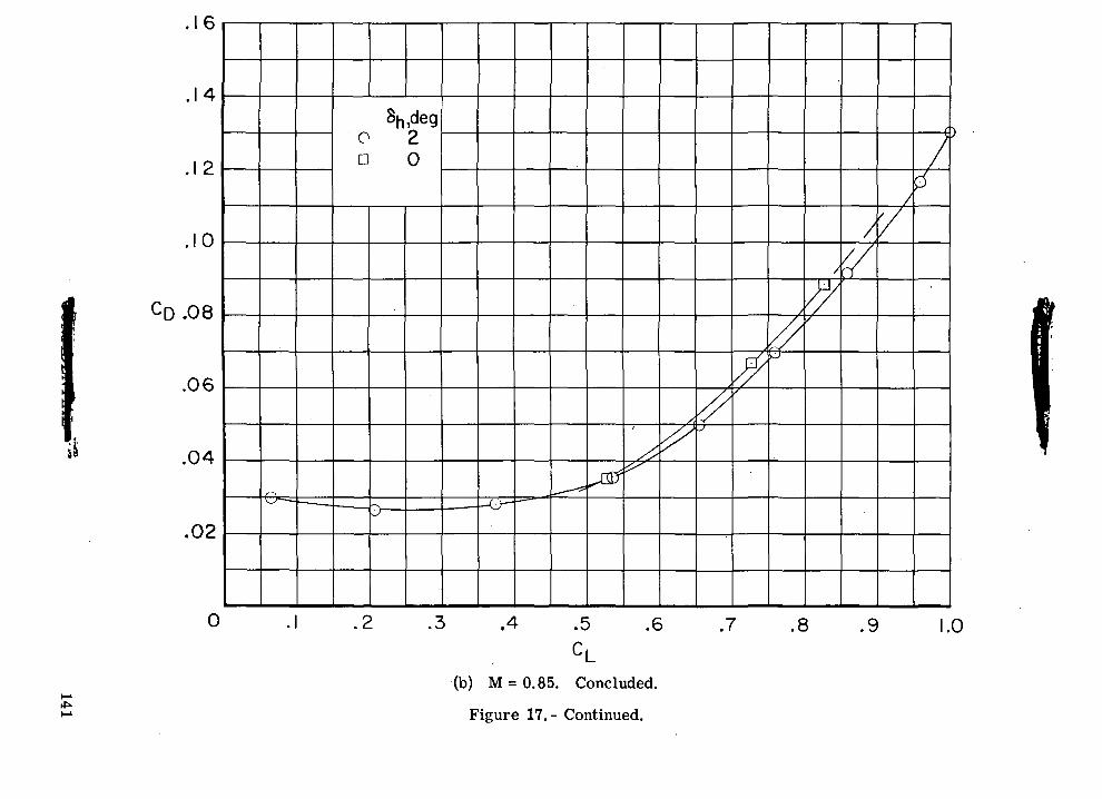
0)"0,-C
VJ O
O D
C)
OJ
00qQo
tooCOO
ocr>oor--(D
o
(UoIinoooII
130)
1OO
rO
141
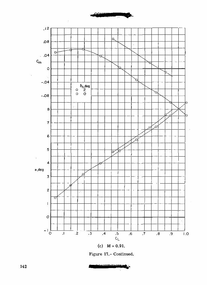
.12
.08
.04
0
-.04
-.08
•rn
a,deg
0
-I
Sh,degO 2D 0
fl Z_
-D
A .5
CL.6 .7 .8 .9 1.0
(c) M=0.91.
Figure 17.- Continued.
142
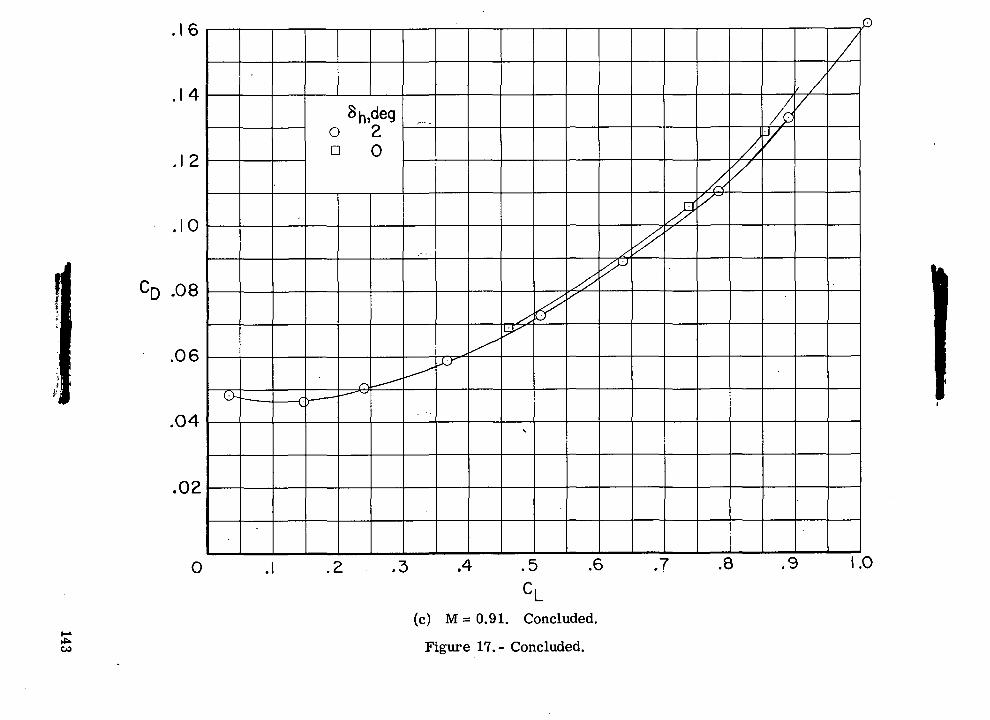
o>-8
c\J O.c
#3
o n
Ac>
oCDCOrOOJ
OII
131o<1>
CDCM
000100
c\j
QO
143
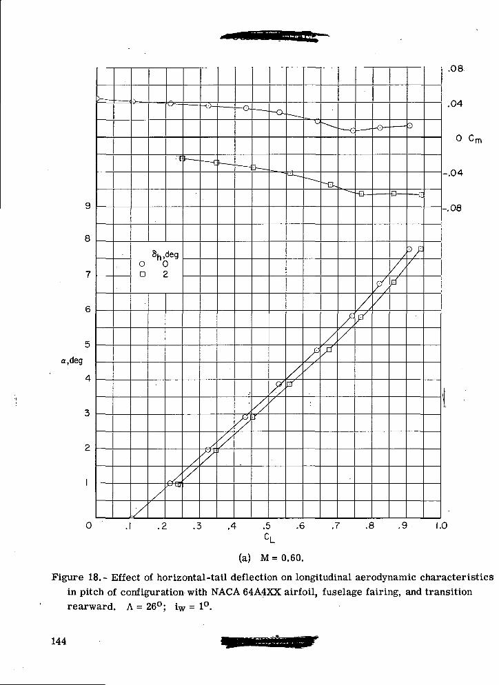
8
a,deg
0
Sh,dego 0a 2
.1 .2 .3 .4 .5 .6 .7 .8 .9
-.04
-.08
.08
.04
0 Cm
1.0
(a) M = 0.60.
Figure 18.- Effect of horizontal-tail deflection on longitudinal aerodynamic characteristicsin pitch of configuration with NACA 64A4XX airfoil, fuselage fairing, and transitionrearward. A = 26°; iw = 1°.
144
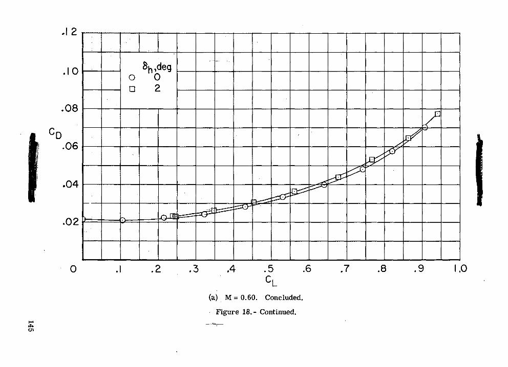
o
cv
1
o»0>"°_
O c\J
.c£Q
0 D
J1
\)\
\
~ ^^>
1I\\\I1\\(.cs
O
00
C
D
^
CM
—
O
O
O
O*
Q
'0
CD•
CO•
1»
(D•o<w
«••§
«A
3
CJ C
I G
"-
1
^cy 1 1o
'
to oo
0
*"
. II
gj
>i
rOCO••
o
145
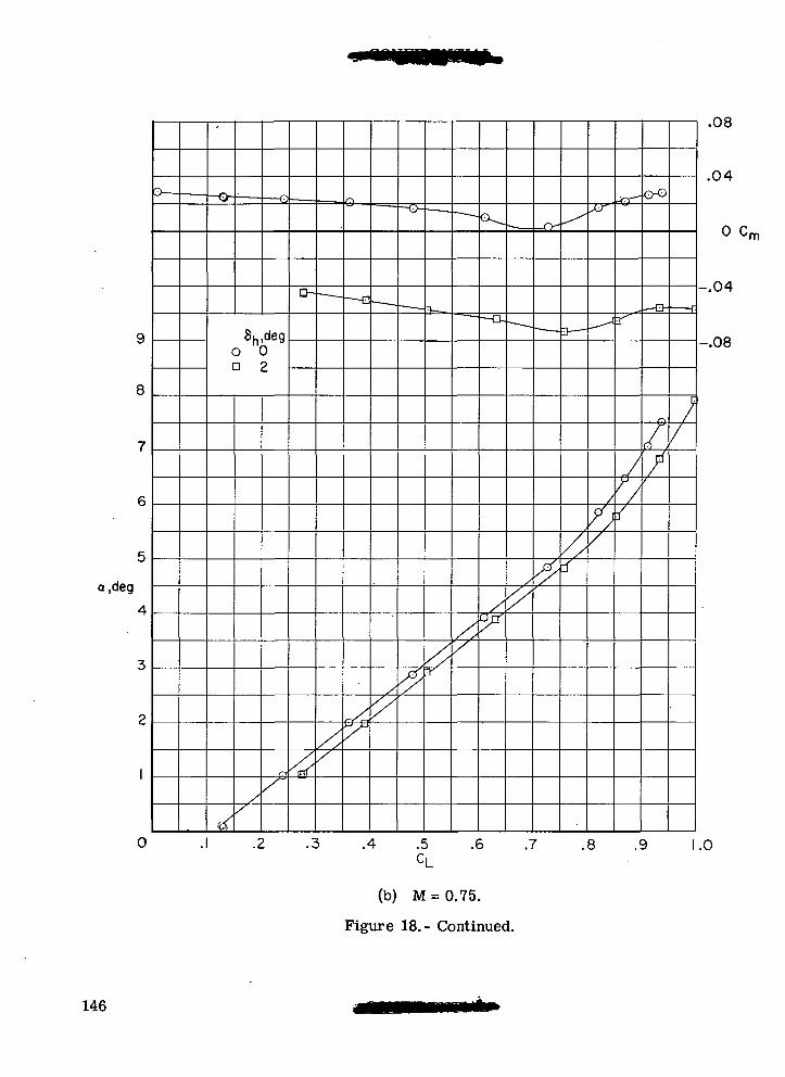
,deg
O
Sh,dego 0n 2
a 7
.08
.04
0 Cm
-.04
-.08
.3 .4 .5CL
.6 .7 .8 .9
(b) M = 0.75.
Figure 18.- Continued.
1.0
146
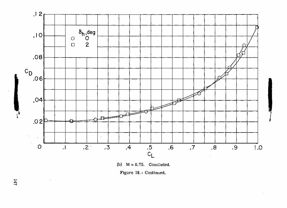
o
O)o n
00in
0)
s"oIt-o
73IOOooO)
roOJ
CVJ00o
CDoO
Jo
Qo
147
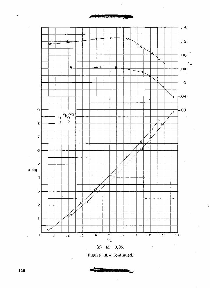
a,deg
0
8h,deg0 0D 2
.4 .5CL
(c) M = 0.85.
Figure 18.- Continued.
\
.6 .7. .8 .9
.16
.12
.08
.04-m
--.04
--.08
1.0
148ObK)
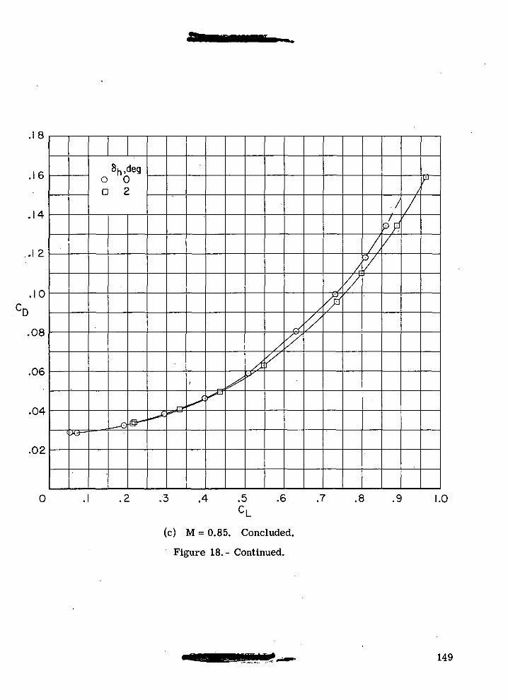
.18
.16
.14
. .12
Sh,degO 0D 2 z
.10
.08
.06
.04
.02
0 .3 .4 .5 .6 .7
CL
(c) M = 0.85. Concluded.
Figure 18.- Continued.
.8 .9 1.0
149
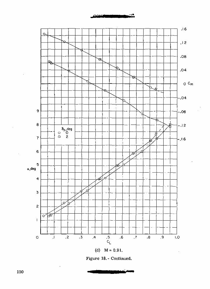
(X.
a.deg
8h,dego 0a 2
.4 .5 .6 .7 .8 .9
(d) M = 0.91.
Figure 18.- Continued.
.16
. 12
.08
.04
0 cm
-.04
-.08
-.12
--.16
1.0
150
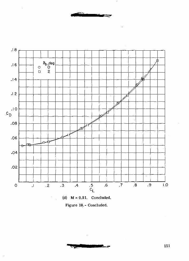
8
Sh,deg0 0D 2
.1 2
.10
.08
.06
.04
.02
3 .4 .5 .6 .7 .8 .9 1.0CL
(d) M=0.91. Concluded.
Figure 18.- Concluded.
151
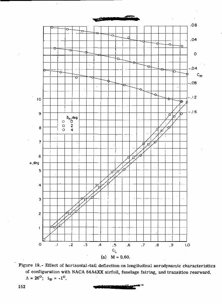
10
a,deg
0
8h,dego 0a 2O 4
77.
.08
.04
-.04
-.08
-.12
-.16
.1 .2 .3 .4 .5 .6 .7 .8 .9 1.0
(a) M = 0.60.
Figure 19.- Effect of horizontal-tail deflection on longitudinal aerodynamic characteristicsof configuration with NACA 64A4XX airfoil, fuselage fairing, and transition rearward.A = 26°; iw = -1°.
152
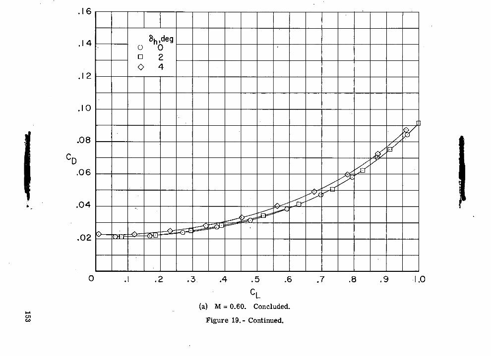
o>V"R-O
cvj <fr-C
<SO
0 D
O
COq
oQ
'
0
COtoroCJ
0
£3
| 1
o
^II
£
^
bD
153
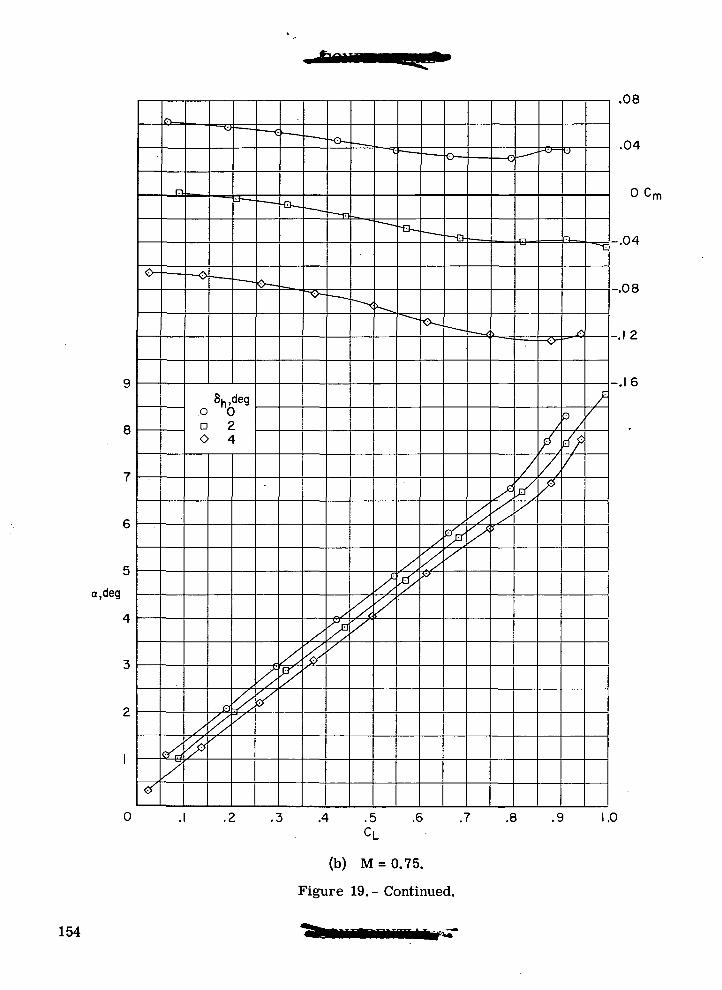
8
a,deg
o VD 2O 4
A .5CL
(b) M = 0.75.
Figure 19. - Continued.
7
.08
.04
0 Cm
-.04
-.08
-.1 2
.-.16
.6 .7 .8 .9 1.0
154
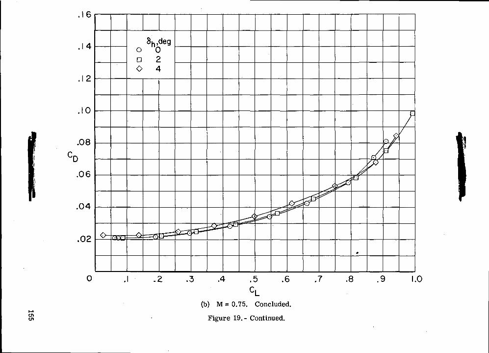
g15oOiOi
1—I0)bC
155
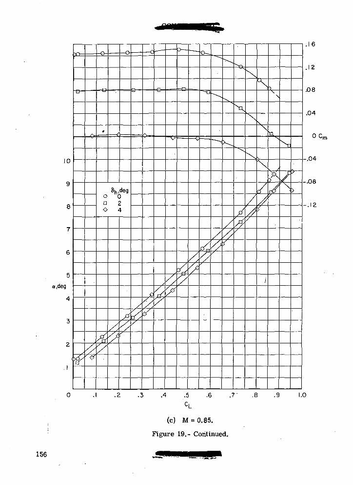
10
8
a,deg
oa 2O 4
.16
.12
.08
.04
O Cm
-.04
.4 .5 .6 .7' .8 .9
-.08
-.12
1.0
(c) M = 0.85.
Figure 19.- Continued.
156
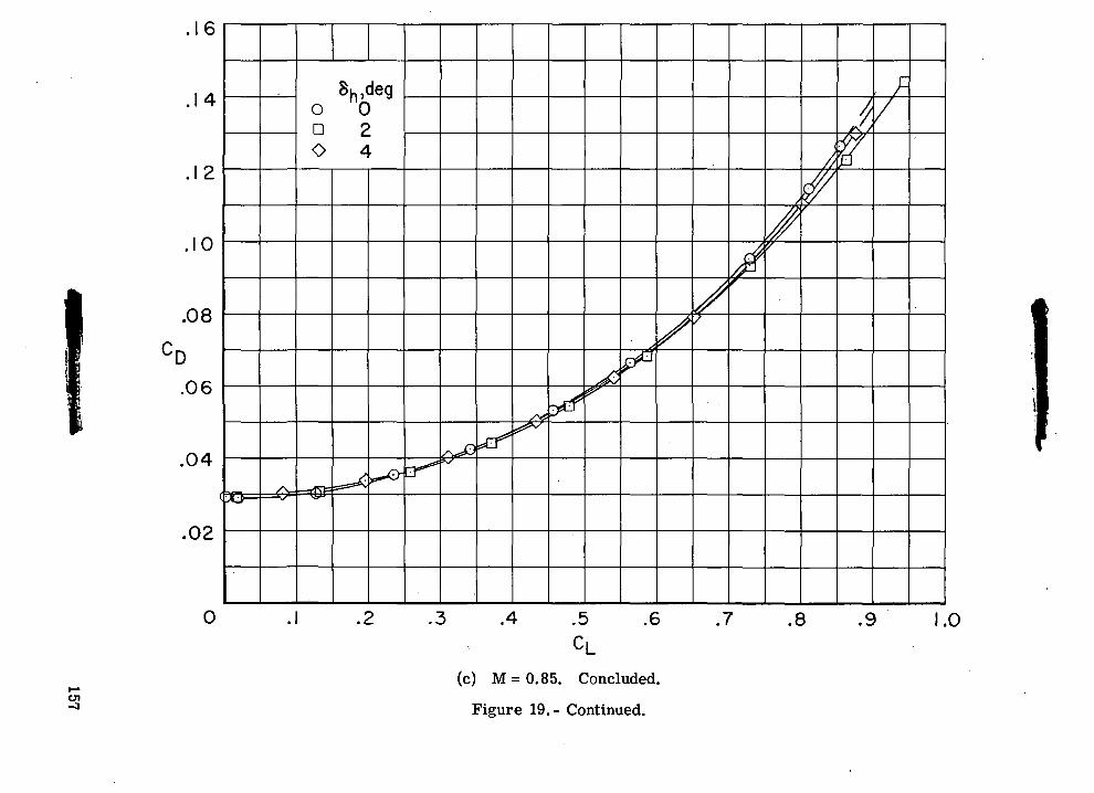
0>"
c\J
O D
O
\
I
00CD
oO
CVJo
00CDlOro
•8 •«
3 2
•-H s
8 IO
o
in '
ooO
5
,. g
157
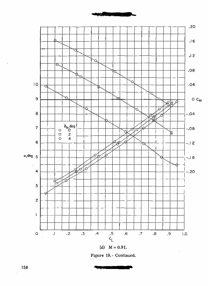
10
9
8
a.deg 5
0
_£L
8hldego 0a 20 4
NX
.4 .5 .6 .7 .8 .9
.16
.12
.08
.04
o cm
-.04
-.08
-.12
1.0
(d) M=0.91.
Figure 19.- Continued.
158
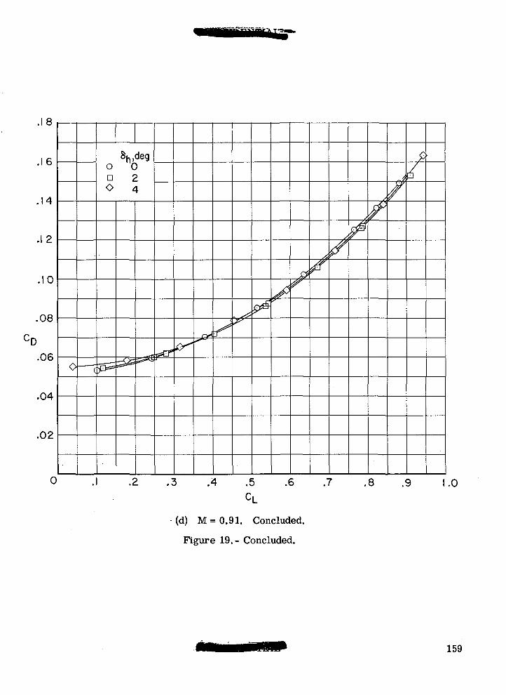
(d) M = 0.91. Concluded.
Figure 19.- Concluded.
159
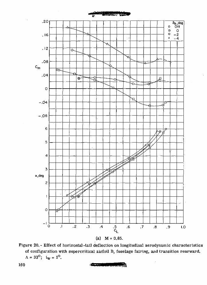
.20
16
. 12
.08
.04
0
-.04
-.08
a.deg
0
Sh,dego Offa 0O -2* -4
0 -I -2 .3 .4 .5 .6 .7 .8 9 1.0CL
(a) M = 0.85.
Figure 20.- Effect of horizontal-tail deflection on longitudinal aerodynamic characteristicsof configuration with supercritical airfoil B, fuselage fairing, and transition rearward.A = 33°; iw = 1°.
160
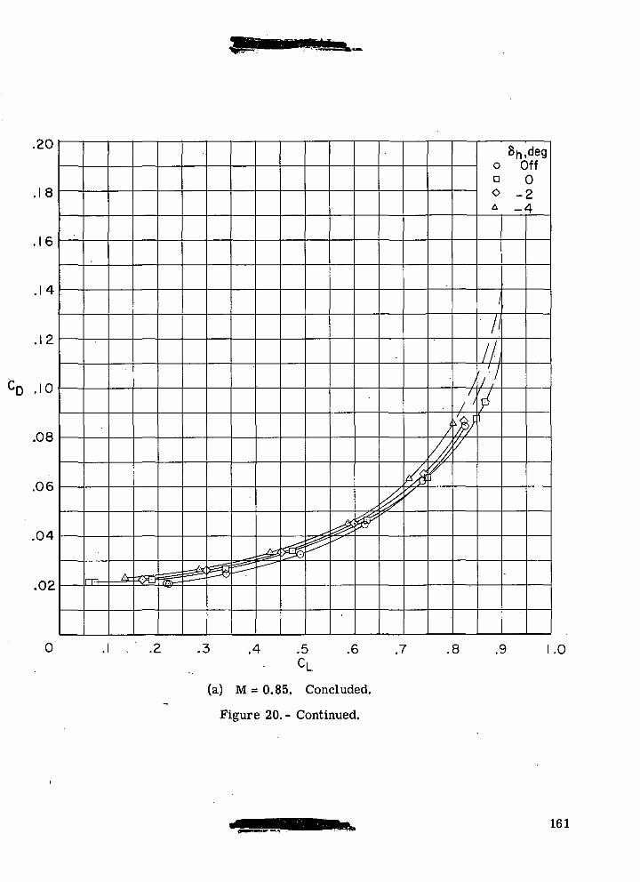
.20
8
,16
8h,dego Offn 0O -2A _4
.14
.12
2.08
.06
.04
.02
.4 .5CL
.6 .7 .8 .9 1.0
(a) M = 0.85. Concluded.
Figure 20.- Continued.
161
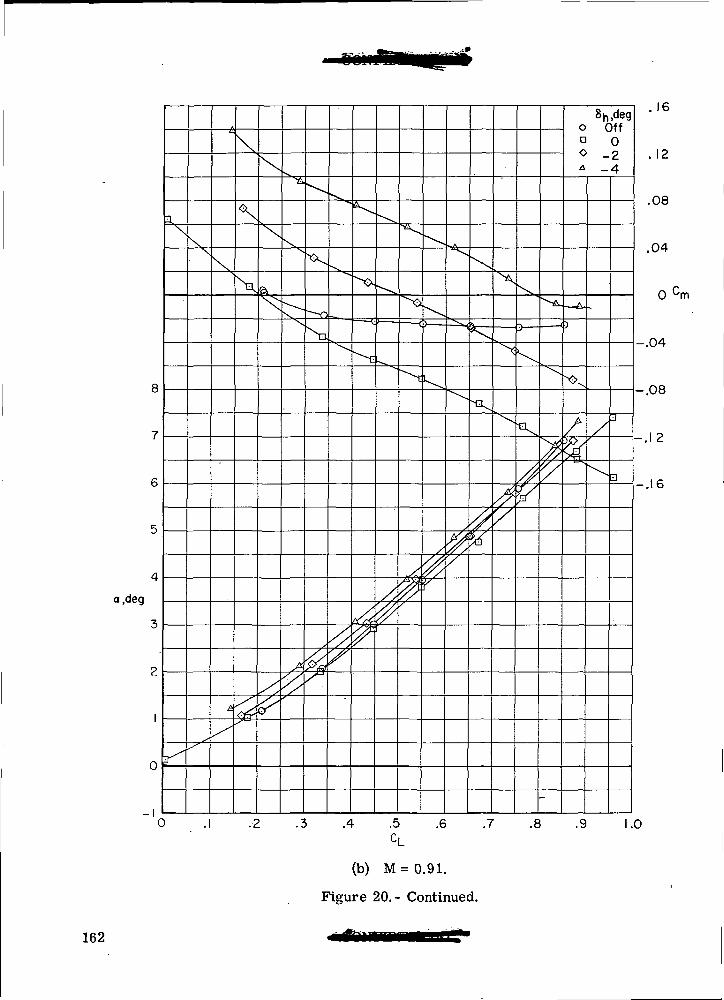
a.deg
0
-I0
Va
Ni
^
X
.4 .5
CL '
(b) M = 0.91.
Figure 20.- Continued.
Sh,dego Offa 0O -2* -4
.16
. 12
.08
.04
0 cm
-.04
-.08
-.1 2
-.16
.6 .7 .8 .9 1.0
162
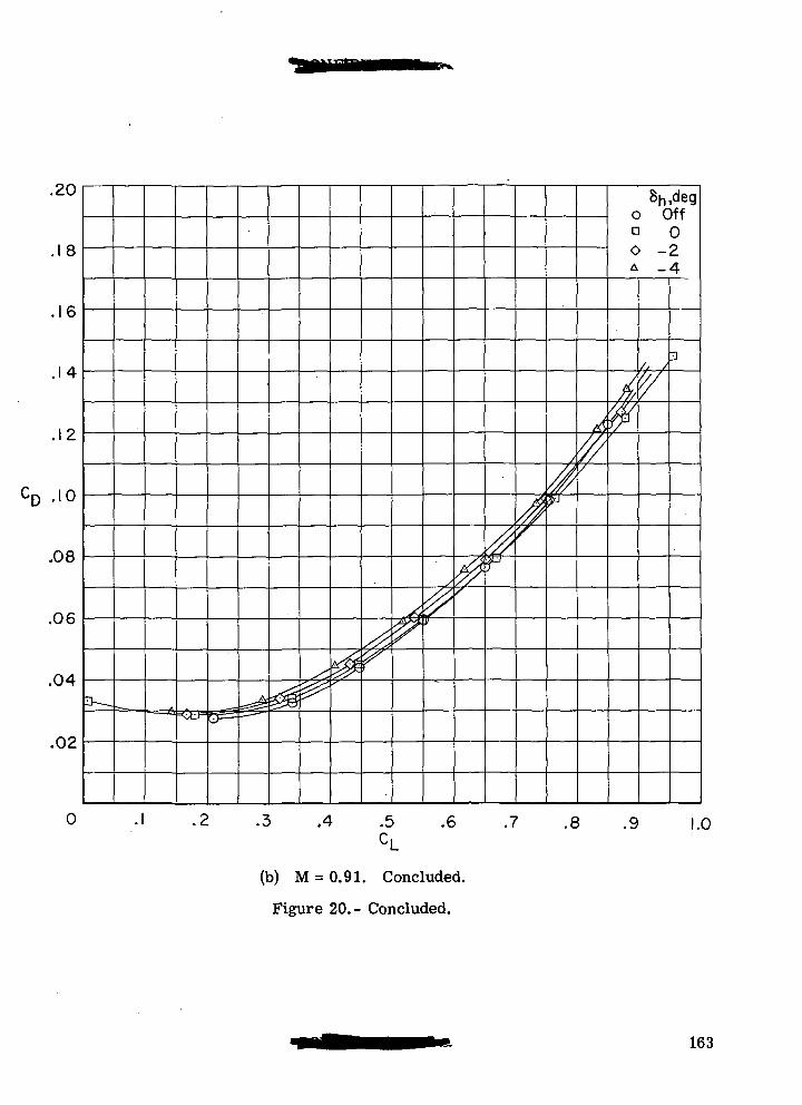
.20
8
16
.14
.12
.10
.08
.06
.04
.02
8h,dego Offa 0O -2* -4
0 .4 .5 .6 .7 .8 .9 1.0
(b) M = 0.91. Concluded.
Figure 20.- Concluded.
163
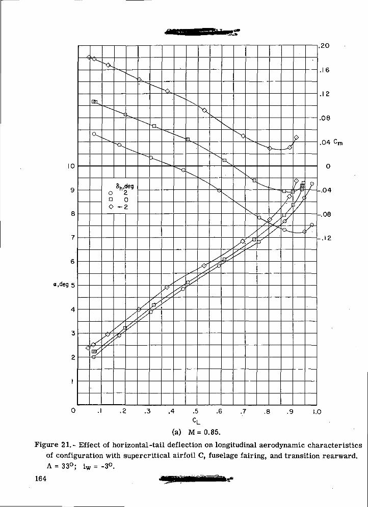
10
a.deg 5
0
Sh,dego 2a 00 -2
.1 .2 .3 .4 .5 .6
•//-.08
.16
.12
.08
.04 Cm
-.12
.7 .8 .9 1.0
(a) M=0.85.
Figure 21. ~ Effect of horizontal -tail deflection on longitudinal aerodynamic characteristicsof configuration with supercritical airfoil C, fuselage fairing, and transition rearward.A = 33°; iw = -3°.
164
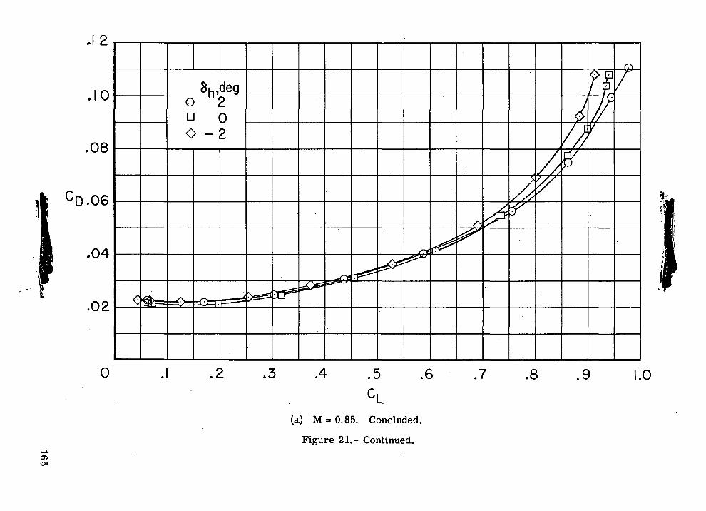
O (M
<5O
o a
O
1
oo. o
•aI 1
•—i
So
c§ =gO
o
l«OO
i-H
o
N
II 2£
rOC\J
(X)o
too•
ao
oCVJo
165
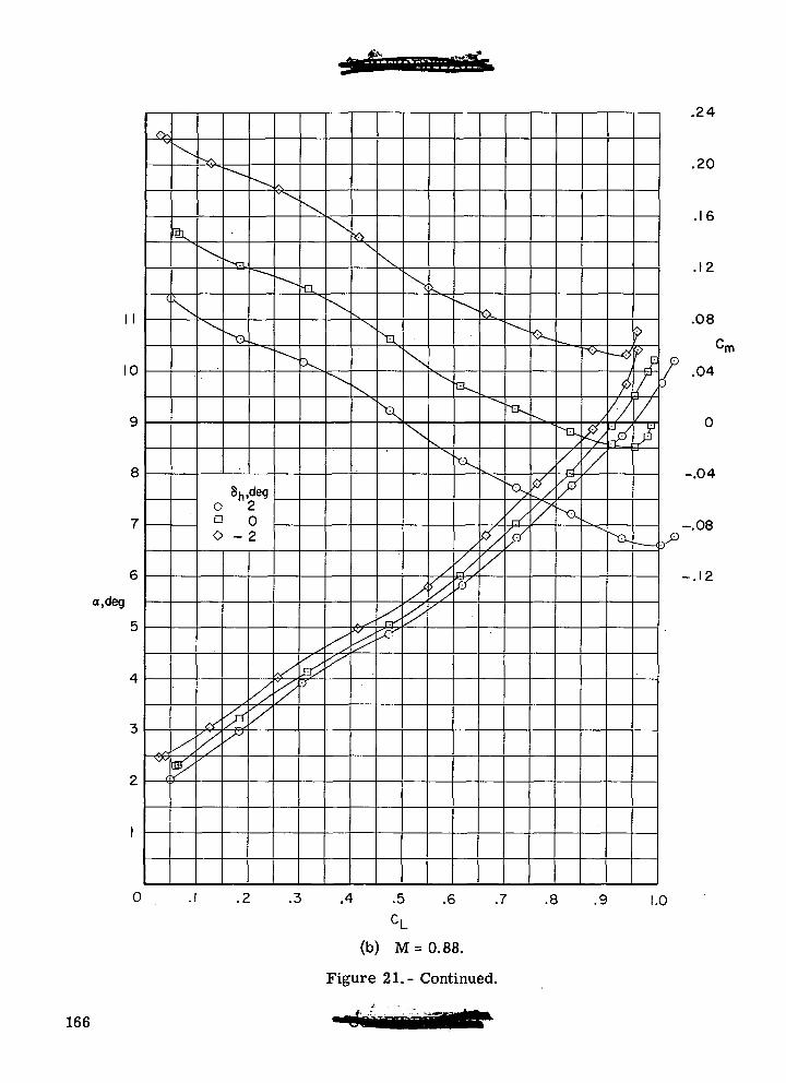
II
10
a.deg
0
8h,degO 2a 00 - 2
i>
A .5 .6 .7 .8 .9
CL(b) M = 0.88.
Figure 21.- Continued.
.24
.20
.16
.12
.08
•rn
.04
-.04
-.08
-.12
1.0
166
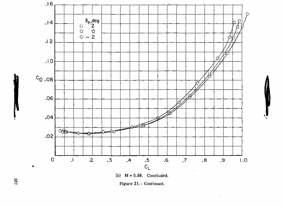
o>-O
CM
O C
VJ
O D
O
CVJ00o
9
QO
cooCVJO
oo10
•a"§ a>
I §
§ iO
oU
oo' '
CO
^
O
<M
II ^
" fa
fl
^
E
rOCMO
167
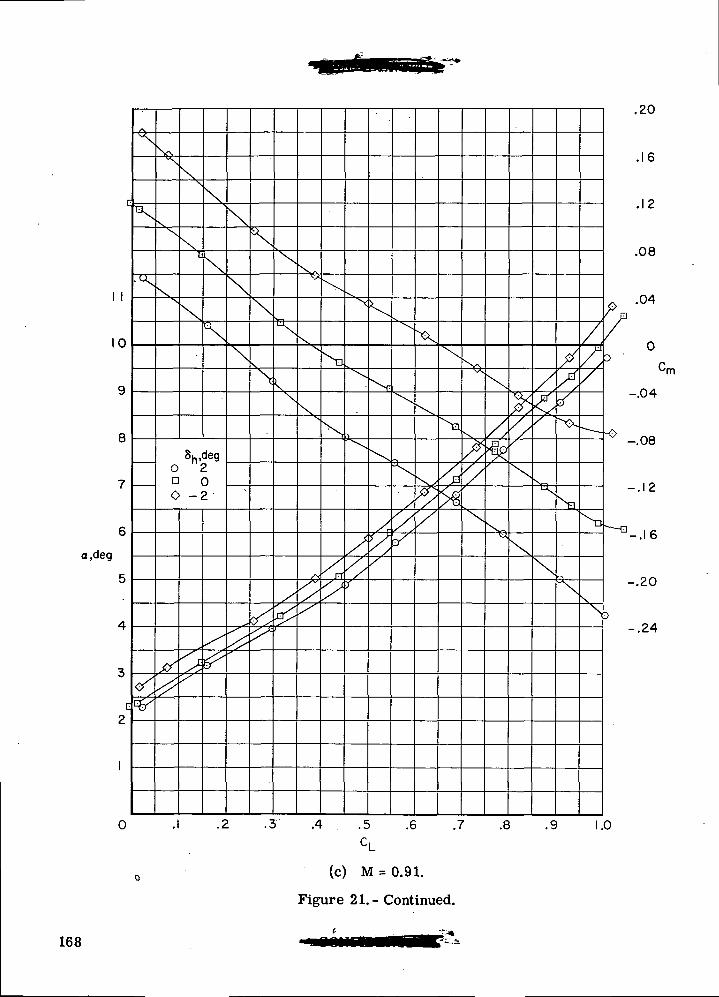
1 1
a.deg
V.
n oO -2
.20
.16
.12
.08
.04
•rn
-.04
-.08
-.12
J-.I6
-.20
-.24
0 .3 .4 . .5 .6 .7 .8 .9 1.0
(c) M = 0.91.
Figure 21.- Continued.
168
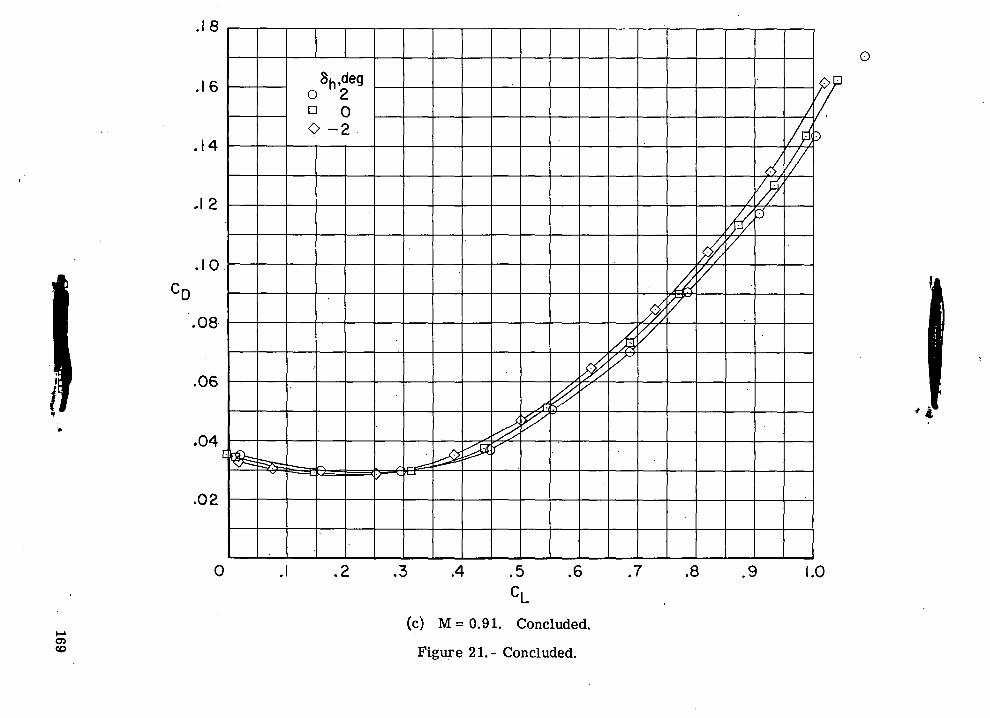
o
o>0)"D
CVJ O
<M
£ '
O D
O
ooooO
QO
OJ
O
00
ro
T3V
~S
TJ
~
5 -S
§ •§OO
O
pq
II CU
" I
169
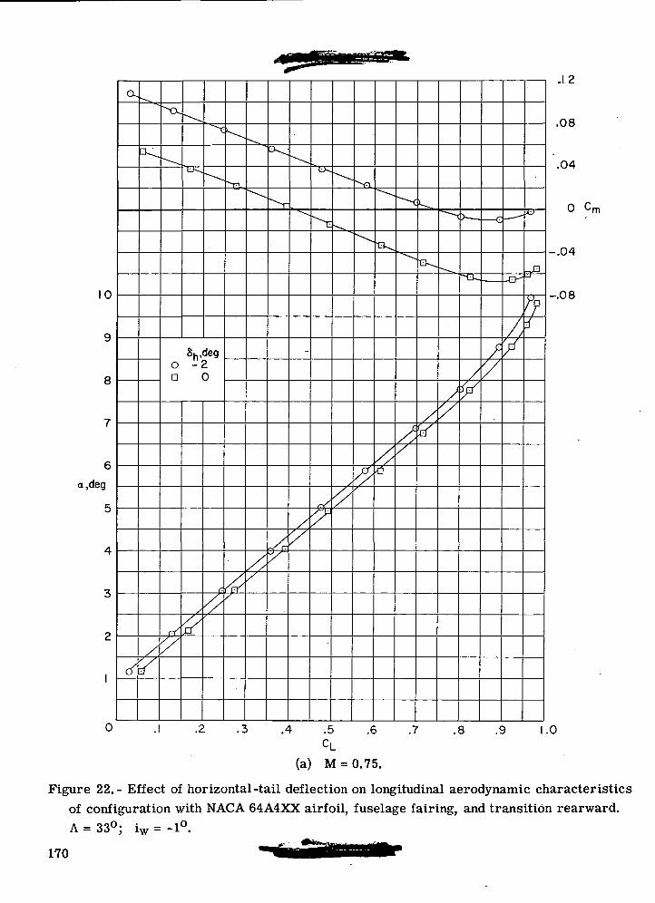
a,deg
cx
8h,degO -2D 0
.12
.08
.04
0 Cm
-.04
-.08
0 .1 .2 .3 .4 .5 .6 .7 .8 .9 1.0CL
(a) M = 0.75.
Figure 22.- Effect of horizontal-tail deflection on longitudinal aerodynamic characteristicsof configuration with NACA 64A4XX airfoil, fuselage fairing, and transition rearward.A = 33°; iw = -1°.
170
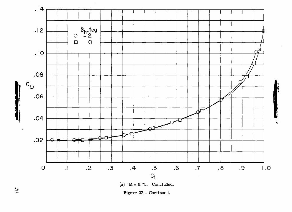
o
0)
_•U.CO O<5O
o n
00
0)
I-HOoinC-;
oII
T3a;oOcaOsl
0
OJ
GOO(DO
OJ
OQ
O
171
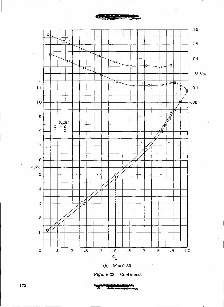
10
6
o,deg
5
ex
0
8h,deg0 -2D 0
^
4>-
.4 .5
c,
(b) M = 0.80.
Figure 22. - Continued.
= CP=
f
.6 ,7 .8 .9
.12
.08
.04
o cm
-.04
-.08
1.0
172
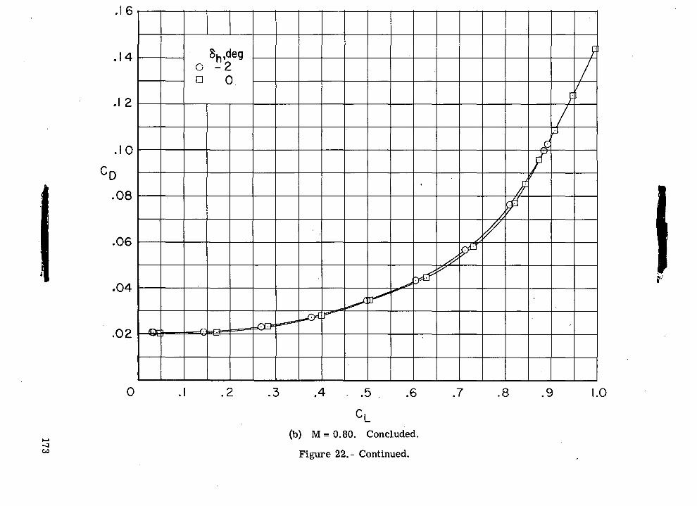
-S.OJ o
o a
V00CD
o
T30)o
cC
£o
"ao
oo
o
'oo
evio
NII
g
s I
OJ
QO
COOCDO
CVJO
173
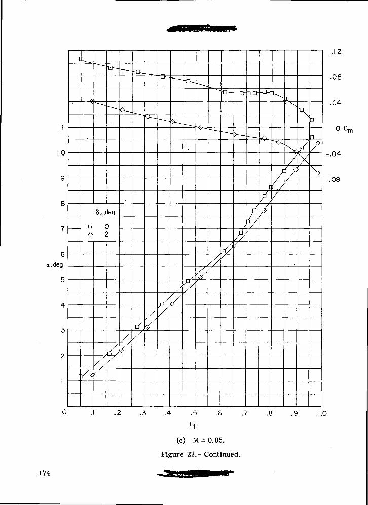
1 1
10
8
6
a,deg
0
a 00 2
e=
//
11 y
a
.4 .5 .6 .7 .8 .9
.08
.04
o c•m
-.04
-.08
1.0
(c) M = 0.85.
Figure 22.- Continued.
174
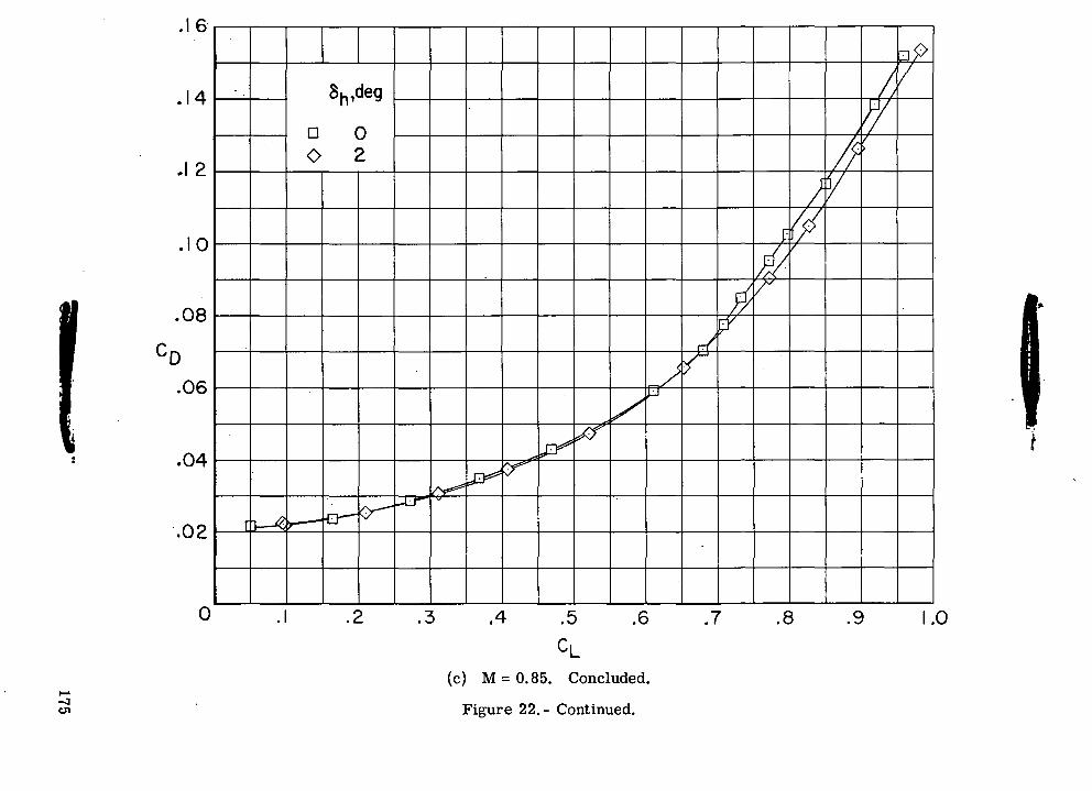
•§..c00
O C
O
n O
X
cr>00
•83ufl
°uoo
roCM
CDC\J
00 C
OO
O
Q
•O
CVJO
175
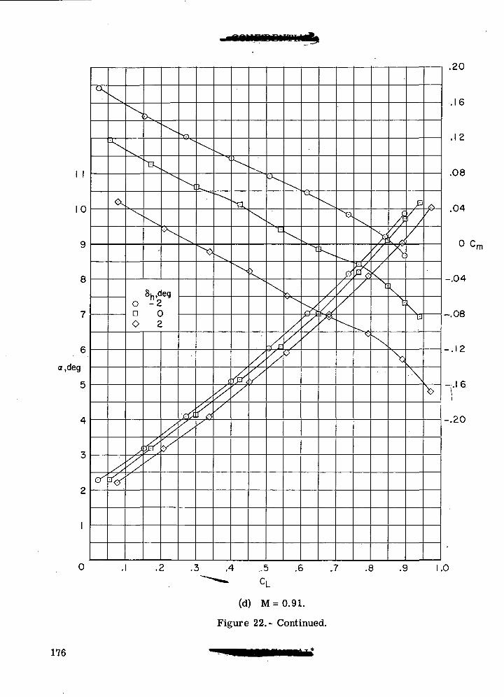
10
8
a,deg
o
8h,deg0 -2n 00 2
&y
N
7^
.4 ..5
(d) M = 0.91.
Figure 22.- Continued.
^c
>
.20
.16
.12
.08
.04
0 Cr
-.04
u -.08
-.12
-.20
.6 .7 .8 .9 1.0
176
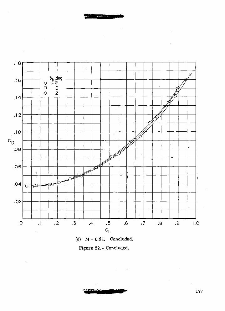
.18
6
.14
O 2n 0O 2
.10
.08
.06
,04
.02
0 .4 .5 .6 .7 .8 .9 1.0
(d) M = 0.91. Concluded.
Figure 22.- Concluded.
177
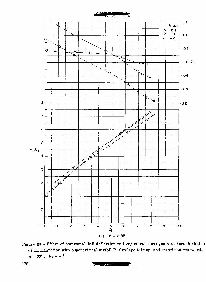
o.deg
0
>X
O
.2 .3 .4 .5 .6 .7
8hldego Off0 0A -2
.8 .9
.08
.04
o cm
.04
.08
-.12
1.0
(a) M = 0.85.
Figure 23.- Effect of horizontal-tail deflection on longitudinal aerodynamic characteristicsof configuration with supercritical airfoil B, fuselage fairing, and transition rearward.A = 39°; iw = -1°.
178
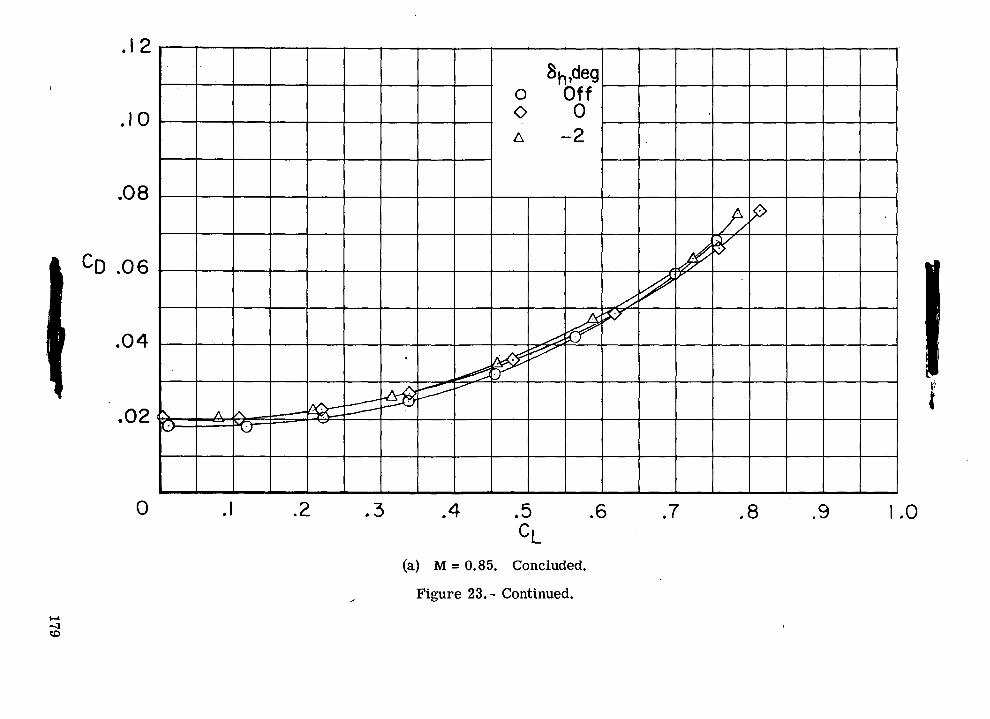
o
<JO
oo
<
00
•OauoUIDoooII
oUiCO0)
§>
rO
CJ
oooCOoQo
179
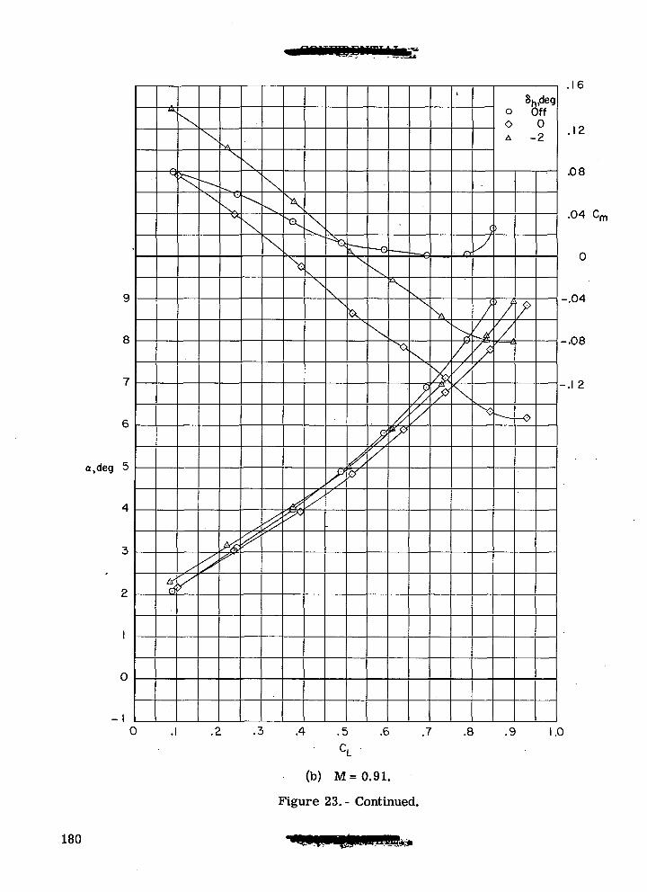
8
a.deg 5
0
0
Su,dego OffO 0A -2
A .5
C,
.6 .7 .8 .9
(b) M=0.91.
Figure 23.- Continued.
.16
.12
.08
.04 Cr
-.04
-.08
-.1 2
1.0
180

•3*.'
0)
^_"«JO
(NJ
OO
<
\
OJ
00OCDO
CVIO
CD
CD73<U73
733
Q
)
1 I
O
O0
§uo
S
II o>
OO
181
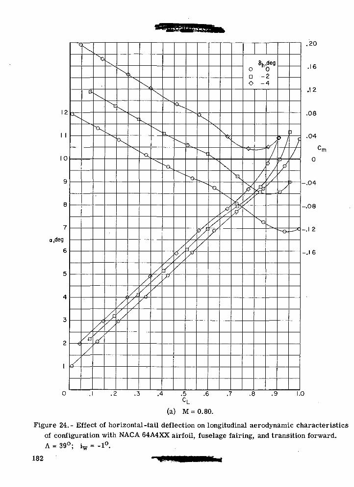
12
I I
10
i,deg
S*
0
x
ODO
8h,deg°0-2
4
.20
.16
.12
.08
.04
-.04
-.08
-.1 2
-.16
.1 .2 .3 .4 .5 .6 .7 .8 .9 1.0
(a) M=0.80.
Figure 24.- Effect of horizontal-tail deflection on longitudinal aerodynamic characteristicsof configuration with NACA 64A4XX airfoil, fuselage fairing, and transition forward.A = 39°; iw = -1°.
182
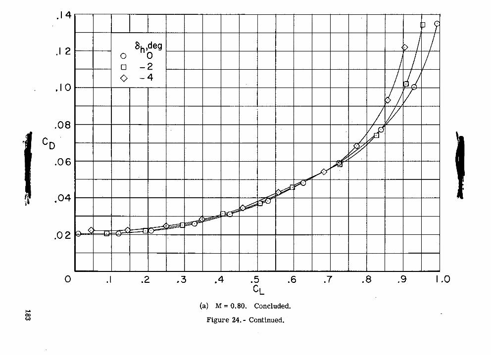
-S-
0)o
c\J
o n
O
CVJ00
CO
o
o•
Q
'O
OJ
o
CD00(D
1 "8I §
C
£
O
oOo
'.O
O
^H
II £
s a
ro
183
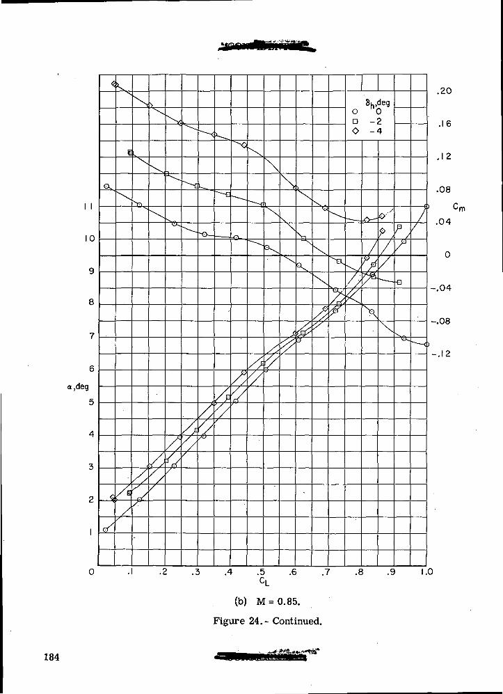
I I
o,deg
'J-
'J-
o
8h,dego nOD -2O -4
Pr.
™
.4 .5 .6 .7 .8 .9
(b) M = 0.85.
Figure 24.- Continued.
.20
.16
.12
.08
.04
•rn
-.04
-.08
-.12
1.0
184
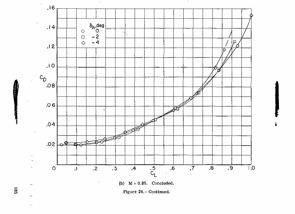
CVJ
O D
O
<3
00
•a0)
1oLOoooII
•oI•sdCM0)
rOCVJ
CVJ00O
CJ
OQ
O
185
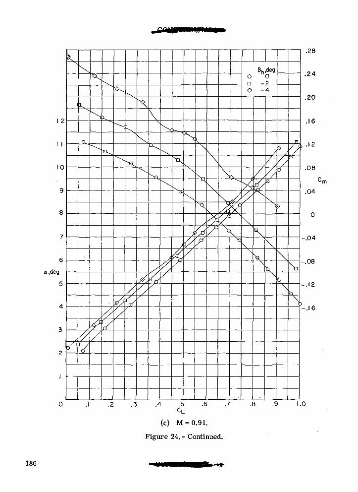
10
a,deg
1
CL
V
X
8h,dego nOD -2O -4
t)
Al
.28
.24
.20
.16
.12
.08
.04
0
-.04
-.08
-.12
-.16
.3 .4 .5CL
.6 .7 .8 .9 1.0
(c) M=0.91.
Figure 24.- Continued.
186
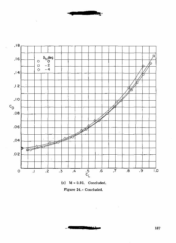
18
.16
.14
8h,dego nOn -20 -4
.1 2
.10
.08
.06
.04
.02
ss**^tto-o^
3 .4 .5 .6 .7 .8 .9 1.0CL
(c) M = 0.91. Concluded.
Figure 24.- Concluded.
187
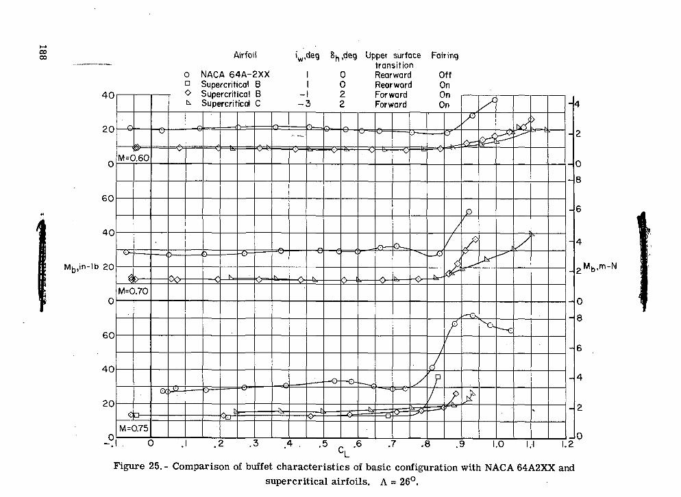
COCD
i£_.0SCM
O 00
CM
• T3 "a
O O CM CM
o o o
o
•™ '.""*
^
o o O
Q
COto0 .H -g
intoCM
inC)
OIDOsr
oCMoCD
OCMO.
188
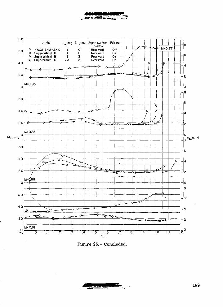
Mb,in-lb
iw,deg 8h,deg Upper surface Fairingtransition
0 NACA 64A-2XXa Supercritical BO Supercritical B
Supercritical C
RearwardRearwardRearwardRearward
.2 .3 .4 .5
Mb,m-N
1 .0 I . I 1 .2
Figure 25.- Concluded.
189
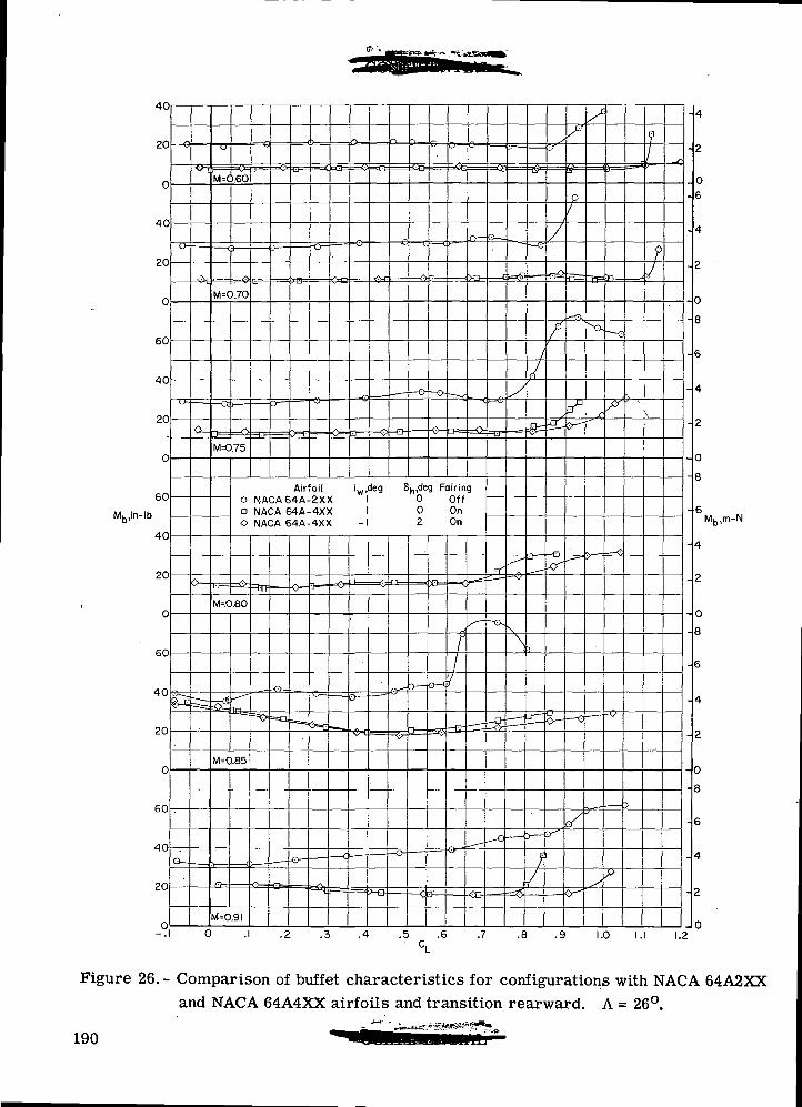
40
20
40
20
60
40
20
60
Mb,in-lb
M=0.6O
M=O.70
M=0.75
Airfoil iw,deg 8j,,deg Fairingo NACA64A-2XX I 0 OffD NACA 64A-4XX I 0 OnO NACA 64A-4XX -1 2 On
.1 .2 .3 .4 .5 .6
27
-4
2
06
4
2
0
8
6
4
2
0
8
6I
4
2
0
8
6
4
2
0
8
MK,m-N
.9 1.0 I.I 1.2
Figure 26.- Comparison of buffet characteristics for configurations with NACA 64A2XXand NACA 64A4XX airfoils and transition rearward. A = 26°.
190
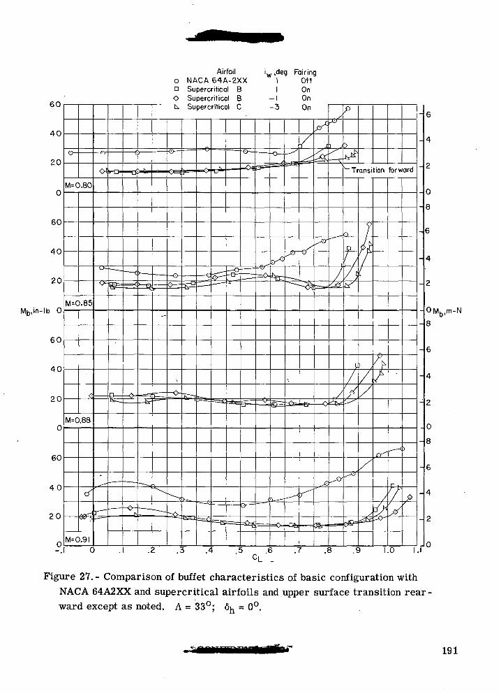
60
40
20
M=0.80
60
40
20
Mt,,in-lb 0
60
40
20
60
40
20
M=0.85
M=0.88
cT
M=0.9I
Airfoil0 NACA 64A-2XXa Supercritical BO Supercritical Bt^ Supercritical C
w ,deg Fairing1 Off1 On
-1 On-3 On
.1 .2 .3 .4 5 .6CL .
r
- 6
.7 .8
OMK,m-Nb,
8
1.0 I.I
Figure 27. - Comparison of buffet characteristics of basic configuration withNACA 64A2XX and supercritical airfoils and upper surface transition rear -ward except as noted. A = 33°; 6^ = 0°.
191
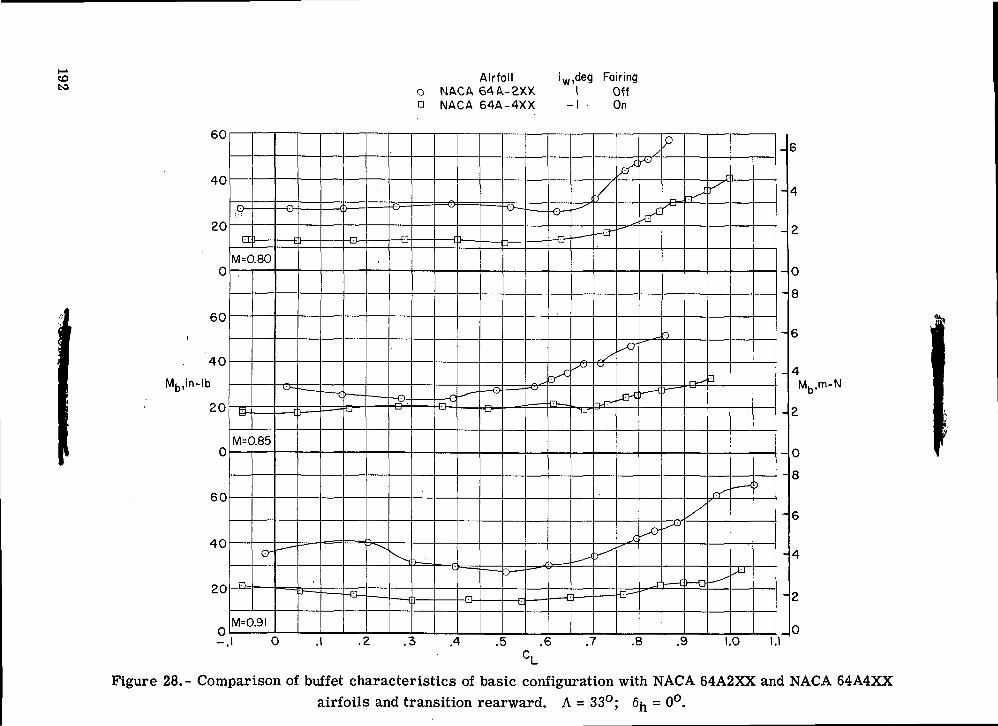
s O
O
•S--
x x
X X
-- ^ ^
t<
<£ IO
<£ <
O O
O n
.
ID
H3•*CO
<O£CD
° o
'55
°
c oO
co
•S
co
•aortO
S S^
wto
S
o
^rt
3
S
w*3
1—
1
° 'S
•s t:
•s
O I
Q,
O0cCMCDbe
192
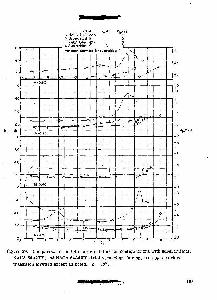
40
20
60
40
20
Mb,in-lb
60
40
20
60
40
20
^}
M=0.80
M=0.85
M=0.88
M=0.9I
Airfoil L.deg 8h,degO N A C A 6 4 A - 2 X X I -2n Supercritical B -1 0O NACA 64A-4XX -I 0k Supercritical C -3 0
(transition rearward for supercritical C)
.2 .3 .5 .„ .6 .7 .8 .9 1.0
Mb,m-N
Figure 29.- Comparison of buffet characteristics for configurations with supercritical,NACA 64A2XX, and NACA 64A4XX airfoils, fuselage fairing, and upper surfacetransition forward except as noted. A = 39°. .
193
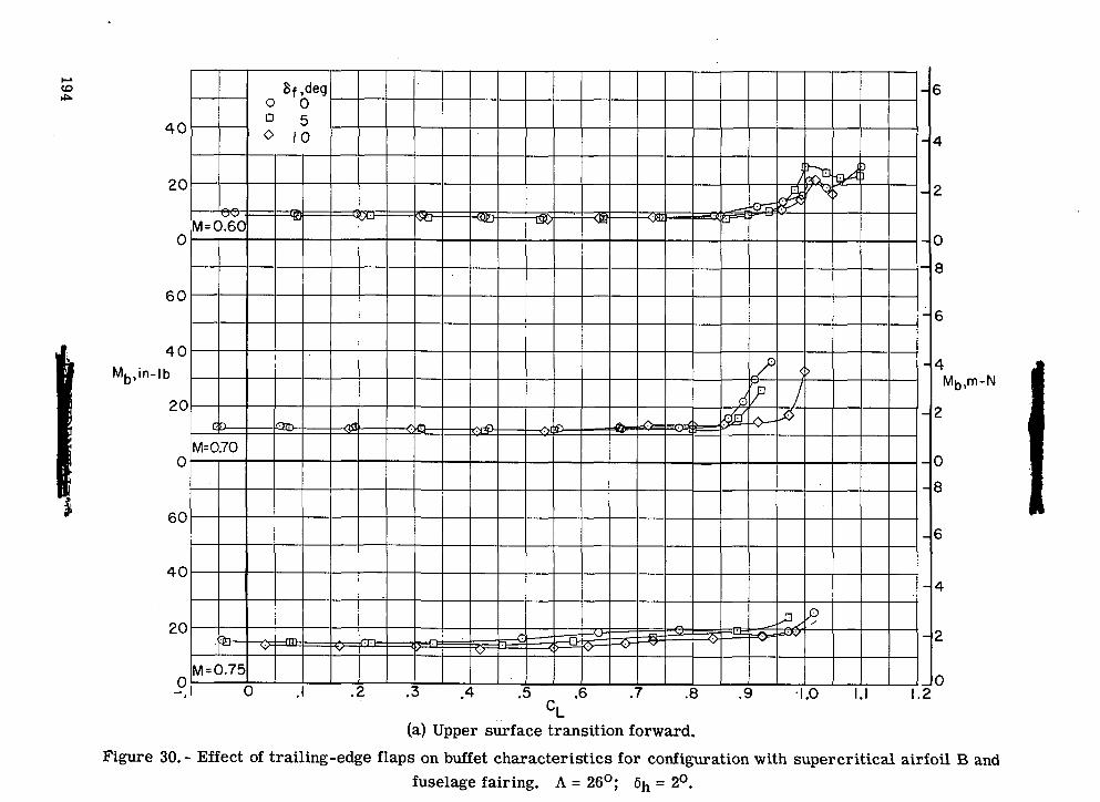
I£
<£CM
O
CO
COCM
O
CO
(OCM
O
°.O
ID O
00o a
o
fI<P
\s
?94o
o«•oC
Mo(D
OOCD
I CM
O)
TJf-,rt
«2c
toIDrtfHgw
roCM
o,
1PQoCO<D
194
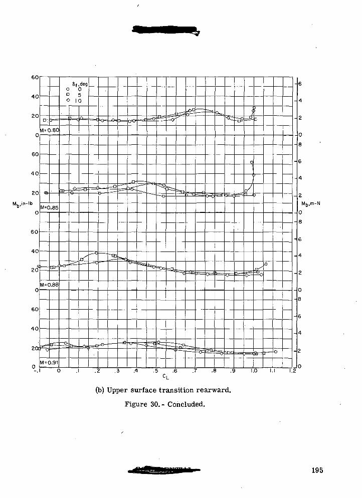
Mb,in-lb
bU
40
20
0
60
40
20
b
0
60
40
203
0
60
40
-,
DT ••>—
M^O.801
M=0.85
M = 0.88
V
M = 0.9I
Sf ,dego 0D *>
0 10
m-
=^ -
^
rrx
.
==E
" ~
P=e
=o-
-O-
-n-
_ —
.— — '
- >
o<^=s£
.^ — —
^- i
=^
=c^
— <^
3=0
^
-<^
Sr:
^_____
-^
3i=
— — .
r^2
==T>
-x
1_S^
-lilt
^-^~_-x^
^J
O=^
0^
^
r —
-^
•x^-
'
o1
r/J <j
5=
>
^
^
SF=
o
-o
0 . .2 .3 .4 .5 .6 .7 .8 .9 1.0 I.I 1 2
6
4
2
0
8
6
4
2
N
0
8
6
4
2
0
8
6
4
2
0
(b) Upper surface transition rearward.
Figure 30.- Concluded.
195
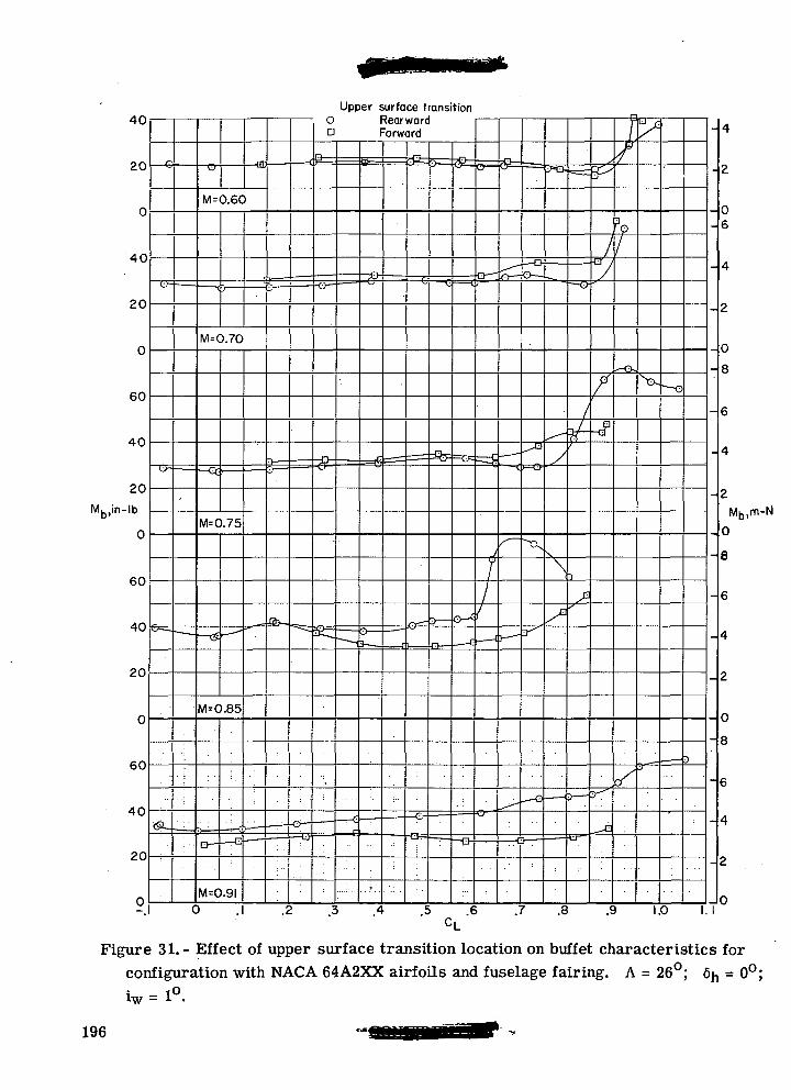
40
20
40
20
60
40
20
Mb,in-lb
0
60
40
20
60
40
20
0
M=0.60
M=0.7O
M=0.75
M=0.85
M=0.9I
Upper surface transitionO RearwardD Forward
7
0 .1 .2 .3 .4 .5 .6 .7 .8 .9 1.0 I.I
Figure 31.- Effect of upper surface transition location on buffet characteristics forconfiguration with NACA 64A2XX airfoils and fuselage fairing. A = 26°; 6^ = 0°;
iw = 1°.
196
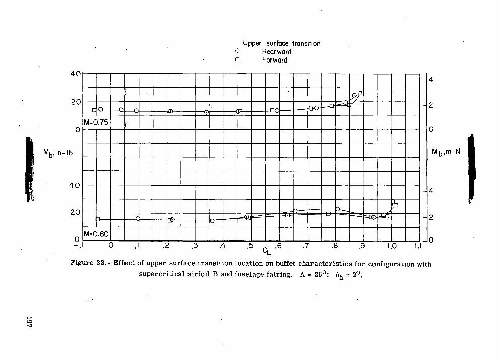
sJ
-o
oO
s
fr c
vj
O
.c
Upper surface transition° Rearwarda Forward
ii
i i
i
ON
1
-
.1
\g
P(EC.GG |I^f'Q
.IT)
OII
^
1(1 ]t1LToQ
§n
.2 .3 .4 .5 _ .6 .7 .8 .9 1.0 I.ICL
Df upper surface transition location on buffet characteristics for configuration witsupercritical airfoil B and fuselage fairing. A = 26°; 6h = 2°.
-MOCD
Wo
,COCD3
o
o
o
o
o
o i"
-SP
^J- CV
J _
rt- C\J
P>H
197
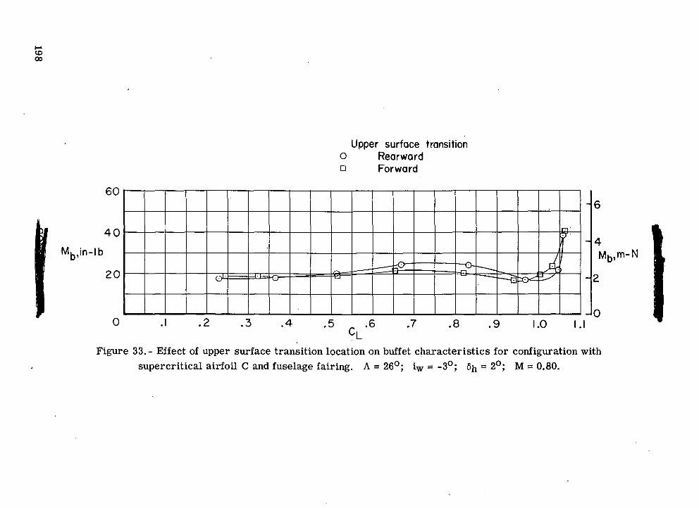
I£.a
OJ
(APsl-gO0)
O
CDa.
CLo a
i§ou
O
ocooti
CO
cu
oII<o
oCO
O0)
oCD
CM
coooo
3!H'3«*H0)
to
£
cos-,
35
CD
a>
CO
CQC
O0)
a
198
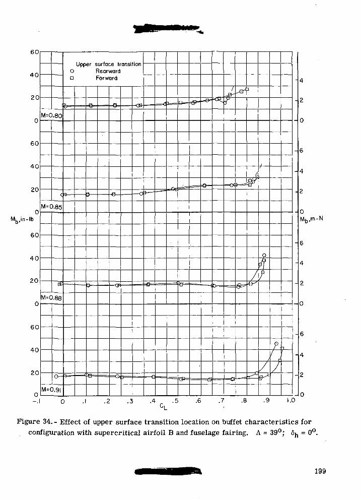
60
40
20
0
60
40
20
Mb,in-lb
60
40
20
60
40
20
M=0.80
C 3-
= 0.85
M=0.88
M=0.9I
Upper surface transitiono Rearwardn Forward
-£.
.2 .3 .4 . .5 .6 .7 .8 .9
0Mb,m-N
1.0
Figure 34.- Effect of upper surface transition location on buffet characteristics forconfiguration with supercritical airfoil B and fuselage fairing. A = 39°; 6n = 0°.
199
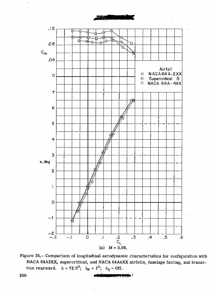
.12
.08
.04
0
a.deg
-I
-2
E
I
Airfoilo NACA64A-2XXa Supercritical BO NACA 64A-4XX
0 .1 .2 .3 .4 .5 .6
(a) M = 0.95.
Figure 35. - Comparison of longitudinal aerodynamic characteristics for configuration withNACA 64A2XX, supercritical, and NACA 64A4XX airfoils, fuselage fairing, and transi-tion rearward. A = 72.5°; iw = 1°; 6h = Off.
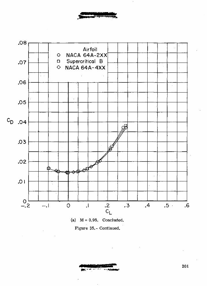
.07
.06
.05
D .04
.03
.02
.0
-.2 -.1
Airfoil0 NACA 64A-2XXa Supercritical BO NACA64A-4XX
0 .2 .3
(a) M = 0.95. Concluded.
Figure 35.- Continued.
.4 .5 .6
201
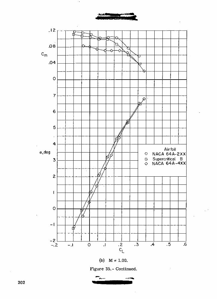
.12
.08
.04
0
a,deg
-I
-2-.2
•x,
V
Airfoilo NACA 64A-2XXa Supercritical BO NACA 64A-4XX
0 .1 .2 .3 .4 .5 .6
(b) M = 1.00.
Figure 35.- Continued.
202
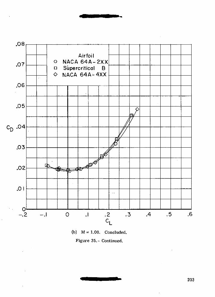
.07
.06
.05
CD -04
.03
.02
.01
0/•*
c
Airfoil0 N A C A 6 4 A - 2 X Xa Supercritical BO NACA 64A-4XX
!^.«fii
ib=^-n^*£f
/"$
If
//
oUV
7
-.1 0 .1 .2 .3 .4 .5 .6CL
(b) M = 1.00. Concluded.
Figure 35.- Continued.
203

Cm '°8
.04
a,deg
0
-I &
J
\
L
X)
Airfoil0 NACA 64A-2XXD Supercritical B0 NACA 64A-4XX
0 .2 .3 .4 .5 .6
(c) M=1.03.
Figure 35.- Continued.
204
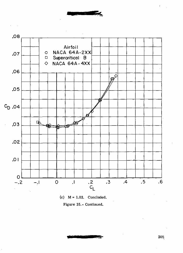
.08
.07
.06
.05
.04
.03
.02
.01
0-.2
q
Airfoilo NACA 64A-2XXQ Supercritical BO NACA 64A-4XX
*B-J
(sH^^yvS
it*
i
s
1,/$
<^>V
i -.1 0 .1 .2 .3 .4 .5 .6CL
(c) M = 1.03. Concluded.
Figure 35.- Continued.
205
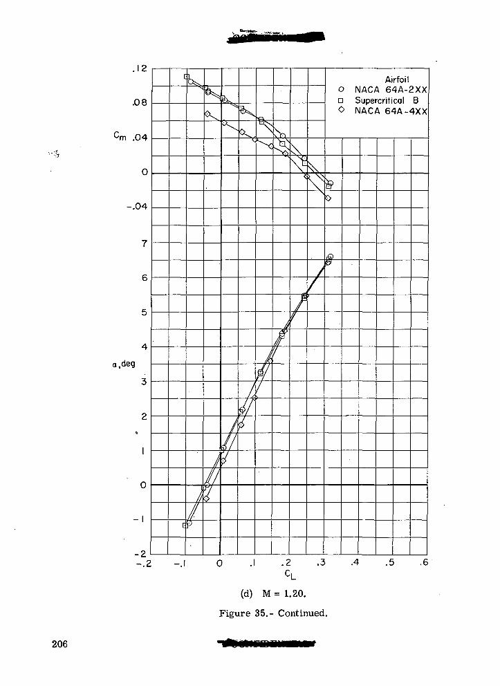
.12
.08
.04
0
-.04
a,deg
-I
-2-.2
L4L
O
Airfoilo NACA 64A-2XXa Supercritical B0 NACA 64A-4XX
.2 .3 .4 .5 .6
(d) M = 1.20.
Figure 35.- Continued.
206
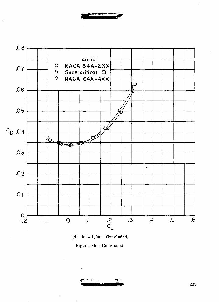
.07
.06
.05
.04
.03
.02
.01
0-.2
c
Airfoil0 N A C A 6 4 A - 2 X XE Supercritical BO NACA 64A-4XX
J K _
*^
-.1 0
^
$'
&
//
'
//
f
$
.2 .3 ,4 .5 .6
(d) M=1.20. Concluded.
Figure 35.- Concluded.
207
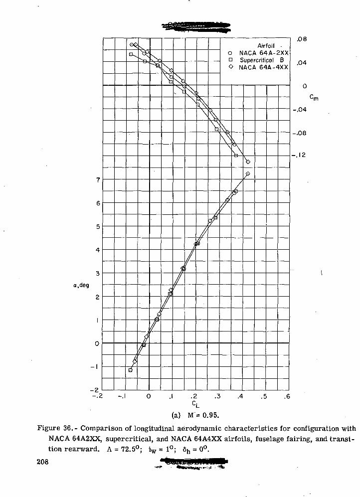
a,deg
-2
d
0
Airfoil •0 NACA 64A-2XXD Supercritical BO NACA 64A-4XX
.2 .3 .4 .5
.08
.04
•rn
-.04
-.08
-.12
.6
(a) M = 0.95.
Figure 36.- Comparison of longitudinal aerodynamic characteristics for configuration withNACA 64A2XX, supercritical, and NACA 64A4XX airfoils, fuselage fairing, and transi-tion rearward. A = 72.5°; iw=l°; 6h = 0°.
208
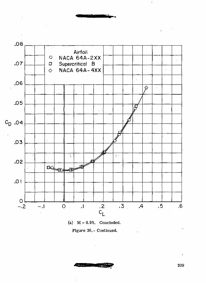
.08
.07
.06
.05
CD .04
.03
.02
.01
0-.2
Airfoilo NACA 64A-2XXn Supercritical BO NACA 64A-4XX
Fto
\
=^ j ^^XJy
«r
y
/
/
rrf
/\ '
f
f\f
f
-.1 0 .1 .2 .3 . .4 .5 .6
(a) M = 0.95. Concluded.
Figure 36.- Continued.
209
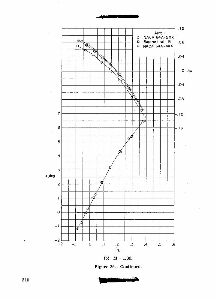
a.deg
GO
-2-.2 -.1
N\
Airfoil0 NACA 64A-2XXn Supercritical B0 NACA 64A-4XX
0
.12
.08
.04
0 Cm
-.04
-.08
-.1 2
-.16
.2 .3 .4 .5 .6
(b) M = 1.00.
Figure 36.- Continued.
210
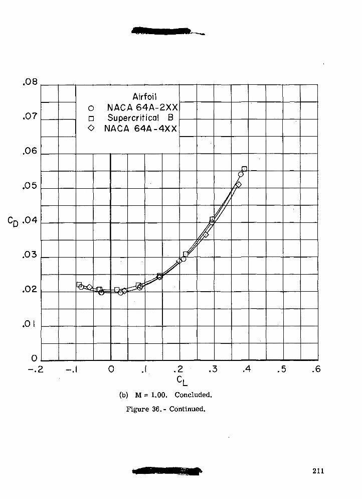
.08
.07
.06
.05
CD .04
.03
.02
.01
0—.2
Airfoil0 NACA 64A-2XXn Supercritical B0 NACA 64A-4XX
%= ^^
/c/p
£
y
///
n
k7
> -.1 0 .1 .2 .3 .4 .5 .6
(b) M = 1.00. Concluded.
Figure 36.- Continued.
211
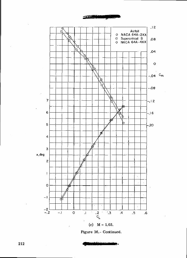
a,deg
7
6
5
4
3
2
1
0
1
2-.2
c
0
\
ff//3
\N
/
f
\
Ll ^
\
I/
f
Nd
/
^S
J
/
\\\
/
\V
\
r
.\\\
<
/
Airfoil0 NACA 64A-2XXa Supercritical B0 NACA 64A-4XX
k
\
/
y\
^
\3
. 1 c.
.08
.04
0
.04 Cm
-.08
-J 2
-.16
-.20
0 .1 .2 '.3 "A .5 .6c.
(c) M = 1.03.
Figure 36.- Continued.
212
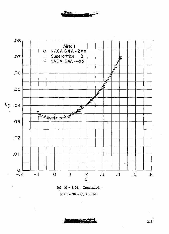
.07
.06
.05
CD .04
.03
.02
.01
0-.2
F(
Airfoilo N A C A 6 4 A - 2 X Xn Supercritical BO NACA 64A-4XX
fes* a^
-.1 0
0^y?P T ^
X/
Jf
;f\' ?
.2 .3 .4 .5 .6
(c) M = 1.03. Concluded.
Figure 36.- Continued.
213
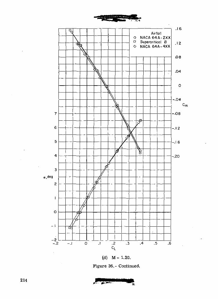
«,deg
7
6
5
4
3
2
1
0
1
-2-.2
^
/t£
V<$
rrf
XX/
\
^
r
I/ry
\.
\^
f,$
L
^
//j
2
V^
k
\,\\
/5
^
/0
\
/f
Airfoil0 N A C A 6 4 A - 2 X XD Supercritical B0 NACA 64A-4XX
y\
\
n
^
k%
-.1 0 .1 .2 .3 .4 .5 .6
CL
.1 D
.12
.08
.04
0
n/i
-.08
-.12
—.1 D
-.20
(d) M = 1.20.
Figure 36.- Continued.
214
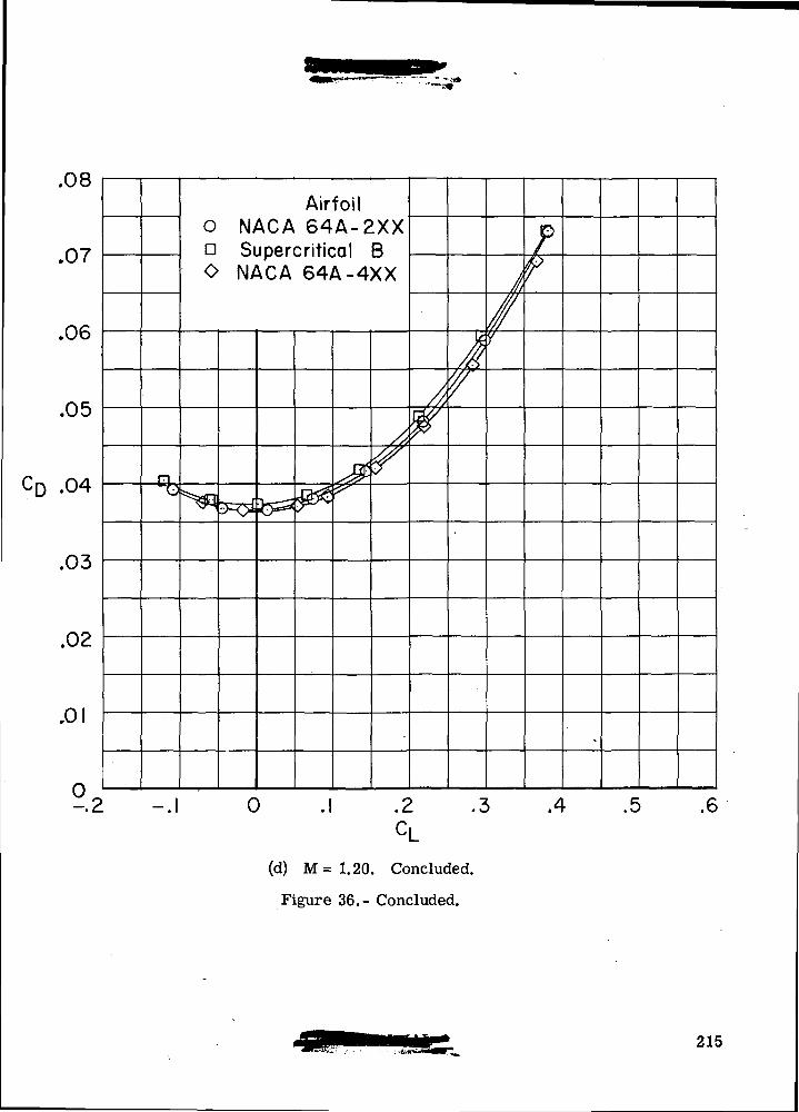
.uo
.07
.06
.05
CD .04
.03
.02
.01
°2
Airfoilo NACA 64A-2XXa Supercritical BO NACA 64A-4XX
s&
/*?//<
W
J'//
//,/y
/r
^
-.1 0 .1 .2 .3 ,4 .5 .6
CL(d) M= 1.20. Concluded.
Figure 36.- Concluded.
215
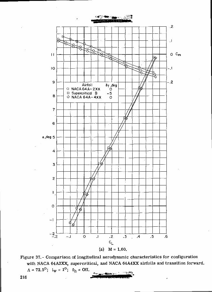
1 1
10
9
8
7
6
a,deg 5
4
3
2
1
0
-1
-2,— . c
CQs.k .
^
[k
33- -r>
^^
Ni
•o^ P-JV
" ^1
^s
Airfoil 8f ,deg0 NACA64A-2XX 0P Supercritical B -5O NACA 64A-4XX 0
c
;/ /V
)/ /
$
^
r
//
7
/
//Y
/
41
^'/
/!
/
^
jrf
//1
^
////
^
f/
//f
\.
//
Vf
I
///Ay^~
I -.1 0 .2 .3 . .4 .5 .6
.2
0 Cm
-.2
(a) M = 1.60.
Figure 37. - Comparison of longitudinal aerodynamic characteristics for configurationwith NACA 64A2XX, supercritical, and NACA 64A4XX airfoils and transition forward.A-72.5°; iw= 1°; 6h = Off.
216
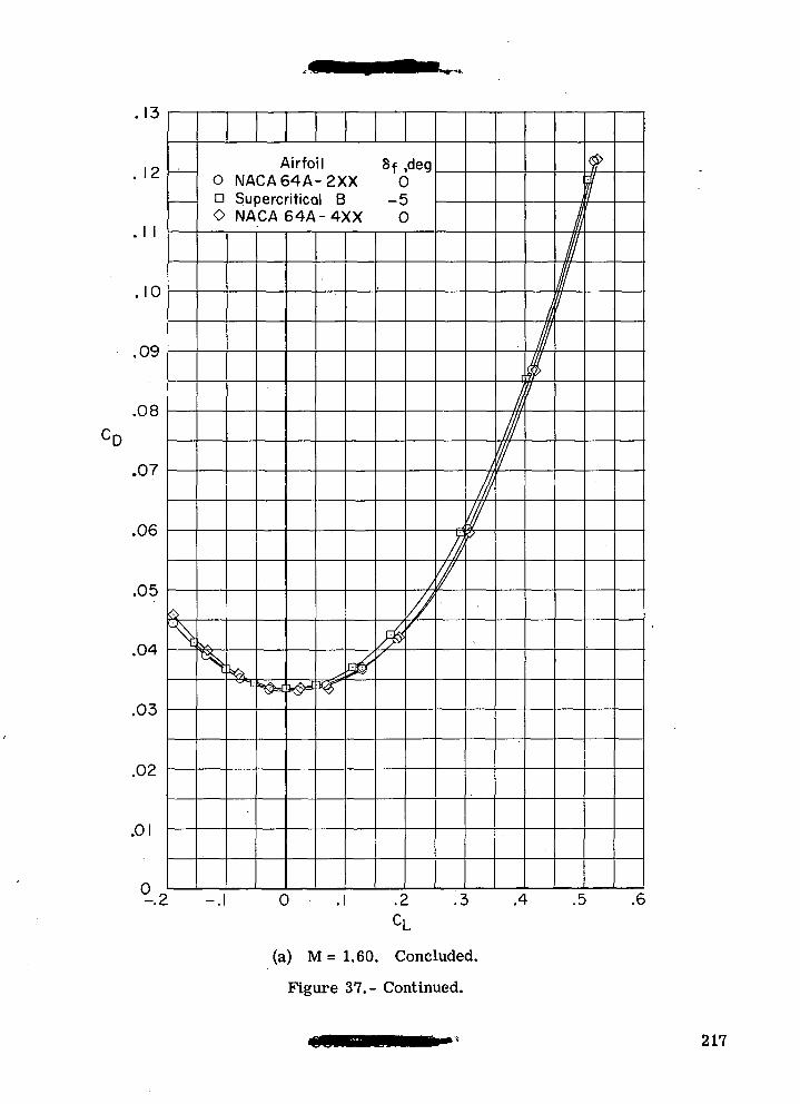
. \J
12
1 1
.10
09
08
07
06
05
04
03
02
01
°2
0
^
Airfoil Sf ,deg0 NACA64A-2XX 0n Supercritical B 5O NACA 64A-4XX 0
y\
1^H:S0*k^,
*# ^
&/
/
////
/
//
iV
[
kIII"'1
ll1
$7
I1//
f
1
0 . .2 .3 .4 .5 .6
CL
(a) M = 1.60. Concluded.
Figure 37.- Continued.
217
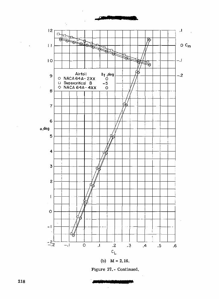
1 £.
\ \
10
9
8
7
6
a,deg
5
4
3
2
1
0
-1
o
Q-
$
13—
==<$^==^H -- ,
^^^p-c-^f>s@
Airfoil 8f ,deg0 NACA64A-2XX 0a Supercritical B -5O NACA 64A-4XX 0
-22 -.
/
MS3
c
/Ip<p
/
f-II¥v
/
flIII$
d>n'/K
4if!
^
///
//1
/}M7
^ -s
/////
/J
^
If1
. 1
0
.1
?
0 . .2 .3 ' .4 .5 .6
CL
(b) M = 2.16.
Figure 37.- Continued.
'm
218
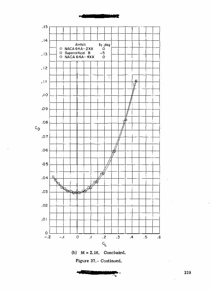
. i a
.14
.13
. 12
.1 1
.10
.09
.08
.07
.06
.05
.04
.03
.02
.01
0r
q,$
Airfoil Sf ,deg0 NACA64A-2XX 0D Supercritical B -5O NACA64A-4XX 0
\a
> _
%It_IJjjj h-3fsHi/p\/
•
////
/^if
////
I
/
I
f//
0 .2 .3 .4 .5 .6
c,
(b) M = 2.16. Concluded.
Figure 37.- Continued.
219
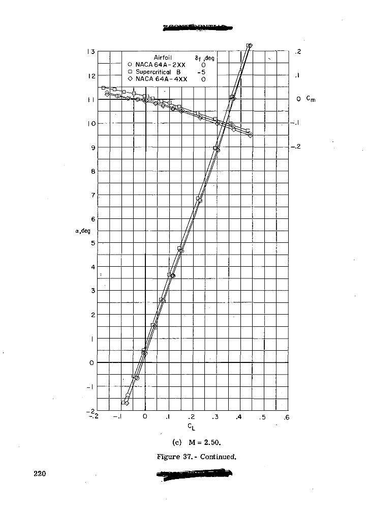
1 O
12
1 1
10
9
8
7
6
a.deg
5
4
3
2
1
0
1— 1
--22
9-a —
^
Airfoil 8f ,deg0 NACA64A-2XX 0o Supercritical B -5O NACA64A-4XX 0
•*r SV-
I
#
V-G
/
Vi
^
j
J/Ff5
^//
6^/
rf
//IIIj
^^lt-*s!
///
//1
%
,
Afri
^
J,
I1'/I
/
dfI*>
II
m1
fe^
///
-s
0 . .2 .3 .4 .5 .6CL
.2
(c) M=2.50.
Figure 37.- Continued.
0 Cm
-.2
220
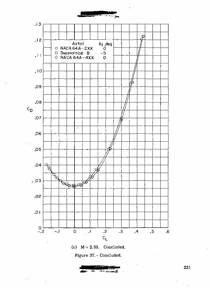
. 1 3
.12
.1 1
. 10
.09
.08
.07
.06
.05
.04
.03
.02
.01
0/•
\
Airfoil Sf ,deg0 NACA64A-2XX 0n Supercritical B -5O NACA64A-4XX 0
n
^k§
—
rf^^
w
ft
1
//y
iJ/f
ftII'/
I
'1•}
1
11
f1
$1I1
> -.1 0 .1 .2 .3 .4 .5 .6
CL
(c) M = 2.50. Concluded.
Figure 37.- Concluded.
221
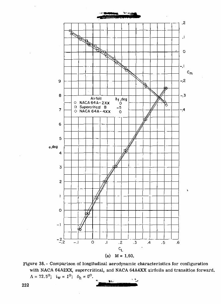
8
.deg
~-22
K
Airfoil Sf ,deg0 NACA64A-2XX 0a Supercritical B -5O NACA64A-4XX 0
V
A
. .2 .3 .4 .5
.2
-2
-.3
— 4
.6
(a) M = 1.60.
Figure 38. - Comparison of longitudinal aerodynamic characteristics for configurationwith NACA 64A2XX, supercritical, and NACA 64A4XX airfoils and transition forward.A= 72.5°; iw= 1°; 6h = 0°.
222
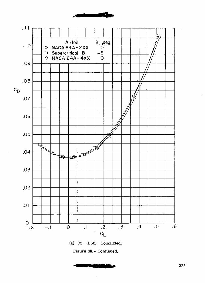
'D
• 1 1
.10
.09
.08
.07
.06
.05
.04
.03
.02
.01
0—.2
Airfoil 8f ,deg0 NACA64A-2XX 0n Supercritical B -5O NACA64A-4XX 0
s
> _^
"1£
*
,
A
$
///
V
//,//7
I
MY
Itii
}iIfi
f
0 .1 .2 .3 .4 .5 .*
(a) M = 1.60. Concluded.
Figure 38.- Continued.
223
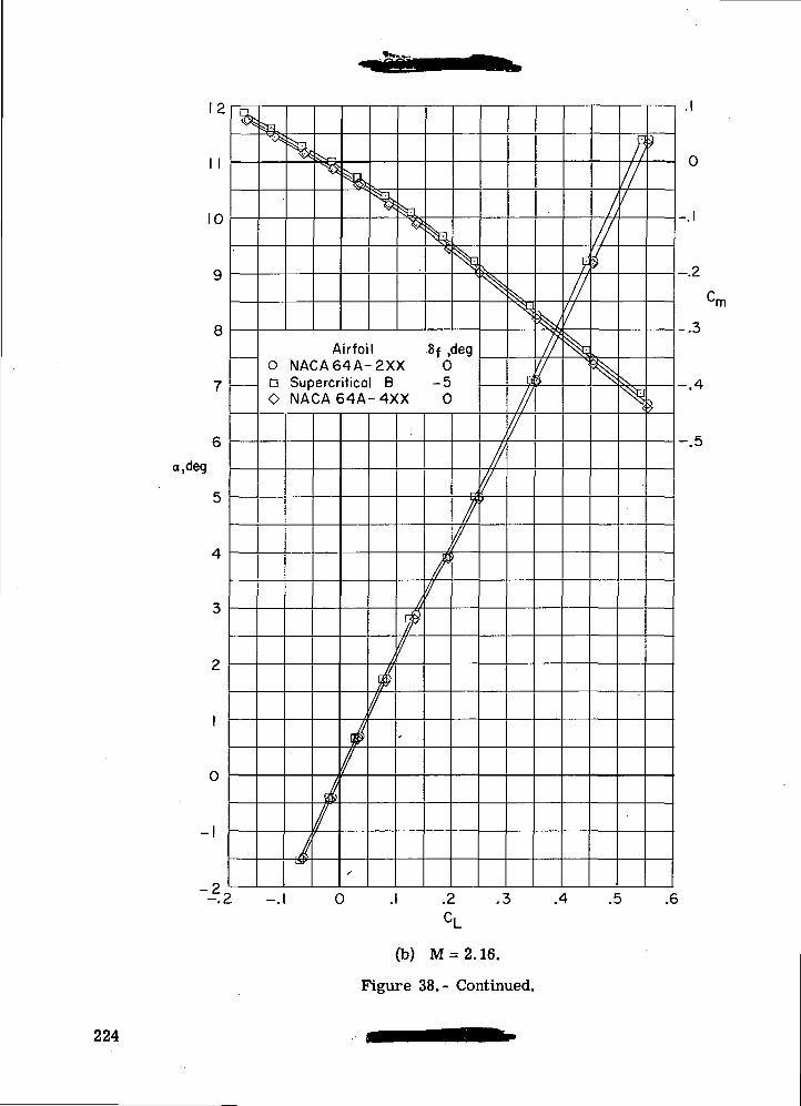
1 1
10
8
a,deg
0
-2
N^
Airfoil 8f ,deg0 NACA64A-2XX 0D Supercritical B -5O NACA 64A-4XX 0
-.2 -.1 0
/
.2 .3 .4 .5
0
-.2
-.3
-.4
-.5
.6
(b) M = 2.16.
Figure 38.- Continued.
224
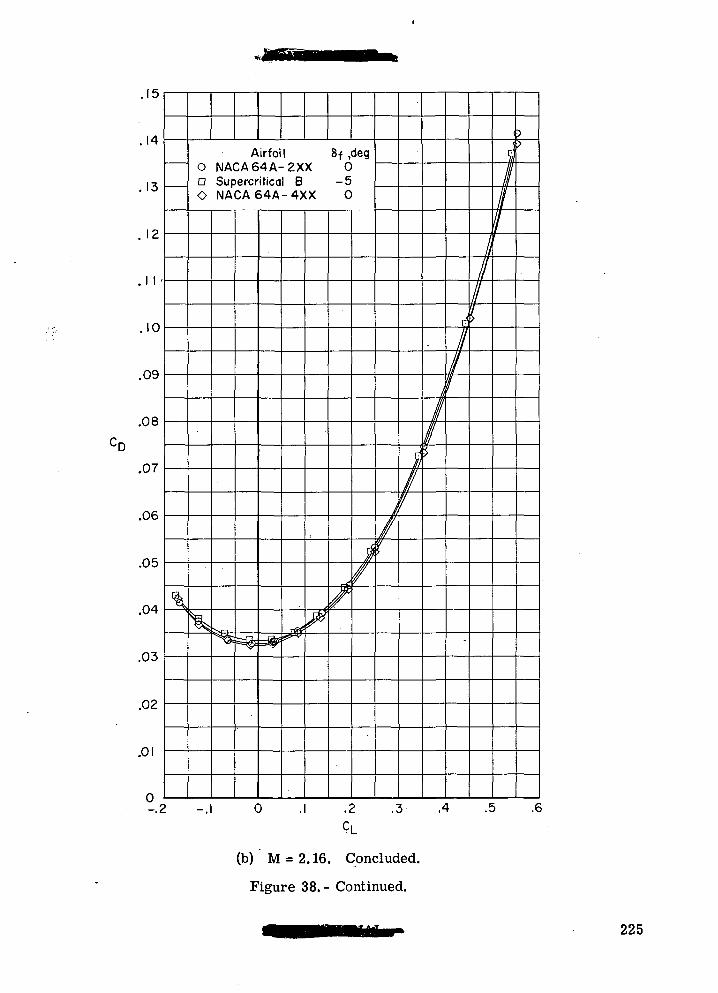
. 1 D
.14
.13
. 12
.1 1 •
.10
.09
.08
.07
.06
.05
.04
.03
.02
.01
0-.2
\
Airfoil 8f ,deg0 NACA64A-2XX 0D Supercritical B -5O NACA64A-4XX 0
%"«« -l
-%
^
rfif*#*JUX
r
//
t,
1
P
V
V
I,
1Ii
ij
/f
-
I
F
/
/7
p>
-.1 0 .1 .2 .3 .4 .5 .6
CL
(b) M = 2.16. Concluded.
Figure 38.- Continued.
225
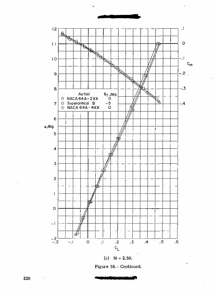
12
I I
0
8Airfoil 8f ,deg
O NACA64A-2XX 0n Supercritical B -5O NACA64A-4XX 0
a,deg
0
-I III
I
III
III
III
a/
'10
-.2
-.3
-.4
-2-.2 -.1 0 .1 .2 .3 .4 .5 .6
CL
(c) M = 2.50.
Figure 38.- Continued.
226
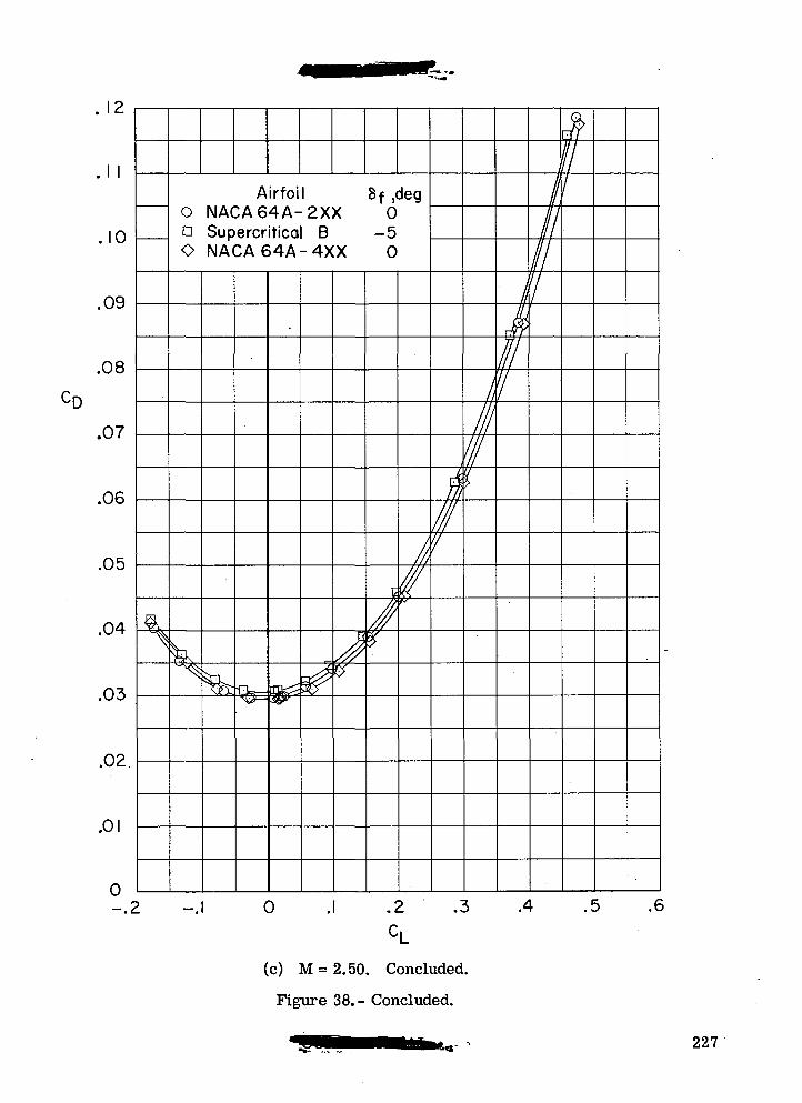
. I t-
.1 1
.10
.09
.08
.07
.06
.05
.04
.03
.02.
.01
0f
%\
Airfoil Sf ,deg0 NACA64A-2XX 0n Supercritical B -5O NACA64A-4XX 0
^ ^hr •Q^_i
^^
J
t
/%
//,/
ill///'/
!i111!I.
1k
//1
1
iI11
J>/1
> -.1 0 . .2 .3 .4 .5 .6
(c) M = 2.50. Concluded.
Figure 38.- Concluded.
227
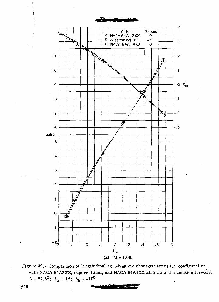
II
10
9
8
7
6
a,deg
5
4
3
2
1
0
-1
o
k^
'[
/
If®
%
/f
^su%
A
/
\
^
/''
Airfoil 8f ,deg0 NACA64A-2XX 0n Supercritical B -5O NACA64A-4XX 0
«&S•
A4
V
/
s
f/
.
/)
\,
//
>i'
//\
1
//'/
\\
ffi?
^
.a,
.3
.2
.1
o cm
-.1
j>
-3.
0 .1 .2 .3 .4 .5 .6CL
(a) M = 1.60.
Figure 39. - Comparison of longitudinal aerodynamic characteristics for configurationwith NACA 64A2XX, supercritical, and NACA 64A4XX airfoils and transition forward.A = 72.5°; iw= 1°; 6h = -10°.
228
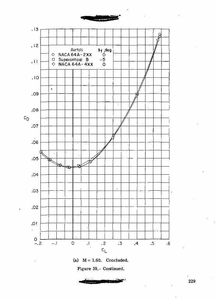
13
1 I
10
.09
.08
.07
.06
.05
.04
.03
.02
.01
Airfoil 8f ,deg0 NACA64A-2XX 0n Supercritical B -50 NACA64A-4XX 0
-.2 0 .2 .3 .4 .5 .6
(a) M = 1.60. Concluded.
Figure 39.- Continued.
229
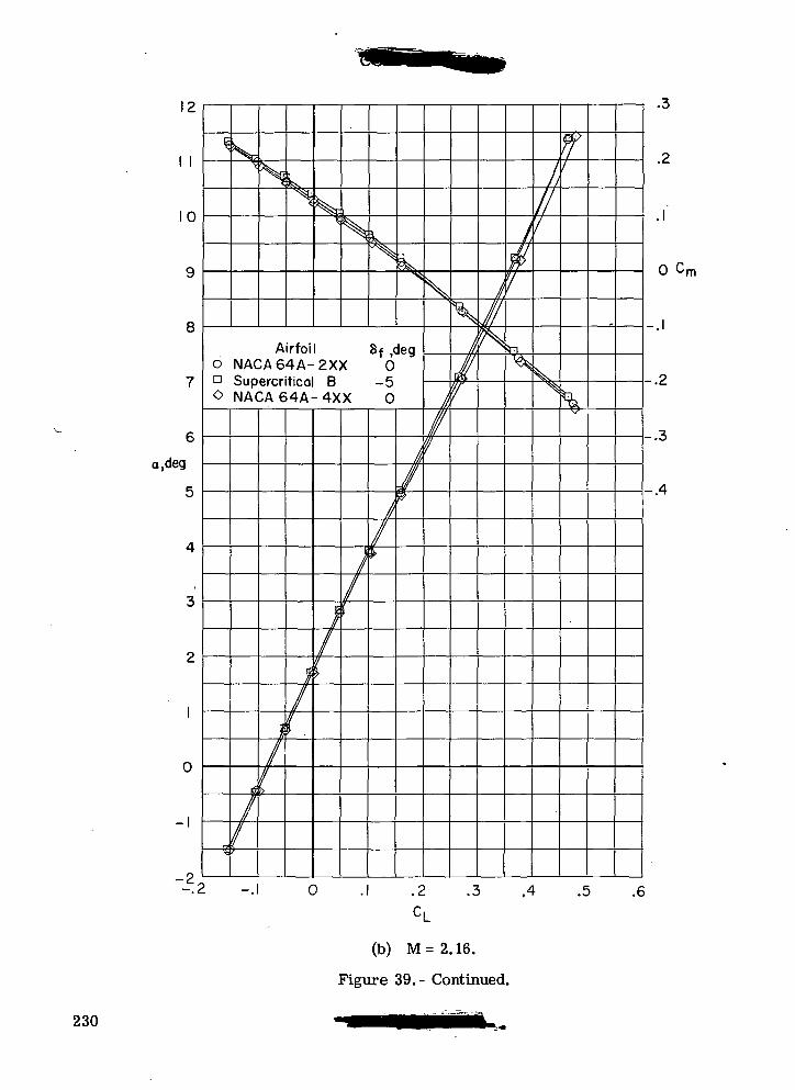
\ <L
\ \
10
9
8
7
6
eg
5
4
3
2
1
0
-1
-2,— . f.
\Hsk
<£S
Airfoil0 NACA64A-2XXD Supercritical B0 NACA64A-4XX
P
^
^/
/
n//
i/r
;/f
i
/(
kJ>PL^
8f ,deg0
0
1
/\
/
/p
v
/f
^^^v
^mr!/'
y/N
/
^7
^
/
///
^
r'
- --I 0 .1 .2 .3 .4 .5 .6UL
(b) M=2.16.
Figvire 39.- Continued.
.3
.2
0 Cr
-.2
-.3
-.4
230
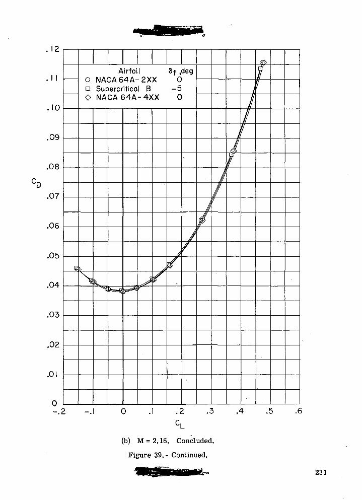
.1 1
.10
.09
.08
.07
.06
.05
.04
.03
.02
.01
0f
i
Ao NACA6D SupercrO NACA(
j>
NIV^
irfoiyi A4 A-
itica54A
^r^-fgZ*^
\ 8f ,deg-2XX 01 B -5-4XX 0
(^r^
> -.1 0
A/4
•
//
/r
1/?
//
1j
I//
<®>
1j
.2 .3 .4 .5 .€CL
(b) M = 2.16. Concluded.
Figure 39.- Continued.
231
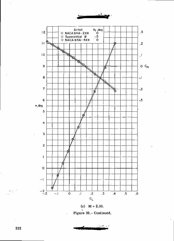
12
II ^
10
9
8
7
6
a,deg
5
4
3
2
1
0
1
-2-.2
»K"S
?
s,
;/2
Airfoil 8f ,deg0 NACA64A-2XX 0a Supercritical B -5O NACA64A-4XX O
L
^
/
/
sJX-1
^//
^
Ji1
^n
^
j|
f
/
0
"^
/t
41
s
ftI'I
•
ll$I
d
ll
1
r
*\
r
//f
\v
N
>
.2 .3 .4 .5 .6
CL
o cm
-.2
-.3
(c) M = 2.50.V
Figure 39.- Continued.
232
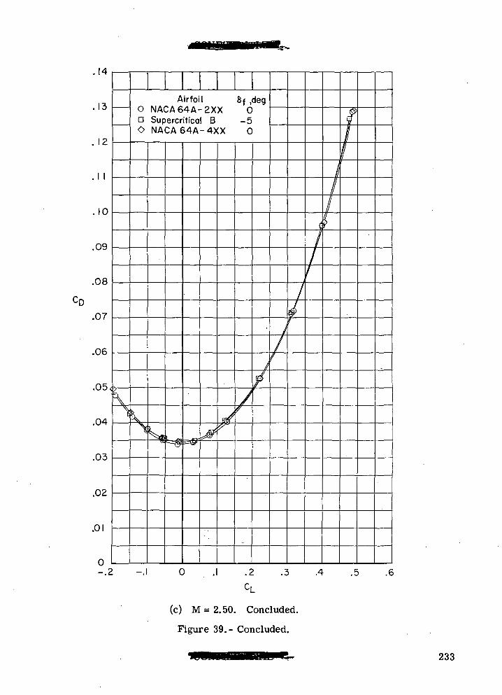
14
13
12
I I
10
.09
.08
.07
.06
.05,
.04
.03
.02
.01
Airfoil 8f ,degO NACA64A-2XX 0Q Supercritical B -5O NACA 64A-4XX 0
0-.2 -.1 0 .1 .2 .3 .4 .5 .6
(c) M = 2.50. Concluded.
Figure 39.- Concluded.
233
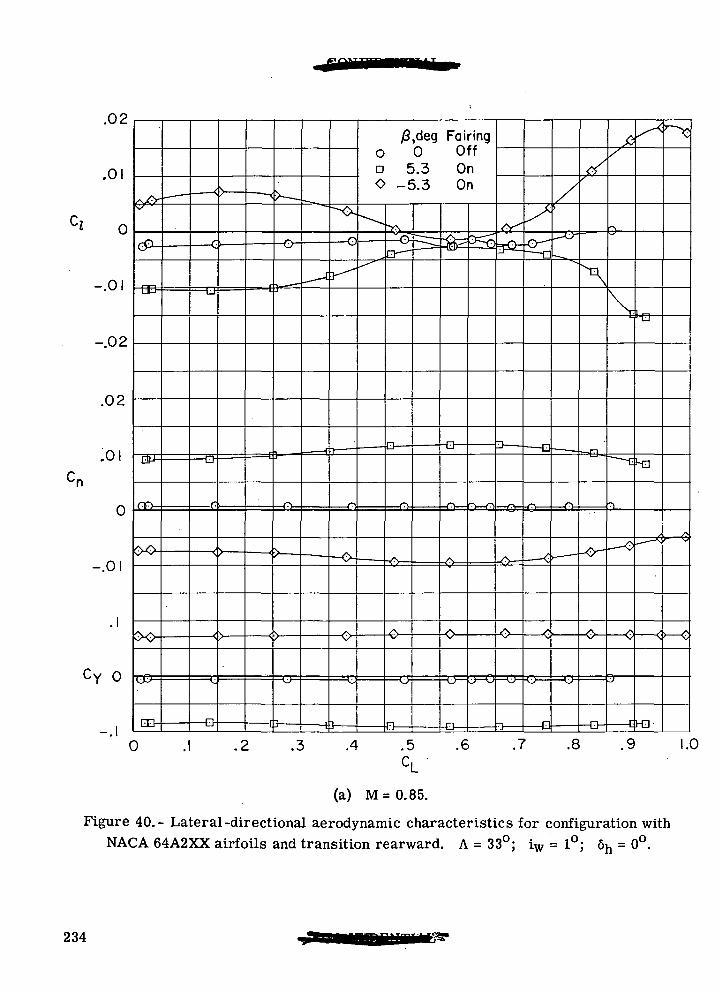
.02
0
-.01
-.02
.02
.01
-.01
cY o
-.1 -Q •13 [}
£,deg Fairingo 0 Offa 5.3 OnO -5.3 On
0 .1
•Q-
.3 .4 .5 .6 .7 .8 .9 1.0
(a) M = 0.85.
Figure 40.- Lateral-directional aerodynamic characteristics for configuration withNACA 64A2XX airfoils and transition rearward. A = 33°; iw = 1°; 6h = 0°.
234
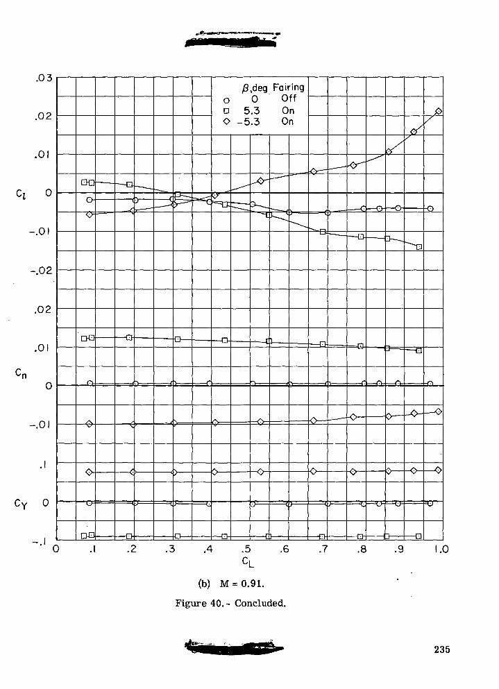
.03
.02
-.01
-.02
.02
.01
-.01
CY o
o
-Cfc
DO -O
.2
O-
/3,deg Foiringo 0 Offa 5.3 OnO -5.3 On
-B
-Q
-Cl
.3 .4 .5 .6 .7<3——n
.8 .9 .0
(b) M = 0.91.
Figure 40. - Concluded.
235
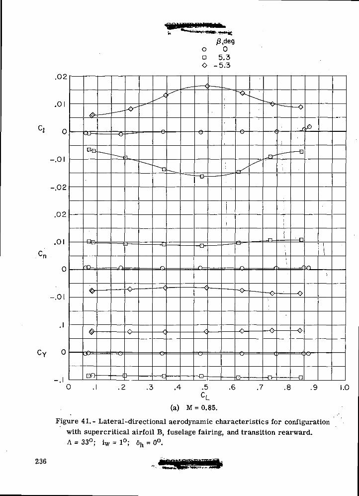
.02
.01
o
-.01
-.02
.02
.01
0
-.01
CY o
o[DO
=0:
O-
=c
-e- -n.2 .3 .4 .5 .6 .7 .8 .9
(a) M = 0.85.
Figure 41.- Lateral-directional aerodynamic characteristics for configurationwith supercritical airfoil B, fuselage fairing, and transition rearward.A = 33°; iw=l°; 6h = 0°.
1.0
236
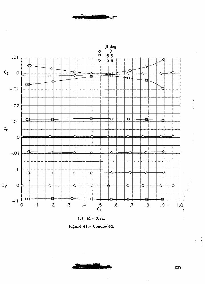
.01
0
-.01
.02
.01
0
-.01
CY
EEh
0
=0=
-D •Q- -D-
-O-
-D
.2 .3 .4 .5 .6CL
(b) M = 0.91.
Figure 41.- Concluded.
.7 .8 .9
237
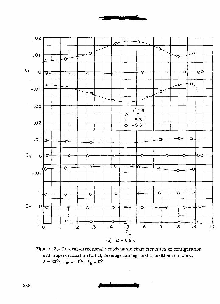
.02
.0!
0
-.01
-.02
.02
.01
0
-.01
CY o •©=
ED-
0
-o
-Q
./y
-O-
=(7
o 0Q 5.3O -5.3
=O=
.2 .3 .4 .5 .6 .7 .8 .9 .0
(a) M = 0.85.
Figure 42.- Lateral-directional aerodynamic characteristics of configurationwith supercritical airfoil B, fuselage fairing, and transition rearward.A =33°; iw= -1°; 6h = 0°.
238
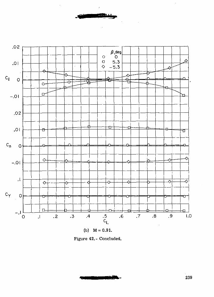
.02
.01
0
-.01
.02
cn 0
-.01
CY 0
0
-B-
O-
D- -D- •13-
.2 .3 .4 .5C,
.6 .7
(b) M = 0.91.
Figure 42.- Concluded.
-D-
.8 .9dIL
1.0
239
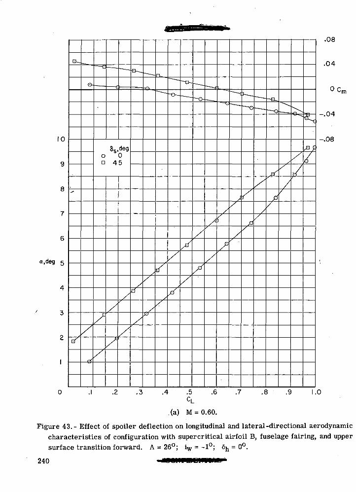
10
6
a.deg
Ss,dego 0a 45
X
zn c
.08
.04
O Cm
-.04
-.08
0 .1 .2 .3 .4 .5 .6 .7 .8 .9 1.0CL
(a) M = 0.60.
Figure 43.- Effect of spoiler deflection on longitudinal and lateral-directional aerodynamiccharacteristics of configuration with supercritical airfoil B, fuselage fairing, and uppersurface transition forward. A = 26°; iw = -1°; 6h = 0°.
240
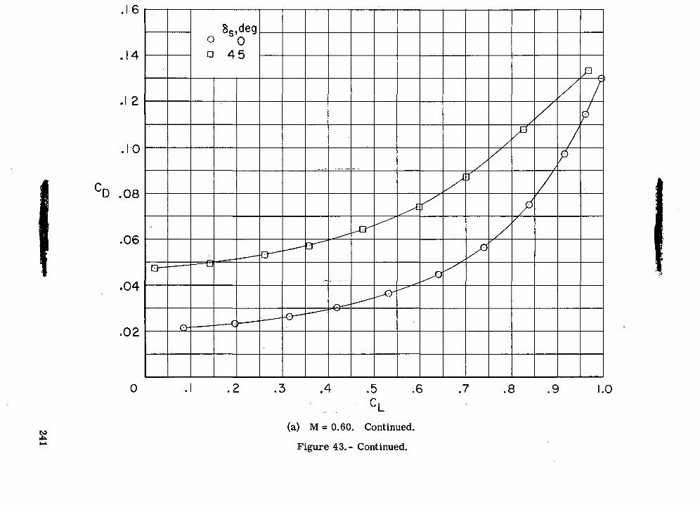
totoO
D
CO
i
00OCOO
CVJo
IT) O
rO
•o18ocooII
OOCO
•=*<0)
QO
241
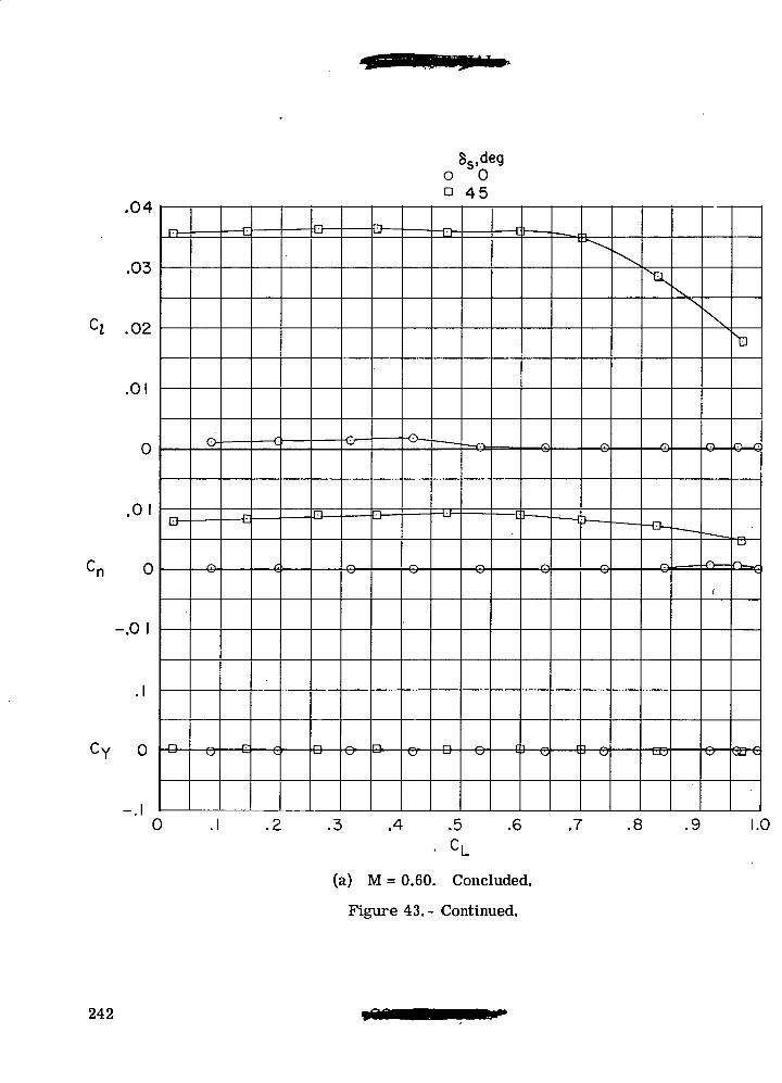
.04
Ss,dego 0D 45
D- :Ct
X
.01
0 o-
tao-
•e-
-.0 I
•e- -e- <J—e -e& •(B-
-.10 .2 .3 .4 .5 .6 .7 .8 .9 1.0
(a) M = 0.60. Concluded.
Figure 43.- Continued.
242
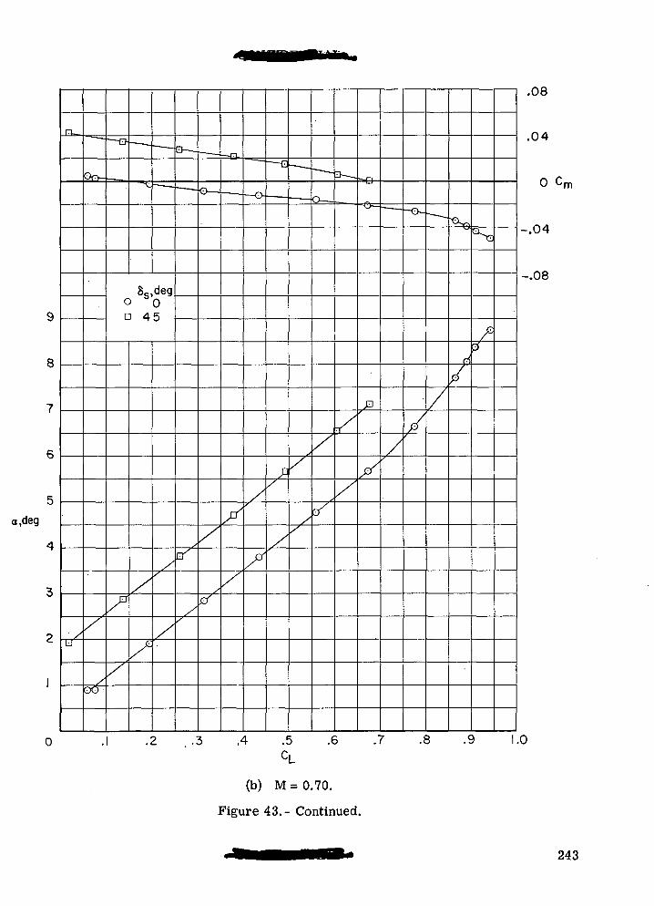
a,deg
8s,deg0
45
,4 .5 .6 .7 .8 .9
(b) M = 0.70.
Figure 43.- Continued.
.08
.04
0 Cm
-.04
-.08
243
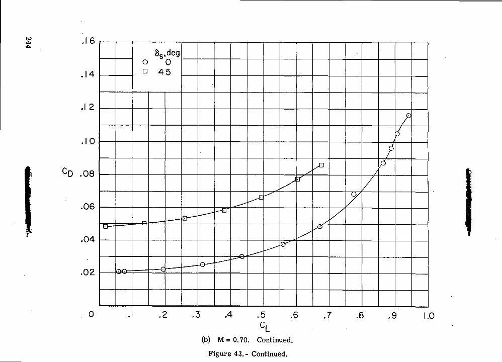
O)
IOV>
60
o a
\
CVJCOo
CDO
kAoCVJO
CDIT)
rOc\J
§oU
TJIcSCO
QO
244
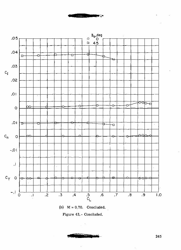
OS
O4.
n*^
C;4
o?
n i
0
0 1i
r PI<-n 0
O 1
i. i
Cw D^ y u
i
LJ—
Q —
-
)
QO-
— D
— D-
G
fT
\.
f>
D
n
•3i
— H—
.4
— 0
"
[
D
E
c
C
ss,4
L
deg
5
3 —
.6
i11---
Tl
~o—
O
.7r
-o-
.6
^— -
1
"t3
.9 1.
(b) M = 0.70. Concluded.
Figure 43.- Concluded.
245
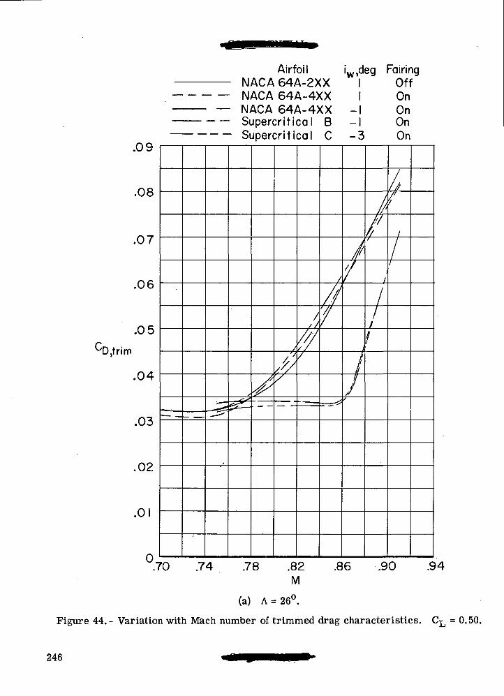
Airfoil iw,deg Fairing
.09
.08
.07
.06
.05CD,trim
.04
.03
.02
.0
0
-2f
- IMMUM OHM-^AA
NACA 64A-4XX• NACA 64A-4XX• Supercritical B- Supercritical C
s
<s**^^
S
/
///
// /
////
" —
/
//7
- • ^y
11
-11-1
-3
/
/
i
//
UTT
OnOnOnOn
//'//
/
///1
///
/
//
.70 .74 78 .82 .86 .90M
.94
(a) A = 26°.
Figure 44.- Variation with Mach number of trimmed drag characteristics. CL = 0.50.
246
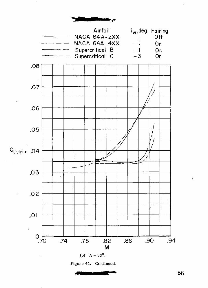
AirfoilNACA 64A-2XXNACA 64A-4XXSupercritical BSupercritical C
w,deg FairingI Off
-I On-I On-3 On
.u«
.07
.06
.05
.04
.03
.02
.01
0.7
~- -» ,_ • — • -"" ^
/
•• — «=-
//
'/
j
/'}
-=^ —
/
^/^~
f
//
I
1'/
'0 .74 .78 .82 .86 .90 .SM
(b) A = 33°.
Figure 44.- Continued.
247
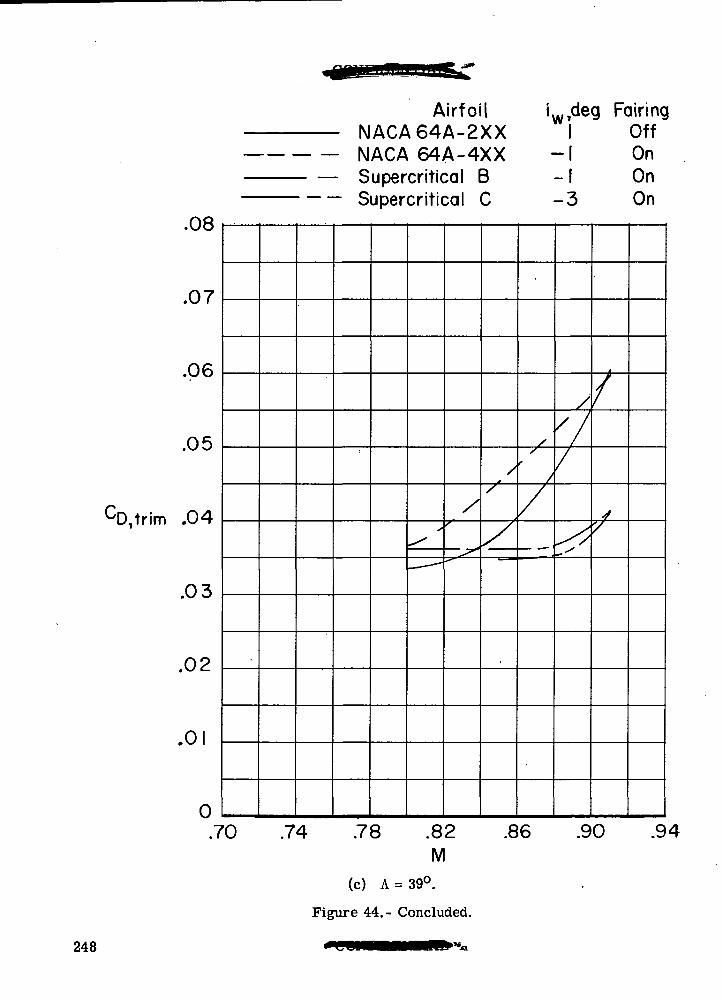
.08
.07
.06
.05
.04
.03
.02
.01
0.7
N
<>o
Airfoil i,ACA64A-2XXACA 64A-4XXupercritical Bjpercritical C
^ '
/r
^^^
/
'
y_
f
/. .
-1i
/
V/
S
g FdiringOffOnOnOn
^
'0 .74 .78 .82 .86 .90 .9M
(c) A = 39°.
Figure 44.- Concluded.
248
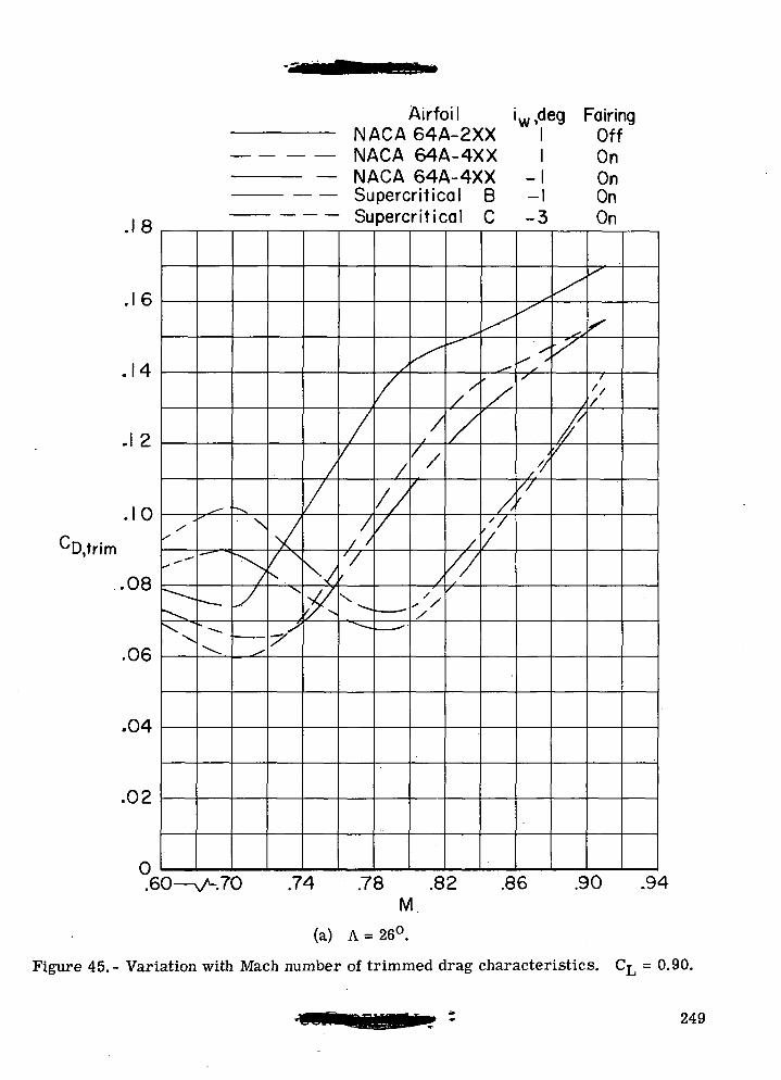
Airfoil iw,deg Fairing
8
16
.10CD,trim
/X
--"""
•
\ "\
- —
^_
•Nsy^
^/ ^^\
-S
//V^
IMMUA DtM-^AA
NACA 64A-4XXNACA 64A-4XXSupercritical BSupercritical C
//
// /V
\ • —^~,
s
/
/
///
- -—
-. — -^'
^
// //
/
,'//
^f*
//
A
///f
^
'/
/'//
\\
-1i— i-3
^
^
s^ *
ss
////f
UTT
OnOnOnOn
/"
^s
7
j//
///
s~
s
1
'//
.08
.06
.04
.02
.60—N/-.70 .74 .78 .82 .86 .90 .94M.
(a) A = 26°.
Figure 45.- Variation with Mach number of trimmed drag characteristics. CL = 0.90.
249
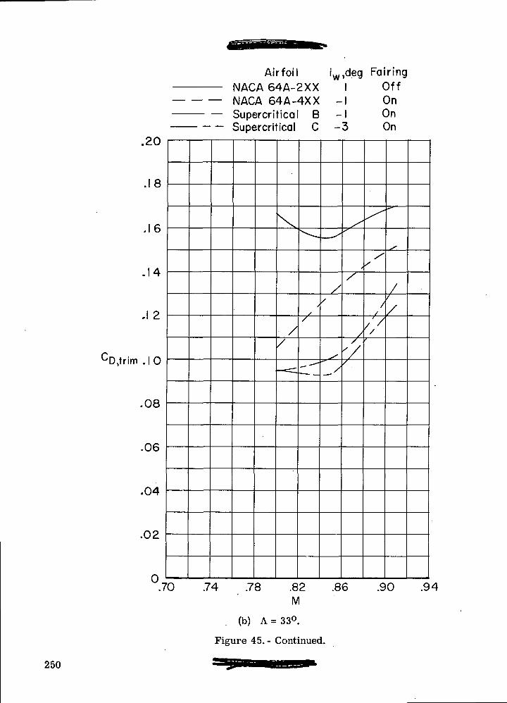
.20
.18
.16
.14
.1 2
CD,trim .10
.08
.06
.04
.02
°7
AirfoilNACA 64A-2XXNACA 64A-4XXSupercritical BSupercritical C
\
//
— =:
^-^
s/
• — —
fw
— s
//
^s•*~__/
,deg Fairing1 Off1 On1 On3 On
^S'
/
/
'//
^
//
////
^~~
st
//
/
0 .74 .78 .82 .86 .90 .94M
(b) A = 33°.
Figure 45.- Continued.
250
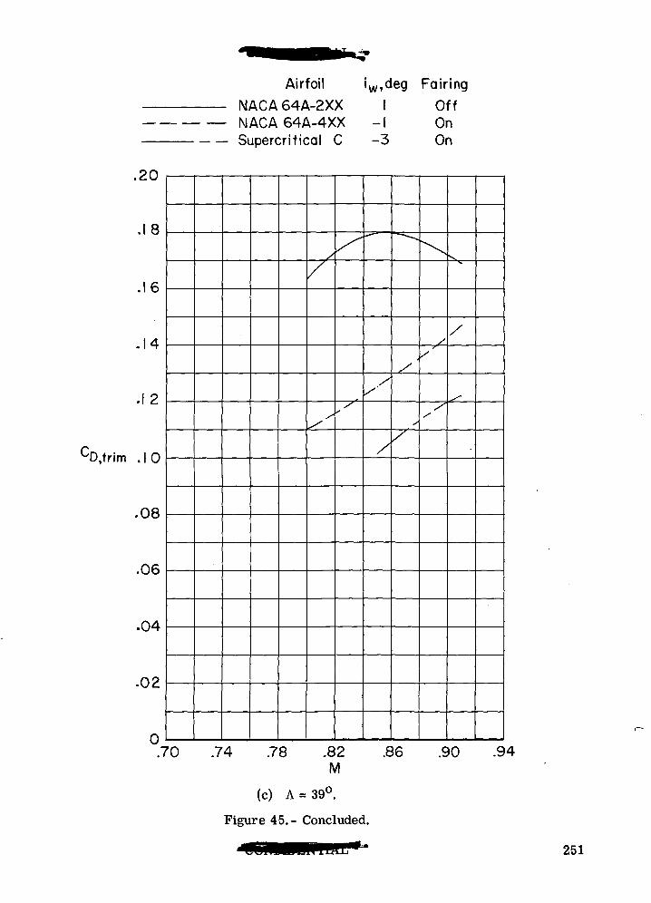
M
.20
.18
.16
.14
.12
CD,trim JO
.08
.06
.04
.02
0.7
NSi
Airfoil 'wjdeg Fairing
aCA 64A-2XX 1 OffACA 64A-4XX -1 Onjpercritical C -3 On
/
/
^
^
^
**-*
/
/
"
,-
,/
•\
'
s'
/
'0 .74 .78 .82 .86 .90 .94M
(c) A = 39°.
Figure 45.- Concluded.
251
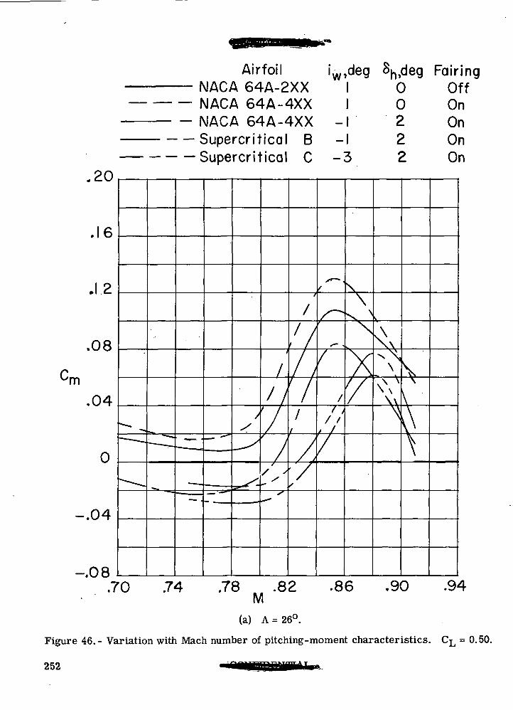
Airfoil 'wdeg Sh>deg Fairing
.20
,16
.12
.08
n
.04
0
-.04
-.08.7
ir
cN.
c
"
.
^
-
"•"^— — — .
^ .
1 — i —
• ^- ~
VIMOM OH-M-^AA
vlACA 64A-4XXslACA 64A-4XXSupercritical BSupercritical C
•WB^_^BP«
~
y
^
^^
t
////
•*- -
/
t i
,7t
s
f<~.
jS~^
> 1
'/
1 U UTT
1 0 On1 2 On1 2 On3 2 On
\\
\ x
\
'/
\\
\V
N
\
l\\
0 .74 .78 .82 .86 .90 .94M
(a) A = 26°.
Figure 46.- Variation with Mach number of pitching-moment characteristics. CL = 0.50.
252
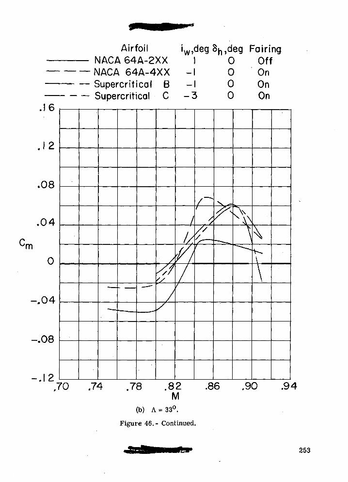
IVr
• • •-
.16
.12
.08
.04
Cm
0
-,04
-.08
-.12
v_
_ c
AirfoilJACA 64A-2XXJACA 64A-4XXSupercritical BSupercritical C
• •
•* —,
- _ -
"
'
'
$
/
^
'w»
-—
1I/.
'(////
deg 8^,deg Fairing0 Off0 On0 On
\ 0 On
,—+!
/,£_
?"— -~^
*.
\^^
\^\
\
'0 .74 .78 .82 .86 .90 .94M
(b) A = 33°.
Figure 46. - Continued.
253
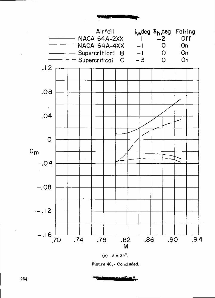
r(V
1
.12
.08
.04
0
m
-.04
-.08
.12
-.16.1
'
AirfoilMACA 64A-2XXsIACA 64A-4XXSupercritical BSupercritical C
r*
iw>de91
-1i
^/
/
- I
3
/
/
8^,deg Fairing-2 Off
0 On0 On0 On
//
— •
/*
- — -.
/
^^
-~ .r .
'0 .74 .78 .82 .86 .90 .94M
(c) A =39°.
Figure 46.- Concluded.
254
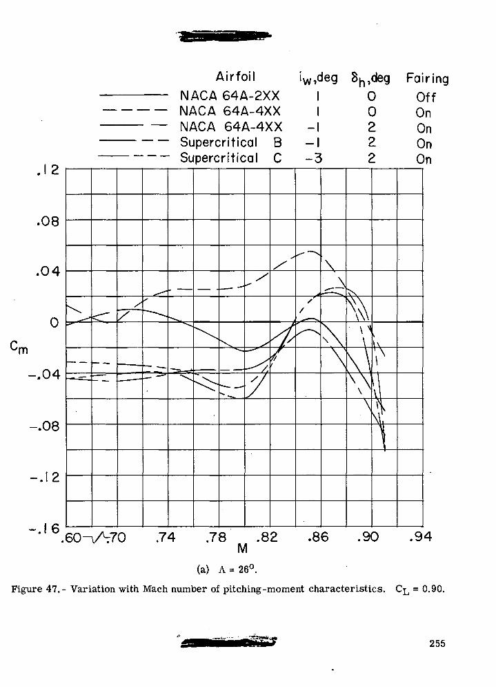
.12
.08
.04
0
'm
-.04 ^
-.08
-.12
-.16
•^^"
• —
/
— —
•• —
^~s
— ,
^=_a^_
AirfoilNACA 64A-2XXNACA 64A-4XXNACA 64A-4XXSupercritical B
• Supercritical C
„
"=^
.
\
— — •
x"*-*.
^11 • _ -•
•
/I*'
^-"
~^y,
7
S/
4/
'w»c11
-3
^^
^A
//
^
leg 8^,deg Fairing0 Off0 On2 On2 On2 On
\'• —
\\
>s
[ \\kf\\\\\
.60W70 .74 .78 .82 .86 .90M
(a) A = 26°.
Figure 47.- Variation with Mach number of pitching -moment characteristics.
.94
= 0.90.
255
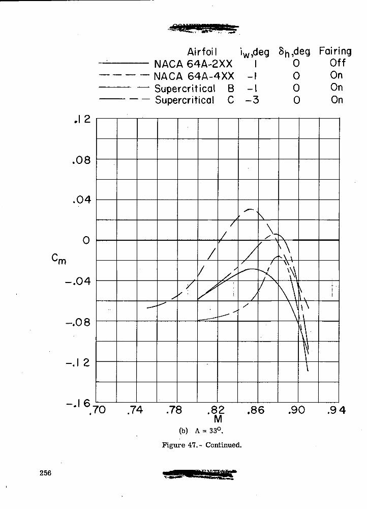
'm
-.04
-.08
-.1 2
-.16
Airfoil iw,deg Sn,deg FairingNACA 64A-2XX I 0 OffNACA 64A-4XX -I 0 On
- — Supercritical B -I 0 OnSupercritical C -3 0 On
.94
Figure 47.- Continued.
256
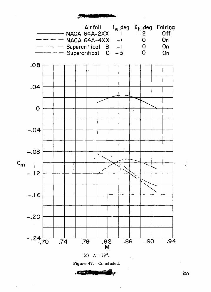
Airfoil iw,deg 8n ,deg FairingNACA 64A-2XX I -2 OffNACA 64A-4XX -I 0 OnSupercritical B -I 0 OnSupercritical C -3 0 On
r\A-.UH-
no-, Uo
1 O• . 1 c.
I C-.1 b
D r\.d.\J
ro .7-
\
*.78
^
"\
/
.8IV
^, — •
^*
21
— .
^, —
i^s
.&(
*^^
s.
^^
<»
^
^
F\X
.91
^
^
\
3 .9^
(c) A = 39°.
Figure 47.- Concluded.
257
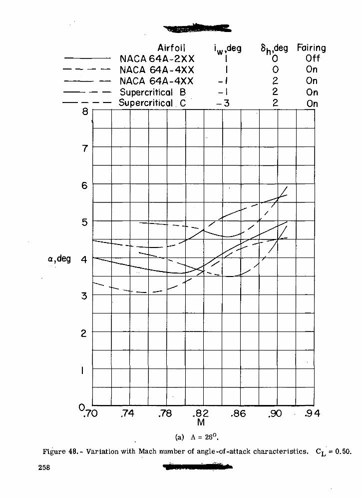
—
^^^^ - H^V —
8
7
6
5
jg 4
3
2
1
/"»
- —^—-^
^
AirfoilNACA64A-2XXNACA 64A-4XXNACA 64A-4XXSupercritical BSupercritical C
• — • -
-- — .
•—• —
•" i—
*~ — i i i
• — .
— -
— • —
—- —
~~~~ —
*s
-<
^'
/
>5^
'«
-
s/
^~~~.
,///
,deg Su,deg FairI 0 011 0 Of1 2 Or1 2 Oi3 2 Oi
*
^— "•
^^
-^
^
/
^
/^
//
s
^'"/s
/
;/
ng:fiini
.70 .74 .78 .82 .86 .90 .94M
(a) A = 26°.
Figure 48.- Variation with Mach number of angle-of-attack characteristics. CL = 0.50.
258
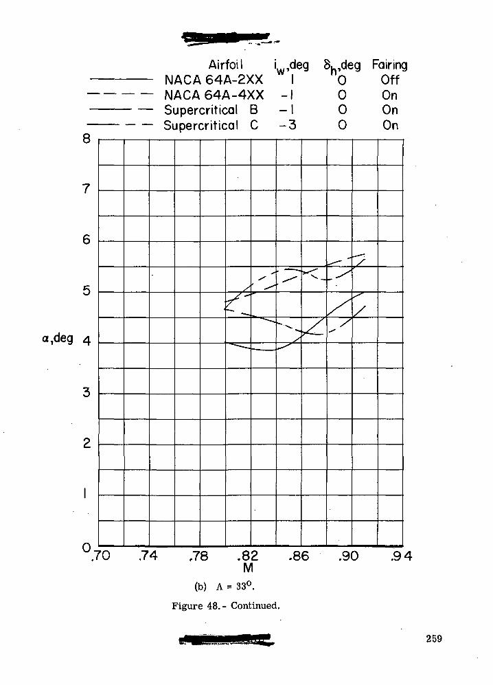
MIMI\J0.
8
7
6
5
a7deg 4
3
2
1
O»
Si
Airfoil L,deg S^.deg Fairin<\AI nACA64A-2XX 1 0 OffACA64A-4XX -1 0 Onjpercritical B - 1 0 Onjpercritical C -3 0 On
™« . •— .
^--—
^
~~.
^
, — —
^._
^
<-
V-
~^~
-^
/
''
~~
/
3
'0 .74 ,78 .82 .86 .90 .94M
(b) A = 33°.
Figure 48.- Continued.
259

a,deg
8
7
6
5
4
3
2
1
n
_ — —
Airfoil LNACA 64A-2XXNACA 64A-4XXSupercritical BSupercritical C
•
— — •
^^^
• —
«
•
deg 81
-1i— i
-3
^t-
-\—
=- — =
• — .
"i?— c.
000
•• — •
^=^L
;g FairingOffOnOnOn
M *
^"
, '
•««•
-
'
.70 .74 .78 .82M
(c) A = 39°.
Figure 48. - Concluded.
.86 .90 .94
260
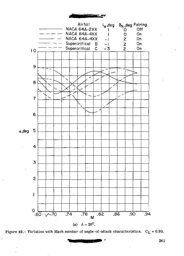
Airfoil iw,deg 8h,deg FairingNACA 64A-2XX I 0 Off
: NACA 64A-4XX I 0 On
10
9
8
7
6
a,deg 5
4
3
2
1
0
\\ \
N\
--
V
N
^\
^x
X
— -^
iv*+\jf-\ U-t«-1-AA —| C. \J\\
Supercritical B -1 2 OnSupercritical C -3 2 On
\
v^^- S
^ '
^/^>
'\\
/ '/
^--
\\
V
^^'
'
^
"^_
\^s
--
-^
<^
X
/
.—
X^-
/X
^
'
-"
-~,
• .
,ff~*
>
•- •*
.74 .78 .82 .86 .90 .94M
(a) A = 26°.
Figure 49.- Variation with Mach number of angle-of-attack characteristics. CL = 0.90.
261
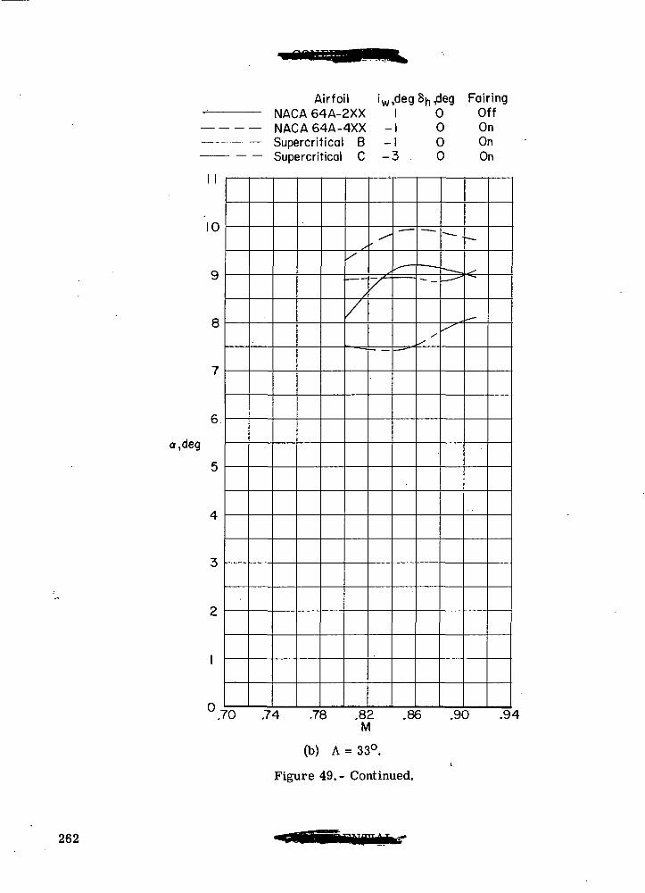
Airfoil iw,degSn,deg FairingNACA64A-2XX I 0 OffNACA64A-4XX -I 0 OnSupercritical B -I 0 On
a.deg
1 1
10
9
8
7
6
5
4
3
2
1
.7
oupercrmcai ^ —o. u un
x
~~~
/
x^
^ —— — ~ ,"""*• —
^
—-
— .— "
^
• —
.-—
'0 .74 .78 .82 .86 .90 .9M
(b) A = 33°.
Figure 49.- Continued.
262
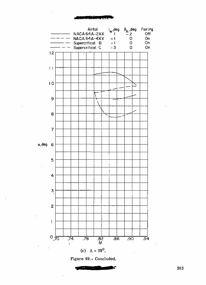
12
1 1
10
9
8
7
a,deg 6
5
4
3
2
1
AirfoilNACA64A-2XXNACA64A-4XXSupercritical BSupercritical C
.— —
V"\
\\
.»-—
vv •
wdeg
-11
-3
-^
^_
^
— -
—
Sh'd— C.
000
\—
-
eg FairingOffOnOnOn
—
, —
/
°.70 .74 .78 .82 .86 .90 .94M
(c) A = 39°.
Figure 49.- Concluded.
263
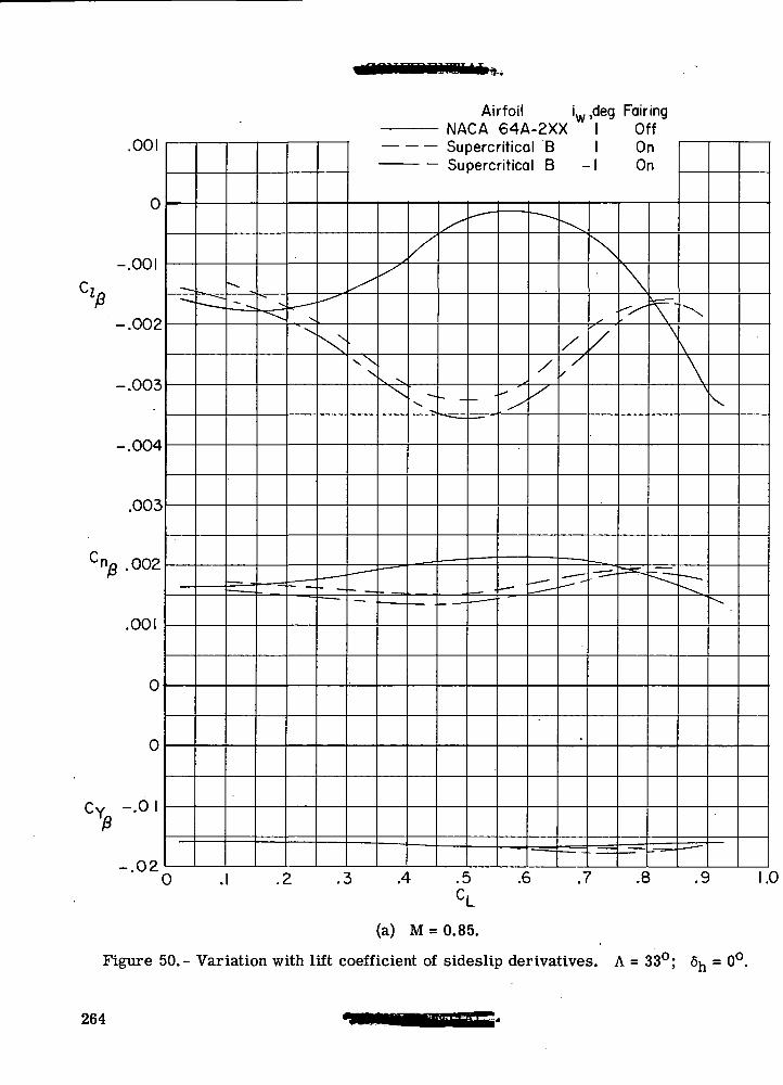
Airfoil iw,deg Fairing
.UUI
0
cl
-.002
-.003
.003
Cng .002
.001
0
0
CY -.01
n?
— --
-•*•. — _
" — - -•*- —
^
^
i • ^-^^^T-^
^— — -
\
^
— — .
1 --
"
\^
<- —.
— — -~
^
x^
. •
^
V V.
X
^- ~
••
/
-«•
— - — •
Supercritical BSupercritical B
/*
- _
~~~- -
•_ - —
.
—
— —
. —
-*
^
--—
~— -^
//
^-
-^
/
/
.
^
^
\ On1 On
\
/
' — -^
- ^^_ ~-~
\^
*=•-\\
:
— -
^
\
\
— — .
V
^ .
' 0 .1 .2 .3 .4 .5 .6 .7 .8 .9 1.0CL
(a) M = 0.85.
Figure 50.- Variation with lift coefficient of sideslip derivatives. A = 33°; 6^ = 0°.
264
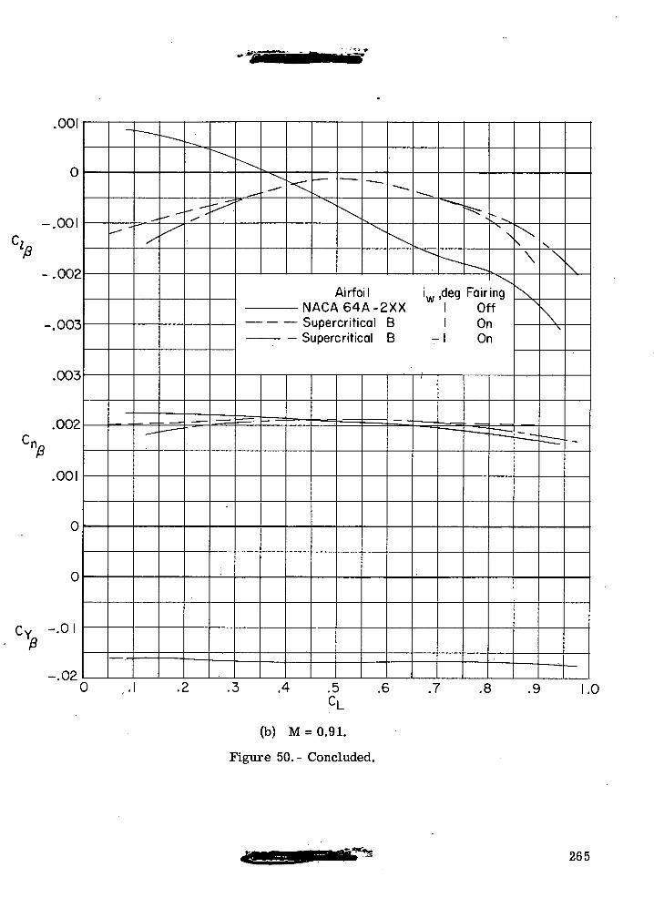
.001
-.001
'f*-.002
-.003
.003
.002
.001
0
0
-.01
-.020
N
\
Airfoil i ,deg FairingNACA64A-2XX I OffSupercritical B I OnSupercritical B -1 On
.2 .3 .4 .5CL
(b) M = 0.91.
Figure 50.- Concluded.
.6 .7 .8 .9 1.0
265
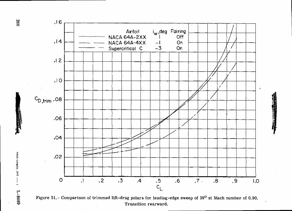
^
oa<v~cH-
<
)*
--*,
rt*4Mc.
n5
>N
; cc<c«rf
^
- IJ C
O<v. ?
M ^
•t <t D
Cu: <J Ci <
2 :xt X=<<
fv
*-4-
.
D :
JI^ (
i
v\cDr>>1>O^:"?/) \:c\ vx
1
^N
^xC
\X
%)•
\\
ac
-co \\))•Ezh-
zT
\\
\\C£C
\y\
))
\\
\\\\\
xj
c \\\
\\\\\\)»
\\\
c\\\\\c\cJ)
05
o"SQ)
CD
&g0
00
JgtsoasCO
lx~•
Oa0)a>iCD
CD&D
(1)
, ^'S
I/-4 —
1
T5
™
10 o
s £^ H
O
^
en o
0 1
o.
*3
K"\
F(
-|_»0)s'C<4-lod0CO1o
O
i-I0)h
266N
ASA
-Langley, 1973
i L
-8689
"The aeronautical and space activities of the United States shall beconducted so as to contribute . . . to the expansion of human knowl-edge of phenomena in the atmosphere and space. The Administrationshall provide for the widest practicable and appropriate disseminationof information concerning its activities and the results thereof."
—NATIONAL AERONAUTICS AND SPACE ACT OF 1958
NASA SCIENTIFIC AND TECHNICAL PUBLICATIONS
TECHNICAL REPORTS: Scientific and technical information consideredimportant, complete, and a lasting contribution to existing knowledge.
TECHNICAL NOTES: Information less broad in scope but nevertheless ofimportance as a contribution to existing knowledge.
TECHNICAL MEMORANDUMS: Information receiving limited distribu-tion because of preliminary data, security classification, or other reasons.
CONTRACTOR REPORTS: Scientific and technical information generatedunder a NASA contract or grant and considered an important contribution toexisting knowledge.
TECHNICAL TRANSLATIONS: Information published in a foreignlanguage considered to merit NASA distribution in English.
SPECIAL PUBLICATIONS: Information derived from or of value to NASAactivities. Publications include conference proceedings, monographs, datacompilations, handbooks, sourcebooks, and special bibliographies.
TECHNOLOGY UTILIZATION PUBLICATIONS: Information on tech-nology used by NASA that may be of particular interest in commercial and othernon-aerospace applications. Publications include Tech Briefs, TechnologyUtilization Reports, and Technology Surveys.
Details on f/ie availability of these publications may be obtained from:
SCIENTIFIC AND TECHNICAL INFORMATION OFFICE
NATIONAL AERONAUTICS AND SPACE ADMINISTRATION
Wwhinston, D.C. 20546