tm 3-34.51 (tm 5-581b/8 december 1972) construction
TRANSCRIPT

TM 3-34.51 (TM 5-581B/8 December 1972)
CONSTRUCTION DRAFTING
June 2012
DISTRIBUTION RESTRICTION: Approved for public release; distribution is unlimited.
HEADQUARTERS, DEPARTMENT OF THE ARMY
Publication of TM 3-34.51, 15 June 2012, supersedes TM 5-581B, Construction Drafting, 8 December 1972. This special conversion to the TM publishing medium/nomenclature has been accomplished to comply with TRADOC doctrine restructuring requirements. The title and content of TM 3-34.51 is identical to that of the superseded TM 5-581B. This special conversion does not integrate any changes in Army doctrine since December 1972 and does not alter the publication’s original references; therefore, some sources cited in this TM may no longer be current. For the status of official Department of the Army (DA) publications, consult DA Pam 25-30, Consolidated Index of Army Publications and Blank Forms, at http://armypubs.army.mil/2530.html. DA Pam 25-30 is updated as new and revised publications, as well as changes to publications are published. For the content/availability of specific subject matter, contact the appropriate proponent.

This publication is available at Army Knowledge Online https://armypubs.us.army.mil/doctrine/index.html.
*TM 3-34.51 (TM 5-581B)
DISTRIBUTION RESTRICTION: Approved for public release; distribution is unlimited.
*This publication supersedes TM 5-581B, 8 December 1972.
i
Technical Manual
No. 3-34.51 (5-581B)
Headquarters Department of the Army
Washington, DC, 15 June 2012
Construction Drafting
Contents
Page
Chapter 1 INTRODUCTION ................................................................................................ 1-1 Purpose and Scope ............................................................................................ 1-1 Duties .................................................................................................................. 1-1 Drafting a Graphic Language ............................................................................. 1-1 Types of Engineer Construction ......................................................................... 1-1 Principles of Military Construction ...................................................................... 1-2 Comments .......................................................................................................... 1-2
Chapter 2 BASIC CONSTRUCTION CONSIDERATIONS ................................................. 2-1 Definitions ........................................................................................................... 2-1 Information From Construction Drawings ........................................................... 2-2 Numbering of Contract Drawings ....................................................................... 2-2 Materials of Construction .................................................................................... 2-2 Standards of Construction .................................................................................. 2-3 Understanding Construction Working Drawings................................................. 2-3 Drawing Techniques ........................................................................................... 2-4 The Engineer, Draftsman, and Construction Worker ......................................... 2-5
Chapter 3 TOPOGRAPHY AND SITE PLANS ................................................................... 3-1 Introduction ......................................................................................................... 3-1 Classification of Maps ......................................................................................... 3-1 Types of Maps .................................................................................................... 3-1 Definitions ........................................................................................................... 3-2 Topographic Symbols and Map Colors .............................................................. 3-3 Site Selection ...................................................................................................... 3-4 Locating Boundary Lines .................................................................................... 3-5 Measuring Elevations ......................................................................................... 3-6 Locating Physical Details .................................................................................... 3-6 Plotting Site Plan Data ........................................................................................ 3-7 Grading ............................................................................................................... 3-9 Grading Definitions ............................................................................................. 3-9 Profile ................................................................................................................ 3-10
Contents
ii TM 3-34.51 15 June 2012
Cross Sections .................................................................................................. 3-12 Estimate of Earthwork ....................................................................................... 3-13 Determination of End Areas .............................................................................. 3-13 Graphic Organization of Earthwork ................................................................... 3-14
Chapter 4 BUILDING DRAWINGS ...................................................................................... 4-1 Introduction ......................................................................................................... 4-1 Views in Building Drawings ................................................................................. 4-1 Plans ................................................................................................................... 4-1 Elevations ............................................................................................................ 4-5 Framing Plans ..................................................................................................... 4-8 Sectional Views ................................................................................................. 4-10 Details ............................................................................................................... 4-12 Drawing a Section ............................................................................................. 4-12 Scale ................................................................................................................. 4-17 Symbols in Building Drawings ........................................................................... 4-18 Dimensioning Building Drawings ...................................................................... 4-19 Notes in Construction Drawings ........................................................................ 4-21 Specifications in Construction Drawings ........................................................... 4-22 Bill of Material in Construction Drawings .......................................................... 4-22 Nominal and Actual Sizes ................................................................................. 4-23
Chapter 5 WOOD CONSTRUCTION .................................................................................. 5-1 Section I - LIGHT FRAME STRUCTURES ....................................................... 5-1 Wood Classification............................................................................................. 5-1 Species ............................................................................................................... 5-1 Grading ............................................................................................................... 5-1 Surfacing and Worked Lumber ........................................................................... 5-2 Actual and Nominal Sizes of Lumber .................................................................. 5-2 Board Feet .......................................................................................................... 5-3 Light Framing ...................................................................................................... 5-5 Types of Light Framing ....................................................................................... 5-5 Covering Frame .................................................................................................. 5-6 General Drawing Practices With Wood Structures ............................................. 5-8 Roof Trusses ....................................................................................................... 5-8 Roofing ................................................................................................................ 5-8 Water Control on Roofs ...................................................................................... 5-9 Representation of Roofs ................................................................................... 5-10 Section II - TIMBER STRUCTURES ............................................................... 5-11 Timber Construction .......................................................................................... 5-11 Timber Connectors ............................................................................................ 5-11 Timber Bridges .................................................................................................. 5-12 Drafting Requirements for a Timber Trestle Bridge .......................................... 5-21 Water Tower ...................................................................................................... 5-22
Chapter 6 MASONRY STRUCTURES ................................................................................ 6-1 Section I - Brick Masonry ................................................................................. 6-1 Introduction ......................................................................................................... 6-1 Description .......................................................................................................... 6-1
Contents
15 June 2012 TM 3-34.51 iii
Brick Classification ............................................................................................. 6-1 Brick Types ......................................................................................................... 6-1 Brick Sizes, Surfaces, and Shapes .................................................................... 6-2 Bricklaying .......................................................................................................... 6-3 Bonds .................................................................................................................. 6-4 Masonry Wall Types ........................................................................................... 6-9 Mortar Joints ....................................................................................................... 6-9 Brick Masonry Drawings ................................................................................... 6-10 Dimensions ....................................................................................................... 6-15 Section II - CONCRETE, TILE AND STONE MASONRY .............................. 6-15 Concrete Masonry ............................................................................................ 6-15 Concrete Masonry Drawings ............................................................................ 6-17 Hollow Clay Tiles .............................................................................................. 6-17 Stone Masonry ................................................................................................. 6-19
Chapter 7 CONCRETE STRUCTURES .............................................................................. 7-1 Introduction ......................................................................................................... 7-1 Concrete as a Material ....................................................................................... 7-1 Forms .................................................................................................................. 7-3 Types of Concrete and Their Uses ..................................................................... 7-5 Structural Members Constructed From Concrete............................................... 7-6 Types of Reinforcing for Concrete ...................................................................... 7-7 Joints and Connections ...................................................................................... 7-8 Devices for Distributing Loads .......................................................................... 7-10 Concrete Construction Drawing ....................................................................... 7-11 Concrete Takeoff .............................................................................................. 7-25 Concrete Construction Drawings in the T/O ..................................................... 7-26
Chapter 8 STEEL STRUCTURES ...................................................................................... 8-1 Introduction ......................................................................................................... 8-1 Structural Steel Details ....................................................................................... 8-1 Actual Size and Weight Versus Nominal Size Classification ............................. 8-1 Conventional Symbols and Representations ..................................................... 8-3 Shop Drawings ................................................................................................... 8-6 Plans for Steel Framing Systems ..................................................................... 8-10 Bill of Material ................................................................................................... 8-10 Rivet Lists ......................................................................................................... 8-11
Chapter 9 MACHINE DRAWING ........................................................................................ 9-1 Section I - SCREWS, BOLTS, RIVETS AND WELDS ..................................... 9-1 General Requirements ....................................................................................... 9-1 Screw Threads ................................................................................................... 9-1 Bolts and Nuts .................................................................................................... 9-5 Rivets .................................................................................................................. 9-8 Welding ............................................................................................................... 9-9 Section II - MACHINE PARTS ........................................................................ 9-14 Purpose ............................................................................................................ 9-14 Introduction ....................................................................................................... 9-14 Linkages ........................................................................................................... 9-14
Contents
iv TM 3-34.51 15 June 2012
Straight-Line Mechanisms ................................................................................ 9-18 Cams ................................................................................................................. 9-19 Gears ................................................................................................................ 9-23 Section III - Details and Assembly Practices ............................................... 9-26 Detail and Assembly Drawing Synonymous With Working Drawing ................ 9-26 Detail Drawing ................................................................................................... 9-26 Mechanical Practice .......................................................................................... 9-26
Chapter 10 UTILITIES DRAWINGS .................................................................................... 10-1 Section I - Water Supply and Distribution .................................................... 10-1 Definition ........................................................................................................... 10-1 Water Supply System........................................................................................ 10-1 Distribution System ........................................................................................... 10-1 Unit Construction and Package Unit Prints ....................................................... 10-1 Section II - Plumbing....................................................................................... 10-7 Definition ........................................................................................................... 10-7 Plumbing Plans ................................................................................................. 10-7 Utility Plans ..................................................................................................... 10-12 Section III - Sewerage Systems ................................................................... 10-16 Sewage Pipes and Fittings ............................................................................. 10-16 Sewage Treatment .......................................................................................... 10-19 Disposal Facilities ........................................................................................... 10-24 Sewage System Plans .................................................................................... 10-26 Section IV - Electrical Distribution System ................................................ 10-29 Definition ......................................................................................................... 10-29 Nomenclature .................................................................................................. 10-29 Conventions .................................................................................................... 10-29 Electrical Distribution Plan .............................................................................. 10-31 Detail Drawings ............................................................................................... 10-35 Section V - Electrical Wiring ........................................................................ 10-40 Definition ......................................................................................................... 10-40 Nomenclature .................................................................................................. 10-40 Electrical Symbols and Wire Sizes ................................................................. 10-41 Electrical Plans ................................................................................................ 10-46 Section VI - Heating ...................................................................................... 10-49 Definition ......................................................................................................... 10-49 Hot-Water Heating Systems ........................................................................... 10-54 Warm-Air Heating Systems ............................................................................. 10-56 Section VII - Air Conditioning ...................................................................... 10-59 Definition ......................................................................................................... 10-59 Air-Conditioning System Symbols ................................................................... 10-59 Typical Air-Conditioning Plan .......................................................................... 10-59 Section VIII - Refrigeration ........................................................................... 10-62 Definition ......................................................................................................... 10-62 Conventional Symbols .................................................................................... 10-62 Refrigeration Plans .......................................................................................... 10-63
Contents
15 June 2012 TM 3-34.51 v
Chapter 11 Material Estimates .......................................................................................... 11-1 Introduction ....................................................................................................... 11-1 Purpose ............................................................................................................ 11-1 Function ............................................................................................................ 11-1 Quantity Estimates ........................................................................................... 11-2
Chapter 12 CONSTRUCTION IN THE THEATER OF OPERATIONS ............................... 12-1 General ............................................................................................................. 12-1 TM 5-302 .......................................................................................................... 12-1
Chapter 13 ROADS ............................................................................................................. 13-1 Introduction ....................................................................................................... 13-1 Nomenclature ................................................................................................... 13-1 Survey ............................................................................................................... 13-2 Road Plan ......................................................................................................... 13-4 Horizontal Curves ............................................................................................. 13-5 Control Points ................................................................................................... 13-7 Profile ................................................................................................................ 13-8 Vertical Curves ................................................................................................. 13-9 Drawing the Gradeline .................................................................................... 13-10 Road Dimensions ........................................................................................... 13-10 Sequence of Construction .............................................................................. 13-13 sections ........................................................................................................... 13-13 Cross Sections ............................................................................................... 13-16 Drainage ......................................................................................................... 13-17 Roadway Ditches ............................................................................................ 13-19 Interceptor Ditches ......................................................................................... 13-20 Diversion Ditches ............................................................................................ 13-21 Culverts ........................................................................................................... 13-21
Chapter 14 AIRFIELD AND HELIPORTS ........................................................................... 14-1 Section I - Introduction .................................................................................. 14-1 General Concepts ............................................................................................. 14-1 Controlling Aircraft Classification ...................................................................... 14-2 Airfield-Heliport Types ...................................................................................... 14-3 Responsibilities, Engineer ................................................................................ 14-3 Section II - Airfields ........................................................................................ 14-3 Site Requirements ............................................................................................ 14-3 Reconnaissance ............................................................................................... 14-5 Elements of the Airfield ..................................................................................... 14-5 Geometric Design and Layout .......................................................................... 14-7 Section III - Heliports .................................................................................... 14-17 Characteristics ................................................................................................ 14-17 Layout ............................................................................................................. 14-17
Chapter 15 PORT CONSTRUCTION .................................................................................. 15-1 Introduction ....................................................................................................... 15-1 Harbor Studies and Surveys ............................................................................ 15-1 Port Facilities .................................................................................................... 15-2 Port Construction Materials ............................................................................ 15-13
Contents
vi TM 3-34.51 15 June 2012
Chapter 16 RAILROADS ..................................................................................................... 16-1 Introduction ....................................................................................................... 16-1 Ties ................................................................................................................... 16-1 Tie Plates .......................................................................................................... 16-1 Track Spike ....................................................................................................... 16-4 Rails .................................................................................................................. 16-6 Track Gage ....................................................................................................... 16-9 Curves and Superelevations ............................................................................. 16-9 Track Spacing ................................................................................................. 16-11 Ditches ............................................................................................................ 16-11 Overhead Clearance ....................................................................................... 16-12 Turnouts .......................................................................................................... 16-12 Frogs ............................................................................................................... 16-17 Crossovers ...................................................................................................... 16-19 Highway and Rail Crossings at Grades .......................................................... 16-20 Railroad Construction Drawings ..................................................................... 16-21
Chapter 17 DRAFTING ROOM OPERATIONS .................................................................. 17-1 Introduction ....................................................................................................... 17-1 Drafting Room Arrangement ............................................................................. 17-1 Reproduction Room .......................................................................................... 17-1 Checking ........................................................................................................... 17-2 Technical Library and Plan Files ....................................................................... 17-3 Filing and Retiring Drawings ............................................................................. 17-3 Revisions ........................................................................................................... 17-5 Planning and Estimating Time and Materials ................................................... 17-6 Supply ............................................................................................................... 17-6 Site Inspection ................................................................................................... 17-7 Procedure for Transfer of Completed Construction .......................................... 17-7
Appendix A REFERENCES ................................................................................................... A-1
Appendix B ABBREVIATIONS ............................................................................................. B-1
Appendix C MATERIAL SYMBOLS ...................................................................................... C-1
Appendix D ARCHITECTURAL SYMBOLS ......................................................................... D-1
Appendix E PLUMBING SYMBOLS ..................................................................................... E-1
Appendix F HEATING SYMBOLS ......................................................................................... F-1
Appendix G AIR-CONDITIONING AND REFRIGERATION SYMBOLS .............................. G-1
Appendix H ELECTRICAL SYMBOLS ................................................................................. H-1
INDEX ......................................................................................................... Index-1
Figures
Figure 2-1. Drawing techniques ....................................................................................... 2-4 Figure 3-1. Soil symbols ................................................................................................... 3-9 Figure 3-2. Ground profile with gradeline....................................................................... 3-12

Contents
15 June 2012 TM 3-34.51 vii
Figure 3-3. Cross section of a road ............................................................................... 3-13 Figure 4-1. Typical site plan. ........................................................................................... 4-3 Figure 4-2. Foundation plan ............................................................................................ 4-4 Figure 4-3. Typical floor plan ........................................................................................... 4-6 Figure 4-4. Elevation views ............................................................................................. 4-8 Figure 4-5. Floor framing. .............................................................................................. 4-10 Figure 4-6. Typical wall section detail ........................................................................... 4-11 Figure 4-7. Specific section (outside steps) .................................................................. 4-12 Figure 4-8. Typical sill details ........................................................................................ 4-13 Figure 4-9. Girder and joist connections ....................................................................... 4-14 Figure 4-10. Typical wood sash detail ........................................................................... 4-14 Figure 4-11. Detail of window W2.................................................................................. 4-15 Figure 4-12. Doors ......................................................................................................... 4-16 Figure 4-13. Detail of door 2D ....................................................................................... 4-16 Figure 4-14. Cornice details .......................................................................................... 4-17 Figure 4-15. Stairways and steps .................................................................................. 4-19 Figure 4-16. Masonry and frame conventions ............................................................... 4-20 Figure 4-17 Bill of materials ........................................................................................... 4-25 Figure 5-1. Light framing details ...................................................................................... 5-5 Figure 5-2. Framing for light structures ........................................................................... 5-7 Figure 5-3. Smokepipe details ....................................................................................... 5-10 Figure 5-4. Timber connector symbols .......................................................................... 5-11 Figure 5-5. Simple abutment ......................................................................................... 5-13 Figure 5-6. Combination pile abutment and retaining wall ............................................ 5-13 Figure 5-7. Combination trestle abutment and retaining wall ........................................ 5-13 Figure 5-8. Timber trestle bent ...................................................................................... 5-14 Figure 5-9. Pile bent ...................................................................................................... 5-15 Figure 5-10. Trestle pier ................................................................................................ 5-16 Figure 5-11. Pile pier ..................................................................................................... 5-17 Figure 5-12. Crib pier ..................................................................................................... 5-17 Figure 5-13. Timber trestle bridge ................................................................................. 5-19 Figure 5-14. Lateral bracing of stringers ....................................................................... 5-20 Figure 5-15. Curb and handrail system ......................................................................... 5-21 Figure 5-17. Water tower ............................................................................................... 5-23 Figure 6-1. Brick surfaces ................................................................................................ 6-3 Figure 6-2. Brick shapes .................................................................................................. 6-3 Figure 6-3. Masonry units and mortar joints .................................................................... 6-4 Figure 6-4. Brick patterns ................................................................................................ 6-6 Figure 6-5. Brick bonds ................................................................................................... 6-7 Figure 6-6. Metal ties ....................................................................................................... 6-8 Figure 6-7. Metal ties in use ............................................................................................ 6-8
Contents
viii TM 3-34.51 15 June 2012
Figure 6-8. Joint finishes ................................................................................................ 6-10 Figure 6-9. Typical brick masonry structure in plan, elevation and section ................... 6-11 Figure 6-10. Masonry construction wall section ............................................................. 6-12 Figure 6-11. Flashing at window opening ...................................................................... 6-13 Figure 6-12. Flashing at window joint. ........................................................................... 6-14 Figure 6-13. Flashing at intersection of roof and wall .................................................... 6-14 Figure 6-14. Typical sizes and shapes of concrete masonry units ................................ 6-16 Figure 6-15. Concrete block section symbol .................................................................. 6-17 Figure 6-16. Types and sizes of hollow clay construction tile ........................................ 6-18 Figure 6-17. Rubble stone masonry ............................................................................... 6-19 Figure 6-18. Rubble stone masonry wall, bonding ........................................................ 6-20 Figure 6-19. Stone ......................................................................................................... 6-20 Figure 7-1. Making concrete ............................................................................................ 7-2 Figure 7-2. Slump test ...................................................................................................... 7-3 Figure 7-3. Wall form ........................................................................................................ 7-4 Figure 7-4. Casting bed for pre-tensing beams ............................................................... 7-6 Figure 7-5. Reinforce steel in a footing ............................................................................ 7-6 Figure 7-6. Reinforcing steel for a floor slab .................................................................... 7-7 Figure 7-7. Types of reinforcing bars ............................................................................... 7-8 Figure 7-8. Contraction and expansion joints ................................................................ 7-10 Figure 7-9. Load distributing devices ............................................................................. 7-11 Figure 7-10. Sheet layout ............................................................................................... 7-12 Figure 7-11. Typical reinforcing plan .............................................................................. 7-14 Figure 7-12. Concrete and reinforced concrete symbols ............................................... 7-15 Figure 7-13. Reinforcement symbols ............................................................................. 7-16 Figure 7-14. Reinforcing bars for a wall ......................................................................... 7-17 Figure 7-15. Reinforced concrete details ....................................................................... 7-18 Figure 7-16. Beam reinforcing ....................................................................................... 7-19 Figure 7-17. Beam elevation .......................................................................................... 7-19 Figure 7-18. Hook details for reinforcing steel ............................................................... 7-20 Figure 7-19. Beam-column connection .......................................................................... 7-21 Figure 7-20. Beam-slab connection ............................................................................... 7-21 Figure 7-21. Framing plans and grids ............................................................................ 7-23 Figure 8-1. Symbols for single structural shapes ............................................................. 8-2 Figure 8-2. Conventional representation of structural elements ...................................... 8-4 Figure 8-3. Recessed pin nuts and cotter pins ................................................................ 8-5 Figure 8-4. Shop drawing of a beam ................................................................................ 8-7 Figure 8-5. Shop drawing of a typical steel truss ............................................................. 8-8 Figure 8-6. Shop drawing of a column ............................................................................. 8-9 Figure 8-7. Typical steel frame construction .................................................................. 8-10 Figure 9-1. Type of screw threads ................................................................................... 9-1

Contents
15 June 2012 TM 3-34.51 ix
Figure 9-2. Screw thread definitions ................................................................................ 9-2 Figure 9-3. Drawing semiconventional threads ............................................................... 9-3 Figure 9-4. Drawing regular and simplified thread symbols ............................................ 9-3 Figure 9-5. Thread specification note .............................................................................. 9-5 Figure 9-6. Bolt information ............................................................................................. 9-6 Figure 9-7. Bolt and nut formulas .................................................................................... 9-7 Figure 9-8. Steps in drawing bolts and nuts .................................................................... 9-8 Figure 9-9. Forms of rivet heads ..................................................................................... 9-9 Figure 9-10. Rivet conventions ...................................................................................... 9-10 Figure 9-11. Common welding processes ..................................................................... 9-11 Figure 9-12. Basic welding symbol ................................................................................ 9-11 Figure 9-13. Basic arc and gas weld symbols ............................................................... 9-12 Figure 9-14. Basic resistance weld symbols ................................................................. 9-12 Figure 9-15. Supplementary symbols ............................................................................ 9-13 Figure 9-16. Standard location of elements on the welding symbols ............................ 9-13 Figure 9-17. Application of the welding symbol ............................................................. 9-14 Figure 9-18. Levers ....................................................................................................... 9-15 Figure 9-19. Rocker arm ................................................................................................ 9-15 Figure 9-20. Bell crank .................................................................................................. 9-16 Figure 9-21. Rotating crank ........................................................................................... 9-16 Figure 9-22. Four-bar linkage ........................................................................................ 9-17 Figure 9-23. Crank and connecting rod ......................................................................... 9-17 Figure 9-24. Resultant of two forces ............................................................................. 9-18 Figure 9-25. Straight-line mechanism ........................................................................... 9-18 Figure 9-26. Pantograph ................................................................................................ 9-19 Figure 9-27. Cams and followers .................................................................................. 9-20 Figure 9-28. Motion diagrams ........................................................................................ 9-21 Figure 9-29. Construction of a cam ............................................................................... 9-23 Figure 9-30. Gear terminology....................................................................................... 9-24 Figure 9-31. Drawing a spur gear .................................................................................. 9-26 Figure 9-32. Relation of details versus assembly.......................................................... 9-27 Figure 9-33. Detail drawing for the foundry ................................................................... 9-28 Figure 9-34. Detail drawing for the machine shop......................................................... 9-29 Figure 9-35. Single drawing for use by all shops .......................................................... 9-30 Figure 9-36. Finish marks .............................................................................................. 9-30 Figure 10-1. Water supply system ................................................................................. 10-2 Figure 10-2. Water distribution plan .............................................................................. 10-3 Figure 10-3. Typical water and tower detail plumbing diagram ..................................... 10-4 Figure 10-5. Line symbols for piping ............................................................................. 10-8 Figure 10-6. Pipefitting symbols .................................................................................... 10-9 Figure 10-7. Plumbing symbols for valves .................................................................. 10-11
Contents
x TM 3-34.51 15 June 2012
Figure 10-8. Symbols for plumbing fixtures ................................................................. 10-12 Figure 10-9. Typical utility plan for a bathhouse .......................................................... 10-13 Figure 10-10. Typical plumbing details ........................................................................ 10-14 Figure 10-11. Typical building waste system arrangement ......................................... 10-15 Figure 10-12. Standard vitrified clay and cast iron pipefittings .................................... 10-16 Figure 10-13. Typical building connections.................................................................. 10-17 Figure 10-14. Typical sewer system plan .................................................................... 10-18 Figure 10-15. Typical manhole .................................................................................... 10-19 Figure 10-16. Grease trap ............................................................................................ 10-19 Figure 10-17. Typical small septic tank ........................................................................ 10-20 Figure 10-18. Imhoff tank, 25,000 gallon capacity ....................................................... 10-21 Figure 10-20. Leaching tank ........................................................................................ 10-24 Figure 10-21. Typical subsurface irrigation construction ............................................. 10-25 Figure 10-22. Typical sand-filter fields ......................................................................... 10-26 Figure 10-23. Typical small average system, profile view ........................................... 10-28 Figure 10-24. Line symbols for electric power distribution ........................................... 10-30 Figure 10-25. Conventional symbols for electric distribution equipment ..................... 10-31 Figure 10-26. Typical electrical distribution plan .......................................................... 10-33 Figure 10-27. Typical electrical distribution installation ............................................... 10-34 Figure 10-28. Typical tabulation of electrical loads ...................................................... 10-35 Figure 10-29. Typical electrical secondary distribution details .................................... 10-36 Figure 10-30. Transformer installation on a platform ................................................... 10-37 Figure 10-31. Line symbols for electrical wiring ........................................................... 10-43 Figure 10-32. Symbols for electrical fixtures and controls ........................................... 10-44 Figure 10-33. Typical electrical plan ............................................................................ 10-47 Figure 10-34. Typical ceiling wiring diagram................................................................ 10-48 Figure 10-35. Typical circuit breaker panel installation detail ...................................... 10-49 Figure 10-36. Wiring diagram for a three way switch .................................................. 10-49 Figure 10-37. Heating piping symbols ......................................................................... 10-50 Figure 10-38. Heating symbols .................................................................................... 10-51 Figure 10-39. Ventilating symbols ................................................................................ 10-52 Figure 10-40. Heat-power symbols .............................................................................. 10-53 Figure 10-41. Fluid-power diagram symbols................................................................ 10-54 Figure 10-42. One-pipe hot-water heating system diagram ........................................ 10-55 Figure 10-43. Two-pipe hot-water heating system diagram ........................................ 10-55 Figure 10-44. Typical hot-water heating system plan .................................................. 10-56 Figure 10-45. Warm-air heating system ....................................................................... 10-57 Figure 10-46. Common duct connections .................................................................... 10-58 Figure 10-47. Typical warm-air heating system plan. .................................................. 10-58 Figure 10-48. Air-conditioning piping symbols ............................................................. 10-59 Figure 10-49. Air conditioning symbols ........................................................................ 10-60
Contents
15 June 2012 TM 3-34.51 xi
Figure 10-50. Air-conditioning system plan ................................................................. 10-61 Figure 10-51. Refrigeration piping symbols ................................................................. 10-62 Figure 10-52. Refrigeration symbols ........................................................................... 10-63 Figure 10-53. Typical small refrigerated warehouse or ice house, all climates .......... 10-64 Figure 13-1. Road nomenclature ................................................................................... 13-2 Figure 13-2. Traverse .................................................................................................... 13-3 Figure 13-3. Bearing angles .......................................................................................... 13-4 Figure 3-4. The road plan .............................................................................................. 13-6 Figure 13-5. Superelevation .......................................................................................... 13-7 Figure 13-6. Road profile ............................................................................................... 13-8 Figure 13-7. Profile and gradeline ............................................................................... 13-12 Figure 13-8. Road courses .......................................................................................... 13-13 Figure 13-9. Typical sections ....................................................................................... 13-15 Figure 13-10. Curve section ........................................................................................ 13-16 Figure 13-11. Cross section ........................................................................................ 13-17 Figure 13-12. Subsurface drainage ............................................................................. 13-18 Figure 13-13. Check dams .......................................................................................... 13-20 Figure 13-14. Types of ditches .................................................................................... 13-20 Figure 13-15. Drainage systems ................................................................................. 13-21 Figure 13-16. Flange type culvert ................................................................................ 13-22 Figure 13-17. Flange type culvert detail ...................................................................... 13-22 Figure 13-18. Log culvert ............................................................................................. 13-23 Figure 13-19. Timber box culvert................................................................................. 13-24 Figure 13-20. PSP culvert ........................................................................................... 13-25 Figure 13-21. Stream cross section ............................................................................ 13-26 Figure 13-22. Timber headwall .................................................................................... 13-26 Figure 13-23. Culvert length ........................................................................................ 13-27 Figure 13-24. Culvert cover ......................................................................................... 13-27 Figure 13-25. Skew culverts ........................................................................................ 13-28 Figure 13-26. Culvert alinement .................................................................................. 13-28 Figure 14-1. Theater of operations airfield concept, typical .......................................... 14-1 Figure 14-2. Theater of operations heliport concept, typical ......................................... 14-2 Figure 14-3. Elements of the airfield ............................................................................. 14-6 Figure 14-4. Wind components ................................................................................... 14-10 Figure 14-5. Typical wind rose .................................................................................... 14-11 Figure 14-6. Wind vector ............................................................................................. 14-13 Figure 14-7. Layout of liaison type airfield ................................................................... 14-14 Figure 14-8. Layout of medium lift airfield in the support area .................................... 14-15 Figure 14-9. Helipad .................................................................................................... 14-19 Figure 14-10. Heliport with taxi-hoverlanes ................................................................. 14-20 Figure 14-11. Heliport with runways ............................................................................ 14-21
Contents
xii TM 3-34.51 15 June 2012
Figure 14-12. Mixed battalion heliport .......................................................................... 14-22 Figure 15-1. Types of wharf layout ................................................................................ 15-4 Figure 15-2. Harbor area protected by breakwater ........................................................ 15-5 Figure 15-3. Fill material for rock mound breakwater .................................................... 15-5 Figure 15-4. Rock mound breakwater, upper course .................................................... 15-6 Figure 15-5. Jetty alinement .......................................................................................... 15-7 Figure 15-6. Jetty cross section, composite type ........................................................... 15-7 Figure 15-7. Groin .......................................................................................................... 15-8 Figure 15-8. Groin alinement ......................................................................................... 15-9 Figure 15-9. Construction of one type of bulkhead ........................................................ 15-9 Figure 15-10. Types of sea walls ................................................................................. 15-11 Figure 5-11. Rip-rap sea wall ....................................................................................... 15-12 Figure 15-12. Concrete block sea wall ......................................................................... 15-12 Figure 15-13. Timber pile dolphins .............................................................................. 15-13 Figure 15-14. Timber pile wharf construction............................................................... 15-14 Figure 15-15. Timber pile construction ........................................................................ 15-15 Figure 15-16. Timber pile wharf, wharf edge cross section ......................................... 15-16 Figure 15-17. Steel pile construction, alining and capping .......................................... 15-17 Figure 15-18. Steel pile construction, wharf edge cross section ................................. 15-18 Figure 15-19. Concrete piles falsework, before and after cuttoff ................................. 15-19 Figure 15-20. Concrete surface on timber deck .......................................................... 15-19 Figure 15-21. Tie-rod equipment ................................................................................. 15-21 Figure 15-22. Tie-rod assembly ................................................................................... 15-22 Figure 15-23. Bollards .................................................................................................. 15-22 Figure 15-24. Corner mooring post .............................................................................. 15-23 Figure 15-25. Cleat ...................................................................................................... 15-23 Figure 15-26. Chocks ................................................................................................... 15-24 Figure 15-27. Pad eye .................................................................................................. 15-24 Figure 15-28. Mooring hardware located over bearing pile ......................................... 15-25 Figure 15-29. Timber grillwork for hardware anchorage .............................................. 15-26 Figure 16-1. Ties, treated and untreated ....................................................................... 16-2 Figure 16-2. Crossties under crossings ......................................................................... 16-3 Figure 16-3. Tie plates ................................................................................................... 16-4 Figure 16-4. Track spike ................................................................................................ 16-5 Figure 16-5. Screw spike ............................................................................................... 16-6 Figure 16-6. Standard rail section .................................................................................. 16-7 Figure 16-7. Rail with rail brace ..................................................................................... 16-7 Figure 16-8. Rails, spikes, tie plates, and ties assembled ............................................. 16-8 Figure 16-9. Rails, spikes, tie plates, and ties on grade ................................................ 16-9 Figure 16-10. Tangent single track ................................................................................ 16-9 Figure 16-11. Curve data ............................................................................................. 16-10
Contents
15 June 2012 TM 3-34.51 xiii
Figure 16-12. Curved single track ............................................................................... 16-10 Figure 16-13. Tangent double track ............................................................................ 16-11 Figure 16-14. Curved double track .............................................................................. 16-11 Figure 16-15. Details of track and intercepting ditches ............................................... 16-12 Figure 16-16. Minimum clearances ............................................................................. 16-13 Figure 16-17. Turnout in track ..................................................................................... 16-14 Figure 16-18. Plan of turnout ....................................................................................... 16-15 Figure 16-19. Straight split switch ............................................................................... 16-16 Figure 16-20. Spring frog operation ............................................................................ 16-17 Figure 16-21. Spring frog ............................................................................................. 16-18 Figure 16-22. Rigid frogs ............................................................................................. 16-18 Figure 16-23. Rigid frog in track .................................................................................. 16-19 Figure 16-24. Typical crossover installation ................................................................ 16-19 Figure 16-25. Crossover .............................................................................................. 16-20 Figure 16-26. Highway crossing .................................................................................. 16-20 Figure 16-27. Rail crossing .......................................................................................... 16-21 Figure 16-28. typical track chart .................................................................................. 16-22 Figure 16-29. Typical profile ........................................................................................ 16-24 Figure 17-1. Print and drawing storage ......................................................................... 17-4 Figure C-1. Material symbols ........................................................................................... C-1 Figure D-1. Window symbols ........................................................................................... D-1 Figure D-2. Door symbols ................................................................................................ D-2 Figure D-3. Miscellaneous symbols ................................................................................ D-4 Figure D-4. Structural steel and aluminum construction symbols ................................... D-5 Figure D-5. Reinforced concrete construction symbols .................................................. D-6 Figure D-6. Rivet convention symbols ............................................................................. D-7 Figure D-7. Welding symbols .......................................................................................... D-8 Figure E-1. Plumbing symbols ......................................................................................... E-1 Figure F-1. Heating symbols ........................................................................................... F-1 Figure G-1. Air-conditioning and refrigeration symbols ................................................... G-1 Figure H-1. Electrical symbols ......................................................................................... H-1 Figure H-2. Electrical device symbols ............................................................................. H-2 Figure H-2. Electrical device symbols ............................................................................. H-4 Figure H-2. Electrical device symbols ............................................................................. H-5 Figure H-2. Electrical device symbols ............................................................................. H-6 Figure H-3. Electrical wiring, line symbols ....................................................................... H-7 Figure H-4. Electrical power distribution, line symbols .................................................... H-8
Tables
Contents
xiv TM 3-34.51 15 June 2012
Table 5-1. Standard sizes of lumber (inches) .................................................................. 5-3 Table 5-2. Wood construction .......................................................................................... 5-3 Table 7-1. Sizes, areas, and weights of reinforcing bars ................................................. 7-9 Table 7-2. Concrete takeoff ........................................................................................... 7-25 Table 7-3. Concrete mixes ............................................................................................. 7-25 Table 7-4. Slabs, sidewalks, walls (materials per 100 sq ft) .......................................... 7-26 Table 8-1. American standard channels dimensions for detailing ................................... 8-3 Table 8-2. American standard beams dimensions for detailing ....................................... 8-3 Table 8-3. Wide flange shapes dimensions for detailing ................................................. 8-3 Table 9-1. American national coarse (NC) and national fine (NF) series number of
threads per inch ............................................................................................ 9-4 Table 9-2. Gear proportions ........................................................................................... 9-25 Table 10-1. Characteristics of bare solid copper wire .................................................. 10-32 Table 10-2. Characteristics of weatherproof solid copper wire .................................... 10-32 Table 10-3. Characteristics of weatherproof stranded copper wire ............................. 10-32 Table 10-4. Characteristics of weatherproof stranded copper wire (braided) .............. 10-32 Table 10-5. Classification of wood poles ..................................................................... 10-38 Table 10-6. Typical sag table for primary distribution wiring ........................................ 10-39 Table 10-7. Sag table for secondary distribution wiring ............................................... 10-39 Table 10-8. Minimum wire sizes .................................................................................. 10-42 Table 13-1. Curve table................................................................................................ 13-16 Table 14-1. Aircraft characteristics used in design of theater of operations airfields .... 14-4 Table 14-2. Runway length determination for airfields in the theater o f operations ..... 14-7 Table 14-3. Minimum airfield area requirements ........................................................... 14-8 Table 14-4. Annual percentage of all surface winds—by velocity (MPH)
and direction ............................................................................................. 14-12 Table 14-5. Helicopter and refueling vehicle characteristics ....................................... 14-18
15 June 2012 TM-3-34.51 1-1
Chapter 1
Introduction
PURPOSE AND SCOPE 1-1. The basic element of the graphic language of the engineer are described and discussed in TM 5-581A. These include shape and size descriptions, projection and pictorial drawings, and line and format conventions. The purpose of this manual is to show the professional application of the elements, rules, and methods of this graphic language.
1-2. This manual contains the information required in applying the construction draftsman military occupational specialty (both specialist and noncommissioned officer). It covers topographic and site plans; building drawings and wood construction plans; masonry, concrete and steel structural plans; machine and utility drawings; road, railroad, airfield, heliport, and port construction plans; material estimates; construction in the theater of operations; and drafting room operations.
DUTIES 1-3. The duties of the construction draftsman include but are not limited to the following. He draws working plans for the construction of bridges, airfields, roads, railroads, piers, and buildings. He plots profiles for the construction of roads, railroads, and other military construction projects from survey notes or large scale contour maps. He modifies, corrects, or improves drawings to conform to specifications. He assists the design and contracting officer in the modification of design of steel, concrete, masonry, or wood structures or their details. He plans and organizes work schedules, assigns duties, and instructs subordinate personnel in work techniques and procedures.
DRAFTING A GRAPHIC LANGUAGE 1-4. Engineering drawing has been called the graphic language of the engineer. It has definite rules of usage to make sure that it has the same meaning wherever it is used. Anyone who learns the rules can read engineering drawings. Engineering drawing must present information such as size, shape, location, material, and so forth, meeting certain requirements and specifications. It must be presented in such a way that the finished product will be in accord with the requirements specified by the designer. Special tools, or drawing instruments, are used to record this language with the required accuracy. These tools are used by military draftsmen and engineers to produce engineering drawings that conform to accepted standards and practices.
TYPES OF ENGINEER CONSTRUCTION 1-5. General construction performed by engineer construction units include such structures as headquarters installations, housing facilities, workshops, hospitals, depots, protective shelters, storage and supply facilities, laundries, bakeries, refrigerated warehouses, training facilities, and miscellaneous related projects.
1-6. Specialized construction projects include construction of new roads or upgrading of existing ones; building permanent and semipermanent bridges; construction and repair of railroads; planning and constructing military pipeline facilities; repair and construction of port facilities; and construction of airfields and heliports.
Chapter 1
1-2 TM-3-34.51 15 June 2012
PRINCIPLES OF MILITARY CONSTRUCTION 1-7. Construction should be accomplished within the allocated time using a minimum of materials, equipment, and manpower. If new design is necessary, it should be simple and flexible and must reflect available materials and level of training of construction personnel. The permanency of any structure erected must not exceed limits established by the theater commander.
1-8. Generally, a large project is completed in units to allow the completed parts to be used while construction continues. Underground or protected sites should be considered in the construction of essential facilities. Improvisations should be used whenever possible to reduce material requirements. Facility planning should be of such a nature as to avoid creating targets; dispersion of installations should be considered at all times.
COMMENTS 1-9. Users of this manual are encouraged to submit recommended changes or comments to improve the manual. Comments should be keyed to the specific page, paragraph, and line of the text in which change is recommended. Reasons should be provided for each comment to insure complete understanding and evaluation. Comments should be prepared using DA Form 2028 (Recommended Changes to Publications) and forwarded direct to the Commandant, US Army Engineer School, Fort Belvoir, Virginia 22060.
15 June 2012 TM-3-34.51 2-1
Chapter 2
Basic Construction Considerations
DEFINITIONS 2-1. The various types of technical drawings differ in the symbolization, conventional practices, standards, and dimensioning methods. These differences are covered in the appropriate chapters of this manual, but some of the more common general and special terms used for military construction drawings are listed below.
GENERAL TERMS Assembly drawings. These drawings are used to show the location of each component in
relationship to the others. Schematic diagrams. These diagrams emphasize the system rather than the physical location,
size, or shape of the component parts. Machine drawings. These drawings are used to show the combination mechanisms for using or
applying power or both. Machine drawings contain detail drawings, assembly drawings, and casting or forging drawings.
Utility drawings. These drawings are used to show the detail for the installation of utilities, to include plumbing, air conditioning, ventilation, heating, sewerage, and electrical wiring.
SPECIAL TERMS Master plan drawings. These drawings are used in the architectural, topographical, and
construction fields and show sufficient features so they may be used as guides in long range area development. They usually contain section boundary lines, horizontal and vertical control data, acreage, location and description of existing and proposed structures, existing and proposed surfaced and unsurfaced roads and sidewalks, streams, rights-of-way and appurtenances, existing utilities, north point indicator, contour lines, and profiles.
Preliminary drawings. These drawings are the proposed plans for military construction projects prepared with the design analysis by the Design Branch, Engineering Division, USA Corps of Engineers. These drawings are forwarded for review to the Technical Review Section, Construction Division, USACE.
Prefinal drawings. These drawings are used by the Specification Section, Engineering Division to prepare contract specifications. These drawings have incorporated in them the comments and revisions noted by the Technical Review Section.
Final drawings. These are the drawings signed by the contracting officer and used for bidding purposes. These drawings are stamped "Preliminary Contract Drawings" by the contracting officer.
Official contract drawings. This is the set of plans (drawings) on which the contract is awarded. Revised drawings. These are the contract drawings that have been revised to show major
changes made by a change order with the concurrence of both the contractor and contracting officer.
Shop drawings. These drawings show how the contractor intends to carry out the details of construction shown on the official contract drawings. Shop drawings, as well as bills of materials, samples, tests, and various schedules are submitted by the contractor for approval by the contracting officer or his authorized representative. When approved, the shop drawings should be cross-referenced with the contract drawings and specifications, especially when making the marked-up as-built drawings.
Chapter 2
2-2 TM-3-34.51 15 June 2012
Marked-up as-built drawings. These are the official contract drawings that were marked up during the construction to show the as-built conditions. These drawings are marked in color as follows: Yellow to indicate no change; Blue to show deletions; and Red to show changes and additions.
As-built drawings. These are the original contract drawings that have been changed to show the as-built conditions from the marked-up as-built drawings.
INFORMATION FROM CONSTRUCTION DRAWINGS 2-2. The building of any structure is described by a set of related drawings and specifications that give the workmen a complete graphic description of the total project. In most cases, a set of working drawings begins by showing the boundaries, contours, and outstanding physical characteristics of the construction site and its adjoining areas. Succeeding drawings give instructions for the excavation and disposition of existing ground; erection of the foundations and superstructures; installation of heating, plumbing, and electrical facilities; and whatever else is required to complete the construction project.
NUMBERING OF CONTRACT DRAWINGS 2-3. Contract drawings are numbered according to the type of construction. For a complete discussion of the numbering system refer to EM 1110-345-710, "Contract Drawing Numbering System." Drawing and sheet numbers are Arabic numbers and are usually followed by a letter to indicate the type of detail shown on the drawing. The letters used for the particular detail are: A for architectural; C for civil; E for electrical; M for mechanical; and S for structure. The drawings for buildings or structures are arranged and tabbed in the following order :
Title sheet and index of drawings. Plot or vicinity plans or both (including civil and utility plans). Architectural. Structural. Mechanical. Plumbing. Electrical.
MATERIALS OF CONSTRUCTION 2-4. The major differences in construction drawings, notes, and dimensions are caused by the different methods of manufacturing the construction materials as well as the different construction practices used in assembling or installing these materials. To successfully prepare a drawing showing how material is assembled, the material must be known. Materials are identified below and discussed in detail in subsequent chapters.
WOOD
2-5. Wood is one of the most commonly used materials of construction. In Army building, wood is used in every type of construction from tent frames to large buildings and bridges. Because of the wide usage of wood, particularly in temporary Army structures, a draftsman must know the terminology of wood, the nomenclature of structural members, and the function and location of the various members. In addition, he must know the size standards for wood in order to detail drawings.
CONCRETE
2-6. Concrete is the material used most frequently for footings and foundations. It may be strengthened by the addition of steel bars, in which case it is known as reinforced concrete and may be used to support heavy structural loads. Draftsman, to complete comprehensive drawings, also must know the materials used to make concrete as well as the methods of building concrete structures and representing reinforcing steel.
Basic Construction Considerations
15 June 2012 TM-3-34.51 2-3
MASONRY
2-7. Masonry materials can be classified roughly as those bonded together with mortar. This includes clay bricks, stone, concrete blocks, and the various tile products. Each has specific uses and properties, such as standard unit sizes, and the draftsman must know these in order to prepare accurate drawings of masonry construction.
STEEL
2-8. Steel construction usually consists of assembling structural steel members that have fabricated at the mill for the particular structure being erected. Draftsmen must know the shapes and sizes of standard members, the methods of connecting them, and the drawing practices peculiar to depicting steel construction.
STANDARDS OF CONSTRUCTION 2-9. The standards of construction refer to the amount of engineering effort possible at the time of construction. As an example, combat engineers constructing a heliport in a battle area probably will not employ drawings. They will reduce the quality of the landing pad in order to expedite the use of the facility. However, in the rear support areas much more in-depth planning and more exact construction will take place, requiring sketches, preliminary designs, revised designs, and a complete set of working drawings. It is the draftsman's responsibility to realize the standards of construction intended so that his drawings will supply the proper depth of information required. Refer to "Construction Inspector's Guide" pamphlets, EP 415-1-261 through 264, for detailed information on construction standards.
UNDERSTANDING CONSTRUCTION WORKING DRAWINGS 2-10. Construction drawings are based on the same general principles as are all other technical drawings. The shape of a structure is described in orthographic views drawn to scale. Its size is described by figure dimensions, whose extent is indicated by dimension lines, arrowheads, and extension lines. Overall relationships are shown in general drawings similar to assembly drawings. Important specific features are shown in detail drawings usually drawn to a larger scale than the general drawings. Additional information about size and material is furnished in the specific and general notes. All these principles have certain applications and terminology peculiar to construction drawing. These are determined by the materials and methods of construction and the conventional practices of construction drawing.
CONSTRUCTION WORKING DRAWINGS
2-11. Construction working drawings contain graphic and notational information compiled in a logical manner and used for the construction of a structure. Complete working drawings should be clear, factual, and sufficient in detail such that a "package unit" of explanation exists. Basically, construction working drawings will contain general information and detailed information.
General information. Information of a general nature is supplied in plans, evaluations, and sections. These views may be compared to the third angle projection views employed in mechanical drawings.
Detail information. In order to understand complicated portions of a structure, specific details are drawn. Such details, working together with plans, evaluations, and sections help explain more clearly the complicated portion of a structure. In other words, they magnify for clarification.
Notes and specifications. Written information (also referred to as informal information) clarifies and explains what cannot be drawn clearly. Refer to "Design Manual" NAVFAC DM-6 for detailed information, specifically chapter 2, paragraph 9, "Drawing Notes" and chapter 3, paragraph 5, "Phraseology."
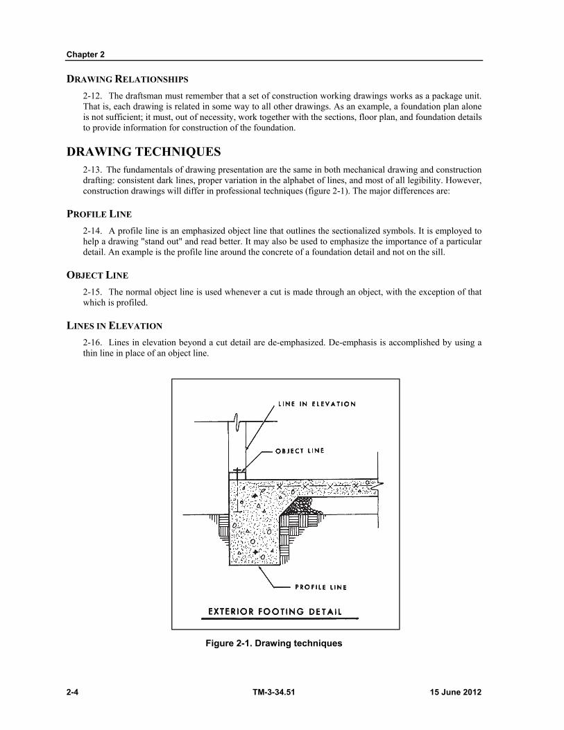
Chapter 2
2-4 TM-3-34.51 15 June 2012
DRAWING RELATIONSHIPS
2-12. The draftsman must remember that a set of construction working drawings works as a package unit. That is, each drawing is related in some way to all other drawings. As an example, a foundation plan alone is not sufficient; it must, out of necessity, work together with the sections, floor plan, and foundation details to provide information for construction of the foundation.
DRAWING TECHNIQUES 2-13. The fundamentals of drawing presentation are the same in both mechanical drawing and construction drafting: consistent dark lines, proper variation in the alphabet of lines, and most of all legibility. However, construction drawings will differ in professional techniques (figure 2-1). The major differences are:
PROFILE LINE
2-14. A profile line is an emphasized object line that outlines the sectionalized symbols. It is employed to help a drawing "stand out" and read better. It may also be used to emphasize the importance of a particular detail. An example is the profile line around the concrete of a foundation detail and not on the sill.
OBJECT LINE
2-15. The normal object line is used whenever a cut is made through an object, with the exception of that which is profiled.
LINES IN ELEVATION
2-16. Lines in elevation beyond a cut detail are de-emphasized. De-emphasis is accomplished by using a thin line in place of an object line.
Figure 2-1. Drawing techniques

Basic Construction Considerations
15 June 2012 TM-3-34.51 2-5
THE ENGINEER, DRAFTSMAN, AND CONSTRUCTION WORKER 2-17. The construction draftsman plays a vital role in the execution of military construction projects. His knowledge must be general in that he has a speaking knowledge with the engineer and construction worker, and a specific knowledge with respect to graphic communication. It is the draftsman's job to interpret the engineer's sketches, calculation results, and ideas into usable working drawings for the construction workers. He should clearly understand his position in the execution of military construction projects and always be expanding his knowledge and technical skills.

This page intentionally left blank.
15 June 2012 TM-3-34.51 3-1
Chapter 3
Topography and Site Plans
INTRODUCTION 3-1. Up to this point the graphic representation of man-made objects has been discussed. Topographic drawing has to do with the graphic representation of portions of earth's surface to a convenient scale. Since the shape of the earth is spherical, any representation on a plane, such as a piece of paper, is necessarily somewhat distorted. In drawing large areas, therefore, some method of projection must be used which results in a minimum of distortion. In such work, the position of the control or reference points is usually defined by spherical reference lines on the drawing. In drawing small areas to a relatively large scale, the distortion due to earth-curvature is so slight as to be unnoticeable, and may therefore be entirely neglected. Surveying and mapping the site is the first step taken in engineering construction projects along with soil testing by geologists. The first sheet of the official construction contract drawings has a location map and a site plan. Therefore all construction draftsmen should be familiar with the methods and symbols (FM 21-31) used on maps and topographic drawings.
CLASSIFICATION OF MAPS 3-2. The information or content on maps is generally classified under three divisions:
BOUNDARIES, BEARINGS AND DISTANCES
3-3. The representation of boundaries, bearings, and distances, such as divisions between areas subject to different authority or ownership, either public or private; or lines indicating geometric measurements on land, on sea and in the air. This division includes plats or land maps, farm surveys, city subdivisions, plats of mineral claims, and nautical and aeronautical charts.
REAL OR MATERIAL FEATURES OR OBJECTS
3-4. The representation of real or material features or objects within the limits of the tract, showing their relative location or size and location, depending upon the purpose of the map. When only relative location is required, the scale may be employed to represent objects, such as houses, bridges, or even towns. When the size of the objects is an important consideration, the scale must be large and the map becomes a real orthographic top view.
ELEVATION
3-5. The vertical distance from a datum, usually mean sea level, to a point or object on the earth's surface. This is not to be confused with altitude which refers to points or objects above the earth's surface. A topographic map which portrays relief by the use of contour lines is referred to as a contour map. A map showing land or submarine bottom relief in terms of height above or below a datum by any method, such as contours, hachures, shading, or tinting is referred to as a hypsographic map.
TYPES OF MAPS 3-6. Various combinations of the above divisions are required for different purposes. Maps are classified according to their intended purpose, as follows:
Geographic Maps. Geographic maps include large areas and consequently must be drawn to a small scale. They show important towns and cities, streams and bodies of water, political boundaries, and relief.

Chapter 3
3-2 TM-3-34.51 15 June 2012
Topographic Maps. Topographic maps are complete descriptions of certain areas and are at a larger scale. They depict the geographic positions of the natural features and the works of man. The relief is usually represented by contours.
Hydrographic Maps. Hydrographic maps deal with information concerning bodies of water such as shore lines, sounding depths, subaqueous contours, navigational aids, and water control.
Nautical Maps. Nautical maps or charts show aids to water navigation, such as buoys, beacons, lighthouses, lanes of traffic, sounding depths, shoals, and radio compass stations.
Aeronautical Maps. Aeronautical maps or charts give prominent landmarks of the terrain and accentuate the relief by layer tints, hachures, and 500or 1,000-foot contours as aids to air navigation.
Cadastral Maps. Cadastral maps are accurate control maps for cities and towns, made to large scale with all features drawn to size. They are used to control city development and operation, particularly as related to taxation.
Engineering Maps. Engineering maps are working maps for engineering projects and are designed for specific purposes to aid construction. They provide accurate horizontal and vertical control data and show objects on the site or along the right of way.
Photogrammetric Maps. Photogrammetric maps represent features on the earth's surface from terrestrial and aerial photographs. These photographs are prespectives from which orthographic views are obtained by stereoscopic instruments. Ground-control stations are necessary to bring photographs to a required datum.
Military Maps. Military maps contain information of military importance in the area represented. Landscape Maps. Landscape maps are used in planning installations of trees, shrubbery, drives,
and so forth, in the artistic design of area improvements. Plats. A map plotted from a plane survey and having the third dimension omitted is called a
"plat" or "land map." It is used in the description of any tract of land when it is not necessary to show relief, as in a farm survey or a city plat, showing the calculation of areas, the location of property lines, or the location of a building project.
DEFINITIONS 3-7. Listed below are some of the more common terms used in topography and they are given to assist in understanding how to draft topographic maps and site plans. For a complete listing of terms and definitions, refer to DOD, Glossary of Mapping, Charting, and Geodetic Terms, dated Dec 1969.
Altitude. The vertical angle measured between the plane of the observer's true horizon and a line to the object.
Azimuth. The horizontal direction of a line measured clockwise from a reference plane, usually the meridian. Often called forward azimuth to differentiate from back azimuth.
Backsight. A sight on a previously established survey point, and one which is not the closing sight of the survey.
Base Line. A surveyed line established with more than usual care, to which surveys are referred for coordination and correlation.
Bench Mark. A marked vertical control point which has been located on a relatively permanent material object, natural or artificial, and whose elevation above or below an adopted datum has been established. It is usually designated as a BM; such a mark is sometimes further qualified as a PBM (permanent bench mark), or as a TBM (temporary bench mark).
Closed Traverse. A traverse that starts and ends at the same station or upon stations whose relative positions have been determined by other surveys of equal or higher order of accuracy.
Contour. An imaginary line on the ground, all points of which are at the same elevation above or below a specific datum surface, usually mean sea level. A contour line is a line on a map or chart connecting points of equal elevation.
Datum. Any numerical or geometrical quantity or set of such quantities which may serve as a reference or base for other quantities.
Topography and Site Plans
15 June 2012 TM-3-34.51 3-3
Elevation. Vertical distance from a datum, usually mean sea level, to a point or object on the earth's surface. Not to be confused with altitude which refers to points or objects above the earth's surface.
Foresight. An observation of the distance and direction to the next instrument station. A point set ahead to be used for reference when resetting the instrument on line or when verifying the alinement Also the reading on a rod that is held at a point whose elevation is to be determined.
Hachures. A method of portraying relief by short, wedge-shaped marks radiating from high elevations and following the direction of slope to the lowland.
Mean Sea Level (MSL). The average height of the surface of the sea for all stages of the tide, usually determined by averaging height readings observed hourly over a minimum period of 19 years.
Monument. A structure used or erected to mark the position of a survey station; permanence is implied.
Plumb Line. The line of force in the geo-potential field. The continuous curve to which the direction of gravity is everywhere tangential.
Profile. A vertical section of the surface of the ground, or of underlying strata, or both, along any fixed line. Thus, if a vertical section were to be cut into the earth, the top line of this section would represent the ground profile.
Traverse. A method of surveying in which lengths and directions of lines between points on the earth are obtained by or from field measurements and used in determining positions of the points. Survey traverses are classified and identified in a variety of ways: According to methods used, as astronomic traverse; according to quality of results, as first-order traverse; according to purpose served, as geographic-exploration traverse ; and according to form, as closed traverse.
TOPOGRAPHIC SYMBOLS AND MAP COLORS 3-8. This paragraph describes some of the symbols and the colors authorized for use in the interpretation of military maps, overlays, and related features and activities. For a more complete discussion, refer to FM 21-31.
SYMBOLS
3-9. So far as is practical, a mapped feature is shown by the same symbol on maps of different scales, but certain modifications and departures are necessary because of varying map uses and scales. Normally, symbols resemble the features they represent. The center and the orientation of a symbol usually corresponds to the true center and orientation of the feature represented. All lines features such as roads, railroads, streams, power lines, and similar features retain, within the limitations of scale, the variations of alinement which actually exist. Along such features as roads, the locations of buildings and other features are necessarily displaced because of the exaggerated size of the symbols. Reference to the positions of such features must be made with caution.
3-10. Where no symbol is prescribed for a specialized local feature, the draftsman is authorized to use a special symbol, providing—(a) There is no conflict with the standardized symbols shown in FM 21-31, and (b) Any special symbol used is explained either in the legend of the drawing, or by appropriate labeling within the body of the drawing, so that no uncertainty may result.
MAP COLORS
3-11. Topographic symbols usually appear in characteristic colors:
Black for cultural (man-made) features other than roads. Blue for water features. Brown for relief features. Green for vegetation. Red for road classifications.
Chapter 3
3-4 TM-3-34.51 15 June 2012
Modifications of these colors are occasionally used on maps to portray unique circumstances. Consequently, the symbol legend and marginal information should be carefully studied before using any map to draw site plans.
SITE SELECTION 3-12. Before making the final selection of a site for housing or storage of supply, it is necessary to consider probable future needs, terrain transportation facilities, provision for utilities and proximity to other military installations.
PRELIMINARY PLANNING
3-13. It is frequently possible to base preliminary drawings on information from maps, photographs, aerial reconnaissance, and personal familiarity with the area. Ground reconnaissance, however, should be made whenever practicable because it is the most reliable method of determining the suitability of a site. The basic features of a site are classified either as "required" or "desirable," depending on the type of project and size of the installation. Because a site cannot be used if it does not have "required" features, they must be given first consideration.
MAJOR CONSIDERATIONS
3-14. The following factors influence the selection of a site and should be included in the ground reconnaissance reports and sketches presented to the draftsman.
Transportation facilities. If a project requires access to transportation facilities, selection of a site adjacent or close to such facilities results in a saving of labor, material, and time.
Terrain. Selection of a site with terrain requiring a minimum of grading becomes more important as the size of the area to be covered by the project increases. Relatively flat, well-drained terrain requires only a small expenditure in labor, material, and time for grading.
Soil. For major depots and large troop housing projects, stable, easily drained soil is particularly desirable. If soil conditions are unfavorable, some type of surfacing is necessary for the storage of equipment or the continual use of areas by troops.
Protective concealment. It takes much more time to camouflage a nondispersed area than to develop a site where dispersion of supplies and structures is relatively easy. The following items are some of the things to remember when selecting a site. Landmarks. Sites should be avoided near landmarks such as: bends of rivers, points of
lands, and road and railroad intersections. Boundary lines. A site should have irregular boundary lines formed by natural features such
as roads, streams, or hedgerows. Concealment. Barren sites are poor from the standpoint of camouflage. A wooded site
should be selected for concealment of buildings. Hills or mountains. The approach of hostile planes can be limited when a site is surrounded
by, or adjacent to, sharply rising hills or mountains. Water. A water supply that is either initially potable or can be made so by ordinary chlorination
and filtration is a prerequisite for large group housing and hospital projects. Sewage disposal. If the site requires waterborne sewage, a suitable outlet for the sewers must be
considered. If the project utilizes pit latrines, it is necessary to have open soil draining away from any source of existing or proposed water supply.
Electric power. Sites for projects requiring electric power should be located near commercial electric power lines from which 50-or 60-hertz alternating current is available. This usually is obtainable only in rear areas.
Proximity to other military installations. Dispersion of sites must not be carried so far as to interfere with the efficient operation of a project. A general depot, for example, may have to be set up at the point on a main line, thus requiring turnouts to dispersed areas. Ammunition and

Topography and Site Plans
15 June 2012 TM-3-34.51 3-5
fuel storage sites should be located far enough from the depot so that if they are bombed other services will not be interrupted.
Expansion. A reasonable degree of expansion should be allowed for in projects, and the areas chosen should be large enough to make this possible.
Available existing facilities. Choosing a site where essential requirements exist results in a saving of material, transportation, labor, and time.
LOCATING BOUNDARY LINES 3-15. The perimeter of any site is formed by a series of connected imaginary lines, each line extending a definite distance in a specific direction. Measurement of these distances and directions in the field is called running a traverse. Traverses usually are run by a survey party using a transit to determine direction and a 100-foot tape to determine distance. (Rough traverses can be run by substituting a compass for a transit. When the survey returns to its original starting point after following the boundary lines in sequence, thus forming a closed figure, it is called a closed traverse.) For a complete discussion of running a construction project traverse, refer to TM 5-233.
RUNNING A TRAVERSE
3-16. In running a traverse, the transit is set up over a corner, sighted along a known traverse line and an angle turned with the transit to establish or measure the direction of the connecting traverse line. The terminal points of traverse lines are called corners. A corner may be indicated in the field by a stake, pipe, or spike driven into the ground, a tack in a tree stump, a chisel mark on an embedded rock, or some other appropriate method. Such a mark is required whenever a traverse line changes direction. Two corners established the length and direction of a traverse line.
MEASURING TRAVERSE ANGLES
3-17. Traverse angles are commonly indicated in field notes as interior or deflection angles and/or bearings.
Interior angles. An interior angle is swung through the inside of the closed figure formed by the traverse lines. It may be greater than 180°, depending on the directions of the connecting lines.
Deflection angle. A deflection angle is the angular distance between a line representing a continuation of a traverse line and the connecting traverse line. In other words, a deflection angle is the difference between the interior angle and 180°. Deflection angles are turned either to the right or left and are marked in the field notes as so many degrees R or L.
Bearings. Interior and deflection angles express the direction of a traverse line relative to its connecting line. A bearing gives the direction of a line relative to a meridian. For example, a bearing is written N 76 E. If the northpointing arrow in the drawing points toward the top of the drawing sheet, this bearing means that the traverse line is drawn from its starting point (corner) toward the right (east) and makes an angle of 76° with any line parallel to the north-pointing arrow.
MEASURING DISTANCES
3-18. Distance measurements do not take into consideration the irregularities of terrain. The tape is always held horizontally and all distances written in a plan view express a horizontal measurement between two points. The distance between the top and bottom of a slope that appears in field notes represents the sum of a series of horizontal measurements. The slant height of the slope is calculated as the hypotenuse of a triangle, from a knowledge of the elevations at top and bottom (vertical distance) and the horizontal distance between these points. The use of horizontal distances only in a plan view is consistent with the principles of orthographic projection. Distances are written decimally in field notes because the 100-foot tape is divided into feet and decimal subdivisions thereof.
Chapter 3
3-6 TM-3-34.51 15 June 2012
MEASURING ELEVATIONS 3-19. In ground reconnaissance, elevations usually are measured with the aid of a surveying instrument called a level, which is used to establish ground heights relative to a reference elevation called a bench mark.
BENCH MARK
3-20. A bench mark is given either an arbitrary elevation or an elevation in relation to some common datum. Elevations, bench marks, and contours shown on standard maps refer to mean sea level, which is considered zero. When indicated in a drawing, a bench mark is indicated by a symbol, a written elevation, and the abbreviation B.M. A note may be used to identify the symbol as a stake, geodetic monument, or other marker.
CONTOUR LINES
3-21. Contour lines can be pictured best by imagining a cone-shaped hill with the sides fluted or otherwise irregular. If a horizontal cutting plane is passed through the hill, the outline of the section thus exposed forms a closed figure with an irregularly shaped perimeter. Because the cutting plane is horizontal, all points on the perimeter are at the same elevation. Outlines of horizontal sections taken at different elevations will show figures of different size and shape. In all cases the height taken at any point on the perimeter of the figure is equal to the height taken at any other point on the perimeter of the same figure. A contour forms a closed figure either within or beyond the limits of the drawing sheet. Any point on a contour has the same elevation as any other point.
LAYING OUT A GRID TO MEASURE CONTOURS
3-22. The usual method of establishing contours is to run a series of parallel transit lines spaced at equal intervals. Nails or other markers are used to establish the terminal points of each line. Markers are also placed at equal intervals along the lines between the terminal points. The effect is to create a grid or rectangular coordinate framework. Each point may be given a unique designation by numbering the lines progressing in one direction and lettering the lines progressing in the other. Ground elevation is taken at each point and recorded in the field notes.
LOCATING PHYSICAL DETAILS
GRID
3-23. Existing physical details lying within the boundaries of a construction site may be located easily by using the grid that was laid out to establish contours. As in the construction of a graph, points on a grid are located by their rectangular coordinates. This involves only a distance measured perpendicularly to a reference line and establishes the two coordinates of the point. When laid out, a grid provides convenient reference lines for measuring horizontal linear distances both before and during construction. A grid system laid out for locating construction points is called a local grid. For a more complete discussion of local grids, and methods of locating features, refer to chapter 13, TM 5-232.
TRAVERSE LINES
3-24. The location of the physical details relative to traverse lines may be indicated in field notes by one of the following methods.
Perpendicular offsets. This method is useful in locating roads, streams, or utility lines running adjacent to a traverse line. At measured intervals along the traverse line, the perpendicular distance between the traverse line and adjacent detail is measured. These intervals are related to convenient reference points, such as corners or traverse stations. The measurements to the detail from successive stations are called perpendicular offsets.
Topography and Site Plans
15 June 2012 TM-3-34.51 3-7
Ties. A horizontal linear measurement from a known point to a point whose location is unknown is called a tie. A point may be located by ties from two known points.
Polar coordinates. A point located by an angle and a distance from a known point.
PLOTTING SITE PLAN DATA 3-25. A site plan is drawn by plotting the survey data contained in field notes and sketches.
BOUNDARY LINES Tools. A protractor and engineer's scale are the only measuring tools needed for plotting angles
and distances. A pencil, triangle, and straightedge are the necessary basic drawing tools. Drawing boundary lines. First, draw a rough sketch of the traverse to scale, which will give an
idea of the relative lengths of the traverse lines. Select a scale suitable to the size of the area being represented and the amount of detail shown. Using the sketch as a guide, draw the first line of the traverse so that the other traverse lines will lie on the drawing sheet. Use the scale to mark the two extremities at the first line and allow the line to extend beyond the angle points just marked. Place the vertex mark of the protractor on the angle point with the 0° and 180° marks on the line just drawn. Lay off the angle corresponding to the traverse angle at this point, and line up the straightedge along the corner point and the point just marked. Draw the connecting traverse line, scale the length of the second line, and repeat the process just described until all traverse lines have been drawn. If a traverse is a closed traverse, the boundary lines of the site plan should close on paper. If the plot does not close, check the scale and protractor measurements against the distances and angles given in the field notes. Make sure that angles are drawn in a direction corresponding to the direction that they were turned in the field. Cumulative angular errors can be avoided by plotting half of the traverse from one end of the starting line and the other half from the other end.
CONTOUR LINES
3-26. Drawing contour lines in a plan view permits the three principal dimensions, height, width, and depth, to be shown in a single view.
Plotting contour points. On the drawing sheet, construct to scale the grid used in the field notes, using a pencil (4H) and drawing the lines lightly. Mark the elevations at the intersections of the grid lines and interpolate, by eye, and mark points where the elevations approximate a multiple of 10. For example, if the elevation at an intersection is 105 and at intersection vertically above it is 115, mark a point midway between on the vertical gridline connecting the two intersections. This point represents an elevation of 110. Locate all elevations representing a multiple of 10 in the same manner; if there is little variation in elevation, a smaller interval than 10 may be used. In a plan drawn to small scale, representing a large area with steep contours, an interval larger than 10 may be used to avoid crowding the drawing with contour lines.
Drawing contour lines. All points on a contour have the same elevation and should form a closed figure if they lie on the drawing sheet. Connect all points of the same elevation freehand so they form a closed figure or extend to the site boundary lines. Contour lines should be unbroken except at one point to allow the elevation to be written. Every fifth contour line should be heavier. Elevations. Elevations are written as simple figures without any unit indications. When
possible, they should be alined so that the elevations of the contours may be read at a glance.
Inking. When inking contours on tracing paper or cloth, use a fine freehand pen, such as Gillott's 170, Esterbrook's 356, or any equivalent pen.
Chapter 3
3-8 TM-3-34.51 15 June 2012
PLOTTING DETAILS
3-27. Details are located in the site plan by methods of measurement corresponding to those used in the field.
Locating details from traverse lines. When points have been located in the field by ties, a large compass may be used to swing arcs from the points on the drawing sheet to represent those used in the field. The radius of each arc corresponds to a tie distance. Perpendicular offset and polar coordinate methods are repeated, with distances measured to scale and angles measured with a protractor.
Grid. Gridlines and measurements are reproduced to scale on the drawing sheet. Symbols. Topographic details are represented by symbols showing physical features such as
water surfaces, soil composition, limits of cultivation, roads, fences, and buildings in their proper relative locations. Figure 3-1 shows soil symbols used to indicate soil composition in a site plan. Buildings are represented by a single-line plan view showing the shape of their exterior walls. Other topographic symbols can be found in FM 21-31. Cartographic drawing is covered in detail in TM 5-240.
NOTES AND DIMENSIONS
3-28. Each boundary line is identified by a distance and bearing written parallel to the line. A north-pointing arrow is placed on the drawing. Utility lines, buildings, roads, and streams are identified by name in specific notes. The scale is written in the title box. Distances are given between principal details and reference lines.
DRAWING AREA LAYOUT
3-29. Road centerlines are drawn first. Note that all dimensions are location dimensions and related to the main reference lines. Buildings are diagrammatic; no architectural symbols are used. Size dimensions and building types are given in the schedule at the foot of the drawing. Buildings are located first, then drawn to scale.
Roads. Road centerlines are not indicated in the finished drawing. Roads are indicated by parallel lines; the distance between them includes ditches, shoulders, and travelways. For a complete discussion of roads, refer to chapter 13.
Buildings. Each building is given a code letter by which it can be identified in the schedule. This prevents cluttering the drawing area with dimension lines and figures in a drawing made to small scale and involving many buildings of standard construction.
AREA LAYOUT AND SITE PLAN
3-30. When locating an area layout in a site plan, the area layout must be oriented with north-pointing arrows to distinguish site north from magnetic north. Physical details such as contours, streams, and railroads are included in the drawing. A typical area layout is discussed in paragraph 4-3.
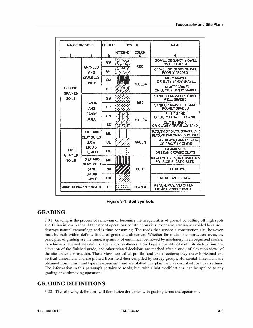
Topography and Site Plans
15 June 2012 TM-3-34.51 3-9
Figure 3-1. Soil symbols
GRADING 3-31. Grading is the process of removing or lessening the irregularities of ground by cutting off high spots and filling in low places. At theater of operations construction sites, extensive grading is avoided because it destroys natural camouflage and is time consuming. The roads that service a construction site, however, must be built within definite limits of grade and alinement. Whether for roads or construction areas, the principles of grading are the same; a quantity of earth must be moved by machinery in an organized manner to achieve a required elevation, shape, and smoothness. How large a quantity of earth, its distribution, the elevation of the finished grade, and other related decisions are reached after a study of elevation views of the site under construction. These views are called profiles and cross sections; they show horizontal and vertical dimensions and are plotted from field data compiled by survey groups. Horizontal dimensions are obtained from transit and tape measurements and are plotted in a plan view as described for traverse lines. The information in this paragraph pertains to roads, but, with slight modifications, can be applied to any grading or earthmoving operation.
GRADING DEFINITIONS 3-32. The following definitions will familiarize draftsmen with grading terms and operations.
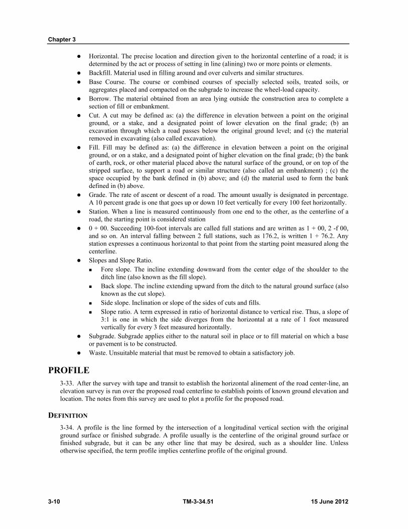
Chapter 3
3-10 TM-3-34.51 15 June 2012
Horizontal. The precise location and direction given to the horizontal centerline of a road; it is determined by the act or process of setting in line (alining) two or more points or elements.
Backfill. Material used in filling around and over culverts and similar structures. Base Course. The course or combined courses of specially selected soils, treated soils, or
aggregates placed and compacted on the subgrade to increase the wheel-load capacity. Borrow. The material obtained from an area lying outside the construction area to complete a
section of fill or embankment. Cut. A cut may be defined as: (a) the difference in elevation between a point on the original
ground, or a stake, and a designated point of lower elevation on the final grade; (b) an excavation through which a road passes below the original ground level; and (c) the material removed in excavating (also called excavation).
Fill. Fill may be defined as: (a) the difference in elevation between a point on the original ground, or on a stake, and a designated point of higher elevation on the final grade; (b) the bank of earth, rock, or other material placed above the natural surface of the ground, or on top of the stripped surface, to support a road or similar structure (also called an embankment) ; (c) the space occupied by the bank defined in (b) above; and (d) the material used to form the bank defined in (b) above.
Grade. The rate of ascent or descent of a road. The amount usually is designated in percentage. A 10 percent grade is one that goes up or down 10 feet vertically for every 100 feet horizontally.
Station. When a line is measured continuously from one end to the other, as the centerline of a road, the starting point is considered station
0 + 00. Succeeding 100-foot intervals are called full stations and are written as 1 + 00, 2 -f 00, and so on. An interval falling between 2 full stations, such as 176.2, is written 1 + 76.2. Any station expresses a continuous horizontal to that point from the starting point measured along the centerline.
Slopes and Slope Ratio. Fore slope. The incline extending downward from the center edge of the shoulder to the
ditch line (also known as the fill slope). Back slope. The incline extending upward from the ditch to the natural ground surface (also
known as the cut slope). Side slope. Inclination or slope of the sides of cuts and fills. Slope ratio. A term expressed in ratio of horizontal distance to vertical rise. Thus, a slope of
3:1 is one in which the side diverges from the horizontal at a rate of 1 foot measured vertically for every 3 feet measured horizontally.
Subgrade. Subgrade applies either to the natural soil in place or to fill material on which a base or pavement is to be constructed.
Waste. Unsuitable material that must be removed to obtain a satisfactory job.
PROFILE 3-33. After the survey with tape and transit to establish the horizontal alinement of the road center-line, an elevation survey is run over the proposed road centerline to establish points of known ground elevation and location. The notes from this survey are used to plot a profile for the proposed road.
DEFINITION
3-34. A profile is the line formed by the intersection of a longitudinal vertical section with the original ground surface or finished subgrade. A profile usually is the centerline of the original ground surface or finished subgrade, but it can be any other line that may be desired, such as a shoulder line. Unless otherwise specified, the term profile implies centerline profile of the original ground.
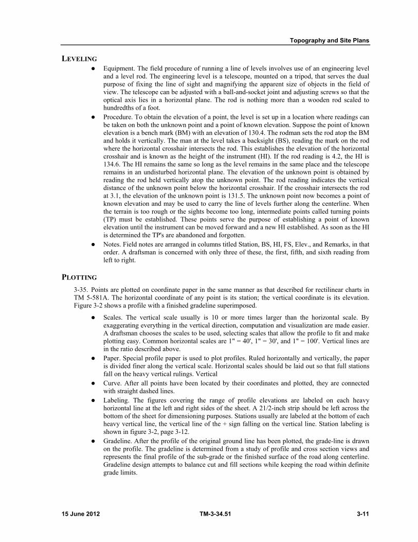
Topography and Site Plans
15 June 2012 TM-3-34.51 3-11
LEVELING Equipment. The field procedure of running a line of levels involves use of an engineering level
and a level rod. The engineering level is a telescope, mounted on a tripod, that serves the dual purpose of fixing the line of sight and magnifying the apparent size of objects in the field of view. The telescope can be adjusted with a ball-and-socket joint and adjusting screws so that the optical axis lies in a horizontal plane. The rod is nothing more than a wooden rod scaled to hundredths of a foot.
Procedure. To obtain the elevation of a point, the level is set up in a location where readings can be taken on both the unknown point and a point of known elevation. Suppose the point of known elevation is a bench mark (BM) with an elevation of 130.4. The rodman sets the rod atop the BM and holds it vertically. The man at the level takes a backsight (BS), reading the mark on the rod where the horizontal crosshair intersects the rod. This establishes the elevation of the horizontal crosshair and is known as the height of the instrument (HI). If the rod reading is 4.2, the HI is 134.6. The HI remains the same so long as the level remains in the same place and the telescope remains in an undisturbed horizontal plane. The elevation of the unknown point is obtained by reading the rod held vertically atop the unknown point. The rod reading indicates the vertical distance of the unknown point below the horizontal crosshair. If the crosshair intersects the rod at 3.1, the elevation of the unknown point is 131.5. The unknown point now becomes a point of known elevation and may be used to carry the line of levels further along the centerline. When the terrain is too rough or the sights become too long, intermediate points called turning points (TP) must be established. These points serve the purpose of establishing a point of known elevation until the instrument can be moved forward and a new HI established. As soon as the HI is determined the TP's are abandoned and forgotten.
Notes. Field notes are arranged in columns titled Station, BS, HI, FS, Elev., and Remarks, in that order. A draftsman is concerned with only three of these, the first, fifth, and sixth reading from left to right.
PLOTTING
3-35. Points are plotted on coordinate paper in the same manner as that described for rectilinear charts in TM 5-581A. The horizontal coordinate of any point is its station; the vertical coordinate is its elevation. Figure 3-2 shows a profile with a finished gradeline superimposed.
Scales. The vertical scale usually is 10 or more times larger than the horizontal scale. By exaggerating everything in the vertical direction, computation and visualization are made easier. A draftsman chooses the scales to be used, selecting scales that allow the profile to fit and make plotting easy. Common horizontal scales are 1" = 40', 1" = 30', and 1" = 100'. Vertical lines are in the ratio described above.
Paper. Special profile paper is used to plot profiles. Ruled horizontally and vertically, the paper is divided finer along the vertical scale. Horizontal scales should be laid out so that full stations fall on the heavy vertical rulings. Vertical
Curve. After all points have been located by their coordinates and plotted, they are connected with straight dashed lines.
Labeling. The figures covering the range of profile elevations are labeled on each heavy horizontal line at the left and right sides of the sheet. A 21/2-inch strip should be left across the bottom of the sheet for dimensioning purposes. Stations usually are labeled at the bottom of each heavy vertical line, the vertical line of the + sign falling on the vertical line. Station labeling is shown in figure 3-2, page 3-12.
Gradeline. After the profile of the original ground line has been plotted, the grade-line is drawn on the profile. The gradeline is determined from a study of profile and cross section views and represents the final profile of the sub-grade or the finished surface of the road along centerline. Gradeline design attempts to balance cut and fill sections while keeping the road within definite grade limits.
Chapter 3
3-12 TM-3-34.51 15 June 2012
Figure 3-2. Ground profile with gradeline
CROSS SECTIONS 3-36. Cross sections are elevations of the original ground lying on either side of the centerline and are taken along a line running perpendicularly to the centerline. The transverse lines usually are established at 50-foot intervals along the center-line, although intervals are closer together when there are abrupt changes in terrain.
FIELD PROCEDURE
3-37. Cross sectioning combines horizontal and vertical measurements. The horizontal measurements include the stations along the centerline and the perpendicular distances to the right and left of each, where the rod is held. Right and left distances are random and are measured to points, within the road width, where the ground changes slope most abruptly. Vertical measurements are the elevations taken at the centerline stations and the measured points on either side.
FIELD NOTES
3-38. Field notes for cross sections occupy two adjacent pages of the notebook used for recording survey party data. The left-hand page corresponds to the leveling notes kept for profiles. The right-hand page gives elevations and distances out for each station recorded on the left.
Sequence of notes. Level notes for cross sections usually are recorded up the page, with the lowest station at the bottom.
Typical notes. Field notes may record the actual ground elevation rather than leaving these calculations to be made in the office. Using this method, the right-hand page of field notes for figure 3-3 would appear as follows.
Left
Centerline Right
34 20 5 0 15 37
65.2 63.3 64.4 64.3 63.5 64.4
Note that the distance out from the centerline appears as the numerator in the field notes. The centerline elevation needs no numerator. Left and right on the page correspond to these directions in the field when standing at station 1 + 00 and facing station 2 + 00. The station number 1 + 00 would appear on the left-hand page, adjacent to the cross section data, with other leveling information.

Topography and Site Plans
15 June 2012 TM-3-34.51 3-13
PLOTTING CROSS SECTIONS
3-39. Cross sections are plotted on cross section paper (figure 3-3). The sub-grade elevation of the finished section at each station is read from the profile. Cross section levels are taken with an instrument in the field or, if time does not permit, ground elevations may be read from a contour map. Cross sections are usually plotted to the same vertical and horizontal scale, but if the vertical cut or fill is small in comparison with the width, an exaggerated vertical scale may be used without reducing accuracy. If an exaggerated scale is used, it should be used throughout to avoid errors and the proper factor must be applied to instrument reading when the planimeter is used to determine cross section areas. The use of a template of the finished section, constructed to the proper scale, will facilitate the scales should be arranged so that even 5or 10-foot elevations fall on a heavy horizontal ruling, plotting of cross sections. Cross sections are also plotted at any intermediate place where there is a distinct change in slope along the centerline, where the natural ground profile and the grade line correspond, i.e., the earthwork changes from cut to fill, and where the surface on either side of the centerline is uneven enough to require plotting a section in order to represent properly the volumes indicated between the cross sections.
Figure 3-3. Cross section of a road
ESTIMATE OF EARTHWORK 3-40. Planning earthmoving operations is as important as planning any other phase of construction work. Detailed progress schedules are set up so that maximum efficiency can be attained. As in other construction operations, schedules are based on the estimate of the quantities involved. It is necessary to know where the cut and fill sections are located, the quantity to be removed in cut, and the quantity to be added in fill. Earthwork quantities are measured by volume with the cubic yard as the unit of measurement. Volumes are estimated by computing the area of cut or fill in each cross section, averaging it with the area of cut or fill in the next cross section and multiplying the average area by the distance between the two cross sections. This tells how much earth must be added in fill or taken away in cut between the two points at which cross sections where taken. The procedure is repeated for the entire length of the road.
DETERMINATION OF END AREAS 3-41. The area to be calculated is enclosed between the ground line and the gradeline. The figure formed in this fashion is called an end area; it rarely, if ever, assumes a simple geometric shape. End areas, therefore, cannot be determined by a simple geometric formula. Several methods are used, depending on the degree of accuracy desired. (For a more complete discussion on area computations, refer to TM 5-232.)
PLANIMETER
3-42. The simplest method utilizes an instrument called a planimeter. It has two arms, one of which has a pin in the end and the other a calibrated wheel. The arm with the pin is pressed into the board, off to the
Chapter 3
3-14 TM-3-34.51 15 June 2012
side of the drawing, and held stationary; the other arm, with the calibrated wheel, is traced over the perimeter of the cross section. The area is then read directly from the instrument.
COUNTING SQUARES
3-43. This method consists of counting the enclosed squares formed by the cross section paper rulings; the total of the enclosed squares is multiplied by the area in square feet of one square to give the area of the section in square feet. The area in square feet of one square is determined by the horizontal and vertical scales used in plotting the cross section.
DOUBLE-MERIDIAN DISTANCE METHOD
3-44. To determine areas of cross sections, the Army uses the modified double meridian distance method. This method involves more computations than other methods of determining cross-sectional area, but it is adaptable to a cross section of any shape. In studying the double-meridian distance method (DMD) it is important to remember that distances are added and elevations are subtracted.
TRAPEZOIDAL METHOD
3-45. In the trapezoidal method, the area is obtained by breaking the cross section into a series of trapezoids and triangles. Areas of component parts are calculated and added together. When the procedure uses the sum of the bases of the trapezoids and the entire base length of the triangles, the area obtained will be double the true area until the division by two is made in the final step of the operation. Bases of the trapezoids are taken as vertical lines drawn through break points on either the grade or ground line. Length of bases is equal to difference in elevation in feet between ground line and gradeline. (All areas of individual trapezoids are triangles and are added and then divided by two to obtain the area of the cross section points.)
GRAPHIC ORGANIZATION OF EARTHWORK 3-46. A mass diagram is the best means of making a study of excavation, embankment, and haul requirements to determine the quickest way to complete an earthmoving job. It also serves as a guide in determining what equipment to assign to specific portions of the haul. The diagram is a graph in which the algebraic sum of the embankment and excavation is plotted as the ordinate and the linear distance as the abscissa. Algebraic sums are obtained by using excavation quantities as positive and embankment quantities as negative. The mass diagram is used also to determine the most economical distribution of materials. Because the amount of excess material between any two points can be determined, a careful study of the diagram will show where it will be expedient to waste material and to borrow closer to the area to be filled. In making a decision to borrow, the work involved in opening and closing a borrow pit, and in wasting excess material, must be balanced against the decreased yardage output of the same equipment at longer hauls. When there are both cut and fill volumes between stations, the diagram shows only the volume of earth necessary to complete the balance; therefore, when cut and fill volumes balance between two stations the diagram may show no earth haul necessary. Earthwork sheets should be used with the diagram in determining equipment requirements. For more complete details of the mass diagram method, refer to TM 5-330.
15 June 2012 TM 3-34.51 4-1
Chapter 4
Building Drawings
INTRODUCTION 4-1. Construction drawings are based on the same general principles as are all other technical drawings. The shape of a structure is described in orthographic views drawn to scale. Its size is described by figured dimensions, whose extent is indicated by dimension lines, arrowheads, and extension lines. Overall relationships are shown in general drawings similar to assembly drawings. Important specific features are shown in detail drawings usually drawn to a larger scale than the general drawings. Additional information about size and material is furnished in the specific and general notes. All these principles, however, have certain applications and terminology peculiar to building construction drawing that are determined by the materials and methods of construction and the conventional practices of construction drawing.
VIEWS IN BUILDING DRAWINGS 4-2. The views of a structure are presented in general and detail drawings. General drawings consist of plans and elevations; detail drawings are made up of sectional and detail views.
PLANS 4-3. A plan corresponds to a top view, namely, a projection on a horizontal plane. There are several types of plan views which are used for specific purposes, such as site plans, foundation plans, and floor plans.
SITE PLAN
4-4. A site plan shows the building site with boundaries, contours, existing roads, utilities, and other physical details such as trees and buildings. Figure 4-1, page 4-3, is a typical site plan. Site plans are drawn from notes and sketches based upon a survey. The layout of the structure is superimposed on the contour drawings, and corners of the structure are located by reference to established natural objects or other buildings.
FOUNDATION PLAN
4-5. A foundation plan is a top view of the footings or foundation walls, showing their area, and location by distances between centerlines and distances from reference lines or boundary lines. Foundation walls are located by dimensions to their corners, and all openings in foundation walls are shown. Figure 4-2, page 4-4, shows the typical foundation plans for alternate conditions.
FLOOR PLAN
4-6. Floor plans, commonly referred to as plan views, are cross section views of a building. The horizontal cutting plane is passed so that it includes all doors and window openings. A floor plan (fig 4-3, page 4-6) shows the outside shape of the buildings; the arrangement, size and shape of rooms; the type of materials; the thickness of walls and partitions; and the type, size, and location of doors and windows for each story. A plan also may include details of framework and structure, although these features are usually shown on separate drawings called framing plans.
Chapter 4
4-2 TM 3-34.51 15 June 2012
PROCEDURE FOR DRAWING PLANS
4-7. Plan views are drawn first because other views depend upon the plan views for details and dimensions.
Orientation. Plan views may be drawn so that the front of the building is at the bottom or right of the sheet. However, when this is not practical, they may be drawn in any arrangement which space permits. Select a suitable scale and lay out the line representing the exterior face of the front wall. Draw the line lightly and allow enough space for notes and dimensions at the bottom or right of the working area. Then, for a symmetrical plan such as figure 4-3, page 4-6, draw the main axis. The main axis corresponds to the center line of a view and is helpful in centering a plan view.
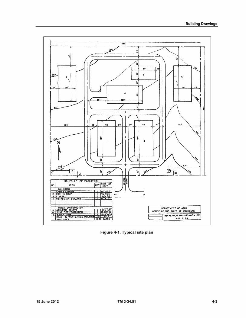
Building Drawings
15 June 2012 TM 3-34.51 4-3
Figure 4-1. Typical site plan
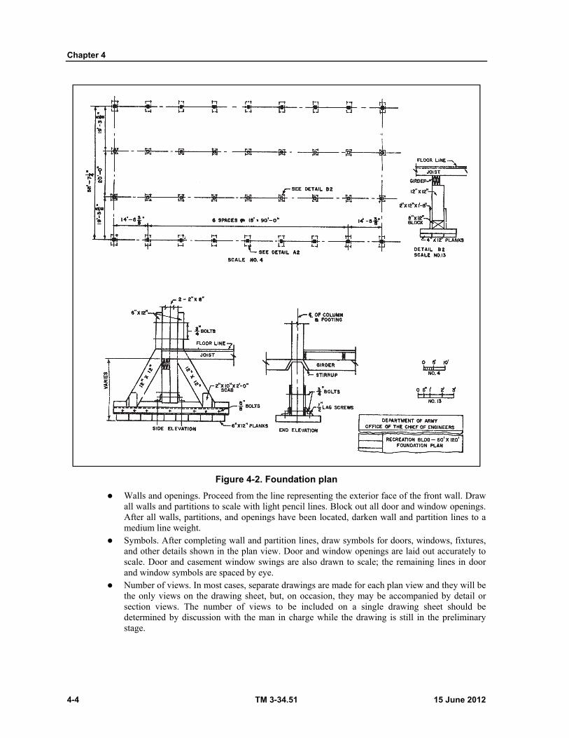
Chapter 4
4-4 TM 3-34.51 15 June 2012
Figure 4-2. Foundation plan
Walls and openings. Proceed from the line representing the exterior face of the front wall. Draw all walls and partitions to scale with light pencil lines. Block out all door and window openings. After all walls, partitions, and openings have been located, darken wall and partition lines to a medium line weight.
Symbols. After completing wall and partition lines, draw symbols for doors, windows, fixtures, and other details shown in the plan view. Door and window openings are laid out accurately to scale. Door and casement window swings are also drawn to scale; the remaining lines in door and window symbols are spaced by eye.
Number of views. In most cases, separate drawings are made for each plan view and they will be the only views on the drawing sheet, but, on occasion, they may be accompanied by detail or section views. The number of views to be included on a single drawing sheet should be determined by discussion with the man in charge while the drawing is still in the preliminary stage.

Building Drawings
15 June 2012 TM 3-34.51 4-5
ELEVATIONS 4-8. Elevations are external views of a structure and may be drawn to show the front, rear, right or left side-views. They correspond to the front, rear, or side views in orthographic projection because they are projections on vertical planes. An elevation is a picture-like view of a building that shows exterior materials and the height of windows, doors, and rooms as in figure 4-4, page 4-8. It may also show the ground level surrounding the structure, called the grade. The following procedure is used for developing an elevation:

Chapter 4
4-6 TM 3-34.51 15 June 2012
Figure 4-3. Typical floor plan
Building Drawings
15 June 2012 TM 3-34.51 4-7
PROJECTION
4-9. Complete a related plan view and a typical section before beginning to draw an elevation. These are equivalent to top and side views in machine drawing. The plan and section should be drawn to the same scale decided for the elevation. The section may be placed to one side of the drawing sheet for the elevation. The section should show the foundation, gradeline, finished floor heights, heights of sills and heads for windows and doors, and the pitch of the roof.
Vertical dimensions. Project the grade-line across from the typical section first. Next project the floor and ceiling heights. Use light pencil lines,
Horizontal dimensions. Fasten the plan view above the drawing sheet, arranged so that the wall corresponding to the one drawn in elevation is placed nearest to the elevation drawing sheet and parallel to the floor lines. Project lines down from the plan view.
Procedure. Work back and forth between the plan and section until exterior details for the elevation in question have been located.
LINES AND SYMBOLS
4-10. Darken the building outlines and the outlines of doors and windows, and add line and material symbol.
Line symbols. Finished floor lines are indicated in an elevation by alternate long and short dashes (same as center line symbol, (figure 4-4, page 4-8) drawn over the other lines. Foundations below grade are shown by the line symbol for hidden details.
Roof drains. When used, rain gutters and downspouts are shown in an elevation view.
NOTES AND DIMENSIONS
4-11. Draw guidelines and letter the specific notes identifying building materials. If more than one view is shown on a drawing sheet, identify each view by title. If any view is drawn to a scale different from that shown in the title block, note the scale beneath the view title. No horizontal dimensions are given in an elevation.
Elevations. Finished floor and grade elevations are written as a note, accompanied by a dimension, written on the line symbol denoting the finished floor; the line symbol is extended beyond the building area (figure 4-4) for this purpose. Grade elevations may be given at two points for a sloping gradeline.
Pane dimensions. Pane dimensions are given in the window schedule.
NUMBER OF ELEVATIONS
4-12. The number of elevations drawn for any building is principally determined by the complexity of its shape. A building that is symmetrical about a centerline in the plan view may show adjacent half elevations of the front and rear. Roof, floor, and foundation lines are continuous; a vertical centerline symbol separates the two halves, which are identified by titles centered under each one.
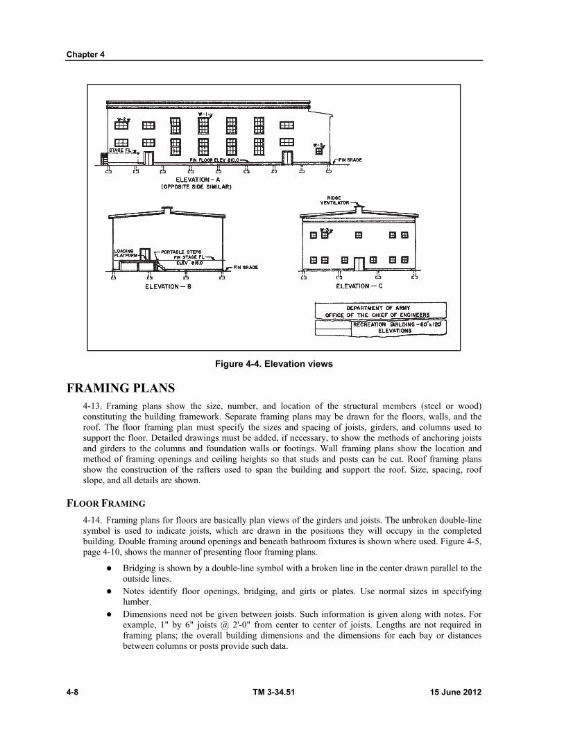
Chapter 4
4-8 TM 3-34.51 15 June 2012
Figure 4-4. Elevation views
FRAMING PLANS 4-13. Framing plans show the size, number, and location of the structural members (steel or wood) constituting the building framework. Separate framing plans may be drawn for the floors, walls, and the roof. The floor framing plan must specify the sizes and spacing of joists, girders, and columns used to support the floor. Detailed drawings must be added, if necessary, to show the methods of anchoring joists and girders to the columns and foundation walls or footings. Wall framing plans show the location and method of framing openings and ceiling heights so that studs and posts can be cut. Roof framing plans show the construction of the rafters used to span the building and support the roof. Size, spacing, roof slope, and all details are shown.
FLOOR FRAMING
4-14. Framing plans for floors are basically plan views of the girders and joists. The unbroken double-line symbol is used to indicate joists, which are drawn in the positions they will occupy in the completed building. Double framing around openings and beneath bathroom fixtures is shown where used. Figure 4-5, page 4-10, shows the manner of presenting floor framing plans.
Bridging is shown by a double-line symbol with a broken line in the center drawn parallel to the outside lines.
Notes identify floor openings, bridging, and girts or plates. Use normal sizes in specifying lumber.
Dimensions need not be given between joists. Such information is given along with notes. For example, 1" by 6" joists @ 2'-0" from center to center of joists. Lengths are not required in framing plans; the overall building dimensions and the dimensions for each bay or distances between columns or posts provide such data.
Building Drawings
15 June 2012 TM 3-34.51 4-9
WALL FRAMING
4-15. Wall framing plans are detail drawings showing the location of studs, plates, sills, girts, and bracing. They show one wall at a time and usually are shown as elevation views.
Door and window framing is shown in wall framing details; openings are indicated by intersecting, single-line diagonals and are identified by the abbreviations D and W.
Bracing is indicated by a dashed, double-line symbol and is drawn to scale in its correct location. Dimensions. Vertical dimensions given overall height from the bottom of the sill (for first floor)
on the top of the plate or girt. Horizontal dimensions give the spacing of studs on centers. Notes. Specific notes identify types of doors and windows or make reference to general notes.
General notes give instructions about such factors as variations in door and window framing, and the installation of bracing.
ROOF FRAMING
4-16. Framing plans for roofs are drawn in the same manner as floor framing plans. A draftsman should visualize himself as looking down on the roof before any of the roofing material (sheathing) has been added. Rafters are shown in the same manner as joists.
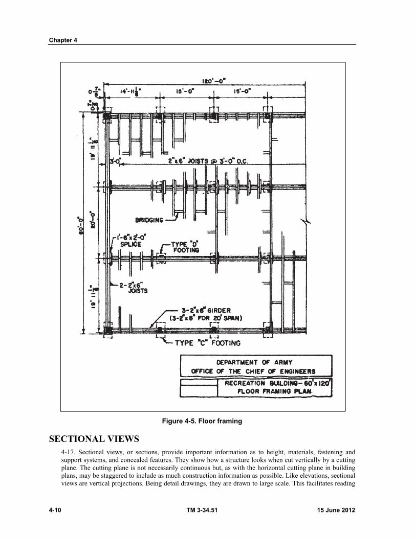
Chapter 4
4-10 TM 3-34.51 15 June 2012
Figure 4-5. Floor framing
SECTIONAL VIEWS 4-17. Sectional views, or sections, provide important information as to height, materials, fastening and support systems, and concealed features. They show how a structure looks when cut vertically by a cutting plane. The cutting plane is not necessarily continuous but, as with the horizontal cutting plane in building plans, may be staggered to include as much construction information as possible. Like elevations, sectional views are vertical projections. Being detail drawings, they are drawn to large scale. This facilitates reading
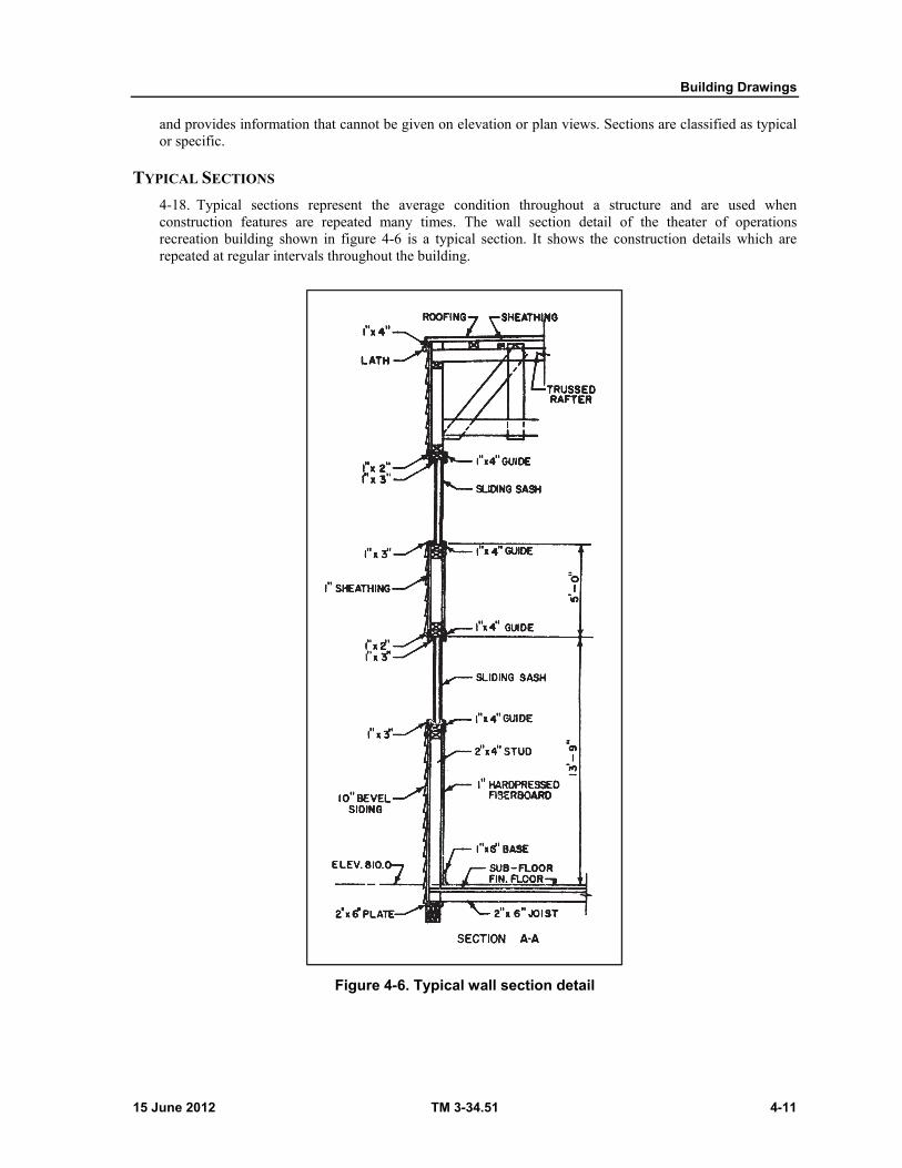
Building Drawings
15 June 2012 TM 3-34.51 4-11
and provides information that cannot be given on elevation or plan views. Sections are classified as typical or specific.
TYPICAL SECTIONS
4-18. Typical sections represent the average condition throughout a structure and are used when construction features are repeated many times. The wall section detail of the theater of operations recreation building shown in figure 4-6 is a typical section. It shows the construction details which are repeated at regular intervals throughout the building.
Figure 4-6. Typical wall section detail
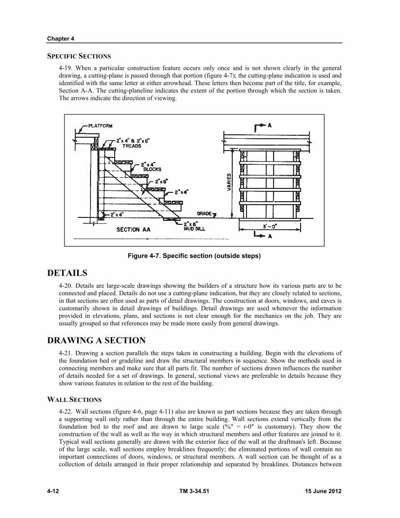
Chapter 4
4-12 TM 3-34.51 15 June 2012
SPECIFIC SECTIONS
4-19. When a particular construction feature occurs only once and is not shown clearly in the general drawing, a cutting-plane is passed through that portion (figure 4-7); the cutting-plane indication is used and identified with the same letter at either arrowhead. These letters then become part of the title, for example, Section A-A. The cutting-planeline indicates the extent of the portion through which the section is taken. The arrows indicate the direction of viewing.
Figure 4-7. Specific section (outside steps)
DETAILS 4-20. Details are large-scale drawings showing the builders of a structure how its various parts are to be connected and placed. Details do not use a cutting-plane indication, but they are closely related to sections, in that sections are often used as parts of detail drawings. The construction at doors, windows, and eaves is customarily shown in detail drawings of buildings. Detail drawings are used whenever the information provided in elevations, plans, and sections is not clear enough for the mechanics on the job. They are usually grouped so that references may be made more easily from general drawings.
DRAWING A SECTION 4-21. Drawing a section parallels the steps taken in constructing a building. Begin with the elevations of the foundation bed or gradeline and draw the structural members in sequence. Show the methods used in connecting members and make sure that all parts fit. The number of sections drawn influences the number of details needed for a set of drawings. In general, sectional views are preferable to details because they show various features in relation to the rest of the building.
WALL SECTIONS
4-22. Wall sections (figure 4-6, page 4-11) also are known as part sections because they are taken through a supporting wall only rather than through the entire building. Wall sections extend vertically from the foundation bed to the roof and are drawn to large scale (%" = r-0" is customary). They show the construction of the wall as well as the way in which structural members and other features are joined to it. Typical wall sections generally are drawn with the exterior face of the wall at the draftman's left. Because of the large scale, wall sections employ breaklines frequently; the eliminated portions of wall contain no important connections of doors, windows, or structural members. A wall section can be thought of as a collection of details arranged in their proper relationship and separated by breaklines. Distances between
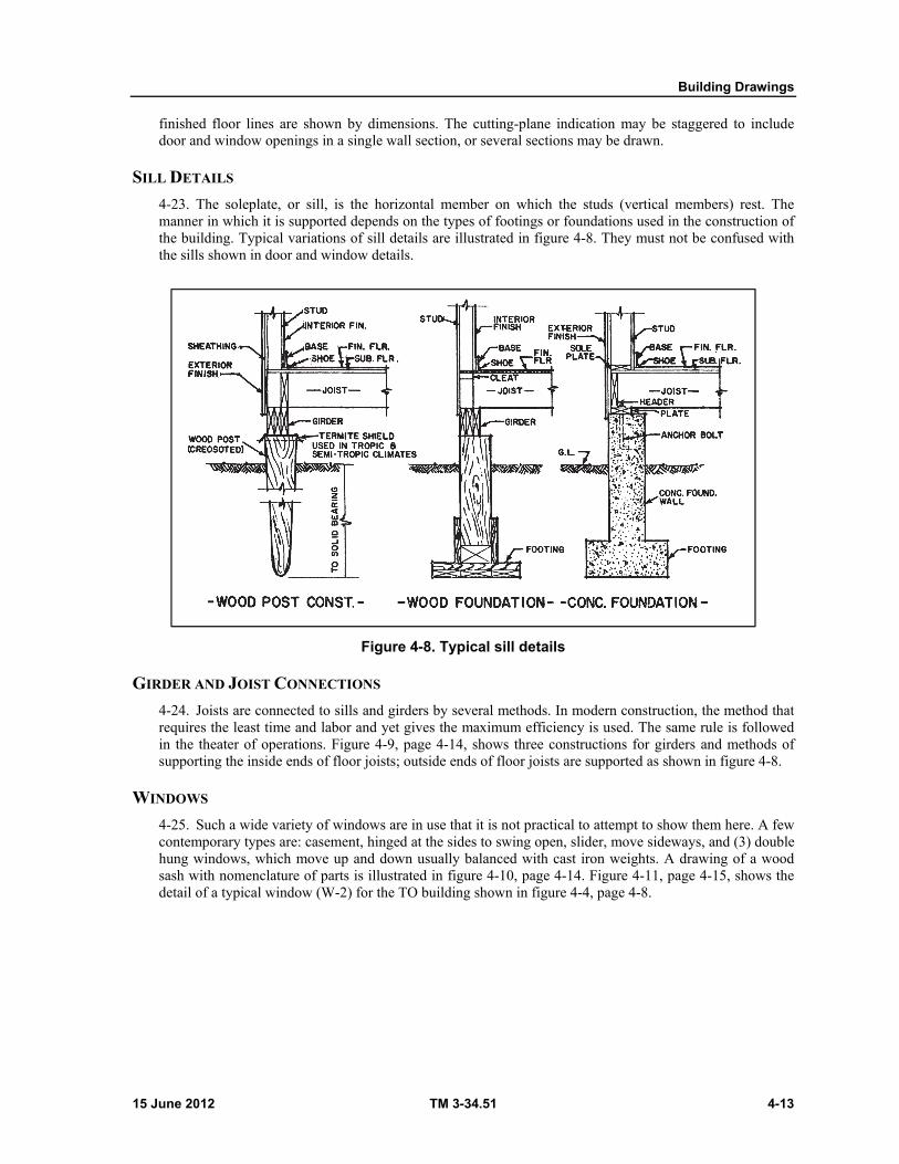
Building Drawings
15 June 2012 TM 3-34.51 4-13
finished floor lines are shown by dimensions. The cutting-plane indication may be staggered to include door and window openings in a single wall section, or several sections may be drawn.
SILL DETAILS
4-23. The soleplate, or sill, is the horizontal member on which the studs (vertical members) rest. The manner in which it is supported depends on the types of footings or foundations used in the construction of the building. Typical variations of sill details are illustrated in figure 4-8. They must not be confused with the sills shown in door and window details.
Figure 4-8. Typical sill details
GIRDER AND JOIST CONNECTIONS
4-24. Joists are connected to sills and girders by several methods. In modern construction, the method that requires the least time and labor and yet gives the maximum efficiency is used. The same rule is followed in the theater of operations. Figure 4-9, page 4-14, shows three constructions for girders and methods of supporting the inside ends of floor joists; outside ends of floor joists are supported as shown in figure 4-8.
WINDOWS
4-25. Such a wide variety of windows are in use that it is not practical to attempt to show them here. A few contemporary types are: casement, hinged at the sides to swing open, slider, move sideways, and (3) double hung windows, which move up and down usually balanced with cast iron weights. A drawing of a wood sash with nomenclature of parts is illustrated in figure 4-10, page 4-14. Figure 4-11, page 4-15, shows the detail of a typical window (W-2) for the TO building shown in figure 4-4, page 4-8.
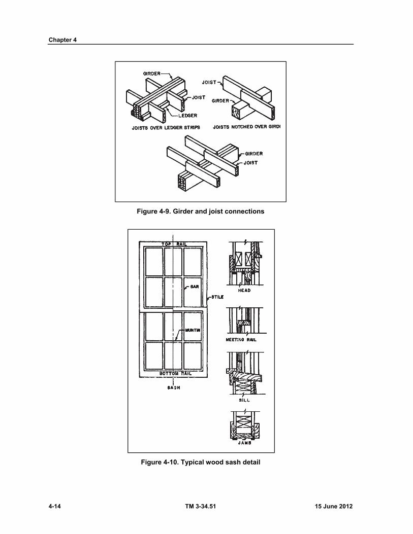
Chapter 4
4-14 TM 3-34.51 15 June 2012
Figure 4-9. Girder and joist connections
Figure 4-10. Typical wood sash detail
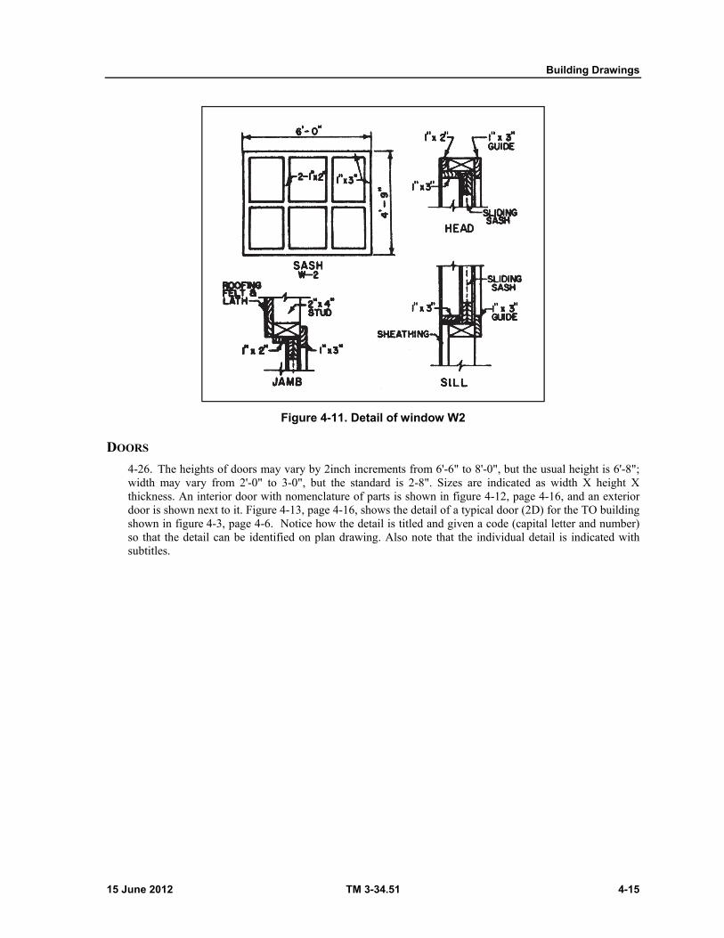
Building Drawings
15 June 2012 TM 3-34.51 4-15
Figure 4-11. Detail of window W2
DOORS
4-26. The heights of doors may vary by 2inch increments from 6'-6" to 8'-0", but the usual height is 6'-8"; width may vary from 2'-0" to 3-0", but the standard is 2-8". Sizes are indicated as width X height X thickness. An interior door with nomenclature of parts is shown in figure 4-12, page 4-16, and an exterior door is shown next to it. Figure 4-13, page 4-16, shows the detail of a typical door (2D) for the TO building shown in figure 4-3, page 4-6. Notice how the detail is titled and given a code (capital letter and number) so that the detail can be identified on plan drawing. Also note that the individual detail is indicated with subtitles.
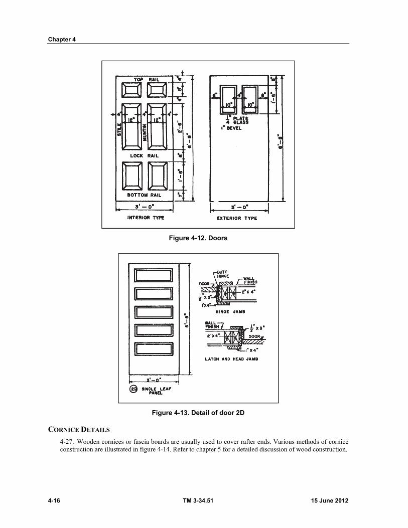
Chapter 4
4-16 TM 3-34.51 15 June 2012
Figure 4-12. Doors
Figure 4-13. Detail of door 2D
CORNICE DETAILS
4-27. Wooden cornices or fascia boards are usually used to cover rafter ends. Various methods of cornice construction are illustrated in figure 4-14. Refer to chapter 5 for a detailed discussion of wood construction.
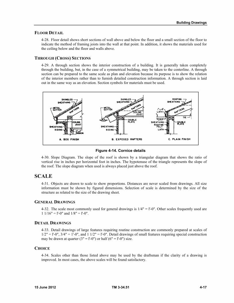
Building Drawings
15 June 2012 TM 3-34.51 4-17
FLOOR DETAIL
4-28. Floor detail shows short sections of wall above and below the floor and a small section of the floor to indicate the method of framing joists into the wall at that point. In addition, it shows the materials used for the ceiling below and the floor and walls above.
THROUGH (CROSS) SECTIONS
4-29. A through section shows the interior construction of a building. It is generally taken completely through the building, but, in the case of a symmetrical building, may be taken to the centerline. A through section can be prepared to the same scale as plan and elevation because its purpose is to show the relation of the interior members rather than to furnish detailed construction information. A through section is laid out in the same way as an elevation. Section symbols for materials must be used.
Figure 4-14. Cornice details
4-30. Slope Diagram. The slope of the roof is shown by a triangular diagram that shows the ratio of vertical rise in inches per horizontal foot in inches. The hypotenuse of the triangle represents the slope of the roof. The slope diagram when used is always placed just above the roof.
SCALE 4-31. Objects are drawn to scale to show proportions. Distances are never scaled from drawings. All size information must be shown by figured dimensions. Selection of scale is determined by the size of the structure as related to the size of the drawing sheet.
GENERAL DRAWINGS
4-32. The scale most commonly used for general drawings is 1/4" = l'-0". Other scales frequently used are 1 1/16" = l'-0" and 1/8" = l'-0".
DETAIL DRAWINGS
4-33. Detail drawings of large features requiring routine construction are commonly prepared at scales of 1/2" = l'-0", 3/4" = 1'-0", and 1 1/2" = l'-0". Detail drawings of small features requiring special construction may be drawn at quarter (3" = l'-0") or half (6" = l'-0") size.
CHOICE
4-34. Scales other than those listed above may be used by the draftsman if the clarity of a drawing is improved. In most cases, the above scales will be found satisfactory.
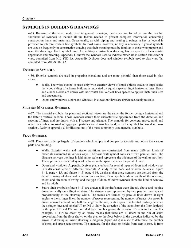
Chapter 4
4-18 TM 3-34.51 15 June 2012
SYMBOLS IN BUILDING DRAWINGS 4-35. Because of the small scale used in general drawings, draftsmen are forced to use the graphic shorthand of symbols to include all the factors needed to present complete information concerning construction items and materials. Occasionally, as with piping and heating drawings, a key or legend is provided to interpret certain line symbols. In most cases, however, no key is necessary. Typical symbols are used so frequently in construction drawing that their meaning must be familiar to those who prepare and read the drawings. Each symbol used for military construction drawing has its specific characteristic appearance and meaning. Appendix C shows the symbols used to indicate materials in section and exterior view, compiled from MIL-STD-1A. Appendix D shows door and window symbols used to plan view Ts, compiled from MIL-STD-14A.
EXTERIOR SYMBOLS
4-36. Exterior symbols are used in preparing elevations and are more pictorial than those used in plan views.
Walls. The wood symbol is used only with exterior views of small objects drawn to large scale; the wood siding of a frame building is indicated by equally spaced, light horizontal lines. Brick and cinder blocks are drawn with horizontal and vertical lines spaced to approximate their size and appearance.
Doors and windows. Doors and windows in elevation views are drawn accurately to scale.
SECTION MATERIAL SYMBOLS
4-37. The material symbols for plans and sectional views are the same, the former being a horizontal and the latter a vertical section. Those symbols derive their characteristic appearance from the direction and spacing of lines, and are drawn with a T-square and triangle. The symbols for concrete, grave, sand, and other materials composed of aggregate particles are drawn freehand, as is the symbol for wood in cross sections. Refer to appendix C for illustrations of the most commonly used material symbols.
PLAN SYMBOLS
4-38. Plans are made up largely of symbols which simply and compactly identify and locate the various parts of a building.
Walls. Exterior walls and interior partitions are constructed from many different kinds of materials assembled in various ways. The basic wall symbol consists of two parallel lines. The distance between the lines is laid out to scale and represents the thickness of the wall or partition. The approximate material symbol is drawn in the space between the parallel lines.
Doors and windows. Appendix D gives plan symbols for several types of doors and windows set in walls constructed of different materials. A study of the door and window details in figure 4-11, page 4-15, and figure 4-13, page 4-16, discloses that these symbols are derived from the detail drawing of door and window construction. Door symbols show width of the opening, extent and direction of swing, and the type of door. Window symbols show the kind of window and its width.
Stairs. Stair symbols (figure 4-15) are drawn as if the draftsman were directly above and looking down vertically on a flight of stairs. The stringers are represented by two parallel lines spaced proportionally to the stairway width. The treads are formed by parallel lines drawn at right angles to the stringer lines, the number of spaces representing the number of treads. An arrow is drawn across the tread lines half the length of the run, or stair span. It is located midway between the stringer lines and labeled UP or DN to show the direction of the stairs from the floor depicted in the plan. UP and DN are preceded by a number giving the amount of risers in the run. For example, 17 DN followed by an arrow means that there are 17 risers in the run of stairs proceeding from the floor shown on the plan to the floor below in the direction indicated by the arrow. In drawing an inside stairway, a diagram (figure 4-15) is made to determine the number of steps and space requirements. The standard for the riser, or height from step to step, is from
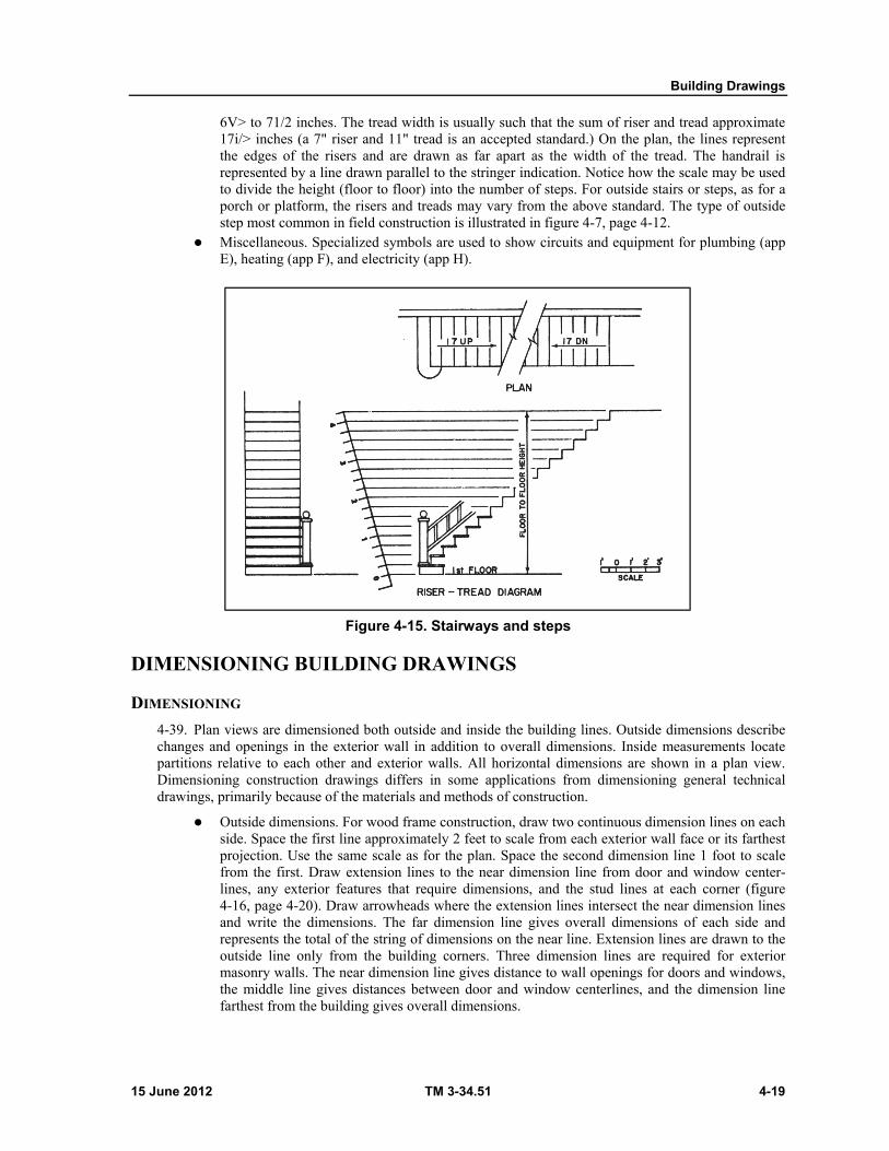
Building Drawings
15 June 2012 TM 3-34.51 4-19
6V> to 71/2 inches. The tread width is usually such that the sum of riser and tread approximate 17i/> inches (a 7" riser and 11" tread is an accepted standard.) On the plan, the lines represent the edges of the risers and are drawn as far apart as the width of the tread. The handrail is represented by a line drawn parallel to the stringer indication. Notice how the scale may be used to divide the height (floor to floor) into the number of steps. For outside stairs or steps, as for a porch or platform, the risers and treads may vary from the above standard. The type of outside step most common in field construction is illustrated in figure 4-7, page 4-12.
Miscellaneous. Specialized symbols are used to show circuits and equipment for plumbing (app E), heating (app F), and electricity (app H).
Figure 4-15. Stairways and steps
DIMENSIONING BUILDING DRAWINGS
DIMENSIONING
4-39. Plan views are dimensioned both outside and inside the building lines. Outside dimensions describe changes and openings in the exterior wall in addition to overall dimensions. Inside measurements locate partitions relative to each other and exterior walls. All horizontal dimensions are shown in a plan view. Dimensioning construction drawings differs in some applications from dimensioning general technical drawings, primarily because of the materials and methods of construction.
Outside dimensions. For wood frame construction, draw two continuous dimension lines on each side. Space the first line approximately 2 feet to scale from each exterior wall face or its farthest projection. Use the same scale as for the plan. Space the second dimension line 1 foot to scale from the first. Draw extension lines to the near dimension line from door and window center-lines, any exterior features that require dimensions, and the stud lines at each corner (figure 4-16, page 4-20). Draw arrowheads where the extension lines intersect the near dimension lines and write the dimensions. The far dimension line gives overall dimensions of each side and represents the total of the string of dimensions on the near line. Extension lines are drawn to the outside line only from the building corners. Three dimension lines are required for exterior masonry walls. The near dimension line gives distance to wall openings for doors and windows, the middle line gives distances between door and window centerlines, and the dimension line farthest from the building gives overall dimensions.

Chapter 4
4-20 TM 3-34.51 15 June 2012
Inside dimensions. Inside dimension lines are drawn unbroken between the inside faces of building walls. One string of dimensions spans the inside width of the building, and a second spans its length. As shown in figure 4-3, page 4-6, and figure 4-16, dimensions are given to the centerline of wood frame partitions.
DIMENSION LINE
4-40. Dimension lines in construction drawings are unbroken from one extension line to another. This type of line is much easier and faster to make. An ordinary construction drawing contains numerous dimensions all in line and continuous, which saves considerable time.
DIMENSION ACCURACY
4-41. Construction procedure does not involve fine measurements, and tolerancing is not a consideration. Often, as with lumber, the materials used in constructing are not accurate enough to obtain satisfactory placement by giving dimensions to the edge of the structural member. This difficulty is overcome by giving center to-center dimensions. Thus, even if the dimensions of certain kinds of lumber vary considerable, their placement is constant. Dimensions are given to the centerlines of door and window openings, frame partitions, beams, and columns.
Figure 4-16. Masonry and frame conventions
WRITING DIMENSIONS
4-42. Dimensions are given in feet and inches, with the exception noted below. Unit marks are used and the feet and inch numerals are separated by a hyphen. A typical construction drawing dimension is written 2'-7". The following specific rules apply to placing dimensions for construction drawings other than steel drawings.
Fractions. For indicating fractions of an inch alone, no zero is used, thus 1/4". Inches alone. For indicating inches alone, no zero is used, thus: 5". Combinations. For indicating inches in combination with fractions no zero is used, thus: 31/8". Feet and inches. For indicating feet and inches no zero is used, thus: 5'-9".

Building Drawings
15 June 2012 TM 3-34.51 4-21
Feet without inches. For indicating feet without inches, a zero is used, thus: 6'-0". Feet and fractions. For indicating feet and no inches with fractions of an inch a zero is used,
thus: 4'-0 3/8". Foot symbol. For indicating 1 foot use l'-0", never 12".
PLACING DIMENSIONS
4-43. Dimensions are placed slightly above the dimension line. The exact distance varies depending on the scale, size of lettering, and available space. For most conditions, one-fourth to one-half the lettering size is used. The figure should never be closer to another dimension line than to the line it represents. Lettering size is normally 1/8 inch. Guidelines should be used for drawing all figures.
DECIMAL DIMENSIONS
4-44. Elevations are always given in decimals in construction drawings. These are vertical reference heights and are not to be confused with elevation views. They should be preceded by the abbreviation EL, thus: EL 810.0 (figure 4-4, page 4-8). Decimals may also be written as 81000. The latter form is used when the loss of a decimal point might occur because of dirt or poor reproduction, as in field work. Elevations frequently noted are ground level, footing elevation, anchor bolt elevation, and the elevations of drainage lines.
VARIATIONS CAUSED BY MATERIALS
4-45. Figure 4-16 gives a few examples of variations in dimensioning practice caused by differences in materials and methods of construction. In addition, it presents dimensioning conventions for doors, windows, and walls. Note that concrete and solid brick walls are dimensioned to the outside corner because the structural material and the siding material are homogenous. In brick veneer and frame construction, structural materials are not integral with siding materials. Well dimensions in a plan view are therefore given to the wood frame in brick veneer construction and to the studs in frame construction. All dimensioning in figure 4-16 is applicable to plan views only.
NOTES IN CONSTRUCTION DRAWINGS 4-46. Notes in a construction drawing are classified as specific and general. Their lettering, size, location, and general preparation have been described in chapter 10, TM 5-581A. Briefly, notes are clear, explicit statements regarding material, construction, and finish. They are used so extensively that a separate compilation is made and referred to as specifications. These are written instructions, organized into a document, stating the manner in which work will be performed, designating what materials and finishes are to be used, and establishing the responsibility of the unit performing the work.
SPECIFIC NOTES
4-47. Specific notes may be used either to augment dimensioning information or to be explanatory. When more than one line of explanatory notes is placed in a drawing, lowercase lettering is used. Titles and subtitles are always prepared in uppercase letters. Many of the terms frequently used for construction drawings are expressed as abbreviations, to save space.
GENERAL NOTES
4-48. General notes usually are grouped according to materials of construction in a tabular form called a schedule. As used in this manual, the category, General Notes, refers to all notes on the drawing not accompanied by a leader and arrowhead. Item schedules for doors, rooms, footings, and so on, are more detailed. Typical door and window schedule formats are presented below.
Door schedule. The doors shown by symbol in a plan view may be identified as to size, type, and style with code numbers placed next to each symbol (figures 4-3 and 4-4). This code number, or mark, is then entered on a line in a door schedule and the principal characteristics of the door are
Chapter 4
4-22 TM 3-34.51 15 June 2012
entered in successive columns along the line. The No. column allows a quantity check on doors of the same design as well as the total number of doors required. By using a number with a letter, the mark can serve a double purpose: the number identifies the floor on which the door is located, and the letter identifies the door design. Mark 1-D would mean door style D on the first floor. The sequence of writing door sizes is width X height X thickness. The description column allows identification by type (panel, flush), style, and material. The remarks column allows reference to the appropriate detail drawing. The schedule is a convenient way of presenting pertinent data without making mechanics and builders refer to the specifications.
No Mark Size Description Remarks
6 1-D__ 5 X 7__ Flush Double door hinged
9 2-D 2 1/2 X 7__ Panel Single door hinged
Window schedule. A window schedule is similar to a door schedule for providing an organized presentation of the significant window characteristics. The code mark (figure 4-4) used in the schedule is placed next to the window symbol that applies on the plan view.
No. Mark Size Description Remarks
16 W-l 5 X 9 Double Hung Slide from bottom to top and top to bottom.
12 W-2 4 X 7 Casement Hinged at top.
SPECIFICATIONS IN CONSTRUCTION DRAWINGS 4-49. Although it is not a draftsmen's responsibility to prepare specifications, for two outstanding reasons he should be familiar with them; specifications give detailed instructions regarding materials and methods of work and constitute an important source of pertinent information for the set of drawings; and a draftsman experienced in preparing construction drawings can be of assistance to the specifications writer. Specifications should be written with clear, concise statements. The use of vague statements, such as ". . . the material specified or its equivalent . . .," should be avoided by stating first and second choices for substitute materials. For further details refer to "Drawings and Specifications,, NAVFAC Design Manual-6, July 1967, chapter 3, "Specifications."
GENERAL CONDITIONS
4-50. Every list of specifications begins with a statement of general conditions, which are routine declarations of responsibility and conditions to be adhered to on the job. These often are prepared in printed form and used for all construction work falling within a general category.
SPECIFIC CONDITIONS
4-51. A construction job is classified by phases, each phase related to a particular material or operation. A separate specification is written for each phase of a particular job, and these are compiled to parallel the job sequence of the phases. A phase specification establishes the following in the order stated: general conditions, scope of work, quality and inspection of materials, conditions of workmanship, kinds of equipment, delivery and storage of materials, and protection of finished work.
BILL OF MATERIAL IN CONSTRUCTION DRAWINGS 4-52. A bill of material is a tabulated statement of requirements for a given project that shows the item number, name, description, quantity, material, stock size, number, and, sometimes, the weight of each piece.
Building Drawings
15 June 2012 TM 3-34.51 4-23
MATERIALS TAKEOFF
4-53. Bills of material are sometimes called materials estimate sheets or materials takeoff sheets. Actually, a bill of material is a grouped compilation based on takeoffs and estimates of all material needed to complete a structure. The takeoff usually is an actual tally and checkoff of the items shown, noted, or specified on the construction drawings and specifications. The estimated quantities are those known to be necessary but which may not have been placed on the drawings, such as nails, cement, concrete-form lumber and tie wire, temporary bracing or scaffold lumber, and so on. These are calculated from a knowledge of construction methods that will be used for field erection.
TALLY SHEETS
4-54. Draftsmen use tally sheets to list the material and record the quantities as each item is drawn. A series of tally sheets is required for each material, depending on the complexity of the classification. When a series of tally sheets is prepared for an electrical takeoff, for example, one sheet lists the kinds and sizes of conduits, another the kinds and sizes of wire, a third the outlets and fittings. The quantities of each are tallied next to the appropriate classification as they are drawn and noted.
QUANTITIES
4-55. Bulk quantities classified by cubic measurement, such as concrete and earth, may be calculated after the drawing has been completed. Draftsmen will find that facility with a slide rule is an aid in performing rapid calculations of this kind. When a set of drawings has been completed, quantities are totaled and the various types are regrouped by sizes beginning with the smallest and progressing to the largest.
TABULATION
4-56. The tabulation should include headings for each item, including: (a) item number; (b) item description; (c) unit of measure; and (d) quantity.
FINAL TABULATION
4-57. The final tabulation of material is by type under appropriate subheadings: frame, roof, cladding, miscellaneous, and hardware.
WASTAGE ESTIMATES
4-58. Wastage estimates also are made to allow for field breakage, waste, transit damage, and construction losses. Breakage allowances usually are taken as a percentage of the final grouped item summaries and are shown in the material type quantity columns before the grand totals. Wastage percentages vary with the classification of material under consideration and generally are based on past experience, anticipated field conditions, and calculated shipment risks.
SAMPLE BILL OF MATERIAL
4-59. A partial bill of material for a single structure is given in figure 4-17, pages 4-24 and 4-25, in which items needed for the construction of a standard frame building are tabulated for the preparation of the necessary requisitions.
NOMINAL AND ACTUAL SIZES 4-60. The sizes given in specific notes for structural members are called nominal sizes. A joist whose nominal size is 2 inches thick by 6 inches wide is 15/8 X 55/8 inches in actual size. The difference in dimensions is caused by material lost in finishing or surfacing the piece of lumber. Nominal sizes are always used to identify a piece in notes, specifications, and bills of material. In preparing any drawing at a scale of 1/2" = l'-0" or larger, the actual sizes are drawn to scale. For drawings prepared at a smaller scale,

Chapter 4
4-24 TM 3-34.51 15 June 2012
nominal sizes are used. The actual sizes of wood (chap 5), steel shapes (chap 8), and masonry units (chap 6) such as brick and cinder block differ from their nominal sizes.
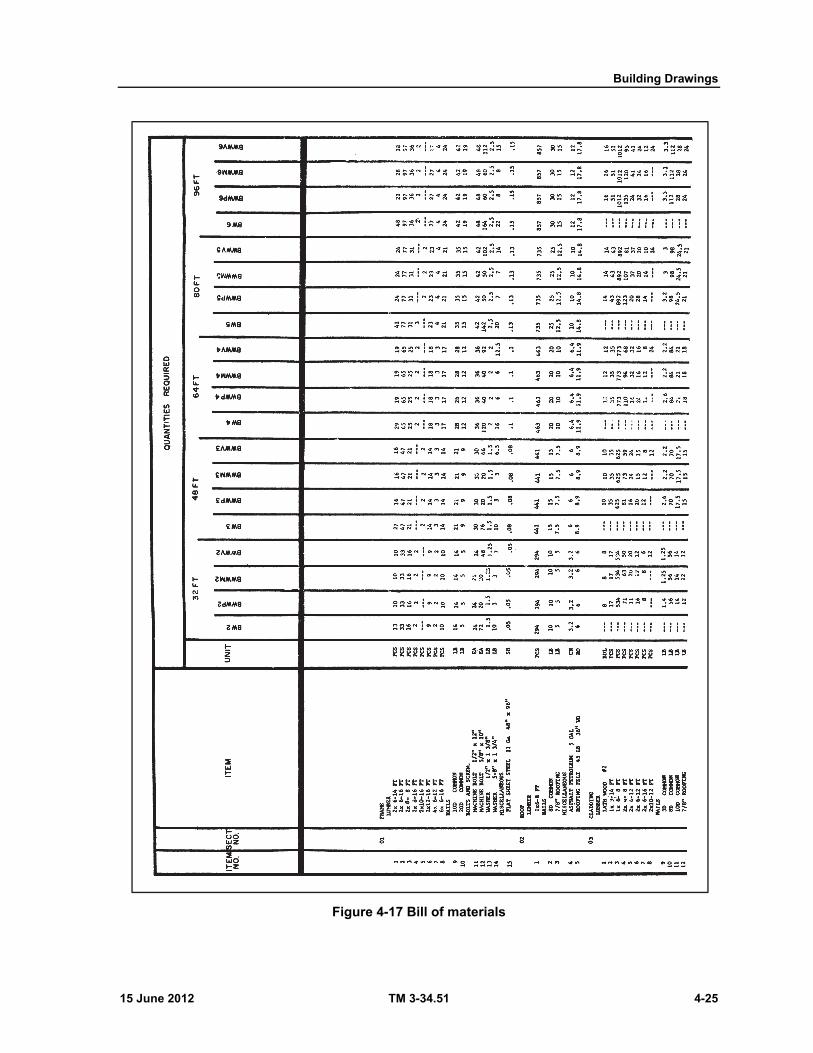
Building Drawings
15 June 2012 TM 3-34.51 4-25
Figure 4-17 Bill of materials

Chapter 4
4-26 TM 3-34.51 15 June 2012
Figure 4-17 Bill of materials (continued)
15 June 2012 TM 3-34.51 5-1
Chapter 5
Wood Construction
SECTION I - LIGHT FRAME STRUCTURES
WOOD CLASSIFICATION 5-1. Wood is a basic, almost universal, construction material and is used widely by the Army, particularly in theater of operations (TO) building. To prepare detail drawings, notes, schedules, and bills of material for wooden structures, a construction draftsman should be familiar with the classification of wood.
SPECIES 5-2. Native species of trees are divided into two classes: hardwoods, which have broad leaves; and softwoods, which have leaves like needles or scales. No definite degree of hardness divides them. In fact, many hardwoods actually are softer than an average softwood.
HARDWOODS
5-3. Some familiar native species of the hardwood, or deciduous, class are ash, birch, hickory, oak, beech, and maple. All are broad leaved. Lumber cut from hardwoods is not generally used for the construction of structural framing, but is used principally for flooring, special interior paneling, trim, and doors.
SOFTWOODS
5-4. Most native species of softwood bear cones and are called coniferous woods. Some familiar softwoods are pine, spruce, fir, cedar, and redwood. These woods are worked easily and make suitable material for structural framing. Of the various softwoods, southern yellow pine and Douglas fir are the varieties used most frequently for construction.
Southern yellow pine. All southern yellow pine used for structural purposes is classified as longleaf or shortleaf. The wood is dense, moderately hard, and strong. When described in a bill of material or specifications, longleaf yellow pine is abbreviated as LLYP, and shortleaf yellow pine is abbreviated as SLYP.
Douglas fir. Douglas fir in the form of lumber and timber is one of the most desirable woods for structural purposes. It also has extensive use as poles, piling, and ties, and large quantities are cut into veneer for plywood and other purposes. It is strong, moderately hard, and heavy. In general, it has a tendency to check and split and does not hold paint well.
GRADING 5-5. Softwoods and hardwoods are graded by different standards. Only softwood grading is considered here because as explained previously, hardwoods are rarely used for structural purposes and the construction draftsman is seldom required to describe hardwoods in the notes or bill of material.
GRADING CRITERIA
5-6. In most cases, the grading of lumber is based on the number, character, and location of features such as knots, pitch pockets, and so on, which are commonly called defects and defined as any irregularity occurring in or on wood that may lower its strength, durability, or utility values. The best grades are
Chapter 5
5-2 TM 3-34.51 15 June 2012
practically free of these features; others, comprising the greater bulk of lumber, contain fairly numerous knots and other natural growth characteristics.
SELECT LUMBER
5-7. Select lumber is the general classification for lumber of good appearance and finishing qualities. Grades A and B are suitable for natural finishes; grades C and D are suitable for paint finishes.
COMMON LUMBER
5-8. Common lumber is the general classification for lumber containing the defects and blemishes described above. The grades are numbers 1 through 5. Nos. 1 and 2 are for use without waste in framing and sheathing; No. 3 can be used for temporary construction. Nos. 4 and 5 are NOT generally used in construction because they are of poor quality and are subject to much waste.
SURFACING AND WORKED LUMBER 5-9. Lumber is further classified according to the manner in which it is milled.
SURFACING
5-10. Lumber is classified as rough or dressed, according to the amount of planing done in the mill.
Rough. Rough lumber is as it emerges from the saw, or unplaned; when indicating rough lumber, the abbreviation is RGH.
Dressed. Dressed, or surfaced, lumber is the rough lumber after it has been run through a planer. It may have any combination of edges and sides dressed, such as SIS, surfaced on one side; S2S, surfaced on two sides; S1S1E, surfaced on one side and one edge; and S4S, surfaced on four sides.
WORKED LUMBER
5-11. Worked lumber has been run through a machine such as a matcher, shaper, or moulder; it can be matched, shiplapped, or patterened.
Matched lumber. Matched lumber is cut so that it interlocks. A common type is tongue and grove (T & G), in which a groove is cut in one edge and a mating bead, or projection, is cut on the other edge. Boards are frequently dressed and matched (D & M), with the tongue and groove in the center, making the pieces center matched.
Shiplapped lumber. Shiplapped pieces are cut with a square step on either edge, the projection on one edge at the bottom and at the top of the piece on the other edge; in this way, adjacent boards overlap each other to form a joint.
Patterned lumber. Patterned lumber is cut in many designs and is used for trim.
ACTUAL AND NOMINAL SIZES OF LUMBER 5-12. Sizes of lumber are specified by nominal dimensions which differ from the actual dimensions of the milled pieces. When lumber is run through a saw and planer its nominal size remains the same but its actual size is reduced by the amount of surfacing it undergoes. Approximately 14 inch is planed off each side in surfacing. Lumber is also divided into groups according to size, namely: strips—pieces less than 2 inches thick and under 8 inches wide; boards—less than 2 inches thick and more than 8 inches wide; dimensioned lumber—2 to 6 inches thick and of any width; and timber—6 or more inches in the least dimension. Dimensions of some common sizes are given in table 5-1.
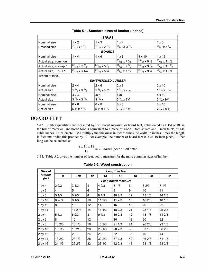
Wood Construction
15 June 2012 TM 3-34.51 5-3
Table 5-1. Standard sizes of lumber (inches)
STRIPS
Nominal size 1 x 2 1 x 3 1 x 4 1 x 6
Dressed size 25/32 x 1 5/8 25/32 x 2 5/8
25/32 X 3 5/8 25/32 x 5 5/8
BOARDS
Nominal size 1 x 4 1 x 6 1 x 8 1 x 10 1 x 12
Actual size, common 25/32 x 7 ½ 25/32 x 9 ½ 25/32 x 11 ½
Actual size, shiplap * 25/32 X 3 1/8
25/32 x 5 1/8
25/32 x 7 1/8
25/32 x 9 1/8
25/32 x 11 1/8
Actual size, T & G * 25/32 x 3 1/4 25/32 x 5 ¼ 25/32 x 7 ¼ 25/32 x 9 ¼ 25/32 x 11 ¼
♦Width of face.
DIMENSIONED LUMBER
Nominal size 2 x 4 2 x 6 2 x 8 2 x 10
Actual size 1 5/8 x 3 5/8 1 5/8 x 5 ½ 1 5/8 x 7 ½ 1 5/8 x 9 ½
Nominal size 4 x 4 4x6 4x8 4 x 10
Actual size 3 5/8 x 3 5/8 3 5/8 x 3 5/8 x 7M 3 5/8x 9M
Nominal size 6 x 6 6 x 8 8 x 8 8 x 10
Actual size 5 ½ x 5 ½ 5 ½ x 7 ½ 7 ½ x 7 ½ 7 ½ x 9 ½
BOARD FEET 5-13. Lumber quantities are measured by feet, board measure, or board feet, abbreviated as FBM or BF in the bill of material. One board foot is equivalent to a piece of wood 1 foot square and 1 inch thick, or 144 cubic inches. To calculate FBM multiply the thickness in inches times the width in inches, times the length in feet and divide this product by 12. For example, the number of board feet in a 2x 10-inch piece, 12 feet long can be calculated as— 2 x 10 x 1212 = 20 𝑏𝑜𝑎𝑟𝑑 𝑓𝑒𝑒𝑡 𝑜𝑟 20 𝐹𝐵𝑀
5-14. Table 5-2 gives the number of feet, board measure, for the more common sizes of lumber.
Table 5-2. Wood construction
Size of lumber
(In.)
Length in feet
8 10 12 14 16 18 20 22
Feet, board measure
1 by 4 2 2/3 3 1/3 4 4 2/3 5 1/3 6 6 2/3 7 1/3
1 by 6 4 5 6 7 8 9 10 11
1 by 8 5 1/3 6 2/3 8 9 1/3 10 2/3 12 13 1/3 14 2/3
1 by 10 6 2/ 3 8 1/3 10 11 2/3 11 2/3 15 16 2/3 18 1/3
1 by 12 8 10 12 14 16 18 20 22
1 by 14 11 2 /3 14 16 1/3 18 2/3 21 23 1/3 25 2/3
2 by 4 5 1/3 6 2/3 8 9 1/3 10 2/3 12 13 1/3 14 2/3
2 by 6 8 10 12 14 16 18 20 22
2 by 8 10 2/3 13 1/3 16 18 2/3 21 1/3 24 26 2/3 29 1/3
2 by 10 13 1/3 16 2/3 20 23 1/3 28 2/3 30 33 1/3 36 2/3
2 by 12 16 20 24 28 32 36 40 44
2 by 14 18 2/3 23 1/3 28 32 2/3 37 1/3 42 46 2/3 51 1/3
2 by 16 21 1/3 26 2/3 32 37 1/3 42 2/3 48 53 1/3 58 2/3
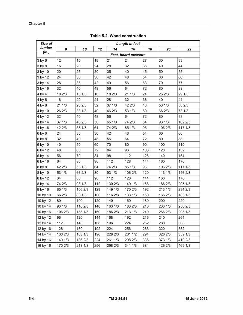
Chapter 5
5-4 TM 3-34.51 15 June 2012
Table 5-2. Wood construction
Size of lumber
(In.)
Length in feet
8 10 12 14 16 18 20 22
Feet, board measure
3 by 6 12 15 18 21 24 27 30 33
3 by 8 16 20 24 28 32 36 40 44
3 by 10 20 25 30 35 40 45 50 55
3 by 12 24 30 36 42 48 54 60 66
3 by 14 28 35 42 49 56 63 70 77
3 by 16 32 40 48 56 64 72 80 88
4 by 4 10 2/3 13 1/3 16 18 2/3 21 1/3 24 26 2/3 29 1/3
4 by 6 16 20 24 28 32 36 40 44
4 by 8 21 1/3 26 2/3 32 37 1/3 42 2/3 48 53 1/3 58 2/3
4 by 10 26 2/3 33 1/3 40 46 2/3 53 1/3 60 66 2/3 73 1/3
4 by 12 32 40 48 56 64 72 80 88
4 by 14 37 1/3 46 2/3 56 65 1/3 74 2/3 84 93 1/3 102 2/3
4 by 16 42 2/3 53 1/3 64 74 2/3 85 1/3 96 106 2/3 117 1/3
6 by 6 24 30 36 42 48 54 60 66
6 by 8 32 40 48 56 64 72 80 88
6 by 10 40 50 60 70 80 90 100 110
6 by 12 48 60 72 84 96 108 120 132
6 by 14 56 70 84 98 112 126 140 154
6 by 16 64 80 96 112 128 144 160 176
8 by 8 42 2/3 53 1/3 64 74 2/3 85 1/3 96 106 2/3 117 1/3
8 by 10 53 1/3 66 2/3 80 93 1/3 106 2/3 120 113 1/3 146 2/3
8 by 12 64 80 96 112 128 144 160 176
8 by 14 74 2/3 93 1/3 112 130 2/3 149 1/3 168 186 2/3 205 1/3
8 by 16 85 1/3 106 2/3 128 149 1/3 170 2/3 192 213 1/3 234 2/3
10 by 10 66 2/3 83 1/3 100 116 2/3 133 1/3 150 166 2/3 183 1/3
10 by 12 80 100 120 140 160 180 200 220
10 by 14 93 1/3 116 2/3 140 163 1/3 183 2/3 210 233 1/3 256 2/3
10 by 16 106 2/3 133 1/3 160 186 2/3 213 1/3 240 266 2/3 293 1/3
12 by 12 96 120 144 168 192 216 240 264
12 by 14 112 140 168 196 224 252 280 308
12 by 16 128 160 192 224 256 288 320 352
14 by 14 130 2/3 163 1/3 196 228 2/3 261 1/2 294 326 2/3 359 1/3
14 by 16 149 1/3 186 2/3 224 261 1/3 298 2/3 336 373 1/3 410 2/3
16 by 16 170 2/3 213 1/3 256 298 2/3 341 1/3 384 426 2/3 469 1/3
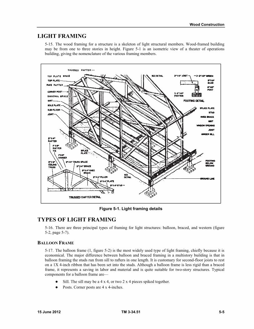
Wood Construction
15 June 2012 TM 3-34.51 5-5
LIGHT FRAMING 5-15. The wood framing for a structure is a skeleton of light structural members. Wood-framed building may be from one to three stories in height. Figure 5-1 is an isometric view of a theater of operations building, giving the nomenclature of the various framing members.
Figure 5-1. Light framing details
TYPES OF LIGHT FRAMING 5-16. There are three principal types of framing for light structures: balloon, braced, and western (figure 5-2, page 5-7).
BALLOON FRAME
5-17. The balloon frame (1, figure 5-2) is the most widely used type of light framing, chiefly because it is economical. The major difference between balloon and braced framing in a multistory building is that in balloon framing the studs run from sill to rafters in one length. It is customary for second-floor joists to rest on a 1X 4-inch ribbon that has been set into the studs. Although a balloon frame is less rigid than a braced frame, it represents a saving in labor and material and is quite suitable for two-story structures. Typical components for a balloon frame are—
Sill. The sill may be a 4 x 4, or two 2 x 4 pieces spiked together. Posts. Corner posts are 4 x 4-inches.
Chapter 5
5-6 TM 3-34.51 15 June 2012
Studs. Studs are 2 x 4's set 16 inches on centers. The 16 inch centering is a satisfactory standard because of the spacing requirements for interior lath and exterior sheathing. It also enables floor joists to be nailed to the studs.
Plates The plate is placed across the tops of the studs. The plate, which is a 4 X 4, or two 2 x 4's spiked
together, serve as a lower base for the ends of the roof rafters. Sheathing. Sheathing is generally applied diagonally to assist in strengthening the structure. Cross bracing. Cross bracing between joists is required for balloon-framed structures to increase
their rigidity.
BRACED FRAME
5-18. A braced frame (2, figure 5-2) is much more rigid than a balloon frame. Exterior studs extend only between floors and are topped by girts that form a sill for the joists of the succeeding floor. Girts usually are 4X 6inches. With the exception of studs, braced framed members are heavier than those in balloon framing. Sills and corner posts are customarily 4X 6-inches. Unlike the studs, corner posts extend from sill to plate. Knee braces, when used are usually 3X 4-inches and are placed diagonally against each side of the corner posts. Interior studding for braced frames is the same as for balloon frame construction.
WESTERN FRAME
5-19. The western or platform frame (3, figure 5-2) is used extensively in military construction. It is similar to the braced frame, but has boxed-sill construction at each floor line. For one-story structures, the western frame is preferred since it permits both the bearing walls and the nonbearing walls, which are supported by the joists, to settle uniformly.
COVERING FRAME
ROUGH SHEATHING
5-20. Joists are covered with subflooring usually made of tongue and groove boards. Studs are covered on the outside with sheathing that may be placed horizontally or diagonally. Rough roofing is placed across the rafters. Fabricated fiber boards or a sheathing grade of plywood can be used for rough flooring and sheathing in place of T & G boards.
EXTERIOR FINISHED SIDING
5-21. Rough-finished sheathing is covered with building paper first, then selected siding material is fastened in place. Siding may be boards worked into specific shapes, for example bevel siding, drop siding, and ship-lap siding. Theater of operations buildings may be constructed with no siding covering the roofing paper.
Veneer. Brick or stone veneer may be used as exterior siding for a wood-frame building. Brick is bonded to the sheathing at intervals of not more than 16 inches vertically and 24 inches horizontally. Lintels support brick veneer over all openings.
Fascia boards. Rafter ends are enclosed with fascia boards, wooden cornices, or verge boards that usually are cut to a specific size. They are frequently made of white pine, which is easily worked and presents a good appearance when painted.

Wood Construction
15 June 2012 TM 3-34.51 5-7
Figure 5-2. Framing for light structures
INTERIOR FINISHES Insulation. Insulation material is installed before interior wall finishes and is normally fastened
in place by nailing between the exterior studs and, if required, the ceiling joists. Rockwool is a common form of building insulation.
Wall finishes. Interior wall finishes may be one of the following: Plaster on metal lath. Metal lath is an expanded ribbed metal that is nailed to the studding
where it serves as a base for plaster. Before plaster is applied, grounds, usually 1X 2-inch strips, are placed around the base and top of the studs and around all openings. These serve as a stop for the plaster, which is usually applied in three coats.
Plaster and composition board. The base for the plaster in this instance is a composition board usually perforated to provide a key for the plaster.
Plasterboard. Plasterboard is a composition board forming a finished surface after painting. It is nailed directly to the studs.
Miscellaneous. Plywood and various kinds of wood paneling may be used to cover studding in the building interior.
Chapter 5
5-8 TM 3-34.51 15 June 2012
Ceiling. Ceilings can be finished in the same manner as sidewalls. Acoustic tiles often are used when sound deadening is desired.
Flooring. Floor finishes are placed over the subflooring. A deadening felt may be placed between it and the finished floor. Hardwoods such as maple, birch, oak, or beech are commonly used in permanent construction. Wood-block strips joined together at the factory to make 9X 9-inch blocks are used sometimes and are fastened to the subfloor with a mastic adhesive. Other floor coverings include plywood, asphalt tile, and linoleum.
FINISH SCHEDULE
5-22. A type of schedule used for buildings with a number of different rooms is the finish schedule. This schedule lists the individual spaces either by room or space number and lists the finish requirements of walls, floors, ceilings, and other portions for each room. An abbreviated typical finish schedule (first floor) is presented below.
GENERAL DRAWING PRACTICES WITH WOOD STRUCTURES 5-23. The basic procedures in preparing drawings for a frame structure have been described in chapter 4. A construction draftsman, however, should remain aware that he is translating a designer's construction into a conventional, graphic language and that when transmitted to mechanics in the field the set of working drawings should contain all information needed for the erection and completion of a structure.
ROOF TRUSSES 5-24. Roof trusses are designed to span clear areas up to 200 feet. Many different types of trusses, among them the bowstrong, crescent, Belgian, and Fink, have been designed to account for various practical requirements. Truss details are shown in TM 5-302.
ROOFING 5-25. Although the term roofing usually is interpreted to mean the material covering the rough sheathing of a roof, it also may be considered to include roof framing members such as rafters and purlins as well as flashing and trim.
FRAMING MEMBERS
5-26. In most instances of light framing, roof sheathing can be applied directly over the rafters. If wider spans are encountered, purlins are used over roof trusses to stiffen roof structure, in which case the trusses correspond to girders and the purlins to joists. Where purlins are used, sheathing is applied over them.
ROOFING MATERIALS
5-27. Roofing areas and materials are measured by the square, which is equivalent to 100 square feet. Shingles are the exception to this, being measured by the bundle of 1,000. Some of the more frequently encountered roofing materials are described below.
Roofing paper and felt. Roofing paper and felt can be used under roofing materials such as asphalt shingles (paper) and asbestos or slate shingles (felt) ; the felt is impregnated with tar or asphalt. Both are applied to the sheathing with large-headed nails.
Asphalt-roll roofing. Asphalt-roll roofing can be used as an outside roofing material for temporary buildings and can be applied directly over sheathing without roofing paper underneath. It is classified by weight, for example, 45-pound and 65-pound roofing. Prepared 45-pound roofing should be lapped 4 inches horizontally and 8 inches vertically; edges should be cemented with roofing cement and nailed with nails 3 inches on centers.

Wood Construction
15 June 2012 TM 3-34.51 5-9
Wood shingles. Wood shingles are nailed to 1- x 4-inch shingle strips on 6-inch centers that are nailed to the sheathing. Shingles come in random widths and usually are from 16 to 18 inches long. They overlap to form a roof covering three layers thick.
Built-up roofing. Built-up or composition roofing is used for comparatively flat roofs. It is applied in layers or plies, a ply consisting of a layer of roofing felt over a layer of tar or asphalt. The tar or asphalt is applied hot, creating a bond for the felt. Two to five-ply composition roofs are customary.
Other materials. Shingles are available in asphalt, asbestos, slate, and metal as well as wood. Metal roofing comes in flat, crimped, or corrugated sheets. Two or three-ply canvas bonded to the sheathing with paint and fastened with galvanized steel tacks also is used as a roofing material; it is waterproofed by applying additional coats of paint.
Room
no. Room name
Floor Base Walls Ceilings Wainscot Remarks
101 Hall Asphalt tile Rubber Plaster Plaster
102 Office Asphalt tile Rubber Plaster Plaster
103 Lavatory- Terrazzo Terrazzo Plaster Plaster Ceramic tile
Wainscot 6'-0" except shower room full height
104 Conference room
Oak strip Wood Plaster Acoustic tile
Pine panels
Wainscot 6'-0"
WATER CONTROL ON ROOFS
FLASHING
5-28. Flashing signifies both the material used and the process of making watertight the roof intersections and other joints such as those caused by the penetration of a chimney or smokepipe (figure 5-3, page 5-10) through the roof.
Roof intersections. The most frequently encountered roof intersections are classified as ridges, hips, and valleys. The angle at which a roof slopes is called the pitch.
Flashing materials. Normally sheet metal strips or sections are used for flashing material, but prepared-roofing strips can be used for cheap and one-season construction. Metal sheets or 5by 7-inch shingles are commonly used around chimney and vent openings. Rolls of metal or asphalt roofing can be used for ridge, valley, and hip flashing.
ROOFING TRIM
5-29. Roofing trim signifies the gutters and downspouts, or leaders, used to collect and lead to the ground water draining from the roof. Roofing trim is not required for temporary buildings because drainage is diverted beyond building walls and eaves. An eave is the lower edge of a roof that overhangs the wall. Roofing trim is measured by the linear foot.
Gutters. A gutter usually is a semicircular or rectangular trough attached to the lower edge of the roof by hooks or hangers. It is made of galvanized steel or copper. Gutters are a minimum of 4 inches wide and have a minimum slope of 1 inch in 16 feet. For gutters larger than 4 inches, the width is determined by the roof area being drained.
Downspouts. Downspouts must be large enough to accelerate the velocity of the water entering from the gutter. A sufficient number of downspouts must be provided to carry water away promptly.
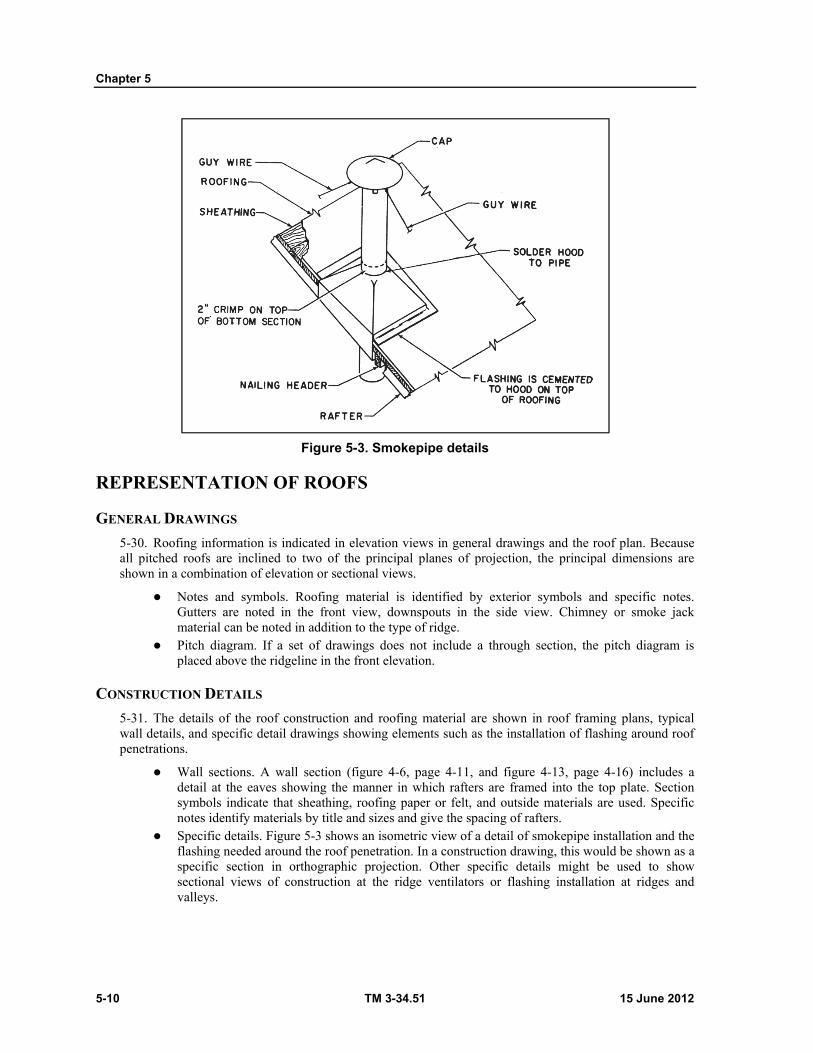
Chapter 5
5-10 TM 3-34.51 15 June 2012
Figure 5-3. Smokepipe details
REPRESENTATION OF ROOFS
GENERAL DRAWINGS
5-30. Roofing information is indicated in elevation views in general drawings and the roof plan. Because all pitched roofs are inclined to two of the principal planes of projection, the principal dimensions are shown in a combination of elevation or sectional views.
Notes and symbols. Roofing material is identified by exterior symbols and specific notes. Gutters are noted in the front view, downspouts in the side view. Chimney or smoke jack material can be noted in addition to the type of ridge.
Pitch diagram. If a set of drawings does not include a through section, the pitch diagram is placed above the ridgeline in the front elevation.
CONSTRUCTION DETAILS
5-31. The details of the roof construction and roofing material are shown in roof framing plans, typical wall details, and specific detail drawings showing elements such as the installation of flashing around roof penetrations.
Wall sections. A wall section (figure 4-6, page 4-11, and figure 4-13, page 4-16) includes a detail at the eaves showing the manner in which rafters are framed into the top plate. Section symbols indicate that sheathing, roofing paper or felt, and outside materials are used. Specific notes identify materials by title and sizes and give the spacing of rafters.
Specific details. Figure 5-3 shows an isometric view of a detail of smokepipe installation and the flashing needed around the roof penetration. In a construction drawing, this would be shown as a specific section in orthographic projection. Other specific details might be used to show sectional views of construction at the ridge ventilators or flashing installation at ridges and valleys.
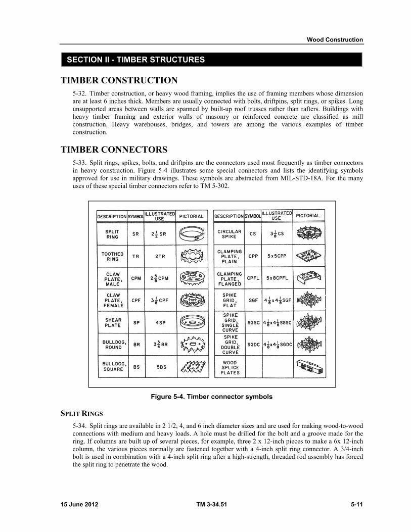
Wood Construction
15 June 2012 TM 3-34.51 5-11
SECTION II - TIMBER STRUCTURES
TIMBER CONSTRUCTION 5-32. Timber construction, or heavy wood framing, implies the use of framing members whose dimension are at least 6 inches thick. Members are usually connected with bolts, driftpins, split rings, or spikes. Long unsupported areas between walls are spanned by built-up roof trusses rather than rafters. Buildings with heavy timber framing and exterior walls of masonry or reinforced concrete are classified as mill construction. Heavy warehouses, bridges, and towers are among the various examples of timber construction.
TIMBER CONNECTORS 5-33. Split rings, spikes, bolts, and driftpins are the connectors used most frequently as timber connectors in heavy construction. Figure 5-4 illustrates some special connectors and lists the identifying symbols approved for use in military drawings. These symbols are abstracted from MIL-STD-18A. For the many uses of these special timber connectors refer to TM 5-302.
Figure 5-4. Timber connector symbols
SPLIT RINGS
5-34. Split rings are available in 2 1/2, 4, and 6 inch diameter sizes and are used for making wood-to-wood connections with medium and heavy loads. A hole must be drilled for the bolt and a groove made for the ring. If columns are built up of several pieces, for example, three 2 x 12-inch pieces to make a 6x 12-inch column, the various pieces normally are fastened together with a 4-inch split ring connector. A 3/4-inch bolt is used in combination with a 4-inch split ring after a high-strength, threaded rod assembly has forced the split ring to penetrate the wood.
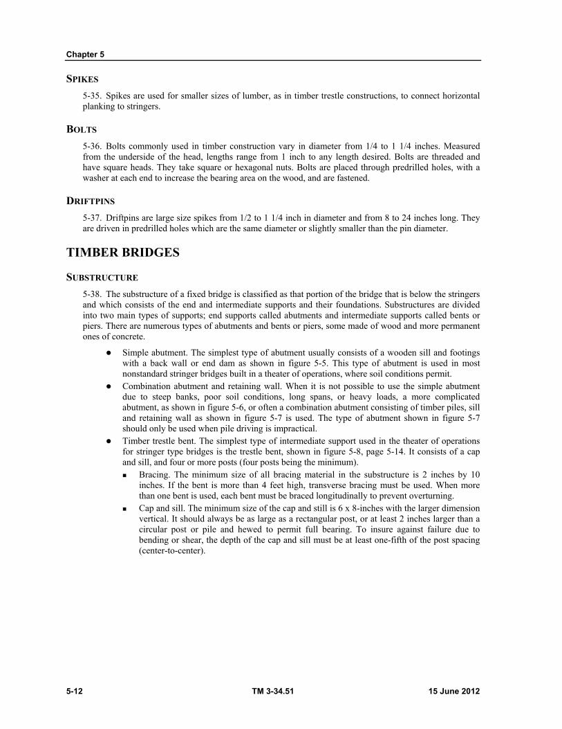
Chapter 5
5-12 TM 3-34.51 15 June 2012
SPIKES
5-35. Spikes are used for smaller sizes of lumber, as in timber trestle constructions, to connect horizontal planking to stringers.
BOLTS
5-36. Bolts commonly used in timber construction vary in diameter from 1/4 to 1 1/4 inches. Measured from the underside of the head, lengths range from 1 inch to any length desired. Bolts are threaded and have square heads. They take square or hexagonal nuts. Bolts are placed through predrilled holes, with a washer at each end to increase the bearing area on the wood, and are fastened.
DRIFTPINS
5-37. Driftpins are large size spikes from 1/2 to 1 1/4 inch in diameter and from 8 to 24 inches long. They are driven in predrilled holes which are the same diameter or slightly smaller than the pin diameter.
TIMBER BRIDGES
SUBSTRUCTURE
5-38. The substructure of a fixed bridge is classified as that portion of the bridge that is below the stringers and which consists of the end and intermediate supports and their foundations. Substructures are divided into two main types of supports; end supports called abutments and intermediate supports called bents or piers. There are numerous types of abutments and bents or piers, some made of wood and more permanent ones of concrete.
Simple abutment. The simplest type of abutment usually consists of a wooden sill and footings with a back wall or end dam as shown in figure 5-5. This type of abutment is used in most nonstandard stringer bridges built in a theater of operations, where soil conditions permit.
Combination abutment and retaining wall. When it is not possible to use the simple abutment due to steep banks, poor soil conditions, long spans, or heavy loads, a more complicated abutment, as shown in figure 5-6, or often a combination abutment consisting of timber piles, sill and retaining wall as shown in figure 5-7 is used. The type of abutment shown in figure 5-7 should only be used when pile driving is impractical.
Timber trestle bent. The simplest type of intermediate support used in the theater of operations for stringer type bridges is the trestle bent, shown in figure 5-8, page 5-14. It consists of a cap and sill, and four or more posts (four posts being the minimum). Bracing. The minimum size of all bracing material in the substructure is 2 inches by 10
inches. If the bent is more than 4 feet high, transverse bracing must be used. When more than one bent is used, each bent must be braced longitudinally to prevent overturning.
Cap and sill. The minimum size of the cap and still is 6 x 8-inches with the larger dimension vertical. It should always be as large as a rectangular post, or at least 2 inches larger than a circular post or pile and hewed to permit full bearing. To insure against failure due to bending or shear, the depth of the cap and sill must be at least one-fifth of the post spacing (center-to-center).
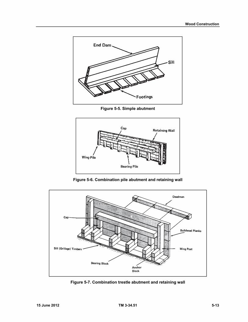
Wood Construction
15 June 2012 TM 3-34.51 5-13
Figure 5-5. Simple abutment
Figure 5-6. Combination pile abutment and retaining wall
Figure 5-7. Combination trestle abutment and retaining wall
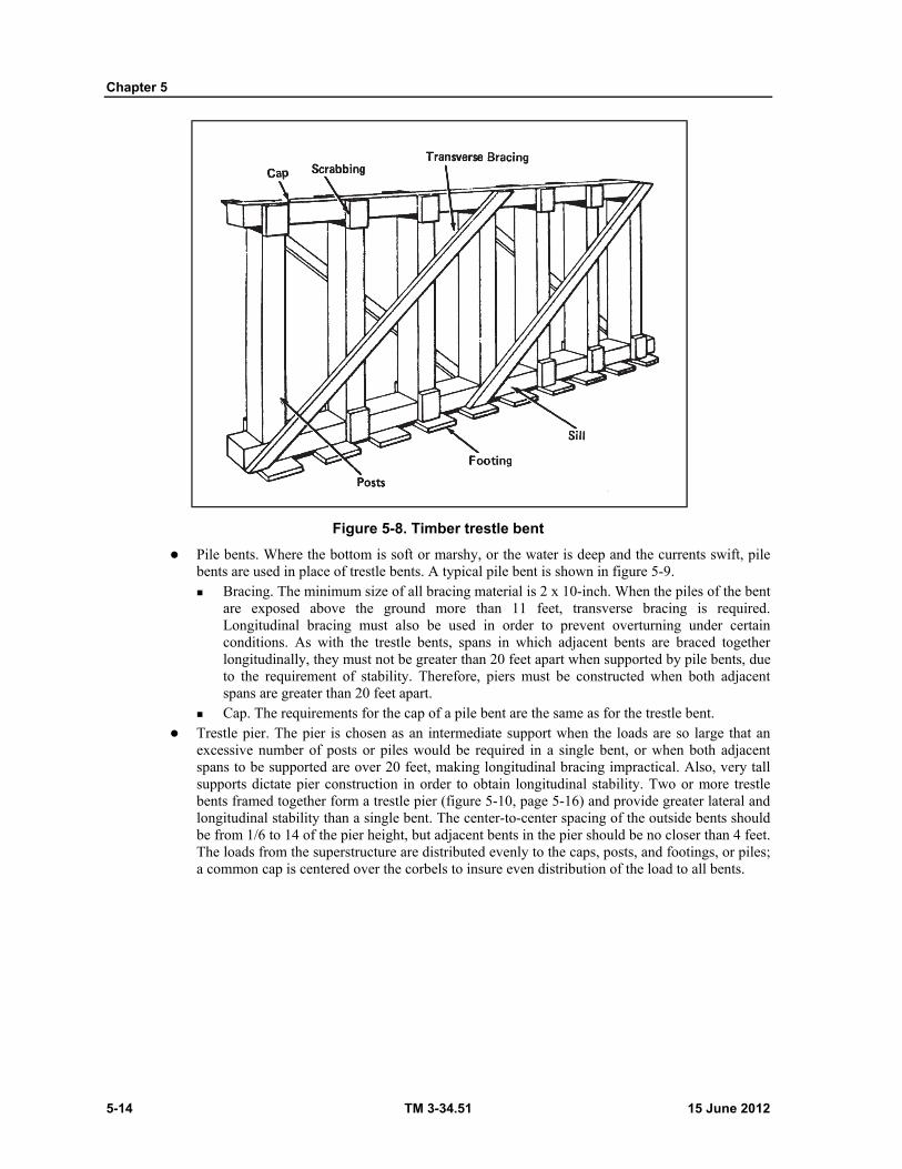
Chapter 5
5-14 TM 3-34.51 15 June 2012
Figure 5-8. Timber trestle bent
Pile bents. Where the bottom is soft or marshy, or the water is deep and the currents swift, pile bents are used in place of trestle bents. A typical pile bent is shown in figure 5-9. Bracing. The minimum size of all bracing material is 2 x 10-inch. When the piles of the bent
are exposed above the ground more than 11 feet, transverse bracing is required. Longitudinal bracing must also be used in order to prevent overturning under certain conditions. As with the trestle bents, spans in which adjacent bents are braced together longitudinally, they must not be greater than 20 feet apart when supported by pile bents, due to the requirement of stability. Therefore, piers must be constructed when both adjacent spans are greater than 20 feet apart.
Cap. The requirements for the cap of a pile bent are the same as for the trestle bent. Trestle pier. The pier is chosen as an intermediate support when the loads are so large that an
excessive number of posts or piles would be required in a single bent, or when both adjacent spans to be supported are over 20 feet, making longitudinal bracing impractical. Also, very tall supports dictate pier construction in order to obtain longitudinal stability. Two or more trestle bents framed together form a trestle pier (figure 5-10, page 5-16) and provide greater lateral and longitudinal stability than a single bent. The center-to-center spacing of the outside bents should be from 1/6 to 14 of the pier height, but adjacent bents in the pier should be no closer than 4 feet. The loads from the superstructure are distributed evenly to the caps, posts, and footings, or piles; a common cap is centered over the corbels to insure even distribution of the load to all bents.
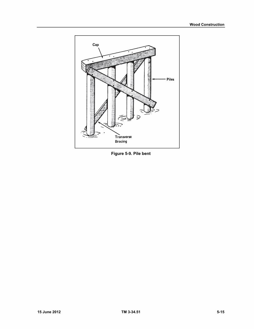
Wood Construction
15 June 2012 TM 3-34.51 5-15
Figure 5-9. Pile bent

Chapter 5
5-16 TM 3-34.51 15 June 2012
Figure 5-10. Trestle pier
Pile piers. A standard pile pier (figure 5-11) consists of two or more bents spaced 3 or more feet apart, depending on the pier height, and braced in the same manner as trestle piers. Piers are often constructed with fender piles driven around the upstream end or with cribbing to protect them from the effects of ice, swift currents, debris, or water borne traffic (TM 5-258).
Crib piers. Crib piers (figure 5-12) are usually built up of logs with the bottom wider than the top. The center of the crib is filled with ballast such as stone to provide weight and stability. Normally cribs are built in place during low water or by diverting the stream. Usually crib piers are not used when a simpler support will suffice.
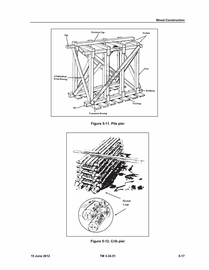
Wood Construction
15 June 2012 TM 3-34.51 5-17
Figure 5-11. Pile pier
Figure 5-12. Crib pier
Chapter 5
5-18 TM 3-34.51 15 June 2012
BRIDGE SUPERSTRUCTURE
5-39. The superstructure of a bridge consists of the longitudinal members, flooring, curbs, walks, handrails, and other items which make up the bridge above the substructure. The principal components of the superstructure of a fixed bridge are shown in figure 5-13. There are many types of superstructures. The use of any particular type depends on the size and the type of loads to be carried, span, availability of materials, manpower and equipment, and the time available for erection.
Wood stringer bridge. One of the simplest types of bridges that can be built in a theater of operations is the wood stringer bridge (figure 5-13). The stringers can be square, rectangular, or round and in many cases they are made from the timber or logs found locally. For single spans the stringers can rest on abutments of the type shown in figures 5-5, 5-6, or 5-7, page 5-13. Usually spans are limited to about 25 feet. Where more than one span is required, trestle bents or piles can be used as intermediate supports.
Stringers. Common stringer sizes are 4 x 16, 6 x 16, and 8 x 16 inches, the size depending on the span
and load for which the trestle is designed. Stringers are placed on edge and fastened to the caps by driftpins. They should lap over bent caps at either end to permit successive stringers to be bolted together. Stringers are usually surfaced on one side to insure a base of uniform elevation for the deck.
If the deflection of the timber stringers of a bridge exceeds approximately 1/200 of the span length, there is a possibility that the decking may loosen or break from the beams. Therefore, stringer sizes should be chosen so that the L/d ratio for the spans does not exceed 18, which will automatically eliminate the possibility of deflections larger than 1/200.
Where: L = span length center-to-center of support (caps) in inches d = depth of stringer in inches
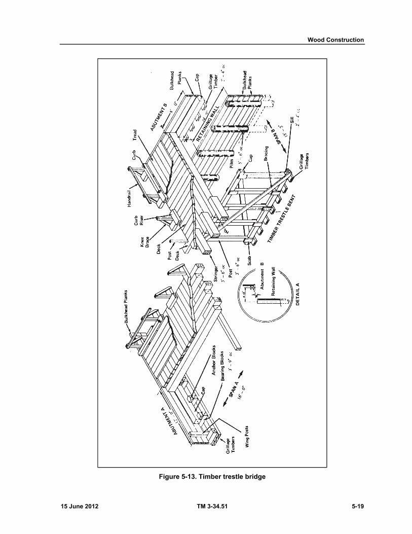
Wood Construction
15 June 2012 TM 3-34.51 5-19
Figure 5-13. Timber trestle bridge
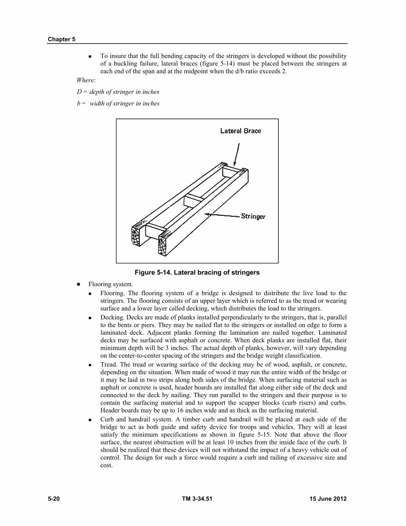
Chapter 5
5-20 TM 3-34.51 15 June 2012
To insure that the full bending capacity of the stringers is developed without the possibility of a buckling failure, lateral braces (figure 5-14) must be placed between the stringers at each end of the span and at the midpoint when the d/b ratio exceeds 2.
Where:
D = depth of stringer in inches
b = width of stringer in inches
Figure 5-14. Lateral bracing of stringers
Flooring system. Flooring. The flooring system of a bridge is designed to distribute the live load to the
stringers. The flooring consists of an upper layer which is referred to as the tread or wearing surface and a lower layer called decking, which distributes the load to the stringers.
Decking. Decks are made of planks installed perpendicularly to the stringers, that is, parallel to the bents or piers. They may be nailed flat to the stringers or installed on edge to form a laminated deck. Adjacent planks forming the lamination are nailed together. Laminated decks may be surfaced with asphalt or concrete. When deck planks are installed flat, their minimum depth will be 3 inches. The actual depth of planks, however, will vary depending on the center-to-center spacing of the stringers and the bridge weight classification.
Tread. The tread or wearing surface of the decking may be of wood, asphalt, or concrete, depending on the situation. When made of wood it may run the entire width of the bridge or it may be laid in two strips along both sides of the bridge. When surfacing material such as asphalt or concrete is used, header boards are installed flat along either side of the deck and connected to the deck by nailing. They run parallel to the stringers and their purpose is to contain the surfacing material and to support the scupper blocks (curb risers) and curbs. Header boards may be up to 16 inches wide and as thick as the surfacing material.
Curb and handrail system. A timber curb and handrail will be placed at each side of the bridge to act as both guide and safety device for troops and vehicles. They will at least satisfy the minimum specifications as shown in figure 5-15. Note that above the floor surface, the nearest obstruction will be at least 10 inches from the inside face of the curb. It should be realized that these devices will not withstand the impact of a heavy vehicle out of control. The design for such a force would require a curb and railing of excessive size and cost.
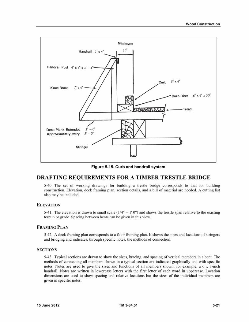
Wood Construction
15 June 2012 TM 3-34.51 5-21
Figure 5-15. Curb and handrail system
DRAFTING REQUIREMENTS FOR A TIMBER TRESTLE BRIDGE 5-40. The set of working drawings for building a trestle bridge corresponds to that for building construction. Elevation, deck framing plan, section details, and a bill of material are needed. A cutting list also may be included.
ELEVATION
5-41. The elevation is drawn to small scale (1/4" = 1' 0") and shows the trestle span relative to the existing terrain or grade. Spacing between bents can be given in this view.
FRAMING PLAN
5-42. A deck framing plan corresponds to a floor framing plan. It shows the sizes and locations of stringers and bridging and indicates, through specific notes, the methods of connection.
SECTIONS
5-43. Typical sections are drawn to show the sizes, bracing, and spacing of vertical members in a bent. The methods of connecting all members shown in a typical section are indicated graphically and with specific notes. Notes are used to give the sizes and functions of all members shown; for example, a 6 x 8-inch handrail. Notes are written in lowercase letters with the first letter of each word in uppercase. Location dimensions are used to show spacing and relative locations but the sizes of the individual members are given in specific notes.
Chapter 5
5-22 TM 3-34.51 15 June 2012
DETAILS
5-44. Details show methods of connection at large scale. A typical detail might show the method of bolting a handrail post to stringer, deck, and curb. The same detail also would show the bolt passing through curb, scupper board, header, and deck.
WATER TOWER 5-45. Figure 5-16 represents a simplified drawing of a tower for a 4,000-gallon water storage tank. Although minor location dimensions have been omitted for sake of clarity, this is a typical working drawing of a timber structure and illustrates the manner in which members and methods of connection are drawn and identified.
FOUNDATION PLAN
5-46. The foundation plan gives the horizontal dimensions needed to lay out the elevations. In addition to showing the spacing between columns, or posts, it shows the horizontal dimensions of footings. Note the economy with which dimensions are represented.
PLATFORM PLAN
5-47. The platform plan shows that the same 8-foot spacing is maintained between the outside edges of the vertical posts. Like the deck plan of a trestle, it shows the spacing of stringers, although these location dimensions have been omitted in this plan. Girder size is noted in this view and stringer sizes in the elevation view. Dunnage beam sizes are not noted because the general notes state that dunnage beams are supplied with the tank, meaning that they do not have to be fabricated on the job. Tank and dunnage beam locations are indicated with the phantom-like symbol because their erection is not part of this job. The platform plan also shows the relative locations of elevations A and B.
ELEVATIONS A AND B
5-48. These elevations show the vertical members, location dimensions, and method of connection. An examination of the elevations show the tower to be composed basically of 4 posts supporting a platform on which a water storage tank can be placed at an elevation sufficient to supply water under the required pressure. Each column is composed of three 8 x 8-inch posts, 16-, 12-, and 10-feet in length, respectively. Posts must be of sufficient size to prevent buckling under the load, the foundations must be of the proper compressive strength to support the vertical loads, and the soil of sufficient bearing capacity to support foundations of the size shown. The posts are braced in three ways for rigidity. A draftsman should examine the ways in which the following connections are shown on the drawing.
Base. Notes and drawings show that four 3/4-inch dowels have been bonded into each concrete footing base. The dowels are 42 inches long and are arranged in pairs on the opposite sides of each post. Posts and dowels are connected to each other with three 3/4-inch anchor rods, two anchor rods are parallel to elevation A and one parallel to elevation B. Posts, anchor rods, and dowels are enclosed in 2 x 2 x 2-foot concrete piers. Note that the excavations required for the footings are to be backfilled to 3 inches below the tops of the pier.
Splice plates. Splice plates are used to connect successive column sections. Location dimensions for bolts have not been included in this illustration because of the small scale, but they must be provided on the working drawings. Splice plates are bolted to the posts. A general note covers the number and kind of washers required per bolt.
Bracing. Posts are braced with horizontal 3 x 8-inch struts, and 2 x 8-inch cross bracing placed horizontally (section C-C) and vertically. Note that the vertical cross bracing is drawn with the hidden-line symbols for the ends of one of each pair of diagonals. This indicates that the diagonals are placed on opposite sides of the 8 x 8-inch posts and explains why 8-inch blocking is required between diagonals at the point where they are bolted together.
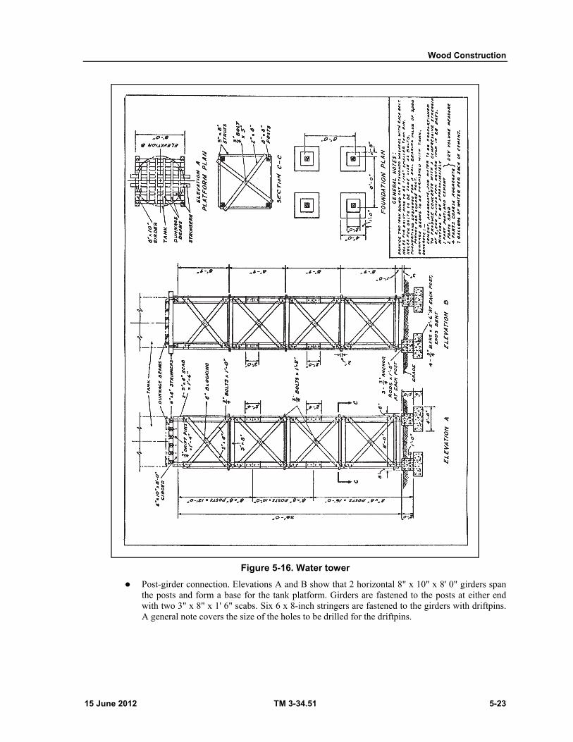
Wood Construction
15 June 2012 TM 3-34.51 5-23
Figure 5-16. Water tower
Post-girder connection. Elevations A and B show that 2 horizontal 8" x 10" x 8' 0" girders span the posts and form a base for the tank platform. Girders are fastened to the posts at either end with two 3" x 8" x 1' 6" scabs. Six 6 x 8-inch stringers are fastened to the girders with driftpins. A general note covers the size of the holes to be drilled for the driftpins.
Chapter 5
5-24 TM 3-34.51 15 June 2012
SECTIONS
5-49. A single cross sectional view, section C-C, is required to show the arrangement of the horizontal bracing. Notice that no hidden-line symbol is used at the ends of the bracing, and no blocking is specified in notes.
SYMBOLS
5-50. Note that the ends of the framing timber are indicated by intersecting diagonals. Timber in section, as shown in section C-C and the foundation plan, is indicated by a different symbol. Note also the symbols used for concrete, dowels, and soil. Use of the phantom line to indicate the tank and dunnage beam location has been described in b above.
NOTES
5-51. Draftsmen should study the use of specific notes, paying attention to the way in which members are identified by size and function.
DIMENSIONS
5-52. Note that the horizontal dimensions are given in the plan views and the vertical dimensions in the elevations. Study the manner in which dimensions are represented without repetition.
15 June 2012 TM 3-34.51 6-1
Chapter 6
Masonry Structures
SECTION I - BRICK MASONRY
INTRODUCTION 6-1. Masonry or masonry construction encompasses construction with brick, concrete or cinder blocks, clay tile, and stone. The sizes, shapes, and characteristics of masonry units determine which type is applicable for use in the particular construction project. For a detailed discussion of masonry and masonry construction refer to Part II, TM 5-742.
DESCRIPTION 6-2. Brick masonry is that type of construction in which units of baked clay or shale of uniform size, small enough to be placed with one hand, are laid in courses with mortar joints to form walls of virtually unlimited length and height. Bricks are kiln-baked from various clay and shale mixtures. The chemical and physical characteristics of the ingredients vary considerably; these and the kiln temperatures combine to produce bricks in a variety of colors and hardnesses.
BRICK CLASSIFICATION 6-3. There are three general types of structural clay masonry units: solid masonry units, hollow masonry units, and architectural terra cotta. These units may serve as a structural function, as a decorative finish, or a combination of both. Structural clay products include brick, hollow tile of all types, and architectural terra cotta. They do not include thin wall tile, sewer pipe, flue linings, drain tile, or other similar tiles.
BRICK TYPES 6-4. There are many types of brick. Some are different in formation and composition while others vary according to their use. Some of the more commonly used types of brick are as follows:
BUILDING BRICK
6-5. The term building brick, formerly called common brick, is applied to brick made of ordinary clays and shales and burned in the usual manner in the kilns. These bricks do not have special scorings or markings and are not produced ill any special color or surface texture. Building brick is also known as hard and kiln run brick. It is used generally for the backing courses in solid or cavity brick walls. The harder and more durable kinds are preferred for this purpose.
FACE BRICK
6-6. Face bricks are used in the exposed face of a wall and are higher quality units than backup brick. They have better durability and appearance. The most common colors of face brick are various shades of brown, red, gray, yellow, and white.
CLINKER BRICK
6-7. When bricks are overburned in the kilns, they are called clinker brick. This type of brick is usually hard and durable and may be irregular in shape. Rough hard corresponds to the clinker classification.
Chapter 6
6-2 TM 3-34.51 15 June 2012
PRESSED BRICK
6-8. The dry press process is used to make this class of brick which has regular smooth faces, sharp edges, and perfectly square corners. Ordinarily all press brick is used as face brick.
GLAZED BRICK
6-9. This type of brick has one surface of each brick glazed in white or other color. The ceramic glaze consists of mineral ingredients which fuse together in a glass-like coating during burning. This type of brick is particularly suited for walls or partitions in hospitals, dairies, laboratories or other buildings where cleanliness and ease of cleaning is necessary.
FIRE BRICK
6-10. This type of brick is made of a special type of fire clay which will withstand the high temperatures of fireplaces, boilers, and similar usages without cracking or decomposing. Fire brick is generally larger than the regular structural brick and often is hand molded.
CORED BRICK
6-11. Cored bricks are bricks made with two rows of five holes extending through their beds to reduce the weight. There is no significant difference between the strength of walls constructed with cored brick and those constructed with solid brick. Resistance to moisture penetration is about the same for both types of walls. The most easily available brick that will meet requirements should be used whether the brick is cored or solid.
EUROPEAN BRICK
6-12. The strength and durability of most European clay brick, particularly English and Dutch, compares favorably with the clay brick made in the United States.
SAND-LIME BRICK
6-13. Sand-lime bricks are extensively used in Germany. They are made from a lean mixture of slaked lime and fine silicious sand molded under mechanical pressure and hardened under steam pressure.
BRICK SIZES, SURFACES, AND SHAPES
BRICK SIZES
6-14. Standard bricks manufactured in the United States are 2 1/4 x 3 3/4 x 8-inches. English bricks are 3 x 4 1/2 x 9-inches, Roman bricks are 1 1/2 x 4 x 12-inches, and Norman bricks are 2 3/4 x 4 x 12-inches. The actual dimensions of brick vary a little because of shrinkage during burning.
BRICK SURFACES
6-15. The six surfaces of a brick are called the face, the side, the cull, the end, and the beds (fig 6-1).
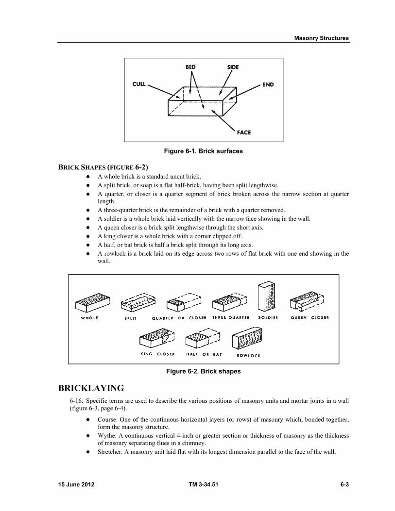
Masonry Structures
15 June 2012 TM 3-34.51 6-3
Figure 6-1. Brick surfaces
BRICK SHAPES (FIGURE 6-2) A whole brick is a standard uncut brick. A split brick, or soap is a flat half-brick, having been split lengthwise. A quarter, or closer is a quarter segment of brick broken across the narrow section at quarter
length. A three-quarter brick is the remainder of a brick with a quarter removed. A soldier is a whole brick laid vertically with the narrow face showing in the wall. A queen closer is a brick split lengthwise through the short axis. A king closer is a whole brick with a corner clipped off. A half, or bat brick is half a brick split through its long axis. A rowlock is a brick laid on its edge across two rows of flat brick with one end showing in the
wall.
Figure 6-2. Brick shapes
BRICKLAYING 6-16. Specific terms are used to describe the various positions of masonry units and mortar joints in a wall (figure 6-3, page 6-4).
Course. One of the continuous horizontal layers (or rows) of masonry which, bonded together, form the masonry structure.
Wythe. A continuous vertical 4-inch or greater section or thickness of masonry as the thickness of masonry separating flues in a chimney.
Stretcher. A masonry unit laid flat with its longest dimension parallel to the face of the wall.

Chapter 6
6-4 TM 3-34.51 15 June 2012
Header. A masonry unit laid flat with its longest dimension perpendicular to the face of the wall. It is generally used to tie two wythes of masonry together.
Rowlock. A brick laid on its edge (face). Bull-stretcher. A rowlock brick laid with its longest dimension parallel to the face of the wall. Bull-header. A rowlock brick laid with its longest dimension perpendicular to the face of the
wall. Soldier. A brick laid on its end so that its longest dimension is parallel to the vertical axis of the
face of the wall.
Figure 6-3. Masonry units and mortar joints
BONDS 6-17. The word bond, when used in reference to masonry, may have three different meanings:

Masonry Structures
15 June 2012 TM 3-34.51 6-5
STRUCTURAL BOND
6-18. Structural bond is the method by which individual masonry units are interlocked or tied together to cause the entire assembly to act as a single structural unit. Structural bonding of brick and tile walls may be accomplished in three ways. First, by overlapping (interlocking) the masonry units, second by the use of metal ties embedded in connecting joints, and third by the adhesion of grout to adjacent wythes of masonry.
MORTAR BOND
6-19. Mortar bond is the adhesion of the joint mortar to the masonry units or to the reinforcing steel.
PATTERN BOND
6-20. Pattern bond is the pattern formed by the masonry units and the mortar joints on the face of a wall. The pattern may result from the type of structural bond used or may be purely a decorative one in no way related to the structural bond. There are five basic: pattern bonds in common use today (figures 6-4 and 6-5, pages 6-6 and 6-7): running bond, common or American bond, Flemish bond, English bond, and block or stack bond.
Running bond. This is the simplest of the basic pattern bonds, the running bond consists of all stretchers. Since there are no headers used in this bond, metal ties are usually used. Running bond is used largely in cavity wall construction and veneered walls of brick, and often in facing tile walls where bonding may be accomplished by extra width stretcher tile.
Common or American bond. Common bond is a variation of running bond with a course of full length headers at regular intervals. These headers provide structural bonding as well as pattern. Header courses usually appear at every fifth, sixth, or seventh course depending on the structural bonding requirements. In laying out any bond pattern it is very important that the corners be started correctly. For common bond, a ''three-quarter" brick must start each header course at the corner. Common bond may be varied by using a Flemish header course.
Flemish bond. Each course of brick is made up of alternate stretchers and headers, with the headers in alternate courses centered over t he stretchers in the intervening courses. Where the headers are not used for the structural bonding, they may be obtained by using half brick, called "blind-headers." There are two methods used in starting the corners. Figure 6-4 shows the so called "Dutch" corner in which a three-quarter brick is used to start each course and the "English" corner in which 2 inch or quarter-brick closures must be used.
English bond. English bond is composed of alternate courses of headers and stretchers. The headers are centered on the stretchers and joints between stretchers. The vertical (head) joints between stretchers in all courses line up vertically. Blind headers are used in courses which are not structural bonding courses. An English cross or Dutch bond is a variation of English bond and differs only in that vertical joints between the stretchers in alternate courses do not line up vertically. These joints center on the stretchers themselves in the courses above and below.
Block or stack bond. Stack bond is purely a pattern bond. There is no overlapping of the units, all vertical joints being alined. Usually this pattern is bonded to the backing with rigid steel ties, but when 8-inch-thick stretcher units are available, they may be used. In large wall areas and in load-bearing construction, it is advisable to reinforce the wall with steel pencil rods placed in horizontal mortar joints. The vertical alignment requires dimensionally accurate units, or carefully prematched units, for each vertical joint alinement. Variety in pattern may be achieved by numerous combinations and modifications of the basic patterns shown.
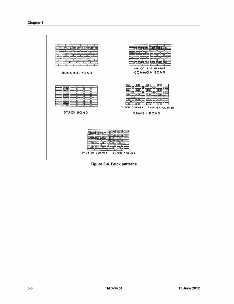
Chapter 6
6-6 TM 3-34.51 15 June 2012
Figure 6-4. Brick patterns

Masonry Structures
15 June 2012 TM 3-34.51 6-7
Figure 6-5. Brick bonds
METAL TIES
6-21. Metal ties can be used to tie the brick on the outside face of the wall to the backing courses. These are used when no header courses are installed. They are not as satisfactory as header courses. Typical metal ties are shown in figure 6-6, page 6-8, and in use in figure 6-7, page 6-8.
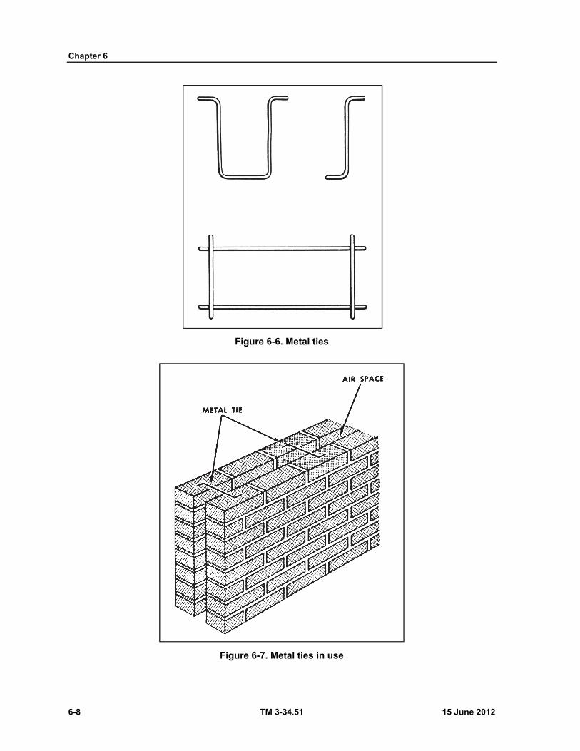
Chapter 6
6-8 TM 3-34.51 15 June 2012
Figure 6-6. Metal ties
Figure 6-7. Metal ties in use
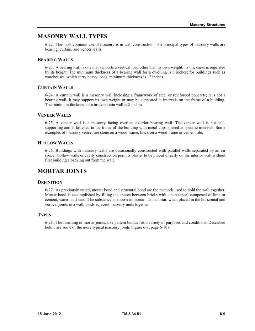
Masonry Structures
15 June 2012 TM 3-34.51 6-9
MASONRY WALL TYPES 6-22. The most common use of masonry is in wall construction. The principal types of masonry walls are bearing, curtain, and veneer walls.
BEARING WALLS
6-23. A bearing wall is one that supports a vertical load other than its own weight; its thickness is regulated by its height. The minimum thickness of a bearing wall for a dwelling is 8 inches; for buildings such as warehouses, which carry heavy loads, minimum thickness is 12 inches.
CURTAIN WALLS
6-24. A curtain wall is a masonry wall inclosing a framework of steel or reinforced concrete; it is not a bearing wall. It may support its own weight or may be supported at intervals on the frame of a building. The minimum thickness of a brick curtain wall is 8 inches.
VENEER WALLS
6-25. A veneer wall is a masonry facing over an exterior bearing wall. The veneer wall is not self-supporting and is fastened to the frame of the building with metal clips spaced at specific intervals. Some examples of masonry veneer are stone on a wood frame, brick on a wood frame or cement tile.
HOLLOW WALLS
6-26. Buildings with masonry walls are occasionally constructed with parallel walls separated by an air space. Hollow walls or cavity construction permits plaster to be placed directly on the interior wall without first building a backing out from the wall.
MORTAR JOINTS
DEFINITION
6-27. As previously stated, mortar bond and structural bond are the methods used to hold the wall together. Mortar bond is accomplished by filling the spaces between bricks with a substance) composed of lime or cement, water, and sand. The substance is known as mortar. This mortar, when placed in the horizontal and vertical joints in a wall, binds adjacent masonry units together
TYPES
6-28. The finishing of mortar joints, like pattern bonds, fits a variety of purposes and conditions. Described below are some of the more typical masonry joints (figure 6-8, page 6-10).
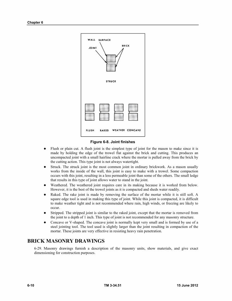
Chapter 6
6-10 TM 3-34.51 15 June 2012
Figure 6-8. Joint finishes
Flush or plain cut. A flush joint is the simplest type of joint for the mason to make since it is made by holding the edge of the trowel flat against the brick and cutting. This produces an uncompacted joint with a small hairline crack where the mortar is pulled away from the brick by the cutting action. This type joint is not always watertight.
Struck. The struck joint is the most common joint in ordinary brickwork. As a mason usually works from the inside of the wall, this joint is easy to make with a trowel. Some compaction occurs with this joint, resulting in a less permeable joint than some of the others. The small ledge that results in this type of joint allows water to stand in the joint.
Weathered. The weathered joint requires care in its making because it is worked from below. However, it is the best of the trowel joints as it is compacted and sheds water readily.
Raked. The rake joint is made by removing the surface of the mortar while it is still soft. A square edge tool is used in making this type of joint. While this joint is compacted, it is difficult to make weather tight and is not recommended where rain, high winds, or freezing are likely to occur.
Stripped. The stripped joint is similar to the raked joint, except that the mortar is removed from the joint to a depth of 1 inch. This type of joint is not recommended for any masonry structure.
Concave or V-shaped. The concave joint is normally kept very small and is formed by use of a steel jointing tool. The tool used is slightly larger than the joint resulting in compaction of the mortar. These joints are very effective in resisting heavy rain penetration.
BRICK MASONRY DRAWINGS 6-29. Masonry drawings furnish a description of the masonry units, show materials, and give exact dimensioning for construction purposes.
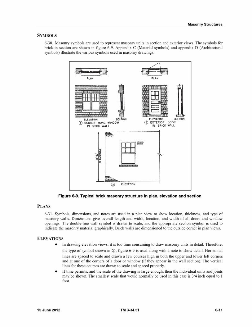
Masonry Structures
15 June 2012 TM 3-34.51 6-11
SYMBOLS
6-30. Masonry symbols are used to represent masonry units in section and exterior views. The symbols for brick in section are shown in figure 6-9. Appendix C (Material symbols) and appendix D (Architectural symbols) illustrate the various symbols used in masonry drawings.
Figure 6-9. Typical brick masonry structure in plan, elevation and section
PLANS
6-31. Symbols, dimensions, and notes are used in a plan view to show location, thickness, and type of masonry walls. Dimensions give overall length and width, location, and width of all doors and window openings. The double-line wall symbol is drawn to scale, and the appropriate section symbol is used to indicate the masonry material graphically. Brick walls are dimensioned to the outside corner in plan views.
ELEVATIONS In drawing elevation views, it is too time consuming to draw masonry units in detail. Therefore,
the type of symbol shown in ③, figure 6-9 is used along with a note to show detail. Horizontal lines are spaced to scale and drawn a few courses high in both the upper and lower left corners and at one of the corners of a door or window (if they appear in the wall section). The vertical lines for these courses are drawn to scale and spaced properly.
If time permits, and the scale of the drawing is large enough, then the individual units and joints may be shown. The smallest scale that would normally be used in this case is 3/4 inch equal to 1 foot.
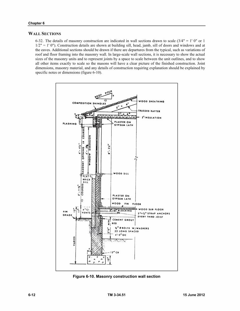
Chapter 6
6-12 TM 3-34.51 15 June 2012
WALL SECTIONS
6-32. The details of masonry construction are indicated in wall sections drawn to scale (3/4" = 1' 0" or 1 1/2" = 1' 0"). Construction details are shown at building sill, head, jamb, sill of doors and windows and at the eaves. Additional sections should be drawn if there are departures from the typical, such as variations of roof and floor framing into the masonry wall. In large-scale wall sections, it is necessary to show the actual sizes of the masonry units and to represent joints by a space to scale between the unit outlines, and to show all other items exactly to scale so the masons will have a clear picture of the finished construction. Joint dimensions, masonry material, and any details of construction requiring explanation should be explained by specific notes or dimensions (figure 6-10).
Figure 6-10. Masonry construction wall section
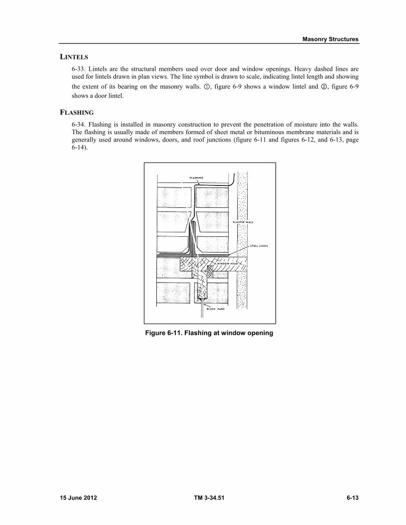
Masonry Structures
15 June 2012 TM 3-34.51 6-13
LINTELS
6-33. Lintels are the structural members used over door and window openings. Heavy dashed lines are used for lintels drawn in plan views. The line symbol is drawn to scale, indicating lintel length and showing
the extent of its bearing on the masonry walls. ①, figure 6-9 shows a window lintel and ②, figure 6-9 shows a door lintel.
FLASHING
6-34. Flashing is installed in masonry construction to prevent the penetration of moisture into the walls. The flashing is usually made of members formed of sheet metal or bituminous membrane materials and is generally used around windows, doors, and roof junctions (figure 6-11 and figures 6-12, and 6-13, page 6-14).
Figure 6-11. Flashing at window opening
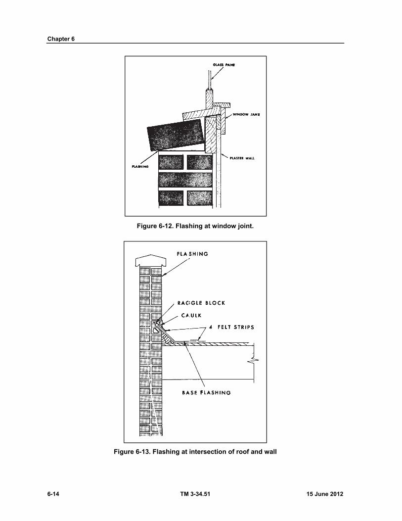
Chapter 6
6-14 TM 3-34.51 15 June 2012
Figure 6-12. Flashing at window joint.
Figure 6-13. Flashing at intersection of roof and wall

Masonry Structures
15 June 2012 TM 3-34.51 6-15
DIMENSIONS 6-35. As well as the symbols, dimensions and notes are used in a plan view to show location, thickness, and types of masonry walls. Brick walls are dimensioned to the outside corner.
DIMENSIONING ELEVATIONS
6-36. In elevation views, door and window openings are drawn to scale. The number and dimension of courses are shown in the elevations between finished floor lines, from the finished floor line to the bottom of a window opening, and to other vertical construction points as required (figure 6-10, page 6-12).
DIMENSIONING SECTIONS
6-37. In a wall section, construction details are shown at the building sill, head, jamb, sill of doors and windows, and at the eaves (figure 6-10).
SECTION II - CONCRETE, TILE, AND STONE MASONRY
CONCRETE MASONRY 6-38. The term concrete masonry applies to various sizes and kinds of blocks molded from concrete. Concrete masonry has become increasingly important as a construction material. It satisfies varied building requirements including fire, safety, durability, economy, appearance, utility, comfort, and good acoustics.
DESCRIPTION
6-39. Concrete units are usually referred to by their nominal dimensions. The standard concrete block measuring 75/8" x 75/8" x 155/8" is nominally referred to as an 8 x 8 x 16 inch unit. The weight of a standard hollow block will range between 25 and 50 pounds. If lightweight aggregate is used, it will have a weight of 25 to 35 pounds. Heavyweight units weigh 40 to 50 pounds.
TYPES
6-40. There are several different types of concrete masonry units and of these types, the hollow load-bearing concrete block is the most widely used. The following is a list of the commonly used concrete masonry units:
Hollow load-bearing concrete block. Solid load-bearing concrete block. Hollow nonload-bearing concrete block. Concrete building tile. Concrete brick.
SIZES AND SHAPES
6-41. Concrete masonry units are made in sizes and shapes to fit different needs. Figure 6-14, page 6-16, shows the typical sizes and shapes.
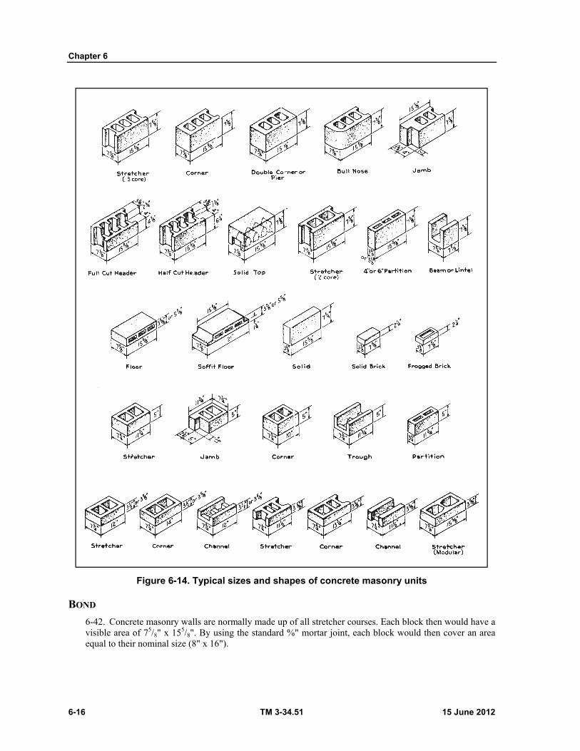
Chapter 6
6-16 TM 3-34.51 15 June 2012
Figure 6-14. Typical sizes and shapes of concrete masonry units
BOND
6-42. Concrete masonry walls are normally made up of all stretcher courses. Each block then would have a visible area of 75/8" x 155/8". By using the standard %" mortar joint, each block would then cover an area equal to their nominal size (8" x 16").
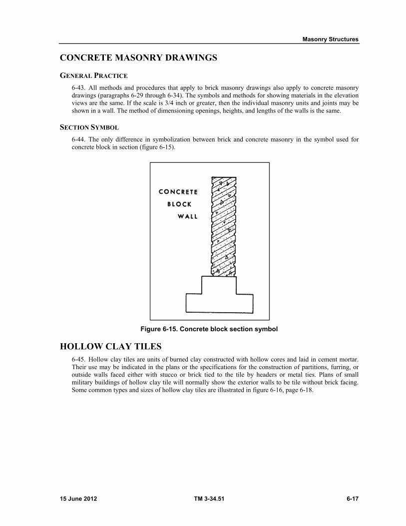
Masonry Structures
15 June 2012 TM 3-34.51 6-17
CONCRETE MASONRY DRAWINGS
GENERAL PRACTICE
6-43. All methods and procedures that apply to brick masonry drawings also apply to concrete masonry drawings (paragraphs 6-29 through 6-34). The symbols and methods for showing materials in the elevation views are the same. If the scale is 3/4 inch or greater, then the individual masonry units and joints may be shown in a wall. The method of dimensioning openings, heights, and lengths of the walls is the same.
SECTION SYMBOL
6-44. The only difference in symbolization between brick and concrete masonry in the symbol used for concrete block in section (figure 6-15).
Figure 6-15. Concrete block section symbol
HOLLOW CLAY TILES 6-45. Hollow clay tiles are units of burned clay constructed with hollow cores and laid in cement mortar. Their use may be indicated in the plans or the specifications for the construction of partitions, furring, or outside walls faced either with stucco or brick tied to the tile by headers or metal ties. Plans of small military buildings of hollow clay tile will normally show the exterior walls to be tile without brick facing. Some common types and sizes of hollow clay tiles are illustrated in figure 6-16, page 6-18.
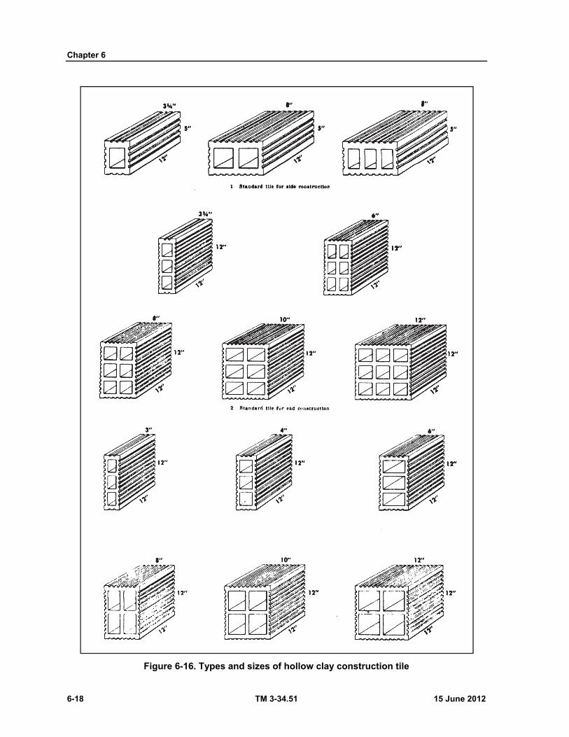
Chapter 6
6-18 TM 3-34.51 15 June 2012
Figure 6-16. Types and sizes of hollow clay construction tile
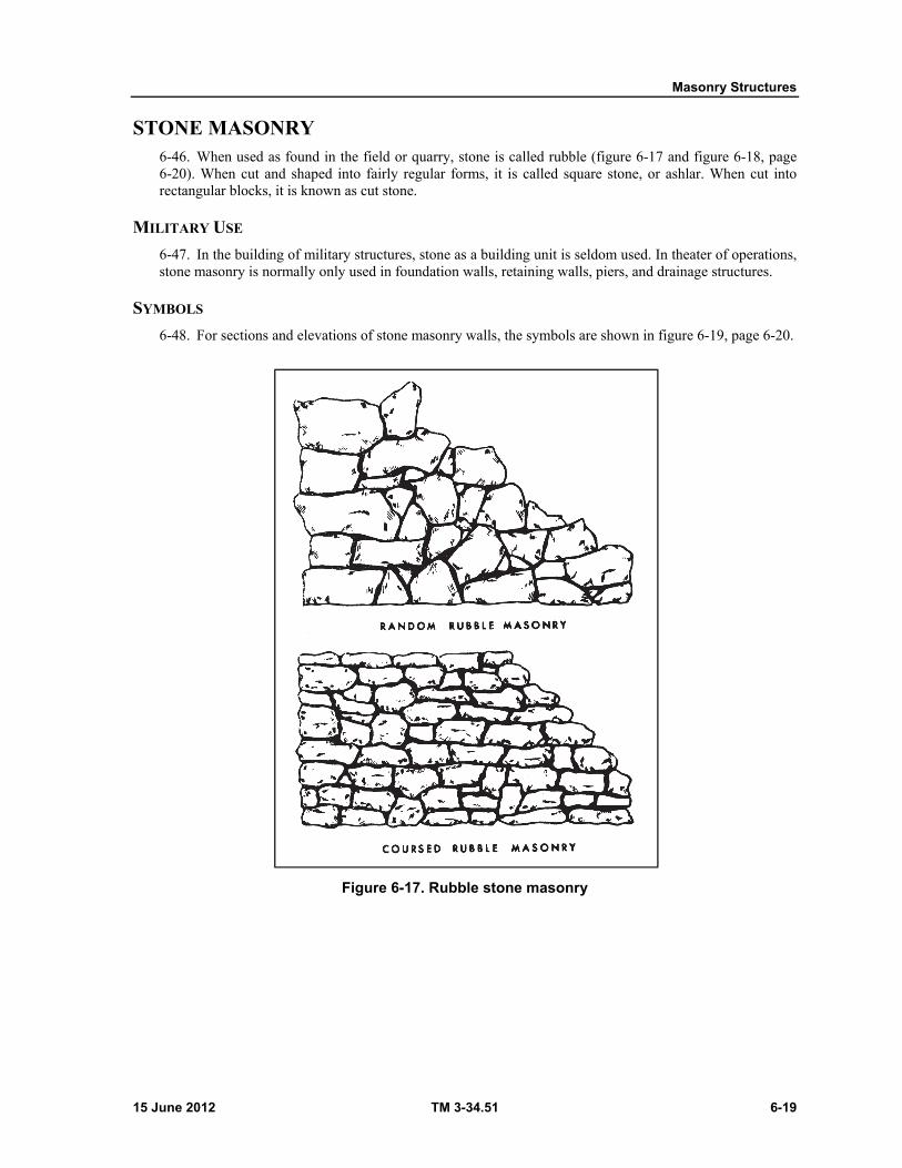
Masonry Structures
15 June 2012 TM 3-34.51 6-19
STONE MASONRY 6-46. When used as found in the field or quarry, stone is called rubble (figure 6-17 and figure 6-18, page 6-20). When cut and shaped into fairly regular forms, it is called square stone, or ashlar. When cut into rectangular blocks, it is known as cut stone.
MILITARY USE
6-47. In the building of military structures, stone as a building unit is seldom used. In theater of operations, stone masonry is normally only used in foundation walls, retaining walls, piers, and drainage structures.
SYMBOLS
6-48. For sections and elevations of stone masonry walls, the symbols are shown in figure 6-19, page 6-20.
Figure 6-17. Rubble stone masonry
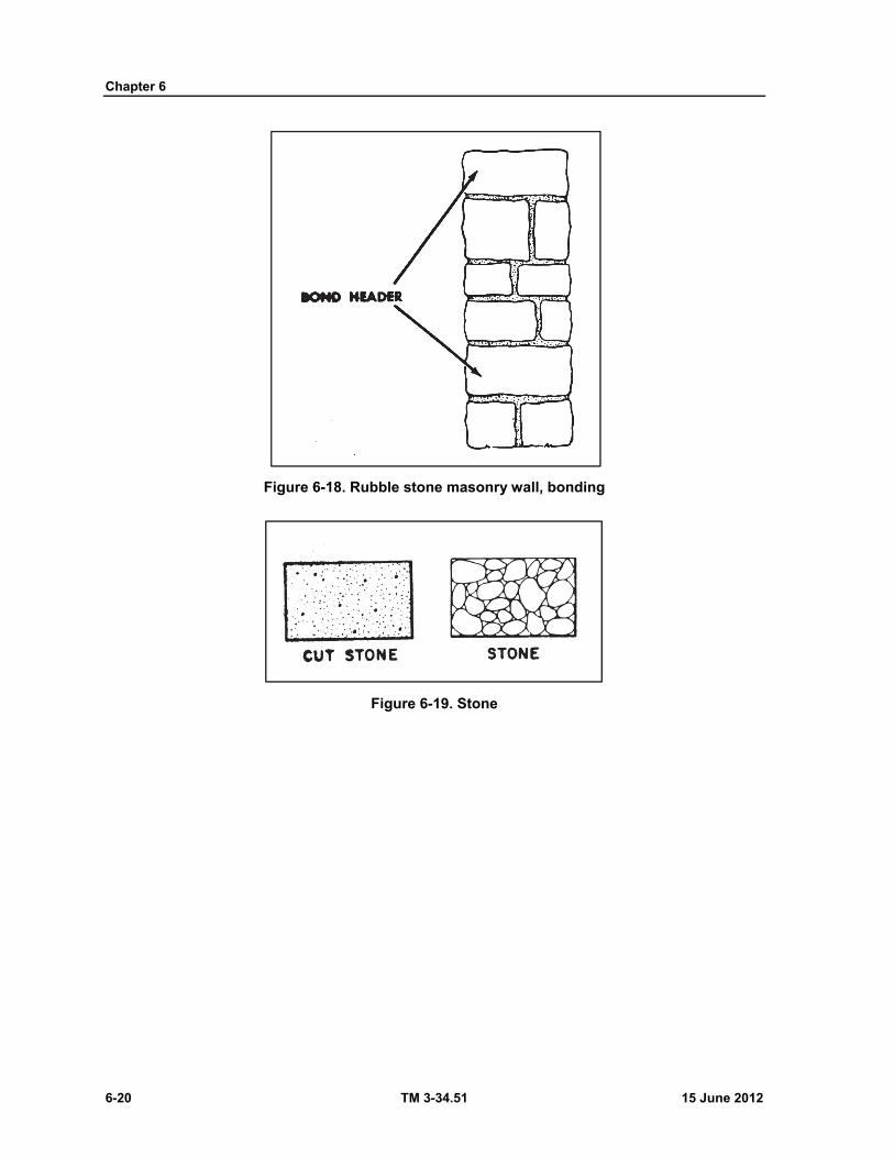
Chapter 6
6-20 TM 3-34.51 15 June 2012
Figure 6-18. Rubble stone masonry wall, bonding
Figure 6-19. Stone
15 June 2012 TM 3-34.51 7-1
Chapter 7
Concrete Structures
INTRODUCTION 7-1. As a construction draftsman it is necessary to have a knowledge of all the materials of construction, one of which is concrete. Although concrete was known and used by the Romans, it is within the last one hundred years that concrete has come into widespread use. Today it is used in many different forms, plain, reinforced and precast, for both civilian and military construction. For more technical information on concrete not covered in this chapter, refer to TM 5-742.
CONCRETE AS A MATERIAL
ADVANTAGES
7-2. Portland cement is the most important masonry material used in modern construction. It has numerous advantages, and is one of the most economical, versatile, and universally used construction materials available. It is commonly used for buildings, bridges, sewers, culverts, foundations, footings, piers, abutments, retaining walls, and pavements. A concrete structure is unique among the many systems of modern construction with few exceptions. In its plastic state, concrete can be readily handled and placed in forms and cast into any desired shape. Quality concrete work produces structures which are lasting, strong in compression, fireproof, and pleasing in appearance, and require comparatively little maintenance.
DISADVANTAGES
7-3. Recognition of the limitations of concrete construction in the design phase will eliminate some of the structural weaknesses that detract from the appearance and serviceability of concrete structures. Due to the low tensile strength, concrete members which are subjected to tensile stress must be reinforced with steel bars or mesh. Because of the great weight of this material, it is necessary to have larger supports. Therefore, it must be used where large supports are not an objection. Where space is critical and smaller supports are desirable, other construction material, such as structural steel, should be used. Concrete, like all construction materials, contracts and expands under various conditions of moisture or temperature, or both. This normal movement should be anticipated and provided for in the design, placement, and curing. Otherwise, cracks may result. When planning construction progress, high labor cost depending on the locality and the long drying and curing time required for the concrete to be properly set must be given full consideration. Another disadvantage is that even the best concrete is not entirely impervious to moisture. It contains soluble compounds which may be leached out to varying degrees by water. Impermeability is particularly important in reinforced concrete where reliance is placed on the concrete cover to prevent rusting of the steel, and where the structure is exposed to freezing and thawing.
DEFINITION AND DESCRIPTION OF CONCRETE
7-4. Concrete is a mixture of cement, aggregate, and water (figure 7-1, page 7-2).

Chapter 7
7-2 TM 3-34.51 15 June 2012
Figure 7-1. Making concrete
Cement. There are five main types of Portland cement. The type depends upon the use of the concrete. Briefly the types are: normal, modified, high early strength, low heat of hydration, and sulfate resistant. There are various other types for special projects.
Aggregate. Aggregate is classified as fine and coarse; fine aggregate refers to sand and coarse aggregate either to crushed stone or gravel. Mixed together in specific proportions fine aggregate fills the voids in coarse aggregate and cement and water form a paste that hardens to blend the aggregate together in a unified mass. Concrete is poured into the forms while it is still plastic. Once hard, the concrete retains the shape imparted to it by the form.
Water. The purpose of water in the concrete mix is to combine with the cement in the hydration process, coat the aggregate and permit the mix to be worked. Mixing water should be clean, free from organic materials, alkalies, acids, and oil. In general, water that is fit to drink is suitable for mixing with cement. However, water with excessive quantities of sulfates should be avoided. Otherwise, the result is a weak paste that may contribute to deterioration or failure of the concrete. When sea water is used, the compressive strength of concrete is 10-20 percent lower than for a comparable mix using ordinary water. There is no evidence that the use of sea water causes deterioration or corrosion of reinforcing steel.
Mix. The compressive strength and consistency of concrete are determined by the proportions in which cement, water and aggregate are combined. The particular combination required for any structural member is called the mix, which is always stated either in the specifications or general notes in the set of drawings. It may be written out, or expressed as a ratio. In the latter case, the sequence is always sacks of cement, parts of sand, parts of coarse aggregate. The quantity of water per sack of cement is stated separately. The Army uses volume measurement in concrete mixes. The units of measurement are sacks of cement (1 sack weighs 94 pounds, its volume is 1 cu ft), cubic yards of aggregate, and gallons of water (7.5 US gallons of water equal 1 cubic foot).
Strength. The strength of concrete is mainly dependent upon two things: the curing time of the concrete and the amount of water in the concrete. As water is added, final strength decreases; and as curing time (drying time) increases, strength also increases. One method of getting an idea of the amount of water in a mix is by the use of a slump test (figure 7-2). For procedure, refer to TM 5-742.
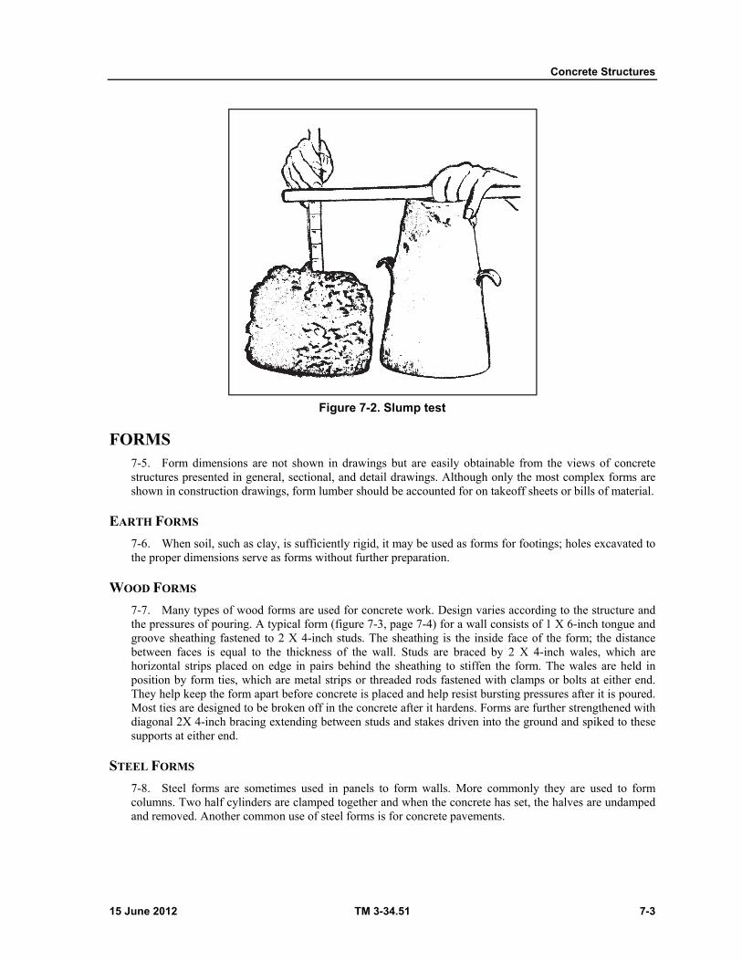
Concrete Structures
15 June 2012 TM 3-34.51 7-3
Figure 7-2. Slump test
FORMS 7-5. Form dimensions are not shown in drawings but are easily obtainable from the views of concrete structures presented in general, sectional, and detail drawings. Although only the most complex forms are shown in construction drawings, form lumber should be accounted for on takeoff sheets or bills of material.
EARTH FORMS
7-6. When soil, such as clay, is sufficiently rigid, it may be used as forms for footings; holes excavated to the proper dimensions serve as forms without further preparation.
WOOD FORMS
7-7. Many types of wood forms are used for concrete work. Design varies according to the structure and the pressures of pouring. A typical form (figure 7-3, page 7-4) for a wall consists of 1 X 6-inch tongue and groove sheathing fastened to 2 X 4-inch studs. The sheathing is the inside face of the form; the distance between faces is equal to the thickness of the wall. Studs are braced by 2 X 4-inch wales, which are horizontal strips placed on edge in pairs behind the sheathing to stiffen the form. The wales are held in position by form ties, which are metal strips or threaded rods fastened with clamps or bolts at either end. They help keep the form apart before concrete is placed and help resist bursting pressures after it is poured. Most ties are designed to be broken off in the concrete after it hardens. Forms are further strengthened with diagonal 2X 4-inch bracing extending between studs and stakes driven into the ground and spiked to these supports at either end.
STEEL FORMS
7-8. Steel forms are sometimes used in panels to form walls. More commonly they are used to form columns. Two half cylinders are clamped together and when the concrete has set, the halves are undamped and removed. Another common use of steel forms is for concrete pavements.
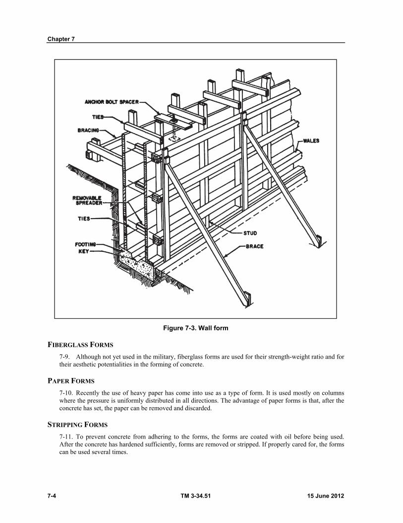
Chapter 7
7-4 TM 3-34.51 15 June 2012
Figure 7-3. Wall form
FIBERGLASS FORMS
7-9. Although not yet used in the military, fiberglass forms are used for their strength-weight ratio and for their aesthetic potentialities in the forming of concrete.
PAPER FORMS
7-10. Recently the use of heavy paper has come into use as a type of form. It is used mostly on columns where the pressure is uniformly distributed in all directions. The advantage of paper forms is that, after the concrete has set, the paper can be removed and discarded.
STRIPPING FORMS
7-11. To prevent concrete from adhering to the forms, the forms are coated with oil before being used. After the concrete has hardened sufficiently, forms are removed or stripped. If properly cared for, the forms can be used several times.

Concrete Structures
15 June 2012 TM 3-34.51 7-5
SLIP FORMS
7-12. Now being used on concrete roads is a system whereby the paver has the forms attached to it. They slide with the machine. It requires a stiffer mix but saves time and money. No labor is needed to set or remove forms and no material is needed for forms.
TYPES OF CONCRETE AND THEIR USES
BASIC CONCRETE
7-13. Concrete without reinforcement is used mostly where strength is not essential. Examples of where reinforcement may not be used are sidewalks, and slabs or floors where heavy loads are not anticipated. Without heavy loads stresses are minimal.
REINFORCED CONCRETE
7-14. Most concrete has reinforcing in it to resist large stresses. Concrete resists the compressive stresses, while reinforcing is used to resist tensile stresses. Shear is alleviated by a combination of concrete and reinforcing steel. The reinforcing is then placed where tension and shear are present in a member. Reinforcing of members may vary according to the loading on them. Identical beams may be reinforced differently due to different loading situations.
PRECAST CONCRETE
7-15. Becoming more popular in civilian and military construction is the use of precast concrete. Precast concrete is used mostly as beams or girders; however, it has been used for numerous other things such as wall panels that are cast and hoisted into place. Some advantages of precast concrete are: (1) structures can be built by parts; (2) the parts can be cast ahead of time and assembled at the site, saving time; and (3) the forms can be used over and over again. Drafting precast concrete involves no variation from the drafting of reinforced concrete.
PRESTRESSED CONCRETE Concrete in which high strength reinforcing steel is specially stretched to induce desired
compressive stress before the working loads are applied is called prestressed concrete. Unique structures or loading situations sometimes merit the use of prestressed concrete by the designer (figure 7-4, page 7-6).
When cable or reinforcing is prestressed it is called out or noted on the drawing. Drafting of prestressed elements may involve drawing some sort of jacking system used in the prestressing.
When prestressed and precast concrete are used together, the drafting of the member is done like the prestressed with the special situation noted.
PNEUMATIC OR SPRAYED CONCRETE
7-16. Often it is easier to spray concrete than to form and pour it. On steep inclines or for fireproofing around steel columns or beams it is more convenient to spray than to form and pour. It would be an exception for the draftsman to draw plans for pneumatic placement in concrete.
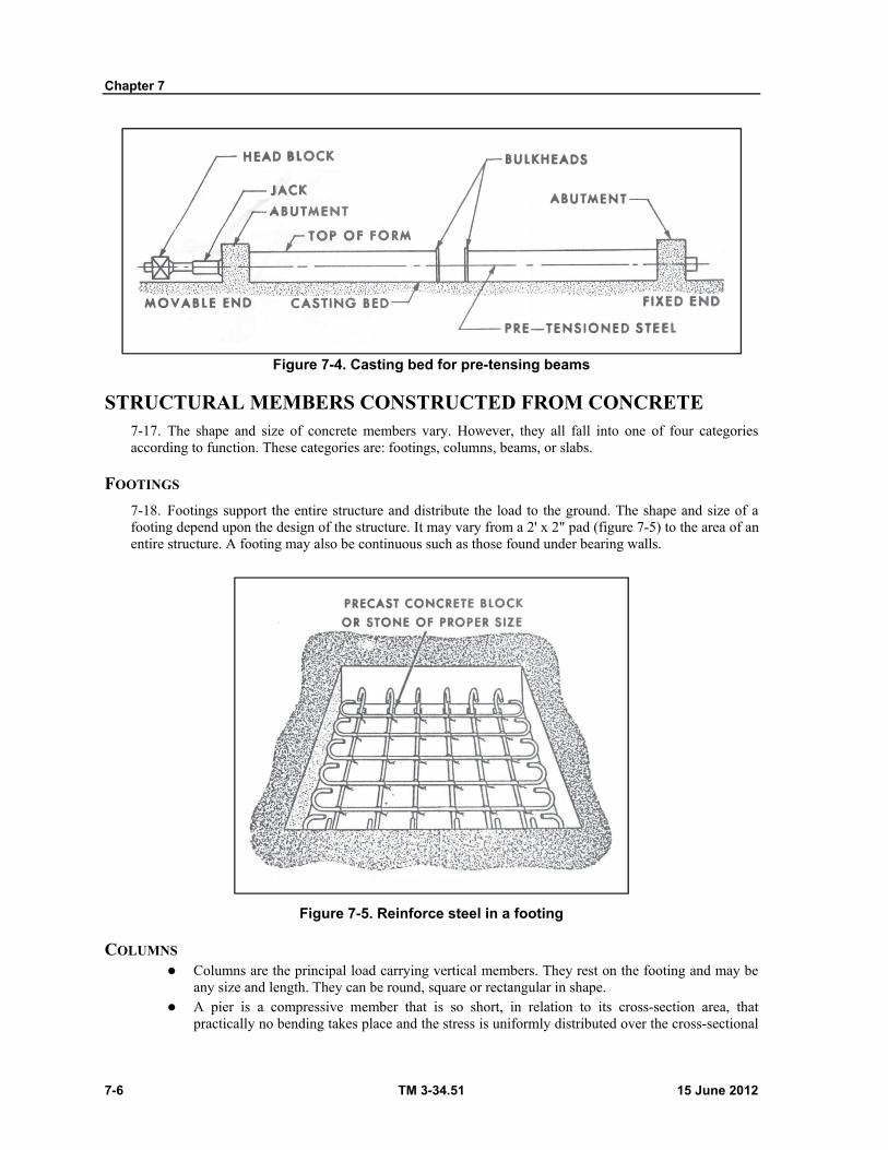
Chapter 7
7-6 TM 3-34.51 15 June 2012
Figure 7-4. Casting bed for pre-tensing beams
STRUCTURAL MEMBERS CONSTRUCTED FROM CONCRETE 7-17. The shape and size of concrete members vary. However, they all fall into one of four categories according to function. These categories are: footings, columns, beams, or slabs.
FOOTINGS
7-18. Footings support the entire structure and distribute the load to the ground. The shape and size of a footing depend upon the design of the structure. It may vary from a 2' x 2" pad (figure 7-5) to the area of an entire structure. A footing may also be continuous such as those found under bearing walls.
Figure 7-5. Reinforce steel in a footing
COLUMNS Columns are the principal load carrying vertical members. They rest on the footing and may be
any size and length. They can be round, square or rectangular in shape. A pier is a compressive member that is so short, in relation to its cross-section area, that
practically no bending takes place and the stress is uniformly distributed over the cross-sectional
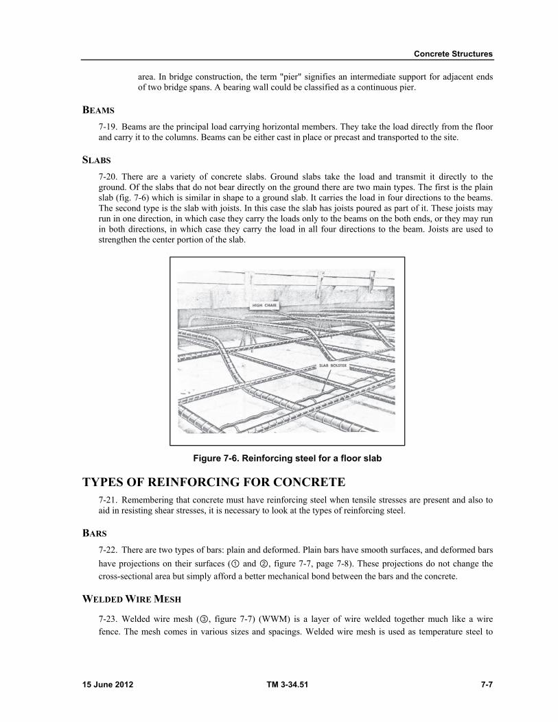
Concrete Structures
15 June 2012 TM 3-34.51 7-7
area. In bridge construction, the term "pier" signifies an intermediate support for adjacent ends of two bridge spans. A bearing wall could be classified as a continuous pier.
BEAMS
7-19. Beams are the principal load carrying horizontal members. They take the load directly from the floor and carry it to the columns. Beams can be either cast in place or precast and transported to the site.
SLABS
7-20. There are a variety of concrete slabs. Ground slabs take the load and transmit it directly to the ground. Of the slabs that do not bear directly on the ground there are two main types. The first is the plain slab (fig. 7-6) which is similar in shape to a ground slab. It carries the load in four directions to the beams. The second type is the slab with joists. In this case the slab has joists poured as part of it. These joists may run in one direction, in which case they carry the loads only to the beams on the both ends, or they may run in both directions, in which case they carry the load in all four directions to the beam. Joists are used to strengthen the center portion of the slab.
Figure 7-6. Reinforcing steel for a floor slab
TYPES OF REINFORCING FOR CONCRETE 7-21. Remembering that concrete must have reinforcing steel when tensile stresses are present and also to aid in resisting shear stresses, it is necessary to look at the types of reinforcing steel.
BARS
7-22. There are two types of bars: plain and deformed. Plain bars have smooth surfaces, and deformed bars
have projections on their surfaces (① and ②, figure 7-7, page 7-8). These projections do not change the cross-sectional area but simply afford a better mechanical bond between the bars and the concrete.
WELDED WIRE MESH
7-23. Welded wire mesh (③, figure 7-7) (WWM) is a layer of wire welded together much like a wire fence. The mesh comes in various sizes and spacings. Welded wire mesh is used as temperature steel to

Chapter 7
7-8 TM 3-34.51 15 June 2012
resist cracking in slabs where there is movement in the concrete due to larger temperature changes. Both bars and WWM are listed by size, area, and weight in Table 7-1.
MATS
7-24. Mats are merely a mesh of bars either welded or wired together. Mats are used in members of heavy construction projects (figure 7-5, page 7-6).
Figure 7-7. Types of reinforcing bars
JOINTS AND CONNECTIONS 7-25. One of the principal responsibilities of a construction draftsman is to show, in detail drawings, the manner in which structural members and construction materials are connected to each other.
FOUNDATION WALLS
7-26. Foundation walls are bonded to footings with vertical reinforcing bars called dowels which are placed in footings and extend 3 to 4 feet up into the wall. A wedge-shaped trough, called a keyway, is built into spread footings to strengthen the bond between footings and walls that are poured later.
CONSTRUCTION JOINTS
7-27. Construction joints are divisions between concrete work done at periods far enough apart to allow partial hardening. For horizontal work, such as floor slabs, construction joints should be in a vertical plane. For vertical work, such as columns, the joints should lie in a horizontal plane. Although construction joints have no permanent function but to represent a convenient stopping place, they affect the strength of the

Concrete Structures
15 June 2012 TM 3-34.51 7-9
structure. Their location is indicated in a drawing with a heavy, unbroken line and the note "permissable construction joint," or "construction joint."
Table 7-1. Sizes, areas, and weights of reinforcing bars
(in.) Sizea (numbers) Weight
(lb per ft)
Nominal diameter
(in.)
Dimensions-round cross
sectional area (sq in.)
Section perimeter
(in.)
¼ 2b 0.167 0.250 0.05 0.786 3/8 3 0.376 0.375 0.11 1.178
½ 4 0.688 0.500 0.20 1.571 5/8 5 1.043 0.625 0.31 1.963
¾ 6 1.502 0.750 0.44 2.356 7/8 7 2.044 0.875 0.60 2.749
1 8 2.670 1.000 0.79 3.142
1 9 3.400 1.128 1.00 3.544
1 1/8 10 4.303 1.270 1.27 3.990
1 ¼ 11 5.313 1.410 1.56 4.430 a.The bar numbers are based on the number of 1/8 inches included in the nominal diameter of the bar. b. Bar number 2 in plain rounds only. Bars numbered 9, 10, and 11 are rounded bars and equivalent in weight and nominal cross sectional area to the old type 1", 1 ½", and 1 ¼ " square bars.
CONTRACTION AND EXPANSION JOINTS
7-28. Concrete usually contracts while hardening and expands after it has hardened because of changes in atmospheric temperature. To provide for the changes in volume that occur at these times, it is necessary to provide joints at frequent intervals.
CONTRACTION JOINTS
7-29. The purpose of contraction joints is to control cracking due to temperature changes incident to shrinkage of the concrete. Contraction joints are usually made with no filler or with a thin coat of asphalt to break the bond. These dummy contraction joints are usually formed by cutting a depth of one third to one
fourth the thickness of the section (①figure 7-8, page 7-10).
EXPANSION JOINTS
7-30. Expansion joints are required wherever expansion might cause a concrete slab to buckle. Mastic
joints are commonly used to separate sections from each other, thus allowing room for expansion (②③,
and ④figure 7-8).
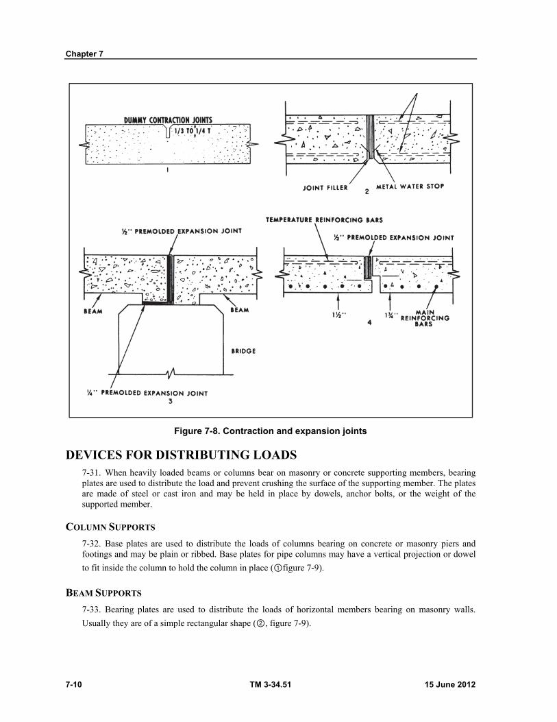
Chapter 7
7-10 TM 3-34.51 15 June 2012
Figure 7-8. Contraction and expansion joints
DEVICES FOR DISTRIBUTING LOADS 7-31. When heavily loaded beams or columns bear on masonry or concrete supporting members, bearing plates are used to distribute the load and prevent crushing the surface of the supporting member. The plates are made of steel or cast iron and may be held in place by dowels, anchor bolts, or the weight of the supported member.
COLUMN SUPPORTS
7-32. Base plates are used to distribute the loads of columns bearing on concrete or masonry piers and footings and may be plain or ribbed. Base plates for pipe columns may have a vertical projection or dowel
to fit inside the column to hold the column in place (①figure 7-9).
BEAM SUPPORTS
7-33. Bearing plates are used to distribute the loads of horizontal members bearing on masonry walls.
Usually they are of a simple rectangular shape (②, figure 7-9).
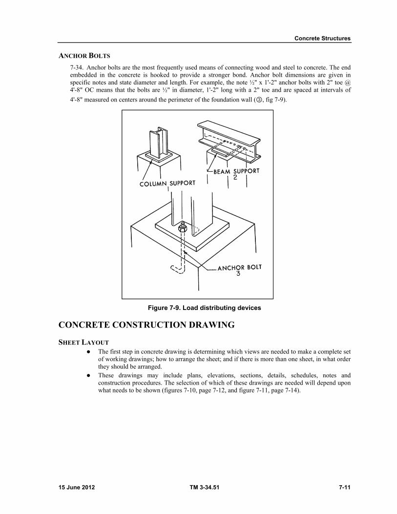
Concrete Structures
15 June 2012 TM 3-34.51 7-11
ANCHOR BOLTS
7-34. Anchor bolts are the most frequently used means of connecting wood and steel to concrete. The end embedded in the concrete is hooked to provide a stronger bond. Anchor bolt dimensions are given in specific notes and state diameter and length. For example, the note ½" x 1'-2" anchor bolts with 2" toe @ 4'-8" OC means that the bolts are ½" in diameter, 1'-2" long with a 2" toe and are spaced at intervals of
4'-8" measured on centers around the perimeter of the foundation wall (③, fig 7-9).
Figure 7-9. Load distributing devices
CONCRETE CONSTRUCTION DRAWING
SHEET LAYOUT The first step in concrete drawing is determining which views are needed to make a complete set
of working drawings; how to arrange the sheet; and if there is more than one sheet, in what order they should be arranged.
These drawings may include plans, elevations, sections, details, schedules, notes and construction procedures. The selection of which of these drawings are needed will depend upon what needs to be shown (figures 7-10, page 7-12, and figure 7-11, page 7-14).
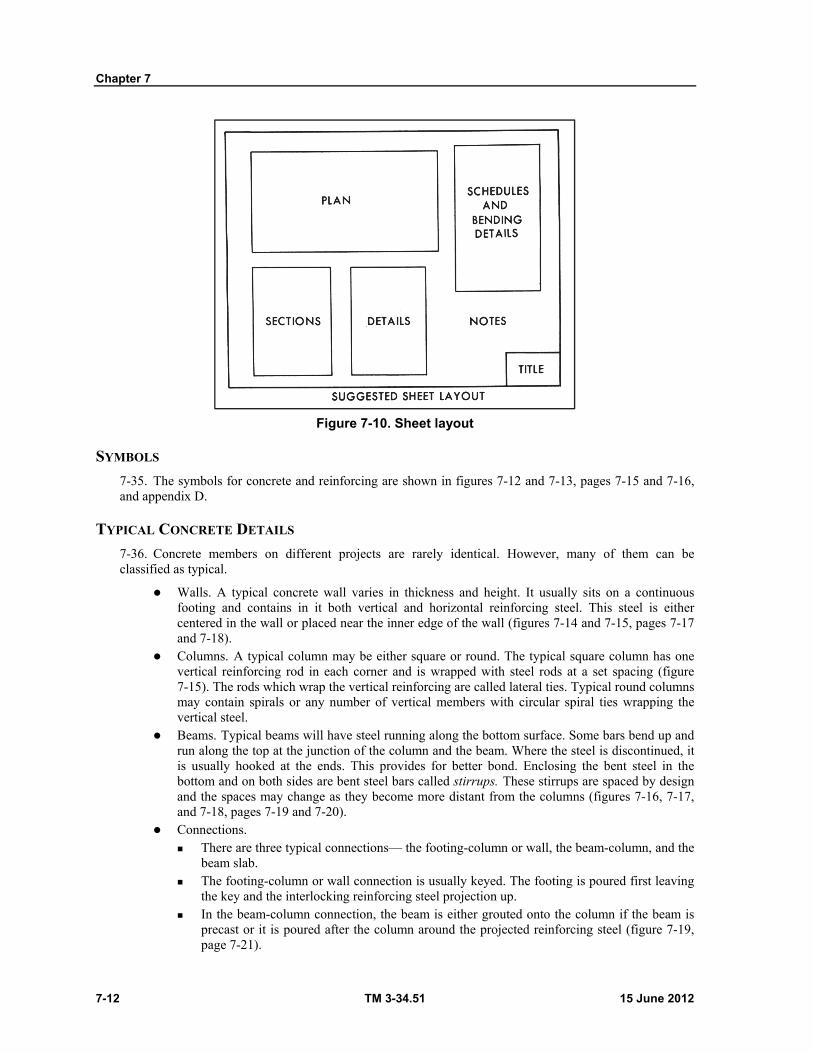
Chapter 7
7-12 TM 3-34.51 15 June 2012
Figure 7-10. Sheet layout
SYMBOLS
7-35. The symbols for concrete and reinforcing are shown in figures 7-12 and 7-13, pages 7-15 and 7-16, and appendix D.
TYPICAL CONCRETE DETAILS
7-36. Concrete members on different projects are rarely identical. However, many of them can be classified as typical.
Walls. A typical concrete wall varies in thickness and height. It usually sits on a continuous footing and contains in it both vertical and horizontal reinforcing steel. This steel is either centered in the wall or placed near the inner edge of the wall (figures 7-14 and 7-15, pages 7-17 and 7-18).
Columns. A typical column may be either square or round. The typical square column has one vertical reinforcing rod in each corner and is wrapped with steel rods at a set spacing (figure 7-15). The rods which wrap the vertical reinforcing are called lateral ties. Typical round columns may contain spirals or any number of vertical members with circular spiral ties wrapping the vertical steel.
Beams. Typical beams will have steel running along the bottom surface. Some bars bend up and run along the top at the junction of the column and the beam. Where the steel is discontinued, it is usually hooked at the ends. This provides for better bond. Enclosing the bent steel in the bottom and on both sides are bent steel bars called stirrups. These stirrups are spaced by design and the spaces may change as they become more distant from the columns (figures 7-16, 7-17, and 7-18, pages 7-19 and 7-20).
Connections. There are three typical connections— the footing-column or wall, the beam-column, and the
beam slab. The footing-column or wall connection is usually keyed. The footing is poured first leaving
the key and the interlocking reinforcing steel projection up. In the beam-column connection, the beam is either grouted onto the column if the beam is
precast or it is poured after the column around the projected reinforcing steel (figure 7-19, page 7-21).

Concrete Structures
15 June 2012 TM 3-34.51 7-13
The beam-slab connection is similar to the beam-column. It can be precast and grouted in place or poured with the reinforcing steel spanning the joint to strengthen it (figure 7-20, page 7-21). In the latter case, the beam and slab may be poured at the same time.
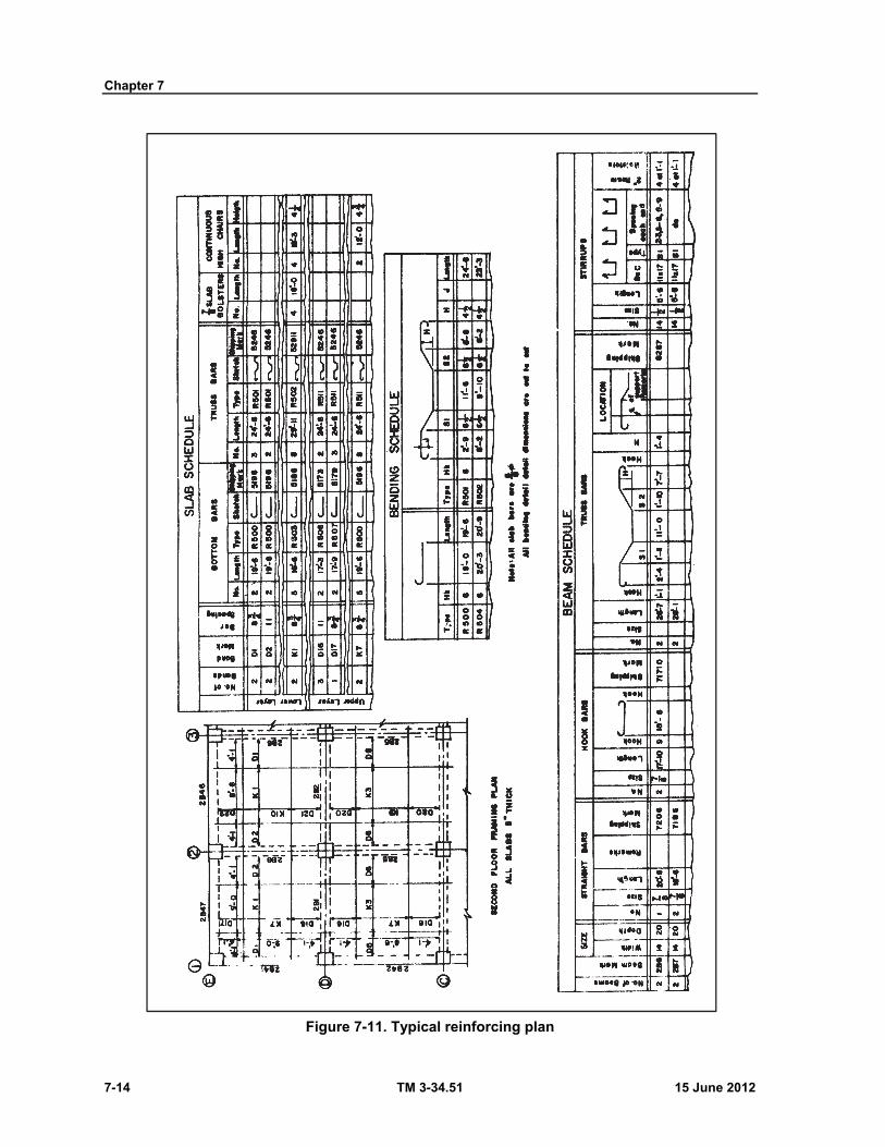
Chapter 7
7-14 TM 3-34.51 15 June 2012
Figure 7-11. Typical reinforcing plan
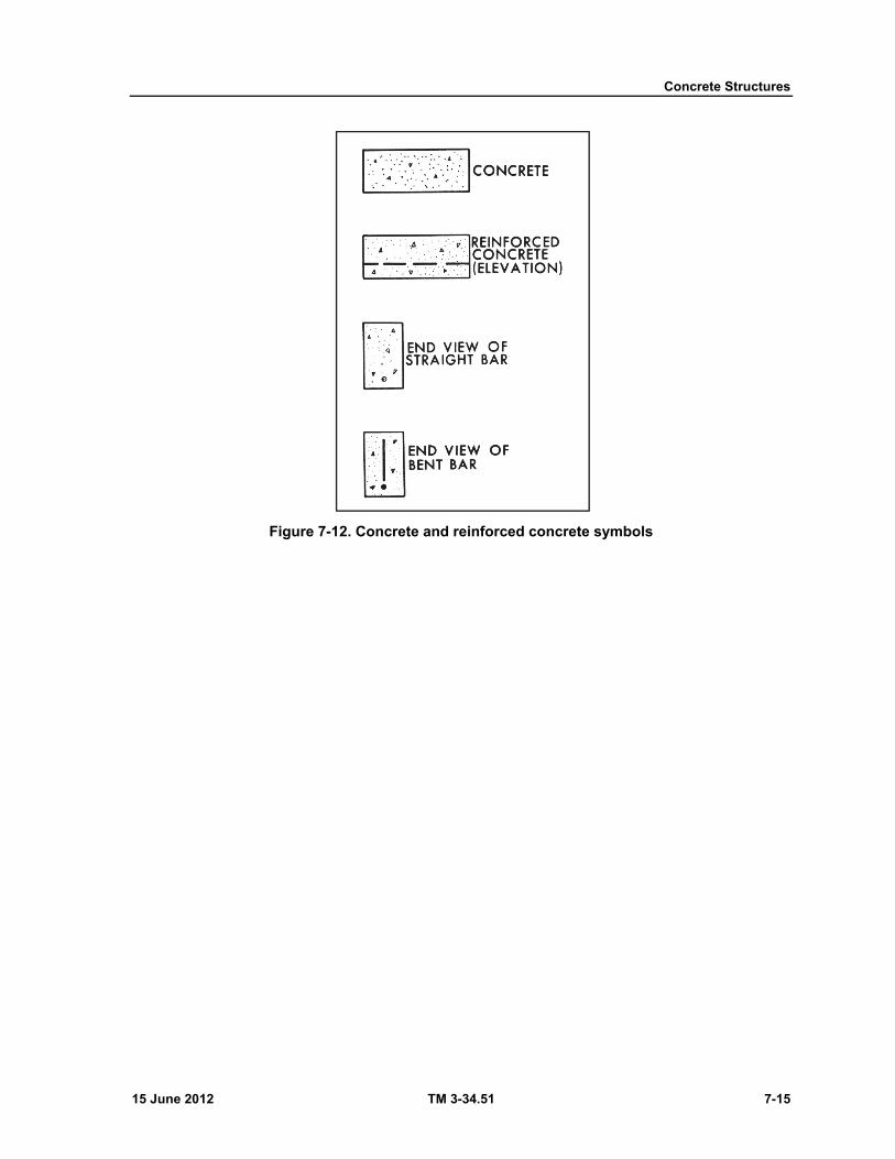
Concrete Structures
15 June 2012 TM 3-34.51 7-15
Figure 7-12. Concrete and reinforced concrete symbols
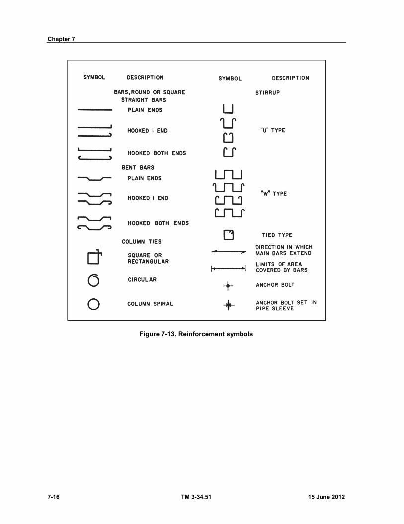
Chapter 7
7-16 TM 3-34.51 15 June 2012
Figure 7-13. Reinforcement symbols
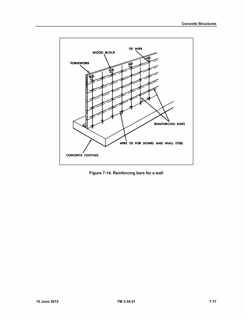
Concrete Structures
15 June 2012 TM 3-34.51 7-17
Figure 7-14. Reinforcing bars for a wall
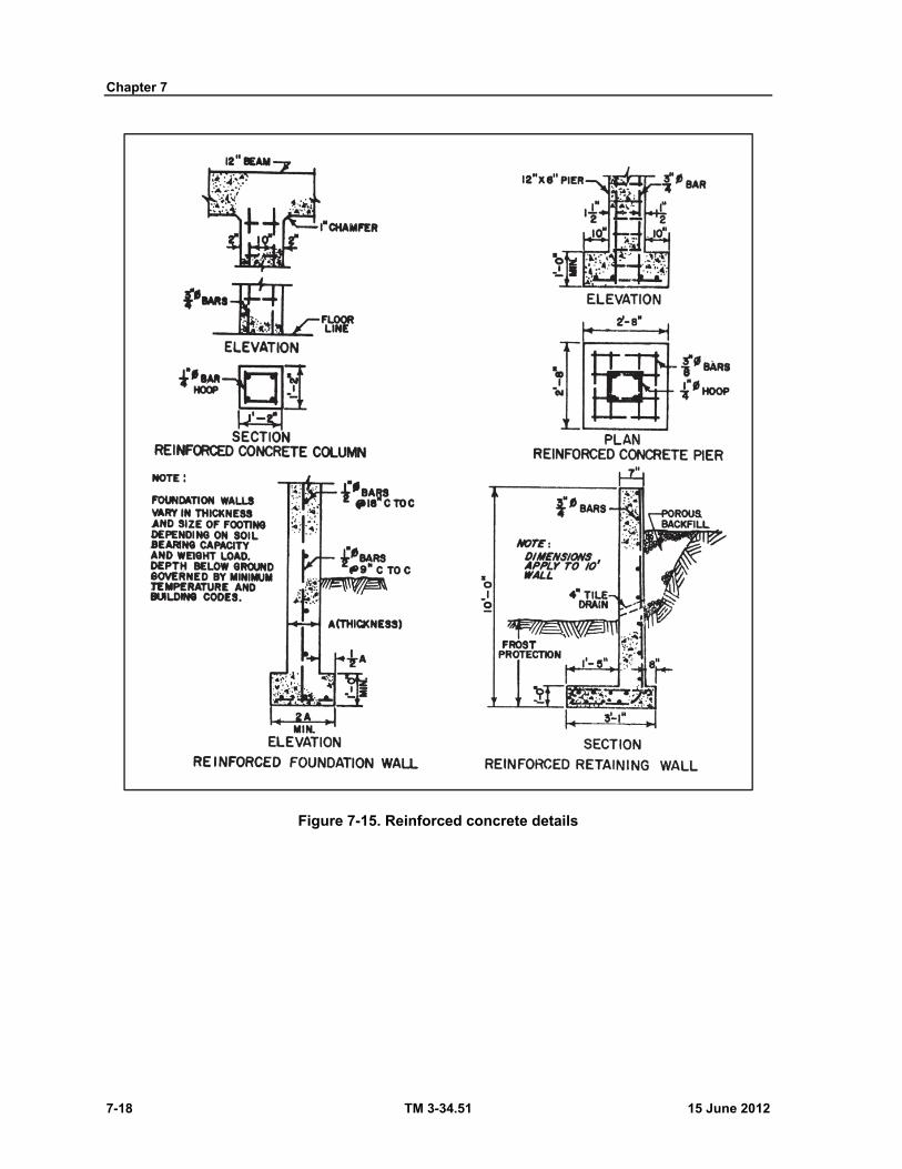
Chapter 7
7-18 TM 3-34.51 15 June 2012
Figure 7-15. Reinforced concrete details

Concrete Structures
15 June 2012 TM 3-34.51 7-19
Figure 7-16. Beam reinforcing
Figure 7-17. Beam elevation
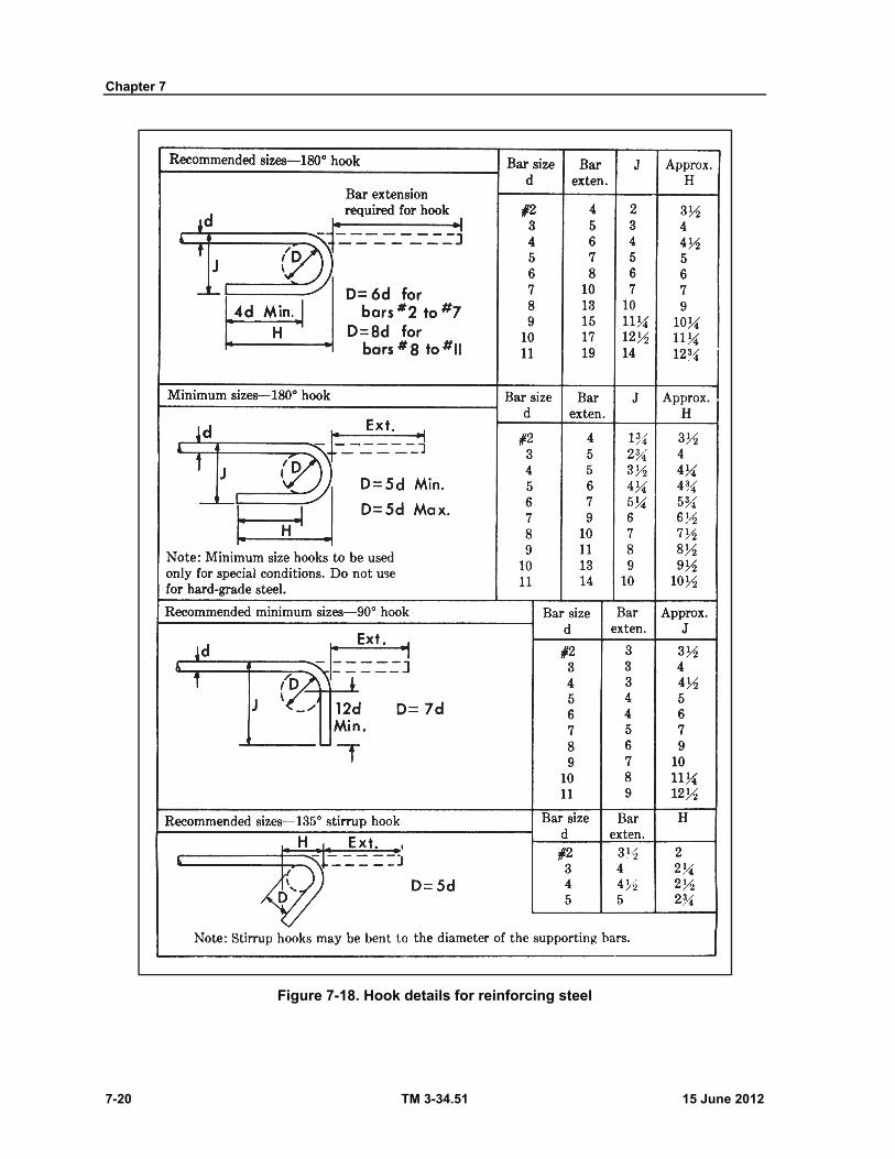
Chapter 7
7-20 TM 3-34.51 15 June 2012
Figure 7-18. Hook details for reinforcing steel
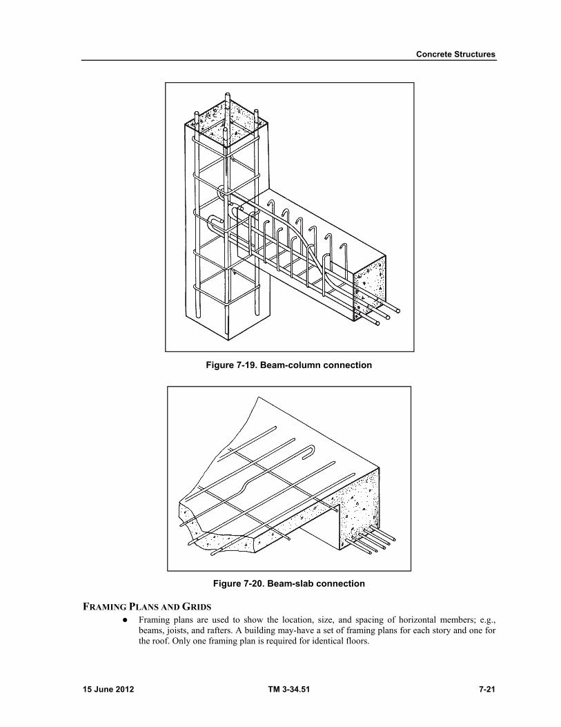
Concrete Structures
15 June 2012 TM 3-34.51 7-21
Figure 7-19. Beam-column connection
Figure 7-20. Beam-slab connection
FRAMING PLANS AND GRIDS Framing plans are used to show the location, size, and spacing of horizontal members; e.g.,
beams, joists, and rafters. A building may-have a set of framing plans for each story and one for the roof. Only one framing plan is required for identical floors.
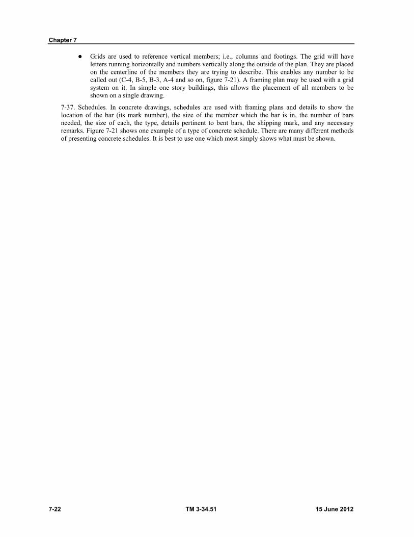
Chapter 7
7-22 TM 3-34.51 15 June 2012
Grids are used to reference vertical members; i.e., columns and footings. The grid will have letters running horizontally and numbers vertically along the outside of the plan. They are placed on the centerline of the members they are trying to describe. This enables any number to be called out (C-4, B-5, B-3, A-4 and so on, figure 7-21). A framing plan may be used with a grid system on it. In simple one story buildings, this allows the placement of all members to be shown on a single drawing.
7-37. Schedules. In concrete drawings, schedules are used with framing plans and details to show the location of the bar (its mark number), the size of the member which the bar is in, the number of bars needed, the size of each, the type, details pertinent to bent bars, the shipping mark, and any necessary remarks. Figure 7-21 shows one example of a type of concrete schedule. There are many different methods of presenting concrete schedules. It is best to use one which most simply shows what must be shown.
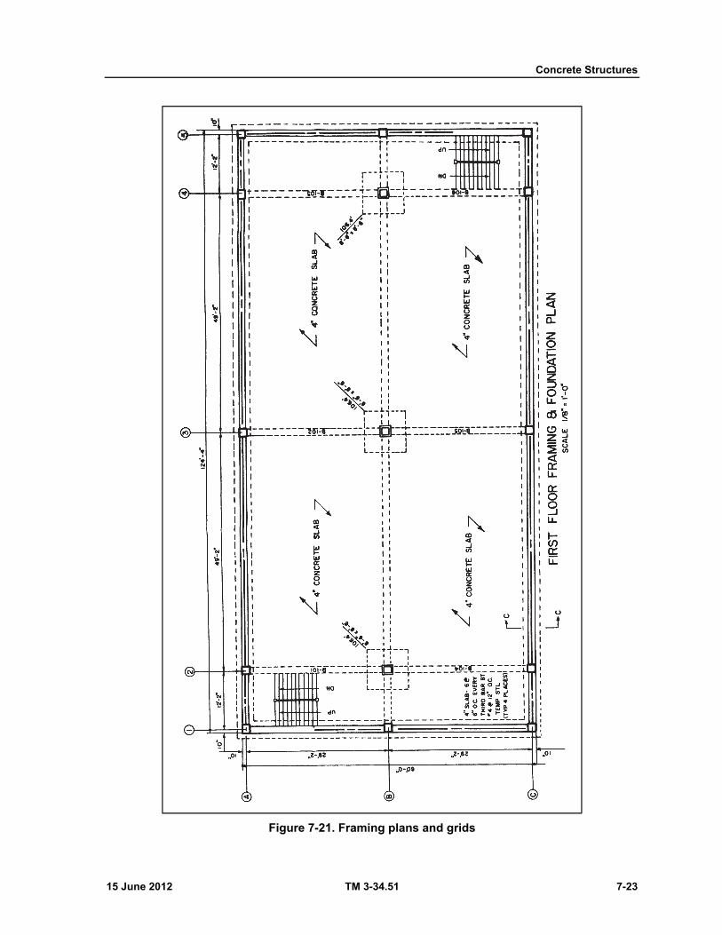
Concrete Structures
15 June 2012 TM 3-34.51 7-23
Figure 7-21. Framing plans and grids
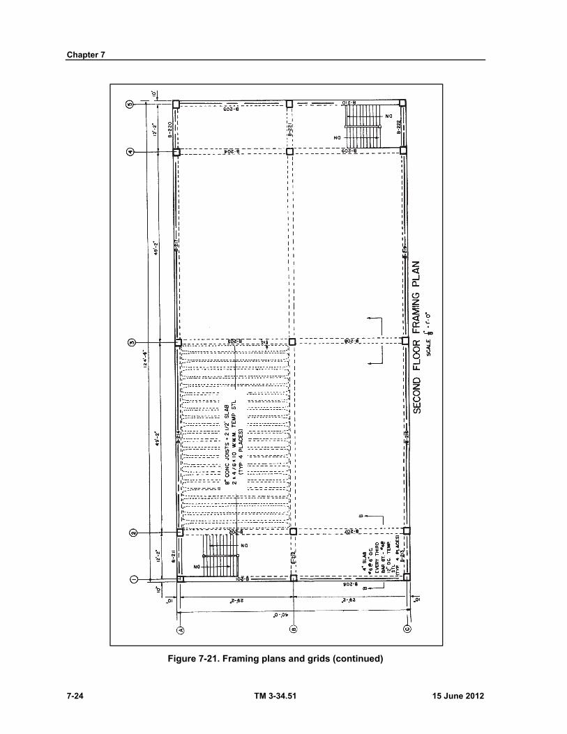
Chapter 7
7-24 TM 3-34.51 15 June 2012
Figure 7-21. Framing plans and grids (continued)
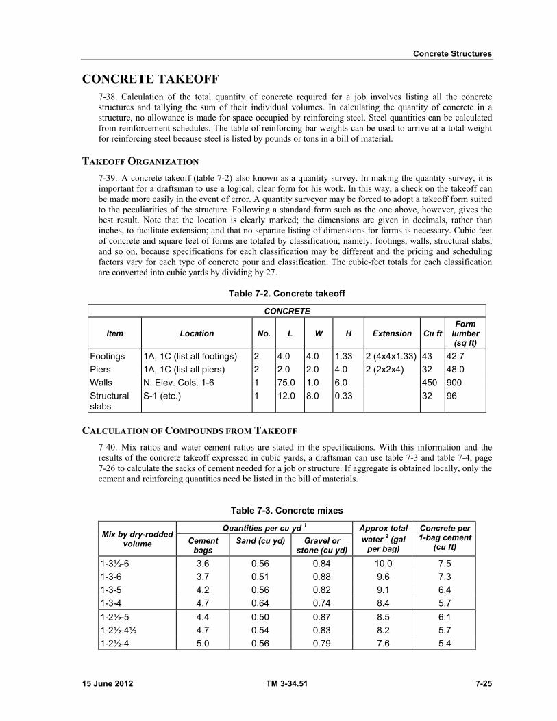
Concrete Structures
15 June 2012 TM 3-34.51 7-25
CONCRETE TAKEOFF 7-38. Calculation of the total quantity of concrete required for a job involves listing all the concrete structures and tallying the sum of their individual volumes. In calculating the quantity of concrete in a structure, no allowance is made for space occupied by reinforcing steel. Steel quantities can be calculated from reinforcement schedules. The table of reinforcing bar weights can be used to arrive at a total weight for reinforcing steel because steel is listed by pounds or tons in a bill of material.
TAKEOFF ORGANIZATION
7-39. A concrete takeoff (table 7-2) also known as a quantity survey. In making the quantity survey, it is important for a draftsman to use a logical, clear form for his work. In this way, a check on the takeoff can be made more easily in the event of error. A quantity surveyor may be forced to adopt a takeoff form suited to the peculiarities of the structure. Following a standard form such as the one above, however, gives the best result. Note that the location is clearly marked; the dimensions are given in decimals, rather than inches, to facilitate extension; and that no separate listing of dimensions for forms is necessary. Cubic feet of concrete and square feet of forms are totaled by classification; namely, footings, walls, structural slabs, and so on, because specifications for each classification may be different and the pricing and scheduling factors vary for each type of concrete pour and classification. The cubic-feet totals for each classification are converted into cubic yards by dividing by 27.
Table 7-2. Concrete takeoff
CONCRETE
Item Location No. L W H Extension Cu ft Form
lumber (sq ft)
Footings 1A, 1C (list all footings) 2 4.0 4.0 1.33 2 (4x4x1.33) 43 42.7
Piers 1A, 1C (list all piers) 2 2.0 2.0 4.0 2 (2x2x4) 32 48.0
Walls N. Elev. Cols. 1-6 1 75.0 1.0 6.0 450 900
Structural slabs
S-1 (etc.) 1 12.0 8.0 0.33 32 96
CALCULATION OF COMPOUNDS FROM TAKEOFF
7-40. Mix ratios and water-cement ratios are stated in the specifications. With this information and the results of the concrete takeoff expressed in cubic yards, a draftsman can use table 7-3 and table 7-4, page 7-26 to calculate the sacks of cement needed for a job or structure. If aggregate is obtained locally, only the cement and reinforcing quantities need be listed in the bill of materials.
Table 7-3. Concrete mixes
Mix by dry-rodded volume
Quantities per cu yd 1 Approx total water 2 (gal
per bag)
Concrete per 1-bag cement
(cu ft) Cement
bags Sand (cu yd) Gravel or
stone (cu yd)
1-3½-6 3.6 0.56 0.84 10.0 7.5
1-3-6 3.7 0.51 0.88 9.6 7.3
1-3-5 4.2 0.56 0.82 9.1 6.4
1-3-4 4.7 0.64 0.74 8.4 5.7
1-2½-5 4.4 0.50 0.87 8.5 6.1
1-2½-4½ 4.7 0.54 0.83 8.2 5.7
1-2½-4 5.0 0.56 0.79 7.6 5.4
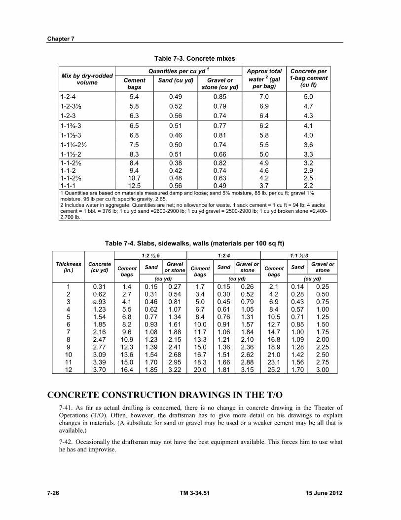
Chapter 7
7-26 TM 3-34.51 15 June 2012
Table 7-3. Concrete mixes
Mix by dry-rodded volume
Quantities per cu yd 1 Approx total water 2 (gal
per bag)
Concrete per 1-bag cement
(cu ft) Cement
bags Sand (cu yd) Gravel or
stone (cu yd)
1-2-4 5.4 0.49 0.85 7.0 5.0
1-2-3½ 5.8 0.52 0.79 6.9 4.7
1-2-3 6.3 0.56 0.74 6.4 4.3
1-1¾-3 6.5 0.51 0.77 6.2 4.1
1-1½-3 6.8 0.46 0.81 5.8 4.0
1-1½-2½ 7.5 0.50 0.74 5.5 3.6
1-1½-2 8.3 0.51 0.66 5.0 3.3 1-1-2½ 8.4 0.38 0.82 4.9 3.2 1-1-2 9.4 0.42 0.74 4.6 2.9 1-1-2½ 10.7 0.48 0.63 4.2 2.5 1-1-1 12.5 0.56 0.49 3.7 2.2 1 Quantities are based on materials measured damp and loose; sand 5% moisture, 85 lb. per cu ft; gravel 1% moisture, 95 lb per cu ft; specific gravity, 2.65. 2 Includes water in aggregate. Quantities are net; no allowance for waste. 1 sack cement = 1 cu ft = 94 lb; 4 sacks cement = 1 bbl. = 376 lb; 1 cu yd sand =2600-2900 lb; 1 cu yd gravel = 2500-2900 lb; 1 cu yd broken stone =2,400-2,700 lb.
Table 7-4. Slabs, sidewalks, walls (materials per 100 sq ft)
Thickness (in.)
Concrete (cu yd)
1:2 ½:5 1:2:4 1:1 ½:3
Cement bags
Sand Gravel
or stone Cement bags
Sand Gravel or
stone Cement bags
Sand Gravel or
stone
(cu yd) (cu yd) (cu yd)
1 0.31 1.4 0.15 0.27 1.7 0.15 0.26 2.1 0.14 0.25 2 0.62 2.7 0.31 0.54 3.4 0.30 0.52 4.2 0.28 0.50 3 a.93 4.1 0.46 0.81 5.0 0.45 0.79 6.9 0.43 0.75 4 1.23 5.5 0.62 1.07 6.7 0.61 1.05 8.4 0.57 1.00 5 1.54 6.8 0.77 1.34 8.4 0.76 1.31 10.5 0.71 1.25 6 1.85 8.2 0.93 1.61 10.0 0.91 1.57 12.7 0.85 1.50 7 2.16 9.6 1.08 1.88 11.7 1.06 1.84 14.7 1.00 1.75 8 2.47 10.9 1.23 2.15 13.3 1.21 2.10 16.8 1.09 2.00 9 2.77 12.3 1.39 2.41 15.0 1.36 2.36 18.9 1.28 2.25 10 3.09 13.6 1.54 2.68 16.7 1.51 2.62 21.0 1.42 2.50 11 3.39 15.0 1.70 2.95 18.3 1.66 2.88 23.1 1.56 2.75 12 3.70 16.4 1.85 3.22 20.0 1.81 3.15 25.2 1.70 3.00
CONCRETE CONSTRUCTION DRAWINGS IN THE T/O 7-41. As far as actual drafting is concerned, there is no change in concrete drawing in the Theater of Operations (T/O). Often, however, the draftsman has to give more detail on his drawings to explain changes in materials. (A substitute for sand or gravel may be used or a weaker cement may be all that is available.)
7-42. Occasionally the draftsman may not have the best equipment available. This forces him to use what he has and improvise.

Concrete Structures
15 June 2012 TM 3-34.51 7-27
7-43. Probably the most noticeable difference for a draftsman in the T/O is the time factor. In the T/O, a draftsman may have to cut corners. He may be forced to omit some of the refined points of drafting from his drawings in order to produce them on time without sacrificing accuracy.
7-44. Few permanent structures are built in the T/O. However, there are many instances where concrete is used; slabs, bridge substructures, septic tanks, box culverts, wing walls, and vehicle maintenance racks are some of these uses.
7-45. Some standard concrete drawings are found in TM 5-302, December 1969.

This page intentionally left blank.
15 June 2012 TM 3-34.51 8-1
Chapter 8
Steel Structures
INTRODUCTION 8-1. Structural steel is another structural material that a construction draftsman should know in order to complete comprehensive drawings of steel construction. In steel construction, structural steel forms the framework of many structures such as bridges, piers, hangars, towers, warehouses, and office and shop buildings. The steel framework of the structure may be the most visible part of the structure, as in a tower or bridge, or it may be concealed, as in various types of buildings. In any case, the steel framework carries both the weight of the structure and the applied loads. The steel framework is made up of steel members fabricated in the shop and combined with other members at the project site. The individual members may be a single piece of steel, or it may be fabricated of several component pieces. At the site, the members are erected into their proper places in the structure. Erection involves all the processes of rigging, hoisting, or lifting of members, and making the finished connections between the members. For a detailed discussion of steel construction, refer to TM 5-744.
STRUCTURAL STEEL DETAILS 8-2. Steel structures are composed of rolled-steel shapes used either singly or built up to form members. Figure 8-1 shows sections of the common shapes together with the symbols used to identify them in notes, dimensions, and bills of material. Dimensions for detailing these and other less used shapes are described completely in the American Institute of Steel Construction (AISC) handbook or appropriate military standard specifications. Abbreviations and order of specifications for some of the shapes given in figure 8-1, page 8-2, are as follows:
Equal angles. L3 x 3" X 1/4" X 8'-0" (size of legs X thickness X length). Unequal angles. L7 X 4" X V2" X 6'-0" (size of long leg X size of short leg X thickness X
length).
Channels. 9 ⊔ 13.4" X 9'-8" (depth X weight/foot X length).
I beams. 15 I 42.9" X 12'-6" (depth X weight/foot X length). Wide flange shapes. 24 WF- 76 X 18'-3" (nominal depth X weight/foot X length). Zees. Z6 X 3½ X 15.7 X 2'-6" (depth X flange width X weight/foot X length). Plates. P1 18 X ½ X 2'-6" (width X thickness X length).
ACTUAL SIZE AND WEIGHT VERSUS NOMINAL SIZE CLASSIFICATION
8-3. The process for rolling structural shapes permits a wide range of actual sizes and weights within a single nominal size classification. Although a beginning construction draftsman may not be required to prepare steel detail drawings, he should be aware of the reasons for specifying members in the manner described above. Steel details can not be prepared without a structural steel hand book that specifies the actual dimensions for the various weights. Examples of such data are given in tables 8-1, 8-2 and 8-3, page 8-3.
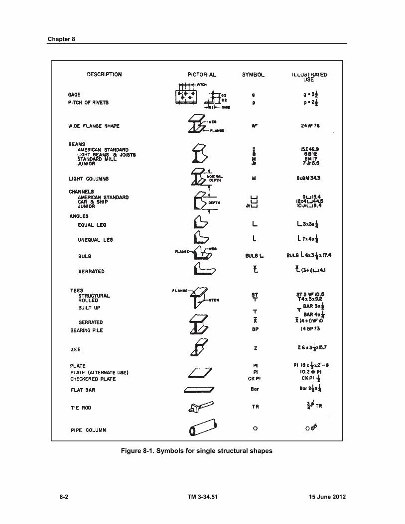
Chapter 8
8-2 TM 3-34.51 15 June 2012
Figure 8-1. Symbols for single structural shapes
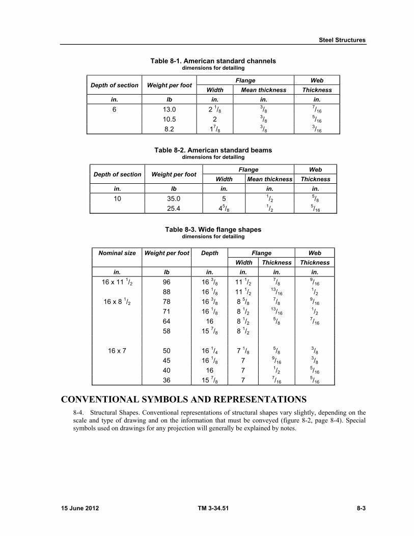
Steel Structures
15 June 2012 TM 3-34.51 8-3
Table 8-1. American standard channels dimensions for detailing
Depth of section Weight per foot Flange Web
Width Mean thickness Thickness
in. lb in. in. in.
6 13.0 2 1/8 3/8
7/16
10.5 2 3/8 5/16
8.2 17/8 3/8
3/16
Table 8-2. American standard beams dimensions for detailing
Depth of section Weight per foot Flange Web
Width Mean thickness Thickness
in. lb in. in. in.
10 35.0 5 1/2 5/8
25.4 45/8 1/2
5/16
Table 8-3. Wide flange shapes dimensions for detailing
Nominal size Weight per foot Depth Flange Web
Width Thickness Thickness
in. lb in. in. in. in.
16 x 11 1/2 96 16 3/8 11 1/2 7/8
9/16
88 16 1/8 11 1/2 13/16
1/2
16 x 8 1/2 78 16 3/8 8 5/8 7/8
9/16
71 16 1/8 8 1/2 13/16
1/2
64 16 8 1/2 5/8
7/16
58 15 7/8 8 1/2
16 x 7 50 16 1/4 7 1/8 5/8
3/8
45 16 1/8 7 9/16 3/8
40 16 7 1/2 5/16
36 15 7/8 7 7/16 5/16
CONVENTIONAL SYMBOLS AND REPRESENTATIONS 8-4. Structural Shapes. Conventional representations of structural shapes vary slightly, depending on the scale and type of drawing and on the information that must be conveyed (figure 8-2, page 8-4). Special symbols used on drawings for any projection will generally be explained by notes.

Chapter 8
8-4 TM 3-34.51 15 June 2012
Figure 8-2. Conventional representation of structural elements
8-5. Connections. There are four types of connections used in steel structures. They are bolts, welds, pins, and rivets. For a discussion of bolts, welds, and rivets, refer to chapter 9. Pinned connections are used most often when it is desirable to have a freedom of rotation between memmonly used are threaded or bridge pins and cotterbers being connected. Two types of pins most compins (figure 8-3).
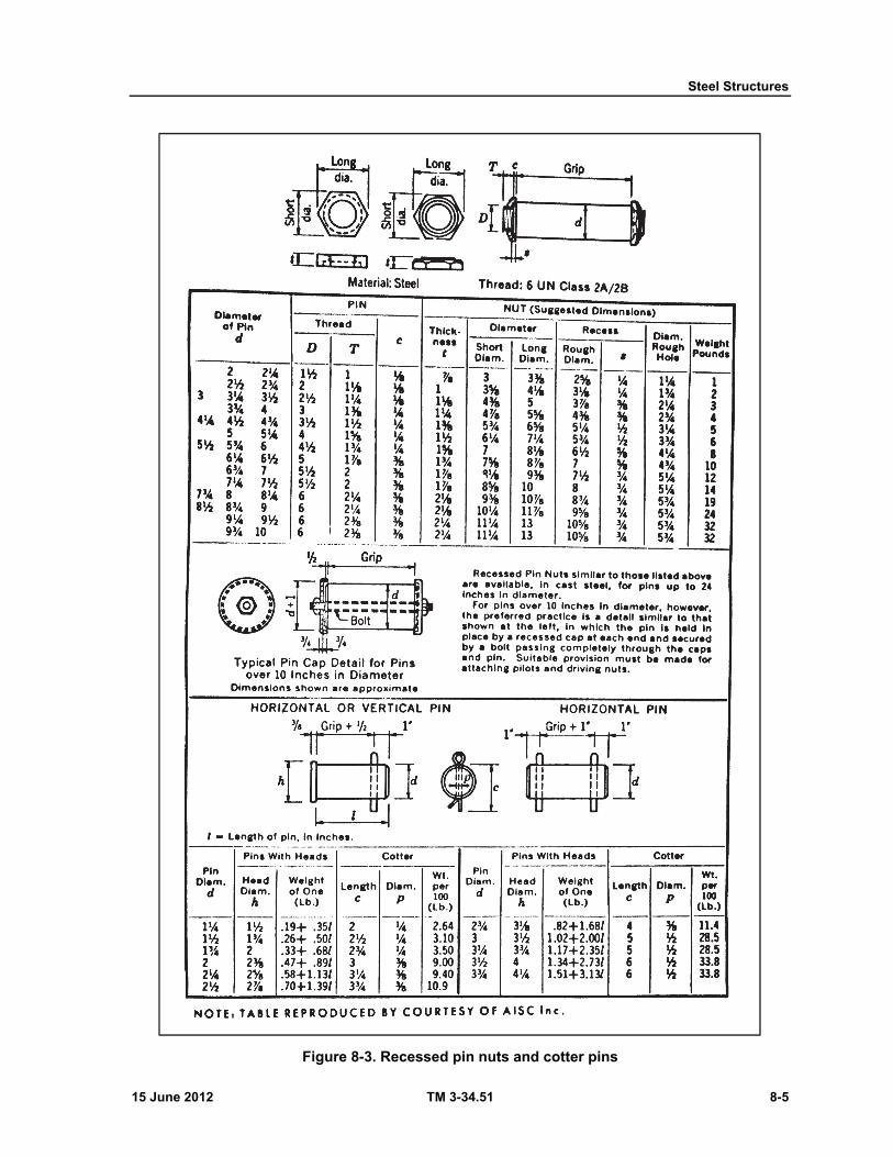
Steel Structures
15 June 2012 TM 3-34.51 8-5
Figure 8-3. Recessed pin nuts and cotter pins
Chapter 8
8-6 TM 3-34.51 15 June 2012
SHOP DRAWINGS 8-6. Steel structural members are prepared in special fabricating shops, and the drawings showing the required fabrication of parts and methods of assembly are called shop detail drawings or simply shop drawings. Figure 8-4 is a shop drawing of a structural steel member made from a single rolled shape. Figures 8-5, 8-6, and 8-7, pages 8-8 through 8-10, are shop drawings of members built up of a combination of rolled shapes. The practices for detailing structural steel, as illustrated by these figures, include the following:
Working Lines and Working Points. Shop drawings are made about light working lines laid out first along the centerlines or rivet gage lines to form a skeleton of the assembled member. The intersections of these working lines are called working points from which all dimensions are given. This skeleton is usually the same as, or taken from, the designer's stress diagram. Generally, the skeleton diagram is drawn to a small scale on the shop drawing (figure 8-5).
Relative Position of Parts. Parts to be riveted or welded together in the shop are shown in the same relative position (vertical, horizontal, or inclined, as in figure 8-5) which they will occupy in their assembled position in the structure, instead of being detailed individually, as is the practice for machine drawings. Notice in figure 8-5 that since the truss is symmetrical about each side of the center, only half of the truss need be shown. In such cases, it is always the left end which is drawn.
Long Vertical or Inclined Members. Long vertical (columns) or inclined (braces) members are sometimes drawn in a horizontal position on the drawing. When thus drawn, a vertical member is drawn with the bottom at the left (figure 8-6) and an inclined member is drawn in the direction it would fall.
Scales. Scales of shop drawings vary from 14" = 1'-0" to 1" = 1'-0", depending on the size of the drawing sheet as compared with the size of the structural member. Usually two scales are used in the same view, one denoting length and the other showing the cross section at a larger scale than the length, as in figure 8-5. Often, it is expedient to disregard scaled length and draw the member as if there were breaks in the length (figure 8-6) so that details of intermediate connections and rivet spacings at the ends can be drawn at the same scale as the cross section.
Dimensions. Dimensions are always placed above the dimension line. Remember on construction drawings, the dimension lines are unbroken. Dimensions are given to centerlines and working lines, never to the outer edges of rolled shapes (except for height and length dimensions), and extension lines are drawn in accordance with routine drawing practice. When members differ in length only, they may be shown by a single drawing. When thus drawn, the different lengths are given separately and are identified by erection marks at the left end of each dimension line. Figure 8-4 shows two beams detailed on the same drawing.
Sizes of Rolled Shapes. Sizes of rolled shapes are specified by abbreviated notes as described in paragraph 8-2. The specification note may be given along with the length dimension (figure 8-6) or is placed near and parallel to the part as in figures 8-4 and 8-5. In some cases, it is advantageous to place the specification right on the front view of the shape (figure 8-7).
Slopes. Slopes of members and inclined centerlines, cuts, and so forth, are indicated by their tangents. The value of the angle is given by constructing a small right triangle (not necessarily to scale) with its hypotenuse on or parallel to the skewed line. The long leg of the triangle is always labeled 12, meaning 12 inches. Figures 8-4 and 8-5 illustrate the manner in which the slope triangle is used.
Erection Marks. Erection marks facilitate the identification of members. Like index marks on a road map, they consist of capital letters (B for beam, C for column, T for truss, and so forth, indicating the type of member and a number giving the specific member in an assembly or its location in the structure. They are indicated in subtitles of the shop drawings (figure 8-4) and on erection diagrams (figure 8-7).
Assembly Marks. Assembly marks identify the use of the same shape is more than one place. The member is completely specified once and then given an assembly mark (lower case letter, to avoid confusing it with the erection mark). It is not necessary to repeat the complete
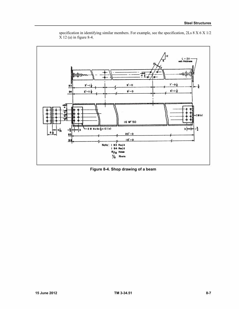
Steel Structures
15 June 2012 TM 3-34.51 8-7
specification in identifying similar members. For example, see the specification, 2Ls 8 X 6 X 1/2 X 12 (a) in figure 8-4.
Figure 8-4. Shop drawing of a beam
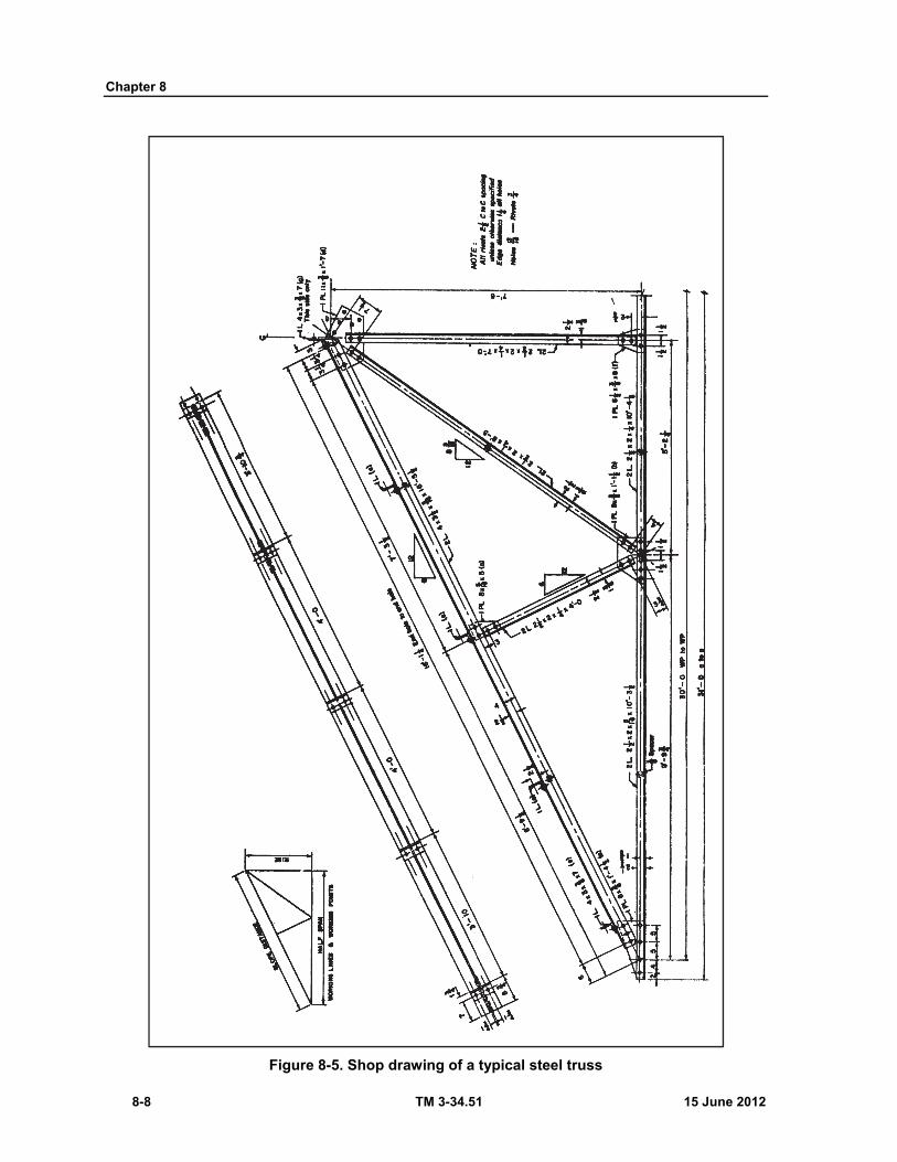
Chapter 8
8-8 TM 3-34.51 15 June 2012
Figure 8-5. Shop drawing of a typical steel truss
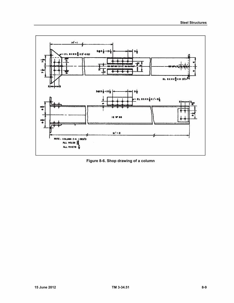
Steel Structures
15 June 2012 TM 3-34.51 8-9
Figure 8-6. Shop drawing of a column
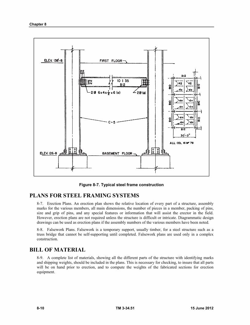
Chapter 8
8-10 TM 3-34.51 15 June 2012
Figure 8-7. Typical steel frame construction
PLANS FOR STEEL FRAMING SYSTEMS 8-7. Erection Plans. An erection plan shows the relative location of every part of a structure, assembly marks for the various members, all main dimensions, the number of pieces in a member, packing of pins, size and grip of pins, and any special features or information that will assist the erector in the field. However, erection plans are not required unless the structure is difficult or intricate. Diagrammatic design drawings can be used as erection plans if the assembly numbers of the various members have been noted.
8-8. Falsework Plans. Falsework is a temporary support, usually timber, for a steel structure such as a truss bridge that cannot be self-supporting until completed. Falsework plans are used only in a complex construction.
BILL OF MATERIAL 8-9. A complete list of materials, showing all the different parts of the structure with identifying marks and shipping weights, should be included in the plans. This is necessary for checking, to insure that all parts will be on hand prior to erection, and to compute the weights of the fabricated sections for erection equipment.

Steel Structures
15 June 2012 TM 3-34.51 8-11
RIVET LISTS 8-10. A rivet list may be shown in the bill of material or elsewhere in the plans. It shows the dimension and number of all field rivets, field bolts, and spikes used in the erection of a structure. Refer to chapter 9 for a complete discussion of rivets, bolts, and welds.

This page intentionally left blank.
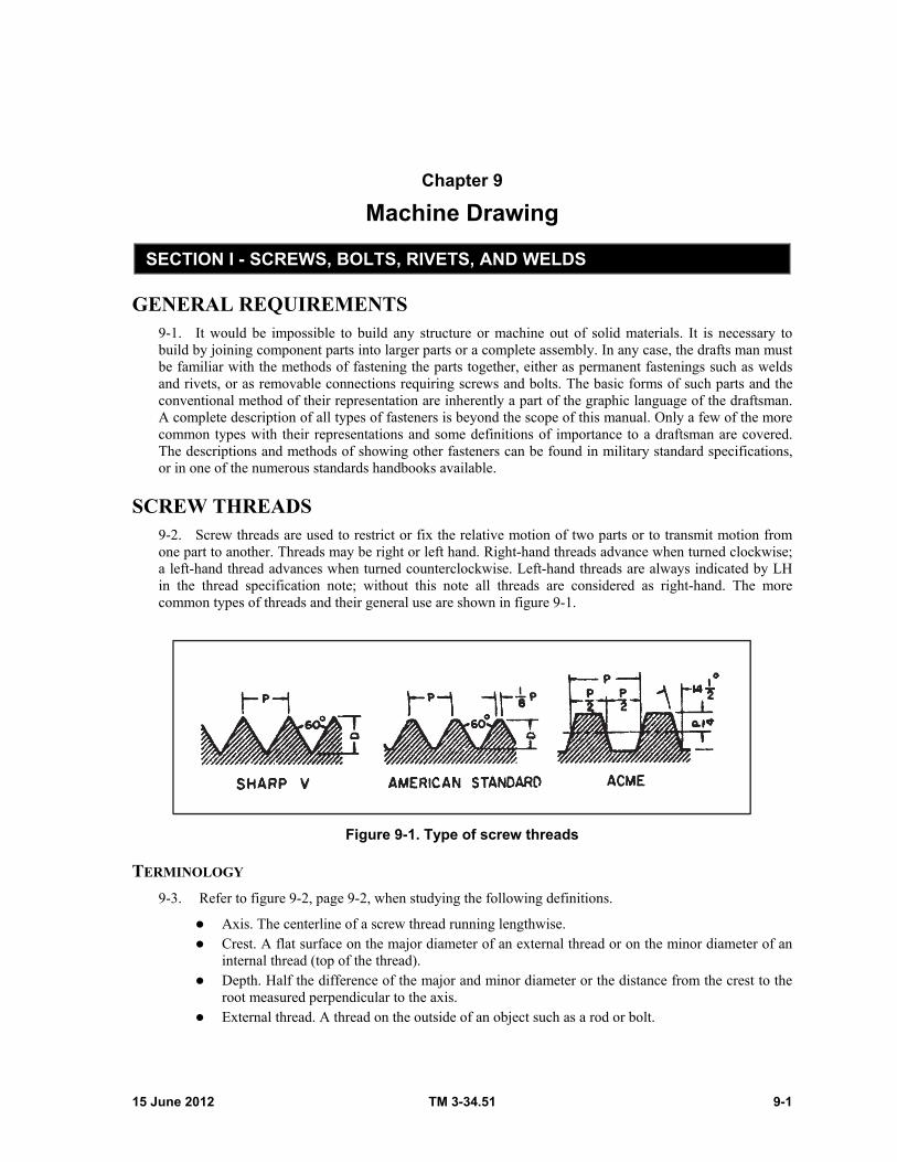
15 June 2012 TM 3-34.51 9-1
Chapter 9
Machine Drawing
SECTION I - SCREWS, BOLTS, RIVETS, AND WELDS
GENERAL REQUIREMENTS 9-1. It would be impossible to build any structure or machine out of solid materials. It is necessary to build by joining component parts into larger parts or a complete assembly. In any case, the drafts man must be familiar with the methods of fastening the parts together, either as permanent fastenings such as welds and rivets, or as removable connections requiring screws and bolts. The basic forms of such parts and the conventional method of their representation are inherently a part of the graphic language of the draftsman. A complete description of all types of fasteners is beyond the scope of this manual. Only a few of the more common types with their representations and some definitions of importance to a draftsman are covered. The descriptions and methods of showing other fasteners can be found in military standard specifications, or in one of the numerous standards handbooks available.
SCREW THREADS 9-2. Screw threads are used to restrict or fix the relative motion of two parts or to transmit motion from one part to another. Threads may be right or left hand. Right-hand threads advance when turned clockwise; a left-hand thread advances when turned counterclockwise. Left-hand threads are always indicated by LH in the thread specification note; without this note all threads are considered as right-hand. The more common types of threads and their general use are shown in figure 9-1.
Figure 9-1. Type of screw threads
TERMINOLOGY
9-3. Refer to figure 9-2, page 9-2, when studying the following definitions.
Axis. The centerline of a screw thread running lengthwise. Crest. A flat surface on the major diameter of an external thread or on the minor diameter of an
internal thread (top of the thread). Depth. Half the difference of the major and minor diameter or the distance from the crest to the
root measured perpendicular to the axis. External thread. A thread on the outside of an object such as a rod or bolt.
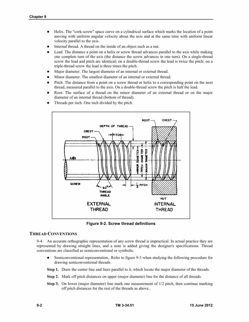
Chapter 9
9-2 TM 3-34.51 15 June 2012
Helix. The "cork-screw" space curve on a cylindrical surface which marks the location of a point moving with uniform angular velocity about the axis and at the same time with uniform linear velocity parallel to the axis.
Internal thread. A thread on the inside of an object such as a nut. Lead. The distance a point on a helix or screw thread advances parallel to the axis while making
one complete turn of the axis (the distance the screw advances in one turn). On a single-thread screw the lead and pitch are identical; on a double-thread screw the lead is twice the pitch; on a triple-thread screw the lead is three times the pitch.
Major diameter. The largest diameter of an internal or external thread. Minor diameter. The smallest diameter of an internal or external thread. Pitch. The distance from a point on a screw thread or helix to a corresponding point on the next
thread, measured parallel to the axis. On a double-thread screw the pitch is half the lead. Root. The surface of a thread on the minor diameter of an external thread or on the major
diameter of an internal thread (bottom of thread). Threads per inch. One inch divided by the pitch.
Figure 9-2. Screw thread definitions
THREAD CONVENTIONS
9-4. An accurate orthographic representation of any screw thread is impractical. In actual practice they are represented by drawing straight lines, and a note is added giving the designer's specifications. Thread conventions are classified as semiconventional or symbolic.
Semiconventional representation,. Refer to figure 9-3 when studying the following procedure for drawing semiconventional threads.
Step 1. Draw the center line and lines parallel to it, which locate the major diameter of the threads.
Step 2. Mark off pitch distances on upper (major diameter) line for the distance of all threads.
Step 3. On lower (major diameter) line mark one measurement of 1/2 pitch, then continue marking off pitch distances for the rest of the threads as above..
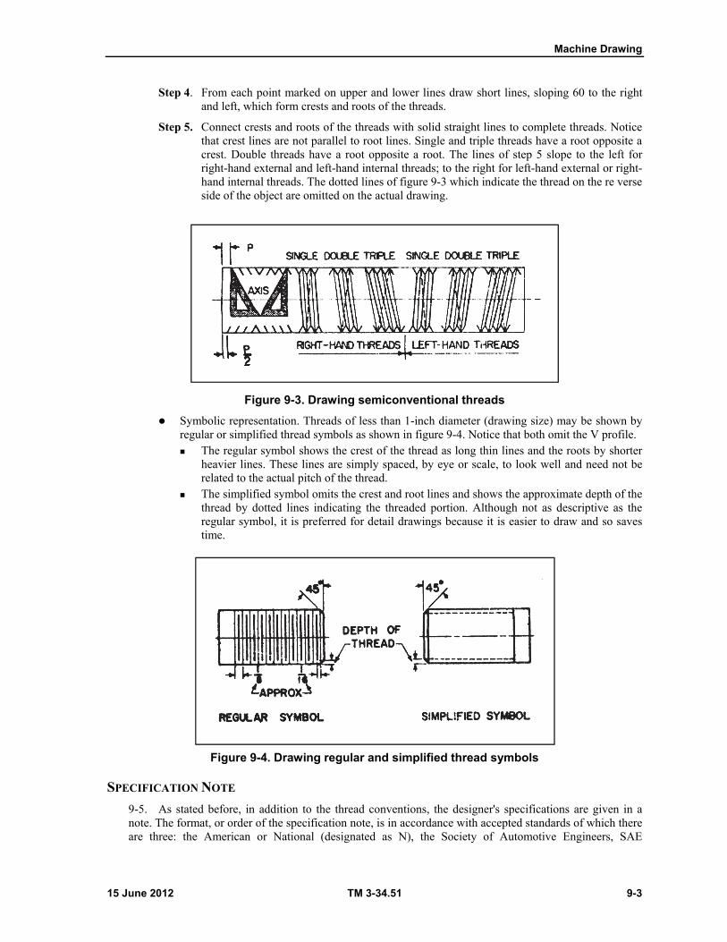
Machine Drawing
15 June 2012 TM 3-34.51 9-3
Step 4. From each point marked on upper and lower lines draw short lines, sloping 60 to the right and left, which form crests and roots of the threads.
Step 5. Connect crests and roots of the threads with solid straight lines to complete threads. Notice that crest lines are not parallel to root lines. Single and triple threads have a root opposite a crest. Double threads have a root opposite a root. The lines of step 5 slope to the left for right-hand external and left-hand internal threads; to the right for left-hand external or right-hand internal threads. The dotted lines of figure 9-3 which indicate the thread on the re verse side of the object are omitted on the actual drawing.
Figure 9-3. Drawing semiconventional threads
Symbolic representation. Threads of less than 1-inch diameter (drawing size) may be shown by regular or simplified thread symbols as shown in figure 9-4. Notice that both omit the V profile. The regular symbol shows the crest of the thread as long thin lines and the roots by shorter
heavier lines. These lines are simply spaced, by eye or scale, to look well and need not be related to the actual pitch of the thread.
The simplified symbol omits the crest and root lines and shows the approximate depth of the thread by dotted lines indicating the threaded portion. Although not as descriptive as the regular symbol, it is preferred for detail drawings because it is easier to draw and so saves time.
Figure 9-4. Drawing regular and simplified thread symbols
SPECIFICATION NOTE
9-5. As stated before, in addition to the thread conventions, the designer's specifications are given in a note. The format, or order of the specification note, is in accordance with accepted standards of which there are three: the American or National (designated as N), the Society of Automotive Engineers, SAE

Chapter 9
9-4 TM 3-34.51 15 June 2012
(designated as EF), and the International Organization for Standardization (designated as UN). Only the American standard is covered here; the others are described completely in military standard specifications or standards handbooks. The principal elements are thread series and screw thread fits.
Thread series. The American standard lists five thread series: coarse (NC), recommended for general use, includes 12 numbered sizes below 1/4 inch; fine (NF), has more threads per inch and is used where ease of assembly and resistance to vibration are required, and includes 13 numbered sizes below 1/4 inch; 8-pitch (8N), eight threads per inch, 1" to 6" dia, used primarily on bolts for high-pressure pipe flanges or cylinder and boiler heads, and similar fastenings against pressure; 12-pitch (12N), 12 threads per inch, 1/2" to 6" dia, used widely in machine construction requiring thin parts; and 16-pitch (16N), 16 threads per inch, 3/4" to 4" dia, used on such items as adjusting collars and bearing retainers. Table 9-1 lists the American National Coarse and National Fine Series.
Screw thread fits. Four types of screw thread fits have been standardized: Class I. For rapid assembly and where some shake play is not objectionable. Class II. Standard commercial where interchangeability is essential. Class III. High quality commercial required for precision work. Class IV. Where selected fit is required.
Thread specification note. Figure 9-5 shows the order of specification note and explains its interpretation.
Table 9-1. American national coarse (NC) and national fine (NF) series number of threads per inch
Size major diameter
NC series NF series Size major diameter NC series NF series
0 — 80 9/16 12 18
1 64 72 5/8 11 18
2 56 64 ¾ 10 16
3 48 56 7/8 9 14
4 40 48 1 8 14
5 40 44 1 7 12
6 32 40 1 1/8X 7 12
8 32 36 1 1/4 6 12
10 24 32 1 3/8 6 12
12 24 28 1 5
1/4 20 28 13/4 4 1/2
5/16 18 24 2 4 1/2
3/8 16 24 2 1/4 4
7/16 14 20 2 3/4 4
1/2 13 20 3 4
3 1/4 4
3 1/2 4
3 3/4 4
4 4 Note. Number 13 size NF series, not given.
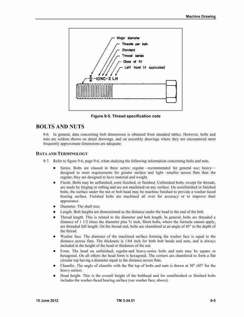
Machine Drawing
15 June 2012 TM 3-34.51 9-5
Figure 9-5. Thread specification note
BOLTS AND NUTS 9-6. In general, data concerning bolt dimensions is obtained from standard tables. However, bolts and nuts are seldom shown on detail drawings, and on assembly drawings where they are encountered most frequently approximate dimensions are adequate.
DATA AND TERMINOLOGY
9-7. Refer to figure 9-6, page 9-6, when studying the following information concerning bolts and nuts.
Series. Bolts are classed in three series: regular—recommended for general use; heavy— designed to meet requirements for greater surface and light—smaller across flats than the regular, they are designed to have material and weight.
Finish. Bolts may be unfinished, semi finished, or finished. Unfinished bolts, except for threads, are made by forging or rolling and are not machined on any surface. On semifinished or finished bolts, the surface under the nut or bolt head may be machine finished to provide a washer-faced bearing surface. Finished bolts are machined all over for accuracy or to improve their appearance.
Diameter. The shaft size. Length. Bolt lengths are dimensioned as the distance under the head to the end of the bolt. Thread length. This is related to the diameter and bolt length. In general, bolts are threaded a
distance of 1 1/2 times the diameter plus % inch. Short bolts, where the formula cannot apply, are threaded full length. On the thread end, bolts are chamfered at an angle of 45° to the depth of the thread.
Washer face. The diameter of the machined surface forming the washer face is equal to the distance across flats. The thickness is 1/64 inch for both bolt heads and nuts, and is always included in the height of the head or thickness of the nut.
Form. The head on unfinished, regular-and heavy-series bolts and nuts may be square or hexagonal. On all others the head form is hexagonal. The corners are chamfered to form a flat circular top having a diameter equal to the distance across flats.
Chamfer. The angle of chamfer with the flat top of bolts and nuts is drawn at 30° (45° for the heavy series).
Head height. This is the overall height of the bolthead and for semifinished or finished bolts includes the washer-faced bearing surface (see washer face, above).
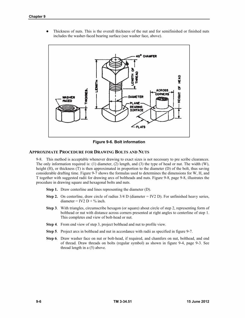
Chapter 9
9-6 TM 3-34.51 15 June 2012
Thickness of nuts. This is the overall thickness of the nut and for semifinished or finished nuts includes the washer-faced bearing surface (see washer face, above).
Figure 9-6. Bolt information
APPROXIMATE PROCEDURE FOR DRAWING BOLTS AND NUTS
9-8. This method is acceptable whenever drawing to exact sizes is not necessary to pre scribe clearances. The only information required is: (1) diameter, (2) length, and (3) the type of head or nut. The width (W), height (H), or thickness (T) is then approximated in proportion to the diameter (D) of the bolt, thus saving considerable drafting time. Figure 9-7 shows the formulas used to determines the dimensions for W, H, and T together with suggested radii for drawing arcs of boltheads and nuts. Figure 9-8, page 9-8, illustrates the procedure in drawing square and hexagonal bolts and nuts.
Step 1. Draw centerline and lines representing the diameter (D).
Step 2. On centerline, draw circle of radius 3/4 D (diameter = IV2 D). For unfinished heavy series, diameter = IV2 D + % inch.
Step 3. With triangles, circumscribe hexagon (or square) about circle of step 2, representing form of bolthead or nut with distance across corners presented at right angles to centerline of step 1. This completes end view of bolt-head or nut.
Step 4. From end view of step 3, project bolthead and nut to profile view.
Step 5. Project arcs in bolthead and nut in accordance with radii as specified in figure 9-7.
Step 6. Draw washer face on nut or bolt-head, if required, and chamfers on nut, bolthead, and end of thread. Draw threads on bolts (regular symbol) as shown in figure 9-4, page 9-3. See thread length in a (5) above.

Machine Drawing
15 June 2012 TM 3-34.51 9-7
Figure 9-7. Bolt and nut formulas
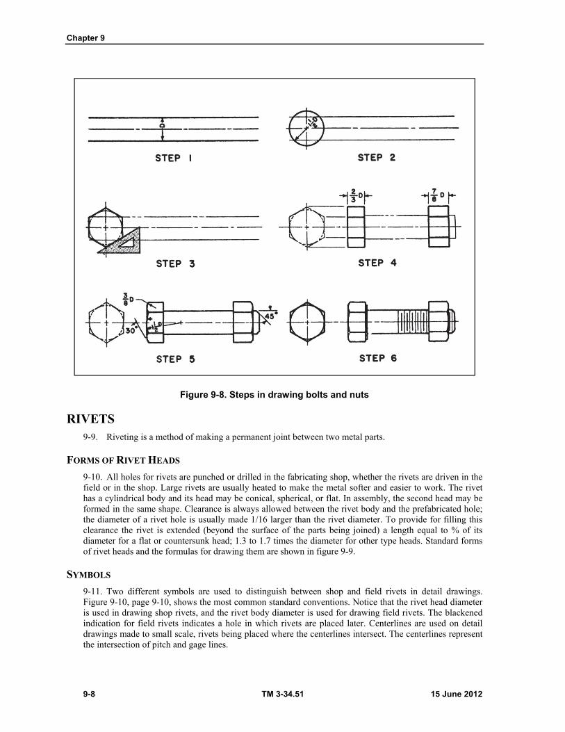
Chapter 9
9-8 TM 3-34.51 15 June 2012
Figure 9-8. Steps in drawing bolts and nuts
RIVETS 9-9. Riveting is a method of making a permanent joint between two metal parts.
FORMS OF RIVET HEADS
9-10. All holes for rivets are punched or drilled in the fabricating shop, whether the rivets are driven in the field or in the shop. Large rivets are usually heated to make the metal softer and easier to work. The rivet has a cylindrical body and its head may be conical, spherical, or flat. In assembly, the second head may be formed in the same shape. Clearance is always allowed between the rivet body and the prefabricated hole; the diameter of a rivet hole is usually made 1/16 larger than the rivet diameter. To provide for filling this clearance the rivet is extended (beyond the surface of the parts being joined) a length equal to % of its diameter for a flat or countersunk head; 1.3 to 1.7 times the diameter for other type heads. Standard forms of rivet heads and the formulas for drawing them are shown in figure 9-9.
SYMBOLS
9-11. Two different symbols are used to distinguish between shop and field rivets in detail drawings. Figure 9-10, page 9-10, shows the most common standard conventions. Notice that the rivet head diameter is used in drawing shop rivets, and the rivet body diameter is used for drawing field rivets. The blackened indication for field rivets indicates a hole in which rivets are placed later. Centerlines are used on detail drawings made to small scale, rivets being placed where the centerlines intersect. The centerlines represent the intersection of pitch and gage lines.
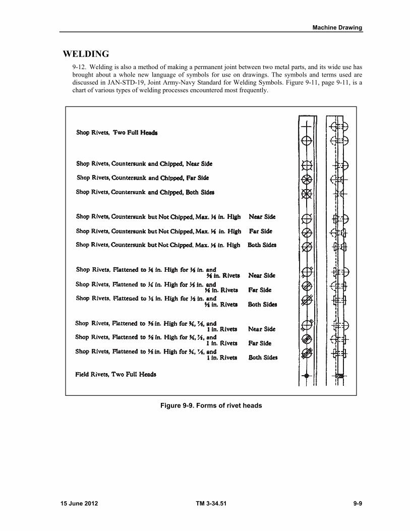
Machine Drawing
15 June 2012 TM 3-34.51 9-9
WELDING 9-12. Welding is also a method of making a permanent joint between two metal parts, and its wide use has brought about a whole new language of symbols for use on drawings. The symbols and terms used are discussed in JAN-STD-19, Joint Army-Navy Standard for Welding Symbols. Figure 9-11, page 9-11, is a chart of various types of welding processes encountered most frequently.
Figure 9-9. Forms of rivet heads
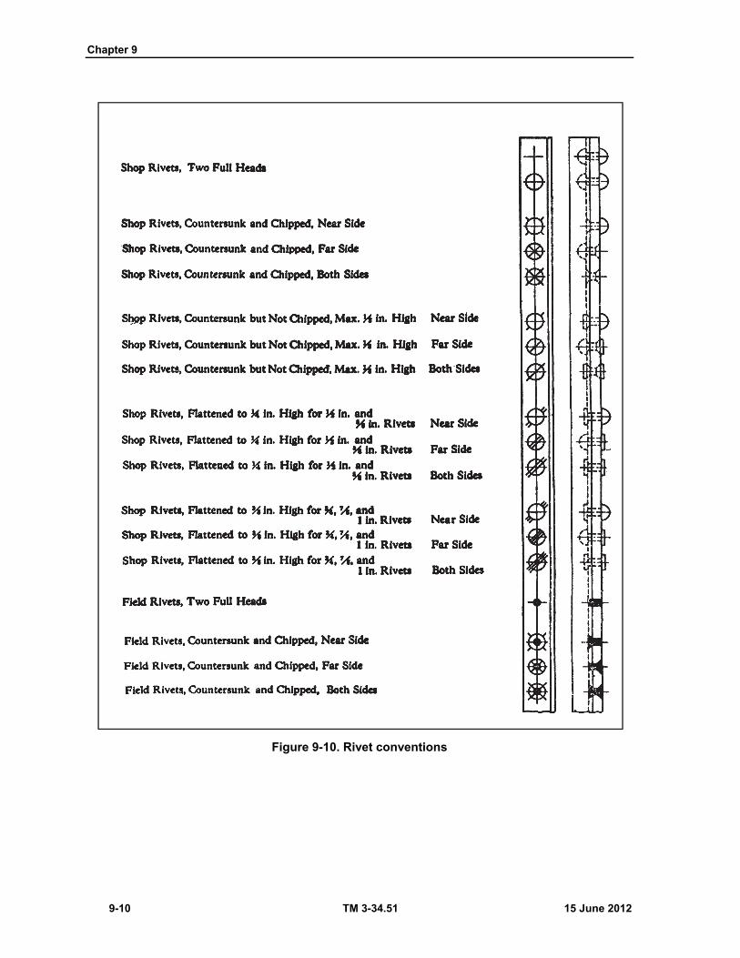
Chapter 9
9-10 TM 3-34.51 15 June 2012
Figure 9-10. Rivet conventions

Machine Drawing
15 June 2012 TM 3-34.51 9-11
Figure 9-11. Common welding processes
WELDING SYMBOL
9-13. The basic welding symbol (figure 9-12) is simply a reference line forming an arrow, with one or more angle bends behind the arrowhead, which points to the location of the weld. All information required to indicate the welding process to be used, the location and type of weld, the size, finish, and so on, is located in specified positions on or near the welding symbol.
Figure 9-12. Basic welding symbol
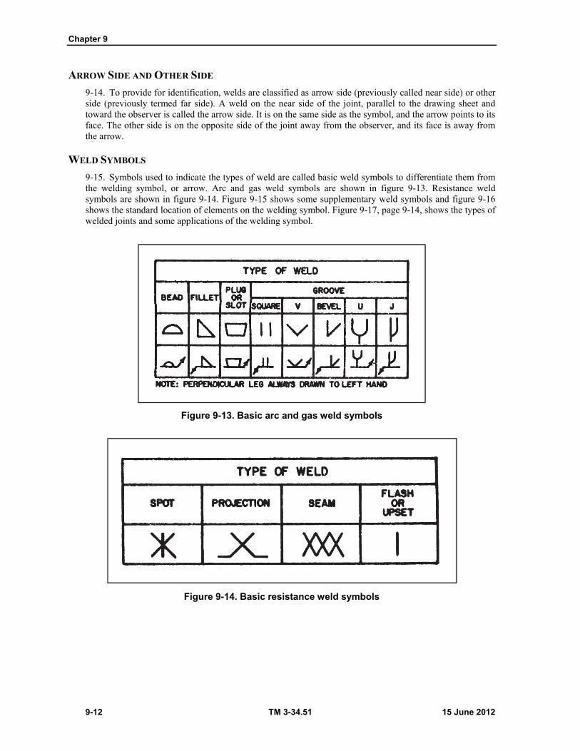
Chapter 9
9-12 TM 3-34.51 15 June 2012
ARROW SIDE AND OTHER SIDE
9-14. To provide for identification, welds are classified as arrow side (previously called near side) or other side (previously termed far side). A weld on the near side of the joint, parallel to the drawing sheet and toward the observer is called the arrow side. It is on the same side as the symbol, and the arrow points to its face. The other side is on the opposite side of the joint away from the observer, and its face is away from the arrow.
WELD SYMBOLS
9-15. Symbols used to indicate the types of weld are called basic weld symbols to differentiate them from the welding symbol, or arrow. Arc and gas weld symbols are shown in figure 9-13. Resistance weld symbols are shown in figure 9-14. Figure 9-15 shows some supplementary weld symbols and figure 9-16 shows the standard location of elements on the welding symbol. Figure 9-17, page 9-14, shows the types of welded joints and some applications of the welding symbol.
Figure 9-13. Basic arc and gas weld symbols
Figure 9-14. Basic resistance weld symbols
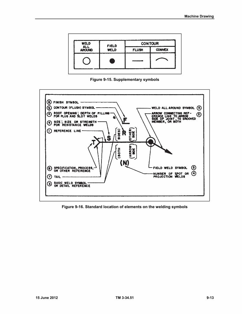
Machine Drawing
15 June 2012 TM 3-34.51 9-13
Figure 9-15. Supplementary symbols
Figure 9-16. Standard location of elements on the welding symbols
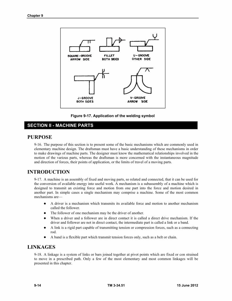
Chapter 9
9-14 TM 3-34.51 15 June 2012
Figure 9-17. Application of the welding symbol
SECTION II - MACHINE PARTS
PURPOSE 9-16. The purpose of this section is to present some of the basic mechanisms which are commonly used in elementary machine design. The draftsman must have a basic understanding of these mechanisms in order to make drawings of machine parts. The designer must know the mathematical relationships involved in the motion of the various parts, whereas the draftsman is more concerned with the instantaneous magnitude and direction of forces, their points of application, or the limits of travel of a moving parts.
INTRODUCTION 9-17. A machine is an assembly of fixed and moving parts, so related and connected, that it can be used for the conversion of available energy into useful work. A mechanism is a subassembly of a machine which is designed to transmit an existing force and motion from one part into the force and motion desired in another part. In simple cases a single mechanism may comprise a machine. Some of the most common mechanisms are—
A driver is a mechanism which transmits its available force and motion to another mechanism called the follower.
The follower of one mechanism may be the driver of another. When a driver and a follower are in direct contact it is called a direct drive mechanism. If the
driver and follower are not in direct contact, the intermediate part is called a link or a band. A link is a rigid part capable of transmitting tension or compression forces, such as a connecting
rod. A band is a flexible part which transmit tension forces only, such as a belt or chain.
LINKAGES 9-18. A linkage is a system of links or bars joined together at pivot points which are fixed or con strained to move in a prescribed path. Only a few of the most elementary and most common linkages will be presented in this chapter.
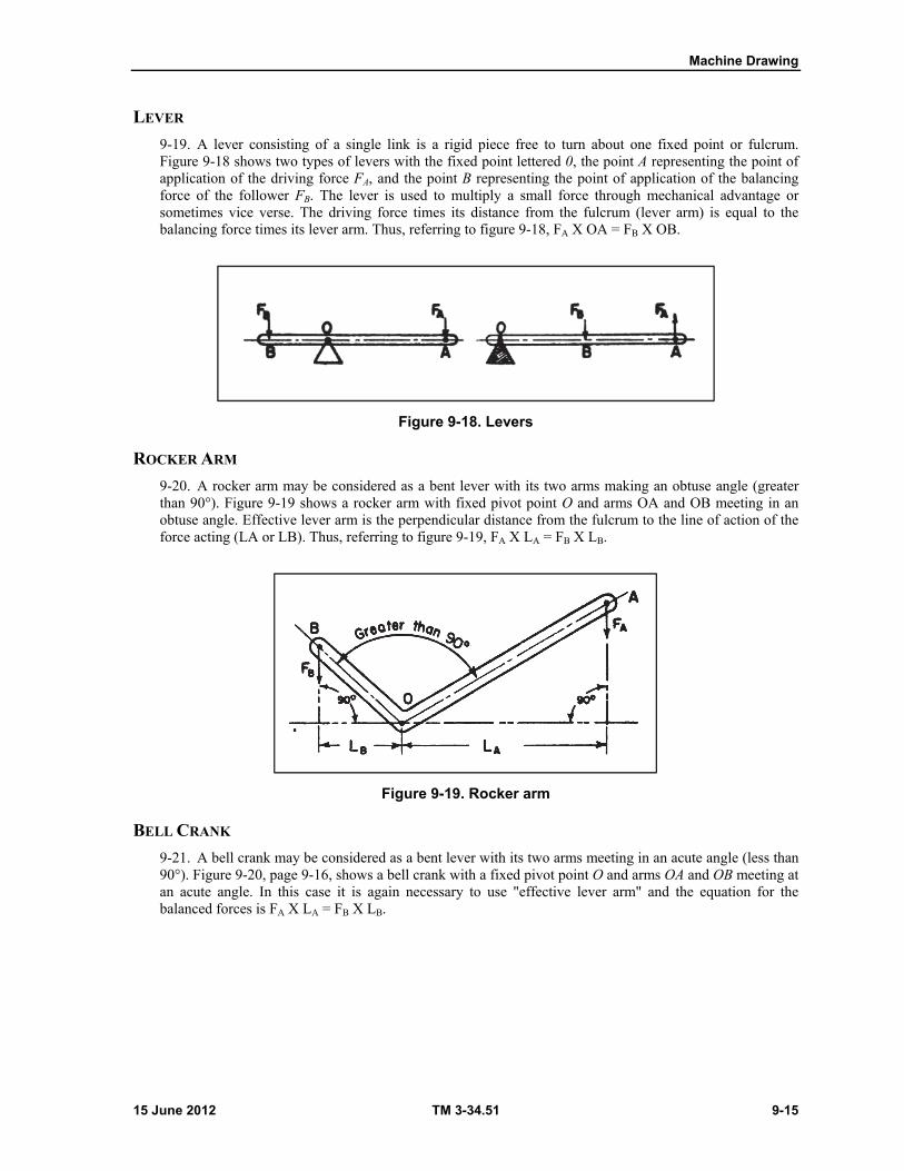
Machine Drawing
15 June 2012 TM 3-34.51 9-15
LEVER
9-19. A lever consisting of a single link is a rigid piece free to turn about one fixed point or fulcrum. Figure 9-18 shows two types of levers with the fixed point lettered 0, the point A representing the point of application of the driving force FA, and the point B representing the point of application of the balancing force of the follower FB. The lever is used to multiply a small force through mechanical advantage or sometimes vice verse. The driving force times its distance from the fulcrum (lever arm) is equal to the balancing force times its lever arm. Thus, referring to figure 9-18, FA X OA = FB X OB.
Figure 9-18. Levers
ROCKER ARM
9-20. A rocker arm may be considered as a bent lever with its two arms making an obtuse angle (greater than 90°). Figure 9-19 shows a rocker arm with fixed pivot point O and arms OA and OB meeting in an obtuse angle. Effective lever arm is the perpendicular distance from the fulcrum to the line of action of the force acting (LA or LB). Thus, referring to figure 9-19, FA X LA = FB X LB.
Figure 9-19. Rocker arm
BELL CRANK
9-21. A bell crank may be considered as a bent lever with its two arms meeting in an acute angle (less than 90°). Figure 9-20, page 9-16, shows a bell crank with a fixed pivot point O and arms OA and OB meeting at an acute angle. In this case it is again necessary to use "effective lever arm" and the equation for the balanced forces is FA X LA = FB X LB.
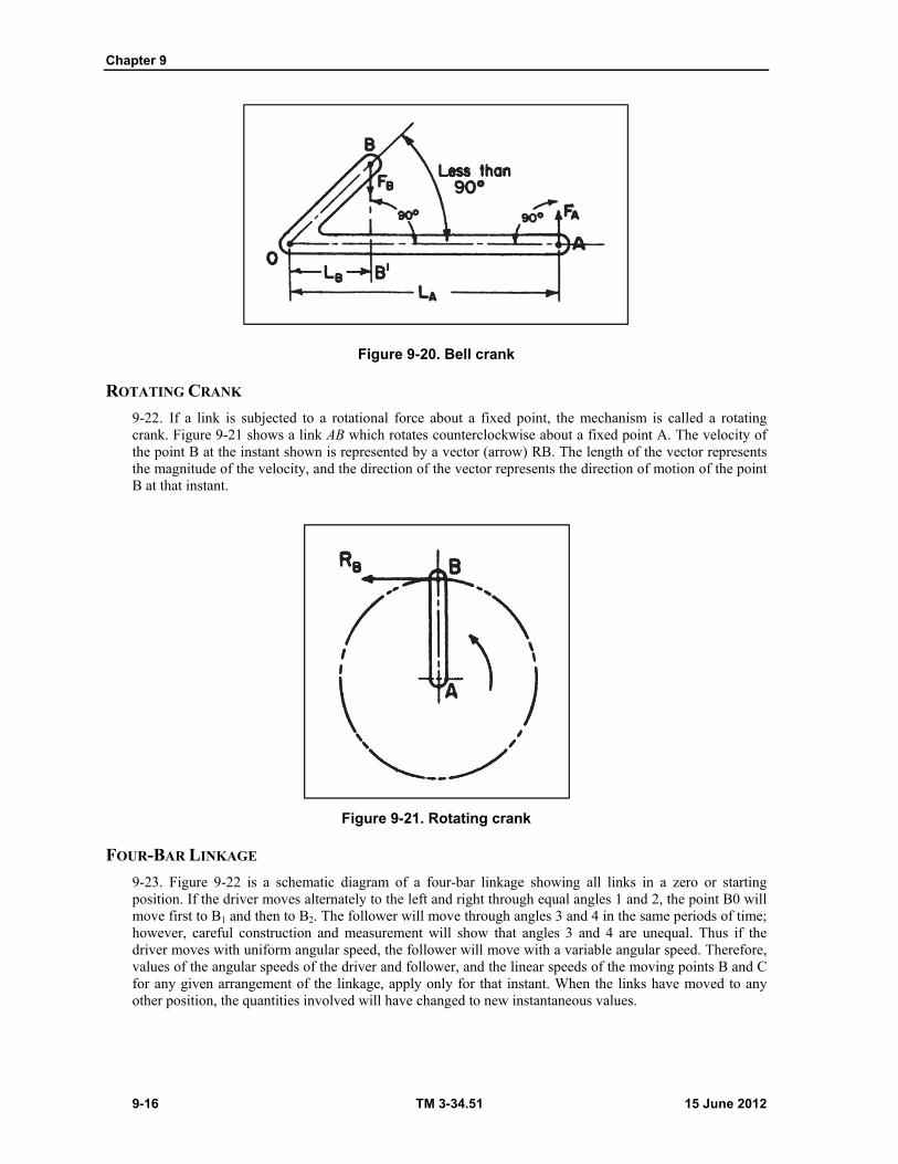
Chapter 9
9-16 TM 3-34.51 15 June 2012
Figure 9-20. Bell crank
ROTATING CRANK
9-22. If a link is subjected to a rotational force about a fixed point, the mechanism is called a rotating crank. Figure 9-21 shows a link AB which rotates counterclockwise about a fixed point A. The velocity of the point B at the instant shown is represented by a vector (arrow) RB. The length of the vector represents the magnitude of the velocity, and the direction of the vector represents the direction of motion of the point B at that instant.
Figure 9-21. Rotating crank
FOUR-BAR LINKAGE
9-23. Figure 9-22 is a schematic diagram of a four-bar linkage showing all links in a zero or starting position. If the driver moves alternately to the left and right through equal angles 1 and 2, the point B0 will move first to B1 and then to B2. The follower will move through angles 3 and 4 in the same periods of time; however, careful construction and measurement will show that angles 3 and 4 are unequal. Thus if the driver moves with uniform angular speed, the follower will move with a variable angular speed. Therefore, values of the angular speeds of the driver and follower, and the linear speeds of the moving points B and C for any given arrangement of the linkage, apply only for that instant. When the links have moved to any other position, the quantities involved will have changed to new instantaneous values.
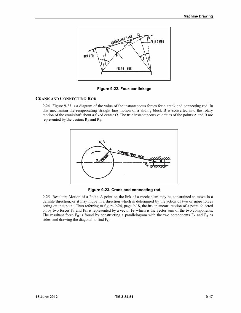
Machine Drawing
15 June 2012 TM 3-34.51 9-17
Figure 9-22. Four-bar linkage
CRANK AND CONNECTING ROD
9-24. Figure 9-23 is a diagram of the value of the instantaneous forces for a crank and connecting rod. In this mechanism the reciprocating straight line motion of a sliding block B is converted into the rotary motion of the crankshaft about a fixed center O. The true instantaneous velocities of the points A and B are represented by the vectors RA and RB.
Figure 9-23. Crank and connecting rod
9-25. Resultant Motion of a Point. A point on the link of a mechanism may be constrained to move in a definite direction, or it may move in a direction which is determined by the action of two or more forces acting on that point. Thus referring to figure 9-24, page 9-18, the instantaneous motion of a point O, acted on by two forces FA and FB, is represented by a vector FR which is the vector sum of the two components. The resultant force FR is found by constructing a parallelogram with the two components FA and FR as sides, and drawing the diagonal to find FR.
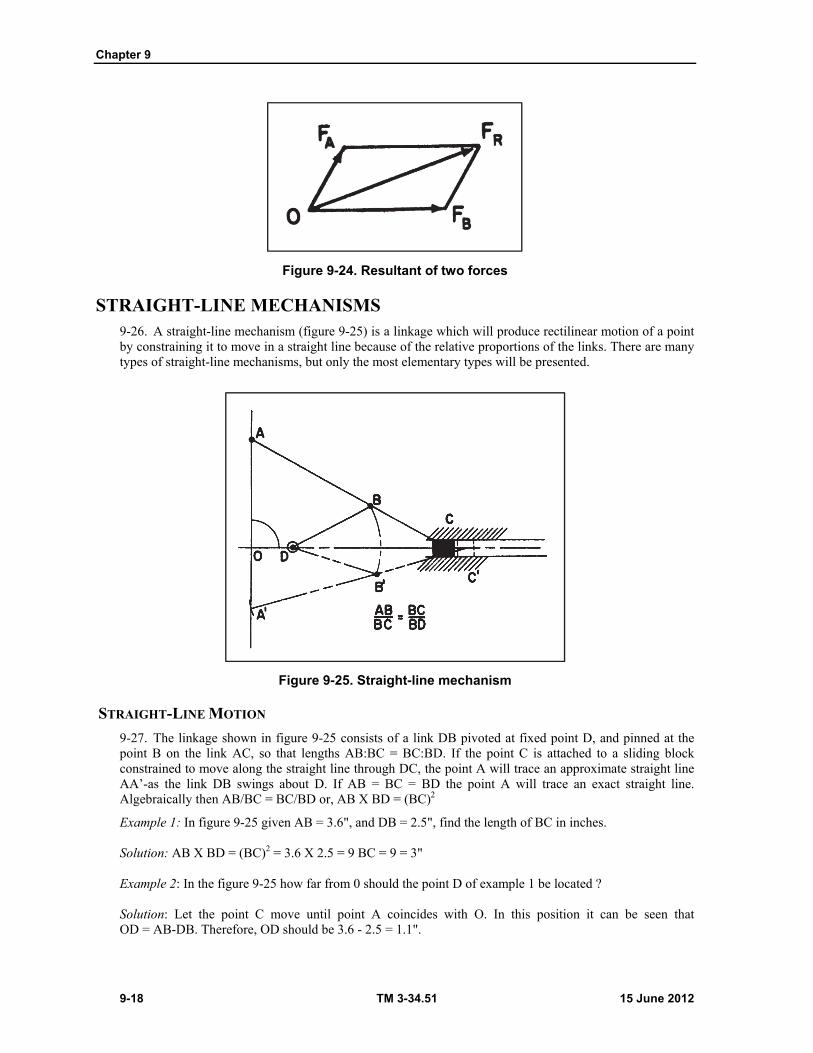
Chapter 9
9-18 TM 3-34.51 15 June 2012
Figure 9-24. Resultant of two forces
STRAIGHT-LINE MECHANISMS 9-26. A straight-line mechanism (figure 9-25) is a linkage which will produce rectilinear motion of a point by constraining it to move in a straight line because of the relative proportions of the links. There are many types of straight-line mechanisms, but only the most elementary types will be presented.
Figure 9-25. Straight-line mechanism
STRAIGHT-LINE MOTION
9-27. The linkage shown in figure 9-25 consists of a link DB pivoted at fixed point D, and pinned at the point B on the link AC, so that lengths AB:BC = BC:BD. If the point C is attached to a sliding block constrained to move along the straight line through DC, the point A will trace an approximate straight line AA’-as the link DB swings about D. If AB = BC = BD the point A will trace an exact straight line. Algebraically then AB/BC = BC/BD or, AB X BD = (BC)2
Example 1: In figure 9-25 given AB = 3.6", and DB = 2.5", find the length of BC in inches. Solution: AB X BD = (BC)2 = 3.6 X 2.5 = 9 BC = 9 = 3" Example 2: In the figure 9-25 how far from 0 should the point D of example 1 be located ? Solution: Let the point C move until point A coincides with O. In this position it can be seen that OD = AB-DB. Therefore, OD should be 3.6 - 2.5 = 1.1".
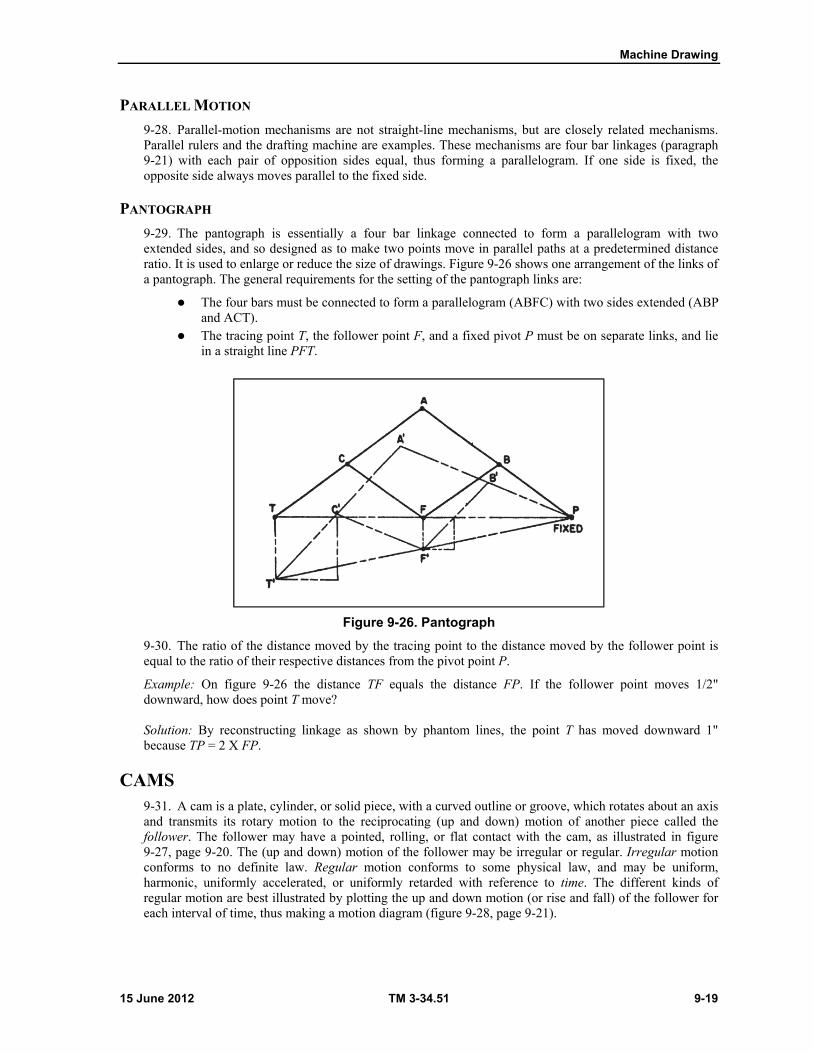
Machine Drawing
15 June 2012 TM 3-34.51 9-19
PARALLEL MOTION
9-28. Parallel-motion mechanisms are not straight-line mechanisms, but are closely related mechanisms. Parallel rulers and the drafting machine are examples. These mechanisms are four bar linkages (paragraph 9-21) with each pair of opposition sides equal, thus forming a parallelogram. If one side is fixed, the opposite side always moves parallel to the fixed side.
PANTOGRAPH
9-29. The pantograph is essentially a four bar linkage connected to form a parallelogram with two extended sides, and so designed as to make two points move in parallel paths at a predetermined distance ratio. It is used to enlarge or reduce the size of drawings. Figure 9-26 shows one arrangement of the links of a pantograph. The general requirements for the setting of the pantograph links are:
The four bars must be connected to form a parallelogram (ABFC) with two sides extended (ABP and ACT).
The tracing point T, the follower point F, and a fixed pivot P must be on separate links, and lie in a straight line PFT.
Figure 9-26. Pantograph
9-30. The ratio of the distance moved by the tracing point to the distance moved by the follower point is equal to the ratio of their respective distances from the pivot point P.
Example: On figure 9-26 the distance TF equals the distance FP. If the follower point moves 1/2" downward, how does point T move? Solution: By reconstructing linkage as shown by phantom lines, the point T has moved downward 1" because TP = 2 X FP.
CAMS 9-31. A cam is a plate, cylinder, or solid piece, with a curved outline or groove, which rotates about an axis and transmits its rotary motion to the reciprocating (up and down) motion of another piece called the follower. The follower may have a pointed, rolling, or flat contact with the cam, as illustrated in figure 9-27, page 9-20. The (up and down) motion of the follower may be irregular or regular. Irregular motion conforms to no definite law. Regular motion conforms to some physical law, and may be uniform, harmonic, uniformly accelerated, or uniformly retarded with reference to time. The different kinds of regular motion are best illustrated by plotting the up and down motion (or rise and fall) of the follower for each interval of time, thus making a motion diagram (figure 9-28, page 9-21).

Chapter 9
9-20 TM 3-34.51 15 June 2012
Note. In this chapter it is assumed that the cam and camshaft are turning at a constant speed in revolutions per minute so that equal angles about the center of the cam represent equal periods of time. It is also assumed that the follower is constrained to move in an up and down line of motion only.
UNIFORM MOTION
9-32. If the point of a follower moves equal distances in equal periods of time, the follower has uniform motion. Referring to diagram 1, figure 9-28, the total rise of the follower, represented by AB, is divided into three equal parts. The follower must rise to points 1, 2, and 3 in the time it takes the cam to turn in equal intervals of time to 30°, 60°, and 90° respectively. The follower may have uniform fall as shown on the right side of diagram 1.
HARMONIC MOTION
9-33. Diagram 2, figure 9-28, is the motion diagram for harmonic motion of the follower. The line AB represents the total rise of the follower. Points on the motion diagram are found by dividing a semicircle into 30° sectors, intersecting the semicircle in points numbered from 1 to 6. The numbered points are projected horizontally to the ordinates drawn for equal time intervals of rotation of the cam. The solid curve shows the harmonic "rise" for 180° rotation of the cam, and the dotted curve shows the harmonic "fall" of the follower to its original position. A cam with this motion is useful for high speed operation.
Figure 9-27. Cams and followers

Machine Drawing
15 June 2012 TM 3-34.51 9-21
Figure 9-28. Motion diagrams
UNIFORMLY ACCELERATED AND RETARDED MOTION
9-34. Diagram 3, figure 9-28, represents uniformly accelerated and uniformly retarded motion. The line AB represents the total "rise" of the follower as before. The line AB is halved, and the lower half is divided into three parts in the ratios of 1:3:5.
9-35. This is done graphically so that = = .
9-36. The upper half of the line AB is divided by using dividers so that = = B. The solid curve
shows the "rise" of the follower by uniform acceleration to the midpoint of travel and its continued rise by uniformly retarded motion. The dotted curve shows the "fall" of the follower to its midpoint of travel, by uniformly accelerated motion and its continued fall by uniformly retarded motion to its original position. Uniformly accelerated motion is the motion of a freely falling body, and it gives the easiest motion to a cam.
Chapter 9
9-22 TM 3-34.51 15 June 2012
CONSTRUCTION OF A CAM
9-37. To develop the design for a cam it is necessary to know the initial position of the follower with respect to the camshaft, the type of contact, the motion required of the follower and the direction of rotation of the camshaft.
Example: Construct a plate cam with a pointed follower to turn counterclockwise. The follower is to move in a vertical line above the center of the cam. In the initial position, the follower point is 1 inch above the center of the cam. The follower is required to have the following motions: 0°-120°, rise 1 inch with simple harmonic motion; 120°-210°, dwell or rest with no motion; at 210°, drop 1/4 inch instantly; 210°-360°, fall 3/4 inch with uniform motion. Solution: Refer to figure 9-29 and study each step.
Draw baselines of motion diagram and mark off 12 equal spaces along baseline, and number points of 12 equal spaces to represent each 30° interval rotation of the cam.
Draw semicircle at left end of baseline with diameter equal to 1 inch rise and tangent to baseline. Divide semicircle into four equal arcs (at 45° intervals) numbered 1, 2, 3, and 4. The semicircle is divided into four equal arcs because there are four 30° intervals from 0°-120°. Points 1, 2, 3, and 4 are projected horizontally with T-square to locate points 1, 2, 3, and 4 on the motion diagram. Points 4, 5, 6, and 7 are all on the line 1 inch above baseline because follower rests from 120°-210°. The point 8 is 1/4 inch below point 7 because the follower drops 1/4 inch instantly at 210°. From 210°-360° the follower falls 3/4 inch to starting position with uniform motion, and a straight line is drawn from point 8 to the end of the diagram.
Draw base circle with radius of 1 inch and mark the initial point of the follower at 0° position of the cam. Extend all 30° lines outside base circle.
Locate points on cam by transferring distances of each point above baseline in motion diagram with dividers to same distance outside base circle. See distance "a" for point No. 2 on 60° line.
Connect points 0-1-2-3-4 and 8-9-10-11-12-0 with a French curve. Points 4 through 7 are connected with a curve of 2-inch radius.
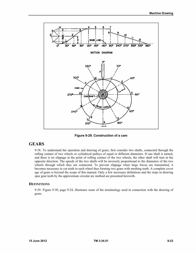
Machine Drawing
15 June 2012 TM 3-34.51 9-23
Figure 9-29. Construction of a cam
GEARS 9-38. To understand the operation and drawing of gears, first consider two shafts, connected through the rolling contact of two wheels or cylindrical pulleys of equal or different diameters. If one shaft is turned, and there is no slippage at the point of rolling contact of the two wheels, the other shaft will turn in the opposite direction. The speeds of the two shafts will be inversely proportional to the diameters of the two wheels through which they are connected. To prevent slippage when large forces are transmitted, it becomes necessary to cut teeth in each wheel thus forming two gears with meshing teeth. A complete cover age of gears is beyond the scope of this manual. Only a few necessary definitions and the steps in drawing spur gear teeth by the approximate circular arc method are presented herewith.
DEFINITIONS
9-39. Figure 9-30, page 9-24, illustrates some of the terminology used in connection with the drawing of gears.

Chapter 9
9-24 TM 3-34.51 15 June 2012
Figure 9-30. Gear terminology
Pitch circle is the projection of an equivalent cylinder on a plane perpendicular to the axis of the gear. The pitch circles of two meshing gears are tangent at the pitch point, which is on their line of centers.
Pitch diameter is the diameter of the pitch circle. Gear teeth are designed to the size of equal subdivisions stepped off on the pitch circle.
Circular pitch is the linear distances between corresponding points on two adjacent teeth measured along the pitch circle. The circular pitches of two meshing gears are equal.
Diametrical pitch is the number of teeth on the gear wheel per inch of pitch diameter. Addendum circle, or outside circle, is the circle which passes through the outer extremities of the
teeth. Root circle is the circle which passes through the bottoms of the grooves between the teeth. The
addendum circle and the root circle are concentric with the pitch circle. The addendum distance of a gear is equal to the radius of the addendum circle minus the radius
of the pitch circle. The dedendum distance of a gear is equal to the radius of the pitch circle minus the radius of the
root circle. Clearance is the difference between the addendum distance of one gear and dedendum distance
of another gear in mesh with it. The face of a tooth is the portion of the contact surface between the pitch circle and the
addendum circle. The flank of a tooth is the portion of the contact surface between the pitch circle and the root
circle.
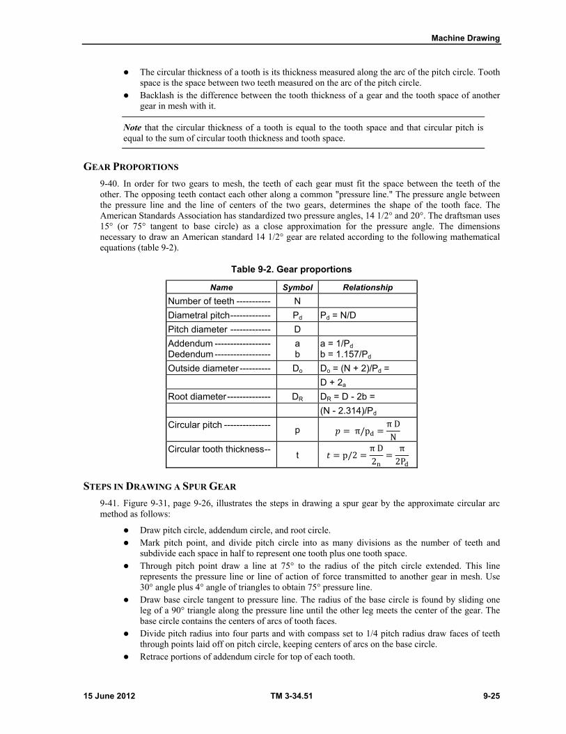
Machine Drawing
15 June 2012 TM 3-34.51 9-25
The circular thickness of a tooth is its thickness measured along the arc of the pitch circle. Tooth space is the space between two teeth measured on the arc of the pitch circle.
Backlash is the difference between the tooth thickness of a gear and the tooth space of another gear in mesh with it.
Note that the circular thickness of a tooth is equal to the tooth space and that circular pitch is equal to the sum of circular tooth thickness and tooth space.
GEAR PROPORTIONS
9-40. In order for two gears to mesh, the teeth of each gear must fit the space between the teeth of the other. The opposing teeth contact each other along a common "pressure line." The pressure angle between the pressure line and the line of centers of the two gears, determines the shape of the tooth face. The American Standards Association has standardized two pressure angles, 14 1/2° and 20°. The draftsman uses 15° (or 75° tangent to base circle) as a close approximation for the pressure angle. The dimensions necessary to draw an American standard 14 1/2° gear are related according to the following mathematical equations (table 9-2).
Table 9-2. Gear proportions
Name Symbol Relationship
Number of teeth ----------- N
Diametral pitch ------------- Pd Pd = N/D
Pitch diameter ------------- D
Addendum ------------------ Dedendum ------------------
a b
a = 1/Pd b = 1.157/Pd
Outside diameter ---------- Do Do = (N + 2)/Pd =
D + 2a
Root diameter -------------- DR DR = D - 2b =
(N - 2.314)/Pd
Circular pitch --------------- p 𝑝 = π/p = π DN
Circular tooth thickness -- t 𝑡 = p/2 = π D2 = π2P
STEPS IN DRAWING A SPUR GEAR
9-41. Figure 9-31, page 9-26, illustrates the steps in drawing a spur gear by the approximate circular arc method as follows:
Draw pitch circle, addendum circle, and root circle. Mark pitch point, and divide pitch circle into as many divisions as the number of teeth and
subdivide each space in half to represent one tooth plus one tooth space. Through pitch point draw a line at 75° to the radius of the pitch circle extended. This line
represents the pressure line or line of action of force transmitted to another gear in mesh. Use 30° angle plus 4° angle of triangles to obtain 75° pressure line.
Draw base circle tangent to pressure line. The radius of the base circle is found by sliding one leg of a 90° triangle along the pressure line until the other leg meets the center of the gear. The base circle contains the centers of arcs of tooth faces.
Divide pitch radius into four parts and with compass set to 1/4 pitch radius draw faces of teeth through points laid off on pitch circle, keeping centers of arcs on the base circle.
Retrace portions of addendum circle for top of each tooth.
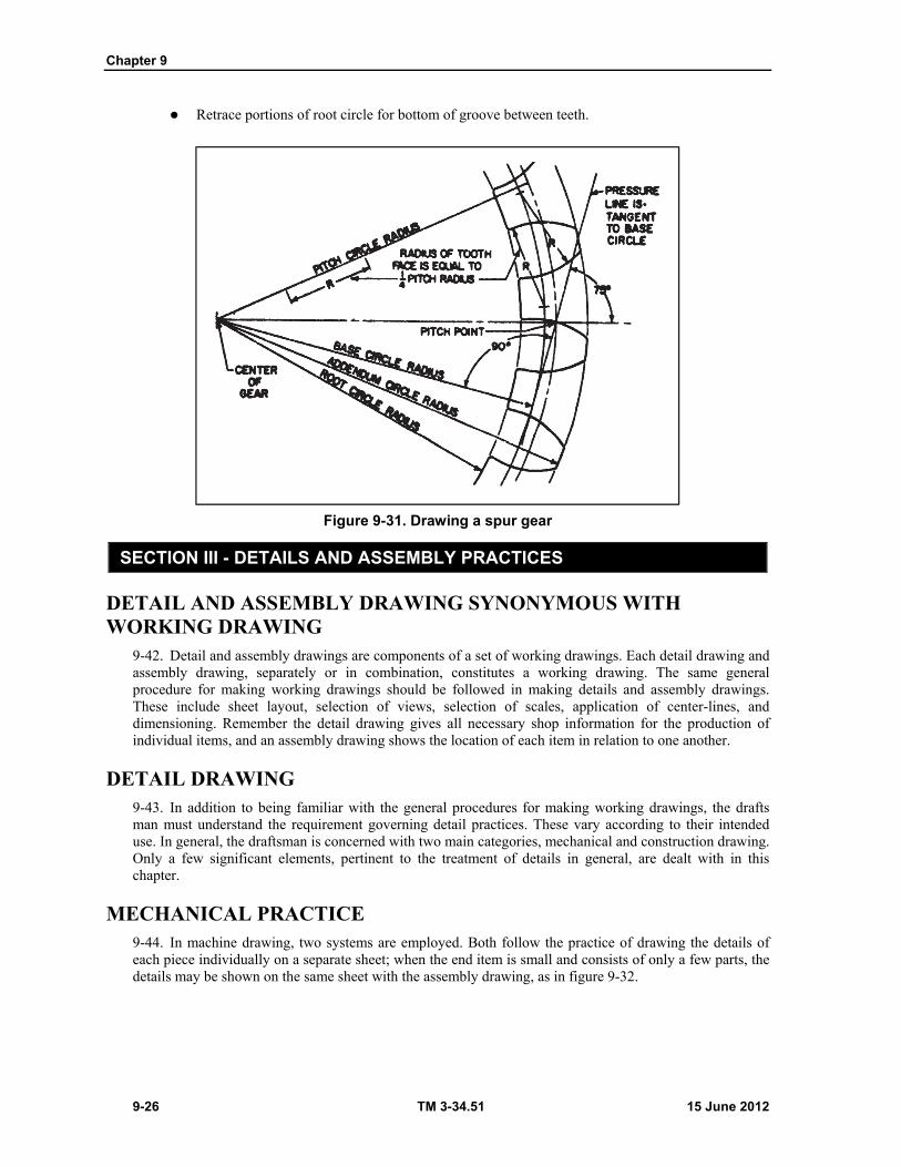
Chapter 9
9-26 TM 3-34.51 15 June 2012
Retrace portions of root circle for bottom of groove between teeth.
Figure 9-31. Drawing a spur gear
SECTION III - DETAILS AND ASSEMBLY PRACTICES
DETAIL AND ASSEMBLY DRAWING SYNONYMOUS WITH WORKING DRAWING
9-42. Detail and assembly drawings are components of a set of working drawings. Each detail drawing and assembly drawing, separately or in combination, constitutes a working drawing. The same general procedure for making working drawings should be followed in making details and assembly drawings. These include sheet layout, selection of views, selection of scales, application of center-lines, and dimensioning. Remember the detail drawing gives all necessary shop information for the production of individual items, and an assembly drawing shows the location of each item in relation to one another.
DETAIL DRAWING 9-43. In addition to being familiar with the general procedures for making working drawings, the drafts man must understand the requirement governing detail practices. These vary according to their intended use. In general, the draftsman is concerned with two main categories, mechanical and construction drawing. Only a few significant elements, pertinent to the treatment of details in general, are dealt with in this chapter.
MECHANICAL PRACTICE 9-44. In machine drawing, two systems are employed. Both follow the practice of drawing the details of each piece individually on a separate sheet; when the end item is small and consists of only a few parts, the details may be shown on the same sheet with the assembly drawing, as in figure 9-32.
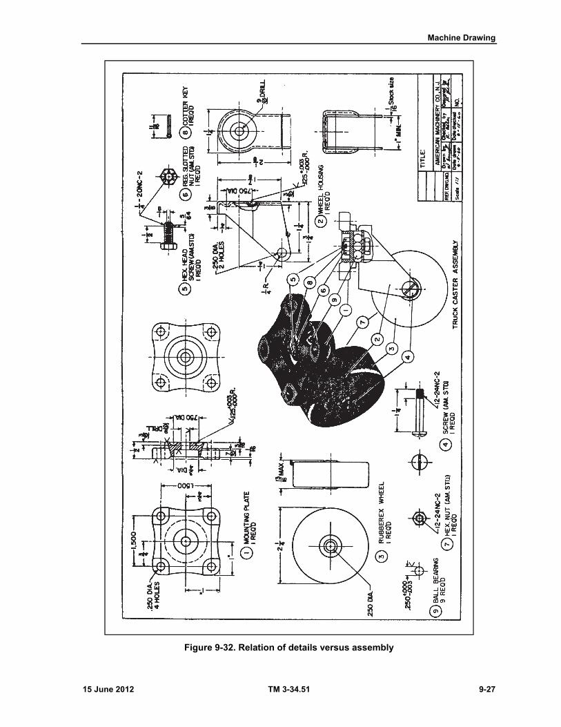
Machine Drawing
15 June 2012 TM 3-34.51 9-27
Figure 9-32. Relation of details versus assembly
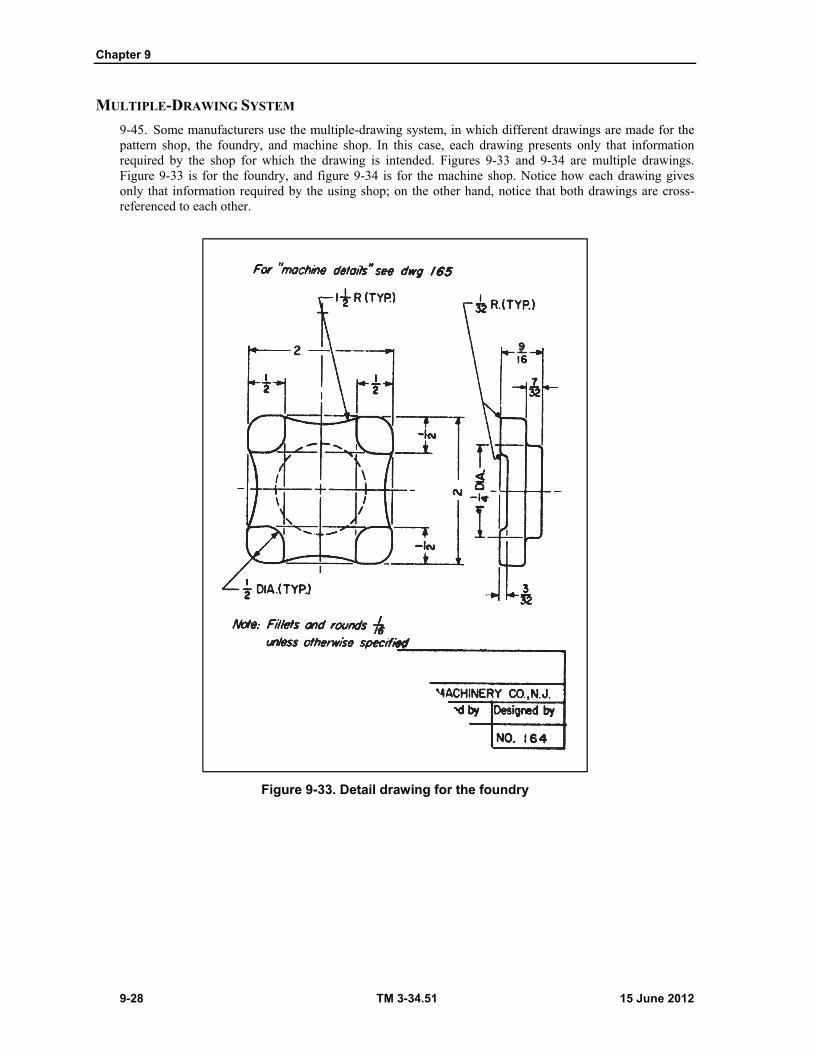
Chapter 9
9-28 TM 3-34.51 15 June 2012
MULTIPLE-DRAWING SYSTEM
9-45. Some manufacturers use the multiple-drawing system, in which different drawings are made for the pattern shop, the foundry, and machine shop. In this case, each drawing presents only that information required by the shop for which the drawing is intended. Figures 9-33 and 9-34 are multiple drawings. Figure 9-33 is for the foundry, and figure 9-34 is for the machine shop. Notice how each drawing gives only that information required by the using shop; on the other hand, notice that both drawings are cross-referenced to each other.
Figure 9-33. Detail drawing for the foundry
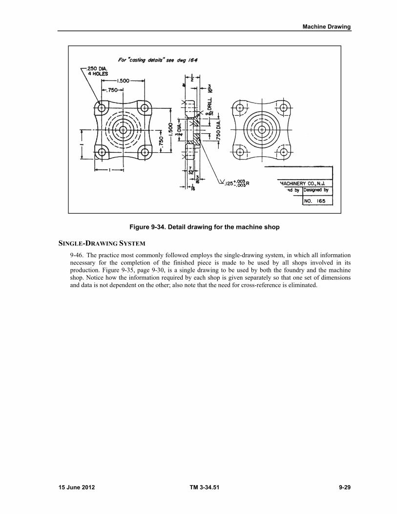
Machine Drawing
15 June 2012 TM 3-34.51 9-29
Figure 9-34. Detail drawing for the machine shop
SINGLE-DRAWING SYSTEM
9-46. The practice most commonly followed employs the single-drawing system, in which all information necessary for the completion of the finished piece is made to be used by all shops involved in its production. Figure 9-35, page 9-30, is a single drawing to be used by both the foundry and the machine shop. Notice how the information required by each shop is given separately so that one set of dimensions and data is not dependent on the other; also note that the need for cross-reference is eliminated.
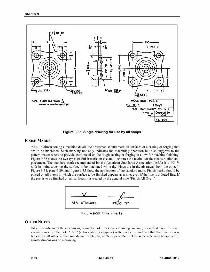
Chapter 9
9-30 TM 3-34.51 15 June 2012
Figure 9-35. Single drawing for use by all shops
FINISH MARKS
9-47. In dimensioning a machine detail, the draftsman should mark all surfaces of a casting or forging that are to be machined. Such marking not only indicates the machining operation but also suggests to the pattern maker where to provide extra metal on the rough casting or forging to allow for machine finishing. Figure 9-36 shows the two types of finish marks in use and illustrates the method of their construction and placement. The standard mark recommended by the American Standards Association (ASA) is a 60° V with its point touching the surface to be machined while the wings are in the air (away from the object). Figure 9-34, page 9-29, and figure 9-35 show the application of the standard mark. Finish marks should be placed on all views in which the surface to be finished appears as a line, even if the line is a dotted line. If the part is to be finished on all surfaces, it is treated by the general note "Finish All Over."
Figure 9-36. Finish marks
OTHER NOTES
9-48. Rounds and fillets occurring a number of times on a drawing are only identified once for each variation in size. The note "TYP" (abbreviation for typical) is then added to indicate that the dimension is typical for all other similar rounds and fillets (figure 9-33, page 9-28). This same note may be applied to similar dimensions on a drawing.
15 June 2012 TM 3-34.51 10-1
Chapter 10
Utilities Drawings
SECTION I - WATER SUPPLY AND DISTRIBUTION
DEFINITION 10-1. A water supply system consists of facilities, equipment, and piping that are used to obtain, treat, and transport water for a water distribution system. A distribution system is a combination of connected pipes laid out in the form of a "tree" or "gridiron" to carry the supplied water to the usage points in the system.
WATER SUPPLY SYSTEM 10-2. Elements found on a typical construction plan for a water supply system are shown in figure 10-1, page 10-2. The general plan shows how the water is diverted from the stream. Two section views are drawn on the general plan view. Section A-A shows the details of the baffle and the shape of the diversion ditch. Section B-B shows that the water is pumped through a hose with a strainer from a box secured in the sedimentation basin to a purification unit. The primary drawing is a detailed plan of the sand filter which shows how to indicate a 2:1 slope on the sides of the sand filter and other pertinent features. The general notes include such information as the capacity of each sand filter and how one unit can supply the rated capacity while the other is being cleaned.
DISTRIBUTION SYSTEM 10-3. A typical water distribution system for a hospital area is shown in figure 10-2, page 10-3. The general location and size of the pipes are shown along with the valves, sumps, water tank and other fixtures. In general, the symbols used on distribution system plans correspond to those for water plumbing. Additional symbols which may not be in common use should be explained by notes or a legend on each construction print on which they appear.
UNIT CONSTRUCTION AND PACKAGE UNIT PRINTS 10-4. Additional drawings should be prepared for construction or installation, or both, of unit structures and equipment used in water supply and distribution systems. The type of additional drawings that should be drawn depends on whether the unit is constructed in the field or is a "package unit" which is assembled in the field.
UNIT CONSTRUCTION DRAWINGS
10-5. Structures in water supply and distribution systems use the same methods as architectural and structural drawings covered in chapters 4 through 8. Figure 10-3, pages 10-4 through 10-6, shows how to indicate the size of the tower, the steel beams, the dunnage beams, and the footings required for three types of tanks. All piping requirements, including the detailed plumbing connection for the float valve, should also be shown.
PACKAGE UNITS
10-6. Package units are assembled in the field and installed in accordance with the manufacturers' instructions supplied with the unit or units. These shop drawings, when approved by the authorized representative of the contracting officer, should be cross-referenced with the contract drawings and
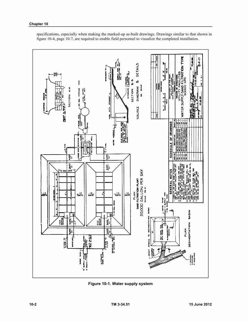
Chapter 10
10-2 TM 3-34.51 15 June 2012
specifications, especially when making the marked-up as-built drawings. Drawings similar to that shown in figure 10-4, page 10-7, are required to enable field personnel to visualize the completed installation.
Figure 10-1. Water supply system

Utilities Drawings
15 June 2012 TM 3-34.51 10-3
Figure 10-2. Water distribution plan
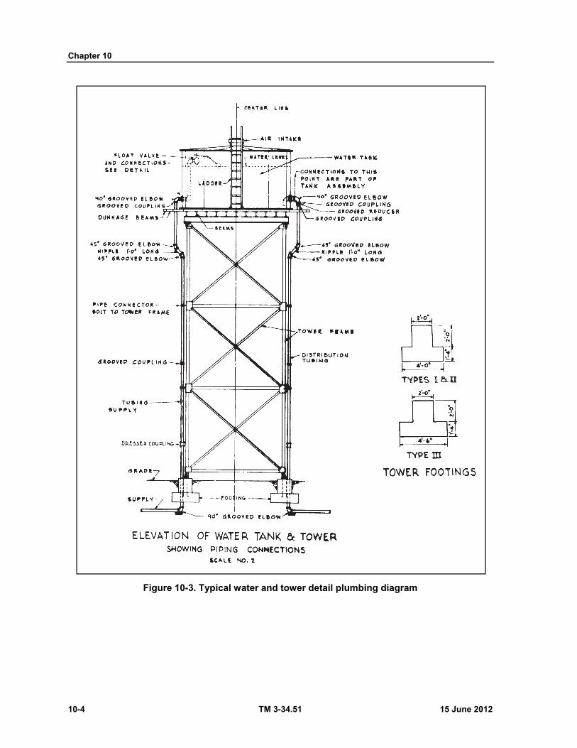
Chapter 10
10-4 TM 3-34.51 15 June 2012
Figure 10-3. Typical water and tower detail plumbing diagram
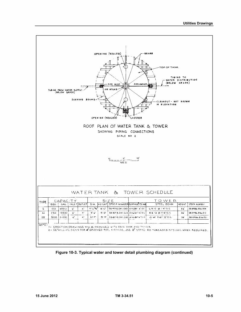
Utilities Drawings
15 June 2012 TM 3-34.51 10-5
Figure 10-3. Typical water and tower detail plumbing diagram (continued)
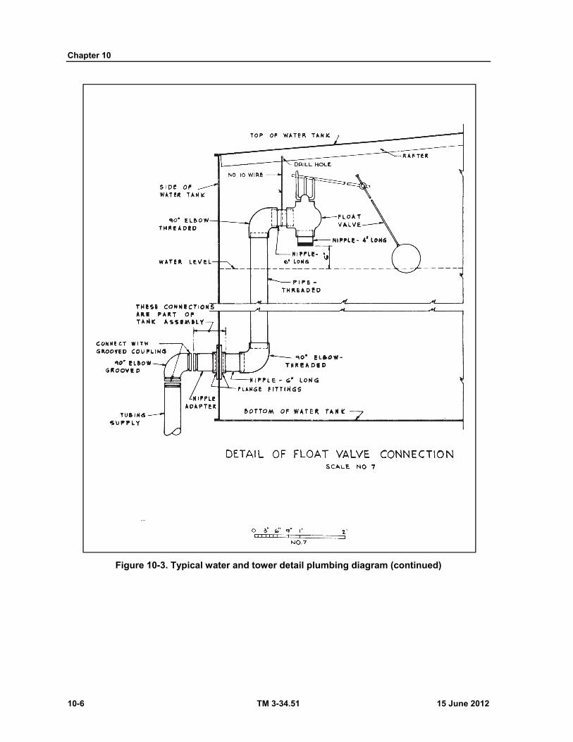
Chapter 10
10-6 TM 3-34.51 15 June 2012
Figure 10-3. Typical water and tower detail plumbing diagram (continued)

Utilities Drawings
15 June 2012 TM 3-34.51 10-7
Figure 10-4. Flow diagram for a water treatment plant
SECTION II - PLUMBING
DEFINITION 10-7. All piping, apparatus, and fixtures for water distribution and waste disposal within a building are classified as plumbing. Piping for heating systems is called steampiping. Refer to TM 5-551K and TM 5-745 for further discussion of steampiping.
PLUMBING PLANS 10-8. As a rule, plumbing plans should show the location of fixtures and fittings to be installed, and the size and routine of piping. The basic details are left to the plumber who is responsible for installing a properly connected system in accordance with the specifications and good plumbing and construction
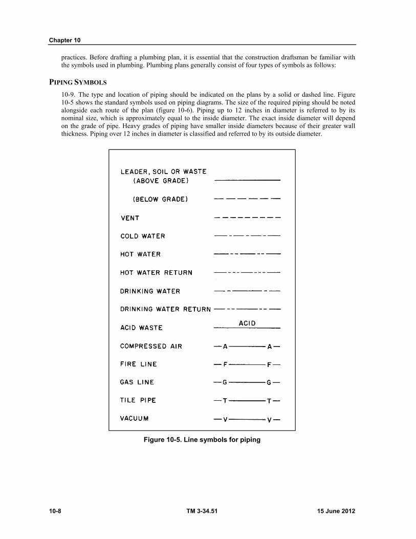
Chapter 10
10-8 TM 3-34.51 15 June 2012
practices. Before drafting a plumbing plan, it is essential that the construction draftsman be familiar with the symbols used in plumbing. Plumbing plans generally consist of four types of symbols as follows:
PIPING SYMBOLS
10-9. The type and location of piping should be indicated on the plans by a solid or dashed line. Figure 10-5 shows the standard symbols used on piping diagrams. The size of the required piping should be noted alongside each route of the plan (figure 10-6). Piping up to 12 inches in diameter is referred to by its nominal size, which is approximately equal to the inside diameter. The exact inside diameter will depend on the grade of pipe. Heavy grades of piping have smaller inside diameters because of their greater wall thickness. Piping over 12 inches in diameter is classified and referred to by its outside diameter.
Figure 10-5. Line symbols for piping
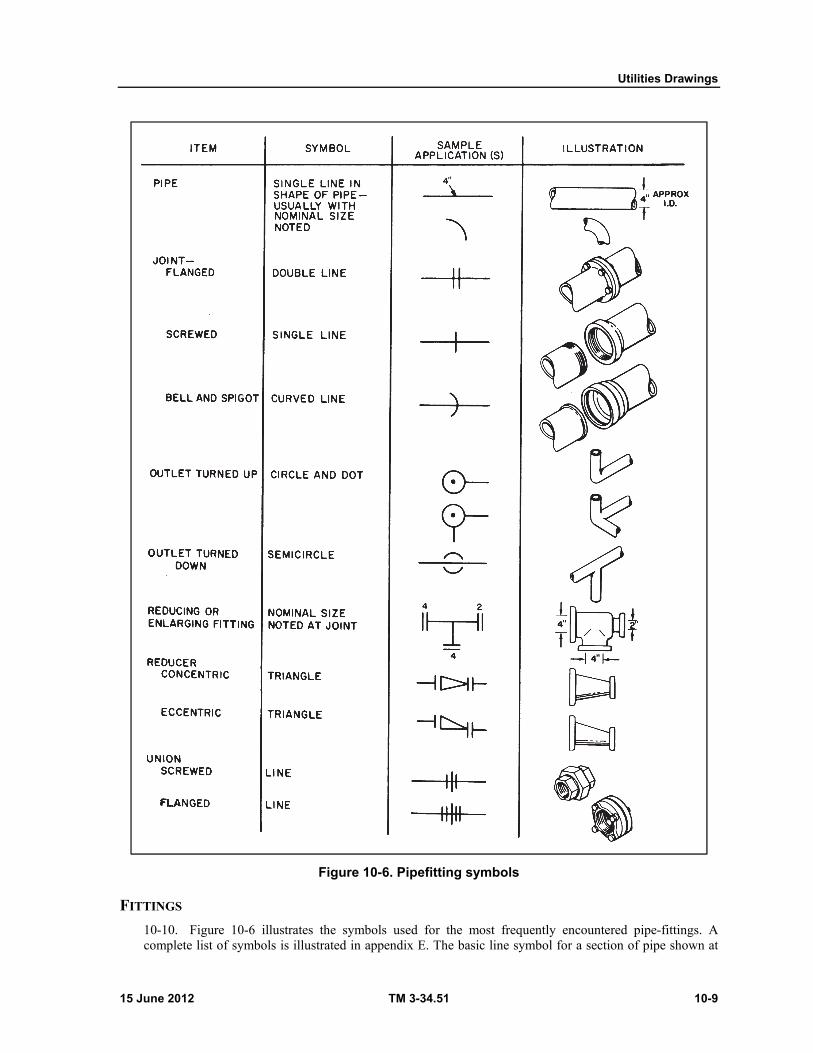
Utilities Drawings
15 June 2012 TM 3-34.51 10-9
Figure 10-6. Pipefitting symbols
FITTINGS
10-10. Figure 10-6 illustrates the symbols used for the most frequently encountered pipe-fittings. A complete list of symbols is illustrated in appendix E. The basic line symbol for a section of pipe shown at

Chapter 10
10-10 TM 3-34.51 15 June 2012
the top of figure 10-6 will be combined with the line symbology shown on figure 10-5. In this way, it is possible to show not only the size of the pipe and the method of branching and coupling, but also the use to which the pipe will be put. This is important, in that the type of material from which the pipe is made determines how the pipe should be used.
VALVES
10-11. Figure 10-7 illustrates the symbols used for the most frequently encountered valves. Material and sizes for valves are normally not noted on drawings, but must be assumed from the size and material of the connected pipe. However, when specified on a bill of materials or plumbing takeoff, valves are called out by size, type, material, and working pressure. For example: 2-inch check valve, brass, 175 pounds working pressure.

Utilities Drawings
15 June 2012 TM 3-34.51 10-11
Figure 10-7. Plumbing symbols for valves
10-12. Fixtures. General appurtenances such as drains and sumps, also fixtures such as sinks, water closets, and shower stalls, are indicated on the plans by pictorial or black symbols. The symbols for those most frequently encountered are illustrated in figure 10-8, page 10-12. The extent to which the symbols are used depends on the nature of the drawing. In many cases, the fixtures will be specified on a bill of materials or other schedule keyed to the plumbing plan. When the fixtures are described on the schedule, the draftsman can use symbols which closely approximate the shape of the actual fixtures rather than the standard block or circle and the standard abbreviations.
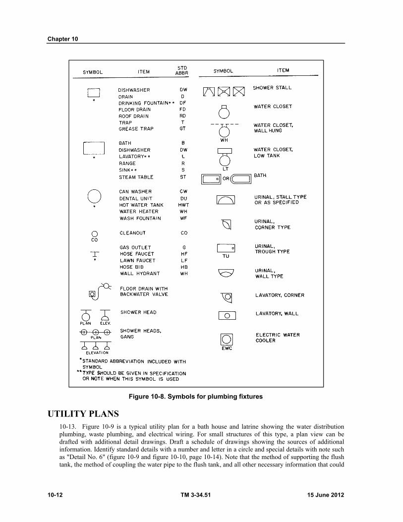
Chapter 10
10-12 TM 3-34.51 15 June 2012
Figure 10-8. Symbols for plumbing fixtures
UTILITY PLANS 10-13. Figure 10-9 is a typical utility plan for a bath house and latrine showing the water distribution plumbing, waste plumbing, and electrical wiring. For small structures of this type, a plan view can be drafted with additional detail drawings. Draft a schedule of drawings showing the sources of additional information. Identify standard details with a number and letter in a circle and special details with note such as "Detail No. 6" (figure 10-9 and figure 10-10, page 10-14). Note that the method of supporting the flush tank, the method of coupling the water pipe to the flush tank, and all other necessary information that could
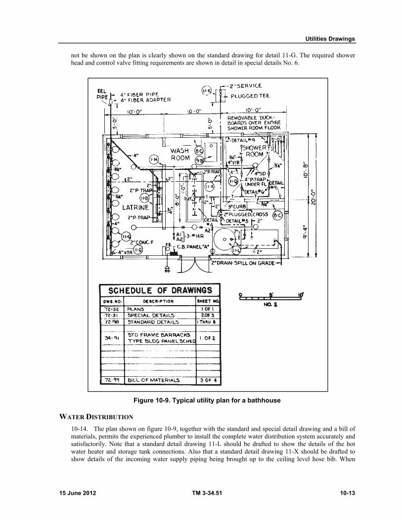
Utilities Drawings
15 June 2012 TM 3-34.51 10-13
not be shown on the plan is clearly shown on the standard drawing for detail 11-G. The required shower head and control valve fitting requirements are shown in detail in special details No. 6.
Figure 10-9. Typical utility plan for a bathhouse
WATER DISTRIBUTION
10-14. The plan shown on figure 10-9, together with the standard and special detail drawing and a bill of materials, permits the experienced plumber to install the complete water distribution system accurately and satisfactorily. Note that a standard detail drawing 11-L should be drafted to show the details of the hot water heater and storage tank connections. Also that a standard detail drawing 11-X should be drafted to show details of the incoming water supply piping being brought up to the ceiling level hose bib. When

Chapter 10
10-14 TM 3-34.51 15 June 2012
drafting such utility plans, check carefully to note that the pipe sizes and types are clearly specified in all cases.
Figure 10-10. Typical plumbing details
10-15. Waste System. The plan (figure 10-9, page 10-13) also shows the building waste system, making reference to standard and special details. Figure 10-11 shows a typical building waste system arrangement in an isometric diagram and other details.
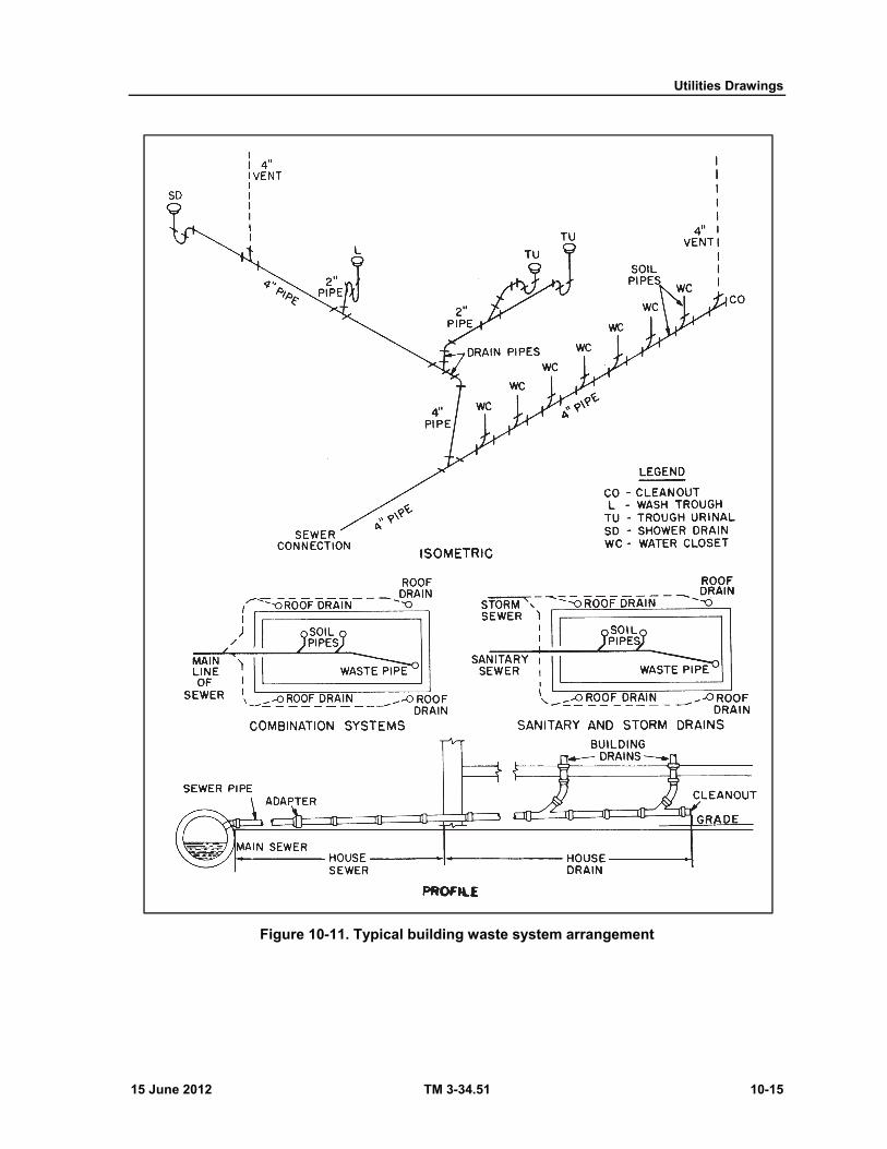
Utilities Drawings
15 June 2012 TM 3-34.51 10-15
Figure 10-11. Typical building waste system arrangement
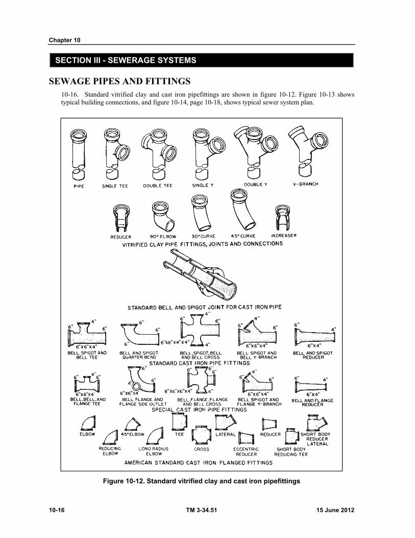
Chapter 10
10-16 TM 3-34.51 15 June 2012
SECTION III - SEWERAGE SYSTEMS
SEWAGE PIPES AND FITTINGS 10-16. Standard vitrified clay and cast iron pipefittings are shown in figure 10-12. Figure 10-13 shows typical building connections, and figure 10-14, page 10-18, shows typical sewer system plan.
Figure 10-12. Standard vitrified clay and cast iron pipefittings
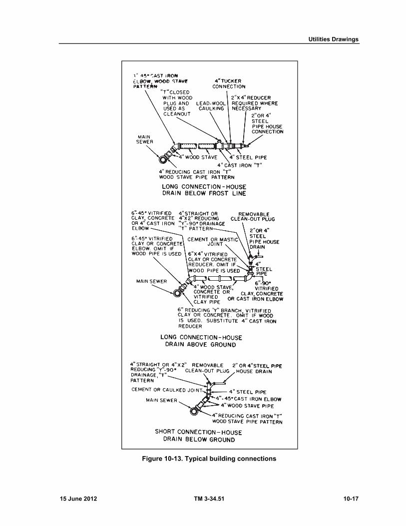
Utilities Drawings
15 June 2012 TM 3-34.51 10-17
Figure 10-13. Typical building connections
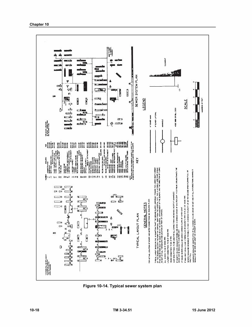
Chapter 10
10-18 TM 3-34.51 15 June 2012
Figure 10-14. Typical sewer system plan
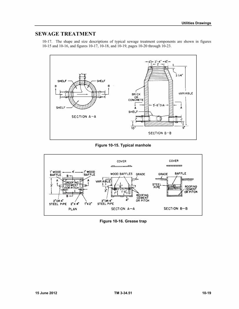
Utilities Drawings
15 June 2012 TM 3-34.51 10-19
SEWAGE TREATMENT 10-17. The shape and size descriptions of typical sewage treatment components are shown in figures 10-15 and 10-16, and figures 10-17, 10-18, and 10-19, pages 10-20 through 10-23.
Figure 10-15. Typical manhole
Figure 10-16. Grease trap
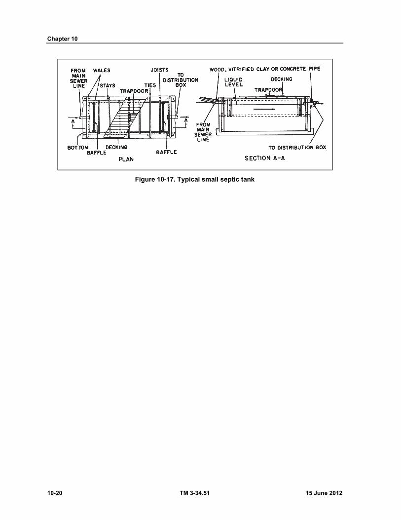
Chapter 10
10-20 TM 3-34.51 15 June 2012
Figure 10-17. Typical small septic tank

Utilities Drawings
15 June 2012 TM 3-34.51 10-21
Figure 10-18. Imhoff tank, 25,000 gallon capacity
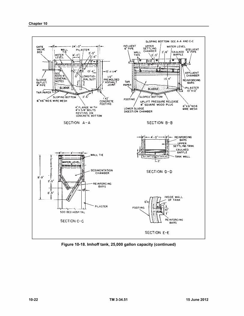
Chapter 10
10-22 TM 3-34.51 15 June 2012
Figure 10-18. Imhoff tank, 25,000 gallon capacity (continued)
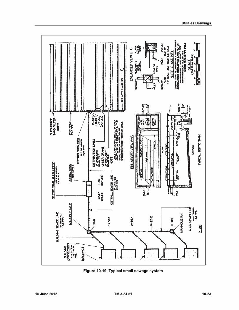
Utilities Drawings
15 June 2012 TM 3-34.51 10-23
Figure 10-19. Typical small sewage system
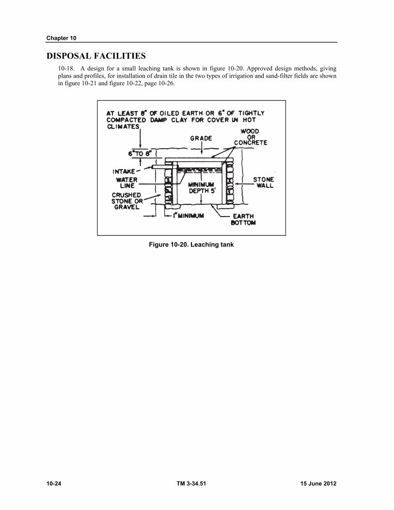
Chapter 10
10-24 TM 3-34.51 15 June 2012
DISPOSAL FACILITIES 10-18. A design for a small leaching tank is shown in figure 10-20. Approved design methods, giving plans and profiles, for installation of drain tile in the two types of irrigation and sand-filter fields are shown in figure 10-21 and figure 10-22, page 10-26.
Figure 10-20. Leaching tank

Utilities Drawings
15 June 2012 TM 3-34.51 10-25
Figure 10-21. Typical subsurface irrigation construction
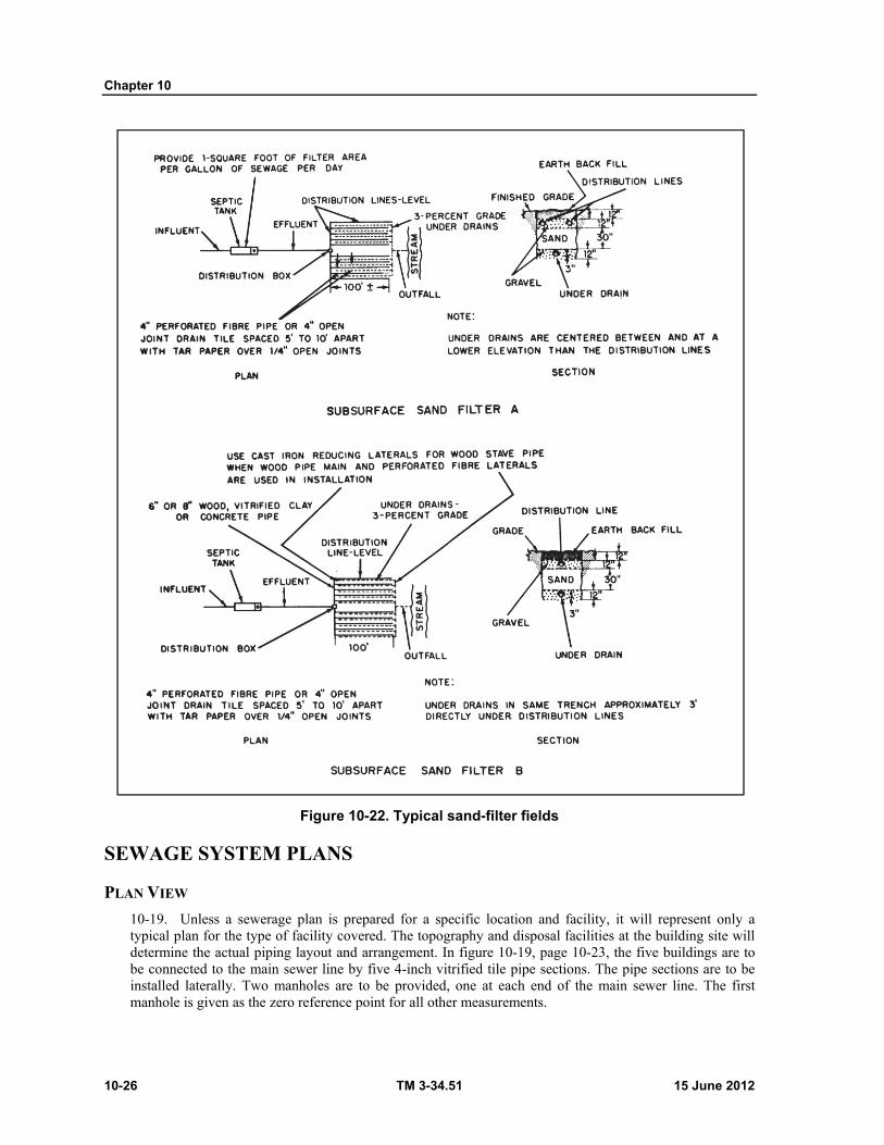
Chapter 10
10-26 TM 3-34.51 15 June 2012
Figure 10-22. Typical sand-filter fields
SEWAGE SYSTEM PLANS
PLAN VIEW
10-19. Unless a sewerage plan is prepared for a specific location and facility, it will represent only a typical plan for the type of facility covered. The topography and disposal facilities at the building site will determine the actual piping layout and arrangement. In figure 10-19, page 10-23, the five buildings are to be connected to the main sewer line by five 4-inch vitrified tile pipe sections. The pipe sections are to be installed laterally. Two manholes are to be provided, one at each end of the main sewer line. The first manhole is given as the zero reference point for all other measurements.

Utilities Drawings
15 June 2012 TM 3-34.51 10-27
PROFILE VIEW
10-20. The profile is taken along the path of sewage flow in the manner of an alined section. Figure 10-23, page 10-28, is the profile view that complements the plan of figure 10-19. To provide for easier reading, note that the vertical scale is expanded so that one square equals 1 foot whereas for the horizontal scale, one square equals 10 feet. Note that the floors of the buildings are shown at an elevation of 200 feet. It is common practice to assign a convenient round number to this reference point. The actual elevation might have been 196 or 207 feet, but for the purposes of convenience a value of 200 feet is used. All elevations are then referenced to this point.

Chapter 10
10-28 TM 3-34.51 15 June 2012
Figure 10-23. Typical small average system, profile view

Utilities Drawings
15 June 2012 TM 3-34.51 10-29
SECTION IV - ELECTRICAL DISTRIBUTION SYSTEM
DEFINITION 10-21. Electrical distribution is the delivery of power to the using premises from the power plant or substation through feeders and mains carried on poles or placed underground.
NOMENCLATURE 10-22. The general term "power system" covers the large-capacity wiring installations and associated equipment for the delivery of electrical energy from the point of generation to the point of use. The power system is generally considered to be a combination of two sections: the transmission section and the distribution section. The difference between the two sections depends on the function of each as defined below. At times, in small power systems, the difference tends to disappear and the transmission section merges with the distribution section, and the delivery network as a whole is referred to as the distribution section.
TRANSMISSION SECTION
10-23. A transmission section usually consists of step-up and step-down transformer stations, transmission lines, and switching or substations. The section is used for the transmission of bulk power to load centers or large industrial users, or both, beyond the economical service range of the regular primary distribution lines.
DISTRIBUTION SECTION
10-24. The distribution section usually consists of primary distribution lines or networks. The section is used to deliver power from generating stations or transmissions substations to various points of use. While the term "distribution section" is normally used to designate the outside lines, they are frequently continued inside the building to power outlets. These power outlets are distinct from the usual lighting circuits or interior wiring.
CONVENTIONS 10-25. The conventions used on the electrical utility plans are symbols that indicate the general layout, units, related equipment, and fixtures to be installed. Some of the most common symbols are shown in figures 10-24 and 10-25, pages 10-30 and 10-31. A more complete list is illustrated in appendix H. Tables 10-1 through 10-4 list the dimensions and current-carrying capacity for the most frequently used wire types and sizes. Sizes are listed by American Wire Gage (AWG) numbers.
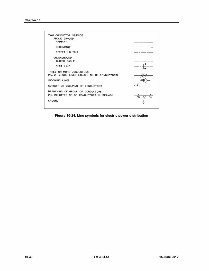
Chapter 10
10-30 TM 3-34.51 15 June 2012
Figure 10-24. Line symbols for electric power distribution
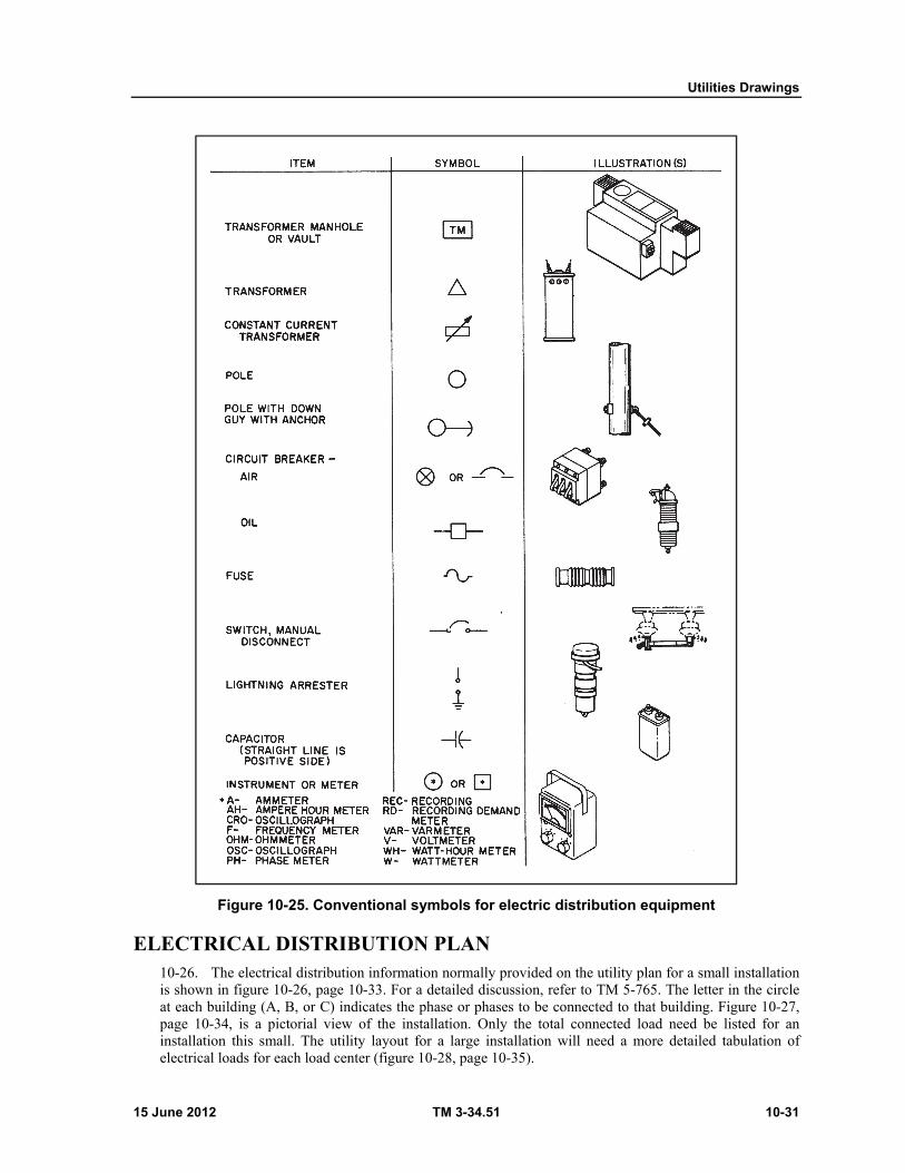
Utilities Drawings
15 June 2012 TM 3-34.51 10-31
Figure 10-25. Conventional symbols for electric distribution equipment
ELECTRICAL DISTRIBUTION PLAN 10-26. The electrical distribution information normally provided on the utility plan for a small installation is shown in figure 10-26, page 10-33. For a detailed discussion, refer to TM 5-765. The letter in the circle at each building (A, B, or C) indicates the phase or phases to be connected to that building. Figure 10-27, page 10-34, is a pictorial view of the installation. Only the total connected load need be listed for an installation this small. The utility layout for a large installation will need a more detailed tabulation of electrical loads for each load center (figure 10-28, page 10-35).
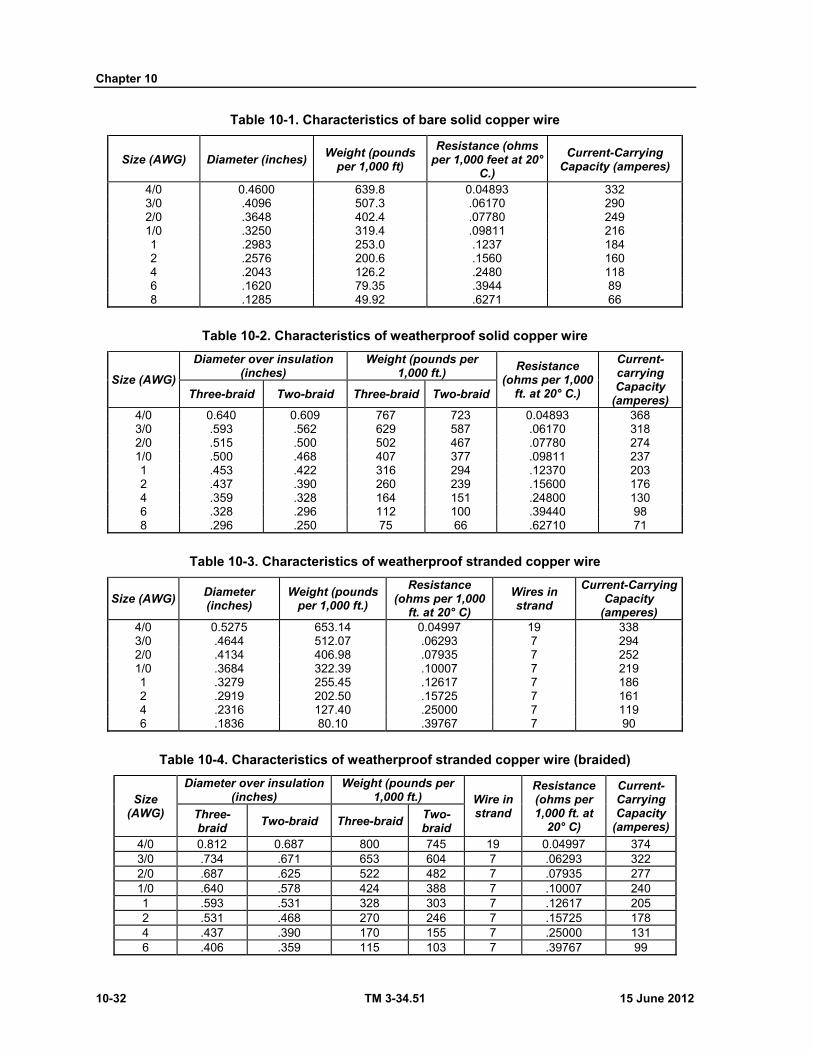
Chapter 10
10-32 TM 3-34.51 15 June 2012
Table 10-1. Characteristics of bare solid copper wire
Size (AWG) Diameter (inches) Weight (pounds
per 1,000 ft)
Resistance (ohms per 1,000 feet at 20°
C.)
Current-Carrying Capacity (amperes)
4/0 0.4600 639.8 0.04893 332 3/0 .4096 507.3 .06170 290 2/0 .3648 402.4 .07780 249 1/0 .3250 319.4 .09811 216 1 .2983 253.0 .1237 184 2 .2576 200.6 .1560 160 4 .2043 126.2 .2480 118 6 .1620 79.35 .3944 89 8 .1285 49.92 .6271 66
Table 10-2. Characteristics of weatherproof solid copper wire
Size (AWG)
Diameter over insulation (inches)
Weight (pounds per 1,000 ft.)
Resistance (ohms per 1,000
ft. at 20° C.)
Current-carrying Capacity
(amperes) Three-braid Two-braid Three-braid Two-braid
4/0 0.640 0.609 767 723 0.04893 368 3/0 .593 .562 629 587 .06170 318 2/0 .515 .500 502 467 .07780 274 1/0 .500 .468 407 377 .09811 237 1 .453 .422 316 294 .12370 203 2 .437 .390 260 239 .15600 176 4 .359 .328 164 151 .24800 130 6 .328 .296 112 100 .39440 98 8 .296 .250 75 66 .62710 71
Table 10-3. Characteristics of weatherproof stranded copper wire
Size (AWG) Diameter (inches)
Weight (pounds per 1,000 ft.)
Resistance (ohms per 1,000
ft. at 20° C)
Wires in strand
Current-Carrying Capacity
(amperes) 4/0 0.5275 653.14 0.04997 19 338 3/0 .4644 512.07 .06293 7 294 2/0 .4134 406.98 .07935 7 252 1/0 .3684 322.39 .10007 7 219 1 .3279 255.45 .12617 7 186 2 .2919 202.50 .15725 7 161 4 .2316 127.40 .25000 7 119 6 .1836 80.10 .39767 7 90
Table 10-4. Characteristics of weatherproof stranded copper wire (braided)
Size (AWG)
Diameter over insulation (inches)
Weight (pounds per 1,000 ft.) Wire in
strand
Resistance (ohms per 1,000 ft. at
20° C)
Current-Carrying Capacity
(amperes)Three-braid
Two-braid Three-braidTwo-braid
4/0 0.812 0.687 800 745 19 0.04997 374 3/0 .734 .671 653 604 7 .06293 322 2/0 .687 .625 522 482 7 .07935 277 1/0 .640 .578 424 388 7 .10007 240 1 .593 .531 328 303 7 .12617 205 2 .531 .468 270 246 7 .15725 178 4 .437 .390 170 155 7 .25000 131 6 .406 .359 115 103 7 .39767 99
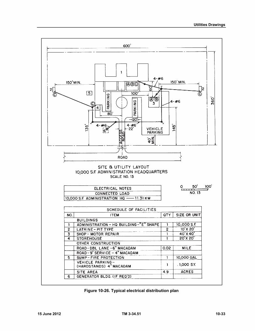
Utilities Drawings
15 June 2012 TM 3-34.51 10-33
Figure 10-26. Typical electrical distribution plan
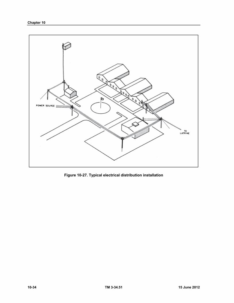
Chapter 10
10-34 TM 3-34.51 15 June 2012
Figure 10-27. Typical electrical distribution installation

Utilities Drawings
15 June 2012 TM 3-34.51 10-35
Figure 10-28. Typical tabulation of electrical loads
DETAIL DRAWINGS 10-27. To show complex installations, standard connection methods, and specifications, detail drawings should be drawn. Figure 10-29, page 10-36, illustrates the typical detail drawings for secondary power distribution connections. The first detail indicates the method of connecting service drops at a mast on a building. The second details the pole connection for both small and large angle turns. Figure 10-30, page 10-37, illustrates the type of detail drawing that should be used for complex installations. To give information, such as size and class of pole, dimension of cross arm, type and size of wire, height of platform, and transformer wiring, this type of drawing should be used. Table 10-5, pages 10-38 and 10-39, lists the characteristics of four types of poles for the various classes and sizes. When distribution lines are installed, specifications require proper tensioning. For this purpose it is helpful to show sag tables such as shown in tables 10-6 and 10-7, pages 10-39 and 10-40. For a detailed discussion refer to TM 5-765.
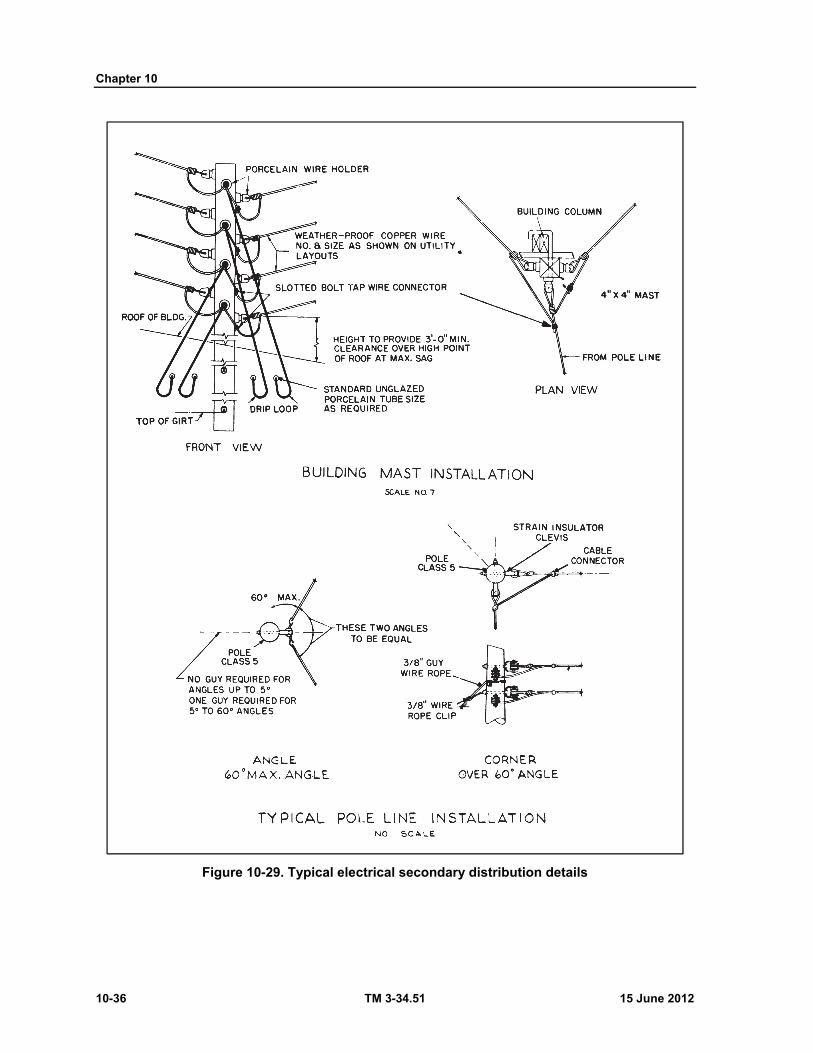
Chapter 10
10-36 TM 3-34.51 15 June 2012
Figure 10-29. Typical electrical secondary distribution details
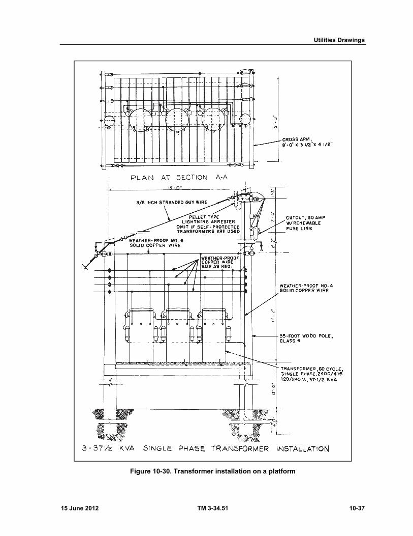
Utilities Drawings
15 June 2012 TM 3-34.51 10-37
Figure 10-30. Transformer installation on a platform

Chapter 10
10-38 TM 3-34.51 15 June 2012
Table 10-5. Classification of wood poles
Pole length (feet)
USA class
Minimum circum- ference at top
(inches)
Southern yellow pine
Chestnut Western red cedar Northern white cedar
Circum. 6 ft. from
butt (inches)
Resisting moment
Circum. 6 ft. from
butt finches)
Resisting moment
(ft-lb;
Circum. 6 ft. from
butt (inches)
Resisting moment
(ft-lb)
Circum. 6 ft. from
butt (inches)
Resisting moment
(ft-lb)
25 1 27 34.5 80,200 37.0 80,200 38.0 81,000 43.5 78,200
25 1 27 34.5 80,200 37.0 80,200 38.0 81,000 43.5 78,200
25 2 25 32.5 67,000 34.5 65,000 35.5 66,100 41.0 65,400
25 3 23 30.0 52,700 32.5 54,300 33.0 53,100 38.0 52,100
25 4 21 28.0 42,860 30.0 42,700 30.5 41,900 35.5 42,500
25 5 19 26.0 34,320 28.0 34,720 28.5 34,200 32.5 32,660
25 6 17 24.0 36,990 25.5 26,230 26.0 25,970 30.0 25,640
25 7 15 22.0 20,800 24.0 21,870 24.5 21,730 28.0 20,840
30 1 27 37.5 102,900 40.0 101,200 41.0 101,700 47.5 101,800
30 2 25 35.0 83,700 37.5 83,500 38.5 84,300 44.5 83,700
30 3 23 32.5 67,000 35.0 67,850 35.5 66,100 41.5 67,800
30 4 21 30.0 52,700 32.5 54,300 33.0 53,100 38.5 54,200
30 5 19 28.0 42,860 30.0 42,700 30.5 41,900 35.5 42,500
30 6 17 26.0 34,320 28.0 34,720 28.5 34,200 33.0 34,100
30 7 15 24.0 26,990 26.0 27,820 26.5 27,500 30.5 26,930
35 1 27 40.0 124,900 42.5 121,400 43.5 121,600 50.5 122,300
35 2 25 37.5 102,900 40.0 101,200 41.0 101,700 47.5 101,800
35 3 23 35.0 83,700 37.5 83,500 38.0 81,000 44.0 80,900
35 4 21 32.0 64,000 34.5 65,000 35.0 63,350 41.0 65,400
35 5 19 30.0 52,700 32.0 51,900 32.5 50,700 38.0 52,100
35 6 17 27.5 40,600 30.0 42,700 30.5 41,900 35.0 40,700
35 7 15 25.5 32,380 27.5 32,920 28.0 32,410 32.5 32,600
40 1 27 42.0 144,600 45.0 144,100 46.0 143,800 53.5 145,500
40 2 25 39.5 120,300 42.5 121,400 43.5 121,600 50.0 118,700
40 3 23 37.0 98,900 39.5 97,500 40.5 98,100 46.5 95,500
40 4 21 34.0 76,700 36.5 77,000 37.5 77,900 43.5 78,200
40 5 19 31.5 60,900 34.0 62,200 34.5 60,700 40.0 60,800
40 6 17 29.0 47,600 31.5 49,400 32.0 48,400 37.0 48,100
40 7 15 27.0 38,400 29.5 40,600
45 1 27 44.0 166,300 47.5 169,600 48.5 168,500 56.0 166,800
45 2 25 41.5 139,400 44.5 139,500 45.5 139,100 52.5 137,400
45 3 23 38.5 111,400 41.5 113,000 42.5 113,400 49.0 111,600
45 4 21 36.0 91,100 38.5 90,300 39.5 91,000 45.5 89,500
45 5 19 33.0 70,200 36.0 73,800 36.5 71,800 42.0 70,300
45 6 17 30.5 55,400 33.0 56,800
45 7 15 28.5 45,200 31.0 47,200
50 1 27 46.0 190,000 49.5 191,900 50.5 190,200 58.5 190,100
50 2 25 43.0 155,200 46.5 159,000 47.5 158,300 55.0 158,000
50 3 23 40.0 124,900 43.5 130,200 44.5 130,100 51.5 129,500
50 4 21 37.5 102,900 40.0 101,200 41.0 101,700 47.5 101,800
50 5 19 34.5 80,200 37.5 83,500 38.0 81,000 44.0 80,900
50 6 17 32.0 64,000 34.5 65,000
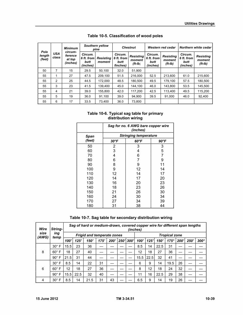
Utilities Drawings
15 June 2012 TM 3-34.51 10-39
Table 10-5. Classification of wood poles
Pole length (feet)
USA class
Minimum circum- ference at top
(inches)
Southern yellow pine
Chestnut Western red cedar Northern white cedar
Circum. 6 ft. from
butt (inches)
Resisting moment
Circum. 6 ft. from
butt finches)
Resisting moment
(ft-lb;
Circum. 6 ft. from
butt (inches)
Resisting moment
(ft-lb)
Circum. 6 ft. from
butt (inches)
Resisting moment
(ft-lb)
50 7 15 29.5 50,100 32.0 51,900
55 1 27 47.5 209,100 51.5 216,000 52.5 213,600 61.0 215,600
55 2 25 44.5 172,000 48.5 180,500 49.5 179,100 57.5 180,500
55 3 23 41.5 139,400 45.0 144,100 46.0 143,800 53.5 145,500
55 4 21 39.0 155,800 42.0 117,200 42.5 113,400 49.5 115,200
55 5 19 36.0 91,100 39.0 94,900 39.5 91,000 46.0 92,400
55 6 17 33.5 73,400 36.0 73,800
Table 10-6. Typical sag table for primary distribution wiring
Sag for no. 6 AWG bare copper wire
(inches)
Span (feet)
Stringing temperature
30°F 60°F 90°F
50 2 3 3 60 3 4 5 70 4 6 7 80 6 7 9 90 8 9 11
100 9 12 14 110 12 14 17 120 14 17 20 130 16 20 23 140 18 23 26 150 21 26 30 160 24 30 34 170 27 34 39 180 31 38 44
Table 10-7. Sag table for secondary distribution wiring
Wire size
(AWG)
String- ing
temp
Sag of hard or medium-drawn, covered copper wire for different span lengths (inches)
Frigid and temperate zones Tropical zone
100' 125' 150' 175' 200' 250' 300' 100' 125' 150' 175* 200' 250' 300*
8
30° F 15.5 23 36 — — — — 8.5 14 22.5 31 — — —
60° F 18 27 40 — — — — 12 18 27 36 — — —
90° F 21.5 31 44 — — — — 15.5 22.5 32 41 — — —
6
30° F 8.5 14 22 31 — — — 6 9 14 19.5 26 — —
60° F 12 18 27 36 — — — 8 12 18 24 32 — —
90° F 15.5 22.5 32 40 — — — 11 16 22.5 29 38 — —
4 30° F 8.5 14 21.5 31 43 — — 6.5 9 14 19 26 — —
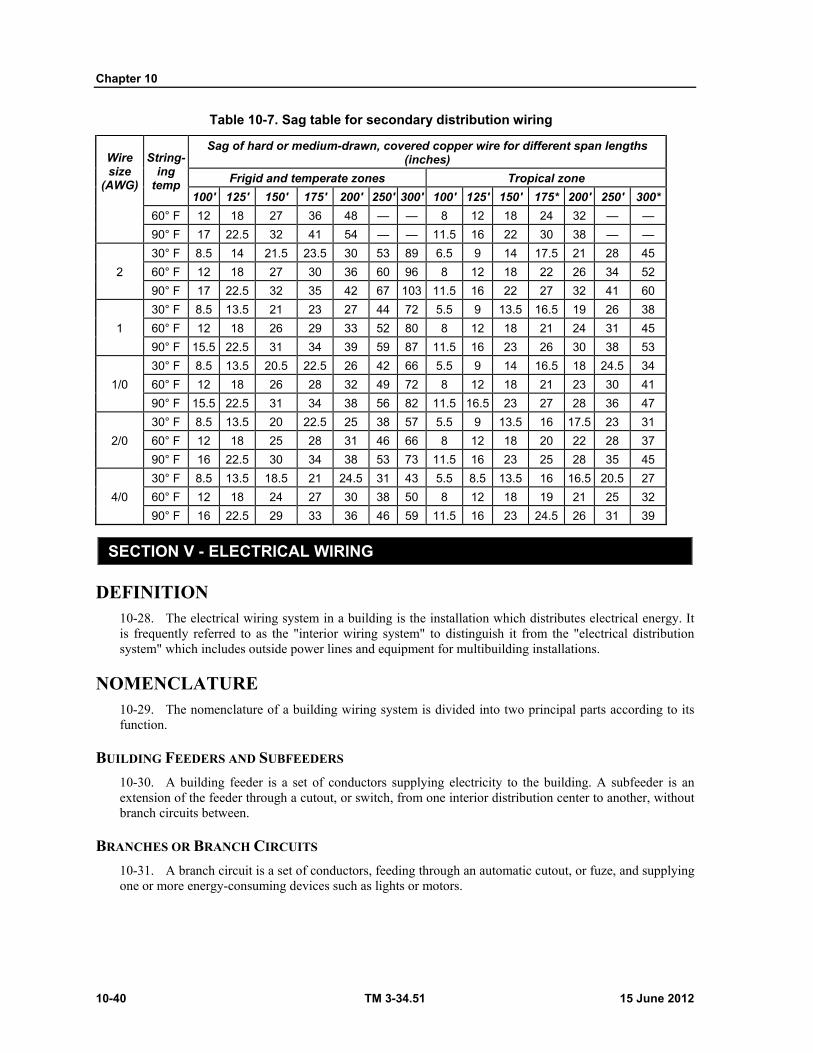
Chapter 10
10-40 TM 3-34.51 15 June 2012
Table 10-7. Sag table for secondary distribution wiring
Wire size
(AWG)
String- ing
temp
Sag of hard or medium-drawn, covered copper wire for different span lengths (inches)
Frigid and temperate zones Tropical zone
100' 125' 150' 175' 200' 250' 300' 100' 125' 150' 175* 200' 250' 300*
60° F 12 18 27 36 48 — — 8 12 18 24 32 — —
90° F 17 22.5 32 41 54 — — 11.5 16 22 30 38 — —
2
30° F 8.5 14 21.5 23.5 30 53 89 6.5 9 14 17.5 21 28 45
60° F 12 18 27 30 36 60 96 8 12 18 22 26 34 52
90° F 17 22.5 32 35 42 67 103 11.5 16 22 27 32 41 60
1
30° F 8.5 13.5 21 23 27 44 72 5.5 9 13.5 16.5 19 26 38
60° F 12 18 26 29 33 52 80 8 12 18 21 24 31 45
90° F 15.5 22.5 31 34 39 59 87 11.5 16 23 26 30 38 53
1/0
30° F 8.5 13.5 20.5 22.5 26 42 66 5.5 9 14 16.5 18 24.5 34
60° F 12 18 26 28 32 49 72 8 12 18 21 23 30 41
90° F 15.5 22.5 31 34 38 56 82 11.5 16.5 23 27 28 36 47
2/0
30° F 8.5 13.5 20 22.5 25 38 57 5.5 9 13.5 16 17.5 23 31
60° F 12 18 25 28 31 46 66 8 12 18 20 22 28 37
90° F 16 22.5 30 34 38 53 73 11.5 16 23 25 28 35 45
4/0
30° F 8.5 13.5 18.5 21 24.5 31 43 5.5 8.5 13.5 16 16.5 20.5 27
60° F 12 18 24 27 30 38 50 8 12 18 19 21 25 32
90° F 16 22.5 29 33 36 46 59 11.5 16 23 24.5 26 31 39
SECTION V - ELECTRICAL WIRING
DEFINITION 10-28. The electrical wiring system in a building is the installation which distributes electrical energy. It is frequently referred to as the "interior wiring system" to distinguish it from the "electrical distribution system" which includes outside power lines and equipment for multibuilding installations.
NOMENCLATURE 10-29. The nomenclature of a building wiring system is divided into two principal parts according to its function.
BUILDING FEEDERS AND SUBFEEDERS
10-30. A building feeder is a set of conductors supplying electricity to the building. A subfeeder is an extension of the feeder through a cutout, or switch, from one interior distribution center to another, without branch circuits between.
BRANCHES OR BRANCH CIRCUITS
10-31. A branch circuit is a set of conductors, feeding through an automatic cutout, or fuze, and supplying one or more energy-consuming devices such as lights or motors.

Utilities Drawings
15 June 2012 TM 3-34.51 10-41
ELECTRICAL SYMBOLS AND WIRE SIZES 10-32. A variety of materials and fittings are used in the installation of electrical wiring. Table 10-8, page 10-42 and 10-43, lists the wire sizes required for various distances between supply and load, at different load currents, and the service-wire requirements and capacities. The common symbols used on electrical plans to show the routing and interconnection of wiring are shown in figure 10-31, page 10-43. The symbols for various switches and outlets are shown in figure 10-32, pages 10-44 and 10-45.

Chapter 10
10-42 TM 3-34.51 15 June 2012
Table 10-8. Minimum wire sizes
Wire size for 120-voIt single phase circuit
Load (amps)
Minimum wire size (AWG)
Service wire size (AWG)
Wire size (AWG)
Distance one way from supply to load (ft.)
50 75 100 125 150 175 200 250 300 350 400 450 500
15 14 10 14 12 10 8 8 6 6 6 4 4 4
20 14 10 12 10 8 8 6 6 6 4 4 2 2 2 2
25 12 8 10 8 8 6 6 4 4 4 2 2 2 1 1
30 12 8 10 8 6 6 4 4 4 2 2 1 1 0 0
35 12 6 8 6 6 4 4 4 2 2 1 1 0 0 2/0
40 10 6 8 6 6 4 4 2 2 2 1 0 0 2/0 2/0
45 10 6 8 6 4 4 2 2 2 1 0 0 2/0 2/0 3/0
50 10 6 8 6 4 4 2 2 2 1 0 2/0 2/0 3/0 3/0
55 8 4 6 4 4 2 2 2 1 0 2/0 2/0 3/0 3/0 4/0
60 8 4 6 4 4 2 2 1 1 0 2/0 3/0 3/0 4/0 4/0
65 8 4 6 4 4 2 2 1 0 2/0 2/0 3/0 4/0 4/0
70 8 4 6 4 2 2 1 1 0 2/0 2/0 3/0 4/0 4/0
76 6 4 6 4 2 2 1 0 0 2/0 3/0 4/0
80 6 4 6 4 2 2 1 0 0 2/0 3/0 4/0 4/0
85 6 4 4 4 2 1 1 0 2/0 3/0 3/0 4/0
90 6 2 4 2 2 1 0 0 2/0 3/0 4/0 4/0
95 6 2 4 2 2 1 0 2/0 2/0 3/0 4/0
100 4 2 4 2 2 1 0 2/0 2/0 3/0 4/0
Wire size for 220-voIt three phase circuits
Load (amps)
Minimum wire size (AWG)
Service wire size (AWG)
Wire size (AWG)
Distance one way from supply to load (ft.)
100 150 200 250 300 350 400 500 600 700 800 900 1,000
15 14 12 14 12 10 8 8 8 6 6 6 4 4 4 2
20 14 10 12 10 8 8 6 6 6 4 4 4 2 2 2
25 12 8 10 8 8 6 6 6 4 4 2 2 2 2 1
30 12 8 10 8 6 6 6 4 4 2 2 2 1 1 0
35 12 8 10 8 6 6 4 4 4 2 2 1 1 0 0
40 10 6 8 6 6 4 4 4 2 1 1 1 0 0 2/0
45 10 6 8 6 6 4 4 2 2 2 1 0 0 2/0 2/0
50 10 6 8 6 4 4 2 2 2 1 0 0 2/0 2/0 3/0
55 8 6 8 6 4 4 2 2 2 1 0 2/0 2/0 3/0 3/0
60 8 6 6 6 4 2 2 2 1 0 0 2/0 3/0 3/0 4/0
6b 8 4 6 4 4 2 2 2 1 0 2/0 2/0 3/0 3/0 4/0
70 8 4 6 4 4 2 2 1 1 0 2/0 3/0 3/0 4/0 4/0
75 6 4 6 4 2 2 2 1 0 2/0 2/0 3/0 4/0 4/0
80 6 4 6 4 2 2 1 1 0 2/0 3/0 3/0 4/0 4/0
85 6 4 6 4 2 2 1 0 0 2/0 3/0 4/0 4/0
90 6 4 6 4 2 2 1 0 0 2/0 3/0 4/0 4/0
95 6 4 6 4 2 1 1 0 2/0 3/0 3/0 4/0
100 4 2 4 2 2 1 0 0 2/0 3/0 4/0 4/0
125 4 2 4 2 1 0 2/0 2/0 3/0 4/0
150 2 2 2 2 0 2/0 2/0 3/0 4/0
175 2 1 2 1 0 2/0 3/0 4/0 4/0
200 1 0 1 0 2/0 3/0 4/0 4/0
225 0 0 0 0 2/0 3/0 4/0
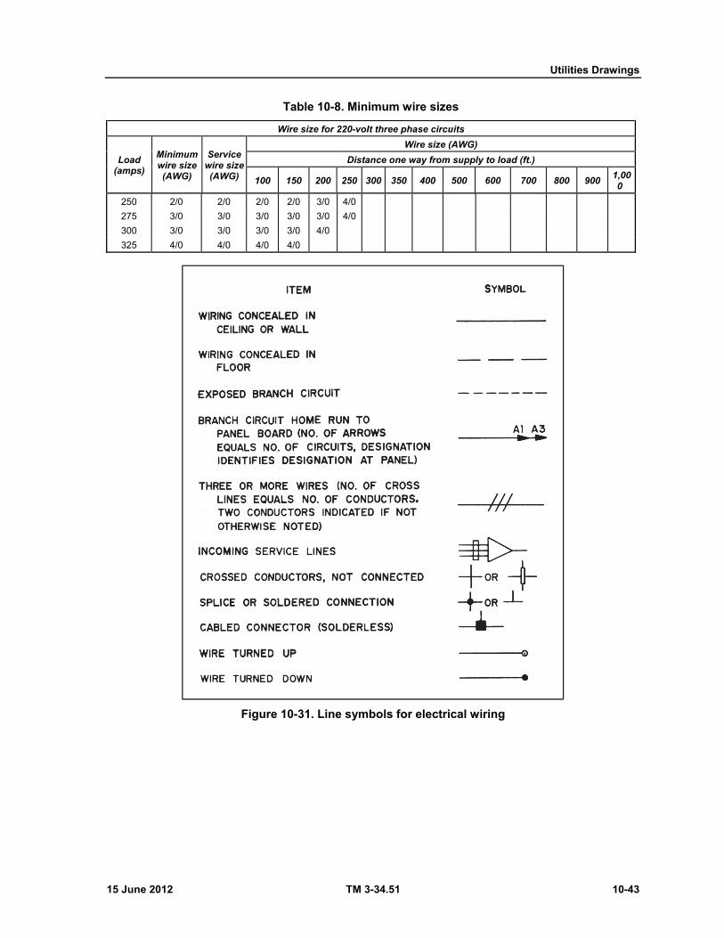
Utilities Drawings
15 June 2012 TM 3-34.51 10-43
Table 10-8. Minimum wire sizes
Wire size for 220-voIt three phase circuits
Load (amps)
Minimum wire size (AWG)
Service wire size (AWG)
Wire size (AWG)
Distance one way from supply to load (ft.)
100 150 200 250 300 350 400 500 600 700 800 900 1,000
250 2/0 2/0 2/0 2/0 3/0 4/0
275 3/0 3/0 3/0 3/0 3/0 4/0
300 3/0 3/0 3/0 3/0 4/0
325 4/0 4/0 4/0 4/0
Figure 10-31. Line symbols for electrical wiring

Chapter 10
10-44 TM 3-34.51 15 June 2012
Figure 10-32. Symbols for electrical fixtures and controls
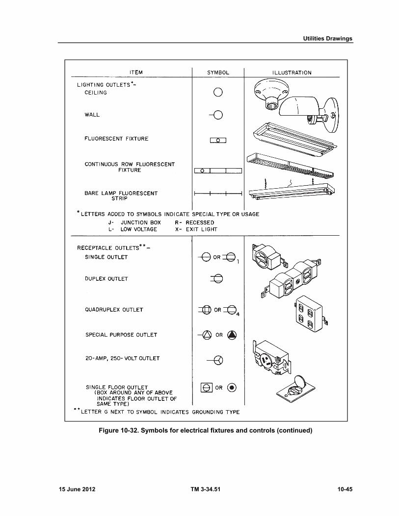
Utilities Drawings
15 June 2012 TM 3-34.51 10-45
Figure 10-32. Symbols for electrical fixtures and controls (continued)
Chapter 10
10-46 TM 3-34.51 15 June 2012
ELECTRICAL PLANS 10-33. Electrical plans show what items are to be installed, their approximate location, and the circuits to which they are to be connected. A typical electrical plan for a post exchange is shown in figure 10-33. The plan shows that the incoming service consists of three No. 8 wires and that two circuit-breaker panels are to be installed. Starting at the upper left, the plan shows that nine ceiling lighting outlets and two duplex wall outlets are to be installed in the bulk storage area. The arrow designated "B2" indicates that these outlets are to be connected to circuit 2 of circuit-breaker panel B. Note that three wires are indicated from this point to the double home-run arrows designated "B1, B2." These are the hot wire from the bulk storage area to circuit 2 of panel B, the hot wire from the administration area to circuit 1 of panel B, and a common neutral. From the double arrowhead, these wires are run to the circuit breaker panel without additional connections. This run is shown at the left side of figure 10-34, page 10-48, which is typical of the ceiling wiring diagrams provided for open wiring of medium or extreme complexity. Note that the entire installation is not shown in figure 10-34. The diagram shows the splices, support, and insulator arrangements used. Note that this is a physical drawing rather than symbolic one, so each line represents a single wire rather than a pair of conductors as in the plan. A note calls out a circuit breaker installation detail at the point where the wires are down to the circuit-breaker panel, and the arrowheads on the leader from the note show the direction from which the circuit breaker installation detail is drawn. The circuit breaker panel installation detail (figure 10-35, page 10-49) shows the installation arrangement for the circuit breakers, including grounding, splices, and connections to the incoming service. Note that the circuit breaker panels are placed 5 feet 6 inches from the floor line, and that a 3/4-inch pipe driven 8 feet into the ground is used for grounding the No. 8 ground wire.
10-34. In some installations, alternate outlets are connected to different circuits so that half the lighting may be turned on at one time and only part of the service will be out if a circuit breaker is tripped. For these plans, the circuit identification (Al, B1, and so on) is noted alongside each fixture.
10-35. Wiring plans are not usually provided for the fixtures themselves. If the connections are not obvious, diagrams are normally supplied with the device. A three-way switch circuit, which enables the control of a single outlet from two locations, is shown in figure 10-36, page 10-49. On an electrical plan you will find the three-way switch is indicated by the symbol S3.
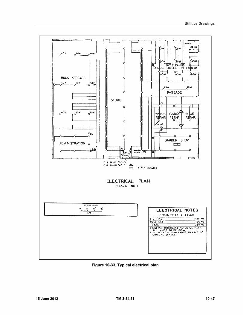
Utilities Drawings
15 June 2012 TM 3-34.51 10-47
Figure 10-33. Typical electrical plan
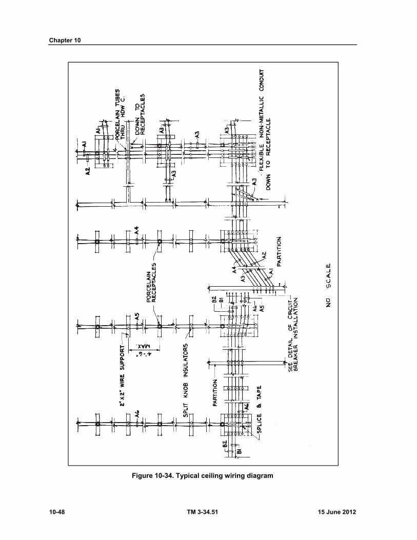
Chapter 10
10-48 TM 3-34.51 15 June 2012
Figure 10-34. Typical ceiling wiring diagram
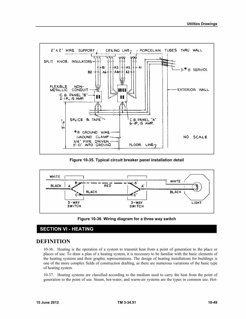
Utilities Drawings
15 June 2012 TM 3-34.51 10-49
Figure 10-35. Typical circuit breaker panel installation detail
Figure 10-36. Wiring diagram for a three way switch
SECTION VI - HEATING
DEFINITION 10-36. Heating is the operation of a system to transmit heat from a point of generation to the place or places of use. To draw a plan of a heating system, it is necessary to be familiar with the basic elements of the heating systems and their graphic representations. The design of heating installations for buildings is one of the more complex fields of construction drafting, as there are numerous variations of the basic type of heating system.
10-37. Heating systems are classified according to the medium used to carry the heat from the point of generation to the point of use. Steam, hot-water, and warm-air systems are the types in common use. Hot-

Chapter 10
10-50 TM 3-34.51 15 June 2012
water heating is used extensively. Warm-air heating is probably the most familiar because it is used in almost all semipermanent construction and most barracks.
10-38. Because of the numerous variations, any discussion of the heating systems must be limited. Only symbols for the more common types of piping, fittings, traps, valves, heat-power apparatus, and fluid-power diagram symbols are presented in figures 10-37 and 10-38, and figures 10-39 through 10-41, pages 10-52 through 10-54. Additional symbols are listed in appendix F. For a detailed discussion of heating refer to TM 5-745.
Figure 10-37. Heating piping symbols
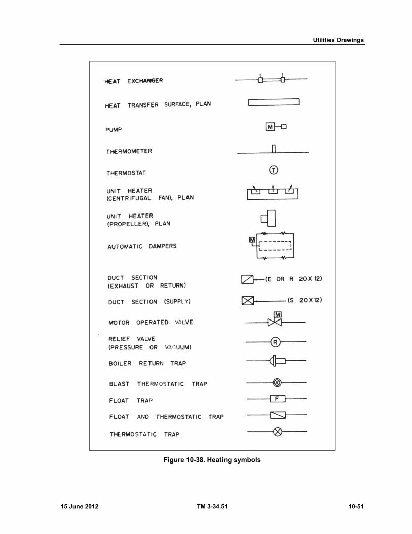
Utilities Drawings
15 June 2012 TM 3-34.51 10-51
Figure 10-38. Heating symbols
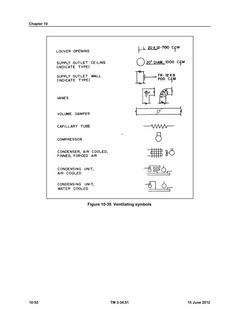
Chapter 10
10-52 TM 3-34.51 15 June 2012
Figure 10-39. Ventilating symbols
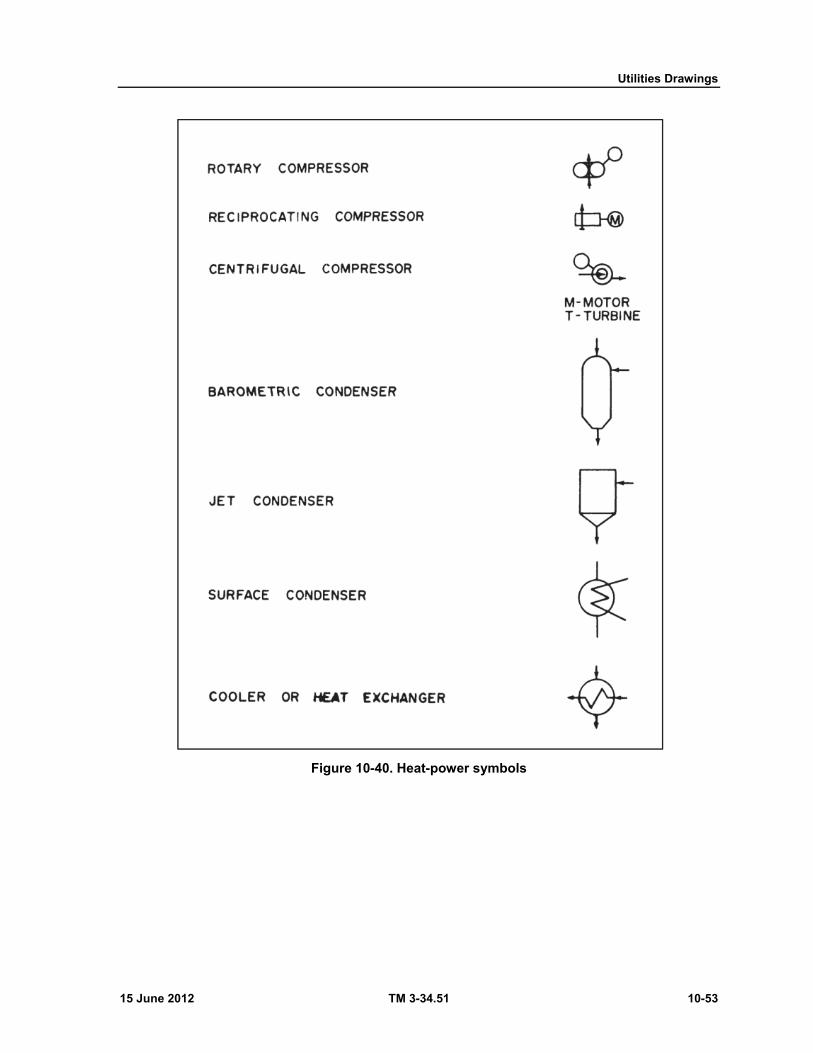
Utilities Drawings
15 June 2012 TM 3-34.51 10-53
Figure 10-40. Heat-power symbols
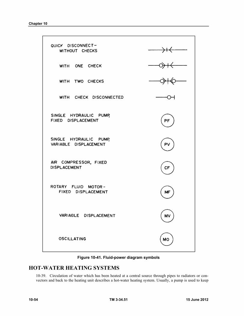
Chapter 10
10-54 TM 3-34.51 15 June 2012
Figure 10-41. Fluid-power diagram symbols
HOT-WATER HEATING SYSTEMS 10-39. Circulation of water which has been heated at a central source through pipes to radiators or con-vectors and back to the heating unit describes a hot-water heating system. Usually, a pump is used to keep
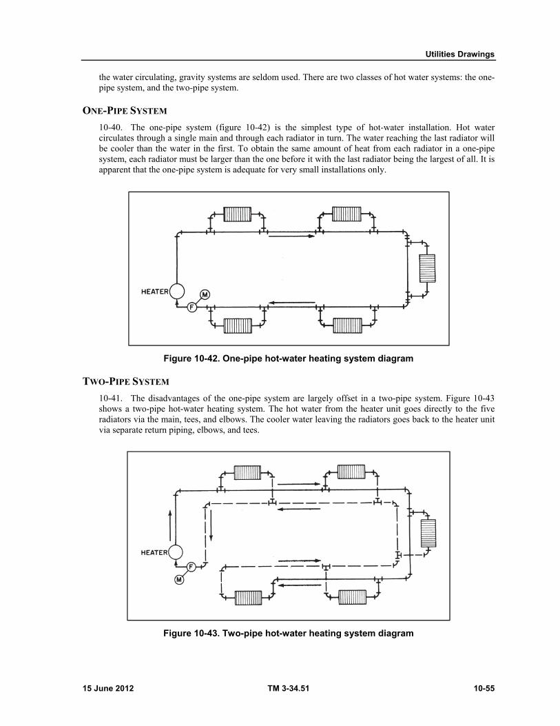
Utilities Drawings
15 June 2012 TM 3-34.51 10-55
the water circulating, gravity systems are seldom used. There are two classes of hot water systems: the one-pipe system, and the two-pipe system.
ONE-PIPE SYSTEM
10-40. The one-pipe system (figure 10-42) is the simplest type of hot-water installation. Hot water circulates through a single main and through each radiator in turn. The water reaching the last radiator will be cooler than the water in the first. To obtain the same amount of heat from each radiator in a one-pipe system, each radiator must be larger than the one before it with the last radiator being the largest of all. It is apparent that the one-pipe system is adequate for very small installations only.
Figure 10-42. One-pipe hot-water heating system diagram
TWO-PIPE SYSTEM
10-41. The disadvantages of the one-pipe system are largely offset in a two-pipe system. Figure 10-43 shows a two-pipe hot-water heating system. The hot water from the heater unit goes directly to the five radiators via the main, tees, and elbows. The cooler water leaving the radiators goes back to the heater unit via separate return piping, elbows, and tees.
Figure 10-43. Two-pipe hot-water heating system diagram
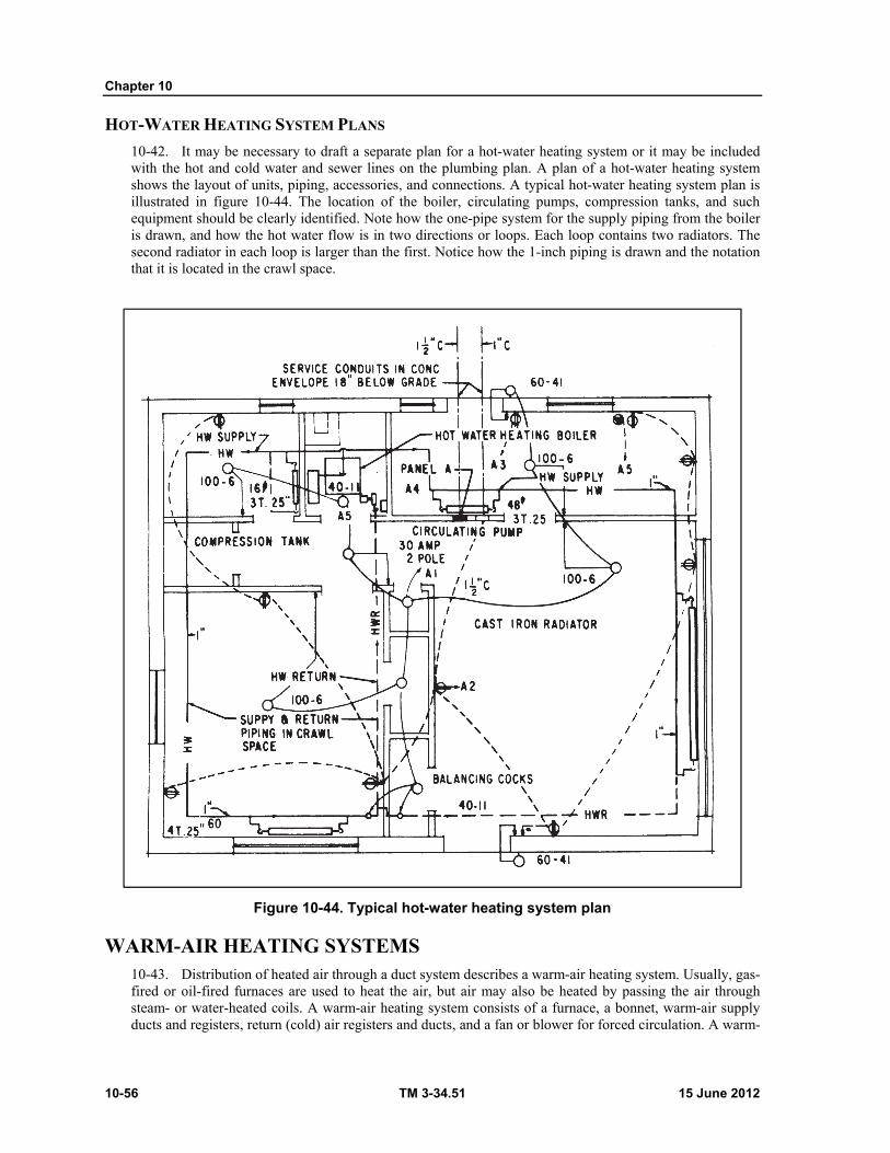
Chapter 10
10-56 TM 3-34.51 15 June 2012
HOT-WATER HEATING SYSTEM PLANS
10-42. It may be necessary to draft a separate plan for a hot-water heating system or it may be included with the hot and cold water and sewer lines on the plumbing plan. A plan of a hot-water heating system shows the layout of units, piping, accessories, and connections. A typical hot-water heating system plan is illustrated in figure 10-44. The location of the boiler, circulating pumps, compression tanks, and such equipment should be clearly identified. Note how the one-pipe system for the supply piping from the boiler is drawn, and how the hot water flow is in two directions or loops. Each loop contains two radiators. The second radiator in each loop is larger than the first. Notice how the 1-inch piping is drawn and the notation that it is located in the crawl space.
Figure 10-44. Typical hot-water heating system plan
WARM-AIR HEATING SYSTEMS 10-43. Distribution of heated air through a duct system describes a warm-air heating system. Usually, gas-fired or oil-fired furnaces are used to heat the air, but air may also be heated by passing the air through steam- or water-heated coils. A warm-air heating system consists of a furnace, a bonnet, warm-air supply ducts and registers, return (cold) air registers and ducts, and a fan or blower for forced circulation. A warm-
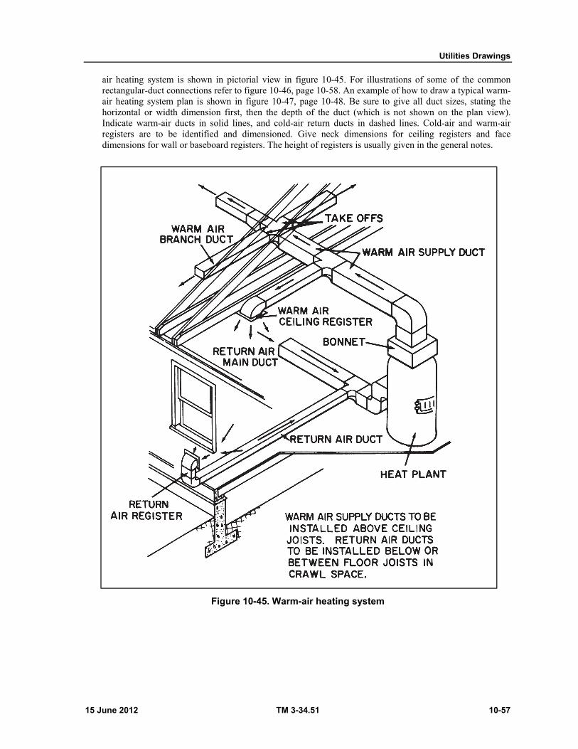
Utilities Drawings
15 June 2012 TM 3-34.51 10-57
air heating system is shown in pictorial view in figure 10-45. For illustrations of some of the common rectangular-duct connections refer to figure 10-46, page 10-58. An example of how to draw a typical warm-air heating system plan is shown in figure 10-47, page 10-48. Be sure to give all duct sizes, stating the horizontal or width dimension first, then the depth of the duct (which is not shown on the plan view). Indicate warm-air ducts in solid lines, and cold-air return ducts in dashed lines. Cold-air and warm-air registers are to be identified and dimensioned. Give neck dimensions for ceiling registers and face dimensions for wall or baseboard registers. The height of registers is usually given in the general notes.
Figure 10-45. Warm-air heating system

Chapter 10
10-58 TM 3-34.51 15 June 2012
Figure 10-46. Common duct connections
Figure 10-47. Typical warm-air heating system plan.
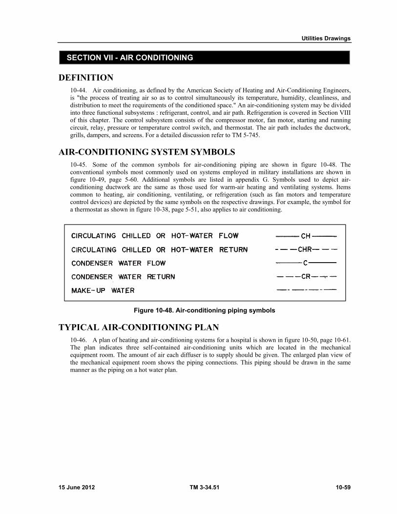
Utilities Drawings
15 June 2012 TM 3-34.51 10-59
SECTION VII - AIR CONDITIONING
DEFINITION 10-44. Air conditioning, as defined by the American Society of Heating and Air-Conditioning Engineers, is "the process of treating air so as to control simultaneously its temperature, humidity, cleanliness, and distribution to meet the requirements of the conditioned space." An air-conditioning system may be divided into three functional subsystems : refrigerant, control, and air path. Refrigeration is covered in Section VIII of this chapter. The control subsystem consists of the compressor motor, fan motor, starting and running circuit, relay, pressure or temperature control switch, and thermostat. The air path includes the ductwork, grills, dampers, and screens. For a detailed discussion refer to TM 5-745.
AIR-CONDITIONING SYSTEM SYMBOLS 10-45. Some of the common symbols for air-conditioning piping are shown in figure 10-48. The conventional symbols most commonly used on systems employed in military installations are shown in figure 10-49, page 5-60. Additional symbols are listed in appendix G. Symbols used to depict air-conditioning ductwork are the same as those used for warm-air heating and ventilating systems. Items common to heating, air conditioning, ventilating, or refrigeration (such as fan motors and temperature control devices) are depicted by the same symbols on the respective drawings. For example, the symbol for a thermostat as shown in figure 10-38, page 5-51, also applies to air conditioning.
Figure 10-48. Air-conditioning piping symbols
TYPICAL AIR-CONDITIONING PLAN 10-46. A plan of heating and air-conditioning systems for a hospital is shown in figure 10-50, page 10-61. The plan indicates three self-contained air-conditioning units which are located in the mechanical equipment room. The amount of air each diffuser is to supply should be given. The enlarged plan view of the mechanical equipment room shows the piping connections. This piping should be drawn in the same manner as the piping on a hot water plan.
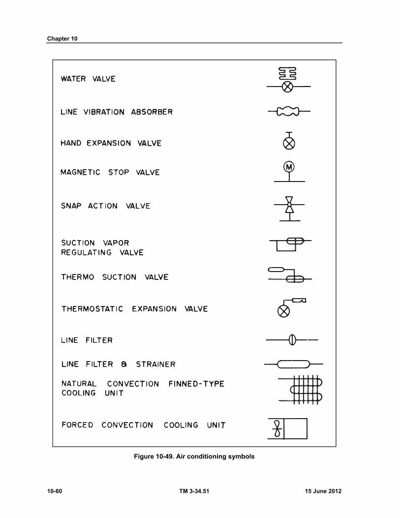
Chapter 10
10-60 TM 3-34.51 15 June 2012
Figure 10-49. Air conditioning symbols
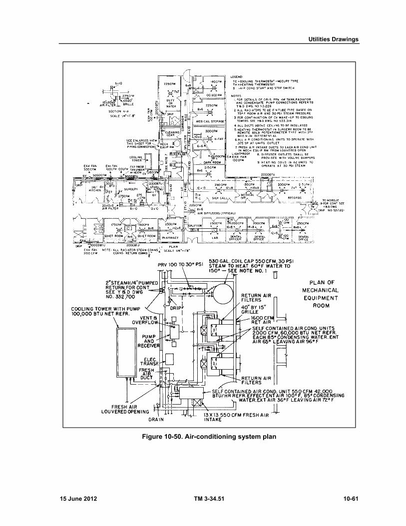
Utilities Drawings
15 June 2012 TM 3-34.51 10-61
Figure 10-50. Air-conditioning system plan
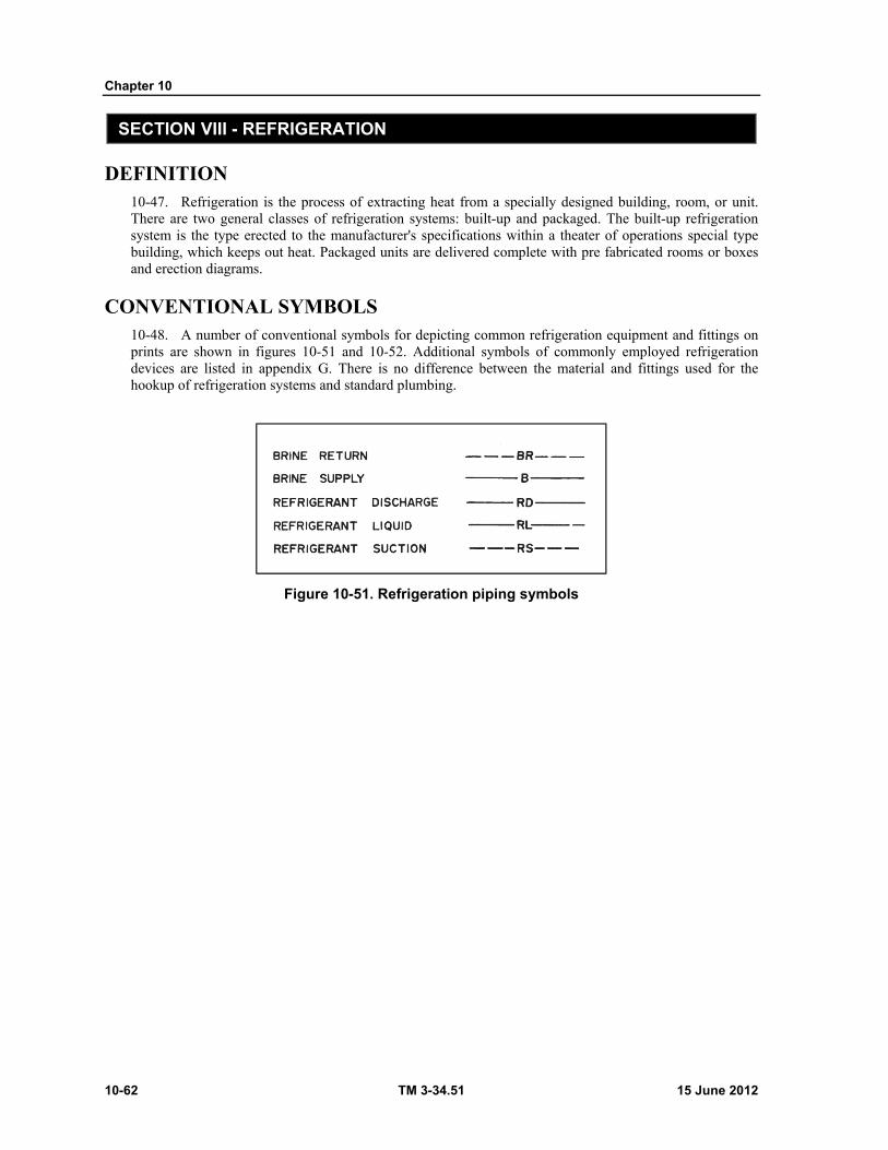
Chapter 10
10-62 TM 3-34.51 15 June 2012
SECTION VIII - REFRIGERATION
DEFINITION 10-47. Refrigeration is the process of extracting heat from a specially designed building, room, or unit. There are two general classes of refrigeration systems: built-up and packaged. The built-up refrigeration system is the type erected to the manufacturer's specifications within a theater of operations special type building, which keeps out heat. Packaged units are delivered complete with pre fabricated rooms or boxes and erection diagrams.
CONVENTIONAL SYMBOLS 10-48. A number of conventional symbols for depicting common refrigeration equipment and fittings on prints are shown in figures 10-51 and 10-52. Additional symbols of commonly employed refrigeration devices are listed in appendix G. There is no difference between the material and fittings used for the hookup of refrigeration systems and standard plumbing.
Figure 10-51. Refrigeration piping symbols

Utilities Drawings
15 June 2012 TM 3-34.51 10-63
Figure 10-52. Refrigeration symbols
REFRIGERATION PLANS 10-49. Refrigeration plans for theater of operations type construction generally need only to show the placement of the principal units in the building or room. Figure 10-53, page 10-64, illustrates the standard plan of a typical small refrigerated building. Plumbing and wiring details are not given; such details are left to competent journeymen.

Chapter 10
10-64 TM 3-34.51 15 June 2012
Figure 10-53. Typical small refrigerated warehouse or ice house, all climates
15 June 2012 TM 3-34.51 11-1
Chapter 11
Material Estimates
INTRODUCTION 11-1. After the site has been chosen, the design work completed, and the drawings finished; the next step in any construction project is to order the materials so that work may begin. In order to do this a systematic tabulation of all the construction materials for the complete project is needed. This tabulation is the materials estimate, sometimes referred to as the bill of materials. This estimate is taken from the construction drawings and it may therefore be the draftsman's responsibility. An accurate and complete materials estimate is essential for the successful completion of any construction project. The carpenter can not build a frame unless the wood is available, nor the plumber install sanitation facilities unless the pipes and fittings of the correct size and number have been supplied according to the drawings.
PURPOSE 11-2. The primary purpose then of the materials estimate is to provide an itemized listing of all the materials necessary to construct a given project. The materials estimate is also used to determine project cost, but this function is normally not the responsibility of the draftsman or materials estimator.
FUNCTION
REQUIRED INFORMATION
11-3. Certain necessary information is required in the materials estimate. The estimate must show item number, stock number (if any), nomenclature or description, or both, intended use, quantity, and unit of measure (refer to TM 5-333 and TM 5-303).
SKILLS
11-4. A good materials estimator must possess a knowledge of the processes used in construction. The following is a list of some of the skills that he must possess.
Must be familiar with job conditions at the project site. Must know how a structure is erected. Must be familiar with all major components used in construction. Must be familiar with construction methods, because many items not shown on the drawings
must be included in the materials estimate. Examples of this are: forms for placing concrete; scaffolding for steel erection; and sand, cement, and gravel for a brick wall.
Must be able to read and measure working drawings. Must be familiar with mathematics. Almost all measurements and computations for an average
building are made in board feet, square feet, cubic feet, square yards, or cubic yards. The estimator must be able to calculate accurately in these units and be able to convert from one unit of measure to any of the others.
MATERIAL TAKEOFF The materials takeoff (MTO) is the heart of the materials estimate. Its name implies its
definition; the "material" is "taken off" the drawings and listed. Accuracy during this phase of
Chapter 11
11-2 TM 3-34.51 15 June 2012
the estimate is critical; underestimating can cause a shortage on the job, delaying completion; and overestimating can cause a surplus, increasing the cost of the project.
Most materials can be scaled directly from the drawings, such as steel and lumber. Others can be calculated, such as concrete and earthwork. Some items are simply listed according to the quantity or number of each required.
TALLY SHEETS
11-5. Tally sheets are used to list the items, materials, and quantities from one drawing. Some drawings require more than one tally sheet depending on the complexity of the classification. An electrical takeoff, for example, will have one tally sheet for conduits, another for wire, and a third for outlets and fittings.
TABULATION
11-6. The tally sheets for the complete project are compiled into one final tabulation. This tabulation is broken down into major items such as roof, hardware, plumbing, electrical, and so on.
WASTAGE
11-7. Any material estimate is just what the name implies, an estimate. It is impossible to do a material takeoff and say that this is all that will be needed to complete the project. There is always justification for including an increased quantity in the material takeoff.
11-8. This increased quantity (or over calculation) is done for a number of reasons, depending on the particular item in question. Because most items are transported to the job site, there is a certain amount of handling that is necessary prior to construction. Allowances should be made for transit damage, field breakage, construction losses (pilferage), and wastage due to construction problems inherent to the particular project.
11-9. The allowances are normally figured as a percentage of the material quantity in each particular area of work or of the final grouped item summaries. These percentages vary depending on the item or material and are generally based on past experience, field conditions, and calculated transit risks.
11-10. Overrun or underrun is calculated for each item after the construction project has been completed.
QUANTITY ESTIMATES
EARTHWORK
11-11. Earthwork is generally divided into two categories, cut and fill. These quantities are calculated from the cite plan drawings. The actual volumes of soil to be removed or filled, or both, to level the site, plus soil removed for foundation is calculated in cubic yards (TM 5-233).
CONCRETE
11-12. Ready mix concrete is calculated by volume in units of cubic yards. Bulk cement or bagged cement is calculated in cubic feet. (One bag of cement equals one cubic foot of cement.) Tables are normally provided for finding the volume of concrete from a given volume of cement. If these tables are not available the quantities may be calculated by the estimator. For any quantity, the "three halves" rule is used. This rule states that for a given volume of concrete, the required total volume of cement, sand, and gravel is greater by 3/2. The reason for this is that the void spaces in the gravel are filled by sand and cement. This reduction in volume is approximately 1/3. In other words, one cubic foot of cement, plus one cubic foot of sand, plus one cubic foot of gravel yields approximately 2 cubic feet of concrete, as follows: 3 2 𝑋 = 3 (1 𝑐𝑒𝑚𝑒𝑛𝑡, 1 𝑠𝑎𝑛𝑑, 1 𝑔𝑟𝑎𝑣𝑒𝑙) 𝑋 = 2 (3)3

Material Estimates
15 June 2012 TM 3-34.51 11-3
𝑋 = 2 𝑐𝑢𝑏𝑖𝑐 𝑓𝑒𝑒𝑡 For example:
11-13. Determine the amount of sand, gravel and cement needed to construct a concrete retaining wall that measures 45' X 10' X 2'. Assume a mix ratio of 1:2:3. The volume of concrete required is equal to 45 X 10 X 2 or 900 cubic feet, to this add a 10% waste factor or 900 + 90 = 990 cubic feet. Using the 3/2 rule, we have 3 2 𝑋 = 990 𝑋 = 3 (990)2 𝑋 = 1485 𝑐𝑢𝑏𝑖𝑐 𝑓𝑒𝑒𝑡 𝑜𝑟 55 𝑐𝑢𝑏𝑖𝑐 𝑦𝑎𝑟𝑑𝑠
11-14. Using the mix ratio of 1 part cement, 2 parts sand to 3 parts gravel yields a total of six parts by volume (or 1/6 cement, 2/6 sand and 3/6 gravel). Therefore, we now have:
1/6 X 55 = 9.17 cubic yards of cement
2/6 X 55 — 18.33 cubic yards of sand
3/6 X 55 = 27.50 cubic yards of gravel
6/6 X 55 = 55.00 total volume
11-15. Formwork for concrete is not shown on the concrete drawings, but it still must be included in the material estimate. A basic knowledge of how concrete is poured is needed to be able to figure the formwork required. The area where the formwork is placed is figured in square feet. The formwork is listed in this way because it is readily available in prefabricated sections.
11-16. Reinforcing steel is taken off the concrete drawings as the lengths of the different size bars multiplied by their respective weights per linear foot. The total quantity of reinforcing steel is then listed in pounds or tons.
MASONRY
11-17. Bricks and cinder or concrete blocks are listed by the number of each. The numbers can be calculated from the square footage of wall area and the type of bond. For example: for a 12 inch brick wall of common bond with every sixth course a header course, there are approximately 7% face and 12% common bricks per square foot. Concrete and cinder blocks are figured in a similar manner. The ratios of typical masonry blocks per square foot and mortar quantities are available in tables (TM 5-742).
11-18. A waste factor of 25 percent for mortar for hollow blocks is normally used. The waste factor for solid bricks is relatively small, usually 1 1/2 to 2 percent.
STRUCTURAL STEEL
11-19. Steel members are noted on the steel plan and elevation drawings according to the size and weight per linear foot. The weight per linear foot makes a steel takeoff much easier. The lengths of the steel members in feet are multiplied by their respective weights per linear foot.
11-20. The steel takeoff is usually broken down into subheadings of base plates, columns, beams, girders, connectors, and so on.
11-21. Steel grating and siding are figured by weight per square foot. Connections are also taken off although sometimes 10 percent is allowed for this requirement.
WOOD STRUCTURAL
11-22. Subheadings under wood structural are flooring (sub and finished), studs, posts, lintels, rafters, sheathing, and so on. These items are ordered in units of board feet (BF) or foot board measure (FBM). One board foot is equivalent to a piece of wood 1 foot square and 1 inch thick or 144 cubic inches. Normal
Chapter 11
11-4 TM 3-34.51 15 June 2012
board sizes can be converted into FBM by multiplying the thickness in inches by the width in inches by the length in feet and divide this product by 12. For example, a board 2" X 4" X 16'6" is equal to: 11-23. . = 2.75 𝑜𝑟 2 3 4⁄ 𝐵𝐹 11-24. The waste factor for lumber is normally 10 percent.
PLUMBING
11-25. Plumbing components are categorized under headings of pipes, fittings, and fixtures. Soil piping is listed separately. Pipe is listed by size, material, stock number, and total linear feet. Fittings are listed by size, material, classification, stock number, and quantity each. Fixtures are listed by name, size, stock number, and quantity each. Soil piping is listed by size, strength, and number of 5-foot lengths.
Example:
Piping— 1/2" galvanized steel…..Stock Number………105 LF 1/2" red brass………….Stock Number.………..75 LF Fittings—Elbows 1/2" galvanized cast iron 90°……………………Stock Number……….26 each 45°……………………Stock Number….........12 each
Fixtures—Faucets 1/2"…………………...Stock Number…….…..4 each 3/4……………………Stock Number…….…...4 each Soil piping— 4" extra-heavy cast iron……………………...5 lengths 4" quarter bend extra heavy cast iron…….…4 lengths
ELECTRICAL
11-26. Electrical systems are broken down into conduits, wire, and fixtures. Conduits are listed by type (rigid, flexible, flexible tubing, or armored cable, weight (light or heavy), and total number of linear feet. Heavy conduits cannot be bent and therefore require fittings. These must be listed. Light conduits can be bent and no fittings are required. Wire is classified by type of conductor (solid or strand), insulation, gage size, and total linear feet. Fixtures are listed by name and any other important specification, and quantity of each.
Example:
Switches— 3-way .................................................................. 3 each 4-way .................................................................. 6 each Toggle ................................................................. 2 each
MECHANICAL (HEATING AND AIR CONDITIONING)
11-27. Heating and air conditioning takeoffs are compiled similarly to plumbing. Radiators, heating, and air-conditioning units are listed by quantity each. Ductwork is awkward to figure because of its complexity of assembly and installation. It is usually listed by duct size, sheet metal gage, number, and total linear feet.
HARDWARE SCHEDULES
11-28. Hardware may be divided into two categories; rough and finish (or miscellaneous). Rough hardware schedules include nails, screws, bolts, anchors, sash cords or chains, sash weights and pulleys, window fixtures, and so on. Finish hardware schedules include butts, door locks, escutcheon plates, door holders, window lifts, locks, and so on.
Material Estimates
15 June 2012 TM 3-34.51 11-5
11-29. Hardware quantities are taken off the drawings or figured from knowledge of construction methods and procedures. Nails, for example, present a problem in that they are not normally shown on a drawing. They are listed according to size (common wire nails) and pennyweight-2d, 3d and up to 60d ("d" represents pennyweight) ; any nail over 6 inches is considered a spike. There are two formulas used to estimate the pounds of nails required for a building. One formula is for 1-inch boards or less. The other is for larger boards.
Formula: Boards 1" or less. 10 𝑋 𝑑4 𝑋 𝑀𝐹𝐵 = 𝑝𝑜𝑢𝑛𝑑𝑠 𝑜𝑓 𝑛𝑎𝑖𝑙𝑠
Boards over 1". 10 𝑋 𝑑6 𝑋 𝑀𝐹𝐵 = 𝑝𝑜𝑢𝑛𝑑𝑠 𝑜𝑓 𝑛𝑎𝑖𝑙𝑠
Where: d = pennyweight MBF = 1000 board feet
Example: Number of pounds of 8d nails required for 2500 MBF or 1" X 6" sheathing. 10 𝑋 84 𝑋 25001000 = 50 𝑝𝑜𝑢𝑛𝑑𝑠 𝑜𝑓 𝑛𝑎𝑖𝑙𝑠
Nails are ordered by the pound or by the keg (100 pounds).
11-30. Anchor bolts up to 1 inch X 2 feet 3 inches are usually ordered by the piece. Smaller sizes are ordered by the pound. Washers and nuts are included.
MISCELLANEOUS
11-31. Miscellaneous items include anything not covered by other categories. Usually this is interior furnishing, landscaping (if a separate heading is not made), and so on. These items are usually listed by the number of each.

This page intentionally left blank.
15 June 2012 TM 3-34.51 12-1
Chapter 12
Construction in the Theater of Operations
GENERAL
INTRODUCTION
12-1. In line with the Army's construction policy in the United States, few Army buildings are actually built here by Army labor; instead, they are constructed by civilian contractors with Army supervision. In the theater of operations, however, it is an entirely different matter. The Corps of Engineers constructs almost all theater of operation (T/O) buildings using Army labor and Army equipment. The Army construction policy is primarily established by the Corps of Engineers and their mission is to plan, design, and construct all installations and facilities (most temporary construction of 5 years or less life expectancy) necessary for the accomplishment of the mission with minimum expenditure of time, materials, and manpower.
T/O CONSTRUCTION
12-2. T/O construction, as the name implies, is done primarily in overseas areas using troops, locally available unskilled labor, and primarily native materials. The military draftsman or users of this text should have some appreciation of the variety of materials and methods used in construction and should realize that the complete information required for a set of drawings needs extensive reference materials; particularly in the preparation of detail drawings, graphic reference data is needed rather than written information. Since T/O construction is primarily designed for speed, one must be thoroughly familiar with the construction policy of the theater of operations together with the reference materials provided for use in construction. Therefore a working knowledge of the basic T/O building construction manual, TM 5-302, is vitally important.
TM 5-302
PURPOSE
12-3. TM 5-302 provides standard construction drawings for T/O construction, and fills the military draftsman's needs for such graphic reference material. Standard typical plans are made to save time and materials, to eliminate the needs for individual design, and to simplify construction.
CONTENT
12-4. The first four chapters of the TM 5-302 introduce the manual, explain the organization of the manual, state the supply procedures and give a hypothetical problem with a proposed solution to show how the manual can be used. Chapter 5 has an alphabetical index of drawings with four-digit drawing numbers, a sheet showing the common and accepted drawing symbols, and then drawings arranged from 11-11 through 99-98. These drawings compose the bulk of the manual and are arranged according to category listed in paragraph 7a, chapter 2. These drawings include installation drawings, facility drawings, and standard construction details. Installation drawings indicate the general layout and arrangement of facilities that are part of each installation. Facility drawings in this manual are plans, elevations, and construction details of military facilities that provide a service or a basic component part. Standard details that are common to two or more facilities are shown in drawings 99-98. These construction details are identified by a circled symbol consisting of a digit followed by a single or double letter. An example of the construction detail code is 2-H, located on sheet 2 of drawing number 99-98 and shows details of a 3-foot-wide batten door. At
Chapter 12
12-2 TM 3-34.51 15 June 2012
the end of the manual are the appendixes giving references, revisions, additions and deletions to facility and installation numbers, and conversion factors.
Phases of construction. This manual includes typical designs for wood frame and prefabricated steel frame buildings. However, this is not intended to limi the user to these specific building types. The facilities that require shelter components are subdivided into five phases, which provide flexibility to the user in selecting shelter components. The five phases are: Phase 1—Frame, roof, and foundation of a building structure. Phase 2—Wall cladding of a building structure. Phase 3—Floor system of a building structure. Phase 4—Wall liner and/or insulation of a building structure. Phase 5—The interior of a building as shown on each floor plan, including partitions,
electrical wiring, plumbing, and other equipment and fixtures when indicated on the floor plan. The user may select any combination of phases for a shelter component, such as a wood or steel frame building (phase 1), a wood and felt or metal cladding (phase 2), a wood or concrete floor (phase 3), and a wall board insulation with or without vapor barrier (phase 4). Any of these combinations may be used with the interior (phase 5), or the user may procure some other commercial building system and use the interiors shown in this manual.
Standards of construction. Standards of construction are identified for the purpose of managing construction resources. The availability of resources and the unit's missions and activities will dictate the standards of construction to be used in theaters of operations. Six standards of construction are identified to provide the user with greater flexibility in managing construction resources. All installations in the Engineer Functional Components System (EFCS) that require building facilities are identified by one of the six construction standards. The six construction standards and a description of each are given below. Standard 1—The EFCS does not contain construction material for this standard. The troop
unit utilizes organic TOE equipment and materials. For example, TOE tents are used and building facilities are not furnished.
Standard 2—Resources are furnished for site and road construction. Roads are graded and drained. Building facilities, tent frames, and exterior utilities are furnished for medical facilities. Other facility requirements are met with organic TOE materials. Pit type latrines are used.
Standard 3—Equipment and materials are furnished for site and road construction. Roads are stabilized with local materials. Building facilities are provided for all purposes except housing. Tent frames with floors are provided for housing troops. Exterior utilities are provided for facilities in buildings. Pit type latrines are used.
Standard 4—Same as standard 3 plus electrical distribution for tent housing and improved roads.
Standard 5—Materials and equipment are furnished for site preparation and roads. Roads are stabilized with local materials. Buildings are provided for all facilities requiring shelter components. Exterior utilities are furnished to all building facilities. Pit type latrines are used.
Standard 6—Same as standard 5 plus bituminous surfacing of all roads and water borne sewage facilities.
Use. The following example will show how the manual may be used. Example: Your platoon has been assigned the task of constructing a 50-man (20' X 100') barracks with
wood frame for temperate climate. Solution:
Step 1. Turn to chapter 5, on page 12, sheet 1 of 3, and look for "Barracks, 50-man, 20' X 100'. The drawing for this type of barracks is 72-21.
Construction in the Theater of Operations
15 June 2012 TM 3-34.51 12-3
Step 2. Turn to drawing no. 72-21 on page 348. On this sheet look under schedule of drawings. For wood frame construction, use drawing 34-03, and for field requisition list for interior only use drawing no. 72-99. Under general notes, it states to use TM 5-303 for building shell requirements, and for FSN Bill of Materials, to refer to TM 5-303 by facility number.
Step 3. Turn to drawing 34-03, in the upper portion of the sheet. Just right of the center is the 20-foot-wide building, temperate climate, scale no. 3. For scale no. 3, look under graphic scales above the title block and below the revision block.
Step 4. On drawing 34-03 under "Schedule of Drawings," it shows that typical framing and elevations are on sheet 1; panel details, ridge ventilator details are on sheet 2; lumber cutting details, and footing details are on sheet 3; typical cross sections and details, sheet 4; alternate wood floor framing platforms and steps, sheet 5; alternate wood floor framing, sheet 6; alternate footing details and Miscellaneous Details are on drawing 34-18, sheets 1 and 2 of 2. In the upper right hand corner, phase 1 thru 4 construction is listed, with note that for field requisition lists of materials, refer to drawing no. 34-99, sheet 1.
Thus using these sheets, a complete set of drawings for constructing a 50-Man Barracks, wood frame, for temperate climate can be compiled.

This page intentionally left blank.
15 June 2012 TM 3-34.51 13-1
Chapter 13
Roads
INTRODUCTION 13-1. A military road is defined as any route used by the military for transportation of any type. This includes everything from a superhighway to a path through the jungle. The type of road required depends mainly upon the mission of the units that will be using it. In forward combat areas, the requirements are usually met by expedient type roads, anything that will get the job done, with no attempt at permanency. In rear areas, the requirements usually call for a greater degree of permanency and higher construction standards. In spite of the diversity of road types, this section of the manual will be based upon the two-lane, earth, gravel, or paved surface type road.
NOMENCLATURE 13-2. It is important for a draftsman to be familiar with the words and terms used in military road work. The following is an interpretation of the most common terms used in road construction (figure 13-1, page 13-2).
Cut. This term has two connotations; Refers to an excavation through which the road passes. Denotes the vertical distance the final grade is below original ground.
Final, or Finished Grade. The elevation to which the road surface is built. Surface. The portion of the road which comes into direct contact with traffic. Original Ground. The undisturbed earth before construction begins. Fill. Has two connotations:
Refers to earth that has been piled up to make the road. Denotes the vertical distance the final grade is above original ground.
Subgrade. The foundation of a road; can be either undisturbed earth (for a cut), or material placed on top of original ground.
Base. Select material (crushed stone, gravel, etc.) placed in a layer over the subgrade for the purpose of distributing the load to the subgrade.
Traffic Lane. That portion of the road surface over which a single line of traffic traveling in the same direction will pass.
Traveled Way. That portion of the roadway upon which all vehicles travel (both lanes for 2lane road).
Shoulders. The additional width immediately adjacent to each side of the traveled way. Roadbed. The entire width of surface upon which a vehicle may stand or move (traveled way
plus shoulders). Roadway. The entire width which lies within the limits of earthwork construction. Roadway Ditch. The excavation, or channel, adjacent and parallel to the roadbed. Ditch Slope. The slope which extends from the outside edge of the shoulder to the bottom of the
ditch. Cut Slope. The slope from the top of the cut to the bottom of the ditch (sometimes called back-
slope). Fill Slope. The slope from the outside edge of the shoulder to the toe of the fill. Toe of Fill. The extremity of the fill; where the original ground intercepts the fill.
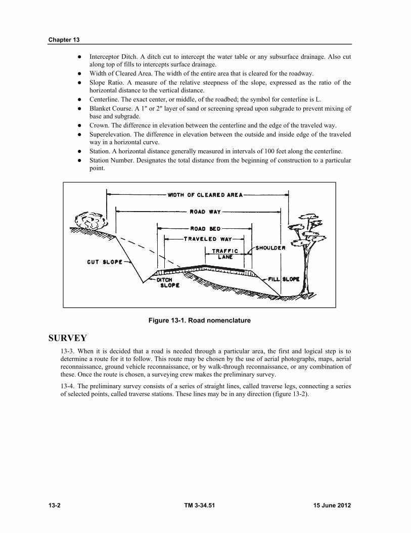
Chapter 13
13-2 TM 3-34.51 15 June 2012
Interceptor Ditch. A ditch cut to intercept the water table or any subsurface drainage. Also cut along top of fills to intercepts surface drainage.
Width of Cleared Area. The width of the entire area that is cleared for the roadway. Slope Ratio. A measure of the relative steepness of the slope, expressed as the ratio of the
horizontal distance to the vertical distance. Centerline. The exact center, or middle, of the roadbed; the symbol for centerline is L. Blanket Course. A 1" or 2" layer of sand or screening spread upon subgrade to prevent mixing of
base and subgrade. Crown. The difference in elevation between the centerline and the edge of the traveled way. Superelevation. The difference in elevation between the outside and inside edge of the traveled
way in a horizontal curve. Station. A horizontal distance generally measured in intervals of 100 feet along the centerline. Station Number. Designates the total distance from the beginning of construction to a particular
point.
Figure 13-1. Road nomenclature
SURVEY 13-3. When it is decided that a road is needed through a particular area, the first and logical step is to determine a route for it to follow. This route may be chosen by the use of aerial photographs, maps, aerial reconnaissance, ground vehicle reconnaissance, or by walk-through reconnaissance, or any combination of these. Once the route is chosen, a surveying crew makes the preliminary survey.
13-4. The preliminary survey consists of a series of straight lines, called traverse legs, connecting a series of selected points, called traverse stations. These lines may be in any direction (figure 13-2).
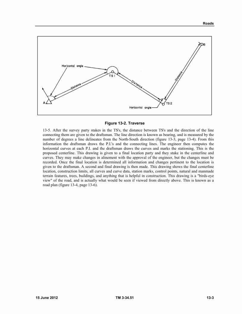
Roads
15 June 2012 TM 3-34.51 13-3
Figure 13-2. Traverse
13-5. After the survey party stakes in the TS's, the distance between TS's and the direction of the line connecting them are given to the draftsman. The line direction is known as bearing, and is measured by the number of degrees a line delineates from the North-South direction (figure 13-3, page 13-4). From this information the draftsman draws the P.I.'s and the connecting lines. The engineer then computes the horizontal curves at each P.I. and the draftsman draws the curves and marks the stationing. This is the proposed centerline. This drawing is given to a final location party and they stake in the centerline and curves. They may make changes in alinement with the approval of the engineer, but the changes must be recorded. Once the final location is determined all information and changes pertinent to the location is given to the draftsman. A second and final drawing is then made. This drawing shows the final centerline location, construction limits, all curves and curve data, station marks, control points, natural and manmade terrain features, trees, buildings, and anything that is helpful in construction. This drawing is a "birds-eye view" of the road, and is actually what would be seen if viewed from directly above. This is known as a road plan (figure 13-4, page 13-6).
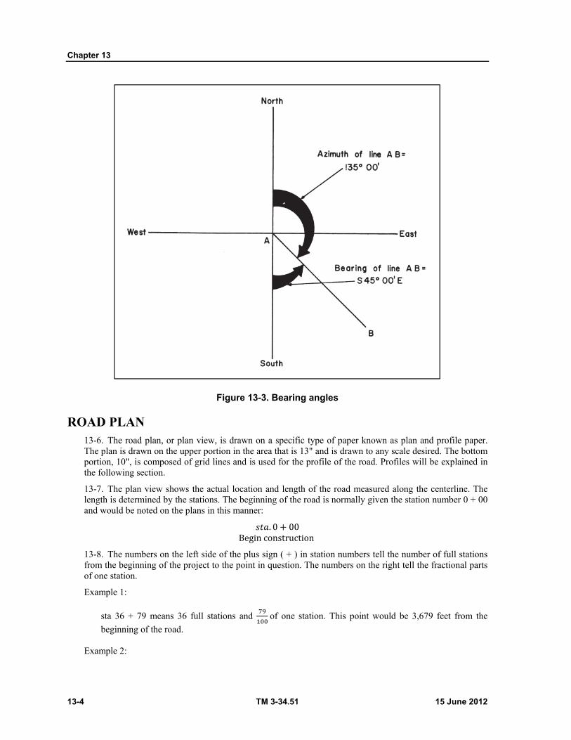
Chapter 13
13-4 TM 3-34.51 15 June 2012
Figure 13-3. Bearing angles
ROAD PLAN 13-6. The road plan, or plan view, is drawn on a specific type of paper known as plan and profile paper. The plan is drawn on the upper portion in the area that is 13" and is drawn to any scale desired. The bottom portion, 10", is composed of grid lines and is used for the profile of the road. Profiles will be explained in the following section.
13-7. The plan view shows the actual location and length of the road measured along the centerline. The length is determined by the stations. The beginning of the road is normally given the station number 0 + 00 and would be noted on the plans in this manner: 𝑠𝑡𝑎. 0 + 00 Begin construction 13-8. The numbers on the left side of the plus sign ( + ) in station numbers tell the number of full stations from the beginning of the project to the point in question. The numbers on the right tell the fractional parts of one station.
Example 1:
sta 36 + 79 means 36 full stations and of one station. This point would be 3,679 feet from the
beginning of the road.
Example 2:

Roads
15 June 2012 TM 3-34.51 13-5
119 + 2680
This point is 11,926.80 feet from the beginning.
13-9. A full station represents 100', and a plus station any distance between full stations. Full stations are
shown on the plans as a 1/4" hash mark through the ℄ (centerline). Plus stations are shown by shorter hash
marks on the upper side of the ℄. The hash marks are always drawn perpendicular to the ℄. The station
numbers themselves are put on the plan in a horizontal position and centered on the hash marks.
13-10. All manmade and natural objects such as trees, buildings, fences, wells, and so on, are also plotted on the plan if they are in the right-of-way or construction limits. (Right of way is the land acquired for the road construction.) These objects and their location are taken from the surveyor's notebook. Their location
is determined by a station number and their distance from ℄. All measurements and distances are made
perpendicular to the ℄ of the particular station unless otherwise noted.
HORIZONTAL CURVES
13-11. The road ℄ consists of straight lines and curves. The straight lines are called tangents, and the curves, horizontal curves. These curves are used to change the horizontal direction of the road.
13-12. All information necessary to draw a curve should be furnished by the engineer or surveyor's notebook. The necessary information is known as curve data. Below is the data for a curve and the explanation of the terms.
13-13. ∆ = 56° 13'
13-14. D = 18° 42'
13-15. T = 163.39'
13-16. L = 300.62'
13-17. R = 307.76'
The symbol ∆ (Delta) represents the angle made by the tangents where they intersect, and is known as the intersection angle (figure 13-4, page 13-6).
D is the degree of curvature, or degree of curve. It is the angle subtended by a 100' arc or chord (figure 13-4). It makes no difference as far as the draftsman is concerned whether the degree of curve is for the arc or chord. In the military, DA is used, and the surveying party who stakes the centerline of the road must know which degree of curve to use.
T is the tangent length, and is measured from the P.I. to the point of curvature (P.C.) and the point of tangency (P.T.). The P.C. is the beginning of the curve, and the P.T. is the end of the curve.
L is the total length of the curve measured in feet. R is the radius of the curve, or arc. The radius is always perpendicular to the curve tangents of
the P.C. and the P.T.
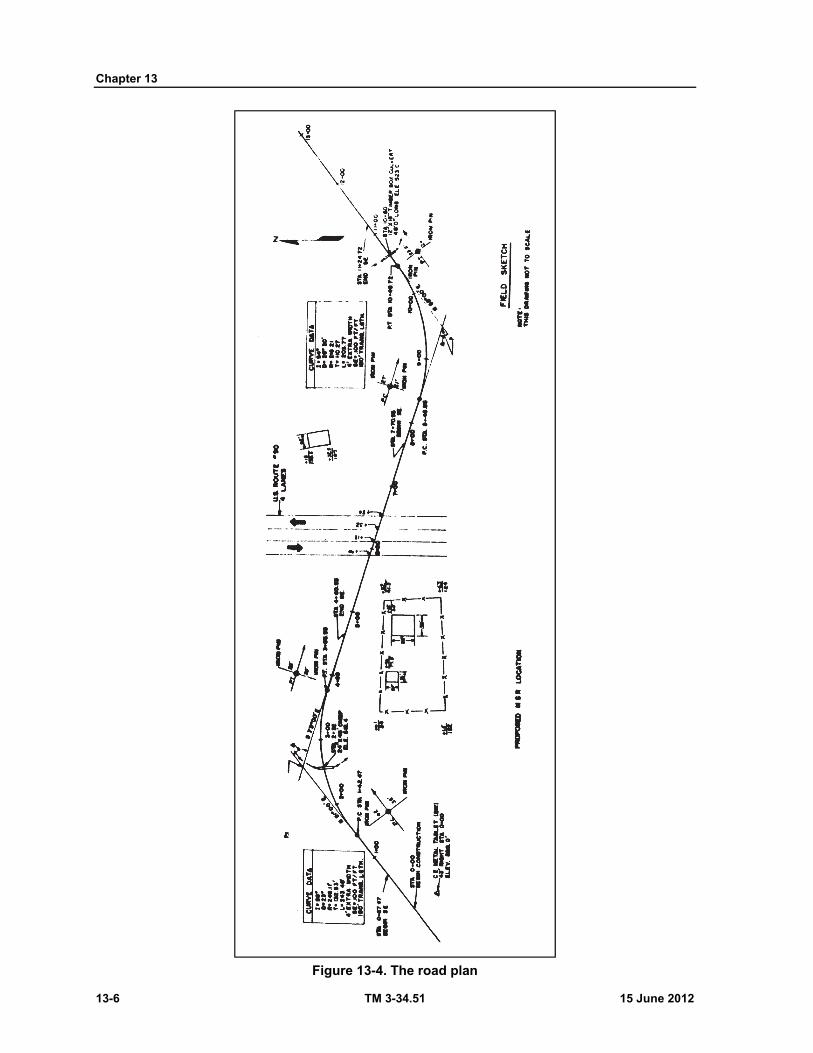
Chapter 13
13-6 TM 3-34.51 15 June 2012
Figure 13-4. The road plan
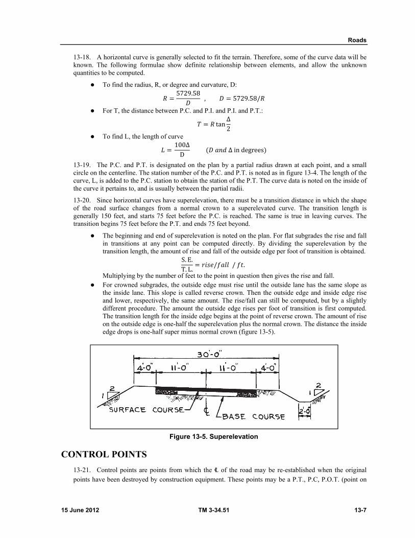
Roads
15 June 2012 TM 3-34.51 13-7
13-18. A horizontal curve is generally selected to fit the terrain. Therefore, some of the curve data will be known. The following formulae show definite relationship between elements, and allow the unknown quantities to be computed.
To find the radius, R, or degree and curvature, D: 𝑅 = 5729.58𝐷 , 𝐷 = 5729.58/𝑅
For T, the distance between P.C. and P.I. and P.I. and P.T.: 𝑇 = 𝑅 tan ∆2
To find L, the length of curve 𝐿 = 100∆D (𝐷 𝑎𝑛𝑑 ∆ in degrees)
13-19. The P.C. and P.T. is designated on the plan by a partial radius drawn at each point, and a small circle on the centerline. The station number of the P.C. and P.T. is noted as in figure 13-4. The length of the curve, L, is added to the P.C. station to obtain the station of the P.T. The curve data is noted on the inside of the curve it pertains to, and is usually between the partial radii.
13-20. Since horizontal curves have superelevation, there must be a transition distance in which the shape of the road surface changes from a normal crown to a superelevated curve. The transition length is generally 150 feet, and starts 75 feet before the P.C. is reached. The same is true in leaving curves. The transition begins 75 feet before the P.T. and ends 75 feet beyond.
The beginning and end of superelevation is noted on the plan. For flat subgrades the rise and fall in transitions at any point can be computed directly. By dividing the superelevation by the transition length, the amount of rise and fall of the outside edge per foot of transition is obtained. S. E.T. L. = 𝑟𝑖𝑠𝑒/𝑓𝑎𝑙𝑙 / 𝑓𝑡. Multiplying by the number of feet to the point in question then gives the rise and fall.
For crowned subgrades, the outside edge must rise until the outside lane has the same slope as the inside lane. This slope is called reverse crown. Then the outside edge and inside edge rise and lower, respectively, the same amount. The rise/fall can still be computed, but by a slightly different procedure. The amount the outside edge rises per foot of transition is first computed. The transition length for the inside edge begins at the point of reverse crown. The amount of rise on the outside edge is one-half the superelevation plus the normal crown. The distance the inside edge drops is one-half super minus normal crown (figure 13-5).
Figure 13-5. Superelevation
CONTROL POINTS
13-21. Control points are points from which the ℄ of the road may be re-established when the original
points have been destroyed by construction equipment. These points may be a P.T., P.C, P.O.T. (point on
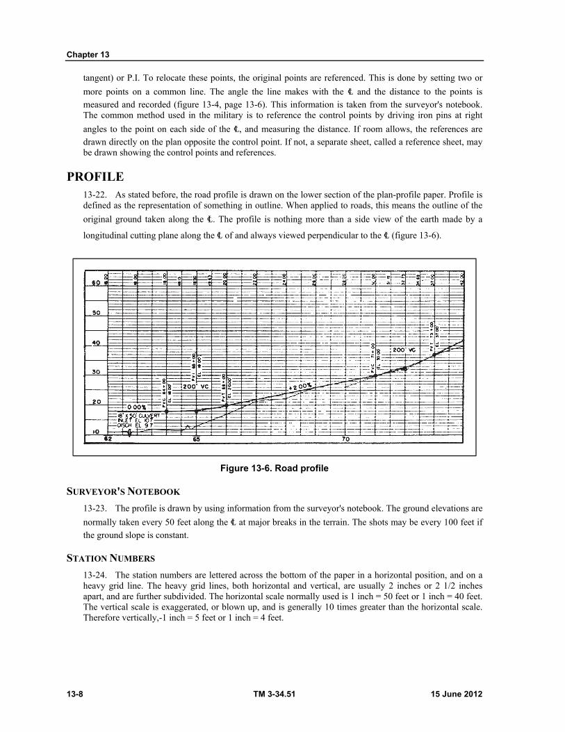
Chapter 13
13-8 TM 3-34.51 15 June 2012
tangent) or P.I. To relocate these points, the original points are referenced. This is done by setting two or
more points on a common line. The angle the line makes with the ℄ and the distance to the points is
measured and recorded (figure 13-4, page 13-6). This information is taken from the surveyor's notebook. The common method used in the military is to reference the control points by driving iron pins at right
angles to the point on each side of the ℄, and measuring the distance. If room allows, the references are
drawn directly on the plan opposite the control point. If not, a separate sheet, called a reference sheet, may be drawn showing the control points and references.
PROFILE 13-22. As stated before, the road profile is drawn on the lower section of the plan-profile paper. Profile is defined as the representation of something in outline. When applied to roads, this means the outline of the
original ground taken along the ℄. The profile is nothing more than a side view of the earth made by a
longitudinal cutting plane along the ℄ of and always viewed perpendicular to the ℄ (figure 13-6).
Figure 13-6. Road profile
SURVEYOR'S NOTEBOOK
13-23. The profile is drawn by using information from the surveyor's notebook. The ground elevations are
normally taken every 50 feet along the ℄ at major breaks in the terrain. The shots may be every 100 feet if
the ground slope is constant.
STATION NUMBERS
13-24. The station numbers are lettered across the bottom of the paper in a horizontal position, and on a heavy grid line. The heavy grid lines, both horizontal and vertical, are usually 2 inches or 2 1/2 inches apart, and are further subdivided. The horizontal scale normally used is 1 inch = 50 feet or 1 inch = 40 feet. The vertical scale is exaggerated, or blown up, and is generally 10 times greater than the horizontal scale. Therefore vertically,-1 inch = 5 feet or 1 inch = 4 feet.
Roads
15 June 2012 TM 3-34.51 13-9
ELEVATIONS
13-25. After the proper scale is selected, datum elevations are lettered along the left (and sometimes right) border on the heavy horizontal grid lines. These elevations range below and above the lowest and highest profile elevation, respectively, on that sheet. For example, the highest profile elevation is 537.2 and the lowest is 514.7. The lowest datum elevation would be 510.0. On the next heavy grid above would be lettered 520.0, the next 530.0. The highest would be 540.0.
The elevations given in the surveyor's notebook are plotted above their respective stations, A good method is to make a dot and then lightly circle it.
The elevation points are connected with straight dashed lines of medium length. Care should be taken so as not to miss a point.
GRADELINES
13-26. A road gradeline is also drawn on the lower portion of the plan-profile paper, and is represented by
a heavy solid line. The gradeline is also a longitudinal section along the ℄ or side view, and shows the elevations to which the road is built (figure 13-6).
The grade line is normally the ℄ elevations of the finished surface, but may be ℄ elevation of the subgrade. If the subgrade, it should be well noted.
The gradelines are a series of straight lines (tangents) connected by curves, called vertical curves. The lines may be level or sloped. If the lines slope upward, the grade is positive. If they slope downward, the grade is negative. The slopes are in reference to the direction of increasing stations. The amount of slope is above the gradeline. (Grade is the percent rise or fall per 100 feet.)
The point at which the straight lines intersect is the PVI (point of vertical intersection). This point is comparable to the PI of horizontal curves.
VERTICAL CURVES 13-27. To eliminate riding discomforts and safety hazards, the sharp break of the PVI is eliminated by vertical curves. If the road is over a hill, then a crest vertical curve is used. If across a valley, an overt or sag curve is used.
LENGTH
13-28. The length of the curves depends upon the steepness of the intersecting grades. The formula used in the military for finding the length of vertical curves is L = S ∆ G, where ∆ G is the algebraic difference in grades G2-G1. S is a constant (0.31 for crest and 0.25 for overt) based upon the required safety features. G1 and G2 are the grades before and after the PVI, respectively. Subtracting the grades algebraically, ∆ G = G2 - G1 = –7– (+6) = –13. (The minus sign is irrelevant here.) So, for crest curves, L = S ∆ G. L = 0.31 (13) = 4.03 For overt curves: L = 0.25 (13) = 3.25 These values are in stations, and are rounded off to the next higher station. 4.03 rounded would be 5 stations 3.25 rounds to 4 stations
SYMMETRY
13-29. In most cases, vertical curves are symmetrical. That is, the same length of curve on both sides of the PVI. The length of the curves are horizontal lengths, and not the length along the curve. The station on which the curve begins is called the PVC (point of vertical curvature) and ends is called the PVT (point of vertical tangency).
Chapter 13
13-10 TM 3-34.51 15 June 2012
OFFSET
13-30. Vertical curves, unlike horizontal curves, are parabolic, and have no constant radius. Therefore, the curves are plotted, usually in 50foot lengths, by computing the offsets from the two tangents. The formula for this is T. O. = ∆G2L (X)
where,
∆G = G2 – G1, L is length of curve in stations, and X is the distance from the PVC or PVT to the point in question, in stations.
Example: G = −4 − (+5) = −9 L = SG = 0.31 (9) = 2.79 rounded L = 3 sta If X = 100' T. O. = ∆G /2L (X) T. O. = −4 − (+5)2(3) (10) = − 96 (1) = −96 (1) T. O. = 1.5′
13-31. The minus sign shows the offset is vertically below the tangents. After one half of the curve is plotted, then the offsets for the other half are computed with the X distance measured from the PVT. A solid heavy line is drawn through the points and the curve labeled. The PVC, PVI, and PVT are shown by small circles, and have the station and elevation lettered vertically above.
DRAWING THE GRADELINE
CUT OR FILL
13-32. The gradeline is drawn using the same horizontal and vertical scale as the profile. This allows the amount of cut or fill for a particular point to be measured. If the gradeline is higher than the profile, fill is required. If lower, then it is cut.
DRAINAGE STRUCTURES
13-33. The profile and gradeline drawings also show the relative locations of drainage structures such as box culverts and pipe. The structure is drawn using the vertical scale only. The larger scale eliminates the possibility of the structure being overlooked, and also shows the actual shape.
ROAD DIMENSIONS 13-34. The type of dimensioning used for road plans is a variation of the standard dimensioning. In road dimensioning, numerical values for elevations, cuts, fills, and stations are considered dimensions also.
STATION NUMBERS
13-35. Most road dimensions appear on the profile-gradeline drawing. The station numbers are lettered horizontally below the profile-gradeline and are centered on the appropriate vertical grid line.
ELEVATIONS
13-36. At the bottom of the sheet the profile and gradeline elevations for each station are lettered vertically. The gradeline elevations are lettered just above the profile elevations. Any station numbers other

Roads
15 June 2012 TM 3-34.51 13-11
than full stations are noted as plus stations vertically just outside the bottom border (figure 13-7, page 13-12).
CUTS AND FILLS
13-37. Above the profile and gradeline elevations are lettered the cuts and fills (figure 13-7). There are also in a vertical position. The gradepoints, or points where the profile crosses the gradeline, are also noted in this row. They are designated by the word "GRADE" lettered vertically above the gradepoint station.
DITCHES
13-38. There are several steps in the procedure for dimensioning ditches.
Extension lines are drawn from the ends of a ditch, or any point in the ditch where the ditch grade changes. These lines are extended downward, and dimension lines drawn, with heavy arrowheads. These extension and dimension lines should be heavier than normal so they may be distinguished from grid lines.
The information necessary to describe the ditch is lettered above the dimension line. If the lettering is crowded the space below the line may also be used. The information furnished is percent grade of the ditch, depth relative to ^L, type and width of ditch. The elevation and station are given at the ends of the ditches and at changes of grade (figure 13-7).
Vertical Curves. Each vertical curve on the gradeline is also dimensioned. Extension lines are drawn upward from the PVC and PVT. A dimension line and arrowheads are drawn and the length of the curve lettered above. The station and elevation of the PVC, PVI, PVT are lettered vertically over these points and above the dimension line.
Correlation with Plan. All points on the profile-gradeline coincide with x. points on the plan. Beginning and end of construction of the plan view is also shown on the gradeline as beginning and end of construction. The elevations at these points are also noted.
Drainage Structures. All drainage structures such as pipes and culverts are dimensioned by notes. The station number, size of opening, length of pipe, and flow line elevation are noted.
Title. The title, "PROFILE AND GRADELINE" is lettered below the ditch dimensions. Below this are noted the horizontal and vertical scales.

Chapter 13
13-12 TM 3-34.51 15 June 2012
Figure 13-7. Profile and gradeline
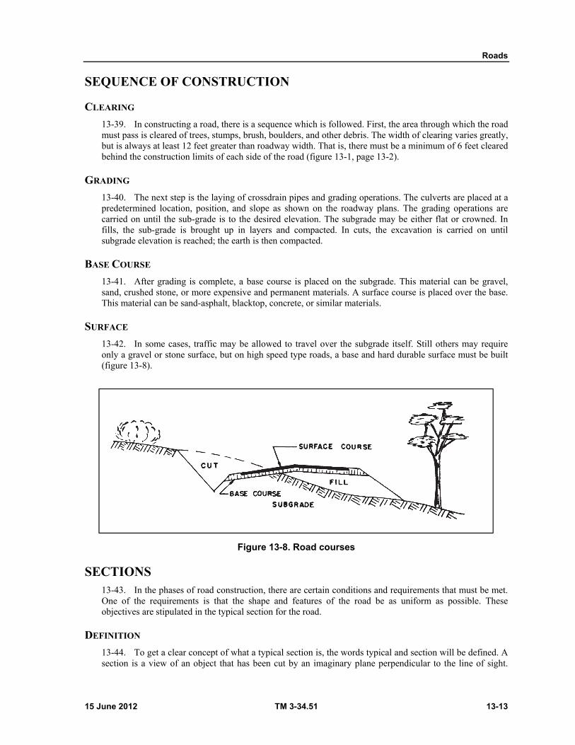
Roads
15 June 2012 TM 3-34.51 13-13
SEQUENCE OF CONSTRUCTION
CLEARING
13-39. In constructing a road, there is a sequence which is followed. First, the area through which the road must pass is cleared of trees, stumps, brush, boulders, and other debris. The width of clearing varies greatly, but is always at least 12 feet greater than roadway width. That is, there must be a minimum of 6 feet cleared behind the construction limits of each side of the road (figure 13-1, page 13-2).
GRADING
13-40. The next step is the laying of crossdrain pipes and grading operations. The culverts are placed at a predetermined location, position, and slope as shown on the roadway plans. The grading operations are carried on until the sub-grade is to the desired elevation. The subgrade may be either flat or crowned. In fills, the sub-grade is brought up in layers and compacted. In cuts, the excavation is carried on until subgrade elevation is reached; the earth is then compacted.
BASE COURSE
13-41. After grading is complete, a base course is placed on the subgrade. This material can be gravel, sand, crushed stone, or more expensive and permanent materials. A surface course is placed over the base. This material can be sand-asphalt, blacktop, concrete, or similar materials.
SURFACE
13-42. In some cases, traffic may be allowed to travel over the subgrade itself. Still others may require only a gravel or stone surface, but on high speed type roads, a base and hard durable surface must be built (figure 13-8).
Figure 13-8. Road courses
SECTIONS 13-43. In the phases of road construction, there are certain conditions and requirements that must be met. One of the requirements is that the shape and features of the road be as uniform as possible. These objectives are stipulated in the typical section for the road.
DEFINITION
13-44. To get a clear concept of what a typical section is, the words typical and section will be defined. A section is a view of an object that has been cut by an imaginary plane perpendicular to the line of sight.
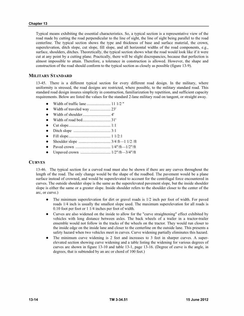
Chapter 13
13-14 TM 3-34.51 15 June 2012
Typical means exhibiting the essential characteristics. So, a typical section is a representative view of the road made by cutting the road perpendicular to the line of sight, the line of sight being parallel to the road centerline. The typical section shows the type and thickness of base and surface material, the crown, superelevation, ditch slope, cut slope, fill slope, and all horizontal widths of the road components, e.g., surface, shoulders, ditches. Theoretically, the typical section shows what the road would look like if it were cut at any point by a cutting plane. Practically, there will be slight discrepancies, because that perfection is almost impossible to attain. Therefore, a tolerance in construction is allowed. However, the shape and construction of the road should conform to the typical section as closely as possible (figure 13-9).
MILITARY STANDARD
13-45. There is a different typical section for every different road design. In the military, where uniformity is stressed, the road designs are restricted, where possible, to the military standard road. This standard road design insures simplicity in construction, familiarization by repetition, and sufficient capacity requirements. Below are listed the values for the standard 2-lane military road on tangent, or straight away.
Width of traffic lane ........................ 11 1/2 " Width of traveled way ..................... 23' Width of shoulder ............................ 4' Width of road bed ............................ 31' Cut slope .......................................... 1:1 Ditch slope ..................................... 3:1 Fill slope .......................................... 1 1/2:1 Shoulder slope ................................ 3/4 ft—1 1/2 /ft Paved crown ................................... 1/4"/ft—1/2"/ft Unpaved crown .............................. 1/2"/ft—3/4"/ft
CURVES
13-46. The typical section for a curved road must also be shown if there are any curves throughout the length of the road. The only change would be the shape of the roadbed. The pavement would be a plane surface instead of crowned, and would be superelevated to account for the centrifugal force encountered in curves. The outside shoulder slope is the same as the superelevated pavement slope, but the inside shoulder slope is either the same or a greater slope. Inside shoulder refers to the shoulder closer to the center of the arc, or curve.)
The minimum superelevation for dirt or gravel roads is 1/2 inch per foot of width. For paved roads 1/4 inch is usually the smallest slope used. The maximum superelevation for all roads is 0.10 foot per foot or 1 1/4 inches per foot of width.
Curves are also widened on the inside to allow for the "curve straightening" effect exhibited by vehicles with long distance between axles. The back wheels of a trailer in a tractor-trailer ensemble would not follow in the tracks of the wheels on the tractor. They would run closer to the inside edge on the inside lane and closer to the centerline on the outside lane. This presents a safety hazard when two vehicles meet in curves. Curve widening partially eliminates this hazard.
The minimum curve widening is 2 feet and increases to 3 feet in sharper curves. A super-elevated section showing curve widening and a table listing the widening for various degrees of curves are shown in figure 13-10 and table 13-1, page 13-16. (Degree of curve is the angle, in degrees, that is subtended by an arc or chord of 100 feet.)
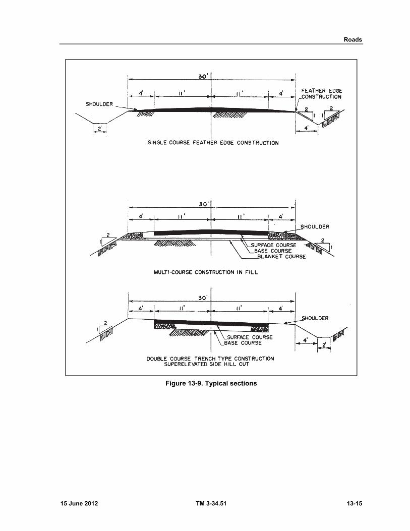
Roads
15 June 2012 TM 3-34.51 13-15
Figure 13-9. Typical sections

Chapter 13
13-16 TM 3-34.51 15 June 2012
Figure 13-10. Curve section
Table 13-1. Curve table
Degree of curvature (degrees) Radius of curvature (feet) Superelevation (inches per foot)
Widening of two-way roads on curve (feet)
1° 00'— 4° 00' ........................ 5,730—1,432 ................... 1/4" /ft ..................... 2
5° 00'— 7° 00' ........................ 1,146—819 ...................... 3/8" /ft ..................... 2
8° 00'— 9° 00' ........................ 716—637 ......................... 5/8" /ft ..................... 2
10° 00'—11° 00' ..................... 572—521 ......................... 3/4" /ft ..................... 2
12° 00'—13° 00' ..................... 447—441 ......................... 7/8" /ft ..................... 3
14° 00'—16° 00' ..................... 409—359 ......................... 1" /ft ........................ 3
17° 00' .................................... 337 ................................... 1 1/4" /ft .................. 3
CROSS SECTIONS
FINAL CROSS-SECTIONS
13-47. To determine how closely a road has been built to conform to the typical section, road cross sections are taken. Cross sections are usually taken 50 feet apart, on each station and half station, and other points which warrant them, such as entrances or side road approaches. Cross sections, like typical sections, are views of the road made by a plane cutting the roadway perpendicular to the road center-line, and viewed parallel to the centerline. These views show the actual shape of the road, the horizontal width of components and their distances from centerline, the constructed elevations, and the extremities of the cut and fill. They also show the slopes of the surface, ditch, shoulders, cut, and fill. This type of cross section is known as a final cross section. These are taken after the road is completed.
ORIGINAL CROSS SECTIONS
13-48. The other type of cross section is known as an original cross section. These sections are usually taken after the clearing of the roadway has been done, but can be taken before. If taken before, the thickness of sod to be stripped off is normally deducted from the elevations. The original section shows the elevations of the natural, or original, ground. These are taken on the same stations as the final cross sections.
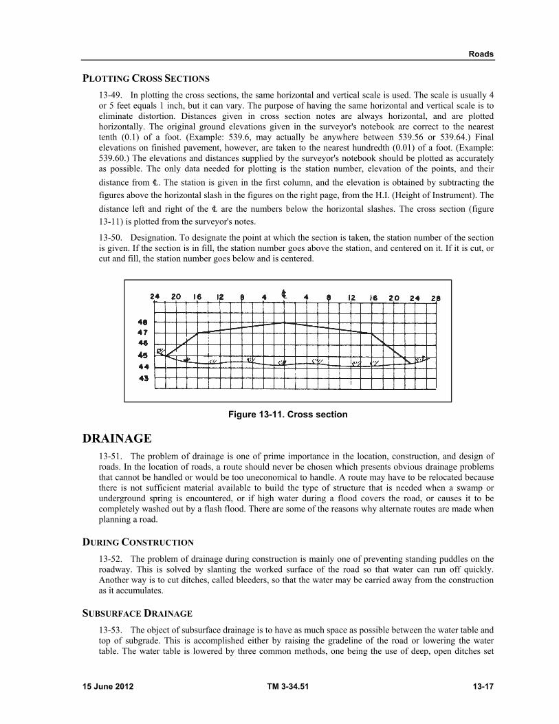
Roads
15 June 2012 TM 3-34.51 13-17
PLOTTING CROSS SECTIONS
13-49. In plotting the cross sections, the same horizontal and vertical scale is used. The scale is usually 4 or 5 feet equals 1 inch, but it can vary. The purpose of having the same horizontal and vertical scale is to eliminate distortion. Distances given in cross section notes are always horizontal, and are plotted horizontally. The original ground elevations given in the surveyor's notebook are correct to the nearest tenth (0.1) of a foot. (Example: 539.6, may actually be anywhere between 539.56 or 539.64.) Final elevations on finished pavement, however, are taken to the nearest hundredth (0.01) of a foot. (Example: 539.60.) The elevations and distances supplied by the surveyor's notebook should be plotted as accurately as possible. The only data needed for plotting is the station number, elevation of the points, and their
distance from ℄. The station is given in the first column, and the elevation is obtained by subtracting the figures above the horizontal slash in the figures on the right page, from the H.I. (Height of Instrument). The
distance left and right of the ℄ are the numbers below the horizontal slashes. The cross section (figure 13-11) is plotted from the surveyor's notes.
13-50. Designation. To designate the point at which the section is taken, the station number of the section is given. If the section is in fill, the station number goes above the station, and centered on it. If it is cut, or cut and fill, the station number goes below and is centered.
Figure 13-11. Cross section
DRAINAGE 13-51. The problem of drainage is one of prime importance in the location, construction, and design of roads. In the location of roads, a route should never be chosen which presents obvious drainage problems that cannot be handled or would be too uneconomical to handle. A route may have to be relocated because there is not sufficient material available to build the type of structure that is needed when a swamp or underground spring is encountered, or if high water during a flood covers the road, or causes it to be completely washed out by a flash flood. There are some of the reasons why alternate routes are made when planning a road.
DURING CONSTRUCTION
13-52. The problem of drainage during construction is mainly one of preventing standing puddles on the roadway. This is solved by slanting the worked surface of the road so that water can run off quickly. Another way is to cut ditches, called bleeders, so that the water may be carried away from the construction as it accumulates.
SUBSURFACE DRAINAGE
13-53. The object of subsurface drainage is to have as much space as possible between the water table and top of subgrade. This is accomplished either by raising the gradeline of the road or lowering the water table. The water table is lowered by three common methods, one being the use of deep, open ditches set

Chapter 13
13-18 TM 3-34.51 15 June 2012
back beyond the roadway limits. These ditches intercept the water table, allowing the ground water to seep through the sides. The water then flows along the bottom and out the end.
13-54. Another type of subsurface drainage structure is the French drain, a deep trench dug exactly where the finished roadway ditch would be. The trench is then backfilled to a designated depth with rocks or large gravel of varying size, with the larger size at the bottom. The rocks are capped with a layer of branches or straw, and the remainder of the trench backfilled with soil and compacted.
13-55. The tile drain is the same as the French drain, except that a perforated pipe or tile is placed in the bottom of the trench. The trench is then backfilled with gravel to the desired depth. The minimum pipe grade is 0.3 percent with the maximum varying to meet conditions (figure 13-12).
Figure 13-12. Subsurface drainage
SURFACE DRAINAGE
13-56. Surface drainage involves water from direct precipitation and snow, surface runoff, and rivers and streams. (Surface runoff is rainfall that is not absorbed by the soil, but runs off a surface in sheets or rivulets.) Surface drainage is handled in various ways.
13-57. The source that has immediate effect upon a roadway is rainfall. Obviously, this water would cause safety hazards or weak spots on the roadway if it is allowed to stand. Water that falls upon the surface, or traveled way, is drained by crowning the surface. This is done by constructing the traveled way so. that the middle is higher than the edges. If the traveled way is paved, the crown is usually 1/4 to 1/2 inch per foot of width while it is generally 1/2 to 3/4 inch per foot for gravel or dirt surfaces.
13-58. Drainage from the traveled way in curves is accomplished by superelevating the surface to create a slanted plan. The edge on the inside of the curve is lower than the outside edge.
SHOULDERS
13-59. The water which drains from the surface continues over the shoulders. The shoulders always have a slope greater than, or at least equal to, the surface slope, generally 3/4 to 1 1/2 inch per foot. This slightly increases the speed of the draining water and therefore increases the rate of drainage. The water then flows from the shoulder down the side of the fill, if in a fill section of roadway. If the section is in a cut, the water flows into a roadway ditch. Roadway ditches aren't normally in a fill section.

Roads
15 June 2012 TM 3-34.51 13-19
ROADWAY DITCHES 13-60. The functioning of a roadway ditch is the most important factor in roadway drainage. If the ditch becomes obstructed, or is inadequate for the volume of water, then the roadbed becomes flooded. Not only can this block traffic, but it can also wash away surface and shoulder material.
DESIGN FACTORS
13-61. There are several factors to consider in determining the size and type of longitudinal side ditches, or roadway ditches. One must consider the volume of water to be carried, the slope of the backslope, soil types, the "lay of the land," and the maximum and minimum ditch grades.
13-62. The slopes of the surface, shoulders, and backslopes affect the volume. A steep slope would increase the rate of runoff, thereby causing a greater instantaneous volume of water in the ditch. On the other hand, a flatter slope would decrease the rate of runoff, but would expose more surface area on the backslope, which would increase the amount of runoff.
13-63. The choice of slopes to use would be governed by other factors, however. The foremost are, whether the additional excavation is needed in the roadway construction, and the type of soil. A flatter slope would be required if the cut is in sand than if it is in clay or rock. The standard cut slope, or backslope, is 1:1 (1 foot horizontal, 1 foot vertical). This slope may be decreased for sandy soil, or greatly increased for rock cuts. The standard ditch slope, from the shoulder to the bottom of the ditch, is 3:1 (3 hor., 1 vert.). All these soil types have different amounts of runoff. The runoff from a sandy soil is very low, but from a clay soil is high, and almost 100 percent from solid rock.
13-64. A very important design factor is the ditch grade itself. The minimum grade is 0.5 percent and the desirable maximum grade is 4 percent. Grade greater than 4 percent would cause excessive erosion due to the greater velocity of the water. In such cases, low dams of wood or stones, called check dams, (figure 13-13, page 13-20), are built across the bottom of the ditch to slow the water down. In general, a moderate velocity is desirable because excessive erosion is prevented, and the water is still moving fast enough that the ponding effect exhibited by slow moving water is decreased.
13-65. One factor involving the volume that cannot be controlled is the rainfall itself. The more intense the rainfall and the longer the duration, the greater the volume of water the ditch will have to carry. Local residents are sometimes helpful in determining the heaviest rainfall to expect in a particular area, as well as high water marks along streams.
DITCH DESIGN.
13-66. After all the factors involving the volume of water have been considered, the ditch design itself must be considered. The two common types of ditches are the v-bottom ditch and the flat bottom, or trapezoidal, ditch (figure 13-14, page 13-20).
13-67. The most common ditch is the v-type because of its ease of construction. Under similar conditions, the water flows faster in a v-bottom than the trapezoidal type. The side slope for a shallow v-bottom is 4:1 or greater. For a deep v-bottom, the side slopes are 3:1, 2:1, and 1:1.
13-68. Sometimes the depth of a ditch is fixed and the volume is too great for a v-bottom. Then, a trapezoidal is used. They are also used on steep grades, because the increased area of the ditch would carry the same volume as a v-bottom, but at a slower velocity. Due to the slow velocity this is the desirable type to use in easily erodible soils. The side slopes of the ditch are usually 3:1, 2:1, and 1:1. The flat bottom is generally 2 feet wide, but it can range from 1 foot to 6 feet or greater. Trapezoidal ditches are recommended if trucks and equipment are required to cross them.
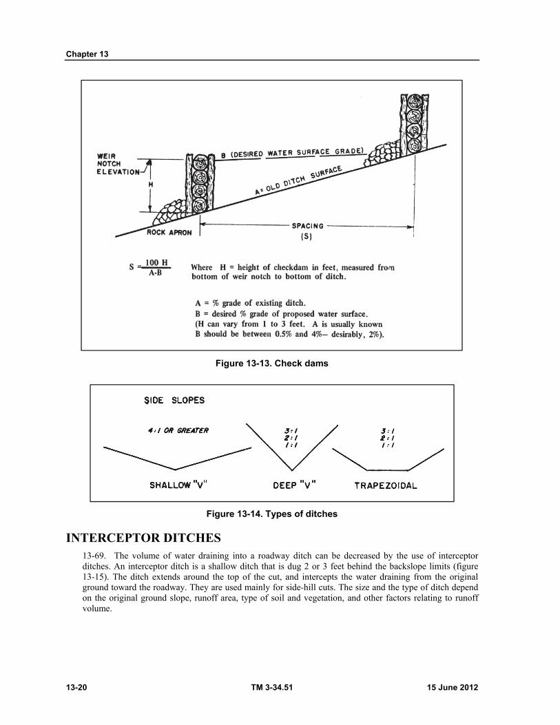
Chapter 13
13-20 TM 3-34.51 15 June 2012
Figure 13-13. Check dams
Figure 13-14. Types of ditches
INTERCEPTOR DITCHES 13-69. The volume of water draining into a roadway ditch can be decreased by the use of interceptor ditches. An interceptor ditch is a shallow ditch that is dug 2 or 3 feet behind the backslope limits (figure 13-15). The ditch extends around the top of the cut, and intercepts the water draining from the original ground toward the roadway. They are used mainly for side-hill cuts. The size and the type of ditch depend on the original ground slope, runoff area, type of soil and vegetation, and other factors relating to runoff volume.
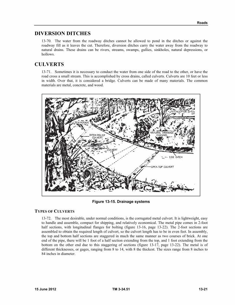
Roads
15 June 2012 TM 3-34.51 13-21
DIVERSION DITCHES 13-70. The water from the roadway ditches cannot be allowed to pond in the ditches or against the roadway fill as it leaves the cut. Therefore, diversion ditches carry the water away from the roadway to natural drains. These drains can be rivers, streams, swamps, gullies, sinkholes, natural depressions, or hollows.
CULVERTS 13-71. Sometimes it is necessary to conduct the water from one side of the road to the other, or have the road cross a small stream. This is accomplished by cross drains, called culverts. Culverts are 10 feet or less in width. Over that, it is considered a bridge. Culverts can be made of many materials. The common materials are metal, concrete, and wood.
Figure 13-15. Drainage systems
TYPES OF CULVERTS
13-72. The most desirable, under normal conditions, is the corrugated metal culvert. It is lightweight, easy to handle and assemble, compact for shipping, and relatively economical. The metal pipe comes in 2-foot half sections, with longitudinal flanges for bolting (figure 13-16, page 13-22). The 2-foot sections are assembled to obtain the required length of culvert, so the culvert length has to be in even feet. In assembly, the top and bottom half sections are staggered in much the same manner as two courses of brick. At one end of the pipe, there will be 1 foot of a half section extending from the top, and 1 foot extending from the bottom on the other end due to this staggering of sections (figure 13-17, page 13-22). The metal is of different thicknesses, or gages, ranging from 8 to 14, with 8 the thickest. The sizes range from 8 inches to 84 inches in diameter.
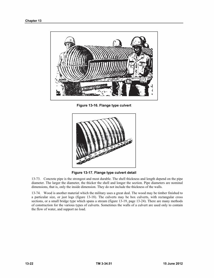
Chapter 13
13-22 TM 3-34.51 15 June 2012
Figure 13-16. Flange type culvert
Figure 13-17. Flange type culvert detail
13-73. Concrete pipe is the strongest and most durable. The shell thickness and length depend on the pipe diameter. The larger the diameter, the thicker the shell and longer the section. Pipe diameters are nominal dimensions, that is, only the inside dimension. They do not include the thickness of the walls.
13-74. Wood is another material which the military uses a great deal. The wood may be timber finished to a particular size, or just logs (figure 13-18). The culverts may be box culverts, with rectangular cross sections, or a small bridge type which spans a stream (figure 13-19, page 13-24). There are many methods of construction for the various types of culverts. Sometimes the walls of a culvert are used only to contain the flow of water, and support no load.
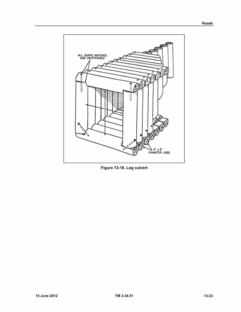
Roads
15 June 2012 TM 3-34.51 13-23
Figure 13-18. Log culvert
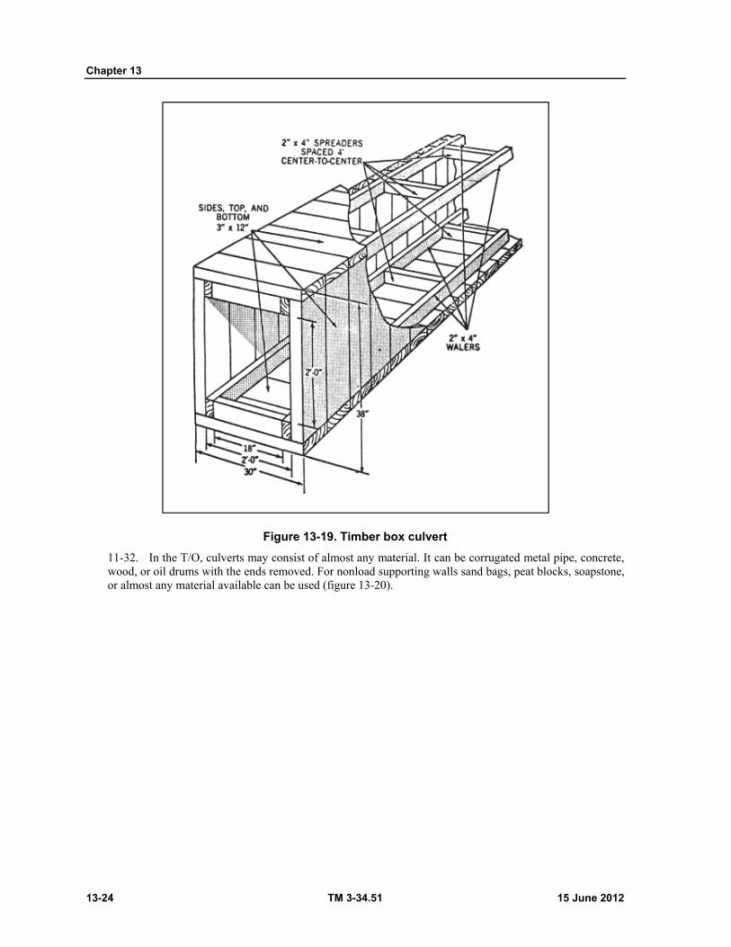
Chapter 13
13-24 TM 3-34.51 15 June 2012
Figure 13-19. Timber box culvert
11-32. In the T/O, culverts may consist of almost any material. It can be corrugated metal pipe, concrete, wood, or oil drums with the ends removed. For nonload supporting walls sand bags, peat blocks, soapstone, or almost any material available can be used (figure 13-20).
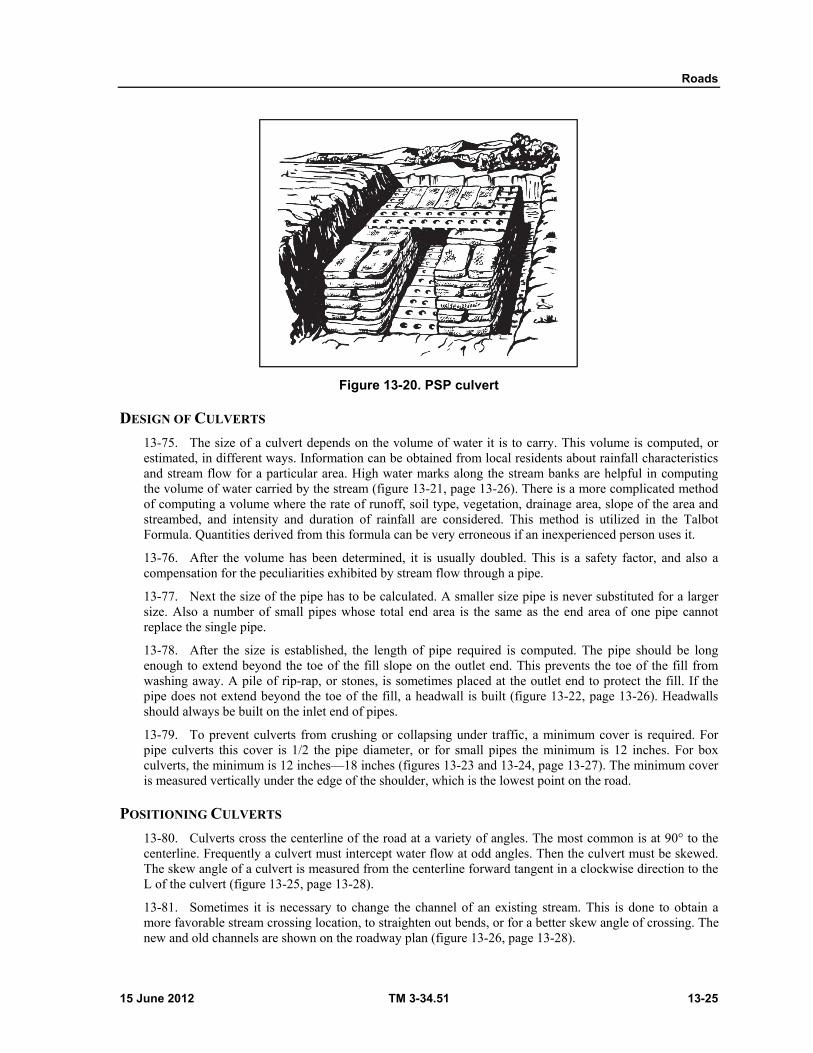
Roads
15 June 2012 TM 3-34.51 13-25
Figure 13-20. PSP culvert
DESIGN OF CULVERTS
13-75. The size of a culvert depends on the volume of water it is to carry. This volume is computed, or estimated, in different ways. Information can be obtained from local residents about rainfall characteristics and stream flow for a particular area. High water marks along the stream banks are helpful in computing the volume of water carried by the stream (figure 13-21, page 13-26). There is a more complicated method of computing a volume where the rate of runoff, soil type, vegetation, drainage area, slope of the area and streambed, and intensity and duration of rainfall are considered. This method is utilized in the Talbot Formula. Quantities derived from this formula can be very erroneous if an inexperienced person uses it.
13-76. After the volume has been determined, it is usually doubled. This is a safety factor, and also a compensation for the peculiarities exhibited by stream flow through a pipe.
13-77. Next the size of the pipe has to be calculated. A smaller size pipe is never substituted for a larger size. Also a number of small pipes whose total end area is the same as the end area of one pipe cannot replace the single pipe.
13-78. After the size is established, the length of pipe required is computed. The pipe should be long enough to extend beyond the toe of the fill slope on the outlet end. This prevents the toe of the fill from washing away. A pile of rip-rap, or stones, is sometimes placed at the outlet end to protect the fill. If the pipe does not extend beyond the toe of the fill, a headwall is built (figure 13-22, page 13-26). Headwalls should always be built on the inlet end of pipes.
13-79. To prevent culverts from crushing or collapsing under traffic, a minimum cover is required. For pipe culverts this cover is 1/2 the pipe diameter, or for small pipes the minimum is 12 inches. For box culverts, the minimum is 12 inches—18 inches (figures 13-23 and 13-24, page 13-27). The minimum cover is measured vertically under the edge of the shoulder, which is the lowest point on the road.
POSITIONING CULVERTS
13-80. Culverts cross the centerline of the road at a variety of angles. The most common is at 90° to the centerline. Frequently a culvert must intercept water flow at odd angles. Then the culvert must be skewed. The skew angle of a culvert is measured from the centerline forward tangent in a clockwise direction to the L of the culvert (figure 13-25, page 13-28).
13-81. Sometimes it is necessary to change the channel of an existing stream. This is done to obtain a more favorable stream crossing location, to straighten out bends, or for a better skew angle of crossing. The new and old channels are shown on the roadway plan (figure 13-26, page 13-28).
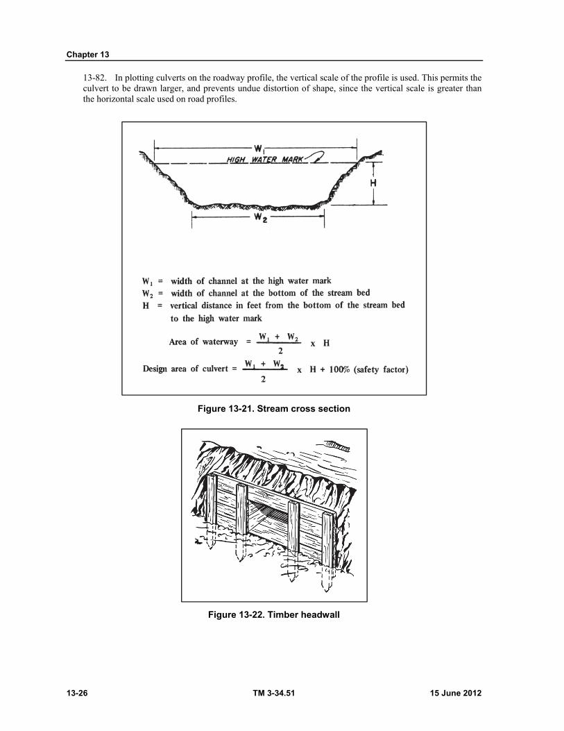
Chapter 13
13-26 TM 3-34.51 15 June 2012
13-82. In plotting culverts on the roadway profile, the vertical scale of the profile is used. This permits the culvert to be drawn larger, and prevents undue distortion of shape, since the vertical scale is greater than the horizontal scale used on road profiles.
Figure 13-21. Stream cross section
Figure 13-22. Timber headwall
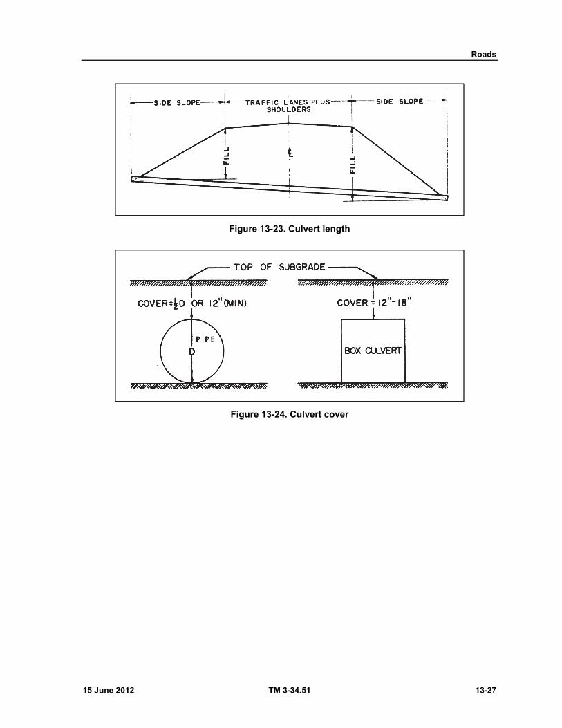
Roads
15 June 2012 TM 3-34.51 13-27
Figure 13-23. Culvert length
Figure 13-24. Culvert cover

Chapter 13
13-28 TM 3-34.51 15 June 2012
Figure 13-25. Skew culverts
Figure 13-26. Culvert alinement
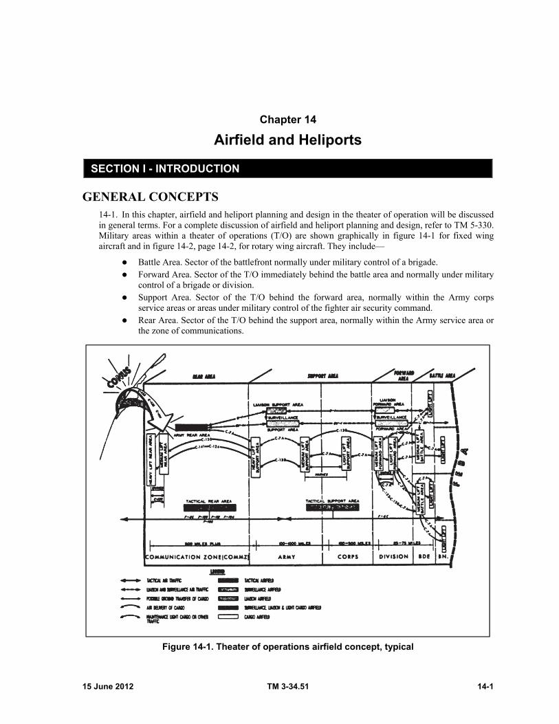
15 June 2012 TM 3-34.51 14-1
Chapter 14
Airfield and Heliports
SECTION I - INTRODUCTION
GENERAL CONCEPTS 14-1. In this chapter, airfield and heliport planning and design in the theater of operation will be discussed in general terms. For a complete discussion of airfield and heliport planning and design, refer to TM 5-330. Military areas within a theater of operations (T/O) are shown graphically in figure 14-1 for fixed wing aircraft and in figure 14-2, page 14-2, for rotary wing aircraft. They include—
Battle Area. Sector of the battlefront normally under military control of a brigade. Forward Area. Sector of the T/O immediately behind the battle area and normally under military
control of a brigade or division. Support Area. Sector of the T/O behind the forward area, normally within the Army corps
service areas or areas under military control of the fighter air security command. Rear Area. Sector of the T/O behind the support area, normally within the Army service area or
the zone of communications.
Figure 14-1. Theater of operations airfield concept, typical
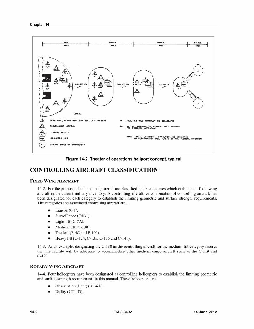
Chapter 14
14-2 TM 3-34.51 15 June 2012
Figure 14-2. Theater of operations heliport concept, typical
CONTROLLING AIRCRAFT CLASSIFICATION
FIXED WING AIRCRAFT
14-2. For the purpose of this manual, aircraft are classified in six categories which embrace all fixed wing aircraft in the current military inventory. A controlling aircraft, or combination of controlling aircraft, has been designated for each category to establish the limiting geometric and surface strength requirements. The categories and associated controlling aircraft are—
Liaison (0-1). Surveillance (OV-1). Light lift (C-7A). Medium lift (C-130). Tactical (F-4C and F-105). Heavy lift (C-124, C-133, C-135 and C-141).
14-3. As an example, designating the C-130 as the controlling aircraft for the medium-lift category insures that the facility will be adequate to accommodate other medium cargo aircraft such as the C-119 and C-123.
ROTARY WING AIRCRAFT
14-4. Four helicopters have been designated as controlling helicopters to establish the limiting geometric and surface strength requirements in this manual. These helicopters are—
Observation (light) (0H-6A). Utility (UH-1D).

Airfield and Heliports
15 June 2012 TM 3-34.51 14-3
Cargo, medium transport (CH-47). Cargo, heavy lift (CH-54).
AIRFIELD-HELIPORT TYPES
AIRFIELD
14-5. The airfield classification system developed herein includes all known air missions for fixed wing aircraft in the T/0. The airfield types are derived by combining the controlling aircraft classification with the appropriate military area. Where airfields are to serve as multi-mission facilities for support of all classes of Army and Air Force aircraft, the first term in the airfield type designation will become "Army" or "Air Force" rather than a controlling aircraft classification, for example, Army rear area.
HELIPORTS
14-6. The heliport classification system also developed herein is derived by combining the selected helicopters with appropriate military areas.
RESPONSIBILITIES, ENGINEER 14-7. Engineer construction units, under the appropriate Army command, will be responsible for performing Air Force-Army construction on a general support and close support basis. The execution of large construction projects will normally be on a general support, that is, project directives, basis; units assigned in general support may be additionally assigned in close support of a specific Army or Air Force element for emergency rehabilitation. Units, when executing either general or close support missions, will remain under Army command and operational control.
14-8. In accomplishing the engineer mission, the engineer commander is concerned with site reconnaissance and recommendations, with the design of the airfield, and with the actual construction of the airfield. The engineer is normally furnished standard designs for the type and capacity of the airfield required, but these designs must frequently be altered to meet time and material limitations or those imposed by local terrain, area, or obstruction characteristics. When alterations take place, it becomes the construction draftsman's responsibility to incorporate them into the original drawings or make new drawings of the airfield. These drawings are usually supervised by the project engineer, but the construction draftsman must be familiar with the terms used in conjunction with airfield design.
SECTION II - AIRFIELDS
SITE REQUIREMENTS 14-9. The operational plan will establish the tactical or logical (or both) requirements which, in turn, will influence the type and number of aircraft, and the number of aircraft missions required. This will enable the planner to determine the number, type, service life, and the construction time limitations for the airfields required in each military area (table 14-1, page 14-4).
14-10. Within the established site requirements, as dictated by the tactical situation, the geographical location of the various airfields needed will be made on the basis of topographic features (grading, drainage, and hydrology), soil conditions, vegetation cover, and climatic conditions.

Chapter 14
14-4 TM 3-34.51 15 June 2012
Table 14-1. Aircraft characteristics used in design of theater of operations airfields
Airfield type Typical sector Anticipated service life
Possible using
aircraft U.S. type
Gross weight
Wing length segment used to
compute dustproofing
area, ft
Ground run at
sea level and 59°,
ft d
Battle area: 3 days
Light lift ............................... Brigade base .................... C-7A a 25,000 37 625
Medium lift .......................... Brigade base .................... C-130 a 100,000 60 1,600
C-123 48,000 49 1,600
Forward area: 2 weeks
Liaison ................................ Division or brigade base .. O-1 a 2,400 15 390
Surveillance ........................ Division base.................... OV-1 a 15,800 20 2,000
Light lift ............................... Division base.................... C-7A a 28,500 37 625
Medium lift .......................... Division base.................... C-130 a 110,000 60 2,000
C-7A 28,500 37 625
Liaison ................................ Corps area ....................... O-1 a 2,400 15 390
Surveillance ........................ Corps area ....................... OV-1 a 15,800 20 2,000
Light lift ............................... Corps area or FASCOM b C-7A a 28,500 37 625
Medium lift .......................... Corps area or FASCOM C-130 a 130,000 60 2,800
C-7A 28,500 37 625
Heavy lift ............................. Corps area or FASCOM .. C-124 a 190,000 4,000
C-141 a 260,000 73 2,400
Tactical ............................... Corps area or FASCOM .. F-4C a 56,000 11 4,000
F-101 51,000 4,000
Rear area: 6-12 months
Army ................................... COMMZ c ......................... OV-1 a 15,800 2,000
C-7A 28,500 37 625
O-1 2,400 15 390
Medium lift .......................... COMMZ ........................... C-130 a 155,000 60 4,000
Heavy lift ............................. COMMZ ........................... C-141 a 316,000 73 3,900
C-135 a 250,000 6,700
C-133 300,000 82 5,300
Tactical .............................. COMMZ ........................... F-4C a 56,000 11 4,000
F-105 a 53,000 5,300
F-100 37,800 14 5,000
F-101 51,000 4,000
F-104 28,000 5,200
a Particular aircraft that is critical in load and/or ground run from which area requirements, geometrics, and expedient surfacing requirements were developed. b Fighter Air Support Command. c Communications Zone. d Ground run lengths indicated are for classification and can undergo changes depending on operating weight of aircraft, pressure altitude corrections, temperature corrections and local conditions.
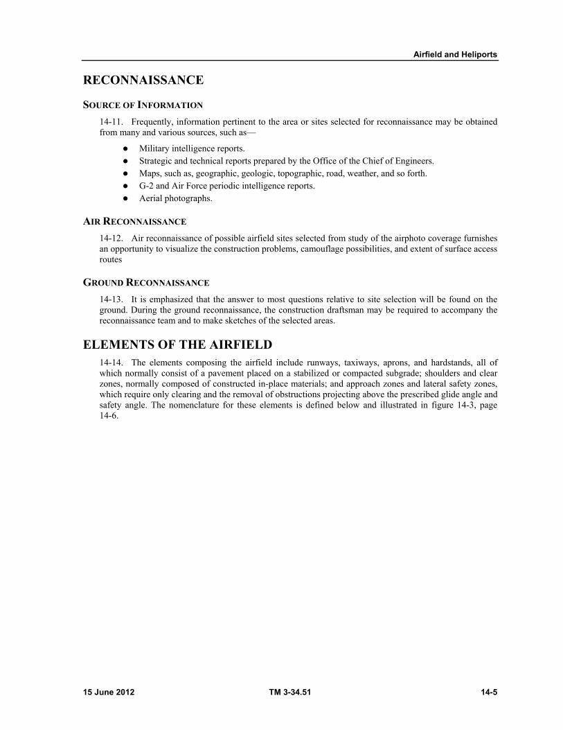
Airfield and Heliports
15 June 2012 TM 3-34.51 14-5
RECONNAISSANCE
SOURCE OF INFORMATION
14-11. Frequently, information pertinent to the area or sites selected for reconnaissance may be obtained from many and various sources, such as—
Military intelligence reports. Strategic and technical reports prepared by the Office of the Chief of Engineers. Maps, such as, geographic, geologic, topographic, road, weather, and so forth. G-2 and Air Force periodic intelligence reports. Aerial photographs.
AIR RECONNAISSANCE
14-12. Air reconnaissance of possible airfield sites selected from study of the airphoto coverage furnishes an opportunity to visualize the construction problems, camouflage possibilities, and extent of surface access routes
GROUND RECONNAISSANCE
14-13. It is emphasized that the answer to most questions relative to site selection will be found on the ground. During the ground reconnaissance, the construction draftsman may be required to accompany the reconnaissance team and to make sketches of the selected areas.
ELEMENTS OF THE AIRFIELD 14-14. The elements composing the airfield include runways, taxiways, aprons, and hardstands, all of which normally consist of a pavement placed on a stabilized or compacted subgrade; shoulders and clear zones, normally composed of constructed in-place materials; and approach zones and lateral safety zones, which require only clearing and the removal of obstructions projecting above the prescribed glide angle and safety angle. The nomenclature for these elements is defined below and illustrated in figure 14-3, page 14-6.
Chapter 14
14-6 TM 3-34.51 15 June 2012
Figure 14-3. Elements of the airfield
Angle, Glide. A small vertical angle measured outward and upward from the end of the flightstrip, above which no obstruction should extend within the area of the approach zones.
Apron. The apron is a stabilized area for parking, maintenance, loading, unloading, and refueling of aircraft.
Clear Area. A rectangular area located adjacent to and outside of the runway shoulders, in which tree stumps are cut close to the ground, boulders removed, and the general area roughly graded to the extent necessary to reduce damage to aircraft in the event of erratic performance in which the aircraft runs off the runway.
Clear Zone. A cleared area located at each end of the runway. Width is equal to runway, runway shoulders, and runway clear areas and length is normally equal to the overrun.
Flightstrip. Includes area of the runway, shoulders, clear area, overruns, and clear zones. Flightway. Includes flightstrip area together with the two approach zones. Hardstand. A stabilized or surfaced area provided to support standing aircraft. Hardstands are
normally dispersed at intervals along each side of a taxiway. Lateral Safety Zone. An area (transitional surface) located between the runway clear area or
runway edge when no clear area is provided and the clearance lines limiting the placement of building construction and other obstacles with respect to the runway centerline. The slope of the transitional surface is 7:1 outward and upward at a right angle to the runway centerline.
Overrun. A graded and compacted portion of the clear zone, located at the extension of each end of the runway, to minimize risk of accident to aircraft due to overrun on takeoff or undershooting on landing. Its length is normally equal to that of the clear zone and its width equal to that of the runway and shoulders.
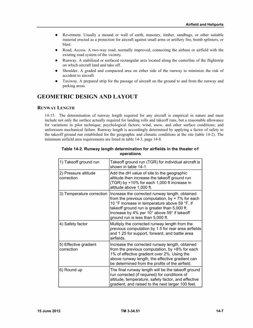
Airfield and Heliports
15 June 2012 TM 3-34.51 14-7
Revetment. Usually a mound or wall of earth, masonry, timber, sandbags, or other suitable material erected as a protection for aircraft against small arms or artillery fire, bomb splinters, or blast.
Road, Access. A two-way road, normally improved, connecting the airbase or airfield with the existing road system of the vicinity.
Runway. A stabilized or surfaced rectangular area located along the centerline of the flightstrip on which aircraft land and take off.
Shoulder. A graded and compacted area on either side of the runway to minimize the risk of accident to aircraft.
Taxiway. A prepared strip for the passage of aircraft on the ground to and from the runway and parking areas.
GEOMETRIC DESIGN AND LAYOUT
RUNWAY LENGTH
14-15. The determination of runway length required for any aircraft is empirical in nature and must include not only the surface actually required for landing rolls and takeoff runs, but a reasonable allowance for variations in pilot technique; psychological factors; wind, snow, and other surface conditions; and unforeseen mechanical failure. Runway length is accordingly determined by applying a factor of safety to the takeoff ground run established for the geographic and climatic conditions at the site (table 14-2). The minimum airfield area requirements are listed in table 14-3, page 14-8.
Table 14-2. Runway length determination for airfields in the theater o f operations
1) Takeoff ground run Takeoff ground run (TGR) for individual aircraft is shown in table 14-1.
2) Pressure altitude correction
Add the dH value of site to the geographic altitude then increase the takeoff ground run (TGR) by +10% for each 1,000 ft increase in altitude above 1,000 ft.
3) Temperature correction Increase the corrected runway length, obtained from the previous computation, by + 7% for each 10 °F increase in temperature above 59 °F, if takeoff ground run is greater than 5,000 ft. Increase by 4% per 10° above 59° if takeoff ground run is less than 5,000 ft.
4) Safety factor Multiply the corrected runway length from the previous computation by 1.5 for rear area airfields and 1.25 for support, forward, and battle area airfields.
5) Effective gradient correction
Increase the corrected runway length, obtained from the previous computation, by +8% for each 1% of effective gradient over 2%. Using the above runway length, the effective gradient can be determined from the profile of the airfield.
6) Round up The final runway length will be the takeoff ground run corrected (if required) for conditions of altitude, temperature, safety factor, and effective gradient, and raised to the next larger 100 feet.

Chapter 14
14-8 TM 3-34.51 15 June 2012
Table 14-2. Runway length determination for airfields in the theater o f operations
7) Compare with minimum required
Compare calculated length obtained from the previous computation with the minimum length required as shown in column 5 of table 14-3. Use the greater value.
1 The temperature to be considered is the mean temperature for the warmest period during which operations will be conducted from the airfield.
Table 14-3. Minimum airfield area requirements
Airfield type Typical sector Anticipated service life
Possible using
aircraft
U.S.
type
Minimum length
required, ft
Width ft
Gradients
Longitudinal %
Transverse %
Max grade
change per 100 ft
%
Battle area: 3 days
Light lift Brigade base C-7A a 1,000 50 0± 5.0 3.0 2.0
Medium lift Brigade base C-130 a 2,000 60 0± 4.0 0.5—3.0 2.0 c
C-123
Forward area: 2 weeks
Liaison Division or brigade base
O-l a 750 50 0± 10.0 5.0 2.0
Surveillance Division base OV-1 a 2,500 60 0± 5.0 0.5—3.0
Light lift Division base C-7A a 1,200 60 0± 5.0 0.5—3.0 2.0
Medium lift Division base C-130 a 2,500 60 0± 3.0 0.5—2.0 1.5 c
C-7A
Support area: 1-2 mo.
Liaison Corps area 0-1 a 1,000 50 0± 10.0 5.0 2.0
Surveillance Corps area OV-1 * 3,000 60 0± 4.0 0.5—3.0 1.5
Light lift Corps area or FASCOM b
C-7A a 1,500 60 0± 4.0 0.5—3.0 1.5
Medium lift Corps area or FASCOM
C-130 a 3,500 60 0± 3.0 0.5-2.0 1.5 c
C-7A
Heavy lift Corps area or FASCOM-.
C-124 a 6,000 100 0± 2.0 0.5—3.0 1.5 c
C-141 a
Tactical Corps area or FASCOM.
F-4C a 5,000 60 0± 3.0 0.5—3.0 1.5 c
Rear area: 6-12 mo.
Army COMMZ d OV-1 a 3,000 72 0± 3.0 0. —2.0 1.5
C-7A
0-1
Medium lift COMMZ C-130 a 6,000 72 0± 3.0 0.5—3.0 1.5 c
Heavy lift COMMZ C-141 a 10,000 156 0± 2.0 0.5—1.5 1.5 c
C-135 a
C-133
Tactical COMMZ F-4C a 8,000 108 0± 2.0 0.5—1.5 0.33 c
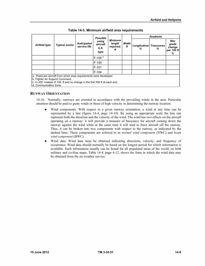
Airfield and Heliports
15 June 2012 TM 3-34.51 14-9
Table 14-3. Minimum airfield area requirements
Airfield type Typical sector Anticipated service life
Possible using
aircraft
U.S.
type
Minimum length
required, ft
Width ft
Gradients
Longitudinal %
Transverse %
Max grade
change per 100 ft
%
F-105 a
F-100
F-101
F-104 a. Particular aircraft from which area requirements were developed. b. Fighter Air Support Command. c. In 200, instead of 100, ft and no change in the first 500 ft at each end. d. Communication Zone.
RUNWAY ORIENTATION
14-16. Normally, runways are oriented in accordance with the prevailing winds in the area. Particular attention should be paid to gusty winds or those of high velocity in determining the runway location.
Wind components. With respect to a given runway orientation, a wind at any time can be represented by a line (figure 14-4, page 14-10). By using an appropriate scale the line can represent both the direction and the velocity of the wind. The wind has two effects on the aircraft operating on a runway: it will provide a measure of buoyancy for aircraft coming down the runway against the wind while at the same time it will tend to force aircraft off the runway. Thus, it can be broken into two components with respect to the runway, as indicated by the dashed lines. These components are referred to as normal wind component (NWC) and beam wind component (BWC).
Wind data. Wind data must be obtained indicating directions, velocity, and frequency of occurrence. Wind data should normally be based on the longest period for which information is available. Such information usually can be found for all populated areas of the world, on both military and civilian maps. Table 14-4, page 4-12, shows the form in which the wind data may be obtained from the air weather service.
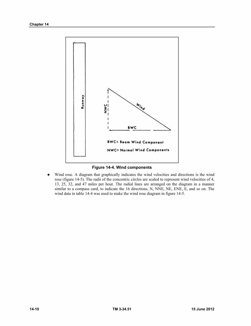
Chapter 14
14-10 TM 3-34.51 15 June 2012
Figure 14-4. Wind components
Wind rose. A diagram that graphically indicates the wind velocities and directions is the wind rose (figure 14-5). The radii of the concentric circles are scaled to represent wind velocities of 4, 13, 25, 32, and 47 miles per hour. The radial lines are arranged on the diagram in a manner similar to a compass card, to indicate the 16 directions, N, NNE, NE, ENE, E, and so on. The wind data in table 14-4 was used to make the wind rose diagram in figure 14-5.
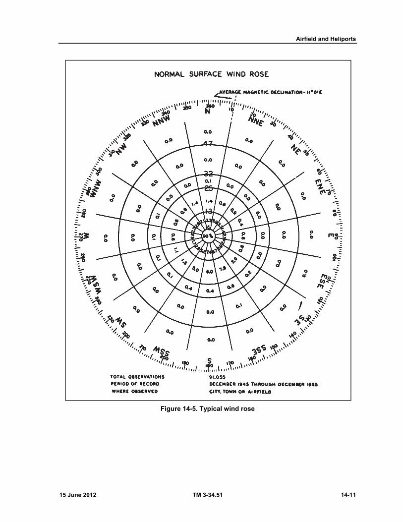
Airfield and Heliports
15 June 2012 TM 3-34.51 14-11
Figure 14-5. Typical wind rose

Chapter 14
14-12 TM 3-34.51 15 June 2012
Table 14-4. Annual percentage of all surface winds—by velocity (MPH) and direction
Direction
Wind velocity group (mph) Total
all groups
1-4 4-13 13-25 25-32 32-47 Over 47
(a) (b) (c) (d) (e) (f)
Percent
N 0.3 3.3 1.4 0.1 .0 0 5.1
NNE .3 3.0 .9 .0 .0 0 4.2
NE .5 3.3 .9 .0 .0 0 4.7
ENE .2 1.4 .4 .0 .0 0 2.0
E .5 2.5 .6 .0 .0 0 3.6
ESE .3 2.4 .8 .0 .0 0 3.5
SE .6 5.9 2.9 .0 .0 0 9.6
SSE .5 6.7 7.9 .6 .1 0 15.8
S .3 7.4 6.0 .4 .0 0 14.6
SSW .6 5.2 5.0 .4 .0 0 11.2
SW .5 2.9 1.3 .1 .0 0 4.8
WSW .3 1.7 1.1 .1 .0 0 3.2
W .4 2.3 .6 .1 .0 0 3.4
WNW .4 2.3 .8 .1 .0 0 3.6
NW .5 2.6 .8 .0 .0 0 3.9
NNW .3 3.1 1.4 .0 .0 0 4.8
Calms 2.0 .0 .0 .0 .0 0 2.0
Total 9.0 56.0 32.8 2.1 .1 0 100.0Period of record: July 1954 through July 1964. Total number of hourly observations = 91,055 = 100 percent.
Wind vector. A graphical procedure is used for the wind rose analysis, the basic idea of which is illustrated in figure 14-6. Line D-o represents the direction of the prevailing wind and line A-B the direction of the runway. The velocity of the prevailing wind is scaled off on D-o and indicated as c-o. If the scale used is 0.1 inch equals 1 mph and the prevailing wind has a velocity of 18 mph, the length of line c-o would be 1.8 inches. The wind component perpendicular to the direction of the runway may be determined by drawing a line c-b at a right angle to A-B. This line measures 0.9 inch and therefore at the same scale represents 9.0 mph, the cross-wind component. The line b-o measures 1.56 inches and therefore represents 15.6 mph, the wind component parallel to the runway.
For a complete explanation of how to construct, use, and analyze the wind rose diagram, refer to TM 5-330.

Airfield and Heliports
15 June 2012 TM 3-34.51 14-13
Figure 14-6. Wind vector
GEOMETRIC REQUIREMENTS
14-17. These requirements are based on the operational characteristics of the aircraft considered; therefore, variations in these requirements will not be allowed except where sufficient evidence is presented to justify a proposed change.
AREA REQUIREMENTS
14-18. The minimum area requirements of airfields are listed in table 14-3, page 14-9.
AIRFIELD LAYOUT
14-19. Typical airfield layouts are shown in figures 14-7 and 14-8, pages 14-14 through 14-16.
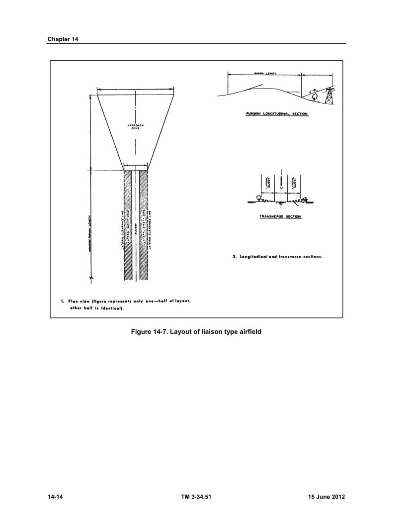
Chapter 14
14-14 TM 3-34.51 15 June 2012
Figure 14-7. Layout of liaison type airfield
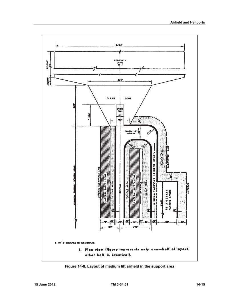
Airfield and Heliports
15 June 2012 TM 3-34.51 14-15
Figure 14-8. Layout of medium lift airfield in the support area
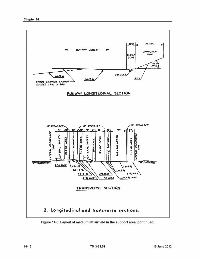
Chapter 14
14-16 TM 3-34.51 15 June 2012
Figure 14-8. Layout of medium lift airfield in the support area (continued)

Airfield and Heliports
15 June 2012 TM 3-34.51 14-17
SECTION III - HELIPORTS
CHARACTERISTICS 14-20. Important characteristics of current Army helicopters are shown in table 14-5, page 14-18. Army helicopters are classed as observation, utility, cargo, and armed aircraft.
OBSERVATION (LIGHT) HELICOPTERS (OH)
14-21. These helicopters are usually used for visual, photographic, or electronic observation, and for the adjustment of fires or aerial wire laying.
UTILITY HELICOPTERS (UH)
14-22. These helicopters are usually for missions such as cargo and passenger transport.
CARGO (MEDIUM TRANSPORT AND HEAVY LIFT) HELICOPTERS (CH)
14-23. These helicopters are usually used for airmobile operations and transport of troops, equipment, and supplies within the battle area.
ARMED HELICOPTERS (AH OR UH)
14-24. These helicopters are usually used to provide escort for troop-carrying helicopters and a gun platform to accommodate a variety of weapons.
LAYOUT 14-25. The geometric design requirements for helicopter landing areas can be simplified into four basic types: helipads; heliports with taxi-hoverlanes; heliports with runways; and mixed battalion heliports. The geometric layout and section views of these landing areas are shown in figures 14-9 through 14-12, pages 14-19 through 14-22. For a complete discussion of heliports, refer to chapters 14 and 15, TM 5-330.
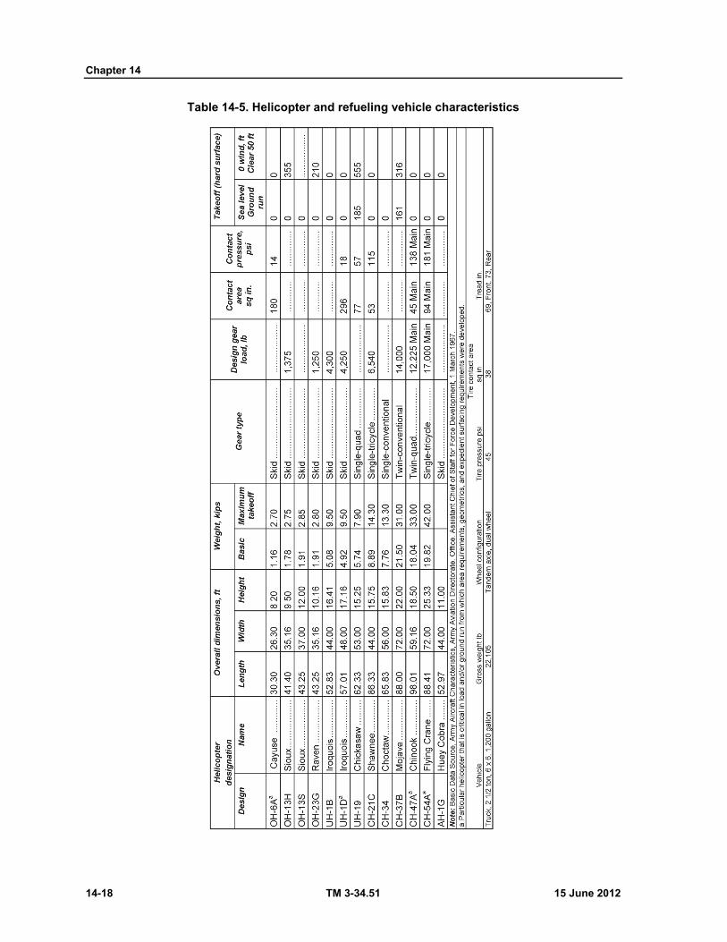
Chapter 14
14-18 TM 3-34.51 15 June 2012
Table 14-5. Helicopter and refueling vehicle characteristics

Airfield and Heliports
15 June 2012 TM 3-34.51 14-19
Figure 14-9. Helipad
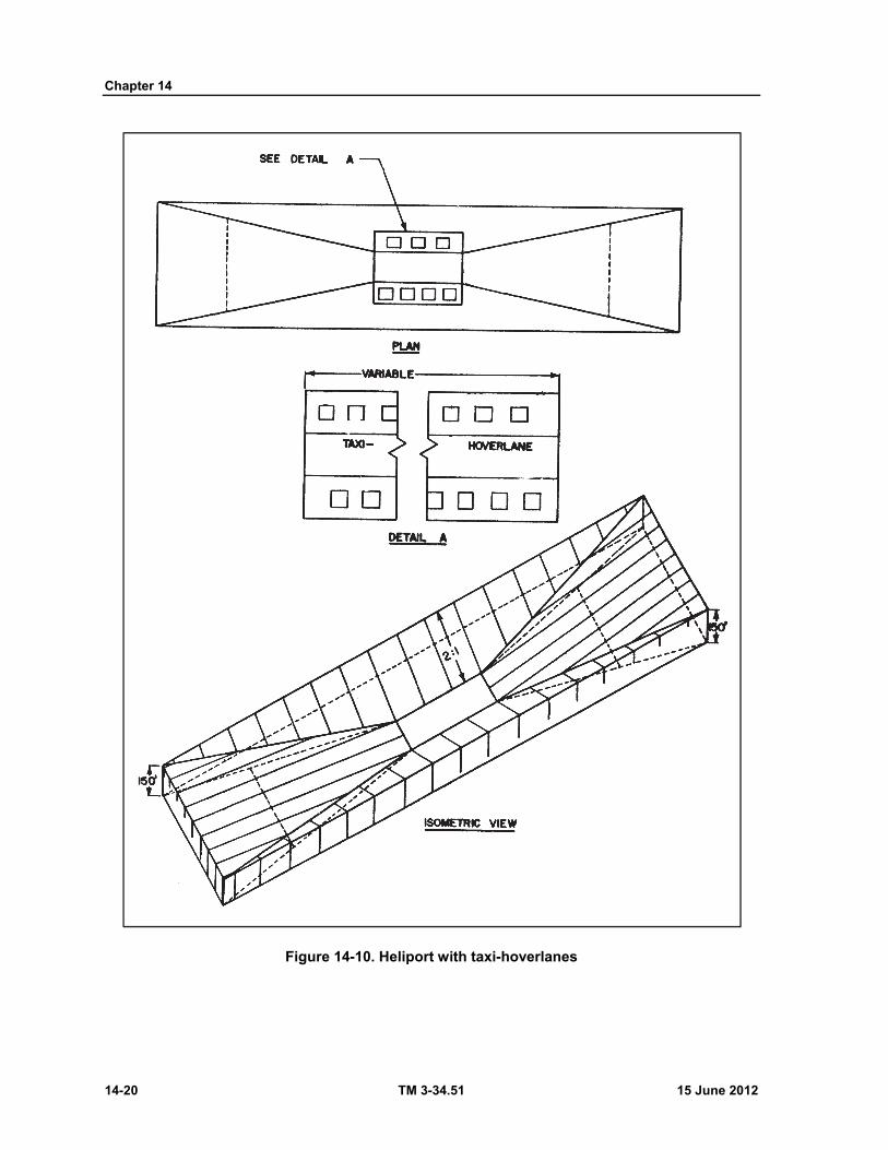
Chapter 14
14-20 TM 3-34.51 15 June 2012
Figure 14-10. Heliport with taxi-hoverlanes
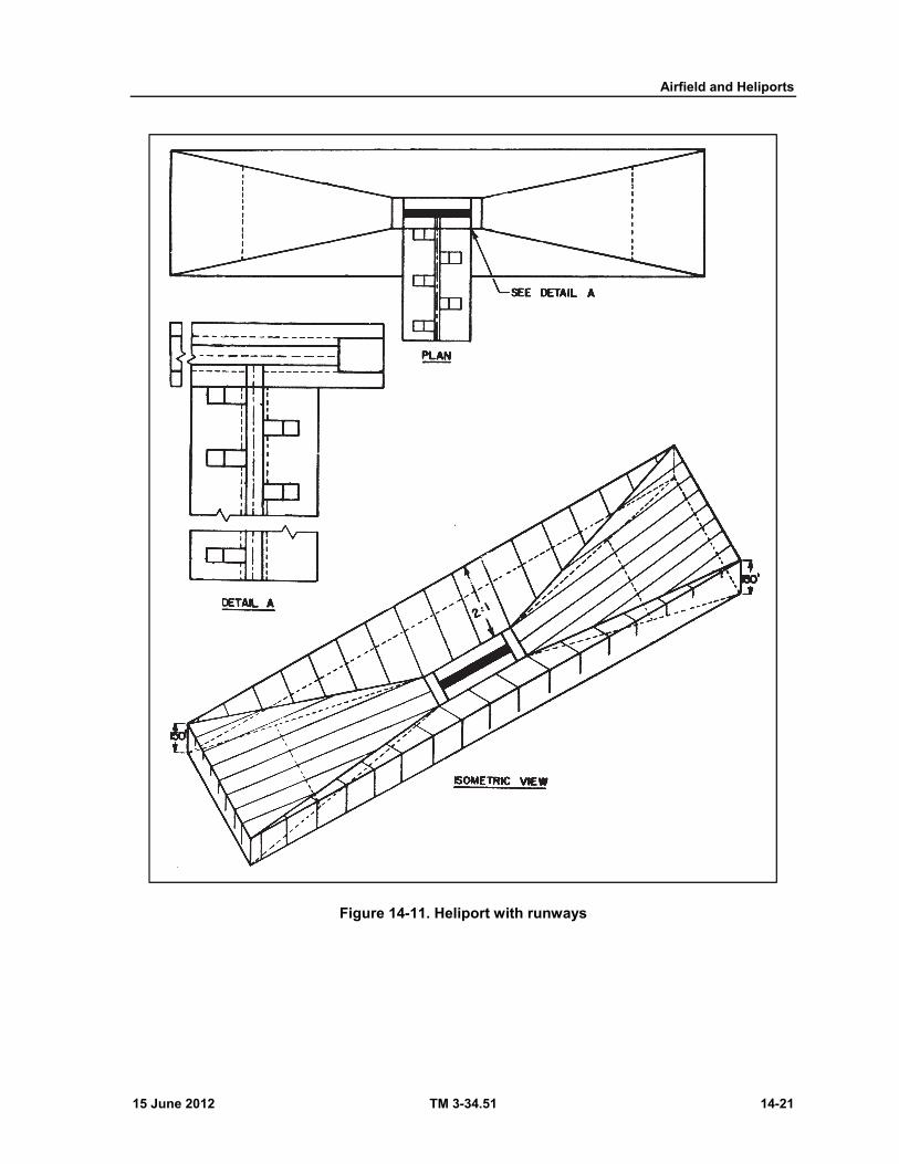
Airfield and Heliports
15 June 2012 TM 3-34.51 14-21
Figure 14-11. Heliport with runways
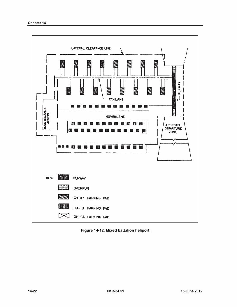
Chapter 14
14-22 TM 3-34.51 15 June 2012
Figure 14-12. Mixed battalion heliport
15 June 2012 TM 3-34.51 15-1
Chapter 15
Port Construction
INTRODUCTION
On land construction and waterfront construction are similar, but waterfront construction has more limiting or controlling factors. For example, the elevation of a waterfront structure depends on the tidal range; and its length and width must conform to requirements of ship maneuvering, the water source, traffic pattern, prevailing wind direction, wave action, and current force and direction. Yet, in all cases, the principal controlling factor in waterfront construction is the tidal range of the area involved because tidal range also limits the times that construction operations can proceed. Understanding of these factors is necessary for the construction of a functional port.
HARBOR STUDIES AND SURVEYS
TIDAL TABLES
15-1. From tidal observations covering ex-tended periods and careful analyses of all tide-producing factors, it is possible to predict the heights and times of occurrence of tides in various parts of the world. Such predicted data are published annually by the NATIONAL OCEANO-GRAPHIC SURVEY, ESSA, in their tide tables. The tide tables, listed below, are items of military issue:
Tide Tables, Central and Western Pacific Ocean and Indian Ocean. Tide Tables, East Coast North and South America including Greenland. Tide Tables, West Coast North and South America including Hawaiian Islands.
15-2. These tables give daily tidal data at a number of reference ports and stations and tables of tidal differences and constants, so that the daily values for any one of a large number of subordinate ports listed can be quickly computed from the data for a reference station.
TIDAL RANGE DATA FROM TIDE TABLES Mean high water for the day of the month is obtained from the summation of all high waters. Mean low water for the day of the month is obtained from the summation of all low waters. Higher high water for the day of the month is obtained from the higher of the high waters for the
period concerned. Lower low water for the day of the month is obtained from the lower of the low waters for the
period concerned.
SHORELINE LIMITS Bulkhead line. The bulkhead line establishes the limit for solid fill structures into the waterway. Pier head line. The pier head line establishes the limit for framed structures into the waterway.
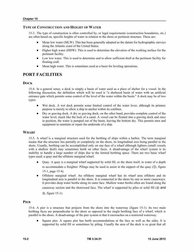
Chapter 15
15-2 TM 3-34.51 15 June 2012
TYPE OF CONSTRUCTION AND HEIGHT OF WATER
15-3. The type of construction is often controlled by, or legal requirements (construction boundaries, etc.) are often based on, specific heights of water in relation to the shore or pertinent structure. These are:
Mean low water (MLW). This has been generally adopted as the datum for hydrographic surveys along the Atlantic coast of the United States.
Higher high water (HHW). This is used to determine the elevation of the working surface for the pertinent facility.
Low low water. This is used to determine and to allow sufficient draft at the pertinent facility for floating craft.
Mean high water. This is sometimes used as a basis for leveling operations.
PORT FACILITIES
DOCK
15-4. In a general sense, a dock is simply a basin of water used as a place of shelter for a vessel. In the following discussion, the definition which will be used is "a sheltered basin of water with an artificial entrance gate which permits some control of the level of the water within the basin." A dock may be of two types:
Wet dock. A wet dock permits some limited control of the water lever, although its primary purpose is merely to allow a ship to anchor within its confines.
Dry or graving dock. A dry or graving dock, on the other hand, provides complete control of the water level, much like the lock of a canal. A vessel can be floated into a graving dock and once in position, the water is pumped out of the basin, leaving the bottom dry. This permits men and equipment to maintain or repair the underside of a ship.
WHARF
15-5. A wharf is a marginal structure used for the berthing of ships within a harbor. The term marginal means that the structure lies partially or completely on the shore, its longitudinal axis being parallel to the shore. Usually, berthing can be accomplished only on one face of a wharf although lighters (small vessels with a shallow draft) may sometimes berth on other faces. A disadvantage of the wharf system is its inability to handle a large number of ships due to the limited berthing space. There are two basic wharf types used: a quay and the offshore marginal wharf.
Quay. A quay is a marginal wharf supported by solid fill, or the shore itself, in water of a depth
to accommodate a freighter. Pilings may be used to assist in the support of the quay (①, figure
15-1, page 15-4). Offshore marginal wharf. An offshore marginal wharf has its wharf area offshore and its
longitudinal axis is parallel to the shore. It is connected to the shore by one or more causeways. It provides deep water berths along its outer face. Shallow water berths often are found along the
causeway section and the shoreward face. The wharf is supported by piles or solid fill (⑧ and ⑨, figure 15-1).
PIER
15-6. A pier is a structure that projects from the shore into the waterway (figure 15-1). Its two main berthing faces are perpendicular to the shore as opposed to the single berthing face of a wharf, which is parallel to the shore. A disadvantage of the pier system is that it encroaches on a restricted waterway.
Square pier. A square pier has berth accommodations at the face as well as the sides. It is supported by solid fill or sometimes by piling. Usually the area of the deck is so great that all
Port Construction
15 June 2012 TM 3-34.51 15-3
pile construction is impractical. For this reason, although often found in commercial harbors, this type of pier is rarely adaptable for new construction in the theater of operations.
Right angle pier and slip. The pier and slip system (③, ④, and ⑥, figure 15-1) provides
alongside berthing space perpendicular to the shore. This type generally is used in commercial ports. The piers are long enough to accommodate the length of the ship and wide enough to provide adequate working space for cargo handling. The slips should provide depth for the draft of ships and width between two berthed ships at adjacent piers for floating cranes, lighter, or other harbor craft. While usually of pile construction, solid fill is also used. Pier construction obviously is impractical in water too deep for the piling available. In water depths suitable for driving piles but resulting in excessive unsupported length of piling, the dumping of rock fill after the piles are driven may be a desirable solution.
Acute angle pier and slip. In the acute angle pier and slip system (⑤ and ⑦, figure 15-1),
alongside berthing is provided, but the piers are not placed at right angles to the shore. This layout is advantageous where the range of suitable depth is too narrow for the perpendicular pier layout or where the pier system is located on a relatively narrow waterway, with insufficient room for a ship to make a 90° turn to enter the slip.
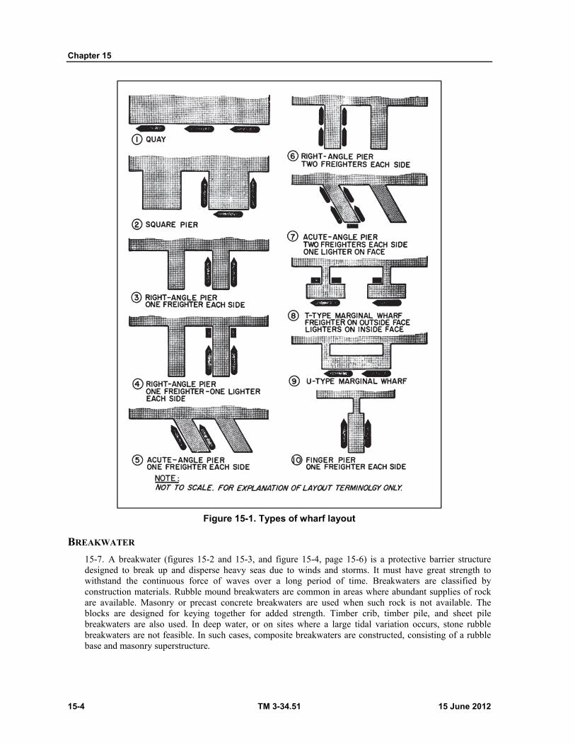
Chapter 15
15-4 TM 3-34.51 15 June 2012
Figure 15-1. Types of wharf layout
BREAKWATER
15-7. A breakwater (figures 15-2 and 15-3, and figure 15-4, page 15-6) is a protective barrier structure designed to break up and disperse heavy seas due to winds and storms. It must have great strength to withstand the continuous force of waves over a long period of time. Breakwaters are classified by construction materials. Rubble mound breakwaters are common in areas where abundant supplies of rock are available. Masonry or precast concrete breakwaters are used when such rock is not available. The blocks are designed for keying together for added strength. Timber crib, timber pile, and sheet pile breakwaters are also used. In deep water, or on sites where a large tidal variation occurs, stone rubble breakwaters are not feasible. In such cases, composite breakwaters are constructed, consisting of a rubble base and masonry superstructure.
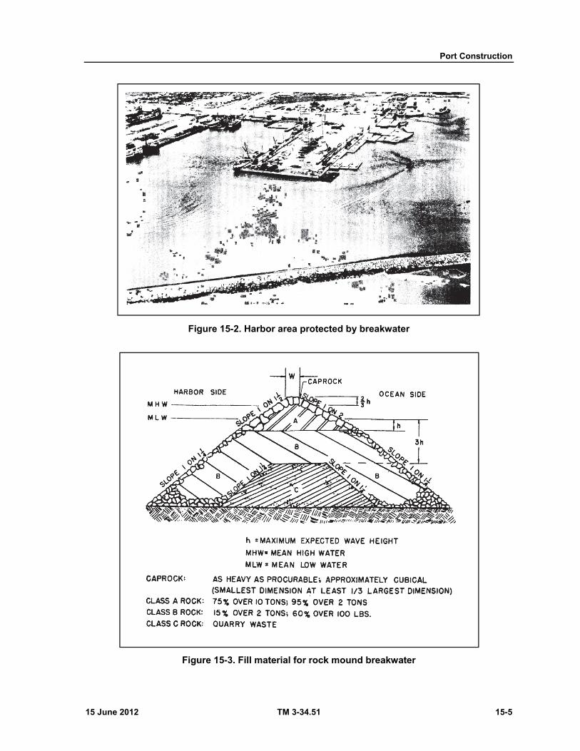
Port Construction
15 June 2012 TM 3-34.51 15-5
Figure 15-2. Harbor area protected by breakwater
Figure 15-3. Fill material for rock mound breakwater

Chapter 15
15-6 TM 3-34.51 15 June 2012
Figure 15-4. Rock mound breakwater, upper course
JETTY
15-8. A jetty (figures 15-5 and 15-6) is a structure, similar to a breakwater, that is placed at the entrance of a harbor or river and extends into the water, diverting or directing existing currents, to create or protect a selected channel. Jetties are categorized in the same types as breakwaters, although they are normally lower in height and less massive, since lesser wave forces are encountered. Rubble mound jetties are the most common although others may be found. The concrete caissons of the composite type jetties shown in figure 15-6 are usually prefrabricated and sunk in place.
MOLE
15-9. A mole is a breakwater or jetty that can serve the dual mission of protection or berthing. A road or railroad may be constructed on a breakwater or jetty to assist in the loading or unloading of a vessel moored next to the harbor side face of the structure.
GROIN
15-10. A groin (figure 15-7, page 15-8) is basically a combination breakwater and jetty although much smaller in size. Its purpose is to influence or control wave action or offshore currents. Groins maybe classified as impermeable, semi-permeable, or permeable. Impermeable groins completely divert currents while the latter two divert less current. Permeable groins allow part of the current to pass the groin undisturbed. Groins are not used when harbor conditions require the use of more massive structures. Figure 15-8, page 15-9, shows the various alinements of groins.
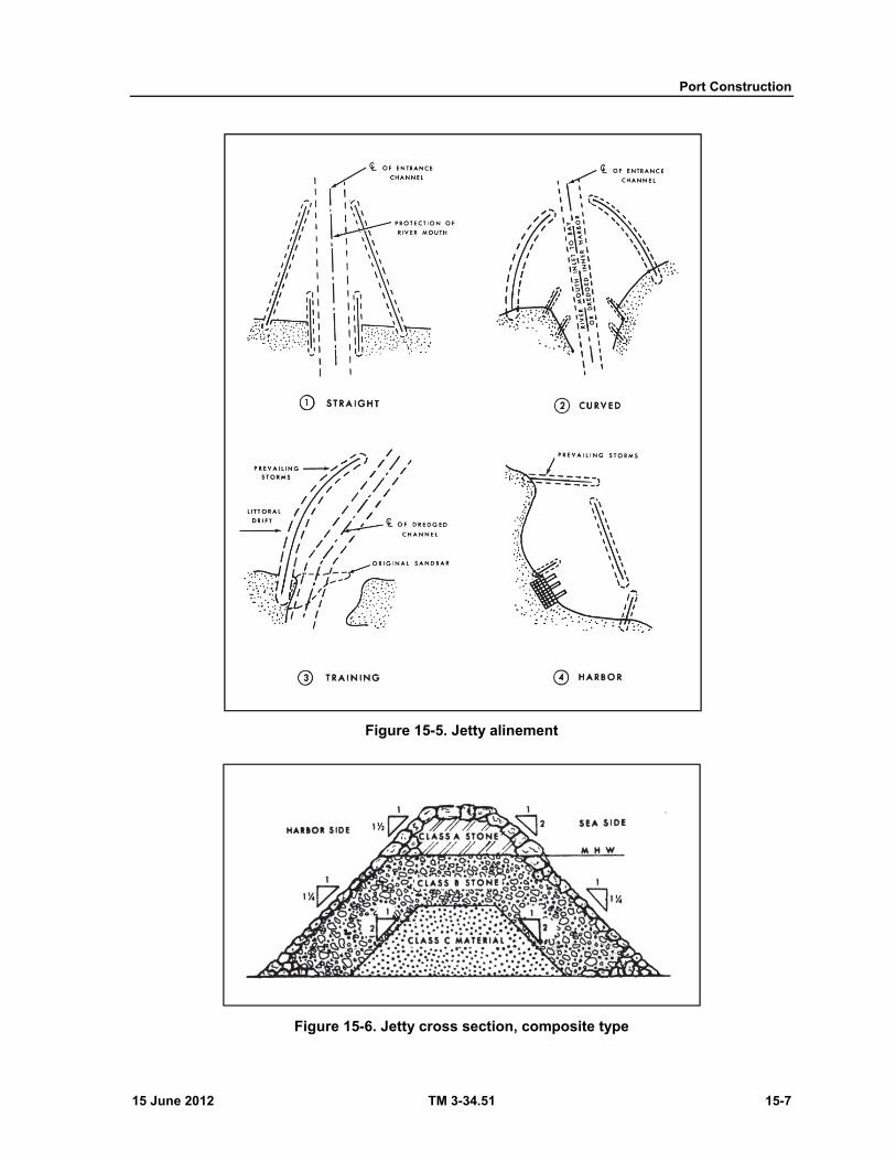
Port Construction
15 June 2012 TM 3-34.51 15-7
Figure 15-5. Jetty alinement
Figure 15-6. Jetty cross section, composite type
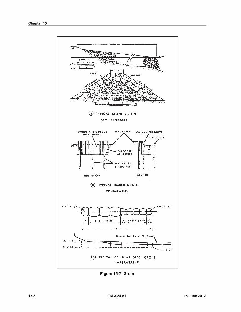
Chapter 15
15-8 TM 3-34.51 15 June 2012
Figure 15-7. Groin
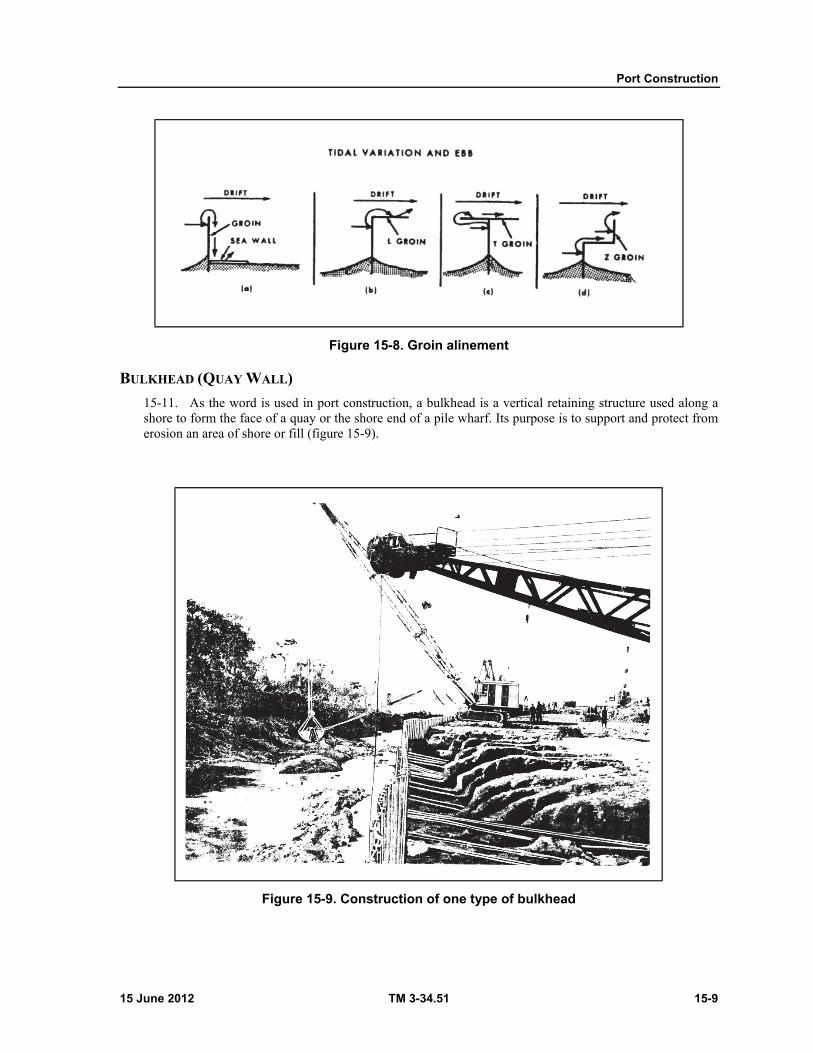
Port Construction
15 June 2012 TM 3-34.51 15-9
Figure 15-8. Groin alinement
BULKHEAD (QUAY WALL)
15-11. As the word is used in port construction, a bulkhead is a vertical retaining structure used along a shore to form the face of a quay or the shore end of a pile wharf. Its purpose is to support and protect from erosion an area of shore or fill (figure 15-9).
Figure 15-9. Construction of one type of bulkhead
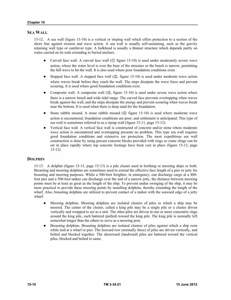
Chapter 15
15-10 TM 3-34.51 15 June 2012
SEA WALL
15-12. A sea wall (figure 15-10) is a vertical or sloping wall which offers protection to a section of the shore line against erosion and wave action. A sea wall is usually self-sustaining, such as the gravity retaining wall type or cantilever type. A bulkhead is usually a thinner structure which depends partly on wales carried on tie rods extending to buried anchors.
Curved face wall. A curved face wall (① figure 15-10) is used under moderately severe wave
action, where the water level is over the base of the structure or the beach is narrow, permitting the full wave to hit the wall. It is also used where poor foundation conditions exist.
Stepped face wall. A stepped face wall (②, figure 15-10) is used under moderate wave action
where waves break before they reach the wall. The steps dissipate the wave force and prevent scouring. It is used where good foundation conditions exist.
Composite wall. A composite wall (③, figure 15-10) is used under severe wave action where
there is a narrow beach and wide tidal range. The curved face prevents overtopping when waves break against the wall, and the steps dissipate the energy and prevent scouring when waves break near the bottom. It is used when there is deep sand for the foundation.
Stone rubble mound. A stone rubble mound (④ figure 15-10) is used where moderate wave action is encountered, foundation conditions are poor, and settlement is anticipated. This type of sea wall is sometimes referred to as a riprap wall (figure 15-11, page 15-12).
Vertical face wall. A vertical face wall is constructed of concrete and/or stone where moderate wave action is encountered and overtopping presents no problem. This type sea wall requires good foundation conditions and extensive toe protection. The most expeditious sea wall construction is done by using precast concrete blocks provided with rings so crane slings can be set in place rapidly where top concrete footings have been cast in place (figure 15-12, page 15-12).
DOLPHIN
15-13. A dolphin (figure 15-13, page 15-13) is a pile cluster used in berthing or mooring ships or both. Breasting and mooring dolphins are sometimes used to extend the effective face length of a pier or jetty for breasting and mooring purposes. While a 500-foot freighter, in emergency, can discharge cargo at a 400-foot pier and a 500-foot tanker can discharge over the end of a narrow jetty, the distance between mooring points must be at least as great as the length of the ship. To prevent undue swinging of the ship, it may be more practical to provide these mooring points by installing dolphins, thereby extending the length of the wharf. Also, breasting dolphins are utilized to prevent contact of a tanker with the seaward edge of a jetty wharf.
Mooring dolphins. Mooring dolphins are isolated clusters of piles to which a ship may be moored. The center of the cluster, called a king pile may be a single pile or a cluster driven vertically and wrapped to act as a unit. The other piles are driven in one or more concentric rings around the king pile, each battered (pulled) toward the king pile. The king pile is normally left somewhat longer than the others to serve as a mooring post.
Breasting dolphins. Breasting dolphins are isolated clusters of piles against which a ship rests while tied at a wharf or pier. The leeward row (normally three) of piles are driven vertically, and bolted and blocked together. The shoreward (landward) piles are battered toward the vertical piles, blocked and bolted to same.
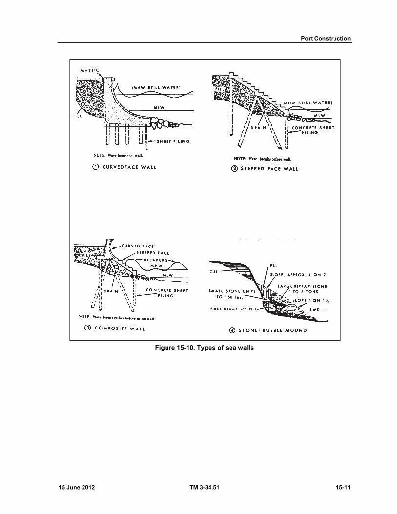
Port Construction
15 June 2012 TM 3-34.51 15-11
Figure 15-10. Types of sea walls
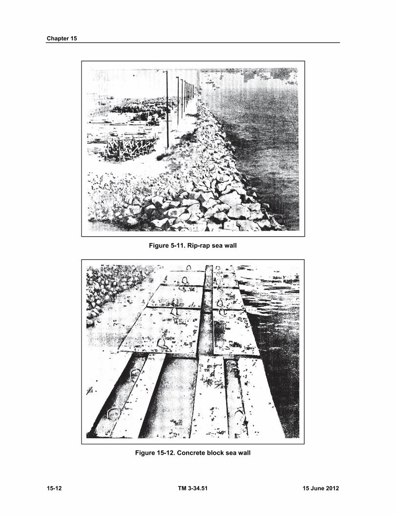
Chapter 15
15-12 TM 3-34.51 15 June 2012
Figure 5-11. Rip-rap sea wall
Figure 15-12. Concrete block sea wall
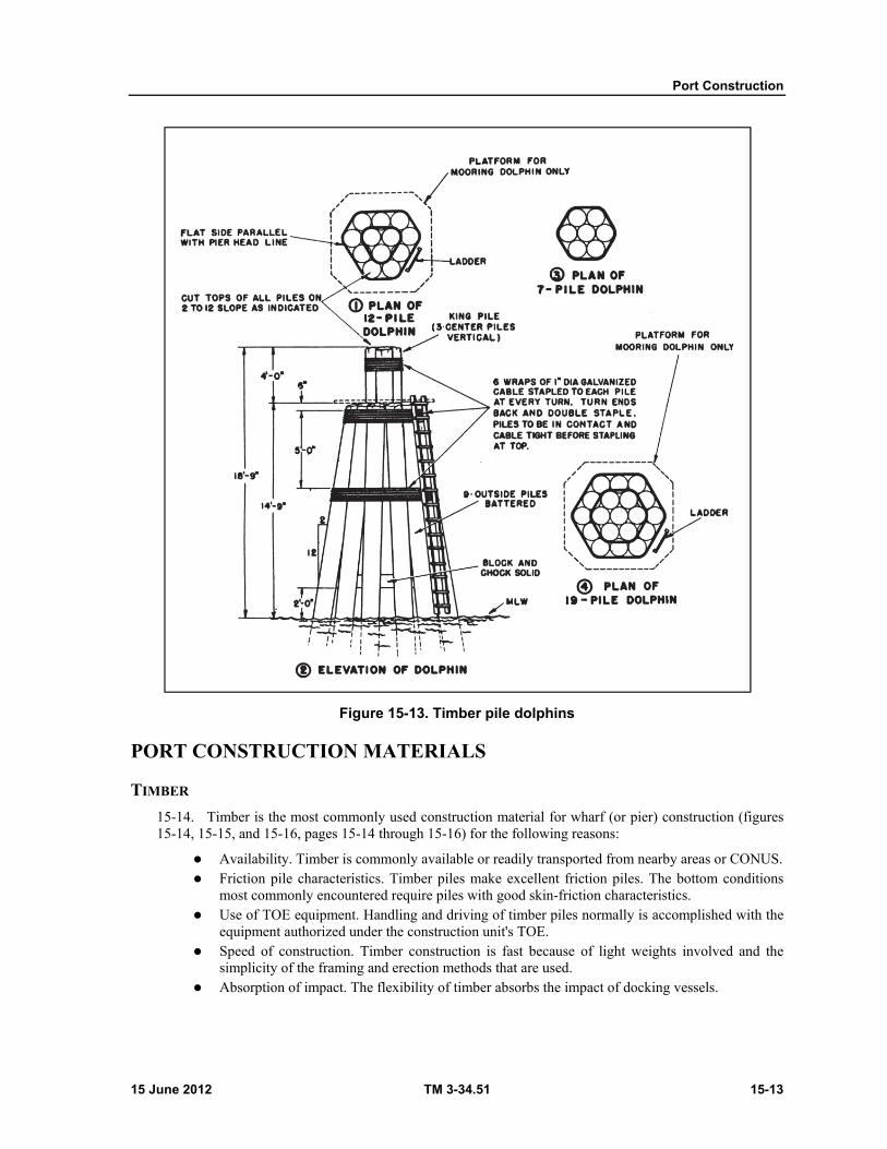
Port Construction
15 June 2012 TM 3-34.51 15-13
Figure 15-13. Timber pile dolphins
PORT CONSTRUCTION MATERIALS
TIMBER
15-14. Timber is the most commonly used construction material for wharf (or pier) construction (figures 15-14, 15-15, and 15-16, pages 15-14 through 15-16) for the following reasons:
Availability. Timber is commonly available or readily transported from nearby areas or CONUS. Friction pile characteristics. Timber piles make excellent friction piles. The bottom conditions
most commonly encountered require piles with good skin-friction characteristics. Use of TOE equipment. Handling and driving of timber piles normally is accomplished with the
equipment authorized under the construction unit's TOE. Speed of construction. Timber construction is fast because of light weights involved and the
simplicity of the framing and erection methods that are used. Absorption of impact. The flexibility of timber absorbs the impact of docking vessels.
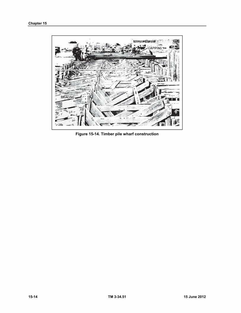
Chapter 15
15-14 TM 3-34.51 15 June 2012
Figure 15-14. Timber pile wharf construction
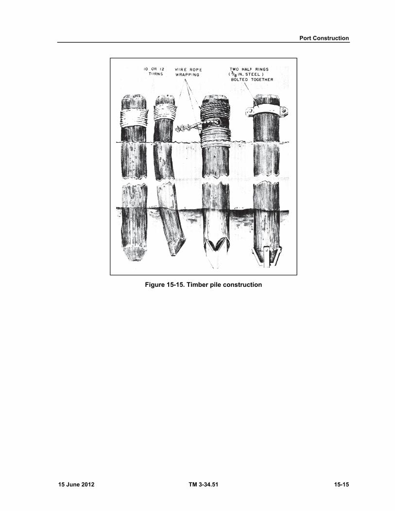
Port Construction
15 June 2012 TM 3-34.51 15-15
Figure 15-15. Timber pile construction
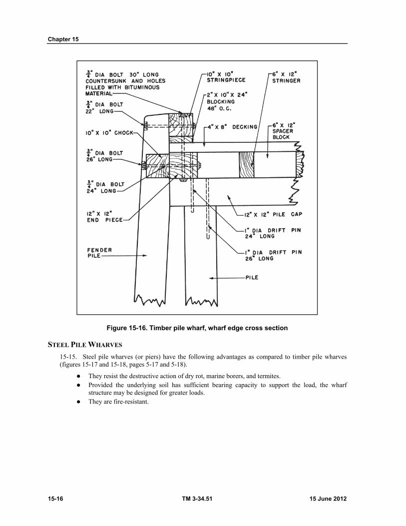
Chapter 15
15-16 TM 3-34.51 15 June 2012
Figure 15-16. Timber pile wharf, wharf edge cross section
STEEL PILE WHARVES
15-15. Steel pile wharves (or piers) have the following advantages as compared to timber pile wharves (figures 15-17 and 15-18, pages 5-17 and 5-18).
They resist the destructive action of dry rot, marine borers, and termites. Provided the underlying soil has sufficient bearing capacity to support the load, the wharf
structure may be designed for greater loads. They are fire-resistant.

Port Construction
15 June 2012 TM 3-34.51 15-17
Figure 15-17. Steel pile construction, alining and capping
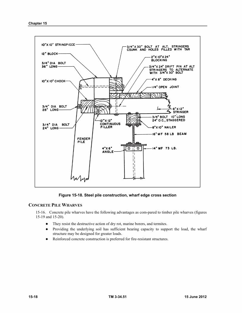
Chapter 15
15-18 TM 3-34.51 15 June 2012
Figure 15-18. Steel pile construction, wharf edge cross section
CONCRETE PILE WHARVES
15-16. Concrete pile wharves have the following advantages as com-pared to timber pile wharves (figures 15-19 and 15-20).
They resist the destructive action of dry rot, marine borers, and termites. Providing the underlying soil has sufficient bearing capacity to support the load, the wharf
structure may be designed for greater loads. Reinforced concrete construction is preferred for fire-resistant structures.

Port Construction
15 June 2012 TM 3-34.51 15-19
Figure 15-19. Concrete piles falsework, before and after cuttoff
Figure 15-20. Concrete surface on timber deck
Chapter 15
15-20 TM 3-34.51 15 June 2012
HARDWARE Wire nails. Common wire nails are largely used for deck lamination and tread securing. Nails of
the screw type are also highly desirable, because of greater holding power. Driftpins. Driftpins are long, heavy, threadless bolts used to hold heavy pieces of timber
together. The term driftbolt is sometimes used for supply purposes (figure 15-16, page 15-20). Bolts. Bolts with O.G. washers are utilized in timber wharf (or pier) construction because of the
holding strength required. Also, bolts afford some latitude of flexibility in the structure. O.G. washers are made of cast iron, usually one-half inch to three-quarters of an inch thick. The outside perimeter of the bolt taken at a cross section resembles an ogee curve. Thus, the nomenclature O.G. washer was derived. This washer was especially designed for timber, because it can distribute the torque load of the bolt over a wider area, due to its stiffness.
Turnbuckles. Turnbuckles are devices normally used to apply controlled tension to wire rope or steel rods for bracing or holding purposes (figure 15-21).
Steelrods. Steel rods of required cross section are utilized with threaded ends in conjunction with turnbuckles (figure 15-21 and figure 15-22, page 15-22).
Wire rope. Wire rope of required cross section (or diameter) is used in conjunction with turnbuckles and wire rope clips for holding and bracing purposes (dolphins, bulkheads, etc.).
Rubber sheet. Sheet rubber is used in required amounts for impact absorption purposes. It is placed along the working edge of the pertinent facility to protect the structure from abrasive action. Rubber tires are used quite effectively for this purpose.
Springs. Heavy duty springs are used as impact absorbers along the working edge of a facility.
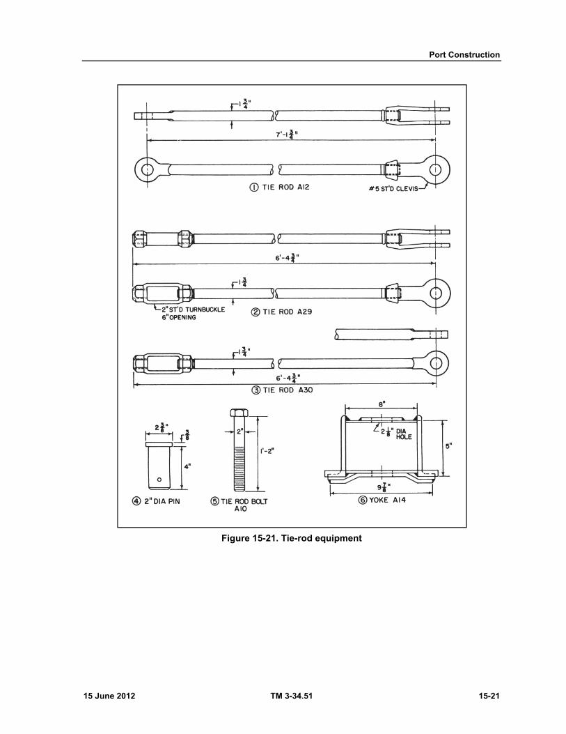
Port Construction
15 June 2012 TM 3-34.51 15-21
Figure 15-21. Tie-rod equipment
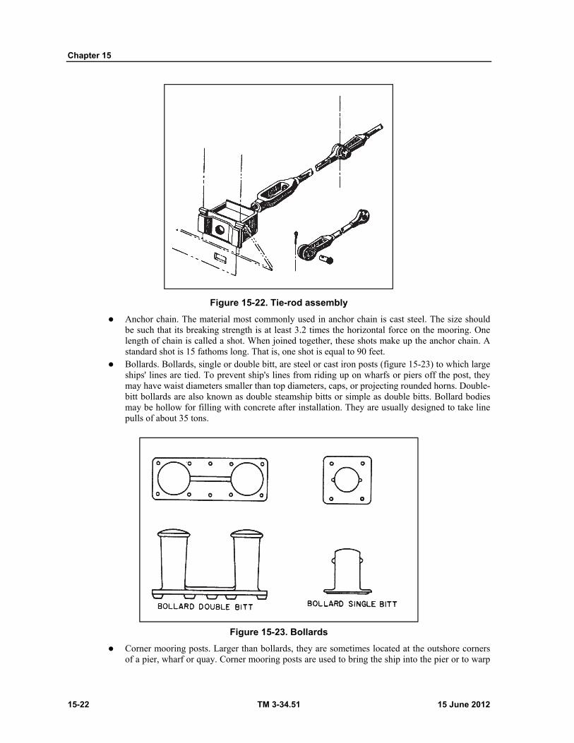
Chapter 15
15-22 TM 3-34.51 15 June 2012
Figure 15-22. Tie-rod assembly
Anchor chain. The material most commonly used in anchor chain is cast steel. The size should be such that its breaking strength is at least 3.2 times the horizontal force on the mooring. One length of chain is called a shot. When joined together, these shots make up the anchor chain. A standard shot is 15 fathoms long. That is, one shot is equal to 90 feet.
Bollards. Bollards, single or double bitt, are steel or cast iron posts (figure 15-23) to which large ships' lines are tied. To prevent ship's lines from riding up on wharfs or piers off the post, they may have waist diameters smaller than top diameters, caps, or projecting rounded horns. Double-bitt bollards are also known as double steamship bitts or simple as double bitts. Bollard bodies may be hollow for filling with concrete after installation. They are usually designed to take line pulls of about 35 tons.
Figure 15-23. Bollards
Corner mooring posts. Larger than bollards, they are sometimes located at the outshore corners of a pier, wharf or quay. Corner mooring posts are used to bring the ship into the pier or to warp

Port Construction
15 June 2012 TM 3-34.51 15-23
the ship around the corner of the pier or around a turning dolphin as well as for securing lines. Corner mooring posts are usually designed to take line pulls of up to 50 tons (figure 15-24).
Figure 15-24. Corner mooring post
Cleats. Cleats (figure 15-25) are generally cast iron, shaped with arms extending horizontally from a relatively low body. The base may be open or closed. They are used for securing smaller ships, tugs, and work boats.
Figure 15-25. Cleat
Chocks. Open or closed chocks (figure 15-26, page 15-24), generally made of cast iron, are used for directing lines and for snubbing lines when working a ship into or out of her berth. The closed chock must be used when there is a change in the vertical as well as the horizontal direction of the line.

Chapter 15
15-24 TM 3-34.51 15 June 2012
Figure 15-26. Chocks
Pad eyes. Pad eyes (figure 15-27) are metal rings mounted vertically on a plate and intended to receive a ship's line spliced with thimble and shackle. Pad eyes are used only for securing small craft.
Figure 15-27. Pad eye
INSTALLATION OF HARDWARE
15-17. Bollards and other items of mooring hardware are installed on a wharf for securing ship's lines. Mooring hardware should be of adequate size and properly installed. Proper installation requires that the stress on mooring hardware from the vertical and horizontal components of pull be transferred to a considerable portion of the wharf structure (figure 15-28). This is done by increasing the number and size of stringers under the hardware installation (figure 15-29, page 15-26), and providing an anchorage for mooring hardware bolts that will transfer the stress through the pile cap of one or more bents to several piles.
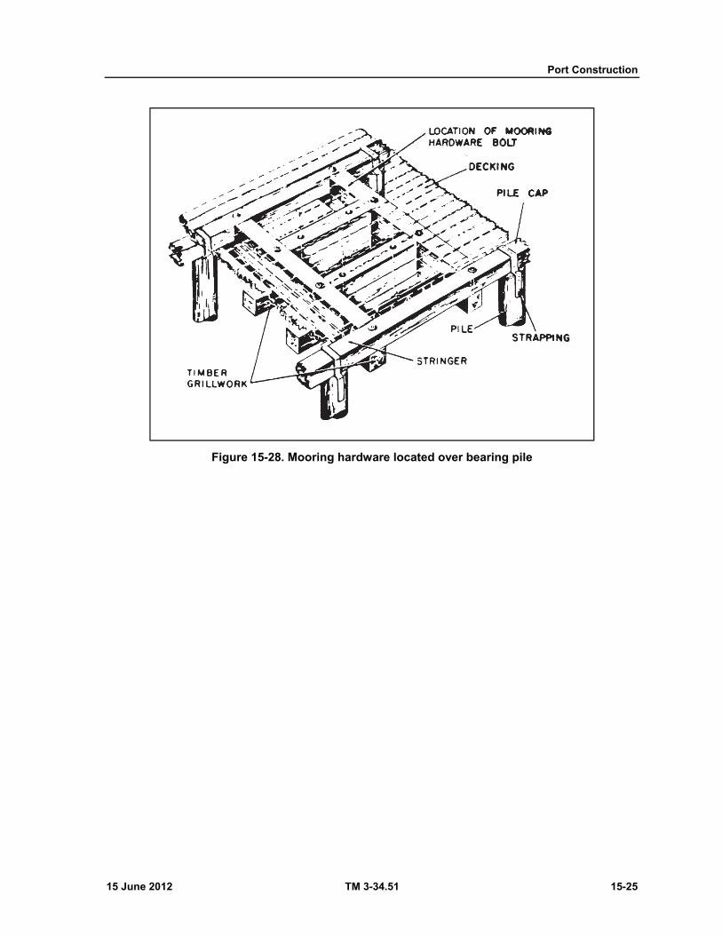
Port Construction
15 June 2012 TM 3-34.51 15-25
Figure 15-28. Mooring hardware located over bearing pile
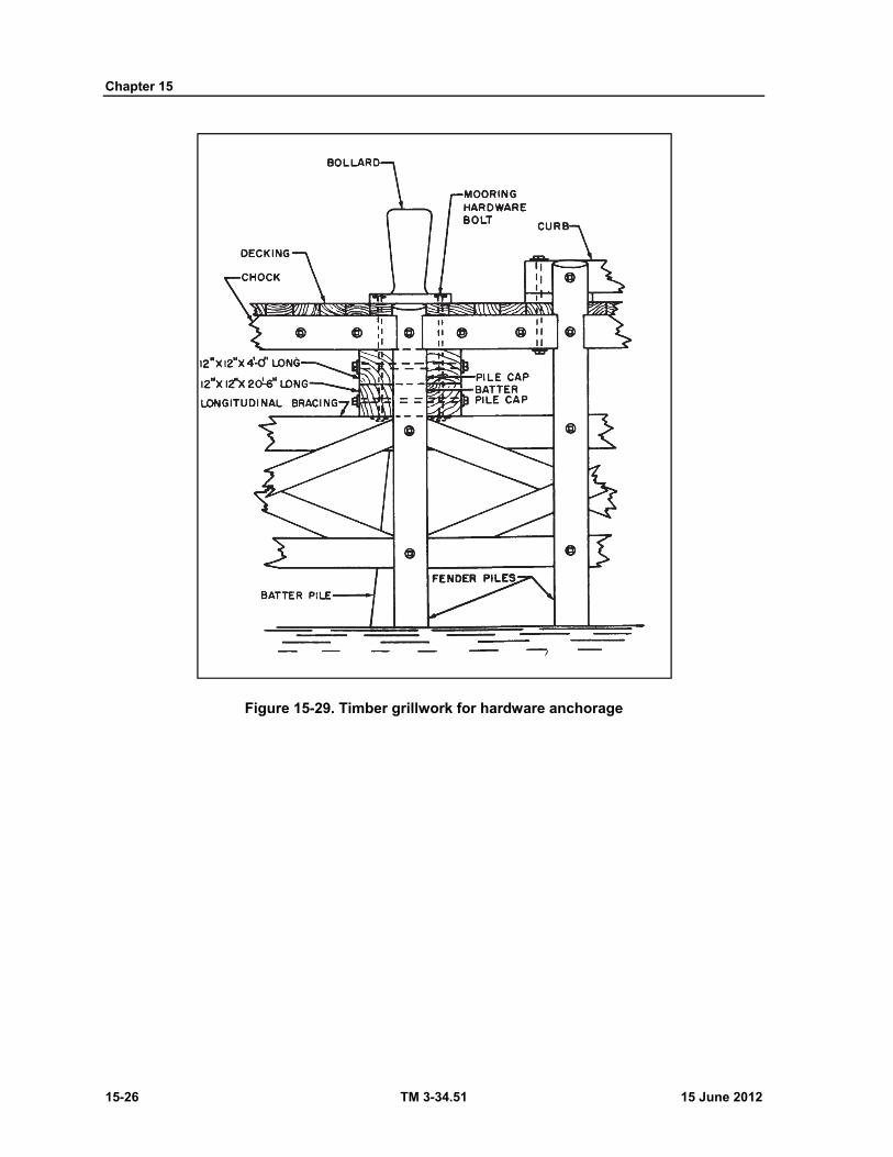
Chapter 15
15-26 TM 3-34.51 15 June 2012
Figure 15-29. Timber grillwork for hardware anchorage
15 June 2012 TM 3-34.51 16-1
Chapter 16
Railroads
INTRODUCTION 16-1. The success or failure of an army in the field depends to a large degree on its routes of communication. These routes are the arteries over which needed troops and supplies must travel to the front. Railroads are the most effective form of mass transport in the theater of operations (FM 100-10) as they can move large quantities of supplies quickly, with maximum regularity, low cost, high flexibility, and minimum interference from weather. Their employment, rehabilitation and possible extension by new trackage can be an important part of the planning of a military operation.
16-2. The more common elements of railroad construction that concern the draftsman are discussed in this chapter. For a detailed coverage of railroads, refer to TM 5-370.
TIES 16-3. Ties are the transverse support to which rails are fastened to keep them in line, gage, and grade. The ties themselves rest directly on the roadbed.
MATERIAL
16-4. Wood is the best material for ties because it is easy to work with and has a long life span if properly treated. Wooden ties are soaked in creosote oil to give them a long life span (figure 16-1, page 16-2).
SIZE
16-5. The standard military size for ties is 6 to 7 inches thick, 8 to 10 inches wide, and 8 to 9 feet long. The length of ties varies depending on their location (figure 16-2, page 16-3).
TIE PLATES 16-6. Rails are fastened to the ties by means of spikes and tie plates. The tie plate distributes the rail load over a larger tie area with diminished unit pressure and protects the tie fibers from abrasion and cutting. For this purpose the larger the plate area the better. A well-designed plate increases the efficiency of spikes in holding the rails to correct gage (figure 16-3, page 16-4).
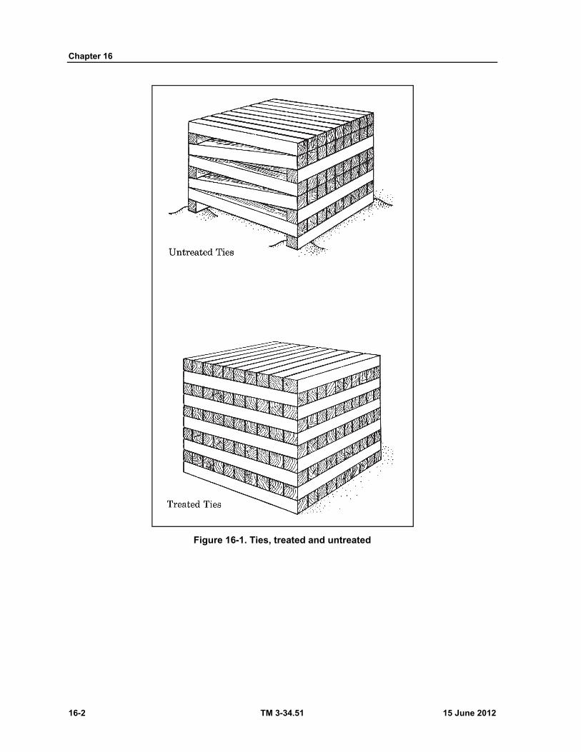
Chapter 16
16-2 TM 3-34.51 15 June 2012
Figure 16-1. Ties, treated and untreated
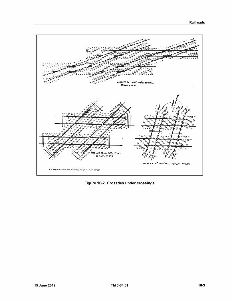
Railroads
15 June 2012 TM 3-34.51 16-3
Figure 16-2. Crossties under crossings
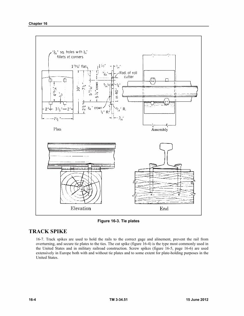
Chapter 16
16-4 TM 3-34.51 15 June 2012
Figure 16-3. Tie plates
TRACK SPIKE 16-7. Track spikes are used to hold the rails to the correct gage and alinement, prevent the rail from overturning, and secure tie plates to the ties. The cut spike (figure 16-4) is the type most commonly used in the United States and in military railroad construction. Screw spikes (figure 16-5, page 16-6) are used extensively in Europe both with and without tie plates and to some extent for plate-holding purposes in the United States.

Railroads
15 June 2012 TM 3-34.51 16-5
Figure 16-4. Track spike
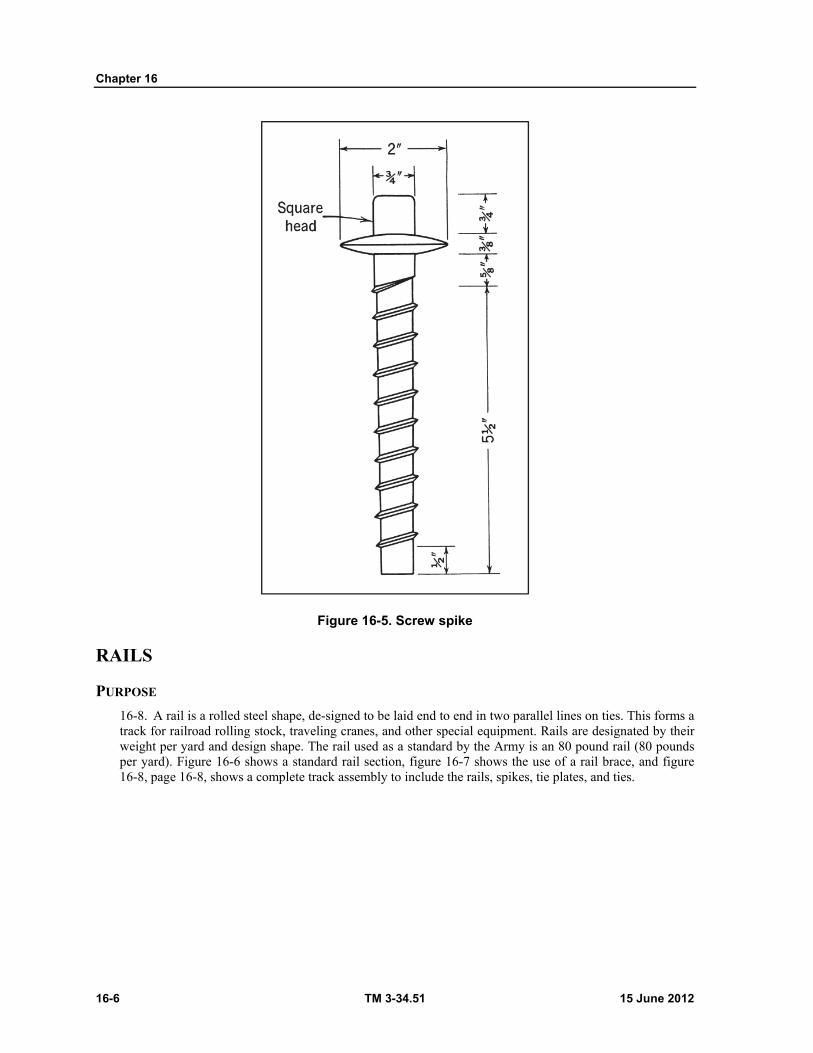
Chapter 16
16-6 TM 3-34.51 15 June 2012
Figure 16-5. Screw spike
RAILS
PURPOSE
16-8. A rail is a rolled steel shape, de-signed to be laid end to end in two parallel lines on ties. This forms a track for railroad rolling stock, traveling cranes, and other special equipment. Rails are designated by their weight per yard and design shape. The rail used as a standard by the Army is an 80 pound rail (80 pounds per yard). Figure 16-6 shows a standard rail section, figure 16-7 shows the use of a rail brace, and figure 16-8, page 16-8, shows a complete track assembly to include the rails, spikes, tie plates, and ties.
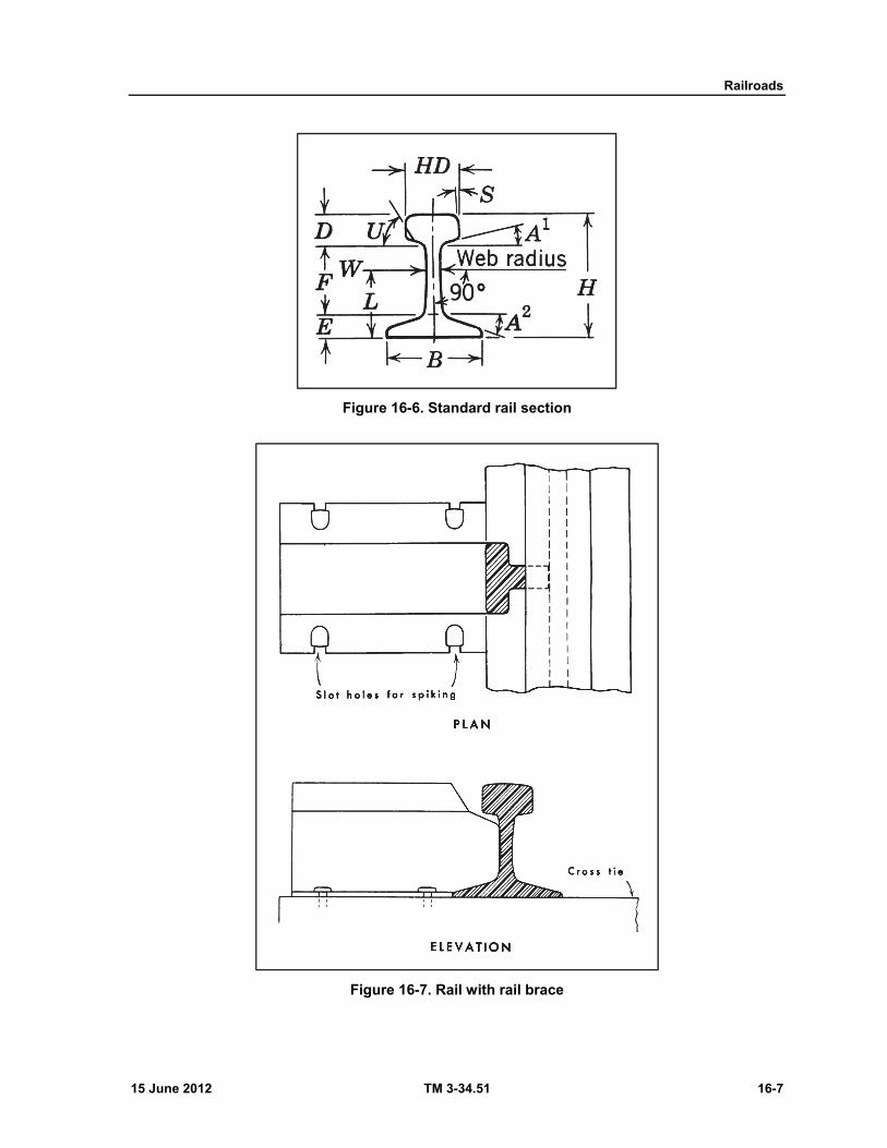
Railroads
15 June 2012 TM 3-34.51 16-7
Figure 16-6. Standard rail section
Figure 16-7. Rail with rail brace
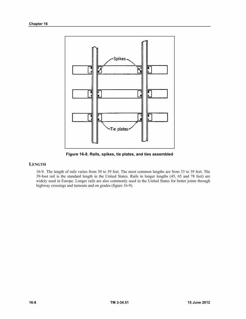
Chapter 16
16-8 TM 3-34.51 15 June 2012
Figure 16-8. Rails, spikes, tie plates, and ties assembled
LENGTH
16-9. The length of rails varies from 30 to 39 feet. The most common lengths are from 33 to 39 feet. The 39-foot rail is the standard length in the United States. Rails in longer lengths (45, 65 and 78 feet) are widely used in Europe. Longer rails are also commonly used in the United States for better joints through highway crossings and turnouts and on grades (figure 16-9).
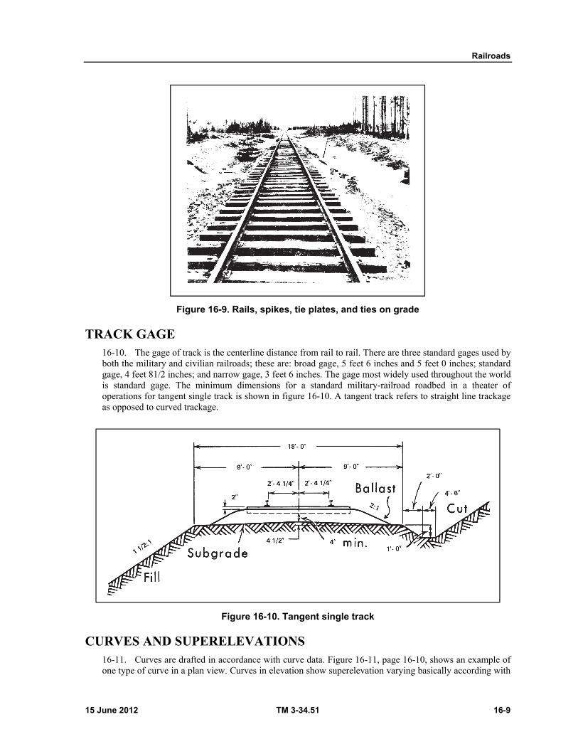
Railroads
15 June 2012 TM 3-34.51 16-9
Figure 16-9. Rails, spikes, tie plates, and ties on grade
TRACK GAGE 16-10. The gage of track is the centerline distance from rail to rail. There are three standard gages used by both the military and civilian railroads; these are: broad gage, 5 feet 6 inches and 5 feet 0 inches; standard gage, 4 feet 81/2 inches; and narrow gage, 3 feet 6 inches. The gage most widely used throughout the world is standard gage. The minimum dimensions for a standard military-railroad roadbed in a theater of operations for tangent single track is shown in figure 16-10. A tangent track refers to straight line trackage as opposed to curved trackage.
Figure 16-10. Tangent single track
CURVES AND SUPERELEVATIONS 16-11. Curves are drafted in accordance with curve data. Figure 16-11, page 16-10, shows an example of one type of curve in a plan view. Curves in elevation show superelevation varying basically according with
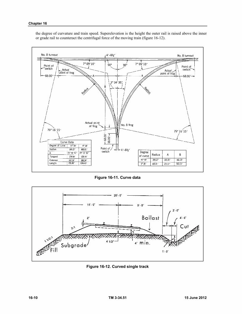
Chapter 16
16-10 TM 3-34.51 15 June 2012
the degree of curvature and train speed. Superelevation is the height the outer rail is raised above the inner or grade rail to counteract the centrifugal force of the moving train (figure 16-12).
Figure 16-11. Curve data
Figure 16-12. Curved single track
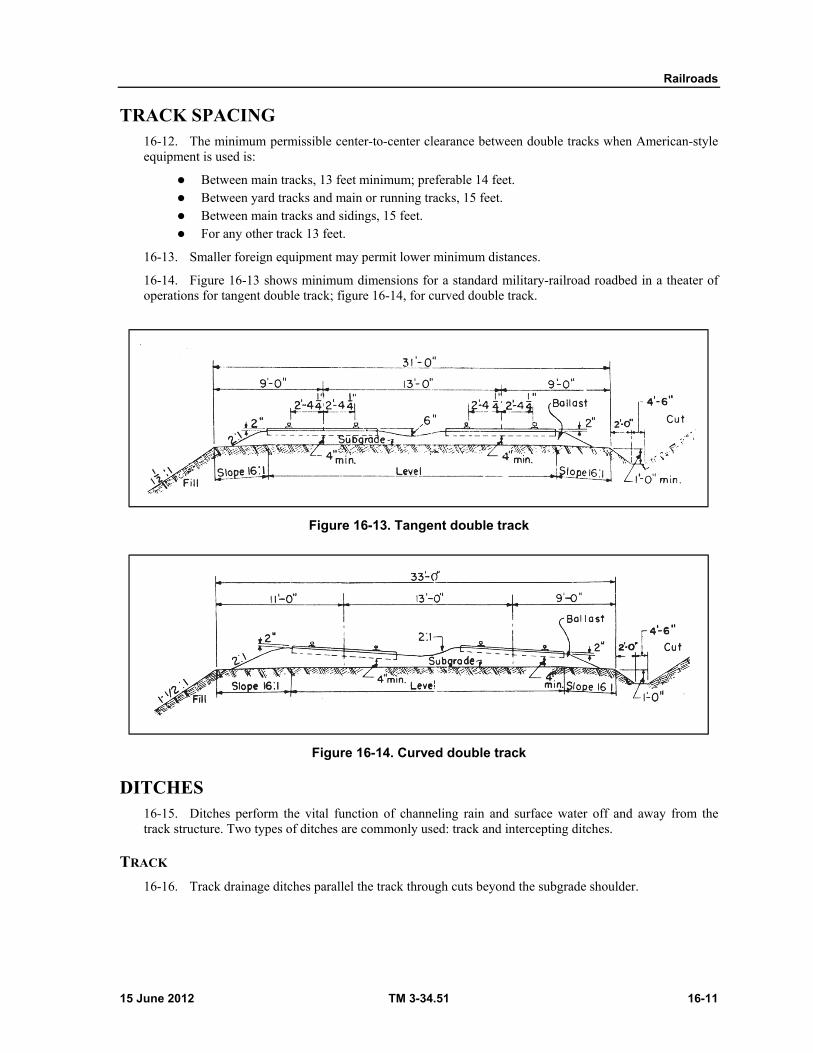
Railroads
15 June 2012 TM 3-34.51 16-11
TRACK SPACING 16-12. The minimum permissible center-to-center clearance between double tracks when American-style equipment is used is:
Between main tracks, 13 feet minimum; preferable 14 feet. Between yard tracks and main or running tracks, 15 feet. Between main tracks and sidings, 15 feet. For any other track 13 feet.
16-13. Smaller foreign equipment may permit lower minimum distances.
16-14. Figure 16-13 shows minimum dimensions for a standard military-railroad roadbed in a theater of operations for tangent double track; figure 16-14, for curved double track.
Figure 16-13. Tangent double track
Figure 16-14. Curved double track
DITCHES 16-15. Ditches perform the vital function of channeling rain and surface water off and away from the track structure. Two types of ditches are commonly used: track and intercepting ditches.
TRACK
16-16. Track drainage ditches parallel the track through cuts beyond the subgrade shoulder.
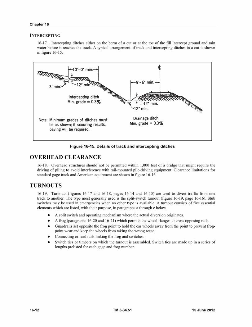
Chapter 16
16-12 TM 3-34.51 15 June 2012
INTERCEPTING
16-17. Intercepting ditches either on the berm of a cut or at the toe of the fill intercept ground and rain water before it reaches the track. A typical arrangement of track and intercepting ditches in a cut is shown in figure 16-15.
Figure 16-15. Details of track and intercepting ditches
OVERHEAD CLEARANCE 16-18. Overhead structures should not be permitted within 1,000 feet of a bridge that might require the driving of piling to avoid interference with rail-mounted pile-driving equipment. Clearance limitations for standard gage track and American equipment are shown in figure 16-16.
TURNOUTS 16-19. Turnouts (figures 16-17 and 16-18, pages 16-14 and 16-15) are used to divert traffic from one track to another. The type most generally used is the split-switch turnout (figure 16-19, page 16-16). Stub switches may be used in emergencies when no other type is available. A turnout consists of five essential elements which are listed, with their purpose, in paragraphs a through e below.
A split switch and operating mechanism where the actual diversion originates. A frog (paragraphs 16-20 and 16-21) which permits the wheel flanges to cross opposing rails. Guardrails set opposite the frog point to hold the car wheels away from the point to prevent frog-
point wear and keep the wheels from taking the wrong route. Connecting or lead rails linking the frog and switches. Switch ties or timbers on which the turnout is assembled. Switch ties are made up in a series of
lengths prelisted for each gage and frog number.
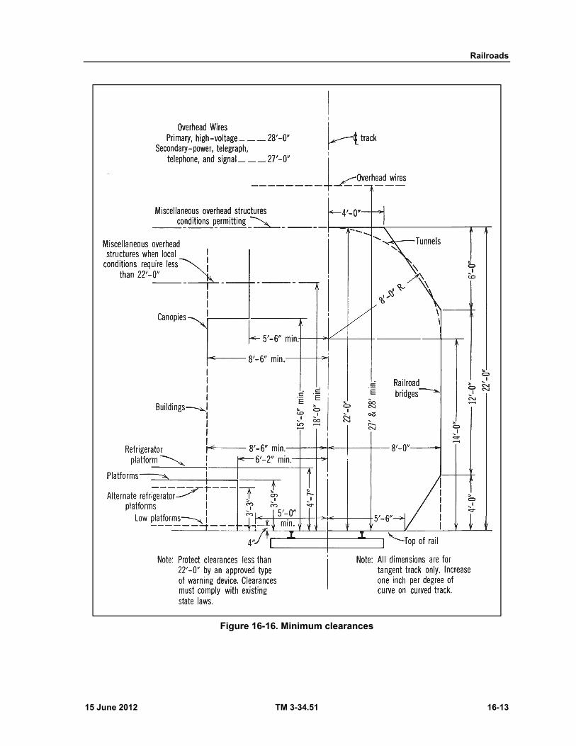
Railroads
15 June 2012 TM 3-34.51 16-13
Figure 16-16. Minimum clearances
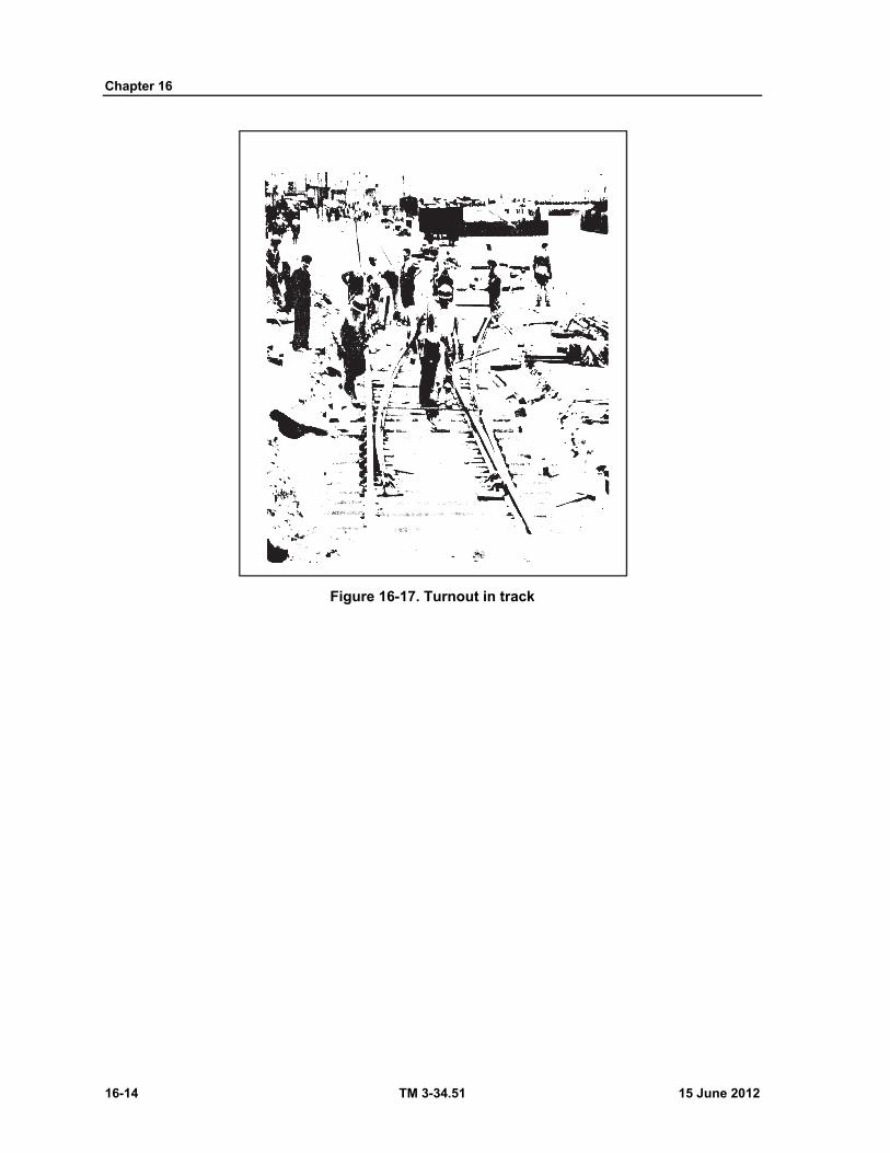
Chapter 16
16-14 TM 3-34.51 15 June 2012
Figure 16-17. Turnout in track
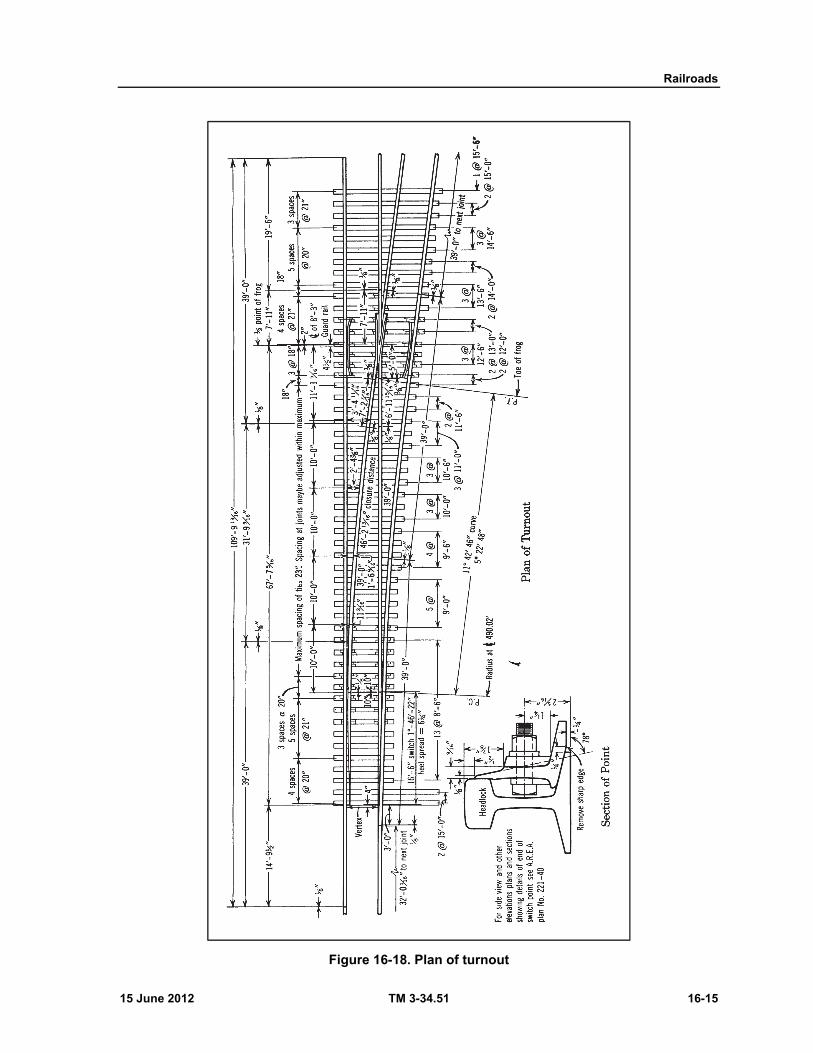
Railroads
15 June 2012 TM 3-34.51 16-15
Figure 16-18. Plan of turnout
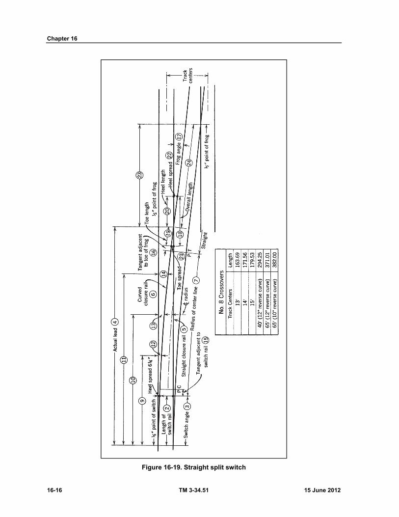
Chapter 16
16-16 TM 3-34.51 15 June 2012
Figure 16-19. Straight split switch
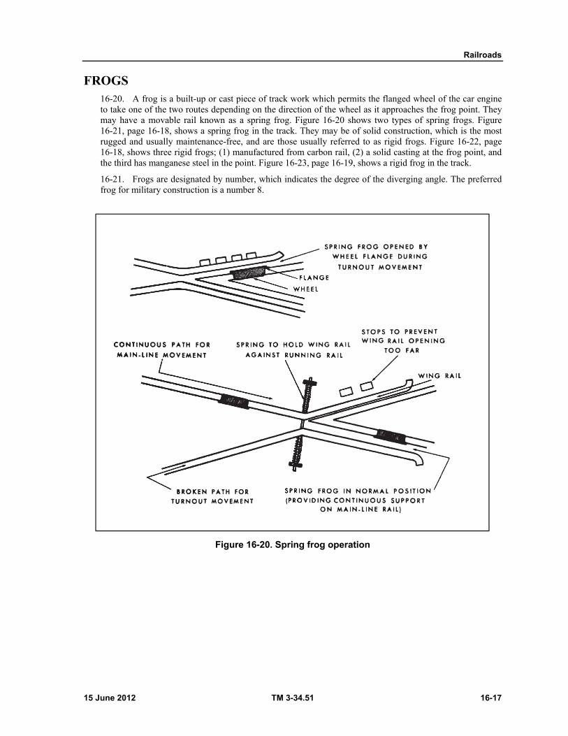
Railroads
15 June 2012 TM 3-34.51 16-17
FROGS 16-20. A frog is a built-up or cast piece of track work which permits the flanged wheel of the car engine to take one of the two routes depending on the direction of the wheel as it approaches the frog point. They may have a movable rail known as a spring frog. Figure 16-20 shows two types of spring frogs. Figure 16-21, page 16-18, shows a spring frog in the track. They may be of solid construction, which is the most rugged and usually maintenance-free, and are those usually referred to as rigid frogs. Figure 16-22, page 16-18, shows three rigid frogs; (1) manufactured from carbon rail, (2) a solid casting at the frog point, and the third has manganese steel in the point. Figure 16-23, page 16-19, shows a rigid frog in the track.
16-21. Frogs are designated by number, which indicates the degree of the diverging angle. The preferred frog for military construction is a number 8.
Figure 16-20. Spring frog operation

Chapter 16
16-18 TM 3-34.51 15 June 2012
Figure 16-21. Spring frog
Figure 16-22. Rigid frogs
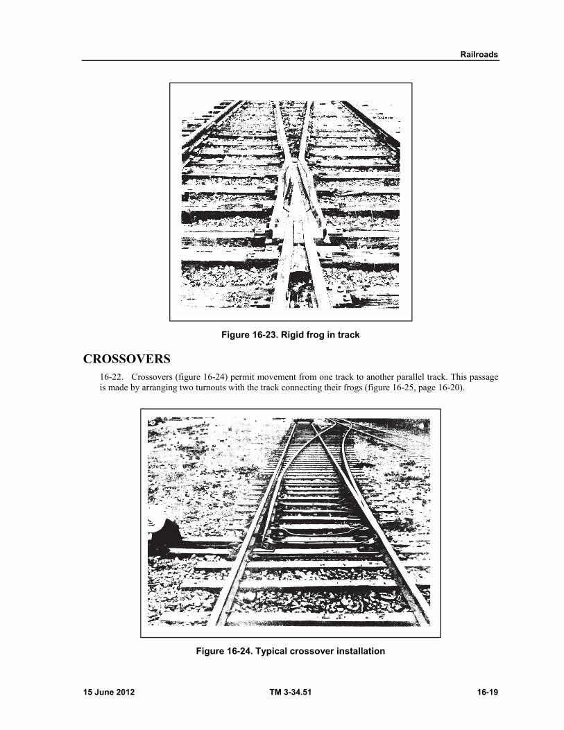
Railroads
15 June 2012 TM 3-34.51 16-19
Figure 16-23. Rigid frog in track
CROSSOVERS 16-22. Crossovers (figure 16-24) permit movement from one track to another parallel track. This passage is made by arranging two turnouts with the track connecting their frogs (figure 16-25, page 16-20).
Figure 16-24. Typical crossover installation

Chapter 16
16-20 TM 3-34.51 15 June 2012
Figure 16-25. Crossover
HIGHWAY AND RAIL CROSSINGS AT GRADES 16-23. Highway and road crossing at grades area voided wherever possible. When they must be installed they are usually constructed so that the axis of the road is approximately perpendicular to the center line of the railroad. The crossings are usually located on tangent track to provide maximum view along the track. A typical highway crossing is shown in figure 16-26.
Figure 16-26. Highway crossing
16-24. Rail crossings are installed to carry one track across another at grade and permit passing of wheel flanges, through opposing rails. Frogs are used at these crossings (figure 16-27).
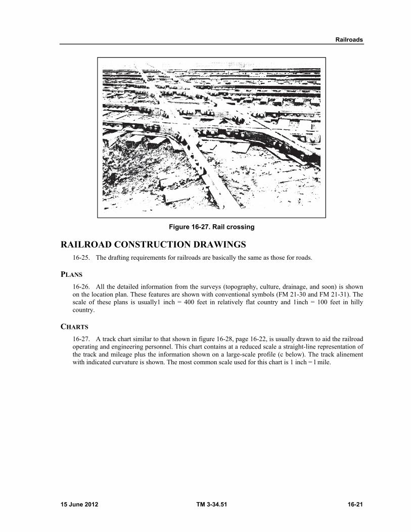
Railroads
15 June 2012 TM 3-34.51 16-21
Figure 16-27. Rail crossing
RAILROAD CONSTRUCTION DRAWINGS 16-25. The drafting requirements for railroads are basically the same as those for roads.
PLANS
16-26. All the detailed information from the surveys (topography, culture, drainage, and soon) is shown on the location plan. These features are shown with conventional symbols (FM 21-30 and FM 21-31). The scale of these plans is usually1 inch = 400 feet in relatively flat country and 1inch = 100 feet in hilly country.
CHARTS
16-27. A track chart similar to that shown in figure 16-28, page 16-22, is usually drawn to aid the railroad operating and engineering personnel. This chart contains at a reduced scale a straight-line representation of the track and mileage plus the information shown on a large-scale profile (c below). The track alinement with indicated curvature is shown. The most common scale used for this chart is 1 inch = l mile.
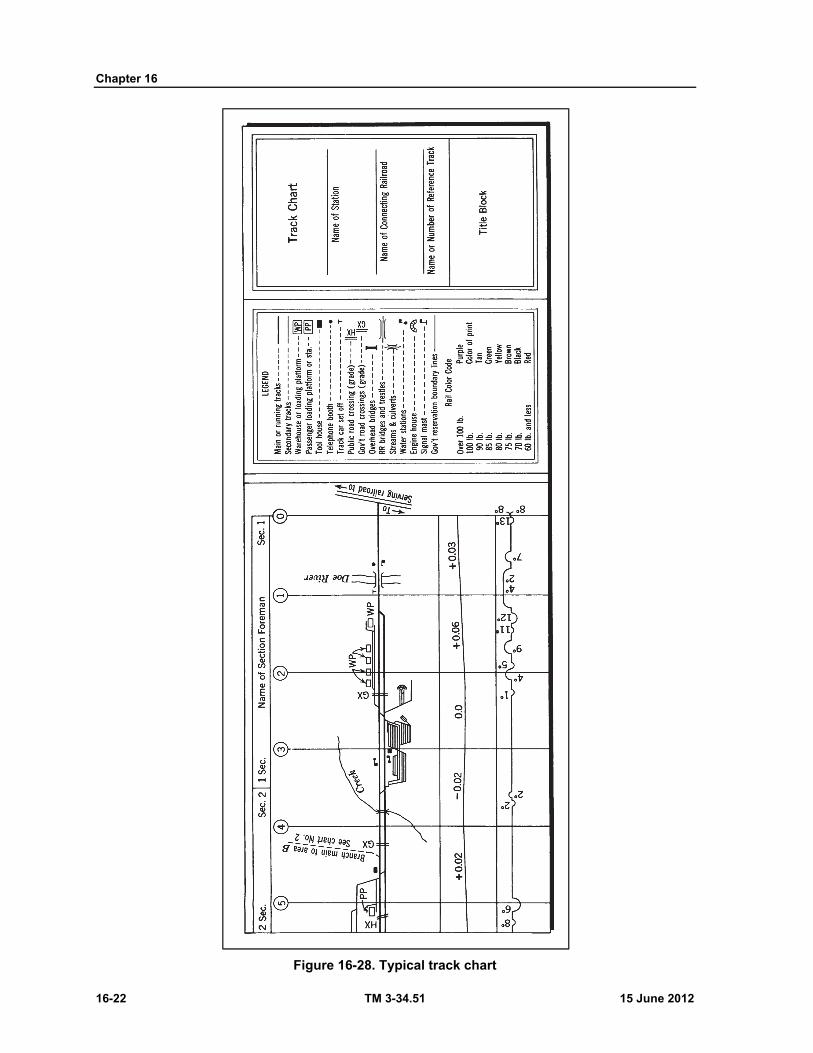
Chapter 16
16-22 TM 3-34.51 15 June 2012
Figure 16-28. Typical track chart

Railroads
15 June 2012 TM 3-34.51 16-23
PROFILES
16-28. Generally the profiles are drafted on profile paper (figure 16-29, page 16-24) using the same horizontal scales as used in the plan. Vertical scales of 1 inch = 20 feet or 1 inch = 40 feet are used depending on the extremes of elevation to be shown. Details of elevation (at breaks in grade and along vertical curves), drainage structures, ground line profile, and other pertinent data should be included. A schematic alinement showing survey stationing, curves, drainage structures, and so on, should be placed below the profile.

Chapter 16
16-24 TM 3-34.51 15 June 2012
Figure 16-29. Typical profile
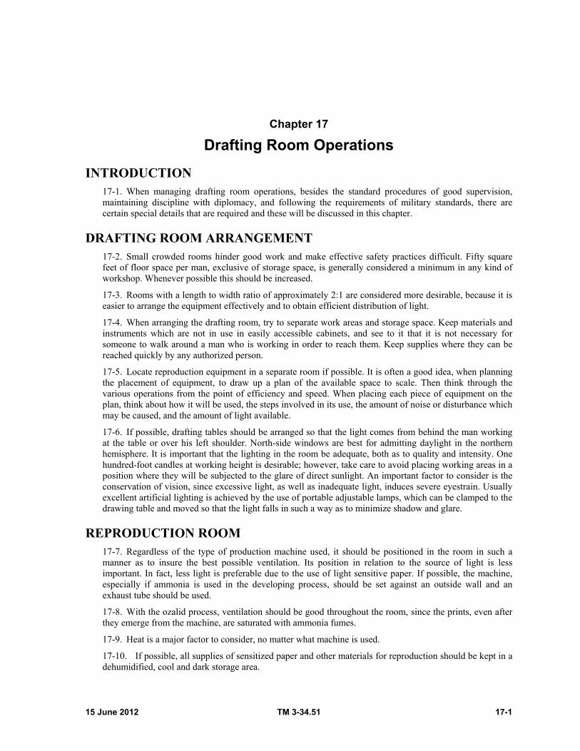
15 June 2012 TM 3-34.51 17-1
Chapter 17
Drafting Room Operations
INTRODUCTION 17-1. When managing drafting room operations, besides the standard procedures of good supervision, maintaining discipline with diplomacy, and following the requirements of military standards, there are certain special details that are required and these will be discussed in this chapter.
DRAFTING ROOM ARRANGEMENT 17-2. Small crowded rooms hinder good work and make effective safety practices difficult. Fifty square feet of floor space per man, exclusive of storage space, is generally considered a minimum in any kind of workshop. Whenever possible this should be increased.
17-3. Rooms with a length to width ratio of approximately 2:1 are considered more desirable, because it is easier to arrange the equipment effectively and to obtain efficient distribution of light.
17-4. When arranging the drafting room, try to separate work areas and storage space. Keep materials and instruments which are not in use in easily accessible cabinets, and see to it that it is not necessary for someone to walk around a man who is working in order to reach them. Keep supplies where they can be reached quickly by any authorized person.
17-5. Locate reproduction equipment in a separate room if possible. It is often a good idea, when planning the placement of equipment, to draw up a plan of the available space to scale. Then think through the various operations from the point of efficiency and speed. When placing each piece of equipment on the plan, think about how it will be used, the steps involved in its use, the amount of noise or disturbance which may be caused, and the amount of light available.
17-6. If possible, drafting tables should be arranged so that the light comes from behind the man working at the table or over his left shoulder. North-side windows are best for admitting daylight in the northern hemisphere. It is important that the lighting in the room be adequate, both as to quality and intensity. One hundred-foot candles at working height is desirable; however, take care to avoid placing working areas in a position where they will be subjected to the glare of direct sunlight. An important factor to consider is the conservation of vision, since excessive light, as well as inadequate light, induces severe eyestrain. Usually excellent artificial lighting is achieved by the use of portable adjustable lamps, which can be clamped to the drawing table and moved so that the light falls in such a way as to minimize shadow and glare.
REPRODUCTION ROOM 17-7. Regardless of the type of production machine used, it should be positioned in the room in such a manner as to insure the best possible ventilation. Its position in relation to the source of light is less important. In fact, less light is preferable due to the use of light sensitive paper. If possible, the machine, especially if ammonia is used in the developing process, should be set against an outside wall and an exhaust tube should be used.
17-8. With the ozalid process, ventilation should be good throughout the room, since the prints, even after they emerge from the machine, are saturated with ammonia fumes.
17-9. Heat is a major factor to consider, no matter what machine is used.
17-10. If possible, all supplies of sensitized paper and other materials for reproduction should be kept in a dehumidified, cool and dark storage area.
Chapter 17
17-2 TM 3-34.51 15 June 2012
17-11. When light sensitive film and paper is brought into the reproduction room they should be stored in a light-tight space to preserve the sensitivity. Usually the original containers are light-tight and it is best to keep the materials in them. It is good practice to date the supplies so as to use the oldest stock first.
17-12. Chemicals used in developing solutions, that come in powder form, should be stored the same as sensitized materials. Ammonia usually comes in shatterproof bottles. If not, then it should be transferred to shatterproof bottles before storing. The fumes from ammonia are very powerful and personnel exposed to them may be temporarily blinded.
CHECKING 17-13. Checking of drawings is defined as the act of verifying the drawing's accuracy, completeness, and conformance to applicable standards. The responsibility for the drawing, its design, contents, accuracy, and completeness, rests with those who initial or sign the drawing as of the date indicated. Subsequent revisions are also made and dated on the drawing.
17-14. Careful checking of drawings for all items depicted is of paramount importance to the organization because the drawings become legal documents when used for procurement and fabrication. Checking newly prepared drawings at the drafting level is normally done by personnel known as checkers; otherwise the section chief will do the checking.
17-15. Checking responsibilities at the drafting room level begin with the preparation of the drawing. Section heads are responsible for the drawing and through direct guidance to the draftsman, they actually check the work as it progresses.
17-16. The draftsman, after completing the drawing, examines his own work in the light of the instructions and directions received. If the work appears satisfactory, he informs the section head who reviews the drawing for accuracy and completeness before the drawing is removed from the drawing board. After the drawing is removed from the board, a reproduced copy (a checkprint) of the original is made and forwarded to the checker or section chief or both.
17-17. To do a thorough job of checking, a definite sequence of procedures and a checklist of points are advisable. The following checking procedures, although most applicable to machine drawings, may, with a few changes, be applied to any type of drawing.
17-18. The draftsman must ask himself whether the drawing fits in the overall pattern. For example—
Will the drawing reproduce? Will it be possible to make prints or other copies from it? Are the line weights such that they will reproduce well? Does it meet MIL-STD requirements for format? Is the drawing size correct? Are the headings
and title blocks properly placed? Has proper reference been made to other drawings? Does the drawing have the correct drawing number?
17-19. The checker or section head then must ask himself whether the proper methods of representing the object have been used, if the drawing shows the job, and how it is to be done properly:
Is the method of projection the proper one for the job? Are the views adequate to clearly show all the information necessary and are they arranged
properly? Are sectional views constructed correctly and is the section symbol correct? Are the line conventions and symbols consistent with MIL-STD requirements? Is the proper scale used? Is that scale properly indicated on the drawing? Is the drawing drawn to scale? When a drawing has been revised, it may no longer be to scale;
and this should be indicated by an underlined dimension and a note in the revision block. Do the dimensions agree with the original layout and information? Do the dimensions agree with corresponding dimensions on mating parts?
Drafting Room Operations
15 June 2012 TM 3-34.51 17-3
When dimensions carry tolerances, are the tolerances correct to allow proper manufacturing tolerances and allowances for fits?
Are the dimensions properly indicated so that the man using the drawing will have an absolute minimum of addition and subtraction?
Are there enough dimensions shown so that the job can be done? Note also that dimensions should not be repeated unnecessarily, because there is the danger of one being revised, while the other is unchanged.
When revisions are made, and there are several sheets to a complete set of plans, have the revisions been reflected on all applicable sheets ?
Are all necessary explanatory notes given and are they properly placed? Are all figures and letters properly formed? Are standard terminology and standard abbreviations used? Is the type of material for each part specified ? Are the required quantities of each part given? Is the finish specified, where it is needed ?
Note. When checking drawings, references to material, sizes, and specifications can be obtained from catalogs and handbooks. Also, use NAVFAC Design Manual-6, Drawings and Specifications, as a guide for checking the drawings.
TECHNICAL LIBRARY AND PLAN FILES 17-20. Most drawing rooms must, of necessity, have available a technical library of handbooks, military publications, and specifications, as well as copies of all active contracts, and specifications, contract and shop drawings. The technical library and plan files are intended for use by other sections. Those JAN and MIL standards which pertain to your shop needs should be a part of your technical library. Each book should be classified and marked before it is placed on a shelf. This is so that it can be identified as be-longing to your shop; thus it will be easier to trace its whereabouts. Identifying marks are usually made with a rubber stamp bearing the name of the unit. The book is stamped on the inside of the front and back covers and on the title page. When there are two or more copies of the same book, the book, as well as any file cards, should be marked to indicate this fact. It is not necessary to mark the first copy, but the second copy should be marked "Copy 2", and so forth. In order to keep a record of books, it is best to keep a card file. Plain cards, 3 inches X 5 inches, may be used with the author and title filed alphabetically. Some method should be devised for keeping track of the drawings. If possible, the cards should be typed. Checking books or drawings in and out of the library from the plan files requires careful attention to detail. A record should always be made of actions regarding each book or drawing and these records should be uniform. Without a working system it will not be possible to know the whereabouts of the library books or drawings from the plan files.
FILING AND RETIRING DRAWINGS 17-21. Since there are no two drafting shops that are alike in the military, no hard and fast rules can be laid down for filing. A filing system must be established to fit the needs of the activity using it. This paragraph contains suggestions on setting up files, describes some of the standard filing equipment available, and provides information on record-keeping (figure 17-1, page 17-4).
17-22. Instructions for drawings that are to be classified should be investigated by the security officer in command. The security officer should be able to assist the senior draftsman in furnishing the proper security manuals and control procedures related to marking, handling, filing, storage and disposing of classified drawings and material.
17-23. In determining the security of file cabinets, three factors must be considered: (1) portability, (2) ease or difficulty of opening by unauthorized persons and, (3) fire resistance.
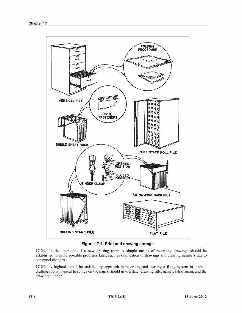
Chapter 17
17-4 TM 3-34.51 15 June 2012
Figure 17-1. Print and drawing storage
17-24. In the operation of a new drafting room, a simple means of recording drawings should be established to avoid possible problems later, such as duplication of drawings and drawing numbers due to personnel changes.
17-25. A logbook could be satisfactory approach in recording and starting a filing system in a small drafting room. Typical headings on the pages should give a date, drawing title, name of draftsman, and the drawing number.

Drafting Room Operations
15 June 2012 TM 3-34.51 17-5
17-26. The convenient method of filing drawings is by the drawing number in numerical sequence. This method permits the filing of drawings in a definite location, and avoids shifting files to make space for drawings having lower drawing numbers. Later drawings need only be added to the file and additional filing cases obtained when required.
17-27. Original drawings that are maintained as a permanent record, and for reproduction, require that they not be folded when filing. The file cabinet size will be determined by the size of the individual sheets. The drawers or cabinet should be a little larger than the material to be filed. The maximum flat size drawing sheet, per MILSTD-100A, is designated by the letter size E that has a width of 34 inches and a length of 44 inches.
17-28. Drawings are usually filed for safekeeping in sectional steel or wooden cabinets with shallow drawers. Drawings may be placed in the drawers of these cabinets so that they lie flat. If drawings are large, they may be rolled in cylindrical map cartons.
17-29. Original drawings should be withdrawn from the files only for reproduction and revisions.
17-30. reproduced copy of each drawing in the file should be retained in the drafting room as ready reference.
17-31. The reproduced copies can be filed on a stick that holds about 50 drawings. The outer cover could be a heavy brown wrapping paper that would list all the drawings on the stick. Stick files are obtainable through commercial sources, or can be easily and economically made.
17-32. In retiring Military Construction Contract Files (1519-09), which include original contract drawings, shop drawings, as-built drawings, computations and cross sections, contracts, and specifications; refer to AR 340-18-15, for the proper method of disposing of these records. Depending on various circumstances, they are usually held for 1 year after the contract has been completed, then held in a Record Holding Area for a period of time, and/or destroyed. Also, refer to "Microfilming of records" (AR 340-22,) and take action if feasible.
REVISIONS 17-33. Revisions of line drawings are made only when someone with the authority has requested them. If, when the drawing is used, something proves to be incorrect, or if improvements are suggested, a drawing will usually be revised. Revisions must always be properly indicated in accordance with military standards.
17-34. The purpose of the change column is to show how the drawing appeared before it was revised. For example, suppose that a dimension was 2 inches and is changed to 3 inches. The change column should carry the old and the new dimension, with the new dimension also appearing on the drawing. Also, if something is added to the drawing, a note should be made of this addition.
17-35. The revision block serves as a means of recording events pertaining to the drawing.
17-36. When it is necessary to make erasures on the original drawing, turn the paper ever and erase on the back as well as the front of the sheet.
17-37. This has two purposes; first, dirt may have collected on the ridges formed where lines have been drawn on the face of the drawing this dirt can be removed by erasing. If the dirt is left on the drawing, it will print, even though the line has been erased on the face of the drawing. Second, the pressure of the erasure on the ridges bends the surface back into place, eliminating the old indentation and preparing the surface, or face, of the drawing to receive new lines.
17-38. When an erasure is made on the face of the drawing, it must be checked to be sure that something besides the area to be revised has not been erased accidentally. This may happen even when an erasing shield is used. Anything erased by accident must be replaced.
17-39. When a revision is made, the style of the original drawing should be matched as closely as possible. For example, slanted letters should never be added to a line of vertical lettering, and line weights should be as close to the original line weight as possible.

Chapter 17
17-6 TM 3-34.51 15 June 2012
17-40. Ordinarily, it is not necessary to change the lines of a drawing if a dimension is merely being changed. In this case, the old dimension is noted in the change column, and the new dimension is underlined to show that the line it refers to is not to scale.
17-41. If revisions affect several sheets of a complete set of contract drawings, be exceedingly careful to make changes on all sheets, and everywhere on the sheet, where applicable. Tie in with the exact statement in the amendment or addendum to the contract and specifications. Also keep up with the progress of the revision and add in the COP No., and date when "Notice to proceed" was effective. Pay particular attention and watch to see if the revision has been deleted or an official change order has been issued.
PLANNING AND ESTIMATING TIME AND MATERIALS 17-42. As the ranking man in charge of the drafting section, it will be the senior draftsman's responsibility to accept the work requests and assign the work to his men. He will be the individual who decides when the work is to be completed, and of course, his decision will be based on the information given to him by the requesting authority. In making this decision, the senior draftsman must first be familiar with the type of work being requested, the type of medium to be used in its completion, type of possible reproduction desired, and most important of all, he must know the capabilities of his men and their abilities to complete the assignment.
17-43. The senior draftsman has the following responsibilities:
Planning. Planning is the process of determining requirements and devising and developing methods and schemes of action for the execution and completion of a project or work request. The success of any project depends to a great extent upon the amount of detail and care taken in planning it. The drafting shop should not be run on the theory that it's "good enough for government work." In relationship to the amount of time allotted to the drafting shop to do the jobs, only the best work should ever come from the shop.
Estimating. Estimating is, "the act of determining the size and kind of work to be performed and determining quantities of work elements, materials, and manhours needed to complete the task." The first thoughts the senior draftsman would probably have, after being advised of a work request, is "What size will it be? Who is to be assigned to it? How long should it take him? Will it have to be reproduced?"
17-44. Most assignments coming through the drafting shop will require the expenditure of supplies. Because of this, this section head will be required to make a material estimate or a listing and description of the various materials and the quantities required to complete a given project. The section head doesn't want to give an assignment to one of his men and expect him to complete it when he doesn't have sufficient material on hand to finish the job. The section head has the responsibility of maintaining a sufficient quantity of materials on hand to accomplish the work that is assigned to his shop.
17-45. As may be seen, estimating time and materials for any job is no more than taking the time to think the job out, making proper assignments according to the ability of the assigned personnel to complete the job, assigning enough material for the completion of the job, and keeping account of the materials being used so that it can be replenished properly, and in time, before supplies run out.
17-46. It is impossible to predict here what individual shop requirements will be, because each command and each drafting shop's functions are different.
SUPPLY 17-47. Without the proper materials on hand, the drafting room cannot accomplish its required mission, nor can it turn out the quality work of which it is capable.
17-48. It is the responsibility of the ranking man in the drafting room to see to it that the required supplies are on hand at all times. The exact procedure that is used to request supplies will depend largely on local command policy.
Drafting Room Operations
15 June 2012 TM 3-34.51 17-7
17-49. Most items required in the drafting room may be ordered through normal supply channels. In some instances, supplies required will have to be procured commercially. These articles should be ordered with proper lead time to allow for special handling. Under normal conditions, an inventory on a monthly basis will keep the section head in a position to know what, how many, and when to reorder.
17-50. A file should be set up to determine stock usage. This will help maintain a basic load of supplies.
SITE INSPECTION 17-51. Many times, construction draftsmen will be called upon to inspect sites selected for proposed or existing projects. The information collected will greatly affect the layout, planning, design, materials, equipment, and manpower to be utilized on the project.
17-52. After preliminary research and evaluation of available information from maps, construction drawings, photographs, aerial reconnaissance (if applicable), reports, and personnel familiar with the area; ground reconnaissance is the best method for determining suitability of a site.
17-53. The following outline may serve as a checklist of subjects mostly covered during site inspection:
Designation of site. Type of installation to be accommodated and special requirements. Location and description of boundaries. Availability of transportation facilities. Character of terrain:
Slopes, soil-drainage conditions, ground water elevation, and composition. Natural cover, concealment qualities, absence of landmarks.
Water supply—availability, quality, quantity, source. Sewage disposal—suitable outlets, drainage for pit latrines or applicable system. Electric power—availability, capacity, and reliability. Relationship to military objectives. Adequacy of area for immediate needs and for expansion. Availability, condition, and adaptability of existing structures. Availability and adaptability of local materials.
PROCEDURE FOR TRANSFER OF COMPLETED CONSTRUCTION 17-54. Though the senior supervisory draftsman may not be responsible for the entire transaction of the transfer of completed construction, he should at least be prepared to do his part. For details not mentioned in this paragraph refer to SOP for Resident Engineers or EP 415-1-260, "Resident Engineers* Management Guide."
ITEMS FURNISHED AT THE TIME OF TRANSFER
17-55. Original contract drawings, shop drawings, contract, and specifications must be accurate, contain all necessary information, and kept current in order to prepare the necessary transfer documents. Following is a list of some of the transfer documents required at the time of transfer:
Contract number and list of all items of equipment The guarantee documents and period of guarantee Letter of acceptance Test results for mechanical and electrical systems or equipment, or both. DD Form 1354, "Transfer and Acceptance of Military Real Property. DA Form 5-47 through 52, "Real Property Record Cards." Items Furnished After Transfer. As soon as practicable but not later than 90 days after
acceptance of the completed facility, the following must be furnished:
Chapter 17
17-8 TM 3-34.51 15 June 2012
Complete set of as-built drawings Complete set of final approved shop drawings Final approved copies of the construction contract and specifications Manufacturers' catalogs and spare parts lists Operating and maintenance instructions
ITEMS FURNISHED AFTER TRANSFER
17-56. As soon as practicable but not later than 90 days after acceptance of the completed facility, the following must be furnished:
Complete set of as-built drawings Complete set of final approved shop drawings Final approved copies of the construction contract and specifications Manufacturers’ catalogs and spare parts lists Operating and maintenance instructions
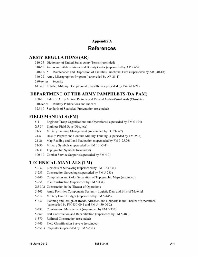
15 June 2012 TM 3-34.51 A-1
Appendix A
References
ARMY REGULATIONS (AR) 310-25 Dictionary of United States Army Terms (rescinded)
310-50 Authorized Abbreviations and Brevity Codes (superseded by AR 25-52)
340-18-15 Maintenance and Disposition of Facilities Functional Files (superseded by AR 340-18)
340-22 Army Micrographics Program (superseded by AR 25-1)
380-series Security
611-201 Enlisted Military Occupational Specialties (superseded by Pam 611-21)
DEPARTMENT OF THE ARMY PAMPHLETS (DA PAM) 108-1 Index of Army Motion Pictures and Related Audio-Visual Aids (Obsolete)
310-series Military Publications and Indexes
325-10 Standards of Statistical Presentation (rescinded)
FIELD MANUALS (FM) 5-1 Engineer Troop Organizations and Operations (superseded by FM 5-104)
X5-34 Engineer Field Data (Obsolete)
21-5 Military Training Management (superseded by TC 21-5-7)
21-6 How to Prepare and Conduct Military Training (superseded by FM 25-3)
21-26 Map Reading and Land Navigation (superseded by FM 3-25.26)
21-30 Military Symbols (superseded by FM 101-5-1)
21-31 Topographic Symbols (rescinded)
100-10 Combat Service Support (superseded by FM 4-0)
TECHNICAL MANUALS (TM) 5-232 Elements of Surveying (superseded by FM 3-34.331)
5-233 Construction Surveying (superseded by FM 5-233)
5-240 Compilation and Color Separation of Topographic Maps (rescinded)
5-258 Pile Construction (superseded by FM 5-134)
X5-302 Construction in the Theater of Operations
5-303 Army Facilities Components System – Logistic Data and Bills of Materiel
5-312 Military Fixed Bridges (superseded by FM 5-446)
5-330 Planning and Design of Roads, Airbases, and Heliports in the Theater of Operations (superseded by FM 430-00-1 and FM 5-430-00-2)
5-333 Construction Management (superseded by FM 5-333)
5-360 Port Construction and Rehabilitation (superseded by FM 5-480)
5-370 Railroad Construction (rescinded)
5-443 Field Classification Surveys (rescinded)
5-551B Carpenter (superseded by FM 5-551)
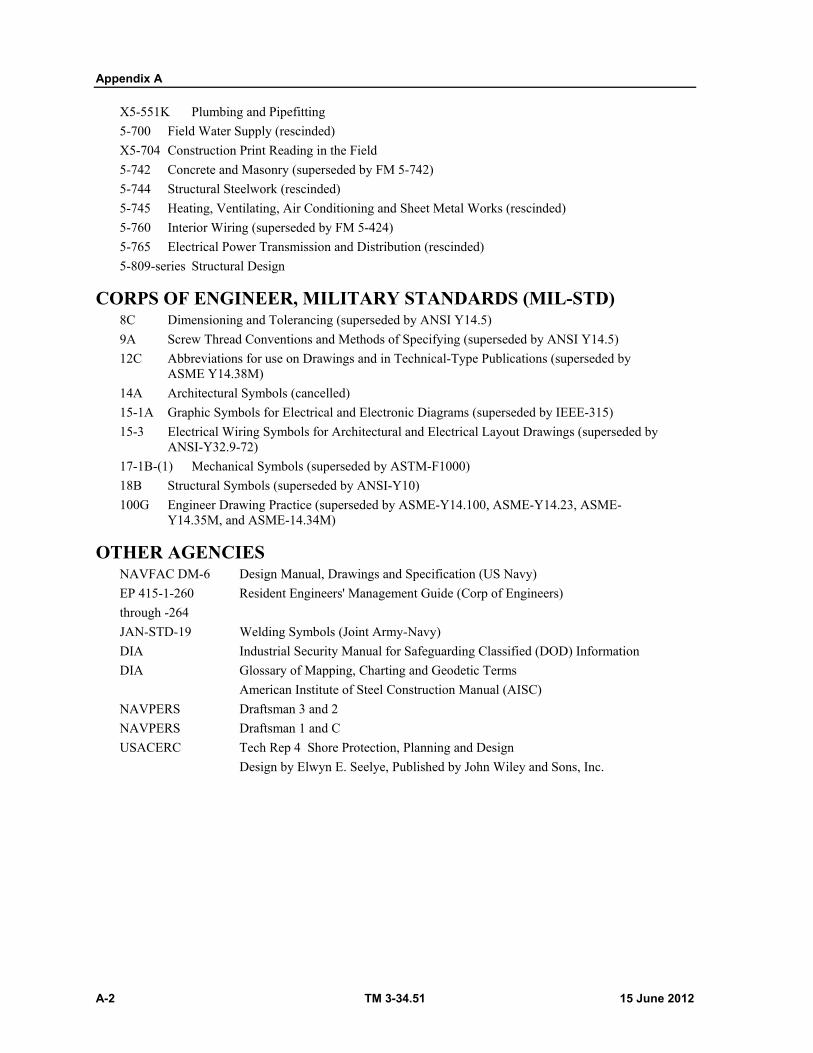
Appendix A
A-2 TM 3-34.51 15 June 2012
X5-551K Plumbing and Pipefitting
5-700 Field Water Supply (rescinded)
X5-704 Construction Print Reading in the Field
5-742 Concrete and Masonry (superseded by FM 5-742)
5-744 Structural Steelwork (rescinded)
5-745 Heating, Ventilating, Air Conditioning and Sheet Metal Works (rescinded)
5-760 Interior Wiring (superseded by FM 5-424)
5-765 Electrical Power Transmission and Distribution (rescinded)
5-809-series Structural Design
CORPS OF ENGINEER, MILITARY STANDARDS (MIL-STD) 8C Dimensioning and Tolerancing (superseded by ANSI Y14.5)
9A Screw Thread Conventions and Methods of Specifying (superseded by ANSI Y14.5)
12C Abbreviations for use on Drawings and in Technical-Type Publications (superseded by ASME Y14.38M)
14A Architectural Symbols (cancelled)
15-1A Graphic Symbols for Electrical and Electronic Diagrams (superseded by IEEE-315)
15-3 Electrical Wiring Symbols for Architectural and Electrical Layout Drawings (superseded by ANSI-Y32.9-72)
17-1B-(1) Mechanical Symbols (superseded by ASTM-F1000)
18B Structural Symbols (superseded by ANSI-Y10)
100G Engineer Drawing Practice (superseded by ASME-Y14.100, ASME-Y14.23, ASME-Y14.35M, and ASME-14.34M)
OTHER AGENCIES NAVFAC DM-6 Design Manual, Drawings and Specification (US Navy)
EP 415-1-260 Resident Engineers' Management Guide (Corp of Engineers)
through -264
JAN-STD-19 Welding Symbols (Joint Army-Navy)
DIA Industrial Security Manual for Safeguarding Classified (DOD) Information
DIA Glossary of Mapping, Charting and Geodetic Terms
American Institute of Steel Construction Manual (AISC)
NAVPERS Draftsman 3 and 2
NAVPERS Draftsman 1 and C
USACERC Tech Rep 4 Shore Protection, Planning and Design
Design by Elwyn E. Seelye, Published by John Wiley and Sons, Inc.

15 June 2012 TM 3-34.51 B-1
Appendix B
Abbreviations
These abbreviations are from Mil-Std-12B, Abbreviations for Use on Drawings and in Technical-Type Publications; Style Manual, Government Printing Office; and AR 310-50, Authorized Abbreviations and Brevity Codes.
ABT About
ABV Above
ACS Access
AO Access opening
AP Access panel
ACCESS Accessory
A/W Accordance with
ACCUR Accurate
ACTT Acetate
ACET Acetylene
AR Acid resisting
APF Acidproof floor
ACK Acknowledge
ACME Acme screw thread
ACST Acoustic
ATC Acoustic tile ceiling
APC Acoustical plaster ceiling
ACR Across
ACRFLT Across flats
ACTUL Actual
ADPTR Adapter
ADD Addendum
ADH Adhesive
ADJ Adjacent
ADJ Adjust
ADV Advance
AERO Aeronautic
AMS Aeronautical material specification
AFT After
AGGR Aggregate
AIR COND Air condition
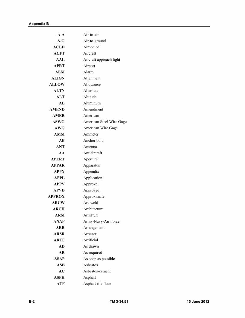
Appendix B
B-2 TM 3-34.51 15 June 2012
A-A Air-to-air
A-G Air-to-ground
ACLD Aircooled
ACFT Aircraft
AAL Aircraft approach light
APRT Airport
ALM Alarm
ALIGN Alignment
ALLOW Allowance
ALTN Alternate
ALT Altitude
AL Aluminum
AMEND Amendment
AMER American
ASWG American Steel Wire Gage
AWG American Wire Gage
AMM Ammeter
AB Anchor bolt
ANT Antenna
AA Antiaircraft
APERT Aperture
APPAR Apparatus
APPX Appendix
APPL Application
APPV Approve
APVD Approved
APPROX Approximate
ARCW Arc weld
ARCH Architecture
ARM Armature
ANAF Army-Navy-Air Force
ARR Arrangement
ARSR Arrester
ARTF Artificial
AD As drawn
AR As required
ASAP As soon as possible
ASB Asbestos
AC Asbestos-cement
ASPH Asphalt
ATF Asphalt-tile floor
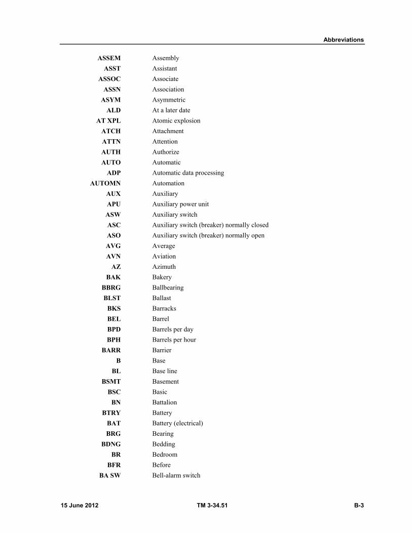
Abbreviations
15 June 2012 TM 3-34.51 B-3
ASSEM Assembly
ASST Assistant
ASSOC Associate
ASSN Association
ASYM Asymmetric
ALD At a later date
AT XPL Atomic explosion
ATCH Attachment
ATTN Attention
AUTH Authorize
AUTO Automatic
ADP Automatic data processing
AUTOMN Automation
AUX Auxiliary
APU Auxiliary power unit
ASW Auxiliary switch
ASC Auxiliary switch (breaker) normally closed
ASO Auxiliary switch (breaker) normally open
AVG Average
AVN Aviation
AZ Azimuth
BAK Bakery
BBRG Ballbearing
BLST Ballast
BKS Barracks
BEL Barrel
BPD Barrels per day
BPH Barrels per hour
BARR Barrier
B Base
BL Base line
BSMT Basement
BSC Basic
BN Battalion
BTRY Battery
BAT Battery (electrical)
BRG Bearing
BDNG Bedding
BR Bedroom
BFR Before
BA SW Bell-alarm switch
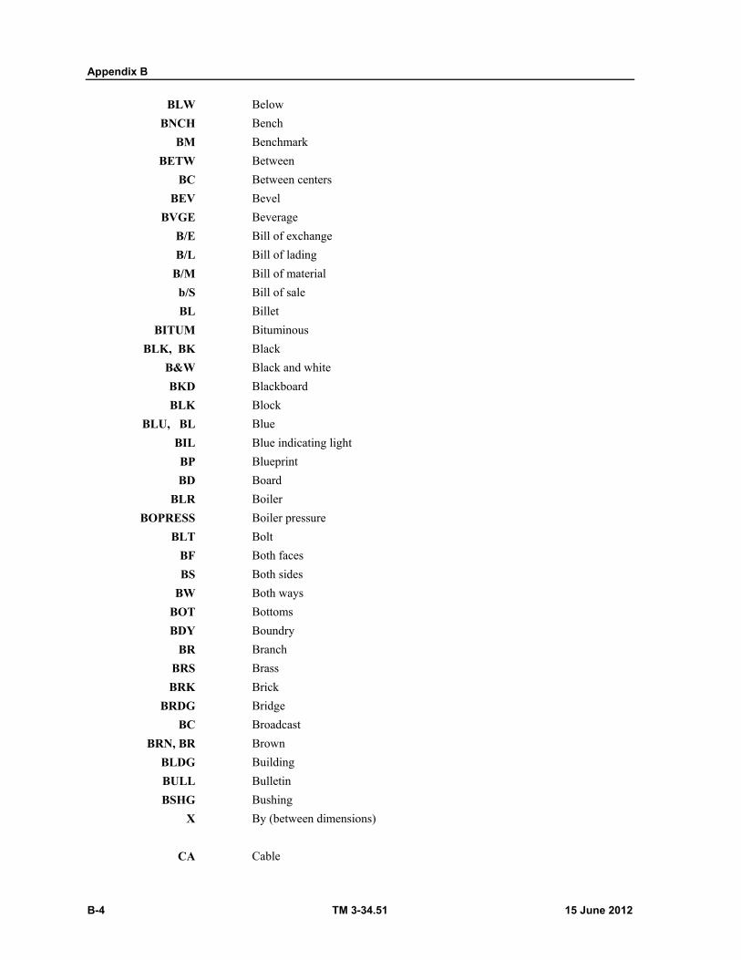
Appendix B
B-4 TM 3-34.51 15 June 2012
BLW Below
BNCH Bench
BM Benchmark
BETW Between
BC Between centers
BEV Bevel
BVGE Beverage
B/E Bill of exchange
B/L Bill of lading
B/M Bill of material
b/S Bill of sale
BL Billet
BITUM Bituminous
BLK, BK Black
B&W Black and white
BKD Blackboard
BLK Block
BLU, BL Blue
BIL Blue indicating light
BP Blueprint
BD Board
BLR Boiler
BOPRESS Boiler pressure
BLT Bolt
BF Both faces
BS Both sides
BW Both ways
BOT Bottoms
BDY Boundry
BR Branch
BRS Brass
BRK Brick
BRDG Bridge
BC Broadcast
BRN, BR Brown
BLDG Building
BULL Bulletin
BSHG Bushing
X By (between dimensions)
CA Cable
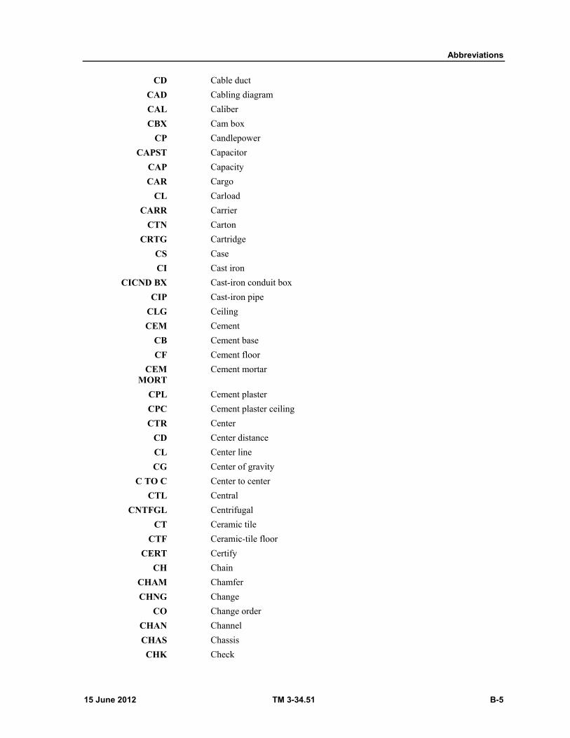
Abbreviations
15 June 2012 TM 3-34.51 B-5
CD Cable duct
CAD Cabling diagram
CAL Caliber
CBX Cam box
CP Candlepower
CAPST Capacitor
CAP Capacity
CAR Cargo
CL Carload
CARR Carrier
CTN Carton
CRTG Cartridge
CS Case
CI Cast iron
CICND BX Cast-iron conduit box
CIP Cast-iron pipe
CLG Ceiling
CEM Cement
CB Cement base
CF Cement floor
CEM MORT
Cement mortar
CPL Cement plaster
CPC Cement plaster ceiling
CTR Center
CD Center distance
CL Center line
CG Center of gravity
C TO C Center to center
CTL Central
CNTFGL Centrifugal
CT Ceramic tile
CTF Ceramic-tile floor
CERT Certify
CH Chain
CHAM Chamfer
CHNG Change
CO Change order
CHAN Channel
CHAS Chassis
CHK Check
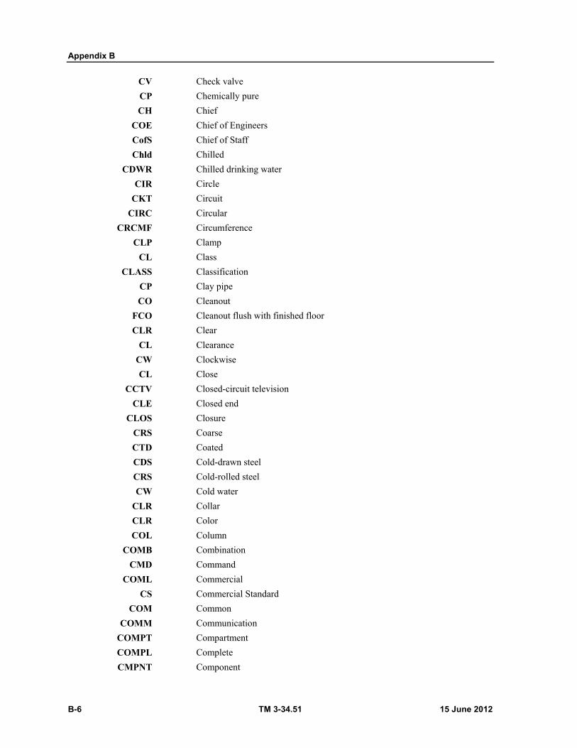
Appendix B
B-6 TM 3-34.51 15 June 2012
CV Check valve
CP Chemically pure
CH Chief
COE Chief of Engineers
CofS Chief of Staff
Chld Chilled
CDWR Chilled drinking water
CIR Circle
CKT Circuit
CIRC Circular
CRCMF Circumference
CLP Clamp
CL Class
CLASS Classification
CP Clay pipe
CO Cleanout
FCO Cleanout flush with finished floor
CLR Clear
CL Clearance
CW Clockwise
CL Close
CCTV Closed-circuit television
CLE Closed end
CLOS Closure
CRS Coarse
CTD Coated
CDS Cold-drawn steel
CRS Cold-rolled steel
CW Cold water
CLR Collar
CLR Color
COL Column
COMB Combination
CMD Command
COML Commercial
CS Commercial Standard
COM Common
COMM Communication
COMPT Compartment
COMPL Complete
CMPNT Component
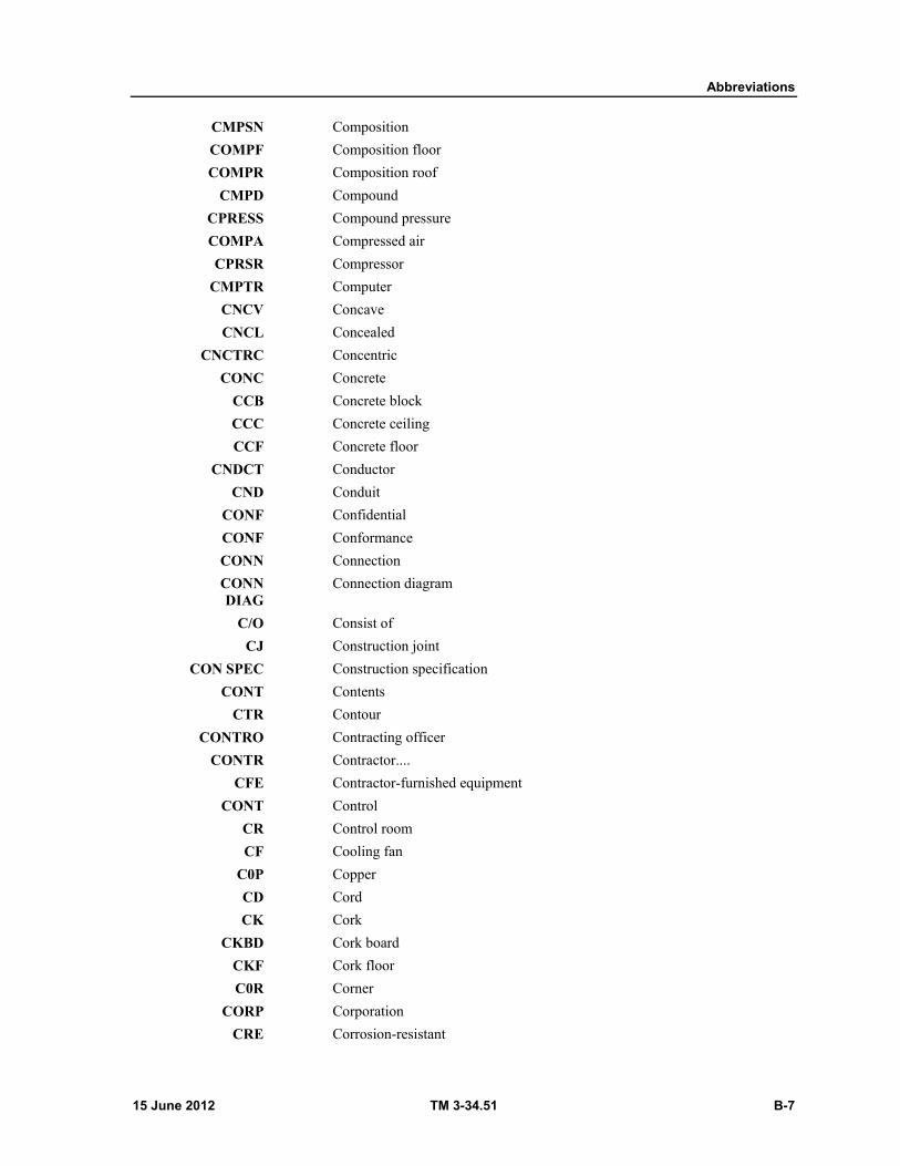
Abbreviations
15 June 2012 TM 3-34.51 B-7
CMPSN Composition
COMPF Composition floor
COMPR Composition roof
CMPD Compound
CPRESS Compound pressure
COMPA Compressed air
CPRSR Compressor
CMPTR Computer
CNCV Concave
CNCL Concealed
CNCTRC Concentric
CONC Concrete
CCB Concrete block
CCC Concrete ceiling
CCF Concrete floor
CNDCT Conductor
CND Conduit
CONF Confidential
CONF Conformance
CONN Connection
CONN DIAG
Connection diagram
C/O Consist of
CJ Construction joint
CON SPEC Construction specification
CONT Contents
CTR Contour
CONTRO Contracting officer
CONTR Contractor....
CFE Contractor-furnished equipment
CONT Control
CR Control room
CF Cooling fan
C0P Copper
CD Cord
CK Cork
CKBD Cork board
CKF Cork floor
C0R Corner
CORP Corporation
CRE Corrosion-resistant
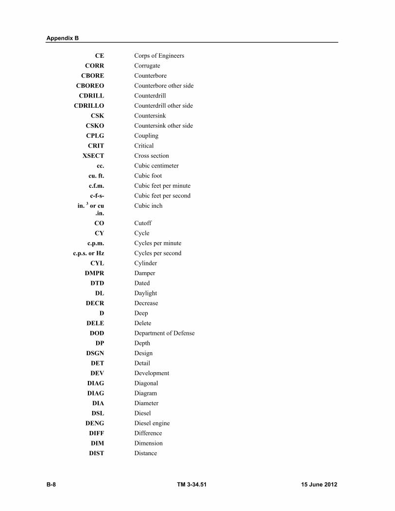
Appendix B
B-8 TM 3-34.51 15 June 2012
CE Corps of Engineers
CORR Corrugate
CBORE Counterbore
CBOREO Counterbore other side
CDRILL Counterdrill
CDRILLO Counterdrill other side
CSK Countersink
CSKO Countersink other side
CPLG Coupling
CRIT Critical
XSECT Cross section
cc. Cubic centimeter
cu. ft. Cubic foot
c.f.m. Cubic feet per minute
c-f-s- Cubic feet per second
in. 3 or cu .in.
Cubic inch
CO Cutoff
CY Cycle
c.p.m. Cycles per minute
c.p.s. or Hz Cycles per second
CYL Cylinder
DMPR Damper
DTD Dated
DL Daylight
DECR Decrease
D Deep
DELE Delete
DOD Department of Defense
DP Depth
DSGN Design
DET Detail
DEV Development
DIAG Diagonal
DIAG Diagram
DIA Diameter
DSL Diesel
DENG Diesel engine
DIFF Difference
DIM Dimension
DIST Distance

Abbreviations
15 June 2012 TM 3-34.51 B-9
DB Distribution box
DPNL Distribution panel
DIST District
DE District Engineer
DO Ditto
DOC Document
DNA Does not apply
DR Door
DN Down
DOZ Dozen
DFTG Drafting
DR Drain
DWG Drawing
DL Drawing list
DR Drill
EA Each
EF Each face
EL Each layer
EW Each way
ET Edge thickness
ELB Elbow
ELEC Electric
EMD Electric-motor driven
EPD Electric power distribution
ELCT Electronic
ELECTC Electronic Control
ELEX Electronics
EL Elevation
EMER Emergency
EPWR Emergency power
E TO E End to end
ENG Engine
ENGR Engineer
ENGRG Engineering
ECO Engineering change order
EWO Engineering work order
ENTR Entrance
EQL Equal
EQL SP Equally spaced
E&I Equip and install
EQPT Equipment
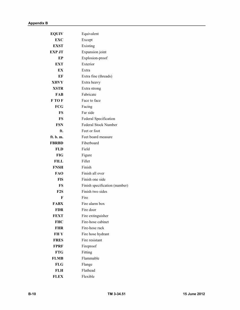
Appendix B
B-10 TM 3-34.51 15 June 2012
EQUIV Equivalent
EXC Except
EXST Existing
EXP JT Expansion joint
EP Explosion-proof
EXT Exterior
EX Extra
EF Extra fine (threads)
XHVY Extra heavy
XSTR Extra strong
FAB Fabricate
F TO F Face to face
FCG Facing
FS Far side
FS Federal Specification
FSN Federal Stock Number
ft. Feet or foot
ft. b. m. Feet board measure
FBRBD Fiberboard
FLD Field
FIG Figure
FILL Fillet
FNSH Finish
FAO Finish all over
FlS Finish one side
FS Finish specification (number)
F2S Finish two sides
F Fire
FABX Fire alarm box
FDR Fire door
FEXT Fire extinguisher
FHC Fire-hose cabinet
FHR Fire-hose rack
FH Y Fire hose hydrant
FRES Fire resistant
FPRF Fireproof
FTG Fitting
FLMB Flammable
FLG Flange
FLH Flathead
FLEX Flexible
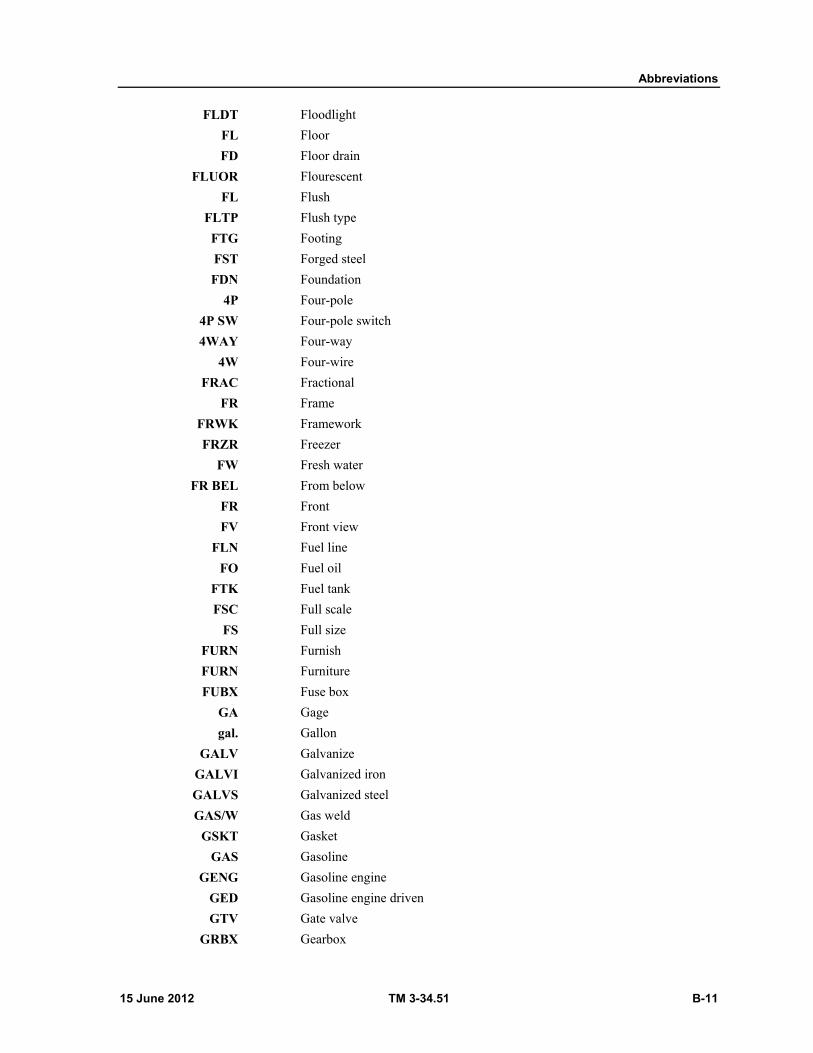
Abbreviations
15 June 2012 TM 3-34.51 B-11
FLDT Floodlight
FL Floor
FD Floor drain
FLUOR Flourescent
FL Flush
FLTP Flush type
FTG Footing
FST Forged steel
FDN Foundation
4P Four-pole
4P SW Four-pole switch
4WAY Four-way
4W Four-wire
FRAC Fractional
FR Frame
FRWK Framework
FRZR Freezer
FW Fresh water
FR BEL From below
FR Front
FV Front view
FLN Fuel line
FO Fuel oil
FTK Fuel tank
FSC Full scale
FS Full size
FURN Furnish
FURN Furniture
FUBX Fuse box
GA Gage
gal. Gallon
GALV Galvanize
GALVI Galvanized iron
GALVS Galvanized steel
GAS/W Gas weld
GSKT Gasket
GAS Gasoline
GENG Gasoline engine
GED Gasoline engine driven
GTV Gate valve
GRBX Gearbox
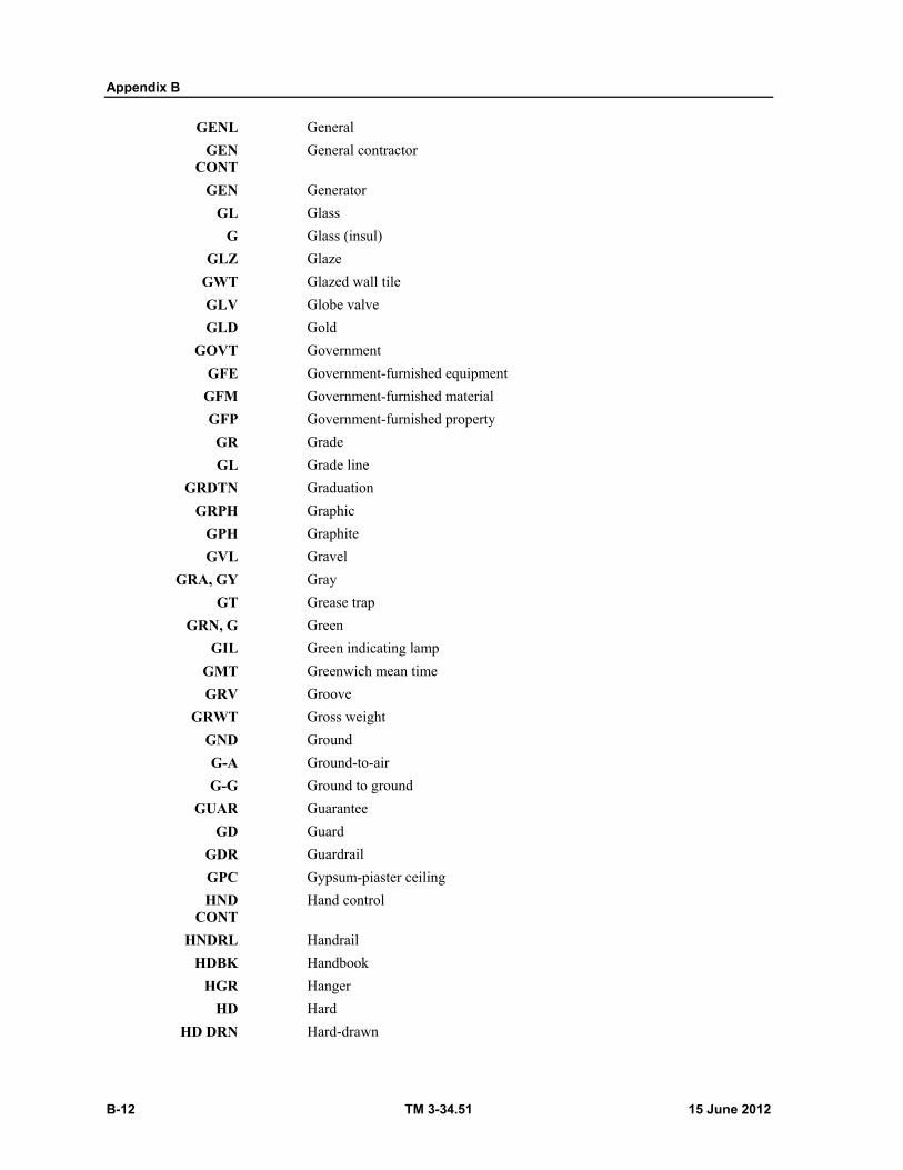
Appendix B
B-12 TM 3-34.51 15 June 2012
GENL General
GEN CONT
General contractor
GEN Generator
GL Glass
G Glass (insul)
GLZ Glaze
GWT Glazed wall tile
GLV Globe valve
GLD Gold
GOVT Government
GFE Government-furnished equipment
GFM Government-furnished material
GFP Government-furnished property
GR Grade
GL Grade line
GRDTN Graduation
GRPH Graphic
GPH Graphite
GVL Gravel
GRA, GY Gray
GT Grease trap
GRN, G Green
GIL Green indicating lamp
GMT Greenwich mean time
GRV Groove
GRWT Gross weight
GND Ground
G-A Ground-to-air
G-G Ground to ground
GUAR Guarantee
GD Guard
GDR Guardrail
GPC Gypsum-piaster ceiling
HND CONT
Hand control
HNDRL Handrail
HDBK Handbook
HGR Hanger
HD Hard
HD DRN Hard-drawn
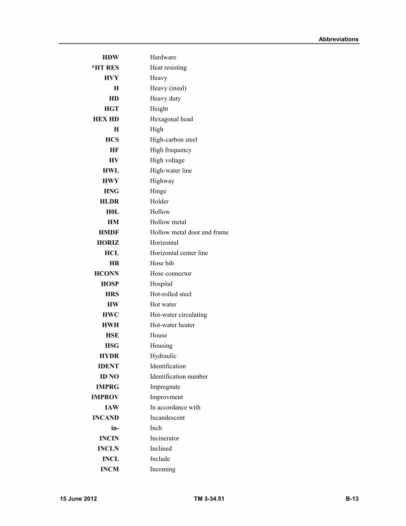
Abbreviations
15 June 2012 TM 3-34.51 B-13
HDW Hardware
*HT RES Heat resisting
HVY Heavy
H Heavy (insul)
HD Heavy duty
HGT Height
HEX HD Hexagonal head
H High
HCS High-carbon steel
HF High frequency
HV High voltage
HWL High-water line
HWY Highway
HNG Hinge
HLDR Holder
H0L Hollow
HM Hollow metal
HMDF Hollow metal door and frame
HORIZ Horizontal
HCL Horizontal center line
HB Hose bib
HCONN Hose connector
HOSP Hospital
HRS Hot-rolled steel
HW Hot water
HWC Hot-water circulating
HWH Hot-water heater
HSE House
HSG Housing
HYDR Hydraulic
IDENT Identification
ID NO Identification number
IMPRG Impregnate
IMPROV Improvment
IAW In accordance with
INCAND Incandescent
in- Inch
INCIN Incinerator
INCLN Inclined
INCL Include
INCM Incoming
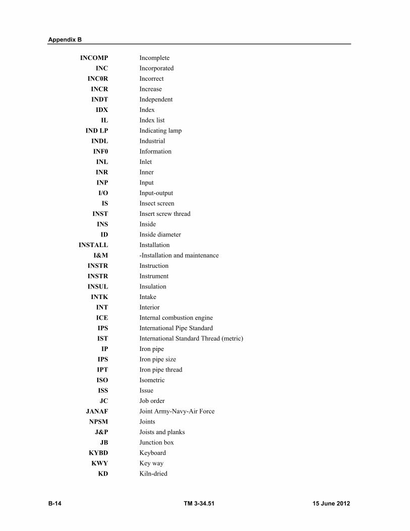
Appendix B
B-14 TM 3-34.51 15 June 2012
INCOMP Incomplete
INC Incorporated
INC0R Incorrect
INCR Increase
INDT Independent
IDX Index
IL Index list
IND LP Indicating lamp
INDL Industrial
INF0 Information
INL Inlet
INR Inner
INP Input
I/O Input-output
IS Insect screen
INST Insert screw thread
INS Inside
ID Inside diameter
INSTALL Installation
I&M -Installation and maintenance
INSTR Instruction
INSTR Instrument
INSUL Insulation
INTK Intake
INT Interior
ICE Internal combustion engine
IPS International Pipe Standard
IST International Standard Thread (metric)
IP Iron pipe
IPS Iron pipe size
IPT Iron pipe thread
ISO Isometric
ISS Issue
JC Job order
JANAF Joint Army-Navy-Air Force
NPSM Joints
J&P Joists and planks
JB Junction box
KYBD Keyboard
KWY Key way
KD Kiln-dried

Abbreviations
15 June 2012 TM 3-34.51 B-15
KVAM Kilovolt-ampere meter
KWHM Kilowatt-hour meter
KNRL Knurl
LD MK Landmark
LGE Large
LADAR Laser detection and ranging
LAT Latitude
LP Lawn faucet
LYT Layout
LDR Leader
L Left
LH Left hand
LS Left side
LG Length
LOA Length over-all
LVL Level
LT Light
LDB Light distribution box
LTSW Light switch
LTG Lightning
LA Lightning arrestor
LWC Lightweight concrete
LS Limestone
LD Line drawing
LOS Line-of-sight
LK Link
LINOL Linoleum
LF Linoleum floor
LNTL Lintel
LIQ Liquid
LM List of material
LK WASH Lock washer
L/R Locus of radius
L Long
LONG Longitude
LEJ Longitudinal expansion joint
LS Loudspeaker
LVR Louver
LVD Louvered door
L Low
LF Low frequency
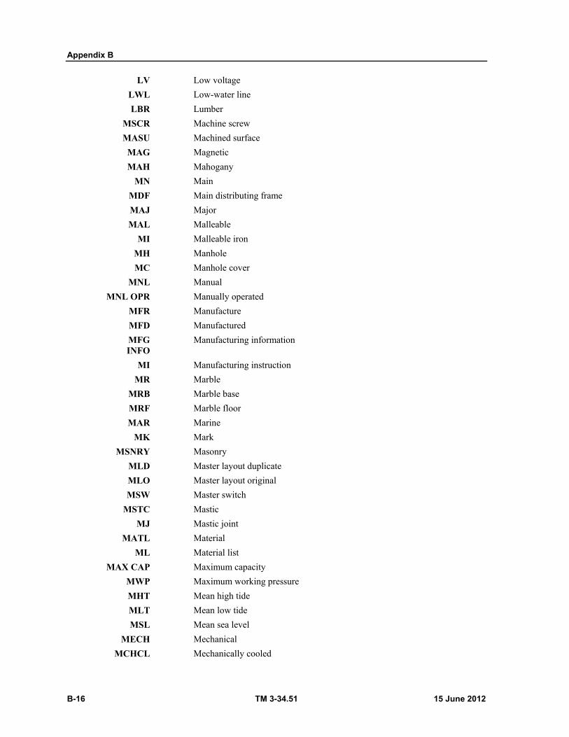
Appendix B
B-16 TM 3-34.51 15 June 2012
LV Low voltage
LWL Low-water line
LBR Lumber
MSCR Machine screw
MASU Machined surface
MAG Magnetic
MAH Mahogany
MN Main
MDF Main distributing frame
MAJ Major
MAL Malleable
MI Malleable iron
MH Manhole
MC Manhole cover
MNL Manual
MNL OPR Manually operated
MFR Manufacture
MFD Manufactured
MFG INFO
Manufacturing information
MI Manufacturing instruction
MR Marble
MRB Marble base
MRF Marble floor
MAR Marine
MK Mark
MSNRY Masonry
MLD Master layout duplicate
MLO Master layout original
MSW Master switch
MSTC Mastic
MJ Mastic joint
MATL Material
ML Material list
MAX CAP Maximum capacity
MWP Maximum working pressure
MHT Mean high tide
MLT Mean low tide
MSL Mean sea level
MECH Mechanical
MCHCL Mechanically cooled

Abbreviations
15 June 2012 TM 3-34.51 B-17
MDN Median
MDM Medium
MP Melting point
MWP Membrane waterproofing
MER Meridian
MET Metal
METD Metal door
METF Metal flashing
METJ Metal jalousie
MRD Metal rolling door
MTR Meter
MTHD Method
MDL Middle
MIL Military
MIL-STD Military standard (book)
MS Military standard (sheet)
MNRL Mineral
MINTR Minature
MIN Minimum
MIN Minute
MISC Miscellaneous
MIT Miter
MXT Mixture
MBL Mobil
MOD Model
MOD Modification
MSTRE Moisture
MLDG Molding
MO Month
MON Monument
MOT Motor
MBD Motor belt drive
MTRDN Motor driven
MG Motor generator
MO Motor operated
MTZ Motorized
MT Mount
MTD Mounted
MTG Mounting
MVBL Movable
MULT Multiple
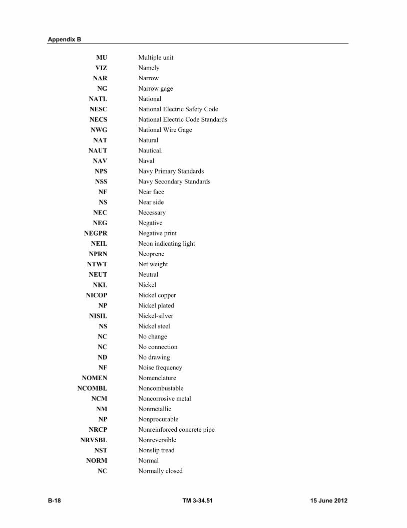
Appendix B
B-18 TM 3-34.51 15 June 2012
MU Multiple unit
VIZ Namely
NAR Narrow
NG Narrow gage
NATL National
NESC National Electric Safety Code
NECS National Electric Code Standards
NWG National Wire Gage
NAT Natural
NAUT Nautical.
NAV Naval
NPS Navy Primary Standards
NSS Navy Secondary Standards
NF Near face
NS Near side
NEC Necessary
NEG Negative
NEGPR Negative print
NEIL Neon indicating light
NPRN Neoprene
NTWT Net weight
NEUT Neutral
NKL Nickel
NICOP Nickel copper
NP Nickel plated
NISIL Nickel-silver
NS Nickel steel
NC No change
NC No connection
ND No drawing
NF Noise frequency
NOMEN Nomenclature
NCOMBL Noncombustable
NCM Noncorrosive metal
NM Nonmetallic
NP Nonprocurable
NRCP Nonreinforced concrete pipe
NRVSBL Nonreversible
NST Nonslip tread
NORM Normal
NC Normally closed
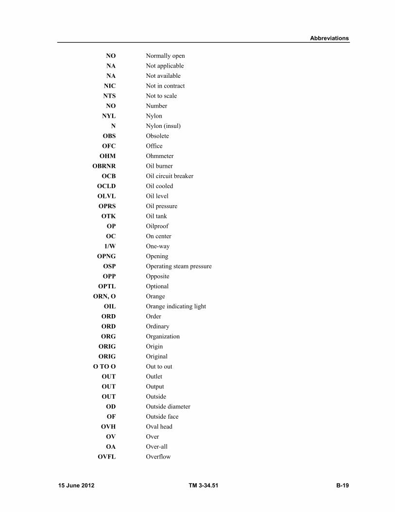
Abbreviations
15 June 2012 TM 3-34.51 B-19
NO Normally open
NA Not applicable
NA Not available
NIC Not in contract
NTS Not to scale
NO Number
NYL Nylon
N Nylon (insul)
OBS Obsolete
OFC Office
OHM Ohmmeter
OBRNR Oil burner
OCB Oil circuit breaker
OCLD Oil cooled
OLVL Oil level
OPRS Oil pressure
OTK Oil tank
OP Oilproof
OC On center
1/W One-way
OPNG Opening
OSP Operating steam pressure
OPP Opposite
OPTL Optional
ORN, O Orange
OIL Orange indicating light
ORD Order
ORD Ordinary
ORG Organization
ORIG Origin
ORIG Original
O TO O Out to out
OUT Outlet
OUT Output
OUT Outside
OD Outside diameter
OF Outside face
OVH Oval head
OV Over
OA Over-all
OVFL Overflow
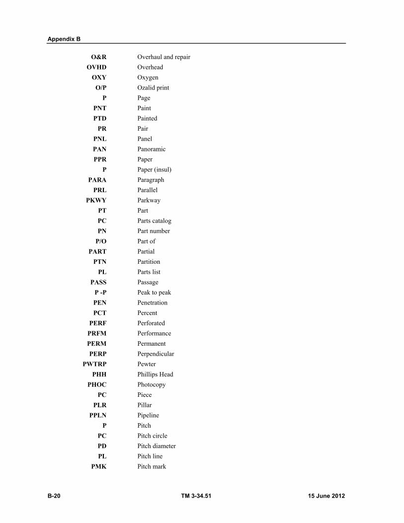
Appendix B
B-20 TM 3-34.51 15 June 2012
O&R Overhaul and repair
OVHD Overhead
OXY Oxygen
O/P Ozalid print P Page
PNT Paint
PTD Painted
PR Pair
PNL Panel
PAN Panoramic
PPR Paper
P Paper (insul)
PARA Paragraph
PRL Parallel
PKWY Parkway
PT Part
PC Parts catalog
PN Part number
P/O Part of
PART Partial
PTN Partition
PL Parts list
PASS Passage
P -P Peak to peak
PEN Penetration
PCT Percent
PERF Perforated
PRFM Performance
PERM Permanent
PERP Perpendicular
PWTRP Pewter
PHH Phillips Head
PHOC Photocopy
PC Piece
PLR Pillar
PPLN Pipeline
P Pitch
PC Pitch circle
PD Pitch diameter
PL Pitch line
PMK Pitch mark

Abbreviations
15 June 2012 TM 3-34.51 B-21
PVT Pivot
PL Place
PL Plain
PV Plan view
PLN Plane
PLAS Plaster
PLSTC Plastic
PL Plate
PLGL Plate glass
PLATF Platform
PLAT Platinum
PL Plug
PLMB Plumbing
PORM Plus or minus
PLYWD Plywood
PNEU Pneumatic
PKT Pocket
PT Point
PC Point of curve
PI Point of intersection
PRC Point of reverse curve
PT Point of tangency
P Pole
POLYEST Polyester
POLTHN Polyethylene (insul)
PIC Polyethylene-insulated conductor
PORC Porcelain
PORT Portable
POSN Position
POS Positive
POTW Potable water
lb. Pound
PWR Power
P&L DISTR
Power and lightning distribution
PCB Power circuit breaker
PDVN Power driven
PP Power plant
PWR SPLY
Power supply
PWRH Powerhouse
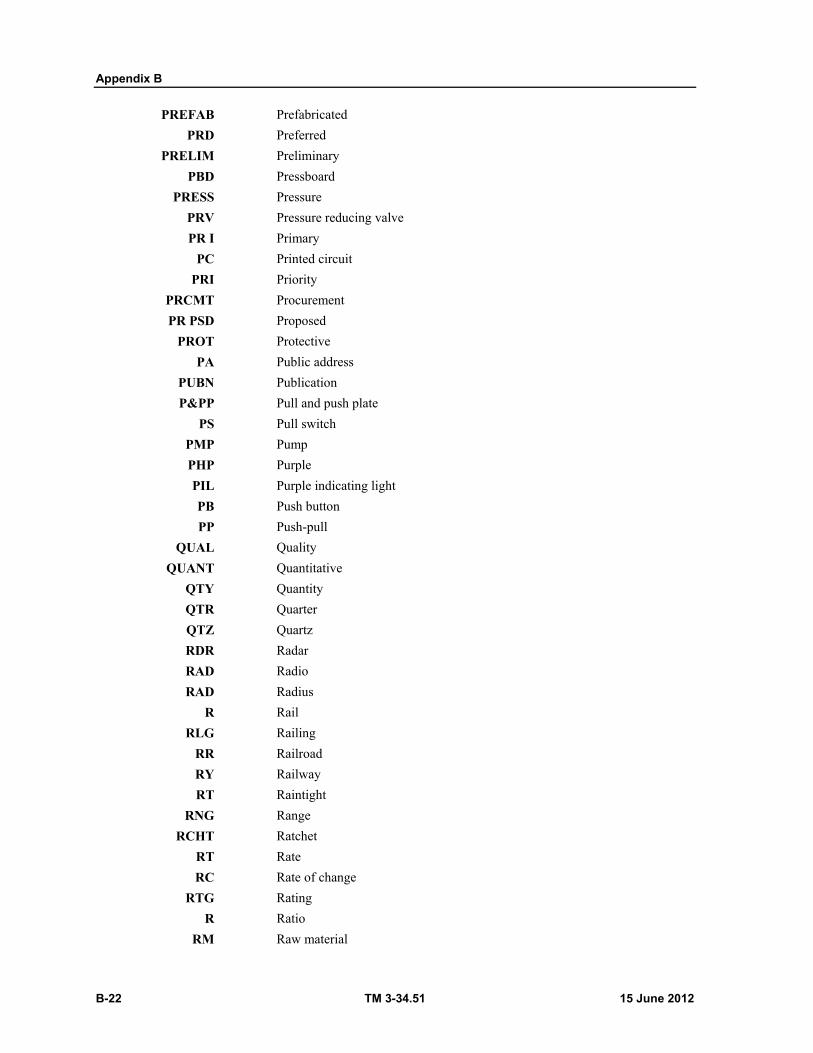
Appendix B
B-22 TM 3-34.51 15 June 2012
PREFAB Prefabricated
PRD Preferred
PRELIM Preliminary
PBD Pressboard
PRESS Pressure
PRV Pressure reducing valve
PR I Primary
PC Printed circuit
PRI Priority
PRCMT Procurement
PR PSD Proposed
PROT Protective
PA Public address
PUBN Publication
P&PP Pull and push plate
PS Pull switch
PMP Pump
PHP Purple
PIL Purple indicating light
PB Push button
PP Push-pull
QUAL Quality
QUANT Quantitative
QTY Quantity
QTR Quarter
QTZ Quartz
RDR Radar
RAD Radio
RAD Radius
R Rail
RLG Railing
RR Railroad
RY Railway
RT Raintight
RNG Range
RCHT Ratchet
RT Rate
RC Rate of change
RTG Rating
R Ratio
RM Raw material

Abbreviations
15 June 2012 TM 3-34.51 B-23
RYN Rayon
RA Rayon (insul)
REACTVT Reactivate
RV Rear view
RCV Receive
RCVR Receiver
RCPT Receptacle
RCN Recreation
RED, R Red
RIL Red indicating lamp
REDWN Redrawn
RDC Reduce
REF Reference
REFL Reference line
REFR Refrigerator
RGLTR Regulator
REINF Reinforce
RC Reinforced concrete
RCCP Reinforced concrete culvert pipe
RCP Reinforced concrete pipe
RST Reinforcing steel
REJ Reject
RH Relative humidity
RLY Relay
RB Relay block
RLV Relief valve
RELOC Relocated
REM Remainder
RMT Remote
RC Remote control
RCS Remote control system
REM Removable
REM COV Removable cover
R&R Remove and replace
RPR Repair
RPT Repeat
REPL Replace
REPRO Reproduce
REQ Require
REQD Required
REQT Requirement
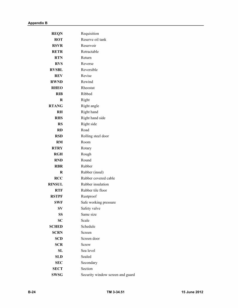
Appendix B
B-24 TM 3-34.51 15 June 2012
REQN Requisition
ROT Reserve oil tank
RSVR Reservoir
RETR Retractable
RTN Return
RVS Reverse
RVSBL Reversible
REV Revise
RWND Rewind
RHEO Rheostat
RIB Ribbed
R Right
RTANG Right angle
RH Right hand
RHS Right hand side
RS Right side
RD Road
RSD Rolling steel door
RM Room
RTRY Rotary
RGH Rough
RND Round
RBR Rubber
R Rubber (insul)
RCC Rubber covered cable
RINSUL Rubber insulation
RTF Rubber tile floor
RSTPF Rustproof
SWF Safe working pressure
SV Safety valve
SS Same size
SC Scale
SCHED Schedule
SCRN Screen
SCD Screen door
SCR Screw
SL Sea level
SLD Sealed
SEC Secondary
SECT Section
SWSG Security window screen and guard
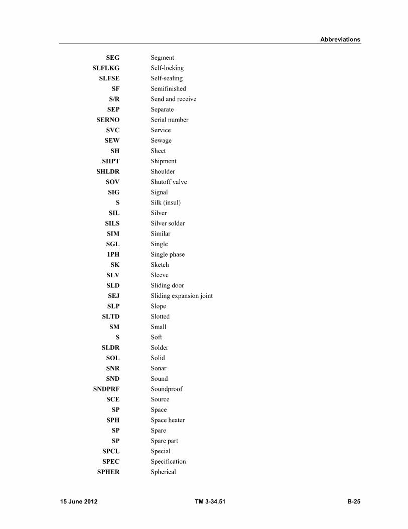
Abbreviations
15 June 2012 TM 3-34.51 B-25
SEG Segment
SLFLKG Self-locking
SLFSE Self-sealing
SF Semifinished
S/R Send and receive
SEP Separate
SERNO Serial number
SVC Service
SEW Sewage
SH Sheet
SHPT Shipment
SHLDR Shoulder
SOV Shutoff valve
SIG Signal
S Silk (insul)
SIL Silver
SILS Silver solder
SIM Similar
SGL Single
1PH Single phase
SK Sketch
SLV Sleeve
SLD Sliding door
SEJ Sliding expansion joint
SLP Slope
SLTD Slotted
SM Small
S Soft
SLDR Solder
SOL Solid
SNR Sonar
SND Sound
SNDPRF Soundproof
SCE Source
SP Space
SPH Space heater
SP Spare
SP Spare part
SPCL Special
SPEC Specification
SPHER Spherical
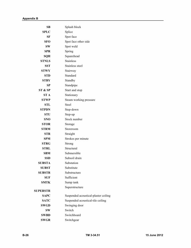
Appendix B
B-26 TM 3-34.51 15 June 2012
SB Splash block
SPLC Splice
SF Spot face
SFO Spot face other side
SW Spot weld
SPR Spring
SQH Squarehead
STNLS Stainless
SST Stainless steel
STWY Stairway
STD Standard
STBY Standby
SP Standpipe
ST & SP Start and stop
ST A Stationary
STWP Steam working pressure
STL Steel
STPDN Step-down
STU Step-up
SNO Stock number
STOR Storage
STRM Storeroom
STR Straight
SPM Strokes per minute
STRG Strong
STRL Structural
SBM Submersible
SSD Subsoil drain
SUBSTA Substation
SUBST Substitute
SUBSTR Substructure
SUF Sufficient
SMTK Sump tank
SUPERSTR
Superstructure
SAPC Suspended acoustical-plaster ceiling
SATC Suspended acoustical-tile ceiling
SWGD Swinging door
SW Switch
SWBD Switchboard
SWGR Switchgear
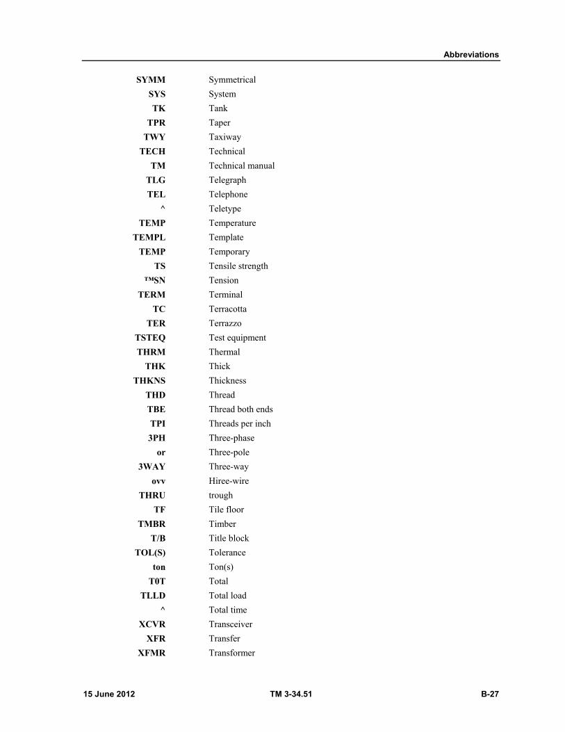
Abbreviations
15 June 2012 TM 3-34.51 B-27
SYMM Symmetrical
SYS System
TK Tank
TPR Taper
TWY Taxiway
TECH Technical
TM Technical manual
TLG Telegraph
TEL Telephone
^ Teletype
TEMP Temperature
TEMPL Template
TEMP Temporary
TS Tensile strength
™SN Tension
TERM Terminal
TC Terracotta
TER Terrazzo
TSTEQ Test equipment
THRM Thermal
THK Thick
THKNS Thickness
THD Thread
TBE Thread both ends
TPI Threads per inch
3PH Three-phase
or Three-pole
3WAY Three-way
ovv Hiree-wire
THRU trough
TF Tile floor
TMBR Timber
T/B Title block
TOL(S) Tolerance
ton Ton(s)
T0T Total
TLLD Total load
^ Total time
XCVR Transceiver
XFR Transfer
XFMR Transformer
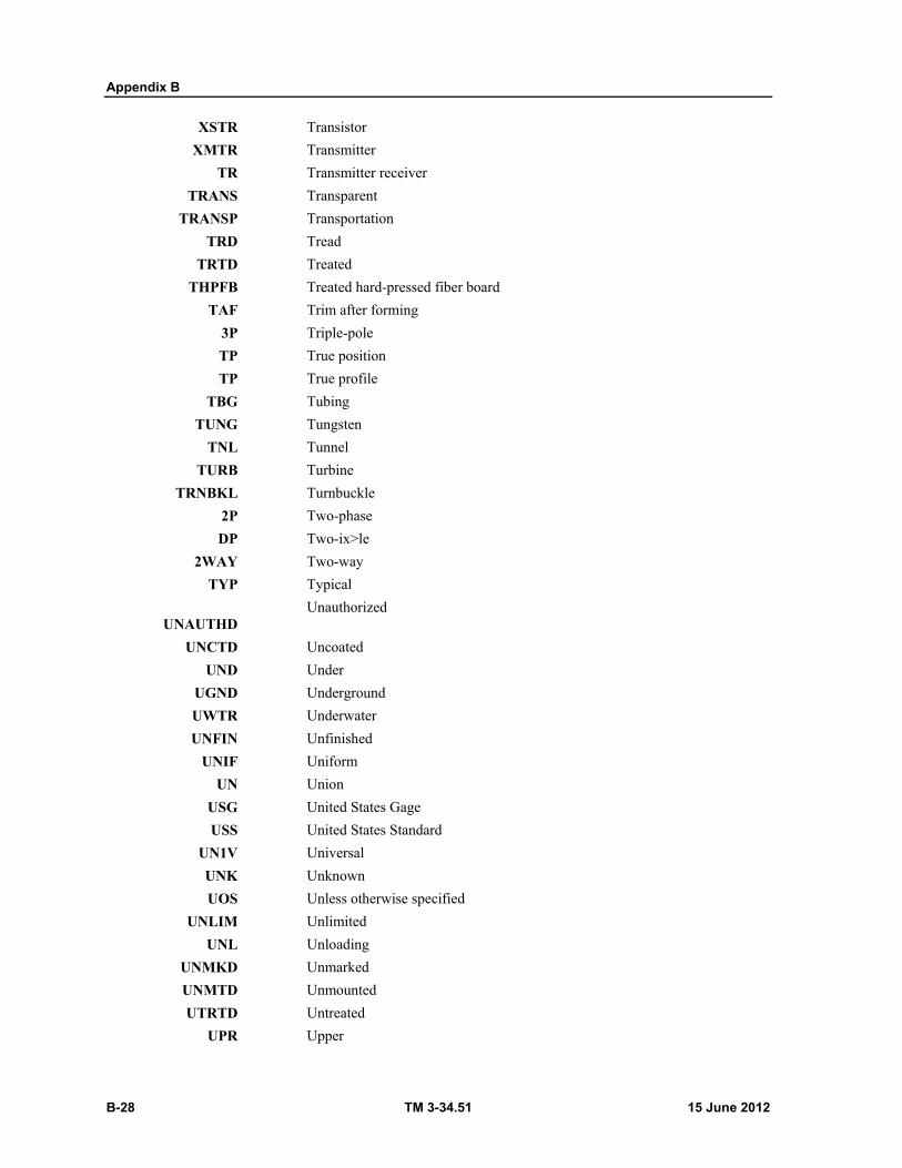
Appendix B
B-28 TM 3-34.51 15 June 2012
XSTR Transistor
XMTR Transmitter
TR Transmitter receiver
TRANS Transparent
TRANSP Transportation
TRD Tread
TRTD Treated
THPFB Treated hard-pressed fiber board
TAF Trim after forming
3P Triple-pole
TP True position
TP True profile
TBG Tubing
TUNG Tungsten
TNL Tunnel
TURB Turbine
TRNBKL Turnbuckle
2P Two-phase
DP Two-ix>le
2WAY Two-way
TYP Typical
UNAUTHD
Unauthorized
UNCTD Uncoated
UND Under
UGND Underground
UWTR Underwater
UNFIN Unfinished
UNIF Uniform
UN Union
USG United States Gage
USS United States Standard
UN1V Universal
UNK Unknown
UOS Unless otherwise specified
UNLIM Unlimited
UNL Unloading
UNMKD Unmarked
UNMTD Unmounted
UTRTD Untreated
UPR Upper
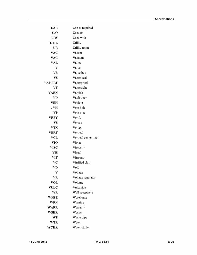
Abbreviations
15 June 2012 TM 3-34.51 B-29
UAR Use as required
U/O Used on
U/W Used with
UTIL Utility
UR Utility room
VAC Vacant
VAC Vacuum
VAL Valley
V Valve
VB Valve box
VS Vapor seal
VAP PRF Vaporproof
VT Vaportight
VARN Varnish
VD Vault door
VEH Vehicle
, VH Vent hole
VP Vent pipe
VRFY Verify
VS Versus
VTX Vertex
VERT Vertical
VCL Vertical center line
VIO Violet
VISC Viscosity
VIS Visual
VIT Vitreous
VC Vitrified clay
VD Void
V Voltage
VR Voltage regulator
VOL Volume
VULC Vulcanize
WR Wall receptacle
WHSE Warehouse
WRN Warning
WARR Warranty
WSHR Washer
WP Waste pipe
WTR Water
WCHR Water chiller
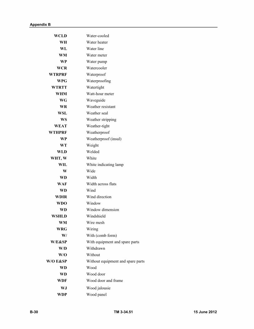
Appendix B
B-30 TM 3-34.51 15 June 2012
WCLD Water-cooled
WH Water heater
WL Water line
WM Water meter
WP Water pump
WCR Watercooler
WTRPRF Waterproof
WPG Waterproofing
WTRTT Watertight
WHM Watt-hour meter
WG Waveguide
WR Weather resistant
WSL Weather seal
WS Weather stripping
WEAT Weather-tight
WTHPRF Weatherproof
WP Weatherproof (insul)
WT Weight
WLD Welded
WHT, W White
WIL White indicating lamp
W Wide
WD Width
WAF Width across flats
WD Wind
WDIR Wind direction
WDO Window
WD Window dimension
WSHLD Windshield
WM Wire mesh
WRG Wiring
W/ With (comb form)
W/E&SP With equipment and spare parts
W/D Withdrawn
W/O Without
W/O E&SP Without equipment and spare parts
WD Wood
WD Wood door
WDF Wood door and frame
WJ Wood jalousie
WDP Wood panel
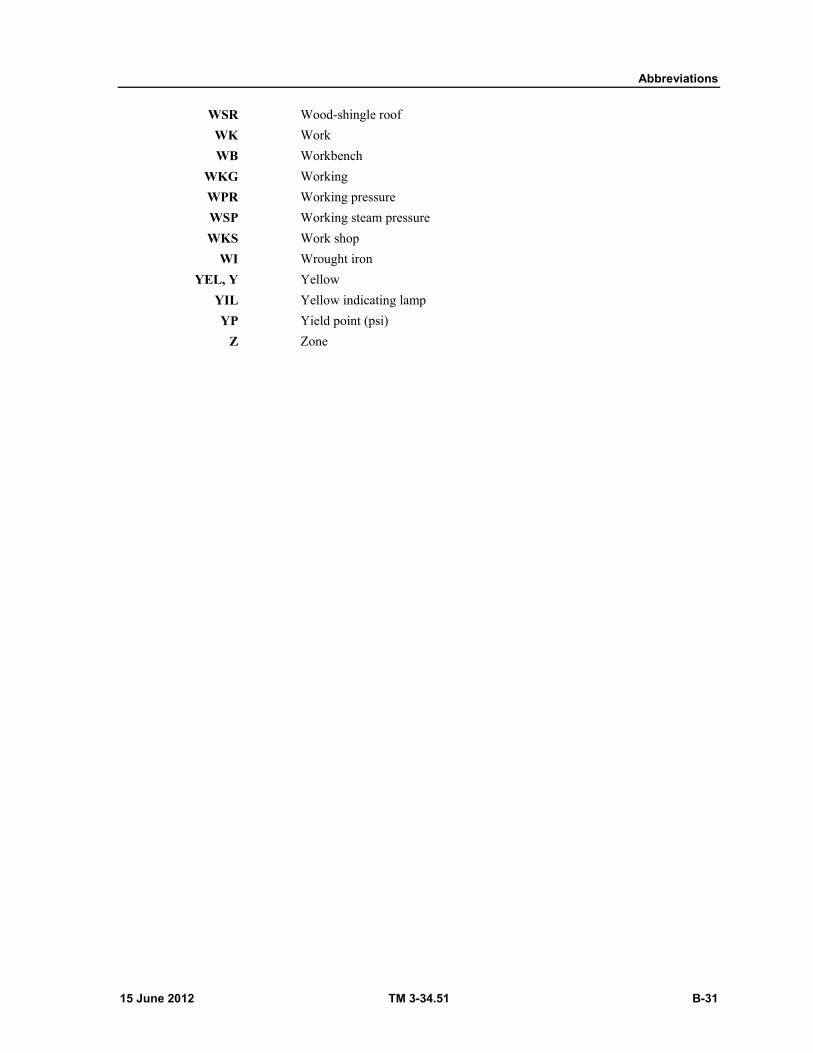
Abbreviations
15 June 2012 TM 3-34.51 B-31
WSR Wood-shingle roof
WK Work
WB Workbench
WKG Working
WPR Working pressure
WSP Working steam pressure
WKS Work shop
WI Wrought iron
YEL, Y Yellow
YIL Yellow indicating lamp
YP Yield point (psi)
Z Zone

This page intentionally left blank.
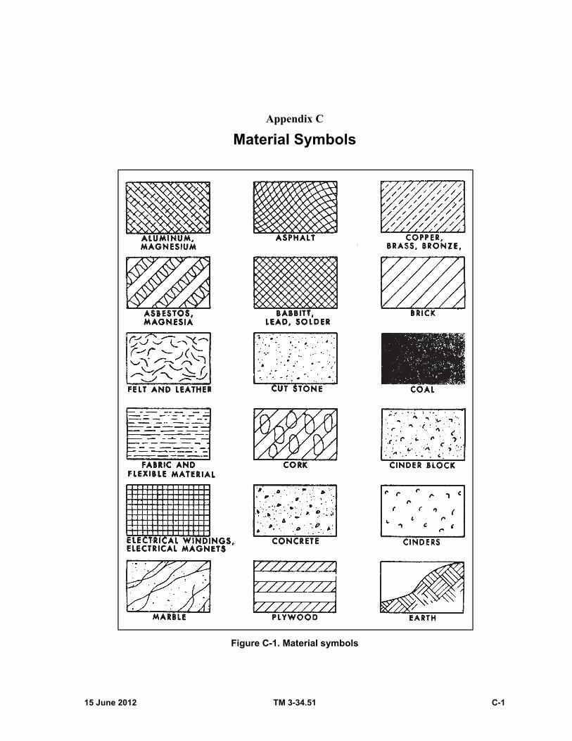
15 June 2012 TM 3-34.51 C-1
Appendix C
Material Symbols
Figure C-1. Material symbols
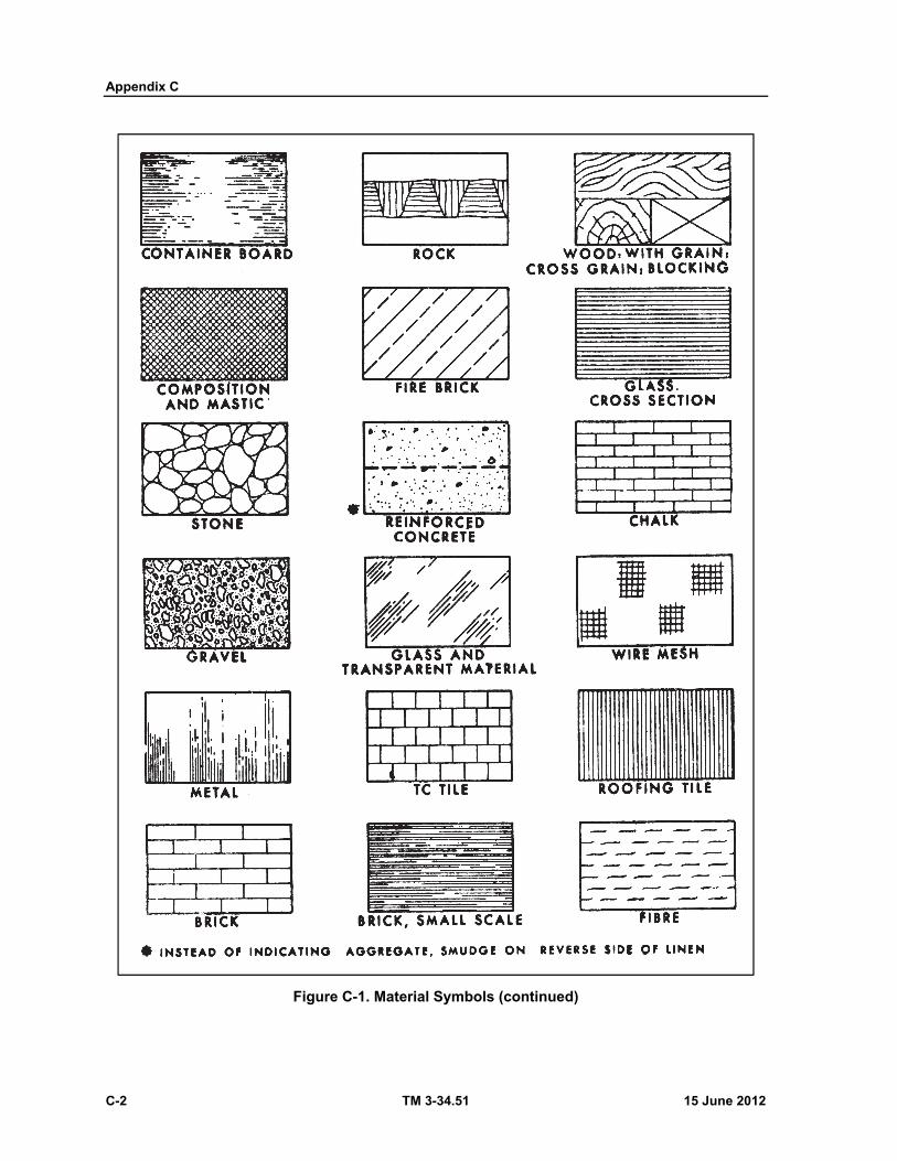
Appendix C
C-2 TM 3-34.51 15 June 2012
Figure C-1. Material Symbols (continued)

Material Symbols
15 June 2012 TM 3-34.51 C-3
Figure C-1. Material Symbols (continued)

This page intentionally left blank.
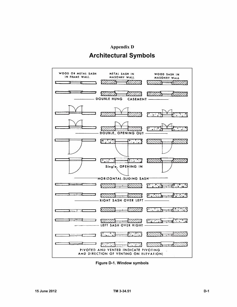
15 June 2012 TM 3-34.51 D-1
Appendix D
Architectural Symbols
Figure D-1. Window symbols
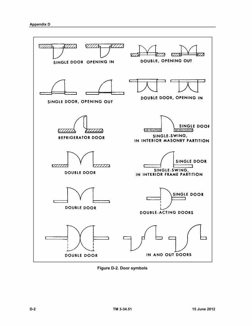
Appendix D
D-2 TM 3-34.51 15 June 2012
Figure D-2. Door symbols
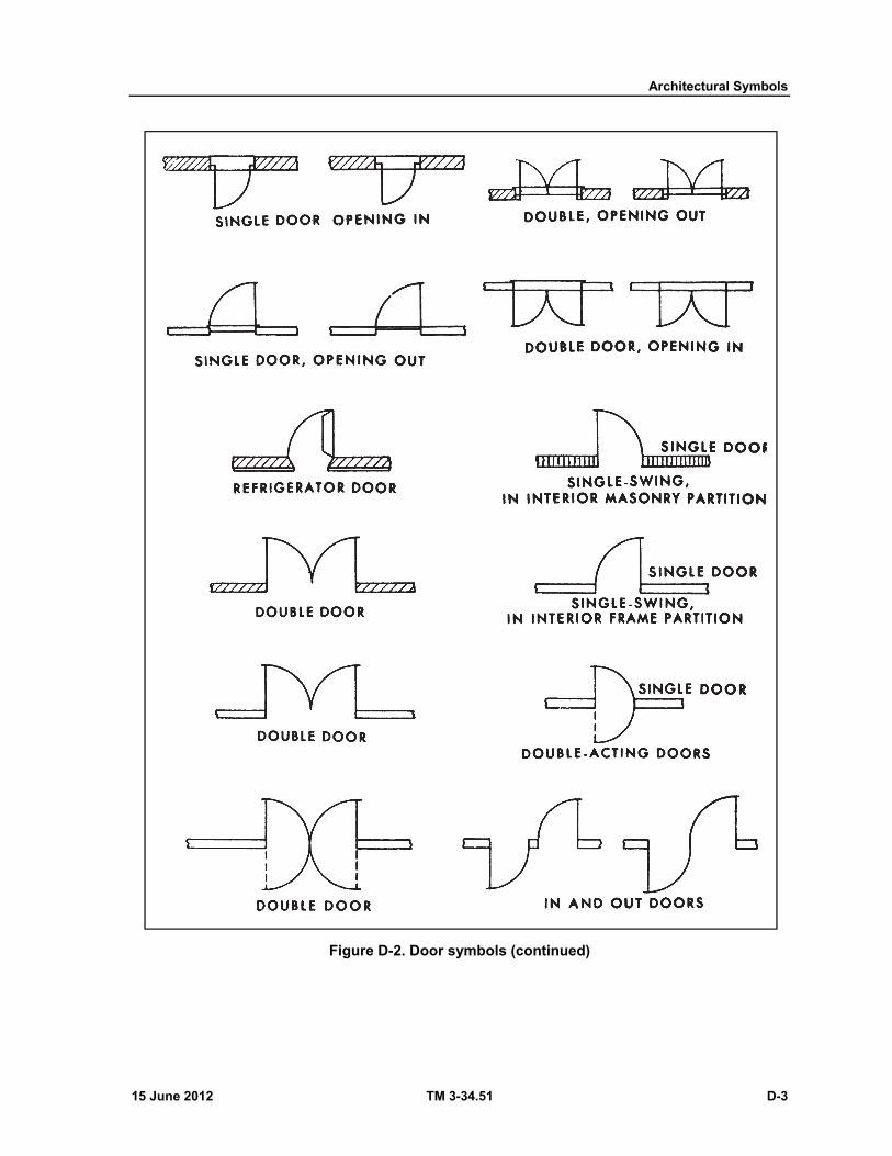
Architectural Symbols
15 June 2012 TM 3-34.51 D-3
Figure D-2. Door symbols (continued)
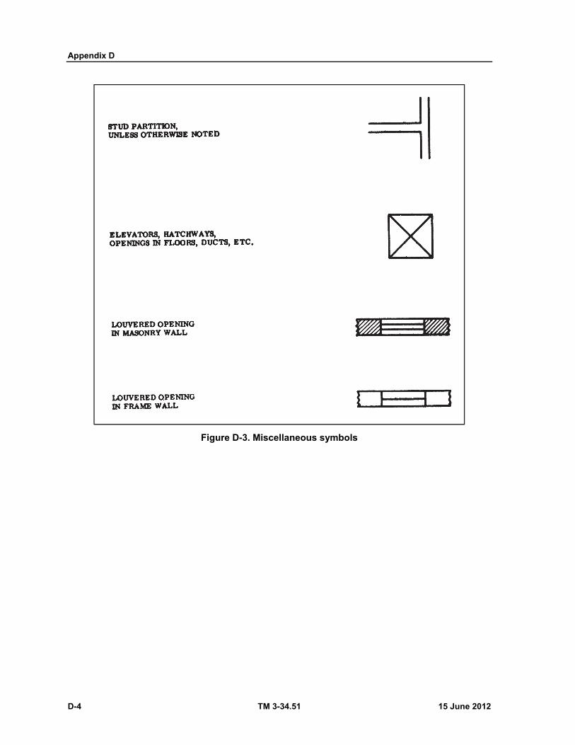
Appendix D
D-4 TM 3-34.51 15 June 2012
Figure D-3. Miscellaneous symbols
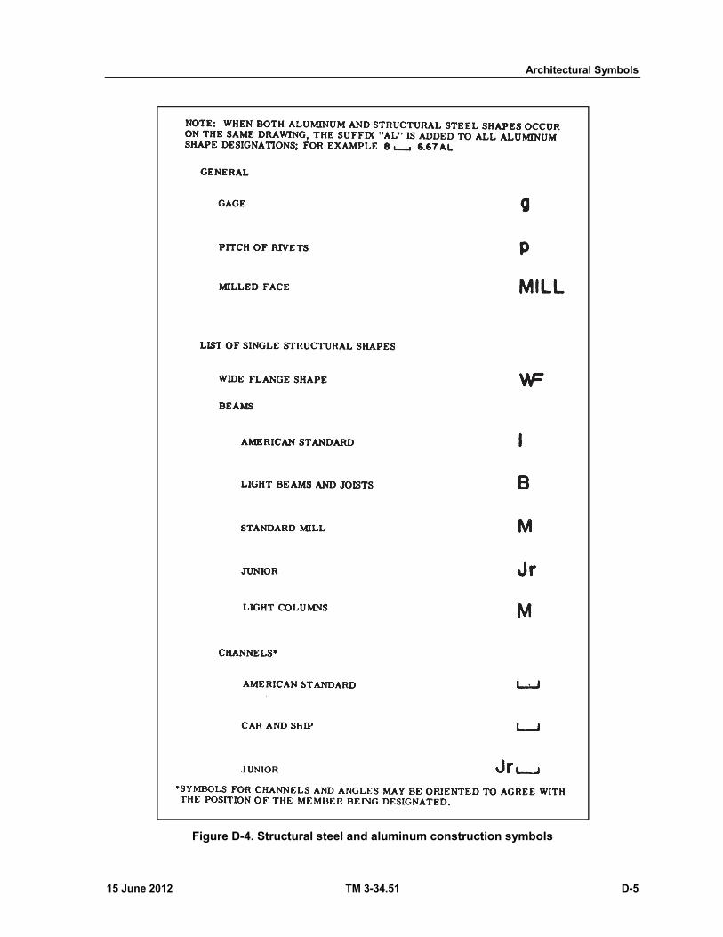
Architectural Symbols
15 June 2012 TM 3-34.51 D-5
Figure D-4. Structural steel and aluminum construction symbols
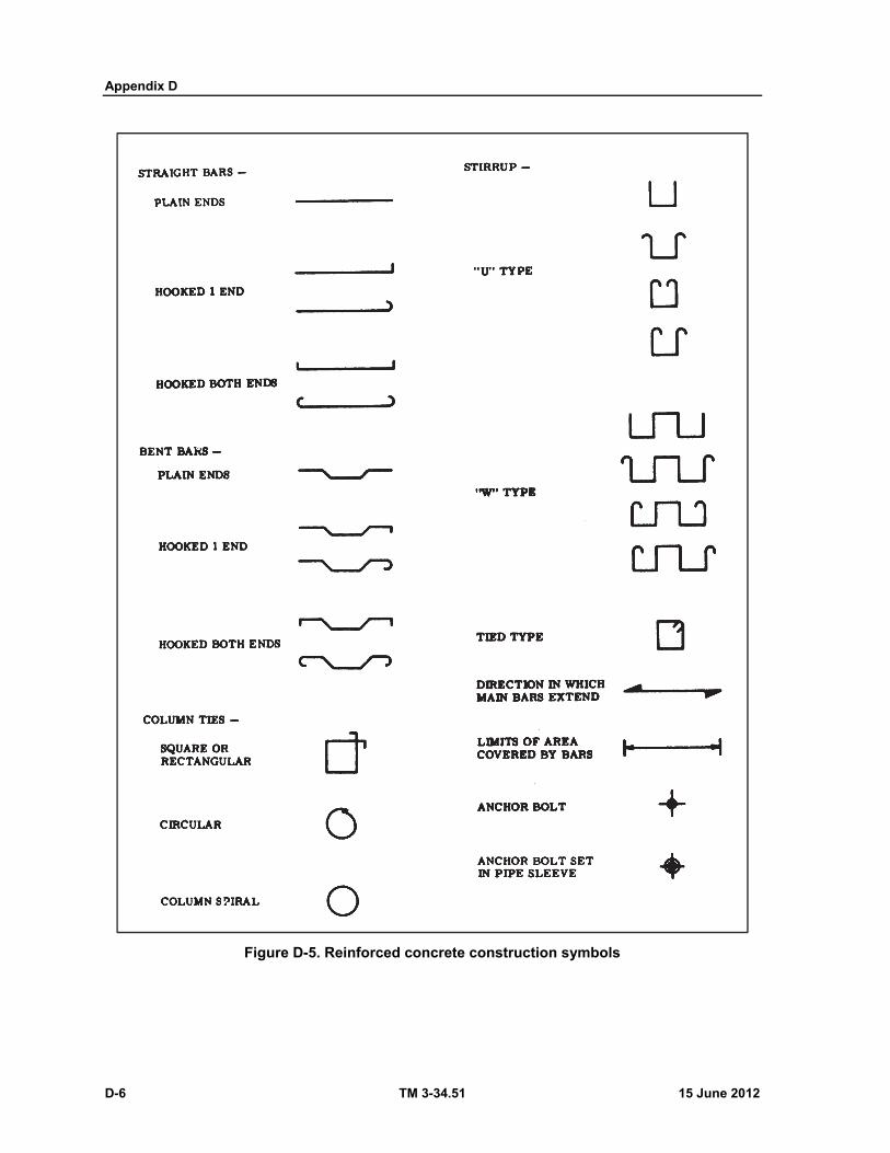
Appendix D
D-6 TM 3-34.51 15 June 2012
Figure D-5. Reinforced concrete construction symbols
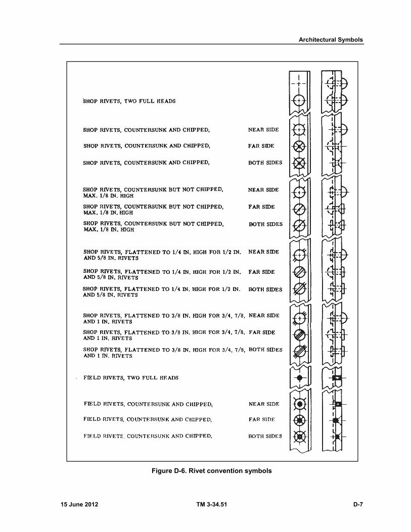
Architectural Symbols
15 June 2012 TM 3-34.51 D-7
Figure D-6. Rivet convention symbols
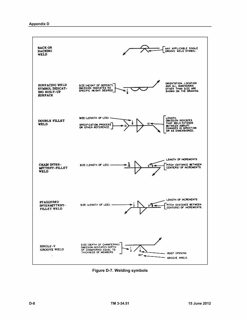
Appendix D
D-8 TM 3-34.51 15 June 2012
Figure D-7. Welding symbols
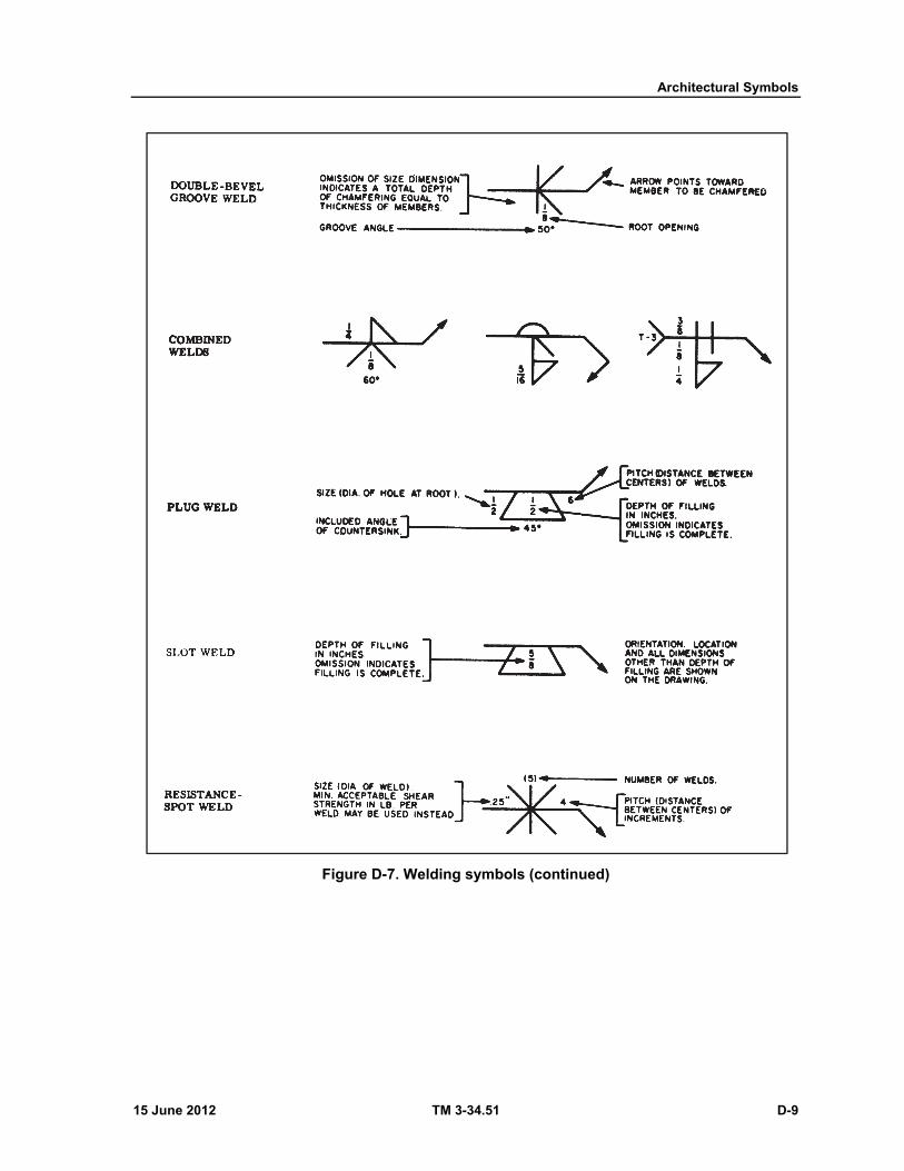
Architectural Symbols
15 June 2012 TM 3-34.51 D-9
Figure D-7. Welding symbols (continued)

This page intentionally left blank.
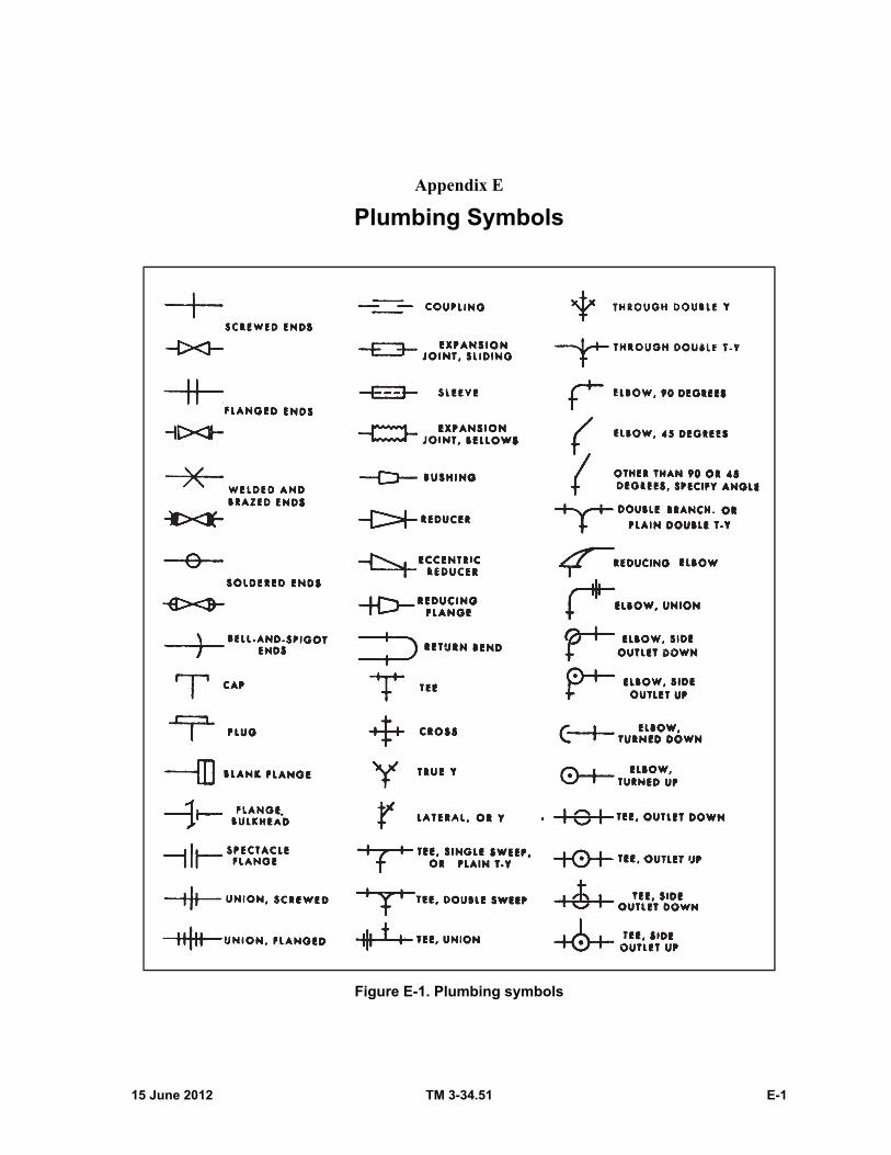
15 June 2012 TM 3-34.51 E-1
Appendix E
Plumbing Symbols
Figure E-1. Plumbing symbols
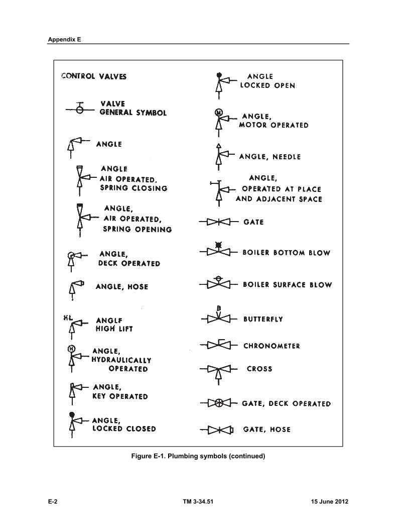
Appendix E
E-2 TM 3-34.51 15 June 2012
Figure E-1. Plumbing symbols (continued)

Plumbing Symbols
15 June 2012 TM 3-34.51 E-3
Figure E-1. Plumbing symbols (continued)
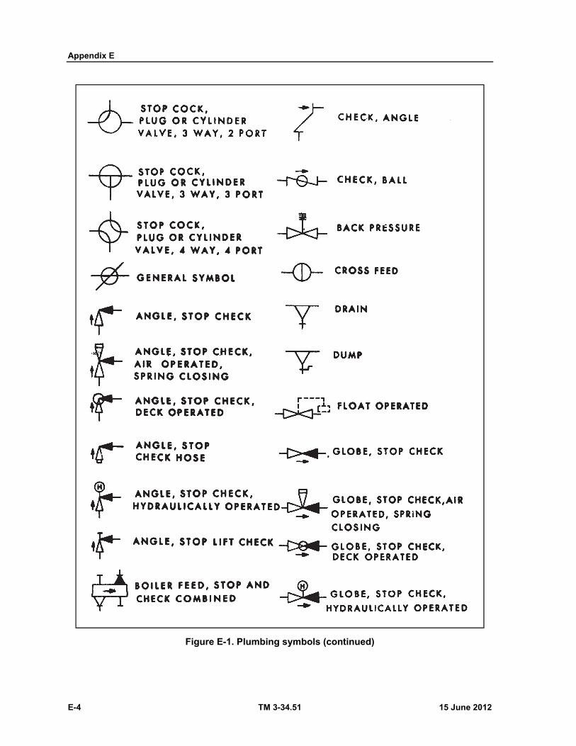
Appendix E
E-4 TM 3-34.51 15 June 2012
Figure E-1. Plumbing symbols (continued)

Plumbing Symbols
15 June 2012 TM 3-34.51 E-5
Figure E-1. Plumbing symbols (continued)

Appendix E
E-6 TM 3-34.51 15 June 2012
Figure E-1. Plumbing symbols (continued)
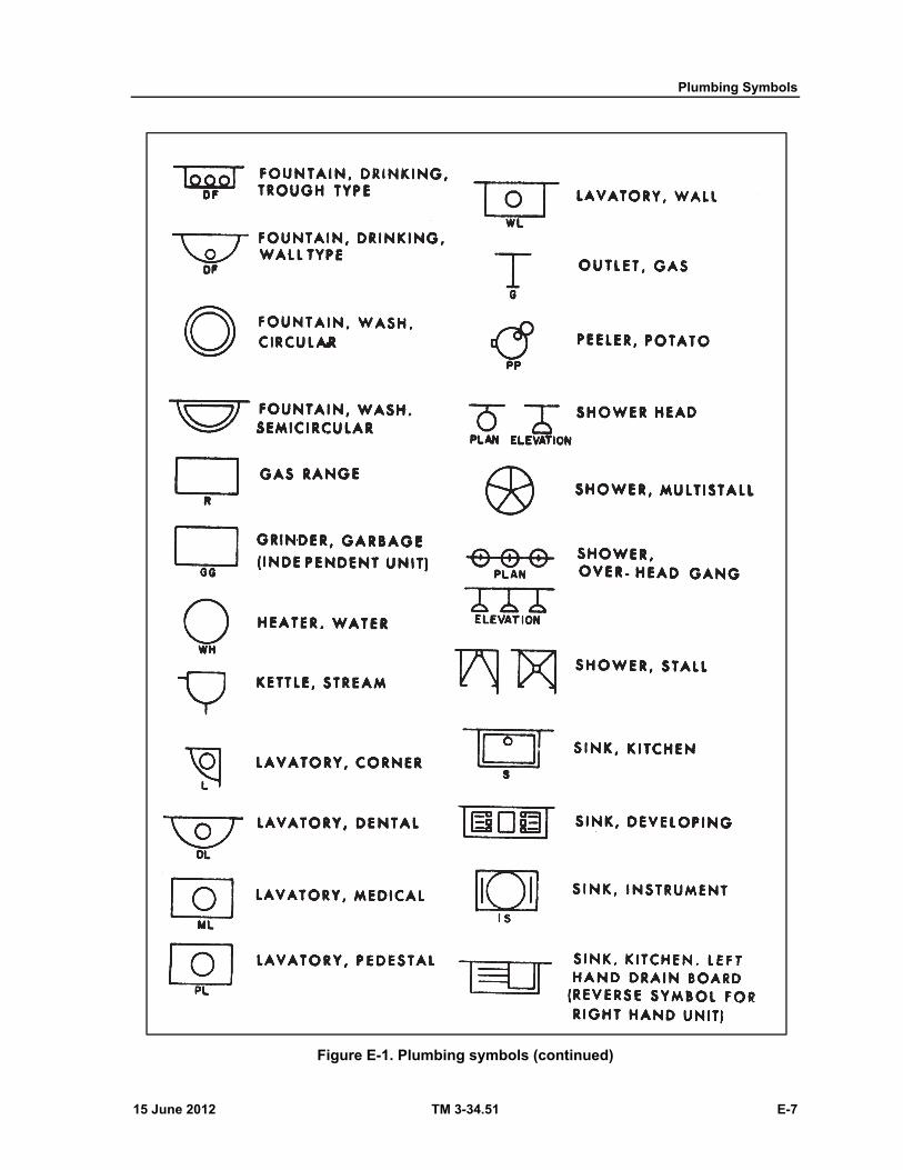
Plumbing Symbols
15 June 2012 TM 3-34.51 E-7
Figure E-1. Plumbing symbols (continued)
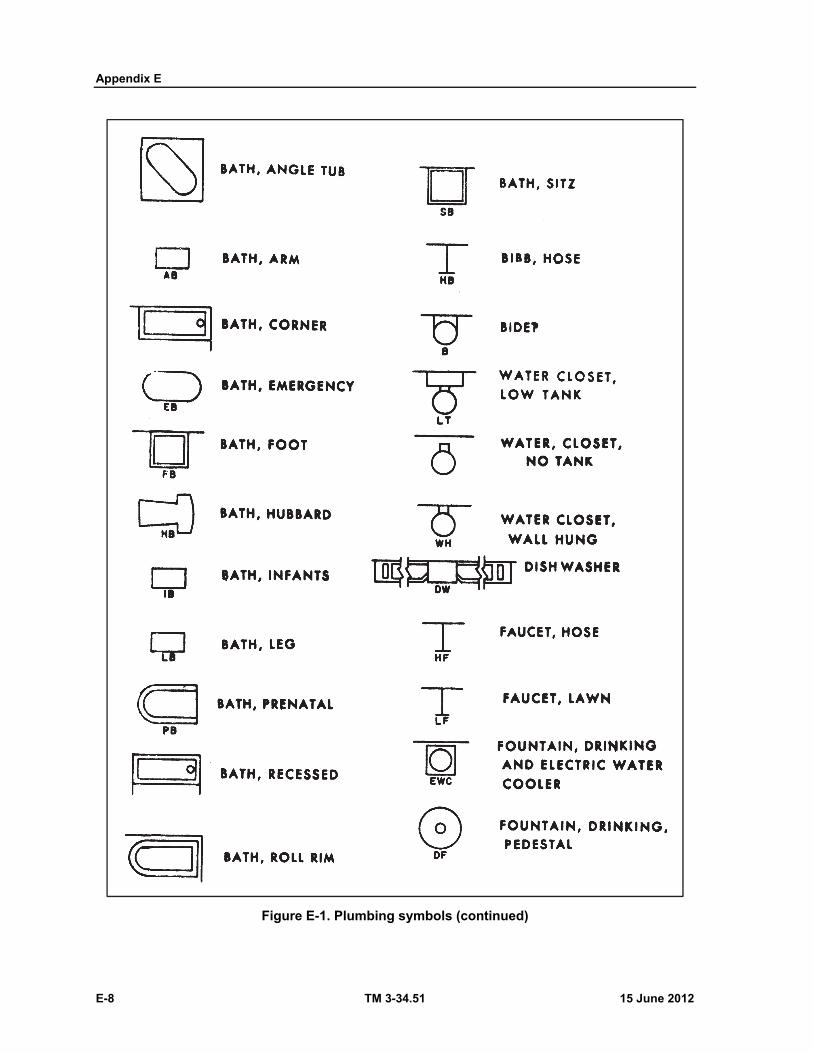
Appendix E
E-8 TM 3-34.51 15 June 2012
Figure E-1. Plumbing symbols (continued)
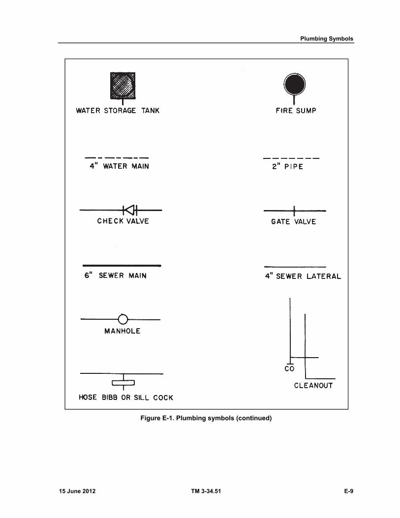
Plumbing Symbols
15 June 2012 TM 3-34.51 E-9
Figure E-1. Plumbing symbols (continued)

This page intentionally left blank.
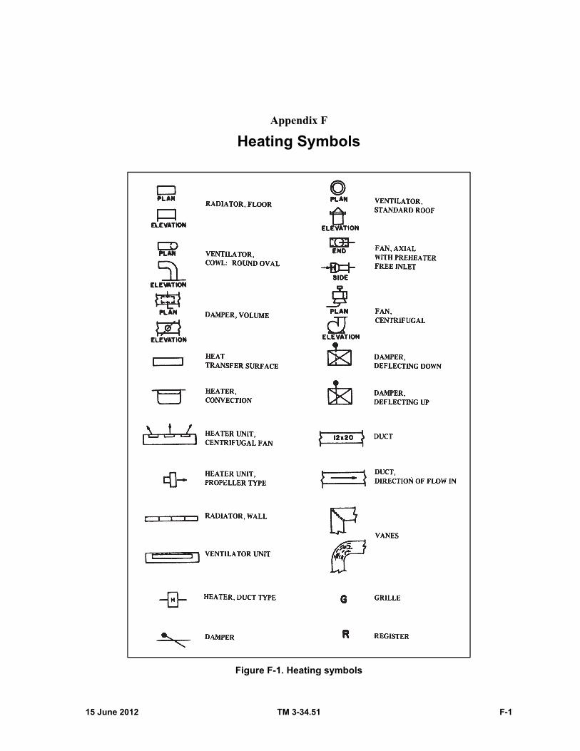
15 June 2012 TM 3-34.51 F-1
Appendix F
Heating Symbols
Figure F-1. Heating symbols
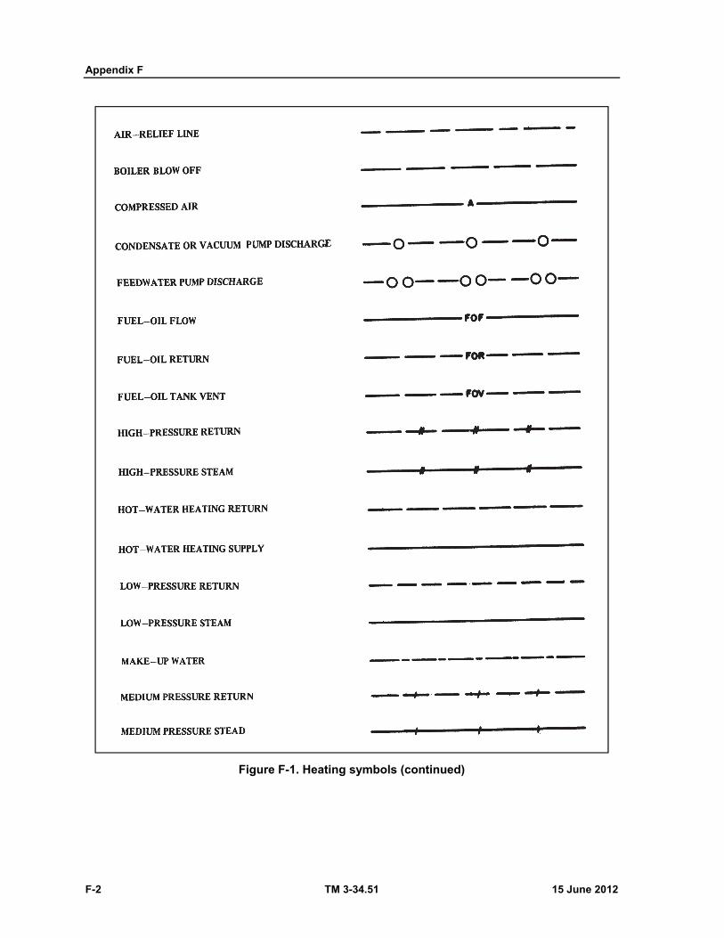
Appendix F
F-2 TM 3-34.51 15 June 2012
Figure F-1. Heating symbols (continued)
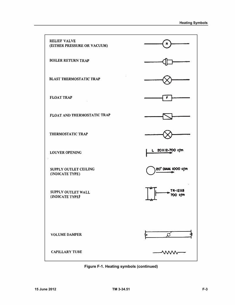
Heating Symbols
15 June 2012 TM 3-34.51 F-3
Figure F-1. Heating symbols (continued)
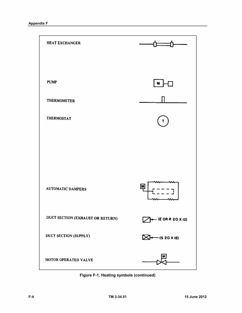
Appendix F
F-4 TM 3-34.51 15 June 2012
Figure F-1. Heating symbols (continued)
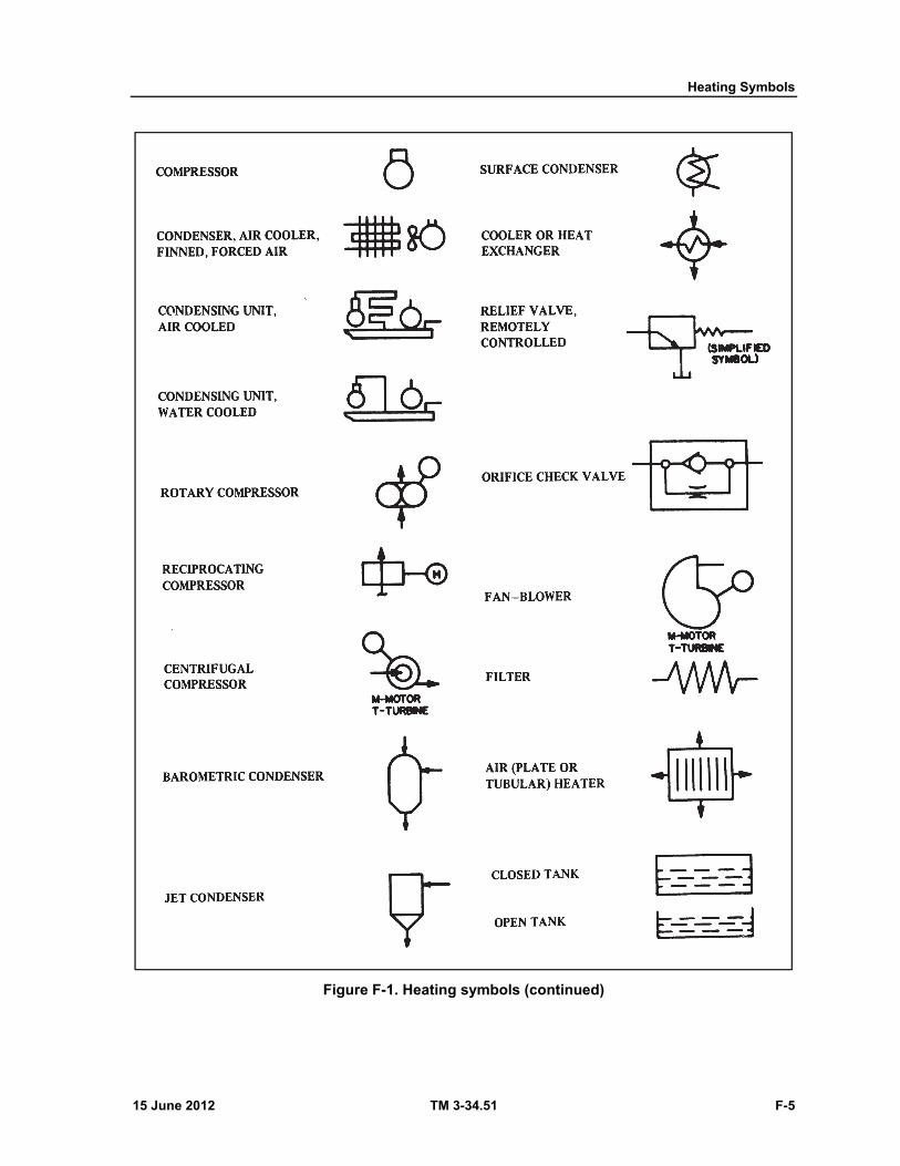
Heating Symbols
15 June 2012 TM 3-34.51 F-5
Figure F-1. Heating symbols (continued)
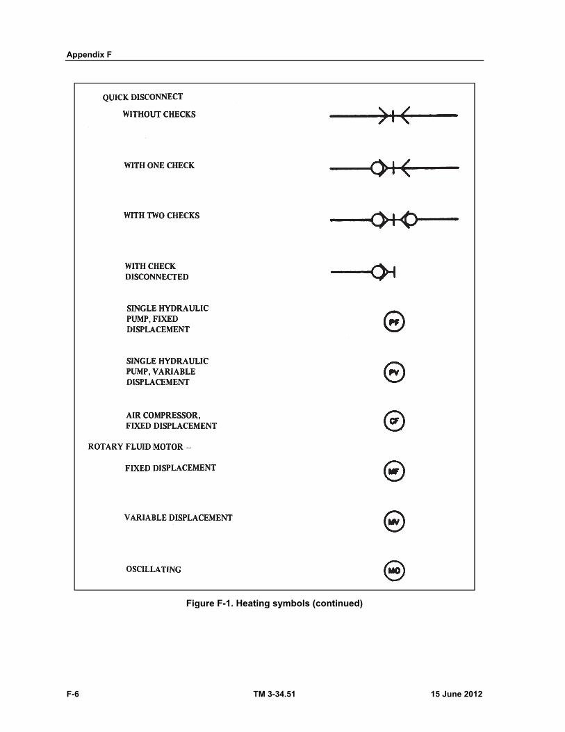
Appendix F
F-6 TM 3-34.51 15 June 2012
Figure F-1. Heating symbols (continued)
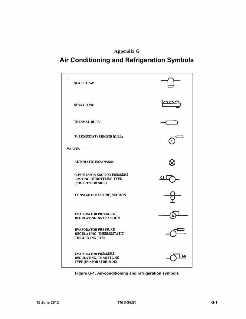
15 June 2012 TM 3-34.51 G-1
Appendix G
Air Conditioning and Refrigeration Symbols
Figure G-1. Air-conditioning and refrigeration symbols
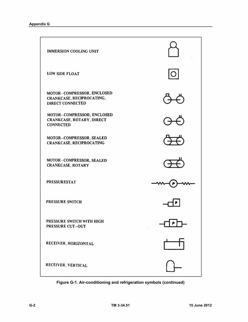
Appendix G
G-2 TM 3-34.51 15 June 2012
Figure G-1. Air-conditioning and refrigeration symbols (continued)

Air Conditioning and Refrigeration Symbols
15 June 2012 TM 3-34.51 G-3
Figure G-1. Air-conditioning and refrigeration symbols (continued)
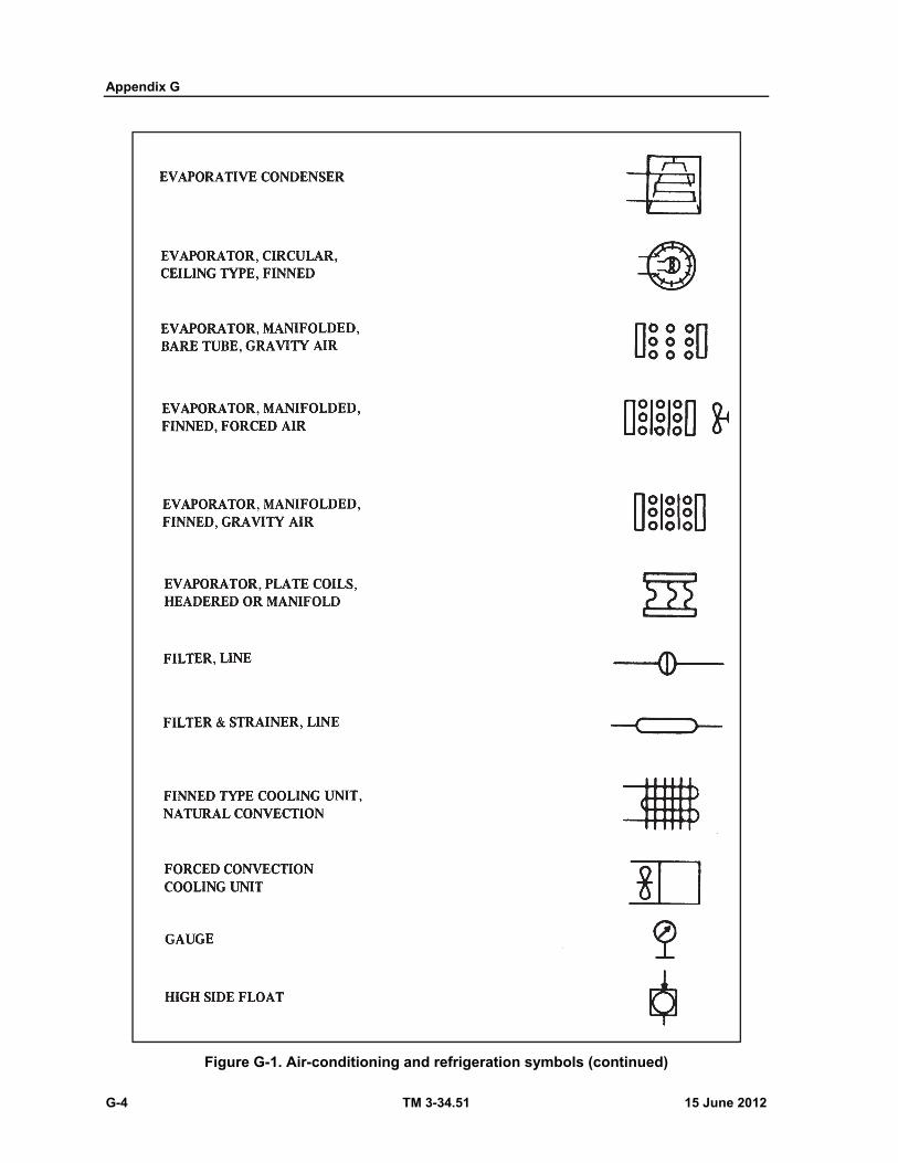
Appendix G
G-4 TM 3-34.51 15 June 2012
Figure G-1. Air-conditioning and refrigeration symbols (continued)
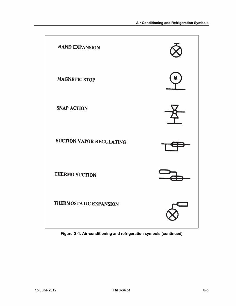
Air Conditioning and Refrigeration Symbols
15 June 2012 TM 3-34.51 G-5
Figure G-1. Air-conditioning and refrigeration symbols (continued)

This page intentionally left blank.
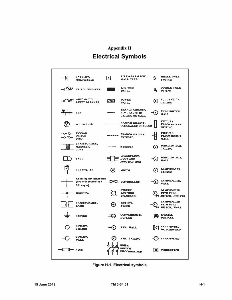
15 June 2012 TM 3-34.51 H-1
Appendix H
Electrical Symbols
Figure H-1. Electrical symbols
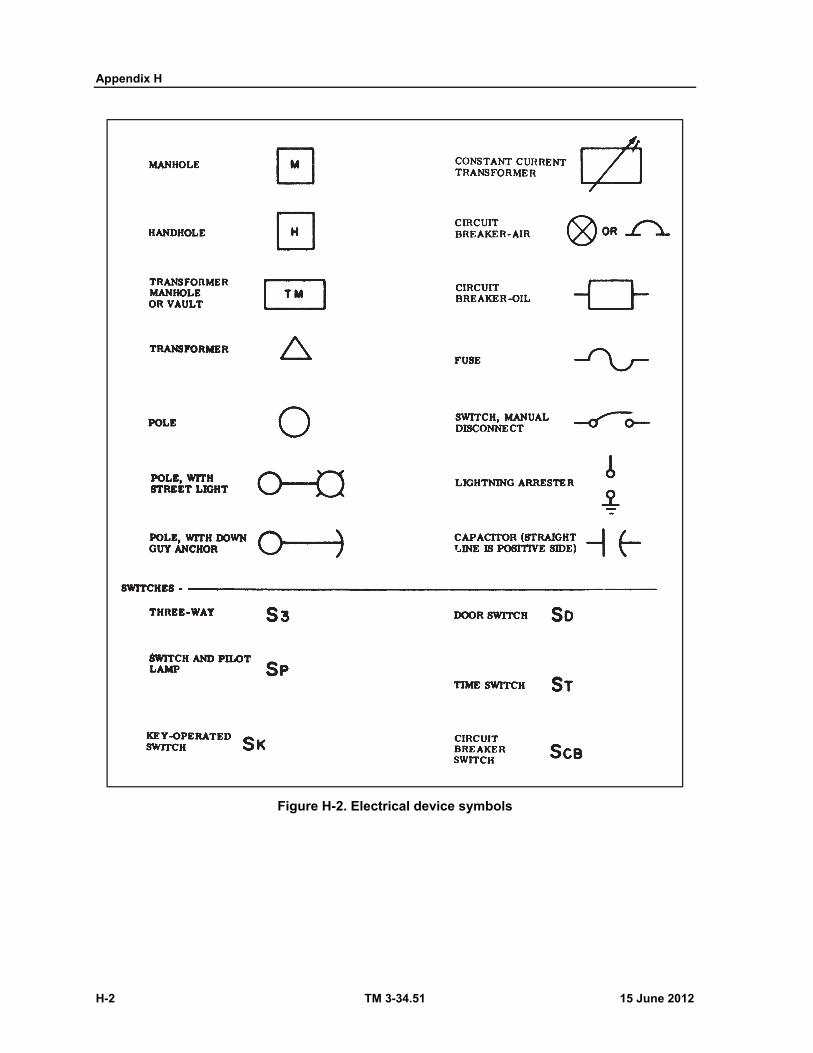
Appendix H
H-2 TM 3-34.51 15 June 2012
Figure H-2. Electrical device symbols

Electrical Symbols
15 June 2012 TM 3-34.51 H-3
Figure H-2. Electrical device symbols (continued)
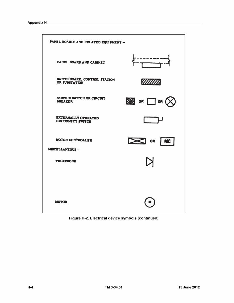
Appendix H
H-4 TM 3-34.51 15 June 2012
Figure H-2. Electrical device symbols (continued)
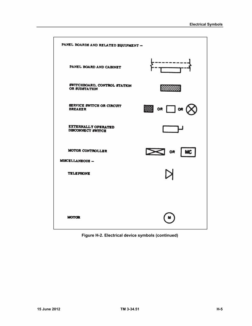
Electrical Symbols
15 June 2012 TM 3-34.51 H-5
Figure H-2. Electrical device symbols (continued)
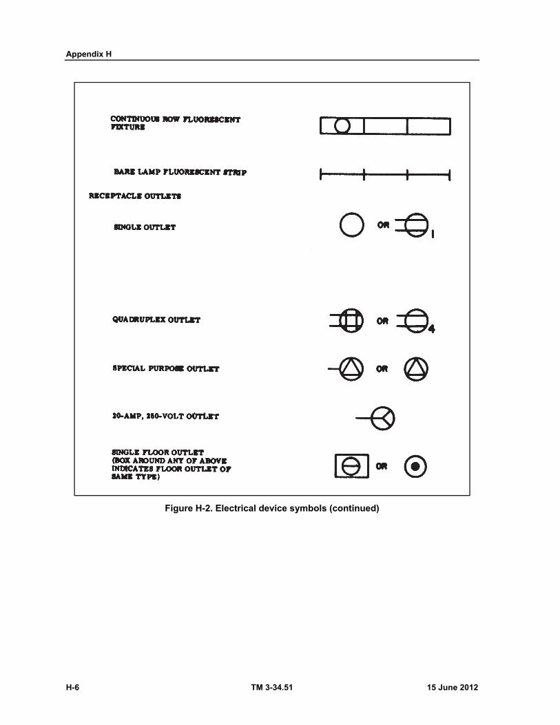
Appendix H
H-6 TM 3-34.51 15 June 2012
Figure H-2. Electrical device symbols (continued)
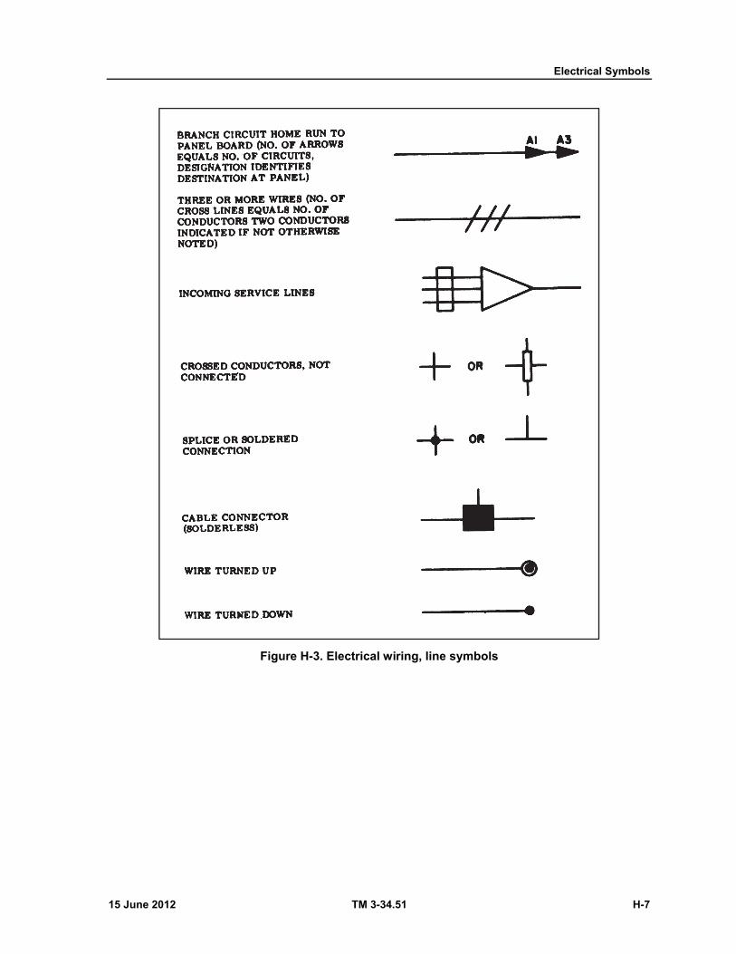
Electrical Symbols
15 June 2012 TM 3-34.51 H-7
Figure H-3. Electrical wiring, line symbols
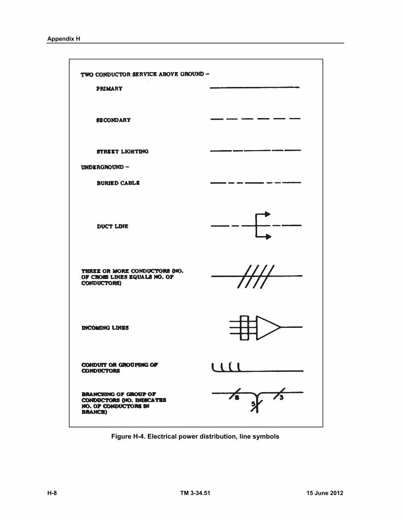
Appendix H
H-8 TM 3-34.51 15 June 2012
Figure H-4. Electrical power distribution, line symbols
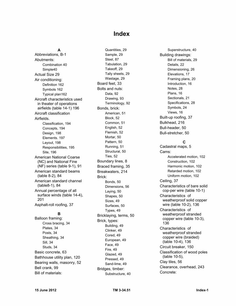
15 June 2012 TM 3-34.51 Index-1
Index
A Abbreviations, B-1 Abutments:
Combination 40 Simple40
Actual Size 29 Air conditioning:
Definition 162 Symbols 162 Typical plan162
Aircraft characteristics used in theater of operations airfields (table 14-1) 196
Aircraft classification Airfields.
Classification, 194 Concepts, 194 Design, 198 Elements. 197 Layout, 198 Responsibilities, 195 Site, 196
American National Coarse (NC) and National Fine (NF) series (table 9-1), 91
American standard beams (table 8-2), 84
American standard channel (table8-1), 84
Annual percentage of all surface winds (table 14-4), 201
Asphalt-roll roofing, 37
B Balloon framing:
Cross bracing, 34 Plates, 34 Posts, 34 Sheathing, 34 Sill, 34 Studs, 34
Basic concrete, 63 Bathhouse utility plan, 120 Bearing walls, masonry, 52 Bell crank, 99 Bill of materials:
Quantities, 29 Sample, 29 Steel, 87 Tabulation, 29 Takeoff, 29 Tally sheets, 29 Wastage, 29
Board feet, 33 Bolts and nuts:
Data, 92 Drawing, 93 Terminology, 92
Bonds, brick: American, 51 Block, 52 Common, 51 English, 52 Flemish, 52 Mortar, 50 Pattern, 50 Running, 51 Structural, 50 Ties, 52
Boundary lines, 8 Braced framing, 35 Breakwaters, 214 Brick:
Bonds, 50 Dimensions, 56 Laying, 50 Shapes, 50 Sizes, 49 Surfaces, 50 Types, 49
Bricklaying, terms, 50 Brick, types:
Building, 49 Clinker, 49 Cored, 49 European, 49 Face, 49 Fire, 49 Glazed, 49 Pressed, 49 Sand-lime, 49
Bridges, timber: Substructure, 40
Superstructure, 40
Building drawings: Bill of materials, 29 Details, 22 Dimensioning, 26 Elevations, 17 Framing plans, 20 Introduction, 16 Notes, 28 Plans, 16 Sectionals, 21 Specifications, 28 Symbols, 24 Views, 16
Built-up roofing, 37 Bulkhead, 216 Bull-header, 50 Bull-stretcher, 50
C Cadastral maps, 5 Cams:
Accelerated motion, 102 Construction, 102 Harmonic motion, 102 Retarded motion, 102 Uniform motion, 102
Ceiling, 37 Characteristics of bare solid
cop-per wire (table 10-1) Characteristics of
weatherproof solid copper wire (table 10-2), 136
Characteristics of weatherproof stranded copper wire (table 10-3), 136
Characteristics of weatherproof stranded copper wire (braided) (table 10-4), 136
Circuit breaker, 150 Classification of wood poles
(table 10-5), Clay tiles, 56 Clearance, overhead, 243 Concrete:

Index
Index-2 TM 3-34.51 15 June 2012
As a material, 62 Connections, 66 Distributing loads, 67 Drawing, 69, 80 Estimates, 169 Forms, 63 Introduction, 62 Joints, 66 Reinforcing, 66 Structural members, 65 Takeoff, 77
Concrete masonry Bonds, 56 Description, 56 Sizes, 56 Types, 56
Concrete mixes (table 7-3) Concrete takeoff (table 7-2) Connecting rod, 100 Connectors, timber:
Bolts, 40 Driftpins, 40 Spikes, 40 Split rings, 40
Construction drafting Contract drawing, 2 Definitions, 2 Purpose, 1 Scope, 1 Standards, 3 Technique, 4 Understanding, 3
Construction material: Concrete, 3 Masonry, 3 Steel, 3 Wood, 3
Construction standards, 3 Contraction Joints, 67 Control points, roads, 177 Cooper wire (tables 10-1
through 10-4) Covering frame:
Finish schedule, 37 Exterior finish, 35 Interior finish, 36 Rough sheathing, 35
Crib pier, 42 Crossovers, 249 Cross sections, site, 13 Culverts, 187
Curve table (table 13-1) Curtain walls, masonr, 52 Cuts and fills, roads, 179
D Dams, check, 185 Definition of drawings:
General terms, 2 Special terms, 2
Details: Cornices, 24 Doors, 23 Floors, 24 Sills, 22 Walls, 22 Windows, 23
Dimensioning buildings: Accuracy, 27 Decimal, 28 Inside, 26 Line, 27 Outside, 26 Placing, 27 Variations, 28 Writing, 27
Disposal facilities, sewage, 124
Distributing loads, concrete: Anchor bolts, 67 Beam supports, 67 Column supports, 67
Distribution system, water, 109
Ditches, roads, 185 Docks, 212 Dolphins, 216 Door schedule, 28 Downspouts, 38 Drainage, roads, 184 Drafting room operations:
Arrangement, 254 Checking, 254 Files, 256 Introduction, 254 Library, 255 Planning, 258 Reproduction room, 254 Revisions, 256 Supply, 258
Drawing a section: Cornice, 24
Doors, 23 Floor, 24 Girder, 22 Joist, 22 Sill, 22 Slope, 24 Wall, 22 Windows, 23
Drawings: Airfields, 198 Brick masonry:
Elevation, 55 Flashing, 56 Lintels, 56 Plans, 55 Symbols, 55 Wall sections, 56
Concrete construction:
Details, 71 Framing, 77 Grids, 77 Masonry, 56 Schedules, 77 Sheet layout, 69 Symbols, 69 Takeoff, 77 Theater of
operations, 80 Machine:
Bolts and nuts, 92 Requirements, 90 Rivets, 93
Screw threads Welding, 97
Machine parts: Cams, 101 Details, 105 Gears, 103 Introduction, 99 Linkage, 99 Mechanical practice, 105 Purpose, 99 Straight-line, 100
Railroads, 249 Revisions, 256 Roads, 174 Roofs: Details, 39 General, 38 Steel:
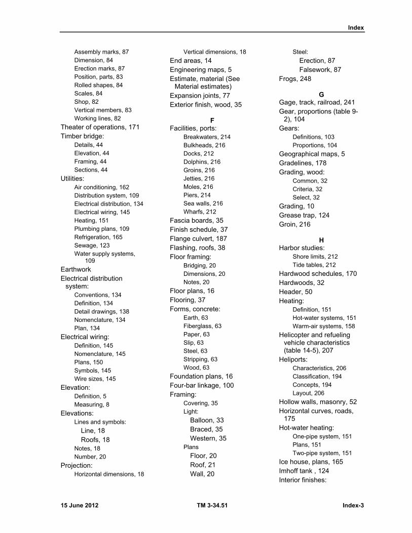
Index
15 June 2012 TM 3-34.51 Index-3
Assembly marks, 87 Dimension, 84 Erection marks, 87 Position, parts, 83 Rolled shapes, 84 Scales, 84 Shop, 82 Vertical members, 83 Working lines, 82
Theater of operations, 171 Timber bridge:
Details, 44 Elevation, 44 Framing, 44 Sections, 44
Utilities: Air conditioning, 162 Distribution system, 109 Electrical distribution, 134 Electrical wiring, 145 Heating, 151 Plumbing plans, 109 Refrigeration, 165 Sewage, 123 Water supply systems,
109
Earthwork Electrical distribution
system: Conventions, 134 Definition, 134 Detail drawings, 138 Nomenclature, 134 Plan, 134
Electrical wiring: Definition, 145 Nomenclature, 145 Plans, 150 Symbols, 145 Wire sizes, 145
Elevation: Definition, 5 Measuring, 8
Elevations: Lines and symbols:
Line, 18 Roofs, 18
Notes, 18 Number, 20
Projection: Horizontal dimensions, 18
Vertical dimensions, 18
End areas, 14 Engineering maps, 5 Estimate, material (See
Material estimates) Expansion joints, 77 Exterior finish, wood, 35
F Facilities, ports:
Breakwaters, 214 Bulkheads, 216 Docks, 212 Dolphins, 216 Groins, 216 Jetties, 216 Moles, 216 Piers, 214 Sea walls, 216 Wharfs, 212
Fascia boards, 35 Finish schedule, 37 Flange culvert, 187 Flashing, roofs, 38 Floor framing:
Bridging, 20 Dimensions, 20 Notes, 20
Floor plans, 16 Flooring, 37 Forms, concrete:
Earth, 63 Fiberglass, 63 Paper, 63 Slip, 63 Steel, 63 Stripping, 63 Wood, 63
Foundation plans, 16 Four-bar linkage, 100 Framing:
Covering, 35 Light:
Balloon, 33 Braced, 35 Western, 35
Plans
Floor, 20 Roof, 21 Wall, 20
Steel:
Erection, 87 Falsework, 87
Frogs, 248
G Gage, track, railroad, 241 Gear, proportions (table 9-
2), 104 Gears:
Definitions, 103 Proportions, 104
Geographical maps, 5 Gradelines, 178 Grading, wood:
Common, 32 Criteria, 32 Select, 32
Grading, 10 Grease trap, 124 Groin, 216
H Harbor studies:
Shore limits, 212 Tide tables, 212
Hardwood schedules, 170 Hardwoods, 32 Header, 50 Heating:
Definition, 151 Hot-water systems, 151 Warm-air systems, 158
Helicopter and refueling vehicle characteristics (table 14-5), 207
Heliports: Characteristics, 206 Classification, 194 Concepts, 194 Layout, 206
Hollow walls, masonry, 52 Horizontal curves, roads,
175 Hot-water heating:
One-pipe system, 151 Plans, 151 Two-pipe system, 151
Ice house, plans, 165 Imhoff tank , 124 Interior finishes:
Index
Index-4 TM 3-34.51 15 June 2012
Ceiling , 37 Flooring, 37 Insulation, 36 Wall, 36
Jetty, 216 Joints and connectors,
concrete: Construction joints, 66 Contraction, 67 Expansion, 67 Foundation walls, 66
Leaching tank, 124 Linkage:
Bell crank, 99 Connecting rod, 100 Four-bar, 100 Levers, 99 Resultant motion, 100 Rocker arm, 99 Rotating crank, 99
Logbook, 256 Log culvert, 188 Lumber:
Sizes, standard, 33 Surfacing:
Dressed, 32 Rough, 32
Worked:
Matched, 32 Patterned, 33 Shiplappe, 33
Machine parts: Cams, 101 Details, 105 Gear, 103 Introduction, 99 Linkage, 99 Mechanical practice, 105 Purpose, 99 Straight-line, 101
Manhole, 124 Maps:
Classification, 5 Colors, 6 Types:
Aeronautical, 5 Cadastral, 5 Engineering, 5 Geographical, 5 Hydrographic, 5
Nautical, 8 Photogrammetric, 5 Plats, 6 Topographic, 5
Masonry: Brick:
Bonds, 50 Classification, 49 Description, 49 Drawings, 54 Introduction, 49 Laying, 50 Mortar, 52 Sizes, 49 Types, 49 Walls, 52
Concrete:
Bond, 56 Clay tiles, 56 Description, 56 Drawing, 56 Sizes, 56 Stone, 59 Types, 56
Material estimates: Function:
Required, 168 Skills, 168 Tabulation, 168 Takeoff, 168 Tally sheets, 168 Wastage, 168
Introduction, 168 Purpose, 168 Quantities:
Air conditioning, 170 Concrete, 169 Earthwork, 169 Electrical, 170 Hardware schedules,
170 Heating, 169 Masonry, 170 Miscellaneous, 170 Plumbing, 170 Steel, 169 Wood, 169
Materials, roofing:
Asphalt-roll, 37 Built-up, 37 Miscellaneous, 37 Paper, 37 Shingles, 37
Materials, concrete: Advantages, 62 Disadvantages, 62 Mixture, 62
Mechanical practice drawing:
Finish marks, 105 Multiple-drawing system,
105 Other notes, 105 Single-drawing system,
105
Metal ties, bricks, 52 Minimum airfield area
requirements (table 14-3), 199
Minimum wire sizes (table 10 8)
Mole, 216 Mortar bond, 50 Mortar joints:
Definition, 52 Types:
Concave, 54 Flush, 53 Raked, 54 Stripped, 54 Struck, 53 V-shaped, 54 Weathered, 54
N Nominal size, 29 Numbering of drawing, 2 Nuts and bolts (See Bolts
and nuts)
O Operation, drafting room
(See Drafting room operation)
P Pattern bonds:
American, 51 Block, 52 Common, 51
Index
15 June 2012 TM 3-34.51 Index-5
English, 52 Flemish, 52 Running, 51 Stack, 52
Phases of construction, 171 Photogrammetric maps, 5 Physical details, locating, 9 Piers, 214 Pile bents, 40 Pile piers, 42 Plan, roads, 174 Plans:
Floor, 16 Foundation, 16 Procedure, 16 Site, 16 Symbols, 25
Plans, sewage system: Plan view, 130 Profile view, 130
Plaster: Composition, 36 Metal lath, 36 Miscellaneous, 37 Plasterboard, 36
Plats, 6 Plumbing: Fittings, 116 Fixtures, 116 Symbols, 109 Typical plan, 120 Valves, 116
Pneumatic concrete, 64 Poles, wooden, electric, 138 Port construction:
Facilities, 212 Introduction, 212 Materials, 225
Power system, 134 Precast concrete, 64 Prestressed concrete, 64 Profile, roads, 178 Profiling, 12 PSP culvert, 1881 Railroads:
Clearance, 243 Crossovers, 249 Curves, 241 Ditches, 241 Drawings, 249
Frogs, 248 Introduction, 236 Spacing, 241 Track gage, 241 Turnouts, 243
Rails, 237 Refrigeration:
Definition, 165 Plans, 165 Symbols, 165
Reinforced concrete, 64 Reinforcing:
Bars, 66 Mats, 66 Welded wire, 66
Retiring drawings, 256 Revetments, 198 Revision, drawings, 256 Rivet lists, 87 Rivets:
Conventions, 93 Heads, 93 Symbols, 93
Roads: Cross sections, 183 Curves, 175, 179 Dimensions, 179 Drainage, 184, 185 Drawing, 179 Introduction, 173 Nomenclature, 173 Plan, 174 Sequence, 181 Survey, 174
Rocker arm, 99 Roofing paper, 37 Roofs:
Flashing, 38 Framing, 21 Materials, 37 Members, 37 Representation, 38 Trim, 38 Trusses, 38 Water control, 38
Rose, wind, 200 Rotating crank, 99 Rowlock, 50 Runway length
determination for airfields
in the theater of opera-tions (table 14-2)
Runways, 198
S Sag table for secondary
distribution wiring ¶ Scale, building drawings:
Details, 24 General, 24
Schedules: Concrete, 77 Door, 28 Finish, 37 Window, 28
Screw threads: American National Coarse
(table 9-1), 92 Conventions, 90 National Fine Series
(table 9-1), 92 Specification note, 91 Terminology, 90 Types, 90
Sea walls, 216 Septic tank, small, 124 Sewage :
Disposal facilities, 124 Fitting, 123 Pipes, 123 Plans, 130 System, 124 Treatment, 124
Sheathing, rough, 35 Shingles, wood, 37 Shop drawings, steel, 82 Site plan data: Area layout, 10 Boundary lines, 9 Contour lines, 9 Notes, Plotting details ¶ Site selection:
Major considerations, 7 Plotting site, 9 Preliminary planning, 7
Sizes, areas, and weights of reinforcing bars (table 7-1), 66
Sizes, steel, 82
Index
Index-6 TM 3-34.51 15 June 2012
Slabs, sidewalks, walks (materials per 100 sq ft) (table 7-4), 81
Slope diagram, 24 Slump test, 63 Softwoods, 32 Soldier, 50 Specifications, construction
drawings, 28 Sprayed concrete, 64 Standards of construction,
3, 172 Standard sizes of lumber
(inches) (table 5-1), 33 Steel, structures:
Bill of materials, 87 Drawing, shop, 82 Introduction, 82 Plans, framing, 87 Sizes, 82 Structural details, 82 Symbols, 82
Stone masonry, 59 Straight-line mechanisms:
Motion, 100 Pantograph, 101 Parallel, 101
Stringers, bridge, 42 Structural bonds, 50 Structural members,
concrete: Beams, 65 Columns, 65 Footings, 65 Slabs, 65
Structural, steel details, 82 Substructure, bridges: Combination, 40 Crib pier, 42 Pile bent, 40 Pile piers, 42 Simple abutment, 40 Trestle bent, 40 Trestle pier, 41 Superelevation, roads, 177 Superstructure, bridges:
Curb, 44 Flooring, 43 Stringers, 42 Wood stringer, 42
Supply, drafting room, 258 Surfacing and worked
lumber, 32 Survey, roads, 174 Symbols:
Air conditioning, 299 Architectural, 275 Concrete, 280 Door, 376 Electrical devices, 305 Electrical wiring, 309 Heating, 293 Materials, 272 Miscellaneous, 278 Plan, 25 Plumbing, 109 Refrigeration, 165, 299 Rivet, 281 Section materials, 25 Steel, 82, 279 Welding, 282 Windows, 275
T Tables:
Aircraft characteristics used in theater of operations, 194
American National Coarse (NC) and National Fine (NF) series, 92
American Standard beams, 84
American Standard channels, 84
Annual percentage of all surface winds, 201
Characteristics of bare solid copper wire, 136
Characteristics of weatherproof solid copper wire, 136
Characteristics of weatherproof stranded copper wire, 136
Characteristics of weather- proof stranded copper wire (braided), 136
Classification of wood poles, 142
Concrete mixes, 80
Concrete takeoff, 80 Curve table, 182
Gear proportion, 104 Helicopter and refueling
vehicle characteristic, 207 Minimum airfield area re-
quirements, 199 Minimum wire sizes, 145 Runway length for airfields
in theater of operations, 198
Sag table for secondary distribution wiring, 138
Sizes, areas, and weights of reinforcing bar, 66
Slabs, sidewalks, walks (materials per 100 sq ft), 81
Standard sizes of lumber (inches), 33
Typical sag table for pri-mary distribution wiring, 138
Wide flange shapes, 84 Wood construction, size of
lumber, Takeoff concrete:
Calculations, 77 Organization, 77
Theater of operation (T/O): Construction, 171 Drawings, 171
Ties, railroad, 236 Tiles, clay, 56 Timber:
Bridges, 40 Connectors, 39 Construction, 39 Drafting, 44 Water towers, 44
Time estimating, 258 Topographic maps, 5 Topography:
Classification of maps, 5 Definitions, 6 Elevations, 8 Grading, 10 Introduction, 5 Plotting, 9 Profile , 12 Site selection, 7
Index
15 June 2012 TM 3-34.51 Index-7
Symbols, 6 Types of maps, 5
Towers, water, 44 Transformer, electrical, 138 Treatment, sewage, 124 Trestle bent, 40 Trestle pier, 41 Trim, roofing, 38 Trusses, roof, 37 Turnouts, 243 Typical sag table for
primary distribution wiring (table 10-6)
U Utilities, drawings:
Distribution system, 109 Package units, 109 Unit construction, 109 Water supply systems,
109
V Veneer walls, masonry, 52 Veneer, wood, 35 Vertical curves, roads, 179
Views, sectional: Specific, 21 Typical, 21
W Wall finishes, 52 Wall framing:
Bracing, 21 Dimensions, 21 Door, 21 Notes, 21 Window, 21
Wall section, 22 Walls, masonry:
Bearing, 52 Curtain, 52 Hollow, 52 Veneer, 52
Warm-air heating, 158 Water supply systems, 109 Water towers, plans:
Dimensions, 48 Elevations, 46 Foundations, 44 Notes, 48 Platform, 44
Sections, 48 Symbols, 66
Welded wire mesh Welding: Arrow side, 97 Symbols, 97
Western framing, 35 Wharfs, 212 Wide flange shapes (table
8-3), 84 Window schedule, 28 Wind rose, 200 Wire gage sizes (tables 10-
1 through 10-4), 136 Wood:
Classification, 32 Grading, 32 Measure, 33 Sizes, 33 Species, 32 Surfacing, 32
Wood construction, size of lumber (table 5-2), 34
Working drawings, 4 Wythe, 50

This page intentionally left blank.
TM 3-34.51 15 June 2012
By order of the Secretary of the Army:
RAYMOND T. ODIERNO General, United States Army
Chief of Staff
Official:
JOYCE E. MORROW Administrative Assistant to the
Secretary of the Army 1030808
DISTRIBUTION: Active Army, Army National Guard, and U.S. Army Reserve. Not to be distributed; electronic media only.

PIN: 100568-000