tandem nonstop (tm) and nonstop ii (tm) systems expand (tm
TRANSCRIPT
Tandem NonStop (TM) and NonStop II (TM) Systems
EXPAND (TM) User's Manual
ABSTRACT: This manual describes the GUARDIAN/EXPAND operating system for network managers, programmers, and operators.
PRODUCT VERSION: EXPAND COO
OPERATING SYSTEM VERSION: GUARDIAN A06 (NonStop II System) GUARDIAN E07 (NonStop System)
Throughout this document, all references to the "NonStop II system" indicate the software that runs on Tandem NonStop II processors and/or NonStop TXP (TM) processors.
Tandem Computers Incorporated 19333 Vallco Parkway
Cupertino, California 95014-2599
Part No. 82085 COO December 1983
Printed in U.S.A.
Edition -----
First Edition Second Edition Third Edition
DOCUMENT HISTORY
Operating Part System Number Version
82085 ADO GUARDIAN AOO/EOO 82085 BOO GUARDIAN AOO/E01 82085 COO GUARDIAN A06/E07
Date -------
April 1981 June 1981 December 1983
New editions incorporate all updates issued since the previous edition. Update packages, which are issued between editions, contain additional and replacement pages that you should merge into the most recent edition of the manual.
Copyright © 1983 by Tandem Computers Incorporated.
All rights reserved. No part of this document may be reproduced in any form, including photocopying or translation to another language, without the prior written consent of Tandem Computers Incorporated.
The following are trademarks or servicemarks of Tandem Computers Incorporated:
AXCESS BINDER CROSSREF DDL EDIT ENABLE ENCOMPASS ENCORE ENSCRIBE ENTRY ENTRY520 ENVOY EXPAND FOX GUARDIAN INSPECT NonStop 1+ NonStop I I NonStop TXP PATHWAY SNAX Tandem TAL TGAL TIL TMF TRANSFER XRAY
INFOSAT is a trademark in which both 'randem and American Satellite have rights.
DYNABUS ENF'ORM EXCHANGE NonStop PERUSE THL XREF
HYPERchannel is a trademark of Network Systems Corporation.
IBM is a registered trademark of International Business Machines Corporation.
NEW AND CHANGED INFORMATION
This edition of the EXPAND User's Manual contains the following principal changes:
The new enhanced routing description is added. You may now declare, through a call to the system procedure SETMODE, a transmission priority. This transmission priority is used in combination with the type of transport media available to provide the most efficient transfer of data withing the network. The SETMODE function (71) is described in Section 3, System Procedures. Enhanced routing is described in Section 4.
A brief description of the CSS6100 Communications Management Interface (CMI) has been added to Section 4.
Two new sections have been added. These are:
Section 5. Section 6.
Fiber Optic Extension (FOX) Introduction to INFOSAT
Appendix A, File System Errors, has been removed. The File System errors are now listed in the GUARDIAN Operating Syst~~ Programming Manual, Volume 2.
Appendix S, Console Messages, is now Appendix A.
Other minor changes resulting from comments submitted by users of this document have been incorporated into this edition.
111

CONTENTS
PREFACE
SYNTAX CONVENTIONS IN THIS MANUAL ........................... SECTION 1. INTRODUCTION
Definitions ...... . Features of EXPAND Components of EXPAND
SECTION 2. OPERATOR INTERFACE Network File Access
System Names ........... . Network File Names Default System Name Explicit and Implicit RUN Commands Running Programs Using the Default
The WHO Command ........ . Subsystem Considerations
BACKUP and RESTORE COMINT EDIT PUP SYSGEN SPOOLER
SECTION 3 • PROGRAMMER INTERFACE System Names and System Numbers Network File Names (Internal Form)
(CRTPIDs) Process IDs Timestamp Form Process-name Form
System Name
Conversion between External and FNAMECOLLAPSE Procedure FNAMEEXPAND Procedure FNAMECOMPARE Procedure
Internal File Names
System Procedures ....•.. CONVERTPROCESSNAME Procedure CREATEREMOTENAME Procedure GETPPDENTRY Procedure .•... GETREMOTECRTPID Procedure
IX
Xl
1-1 1-1 1-2 1-3
2-1 2-1 2-2 2-2 2-4 2-5 2-6 2-7 2-7 2-8 2-8 2-8 2-9 2-9 2-9
3-1 3-2 3-2 3-5 3-5 3-6 3-7 3-8 3-10 3-14 3-20 3-22 3-23 3-25 3-27
v
Contents
System Procedures (continued) G:ETSYSTEMNAME Procedure LOCATESYSTEM Procedure MONITORNET Procedure MYSYSTEMNUMBER Procedure PROCESS INFO Procedure REMOTEPROCESSORSTATUS Procedure SETMODE and SETMODENOWAIT Procedures
Programming Considerations ..................•.. Network File Names (External Form) MYTERM Procedure--Network Considerations Command Interpreter Startup Message Remote Process Creation .•.•...
CPU Defaulting ............ . Sending the Startup Message
Saving File Names .•••........ Alternate Key and Partitioned Files
SECTION 4. NETWORK MANAGEMENT
vi
Best-Path Determination ...... . Enhanced Routing
Path Selection LINESPEED TRANSDELAY
Transmission Priority Transport Media ....•.
NETMON Network Utility NETMON Command EXIT Command Fe Command BREAK Key Control-Y
NETMON Commands ADD Command BACKUPCPU Command CPUS Command DELETE Command DISPLAY Command ..... HELP Command LOGCENTRAL Command MAPS Command PATHS Command PERIOD Command PHOBE Command ..... SHOW Command STATS Command THRESHOLD Command Messages ..........•• Syntax Summary
Network Security Overview ...•.. Global Knowledge of User IDs RE~mote Passwords Disc File Security ....... .
-...
..
3-28 3-29 3-31 3--32 3-33 3-37 3-39 3-40 3-40 3-41 3-41 3-42 3-43 3-43 3-44 3-44
L~-l
4-1 4-5 4-5 4-5 4-5 4-5 4-5 4-7 4-7 4-8 ~~-9
4-9 4-9 4-10 4-11 4--12 4-13 4-15 4-16 4-19 L1-20 L1-22 4-27 4-31 £1- 3 2 4-35 4-36 4-38 4-39 4-42 4--43 4-43 4-43 4-43 4-46
Contents
Network Security (continued) Default File Security ....•..•••..•••••••.•.•.......•... Process Access .......••..•..••••••.•••••.•...••....•.•. Programmatic Logon (VERIFYUSER Procedure) ..........•...
Network Management Considerations ..•...•.•...•.••.•...... System Generation (SYSGEN) ......•.••...•.....••....•..• Communications Utility Program (CUp) ..•..••....•....... Peripheral Utility Program (PUp) ...•..•.....•.......... Console Logging Messages •••..•.........•.••...•......•. EXPAND Line Connection to an X.25 Line ........•.•...••• Communications Management Interface ...•.........••.•... XRAY Program •••••••••••••••••••••••••••••••••••••••••••
SECTION 5. FIBER OPTIC EXTENSION (FOX) Introduction to FOX ..................................•... Theory of Operat ion .•............•.......................
Local Bus Un it ........................................ . Line Handlers .......•..........•.......................
In t e rprocesso r Bus Man ito r Process ...................... . S umm a r y 0 f Key Fe a t u res .....•...•...•.•........•...•...
Local Bus Unit (LBU) Management ............•..•...... Message System Protocol Supervision ••......•..•.•.... Diagnostic Support ...•....... ~ ...•................... Active Inter-Cluster Link Monitoring .........•......•
Detailed Functional Specifications .................... .
SECTION 6. INTRODUCTION TO INFOSAT ....•................... Overview ••..••••••.•••••••.•••••••••••••••••••••••••••..• Satell i tes .............................................. .
Satellite Components •.....•............................ Satellite Frequency Bands ...........•..•............... Footprint .................•..•.........•....•..........
The Deducated Earth Station ....••........................ Shared-Use Earth Stations .•....•..••....•...........•.
Computer Communication Interface Module (CCIM) ..... . INFOSAT Software ••..••••••••••••••••••••..••.••••••.•• The INFOSAT/EXPAND Network ......•.•...................... Tandem INFOSAT Control System (TICS) ..•..................
APPENDIX A. CONSOLE MESSAGES Message Form •••••••••••••••••••••••••••••••••••••••••••••
Driver Generated Messages ....................•.....•.•. Byte Synchronous Controller ....•.•........•.......... Bit Synchronous Controller .......................... .
NCP Generated Messages .............•........••..••..... Fiber Optic Extension (FOX) Generated Messages ..•......
Status and Reset Codes ...............•.......•.••.••...•. Network Line-error Diagnosis .....•.•..........•.•..•...•.
Modem Status Error (140) .•....•.....•..•.•...••..••.... I/O Bus Error (218) ..•....•..••........•..•••••.••..... Not Ready (248) •......•...••....•..•...•..••••..•••...•
4-47 4-50 4-52 4-54 4-54 4-55 4-56 4-57 4-58 4-59 4-60
5--1 5-1 5-2 5-3 5-4 5-5 5-5 5-5 5-5 5-6 5-6 5-6
6-1 6-1 6-2 6-3 6-5 6-5 6-7 6-9 6-9 6-9 6-12 6-15
A-I A-I A-2 A-2 A-3 A-5 A-7 A-I0 A-13 A-13 A-14 A-14
INDEX ••••••••••••••••••••••••••••••••••••••••••••••••••• index-l
VII
Contents
LIST OF FIGURES
figure
1-1 A Network of Systems ..••••.•.•.•..•..•.•.....•..••• 1-3 1-2 Network Containing Only Direct-Connect Line
Handlers .................. e ••••••••••••••••• • ' •• 1--5 1-3 System with Direct Connect and X.25 Line Handlers .. 1-6
2-1 Interactive Network Access •••••••••••••••••••••• Cl •• 2·-2
3-1 Network File Names in I nterna 1 Form ................. 3,-4 3-2 Allocation of 34 Bytes for Network File Name ........ 3-40
4-1 Time Factors Based on Line Speed .................... 4-3 4-2 Graph of Sample Network Interconnections ............ 4-26
5-1 FOX Network Ring ........••.•.. ~ •..•............. " •. 5-2 5-2 Ring Structure Showing Local Bus Units ....•...•..... 5-4
6-1 Satellite Components .•.••..••. ~ ••...•.•..•...... " .. 6-4 6-2 The INFOSAT Footprint ................................ 6-6 6-3 The INFOSAT Dedicated Earth Station .•.•..•.••.•...•• 6-8 6-4 INFOSAT Hardware and Software ....•... ~ .....•...• " .. 6-11 6-5 INFOSAT/EXPAND Network .............................. 6-12 6 - 6 Sat e 11 i t e Hopp i ng •.......•.....•..•......•....•..•• 6 -14 6-7 The INFOSAT Connection •..•..•..•..••.•.•..•.•••.•.. 6-16
LIST OF TABLES
Table
2-1 Valid and Invalid Network File Names .•....••.....•• 2-4
3-1 Length Restrictions on Network File Names ..••...... 3-4
4-1 Time Factors According to Line Speed ..•...•...•.... 4-3 4-2 Local and Remote Access Codes ...•.....••..••....••• 4-47
viii
PREFACE
This manual describes the GUARDIAN/EXPAND operating system and applies to both Tandem NonStop Systems and Tandem NonStop II Systems. It assumes that you have basic knowledge of your system. The manual is organized into these sections:
Section 1. Introduction to EXPAND.
Section 2. Operator Interface: interactive functions such as editing remote files, copying files to a remote system, and running application programs on remote systems.
Section 3. Programmer Interface: writing application programs that access remote files.
Section 4. Network Management: security, the NETMON utility program, and considerations for SYSGEN, CUP, PUP, CMI, and XRAY.
Section 5. Fiber Optic Extension (FOX): FOX network description, theory of operation, and considerations for use on a NonStop II system.
Section 6. Introduction to INFOSAT: overview, description, and considerations for use of the computer/satellite network capabilities on a NonStop II system.
Appendix A. Network-related console messages and brief explanation of file system errors for line error diagnosis.
Index
Each section assumes knowledge of the corresponding topic on a single system. You should know how to edit a file before attempting to edit a remote file; you should know how to write programs for a NonStop system before attempting to write programs for a network.
lX
Preface
RELATED DOCUMENTATION
This manual is intended to be used in conjunction with other Tandem documentation--programming manuals, operating manuals, and so forth.
Additional information about interfacing to an X.25 packet switching network is in ACCESS, Volume 2: X.25 Access Methods (X25AM) .
Additional information about performing line traces and obtaining line statistics is in AXCESS, Volume 1: Introduction and Communications Utility Program (CUp).
Additional information about system generation IS in your System ~anagement Manual.
Of these other manuals containing information applicable to EXPAND users, some apply only to Tandem NonStop System II computers, some apply only to original Tandem NonStop System computers, and some apply to both.
x
Part No. Title
82000 82073
82075 82077 82081
82082 82083 82084 82089 82311 82333
82334 82335 82336
82337
82344
82352
--------------------------------System Description Manual (Tandem NonStop Systems) GUARDIAN Operating System Command Language and
Utilities Manual System Operations Manual (Tandem NonStop II Systems) System Description Manual (Tandem NonStop II Systems) Transaction Application Language (TAL) Reference
Manual ENVOY Byte-oriented Protocols Reference Manual ENSCRIBE Programming Manual AXCESS Data Communication Programming Manual System Operations Manual (Tandem NonStop Systems) Introduction to Tandem Data Communications AXCESS--Volume 1: Introduction and Communications
Utility Program (CUP) AXCESS--Volume 2: X.25 Access Methods (X25AM) AXCESS--Volume 3: Device-specific Access Methods GUARDIAN Operating System Programming Manual--
Volume I GUARDIAN Operating System Programming Manual-
Volume 2 Communications Management Interface (CMI) Operator's
Guide Guide to Software Manuals
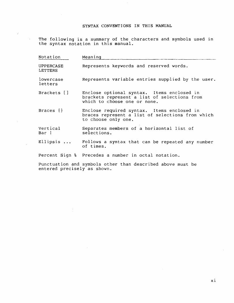
SYNTAX CONVENTIONS IN THIS MANUAL
The following is a summary of the characters and symbols used in the syntax notation in this manual.
Notation
UPPERCASE LETTERS
lowercase letters
Brackets []
Braces {}
Vertical Bar I
Ellipsis
Percent Sign %
Meaning
Represents keywords and reserved words.
Represents variable entries supplied by the user.
Enclose optional syntax. Items enclosed in brackets represent a·list of selections from which to choose one or none.
Enclose required syntax. Items enclosed in braces represent a list of selections from which to choose only one.
Separates members of a horizontal list of selections.
Follows a syntax that can be repeated any number of times.
Precedes a number in octal notation.
Punctuation and symbols other than described above must be entered precisely as shown.
xi

SECTION 1
INTRODUCTION
The GUARDIAN/EXPAND operating system.links together as many as 255 geographically distributed Tandem NonStop or NonStop II computer systems to create a network having the same reliability, capacity to preserve data base integrity, and potential for modular expansion as a single system.
DEFINITIONS
Before proceeding further, certain words used In this manual are defined:
• network
In this manual, a network consists of two or more Tandem NonStop or NonStop II Systems connected by communication paths. The paths can be full-duplex phone lines, X.25 virtual circuits, fiber optic circuits, or satellite links. Each individual system, also called a node, runs under the GUARDIAN/EXPAND operating system.
• residence of files
A disc file resides on a system if the file is located on a disc physically connected to that system; a device resides on
a system if it is physically connected to that system; and a process resides on a system if it is running in a processor module of that system.
Different partitions of a disc file can reside on different systems. (See "Alternate Key and Partitioned Files" in Section 3.
• local, remote, and network files
With respect to any particular system, a local file is a file that resides on that system; a remote file is a file that resides on a different system; and a network file describes a
1-1
Introduction
file that can be either local or remote, when it is not necessary to make that distinction. The concepts of "local" and "remote" are relative to a particular system.
FEATURES OF EXPAND
Included among EXPAND features are:
• ease of operation and programming. EXPAND causes a network to appear to the user or programmer very much like a single system. Methods of accessing geographically remote devices, disc files and processes are identical to the corresponding procedures for accessing local files. If you know how to use the system, then you already know how to use a network of systems.
• pass-through routing. Systems need not be connected directly to one another to exchange data; in fact, messages may be passed through intermediate systems, allowing the number of communication lines in the network to be minimized.
• multi-line facility. A path can be made up of several lines where: a line is an actual physical communications wirE~ and a path is the logical connection between two adjacent nodes in the EXPAND network. The multi-line facility increases network performance and reliability in the following manner:
Increased network performance. Allows simultaneous transmission over all lines within a path; thus increasing the overall bandwidth of the path.
Increased network reliability. Because multiple lines may exist in a single path, a single line failure will not bring down a path. Because lines may be distributed between mUltiple controllers, a single controller failure will not bring down a path; however, all controllers in a path must be in the same controller group--see SYSGEN in the System Management Manual. In the event of either a single line or controller failure, the EXPAND error routine recovers messages in transit and reassigns the new path.
• best-path routing. When mUltiple paths between systems exist, EXPAND routes data via the best path. If the status of the currently used best path changes--for example, following the failure or recovery of a communication line--message traffic is automatically rerouted along the new best path.
• enhanced routing. EXPAND enhanced routing provides the optimal transfer of data within a network. You may define a transmission priority through a SETMODE function call. Then, once the best-path route is determined, the line handler uses this priority to order the message transmission on the path. Highest priority messages are transmitted first.
1-2
Introduction
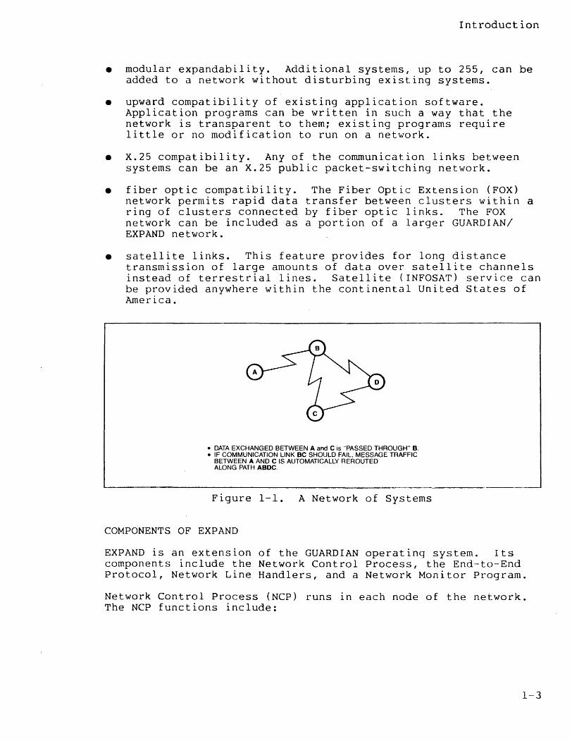
• modular expandability. Additional systems, up to 255, can be added to a network without disturbing existing systems.
• upward compatibility of existing application software. Application programs can be written in such a way that the network is transparent to them; existing programs require little or no modification to run on a network.
• X.25 compatibility. Any of the communication links between systems can be an X.25 public packet-switching network.
• fiber optic compatibility. network permits rapid data ring of clusters connected network can be included as EXPAND network.
The Fiber Optic Extension (FOX) transfer between clusters within a by fiber optic links. The FOX a portion of a larger GUARDIAN/
• satellite links. This feature provides for long distance transmission of large amounts of data over satellite channels instead of terrestrial lines. Satellite (INFOSAT) service can be provided anywhere within the continental United States of America.
• DATA EXCHANGED BETWEEN A and C IS "PASSED THROUGH" B . • IF COMMUNICATION LINK BC SHOULD FAIL. MESSAGE TRAFFIC
BETWEEN A AND C IS AUTOMATICALLY REROUTED ALONG PATH ABDC.
Figure 1-1. A Network of Systems
COMPONENTS OF EXPAND
EXPAND is an extension of the GUARDIAN operating system. Its components include the Network Control Process, the End-to-End Protocol, Network Line Handlers, and a Network Monitor Program.
Network Control Process (NCP) runs in each node of the network. The NCP functions include:
1-3
Introduction
• establishing intersystem connections
• maintaining network-related system tables, including routing information
• determining the best path to other systems
• monitoring and logging changes in the status of the network and its constituent systems.
End-to-End protocol is a Tandem-defined, packet-switched protocol for the exchange of data between systems. The End-to-End protocol guarantees data integrity from sender to receiver regardless of how many intervening systems are involved in the transfer.
Four types of EXPAND network line handlers (Direct Connect, X.25, FOX, and Satellite Connect) manage a communication path and implement the End-to-End protocol.
• The Direct Connect line handler, which acts as an I/O process, manages one end of a full-duplex phone line between two systems.
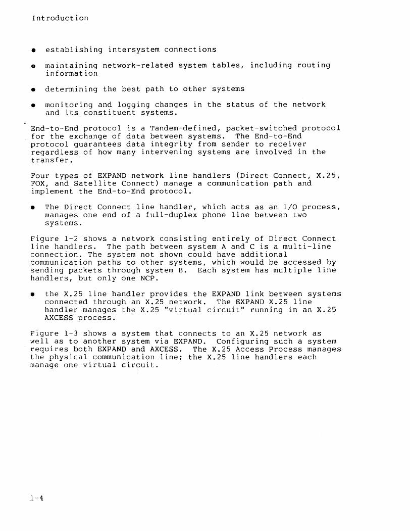
Figure 1-2 shows a network consisting entirely of Direct Connect line handlers. The path between system A and C is a multi-line connection. The system not shown could have additional communication paths to other systems, which would be accessed by sending packets through system B. Each system has mUltiple line handlers, but only one NCP.
• the X.25 line handler provides the EXPAND link between systems connected through an X.25 network. The EXPAND X.25 line handler manages the X.25 "virtual circuit" running in an X.25 AXCESS process.
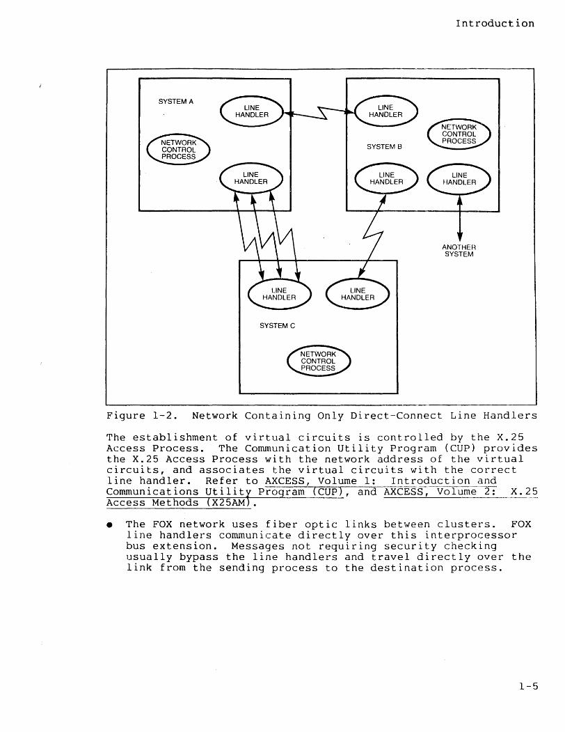
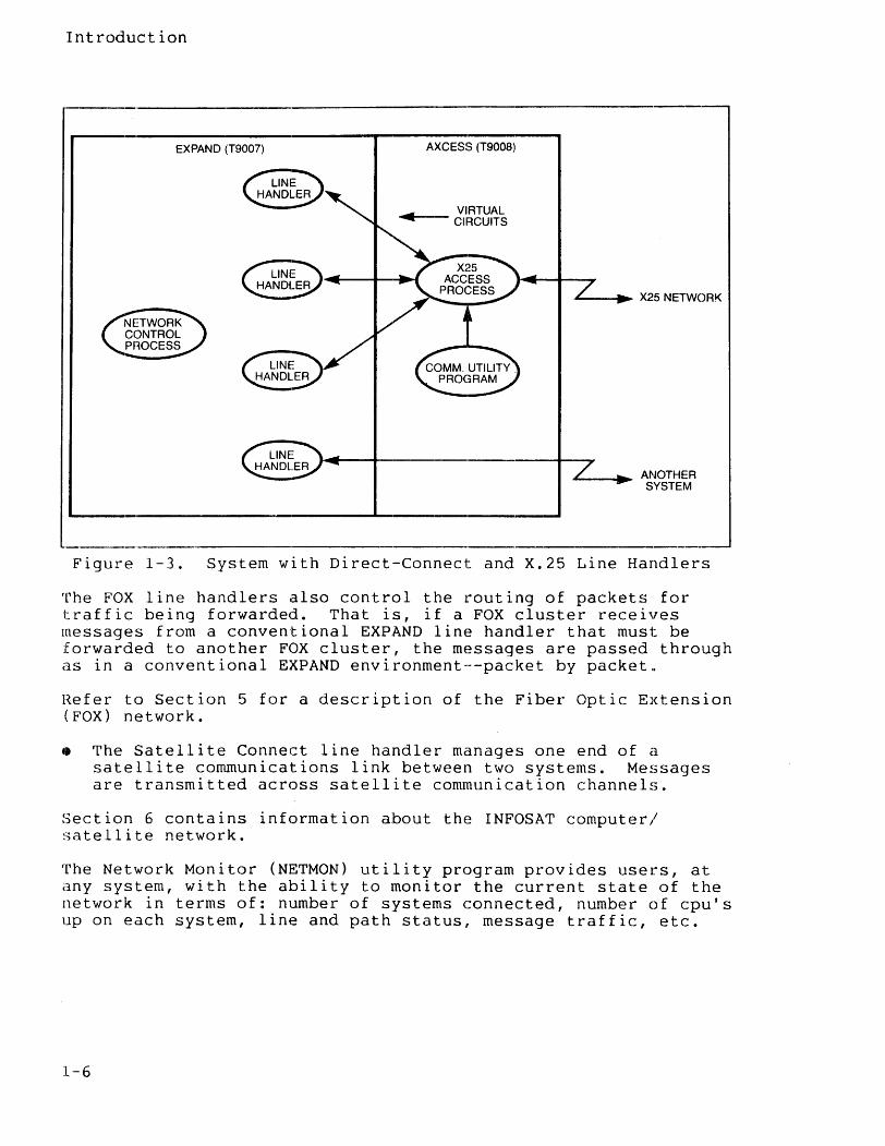
Figure 1-3 shows a system that connects to an X.25 network as well as to another system via EXPAND. Configuring such a system requires both EXPAND and AXCESS. The X.25 Access Process manages the physical communication line; the X.25 line handlers each manage one virtual circuit.
1-4
SYSTEM A
SYSTEM B
SYSTEM C
Introduction
ANOTHER SYSTEM
Figure 1-2. Network Containing Only Direct-Connect Line Handlers
The establishment of virtual circuits is controlled by the X.25 Access Process. The Communication Utility Program (CUp) provides the X.25 Access Process with the network address of the virtual circuits, and associates the virtual circuits with the correct line handler. Refer to AXCESS, Volume 1: Introduction and Communications Utilitf Program (CUp), and AXCESS, Volume 2: X.25 Access Methods (X25AM .
• The FOX network uses fiber optic links between clusters. FOX line handlers communicate directly over this interprocessor bus extension. Messages not requiring security checking usually bypass the line handlers and travel directly over the link from the sending process to the destination process.
1-5
Introduction
EXPAND (T9007) AXCESS (T9008)
VIRTUAL ....... -- CIRCUITS
£.-_~ X25 NETWORK
L-_ ..... ANOTHER SYSTEM
Figure 1-3. System with Direct-Connect and X.25 Line Handlers
The FOX line handlers also control the routing of packets for traffic being forwarded. That is, if a FOX cluster receives messages from a conventional EXPAND line handler that must be forwarded to another FOX cluster, the messages are passed through as in a conventional EXPAND environment--packet by packet.
Refer to Section 5 for a description of the Fiber Optic Extension (FOX) network.
• The Satellite Connect line handler manages one end of a satellite communications link between two systems. Messages are transmitted across satellite communication channels.
Section 6 contains information about the INFOSAT computer/ satellite network.
The Network Monitor (NETMON) utility program provides users, at any system, with the ability to monitor the current state of the Iletwork in terms of: number of systems connected, number of cpu's up on each system, line and path status, message traffic, etc.
1-6
SECTION 2
OPERATOR INTERFACE
This section describes the interface .between an interactive user and a network; it assumes that you are familiar with the command interpreter and wish to perform similar operations on a remote system, such as:
• editing a remote file
• running a program on a remote system
• duplicating a set of files from one system to another
with a few exceptions, any operation performed on a system using the command interpreter can be performed on any system in a network.
NETWORK FILE ACCESS
Interactive interface to the system consists of using the command interpreter, FUP, PUP, the Editor, and other subsystems to access files. Access to a file is via its symbolic file name.
Access to a file in a network is achieved by qualifying a symbolic file name with the name of a system. For example, the command
:EDIT \NEWYORK.$SYSTEM.SYSTEM.TEXTFILE
edits the disc file $SYSTEM.SYSTEM.TEXTFILE, located on the system designated \NEWYORK. Similarly, the command
:RUN \PARIS.MYPROG
runs a program named MYPROG on the default volume and subvolume of the system designated \PARIS.
Thus, a network file name consists of a local file name preceded by a system name.
2-1
Operator Interface to EXPAND Network File Access
REMOTE SYSTEMS
\SATURN \NEPTUNE
\ NEPTUNE SDATA
---------------------------------------------------------------~
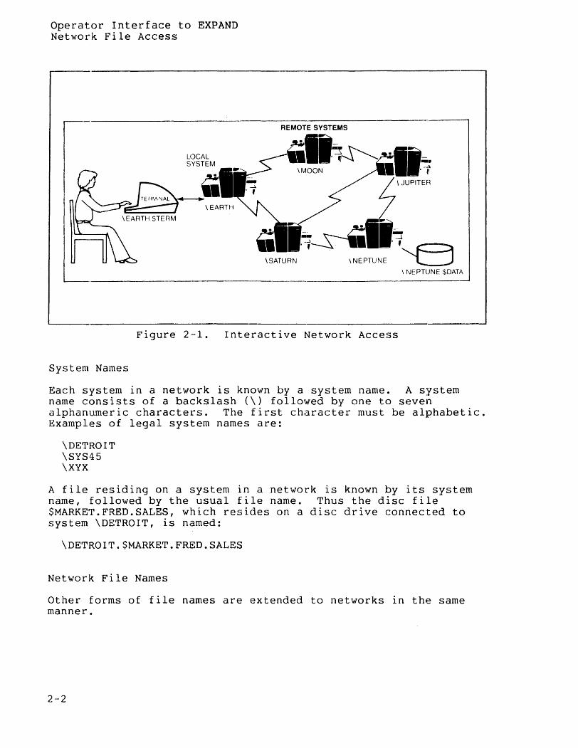
Figure 2-1. Interactive Network Access
System Names
Each system in a network is known by a system name. A system name consists of a backslash (\) followed by one to seven alphanumeric characters. The first character must be alphabetic. Examples of legal system names are:
\DETROIT \SYS45 \XYX
A file residing on a system in a network is known by its system name, followed by the usual file name. Thus the disc file $MARKET.FRED.SALES, which resides on a disc drive connected to system \DETROIT, is named:
\DETROIT.$MARKET.FRED.SALES
Network File Names
Other forms of file names are extended to networks in the same manner.
2-2
Operator Interface to EXPAND Network File Access
EXAMPLES:
\DETROIT.$TAPE a device name--in this case, a tape drive residing on the system \DETROIT
\XYZ.$PROC named process
The length restrictions on network file names are:
• Device names, including names of disc volumes, can have no more than six characters.
• Process names can have no more than four characters.
These restrictions are due to the inclusion of a system number in the internal form of file names.
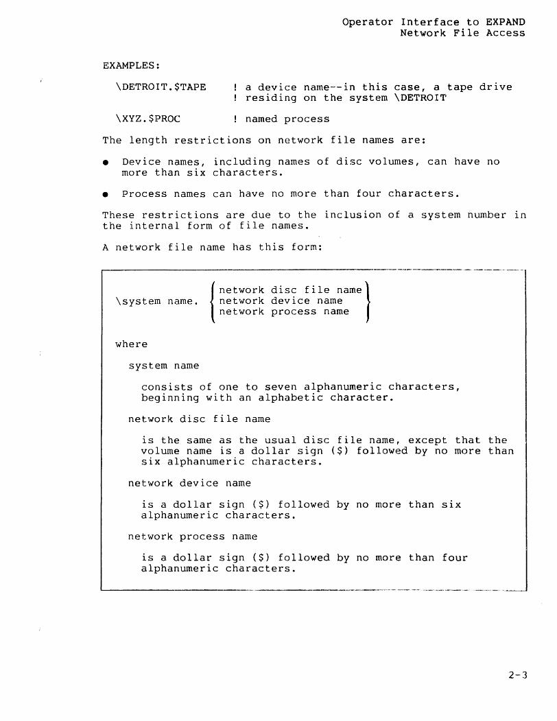
A network file name has this form:
I network disc file namel \system name. network device name
network process name
where
system name
consists of one to seven alphanumeric characters, beginning with an alphabetic character.
network disc file name
is the same as the usual disc file name, except that the volume name is a dollar sign ($) followed by no more than six alphanumeric characterso
network device name
is a dollar sign ($) followed by no more than six alphanumeric characters.
network process name
is a dollar sign ($) followed by no more than four alphanumeric characters.
2-3
Operator Interface to EXPAND Network File Access
EXAMPLES:
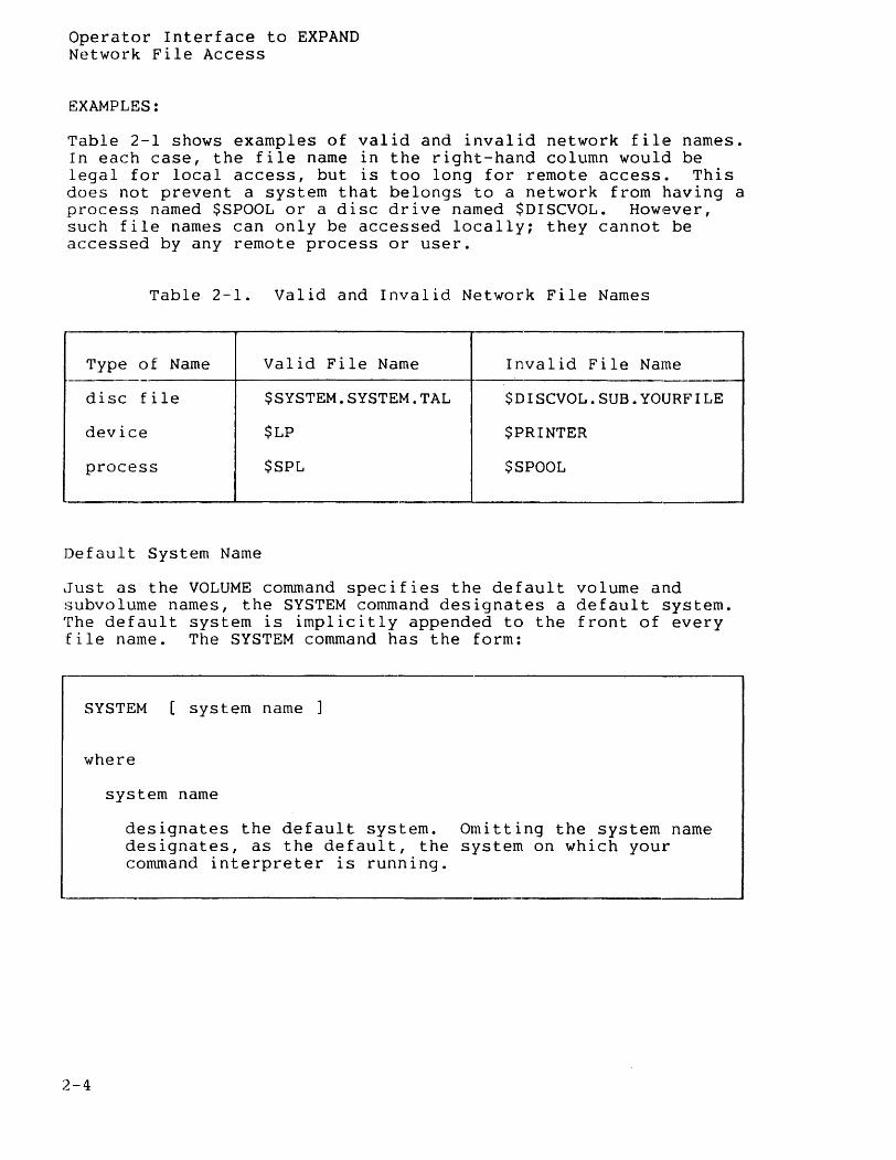
Table 2-1 shows examples of valid and invalid network file names. In each case, the file name in the right-hand column would be legal for local access, but is too long for remote access. This does not prevent a system that belongs to a network from having a process named $SPOOL or a disc drive named $DISCVOL. However, such file names can only be accessed locally: they cannot be accessed by any remote process or user.
Table 2-1. Valid and Invalid Network File Names
Type of Name Valid File Name Invalid File Name --
disc file $SYSTEM.SYSTEM.TAL $DISCVOL.SUB.YOURFILE
device $LP $PRINTER
process $SPL $SPOOL
.-
Default System Name
lJUst as the VOLUME command specifies the default volume and subvolume names, the SYSTEM command designates a default system. The default system is implicitly appended to the front of every file name. The SYSTEM command has the form:
SYSTEM [system name ]
where
2-4
system name
designates the default system. Omitting the system name designates, as the default, the system on which your command interpreter is running.
Operator Interface to EXPAND Network File Access
EXAMPLES:
:SYSTEM \DETROIT
makes \DETROIT the default system and causes filenames to be expanded in the network format.
: SYSTEM
removes any default system specification and causes filenames to be expanded in the local format.
Assuming that the local system is named \LOCAL and that the command interpreter is running on the local system then:
:SYSTEM \LOCAL :STOP $ABCDE
would cause an "ILLEGAL FILE NAME" error, even though process $ABCDE happens to be running locally, because the SYSTEM \LOCAL command interprets $ABCDE as a network file name, subject to the four-character length restriction. However, the commands:
: SYSTEM :STOP $ABCDE
would correctly interpret $ABCDE as a local process name and the STOP command would be executed.
Explicit and Implicit RUN Commands
To run programs on a network, you must keep in mind that the program file must reside on the system where the program is to run. The program file must also be secured for the appropriate network access; you as a user must have previously acquired network access rights to any systems on which you wish to run. Other than that, the explicit and implicit RUN commands work exactly as they do in a local system. For example, in the command:
: SYSTEM
the local system is the default. The command
:EDIT
runs the Editor on the local system. The command:
:RUN MYPROG
runs MYPROG, which is stored on the default volume and subvolume, on the local system.
2-5
Operator Interface to EXPAND Network File Access
To run a program on the system \DETROIT, you would use the command:
:RUN \DETROIT.MYPROG
The default volume and subvolume names remain in effect; thus, the command interpreter runs a program file named MYPROG, assuming that this file exists on the remote system. Note however, that the local system remains the default. Thus, if MYPROG references any files internally, it will try to get them from \LOCAL.filenames unless another system is explicitly specified.
Implicit run commands work the same way. Just as the command:
:EDIT
implicitly runs a program whose object file is named $SYSTEM.SYSTEM.EDIT, the command:
:\DETROIT.EDIT
implicitly runs a program whose object file is named \DETROIT.$SYSTEM.SYSTEM.EDIT; because this file resides on system \DETROIT, and because programs run where their program files are located, the Editor runs on \DETROIT.
Running Programs using the Default System Name
Some more illustrations of the use of the SYSTEM command in conjunction with RUN and implicit RUN commands may be useful. The command sequence:
:SYSTEM \XYZ :EDIT YOURFILE
runs an Editor in system \XYZ. If the default volume and subvolume are both DEFLT, then the file being edited is \XYZ.DEFLT.DEFLT.YOURFILE. The command sequence:
:SYSTEM \DETROIT :RUN MYPROG lIN \XYZ.$MKT.SUB.FNAME, OUT \SYS45.$SPL, CPU 3/
runs \DETROIT.DEFLT.DEFLT.MYPROG in processor 3 of system \DETROIT. The IN file is a disc file located on system \XYZ, and the OUT file is a process named $SPL running on system \SYS45.
2-6
Operator Interface to EXPAND Network File Access
THE WHO COMMAND
It is possible to forget what the default system is, and run a program remotely by mistake. You could type EDIT, for example, meaning to run the Editor in your own system, forgetting that you had previously issued a SYSTEM \DETROIT command.
The WHO command helps you remember where you are. Its syntax is simply:
:WHO
The WHO command displays the name of the home terminal (the terminal on which your command interpreter is running), the name of the command interpreter, its primary and backup CPUs, and the current default names.
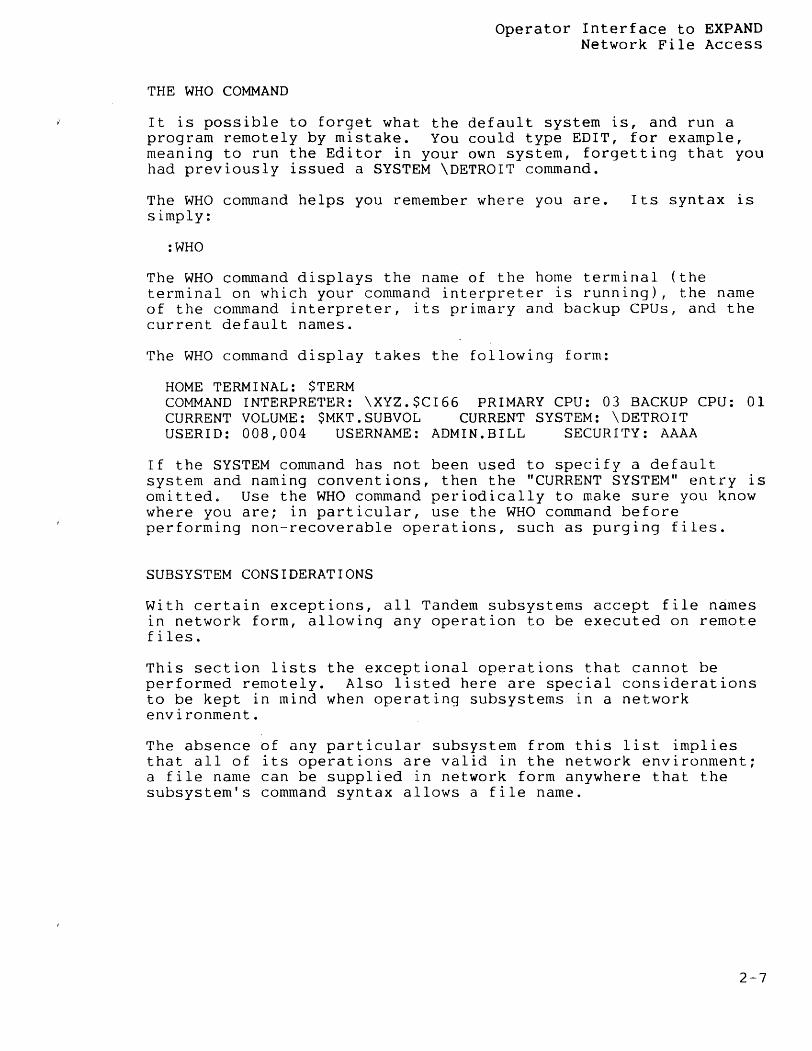
The WHO command display takes the following form:
HOME TERMINAL: $TERM COMMAND INTERPRETER: \XYZ.$CI66 PRIMARY CPU: 03 BACKUP CPU: 01 CURRENT VOLUME: $MKT.SUBVOL CURRENT SYSTEM: \DETROIT USERID: 008,004 USERNAME: ADMIN.BILL SECURITY: AAAA
If the SYSTEM command has not been used to specify a default system and naming conventions, then the "CURRENT SYSTEM" entry is omitted. Use the WHO command periodically to make sure you know where you are; in particular, use the WHO command before performing non-recoverable operations, such as purging files.
SUBSYSTEM CONSIDERATIONS
With certain exceptions, all Tandem subsystems accept file names in network form, allowing any operation to be executed on remote files.
This section lists the exceptional operations that cannot be performed remotely. Also listed here are special considerations to be kept in mind when operating subsystems in a network environment.
The absence of any particular subsystem from this list implies that all of its operations are valid in the network environment; a file name can be supplied in network form anywhere that the subsystem's command syntax allows a file name.
2-7
Operator Interface to EXPAND Subsystem Considerations
BACKUP and RESTORE
The BACKUP program must be run in the system where the disc files to be backed up reside. However, the tape file and list file for BACKUP can be anywhere in the network. Therefore, to back up a set of files on the system \ REMOTE , use the commands:
:SYSTEM \REMOTE :BACKUP / OUT \LOCAL.$LP / \LOCAL.$TAPE , $MYVOL.FILES.*
The same restriction applies to RESTORE.
COMINT
The commands RELOAD, XBUSUP, YBUSUP, XBUSDOWN, YBUSDOWN, SETTIME and TIME can apply only to the local system.
Normally, all LOGON, LOGOFF, and process-creation commands are sent to the CMON process running in the same system as the command interpreter. For systems in a network, however, process-creation commands are sent to the CMON process in the system where the new process is to run, allowing an installation to control remote process creation. LOGON and LOGOFF commands are still sent to the CMON process in the command interpreter's system.
EDIT
To reduce the amount of text that must be sent over the communication path, you should run the Editor on the same system as the text file to be edited. For example, with the Editor and its text file residing on different systems, the command:
*LIST "XYZ"
causes every line of text to be sent across the communication path. With the Editor and the text file on the same system, only the lines containing "XYZ" need be transmitted. If the text file is larg~, running the Editor in the same system as the text file causes a noticeable improvement in response time.
2-8
Operator Interface to EXPAND Subsystem Considerations
PUP
PUP commands can refer only to those devices residing on the system where PUP is running. Therefore, to list the free disc space on \REMOTE.$SYSTEM, the commands
:SYSTEM \REMOTE :PUP LISTFREE $SYSTEM
must be issued: you cannot type
:PUP LISTFREE \REMOTE.$SYSTEM
The CONSOLE command can specify a remote device as the operator console as in the following example:
#CONSOLE \REMOTE.$LP
SYSGEN
The configuration file, list file, and work file can reside anywhere on the network. However, if the operating system image is to be placed directly onto disc (rather than tape, as is usually done) the disc volume specified must reside on the system where SYSGEN will run.
SPOOLER
The supervisor, collectors, and print processes belonging to a particular spooler must all run in the same system.
A spool system can include remote devices.
An application process can direct its output to a remote spooler, as with this command:
:RUN MYPROG/ OUT \CHICAGO.$SPL /
2-9

SECTION 3
PROGRAMMER INTERFACE
This section describes how to wri~e ~pplication programs that access remote files. It covers these topics:
• overview of network programming I
• network file names and conversion between internal and external file names
• network-related system procedures
• examples and considerations
It is assumed that the reader already knows how to program the Tandem NonStop or NonStop II System, and is familiar with concepts such as file names, CRTPIDS, and the use of the file system and process-control procedures. These subjects are discussed in your system programming manuals.
Writing a program that accesses remote files on a network is similar to writing an application that accesses only local files. A program need not be aware of whether the files it is accessing are local or remote unless it specifically needs to test for that condition.
A local program (or application) is understood to be a program that accesses files only on the system on which it is running. A network program is a program that has access to files on systems other than the one on which it is running. As usual, a file can be a disc file, a peripheral device, or another process.
A local application is written as if the network does not exist. If your application does not intend to access any remote files but is going to be run on a system that is part of a network, there are no special considerations.
3-1
Programmer Interface System Names and System Numbers
SYSTEM NAMES AND SYSTEM NUMBERS
Each system in a network is assigned a unique name and number~ The system name consists of a backslash (\) followed by one to seven alphanumeric characters. A system name qualifies a file name at the external (i.e., operator) level. For example, the system name \NEWYORK qualifies a file name passed as the IN parameter to a command interpreter RUN command:
:TGAL/IN \NEWYORK.$SYSTEM.REPORT.TEXTFILE , OUT $LP/
Corresponding to the system name is the system number, an integer between 0 and 254 inclusive. The system number qualifies an internal file name.
The application process does not need to know about specific system names and numbers. The FNAMEEXPAND·and FNAMECOLLAPSE procedures perform the conversions automatically.
To gain access to a file, a process passes the file's symbolic file name to the file system OPEN procedure, which returns a file number that can be passed to other file system procedures.
Remote files are accessed the same way. To specify a particular system as well as a file, a file name can optionally include a system number to identify the system. Such a file name is a network file name. A file name that does not include a system number is a local file name.
To access a file on its local system, a process can pass the name of the file in local form (which causes OPEN to assume that the local system is intended) or in network form, including the system number of the local system.
To access a file on a remote system, a process must pass a network file name, with the appropriate system number, to the OPEN procedure.
NETWORK FILE NAMES (INTERNAL FORM)
A file name in internal form (i.e., a 12-word array suitable for passing to the OPEN procedure) that is qualified by a system number is a network file name. Its form is:
3-2
Programmer Interface Network File Names (Internal Form)
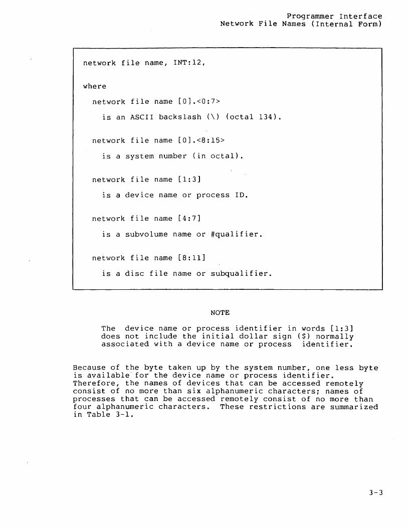
network file name, INT:12,
where
network file name [0].<0:7>
is an ASCII backslash (\) (octal 134).
network file name [0].<8:15>
is a system number (in octal).
network file name [1:3]
is a device name or process ID.
network file name [4:7]
is a subvolume name or #qualifier.
network file name [8:11]
is a disc file name or subqualifier.
NOTE
The device name or process identifier in words [1:3] does not include the initial dollar sign ($) normally associated with a device name or process identifier.
Because of the byte taken up by the system number, one less byte is available for the device name or process identifier. Therefore, the names of devices that can be accessed remotely consist of no more than six alphanumeric characters; names of processes that can be accessed remotely consist of no more than four alphanumeric characters. These restrictions are summarized in Table 3-1.
3-3
Programmer Intertace Network File Names (Internal Form)
Table 3-1. Length Restrictions on Network File Names
Object Type Named Local Name Limit Network Name Limit --
device (including $ and 7 characters $ and 6 characters disc volume)
process $ and 5 characters $ and 4 characters
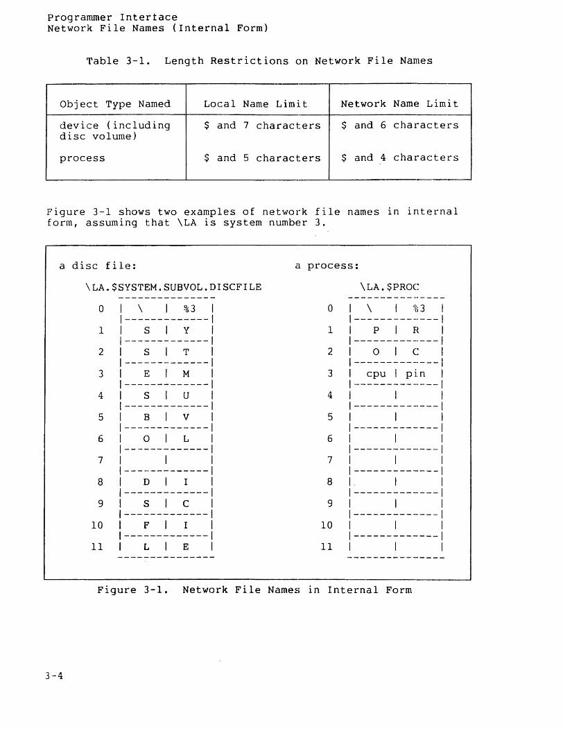
Figure 3-1 shows two examples of network file names in internal form, assuming that \LA is system number 3.
~--------------------------------------------.-------------------
a disc file:
\LA.$SYSTEM.SUBVOL.DISCFILE
o
1
2
3
4
5
6
7
8
9
10
11
1 \ 1 %3 1-------------1 Sly 1-------------
SiT
E M
s u
B V
OiL -------------
I
D I
S C
F I
L E
a process:
o
1
2
3
4
5
6
7
8
9
10
11
\LA.$PROe
\ 1 ~53 I
-------------- I P 1 H 1
-------------- I ole 1
--------------1 cpu 1 pin 1
--------------1 1 1
-------------- 1
1 1 --------------1
1 1 --------------1
1 1 --------------1
1 1 --------------1
1 1 --------------1
1 I
-------------- 1
1 1
Figure 3-1. Network File Names in Internal Form
3-4
Programmer Interface Network File Names (Internal Form)
PROCESS IDs (CRTPIDs)
A process is uniquely identified by its process identifier. The network forms of process identifier are shown in the following paragraphs.
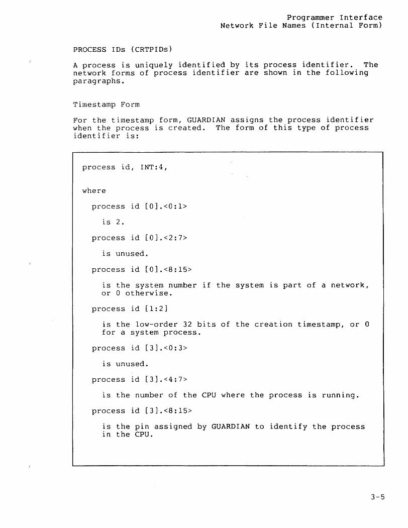
Timestamp Form
For the timestamp form, GUARDIAN assigns the process identifier when the process is created. The form of this type of process identifier is:
process id, INT:4,
where
process id [0].<0:1>
is 2.
process id [0].<2:7>
is unused.
process id [0].<8:15>
is the system number if the system is part of a network, or 0 otherwise.
process id [1:2]
is the low-order 32 bits of the creation timestamp, or a for a system process.
process id [3].<0:3>
is unused.
process id [3].<4:7>
is the number of the CPU where the process is running.
process id [3].<8:15>
is the pin assigned by GUARDIAN to identify the process in the CPU.
3-5
Programmer Interface Network File Names (Internal Form)
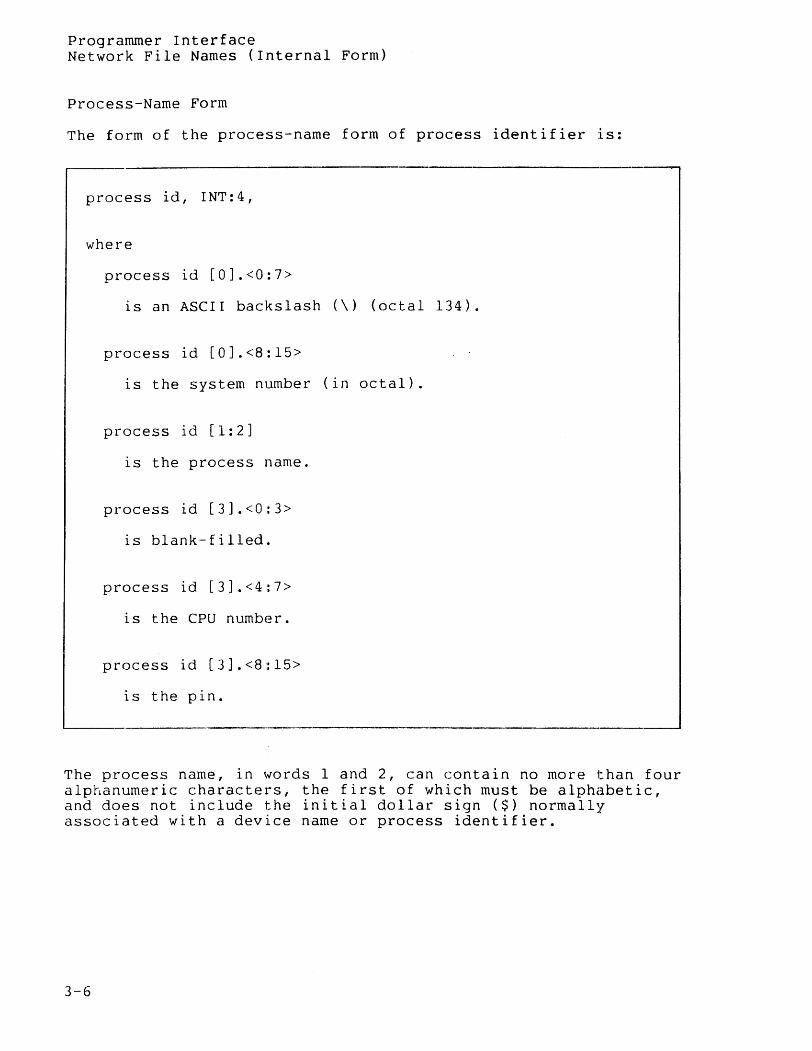
Process-Name Form
The form of the process-name form of process identifier is:
process id, INT:4,
where
process id [0].<0:7>
is an ASCII backslash (\) (octal 134).
process id [0].<8:15>
is the system number (in octal).
process id [1:2]
is the process name.
process id [3].<0:3>
is blank-filled.
process id [3].<4:7>
is the CPU number.
process id [3].<8:15>
is the pin.
The process name, in words 1 and 2, can contain no more than four alphanumeric characters; the first of which must be alphabetic, and does not include the initial dollar sign ($) normally associated with a device name or process identifier.
3-6
Programmer Interface--File-Name Conversion
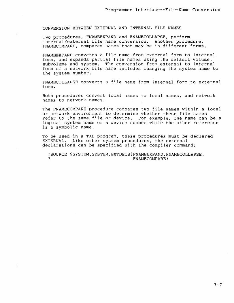
CONVERSION BETWEEN EXTERNAL AND INTERNAL FILE NAMES
Two procedures, FNAMEEXPAND and FNAMECOLLAPSE, perform internal/external file name conversion. Another procedure, FNAMECOMPARE, compares names that may be in different forms.
FNAMEEXPAND converts a file name from external form to internal form, and expands partial file names using the default volume, subvolume and system. The conversion from external to internal form of a network file name includes changing the system name to the system number.
FNAMECOLLAPSE converts a file name from internal form to external form.
Both procedures convert local names to local names, and network names to network names.
The FNAMECOMPARE procedure compares two file names within a local or network environment to determine whether these file names refer to the same file or device. For example, one name can be a logical system name or a device number while the other reference is a symbolic name.
To be used in a TAL program, these procedures must be declared EXTERNAL. Like other system procedures, the external declarations can be specified with the compiler command:
?SOURCE $SYSTEM. SYSTEM. EXTDECS (FNAMEEXPAND,FNAMECOLLAPSE, ? FNAMECOMPARE)
3-7
Programmer Interface--File-Name Conversion FNAMECOLLAPSE Procedure
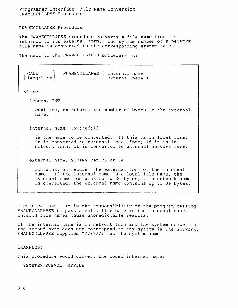
FNAMECOLLAPSE Procedure
The FNAMECOLLAPSE procedure converts a file name from its internal to its external form. The system number of a network file name is converted to the corresponding system name.
The call to the FNAMECOLLAPSE procedure is:
,-----------------------------------------------------------------------FNAMECOLLAPSE internal name
, external name
where
length, I NT
contains, on return, the number of bytes in the external name.
internal name, INT:ref:12
is the name to be converted. If this is in local form, it is converted to external local form; if it is in network form, it is converted to external network formG
external name, STRING:ref:26 or 34
contains, on return, the external form of the internal name. If the internal name is a local file name, the external name contains up to 26 bytes; if a network name is converted, the external name contains up to 34 bytes~
,--------------------_._-----------------_----1
CONSIDERATIONS. It is the responsibility of the program calling FNAMECOLLAPSE to pass a valid file name in the internal name. Invalid file names cause unpredictable results.
If the internal name is in network form and the system number in the second byte does not correspond to any system in the network, FNAMECOLLAPSE supplies "???????" as the system name.
EXAMPLES:
rrhis procedure would convert the local internal name:
$SYSTEM SUBVOL MYFILE
]-8

Programmer Interface--File-Name Conversion FNAMECOLLAPSE Procedure
to $SYSTEM.SUBVOL.MYFILE. Where system number 5 is named \SF, and we use <%5> to denote octal 5 in the second byte, the procedure would convert the network internal name:
\<%5>SYSTEMSUBVOL MYFILE
to the external form \SF.$SYSTEM.SUBVOL.MYFILE.
3-9
Programmer Interface--File-Name Conversion FNAMEEXPAND Procedure
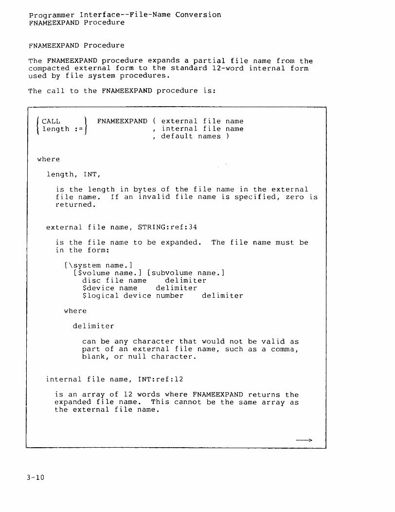
FN~~EEXPAND Procedure
The FNAMEEXPAND procedure expands a partial file name from the compacted external form to the standard l2-word internal form used by file system procedures.
The call to the FNAMEEXPAND procedure is:
{CALL } length :=
FNAMEEXPAND external file name , internal file name , default names }
where
3-10
length, INT,
is the length in bytes of the file name in the external file name. If an invalid file name is specified, zero is r.eturned.
external file name, STRING:ref:34
is the file name to be expanded. The file name must be in the form:
[\system name.] [$volume name.] [subvolume name.]
disc file name delimiter $device name delimiter $logical device number delimiter
where
delimiter
can be any character that would not be valid as part of an external file name, such as a comma, blank, or null character.
internal file name, INT:ref:12
is an array of 12 words where FNAMEEXPAND returns the expanded file name. This cannot be the same array as the external file name.
Programmer Interface--File-Name Conversion FNAMEEXPAND Procedure
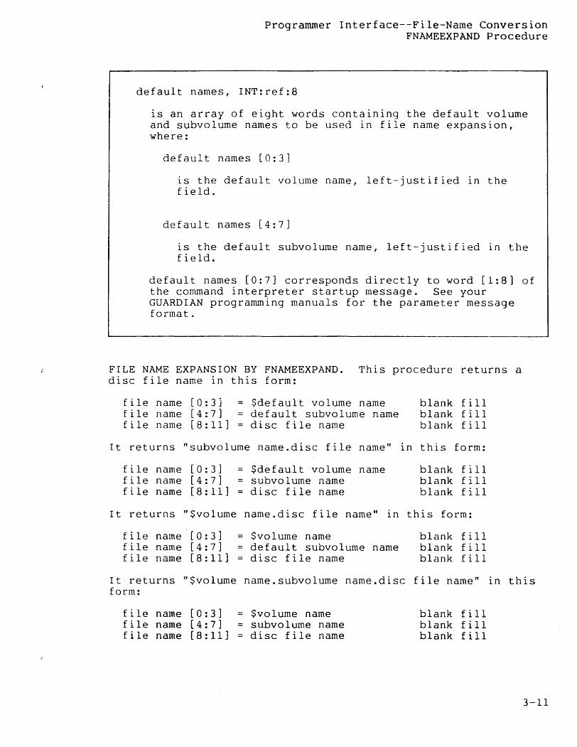
default names, INT:ref:8
is an array of eight words containing the default volume and subvolume names to be used in file name expansion, where:
default names [0:3]
is the default volume name, left-justified in the field.
default names [4:7]
is the default subvolurne name, left-justified in the field.
default names [0:7] corresponds directly to word [1:8] of the command interpreter startup message. See your GUARDIAN programming manuals for the parameter message format.
FILE NAME EXPANSION BY FNAMEEXPAND. This procedure returns a disc file name in this form:
file name [0:3] file name [4:7] file name [8:11]
= $defau1t volume name default subvo1ume name disc file name
blank fill blank fill blank fill
It returns "subvolume name.disc file name" in this form:
file name [0:3] file name [4:7] file name [8:11]
$default volume name subvolume name disc file name
blank fill blank fill blank fill
It returns "$volume name.disc file name" in this form:
f i 1 e name' [ 0 : 3 ] file name [4:7] file name [8:11]
$volume name default subvolume name disc file name
blank fill blank fill blank fill
It returns "$volume name.subvolume name.disc file name" in this form:
file name [0:3] file name [4:7] file name [8:11]
= $volume name = subvolurne name
disc file name
blank fill blank fill blank fill
3-11
Programmer Interface--File-Name Conversion FNAMEEXPAND Procedure
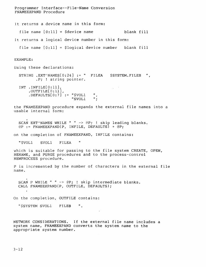
It returns a device name in this form:
file name [0:11] = $device name blank fill
It returns a logical device number in this form:
file name [0:11] = $logical device number blank fill
EXAMPLE:
Using these declarations:
STRING .EXT"NAMES[O:24] := n .P; ! string pointer.
INT .INFILE[O:ll], .0UTFILE[O:11], .DEFAULTS[O:7] := "$VOLI
"SVOLI
FILEA
" , " . ,
$SYSTEM.FILEB "
the FNAMEEXPAND procedure expands the external file names into a usable internal form:
SCAN EXT"NAMES WHILE" " -> @P; ! skip leading blanks. @P := FNAMEEXPAND(P, INFILE, DEFAULTS) + @P;
on the completion of FNAMEEXPAND, INFILE contains:
n$VOLl SVOLI FILEA "
which is suitable for passing to the file system CREATE, OPEN, RENAME, and PURGE procedures and to the process-control NEWPROCESS procedure.
P is incremented by the number of characters in the external file name.
SCAN P WHILE" n -> @P; ! skip intermediate blanks. CALL FNAMEEXPAND(P, OUTFILE, DEFAULTS);
On the completion, OUTFILE contains:
"$SYSTEM SVOL1 FILEB "
NETWORK CONSIDERATIONS~ If the external file name includE~s a system name, FNAMEEXPAND converts the system name to the appropriate system number.
3-12
Programmer Interface--File-Name Conversion FNAMEEXPAND Procedure
If the external file name does not include a system name, but a default system name is part of the DEFAULTS parameter, FNAMEEXPAND converts the external file name to a network internal file name having the correct system number.
NETWORK EXAMPLE:
Suppose that system \NEWYORK is assigned system number 4. Then the external file name \NEWYORK.$DATA.SUB.MYFILE is converted by FNAMEEXPAND to:
n\<%4>DATA SUB MYFILE "
where <%4> denotes octal 4 in the second byte.
I f the system name does not exist' in, the network, FNAMEEXPAND supplies 255 as the system number.
3-13
Programmer Interface--File-Name Conversion FNAMECOMPARE Procedure
FNAMECOMPARE Procedure
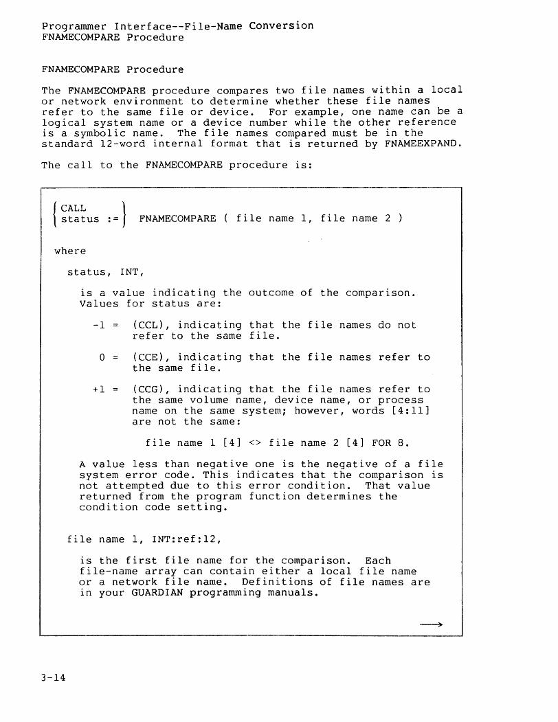
The FNAMECOMPARE procedure compares two file n~mes within a local or network environment to determine whether these file names refer to the same file or device. For example, one name can be a logical system name or a device number while the other reference is a symbolic name. The file names compared must be in the standard 12-word internal format that is returned by FNAMl~EXPAND.
The call to the FNAMECOMPARE procedure is:
{~~~~us :=} FNAMECOMPARE ( file name 1, file name 2 )
where
3-14
s tat us, I NT ,
is a value indicating the outcome of the comparison. Values for status are:
-1 = (CCL), indicating that the file names do not refer to the same file.
o = (CCE), indicating that the file names refer to the same file.
+1 = (CCG), indicating that the file names refer to the same volume name, device name, or process name on the same system; however, words [4:11] are not the same:
file name I [4] <> file name 2 [4] FOR 8.
A value less than negative one is the negative of a file system error code. This indicates that the comparison is not attempted due to this error condition. That value returned from the program function determines the condition code setting.
file name 1, INT:ref:12,
is the first file name for the comparison. Each file-name array can contain either a local file name or a network file name. Definitions of file names are in your GUARDIAN programming manuals.
~,
Programmer Interface--File-Name Conversion FNAMECOMPARE Procedure
file name 2, INT:ref:12,
is the second file name for the comparison.
CONSIDERATIONS. The arrays containing the file names for comparison are not modified.
Alphabetic characters within qualified process names are not upshifted before comparison.
If a logical device number format, such as $0076, is used for one file name, but not the other, the-device table of the referenced system is consulted to determine whether the names are equivalent. This case is the only time the device table is used. All other comparisons involve only the examination of the two file names supplied.
Some of the most common negative file system error codes returned are:
-13 an illegal file name specification for either file name is made.
-14 the device does not exist. (See note.)
-18 no such system is defined in this network. (See note.)
-22 = a parameter or buffer is out of bounds.
-250 = all paths to the system are down. (See note.)
NOTE
These negative file system error codes indicate that only one of the file names is passed in logical device number format (requiring a check of the device table) and the file name represents a device connected to a remote network node.
In a network node with a system number = 6, execution of the next code example returns a status of 0 and the condition code (CCE). In a non-network system, execution of this code returns a status of negative one and the condition code (eCL).
INT .FNAMEl[ 0:11 J, .FNAME2[ 0:11 J, STATUS;
3-15
Programmer Interface--File-Name Conversion FNAMECOMPARE Procedure
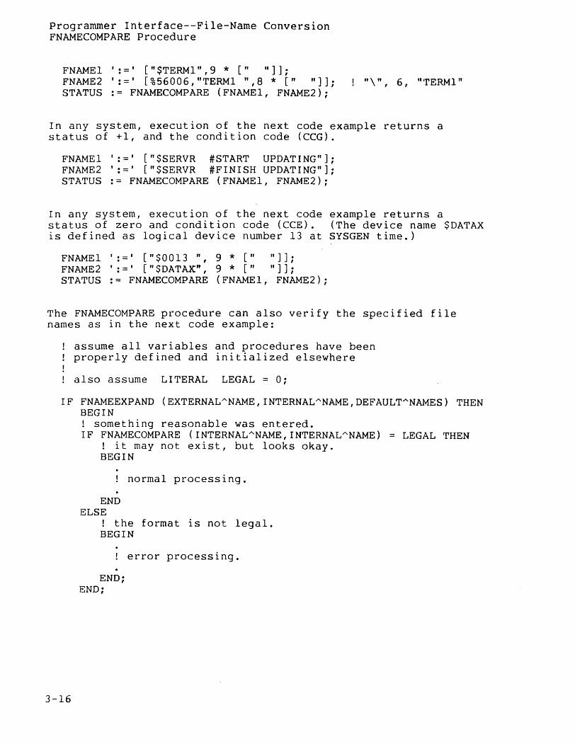
FNAME1 ': =' [" $TERM1" ,9 * [" " ] ] ; FNAME2 ':=' [%56006,"TERM1 ",8 * [" II]]; STATUS := FNAMECOMPARE (FNAME1, FNAME2);
"\ ", 6, "'rERMI"
In any system, execution of the next code example returns a status of +1, and the condition code (CCG).
FNAME1 ':=' ["$SERVR #START UPDATING"]; FNAME2 ':=' ["$SERVR #FINISH UPDATING"]; STATUS := FNAMECOMPARE (FNAME1, FNAME2);
In any system, execution of the next code example returns a status of zero and condition code (CCE). (The device name $DATAX is defined as logical device number 13 at SYSGEN time.)
FNAMEI ':=' ["$0013 ", 9 * [" II]]; FNAME2 ':=' ["$DATAXtt, 9 * [II "]]; STATUS := FNAMECOMPARE (FNAMEI, FNAME2);
The FNAMECOMPARE procedure can also verify the specified file names as in the next code example:
assume all variables and procedures have been properly defined and initialized elsewhere
also assume LITERAL LEGAL = 0;
IF FNAMEEXPAND (EXTERNALANAME,INTERNALANAME,DEFAULTANN~ES) THEN BEGIN
3-16
! something reasonable was entered. IF FNAMECOMPARE (INTERNALANAME,INTERNALANAME) LEGAL THEN
! it may not exist, but looks okay. BEGIN
END ELSE
normal processing.
! the format is not legal. BEGIN
! error processing.
END; END;
Programmer Interface--File-Name Conversion FNAMECOMPARE Procedure
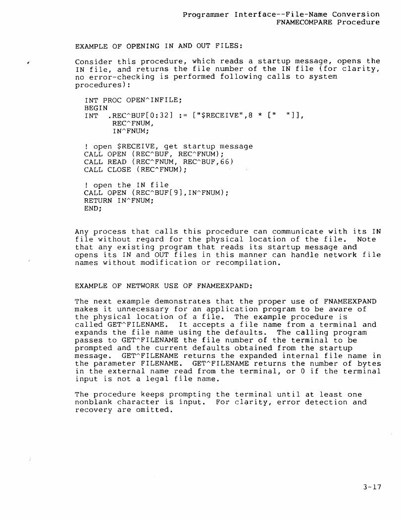
EXAMPLE OF OPENING IN AND OUT FILES:
Consider this procedure, which reads a startup message, opens the IN file, and returns the file number of the IN file (for clarity, no error-checking is performed following calls to system procedures):
INT PROC OPENAINFILE~ BEGIN INT .RECABUF[O:32] := ["$RECEIVE",8 * [" "]],
RECAFNUM, INAFNUM;
open $RECEIVE, get startup message CALL OPEN (RECABUF, RECAFNUM); CALL READ (RECAFNUM, RECABUF,66) CALL CLOSE (RECAFNUM);
! open the IN file CALL OPEN (RECABUF[9],INAFNUM); RETURN INAFNUM: END;
Any process that calls this procedure can communicate with its IN file without regard for the physical location of the file. Note that any existing program that reads its startup message and opens its IN and OUT files in this manner can handle network file names without modification or recompilation.
EXAMPLE OF NETWORK USE OF FNAMEEXPAND:
The next example demonstrates that the proper use of FNAMEEXPAND makes it unnecessary for an application program to be aware of the physical location of a filee The example procedure is called GETAFILENAME. It accepts a file name from a terminal and expands the file name using the defaults. The calling program passes to GETAFILENAME the file number of the terminal to be prompted and the current defaults obtained from the startup message. GETAFILENAME returns the expanded internal file name in the parameter FILENAME. GETAFILENAME returns the number of bytes in the external name read from the terminal, or 0 if the terminal input is not a legal file name.
The procedure keeps prompting the terminal until at least one nonblank character is input. For clarity, error detection and recovery are omitted.
3-17
Programmer Interface--File-Name Conversion FNAMECOMPARE Procedure
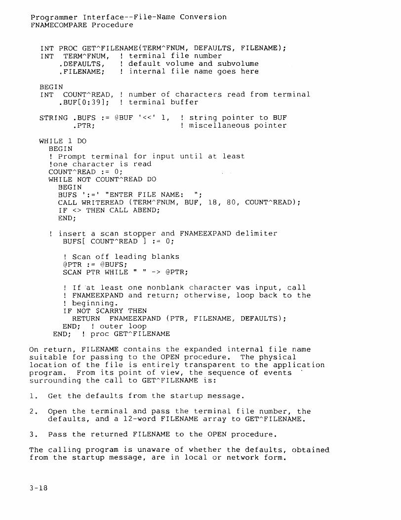
INT PROC GET"FI LENAME (TERM"FNUM, DEFAULTS, FILENAME); INT TERM"FNUM, terminal file number
. DEFAULTS , default volume and subvolume
. FILENAME; internal file name goes here
BEGIN INT COUNT'" READ ,
.BUF[O:39]; number of characters read from terminal terminal buffer
STRING .BUFS .- @BUF '«' 1, .PTR;
string pointer to BUF miscellaneous pointer
WHILE 1 DO BEGIN ! Prompt terminal for input until at least lone character is read COUNT"'READ : = 0; WHILE NOT COUNT"READ DO
BEGIN BUFS ': =' "ENTER FI LE NAME: "; CALL WRITEREAD (TERM"'FNUM, BUF, 18, 80, COUNT"'READ); IF <> THEN CALL ABEND; END;
insert a scan stopper and FNAMEEXPAND delimiter BUFS[ COUNTAREAD ] := 0;
! Scan off leading blanks @PTR := @BUFS; SCAN PTR WHILE " " -> @PTR;
I f "at least one nonblank character was input, call FNAMEEXPAND and return; otherwise, loop back to the beginning.
IF NOT $CARRY THEN RETURN FNAMEEXPAND (PTR, FILENAME, DEFAULTS);
END; ! outer loop END; ! proc GET"'FILENAME
On return, FILENAME contains the expanded internal file name suitable for passing to the OPEN procedure. The physical location of the file is entirely transparent to the application program. From its point of view, the sequence of events . surrounding the call to GETAFILENAME is:
1. Get the defaults from the startup message.
2. Open the terminal and pass the terminal file number, the defaults, and a 12-word FILENAME array to GETAFILENPJ.1E.
3. Pass the returned FILENAME to the OPEN procedure.
The calling program is unaware of whether the defaults, obtained from the startup message, are in local or network form.
3-18

Programmer Interface--File-Name Conversion FNAMECOMPARE Procedure
FNAMEEXPAND returns a network file name in FILENAME if either:
• the external name, read from the terminal, included a system name, or
• the defaults included a system number.
However, the calling program passes FILENAME directly to OPEN without caring whether the file is local or remote.
3-19
Programmer Interface--System Procedures
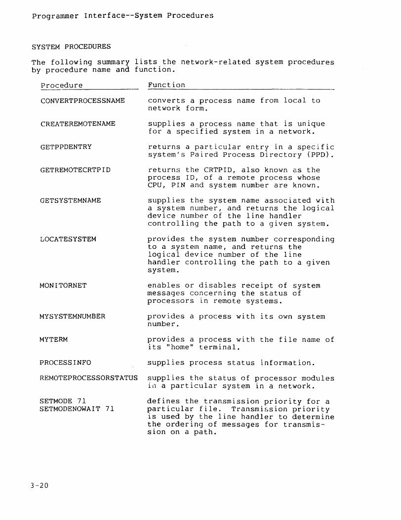
SYSTEM PROCEDURES
The following summary lists the network-related system procedures by procedure name and function.
Procedure
CONVERTPROCESSNAME
CREATEREMOTENAME
GETPPDENTRY
GETREMOTECRTPID
GETSYSTEMNAME
LOCATESYSTEM
MONITORNET
MYSYSTEMNUMBER
MYTERM
PROCESS INFO
REMOTEPROCESSORSTATUS
SETMODE 71 SETMODENOWAIT 71
3-20
Function
converts a process name from local to network form.
supplies a process name that is unique for a specified system in a network.
returns a particular entry in a specific system's Paired Process Directory (PPD).
returns the CRTPID, also known as the process ID, of a remote process whose CPU, PIN and system number are known~
supplies the system name associated with a system number, and returns the logical device number of the line handler controlling the path to a given system.
provides the system number corresponding to a system name, and returns the logical device number of the line handler controlling the path to a given system.
enables or disables receipt of system messages concerning the status of processors in remote systems.
provides a process with its own system number.
provides a process with the file name of its " home" term ina 1 .
supplies process status information.
supplies the status of processor modules in a particular system in a network.
defines the transmission priority for a particular file. Transmission priority is used by the line handler to determine the ordering of messages for transmission on a path.
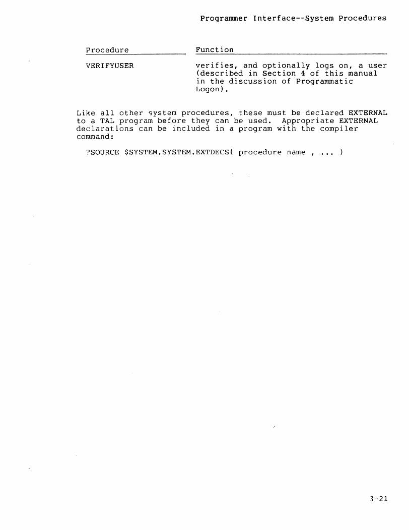
Procedure
VERI FYUSER
Programmer Interface--System Procedures
Function
verifies, and optionally logs on, a user (described in Section 4 of this manual in the discussion of Programmatic Logon).
Like all other system procedures, these must be declared EXTERNAL to a TAL program before they can be used. Appropriate EXTERNAL declarations can be included in a program with the compiler command:
?SOURCE $SYSTEM.SYSTEM.EXTDECS{ procedure name, ... )
3-21
Programmer Interface--System Procedures CONVERTPROCESSNAME Procedure
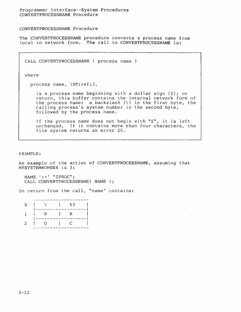
CONVERTPROCESSNAME Procedure
The CONVERTPROCESSNAME procedure converts a process name from local to network form. The call to CONVERTPROCESSNAME is:
~--------------------------------------------.---------------------------
CALL CONVERTPROCESSNAME ( process name )
where
process name, INT:ref:3,
is a process name beginning with a dollar sign ($); on return, this buffer contains the internal network form of the process name: a backslash (\) in the first byte, the calling process's system number in the second byte, followed by the process name.
If the process name does not begin with "$", it is left unchanged. If it contains more than four characters, the file system returns an error 20.
EXAMPLE:
An example of the action of CONVERTPROCESSNAME, assuming that MYSYSTEMNUMBER is 3:
NAME ': =' "$PROC"; CALL CONVERTPROCESSNAME( NAME );
On return from the call, "name" contains:
o I \ I %3 1 1------------------1
I I P I R 1
I---------------~--I 2 I 0 I C I
3-22
Programmer Interface--System Procedures CREATEREMOTENAME Procedure
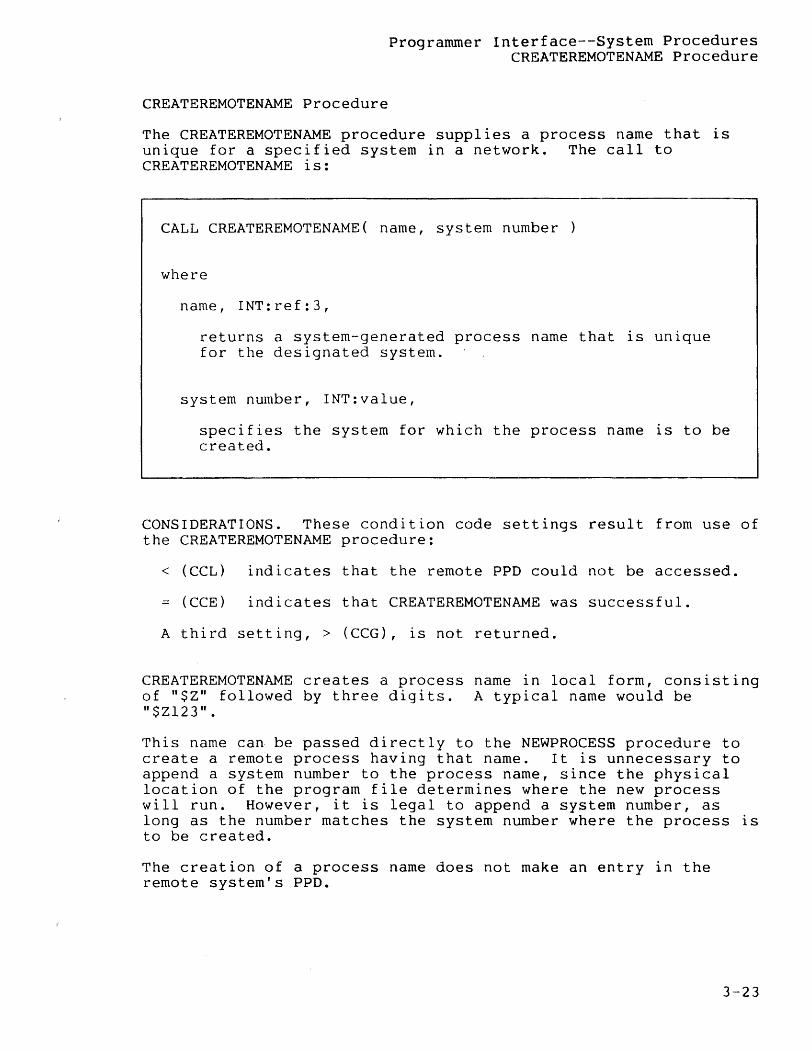
CREATEREMOTENAME Procedure
The CREATEREMOTENAME procedure supplies a process name that is unique for a specified system in a network. The call to CREATEREMOTENAME is:
CALL CREATEREMOTENAME( name, system number )
where
name, INT:ref:3,
returns a system-generated process name that is unique for the designated system.
system number, INT:value,
specifies the system for which the process name is to be created.
CONSIDERATIONS. These condition code settings result from use of the CREATEREMOTENAME procedure:
< (CCL) indicates that the remote PPD could not be accessed.
= (CCE) indicates that CREATEREMOTENAME was successful.
A third setting, > (CCG), is not returned.
CREATEREMOTENAME creates a process name in local form, consisting of "$Z" followed by three digits. A typical name would be "$Z123".
This name can be passed directly to the NEWPROCESS procedure to create a remote process having that name. It is unnecessary to append a system number to the process name, since the physical location of the program file determines where the new process will run. However, it is legal to append a system number, as long as the number matches the system number where the process is to be created.
The creation of a process name does not make an entry in the remote system's PPD.
3-23

Programmer Interface--System Procedures CREATEREMOTENAME Procedure
EXAMPLE:
An example of the use of this procedure is:
CALL CREATEREMOTENAME( NAME, SYS"'NUM ); IF < THEN ... ! problems
3-24
Programmer Interface--System Procedures GETPPDENTRY Procedure
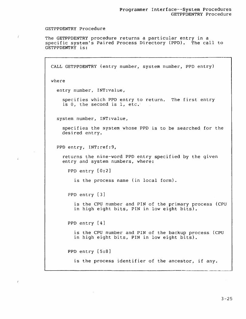
GETPPDENTRY Procedure
The GETPPDENTRY procedure returns a particular entry in a specific system's Paired Process Directory (PPD). The call to GETPPDENTRY is:
CALL GETPPDENTRY (entry number, system number, PPD entry)
where
entry number, INT:value,
specifies which PPD entry to return. The first entry is 0, the second is 1, etc."
system number, INT:value,
specifies the system whose PPD is to be searched for the desired entry.
PPD entry, INT:ref:9,
returns the nine-word PPD entry specified by the given entry and system numbers, where:
PPD entry [0:2]
is the process name (in local form).
PPD entry [3]
is the CPU number and PIN of the primary process (CPU in high eight bits, PIN in low eight bits).
PPD entry [4]
is the CPU number and PIN of the backup process (CPU in high eight bits, PIN in low eight bits).
PPD entry [5:8]
is the process identifier of the ancestor, if any.
3-25
Programmer Interface--System Procedures GETPPDENTRY Procedure
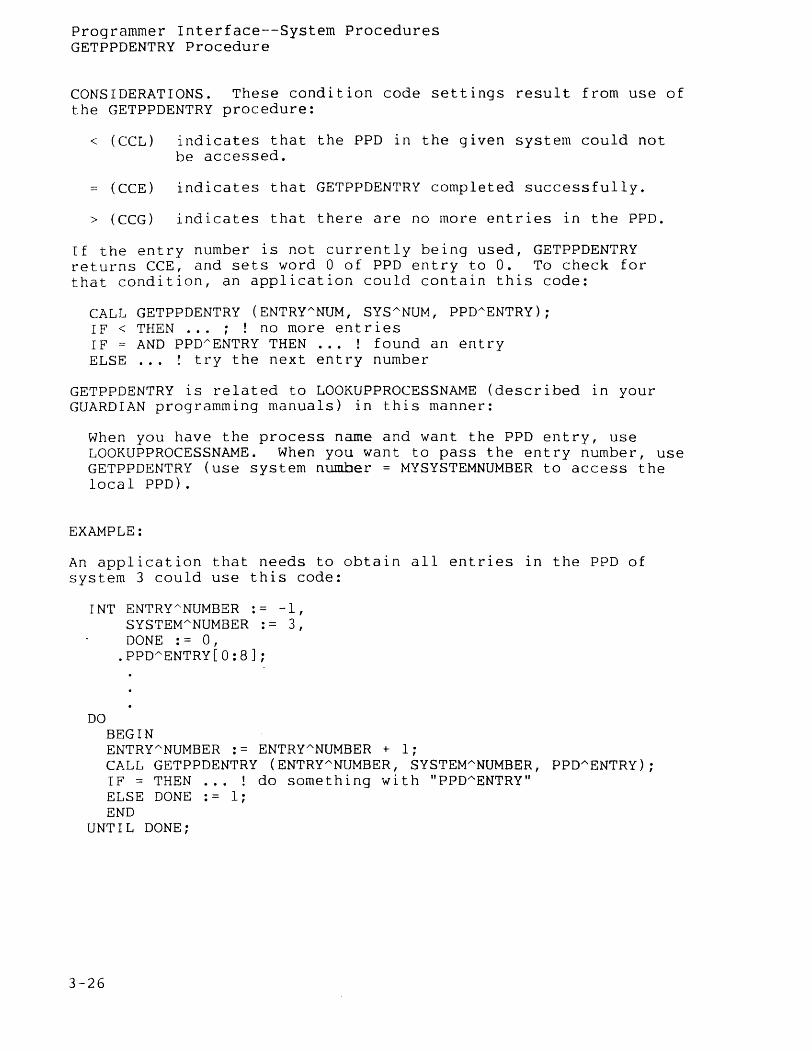
CONSIDERATIONS. These condition code settings result from use of the GETPPDENTRY procedure:
< (CCL) indicates that the PPD in the given system could not be accessed.
(CCE) indicates that GETPPDENTRY completed successfully.
> (CCG) indicates that there are no more entries in the PPD.
If the entry number is not currently being used, GETPPDENTRY returns CCE, and sets word 0 of PPD entry to O. To check for that condition, an application could contain this code:
CALL GETPPDENTRY (ENTRYANUM, SYSANUM, PPDAENTRY); IF < THEN ... ; ! no more entries IF = AND PPD~ENTRY THEN ... ! found an entry ELSE ... ! try the next entry number
GETPPDENTRY is related to LOOKUPPROCESSNAME (described 1n your GUARDIAN programming manuals) in this manner:
When you have the process name and want the PPD entry, use LOOKUPPROCESSNAME. When you want to pass the entry number, use GETPPDENTRY (use system number = MYSYSTEMNUMBER to access the local PPD).
EXAMPLE:
An application that needs to obtain all entries in the PPD of system 3 could use this code:
INT ENTRYANUMBER := -1, SYSTEMANUMBER := 3, DONE := 0,
.PPDAENTRY[0:8J;
DO BEGIN ENTRYANUMBER := ENTRYANUMBER + 1; CALL GETPPDENTRY (ENTRYANUMBER, SYSTEMANUMBER, PPDAENTRY); IF = THEN ... ! do something with "PPDAENTRY" ELSE DONE .- I: END
UNTIL DONE;
3-26
Programmer Interface--System Procedures GETREMOTECRTPID Procedure
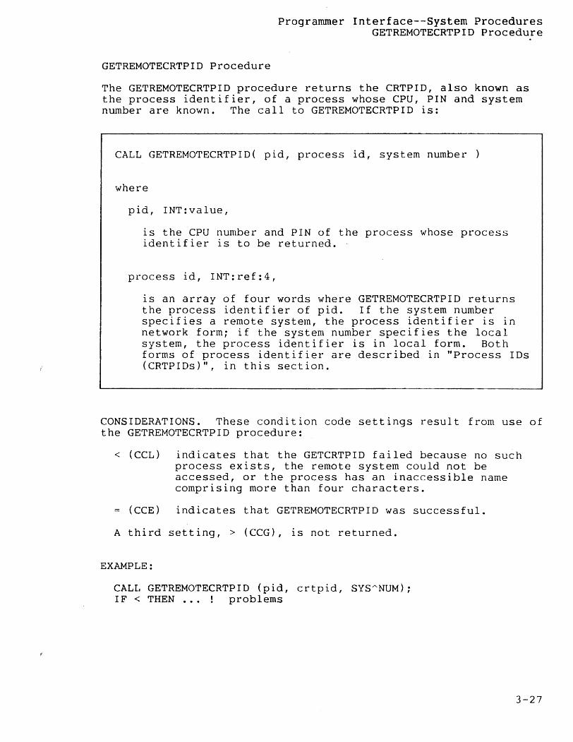
GETREMOTECRTPID Procedure
The GETREMOTECRTPID procedure returns the CRTPID, also known as the process identifier, of a process whose CPU, PIN and system number are known. The call to GETREMOTECRTPID is:
CALL GETREMOTECRTPID( pid, process id, system number )
where
p i d , I NT : val u e ,
is the CPU number and PIN of the process whose process identifier is to be returned.
process id, INT:ref:4,
is an array of four words where GETREMOTECRTPID returns the process identifier of pid. If the system number specifies a remote system, the process identifier is in network form; if the system number specifies the local system, the process identifier is in local form. Both forms of process identifier are described in "Process IDs (CRTPIDs)", in this section.
CONSIDERATIONS. These condition code settings result from use of the GETREMOTECRTPID procedure:
< (CCL) indicates that the GETCRTPID failed because no such process exists, the remote system could not be accessed, or the process has an inaccessible name comprising more than four characters.
(CCE) indicates that GETREMOTECRTPID was successful.
A third setting, > (CCG), is not returned.
EXAMPLE:
CALL GETREMOTECRTPID (pid, crtpid, SYSANUM); IF < THEN •.. problems
3-27
Programmer Interface--System Procedures GETSYSTEMNAME Procedure
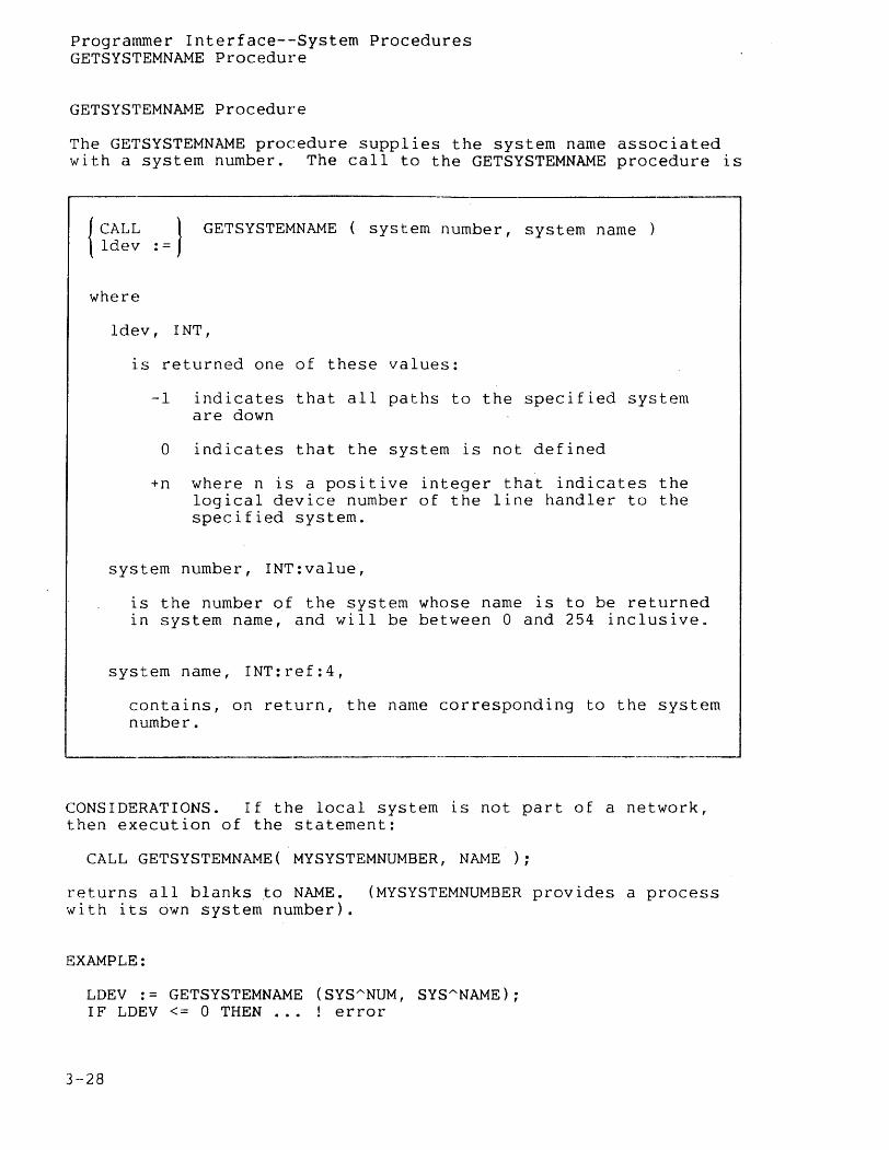
GETSYSTEMNAME Procedure
The GETSYSTEMNAME procedure supplies the system name associated with a system number. The call to the GETSYSTEMNAME procedure is
------------------------------------.--------------------------
{CALL } GETSYSTEMNAME ( system number, system name ldev :=
where
ldev, INT,
is returned one of these values:
-1 indicates that all paths to the specified system are down
o indicates that the system is not defined
+n where n is a positive integer that indicates the logical device number of the line handler to the specified system.
system number, INT:value,
is the number of the system whose name is to be returned in system name, and will be between 0 and 254 inclusive.
system name, INT:ref:4,
contains, on return, the name corresponding to the system number.
CONSIDERATIONS. If the local system is not part of a network, then execution of the statement:
CALL GETSYSTEMNAME( MYSYSTEMNUMBER, NAME );
returns all blanks to NAME. (MYSYSTEMNUMBER provides a process with its own system number).
EXAMPLE:
LDEV := GETSYSTEMNAME (SYSANUM, SYSANAME); IF LDEV <= 0 THEN ... ! error
3-28
Programmer Interface--Systern Procedures LOCATESYSTEM Procedure
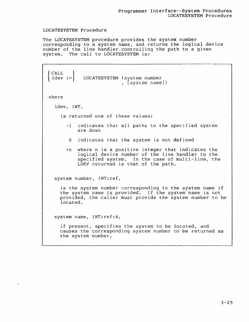
LOCATESYSTEM Procedure
The LOCATESYSTEM procedure provides the system number corresponding to a system name, and returns the logical device number of the line handler controlling the path to a given system. The call to LOCATESYSTEM is:
{CALL } ldev := LOCATESYSTEM (system number
, [system name])
where
ldev, INT,
is returned one of these values:
-1 indicates that all paths to the specified system are down
o indicates that the system is not defined
+n where n is a positive integer that indicates the logical device number of the line handler to the specified system. In the case of multi-line, the LDEV returned is that of the path.
system number, INT:ref,
is the system number corresponding to the system name if the system name is provided. If the system name is not provided, the caller must provide the system number to be located.
system name, INT:ref:4,
if present, specifies the system to be located, and causes the corresponding system number to be returned as the sY$tem number.
3-29
Programmer Interface--System Procedures LOCATESYSTEM Procedure
EXAMPLES:
! locate \NEWYORK, and return its system number SYSANAME ':=' \NEWYORK; LDEV := LOCATESYSTEM (SYSANUM, SYSANAME); IF LDEV> 0 THEN ... ! success
! locate system 3 SYSANUM := 3; LDEV := LOCATESYSTEM (SYSANUM); IF LDEV <= 0 THEN ... ! problems
3-30
Programmer Interface--System Procedures MONITORNET Procedure
MONITORNET Procedure
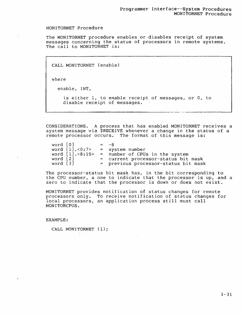
The MONITORNET procedure enables or disables receipt of system messages concerning the status of processors in remote systems. The call to MONITORNET is:
CALL MONITORNET (enable)
where
enable, INT,
is either 1, to enable receipt of messages, or 0, to disable receipt of messages.
CONSIDERATIONS. A process that has enabled MONITORNET receives a system message via $RECEIVE whenever a change in the status of a remote processor occurs. The format of this message is:
word [0] word [1].<0:7> word [1].<8:15> word [2] word [3]
= -8 = system number
number of CPUs in the system = current processor-status bit mask
previous processor-status bit mask
The processor-status bit mask has, in the bit corresponding to the CPU number, a one to indicate that the processor is up, and a zero to indicate that the processor is down or does not exist.
MONITORNET provides notification of status changes for remote processors only. To receive notification of status changes for local processors, an application process still must call MONITORCPUS.
EXAMPLE:
CALL MONITORNET (1);
3-31
Programmer Interface--System Procedures MYSYSTEMNUMBER Procedure
MYSYSTEMNUMBER Procedure
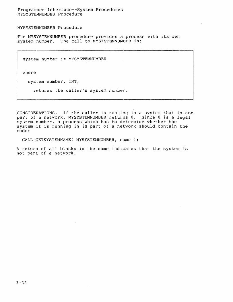
The MYSYSTEMNUMBER procedure provides a process with its own system number. The call to MYSYSTEMNUMBER is:
-------------------------------------.----------------------------system number := MYSYSTEMNUMBER
where
system number, INT,
returns the caller's system number.
CONSIDERATIONS. If the caller is running in a system that is not part of a network, MYSYSTEMNUMBER returns O. Since 0 is a legal system number, a process which has to determine whether the system it is running in is part of a network should contain the code:
CALL GETSYSTEMNAME( MYSYSTEMNUMBER, name );
A return of all blanks in the name indicates that the system is not part of a network.
]-32
Programmer Interface--System Procedures PROCESS INFO Procedure
PROCESS INFO Procedure
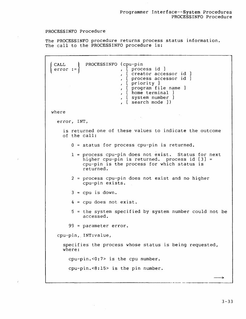
The PROCESSINFO procedure returns process status information. The call to the PROCESSINFO procedure is:
{ CALL : = }
PROCESS INFO (cpu-pin error , [ process id ]
, [ creator accessor id ] , [ process accessor id ] , [ priority ] , [ program file name , [ home terminal ] , [ system number ] , [ search mode ] )
where
error, INT,
is returned one of these values to indicate the outcome of the call:
o = status for process cpu-pin is returned.
1 = process cpu-pin does not exist. Status for next higher cpu-pin is returned. process id [3] = cpu-pin is the process for which status is returned.
2 process cpu-pin does not exist and no higher cpu-pin exists.
3 cpu is down.
4 = cpu does not exist.
5 = the system specified by system number could not be accessed.
99 = parameter error.
cpu-pin, INT:value,
specifies the process whose status is being requested, where:
cpu-pin.<O:7> 1S the cpu number.
cpu-pin.<8:15> is the pin number.
3-33
Programmer Interface--System Procedures PROCESSINFO Procedure
3-34
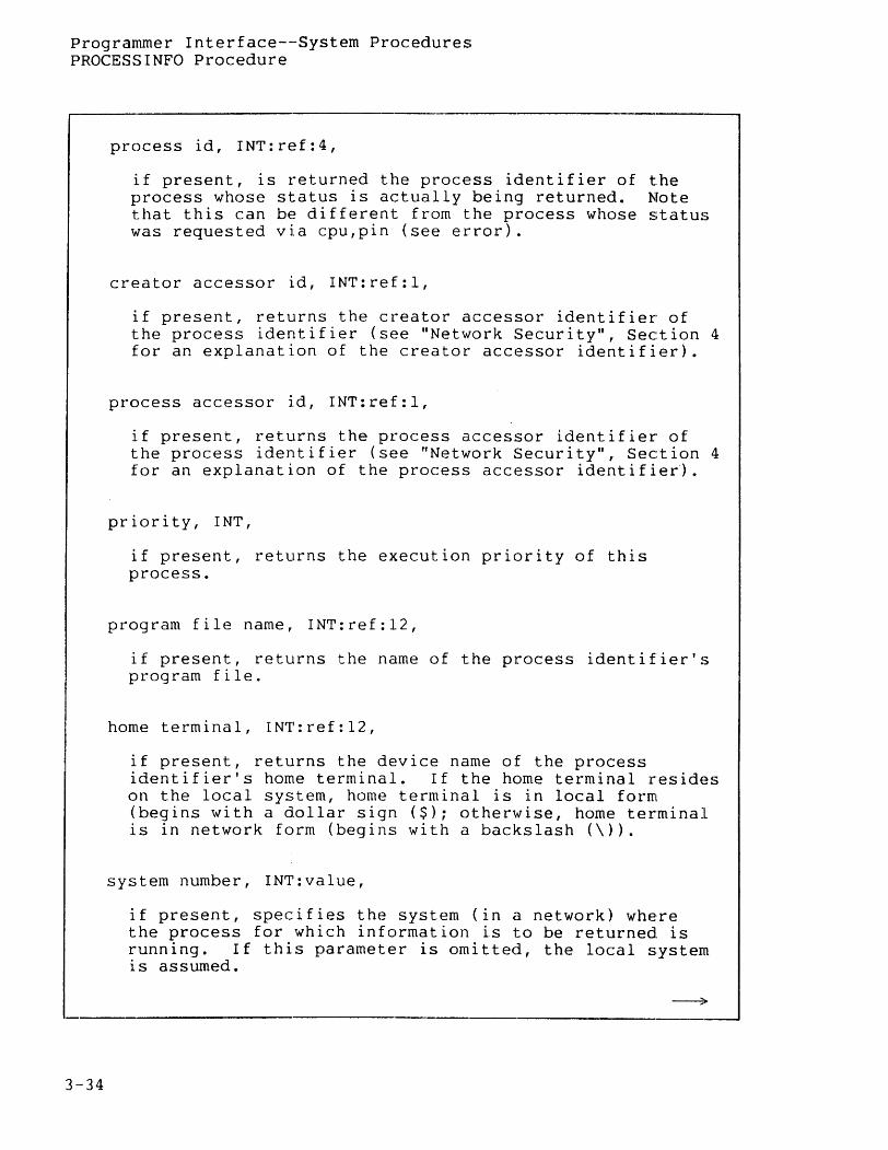
process id, INT:ref:4,
if present, is returned the process identifier of the process whose status is actually being returned. Note that this can be different from the process whose status was requested via cpu,pin (see error).
creator accessor id, INT:ref:l,
if present, returns the creator accessor identifier of the process identifier (see "Network Security", Section 4 for an explanation of the creator accessor identifier).
process accessor id, INT:ref:l,
if present, returns the process accessor identifier of the process identifier (see "Network Security", Section 4 for an explanation of the process accessor identifier).
priority, INT,
if present, returns the execution priority of this process.
program file name, INT:ref:12,
if present, returns the name of the process identifier's program file.
home terminal, INT:ref:12,
if present, returns the device name of the process identifier's home terminal. If the home terminal resides on the local system, home terminal is in local form (begins with a dollar sign ($); otherwise, home terminal is in network form (begins with a backslash (\)).
system number, INT:value,
if present, specifies the system (in a network) where the process for which information is to be returned is running. If this parameter is omitted, the local system is assumed.

Programmer Interface--System Procedures PROCESS INFO Procedure
search mode, INT:value,
if present, is a bit mask that specifies one or more "search" conditions. If omitted, zero is used.
CONSIDERATIONS. On the call, the parameters to PROCESSINFO contain the value(s) for the search condition(s) and the bit fields in search mode specify the conditions being searched for (1 = condition must be met; 0 = don't care):
search mode.<O>
search mode.<l>
search mode.<2>
indicates that the searched process must match process identifier for three words.
indicates tha~ the searched process must match the creator accessor identifier.
indicates that the searched process must match the process accessor identifier.
search mode.<3> indicates that the searched process must be equal to or less than priority.
search mode.<4>
search mode.<5>
indicates that the searched process must match program file name.
indicates that the searched process must match home terminal.
If multiple search conditions are specified, then all must be met.
If the system number specifies a remote system, the process identifier is returned in network form; otherwise, the process identifier is returned in local form.
If the process's home terminal is remote, home terminal is returned in network form; if the home terminal is local, home terminal is in local form.
3-35
Programmer Interface--Systern Procedures PROCESS INFO Procedure
EXAMPLE:
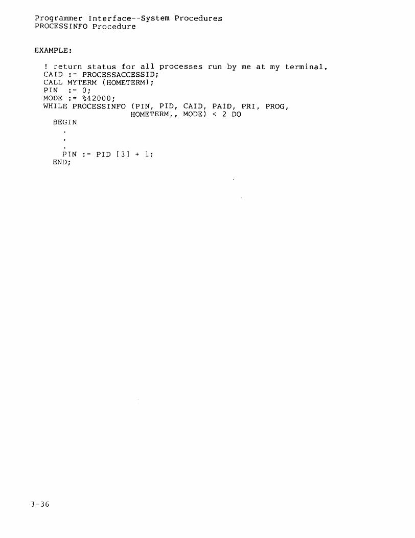
! return status for all processes run by me at my terminal. CAID := PROCESSACCESSID; CALL MYTERM (HOMETERM); PIN := 0; MODE := %42000; WHILE PROCESSINFO (PIN, PlD, CAlD, PAID, PRl, PROG,
HOMETERM" MODE) < 2 DO
3-36
BEGIN
PIN .- PlD [3] + 1; END;
Programmer Interface--System Procedures REMOTEPROCESSORSTATUS Procedure
REMOTEPROCESSORSTATUS Procedure
The REMOTEPROCESSORSTATUS procedure supplies the status of processor modules in a particular system in a network. The call to REMOTEPROCESSORSTATUS is:
status := REMOTEPROCESSORSTATUS ( system number)
where
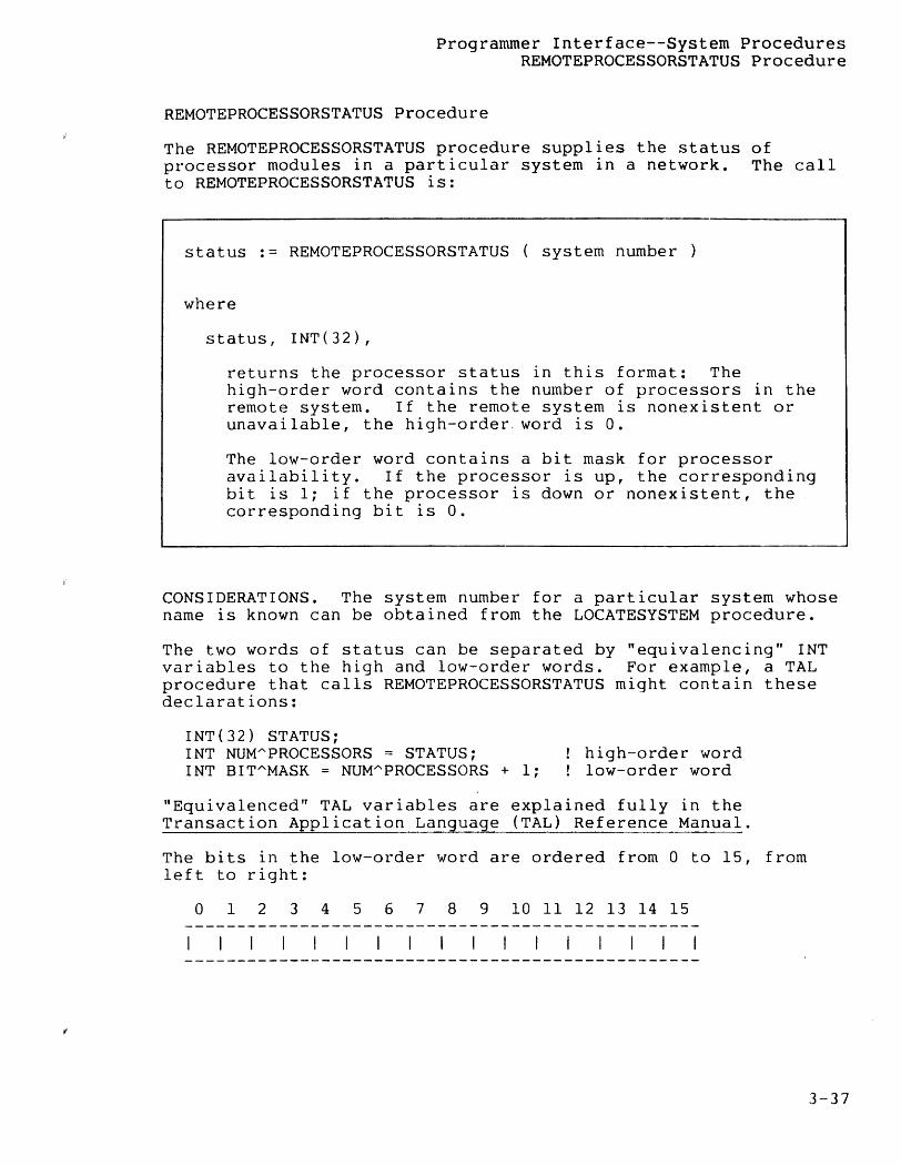
status, INT(32),
returns the processor status in this format: The high-order word contains the number of processors in the remote system. If the remote system is nonexistent or unavailable, the high-order. word is O.
The low-order word contains a bit mask for processor availability. If the processor is up, the corresponding bit is 1; if the processor is down or nonexistent, the corresponding bit is o.
CONSIDERATIONS. The system number for a particular system whose name is known can be obtained from the LOCATESYSTEM procedure.
The two words of status can be separated by "equivalencing" INT variables to the high and low-order words. For example, a TAL procedure that calls REMOTEPROCESSORSTATUS might contain these declarations:
INT(32) STATUS; INT NUMAPROCESSORS = STATUS; INT BITAMASK = NUMAPROCESSORS + 1;
! high-order word ! low-order word
"Equivalenced" TAL variables are explained fully in the Transaction Application Language (TAL) Reference Manual.
The bits in the low-order word are ordered from 0 to 15, from left to right:
o 1 2 3 4 5 6 7 8 9 10 11 12 13 14 15
3-37

Programmer Interface--System Procedures REMOTEPROCESSORSTATUS Procedure
REMOTEPROCESSORSTATUS can also be used to obtain the status of local processors, as shown here:
INT(32) MYAPROCESSORASTATUSi MYAPROCESSORASTATUS := REMOTEPROCESSORSTATUS (MYSYSTEMNUMBER)i
3-38
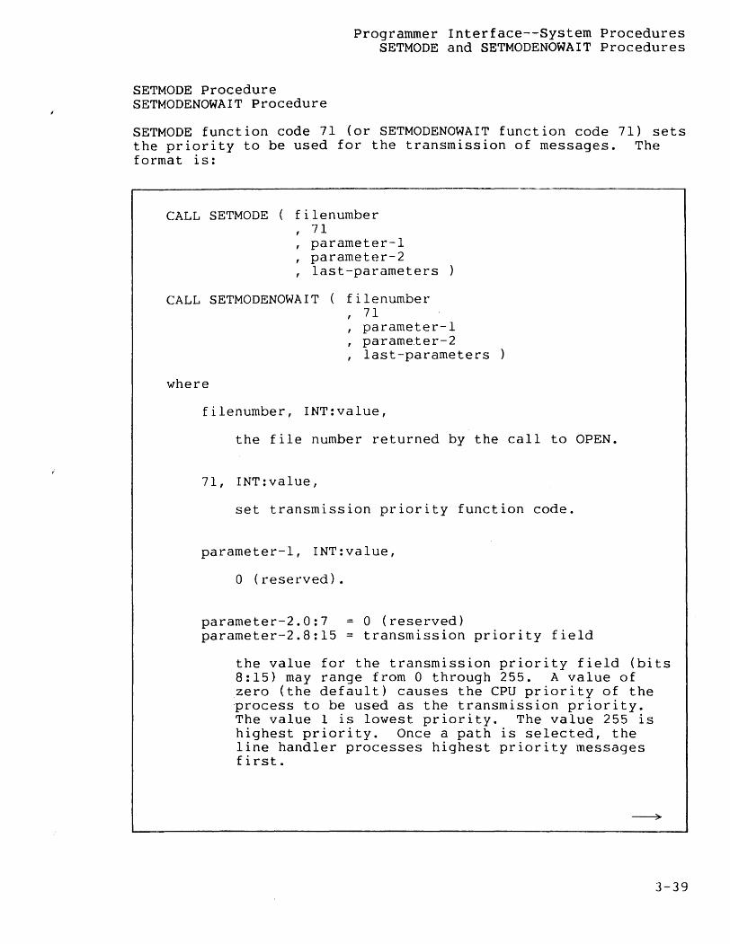
Programmer Interface--System Procedures SETMODE and SETMODENOWAIT Procedures
SETMODE Procedure SETMODENOWAIT Procedure
SETMODE function code 71 (or SETMODENOWAIT function code 71) sets the priority to be used for the transmission of messages. The format is:
CALL SETMODE ( filenumber 71
, parameter-1 , parameter-2 , last-parameters
CALL SETMODENOWAIT ( filenumber
where
71 , parameter-l , parame.ter-2 , last-parameters
filenumber, INT:value,
the file number returned by the call to OPEN.
7 I, I NT : val u e ,
set transmission priority function code.
parameter-I, INT:value,
o (reserved).
parameter-2.O:7 parameter-2.8:15
= 0 (reserved) = transmission priority field
the value for the transmission priority field (bits 8:15) may range from 0 through 255. A value of zero (the default) causes the CPU priority of the process to be used as the transmission priority. The value 1 is lowest priority. The value 255 is highest priority. Once a path is selected, the line handler processes highest priority messages first.
3-39
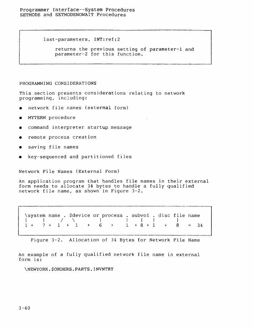
Programmer Interface--System Procedures SETMODE and SETMODENOWAIT Procedures
last-parameters, INT:ref:2
returns the previous setting of parameter-l and parameter-2 for this function.
PROGRAMMING CONSIDERATIONS
This section presents considerations relating to network programming, including:
• network file names (external form)
• MY1'ERM procedure
• command interpreter startup message
• remote process creation
• saving file names
• key-sequenced and partitioned files
Network File Names (External Form)
An application program that handles file names in their external form needs to allocate 34 bytes to handle a fully qualified network file name, as shown in Figure 3-2.
-------------------------------------\system name . $device or process . subvol . I I / \ I I I I 1 + 7 + 1 + 1 + 6 + 1 + 8 -I- 1
disc file name I
+ 8 = 34
Figure 3-2. Allocation of 34 Bytes for Network File Name
An example of a fully qualified network file name in external form is:
\NEWYORK.$ORDERS.PARTS.INVNTRY
3-40
Programmer Interface--Considerations MYTERM Procedure--Network Considerations
MYTERM Procedure--Network Considerations
If the home terminal is local, MYTERM returns the name of the horne terminal in local form: otherwise, MYTERM returns the name of the horne terminal in network form.
Unlike the command interpreter startup message's IN and OUT files, the name returned by MYTERM is not affected by any SYSTEM command which the user may have issued. Therefore the command:
:SYSTEM \SF
has no effect Of1 MYTERM: if the home terminal is local, the horne terminal name is in local form. However, this command would cause in IN and OUT files, even if they were local, to be passed to a process in network form.
Command Interpreter Startup Message
The first task performed by an application process is to open its $RECEIVE file and read the command interpreter startup message. This message supplies the application process with the ~ames of its IN file, its OUT file, and the current defaults. (The startup message is described in your GUARDIAN programming manuals in the discussion of the command interpreter.)
IN AND OUT FILES. The names of the IN and OUT files are passed in local or network form, depending on whether each file is local or remote.
There is one exception to this rule: the name of a local file is passed in network form if the local system was explicitly specified (via the SYSTEM command) as the default system, and the file name was expanded using the default system. For example, suppose that the local system is \BUFFALO, and that these commands are issued:
:SYSTEM \BUFFALO :RUN MYPROG lIN MYFILE/
Any SYSTEM system name command causes the command interpreter to expand all partial file names using the default system. Therefore, MYFILE is expanded by the command interpreter using the default system \BUFFALO, and the IN file passed to MYPROG is in network form.
An application process can either ignore or consider the physical location of its IN and OUT files. If the physical location of a file is not important, the process simply passes the file name to the OPEN procedure: if the physical location of the file is important, the process checks whether the first byte of the file name is a dollar sign or backslash ($ or \) and acts accordingly.
3-41
Programmer Interface--Considerations Command Interpreter Startup Message
DEFAULTS. The name of the default system, if one has been explicitly defined, is passed as part of the default volume name. For example, following the command interpreter commands:
:VOLUME $VOL.SUBVOL :SYSTEM \LONDON
assuming that \LONDON corresponds to system number 2, words [1:8] of the startup message sent to any process created by thE~ command interpreter contain
\<2>VOL SUBVOL
where <2> denotes octal (not ASCII) 2 In the second byte.
The default system is included in the default volume name only if a system has been explicitly specified via a SYSTEM system name command. The command
: SYSTEM
causes the default names to be passed In local form, as does the complete absence of a SYSTEM command.
Observe that the command:
:SYSTEM \BUFFALO
causes the default names to be passed in network form regardless of whether \BUFFALO is the local system.
Remote Process Creation
A process is created in a remote system the same way one is created in the local system: by passing the program file name to the NEWPROCESS procedure. There is one basic rule: a process's program file must reside on the system in which the process is to run.
If you want to create a remote process in a system that does not possess a copy of the program file, you must copy the program file to the remote system.
Assuming that the app~opriate program file resides on the remote system, creating the remote process is accomplished by passing the program file name to the NEWPROCESS procedure. For example, this code runs TAL as an unnamed process on system \DETROIT, in CPU 2 at priority 140:
3-42
Programmer Interface--Considerations Remote Process Creation
STRING .PROCANAME[0:27] := ["\OETROIT.$SYSTEM.SYSTEM.TAL", 0]; INT .PROGRAMAFILE[0:11],
.PID, PRI := 140, CPU := 2, ERROR;
CALL FNAMEEXPAND (PROCANAME, PROGRAMAFILE, DEFAULTS): CALL NEWPROCESS (PROGRAMAFILE, PRI, , CPU, PIO, ERROR); IF ERROR THEN ...
CPU DEFAULTING. The CPU parameter of NEWPROCESS lets you specify the processor in which the new process is to run. Any remote processor can be used for process creation.
If the CPU parameter is not specified, the new process runs in a processor selected from among those processors specified at SYSGEN time as being available to the network.
SENDING THE STARTUP MESSAGE. After a process is created, it must be sent a startup message. When formatting the startup message, the creator must take care to convert the IN and OUT file names and the default names to network form, so the new process can reference its files correctly.
EXAMPLES:
Suppose that the creator wishes to designate itself as the new process's IN file. The creator could contain this code:
! first, get my process ID CALL GETCRTPID (MYPID, MYPROCESSID): ! convert to network form CALL CONVERTPROCESSNAME (MYPROCESSID); ! move into startup message STARTUpAMSG[9] ':=' MYPROCESSID FOR 4;
Note that if the creator is running as a named process, then CONVERTPROCESSNAME transforms the local name into network form. If the creator is running as an unnamed process, then its CRTPID already specifies the system number (in the second byte) and CONVERTPROCESSNAME leaves the CRTPID unaltered.
The code in the next example could be used to specify the creator's own OUT file as the new process's OUT file. Assume that OUTFILE contains the creator's OUT file name as obtained from its startup message.
3-43
Programmer Interface--Considerations Remote Process Creation
STRING .OUTFILES := @OUTFILE '«' 1;
IF OUTFILES = "$" THEN! change it to network form, ! using my system number
BEGIN OUTF I LES [ 7] '=:' OUTF I LES [ 6] FOR 7; OUTFILE := "\" '«' 8 + MYSYSTEMNUMBER; END;
If the first byte of OUTFILE contained a backs lash (\) character (indicating a network file name), or neither a dollar sign ($) nor a backslash (indicating the CRTPID of an unnamed process), then OUTFILE would be left unchanged.
Similar code could ensure that the default names are passed correctly.
Other cases--for example, the new process's OUT file being specified as a process in some other system--must be handled on an individual basis. Keep in mind that the new process will assume that file names in local form are local files. If this would cause incorrect results, then the creator must modify the startup message before sending it.
Saving File Names
Programs that save network file names should save the file names in external form. File names in external form should be converted to internal form immediately before opening the file. The reason is that conversion from system name to system number depends on the current state of the communication path to the remote system: if the path is down, the system name is converted to system number 255, an illegal value that causes OPEN to fail.
Alternate-Key and Partitioned Files
An alternate-key file can be made to reside on a different system than the primary file by listing the alternate-key file's location in network form in the alternate key params array when the primary file is c~eated, and passing the file name in network form to the CREATE procedure to create the alternate-key file. Passing a local file name to CREATE causes an alternate-key file to be created on the same system as the primary file, not on the default system.
3-44
Programmer Interface--Considerations Alternate-Key and Partitioned Files
Any file, including an alternate-key file, can be partitioned across system boundaries. To create a partitioned file having partitions on different systems, follow the same procedure used to create a partitioned file, as described in the ENSCRIBE Programming Manual. The partition params array is used in the same way. However, instead of supplying the $volume on which a partition is to reside, you must supply
\system number volume name
where the "$" is omitted from the volume name. Supplying a $volume name without a system number causes the partition to be created on the same system as the primary partition, not on the default system.
3-45

SECTION 4
NETWORK MANAGEMENT
This section presents information relevant to the management of a network. Topics included are:
• best-path determination
• enhanced routing
• Network Monitor (NETMON) utility program
• network security
• items to consider when using SYSGEN, CUP, PUP, CMI, and XRAY
BEST-PATH DETERMINATION
Intersystem messages are always sent via the best path between the two systems. The determination of the "best" path is made by assigning time factors based on line speed to the communication lines, and computing the sum of the time factors along each possible path.
The multi-line facility allows all lines in a path to be used simultaneously. The effective bandwidth will be the sum of the bandwidths of all lines in the path: that is, multiple packet messages are distributed over multiple lines.
If a line fails, the NCP updates its NETMAPS to reflect the decrease in path bandwidth. Reactivation of the line updates the NETMAPS to reflect the increase in bandwidth. If a controller fails, the NCP updates its NETMAPS to reflect the decrease in bandwidth for all lines connected to the failed controller.
4-1
Network Management--Best-Path Determination
Each line has a configured line time factor (SYSGEN LINESPEED), as shown in Table 4-1. The line handlers for the neighbor paths establish the time factor value during path initialization and whenever a line failure or activation occurs. For routing purposes, the neighbor NCPs agree to use the slower line speed (larger value). The following equation shows how the time factor for a multi-line path is determined:
path TF = TF conversion factor
TF conv fact TF conv fact TF conv fact ------------- + ------------- + ••• + ---------------
linel TF line2 TF
For example, the time factor for a multi~line path consisting of three lines with each line's speed configured for 4800 bps (bits per second) and time factor of 47 is:
path TF = 224000
224000 224000 224000 -------- + -------- + --------
47 47 47
= 224000
4765 + 4765 + 4765
= 224000 15.7 = 16
14295
This results in converting the time factors to line speeds, adding the line speeds together to get a path speed, and then dividing the time factor conversion factor by the path speed to get the path time factor (number of seconds required to transmit 224000 bits).
4-2
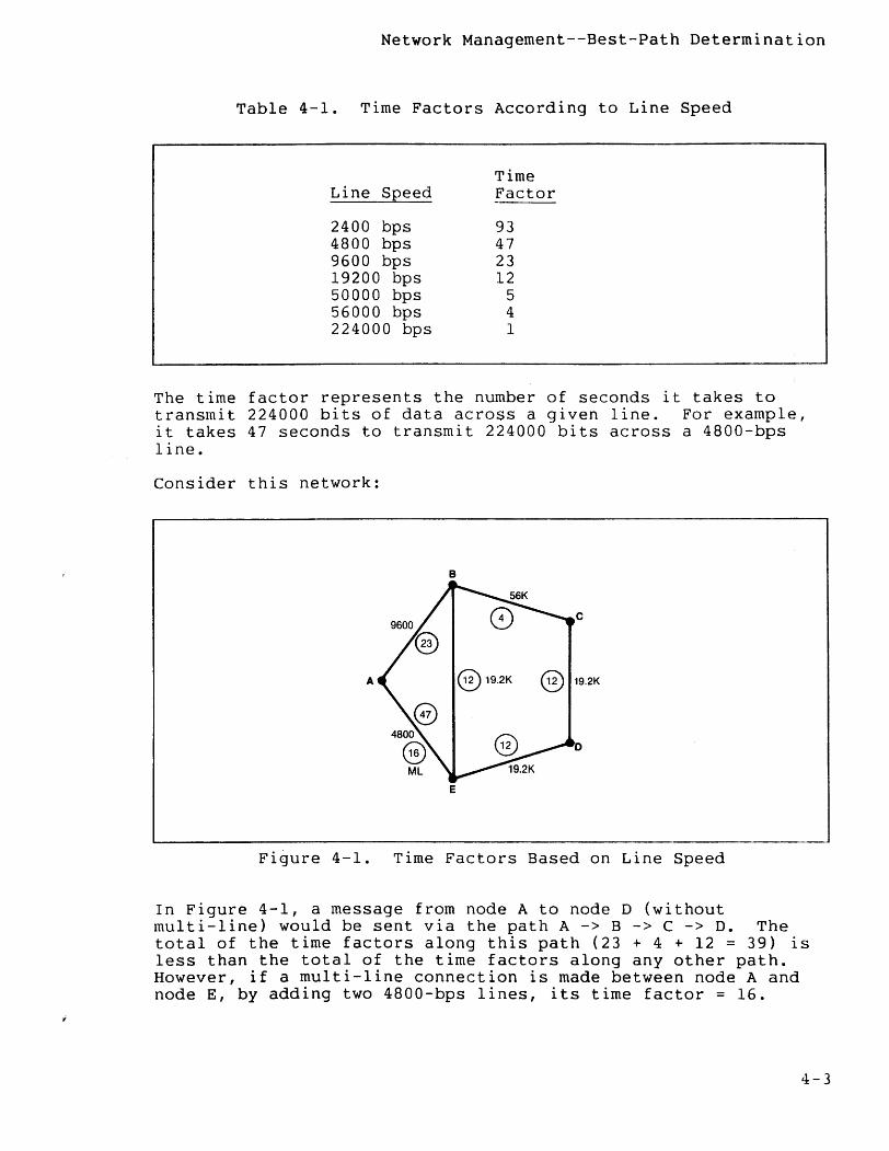
Network Management--Best-Path Determination
Table 4-1. Time Factors According to Line Speed
Line Speed
2400 bps 4800 bps 9600 bps 19200 bps 50000 bps 56000 bps 224000 bps
Time Factor
93 47 23 12
5 4 1
The time factor represents the number of seconds it takes to transmit 224000 bits of data across a given line. For example, it takes 47 seconds to transmit 224000 bits across a 4800-bps line.
Consider this network:
B
c
A @19.2K @ 19.2K
o
E
Figure 4-1. Time Factors Based on Line Speed
In Figure 4-1, a message from node A to node D {without multi-line} would be sent via the path A -> B -> C -> D. The total of the time factors along this path {23 + 4 + 12 = 39} is less than the total of the time factors along any other path. However, if a multi-line connection is made between node A and node E, by adding two 4800-bps lines, its time factor = 16.
4-3
Network Management--Best-path Determination
Thus, with multi-line, a message from node A to node D takes the path A -> E -> D. The total time factor along this path is (16 + 12 = 28).
Each line's time factor is specified via SYSGEN. It is not necessary to use the values given in the table. If you want to force message traffic to travel over a slow path (for whatever reason), you can configure a small time factor for the line.
For the best-path routing scheme to work, each node must know about the current status of the network. The Network Control Process in each node maintains routing tables that enable messages to be routed correctly. Changes in the status of the network are propagated throughout the network by the exchange of messages between the NCPs in neighboring systems.
Suppose, in the example above, that the communication line between Band C fails:
System C informs D of the failure; then D informs E, and E informs A and B.
Meanwhile, B informs A and E, A informs E, and E informs A and D.
Each system updates its routing tables as it becomes aware of the change in network status, allowing all message traffic to be routed correctly. The same scheme of informing one's neighbor is used when a communication line becomes available or a new system is added to the network.
In the case of multi-line, the general network routing procedure remains the same with one exception. A line ready or not ready condition causes an update to the NETMAPS to reflect the change in the path time factor; however, a line down does not necessarily mean that the path is down (time factor of infinity). In fact, the new best path may indeed be the same as the original path.
The method of informing all nodes about routing changes is implemented in such a way that no system ever becomes confused about where to send a message; packets are always routed correctly regardless of any sequence of catastprophes.
4-4
Network Management--Enhanced Routing
ENHANCED ROUTING
EXPAND enhanced routing permits the network user to declare a transmission priority that is used in combination with the best available transmission path for optimal transfer of data over the best-path route selected.
Path Selection
The transmission modifiers LINESPEED and TRANS DELAY are available for defining EXPAND lines during system generation (SYSGEN):
LINESPEED. The LINESPEED modifier replaces the RSIZE modifier (RSIZE continues to be required--specification of LINESPEED overrides the RSIZE declaration). The value specified in the LINESPEED modifier sets the bandwidth (baud rate) of the communication line.
TRANSDELAY. The TRANSDELAY modifier set the amount of delay time expected during message transmission.
Transmission Priority
You specify a file's transmission priority by issuing a SETMODE file management request (see Section 3, System Procedures). EXPAND attempts to provide this priority by queuing the messages for transmission in the appropriate sequence.
The line handler uses the transmission priority to determine the ordering of messages for transmission on a path. That is, the line handler selects the highest priority message to present for transmission.
Transport Media
Each network node contains a Network Control Program (NCP) which exchanges information with each neighbor node regarding available routing alternatives.
Once you define (through SYSGEN) the bandwidth, the transmission delay, and the logical path grouping of lines (see the System Management Manual), the NCP reduces this data into a Network Routing Table (NRT) that resides in each processor at the node. For each destination system in the network, the NRT contains the logical device number (LDEV) of the "best-path" line handler based on bandwidth.
The GUARDIAN operating system uses the NRT to select the appropriate LDEV for message transmission to other nodes.
4-5

Network Management--Enhanced Routing
The line handler uses the transmission size--the message size at a given bandwidth (LINESPEED)--together with the amount of delay before the message can be dispatched (the amount of previously queued data at a given bandwidth), and the transmission delay (TRANSDELAY) value to select the best line for data transmission within a multi-line path.
4-6
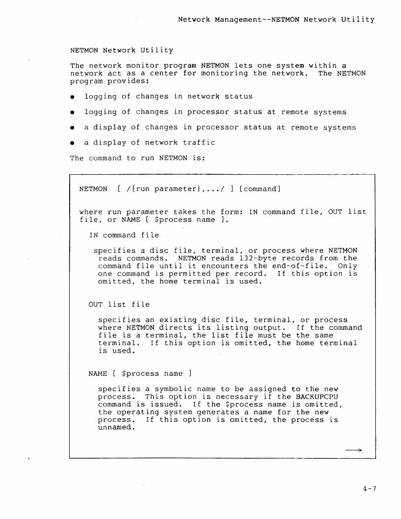
Network Management--NETMON Network Utility
NETMON Network Utility
The network monitor program NETMON lets one system within a network act as a center for monitoring the network. The NETMON program provides:
• logging of changes in network status
• logging of changes in processor status at remote systems
• a display of changes in processor status at remote systems
• a display of network traffic
The command to run NETMON is:
NETMON [/{run parameter}, ... 1 .] [command]
where run parameter takes the form: IN command file, OUT list file, or NAME [ $process name ].
IN command file
specifies a disc file, terminal, or process where NETMON reads commands. NETMON re~ds 132-byte records from the command file until it encounters the end-of-file. Only one command is permitted per record. If this option is omitted, the home terminal is used.
OUT list file
specifies an existing disc file, terminal, or process where NETMON directs its listing output. If the command file is a terminal, the list file must be the same terminal. If this option is omitted, the home terminal is used.
NAME [ $process name ]
specifies a symbolic name to be assigned to the new process. This option is necessary if the BACKUPCPU command is issued. If the $process name is omitted, the operating system generates a name for the new process. If this option is omitted, the process is unnamed.
4-7
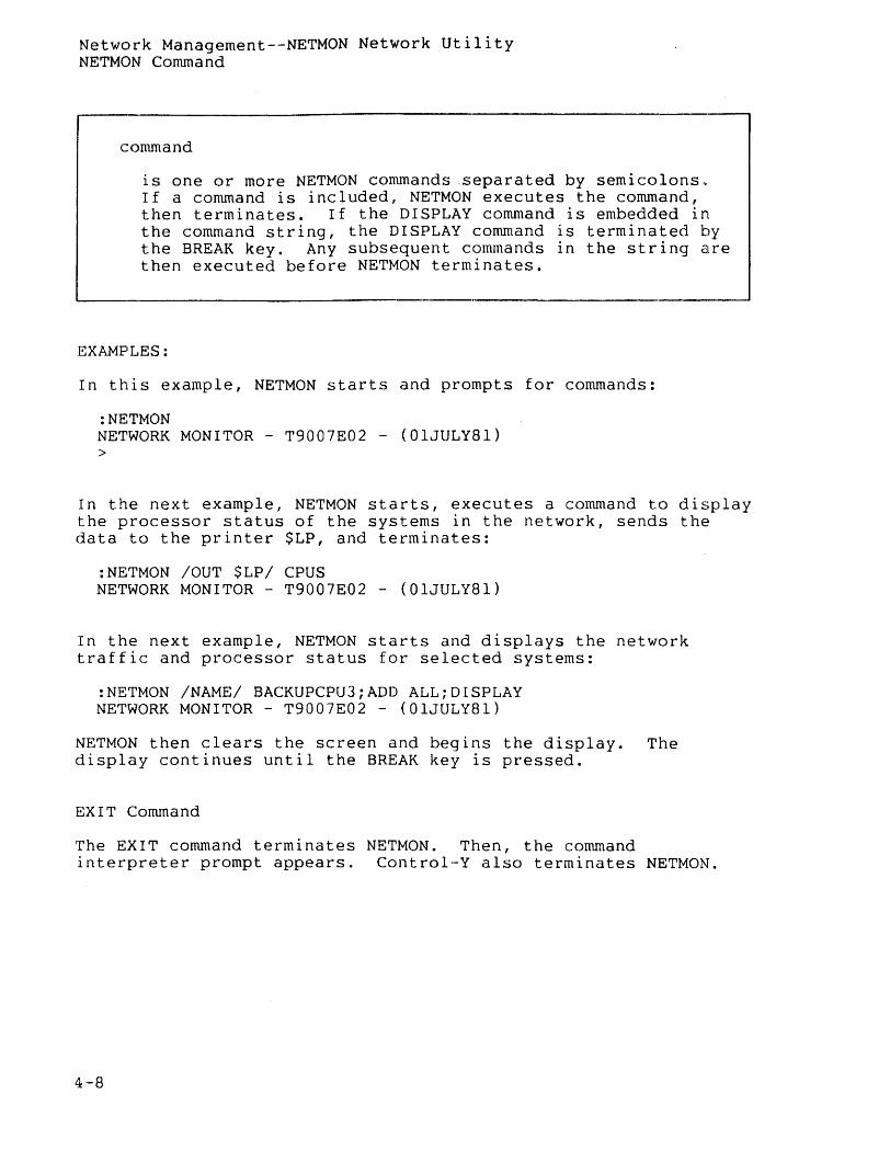
Network Managernent--NETMON Network Utility NETMON Command
command
is one or more NETMON commands .separated by semicolons~ If a command is included, NETMON executes the command, then terminates. If the DISPLAY command is embedded in the command string, the DISPLAY command is terminated by the BREAK key. Any subsequent commands in the string are then executed before NETMON terminates.
EXAMPLES:
In this example, NETMON starts and prompts for commands:
:NETMON NETWORK MONITOR - T9007E02 - (OlJULY81) >
In the next example, NETMON starts, executes a command to display the processor status of the systems in the network, sends the data to the printer $LP, and terminates:
:NETMON lOUT $LP/ CPUS NETWORK MONITOR - T9007E02 - (OlJULY8l)
In the next example, NETMON starts and displays the network traffic and processor status for selected systems:
:NETMON /NAME/ BACKUPCPU3;ADD ALL;DISPLAY NETWORK MONITOR - T9007E02 - (OlJULY81)
NETMON then clears the screen and begins the display. The display continues until the BREAK key is pressed~
EXIT Command
The EXIT command terminates NETMON. Then, the command interpreter prompt appears. Control-Y also terminates NETMON.
4-8
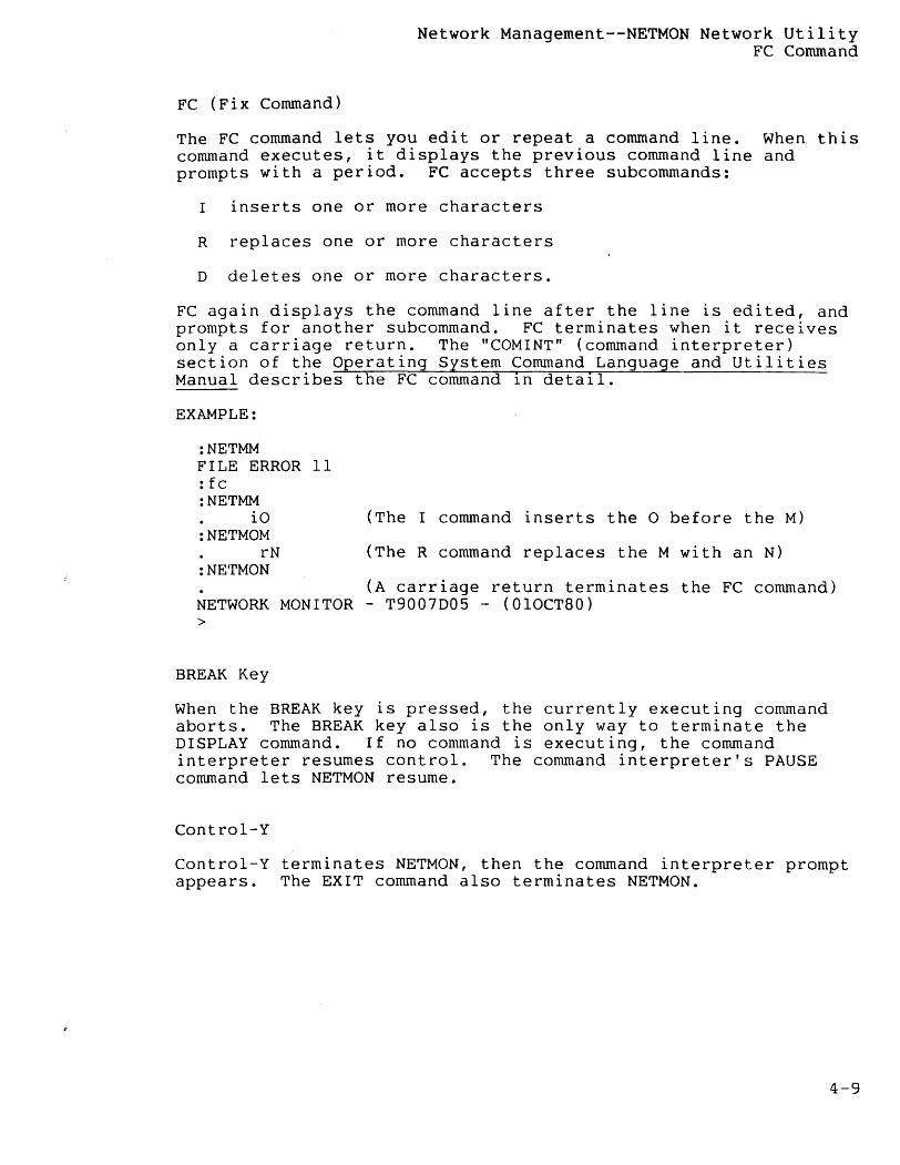
Network Management--NETMON Network Utility FC Command
FC (Fix Command)
The FC command lets you edit or repeat a command line. When this command executes, it displays the previous command line and prompts with a period. FC accepts three subcommands:
I inserts one or more characters
R replaces one or more characters
D deletes one or more characters.
FC again displays the command line after the line is edited, and prompts for another subcommand. FC terminates when it receives only a carriage return. The "COMINT" (command interpreter) section of the Operating System Command Language and Utilities Manual describes the FC command in detail.
EXAMPLE:
:NETMM FILE ERROR 11 :fc :NETMM
iO :NETMOM
rN :NETMON
(The I command inserts the 0 before the M)
(The R command replaces the M with an N)
(A carriage return terminates the FC command) NETWORK MONITOR - T9007D05 - (OlOCT80) >
BREAK Key
When the BREAK key is pressed, the currently executing command aborts. The BREAK key also is the only way to terminate the DISPLAY command. If no command is executing, the command interpreter resumes control. The command interpreter's PAUSE command lets NETMON resume.
Control-Y
Control-Y terminates NETMON, then the command interpreter prompt appears. The EXIT command also terminates NETMON.
4-9
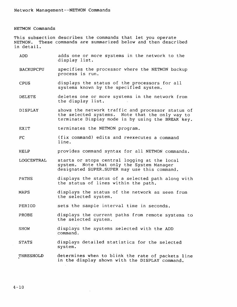
Network Management--NETMON Commands
NETMON Commands
This subsection describes the conunands that let you operatE~ NETMON. These conunands are sununarized below and then described in detail.
ADD
BACKUPCPU
CPUS
DELETE
DISPLAY
EXIT
FC
HELP
LOGCENTRAL
PATHS
MAPS
PERIOD
PROBE
SHOW
STATS
THRESHOLD 'I.
4-10
adds one or more systems in the network to the display list.
specifies the processor where the NETMON backup process is run.
displays the status of the processors for all systems known by the specified system.
deletes one or more systems in the network from the display list.
shows the network traffic and processor status of the selected systems. Note that the only way to terminate Display mode is by using the BREAK key.
terminates the NETMON program.
(fix conunand) edits and reexecutes a conunand line.
provides command syntax for all NETMON commands.
starts or stops central logging at the local system. Note that only the System Manager designated SUPER. SUPER may use this command.
displays the status of a selected path along with the status of lines within the path.
displays the status of the network as seen from the selected system.
sets the sample interval time in seconds.
displays the current paths from remote systems to the selected system.
displays the systems selected with the ADD commandQ
displays detailed statistics for the selected system.
determines when to blink the rate of packets line in the display shown with the DISPLAY command.
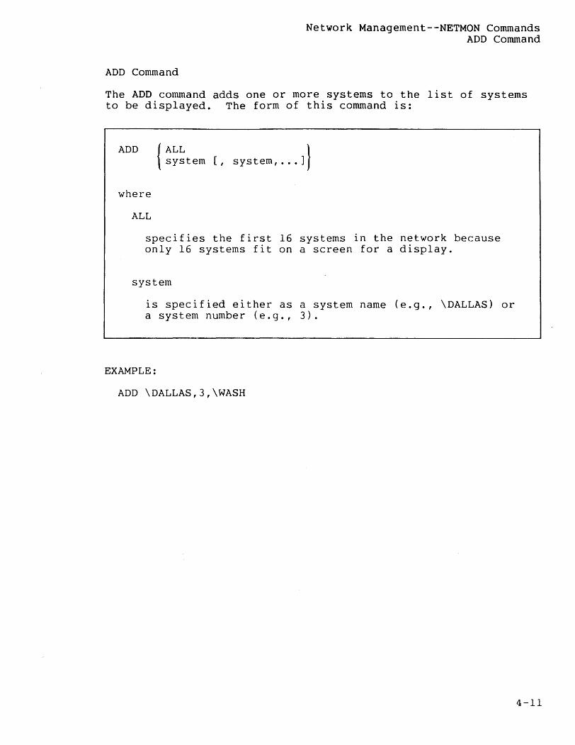
Network Management--NETMON Commands ADD Command
ADD Command
The ADD command adds one or more systems to the list of systems to be displayed. The form of this command is:
ADD {
ALL } system [, system, ... ]
where
ALL
specifies the first 16 systems in the network because only 16 systems fit on a screen for a display.
system
is specified either as a system name (e.g., \DALLAS) or a system number (e.g., 3).
EXAMPLE:
ADD \OALLAS,3,\WASH
4-11
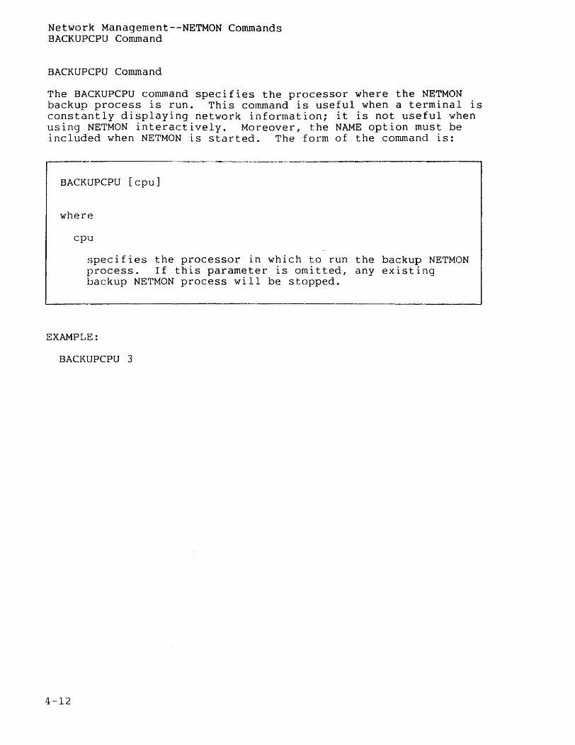
Network Management--NETMON Commands BACKUPCPU Command
BACKUPCPU Command
The BACKUPCPU command specifies the processor where the NETMON backup process is run. This command is useful when a terminal is constantly displaying network information; it is not useful when using NETMON interactively. Moreover, the NAME option must be included when NETMON is started. The form of the command is:
•• _______ "'" __ .. _, ________ 0 _____ '
BACKUPCPU [cpu]
where
cpu
specifies the processor in which to run the backup NETMON process. If this parameter is omitted, any existing backup NETMON process will be stopped.
EXAMPLE:
BACKUPCPU 3
4-12
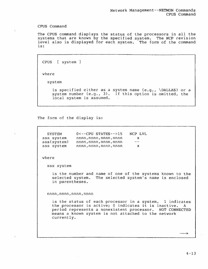
Network Management--NETMON Commands CPUS Command
CPUS Command
The CPUS command displays the status of the processors in all the systems that are known by the specified system. The NCP revision level also is displayed for each system. The form of the command is:
CPUS [system]
where
system
is specified either as a system name (e.g., \DALLAS) or a system number (e.g., 3). If this option is omitted, the local system is assumed.
The form of the display is:
SYSTEM sss system sss(system) sss system
where
sss system
O<--CPU STATES-->l5 nnnn,nnnn,nnnn,nnnn nnnn,nnnn,nnnn,nnnn nnnn,nnnn,nnnn,nnnn
NCP LVL x
x
is the number and name of one of the systems known to the selected system. The selected system's name is enclosed in parentheses.
nnnn,nnnn,nnnn,nnnn
is the status of each processor in a system. 1 indicates the processor is active; 0 indicates it is inactive. A period represents a nonexistent processor. NOT CONNECTED means a known system is not attached to the network currently.
4-13
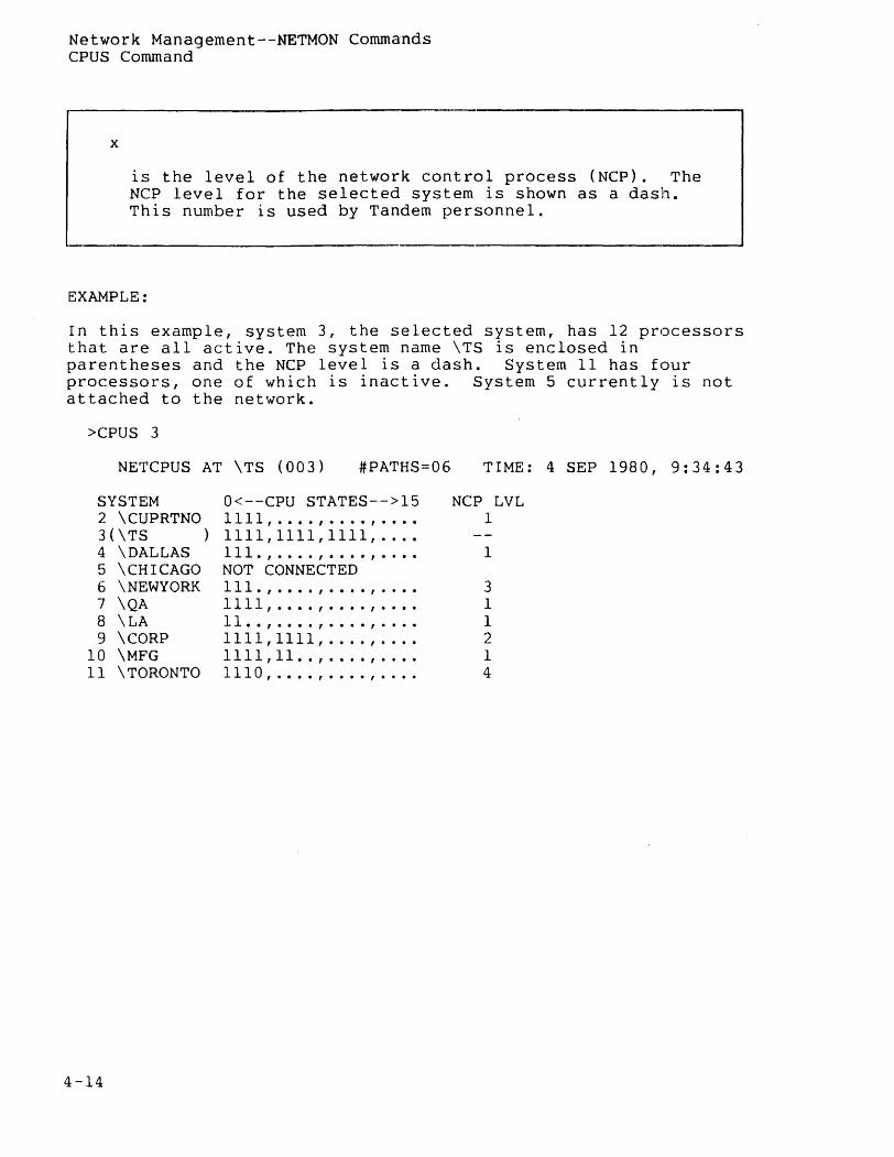
Network Management--NETMON Commands CPUS Command
x
is the level of the network control process (NCP). The NCP level for the selected system is shown as a dash. This number is used by Tandem personnel.
EXAMPLE:
In this example, system 3, the selected system, has 12 processors that are all active. The system name \TS is enclosed in parentheses and the NCP level is a dash. System 11 has four processors, one of which is inactive. System 5 currently is not attached to the network.
>CPUS 3
NETCPUS AT \TS (003) #PATHS=06
SYSTEM O<--CPU STATES-->15 2 \CUPRTNO 1111, .... , .... , ... . 3(\TS ) 1111,1111,1111, ... . 4 \DALLAS Ill., .... , .... , ... . 5 \CHICAGO NOT CONNECTED 6 \NEWYORK Ill., .•.. , .... , ...• 7 \ QA 1111 , . . . . , . . . . , . . . . 8 \ LA 11 . . , . . . . , . . . . , . . . . 9 \CORP 1111,1111, .... , ... .
10 \MFG 1111,11 .. , .... , ... . 11 \TORONTO 1110, .... , .... , ... .
4-14
TIME: 4 SEP 1980, 9:34:43
NCP LVL 1
1
3 1 1 2 1 4

Network Management--NETMON Commands DELETE Command
DELETE Command
The DELETE command removes one or more systems from the list of systems to be displayed. The form of this command is:
DELETE {
ALL } system [ ,system, ... ]
where
ALL
specifies all the systems that are currently selected.
system
is specified either as a system name (e.g., \DALLAS) or a system number (e.g., 3).
EXAMPLE:
DELETE ALL
4-15
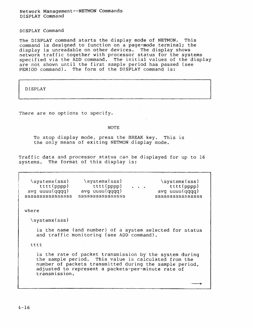
Network Management--NETMON Commands DISPLAY Command
DISPLAY Command
The DISPLAY command starts the display mode of NETMON. This command is designed to function on a page-mode terminal; the display is unreadable on other devices. The display shows network traffic together with processor status for the systems specified via the ADD command. The initial values of the display are not shown until the first sample period has passed (see PERIOD command). The form of the DISPLAY command is:
E,_LAY ________ J There are no options to specify.
NOTE
To stop display mode, press the BREAK key. This IS
the only means of exiting NETMON display mode.
Traffic data and processor status can be displayed for up to 16 systems. The format of this display is:
\systemx(sss) tttt(pppp)
avg uuuu(qqqq)
\systemx(sss) tttt(pppp)
avg uuuu(qqqq)
\systemx(sss) tttt(pppp)
avg uuuu(qqqq) ssssssssssssssss ssssssssssssssss ssssssssssssssss
where
4-16
\systemx(sss)
is the name (and number) of a system selected for status and traffic monitoring (see ADD command).
tttt
is the rate of packet transmission by the system during the sample period. This value is calculated from the number of packets transmitted during the sample period, adjusted to represent a packets-per-minute rate of transmission.
--~
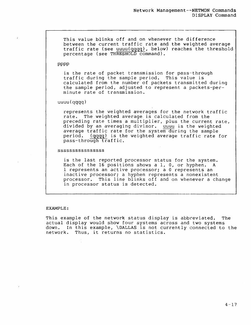
Network Management--NETMON Commands DISPLAY Command
This value blinks off and on whenever the difference between the current traffic rate and the weighted average traffic rate (see uuuu(qqqq), below} reaches the threshold percentage (see THRESHOLD command).
pppp
is the rate of packet transmission for pass-through traffic during the sample period. This value is calculated from the number of packets transmitted during the sample period, adjusted to represent a packets-perminute rate of transmission.
uuuu(qqqq)
represents the weighted averages for the network traffic rate. The weighted average. is calculated from the preceding rate times a multiplier, plus the current rate, divided by an averaging divisor. uuuu is the weighted average traffic rate for the system during the sample period. (qqqq) is the weighted average traffic rate for pass-through traffic.
ssssssssssssssss
is the last reported processor status for the system. Each of the 16 positions shows a 1, 0, or hyphen. A 1 represents an active processor; a ° represents an inactive processor; a hyphen represents a nonexistent processor. This line blinks off and on whenever a change in processor status is detected.
EXAMPLE:
This example of the network status display is abbreviated. The actual display would show four systems across and two systems down. In this example, \DALLAS is not currently connected to the network. Thus, it returns no statistics.
4-17
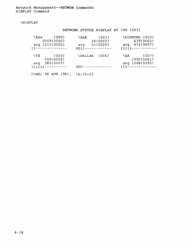
Network Management--NETMON Commands DISPLAY Command
>DISPLAY
NETWORK STATUS DISPLAY AT \TS (003)
4-18
\SAA (OOO) 2049(0000)
avg 1215(0000) 11--------------
\TS (003) 559(0004)
avg 385(0003) 111111----------
\SAB (001) 34(0000)
avg 22(0000) 0011------------
\DALLAS (004)
000-------------
T I ME : 2 8 AP R 1 98 1 , 16 : 3 9 : 2 3
\CUPRTNO (002) 639(0062)
avg 474(0057) 11111-----------
\QA (007) 1990(0661)
avg 1008(0293) 111-------------
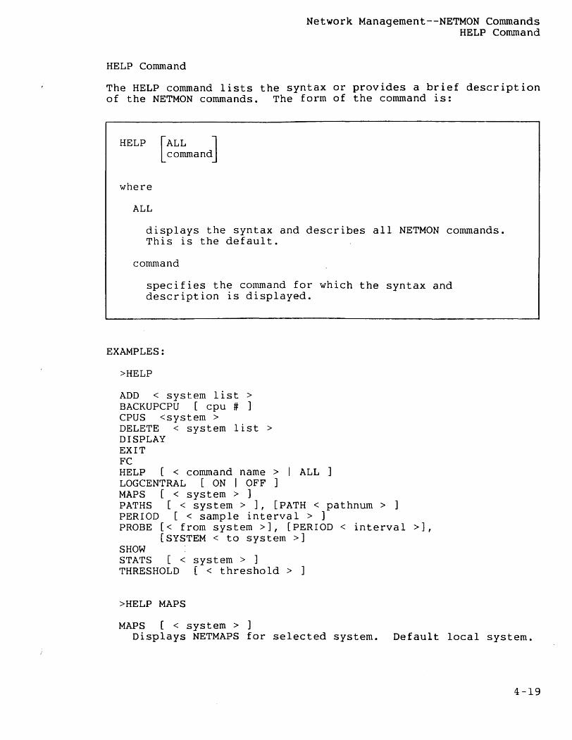
Network Managernent--NETMON Commands HELP Command
HELP Command
The HELP command lists the syntax or provides a brief description of the NETMON commands. The form of the command is:
HELP [
ALL J command
where
ALL
displays the syntax and describes all NETMON commands. This is the default.
command
specifies the command for which the syntax and description is displayed.
EXAMPLES:
>HELP
ADD < system list> BACKUPCPU [cpu # ] CPUS <system > DELETE < system list> DISPLAY EXIT FC HELP [< command name > I ALL ] LOGCENTRAL [ON I OFF ] MAPS [< system > ] PATHS [< system> ], [PATH < pathnum > ] PERIOD [< sample interval > ] PROBE [< from system >], [PERIOD < interval >],
[SYSTEM < to system >] SHOW STATS [< system > ] THRESHOLD [< threshold > ]
>HELP MAPS
MAPS [< system > ] Displays NETMAPS for selected system. Default local system.
4-19
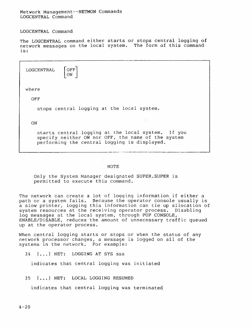
Network Management--NETMON Commands LOGCENTRAL Command
LOGCENTRAL Command
The LOGCENTRAL command either starts or stops central logging of network messages on the local system. The form of this command is:
LOGCENTRAL
where
OFF
ON
stops central logging at the local system.
starts central logging at the local system. If you specify neither ON nor OFF, the name of the system performing the central logging is displayed.
NOTE
Only the System Manager designated SUPER. SUPER is permitted to execute this command.
The network can create a lot of logging information if either a path or a system fails. Because the operator console usually is a slow printer, logging this information can tie up allocation of system resources at the receiving operator process. Disabling log messages at the local system, through PUP CONSOLE, ENABLE/DISABLE, reduces the amount of unnecessary traffic queued up at the operator process.
When central logging starts or stops or when the status of any network processor changes, a message is logged on all of the systems in the network. For example:
34 { ... } NET: LOGGING AT SYS sss
indicates that central logging was initiated
35 { ... } NET: LOCAL LOGGING RESUMED
indicates that central logging was terminated
4-20
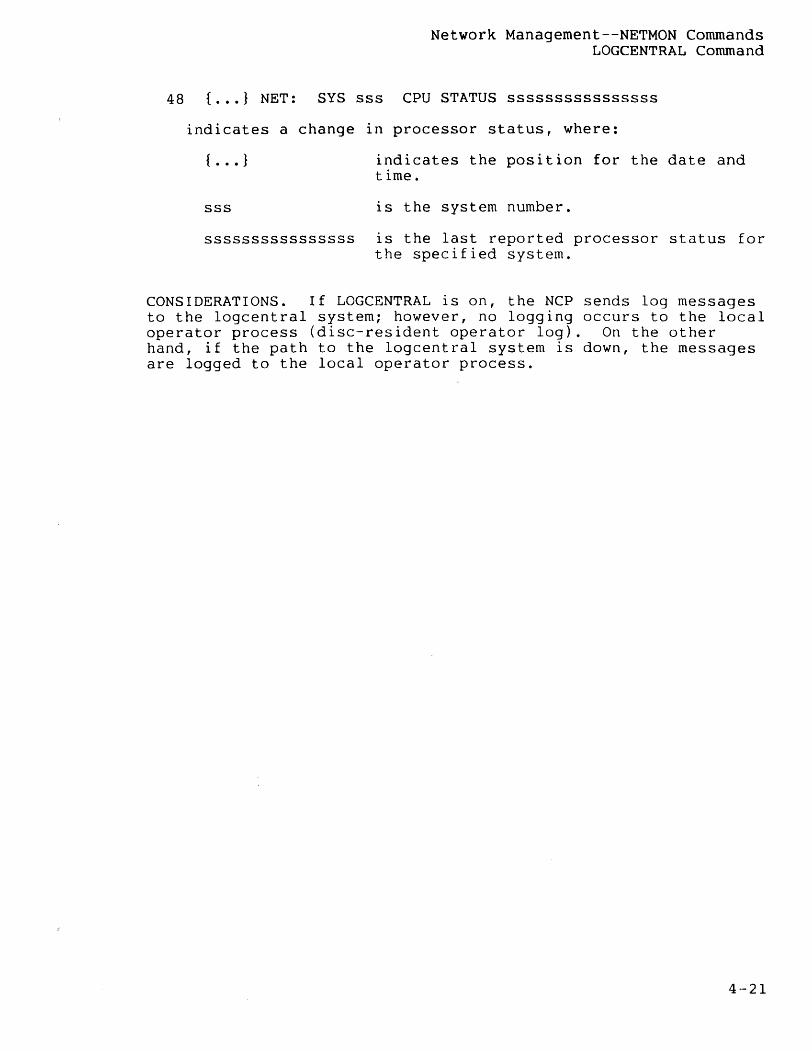
Network Managernent--NETMON Commands LOGCENTRAL Command
48 { ... } NET: SYS sss CPU STATUS ssssssssssssssss
indicates a change in processor status, where:
{ . . . } indicates the position for the date and time.
sss is the system number.
ssssssssssssssss is the last reported processor status for the specified system.
CONSIDERATIONS. If LOGCENTRAL is on, the NCP sends log messages to the logcentral system; however, no logging occurs to the local operator process (disc-resident operator log). On the other hand, if the path to the logcentral system is down, the messages are logged to the local operator process.
4-21
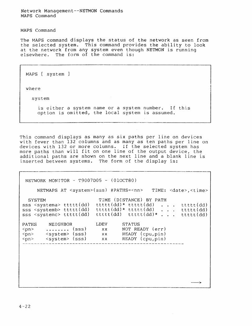
Network Management--NETMON Commands MAPS Command
MAPS Command
The MAPS command displays the status of the network as seen from the selected system. This command provides the ability to look at the network from any system even though NETMON is running elsewhere. The form of the command is:
MAPS [ system ] l where
system
is either a system name or a system. number. If this option is omitted, the local system is assumed.
This command displays as many as six paths per line on dE~vices with fewer than 132 columns and as many as ten paths per line on devices with 132 or more columns. If the selected system has more paths than will fit on one line of the output device, the additional paths are shown on the next line and a blank line is inserted between systems. The form of the display is:
NETWORK MONITOR - T9007D05 - (OlOCT80)
NETMAPS AT <system>(sss) #PATHS=<nn> TIME: <date>,<time>
SYSTEM sss <systema> ttttt(dd) sss <systemb> ttttt(dd) sss <systemc> ttttt(dd)
PATHS <pn> <pn> <pn>
4-22
NEIGHBOR . . . . . . .. (sss) <system> (sss) <system> (sss)
TIME (DISTANCE) BY PATH ttttt(dd)* ttttt(dd) ttttt(dd)* ttttt(dd) ttttt(dd) ttttt(dd)*.
LDEV xx xx xx
STATUS NOT READY (err) READY (cpu,pin) READY (cpu, pin)
ttttt(dd) ttttt(dd) ttttt(dd)
--).
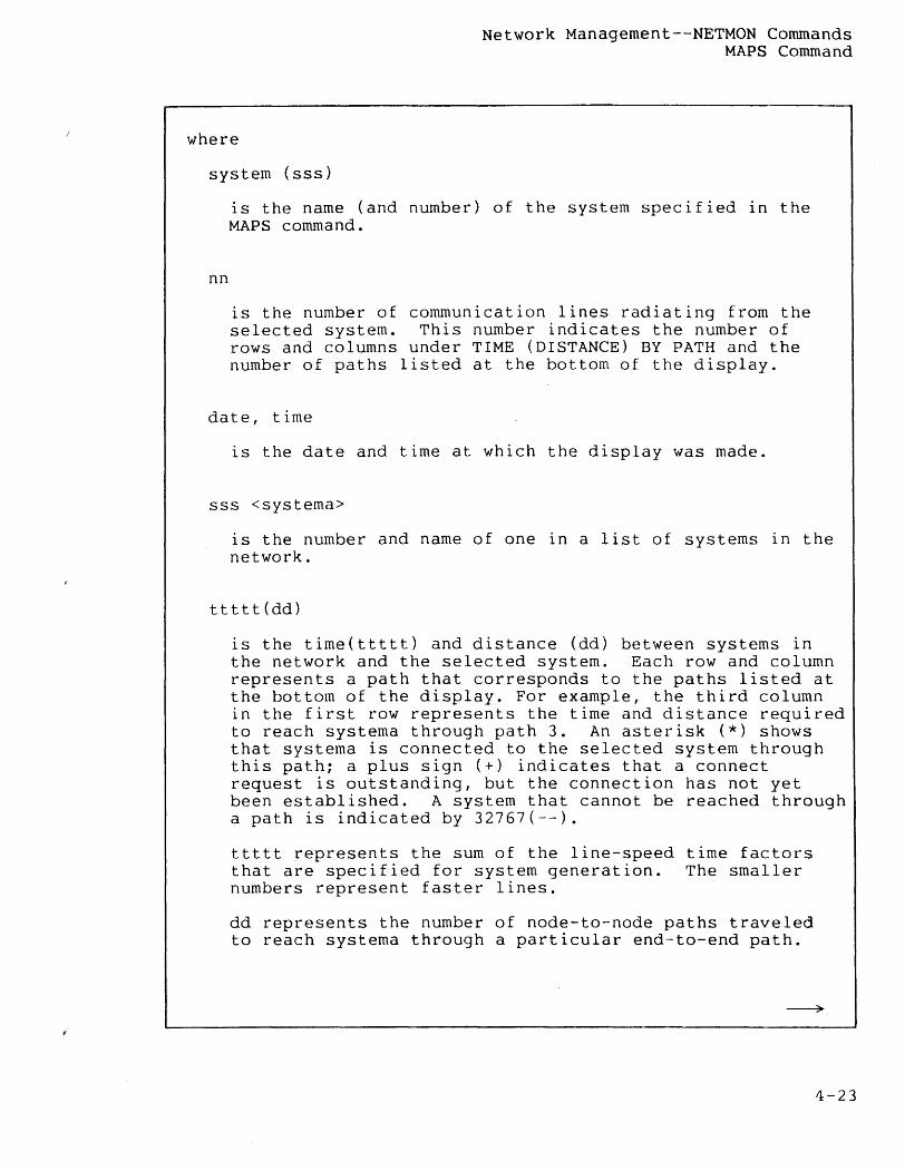
Network Management--NETMON Commands MAPS Command
where
system (sss)
nn
is the name (and number) of the system specified In the MAPS command.
is the number of communication lines radiating from the selected system. This number indicates the number of rows and columns under TIME (DISTANCE) BY PATH and the number of paths listed at the bottom of the display.
date, time
is the date and time at which the display was made.
sss <systema>
is the number and name of one in a list of systems in the network.
ttttt(dd)
is the time(ttttt) and distance (dd) between systems in the network and the selected system. Each row and column represents a path that corresponds to the paths listed at the bottom of the display. For example, the third column in the first row represents the time and distance required to reach systema through path 3. An asterisk (*) shows that systema is connected to the selected system through this path; a plus sign (+) indicates that a connect request is outstanding, but the connection has not yet been established. A system that cannot be reached through a path is indicated by 32767(--).
ttttt represents the sum of the line-speed time factors that are specified for system generation. The smaller numbers represent faster lines.
dd represents the number of node-to-node paths traveled to reach systema through a particular end--to-end path.
4-23
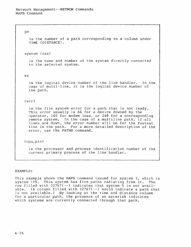
Network Management--NETMON Commands MAPS Command
pn
is the number of a path corresponding to a column under TIME (DISTANCE).
system (sss)
xx
IS the name and number of the system directly connected to the selected system.
is the logical device number of the line handler. In the case of multi-line, it is the logical device number of the path.
(err)
is the file system error for a path that is not ready. This error usually is 66 for a device downed by the operator, 140 for modern loss, or 248 for a nonresponding remote system. In the case of a multiline path, if all lines are down, the error number will be for the fastest line in the path. For a more detailed description of the error, use the PATHS command.
(cpu,pin)
is the processor and process identification number of the current primary process of the line handler.
EXAMPLE:
This example shows the MAPS command issued for system 3, which is system \TS. This system has five paths radiating from it. The row filled with 32767{--} indicates that system 5 is not available. (A column filled with 32767{--) would indicate a path that is not available.} By looking at the time and distance column for a particular path, the presence of an asterisk indicates which systems are currently connected through that path.
4-24
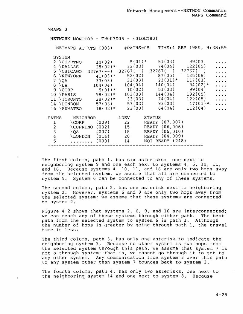
>MAPS 3
Network Management--NETMON Commands MAPS Command
NETWORK MONITOR - T9007D05 - (010CT80>
NETMAPS AT \TS (003) #PATHS=05 TIME:4 SEP 1980, 9:38:59
SYSTEM 2 \CUPRTNO 10(02) 5(01)* 51(03) 99(03) 4 \DALLAS 28(02)* 33(03) 74(04) 122(05) 5 \CHICAGO 32767(--) 32767(--) 32767(--) 32767(--) 6 \NEWYORK 41(03)* 52(02) 87(05) 135(05) 7 \QA 33(03) 33(03) 23(01)* 117(03) 8 \LA 104(04) 104(04) 140(04) 94(02)* 9 \CORP 5(01)* 10(02) 51(03) 99(04)
10 \PARIS 98(02)* 103(03) 144(04) 192(05) 11 \TORONTO 28(02)* 33(03) 74(04) 122(05) 14 \LONDON 57(03) 57(03)· 93(03) 47(01)* 16 \SNMATEO 18(02)* 23(03) 64(04) 112(04)
PATHS NEIGHBOR LDEV STATUS 1 \CORP (009) 22 READY (07,007) 2 \CUPRTNO (002) 15 READY (06,006) 3 \QA (007) 18 READY (05,010) 4 \ LONDON (014) 20 READY (04,009) 5 ........ (000) 14 NOT READY (248)
The first column, path 1, has six asterisks: one next to neighboring system 9 and one each next to systems 4, 6, 10, 11, and 16. Because systems 4, 10, 11, and 16 are only two hops away from the selected system, we assume that all are connected to system 9. System 6 can be connected to any of these systems.
The second column, path 2, has one asterisk next to neighboring system 2. However, systems 6 and 9 are only two hops away from the selected system; we assume that these systems are connected to system 2.
Figure 4-2 shows that systems 2, 6, 9, and 16 are interconnected; we can reach any of these systems through either path. The best path from the selected system to system 6 is path 1. Although the number of hops is greater by going through path 1, the travel time is less~
The third column, path 3, has only one asterisk to indicate the neighboring system 7. Because no other system is two hops from the selected system through this path, we assume that system 7 is not a through system--that is, we cannot go through it to get to any other system. Any communication from system 3 over this path to any system other than system 7 bounces back to system 3.
The fourth column, path 4, has only two asterisks, one next to the neighboring system 14 and one next to system 8. Because
4-25
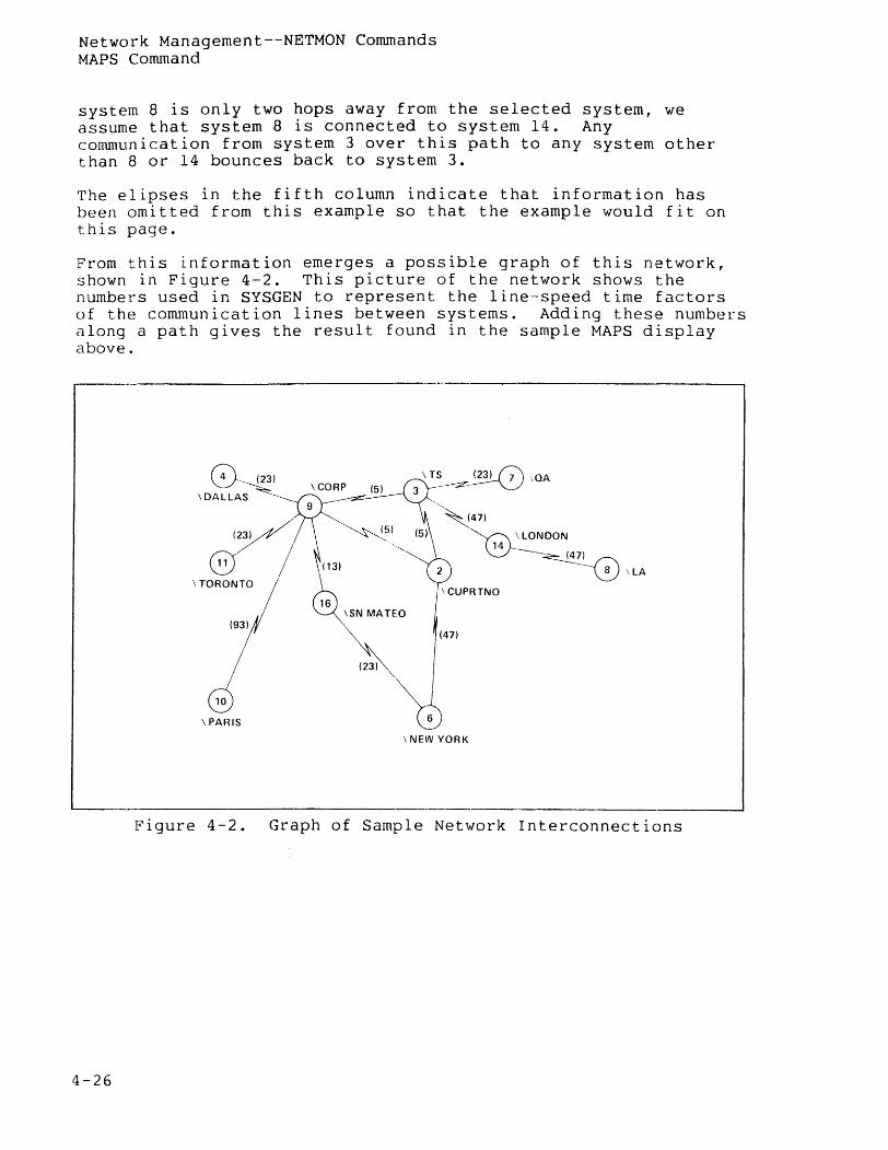
Network Management--NETMON Commands MAPS Command
system 8 is only two hops away from the selected system, we assume that system 8 is connected to system 14. Any communication from system 3 over this path to any system other than 8 or 14 bounces back to system 3.
The elipses in the fifth column indicate that information has been omitted from this example so that the example would fit on this page.
From this information emerges a possible graph of this network, shown in Figure 4-2. This picture of the network shows the numbers used in SYSGEN to represent the line-speed time factors of the cornmunicat ion lines between systems. Adding thesle numbers along a path gives the result found in the sample MAPS display above.
4-26
0- (23)
\DALLA~
I~ @
10
\PARIS
\ TS . (23) 0 ,QA 3 --~~
'--~47)
~LONDON
14 ~7)
~\LA
\SN MATEO
\ NEW YORK
Figure 4-2. Graph of Sample Network Interconnections
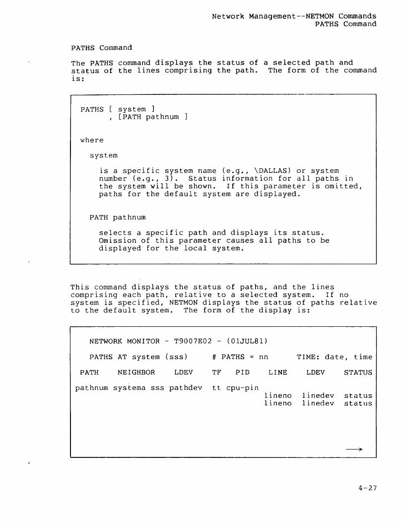
PATHS Command
Network Management--NETMON Commands PATHS Command
The PATHS command displays the status of a selected path and status of the lines comprising the path. The form of the command is:
PATHS system] , [PATH pathnum
where
system
is a specific system name (e.g., \DALLAS) or system number (e.g., 3). Status information for all paths in the system will be shown. If this parameter is omitted, paths for the default system are displayed.
PATH pathnum
selects a specific path and displays its status. Omission of this parameter causes all paths to be displayed for the local system.
This command displays the status of paths, and the lines comprising each path, relative to a selected system. If no system is specified, NETMON displays the status of paths relative to the default system. The form of the display is:
NETWORK MONITOR - T9007E02 - (OIJUL81)
PATHS AT system (sss) # PATHS = nn TIME: date, time
PATH NEIGHBOR LDEV TF PID LINE LDEV STATUS
pathnum systema sss pathdev tt cpu-pin lineno linedev status lineno linedev status
4-27
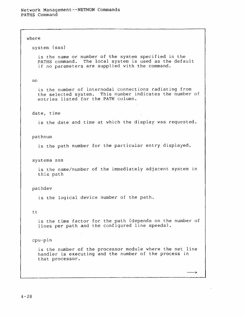
Network Management--NETMON Commands PATHS Command
where
4-28
system (sss)
nn
is the name or number of the system specified in the PATHS command. The local system is used as the default if no parameters are supplied with the command.
is the number of internodal connections radiating from the selected system. This number indicates the number of entries listed for the PATH column.
date, time
is the date and time at which the display was requested.
pathnum
is the path number for the particular entry displayed.
systema sss
is the name/number of the immediately adjacent system in this path
pathdev
tt
is the logical device number of the path.
is the time factor for the path (depends on the number of lines per path and the configured line speeds).
cpu-pin
is the number of the processor module where the net line handler is executing and the number of the process in that processor.
--;,.
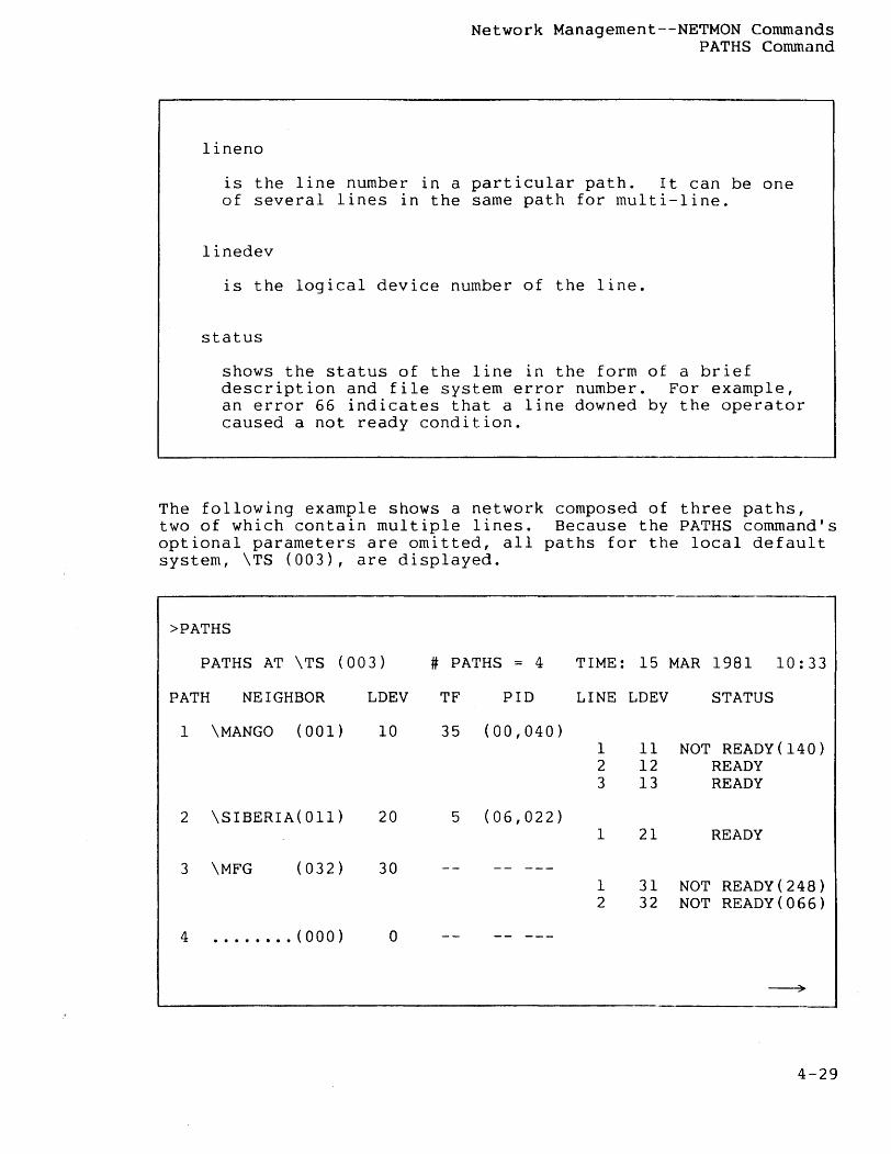
lineno
Network Management--NETMON Commands PATHS Command
is the line number in a particular path. It can be one of several lines in the same path for multi-line.
linedev
is the logical device number of the line.
status
shows the status of the line in the form of a brief description and file system error number. For example, an error 66 indicates that a line downed by the operator caused a not ready condition.
The following example shows a network composed of three paths, two of which contain multiple lines. Because the PATHS command's optional parameters are omitted, all paths for the local default system, \TS (003), are displayed.
>PATHS
PATHS AT \TS (003) # PATHS = 4 TIME: 15 MAR 1981 10:33
PATH NEIGHBOR LDEV TF PID LINE LDEV STATUS
1 \MANGO (001) 10 35 (00,040) 1 11 NOT READY(140) 2 12 READY 3 13 READY
2 \SIBERIA(Oll) 20 5 (06,022) 1 21 READY
3 \MFG (032) 30 -- ---I 31 NOT READY(248) 2 32 NOT READY(066)
4 .....••. (000) 0 -- ---
~
4-29
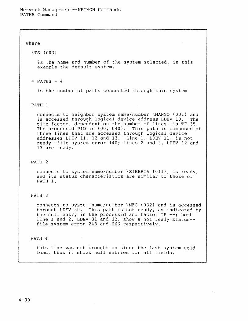
Network Management--NETMON Commands PATHS Command
where
4-30
\TS (003)
is the name and number of the system selected, in this example the default system.
# PATHS = 4
is the number of paths connected through this system
PATH 1
connects to neighbor system name/number \MANGO (001) and is accessed through logical device address LDEV 10. The time factor, dependent on the number of lines, is TF 35. The processid PID is COO, 040). This path is composed of three lines that are accessed through logical device addresses LDEV 11, 12 and 13. Line 1, LDEV 11, is not ready--file system error 140; lines 2 and 3, LDEV 12 and 13 are ready.
PATH 2
connects to system name/number \SIBERIA (all), is ready, and its status characteristics are similar to those of PATH 1.
PATH 3
connects to system name/number \MFG (032) and is accessed through LDEV 30. This path is not ready, as indicated by the null entry in the processid and factor TF --; both line 1 and 2, LDEV 31 and 32, show a not ready status-file system error 248 and 066 respectively.
PATH 4
this line was not brought up since the last system cold load, thus it shows null entries for all fields.
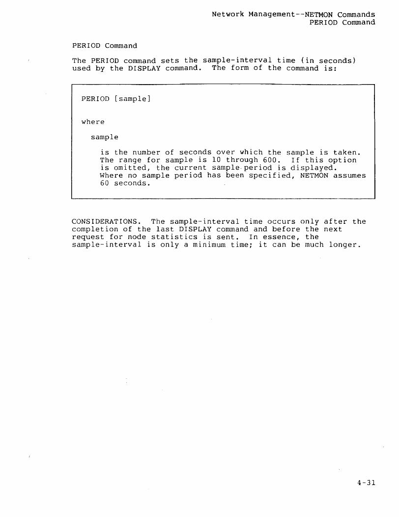
PERIOD Command
Network Management--NETMON Commands PERIOD Command
The PERIOD command sets the sample-interval time (in seconds) used by the DISPLAY command. The form of the command is:
PERIOD [sample]
where
sample
is the number of seconds over which the sample is taken. The range for sample is 10 through 600. If this option is omitted, the current sample. period is displayed. Where no sample period has been specified, NETMON assumes 60 seconds.
CONSIDERATIONS. The sample-interval time occurs only after the completion of the last DISPLAY command and before the next request for node statistics is sent. In essence, the sample-interval is only a minimum time; it can be much longer.
4-31
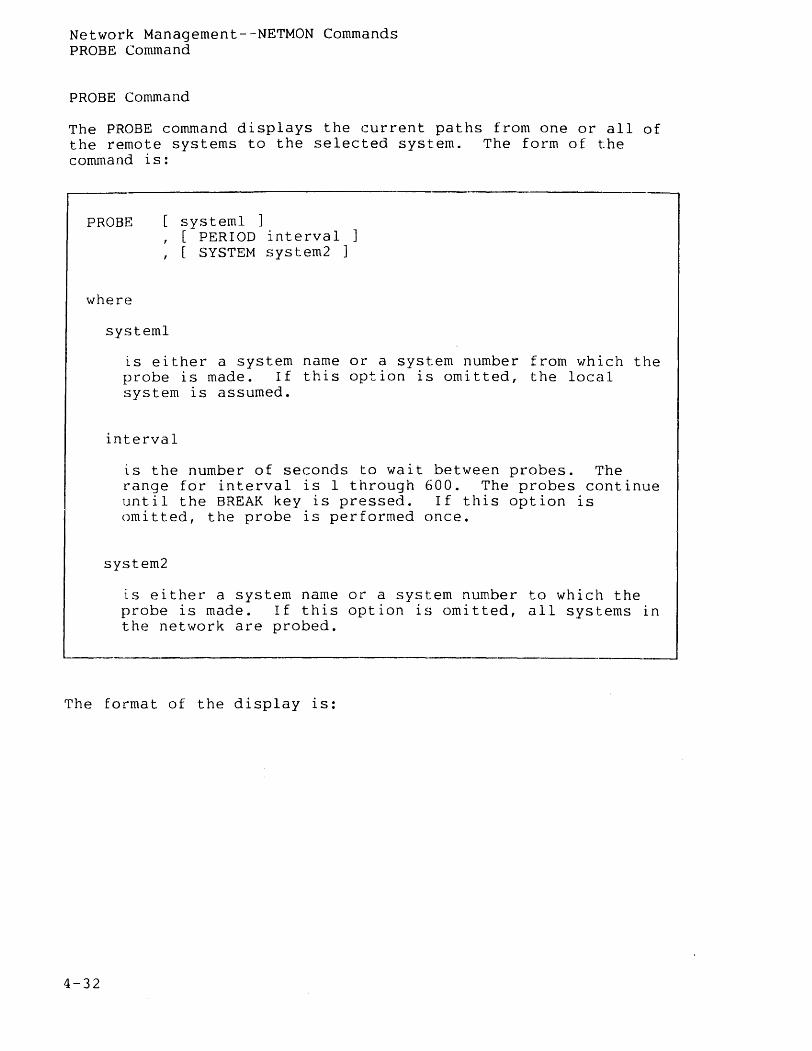
Network Management--NETMON Commands PROBE Command
PROBE Command
The PROBE command displays the current paths from one or all of the remote systems to the selected system. The form of the command is:
PROBE systeml ] , [ PERIOD interval ] , [ SYSTEM system2 ]
where
systeml
is either a system name or a system number from which the probe is made. If this option is omitted, the local system is assumed.
interval
is the number of seconds to wait between probes. The range for interval is 1 through 600. The probes continue until the BREAK key is pressed. If this option is omitted, the probe is performed once.
system2
is either a system name or a system number to which the probe is made. If this option is omitted, all systems in the network are probed.
The format of the display is:
4-32
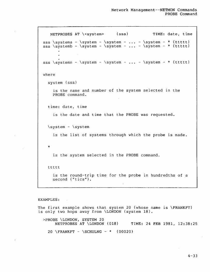
Network Management--NETMON Commands PROBE Command
NETPROBES AT \<system> (sss) TIME: date, time
sss \systema - \system - \system -sss \systemb - \system - \system -
- \system - * (ttttt) - \system - * (ttttt)
sss \systemn - \system - \system - ... - \system - * (ttttt)
where
system (sss)
is the name and number of the system selected in the PROBE command.
time: date, time
is the date and time that the PROBE was requested.
\system - \system
is the list of systems through which the probe is made.
* is the system selected in the PROBE command.
ttttt
is the round-trip time for the probe in hundredths of a second ("tics").
EXAMPLES:
The first example shows that system 20 (whose name is \FRANKFT) is only two hops away from \LONDON (system 18).
>PROBE \LONDON, SYSTEM 20 NETPROBES AT \LONDON (018) TIME: 24 FEB 1981, 12:38:25
20 \FRANKFT - \SCHULNG - * (00020)
4-33
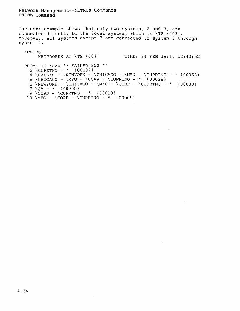
Network Management--NETMON Commands PROBE Command
The next example shows that only two systems, 2 and 7, are connected directly to the local system, which is \TS (003). Moreover, all systems except 7 are connected to system 3 through system 2.
>PROBE NETPROBES AT \TS (003) TIME: 24 FEB 1981, 12:43:52
PROBE TO \SAA ** FAILED 250 ** 2 \CUPRTNO - * (00007) 4 \DALLAS - \NEWYORK - \CHICAGO - \MFG - \CUPRTNO - * (00053) 5 \CHICAGO - \MFG - \CORP - \CUPRTNO - * (00028) 6 \NEWYORK - \CHICAGO - \MFG - \CORP - \CUPRTNO - * (00039) 7 \QA - * (00005) 9 \CORP - \CUPRTNO - * (00010)
10 \MFG - \CORP - \CUPRTNO - * (00009)
4-34
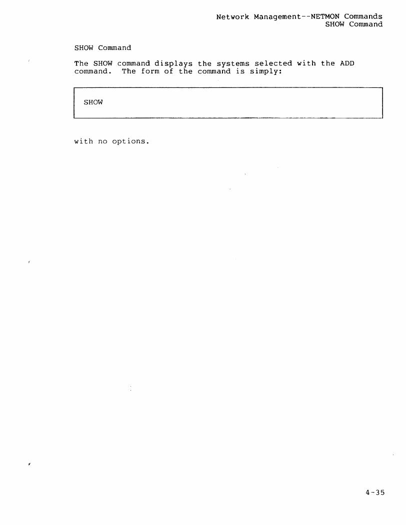
SHOW Command
Network Management--NETMON Commands SHOW Command
The SHOW command displays the systems selected with the ADD command. The form of the command is simply:
SHOW
with no options.
4-35
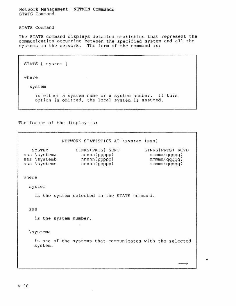
Network Management--NETMON Commands STATS Command
STATS Command
The STATS command displays detailed statistics that reprE!Sent the communication occurring between the specified system and all the systems in the network. The form of the command is:
STATS [ system ]
where
system
is either a system name or a system number. If this option is omitted, the local system. is assumed.
The format of the display is:
NETWORK STATISTICS AT \system (sss)
SYSTEM sss \systema sss \systemb sss \systemc
where
system
LINKS(PKTS) SENT nnnnn(ppppp) nnnnn(ppppp) nnnnn(ppppp)
LINKS(PKTS) RCVD mmrnmm(qqqqq) mmmmm(qqqqq) mmmmm(qqqqq)
is the system selected in the STATS command.
4-36
sss
1S the system number.
\systema
is one of the systems that communicates with the selected system.
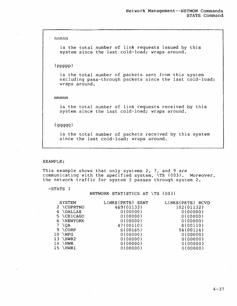
Network Management--NETMON Commands STATS Command
nnnnn
is the total number of link requests issued by this system since the last cold-load; wraps around.
(ppppp)
is the total number of packets sent from this system excluding pass-through packets since the last cold-load~ wraps around.
mmrnmm
is the total number of link requests received by this system since the last cold-load; wraps aroundo
(qqqqq)
is the total number of packets received by this system since the last cold-load; wraps around.
EXAMPLE:
This example shows that only systems 2, 7, and 9 are communicating with the specified system, \TS (003). Moreover, the network traffic for system 3 passes through system 2.
>STATS 3
SYSTEM 2 \CUPRTNO 4 \DALLAS 5 \CHICAGO 6 \NEWYORK 7 \QA 9 \CORP'
10 \MFG 13 \HWR2 14 \HWR 15 \HWRI
NETWORK STATISTICS AT \TS (003)
LINKS(PKTS) SENT 469(01133)
0(00000) 0(00000) 0(00000)
47(00110) 6(00165) 0(00000) 0(00000) 0(00000) 0(00000)
LINKS(PKTS) RCVD 102(01132)
0(00000) 0(00000) 0(00000) 8(00110)
54(00114) 0(00000) 0(00000) 0(00000) 0(00000)
4-37

Network Management--NETMON Commands THRESHOLD Command
THRESHOLD Command
The THRESHOLD command determines when to blink the rate of packets line in the display shown with the DISPLAY command. 11he THRESHOLD command checks the rate of packets in each sample period. When the difference between the previous rate of packets and the current rate reaches the specified percentage, the rate of packets line blinks for one sample period. The form of the command is:
THRESHOLD [percentage]
where
4-38
percentage
is the percentage difference to be met to start blinking the rate of packets line. If this option is omitted, the current threshold value is displayed. If no threshold is specified, NETMON assumes 50 percent.
------------------------------------.--------------------------
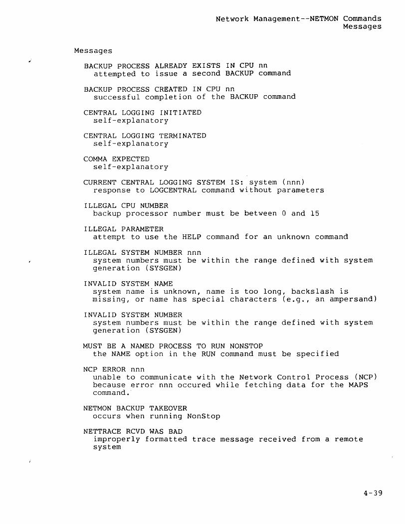
Network Management--NETMON Commands Messages
Messages
BACKUP PROCESS ALREADY EXISTS IN CPU nn attempted to issue a second BACKUP command
BACKUP PROCESS CREATED IN CPU nn successful completion of the BACKUP command
CENTRAL LOGGING INITIATED self-explanatory
CENTRAL LOGGING TERMINATED self-explanatory
COMMA EXPECTED self-explanatory
CURRENT CENTRAL LOGGING SYSTEM IS: system (nnn) response to LOGCENTRAL command without parameters
ILLEGAL CPU NUMBER backup processor number must be between 0 and 15
ILLEGAL PARAMETER attempt to use the HELP command for an unknown command
ILLEGAL SYSTEM NUMBER nnn system numbers must be within the range defined with system generation (SYSGEN)
INVALID SYSTEM NAME system name is unknown, name is too long, backslash is missing, or name has special characters (e.g., an ampersand)
INVALID SYSTEM NUMBER system numbers must be within the range defined with system generation (SYSGEN)
MUST BE A NAMED PROCESS TO RUN NONSTOP the NAME option in the RUN command must be specified
NCP ERROR nnn unable to communicate with the Network Control Process (NCP) because error nnn occured while fetching data for the MAPS command.
NETMON BACKUP TAKEOVER occurs when running NonStop
NETTRACE RCVD WAS BAD improperly formatted trace message received from a remote system
4-39
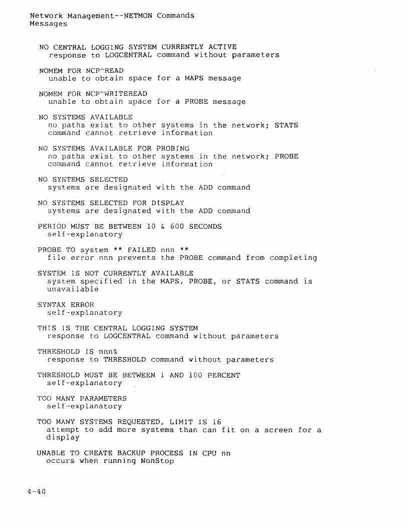
Network Management--NETMON Commands Messages
NO CENTRAL LOGGING SYSTEM CURRENTLY ACTIVE response to LOGCENTRAL command without parameters
NOMEM FOR NCpAREAD unable to obtain space for a MAPS message
NOM EM FOR NCpAWRITEREAD unable to obtain space for a PROBE message
NO SYSTEMS AVAILABLE no paths exist to other systems in the network; STATS command cannot retrieve information
NO SYSTEMS AVAILABLE FOR PROBING no paths exist to other systems in the network; PROBE command cannot retrieve information
NO SYSTEMS SELECTED systems are designated with the ADD command
NO SYSTEMS SELECTED FOR DISPLAY systems are designated with the ADD command
PERIOD MUST BE BETWEEN 10 & 600 SECONDS self-explanatory
PROBE TO system ** FAILED nnn ** file error nnn prevents the PROBE command from completing
SYSTEM IS NOT CURRENTLY AVAILABLE system specified in the MAPS, PROBE, or STATS command is unavailable
SYN'r AX ERROR self-explanatory
THIS IS THE CENTRAL LOGGING SYSTEM response to LOGCENTRAL command without parameters
THRESHOLD IS nnn% response to THRESHOLD command without parameters
THRESHOLD MUST BE BETWEEN 1 AND 100 PERCENT self-explanatory
TOO MANY PARAMETERS self-explanatory
TOO MANY SYSTEMS REQUESTED, LIMIT IS 16 attempt to add more systems than can fit on a screen for a display
UNABLE TO CREATE BACKUP PROCESS IN CPU nn occurs when running NonStop
4-40

UNKNOWN COMMAND self-explanatory
U~KNOWN KEYWORD self-explanatory
Network Management--NETMON Commands Messages
4-41
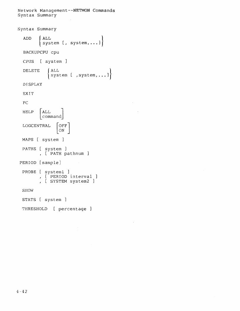
Network Management--NETMON Commands Syntax Summary
Syntax Summary
ADD {~~~tem [, system, ••• J} BACKUPCPU cpu
CPUS system
DELETE {~~~tem [ ,system, .•• J} DISPLAY
EXIT
FC
HELP [~~~andJ LOGCENTRAL [g~FJ
MAPS [ system ]
PATHS [ system , [ PATH pa t hnurn
PERIOD [sample]
PROBE systeml
SHOW
, [ PERIOD interval ] , [ SYSTEM system2 ]
STATS [ system ]
THRESHOLD [percentage
/~ -42
Network Management--Network Security
NETWORK SECURITY
This section discusses network security. The reader should already be familiar with one-system security as described in the GUARDIAN Operating System Programming Manual, Volume 2.
Overview
Security in a network is more restrictive than security on a single system. The security philosophy of the system--that the machine serves a community of cooperating, intelligent users--does not extend to a network, in which nothing about the remote-user community can be controlled or assumed.
Therefore, while the security system on one system allows any operation that is not specifically prohibited, the security on a network prohibits any operation that is not specifically allowed. Prior cooperation between system managers at each node is required before a user at one system can access another.
A user at system X wishing to access a file (disc file, device, or process) residing on system Y must satisfy each of these three requirements:
• the user at system X must also be a user at system Y
• the user must have matching REMOTEPASSWORDS set up at both system X and system Y
• the user at X must have sufficient capability to access a disc file at Y.
Each of these three security levels is discussed below.
Global Knowledge of User IDs
Each system user is known to the machine by a user name, such as ADMIN.BILL, and a user identifier, such as 8,4.
A user has access to files on a remote system only if that user's name and 1D are known to the remote system.
Thus if ADMI~.BILL, whose user ID is 3,46, wishes to access a file on a remote system, the remote system must also have a user named ADMIN.BILL whose user 1D is 3,46.
Remote Passwords
Once the user identifiers of network users have been added to each node, a system of remote passwords is used to specify whether remote access is permitted.
4-43
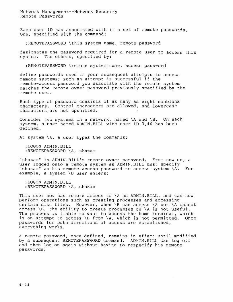
Network Management--Network Security Remote Passwords
Each us~r ID has associated with it a set of remote passwords. One, specified with the command:
:REMOTEPASSWORD \this system name, remote password
designates the password required for a remote user to access this system. The others, specified by:
:REMOTEPASSWORD \remote system name, access password
define passwords used in your subsequent attempts to access remote systems; such an attempt is successful if the remote-access password you associate with the remote system matches the remote-owner password previously specified by the remote user.
Each type of password consists of as many. as eight nonblank characters. Control characters are allowed, and lowercase characters are not upshifted.
Consider two systems in a network, named \A and \B. On each system, a user named ADMIN.BILL with user ID 3,46 has been defined.
At system \A, a user types the commands:
:LOGON ADMIN.BILL :REMOTEPASSWORD \A, shazam
"shazam" is ADMIN.BILL's remote-owner password. From now on, a user logged onto a remote system as ADMIN. BILL must specify "shazam" as his remote-access password to access system \A. For example, a system \B user enters:
:LOGON ADMIN.BILL :REMOTEPASSWORD \A, shazam
This user now has remote access to \A as ADMIN.BILL, and can now perform operations such as creating processes and accessing certain disc files. However, when \B can access \A but \A cannot access \B, the ability to create processes on \A is not useful. The process is liable to want to access the home terminal, which is an attempt to access \B from \A, which is not permitted. Once passwords for both directions of access are established, everything works.
A remote password, once defined, remains in effect until modified by a subsequent REMOTEPASSWORD command. ADMIN.BILL can log off and then log on again without having to respecify his remote passwords.
4-44
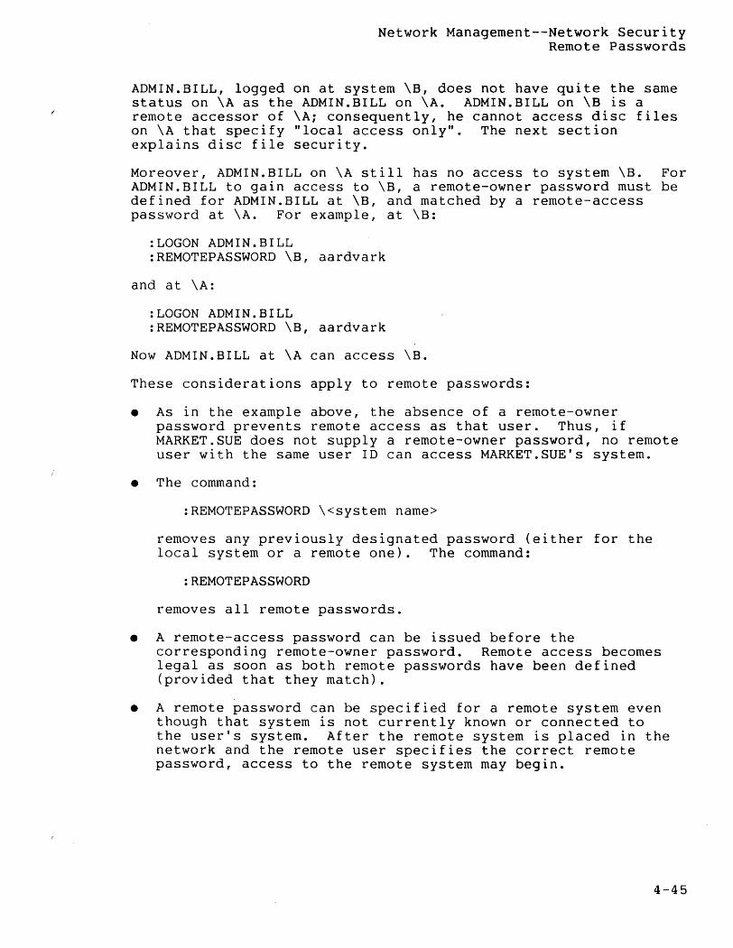
Network Management--Network Security Remote Passwords
ADMIN.BILL, logged on at system \B, does not have quite the same status on \A as the ADMIN.BILL on \A. ADMIN. BILL on \B is a remote accessor of \A; consequently, he cannot access disc files on \A that specify "local access only". The next section explains disc file security.
Moreover, ADMIN.BILL on \A still has no access to system \B. For ADMIN.BILL to gain access to \B, a remote-owner password must be defined for ADMIN.BILL at \B, and matched by a remote-access password at \A. For example, at \B:
:LOGON ADMIN.BILL :REMOTEPASSWORD \B, aardvark
and at \A:
:LOGON ADMIN.BILL :REMOTEPASSWORD \B, aardvark
Now ADMIN.BILL at \A can access \B.
These considerations apply to remote passwords:
• As in the example above, the absence of a remote-owner password prevents remote access as that user. Thus, if MARKET.SUE does not supply a remote-owner password, no remote user with the same user ID can access MARKET.SUE's system.
• The command:
:REMOTEPASSWORD \<system name>
removes any previously designated password (either for the local system or a remote one). The command:
:REMOTEPASSWORD
removes all remote passwords.
• A remote-access password can be issued before the corresponding remote-owner password. Remote access becomes legal as soon as both remote passwords have been defined (provided that they match).
• A remote password can be specified for a remote system even though that system is not currently known or connected to the user's system. After the remote system is placed in the network and the remote user specifies the correct remote password, access to the remote system may begin.
4-45
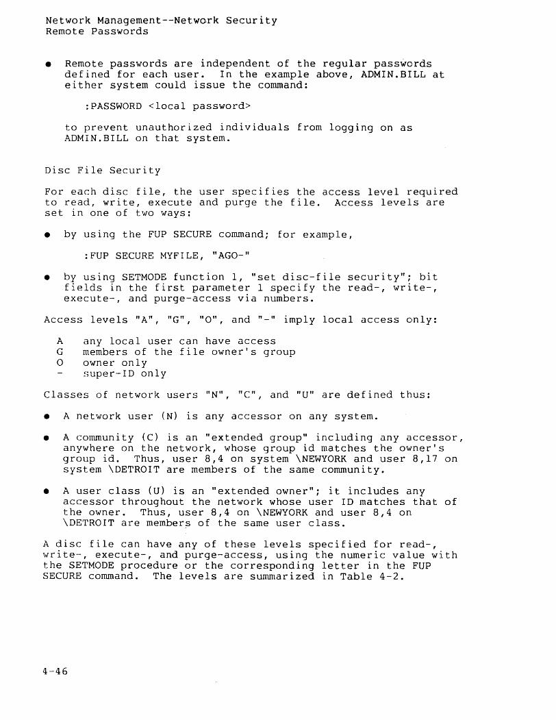
Network Management--Network Security Remote Passwords
• Remote passwords are independent of the regular passwords defined for each user. In the example above, ADMIN. BILL at either system could issue the command:
:PASSWORD <local password>
to prevent unauthorized individuals from logging on as ADMIN.BILL on that system.
Disc File Security
For each disc file, the user specifies the access level required to read, write, execute and purge the file. Access levels are set in one of two ways:
• by using the FUP SECURE command; for example,
:FUP SECURE MYFILE, "AGO-"
• by using SETMODE function 1, "set disc-file security"; bit fields in the first parameter 1 specify the read-, write-, execute-, and purge-access via numbers.
Access levels "A", "G", "0", and "_" imply local access only:
A any local user can have access G members of the file owner's group a owner only
super-ID only
Classes of network users liN", "e", and "U" are defined thus:
• A network user (N) is any accessor on any system.
• A community (C) is an "extended group" including any accessor, anywhere on the network, whose group id matches the owner's group ide Thus, user 8,4 on system \NEWYORK and user 8,17 on system \DETROIT are members of the same community.
• A user class (U) is an "extended owner"; it includes any accessor throughout the network whose user ID matches that of the owner. Thus, user 8,4 on \NEWYORK and user 8,4 on \DETROIT are members of the same user class.
A disc file can have any of these levels specified for read-, write--, execute-, and purge-access, using the numeric value with the SETMODE procedure or the corresponding letter in the FUP SECURE command. The levels are summarized in Table 4-2.
4-46
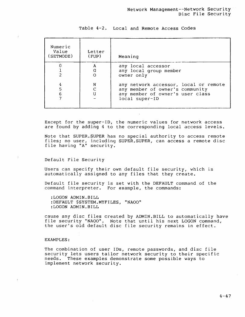
Network Managernent--Network Security Disc File Security
Table 4-2. Local and Remote Access Codes
Numeric Value Letter
(SETMODE) (FUP) Meaning
0 A any local accessor 1 G any local group member 2 0 owner only
4 N any network accessor, local or remote 5 C any member of owner's community 6 U any member of owner's user class 7 - local super-ID
Except for the super-ID, the numeric values for network access are found by adding 4 to the corresponding local access levels.
Note that SUPER.SUPER has no special authority to access remote files; no user, including SUPER.SUPER, can access a remote disc file having "A" security.
Default File Security
Users can specify their own default file security, which is automatically assigned to any files that they create.
Default file security is set with the DEFAULT command of the command interpreter. For example, the commands:
:LOGON ADMIN.BILL :DEFAULT $SYSTEM.MYFILES, "NAOO" :LOGON ADMIN.BILL
cause any disc files created by ADMIN.BILL to automatically have file security "NAOO". Note that until his next LOGON command, the user's old default disc file security remains in effect.
EXAMPLES:
The combination of user IDs, remote passwords, and disc file security lets users tailor network security to their specific needs. These examples demonstrate some possible ways to implement network security.
4-47
Network Management--Network Security Default File Security
Example 1 (Local and Remote Users): Accessors of a file are classified as either "local" or remote" with respect to that file. A local user is one who is logged on to the system on which the file resides; a remote user is one logged on to a different system.
A remote accessor of a system can become a local accessor by simply running a command interpreter in the remote systenl, and logging on. For example, if ADMIN.BILL on \A has specified the proper remote password to gain access to system \B, he can issue the commands:
:WAKEUP OFF :\B.COMINT :LOGON ADMIN.BILL
He is now logged on as the local ADMIN. BILL on system \B. Thus, he can access disc files on \B owned by ADMIN.BILL havin9 security "0". This remote session is terminated with a control-Y or LOGOFF. In the case of a control-Y, the command interpreter then asks "Are you sure you want to stop your command interpreter on \B7" Reply YES to awaken the local command interpretE!r. In the case of a LOGOFF, the command interpreter simply responds with "Exiting from CIon system \B."
System \B can prevent a remote user from becoming a local user in a number of ways. One method is to specify "A" as the "execute" security for $SYSTEM.SYSTEM.COMINT, preventing anyone in any remote system from running the program file.
Another way to prevent ADMIN. BILL, on \A, from logging on to \B is to simply give ADMIN.BILL at \B a local password that is unknown to ADMIN.BILL at \A.
Example 2: Suppose that there are so many systems in the network that nobody wants to type all the required REMOTEPASSWORD commands, but it is important to deny network access to certain users.
At each node, establish a user called NET.ACCESS, and issue the following commands:
:LOGON NET.ACCESS :PASSWORD local password :REMOTEPASSWORD \system 1, global password :REMOTEPASSWORD \system 2, global password
:REMOTEPASSWORD \system n, global password
4-48
Network Management--Network Security Default File Security
The global password is the same for all systems and is known only to the system managers; the local password is different for each system and is given to those users who are allowed to access the network.
Only those users who know the local password can log on as NET.ACCESS. The command:
:LOGON NET.ACCESS, local password
allows them to access remote files.
Example 3 (Sub-Networks): In a large network, it may be desirable to allow users to access some nodes, but not others. For example, you might want to allow users on system \SANFRAN to be able to access systems \LA, \SEATTLE, and \CUPRTNO, but not \NEWYORK and \CHICAGO.
In this case, the idea used in Example access to any number of subnets, where as any collection of individual nodes. established at each node of the subnet, such as the one in Example 2 is used to log on as NET.WEST.
1 can be extended to allow a subnet is defined simply
A user named NET.WEST is and a password scheme allow certain users to
Subnets implemented in this manner can be allowed to overlap or include one another. For example, \CHICAGO might be accessible from \NEWYORK, by logging on as NET. EAST, and from \PHOENIX, by logging on as NET.MIDWEST. Similarly, each node in the entire network might have a user NET.GLOBAL, who is allowed to access every other node.
Example 4 (Defining the Capabilities of SUPER.SUPER): On a single system, SUPER. SUPER is allowed access to any file. On a network, the user can define whether the powers of the super-ID are local, global, or somewhere in between.
To make SUPER.SUPER a local super-ID only, do not issue a REMOTEPASSWORD command for SUPER. SUPER at any node. This prevents a remote super-ID from accessing the node's files.
To make SUPE.R.SUPER a global super-ID, issue, at each node, REMOTEPASSWORD commands as in Example 2, so that SUPER.SUPER can access files on remote systems, and give every SUPER. SUPER the same password. Now, if a disc file has security "A", "G", "0" or "-", a remote super-ID can still gain access to the file by running a command interpreter in the system containing the disc file, and logging on as the local SUPER. SUPER.
4-49
Network Management--Network Security Default File Security
To make SUPER. SUPER an in-between super-ID, issue, at each node,REMOTEPASSWORD commands as in Example 2, so that SUPER.SUPER can access files on remote systems. Additionally, issue each SUPER. SUPER a distinct password. Then, any disc file can be protected from remote access by giving it "A", "G", "0", or "-" security; a remote SUPER. SUPER cannot log on as the local one, since the local super-ID's password is unknown.
Process Access
Several security considerations relate to remote processes:
• With respect to a given system, each process in the network is either "local" or "remote", according to these rules:
A process is remote if it is running in a remote system.
A process is remote if its creator is in a remote system.
A process is remote if its creator is remote.
According to the second and third rules, even a process running in a particular system can be remote with respect to that system. These rules prevent a user from remotely running a process that creates another process that accesses a file whose security specifies "local access only".
• A remote process cannot suspend or activate a local process. A remote process cannot stop a local process, unless the local process's stop mode is 0 ("anyone can stop me").
• A remote process can not put a local process into DEBUG.
It is possible for a process that is remote with respect to the system in which it's running to become local. For instance, Example 1, above, characterized users as either local or remote on the basis of where they are logged on. The example also showed how a user in system \A could become local with respect to \B by running a command interpreter at \B and logging on.
consider the command interpreter in \B~ Its creator is the user's command interpreter in \A; thus, the command interpreter in \B is remote with respect to \B. But the user's LOGON command causes that command interpreter to become local with respect to \B. Thus, if you allow the possibility of a process somehow making itself local with respect to the system in which it's running, the concept of local and remote users becomes equivalent to the concept of local and remote processes: a user is local (remote) with respect to a given system if his command interpreter is local (remote) with respect to that system.
4-50

Network Management--Network Security Process Access
A process that makes itself local with respect to the system in which it is running is said to "programmatically log on" to that system.
4-51
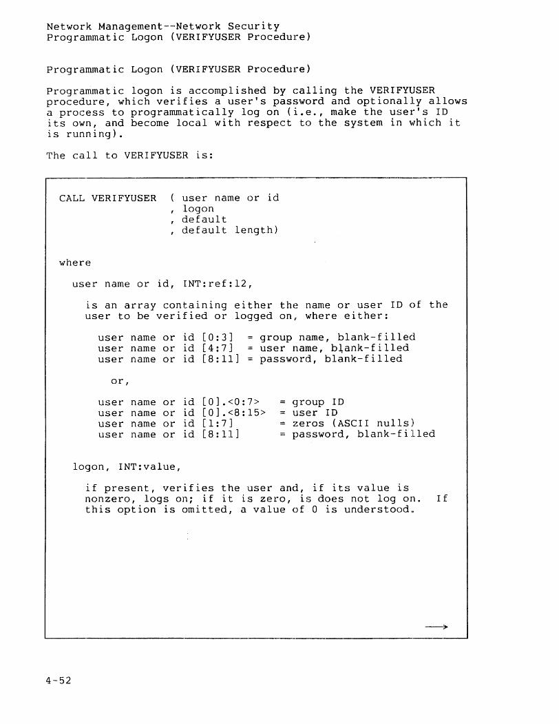
Network Management--Network Security Programmatic Logon (VERIFYUSER Procedure)
Programmatic Logon (VERIFYUSER Procedure)
Programmatic logon is accomplished by calling the VERIFYUSER procedure, which verifies a user's password and optionally allows a process to programmatically log on (i.e., make the user's ID its own, and become local with respect to the system in ~lhich it is running).
The call to VERIFYUSER is:
CALL VERIFYUSER user name or id , logon
default def aul t length)
where
4-52
user name or id, INT:ref:12,
is an array containing either the name or user ID of the user to be verified or logged on, where either:
user name or id [0:3] group name, blank-filled user name or id [4:7] = user name, b~ank-filled user name or id [8:11] = password, blank-filled
or,
user name or id [0] .<0:7> = ~1roup ID user name or id [0].<8:15> user ID user name or id [ 1 : 7 ] = zeros (ASCII nulls) user name or id [8:11] password, blank-filled
logon, INT:value,
if present, verifies the user and, if its value is nonzero, logs on; if it is zero, is does not log on. If this option is omitted, a value of 0 is understoodu
--~
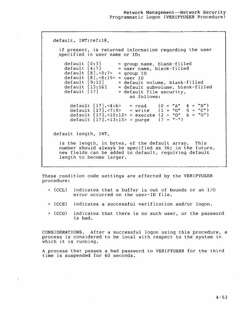
Network Management--Network Security Programmatic Logon (VERIFYUSER Procedure)
default, INT:ref:18,
if present, is returned information regarding the user specified in user name or ID:
default default default default default default default
[0:3] = group name, blank-filled [4:7] = user name, blank-filled [8].<0:7> = group ID [8].<8:15> = user ID [9:12] = default volume, blank-filled [13:16] = default subvolume, blank-filled [17] = default file security,
default [17].<4:6> default [17].<7:9> default [17].<10:12> default [17].<13:15>
default length, INT,
as follows:
read = write
execute purge
(0 ( 1 ( 2 ( 7
"A" "G" "0"
= "_")
4 = "N") 5 "C") 6 "U")
is the length, in bytes, of the default array. This number should always be specified as 36; in the future, new fields can be added to default, requiring default length to become larger.
These condition code settings are effected by the VERIFYUSER procedure:
< (CCL) indicates that a buffer is out of bounds or an I/O error occurred on the user-ID file.
(CCE) indicates a successful verification and/or logon.
> (CCG) indicates that there is no such user, or the password is bad.
CONSIDERATIONS. After a successful logon using this procedure, a process is considered to be local with respect to the system in which it is running.
A process that passes a bad password to VERIFYUSER for the third time is suspended for 60 seconds.
4-53
Network Management--Network Security Programmatic Logon (VERIFYUSER Procedure)
EXAMPLE:
USER := 3 '«~I 8 + 17; USER [ 1] ': =' a & USER [ 1] FOR 6; USER[8] ':=' PASSWORD FOR 8;
user ID 3,17 all zeros
LOGON := 1; ! log this user on CALL VERIFYUSER( USER, LOGON, DEFAULT, 36 ); IF < THEN buffer or I/O error ELSE IF > THEN ... no such user, or bad password ELSE successful
NETWORK MANAGEMENT CONSIDERATIONS
To develop and manipulate an EXPAND network it is necessary to use several Tandem-supplied programs and subsystems. These programs include: SYSGEN, CUP, PUP, CMI, and XRAY. The following discussion gives a brief description of each program and points out any special considerations for their use.
System Generation (SYSGEN)
The System Generation (SYSGEN) program generates an Operating System for a given hardware/software configuration. Network management considerations for running SYSGEN for an EXPAND network include:
• Maximum system number (max systems). This network global SYSGEN parameter specifies the maximum number of systems in the network and establishes an upper bounds on the system numbers that will be recognized. Peculiar results occur if the value of max systems is not agreed to by all systems in a network.
Consider the example of a network composed of \SYSTEMA (90) and \SYSTEMB (10). If \SYSTEMA is assigned a max systems value of 100 and \SYSTEMB is assigned a max systems value of 10, then \SYSTEMB will never recognize a connect message sent from \SYSTEMA because the max systems value for \SYSTEMA does not fall within the bounds specified for \SYSTEMS.
Thus, even though connected properly in all other respects, the two systems will never be able to communicate. To resolve the problem, change the max systems value to be compatible in one or both systems and run another SYSGEN in each modified system .
• Establishing an EXPAND link using an X.25 line. As mentioned in Section I of this manual, it is possible to connect two systems via EXPAND using an X.25 network. To accomplish this you must perform the following three steps. First, SYSGEN an X.25 line with the correct subtype to connect to the specific vendor X.25 network (such as Telenet, Tymnet, Datapac, or
4-54
Network Management--Network Security Network Management Considerations
Transpac). Next, SYSGEN an EXPAND line (type NET A X25) as a separate LDEV. After the system is running, use CUP to ADD the EXPAND line as a subdevice to the X.25 line and to specify the various line parameters (see AXCESS, Volume 1: Introduction and Communications Utility program)_.
• Line time factor. The LINESPEED parameter contains the value of the line time factor (recommended values are given in the SYSGEN section of the GUARDIAN System Mana9.el!len~._~~nua!). However, any value may be selected. In fact, the network manager may cause the NCP to select a new "best path" by assigning an LINESPEED value small enough where a particular path is always selected.
• All lines in a multiline path must be in the same controller group and run in the same cpu. If lines are distributed across mUltiple controllers to increase reliability, performance could be reduced by a controller ownership switch to the backup cpu. An ownership switch results if the following conditions are true: a non-EXPAND line (such as AM3270) connected to this controller group fails with an error in the range 210-226. Failure of a line in an EXPAND multi-line path, however, does not cause an ownership switch.
Communications Utility Program (CUP)
The Communications Utility Program (CUp) allows access to data communication lines in the EXPAND network environment. Operations performed by CUP include:
• initiate line traces via the TRACE command
• modify communication line or subdevice characteristics via the ALTER command
• list the SYSGEN configured communication line handlers via the LISTLH command
• add communication subdevices to an existing line handler via the ADD command
• list attributes of a particular line, subdevice, or group of subdevices via the SHOW command
• display line and subdevice statistics via the STATS command; optionally resets the statistics
• display a previously generated TRACE output file via the DUMP command
• display syst~m-related network information via the SHOW command
4-55
Network Management--Network Security Network Management Considerations
The CUP TRACE facility now allows the Network Control Process (NCP) as well as the line handler to be traced~ The NCP supplies CUP with the following information:
• NCP messages sent and received on a network path
• Action and state changes caused by the receipt or transmission of a message, or an event (internal or external) on both an internodal path and end-to-end path.
The CUP STATS command displays statistical information for the default line; default established through CUP LINE command. Line statistics are useful in determining optimal values for configuration parameters:
• "NO BUFFER" indicates the number of times the L2 dedicated buffer was full. This is not an error, but a warning that next frame will be discarded if the buffer is not emptied. the count is > 10% of the number of I-frames received, the size of the L2 dedicated buffer should b~ increased.
the If
• "BUFFER USAGE" maintains a count of line handler usage of rOPOOL. If the value for BUFFER USAGE approaches the SYSGEN value specified for the processor, the configured size should be increased.
The CONNECT and CLEAR commands establish and terminate connection to an X.25-type device. For a detailed description of how to use CUP, refer to AXCESS, Volume 1: Introduction and Communications Utility Program (CUp).
Peripheral Utility Program (PUp)
The Peripheral Utility Program (PUp) performs various functions related to the peripheral devices connected to the system. Those functions related to the EXPAND network include:
• the DOWN command removes a line/path from service. If is specified, any current activity on the line is aborted. If! is not specified, the line is removed from service only if there is no current activity on the line.
• the UP command places a downed line/path back into service. For NET A X25 lines,connection to the network must have been made previously through CUP.
• the LISTDEV command displays configuration characteristics for a given line/path.
PUP is described in the System Operations Manual.
4-56
Network Management--Network Security Network Management Considerations
Console Logging Messages
Two commands (CUP ALTER MSGON/MSGOFF and PUP CONSOLE ENABLE/DISABLE) work together to determine the manner in which network-related console messages are handled:
• the CUP ALTER MSGON/MSGOFF command may selectively enable/disable network messages (43, 46, 48, and 49); messages (44, 45 and 47) are always enabled. In the event that these messages are disabled, the NCP discontinues sending them to the operator process. This results in no message logging to the disc-resident operator log and a reduction of traffic queued to the operator process. Remote logging, however, overrides the CUP ALTER disable. In this case, the NCP simply sends all messages to the system designated as the LOGCENTRAL system.
• the PUP CONSOLE ENABLE/DISABLE command enables/disables the printing of the messages on the local system's console. A preliminary scan by the NCP checks whether the CUP ALTER command has enabled/disabled the messages. If enabled through CUP, they are sent to the operator process where the PUP CONSOLE enable/disable message list is checked to determine whether to print or not print the message at the console. However, if disabled by CUP, the messages are never sent to the operator process, thus nullifying the effect of the PUP CONSOLE enable/disable.
4-57
Network Management--Network Security Network Management Considerations
EXPAND Line Connection to an X.25 Line
The following example shows how to bring up an EXPAND line connection to an X.25 line (It is assumed that the X.25 line ($X25LIN) and the EXPAND line ($EXPLIN) have previously been defined through execution of the SYSGEN program.):
PUP DOWN ! $X25LIN
CUP
> LINE $X25LIN
> ALTER NETADDR 311041500091
! NETADDR is the X25 network address for this line
> ADD #NETLIN, PROTOCOL NET, TYPE (63,0),' RECSIZE 256, LHLDEV 25, NEXTSYS 3, ADDR 311041500091, PORT 77
RECSIZE is the EXPAND packet size in bytes LHLDEV is the logical device number for $EXPLIN NEXTSYS is the system number of the EXPAND node connected
by $EXPLIN AD DR is the X25 network address of the EXPAND subdevice on
the other end of this virtual circuit PORT is the X25 port number on the line specified by
NETADDR
> EXIT
PUP UP $X25LIN PUP UP $EXPLIN
CUP
> LINE $X25LIN
> CONNECT #NETLIN
causes the EXPAND line handler to ask the X25 AXCESS method
to place a callout to the address in subdevice #NETLIN
> EXIT
4-58
Network Management--Network Security Network Management Considerations
Communications Management Interface (CMI)
CMI is used to describe and control characteristics of both 6100CSS Communication Subsystems and non-6100CSS subsystems. Detailed information about CMI is given in the Communications Management Interface (CMI) Operator's Guide.
There are three EXPAND object types that can be defined and manipulated through CMI. These are:
PATH LINE PROCESS
a multi-line communication path a single communication line the EXPAND CAP process
Various CMI commands permit descriptive and operational control over these object types. The descriptive commands include:
ALTER PATH ALTER LINE ALTER PROCESS
INFO PATH INFO LINE INFO PROCESS
The operation commands include:
ABORT PATH ABORT LINE CONTROL LINE START PATH START LINE STATUS PATH
STATUS LINE STOP PATH STOP LINE TRACE PATH TRACE LINE
Refer to Appendix H of the Communications Mana<]ement .Interface (CMI) Operator's Guide for a detailed descriptlon of CMI characteristics.
4-59
Network Management--Network Security Network Management Considerations
XRAY Program
XRAY is a tool for monitoring the performance of a Tandem system. XRAY monitors:
• cpu use
• line use
• NCP or line handler process use of system resources
For detailed information on how to use XRAY, refer to the XRAY User's Manual.
4-60
SECTION 5
FIBER OPTIC EXTENSION (FOX)
NOTE
This product is available only on the Tandem NonStop II system. It cannot be used on the Tandem NonStop system.
INTRODUCTION TO FOX
Tandem NonStop II systems are limited to 16 processors per system. Further expansion is possible only by accessing other Tandem systems across a network. Using conventional line speeds such as those available under EXPAND, sending a message between systems in a network is noticeably slower than sending a message between two processors within the same system because the message must be received and retransmitted by each intervening system. Even if there are no intervening systems, messages are slowed by line handler intervention. The Fiber Optic Extension (FOX) network was developed to allow much faster transfers of information between systems.
In the FOX network, a system is called a cluster. The FOX network is always a ring of systems. Each cluster is a NonStop II system of up to 16 processors. Up to 14 clusters can be included in the ring. Each cluster can communicate with other clusters in the ring. Each cluster can be located up to 1000 meters (1 kilometer) from the next cluster. Further, FOX clusters can be a part of a larger GUARDIAN/EXPAND network containing a mixture of other forms of communication links.
The FOX network, using fiber optic lines between clusters, can attain speeds up to 1 million bytes per second. Furthermore, messages usually pass directly from the sending processor to the bus and always pass through only the controllers of intervening systems (avoiding the line handlers).
5-1
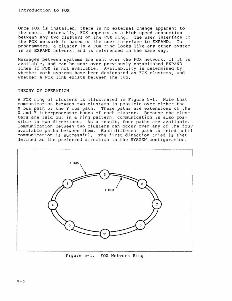
Introduction to FOX
Once FOX is installed, there is no external change apparent to the user. Externally, FOX appears as a high-speed connection between any two clusters on the FOX ring. The user interface to the FOX network is based on the user interface to EXPAND. To programmers, a cluster in a FOX ring looks like any other system in an EXPAND network, and is referenced in the same way.
Messages between systems are sent over the FOX network, if it is available, and can be sent over previously established EXPAND lines if FOX is not available. Availability is determined by whether both systems have been designated as FOX clusters, and whether a FOX link exists between the two.
THEORY OF OPERATION
A FOX ring of clusters is illustrated in Figure 5-1. Note that communication between two clusters is possible over either the X bus path or the Y bus path. These paths are extensions of the X and Y interprocessor buses of each cluster-. Because the clusters are laid out in a ring pattern, communication is also possible in two directions. As a result, four paths are available. Communication between two clusters can occur over any of the four available paths between them. Each different path is tried until communication is successful. The first direction tried is that defined as the preferred direction in the SYSGEN configuration.
Figure 5-1. FOX Network Ring
5-2
Theory of Operation
The FOX network continues to operate even if three of the four paths fail. In fact, communication is usually not interrupted even if the ring is broken to add another FOX cluster. Processors can still be replaced or added online because there is no change to the X and Y bus structure.
If a transmission via the preferred path between two clusters fails, the next preferred path of the remaining three paths is automatically tried. For example, if a message is to be sent from cluster 1 to cluster 3, the shortest path is via cluster 2 (See Figure 5-1).
If cluster 2 is removed from service but the Serial Link Board (SLB) of its local bus unit is not powered off, messages can still be routed through it. If the SLB of the local bus unit is powered off, messages can still be sent around the ring in the other direction.
Local Bus Unit
The local bus unit both controls the local interprocessor bus and sends and receives packets over the ring network. Configuration of local bus units is illustrated in Figure 5-2. A ring can nave from 2 to 14 clusters. Each cluster must have a unique cluster number in the range of 1 through 14. Cluster number 15 is re~ served for special functions. Cluster number 0 is used to send a message from one processor to another processor within the same cluster.
There are actually four optical fiber cable connections between each pair of adjacent clusters in the FOX network; one pair (for outgoing and incoming lines) for each of the two buses. Each cable terminates at a controller which consists of a set of three FOX circuit boards for each bus. These boards are the Serial Link Board (SLB), the Control Processor Board (CPB), and the Interprocessor Bus Control (IPC). The controller which is made up of these three boards is known as the Local Bus Unit (LBU).
The basic FOX network is made up of local bus units interconnected In a ring. Every cluster has a local bus unit for each bus.
5-3
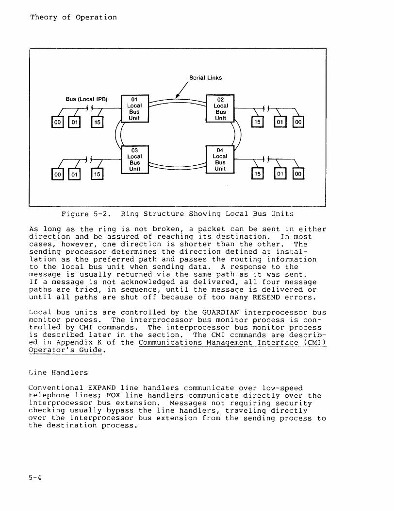
Theory of Operation
Serial Links
Bus (Local IPB) 01 02
~ Local Local
1J~ Bus Bus Unit Unit
15 15
03 04
" Local Local
M Bus Bus Unit U.nit
15 15
Figure 5-2. Ring Structure Showing Local Bus Units
As long as the ring is not broken, a packet can be sent in either direction and be assured of reaching its destination. In most cases, however, one direction is shorter than the other. The sending processor determines the direction defined at installation as the preferred path and passes the routing information to the local bus unit when sending data. A response to the message is usually returned via the same path as it was sent. If a message is not acknowledged as delivered, all four message paths are tried, in sequence, until the message is delivered or until all paths are shut off because of too many RESEND el~rors.
Local bus units are controlled by the GUARDIAN interprocessor bus monitor process. The interprocessor bus monitor process is controlled by eMI commands. The interprocessor bus monitor process is described later in the section. The eMI commands are described in Appendix K of the Communicat ions Management Interfa~:~_~~MI ~ 9perator's Guide.
Line Handlers
Conventional EXPAND line handlers communicate over low-speed telephone lines; FOX line handlers communicate directly over the interprocessor bus extension. Messages not requiring security checking usually bypass the line handlers, traveling directly over the interprocessor bus extension from the sending process to the destination process.
5-4
Theory of Operation
The FOX line handler plays a role in many ways analogous to that of the conventional EXPAND line handler. The FOX line handler interfaces with the Network Control Program to establish and manage the connection of clusters in the same manner as it does in EXPAND. Also, the line handler handles the routing of packets for traffic that is being forwarded~ thus, if a FOX cluster receives messages from a conventional EXPAND line handler that must be forwarded to another FOX cluster, the messages are passed through on a packet-by-packet basis as in conventional EXPAND.
Information on the configuration of FOX line handlers appears in the System Management Manual.
INTERPROCESSOR BUS MONITOR PROCESS
The GUARDIAN interprocessor bus monitor process for NonStop II systems controls the state of the Local Bus Unit (LBU). It also controls the downloading of the Loadable Control Store (LCS) with the correct firmware for the LBU.
The interprocessor bus monitor process must be defined at system generation as a dummy I/O device. It can be assigned any name. For ease of reference in this document, it is always referred to as $IPB.
Systems using the FOX network must specify one $IPB process at system generation. Both FOX and $IPB must be generated into the system, as described in the SYSGEN sections of the System Management Manual. $IPB is controlled by CMI commands, as described in Appendix K of the Communications Management Interface (CMI) Operator's Guide. ----
$IPB can be run on NonStop II processors without FOX. However, most features of $IPB are available only when FOX is installed.
Summary of Key Features
LOCAL BUS UNIT (LBU) MANAGEMENT. When the LBU is installed, $IPB monitors the Local Bus Unit, using a special function packet interface to poll for controller status and error data. $IPB is responsible for correct loading of firmware into the Loadable Control Store.
MESSAGE SYSTEM PROTOCOL SUPERVISION. $IPB controls the state of individual physical links (X/Y, left/ right) to remote clusters and individual buses to all processors. Certain error status data generated by message system operations is passed to $IPB by the monitor process of the processor which encountered the error.
5-5
$IPB Process
DIAGNOSTIC SUPPORT. The EPROM resident self-test on the FOX controller and a downloadable Extended Self Test are executed as a step of the procedure by which the LBU is downloaded with operational code. Error statistics and status can be displayed by using CMI commands described in Appendix K of the Communications Management Interface (CMI) 9pera~?rrs Guide.
ACTIVE INTER-CLUSTER LINK MONITORING. $IPB establishes communication with its counterparts in other clusters on a FOX ring using a low-level handshaking protocol that coexists with, and is independent of, the inter-cluster bus protocol used by the message system. This enables $IPB to continually test the state of the FOX ring and to collect status information for diagnostic and maintenance purposes. This information can be retrieved by use of CMI commands described in Appendix K of the Communications Mangagemen tIn ter face (CM~}_,_Op'~~a tC?!:"_'_~_Gu ide.
Detailed Functional Specifications
LOCAL BUS UNIT MANAGEMENT. The $IPB process is responsible for controlling the state of the LBU. When a primary $IPB process is initialized, it determines the state of the X and Y bus controllers by requesting LBU status. Persistent failure to obtain a response to the status request is recognized as an indication that the FOX network has not been installed, or that an error condition exists.
If $IPB gets answers to its status requests, then $IPB can bring the controllers to the appropriate state. This can require loading the operational firmware into the controller if it is not already running the correct version. The user can specify through SYSGEN whether the controller is to be started or stopped initially, and whether the firmware is to be replaced if the executing firmware is not identical to the firmware indicated in the microcode file.
Once initialization is complete, $IPB will maintain the status of the controller by periodically querying its status using special function packets. The state of the controller can be modified through use of the CMI commands START, STOP, and ABORT. 'rhe name of the operational firmware file to be used can be changed with the ALTER command.
$IPB is responsible for correct recovery from power failures that cause loss of the operational firmware.
Each time the FOX boards are powered on, or the reset button is pressed, the LBU runs a self-test diagnostic on the boards. When a START command is issued, $IPB checks the hardware ID of the LBU
5-6
$IPB Process
and downloads an appropriate operational loader module (LOADER). LOADER downloads the extended self-test module (EXTSELFTST). Then LOADER downloads the standard firmware module (STANDARD) which handles normal FOX traffic.
INTER-CLUSTER PROTOCOL SUPERVISION. $IPB receives error information generated by the GUARDIAN message system during the transfer of messages between clusters. This includes the shutting down of paths as a result of send timeouts and resend (WACK) timeouts. This information is also reported by the message system to the operator device and disc log as usual. $IPB must receive this information to support the diagnostic process and to maintain current status information on all paths.
ACTIVE INTER-CLUSTER LINK MONITORING. $IPB continually monitors the state of all paths to every system in the ring with an active $IPB. This is accomplished throug~ use of a low-level handshaking protocol that uses special unsequenced packets. A class identifier in the packet allows the packets used by $IPB and the packets used by FOX line handlers to coexist without interference or confusion. $IPB can establish and maintain handshaking continuity independent of EXPAND logical connections between the systems. Also the status information exchanged through handshaking packets permits every $IPB to have a comprehensive view of the state of the FOX ring. This aid is important to systems diagnosis and maintenance.
FOX controllers exchange "I'm alive" messages with their neighbors that include the cluster number of the sending controller. This allows $IPB to determine the cluster numbers of its operational neighbors. These FOX "I'm alive" messages are not to be confused with the "I'm alive" messages exchanged between system processors.
In addition, the controllers also send "My host is alive" messages. These messages contain the cluster number and CPU number of the last special function packet requesting status information from the LBU. If such a packet is not received within a time interval of approximately 30 seconds, the controller assumes that its host is dead. When this occurs, the controller enters a state in which the "My host is alive" messages are allowed to pass through; these messages include the cluster and CPU being received from the LBU in the opposite direction. Thus, every controller retains the identity of the CPU containing the next adjacent system with an "alive" $IPB in it. This data is available to $IPB in the status reply packet that it receives from the LBU.
Operator commands for $IPB are provided through the CMI product, which is described in Appendix K of the Communications Management Interface (CMI) Operator's Guide.
S-7

SECTION 6
INTRODUCTION TO INFOSAT
NOTE
This product is available only on the Tandem NonStop II system. It cannot be used on the Tandem NonStop system.
This section introduces INFOSAT, Tandem's joint venture with American Satellite Company (ASC). INFOSAT is a fully integrated, computer/satellite network. You'll find information here about how satellites and earth stations work, and about the benefits of transmitting and receiving over satellite lines. In addition, this section describes many of the different components that make up the satellite, the earth station, and the Tandem NonStop II interface.
If you need to learn more about INFOSAT after reading this section, see Appendix L of the Communications Management Interface (CMI) Operator's Guide. It explains how to use eMI to access INFOSAT. The System Mana~ement Manual tells you how to configure an INFOSAT subnetwork lnto your EXPAND network. Finally, if you need to run on-line diagnostic functions on your INFOSAT system, read the Guide to the CM! Diagnostic Facility.
OVERVIEW
INFOSAT allows the EXPAND network to run on satellite channels instead of terrestrial lines as the communications medium. If you need to transfer data over long distances, an INFOSAT system provides the following benefits:
• Price/performance - Satellite channels can add a large amount of transmission capacity and significantly reduce the cost of long distance communications.
6-1
Introduction to INFOSAT
• Reliability - INFOSAT is fault tolerant; that is, there are two parallel "sides," or paths to the satellite. Hence, if a failure should occur, the data rate will degrade to only 56 kbps (from 112 kbps).
• Low error rate - The average error rate for INFOSAT is better than for terrestrial lines. This reduces the occurrence of retransmissions and results in better response time and throughput.
• Responsibility/Serviceability - There is a single source of responsibility and maintenance for all elements in the communications links. By integrating the earth station with a Tandem NonStop II computer, you can constantly monitor and diagnose the entire system. Many INFOSAT components are equipped with Field Replaceable Units (FRUs). If a FRU fails, a Tandem representative needs only theFRU number in order to replace the entire module.
• Availability - INFOSAT service can be provided anywhere in the continental U.S., whereas terrestrial high-speed digital circuits may have long service lead times or may not be available at all in some areas.
SATELLITES
A communications satellite is a relay station which receives, amplifies, and retransmits data signals from stations on earth (called, appropriately, earth stations).
Early satellites moved around the earth and could echo signals only as they passed over the serviced area. Earth stations needed to track these early satellites as they passed across the sky.
Today's communications satellites appear to be in a stationary orbit from the ground, providing 24-hour availability. This means that an antenna on an earth station can point toward a satellite without moving. How does this stationary orbit work?
The satellite must be the geosynchronous type, that is, it must travel at the same speed as the earth's rotation in a "geostationary" orbit. To maintain a geostationary orbit, the satellite orbits in ~ fixed position approximately 22,300 miles above the equator. At this position, the satellite rotates around the earth in exactly 24 hours. Since 1963, all communications satellites have been of the geosynchronous type.
6-2
Introduction to INFOSAT
Satellite Components
The satellite consists of the following components:
• Transponders, which receive, amplify, change the frequency of and retransmit signals from earth stations.
• Solar panels, storage batteries and power conditioners, which generate and store the power for the satellite.
• position control thrusters, which adjust the satellite orbital position and altitude.
• A command and telemetry subsystem, which transmit data about the satellite to the earth station and receive commands from the earth station.
• An antenna, which receives and transmits signals.
Figure 6-1 illustrates how the components of the satellite work together. The solar panels generate power and pass it to the storage batteries and power conditioner. The power is then distributed to the transponders (receivers, frequency translators and transmitters), and the command/telemetry subsystem.
Meanwhile, signals received at the antenna are transmitted through the antenna subsystem to the receiver portion of the transponder. There, the signals are amplified and passed to the frequency translator where the frequency is changed from 6GHz to 4GHz (1 gigahertz (GHz) means 1000 million cycles per second). The signals then continue through the transmitter, where they are further amplified. Finally, the signals are returned to the antenna for broadcast. In essence, the satellite echoes back to earth the same data stream it receives, after amplifying it and changing its carrier frequency.
6-3
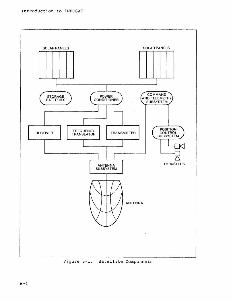
Introduction to INFOSAT
~--------------------------------.------------'-----------------------~
SOLAR PANELS
STORAGE BATTERIES
RECEIVER FREQUENCY
TRANSLATOR
SOLAR PANELS
COMMAND '-----lAND TELEMETRY
SUBSYSTEM
TRANSMITTER] POSITI(~N CONTROL
SUBSYSTEM
ANTENNA SUBSYSTEM
ANTENNA
THRUSTERS
~----------------------------------------------------------------.--~ Figure 6-1. Satellite Components
6-4
Introduction to INFOSAT
Satellite Frequency Bands
Satellites operate in one or both of two frequency bands-Ku-band or C-band. The main difference between the two is that Ku-band operates at 14GHz for its uplink, 12 GHz for its downlink, while C-band operates at 6GHz for the uplink and 4GHz for the downlink. INFOSAT uses C-band for a number of reasons.
• C-band is not as susceptible to attenuation (weakening of the signal) during rainstorms.
• Components are simpler, less expensive, more reliable and more available for C-band.
• Antennas are less expensive because uniform surface tolerances are not as critical.
One drawback of C-band is that it is more subject to radio frequency (RF) congestion in metropolitan areas. INFOSAT addresses this problem by providing large, shared-use earth stations for customers who need it.
Footprint
Satellites broadcast signals over an area called a "footprint" (see Figure 6-2); the larger the footprint, the weaker the signal. There are several ways to compensate for weak signals, including larger earth station antennas, more powerful transmission amplifiers, or more sophisticated error correction techniques.
The satellite determines the shape of the footprint, concentrating the signal where it is needed, instead of broadcasting over too wide an area. INFOSAT's footprint covers the continental United States. Figure 6-2 illustrates the INFOSAT footprint. Note that areas located on the fringe of the footprint (southern Texas and Florida, Northern Maine and portions of some states bordering Canada) will receive a weaker signal than those toward the center and may therefore require a slightly larger earth station antenna to capture the signals.
6-5
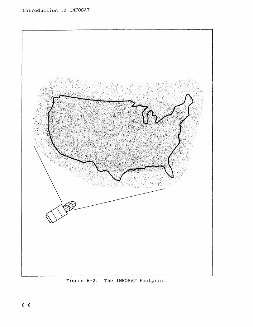
Introduction to INFOSAT
r----.------------------------.-.
Figure 6-2. The INFOSAT Footprint
6-6
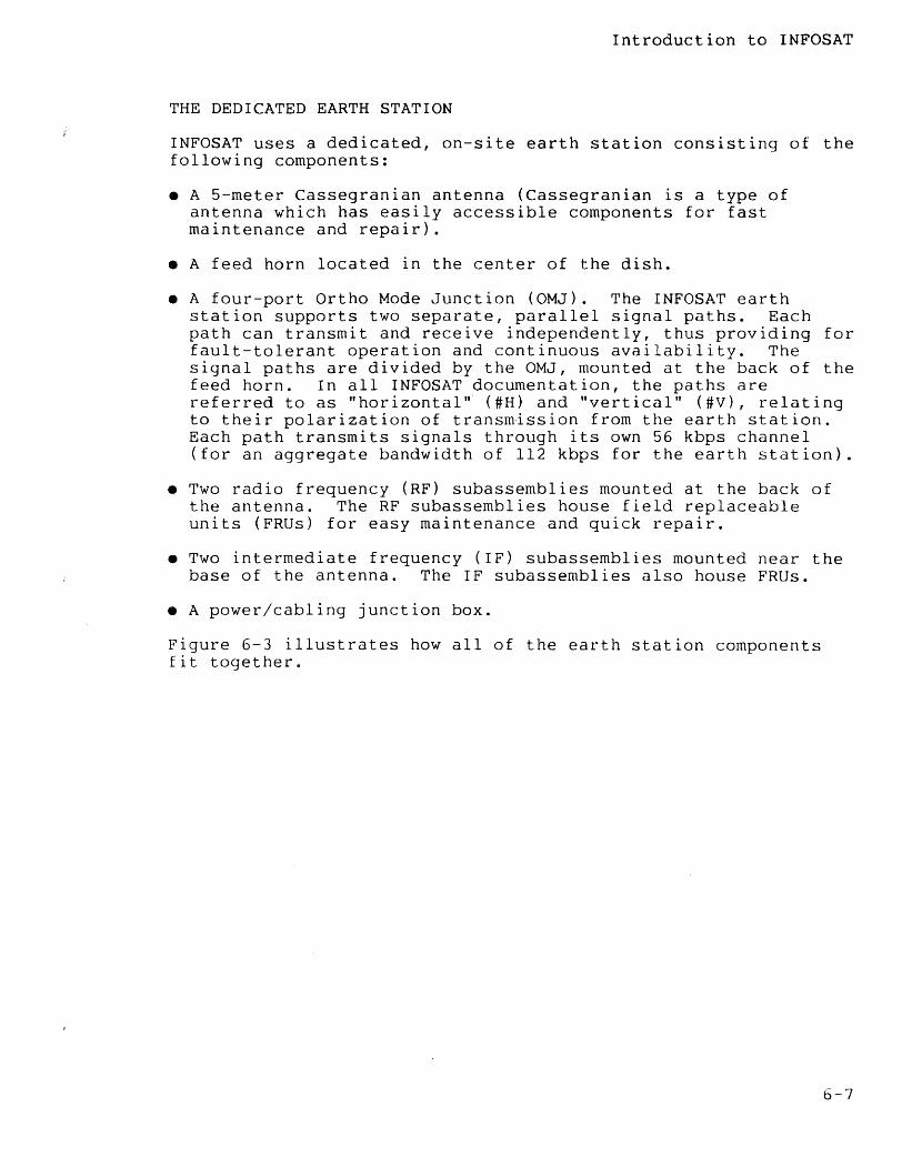
Introduction to INFOSAT
THE DEDICATED EARTH STATION
INFOSAT uses a dedicated, on-site earth station consisting of the following components:
• A 5-meter Cassegranian antenna (Cassegranian is a type of antenna which has easily accessible components for fast maintenance and repair).
• A feed horn located in the center of the dish.
• A four-port Ortho Mode Junction (OMJ). The INFOSAT earth station supports two separate, parallel signal paths. Each path can transmit and receive independently, thus providing for fault-tolerant operation and continuous availability. The signal paths are divided by the OMJ, mounted at the back of the feed horn. In all INFOSAT documentation, the paths are referred to as "horizontal" (#H) and "vertical" (#V), relating to their polarization of transmission from the earth station. Each path transmits signals through its own 56 kbps channel (for an aggregate bandwidth of 112 kbps for the earth station).
• Two radio frequency (RF) subassemblies mounted at the back of the antenna. The RF subassemblies house field replaceable units (FRUs) for easy maintenance and quick repair.
• Two intermediate frequency (IF) subassemblies mounted near the base of the antenna. The IF subassemblies also house FRUs.
• A power/cabling junction box.
Figure 6-3 illustrates how all of the earth station components fit together.
6-7
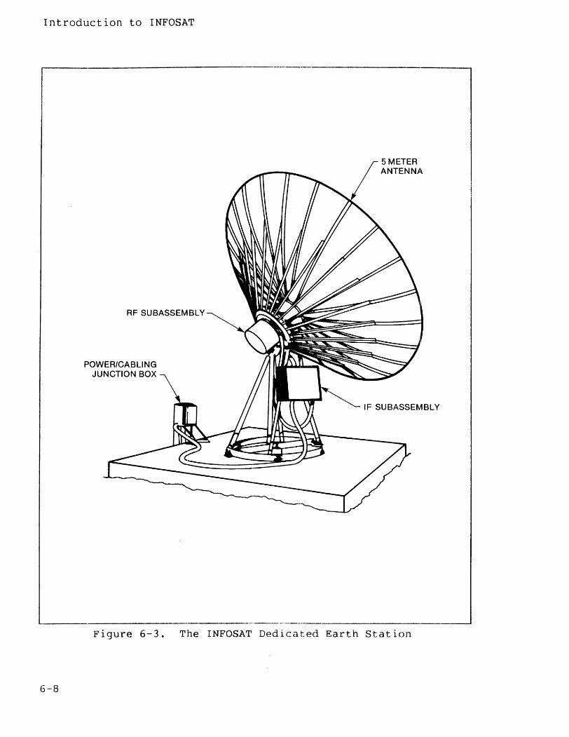
Introduction to INFOSAT
r-------------------------------'-------------,
RF SUBASSEMBLY
POWER/CABLING JUNCTION BOX
IF SUBASSEMBLY
----_. __ ._---,
Figure 6-3. The INFOSAT Dedicated Earth Station
6-8
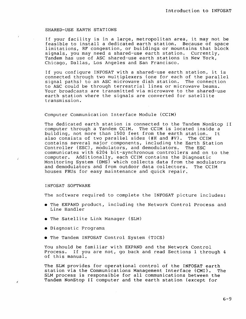
Introduction to INFOSAT
SHARED-USE EARTH STATIONS
If your facility is in a large, metropolitan area, it may not be feasible to install a dedicated earth station. Because of space limitations, RF congestion, or buildings or mountains that block signals, you may need a shared-use earth station. Currently, Tandem has use of ASC shared-use earth stations in New York, Chicago, Dallas, Los Angeles and San Francisco.
If you configure INFOSAT with a shared-use earth station, it is connected through two multiplexers (one for each of the parallel signal paths) to an ASC microwave dish station. The connection to ASC could be through terrestrial lines or microwave beams. Your broadcasts are transmitted via microwave to the shared-use earth station where the signals are converted for satellite transmission.
Computer Communication Interface Module (CCIM)
The dedicated earth station is connected to the Tandem NonStop II computer through a Tandem CCIM. The CCIM is located inside a building, not more than 1500 feet from the earth station. It also consists of two parallel sides (#H and #V). The CCIM contains several major components, including the Earth Station Controller (ESC), modulators, and demodulators. The ESC communicates with 6204 bit-synchronous controllers and on to the computer. Additionally, each CCIM contains the Diagnostic Monitoring System (DMS) which collects data from the modulators and demodulators and from outdoor data collectors. The CCIM houses FRUs for easy maintenance and quick repair.
INFOSAT SOFTWARE
The software required to complete the INFOSAT picture includes:
• The EXPAND product, including the Network Control Process and Line Handler
• The Satellite Link Manager (SLM)
• Diagnostic Programs
• The Tandem INFOSAT Control System (TICS)
You should be familiar with EXPAND and the Network Control Process. If you are not, go back and read Sections 1 through 4 of this manual.
The SLM provides for operational control of the INFOSAT earth station via the Communications Management Interface (eMI). The SLM process is responsible for all communications between the Tandem NonStop II computer and the earth station (except for
6-9
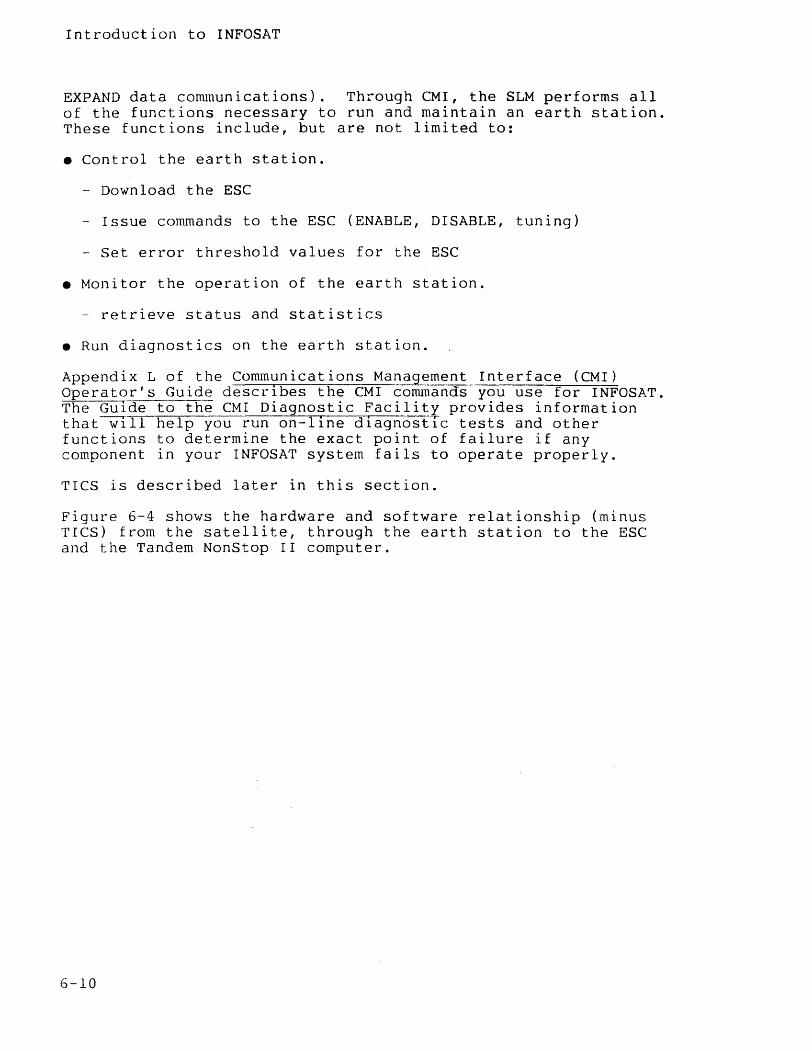
Introduction to INFOSAT
EXPAND data communications). Through eMI, the SLM performs all of the functions necessary to run and maintain an earth station. These functions include, but are not limited to:
• Control the earth station.
- Download the ESC
- Issue commands to the ESC (ENABLE, DISABLE, tuning)
- Set error threshold values for the ESC
• Monitor the operation of the earth station.
- retrieve status and statistics
• Run diagnostics on the earth station.
Appendix L of the Communications Ma~agement Interface (CMI) Operator's Guide describes the CMI commands you use for INFOSAT. The Guide to the CMI Diagnostic Facility provides information that will help you run on-line diagnostIc tests and other functions to determine the exact point of failure if any component in your INFOSAT system fails to operate properly.
TICS is described later in this section.
Figure 6-4 shows the hardware and software relationship (minus TICS) from the satellite, through the earth station to the ESC and the Tandem NonStop II computer.
6-10
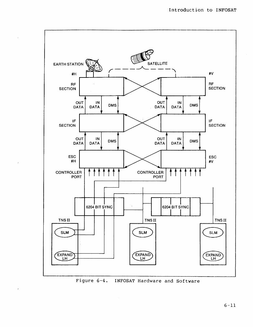
Introduction to INFOSAT
EARTH STATION ~ /" _____ ~_TEL_LlT_E ""\ #H r - (
--~----~I~--~ ~ ______ I ______ ~
~C><~ RF SECTION
OUT IN DATA DATA
IF SECTION
DMS DMS OUT IN
DATA DATA
1>< ----------------~ ~~~----~--~~ ~
DMS OUT IN
DATA DATA DMS
OUT IN DATA DATA ,
ESC #H ~><~
CONTROLLER t t t t t t ~ CONTROLLER t t t t t t PORT PORT
I I 6204 BIT SYNC 6204 BIT SYNC
I I TNSII TNSII
- -"""''-----'L-.-II
SLM I--....",
#v
RF SECTION
IF SECTION
ESC #V
TNSII
--....,. EXPAND~+-------~
...!:.t!..." ~PA~ LH ~PA~ LH
Figure 6-4. INFOSAT Hardware and Software
6-11
Introduction to INFOSAT
THE INFOSAT/EXPAND NETWORK
The basic INFOSAT configuration consists of two or more Tandem NonStop II systems with dedicated earth stations and transponder space on an orbiting satellite. This configuration fulfills the requirements for an integrated computer/satellite network that is fault-tolerant and continuously available.
An INFOSAT node can be included as a part of a larger EXPAND network. In this case, all nodes with the network are directly connected. Figure 6-5 illustrates this type of network configuration.
6-12
/ /
/
EXPAND ~l INFOSAT NETWORK - -....... -....
/' .........
/ '" / "-
/ \ / \ I \ I \ \ I \ I \ jl
" / " / " /' ........ _---/
-------------------Figure 6-5. INFOSAT/EXPAND Network
Introduction to INFOSAT
Remember that the EXPAND network can support up to 255 nodes. With INFOSAT, each dedicated earth station can receive signals from up to seven other INFOSAT nodes. Conceivably then, all 255 nodes in an EXPAND network could be INFOSAT nodes, each able to receive signals from seven other INFOSAT nodes. If two nodes not directly connected to each other need to communicate, they can do so through standard EXPAND terrestrial lines, or they can pass data through a third INFOSAT node to which both are connected.
Figure 6-6 illustrates this type of connection. The "A" nodes on the left are all directly connected to each other and to node "Bl" on the right. The "B" nodes on the right are all directly connected to each other and to node "AI" on the left. If node A5 needs to communicate with node B5, two "hops" are necessary; one satellite hop from node A5 to node Bl and a second hop from node Bl to node B5.
6-13
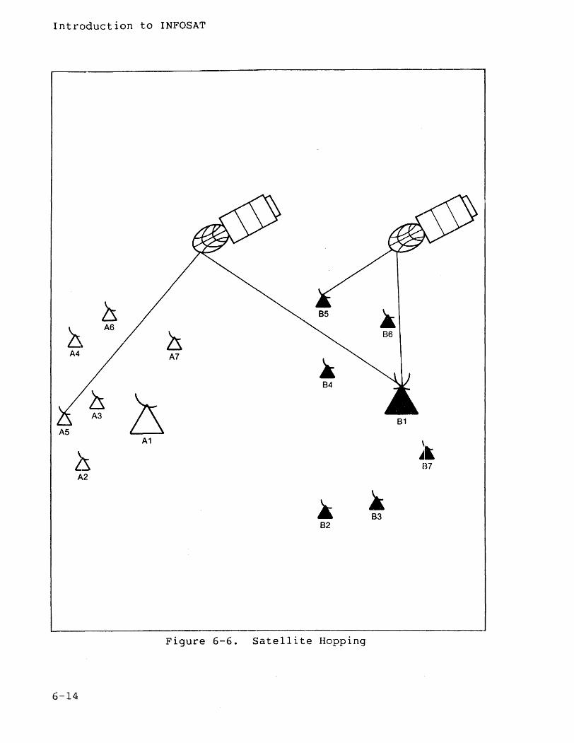
Introduction to INFOSAT
----------------------------------.-----------------------------
ls 85 ~ ~
A6
Zs 86
A4 A7
~ 84
A3 ~ 81 A5
A1
~k ~ B7 A2
~ ~ 83
82
Figure 6-6. Satellite Hopping
6-14
Introduction to INFOSAT
TANDEM INFOSAT CONTROL SYSTEM (TICS)
Satellites are a broadcast medium. This means that anyone with an earth station and a parabolic dish can receive the broadcast. Therefore, the FCC has established stringent requirements on earth station broadcast parameters. Two requirements are of particular interest: First, all parameters must be established by FCC-licensed personnel and second, any earth station broadcasting out of tolerance must be shut down in a reasonable amount of time.
INFOSAT is constantly monitored by ASC's Network Operation Control Center (NOCC). Due to FCC regulations, it is necessary for the NOCC to have access to your Tandem NonStop II System. Note that the NOCC does not have access to your data base!
The NOCC can access your system through Tandem-operated software called the Tandem INFOSAT Control System (TICS). TICS provides a central control point for INFOSAT. operation, and coordinates INFOSAT earth stations. TICS is an application program which allows FCC-licensed Tandem personnel to perform various operations on any INFOSAT earth station. TICS maintains a dial-up connection with all INFOSAT sites. In essence, TICS acts as an intermediary through which the NOCC monitors the performance of your system and insures that FCC regulations are adhered tOe
The dial-in/dial-out capabilities of TICS perform the following functions:
• Handle asynchronous terminal dial-in ports for communications from NOCC, ASC, or a Tandem field engineer
• Authenticate the caller
• Turn on or turn off the transmitter
• Set transmit frequencies
• Set transmit power levels
• Establish station IDs
• Read an INFOSAT station's status and monitor data
• Execute diagnostics (limited)
• Maintain a telephone directory for customer dial-in ports
• Dial out to a customer upon command, authenticate the connection, and transfer commands and responses.
• Log actions for each INFOSAT system
6-15
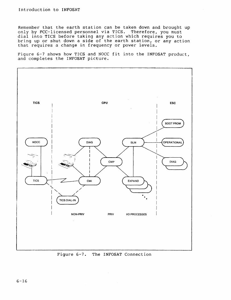
Introduction to INFOSAT
Remember that the earth station can be taken down and brought up only by FCC-licensed personnel via TICS. Therefore, you must dial into TICS before taking any action which requires you to bring up or shut down a side of the earth station, or any action that requires a change in frequency or power levels.
Figure 6-7 shows how TICS and NOCC fit into the INFOSAT product, and completes the INFOSAT picture.
TICS CPU ESC
~----~ ... , \.::--- .
NON·PRIV PRIV 1/0 PROCESSES
Figure 6-7. The INFOSAT Connection
6-16
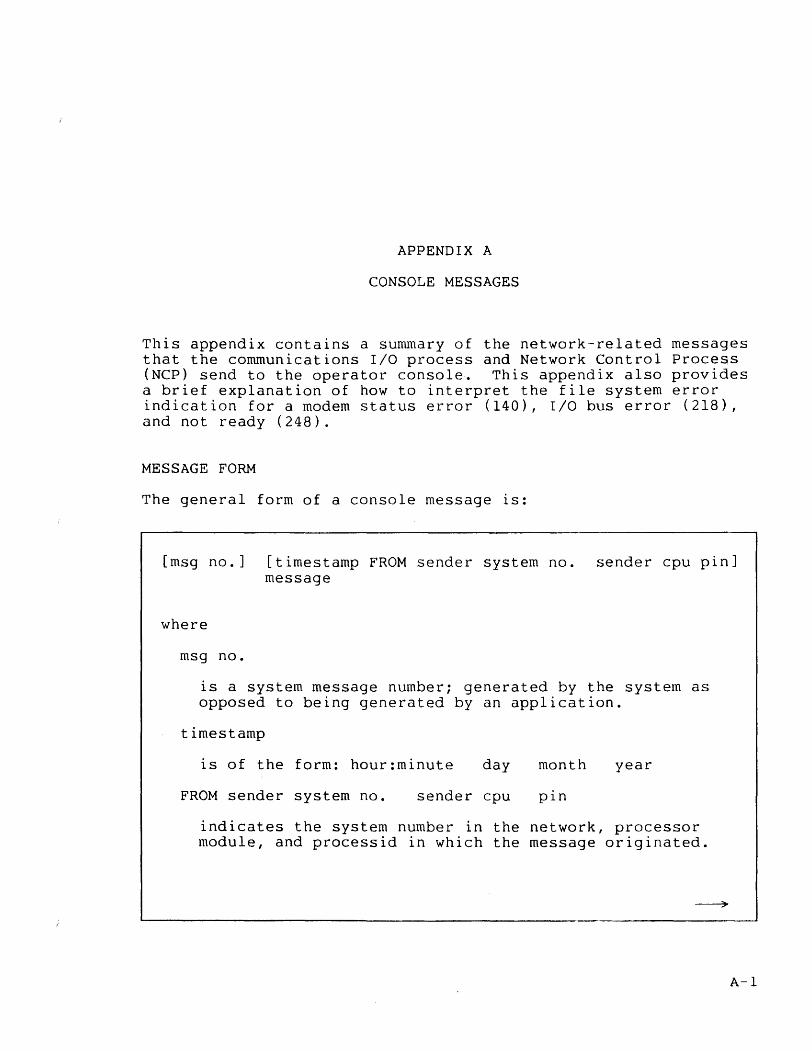
APPENDIX A
CONSOLE MESSAGES
This appendix contains a summary of the network-related messages that the communications I/O process and Network Control Process (NCP) send to the operator console·. This appendix also provides a brief explanation of how to interpret the file system error indication for a modem status error (140), I/O bus error (218), and not ready (248).
MESSAGE FORM
The general form of a console message is:
[msg no.] [timestamp FROM sender system no. sender cpu pin] message
where
msg no.
is a system message number; generated by the system as opposed to being generated by an application.
timestamp
is of the form: hour:minute day month year
FROM sender system no. sender cpu pin
indicates the system number in the network, processor module, and processid in which the message originated.
A-I
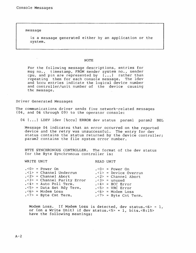
Console Messages
message
is a message generated either by an application or the system.
NOTE
For the following message descriptions, entries for msg no., timestamp, FROM sender system no., sender cpu, and pin are represented by { •.. } rather than repeating them for each console message. The ldev and %ccu entries indicate the logical device number and controller/unit number of the device causing the message.
Driver Generated Messages
The communications driver sends five network-related messages (04, and 06 through 09) to the operator console:
04 { ... } LDEV ldev [%ccu] ERROR dev status paraml param2 BEL
A-2
Message 04 indicates that an error occurred on the reported device and the retry was unsuccessful. The entry for dev status contains the status returned by the device controller; param2 contains the file system error number.
BYTE SYNCHRONOUS CONTROLLERe The format of the dev status for the Byte Synchronous controller IS:
WRITE UNIT READ UNIT
.<0> = Power On .<0> Power On $<1> Channel Underrun .<1> Device Overrun .<2> Channel Abort .<2> Channel Abort .<3> Channel Parity Error .<3> unused .<4> Auto Poll Term. .<4> = BCC Error .<5> Data Set Rdy Term. .<5> = VRC Error .<6> Modem Loss .<6> Modem Loss .<7> Byte Cnt Term. .<7> Byte Cnt Term.
Modem Loss. If Modem Loss is detected, dev status.<6> =: 1, or (on a Write Unit) if dev status.<5> = 1, bits.<8:15> have the following meanings:
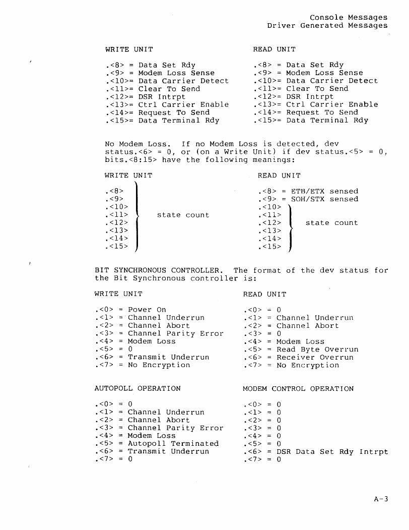
WRITE UNIT
.<8> = Data Set Rdy
.<9> = Modem Loss Sense
.<10>= Data Carrier Detect
.<11>= Clear To Send
.<12>= DSR Intrpt
.<13>= Ctrl Carrier Enable
.<14>= Request To Send
.<15>= Data Terminal Rdy
Console Messages Driver Generated Messages
READ UNIT
.<8>
.<9>
.<10>=
.<11>=
.<12>=
.<13>=
.<14>=
.<15>=
Data Set Rdy Modem Loss Sense Data Carrier Detect Clear To Send DSR Intrpt Ctr1 Carrier Enable Request To Send Data Terminal Rdy
No Modem Loss. If no Modem Loss is detected, dev status.<6> = 0, or (on a Write Unit) if dev status.<5> 0, bits.<8:15> have the following meanings:
WRITE UNIT
.<8>
.<9>
.<10>
.<11>
.<12>
.<13>
.<14> 0<15>
state count
READ UNIT
.<8>
.<9>
.<10>
.<11>
.<12>
.<13>
.<14>
.<15>
ETB/ETX sensed SOH/STX sensed
state count
BIT SYNCHRONOUS CONTROLLER. The format of the dev status for the Bit Synchronous controller is:
WRITE UNIT
.<0> =
.<1>
.<2> -
.<3>
.<4> =
.<5> =
.<6>
.<7>
Power On Channel Underrun Channel Abort Channel Parity Error Modem Loss o Transmit Underrun No Encryption
AUTOPOLL OPERATION
.<0> = 0
.<1> Channel Underrun
.<2> = Channel Abort
.<3> Channel Parity Error
.<4> = Modem Loss
.<5> = Autopoll Terminated
.<6> Transmit Underrun
.<7> = 0
READ UNIT
.<0>
.<1>
.<2>
.<3>
.<4>
.<5>
.<6>
.<7>
o Channel Underrun Channel Abort o
= Modem Loss Read Byte Overrun Receiver Overrun No Encryption
MODEM CONTROL OPERATION
.<0> 0
.<1> 0
.<2> = 0
.<3> 0
.<4> 0
.<5> = 0
.<6> = DSR Data Set Rdy
.<7> = 0 Intrpt
A-3
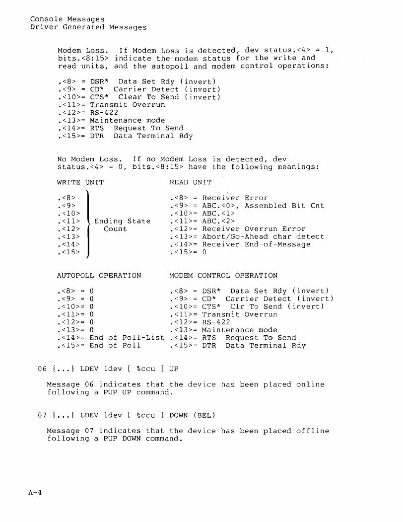
Console Messages Driver Generated Messages
Modem Loss. If Modem Loss is detected, dev status.<4> =1, bits.<8:15> indicate the modem status for the write and read units, and the autopoll and modem control operations:
.<8>
.<9> =
.<10>=
.<11>=
.<12>=
.<13>=
.<14>=
.<15>=
DSR* Data Set Rdy (invert) CD* Carrier Detect (invert) CTS* Clear To Send (invert) Transmit Overrun RS-422 Maintenance mode RTS Request To Send DTR Data Terminal Rdy
No Modem Loss. If no Modem Loss is detected, dev status.<4> = 0, bits.<8:15> have the following meanings:
WRITE UNIT
.<8>
.<9>
.<10>
.<11>
.<12>
.<13>
.<14>
.<15>
Ending State Count
AUTOPOLL OPERATION
.<8> = 0
.<9> = 0
.<10>= 0
.<11>= 0
.<12>= 0
.<13>= 0
.<14>= End of Poll-List
.<15>= End of Poll
READ UNIT
.<8>
.<9>
.<10>=
.<11>=
.<12>=
.<13>=
.<14>=
.<15>=
Receiver Error ABC.<O>, Assembled Bit Cnt ABC.<l> ABC.<2> Receiver Overrun Error Abort/Go-Ahead char detect Receiver End-of-Message o
MODEM CONTROL OPERATION
.<8> = DSR* Data Set Rdy (invert)
.<9> = CD* Carrier Detect (invert)
.<10>= CTS* C1r To Send (invert)
.<11>= Transmit Overrun • < 12 > = RS -- 4 2 2 .<13>= Maintenance mode .<14>= RTS Request To Send .<15>= DTR Data Terminal Rdy
06 { ... } LDEV ldev [ %ccu ] UP
Message 06 indicates that the device has been placed online following a PUP UP command.
07 { ... } LDEV ldev [ %ccu ] DOWN (BEL)
A-4
Message 07 indicates that the device has been placed offline following a PUP DOWN command.
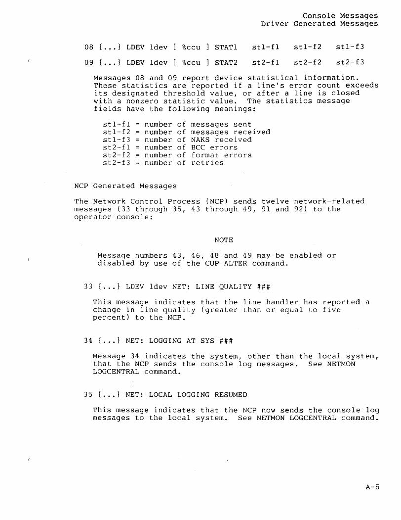
Console Messages Driver Generated Messages
08 { ..• } LDEV ldev %ccu
09 { •.. } LDEV ldev [ %ccu
STAT1
STAT2
st1-f1
st2-f1
st1-f2 st1-f3
st2-f2 st2-f3
Messages 08 and 09 report device statistical information. These statistics are reported if a line's error count exceeds its designated threshold value, or after a line is closed with a nonzero statistic value. The statistics message fields have the following meanings:
st1-f1 number of messages sent st1-f2 number of messages received st1-f3 number of NAKS received st2-fl = number of BCC errors st2-f2 number of format errors st2-f3 = number of retries
NCP Generated Messages
The Network Control Process (NCP) sends twelve network-related messages (33 through 35, 43 through 49, 91 and 92) to the operator console:
NOTE
Message numbers 43, 46, 48 and 49 may be enabled or disabled by use of the CUP ALTER command.
33 { ... } LDEV Idev NET: LINE QUALITY ###
This message indicates that the line handler has reported a change in line quality (greater than or equal to five percent) to the NCP.
34 { ... } NET: LOGGING AT SYS ###
Message 34 indicates the system, other than the local system, that the NCP sends the console log messages. See NETMON LOGCENTRAL command.
35 { ... } NET: LOCAL LOGGING RESUMED
This message indicates that the NCP now sends the console log messages to the local system. See NETMON LOGCENTRAL command.
A-5
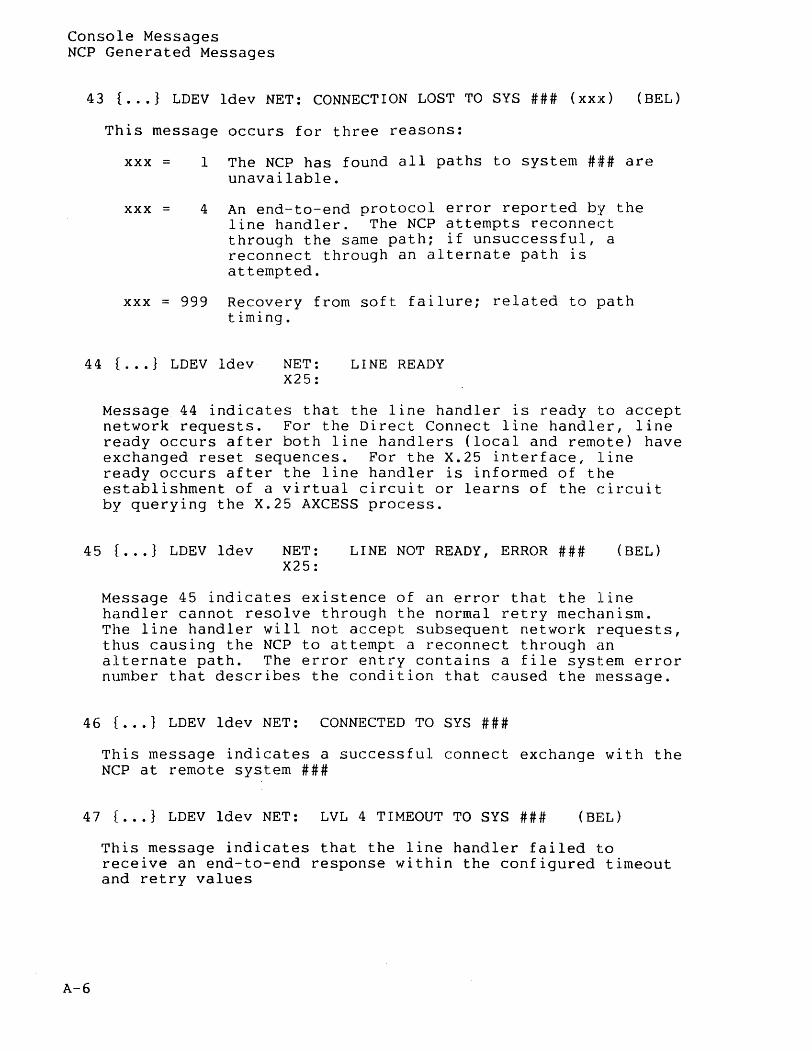
Console Messages NCP Generated Messages
43 { ... } LDEV ldev NET: CONNECTION LOST TO SYS ### (xxx) (BEL)
This message occurs for three reasons:
xxx =
xxx =
I The NCP has found all paths to system ### are unavailable.
4 An end-to-end protocol error reported by the line handler. The NCP attempts reconnect through the same path; if unsuccessful, a reconnect through an alternate path is attempted.
xxx = 999 Recovery from soft failure; related to path timing.
44 { ... } LDEV ldev NET: LINE READY X25:
Message 44 indicates that the line handler is ready to accept network requests. For the Direct Connect line handler, line ready occurs after both line handlers (local and remote) have exchanged reset sequences. For the X.25 interface, line ready occurs after the line handler is informed of the establishment of a virtual circuit or learns of the circuit by querying the X.25 AXCESS process.
45 { ... } LDEV ldev NET: LINE NOT READY, ERROR ### (BEL) X25:
Message 45 indicates existence of an error that the line handler cannot resolve through the normal retry mechanism. The line handler will not accept subsequent network requests, thus causing the NCP to attempt a reconnect through an alternate path. The error entry contains a file system error number that describes the condition that caused the message.
46 { ... J LDEV ldev NET: CONNECTED TO SYS ###
This message indicates a successful connect exchange with the NCP at remote system ###
47 { ... } LDEV ldev NET: LVL 4 TIMEOUT TO SYS ### (BEL)
A-6
This message indicates that the line handler failed to receive an end-to-end response within the configured timeout and retry values
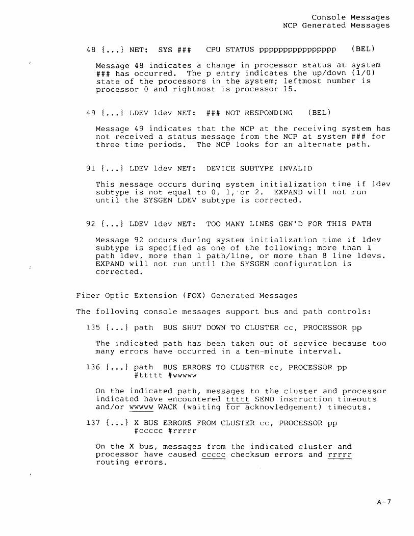
Console Messages NCP Generated Messages
48 { ... } NET: SYS ### CPU STATUS pppppppppppppppp (BEL)
Message 48 indicates a change in processor status at system ### has occurred. The p entry indicates the up/down (1/0) state of the processors in the system; leftmost number is processor 0 and rightmost is processor 15.
49 { ... } LDEV ldev NET: ### NOT RESPONDING (BEL)
Message 49 indicates that the NCP at the receiving system has not received a status message from the NCP at system ### for three time periods. The NCP looks for an alternate path.
91 { ... } LDEV ldev NET: DEVICE SUBTYPE INVALID
This message occurs during system initialization time if ldev subtype is not equal to 0, 1, 'or 2. EXPAND will not run until the SYSGEN LDEV subtype is corrected.
92 { ... } LDEV ldev NET: TOO MANY LINES GEN'D FOR THIS PATH
Message 92 occurs during system initialization time if ldev subtype is specified as one of the following: more than 1 path ldev, more than 1 path/line, or more than 8 line ldevs. EXPAND will not run until the SYSGEN configuration is corrected.
Fiber Optic Extension (FOX) Generated Messages
The following console messages support bus and path controls:
135 { ... } path BUS SHUT DOWN TO CLUSTER cc, PROCESSOR pp
The indicated path has been taken out of service because too many errors have occurred in a ten-minute interval.
136 { ... } path BUS ERRORS TO CLUSTER cc, PROCESSOR pp #ttttt #wwwww
On the indicated path, messages to the cluster and processor indicated have encountered ttttt SEND instruction timeouts and/or wwwww WACK (waiting for acknowledgement) timeouts.
137 { ... } X BUS ERRORS FROM CLUSTER cc, PROCESSOR pp #ccccc #rrrrr
On the X bus, messages from the indicated cluster and processor have caused ccccc checksum errors and rrrrr routing errors.
A-7
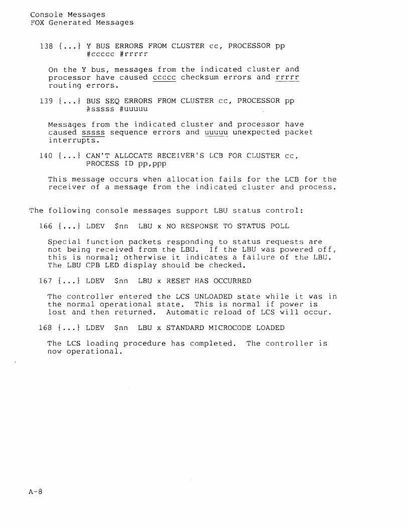
Console Messages FOX Generated Messages
138 f ••• } Y BUS ERRORS FROM CLUSTER cc, PROCESSOR pp #ccccc #rrrrr
On the Y bus, messages from the indicated cluster and processor have caused ccccc checksum errors and rrrrr routing errors.
139 f ••• } BUS SEQ ERRORS FROM CLUSTER cc, PROCESSOR pp #sssss #uuuuu
Messages from the indicated cluster and processor have caused sssss sequence errors and uuuuu unexpected packet interrupts.
140 [ ... } CAN'T ALLOCATE RECEIVER'S LCB FOR CLUSTER cc, PROCESS ID pp,ppp
This message occurs when allocation fails for the LCB for the receiver of a message from the indicated cluster and process.
The following console messages support LBU status control:
166 [ ... } LDEV $nn LBU x NO RESPONSE TO STATUS POLL
Special function packets responding to status requests are not being received from the LBU. If the LBU was powered off, this is normal; otherwise it indicates a failure of the LBU. The LBU CPB LED display should be checked.
167 { ... } LDEV $nn LBU x RESET HAS OCCURRED
The controller entered the LCS UNLOADED state while it was in the normal operational state. This is normal if power is lost and then returned. Automatic reload of LCS will occur.
168 { ... } LDEV $nn LBU x STANDARD MICROCODE LOADED
A-8
The LCS loading procedure has completed. The controller is now operational.
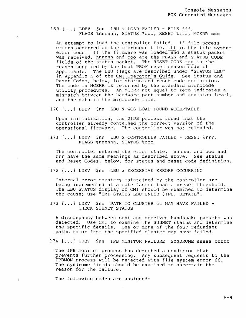
Console Messages FOX Generated Messages
169 f ••• } LDEV FLAGS
$nn LBU x LOAD FAILED - FILE fff, %nnnnnn, STATUS %000, RESET %rrr, MCERR mmrn
An attempt to load the controller failed. If file access errors occurred on the microcode file, fff is the file system error code. If the firmware was loaded and a status packet was received, nnnnnn and 000 are the FLAGS and STATUS CODE fields of the status packet. The RESET CODE rrr is the reason supplied by the boot PROM reset reason code if applicable. The LBU flags are described under "STATUS LBU" in Appendix K of the CMI Operator's Guide. See Status and Reset Codes, below, for status and reset code definition. The code in MCERR is returned by the standard microcode utility procedures. An MCERR not equal to zero indicates a mismatch between the hardware part number and revision level, and the data in the microcode file.
170 f ••• } LDEV $nn LBU x WCS LOAD FOUND ACCEPTABLE
Upon initialization, the $IPB process found that the controller already contained the correct version of the operational firmware. The controller was not reloaded.
171 f ••• } LDEV FLAGS
$nn LBU x CONTROLLER FAILED - RESET %rrr, %nnnnnn, STATUS %000
The controller entered the error state. nnnnnn and 000 and rrr have the same meanings as described above. See Status and Reset Codes, below, for status and reset code definition.
172 f ••• l LDEV $nn LBU x EXCESSIVE ERRORS OCCURRING
Internal error counters maintained by the controller are being incremented at a rate faster than a preset threshold. The LBU STATUS display of CMI should be examined to determine the cause; use "CMI STATUS LBU UNDER $IPB, DETAIL".
173 f ••• l LDEV $nn PATH TO CLUSTER cc MAY HAVE FAILED -CHECK SUBNET STATUS
A discrepancy between sent and received handshake packets was detected. Use CMI to examine the SUBNET status and determine the specific details. One or more of the four redundant paths to or from the specified cluster may have failed.
174 { ... } LDEV $nn IPB MONITOR FAILURE SYNDROME aaaaa bbbbb
The IPB monitor process has detected a condition that prevents further processing. Any subsequent requests to the IPBMON process will be rejected with file system error 66. The syndrome fields should be examined to ascertain the reason for the failure.
The following codes are assigned:
A-9
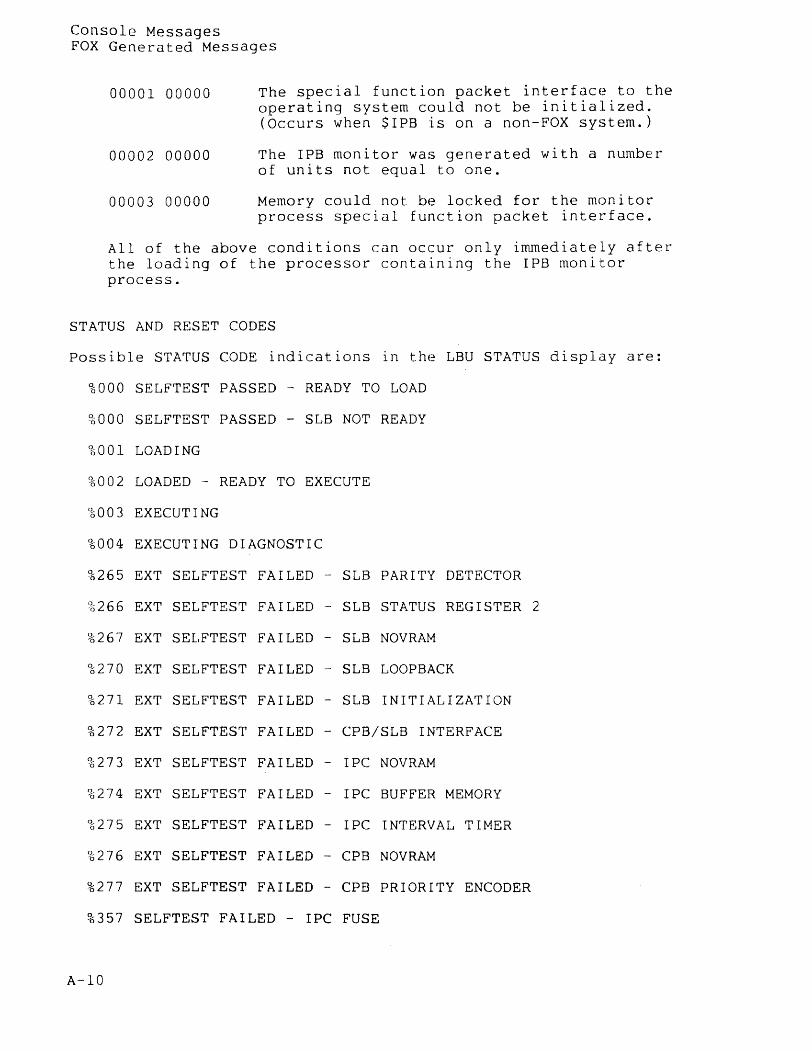
Console Messages FOX Generated Messages
00001 00000
00002 00000
00003 00000
The special function packet interface to the operating system could not be initialized. (Occurs when SIPB is on a non-FOX system.)
The IPB monitor was generated with a number of units not equal to one.
Memory could not be locked for the monitor process special function packet interface.
All of the above conditions can occur only immediately after the loading of the processor containing the IPB monitor process.
STATUS AND RESET CODES
possible STATUS CODE indications in the LBU STATUS display are:
%000 SELFTEST PASSED - READY TO LOAD
%000 SELFTEST PASSED - SLB NOT READY
96 a 0 1 LOAD I NG
%002 LOADED - READY TO EXECUTE
%003 EXECUTING
%004 EXECUTING DIAGNOSTIC
%265 EXT SELFTEST FAILED - SLB PARITY DETECTOR
%266 EXT SELFTEST FAILED - SLB STATUS REGISTER 2
%267 EXT SELFTEST FAILED - SLB NOVRAM
%270 EXT SELFTEST FAILED - SLB LOOPBACK
%271 EXT SELFTEST FAILED - SLB INITIALIZATION
%272 EXT SELFTEST FAILED - CPB/SLB INTERFACE
%273 EXT SELFTEST FAILED - IPC NOVRAM
%274 EXT SELFTEST FAILED - IPC BUFFER MEMORY
%275 EXT SELFTEST FAILED - IPC INTERVAL TIMER
%276 EXT SELFTEST FAILED - CPB NOVRAM
%277 EXT SELFTEST FAILED - CPB PRIORITY ENCODER
%357 SELFTEST FAILED - IPC FUSE
A-lO
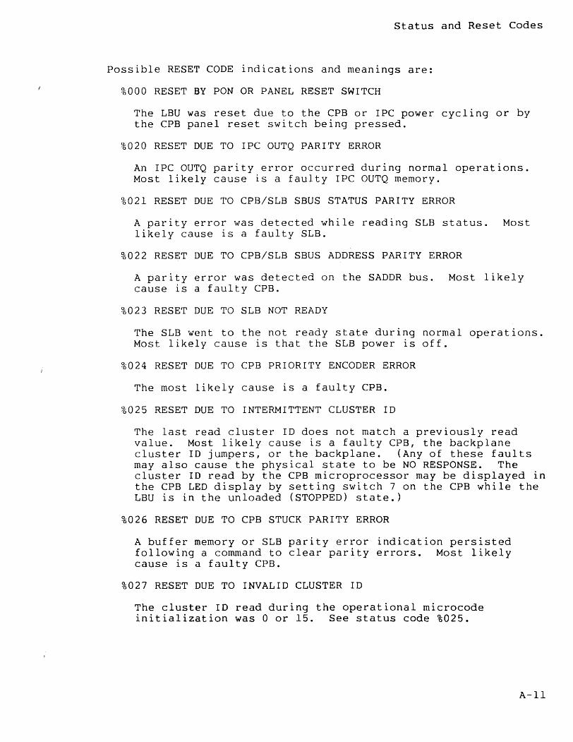
Status and Reset Codes
possible RESET CODE indications and meanings are:
%000 RESET BY PON OR PANEL RESET SWITCH
The LBU was reset due to the CPB or IPC power cycling or by the CPB panel reset switch being pressed.
%020 RESET DUE TO IPC OUTQ PARITY ERROR
An IPC OUTQ parity error occurred during normal operations. Most likely cause is a faulty IPC OUTQ memory.
%021 RESET DUE TO CPB/SLB SBUS STATUS PARITY ERROR
A parity error was detected while reading SLB status. Most likely cause 1S a faulty SLB.
%022 RESET DUE TO CPB/SLB SBUS ADDRESS PARITY ERROR
A parity error was detected on the SADDR bus. Most likely cause is a faulty CPB.
%023 RESET DUE TO SLB NOT READY
The SLB went to the not ready state during normal operations. Most likely cause is that the SLB power is off.
%024 RESET DUE TO CPB PRIORITY ENCODER ERROR
The most likely cause is a faulty CPB.
%025 RESET DUE TO INTERMITTENT CLUSTER ID
The last read cluster ID does not match a previously read value. Most likely cause is a faulty CPB, the backplane cluster ID jumpers, or the backplane. (Any of these faults may also cause the physical state to be NO RESPONSE. The cluster 10 read by the CPB microprocessor may be displayed in the CPB LED display by setting switch 7 on the CPB while the LBU is in the unloaded (STOPPED) state.)
%026 RESET DUE TO CPB STUCK PARITY ERROR
A buffer memory or SLB parity error indication persisted following a command to clear parity errors. Most likely cause is a faulty CPB.
%027 RESET DUE TO INVALID CLUSTER ID
The cluster ID read during the operational microcode initialization was 0 or 15. See status code %025.
A-II
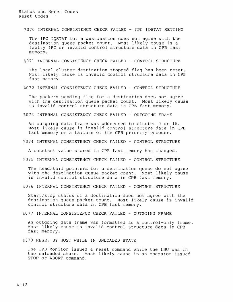
Status and Reset Codes Reset Codes
%070 INTERNAL CONSISTENCY CHECK FAILED - IPC IQSTAT SETTING
The IPC IQSTAT for a destination does not agree with the destination queue packet count. Most likely cause is a faulty IPC or invalid control structure data in CPB fast memory.
%071 INTERNAL CONSISTENCY CHECK FAILED - CONTROL STRUCTURE
The local cluster destination stopped flag has been reset. Most likely cause is invalid control structure data in CPB fast memory.
%072 INTERNAL CONSISTENCY CHECK FAILED - CONTROL STRUCTURE
The packets pending flag for a destination does not agree with the destination queue packet count. Most likely cause is invalid control structure data in CPB fast memory.
%073 INTERNAL CONSISTENCY CHECK FAILED - OUTGOING FRAME
An outgoing data frame was addressed to cluster 0 or 15. Most likely cause is invalid control structure data in CPB fast memory or a failure of the CPB priority encoder.
%074 INTERNAL CONSISTENCY CHECK FAILED - CONTROL STRUCTURE
A constant value stored in CPB fast memory has changed.
%075 INTERNAL CONSISTENCY CHECK FAILED - CONTROL STRUCTURE
The head/tail pointers for a destination queue do not agree with the destination queue packet count. Most likely cause is invalid control structure data in CPB fast memory.
%076 INTERNAL CONSISTENCY CHECK FAILED - CONTROL STRUCTURE
Start/stop status of a destination does not agree with the destination queue packet count. Most likely cause is invalid control structure data in CPB fast memory.
%077 INTERNAL CONSISTENCY CHECK FAILED - OUTGOING FRAME
An outgoing data frame was formatted as a control-only frame. Most likely cause is invalid control structure data in CPB fast memory.
%370 RESET BY HOST WHILE IN UNLOADED STATE
A-12
The IPB Monitor issued a reset command while the LBU was in the unloaded state. Most likely cause is an operator-issued STOP or ABORT command.
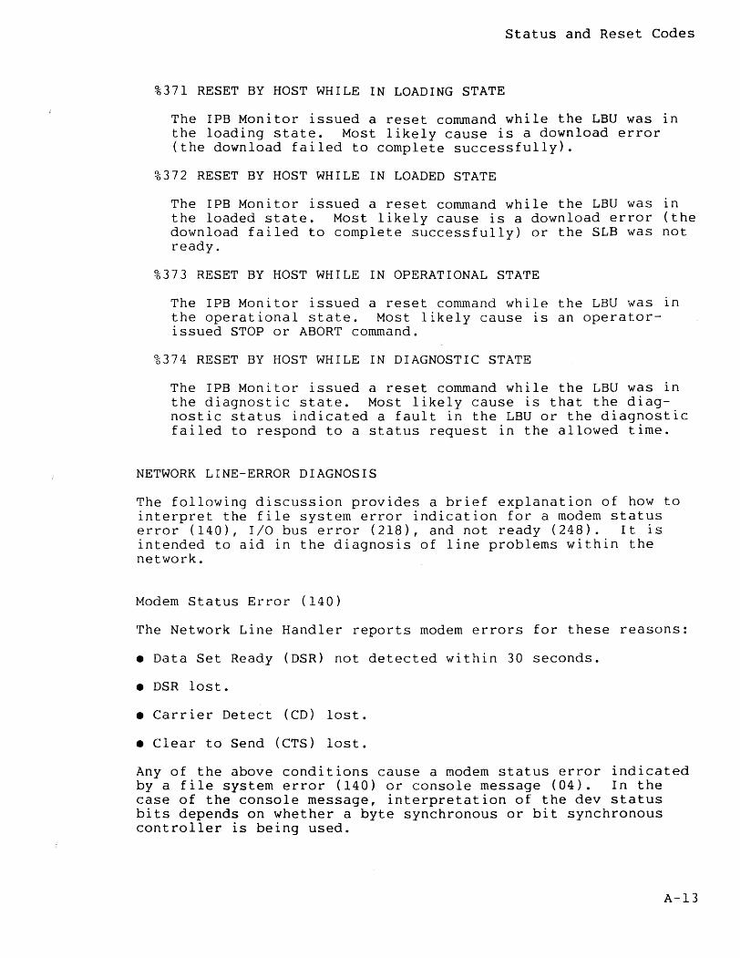
Status and Reset Codes
%371 RESET BY HOST WHILE IN LOADING STATE
The IPB Monitor issued a reset command while the LBU was in the loading state. Most likely cause is a download error (the download failed to complete successfully).
%372 RESET BY HOST WHILE IN LOADED STATE
The IPB Monitor issued a reset command while the LBU was in the loaded state. Most likely cause is a download error (the download failed to complete successfully) or the SLB was not ready.
%373 RESET BY HOST WHILE IN OPERATIONAL STATE
The IPB Monitor issued a reset command while the LBU was in the operational state. Most likely cause is an operatorissued STOP or ABORT command.
%374 RESET BY HOST WHILE IN DIAGNOSTIC STATE
The IPB Monitor issued a reset command while the LBU was in the diagnostic state. Most likely cause is that the diagnostic status indicated a fault in the LBU or the diagnostic failed to respond to a status request in the allowed time.
NETWORK LINE-ERROR DIAGNOSIS
The following discussion provides a brief explanation of how to interpret the file system error indication for a modem status error (140), I/O bus error (218), and not ready (248). It is intended to aid in the diagnosis of line problems within the network.
Modem Status Error (140)
The Network Line Handler reports modem errors for these reasons:
• Data Set Ready (DSR) not detected within 30 seconds.
• DSR lost.
• Carrier Detect (CD) lost.
• Clear to Send (CTS) lost.
Any of the above conditions cause a modem status error indicated by a file system error (140) or console message (04). In the case of the console message, interpretation of the dev status bits depends on whether a byte synchronous or bit synchronous controller is being used.
A-13
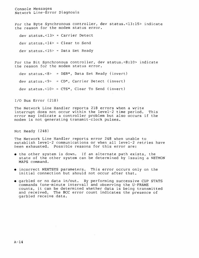
Console Messages Network Line-Error Diagnosis
For the Byte Synchronous controller, dey status.<13:15> indicate the reason for the modern status error.
dey status.<13> Carrier Detect
dey status.<14> Clear to Send
dey status.<15> Data Set Ready
For the Bit Synchronous controller, dey status.<8:10> indicate the reason for the modern status error.
dey status.<8> = DSR*, Data Set Ready (invert)
dey status.<9> = CD*, Carrier Detect (invert)
dey status.<lO> CTS*, Clear To Send (invert)
I/O Bus Error (218)
The Network Line Handler reports 218 errors when a write interrupt does not occur within the level-2 time period. This error may indicate a controller problem but also occurs if the modern is not generating transmit-clock pulses.
Not Ready (248)
The Network Line Handler reports error 248 when unable to establish level-2 communications or when all level-2 retries have been exhausted. possible reasons for this error are:
• the other system is down. If an alternate path exists, the state of the other system can be determined by issuing a NETMON MAPS command.
• incorrect NEXTSYS parameters. This error occurs only on the initial connection but should not occur after that.
• garbled or no data in/out. By performing successive CUP STATS commands (one-minute interval) and observing the U-FRAMg counts, it can be determined whether data is being transmitted and received. The BCC error count indicates the presence of garbled receive data.
A-14

Console Messages Network Line-error Diagnosis
If the CUP STATS commands do not indicate both send and receive data, place the local modern in analog loopback and observe the U-FRAME counts again. If both send and receive counts are incrementing, the local controller and modern are okay. If both systems check out, check the lines by first using the modern self-test, then observe the U-FRAME counts with the remote modem in digital loopback. If all tests indicate data is being transmitted and received, then a trace at both ends of the line should indicate the cause of the not ready condition.
A-15

ADD command 4-10, 4-11, 4-42 Alternate key files 3-44 AXCESS 1-4, 1-5, 4-55
BACKUP 2-8
INDEX
BACKUPCPU command 4-10, 4-12, 4-42 Best path 1-2, 4-1/4 BREAK key 4-9, 4-16
CCIM (Computer Communication Interface Module) 6-9
CMI considerations, network manager 4-59 COMINT 2-8 Command Interpreter startup message 3-40/41 Communications Management Interface
(CMI) 4-59 Communications Utility Program (CUP) 1-4, 4-55 Community (of users) 4-46 Components of EXPAND 1-3 Computer Communication Interface Module
(CCIM) 6-9 Console logging messages
General messages A-I Network manager 4-57
Control-Y 4-9 Conversion, file name 3-7 CONVERTPROCESSNAME procedure 3-20, 3-22 CPUS command 4-10, 4-13, 4-42 CREATEREMOTENAME procedure 3-20, 3-23 CRTPIDs 3-5 CUP considerations, network manager 4-55
Dedicated earth station, INFOSAT 6-7 Default file security 4-47 Default system name 2-4 Definitions
File residence 1-1 Local file 1-1
index-l
Index
Definitions (continued) Network 1-1 Network file 1-1 Remote file 1-1
DELETE command 4-10, 4-15, 4-42 Diagnostic Support, FOX 5-6 Direct connect line handler 1-4 Disc file security
SETMODE 4-46 DISPLAY command 4-10, 4-16, 4-42
Earth Station Controller (ESC), INFOSAT 6-9 Earth station, INFOSAT
Dedicated 6-7 Shared-use 6-9
EDIT 2-8 End-to-end protocol 1-3 Enhanced routing 1-2, 4-1, 4-5
Path selection 4-5 Transmission priority 3-20, 4-5 Transport media 4-5
Error messages Driver generated A-2 FOX generated A-7 NCP generated A-5 Status and reset codes A-10
ESC (Earth Station Controller), INFOSAT 6-9 EXIT command 4-8, 4-10, 4-42 EXPAND line connection to an X.25 line 4-57 EXPAND/INFOSAT network 6-12
FC command 4-9, 4-10, 4-42 Features of EXPAND
Best path routing 1-2 Multi-line facility 1-2 Pass-through routing 1-2 Upward compatibility 1-3 X.25 compatibility 1-3
Fiber Optic Extension (FOX) 5-1 File access 2-1 File definitions
Local 1-1 Network 1-1 Remote 1-1 Residence 1-1
File names External 3-40 Internal 3-2 Network 2-2, 3-2, 3-40 Saving 3-40, 3-44
FNAMECOLLAPSE procedure 3-8 FNAMECOMPARE procedure 3-14 FNAMEEXPAND procedure 3-10
index-2
Footprint, INFOSAT 6-5 FOX
Diagnostic support 5-6 Functional specifications 5-6 Inter-cluster link monitoring 5-6 Inter-cluster protocol supervision 5-7 Interprocessor Bus Monitor Process 5-5 Introduction 5-1 LBU (Local Bus Unit) 5-3 Theory of operation 5-2
FOX (Fiber Optic Extension) 5-1 Frequency bands, satellite, INFOSAT 6-5
GETPPDENTRY procedure 3-20, 3-25 GETREMOTECRTPID procedure 3-20, 3-27 GETSYSTEMNAME procedure 3-20, 3-28
HELP command 4-10, 4-19, 4-42
INFOSAT Computer Communication Interface Module
(CCIM) 6-9 Dedicated earth station 6-7 Earth Station Controller (ESC) 6-9 EXPAND network 6-12 Footprint 6-6 Hardware 6-11 Introduction 6-1 Overview 6-1 Satellite components 6-3 Satellite frequency bands 6-5 Satellites 6-2 Shared-use earth station 6-9 Software 6-9
INFOSAT/EXPAND network 6-12 Interprocessor Bus Monitor Process, FOX 5-5
LBU (Local Bus Unit), FOX 5-3 Line error diagnosis A-13 Line handler
Direct Connect 1-4 FOX 5-4 X.25 1-4
LINESPEED 4-2, 4-5/6, 4-55 Local Bus Unit (LBU), FOX 5-3 LOCATESYSTEM procedure 3-20, 3-29 LOGCENTRAL command 4-10, 4-20, 4-42 Logon, programmatic 4-52
MAPS command 4-10, 4-22, 4-42 Messages
Console NETMON
A-I 4-39
Index
index-3
Index
MONITORNET procedure 3-31 MYSYSTEMNUMBER procedure 3-32 MYTERM procedure, network considerations 3-41
NCP (Network Control Process) 1-3, 4-5 NETMON
ADD command 4-10, 4-11, 4-42 BACKUPCPU command 4-10, 4-12, 4-42 Break 4-9, 4-16 Control-Y 4-9 CPUS command 4-10, 4-13, 4-42 DELETE command 4-10, 4-15, 4-42 DISPLAY command 4-10, 4-16, 4-42 EXIT command 4-8, 4-10, 4-42 FC command 4-9, 4-·-10, 4-42 HELP command 4--10,4-19,4-42 LOGCENTRAL command 4-10, 4-20, 4-42 MAPS command 4-10, 4-22, 4-42 Messages 4-39 PATHS command 4-10, 4-27, 4-42 PERIOD command 4-10, 4-31, 4-42 PROBE command 4-10, 4-32, 4-42 Program 1-5, 4-7 SHOW command 4-10, 4-35, 4-42 STATS command 4-10, 4-36, 4-42 Syntax summary, commands 4-42 THRESHOLD command 4-10, 4-38, 4-42 Usage 1-6
Network (users) 4-46 Network Control Process 1-3, 4-5 Network definition 1-1 Network file names 2-2 Network security 4-43
Partitioned files 3-44 Passwords, remote 4-43 Path selection
Enhanced routing 4-5 PATHS command 4-10, 4-27, 4-42 PERIOD command 4-10, 4-31, 4-42 PROBE command 4-10, 4-32, 4-42 Procedures, network 3-20/44 Process access 4-50 Process creation, remote 3-42 Process 10, network 3-5 PROCESSINFO procedure 3-20, 3-33 Programmatic logon 4-52 Programming, network considerations 3-40 PUP considerations
Network manager 4-56 Operator 2-9
Remote passwords 4-43 Remote process creation 3-42
index-4
REMOTEPASSWORD Command 4-43 REMOTEPROCESSORSTATUS procedure 3-37 RESTORE 2-8 Routing
Best-path 1-2, 4-1 Changes, path 4-4 Enhanced 1-2, 4-1, 4-5
RUN command 2-5
Satellite, INFOSAT 6-2 Security overview 4-43 Security, default disc file 4-47 Security, disc file 4-46 Sending the startup message 3-43 SETMODE
Function 1 (disc file security) 4-46 Function 71 (transmission priority) 3-39
SETMODENOWAIT Function 71 (transmission priority) 3-39
Shared-use earth station, INFOSAT 6-9 SHOW command 4-10, 4-35, 4-42 SPOOLER considerations, operator 2-9 STATS command 4-10, 4-36, 4-42 Syntax summary, NETMON 4-42 SYSGEN considerations
Network manager 4-54 Operator 2-9
System name 2-2, 3-2 System number 3-2
Tandem INFOSAT Control System (TICS) 6-15 Theory of operation, FOX 5-2 THRESHOLD command 4-10, 4-38, 4-42 TICS (Tandem INFOSAT Control System) 6-15 Time (Weight) factors 4-2/4 TRANSDELAY 4-5/6 Transmission priority
Enhanced routing 3-20, 4-5 Transport media
Enhanced routing 4-5
User class 4-46 User IDs 4-43 Utility programs 4-54
VERIFYUSER procedure 4-52
Weight (Time) factors 4-2/4 WHO command 2-7
X.25 compatibility 1-3 X.25 line handler 1-4 X.25 line, EXPAND connection 1-3, 1-4, 4-58 XRAY considerations, network management 4-60
Index
index-5

YOUR COMMENTS PLEASE
Tandem NonStopTM & NonStop DTM Systems EXPAND™ User's Manual
82085 COO
Tandem welcomes your comments on the quality and usefulness of its publications. Does this publication serve your needs? If not, how could we improve it? If you have specific comments, please give the page numbers with your suggestions.
This comment sheet is not intended as an order form. Please order Tandem publications from your local Sales office.
FROM:
Name ___ . ___________ .. _ ..... ___ . Date
Company ______ . ___ ... ______ .
Address
City/State Zip
III111
FIRST CLA~SUS~~R~~~O~8~P~~P~~} CA: U.SA J POSTAGE WILL BE PAID BY ADDRESSEE
Tandem Computers Incorporated 19333 Valko Parkway Cupertino, CA 95014-9990
Attn: Manager-Software Publications
TAPF
NO POSTAGE NECESSARY
IF MAILED IN THE
UNITED STATES