minimum technical requirements
TRANSCRIPT

Minimum Technical Requirements
412_13_SD01
Date Feb 16
Version 6

2 of 62
Environment Agency
Minimum Technical Requirements
Preamble to the Minimum Technical Requirements
• The Minimum Technical Requirements referred to in this contract shall be the “Civil Engineering Specification for the Water Industry, 7th Edition”, published by the Water Services Association in March 2011. All Minimum Technical Requirements clauses apply unless stated as deleted or amended by this document. These clauses are also augmented by the supplementary clauses in this document and the particular information in the Works Information and its appended Works Specification.
• The Minimum Technical Requirements includes all EA MEICA Product Descriptions current at 01 February 2016 and found in the Asite folder.
Document Number Document title Revision
1418_12 Passive design guidance 1
369_13 MEICA standard specification 1
369_13_SD22 Electric vehicle charging points
369_13_SD01 Materials and mechanical installations 1
369_13_SD02 Painting and protection systems 1
369_13_SD03 Hydraulic and pneumatic equipment 1
369_13_SD04 Water control structures 1
369_13_SD05 Valves and penstocks 1
369_13_SD06 Gate and valve actuators 1
369_13_SD07 Lifting equipment 1
369_13_SD08 Powered weedscreens 1
369_13_SD09 Pumps 1
369_13_SD10 Kiosks and enclosures 1
369_13_SD11 Electrical installations 1
369_13_SD12 Switchboards 1
369_13_SD13 Uninterruptible power systems 1
369_13_SD14 Rechargeable batteries 1
369_13_SD15 Engine generating sets 1
369_13_SD16 Electric motors 1
369_13_SD17 Pump starters 1
369_13_SD18 Security systems 1
369_13_SD19 Instrumentation 1
369_13_SD20 Programmable logic controllers 1
369_13_SD21 Documentation 1
801_14 Environmental sustainability, design and management
2
801_14_SD02 Landscape and Environmental Design 1
516_15 BIM - Employers Information Requirements 1
SCHO1109BRHF-E-P Trash and Security Screen Guide (2009) 1
155_04_SD364 Site Investigation Specification and Schedules 2

3 of 62
• In so far as any particular or supplementary clause may conflict or be inconsistent with any provision of the Minimum Technical Requirements, the Works Information shall prevail, then the supplementary clause. The Project Manager shall be informed of any inconsistencies.
• The numbering of the supplementary clauses follows the numbering system of the Minimum Technical Requirements.
• Where the Works Information refers to the “Project Manager” or “Engineer”, this is interpreted as meaning the “Project Manager” and/ or the “Supervisor” as the context demands. If the Contractor is in any doubt as to whether a matter should raised with Project Manager or Supervisor, he shall ask the Project Manager to decide the issue.
• Where the specification refers to plant or equipment, the following definitions are to apply:
▪ “Plant” is items which (together with Materials) are intended to be included (incorporated) in the works.
▪ “Equipment” is items provided by the Contractor and used by him to provide the works.
• References in the Works Information to equipment should be read as references to Plant or Equipment, as the context requires.
• If the Contractor is in any doubt as to an interpretation, the matter should be raised with the Project Manager who shall decide the issue.
• References in the Works Information to the particular Works Information shall be read as references to the Works Information.
• References in the Works Information to the client or purchaser shall be read as references to the Employer.
• References in the Works Information to the Site shall be read as references to the Working Area.

4 of 62
Contents
Section 1 General
1.1 Accommodation for the Contract
1.2 Bill Posting and Advertising
1.5 Tidiness of the Site
1.7 Survey of Highways, Properties and Land
1.8 Levels and Reference Points
1.9 Site Fencing and Gates
1.12 Procedure for Complaints and Claims
1.17 Apparatus of Statutory Undertakers, Highways Authorities and Others
1.19 Emergency Arrangements
1.25 Periodic Returns
1.27 Noise Control and Working Hours
1.28 Sign Boards
1.29 Maintenance of Existing Flood Defences
1.30 Health and Safety and Environment at Work
1.31 Temporary Works
1.32 Existing Structures and Environment
1.33 Street Furniture
1.34 Residential Caravans
1.35 Record Photographs
1.36 Amenities
1.37 Dust, Sand and Mud on Highways
1.38 Maintenance of Public and Private Rights of Way
1.39 Possession of the Site
1.40 Restriction of Use of Site
1.41 Management of Waste
1.42 Disposal of Domestic Waste
1.43 Supply of Water
1.44 Temporary Storage
1.45 Work in Adverse Weather
1.46 Supervision of Site Investigation works
1.47 Origins and traceability of key materials
Section 2 Materials
2.3 Admixtures for Concrete or Grout
2.4 Aggregates for Concrete
2.14 Bricks and Blocks
2.15 Cast Stone
2.16 Cement
2.26 Concrete - Pipes and Fittings
2.40 Field Gates
2.48 Gabions
2.53 Glass Reinforced Plastics (GRP) Pipes and Fittings
2.55 Granular Sub-Base Material
2.56 Grass Seed

5 of 62
2.60 Handrails and Balusters
2.64 Industrial Flooring, Walkways and Stair Treads
2.66 Joint Sealing Compounds and Sealants
2.75 Manhole Steps
2.78 Mechanical Couplings for Pipelines and Fittings
2.80 Metal Ties
2.82 Mortar
2.84 Natural Stone
2.86 Nuts, Screws, Washers and Bolts
2.89 Permanent Fencing
2.90 Pipe Surround Materials
2.100 Precast Concrete Kerbs, Channels, Edgings And Quadrants
2.101 Precast Concrete Manholes and Soakaways
2.102 Precast Concrete Box Culverts
2.106 Prestressed Concrete Pipes and Fittings
2.111 Pulverised Fuel Ash
2.113 Rolled Asphalt
2.115 Safety Chains
2.120 Steel Reinforcement
2.121 Steel Sheet Piles
2.124 Surface Boxes and Guards
2.126 Timber and Preservation of Timber
2.127 Trees and Shrubs
2.130 Valves
2.132 Vitrified Clay Pipes and Pipeline Fittings
2.134 Water
2.150 Marking and Packing Of Pipes And Fittings
2.151 Wrapping Material
2.152 Grilles, Screens and Other Miscellaneous Metalwork
2.153 Cover Tiles and Route Markers
2.154 Waterproofing Membranes and Sundries
2.155 Fusion-Bonded Epoxy Coating
2.156 Capping Material
2.157 Road-Marking Paint
2.158 Dissimilar Metals
2.159 Pipework Identification
2.161 Concrete Bagwork
2.162 Geotextiles
2.163 Rip Rap (Core Stone)
2.164 General Testing, Inspection and Commissioning Of Plant
2.165 Material Certification
2.166 Backfill Material
2.168 Trash Screens
2.170 Signage
2.171 Storage Handling and Use Of Materials
2.172 Site Furniture
2.173 Gravel / Hoggin / Resin Bound Material
2.174 River Bank / Wetland Edge/ Ecological Materials
2.175 Brick / Block Paving Material
2.176 Slab / Sett / Cobble Paving

6 of 62
2.177 Paving Material
2.178 Fill Material
Section 3 Excavation, Backfilling and Restoration
3.1 Excavation
3.3 Topsoil for Re-Use
3.4 Dealing with Water
3.7 Reinstatement of Maintainable Highways
3.9 Reinstatement of Unpaved Land
3.10 Trees
3.12 Land Drains
3.13 Filling Above Ground
3.14 Blasting
3.15 Piling
3.18 Grass Bank Protection
3.19 Stone Pitching
3.20 Support to Excavations and Excavation Near Structures
3.21 Construction of Gabions and Mattresses
3.22 Reinstatement to Land in Private Ownership
Section 4 Concrete and Formwork
4.1 Supply of Information
4.5 Transporting, Placing and Compacting
4.8 Curing
4.9 Records of Concreting
4.10 Construction of Formwork
4.11 Cleaning and Treatment of Forms
4.21 Surface Finishes Produced Without Formwork
4.22 Surface Finishes Produced With Formwork
4.24 Tie Bolts for Formwork
Section 5 Construction of Pipelines, Tunnels and Ancillary Works
5.1 Pipelaying Generally
5.2 Pipe Bedding
5.3 Concrete Protection to Pipes
5.7 Pipe Jointing Generally
5.15 Cutting Pipes
5.18 Inverts and Benching
5.19 Pipes and Joints Adjacent to Buildings
5.21 Setting Manhole Covers and Frames
5.34 Precast Concrete Segmental Manholes
5.35 Holes in Chambers
5.36 Steel Pipes and Fittings
5.37 Pipe Ramming
5.38 Ground Movement Monitoring Under Rail Track
Section 6 Building Works
6.1 Brickwork and Blockwork Generally
6.2 Brickwork and Blockwork, Jointing And Pointing
6.6 Bonding to Concrete

7 of 62
Section 7 Testing and Disinfection
7.2 Precautions Prior to Testing Pipelines
7.4 Testing Non-Pressure Pipelines
7.5 Water Test for Non-Pressure Pipelines
7.7 CCTV Inspection Of Pipelines
Section 8 Roadworks
8.17 Cold Weather Working For Roadworks
Section 9 Sewer Renovation
9.1 Isolation of Flows
9.2 Preparatory Survey
9.3 Preparation of Sewers
9.18 Rendering and Local Repairs
9.22 Laterals
9.23 Cleaning of Surfaces
Section 12 Additional Supplementary Clauses Relating to Landscape and Environmental Design
12.1 Resource Efficiency / Carbon Management
12.2 General
12.3 Site Preparation
12.4 Topsoil
12.5 Planting
12.6 Establishment of Grass Seeded Areas
12.7 Reinstating Fields
12.8 River bank / Wetland Edge/ Ecological Mitigation
12.9 Site Furniture
12.10 Painting
12.11 Gravel / Hoggin / Resin Bound paving
12.12 Rolled Asphalt
12.13 Brick / Block Paving
12.14 Precast Concrete Kerbs, Channels, Edgings and Quadrants
12.22 Slab / Sett / Cobble Paving
12.23 Permanent Fencing
12.24 Natural Stone Walling / Cladding

8 of 62
Specification: Supplementary Clauses
Section 1 – General
1.2 Accommodation for the Contract
Accommodation
5. The Contractor shall submit for acceptance of the siting of all accommodation from the Project Manager.
6. The Contractor shall provide, as a minimum, the accommodation described below for the Project Manager, Supervisor and assistant:
• One office/conference room (Project Manager Room, No. 1).
• One office room (Supervisor + 1 Assistant, Room No. 2).
• Access to a kitchen.
• Access to a drying room for drying and storage of site clothing.
7. The site office complex shall include for sufficient room to allow for site based progress meetings, with a table layout sufficient to seat the site staff, Employer, and the Contractor’s staff.
8. Access to a flush toilet and a wash hand basin in separate rooms for males and females. Hot and cold water supplies shall be provided to all basins.
9. The accommodation is provided ready for use within 7 days of the Contractor taking possession of the Site.
10. Car parking space on suitable hard standing shall be provided adjacent to the Project Manager’s Office for his staff.
11. Accommodation and services are removed by the Contractor on Completion.
12. The offices shall be suitably partitioned, draught proof and weather tight. The accommodation shall be provided with adequate heating, lighting, electric power supply and access to hot and cold water services, including drinking water. The entrance door shall be lockable.
13. The Contractor shall allow for all payments, fees and charges by local authorities and private contractors in respects of connection to main drainage or for emptying of septic tanks.
14. An metered electricity supply shall be provided by the Contractor and an adequate supply of potable water shall be made available for the use of the Project Manager and his staff and paid for by the Contractor.
15. The Contractor shall pay for the installation and quarterly rental of the phone lines and internet connections.
16. The following furniture and equipment shall be provided.
1 no table 1.5 m x 0.9 m and chair for Project Manager and each of their staff 4 no stacking plastic chairs 1 no 4 drawer steel lockable filing cabinet 2 no pinboards 1.5 m x 2 m 1 no 3 tier filing tray 2 no wastepaper basket (to be emptied daily) 1 no A3, A4 electrostatic photocopier (a shared facility with the Contractor would be
acceptable) 6 no coat hooks 1 no fire extinguisher 1 no boot scraper

9 of 62
1 no maximum/minimum thermometer 1 no paper towel dispenser 1 no first aid box as Section 6(2) of the Construction (Health and Welfare)
Regulations 1966 The following kitchen equipment may be shared with the Contractor 1 no kettle (electric) 1 no double burner/hotplate stove 1 no convector heater 1 no refrigerator 1 no microwave oven 1 set of crockery, cutlery and cooking equipment sufficient for six people
Equipment
17. The Contractor shall provide and install the office furniture, kitchen and office equipment, protective clothing, survey equipment, consumable items, laboratory equipment, and documents listed below. The furnishings and equipment shall remain the property of the Contractor at the end of the Contract. This equipment may be shared with the Contractor.
1 no precision automatic level with light collapsible tripod 1 no 5 m collapsible levelling staff with levelling bubble Ranging rods and 3 legged adjustable supports, as required 1 no 30 metre steel tape, 1 no 30 metre fibron tape and 1 no 5 metre steel tape 1 no 1 metre builder's spirit level 1 no plummet and line all survey books, record sheets, marking paint, crayons, brass studs, survey
pegs, nails, etc., required for carrying out the survey work. 1 no calibrated hand shear vane
18. All equipment shall be supplied within four weeks of the date of commencement of the works on site.
19. The Contractor shall ensure that the office is cleaned and maintained daily, and that towels and tea towels are laundered twice weekly and shall supply heating and lighting and labour for maintenance during the Contract period.
20. The Contractor shall ensure that domestic waste from the accommodation are disposed of and that where appropriate recycling facilities are available for use.
21. All survey and or measuring equipment supplied by the Contractor shall be supplied with a current certificate of accuracy and a schedule for maintenance and testing of accuracy for each instrument.
1.5 Tidiness of Site
5. The Contractor shall take special care by the provision of suitable bunding and appropriate spill kits to contain any spillages of diesel fuel or oil stored on site.
6. The Contractor shall obtain the Project Manager’s acceptance of any location where he intends to stockpile materials or completed prefabricated units.
1.7 Survey of Highways, Properties and Land
Delete sub clause 1 and replace with:
To the extent that the Works have affected adjacent roads, the Contractor shall be responsible for their maintenance. This “maintenance” shall include the regular cleaning of the above areas of all debris arising from the works and the repair of any damage caused by the Contractor’s activities, as and when instructed by the Project Manager.

10 of 62
1.8 Levels and Reference Points
2. All levels are in metres and relate to Ordnance Datum (Newlyn).
3. The Contractor shall, before commencing work, check, verify and satisfy himself as to the existing levels of the ground and existing structures and agree them with the Project Manager. Before any excavation or breaking out is commenced, the Contractor shall define, by appropriate means, the reference lines and levels for setting out the works. These markers shall be regularly checked for accuracy throughout the Contract and where any displacement has occurred due to wave action, vandalism, equipment movements, etc., shall be accurately reset in their former positions.
1.9 Site Fencing & Gates
5. Temporary fencing to the Site shall be HERAS type fencing 1800 mm high. Temporary fencing for stock control purposes shall be chestnut pale fencing conforming to and fixed in accordance with BS 1722: Part 4. For areas requiring high levels of security, post and chainlink fencing 1.8m high shall be used to BS 1722: Part 1. Fencing shall be provided with additional strutting where this is necessary. If requested on the drawings (for example adjacent to dwellings), this shall be faced with a fine gauge green mesh netting to reduce dust intrusion.
6. As soon as the Contractor is given possession of the site, he shall erect temporary fencing as per clause 1.9.5
7. Temporary gates shall be provided where shown on the Drawings and as required by the Contractor to match the associated temporary fencing.
8. The fencing requirements specified above will be regarded as the minimum standard for security purposes. This shall not relieve the Contractor of his responsibilities for site security.
9. The Contractor shall provide a set of keys for all site entrance locks to the Project Manager and allow the Employer’s Operations team emergency access at all times.
1.12 Procedure for Complaints and Claims
4. Details of all complaints, claims or warnings of intended claims that may be received from third parties shall be notified immediately to the Project Manager and confirmed in writing within seven days. The Employer shall also be notified as soon as practicable.
5. The Contractor notifies the Project Manager immediately following any damage or injury arising out of the execution of the works.
6. The Contractor and Project Manager notify each other without delay of all complaints, claims or warnings of intended claims which they may receive.
1.17 Apparatus of Statutory Undertakers, Highways Authorities and Others
5. The Contractor shall at all times during the progress of the works afford facilities to properly accredited agents of any Public or Statutory Authorities for access to all or any of their apparatus situated in or under the Site as may be necessary for inspection, reporting, maintaining, removing, renewing or altering such apparatus in connection with the construction of the works, whether or not specifically referred to in the Contract, or any other purpose whatsoever.
6. Copies of correspondence from statutory undertakers are held in the Works Information. No warranty is given for this information and the Contractor is not relieved of any of his obligations under the foregoing sub-clause.
7. The Contractor shall, by hand digging or other approved means dig trial pits well in advance of the permanent works to locate beyond any doubt the route and level of any culverts, drains, sewers, pipes, cables etc. which may be affected by the works.

11 of 62
8. The Employer shall be responsible for the cost of any works which the Statutory Undertakers carry out in consequence of the works and the Contractor for any damage to the Undertaker’s plant and equipment attributable to the Contractor.
1.19 Emergency Arrangements
3. The Emergency Contact List (Agency Form 155_04_SD79) shall include at least two names of responsible representatives of the Contractor and telephone numbers at which they can be contacted at all times outside normal working hours. One of these telephone numbers should be that of the Contractor’s Construction Manager.
4. The Contractor shall carry out the works in such a way as to avoid pollution incidents, however should any occur, procedures and measures shall be implemented to contain and limit the effect as far as reasonably practicable. Such procedures and measures will cover atmospheric, aquatic or land pollution and procedures in the event of fire.
5. The Contractor shall ensure the correct storage, handling, use and disposal of any potentially hazardous materials in accordance with the relevant statutory provisions, including COSHH, and Health and Safety Executive (HSE) Codes of Practice and Guidance Notes.
6. The Contractor shall consult with the relevant statutory bodies including the HSE, Fire Authority, the Environment Agency, and the Local Authority (Emergency Planning) and prepare an ‘Emergency Pollution Response Plan’ (EPRP). This plan will cover the procedures to be followed to limit the spread of pollution in the event of an incident. The Contractor shall incorporate the EPRP into the Method Statement(s).
7. The Contractor shall prepare the specific sections of the EPRP for discussion with the relevant statutory authorities and acceptance where required by legislation.
8. The Contractor shall ensure that the EPRP complements and is consistent with the relevant Emergency Preparedness Plans, as required by Health and Safety legislation, other environmental management and health and safety procedures.
9. The EPRP will contain, but not necessarily be restricted to:
• a full and up-to-date list of all substances stored on site, including comprehensive data on the behaviour and toxicity of the stored substances in the water environment, together with location (which must be away from watercourses)
• a full drainage plan for the site and its compounds
• guidance on the storage and use of hazardous materials with the aim of preventing and containing spills and releases details of emergency equipment available on and off site
• a breakdown of staff responsibilities
• procedures for notifying appropriate emergency services, authorities, Contractor and Contractor’s personnel
• provision of site access information to the emergency services
• Procedures for the removal of materials in the event of a flood warning
10. The EPRP shall be easily accessible and a copy kept away from the main site accommodation. A notice at the entrance to each site shall be posted, indicating the location of relevant emergency instructions. Copies of the EPRP shall be supplied to the emergency services, the Environment Agency and other relevant Statutory Authorities. The Contractor shall obtain and store on site all the necessary equipment which may be required in order to alleviate a pollution spillage.
11. All site staff will be trained so that they can undertake the following actions upon discovery of a pollution incident:
• raise the alarm and contact the appropriate site staff and authorities
• locate the pollution control equipment
• deploy pollution control equipment in an appropriate and effective manner so as to contain and limit pollution until such a time as the appropriate authorities arrive on site
12. The Contractor shall be responsible for arranging appropriate site security for the duration of the works

12 of 62
13. The Contractor shall ensure a copy of the Environment Agency’s ‘Environmental Incident Reporting Flowchart’ is displayed in all site offices. Copies are available from the Employer.
Add the Following Clauses
1.25 Periodic Returns
1. Monthly Returns
The Contractor shall report in writing to the Project Manager on the progress made during each month up to the last Sunday in the month and this report shall be submitted before the end of the seventh day of the following month. This should include:
• Number of personnel employed at the site sub-divided into staff, tradesmen and others.
• Allocation sheets identifying the areas worked and the resources utilised and the progress made
• Number of men employed by Sub-Contractors at the site.
• Equipment used and standing at the site.
• Accidents to Employees reportable and non-reportable by Statute.
• Weather conditions on each day and night.
• Progress on implementation of the Environmental Action Plan
The report shall correlate the progress made in all principal items of work with the progress anticipated by the agreed programmes with respect to the rate of progress during the month and the total achievement by the end of the month.
The report shall include proposals for taking advantage of work ahead of programme and for the acceleration of works which are lagging. The report shall also include a statement of the dates during the month on which principal items of plant were delivered to site and the date on which any such items were removed from site.
2. Time Sheets and Wages
The Contractor shall keep on site proper books and time sheets showing the wages paid to and the time worked by the work-people in his employ in and about the execution of the Contract, and such wages, books and time sheets shall be produced whenever required for the inspection of any officer authorised by the Project Manager.
3. Progress reports
On a monthly basis and in support of the Project Manager /Cost consultants end of month report the Contractor shall supply to the Project Manager an updated schedule of the main work items in each section of the works for that month the average number of site workers, the aggregates used, waste created and timber sourced. The Contractor shall provide a supporting revised programme of works. Specifically the programme shall indicate
• Elements of work compliant to the Works Information (and subsequent changes to Works Information) with key milestone dates.
• Progress of work during the previous month and cumulative progress to date.
• Float (i.e. “spare time within the Contract programme after time risk allowances have been included” (NEC 31.2) )
• Time risk allowances.
• Cause and effect to any delay/advancement of the Completion Date
• Any H&S or environmental incidents and near misses together with work done to prevent a repeat event.

13 of 62
1.27 Noise Control and Working Hours
1. The Contractor shall liaise with the Local Authority and comply with their requirements for noise control. The contact details are shown in the Works Information.
The Employer’s limits on noise control and working hours are:
2. Normal working hours will be from 0800 to 1800 Monday to Friday and from 0800 to 1300 Saturday, unless planning conditions specify otherwise. Where practicable, operations which may cause noise and or vibration disturbance should be scheduled for daylight working.
Works Permitted Hours
Construction activities (excluding piling) for tidal affected activities
0600 – 2200, Monday to Saturday
Piling 08.00 and 18.00 hours Monday to Friday inclusive and between 09.00 and 13.00 hours on Saturday
3. Exceptionally, consent for work outside these hours shown in the table above may be given after the necessary consultation. The Contractor shall seek consent from both the Project Manager and The Local Authority and a minimum notice period of 14 days is required.
4. All working hour restrictions will be subjected to review during the course of the works.
5. The Contractor shall take all reasonable precautions to minimise the noise arising from his plant, vehicles and method of construction, and shall adopt the relevant recommendations of BS 5228: 2009.
6. Any local limits on working hours shall be detailed in the Works Information
Period Ambient Noise
Level Leq
1 Hr dB(A)
Max. Peak
Noise Level
dB(A)
Mondays to Fridays
0730 to 1830 hours excluding Bank Holidays
74
80
Mondays to Fridays
1830 to 2200 hours excluding Bank Holidays
65
70
All days
2200 to 0730 hours
45
50
Saturdays
0730 to 1300 hours
65
70
Saturdays
1300 to 2000 hours
55
60
7. All plant shall be muffled in accordance with the procedure set out BS5228. The Project Manager shall have the authority to instruct the Contractor to remove unsilenced plant from the site.

14 of 62
8. The Contractor will limit transient vibration levels arising from site activities to the values contained in the following table from BS 5228:2009 - Code of practice for noise and vibration control on construction and open sites – Part 1: Vibration:
Transient vibration guide values for cosmetic damage
Type of Building Peak component particle velocity in frequency range of predominant pulse
4Hz to 15Hz 15Hz and above
Reinforced or framed structures
Industrial and heavy commercial buildings
50 mm/s at 4 H z and above
50 mm/s at 4 H z and above
Un-reinforced or light framed structures
Residential or light commercial buildings
15 mm/s at 4 Hz increasing to 20 mm/s at 15 Hz
20 mm/s at 15 Hz increasing to 50 mm/s at 40 Hz and above
NOTE 1 Values referred to are at the base of the building.
NOTE 2 For un-reinforced or light framed structures at frequencies below 4 Hz, a maximum displacement of 0.6 mm (zero to peak) should not be exceeded.
The above values relate to the maximum peak particle velocity measured in any of the three orthogonal components. The above values should be reduced by 50% when the vibration is continuous, and if the building exhibits existing significant defects of a structural nature (such as a result of settlement).
The Contractor shall also limit vibration levels arising from site activities at all residential buildings between 22.00hrs and 07.30hrs to a peak particle velocity of 1.5 mm/s in any of the three orthogonal components.
The measurement and evaluation of vibration shall be in accordance with the guidance given in BS 4866 for ‘control’ monitoring, and should utilise equipment capable of measuring the peak particle velocity time history over a frequency range 1Hz to 300Hz.
Monitoring shall be undertaken continuously, starting 1 week prior to commencement of construction and continuing throughout the construction period. The location of vibration monitoring shall be submitted for acceptance to the Supervisor and reviewed as construction activities progress. Monitoring is to be conducted by a specialist consultant as nominated by The Employer who will provide the results of the vibration monitoring to the Supervisor once per week. If vibration levels exceed the limits stated above The Contractor shall identify the cause and propose remedial actions to comply with the vibration limits stated in this clause where practicable, in the event this shall be agreed as a matter of urgency.
10. Public Relations
The Contractor shall be responsible for notifying local residents, businesses and The Local Authority’s Environmental Health Officer of any unavoidable disruptive operations, particularly when these are to take place outside the normal working hours, and for fostering good public relations generally in respect of the works. The Supervisor and the Project Manager shall be notified or any correspondence and copies passed to them. A contact name within the

15 of 62
Contractor's organisation shall be provided to residents who would be available to deal with complaints or queries in relation to the works.
The Contractor is expected to work to the principles of the Considerate Constructor Scheme (www.ccscheme.org.uk) for the site and dealings with the public.
1.28 Sign Boards
1. The Contractor shall provide warning signs, at locations agreed with the Project Manager, warning the public of the dangers of the works and bearing the name, address and emergency telephone number of the Contractor. The signs shall be erected prior to commencement of the works and maintained for the duration of the works.
2. Signs shall be provided as necessary for the closing and/or temporary diversion of public footpaths and shall be checked and maintained on a daily basis.
3. The Contractor shall erect, maintain and remove upon completion progress signboards at agreed locations. They will contain selected progress photographs and short text explanations noting the progress made, to be changed at least bi-monthly or at significant milestones.
1.29 Maintenance of Existing Flood Defences
1. The Contractor's operations shall not reduce the effectiveness of the existing flood defences. The existing defence level shall be maintained at all times during the works except where the existing defence needs to be broken out for construction of the new works. In this event the extent of existing defences to be broken out ahead of construction of the new defence will be agreed with the Project Manager in advance of the works being carried out.
1.30 Health, Safety and Environment at Work
1. The Contractor's attention is drawn to the definition of 'Place of Work'; it shall mean the entire area of the works inclusive of working space and any adjacent areas that may be used by the Contractor's or sub-Contractor's labour, equipment and materials necessary for the satisfactory completion of the Works.
1.31 Temporary Works
1. The Contractor shall design his Temporary Works to be of adequate strength and stability and suitable for their purpose and shall submit his calculations and drawings to the Project Manager if so required. The Contractor, at his own cost, shall change the design and, if necessary, Temporary Works already constructed in any case where the Project Manager considers the design to be inadequate.
2. Any consents are the responsibility of the Contractor and the Contractor's Temporary Works shall not relieve the Contractor of his obligations under the Contract, or infer any liability upon the Project Manager. Conditions in the EAP also relate to any temporary works.
1.32 Existing Structures and Environment
1. The Contractor shall be responsible for ensuring that no damage occurs to existing structures or environmental features. Any such damage shall be repaired at the Contractor's own expense.
2. All existing foundations, springs or other underground works or apparatus, (whether in proper working order or otherwise) shall be supported, maintained and protected by the Contractor who shall also provide everything necessary for efficiently dealing with pumping or removing as the case may be, all water, sewage deposit or spill therein or arising there from.

16 of 62
1.33 Street Furniture
1. Any street furniture including seats, waste bins and signs, which require moving for the advancement of the Contract shall be taken up/down, stored or temporarily relocated as directed by the Project Manager. The items shall be returned and re-erected at the original position following completion of the adjacent works.
1.34 Residential Caravans
1. No residential caravans will be permitted on any part of the site. Neither shall the Contractor permit any person to reside on the Site. Arrangements for security staff should be agreed with the Project Manager in advance.
1.35 Record Photographs
1. Before commencement on site the Contractor shall make a comprehensive photographic record of the proposed site area, compounds and accesses. A full video record is also to be taken. These records shall include the public highway within 100m each side of the site entrances and 10m beyond the site boundary (excluding private property)
2. Photographs shall be taken when and where directed by the Project Manager and a reference set of digital images provided. These shall be marked with the date of exposure, identity reference number and brief description of the work including chainage, location and direction of view.
3. The copyright of all photographs shall be vested in the Employer and the data files shall be delivered to the Project Manager within 4 weeks of being taken. The photographs shall not be used for any purpose whatsoever without the Project Manager's acceptance, but will be available for site based record use by the project staff.
4. All digital photographs shall be stored in jpeg format Copies shall also be submitted on regular Hard Drive, Data Stick, CD-ROM or Asite as appropriate for delivery to the Employer.
1.36 Amenities
1. Throughout the Contract, the Contractor shall take care that no broken concrete, timber cut-offs, reinforcement or rubbish, etc., are left on areas open to the public. Where areas are open to the public, the Contractor must ensure that no part of the works, plant or materials constitute a danger to the public. Any materials cleared shall be separated and recycled where possible according the site waste management plan.
1.37 Dust, Sand and Mud on Highways
1. The Contractor must take all reasonable steps to minimise dust, sand and mud nuisance during the construction of the works.
a. All existing highways used by vehicles of the Contractor or any of his Sub-Contractors or suppliers of material or plant shall be kept clean and clear of all dust, sand and mud any other matter dropped by the said vehicles or their tyres.
b. Similarly, the Contractor shall clear all dust, sand and mud, or any other loose material from the Works spreading on these highways
c. Clearance shall be effected immediately by manual sweeping and removal of debris or, if so directed by the Project Manager, by mechanical sweeping and clearing equipment and all dust, sand, mud and other debris shall be removed entirely from the road surface. Additionally, if so directed by the Project Manager, the road surface shall be hosed or watered using suitable equipment.
2. Compliance with the foregoing will not relieve Contractor of any responsibility for complying with the requirements of any Highway Authority in respect of keeping roads clean.

17 of 62
1.38 Maintenance of Public and Private Rights Of Way
1. The Contractor is to address all issues highlighted in the closure order
1.39 Possession of the Site
1. The Contractor will be given possession of the Site.
1.40 Restriction of Use of Site
1. The Contractor shall not place or erect any buildings on the Site without the written acceptance of the Project Manager.
1.41 Management of Waste
1. The Contractor shall produce as part of the Method Statement(s) a ‘Site Waste Management Plan’ (SWMP) which provides for the management of all waste arisings on site, and specifically covers, but is not limited to, the following:
• a location plan identifying waste storage areas, and provisions for each type of waste which will be encountered
• classification of all waste including special waste according to current legislative provisions;
• recording of the quantity, classification and location of all waste arising
• limiting the generation of waste arising on site, and identifying those wastes which have a potential for reuse either on or off site
• recording of proposed waste carriers and the terms of their respective licences
• an indication of the Contractor’s intentions regarding the use of disposal sites for all types and classifications of waste (including special and hazardous waste), and the relevant requirements of the respective licences and planning permissions
• an appropriate audit trail encompassing waste disposal activities and waste consignment notes; and
• measures to avoid fly tipping and vandalism by others
2. The Contractor shall make the necessary arrangements to ensure that domestic wastes such as food and drink packaging and leftovers are disposed of at least on a weekly basis by a licensed contractor, and that a designated staff member is appointed to ensure that litter creation is both restricted and disposed of where it occurs
1.42 Disposal of Domestic Waste
1. All WC’s, hand-basins, sinks and other domestic type wastes from the Project Manager’s and Contractor’s accommodation shall be connected to a water sewer or septic tank.
2. The Contractor shall be responsible for arranging the connection to foul water sewer or septic tank.
3. Any site personnel found fouling the Site shall be severally reprimanded and dismissed upon a repeat occurrence. The Contractor must address by inductions and ensure that adequate facilities are provided within the site area to ensure that this should not happen.
1.43 Supply of Water
1. The Contractor shall apply to the relevant utility for a supply of water. The Environment Agency welcomes the use of clean recycled water for use in some operations subject to acceptance of the Project Manager.
2. The Contractor shall comply with the relevant Statutory Water Undertaker’s by-laws.
3. The Contractor shall ascertain from the supplier any restrictions of supply which are likely to impose limitations on his programme of work.

18 of 62
1.44 Temporary Storage
1. All petroleum and inflammable materials shall be stored in ventilated fireproof buildings.
2. No petroleum spirit within the meaning of the Petroleum (Consolidated) Act 1928 as amended by DSEAR and the Petroleum (Transfer of Licences) Act 1936 shall be stored on the Site until the acceptance of the Project Manager and the necessary licences under the Act have been obtained.
1.45 Work in Adverse Weather
1. Work shall not be carried out in adverse weather if, in the opinion of the Project Manager, such work is likely to be injuriously affected by weather conditions. Suitable protective covers shall be made available at all times to cover up work in progress or recently completed work either of which may be damaged by adverse weather.
1.46 Site supervision of Ground Investigation works
Competence requirements of SI/GI site supervisors:
Whilst each Contractor and Consultant and CDM duty holder is responsible for strictly ensuring the competence, including physical capability, of each organisation, team and individual to carry out their undertaking, the Employer also requires the following minimum standards for those individuals employed to supervise site and or ground investigation works:
- Appropriate technical qualification (in civil engineering, geology, contaminated land, or other discipline)
- CSCS card holder (not visitor);
- Current holder of a certificate for IOSH managing safely or CITB site safety manager, IOSH safety in geotechnical investigations (non notifiable schemes)
- Approved Environmental awareness training course (as per SHE CoP requirements)
- Has attended a CDM 2015 awareness training
- Five years experience of Site Investigation or Ground Investigation, of which two should be supervisory.
1.47 Supply Chain transparency - Minimising risk through responsible sourcing:
Designers and contractors delivering projects will now be accountable and must provide full transparency of their design and construction supply chains. Whether it is sourcing suppliers and material choices at design or the delivery of construction services. The Employer’s requirements will include full traceability of identifying suppliers, their reasons for different material options (including sustainability considerations such as resource efficiency, embedded carbon and water, biodiversity impacts, working conditions) and the merits of the final option. Mapping connections from the location of raw materials extraction, manufacturing supply chains, to distribution and transportation of finished goods.
Traceability should be considered as an important part of supply chain sustainability as it can be used to confirm and verify environmental and ethical performance, ensuring respect for people and the environment throughout the supply chain. Contractors must provide details of their business continuity plans for construction materials to include climate change risks.
Currently under WEM Schedule 14 - 2e the following data is collated:
Carry out an assessment on spend and sustainability risk of the key materials that they purchase on behalf of the Employer. The Supplier shall be able to report baseline data on 5 key agreed

19 of 62
materials by the end of year 2 of the framework. The data will include as a minimum; material type, whether it is virgin or recycled, country of origin, tonnage and spend. Once a baseline has been established the Supplier must report on this annually.
.

20 of 62
Materials
Please refer to Clause 1.47 when procuring materials
2.3 Admixtures for Concrete or Grout
Delete Clause 1 and replace with:
1. Air-entraining admixtures shall comply with the relevant provisions of BS EN 934-1 and accelerating, retarding, water-reducing and superplasticising admixtures for concrete or grout shall comply with the relevant provisions of BS EN 934-2.
2.4 Aggregates for Concrete
Aggregates from natural sources for concrete shall be obtained from an approved source and shall conform to the requirements of BS EN12620 as appropriate for the intended end use of the concrete.
2. Coarse recycled concrete aggregate shall comply with BS8500-2 and shall not exceed 20% by mass of the total coarse aggregate content. Recycled aggregates shall not be obtained from the wastes of metalliferous mining and shall not be used in contact with potable water.
3. The water absorption of aggregates for concrete designed to retain aqueous liquids shall not exceed 3% when measured in accordance with BS EN 1097-6.
4. Aggregates shall not be obtained from the wastes of metalliferous mining.
5. Oolitic limestone gravels may be used provided that satisfactory results are submitted from tests for Los Angeles Abrasion values carried out within the six months preceding its proposed use.. Evidence shall also be provided that the aggregates have remained below the maximum LAA value for a period of at least two years.
Alkali reactions with cement:
6. Aggregates shall not contain any material that is likely to undergo disruptive expansive reactions with alkalis in the mix or which is likely to otherwise affect the long-term durability of the concrete. Aggregates shall be subject to petrographic examination in order to establish the potential reactivity in accordance with BS8500-2:2002 and BRE Digest 330.
7. The water-soluble chloride content of aggregates shall be determined in accordance with BS EN 1744-1: 1998.
Coarse and fine low-shrinkage aggregates:
8. The coarse aggregates shall be capable of producing concrete having a drying shrinkage of not more than 0.075% when tested in accordance with EN1367-4.
9. The Contractor shall provide evidence from the supplier certifying compliance with the specified requirement. Where such data is not available.
10. Where a source of supply produces coarse aggregates which do not satisfy the stipulated shrinkage requirement, such a source shall not be used for the supply of fine aggregates.
2.14 Bricks and Blocks
8. Where engineering brickwork is specified, the bricks shall be well-shaped, hard, sound engineering bricks, uniform in size and free from cracks and flaking with a suitable confirmed absorbency rating.
9. Engineering bricks for manholes and chambers shall be solid.
10. The Contractor shall consider in his design the inclusion of, and if applicable to the project specify the landscape works to comply with:

21 of 62
Clay Facing Brickwork Cladding: F10/110
Reclaimed Brick Facing Cladding: F10/230A
Clay Common Brickwork for walls: F10/315
Engineering Brickwork for walls: F10/380
Drainage accessories (weepholes): F30/8A
Expansion joints: F30/80
Meshwork reinforcement: F30/42
Waterproof tanking: J30/100, 200, 300
2.15 Cast Stone
3. Reconstituted stone masonry coping and blockwork shall be constructed in accordance with BS6457, 1984. The compressive strength when tested in accordance with BS EN 771 shall be 20N/mm2.
4. Reconstituted stone shall be capable of withstanding all exposure conditions for the design life of the scheme. When tested in accordance with BS1881: Part 122 : 1983, the value of total immersion at 30 minutes should be not more than 3%.
5. Facing stone and copings shall match in texture and as dictated by the planning applications. The exact finish and colour is to be agreed with the Project Manager, in consultation with the landscape architect, prior to placing any order. If required, a sample panel shall be constructed for acceptance.
2.16 Cement
4. High alumina cement and Portland limestone cement shall not be used.
2.26 Concrete - Pipes and Fittings
4. All concrete pipes and fittings shall be manufactured for a minimum design chemical class of DC-3.
5. Concrete pipes shall comply with the crushing test loads of BS 5911: Table 2.
6. Where pipes are reinforced reinforcement must be circularly arranged.
7. Certificates of compliance with the requirements of BS 5911, Part 1 shall be supplied for pipes used in the works.
2.40 Field Gates
2. Concrete surround to posts shall be grade C20.
3. Gates shall be securely fixed to prevent removal, e.g. by using opposing hinge bolts.
4. The Contractor shall consider in his design the inclusion of, and if applicable to the project specify the landscape works to comply with Landscape Specifications:
Materials generally: Q40/550 (wood), 560 (steel)
Kissing Gate: Q40/530
Stile: Q40/540A
Timber Field Gate: Q40/542
Gates: Q40/570
Wrought Iron: Q40/580
Radar Access Gate: Q40/585

22 of 62
2.48 Gabions
3. Either welded or woven mesh gabions may be used:
a. Deformable wire mesh gabions shall be manufactured from triple twisted (also known as double twisted) hexagonal woven galvanized wire.
b. Rigid weldmesh gabions shall be welded at every intersection and galvanised after mesh manufacture.
c. Wire to comply with BS 1052. Minimum wire diameter 2.7mm. Minimum mesh spacing 60mm, maximum mesh spacing 100mm.
4. Galvanizing of rigid weldmesh gabions to comply with BS729: Minimum coating weight of 610g/sq.m for wires of 5.0mm diameter and over and 460g/sq.m for wires under 5.0mm. Galvanizing of deformable wire mesh gabions to comply with BS443.
5. PVC coating shall be black, green or grey with a minimum thickness of 0.5mm (or 0.25mm if chemically bonded to the wire). The coating shall be capable of resisting the effects of immersion in sea water and exposure to ultra-violet light for a period of not less than 3000 hrs in accordance with ASTM Test G23.89 or equivalent.
6. Lacing wire and helicals shall be produced from wire of a least 2.5mm diameter and zinc coated to BS443.
7. Split rings shall be produced from steel spring wire to BS5216 and zinc coated to BS443.
8. Fill material shall be durable rock of minimum density 2400kg/cu.m. The grading of the material shall be such that the minimum particle size shall exceed the maximum size of the gabion mesh opening, and a maximum particle size of 200mm.
9. Confirmation of BBA certification shall be provided by the Contractor for all proposed gabions and rockfill mattresses
10. Fill Material to be locally sourced where possible
2.53 Glass Reinforced Plastics (GRP) Pipes and Fittings
2. Pipes shall have dense, void-free walls. They shall be manufactured by a manufacturer accepted by the Project Manager, using a centrifugally-spun or externally-wound filament method. Details of the manufacturing process and material to be used shall be submitted to the Project Manager for acceptance before manufacture starts. The manufacturer shall submit evidence of having satisfactorily manufactured pipes having a similar specification.
3. The materials used in the manufacture of the pipes shall be resistant to abrasion and to chemical and biological attack, and shall not react with or be soluble in the liquid being conveyed, or the surrounding ground or groundwater, within the temperature range prescribed in the Works Information. The composition of the pipe materials shall be such as to avoid deterioration during transport or storage due to ultra-violet radiation.
4. All pressure pipes shall be tested at the manufacturer’s works to 1.5 times the specified working pressure in accordance with BS 8010. The manufacturer shall submit a schedule of tests for acceptance by the Project Manager before manufacture begins.
5. The minimum stiffness of the pipes is to be 10,000N/m2
6. All lengths of pipe shall have one standard FW Coupling joint.
7. Pipes shall be laid in accordance with the manufacturer’s installation procedures.
8. The pressure rating of the pipes shall be 10 bar

23 of 62
9. Pipes shall be capable of carrying raw water.
2.55 Granular Sub-Base Material
9. Type 1 material shall be delivered to the site at a moisture content within +1% and -2% of optimum.
10. Type 2 granular sub-base shall not be used as the sub-base element of road or footpath construction.
11. Where organic limestone is to be used it shall be of the Carboniferous form. 12. The Contractor shall consider in his design the inclusion of, and if applicable to the project
specify the landscape works to comply with:
Type 1: Q20/210
Granular material Q20/211
2.56 Grass Seed 1. The Contractor shall consider in his design the inclusion of, and if applicable to the project
specify the landscape works to ensure compliance with:
Flora Locale: Section Q30/308
Where applicable, the specification of the Landscape Works will contain as a minimum the use of the following seed mix types:
− Pond Edge Mixture: Q30/312
− General purpose with wild flowers: Q31/314
− Low maintenance grass with wildflowers: Q31/315
− Grass for loamy soil: Q31/316
− Tree and shrub seeding: Q31/332
2. For all projects the Contractor shall submit a detailed specification for grass seed mix in situations listed below to the Project Manager for acceptance, where the design requires an alternative seeding application to comply with Q30/308:
− Seeding of general amenity grassed areas: Q30/313
− Seeding to create wildflower meadows: Q30/317
− Hydraulic seeding: Q30/376
− Seeding of Embankments
3. The Contractor shall consult the site owner / manager for advice on the appropriate species, % mix, provenance and available source(s) of seed in the locality where the design requires an alternative seeding application to comply with Q30/308:
− Seed mix for use within and adjacent to Sites of Special Scientific Interest (SSSI)
− Seed mix / Grass plug planting (Marram) for Dune Regeneration/Stabilisation works
− Natural regeneration of existing coastal / Dune vegetation
For all projects the Contractor shall submit a detailed specification for grass seed mix and / or plant material (in accordance with the HTA plant specification) to the Project Manager for acceptance.
4. Bumble bee grass seed mix shall be considered for use on embankments
- Agrostis capillaris (Common Bent) - 15% - Cynosurus cristatus (Crested Dogstail) - 10% - Festuca ovina (Sheep's Fescue) - 15% - Festuca rubra (Slender Red Fescue) - 20% - Phleum bertolonii (Smaller Cat's-tail) - 10%

24 of 62
- Poa pratensis (Smooth-stalked Meadow-grass) - 15% - Lolium multiflorum (Westerwolds Ryegrass) - 7% - Trifolium pratense (Red Clover) -agric - 5% - Vicia cracca (Tufted Vetch) - 0.6% - Lotus corniculatus (Birdsfoot Trefoil) - 0.6% - Centaurea nigra (Common Knapweed) - 0.6% - Betonica officinalis (Betony) - 0.6% - Galium verum (Lady's Bedstraw) - 0.6% - Application rate 35g/m2
2.60 Handrails and Balusters
2. The Contractor shall submit fabrication drawings for the acceptance of the Project Manager prior to manufacture.
3. All handrails, balusters and in-fill panels including not MEICA assets must comply with the requirements in MEICA standard Materials and mechanical installations: 369_13_SD01
4. All finishes and colours shall submitted for acceptance by the Project Manager.
2.64 Industrial Flooring, Walkways and Stair Treads
5. Except as otherwise stated in BS 4592, flooring walkways, stair treads and staircases shall be designed by the Contractor following the recommendations of BS 5395.
6. The Contractor shall submit fabrication drawings for the acceptance of the Project Manager prior to manufacture.
7. Unless otherwise specified, floor panels and stair treads shall be of adequate section to support a uniformly distributed load of 5kN/m². Under maximum specified load deflections in the panels should not exceed 0.5% of the span or 5mm, whichever is the smaller.
8. Flooring, walkways, stair treads and similar shall be ‘General duty’ as defined in BS 4592.
9. Where shown in the Drawings, industrial flooring shall be lockable and set flush in frames manufactured from the same material. Frames shall be provided with lugs for building in.
10. Flooring shall be provided in panel sizes suitable for removal by one person. Panels shall be provided with appropriate cut-outs and be so arranged to permit removal without disturbing any adjacent panels, machinery or Plant including valve spindles, supporting brackets or pipework. Cut openings and edges shall be fully and neatly trimmed with a full-depth binding bar in order to deflect normal loadings.
11. Solid plate flooring shall be manufactured from raised-pattern mild steel plate.
12. Open mesh type flooring and stair treads shall be rectangular pattern constructed of straight bars on edge with welded transverse bars.
13. Open mesh type metal flooring shall be fixed using a positive fixing secured from the top of the walkway to assist maintenance. Clip type fixings shall not be used. Panels shall be detailed to ensure that horizontal movement of adjacent panels is not possible when positive fixings are temporarily removed.
14. Open mesh type metal flooring panels shall be manufactured so that when fitted the load-bearing bars and transverse bars are aligned with adjacent panels.
15. All areas on which people may walk shall have non-slip surfaces and be free of tripping hazards.

25 of 62
16. Where contact with water under preparation or conveyance for public water supply occurs only stainless steel flooring, walkways, stair treads and platforms shall be used. The stainless steel shall be Grade 316S31 complying with BS 1449.
17. Panels and support beams shall be stamped with a reference to allow correct placement.
18. Where shown on the drawings anti-slip fibreglass floor gratings shall be used. They shall have the following properties:
Thickness: 60mm
Mesh: Standard (26mm x 26mm open mesh)
Surface Finish:
Gritted Top (BS 4592-0 Approved),
Bottom: Smooth
Colour: Light Grey RAL 7047
Weight per Kg/m²:
42.5kg
They shall be manufactured using the highest quality Industrial Grade chemical resistant polyester resins with pure glass fibre roving reinforcements and pigmented throughout to Light Gray RAL 7047. Moulded Fibreglass Grating is produced in accordance with ISO 9001 certification
2.66 Joint Sealing Compounds and Sealants
7. Cold applied joint sealing compound for jointing precast concrete manhole rings, inspection chamber units, bolted lining tunnel segments or other approved uses, shall consist of a filled bituminous putty compound of approved quality suitable for application by trowel, gun or in strip form. The compound shall have good adhesion and elastic properties.
2.75 Manhole Steps
2. Unless otherwise specified all steps or step rungs for manholes shall be stainless steel.
2.78 Mechanical Couplings for Pipelines and Fittings
6. Flexible couplings for each size of pipe shall be capable of withstanding the shear force applied by the weight of a 4m length of pipe of that diameter full of water suspended between two couplings.
7. Detachable flexible couplings shall be provided with central register ribs or location plugs.
8. Flange adapters shall have flanges as specified for flanged joints.
9. The metal components of detachable flexible couplings and flange adapters shall be protected.
10. Nuts, bolts and screws shall be manufactured from alloy or carbon steel to BS 970, BS 3111, BS 4882, BS 1506, BS 4190 or equal accepted.
2.80 Metal Ties
2. All wall ties shall be austenitic stainless steel grade 1.4301 or 1.4401 to BS EN 10088. Ties for cavity walls shall be to BS EN 845-1.
3. For masonry facing to new concrete walls, the ties shall be an accepted type of anchorage comprising stainless steel dovetail anchor slots for casting into the concrete and stainless steel anchors which project 100mm from the face of the concrete.

26 of 62
4. For masonry facing to existing concrete walls, the ties shall be an accepted type of grout-in anchorage, not less than 165mm in overall length.
2.82 Mortar
5. Mortar for bedding and jointing masonry shall normally be Class M3 as defined by BS EN 998-2. Plasticisers or proprietary ‘masonry cements’ may be used where approved by the Project Manager, in which case the proportions of the mix shall be based upon the manufacturer’s instructions.
6. Pigments for mortars shall comply with BS EN 12878 and colour submitted for acceptance with the Project Manager. Trials shall be undertaken prior to commencing masonry works on site to confirm the proposed materials and methods will provide a mortar of the required consistency for the work.
7. Mortar shall be mixed in a forced action mixer. Free-fall drum mixers shall not be used. Each batch of mortar shall be inspected after mixing to confirm thorough dispersion of the constituents and absence of balling. If the mortar has evidence of poor mixing or proportioning then a revised design and/or mixing method shall be submitted to the Project Manager.
8. The Contractor shall consider in his design the inclusion of, and if applicable to the project specify the landscape works to comply with:
Materials for mortar: Z21/160A (cement), 120 (sand), 131, 135 (lime: sand)
Admixture: Z21/180
Making: 210A (cement gauge) 360A (lime: sand mortar)
Storage: Z21/200, 350
Sample panel: A trial section of masonry at least 1x2m shall be constructed for acceptance by the Project Manager, in consultation with the landscape architect. Record photographs shall be taken of the trial section.
2.84 Natural Stone
1. The Contractor shall consider in his design the inclusion of, and if applicable to the project specify the landscape works to comply with:
Stone material: F20/110A
Material Quality: F20/250, 240
Reservation: F20/220
2. Stone for pitching shall be a hard durable stone from a source submitted for acceptance with the Project Manager, in consultation with the Contractor’s Landscape architect, and appropriate for the visual context of its use
2.86 Nuts, Screws, Washers and Bolts
7. The MEICA standard for Materials and mechanical installations: 369_13_SD01 must take precedence when choosing grades and material types
8. Pipeline flange bolting requirements shall be in accordance with BS EN 1092 in respect of diameter and grade of bolt. Bolt lengths and tightening torques shall be in accordance with pipe manufacturers’ recommendations.
9. All fastener components shall be coated in accordance with Water Industry Specification - Specification for anti-corrosion coatings on threaded fasteners (4–52–03) unless they are manufactured from stainless steel in accordance with Clause 2.78.9. Sheradising in accordance with BS 4921 and a resin coating shall be the preferred method of corrosion

27 of 62
protection. This requirement applies to pipelines for both above and below ground use and within protective structures.
10. Bolt sets which are submerged or part submerged shall be made of stainless steel Grade 316S31 complying with BS 1449: Part 2. Those required or designed to be tightened, released or adjusted during the maintenance of the Plant, or for anchoring of plant or services to walls or foundations shall be stainless steel. Nuts, washers and bolts for use with pre-cast concrete bolted segments in tunnels and shafts shall be hot dip galvanised in accordance with BS EN 12502-3.
11. Bolting shall be compatible with the material being fixed.
12. Nuts, screws, washers and bolts in contact with water under preparation or conveyance for public water supply shall be stainless steel.
13. All fasteners shall be ferrous and shall comply with metric BS 7371 The thread form selected shall be to suit the application.
14. Zinc plating is not acceptable as a means of corrosion protection.
15. The grades of hardnesses of stainless steel used in bolt sets shall be such as to avoid seizing problems. An anti-seize lubricant shall be used in line with the manufacturer’s specifications.
2.89 Permanent Fencing
2. Straining posts supported by struts are to be provided not more than 150m apart and at all substantial changes in direction and at the ends of each section. They are to be 1950mm long, 125mm dia at top or 100mm x 100mm sawn and dug into the ground 750mm deep.
3. Struts are to be 1950mm long, 75mm dia, or equivalent at the smaller end, with ends squared and nailed into a sawn notch in the posts 250mm from the top and extending into the ground at 45° resting on a substantial padstone or timber foot.
4. All posts are to be treated, off site, with waterborne preservative by impregnation under pressure or by hot and cold treatment unless cut from the heartwood of oak, larch or sweet chestnut.
5. Staples are to be galvanised 38mm long x No 8 Standard Wire Gauge (BS 3737:1964).
6. Strainers are to be galvanised 250mm x 9mm eyebolts.
7. The Contractor shall consider in his design the inclusion of, and if applicable to the project specify the landscape works to comply with:
− Woven Wire: Q40/142
− Stock Proof wire: Q40/143
− Barbed wire: Q40/150
− Timber post and rail: Q40/210A
− Mild steel vertical bar: Q40/215, 218, 340A and Z11/105, 310, 704
− Bow top: Q40/345
8. Where applicable, the Contractor shall submit a detailed specification clause for a specific material and / or proprietary product to the Project Manager for acceptance.
A proprietary fencing system: Q40/430
2.90 Pipe Surround Materials
3. Type ‘A’ granular material shall be aggregates from natural sources complying with the provisions of BS EN 12620 and with the recommendations of WIS no. 4 08 01 and
28 of 62
requirements of Water Industry Specification no. 4-08-02. The aggregates shall be clean, hard, free-draining and chemically stable gravels or crushed rock. Unless otherwise specified, gradings shall comply with Clause 5.1 of BS EN 12620; the ‘dry-sieving’ alternative shall not be used. Reference to these aggregates shall distinguish between graded and single-sized materials as follows:
• Type A(20-5) shall mean a graded aggregate with 20mm nominal maximum size.
• Type A(10) shall mean a single-sized aggregate with 10mm nominal maximum size.
4. When determined in accordance with BS 812: Part 111, using specimens in the soaked condition, the 10% fines value shall be not less than 100kN.
5. Type ‘AF’ granular material for bedding and haunching flexible pipes such as thin-walled steel, GRP and large-diameter ductile iron, shall be well-graded Type ‘A’ granular material with 100% passing a 10mm sieve and no particles passing a 0.1mm sieve.
6. Sand for bedding pipes shall comply with the provisions of BS EN 12620, Table 5 for Grading Zone C.
7. Selected main backfill Type ‘B’, whether selected from locally excavated material or imported, shall consist of uniform readily-compactable material, free from vegetable matter, building rubbish and frozen material, or materials susceptible to spontaneous combustion, and excluding clay of liquid limit greater than 50 and/or plastic limit greater than 55 and materials of excessively high moisture content. Clay lumps and stones retained on 75mm and 37.5mm sieves respectively shall be excluded from the fill material.
8. Type ‘BX’ selected fill material shall be similar to Type ‘B’ in all respects except that clay lumps and stones retained on 37.5mm and 20mm sieves respectively shall be excluded.
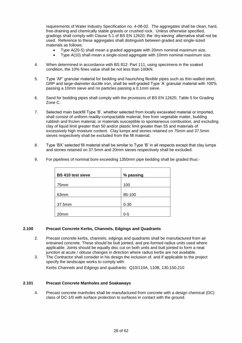
9. For pipelines of nominal bore exceeding 1350mm pipe bedding shall be graded thus:-
BS 410 test sieve % passing
75mm 100
63mm 85-100
37.5mm 0-30
20mm 0-5
2.100 Precast Concrete Kerbs, Channels, Edgings and Quadrants
2. Precast concrete kerbs, channels, edgings and quadrants shall be manufactured from air entrained concrete. These should be butt jointed, and pre-formed radius units used where applicable. Joints should be equally disc cut on both units and butt jointed to form a neat junction at acute / obtuse changes in direction where radius kerbs are not available.
3. The Contractor shall consider in his design the inclusion of, and if applicable to the project specify the landscape works to comply with:
Kerbs Channels and Edgings and quadrants: Q10/110A, 110B, 130,150,210
2.101 Precast Concrete Manholes and Soakaways
4. Precast concrete manholes shall be manufactured from concrete with a design chemical (DC) class of DC-1/0 with surface protection to surfaces in contact with the ground.

29 of 62
2.102 Precast Concrete Box Culverts
2. Precast concrete manholes shall be manufactured from concrete with a design chemical (DC) class of DC-1/0 with surface protection to surfaces in contact with the ground.
2.106 Prestressed Concrete Pipes and Fittings
3. All prestressed concrete pipes and fittings shall be manufactured from concrete with a design chemical (DC) class of DC-1/0 with surface protection to surfaces in contact with the ground.
4. Prestressed concrete pipes and fittings shall not be utilised for buried pressurised water pipelines.
2.111 Pulverised Fuel Ash
4. Each consignment of PFA delivered to the concrete production plant for use in structural concrete shall be accompanied by a certificate of compliance with BS 3892: Part 1. A copy shall be submitted to the Project Manager.
2.113 Rolled Asphalt
2. Where high stone-content asphalt is used for roadways, it shall comply with BS EN 13108-4, and shall be suitable for laying by machine.
3. The Contractor shall consider in his design the inclusion of, and if applicable to the project specify the landscape works to comply with:
4. Asphalt surfacing: Q22/120 (vehicular grade), 121 (pedestrian grade),122 (red Macamit), 124, 360A (uncoated chippings), 365A (propriety surface treatment), 365B, 368 (surface markings).
2.115 Safety Chains
5. Safety chains shall be fitted with a ‘D’ shackle at one end and a carbine hook on the other, both of the same material as the safety chain.
2.120 Steel Reinforcement
4. High yield steel shall be type 2 (ribbed) bond characteristic.
5. Where practicable all vertical bars which would otherwise require “mushrooms” for protection of personnel to be hook ended.
6. Steel used shall have a high recycled content. As a minimum this should be 70%, but higher recycled content rates are expected.
7. If environmentally friendly coatings are available these shall be used unless a deviation is accepted by the Project Manager.
8. The steel supply chain used shall be accredited and in line with the Social Accountability International standard SA8000:2004 or equivalent standard.
9. Contractors must demonstrate that life cycle sustainability impacts have been considered and
minimised in the purchase of steel. Credible evidence must be obtained which demonstrates
sustainability and traceability through the supply chain
10. Contractors should work with steel suppliers to develop solutions that use less steel without
compromising strength and quality or increased cost, including options for corrosion resistance

30 of 62
2.121 Steel Sheet Piles
4. The tolerances for manufacture of steel sheet piles shall be in accordance with EN10249 Part 2-Pile clutches shall allow adjacent piles to interlock freely.
5. The design and fabrication of steel for walings, tie rods, fittings etc, shall conform to Eurocode 3.
6. Steel used shall have a high recycled content. As a minimum this should be 70%, but higher recycled content rates are expected.
7. If environmentally friendly coatings are available these shall be used unless unless a deviation is accepted by the Project Manager.
8. The steel supply chain used shall be accredited and in line with the Social Accountability International standard SA8000:2004 or equivalent standard.
9. Contractors must demonstrate that life cycle sustainability impacts have been considered and minimised in the purchase of steel. Credible evidence must be obtained which demonstrates sustainability and traceability through the supply chain.
10. Contractors should work with steel suppliers to develop solutions that use less steel without compromising strength and quality or increased cost, including options for corrosion resistance.
2.124 Surface Boxes and Guards
11. Surface boxes for valve and penstock spindles shall be manufactured from ductile iron, shall comply with BS 5834 Part 2 and shall have a clear opening 100mm dia with a depth of 100mm. Covers shall be lockable and watertight.
2.126 Timber and Preservation of Timber
4. All new timber shall be provided from a managed renewable resource and certified as such and shall carry the Forest Stewardship Council (FSC) trademark or other label from an equivalent internationally recognised, globally applicable, independent certification scheme for good forest management
5. For softwood or temperate hardwood, this shall be certified by either Forest Stewardship Council, Programme for the Endorsement of Forest Certification Schemes [Note: coppiced material is exempt].
6. Tropical hardwood requests must be made through the project board. Once a request has been made, the Employer will submit a business case for all potential applications/uses of tropical hardwood and senior management acceptance will be needed before any purchases can be made. Note: This needs to consider the use of lesser used species and recycled timber where they can meet the performance requirements.
7. If tropical hardwood is purchased, it must be certified whenever possible as for softwood or temperate hardwood. If certified timber is not available, credible evidence must be obtained which demonstrates legality, sustainability and traceability through the supply chain.
8. Coppiced material is exempt from the requirements for softwood and temperate hardwood if documentary evidence which demonstrates the following is obtained:
• The source of the coppiced material
• The coppicer has legal rights to coppice the wood
9. The purchase of recycled timber is preferable to the purchase of virgin timber from a waste hierarchy and resource use perspective. Recycled timber is defined as timber which is being used for a different purpose than the purpose for which the tree was originally felled. The previous use must be established and documented and details of chain of custody provided. [Note: this will be strictly monitored]. However, it is not necessary to prove legality or sustainability of the recycled timber.

31 of 62
10. If environmentally friendly preservatives are available these shall be used unless a deviation is
accepted by the Project Manager.
2.127 Trees and Shrubs.
1. The specification of the Landscape Works will contain as a minimum, and not limited to the following clauses:
General requirements
Plants / trees: Q31/200A
Criteria: Q31/215A
Container grown stock: Q31/235
Container grown aquatic marginal plants: Q31/236
2. Identification
Labelling Plant material: Q31/ clauses 245, 246
Inspection of plant material: Q31/ clauses 121 (plants), 121A (aquatic/marginal’s), 123 (guarantees), 255 (reserved trees/plants)
Identification: Q31/122
3. Planting Stock
Mature/Semi Mature Trees: Q31/
Extra Heavy / Standard Trees: Q31/
Tree whips / transplants: Q31/
Shrubs: Q31/
Instant hedging: Q31/474
Bulbs/Corms: Q31/205
Wetland Material: Q31/395 (Seed Collection)
Coastal Marram Plug Planting: Q31/
4. Plant Substitutions:
The Contractor shall inform the Project Manager at the pre-start meeting if the following clause applies.
Q31/260A (planting substitutions)
5. Contract Grow
The Contractor shall consider in his design the inclusion of, and if applicable to the project the option of Contract Grow: Q31/396
6. Planting Sundries
The specification of the Landscape Works will contain as a minimum, and not limited to the following clauses:
Preparation / mulching: Q31/165, 385
Protective Fencing: (for aquatic/marginal’s) Q31/731 and Q40/431, 432
Tree pit Accessories: Q31/511 (root barrier), 512 (sundries),
Tree Staking/ Guying: Q31/535A (stakes generally), 555 (short), 575 (double), 516 (underground)
Tree/ Shrub Shelters: Q31/486 (shelter), 487 (shelter), 488 (spiral)
Tree Protection: Q31/595, 596
Parkland Tree Guards: Q31/598 (timber)
Tree Irrigation / Drainage: Q31/54 (pipe), 515 (drainage layer)

32 of 62
2.130 Valves
1. The MEICA standard for Materials and mechanical installations: 369_13_SD01 must take precedence. All valve types must comply with the requirements in MEICA design standard Valves and Penstocks: 369_13_SD05 must take precedence.
2.132 Vitrified Clay Pipes and Pipeline Fittings
2. Vitrified clay pipes and fittings shall be of 'Extra Strength' strength class in accordance with Table 5 of BS 65.
2.134 Water
2. Potable water used in the production of concrete shall be assumed to comply with BS EN 1008 without test. Where recycled water is used, systems shall be in place to ensure that it complies with the requirements of BS EN 1008. Water for use in connection with the works shall be provided by the Contractor.
2.150 Marking and Packing of Pipes and Fittings
1. Each pipe and fitting shall be indelibly marked with the diameter, class and works test pressure. Wherever possible the identification marks shall be painted on the outside of pipes and fittings close to one end, which in the case of pipes and fittings with socket and spigot joints shall be the socket end.
2. Where there is insufficient smooth surface area to accommodate the above information the marking shall be put on rust-proofed metal tags secured to the item with galvanised wire.
3. The flanges of pipes and fittings shall be protected by wooden discs attached by means of service bolts or by other accepted means. Service bolts shall not be incorporated in the works.
4. All other pipe ends shall be protected against impact damage and entry of foreign matter.
5. Small items, such as small valves, parts of operating gear, bolts, nuts, gaskets and other joint components shall be crated for delivery. Each crate shall contain a detailed packing list in a waterproof envelope. The outside of the crate shall bear a general description of the contents and an identification mark relating it to the detailed packing list.
2.151 Wrapping Material
1. Wrapping material for site wrapping of completed pipe joints or couplings shall be a proprietary heavy-duty, self-adhesive, rubber-bitumen compound with PVC carrier strip together with primer and moulding putty. All materials shall be supplied by the same manufacturer.
2.152 Grilles, Screens and Other Miscellaneous Metalwork
1. All mild steel fabrications and associated cleats, brackets, packing pieces and the like shall be made off-site in workshops accepted by the Project Manager and shall be galvanised before delivery to Site.
2. Surface preparation, coating requirements and hot dip galvanising shall be in accordance with BS EN ISO 1461. The total nominal thickness of the coating shall be 140 microns: System Reference SB 2 in BS 5493 (equivalent to 995g/m²).
2.153 Cover Tiles and Route Markers
1. Cable cover tiles shall be earthenware tiles of the interlocking pattern manufactured in accordance with BS 2484. The form of interlocking shall be such as to ensure that no

33 of 62
displacement is possible in the event of ground settlement or other interference. Each tile shall bear the words ‘Elect’, ‘Elec Cable’ or similar accepted.
2. Route marker posts shall be of concrete, overall height 900 mm, 75mm thick, 230mm wide with a recess for a standard plate.
3. Indicator plates shall be of cast aluminium with raised black characters and be generally similar to class A hydrant indicator plates to BS 3251 with apertures for the insertion of character plates indicating details of the service and its distance from the marker post.
4. Valve marker posts shall be fitted with a 180 x 200mm indicator plate to indicate W.O., S.V. or A.V. as appropriate together with the main size and distance from the post. Plates shall comply with BS3251 unless stated otherwise and shall be fixed to the post with stainless steel fixings.
5. The colour for:-
• Fire Hydrant (FH) plates shall be as BS3251 (black letters on a yellow background).
• Washout (WO), Sluice Valve (SV) and Air Valve (AV) plates shall be black letters on a white background.
6. Pipeline and cable posts shall have the word ‘PIPELINE’ cast in the post and shall be positioned directly above the pipeline.
7. Where three or more marker posts would be required at one location, they shall be replaced by a single post, with a pipework diagram engraved on a plastic plate.
2.154 Waterproofing Membranes And Sundries
1. Waterproofing membranes shall comprise a cross-laminated polyethylene carrier sheet with a layer of rubberised bitumen compound of total thickness not less than 1.5mm. The primer for the membrane and other sundry materials for forming fillets, upstands and chamfers shall be fully compatible with the membrane material.
2.155 Fusion-Bonded Epoxy Coating
1. Fusion-bonded epoxy coatings described in this clause are intended for applications containing ductile iron, cast iron, steel, and aluminium-based substrates used in the manufacture of pipes, fittings and their components, that will be in contact with potable water, domestic effluent, any soil conditions and above-ground applications. The coating shall consist of a polymeric anti-corrosion barrier applied at a factory accepted by the Project Manager.
2. The coating system requirements, performance testing and factory-applied coating requirements and practice shall be in accordance with Water Industry Specification No. 4-52-01 (Polymeric anti-corrosion (Barrier) coatings). Where applicable, all materials shall comply with Clause 2.0.
3. The method of surface preparation and cleaning shall be in accordance with the Contractor’s design which shall be no less than the minimum requirements specified by the coating material manufacturer and the following requirements:
• the pre-coating surface shall be blast-cleaned to a minimum standard of Grade SA2½ in accordance with BS 7079: Part A1;
• the surface shall be tested for soluble salts and re-blasted if soluble salts are found to be present;
• all oil, grease and other contaminants shall be removed;
• all slivers, scabs and the like made visible by blast cleaning and detrimental to the coating process shall be removed;
• welds shall be fettled smooth;
• edges and corners shall be smoothed to a 1.5mm minimum radius;
• zinc chromate pre-treatment shall not be permitted.
4. The minimum coating thickness for pipes and fittings shall be 300 microns. The maximum coating thickness on a pipe wall shall be 1.6mm. The maximum coating thickness on a flange

34 of 62
shall be 2.0mm; the minimum and maximum coating thicknesses shall apply to coating inside bolt holes. Any thickness-critical surfaces shall be coated to the thickness specified and within the tolerances identified.
5. All coatings shall be examined to a class A coating classification and each item shall be checked for holidays over all of the coated surfaces. A fitting with 2 or more holidays per 3m² of surface area or a pipe with 30 or more holidays per pipe length shall be rejected for subsequent stripping and re-coating. All holidays detected shall be repaired and on completion the item shall be re-examined for holidays.
2.156 Capping Material
1. Capping materials shall comply with the relevant parts for capping as given in Table 6/1 of the Department of Transport Specification for Highway Works, subject to the requirements in Appendix 6/1.
2.157 Road-Marking Paint
1. Road-marking paint shall be either one-pack epoxy, or alkyd-based, and shall be supplied by an accepted manufacturer. It shall be suitable for applying by brush or mechanical means to concrete or bituminous pavement and to concrete block paving so as to give a chemically stable film of uniform thickness
2. When in the adopted highway, road markings to be as required by the highway authority
3. White paint shall contain not less than 6% by mass of titanium dioxide as a pigment, conforming to type A (anatase) or type R (rutile) specified in BS EN ISO 591-1. Yellow paint shall be standard colour BS 381C no. 355, and shall contain not less than 6% by mass of a suitable yellow pigment.
4. The paint shall be supplied fresh and ready for use in sealed containers.
2.158 Dissimilar Metals
1. Where dissimilar metals would otherwise be in contact, insulation systems shall be fitted as appropriate to prevent electro-chemical corrosion. Any applied coating to the metal will not be regarded as insulated.
2. Insulation systems shall not be required where the difference in potential between materials does not exceed 0.25 volts.
3. Bolts shall be sleeved with an insulator, and insulating washers shall be fitted at either side.
2.159 Pipework Identification
1. All pipework painted in the basic colour is to have banding colours repeated at all junctions, at both sides of valves, at appliances, bulkheads, wall penetrations and any other points where identification is deemed necessary. All other pipework shall be banded with the basic colours and banding colours at all points mentioned above.
2. Pipe identification banding shall be in accordance with BS 1710.
3. All pipework shall have direction of flow indication. This shall be in accordance with BS 1710.
4. Valves shall be generally painted in the basic colour of the pipework in which they are situated. If further identification is considered necessary, the top flange shall be painted in the relevant banding colour.
5. Information regarding the specific nature of the pipework contents shall be affixed to the pipework and repeated at regular intervals in accordance with BS 1710.

35 of 62
6. Where pipes containing chemicals are installed, colour banding identification reference panels shall be mounted, detailing the contents of each pipe within the area.
7. Visible pipes containing or transporting dangerous substances or preparations must be labelled with a pictogram or symbol as required by the EC Directive 92/58/EC. These shall be positioned on the pipe at the most dangerous points, such as valves and joints, and at regular intervals.
2.161 Concrete Bagwork
1. Bags for concrete filled bagwork shall be 360mm x 840mm hessian sandbags complete with tie strings, to BS 1214. The hessian shall be type C fabric and rot proofed to BS 2087. They shall be filled at a rate of 40 bags per tonne of semidry concrete (cement/aggregate ratio 1/6).
2.162 Geotextiles
Composite turf reinforcement mat
1. The composite turf reinforcement mat (C-TRM) shall be a machine-produced mat of 100% coconut fibre matrix incorporated into a permanent three-dimensional turf reinforcement matting.
2. The matrix shall be evenly distributed across the entire width of the matting and stitch bonded between a super heavy duty UV stabilized bottom net with 12.7 x 12.7 mm openings, an ultra-heavy duty UV stabilized, dramatically corrugated (crimped) intermediate netting with 12.7 x 12.7 mm openings, and covered by a super heavy duty UV stabilized top net with 12.7 x 12.7 mm openings. The corrugated netting shall form prominent closely spaced ridges across the entire width of the mat. The three nettings shall be stitched together on 38.1 mm centres with UV stabilized polypropylene thread to form a permanent three- dimensional turf reinforcement matting.
3. Installation staple patterns shall be clearly marked on the turf reinforcement matting with environmentally safe paint. All mats shall be manufactured with a coloured thread stitched along both outer edges (approximately 5-12.5 cm from the edge) as an overlap guide for adjacent mats.
4. The permanent composite turf reinforcement mat shall have the following physical properties:
Matrix: 100% Coconut Fibre
(0.50 lb/yd2) (0.27 kg/m2)
Nettings: Top Super Heavy Duty UV Stabilized Polypropylene
8.00 lbs/1,000 ft2 (3.91 kg/100 m2)
Middle Corrugated Ultra-Heavy Duty UV Stabilized Polypropylene
24 lb/1,000 ft2 (11.7 kg/100 m2)
Bottom Super Heavy Duty UV Stabilized Polypropylene
8.00 lbs/1,000 ft2 (3.91 kg/100 m2)
Thread: UV Stabilized Polypropylene
5. The composite turf reinforced mat shall be laid on a pres-seeded layer of approved top soil.
6. The composite turf reinforced mat shall be secured using steel staples as recommended by the manufacturer at 500mm centres in a domino 5 pattern.
Filter fabric – general use
7. Thermally Bonded Non Woven Geotextiles shall have the following properties:-

36 of 62
Unit Specification
Mechanical Properties - control
Wide width strip tensile EN ISO 10319
Mean peak strength kN/m 8.0
Elongation % 28
CBR Puncture resistance EN ISO 12236
Mean peak strength N 1500
Mechanical Properties – consequential
Wide width strip tensile EN ISO 10319
Strength at 5% strain kN/m 3.4
Hydraulic Properties
Pore size EN ISO 12956
Mean AOS 090 μm 150
Permeability EN ISO 11058
Mean Flow Rate – 5cm head l/m2.s 100
Mass per unit area g/m2 125
Woven geotextile
8. Permeable woven monofilament geotextile to have the following properties.
Unit Specification
Raw Material Polypropylene
Thickness at 2kPa EN 964/1 mm 0.5
Weight EN 965 g/m2 185
Tensile strength-warp EN ISO 10319 kN/m 18
Tensile strength-weft EN ISO 10319 kN/m 18
Elongation-warp EN ISO 10319 % 27
Elongation-weft EN ISO 10319 % 24
Cone Drop EN 918 mm 16
CBR Puncture Resistance EN ISO 12236 N 2100
Opening Size 090 EN ISO 12956 μm 1200
Waterflow normal to the plane EN ISO 11058
l/m2/s 765
Ground stabilisation geogrid
9. Ground stabilization geogrids shall have the following properties:
10. The mechanical stabilisation element shall be a geogrid manufactured in accordance with a management system which complies with the requirement of BS EN ISO 9001:2000 and BS ISO 14001:2004. If required by the Project Manager, the Contractor shall provide evidence of the manufacturer’s certification of its Quality Assurance System and the Environmental Management System.
11. The mechanical stabilisation element shall be a geogrid manufactured from a punched polypropylene sheet, which is then oriented in two directions so that the resulting ribs shall have a high degree of molecular orientation, which continues through the mass of the integral node.
12. The granular aggregate layer reinforcing mechanism shall be one of the mechanical interlock with the geogrid apertures and where both rigid ribs and rigid junctions absorb the loads such

37 of 62
that the interlocking aggregate particles are laterally confined.
13. The ribs of the reinforcing element shall be of rectangular cross section in both the longitudinal and transverse directions with the typical minimum rib depth of 1.3mm and rib width of 2.3mm. The geogrid aperture size shall be approximately 39mm x 39mm. The nodal thickness shall be approximately 5.0mm.
14. The junction efficiency shall be 95%, aperture stability shall be 9.1 kg-cm/deg and the radial stiffness shall be 390 kN/m at a strain level of 0.5%.
15. The reinforcing grid shall be inert to all chemicals naturally found in soils and shall have no solvents at ambient temperature. It shall not be susceptible to hydrolysis, shall be resistant to aqueous solutions of salts, acids and alkalis, shall be non-biodegradable. The reinforcing grid shall have a minimum of 2% finely divided carbon black, as determined by BS 2782:Part 4:Method 452B:1993, well dispersed in the polymer matrix to inhibit attack by ultra violet light.
General
16. Joints in all geotextiles shall be overlapped by a minimum of 500 mm.
2.163 Rip Rap (Core Stone)
1. The specific gravity of Rip Rap (Core Stone) shall be greater than 2.50 T/m3 and water absorption less than 2.0% by weight. Individual core stone shall be roughly cuboid with angular corners. The length of the longest edge of any block shall be less than twice the length of the shortest edge.
2. All rock types shall also comply with the following standards:
• Aggregate impact value. Value should not be greater than 30% for standard test fraction. Test method should be as described in BS 812.
• Ten percent fines. The force required to produce ten percent fines shall be a minimum of 100 kN. Test method should be as described in BS 812.
• Soundness. Loss in mass after 5 cycles should be not more than 12% for sodium sulphate or 18% for magnesium sulphate, by the test method given in BS EN 13043 : 2002.
• Aggregate abrasion value. Value should be not more than 15% using the method as described in BS 812.
• The source location, type and colour should be chosen to obtain consistency with local stone
3. Where necessary, a representative sample of large rock should be crushed to provide sizes acceptable for testing by these procedures.
4. Rock shall comply with the following grading in accordance with the ‘The Rock Manual, The use of rock in hydraulic engineering’, (CIRIA )
• Core Stone Medium Grading and free draining Dn50 = 170mm
• Characteristic weight: W50 = 12.5kg
5. Core stone shall be tested to demonstrate compliance with this document. The Project Manager shall require two suites of tests per source for acceptance prior to the stone being imported to the Site.
6. The visual impact of the rip rap shall be submitted for acceptance by the Project Manager.
2.164 General Testing, Inspection and Commissioning of Plant
General
The following Clauses define the requirements for testing and inspection.
1. The Contractor shall offer all items of Plant for inspection examination and witness testing. The Contractor shall inform the Supervisor of the date when the Plant will be ready for inspection

38 of 62
and witness testing. If the tests are beyond the resources of the manufacturer, the Contractor shall make arrangements for these to be carried out elsewhere. Any variation of this requirement shall be submitted for acceptance by the Project Manager.
2. The Contractor shall give the Supervisor two weeks notice, in writing that the Plant is ready for operation and of his intention to carry out tests.
3. The Contractor shall carry out tests as stated in the current appropriate British Standard, performance tests and such other tests as are necessary, in the opinion of the Project Manager, to determine that the works comply with the Works Information, either under test conditions in the manufacturer’s works, on site or elsewhere.
4. The Project Manager reserves the right to require the Contractor to meet any extra costs which are occasioned by failure of the Contractor to comply with the above testing and inspection requirements including the provision of test certificates, curves, sub-orders, etc., or which in the opinion of the Project Manager are due to insufficient care having been taken by the Contractor or his Sub-Contractor before presenting the Plant for inspection or test. If unauthorised delivery has taken place, the Contractor may be required to arrange for the plant to be returned to the manufacturer for inspection and/or witness testing.
5. Any inspection, examination, or testing, shall not release the Contractor, manufacturer or supplier of any item from any obligation.
6. Whilst the Project Manager shall be invited for witness testing and/or inspection of specified items of Plant at the manufacturer’s works, the Project Manager may at their discretion advise that the tests shall proceed in their absence, the tests shall be made as if in their presence, and duly certified copies of test readings shall be submitted.
7. Where items of Plant are of identical size and duty it may be required, at the Project Manager’s discretion, that a reduced number of the items be subject to witness tests, however, this shall not relieve the manufacturers from the requirement of carrying out the performance tests on all items prior to offering for witness testing.
8. The Contractor shall satisfy the Project Manager as to the accuracy of all instruments used for testing and if required shall produce recent calibration test certificates.
9. The Contractor shall obtain and submit to the Project Manager within two weeks of completion of any witnessed tests, test certificates and curves of all items certifying that they have been satisfactorily tested and describing and giving full particulars of such tests.
10. When the test certificates, curves, etc. have been checked, the Project Manager shall confirm acceptance in writing and the Plant shall not be incorporated in the works or delivered until this acceptance has been received.
11. The tests on or before Completion shall fully demonstrate the satisfactory operation of the Plant in accordance with the published manuals and instructions in the presence of the Project Manager and the Employer or their respective representative.
12. Draft Operating and Maintenance Manuals including detailed information of each item of plant and Health and Safety information with regard to Section 6 Health and Safety at Work Act 1974, shall be supplied four weeks prior to the commencement of tests on site.
13. The Contractor shall conduct his own site pre-commissioning tests prior to informing the Project Manager that the works or Plant is ready for site testing. Such pre-commissioning tests shall receive the prior acceptance of the Project Manager.
14. The tests shall satisfy the Project Manager of the reliability of the Plant under working conditions and that the guaranteed characteristics of each unit, the overall efficiencies of the plant and that the specification has been complied with. The Contractor shall provide everything necessary for the satisfactory testing of the Plant.

39 of 62
15. Two copies of the Operating and Maintenance Manuals shall be supplied to the Project Manager prior to the Completion certificate being issued.
Valves and Actuators
16. Valves detailed in the Contract shall be hydraulically tested in accordance with the appropriate BS quoted in this document.
17. The actuator shall be tested to ensure that it functions correctly over the valve stroke. Operation of the end of travel limit switches and position feedback facilities shall also be checked.
Cranes, Hoists and Lifting Tackle
18. All handling devices and lifting tackle supplied for maintenance purposes shall, unless they are built into and form part of the Plant, be tested, marked and certificates of test provided.
19. Lifting tackle built into and forming part of the Plant shall be operated at the maximum working load to the satisfaction of the Project Manager.
2.165 Material Certification
1. The Contractor shall provide appropriate certification obtained from his suppliers to authenticate the grade or quality of materials or Plant as requested by the Project Manager. Where quality of materials or Plant depends upon the continued standard of the supplier’s manufacturing process the Contractor shall provide evidence that the quality of materials or goods can be assured. Materials may be rejected if evidence of compliance with the Works Information is not forthcoming.
2.166 Backfill Material
1. Where available, suitable fill for re use will be taken from excavation works carried out on site. The Contractor shall be required to take reasonable measures to avoid the deterioration by wetting, drying, segregation, contamination or other cause which might cause material to become unsuitable; and shall remove and replace such deteriorated material. Where there is insufficient excavated material for this purpose this should be brought to the attention of the Supervisor.
2. Unsuitable fill material shall not be used within the works unless directed and shall include:
• material from swamps, bogs or marshes; peat, logs, stumps, roots, perishable or vegetable matter; building rubbish, ashes, boulders or clay lumps retained on a 100mm sieve; frozen material; toxic material or material susceptible to spontaneous combustion; material having an excessive moisture content or other quality which will prevent satisfactory compaction.
3. Selected fill is material which is not unsuitable and which may be used within the works.
4. The specification of the Landscape Works will contain as a minimum, and not limited to the following clauses:
Standards for Soil Products: Q28/270,
Imported Topsoil: Q28/315A
Compost: Q28/360A
Imported clay puddle: Q28/930

40 of 62
2.168 Trash Screens
1. Trash Screens shall be designed and manufactured in accordance with the Environment Agency’s Trash and Security Screen Guide (2009)
2. Trash screens shall be fabricated from mild steel sections, galvanised to BS EN ISO 1461:2009 and painted with 2 coats of bituminous paint. The screen bars are to be from 100mm x 10mm flat as detailed in the ‘Culvert design and operation guide’ (CIRIA).
3. Welding shall be carried out in accordance with BS EN 1011.
4. The Contractor shall prepare a fabrication drawing suitable for the fabrication of all elements of steelwork. The fabrication drawing(s) shall be submitted to the Project Manager for acceptance at least two weeks prior to the planned date for fabrication.
2.170 Signage
1. All signage is to be provided in accordance with the Environment Agency Public Safety Risk Assessments of Assets – Signage Guidance
2.171 Storage Handling and Use of Materials
1. The Contractor shall ensure that the Project Manager is kept informed by approved method statement his proposals for the delivery, handling and storage of all pre-cast units to be used in the works.
2. The Contractor shall ensure that a nominated individual on site has a defined responsibility for controlling and monitoring the management of materials on site, including the supervision of subcontractors in their management of materials. The name of the individual and the management structure into which they fall shall be communicated to the Project Manager.
3. Site staff shall demonstrate good practice in materials management on site.
4. A structure shall be introduced which allows the Contractor to monitor the rates of wastage of materials on site, which can be communicated to the Project Manager if so required.
5. The Contractor shall organise material ordering, delivery and storage in order to incorporate industry best practice, such that:
• the length of time materials are stored on site is minimised
• delivered quantities can be safely and appropriately stored on site
• appropriate preparations can be made on site to receive the goods (e.g. storage location and handling equipment may be made ready)
• all deliveries can be met by a person authorised to check the materials delivered and sign the delivery receipt
• deliveries to site are checked as soon as they arrive on site, before materials are unloaded if possible
• a protocol for refusing deliveries to site is established - for example, if the materials are damaged, if the wrong material has been delivered, and if an excess quantity has been delivered
6. The Contractor shall ensure that the suppliers’ recommendations for materials’ storage are being followed, and maintain good practice in materials storage at the storage compound. There shall be no facilities for the storage of materials anywhere other than the storage compounds.
7. Wherever possible, the Contractor shall ensure that materials are stored on a hardstanding, and protected from floodwater, theft and vandalism, the elements, from vehicle movements and from mud splashing.
8. The Contractor shall control the issue of materials from store to ensure that materials’ use may be monitored, paying particular attention to the storage of hazardous materials and liquids
41 of 62
which shall be in a manner appropriate to the safe storage of that substance, and following prevailing legislation and industry best practice.
9. The Contractor shall ensure that materials are clearly identified whilst they are on site and keep labels on materials for as long as possible. Where appropriate, the Contractor shall make every effort to reuse or recycle packaging.
10. Cement and PFA shall be stored in a dry, weatherproof area or in a silo and shall be delivered in quantities sufficient to ensure that there is no suspension or interruption of the work of concreting or grouting at any time. If stored in sheds, each consignment shall be kept separate and distinct.
11. Cement and PFA shall be stored in such a manner as to prevent nuisance due to blown dust. A record of any complaints received in this respect shall be maintained by the Contractor. The Contractor shall notify the Project Manager immediately on receiving such complaint. All aggregates brought to the site shall be kept free from contact with deleterious matter and in the case of aggregates passing a 5 millimetres sieve they shall, wherever possible, be deposited on the site of mixing for not less than 8 hours before use. Aggregates of different sizes shall be stored in different hoppers, or different stockpiles which shall be separated from each other and adequately drained.
12. The Contractor will provide temporary storage areas which do not form part of the Site area. The goods and materials shall be insured by the Contractor at all times.
13. Where possible, materials remaining on completion shall be transferred to other sites rather than disposed of. A list of such materials shall be provided to enable the Project Manager to search for other suitable sites.

42 of 62
2.172 Site Furniture
1. The specification of the Landscape Works will contain as a minimum, and not limited to the following clauses:
metal bollards: Q50/190
Benches: Q50/220
Litter Bins: Q50/240
Tree Grills: Q50/262
Tables: Q50/230
Hanging Baskets: Q50/270
Interpretation Boards: Q50/275
2.173 Gravel / Hoggin / Resin Bound Material
1. The specification of the Landscape Works will contain as a minimum, and not limited to the following clauses:
Q23/110A, 130A, 135,138, 180, 185, 230A
2.174 River Bank / Wetland Edge/ Ecological Materials
1 The specification of the Landscape Works will contain as a minimum, and not limited to the following clauses:
Coir roll/logs: Q31/238
Floating habitat: Section Q31/ clause 239, 463
Coir pallet: Q31/240
Brushwood : Section Q31/ clause 241 (faggots), 242 (matting)
Willow spilling: Section Q31/ clause 244 (willow), 243 (staking)
Mulch / Geotextile/ liner: Q31/390
Reptile / Newt Fencing: Q40/590
Reptile / Newt Hibernacula: Q50/280
2.175 Brick / Block Paving Material
1. The specification of the Landscape Works will contain as a minimum, and not limited to the following clauses:
Block Paving: Q24/110(concrete), 120(clay), 170 (reinforced grass)
2.176 Slab / Sett / Cobble Paving
1. The specification of the Landscape Works will contain as a minimum, and not limited to the following clauses:
Concrete slab paving: Q25/315A
Brick paving: Q25/130, 315A
Natural stone setts: Q25/330A
2.177 Paving Material
1. The specification of the Landscape Works will contain as a minimum, and not limited to the following clauses:
Geotextile sheet: Q25/365

43 of 62
Sand: Q25/390
2.178 Fill Material
1. The specification of the Landscape Works will contain as a minimum, and not limited to the following clauses:
Granular Type 1: D20/660
Hardcore: D20/710A
Course Gravel: D20/725
Pea Gravel: D20/735
Fine Gravel: D20/725
Medium to course sand: D20/758
Fine to medium sand: D20/760

44 of 62
3 Excavation, Backfilling and Restoration
3.1 Excavation
9. The Contractor identifies all routes of waste removed from site. All debris and waste material is removed from site to a licensed landfill site as set out in clause 1.45
10. The method of Excavation in rock shall prevent damage to existing structures and to the Works.
11. 'Rock' shall mean rock found only in ledges or masses in its original position which would normally be removed by blasting, or with the assistance of hydraulic hammers, by pneumatic spades, or by wedges and sledge hammers if removed by hand. Also all solid boulders or detached pieces of rock exceeding 0.5m3 in size in trenches and other excavations.
12. 'Artificial hard material' shall mean blockwork, brickwork, stonework, masonry, concrete (including reinforced concrete) and any other artificially made or placed material, which is encountered below original ground level. Where artificial hard material is encountered in the excavation the Contractor informs the Project Manager immediately. On the Project Managers instructions the Contractor shall submit their assessment of material classification for acceptance. The material shall only be considered as artificial hard material when the volume exceeds 0.5m3 in one solid piece.
13. 'Running sand' shall mean saturated sand or silt which is carried into the excavation by the lateral upward flow of groundwater, where stability can only be achieved either by close-sheeting, artificial lowering of the water table or by chemical means or other consolidation of the unstable stratum. Notwithstanding this definition, no material will be regarded as running sand unless the Project Manager has confirmed in writing that it may be considered as such.
14. When approaching the final surface in Material other than Rock, the final trimming for foundations or blinding concrete shall not take place until placing of concrete is about to commence.
15. When approaching the final surface in cohesive soil, the final 150mm shall not be excavated until it can be followed immediately by the placing of foundations, concrete or other materials, or by the laying of pipes.
16. All loose and soft material and water shall be removed from the rock surface before placing concrete and the rock surfaces shall be maintained free of water during concreting.
17. Excavation in excess depth of that required to provide the Works shall be brought up to its correct level with designated concrete mix GEN3 (Grade C16/20) in accordance with BS 8500: Part 1, Clause 4.2.
18. If any feature of archaeological interest is uncovered, work shall cease and the Project Manager shall be notified and will instruct how to proceed.
3.3 Topsoil for Re-Use
5. The Contractor shall not allow Plant of any description to travel over topsoil heaps.
6. The soil which is stripped from the working area shall only be re-used after acceptance by the Project Manager.
7. Topsoil stripping and replacement shall be carried out with the minimum amount of mauling (moving around of soil, which destroys its structure). Topsoil stripping or replacement shall cease if the Project Manager, judges weather and / or ground conditions to be unsuitable
8. The specification of the Landscape Works will contain as a minimum, and not be limited to the following clauses:
Generally: Section D20/ clause 110

45 of 62
Clearance / Excavating: Section D20/ clauses 220 (stripping), 221 (treating), 225 (handling topsoil)
Disposal: Section D20/ clauses 410 (storage), 415 (removal), 420 (storage heaps), 421 (treatment)
Fill: Section D20/ 610A (compacted), 615 (loose tip)
3.4 Dealing with Water
5. The Contractor shall take such reasonable steps as the Project Manager considers necessary to protect and maintain the slopes of excavations or infilled areas from fluvial erosion during the course of the works.
6. The Contractor shall take all steps necessary to ensure that exposed formations are not subject to heave or other damage due to groundwater.
7. When dealing with water requires the continuous 24-hour operation of the associated Plant, the Plant chosen shall operate in compliance with Clause 1.26.of this document (Noise Control and Working Hours)
8. The Contractor notes that pumps will not be permitted to discharge on to carriageways, paved areas etc. All pump discharges shall be piped to a discharge point approved by the Project Manager. The discharging of pumps to sewers or drains shall only be permitted where no other system of discharge is practicable, and then only upon receipt of the Project Manager's written permission. Where permission to discharge to sewers, drains or watercourses has been granted, silt traps of adequate size and design shall be provided and maintained by the Contractor at each point of entry, to prevent the passage of deleterious material.
9. The Contractor shall keep the Project Manager informed of all arrangements made and consents obtained for the temporary discharge of water from the site.
3.7 Reinstatement of Maintainable Highways
5. Reinstatement of roads and streets which are maintainable (adopted by Highways Authority) highways shall be undertaken in accordance with the relevant provisions of the Highways Authority and Utilities Committee (HUAC) ‘Specification for the Reinstatements of the Openings in Roads’.
6. Where the Works involve excavation and reinstatement of any highway the Contractor ensures that the reinstatement complies with the performance requirements specified in the Northern Ireland Road Authority and Utilities Committee (NIRAUC) code of practice entitled “ Specification for Reinstatement of Openings in Roads” dated November 1998.
3.9 Reinstatement of Unpaved Land
6. The Contractor shall have a qualified specialist control the spread of and eradicate weeds in temporary soil stockpiles and in the reinstated areas by the application of a selective weed-killer which shall be applied before the weeds have gone to seed. If adjacent to any watercourse, PA4A and PA4AW certification will be required by a qualified person and acceptance gained in the application of herbicides from the Environment Agency.
7. Reference should be made to the Environment Agency document “Managing Japanese knotweed on development sites (2013) available on www.gov.uk/government/publications ” for reinstatement of land with knotweed present.
3.10 Trees
5. Protection of Retained Trees
The Contractor's method of working and use of constructional Plant shall be such that trees and bushes to be retained are not jeopardised, (i.e. roots crushed or branches damaged) except

46 of 62
that necessary pruning or lopping may be carried out, subject to the Project Managers acceptance.
3.12 Land Drains
6. Without limiting the Contractor’s liability for restoration of damage, the Contractor shall notify the Project Manager of any land drain which is blocked or is otherwise defective when the drain is first exposed.
7. Reinstated pipes shall be bedded and surrounded to 300mm above the crown of the pipe in fill material to Clause 2.90
8. The trench for a land drain shall be 400mm wide and 1000mm minimum deep below topsoil and lined with geotextile. The pipe shall be perforated uPVC in 100mm Type A(Y1) material surround, and the trench backfilled with Type E material as detailed in Volume 1 - Specification for Highway Works.
9. The geotextile for land drains shall have a weight of 110-150 g/m2 and a permeability of 50 l/m2s under a 100mm head of water. It shall be overlapped at joints by 300mm.
3.13 Filling Above Ground
3. The Project Manager is to inspect all formations prior to filling.
3.14 Blasting
5. The use of blasting is not permitted under any circumstances.
3.15 Piling
1. All piling shall be in accordance with the ‘Specification for Piling and Embedded Retaining Walls’ Second Edition, published by the Institution of Civil Engineers in 2007.
2. Precautions shall be taken to avoid damage to services as a consequence of piling operations. Statutory Undertakers restrictions apply to all piling and excavations adjacent to services, and as far as reasonably practical:
• Services must be located and exposed by hand excavation, prior to piling within 3m of the service. Great care must be exercised in hand excavations within 1m of the service to prevent damage to protective wrappings, flanges, etc.
• No impact type pile installation may take place within a distance likely to cause vibration or distress to the service, without prior agreement with the statutory undertaker(s) and/or service owner(s) before commencing piling activities.
• Piles should not be installed within 1m of any service
• The effects of stationary and/or moving heavy vehicles and plant over and/or in the vicinity of services must be carefully considered, and statutory undertakers and service owners should be consulted to agree procedures and/or mitigation/protection measures.
3.18 Grass Bank Protection
1. Grass banks shall be protected from erosion, where directed, by the inclusion of a layer of suitable geotextile placed according to the manufacturer's instructions, and topsoiled and seeded in accordance with Section 13 of this document.
3.19 Stone Pitching
1. Stone pitching to channel beds and banks shall be sound basalt or equal and approved hard stone. The pitching shall be one stone thick laid on 100mm of C20P/20 concrete.

47 of 62
2. The average depth of stone shall be 250mm, with no stone being less than 200mm thick. At least 20% of the stones shall be of greater surface area than 0.1m2.
3.20 Support to Excavations and Excavation Near Structures
1. The Contractor is responsible for the safety of all excavations and/or trenches and provides adequate timbering, trench sheeting, sheet piling or any other side support necessary whatever the depth to ensure the stability of the excavation and/or trench and that there will be no danger of disturbance to walls, fences, roads, paths or any other structure adjacent to or above work in progress. Walls, etc, shall be strutted and shored and every precaution taken to ensure their safety. Special consideration shall be given to works near protected heritage features and those with known heritage or archaeological interest.
2. Excavation and trench support shall be in accordance with the Health and Safety at Work (NI) Order 1978, Factories Act (NI) 1965 and the Construction (Health, Safety and Welfare Regulations 1996, and all other attendant regulations.
3. Should any damage occur to adjacent structures including roads and paths, the Contractor shall make it good and indemnify the Employer in respect of any such damage, settlement or disturbance.
4. All trenches, manholes, pits, etc, which are excavated in sand or similar loose material shall be close sheeted where required and in the case of roads and in close proximity to buildings or other structures where the depth of excavation exceeds 600mm.
5. Particular attention should be taken to ensure that excavations in the following areas are adequately supported:
• Adjacent to public highways (whether for pedestrian or vehicular traffic) and car parks;
• Adjacent to existing known services;
• Adjacent to existing structures.
3.21 Construction of Gabions and Mattresses
1. Gabions shall comply with this document Clause 2.48. Gabions shall have internal diaphragms of the same mesh as the enclosing fabric. Diaphragms shall be positioned such that no internal dimension in a gabion exceeds 1.0m and such as to give a maximum compartment size of 2.0m x 0.6m in gabion mattress.
2. Adjoining gabions and gabion mattresses shall be securely laced together along the full length of all adjacent sides.
3. Mechanical equipment may only be used for filling gabion units provided that the exposed faces are fair and stone filling shall be placed packed tightly, to ensure maximum density. Gabions shall be overfilled by 25mm – 50mm above the top to allow for settlement.
4. Lids shall be stretched tightly over the box and secured immediately after filling.
5. Where cutting of the gabion or mattress is necessary the mesh shall be cut cleanly and the surplus mesh cut completely out, or folded back and wired to the gabion face. All cut edges of the mesh shall be securely laced together.
6. Gabion units shall be maintained square and vertical sides.
3.22 Reinstatement to Land in Private Ownership
1. The Contractor shall wherever possible, take up and preserve existing structures, features and pavings to enable these to be replaced as final reinstatement. Where this is not possible new items are required to replace those removed, disturbed or damaged by the Works.
2. Reinstatement of structures, features and pavings shall be with materials of equivalent quality to those removed, disturbed or damaged; and shall match existing items so far as this is possible with currently available materials.

48 of 62
3. The Contractor shall ensure all working areas, site compound, storage and office areas to be reinstated to their original condition prior to the works and to the satisfaction of the Project Manager

49 of 62
4 Concreting and Formwork
4.1 Supply of Information
2. The delivery ticket required for each load of ready mixed concrete shall, in addition to the information prescribed under Clause 7.3 of BS EN 206: Part 1, detail:
• The type of aggregate,
• The proportion of any admixture,
• The actual cementitious content and the percentage of any pfa or ggbs included,
• The position of the concrete in the Works, and
• The time of arrival on site.
3. Ready-mixed concrete batched off the site shall comply with BS EN 206: Part 1 complemented by BS 8500: Parts 1 and 2. The producer provides the Project Manager with information in accordance with Clause 7 of BS EN 206: Part 1 before any concrete is supplied. On-site batching of small quantities of concrete, cement mortar, etc.; will only be permitted with the prior acceptance of the Project Manager.
4. The Contractor obtains the Project Manager’s acceptance of the source and satisfies the Project Manager that the supplier operates procedures for maintaining adequate quality control in accordance with BS EN 206: Part 1.
5. The Contractor also informs the Project Manager which alternative suppliers are available to him if the approval of the source referred to above has to be withdrawn by the Project Manager during the currency of the contract or for use as back up supplier in unforeseen circumstances.
6. Only plants having Accredited status of the Quality Scheme for Ready Mixed Concrete (QSRMC) or BSI shall be used. Unless it can be demonstrated that the Producer has a quality system in place and of similar scope to fully manage the infra-structure and production of the concrete that is accepted by the Project Manager.
7. The Contractor delivers to the Project Manager certification from the concrete supplier that the materials used comply with the requirements of this specification concerning chemical composition.
8. Where “Identity” testing is carried out by the Contractor, all test results shall be traceable to the producers delivery and/or production records
9. If instructed by the Project Manager, the Contractor shall make available any certificates of conformity or results from routine quality control testing to establish that the concrete has been supplied as a conforming product.
4.5 Transporting, Placing and Compacting
6. Concrete shall be transported from the mixer in accordance with Clause 12 of BS 8500:Part 1 and placed in the works as rapidly as practicable by methods which will prevent the segregation or loss of any of the ingredients and will maintain the required workability. It shall be deposited as nearly as practicable in its final position and all equipment for transporting concrete shall be kept clean.
7. Concrete shall not be dropped from a height greater than 2 metres or chutes longer than 4.5 metres or inclined at more than 45 degrees to the horizontal shall not be used unless it can be demonstrated by the Contractor that there is no detrimental effect to the concrete. Accumulations of set concrete on the reinforcement shall be avoided and a competent steel fixer shall be in constant attendance to adjust and correct if necessary the position of the reinforcement. Concrete shall be placed directly in its required position and shall not be worked along the shuttering to that position.
8. If concreting is not started within 24 hours of approval being given, acceptance shall again be obtained from the Project Manager. Concreting shall then proceed continuously over the area between construction joints. Fresh concrete shall not be placed against insitu concrete, which
50 of 62
has been in position for more than 30 minutes unless a construction joint is formed or it is demonstrated, by the Contractor that the concrete retains sufficient consistence to prevent the formation of a “Cold” joint. When insitu concrete has been in place for 4 hours no further concrete shall be placed against it for a further 20 hours.
9. Except where otherwise agreed by the Project Manager, concrete shall be deposited in horizontal layers to a compacted depth not exceeding 450 mm where internal vibrators are used or 300 mm in all other cases.
10. All concrete shall be deposited on a dry formation and the placing of concrete under water will not be permitted unless by an approved method agreed with the Project Manager.
11. Except with the prior acceptance of the Project Manager, water shall not be allowed to rise over unprotected concrete until it has sufficiently stiffened to prevent water damage. Concrete subject to immersion in water shall be protected by allowing shuttering to be left in place or in the case of unformed surfaces by securely covering the surface with polyethylene sheeting or other protective covering to the of the Project Manager.
12. Placing of concrete shall be arranged so that the number of construction joints is reduced to a minimum. Construction joints shall be formed at right angles to the axis of the member. The position of any construction joints shall be subjected to the acceptance of the Project Manager.
13. Where concrete is to be placed directly onto natural or filled formation, compaction of the formation shall be first carried out.
14. The exposed faces of concrete shall comply with the required class of finish indicated on the drawings. No repairing of any concrete facing shall be carried out without the Project Manager’s permission. Where directed, any voids found shall be filled up immediately following striking of shuttering with a 1:1 sand-cement mortar.
15. The general recommendations of Eurocode 2 and BS 8500: Part 1 section A.9.2 and A9.3 shall be applied to concreting in cold and hot weather respectively..
16. Concrete shall not be subjected to vibration between 4 and 24 hours after installation in line with Volume 1 Specification for Highway Works, Series 1700 Structural Concrete.
17. Where concrete is not placed directly into the Works, it should be placed on bunded sheeting and provision made to stop the material escaping into the adjacent ground.
4.8 Curing
4. Every care shall be taken to protect the concrete during placing and for the following 7 days, from the harmful effects of wave action, weather, rain, rapid temperature changes and frost. Concrete placed below ground shall be protected from falling earth during and after placing and all exposed edges and surfaces of hardened concrete which are liable to injury during the construction of the Works shall be properly cased up and protected. No loads of any kind shall be imposed on the concrete until it has developed sufficient strength so as not to be injured thereby.
5. Details of the Contractor’s proposed method of protecting the concrete shall be submitted to the Project Manager for his acceptance before work is commenced.
6. No concrete or concrete structure shall be put under load in any manner or used for any purpose without the sanction of the Project Manager in writing and such sanction shall not relieve the Contractor of any responsibilities as to safety, damage to concrete or maintenance.
4.9 Records of Concreting
3. In addition to the records specified in Clause 4.9.1, the Contractor shall keep records of concrete detailing:
• The location in the Works for each concrete batch
• The quantity and type, mix or grade of concrete
51 of 62
• The amount of water, if any, added to the mix after departure from the plant of manufacture.
• Slump
• Cube identification number
• The results of tests in accordance with BS EN 206: Part 1, Clause 9.4.
4.10 Construction of Formwork
7. Immediately before the placing of each lift of concrete the forms shall be re-examined and adjusted where necessary so that they will form a perfect fit and so that no leakage will occur between the forms and the existing concrete.
8. Shuttering to be re-used shall be thoroughly cleaned, and if necessary repaired before being used.
9. Re-use of the former for rebates shall only be permitted with the acceptance of the Contract Administrator. The formwork details at joints and rebates shall be such as to prevent grout loss, minimise air holes and produce a sound surface at stop ends and rebates.
10. ‘Pan system’ formwork shall not be used for water retaining structures where a fair finish is required, unless pan joint locations are subsequently smoothed down to achieve an approved finish.
11. All exposed arises shall have 25mm x 25mm formed chamfers.
4.11 Cleaning and Treatment of Forms
3. Polyurethane varnish shall not be used as a release agent for formwork of surfaces to be permanently exposed. Different release agents shall not be used in formwork to concrete which will be visible in the finished works.
4.21 Surface Finishes Produced Without Formwork
6. Finishes to exposed faces of inlet and outlet structures and other exposed concrete shall be Wood Float Finish for unformed finishes.
7. Floating shall be done only after the concrete has hardened sufficiently. Care shall be taken that the concrete is worked no more than is necessary to produce a uniform surface free from screed marks.
8. The specification of the Landscape Works will contain as a minimum, and not be limited to the following clauses:
Trowelled Finish for pavement wearing surfaces: E41/331
Smooth Float Finish: E41/310
4.22 Surface Finishes Produced with Formwork
6. Finishes to exposed faces of inlet and outlet structures and other exposed concrete shall be Fair Finished for formed finishes.
7. All exposed arises on concrete should incorporate 25mm chamfers.
4.24 Tie Bolts for Formwork
6. Tie bolts or other devices to be built into concrete shall be built to specification as detailed in the contract documents as accepted by the Project Manager.

52 of 62
5 Construction of Pipelines, Tunnels and Ancillary Works
5.1 Pipelaying Generally
9. Whenever the Contractor is not engaged in laying pipes, the pipe ends shall be effectively stopped with strong drum heads securely fixed to the pipes. Manholes, hatch boxes, cable pass holes and branches shall also be made secure against entry by persons, material, debris and vermin.
10. The Contractor shall pay particular attention to the relevant sections of BS 8010 – Pipelines and BS EN 14161.
11. Bedding, fill side and cover to polyethylene pipes shall comprise material in accordance with Clause 2.90.
12. The deformation of the pipe diameter when backfilled as specified shall not exceed 1% of the nominal diameter as compared to the diameter when laid prior to backfilling.
13. No pipe whatsoever may be installed by the Contractor where the wall of pipe has been scratched, scored or damaged such that defects penetrate the wall to a depth greater than 10% of the wall thickness.
14. Any pipe containing defects greater than 10% of wall thickness will be rejected and the Contractor shall be liable for all consequential costs in replacing such pipe and rewelding.
15. It is therefore the responsibility of the Contractor to examine all pipes to ensure that no damage exists at the delivery stage. It is also the responsibility of the Contractor to provide suitable storage and security for pipe held on site.
16. Before placing pipe bedding the trench bottom shall be prepared. All loose stones, lumps of clay, rock projections, boulders and other hard spots shall be removed. Where necessary joint holes shall be neatly cut to permit the barrel of the pipe to be properly supported throughout it length, and shall not be larger than is required for marking the joint.
17. Pipes shall be laid in straight lines between manholes, or between tangent points if there are bends in the pipeline, with a maximum deviation in the horizontal plane of 10mm from a line set with a theodolite. Pipes shall be laid to even gradients to the levels shown on Drawings with a maximum permitted tolerance of level of +10mm or -10mm and with a minimum disturbance to the bedding material. Points on either side of a joint shall not err from true line and level by differing amounts.
18. All adjustments to line and level must be made by adding or removing bedding material under the body of the pipe and not by wedging and blocking.
19. The use of pipes produced by different manufacturers will not be permitted in the same water main and all faulty, cracked and damaged pipes shall be rejected. No pipe shall be disturbed after setting and jointing.
5.2 Pipe Bedding
5. Backfilling shall be undertaken immediately after the required operation preceding it has been completed. Pipe bedding must be a hard durable gritstone or flint gravel (limestone is not acceptable).
6. Where a granular surround is required it shall be placed and compacted in layers not exceeding 150mm before compaction, to a minimum thickness of 150mm above the crown of the pipe. Compaction shall be carried out with hand rammers in 150mm layers.

53 of 62
5.3 Concrete Protection to Pipes
5. Concrete protection to pipes shall be well vibrated, rammed and worked under and around the pipe. Top surface shall have a spade finish. The Contractor shall take such measures as are necessary to prevent flotation of pipes during the placing of concrete protection
5.7 Pipe Jointing Generally
7. The Contractor shall construct flexibly jointed pipelines with joint widths within the manufactures recommended limits. The Contractor shall make allowance in setting joint widths for any future movement of the pipe.
8. After jointing and testing flexibly joined pipes other than ferrous pipelines and before any concreting or backfilling is commenced, the annular space between the inside face of a socket and the pipe barrel shall be sealed with a compressible gasket.
9. All flanged joints inside pumping stations and valve chambers shall be made using stainless steel bolts.
10. The pipes are to be laid singly with the sockets uphill and the barrels firmly embedded on the granular bedding throughout their length, the spigot end is to be inserted and supported concentrically in the socket of the pipe behind. Pipes are to be laid with the British Standards mark at the top of the barrel.
5.15 Cutting Pipes
6. Pipes shall be cut by a method which provides a clean square profile, without splitting or fracturing the pipe wall, and which causes minimal damage to any protective coating.
7. Where pipes are to be cut to form non-standard lengths, the Contractor shall comply with the manufacturer’s recommendations in respect of ovality correction and tolerances to the cut spigot end.
5.18 Inverts and Benching
3. Bases of manholes shall be formed in concrete of grade C30P/20. Benching shall be formed in Designated concrete RC40 (Grade C32/40) and comply with the relevant clauses of BS 8500-1, Clause 4.2. Benching of grade C30P/20, and shall be rendered in granolithic concrete 50mm thick, trowelled smooth, and slope at 1 in 12 towards the main channel.
5.19 Pipes and Joints Adjacent to Buildings
4. Pipes built into a structure shall be supported by a concrete bed and haunch up to the central axis level integral with the structure.
5. Where proposed Works pass through a wall or other structure the Contractor, seven days (minimum) before commencing the crossing, provides the Project Manager with a method statement detailing how he intends to safely affect the crossing. The crossing shall not be carried out until the Project Manager has accepted the method.
6. If the Contractor accepted method is to demolish the wall, demolition shall be the full height of the wall and shall extend to the full trench width. The remaining wall ends shall be adequately battered to ensure their stability.
7. Pipes laid through walls or other structures shall have a class A unreinforced concrete bed. As referenced in Standards for Highways – Design Manual for Roads and Bridges – Volume 4 (Geotechnics and Drainage), section 2, Part 5, HA40/01 Determination of pipe and bedding combinations for drainage works.

54 of 62
5.21 Setting Manhole Covers and Frames
4. Insitu concrete haunching to manhole cover frames surrounds to chamber sections, beds and haunches to pipes built into manholes shall be formed in standard prescribed concrete ST4-X0-S3 (Grade 16/20).
5.34 Precast Concrete Segmental Manholes
1. Precast concrete chamber rings shall be surrounded in 150mm designated concrete GEN3 (Grade C16/20) in accordance with BS 8500: Part 1, Clause 4.2, when manholes are situated in roads or footways or below 3m depth when in fields or open country.
2. Finish to this concrete shall be Type Rough.
5.35 Holes in Chambers
1. Holes required to be formed in pre-cast concrete chamber units to allow pipework to pass through shall be made in-situ 10mm oversize by pre drilling around their perimeters. Any over break of holes shall be made good in Class M1 mortar at the Contractors expense, or the units shall be replaced at the Project Managers’ discretion.
5.36 Steel Pipes and Fittings
1. Steel pipes, fittings and joints shall comply with the relevant provisions of BS EN 10311 and BS EN 10216.
2. The steel pipes shall be supplied by an approved manufacturer who will be required to show
• Quality Assurance and control programme approved by the Project Manager.
• Compliance with British Standards regarding materials, manufacture, testing and storing of materials.
3. Pipes for cutting shall be clearly identified and used only as directed.
5.37 Pipe Ramming
1. The Contractor shall submit Method Statements for all operations for the acceptance of the Project Manager before commencement of the Work.
2. Before any particular pipe ram length commences sufficient pipes shall be available to ensure continuous operation.
5.38 Ground Movement Monitoring Under Rail Track
1. The Contractor shall monitor the effects of the undertrack crossing construction at the surface, including all ground movements and the effects on all structures, including the works.
2. The tolerances, monitoring requirements and contingency plans with regard to potential track movements will be stated by Network Rail prior to the Works commencing.
3. Continuous monitoring of the Network Rail tracks will be undertaken by the Contractor and verified by Network Rail engineers, and will be measured against the amber and red trigger levels as stated by Network Rail.
4. Monitoring equipment shall be provided by the Contractor to enable the structural response of structures to be determined. Equipment and instruments shall be installed to the manufacturer’s instructions and shall be calibrated and tested as appropriate. Monitoring pins and devices shall be securely fixed in position. Due regard shall be given to the construction of the structure and the layout of its primary support.
5. Monitoring shall be referenced to stable survey stations located outside of the zone of influence of the Works and not subject to ground movement. Such bench marks and coordinated stations

55 of 62
shall be established and agreed with the Project Manager before the Works commence. They shall be checked weekly during the duration of the Works.
6. The Contractor shall observe record and analyse the readings to establish trends in movement and shall provide a copy of the recorded results to the Project Manager. He shall make available results to the Project Manager monthly.
7. During the execution of the Works, defects which have been scheduled shall be inspected and monitored as necessary. Defects which arise during the course of the Works shall be recorded. The Contractor shall keep records of such inspections and a copy shall be made available to the Project Manager.

56 of 62
6. Building Works
6.1 Brickwork and Blockwork Generally
7. In this Clause ‘brickwork’ shall be deemed to include brickwork and masonry.
8. The courses shall be properly levelled, perpendiculars kept and quoins, jambs and other angles plumbed as the work proceeds. Brickwork in the course of erection shall be adequately protected against rain, both during and outside working hours.
9. Brickwork one brick thick and over shall be English Bond. Half brick walls including half brick skins of cavity walls shall be in Stretcher Bond. All cement shall be Sulphate Resisting Portland Cement.
10. Bricks shall be wetted before they are laid. Partially completed work shall be wetted before laying further brickwork thereon. Only sufficient water shall be used in order to prevent adsorption of moisture from the mortar. When frost is expected bricks shall not be wetted. Only hand stacking and discharging of bricks shall be permitted whether at the place of manufacture, in transit or at the site unless palletised.
11. No bricks shall be laid where the air temperature in the shade is below 3c unless special precautions are taken which have been accepted.
12. Where necessary the bricks, water and sand for mortar shall be preheated to ensure a temperature of 5c in the brickwork when laid. An approved mortar plasticiser may be used, but anti-freeze compounds shall not be accepted.
13. Other than as required by Clause 6.1.10 bricks which are wet shall not be used.
14. All new brickwork shall be suitably covered for a period of 3-7 days as required, and the temperature of the brickwork shall not be allowed to fall below freezing point.
15. The specification of the Landscape Works will contain as a minimum, and not be limited to the following clauses:
Workmanship generally: F10/410,415,430,860
Laying: F10/561,580,690A,780A,790,820A,
Jointing: F10/635,645A,665,870,880
Bond:F10/800
Coursing: F10/560
Facework: F10/710,760,890
Capping: F10/820
Colour consistency: F10/750A,
Finished reference panels: F10/740A,
6.2 Brickwork and Blockwork, Jointing and Pointing
3. All mortar joints in brickwork and blockwork shall be pointed to produce a bucket handle finish, with the exception of brickwork copings which shall be flush pointed.
6.6 Bonding To Concrete
1. Where masonry is to be bonded to concrete, this shall be achieved by means of metal ties, evenly placed at 4 per m2, and masonry shall be brought up to the concrete.
57 of 62
7 Testing and Disinfection
7.2 Precautions Prior to Testing Pipelines
4. The Contractor shall provide and install all necessary temporary plugs, caps, blank flanges and thrust blocks for testing of pipelines.
5. Pressure testing against closed valves will not be permitted.
7.4 Testing Non-Pressure Pipelines
4. The Contractor shall provide all test equipment and labour required for testing.
5. All new pipelines shall be air tested in accordance with Clause 7.6 after backfilling but before the connection of laterals. Temporary caps or stoppers shall be fitted to junctions to facilitate the air test. Water tests shall only be carried out on such pipelines in the event of an air test failure.
6. All pipelines of diameter 150mm or above shall be visually inspected by CCTV examination and digital records for the Project Manager retained.
7.5 Water Test for Non-Pressure Pipelines
4. The Contractor shall be responsible for the disposal of all water used for testing.
5. Mains water shall be used for testing.
7.7 CCTV Inspection of Pipelines
2. A written report together with a digital recording of the inspection shall be provided to the Project Manager.

58 of 62
8 Roadworks
Add the Following Clauses
8.17 Cold Weather Working for Roadworks
1. No material in a frozen condition shall be incorporated in the Works but shall be instead retained on the site for use if suitable when unfrozen.
2. Material for use in road pavement shall not be laid on any surface, which is frozen or covered with ice.
3. Laying of materials containing tar or bitumen binder, or mixtures thereof, shall cease if the temperature of the surface to be covered is at or falls below 2 degrees Celsius. Where however the surface is dry, unfrozen and free from ice, laying may proceed at temperatures at or above 1 degree Celsius on a rising thermometer.
4. Laying of roadworks materials containing cement shall cease when descending air temperature in the shade falls below 3 degrees Celsius and shall not be resumed until the ascending air temperature in the shade reaches 3 degrees Celsius.
5. If material used in the road pavement contains cement and frost occurs during the first 20 days or 14 days as appropriate to the time of year after placing concrete slabs or the first 7 days in the case of other cemented materials, one day shall be added to the period which would otherwise be required before running of traffic of any sort on it for each night on which the temperature of the surface of the layer in question falls to 0 degrees Celsius or below.

59 of 62
9 Sewer Renovation
9.1 Isolation of Flows
2. The Contractor allows for maintaining of flows in the watercourse at all times. When carrying out any temporary Works within the culvert the Contractor ensures that flow does not escape from the culvert.
3. The Contractor is responsible for making such arrangements as he considers necessary to deal with the flow of water in the existing culvert for the duration of the Works. Arrangements shall also be made to deal with flows from connections.
4. Relining Works shall be carried out in dry conditions. Flows shall not be permitted to pass through liners during installation.
9.2 Preparatory Survey
6. Relining work shall not be permitted until the prepared sewer has been inspected and accepted by the Project Manager.
7. The plans, longitudinal sections and nominal cross-sections of the culvert shown in the drawings are for general or measurement purposes only. The Contractor shall carry out a detailed survey before commencing remedial Works and shall include:
• Invert levels at 2m intervals;
• Dimensional section profiles at each change in section and at 10m intervals if no change in section;
• Details of location, level, size and pipe material of all connections.
8. The Contractor submits to the Project Manager two copies of the survey showing a longitudinal section at 1:100 horizontal scale and 1:20 vertical, plan at 1:100 scale, and cross sections at 1:20 scale.
9.3 Preparation of Sewers
8. Any repair materials previously placed in the existing culvert as temporary repairs shall be removed using methods accepted by the Project Manager, in such a way as to cause minimum damage to the existing culvert.
9. All pipes projecting into the existing culvert shall be trimmed back flush in such a way as to cause no damage to the remaining connection pipework or main culvert.
9.18 Rendering and Local Repairs
2. Repairs to lengths of man-entry sewers shall be carried out in such a manner, and over such area at one time, that the stability of the existing sewer is not jeopardised. The Contractor provides all temporary supports necessary to the existing structure to ensure stability during repairs.
9.22 Laterals
1. All laterals are to be reconnected except those designated abandoned by the Project Manager. Connections cannot be made at or within 100mm of a circumferential lining joint.
2. Connections to be made flush with the lined sewer and provide a smooth transition to the existing lateral pipework.
3. Laterals designated abandoned by the Project Manager shall be plugged with 300mm thick designated concrete GEN3 (Grade C16/20) in accordance with BS 8500: Part 1, Clause 4.2, grade C20P/10 before installation of any lining.

60 of 62
4. Connections to GRP linings shall be made with approved preformed branches where possible, otherwise in-situ connections shall be permitted. Holes and cuts in the lining shall be sealed with a suitable compatible resin, approved by the lining manufacturer, to prevent ingress of water into the glass filaments. In-situ connections shall consist of uPVC pipes that just fit over the clean and square cut end of the existing lateral, and shall be sealed using Densotape or equal approved. All pipes from existing laterals to new linings shall be adequately supported to prevent movement during concreting and grouting. The connection to the lining shall be surrounded in designated concrete GEN3 (Grade C16/20) in accordance with BS 8500: Part 1, Clause 4.2 concrete grade C20P/10 and shall form a grout-tight and watertight seal.
9.23 Cleaning of Surfaces
1. All deposits, which are likely to jeopardise the performance of the lining, shall be removed.
2. Cleaning shall be carried out in small lengths immediately prior to any remedial Works. In the event of a delay occurring between cleaning and subsequent remedial work, any deposited material shall be removed before commencement of the work.
3. All cleaning work shall be carried out in such a manner as to cause minimum damage to the existing culvert.

61 of 62
12 Additional Supplementary Clauses Relating to Landscape and Environmental Design
12.1 Resource Efficiency / Carbon Management
1. In general Contractors shall:
• be efficient through early Contractor involvement and design within design and build contracts such that we make best use of available materials, minimise the volume of materials required and minimise wasted materials (i.e. adopt a zero waste principle as far as practicable).
• use tools during design to help maximise resource efficiency e.g. ‘WRAP Designing out waste tool for civils projects’, which can be found on the web site http://www.wrap.org.uk/construction/index.html.
• implement materials management plans and site waste management plans to maximise opportunities for reuse/recycling and to minimise waste sent to landfill.
• seek to avoid using virgin, finite resources as far as practicable, and look to use materials and products that are from recycled or renewable sources.
• be efficient through construction by sourcing materials locally and optimising transport of materials.
• encourage innovation in order to deliver cost-effective low carbon solutions, taking advantage of opportunities for standardisation, prefabrication and off-site manufacture.
• utilise information available from the Environment Agency’s procurement sustainability risk assessments for each project
2. In particular Contractors shall:
• Purchase timber from legal and sustainable sources with an audit trail from forest to end use in accordance with the Environment Agency’s policy.
• Specify, source and purchase recycled aggregates ahead of virgin aggregates
• Use on-site borrow pits where appropriate to win material with subsequent habitat creation.
• Minimise waste sent to landfill by following the waste hierarchy (reduce, reuse, recycle).
• Use the Construction carbon calculator during appraisal, outline design, detailed design and at construction stages to identify, investigate and implement alternatives to reduce the carbon footprint.
• Implement energy efficiency initiatives on site, buy/hire energy efficient plant, vehicles, cabins etc.
• Minimise our travel footprint by making use of technology, reducing journeys and materials movement, use of public transport and sharing lifts.
12.2 General
1. Refer to the Landscape and Environmental Design MTR 801_14 SD 02. The design and landscape specification shall as a minimum technical requirement comply with the relevant specification clauses set out in the relevant section of the document: Landscape Specification for Environment Agency Landscape Works Implementation and Maintenance Works
The current version of this Landscape Specification overwrites NEC 3rd Edition CESWI Specification for all landscape construction, establishment and maintenance works including topsoil supply, spreading and cultivation, all soft landscape works and all soft landscape establishment maintenance works. If there is any contradiction between the current version of the Landscape Specification for Environment Agency Landscape Works Implementation and Establishment Maintenance Works and the NEC 3rd Edition CESWI Specification, the Landscape Specification for Environment Agency Landscape Works Implementation and Establishment Maintenance Works is to take precedence.
2. Amending clauses to suit the specific project design and site requirements:
a) Some landscape works being undertaken by the Contractor, and some landscape works being delivered by the Employer e.g. through a separate JCLI Landscape contract or a separate tender exercise: The Contractor will incorporate applicable specification clauses

62 of 62
for the landscape works within their own contract from the “Landscape Specification for Environment Agency Landscape Works Implementation and Maintenance Works”.
b) Landscape Works being delivered solely by the Contractor: An Addendum to the “Landscape Specification for Environment Agency Landscape Works Implementation and Maintenance Works” will be incorporated in their contract, listing applicable clauses in addition to any new clauses to suit specific project design.
For materials and/or landscape products required but not specified within the Environment Agency’s ‘Landscape Specification for Environment Agency Landscape Works Implementation and Maintenance Work’s’ template, the Contractor shall submit a detailed specification for the alternative material and / or proprietary product required to the Project Manager for acceptance.
The source and local provenance of grass seeing mixtures, new planting and specimen tree stock shall be instructed by the Project Manager.