project specific requirements
TRANSCRIPT
Page 1 of 19
THERMAX LIMITED RESEARCH, TECHNOLOGY AND INNOVATION CENTER
DOC NAME: PROJECT SPECIFIC REQUIREMENTS DOC NO.: TL-PSR-2019-001_Rev 00
PROJECT SPECIFIC REQUIREMENTS
FOR
Thermax Project Number No- ME1801
Doc No.: TL-PSR-2019-001_Rev 00
THERMAX LTD, PUNE
00 05/08/2019 Issued for Enquiry B.HAJARE A.VERMA C.BARNI
Rev. Date Description Prepared Checked Approved
Page 2 of 19
THERMAX LIMITED RESEARCH, TECHNOLOGY AND INNOVATION CENTER
DOC NAME: PROJECT SPECIFIC REQUIREMENTS DOC NO.: TL-PSR-2019-001_Rev 00
INDEX A. GENERAL REQUIREMENTS
B. DESIGN, FABRICATION, CODES AND STANDARDS
C. DRAWINGS AND DOCUMENTS
D. MATERIAL OF CONSTRUCTION
E. VENDOR’S SCOPE OF WORK AND SUPPLY
F. EXCLUSION OF SCOPE OF SUPPLY
G. PROJECT SPECIFIC DRAWING APPROVAL PLAN
H. PROJECT SPECIFIC INSPECTION REQUIREMENTS
I. PACKING AND TRANSPORTATION
J. DOCUMENTATION
K. SPARES
L. PROJECT EXECUTION
M. VENDOR DOCUMENT REQUIREMENTS
N. GENERAL GUIDLINE DURING FABRICATION
O. ABBREVIATIONS
Annexure T1 – Preliminary GA drawings. Annexure T2 – Material Specification (Doc No.TL-MEA-ED-001)
Annexure T3 – Painting specification (Doc No.TL-MEA-ED-002)
Annexure T4 – Quality Assurance Plan (Doc No. ME1801-VSL) Annexure T5 – Process data Sheet Annexure T6 – Tolerance specification (Doc. No. TL-MEA-ED-004) Annexure T7 – Nozzle allowable loads (Doc. No. TL-MEA-ED-005) Annexure T8 – Technical Compliance sheet for Vendor (Doc.No. TL-MEA-ED-006) Annexure T9 – Distributor Performance test (FAT Test) Annexure T10 – Non-Disclosure Agreement
Page 3 of 19
THERMAX LIMITED RESEARCH, TECHNOLOGY AND INNOVATION CENTER
DOC NAME: PROJECT SPECIFIC REQUIREMENTS DOC NO.: TL-PSR-2019-001_Rev 00
A. GENERAL REQUIREMENTS
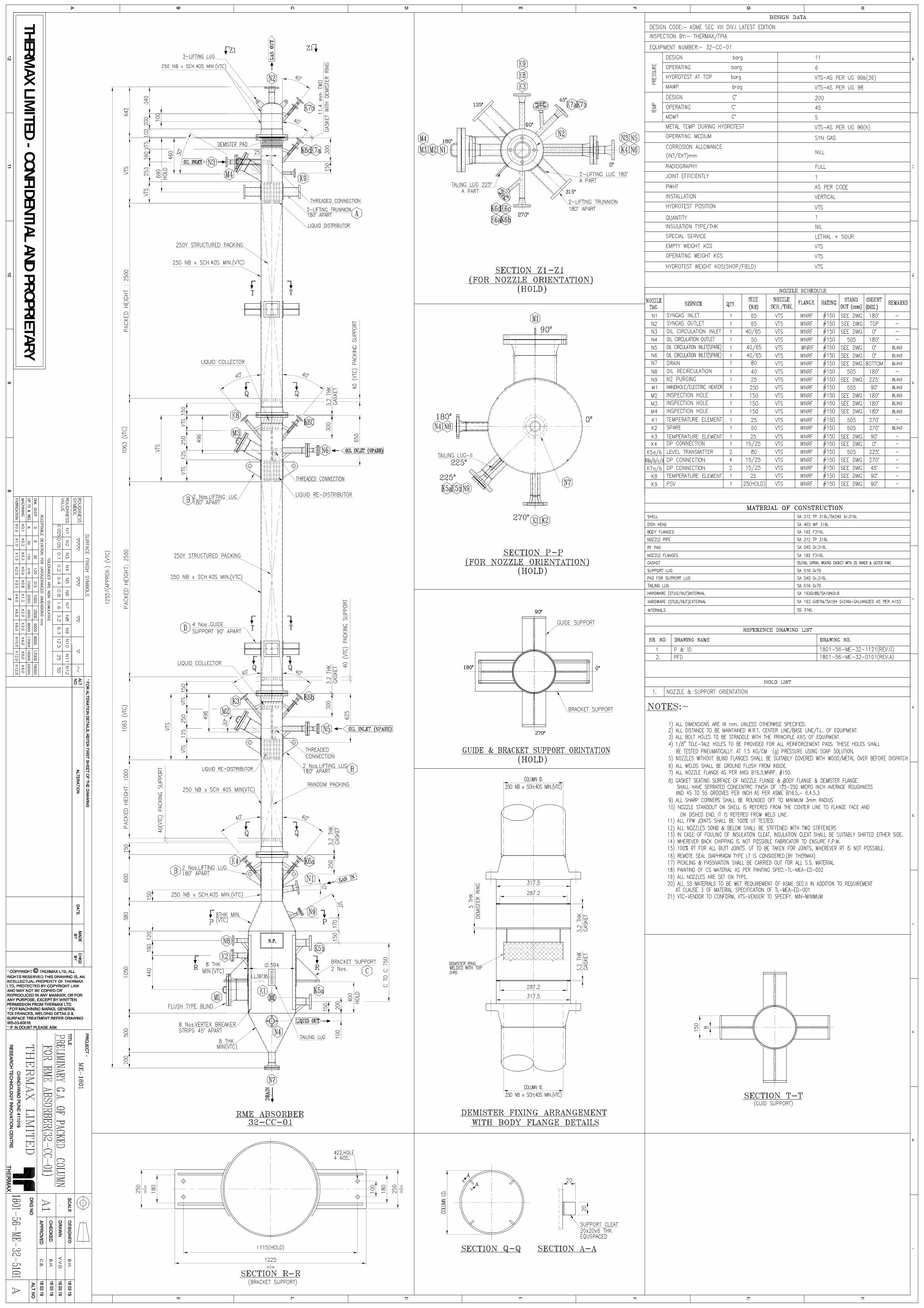
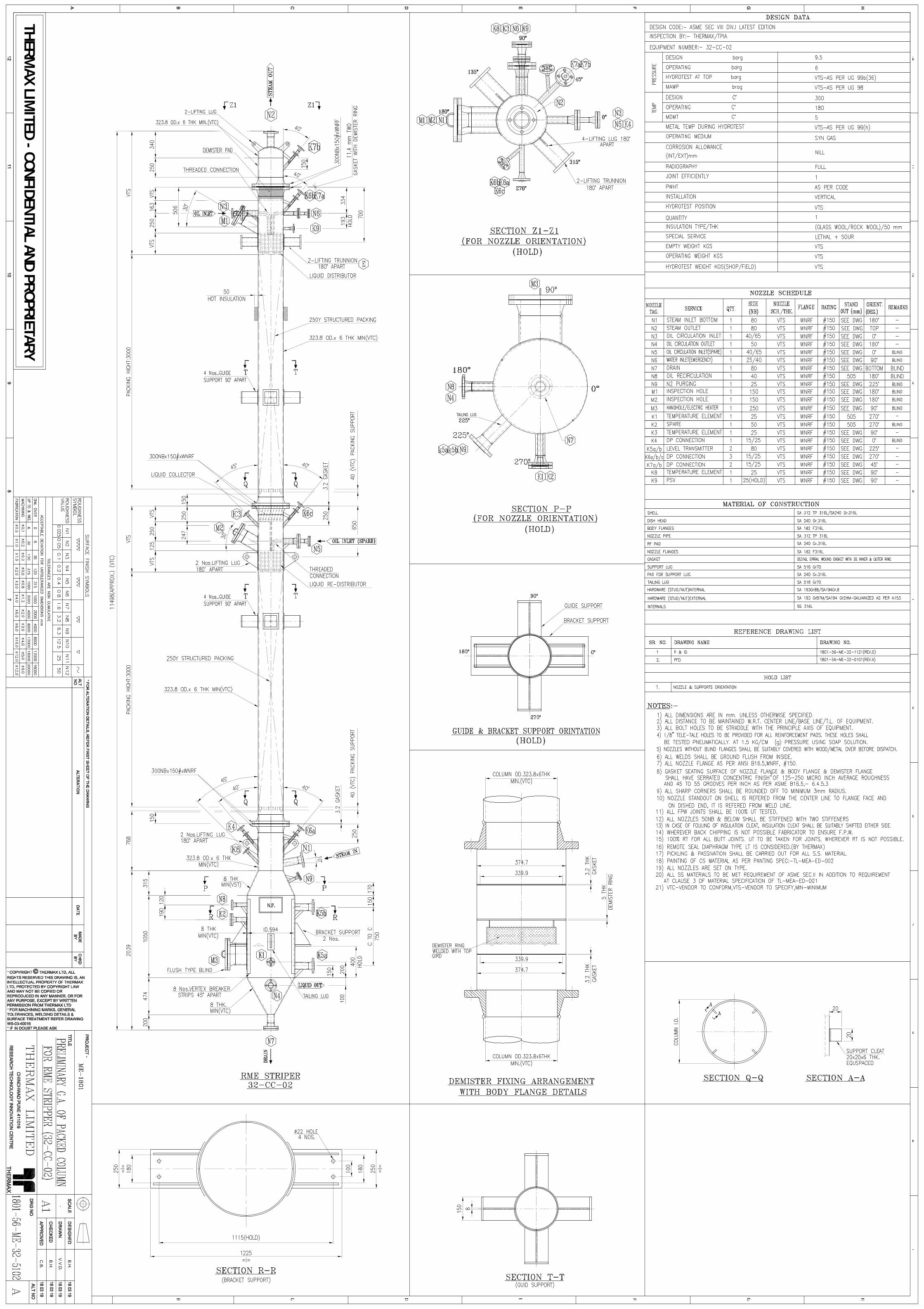
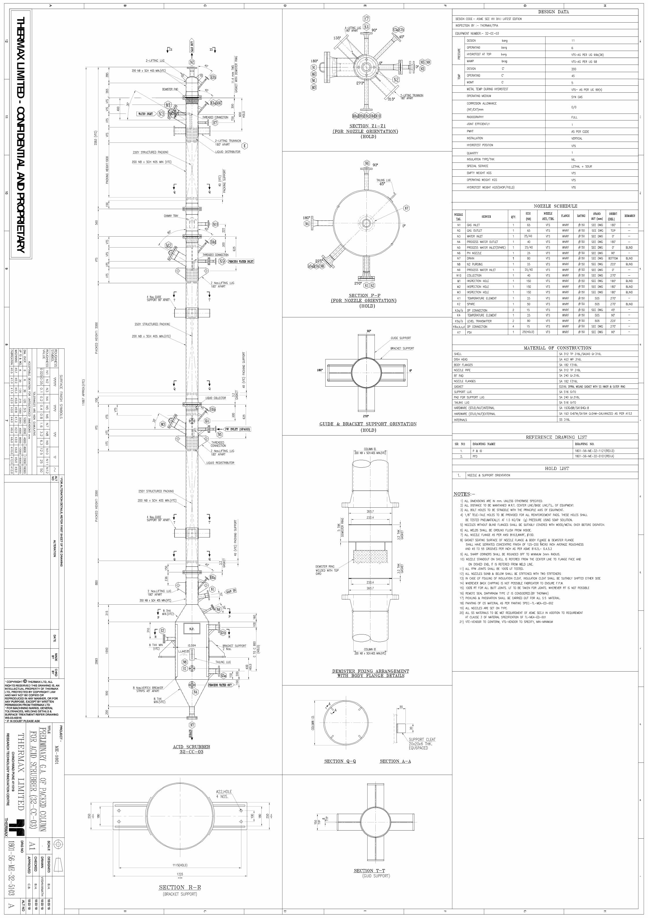
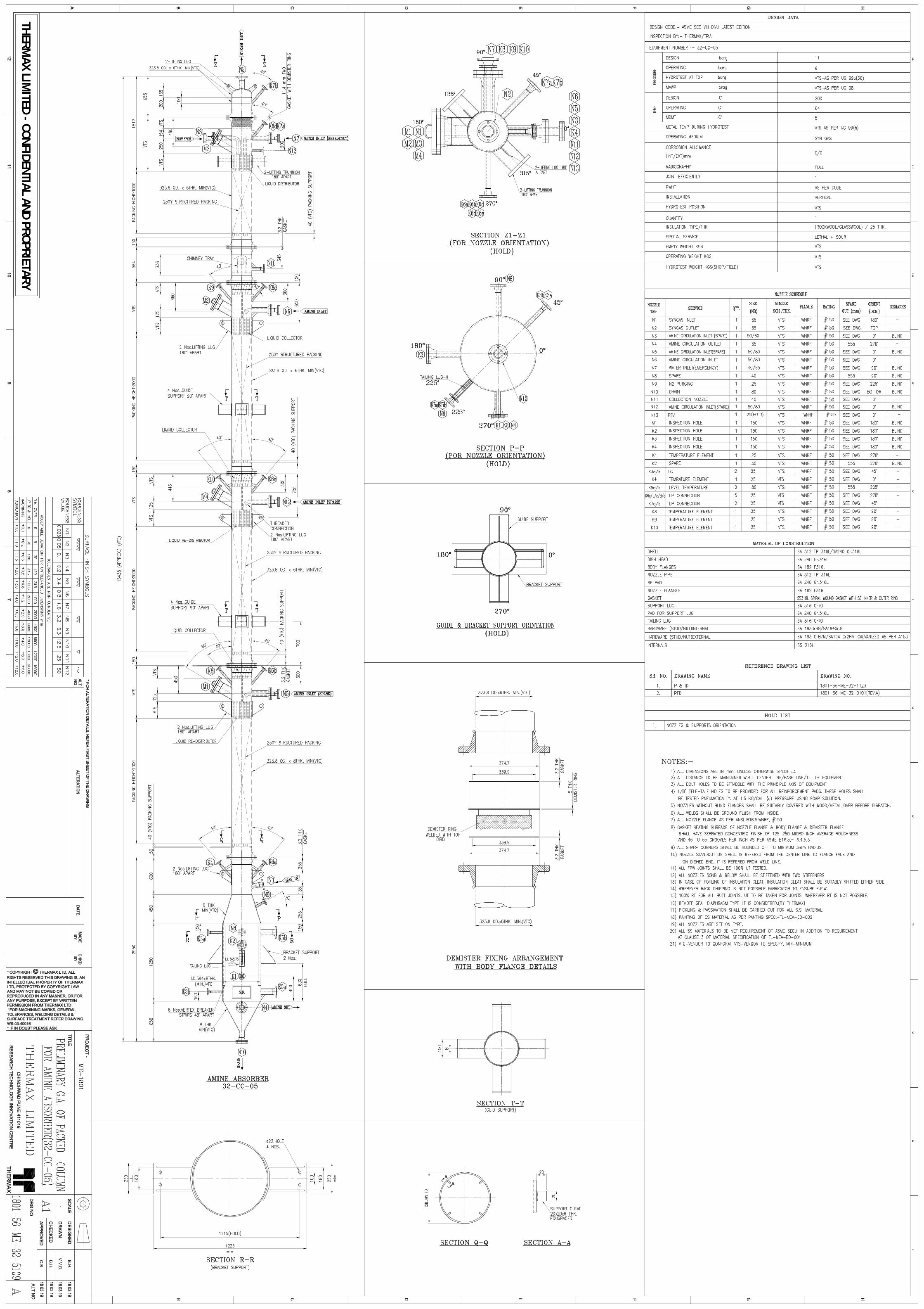
1) Preliminary GA drawings of all equipment’s are attached with PSR through Annexure-T1.
2) THERMAX will provide Process data sheets and Preliminary GA drawings for each equipment which contains such information as the shape, basic dimensions, min estimated thickness and weight, design conditions, materials for primary parts, nozzle specifications, and details of internals as required by Vendor to accomplish his packing & internals design, mechanical design of the pressure vessel and to prepare furnished Engineering Drawings covering the same contents as specified.
3) Vendor may discuss query / doubt (if any) in Pre bid meeting within 7 days from
tender opening date or else THERMAX will consider it as complete understanding of all documents / drawings from vendor side.
4) All drawings/documents issued by THERMAX are an intellectual property of M/S
THERMAX Ltd, No part of these drawings/documents shall be copied, reproduced or adapted in any form whatsoever for any purpose without the explicit written permission from THERMAX. Vendor need to sign Non-disclosure agreement (NDA) on 500/- Rs. Stamp Paper after receipt of the Purchase order. Please refer the NDA format as per Annexure-T10.
5) Packing & Internals design, Mechanical design, furnished G.A. Drawing, detailed Manufacturing Drawings, Procurement, Manufacturing, Testing, Inspection, Painting, Supply, Transportation to site, Supervision of Erection and Commissioning for Equipment as per applicable Drawings, specifications, codes & standards.
6) The scope of supply/work shall be as defined in section E.
7) Where no code or standard is specified in the Project Specifications and other
reference documents, the Vendor shall propose applicable codes and /or standards on which the Vendor's manufacturing is based, for review and approval by THERMAX.
8) In case of conflict between the specification and the data sheets, job and other
attached specifications, following order of precedence shall govern. • Statutory requirements • Drawings • THERMAX specifications • Codes & Standards.
Page 4 of 19
THERMAX LIMITED RESEARCH, TECHNOLOGY AND INNOVATION CENTER
DOC NAME: PROJECT SPECIFIC REQUIREMENTS DOC NO.: TL-PSR-2019-001_Rev 00
9) In case of any conflict between these documents, the Vendor shall notify the
THERMAX and obtain a written clarification of the points in question. The decision of the THERMAX shall be final.
10) Material/ Bought out items shall be procured from reputed manufacturer (China
Make material not to be used). Vendor shall submit the raw material manufacturer list for THERMAX approval.
11) All plates above 16mm thickness and Forgings above 50mm thickness shall be ultrasonically tested.
12) Clean potable water shall be used for hydrotest having chloride content less
than 25 ppm for SS Equipment’s and 80 ppm for CS equipment’s. Sea water shall not be used
13) Vendor shall be responsible for any discrepancies, errors or omissions in the
documents prepared by Vendor, even if these have been approved / reviewed by THERMAX. Review of Vendor’s documents by THERMAX does not relieve Vendor of his responsibility for correctness of supply. If any such errors or omissions are discovered later, that shall be made good, by Vendor, at his sole expense.
14) The Vendor shall carry out pre-shipment protection and preservation of
equipment and materials as per Project specification and Vendor’s standard.
15) Adequate supports and fasteners / transportation saddles shall be provided by vendor for safe transportation and handling of equipment in single piece.
16) All Equipment shall be supplied in single piece. However, in exceptional cases,
Site assembly is required then Prior written approval from THERMAX shall be obtained by the vendor at offer /inquiry stage itself.
17) Guarantee for Material and Workmanship shall be in Vendor’s scope of work.
18) Vendor shall provide previous track record details (PTR) along with the offer.
PTR should have complete information of process, supply detail and year of installation.
19) Vendor shall refer latest edition of all codes and standards. B. DESIGN, FABRICATION, CODES AND STANDARDS
1) The vendor shall do the preparation of design calculations and fabrication drawings based on the Process data sheet and Preliminary GA drawing provided along with the enquiry, as per the relevant design codes, standards & project
Page 5 of 19
THERMAX LIMITED RESEARCH, TECHNOLOGY AND INNOVATION CENTER
DOC NAME: PROJECT SPECIFIC REQUIREMENTS DOC NO.: TL-PSR-2019-001_Rev 00
specifications and submit the fabrication drawings and calculation for review by THERMAX before starting fabrication
2) The thickness of various parts, if indicated, in the preliminary G.A. drawing is the minimum requirements only and same shall be verified by the vendor based on design conditions and project specific requirements. Vendor shall check and confirm that such thickness provides adequate strength under the specified conditions and Adequacy of thickness is responsibility of the vendor and only upward revision is acceptable. Vendor has to ensure that all aspects covered in the Specifications and data sheets attached with the enquiry are complied with mechanical design of equipment, is in Vendor scope of supply. If any change in thickness / weight of the parts is found to be required as per codes / standards during review of the vendor’s GA and fabrication drawings or strength calculations by THERMAX, the same shall be incorporated by vendor without any price or delivery implications. Vendor to fabricate and supply the equipment based on his responsibility of ensuring compliance to THERMAX requirements including drawings, specifications etc. Vendor to note that approval of documents does not mean approval of any deviations contained therein. Such deviations if noticed at any time shall have to be rectified as per the requisition by vendor at no extra cost.
3) Higher Thickness of RF Pad, stiffener and non-pressure part is acceptable.
4) Minimum Design Metal Temperature is 5 Deg.C
5) Wind load shall be as followed:-
Applicable Standard: IS 875 (Part 3) 2015 Basic Wind Speed (Vb): 141 Km / hr. @ Base elevation 3 meter. Wind Zone Number : 2 Risk Factor : 2 Terrain Category: 3 Equipment class : Class A
Topography Factor (K3): 1.0
6) Seismic load shall be as followed :- Applicable Standard: IS 1893 (Part4) 2015 Importance Factor: 1.5 Soil Factor : 1.2 Seismic Zone: III
7) In case geometries cannot be analyzed by design rules given in code and pressure vessel design software such as PV elite (e.g tangential nozzles, offset nozzles, nozzles on conical section, blind flanges with opening, conical section, supports to internals, big bore nozzles, brackets etc) OR geometries falling in local load analysis by design rules (e.g nozzle local loading etc) then the same
Page 6 of 19
THERMAX LIMITED RESEARCH, TECHNOLOGY AND INNOVATION CENTER
DOC NAME: PROJECT SPECIFIC REQUIREMENTS DOC NO.: TL-PSR-2019-001_Rev 00
shall be analyzed by vendor using Finite element analysis (FEA) or Nozzle Pro software.
8) All mechanical design calculations shall be done with PV-Elite software. Manual calculations are not acceptable, unless otherwise agreed in writing by THERMAX.
9) Strength calculations shall cover:
5.1) Code calculations for all pressure retaining parts including reinforcements for nozzle openings.
5.2) Structural calculations for internals. 5.3) Structural calculations for lifting lugs and transportation fittings. 5.4) Stability check of vessel and support for wind and/or seismic load. 5.5) Stability check of vessel and support at transportation, loading & unloading
and erection. 5.6) Local stress analysis against external loading on nozzles and lugs.
10) Equipment shall preferably rested on Structure using Lug support. Also Guide support shall be provided for alignment of equipment.
11) Local stresses at shell around attachments such as nozzle, vessel support, lifting lug and so on, shall be calculated and evaluated by vendor. The following generally accepted calculation procedure, or the equivalent, may
be applied:- 7.1) Bulletin of Welding Research Council No. 107 or 297 7.2) Nozzle Pro software / Finite Element Analysis
12) Minimum allowable Nozzle loads shall be as per Annexure-T7 NOZZLE ALLOWABLE LOADS(TL-MEA-ED-005), For nozzle sizes/load not mentioned in THERMAX specification, Vendor shall mention (with Offer, also) the allowable Nozzle loads as per equipment capacity/ design.
13) The formed head shall be as specified on preliminary drawing or data sheet. 2:1 ellipsoidal are used, in general.
14) For stainless steel, equipment to ASME VIII Div.I the higher tensile stress value may be used to shells and heads but lower stresses must be used for flanges and other components subjected to distortion.
15) All removable internals shall be checked by suitable methods to be passed
through the manhole/Body flange. Extra care shall be given to the design of hold-down the gratings which are inserted after the packing is filled up.
16) The opening reinforcement shall be so designed as not to limit the maximum allowable working pressure of the vessel.
17) Vessels shall be provided with two earth lugs, unless otherwise specified
Page 7 of 19
THERMAX LIMITED RESEARCH, TECHNOLOGY AND INNOVATION CENTER
DOC NAME: PROJECT SPECIFIC REQUIREMENTS DOC NO.: TL-PSR-2019-001_Rev 00
18) Internal bolts subject to vibration, fluctuating load, impact load or dynamic load
shall be protected against loosening. Double nuts, unti-loose washers, tack welding, etc. shall be used.
19) Metric bolting shall be adopted for non-standard flanges.
20) Fabrication drawings must include torque required by torque wrench and load
required by bolt tensioner for tightening of all bolts.
21) Shell rolling shall be along length coarse direction of plate. Minimum shell course width shall be 1 meter.
22) The thickness after forming of any pressure retaining parts shall not be less than the calculated thickness.
23) Equipment shall be designed so as to permit site testing of the equipment with
water at the test pressure on the top of the equipment considering 33% of design wind load. The design shall be based on fully corroded condition.
24) Design calculations (Lifting lug stresses & Shell stresses) for lifting shall be
carried out considering an Impact factor of 1.5. Combined Induced stresses during lifting shall not exceed 90% of Yield stress.
25) Unless otherwise specified, all internals shall be designed for a
concentrated load of 1.5 times of packing load.
26) All internal bolts shall be Min. M10 size and of SS with double nuts.
27) Nozzle flange shall be of welding neck type as per ASME B16.5 up to 600 NB above 600 NB shall be as per ASME B 16.47 (SERIES 'B').
28) All flange facing shall have 125 – 250 AARH finish. Machined surfaces of all
forgings shall be examined for surface defects by D.P test after machining.
29) Nozzle equal or less than 2” shall be minimum Sch 80 thickness for carbon steel nozzle. And above 2” nozzle shall be minimum Sch 40 thickness.
30) Nozzle equal or less than 4” shall be minimum Sch40s thickness for stainless steel nozzle. And above 4” nozzle shall be minimum Sch 10s thickness.
31) All sharp corners shall be rounded off to 3 mm radius. Mainly for manholes,
inside edges manholes shall be rounded off smooth with a minimum radius of 3mm.
Page 8 of 19
THERMAX LIMITED RESEARCH, TECHNOLOGY AND INNOVATION CENTER
DOC NAME: PROJECT SPECIFIC REQUIREMENTS DOC NO.: TL-PSR-2019-001_Rev 00
32) Flange connections stud bolts shall be used according to ANSI B1.1 UNC Class 2A for 1" and smaller & UN8 for more than 1". Dimension standard for nuts shall be ANSI B 1.1 Class 2B. Studs shall extend beyond nuts at least by 2 threads & studs shall be threaded to full length. Bolts/studs (to be tightened by hydraulic bolt tensioner) shall be longer than normal length by minimum 1 nut diameter.
33) Threads on external bolting shall be lubricated with suitable grade of grease.
34) Bolt holes shall straddle the horizontal and vertical center lines in elevation and
the North/South center lines in plan, unless specified otherwise.
35) Fittings / Forgings / Pipes shall always be seamless, unless otherwise specified. All elbows shall be long radius (LR) unless otherwise specified.
36) Gasket shall be of one piece construction unless otherwise agreed with Client.
Gasket used for hydrotest shall be of the same material and size as the service gasket.
37) 1/8"NPT telltale holes shall be provided @ 180° apart on R.F pads. The same
shall be air tested to 1.5 kg/cm2 (g) using soap solution. Telltale holes shall be filled with correction inhibiting grease after hydro test prior to shipment.
38) All the materials shall be as per equipment Drawings and conform to ASME Sec
II and inspected as per the corresponding ASME specifications.
39) Materials for vessels shall be carefully stored at shop not to be heavily rusted or damaged. Stainless steel shall be stored under roof and protected from the contamination of any harmful substances such as chloride and zinc.
40) Positive Material Identification (PMI) to be performed at the Vendor's works on
Metallic Materials as per Project specification and Vendor’s standard practice at Supplier's Works. PMI examination of materials is independent of any certification, markings or colour coding that may exist and is aimed at verifying that the alloy used are as per specified grades.
41) All welds shall be full penetration weld (FPW) either by back chipping to sound
metal and Re-weld from second side or all root run shall be made with TIG process to ensure full penetration weld to comply requirements of UW-35. All Welds are continuous, unless otherwise stated.
42) All weld seams shall be clear of nozzles, reinforcement pads, internals, cleats
and stiffening rings by five times of thickness but not less than 25mm (weld edge to weld edge).Deviation to this requirement shall be approved by THERMAX on case to case basis.
If the seams are covered with reinforcement plates or saddle pads under THERMAX approval, they shall be ground flush with shell surface and radiographically examined in full length prior to welding of plates or pads.
Page 9 of 19
THERMAX LIMITED RESEARCH, TECHNOLOGY AND INNOVATION CENTER
DOC NAME: PROJECT SPECIFIC REQUIREMENTS DOC NO.: TL-PSR-2019-001_Rev 00
Longitudinal welded seams on adjacent shell segments shall be separated by at least 5 times the wall thickness of the thicker plate but not less than 100 mm. Longitudinal and circumferential welded seams shall be kept out of the internal welds, and shall be so located that they can be easily inspected with internals in place.
43) All welds shall be smooth and free of undercuts, cavities, cracks, inclusions all
inside welds shall be flushed with shell I.D.
44) All inside butt welds shall be ground smooth and all external welds and surfaces shall be cleaned to remove scales, weld spatters.etc. All sharp corners are to be rounded. All nozzles to vessel welds shall be ground flush with inside surface of the vessel & internal edge of the nozzle pipe shall be rounded off.
45) Wherever hot forming and subsequent heat treatment is involved, adopted procedure shall not impair the mechanical properties of the material beyond the limits specified in respective material specification.
46) When temporary attachments are required during the forming work, they shall be welded to the shell plate using the same welding procedures as for the main seams. After removing these attachments, the surface shall be ground flush and examined by magnetic particle method. In case of high alloy steel or non ferrous materials, liquid penetrant method can be substituted.
47) Post weld heat treatment, Stress reveling, Preheating and all nondestructive
testing like radiography, ultrasonic testing, magnetic particle/dye penetrant examination etc. shall be conducted as per requisition, Code & Standards, approved drawings.
48) No welding shall be performed on vessels after the grinding, final post weld heat treatment and hydro test.
49) The hydrostatic test pressure shall be held at least 1 hour.
Hydro test pressure shall be as per UG-99 b (36) and hydro test temperature Shall be as per UG-99h.
50) Pickling & passivation for all SS surfaces (both inside and outside) shall be
carried out as per ASTM A-380.
51) Surface cleaning and complete final painting of carbon steel parts at shop shall be as per Annexure-T3: Painting specification TL-MEA-ED-002.
52) A nameplate shall be mounted on each vessel and vendor shall mark actual erection weight on name plate & center of gravity on equipment (C.G.) for erection purpose. Mounting of nameplate on the removable parts is prohibited
Page 10 of 19
THERMAX LIMITED RESEARCH, TECHNOLOGY AND INNOVATION CENTER
DOC NAME: PROJECT SPECIFIC REQUIREMENTS DOC NO.: TL-PSR-2019-001_Rev 00
53) Tolerance shall be as per design code & Annexure-T6: Tolerance specification TL-MEA-ED-004.
54) 1mm per meter or maximum 20mm verticality of complete column shall be maintained.
55) The applicable code shall be ASME Sec VIII Div 1, Sec II, Sec V, Sec-IX, B16.5/16.47, B31.3, NACE MR 0103, NACE TM0284, NACE TM0177, ASTM 262,WRC107&297 (Latest Edition).
C. DRAWINGS AND DOCUMENTS
1) All the drawings shall be prepared on Auto CAD 2013 or later versions. English language and metric units shall be used in all documents. The successful vendor shall make fabrication drawings of the Vessel/Parts/Piping modifications and submit to THERMAX for review before any fabrication starts. If any discrepancy is found during design and fabrication stages the fabricator shall inform THERMAX immediately, and obtain necessary approval before proceeding with that portion of the job any further. THERMAX review of fabrication drawings and documents must not be considered as a check and shall not relieve the fabricator of his responsibilities to supply equipment as per requisition. Fabricator shall remain responsible for conflicts between his drawings / documents and THERMAX drawings / documents.
2) All fabricators drawings submitted to THERMAX shall be based on purchase
requisition and shall bear reference number and revision of the corresponding THERMAX drawings. In addition it shall indicate item number, client’s name, project name, fabricator’s name, purchase order number, purchase requisition number, drawing number etc., all in the lower right hand corner. All revisions shall be clearly marked by encircling with revision marks. Submission of required drawing / documents shall be the responsibility of the fabricator. Drawing index shall be prepared for each item giving serial number, description of drawing, drawing number and revision number. Updated index shall be forwarded along with each submission. Submission of all required drawing / documents in time shall be responsibility of the fabricator.
3) All drawings shall be thoroughly checked and duly signed by the fabricator.
Unchecked drawings and drawings without revisions clearly marked shall be returned without review. Successive review of the same fabrication drawing shall apply only to THERMAX latest data sheet/ comments on the previous revision. Drawings and documents returned to the fabricator for revision shall be resubmitted at the earliest. Vendor must ensure that all the vendor documents are thoroughly checked and approved at vendor's end by vendor's competent engineer and responsible engineering office in charge, before the same is submitted to THERMAX for review.
Page 11 of 19
THERMAX LIMITED RESEARCH, TECHNOLOGY AND INNOVATION CENTER
DOC NAME: PROJECT SPECIFIC REQUIREMENTS DOC NO.: TL-PSR-2019-001_Rev 00
4) Vendor shall furnish list of drawings/ documents with schedule of submission of drawings for approval by THERMAX. The same shall be submitted to THERMAX immediately after placement of order. Vendor shall furnish drawings/ documents list, technical data, documents and drawings as listed in the enclosed “Vendor Document requirements”. All documents and drawing shall bear the requisition no., project title, document name, document number, and revision number. The soft copies of documents shall be submitted in MS-Word / MS-Excel / AutoCAD only.
5) Document submission date shall be agreed with Vendor before finalization of
Purchase Order and shall be adhered to without fail during order execution unless otherwise agreed. Unless otherwise specified, review cycle will be a period of 1 week for the review / approval of documents by THERMAX.
6) All drawings and documents shall show the name of Client (end user), work order
No., Item No. and service of the commodity.
7) Drawings shall be prepared to scale and in third angle projection.
8) Drawings shall contain: 8.1) Title block (Work No., Requisition No., Item No. and service of the commodity). 8.2) Design Data 8.3) Detailed Bill of Material. 8.4) Nozzle list & Projection 8.5) all weld seams, and weld details and surface finish symbols. 8.6) Detailed dimensions and thickness of each part. 8.7) Applicable notes. 8.8) All internal and external attachment details. 8.9) Packing & Internals dimensions. 8.10) Name Plate (Tag No & name, Manufacturer & client name, weight, hydro test date, manufacturing year, design data etc.) 8.11) Centre of Gravity. 8.12) Weight and capacity. 8.13) Nozzle orientation and details. 8.14) Torque table.
9) Any deviation against datasheet & Approved drawing shall be raised through
Design Change Request form (DCR). Vendor can proceed further only after Approval on DCR from THERMAX, THERMAX appointed TPI or ASME authorized Inspector as applicable.
10) Any observed non conformity against Approved drawing shall be regularized through NCR FORM. THERMAX has reserved rights to accept or reject the NCR.
D. MATERIAL OF CONSTRUCTION
Page 12 of 19
THERMAX LIMITED RESEARCH, TECHNOLOGY AND INNOVATION CENTER
DOC NAME: PROJECT SPECIFIC REQUIREMENTS DOC NO.: TL-PSR-2019-001_Rev 00
1) All the materials shall be as per equipment G.A. drawings and conform to ASME Sec II.
2) Refer Annexure-T2: Material specification (Doc. No:- TL-MEA-ED-001) for additional requirement.
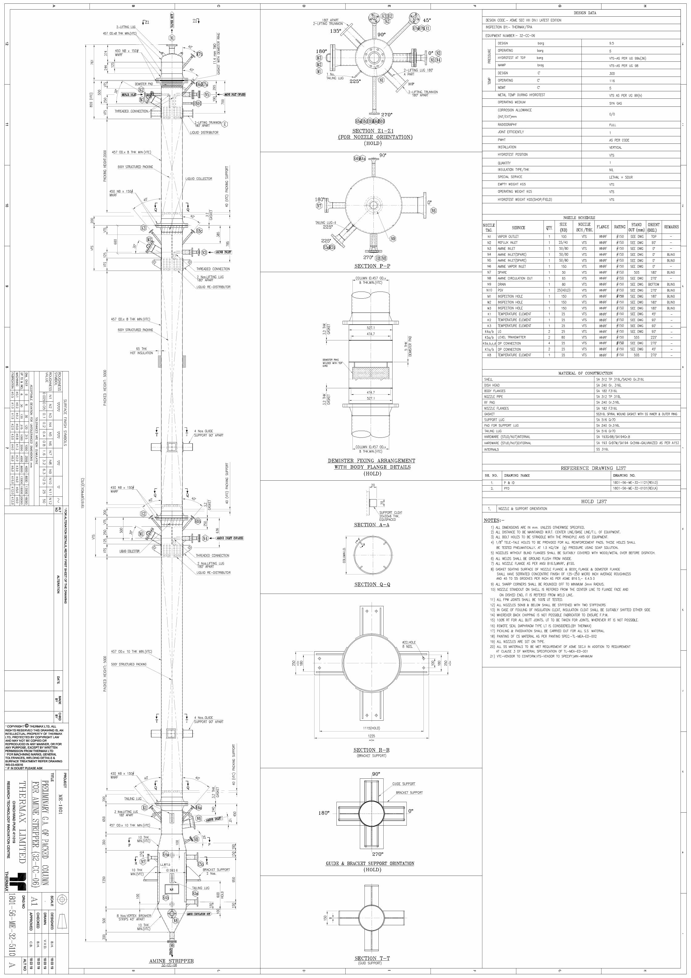
E. VENDOR’S SCOPE OF WORK AND SUPPLY EQUIPMENT LIST: - Sr. No. DESCRIPTION TAG NO. QUANTITY DWG. No.
1 RME Absorber 32-CC-01 1 1801-56-ME-32-5101 2 RME Stripper 32-CC-02 1 1801-56-ME-32-5102 3 Acid Scrubber 32-CC-03 1 1801-56-ME-32-5103 4 Amine Absorber 32-CC-05 1 1801-56-ME-32-5109 5 Amine Stripper 32-CC-06 1 1801-56-ME-32-5110
Vendor’s Scope of work and supply will be defined & limited as per PSR Documents, Drawings, specifications, codes and standards are following:- 1) Packing & Internals design : - Vendor shall do preparation of Packing & Internals
design calculation and dimensional GA of Packing & Internals, detail of same shall be incorporated in GA and fabrication drawing of column based on Process data sheet, Preliminary GA drawing provided along with the PSR, as per relevant design code, standards and THERMAX specifications. Vendor need to submit detail information requested in PDS Annexure T5-Process data sheet. Vendor need to perform FAT test as per Annexure T9-Distribution Performance Test.
2) Mechanical Design Calculation, GA Drawing and Detailed fabrication drawing:-
Vendor shall do preparation of Mechanical design calculation, GA drawing and detailed fabrication drawings based on Process data sheet, Preliminary GA drawing provided along with the PSR, as per relevant design code, standards and THERMAX specifications. Same shall be submitted for THERMAX approval.
3) Procedures & Documents: - Vendor shall prepare Welder qualification, WPS, PQR,
Procedures like PT, RT, UT, Hydro test, packing, preservation, Lifting and Shipment etc. Same shall be submitted for THERMAX approval prior to start manufacturing.
4) Raw Material Supply: -Vendor shall procure all raw materials based on approved
G.A. and detail fabrication Drawings, as per relevant design code, standards and THERMAX specifications.
Raw materials shall be procured with testing such as NACE, HIC and IGC
etc., if mentioned in preliminary G.A. drawing.
Page 13 of 19
THERMAX LIMITED RESEARCH, TECHNOLOGY AND INNOVATION CENTER
DOC NAME: PROJECT SPECIFIC REQUIREMENTS DOC NO.: TL-PSR-2019-001_Rev 00
Procurement of raw material with test certificates in 3.1 formats (All Raw material to be offered for identification to THERMAX prior to start manufacturing)
5) Manufacturing:-Vendor shall do complete manufacturing including internals based
on approved G.A., detail fabrication Drawings, procedures and QAP, as per relevant design code, standards and THERMAX specifications.
6) Inspection & Testing: - Vendor shall do complete inspection, NDT testing’s based
on approved G.A., detail fabrication Drawings, procedures and QAP, as per relevant design code, standards and THERMAX specifications.
7) Surface Preparation and Painting:-Vendor shall do surface preparation and painting Carbon steel parts as per Annexure-T3 Painting specification TL-MEA-ED-002. Vendor shall do Pickling & passivation for all SS surfaces (both inside and outside).
8) Packing and Transportation: - Vendor shall do Transportation of equipment’s from
vendors shop to Thermax Chinchwad Factory based on procedure mentioned As per Clause no 12. In NIQ (Notice Invitation for Quotation).
9) Special tools and tackles: - Vendor shall provide Special tools and tackles for
installation and normal maintenance (as per Vendor’s recommendation).
10) Spares:- i) Vendor shall provide Mandatory Spares as per drawings and Section K. ii) Vendor shall provide Commissioning and initial operation (start-up) spares (as Per Vendor’s recommendation).
11) Supervision:-Vendor shall provide Supervision for Erection, commissioning and
Performance test at Site.
12) Additional Scope of Supply:- Cleats for platform / ladder, piping, instruments and electrical (if applicable) Insulation and support ring / Cleats Demister and Mist eliminator (if required) Blind & companion flanges together with studs/bolts, nuts and gaskets along with
spares Unless specified otherwise, all removable internals with studs, nuts, gaskets
(including spares). Supply of Internal Support assembly (Support rings, beams and Cleats) and
fasteners/gaskets. Testing accessories Test Flange / Test ring / Dummy shell (as applicable). Jigs& Fixtures for transportation including.
a. Nozzle cover, bolts, nuts and gaskets. b. Temporary skid and clamping arrangement/ wooden saddle for safe
transportation.
Page 14 of 19
THERMAX LIMITED RESEARCH, TECHNOLOGY AND INNOVATION CENTER
DOC NAME: PROJECT SPECIFIC REQUIREMENTS DOC NO.: TL-PSR-2019-001_Rev 00
Packing, weather protection and its supports. Vortex Breaker, impingement baffles and chimney trays (if required).
F. EXCLUSION OF SCOPE OF SUPPLY:
1) Instrumentation (By Client) 2) Insulation and Fire proofing (By Client) 3) Lug/ bracket Support bolts (By Client)
G. PROJECT SPECIFIC DRAWING APPROVAL PLAN
1) Vendor to submit General arrangement and Detail fabrication drawings in AutoCAD format and in PDF format for approval.
2) Vendor to submit mechanical calculations in PVELITE format (native file) and in PDF format for approval. And also, FEA calculations (if required) in PDF format with Native files.
3) Drawings and Calculations will be submitted to THERMAX Only 4) Approval/Review of the drawings & calculations will be carried out by THERMAX. 5) Considering stringent lead for project drawing and calculation approval can be
carried out across the table at customer office. H. PROJECT SPECIFIC INSPECTION REQUIREMENTS
1) Stage wise / Final Inspection / Test Document Review shall be carried out by
THERMAX / THERMAX Appointed Third Party Inspection Agency (TPIA) in accordance with approved drawings/documents, ITP / QAP and other inspection documents.
2) All the test documents shall be duly signed by the vendor and THERMAX
inspector and shall be submitted for records in required number of sets.
3) Test certificates for this material shall be prepared in English and the same should be submitted to THERMAX.
4) Inspection and witnessed tests by the THERMAX / THERMAX Appointed
Third Party Inspection (TPI) agency. THERMAX shall not relieve the Vendor of any guarantees, responsibilities or obligations to provide satisfactory equipment.
5) Following stages of Inspection (as a minimum) are to be witnessed by a
reputed third Party Inspection/ THERMAX Raw Material Identification and review of all raw material test certificates Final dimensional inspection after manufacturing completion Witness for Dye Penetrant Test, Review of Radiographs, Witness of UT as
applicable at various stages of manufacturing
Page 15 of 19
THERMAX LIMITED RESEARCH, TECHNOLOGY AND INNOVATION CENTER
DOC NAME: PROJECT SPECIFIC REQUIREMENTS DOC NO.: TL-PSR-2019-001_Rev 00
Witness of Hydro test. Witness of painting & cleaning and final packing. All inspection calls to be raised 3 days in advance.
I. PACKING AND TRANSPORTATION
Packing of all vessels in fabrication vendors scope 1) Wooden/Steel Saddles along with clamping assemblies/arrangement to be
provided to all Equipment for transportation. 2) Packing, weather protection & its supports shall be as per project specification
and Vendor standard. 3) Nuts, bolts & Hardware items to be packed in separate wooden box. 4) Gaskets to be packed in separate box. 5) Detail packing list to be provided with each shipment 6) Packing list to be affixed on inside and outside the box in water proof envelope 7) Box Numbers to be stencilled on each box
J. DOCUMENTATION Four sets of “As built” documents and “Data folder” (containing test certificates, test reports, inspection reports etc.), including one set of files in electronic format, shall be supplied by the successful bidder along with the equipment. The list of documents shall be as specified in “Vendor data/document requirements”, forming part of this specification. Soft copies of all drawings in Autocad (.DWG format), calculation in PvElite (.PVI)/FEA, documents in MSWord & MSExcel; shall be submitted to THERMAX in DVD/CD as part of final documentation. Vendor shall ensure that all data folder documents including the “AS BUILT DRAWING” are updated & complete in all respects and shall incorporate all suggestions/correction informed by THERMAX or the authorized inspector while obtaining certificate of completeness from the Inspection Agency. In the event of the fabricator’s failure to meet the above requirements, the supply of equipment shall be considered as incomplete. K. SPARES All mandatory spares shall be listed separately along with description, item no., detailed specifications, name of supplier etc. As a minimum, the following spares are to be furnished. Any higher quantity mentioned elsewhere in the standard specifications shall also be furnished.
Gaskets = the gasket quantity supplied will be 100%actual+400%as mandatory spare.
Fasteners = Hardware quantity like nuts& bolts will be 100%actual +10% mandatory spare. (Min 2 nos of each joint)
Page 16 of 19
THERMAX LIMITED RESEARCH, TECHNOLOGY AND INNOVATION CENTER
DOC NAME: PROJECT SPECIFIC REQUIREMENTS DOC NO.: TL-PSR-2019-001_Rev 00
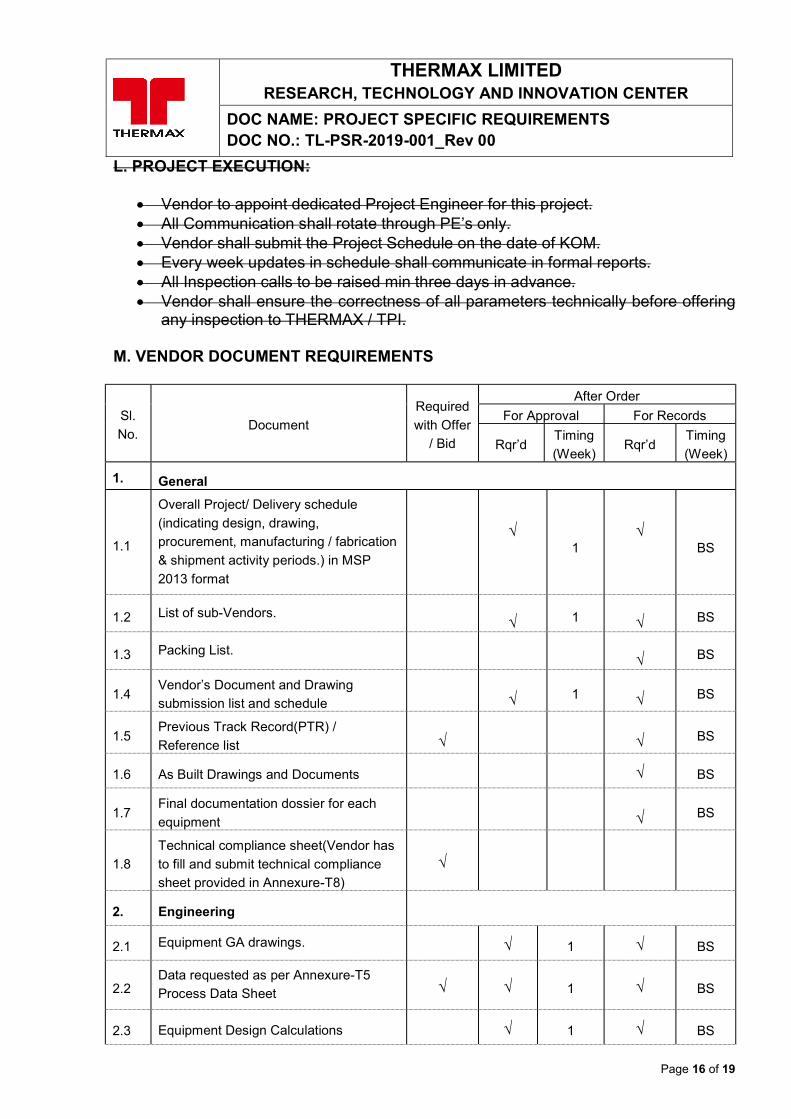
L. PROJECT EXECUTION:
Vendor to appoint dedicated Project Engineer for this project. All Communication shall rotate through PE’s only. Vendor shall submit the Project Schedule on the date of KOM. Every week updates in schedule shall communicate in formal reports. All Inspection calls to be raised min three days in advance. Vendor shall ensure the correctness of all parameters technically before offering
any inspection to THERMAX / TPI. M. VENDOR DOCUMENT REQUIREMENTS
Sl.
No. Document
Required
with Offer
/ Bid
After Order
For Approval For Records
Rqr’d Timing
(Week) Rqr’d
Timing
(Week)
1. General
1.1
Overall Project/ Delivery schedule
(indicating design, drawing,
procurement, manufacturing / fabrication
& shipment activity periods.) in MSP
2013 format
√
1 √
BS
1.2 List of sub-Vendors.
√ 1
√ BS
1.3 Packing List.
√ BS
1.4 Vendor’s Document and Drawing
submission list and schedule
√ 1
√ BS
1.5 Previous Track Record(PTR) /
Reference list
√
√ BS
1.6 As Built Drawings and Documents √ BS
1.7 Final documentation dossier for each
equipment
√ BS
1.8
Technical compliance sheet(Vendor has
to fill and submit technical compliance
sheet provided in Annexure-T8)
√
2. Engineering
2.1 Equipment GA drawings. √ 1 √ BS
2.2 Data requested as per Annexure-T5
Process Data Sheet √ √ 1 √ BS
2.3 Equipment Design Calculations √ 1 √ BS
Page 17 of 19
THERMAX LIMITED RESEARCH, TECHNOLOGY AND INNOVATION CENTER
DOC NAME: PROJECT SPECIFIC REQUIREMENTS DOC NO.: TL-PSR-2019-001_Rev 00
Sl.
No. Document
Required
with Offer
/ Bid
After Order
For Approval For Records
Rqr’d Timing
(Week) Rqr’d
Timing
(Week)
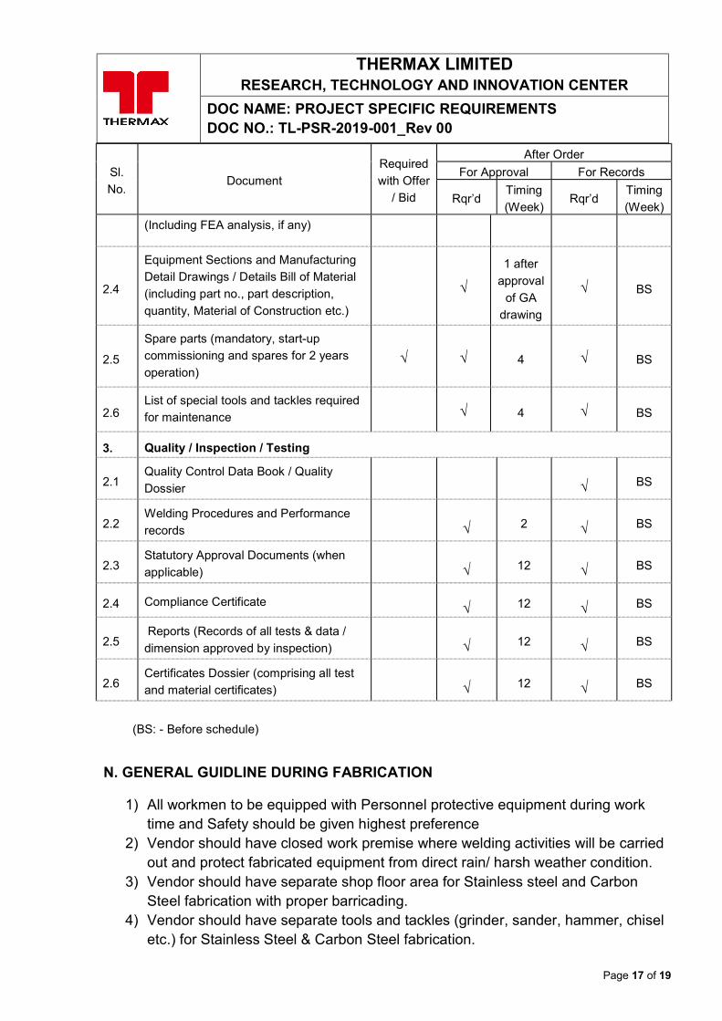
(Including FEA analysis, if any)
2.4
Equipment Sections and Manufacturing
Detail Drawings / Details Bill of Material (including part no., part description,
quantity, Material of Construction etc.)
√
1 after
approval
of GA
drawing
√ BS
2.5
Spare parts (mandatory, start-up
commissioning and spares for 2 years
operation) √ √ 4 √ BS
2.6 List of special tools and tackles required
for maintenance √ 4 √ BS
3. Quality / Inspection / Testing
2.1 Quality Control Data Book / Quality
Dossier
√ BS
2.2 Welding Procedures and Performance
records
√ 2
√ BS
2.3 Statutory Approval Documents (when
applicable)
√ 12
√ BS
2.4 Compliance Certificate
√ 12
√ BS
2.5 Reports (Records of all tests & data /
dimension approved by inspection)
√ 12
√ BS
2.6 Certificates Dossier (comprising all test
and material certificates)
√ 12
√ BS
(BS: - Before schedule)
N. GENERAL GUIDLINE DURING FABRICATION
1) All workmen to be equipped with Personnel protective equipment during work time and Safety should be given highest preference
2) Vendor should have closed work premise where welding activities will be carried out and protect fabricated equipment from direct rain/ harsh weather condition.
3) Vendor should have separate shop floor area for Stainless steel and Carbon Steel fabrication with proper barricading.
4) Vendor should have separate tools and tackles (grinder, sander, hammer, chisel etc.) for Stainless Steel & Carbon Steel fabrication.
Page 18 of 19
THERMAX LIMITED RESEARCH, TECHNOLOGY AND INNOVATION CENTER
DOC NAME: PROJECT SPECIFIC REQUIREMENTS DOC NO.: TL-PSR-2019-001_Rev 00
5) Dedicated Store area where project consumables, flanges, fittings and misc. material will be stored with tagging for quick identification.
6) All welding machines must be calibrated. 7) Electric / manual rotator suitable for diameter and length of job should be
available for ease of job rotation for C-seam welding and nozzle setup 8) Vendor must have qualified (Level 1 / Level 2) staff and trained shop floor
employee for conducting in-house Dye Penetrant test. 9) All measuring instrument (vernier caliper, micrometer, measuring tape etc.)
required for inspection must be available with calibration certificate. 10) Shop floor area must be adequately illuminated. 11) Shop floor must be equipped with over-head crane for material handling and
capacity suitable for handling equipment. 12) Vendor to share list of manufacturing process he is capable of performing in-
house and typical manufacturing activities out-sourced. 13) Vendor with on-roll shop floor employee will be given selection preference over contract
shop floor manpower. 14) Radiographic film viewer to be made available whenever required. 15) Vendor should be aware of all NDT techniques.
O. ABBREVIATIONS
ASME: - American Society of Mechanical Engineers.
ASTM: - American Society for Testing Materials.
GA: - General Arrangement
PSR: - Project Specific Requirements
PTR: - Previous Track Record
DP: - Dye Penetration Test
RF: - Reinforcement Pad
PMI:-Positive Material Identification
FPW:-Full Penetration Weld
TIG:-Tungsten Inert Gas
ID:-Inside Diameter
SS: - Stainless Steel
CS:-Carbon Steel
DCR:-Design Change Request
TPI: - Third Party Inspection/inspector
NCR:-Non Conformity Report
Page 19 of 19
THERMAX LIMITED RESEARCH, TECHNOLOGY AND INNOVATION CENTER
DOC NAME: PROJECT SPECIFIC REQUIREMENTS DOC NO.: TL-PSR-2019-001_Rev 00
MOC: - Material Of Construction
IGC: - Inter Granular Corrosion
WPS:-Welding Procedure Specification
PQR:-Procedure Qualification Record
ITP: - Inspection Test Plan
NDT: - Non Destructive Testing
PT:-Penetrant Test
RT: - Radiography Test
UT: - Ultrasonic Test
TPIA: - Third Party Inspection Agency
QAP: - Quality Assurance Plan
PE: - Project Engineer
KOM: - Kick Off Meeting
CV: - coefficient of variation
THERMAX LIMITED RESEARCH, TECHNOLOGY AND INNOVATION CENTER
DOC NAME: Annexure T1- Preliminary GA Drawings
ANNEXURE T1
PRELIMINARY GA DRAWINGS
C.B.
B.H
.
B.H
.
V.V.D
.-
THERMAX LIM
ITED - CONFIDENTIAL AND PROPRIETARY
C.B.
B.H
.
B.H
.
V.V.D
.-
THERMAX LIM
ITED - CONFIDENTIAL AND PROPRIETARY
C.B.
B.H
.
B.H
.
VISH
VAN
ATH-
THERMAX LIM
ITED - CONFIDENTIAL AND PROPRIETARY
C.B.
B.H
.
B.H
.
V.V.D
.-
THERMAX LIM
ITED - CONFIDENTIAL AND PROPRIETARY
C.B.
B.H
.
B.H
.
V.V.D
.-
Page 1 of 3
THERMAX LIMITED RESEARCH, TECHNOLOGY AND INNOVATION CENTER
ANNEXURE-T2 MATERIAL SPECIFICATION DOCUMENT NUMBER:- TL-MEA-ED-001_Rev-00
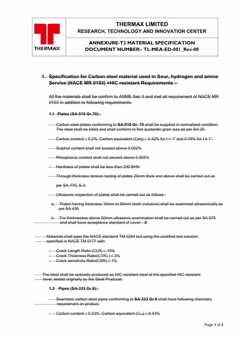
1. Specification for Carbon steel material used in Sour, hydrogen and amine Service (NACE MR 0103) +HIC resistant Requirements :- All the materials shall be confirm to ASME Sec II and met all requirement of NACE MR 0103 in addition to following requirements- 1.1 Plates (SA-516 Gr.70):-
- Carbon steel plates conforming to SA-516 Gr. 70 shall be supplied in normalised condition.
The steel shall be killed and shall conform to fine austenitic grain size as per SA-20.
- Carbon content 0.2%. Carbon equivalent (Ceq) 0.42% for t < 1” and 0.45% for t ≥ 1”.
- Sulphur content shall not exceed above 0.002%
- Phosphorus content shall not exceed above 0.005%
- Hardness of plates shall be less than 200 BHN
- Through thickness tension testing of plates 25mm thick and above shall be carried out as per SA-770, S-3.
- Ultrasonic inspection of plates shall be carried out as follows :
a. Plates having thickness 16mm to 50mm (both inclusive) shall be examined ultrasonically as per SA 435
b. For thicknesses above 50mm ultrasonic examination shall be carried out as per SA 578 and shall have acceptance standard of Level – B Materials shall pass the NACE standard TM 0284 but using the acidified test solution specified in NACE TM 0177 with:
- Crack Length Ratio (CLR) 10% - Crack Thickness Ratio(CTR) ) 3% - Crack sensitivity Ratio(CSR)1%
The steel shall be specially produced as HIC resistant steel at the specified HIC resistant level, tested originally by the Steel Producer.
1.2 Pipes (SA-333 Gr.6):-
- Seamless carbon steel pipes conforming to SA-333 Gr.6 shall have following chemistry requirement on product.
- Carbon content 0.23%, Carbon equivalent (Ceq) 0.43%
Page 2 of 3
THERMAX LIMITED RESEARCH, TECHNOLOGY AND INNOVATION CENTER
ANNEXURE-T2 MATERIAL SPECIFICATION DOCUMENT NUMBER:- TL-MEA-ED-001_Rev-00
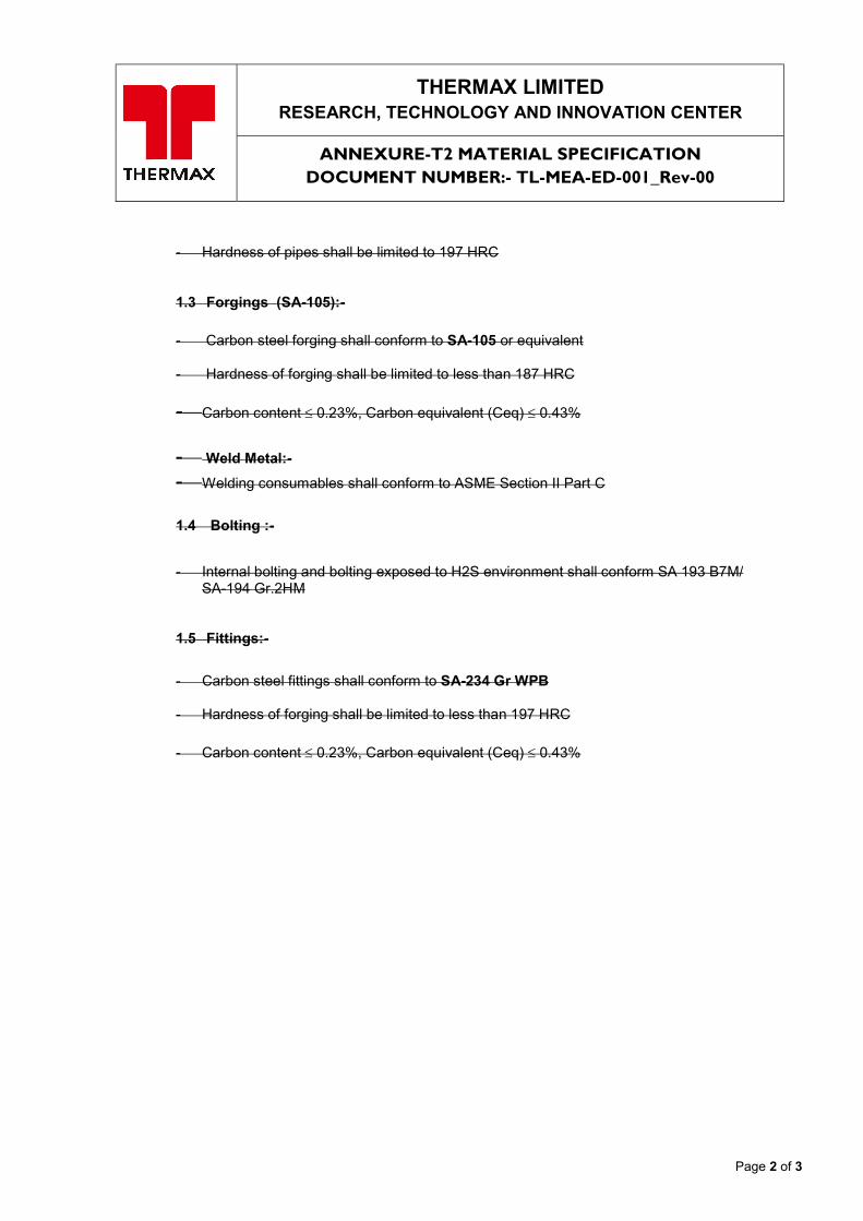
- Hardness of pipes shall be limited to 197 HRC
1.3 Forgings (SA-105):-
- Carbon steel forging shall conform to SA-105 or equivalent
- Hardness of forging shall be limited to less than 187 HRC
- Carbon content 0.23%, Carbon equivalent (Ceq) 0.43% - Weld Metal:- - Welding consumables shall conform to ASME Section II Part C
1.4 Bolting :-
- Internal bolting and bolting exposed to H2S environment shall conform SA 193 B7M/
SA-194 Gr.2HM
1.5 Fittings:-
- Carbon steel fittings shall conform to SA-234 Gr WPB
- Hardness of forging shall be limited to less than 197 HRC
- Carbon content 0.23%, Carbon equivalent (Ceq) 0.43%
Page 3 of 3
THERMAX LIMITED RESEARCH, TECHNOLOGY AND INNOVATION CENTER
ANNEXURE-T2 MATERIAL SPECIFICATION DOCUMENT NUMBER:- TL-MEA-ED-001_Rev-00
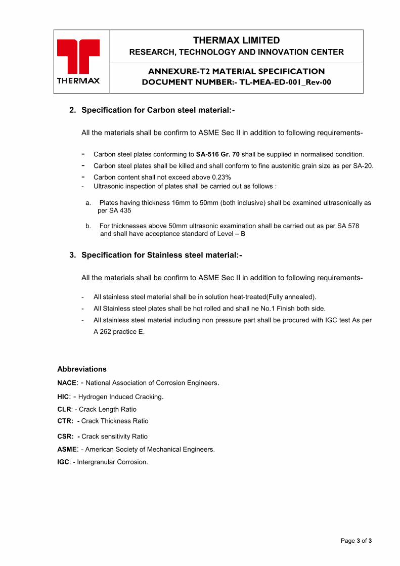
2. Specification for Carbon steel material:- All the materials shall be confirm to ASME Sec II in addition to following requirements-
- Carbon steel plates conforming to SA-516 Gr. 70 shall be supplied in normalised condition. - Carbon steel plates shall be killed and shall conform to fine austenitic grain size as per SA-20. - Carbon content shall not exceed above 0.23% - Ultrasonic inspection of plates shall be carried out as follows :
a. Plates having thickness 16mm to 50mm (both inclusive) shall be examined ultrasonically as
per SA 435
b. For thicknesses above 50mm ultrasonic examination shall be carried out as per SA 578 and shall have acceptance standard of Level – B
3. Specification for Stainless steel material:- All the materials shall be confirm to ASME Sec II in addition to following requirements- - All stainless steel material shall be in solution heat-treated(Fully annealed).
- All Stainless steel plates shall be hot rolled and shall ne No.1 Finish both side.
- All stainless steel material including non pressure part shall be procured with IGC test As per
A 262 practice E.
Abbreviations
NACE: - National Association of Corrosion Engineers.
HIC: - Hydrogen Induced Cracking.
CLR: - Crack Length Ratio
CTR: - Crack Thickness Ratio CSR: - Crack sensitivity Ratio
ASME: - American Society of Mechanical Engineers.
IGC: - Intergranular Corrosion.
Page 1 of 9
THERMAX LIMITED RESEARCH, TECHNOLOGY AND INNOVATION CENTER
ANNEXURE-T3 PAINTING SPECIFICATION DOCUMENT NUMBER:- TL-MEA-ED-002_Rev-00
CONTENTS
1 General
1.1 Scope 1.2 Code and Standards
2 Extent of Surface to be Painted
2.1 Surface to be painted 2.2 Surface not to be painted
3 Painting Scheme
4 Execution of Painting Work
4.1 Surface Preparation 4.2 Execution of Painting Work 5 Field Safety and Hygiene
6 Field Storage and Control of paint material
6.1 Storage 6.2 Quality control and Stored Pain materials 7 Inspection
7.1 In-process Inspection 7.2 Inspection of Surface Preparation 7.3 Inspection of Paint Film
8 Transportation
Page 2 of 9
THERMAX LIMITED RESEARCH, TECHNOLOGY AND INNOVATION CENTER
ANNEXURE-T3 PAINTING SPECIFICATION DOCUMENT NUMBER:- TL-MEA-ED-002_Rev-00
1. General 1.1 Scope
1.1.1 This Engineering Specification covers the requirements for the painting including surface preparation, paint materials, procedure and inspection, of all equipment, piping, steel structure for the plant constructed by Thermax for ME1801 project. Internal coating and linings are not covered in this Engineering Specification.
1.1.2 This Engineering Specification shall be applied to Vendor’s shop painting by Vendor of equipment..
1.1.3 This Engineering Specification shall not apply to the following painting works. (a) Painting to be carried out based on manufacturer’s specification
(b) Repainting
(c) Painting of temporary installations
(d) Painting using methods other than general methods such as brushing and spraying
(e) Painting intended solely for coloring or marking
(f) Coating and Lining
(g) Painting of building except steel structure 1.2 Code and Standards
1.2.1 The applicable codes and standards referenced in this Engineering Specification shall be as follows. (1) Steel structure Painting Council (SSPC)
(2) Swedish Standards Institution (SIS)
(3) International Organization for Standardization (ISO)
(4) Indian Standard ( IS) 1.2.2 If there is any conflict between the requirements of above mentioned codes and standards and this Engineering Specification, the requirements of this Engineering Specification shall be prevail. All conflict shall be referred to Thermax for clarification before proceeding with this work.
Page 3 of 9
THERMAX LIMITED RESEARCH, TECHNOLOGY AND INNOVATION CENTER
ANNEXURE-T3 PAINTING SPECIFICATION DOCUMENT NUMBER:- TL-MEA-ED-002_Rev-00
2. Extent of surface to be painted 2.1 Surfaces to be painted The extent of painting shall be as follows: (1) Exposed surface of: (a) Structure Steel (b) Equipment (c) Steel piping and pipe supports (d) Ladders, handrails, platforms, stairways, etc. (e) Instrument and electrical panel boards (f) Valve, relief valves (2) Surface of rotating machinery and the like, expect for rotating and sliding contact surfaces. (3) External surface of equipment, storage tanks, piping etc. to be covered with cold insulation materials. (4) All other surface, requiring rust and corrosion protection paint. 2.2 Surface not to be painted The extent basically not requiring painting shall be as follows: (1) External surfaces of field fabricated equipment, storage tanks, piping, etc. to be covered with hot insulation materials. (2) Internal surfaces of pipes, equipment, etc. and internal surfaces of closed steel structures which do not require chemical, acid and alkali resistance. (3) Surfaces of steel structures to be fire-proofed with concrete or mortar covering (4) Surfaces of steel structures embedded or in contact with concrete or mortar. (5) Interior wall surfaces of furnaces, boilers, etc., heating tubes and portions with heat resistant treatment. (6) Materials with high resistance to corrosion, such as stainless steel and weathering steel. (7) Galvanized steel materials, except touch-up for damaged parts such as cut or welded part. Note: a) Organic zinc rich paint shall be applied for touch-up and surfaces to be touched-up shall be clean, dry and free of oil, grease preexisting pain, and corrosion by products. b) The part on which white rust appears does not need to be touched-up because white rust does not affect corrosion resistance. (8) Friction surfaces to be connected with high tensile strength bolts unless inorganic Zinc rich paint is applied. (9) Part of entire surfaces of items not to be painted, in order to maintain function of plant facilities.
Page 4 of 9
THERMAX LIMITED RESEARCH, TECHNOLOGY AND INNOVATION CENTER
ANNEXURE-T3 PAINTING SPECIFICATION DOCUMENT NUMBER:- TL-MEA-ED-002_Rev-00
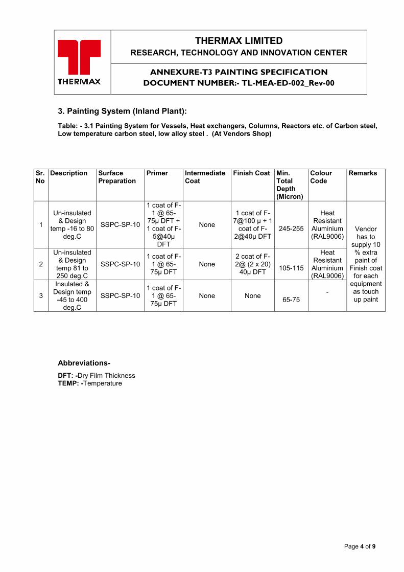
3. Painting System (Inland Plant): Table: - 3.1 Painting System for Vessels, Heat exchangers, Columns, Reactors etc. of Carbon steel, Low temperature carbon steel, low alloy steel . (At Vendors Shop)
Sr.No
Description Surface Preparation
Primer Intermediate Coat
Finish Coat Min. Total Depth (Micron)
Colour Code
Remarks
1
Un-insulated & Design
temp -16 to 80 deg.C
SSPC-SP-10
1 coat of F-1 @ 65-
75µ DFT + 1 coat of F-
5@40µ DFT
None
1 coat of F-7@100 µ + 1
coat of F-2@40µ DFT
245-255
Heat Resistant Aluminium (RAL9006)
Vendor has to
supply 10 % extra paint of
Finish coat for each
equipment as touch up paint
2
Un-insulated & Design
temp 81 to 250 deg.C
SSPC-SP-10 1 coat of F-
1 @ 65-75µ DFT
None 2 coat of F-2@ (2 x 20)
40µ DFT
105-115
Heat Resistant Aluminium (RAL9006)
3
Insulated & Design temp
-45 to 400 deg.C
SSPC-SP-10 1 coat of F-
1 @ 65-75µ DFT
None None
65-75 -
Abbreviations-
DFT: -Dry Film Thickness TEMP: -Temperature
Page 5 of 9
THERMAX LIMITED RESEARCH, TECHNOLOGY AND INNOVATION CENTER
ANNEXURE-T3 PAINTING SPECIFICATION DOCUMENT NUMBER:- TL-MEA-ED-002_Rev-00
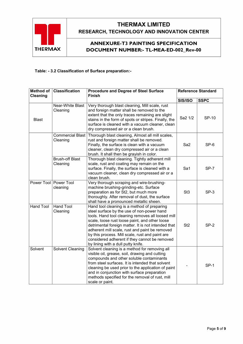
Table: - 3.2 Classification of Surface preparation:-
Method of Cleaning
Classification
Procedure and Degree of Steel Surface Finish
Reference Standard SIS/ISO SSPC
Blast
Near-White Blast Cleaning
Very thorough blast cleaning, Mill scale, rust and foreign matter shall be removed to the extent that the only traces remaining are slight stains in the form of spots or stripes. Finally, the surface is cleaned with a vacuum cleaner, clean dry compressed air or a clean brush.
Sa2 1/2 SP-10
Commercial Blast Cleaning
Thorough blast cleaning, Almost all mill scales, rust and foreign matter shall be removed. Finally, the surface is clean with a vacuum cleaner, clean dry compressed air or a clean brush. It shall then be grayish in color.
Sa2 SP-6
Brush-off Blast Cleaning
Thorough blast cleaning. Tightly adherent mill scale, rust and coating may remain on the surface. Finally, the surface is cleaned with a vacuum cleaner, clean dry compressed air or a clean brush.
Sa1 SP-7
Power Tool Power Tool cleaning
Very thorough scraping and wire-brushing-machine brushing-grinding-etc. Surface preparation as for St2, but much more thoroughly. After removal of dust, the surface shall have a pronounced metallic sheen.
St3 SP-3
Hand Tool Hand Tool Cleaning
Hand tool cleaning is a method of preparing steel surface by the use of non-power hand tools. Hand tool cleaning removes all loosed mill scale, loose rust loose paint, and other loose detrimental foreign matter. It is not intended that adherent mill scale, rust and paint be removed by this process. Mill scale, rust and paint are considered adherent if they cannot be removed by lining with a dull putty knife.
St2 SP-2
Solvent Solvent Cleaning Solvent cleaning is a method for removing all visible oil, grease, soil, drawing and cutting compounds and other soluble contaminants from steel surfaces. It is intended that solvent cleaning be used prior to the application of paint and in conjunction with surface preparation methods specified for the removal of rust, mill scale or paint.
- SP-1
Page 6 of 9
THERMAX LIMITED RESEARCH, TECHNOLOGY AND INNOVATION CENTER
ANNEXURE-T3 PAINTING SPECIFICATION DOCUMENT NUMBER:- TL-MEA-ED-002_Rev-00
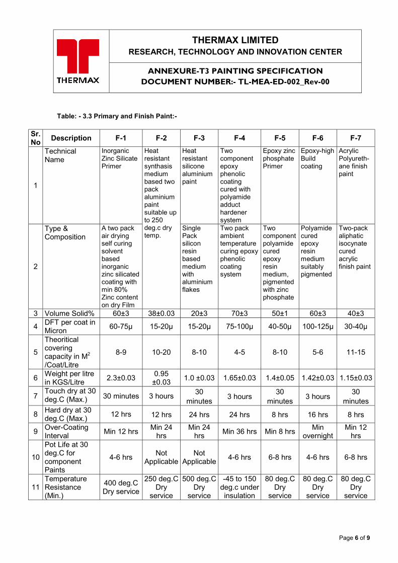
Table: - 3.3 Primary and Finish Paint:-
Sr.No
Description F-1 F-2 F-3 F-4 F-5 F-6 F-7
1
Technical Name
Inorganic Zinc Silicate Primer
Heat resistant synthasis medium based two pack aluminium paint suitable up to 250 deg.c dry temp.
Heat resistant silicone aluminium paint
Two component epoxy phenolic coating cured with polyamide adduct hardener system
Epoxy zinc phosphate Primer
Epoxy-high Build coating
Acrylic Polyureth-ane finish paint
2
Type & Composition
A two pack air drying self curing solvent based inorganic zinc silicated coating with min 80% Zinc content on dry Film
Single Pack silicon resin based medium with aluminium flakes
Two pack ambient temperature curing epoxy phenolic coating system
Two component polyamide cured epoxy resin medium, pigmented with zinc phosphate
Polyamide cured epoxy resin medium suitably pigmented
Two-pack aliphatic isocynate cured acrylic finish paint
3 Volume Solid% 60±3 38±0.03 20±3 70±3 50±1 60±3 40±3
4 DFT per coat in Micron
60-75µ 15-20µ 15-20µ 75-100µ 40-50µ 100-125µ 30-40µ
5
Theoritical covering capacity in M2 /Coat/Litre
8-9 10-20 8-10 4-5 8-10 5-6 11-15
6 Weight per litre in KGS/Litre
2.3±0.03 0.95 ±0.03
1.0 ±0.03 1.65±0.03 1.4±0.05 1.42±0.03 1.15±0.03
7 Touch dry at 30 deg.C (Max.) 30 minutes 3 hours
30 minutes
3 hours 30
minutes 3 hours
30 minutes
8 Hard dry at 30 deg.C (Max.)
12 hrs 12 hrs 24 hrs 24 hrs 8 hrs 16 hrs 8 hrs
9 Over-Coating Interval
Min 12 hrs Min 24
hrs Min 24
hrs Min 36 hrs Min 8 hrs
Min overnight
Min 12 hrs
10
Pot Life at 30 deg.C for component Paints
4-6 hrs Not
Applicable Not
Applicable 4-6 hrs 6-8 hrs 4-6 hrs 6-8 hrs
11 Temperature Resistance (Min.)
400 deg.C Dry service
250 deg.C Dry
service
500 deg.C Dry
service
-45 to 150 deg.c under insulation
80 deg.C Dry
service
80 deg.C Dry
service
80 deg.C Dry
service
Page 7 of 9
THERMAX LIMITED RESEARCH, TECHNOLOGY AND INNOVATION CENTER
ANNEXURE-T3 PAINTING SPECIFICATION DOCUMENT NUMBER:- TL-MEA-ED-002_Rev-00
4. Execution of painting work 4.1 Surface Preparation 4.1.1 Treatment prior to surface preparation The following work shall be carried out prior to surface preparation. (1) Remove slag, flux and spatter adhered to weld area and steel surface. (2) Where substances such as grease and machine oil are found on the surface, remove them with cleaning solvent, steam or other appropriate methods. (3) Remove excessive rust and dirt using appropriate methods. 4.1.2 Execution of surface preparation work (1) Surface preparation shall be carried out by appropriate methods that will ensure the required grade of finish. Procedure and degree of surface preparation are shown in Table- 3.2”Classification of Steel Surface Preparation”. 2) Restrictions concerning surface preparation and protective measures: (a) In case of rain or bad weather, surface preparation shall not be carried out outdoors. (b) When the surface to be prepared is wet, preparation shall not be carried out. (c) When the relative humidity is 85% or higher, surface preparation shall not, in principle, be carried out. (d) When surface preparation is carried out during the night or in dark locations (Inside of tanks, etc.), use lighting equipment by means of which the extent of rust removal from the surface can be seen. (e) When blast cleaning is to be carried out at the job site, appropriate protective measures shall be taken to ensure prevention of adverse effect of dust on adjacent work or environmental pollution in the surrounding area. 4.1.3 Treatment after surface preparation After the completion of surface preparation, the following confirmation and work shall be carried out and the subsequent painting shall also be started promptly. (1) When rusting occurs after completion of surface preparation and before painting, carry out surface preparation again using appropriate methods. (2) The painting surface shall be fully cleaned of mill scale, rust and other dust accumulated on the surface due to the surface preparation work. (3) The painting surfaces (cleaning of which has also been completed) shall be kept clean in such a way as to prevent the adherence of grease, oil, dust and other detrimental matters until the painting work is started. 4.2 Execution of Painting Work 4.2.1 Protection Vendor shall fully protect all equipment, piping, walls, floors and other surfaces from damage and contamination, and shall provide the necessary protection required to fully protect all surfaces from dust, paint droppings, paint mist, other contaminants during the execution of painting work. Especially, the particular care must be exercised to protect all stainless steel surfaces from zinc paint. 4.2.1.1 For items having dual material of construction, coating containing zinc shall not overlap on to Stainless Steel or high alloy metals, including the Stainless Steel to Carbon steel weld, Examples of such application include: a. Carbon steel saddles and skirts on Stainless Steel equipment b Stainless Steel piping with Carbon steel skirts c. Stainless Steel nozzles, flange, and piping on clad equipment
Page 8 of 9
THERMAX LIMITED RESEARCH, TECHNOLOGY AND INNOVATION CENTER
ANNEXURE-T3 PAINTING SPECIFICATION DOCUMENT NUMBER:- TL-MEA-ED-002_Rev-00
d. Miscellaneous Carbon steel clips and brackets on Stainless Steel equipment e. Stainless Steel components in Carbon steel piping and equipment f. Carbon steel trunnions on piping and equipment g. Carbon steel flanged rings on Stainless Steel lapped joint flanges. 4.2.1.2 Carbon steel lap joint flanges shall be coated prior to assembly. 4.2.2 Mixing of paint materials (1) Paint materials shall be thoroughly stirred before use. (2) For multi-liquid type paint materials, the specified mixing ratio and pot life shall be observed. 4.2.3 Application (1) Painting tools suitable for the properties of the paint materials shall be used according to manufacturer’s recommendation and studying work location, environment, shape of the items to be painted and condition of surface to be painted. (2) Each coat shall be painted in the order of the specified type of paint. In this case, for the coating of each film, observe the interval between coats and film thickness specified according to the properties and performance of the paint materials. (3) Where each coat is applied successively, such continuous painting work shall be carried out after the lapse of specified drying time and drying of previous film has been confirmed. 4.2.4 Restrictions concerning painting Unless special measures are taken, painting shall not be carried out under the following conditions: (1) When the painting surfaces are moist or likely to become moist due to rain, snow, dew or frost. (2) When the temperature during painting is 5℃ or lower and is not suitable for drying and hardening of paint materials. (3) When the relative humidity is 85% or more. (4) When the temperature of painting surfaces is high and defects such as air bubbles may occur in the paint film. (5) When a strong wind is blowing and foreign matters such as sand may adhere to the paint film. 5. Field Safety and Hygiene Safety and hygiene in connection with the painting work shall be controlled sufficiently. Special care shall be taken with regard to the following matters: (1) When surfaces are to be prepared by blast cleaning or the use of power tools, use protectors such as goggles, as necessary (2) When painting work is to be carried out using organic solvent in an almost airtight environment, provide appropriate ventilating and lighting equipment. Additionally, wear appropriate protectors such as gas masks. (3) Monitor the use of fire around the work location and remove any fire deemed to be unsafe. 6. Field Storage and Control of Paint Materials 6.1 Storage (1) As a rule, paint materials shall be stored in a well-ventilated room. (2) When paint materials is stored outdoors, it shall be protected using sheets or other appropriate measures, in order to prevent damage to containers or changes in the quality of the paint materials. (3) For storage areas, provide prescribed protective measure and signs. Paint materials exceeding the prescribed amount shall not be stored.
Page 9 of 9
THERMAX LIMITED RESEARCH, TECHNOLOGY AND INNOVATION CENTER
ANNEXURE-T3 PAINTING SPECIFICATION DOCUMENT NUMBER:- TL-MEA-ED-002_Rev-00
(4) When paint materials are temporarily stored in the working area, the amount equivalent to one day’s use or less shall be stored. Paint materials shall be protected from rain, etc., using sheets 6.2 Quality Control of Stored Paint materials (1) All paint materials and thinner shall be stored in such a way that the manufacturer’s labels can be readily identified. (2) Stocks of paint materials shall be controlled so that they can be used within their effective period of use. (3) Care shall be taken with storing and handling to avoid breakage or marked deformation of containers. 7. Inspection 7.1 In-process Inspection The painting work shall be subject to the In-process Inspection which needs the inspection by qualified paint inspector in the full course of work steps. 7.2 Inspection of Surface Preparation The prepared surfaces shall be compared with the standard photographs of SIS, ISO or SSPC. Where the prepared surfaces are deemed to be equivalent to those indicated in the above standard photographs, they shall be deemed acceptable. 7.3 Inspection of Paint Film 7.3.1 Appearance Paint film shall be visually checked with regard to the following: -Unfinished surface, drips, wrinkles, blistering, peeling, cracking, crawling, discoloring, stains, pinholes, and spray dust Where there are no marked defects in appearance, the paint film shall be deemed acceptable. 7.3.2 Paint film thickness (1) Measurement (a) Film thickness shall be measured with appropriate instruments. (b) As a rule, film thickness shall be measured at Vendor’s shop or field for the total dry film thickness. (2) Number of measurements and measured values: (a) The number and position of measurements shall be determined with due consideration given to the size and shape of items to be painted. (b) Measurements shall be carried out three times at each measuring point. The average of three measurements shall be taken as the measured value for the item concerned. (3) Rating of measured value When the measured values satisfy the following requirements, they shall be deemed acceptable: (a) Average of measured film thickness: 90% or more of prescribed film thickness. (b) Minimum of measured film thickness; 70% or more of the prescribed film thickness. 8. Transportation (1) Painted products shall not be moved or transported until the required curing period has elapsed. (2) Painted products shall be handled, moved or transported in such a manner as will not damage the paint film.
THERMAX LIMITED RESEARCH, TECHNOLOGY AND INNOVATION CENTER
DOC NAME: Annexure T4- QUALITY ASSURANCE PLAN / ROUTE SHEET DOC. No.:- ME1801-VSL CONTROL No.:-ME1801-CLM-00
ANNEXURE T4
QUALITY ASSURANCE PLAN / ROUTE SHEET
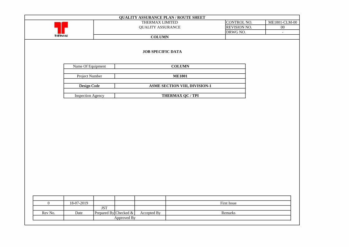
0 18-07-2019
JST
Rev No. Date Prepared By Checked & Accepted By
Approved By
Design Code
JOB SPECIFIC DATA
Name Of Equipment
THERMAX QC / TPI
COLUMN
-
Remarks
COLUMN
THERMAX LIMITED
QUALITY ASSURANCE REVISION NO.
DRWG NO.
First Issue
Design Code
QUALITY ASSURANCE PLAN / ROUTE SHEET
CONTROL NO. ME1801-CLM-00
Inspection Agency
00
ME1801Project Number
ASME SECTION VIII, DIVISION-1
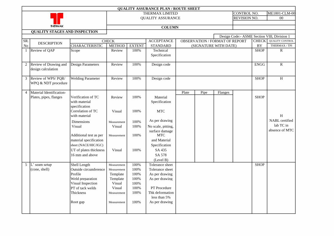
CHARACTERISTIC METHOD EXTENT
1 Review of QAP Scope Review 100% Technical SHOP
Specification
2 Review of Drawing and Design Parameters Review 100% Design code ENGG
design calculation
3 Review of WPS/ PQR/ Welding Parameter Review 100% Design code SHOP
WPQ & NDT procedure
4 Material Identification- Plate Pipe Flanges
Plates, pipes, flanges Verification of TC Review 100% Material SHOP
with material Specification
specification
Correlation of TC Visual 100% MTC
with material
Dimensions Measurement 100% As per drawing
Visual Visual 100% No scale, pitting,
surface damageAdditional test as per Measurement 100% MTC
material specification and Material
sheet (NACE/HIC/IGC) Specification
UT of plates thickness Visual 100% SA 435
16 mm and above SA 578
(Level B)
5 L’ seam setup Shell Length Measurement 100% Tolerance sheet SHOP
(cone, shell) Outside circumference Measurement 100% Tolerance sheet
Profile Template 100% As per drawing
Weld preparation Template 100% As per drawing
Visual Inspection Visual 100%
PT of tack welds Visual 100% PT Procedure
Thickness Measurement 100% Thk deformation
less than 5%
Root gap Measurement 100% As per drawing
H
H
OBSERVATION / FORMAT OF REPORT
(SIGNATURE WITH DATE)
QUALITY ASSURANCE PLAN / ROUTE SHEET
THERMAX LIMITED CONTROL NO. ME1801-CLM-00
00
Design Code:- ASME Section VIII, Division 1
QUALITY STAGES AND INSPECTION
QUALITY ASSURANCE REVISION NO.
QUALITY CONTROL
COLUMN
CHECK
BY
R
ACCEPTANCE
STANDARD
SR.
NoDESCRIPTION
CHECK
NABL certified
lab TC in
absence of MTC
R
THERMAX / TPI
CHARACTERISTIC METHOD EXTENT
OBSERVATION / FORMAT OF REPORT
(SIGNATURE WITH DATE)
QUALITY ASSURANCE PLAN / ROUTE SHEET
THERMAX LIMITED CONTROL NO. ME1801-CLM-00
00
Design Code:- ASME Section VIII, Division 1
QUALITY STAGES AND INSPECTION
QUALITY ASSURANCE REVISION NO.
QUALITY CONTROL
COLUMN
CHECK
BY
ACCEPTANCE
STANDARD
SR.
NoDESCRIPTION
CHECK
THERMAX / TPI
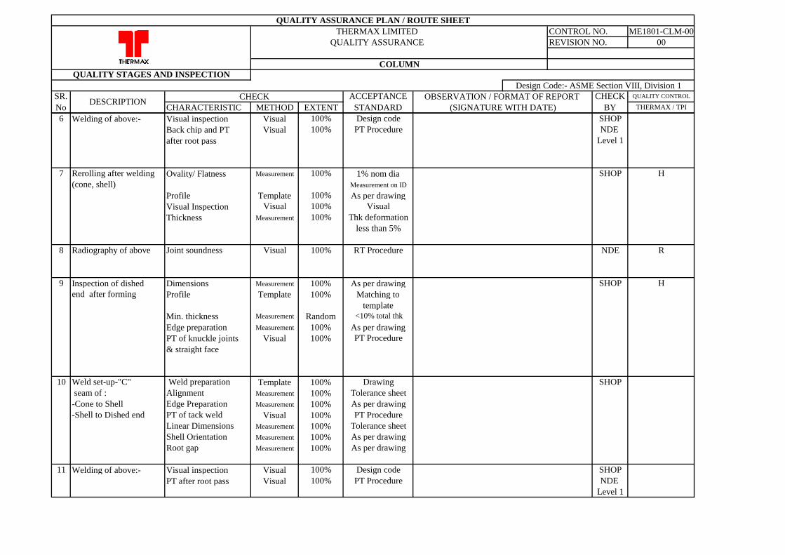
6 Welding of above:- Visual inspection Visual 100% Design code SHOP
Back chip and PT Visual 100% PT Procedure NDE
after root pass Level 1
7 Rerolling after welding Ovality/ Flatness Measurement 100% 1% nom dia SHOP
(cone, shell) Measurement on ID
Profile Template 100% As per drawing
Visual Inspection Visual 100% Visual
Thickness Measurement 100% Thk deformation
less than 5%
8 Radiography of above Joint soundness Visual 100% RT Procedure NDE
9 Inspection of dished Dimensions Measurement 100% As per drawing SHOP
end after forming Profile Template 100% Matching to
template
Min. thickness Measurement Random <10% total thk
Edge preparation Measurement 100% As per drawing
PT of knuckle joints Visual 100% PT Procedure
& straight face
10 Weld set-up-"C" Weld preparation Template 100% Drawing SHOP
seam of : Alignment Measurement 100% Tolerance sheet
-Cone to Shell Edge Preparation Measurement 100% As per drawing
-Shell to Dished end PT of tack weld Visual 100% PT Procedure
Linear Dimensions Measurement 100% Tolerance sheet
Shell Orientation Measurement 100% As per drawing
Root gap Measurement 100% As per drawing
11 Welding of above:- Visual inspection Visual 100% Design code SHOP
PT after root pass Visual 100% PT Procedure NDE
Level 1
R
H
H
CHARACTERISTIC METHOD EXTENT
OBSERVATION / FORMAT OF REPORT
(SIGNATURE WITH DATE)
QUALITY ASSURANCE PLAN / ROUTE SHEET
THERMAX LIMITED CONTROL NO. ME1801-CLM-00
00
Design Code:- ASME Section VIII, Division 1
QUALITY STAGES AND INSPECTION
QUALITY ASSURANCE REVISION NO.
QUALITY CONTROL
COLUMN
CHECK
BY
ACCEPTANCE
STANDARD
SR.
NoDESCRIPTION
CHECK
THERMAX / TPI
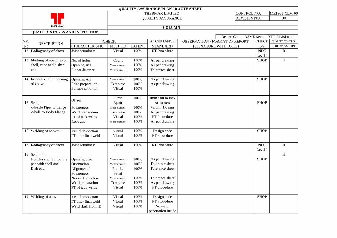
12 Radiography of above Joint soundness Visual 100% RT Procedure NDE
Level I
13 Marking of openings on No. of holes Count 100% As per drawing SHOP
shell, cone and dished Opening size Measurement 100% As per drawing
end Linear distance Measurement 100% Tolerance sheet
14 Inspection after opening Opening size Measurement 100% As per drawing SHOP
of above Edge preparation Template 100% As per drawing
Surface condition Visual 100%
15 Setup:-Offset
Plumb/
Spirit
100% 1mm / mt to max
of 10 mm SHOP
-Nozzle Pipe to flange Squareness Measurement 100% Within 1.0 mm
-Shell to Body Flange Weld preparation Template 100% As per drawing
PT of tack welds Visual 100% PT Procedure
Root gap Measurement 100% As per drawing
16 Welding of above:- Visual inspection Visual 100% Design code SHOP
PT after final weld Visual 100% PT Procedure
17 Radiography of above Joint soundness Visual 100% RT Procedure NDE
Level I
18 Setup of :-
Nozzles and reinforcing Opening Size Measurement 100% As per drawing SHOP
pad with shell and Orientation Measurement 100% Tolerance sheet
Dish end Alignment / Plumb/ 100% Tolerance sheet
Squareness Spirit
Nozzle Projection Measurement 100% Tolerance sheet
Weld preparation Template 100% As per drawing
PT of tack welds Visual 100% PT procedure
19 Welding of above Visual inspection Visual 100% Design code SHOP
PT after final weld Visual 100% PT Procedure
Weld flush from ID Visual 100% No weld
penetration inside
R
R
H
H
CHARACTERISTIC METHOD EXTENT
OBSERVATION / FORMAT OF REPORT
(SIGNATURE WITH DATE)
QUALITY ASSURANCE PLAN / ROUTE SHEET
THERMAX LIMITED CONTROL NO. ME1801-CLM-00
00
Design Code:- ASME Section VIII, Division 1
QUALITY STAGES AND INSPECTION
QUALITY ASSURANCE REVISION NO.
QUALITY CONTROL
COLUMN
CHECK
BY
ACCEPTANCE
STANDARD
SR.
NoDESCRIPTION
CHECK
THERMAX / TPI
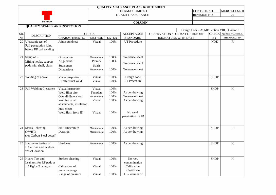
20 Ultrasonic test of Joint soundness Visual 100% UT Procedure NDE
Full penetration joint
before RF pad welding
21 Setup of :- Orientation Measurement 100% Tolerance sheet
Lifting hooks, support Alignment / Plumb/ 100%
pads with shell, cleats Squareness Spirit
Dimensions Measurement 100% Tolerance sheet
22 Welding of above Visual inspection Visual 100% Design code SHOP
PT after final weld Visual 100% PT Procedure
23 Full Welding Clearance Visual Inspection Visual 100% SHOP
Weld fillet size Template 100% As per drawing
Overall dimensions Measurement 100% Tolerance sheet
Welding of all Visual 100% As per drawing
attachments, insulation
lugs, cleats
Weld flush from ID Visual 100% No weld
penetration on ID
24 Stress Relieving SR Temperature Measurement 100% As per drawing SHOP
(PWHT) Duration Measurement 100% As per drawing
(for Carbon Steel vessel)
25 Hardnesss testing of Hardness Measurement 100% As per drawing SHOP
HAZ zone and random
vessel location
26 Hydro Test and Surface cleaning Visual 100% No rust/ SHOP
Leak test for RF pads at contamination
1.5 Kg/cm2 using air Calibration of Visual 100% Calibration
pressure gauge Certificate
Range of pressure Visual 100% 1.5 - 4 times of
H
R
R
H
H
Tolerance sheet
CHARACTERISTIC METHOD EXTENT
OBSERVATION / FORMAT OF REPORT
(SIGNATURE WITH DATE)
QUALITY ASSURANCE PLAN / ROUTE SHEET
THERMAX LIMITED CONTROL NO. ME1801-CLM-00
00
Design Code:- ASME Section VIII, Division 1
QUALITY STAGES AND INSPECTION
QUALITY ASSURANCE REVISION NO.
QUALITY CONTROL
COLUMN
CHECK
BY
ACCEPTANCE
STANDARD
SR.
NoDESCRIPTION
CHECK
THERMAX / TPI
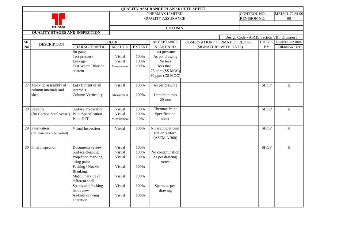
for gauge test pressure
Test pressure Visual 100% As per drawing
Leakage Visual 100% No leak
Test Water Chloride Measurement 100% less than
content 25 ppm (SS MOC)
80 ppm (CS MOC)
27 Mock up asssembly of Easy fitment of all Visual 100% As per drawing SHOP
column internals and internals
shell Column Verticality Measurment 100% 1mm/m to max
20 mm
28 Painting Surface Preparation Visual 100% SHOP
(for Carbon Steel vessel) Paint Specification Visual 100%
Paint DFT Measurement 10%
29 Passivation Visual Inspection Visual 100% No scaling & heat SHOP
(for Stainless Steel vessel) tint on surface
(ASTM A 380)
30 Final Inspection Documents review Visual 100% SHOP
Surface cleaning Visual 100% No contamination
Projection marking Visual 100% As per drawing
using paint notes
Packing / Nozzle Visual 100%
Blanking
Match marking of Visual 100%
different shell
Spares and Packing Visual 100% Spares as per
list review drawing
As-built drawing Visual 100%
alteration
H
H
H
H
Thermax Paint
Specification
sheet
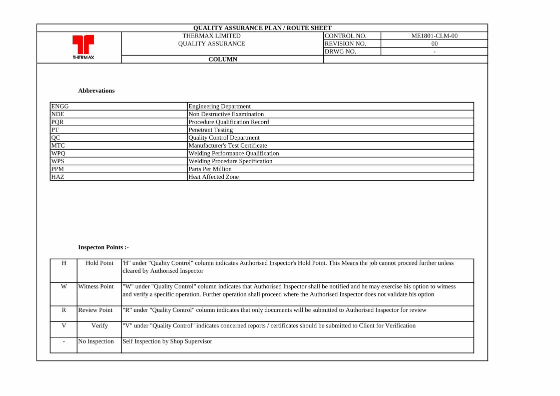
Abbrevations
ENGG Engineering Department
NDE Non Destructive Examination
PQR Procedure Qualification Record
PT Penetrant Testing
QC Quality Control Department
MTC Manufacturer's Test Certificate
WPQ Welding Performance Qualification
WPS Welding Procedure Specification
PPM Parts Per Million
HAZ Heat Affected Zone
Inspecton Points :-
H Hold Point 'H" under "Quality Control" column indicates Authorised Inspector's Hold Point. This Means the job cannot proceed further unless
cleared by Authorised Inspector
W Witness Point "W" under "Quality Control" column indicates that Authorised Inspector shall be notified and he may exercise his option to witness
and verify a specific operation. Further operation shall proceed where the Authorised Inspector does not validate his option
R Review Point "R" under "Quality Control" column indicates that only documents will be submitted to Authorised Inspector for review
V Verify "V" under "Quality Control" indicates concerned reports / certificates should be submitted to Client for Verification
- No Inspection Self Inspection by Shop Supervisor
-
COLUMN
QUALITY ASSURANCE PLAN / ROUTE SHEET
THERMAX LIMITED CONTROL NO. ME1801-CLM-00
QUALITY ASSURANCE REVISION NO. 00
DRWG NO.
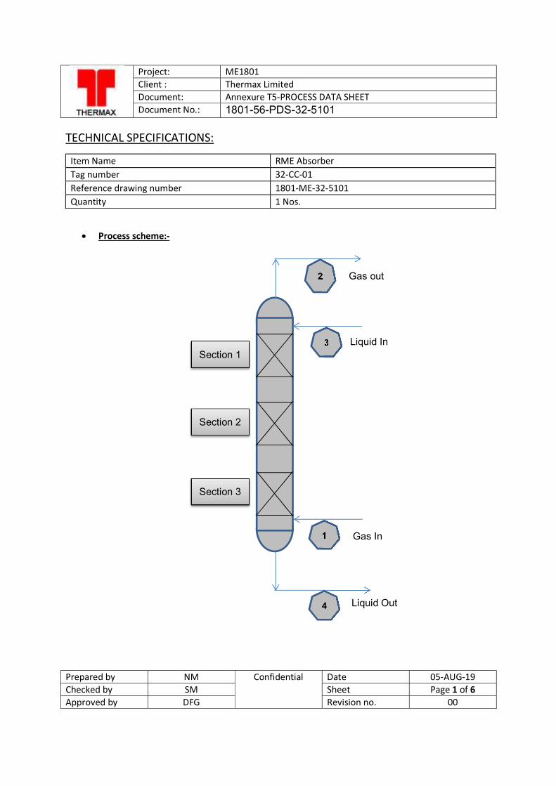
Project: ME1801 Client : Thermax Limited Document: Annexure T5-PROCESS DATA SHEET Document No.: 1801-56-PDS-32-5101
Prepared by NM Confidential Date 05-AUG-19 Checked by SM Sheet Page 1 of 6 Approved by DFG Revision no. 00
TECHNICAL SPECIFICATIONS:
Item Name RME Absorber Tag number 32-CC-01 Reference drawing number 1801-ME-32-5101 Quantity 1 Nos.
Process scheme:-
2
3
1
4
Section 1
Gas out
Liquid In
Gas In
Liquid Out
Section 2
Section 3
Project: ME1801 Client : Thermax Limited Document: Annexure T5-PROCESS DATA SHEET Document No.: 1801-56-PDS-32-5101
Prepared by NM Confidential Date 05-AUG-19 Checked by SM Sheet Page 2 of 6 Approved by DFG Revision no. 00
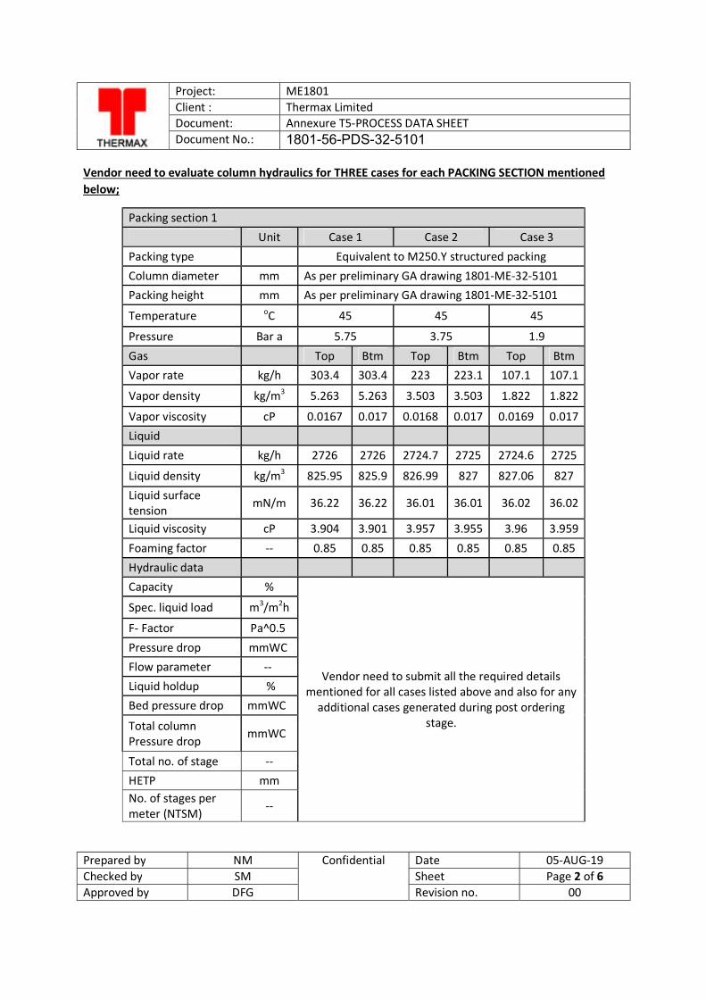
Vendor need to evaluate column hydraulics for THREE cases for each PACKING SECTION mentioned below;
Packing section 1 Unit Case 1 Case 2 Case 3 Packing type Equivalent to M250.Y structured packing Column diameter mm As per preliminary GA drawing 1801-ME-32-5101 Packing height mm As per preliminary GA drawing 1801-ME-32-5101
Temperature oC 45 45 45
Pressure Bar a 5.75 3.75 1.9
Gas Top Btm Top Btm Top Btm Vapor rate kg/h 303.4 303.4 223 223.1 107.1 107.1
Vapor density kg/m3 5.263 5.263 3.503 3.503 1.822 1.822
Vapor viscosity cP 0.0167 0.017 0.0168 0.017 0.0169 0.017 Liquid
Liquid rate kg/h 2726 2726 2724.7 2725 2724.6 2725
Liquid density kg/m3 825.95 825.9 826.99 827 827.06 827 Liquid surface tension mN/m 36.22 36.22 36.01 36.01 36.02 36.02
Liquid viscosity cP 3.904 3.901 3.957 3.955 3.96 3.959
Foaming factor -- 0.85 0.85 0.85 0.85 0.85 0.85 Hydraulic data
Capacity %
Vendor need to submit all the required details mentioned for all cases listed above and also for any
additional cases generated during post ordering stage.
Spec. liquid load m3/m2h
F- Factor Pa^0.5
Pressure drop mmWC Flow parameter -- Liquid holdup % Bed pressure drop mmWC
Total column Pressure drop
mmWC
Total no. of stage -- HETP mm No. of stages per meter (NTSM)
--
Project: ME1801 Client : Thermax Limited Document: Annexure T5-PROCESS DATA SHEET Document No.: 1801-56-PDS-32-5101
Prepared by NM Confidential Date 05-AUG-19 Checked by SM Sheet Page 3 of 6 Approved by DFG Revision no. 00
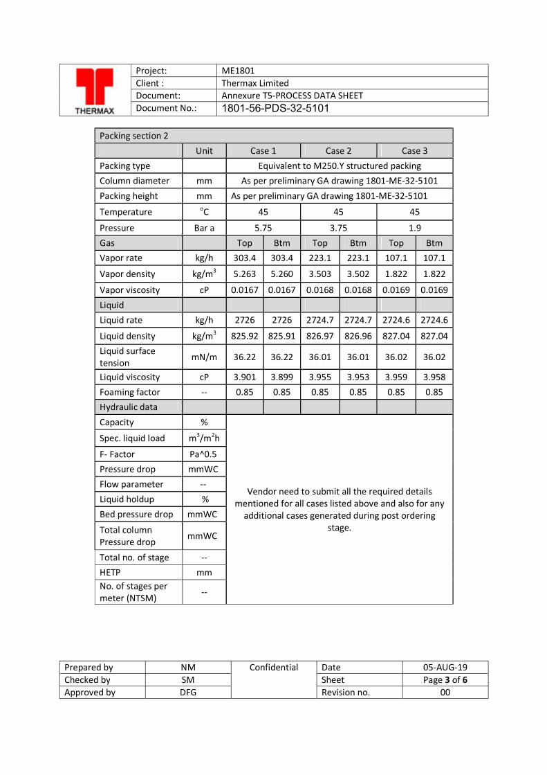
Packing section 2 Unit Case 1 Case 2 Case 3 Packing type
Equivalent to M250.Y structured packing
Column diameter mm As per preliminary GA drawing 1801-ME-32-5101
Packing height mm As per preliminary GA drawing 1801-ME-32-5101
Temperature oC 45 45 45
Pressure Bar a 5.75 3.75 1.9 Gas Top Btm Top Btm Top Btm Vapor rate kg/h 303.4 303.4 223.1 223.1 107.1 107.1
Vapor density kg/m3 5.263 5.260 3.503 3.502 1.822 1.822
Vapor viscosity cP 0.0167 0.0167 0.0168 0.0168 0.0169 0.0169
Liquid Liquid rate kg/h 2726 2726 2724.7 2724.7 2724.6 2724.6
Liquid density kg/m3 825.92 825.91 826.97 826.96 827.04 827.04 Liquid surface tension mN/m 36.22 36.22 36.01 36.01 36.02 36.02
Liquid viscosity cP 3.901 3.899 3.955 3.953 3.959 3.958 Foaming factor -- 0.85 0.85 0.85 0.85 0.85 0.85 Hydraulic data
Capacity %
Vendor need to submit all the required details mentioned for all cases listed above and also for any
additional cases generated during post ordering stage.
Spec. liquid load m3/m2h
F- Factor Pa^0.5 Pressure drop mmWC Flow parameter -- Liquid holdup % Bed pressure drop mmWC
Total column Pressure drop
mmWC
Total no. of stage -- HETP mm No. of stages per meter (NTSM)
--
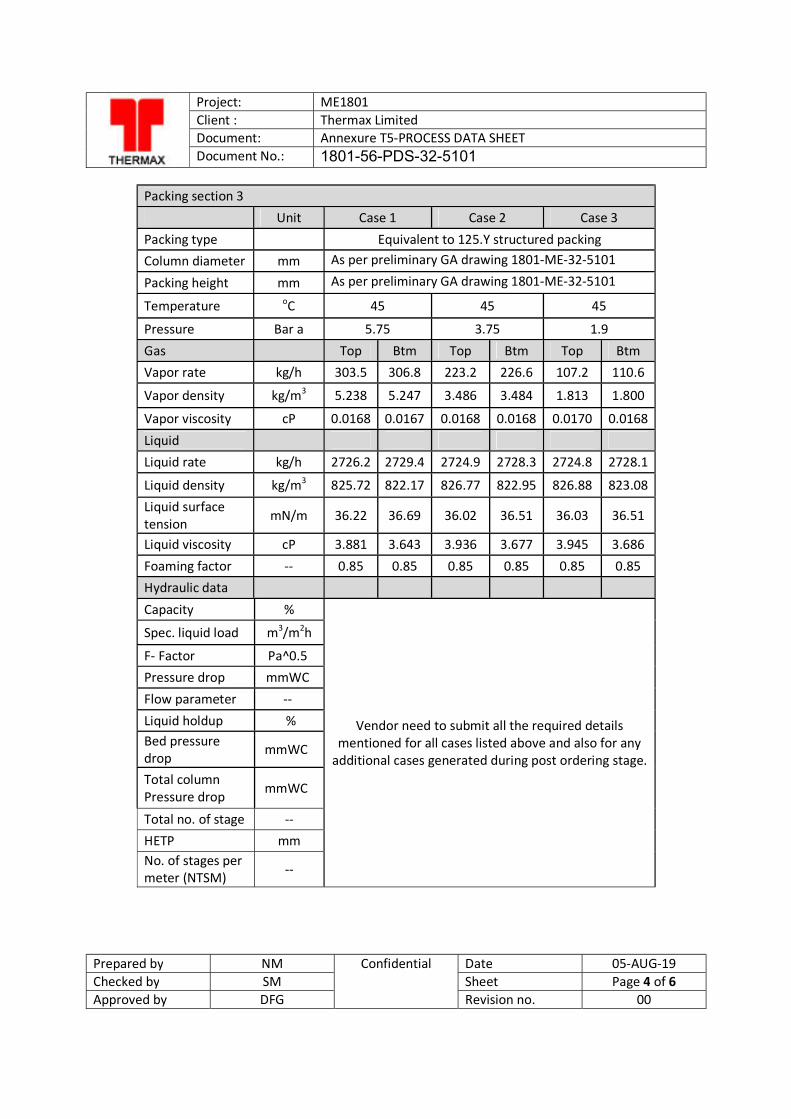
Project: ME1801 Client : Thermax Limited Document: Annexure T5-PROCESS DATA SHEET Document No.: 1801-56-PDS-32-5101
Prepared by NM Confidential Date 05-AUG-19 Checked by SM Sheet Page 4 of 6 Approved by DFG Revision no. 00
Packing section 3 Unit Case 1 Case 2 Case 3 Packing type
Equivalent to 125.Y structured packing
Column diameter mm As per preliminary GA drawing 1801-ME-32-5101
Packing height mm As per preliminary GA drawing 1801-ME-32-5101
Temperature oC 45 45 45
Pressure Bar a 5.75 3.75 1.9 Gas Top Btm Top Btm Top Btm Vapor rate kg/h 303.5 306.8 223.2 226.6 107.2 110.6
Vapor density kg/m3 5.238 5.247 3.486 3.484 1.813 1.800
Vapor viscosity cP 0.0168 0.0167 0.0168 0.0168 0.0170 0.0168
Liquid Liquid rate kg/h 2726.2 2729.4 2724.9 2728.3 2724.8 2728.1
Liquid density kg/m3 825.72 822.17 826.77 822.95 826.88 823.08 Liquid surface tension mN/m 36.22 36.69 36.02 36.51 36.03 36.51
Liquid viscosity cP 3.881 3.643 3.936 3.677 3.945 3.686 Foaming factor -- 0.85 0.85 0.85 0.85 0.85 0.85 Hydraulic data
Capacity %
Vendor need to submit all the required details mentioned for all cases listed above and also for any
additional cases generated during post ordering stage.
Spec. liquid load m3/m2h
F- Factor Pa^0.5 Pressure drop mmWC Flow parameter -- Liquid holdup % Bed pressure drop
mmWC
Total column Pressure drop mmWC
Total no. of stage -- HETP mm No. of stages per meter (NTSM) --
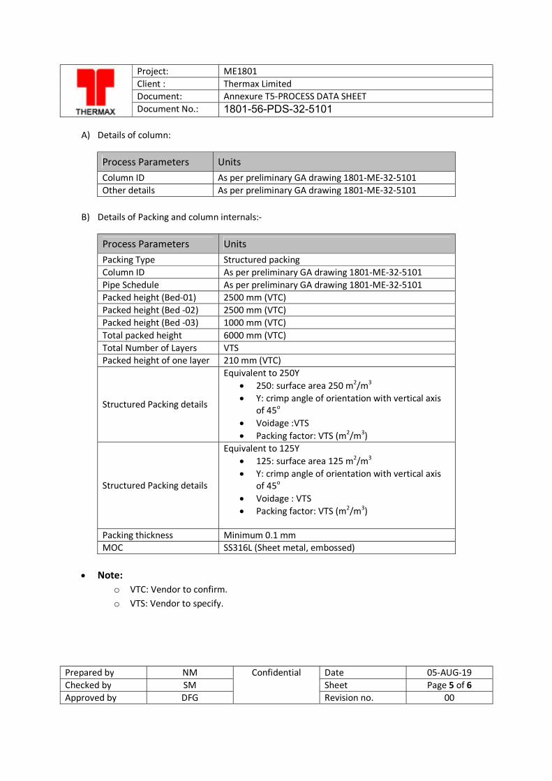
Project: ME1801 Client : Thermax Limited Document: Annexure T5-PROCESS DATA SHEET Document No.: 1801-56-PDS-32-5101
Prepared by NM Confidential Date 05-AUG-19 Checked by SM Sheet Page 5 of 6 Approved by DFG Revision no. 00
A) Details of column:
Process Parameters Units Column ID As per preliminary GA drawing 1801-ME-32-5101 Other details As per preliminary GA drawing 1801-ME-32-5101
B) Details of Packing and column internals:-
Process Parameters Units Packing Type Structured packing Column ID As per preliminary GA drawing 1801-ME-32-5101 Pipe Schedule As per preliminary GA drawing 1801-ME-32-5101 Packed height (Bed-01) 2500 mm (VTC) Packed height (Bed -02) 2500 mm (VTC) Packed height (Bed -03) 1000 mm (VTC) Total packed height 6000 mm (VTC) Total Number of Layers VTS Packed height of one layer 210 mm (VTC)
Structured Packing details
Equivalent to 250Y 250: surface area 250 m2/m3 Y: crimp angle of orientation with vertical axis
of 45o Voidage :VTS Packing factor: VTS (m2/m3)
Structured Packing details
Equivalent to 125Y 125: surface area 125 m2/m3 Y: crimp angle of orientation with vertical axis
of 45o Voidage : VTS Packing factor: VTS (m2/m3)
Packing thickness Minimum 0.1 mm MOC SS316L (Sheet metal, embossed)
Note:
o VTC: Vendor to confirm. o VTS: Vendor to specify.
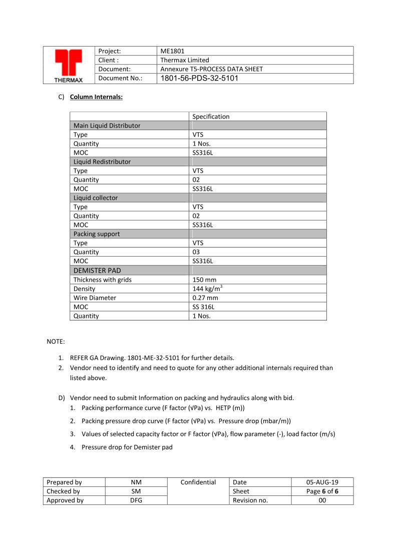
Project: ME1801 Client : Thermax Limited Document: Annexure T5-PROCESS DATA SHEET Document No.: 1801-56-PDS-32-5101
Prepared by NM Confidential Date 05-AUG-19 Checked by SM Sheet Page 6 of 6 Approved by DFG Revision no. 00
C) Column Internals:
Specification Main Liquid Distributor Type VTS Quantity 1 Nos. MOC SS316L Liquid Redistributor Type VTS Quantity 02 MOC SS316L Liquid collector Type VTS Quantity 02 MOC SS316L Packing support Type VTS Quantity 03 MOC SS316L DEMISTER PAD Thickness with grids 150 mm Density 144 kg/m3 Wire Diameter 0.27 mm MOC SS 316L Quantity 1 Nos.
NOTE:
1. REFER GA Drawing. 1801-ME-32-5101 for further details. 2. Vendor need to identify and need to quote for any other additional internals required than
listed above.
D) Vendor need to submit Information on packing and hydraulics along with bid. 1. Packing performance curve (F factor (√Pa) vs. HETP (m))
2. Packing pressure drop curve (F factor (√Pa) vs. Pressure drop (mbar/m))
3. Values of selected capacity factor or F factor (√Pa), flow parameter (-), load factor (m/s)
4. Pressure drop for Demister pad
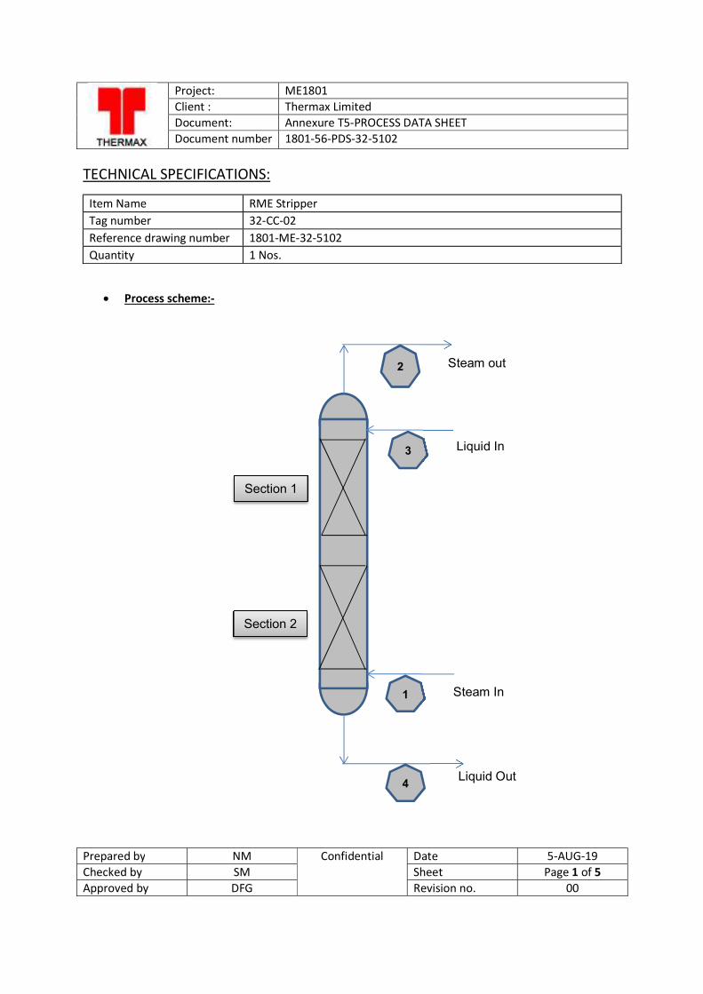
Project: ME1801 Client : Thermax Limited Document: Annexure T5-PROCESS DATA SHEET Document number 1801-56-PDS-32-5102
Prepared by NM Confidential Date 5-AUG-19 Checked by SM Sheet Page 1 of 5 Approved by DFG Revision no. 00
TECHNICAL SPECIFICATIONS:
Item Name RME Stripper Tag number 32-CC-02 Reference drawing number 1801-ME-32-5102 Quantity 1 Nos.
Process scheme:-
2
3
1
4
Section 2
Section 1
Steam out
Liquid In
Steam In
Liquid Out
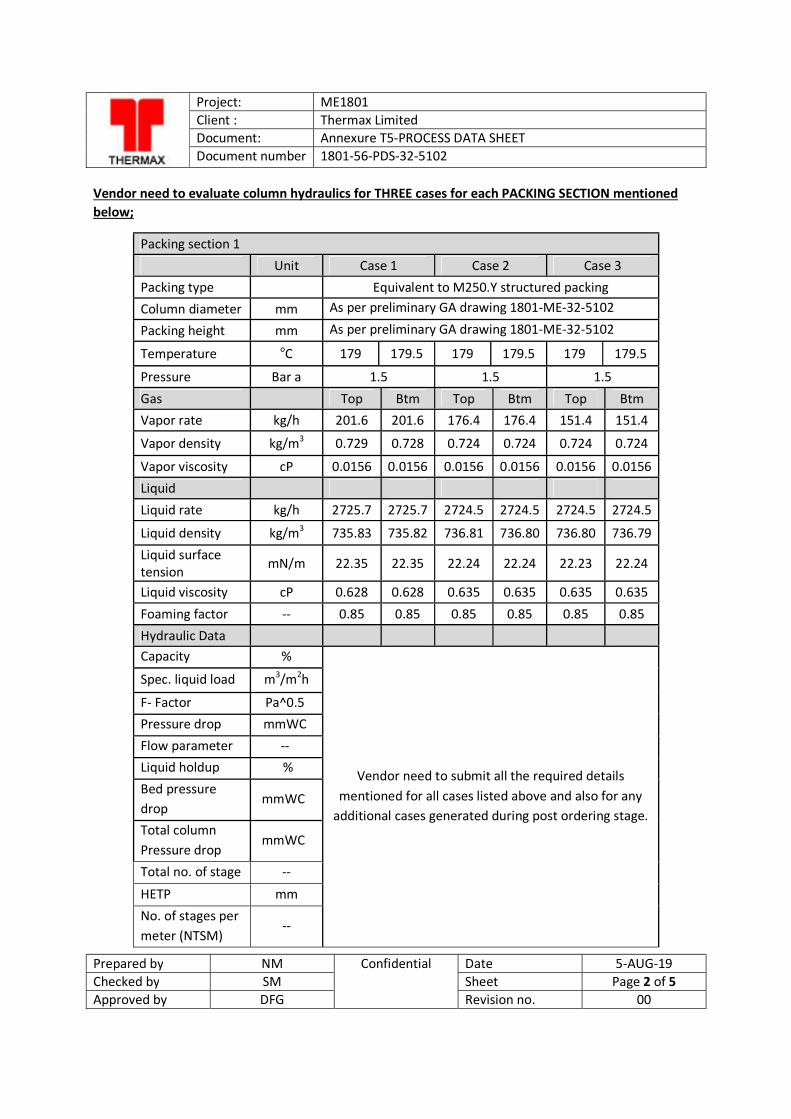
Project: ME1801 Client : Thermax Limited Document: Annexure T5-PROCESS DATA SHEET Document number 1801-56-PDS-32-5102
Prepared by NM Confidential Date 5-AUG-19 Checked by SM Sheet Page 2 of 5 Approved by DFG Revision no. 00
Vendor need to evaluate column hydraulics for THREE cases for each PACKING SECTION mentioned below;
Packing section 1 Unit Case 1 Case 2 Case 3 Packing type Equivalent to M250.Y structured packing Column diameter mm As per preliminary GA drawing 1801-ME-32-5102
Packing height mm As per preliminary GA drawing 1801-ME-32-5102
Temperature oC 179 179.5 179 179.5 179 179.5
Pressure Bar a 1.5 1.5 1.5
Gas Top Btm Top Btm Top Btm Vapor rate kg/h 201.6 201.6 176.4 176.4 151.4 151.4
Vapor density kg/m3 0.729 0.728 0.724 0.724 0.724 0.724
Vapor viscosity cP 0.0156 0.0156 0.0156 0.0156 0.0156 0.0156 Liquid
Liquid rate kg/h 2725.7 2725.7 2724.5 2724.5 2724.5 2724.5
Liquid density kg/m3 735.83 735.82 736.81 736.80 736.80 736.79 Liquid surface tension mN/m 22.35 22.35 22.24 22.24 22.23 22.24
Liquid viscosity cP 0.628 0.628 0.635 0.635 0.635 0.635
Foaming factor -- 0.85 0.85 0.85 0.85 0.85 0.85 Hydraulic Data
Capacity %
Vendor need to submit all the required details mentioned for all cases listed above and also for any
additional cases generated during post ordering stage.
Spec. liquid load m3/m2h
F- Factor Pa^0.5 Pressure drop mmWC Flow parameter -- Liquid holdup % Bed pressure drop
mmWC
Total column Pressure drop
mmWC
Total no. of stage --
HETP mm No. of stages per meter (NTSM)
--
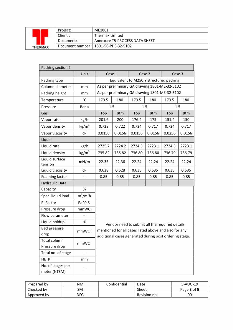
Project: ME1801 Client : Thermax Limited Document: Annexure T5-PROCESS DATA SHEET Document number 1801-56-PDS-32-5102
Prepared by NM Confidential Date 5-AUG-19 Checked by SM Sheet Page 3 of 5 Approved by DFG Revision no. 00
Packing section 2 Unit Case 1 Case 2 Case 3 Packing type
Equivalent to M250.Y structured packing
Column diameter mm As per preliminary GA drawing 1801-ME-32-5102
Packing height mm As per preliminary GA drawing 1801-ME-32-5102
Temperature oC 179.5 180 179.5 180 179.5 180
Pressure Bar a 1.5 1.5 1.5 Gas Top Btm Top Btm Top Btm Vapor rate kg/h 201.6 200 176.4 175 151.4 150
Vapor density kg/m3 0.728 0.722 0.724 0.717 0.724 0.717
Vapor viscosity cP 0.0156 0.0156 0.0156 0.0156 0.0256 0.0156 Liquid Liquid rate kg/h 2725.7 2724.2 2724.5 2723.1 2724.5 2723.1
Liquid density kg/m3 735.82 735.82 736.80 736.80 736.79 736.79 Liquid surface tension mN/m 22.35 22.36 22.24 22.24 22.24 22.24
Liquid viscosity cP 0.628 0.628 0.635 0.635 0.635 0.635 Foaming factor -- 0.85 0.85 0.85 0.85 0.85 0.85 Hydraulic Data Capacity %
Vendor need to submit all the required details mentioned for all cases listed above and also for any additional cases generated during post ordering stage.
Spec. liquid load m3/m2h
F- Factor Pa^0.5 Pressure drop mmWC
Flow parameter -- Liquid holdup % Bed pressure drop
mmWC
Total column Pressure drop
mmWC
Total no. of stage --
HETP mm No. of stages per meter (NTSM)
--
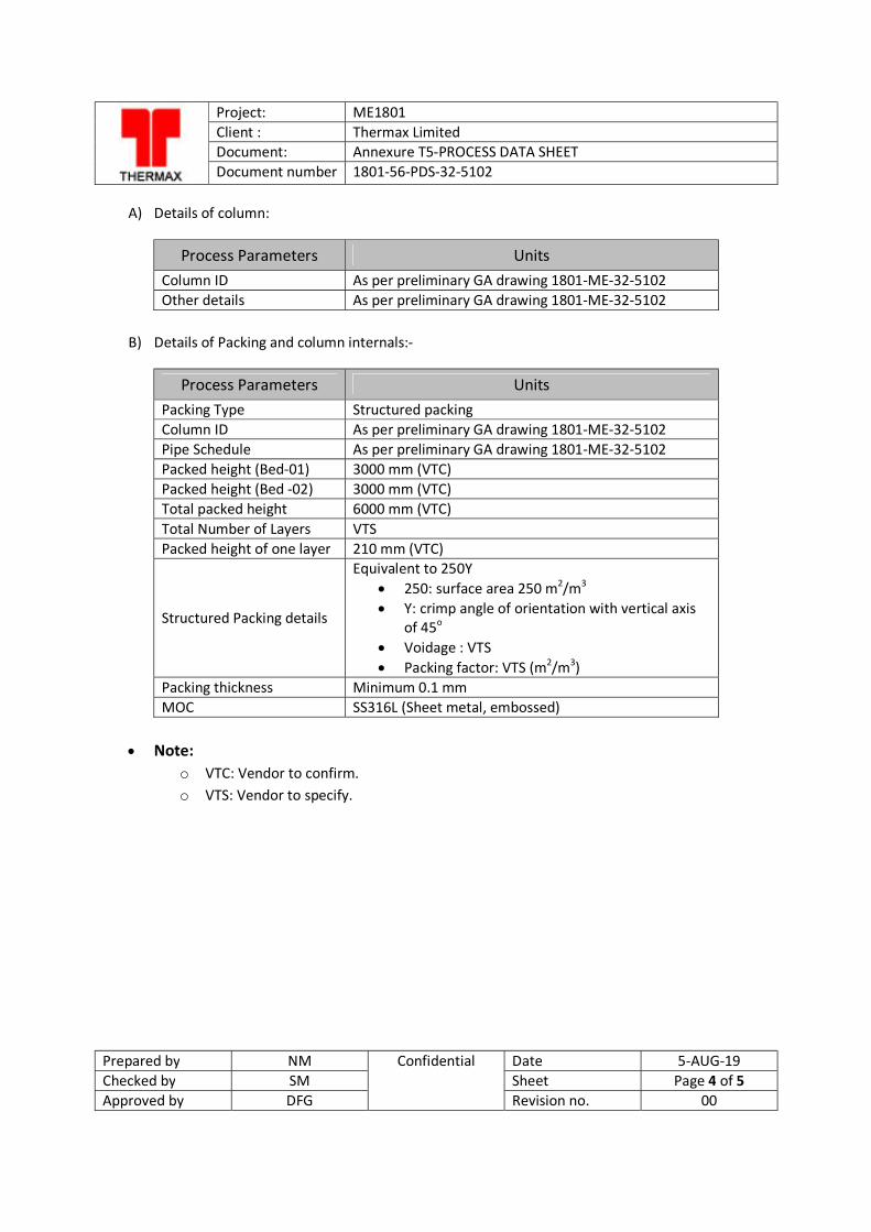
Project: ME1801 Client : Thermax Limited Document: Annexure T5-PROCESS DATA SHEET Document number 1801-56-PDS-32-5102
Prepared by NM Confidential Date 5-AUG-19 Checked by SM Sheet Page 4 of 5 Approved by DFG Revision no. 00
A) Details of column:
Process Parameters Units Column ID As per preliminary GA drawing 1801-ME-32-5102 Other details As per preliminary GA drawing 1801-ME-32-5102
B) Details of Packing and column internals:-
Process Parameters Units Packing Type Structured packing Column ID As per preliminary GA drawing 1801-ME-32-5102 Pipe Schedule As per preliminary GA drawing 1801-ME-32-5102 Packed height (Bed-01) 3000 mm (VTC) Packed height (Bed -02) 3000 mm (VTC) Total packed height 6000 mm (VTC) Total Number of Layers VTS Packed height of one layer 210 mm (VTC)
Structured Packing details
Equivalent to 250Y 250: surface area 250 m2/m3 Y: crimp angle of orientation with vertical axis
of 45o Voidage : VTS Packing factor: VTS (m2/m3)
Packing thickness Minimum 0.1 mm MOC SS316L (Sheet metal, embossed)
Note:
o VTC: Vendor to confirm. o VTS: Vendor to specify.
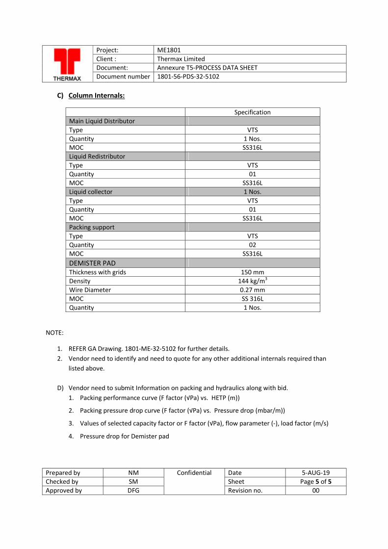
Project: ME1801 Client : Thermax Limited Document: Annexure T5-PROCESS DATA SHEET Document number 1801-56-PDS-32-5102
Prepared by NM Confidential Date 5-AUG-19 Checked by SM Sheet Page 5 of 5 Approved by DFG Revision no. 00
C) Column Internals:
Specification Main Liquid Distributor Type VTS Quantity 1 Nos. MOC SS316L Liquid Redistributor Type VTS Quantity 01 MOC SS316L Liquid collector 1 Nos. Type VTS Quantity 01 MOC SS316L Packing support Type VTS Quantity 02 MOC SS316L DEMISTER PAD Thickness with grids 150 mm Density 144 kg/m3 Wire Diameter 0.27 mm MOC SS 316L Quantity 1 Nos.
NOTE:
1. REFER GA Drawing. 1801-ME-32-5102 for further details. 2. Vendor need to identify and need to quote for any other additional internals required than
listed above.
D) Vendor need to submit Information on packing and hydraulics along with bid. 1. Packing performance curve (F factor (√Pa) vs. HETP (m))
2. Packing pressure drop curve (F factor (√Pa) vs. Pressure drop (mbar/m))
3. Values of selected capacity factor or F factor (√Pa), flow parameter (-), load factor (m/s)
4. Pressure drop for Demister pad
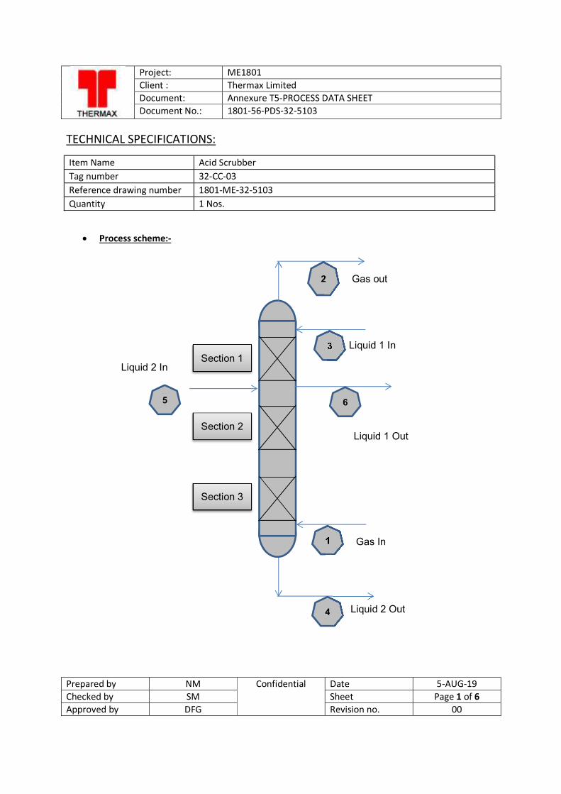
Project: ME1801 Client : Thermax Limited Document: Annexure T5-PROCESS DATA SHEET Document No.: 1801-56-PDS-32-5103
Prepared by NM Confidential Date 5-AUG-19 Checked by SM Sheet Page 1 of 6 Approved by DFG Revision no. 00
TECHNICAL SPECIFICATIONS:
Item Name Acid Scrubber Tag number 32-CC-03 Reference drawing number 1801-ME-32-5103 Quantity 1 Nos.
Process scheme:-
2
3
1
4
5 6
Section 1
Gas out
Liquid 1 In
Gas In
Liquid 2 Out
Section 2
Section 3
Liquid 2 In
Liquid 1 Out
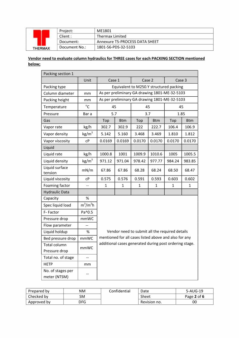
Project: ME1801 Client : Thermax Limited Document: Annexure T5-PROCESS DATA SHEET Document No.: 1801-56-PDS-32-5103
Prepared by NM Confidential Date 5-AUG-19 Checked by SM Sheet Page 2 of 6 Approved by DFG Revision no. 00
Vendor need to evaluate column hydraulics for THREE cases for each PACKING SECTION mentioned below;
Packing section 1 Unit Case 1 Case 2 Case 3 Packing type Equivalent to M250.Y structured packing Column diameter mm As per preliminary GA drawing 1801-ME-32-5103
Packing height mm As per preliminary GA drawing 1801-ME-32-5103
Temperature oC 45 45 45
Pressure Bar a 5.7 3.7 1.85
Gas Top Btm Top Btm Top Btm Vapor rate kg/h 302.7 302.9 222 222.7 106.4 106.9
Vapor density kg/m3 5.142 5.160 3.468 3.469 1.810 1.812
Vapor viscosity cP 0.0169 0.0169 0.0170 0.0170 0.0170 0.0170 Liquid
Liquid rate kg/h 1000.8 1001 1009.9 1010.6 1005 1005.5
Liquid density kg/m3 971.12 971.04 978.42 977.77 984.24 983.85 Liquid surface tension mN/m 67.86 67.86 68.28 68.24 68.50 68.47
Liquid viscosity cP 0.575 0.576 0.591 0.593 0.603 0.602
Foaming factor -- 1 1 1 1 1 1 Hydraulic Data
Capacity %
Vendor need to submit all the required details mentioned for all cases listed above and also for any additional cases generated during post ordering stage.
Spec liquid load m3/m2h
F- Factor Pa^0.5 Pressure drop mmWC Flow parameter -- Liquid holdup %
Bed pressure drop mmWC Total column Pressure drop
mmWC
Total no. of stage --
HETP mm No. of stages per meter (NTSM)
--

Project: ME1801 Client : Thermax Limited Document: Annexure T5-PROCESS DATA SHEET Document No.: 1801-56-PDS-32-5103
Prepared by NM Confidential Date 5-AUG-19 Checked by SM Sheet Page 3 of 6 Approved by DFG Revision no. 00
Packing section 2 Unit Case 1 Case 2 Case 3 Packing type
Equivalent to M250.Y structured packing
Column diameter mm As per preliminary GA drawing 1801-ME-32-5103
Packing height mm As per preliminary GA drawing 1801-ME-32-5103
Temperature oC 45 45 45
Pressure Bar a 5.7 3.7 1.85
Gas
Top Btm Top Btm Top Btm
Vapor rate kg/h 300.2 301.6 221.6 222.5 106.2 106.7
Vapor density kg/m3 5.138 5.150 3.461 3.467 1.809 1.812
Vapor viscosity cP 0.0169 0.0169 0.0170 0.0170 0.0170 0.0170 Liquid Liquid rate kg/h 1529.9 1531.3 1525.7 1526.5 1503.6 1504.1
Liquid density kg/m3 972.33 971.35 978.45 977.84 984.43 984.08 Liquid surface tension
mN/m 68.06 68.02 68.22 68.20 68.50 68.49
Liquid viscosity cP 0.587 0.586 0.596 0.590 0.603 0.603
Foaming factor -- 1 1 1 1 1 1 Hydraulic Data Capacity %
Vendor need to submit all the required details mentioned for all cases listed above and also for any
additional cases generated during post ordering stage.
Spec liquid load m3/m2h
F- Factor Pa^0.5 Pressure drop mmWC Flow parameter -- Liquid holdup % Bed pressure drop
mmWC
Total column Pressure drop
mmWC
Total no. of stage --
HETP mm No. of stages per meter (NTSM)
--
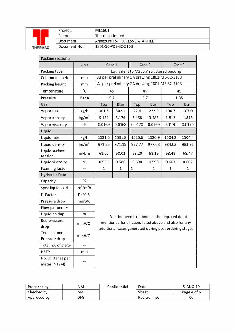
Project: ME1801 Client : Thermax Limited Document: Annexure T5-PROCESS DATA SHEET Document No.: 1801-56-PDS-32-5103
Prepared by NM Confidential Date 5-AUG-19 Checked by SM Sheet Page 4 of 6 Approved by DFG Revision no. 00
Packing section 3 Unit Case 1 Case 2 Case 3 Packing type
Equivalent to M250.Y structured packing
Column diameter mm As per preliminary GA drawing 1801-ME-32-5103
Packing height mm As per preliminary GA drawing 1801-ME-32-5103
Temperature oC 45 45 45
Pressure Bar a 5.7 3.7 1.85 Gas Top Btm Top Btm Top Btm Vapor rate kg/h 301.8 302.1 22.6 222.9 106.7 107.0
Vapor density kg/m3 5.151 5.176 3.468 3.483 1.812 1.815
Vapor viscosity cP 0.0169 0.0168 0.0170 0.0169 0.0170 0.0170
Liquid Liquid rate kg/h 1531.5 1531.8 1526.6 1526.9 1504.2 1504.4
Liquid density kg/m3 971.25 971.15 977.77 977.68 984.03 983.96 Liquid surface tension mN/m 68.02 68.02 68.20 68.19 68.48 68.47
Liquid viscosity cP 0.586 0.586 0.590 0.590 0.603 0.602 Foaming factor -- 1 1 1 1 1 1 Hydraulic Data
Capacity %
Vendor need to submit all the required details mentioned for all cases listed above and also for any
additional cases generated during post ordering stage.
Spec liquid load m3/m2h
F- Factor Pa^0.5 Pressure drop mmWC Flow parameter -- Liquid holdup % Bed pressure drop
mmWC
Total column Pressure drop
mmWC
Total no. of stage --
HETP mm No. of stages per meter (NTSM)
--
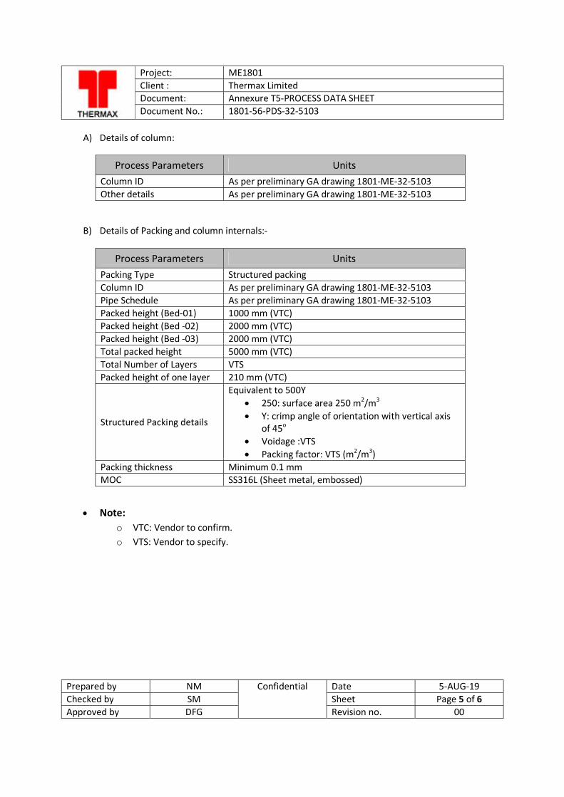
Project: ME1801 Client : Thermax Limited Document: Annexure T5-PROCESS DATA SHEET Document No.: 1801-56-PDS-32-5103
Prepared by NM Confidential Date 5-AUG-19 Checked by SM Sheet Page 5 of 6 Approved by DFG Revision no. 00
A) Details of column:
Process Parameters Units Column ID As per preliminary GA drawing 1801-ME-32-5103 Other details As per preliminary GA drawing 1801-ME-32-5103
B) Details of Packing and column internals:-
Note: o VTC: Vendor to confirm. o VTS: Vendor to specify.
Process Parameters Units Packing Type Structured packing Column ID As per preliminary GA drawing 1801-ME-32-5103 Pipe Schedule As per preliminary GA drawing 1801-ME-32-5103 Packed height (Bed-01) 1000 mm (VTC) Packed height (Bed -02) 2000 mm (VTC) Packed height (Bed -03) 2000 mm (VTC) Total packed height 5000 mm (VTC) Total Number of Layers VTS Packed height of one layer 210 mm (VTC)
Structured Packing details
Equivalent to 500Y 250: surface area 250 m2/m3 Y: crimp angle of orientation with vertical axis
of 45o Voidage :VTS Packing factor: VTS (m2/m3)
Packing thickness Minimum 0.1 mm MOC SS316L (Sheet metal, embossed)
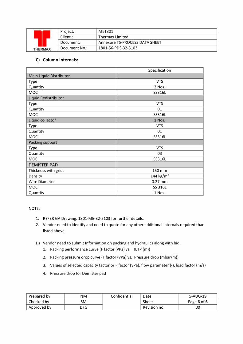
Project: ME1801 Client : Thermax Limited Document: Annexure T5-PROCESS DATA SHEET Document No.: 1801-56-PDS-32-5103
Prepared by NM Confidential Date 5-AUG-19 Checked by SM Sheet Page 6 of 6 Approved by DFG Revision no. 00
C) Column Internals:
Specification Main Liquid Distributor Type VTS Quantity 2 Nos. MOC SS316L Liquid Redistributor Type VTS Quantity 01 MOC SS316L Liquid collector 1 Nos. Type VTS Quantity 01 MOC SS316L Packing support Type VTS Quantity 03 MOC SS316L DEMISTER PAD Thickness with grids 150 mm Density 144 kg/m3 Wire Diameter 0.27 mm MOC SS 316L Quantity 1 Nos.
NOTE:
1. REFER GA Drawing. 1801-ME-32-5103 for further details. 2. Vendor need to identify and need to quote for any other additional internals required than
listed above.
D) Vendor need to submit Information on packing and hydraulics along with bid. 1. Packing performance curve (F factor (√Pa) vs. HETP (m))
2. Packing pressure drop curve (F factor (√Pa) vs. Pressure drop (mbar/m))
3. Values of selected capacity factor or F factor (√Pa), flow parameter (-), load factor (m/s)
4. Pressure drop for Demister pad
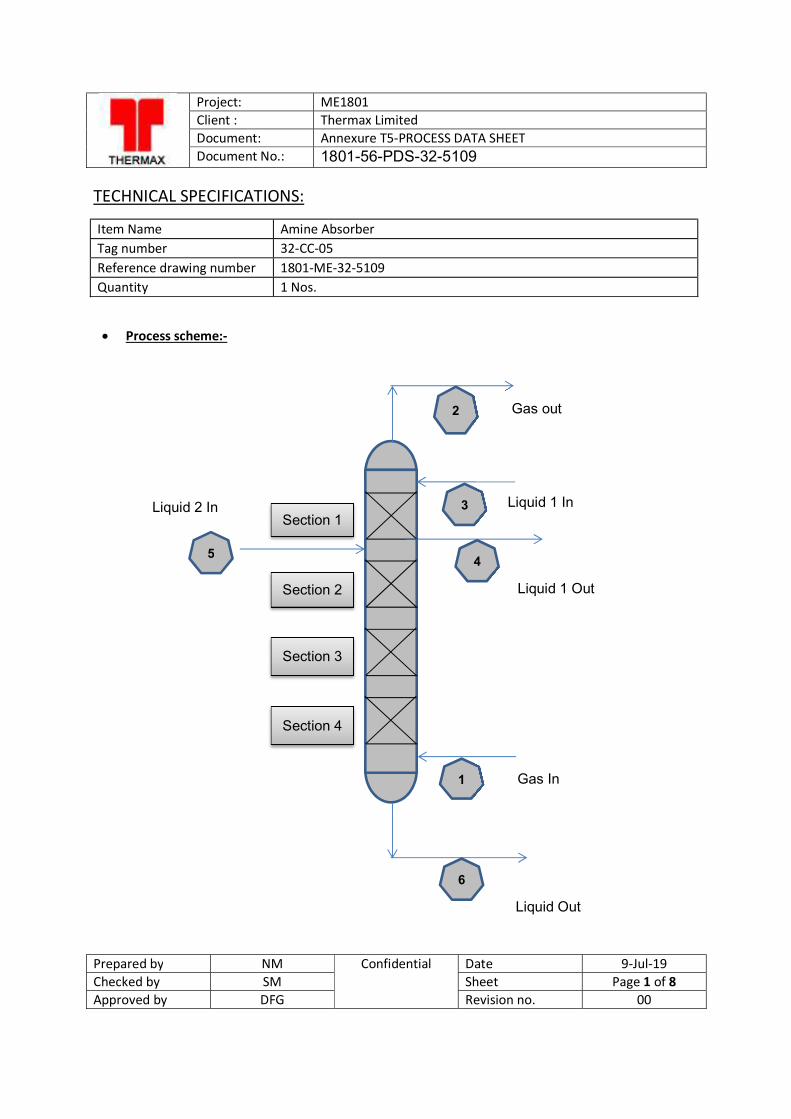
Project: ME1801 Client : Thermax Limited Document: Annexure T5-PROCESS DATA SHEET Document No.: 1801-56-PDS-32-5109
Prepared by NM Confidential Date 9-Jul-19 Checked by SM Sheet Page 1 of 8 Approved by DFG Revision no. 00
TECHNICAL SPECIFICATIONS:
Item Name Amine Absorber Tag number 32-CC-05 Reference drawing number 1801-ME-32-5109 Quantity 1 Nos.
Process scheme:-
2
3
1
6
5 4
Section 1
Section 3
Section 2
Gas out
Liquid 1 In
Gas In
Liquid Out
Section 4
Liquid 1 Out
Liquid 2 In
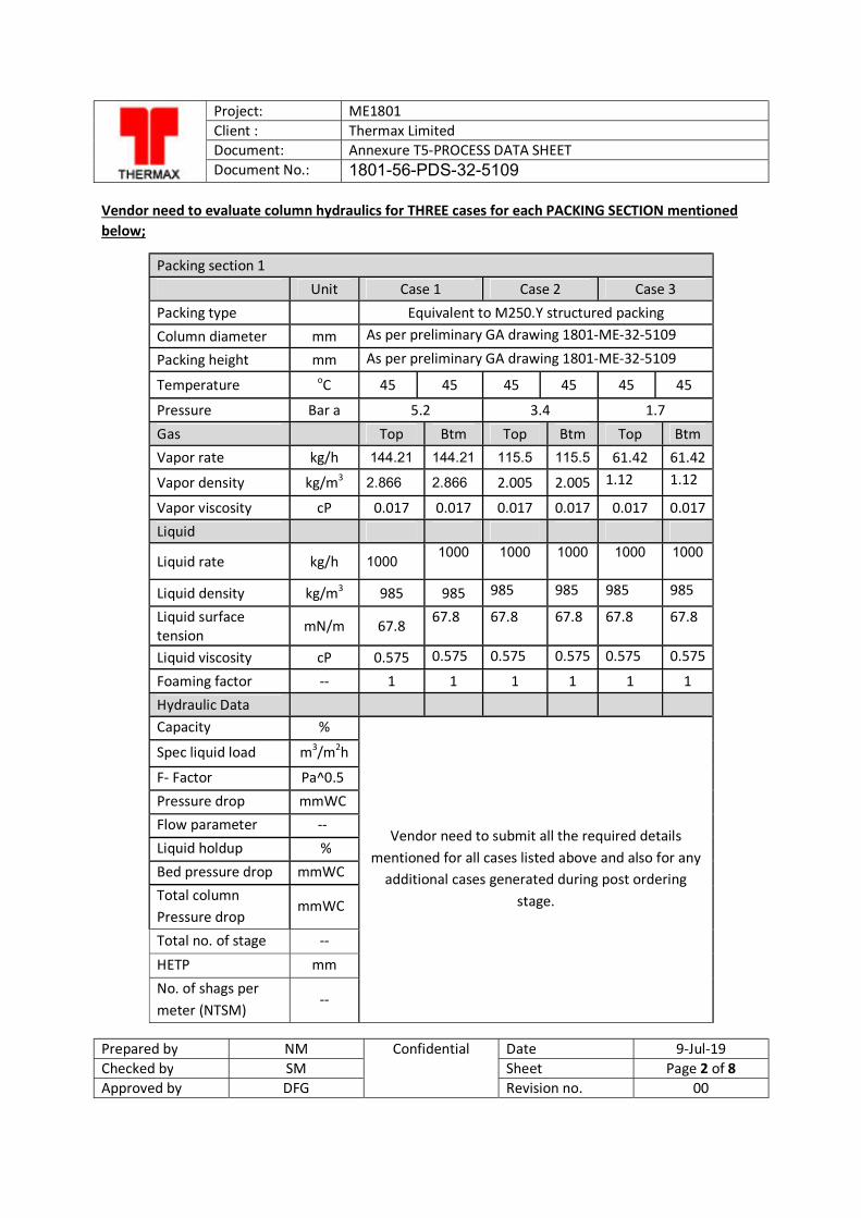
Project: ME1801 Client : Thermax Limited Document: Annexure T5-PROCESS DATA SHEET Document No.: 1801-56-PDS-32-5109
Prepared by NM Confidential Date 9-Jul-19 Checked by SM Sheet Page 2 of 8 Approved by DFG Revision no. 00
Vendor need to evaluate column hydraulics for THREE cases for each PACKING SECTION mentioned below;
Packing section 1 Unit Case 1 Case 2 Case 3 Packing type Equivalent to M250.Y structured packing Column diameter mm As per preliminary GA drawing 1801-ME-32-5109
Packing height mm As per preliminary GA drawing 1801-ME-32-5109
Temperature oC 45 45 45 45 45 45
Pressure Bar a 5.2 3.4 1.7
Gas Top Btm Top Btm Top Btm Vapor rate kg/h 144.21 144.21 115.5 115.5 61.42 61.42
Vapor density kg/m3 2.866 2.866 2.005 2.005 1.12 1.12
Vapor viscosity cP 0.017 0.017 0.017 0.017 0.017 0.017 Liquid
Liquid rate kg/h 1000 1000
1000
1000
1000
1000
Liquid density kg/m3 985 985 985 985 985 985
Liquid surface tension
mN/m 67.8 67.8 67.8 67.8 67.8 67.8
Liquid viscosity cP 0.575 0.575 0.575 0.575 0.575 0.575
Foaming factor -- 1 1 1 1 1 1 Hydraulic Data Capacity %
Vendor need to submit all the required details mentioned for all cases listed above and also for any
additional cases generated during post ordering stage.
Spec liquid load m3/m2h
F- Factor Pa^0.5 Pressure drop mmWC Flow parameter -- Liquid holdup % Bed pressure drop mmWC Total column Pressure drop
mmWC
Total no. of stage --
HETP mm No. of shags per meter (NTSM)
--
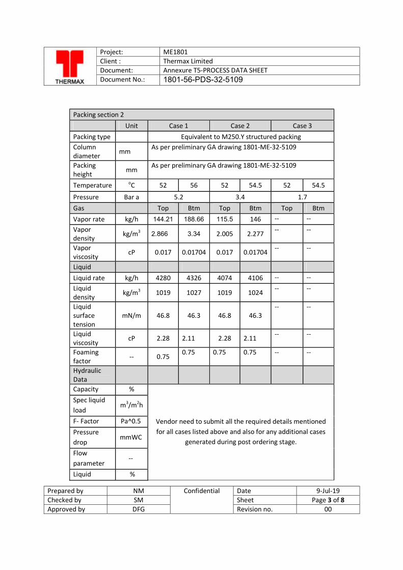
Project: ME1801 Client : Thermax Limited Document: Annexure T5-PROCESS DATA SHEET Document No.: 1801-56-PDS-32-5109
Prepared by NM Confidential Date 9-Jul-19 Checked by SM Sheet Page 3 of 8 Approved by DFG Revision no. 00
Packing section 2
Unit Case 1 Case 2 Case 3 Packing type
Equivalent to M250.Y structured packing
Column diameter
mm As per preliminary GA drawing 1801-ME-32-5109
Packing height mm
As per preliminary GA drawing 1801-ME-32-5109
Temperature oC 52 56 52 54.5 52 54.5
Pressure Bar a 5.2 3.4 1.7 Gas Top Btm Top Btm Top Btm Vapor rate kg/h 144.21 188.66 115.5 146 -- -- Vapor density
kg/m3 2.866 3.34 2.005 2.277 -- --
Vapor viscosity
cP 0.017 0.01704 0.017 0.01704 -- --
Liquid
Liquid rate kg/h 4280 4326 4074 4106 -- -- Liquid density
kg/m3 1019 1027 1019 1024 -- --
Liquid surface tension
mN/m 46.8 46.3 46.8 46.3 -- --
Liquid viscosity
cP 2.28 2.11 2.28 2.11 -- --
Foaming factor -- 0.75
0.75 0.75 0.75 -- --
Hydraulic Data Capacity %
Vendor need to submit all the required details mentioned for all cases listed above and also for any additional cases
generated during post ordering stage.
Spec liquid load
m3/m2h
F- Factor Pa^0.5 Pressure drop
mmWC
Flow parameter
--
Liquid %
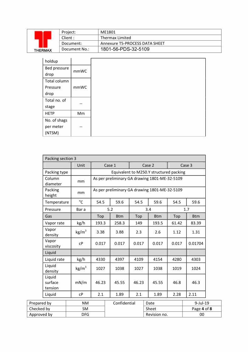
Project: ME1801 Client : Thermax Limited Document: Annexure T5-PROCESS DATA SHEET Document No.: 1801-56-PDS-32-5109
Prepared by NM Confidential Date 9-Jul-19 Checked by SM Sheet Page 4 of 8 Approved by DFG Revision no. 00
holdup Bed pressure drop
mmWC
Total column Pressure drop
mmWC
Total no. of stage
--
HETP Mm
No. of shags per meter (NTSM)
--
Packing section 3 Unit Case 1 Case 2 Case 3 Packing type Equivalent to M250.Y structured packing Column diameter
mm As per preliminary GA drawing 1801-ME-32-5109
Packing height
mm As per preliminary GA drawing 1801-ME-32-5109
Temperature oC 54.5 59.6 54.5 59.6 54.5 59.6
Pressure Bar a 5.2 3.4 1.7 Gas
Top Btm Top Btm Top Btm
Vapor rate kg/h 193.3 258.3 149 193.5 61.42 83.39 Vapor density
kg/m3 3.38 3.88 2.3 2.6 1.12 1.31
Vapor viscosity
cP 0.017 0.017 0.017 0.017 0.017 0.01704
Liquid
Liquid rate kg/h 4330 4397 4109 4154 4280 4303 Liquid density kg/m3 1027 1038 1027 1038 1019 1024
Liquid surface tension
mN/m 46.23 45.55 46.23 45.55 46.8 46.3
Liquid cP 2.1 1.89 2.1 1.89 2.28 2.11
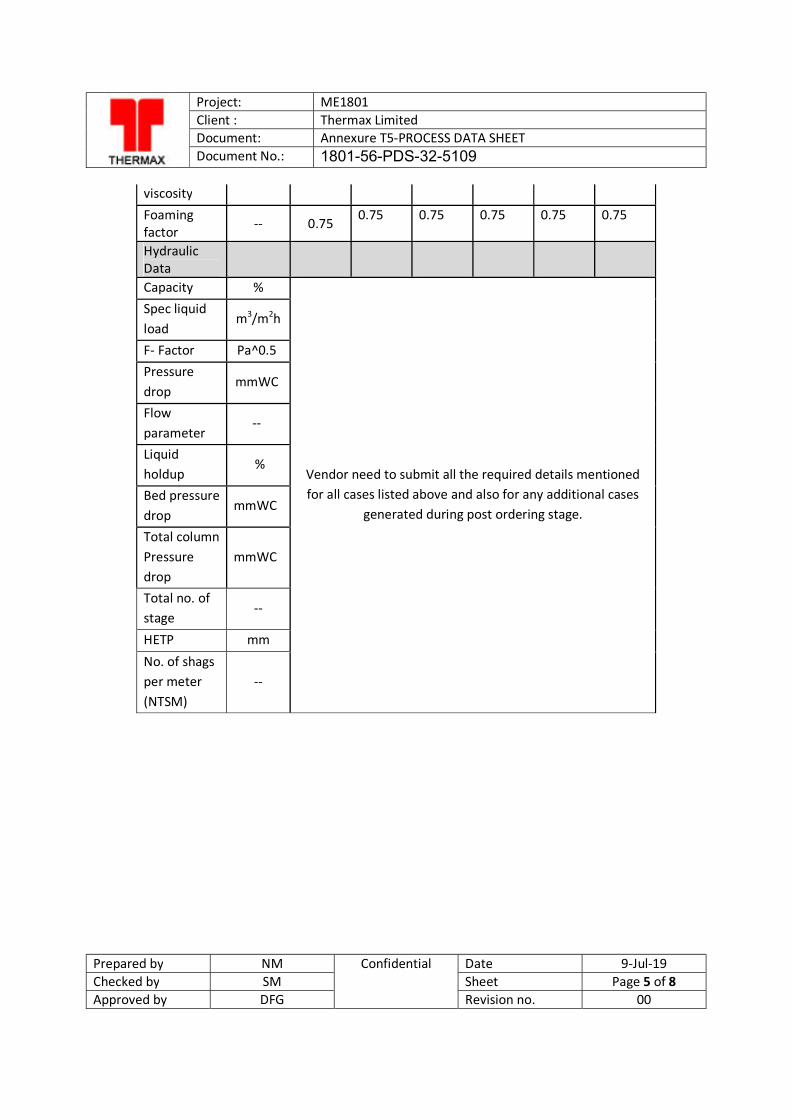
Project: ME1801 Client : Thermax Limited Document: Annexure T5-PROCESS DATA SHEET Document No.: 1801-56-PDS-32-5109
Prepared by NM Confidential Date 9-Jul-19 Checked by SM Sheet Page 5 of 8 Approved by DFG Revision no. 00
viscosity Foaming factor -- 0.75
0.75 0.75 0.75 0.75 0.75
Hydraulic Data Capacity %
Vendor need to submit all the required details mentioned for all cases listed above and also for any additional cases
generated during post ordering stage.
Spec liquid load
m3/m2h
F- Factor Pa^0.5 Pressure drop
mmWC
Flow parameter
--
Liquid holdup
%
Bed pressure drop
mmWC
Total column Pressure drop
mmWC
Total no. of stage
--
HETP mm
No. of shags per meter (NTSM)
--
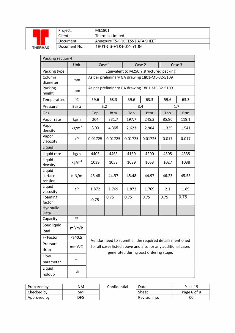
Project: ME1801 Client : Thermax Limited Document: Annexure T5-PROCESS DATA SHEET Document No.: 1801-56-PDS-32-5109
Prepared by NM Confidential Date 9-Jul-19 Checked by SM Sheet Page 6 of 8 Approved by DFG Revision no. 00
Packing section 4 Unit Case 1 Case 2 Case 3 Packing type
Equivalent to M250.Y structured packing
Column diameter
mm As per preliminary GA drawing 1801-ME-32-5109
Packing height mm
As per preliminary GA drawing 1801-ME-32-5109
Temperature oC 59.6 63.3 59.6 63.3 59.6 63.3
Pressure Bar a 5.2 3.4 1.7 Gas Top Btm Top Btm Top Btm Vapor rate kg/h 264 331.7 197.7 245.3 85.86 119.1 Vapor density
kg/m3 3.93 4.365 2.623 2.904 1.325 1.541
Vapor viscosity
cP 0.01725 0.01725 0.01725 0.01725 0.017 0.017
Liquid
Liquid rate kg/h 4403 4463 4159 4200 4305 4335 Liquid density
kg/m3 1039 1053 1039 1053 1027 1038
Liquid surface tension
mN/m 45.48 44.97 45.48 44.97 46.23 45.55
Liquid viscosity
cP 1.872 1.769 1.872 1.769 2.1 1.89
Foaming factor -- 0.75
0.75 0.75 0.75 0.75 0.75
Hydraulic Data Capacity %
Vendor need to submit all the required details mentioned for all cases listed above and also for any additional cases
generated during post ordering stage.
Spec liquid load
m3/m2h
F- Factor Pa^0.5 Pressure drop
mmWC
Flow parameter
--
Liquid holdup
%
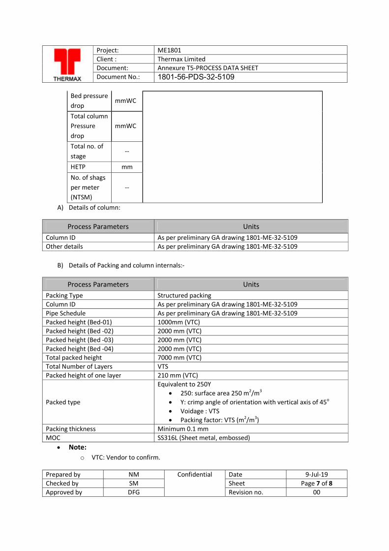
Project: ME1801 Client : Thermax Limited Document: Annexure T5-PROCESS DATA SHEET Document No.: 1801-56-PDS-32-5109
Prepared by NM Confidential Date 9-Jul-19 Checked by SM Sheet Page 7 of 8 Approved by DFG Revision no. 00
Bed pressure drop
mmWC
Total column Pressure drop
mmWC
Total no. of stage
--
HETP mm No. of shags per meter (NTSM)
--
A) Details of column:
Process Parameters Units Column ID As per preliminary GA drawing 1801-ME-32-5109 Other details As per preliminary GA drawing 1801-ME-32-5109
B) Details of Packing and column internals:-
Process Parameters Units Packing Type Structured packing Column ID As per preliminary GA drawing 1801-ME-32-5109 Pipe Schedule As per preliminary GA drawing 1801-ME-32-5109 Packed height (Bed-01) 1000mm (VTC) Packed height (Bed -02) 2000 mm (VTC) Packed height (Bed -03) 2000 mm (VTC) Packed height (Bed -04) 2000 mm (VTC) Total packed height 7000 mm (VTC) Total Number of Layers VTS Packed height of one layer 210 mm (VTC)
Packed type
Equivalent to 250Y 250: surface area 250 m2/m3 Y: crimp angle of orientation with vertical axis of 45o Voidage : VTS Packing factor: VTS (m2/m3)
Packing thickness Minimum 0.1 mm MOC SS316L (Sheet metal, embossed)
Note: o VTC: Vendor to confirm.
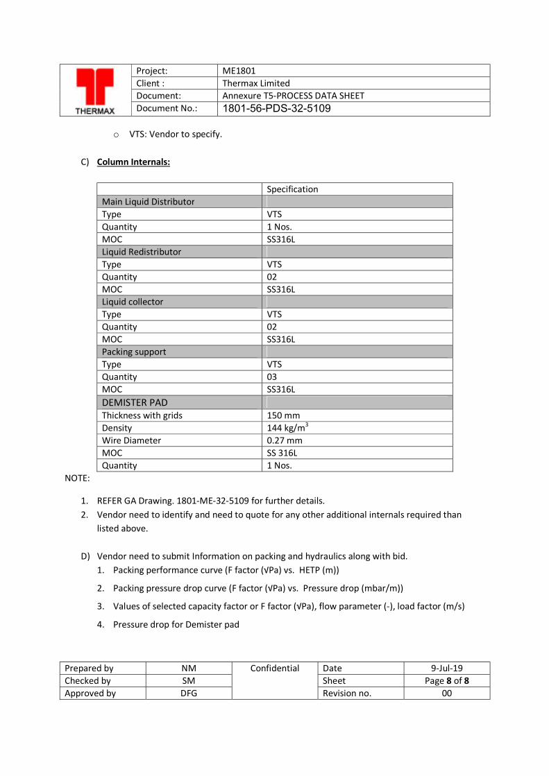
Project: ME1801 Client : Thermax Limited Document: Annexure T5-PROCESS DATA SHEET Document No.: 1801-56-PDS-32-5109
Prepared by NM Confidential Date 9-Jul-19 Checked by SM Sheet Page 8 of 8 Approved by DFG Revision no. 00
o VTS: Vendor to specify.
C) Column Internals:
Specification Main Liquid Distributor Type VTS Quantity 1 Nos. MOC SS316L Liquid Redistributor Type VTS Quantity 02 MOC SS316L Liquid collector Type VTS Quantity 02 MOC SS316L Packing support Type VTS Quantity 03 MOC SS316L DEMISTER PAD Thickness with grids 150 mm Density 144 kg/m3 Wire Diameter 0.27 mm MOC SS 316L Quantity 1 Nos.
NOTE:
1. REFER GA Drawing. 1801-ME-32-5109 for further details. 2. Vendor need to identify and need to quote for any other additional internals required than
listed above.
D) Vendor need to submit Information on packing and hydraulics along with bid. 1. Packing performance curve (F factor (√Pa) vs. HETP (m))
2. Packing pressure drop curve (F factor (√Pa) vs. Pressure drop (mbar/m))
3. Values of selected capacity factor or F factor (√Pa), flow parameter (-), load factor (m/s)
4. Pressure drop for Demister pad
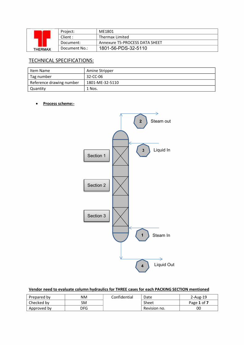
Project: ME1801 Client : Thermax Limited Document: Annexure T5-PROCESS DATA SHEET Document No.: 1801-56-PDS-32-5110
Prepared by NM Confidential Date 2-Aug-19 Checked by SM Sheet Page 1 of 7 Approved by DFG Revision no. 00
TECHNICAL SPECIFICATIONS:
Item Name Amine Stripper Tag number 32-CC-06 Reference drawing number 1801-ME-32-5110 Quantity 1 Nos.
Process scheme:-
Vendor need to evaluate column hydraulics for THREE cases for each PACKING SECTION mentioned
2
3
1
4
Section 1
Steam out
Liquid In
Steam In
Liquid Out
Section 2
Section 3
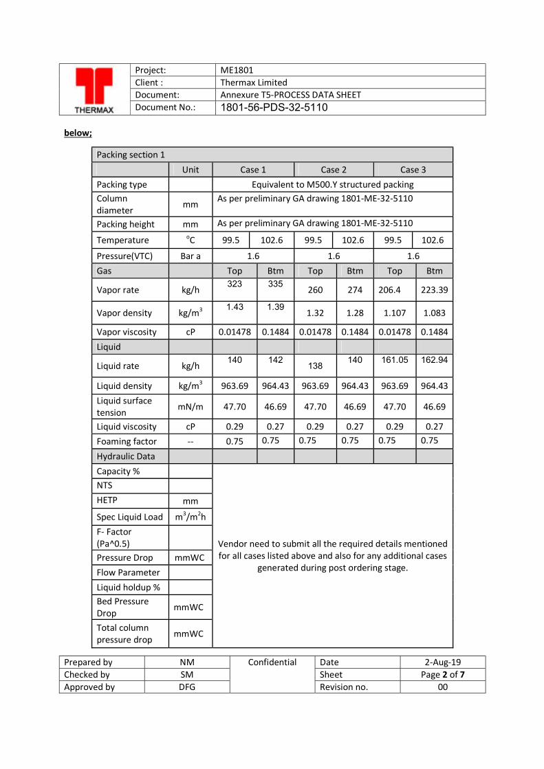
Project: ME1801 Client : Thermax Limited Document: Annexure T5-PROCESS DATA SHEET Document No.: 1801-56-PDS-32-5110
Prepared by NM Confidential Date 2-Aug-19 Checked by SM Sheet Page 2 of 7 Approved by DFG Revision no. 00
below;
Packing section 1
Unit Case 1 Case 2 Case 3 Packing type
Equivalent to M500.Y structured packing
Column diameter
mm As per preliminary GA drawing 1801-ME-32-5110
Packing height mm As per preliminary GA drawing 1801-ME-32-5110
Temperature oC 99.5 102.6 99.5 102.6 99.5 102.6
Pressure(VTC) Bar a 1.6 1.6 1.6 Gas
Top Btm Top Btm Top Btm
Vapor rate kg/h 323
335
260 274 206.4 223.39
Vapor density kg/m3 1.43
1.39
1.32 1.28 1.107 1.083
Vapor viscosity cP 0.01478 0.1484 0.01478 0.1484 0.01478 0.1484 Liquid
Liquid rate kg/h 140
142
138 140
161.05
162.94
Liquid density kg/m3 963.69 964.43 963.69 964.43 963.69 964.43 Liquid surface tension mN/m 47.70 46.69 47.70 46.69 47.70 46.69
Liquid viscosity cP 0.29 0.27 0.29 0.27 0.29 0.27 Foaming factor -- 0.75 0.75 0.75 0.75 0.75 0.75
Hydraulic Data
Capacity %
Vendor need to submit all the required details mentioned for all cases listed above and also for any additional cases
generated during post ordering stage.
NTS HETP mm
Spec Liquid Load m3/m2h F- Factor (Pa^0.5)
Pressure Drop mmWC Flow Parameter Liquid holdup % Bed Pressure Drop
mmWC
Total column pressure drop mmWC
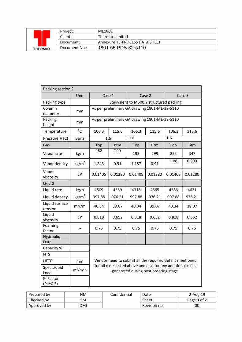
Project: ME1801 Client : Thermax Limited Document: Annexure T5-PROCESS DATA SHEET Document No.: 1801-56-PDS-32-5110
Prepared by NM Confidential Date 2-Aug-19 Checked by SM Sheet Page 3 of 7 Approved by DFG Revision no. 00
Packing section 2 Unit Case 1 Case 2 Case 3 Packing type Equivalent to M500.Y structured packing Column diameter mm
As per preliminary GA drawing 1801-ME-32-5110
Packing height mm
As per preliminary GA drawing 1801-ME-32-5110
Temperature oC 106.3 115.6 106.3 115.6 106.3 115.6
Pressure(VTC) Bar a 1.6 1.6 1.6
Gas Top Btm Top Btm Top Btm
Vapor rate kg/h 182
299
192 299 223 347
Vapor density kg/m3 1.243 0.91 1.187 0.91 1.08
0.909
Vapor viscosity
cP 0.01405 0.01280 0.01405 0.01280 0.01405 0.01280
Liquid
Liquid rate kg/h 4509 4569 4318 4365 4586 4621
Liquid density kg/m3 997.88 976.21 997.88 976.21 997.88 976.21 Liquid surface tension
mN/m 40.34 39.07 40.34 39.07 40.34 39.07
Liquid viscosity
cP 0.818 0.652 0.818 0.652 0.818 0.652
Foaming factor -- 0.75 0.75 0.75 0.75 0.75 0.75
Hydraulic Data Capacity %
Vendor need to submit all the required details mentioned for all cases listed above and also for any additional cases
generated during post ordering stage.
NTS HETP mm Spec Liquid Load
m3/m2h
F- Factor (Pa^0.5)
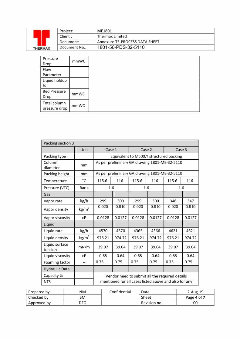
Project: ME1801 Client : Thermax Limited Document: Annexure T5-PROCESS DATA SHEET Document No.: 1801-56-PDS-32-5110
Prepared by NM Confidential Date 2-Aug-19 Checked by SM Sheet Page 4 of 7 Approved by DFG Revision no. 00
Pressure Drop
mmWC
Flow Parameter
Liquid holdup %
Bed Pressure Drop mmWC
Total column pressure drop
mmWC
Packing section 3 Unit Case 1 Case 2 Case 3
Packing type Equivalent to M500.Y structured packing Column diameter mm
As per preliminary GA drawing 1801-ME-32-5110
Packing height mm As per preliminary GA drawing 1801-ME-32-5110
Temperature oC 115.6 116 115.6 116 115.6 116
Pressure (VTC) Bar a 1.6 1.6 1.6 Gas Vapor rate kg/h 299 300 299 300 346 347
Vapor density kg/m3 0.920
0.910
0.920
0.910
0.920
0.910
Vapor viscosity cP 0.0128 0.0127 0.0128 0.0127 0.0128 0.0127 Liquid
Liquid rate kg/h 4570 4570 4365 4366 4621 4621
Liquid density kg/m3 976.21 974.72 976.21 974.72 976.21 974.72
Liquid surface tension
mN/m 39.07 39.04 39.07 39.04 39.07 39.04
Liquid viscosity cP 0.65 0.64 0.65 0.64 0.65 0.64 Foaming factor -- 0.75 0.75 0.75 0.75 0.75 0.75
Hydraulic Data Capacity %
Vendor need to submit all the required details mentioned for all cases listed above and also for any NTS
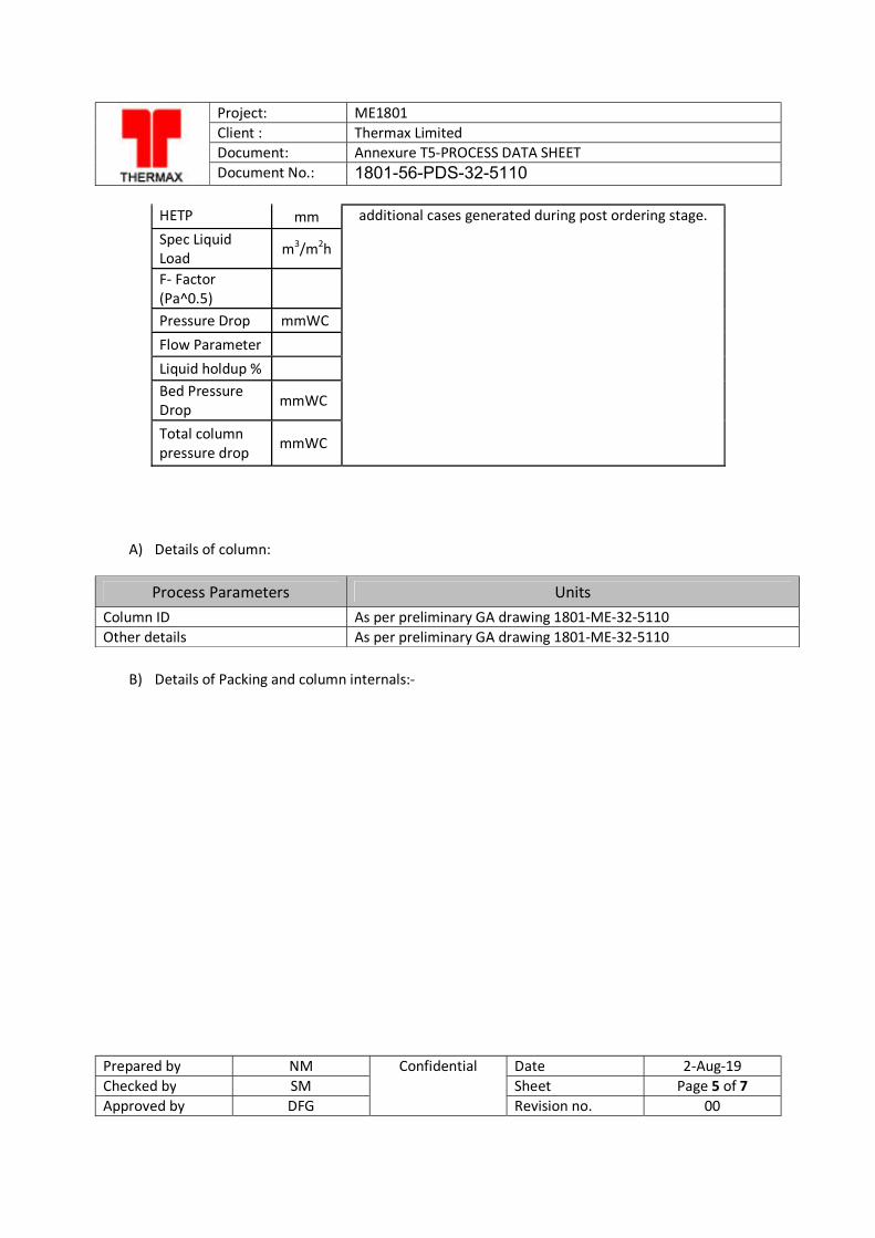
Project: ME1801 Client : Thermax Limited Document: Annexure T5-PROCESS DATA SHEET Document No.: 1801-56-PDS-32-5110
Prepared by NM Confidential Date 2-Aug-19 Checked by SM Sheet Page 5 of 7 Approved by DFG Revision no. 00
HETP mm additional cases generated during post ordering stage. Spec Liquid Load m3/m2h
F- Factor (Pa^0.5)
Pressure Drop mmWC Flow Parameter Liquid holdup % Bed Pressure Drop mmWC
Total column pressure drop
mmWC
A) Details of column:
Process Parameters Units Column ID As per preliminary GA drawing 1801-ME-32-5110 Other details As per preliminary GA drawing 1801-ME-32-5110
B) Details of Packing and column internals:-
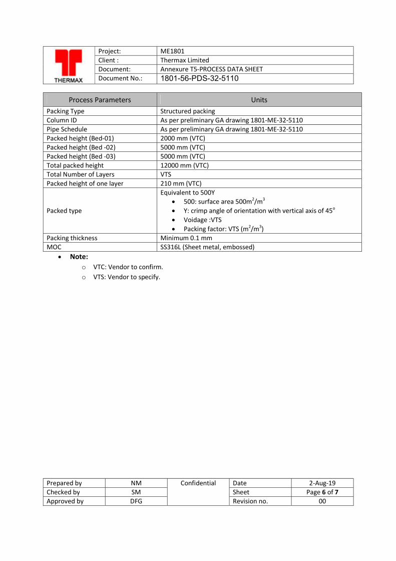
Project: ME1801 Client : Thermax Limited Document: Annexure T5-PROCESS DATA SHEET Document No.: 1801-56-PDS-32-5110
Prepared by NM Confidential Date 2-Aug-19 Checked by SM Sheet Page 6 of 7 Approved by DFG Revision no. 00
Process Parameters Units Packing Type Structured packing Column ID As per preliminary GA drawing 1801-ME-32-5110 Pipe Schedule As per preliminary GA drawing 1801-ME-32-5110 Packed height (Bed-01) 2000 mm (VTC) Packed height (Bed -02) 5000 mm (VTC) Packed height (Bed -03) 5000 mm (VTC) Total packed height 12000 mm (VTC) Total Number of Layers VTS Packed height of one layer 210 mm (VTC)
Packed type
Equivalent to 500Y 500: surface area 500m2/m3 Y: crimp angle of orientation with vertical axis of 45o Voidage :VTS Packing factor: VTS (m2/m3)
Packing thickness Minimum 0.1 mm MOC SS316L (Sheet metal, embossed)
Note: o VTC: Vendor to confirm. o VTS: Vendor to specify.
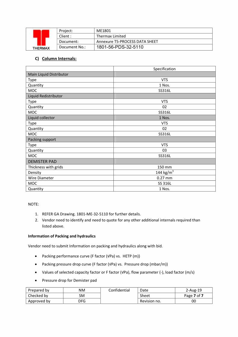
Project: ME1801 Client : Thermax Limited Document: Annexure T5-PROCESS DATA SHEET Document No.: 1801-56-PDS-32-5110
Prepared by NM Confidential Date 2-Aug-19 Checked by SM Sheet Page 7 of 7 Approved by DFG Revision no. 00
C) Column Internals:
Specification Main Liquid Distributor Type VTS Quantity 1 Nos. MOC SS316L Liquid Redistributor Type VTS Quantity 02 MOC SS316L Liquid collector 1 Nos. Type VTS Quantity 02 MOC SS316L Packing support Type VTS Quantity 03 MOC SS316L DEMISTER PAD Thickness with grids 150 mm Density 144 kg/m3 Wire Diameter 0.27 mm MOC SS 316L Quantity 1 Nos.
NOTE:
1. REFER GA Drawing. 1801-ME-32-5110 for further details. 2. Vendor need to identify and need to quote for any other additional internals required than
listed above.
Information of Packing and hydraulics
Vendor need to submit Information on packing and hydraulics along with bid.
Packing performance curve (F factor (√Pa) vs. HETP (m))
Packing pressure drop curve (F factor (√Pa) vs. Pressure drop (mbar/m))
Values of selected capacity factor or F factor (√Pa), flow parameter (-), load factor (m/s)
Pressure drop for Demister pad
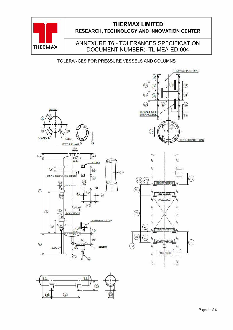
Page 1 of 4
THERMAX LIMITED RESEARCH, TECHNOLOGY AND INNOVATION CENTER
ANNEXURE T6:- TOLERANCES SPECIFICATION DOCUMENT NUMBER:- TL-MEA-ED-004
TOLERANCES FOR PRESSURE VESSELS AND COLUMNS
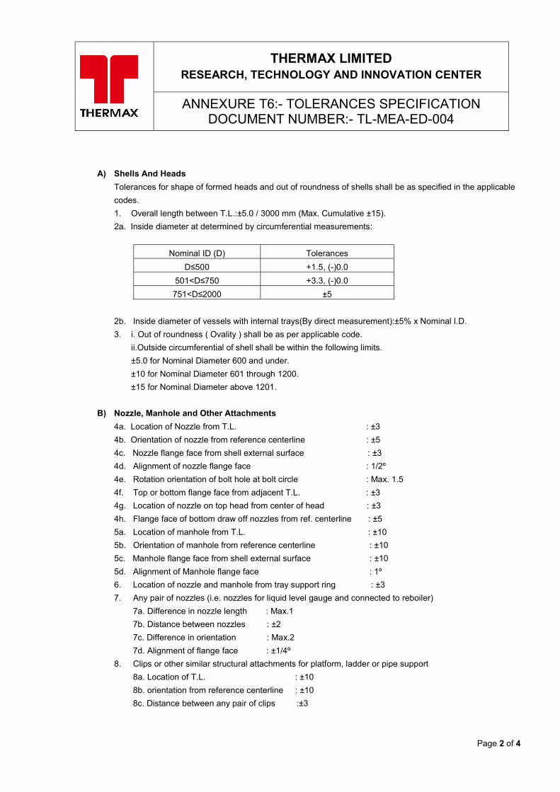
Page 2 of 4
THERMAX LIMITED RESEARCH, TECHNOLOGY AND INNOVATION CENTER
ANNEXURE T6:- TOLERANCES SPECIFICATION DOCUMENT NUMBER:- TL-MEA-ED-004
A) Shells And Heads
Tolerances for shape of formed heads and out of roundness of shells shall be as specified in the applicable
codes.
1. Overall length between T.L.:±5.0 / 3000 mm (Max. Cumulative ±15).
2a. Inside diameter at determined by circumferential measurements:
Nominal ID (D) Tolerances
D≤500 +1.5, (-)0.0
501<D≤750 +3.3, (-)0.0
751<D≤2000 ±5
2b. Inside diameter of vessels with internal trays(By direct measurement):±5% x Nominal I.D.
3. i. Out of roundness ( Ovality ) shall be as per applicable code.
ii.Outside circumferential of shell shall be within the following limits.
±5.0 for Nominal Diameter 600 and under.
±10 for Nominal Diameter 601 through 1200.
±15 for Nominal Diameter above 1201.
B) Nozzle, Manhole and Other Attachments
4a. Location of Nozzle from T.L. : ±3
4b. Orientation of nozzle from reference centerline : ±5
4c. Nozzle flange face from shell external surface : ±3
4d. Alignment of nozzle flange face : 1/2º
4e. Rotation orientation of bolt hole at bolt circle : Max. 1.5
4f. Top or bottom flange face from adjacent T.L. : ±3
4g. Location of nozzle on top head from center of head : ±3
4h. Flange face of bottom draw off nozzles from ref. centerline : ±5
5a. Location of manhole from T.L. : ±10
5b. Orientation of manhole from reference centerline : ±10
5c. Manhole flange face from shell external surface : ±10
5d. Alignment of Manhole flange face : 1º
6. Location of nozzle and manhole from tray support ring : ±3
7. Any pair of nozzles (i.e. nozzles for liquid level gauge and connected to reboiler)
7a. Difference in nozzle length : Max.1
7b. Distance between nozzles : ±2
7c. Difference in orientation : Max.2
7d. Alignment of flange face : ±1/4º
8. Clips or other similar structural attachments for platform, ladder or pipe support
8a. Location of T.L. : ±10
8b. orientation from reference centerline : ±10
8c. Distance between any pair of clips :±3
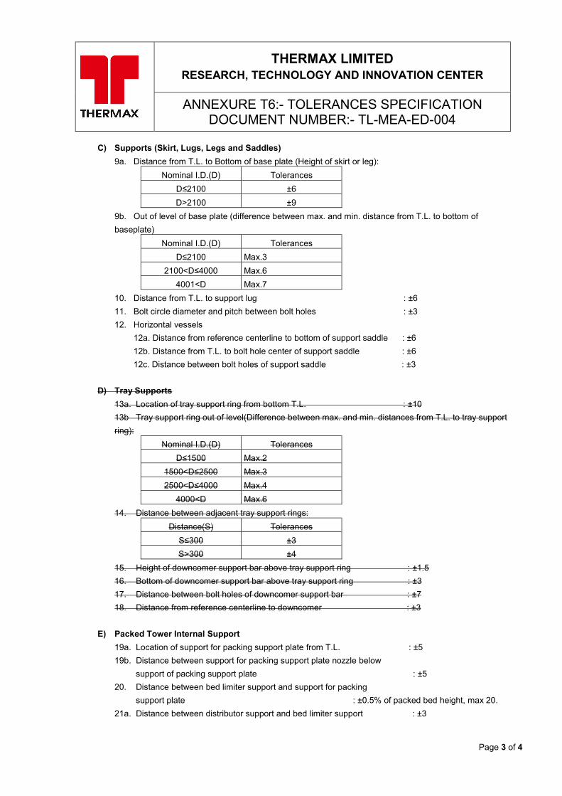
Page 3 of 4
THERMAX LIMITED RESEARCH, TECHNOLOGY AND INNOVATION CENTER
ANNEXURE T6:- TOLERANCES SPECIFICATION DOCUMENT NUMBER:- TL-MEA-ED-004
C) Supports (Skirt, Lugs, Legs and Saddles)
9a. Distance from T.L. to Bottom of base plate (Height of skirt or leg):
Nominal I.D.(D) Tolerances
D≤2100 ±6
D>2100 ±9
9b. Out of level of base plate (difference between max. and min. distance from T.L. to bottom of
baseplate)
Nominal I.D.(D) Tolerances
D≤2100 Max.3
2100<D≤4000 Max.6
4001<D Max.7
10. Distance from T.L. to support lug : ±6
11. Bolt circle diameter and pitch between bolt holes : ±3
12. Horizontal vessels
12a. Distance from reference centerline to bottom of support saddle : ±6
12b. Distance from T.L. to bolt hole center of support saddle : ±6
12c. Distance between bolt holes of support saddle : ±3
D) Tray Supports
13a. Location of tray support ring from bottom T.L. : ±10
13b Tray support ring out of level(Difference between max. and min. distances from T.L. to tray support
ring):
Nominal I.D.(D) Tolerances
D≤1500 Max.2
1500<D≤2500 Max.3
2500<D≤4000 Max.4
4000<D Max.6
14. Distance between adjacent tray support rings:
Distance(S) Tolerances
S≤300 ±3
S>300 ±4
15. Height of downcomer support bar above tray support ring : ±1.5
16. Bottom of downcomer support bar above tray support ring : ±3
17. Distance between bolt holes of downcomer support bar : ±7
18. Distance from reference centerline to downcomer : ±3
E) Packed Tower Internal Support
19a. Location of support for packing support plate from T.L. : ±5
19b. Distance between support for packing support plate nozzle below
support of packing support plate : ±5
20. Distance between bed limiter support and support for packing
support plate : ±0.5% of packed bed height, max 20.
21a. Distance between distributor support and bed limiter support : ±3
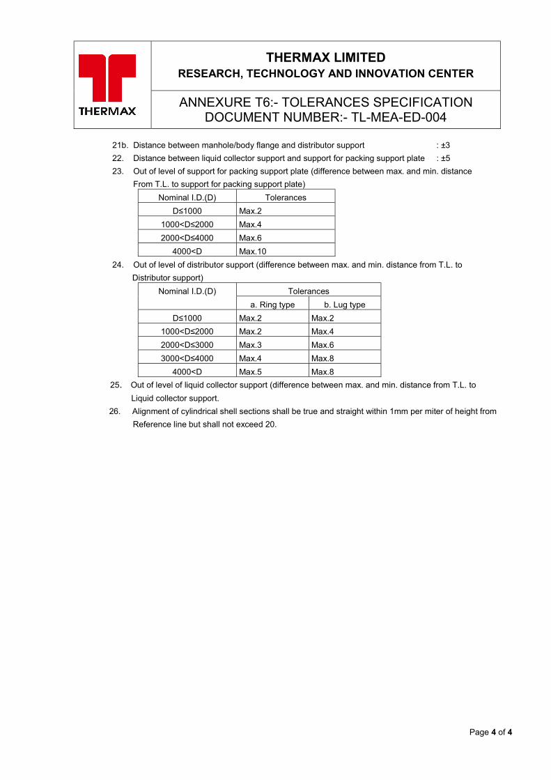
Page 4 of 4
THERMAX LIMITED RESEARCH, TECHNOLOGY AND INNOVATION CENTER
ANNEXURE T6:- TOLERANCES SPECIFICATION DOCUMENT NUMBER:- TL-MEA-ED-004
21b. Distance between manhole/body flange and distributor support : ±3
22. Distance between liquid collector support and support for packing support plate : ±5
23. Out of level of support for packing support plate (difference between max. and min. distance
From T.L. to support for packing support plate)
Nominal I.D.(D) Tolerances
D≤1000 Max.2
1000<D≤2000 Max.4
2000<D≤4000 Max.6
4000<D Max.10
24. Out of level of distributor support (difference between max. and min. distance from T.L. to
Distributor support) Nominal I.D.(D) Tolerances
a. Ring type b. Lug type
D≤1000 Max.2 Max.2
1000<D≤2000 Max.2 Max.4
2000<D≤3000 Max.3 Max.6
3000<D≤4000 Max.4 Max.8
4000<D Max.5 Max.8
25. Out of level of liquid collector support (difference between max. and min. distance from T.L. to Liquid collector support.
26. Alignment of cylindrical shell sections shall be true and straight within 1mm per miter of height from Reference line but shall not exceed 20.
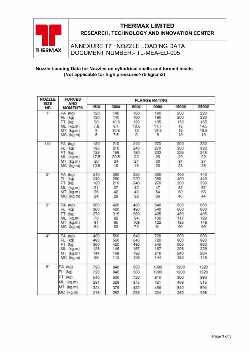
Page 1 of 3
THERMAX LIMITED RESEARCH, TECHNOLOGY AND INNOVATION CENTER
ANNEXURE T7 : NOZZLE LOADING DATA DOCUMENT NUMBER:- TL-MEA-ED-005
Nozzle Loading Data for Nozzles on cylindrical shells and formed heads (Not applicable for high pressures>75 kg/cm2)
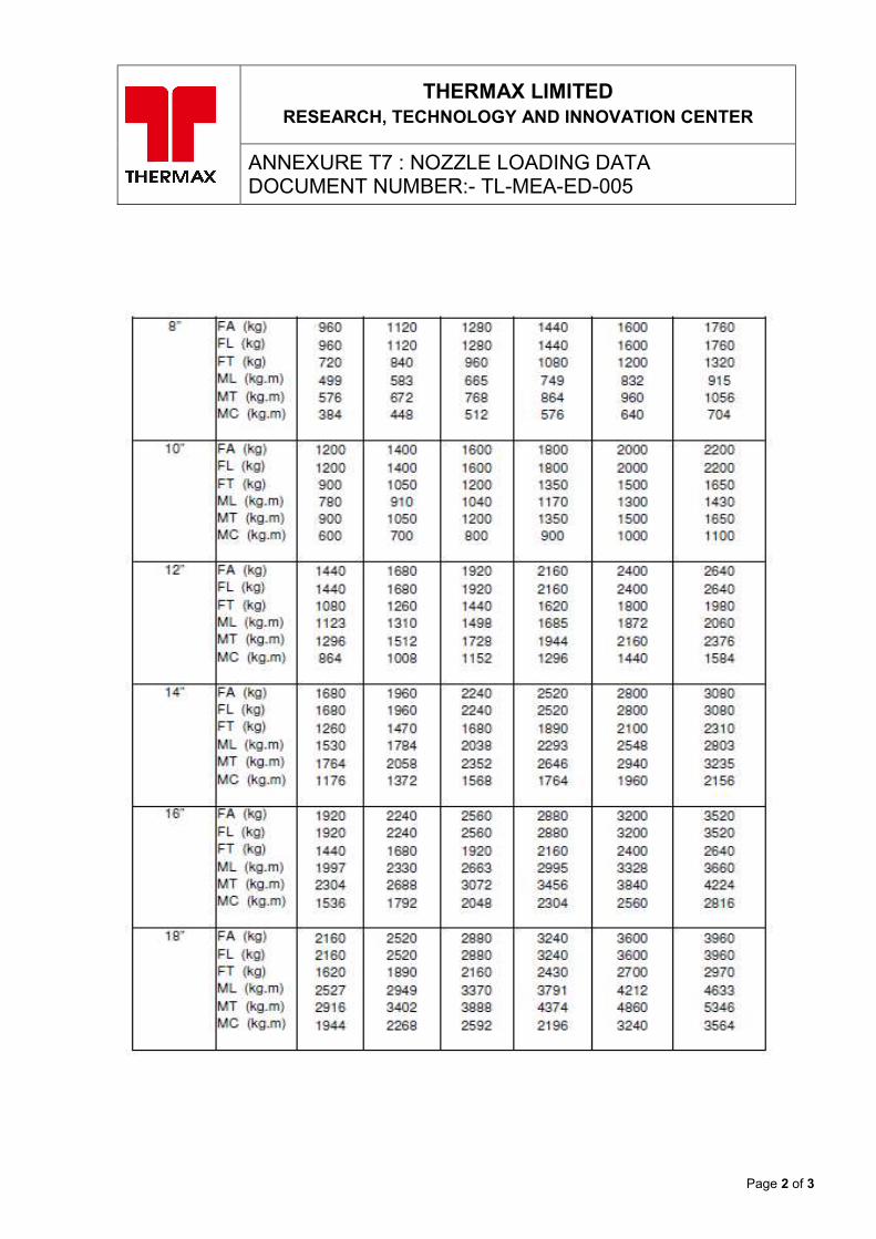
Page 2 of 3
THERMAX LIMITED RESEARCH, TECHNOLOGY AND INNOVATION CENTER
ANNEXURE T7 : NOZZLE LOADING DATA DOCUMENT NUMBER:- TL-MEA-ED-005
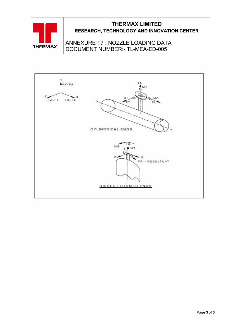
Page 3 of 3
THERMAX LIMITED RESEARCH, TECHNOLOGY AND INNOVATION CENTER
ANNEXURE T7 : NOZZLE LOADING DATA DOCUMENT NUMBER:- TL-MEA-ED-005
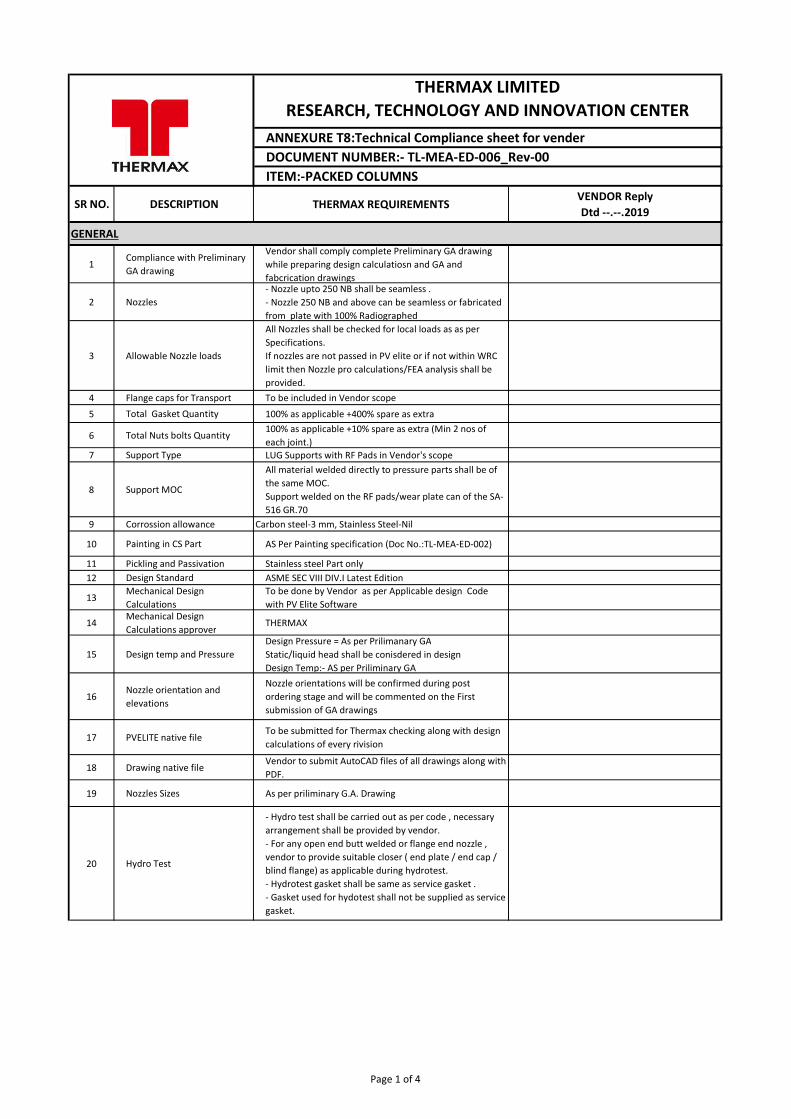
SR NO. DESCRIPTION THERMAX REQUIREMENTSVENDOR ReplyDtd --.--.2019
GENERAL
1Compliance with Preliminary GA drawing
Vendor shall comply complete Preliminary GA drawing while preparing design calculatiosn and GA and fabcrication drawings
2 Nozzles- Nozzle upto 250 NB shall be seamless .- Nozzle 250 NB and above can be seamless or fabricated from plate with 100% Radiographed
3 Allowable Nozzle loads
All Nozzles shall be checked for local loads as as per Specifications.If nozzles are not passed in PV elite or if not within WRC limit then Nozzle pro calculations/FEA analysis shall be provided.
4 Flange caps for Transport To be included in Vendor scope
5 Total Gasket Quantity 100% as applicable +400% spare as extra
6 Total Nuts bolts Quantity 100% as applicable +10% spare as extra (Min 2 nos of each joint.)
7 Support Type LUG Supports with RF Pads in Vendor's scope
8 Support MOC
All material welded directly to pressure parts shall be of the same MOC. Support welded on the RF pads/wear plate can of the SA-516 GR.70
9 Corrossion allowance Carbon steel-3 mm, Stainless Steel-Nil
10 Painting in CS Part AS Per Painting specification (Doc No.:TL-MEA-ED-002)
11 Pickling and Passivation Stainless steel Part only 12 Design Standard ASME SEC VIII DIV.I Latest Edition
13Mechanical Design Calculations
To be done by Vendor as per Applicable design Code with PV Elite Software
14Mechanical Design Calculations approver
THERMAX
15 Design temp and Pressure Design Pressure = As per Prilimanary GAStatic/liquid head shall be conisdered in designDesign Temp:- AS per Priliminary GA
16Nozzle orientation and elevations
Nozzle orientations will be confirmed during post ordering stage and will be commented on the First submission of GA drawings
17 PVELITE native fileTo be submitted for Thermax checking along with design calculations of every rivision
18 Drawing native fileVendor to submit AutoCAD files of all drawings along with PDF.
19 Nozzles Sizes As per priliminary G.A. Drawing
20 Hydro Test
- Hydro test shall be carried out as per code , necessary arrangement shall be provided by vendor.- For any open end butt welded or flange end nozzle , vendor to provide suitable closer ( end plate / end cap / blind flange) as applicable during hydrotest.- Hydrotest gasket shall be same as service gasket .- Gasket used for hydotest shall not be supplied as service gasket.
ANNEXURE T8:Technical Compliance sheet for vender
THERMAX LIMITED RESEARCH, TECHNOLOGY AND INNOVATION CENTER
DOCUMENT NUMBER:- TL-MEA-ED-006_Rev-00ITEM:-PACKED COLUMNS
Page 1 of 4
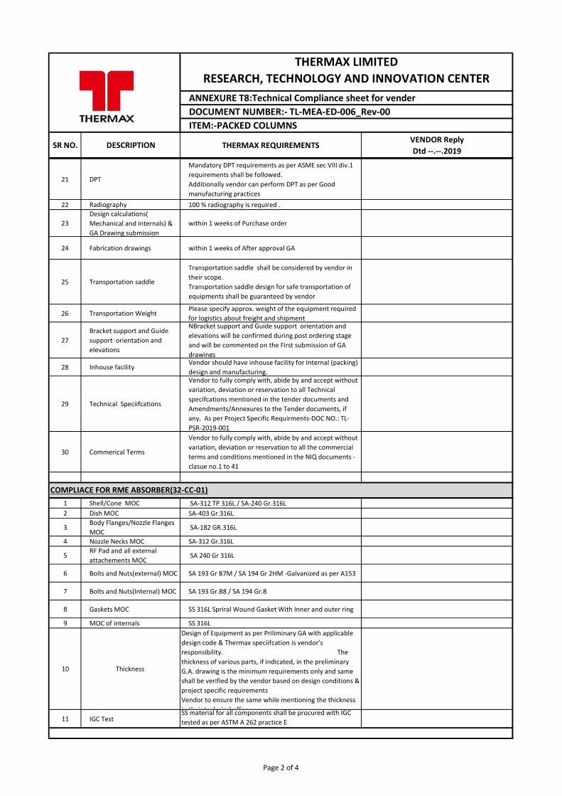
SR NO. DESCRIPTION THERMAX REQUIREMENTSVENDOR ReplyDtd --.--.2019
ANNEXURE T8:Technical Compliance sheet for vender
THERMAX LIMITED RESEARCH, TECHNOLOGY AND INNOVATION CENTER
DOCUMENT NUMBER:- TL-MEA-ED-006_Rev-00ITEM:-PACKED COLUMNS
21 DPT
Mandatory DPT requirements as per ASME sec VIII div.1 requirements shall be followed.Additionally vendor can perform DPT as per Good manufacturing practices
22 Radiography 100 % radiography is required .
23Design calculations( Mechanical and internals) & GA Drawing submission
within 1 weeks of Purchase order
24 Fabrication drawings within 1 weeks of After approval GA
25 Transportation saddle
Transportation saddle shall be considered by vendor in their scope.Transportation saddle design for safe transportation of equipments shall be guaranteed by vendor
26 Transportation WeightPlease specify approx. weight of the equipment required for logistics about freight and shipment
27Bracket support and Guide support orientation and elevations
NBracket support and Guide support orientation and elevations will be confirmed during post ordering stage and will be commented on the First submission of GA drawings
28 Inhouse facilityVendor should have inhouse facility for Internal (packing) design and manufacturing.
29 Technical Speciifcations
Vendor to fully comply with, abide by and accept without variation, deviation or reservation to all Technical specifcations mentioned in the tender documents and Amendments/Annexures to the Tender documents, if any, As per Project Specific Requirments-DOC NO.: TL-PSR-2019-001
30 Commerical Terms
Vendor to fully comply with, abide by and accept without variation, deviation or reservation to all the commercial terms and conditions mentioned in the NIQ documents -clasue no.1 to 41
1 Shell/Cone MOC SA-312 TP 316L / SA-240 Gr.316L2 Dish MOC SA-403 Gr.316L
3Body Flanges/Nozzle Flanges MOC
SA-182 GR.316L
4 Nozzle Necks MOC SA-312 Gr.316L
5RF Pad and all external attachements MOC
SA 240 Gr 316L
6 Bolts and Nuts(external) MOC SA 193 Gr B7M / SA 194 Gr 2HM -Galvanized as per A153
7 Bolts and Nuts(Internal) MOC SA 193 Gr.B8 / SA 194 Gr.8
8 Gaskets MOC SS 316L Spriral Wound Gasket With Inner and outer ring
9 MOC of internals SS 316L
10 Thickness
Design of Equipment as per Priliminary GA with applicable design code & Thermax speciifcation is vendor's responsibility. The thickness of various parts, if indicated, in the preliminary G.A. drawing is the minimum requirements only and same shall be verified by the vendor based on design conditions & project specific requirementsVendor to ensure the same while mentioning the thickness in their technical offer.
11 IGC TestSS material for all components shall be procured with IGC tested as per ASTM A 262 practice E
COMPLIACE FOR RME ABSORBER(32-CC-01)
Page 2 of 4
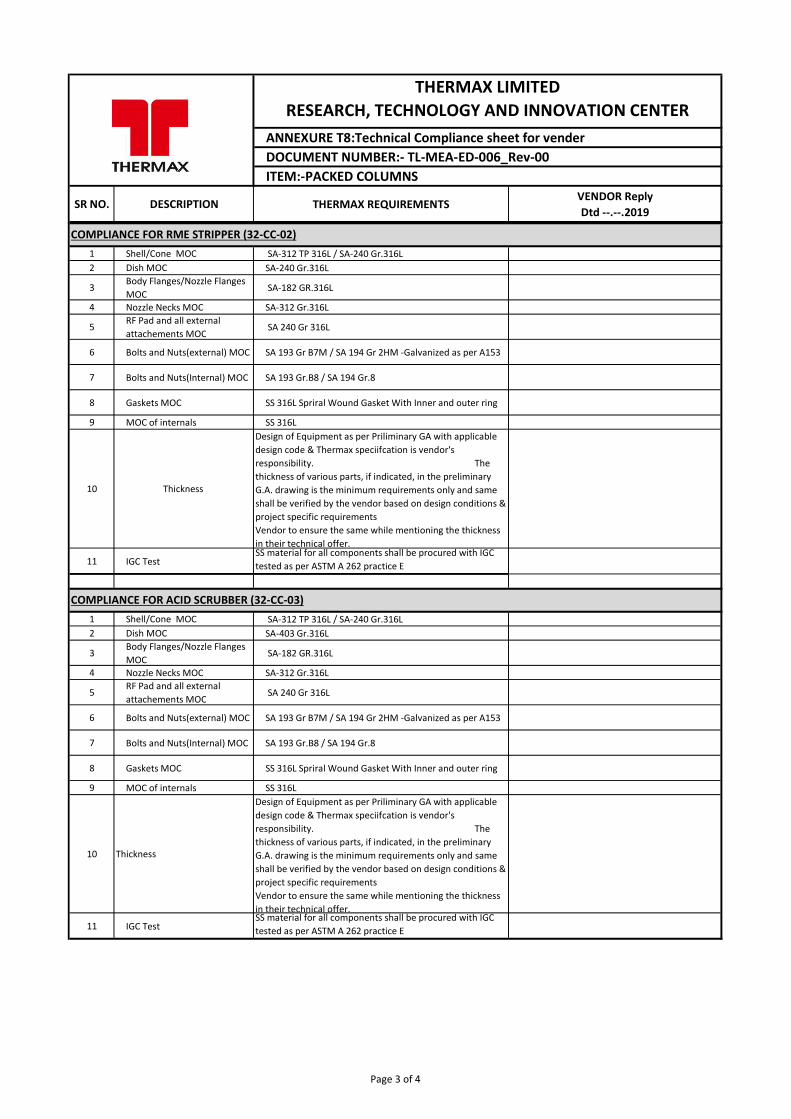
SR NO. DESCRIPTION THERMAX REQUIREMENTSVENDOR ReplyDtd --.--.2019
ANNEXURE T8:Technical Compliance sheet for vender
THERMAX LIMITED RESEARCH, TECHNOLOGY AND INNOVATION CENTER
DOCUMENT NUMBER:- TL-MEA-ED-006_Rev-00ITEM:-PACKED COLUMNS
1 Shell/Cone MOC SA-312 TP 316L / SA-240 Gr.316L2 Dish MOC SA-240 Gr.316L
3Body Flanges/Nozzle Flanges MOC
SA-182 GR.316L
4 Nozzle Necks MOC SA-312 Gr.316L
5RF Pad and all external attachements MOC
SA 240 Gr 316L
6 Bolts and Nuts(external) MOC SA 193 Gr B7M / SA 194 Gr 2HM -Galvanized as per A153
7 Bolts and Nuts(Internal) MOC SA 193 Gr.B8 / SA 194 Gr.8
8 Gaskets MOC SS 316L Spriral Wound Gasket With Inner and outer ring
9 MOC of internals SS 316L
10 Thickness
Design of Equipment as per Priliminary GA with applicable design code & Thermax speciifcation is vendor's responsibility. The thickness of various parts, if indicated, in the preliminary G.A. drawing is the minimum requirements only and same shall be verified by the vendor based on design conditions & project specific requirementsVendor to ensure the same while mentioning the thickness in their technical offer.
11 IGC TestSS material for all components shall be procured with IGC tested as per ASTM A 262 practice E
1 Shell/Cone MOC SA-312 TP 316L / SA-240 Gr.316L2 Dish MOC SA-403 Gr.316L
3Body Flanges/Nozzle Flanges MOC
SA-182 GR.316L
4 Nozzle Necks MOC SA-312 Gr.316L
5RF Pad and all external attachements MOC
SA 240 Gr 316L
6 Bolts and Nuts(external) MOC SA 193 Gr B7M / SA 194 Gr 2HM -Galvanized as per A153
7 Bolts and Nuts(Internal) MOC SA 193 Gr.B8 / SA 194 Gr.8
8 Gaskets MOC SS 316L Spriral Wound Gasket With Inner and outer ring
9 MOC of internals SS 316L
10 Thickness
Design of Equipment as per Priliminary GA with applicable design code & Thermax speciifcation is vendor's responsibility. The thickness of various parts, if indicated, in the preliminary G.A. drawing is the minimum requirements only and same shall be verified by the vendor based on design conditions & project specific requirementsVendor to ensure the same while mentioning the thickness in their technical offer.
11 IGC TestSS material for all components shall be procured with IGC tested as per ASTM A 262 practice E
COMPLIANCE FOR RME STRIPPER (32-CC-02)
COMPLIANCE FOR ACID SCRUBBER (32-CC-03)
Page 3 of 4
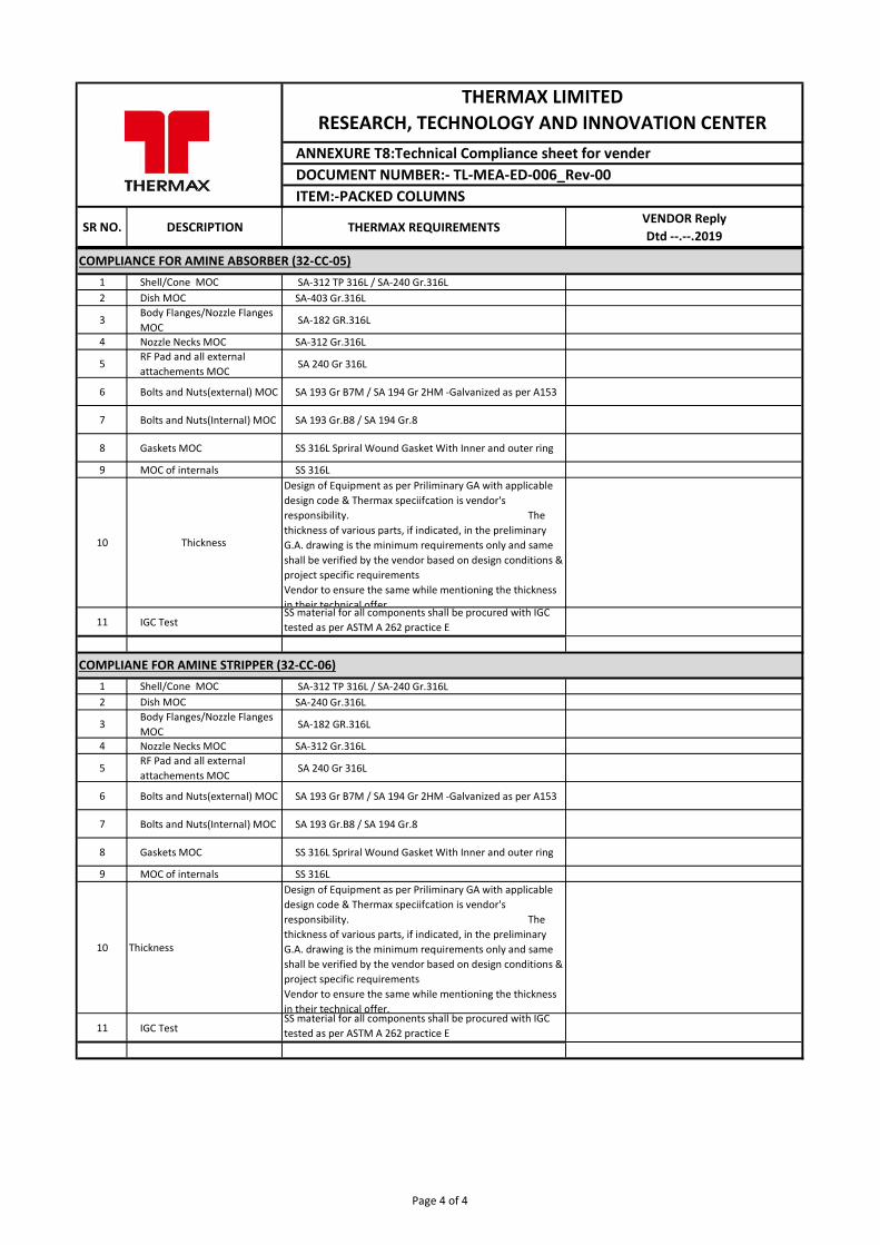
SR NO. DESCRIPTION THERMAX REQUIREMENTSVENDOR ReplyDtd --.--.2019
ANNEXURE T8:Technical Compliance sheet for vender
THERMAX LIMITED RESEARCH, TECHNOLOGY AND INNOVATION CENTER
DOCUMENT NUMBER:- TL-MEA-ED-006_Rev-00ITEM:-PACKED COLUMNS
1 Shell/Cone MOC SA-312 TP 316L / SA-240 Gr.316L2 Dish MOC SA-403 Gr.316L
3Body Flanges/Nozzle Flanges MOC
SA-182 GR.316L
4 Nozzle Necks MOC SA-312 Gr.316L
5RF Pad and all external attachements MOC
SA 240 Gr 316L
6 Bolts and Nuts(external) MOC SA 193 Gr B7M / SA 194 Gr 2HM -Galvanized as per A153
7 Bolts and Nuts(Internal) MOC SA 193 Gr.B8 / SA 194 Gr.8
8 Gaskets MOC SS 316L Spriral Wound Gasket With Inner and outer ring
9 MOC of internals SS 316L
10 Thickness
Design of Equipment as per Priliminary GA with applicable design code & Thermax speciifcation is vendor's responsibility. The thickness of various parts, if indicated, in the preliminary G.A. drawing is the minimum requirements only and same shall be verified by the vendor based on design conditions & project specific requirementsVendor to ensure the same while mentioning the thickness in their technical offer.
11 IGC TestSS material for all components shall be procured with IGC tested as per ASTM A 262 practice E
1 Shell/Cone MOC SA-312 TP 316L / SA-240 Gr.316L2 Dish MOC SA-240 Gr.316L
3Body Flanges/Nozzle Flanges MOC
SA-182 GR.316L
4 Nozzle Necks MOC SA-312 Gr.316L
5RF Pad and all external attachements MOC
SA 240 Gr 316L
6 Bolts and Nuts(external) MOC SA 193 Gr B7M / SA 194 Gr 2HM -Galvanized as per A153
7 Bolts and Nuts(Internal) MOC SA 193 Gr.B8 / SA 194 Gr.8
8 Gaskets MOC SS 316L Spriral Wound Gasket With Inner and outer ring
9 MOC of internals SS 316L
10 Thickness
Design of Equipment as per Priliminary GA with applicable design code & Thermax speciifcation is vendor's responsibility. The thickness of various parts, if indicated, in the preliminary G.A. drawing is the minimum requirements only and same shall be verified by the vendor based on design conditions & project specific requirementsVendor to ensure the same while mentioning the thickness in their technical offer.
11 IGC TestSS material for all components shall be procured with IGC tested as per ASTM A 262 practice E
COMPLIANCE FOR AMINE ABSORBER (32-CC-05)
COMPLIANE FOR AMINE STRIPPER (32-CC-06)
Page 4 of 4
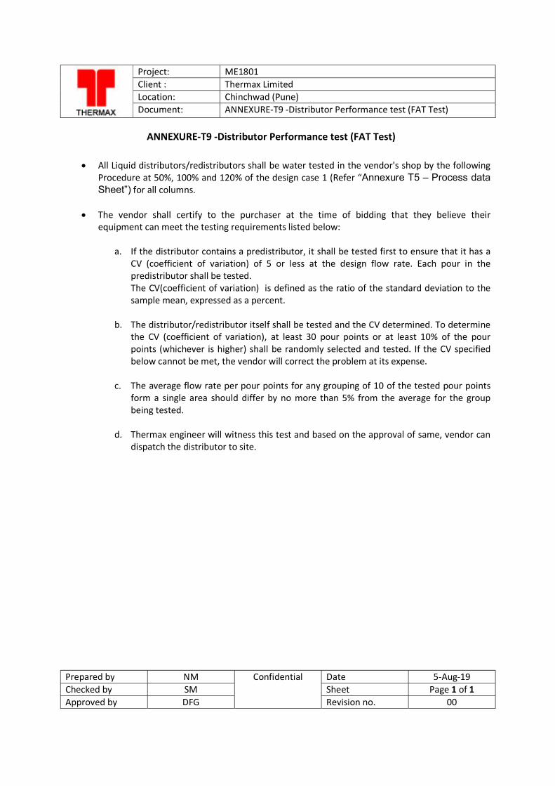
Project: ME1801 Client : Thermax Limited Location: Chinchwad (Pune) Document: ANNEXURE-T9 -Distributor Performance test (FAT Test)
Prepared by NM Confidential Date 5-Aug-19 Checked by SM Sheet Page 1 of 1 Approved by DFG Revision no. 00
ANNEXURE-T9 -Distributor Performance test (FAT Test)
All Liquid distributors/redistributors shall be water tested in the vendor's shop by the following Procedure at 50%, 100% and 120% of the design case 1 (Refer “Annexure T5 – Process data Sheet”) for all columns.
The vendor shall certify to the purchaser at the time of bidding that they believe their equipment can meet the testing requirements listed below:
a. If the distributor contains a predistributor, it shall be tested first to ensure that it has a
CV (coefficient of variation) of 5 or less at the design flow rate. Each pour in the predistributor shall be tested. The CV(coefficient of variation) is defined as the ratio of the standard deviation to the sample mean, expressed as a percent.
b. The distributor/redistributor itself shall be tested and the CV determined. To determine
the CV (coefficient of variation), at least 30 pour points or at least 10% of the pour points (whichever is higher) shall be randomly selected and tested. If the CV specified below cannot be met, the vendor will correct the problem at its expense.
c. The average flow rate per pour points for any grouping of 10 of the tested pour points form a single area should differ by no more than 5% from the average for the group being tested.
d. Thermax engineer will witness this test and based on the approval of same, vendor can dispatch the distributor to site.
(Annexure-T10) NON DISCLOSURE AGREEMENT
This Non-Disclosure Agreement (“Agreement”) is entered into on this _________day of _________ 2019 (“Effective Date”), at Pune:
BETWEEN
Thermax Limited, having its registered office at D 13, MIDC Industrial Estate, R.D. Aga Road, Chinchwad, Pune 411 019, India and engaged in the business of products, services and solutions related to energy and environment (hereinafter called the ‘Thermax’ which expression shall, where the context so admits, include its permitted successors and permitted assigns) of the one part.
AND
______________, having registered office at ___________________________________________ (hereinafter called as ‘______________’ which expression shall where the context so admits include its permitted successors and assigns) of the other part,
Thermax and Company A may hereinafter be referred to collectively as “Parties” and individually as “Party”.
WHEREAS:
A. Thermax is inter alia, in the business of energy & environment and amongst others in design, engineering, procurement, manufacture, distribution, sale, erection, commissioning and servicing of Boilers, Thermic Fluid heaters, Pressurized hot water systems, absorption Chillers, Power Plants and such other similar products. Thermax has considerable presence the world over in the markets for such products.
B. ___________ is _____________(Please fill )
C. Purpose of this Agreement: (Please fill purpose)
Therefore, in consideration of the covenants contained in this Agreement, the receipt and sufficiency of which is hereby acknowledged, the Parties hereto agree as follows:
1. By signing this agreement, the Parties hereby agree to maintain confidentiality of confidential information disclosed by one Party to another.
1.1 “Disclosing Party” in relation to any Confidential Information, means the Party furnishing or causing to be furnished such information.
1.2 “Receiving Party” in relation to any Confidential Information, means the Party receiving, or whose Representative receives such information.
1.3 “Representatives” in respect of a Party, means its affiliates, and the directors, officers, employees, consultants, contractors, accounting, financial and legal advisors of such Party or its affiliates.
1.4 For the purpose of this agreement, “Confidential Information” means any and all information, materials and data of whatever nature or form which is furnished or caused to be furnished by the Disclosing Party to the Receiving Party or its Representatives, whether prior to execution of this Agreement or thereafter, in connection with the Purpose, regardless of whether such Confidential Information is communicated orally, in writing, by means of physical demonstration and operation, pictorially, by electronic transmission or otherwise, which is of a confidential or proprietary nature. Confidential Information furnished in tangible form shall be marked “confidential” at the time of disclosure, and Confidential Information disclosed in intangible form shall be identified as “confidential” at the time of disclosure, summarized in writing, marked “confidential” and delivered by the Disclosing Party to the Receiving Party within 15 days from such disclosure, for such information, materials or data to be treated as Confidential Information.
1.5 In consideration of the Disclosing Party making available its Confidential Information to the Receiving Party and its Representatives, the Receiving Party shall, and shall procure that its Representatives:
i. keep the Purpose and all Confidential Information strictly confidential; ii. use the Confidential Information solely for the Purpose;
iii. restrict disclosure and access to the Confidential Information to the Receiving Party’s Representatives directly engaged in the Purpose of this Agreement and ensure that such Representatives are subject to obligations to maintain the confidentiality of the Confidential Information at least as restrictive as those set forth in this Agreement. The Receiving Party shall be solely responsible for any breach of this Agreement by any of its Representatives;
iv. shall use the same degree of care that it applies to its own confidential information; and v. promptly notify the Disclosing Party in writing of any unauthorized use or disclosure of
the Confidential Information of the Disclosing Party immediately on becoming aware of such unauthorized use or disclosure and shall co-operate with and provide reasonable assistance to the Disclosing Party to protect the confidentiality of such information.
1.6 The confidentiality obligations set out in this Agreement shall not apply to use or
disclosure of any information which the Receiving Party can establish by evidence: i. is at the time of disclosure in the public domain or at any time after the disclosure comes
in the public domain otherwise than through a breach of this Agreement by the Receiving Party or its Representatives;
ii. was lawfully in the possession of the Receiving Party or its Representatives without any breach of obligations of secrecy or duty of confidentiality prior to its disclosure to the Receiving Party or its Representatives by or on behalf of the Disclosing Party;
iii. are received from a third party who has obtained the information lawfully, provided that such third party is not known by the Receiving Party or its Representatives to be under an obligation of secrecy or duty of confidentiality in respect thereof; or
iv. is independently developed by the Receiving Party or its Representatives as shown by the Receiving Party’s or its Representatives’ written records.
1.7 Information shall, however, not be considered to be within the scope of such exceptions set forth in Section 1.6 above:
i. if such information is embraced only by more general information falling within one or more of the exceptions; or
ii. in the case where such information involves a combination of features even if each of the features is within the scope of one or more of the exceptions but only if the combination itself and its principle of operation fall within one or more of the exceptions.
1.8 The Receiving Party acknowledges that disclosure of the Confidential Information or other breach of this Agreement may cause serious and irreparable damage and harm to the Disclosing Party, and the Parties agree that damages may not be a sufficient remedy for the Disclosing Party for any breach or threatened breach of any of the Receiving Party’s undertakings herein provided. The Receiving Party acknowledges that the Disclosing Party may be entitled to specific performance or injunctive relief as a remedy for any breach of any of the undertakings herein provided by the Receiving Party, in addition to any other remedies available to the Disclosing Party in law or in equity. No failure or delay by the Disclosing Party in exercising or enforcing any right, remedy or power hereunder shall operate as a waiver thereof, nor shall any single or partial exercise or enforcement of any right or remedy preclude any further exercise or enforcement thereof or the exercise or enforcement of any other right or remedy.
1.9 In the event the Receiving Party is required to disclose Confidential Information to comply with applicable laws or court orders, decrees or proceedings or governmental or regulatory rules and regulations or for arbitration purposes or is required by rules of any stock exchange on which shares or other securities of the Receiving Party are listed, the
Receiving Party shall promptly, and to the extent reasonably practicable prior to disclosure, give written notice of the requirement of such disclosure to the Disclosing Party and shall not oppose any action by the Disclosing Party to obtain a protective order or other remedy or relief in respect of the Confidential Information.
1.10 In the event such protective order or other remedy or relief is not obtained by the Disclosing Party, the Receiving Party may furnish only such portion of the Confidential Information that the Receiving Party is advised, by its legal counsel and is legally required to be disclosed.
2. General 2.1 Term: This Agreement shall remain in effect for a ________ year(s). Notwithstanding
the foregoing, the Receiving Party’s duty to hold in confidence Confidential Information that was disclosed during term shall remain in effect indefinitely.
2.2 Governing Law and Arbitration: This Agreement shall be governed by the laws of __________________ and shall be binding upon the Parties hereto. The courts in _________________ shall have exclusive jurisdiction to adjudicate any dispute arising out of this Agreement. Parties will try to amicably settle any dispute arising from this Agreement or from terms herein, if however the parties are unable to amicably settle any such dispute within 30 days, the same shall be referred to arbitration, and each Party shall appoint an arbitrator and said appointed arbitrators shall then appoint a third arbitrator . The place of Arbitration will be ______________________ and the proceedings will be conducted in English. The arbitration award shall be final and binding on the parties. Each party will bear its own cost to the arbitration and the common cost of arbitration shall be shared equally by the Parties. If one of the parties refuses or otherwise fails to appoint an arbitrator within 30 days of the date the other party appoints its, the first appointed arbitrator shall be the sole arbitrator, provided that the arbitrator was validly and properly appointed.
2.3 No amendment, modification or waiver of the terms or conditions of this Agreement shall be binding unless placed in writing and duly executed by both the Parties to this Agreement.
2.4 Termination: This Agreement shall stand terminated on the earlier to occur of (i) mutual agreement of Parties to terminate discussions and evaluation of the Purpose or this Agreement, (ii) a Party notifying the Other Party by 30 days prior written notice of the Party’s ceasing to be interested in the Purpose and requiring termination; (iii) expiry of this Agreement by efflux of time, and (iv) Parties entering into definitive agreement in relation to the Purpose.
2.5 The Disclosing Party’s rights and remedies under this Agreement are in addition to and
not in lieu of any rights and remedies under any other agreement or at law or in equity. Should any provisions of this Agreement be held by a court of law to be illegal, invalid or unenforceable, the legality, validity and enforceability of the remaining provisions of this Agreement shall not be affected or impaired thereby.
2.6 At any time upon the written request of the Disclosing Party, the Receiving Party shall return to the Disclosing Party (or destroy as agreed) the Confidential Information disclosed to it and shall not keep any copies thereof. If the Confidential Information is destroyed, then the Receiving Party shall provide the Disclosing Party with a statement from an officer confirming that Confidential Information of the Disclosing Party has been destroyed.
2.7 Notices: Any notice required or permitted by this Agreement shall be in writing and shall be delivered as follows with notice deemed given as indicated:(i) by personal delivery when delivered personally; (ii) by overnight courier upon written verification of receipt; (iii) by telecopy or facsimile transmission upon acknowledgement of receipt of electronic transmission; or (iv) by certified or registered mail, return receipt requested, upon verification of receipt. Notice shall be sent to the addresses of the parties set forth below or such other address as either party may specify in writing subsequently.
In witness whereof the Parties hereto have signed this agreement on the day, month and year mentioned hereinbefore.
For and on behalf of For and on behalf of
Thermax Ltd ________________________
Signature: Signature:
Name: Name:
Title: Title:
Date: Date: